JP7339964B2 - Automated storage and retrieval system with charging stations for charging interchangeable power sources on container handling vehicles - Google Patents
Automated storage and retrieval system with charging stations for charging interchangeable power sources on container handling vehicles Download PDFInfo
- Publication number
- JP7339964B2 JP7339964B2 JP2020558876A JP2020558876A JP7339964B2 JP 7339964 B2 JP7339964 B2 JP 7339964B2 JP 2020558876 A JP2020558876 A JP 2020558876A JP 2020558876 A JP2020558876 A JP 2020558876A JP 7339964 B2 JP7339964 B2 JP 7339964B2
- Authority
- JP
- Japan
- Prior art keywords
- power supply
- power
- storage
- container handling
- compartment
- Prior art date
- Legal status (The legal status is an assumption and is not a legal conclusion. Google has not performed a legal analysis and makes no representation as to the accuracy of the status listed.)
- Active
Links
- 238000003860 storage Methods 0.000 title claims description 292
- 230000007246 mechanism Effects 0.000 claims description 31
- 238000000034 method Methods 0.000 claims description 22
- 230000000712 assembly Effects 0.000 claims description 5
- 238000000429 assembly Methods 0.000 claims description 5
- 210000004027 cell Anatomy 0.000 description 40
- 230000032258 transport Effects 0.000 description 16
- 238000005096 rolling process Methods 0.000 description 6
- 230000000903 blocking effect Effects 0.000 description 5
- 238000004891 communication Methods 0.000 description 5
- 210000000352 storage cell Anatomy 0.000 description 5
- 238000012546 transfer Methods 0.000 description 5
- 230000005484 gravity Effects 0.000 description 3
- 230000009471 action Effects 0.000 description 2
- 230000008901 benefit Effects 0.000 description 2
- 239000003990 capacitor Substances 0.000 description 2
- 230000000295 complement effect Effects 0.000 description 2
- 238000010586 diagram Methods 0.000 description 2
- 238000003780 insertion Methods 0.000 description 2
- 230000037431 insertion Effects 0.000 description 2
- 230000008569 process Effects 0.000 description 2
- 238000000926 separation method Methods 0.000 description 2
- 229910052782 aluminium Inorganic materials 0.000 description 1
- XAGFODPZIPBFFR-UHFFFAOYSA-N aluminium Chemical compound [Al] XAGFODPZIPBFFR-UHFFFAOYSA-N 0.000 description 1
- 238000013459 approach Methods 0.000 description 1
- 238000009412 basement excavation Methods 0.000 description 1
- 230000009286 beneficial effect Effects 0.000 description 1
- 230000005540 biological transmission Effects 0.000 description 1
- 239000004020 conductor Substances 0.000 description 1
- 230000008878 coupling Effects 0.000 description 1
- 238000010168 coupling process Methods 0.000 description 1
- 238000005859 coupling reaction Methods 0.000 description 1
- 230000001419 dependent effect Effects 0.000 description 1
- 238000011161 development Methods 0.000 description 1
- 238000006073 displacement reaction Methods 0.000 description 1
- 238000009826 distribution Methods 0.000 description 1
- 238000005516 engineering process Methods 0.000 description 1
- 239000000284 extract Substances 0.000 description 1
- 230000002452 interceptive effect Effects 0.000 description 1
- 238000012423 maintenance Methods 0.000 description 1
- 238000004519 manufacturing process Methods 0.000 description 1
- 230000013011 mating Effects 0.000 description 1
- 229910052751 metal Inorganic materials 0.000 description 1
- 239000002184 metal Substances 0.000 description 1
- 238000012986 modification Methods 0.000 description 1
- 230000004048 modification Effects 0.000 description 1
- 238000012544 monitoring process Methods 0.000 description 1
Images


Classifications
-
- B—PERFORMING OPERATIONS; TRANSPORTING
- B65—CONVEYING; PACKING; STORING; HANDLING THIN OR FILAMENTARY MATERIAL
- B65G—TRANSPORT OR STORAGE DEVICES, e.g. CONVEYORS FOR LOADING OR TIPPING, SHOP CONVEYOR SYSTEMS OR PNEUMATIC TUBE CONVEYORS
- B65G1/00—Storing articles, individually or in orderly arrangement, in warehouses or magazines
- B65G1/02—Storage devices
- B65G1/04—Storage devices mechanical
- B65G1/0492—Storage devices mechanical with cars adapted to travel in storage aisles
-
- B—PERFORMING OPERATIONS; TRANSPORTING
- B65—CONVEYING; PACKING; STORING; HANDLING THIN OR FILAMENTARY MATERIAL
- B65G—TRANSPORT OR STORAGE DEVICES, e.g. CONVEYORS FOR LOADING OR TIPPING, SHOP CONVEYOR SYSTEMS OR PNEUMATIC TUBE CONVEYORS
- B65G1/00—Storing articles, individually or in orderly arrangement, in warehouses or magazines
- B65G1/02—Storage devices
- B65G1/04—Storage devices mechanical
- B65G1/0464—Storage devices mechanical with access from above
-
- B—PERFORMING OPERATIONS; TRANSPORTING
- B60—VEHICLES IN GENERAL
- B60L—PROPULSION OF ELECTRICALLY-PROPELLED VEHICLES; SUPPLYING ELECTRIC POWER FOR AUXILIARY EQUIPMENT OF ELECTRICALLY-PROPELLED VEHICLES; ELECTRODYNAMIC BRAKE SYSTEMS FOR VEHICLES IN GENERAL; MAGNETIC SUSPENSION OR LEVITATION FOR VEHICLES; MONITORING OPERATING VARIABLES OF ELECTRICALLY-PROPELLED VEHICLES; ELECTRIC SAFETY DEVICES FOR ELECTRICALLY-PROPELLED VEHICLES
- B60L53/00—Methods of charging batteries, specially adapted for electric vehicles; Charging stations or on-board charging equipment therefor; Exchange of energy storage elements in electric vehicles
- B60L53/30—Constructional details of charging stations
- B60L53/35—Means for automatic or assisted adjustment of the relative position of charging devices and vehicles
- B60L53/36—Means for automatic or assisted adjustment of the relative position of charging devices and vehicles by positioning the vehicle
-
- B—PERFORMING OPERATIONS; TRANSPORTING
- B60—VEHICLES IN GENERAL
- B60L—PROPULSION OF ELECTRICALLY-PROPELLED VEHICLES; SUPPLYING ELECTRIC POWER FOR AUXILIARY EQUIPMENT OF ELECTRICALLY-PROPELLED VEHICLES; ELECTRODYNAMIC BRAKE SYSTEMS FOR VEHICLES IN GENERAL; MAGNETIC SUSPENSION OR LEVITATION FOR VEHICLES; MONITORING OPERATING VARIABLES OF ELECTRICALLY-PROPELLED VEHICLES; ELECTRIC SAFETY DEVICES FOR ELECTRICALLY-PROPELLED VEHICLES
- B60L53/00—Methods of charging batteries, specially adapted for electric vehicles; Charging stations or on-board charging equipment therefor; Exchange of energy storage elements in electric vehicles
- B60L53/10—Methods of charging batteries, specially adapted for electric vehicles; Charging stations or on-board charging equipment therefor; Exchange of energy storage elements in electric vehicles characterised by the energy transfer between the charging station and the vehicle
- B60L53/14—Conductive energy transfer
- B60L53/16—Connectors, e.g. plugs or sockets, specially adapted for charging electric vehicles
-
- B—PERFORMING OPERATIONS; TRANSPORTING
- B60—VEHICLES IN GENERAL
- B60L—PROPULSION OF ELECTRICALLY-PROPELLED VEHICLES; SUPPLYING ELECTRIC POWER FOR AUXILIARY EQUIPMENT OF ELECTRICALLY-PROPELLED VEHICLES; ELECTRODYNAMIC BRAKE SYSTEMS FOR VEHICLES IN GENERAL; MAGNETIC SUSPENSION OR LEVITATION FOR VEHICLES; MONITORING OPERATING VARIABLES OF ELECTRICALLY-PROPELLED VEHICLES; ELECTRIC SAFETY DEVICES FOR ELECTRICALLY-PROPELLED VEHICLES
- B60L53/00—Methods of charging batteries, specially adapted for electric vehicles; Charging stations or on-board charging equipment therefor; Exchange of energy storage elements in electric vehicles
- B60L53/30—Constructional details of charging stations
-
- B—PERFORMING OPERATIONS; TRANSPORTING
- B60—VEHICLES IN GENERAL
- B60L—PROPULSION OF ELECTRICALLY-PROPELLED VEHICLES; SUPPLYING ELECTRIC POWER FOR AUXILIARY EQUIPMENT OF ELECTRICALLY-PROPELLED VEHICLES; ELECTRODYNAMIC BRAKE SYSTEMS FOR VEHICLES IN GENERAL; MAGNETIC SUSPENSION OR LEVITATION FOR VEHICLES; MONITORING OPERATING VARIABLES OF ELECTRICALLY-PROPELLED VEHICLES; ELECTRIC SAFETY DEVICES FOR ELECTRICALLY-PROPELLED VEHICLES
- B60L53/00—Methods of charging batteries, specially adapted for electric vehicles; Charging stations or on-board charging equipment therefor; Exchange of energy storage elements in electric vehicles
- B60L53/80—Exchanging energy storage elements, e.g. removable batteries
-
- B—PERFORMING OPERATIONS; TRANSPORTING
- B60—VEHICLES IN GENERAL
- B60S—SERVICING, CLEANING, REPAIRING, SUPPORTING, LIFTING, OR MANOEUVRING OF VEHICLES, NOT OTHERWISE PROVIDED FOR
- B60S5/00—Servicing, maintaining, repairing, or refitting of vehicles
- B60S5/06—Supplying batteries to, or removing batteries from, vehicles
-
- B—PERFORMING OPERATIONS; TRANSPORTING
- B65—CONVEYING; PACKING; STORING; HANDLING THIN OR FILAMENTARY MATERIAL
- B65G—TRANSPORT OR STORAGE DEVICES, e.g. CONVEYORS FOR LOADING OR TIPPING, SHOP CONVEYOR SYSTEMS OR PNEUMATIC TUBE CONVEYORS
- B65G1/00—Storing articles, individually or in orderly arrangement, in warehouses or magazines
- B65G1/02—Storage devices
- B65G1/04—Storage devices mechanical
- B65G1/0478—Storage devices mechanical for matrix-arrangements
-
- B—PERFORMING OPERATIONS; TRANSPORTING
- B65—CONVEYING; PACKING; STORING; HANDLING THIN OR FILAMENTARY MATERIAL
- B65G—TRANSPORT OR STORAGE DEVICES, e.g. CONVEYORS FOR LOADING OR TIPPING, SHOP CONVEYOR SYSTEMS OR PNEUMATIC TUBE CONVEYORS
- B65G1/00—Storing articles, individually or in orderly arrangement, in warehouses or magazines
- B65G1/02—Storage devices
- B65G1/04—Storage devices mechanical
- B65G1/06—Storage devices mechanical with means for presenting articles for removal at predetermined position or level
- B65G1/065—Storage devices mechanical with means for presenting articles for removal at predetermined position or level with self propelled cars
-
- B—PERFORMING OPERATIONS; TRANSPORTING
- B65—CONVEYING; PACKING; STORING; HANDLING THIN OR FILAMENTARY MATERIAL
- B65G—TRANSPORT OR STORAGE DEVICES, e.g. CONVEYORS FOR LOADING OR TIPPING, SHOP CONVEYOR SYSTEMS OR PNEUMATIC TUBE CONVEYORS
- B65G1/00—Storing articles, individually or in orderly arrangement, in warehouses or magazines
- B65G1/02—Storage devices
- B65G1/04—Storage devices mechanical
- B65G1/137—Storage devices mechanical with arrangements or automatic control means for selecting which articles are to be removed
- B65G1/1373—Storage devices mechanical with arrangements or automatic control means for selecting which articles are to be removed for fulfilling orders in warehouses
- B65G1/1378—Storage devices mechanical with arrangements or automatic control means for selecting which articles are to be removed for fulfilling orders in warehouses the orders being assembled on fixed commissioning areas remote from the storage areas
-
- B—PERFORMING OPERATIONS; TRANSPORTING
- B60—VEHICLES IN GENERAL
- B60L—PROPULSION OF ELECTRICALLY-PROPELLED VEHICLES; SUPPLYING ELECTRIC POWER FOR AUXILIARY EQUIPMENT OF ELECTRICALLY-PROPELLED VEHICLES; ELECTRODYNAMIC BRAKE SYSTEMS FOR VEHICLES IN GENERAL; MAGNETIC SUSPENSION OR LEVITATION FOR VEHICLES; MONITORING OPERATING VARIABLES OF ELECTRICALLY-PROPELLED VEHICLES; ELECTRIC SAFETY DEVICES FOR ELECTRICALLY-PROPELLED VEHICLES
- B60L2200/00—Type of vehicles
- B60L2200/40—Working vehicles
- B60L2200/44—Industrial trucks or floor conveyors
-
- B—PERFORMING OPERATIONS; TRANSPORTING
- B60—VEHICLES IN GENERAL
- B60L—PROPULSION OF ELECTRICALLY-PROPELLED VEHICLES; SUPPLYING ELECTRIC POWER FOR AUXILIARY EQUIPMENT OF ELECTRICALLY-PROPELLED VEHICLES; ELECTRODYNAMIC BRAKE SYSTEMS FOR VEHICLES IN GENERAL; MAGNETIC SUSPENSION OR LEVITATION FOR VEHICLES; MONITORING OPERATING VARIABLES OF ELECTRICALLY-PROPELLED VEHICLES; ELECTRIC SAFETY DEVICES FOR ELECTRICALLY-PROPELLED VEHICLES
- B60L2260/00—Operating Modes
- B60L2260/20—Drive modes; Transition between modes
- B60L2260/32—Auto pilot mode
-
- B—PERFORMING OPERATIONS; TRANSPORTING
- B60—VEHICLES IN GENERAL
- B60Y—INDEXING SCHEME RELATING TO ASPECTS CROSS-CUTTING VEHICLE TECHNOLOGY
- B60Y2200/00—Type of vehicle
- B60Y2200/60—Industrial applications, e.g. pipe inspection vehicles
- B60Y2200/62—Conveyors, floor conveyors
-
- B—PERFORMING OPERATIONS; TRANSPORTING
- B65—CONVEYING; PACKING; STORING; HANDLING THIN OR FILAMENTARY MATERIAL
- B65G—TRANSPORT OR STORAGE DEVICES, e.g. CONVEYORS FOR LOADING OR TIPPING, SHOP CONVEYOR SYSTEMS OR PNEUMATIC TUBE CONVEYORS
- B65G2201/00—Indexing codes relating to handling devices, e.g. conveyors, characterised by the type of product or load being conveyed or handled
- B65G2201/02—Articles
- B65G2201/0235—Containers
- B65G2201/0258—Trays, totes or bins
-
- Y—GENERAL TAGGING OF NEW TECHNOLOGICAL DEVELOPMENTS; GENERAL TAGGING OF CROSS-SECTIONAL TECHNOLOGIES SPANNING OVER SEVERAL SECTIONS OF THE IPC; TECHNICAL SUBJECTS COVERED BY FORMER USPC CROSS-REFERENCE ART COLLECTIONS [XRACs] AND DIGESTS
- Y02—TECHNOLOGIES OR APPLICATIONS FOR MITIGATION OR ADAPTATION AGAINST CLIMATE CHANGE
- Y02P—CLIMATE CHANGE MITIGATION TECHNOLOGIES IN THE PRODUCTION OR PROCESSING OF GOODS
- Y02P90/00—Enabling technologies with a potential contribution to greenhouse gas [GHG] emissions mitigation
- Y02P90/60—Electric or hybrid propulsion means for production processes
-
- Y—GENERAL TAGGING OF NEW TECHNOLOGICAL DEVELOPMENTS; GENERAL TAGGING OF CROSS-SECTIONAL TECHNOLOGIES SPANNING OVER SEVERAL SECTIONS OF THE IPC; TECHNICAL SUBJECTS COVERED BY FORMER USPC CROSS-REFERENCE ART COLLECTIONS [XRACs] AND DIGESTS
- Y02—TECHNOLOGIES OR APPLICATIONS FOR MITIGATION OR ADAPTATION AGAINST CLIMATE CHANGE
- Y02T—CLIMATE CHANGE MITIGATION TECHNOLOGIES RELATED TO TRANSPORTATION
- Y02T10/00—Road transport of goods or passengers
- Y02T10/60—Other road transportation technologies with climate change mitigation effect
- Y02T10/70—Energy storage systems for electromobility, e.g. batteries
-
- Y—GENERAL TAGGING OF NEW TECHNOLOGICAL DEVELOPMENTS; GENERAL TAGGING OF CROSS-SECTIONAL TECHNOLOGIES SPANNING OVER SEVERAL SECTIONS OF THE IPC; TECHNICAL SUBJECTS COVERED BY FORMER USPC CROSS-REFERENCE ART COLLECTIONS [XRACs] AND DIGESTS
- Y02—TECHNOLOGIES OR APPLICATIONS FOR MITIGATION OR ADAPTATION AGAINST CLIMATE CHANGE
- Y02T—CLIMATE CHANGE MITIGATION TECHNOLOGIES RELATED TO TRANSPORTATION
- Y02T10/00—Road transport of goods or passengers
- Y02T10/60—Other road transportation technologies with climate change mitigation effect
- Y02T10/7072—Electromobility specific charging systems or methods for batteries, ultracapacitors, supercapacitors or double-layer capacitors
-
- Y—GENERAL TAGGING OF NEW TECHNOLOGICAL DEVELOPMENTS; GENERAL TAGGING OF CROSS-SECTIONAL TECHNOLOGIES SPANNING OVER SEVERAL SECTIONS OF THE IPC; TECHNICAL SUBJECTS COVERED BY FORMER USPC CROSS-REFERENCE ART COLLECTIONS [XRACs] AND DIGESTS
- Y02—TECHNOLOGIES OR APPLICATIONS FOR MITIGATION OR ADAPTATION AGAINST CLIMATE CHANGE
- Y02T—CLIMATE CHANGE MITIGATION TECHNOLOGIES RELATED TO TRANSPORTATION
- Y02T90/00—Enabling technologies or technologies with a potential or indirect contribution to GHG emissions mitigation
- Y02T90/10—Technologies relating to charging of electric vehicles
- Y02T90/12—Electric charging stations
-
- Y—GENERAL TAGGING OF NEW TECHNOLOGICAL DEVELOPMENTS; GENERAL TAGGING OF CROSS-SECTIONAL TECHNOLOGIES SPANNING OVER SEVERAL SECTIONS OF THE IPC; TECHNICAL SUBJECTS COVERED BY FORMER USPC CROSS-REFERENCE ART COLLECTIONS [XRACs] AND DIGESTS
- Y02—TECHNOLOGIES OR APPLICATIONS FOR MITIGATION OR ADAPTATION AGAINST CLIMATE CHANGE
- Y02T—CLIMATE CHANGE MITIGATION TECHNOLOGIES RELATED TO TRANSPORTATION
- Y02T90/00—Enabling technologies or technologies with a potential or indirect contribution to GHG emissions mitigation
- Y02T90/10—Technologies relating to charging of electric vehicles
- Y02T90/14—Plug-in electric vehicles
Landscapes
- Engineering & Computer Science (AREA)
- Mechanical Engineering (AREA)
- Power Engineering (AREA)
- Transportation (AREA)
- Physics & Mathematics (AREA)
- Mathematical Physics (AREA)
- Charge And Discharge Circuits For Batteries Or The Like (AREA)
- Electric Propulsion And Braking For Vehicles (AREA)
- Warehouses Or Storage Devices (AREA)
- Battery Mounting, Suspending (AREA)
Description
本発明は、充電ステーションを用いてコンテナの保管および取出しを行うための自動保管および取出しシステム、ならびにその方法に関する。 The present invention relates to an automated storage and retrieval system and method for storing and retrieving containers using charging stations.
図1は、枠組み構造100を備えた典型的な先行技術の自動保管および取出しシステム1を開示し、図2および図3は、そのようなシステム1を稼働させるのに適した2つの異なる先行技術のコンテナ取扱車両201、301を開示する。
FIG. 1 discloses a typical prior art automated storage and
枠組み構造100は、いくつかの垂直部材102と、この垂直部材102によって支持されるいくつかの水平部材103とを備える。典型的には、部材102、103は、金属、例えば、押出しアルミニウムプロファイルで作製され得る。
The framework structure 100 comprises a number of
枠組み構造100は、列に配置された保管コラム105を備える保管グリッド104を規定しており、この保管コラム105の中に、箱としても知られている保管コンテナ106が、スタック107を形成するように互いに積み重ねられている。保管グリッド104は、保管コンテナ106のスタック107の水平移動を防ぐとともに、コンテナ106の垂直移動を案内するが、通常、積み重ねられたときに、他のやり方で保管コンテナ106を支持しない。
The framework structure 100 defines a
自動保管および取出しシステム1は、保管104の上部にわたってグリッドパターンに配置されたレールシステム108を備え、レールシステム108上には、複数のコンテナ取扱車両201、301が、保管コラム105から保管コンテナ106を持ち上げたり、保管コラム105の中に保管コンテナ106を下げたりするとともに、保管コラム105の上方で保管コンテナ106を搬送をも行うように稼働させられる。レールシステム108は、枠構造100の上部にわたって第1の方向Xのコンテナ取扱車両201、301の移動を案内するように配置された第1のセットの平行なレール110と、第1の方向Xに直角をなす第2の方向Yのコンテナ取扱車両201、301の移動を案内するように第1のセットのレール110に直角をなして配置された第2のセットの平行なレール111とを備える。このように、レールシステム108は、グリッドコラム112を規定し、その上方でコンテナ取扱車両201、301は、保管コラム105の上方を横に、すなわち、水平X-Y平面に平行である平面内で、移動することができる。
The automated storage and
各先行技術のコンテナ取扱車両201、301は、車両本体201a、301aと、それぞれX方向およびY方向のコンテナ取扱車両201、301の横の移動を可能にする第1および第2のセットの車輪201b、301b、201c、301cとを備える。図2および図3において、セットごとの2つの車輪は、十分に見える。第1のセットの車輪201b、301bは、レールのうちの第1のセット110の2つの隣接したレールに係合するように配置され、第2のセットの車輪201c、301cは、レールのうちの第2のセット111の2つの隣接したレールに係合するように配置される。車輪201b、301b 201c、301cの各セットは、持ち上げられるおよび下げられることができ、第1のセットの車輪201b、301b、および/または第2のセットの車輪201c、301cは、どの時点においてもレール110、111のそれぞれのセットに係合できるようになっている。
Each prior art container handling vehicle 201, 301 includes a vehicle body 201a, 301a and first and second sets of wheels 201b that permit lateral movement of the container handling vehicle 201, 301 in the X and Y directions, respectively. , 301b, 201c, 301c. In Figures 2 and 3 two wheels per set are fully visible. A first set of wheels 201b, 301b are arranged to engage two adjacent rails of the
各先行技術のコンテナ取扱車両201、301は、例えば、保管コラム105から保管コンテナ106を持ち上げたり、保管コラム105の中に保管コンテナ106を下げたりする保管コンテナ106を垂直搬送するための持ち上げ装置(図示せず)も備える。持ち上げ装置は、1つまたは複数の把持/係合装置(図示せず)を備え、この把持/係合装置は、保管コンテナ106を係合するようになされるとともに、車両201、301から下げられ得るものであり、車両201、301に対しての把持/係合装置の位置を、第1の方向Xおよび第2の方向Yに直交する第3の方向Zに調整することができるようになっている。
Each prior art container handling vehicle 201 , 301 includes, for example, a lifting device for vertically transporting the
従来から、そしてまた本出願の目的のために、Z=1は、グリッド104の最上層、すなわち、レールシステム108の真下の層、Z=2は、レールシステム108の下方の第2の層、Z=3は、第3の層などを特定する。図1に開示された例示的な先行技術のグリッドでは、Z=8は、グリッド104の最下の底層を特定する。同様に、X=l...n、およびY=l...nは、水平面内の各グリッドコラム112の位置を特定する。したがって、一例として、および図1に示された直交座標系X,Y,Zを用いて、図1の106’として特定される保管コンテナは、グリッド位置またはセルC=10、Y=2、Z=3を占めると言うことができる。コンテナ取扱車両201、301は、層Z=0内で移動すると言うことができ、各グリッドコラム112は、そのXおよびY座標によって特定することができる。
Conventionally, and also for the purposes of this application, Z=1 is the top layer of the
各先行技術のコンテナ取扱車両201、301は、レールシステム108にわたって保管コンテナ106を搬送するときに保管コンテナ106を受容および収容する保管室または空間を備える。保管空間は、図2に示されるように、および例えば、WO2015/193278A1(その内容は参照により本明細書に組み込まれる)に記載されるように、車両本体201a内の中央に配置された空洞を備えることができる。
Each prior art container handling vehicle 201 , 301 includes a storage room or space for receiving and
図3は、片持ち梁構造を備えるコンテナ取扱車両301の一代替構成を示す。そのような車両は、例えば、NO0317366に詳細に説明されており、その内容は参照により本明細書にやはり組み込まれる。 FIG. 3 shows an alternative configuration of a container handling vehicle 301 with a cantilever structure. Such vehicles are described in detail, for example, in NO0317366, the contents of which are also incorporated herein by reference.
図2に示された中央空洞のコンテナ取扱車両201は、例えば、WO2015/193278A1(その内容が参照により本明細書に組み込まれる)に説明されるように、グリッドコラム112の横の広がり、すなわち、X方向およびY方向のグリッドコラム112の広がりにほぼ等しいX方向およびY方向の寸法を有する面積をカバーする設置面積を有することができる。本明細書に使用される用語「横の」は、「水平の」を意味し得る。
The central cavity container handling vehicle 201 shown in FIG. 2 comprises lateral extensions of the
代替として、中央空洞のコンテナ取扱車両101は、例えば、WO2014/090684A1に開示されるように、グリッドコラム112によって規定される横面積よりも大きい設置面積を有してもよい。
Alternatively, the central cavity container handling vehicle 101 may have a footprint larger than the lateral area defined by the
レールシステム108は、図4に示されるように、シングルレールシステムとすることができる。代替として、レールシステム108は、図5に示されるように、ダブルレールシステムであってもよく、これによって、別のコンテナ取扱車両201がこの列に隣り合うグリッドコラムの上方に配置される場合でも、グリッドコラム112によって規定された横面積にほぼ対応する設置面積を有するコンテナ取扱車両201が、グリッドコラムの列に沿って移動することを可能にする。シングルレールシステムとダブルレールシステムの両方、またはシングルレールシステム108内にシングルレールとダブルレールの配置を備える組合せは、複数の矩形および均一のグリッド位置またはグリッドセル122を備える水平面P内のグリッドパターンを形成しており、ただし、各グリッドセル122は、第1の軌道110の一対の軌道110a、110bおよび第2のセットの軌道111の一対の軌道111a、111bによって定められたグリッド開口部115を備える。図5では、グリッドセル122は、破線の四角形によって示される。
したがって、軌道110aおよび110bは、X方向に延びるグリッドセルの平行な列を規定する軌道の対を形成するとともに、軌道111aおよび111bは、Y方向に延びるグリッドセルの平行な列を規定する軌道の対を形成する。
Thus,
図6に示されるように、各グリッドセル122は、典型的には30から150cmの間隔内である幅Wc、および典型的には50から200cmの間隔内である長さLcを有する。各グリッド開口部115は、グリッドセル122の幅Wcおよび長さLcよりも小さい典型的には2から10cmである幅Woおよび長さLoを有する。
As shown in FIG. 6, each
X方向およびY方向において、隣り合ったグリッドセルは、それらの間に空間がないように互いに接触して配置される。 Adjacent grid cells in the X and Y directions are placed in contact with each other such that there is no space between them.
保管グリッド104では、グリッドコラム112の大部分は、保管コラム105、すなわち、グリッドコラム105であり、ここに保管コンテナ106が、スタック107で保管される。しかしながら、通常、グリッド104は、少なくとも1つのグリッドコラム112を有し、この少なくとも1つのグリッドコラム112は、保管コンテナ106を保管するために使用されず、コンテナ取扱車両201、301が保管コンテナ106を降下させるおよび/または取り上げる位置を含み、保管コンテナ106が、保管コンテナ106にグリッド104の外側からアクセスすることができ、またはこれをグリッド104の内外に移送することができるアクセスステーション(図示せず)へ搬送され得るようになっている。当技術分野内で、通常、そのような位置は、「ポート」と呼ばれ、ポートが位置するグリッドコラム112は、「ポートコラム」119、120と呼ばれ得る。アクセスステーションへの搬送は、水平、傾斜および/または垂直である任意の方向であり得る。例えば、保管コンテナ106は、保管グリッド104内でランダムまたは専用のグリッドコラム112に配置され得、次いで、任意のコンテナ取扱車両によって取り上げられ、アクセスステーションへのさらなる搬送のためにポート119、120へ搬送される。用語「傾斜」は、保管コンテナ106の搬送が水平と垂直の間のどこかの一般的な搬送の向きを有することを意味することに留意されたい。
In
図1のグリッド104は、2つのポートコラム119および120を備える。例えば、第1のポートコラム119は、コンテナ取扱車両201、301が搬送される保管コンテナ106をアクセスまたは移送ステーションへ降下させることができる専用の降下ポートコラムとすることができ、第2のポートコラム120は、コンテナ取扱車両201、301がアクセスまたは移送ステーションからグリッド104へ搬送された保管コンテナ106を取り上げることができる専用の取上げポートコラムとすることができる。
典型的には、アクセスステーションは、製品アイテムが保管コンテナ106から取り除かれるまたは保管コンテナ106の中に配置されるピッキングまたはストッキングステーションであり得る。ピッキングまたはストッキングステーションでは、通常、保管コンテナ106は、自動保管および取出しシステム1から決して取り除かれないが、アクセスされるとグリッド104の中に戻される。ポートは、保管コンテナをグリッド104の外へまたはグリッド104の中に移送するのに、例えば、保管コンテナ106を別の保管設備へ(例えば、別のグリッド、または別の自動保管および取出しシステムへ)、輸送車両(例えば、列車またはトラック)へ、または生産施設へ移送するのに使用することもできる。
Typically, an access station may be a picking or stocking station where product items are removed from or placed into
ポート119、120とアクセスステーションの間で保管コンテナを搬送するために、通常、コンベヤを備えるコンベヤシステムが用いられる。 A conveyor system comprising conveyors is typically used to transport the storage containers between the ports 119, 120 and the access stations.
ポート119、120およびアクセスステーションが異なるレベルに位置する場合、コンベヤシステムは、ポート119、120とアクセスステーションの間で保管コンテナ106を垂直に搬送するための垂直構成要素を有するリフト装置を備えてもよい。
If the ports 119, 120 and access stations are located on different levels, the conveyor system may include a lift device with vertical components for vertically transporting the
コンベヤシステムは、例えば、WO2014/075937A1(その内容は参照により本明細書に組み込まれる)に説明されるように、異なるグリッド間で保管コンテナ106を移送するように配置することができる。
The conveyor system can be arranged to transport
図1に開示されたグリッド104内で保管される保管コンテナ106がアクセスされるとき、コンテナ取扱車両201、301の一方は、目標の保管コンテナ106をグリッド104内のその位置から取出し、目標の保管コンテナ106を降下ポート119へ搬送するように指示される。この動作は、目標の保管コンテナ106が位置する保管コラム105の上方のグリッド位置へコンテナ取扱車両201、301を移動させることと、コンテナ取扱車両201、301の持ち上げ装置(図示せず)を用いて保管コラム105から保管コンテナ106を取出すことと、保管コンテナ106を降下ポート119へ搬送することとを含む。目標の保管コンテナ106がスタック107内に深く位置する場合、すなわち、1つまたは複数の他の保管コンテナ106が目標の保管コンテナ106の上方に配置される場合、この動作は、目標の保管コンテナ106を保管コラム105から持ち上げる前に、上方に配置された保管コンテナを一時的に移動させることも含む。当技術分野内で「掘り起こし」と呼ばれる場合もあるこのステップは、目標の保管コンテナを降下ポート119へ搬送するために続いて使用される同じコンテナ取扱車両、または1つもしくは複数の他の協働するコンテナ取扱車両で実行されてもよい。代替として、または加えて、自動保管および取出しシステム1は、保管コラム105から保管コンテナを一時的に取り除く作業に特に専用のコンテナ取扱車両を有してもよい。目標の保管コンテナ106が保管コラム105から取り除かれると、一時的に取り除かれた保管コンテナは、元の保管コラム105の中に再配置することができる。しかしながら、代替として、取り除かれた保管コンテナは、他の保管コラムへ配置し直されてもよい。
When a
保管コンテナ106がグリッド104に保管されるとき、コンテナ取扱車両201、301の一方は、取上げポート120から保管コンテナ106を取り上げ、保管コンテナ106が保管されることになる保管コラム105の上方のグリッド位置へ保管コンテナ106を搬送するように指示される。保管コラムのスタック107内の目標の位置にまたはその上方に配置されたいずれかの保管コンテナが取り除かれた後に、コンテナ取扱車両201、301は、保管コンテナ106を所望の位置に配置する。次いで、取り除かれた保管コンテナは、保管コラム105の中に下げ戻され、または他の保管コラムへ再配置されてもよい。
When the
自動保管および取出しシステム1を監視および制御するために、例えば、グリッド104内のそれぞれの保管コンテナ106の位置、各保管コンテナ106の内容、およびコンテナ取扱車両201、301の移動を監視および制御し、それによって、所望の保管コンテナ106が、コンテナ取扱車両201、301が互いに衝突することなく所望の時間に所望の位置へ送り届けることができるようにするために、自動保管および取出しシステム1は、典型的にはコンピュータ化されているとともに、典型的には保管コンテナ106の軌道を維持するデータベースを備えている制御システムを備える。
To monitor and control the automated storage and
しかしながら、上述された保管システムの場合、再充電の必要性により、望ましくないロボットの停止があり、それによって全体として保管システムの運転サイクルを典型的には1日あたり16時間まで低下させる。 However, in the case of the storage system described above, the need for recharging results in undesirable robot downtime, thereby reducing the operating cycle of the storage system as a whole to typically 16 hours per day.
WO2015/104263A2(その内容は参照により本明細書に組み込まれる)では、保管グリッドの周辺にいくつかの充電ステーションを配置することによって望ましくない停止を解決する保管システムが説明されている。各充電ステーションは、各車両上の電力貯蔵源を充電する能力を有する。しかしながら、WO2015/104263A2に開示された解決策は、電源の配置が保管コンテナのために利用可能な空間と車両の全体的な安定性の両方を低下させるという点で欠点を有する。さらに、電力貯蔵源を充電ステーションに接続するために使用されるフックシステムは、かなり複雑であり、したがってよりサービス集約的であり、故障しがちである。加えて、先行技術のフックシステムは、横方向の電力貯蔵源の支持が制限されることにより、接続された電力貯蔵源の潜在的な横の広がりを制限する。 WO2015/104263A2, the contents of which are incorporated herein by reference, describes a storage system that solves unwanted outages by placing several charging stations around the storage grid. Each charging station has the ability to charge a power storage source on each vehicle. However, the solution disclosed in WO2015/104263A2 has drawbacks in that the placement of the power supply reduces both the space available for the storage container and the overall stability of the vehicle. Furthermore, the hook system used to connect the power storage source to the charging station is rather complex and therefore more service intensive and prone to failure. In addition, prior art hook systems limit the potential lateral spread of connected power storage sources due to the limited support of the power storage sources in the lateral direction.
本明細書に記載された本発明の解決策は、WO2015/104263A2に開示されるような保管システムのさらなる発展を示すものとみなすことができ、空間および安定性に関する上述した欠点が緩和される。 The inventive solution described here can be seen as representing a further development of the storage system as disclosed in WO2015/104263A2, in which the above-mentioned drawbacks regarding space and stability are mitigated.
本発明は、独立請求項に記載されるとともに特徴付けられ、一方、従属請求項は、本発明の他の特徴を説明する。 The invention is set forth and characterized in the independent claim, while the dependent claims describe other features of the invention.
第1の態様では、本発明は、
水平面に配置され、第1の方向に延びる第1のセットの平行な軌道と、水平面に配置され、第1の方向に直交する第2の方向に延びる第2のセットの平行な軌道とを備えた軌道システムであって、第1および第2のセットの軌道は、複数の隣接したグリッドセルを含む水平面内のグリッドパターンを形成し、各グリッドセルは、第1のセットの軌道の一対の隣接した軌道、および第2のセットの軌道の一対の隣接した軌道によって規定されたグリッド開口部を備える、軌道システムと、
軌道システムの真下に位置する複数の保管コラムであって、各保管コラムは、グリッド開口部の垂直下方に位置し、保管コンテナのスタックを保管するように配置される、複数の保管コラムと
スタックに積み重ねられた少なくとも1つの保管コンテナを持ち上げるためのコンテナ取扱車両であって、コンテナ取扱車両は、グリッド開口部を介して保管コンテナにアクセスするように、保管コラムの上方の軌道システム上で横に移動するように構成されており、
コンテナ取扱車両は、保管コンテナを保管する少なくとも1つの保管室を備えた下部、下部の垂直上方に配置された上部、軌道システムに沿ってコンテナ取扱車両を案内する車輪組立体、および交換可能な電源を収容する電源室を備える、コンテナ取扱車両と、
電源充電接続部を有する電源室に収容するための交換可能な電源と、
交換可能な電源を充電するための充電ステーションであって、電源充電接続部との電気接続を生成するように構成された充電接続部、および充電中に電源を解除可能に支持する電源支持体を備えた充電ステーションと
を備え、
電源室は、コンテナ取扱車両の上部に配置され、第1の方向または第2の方向の方に面する開口部を介して交換可能な電源を受容するように構成される、自動保管および取出しシステムを提供する。
In a first aspect, the invention provides:
a first set of parallel tracks arranged in a horizontal plane and extending in a first direction; and a second set of parallel tracks arranged in a horizontal plane and extending in a second direction orthogonal to the first direction. a track system wherein the first and second sets of tracks form a grid pattern in a horizontal plane including a plurality of adjacent grid cells, each grid cell corresponding to a pair of adjacent tracks of the first set; and a grid opening defined by a pair of adjacent tracks of a second set of tracks;
a plurality of storage columns positioned beneath the track system, each storage column positioned vertically below the grid opening and arranged to store a stack of storage containers; A container handling vehicle for lifting at least one stacked storage container, the container handling vehicle moving laterally on a track system above the storage columns to access the storage containers through the grid openings. is configured to
The container handling vehicle has a lower portion with at least one storage room for storing storage containers, an upper portion positioned vertically above the lower portion, a wheel assembly for guiding the container handling vehicle along a track system, and an interchangeable power source. a container-handling vehicle comprising a power supply compartment housing a
a replaceable power supply for housing in a power compartment having a power supply charging connection;
A charging station for charging a replaceable power supply, the charging connection configured to create an electrical connection with the power supply charging connection, and a power supply support for releasably supporting the power supply during charging. with a charging station and
The power compartment is positioned on top of the container handling vehicle and is configured to receive a replaceable power supply via an opening facing toward the first direction or the second direction. I will provide a.
言い換えると、電源室は、少なくとも1つの保管室のレベルの上方のレベルに配置される。電源室は、少なくとも1つの保管室の直接上方に延在してもよい。 In other words, the power supply compartment is located at a level above the level of the at least one storage compartment. The power compartment may extend directly above the at least one storage compartment.
本システムの一実施形態では、電源支持体は、放電した電源を取出すまたは充電した電源を挿入するために電源室の中に延びるように配置されている。 In one embodiment of the system, the power supply support is arranged to extend into the power compartment for removing discharged power or inserting charged power.
電源支持体は、支持された電源が電源支持体に対して上向き方向に単に解除されてもよいように配置される。 The power supply support is positioned so that the supported power supply may simply be released in an upward direction relative to the power supply support.
電源支持体を電源室の中に延びるように配置させたことによって、電源は、電源を車両のコネクタに確かに結合するのに十分な安定性を同時に維持しつつ、コンテナ取扱車両の側面(または水平の周囲)から横に隔たった車両内の位置に導入されてもよい。 By having the power support extend into the power compartment, the power supply can be placed on the side of the container handling vehicle (or horizontal perimeter).
本システムの一実施形態では、電源室は、電源室内の所定の位置に電源を保持するように配置された電源ロック組立体を備える。 In one embodiment of the system, the power compartment includes a power lock assembly positioned to hold the power supply in place within the power compartment.
言い換えると、電源組立体は、収容された電源が電源室に対して移動するのを防ぐように配置される。言い換えると、電源ロック組立体は、電源が電源室に対して横に/水平に移動するのを防ぐ。 In other words, the power assembly is arranged to prevent movement of the contained power supply relative to the power compartment. In other words, the power lock assembly prevents the power supply from moving laterally/horizontally with respect to the power compartment.
本システムの一実施形態では、電源ロック組立体は、電源ロック組立体が所定の位置に電源を保持することができる第1の位置と電源が移動され得る第2の位置との間で移動可能である。 In one embodiment of the system, the power locking assembly is movable between a first position in which the power locking assembly can hold the power source in place and a second position in which the power source can be moved. is.
本システムの一実施形態では、電源ロック組立体は、解除可能なロック機構によって第1の位置でロックされる。 In one embodiment of the system, the power locking assembly is locked in the first position by a releasable locking mechanism.
本システムの一実施形態では、電源支持体は、解除可能なロック機構および/または電源ロック組立体と相互作用するように配置され、電源ロック組立体は、電源支持体が、放電した電源を取出すまたは充電した電源を挿入するために電源室の中に延ばされるときに、第2の位置に移動することができるようになっている。 In one embodiment of the system, the power support is arranged to interact with a releasable locking mechanism and/or a power locking assembly, wherein the power support extracts discharged power. Or it can be moved to a second position when extended into the power compartment for inserting a charged power supply.
解除可能なロック機構は、ロック機構が解除されるように、電源支持体と相互作用するように配置される少なくとも1つの枢動アームを備えてもよい。 The releasable locking mechanism may comprise at least one pivot arm arranged to interact with the power support such that the locking mechanism is unlocked.
本システムの一実施形態では、電源ロック組立体は、コンテナ取扱車両の上部に枢動可能に接続され、電源ロック組立体は、第1の位置と第2の位置の間で枢動することができるようになっている。 In one embodiment of the system, a power lock assembly is pivotally connected to an upper portion of the container handling vehicle, the power lock assembly being pivotable between a first position and a second position. It is possible.
本システムの一実施形態では、電源支持体は、横に延びる2つの案内アームを備え、2つの案内アームの間で、交換可能な電源は支持され得る。 In one embodiment of the system, the power supply support comprises two laterally extending guide arms between which the replaceable power supply may be supported.
各案内アームの少なくともセクションは、電源室の中に延びるように配置されてもよく、および/または少なくとも1つの案内アームの少なくとも端セクションは、電源室の中に延びるように配置されてもよく、および/または電源を間で支持することができる案内アームの少なくともセクションは、電源室の中に延びるように配置される。 At least a section of each guide arm may be arranged to extend into the power compartment and/or at least an end section of at least one guide arm may be arranged to extend into the power compartment, and/or at least a section of the guide arm between which the power supply can be supported is arranged to extend into the power supply compartment.
本システムの一実施形態では、案内アームのうちの少なくとも1つは、解除可能なロック機構および/または電源ロック組立体と相互作用する端を備える。 In one embodiment of the system, at least one of the guide arms comprises an end that interacts with the releasable locking mechanism and/or the power locking assembly.
言い換えると、案内アームのうちの少なくとも1つは、電源ロック組立体が第2の位置に移動することができるように、解除可能なロック機構および/または電源ロック組立体と相互作用する端を備えてもよい。案内アームのうちの少なくとも1つの端は、楔形であってもよい。 In other words, at least one of the guide arms has an end that interacts with the releasable locking mechanism and/or the power lock assembly so that the power lock assembly can be moved to the second position. may At least one end of the guide arm may be wedge-shaped.
本システムの一実施形態では、交換可能な電源は、電源の2つの反対側の側面の各々に配置された支持リブを備え、各支持リブは、電源支持体の対応する案内アームと相互作用するように配置される。支持リブは、電源の反対側側壁で横に/水平に延びてもよい。 In one embodiment of the system, the replaceable power supply comprises support ribs located on each of two opposite sides of the power supply, each support rib interacting with a corresponding guide arm of the power supply support. are arranged as follows. The support ribs may extend laterally/horizontally on opposite sidewalls of the power supply.
本システムの一実施形態では、各支持リブは、案内アームにそれぞれ配置された対応する突出部または凹部と相互作用する凹部または突出部を備える。 In one embodiment of the system, each support rib comprises a recess or protrusion that interacts with a corresponding protrusion or recess respectively arranged on the guide arm.
本システムの一実施形態では、相互作用する凹部および突出部は、電源支持体によって支持されるときに、電源は横移動が妨げられるように配置される。 In one embodiment of the system, the interacting recesses and protrusions are positioned such that the power source is prevented from lateral movement when supported by the power source support.
本システムの一実施形態では、電源ロック組立体は、ロック要素を備え、ロック要素は、電源が電源室内に配置されるとともに、電源ロック組立体が第1の位置にあるときに、電源と相互作用するように配置され、随意に、支持リブを介して電源の2つの反対側の側面の各々に配置され、電源は、少なくとも横方向に移動するのが妨げられるようになっている。 In one embodiment of the system, the power locking assembly includes a locking element that interacts with the power source when the power source is disposed within the power chamber and the power locking assembly is in the first position. operatively arranged, optionally via supporting ribs, on each of two opposite sides of the power supply, such that the power supply is prevented from moving at least laterally.
本システムの一実施形態では、ロック要素は、構造要素によって相互接続された長手方向の2つの側壁上に配置され、側壁は、互いに対して固定されるようになっている。 In one embodiment of the system, the locking elements are arranged on two longitudinal side walls interconnected by a structural element, the side walls being fixed relative to each other.
本システムの一実施形態では、構造要素は、電源が電源室内に配置され、電源ロック組立体が第1の位置にあるときに電源を少なくとも一部カバーするように配置された電源カバーである。 In one embodiment of the system, the structural element is a power supply cover positioned to at least partially cover the power supply when the power supply is positioned within the power supply compartment and the power supply locking assembly is in the first position.
本システムの一実施形態では、電源ロック組立体は、長手方向の2つの側壁、構造要素、または電源カバーを介してコンテナ取扱車両の上部に枢動可能に接続される。 In one embodiment of the system, the power lock assembly is pivotally connected to the top of the container handling vehicle via two longitudinal side walls, structural elements, or power covers.
本システムの一実施形態では、車輪組立体は、第1のセットの軌道に係合するように配置された第1のセットの車輪と、第2のセットの軌道に係合するように配置された第2のセットの車輪とを備え、第1のセットの車輪は、上側車輪位置と下側車輪位置の間で移動可能であり、第1のセットの車輪は下側車輪位置で第1のセットの軌道に係合するとともに、第2のセットの車輪は上側車輪位置で第2のセットの軌道に係合するようになっている。 In one embodiment of the system, the wheel assembly includes a first set of wheels arranged to engage the first set of tracks and a second set of wheels arranged to engage the tracks. and a second set of wheels, the first set of wheels being movable between upper wheel positions and lower wheel positions, the first set of wheels being in the first position at the lower wheel positions. While engaging the set of tracks, the second set of wheels is adapted to engage the second set of tracks at the upper wheel position.
言い換えると、第1のセットの車輪は、コンテナ取扱車両の上部に対して上側位置と下側位置の間で移動可能であり、第1および第2のセットの軌道に対しての電源室のレベルは、それぞれ下側レベルと上側レベルの間で移動可能であるようになっている。 In other words, the first set of wheels is movable between an upper position and a lower position relative to the top of the container handling vehicle and the level of the power bay relative to the first and second sets of tracks. are movable between a lower level and an upper level, respectively.
本システムの一実施形態では、電源ロック組立体は、電源支持体が電源室の中に延び、第1のセットの車輪が下側車輪位置にあるときに、第1の位置にあるように配置される。 In one embodiment of the system, the power lock assembly is positioned to be in the first position when the power support extends into the power compartment and the first set of wheels is in the lower wheel position. be done.
本システムの一実施形態では、電源ロック組立体は、電源支持体が電源室の中に延び、第1のセットの車輪が上側車輪位置にあるときに、第2の位置にあるように配置される。 In one embodiment of the system, the power lock assembly is arranged to be in the second position when the power support extends into the power compartment and the first set of wheels is in the upper wheel position. be.
システムの一実施形態では、電源は、電源支持体が電源室の中の延びるとともに、第1のセットの車輪が上側車輪位置にあるときに、電源支持体によって支持されるように配置される。 In one embodiment of the system, the power supply is arranged to be supported by the power supply support when the power supply support extends into the power compartment and the first set of wheels is in the upper wheel position.
本システムの一実施形態では、電源は、電源支持体から分離しているように配置され、電源支持体が電源室の中に延び、第1のセットの車輪が下側車輪位置にあるときに、電源室の内側に配置された少なくとも1つの支持面によって支持される。少なくとも1つの支持面は、上向きに向いている面とすることができる。 In one embodiment of the system, the power supply is positioned so as to be separate from the power support such that when the power support extends into the power compartment and the first set of wheels is in the lower wheel position. , supported by at least one support surface located inside the power supply compartment. At least one support surface may be an upward facing surface.
本システムの一実施形態では、電源支持体は、軌道システムに対して一定レベルに配置され、充電接続部は、軌道システムに対して下側接続位置と上側接続位置の間で移動可能であり、
下側接続位置で、電源が電源支持体によって支持されるときに、充電接続部は、電源充電接続部のレベルに対応するレベルで配置され、
上側接続位置で、電源が電源室内に収容されるとともに、第1のセットの車輪が下側車輪位置にあるときに、充電接続部は、電源充電接続部のレベルに対応するレベルで配置される。
In one embodiment of the system, the power support is positioned at a level with respect to the track system, the charging connection is movable with respect to the track system between a lower connection position and an upper connection position, and
the charging connection is positioned at a level corresponding to the level of the power supply charging connection when the power supply is supported by the power supply support in the lower connection position;
In the upper connection position the power supply is housed in the power compartment and the charging connections are arranged at a level corresponding to the level of the power supply charging connections when the first set of wheels is in the lower wheel position. .
充電接続部は、電源支持体に対して下側接続位置と上側接続位置の間で移動可能であるように規定することもできる。 The charging connection may also be defined to be movable with respect to the power supply support between a lower connection position and an upper connection position.
本システムの一実施形態では、充電接続部は、上側接続位置の方へ付勢される。 In one embodiment of the system, the charging connection is biased toward the upper connected position.
言い換えると、電源支持体が電源を支持しないとき、充電接続部は、上側接続位置にある。充電接続部は、ばねなどの任意の適切な弾性要素によって上側接続位置の方へ付勢されてもよい。 In other words, the charging connection is in the upper connection position when the power supply support does not support a power supply. The charging connection may be biased toward the upper connection position by any suitable resilient element such as a spring.
充電接続部および電源充電接続部は、プラグ/ソケット接続であってもよい。充電接続部は充電ソケットであってもよく、電源充電接続部は対応する電源充電プラグであってもよく、またはその逆も同様である。 The charging connection and the mains charging connection may be plug/socket connections. The charging connection may be a charging socket and the power charging connection may be a corresponding power charging plug or vice versa.
第2の態様では、本発明は、電源充電接続部を備える交換可能な電源のための充電ステーションであって、充電ステーションは、電源充電接続部との電気接続を生成するように構成された充電接続部と、充電中に電源を解除可能に支持する電源支持体とを備え、充電接続部は、電源支持体に対して下側接続位置と上側接続位置の間で移動することができ、
下側接続位置で、充電接続部は、電源が電源支持体によって支持されるとき、電源充電接続部のレベルに対応するレベルで配置され、
充電接続部は、電源支持体が電源を支持していないときに、充電接続部が上側接続位置にあるように、上側接続位置の方へ付勢される充電ステーションを提供する。
In a second aspect, the invention is a charging station for a replaceable power supply comprising a power supply charging connection, the charging station being configured to generate an electrical connection with the power supply charging connection. a connection and a power supply support for releasably supporting the power supply during charging, wherein the charging connection is movable relative to the power support between a lower connection position and an upper connection position;
in the lower connection position the charging connection is positioned at a level corresponding to the level of the power supply charging connection when the power supply is supported by the power supply support;
The charging connection provides a charging station that is biased toward the upper connected position such that the charging connection is in the upper connected position when the power support does not support a power source.
充電ステーションの一実施形態では、電源支持体は、交換可能な電源を支持することができる横に延びる2つの案内アームを備え、少なくとも1つの案内アームは、電源を支持することができる案内アームのセクションを越えて延びる楔形の端を備える。 In one embodiment of the charging station, the power supply support comprises two laterally extending guide arms capable of supporting interchangeable power supplies, at least one guide arm being one of the guide arms capable of supporting the power supply. It has a wedge-shaped end that extends beyond the section.
充電ステーションの一実施形態では、電源支持体は、交換可能な電源を間で支持することができる横に延びる2つの案内アームを備え、少なくとも1つの案内アームは、電源を間で支持することができる案内アームのセクションを越えて延びる楔形の端を備える。 In one embodiment of the charging station, the power supply support comprises two laterally extending guide arms between which the replaceable power supply can be supported, at least one guide arm between which the power supply can be supported. It has a wedge-shaped end that extends beyond the section of the guide arm that can.
充電ステーションの一実施形態では、各案内アームは、電源を間でまたはこれによって支持することができる案内アームのセクションを越えて延びる楔形の端を備える。 In one embodiment of the charging station, each guide arm comprises a wedge-shaped end extending beyond the section of the guide arm between or by which the power source can be supported.
充電ステーションの一実施形態では、各案内アームのセクションは、電源と相互作用するための少なくとも1つの凹部または突出部を備え、支持された電源の横移動が妨げられるようになっている。言い換えると、各案内アームのセクションは、電源と相互作用するための少なくとも1つの凹部または突出部を備え、充電接続部に対して支持された電源の横移動が妨げられるようになっている。 In one embodiment of the charging station, each guide arm section comprises at least one recess or protrusion for interacting with the power source such that lateral movement of the supported power source is impeded. In other words, each guide arm section comprises at least one recess or protrusion for interacting with the power source such that lateral movement of the supported power source with respect to the charging connection is prevented.
充電ステーションは、第1の態様によるシステムの充電ステーションに存在する特徴のいずれかを含むことができる。 The charging station may include any of the features present in the charging station of the system according to the first aspect.
第3の態様では、本発明は、第1の態様のいずれかの実施形態による自動保管システムのためのコンテナ取扱車両であって、保管コンテナを保管する少なくとも1つの保管室を備えた下部、下部の垂直上方に配置された上部、軌道システムに沿ってコンテナ取扱車両を案内する車輪組立体、および交換可能な電源を収容する電源室を特徴とし、車輪組立体は、軌道システムの第1のセットの軌道に係合するように配置された第1のセットの車輪と、車輪システムの第2のセットの軌道に係合するように配置された第2のセットの車輪とを備え、第1のセットの車輪は、上側位置と下側位置の間で移動することができ、第1のセットの車輪が下側位置で第1のセットの軌道と係合し、第2のセットの車輪が上側位置で第2のセットの軌道に係合するようになっており、電源室は、第1のセットの車輪が下側位置にあるときに車両が移動できる方向に面する開口部を介して、交換可能な電源を受容するように配置される、コンテナ取扱車両を提供する。 In a third aspect, the invention provides a container handling vehicle for an automated storage system according to any embodiment of the first aspect, comprising at least one storage room for storing storage containers. , a wheel assembly for guiding the container handling vehicle along the track system, and a power compartment containing a replaceable power supply, the wheel assembly for the first set of track systems. a first set of wheels arranged to engage the tracks of the wheel system and a second set of wheels arranged to engage a second set of tracks of the wheel system; The set of wheels is movable between an upper position and a lower position, with the first set of wheels engaging the first set of tracks in the lower position and the second set of wheels in the upper position. position to engage the second set of tracks, the power compartment through an opening facing a direction in which the vehicle can travel when the first set of wheels is in the lower position; To provide a container handling vehicle arranged to receive a replaceable power supply.
コンテナ取扱車両の一実施形態では、電源室は、電源室内の所定の位置に電源を保持するように配置された電源ロック組立体を備え、電源ロック組立体は、コンテナ取扱車両の上部に枢動可能に接続され、電源ロック組立体は、電源ロック組立体が所定の位置に電源を保持することができる第1の位置と電源が移動され得る第2の位置との間で枢動できるようになっている。 In one embodiment of the container handling vehicle, the power compartment includes a power lock assembly positioned to hold the power supply in place within the power compartment, the power lock assembly pivoting to the top of the container handling vehicle. The power lock assembly is operably connected such that the power lock assembly is pivotable between a first position in which the power lock assembly can hold the power supply in place and a second position in which the power supply can be moved. It's becoming
コンテナ取扱車両の一実施形態では、電源ロック組立体は、解除可能なロック機構によって第1の位置でロックされる。 In one embodiment of the container handling vehicle, the power lock assembly is locked in the first position by a releasable locking mechanism.
コンテナ取扱車両は、第1の態様によるシステムのコンテナ取扱車両に存在する特徴のいずれかを含むことができる。 The container handling vehicle may include any of the features present in the container handling vehicle of the system according to the first aspect.
電源支持体を備える充電ステーションを用いてコンテナ取扱車両の電源室内に収容された電源を充電する方法であって、
コンテナ取扱車両は、水平面内に配置され、第1の方向の延びる第1のセットの平行な軌道と、水平面内に配置され、第1の方向に直交する第2の方向に延びる第2のセットの平行な軌道とを備えた軌道システム上で移動するように構成され、第1および第2のセットの軌道は、複数の隣接したグリッドセルを含む水平面内のグリッドパターンを形成し、各グリッドセルは、第1のセットの軌道の一対の隣接した軌道、および第2のセットの軌道の一対の隣接した軌道によって規定されたグリッド開口部を備える方法において、
a)充電ステーションの電源支持体が、電源を保管する電源室に少なくとも部分的に入っている位置であって、充電ステーションの少なくとも1つの充電接続部が、電源の少なくとも1つの電源充電接続部と電気接触するように設定される位置へ、コンテナ取扱車両を移動させるステップと、
b)コンテナ取扱車両の電源室から電源支持体へ電源を移送するステップと、
c)コンテナ取扱車両を逆転させ、充電時に充電ステーション上に電源を残すステップと
を含む方法。
1. A method of charging a power source contained within a power compartment of a container handling vehicle using a charging station comprising a power support, comprising:
The container handling vehicles are arranged in a horizontal plane and have a first set of parallel tracks extending in a first direction and a second set arranged in a horizontal plane and extending in a second direction orthogonal to the first direction. and parallel tracks, the first and second sets of tracks forming a grid pattern in a horizontal plane comprising a plurality of adjacent grid cells, each grid cell a grid opening defined by a pair of adjacent tracks of a first set of tracks and a pair of adjacent tracks of a second set of tracks;
a) a position in which the power supply support of the charging station is at least partially contained in the power compartment storing the power supply, and at least one charging connection of the charging station merges with at least one power charging connection of the power supply; moving the container handling vehicle to a position to be set in electrical contact;
b) transferring power from the power compartment of the container handling vehicle to the power support;
c) reversing the container handling vehicle and leaving the power source on the charging station when charging.
方法の一実施形態では、コンテナ取扱車両の電源室から電源支持体へ電源を移送するステップは、下にある軌道システムに対して電源室の高さを調整することによって実現される。 In one embodiment of the method, the step of transferring power from the power bay of the container handling vehicle to the power support is accomplished by adjusting the height of the power bay relative to the underlying track system.
方法の一実施形態では、ステップa)中、電源室は、軌道システムに対して上側位置にある。 In one embodiment of the method, during step a) the power room is in an upper position with respect to the track system.
方法の一実施形態では、コンテナ取扱車両は、保管コンテナを保管する少なくとも1つの保管室を表示する下部と、下部の垂直上方に配置された上部とを備え、電源室は、コンテナ取扱車両の上部に位置する。 In one embodiment of the method, the container handling vehicle comprises a lower portion displaying at least one storage room for storing storage containers and an upper portion positioned vertically above the lower portion, the power room being in the upper portion of the container handling vehicle. Located in
第3の態様による方法では、コンテナ取扱車両および充電ステーションは、第1、第2、および第3の態様の実施形態に定められた特徴のいずれかを含んでもよい。 In the method according to the third aspect, the container handling vehicle and charging station may include any of the features defined in the embodiments of the first, second and third aspects.
方法の一実施形態では、車輪組立体は、第1のセットの軌道に係合するように配置された第1のセットの車輪と、第2のセットの軌道に係合するように配置された第2のセットの車輪とを備え、第1のセットの車輪は、上側車輪位置と下側車輪位置の間で移動可能であり、第1のセットの車輪は下側車輪位置で記第1のセットの軌道に係合するとともに、第2のセットの車輪は上側車輪位置で第2のセットの軌道に係合するようになっている。 In one embodiment of the method, the wheel assembly comprises a first set of wheels arranged to engage a first set of tracks and a second set of wheels arranged to engage a second set of tracks. a second set of wheels, the first set of wheels being movable between upper wheel positions and lower wheel positions, the first set of wheels being in the lower wheel positions; While engaging the set of tracks, the second set of wheels is adapted to engage the second set of tracks at the upper wheel position.
方法の一実施形態では、第1のセットの車輪は、ステップb)において上側車輪位置へ移動させられ、ステップa)の間、下側車輪位置にある。 In one embodiment of the method, the first set of wheels is moved to the upper wheel position in step b) and is in the lower wheel position during step a).
充電ステーションは、受電中に電源を解除可能に支持する、解除可能に保持する、または解除可能に吊るす電源支持体をさらに備えてもよい。この構成では、電源支持体は、コンテナ取扱車両の電源カバーの少なくとも1つの開口部の対応する垂直高さのレベルもしくはおおよそそのレベルで、または少なくとも1つの電源室の垂直高さで軌道システムの上方の垂直高さDに配置されてもよい。 The charging station may further comprise a power supply support that releasably supports, releasably retains, or releasably suspends the power supply while receiving power. In this configuration, the power support is at or about the level of the corresponding vertical height of at least one opening in the power cover of the container handling vehicle, or above the track system at the vertical height of at least one power room. may be positioned at a vertical height D of
好ましくは、充電ステーションは、軌道システムの周辺に、またはその周囲に隣接して配置され、水平面(P)に沿って軌道システムの中にある距離だけ延びる。しかしながら、充電ステーションは、概して、充電ステーションがコンテナ取扱車両から届く範囲内にある限り、軌道システム上またはその外側のどこかに配置されてもよいことに留意されたい。 Preferably, the charging stations are located at or adjacent to the perimeter of the track system and extend a distance into the track system along the horizontal plane (P). However, it should be noted that charging stations may generally be located anywhere on or outside the track system, so long as the charging station is within reach of the container handling vehicle.
電源支持体に加えて、充電ステーションは、軌道システムに直接または間接的に取り付けられた下端を備えた充電ステーションコラムをさらに備えてもよい。この構成では、電源支持体は、コンテナ取扱車両の下部の対応する垂直高さ以上である軌道システムに対しての垂直高さDにある充電ステーションコラム上に、そこに、またはその近くに配置されることが好ましい。この構成の場合、電源は、電源交換中のさらなる垂直調整を必要とすることなく、またはそれが最小の必要性で、保管室の上方に配置される電源室に入ることができる。 In addition to the power supply support, the charging station may further comprise a charging station column with a lower end directly or indirectly attached to the track system. In this configuration, the power support is positioned on, at, or near the charging station column at a vertical height D relative to the track system that is equal to or greater than the corresponding vertical height below the container handling vehicle. preferably. With this configuration, the power supply can enter the power compartment located above the storage compartment with no or minimal need for further vertical adjustment during power supply replacement.
充電ステーションの電源支持体は、コンテナ取扱車両内の電源の垂直高さに等しいまたはほぼ等しい軌道システムからの垂直距離Dで配置されてもよく、電源支持体は、充電中に電源を解除可能に支持するように構成される。 The power support of the charging station may be positioned at a vertical distance D from the track system equal to or approximately equal to the vertical height of the power source within the container handling vehicle, the power support enabling the power source to be disengaged during charging. configured to support.
さらに、充電ステーションは、軌道システムの水平面にまたはその近くに固定された下端を備えた充電ステーションコラムを備えてもよい。 Additionally, the charging station may comprise a charging station column with a lower end fixed at or near the horizontal plane of the track system.
電源支持体は、水平分離している2つの案内ピン(すなわち、案内アーム)を備えてもよく、2つの案内ピンは、充電ステーションコラムの外周から距離Lだけ延びる。上端の反対側の各案内ピンの端は、電源室の中への挿入を助けるように、および/または電源室に電源をうまく挿入することを可能にする解除機構を作動させるように、楔形であることが有利であり得る。楔形は、案内ピンの上面および下面に対しての先細り端面として定義されることに留意されたい。 The power supply support may comprise two horizontally separated guide pins (ie guide arms), the two guide pins extending a distance L from the circumference of the charging station column. The end of each guide pin opposite the upper end is wedged to aid insertion into the power supply compartment and/or to activate a release mechanism that allows successful insertion of the power supply into the power supply compartment. It may be advantageous to have Note that a wedge is defined as a tapered end face to the top and bottom faces of the guide pin.
電源は、第1の方向(X)の電源のサイズに対応する奥行き、第2の方向(Y)の電源のサイズに対応する幅、および水平面(P)に直角をなす電源のサイズに対応する高さを有することができ、好ましくは、上述した2つの案内ピン間の水平分離距離は、電源の幅以下である。 The power supply has a depth corresponding to the size of the power supply in the first direction (X), a width corresponding to the size of the power supply in the second direction (Y), and a size perpendicular to the horizontal plane (P). Preferably, the horizontal separation distance between the two guide pins mentioned above is less than or equal to the width of the power supply.
さらに、充電ステーションコラムの下端は、軌道システムの第1のセットの平行な軌道および第2のセットの平行な軌道内またはその上に配置される充電ステーション基部板を備えてもよい。 Additionally, the lower end of the charging station column may comprise a charging station baseplate positioned within or on the first set of parallel tracks and the second set of parallel tracks of the track system.
充電接続部は、軌道システムに対して垂直に変位可能であり得、例えば、充電ステーションコラムに弾性的に接続される。 The charging connection may be vertically displaceable with respect to the track system, for example elastically connected to the charging station column.
本発明は、電源支持体を備える充電ステーションを用いるコンテナ取扱車両の電源室内に配置された電源を充電する方法にも関する。 The invention also relates to a method of charging a power supply located in a power compartment of a container handling vehicle using a charging station with a power supply support.
電源は、電池またはコンデンサなどの電力を発生させることができる任意の装置であり得る。 The power source can be any device capable of generating electrical power, such as a battery or capacitor.
充電ステーションは、充電ステーションコラムを備えてもよく、この充電ステーションコラムは、水平面(P)内に配置され、第1の方向(X)に延びる第1のセットの平行な軌道と、水平面(P)内に配置され、第1の方向(X)に直交する第2の方向(Y)に延びる第2のセットの平行な軌道と、下端からある距離で延びる上端とを備える軌道システムに取り付けられるようになされた下端をさらに備えてもよい。距離は、軌道システムを動作させるときにコンテナ取扱車両の下部の垂直高さ以上、例えば20cm、25cm、または30cm以上であり得る。後者の高さは、自動保管および取出しシステム内に保管される保管コンテナの典型的な高さを表す。代替として、距離は、コンテナ取扱車両の高さ以上であり得る。 The charging station may comprise a charging station column arranged in a horizontal plane (P) and having a first set of parallel tracks extending in a first direction (X) and a horizontal plane (P ) and mounted on a track system comprising a second set of parallel tracks extending in a second direction (Y) orthogonal to the first direction (X) and an upper end extending a distance from the lower end. It may further comprise a lower end configured as follows. The distance may be equal to or greater than the vertical height of the underside of the container handling vehicle when operating the track system, such as 20 cm, 25 cm, or 30 cm or greater. The latter height represents the typical height of storage containers stored in automated storage and retrieval systems. Alternatively, the distance may be equal to or greater than the height of the container handling vehicle.
コンテナ取扱車両の高さは、以下、アンテナ等などの何らかの鋭い突出部分を除外して、軌道システムを車両の最上位置に接触する最下位置からの垂直距離として定義される。 The height of a container handling vehicle is hereinafter defined as the vertical distance from the lowest point where the track system contacts the highest point of the vehicle, excluding any sharp protrusions such as antennas and the like.
充電ステーションは、例えば、充電ステーションコラム総距離の20%以下である上端の末端からある距離の範囲内で、上端上に、上端に、または上端の近くの位置に、固定された電源支持体をさらに備える。充電ステーションコラムの下端から電源支持体までの距離Dは、軌道システムを動作させるときのコンテナ取扱車両の下部の上方に配置された電源の垂直高さに等しいまたはほぼ等しいものであり得る。距離Dは、例えば、自動保管および取出しシステム内に保管される保管コンテナの典型的な高さ以上、すなわち、20cm、または25cm、または30cm以上とすることができる。 The charging station has a fixed power supply support on, at, or near the top, within a distance from the top end that is, for example, 20% or less of the total charging station column distance. Prepare more. The distance D from the lower end of the charging station column to the power supply support may be equal or approximately equal to the vertical height of the power supply located above the underside of the container handling vehicle when operating the track system. Distance D can be, for example, greater than or equal to the typical height of storage containers stored in automated storage and retrieval systems, ie, 20 cm, or 25 cm, or 30 cm or greater.
電源支持体は、充電中に電源を解除可能に支持する、保持する、または吊るすように構成することができる。 The power supply support can be configured to releasably support, hold, or suspend the power supply during charging.
電源支持体は、充電ステーションコラムの外周、好ましくは上端の外周から距離Lだけ延びることができ、距離Lは電源の幾何学的サイズに等しくまたはほぼ等しく、幾何学的サイズは、長さ、幅、対角線、および直径のうちの1つである。例えば、電源が、幅、高さ、および奥行きを有する矩形の箱のような全体的形状を有する場合、奥行きは、電源の前壁と背壁の間の長さであり、距離Lは、電源の奥行きに等しいまたはほぼ等しいものであり得る。 The power source support may extend from the outer periphery of the charging station column, preferably the outer periphery of the top edge, by a distance L, the distance L being equal or approximately equal to the geometric size of the power source, the geometric size being length, width , diagonal, and diameter. For example, if the power supply has an overall shape like a rectangular box with width, height, and depth, the depth is the length between the front and back walls of the power supply, and the distance L is the distance between the front and back walls of the power supply. can be equal or approximately equal to the depth of
加えてまたは代替として、距離Lは、車両が充電位置にあるとき、充電ステーションコラムの外周、例えば上端の外周から車両の水平中心点、または車両のほぼ水平中心点までの距離であり得る。 Additionally or alternatively, the distance L may be the distance from the circumference of the charging station column, eg, the circumference of the top end, to the horizontal center point of the vehicle, or approximately the horizontal center point of the vehicle, when the vehicle is in the charging position.
用語「ほぼ水平中心点」は、例えば、真の水平中心点からの水平距離として定義することができ、電源支持体の方向の車両の水平の広がりの1/4未満である。 The term "approximately horizontal center point" can be defined, for example, as the horizontal distance from the true horizontal center point, which is less than 1/4 of the horizontal extent of the vehicle in the direction of the power support.
また、電源支持体は、充電ステーションコラムの外周から距離Lだけ延びる2つの案内ピン(すなわち、案内アーム)を含み得る。2つの案内ピン間の水平分離は、上述したように、電源の幾何学的サイズに等しいまたはほぼ等しいものであり得、例えば、矩形の箱形状の場合には、電源の幅に等しいまたはほぼ等しい。好ましくは、2つの案内ピンは、水平面(P)内で相互に位置合わせされる。 The power supply support may also include two guide pins (ie, guide arms) extending a distance L from the outer circumference of the charging station column. The horizontal separation between the two guide pins can be equal or approximately equal to the geometric size of the power source, as described above, for example equal or approximately equal to the width of the power source in the case of a rectangular box shape. . Preferably, the two guide pins are mutually aligned in the horizontal plane (P).
案内ピンの端は、動作中にコンテナ取扱車両内の電源室の入口開口部にまたはその近くに配置された解除機構と相互作用する楔形などの異なる形態を有してもよい。楔形は、例えば、解除機構の一部を構成する枢動アームの枢動を引き起こすことができ、枢動アームの枢動移動によって電源が電源室の中に摺動することを可能にする。しかしながら、並進移動、または枢動移動と並進移動の組合せに基づく解除機構などの他の機構が考えられ得る。 The end of the guide pin may have a different configuration, such as a wedge shape, that interacts with a release mechanism located at or near the entrance opening of the power compartment in the container handling vehicle during operation. The wedge shape can, for example, cause pivoting of a pivot arm forming part of the release mechanism, the pivotal movement of the pivot arm allowing the power supply to slide into the power compartment. However, other mechanisms are conceivable, such as release mechanisms based on translational movement or a combination of pivotal and translational movements.
充電ステーションコラムの下端は、軌道システムへの安定した結合を可能にするために充電ステーション基部板を備えてもよい。充電ステーション基部板は、軌道システムの第1のセットの平行な軌道内および第2のセットの平行な軌道内に適合するように構成される。例えば、基部板の周辺は、グリッドセル内の軌道の2つ以上の内側側壁に固定されてもよい。代替として、または加えて、基部板は、軌道に装着されてもよいが、車両がそれぞれのグリッドセルに入るときに、基部板がコンテナ取扱車両の車輪に干渉しないようになっている。 The lower end of the charging station column may comprise a charging station base plate to allow stable coupling to the track system. The charging station baseplate is configured to fit within the first set of parallel tracks and within the second set of parallel tracks of the track system. For example, the perimeter of the baseplate may be secured to two or more inner sidewalls of the track within the grid cell. Alternatively, or in addition, the baseplates may be mounted on the track, but such that the baseplates do not interfere with the wheels of the container handling vehicle as the vehicles enter their respective grid cells.
充電ステーションは、充電ステーションコラムに、好ましくは充電ステーションコラムの上半分に、より好ましくは上端の末端からの距離が充電ステーションコラムの総距離の25%以下である範囲内にあるコラムの位置に配置された電気ソケットまたは電気プラグなどの充電接続部をさらに備えてもよい。この充電接続部は、電源上に配置された対応する電源充電接続部を介して充電される電源との電気通信を確立するように適合される。 The charging station is located in the charging station column, preferably in the top half of the charging station column, more preferably in a column position within a distance from the top end of the charging station column that is no greater than 25% of the total distance of the charging station column. A charging connection, such as an electrical socket or electrical plug, may also be provided. The charging connection is adapted to establish electrical communication with a power supply that is charged via a corresponding power supply charging connection located on the power supply.
さらに、有利には、充電接続部は、充電ステーションコラムに対して垂直に変位可能であり得る。一構成では、充電接続部は、例えば充電接続部が上側位置の方へ付勢されるばねシステムによって充電ステーションコラムに弾性的に接続され得る。 Furthermore, the charging connection may advantageously be vertically displaceable with respect to the charging station column. In one configuration, the charging connection may be resiliently connected to the charging station column, for example by a spring system that biases the charging connection towards the upper position.
コンテナ取扱車両は、保管コンテナを収容するためのコンテナを受容する保管空間と、スタックの保管位置と保管空間内の搬送位置との間で垂直に保管コンテナを搬送するように配置された持ち上げ装置とを備えてもよい。持ち上げ装置は、保管コンテナを解除可能に把持するように構成された把持装置と、保管空間に対して把持装置を持ち上げたり下げたりするように構成された持ち上げ用モータとを備えることができる。 The container handling vehicle includes a storage space for receiving a container for housing the storage container, and a lifting device arranged to transport the storage container vertically between a stack storage position and a transfer position within the storage space. may be provided. The lifting device may comprise a gripping device configured to releasably grip the storage container and a lifting motor configured to lift and lower the gripping device relative to the storage space.
コンテナを受容する保管空間は、コンテナ取扱車両の下部内で中央に配置されてもよい。 A storage space for receiving containers may be centrally located within the underside of the container handling vehicle.
転がり装置は、保管空間の周辺に配置される車輪を備えてもよい。 The rolling device may comprise wheels arranged around the storage space.
保管室の上方に電源室および電源を配置することによって、電源は、コンテナのために利用可能な保管空間を減少させることなく、車両の中により深く配置することができる。 By locating the power compartment and power supply above the storage compartment, the power supply can be placed deeper into the vehicle without reducing the storage space available for the container.
加えて、電源の配置が車両の水平の広がりの中により深い、すなわち、車両の重心軸へより近いもしくはそこにあると、車両の全体的な安定条件を増加させる。 In addition, the placement of the power supply deeper into the horizontal extent of the vehicle, ie closer to or at the vehicle's center of gravity axis, increases the overall stability requirements of the vehicle.
以下では、権利主張される充電ステーション、システム、および方法の実施形態の徹底的な理解を与えるために、多数の特定の詳細が、単なる例によって導入される。しかしながら、当業者は、これらの実施形態については、特定の詳細のうちの1つまたは複数がなくて、また他の構成要素、システムなどを用いて実施することができると認識しよう。他の例では、開示された実施形態の態様をあいまいにするのを防ぐために、よく知られている構造または動作は示されておらず、または詳細に説明されない。 In the following, numerous specific details are introduced by way of example only in order to provide a thorough understanding of embodiments of the claimed charging stations, systems and methods. One skilled in the relevant art will recognize, however, that these embodiments can be practiced without one or more of the specific details, and with other components, systems, and so on. In other instances, well-known structures or operations are not shown or described in detail to avoid obscuring aspects of the disclosed embodiments.
以下の図面は、本発明の理解を容易にするために添付される。図面は、本発明の実施形態を示しており、次に、この図面を例のみによって説明する。 The following drawings are attached to facilitate understanding of the present invention. The drawing shows an embodiment of the invention and will now be described by way of example only.
図面では、同じ参照番号は、別段明示的に示されない限り、または文脈から暗黙的に理解されない限り、同じ部分、要素、または特徴を示すために使用されている。 In the drawings, the same reference numbers are used to designate the same parts, elements or features unless explicitly indicated otherwise or implicitly understood from the context.
以下において、本発明の実施形態は、添付図面を参照してより詳細に説明される。しかしながら、図面は、本発明を図面に描かれた主題事項に限定することを意図しないと理解されたい。 In the following, embodiments of the invention are described in more detail with reference to the accompanying drawings. It should be understood, however, that the drawings are not intended to limit the invention to the subject matter depicted in the drawings.
自動保管および取出しシステム1の枠組み100は、図1~図6に関連して上述された先行技術の枠組み100、すなわち、いくつかの垂直部材102、およびこの垂直部材102によって支持されるいくつかの水平部材103に従って構築され、さらに、枠組み100は、保管コラム105の上部/グリッドコラム112にわたって配置されたX方向およびY方向の平行な軌道110、111の軌道システム108を備える。グリッドコラム112の水平面積、すなわち、X方向およびY方向に沿った面積は、それぞれ隣接したレール110と111との間の距離によって規定することができる(図4~図6参照)。
The framework 100 of the automated storage and
図1では、グリッド104は、8個のセルの高さで示される。しかしながら、原理上のグリッド104は、任意のサイズであってもよいと理解される。特に、グリッド104は、図1に開示されたものよりもかなり広く、および/または長く、および/または深いものであり得ることが理解される。例えば、グリッド104は、700×700個より多くのグリッドセルの水平の広がり、および12個より多くのグリッドセルの奥行きを有することができる。
In FIG. 1, the
次に、本発明による自動保管および取出しシステムの一実施形態を、図7から図12を参照してより詳細に説明する。 One embodiment of an automated storage and retrieval system according to the present invention will now be described in more detail with reference to Figures 7-12.
図に示されたコンテナ取扱車両3の正確な構成は異なる場合がある。しかしながら、自動保管および取出しシステム1の全ての車両3は、車両本体17と、この車両本体17の下側セクションまたは部分17a(図12参照)に配置された車輪組立体18(または任意の他の転がり手段/転がり装置)とを備え、コンテナ取扱車両3の横移動、すなわち、コンテナ取扱車両3の車両3の移動(図7~図8参照)を可能にするようになっている。
The exact configuration of the
車輪組立体/転がり装置18は、第1のセットの軌道110の一対の軌道110a、110bに係合するように配置された第1のセットの車輪19と、第2のセットの軌道111(図8参照)の一対の軌道111a、111bに係合するように配置された第2のセットの車輪20とを備える。車輪19、20のセットの少なくとも1つは、持ち上げたり下げたりすることができ、それによって第1のセットの車輪19および/または第2のセットの車輪20は、どの時点においても軌道110、111のそれぞれのセットに係合するようにもたらされ得る。持ち上げ/下げの手順は、例えば、車両3の上部17bに配置された持ち上げ用モータを使用することで、それぞれの車輪19、20に取り付けられた側板25(図12参照)を持ち上げることによって行うことができる。
The wheel assembly/rolling
車輪19、20の各セットは、車両3の側面に沿って配置された4つの車輪19a、19b、19c、19d;20a、20b、20c、20dを備える。車輪19aおよび19bは、第1の垂直面に配置され、車輪19cおよび19dは、第1の垂直面に平行である第2の垂直面に配置されるとともに、レール110aと110b(例えば、図8参照)の間の距離に対応する第1の垂直面からの距離に配置される。車輪20aおよび20bは、車輪19a、19b、19c、および19dが配置される各垂直面に直交する第3の垂直面に配置され、車輪20cおよび20dは、第3の垂直面に平行である第4の垂直面に配置されるとともに、レール111aと111bの間の距離に対応する第3の垂直面からの距離に配置される。
Each set of
各セット19、20の車輪の少なくとも1つは、軌道システム108に沿って車両3を推進させるためにモータが付けられる。有利には、各セット19、20の少なくとも1つのモータ付き車輪は、ハブモータ、すなわち、車輪のハブに結合されるまたは車輪のハブに組み込まれる電気モータを備え、車輪を直接駆動する。そのようなモータを備えたコンテナ取扱車両の一例は、WO2016/120075A1に開示されており、その内容は参照により本明細書に組み込まれる。
At least one of the wheels of each set 19 , 20 is motorized to propel the
各コンテナ取扱車両3は、軌道システム108(図8参照)にわたって保管コンテナ106を搬送するときに保管コンテナ106を受容および保持するための車両本体17の下部17a(図12参照)内に配置された保管室または箱保管空間24を備える。箱保管空間24は、下方から、すなわち、コンテナ取扱車両3の底にある開口部からアクセスすることができる。図7~図16に示された特定の車両構成では、箱保管空間24は、車両本体17内で中央にまたはほぼ中央に配置される。
Each
各コンテナ取扱車両3は、保管コンテナ106を垂直搬送するための、例えば、保管コラム105から保管コンテナ106を持ち上げ、保管コンテナ106を箱保管空間24に運び、また保管コンテナ106を保管空間24から保管コラム105の中に下げるための持ち上げ装置21(図10および図12参照)も備える。持ち上げ装置21は、保管コンテナ106に解除可能に係合するように配置される把持装置22を備える。持ち上げ装置21は、車両本体17に対しての把持装置22の位置が第3の方向Z、すなわち、第1の方向Xおよび第2の方向Y(図7に参照)に直交する第3の方向Zに調整可能であり得るように把持装置22を下げたり持ち上げたりするモータ付きの持ち上げ機構23も備える。図10および図12に示された車両構成では、把持装置22は、持ち上げ板22bの真下で取り付けられた遠隔で操作される爪部22aを備える。持ち上げ板22bは、モータ付きの持ち上げ機構23の一部を構成する複数のベルト(図示せず)に接続することができる。
Each
モータ付きの持ち上げ機構23は、充電可能な電池28(図10参照)を装着するための電池カバーまたは格納部27の下方、および箱保管空間24を備えた下部17aの上方で車両本体17(図12参照)の上部17bに配置される。
A
保管グリッド104に保管された保管コンテナ106がアクセスされるとき、コンテナ取扱車両3のうちの1つが、目標の保管コンテナ106を保管グリッド104内のその位置からを取出し、目標の保管コンテナ106をアクセスステーション(図示せず)へ搬送するように指示され、そこで保管コンテナ106は、保管グリッド104の外側からアクセス可能となり、または保管グリッド104から外へ移送可能となる。この動作は、目標の保管コンテナ106が配置される保管コラム105の上方のグリッドセル122へコンテナ取扱車両3を移動させることと、コンテナ取扱車両の持ち上げ装置21を用いて保管コンテナ106を保管コラム105から取出すこととを含む。持ち上げ装置21は、保管コンテナ106を保管コラム105からグリッドセル122のグリッド開口部115を通じて車両3の保管空間24の中に持ち上げる。
When a
目標の保管コンテナ106が(図1に示された)スタック107内に深く位置する場合、すなわち、1つまたは複数の他の保管コンテナが目標の保管コンテナ106の上方に配置されている場合、動作は、保管コラム105から目標の保管コンテナ106を持ち上げる前に、上方に配置された保管コンテナを一時的に移動することも含む。このステップは、当技術分野内で「掘り起こし」と呼ばれる場合があり、目標の保管コンテナ106をアクセスステーションへ搬送するために続いて使用される同じコンテナ取扱車両3、または1つまたは複数の他の協働するコンテナ取扱車両3を用いて実施することができる。代替として、または加えて、自動保管および取出しシステム1は、保管コラム105から保管コンテナを一時的に取り除く作業に特に専用のコンテナ取扱車両、例えば、図19に示されたマルチコンテナ取扱車両5を有してもよい。目標の保管コンテナ106が保管コラム105から取り除かれてしまうと、一時的に取り除かれた保管コンテナは、元の保管コラム105の中に再配置することができる。代替としてまたは加えて、取り除かれた保管コンテナは、他の保管コラムに配置し直されてもよい。
If the
目標の保管コンテナ106がコンテナ取扱車両3の保管空間24の中に運ばれてしまうと、車両3は、保管コンテナ106をアクセスステーションへ搬送し、そこで保管コンテナ106が積み下ろしされる。典型的には、アクセスステーションは、保管グリッド104の周辺にあるグリッド位置を備えることができ、そこで保管コンテナ106は、適切なコンベヤシステム(図示せず)をさらに用いて手動でアクセス、または搬送され得る。
Once the
保管コンテナ106が保管グリッド104に保管されることになるとき、コンテナ取扱車両3のうちの1つは、アクセスステーションも兼ね得る取上げステーション(図示せず)から保管コンテナ106を取り上げ、それをそれが保管されることになる保管コラム105の上方のグリッドセル122へ搬送するように指示される。保管コラムのスタック107内の目標の位置にまたはその上方に配置されたいずれかの保管コンテナが取り除かれた後、コンテナ取扱車両3は、保管コンテナ106を所望の位置に配置する。次いで、取り除かれた保管コンテナは、保管コラム105の中に下げ戻され、または保管グリッド104内の他の保管コラムに配置し直され得る。
When a
コンテナ取扱車両3が互いに衝突することなく所望の保管コンテナ106が所望の時間に所望の位置へ送り届けられ得るように自動保管および取出しシステム1を監視および制御するために、自動保管および取出しシステム1は、制御システムを備え、典型的にはこの制御システムは、コンピュータ化されるとともに、例えば、保管グリッド104内のそれぞれの保管コンテナ106の位置、各保管コンテナ106の内容、およびコンテナ取扱車両3の移動を監視および制御するためのデータベースを備える。したがって、各車両3は、遠隔に位置する制御システムからおよびそこへの信号の送受信を可能にするために適切な送信および受信手段(すなわち、送信機-受信機システム)を備えている車載された制御および通信システム35を備えるべきである。典型的には、コンテナ取扱車両3は、無線通信手段を介して、例えば、IEEE 802.11(WiFi)規格の下で動作するおよび/または4G以上などの移動体電気通信技術を利用するWLANを介して制御システムと通信する。
To monitor and control the automated storage and
各コンテナ取扱車両3は、モータ付き転がり装置18、モータ付き持ち上げ機構23、および車載式の制御および通信システム35を含む車載機器に電力を供給する電池28(すなわち、交換可能な電源)を備える。
Each
図7~図12および図14~図16に示された各コンテナ取扱車両3は、設置面積、すなわち、軌道システム108との接触面積を有し、これは、グリッドセル122の水平面積と等しいまたはそれよりも少ない水平の広がりまたは面積を有する。言い換えると、例えば、保管コラム105から保管コンテナ106を持ち上げるまたは保管コラム105の中にコンテナ106を下げるために、車両3がグリッドセル122の上方に配置されるとき、車両3の設置面積は、グリッドセル122を越えて隣り合ったグリッドセル122の中に広がらない。車輪19a~19d、20a~20dは、箱保管空間24の周辺に配置され、車両3の設置面積は、車輪19a~19d、20a~20dを収容するために十分な分だけ保管空間24よりも大きい。このようにして、車両3の設置面積は、X-Y平面内のあり得る最小量の空間を占める。箱保管空間24は車輪のペア間、すなわち、ペア19aおよび19b、19cおよび19d、20aおよび20b、ならびに20cおよび20dの間に位置するので、保管箱106が保管空間24の中に持ち上げられるとき、車両3の重心は、やはり設置面積30内に位置する。
Each
さらに、車両3は、車輪19a~19d;20a~20dが配置される垂直面と同一平面にあるほぼ垂直の側壁26a~26d(図7、図9~図11、および図14~図16参照)を備える。したがって、コンテナ取扱車両3の下部は、ほぼ立方体形状を有する。
Furthermore, the
上述したように、車両3の上部17b(図12参照)は、電池カバー27を備え、この電池カバー27は、他のほぼ垂直の側壁26cおよび26d(例えば、図7、図9、および図10参照)を越えてX方向に水平に突出することができる。この突出する電池カバー27は、車両3の電池28(図10参照)を格納するように構成される。
As mentioned above, the
例えば、1つまたは複数の交換可能な電池、1つまたは複数の固定された電池、1つまたは複数のコンデンサ、あるいはそれらの組合せなど、任意の種類の電力貯蔵源は、電池カバー27によってカバーされてもよく、または電池室27a内に配置されてもよいことに留意されたい。
Any type of power storage source is covered by the
車両の側壁から突出している電池28(または任意の他の電力貯蔵源)をこのように配置することは、それが充電および/または電池交換ステーション40が充電または電池交換のために電池28に容易にアクセスすることを可能にするので、有利であり得る。特に、電池交換スキームが使用される場合、この場合には、突出する電池カバー27が電池室または細長い穴27a(例えば、図12参照)を覆い、電池カバー27の突出している特徴は、電池交換作業中に電池28に有利な案内を与えることができる。
This placement of the battery 28 (or any other power storage source) projecting from the side wall of the vehicle makes it easy for the charging and/or
しかしながら、電池を充電および交換するための非常に有利なシステムを提供するために、電池カバー27が、車両の側壁から突出することがいずれのやり方でも要求されないことは本説明から明らかである。車両の代替実施形態では、電池カバーは、車両の側壁から間隔をおいて配置することもできる。さらに、電池カバー27および電池28を上部17b内で箱保管空間24の十分上方に配置することによって、電池28は、箱106に利用可能な保管空間をかなり大きく減少させることなく、車両3の中により深く配置され得る。より大きい電池28の使用を可能にすることに加えて、電池が車両の側壁に配置される先行技術の解決策と比較して電池をより深く配置することによって、車両3についての全体的な安定条件を増加させる。本明細書中で用語「より深く」は、X-Y方向に、すなわち車両3の重心を通過する垂直軸に向かって横方向に、車両3の最も外側の周辺に対して定義される。
However, it is clear from this description that the
代替として、または加えて、突出する電池カバー27は、下向きセンサ(図示せず)を保持することができ、これは、例えば、国際公開WO2017/037095A1(その内容は参照により本明細書に組み込まれる)に開示されるように、例えば、車両の一連の流れとして車両を動作させるときに、軌道システム108上の車両の位置、例えば、グリッドセル122に対する車両の位置決めを確立するために、または軌道システム108上の他の車両に対する車両の位置を確立するために使用することができる。
Alternatively, or in addition, the protruding
例えば、グリッドセル122の垂直下方に位置する保管コラム105内のコンテナ106にアクセスするために車両3がグリッドセル122の上方に配置されるとき、この特定の実施形態において、電池カバー27は、隣り合ったグリッドセル122の上に延びる。言い換えると、車両3は、1つのグリッドセル122の水平の広がりを越えて延びないレールシステム108に対する接触面積を有するが、この車両3は、2つ以上のグリッドセル122を占める垂直の突出を有する。
For example, when the
そのような構成は、通常、隣り合ったグリッドセル122、すなわち、第1の車両3の突出する電池カバー27が内部に延びるグリッドセルの上を第2の車両3が移動するのを防ぐ。これは、それが自動保管および取出しシステム1の全体的な能力を減少させ得るので問題であり得る。
Such a configuration would normally prevent the
この特定の問題を解決するために、コンテナ取扱車両3は、突出する電池カバー27(図12参照)の反対で上部17bに配置される凹んだセクション29を備える。言い換えると、突出する電池カバー27および凹んだセクション29は、コンテナ取扱車両3の反対側に配置される。凹んだセクション29は、それらが隣り合ったグリッドセル122の上を通るときに他の車両の突出する電池カバー27を収容することができる。特に、凹んだセクション29は、突出する電池カバー27の形状に相補的である形状を有し、Y方向にコンテナ取扱車両3の全幅にわたって延び、したがって車両3が隣接したグリッドセル122の上を互いに通ることを可能にする。
To solve this particular problem, the
これは、図7~図9に最も明確に示されており、これらは、第2の車両3bが隣り合ったグリッドセル122の上に位置する間に、グリッドセル122の上で動作するために近寄っている第1の車両3aを示す。車両3a、3bが同じ方向に向けられるとき、第1の車両3aの突出する電池カバー27aは、第2の車両3bの凹んだセクション29内に収容され、それによって車両3a、3bが妨げられずに通ることを可能にする。
This is most clearly shown in FIGS. 7-9, which are designed to operate on
開示された実施形態では、各コンテナ取扱車両3の突出する電池カバー27は、X方向に延び、凹んだセクション29は、車両3の全幅にわたってY方向に延びる。しかしながら、代替として、突出しているセクションは、Y方向に延びてもよく、凹んだセクションは、車両3の全幅にわたってX方向に延びてもよいことが理解される。
In the disclosed embodiment, the protruding
さらに別の代替構成では、車両は、上で開示されたように、突出する電池カバー27を備えることができるが、そこには、相補的な凹んだセクション29が存在しない。
In yet another alternative configuration, the vehicle may have a protruding
図5および図8に示された軌道システム108では、軌道システムを構成する各水平部材は、2つの軌道を備える。したがって、各水平部材は、2つ以上の車輪を平行に収容することができる。そのような軌道システム108では、図5に示されるように、隣り合ったグリッドセル122間の境界は、水平部材の中心線に沿って延びる。
In the
次に、上述した充電および/または電池交換ステーション40を、さらに詳細に、および特に図13~図16を参照して説明する。
The charging and/or
以下充電ステーションと呼ばれる充電および/または電池交換ステーション40の一例が、斜視図(図13A)とX方向(図13B)に沿ったおよびY方向(図13C)に沿った側面図との両方において、図13に示される。
An example of a charging and/or
図13~図14に示された特定の実施形態では、充電ステーション40は、充電ステーション基部板41上に装着され、充電ステーション基部板41は、枠組み構造100の周辺におけるまたはその近くにおけるグリッドコラム112(図8参照)の上方の軌道システム108の隣り合ったレール110a、110b、111a、111bに(直接または間接的に)やはり固定される。以下、充電ステーション40を含む特定のグリッドコラム112は、充電ステーションセルと呼ばれる。
In the particular embodiment shown in FIGS. 13-14, charging
図13~図16に示された充電ステーション40は、下端42aにおいてベース板41に固定された垂直の車両充電ステーションコラム42を備える。充電ソケット45は、コラム42の上端42bに、すなわち下端42aの反対側に、またはその近くに、配置され、場合によっては充電電力を所望の電力レベルに変換する電力変圧器を介して、電源44に電気的に接続される。
The charging
充電ソケット45は各車両3(図17参照)に設置された電池28上の充電プラグ46を受容するようにさらに構成され、それよって充電プラグ46が充電ソケット45に電気的に接続されると電力が流れることを可能にする。
The charging
充電ソケット45は、充電ステーション42に弾性的に取り付けられ、充電ソケット45の位置は、外力が充電ソケット45に作用しないときに上側(非搭載)位置に、および充電ソケットが電気的に接続された電池28の重量にさらされるときに下側(搭載)位置に固定されるようになっている。この特徴は、充電ソケット45および充電プラグ46が、接続および切断中に、互いに対して同じレベルにあることを確かなものとする。充電ソケットを上側位置の方へ付勢させるとともに、電池の重量により下側位置に移動可能にさせることは、それが標準的なプラグ/ソケット充電コネクタを使用することを可能にするので、非常に有利な特徴である。付勢された充電ソケットを有する特徴なしで、プラグおよびソケットは、十分に接続されている間、互いに対して垂直に移動できなければならない(すなわち、接続中にそれらが移動する方向に直角をなす方向に互いに対して移動する)。そのようなプラグ/ソケット接続が考えられ得るが、それらは、必要な充電能力および信頼性を有するしっかりした接続を行うことができないと思われる。
The charging
もちろん、充電ソケット45および充電プラグ46は、交換されてもよい。
Of course, charging
一般に、充電ステーション40と電池28の間の任意の種類の切断可能な電気接続が可能である。
In general, any type of breakable electrical connection between charging
本明細書に説明されるように、自動保管および取出しシステム1は、典型的には軌道システム108の周辺に沿って配置される複数のそのような充電ステーション40を備えることができる。しかしながら、代替としてまたはさらに、1つまたは複数の充電ステーション40は、軌道システム108の中におよび/または十分外側にさらに配置されてもよい。後者の構成において、充電ステーション40は、車両3がそれらのそれぞれの充電ステーション40へ移動することを可能にするために、さらなるレールによって軌道システム108に接続されるべきである。
As described herein, automated storage and
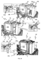
次に、図14A~図14F、図15A~図15D、および図16を特に参照して、考えられる電池交換の工程の1つを説明する。 One possible battery replacement process will now be described with particular reference to FIGS. 14A-14F, 15A-15D, and 16. FIG.
車両3であって、その放電したまたは一部放電した主電池28を、充電のためにその電池室27aから第1の充電ステーションへ移送した車両3は、充電したまたは一部充電した主電池28(図14Aおよび図15C参照)を保管する第2の充電ステーション40へ近づく。
A
車両が充電ステーション保管セルに入ることを可能にするために、第1のセットの車輪19a~dは、下にある軌道システム108(図15A~図15D参照)に接触すべきであり、充電ステーション30に最も近い第2のセットの車輪20a~dは、Y方向に沿って軌道111と干渉しないために、軌道システム108の上方に十分高くあるべきである。
To allow the vehicle to enter the charging station storage cell, the first set of
第2のセットの車輪20a~dのうちの2つの車輪20a、bが充電ステーション保管セルに入ったとき、かつ充電ステーション40が近づく車両3に接触している水平位置に到達する前に、車両3は、軌道システム108の方へ再び下げられる。上述したように、電池28の重量が充電ソケット45をその下側(搭載)位置まで下げさせるので、再びの下げは、電池交換の工程中に主電池28との正しい位置合わせを可能にするために行われる。車両3の下げは、交換手順の全体的な安定性をやはり増加させる。車両3の典型的な垂直変位は、5~15mm、例えば10mmである。
When two
したがって、充電ステーション40は、軌道システム108に対しての充電下の主電池28の高さが、車両3が下げられた位置にあるときに車両3上の電池室27aの対応する高さにおおよそ等しいように構成されるべきである。
Thus, the charging
主電池28を欠く車両3の移動を可能にするために、例えば、公開WO2015/104263A1(その内容は参照により本明細書に組み込まれる)に開示されるのと同じまたは類似したように、補助電池が設置されてもよい。例えば、導体レールなどの外部動力源、手動干渉等の使用といった他の解決策も考えられ得る。
To enable movement of the
充電ステーション40もしくは車両3、または両方の組合せが複数の電池28を含み、それによって電池交換中に充電ステーション40間の車両移動を必要としない代替実施形態がある。上述した保管システム1に適用可能なマルチ電池充電ステーションは、WO2017/220627A1に開示されており、その内容は参照により本明細書に組み込まれる。
There are alternative embodiments in which charging
第2の充電ステーション40上の利用可能な充電済み電池28が、電池支持体43上へ装着され、図13~図15に示された例では、これは、充電ステーションコラム42の上端42bの各側から軌道システム108の中に横に延びる2本の案内ピン43a、43b(すなわち、案内アーム)の形態にある。
The available charged
車両3が充電ステーション40(図14Aおよび図15D参照)に接触しているとき、解除機構50(すなわち、解除可能なロック機構)が作動され、電池カバー27が回転Y軸まわりに傾斜されることを可能にする。
When the
図14~図16に示された例では、解除機構50は、電池28が内部に入るべき電池室27aの開口部の各側に配置された枢動アーム51を備える。
In the example shown in Figures 14-16, the
さらに、(電池支持体43を構成する)案内ピン43a、43bの各突出端は、先細りセクション52(図13Aおよび図13C参照)を表示する。枢動アーム51と案内ピン43の間で接触すると、各枢動アーム51の枢動アーム接触要素51aは、先細りセクション52の方へ押され、それによって枢動アーム51の上向きに向けられた枢動移動を実現する(図14A、図15D、および図16参照)。この枢動移動により、安全ロック51b(図14および図18参照)を解除し、上述した電池カバー27の傾斜を可能にする。
In addition, each protruding end of the guide pins 43a, 43b (constituting the battery support 43) displays a tapered section 52 (see Figures 13A and 13C). Upon contact between the
解除機構50の動作は、図14および図16の連続図面の各々に示されている。明確さを高めるために、解除機構50の拡大領域の図面が図14A~Cおよび図14Fに加えられる。拡大領域の図面は、先細りセクション52と接触すると枢動アームの移動を引き起こし、安全ロック51bを電池カバー27および電池28の続く入り口から離れるように移動させることを明確に示す。
The operation of
取り付けられた電池28と共に案内ピン43が電池室27a(図14Bおよび図14C)の中にある距離だけ入ったとき、案内ピン43は、電池28が電池室27a内のその端位置に完全に収まるまでさらに入ることを可能にする電池ロック27b、27cを解除する。
When
図18では、電池ロック27b、c(すなわち、電源ロック組立体)は、車輪27bと、電池カバー27の内壁から(すなわち、電源ロック組立体の側壁36から)電池室27aの中に延びる1つまたは複数の阻止用歯27cとの形態で電池ロック作動装置を備える。案内ピン43a、bの先細り端52が車輪27bに接触するとき、電池カバー27は、上向きに傾斜され、それによって、電池28および案内ピン43a、bが電池室27aの中により深い移動を続けることができるように1つまたは複数の歯27cを変位させる。電池カバー27の主な機能は、電池ロックの構成要素として働き、阻止用歯および車輪が配置される2つの側壁に剛性を与えることであることに留意されたい。したがって、他の実施形態では、電池カバーは、阻止用歯および車輪が配置される2つの側壁(または長手方向要素)に十分な支持/剛性を与えることができる任意の要素であり得る。
In FIG. 18, the battery locks 27b,c (i.e., the power lock assembly) have
この端位置において、車両3の退避前に、電池28は充電ステーション40と、車輪19a~d、20a~dのためのすなわち駆動モータとの両方の2つと電気的に接続されることができる。
In this end position, prior to retraction of the
電池28が電池カバー27の内側のその端位置にあり、車両3の対応する電気コネクタと電気接触しているとき、電池カバー27は、歯27cが電池室27a内の電池28を物理的にロックまたは保持するようにその初期位置に傾斜して戻る。一例として、歯27cは、電池28(図17参照)の両側面に配置された支持レール49内の専用の凹部49aに入ることができる。
When the
電池ロック27b、cは、電池室27a内の任意の物理的な障害物であり得る。上述した歯27cの代替として、電池ロックは、電池28が一方向に越えることができるが、他方には越えられない1つまたは複数の突出する楔を備えてもよい。この構成では、楔形は、電池ロック作動装置27bとして働く。
Battery locks 27b,c can be any physical obstruction within
電池28がその端位置にあり、電池ロック27b、cによって電池室27aにうまくロックされるとき、車両3の第2のセットの車輪20a~dは、軌道システム108から(典型的には5~15mmの間だけ)持ち上げられ、それによって車両3の全高を持ち上げる。この動作により、電池28を電池支持体43から、例えば、第1および第2の案内ピン43a、b(図13A参照)内の専用のポケットまたは軌道から解除させる。
When the
ここで電池ロック27b、cは電池28を電池室27aにロックしており、電池28は電池支持体43から自由に持ち上げられているので、充電ステーション保管セルから外へ車両3を退避させることにより、車両3に電気的に接続された電池28を残す。
Here, the battery locks 27b and 27c lock the
電池の交換がうまくいくことを可能にすることに加えて、電池28が電池室27aに入ることを阻止することは、電池28が動作中に電池カバー27内で意図せずずれることがないという利点を有する。
In addition to allowing successful battery replacement, preventing
制御システムが充電のためにその電池28を充電ステーション40の中に配置するように指示を車両3へ送ったとき、車両3から充電ステーション40へ電池28を移送するステップは、充電ステーション40から車両3へ電池28を移送する上述したステップの反対の順序および方向と本質的に等しいまたは類似する。
When the control system has sent an instruction to
したがって、車両3がまず持ち上げられることにより、第2のセットの車輪20が第2の方向(Y)の軌道111と干渉することなく車両が充電ステーション保管セルに入ることと、動作する電池28を充電ステーション40の充電ソケット45と位置合わせすることとの両方を可能にする。上述したように、充電ソケット45は、上側の非搭載位置における図13~図16の例示的な構成にある。
Thus, the
車両3が充電ステーション40の方へ近づいている最中、第1および第2の案内ピン43a、bの楔形端52は、まず、解除機構51によって電池格納部27の傾斜を引き起こし、次いで電池ロック27b、cをアクティブにして電池カバー27を上方へ傾斜させ、それによって支持レール49内の対応する凹部49aから阻止用歯27cを取り除く。
While the
車両3を軌道システム108の方へ下げることによって、電池28の支持レール49は、電池支持体43と噛み合う。したがって、続く車両3の退避は、充電ステーション40上の所望の充電位置に電池28を残す。
By lowering the
車両3内でより大きい電池を可能にするために、電池カバー27と任意の解除機構50の両方は、それらがその他のほぼ垂直の側壁26cおよび26dを越えてX方向に水平に突出するよう配置されてもよい。このようにして、システム1における各車両3の全体的な能力は、軌道110、111をより広くさせることを必要とせずに、かなり大きく向上できる。
To allow for a larger battery within the
例えば、一般的なメンテナンスまたは偶発的な電池詰まりにより電池室27aから電池28を取り除くための手動干渉の必要がある場合、突出する解除機構50を備えた構成は、それが電池28の容易な手動ロック解除を可能にするという点でさらなる利点を有する。すなわち、突出の配置は、例えば、解除機構50が電池カバー27内深くに配置された場合に難しい動作である、解除機構50に対して十分な手動の力を及ぼすことを可能にする。
For example, if general maintenance or an accidental battery jam requires manual intervention to remove the
上述した突出構成も、充電ステーション40における早期係合を確実にするのに有益である。
The protruding configuration described above is also beneficial in ensuring early engagement at charging
電池28の一例は、図17に斜視で示される。2つの支持レール49の一方は、電池28の側壁から突出して示されている。同一の支持レールが、反対の側壁から突出している。支持レール49の目的は、電池支持体/案内ピン43上の電池28の安定した支持を確実にすることと、交換中に電池室27aの内外に電池28を正確に案内するのを確実にすることとの両方である。図18は、支持レール49が電池室27a内に十分に挿入されている状態で電池28を示す。図18に示された特定の構成では、電池28は、電池の最大許容体積のおおよそ半分である。
An
図19および図20は、それぞれ第2および第3の実施形態による枠組み構造100上の車両4、5の斜視図を示す。第1の実施形態による車両3において電池室27aを囲む電池供給部カバー27は、第2および第3の実施形態の場合、箱保管空間24の上方に配置される。
Figures 19 and 20 show perspective views of the
図20Aおよび図20Bは、互いに隣接して配置された2つの電池カバー27を備える車両5の一例を示す。図20Bにおいて、車両5の外壁および蓋は、取り除かれている。電池28のいずれの交換も、この例示的な車両5については、一度に1つずつまたは同時に2つの充電ステーション40を使用し得る。持ち上げおよび搬送中の重量配分をとりわけ改善するために、車両5は、車輪セットごとに6つの車輪を備える。
Figures 20A and 20B show an example of a
図21および図22は、自動保管および取出しシステムと共に使用するための充電ステーションの第2の実施形態を示す。この実施形態では、案内ピン43a、43b上の突出部32が、横方向により延ばされる。上述したように、充電ソケット45は、上側位置と下側位置の間で案内ピン43a、43bに対して(または代替として充電ステーションコラム42に対して)垂直方向に変位可能である。図21および図22では、充電ソケットは、上側位置に示される。充電ソケット45は、ばね33によって上側位置の方へ付勢される。この特定の実施形態では、付勢は、充電ソケット45を、ブラケット34aを介してコラム接続要素34bへ摺動可能に接続させることによって、およびブラケット34aとコラム接続要素34bの間にばねを配置させることによって得られ、それによってブラケット34aが上側位置に付勢される。
Figures 21 and 22 show a second embodiment of a charging station for use with an automated storage and retrieval system. In this embodiment, the
前述の説明において、本発明による充電ステーションならびに自動保管および取出しシステムの様々な態様は、例示的な実施形態を参照して説明されている。しかしながら、この説明は、限定の意味で解釈されることは意図されない。当業者に明らかである例示的な実施形態の様々な修正および変更、ならびにシステムの他の実施形態は、添付の特許請求の範囲によって定められる本発明の範囲内にあると考えられる。 In the foregoing description, various aspects of charging stations and automated storage and retrieval systems according to the invention have been described with reference to exemplary embodiments. However, this description is not intended to be construed in a limiting sense. Various modifications and variations of the illustrative embodiments, as well as other embodiments of the system, which are apparent to those skilled in the art are considered to be within the scope of the invention as defined by the appended claims.
1 自動保管および取出しシステム
3 車両、第1の実施形態
3a 第1の車両、第1の実施形態
3b 第2の車両、第1の実施形態
4 車両、第2の実施形態
5 車両、第3の実施形態
17 車両本体
17a 車両本体17の下側セクション
17b 車両本体17の上側セクション
18 車輪組立体/転がり手段/転がり装置
19 第1のセットの車輪
19a 第1のセットの第1の車輪
19b 第1のセットの第2の車輪
19c 第1のセットの第3の車輪
19d 第1のセットの第4の車輪
20 第2のセットの車輪
20a 第2のセットの第1の車輪
20b 第2のセットの第2の車輪
20c 第2のセットの第3の車輪
20d 第2のセットの第4の車輪
21 持ち上げ装置
22 把持装置
23 持ち上げ用モータ
24 保管室、箱保管空間
25 (第1または第2のセットの車輪に取り付けられた)側板
26 車両の側壁
26a 第2の方向(Y)に向けられた第1の側壁
26b 第2の方向(Y)に向けられた第2の側壁
26c 第1の方向(X)に向けられた第3の側壁
26d 第1の方向(X)に向けられた第4の側壁
27 電源カバー/電池カバー/電池格納部
27a 電源室/電池室
27b 電池ロック作動装置
27c 阻止用歯
28 電源/主電源、電池/主電池
29 凹んだセクション
30 電源室の開口部
31 電源室内の支持面
32 案内ピン上の突出部
33 ばね
34a ブラケット
34b コラム接続要素
35 車載された制御および通信システム
36 側壁/長手方向要素
40 充電および/または電池交換ステーション/充電ステーション
41 充電ステーション基部板/基部板
42 充電ステーションコラム/コラム
42a 充電ステーションの下端
42b 充電ステーションの上端
43 電源支持体/電池支持体/案内手段/案内部/案内ピン
43a 第1の案内ピン
43b 第2の案内ピン
44 電源/電力変圧器
45 充電接続部/充電プラグ
46 電源充電接続部/充電ソケット
49 支持レール
49a (支持レール49内の)凹部
50 解除機構
51 枢動アーム
51a 枢動アーム接触要素
52b (電源カバー27の傾斜を妨げるための)安全ロック
52 (案内ピンの)先細りセクション
100 枠組み構造
102 枠組み構造の垂直部材
103 枠組み構造の水平部材
104 保管グリッド
105 保管コラム
106 保管コンテナ
106’ 保管コンテナの特定の位置
107 スタック
108 レールシステム/軌道システム
110 第1の方向(X)の平行な軌道
110a 隣り合う軌道110の第1の軌道
110b 隣り合う軌道110の第2の軌道
111 第2の方向(Y)の平行な軌道
111a 隣り合う軌道111第1の軌道
111b 隣り合う軌道111第2の軌道
112 グリッドコラム
115 グリッド開口部
119 第1のポートコラム/第1のポート
120 第2のポートコラム/第2のポート
122 グリッドセル/保管セル
201 先行技術の単一セルの保管コンテナ車両
201a 保管コンテナ車両101の車両本体
201b 駆動手段/車輪配置、第1の方向(X)
201c 駆動手段/車輪配置、第2の方向(Y)
301 先行技術の片持ち梁の保管コンテナ車両
301a 保管コンテナ車両101の車両本体
301b 第1の方向(X)の駆動手段
301c 第2の方向(Y)の駆動手段
X 第1の方向
Y 第2の方向
Z 第3の方向
P 水平面
D 充電ステーションコラムの下端の末端から電源支持体の最下の部分までの距離
L 充電下における充電ステーションコラムの外周から電源の幾何学的サイズおよび/または車両の水平中心点までの距離
1 Automated storage and retrieval system 3 Vehicle, first embodiment 3a First vehicle, first embodiment 3b Second vehicle, first embodiment 4 Vehicle, second embodiment 5 Vehicle, third embodiment Embodiment 17 Vehicle Body 17a Lower Section of Vehicle Body 17 17b Upper Section of Vehicle Body 17 18 Wheel Assembly/Rolling Means/Rolling Device 19 First Set of Wheels 19a First Set of First Wheels 19b First second set of wheels 19c first set of third wheels 19d first set of fourth wheels 20 second set of wheels 20a second set of first wheels 20b second set of Second wheel 20c Third wheel of second set 20d Fourth wheel of second set 21 Lifting device 22 Grasping device 23 Lifting motor 24 Storage room, box storage space 25 (first or second set side plate 26 vehicle side wall 26a first side wall 26b oriented in a second direction (Y) second side wall 26c oriented in a second direction (Y) 26c first direction ( X) 26d Fourth side wall oriented in the first direction (X) 27 Power supply cover/battery cover/battery compartment 27a Power supply compartment/battery compartment 27b Battery lock actuator 27c For blocking Teeth 28 Power supply/mains, battery/main battery 29 Recessed section 30 Power compartment opening 31 Support surface in power compartment 32 Protrusion on guide pin 33 Spring 34a Bracket 34b Column connection element 35 Onboard control and communication system 36 side wall/longitudinal element 40 charging and/or battery exchange station/charging station 41 charging station base plate/base plate 42 charging station column/column 42a lower edge of charging station 42b upper edge of charging station 43 power supply support/battery support/ Guide Means/Guides/Guide Pins 43a First Guide Pin 43b Second Guide Pin 44 Power Supply/Power Transformer 45 Charging Connection/Charging Plug 46 Mains Charging Connection/Charging Socket 49 Support Rail 49a (in support rail 49) ) recess 50 release mechanism 51 pivot arm 51a pivot arm contact element 52b safety lock (to prevent tilting of power supply cover 27) 52 tapered section (of guide pin) 100 framework structure 102 vertical member of framework structure 103 framework structure 104 storage grid 105 storage column 106 storage container 106' specific location of storage container 107 stack 108 rail system/track system 110 parallel tracks in first direction (X) 110a first track of adjacent tracks 110 110b second track of adjacent track 110 111 parallel track in second direction (Y) 111a adjacent track 111 first track 111b adjacent track 111 second track 112 grid column 115 grid opening 119 first port column/first port 120 second port column/second port 122 grid cell/storage cell 201 prior art single cell storage container vehicle 201a vehicle body of storage container vehicle 101 201b drive means/wheel arrangement , in a first direction (X)
201c drive means/wheel arrangement, second direction (Y)
301 Prior art cantilevered storage container vehicle 301a Vehicle body of storage container vehicle 101 301b Drive means in first direction (X) 301c Drive means in second direction (Y) X First direction Y Second direction Direction Z Third direction P Horizontal plane D Distance from the lower end of the charging station column to the lowest part of the power supply support L Geometric size of the power supply and/or vehicle horizontal from the perimeter of the charging station column under charging distance to center point
Claims (26)
前記軌道システム(108)の真下に位置する複数の保管コラム(105)であって、各保管コラム(105)は、グリッド開口部(115)の垂直下方に位置し、保管コンテナ(106)のスタック(107)を保管するように配置される、複数の保管コラム(105)と、
前記スタック(107)に積み重ねられた少なくとも1つの保管コンテナ(106)を持ち上げるためのコンテナ取扱車両(3~5)であって、前記コンテナ取扱車両(3~5)は、前記グリッド開口部(115)を介して前記保管コンテナ(106)にアクセスするように、前記保管コラム(105)の上方の前記軌道システム(108)上で横に移動するように構成されており、
前記コンテナ取扱車両(3~5)は、保管コンテナ(106)を保管する少なくとも1つの保管室(24)を備えた下部(17a)、前記下部(17a)の垂直上方に配置された上部(17b)、前記軌道システム(108)に沿って前記コンテナ取扱車両(3~5)を案内する車輪組立体(18)、および交換可能な電源(28)を収容する電源室(27a)を備える、コンテナ取扱車両(3~5)と、
電源充電接続部(46)を有する前記電源室に収容するための交換可能な電源(28)と、
前記交換可能な電源(28)を充電するための充電ステーション(40)であって、前記電源充電接続部(46)との電気接続を生成するように構成された充電接続部(45)、および充電中に前記電源(28)を解除可能に支持する電源支持体(43)を備えた充電ステーション(40)と
を備え、
前記電源室(27a)は、前記コンテナ取扱車両(3~5)の前記上部(17b)に配置され、前記第1の方向(X)または前記第2の方向(Y)の方に面する開口部を介して前記交換可能な電源(28)を受容するように構成され、
前記電源室(27a)は、前記電源室(27a)内の所定の位置に前記電源(28)を保持するように配置された電源ロック組立体(27、27b、27c)を備え、
前記電源ロック組立体(27、27b、27c)は、前記電源ロック組立体が所定の位置に前記電源を保持することができる第1の位置と前記電源が移動され得る第2の位置との間で移動可能である、
自動保管および取出しシステム(1)。 a first set of parallel tracks (110) arranged in a horizontal plane (P) and extending in a first direction (X); a second set of parallel tracks (111) extending in a second direction (Y), said first and second sets of tracks (110, 110) comprising: forming a grid pattern in said horizontal plane (P) comprising a plurality of adjacent grid cells (122), each grid cell being a pair of adjacent tracks (110a, 110b) of said first set of tracks (110); , and a grid opening (115) defined by a pair of adjacent tracks (111a, 111b) of the second set of tracks (111);
A plurality of storage columns (105) located beneath said track system (108), each storage column (105) located vertically below a grid opening (115) and a stack of storage containers (106). a plurality of storage columns (105) arranged to store (107);
A container handling vehicle (3-5) for lifting at least one storage container (106) stacked in said stack (107), said container handling vehicle (3-5) being positioned at said grid opening (115). ) to access the storage container (106) via the track system (108) above the storage column (105);
Said container handling vehicles (3-5) have a lower part (17a) with at least one storage room (24) for storing storage containers (106), an upper part (17b) arranged vertically above said lower part (17a) ), wheel assemblies (18) for guiding said container handling vehicles (3-5) along said track system (108), and a power compartment (27a) containing a replaceable power supply (28). Handling vehicles (3 to 5),
a replaceable power supply (28) for housing in the power compartment having a power supply charging connection (46);
a charging station (40) for charging the replaceable power supply (28), the charging connection (45) being configured to generate an electrical connection with the power supply charging connection (46); and a charging station (40) comprising a power supply support (43) releasably supporting said power supply (28) during charging;
The power supply room (27a) is located in the upper part (17b) of the container handling vehicle (3-5) and has an opening facing either the first direction (X) or the second direction (Y). configured to receive said replaceable power supply (28) via a section ;
said power compartment (27a) comprising a power lock assembly (27, 27b, 27c) arranged to hold said power supply (28) in place within said power compartment (27a);
The power lock assembly (27, 27b, 27c) is positioned between a first position in which the power lock assembly can hold the power supply in place and a second position in which the power supply can be moved. can be moved with
Automated storage and retrieval system (1).
前記下側接続位置で、前記電源(28)が前記電源支持体(43)によって支持されるときに、前記充電接続部(45)は、前記電源充電接続部(46)のレベルに対応するレベルで配置され、
前記上側接続位置で、前記電源(28)が前記電源室内に収容されるとともに、前記第1のセットの車輪(19)が前記下側車輪位置にあるときに、前記充電接続部(45)は、前記電源充電接続部(46)のレベルに対応するレベルで配置される、請求項12から16のいずれかに記載のシステム。 The power support (43) is arranged at a level with respect to the track system (108) and the charging connection (45) has a lower connection position and an upper connection position with respect to the track system (108). is movable between
In the lower connection position, when the power supply (28) is supported by the power supply support (43), the charging connection (45) is at a level corresponding to that of the power supply charging connection (46). is placed with
When in the upper connection position the power source (28) is housed in the power compartment and the first set of wheels (19) is in the lower wheel position the charging connection (45) is , at a level corresponding to the level of the mains charging connection ( 46 ).
d)前記充電ステーション(40)の前記電源支持体(43)が前記電源(28)を保管する前記電源室(27a)に少なくとも部分的に入っている位置であって、前記充電ステーション(40)の少なくとも1つの充電接続部(45)が、前記電源(28)の少なくとも1つの電源充電接続部(46)と電気接触するように設定される位置へ、前記コンテナ取扱車両(3~5)を移動させるステップと、
e)前記コンテナ取扱車両(3~5)の前記電源室(27a)から前記電源支持体(43)へ前記電源(28)を移送するステップと、
f)前記コンテナ取扱車両(3~5)を逆転させ、充電時に前記充電ステーション(40)上に前記電源(28)を残すステップと
を含み、
前記電源室(27a)は、前記電源室(27a)内の所定の位置に前記電源(28)を保持するように配置された電源ロック組立体(27、27b、27c)を備え、
前記電源ロック組立体(27、27b、27c)は、前記電源ロック組立体が所定の位置に前記電源を保持することができる第1の位置と前記電源が移動され得る第2の位置との間で移動可能である、
方法。 A method of charging a power source (28) housed in a power compartment (27a) of a container handling vehicle (3-5) using a charging station (40) having a power source support (43), the method comprising: The vehicles (3-5) are arranged in a horizontal plane (P) and with a first set of parallel tracks (110) extending in a first direction (X) and arranged in said horizontal plane (P), said configured to travel on a track system (108) comprising a second set of parallel tracks (111) extending in a second direction (Y) orthogonal to the first direction (X); The first and second sets of tracks (110, 110) form a grid pattern in said horizontal plane (P) comprising a plurality of adjacent grid cells (122), each grid cell being one of said first set. a grid opening (115) defined by a pair of adjacent tracks (110a, 110b) of the tracks (110) and a pair of adjacent tracks (111a, 111b) of the second set of tracks (111); in the method
d) a position in which said power supply support (43) of said charging station (40) is at least partially in said power supply compartment (27a) storing said power supply (28), said charging station (40) said container handling vehicle (3-5) into a position in which at least one charging connection (45) of said power source (28) is set in electrical contact with at least one power charging connection (46) of said power source (28); a step of moving;
e) transferring said power supply (28) from said power supply compartment (27a) of said container handling vehicle (3-5) to said power supply support (43);
f) reversing said container handling vehicle (3-5) leaving said power supply (28) on said charging station (40) when charging ;
said power compartment (27a) comprising a power lock assembly (27, 27b, 27c) arranged to hold said power supply (28) in place within said power compartment (27a);
The power lock assembly (27, 27b, 27c) is positioned between a first position in which the power lock assembly can hold the power supply in place and a second position in which the power supply can be moved. can be moved with
Method.
Priority Applications (1)
| Application Number | Priority Date | Filing Date | Title |
|---|---|---|---|
| JP2023136868A JP2023159362A (en) | 2018-04-25 | 2023-08-25 | Automated storage and retrieval system with charging stations for charging replaceable power sources on container handling vehicles |
Applications Claiming Priority (3)
| Application Number | Priority Date | Filing Date | Title |
|---|---|---|---|
| NO20180586A NO20180586A1 (en) | 2018-04-25 | 2018-04-25 | Charging system for container handling vehicles and method of charging a power supply |
| NO20180586 | 2018-04-25 | ||
| PCT/EP2019/053875 WO2019206490A1 (en) | 2018-04-25 | 2019-02-15 | An automated storage and retrieval system with a charging station for charging of a replaceable power supply of a container handling vehicle |
Related Child Applications (1)
| Application Number | Title | Priority Date | Filing Date |
|---|---|---|---|
| JP2023136868A Division JP2023159362A (en) | 2018-04-25 | 2023-08-25 | Automated storage and retrieval system with charging stations for charging replaceable power sources on container handling vehicles |
Publications (2)
| Publication Number | Publication Date |
|---|---|
| JP2021522130A JP2021522130A (en) | 2021-08-30 |
| JP7339964B2 true JP7339964B2 (en) | 2023-09-06 |
Family
ID=65494123
Family Applications (2)
| Application Number | Title | Priority Date | Filing Date |
|---|---|---|---|
| JP2020558876A Active JP7339964B2 (en) | 2018-04-25 | 2019-02-15 | Automated storage and retrieval system with charging stations for charging interchangeable power sources on container handling vehicles |
| JP2023136868A Pending JP2023159362A (en) | 2018-04-25 | 2023-08-25 | Automated storage and retrieval system with charging stations for charging replaceable power sources on container handling vehicles |
Family Applications After (1)
| Application Number | Title | Priority Date | Filing Date |
|---|---|---|---|
| JP2023136868A Pending JP2023159362A (en) | 2018-04-25 | 2023-08-25 | Automated storage and retrieval system with charging stations for charging replaceable power sources on container handling vehicles |
Country Status (10)
| Country | Link |
|---|---|
| US (1) | US20210032036A1 (en) |
| EP (2) | EP3784604B1 (en) |
| JP (2) | JP7339964B2 (en) |
| CN (2) | CN115417052A (en) |
| CA (1) | CA3092272A1 (en) |
| DK (1) | DK3784604T3 (en) |
| ES (1) | ES2938032T3 (en) |
| NO (1) | NO20180586A1 (en) |
| PL (1) | PL3784604T3 (en) |
| WO (1) | WO2019206490A1 (en) |
Families Citing this family (17)
| Publication number | Priority date | Publication date | Assignee | Title |
|---|---|---|---|---|
| US11567511B1 (en) * | 2019-06-12 | 2023-01-31 | Amazon Technologies, Inc. | After hours package pick up from a robot |
| NO345918B1 (en) * | 2019-09-16 | 2021-10-18 | Autostore Tech As | Automated storage and retrieval system using an automated loader and methods of replacing power supplies |
| GB202001012D0 (en) * | 2020-01-24 | 2020-03-11 | Ocado Innovation Ltd | Raising and lowering containers |
| CN111540260B (en) * | 2020-04-30 | 2022-05-27 | 东莞市名贝电子科技有限公司 | New energy automobile battery duration comparison device |
| CN111483347B (en) * | 2020-05-04 | 2021-08-31 | 李龙德 | New energy automobile battery replacement robot with anti-falling protection performance |
| CN113650999B (en) * | 2020-05-12 | 2022-09-27 | 深圳市海柔创新科技有限公司 | Power changing method for carrying robot |
| NO346054B1 (en) | 2020-06-08 | 2022-01-24 | Autostore Tech As | System and method of determining status of a charging station |
| CN111907351A (en) * | 2020-08-18 | 2020-11-10 | 幻电科技发展有限公司 | Light small-size pure electric automobile quick change electricity basic station |
| NO346543B1 (en) * | 2021-03-09 | 2022-09-26 | Autostore Tech As | A storage system featuring covers arrangeable in storage columns |
| US20230219438A1 (en) * | 2021-05-24 | 2023-07-13 | Mark Ogram | Electric vehicle refueling |
| WO2023041743A1 (en) * | 2021-09-16 | 2023-03-23 | Ocado Innovation Limited | An energy storage system for a load handling device |
| GB2612895B (en) * | 2021-09-16 | 2023-11-29 | Ocado Innovation Ltd | An energy storage system for a load handling device |
| CN113752895B (en) * | 2021-09-18 | 2023-04-25 | 三一重工股份有限公司 | Motor replacing robot, power replacing system and working method of motor replacing robot |
| KR102514054B1 (en) * | 2022-02-23 | 2023-03-24 | 신함인 | Movable apparatus for battery charging of electric vehicle |
| CN114873236B (en) * | 2022-03-31 | 2023-12-12 | 苏州博众仪器科技有限公司 | Battery cabinet entering system and battery cabinet entering method |
| GB2618072A (en) * | 2022-04-21 | 2023-11-01 | Ocado Innovation Ltd | Load handling device with assigned code |
| US20230398898A1 (en) * | 2022-06-08 | 2023-12-14 | Nimble Robotics, Inc. | Robot Having Interchangeable Batteries |
Citations (2)
| Publication number | Priority date | Publication date | Assignee | Title |
|---|---|---|---|---|
| JP2016529181A (en) | 2013-08-09 | 2016-09-23 | オカド・イノベーション・リミテッド | Equipment for recovering units from storage systems |
| JP2017503731A (en) | 2014-01-08 | 2017-02-02 | ヤコブ・ハッテラン・ロジスティックス・アクティーゼルスカブ | Robot for transporting storage containers |
Family Cites Families (18)
| Publication number | Priority date | Publication date | Assignee | Title |
|---|---|---|---|---|
| DE9412219U1 (en) * | 1994-07-29 | 1995-11-23 | Varta Batterie | Automatic coupling system for vehicle batteries |
| JP3907166B2 (en) * | 2001-08-09 | 2007-04-18 | 本田技研工業株式会社 | Electric small vehicle charging system |
| WO2006126881A2 (en) * | 2005-05-24 | 2006-11-30 | Varibel B.V. | Connector assembly for connecting an earpiece of a hearing aid to a glasses temple |
| NL2007566C2 (en) * | 2011-10-11 | 2013-04-15 | Lely Patent Nv | Vehicle system. |
| GB201205807D0 (en) * | 2012-03-30 | 2012-05-16 | Tomtom Int Bv | Mobile device docking station |
| NO334806B1 (en) | 2012-11-13 | 2014-06-02 | Jakob Hatteland Logistics As | storage System |
| NO335839B1 (en) * | 2012-12-10 | 2015-03-02 | Jakob Hatteland Logistics As | Robot for transporting storage containers |
| GB201404870D0 (en) * | 2014-03-18 | 2014-04-30 | Ocado Ltd | Robotic service device and handling method |
| NO337544B1 (en) * | 2014-06-19 | 2016-05-02 | Jakob Hatteland Logistics As | Remote controlled vehicle assembly to pick up storage containers from a storage system |
| ES2751745T3 (en) | 2015-01-28 | 2020-04-01 | Autostore Tech As | Robot to transport storage containers |
| NO340577B1 (en) | 2015-09-04 | 2017-05-15 | Jakob Hatteland Logistics As | Method for fetching a target bin stored in a storage system and a storage system which includes a control device operating in accordance with the method |
| GB201521488D0 (en) * | 2015-12-06 | 2016-01-20 | Ocado Innovation Ltd | Sequencing systems and methods |
| NO20160118A1 (en) * | 2016-01-26 | 2017-07-27 | Autostore Tech As | Remotely operated vehicle |
| JP7054379B2 (en) * | 2016-03-03 | 2022-04-13 | 村田機械株式会社 | Transport system |
| NO344308B1 (en) * | 2016-06-21 | 2019-10-28 | Autostore Tech As | Storage system comprising a charging station assembly and method of replacing the power source of a remotely operated vehicle |
| NO346327B1 (en) * | 2017-05-16 | 2022-06-07 | Autostore Tech As | Automated storage and retrieval system |
| CA3063294A1 (en) * | 2017-05-16 | 2018-11-22 | Autostore Technology AS | Automated storage and retrieval system |
| CN107878248A (en) * | 2017-12-01 | 2018-04-06 | 郭春林 | A kind of method and system for being used to provide emergent charging for electric automobile |
-
2018
- 2018-04-25 NO NO20180586A patent/NO20180586A1/en not_active Application Discontinuation
-
2019
- 2019-02-15 JP JP2020558876A patent/JP7339964B2/en active Active
- 2019-02-15 EP EP19705963.7A patent/EP3784604B1/en active Active
- 2019-02-15 DK DK19705963.7T patent/DK3784604T3/en active
- 2019-02-15 US US16/981,465 patent/US20210032036A1/en active Pending
- 2019-02-15 CN CN202211233425.8A patent/CN115417052A/en active Pending
- 2019-02-15 ES ES19705963T patent/ES2938032T3/en active Active
- 2019-02-15 PL PL19705963.7T patent/PL3784604T3/en unknown
- 2019-02-15 EP EP22201412.8A patent/EP4151558A3/en active Pending
- 2019-02-15 CN CN201980028081.7A patent/CN112041246B/en active Active
- 2019-02-15 CA CA3092272A patent/CA3092272A1/en active Pending
- 2019-02-15 WO PCT/EP2019/053875 patent/WO2019206490A1/en unknown
-
2023
- 2023-08-25 JP JP2023136868A patent/JP2023159362A/en active Pending
Patent Citations (2)
| Publication number | Priority date | Publication date | Assignee | Title |
|---|---|---|---|---|
| JP2016529181A (en) | 2013-08-09 | 2016-09-23 | オカド・イノベーション・リミテッド | Equipment for recovering units from storage systems |
| JP2017503731A (en) | 2014-01-08 | 2017-02-02 | ヤコブ・ハッテラン・ロジスティックス・アクティーゼルスカブ | Robot for transporting storage containers |
Also Published As
| Publication number | Publication date |
|---|---|
| EP4151558A2 (en) | 2023-03-22 |
| US20210032036A1 (en) | 2021-02-04 |
| CN112041246B (en) | 2022-09-27 |
| JP2023159362A (en) | 2023-10-31 |
| NO20180586A1 (en) | 2019-10-28 |
| PL3784604T3 (en) | 2023-03-06 |
| JP2021522130A (en) | 2021-08-30 |
| EP4151558A3 (en) | 2023-05-31 |
| DK3784604T3 (en) | 2023-02-13 |
| EP3784604B1 (en) | 2022-11-23 |
| WO2019206490A1 (en) | 2019-10-31 |
| CN112041246A (en) | 2020-12-04 |
| CA3092272A1 (en) | 2019-10-31 |
| EP3784604A1 (en) | 2021-03-03 |
| CN115417052A (en) | 2022-12-02 |
| ES2938032T3 (en) | 2023-04-04 |
Similar Documents
| Publication | Publication Date | Title |
|---|---|---|
| JP7339964B2 (en) | Automated storage and retrieval system with charging stations for charging interchangeable power sources on container handling vehicles | |
| US11846935B2 (en) | Automated storage and retrieval system | |
| US11912501B2 (en) | Automated storage and retrieval system | |
| EP4031406B1 (en) | Automated storage and retrieval system using an automated loader and methods of replacing power supplies | |
| GB2609683A (en) | Load handling device & methods of exchanging a power source | |
| WO2023017183A1 (en) | Load handling device & methods of exchanging a power source |
Legal Events
| Date | Code | Title | Description |
|---|---|---|---|
| A621 | Written request for application examination |
Free format text: JAPANESE INTERMEDIATE CODE: A621 Effective date: 20220114 |
|
| A977 | Report on retrieval |
Free format text: JAPANESE INTERMEDIATE CODE: A971007 Effective date: 20230228 |
|
| A131 | Notification of reasons for refusal |
Free format text: JAPANESE INTERMEDIATE CODE: A131 Effective date: 20230302 |
|
| A521 | Request for written amendment filed |
Free format text: JAPANESE INTERMEDIATE CODE: A523 Effective date: 20230602 |
|
| TRDD | Decision of grant or rejection written | ||
| A01 | Written decision to grant a patent or to grant a registration (utility model) |
Free format text: JAPANESE INTERMEDIATE CODE: A01 Effective date: 20230809 |
|
| A61 | First payment of annual fees (during grant procedure) |
Free format text: JAPANESE INTERMEDIATE CODE: A61 Effective date: 20230825 |
|
| R150 | Certificate of patent or registration of utility model |
Ref document number: 7339964 Country of ref document: JP Free format text: JAPANESE INTERMEDIATE CODE: R150 |