JP7335323B2 - Interchangeable modular device for hydrogen release - Google Patents
Interchangeable modular device for hydrogen release Download PDFInfo
- Publication number
- JP7335323B2 JP7335323B2 JP2021506075A JP2021506075A JP7335323B2 JP 7335323 B2 JP7335323 B2 JP 7335323B2 JP 2021506075 A JP2021506075 A JP 2021506075A JP 2021506075 A JP2021506075 A JP 2021506075A JP 7335323 B2 JP7335323 B2 JP 7335323B2
- Authority
- JP
- Japan
- Prior art keywords
- modular device
- cartridge
- hydrogen
- catalyst
- cartridges
- Prior art date
- Legal status (The legal status is an assumption and is not a legal conclusion. Google has not performed a legal analysis and makes no representation as to the accuracy of the status listed.)
- Active
Links
Images


Classifications
-
- H—ELECTRICITY
- H01—ELECTRIC ELEMENTS
- H01M—PROCESSES OR MEANS, e.g. BATTERIES, FOR THE DIRECT CONVERSION OF CHEMICAL ENERGY INTO ELECTRICAL ENERGY
- H01M8/00—Fuel cells; Manufacture thereof
- H01M8/04—Auxiliary arrangements, e.g. for control of pressure or for circulation of fluids
- H01M8/04082—Arrangements for control of reactant parameters, e.g. pressure or concentration
- H01M8/04201—Reactant storage and supply, e.g. means for feeding, pipes
- H01M8/04208—Cartridges, cryogenic media or cryogenic reservoirs
-
- B—PERFORMING OPERATIONS; TRANSPORTING
- B01—PHYSICAL OR CHEMICAL PROCESSES OR APPARATUS IN GENERAL
- B01J—CHEMICAL OR PHYSICAL PROCESSES, e.g. CATALYSIS OR COLLOID CHEMISTRY; THEIR RELEVANT APPARATUS
- B01J19/00—Chemical, physical or physico-chemical processes in general; Their relevant apparatus
- B01J19/24—Stationary reactors without moving elements inside
- B01J19/248—Reactors comprising multiple separated flow channels
- B01J19/249—Plate-type reactors
-
- C—CHEMISTRY; METALLURGY
- C01—INORGANIC CHEMISTRY
- C01B—NON-METALLIC ELEMENTS; COMPOUNDS THEREOF; METALLOIDS OR COMPOUNDS THEREOF NOT COVERED BY SUBCLASS C01C
- C01B3/00—Hydrogen; Gaseous mixtures containing hydrogen; Separation of hydrogen from mixtures containing it; Purification of hydrogen
- C01B3/02—Production of hydrogen or of gaseous mixtures containing a substantial proportion of hydrogen
- C01B3/06—Production of hydrogen or of gaseous mixtures containing a substantial proportion of hydrogen by reaction of inorganic compounds containing electro-positively bound hydrogen, e.g. water, acids, bases, ammonia, with inorganic reducing agents
- C01B3/065—Production of hydrogen or of gaseous mixtures containing a substantial proportion of hydrogen by reaction of inorganic compounds containing electro-positively bound hydrogen, e.g. water, acids, bases, ammonia, with inorganic reducing agents from a hydride
-
- B—PERFORMING OPERATIONS; TRANSPORTING
- B01—PHYSICAL OR CHEMICAL PROCESSES OR APPARATUS IN GENERAL
- B01J—CHEMICAL OR PHYSICAL PROCESSES, e.g. CATALYSIS OR COLLOID CHEMISTRY; THEIR RELEVANT APPARATUS
- B01J16/00—Chemical processes in general for reacting liquids with non- particulate solids, e.g. sheet material; Apparatus specially adapted therefor
- B01J16/005—Chemical processes in general for reacting liquids with non- particulate solids, e.g. sheet material; Apparatus specially adapted therefor in the presence of catalytically active bodies, e.g. porous plates
-
- B—PERFORMING OPERATIONS; TRANSPORTING
- B01—PHYSICAL OR CHEMICAL PROCESSES OR APPARATUS IN GENERAL
- B01J—CHEMICAL OR PHYSICAL PROCESSES, e.g. CATALYSIS OR COLLOID CHEMISTRY; THEIR RELEVANT APPARATUS
- B01J19/00—Chemical, physical or physico-chemical processes in general; Their relevant apparatus
- B01J19/0006—Controlling or regulating processes
- B01J19/0013—Controlling the temperature of the process
-
- B—PERFORMING OPERATIONS; TRANSPORTING
- B01—PHYSICAL OR CHEMICAL PROCESSES OR APPARATUS IN GENERAL
- B01J—CHEMICAL OR PHYSICAL PROCESSES, e.g. CATALYSIS OR COLLOID CHEMISTRY; THEIR RELEVANT APPARATUS
- B01J19/00—Chemical, physical or physico-chemical processes in general; Their relevant apparatus
- B01J19/18—Stationary reactors having moving elements inside
-
- B—PERFORMING OPERATIONS; TRANSPORTING
- B01—PHYSICAL OR CHEMICAL PROCESSES OR APPARATUS IN GENERAL
- B01J—CHEMICAL OR PHYSICAL PROCESSES, e.g. CATALYSIS OR COLLOID CHEMISTRY; THEIR RELEVANT APPARATUS
- B01J27/00—Catalysts comprising the elements or compounds of halogens, sulfur, selenium, tellurium, phosphorus or nitrogen; Catalysts comprising carbon compounds
- B01J27/14—Phosphorus; Compounds thereof
- B01J27/185—Phosphorus; Compounds thereof with iron group metals or platinum group metals
- B01J27/1853—Phosphorus; Compounds thereof with iron group metals or platinum group metals with iron, cobalt or nickel
-
- C—CHEMISTRY; METALLURGY
- C01—INORGANIC CHEMISTRY
- C01B—NON-METALLIC ELEMENTS; COMPOUNDS THEREOF; METALLOIDS OR COMPOUNDS THEREOF NOT COVERED BY SUBCLASS C01C
- C01B3/00—Hydrogen; Gaseous mixtures containing hydrogen; Separation of hydrogen from mixtures containing it; Purification of hydrogen
- C01B3/02—Production of hydrogen or of gaseous mixtures containing a substantial proportion of hydrogen
- C01B3/04—Production of hydrogen or of gaseous mixtures containing a substantial proportion of hydrogen by decomposition of inorganic compounds, e.g. ammonia
-
- C—CHEMISTRY; METALLURGY
- C01—INORGANIC CHEMISTRY
- C01B—NON-METALLIC ELEMENTS; COMPOUNDS THEREOF; METALLOIDS OR COMPOUNDS THEREOF NOT COVERED BY SUBCLASS C01C
- C01B3/00—Hydrogen; Gaseous mixtures containing hydrogen; Separation of hydrogen from mixtures containing it; Purification of hydrogen
- C01B3/02—Production of hydrogen or of gaseous mixtures containing a substantial proportion of hydrogen
- C01B3/32—Production of hydrogen or of gaseous mixtures containing a substantial proportion of hydrogen by reaction of gaseous or liquid organic compounds with gasifying agents, e.g. water, carbon dioxide, air
-
- F—MECHANICAL ENGINEERING; LIGHTING; HEATING; WEAPONS; BLASTING
- F17—STORING OR DISTRIBUTING GASES OR LIQUIDS
- F17C—VESSELS FOR CONTAINING OR STORING COMPRESSED, LIQUEFIED OR SOLIDIFIED GASES; FIXED-CAPACITY GAS-HOLDERS; FILLING VESSELS WITH, OR DISCHARGING FROM VESSELS, COMPRESSED, LIQUEFIED, OR SOLIDIFIED GASES
- F17C11/00—Use of gas-solvents or gas-sorbents in vessels
- F17C11/005—Use of gas-solvents or gas-sorbents in vessels for hydrogen
-
- H—ELECTRICITY
- H01—ELECTRIC ELEMENTS
- H01M—PROCESSES OR MEANS, e.g. BATTERIES, FOR THE DIRECT CONVERSION OF CHEMICAL ENERGY INTO ELECTRICAL ENERGY
- H01M4/00—Electrodes
- H01M4/86—Inert electrodes with catalytic activity, e.g. for fuel cells
- H01M4/90—Selection of catalytic material
-
- H—ELECTRICITY
- H01—ELECTRIC ELEMENTS
- H01M—PROCESSES OR MEANS, e.g. BATTERIES, FOR THE DIRECT CONVERSION OF CHEMICAL ENERGY INTO ELECTRICAL ENERGY
- H01M8/00—Fuel cells; Manufacture thereof
- H01M8/04—Auxiliary arrangements, e.g. for control of pressure or for circulation of fluids
- H01M8/04082—Arrangements for control of reactant parameters, e.g. pressure or concentration
- H01M8/04201—Reactant storage and supply, e.g. means for feeding, pipes
- H01M8/04216—Reactant storage and supply, e.g. means for feeding, pipes characterised by the choice for a specific material, e.g. carbon, hydride, absorbent
-
- H—ELECTRICITY
- H01—ELECTRIC ELEMENTS
- H01M—PROCESSES OR MEANS, e.g. BATTERIES, FOR THE DIRECT CONVERSION OF CHEMICAL ENERGY INTO ELECTRICAL ENERGY
- H01M8/00—Fuel cells; Manufacture thereof
- H01M8/06—Combination of fuel cells with means for production of reactants or for treatment of residues
- H01M8/0606—Combination of fuel cells with means for production of reactants or for treatment of residues with means for production of gaseous reactants
- H01M8/065—Combination of fuel cells with means for production of reactants or for treatment of residues with means for production of gaseous reactants by dissolution of metals or alloys; by dehydriding metallic substances
-
- B—PERFORMING OPERATIONS; TRANSPORTING
- B01—PHYSICAL OR CHEMICAL PROCESSES OR APPARATUS IN GENERAL
- B01J—CHEMICAL OR PHYSICAL PROCESSES, e.g. CATALYSIS OR COLLOID CHEMISTRY; THEIR RELEVANT APPARATUS
- B01J2219/00—Chemical, physical or physico-chemical processes in general; Their relevant apparatus
- B01J2219/00049—Controlling or regulating processes
- B01J2219/00051—Controlling the temperature
- B01J2219/00054—Controlling or regulating the heat exchange system
- B01J2219/00056—Controlling or regulating the heat exchange system involving measured parameters
- B01J2219/00058—Temperature measurement
- B01J2219/00063—Temperature measurement of the reactants
-
- B—PERFORMING OPERATIONS; TRANSPORTING
- B01—PHYSICAL OR CHEMICAL PROCESSES OR APPARATUS IN GENERAL
- B01J—CHEMICAL OR PHYSICAL PROCESSES, e.g. CATALYSIS OR COLLOID CHEMISTRY; THEIR RELEVANT APPARATUS
- B01J2219/00—Chemical, physical or physico-chemical processes in general; Their relevant apparatus
- B01J2219/00049—Controlling or regulating processes
- B01J2219/00162—Controlling or regulating processes controlling the pressure
-
- B—PERFORMING OPERATIONS; TRANSPORTING
- B01—PHYSICAL OR CHEMICAL PROCESSES OR APPARATUS IN GENERAL
- B01J—CHEMICAL OR PHYSICAL PROCESSES, e.g. CATALYSIS OR COLLOID CHEMISTRY; THEIR RELEVANT APPARATUS
- B01J2219/00—Chemical, physical or physico-chemical processes in general; Their relevant apparatus
- B01J2219/24—Stationary reactors without moving elements inside
- B01J2219/2401—Reactors comprising multiple separate flow channels
- B01J2219/245—Plate-type reactors
- B01J2219/2451—Geometry of the reactor
- B01J2219/2453—Plates arranged in parallel
-
- B—PERFORMING OPERATIONS; TRANSPORTING
- B01—PHYSICAL OR CHEMICAL PROCESSES OR APPARATUS IN GENERAL
- B01J—CHEMICAL OR PHYSICAL PROCESSES, e.g. CATALYSIS OR COLLOID CHEMISTRY; THEIR RELEVANT APPARATUS
- B01J2219/00—Chemical, physical or physico-chemical processes in general; Their relevant apparatus
- B01J2219/24—Stationary reactors without moving elements inside
- B01J2219/2401—Reactors comprising multiple separate flow channels
- B01J2219/245—Plate-type reactors
- B01J2219/2476—Construction materials
- B01J2219/2477—Construction materials of the catalysts
- B01J2219/2479—Catalysts coated on the surface of plates or inserts
-
- B—PERFORMING OPERATIONS; TRANSPORTING
- B01—PHYSICAL OR CHEMICAL PROCESSES OR APPARATUS IN GENERAL
- B01J—CHEMICAL OR PHYSICAL PROCESSES, e.g. CATALYSIS OR COLLOID CHEMISTRY; THEIR RELEVANT APPARATUS
- B01J2219/00—Chemical, physical or physico-chemical processes in general; Their relevant apparatus
- B01J2219/24—Stationary reactors without moving elements inside
- B01J2219/2401—Reactors comprising multiple separate flow channels
- B01J2219/245—Plate-type reactors
- B01J2219/2491—Other constructional details
- B01J2219/2492—Assembling means
- B01J2219/2493—Means for assembling plates together, e.g. sealing means, screws, bolts
- B01J2219/2495—Means for assembling plates together, e.g. sealing means, screws, bolts the plates being assembled interchangeably or in a disposable way
-
- B—PERFORMING OPERATIONS; TRANSPORTING
- B01—PHYSICAL OR CHEMICAL PROCESSES OR APPARATUS IN GENERAL
- B01J—CHEMICAL OR PHYSICAL PROCESSES, e.g. CATALYSIS OR COLLOID CHEMISTRY; THEIR RELEVANT APPARATUS
- B01J2523/00—Constitutive chemical elements of heterogeneous catalysts
- B01J2523/30—Constitutive chemical elements of heterogeneous catalysts of Group III (IIIA or IIIB) of the Periodic Table
- B01J2523/305—Boron
-
- B—PERFORMING OPERATIONS; TRANSPORTING
- B01—PHYSICAL OR CHEMICAL PROCESSES OR APPARATUS IN GENERAL
- B01J—CHEMICAL OR PHYSICAL PROCESSES, e.g. CATALYSIS OR COLLOID CHEMISTRY; THEIR RELEVANT APPARATUS
- B01J2523/00—Constitutive chemical elements of heterogeneous catalysts
- B01J2523/50—Constitutive chemical elements of heterogeneous catalysts of Group V (VA or VB) of the Periodic Table
- B01J2523/51—Phosphorus
-
- B—PERFORMING OPERATIONS; TRANSPORTING
- B01—PHYSICAL OR CHEMICAL PROCESSES OR APPARATUS IN GENERAL
- B01J—CHEMICAL OR PHYSICAL PROCESSES, e.g. CATALYSIS OR COLLOID CHEMISTRY; THEIR RELEVANT APPARATUS
- B01J2523/00—Constitutive chemical elements of heterogeneous catalysts
- B01J2523/80—Constitutive chemical elements of heterogeneous catalysts of Group VIII of the Periodic Table
- B01J2523/84—Metals of the iron group
- B01J2523/845—Cobalt
-
- B—PERFORMING OPERATIONS; TRANSPORTING
- B01—PHYSICAL OR CHEMICAL PROCESSES OR APPARATUS IN GENERAL
- B01J—CHEMICAL OR PHYSICAL PROCESSES, e.g. CATALYSIS OR COLLOID CHEMISTRY; THEIR RELEVANT APPARATUS
- B01J2523/00—Constitutive chemical elements of heterogeneous catalysts
- B01J2523/80—Constitutive chemical elements of heterogeneous catalysts of Group VIII of the Periodic Table
- B01J2523/84—Metals of the iron group
- B01J2523/847—Nickel
-
- C—CHEMISTRY; METALLURGY
- C01—INORGANIC CHEMISTRY
- C01B—NON-METALLIC ELEMENTS; COMPOUNDS THEREOF; METALLOIDS OR COMPOUNDS THEREOF NOT COVERED BY SUBCLASS C01C
- C01B2203/00—Integrated processes for the production of hydrogen or synthesis gas
- C01B2203/10—Catalysts for performing the hydrogen forming reactions
- C01B2203/1005—Arrangement or shape of catalyst
- C01B2203/1035—Catalyst coated on equipment surfaces, e.g. reactor walls
-
- C—CHEMISTRY; METALLURGY
- C01—INORGANIC CHEMISTRY
- C01B—NON-METALLIC ELEMENTS; COMPOUNDS THEREOF; METALLOIDS OR COMPOUNDS THEREOF NOT COVERED BY SUBCLASS C01C
- C01B2203/00—Integrated processes for the production of hydrogen or synthesis gas
- C01B2203/16—Controlling the process
- C01B2203/1685—Control based on demand of downstream process
-
- F—MECHANICAL ENGINEERING; LIGHTING; HEATING; WEAPONS; BLASTING
- F17—STORING OR DISTRIBUTING GASES OR LIQUIDS
- F17C—VESSELS FOR CONTAINING OR STORING COMPRESSED, LIQUEFIED OR SOLIDIFIED GASES; FIXED-CAPACITY GAS-HOLDERS; FILLING VESSELS WITH, OR DISCHARGING FROM VESSELS, COMPRESSED, LIQUEFIED, OR SOLIDIFIED GASES
- F17C2201/00—Vessel construction, in particular geometry, arrangement or size
- F17C2201/01—Shape
- F17C2201/0176—Shape variable
- F17C2201/018—Shape variable with bladders
-
- F—MECHANICAL ENGINEERING; LIGHTING; HEATING; WEAPONS; BLASTING
- F17—STORING OR DISTRIBUTING GASES OR LIQUIDS
- F17C—VESSELS FOR CONTAINING OR STORING COMPRESSED, LIQUEFIED OR SOLIDIFIED GASES; FIXED-CAPACITY GAS-HOLDERS; FILLING VESSELS WITH, OR DISCHARGING FROM VESSELS, COMPRESSED, LIQUEFIED, OR SOLIDIFIED GASES
- F17C2221/00—Handled fluid, in particular type of fluid
- F17C2221/01—Pure fluids
- F17C2221/012—Hydrogen
-
- F—MECHANICAL ENGINEERING; LIGHTING; HEATING; WEAPONS; BLASTING
- F17—STORING OR DISTRIBUTING GASES OR LIQUIDS
- F17C—VESSELS FOR CONTAINING OR STORING COMPRESSED, LIQUEFIED OR SOLIDIFIED GASES; FIXED-CAPACITY GAS-HOLDERS; FILLING VESSELS WITH, OR DISCHARGING FROM VESSELS, COMPRESSED, LIQUEFIED, OR SOLIDIFIED GASES
- F17C2270/00—Applications
- F17C2270/01—Applications for fluid transport or storage
- F17C2270/0165—Applications for fluid transport or storage on the road
- F17C2270/0184—Fuel cells
-
- H—ELECTRICITY
- H01—ELECTRIC ELEMENTS
- H01M—PROCESSES OR MEANS, e.g. BATTERIES, FOR THE DIRECT CONVERSION OF CHEMICAL ENERGY INTO ELECTRICAL ENERGY
- H01M2220/00—Batteries for particular applications
- H01M2220/20—Batteries in motive systems, e.g. vehicle, ship, plane
-
- H—ELECTRICITY
- H01—ELECTRIC ELEMENTS
- H01M—PROCESSES OR MEANS, e.g. BATTERIES, FOR THE DIRECT CONVERSION OF CHEMICAL ENERGY INTO ELECTRICAL ENERGY
- H01M2250/00—Fuel cells for particular applications; Specific features of fuel cell system
- H01M2250/20—Fuel cells in motive systems, e.g. vehicle, ship, plane
-
- Y—GENERAL TAGGING OF NEW TECHNOLOGICAL DEVELOPMENTS; GENERAL TAGGING OF CROSS-SECTIONAL TECHNOLOGIES SPANNING OVER SEVERAL SECTIONS OF THE IPC; TECHNICAL SUBJECTS COVERED BY FORMER USPC CROSS-REFERENCE ART COLLECTIONS [XRACs] AND DIGESTS
- Y02—TECHNOLOGIES OR APPLICATIONS FOR MITIGATION OR ADAPTATION AGAINST CLIMATE CHANGE
- Y02E—REDUCTION OF GREENHOUSE GAS [GHG] EMISSIONS, RELATED TO ENERGY GENERATION, TRANSMISSION OR DISTRIBUTION
- Y02E60/00—Enabling technologies; Technologies with a potential or indirect contribution to GHG emissions mitigation
- Y02E60/10—Energy storage using batteries
-
- Y—GENERAL TAGGING OF NEW TECHNOLOGICAL DEVELOPMENTS; GENERAL TAGGING OF CROSS-SECTIONAL TECHNOLOGIES SPANNING OVER SEVERAL SECTIONS OF THE IPC; TECHNICAL SUBJECTS COVERED BY FORMER USPC CROSS-REFERENCE ART COLLECTIONS [XRACs] AND DIGESTS
- Y02—TECHNOLOGIES OR APPLICATIONS FOR MITIGATION OR ADAPTATION AGAINST CLIMATE CHANGE
- Y02E—REDUCTION OF GREENHOUSE GAS [GHG] EMISSIONS, RELATED TO ENERGY GENERATION, TRANSMISSION OR DISTRIBUTION
- Y02E60/00—Enabling technologies; Technologies with a potential or indirect contribution to GHG emissions mitigation
- Y02E60/30—Hydrogen technology
- Y02E60/32—Hydrogen storage
-
- Y—GENERAL TAGGING OF NEW TECHNOLOGICAL DEVELOPMENTS; GENERAL TAGGING OF CROSS-SECTIONAL TECHNOLOGIES SPANNING OVER SEVERAL SECTIONS OF THE IPC; TECHNICAL SUBJECTS COVERED BY FORMER USPC CROSS-REFERENCE ART COLLECTIONS [XRACs] AND DIGESTS
- Y02—TECHNOLOGIES OR APPLICATIONS FOR MITIGATION OR ADAPTATION AGAINST CLIMATE CHANGE
- Y02E—REDUCTION OF GREENHOUSE GAS [GHG] EMISSIONS, RELATED TO ENERGY GENERATION, TRANSMISSION OR DISTRIBUTION
- Y02E60/00—Enabling technologies; Technologies with a potential or indirect contribution to GHG emissions mitigation
- Y02E60/30—Hydrogen technology
- Y02E60/36—Hydrogen production from non-carbon containing sources, e.g. by water electrolysis
-
- Y—GENERAL TAGGING OF NEW TECHNOLOGICAL DEVELOPMENTS; GENERAL TAGGING OF CROSS-SECTIONAL TECHNOLOGIES SPANNING OVER SEVERAL SECTIONS OF THE IPC; TECHNICAL SUBJECTS COVERED BY FORMER USPC CROSS-REFERENCE ART COLLECTIONS [XRACs] AND DIGESTS
- Y02—TECHNOLOGIES OR APPLICATIONS FOR MITIGATION OR ADAPTATION AGAINST CLIMATE CHANGE
- Y02E—REDUCTION OF GREENHOUSE GAS [GHG] EMISSIONS, RELATED TO ENERGY GENERATION, TRANSMISSION OR DISTRIBUTION
- Y02E60/00—Enabling technologies; Technologies with a potential or indirect contribution to GHG emissions mitigation
- Y02E60/30—Hydrogen technology
- Y02E60/50—Fuel cells
Description
関連出願への相互参照
[0001]本発明は、2018年4月17日に出願された米国仮出願第62/658,635号、および2018年8月27日に出願された米国仮出願第62/723,331号の利益を主張するものである。先述の出願の各々は、参照によりその全体が本明細書に組み込まれる。
Cross-references to related applications
[0001] This invention is disclosed in U.S. Provisional Application No. 62/658,635, filed April 17, 2018, and U.S. Provisional Application No. 62/723,331, filed Aug. 27, 2018. It claims profit. Each of the aforementioned applications is incorporated herein by reference in its entirety.
[0002]近年、水素は、クリーンエネルギー産生のための魅力的なソースにますますなっている。例えば、水素は、自動車、自転車、航空機、または他の電気ビークルなど、移動性装置のための非常に効率的なゼロ・エミッションエネルギー源を提供し得る。いくつかの水素動力システムは、エネルギー産生のための水素を供給するために貯蔵タンクを利用するが、そのようなシステムは、重量、容積、効率性、安全性、および費用などの技術的懸念を生じさせる。しかしながら、水素燃料電池は、電解酸化反応を通じて燃料電池内のオンデマンドエネルギーの安全な信頼できるソースを提供し得る。例えば、金属ホウ化水素燃料は、比較的高い水素含有量を有するため、水素産生のための魅力的な燃料オプションとなっている。 [0002] In recent years, hydrogen has become an increasingly attractive source for clean energy production. For example, hydrogen can provide a highly efficient, zero-emission energy source for mobile devices such as automobiles, bicycles, aircraft, or other electric vehicles. Some hydrogen power systems utilize storage tanks to supply hydrogen for energy production, but such systems pose technical concerns such as weight, volume, efficiency, safety, and cost. give rise to However, hydrogen fuel cells can provide a safe and reliable source of on-demand energy within the fuel cell through electro-oxidation reactions. For example, metal borohydride fuels have relatively high hydrogen content, making them an attractive fuel option for hydrogen production.
[0003]そのようなホウ化水素燃料電池は、多くの場合、酸素と水素の反応を促進するために、水素液キャリアと接触した触媒を必要とする。水素燃料電池技術における大きな障害は、経時的にあまりに早く劣化しない耐久性のある触媒材料を開発することである。触媒選択および設計においては進歩があったが、触媒の耐久性は、多くの場合、燃料電池技術のライフサイクルにおける制限因子である。したがって、大半のシステムでは、触媒が劣化すると、燃料電池の産生性は大きく低減され、また触媒を交換する手だてがない。 [0003] Such borohydride fuel cells often require a catalyst in contact with a hydrogen liquid carrier to facilitate the reaction of oxygen and hydrogen. A major hurdle in hydrogen fuel cell technology is developing durable catalyst materials that do not degrade too quickly over time. Although advances have been made in catalyst selection and design, catalyst durability is often the limiting factor in the life cycle of fuel cell technology. Therefore, in most systems, when the catalyst degrades, fuel cell productivity is greatly reduced and there is no way to replace the catalyst.
[0004]したがって、これらの不備の観点から、技術的なソリューションが、触媒の交換を可能にする液体水素ベースの燃料電池のために必要とされる。ソリューションは、有利に、保守サイクル中の触媒の取り外しを可能にすべきである。加えて、燃料電池デバイスは、個々に取り外され得、また必要に応じて交換され得る繰り返しトレイまたはカートリッジを可能にする、モジュール式設計を有するべきである。そのようなデバイスは、デバイスの効率またはオンデマンド水素産生の能力を犠牲にすることなく、交換可能な触媒カートリッジを可能にするべきである。 [0004] Therefore, in view of these deficiencies, technical solutions are needed for liquid hydrogen-based fuel cells that allow catalyst replacement. The solution should advantageously allow removal of the catalyst during maintenance cycles. Additionally, the fuel cell device should have a modular design that allows for repeated trays or cartridges that can be individually removed and replaced as needed. Such a device should allow replaceable catalyst cartridges without sacrificing the efficiency of the device or its ability to produce hydrogen on demand.
[0005]本開示に組み込まれ、またその一部を構成する添付の図面は、様々な開示された実施形態を例証する。 [0005] The accompanying drawings, which are incorporated in and constitute a part of this disclosure, illustrate various disclosed embodiments.
[0001]本開示は、水素液キャリアからの水素ガスの産生のためのモジュール式デバイスに関する。本明細書に開示されるモジュール式デバイスは、いくつかの技術的問題を克服する。典型的な水素産生デバイスにおいては、デバイスのライフサイクルは、触媒の耐久性によって制限され、および、したがって、触媒劣化は、燃料電池技術における大きな障害である。以下で論じられるように、開示されたモジュール式デバイスは、水素産生において使用される触媒を含有する一連のカートリッジを有し得る。これらのカートリッジは、検査または交換されるようにモジュール式デバイスから取り外され得る。さらに、モジュール式デバイスは、費用を削減するため、および保守を促進するために、一連の繰り返し取り替え可能なカートリッジを収容し得る。開示されたモジュール式デバイスにおいて交換可能な均一のカートリッジを使用することにより、水素ガス産生デバイスの効率およびライフサイクルは、劇的に改善され得る。 [0001] The present disclosure relates to modular devices for the production of hydrogen gas from a hydrogen liquid carrier. The modular device disclosed herein overcomes several technical problems. In a typical hydrogen production device, the life cycle of the device is limited by the durability of the catalyst and, therefore, catalyst degradation is a major obstacle in fuel cell technology. As discussed below, the disclosed modular device can have a series of cartridges containing catalysts used in hydrogen production. These cartridges can be removed from the modular device to be inspected or replaced. Additionally, a modular device may house a series of repeatedly replaceable cartridges to reduce costs and facilitate maintenance. By using replaceable uniform cartridges in the disclosed modular devices, the efficiency and life cycle of hydrogen gas producing devices can be dramatically improved.
[0002]これより、開示された実施形態について詳細に言及し、その例は、添付の図面に例証される。
[0003]1つの態様において、モジュール式デバイスは、ハウジングと、水素液キャリアを受容するための少なくとも1つの注入口と、ハウジング内に配置される少なくとも1つのカートリッジと、モジュール式デバイス内に放出される水素ガスを排出するための少なくとも1つのガス出口とを含み得る。カートリッジは、水素液キャリアに曝露されるときに水素ガスの放出を引き起こすように構成される少なくとも1つの触媒を含み得る。いくつかの実施形態において、カートリッジは、中央支持構造体であって、触媒が中央支持構造体の片側に取り付けられた状態にある、中央支持構造体を含み得る。他の実施形態において、カートリッジは、中央支持構造体の両側に取り付けられた触媒を有し得る。カートリッジはまた、検査または保守のために、ハウジングから取り外され得る。カートリッジは、注入口から受容される水素液キャリアが複数のカートリッジの間を流れるように配置され得る。
[0002] Reference will now be made in detail to the disclosed embodiments, examples of which are illustrated in the accompanying drawings.
SUMMARY [0003] In one aspect, a modular device comprises a housing, at least one inlet for receiving a hydrogen liquid carrier, at least one cartridge disposed within the housing, and a cartridge discharged into the modular device. and at least one gas outlet for discharging hydrogen gas. The cartridge may contain at least one catalyst configured to cause release of hydrogen gas when exposed to the hydrogen liquid carrier. In some embodiments, the cartridge may include a central support structure with a catalyst attached to one side of the central support structure. In other embodiments, the cartridge may have catalyst attached to both sides of a central support structure. The cartridge can also be removed from the housing for inspection or maintenance. The cartridges may be arranged such that hydrogen liquid carrier received from the inlet flows between the plurality of cartridges.
[0001]モジュール式デバイスは、モジュール式デバイスの少なくとも1つの端に、少なくとも1つの触媒を含む周縁カートリッジ(marginal cartridge)を含み得る。周縁カートリッジはまた、水素液キャリアに曝露されるときに水素ガスの放出を引き起こすように構成される触媒を含み得る。 [0001] A modular device may include a marginal cartridge containing at least one catalyst at at least one end of the modular device. The peripheral cartridge may also contain a catalyst configured to cause release of hydrogen gas when exposed to the hydrogen liquid carrier.
[0002]いくつかの実施形態において、モジュール式デバイスはまた、冷却液を含有する冷却ジャケットを含み得る。冷却ジャケットは、カートリッジの中央支持構造体内に配設され得る。触媒は、伝熱ゲルを使用して冷却ジャケットに装着され得る。 [0002] In some embodiments, a modular device may also include a cooling jacket containing a cooling liquid. A cooling jacket may be disposed within the central support structure of the cartridge. The catalyst may be attached to the cooling jacket using heat transfer gel.
[0003]モジュール式デバイスは、水素液キャリアを注入口からカートリッジへ分配するように構成されるハウジング内の水路を含み得る。水路は、注入口から水素液キャリアを受容し、燃料を、分岐を通じてカートリッジ間の空間へ分配するように構成される主流路を含み得る。 [0003] Modular devices may include a channel within a housing configured to dispense a hydrogen liquid carrier from an inlet to a cartridge. The waterway may include a main flowpath configured to receive the hydrogen liquid carrier from the inlet and distribute the fuel to the space between the cartridges through the branches.
[0004]触媒は、触媒コーティングを有する金属構造体を含み得る。コーティングは、Niを含む内部層、および外部触媒層を含み得る。いくつかの実施形態において、Ni層は、6.3~25μmの範囲の間のRaラフネス値を有し得る。触媒は、構造充填物構成(structured packing configuration)で配置され得る。 [0004] A catalyst may include a metal structure having a catalytic coating. The coating may include an inner layer comprising Ni and an outer catalyst layer. In some embodiments, the Ni layer can have a Ra roughness value between the range of 6.3-25 μm. The catalyst can be arranged in a structured packing configuration.
[0005]別の実施形態において、モジュール式デバイスは、ハウジングと、ハウジング内に配置される少なくとも1つの内部カートリッジであって、水素液キャリアに曝露されるときに水素ガスの放出を引き起こすように構成される少なくとも1つの第1の触媒を含む、内部カートリッジと、ハウジングの第1の端においてハウジング内に配設される第1の周縁カートリッジおよびハウジングの第2の端においてハウジング内に配設される第2の周縁カートリッジとを含み得る。モジュール式デバイスはまた、モジュール式デバイス内に発生した熱を除去するための冷却システムと、水素液キャリアを受容するための燃料注入口と、モジュール式デバイス内に発生した水素ガスを排出するためのガス出口とを含み得る。第1の周縁カートリッジは、第2の触媒を含み、第2の周縁カートリッジは、第3の触媒を含む。 [0005] In another embodiment, a modular device includes a housing and at least one internal cartridge disposed within the housing configured to cause release of hydrogen gas when exposed to a hydrogen liquid carrier. a first peripheral cartridge disposed within the housing at a first end of the housing and a first peripheral cartridge disposed within the housing at a second end of the housing; and a second rim cartridge. The modular device also includes a cooling system for removing heat generated within the modular device, a fuel inlet for receiving a hydrogen liquid carrier, and a fuel inlet for exhausting hydrogen gas generated within the modular device. and a gas outlet. The first rim cartridge contains a second catalyst and the second rim cartridge contains a third catalyst.
[0006]別の実施形態において、モジュール式デバイスは、少なくとも2つの積み重ね可能なカートリッジであって、積み重ね可能なカートリッジの各々が、水素液キャリアに曝露されるときに水素ガスの放出を引き起こすように構成される少なくとも1つの第1の触媒、およびモジュール式デバイスを形成するために、少なくとも2つの積み重ね可能なカートリッジの接合を促進するように構成される1つまたは複数の構造要素を含む、少なくとも2つの積み重ね可能なカートリッジと、水素液キャリアを受容するための少なくとも1つの液体注入口であって、少なくとも2つの積み重ね可能なカートリッジのうちの1つまたは複数に配設される、少なくとも1つの液体注入口と、モジュール式デバイス内に放出される水素ガスを排出するための少なくとも1つのガス出口であって、少なくとも2つの積み重ね可能なカートリッジのうちの1つまたは複数に配設される、少なくとも1つのガス出口と、水素液キャリアを排出するための少なくとも1つの液体出口であって、少なくとも2つの積み重ね可能なカートリッジのうちの1つまたは複数に配設される、少なくとも1つの液体出口とを含み得る。 [0006] In another embodiment, the modular device is at least two stackable cartridges, each stackable cartridge to cause release of hydrogen gas when exposed to a hydrogen liquid carrier. at least one first catalyst configured and one or more structural elements configured to facilitate joining of the at least two stackable cartridges to form a modular device; at least one stackable cartridge and at least one liquid inlet for receiving a hydrogen liquid carrier, the at least one liquid inlet disposed in one or more of the at least two stackable cartridges. at least one inlet and at least one gas outlet for exhausting hydrogen gas released into the modular device, the at least one gas outlet being disposed in one or more of the at least two stackable cartridges; A gas outlet and at least one liquid outlet for discharging the hydrogen liquid carrier, the at least one liquid outlet being disposed in one or more of the at least two stackable cartridges. .
[0007]モジュール式デバイスは、少なくとも1つの液体注入口が、モジュール式デバイスの第2の端よりもモジュール式デバイスの第1の端の近くに位置し、少なくとも1つの液体出口が、モジュール式デバイスの第1の端よりもモジュール式デバイスの第2の端の近くに位置し、少なくとも1つのガス出口が、少なくとも2つの積み重ね可能なカートリッジのうちの1つまたは複数の上部に配設されるように、構成され得る。いくつかの態様において、1つの積み重ね可能なカートリッジの液体注入口は、隣接する積み重ね可能なカートリッジの液体出口と整列するように構成され得る。 [0007] The modular device has at least one liquid inlet located closer to a first end of the modular device than a second end of the modular device, and at least one liquid outlet located in the modular device. so that the at least one gas outlet is disposed on top of one or more of the at least two stackable cartridges. can be configured to In some aspects, the liquid inlet of one stackable cartridge can be configured to align with the liquid outlet of an adjacent stackable cartridge.
[0008]モジュール式デバイスは、少なくとも2つの積み重ね可能なカートリッジの接合を促進するように構成される1つまたは複数の構造要素が、整列構造体、戻り止め、または整列した孔のうちの少なくとも1つを含むように、構成され得る。モジュール式デバイスは、積み重ね可能なカートリッジの間に配設される少なくとも1つのシールをさらに備え得る。 [0008] The modular device includes one or more structural elements configured to facilitate mating of at least two stackable cartridges including at least one of alignment structures, detents, or aligned holes. can be configured to include one The modular device may further comprise at least one seal disposed between stackable cartridges.
[0009]1つの態様において、少なくとも2つの積み重ね可能なカートリッジは、第1および第2の周縁カートリッジを含み、第1の周縁カートリッジが、モジュール式デバイスの第1の端に配設され、第2の周縁カートリッジが、モジュール式デバイスの第2の端に配設され、第1および第2の周縁カートリッジの1つまたは複数の構造要素は、モジュール式デバイスに対して内側に向いているカートリッジの側にのみ配設される。 [0009] In one aspect, the at least two stackable cartridges include first and second perimeter cartridges, the first perimeter cartridge disposed at a first end of the modular device and a second is disposed at the second end of the modular device, and one or more structural elements of the first and second peripheral cartridges are on the side of the cartridge facing inwardly with respect to the modular device. are placed only in
[0010]1つの態様において、少なくとも2つの積み重ね可能なカートリッジの外部表面および少なくとも1つの周縁カートリッジの外部表面は、モジュール式デバイスの外部ハウジングを形成し得る。 [0010] In one aspect, the exterior surfaces of the at least two stackable cartridges and the exterior surface of the at least one peripheral cartridge may form an exterior housing of the modular device.
[0011]1つの態様において、第1および第2の周縁カートリッジの各々は、水素液キャリアに曝露されるときに水素ガスの放出を引き起こすように構成される少なくとも1つの第2の触媒を備える。第1の触媒および第2の触媒は同じであってもよい。 [0011] In one aspect, each of the first and second rim cartridges comprises at least one second catalyst configured to cause release of hydrogen gas when exposed to a hydrogen liquid carrier. The first catalyst and the second catalyst may be the same.
[0012]別の態様において、モジュール式デバイスの触媒に対して保守を実施するための方法が開示される。本方法は、モジュール式デバイスから水素ガスおよび水素液キャリアを抜くステップと、モジュール式デバイスのハウジング上の少なくとも1つのアクセスポートを開くステップと、モジュール式デバイスから少なくとも1つのカートリッジを取り外すステップであって、カートリッジが、水素液キャリアに曝露されるときに水素ガスの放出を引き起こすように構成される少なくとも1つの触媒を含む、ステップと、保守動作を実施するステップであって、劣化について少なくとも1つの触媒を検査すること、または少なくとも1つの触媒もしくは少なくとも1つのカートリッジのうちの少なくとも1つを交換すること、のうちの少なくとも1つを含む、ステップと、を含み得る。 [0012] In another aspect, a method for performing maintenance on a catalyst of a modular device is disclosed. The method comprises the steps of venting hydrogen gas and hydrogen liquid carriers from the modular device, opening at least one access port on a housing of the modular device, and removing at least one cartridge from the modular device. wherein the cartridge comprises at least one catalyst configured to cause the release of hydrogen gas when exposed to the hydrogen liquid carrier; and performing a maintenance operation comprising degrading the at least one catalyst. or replacing at least one of the at least one catalyst or the at least one cartridge.
[0013]本開示は、水素液キャリアからの水素ガスの産生のためのモジュール式デバイス100に関する。本開示は、モジュール式デバイス100のための構成例を提供するが、本開示の態様は、それらの広義において、開示される特定の実施形態に限定されないということに留意されたい。
[0013] The present disclosure relates to a
[0014]モジュール式デバイス100は、水素液キャリアを使用して水素を生成し得る。1つの態様において、水素液キャリアは、ホウ化水素カリウム(KBH4)などの既知のホウ化水素燃料を含み得る。他の態様において、水素液キャリアは、別の形態の金属-ホウ化水素(M1-BH4)を含み得る。水素液キャリアは、Electriq Global(EG)E-Fuelなどの市販の液体ホウ化水素であってもよい。本開示は、液体ホウ化水素燃料の例を提供するが、水素の産生に好適な任意の他の水素液キャリアが使用されてもよい。
[0014]
[0015]本開示によると、モジュール式デバイス100は、水素のオンデマンドソースを提供するために使用され得る。例えば、水素は、オンデマンド水素産生を必要とする燃料電池システムをサポートするために使用され得る。モジュール式デバイス100は、自動車、トラック、自転車、モペッド、ゴルフカート、または航空機などの電気ビークルに動力供給するための水素を供給するために使用され得る。モジュール式デバイス100はまた、燃料電池動力の電子デバイスのための動力を提供し得る。電子デバイスの例としては、携帯電話もしくは他のモバイルデバイス、ラップトップ、パーソナルコンピュータ、カメラ、ウェアラブル電子デバイス、IoTデバイス、医療デバイス、遠隔制御自動車もしくはドローン、または任意の他の電子デバイスを含み得る。
[0015] According to the present disclosure,
[0016]本開示によると、モジュール式デバイス100は、ハウジング110を含み得る。図1は、例えば、例示的なハウジング110を有するモジュール式デバイス100を例証する。ハウジング110は、一連の内部の取り外し可能なカートリッジを保持するのに好適な任意の様式で構成され得る。いくつかの実施形態において、ハウジングは、全体的に形状が略矩形であり得る。代替的に、ハウジング110は、円筒形容器または他のコンテナを含み得る。水素産生プロセスは、かなりの熱および圧力を必要とし得、したがって、ハウジング110は、これらの高動作条件に耐えるように設計され得る。例えば、ハウジング110は、ステンレス鋼などの金属で構築され得る。いくつかの態様において、ハウジング110は、水素産生プロセスを含有することができる単一の壁を有し得る。他の態様において、ハウジング110は、複数の層または壁を用いて製作され得る。ハウジング110はまた、ハウジングを保護するため、または可能性のある汚染から水素産生反応を隔離するために必要な、外部または内部コーティングを有し得る。ハウジング110が、動作中の燃料または水素ガスの漏出のリスクを低減または除去するためのシールまたは他の機構を含み得ることも想定される。
[0016] According to this disclosure,
[0017]モジュール式デバイス100はまた、水素液キャリアを受容するための注入口130を含み得る。注入口130については、可能性のある構成がいくつか存在し得る。注入口は、例えば、モジュール式デバイス100のハウジング110から延びる1つまたは複数の管を含み得る。注入口130はまた、燃料源に接続するためのフランジ状またはねじ式の接続部を含み得る。注入口130は、水素液キャリアを受容するためにプロセス配管に直接溶接され得る。注入口130は、モジュール式デバイス100内への燃料流を制御するため、または別途モジュール式デバイス100の使用を促進するために、弁または他の構成要素を含み得る。加えて、注入口130は、モジュール式デバイス100に対する、およびモジュール式デバイス100内へ水素液キャリアを受容するのに好適な、任意の場所に位置し得る。図1に示されるように、例えば、注入口130は、モジュール式デバイス100の底部に位置付けられ得る。
[0017] The
[0018]モジュール式デバイス100はまた、モジュール式デバイス100内で産生される水素ガスを排出するためのガス出口140を含み得る。注入口130と同様に、出口140については、可能性のある構成がいくつか存在し得る。例えば、出口140は、産生した水素燃料の受容器(例えば、貯蔵器、電力消費デバイスまたはシステムと関連付けられた1つまたは複数の導管など)に接続するために、フランジ状またはねじ式の接続部を含み得る。出口140はまた、デバイス内で産生される水素を排出するためにプロセス配管に直接溶接され得る。出口140はまた、産生した水素のモジュール式デバイス100から離れる方への輸送を促進するために、弁または他の構成要素を含み得る。図1は、例えば、モジュール式デバイス100の上部に位置付けられる出口140を示す。モジュール式デバイス100の上部に接続出口140を位置付けることは、産生プロセス中に上へ上昇する水素ガスを収集するのに有益であり得る。しかしながら、出口140は、産生した水素をモジュール式デバイスから排出するのに好適な任意の位置に接続され得るということを理解されたい。
[0018] The
[0019]モジュール式デバイス100はまた、水素生成プロセスの完了時に使用済みの水素液キャリアをモジュール式デバイスから排出するための液体出口145を含み得る。注入口130と同様に、出口145については、可能性のある構成がいくつか存在し得る。例えば、出口145は、産生した水素燃料の受容器(例えば、貯蔵器、電力消費デバイスまたはシステムと関連付けられた1つまたは複数の導管など)に接続するために、フランジ状またはねじ式の接続部を含み得る。出口145はまた、デバイス内で産生される水素を排出するためにプロセス配管に直接溶接され得る。出口145はまた、産生した水素のモジュール式デバイス100から離れる方への輸送を促進するために、弁または他の構成要素を含み得る。図1は、例えば、モジュール式デバイス100の底部に位置付けられる出口145を示す。しかしながら、出口145は、水素液キャリアをモジュール式デバイスから排出するのに好適な任意の位置に接続され得るということを理解されたい。
[0019] The
[0020]モジュール式デバイス100はまた、ハウジング110内に配置される少なくとも1つのカートリッジ120を含み得る。カートリッジ120は、少なくとも1つの触媒160を含むように構成され得る。触媒160は、上に論じられるように、水素液キャリアに曝露されるときに水素ガスを産生するように構成され得る。触媒160は、ねじ、ボルト、クランプ、クリップ、係止機構、溶接、接着剤、または任意の他の手段によって、カートリッジに装着され得る。触媒160は、水素液キャリアと接触した水素ガスの産生に好適な任意の様式で構成され得る。例えば、いくつかの場合では、触媒は、平面構成を有し得る。他の場合では、図1に示されるように、触媒160は、略平面構成を有し得るが、表面特徴が、触媒と関連付けられた表面積を増加させるように構成されている(例えば、起伏のある表面、ファセット化された表面、粗面など)。触媒160はまた、例えば、モジュール式デバイス100内の水素液キャリアの流れを促すため、または表面積を最大限にするために、様々な他の形状で構成され得る。いくつかの実施形態において、触媒160は、波形シートまたはメッシュとして構成され得る。他の実施形態において、触媒160は、ハニカム、ガーゼ、ニット、シート金属、グリッド、または他の構造充填物構成など、構造充填物構成で配置され得る。他の実施形態において、触媒160は、球体または管状構造体を含み得る。
[0020]
[0021]本開示によると、触媒は、金属構造体、および金属構造体上の触媒コーティングを含み得る。コーティングは、水素液キャリアと接触したときに水素の産生を促進するのに好適な任意の材料を含み得る。例えば、コーティングは、Niを含む層を含み得る。いくつかの場合では、コーティングは、内側層の上に配設される外側層を含み得る。外側層は、水素産生プロセスに対して触媒的である構成要素を含み得る。いくつかの実施形態において、外側層は、III族金属(例えば、コバルト-P、コバルト-B、コバルト-Ni,P、およびコバルト-NIB)を含み得る。本開示は、Niベースのコーティングを有する触媒の例を提供するが、本開示の態様は、それらの広義において、触媒の任意の特定の組成または構造に限定されないということに留意されたい。 [0021] According to the present disclosure, the catalyst may include a metal structure and a catalyst coating on the metal structure. The coating may comprise any material suitable for promoting hydrogen production when contacted with the hydrogen liquid carrier. For example, the coating may include a layer containing Ni. In some cases, the coating can include an outer layer disposed over the inner layer. The outer layer may contain components that are catalytic to the hydrogen production process. In some embodiments, the outer layer can include a Group III metal (eg, Cobalt-P, Cobalt-B, Cobalt-Ni,P, and Cobalt-NIB). Note that although the present disclosure provides examples of catalysts having Ni-based coatings, aspects of the present disclosure in their broadest sense are not limited to any particular composition or structure of the catalyst.
[0022]いくつかの実施形態において、触媒の金属構造体は、ステンレス鋼からなり得る。金属構造体上の触媒コーティング(例えば、Niベースのコーティング)は、触媒材料と水素液キャリアとの相互作用を促進し得る特定のラフネス値またはラフネス値の範囲を含み得る。いくつかの実施形態において、Ni層を含む触媒コーティングは、ラフネス平均(Ra:Roughness Average)として計算される6.3~25μmの間のラフネス値を有し得る。本開示は、例示的なラフネス値の例を提供するが、本開示の態様は、それらの広義において、これらの特定の値に限定されないということに留意されたい。 [0022] In some embodiments, the metal structure of the catalyst may be composed of stainless steel. A catalytic coating (eg, a Ni-based coating) on a metal structure may include a particular roughness value or range of roughness values that may promote interaction between the catalytic material and the hydrogen liquid carrier. In some embodiments, a catalytic coating including a Ni layer can have a roughness value between 6.3-25 μm, calculated as a Roughness Average (Ra). Note that although this disclosure provides examples of exemplary roughness values, aspects of this disclosure in their broadest sense are not limited to these specific values.
[0023]いくつかの実施形態において、モジュール式デバイス100は、複数のカートリッジを保持し得る。図2は、例えば、互いに平行に配列される複数のカートリッジ120を有するモジュール式デバイス100を示す。カートリッジ210は、モジュール式デバイスからの取り外しを可能にする任意の様式で構成され得る。例えば、カートリッジ120は、円形ディスクとして構成され得るか、または、六角形もしくは八角形などの他の幾何形状に基づき得る。カートリッジ120は、図1では垂直配置で示される。カートリッジ120は、水平または斜めなど、任意の他の好適な構成で配置され得るということを理解されたい。
[0023] In some embodiments, the
[0024]本開示によると、モジュール式デバイスはまた、“積み重ねられた”または“ブロック化された”構成で配置され得る。この構成では、モジュール式デバイスは、別個の外部ハウジングを含まなくてもよいが、代わりに、直列に接続された複数の積み重ね可能なカートリッジブロックから形成され得る。積み重ね可能なカートリッジブロックの外縁は、モジュール式デバイスのための外部ハウジングを形成し得る。この実施形態では、モジュール式デバイスのサイズは、デバイスを形成するために積み重ねられるカートリッジブロックの数に依存する。この実施形態は、モジュール式デバイスが用途(例えば、動力供給されるデバイスのサイズ、動力供給されるデバイスのタイプ、必要とされる水素の量など)に応じてスケーリングされることを可能にすることによって、水素ガス産生のさらなる柔軟性を可能にする。図9Aは、積み重ねられた構成にある一連のカートリッジブロック910を備える例示的なモジュール式デバイス100を示す。カートリッジブロック910は、例えば、他のカートリッジに直列で接続するように構成される、上に説明されるようなカートリッジ120であってもよい。カートリッジ120に対するいかなる言及も、モジュール式デバイスが積み重ね可能な構成で構成されるときには、カートリッジブロック910も説明し得るということを理解されたい。
[0024] According to this disclosure, modular devices may also be arranged in a "stacked" or "blocked" configuration. In this configuration, the modular device may not include a separate outer housing, but instead may be formed from multiple stackable cartridge blocks connected in series. The outer edges of the stackable cartridge blocks can form an outer housing for the modular device. In this embodiment, the size of the modular device depends on the number of cartridge blocks stacked to form the device. This embodiment allows the modular device to be scaled according to the application (e.g. size of device powered, type of device powered, amount of hydrogen required, etc.). allows for more flexibility in hydrogen gas production. FIG. 9A shows an exemplary
[0025]カートリッジブロックは、様々な異なるやり方で互いと接続するように構成され得る。例えば、カートリッジブロックは、カートリッジブロック910を通って配設される、植込ボルトなどの、少なくとも1つのねじ棒911によって結合され得る。カートリッジブロック910は、例えば、他のカートリッジブロックの隣に置かれるときに整列するいくつかの孔を備える。ねじ棒911は、カートリッジを通して挿入され、ナットまたは他の留め具を使用して両端において締め付けられ得る。プレートまたはワッシャ912もまた、ねじ棒911に配設され得る。カートリッジブロックを互いに接続する様々な他の方法(例えば、クランプ、ねじ、ボルト、係止機構など)が使用され得ることが予期される。カートリッジブロックは、様々な方法(例えば、整列構造体、戻り止め、または整列した孔)により隣接するカートリッジブロックと整列するようにさらに構成され得る。別個のコネクタがカートリッジブロックの各々の間に配設され得ることがさらに予期される。
[0025] The cartridge blocks may be configured to connect with each other in a variety of different ways. For example, the cartridge blocks may be joined by at least one threaded
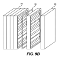
[0026]積み重ねられた構成にあるモジュール式デバイスは、モジュール式デバイスを包囲するために各端に配設される周縁ブロックを含み得る。周縁ブロックの外表面は、カートリッジブロックの外表面/縁と組み合わせて、モジュール式デバイスの外部ハウジングを形成し得る。例えば、図9Bは、周縁ブロック910を含むモジュール式デバイス100を示す。周縁ブロック920は、触媒も収容し得る。例えば、周縁ブロック920は、片側がカートリッジブロックに接続するように構成される、以下に詳細に説明される周縁カートリッジ420であってもよい。周縁カートリッジは、上に説明されるように隣接するカートリッジブロックと接続および/または整列するように構成され得る。周縁カートリッジ420に対するいかなる言及も、周縁ブロック920も説明し得るということを理解されたい。例えば、モジュール式デバイスの両端においてカートリッジブロックに接続される終板またはキャップを使用することなど、様々な他の方法が、モジュール式デバイスを包囲するために使用され得る。代替的に、カートリッジブロック910は、終板または周縁ブロック920が必要とされないように、自己完結型であってもよい。例えば、カートリッジブロック910は、触媒が完全に包囲されるように構成され得る。この実施形態では、流れは、カートリッジブロックの内側の流路もしくは管を通じて、またはブロックに接続される外部マニホールドを通じて、モジュール式デバイス内を進路変更され得る。
[0026] Modular devices in a stacked configuration may include perimeter blocks disposed at each end to enclose the modular devices. The outer surface of the peripheral block can be combined with the outer surface/rim of the cartridge block to form the outer housing of the modular device. For example, FIG. 9B shows
[0027]積み重ねられた構成では、モジュール式デバイスの注入口および出口は、カートリッジブロックまたは周縁カートリッジブロックのうちの1つまたは複数に配設され得る。図9Aに示されるように、注入口130および出口140は、1つの周縁ブロックに配設され得、出口145が、モジュール式デバイスの反対の端にある周縁ブロックに配設される。カートリッジブロックは、水素液キャリアが1つの周縁ブロックから他の周縁ブロックへとカートリッジブロックを通って流れるように構成され得る。例えば、各カートリッジブロックは、1つのカートリッジブロックの注入口が、接続されるときに、隣接するカートリッジブロックの出口と整列するように構成されるように、注入口および出口を含有し得る。代替的に、カートリッジブロックは、カートリッジブロックを通って、隣接するカートリッジブロック内へ入る流れを方向付けるために内部プレートを有し得る。
[0027] In a stacked configuration, the inlets and outlets of the modular device may be disposed in one or more of the cartridge blocks or peripheral cartridge blocks. As shown in FIG. 9A,
[0028]他の実施形態において、モジュール式デバイスのすべての出口および注入口は、単一のカートリッジブロックに、またはいくつかのブロックにわたって、配設され得る。例えば、注入口および出口は、カートリッジブロックの各々に含まれ、マニホールドまたは他のシステムを介して接続され得る。注入口および出口はまた、カートリッジブロックのうちのいくつかにおける注入口および出口のみが使用されるように、例えば弁を使用して、ブロックのうちのいくつかでは閉じられ得る。上に説明されるように、注入口および出口ポートは、図9Aでは垂直構成で示されるが、それらは、様々な配向または設置場所で配置され得る。他の様々な構成が、水素液キャリアの流れがモジュール式デバイスを出入りすることを可能にするため、水素ガスが排出されることを可能にするために使用され得る。 [0028] In other embodiments, all the outlets and inlets of the modular device may be arranged in a single cartridge block or across several blocks. For example, inlets and outlets may be included in each of the cartridge blocks and connected via a manifold or other system. The inlets and outlets may also be closed in some of the blocks, for example using valves, so that only inlets and outlets in some of the cartridge blocks are used. As explained above, although the inlet and outlet ports are shown in a vertical configuration in FIG. 9A, they can be arranged in various orientations or placements. Various other configurations may be used to allow the flow of hydrogen liquid carrier into and out of the modular device, thereby allowing hydrogen gas to be vented.
[0029]モジュール式デバイス100はまた、カートリッジブロック910および/または周縁ブロック920の各々の間に配設される、ガスケット930または他の密閉デバイスなどの少なくとも1つのシールを含み得る。シール930は、水素液キャリア、水素ガス、または他のプロセス流体が、モジュール式デバイスの動作中に漏出しないことを確実にし得る。ガスケット930はまた、カートリッジブロック910、周縁ブロック920、または終板もしくはキャップに、一体形成され得るか、または接続され得る。
[0029]
[0030]本開示の実施形態によると、カートリッジ120はまた、剛性の中央支持構造体を含み得、この支持構造体の側面に少なくとも1つの触媒が装着されている。例えば、カートリッジは、中央支持構造体320の両側に1つの触媒が装着されて、2つの触媒を保持するように構成され得る。図3は、触媒が支持構造体320の両側に装着された状態の例示的なカートリッジ120を示す。カートリッジ120は、水素液キャリアとカートリッジに配設される触媒との接触を促進するのに好適な任意の構成で配置され得る。いくつかの実施形態において、カートリッジは、両側に触媒が装着された状態にある、矩形状で形成され得る。他の実施形態において、カートリッジは、中央支持構造体320なしで、上部および底部においてカートリッジに接続される一連の触媒を収容し得る。
[0030] According to embodiments of the present disclosure,
[0031]図3は、“I”状の構成にある中央支持構造体320を示すが、中央支持構造体320は、任意の他の好適な構成を有し得るということを理解されたい。例えば、支持構造体320は、円形ディスク、球体として、または六角形もしくは八角形などの幾何形状で、構成され得る。
[0031] Although FIG. 3 shows the
[0032]いくつかの例示的な実施形態において、カートリッジ120は、モジュール式デバイス100およびハウジング110から取り外し可能であり得る。カートリッジ120は、カートリッジ120と関連付けられた構造体を検査するために取り外され得る。例えば、定期保守の間、触媒160は、モジュール式デバイス100からカートリッジ120を取り外すことによって、検査され得る。例えば、カートリッジ120は、カートリッジに対する損傷または摩耗について検査され得る。触媒160はまた、水素産生の減少をもたらし得る劣化の兆候について検査され得る。カートリッジ120または触媒160はまた、動作を継続するために、別のカートリッジ120または触媒160と交換され得る。図1は、カートリッジ120の取り外しを可能にする例示的なハウジングを示す。図1は、各カートリッジの取り外しのための一連のアクセスポート150を有するハウジング110を示すが、カートリッジの取り外しのための他の手段が提供され得ることが企図される。例えば、ハウジング110は、すべてのカートリッジへのアクセスを提供する単一のアクセスポートを有し得る。アクセスポート150は、ドアまたは取り外し可能なパネルなど、閉鎖機構を含み得る。他の実施形態において、ハウジング110は、カートリッジの取り外しを可能にするために、モジュール式デバイス100から取り外し可能であり得る。ハウジング110またはモジュール式デバイス100はまた、カートリッジ120の取り外しを促進するために、トラック、ローラ、ベアリング、またはガイドを有し得る。モジュール式デバイス100はまた、動作中にカートリッジ120を適所に保持するための機構(すなわち、クリップ、ロック、ボルト、ねじ、クランプなど)を有し得る。
[0032] In some exemplary embodiments,
[0033]他のカートリッジ構造体が、開示されたモジュール式デバイスと併せて使用され得る。例えば、図4は、別のカートリッジ400の例を示す。この実施形態では、カートリッジ400は、ハウジングの各端への設置のために設計される周縁カートリッジを含む。例えば、周縁カートリッジ420は、ハウジング110の内側を向いているカートリッジの片側のみに装着される触媒を有し得る。周縁カートリッジ420の触媒は、カートリッジ120の触媒と同じであるか、または異なっていてもよい。図4は、例示的な周縁カートリッジ420を示す。図4は、1つの触媒のみを示すが、周縁カートリッジが複数の触媒を保持するように構成され得ることが想定される。例えば、周縁カートリッジ420は、カートリッジの片側に接続されて上部もしくは底部において適所に保持される2つ以上の触媒を含み得るか、または触媒の間の水素液キャリアの流れを可能にするような別の様式で含み得る。いくつかの実施形態において、周縁カートリッジ420は、例えば、片側からのみ水素液キャリアを受容するために、モジュール式デバイスの端への設置のために特に構成され得る。
[0033] Other cartridge structures may be used in conjunction with the disclosed modular device. For example, FIG. 4 shows another
[0034]本開示によるモジュール式デバイスはまた、モジュール式デバイス内に配設される1つまたは複数の冷却ジャケットを含み得る。冷却ジャケットは、水素生成プロセス中に発生した熱を放散するために使用され得る。冷却ジャケットは、ジャケット内に配設される液体を含み得る。いくつかの実施形態において、冷却ジャケットは、熱分散を促すために冷却液を含有し得る。冷却液は、水、グリコール、または何らかの他のガスもしくは液体冷却剤、またはそれらの組み合わせからなり得る。冷却ジャケットは、伝熱を促すために、ジャケットの内側にいくつかのフィンまたはバッフルを含有し得る。代替的に、冷却ジャケットは、シェルアンドチューブ熱交換器、または他の既知の伝熱デバイスであってもよい。冷却ジャケットは、様々な代替の構造体によってモジュール式デバイス内に含まれ得る。冷却ジャケットは、例えば、ハウジングの内壁に沿って置かれ得る。代替的に、冷却ジャケットは、カートリッジ160の間、またはそれに沿って、置かれ得る。
[0034] Modular devices according to the present disclosure may also include one or more cooling jackets disposed within the modular device. A cooling jacket may be used to dissipate heat generated during the hydrogen production process. The cooling jacket may include a liquid disposed within the jacket. In some embodiments, the cooling jacket may contain a cooling liquid to facilitate heat distribution. The coolant may consist of water, glycol, or some other gaseous or liquid coolant, or combinations thereof. The cooling jacket may contain some fins or baffles inside the jacket to facilitate heat transfer. Alternatively, the cooling jacket may be a shell and tube heat exchanger, or other known heat transfer device. The cooling jacket may be contained within the modular device by various alternative structures. A cooling jacket may, for example, be placed along the inner wall of the housing. Alternatively, cooling jackets may be placed between or along
[0035]冷却ジャケットはまた、少なくとも1つのカートリッジ内に配設され得る。各カートリッジは、カートリッジに対して内側に専用の冷却ジャケットを有し得る。これは、水素産生プロセス中に発生した熱がカートリッジ120を通って放散されることを可能にする。例として、図5は、一体式の冷却ジャケットを有する例示的なカートリッジを示す。この例では、カートリッジ500は、中央支持構造体520を有する。冷却ジャケット510は、中央支持構造体520内の腔として一体化される。カートリッジ500はまた、冷却液530の循環のための注入口540および出口550を含み得る。上に論じられるように、冷却ジャケット510は、伝熱を促すために、バッフル、フィン、または何らかの他の構造体をさらに含み得る。
[0035] A cooling jacket may also be disposed within the at least one cartridge. Each cartridge may have its own cooling jacket internal to the cartridge. This allows heat generated during the hydrogen production process to be dissipated through
[0036]本開示の実施形態によると、少なくとも1つの触媒は、伝熱ゲルにより冷却ジャケットに装着され得る。例として、図5は、一体式の冷却ジャケット510を有するカートリッジ500を示す。触媒160は、中央支持構造体520に装着され、伝熱ゲル535は、伝熱を促すために、触媒160と冷却ジャケット510との間に配設される。触媒160、中央支持構造体520、および冷却ジャケット510の他の構成が想定され、図5に示されるカートリッジは、単に例として提供されるということに留意されたい。
[0036] According to embodiments of the present disclosure, at least one catalyst may be attached to the cooling jacket by a heat transfer gel. By way of example, FIG. 5 shows
[0037]いくつかの例示的な実施形態において、モジュール式デバイス100は、注入口から受容される燃料が複数のカートリッジの間を流れるように配置される複数のカートリッジまたはカートリッジブロックを保持し得る。例えば、燃料は、注入口130から受容され、ハウジング110内へ向けられ得る。燃料は、単一の点または複数の場所において、ハウジング110に入り得る。カートリッジ120は、水素液キャリアがカートリッジの間を流れてデバイスにわたって広がり、すべての触媒160に接触するように配置され得る。図6Aは、燃料が単一ポート605において注入される、例示的なモジュール式デバイスを示す。燃料は、カートリッジ120の間を流れて、水素液キャリアがカートリッジに装着される各触媒160に接触することを可能にし得る。図6Aにおける配置は、単に例のために提供され、他の実施形態が想定される。例えば、燃料は、2つ以上の場所で注入されて、カートリッジの間で分散され得る。
[0037] In some exemplary embodiments, the
[0038]他の実施形態において、モジュール式デバイス100は、モジュール式デバイス内の1つまたは複数の水路をさらに含み得る。水路は、注入口からの水素液キャリアを複数のカートリッジへ分配するように構成され得る。カートリッジの各々の間で水素液キャリアを分配することは、触媒にわたる水素産生の分配を促進し得る。いくつかの場合では、カートリッジ間での水素液キャリアの分配は、触媒間での水素の均一またはほぼ均一の産生を可能にし得る。そのような分配は、様々な代替の構造体によって達成され得る。1つの態様において、水路または水路系は、ハウジング110内へ一体的に形成され得る。水路は、例えば、他の製造プロセスによって、直接ハウジング110内へ機械加工または形成され得る。別の態様において、水路は、モジュール式デバイス100内に配設されるプレートまたはマニホールドなど、別個の構造体内へ形成され得る。燃料はまた、モジュール式デバイス100内の管、配管、流路、または他の内部構造体を通じて分配され得る。例えば、水素液キャリアは、一方の側にある周縁カートリッジ(または周縁カートリッジブロック)における燃料注入口を通して注入され、次いで、内部流路を介して、使用済みの水素液キャリアが排出されるデバイスの反対端にある周縁カートリッジ(または周縁カートリッジブロック)へ向かって、順次に触媒プレートの各々を通って流れ得る。
[0038] In other embodiments, the
[0039]図6bは、複数のカートリッジ間で水素液キャリアを分配するための複数の水路を含む例示的なデバイス構成を示す。例示的な開示された実施形態によると、燃料を分配するための水路は、注入口から水素液キャリアを受容するように構成される主流路と、主流路を複数のカートリッジ間の空間に接続する複数の分岐とを含み得る。例えば、図6bは、モジュール式デバイス100内に配設される構造体630を示す。構造体630は、注入口130介して下から燃料を受容するように構成される。構造体630は、モジュール式デバイス100にわたる燃料の分配のための主流路615を有する。構造体630はまた、主流路615から生じる複数の横分岐640を有する。横分岐640は、均一の分配を促すために、水素液キャリアをカートリッジ120の各々の間へ向ける。
[0039] Figure 6b shows an exemplary device configuration including multiple channels for distributing the hydrogen liquid carrier among multiple cartridges. According to an exemplary disclosed embodiment, a conduit for distributing fuel includes a main flow path configured to receive a hydrogen liquid carrier from an inlet and connecting the main flow path to a space between the plurality of cartridges. multiple branches. For example, FIG. 6b shows a
[0040]いくつかの実施形態において、水素液キャリアは、モジュール式デバイス100内へ噴霧され得る。他の実施形態において、水素液キャリアは、触媒を水素液キャリアに浸漬させるために、モジュール式デバイス100内へ流れ得る。いくつかの実施形態において、燃料は、ハウジング110内を自然に流れ得る。他の実施形態において、水素液キャリアは、ハウジング110内を循環することを強いられ得る。例えば、モジュール式デバイス100は、カートリッジの間で燃料を循環させるためのポンプまたは他の手段を含有し得る。
[0040] In some embodiments, the hydrogen liquid carrier may be sprayed into the
[0041]図7は、モジュール式デバイスに対して保守を実施する例示的な方法を例証する。ステップ710において、水素抽出プロセスの動作は、水素液キャリアのすべてが除去または消耗されると終了される。1つの態様において、モジュール式デバイスの動作は、手動で終了され得る。例えば、モジュール式デバイスのオペレータは、デバイスのシャットダウンを開始し得る。他の態様において、動作の終了は、自動プロセスにより発生し得る。例えば、動作の終了は、モジュール式デバイス100を制御するように構成されるコンピュータによって開始され得る。終了はまた、動力産生のためにモジュール式デバイス100を使用する電子デバイスによって開始され得る。ステップ710は、弁を閉めること、または、ポンプ、熱交換器、ファン、ヒータ、もしくは他の関連設備をシャットダウンすることなど、いくつかの副ステップを含み得ることが想定される。
[0041] FIG. 7 illustrates an exemplary method of performing maintenance on a modular device. At
[0042]いかなる残りの水素および水素液キャリアも、ステップ720において、モジュール式デバイスから抜かれ得る。モジュール式デバイス720は、カートリッジが安全にアクセスされ得ることを確実にするために、完全に空にされ得る。ステップ720は、モジュール式デバイス100内に提供される排液管を通じて水素液キャリアを排液することを含み得る。いくつかのセンサまたは他のモニタリングデバイスが、モジュール式デバイス100が開くのに安全であることを確実にするために使用され得る。
[0042] Any remaining hydrogen and hydrogen liquid carrier may be drained from the modular device at
[0043]次に、モジュール式デバイス100が外部ハウジングを含む場合、ステップ730に示されるように、ハウジング内のカートリッジアクセスパネルが、カートリッジ120へアクセスするために開かれ得る。アクセスパネルは、図1に示されるようなアクセスポート150を含み得る。上に説明されるように、開示された発明のいくつかの態様において、アクセスパネルは、単一のカートリッジへのアクセスを提供し得る。この例では、単一のカートリッジがアクセスされ得、残りのカートリッジは現状のままである。他の態様において、アクセスパネルは、複数のカートリッジまたはカートリッジのすべてへのアクセスを提供し得る。代替的に、モジュール式デバイス100が、上に説明されるように、積み重ねられた構成にある場合、カートリッジブロックは、ステップ735において、互いから切り離され得る。次いで、カートリッジ120は、他のカートリッジまたはカートリッジブロックから取り外され得る。カートリッジ120が例として言及されるが、方法700および図7に説明される手順は、他のカートリッジ構成にも当てはまり得るということを理解されたい。例えば、方法700は、図4に示されるような周縁カートリッジ420など、周縁カートリッジに当てはまり得る。方法700は、図5に示されるようなカートリッジ500など、内部冷却ジャケットを有するカートリッジにも当てはまり得る。
[0043] Next, if the
[0044]ステップ740において、カートリッジ120または触媒160は、上に論じられるように、取り外され得る、および/または検査され得る。例えば、カートリッジ160は、損傷もしくは摩耗について、または任意の他の保守目的のために、検査され得る。触媒160は、水素産生プロセス中に発生し得る劣化について調査され得る。カートリッジ120および触媒160はまた、清浄のために取り外され得る。いくつかの実施形態において、ステップ740は、カートリッジ120もしくは触媒160、または両方を交換することを含み得る。
[0044] At
[0045]ステップ750において、カートリッジアクセスパネルは閉じられる。このステップは、シールがハウジング110内に作成されることを確実にすることなど、他の副ステップを含み得ることが想定される。ステップ750はまた、例えば、ねじ、ボルト、ラッチ、クリップ、クランプ、ロック、または他の機械的閉鎖デバイスを使用して、アクセスパネルを機械的に閉じることを必要とし得る。
[0045] At
[0046]ステップ760において、水素生成プロセスの動作は、再開され得る。これは、開くステップ710に関して説明される追加ステップの逆の手順を含み得る。ステップ760はまた、モジュール式デバイス100の動作が再開され得ることを確実にするために安全手順を含み得る。
[0046] At
[0047]図8は、モジュール式水素産生デバイスを動作させるための例示的な方法を例証する。ステップ810において、水素液キャリア(例えば、水素ベースの水素液キャリア)は、モジュール式デバイス100内へ圧送され得る。上に論じられるように、水素液キャリアは、ホウ化水素カリウム(KBH4)などのホウ化水素燃料を含み得る。他の態様において、水素液キャリアは、別の形態の金属-ホウ化水素(M1-BH4)を含み得る。水素液キャリアは、Electriq Global(EG)E-Fuelなどの市販の液体ホウ化水素であってもよい。水素液キャリアは、注入口130より受容され得る。
[0047] FIG. 8 illustrates an exemplary method for operating a modular hydrogen production device. At
[0048]ステップ820において、水素液キャリアは、カートリッジ120の間で分配される。開示された発明のいくつかの態様において、水素液キャリアは、単一の点または複数の場所において、ハウジング110に入り得、図6Aに示されるように、カートリッジ120の間を流れ得る。他の態様において、水素液キャリアは、図6Bに示されるようにカートリッジの間に分配され得る。
[0048] At
[0049]ステップ830において、水素ガスは、水素液キャリアが触媒160と接触した結果として生成される。これは、触媒と接触した液体ホウ化水素燃料を使用した水素ガスの産生のためのプロセスを含む、様々な代替のプロセスによって達成され得る。ステップ830中に生成される水素ガスは、ステップ840において、モジュール式デバイスから排出され得る。水素ガスは、図100に示されるように出口140より排出され得る。水素ガスは、電子ビークルまたは上に説明されるようなデバイスに動力供給するための燃料電池を供給するために使用され得る。
[0049] In
[0050]本開示のいくつかの態様が上に論じられた。例えば、図面のうちの任意の1つまたは複数に関して、上に論じられた、特徴、態様、特性、構造などの任意の実現可能な組み合わせは、本開示の部分と見なされて実施され得ることに留意されたい。それらの実現可能な組み合わせのいくつかは、開示の簡潔さおよび簡明さなどの理由のために、詳細には論じられていないが、それにもかかわらず本開示の一部であり、上記開示の観点で当業者に提示されるものとする。
本発明の具体的態様は以下のとおりである。
[態様1]
水素液キャリアから水素ガスを生成するためのモジュール式デバイスであって、
ハウジングと、
前記水素液キャリアを受容するための少なくとも1つの注入口と、
前記ハウジング内に配置される少なくとも1つのカートリッジであって、前記水素液キャリアに曝露されるときに水素ガスの放出を引き起こすように構成される少なくとも1つの第1の触媒を含む、前記少なくとも1つのカートリッジと、
前記モジュール式デバイス内に放出される前記水素ガスを排出するための少なくとも1つのガス出口と、
前記水素液キャリアを排出するための少なくとも1つの液体出口と
を含む、前記モジュール式デバイス。
[態様2]
前記少なくとも1つのカートリッジが、
中央支持構造体をさらに含み、前記少なくとも1つの触媒が、前記中央支持構造体に片側に取り付けられる、態様1に記載のモジュール式デバイス。
[態様3]
前記少なくとも1つの触媒が、複数の触媒を含み、前記少なくとも1つのカートリッジが、
中央支持構造体であって、前記複数の触媒のうちの1つ目が前記中央支持構造体の第1の側に装着され、前記複数の触媒のうちの2つ目が前記中央支持構造体の第2の側に装着された状態にある、前記中央支持構造体、をさらに含む、態様1に記載のモジュール式デバイス。
[態様4]
前記少なくとも1つのカートリッジが、前記ハウジングから取り外し可能である、態様1に記載のモジュール式デバイス。
[態様5]
前記モジュール式デバイスの少なくとも1つの端に配設される周縁カートリッジであって、前記水素液キャリアに曝露されるときに水素ガスの放出を引き起こすように構成される少なくとも1つの第2の触媒を含む、前記周縁カートリッジ、をさらに含む、態様1に記載のモジュール式デバイス。
[態様6]
前記モジュール式デバイス内に配設される冷却ジャケットをさらに含み、前記冷却ジャケットが、冷却液を含有する、態様1に記載のモジュール式デバイス。
[態様7]
前記冷却ジャケットが、前記少なくとも1つのカートリッジ内に配設される、態様6に記載のモジュール式デバイス。
[態様8]
前記少なくとも1つの触媒が、伝熱媒体により前記冷却ジャケットに装着される、態様6に記載のモジュール式デバイス。
[態様9]
前記少なくとも1つのカートリッジが、複数のカートリッジであって、前記注入口から受容される前記水素液キャリアが前記複数のカートリッジ間を流れるように配置される、前記複数のカートリッジを含む、態様1に記載のモジュール式デバイス。
[態様10]
前記少なくとも1つのカートリッジが、複数のカートリッジを含み、前記モジュール式デバイスが、前記ハウジング内に少なくとも1つの水路をさらに含み、前記少なくとも1つの水路が、前記注入口からの前記水素液キャリアを前記複数のカートリッジへ分配するように構成される、態様1に記載のモジュール式デバイス。
[態様11]
前記少なくとも1つの水路が、
前記注入口から前記水素液キャリアを受容するように構成される主流路と、
前記主流路を前記複数のカートリッジ間の空間に接続する複数の分岐と、を含む、態様10に記載のモジュール式デバイス。
[態様12]
前記少なくとも1つの触媒が、
金属構造体と、
前記金属構造体上の触媒コーティングと、を含み、前記コーティングが、
Niを含む内側層と、
外側触媒層と、を含む、態様1に記載のモジュール式デバイス。
[態様13]
前記Ni層が、6.3~25μmの範囲の間のRaラフネス値を有する、態様12に記載のモジュール式デバイス。
[態様14]
前記金属構造体が、ステンレス鋼を含む、態様12に記載のモジュール式デバイス。
[態様15]
前記少なくとも1つの触媒が、構造充填物構成で配置される、態様1に記載のモジュール式デバイス。
[態様16]
水素液キャリアから水素ガスを生成するためのモジュール式デバイスであって、
ハウジングと、
前記ハウジング内に配置される少なくとも1つの内部カートリッジであって、前記内部カートリッジが、前記水素液キャリアに曝露されるときに水素ガスの放出を引き起こすように構成される少なくとも1つの第1の触媒を含む、前記少なくとも1つの内部カートリッジと、
前記モジュール式デバイスの第1の端において前記ハウジング内に配設される第1の周縁カートリッジ、および前記モジュール式デバイスの第2の端において前記ハウジング内に配設される第2の周縁カートリッジであって、
前記第1の周縁カートリッジが、前記水素液キャリアに曝露されるときに水素ガスの放出を引き起こすように構成される少なくとも1つの第2の触媒を含み、
前記第2の周縁カートリッジが、前記水素液キャリアに曝露されるときに水素ガスの放出を引き起こすように構成される少なくとも1つの第3の触媒を含む、前記第1の周縁カートリッジおよび第2の周縁カートリッジと、
前記モジュール式デバイス内に発生した熱を除去するための冷却システムと、
前記水素液キャリアを受容するための少なくとも1つの燃料注入口と、
前記モジュール式デバイス内に発生した前記水素ガスを排出するための少なくとも1つのガス出口と、
前記水素液キャリアを排出するための少なくとも1つの液体出口と
を含む、前記モジュール式デバイス。
[態様17]
前記少なくとも1つの触媒が、複数の触媒を含み、前記少なくとも1つの内部カートリッジが、
中央支持構造体であって、前記複数の触媒のうちの1つ目が前記中央支持構造体の第1の側に装着され、前記複数の触媒のうちの2つ目が前記中央支持構造体の第2の側に装着された状態にある、前記中央支持構造体、をさらに含む、態様16に記載のモジュール式デバイス。
[態様18]
前記冷却システムが、前記少なくとも1つの内部カートリッジ内に配設される冷却ジャケットを含み、前記冷却ジャケットが、冷却液を含有する、態様16に記載のモジュール式デバイス。
[態様19]
水素液キャリアから水素ガスを生成するためのモジュール式デバイスであって、
少なくとも2つの積み重ね可能なカートリッジであって、前記積み重ね可能なカートリッジの各々が、
前記水素液キャリアに曝露されるときに水素ガスの放出を引き起こすように構成される少なくとも1つの第1の触媒、および
前記モジュール式デバイスを形成するために、前記少なくとも2つの積み重ね可能なカートリッジの接合を促進するように構成される1つまたは複数の構造要素を含む、前記少なくとも2つの積み重ね可能なカートリッジと、
前記水素液キャリアを受容するための少なくとも1つの液体注入口であって、前記少なくとも1つの液体注入口が、前記少なくとも2つの積み重ね可能なカートリッジのうちの1つまたは複数に配設される、前記少なくとも1つの液体注入口と、
前記モジュール式デバイス内に放出される前記水素ガスを排出するための少なくとも1つのガス出口であって、前記少なくとも2つの積み重ね可能なカートリッジのうちの1つまたは複数に配設される、前記少なくとも1つのガス出口と、
前記水素液キャリアを排出するための少なくとも1つの液体出口であって、前記少なくとも2つの積み重ね可能なカートリッジのうちの1つまたは複数に配設される、前記少なくとも1つの液体出口と
を含む、前記モジュール式デバイス。
[態様20]
前記少なくとも1つの液体注入口が、前記モジュール式デバイスの第2の端よりも前記モジュール式デバイスの第1の端の近くに位置し、
前記少なくとも1つの液体出口が、前記モジュール式デバイスの前記第1の端よりも前記モジュール式デバイスの前記第2の端の近くに位置し、
前記少なくとも1つのガス出口が、前記少なくとも2つの積み重ね可能なカートリッジのうちの1つまたは複数の上部に配設される、態様19に記載のモジュール式デバイス。
[態様21]
前記少なくとも2つの積み重ね可能なカートリッジの接合を促進するように構成される前記1つまたは複数の構造要素が、整列構造体、戻り止め、または整列した孔のうちの少なくとも1つを含む、態様19に記載のモジュール式デバイス。
[態様22]
前記積み重ね可能なカートリッジの間に配設される少なくとも1つのシールをさらに含む、態様19に記載のモジュール式デバイス。
[態様23]
前記少なくとも2つの積み重ね可能なカートリッジが、前記少なくとも2つの積み重ね可能なカートリッジを通して挿入される少なくとも1つのボルトを使用して、互いと接続するように構成される、態様19に記載のモジュール式デバイス。
[態様24]
前記少なくとも2つの積み重ね可能なカートリッジが、第1および第2の周縁カートリッジを含み、前記第1の周縁カートリッジが、前記モジュール式デバイスの第1の端に配設され、前記第2の周縁カートリッジが、前記モジュール式デバイスの第2の端に配設され、前記第1および第2の周縁カートリッジの前記1つまたは複数の構造要素は、前記モジュール式デバイスに対して内側に向いている前記カートリッジの側にのみ配設される、態様19に記載のモジュール式デバイス。
[態様25]
前記少なくとも2つの積み重ね可能なカートリッジの外部表面および前記少なくとも1つの周縁カートリッジの外部表面が、前記モジュール式デバイスの外部ハウジングを形成する、態様24に記載のモジュール式デバイス。
[態様26]
前記第1および第2の周縁カートリッジの各々が、前記水素液キャリアに曝露されるときに水素ガスの放出を引き起こすように構成される少なくとも1つの第2の触媒を含む、態様24に記載のモジュール式デバイス。
[態様27]
前記第1の触媒および前記第2の触媒が同じである、態様26に記載のモジュール式デバイス。
[態様28]
前記少なくとも2つの積み重ね可能なカートリッジのうちの前記1つまたは複数の前記少なくとも1つの液体注入口が、前記少なくとも2つの積み重ね可能なカートリッジのうちの隣接するものの前記少なくとも1つの液体出口と整列するように構成される、態様22に記載のモジュール式デバイス。
[態様29]
水素液キャリアから水素ガスを生成するためのモジュール式デバイスの触媒に対して保守を実施するための方法であって、
前記モジュール式デバイスから水素ガスおよび水素液キャリアを抜くステップと、
前記モジュール式デバイスから少なくとも1つのカートリッジを取り外すステップであって、前記カートリッジが、前記水素液キャリアに曝露されるときに水素ガスの放出を引き起こすように構成される少なくとも1つの触媒を含む、前記ステップと、
保守動作を実施するステップであって、
劣化について前記少なくとも1つの触媒を検査すること、または
前記少なくとも1つの触媒もしくは前記少なくとも1つのカートリッジのうちの少なくとも1つを交換すること、のうちの少なくとも1つを含む、前記ステップと
を含む、前記方法。
[0050] Several aspects of the disclosure have been discussed above. For example, any feasible combination of the features, aspects, characteristics, structures, etc. discussed above with respect to any one or more of the drawings may be considered and implemented as part of the present disclosure. Please note. Some of those possible combinations have not been discussed in detail for reasons such as brevity and clarity of disclosure, but are nonetheless part of this disclosure and in view of the above disclosure. should be presented to those skilled in the art.
Specific aspects of the present invention are as follows.
[Aspect 1]
A modular device for producing hydrogen gas from a hydrogen liquid carrier, comprising:
a housing;
at least one inlet for receiving the hydrogen liquid carrier;
at least one cartridge disposed within the housing, the at least one cartridge comprising at least one first catalyst configured to cause release of hydrogen gas when exposed to the hydrogen liquid carrier; a cartridge;
at least one gas outlet for exhausting the hydrogen gas released into the modular device;
at least one liquid outlet for discharging the hydrogen liquid carrier;
The modular device comprising:
[Aspect 2]
the at least one cartridge comprising:
2. The modular device of aspect 1, further comprising a central support structure, wherein said at least one catalyst is attached to one side of said central support structure.
[Aspect 3]
said at least one catalyst comprising a plurality of catalysts, said at least one cartridge comprising:
a central support structure, wherein one of said plurality of catalysts is mounted on a first side of said central support structure and a second of said plurality of catalysts is mounted on said central support structure; 2. The modular device of aspect 1, further comprising said central support structure in an attached state on a second side.
[Aspect 4]
A modular device according to aspect 1, wherein the at least one cartridge is removable from the housing.
[Aspect 5]
A perimeter cartridge disposed at at least one end of said modular device and comprising at least one second catalyst configured to cause release of hydrogen gas when exposed to said hydrogen liquid carrier. , said perimeter cartridge.
[Aspect 6]
2. The modular device of aspect 1, further comprising a cooling jacket disposed within said modular device, said cooling jacket containing a cooling liquid.
[Aspect 7]
7. The modular device of aspect 6, wherein the cooling jacket is disposed within the at least one cartridge.
[Aspect 8]
7. The modular device of aspect 6, wherein the at least one catalyst is attached to the cooling jacket by a heat transfer medium.
[Aspect 9]
Aspect 1. Aspect 1, wherein the at least one cartridge comprises a plurality of cartridges arranged such that the hydrogen liquid carrier received from the inlet flows between the plurality of cartridges. modular device.
[Aspect 10]
The at least one cartridge comprises a plurality of cartridges, and the modular device further comprises at least one channel within the housing, the at least one channel channeling the hydrogen liquid carrier from the inlet to the plurality of cartridges. 2. The modular device of aspect 1, configured to dispense into cartridges of.
[Aspect 11]
the at least one waterway;
a main flow path configured to receive the hydrogen liquid carrier from the inlet;
11. The modular device of aspect 10, comprising a plurality of branches connecting the main flow path to spaces between the plurality of cartridges.
[Aspect 12]
the at least one catalyst comprising:
a metal structure;
a catalytic coating on said metal structure, said coating comprising:
an inner layer comprising Ni;
and an outer catalyst layer.
[Aspect 13]
13. The modular device of aspect 12, wherein the Ni layer has a Ra roughness value between the range of 6.3-25 μm.
[Aspect 14]
13. The modular device of aspect 12, wherein the metallic structure comprises stainless steel.
[Aspect 15]
2. The modular device of aspect 1, wherein the at least one catalyst is arranged in a structured packing configuration.
[Aspect 16]
A modular device for producing hydrogen gas from a hydrogen liquid carrier, comprising:
a housing;
at least one internal cartridge disposed within the housing, the internal cartridge containing at least one first catalyst configured to cause release of hydrogen gas when exposed to the hydrogen liquid carrier; the at least one internal cartridge comprising;
a first perimeter cartridge disposed within the housing at a first end of the modular device; and a second perimeter cartridge disposed within the housing at a second end of the modular device. hand,
said first rim cartridge comprising at least one second catalyst configured to cause release of hydrogen gas when exposed to said hydrogen liquid carrier;
said first rim cartridge and second rim, wherein said second rim cartridge includes at least one third catalyst configured to cause release of hydrogen gas when exposed to said hydrogen liquid carrier; a cartridge;
a cooling system for removing heat generated within the modular device;
at least one fuel inlet for receiving the hydrogen liquid carrier;
at least one gas outlet for exhausting the hydrogen gas generated in the modular device;
at least one liquid outlet for discharging the hydrogen liquid carrier;
The modular device comprising:
[Aspect 17]
said at least one catalyst comprising a plurality of catalysts, said at least one internal cartridge comprising:
a central support structure, wherein one of said plurality of catalysts is mounted on a first side of said central support structure and a second of said plurality of catalysts is mounted on said central support structure; 17. The modular device of aspect 16, further comprising said central support structure in an attached state on a second side.
[Aspect 18]
17. The modular device of aspect 16, wherein the cooling system includes a cooling jacket disposed within the at least one internal cartridge, the cooling jacket containing a cooling liquid.
[Aspect 19]
A modular device for producing hydrogen gas from a hydrogen liquid carrier, comprising:
at least two stackable cartridges, each stackable cartridge comprising:
at least one first catalyst configured to cause release of hydrogen gas when exposed to said hydrogen liquid carrier; and
said at least two stackable cartridges comprising one or more structural elements configured to facilitate joining of said at least two stackable cartridges to form said modular device;
at least one liquid inlet for receiving said hydrogen liquid carrier, said at least one liquid inlet being disposed in one or more of said at least two stackable cartridges; at least one liquid inlet;
at least one gas outlet disposed in one or more of said at least two stackable cartridges for exhausting said hydrogen gas released into said modular device; one gas outlet and
at least one liquid outlet for discharging said hydrogen liquid carrier, said at least one liquid outlet disposed in one or more of said at least two stackable cartridges;
The modular device comprising:
[Aspect 20]
the at least one liquid inlet is located closer to the first end of the modular device than to the second end of the modular device;
the at least one liquid outlet is located closer to the second end of the modular device than to the first end of the modular device;
20. The modular device of aspect 19, wherein said at least one gas outlet is disposed on top of one or more of said at least two stackable cartridges.
[Aspect 21]
Aspect 19, wherein the one or more structural elements configured to facilitate mating of the at least two stackable cartridges comprise at least one of alignment structures, detents, or aligned holes. A modular device as described in .
[Aspect 22]
20. The modular device of aspect 19, further comprising at least one seal disposed between said stackable cartridges.
[Aspect 23]
20. The modular device of aspect 19, wherein the at least two stackable cartridges are configured to connect with each other using at least one bolt inserted through the at least two stackable cartridges.
[Aspect 24]
The at least two stackable cartridges include first and second perimeter cartridges, the first perimeter cartridge disposed at a first end of the modular device, the second perimeter cartridge comprising: , the one or more structural elements of the first and second peripheral cartridges disposed at a second end of the modular device, the one or more structural elements of the cartridges facing inwardly with respect to the modular device; 20. A modular device according to aspect 19, arranged only on the sides.
[Aspect 25]
25. The modular device of aspect 24, wherein the exterior surfaces of the at least two stackable cartridges and the exterior surface of the at least one peripheral cartridge form an exterior housing of the modular device.
[Aspect 26]
25. The module of aspect 24, wherein each of the first and second peripheral cartridges comprises at least one second catalyst configured to cause release of hydrogen gas when exposed to the hydrogen liquid carrier. formula device.
[Aspect 27]
27. The modular device of aspect 26, wherein said first catalyst and said second catalyst are the same.
[Aspect 28]
such that the one or more of the at least one liquid inlet of the at least two stackable cartridges is aligned with the at least one liquid outlet of an adjacent one of the at least two stackable cartridges. 23. The modular device of aspect 22, wherein:
[Aspect 29]
A method for performing maintenance on a catalyst of a modular device for producing hydrogen gas from a hydrogen liquid carrier, comprising:
venting the hydrogen gas and hydrogen liquid carrier from the modular device;
removing at least one cartridge from said modular device, said cartridge comprising at least one catalyst configured to cause release of hydrogen gas when exposed to said hydrogen liquid carrier; and,
performing a maintenance action, comprising:
inspecting the at least one catalyst for deterioration, or
replacing at least one of the at least one catalyst or the at least one cartridge; and
The above method, comprising
Claims (28)
ハウジングと、
前記水素液キャリアを受容するための少なくとも1つの注入口と、
前記ハウジング内に配置される少なくとも1つのカートリッジであって、前記水素液キャリアに曝露されるときに水素ガスの放出を引き起こすように構成される少なくとも1つの第1の触媒を含む、前記少なくとも1つのカートリッジと、
前記モジュール式デバイスの少なくとも1つの端に配設される少なくとも1つの周縁カートリッジであって、前記水素液キャリアに曝露されるときに水素ガスの放出を引き起こすように構成される少なくとも1つの第2の触媒を含む、前記少なくとも1つの周縁カートリッジと、
前記モジュール式デバイス内に放出される前記水素ガスを排出するための少なくとも1つのガス出口と、
前記水素液キャリアを排出するための少なくとも1つの液体出口と
を含む、前記モジュール式デバイス。 A modular device for producing hydrogen gas from a hydrogen liquid carrier, comprising:
a housing;
at least one inlet for receiving the hydrogen liquid carrier;
at least one cartridge disposed within the housing, the at least one cartridge comprising at least one first catalyst configured to cause release of hydrogen gas when exposed to the hydrogen liquid carrier; a cartridge;
at least one second peripheral cartridge disposed at at least one end of said modular device and configured to cause release of hydrogen gas when exposed to said hydrogen liquid carrier; said at least one peripheral cartridge containing a catalyst;
at least one gas outlet for exhausting the hydrogen gas released into the modular device;
at least one liquid outlet for discharging the hydrogen liquid carrier.
中央支持構造体をさらに含み、前記少なくとも1つの第1の触媒が、前記中央支持構造体に片側に取り付けられる、請求項1に記載のモジュール式デバイス。 the at least one cartridge comprising:
2. The modular device of claim 1, further comprising a central support structure, wherein said at least one first catalyst is attached to one side of said central support structure.
中央支持構造体であって、前記複数の触媒のうちの1つ目が前記中央支持構造体の第1の側に装着され、前記複数の触媒のうちの2つ目が前記中央支持構造体の第2の側に装着された状態にある、前記中央支持構造体、をさらに含む、請求項1に記載のモジュール式デバイス。 said at least one first catalyst comprising a plurality of catalysts, said at least one cartridge comprising:
a central support structure, wherein one of said plurality of catalysts is mounted on a first side of said central support structure and a second of said plurality of catalysts is mounted on said central support structure; 2. The modular device of claim 1, further comprising: the central support structure mounted on a second side.
前記注入口から前記水素液キャリアを受容するように構成される主流路と、
前記主流路を前記複数のカートリッジ間の空間に接続する複数の分岐と、を含む、請求項9に記載のモジュール式デバイス。 the at least one waterway;
a main flow path configured to receive the hydrogen liquid carrier from the inlet;
and a plurality of branches connecting the main flow path to spaces between the plurality of cartridges.
金属構造体と、
前記金属構造体上の触媒コーティングと、を含み、前記コーティングが、
Niを含む内側層と、
外側触媒層と、を含む、請求項1に記載のモジュール式デバイス。 the at least one first catalyst comprising:
a metal structure;
a catalytic coating on said metal structure, said coating comprising:
an inner layer comprising Ni;
and an outer catalyst layer.
ハウジングと、
前記ハウジング内に配置される少なくとも1つの内部カートリッジであって、前記内部カートリッジが、前記水素液キャリアに曝露されるときに水素ガスの放出を引き起こすように構成される少なくとも1つの第1の触媒を含む、前記少なくとも1つの内部カートリッジと、
前記モジュール式デバイスの第1の端において前記ハウジング内に配設される第1の周縁カートリッジ、および前記モジュール式デバイスの第2の端において前記ハウジング内に配設される第2の周縁カートリッジであって、
前記第1の周縁カートリッジが、前記水素液キャリアに曝露されるときに水素ガスの放出を引き起こすように構成される少なくとも1つの第2の触媒を含み、
前記第2の周縁カートリッジが、前記水素液キャリアに曝露されるときに水素ガスの放出を引き起こすように構成される少なくとも1つの第3の触媒を含む、前記第1の周縁カートリッジおよび第2の周縁カートリッジと、
前記モジュール式デバイス内に発生した熱を除去するための冷却システムと、
前記水素液キャリアを受容するための少なくとも1つの燃料注入口と、
前記モジュール式デバイス内に発生した前記水素ガスを排出するための少なくとも1つのガス出口と、
前記水素液キャリアを排出するための少なくとも1つの液体出口と
を含む、前記モジュール式デバイス。 A modular device for producing hydrogen gas from a hydrogen liquid carrier, comprising:
a housing;
at least one internal cartridge disposed within the housing, the internal cartridge containing at least one first catalyst configured to cause release of hydrogen gas when exposed to the hydrogen liquid carrier; the at least one internal cartridge comprising;
a first perimeter cartridge disposed within the housing at a first end of the modular device; and a second perimeter cartridge disposed within the housing at a second end of the modular device. hand,
said first rim cartridge comprising at least one second catalyst configured to cause release of hydrogen gas when exposed to said hydrogen liquid carrier;
said first rim cartridge and second rim, wherein said second rim cartridge includes at least one third catalyst configured to cause release of hydrogen gas when exposed to said hydrogen liquid carrier; a cartridge;
a cooling system for removing heat generated within the modular device;
at least one fuel inlet for receiving the hydrogen liquid carrier;
at least one gas outlet for exhausting the hydrogen gas generated in the modular device;
and at least one liquid outlet for discharging the hydrogen liquid carrier.
中央支持構造体であって、前記複数の触媒のうちの1つ目が前記中央支持構造体の第1の側に装着され、前記複数の触媒のうちの2つ目が前記中央支持構造体の第2の側に装着された状態にある、前記中央支持構造体、をさらに含む、請求項15に記載のモジュール式デバイス。 said at least one first catalyst comprising a plurality of catalysts, said at least one internal cartridge comprising:
a central support structure, wherein one of said plurality of catalysts is mounted on a first side of said central support structure and a second of said plurality of catalysts is mounted on said central support structure; 16. The modular device of claim 15 , further comprising: the central support structure mounted on a second side.
少なくとも2つの積み重ね可能なカートリッジであって、前記積み重ね可能なカートリッジの各々が、
前記水素液キャリアに曝露されるときに水素ガスの放出を引き起こすように構成される少なくとも1つの第1の触媒、および
前記モジュール式デバイスを形成するために、前記少なくとも2つの積み重ね可能なカートリッジの接合を促進するように構成される1つまたは複数の構造要素を含む、前記少なくとも2つの積み重ね可能なカートリッジと、
前記水素液キャリアを受容するための少なくとも1つの液体注入口であって、前記少なくとも1つの液体注入口が、前記少なくとも2つの積み重ね可能なカートリッジのうちの1つまたは複数に配設される、前記少なくとも1つの液体注入口と、
前記モジュール式デバイス内に放出される前記水素ガスを排出するための少なくとも1つのガス出口であって、前記少なくとも2つの積み重ね可能なカートリッジのうちの1つまたは複数に配設される、前記少なくとも1つのガス出口と、
前記水素液キャリアを排出するための少なくとも1つの液体出口であって、前記少なくとも2つの積み重ね可能なカートリッジのうちの1つまたは複数に配設される、前記少なくとも1つの液体出口と
を含み、
前記少なくとも2つの積み重ね可能なカートリッジが、前記モジュール式デバイスの少なくとも1つの端に配設される少なくとも1つの周縁カートリッジであって、前記水素液キャリアに曝露されるときに水素ガスの放出を引き起こすように構成される少なくとも1つの第2の触媒を含む、前記少なくとも1つの周縁カートリッジ、を含む、前記モジュール式デバイス。 A modular device for producing hydrogen gas from a hydrogen liquid carrier, comprising:
at least two stackable cartridges, each stackable cartridge comprising:
at least one first catalyst configured to cause release of hydrogen gas when exposed to said hydrogen liquid carrier; and joining said at least two stackable cartridges to form said modular device. the at least two stackable cartridges comprising one or more structural elements configured to facilitate
at least one liquid inlet for receiving said hydrogen liquid carrier, said at least one liquid inlet being disposed in one or more of said at least two stackable cartridges; at least one liquid inlet;
at least one gas outlet disposed in one or more of said at least two stackable cartridges for exhausting said hydrogen gas released into said modular device; one gas outlet and
at least one liquid outlet for discharging the hydrogen liquid carrier, the at least one liquid outlet disposed in one or more of the at least two stackable cartridges;
said at least two stackable cartridges being at least one perimeter cartridge disposed at at least one end of said modular device to cause release of hydrogen gas when exposed to said hydrogen liquid carrier; said at least one peripheral cartridge containing at least one second catalyst configured to:
前記少なくとも1つの液体出口が、前記モジュール式デバイスの前記第1の端よりも前記モジュール式デバイスの前記第2の端の近くに位置し、
前記少なくとも1つのガス出口が、前記少なくとも2つの積み重ね可能なカートリッジのうちの1つまたは複数の上部に配設される、請求項18に記載のモジュール式デバイス。 the at least one liquid inlet is located closer to the first end of the modular device than to the second end of the modular device;
the at least one liquid outlet is located closer to the second end of the modular device than to the first end of the modular device;
19. The modular device of claim 18 , wherein said at least one gas outlet is disposed on the top of one or more of said at least two stackable cartridges.
前記モジュール式デバイスから水素ガスおよび水素液キャリアを抜くステップと、
前記モジュール式デバイスから少なくとも1つのカートリッジを取り外すステップであって、前記カートリッジが、前記水素液キャリアに曝露されるときに水素ガスの放出を引き起こすように構成される少なくとも1つの触媒を含む、前記ステップと、
保守動作を実施するステップであって、
劣化について前記少なくとも1つの触媒を検査すること、または
前記少なくとも1つの触媒もしくは前記少なくとも1つのカートリッジのうちの少なくとも1つを交換すること、のうちの少なくとも1つを含む、前記ステップと
を含み、
前記モジュール式デバイスが、前記モジュール式デバイスの少なくとも1つの端に配設される少なくとも1つの周縁カートリッジであって、前記水素液キャリアに曝露されるときに水素ガスの放出を引き起こすように構成される少なくとも1つの第2の触媒を含む、前記少なくとも1つの周縁カートリッジ、を含む、前記方法。
A method for performing maintenance on a catalyst of a modular device for producing hydrogen gas from a hydrogen liquid carrier, comprising:
venting the hydrogen gas and hydrogen liquid carrier from the modular device;
removing at least one cartridge from said modular device, said cartridge comprising at least one catalyst configured to cause release of hydrogen gas when exposed to said hydrogen liquid carrier; and,
performing a maintenance action, comprising:
and at least one of: inspecting the at least one catalyst for deterioration; or replacing at least one of the at least one catalyst or the at least one cartridge . ,
The modular device has at least one peripheral cartridge disposed at at least one end of the modular device configured to cause release of hydrogen gas when exposed to the hydrogen liquid carrier. said at least one rim cartridge containing at least one second catalyst .
Applications Claiming Priority (5)
| Application Number | Priority Date | Filing Date | Title |
|---|---|---|---|
| US201862658635P | 2018-04-17 | 2018-04-17 | |
| US62/658,635 | 2018-04-17 | ||
| US201862723331P | 2018-08-27 | 2018-08-27 | |
| US62/723,331 | 2018-08-27 | ||
| PCT/IB2019/000162 WO2020008251A1 (en) | 2018-04-17 | 2019-02-15 | Replaceable modular device for hydrogen release |
Publications (2)
| Publication Number | Publication Date |
|---|---|
| JP2021535056A JP2021535056A (en) | 2021-12-16 |
| JP7335323B2 true JP7335323B2 (en) | 2023-08-29 |
Family
ID=66103022
Family Applications (4)
| Application Number | Title | Priority Date | Filing Date |
|---|---|---|---|
| JP2021506075A Active JP7335323B2 (en) | 2018-04-17 | 2019-02-15 | Interchangeable modular device for hydrogen release |
| JP2021506073A Pending JP2021534354A (en) | 2018-04-17 | 2019-02-15 | System for hydrogen liquid carrier storage |
| JP2021506074A Active JP7339328B2 (en) | 2018-04-17 | 2019-02-15 | Hydrogen reactor containing catalyst in flow conduit |
| JP2021506077A Active JP7387711B2 (en) | 2018-04-17 | 2019-04-17 | Batch system and method for hydrogen gas extraction from liquid hydrogen carrier |
Family Applications After (3)
| Application Number | Title | Priority Date | Filing Date |
|---|---|---|---|
| JP2021506073A Pending JP2021534354A (en) | 2018-04-17 | 2019-02-15 | System for hydrogen liquid carrier storage |
| JP2021506074A Active JP7339328B2 (en) | 2018-04-17 | 2019-02-15 | Hydrogen reactor containing catalyst in flow conduit |
| JP2021506077A Active JP7387711B2 (en) | 2018-04-17 | 2019-04-17 | Batch system and method for hydrogen gas extraction from liquid hydrogen carrier |
Country Status (8)
| Country | Link |
|---|---|
| US (5) | US20210155476A1 (en) |
| EP (4) | EP3781302A1 (en) |
| JP (4) | JP7335323B2 (en) |
| KR (4) | KR20220017815A (en) |
| CN (4) | CN113164905B (en) |
| AU (4) | AU2019253959A1 (en) |
| BR (4) | BR112020021336A2 (en) |
| WO (4) | WO2019202381A1 (en) |
Families Citing this family (13)
| Publication number | Priority date | Publication date | Assignee | Title |
|---|---|---|---|---|
| US10767271B2 (en) * | 2015-02-24 | 2020-09-08 | Inovi, Inc. | Electrolysis reactor system |
| WO2021096541A1 (en) * | 2019-11-14 | 2021-05-20 | Liberkowski Janusz B | Method and system for containing a small atomic structure gas |
| JP7394297B2 (en) | 2020-02-28 | 2023-12-08 | 日本エア・リキード合同会社 | Mixed gas equalization device |
| KR102458502B1 (en) * | 2020-11-27 | 2022-10-27 | 한국기계연구원 | Temperature control device for Liquefied hydrogen storage tank and Liquefied hydrogen storage system using the same |
| DE102021104039A1 (en) | 2021-02-19 | 2022-08-25 | Fraunhofer-Gesellschaft zur Förderung der angewandten Forschung eingetragener Verein | Multi-chamber tank for storing liquid hydrogen carriers and corresponding use |
| US20220281653A1 (en) * | 2021-03-04 | 2022-09-08 | Eduardo Maggiolo | Fuel container assembly |
| EP4330186A2 (en) | 2021-04-27 | 2024-03-06 | Electriq-Global Energy Solutions Ltd. | Hydrogen release systems |
| WO2023161942A2 (en) | 2022-02-28 | 2023-08-31 | Electriq-Global Energy Solutions Ltd. | System and method for release of hydrogen gas from liquid carrier |
| KR102512710B1 (en) * | 2022-03-04 | 2023-03-22 | 김충현 | Movable Charging station Connected New Regeneration Energy and charging station management system |
| IL292647B2 (en) * | 2022-05-01 | 2024-03-01 | Electriq Global Energy Solutions Ltd | A catalyst for generating hydrogen and method of its production |
| CN114962989B (en) * | 2022-06-20 | 2024-04-05 | 樊品良 | Hydrogen oil-free water purification pressurization system |
| US20240021852A1 (en) * | 2022-07-13 | 2024-01-18 | H2 Clipper, Inc. | System, method and apparatus for hydrogen management |
| US11894288B1 (en) * | 2023-05-30 | 2024-02-06 | MTS IP Holdings Ltd | Pressure relief valve and adsorbent chamber for two-phase immersion cooling systems and methods for using same |
Citations (8)
| Publication number | Priority date | Publication date | Assignee | Title |
|---|---|---|---|---|
| US20030113259A1 (en) | 2001-12-17 | 2003-06-19 | Ali Rusta-Sallehy | Chemical hydride hydrogen reactor and generation system |
| JP2004000950A (en) | 2002-04-16 | 2004-01-08 | Hewlett Packard Co <Hp> | System for generating gas |
| JP2004149394A (en) | 2002-11-01 | 2004-05-27 | Uchiya Thermostat Kk | Hydrogen producing apparatus |
| JP2006000820A (en) | 2004-06-21 | 2006-01-05 | Materials & Energy Research Institute Tokyo Ltd | Catalytic body, its manufacturing method and hydrogen generating method |
| US20120328491A1 (en) | 2007-03-26 | 2012-12-27 | Protonex Technology Corporation | Compositions, devices and methods for hydrogen generation |
| US20140193304A1 (en) | 2011-08-10 | 2014-07-10 | Worgas Bruciatori S.R.L. | Device for the generation of hydrogen, apparatuses that contain the device, and their use |
| US20160272489A1 (en) | 2013-10-29 | 2016-09-22 | Temasek Polytechnic | Hydrogen Generating System |
| JP2017124394A (en) | 2015-07-31 | 2017-07-20 | Toto株式会社 | Photocatalytic material and manufacturing method therefor |
Family Cites Families (70)
| Publication number | Priority date | Publication date | Assignee | Title |
|---|---|---|---|---|
| US3459510A (en) * | 1965-12-28 | 1969-08-05 | Union Carbide Corp | Hydrogen generator |
| US4428193A (en) * | 1980-09-04 | 1984-01-31 | Papp International Incorporated | Inert gas fuel, fuel preparation apparatus and system for extracting useful work from the fuel |
| GB9809372D0 (en) * | 1998-05-02 | 1998-07-01 | British Gas Plc | Stack assembly primarily for an electrochemical fuel |
| US6534033B1 (en) | 2000-01-07 | 2003-03-18 | Millennium Cell, Inc. | System for hydrogen generation |
| JP2002020101A (en) * | 2000-07-04 | 2002-01-23 | Honda Motor Co Ltd | Hydrogen supply system |
| JP4042342B2 (en) * | 2001-04-20 | 2008-02-06 | 日産自動車株式会社 | Hydrogen supply system |
| US6932847B2 (en) | 2001-07-06 | 2005-08-23 | Millennium Cell, Inc. | Portable hydrogen generator |
| US7316718B2 (en) | 2001-07-11 | 2008-01-08 | Millennium Cell, Inc. | Differential pressure-driven borohydride based generator |
| US6924054B2 (en) * | 2001-10-29 | 2005-08-02 | Hewlett-Packard Development Company L.P. | Fuel supply for a fuel cell |
| US7270907B2 (en) * | 2002-01-08 | 2007-09-18 | Procter & Gamble Company | Fuel container and delivery apparatus for a liquid feed fuel cell system |
| JP2005523568A (en) * | 2002-04-22 | 2005-08-04 | プロトン エネルギー システムズ,インク. | Method and apparatus for supplying module power |
| US7097813B2 (en) | 2002-06-21 | 2006-08-29 | Hewlett-Packard Development Company, L.P. | Hydrogen generating apparatus |
| JP2004026593A (en) * | 2002-06-26 | 2004-01-29 | H2 Japan Kk | Apparatus for generating and storing hydrogen |
| US7501008B2 (en) * | 2003-01-31 | 2009-03-10 | Microcell Corporation | Hydrogen storage systems and fuel cell systems with hydrogen storage capacity |
| US7105033B2 (en) | 2003-02-05 | 2006-09-12 | Millennium Cell, Inc. | Hydrogen gas generation system |
| JP4627997B2 (en) * | 2003-02-24 | 2011-02-09 | セイコーインスツル株式会社 | Fuel cell system |
| US7172825B2 (en) * | 2003-07-29 | 2007-02-06 | Societe Bic | Fuel cartridge with flexible liner containing insert |
| DE10339548A1 (en) * | 2003-08-26 | 2005-03-31 | Kautex Textron Gmbh & Co. Kg | Method and device for supplying fuel to a hydrogen-powered motor vehicle |
| US20050058595A1 (en) * | 2003-09-15 | 2005-03-17 | Celgard Inc. | Reactor and method for generating hydrogen from a metal hydride |
| US7674540B2 (en) | 2003-10-06 | 2010-03-09 | Societe Bic | Fuel cartridges for fuel cells and methods for making same |
| CA2457707A1 (en) * | 2004-02-16 | 2005-08-16 | Florian Tonca | Hydrogen generator |
| WO2006053236A1 (en) * | 2004-11-12 | 2006-05-18 | Trulite, Inc. | Hydrogen generator cartridge |
| JP2006182229A (en) * | 2004-12-28 | 2006-07-13 | Yamaha Motor Co Ltd | Two-wheel vehicle |
| US7585338B2 (en) | 2005-01-21 | 2009-09-08 | Atuhiro Yoshizaki | Hydrogen generating apparatus |
| WO2006135896A2 (en) | 2005-06-13 | 2006-12-21 | Societe Bic | Hydrogen generating fuel cell cartridges |
| US8530102B2 (en) | 2005-03-25 | 2013-09-10 | Seiko Instruments Inc. | Hydrogen generator |
| JP4372725B2 (en) * | 2005-06-17 | 2009-11-25 | 本田技研工業株式会社 | Fuel cell system |
| JP4899474B2 (en) | 2005-08-03 | 2012-03-21 | セイコーインスツル株式会社 | Fuel cell system |
| JP5055883B2 (en) * | 2005-09-07 | 2012-10-24 | トヨタ自動車株式会社 | Hydrogen supply device |
| US20070077480A1 (en) * | 2005-10-05 | 2007-04-05 | Curello Andrew J | Scavenger materials in fuel cartridge |
| US7779856B2 (en) * | 2005-10-05 | 2010-08-24 | Societe Bic | Fuel cartridge of a fuel cell with fuel stored outside fuel liner |
| US8408246B2 (en) * | 2005-10-05 | 2013-04-02 | Societe Bic | Fuel cartridge for fuel cells |
| WO2007052607A1 (en) * | 2005-10-31 | 2007-05-10 | Hitachi Maxell, Ltd. | Hydrogen production equipment and fuel cell system with the same |
| WO2007053682A2 (en) * | 2005-10-31 | 2007-05-10 | Nanscopic Technologies, Inc. | Apparatus and method for producing hydrogen |
| JP4760353B2 (en) * | 2005-12-14 | 2011-08-31 | トヨタ自動車株式会社 | Liquid hydrogen tank remaining amount detection system |
| KR100828704B1 (en) * | 2006-01-24 | 2008-05-09 | 삼성엔지니어링 주식회사 | Thermal siphon reactor and a hydrogen generator having the same |
| TW200735449A (en) * | 2006-02-17 | 2007-09-16 | Intematix Corp | Hydrogen-generating solid fuel cartridge |
| TW200806392A (en) * | 2006-06-20 | 2008-02-01 | Lynntech Inc | Microcartridge hydrogen generator |
| JP4918826B2 (en) * | 2006-08-31 | 2012-04-18 | 株式会社日立製作所 | Fuel tank |
| JP5221863B2 (en) * | 2006-10-06 | 2013-06-26 | 株式会社日立製作所 | Fuel cell system |
| KR100776504B1 (en) * | 2006-11-14 | 2007-11-29 | 삼성에스디아이 주식회사 | Fuel cell system |
| US20090047185A1 (en) * | 2007-03-06 | 2009-02-19 | Fennimore Keith A | Hydrogen generation systems |
| CN101249945A (en) * | 2007-06-19 | 2008-08-27 | 汉能科技有限公司 | Preparation of hydrogen gas used for fuel cell |
| US20090104481A1 (en) * | 2007-10-18 | 2009-04-23 | Mohring Richard M | Methods and devices for hydrogen generation |
| KR100879869B1 (en) * | 2007-10-30 | 2009-01-22 | 삼성에스디아이 주식회사 | Convey channel and fuel cell system |
| CN201154897Y (en) * | 2007-11-13 | 2008-11-26 | 汉能科技有限公司 | Simple portable hydrogen generator |
| US8262752B2 (en) | 2007-12-17 | 2012-09-11 | Idatech, Llc | Systems and methods for reliable feedstock delivery at variable delivery rates |
| US7901491B2 (en) | 2008-03-31 | 2011-03-08 | General Electric Company | Hydrogen storage material and related system |
| BRPI0921811A2 (en) * | 2008-11-03 | 2016-01-12 | SOCIéTé BIC | gas generating apparatus. |
| US20100150824A1 (en) * | 2008-11-21 | 2010-06-17 | Lynntech, Inc. | Hydrogen generator with reactant dilution scheme |
| CN102265443B (en) | 2008-12-23 | 2016-04-06 | 智能能源有限公司 | Utilize the hydrogen generator of aerogel catalyst |
| US20100196769A1 (en) * | 2009-02-05 | 2010-08-05 | Young-Seung Na | Fuel cell system |
| CN201381220Y (en) * | 2009-02-17 | 2010-01-13 | 中国人民解放军63971部队 | Instantaneous self-control hydrogen generation device |
| US8178053B2 (en) * | 2009-02-20 | 2012-05-15 | H R D Corporation | System and method for gas reaction |
| JP5778131B2 (en) | 2009-03-30 | 2015-09-16 | インテリジェント エナジー リミテッドIntelligent Energy Limited | Hydrogen generation system and method using sodium silicide and sodium silica gel materials |
| US9102528B2 (en) | 2009-03-30 | 2015-08-11 | Intelligent Energy Limited | Hydrogen generation systems and methods utilizing sodium silicide and sodium silica gel materials |
| CN201777878U (en) * | 2010-02-01 | 2011-03-30 | 常州南京大学高新技术研究院 | Micro-chemical hydrogen production device |
| KR101881172B1 (en) * | 2010-02-08 | 2018-07-23 | 인텔리전트 에너지, 인크. | Fuel cell cartridge |
| TWI429584B (en) * | 2010-08-12 | 2014-03-11 | Wei Hsin Chen | An apparatus and method for hydrogen production using a rotating packed bed |
| CN201842638U (en) * | 2010-11-11 | 2011-05-25 | 中国人民解放军63971部队 | Automatic-control gas generating device |
| ES2387171B1 (en) | 2010-12-21 | 2013-08-13 | Abengoa Hidrogeno, S.A. | HYDROGEN PRODUCTION PROCESS THROUGH CATALYZED HYDROLYSIS OF A COMPLEX HYDROIDE, AND INSTALLATION WITH SEMICONTINUOUS REACTOR TO CARRY OUT THE PROCEDURE. |
| CN103987655B (en) | 2011-06-28 | 2016-08-17 | 智能能源有限公司 | Hydrogen generator |
| US9023122B2 (en) * | 2011-07-26 | 2015-05-05 | Intelligent Energy Limited | Hydrogen generator with improved fluid distribution |
| JP2013193937A (en) * | 2012-03-21 | 2013-09-30 | Seiko Instruments Inc | Hydrogen generator and fuel cell |
| CN104973567B (en) * | 2015-04-10 | 2017-04-12 | 江苏氢阳能源有限公司 | Liquid hydrogen source material dehydrogenation reaction system and application method thereof |
| CN104973568B (en) * | 2015-06-11 | 2017-04-12 | 江苏氢阳能源有限公司 | Control system and method for stable hydrogen feeding of liquid hydrogen source material dehydrogenation reaction equipment |
| EP3281912A4 (en) | 2015-04-10 | 2018-09-05 | Wuhan Hynertech Co. Ltd | Dehydrogenation reaction system for liquid hydrogen source material |
| CN105170049B (en) * | 2015-09-11 | 2019-05-28 | 中国石油化工股份有限公司 | The method for preparing hydrogen peroxide using micro passage reaction |
| WO2017127022A1 (en) | 2016-01-18 | 2017-07-27 | Advanced Material Engineering Pte. Ltd. | Portable hydrogen generator |
| CN107098310A (en) * | 2016-02-23 | 2017-08-29 | 苏州芷宁信息科技有限公司 | A kind of continuous hydrogen-feeding system |
-
2018
- 2018-04-17 US US17/048,543 patent/US20210155476A1/en active Pending
-
2019
- 2019-02-15 KR KR1020207032965A patent/KR20220017815A/en not_active Application Discontinuation
- 2019-02-15 US US16/277,176 patent/US11101475B2/en active Active
- 2019-02-15 WO PCT/IB2019/000148 patent/WO2019202381A1/en unknown
- 2019-02-15 CN CN201980040758.9A patent/CN113164905B/en active Active
- 2019-02-15 EP EP19721691.4A patent/EP3781302A1/en active Pending
- 2019-02-15 US US16/277,042 patent/US11362348B2/en active Active
- 2019-02-15 WO PCT/IB2019/000162 patent/WO2020008251A1/en unknown
- 2019-02-15 AU AU2019253959A patent/AU2019253959A1/en active Pending
- 2019-02-15 CN CN201980040922.6A patent/CN112996594A/en active Pending
- 2019-02-15 BR BR112020021336-5A patent/BR112020021336A2/en active Search and Examination
- 2019-02-15 KR KR1020207032926A patent/KR20220017814A/en not_active Application Discontinuation
- 2019-02-15 JP JP2021506075A patent/JP7335323B2/en active Active
- 2019-02-15 AU AU2019298815A patent/AU2019298815A1/en active Pending
- 2019-02-15 CN CN201980040757.4A patent/CN112996591B/en active Active
- 2019-02-15 AU AU2019253958A patent/AU2019253958A1/en active Pending
- 2019-02-15 BR BR112020021330-6A patent/BR112020021330A2/en unknown
- 2019-02-15 US US16/277,031 patent/US20190319284A1/en not_active Abandoned
- 2019-02-15 EP EP19717133.3A patent/EP3781299A1/en active Pending
- 2019-02-15 JP JP2021506073A patent/JP2021534354A/en active Pending
- 2019-02-15 WO PCT/IB2019/000156 patent/WO2019202382A1/en unknown
- 2019-02-15 EP EP19721695.5A patent/EP3781303A1/en active Pending
- 2019-02-15 KR KR1020207032929A patent/KR20220016441A/en not_active Application Discontinuation
- 2019-02-15 JP JP2021506074A patent/JP7339328B2/en active Active
- 2019-02-15 BR BR112020021359-4A patent/BR112020021359A2/en active Search and Examination
- 2019-04-17 JP JP2021506077A patent/JP7387711B2/en active Active
- 2019-04-17 WO PCT/IB2019/000483 patent/WO2019202391A2/en unknown
- 2019-04-17 AU AU2019253968A patent/AU2019253968A1/en active Pending
- 2019-04-17 BR BR112020021345-4A patent/BR112020021345A2/en unknown
- 2019-04-17 KR KR1020207032927A patent/KR20220015901A/en not_active Application Discontinuation
- 2019-04-17 CN CN201980040908.6A patent/CN113646256A/en active Pending
- 2019-04-17 EP EP19742248.8A patent/EP3781516A2/en active Pending
-
2022
- 2022-05-27 US US17/826,442 patent/US20220293977A1/en active Pending
Patent Citations (8)
| Publication number | Priority date | Publication date | Assignee | Title |
|---|---|---|---|---|
| US20030113259A1 (en) | 2001-12-17 | 2003-06-19 | Ali Rusta-Sallehy | Chemical hydride hydrogen reactor and generation system |
| JP2004000950A (en) | 2002-04-16 | 2004-01-08 | Hewlett Packard Co <Hp> | System for generating gas |
| JP2004149394A (en) | 2002-11-01 | 2004-05-27 | Uchiya Thermostat Kk | Hydrogen producing apparatus |
| JP2006000820A (en) | 2004-06-21 | 2006-01-05 | Materials & Energy Research Institute Tokyo Ltd | Catalytic body, its manufacturing method and hydrogen generating method |
| US20120328491A1 (en) | 2007-03-26 | 2012-12-27 | Protonex Technology Corporation | Compositions, devices and methods for hydrogen generation |
| US20140193304A1 (en) | 2011-08-10 | 2014-07-10 | Worgas Bruciatori S.R.L. | Device for the generation of hydrogen, apparatuses that contain the device, and their use |
| US20160272489A1 (en) | 2013-10-29 | 2016-09-22 | Temasek Polytechnic | Hydrogen Generating System |
| JP2017124394A (en) | 2015-07-31 | 2017-07-20 | Toto株式会社 | Photocatalytic material and manufacturing method therefor |
Also Published As
Similar Documents
| Publication | Publication Date | Title |
|---|---|---|
| JP7335323B2 (en) | Interchangeable modular device for hydrogen release | |
| US10461342B2 (en) | External manifold for minimizing external leakage of reactant from cell stack | |
| JPH0158629B2 (en) | ||
| US20220149453A1 (en) | Cooling device for power battery system, power battery system and vehicle | |
| EP3087336A1 (en) | Modular heat exchanger | |
| CN206259440U (en) | Solid hydrogen storage device | |
| RU2407701C2 (en) | Gas generator for producing hydrogen | |
| CN111554416A (en) | Waste heat discharge system of heat pipe stack | |
| EP3620231A1 (en) | Plate-type modular temperature control reactor | |
| US20020094476A1 (en) | Device for connecting at least two fuel cell batteries and correspondingly connected plant | |
| JP5063065B2 (en) | Fuel cell module and fuel cell system | |
| US20220203299A1 (en) | Waste Gas Separation and Treatment Apparatus and Control Method Thereof | |
| EP0203861B1 (en) | Modular ultrafiltration apparatus for the cooling liquid of a nuclear reactor | |
| CN218783103U (en) | Battery pack | |
| CN219319112U (en) | Heat exchanger and heat exchange system | |
| CN219263949U (en) | Assembled metal hydride hydrogen storage device | |
| CN218384520U (en) | Sleeve and container for storing and transporting spent fuel assembly | |
| JP2013233500A (en) | Ion exchanger, and fuel battery system containing the same | |
| CN212882389U (en) | Micro-channel reactor | |
| CN116613426B (en) | Liquid cooling plate for energy storage container | |
| JP5446712B2 (en) | Ion exchange resin and method for maintaining shape of ion exchange resin | |
| CN209805654U (en) | Corrosion-resistant power converter | |
| JP5361177B2 (en) | Fuel cell device | |
| CN116146879A (en) | Assembled metal hydride hydrogen storage device | |
| CN115228285A (en) | Low-temperature hydrogen oxidation system |
Legal Events
| Date | Code | Title | Description |
|---|---|---|---|
| A711 | Notification of change in applicant |
Free format text: JAPANESE INTERMEDIATE CODE: A711 Effective date: 20210915 |
|
| A521 | Request for written amendment filed |
Free format text: JAPANESE INTERMEDIATE CODE: A821 Effective date: 20210915 |
|
| A621 | Written request for application examination |
Free format text: JAPANESE INTERMEDIATE CODE: A621 Effective date: 20220121 |
|
| A131 | Notification of reasons for refusal |
Free format text: JAPANESE INTERMEDIATE CODE: A131 Effective date: 20230130 |
|
| A977 | Report on retrieval |
Free format text: JAPANESE INTERMEDIATE CODE: A971007 Effective date: 20230131 |
|
| A521 | Request for written amendment filed |
Free format text: JAPANESE INTERMEDIATE CODE: A523 Effective date: 20230427 |
|
| TRDD | Decision of grant or rejection written | ||
| A01 | Written decision to grant a patent or to grant a registration (utility model) |
Free format text: JAPANESE INTERMEDIATE CODE: A01 Effective date: 20230719 |
|
| A61 | First payment of annual fees (during grant procedure) |
Free format text: JAPANESE INTERMEDIATE CODE: A61 Effective date: 20230817 |
|
| R150 | Certificate of patent or registration of utility model |
Ref document number: 7335323 Country of ref document: JP Free format text: JAPANESE INTERMEDIATE CODE: R150 |