JP7304329B2 - SECONDARY BATTERY AND SECONDARY BATTERY TERMINAL AND METHOD OF MANUFACTURING SAME - Google Patents
SECONDARY BATTERY AND SECONDARY BATTERY TERMINAL AND METHOD OF MANUFACTURING SAME Download PDFInfo
- Publication number
- JP7304329B2 JP7304329B2 JP2020155915A JP2020155915A JP7304329B2 JP 7304329 B2 JP7304329 B2 JP 7304329B2 JP 2020155915 A JP2020155915 A JP 2020155915A JP 2020155915 A JP2020155915 A JP 2020155915A JP 7304329 B2 JP7304329 B2 JP 7304329B2
- Authority
- JP
- Japan
- Prior art keywords
- terminal
- metal
- negative electrode
- secondary battery
- bonding
- Prior art date
- Legal status (The legal status is an assumption and is not a legal conclusion. Google has not performed a legal analysis and makes no representation as to the accuracy of the status listed.)
- Active
Links
Images


Classifications
-
- H—ELECTRICITY
- H01—ELECTRIC ELEMENTS
- H01M—PROCESSES OR MEANS, e.g. BATTERIES, FOR THE DIRECT CONVERSION OF CHEMICAL ENERGY INTO ELECTRICAL ENERGY
- H01M50/00—Constructional details or processes of manufacture of the non-active parts of electrochemical cells other than fuel cells, e.g. hybrid cells
- H01M50/50—Current conducting connections for cells or batteries
- H01M50/543—Terminals
- H01M50/552—Terminals characterised by their shape
- H01M50/553—Terminals adapted for prismatic, pouch or rectangular cells
- H01M50/557—Plate-shaped terminals
-
- H—ELECTRICITY
- H01—ELECTRIC ELEMENTS
- H01M—PROCESSES OR MEANS, e.g. BATTERIES, FOR THE DIRECT CONVERSION OF CHEMICAL ENERGY INTO ELECTRICAL ENERGY
- H01M50/00—Constructional details or processes of manufacture of the non-active parts of electrochemical cells other than fuel cells, e.g. hybrid cells
- H01M50/50—Current conducting connections for cells or batteries
- H01M50/543—Terminals
- H01M50/552—Terminals characterised by their shape
- H01M50/553—Terminals adapted for prismatic, pouch or rectangular cells
-
- H—ELECTRICITY
- H01—ELECTRIC ELEMENTS
- H01M—PROCESSES OR MEANS, e.g. BATTERIES, FOR THE DIRECT CONVERSION OF CHEMICAL ENERGY INTO ELECTRICAL ENERGY
- H01M50/00—Constructional details or processes of manufacture of the non-active parts of electrochemical cells other than fuel cells, e.g. hybrid cells
- H01M50/50—Current conducting connections for cells or batteries
- H01M50/543—Terminals
- H01M50/564—Terminals characterised by their manufacturing process
-
- H—ELECTRICITY
- H01—ELECTRIC ELEMENTS
- H01M—PROCESSES OR MEANS, e.g. BATTERIES, FOR THE DIRECT CONVERSION OF CHEMICAL ENERGY INTO ELECTRICAL ENERGY
- H01M50/00—Constructional details or processes of manufacture of the non-active parts of electrochemical cells other than fuel cells, e.g. hybrid cells
- H01M50/50—Current conducting connections for cells or batteries
- H01M50/502—Interconnectors for connecting terminals of adjacent batteries; Interconnectors for connecting cells outside a battery casing
- H01M50/507—Interconnectors for connecting terminals of adjacent batteries; Interconnectors for connecting cells outside a battery casing comprising an arrangement of two or more busbars within a container structure, e.g. busbar modules
-
- H—ELECTRICITY
- H01—ELECTRIC ELEMENTS
- H01M—PROCESSES OR MEANS, e.g. BATTERIES, FOR THE DIRECT CONVERSION OF CHEMICAL ENERGY INTO ELECTRICAL ENERGY
- H01M50/00—Constructional details or processes of manufacture of the non-active parts of electrochemical cells other than fuel cells, e.g. hybrid cells
- H01M50/50—Current conducting connections for cells or batteries
- H01M50/502—Interconnectors for connecting terminals of adjacent batteries; Interconnectors for connecting cells outside a battery casing
- H01M50/514—Methods for interconnecting adjacent batteries or cells
- H01M50/517—Methods for interconnecting adjacent batteries or cells by fixing means, e.g. screws, rivets or bolts
-
- H—ELECTRICITY
- H01—ELECTRIC ELEMENTS
- H01M—PROCESSES OR MEANS, e.g. BATTERIES, FOR THE DIRECT CONVERSION OF CHEMICAL ENERGY INTO ELECTRICAL ENERGY
- H01M50/00—Constructional details or processes of manufacture of the non-active parts of electrochemical cells other than fuel cells, e.g. hybrid cells
- H01M50/50—Current conducting connections for cells or batteries
- H01M50/502—Interconnectors for connecting terminals of adjacent batteries; Interconnectors for connecting cells outside a battery casing
- H01M50/521—Interconnectors for connecting terminals of adjacent batteries; Interconnectors for connecting cells outside a battery casing characterised by the material
- H01M50/522—Inorganic material
-
- H—ELECTRICITY
- H01—ELECTRIC ELEMENTS
- H01M—PROCESSES OR MEANS, e.g. BATTERIES, FOR THE DIRECT CONVERSION OF CHEMICAL ENERGY INTO ELECTRICAL ENERGY
- H01M50/00—Constructional details or processes of manufacture of the non-active parts of electrochemical cells other than fuel cells, e.g. hybrid cells
- H01M50/50—Current conducting connections for cells or batteries
- H01M50/543—Terminals
- H01M50/547—Terminals characterised by the disposition of the terminals on the cells
- H01M50/55—Terminals characterised by the disposition of the terminals on the cells on the same side of the cell
-
- H—ELECTRICITY
- H01—ELECTRIC ELEMENTS
- H01M—PROCESSES OR MEANS, e.g. BATTERIES, FOR THE DIRECT CONVERSION OF CHEMICAL ENERGY INTO ELECTRICAL ENERGY
- H01M50/00—Constructional details or processes of manufacture of the non-active parts of electrochemical cells other than fuel cells, e.g. hybrid cells
- H01M50/50—Current conducting connections for cells or batteries
- H01M50/543—Terminals
- H01M50/562—Terminals characterised by the material
-
- H—ELECTRICITY
- H01—ELECTRIC ELEMENTS
- H01M—PROCESSES OR MEANS, e.g. BATTERIES, FOR THE DIRECT CONVERSION OF CHEMICAL ENERGY INTO ELECTRICAL ENERGY
- H01M50/00—Constructional details or processes of manufacture of the non-active parts of electrochemical cells other than fuel cells, e.g. hybrid cells
- H01M50/50—Current conducting connections for cells or batteries
- H01M50/543—Terminals
- H01M50/564—Terminals characterised by their manufacturing process
- H01M50/566—Terminals characterised by their manufacturing process by welding, soldering or brazing
-
- H—ELECTRICITY
- H01—ELECTRIC ELEMENTS
- H01M—PROCESSES OR MEANS, e.g. BATTERIES, FOR THE DIRECT CONVERSION OF CHEMICAL ENERGY INTO ELECTRICAL ENERGY
- H01M50/00—Constructional details or processes of manufacture of the non-active parts of electrochemical cells other than fuel cells, e.g. hybrid cells
- H01M50/50—Current conducting connections for cells or batteries
- H01M50/543—Terminals
- H01M50/564—Terminals characterised by their manufacturing process
- H01M50/567—Terminals characterised by their manufacturing process by fixing means, e.g. screws, rivets or bolts
-
- Y—GENERAL TAGGING OF NEW TECHNOLOGICAL DEVELOPMENTS; GENERAL TAGGING OF CROSS-SECTIONAL TECHNOLOGIES SPANNING OVER SEVERAL SECTIONS OF THE IPC; TECHNICAL SUBJECTS COVERED BY FORMER USPC CROSS-REFERENCE ART COLLECTIONS [XRACs] AND DIGESTS
- Y02—TECHNOLOGIES OR APPLICATIONS FOR MITIGATION OR ADAPTATION AGAINST CLIMATE CHANGE
- Y02E—REDUCTION OF GREENHOUSE GAS [GHG] EMISSIONS, RELATED TO ENERGY GENERATION, TRANSMISSION OR DISTRIBUTION
- Y02E60/00—Enabling technologies; Technologies with a potential or indirect contribution to GHG emissions mitigation
- Y02E60/10—Energy storage using batteries
Description
本発明は、二次電池の電極端子に用いられる端子およびその製造方法に関する。 The present invention relates to a terminal used as an electrode terminal of a secondary battery and a manufacturing method thereof.
リチウムイオン二次電池等の非水電解質二次電池は、既存の電池に比べて軽量かつエネルギー密度が高いことから、近年、電気を駆動源とする車両搭載用電源、あるいはパソコンおよび携帯端末等の電気製品等に搭載される電源として用いられている。特に、軽量で高いエネルギー密度が得られる密閉型のリチウムイオン二次電池を単電池として構成される組電池は、電気自動車(EV)、プラグインハイブリッド自動車(PHV)、ハイブリッド自動車(HV)等の車両の駆動用高出力電源として好ましく用いられている。 Non-aqueous electrolyte secondary batteries such as lithium-ion secondary batteries are lighter and have higher energy density than existing batteries. It is used as a power source mounted on electrical products. In particular, assembled batteries composed of sealed lithium-ion secondary batteries that are lightweight and provide high energy density as single cells are used in electric vehicles (EV), plug-in hybrid vehicles (PHV), hybrid vehicles (HV), etc. It is preferably used as a high output power source for driving vehicles.
かかる組電池を構成する密閉型の二次電池は、電極体を収容する電池ケースと、正極および負極の電極端子と、を備えている。二次電池を構成する電極端子の一方の端部は電池ケースの外部に露出しており、他方の端部は電池ケース内部の電極体と集電体を介して接続されている。
このような二次電池(以下、「単電池」ともいう)が所定の配列方向に沿って複数配列され、一の単電池の電極端子が他の一の単電池とバスバを介して電気的に接続されることによって、組電池が構築されている。
A sealed secondary battery that constitutes such an assembled battery includes a battery case that accommodates an electrode assembly, and positive and negative electrode terminals. One end of the electrode terminal constituting the secondary battery is exposed to the outside of the battery case, and the other end is connected to an electrode body inside the battery case via a current collector.
A plurality of such secondary batteries (hereinafter also referred to as "single cells") are arranged along a predetermined arrangement direction, and the electrode terminals of one of the single cells are electrically connected to the other one of the cells via busbars. An assembled battery is constructed by being connected.
通常、この種の二次電池の正極および負極の電極端子はそれぞれ異なる金属材料から構成されている。一方の電極端子と同種の材料からなるバスバを単電池間の接続に用いる場合、該一方の電極端子と比較して他方の電極端子とバスバ間の導通および接合強度が相対的に低くなる。 Generally, the positive and negative electrode terminals of this type of secondary battery are made of different metal materials. When a bus bar made of the same material as one of the electrode terminals is used for connection between cells, the conduction and bonding strength between the other electrode terminal and the bus bar are relatively low compared to the one electrode terminal.
電極端子とバスバ間の導通および接合強度を確保するために、特許文献1および特許文献2には、バスバと異なる種の材料からなる電極端子に対し、バスバと同種の材料からなる中間部材を超音波接合によって接合する技術が開示されている。 In order to secure conduction and bonding strength between the electrode terminals and the bus bar, Patent Documents 1 and 2 disclose that an intermediate member made of the same material as the bus bar is used for the electrode terminal made of a material different from that of the bus bar. Techniques for bonding by sonic bonding are disclosed.
しかしながら、電極端子と中間部材を超音波接合する際には、該電極端子と該中間部材間の接合強度を確保するために、接合面に大きな接合エネルギーを与える必要がある。接合面に大きな接合エネルギーを与えた場合、該中間部材の表面、すなわち、該中間部材とバスバとの接続面に荒れや変形が生じるため、当該表面を平坦にするための後処理が必要である。特許文献1では、超音波接合の後に切削加工処理、研磨加工処理、又は溶融加工処理等の表面処理によって表面粗さを低減する処理が施されている。特許文献2では、超音波接合後によって発生した異物を除去する工程が設けられている。
これらの工程は、電池の容易な組み立て、ひいては電池の生産を妨げる要因となる。電極端子とバスバ等の外部の接続端子とを良好に導通させ、部材間の接合強度を確保し、かつ、煩雑な後処理を必要としないような技術の開発が求められている。
However, when ultrasonically bonding the electrode terminal and the intermediate member, it is necessary to apply a large bonding energy to the bonding surface in order to secure the bonding strength between the electrode terminal and the intermediate member. When a large bonding energy is applied to the joint surface, the surface of the intermediate member, that is, the connection surface between the intermediate member and the bus bar, is roughened or deformed, so post-treatment is required to flatten the surface. . In Patent Document 1, after ultrasonic bonding, a surface treatment such as cutting, polishing, or melt processing is performed to reduce the surface roughness. In Patent Literature 2, a step of removing foreign matter generated after ultrasonic bonding is provided.
These steps hinder the easy assembly of the battery and thus the production of the battery. There is a demand for the development of a technology that provides good electrical continuity between electrode terminals and external connection terminals such as busbars, secures bonding strength between members, and eliminates the need for complicated post-processing.
本発明はかかる点に鑑みてなされたものであり、例えばバスバ等の外部の接続部品との導通に優れる端子を提供することを主な目的とする。併せて、そのような端子を用いた電池、および、後処理を必要とせずに該端子を製造する技術を提供することを他の主な目的とする。 SUMMARY OF THE INVENTION The present invention has been made in view of the above points, and a main object of the present invention is to provide a terminal which is excellent in electrical connection with an external connection component such as a bus bar. Another main object of the present invention is to provide a battery using such a terminal, and a technology for manufacturing the terminal without requiring post-treatment.
本発明者らは、端子を構成する、それぞれ金属製の2つの部材が相互にかしめられることによって部材間の機械強度を強くできることに着目した。さらに、かしめ構造の形態を工夫することによって、当該2つの部材間にさらにかしめ構造に影響させることなく金属接合を付与させることができ、結果、接合強度と導通の両立を従来よりも容易に実現できることを見出し、本発明を完成させた。 The present inventors paid attention to the fact that the mechanical strength between the members can be increased by crimping the two metal members that constitute the terminal. Furthermore, by devising the form of the caulking structure, it is possible to provide metal bonding between the two members without affecting the caulking structure, and as a result, it is easier to achieve both bonding strength and conduction than before. I found that it can be done, and completed the present invention.
ここで開示される端子は、二次電池の正極および負極のいずれかを構成する端子であって、それぞれ金属製の第一部材と第二部材とを有している。前記第一部材は板状に形成され、前記第二部材は前記第一部材に対向するカシメ部を備えている。ここで、前記第一部材の一方の面において、貫通孔を介さずに前記第二部材のカシメ部が該第一部材にかしめられており、かつ、前記第一部材と前記第二部材が対向する面に、相互に金属接合された金属接合面を有する。 The terminal disclosed here is a terminal constituting either a positive electrode or a negative electrode of a secondary battery, and each has a first member and a second member made of metal. The first member is formed in a plate shape, and the second member has a crimped portion facing the first member. Here, on one surface of the first member, the crimped portion of the second member is crimped to the first member without passing through the through hole, and the first member and the second member are opposed to each other. It has metal bonding surfaces that are metal bonded to each other.
通常のかしめでは、一方の部材の一部が、他方の部材に予め形成された貫通孔を通過し、当該通過した一方の部材の一部が他方の部材の貫通孔の周囲においてかしめられることによって、かしめ構造が形成される。しかし、このような貫通孔を介したかしめ構造は、貫通孔の形成によって当該かしめ構造自体が大きな面積を占めるため、別途金属接合を行うのに適する領域を確保することが困難である。
一方、ここで開示される二次電池用端子は、貫通孔を介さずに第一部材と第二部材がかしめられていることによって端子の機械強度が確保される。これにより、かしめ後の第一部材と第二部材とが相互に対向する面に金属接合を形成する領域を確保することができる。さらに、貫通孔を介さずに第一部材と第二部材がかしめられるため、第一部材における第二部材と対向する面とは反対側の面に、かしめ構造に伴う形状変化を抑止することができる。
また、ここで開示される端子では、貫通孔を介さないかしめ構造による機械的強度の確保とともに、第一部材と第二部材が対向する面に、相互に金属接合された金属接合面が形成されることによって、第一部材と第二部材の良好な導通が確保される。
In normal crimping, a part of one member passes through a through hole formed in advance in the other member, and the passed part of the one member is crimped around the through hole of the other member. , a crimped structure is formed. However, with such a crimping structure via a through hole, the crimping structure itself occupies a large area due to the formation of the through hole, so it is difficult to secure a separate area suitable for metal bonding.
On the other hand, in the secondary battery terminal disclosed herein, the mechanical strength of the terminal is ensured by crimping the first member and the second member without passing through the through hole. As a result, it is possible to secure a region where metal bonding is formed on the mutually facing surfaces of the first member and the second member after caulking. Furthermore, since the first member and the second member are crimped without passing through the through-hole, the surface of the first member opposite to the surface facing the second member can be prevented from being deformed due to the crimping structure. can.
In addition, in the terminal disclosed herein, the mechanical strength is ensured by the caulking structure that does not pass through the through hole, and the metal bonding surfaces that are metal-bonded to each other are formed on the surfaces where the first member and the second member face each other. By doing so, good conduction between the first member and the second member is ensured.
好適な一実施形態において、前記金属接合面の面積は、前記第一部材と前記第二部材が対向する面の面積の10%以下である。
かかる構成によると、金属接合が前記第一部材表面に及ぼす影響を小さくすることができる。その結果、板状の第一部材における第二部材と対向する面とは反対側の面(即ち、第一部材における外部の接続部品と接続され得る面)の当初の平坦性を維持することができる。
In a preferred embodiment, the area of the metal joint surface is 10% or less of the area of the surfaces where the first member and the second member face each other.
With such a configuration, the influence of metal bonding on the surface of the first member can be reduced. As a result, it is possible to maintain the initial flatness of the surface of the plate-shaped first member opposite to the surface facing the second member (that is, the surface of the first member that can be connected to an external connection component). can.
より好適な一実施形態において、前記第一部材は、前記第二部材と対向する面と反対側の面に凹部を備え、前記金属接合面は、前記凹部と対向する部分に形成されている。
かかる構成によって、前記板状第一部材の第二部材と対向する面と反対側の面において、前記凹部以外の部分の平坦性を維持することができる。
In a more preferred embodiment, the first member has a recess on a surface opposite to the surface facing the second member, and the metal joint surface is formed in a portion facing the recess.
With this configuration, the flatness of the portion other than the recess can be maintained on the surface of the plate-like first member opposite to the surface facing the second member.
他の好適な一実施形態において、前記第一部材の前記対向する面と反対側の面における
算術平均粗さSaが5μm以下である。
かかる構成によると、板状の第一部材における第二部材と対向する面とは反対側の面(即ち、第一部材における外部の接続部品と接続され得る面)の平坦性が良好に確保される。
In another preferred embodiment, the surface of the first member opposite to the facing surface has an arithmetic mean roughness Sa of 5 μm or less.
According to such a configuration, the flatness of the surface of the plate-shaped first member opposite to the surface facing the second member (that is, the surface of the first member that can be connected to an external connection component) is ensured satisfactorily. be.
ここで開示される技術の好適な一実施形態として、前記第一部材と前記第二部材とは互いに異なる金属から構成されているものが挙げられる。
上記のとおり、ここで開示される技術では、貫通孔を介さないかしめ構造と金属接合とが両立されており、第一部材と前記第二部材とが互いに異なる金属で構成されている場合であっても、良好な機械的強度と導通が実現される。
As a preferred embodiment of the technology disclosed here, the first member and the second member are made of different metals.
As described above, in the technology disclosed herein, both the caulking structure and the metal joining without the through-hole are achieved, even when the first member and the second member are made of different metals. However, good mechanical strength and electrical continuity are achieved.
例えば、前記第一部材がアルミニウムまたはアルミニウムを主体とする合金で構成されており、かつ、前記第二部材が銅または銅を主体とする合金で構成されているものが挙げられる。 For example, the first member may be composed of aluminum or an alloy mainly composed of aluminum, and the second member may be composed of copper or an alloy mainly composed of copper.
一実施形態において、前記第一部材と前記第二部材との間に存在する前記金属接合面は、超音波接合により生じた接合面を有する。
かかる構成によって、前記第一部材および前記第二部材をより良好に導通させることができる。
In one embodiment, the metal joint surface present between the first member and the second member comprises a joint surface produced by ultrasonic bonding.
With such a configuration, the first member and the second member can be better electrically connected.
ここに開示される技術の他の側面として、正極および負極を含む電極体と、該電極体を内部に収容した電池ケースと、前記電極体における正極および負極それぞれと電気的に接続された正極端子および負極端子とを備え、前記正極端子および負極端子の少なくとも一方は、ここに開示される端子を含んだ二次電池が提供される。 Another aspect of the technology disclosed herein is an electrode body including a positive electrode and a negative electrode, a battery case housing the electrode body therein, and a positive electrode terminal electrically connected to each of the positive electrode and the negative electrode in the electrode body. and a negative terminal, wherein at least one of the positive terminal and the negative terminal includes the terminal disclosed herein.
ここに開示される技術の他の側面として、複数の単電池が相互に電気的に接続されて配列された組電池であって、前記複数の単電池として、前記正極端子および負極端子の少なくとも一方はここに開示される端子を含んだ前記二次電池が用いられている組電池が提供される。 Another aspect of the technology disclosed herein is an assembled battery in which a plurality of cells are electrically connected and arranged, wherein at least one of the positive electrode terminal and the negative electrode terminal is provided as the plurality of cells. provides an assembled battery in which the secondary battery including the terminal disclosed herein is used.
好適な一実施形態として、前記複数の単電池は、所定のバスバにより一の単電池の正極端子と他の一の単電池の負極端子とがそれぞれ電気的に接続されており、前記端子の前記第一部材を構成する金属と同じ金属によって前記バスバが構成されている。
かかる構成により、単電池間がより良好に接続された組電池が提供される。
As a preferred embodiment, in the plurality of cells, a positive electrode terminal of one cell and a negative electrode terminal of another cell are electrically connected to each other by a predetermined bus bar, and The bus bar is made of the same metal as the metal forming the first member.
Such a configuration provides an assembled battery in which the cells are better connected.
ここに開示される技術の他の側面として、端子の製造方法が提供される。
すなわち、ここで開示される端子の製造方法は、以下の工程を包含する:
前記端子を構成するそれぞれ金属製の第一部材と第二部材とを用意する工程、ここで、前記第一部材は板状に形成され、前記第二部材は前記第一部材に対向するカシメ部を備えている;
前記第一部材の一方の面において、貫通孔を介さずに前記第二部材のカシメ部を前記第一部材にかしめる工程;および
前記第一部材と前記第二部材との対向する面の少なくとも一部を相互に金属接合する工程。
かかる製造方法によって、ここで開示される端子を構成要素とした端子を製造することができる。
A terminal manufacturing method is provided as another aspect of the technology disclosed herein.
That is, the terminal manufacturing method disclosed herein includes the following steps:
A step of preparing a metal first member and a second member that constitute the terminal, wherein the first member is formed in a plate shape, and the second member is a crimped portion facing the first member has;
a step of crimping the crimped portion of the second member to the first member on one surface of the first member without passing through the through hole; and at least the opposed surfaces of the first member and the second member. The process of metallurgically joining parts together.
A terminal having the terminal disclosed herein as a constituent element can be manufactured by such a manufacturing method.
好適な一実施形態において、前記金属接合工程において、該工程によって形成される金属接合の接合面が、前記第一部材と前記第二部材が対向する面の面積の10%以下となるように実施される。
かかる製造方法によって、金属接合が前記第一部材表面に及ぼす影響を小さくすることができ、その結果、第一部材における外部の接続部品と接続される面の平坦性を維持された端子を製造することができる。
In a preferred embodiment, in the metal bonding step, the bonding surface of the metal bonding formed by the step is 10% or less of the area of the surfaces where the first member and the second member face each other. be done.
This manufacturing method can reduce the effect of metal bonding on the surface of the first member, and as a result, manufacture a terminal in which the flatness of the surface of the first member that is connected to an external connection component is maintained. be able to.
好適な一実施形態において、前記金属接合工程において、該金属接合後における前記第一部材の前記対向面と反対側の面における算術平均粗さSaが5μm以下となるように実施される。
かかる製造方法は、上述のかしめによって部材間の機械強度が確保されていることにより、従来よりも金属接合によって与える接合エネルギーを弱くすることができることにより実現される。その結果、前記第一部材における外部の接続部品と接続される面の粗さを上記の値に抑えられた端子を製造することができる。
In a preferred embodiment, the metal bonding step is performed so that the surface of the first member opposite to the facing surface after the metal bonding has an arithmetic mean roughness Sa of 5 μm or less.
Such a manufacturing method is realized by securing the mechanical strength between the members by the above-described caulking, so that the bonding energy applied by metal bonding can be made weaker than before. As a result, it is possible to manufacture a terminal in which the roughness of the surface of the first member that is connected to the external connection component is suppressed to the above value.
ここに開示される技術の好適な一実施形態として、前記第一部材と前記第二部材とは互いに異なる金属から構成されているものが挙げられる。 As a preferred embodiment of the technology disclosed herein, the first member and the second member are made of different metals.
例えば、前記第一部材がアルミニウムまたはアルミニウムを主体とする合金で構成されており、かつ、前記第二部材が銅または銅を主体とする合金で構成されているものが挙げられる。 For example, the first member may be composed of aluminum or an alloy mainly composed of aluminum, and the second member may be composed of copper or an alloy mainly composed of copper.
以下、適宜図面を参照しながら、ここで開示される端子、該端子を備える二次電池、該端子を備えた単電池を構成要素とする組電池、および該端子の製造方法について、捲回電極体を備えた角形のリチウムイオン二次電池を例に挙げて詳細に説明する。以下の実施形態は、当然ながらここに開示される技術を特に限定することを意図したものではない。
ここで開示される二次電池は、以下に説明するリチウムイオン二次電池に限定されるものではなく、例えば、ナトリウムイオン二次電池、マグネシウムイオン二次電池、あるいは、いわゆる物理電池に包含されるリチウムイオンキャパシタ等もここでいう二次電池に包含される例である。また、ここでは複数の正極および負極の電極体がセパレータを介して捲回された構造を有する捲回電極体を備えたリチウムイオン二次電池を用いて説明するが、電極体はかかる構成に限られず、複数の正極および負極の電極体がセパレータを介して積層された構成であってもよい。
Hereinafter, with reference to the drawings as appropriate, the terminal disclosed herein, a secondary battery having the terminal, an assembled battery having a unit cell having the terminal as a constituent element, and a method for manufacturing the terminal will be described. A prismatic lithium ion secondary battery having a body will be described in detail as an example. The following embodiments are, of course, not intended to specifically limit the technology disclosed herein.
The secondary battery disclosed here is not limited to the lithium ion secondary battery described below, and includes, for example, a sodium ion secondary battery, a magnesium ion secondary battery, or a so-called physical battery. Lithium ion capacitors and the like are also included in the secondary battery referred to here. Further, here, a lithium ion secondary battery having a wound electrode body having a structure in which a plurality of positive and negative electrode bodies are wound with separators interposed is described, but the electrode body is limited to such a structure. Instead, a plurality of positive electrode bodies and negative electrode bodies may be stacked with separators interposed therebetween.
なお、本明細書において特に言及している事項以外の事柄であって本発明の実施に必要な事柄は、当該分野における従来技術に基づく当業者の設計事項として把握され得る。本発明は、本明細書に開示されている内容と当該分野における技術常識とに基づいて実施することができる。 Matters other than those specifically mentioned in this specification, which are necessary for carrying out the present invention, can be grasped as design matters by those skilled in the art based on the prior art in the relevant field. The present invention can be implemented based on the contents disclosed in this specification and common general technical knowledge in the field.
以下の図面において、同じ作用を奏する部材・部位には同じ符号を付し、重複する説明は省略または簡略化することがある。以下の図面における長さや幅等の寸法関係は、実際の寸法関係を必ずしも反映するものではない。
本明細書において数値範囲をA~B(ここで、A,Bは任意の数値)と記載している場合は、A以上B以下を意味するものとする。また、本明細書において「主体」とは、全成分のうち70重量%以上を占める成分のことをいう。
In the drawings below, members and parts having the same function are given the same reference numerals, and redundant description may be omitted or simplified. Dimensional relationships such as length and width in the following drawings do not necessarily reflect actual dimensional relationships.
In this specification, when the numerical range is described as A to B (where A and B are arbitrary numerical values), it means from A to B. In the present specification, the term "main component" refers to a component that accounts for 70% by weight or more of all components.
図1は、一実施形態にかかる端子を用いたリチウムイオン二次電池の外形を模式的に示す斜視図である。
本実施形態に係るリチウムイオン二次電池12は、正極および負極がセパレータを介して積層された構造を有する電極体を電池ケース30の内部に備えている。かかる電極体は、非水電解液(図示せず)とともに電池ケース本体32に収容され、内部が減圧された状態で蓋体34の縁部が溶接等で封止され、密閉されている。電池ケース30には、例えば、アルミニウム等の軽量で熱伝導性の良い金属材料が用いられる。電池ケース30の形状は、図1に記載されているような角形のものに限定されず、例えば円筒型等であってもよい。
FIG. 1 is a perspective view schematically showing the outer shape of a lithium ion secondary battery using a terminal according to one embodiment.
The lithium-ion
図1および図3に示すように、本実施形態に係るリチウムイオン二次電池12は、電池ケース30内部の電極体20(図3)と電気的に接続され、バスバ等を介して外部の接続部品と接続される正極端子40および負極端子50を備えている。図3に示すように、これら正負極端子40,50は、電池ケース30の蓋体34を貫通するようにして設けられている。本実施形態において、負極端子50が、ここで開示される上記第一部材および第二部材を備える端子構造を有する。このことは後述する。
なお、電池ケース外部に露出している正極端子40および負極端子50の形状は特に制限されず、例えば図示されているように矩形状であってもよく、楕円形状を含む円形状等であってもよい。
As shown in FIGS. 1 and 3, the lithium ion
The shape of the
図2は、一実施形態にかかる端子を用いた単電池から構成された組電池を模式的に示す斜視図である。
図1に示した単電池12が複数配列されてなる組電池100において、単電池12はスペーサ11を介して配列されている。最も外側に配置されたスペーサ11のさらに外側には、一対のエンドプレート17が配置されている。これらはエンドプレート17を架橋するように取り付けられた締付け用ビーム材18によって拘束され、締付け用ビーム材18の端部がビス19によって締め付けられ、固定されている。
FIG. 2 is a perspective view schematically showing an assembled battery composed of single cells using terminals according to one embodiment.
In the assembled
正極端子40と負極端子50は、隣接する単電池12と、バスバ14を介して電気的に接続されている。バスバ14としては、一般的に高い導電性と高い機械強度を持つ金属が用いられ、例えば、アルミニウムや銅等が用いられる。
The
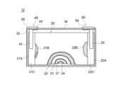
ここで開示される端子を用いた二次電池の内部構造について、図3を参照しつつ説明する。図3は、一実施形態にかかる端子を用いた二次電池の構造を模式的に示す幅広面の断面図である。
ここで開示される電極体20は、図示しない絶縁フィルム等で覆われた状態で、電池ケース30の内部に収容された発電要素であり、長尺シート状の正極21と、長尺シート状の負極22とが、同じく長尺シート状の2枚のセパレータ23、24を間に介在させつつ相互に重ねて扁平状に捲回されたいわゆる捲回電極体である。
The internal structure of a secondary battery using the terminals disclosed herein will be described with reference to FIG. FIG. 3 is a cross-sectional view of a wide surface schematically showing the structure of a secondary battery using a terminal according to one embodiment.
The
正極21は、箔状の正極集電体21Aと、当該正極集電体21Aの両面に長手方向に沿って形成された正極活物質層21Bと、を備えている。また、リチウムイオン二次電池12の幅方向における電極体20の一方の側縁部には、正極活物質層21Bが形成されておらず、正極集電体21Aが露出した正極集電体露出部21Cが設けられている。正極活物質層21Bには、正極活物質、バインダ、導電材等の種々の材料が含まれる。なお、正極活物質層21Bに含まれる材料については、従来の一般的なリチウムイオン二次電池で使用され得るものを特に制限なく使用することができ、本発明を特徴付けるものではないため詳細な説明は省略する。
正極集電端子42としては、例えばアルミニウム箔等が用いられる。
The
As the
負極22は、箔状の負極集電体22Aと、当該負極集電体22Aの片面または両面に長手方向に沿って形成された負極活物質層22Bと、を備えている。また、幅方向における電極体20の他方の側縁部には、負極活物質層22Bが形成されておらず、負極集電体22Aが露出した負極集電体露出部22Cが設けられている。正極活物質層21Bと同様に、負極活物質層22Bには、負極活物質やバインダ等の種々の材料が含まれる。負極活物質層22Bに含まれる材料については、従来の一般的なリチウムイオン二次電池で使用され得るものを特に制限なく使用することができ、本発明を特徴付けるものではないため詳細な説明は省略する。
負極集電端子52としては、例えば銅箔等が用いられる。
The
As the
セパレータ23、24は、正極21と負極22との間に介在し、これらの電極が直接接触することを防止する。図示は省略するが、セパレータ23、24には、微細な孔が複数形成されている。当該微細な孔は、電荷担体(リチウムイオン二次電池の場合は、リチウムイオン)が正極21と負極22との間で移動するように構成されている。
セパレータ23、24には、所要の耐熱性を有する樹脂シート(例えばポリプロピレン、ポリスチレン等のポリオレフィン製シート)等が使用される。
For the
電池ケース30に収容される非水電解液としては、典型的には非水溶媒と支持塩とを含有した、従来の一般的なリチウムイオン二次電池で使用され得るものを特に制限なく使用することができ、本発明を特徴付けるものではないため詳細な説明は省略する。
As the non-aqueous electrolyte contained in the
図3および図4に示すように、正極端子40は電池ケース内部で電極体と接続される正極集電端子42と、該集電端子42と接続され、一部が蓋体の貫通孔36を通過して蓋体の外表面に露出する正極接続端子44とから構成されている。正極集電端子42は、電池ケース30の内部に配置され、正極集電体露出部21Cを介して正極21に接続されている。
As shown in FIGS. 3 and 4, the
図3および図4に示すように、負極端子50は電池ケース内部で電極体と接続される負極集電端子52と、該集電端子52と接続され、一部が蓋体の貫通孔36を通過して蓋体の外表面に露出する負極接続端子54とから構成されている。負極集電端子52は、電池ケース30の内部に配置され、負極集電体露出部22Cを介して負極22に接続されている。
As shown in FIGS. 3 and 4, the
以下では、ここで開示される端子構造が具現化されている負極端子50の構成をもとに、図5を参照しつつ詳細に説明する。なお、正極端子40がここで開示される端子構造を有している場合の構成は、負極端子50が負極接続端子54を有している場合の構成と同様であるので、詳細な説明は省略する。
Below, based on the structure of the
図5は、一実施形態にかかる端子の要部構造を模式的に示す断面図である。
上記のとおり、負極端子50は負極接続端子54と負極集電端子52とから構成されている。負極接続端子54は、第一部材56と第二部材58とから構成されている。
負極集電端子52は、負極接続端子54のうちの第二部材58における電池ケース内部に存在する部分とかしめ、溶接等によって接続されている。本実施形態では、後述するように、負極集電端子52と負極接続端子54のうちの第二部材58の脚部58Lとの間に形成されたかしめ構造によって、負極集電端子52と負極接続端子54とが接続されて本実施形態に係る負極端子50を構成している(図5参照)。
負極集電体22Aと接続される負極集電端子52は、好ましくは負極集電体22Aと同種の金属が用いられ、例えば、銅が用いられる。負極集電端子52と接続される負極接続端子54のうちの第二部材58は、好ましくは負極集電端子52と同種の金属が用いられ、例えば、銅が用いられる。一方、本実施形態では、負極接続端子54のうちの第一部材56は、アルミニウム製である。
FIG. 5 is a cross-sectional view schematically showing the essential structure of the terminal according to one embodiment.
As described above, the
The negative current collecting
The negative electrode
図5に示されるように、負極接続端子54は、蓋体34に形成された貫通孔36に挿通されており、蓋体34と負極端子54の間はガスケット60によって絶縁されている。
ガスケット60は絶縁性を有する材料によって形成されており、例えば、パーフルオロアルコキシアルカン(PFA)等のフッ素樹脂等が用いられる。
また、図示されるように、負極集電端子52はインシュレータ61によって絶縁されている。インシュレータ61は絶縁性を有する材料によって形成されており、例えば、ポ
リフェニレンサルファイド樹脂(PPS)等の樹脂材料が用いられる。
As shown in FIG. 5 , the negative
The
Further, as shown in the figure, the
負極接続端子54は、ここで開示される端子構造を反映したものであり、それぞれ金属製の第一部材56と第二部材58とから構成されている。第一部材56は板状に形成され、第二部材58は第一部材56に対向するカシメ部58Cを備えている。ここで、第一部材56の一方の面において、いかなる貫通孔も介さずに第二部材58のカシメ部58Cが第一部材56にかしめられており、かつ、第一部材56と第二部材58とは、対向面57に相互に金属接合されている金属接合面を有する。第一部材56の前記対向面とは反対側の面55は、例えばバスバ14と少なくとも一部が溶接されることによって外部と接続される。
The
第一部材56および第二部材58の形状は、本発明の効果を損なわない限りにおいて特に制限されない。これに限られないが、第一部材56は板状であり、第二部材58のカシメ部58Cが嵌合する凹部56Rを備えている。これに限られないが、第二部材58は例えば、第一部材56にかしめられるカシメ部58C、蓋体34の貫通孔36に挿通される軸部58Sを備えている。第二部材58は、負極集電端子52に溶接等によって接続され、かつ、かしめ等によって蓋体34に固定されるための脚部58Lを備えていてもよい。即ち、図5に示すように、本実施形態に係る負極接続端子54は、電池ケース内部において、蓋体34の貫通孔36を通過した第二部材58の脚部58Lが、対向する負極集電端子52に設けられたカシメ用の貫通孔53の周囲にかしめられることによって固定されている。
The shapes of the
第二部材58のカシメ部58Cおよび第一部材56の凹部56Rの形状等は、第一部材56と第二部材58がかしめられて十分な強度で接合される限りは、特に限定されない。
図6に示されるように、第二部材58のカシメ部58Cは、軸部58Sの第一部材56と対向する面に凸形状に設けられていてもよい。図7に示されるように、第二部材58のカシメ部58Cは、軸部58Sの第一部材56と対向する面にフランジ形状に設けられていてもよい。
The shape and the like of the crimped
As shown in FIG. 6, the crimped
第一部材56と第二部材58の金属接合は、超音波接合によって行われる。しかし、第一部材56と第二部材58を金属接合により接合する方法は超音波接合に限定されず、例えば、拡散接合、摩擦圧接、レーザ溶接等によっても行われ得る。
Metal bonding of the
ここで開示される負極接続端子54は、上述したように第二部材58のカシメ部58Cが第一部材56にかしめられているため、両部材間の接合強度が良好であり、かつ、金属接合によって接合されていることによって良好な導通が確保されている。
Since the crimped
上述したかしめによって部材間の接合強度が確保されているため、第一部材56と第二部材58の金属接合は、第一部材56と第二部材58が対向する面に対して狭い範囲で行われていてもよい。
これに限られないが、第一部材56と第二部材58が金属接合されている面の面積が、第一部材56と第二部材58とが対向する面の面積の50%以下であることが好ましく、例えば30%以下であることがより好ましい。かかる面積は、本発明の効果を奏する限りにおいて更に狭い面積であってもよく、例えば10%以下や5%以下であってもよい。また、図8および図9に示すように、第一部材56は、第二部材58と対向する面57と反対側の面55に、凹部56R2を備え、上記金属接合面は、凹部56R2の開口に対応する範囲よりも内側に形成されていてもよい。ここで、「第一部材56と第二部材58とが対向する面の面積」とは、第一部材56と第二部材58とが対向している面57を、面55と水平な面に投影した際に形成される面の面積のことをいう。
このように狭い範囲でしか金属接合されていない場合であっても、第一部材56と第二部材58があらかじめかしめられていることによって、部材間の接合強度が良好である。また、金属接合が第一部材表面に及ぼす影響が小さいことによって、第一部材における外部の接続部品と接続される面の平滑性が維持され、平滑化のための後処理が不要である。
Since the bonding strength between the members is secured by the caulking described above, metal bonding of the
Although not limited to this, the area of the surfaces where the
Even if metal bonding is performed only in such a narrow range, the
また、第一部材56と第二部材58の金属接合は、第一部材56において、第二部材58と対向する面と反対側の面の表面粗さが抑えられるように、弱い接合エネルギーで行うことができる。例えば、金属接合後の当該表面の算術平均粗さSaは5μm以下であることが好ましく、3μm以下であることがより好ましく、例えば2μm以下であることがさらに好ましい。
このように、第一部材56と第二部材58が対向する面の反対側の面が平坦であることによって、平滑化等の後処理をすることなく、負極接続端子54はバスバ等の外部の接続部品と良好に接続される。
In addition, the metal bonding of the
In this way, since the surface opposite to the surface where the
本実施形態では、負極接続端子54に接続されるバスバ14がアルミニウムまたはアルミニウムを主体とする合金で構成される。従って、本実施形態においては、アルミニウム製の第一部材56とバスバを構成する金属種が合わされることにより、負極端子とバスバとの導通および接合強度を向上させることができる。
In this embodiment, the
上記のとおり、本実施形態においては第一部材56と第二部材58を超音波接合により形成された金属接合面を有する。
このような接合面を有することは、例えば、第一部材56と第二部材58との界面で破断させ当該破断面を観察することによって確認することができる。図10は、アルミニウムからなる第一部材56と銅からなる第二部材58とを破断させた面のSEM画像である。図中の矢印は、銅からなる第二部材58に対する、アルミニウムからなる第一部材56の凝着を指している。このように、第一部材56と第二部材58の少なくとも一方の破断面に他方の金属の凝着が確認できた場合に、上記の接合面あったと確認することができる。
As described above, in this embodiment, the
Having such a joint surface can be confirmed, for example, by breaking the interface between the
ここに開示される端子(本実施形態では負極端子)を有する二次電池12は、バスバ14等の外部の接続部品と良好に導通され得る。また、単電池として二次電池12が用いられた組電池100において、ここに開示される端子(詳しくは接続端子)の第一部材を構成する金属種と同じ金属でバスバ14を構成することによって、単電池12間をより良好に導通させることができる。
The
以下、ここに開示される端子の製造方法および、該端子を有する二次電池の製造方法について、改めて説明する。
なお、以下では、ここに開示される端子を有する負極端子の製造方法を例に挙げて製造方法を説明する。ここに開示される端子を有する正極端子の製造方法については、該端子を有する負極端子の場合と同様の方法で製造することができるので、説明は省略する。
Hereinafter, the manufacturing method of the terminal disclosed herein and the manufacturing method of the secondary battery having the terminal will be described again.
In the following, the manufacturing method will be described by taking the manufacturing method of the negative electrode terminal having the terminal disclosed herein as an example. The method for manufacturing the positive electrode terminal having the terminal disclosed herein can be manufactured in the same manner as the negative electrode terminal having the terminal, so the description is omitted.
図8は、端子を製造する方法のフローチャートである。
まず、端子を構成する上述した第一部材56と第二部材58とを用意する(S1)。
FIG. 8 is a flow chart of a method of manufacturing a terminal.
First, the above-described
次に、第一部材56と第二部材58を、カシメ部58Cと凹部56Rを介してかしめる(S2)。かしめは例えば、第一部材56と第二部材58のいずれか一方を固定し、他方を一方に対して加圧することによって行うことができる。この操作によって、第一部材56と第二部材58の一方の部材を他方の部材に対して変形させ、圧入させることによって、カシメ部58Cと凹部56Rとを固定することができる。
Next, the
そして、第一部材56と前記第二部材58との対向する面の少なくとも一部を相互に金属接合する(S3)。
第一部材56と第二部材58の金属接合は、上記のとおり超音波接合によって行われる。超音波接合は、例えば、第一部材56と第二部材58とをホーンとアンビルとで挟み、第一部材56と第二部材58の軸部58Sとを押し当てつつ、超音波振動が与えられることによって行われることが好ましい。
例えば、ホーンを介して与えられる超音波振動の条件は、第一部材56と第二部材58の金属種、寸法、ホーンの形状等に応じて、適宜設定し得る。これに限られないが、例えば、振幅は20~80μm程度、周波数は15~150kHz程度、第一部材56と第二部材58に与えられるエネルギー量が30~500J程度に設定され得る。
Then, at least part of the facing surfaces of the
Metal bonding of the
For example, the conditions of the ultrasonic vibration applied through the horn can be appropriately set according to the metal types and dimensions of the
なお、本実施形態に限られず、第一部材56と第二部材58を金属接合により接合する方法は、例えば、拡散接合、摩擦圧接、レーザ溶接等によって行ってもよい。
The method of joining the
ここでは、上記のとおり、第一部材56と前記第二部材58とを金属接合する工程(S3)において、金属接合面が、通常第一部材56と第二部材58が対向する面の面積の50%以下となるように実施するが、特に限定されず、かかる面積は例えば上記対向面の面積の10%を超える領域(例えば全体の面積の10~20%)でもよい。かかる面積が更に狭い面積となるように実施してもよく、例えば10%以下や5%以下となるように実施してもよい。
第一部材56と第二部材58とが予めかしめられていることによって、部材間の接合強度が確保される。そのため金属接合の範囲を狭くしても、部材間の接合強度と導通を両立することができる。金属接合の範囲を狭くすることによって、外部の接続部品と接続される面の荒れる範囲も抑えられる。この方法で製造された端子は、外部の接続部品と接続される面を平滑化する等の後処理が不要となり、生産性の観点からも好ましい。
Here, as described above, in the step (S3) of metal-bonding the
By caulking the
なお、第一部材56と第二部材58とを金属接合する工程(S3)において、上記のとおり、当該金属接合後における第一部材56の対向面と反対側の面における算術平均粗さSaが5μm以下となるように実施することが好ましいのであるが、特に限定されず、3μm以下、例えば2μm以下となるように実施してもよい。第一部材56と第二部材58とを超音波接合によって接合する際に、与える接合エネルギーを小さくすることによって、上記Saを小さくすることを実現することができる。この方法で製造された端子は、外部の接続部品と接続される面を平滑化する等の後処理が不要となり、生産性の観点からも好ましい。
In the step (S3) of metal-bonding the
以上、本発明の具体例を詳細に説明したが、これらは例示にすぎず、請求の範囲を限定するものではない。ここに開示される発明には上記の具体例を様々に変形、変更したものが含まれる。 Although specific examples of the present invention have been described in detail above, these are merely examples and do not limit the scope of the claims. The invention disclosed herein includes various modifications and alterations of the above specific examples.
11 スペーサ
12 二次電池(単電池)
14 バスバ
17 エンドプレート
18 締め付け用ビーム材
19 ビス
20 電極体
21 正極
21A 正極集電体
21B 正極活物質層
21C 正極集電体露出部
22 負極
22A 負極集電体
22B 負極活物質層
22C 負極集電体露出部
23 セパレータ
24 セパレータ
30 電池ケース
32 電池ケース本体
34 蓋体
36 貫通孔(蓋体の貫通孔)
40 正極端子
42 正極集電端子
44 正極接続端子
50 負極端子
52 負極集電端子
53 貫通孔(負極集電端子の貫通孔)
54 負極接続端子
55 対向面と反対側の面
56 第一部材
56R 凹部
56R2 凹部
57 対向面
58 第二部材
58C カシメ部
58L 脚部
58S 軸部
60 ガスケット
61 インシュレータ
100 組電池
11
14
40
54 Negative
Claims (15)
それぞれ金属製の第一部材と第二部材とを有しており、
前記第一部材は、板状に形成され、一方の面に、貫通していない凹部を有し、かつ、前記凹部の底に、前記第一部材と前記第二部材とが相互に金属接合された金属接合面を有し、
前記第二部材は、金属接合された前記凹部の前記底の周りに、金属接合されていないカシメ部を有している、端子。 A terminal constituting either a positive electrode or a negative electrode of a secondary battery,
each having a first member and a second member made of metal,
The first member is formed in a plate shape and has a concave portion that does not penetrate through one surface, and the first member and the second member are metal-bonded to each other at the bottom of the concave portion. has a metal joint surface,
The terminal, wherein the second member has a crimped portion that is not metal-bonded around the bottom of the recess that is metal-bonded.
前記金属接合面は、前記第2の凹部と対向する部分に形成されている、請求項2に記載の端子。 The first member has a second recess on the surface opposite to the surface facing the second member,
3. The terminal according to claim 2, wherein said metal joint surface is formed in a portion facing said second recess.
前記電極体を内部に収容した電池ケースと、
前記電極体における正極および負極それぞれと電気的に接続された正極端子および負極端子とを、備えた二次電池であって、
前記正極端子および前記負極端子の少なくとも一方は、請求項1~6のいずれか一項に記載の端子を含む、二次電池。 an electrode body including a positive electrode and a negative electrode;
a battery case housing the electrode assembly therein;
A secondary battery comprising a positive electrode terminal and a negative electrode terminal electrically connected to the positive electrode and the negative electrode of the electrode assembly, respectively,
A secondary battery, wherein at least one of the positive electrode terminal and the negative electrode terminal includes the terminal according to any one of claims 1 to 6.
前記複数の単電池として請求項7に記載の二次電池が用いられている組電池。 An assembled battery in which a plurality of cells are electrically connected to each other and arranged,
An assembled battery in which the secondary battery according to claim 7 is used as the plurality of cells.
ここで、前記端子の前記第一部材を構成する金属と同じ金属によって前記バスバが構成されている、請求項8に記載の組電池。 the plurality of cells are electrically connected to a positive electrode terminal of one cell and a negative electrode terminal of another cell by a predetermined busbar;
9. The assembled battery according to claim 8, wherein said bus bar is made of the same metal as the metal forming said first member of said terminal.
前記端子を構成するそれぞれ金属製の第一部材と第二部材とを用意する工程、ここで、前記第一部材は板状に形成され、前記第二部材は前記第一部材に対向するカシメ部を備えている;
前記第一部材の一方の面において、貫通孔を介さずに前記第二部材のカシメ部を前記第一部材にかしめる工程;および
前記かしめる工程の後に、前記第一部材と前記第二部材との対向する面の少なくとも一部を相互に金属接合する金属接合工程;
を包含する、端子の製造方法。 A method of manufacturing a terminal that constitutes either a positive electrode or a negative electrode of a secondary battery, comprising the steps of:
A step of preparing a metal first member and a second member that constitute the terminal, wherein the first member is formed in a plate shape, and the second member is a crimped portion facing the first member has;
a step of crimping the crimped portion of the second member to the first member without passing through the through hole on one surface of the first member; and after the crimping step, the first member and the second member a metal bonding step of metal bonding at least a portion of the opposing surfaces of the to each other;
A method of manufacturing a terminal, comprising:
Priority Applications (5)
| Application Number | Priority Date | Filing Date | Title |
|---|---|---|---|
| JP2020155915A JP7304329B2 (en) | 2020-09-17 | 2020-09-17 | SECONDARY BATTERY AND SECONDARY BATTERY TERMINAL AND METHOD OF MANUFACTURING SAME |
| US17/404,454 US20220085463A1 (en) | 2020-09-17 | 2021-08-17 | Secondary battery and terminal for secondary battery and manufacturing method thereof |
| EP21194417.8A EP3972044A1 (en) | 2020-09-17 | 2021-09-01 | Secondary battery and terminal for secondary battery and manufacturing method thereof |
| KR1020210122409A KR20220037371A (en) | 2020-09-17 | 2021-09-14 | Secondary battery and terminal for secondary battery and manufacturing method thereof |
| CN202111080245.6A CN114204219A (en) | 2020-09-17 | 2021-09-15 | Secondary battery, terminal for secondary battery, and method for manufacturing terminal for secondary battery |
Applications Claiming Priority (1)
| Application Number | Priority Date | Filing Date | Title |
|---|---|---|---|
| JP2020155915A JP7304329B2 (en) | 2020-09-17 | 2020-09-17 | SECONDARY BATTERY AND SECONDARY BATTERY TERMINAL AND METHOD OF MANUFACTURING SAME |
Publications (2)
| Publication Number | Publication Date |
|---|---|
| JP2022049728A JP2022049728A (en) | 2022-03-30 |
| JP7304329B2 true JP7304329B2 (en) | 2023-07-06 |
Family
ID=77595477
Family Applications (1)
| Application Number | Title | Priority Date | Filing Date |
|---|---|---|---|
| JP2020155915A Active JP7304329B2 (en) | 2020-09-17 | 2020-09-17 | SECONDARY BATTERY AND SECONDARY BATTERY TERMINAL AND METHOD OF MANUFACTURING SAME |
Country Status (5)
| Country | Link |
|---|---|
| US (1) | US20220085463A1 (en) |
| EP (1) | EP3972044A1 (en) |
| JP (1) | JP7304329B2 (en) |
| KR (1) | KR20220037371A (en) |
| CN (1) | CN114204219A (en) |
Citations (4)
| Publication number | Priority date | Publication date | Assignee | Title |
|---|---|---|---|---|
| JP2011124024A (en) | 2009-12-08 | 2011-06-23 | Hitachi Vehicle Energy Ltd | Battery pack and electric cell |
| JP2016018675A (en) | 2014-07-08 | 2016-02-01 | 日立オートモティブシステムズ株式会社 | Secondary battery |
| JP2016192285A (en) | 2015-03-31 | 2016-11-10 | 株式会社Gsユアサ | Power storage element and manufacturing method for power storage element |
| JP2019009045A (en) | 2017-06-27 | 2019-01-17 | 株式会社Gsユアサ | Power storage element |
Family Cites Families (11)
| Publication number | Priority date | Publication date | Assignee | Title |
|---|---|---|---|---|
| JPH09219204A (en) * | 1996-02-14 | 1997-08-19 | Fuji Elelctrochem Co Ltd | Manufacture of lithium flat battery |
| US6844110B2 (en) * | 2000-05-24 | 2005-01-18 | Ngk Insulators, Ltd. | Lithium secondary cell and assembly thereof |
| JP2001357834A (en) * | 2000-06-16 | 2001-12-26 | Japan Storage Battery Co Ltd | Battery |
| JP2012174452A (en) * | 2011-02-21 | 2012-09-10 | Sharp Corp | Secondary battery |
| JP5976340B2 (en) * | 2012-02-29 | 2016-08-23 | 三洋電機株式会社 | Method for manufacturing prismatic secondary battery |
| WO2014103874A1 (en) * | 2012-12-25 | 2014-07-03 | 株式会社Gsユアサ | Electricity storage element, electricity storage element assembly and method for manufacturing electricity storage element |
| JP6077317B2 (en) * | 2013-01-29 | 2017-02-08 | 株式会社協豊製作所 | Terminal for storage battery |
| JP6146617B2 (en) * | 2014-02-12 | 2017-06-14 | トヨタ自動車株式会社 | Manufacturing method of secondary battery |
| US20170229700A1 (en) * | 2014-08-06 | 2017-08-10 | Hitachi Automotive Systems, Ltd. | Prismatic secondary battery |
| KR101856820B1 (en) * | 2015-03-06 | 2018-05-10 | 주식회사 엘지화학 | Cable type Secondary Battery |
| JP6996308B2 (en) * | 2018-01-17 | 2022-01-17 | 三洋電機株式会社 | Secondary battery and its manufacturing method |
-
2020
- 2020-09-17 JP JP2020155915A patent/JP7304329B2/en active Active
-
2021
- 2021-08-17 US US17/404,454 patent/US20220085463A1/en active Pending
- 2021-09-01 EP EP21194417.8A patent/EP3972044A1/en active Pending
- 2021-09-14 KR KR1020210122409A patent/KR20220037371A/en not_active Application Discontinuation
- 2021-09-15 CN CN202111080245.6A patent/CN114204219A/en active Pending
Patent Citations (4)
| Publication number | Priority date | Publication date | Assignee | Title |
|---|---|---|---|---|
| JP2011124024A (en) | 2009-12-08 | 2011-06-23 | Hitachi Vehicle Energy Ltd | Battery pack and electric cell |
| JP2016018675A (en) | 2014-07-08 | 2016-02-01 | 日立オートモティブシステムズ株式会社 | Secondary battery |
| JP2016192285A (en) | 2015-03-31 | 2016-11-10 | 株式会社Gsユアサ | Power storage element and manufacturing method for power storage element |
| JP2019009045A (en) | 2017-06-27 | 2019-01-17 | 株式会社Gsユアサ | Power storage element |
Also Published As
| Publication number | Publication date |
|---|---|
| JP2022049728A (en) | 2022-03-30 |
| CN114204219A (en) | 2022-03-18 |
| KR20220037371A (en) | 2022-03-24 |
| US20220085463A1 (en) | 2022-03-17 |
| EP3972044A1 (en) | 2022-03-23 |
Similar Documents
| Publication | Publication Date | Title |
|---|---|---|
| US10141560B2 (en) | Energy storage device including a pressing member pressing a separator toward an electrode assembly | |
| JP2023089036A (en) | Terminal for secondary battery and method for manufacturing terminal for secondary battery | |
| US10003067B2 (en) | Electric storage device and method for producing electric storage device | |
| JP7236036B2 (en) | secondary battery | |
| JP5558878B2 (en) | Assembled battery, resistance welding method, and assembled battery manufacturing method | |
| US10615447B2 (en) | Secondary cell and manufacturing method thereof | |
| JP7304329B2 (en) | SECONDARY BATTERY AND SECONDARY BATTERY TERMINAL AND METHOD OF MANUFACTURING SAME | |
| JP7205723B2 (en) | Ultrasonic bonding method | |
| JP7296996B2 (en) | Electrode terminal and its use | |
| JP7389766B2 (en) | Terminal parts, secondary batteries and assembled batteries equipped with the same, and method for manufacturing terminal parts | |
| JP7402202B2 (en) | Terminal components and terminal component manufacturing method | |
| JP7334215B2 (en) | Horns, terminal parts and secondary batteries | |
| JP7285817B2 (en) | SEALED BATTERY AND METHOD OF MANUFACTURING SEALED BATTERY | |
| JP7252926B2 (en) | SECONDARY BATTERY TERMINAL AND SECONDARY BATTERY INCLUDING THE TERMINAL | |
| JP6796260B2 (en) | Sealed battery | |
| JP2022112412A (en) | Terminal component, secondary battery, and battery pack | |
| JP2014170614A (en) | Electrode for electrochemical element and electrochemical element |
Legal Events
| Date | Code | Title | Description |
|---|---|---|---|
| A621 | Written request for application examination |
Free format text: JAPANESE INTERMEDIATE CODE: A621 Effective date: 20211005 |
|
| A131 | Notification of reasons for refusal |
Free format text: JAPANESE INTERMEDIATE CODE: A131 Effective date: 20220818 |
|
| A977 | Report on retrieval |
Free format text: JAPANESE INTERMEDIATE CODE: A971007 Effective date: 20220831 |
|
| A521 | Request for written amendment filed |
Free format text: JAPANESE INTERMEDIATE CODE: A523 Effective date: 20221013 |
|
| A131 | Notification of reasons for refusal |
Free format text: JAPANESE INTERMEDIATE CODE: A131 Effective date: 20230209 |
|
| A521 | Request for written amendment filed |
Free format text: JAPANESE INTERMEDIATE CODE: A523 Effective date: 20230313 |
|
| TRDD | Decision of grant or rejection written | ||
| A01 | Written decision to grant a patent or to grant a registration (utility model) |
Free format text: JAPANESE INTERMEDIATE CODE: A01 Effective date: 20230615 |
|
| A61 | First payment of annual fees (during grant procedure) |
Free format text: JAPANESE INTERMEDIATE CODE: A61 Effective date: 20230626 |
|
| R150 | Certificate of patent or registration of utility model |
Ref document number: 7304329 Country of ref document: JP Free format text: JAPANESE INTERMEDIATE CODE: R150 |