[第1実施形態]
以下、本発明の好適な実施の形態を図面に基づいて説明する。なお、遊技機の説明における前後左右とは、遊技中の遊技者から見た方向を指すものとする。
[First embodiment]
Preferred embodiments of the present invention will be described below with reference to the drawings. Note that front, back, left, and right in the description of the gaming machine refer to directions seen by the player during the game.
〔遊技機全体図〕
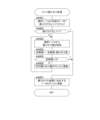
図1は、遊技機を説明する図である。
[General view of game machine]
FIG. 1 is a diagram illustrating a gaming machine.
遊技機10は島設備に固定される枠11に、ヒンジを介して開閉回動自在に取り付けられる開閉枠を備える。開閉枠は、前面枠12(本体枠)及びガラス枠15によって構成されている。
The game machine 10 has an opening/closing frame attached to a frame 11 fixed to an island facility via a hinge so as to be freely opened/closed. The opening/closing frame is composed of a front frame 12 (body frame) and a glass frame 15 .
前面枠12には、遊技盤30(図2参照)が配設されるとともに、遊技盤30の前面を覆うカバーガラス14を有するガラス枠15が取り付けられる。カバーガラス14は、遊技盤30に形成される遊技領域32(図2参照)を視認可能とする遊技視認領域として機能する。
A game board 30 (see FIG. 2) is arranged on the front frame 12, and a glass frame 15 having a cover glass 14 covering the front surface of the game board 30 is attached. The cover glass 14 functions as a game visual recognition area that makes a game area 32 (see FIG. 2) formed on the game board 30 visible.
前面枠12及びガラス枠15は、それぞれ個別に開放することが可能となっている。例えば、ガラス枠15のみを開放することで、遊技盤30の遊技領域32にアクセスすることができる。また、前面枠12をガラス枠15が開放されていない状態で開放することで、遊技盤30の裏面側に配設された遊技制御装置(主基板)100(図3参照)等にアクセスすることができる。
The front frame 12 and the glass frame 15 can be opened individually. For example, by opening only the glass frame 15, the game area 32 of the game board 30 can be accessed. Also, by opening the front frame 12 in a state where the glass frame 15 is not opened, it is possible to access the game control device (main board) 100 (see FIG. 3) and the like arranged on the back side of the game board 30. can be done.
ガラス枠15のカバーガラス14周囲の縁部分には、種々の枠構成部材が配設されている。
Various frame-constituting members are arranged on the edge portion of the glass frame 15 around the cover glass 14 .
ガラス枠15の上部中央及び左側部には、遊技状態に応じて発光演出可能な装飾装置18a,18bが配設されている。装飾装置18a,18bは、内部にLED等の照明部材を収容しており、遊技状態に応じた発光演出を行う。これら装飾装置18a,18bの内部に配設される照明部材は、枠装飾装置18(図4参照)の一部を構成している。
Decoration devices 18a and 18b capable of emitting light according to the game state are arranged at the upper center and left side of the glass frame 15. As shown in FIG. The decoration devices 18a and 18b house lighting members such as LEDs therein, and perform light emission effects according to the game state. The illumination members arranged inside these decoration devices 18a and 18b constitute part of the frame decoration device 18 (see FIG. 4).
ガラス枠15の上右角部分及び上左角部分には、上スピーカ19aがそれぞれ配設される。これら上スピーカ19aとは別に遊技機10の下部には、2つの下スピーカ19bが設けられている。下スピーカ19bは、ガラス枠15の下左角部分及び前面枠12の下右角部分に配設されている。これら上スピーカ19a及び下スピーカ19bは、効果音や警報音、報知音等を発するものである。
Upper speakers 19a are arranged at the upper right corner portion and the upper left corner portion of the glass frame 15, respectively. Two lower speakers 19b are provided in the lower part of the game machine 10 separately from the upper speakers 19a. The lower speaker 19 b is arranged at the lower left corner portion of the glass frame 15 and the lower right corner portion of the front frame 12 . These upper speaker 19a and lower speaker 19b emit sound effects, alarm sounds, notification sounds, and the like.
ガラス枠15の右側部には、遊技機10の上下方向に延設されるとともに、前方(遊技者側)に向かって突出する突出演出ユニット13が配設されている。突出演出ユニット13は、遊技の進行状態に応じて発光演出等を行う演出装置である。突出演出ユニット13の内部に配設される照明部材も枠装飾装置18(図4参照)の一部を構成している。
On the right side of the glass frame 15, a protruding effect unit 13 that extends in the vertical direction of the gaming machine 10 and protrudes forward (toward the player) is arranged. The projecting effect unit 13 is a effect device that performs light emitting effects and the like according to the progress of the game. A lighting member arranged inside the projecting effect unit 13 also constitutes a part of the frame decoration device 18 (see FIG. 4).
ガラス枠15の下部には、遊技球(遊技媒体)を貯留可能な上皿21を有する上皿ユニットが取り付けられている。上皿21は、上面が開口した箱状に形成されている。上皿21に貯留されている遊技球は、一球ずつ球発射装置(図示省略)に供給される。
An upper plate unit having an upper plate 21 capable of storing game balls (game media) is attached to the lower portion of the glass frame 15 . The upper plate 21 is formed in a box shape with an open top. The game balls stored in the upper tray 21 are supplied one by one to a ball shooting device (not shown).
上皿ユニットは、遊技者からの入力操作を受け付ける演出操作装置と、遊技者からの入力操作を受け付ける球貸操作装置と、遊技状態に応じて発光演出等を行う装飾装置22と、をさらに備える。
The upper tray unit further includes a performance operation device for receiving input operations from the players, a ball lending operation device for receiving input operations from the players, and a decoration device 22 for performing light-emitting performance or the like according to the game state. .
演出操作装置は、演出ボタン25にタッチパネル25bを組み込んだ操作装置であり、遊技者が操作しやすいように上皿ユニットの上部中央に設けられている。
The effect operation device is an operation device in which a touch panel 25b is incorporated in the effect button 25, and is provided at the upper center of the upper tray unit so that the player can easily operate it.
遊技者が演出操作装置を操作することによって、表示装置41(図2参照)に表示される特図変動表示ゲーム(ゲーム)等において遊技者の操作を介入させた演出を行うことができる。例えば、演出パターン(演出態様)を選択したり、始動記憶に対応する変動表示ゲーム(ゲーム)の結果を事前に予告する予告演出を実行したりすることができる。なお、変動表示ゲームには特図変動表示ゲームが含まれ、単に変動表示ゲームとした場合には、本明細書では特図変動表示ゲームを指すものとする。
By operating the effect operation device by the player, it is possible to perform an effect in which the player's operation is intervened in a special figure variation display game (game) or the like displayed on the display device 41 (see FIG. 2). For example, it is possible to select an effect pattern (effect mode), or execute an advance notice effect that gives advance notice of the result of the variable display game (game) corresponding to the starting memory. Note that the variable display game includes a special figure variable display game, and when simply referred to as a variable display game, this specification refers to a special figure variable display game.
また、変動表示ゲームの実行中だけでなく、非実行中に遊技者が演出操作装置を操作することによっても演出パターンを変更するようにしてもよい。
Also, the effect pattern may be changed not only during execution of the variable display game but also by the player operating the effect operation device while the game is not being executed.
なお、変動表示ゲームが実行される際の遊技状態は、複数の遊技状態からなる。通常遊技状態(通常状態)とは、特別な遊技状態が発生していない遊技状態である。また、特別な遊技状態とは、例えば、特定遊技状態としての時短状態や変動表示ゲームにおいて特別結果(例えば大当り)の発生確率が高い状態(確変状態、確率変動状態)、大当り状態(特別遊技状態)である。
The game state when the variable display game is executed consists of a plurality of game states. The normal game state (normal state) is a game state in which no special game state occurs. In addition, the special game state is, for example, a state with a high probability of occurrence of a special result (for example, a big hit) in a time-saving state or a variable display game as a specific game state (variable probability state, probability variable state), a big hit state (special game state ).
ここで、確変状態(特定遊技状態)は、次の大当りが発生するまで継続するもの(ループタイプ)、所定回数の変動表示ゲームが実行されるまで継続するもの(回数切りタイプ、ST)、及び所定の確率転落抽選に当選するまで継続するもの(転落抽選タイプ)等がある。
Here, the probability variable state (specific game state) continues until the next big hit occurs (loop type), continues until a predetermined number of variable display games are executed (number cut type, ST), and There is one that continues until a predetermined probability fall lottery is won (fall lottery type).
さらに、確変状態を発生させるか否かを大当り図柄乱数によって決定せずに、大当りが発生した場合に必ず確変状態を発生させるようにしてもよいし、特定領域を備える入賞装置等を設け、特定領域を遊技球が通過した場合に確変状態を発生させるようにしてもよい。
Furthermore, whether or not to generate the probability variable state may be always generated when the big hit occurs without determining whether or not to generate the probability variable state by the big hit pattern random number, or a prize winning device having a specific area may be provided and specified. A variable probability state may be generated when a game ball passes through the area.
球貸操作装置は、遊技者が遊技球を借りる場合に操作する操作装置であって、上皿ユニットの上部右側に設けられている。球貸操作装置は、球貸ボタン27と、返却ボタン28と、残高表示部26と、を備えている。球貸ボタン27は遊技球を借りる場合に遊技者が操作するボタンであり、返却ボタン28は遊技機10に隣接するように配置されるカードユニット(図示省略)からプリペイドカード等を排出させる場合に遊技者が操作するボタンである。残高表示部26は、プリペイドカード等の残高が表示される表示領域である。
The ball lending operation device is an operation device operated by the player when borrowing game balls, and is provided on the upper right side of the upper tray unit. The ball lending operation device includes a ball lending button 27, a return button 28, and a balance display section 26. - 特許庁A ball lending button 27 is a button operated by a player when borrowing a game ball, and a return button 28 is used when ejecting a prepaid card or the like from a card unit (not shown) arranged adjacent to the gaming machine 10. These are buttons operated by the player. The balance display portion 26 is a display area for displaying the balance of a prepaid card or the like.
装飾装置22は、内部にLED等の照明部材を収容しており、遊技状態に応じて発光演出等を行う装置であって、上皿ユニットの前側部分に設けられている。装飾装置22の内部に配設される照明部材は、枠装飾装置18(図4参照)の一部を構成している。
The decoration device 22 accommodates an illumination member such as an LED inside, and is a device that performs light emission effect or the like according to the game state, and is provided in the front portion of the upper tray unit. The illumination member arranged inside the decoration device 22 constitutes a part of the frame decoration device 18 (see FIG. 4).
上記した上皿ユニット等を備えるガラス枠15の下方であって、前面枠12の下部には、球発射装置(図示省略)の動作を制御するための操作ハンドル24と、遊技球を貯留可能な下皿23とが設けられている。
Beneath the glass frame 15 including the above-described upper tray unit and the like, and below the front frame 12, there are an operation handle 24 for controlling the operation of a ball shooting device (not shown) and a game ball capable of being stored. A lower plate 23 is provided.
操作ハンドル24は、前面枠12の右下部であって、右側の下スピーカ19bの下方に配置されている。遊技者が操作ハンドル24を回動操作することによって、球発射装置は上皿21から供給された遊技球を遊技盤30の遊技領域32に発射する。球発射装置から発射される遊技球の発射速度は、操作ハンドル24の回動操作量が大きくなるほど速くなるように設定されている。即ち、球発射装置は、遊技領域に遊技球を発射する勢(速度)である発射勢を、遊技者による操作ハンドル24の操作に対応して変更でき、発射勢の異なる種々の発射態様で遊技球を発射できる。発射態様には、遊技領域32の左側において遊技球を流下させる左打ち(通常打ち)と、遊技領域32の右側において遊技球を流下させる右打ちが含まれる。
The operating handle 24 is arranged in the lower right portion of the front frame 12 and below the right lower speaker 19b. The ball shooting device shoots game balls supplied from the upper tray 21 to the game area 32 of the game board 30 when the player rotates the operation handle 24 . The shooting speed of the game ball shot from the ball shooting device is set so as to increase as the rotation amount of the operation handle 24 increases. That is, the ball shooting device can change the shooting force (speed) of shooting the game ball into the game area in response to the operation of the operation handle 24 by the player, and the game can be played in various shooting modes with different shooting force. Can shoot balls. The shooting modes include left hitting (normal hitting) in which the game ball flows down on the left side of the game area 32 and right hitting in which the game ball flows down on the right side of the game area 32 .
下皿23は、上皿ユニットに対して所定の間隔をあけて、上皿ユニットの下方に配置されている。下皿23は、当該下皿23の底面を上下方向に貫通する球抜き穴23aと、球抜き穴23aを開閉するための開閉操作部23bと、を有している。遊技者が開閉操作部23bを操作して、球抜き穴23aを開くことによって、下皿23に貯留されていた遊技球を球抜き穴23aを通じて外部に排出することができる。
The lower tray 23 is arranged below the upper tray unit with a predetermined gap from the upper tray unit. The lower plate 23 has a ball removal hole 23a vertically passing through the bottom surface of the lower plate 23, and an opening/closing operation portion 23b for opening and closing the ball removal hole 23a. When the player operates the opening/closing operation portion 23b to open the ball extraction hole 23a, the game balls stored in the lower tray 23 can be discharged to the outside through the ball extraction hole 23a.
〔遊技盤〕
続いて、図2を参照して、遊技機10の遊技盤30について説明する。図2は、遊技機10に備えられる遊技盤30の正面図である。
[Game board]
Next, the game board 30 of the game machine 10 will be described with reference to FIG. FIG. 2 is a front view of the game board 30 provided in the game machine 10. As shown in FIG.
図2に示すように、遊技盤30は、各種部材の取付ベースとなる平板状の遊技盤本体30aを備える。遊技盤本体30aは木製又は合成樹脂製であって、当該遊技盤本体30aの前面にはガイドレール31で囲まれた遊技領域32が設けられている。遊技機10は、ガイドレール31で囲まれた遊技領域32内に球発射装置から遊技球を発射して遊技を行うように構成されている。遊技領域32には遊技球の流下方向を変換する部材として風車や障害釘等が配設されており、発射された遊技球はこれら部材により転動方向を変えながら遊技領域32を流下する。
As shown in FIG. 2, the game board 30 includes a flat plate-like game board main body 30a that serves as an attachment base for various members. The game board main body 30a is made of wood or synthetic resin, and a game area 32 surrounded by guide rails 31 is provided on the front surface of the game board main body 30a. The game machine 10 is configured to play a game by shooting game balls from a ball shooting device into a game area 32 surrounded by guide rails 31 . In the game area 32, windmills, obstacle nails, etc. are arranged as members for changing the flowing direction of the game ball.
遊技領域32の略中央には、変動表示ゲームの表示領域となる窓部を形成するセンターケース(前面構成体)40が取り付けられている。センターケース40に形成された窓部の後方には、複数の識別情報を変動表示(可変表示)する演出表示装置(変動表示装置)としての表示装置41が配置されている。表示装置41は、例えば、液晶ディスプレイを備え、センターケース40の窓部を介して遊技盤30の前面側から表示内容が視認可能となるように配置される。なお、表示装置41は、液晶ディスプレイを備えるものに限らず、ELやCRT等のディスプレイを備えるものであってもよい。
At approximately the center of the game area 32, a center case (front structure) 40 is attached to form a window portion that serves as a display area for the variable display game. Behind the window formed in the center case 40, a display device 41 is arranged as a performance display device (variable display device) that variably displays (variably displays) a plurality of pieces of identification information. The display device 41 includes, for example, a liquid crystal display, and is arranged so that display contents can be visually recognized from the front side of the game board 30 through the window portion of the center case 40 . The display device 41 is not limited to having a liquid crystal display, and may have a display such as an EL or a CRT.
表示装置41の表示画面(表示部)には、複数の変動表示領域が設けられており、各変動表示領域に識別情報(特別図柄)や変動表示ゲームを演出するキャラクタが表示される。その他、表示画面には遊技の進行に基づく画像(大当り表示やファンファーレ表示、エンディング表示等)が表示される。
A plurality of variable display areas are provided on the display screen (display unit) of the display device 41, and identification information (special symbols) and characters for producing a variable display game are displayed in each variable display area. In addition, images based on the progress of the game (big win display, fanfare display, ending display, etc.) are displayed on the display screen.
また、センターケース40には、遊技領域32を流下する遊技球をセンターケース40の内側に導くためのワープ通路40eへの流入口40aと、ワープ通路40eを通過した遊技球が転動可能なステージ部40bとが設けられている。センターケース40のステージ部40bは、始動入賞口36及び普通変動入賞装置37の上方に配置されているため、ステージ部40b上で転動した遊技球は始動入賞口36又は普通変動入賞装置37に入賞しやすくなっている。
The center case 40 also has an inflow port 40a to a warp passage 40e for guiding game balls flowing down the game area 32 to the inside of the center case 40, and a stage on which game balls that have passed through the warp passage 40e can roll. A portion 40b is provided. Since the stage portion 40b of the center case 40 is arranged above the starting winning port 36 and the normal variable winning device 37, the game ball rolling on the stage portion 40b enters the starting winning port 36 or the normal variable winning device 37. It is easier to win prizes.
センターケース40の上部及び右側部には、それぞれ上部演出ユニット40c及び側部演出ユニット40dが設けられる。上部演出ユニット40c及び側部演出ユニット40dは、盤装飾装置46(図4参照)及び盤演出装置44(図4参照)の一部を構成している。
An upper effect unit 40c and a side effect unit 40d are provided in the upper part and the right part of the center case 40, respectively. The upper effect unit 40c and the side effect unit 40d constitute a part of the board decoration device 46 (see FIG. 4) and the board effect device 44 (see FIG. 4).
センターケース40の右側方の遊技領域32には、普通図柄始動ゲート(普図始動ゲート)34が設けられている。普図始動ゲート34の内部には、当該普図始動ゲート34を通過した遊技球を検出するためのゲートスイッチ(SW)34a(図3参照)が設けられている。遊技領域32内に打ち込まれた遊技球が普図始動ゲート34を通過すると、普図変動表示ゲームが実行される。
A normal pattern start gate (normal pattern start gate) 34 is provided in the game area 32 on the right side of the center case 40 . Inside the normal pattern starting gate 34, a gate switch (SW) 34a (see FIG. 3) for detecting a game ball that has passed through the normal pattern starting gate 34 is provided. When the game ball hit into the game area 32 passes through the normal pattern starting gate 34, the normal pattern fluctuation display game is executed.
センターケース40の左下方の遊技領域32には一般入賞口35が配置されており、センターケース40の右下方の遊技領域32にも一般入賞口35が配置されている。これら一般入賞口35への遊技球の入賞は、一般入賞口35に備えられた入賞口スイッチ(SW)35a~35n(図3参照)によって検出される。
A general prize winning opening 35 is arranged in the lower left game area 32 of the center case 40 , and a general winning opening 35 is also arranged in the lower right game area 32 of the center case 40 . Winning of game balls into these general winning openings 35 is detected by winning opening switches (SW) 35a to 35n (see FIG. 3) provided in the general winning openings 35. FIG.
センターケース40の下方の遊技領域32には、特図変動表示ゲームの開始条件を付与する始動入賞口(第1始動入賞領域)36が設けられ、その直下には第2始動入賞口(第2始動入賞領域)を備えた普通変動入賞装置37が設けられる。普通変動入賞装置37は、上端側が手前側に倒れる方向に回動することで、遊技球が流入し易い状態に変換する可動部材(可動片)37bを備える。可動部材37bが閉状態である場合には遊技球が普通変動入賞装置37に入賞できないようになっている。遊技球が始動入賞口36又は普通変動入賞装置37に入賞した場合には、補助遊技として特図変動表示ゲームが実行される。
In the lower game area 32 of the center case 40, there is provided a start winning opening (first starting winning area) 36 that gives the starting condition of the special figure fluctuation display game, and directly below it is a second starting winning opening (second A normal variable winning device 37 having a starting winning area) is provided. The normal variable winning device 37 is provided with a movable member (movable piece) 37b that converts into a state in which game balls can easily flow in by rotating in a direction in which the upper end side falls down toward the near side. When the movable member 37b is in the closed state, the game balls cannot win the normal variable winning device 37.例文帳に追加When the game ball wins the starting winning port 36 or the normal variable winning device 37, a special figure variable display game is executed as an auxiliary game.
可動部材37bは、所謂ベロ型の普通電動役物であり、普図変動表示ゲームの結果が所定の停止表示態様となった場合に、普電ソレノイド37c(図3参照)を介して回動して開いて、遊技球が普通変動入賞装置37に流入しやすい開状態(遊技者にとって有利な入賞容易状態)に変化する。
The movable member 37b is a so-called tongue type normal electric accessory, and rotates via a normal electric solenoid 37c (see FIG. 3) when the result of the normal figure fluctuation display game is in a predetermined stop display mode. , and changes to an open state in which game balls tend to flow into the normal variable winning device 37 (an easy winning state advantageous to the player).
なお、可動部材37bは、後述する遊技制御装置100によって制御される。遊技制御装置100は、普図変動表示ゲームの変動時間を短縮したり普図変動表示ゲームの当り確率を通常よりも高確率としたりすることで入賞容易状態の発生頻度を高めたり、通常遊技状態で発生する入賞容易状態よりも入賞容易状態の発生時間を長くしたりすることで、前述の特定遊技状態として時短状態(普電サポート状態)を発生させる。なお、確変状態(潜伏確変状態を除く)においても、重複して時短状態(普電サポート状態)が発生する。
The movable member 37b is controlled by a game control device 100, which will be described later. The game control device 100 shortens the fluctuation time of the normal pattern fluctuation display game or increases the probability of winning the normal pattern fluctuation display game by making the probability higher than usual, thereby increasing the frequency of occurrence of the easy winning state, or normal game state. By making the occurrence time of the easy winning state longer than the easy winning state generated in , a time saving state (general electric support state) is generated as the above-mentioned specific game state. In addition, even in the probability variable state (excluding the latent probability variable state), a time-saving state (general electric support state) occurs in duplicate.
普通変動入賞装置37の右下方の遊技領域32には、大入賞口ソレノイド39b(図3参照)によって上端側が手前側に倒れる方向に回動することで大入賞口を開放するアタッカ形式の開閉扉39cを有する特別変動入賞装置39が設けられている。特別変動入賞装置39は、特図変動表示ゲームの結果によって大入賞口を閉じた状態(遊技者にとって不利な閉塞状態)から開放状態(遊技者にとって有利な特別遊技状態)に変換し、大入賞口内への遊技球の流入を容易にさせることで、遊技者に所定の遊技価値(賞球)を付与するようになっている。なお、大入賞口内には、当該大入賞口に入った遊技球を検出する検出手段としてカウントスイッチ39a(大入賞口スイッチ39a、図3参照)が配設されている。また、大入賞口内や大入賞口近傍には、大入賞口を照らす発光部材が配設されている。
In the game area 32 on the lower right side of the normal variable prize winning device 37, an attacker type opening and closing door that opens the big prize opening by rotating in the direction in which the upper end side falls forward by the big prize opening solenoid 39b (see FIG. 3) A special variable winnings device 39 having 39c is provided. A special variable winning device 39 converts the state in which the large winning opening is closed (closed state disadvantageous to the player) to an open state (special game state advantageous to the player) according to the result of the special figure variable display game, thereby winning a large prize. By facilitating the inflow of game balls into the mouth, predetermined game values (prize balls) are awarded to the player. A count switch 39a (large winning opening switch 39a, see FIG. 3) is arranged in the large winning opening as a detection means for detecting a game ball that has entered the large winning opening. In addition, a light-emitting member for illuminating the big winning opening is arranged in or near the big winning opening.
第2特別変動入賞装置39の内部には、特定領域86(いわゆるV入賞口)が設けられている。特定領域86(V入賞口)に遊技球が入球した場合に大当り終了後の確変状態(高確率状態、特定遊技状態)が確定する。特定領域86は、確変大当りの場合にのみ、長時間開放されるなどして遊技球が容易に通過できるようにしてよい。なお、遊技制御装置100は、特定領域86への遊技球の通過(V入賞)をセンサ(後述の特定領域スイッチ72)等を介して検知でき、V入賞を検知すると大当り終了後に確変状態に移行することを確定するとともに、後述の演出制御装置300にV入賞があったことを示す情報(特定領域通過コマンド等)を送信する。そして、演出制御装置300は、V入賞を表示装置41などにおいて報知できる。
A specific area 86 (so-called V winning opening) is provided inside the second special variable winning device 39 . When the game ball enters the specific area 86 (V winning opening), the variable probability state (high probability state, specific game state) after the end of the big hit is determined. The specific area 86 may be opened for a long time only in the case of a variable probability big hit so that the game ball can easily pass through. In addition, the game control device 100 can detect passage of the game ball to the specific area 86 (V winning) through a sensor (specific area switch 72 described later) or the like. While confirming that it does, it transmits information (specific area passing command etc.) indicating that there was a V prize to the effect control device 300 described later. Then, the effect control device 300 can notify V winning on the display device 41 or the like.
一般入賞口35、始動入賞口36、普通変動入賞装置37、及び特別変動入賞装置39の大入賞口に遊技球が入賞すると、払出制御装置200(図3参照)は、入賞した入賞口の種類に応じた数の賞球を払出装置から上皿21に排出する。また、普通変動入賞装置37の下方の遊技領域32には、入賞口等に入賞しなかった遊技球を回収するアウト口30bが設けられている。
When the game ball wins the general winning opening 35, the starting winning opening 36, the normal variable winning device 37, and the special variable winning device 39, the payout control device 200 (see FIG. 3) determines the type of the winning winning opening. The number of prize balls corresponding to . In addition, in the game area 32 below the normal variable prize winning device 37, an out port 30b for collecting game balls that do not win a prize such as a prize winning port is provided.
また、遊技領域32の外側であって遊技盤本体30aの右下角部には、特図変動表示ゲーム(特図1変動表示ゲーム、特図2変動表示ゲーム)及び普図変動表示ゲームを実行する一括表示装置50が設けられている。一括表示装置50は、現在の遊技状態等の情報を表示する表示部51~60を備える。
In addition, outside the game area 32 and in the lower right corner of the game board main body 30a, a special figure variation display game (a special figure 1 variation display game, a special figure 2 variation display game) and a normal figure variation display game are executed. A collective display device 50 is provided. The collective display device 50 includes display units 51 to 60 for displaying information such as the current game state.
一括表示装置50は、7セグメント型の表示器(LEDランプ)等で構成された変動表示ゲーム用の第1特図変動表示部51(特図1表示器、ランプD1)及び第2特図変動表示部52(特図2表示器、ランプD2)と、普図変動表示ゲーム用の変動表示部53(普図表示器、ランプD10、D18)と、各変動表示ゲームの始動(保留)記憶数報知用の記憶表示部(特図1保留表示器54、特図2保留表示器55、普図保留表示器56)と、を有している。特図1保留表示器54はランプD11、D12により構成される。特図2保留表示器55は、ランプD13、D14により構成される。普図保留表示器56は、ランプD15、D16により構成される。
The collective display device 50 includes a first special figure variation display unit 51 (special figure 1 indicator, lamp D1) and a second special figure variation for a variation display game composed of a 7-segment type display (LED lamp) Display unit 52 (special figure 2 indicator, lamp D2), variation display unit 53 for normal figure variation display game (normal figure indicator, lamps D10, D18), start (hold) memory number of each variation display game It has a storage display unit for notification (special figure 1 reservation indicator 54, special figure 2 reservation indicator 55, general figure reservation indicator 56). The special figure 1 reservation indicator 54 is composed of lamps D11 and D12. Special figure 2 reservation indicator 55 is configured by lamps D13 and D14. The general map holding display 56 is configured by lamps D15 and D16.
また、一括表示装置50には、右打ち時(右打ちすべき時)又は左打ち時(通常打ち時)であることを報知する第1遊技状態表示部57(第1遊技状態表示器、ランプD8)、時短状態が発生すると点灯して時短状態発生を報知する第2遊技状態表示部58(第2遊技状態表示器、ランプD9)、遊技機10の電源投入時に大当りの確率状態が高確率状態となっていることを表示する第3遊技状態表示部59(第3遊技状態表示器、確率状態表示部、ランプD17)、大当り時のラウンド数(特別変動入賞装置39の開閉回数)を表示するラウンド表示部60(ランプD3-D7)が設けられている。
In addition, the collective display device 50 has a first game state display unit 57 (first game state display, lamp D8), a second game state display unit 58 (second game state display, lamp D9) that lights up when a time saving state occurs to notify the occurrence of the time saving state, and a high probability state of a big hit when the gaming machine 10 is turned on. 3rd game state display unit 59 (third game state display unit, probability state display unit, lamp D17) for displaying the status, and the number of rounds at the time of the big hit (the number of opening and closing times of the special variable winning device 39) is displayed. A round display portion 60 (lamps D3 to D7) is provided.
特図1表示器51と特図2表示器52において、変動表示ゲームは、識別情報(例えば、中央のセグメント)の点灯消灯(点滅)を繰り返す変動表示によって実行される。なお、特図1表示器51、特図2表示器52は、このようなセグメント型の表示部に限らず、複数のLEDの集合体により構成されていてもよいし、変動表示を実行する場合に、表示器として設けられるすべてのLEDにより全点灯全消灯(全LEDの同時点滅)や、循環点灯(何れか1のLEDから所定時間毎に所定の順序で点灯し、消灯する)、または複数のLEDのうちの所定数のLEDによる点灯消灯(点滅)や循環点灯によって行ってもよい。普図表示器53においても、変動表示ゲームは、ランプD10、D18の点灯消灯を繰り返す変動表示(点滅)によって実行される。また、普図表示器53も特図1表示器51、特図2表示器52と同様に適宜構成することが可能である。
In the special figure 1 indicator 51 and the special figure 2 indicator 52, the variable display game is executed by a variable display in which the identification information (for example, the central segment) is repeatedly turned on and off (blinking). In addition, the special figure 1 indicator 51 and the special figure 2 indicator 52 are not limited to such a segment type display unit, and may be configured by an aggregate of a plurality of LEDs, and when performing variable display In addition, all LEDs provided as indicators are all lit and all extinguished (simultaneous flashing of all LEDs), cyclic lighting (lighting from any one LED in a predetermined order at predetermined time intervals and extinguishing), or multiple may be performed by lighting and extinguishing (blinking) or cyclic lighting by a predetermined number of LEDs among the LEDs. Also in the normal figure display device 53, the variable display game is executed by a variable display (blinking) in which the lamps D10 and D18 are repeatedly turned on and off. In addition, the general figure indicator 53 can also be appropriately configured in the same manner as the special figure 1 indicator 51 and the special figure 2 indicator 52.
また、センターケース40の上部に設けられるランプ表示装置80は、図柄(第四特別図柄)として点灯表示と消灯表示を繰り返す変動表示(点滅)を実行するランプ表示部(LED)と、各特図変動表示ゲームの始動(保留)記憶数報知用のランプ表示部(LED)を有する。なお、ランプ表示装置80は、演出制御装置300(後述)で制御される。各特図変動表示ゲームの始動(保留)記憶数報知用のランプ表示部(LED)は、大当り発生により保留数の表示を終了するが、大当り状態中以外の場合(表示装置41で後述のリーチが発生している場合も含む)では、保留数の表示を行う。
In addition, the lamp display device 80 provided at the top of the center case 40 is a lamp display unit (LED) that performs variable display (blinking) that repeats lighting display and extinguishing display as a design (fourth special design), and each special design. It has a lamp display section (LED) for notifying the number of starting (holding) memories of the variable display game. Note that the lamp display device 80 is controlled by an effect control device 300 (described later). The lamp display unit (LED) for notifying the start (reservation) memory number of each special figure fluctuation display game ends the display of the reservation number due to the occurrence of a big hit, but if it is not in the state of a big hit (reach described later on the display device 41 (including cases where is occurring), display the number of pending.
次に、遊技機10における遊技の流れ、普図変動表示ゲーム及び特図変動表示ゲームの詳細について説明する。
Next, details of the flow of the game in the gaming machine 10, the normal figure variation display game, and the special figure variation display game will be described.
遊技機10では、図示しない球発射装置から遊技領域32に向けて遊技球が打ち出されることによって遊技が行われる。打ち出された遊技球は、遊技領域32内の各所に配置された障害釘や風車等によって転動方向を変えながら遊技領域32を流下し、普図始動ゲート34、一般入賞口35、始動入賞口36、普通変動入賞装置37、又は特別変動入賞装置39に入賞するか、遊技領域32の最下部に設けられたアウト口30bへ流入し、遊技領域32から排出される。そして、一般入賞口35、始動入賞口36、普通変動入賞装置37、又は特別変動入賞装置39に遊技球が入賞すると、入賞した入賞口の種類に応じた数の賞球が払出装置を介して上皿21に排出される。
In the gaming machine 10, a game is played by shooting game balls toward the game area 32 from a ball shooting device (not shown). The launched game ball flows down the game area 32 while changing the rolling direction by obstructing nails, windmills, etc. arranged at various places in the game area 32, and enters a normal figure start gate 34, a general prize winning opening 35, and a starting winning opening. 36, wins a normal variable winning device 37 or a special variable winning device 39, or flows into an out port 30b provided at the bottom of the game area 32, and is discharged from the game area 32. When game balls enter the general winning port 35, the starting winning port 36, the normal variable winning device 37, or the special variable winning device 39, the number of prize balls corresponding to the type of the winning winning port is sent through the payout device. It is discharged to the upper tray 21 .
普図始動ゲート34には、当該普図始動ゲート34を通過した遊技球を検出するゲートスイッチ34a(図3参照)が設けられている。遊技球が普図始動ゲート34を通過すると、ゲートスイッチ34aによって検出され、このときに抽出された当り判定用乱数値の判定結果に基づき普図変動表示ゲームが実行される。
The normal pattern starting gate 34 is provided with a gate switch 34a (see FIG. 3) for detecting a game ball that has passed through the normal pattern starting gate 34 . When the game ball passes through the normal pattern start gate 34, it is detected by the gate switch 34a, and the normal pattern variation display game is executed based on the determination result of the hit determination random number value extracted at this time.
普図変動表示ゲームを開始できない状態、例えば、既に普図変動表示ゲームが行われており当該普図変動表示ゲームが終了していない場合や、普図変動表示ゲームの結果が当りとなって普通変動入賞装置37が開放状態に変換されている場合に、遊技球が普図始動ゲート34を通過すると、普図始動記憶数が上限数未満ならば当該記憶数が加算(+1)される。
A state where the normal pattern fluctuation display game cannot be started, for example, when the normal pattern fluctuation display game has already been played and the normal pattern fluctuation display game has not ended, or the result of the normal pattern fluctuation display game is a hit. When the variable prize winning device 37 is converted to the open state, when the game ball passes through the normal pattern start gate 34, if the normal pattern start memory number is less than the upper limit number, the memory number is added (+1).
普図始動記憶には普図変動表示ゲームの当りはずれを決定するための当り判定用乱数値が記憶されており、この当り判定用乱数値が判定値と一致した場合に、当該普図変動表示ゲームが当りとなって特定の結果態様(特定結果)が導出される。
The normal pattern start memory stores a hit judgment random value for determining the hit or miss of the normal pattern fluctuation display game, and when this hit judgment random value matches the judgment value, the normal pattern fluctuation display A game wins and a specific result mode (specific result) is derived.
普図変動表示ゲームは、一括表示装置50に設けられた普図表示器53で実行されるようになっている。普図表示器53は、普通識別情報(普図)として点灯状態の場合に当りを示し、消灯状態の場合にはずれを示すLEDから構成され、このLEDを点滅表示することで普通識別情報の変動表示を行い、所定の変動表示時間の経過後、LEDを点灯又は消灯することで結果を表示するようになっている。
The normal pattern fluctuation display game is executed by the normal pattern display device 53 provided in the collective display device 50 . The normal figure display 53 is composed of an LED that indicates a hit in the case of a lit state as normal identification information (normal figure), and indicates a deviation in the case of an off state. After a predetermined variable display time has elapsed, the result is displayed by turning on or off the LED.
普図始動ゲート34通過時に抽出された普図乱数値が当り値である場合には、普図表示器53に表示される普通図柄が当り状態で停止し、当り状態となる。このとき、普電ソレノイド37c(図3参照)が駆動されることにより、可動部材37bが所定の時間(例えば0.3秒間)だけ開状態に変換され、普通変動入賞装置37への遊技球の入賞が許容される。
When the normal pattern random number value extracted when passing the normal pattern starting gate 34 is a winning value, the normal pattern displayed on the normal pattern display device 53 stops in a winning state and becomes a winning state. At this time, by driving the general electric solenoid 37c (see FIG. 3), the movable member 37b is converted to an open state for a predetermined time (for example, 0.3 seconds), and the game balls to the normal variable winning device 37 Winning is allowed.
遊技球の始動入賞口36への入賞及び普通変動入賞装置37への入賞は、始動口1スイッチ36a(図3参照)及び始動口2スイッチ37a(図3参照)によって検出される。始動入賞口36に入賞した遊技球は特図1変動表示ゲームの始動入賞球として検出され、所定の上限数を限度に記憶されるとともに、普通変動入賞装置37に入賞した遊技球は特図2変動表示ゲームの始動入賞球として検出され、所定の上限数を限度に記憶される。
Winning of the game ball to the starting winning opening 36 and winning to the normal variable winning device 37 are detected by the starting opening 1 switch 36a (see FIG. 3) and the starting opening 2 switch 37a (see FIG. 3). A game ball that has won a prize in a starting prize winning port 36 is detected as a prize winning ball in a special figure 1 variable display game, and is stored up to a predetermined upper limit number, and a game ball that has won a prize in a normal fluctuation prize winning device 37 is a special figure 2. It is detected as the starting winning ball of the variable display game, and is stored up to a predetermined upper limit.
特図変動表示ゲームの始動入賞球の検出時には、大当り乱数値や大当り図柄乱数値、各変動パターン乱数値等が抽出される。これら乱数値は、遊技制御装置100の特図保留記憶領域(RAMの一部)に特図始動入賞記憶として各々所定回数分(例えば最大で8回分)を限度に記憶される。特図始動入賞記憶の記憶数は、一括表示装置50の始動入賞数報知用の特図1保留表示器54や特図2保留表示器55に表示されるとともに、表示装置41の表示画面にも表示される。
At the time of detection of the starting prize ball of the special figure variation display game, a big hit random number value, a big hit pattern random number value, each variation pattern random number value, etc. are extracted. These random numbers are stored in the special figure reservation storage area (a part of the RAM) of the game control device 100 as special figure start winning memory for each predetermined number of times (for example, up to 8 times). The number of memories of the special figure start winning memory is displayed on the special figure 1 reservation display 54 and the special figure 2 reservation display 55 for notifying the number of starting prizes of the collective display device 50, and also on the display screen of the display device 41 Is displayed.
遊技制御装置100は、始動入賞口36への入賞若しくは第1始動記憶に基づいて、特図1表示器51で特図1変動表示ゲームを実行する。また、遊技制御装置100は、普通変動入賞装置37への入賞若しくは第2始動記憶に基づいて、特図2表示器52で特図2変動表示ゲームを実行する。
The game control device 100 executes the special figure 1 variable display game with the special figure 1 indicator 51 based on the winning to the start winning opening 36 or the first start memory. Also, the game control device 100 executes the special figure 2 variable display game on the special figure 2 display device 52 based on the winning to the normal variation winning device 37 or the second start memory.
特図1変動表示ゲーム(第1特図変動表示ゲーム)及び特図2変動表示ゲーム(第2特図変動表示ゲーム)は、特図1表示器51及び特図2表示器52において識別情報(特別図柄、特図)を変動表示した後に所定の結果態様を停止表示することで行われる。また、表示装置41では、各特図変動表示ゲームに対応して複数種類の識別情報(例えば、数字、記号、キャラクタ図柄など)を変動表示させる飾り特図変動表示ゲームが実行される。
The special figure 1 variation display game (first special figure variation display game) and special figure 2 variation display game (second special figure variation display game) are identified by the special figure 1 indicator 51 and the special figure 2 indicator 52 ( It is performed by stopping and displaying a predetermined result mode after variably displaying special symbols, special symbols). Also, in the display device 41, a decorative special figure variation display game is executed in which a plurality of types of identification information (eg, numbers, symbols, character designs, etc.) are variably displayed corresponding to each special figure variation display game.
表示装置41における飾り特図変動表示ゲームは、前述した数字等で構成される飾り特別図柄(識別情報)が左(第一特別図柄)、右(第二特別図柄)、中(第三特別図柄)の順に変動表示(スクロール表示)を開始して、所定時間後に変動している図柄を順次停止させて、特図変動表示ゲームの結果を表示することで行われる。また、表示装置41では、興趣向上のためにキャラクタの出現等の多様な演出表示が行われる。さらに、飾り特図変動表示ゲームでは、他の飾り特別図柄(識別情報)として、ランプ表示装置80のランプ表示部(LED)において、点灯表示と消灯表示の繰り返し(点滅)によって第四特別図柄(第4図柄)が変動する。ランプ表示部の変動表示は、開始から所定時間後に、はずれの場合は「点灯」、大当りの場合は「消灯」で停止する。
In the decorative special symbol variation display game on the display device 41, the decorative special symbols (identification information) composed of the numbers etc. described above are left (first special symbol), right (second special symbol), middle (third special symbol ), the variable display (scroll display) is started in order, and after a predetermined time, the varying symbols are sequentially stopped, and the results of the special figure variation display game are displayed. In addition, the display device 41 performs various presentation displays such as the appearance of a character to enhance interest. Furthermore, in the decorative special symbol variation display game, as another decorative special symbol (identification information), in the lamp display unit (LED) of the lamp display device 80, the fourth special symbol ( 4th pattern) fluctuates. After a predetermined period of time from the start, the variable display on the lamp display stops with "lights on" in the case of a loss, and "lights out" in the case of a big hit.
なお、逆に、第四特別図柄(第4図柄)としてのランプ表示部(LED)の変動表示は、はずれの場合は「消灯」、大当りの場合は「点灯」で停止する構成も可能である。また、各ランプ表示部としてLED(第4図柄LED)を複数設けて、はずれの場合に複数のうちの一つのLEDを点灯させ、大当りの場合に複数の全てのLEDが点灯させるような構成も可能である。
Conversely, the variable display of the lamp display unit (LED) as the fourth special pattern (fourth pattern) can be configured to stop at "lights off" in the case of a loss and "lights up" in the case of a big hit. . In addition, there is also a configuration in which a plurality of LEDs (fourth pattern LEDs) are provided as each lamp display part, one of the plurality of LEDs is lit in the case of a loss, and all the plurality of LEDs are lit in the case of a big hit. It is possible.
始動入賞口36又は普通変動入賞装置37への遊技球の入賞が所定のタイミングでなされた場合(入賞検出時の大当り乱数値が大当り値である場合)には、特図1表示器51または特図2表示器52において、特図変動表示ゲームの結果として表示図柄により特定の結果態様(特別結果態様)が導出され、大当り状態(特別遊技状態)となる。これに対応して、表示装置41の表示態様は特別結果態様(例えば「7,7,7」等の数字が揃った状態)となる。
When the winning of the game ball to the starting winning opening 36 or the normal variable winning device 37 is made at a predetermined timing (when the jackpot random value at the time of winning detection is a jackpot value), the special figure 1 display 51 or special In the display 52 of FIG. 2, a specific result mode (special result mode) is derived from the displayed symbols as a result of the special figure variation display game, and a big hit state (special game state) is established. In response to this, the display mode of the display device 41 becomes a special result mode (for example, a state in which numbers such as "7, 7, 7" are aligned).
このとき、特別変動入賞装置39は、大入賞口ソレノイド39b(図3参照)への通電によって、大入賞口が所定の時間(例えば30秒)だけ閉状態から開状態に変換される。すなわち、特別変動入賞装置39に備えられた大入賞口が所定の時間又は所定数の遊技球が入賞するまで大きく開き、この間遊技者は多くの遊技球を獲得することができるという特典が付与される。
At this time, in the special variable prize winning device 39, the special prize winning port solenoid 39b (see FIG. 3) is energized, so that the special prize winning port is changed from the closed state to the open state for a predetermined time (for example, 30 seconds). In other words, the big winning opening provided in the special variable winning device 39 opens wide for a predetermined time or until a predetermined number of game balls win, and during this time the player is given the privilege of being able to win a lot of game balls. be.
なお、特図1表示器51及び特図2表示器52は、別々の表示器として構成してもよいし同一の表示器として構成してもよいが、各特図変動表示ゲームが同時に実行されないように設定される。
In addition, the special figure 1 indicator 51 and the special figure 2 indicator 52 may be configured as separate indicators or may be configured as the same indicator, but each special figure variation display game is not executed at the same time. is set to
表示装置41における飾り特図変動表示ゲームについては、特図1変動表示ゲームと特図2変動表示ゲームとを別々の表示装置や別々の表示領域で実行するようにしてもよいし、同一の表示装置や表示領域で実行するようにしてもよい。この場合、特図1変動表示ゲーム及び特図2変動表示ゲームに対応する飾り特図変動表示ゲームが同時に実行されないようにする。なお、特図2変動表示ゲームは、特図1変動表示ゲームよりも優先して実行されるようになっており、特図1変動表示ゲームと特図2変動表示ゲームの始動記憶があり、特図変動表示ゲームの実行が可能な状態になった場合は特図2変動表示ゲームが実行される。
Regarding the decorative special figure variation display game on the display device 41, the special figure 1 variation display game and the special figure 2 variation display game may be executed on separate display devices or separate display areas, or the same display may be performed. You may make it perform by a device or a display area. In this case, the decoration special figure variation display games corresponding to the special figure 1 variation display game and the special figure 2 variation display game are not executed at the same time. In addition, the special figure 2 variation display game is to be executed with priority over the special figure 1 variation display game, and there is a start memory of the special figure 1 variation display game and the special figure 2 variation display game, When it becomes possible to execute the figure fluctuation display game, the special figure 2 fluctuation display game is executed.
なお、以下の説明において、特図1変動表示ゲームと特図2変動表示ゲームを区別しない場合は、単に特図変動表示ゲームと称する。
In the following description, when the special figure 1 variation display game and the special figure 2 variation display game are not distinguished, they are simply referred to as the special figure variation display game.
また、特に限定されるわけではないが、上記始動入賞口36内の始動口1スイッチ36a、普通変動入賞装置37内の始動口2スイッチ37a、ゲートスイッチ34a、入賞口スイッチ35a、カウントスイッチ39aには、磁気検出用のコイルを備え該コイルに金属が近接すると磁界が変化する現象を利用して遊技球を検出する非接触型の磁気近接センサ(以下、近接スイッチと称する)が使用されている。また、遊技機10のガラス枠15等に設けられたガラス枠開放検出スイッチ63や前面枠(遊技枠)12等に設けられた前面枠開放検出スイッチ64(本体枠開放検出スイッチ)には、機械的な接点を有するマイクロスイッチを用いることができる。
In addition, although not particularly limited, the starting port 1 switch 36a in the starting winning port 36, the starting port 2 switch 37a in the normal variable winning device 37, the gate switch 34a, the winning port switch 35a, and the count switch 39a uses a non-contact type magnetic proximity sensor (hereinafter referred to as a proximity switch) that detects a game ball by utilizing a phenomenon in which the magnetic field changes when a metal object approaches the coil. . In addition, the glass frame open detection switch 63 provided on the glass frame 15 etc. of the game machine 10 and the front frame open detection switch 64 (main body frame open detection switch) provided on the front frame (game frame) 12 etc. A microswitch with positive contacts can be used.
〔遊技制御装置〕
図3は、遊技機10の遊技制御系のブロック図である。遊技機10は遊技制御装置100(主基板)を備え、遊技制御装置100は、遊技を統括的に制御する主制御装置(主基板)であって、遊技用マイクロコンピュータ(以下、遊技用マイコンと称する)111を有するCPU部110と、入力ポートを有する入力部120と、出力ポートやドライバなどを有する出力部130、CPU部110と入力部120と出力部130との間を接続するデータバス140などからなる。
[Game control device]
FIG. 3 is a block diagram of the game control system of the game machine 10. As shown in FIG. The game machine 10 includes a game control device 100 (main board), and the game control device 100 is a main control device (main board) that controls the game in general, and is a game microcomputer (hereinafter referred to as a game microcomputer). ) 111, an input unit 120 having an input port, an output unit 130 having an output port, a driver, etc., and a data bus 140 connecting between the CPU unit 110, the input unit 120, and the output unit 130. And so on.
CPU部110は、アミューズメントチップ(IC)と呼ばれる遊技用マイコン(CPU)111と、水晶振動子のような発振子を備え、CPUの動作クロックやタイマ割込み、乱数生成回路の基準となるクロックを生成する発振回路(水晶発振器)113などを有する。遊技制御装置100及び該遊技制御装置100によって駆動されるソレノイドやモータなどの電子部品には、電源装置400で生成されたDC32V,DC12V,DC5Vなど所定のレベルの直流電圧が供給されて動作可能にされる。
The CPU unit 110 includes a game microcomputer (CPU) 111 called an amusement chip (IC) and an oscillator such as a crystal oscillator, and generates the CPU operation clock, timer interrupt, and the reference clock for the random number generation circuit. It has an oscillation circuit (crystal oscillator) 113 and the like. The game control device 100 and electronic components such as solenoids and motors driven by the game control device 100 are supplied with a DC voltage of a predetermined level such as DC32V, DC12V, and DC5V generated by the power supply device 400 to enable operation. be done.
電源装置400は、24Vの交流電源からDC32Vの直流電圧を生成するACDCコンバータやDC32Vの電圧からDC12V,DC5Vなどのより低いレベルの直流電圧を生成するDC-DCコンバータなどを有する通常電源部410と、遊技用マイコン111の内部のRAMに対して停電時に電源電圧を供給するバックアップ電源部420と、停電監視回路を有し、遊技制御装置100に停電の発生、回復を知らせる停電監視信号やリセット信号などの制御信号を生成して出力する制御信号生成部430などを備える。
The power supply device 400 includes an ACDC converter that generates a DC voltage of 32V from a 24V AC power supply, a DC-DC converter that generates a DC voltage of a lower level such as 12V or 5V from a voltage of 32V DC, and a normal power supply unit 410. , It has a backup power supply unit 420 that supplies power supply voltage to the internal RAM of the game microcomputer 111 at the time of power failure, and a power failure monitoring circuit, and a power failure monitoring signal and a reset signal that inform the game control device 100 of power failure occurrence and recovery. A control signal generator 430 for generating and outputting control signals such as .
本実施形態では、電源装置400は、遊技制御装置100と別個に構成されているが、バックアップ電源部420及び制御信号生成部430は、別個の基板上あるいは遊技制御装置100と一体、すなわち、主基板上に設けるように構成してもよい。遊技盤30及び遊技制御装置100は機種変更の際に交換の対象となるので、実施例のように、電源装置400若しくは主基板とは別の基板にバックアップ電源部420及び制御信号生成部430を設けることにより、交換の対象から外しコストダウンを図ることができる。
In this embodiment, the power supply device 400 is configured separately from the game control device 100, but the backup power supply unit 420 and the control signal generation unit 430 are integrated on a separate board or with the game control device 100, that is, the main It may be configured to be provided on the substrate. Since the game board 30 and the game control device 100 are subject to replacement when the model is changed, the backup power supply unit 420 and the control signal generation unit 430 are provided on a board different from the power supply device 400 or the main board as in the embodiment. By providing it, it is possible to remove it from the object of replacement and to reduce the cost.
バックアップ電源部420は、電解コンデンサのような大容量のコンデンサ1つで構成することができる。バックアップ電源は、遊技制御装置100の遊技用マイコン111(特に内蔵RAM)に供給され、停電中あるいは電源遮断後もRAMに記憶されたデータが保持されるようになっている。制御信号生成部430は、例えば通常電源部410で生成された32Vの電圧を監視してそれが例えば17V以下に下がると停電発生を検出して停電監視信号を変化させるとともに、所定時間後にリセット信号を出力する。また、電源投入時や停電回復時にもその時点から所定時間経過後にリセット信号を出力する。
The backup power supply unit 420 can be configured with one large-capacity capacitor such as an electrolytic capacitor. Backup power is supplied to the game microcomputer 111 (especially built-in RAM) of the game control device 100 so that the data stored in the RAM is retained even during a power outage or after the power is cut off. The control signal generation unit 430 monitors the voltage of 32 V generated by the normal power supply unit 410, for example, and detects the occurrence of a power failure when the voltage drops below 17 V, for example, and changes the power failure monitoring signal. to output Also, when the power is turned on or when the power is restored, the reset signal is output after a predetermined time has elapsed from that time.
また、遊技制御装置100にはRAM初期化スイッチ112が設けられている。RAM初期化スイッチ112が押下げられてオン操作されると初期化スイッチ信号が生成され、これに基づき遊技用マイコン111内のRAM111c及び払出制御装置200内のRAMに記憶されている情報を強制的に初期化する処理が行われる。特に限定されるわけではないが初期化スイッチ信号は電源投入時に読み込まれ、停電監視信号は遊技用マイコン111が実行するメインプログラムのメインループの中で繰り返し読み込まれる。リセット信号は強制割込み信号の一種であり、制御システム全体をリセットさせる。
Also, the game control device 100 is provided with a RAM initialization switch 112 . When the RAM initialization switch 112 is pushed down and turned on, an initialization switch signal is generated. Initialization processing is performed. Although not particularly limited, the initialization switch signal is read when the power is turned on, and the power failure monitoring signal is repeatedly read in the main loop of the main program executed by the gaming microcomputer 111 . A reset signal is a kind of forced interrupt signal and resets the entire control system.
また、遊技制御装置100(主基板)は、設定キースイッチ93を備える。設定キースイッチ93は、操作者の回転操作等によってオンすることによって遊技条件(遊技)に関する設定に応じた確率設定値(設定値)を変更可能な状態にする。なお、RAM初期化スイッチ112は、操作者の操作に応じて確率設定値を変更可能な設定値変更スイッチとしても使用可能である。本実施形態では、確率設定値は、大当り確率や小当り確率(小当りがある場合のみ)などの当選確率を設定するための設定値であるが、確率以外の他の遊技条件(演出など)も確率設定値に応じて変更可能である。設定キースイッチ93とRAM初期化スイッチ112は、遊技条件に関する設定(確率設定値)を変更可能な設定変更手段(設定変更装置42)を構成する。なお、RAM初期化スイッチ112ではなく、他のスイッチが、設定値変更スイッチを兼用してもよいし、専用に独自の設定値変更スイッチを設けてもよい。
Also, the game control device 100 (main board) is provided with a setting key switch 93 . When the setting key switch 93 is turned on by an operator's rotating operation or the like, the probability setting value (setting value) corresponding to the setting regarding the game condition (game) can be changed. The RAM initialization switch 112 can also be used as a set value change switch that can change the probability set value according to the operator's operation. In this embodiment, the probability setting value is a setting value for setting the winning probability such as a big hit probability or a small win probability (only when there is a small win), but other game conditions other than the probability (such as production) can also be changed according to the probability setting value. The setting key switch 93 and the RAM initialization switch 112 constitute setting changing means (setting changing device 42) capable of changing settings (probability setting values) relating to game conditions. Instead of the RAM initialization switch 112, another switch may also serve as the set value change switch, or a unique set value change switch may be provided exclusively.
設定キースイッチ93とRAM初期化スイッチ112は、遊技機10内部の遊技制御装置100上に設けられることによって、前面枠12(本体枠)が開放されなければ操作できない位置(アクセスできない位置)に配置される。即ち、一般の遊技者は、設定キースイッチ93とRAM初期化スイッチ112にアクセスして操作することができない。
The setting key switch 93 and the RAM initialization switch 112 are arranged on the game control device 100 inside the game machine 10 so that they cannot be operated (positions inaccessible) unless the front frame 12 (body frame) is opened. be done. That is, general players cannot access and operate the setting key switch 93 and the RAM initialization switch 112 .
後述するように、遊技機10の電源投入(停電復旧、復電)の際に、遊技機10は、設定キースイッチ93とRAM初期化スイッチ112のオン/オフ状態に応じて、確率設定値を変更可能な設定可変状態(設定変更状態、設定変更モード)、確率設定値を確認可能な設定確認状態(設定確認モード)などの各種状態に、移行することができる。
As will be described later, when the game machine 10 is turned on (recovery from power failure, power recovery), the game machine 10 sets the probability setting value according to the ON/OFF states of the setting key switch 93 and the RAM initialization switch 112. It is possible to shift to various states such as a changeable setting variable state (setting change state, setting change mode) and a setting confirmation state (setting confirmation mode) in which probability setting values can be confirmed.
本実施形態において、確率設定値は、例えば6段階で規定され、確率設定値1(設定1)、確率設定値2(設定2)、確率設定値3(設定3)、確率設定値4(設定4)、確率設定値5(設定5)、確率設定値6(設定6)がある。一般的に、設定1が遊技者に最も不利な設定であり、設定6が遊技者に最も有利な設定である。設定1、2が低設定であり、設定3、4が中間の設定(中間設定)であり、設定5、6が高設定である。
In the present embodiment, the probability setting values are defined, for example, in six stages: probability setting value 1 (setting 1), probability setting value 2 (setting 2), probability setting value 3 (setting 3), probability setting value 4 (setting 4), probability setting value 5 (setting 5), and probability setting value 6 (setting 6). In general, setting 1 is the most unfavorable setting for the player and setting 6 is the most favorable setting for the player. Settings 1 and 2 are low settings, settings 3 and 4 are intermediate settings (intermediate settings), and settings 5 and 6 are high settings.
確率設定変更処理では、操作者によってRAM初期化スイッチ112が押下操作される度に、作業用設定値領域の作業用設定値(設定)が、設定値0(設定1、確率設定値1)→設定値1(設定2、確率設定値2)→設定値2(設定3、確率設定値3)→設定値3(設定4、確率設定値4)→設定値4(設定5、確率設定値5)→設定値5(設定6、確率設定値6)→設定値0(設定1)→設定値1(設定2)→・・・のように変更される。このように、RAM初期化スイッチ112は、設定値変更スイッチとしても機能する。なお、説明の都合上、設定変更状態(設定変更モード)中に、作業用設定値0~5をそれぞれ確率設定値1~6に対応して設けるが、作業用設定値と確率設定値は同じ数値範囲(即ち0~5又は1~6)に揃えて同じものとして取り扱ってもよい(作業用設定値と確率設定値を同じ数値にする)。
In the probability setting change process, every time the operator presses the RAM initialization switch 112, the working setting value (setting) in the working setting value area changes from setting value 0 (setting 1, probability setting value 1) to Setting value 1 (setting 2, probability setting value 2) → setting value 2 (setting 3, probability setting value 3) → setting value 3 (setting 4, probability setting value 4) → setting value 4 (setting 5, probability setting value 5 ) → setting value 5 (setting 6, probability setting value 6) → setting value 0 (setting 1) → setting value 1 (setting 2) → . Thus, the RAM initialization switch 112 also functions as a set value change switch. For the convenience of explanation, work set values 0 to 5 are provided corresponding to probability set values 1 to 6, respectively, in the setting change state (setting change mode), but the work set values and probability set values are the same. They may be treated as the same by aligning them to a numerical range (ie, 0 to 5 or 1 to 6) (making the working set value and the probability set value the same numerical value).
なお、RAM初期化スイッチ112(設定値変更スイッチ)の操作ではなく、設定キースイッチ93を所定の位置に回転操作して確率設定値を変更する構成としてもよい。また、確率設定値は6段階に限られない。そして、選択されている0~5の作業用設定値に対応する表示用確率設定値が、例えば4桁の7セグメント型(ドットDpを含めると8セグメント型)の表示器である性能表示装置152等に表示される。
Instead of operating the RAM initialization switch 112 (setting value change switch), the setting key switch 93 may be rotated to a predetermined position to change the probability setting value. Moreover, the probability setting value is not limited to six levels. The performance display device 152, which is a 4-digit 7-segment type (8-segment type including dot Dp) display, displays the probability setting values for display corresponding to the selected working setting values 0 to 5, for example. etc.
遊技用マイコン111は、CPU(中央処理ユニット:マイクロプロセッサ)111a、読出し専用のROM(リードオンリメモリ)111b及び随時読出し書込み可能なRAM(ランダムアクセスメモリ)111cを備える。
The game microcomputer 111 includes a CPU (central processing unit: microprocessor) 111a, a read-only ROM (read only memory) 111b, and a RAM (random access memory) 111c that can be read and written at any time.
ROM111bは、遊技制御のための不変の情報(プログラム、固定データ、各種乱数の判定値等)を不揮発的に記憶する。RAM111cは、遊技制御時にCPU111aの作業領域や各種信号や乱数値の記憶領域として利用されるもので、遊技に関する情報(遊技情報)が記憶され、停電が発生しても記憶された情報の記憶保持が可能な保持記憶手段となる。ROM111b又はRAM111cとして、EEPROMのような電気的に書換え可能な不揮発性メモリを用いてもよい。
The ROM 111b non-volatilely stores constant information (programs, fixed data, determination values of various random numbers, etc.) for game control. The RAM 111c is used as a work area for the CPU 111a during game control and as a storage area for various signals and random numbers. can be held and stored. An electrically rewritable non-volatile memory such as an EEPROM may be used as the ROM 111b or RAM 111c.
また、ROM111bは、例えば、特図変動表示ゲームの実行時間、演出内容、リーチ状態の発生の有無などを規定する変動パターン(変動態様)を決定するための変動パターンテーブルを記憶している。変動パターンテーブルとは、始動記憶として記憶されている変動パターン乱数1~3をCPU111aが参照して変動パターンを決定するためのテーブルである。また、変動パターンテーブルには、結果がはずれとなる場合に選択されるはずれ変動パターンテーブル、結果が大当りとなる場合に選択される大当り変動パターンテーブル等が含まれる。さらに、これらのパターンテーブルには、リーチ状態となった後の変動パターンである後半変動パターンを決定するためのテーブル(後半変動グループテーブルや後半変動パターン選択テーブル等)、リーチ状態となる前の変動パターンである前半変動パターンを決定するためのテーブル(前半変動グループテーブルや前半変動パターン選択テーブル等)が含まれている。
Further, the ROM 111b stores a variation pattern table for determining a variation pattern (variation mode) that defines, for example, the execution time of the special figure variation display game, the content of the effect, the presence or absence of the occurrence of the ready-to-win state, and the like. The fluctuation pattern table is a table for the CPU 111a to refer to the fluctuation pattern random numbers 1 to 3 stored as start memory to determine the fluctuation pattern. In addition, the variation pattern table includes a winning variation pattern table selected when the result is a loss, a big hit variation pattern table selected when the result is a big hit, and the like. Furthermore, these pattern tables include tables for determining the second half fluctuation pattern, which is the fluctuation pattern after reaching the reach state (second half fluctuation group table, second half fluctuation pattern selection table, etc.), fluctuation before reaching the reach state Tables for determining the first half variation pattern (first half variation group table, first half variation pattern selection table, etc.) are included.
ここでリーチ(リーチ状態)とは、表示状態が変化可能な表示装置を有し、該表示装置が時期を異ならせて複数の表示結果を導出表示し、該複数の表示結果が予め定められた特別結果態様となった場合に、遊技状態が遊技者にとって有利な遊技状態(特別遊技状態)となる遊技機10において、複数の表示結果の一部がまだ導出表示されていない段階で、既に導出表示されている表示結果が特別結果態様となる条件を満たしている表示状態をいう。また、別の表現をすれば、リーチ状態とは、表示装置の変動表示制御が進行して表示結果が導出表示される前段階にまで達した時点でも、特別結果態様となる表示条件からはずれていない表示態様をいう。そして、例えば、特別結果態様が揃った状態を維持しながら複数の変動表示領域による変動表示を行う状態(いわゆる全回転リーチ)もリーチ状態に含まれる。また、リーチ状態とは、表示装置の表示制御が進行して表示結果が導出表示される前段階にまで達した時点での表示状態であって、表示結果が導出表示される以前に決定されている複数の変動表示領域の表示結果の少なくとも一部が特別結果態様となる条件を満たしている場合の表示状態をいう。
Here, reach (reach state) means that the display device has a display device whose display state can be changed, the display device derives and displays a plurality of display results at different times, and the plurality of display results are determined in advance. In the gaming machine 10 in which the game state becomes a game state (special game state) advantageous to the player when the special result mode is set, a part of a plurality of display results has not yet been derived and displayed. A display state in which the displayed display result satisfies the conditions for the special result mode. In other words, the ready-to-reach state means that even when the variable display control of the display device progresses and reaches the stage before the display result is derived and displayed, the display conditions for the special result mode are not met. It refers to a display mode that does not exist. And, for example, a state in which variable display is performed using a plurality of variable display areas while maintaining a state in which the special result modes are uniform (so-called full rotation reach) is also included in the reach state. In addition, the reach state is a display state at the time when the display control of the display device progresses and reaches the stage before the display result is derived and displayed, and is determined before the display result is derived and displayed. It means a display state when at least some of the display results of a plurality of variable display areas that are present satisfy the conditions for the special result mode.
よって、例えば、特図変動表示ゲームに対応して表示装置に表示される飾り特図変動表示ゲームが、表示装置における左、中、右の変動表示領域の各々で所定時間複数の識別情報を変動表示した後、左、右、中の順で変動表示を停止して結果態様を表示するものである場合、左、右の変動表示領域で、特別結果態様となる条件を満たした状態(例えば、同一の識別情報)で変動表示が停止した状態がリーチ状態となる。他に、すべての変動表示領域の変動表示を一旦停止した時点で、左、中、右のうちいずれか二つの変動表示領域で特別結果態様となる条件を満たした状態(例えば、同一の識別情報となった状態、ただし特別結果態様は除く)をリーチ状態とし、リーチ状態から残りの一つの変動表示領域を変動表示するようにしてもよい。
Therefore, for example, the decoration special figure variation display game displayed on the display device corresponding to the special figure variation display game changes the plurality of identification information for a predetermined time in each of the left, middle, and right variation display areas on the display device. After displaying, when the variable display is stopped in the order of left, right, and middle to display the result mode, the condition for the special result mode is satisfied in the left and right variable display areas (for example, The state in which the variable display is stopped with the same identification information) is the reach state. In addition, when the variable display of all the variable display areas is temporarily stopped, any two of the left, middle, and right variable display areas satisfy the condition for the special result mode (for example, the same identification information This state (excluding the special result mode) may be set as the ready-to-win state, and the remaining one variable display area may be variably displayed from the ready-to-win state.
そして、リーチ状態には複数のリーチ演出が含まれ、特別結果態様(大当り態様)が導出される可能性が異なる(期待度が異なる)リーチ演出の系統(種類)として、ノーマルリーチ(Nリーチ)、スペシャル1リーチ(SP1リーチ)、スペシャル2リーチ(SP2リーチ)、スペシャル3リーチ(SP3リーチ)、プレミアリーチが設定されている。なお、リーチ演出の大当りの期待度(期待値)は、リーチなし<ノーマルリーチ<スペシャル1リーチ<スペシャル2リーチ<スペシャル3リーチ<プレミアリーチの順に高くなるようになっている。また、リーチ状態は、少なくとも特図変動表示ゲームで特別結果態様が導出される場合(大当りとなる場合)における変動表示態様に含まれるようになっている。すなわち、特図変動表示ゲームで特別結果態様が導出されないと判定する場合(はずれとなる場合)における変動表示態様に含まれることもある。よって、リーチ状態が発生した状態は、リーチ状態が発生しない場合と比較して大当りとなる可能性の高い状態である。
The ready-to-win state includes a plurality of ready-to-win effects, and normal reach (N reach), normal reach (N reach), Special 1 reach (SP1 reach), special 2 reach (SP2 reach), special 3 reach (SP3 reach), and premier reach are set. The degree of expectation (expected value) of the ready-to-win performance is set to increase in the order of no reach<normal reach<special 1 reach<special 2 reach<special 3 reach<premier reach. Also, the ready-to-win state is included in the variable display mode at least when the special result mode is derived in the special figure variable display game (when the game becomes a big hit). That is, it may be included in the variation display mode when it is determined that the special result mode is not derived in the special figure variation display game (when it is lost). Therefore, the state in which the ready-to-win state has occurred is a state with a high possibility of winning a big hit compared to the case in which the ready-to-win state has not occurred.
なお、演出(予告)の期待度は、その演出が選択された場合に大当りになる確率を示唆し、大当りであるときのその演出の選択率及び大当りでないとき(はずれのとき)のその演出の選択率などに基づいて算出することができる。
In addition, the expectation of the production (notice) suggests the probability of a big hit when the production is selected, the selection rate of the production when it is a big hit, and the production when it is not a big hit (when it is lost). It can be calculated based on the selectivity or the like.
CPU111aは、ROM111b内の遊技制御用プログラムを実行して、払出制御装置200や演出制御装置300に対する制御信号(コマンド)を生成したりソレノイドや表示装置の駆動信号を生成して出力して遊技機10全体の制御を行う。また、図示しないが、遊技用マイコン111は、特図変動表示ゲームの大当りを判定するための大当り乱数や大当りの図柄を決定するための大当り図柄乱数、小当りの図柄を決定するための小当り図柄乱数(小当りがある場合のみ)、特図変動表示ゲームでの変動パターン(各種リーチやリーチなしの変動表示における変動表示ゲームの実行時間等を含む)を決定するための変動パターン乱数等を生成するための乱数生成回路と、発振回路113からの発振信号(原クロック信号)に基づいてCPU111aに対する所定周期(例えば、4msec(ミリ秒))のタイマ割込み信号や乱数生成回路の更新タイミングを与えるクロックを生成するクロックジェネレータを備えている。
The CPU 111a executes a game control program in the ROM 111b to generate a control signal (command) for the payout control device 200 or the effect control device 300, or to generate and output a drive signal for a solenoid or a display device. 10 overall control. In addition, although not shown, the gaming microcomputer 111 generates a jackpot random number for determining a jackpot in a special figure variation display game, a jackpot pattern random number for determining a jackpot pattern, and a small hit pattern for determining a small hit pattern. Pattern random numbers (only if there is a small hit), fluctuation pattern random numbers, etc. for determining the fluctuation pattern in the special figure fluctuation display game (including the execution time of the fluctuation display game in various reach and fluctuation display without reach) A random number generation circuit for generating a random number, and based on the oscillation signal (original clock signal) from the oscillation circuit 113, give a timer interrupt signal of a predetermined cycle (for example, 4 msec (milliseconds)) to the CPU 111a and update timing of the random number generation circuit. It has a clock generator that generates a clock.
また、CPU111aは、特図変動表示ゲームに関する処理において、ROM111bに記憶されている複数の変動パターンテーブルの中から、いずれか一の変動パターンテーブルを取得する。具体的には、CPU111aは、特図変動表示ゲームの遊技結果(大当りあるいははずれ)や、現在の遊技状態としての特図変動表示ゲームの確率状態(通常確率状態あるいは高確率状態)、始動記憶数などに基づいて、複数の変動パターンテーブルの中から、いずれか一の変動パターンテーブルを選択して取得する。ここで、CPU111aは、特図変動表示ゲームを実行する場合に、ROM111bに記憶された複数の変動パターンテーブルのうち、いずれか一の変動パターンテーブルを取得する変動振り分け情報取得手段をなす。
In addition, the CPU 111a acquires any one variation pattern table from among a plurality of variation pattern tables stored in the ROM 111b in the processing relating to the special figure variation display game. Specifically, the CPU 111a, the game result of the special figure fluctuation display game (big hit or lose), the probability state of the special figure fluctuation display game as the current game state (normal probability state or high probability state), the number of starting memories Any one variation pattern table is selected and acquired from among a plurality of variation pattern tables based on the above. Here, the CPU 111a serves as variation distribution information acquisition means for acquiring any one of the plurality of variation pattern tables stored in the ROM 111b when executing the special figure variation display game.
払出制御装置200は、CPU、ROM、RAM、入力インタフェース、出力インタフェース等を備え、遊技制御装置100からの賞球払出し指令(コマンドやデータ)に従って、払出ユニットの払出モータ91を駆動させ、賞球を払い出させるための制御を行う。また、払出制御装置200は、カードユニット600からの貸球要求信号に基づいて払出ユニットの払出モータ91を駆動させ、貸球を払い出させるための制御を行う。
The payout control device 200 includes a CPU, a ROM, a RAM, an input interface, an output interface, etc., and drives a payout motor 91 of the payout unit in accordance with a prize ball payout command (command or data) from the game control device 100 to produce a prize ball. control to pay out Further, the payout control device 200 drives the payout motor 91 of the payout unit based on the ball rental request signal from the card unit 600, and performs control for paying out the rental balls.
遊技制御装置100の入力部120には、遊技機に対する電波の発射を検出する電波センサ62(盤電波センサ)、普図始動ゲート34のゲートスイッチ34a、第1始動入賞口36内の始動口1スイッチ36a、第2始動入賞口37(普通変動入賞装置)内の始動口2スイッチ37a、一般入賞口35の入賞口スイッチ35a、特別変動入賞装置39の大入賞口スイッチ39aに接続され、これらのスイッチから供給されるハイレベルが11Vでロウレベルが7Vのような負論理の信号が入力され、0V-5Vの正論理の信号に変換するインタフェースチップ(近接I/F)121が設けられている。
The input unit 120 of the game control device 100 includes a radio wave sensor 62 (board radio wave sensor) that detects the emission of radio waves to the game machine, a gate switch 34a of the normal figure start gate 34, a start opening 1 in the first start winning opening 36 It is connected to the switch 36a, the starting port 2 switch 37a in the second start winning port 37 (normal variable winning device), the winning port switch 35a of the general winning port 35, and the large winning port switch 39a of the special variable winning device 39. An interface chip (proximity I/F) 121 is provided for inputting a negative logic signal such as a high level of 11V and a low level of 7V supplied from a switch and converting it into a positive logic signal of 0V-5V.
さらに、インタフェースチップ(近接I/F)121は、特定領域スイッチ72、残存球排出口スイッチ73、アウト球検出スイッチ74に接続される。特定領域スイッチ72は、特定領域86(V入賞口)への遊技球の通過(V入賞)を検出する。残存球排出口スイッチ73は、特別変動入賞装置39からの遊技球を排出する残存球排出口を通過した遊技球を検出する。アウト球検出スイッチ74は、アウト口30bを通過する遊技球のみを検出してもよいし、遊技領域に発射されて遊技を終えた全ての遊技球を検出してもよい。
Further, the interface chip (proximity I/F) 121 is connected to the specific area switch 72 , the remaining ball outlet switch 73 and the out ball detection switch 74 . The specific area switch 72 detects passage (V winning) of a game ball to the specific area 86 (V winning opening). The remaining ball discharge port switch 73 detects game balls that have passed through the remaining ball discharge port for discharging game balls from the special variable winning device 39 . The out-ball detection switch 74 may detect only game balls passing through the out port 30b, or may detect all game balls that have been shot into the game area and finished playing.
近接I/F121の出力は、第2入力ポート123、第3入力ポート124、又は、第4入力ポート126に供給されデータバス140を介して遊技用マイコン111に読み込まれる。なお、近接I/F121の出力のうち、ゲートスイッチ34a、始動口1スイッチ36a、始動口2スイッチ37a、入賞口スイッチ35a、大入賞口スイッチ39aの検出信号は第3入力ポート124に入力される。
The output of the proximity I/F 121 is supplied to the second input port 123, the third input port 124, or the fourth input port 126 and read into the game microcomputer 111 via the data bus 140. Among the outputs of the proximity I/F 121, the detection signals of the gate switch 34a, the starting port 1 switch 36a, the starting port 2 switch 37a, the prize winning port switch 35a, and the big winning port switch 39a are input to the third input port 124. .
また、近接I/F121の出力のうち、電波センサ62の検出信号及びセンサやスイッチの異常を検出した際に出力される異常検知信号は第2入力ポート123に入力される。
Among the outputs of the proximity I/F 121 , the detection signal of the radio wave sensor 62 and the abnormality detection signal output when an abnormality of the sensor or switch is detected are input to the second input port 123 .
また、近接I/F121の出力のうち、特定領域スイッチ72、残存球排出口スイッチ73、又は、アウト球検出スイッチ74の検出信号は第4入力ポート126に入力される。
Among the outputs of the proximity I/F 121 , the detection signal of the specific area switch 72 , the remaining ball outlet switch 73 , or the out ball detection switch 74 is input to the fourth input port 126 .
また、第2入力ポート123には、遊技機10の前面枠12等に設けられた不正検出用の磁気センサスイッチ61の検出信号、遊技機10のガラス枠15等に設けられたガラス枠開放検出スイッチ63、前面枠12(本体枠)等に設けられた前面枠開放検出スイッチ64(本体枠開放検出スイッチ)からの信号、遊技機10の振動を検出する振動センサ65からの信号が入力される。また、第2入力ポート123には、遊技機10のガラス枠15等に設けられた呼出しボタンスイッチ67(後述)からの信号も入力される。
Further, the second input port 123 receives the detection signal of the fraud detection magnetic sensor switch 61 provided on the front frame 12 of the gaming machine 10 or the like, and the glass frame opening detection signal provided on the glass frame 15 of the gaming machine 10 or the like. A signal from a switch 63, a front frame open detection switch 64 (main body frame open detection switch) provided on the front frame 12 (main body frame), etc., and a signal from a vibration sensor 65 that detects vibration of the game machine 10 are input. . A signal from a call button switch 67 (described later) provided on the glass frame 15 or the like of the gaming machine 10 is also input to the second input port 123 .
また、第2入力ポート123は、設定キースイッチ93からの設定キースイッチ信号を取り込んでデータバス140を介して遊技用マイコン111に供給する。
Also, the second input port 123 takes in the setting key switch signal from the setting key switch 93 and supplies it to the game microcomputer 111 via the data bus 140 .
また、近接I/F121の出力のうち、第3入力ポート124への出力は、遊技制御装置100から中継基板70を介して図示しない試射試験装置へも供給されるようになっている。さらに、近接I/F121の出力のうち始動口1スイッチ36aと始動口2スイッチ37aの検出信号は、第3入力ポート124の他、遊技用マイコン111に入力されるように構成されている。
Further, among the outputs of the proximity I/F 121, the output to the third input port 124 is also supplied from the game control device 100 through the relay board 70 to a test fire test device (not shown). Furthermore, among the outputs of the proximity I/F 121, the detection signals of the starting port 1 switch 36a and the starting port 2 switch 37a are configured to be input to the gaming microcomputer 111 in addition to the third input port 124.
前述のように近接I/F121は、信号のレベル変換機能を有する。このようなレベル変換機能を可能にするため、近接I/F121には、電源装置400から通常のICの動作に必要な例えば5Vのような電圧の他に、12Vの電圧が供給されるようになっている。
As described above, the proximity I/F 121 has a signal level conversion function. In order to enable such a level conversion function, the proximity I/F 121 is supplied with a voltage of 12 V in addition to a voltage of 5 V required for normal IC operation from the power supply device 400. It's becoming
第3入力ポート124が保持しているデータは、遊技用マイコン111が第3入力ポート124に割り当てられているアドレスをデコードすることによってイネーブル信号CE2をアサート(有効レベルに変化)することよって、読み出すことができる。第2入力ポート123、第4入力ポート126や後述の第1入力ポート122も同様である。
The data held by the third input port 124 is read by asserting the enable signal CE2 (changing to a valid level) by decoding the address assigned to the third input port 124 by the gaming microcomputer 111. be able to. The same applies to the second input port 123, the fourth input port 126, and the first input port 122, which will be described later.
また、入力部120には、払出制御装置200から出力される枠電波不正信号、払出ビジー信号、払出異常を示すステータス信号、払出前の遊技球の不足を示すシュート球切れスイッチ信号、オーバーフローを示すオーバーフロースイッチ信号、操作ハンドル24に設けられたタッチスイッチの入力に基づくタッチスイッチ信号、RAM初期化スイッチ112からの信号を取り込んでデータバス140を介して遊技用マイコン111に供給する第1入力ポート122が設けられている。オーバーフロースイッチ信号は、下皿23に遊技球が所定量以上貯留されていること(満杯になったこと)を検出したときに出力される信号である。枠電波不正信号は前面枠12(本体枠)に設けられた枠電波センサが電波を検出することに基づき出力される信号であり、払出ビジー信号は払出制御装置200がコマンドを受付可能な状態か否かを示す信号である。
In addition, the input unit 120 receives a frame radio fraud signal output from the payout control device 200, a payout busy signal, a status signal indicating payout abnormality, a shoot ball cut switch signal indicating a shortage of game balls before payout, and an overflow. The first input port 122 takes in the overflow switch signal, the touch switch signal based on the input of the touch switch provided on the operation handle 24, and the signal from the RAM initialization switch 112 and supplies them to the game microcomputer 111 via the data bus 140. is provided. The overflow switch signal is a signal that is output when it is detected that the lower tray 23 is filled with a predetermined amount or more of game balls (that the tray is full). The frame radio wave illegal signal is a signal that is output based on the detection of radio waves by a frame radio wave sensor provided on the front frame 12 (body frame). This is a signal indicating whether or not
また、入力部120には、電源装置400からの停電監視信号やリセット信号などの信号を遊技用マイコン111等に入力するためのシュミットバッファ125が設けられており、シュミットバッファ125はこれらの入力信号からノイズを除去する機能を有する。電源装置400からの停電監視信号は、一旦第1入力ポート122に入力され、データバス140を介して遊技用マイコン111に取り込まれる。つまり、前述の各種スイッチからの信号と同等の信号として扱われる。遊技用マイコン111に設けられている外部からの信号を受ける端子の数には制約があるためである。
Further, the input unit 120 is provided with a Schmidt buffer 125 for inputting signals such as a power failure monitoring signal and a reset signal from the power supply device 400 to the game microcomputer 111 and the like. It has the function of removing noise from A power failure monitoring signal from the power supply device 400 is once input to the first input port 122 and taken into the gaming microcomputer 111 via the data bus 140 . That is, they are treated as signals equivalent to the signals from the various switches described above. This is because the number of terminals for receiving signals from the outside provided in the gaming microcomputer 111 is limited.
一方、シュミットバッファ125によりノイズ除去されたリセット信号RSTは、遊技用マイコン111に設けられているリセット端子に直接入力されるとともに、出力部130の各ポートに供給される。また、リセット信号RSTは出力部130を介さずに直接中継基板70に出力することで、試射試験装置に出力するために中継基板70のポート(図示省略)に保持される試射試験信号をオフするように構成されている。
On the other hand, the reset signal RST from which noise has been removed by the Schmitt buffer 125 is directly input to the reset terminal provided in the game microcomputer 111 and is also supplied to each port of the output section 130 . In addition, by outputting the reset signal RST directly to the relay board 70 without going through the output section 130, the test-firing test signal held in the port (not shown) of the relay board 70 for output to the test-firing test apparatus is turned off. is configured as
また、リセット信号RSTを中継基板70を介して試射試験装置に出力可能に構成するようにしてもよい。なお、リセット信号RSTは入力部120の各ポート122,123,124には供給されない。リセット信号RSTが入る直前に遊技用マイコン111によって出力部130の各ポートに設定されたデータはシステムの誤動作を防止するためリセットする必要があるが、リセット信号RSTが入る直前に入力部120の各ポートから遊技用マイコン111が読み込んだデータは、遊技用マイコン111のリセットによって廃棄されるためである。
Also, the reset signal RST may be configured to be output to the test-firing test apparatus via the relay board 70 . Note that the reset signal RST is not supplied to each port 122 , 123 , 124 of the input section 120 . The data set to each port of the output section 130 by the game microcomputer 111 immediately before the reset signal RST is input must be reset to prevent malfunction of the system. This is because the data read by the game microcomputer 111 from the port is discarded when the game microcomputer 111 is reset.
出力部130には、遊技用マイコン111から演出制御装置300への通信経路及び遊技用マイコン111から払出制御装置200への通信経路に配されるシュミットバッファ132が設けられている。遊技制御装置100から演出制御装置300及び払出制御装置200へは、シリアル通信でデータが送信される。なお、演出制御装置300の側から遊技制御装置100へ信号を入力できないようにした片方向通信とされている。
The output unit 130 is provided with a Schmidt buffer 132 arranged on a communication path from the game microcomputer 111 to the effect control device 300 and a communication path from the game microcomputer 111 to the payout control device 200 . Data is transmitted from the game control device 100 to the effect control device 300 and the payout control device 200 by serial communication. In addition, it is made into the one-way communication which made it impossible to input a signal to the game control apparatus 100 from the production control apparatus 300 side.
さらに、出力部130には、データバス140に接続され図示しない認定機関の試射試験装置へ変動表示ゲームの特図図柄情報を知らせるデータや大当りの確率状態を示す信号などを中継基板70を介して出力するバッファ133が実装可能に構成されている。バッファ133は遊技店に設置される実機(量産販売品)としてのパチンコ遊技機の遊技制御装置(主基板)には実装されない部品である。なお、前記近接I/F121から出力される始動口スイッチなど加工の必要のないスイッチの検出信号は、バッファ133を通さずに中継基板70を介して試射試験装置に供給される。
Further, the output unit 130 is connected to the data bus 140 and transmits data for notifying the special symbol pattern information of the variable display game to a trial firing test device of an accredited organization (not shown) and a signal indicating the probability state of the big hit via the relay board 70. A buffer 133 for output is configured to be mountable. The buffer 133 is a component that is not mounted on a game control device (main board) of a pachinko game machine as an actual machine (mass-produced product) installed in amusement arcades. A detection signal of a switch that does not need to be processed, such as a starting switch, output from the proximity I/F 121 is supplied to the test firing test apparatus via the relay board 70 without passing through the buffer 133 .
一方、磁気センサスイッチ61や電波センサ62のようにそのままでは試射試験装置に供給できない検出信号は、一旦遊技用マイコン111に取り込まれて他の信号若しくは情報に加工されて、例えば遊技機が遊技制御できない状態であることを示すエラー信号としてデータバス140からバッファ133、中継基板70を介して試射試験装置に供給される。
On the other hand, detection signals such as those from the magnetic sensor switch 61 and the radio wave sensor 62, which cannot be directly supplied to the test-firing test device, are temporarily taken into the gaming microcomputer 111 and processed into other signals or information. An error signal indicating that it is not possible is supplied from the data bus 140 through the buffer 133 and the relay board 70 to the test-firing apparatus.
なお、中継基板70には、バッファ133から出力された信号を取り込んで試射試験装置に供給するポートや、バッファを介さないスイッチの検出信号の信号線を中継して伝達するコネクタなどが設けられている。中継基板70上のポートには、遊技用マイコン111から出力されるチップイネーブル信号CEも供給され、該信号CEにより選択制御されたポートの信号が試射試験装置に供給されるようになっている。
The relay board 70 is provided with a port that takes in the signal output from the buffer 133 and supplies it to the test firing test apparatus, a connector that relays the signal line of the detection signal of the switch that does not pass through the buffer, and the like. there is A chip enable signal CE output from the game microcomputer 111 is also supplied to a port on the relay board 70, and a signal of the port selected and controlled by the signal CE is supplied to the test firing test apparatus.
また、出力部130には、データバス140に接続され普通変動入賞装置37を開放させるソレノイド(普電ソレノイド)37c、特別変動入賞装置39を開放させる大入賞口ソレノイド39b(大入賞口ソレノイド)、レバーを動作させ特定領域86を開放させるレバーソレノイド86bの開閉データを出力するための第2出力ポート134が設けられている。
The output unit 130 also includes a solenoid (universal electric solenoid) 37c connected to the data bus 140 for opening the normal variable winning device 37, a large winning opening solenoid 39b (large winning opening solenoid) for opening the special variable winning device 39, A second output port 134 is provided for outputting opening/closing data for the lever solenoid 86b that operates the lever to open the specific area 86. As shown in FIG.
また、出力部130には、一括表示装置50に表示する内容に応じてLEDのアノード端子が接続されているセグメント線のオン/オフデータを出力するための第3出力ポート135、一括表示装置50のLEDのカソード端子が接続されているデジット線のオン/オフデータを出力するための第4出力ポート136が設けられている。
The output unit 130 also includes a third output port 135 for outputting ON/OFF data of the segment line to which the anode terminals of the LEDs are connected in accordance with the content to be displayed on the collective display device 50 , and the collective display device 50 . A fourth output port 136 is provided for outputting on/off data for the digit line to which the cathode terminal of the LED is connected.
また、出力部130には、大当り情報など遊技機10に関する情報を外部情報端子71に出力するための第5出力ポート137が設けられている。外部情報端子71にはフォトリレーが備えられ、例えば遊技店に設置された外部装置(情報収集端末や遊技場内部管理装置(ホールコンピュータ)など)に接続可能であり、遊技機10に関する情報を外部装置に供給することができるようになっている。また、第5出力ポート137からはシュミットバッファ132を介して払出制御装置200に発射許可信号も出力される。
The output unit 130 is also provided with a fifth output port 137 for outputting information about the gaming machine 10 such as big win information to the external information terminal 71 . The external information terminal 71 is provided with a photorelay, and can be connected to, for example, an external device (information collection terminal, game hall internal management device (hall computer), etc.) installed in the game parlor, so that information on the game machine 10 can be sent to an external device. It is ready to be fed to the device. Also, a firing permission signal is output from the fifth output port 137 to the payout control device 200 via the Schmitt buffer 132 .
さらに、出力部130には、第2出力ポート134から出力される普電ソレノイド37cや大入賞口ソレノイド39bなどの開閉データ信号を受けてソレノイド駆動信号を生成し出力する第1ドライバ(駆動回路)138a、第3出力ポート135から出力される一括表示装置50の電流供給側のセグメント線のオン/オフ駆動信号を出力する第2ドライバ138b、第4出力ポート136から出力される一括表示装置50の電流引き込み側のデジット線のオン/オフ駆動信号を出力する第3ドライバ138c、第5出力ポート137から管理装置等の外部装置に供給する外部情報信号を外部情報端子71に出力する第4ドライバ138dが設けられている。
Further, in the output unit 130, a first driver (driving circuit) receives opening/closing data signals of the general electric solenoid 37c and the big winning opening solenoid 39b output from the second output port 134 and generates and outputs a solenoid drive signal. 138a, a second driver 138b that outputs an ON/OFF drive signal for the segment line on the current supply side of the collective display device 50 that is output from the third output port 135, and a collective display device 50 output from the fourth output port 136: A third driver 138c for outputting an ON/OFF drive signal for the digit line on the current drawing side, and a fourth driver 138d for outputting to the external information terminal 71 an external information signal to be supplied from the fifth output port 137 to an external device such as a management device. is provided.
第1ドライバ138aには、32Vで動作するソレノイドを駆動できるようにするため、電源電圧としてDC32Vが電源装置400から供給される。また、一括表示装置50のセグメント線を駆動する第2ドライバ138bには、DC12Vが供給される。デジット線を駆動する第3ドライバ138cは、表示データに応じたデジット線を電流で引き抜くためのものであるため、電源電圧は12V又は5Vのいずれであってもよい。
DC 32V is supplied from the power supply device 400 as a power supply voltage to the first driver 138a so as to drive a solenoid that operates at 32V. Also, the second driver 138b that drives the segment lines of the collective display device 50 is supplied with DC 12V. The third driver 138c, which drives the digit lines, draws current from the digit lines according to display data, so the power supply voltage may be either 12V or 5V.
12Vを出力する第2ドライバ138bによりセグメント線を介してLEDのアノード端子に電流を流し込み、接地電位を出力する第3ドライバ138cによりカソード端子よりデジット線を介して電流を引き抜くことで、ダイナミック駆動方式で順次選択されたLEDに電源電圧が流れて点灯される。外部情報信号を外部情報端子71に出力する第4ドライバ138dは、外部情報信号に12Vのレベルを与えるため、DC12Vが供給される。なお、バッファ133や第2出力ポート134、第1ドライバ138a等は、遊技制御装置100の出力部130、すなわち、主基板ではなく、中継基板70側に設けるようにしてもよい。
A second driver 138b that outputs 12 V supplies a current to the anode terminal of the LED via a segment line, and a third driver 138c that outputs a ground potential draws current from the cathode terminal via a digit line. A power supply voltage flows to the LEDs sequentially selected in , and the LEDs are lit. The fourth driver 138d, which outputs the external information signal to the external information terminal 71, is supplied with DC 12V to give the external information signal a level of 12V. The buffer 133, the second output port 134, the first driver 138a, etc. may be provided on the output section 130 of the game control device 100, that is, not on the main board but on the relay board 70 side.
さらに、出力部130には、外部の検査装置500へ各遊技機の識別コードやプログラムなどの情報を送信するためのフォトカプラ139が設けられている。フォトカプラ139は、遊技用マイコン111が検査装置500との間でシリアル通信によってデータの送受信を行えるように双方通信可能に構成されている。なお、かかるデータの送受信は、通常の汎用マイクロプロセッサと同様に遊技用マイコン111が有するシリアル通信端子を利用して行われるため、入力ポート122,123,124のようなポートは設けられていない。
Further, the output unit 130 is provided with a photocoupler 139 for transmitting information such as the identification code and program of each gaming machine to the external inspection device 500 . The photocoupler 139 is configured to allow two-way communication so that the game microcomputer 111 can transmit and receive data to and from the inspection device 500 by serial communication. It should be noted that since the transmission and reception of such data is performed using a serial communication terminal of the game microcomputer 111 as in a normal general-purpose microprocessor, ports such as the input ports 122, 123, and 124 are not provided.
さらに、出力部130には、第2出力ポート134から出力されるシリアルデータ(制御用データ、点灯パターンデータ、キャラクタコード(文字コード)など)を受けて、性能表示装置152(状態表示装置)を駆動するドライバ150が設けられている。本実施形態では、性能表示装置152は、複数(4つ)の7セグメント型(ドットDpを含めると8セグメント型)の表示器(LEDランプ)からなり、ドライバ150はLEDドライバであるが、これに限られるものではない。
Furthermore, the output unit 130 receives serial data (control data, lighting pattern data, character code, etc.) output from the second output port 134, and outputs a performance display device 152 (status display device). A driver 150 is provided for driving. In this embodiment, the performance display device 152 is composed of a plurality (four) of 7-segment type (8-segment type including dots Dp) indicators (LED lamps), and the driver 150 is an LED driver. is not limited to
性能表示装置152は、遊技制御装置100(主基板)上に設けられるものであるが、他の場所に設けられてもよい。例えば、性能表示装置152は、表示用確率設定値や、性能表示として、役物比率や出玉率や排出球数を表示可能である。
The performance display device 152 is provided on the game control device 100 (main board), but may be provided at another location. For example, the performance display device 152 can display the probability setting value for display, and as performance display, the role ratio, the ball output rate, and the number of discharged balls.
ここで、排出球数は、遊技領域32から排出された遊技球の数(アウト球数とも呼ぶ)であり、入賞口を通過した遊技球の数(入賞数)とアウト口30bを通過した遊技球の数との合計である。排出球数は、アウト球検出スイッチ74の信号などをカウント(計数)することにより取得できる。本実施形態では、入賞口には、一般入賞口35、始動入賞口36(第1始動入賞口、始動口1)、普通変動入賞装置37(第2始動入賞口、始動口2)、及び、特別変動入賞装置39(大入賞口)が含まれる。
Here, the number of discharged balls is the number of game balls discharged from the game area 32 (also referred to as the number of out balls), and the number of game balls passed through the winning opening (winning number) and the number of games passing through the out opening 30b. It is the sum with the number of balls. The number of ejected balls can be obtained by counting the signal of the out-ball detection switch 74 or the like. In this embodiment, the winning openings include a general winning opening 35, a starting winning opening 36 (first starting winning opening, starting opening 1), a normal variable winning opening 37 (second starting winning opening, starting opening 2), and A special variable winning device 39 (big winning opening) is included.
出玉率は、排出球数(或は発射球数)に対する賞球数の合計の比率(割合)であり、(獲得球数÷排出球数)×100(%)で計算される。即ち、出玉率は、排出球数100個当りの獲得球数(賞球数の合計)となる。
The ball output rate is the ratio (percentage) of the total number of prize balls to the number of discharged balls (or the number of fired balls), and is calculated by (number of acquired balls÷number of discharged balls)×100(%). That is, the ball output rate is the number of winning balls (total number of prize balls) per 100 discharged balls.
例えば、役物比率は、所定期間(例えば、遊技機10の電源投入から現在まで)に入賞口に入賞したことで得られた全賞球数(賞球の合計数)のうち、大当り状態中に大入賞口に入賞したことで得られた賞球数(役物別獲得球数)の割合(%)(=いわゆる連続役物比率)である。なお、役物比率は、全賞球数のうち、大入賞口に入賞したことで得られた賞球数(大当り状態中と小当り状態中)の割合(=大入賞口比率)でもよいし、或は、大入賞口及び普通変動入賞装置37(第2始動入賞口)に入賞したことで得られた賞球数の割合(=一般的に使用されるいわゆる役物比率(全役物比率))でもよい。
For example, the role ratio is the total number of prize balls (total number of prize balls) obtained by entering a prize slot for a predetermined period (for example, from the power-on of the gaming machine 10 to the present). It is the ratio (%) (=so-called continuous role ratio) of the number of prize balls (number of winning balls by role) obtained by winning the big prize mouth. In addition, the role ratio may be the ratio of the number of prize balls (during the big win state and the small win state) obtained by winning the big prize hole out of the total number of prize balls (= big prize hole ratio). , or the ratio of the number of prize balls obtained by winning the big winning opening and the normal variable winning device 37 (second start winning opening) (= the so-called role ratio (total role ratio )).
〔演出制御装置〕
次に、図4を用いて、演出制御装置300(サブ基板)の構成について説明する。図4は、遊技機10の演出制御系のブロック図である。
[Production control device]
Next, the configuration of the production control device 300 (sub board) will be described with reference to FIG. FIG. 4 is a block diagram of the effect control system of the gaming machine 10. As shown in FIG.
演出制御装置300は、遊技用マイコン111と同様にアミューズメントチップ(IC)からなる主制御用マイコン(CPU)311と、主制御用マイコン311からのコマンドやデータに従って表示装置41への映像表示のための画像処理を行うグラフィックプロセッサとしてのVDP(Video Display Processor)312と、各種のメロディや効果音などをスピーカ19から再生させるため音の出力を制御する音源LSI314を備えている。
The effect control device 300 includes a main control microcomputer (CPU) 311 composed of an amusement chip (IC) similar to the game microcomputer 111, and a command and data from the main control microcomputer 311 for displaying images on the display device 41. A VDP (Video Display Processor) 312 as a graphic processor for performing image processing, and a sound source LSI 314 for controlling sound output for reproducing various melodies and sound effects from the speaker 19 .
主制御用マイコン311には、CPUが実行するプログラムや各種データを格納したPROM(プログラマブルリードオンリメモリ)からなるプログラムROM321、作業領域を提供するRAM322、停電時に電力が供給されなくとも記憶内容を保持可能なFeRAM323、現在の日時(年月日や曜日、時刻など)を示す情報を生成する計時手段をなすRTC(リアルタイムクロック)338が接続されている。なお、主制御用マイコン311の内部にも作業領域を提供するRAMが設けられている。
The main control microcomputer 311 includes a program ROM 321 consisting of a PROM (programmable read-only memory) that stores programs executed by the CPU and various data, a RAM 322 that provides a work area, and retains memory contents even if power is not supplied during a power failure. An FeRAM 323 capable of performing the operation, and an RTC (Real Time Clock) 338 that constitutes timekeeping means for generating information indicating the current date and time (year, month, day of the week, time, etc.) are connected. A RAM that provides a work area is also provided inside the main control microcomputer 311 .
また、主制御用マイコン311にはWDT(ウォッチドッグ・タイマ)回路324が接続されている。主制御用マイコン311は、遊技用マイコン111からのコマンドを解析し、演出内容を決定してVDP312に出力映像の内容を指示したり、音源LSI314への再生音の指示、装飾ランプの点灯、モータやソレノイドの駆動制御、演出時間の管理などの処理を実行する。
A WDT (watchdog timer) circuit 324 is connected to the main control microcomputer 311 . The main control microcomputer 311 analyzes the command from the game microcomputer 111, determines the content of the performance, instructs the VDP 312 on the content of the output video, instructs the sound source LSI 314 to reproduce sound, lights the decoration lamp, and controls the motor. , solenoid drive control, performance time management, etc.
VDP312には、作業領域を提供するRAM312aや、画像を拡大、縮小処理するためのスケーラ312bが設けられている。また、VDP312にはキャラクタ画像や映像データが記憶された画像ROM325や、画像ROM325から読み出されたキャラクタなどの画像データを展開したり加工したりするのに使用される超高速なVRAM(ビデオRAM)326が接続されている。
The VDP 312 is provided with a RAM 312a that provides a work area and a scaler 312b that enlarges and reduces images. The VDP 312 also includes an image ROM 325 storing character images and video data, and an ultra-high-speed VRAM (video RAM) used to develop and process image data such as characters read from the image ROM 325. ) 326 are connected.
特に限定されるわけではないが、主制御用マイコン311とVDP312との間は、パラレル方式でデータの送受信が行われるように構成されている。パラレル方式でデータを送受信することで、シリアルの場合よりも短時間にコマンドやデータを送信することができる。
Although not particularly limited, the main control microcomputer 311 and the VDP 312 are configured to transmit and receive data in parallel. By transmitting and receiving data in parallel, commands and data can be transmitted in a shorter time than in the case of serial transmission.
VDP312から主制御用マイコン311へは、表示装置41の映像とガラス枠15や遊技盤30に設けられている装飾ランプの点灯を同期させるための垂直同期信号VSYNC、データの送信タイミングを与える同期信号STSが入力される。なお、VDP312から主制御用マイコン311へは、VRAMへの描画の終了等処理状況を知らせるため割込み信号INT0~n及び主制御用マイコン311からのコマンドやデータの受信待ちの状態にあることを知らせるためのウェイト信号WAITなども入力される。
From the VDP 312 to the main control microcomputer 311, a vertical synchronization signal VSYNC for synchronizing the image of the display device 41 with lighting of the decorative lamps provided on the glass frame 15 and the game board 30, and a synchronization signal for giving data transmission timing. STS is entered. The VDP 312 notifies the main control microcomputer 311 that it is waiting for reception of interrupt signals INT0 to n and commands and data from the main control microcomputer 311 in order to inform the processing status such as the completion of drawing to the VRAM. A wait signal WAIT or the like for the purpose is also input.
演出制御装置300には、LVDS(小振幅信号伝送)方式で表示装置41に送信する映像信号を生成する信号変換回路313が設けられている。VDP312から信号変換回路313へは、映像データ、水平同期信号HSYNC及び垂直同期信号VSYNCが入力されるようになっており、VDP312で生成された映像は、信号変換回路313を介して表示装置41に表示される。
The effect control device 300 is provided with a signal conversion circuit 313 that generates a video signal to be transmitted to the display device 41 by the LVDS (small amplitude signal transmission) method. Video data, a horizontal synchronization signal HSYNC and a vertical synchronization signal VSYNC are input from the VDP 312 to the signal conversion circuit 313 , and the video generated by the VDP 312 is sent to the display device 41 via the signal conversion circuit 313 . Is displayed.
音源LSI314には音声データが記憶された音声ROM327が接続されている。主制御用マイコン311と音源LSI314は、アドレス/データバス340を介して接続されている。また、音源LSI314から主制御用マイコン311へは割込み信号INTが入力されるようになっている。演出制御装置に300には、ガラス枠15に設けられた上スピーカ19a及び前面枠12に設けられた下スピーカ19bを駆動するオーディオパワーアンプなどからなるアンプ回路337が設けられており、音源LSI314で生成された音声はアンプ回路337を介して上スピーカ19a及び下スピーカ19bから出力される。
An audio ROM 327 storing audio data is connected to the sound source LSI 314 . The main control microcomputer 311 and the tone generator LSI 314 are connected via an address/data bus 340 . An interrupt signal INT is input from the sound source LSI 314 to the main control microcomputer 311 . The effect control device 300 is provided with an amplifier circuit 337 including an audio power amplifier for driving the upper speaker 19 a provided on the glass frame 15 and the lower speaker 19 b provided on the front frame 12 . The generated sound is output from the upper speaker 19a and the lower speaker 19b through the amplifier circuit 337. FIG.
また、演出制御装置300には、遊技制御装置100から送信されるコマンドを受信するインタフェースチップ(コマンドI/F)331が設けられている。コマンドI/F331を介して、遊技制御装置100から演出制御装置300に送信された飾り特図保留数コマンド、飾り特図コマンド、変動コマンド、停止情報コマンド等を、演出制御指令信号(演出コマンド)として受信する。遊技制御装置100の遊技用マイコン111はDC5Vで動作し、演出制御装置300の主制御用マイコン311はDC3.3Vで動作するため、コマンドI/F331には信号のレベル変換の機能が設けられている。
Also, the effect control device 300 is provided with an interface chip (command I/F) 331 for receiving commands transmitted from the game control device 100 . Via the command I / F331, the decoration special figure pending number command, the decoration special figure command, the variation command, the stop information command, etc., transmitted from the game control device 100 to the production control device 300, the production control command signal (production command) receive as Since the game microcomputer 111 of the game control device 100 operates at DC5V and the main control microcomputer 311 of the effect control device 300 operates at DC3.3V, the command I/F 331 is provided with a signal level conversion function. there is
また、演出制御装置300には、遊技盤30(センターケース40を含む)に設けられているLED(発光ダイオード)を有する盤装飾装置46を駆動制御する盤装飾LED制御回路332、ガラス枠15に設けられているLED(発光ダイオード)を有する枠装飾装置(例えば枠装飾装置18等)を駆動制御する枠装飾LED制御回路333、遊技盤30(センターケース40を含む)に設けられている盤演出装置44(例えば表示装置41における演出表示と協働して演出効果を高める可動役物等)を駆動制御する盤演出可動体制御回路334が設けられている。なお、盤装飾装置46には、前述のランプ表示装置80が含まれてよい。
In addition, the effect control device 300 includes a board decoration LED control circuit 332 that drives and controls a board decoration device 46 having LEDs (light emitting diodes) provided on the game board 30 (including the center case 40), A frame decoration LED control circuit 333 that drives and controls a frame decoration device (for example, the frame decoration device 18, etc.) having an LED (light emitting diode) provided, and a board effect provided on the game board 30 (including the center case 40). A board effect movable body control circuit 334 is provided for driving and controlling the device 44 (for example, a movable accessory or the like that enhances the effect in cooperation with the effect display on the display device 41). Note that the board decoration device 46 may include the aforementioned lamp display device 80 .
ランプやモータ及びソレノイドなどを駆動制御するこれらの制御回路332~334は、アドレス/データバス340を介して主制御用マイコン311と接続されている。なお、ガラス枠15に設けられているモータ等の枠演出装置を駆動制御する枠演出可動体制御回路を備えていてもよい。
These control circuits 332 to 334 that drive and control lamps, motors, solenoids, etc. are connected to the main control microcomputer 311 via an address/data bus 340 . A frame effect movable body control circuit for driving and controlling a frame effect device such as a motor provided in the glass frame 15 may be provided.
さらに、演出制御装置300には、ガラス枠15に設けられた演出ボタン25に内蔵されている演出ボタンスイッチ25a、演出ボタン25の表面に設けられているタッチパネル25b、盤演出装置44内のモータの初期位置等を検出する演出役物スイッチ47(演出モータスイッチ)のオン/オフ状態を検出して主制御用マイコン311に検出信号を入力する機能や、演出制御装置300に設けられた音量調節スイッチ335の状態を検出して主制御用マイコン311に検出信号を入力するスイッチ入力回路336が設けられている。
Furthermore, the effect control device 300 includes a effect button switch 25a built into the effect button 25 provided on the glass frame 15, a touch panel 25b provided on the surface of the effect button 25, and a motor inside the board effect device 44. A function of detecting the on/off state of the production accessory switch 47 (production motor switch) that detects the initial position etc. and inputting a detection signal to the main control microcomputer 311, and a volume control switch provided in the production control device 300 A switch input circuit 336 is provided for detecting the state of 335 and inputting a detection signal to the main control microcomputer 311 .
電源装置400の通常電源部410は、前述のような構成を有する演出制御装置300やそれによって制御される電子部品に対して所望のレベルの直流電圧を供給するため、モータやソレノイドを駆動するためのDC32V、液晶パネルからなる表示装置41、モータやLEDを駆動するためのDC12V、コマンドI/F331の電源電圧となるDC5Vの他に、モータやLED、スピーカを駆動するためのDC15Vの電圧を生成するように構成されている。
The normal power supply unit 410 of the power supply device 400 supplies a desired level of DC voltage to the production control device 300 having the configuration described above and the electronic components controlled by it, and drives a motor and a solenoid. DC 32 V, display device 41 consisting of a liquid crystal panel, DC 12 V for driving motors and LEDs, DC 5 V as power supply voltage for command I/F 331, and DC 15 V for driving motors, LEDs, and speakers. is configured to
さらに、主制御用マイコン311として、3.3Vあるいは1.2Vのような低電圧で動作するLSIを使用する場合には、DC5Vに基づいてDC3.3VやDC1.2Vを生成するためのDC-DCコンバータが演出制御装置300に設けられる。なお、DC-DCコンバータは通常電源部410に設けるようにしてもよい。
Furthermore, when using an LSI that operates at a low voltage such as 3.3V or 1.2V as the main control microcomputer 311, a DC- A DC converter is provided in the performance control device 300 . Note that the DC-DC converter may be provided in the normal power supply section 410 .
電源装置400の制御信号生成部430により生成されたリセット信号は、主制御用マイコン311に供給され、当該デバイスをリセット状態にする。また、主制御用マイコン311から出力される形で、VDP312(VDPRESET信号)、音源LSI314、スピーカを駆動するアンプ回路337(SNDRESET信号)、ランプやモータなどを駆動制御する制御回路332~334(IORESET信号)に供給され、これらをリセット状態にする。また、演出制御装置300には遊技機10の各所を冷却する冷却FAN45が接続され、演出制御装置300の電源が投入された状態では冷却FAN45が駆動するようにされている。
The reset signal generated by the control signal generator 430 of the power supply device 400 is supplied to the main control microcomputer 311 to reset the device. In addition, in the form of output from the main control microcomputer 311, the VDP 312 (VDRESET signal), the sound source LSI 314, the amplifier circuit 337 (SNDRESET signal) that drives the speaker, and the control circuits 332 to 334 (IORESET signal) that drive and control lamps and motors. signal) to put them in the reset state. A cooling FAN 45 for cooling various parts of the game machine 10 is connected to the performance control device 300, and the cooling FAN 45 is driven when the performance control device 300 is powered on.
次に、これらの制御回路において行われる遊技制御について説明する。遊技制御装置100の遊技用マイコン111のCPU111aは、普図始動ゲート34に備えられたゲートスイッチ34aからの遊技球の検出信号の入力に基づき、普図の当り判定用乱数値を抽出してROM111bに記憶されている判定値と比較し、普図変動表示ゲームの当り外れを判定する。
Next, game control performed in these control circuits will be described. The CPU 111a of the game microcomputer 111 of the game control device 100 extracts a random number for judging the hit of the normal game based on the input of the detection signal of the game ball from the gate switch 34a provided in the normal game start gate 34, and stores it in the ROM 111b. is compared with the determination value stored in , and the hit/loss of the normal pattern variation display game is determined.
そして、普図表示器53に、識別図柄を所定時間変動表示した後、停止表示する普図変動表示ゲームを表示する。普図変動表示ゲームの結果が当りの場合は、普図表示器53に特別の結果態様を表示するとともに、普電ソレノイド37cを動作させ、普通変動入賞装置37の可動部材37bを所定時間(例えば、0.3秒間)前述のように開放する制御を行う。すなわち、遊技制御装置100が、変換部材(可動部材37b)の変換制御を行う変換制御実行手段をなす。なお、普図変動表示ゲームの結果がはずれの場合は、普図表示器53にはずれの結果態様を表示する制御を行う。
Then, after the identification symbols are variably displayed for a predetermined period of time on the normal pattern display device 53, the normal pattern fluctuation display game is displayed in a stopped manner. When the result of the normal pattern fluctuation display game is a hit, a special result mode is displayed on the normal pattern display device 53, the general electric solenoid 37c is operated, and the movable member 37b of the normal fluctuation prize winning device 37 is held for a predetermined time (for example, , 0.3 seconds) The opening control is performed as described above. That is, the game control device 100 serves as conversion control execution means for performing conversion control of the conversion member (movable member 37b). In addition, when the result of the normal pattern variation display game is a loss, the normal pattern display device 53 is controlled to display the result mode of the loss.
また、始動入賞口36に備えられた始動口1スイッチ36aからの遊技球の検出信号の入力に基づき始動入賞(始動記憶)を記憶し、始動記憶に基づき、特図1変動表示ゲームの大当り判定用乱数値を抽出してROM111bに記憶されている判定値と比較し、特図1変動表示ゲームの当り外れを判定する。
In addition, based on the input of the detection signal of the game ball from the starting opening 1 switch 36a provided in the starting winning opening 36, the starting winning prize (starting memory) is stored, and based on the starting memory, the special figure 1 fluctuation display game big hit determination The random number for use is extracted and compared with the determination value stored in the ROM 111b to determine the hit or miss of the special figure 1 variable display game.
また、普通変動入賞装置37に備えられた始動口2スイッチ37aからの遊技球の検出信号の入力に基づき始動記憶を記憶し、始動記憶に基づき、特図2変動表示ゲームの大当り判定用乱数値を抽出してROM111bに記憶されている判定値と比較し、特図2変動表示ゲームの当り外れを判定する。
In addition, based on the input of the game ball detection signal from the start port 2 switch 37a provided in the normal variable winning device 37, the start memory is stored, and based on the start memory, the random value for judging the big hit of the special figure 2 variable display game is extracted and compared with the determination value stored in the ROM 111b to determine the hit or miss of the special figure 2 variation display game.
そして、遊技制御装置100のCPU111aは、特図1変動表示ゲームや特図2変動表示ゲームの判定結果を含む制御信号(演出制御コマンド)を、演出制御装置300に出力する。そして、特図1表示器51や特図2表示器52に、識別図柄を所定時間変動表示した後、停止表示する特図変動表示ゲームを表示する。すなわち、遊技制御装置100が、遊技領域32を流下する遊技球の始動入賞領域(第1始動入賞口36、普通変動入賞装置37)への入賞に基づき変動表示ゲームの進行制御を行う遊技制御手段をなす。
And CPU111a of the game control apparatus 100 outputs the control signal (production|presentation control command) containing the determination result of a special figure 1 fluctuation display game and a special figure 2 fluctuation display game to the production|presentation control apparatus 300. FIG. Then, after the identification symbols are variably displayed for a predetermined time on the special figure 1 display device 51 and the special figure 2 display device 52, a special figure variation display game that is stopped and displayed is displayed. That is, the game control device 100 controls the progress of the variable display game based on the winning of the game ball flowing down the game area 32 to the starting winning area (first starting winning opening 36, normal variable winning device 37). form.
また、演出制御装置300は、遊技制御装置100からの制御信号に基づき、表示装置41で特図変動表示ゲームに対応した飾り特図変動表示ゲームを表示する。さらに、演出制御装置300は、遊技制御装置100からの制御信号に基づき、演出状態の設定や、スピーカ19a,19bからの音の出力、各種LEDの発光を制御する処理等を行う。すなわち、演出制御装置300が、遊技(変動表示ゲーム等)に関する演出を制御する演出制御手段をなす。
Also, the effect control device 300 displays a decoration special figure variation display game corresponding to the special figure variation display game on the display device 41 based on the control signal from the game control device 100 . Furthermore, based on the control signal from the game control device 100, the effect control device 300 performs processing such as setting the effect state, outputting sounds from the speakers 19a and 19b, and controlling light emission of various LEDs. That is, the effect control device 300 serves as effect control means for controlling effects related to games (such as variable display games).
そして、遊技制御装置100のCPU111aは、特図変動表示ゲームの結果が当りの場合は、特図1表示器51や特図2表示器52に特別結果態様を表示するとともに、特別遊技状態を発生させる。特別遊技状態を発生させる処理においては、CPU111aは、例えば、大入賞口ソレノイド39bにより特別変動入賞装置39の開閉扉39cを開放させ、大入賞口内への遊技球の流入を可能とする制御を行う。
Then, when the result of the special figure variation display game is hit, the CPU 111a of the game control device 100 displays the special result mode on the special figure 1 indicator 51 and the special figure 2 indicator 52, and generates a special game state. Let In the processing for generating the special game state, for example, the CPU 111a controls the opening/closing door 39c of the special variable prize winning device 39 by the big prize winning port solenoid 39b to enable the inflow of game balls into the big prize winning port. .
そして、大入賞口に所定個数(例えば、10個)の遊技球が入賞するか、大入賞口の開放から所定の開放可能時間(例えば、27秒又は0.05秒)が経過するかのいずれかの条件が達成されるまで大入賞口を開放することを1ラウンド(R)とし、これを所定ラウンド回数(例えば、15回、11回又は2回)継続する(繰り返す)制御(サイクル遊技)を行う。すなわち、遊技制御装置100が、停止結果態様が特別結果態様となった場合に、大入賞口を開閉する制御を行う大入賞口開閉制御手段をなす。また、特図変動表示ゲームの結果がはずれの場合は、特図1表示器51や特図2表示器52にはずれの結果態様を表示する制御を行う。
Then, either a predetermined number (for example, 10) of game balls enter the big winning opening, or a predetermined openable time (for example, 27 seconds or 0.05 seconds) elapses after the opening of the big winning opening. 1 round (R) is to open the big winning opening until the condition is achieved, and this is continued (repeated) control (cycle game) for a predetermined number of rounds (for example, 15 times, 11 times or 2 times). I do. That is, the game control device 100 serves as a large winning opening opening/closing control means for controlling opening and closing of the large winning opening when the stop result mode becomes the special result mode. In addition, when the result of the special figure fluctuation display game is lost, the special figure 1 display device 51 and the special figure 2 display device 52 are controlled to display the result mode of the loss.
また、遊技制御装置100は、特図変動表示ゲームの結果態様に基づき、特別遊技状態の終了後に、遊技状態として高確率状態を発生可能である。高確率状態(確変状態)は、特図変動表示ゲームにて当り結果となる確率が、通常確率状態と比較して高い状態である。また、特図1変動表示ゲーム及び特図2変動表示ゲームのどちらの特図変動表示ゲームの結果態様に基づき高確率状態となっても、特図1変動表示ゲーム及び特図2変動表示ゲームの両方が高確率状態となる。
Further, the game control device 100 can generate a high-probability state as a game state after the special game state ends based on the result mode of the special figure variation display game. The high probability state (variable probability state) is a state in which the probability of a hit result in the special figure variation display game is higher than the normal probability state. In addition, even if it becomes a high probability state based on the result mode of any special figure variation display game of the special figure 1 variation display game and the special figure 2 variation display game, the special figure 1 variation display game and the special figure 2 variation display game Both are high probability states.
また、遊技制御装置100は、特図変動表示ゲームの結果態様に基づき、特別遊技状態の終了後に、遊技状態として時短状態(特定遊技状態)を発生可能である。時短状態においては、普図変動表示ゲーム及び普通変動入賞装置37を時短動作状態とする制御を行い、普通変動入賞装置37が通常動作状態である場合よりも、単位時間当りの普通変動入賞装置37の開放時間が実質的に多くなるように制御するため、普電サポート状態となる。なお、潜伏確変状態を除く高確率状態(通常の確変状態)でも、重複して時短状態にして普電サポートを実行する。
Further, the game control device 100 can generate a time-saving state (specific game state) as a game state after the special game state ends based on the result mode of the special figure variation display game. In the time reduction state, control is performed to put the normal figure fluctuation display game and the normal fluctuation prize winning device 37 in the time reduction operation state, and the normal fluctuation prize winning device 37 per unit time is higher than when the normal fluctuation prize winning device 37 is in the normal operation state. is controlled so that the opening time of the is substantially increased, so it becomes a general electricity support state. In addition, even in the high-probability state (normal probability state) except for the latent probability state, the normal power supply support is performed in a time-saving state.
例えば、時短状態においては、前述の普図変動表示ゲームの実行時間(普図変動時間)を通常の第1変動表示時間よりも短い第2変動表示時間にする時間短縮変動が可能である(例えば、10000msecが1000msec)。なお、時短状態においては、特図変動表示ゲームの実行時間(特図変動時間)も通常より短縮され、特図変動表示ゲームの時間短縮変動も実行する。
For example, in the time saving state, it is possible to shorten the time to change the execution time (ordinary figure fluctuation time) of the above-mentioned normal figure fluctuation display game to a second fluctuation display time shorter than the normal first fluctuation display time (for example , 10000 msec is 1000 msec). In addition, in the time saving state, the execution time of the special figure variation display game (special figure variation time) is also shortened than usual, and the time shortening variation of the special figure variation display game is also performed.
また、時短状態においては、普図変動表示ゲームの結果を表示する普図停止時間を第1停止時間(例えば1604msec)よりも短い第2停止時間(例えば704msec)となるように制御することが可能である。
In addition, in the time saving state, it is possible to control the normal pattern stop time for displaying the results of the normal pattern fluctuation display game to be the second stop time (for example, 704 msec) shorter than the first stop time (for example, 1604 msec). is.
また、時短状態においては、普図変動表示ゲームが当り結果となって普通変動入賞装置37が開放される場合に、開放時間(普電開放時間)が通常状態の第1開放時間(例えば100msec)よりも長い第2開放時間(例えば1352msec)となるように制御することが可能である。
In addition, in the time saving state, when the normal fluctuation display game results in a win and the normal fluctuation winning device 37 is opened, the opening time (general electric opening time) is the first opening time (for example, 100 msec) in the normal state. It is possible to control the second opening time (for example, 1352 msec) to be longer.
また、時短状態においては、普図変動表示ゲームの1回の当り結果に対して、普通変動入賞装置37の開放回数(普電開放回数)を第1開放回数(例えば2回)よりも多い回数(例えば、4回)の第2開放回数に設定することが可能である。また、時短状態においては、普図変動表示ゲームの当り結果となる確率(普図確率)を通常動作状態である場合の通常確率(低確率)よりも高い高確率とすることが可能である。
In addition, in the time saving state, the number of openings of the normal fluctuation prize winning device 37 (the number of openings of the general electric power) is greater than the first number of openings (for example, 2 times) for one hit result of the normal figure fluctuation display game. It is possible to set the second number of openings to (eg, 4 times). In addition, in the time-saving state, it is possible to make the probability of a winning result in the normal pattern variation display game (normal pattern probability) higher than the normal probability (low probability) in the normal operation state.
時短状態においては、普図変動時間、普図停止時間、普電開放回数、普電開放時間、普図確率のいずれか一つ又は複数を変化させることで普通変動入賞装置37を開状態に状態変換する時間を通常よりも延長するようにする。これにより、時短状態では、通常遊技状態よりも普通変動入賞装置37への入賞が容易化して、単位時間当たりの特図変動表示ゲームの実行回数が通常遊技状態よりも増加可能である。また、変化させるものが異なる複数種類の時短状態を設定することも可能である。また、通常動作状態において可動部材37bを開放しないように設定(普図確率が0)してもよい。また、当りとなった場合に第1開放態様と第2開放態様のいずれかを選択するようにしてもよい。この場合、第1開放態様と第2開放態様の選択確率を異ならせてもよい。また、高確率状態と時短状態は、それぞれ独立して発生可能であり、両方を同時に発生することも可能であるし一方のみを発生させることも可能である。
In the time saving state, the normal fluctuation winning device 37 is in the open state by changing one or more of the normal pattern fluctuation time, the normal pattern stop time, the normal pattern open number of times, the normal pattern open time, and the normal pattern probability. Make the conversion time longer than usual. Thus, in the time-saving state, winning to the normal variable prize winning device 37 becomes easier than in the normal game state, and the number of executions of the special figure variable display game per unit time can be increased more than in the normal game state. It is also possible to set a plurality of types of time-saving states with different things to be changed. Also, it may be set so that the movable member 37b is not opened in the normal operation state (normal pattern probability is 0). Alternatively, either the first opening mode or the second opening mode may be selected when a win is achieved. In this case, the selection probabilities of the first open mode and the second open mode may be different. Also, the high probability state and the time saving state can be generated independently of each other, both can be generated at the same time, or only one of them can be generated.
〔電源投入時の移行状態〕
前述のように、電源投入時のRAM初期化スイッチ112及び設定キースイッチ93のオンオフ状態によって、4つの状態(モード)へ移行する。
[Transitional state at power-on]
As described above, it shifts to four states (modes) depending on the ON/OFF states of the RAM initialization switch 112 and the setting key switch 93 when the power is turned on.
電源投入時に、RAM初期化スイッチ112と設定キースイッチ93とがオンにされている場合には、確率設定値(設定値)を変更可能な設定可変状態(設定変更状態、設定変更モード)に移行する(図5BのA1027-A1036と図6B参照)。
When the power is turned on, if the RAM initialization switch 112 and the setting key switch 93 are turned on, the setting variable state (setting change state, setting change mode) in which the probability setting value (setting value) can be changed is entered. (see A1027-A1036 in FIG. 5B and FIG. 6B).
次に、電源投入時に、設定キースイッチ93がオンにされているがRAM初期化スイッチ112がオフの場合には、確率設定値を確認可能な設定確認状態(設定確認モード)に移行する(図5BのA1031-A1036と図6B参照)。
Next, when the power is turned on, if the setting key switch 93 is turned on but the RAM initialization switch 112 is turned off, the setting confirmation state (setting confirmation mode) in which the probability setting value can be confirmed is entered (Fig. 5B A1031-A1036 and FIG. 6B).
また、電源投入時に、設定キースイッチ93がオフであるがRAM初期化スイッチ112がオンにされている場合には、RAM初期化状態(RAMクリアモード)に移行し、RAM初期化処理(RAMクリア処理)が実行されて、RAM111cが初期化される(図5BのA1042-1044参照)。
When the power is turned on, if the setting key switch 93 is turned off but the RAM initialization switch 112 is turned on, the state shifts to the RAM initialization state (RAM clear mode) and RAM initialization processing (RAM clear mode) occurs. process) is executed to initialize the RAM 111c (see A1042-1044 in FIG. 5B).
電源投入時に、設定キースイッチ93とRAM初期化スイッチ112とがオフである場合には、通常復電状態(通常復電モード)に移行し、単に復電されるだけの状態になる。
If the setting key switch 93 and the RAM initialization switch 112 are off when the power is turned on, the normal power recovery state (normal power recovery mode) is entered and the power is simply restored.
[遊技制御装置の制御]
以下、このような遊技を行う遊技機の制御について説明する。まず、上記遊技制御装置100の遊技用マイクロコンピュータ(遊技用マイコン)111によって実行される制御について説明する。遊技用マイコン111による制御処理は、主に図5A及び図5Bに示すメイン処理と、所定時間周期(例えば4msec)で行われる図9に示すタイマ割込み処理とからなる。
[Control of game control device]
The control of the gaming machine that performs such games will be described below. First, the control executed by the game microcomputer (game microcomputer) 111 of the game control device 100 will be described. The control processing by the game microcomputer 111 mainly consists of main processing shown in FIGS. 5A and 5B and timer interrupt processing shown in FIG. 9 which is performed at predetermined time intervals (for example, 4 msec).
〔メイン処理(遊技制御装置)〕
まず、メイン処理について説明する。図5A及び図5Bは、遊技制御装置100によるメイン処理の手順を示すフローチャートである。メイン処理は、電源が投入されることで開始される。なお、遊技制御装置100が実行する処理のフローチャートにおいて、ステップの符号(番号)は「A****」と表されている。
[Main processing (game control device)]
First, the main processing will be explained. 5A and 5B are flowcharts showing the procedure of main processing by the game control device 100. FIG. Main processing is started when the power is turned on. In addition, in the flowchart of the processing executed by the game control device 100, the code (number) of the step is expressed as "A****".
図5Aに示すように、遊技制御装置100は、メイン処理を開始すると、まず、割込みを禁止する処理を実行する(A1001)。さらに、割込み発生時にレジスタ等の値を退避する領域の先頭アドレスであるスタックポインタを設定するスタックポインタ設定処理を実行する(A1002)。
As shown in FIG. 5A, when starting the main process, the game control device 100 first executes a process of prohibiting an interrupt (A1001). Furthermore, a stack pointer setting process is executed to set a stack pointer, which is the top address of the area where the values of registers and the like are saved when an interrupt occurs (A1002).
続いて、使用するレジスタバンクとしてレジスタバンク0を指定し(A1003)、所定のレジスタにRAM先頭アドレスの上位アドレスをセットする(A1004)。例えば、RAMのアドレスが0000h~01FFhの範囲である場合に、上位アドレスとして00hをセットする。
Subsequently, the register bank 0 is designated as the register bank to be used (A1003), and the upper address of the RAM head address is set in a predetermined register (A1004). For example, if the RAM address ranges from 0000h to 01FFh, 00h is set as the upper address.
次に、遊技制御装置100は、発射禁止の信号を出力して発射許可信号を禁止状態に設定する(A1005)。発射許可信号は遊技制御装置100と払出制御装置200の少なくとも一方が発射禁止の信号を出力している場合に禁止状態に設定され、遊技球の発射が禁止されるようになっている。その後、遊技制御装置100は、設定キースイッチ93とRAM初期化スイッチ112の状態を読み込む(A1006)。即ち、設定キースイッチ93とRAM初期化スイッチ112からの信号を読み込む。
Next, the game control device 100 outputs a signal for prohibiting the firing and sets the firing permission signal to the prohibited state (A1005). When at least one of the game control device 100 and the payout control device 200 outputs a signal for prohibiting the shooting, the shooting permission signal is set to a prohibited state, and the shooting of the game ball is prohibited. After that, the game control device 100 reads the states of the setting key switch 93 and the RAM initialization switch 112 (A1006). That is, the signals from the setting key switch 93 and the RAM initialization switch 112 are read.
さらに、遊技制御装置100は、電源ディレイタイマを設定する(A1007)。電源ディレイタイマに所定の初期値を設定することにより、主制御手段をなす遊技制御装置100からの指示に従い種々の制御を行う従制御手段(例えば、払出制御装置200や演出制御装置300)のプログラムが正常に起動するまで待機するための待機時間(例えば3秒)が設定される。これにより、電源投入の際に仮に遊技制御装置100が先に立ち上がって従制御装置(例えば払出制御装置200や演出制御装置300)が立ち上がる前にコマンドを従制御装置に送ってしまい、従制御装置がコマンドを取りこぼすことを回避することができる。すなわち、遊技制御装置100が、電源投入時において、主制御手段(遊技制御装置100)の起動を遅らせて従制御装置(払出制御装置200、演出制御装置300等)の起動を待つための所定の待機時間を設定する待機手段をなす。
Furthermore, the game control device 100 sets a power delay timer (A1007). By setting a predetermined initial value to the power delay timer, a program of subordinate control means (for example, payout control device 200 and effect control device 300) that performs various controls according to instructions from the game control device 100 that forms the main control means A waiting time (for example, 3 seconds) is set for waiting until the is normally activated. As a result, when the power is turned on, if the game control device 100 starts up first and the command is sent to the slave control device before the slave control device (for example, the payout control device 200 or the effect control device 300) starts up, the slave control device can avoid missing commands. That is, the game control device 100 delays the start of the main control means (game control device 100) when the power is turned on, and waits for the start of the sub-control device (payout control device 200, effect control device 300, etc.). It constitutes waiting means for setting a waiting time.
また、電源ディレイタイマの計時は、RAMの正当性判定(チェックサム算出)の対象とならない記憶領域(正当性判定対象外のRAM領域又はレジスタ等)を用いて行われる。これにより、RAM領域のチェックサム等のチェックデータを算出する際に、一部のRAM領域を除外して算出する必要がないため電源投入時の制御が複雑になることを防止することができる。
In addition, the power supply delay timer clocks time using a storage area that is not subject to RAM validity determination (checksum calculation) (RAM area not subject to validity determination, registers, or the like). As a result, when calculating check data such as a checksum of the RAM area, there is no need to exclude a part of the RAM area from the calculation, so control at power-on can be prevented from becoming complicated.
なお、待機時間の開始前に設定キースイッチ93とRAM初期化スイッチ112の状態を読み込むことで、設定キースイッチ93とRAM初期化スイッチ112の操作を確実に検出できる。すなわち、待機時間の経過後に設定キースイッチ93とRAM初期化スイッチ112の状態を読み込むようにすると、待機時間の経過を待ってから設定キースイッチ93とRAM初期化スイッチ112を操作したり、電源投入から待機時間の経過まで設定キースイッチ93とRAM初期化スイッチ112を操作し続けたりする必要がある。しかし、待機時間の開始前に状態を読み込むことで、このような煩わしい操作を行わなくても、電源投入時に行った設定キースイッチ93とRAM初期化スイッチ112の操作が受け付けられないような事態を防止できる。
By reading the states of the setting key switch 93 and the RAM initialization switch 112 before the standby time starts, the operation of the setting key switch 93 and the RAM initialization switch 112 can be reliably detected. That is, if the states of the setting key switch 93 and the RAM initialization switch 112 are read after the standby time has elapsed, the setting key switch 93 and the RAM initialization switch 112 are operated after the standby time has elapsed, or the power is turned on. It is necessary to keep operating the setting key switch 93 and the RAM initialization switch 112 until the waiting time elapses. However, by reading the state before the start of the standby time, even without performing such troublesome operations, a situation in which the operation of the setting key switch 93 and the RAM initialization switch 112 performed when the power is turned on can be prevented. can be prevented.
電源ディレイタイマを設定すると(A1007)、遊技制御装置100は、待機時間の計時と、待機時間中における停電の発生を監視する処理とを実行する(A1008からA1010)。
When the power delay timer is set (A1007), the game control device 100 performs a process of timing the waiting time and monitoring the occurrence of power failure during the waiting time (A1008 to A1010).
停電監視処理が開始されると、遊技制御装置100は、まず、電源装置400から入力されている停電監視信号をポート及びデータバスを介して読み込むなどして、停電が発生しているか否か判定する(A1008)。停電が発生している場合に(A1008の結果が「Y」)、遊技機の電源が遮断されるまで待機する。
When the power failure monitoring process is started, the game control device 100 first reads the power failure monitoring signal input from the power supply device 400 via the port and the data bus, and determines whether or not a power failure has occurred. (A1008). If a power failure occurs (the result of A1008 is "Y"), wait until the game machine is powered off.
遊技制御装置100は、停電が発生していない場合には(A1008の結果が「N」)、電源投入ディレイタイマを-1更新し(A1009)、タイマの値が0であるか否かを判定する(A1010)。タイマの値が0でない場合(A1010の結果が「N」)、すなわち、待機時間が終了していない場合には、ステップA1008の処理に戻る。
The game control device 100 updates the power-on delay timer by -1 (A1009) when a power failure has not occurred (the result of A1008 is "N"), and determines whether the value of the timer is 0. (A1010). If the timer value is not 0 (the result of A1010 is "N"), that is, if the standby time has not expired, the process returns to step A1008.
すなわち、遊技制御装置100が、所定の待機時間において停電の発生を監視する停電監視手段をなす。これにより、主制御手段をなす遊技制御装置100の起動を遅らせている期間において発生した停電に対応することが可能となり、電源投入時における不具合に適切に対処することができる。なお、待機時間の終了まではRAMへのアクセスが許可されておらず、前回の電源遮断時の記憶内容が保持されたままとなっているため、ここでの停電発生時にはバックアップの処理等は行う必要がない。したがって、待機時間中に停電が発生してもRAMのバックアップを取る必要がなく、制御の負担を軽減することができる。
That is, the game control device 100 serves as power failure monitoring means for monitoring the occurrence of power failure during a predetermined waiting time. As a result, it is possible to cope with a power failure that occurs during the period in which the activation of the game control device 100, which constitutes the main control means, is delayed, and it is possible to appropriately deal with troubles at the time of turning on the power. Note that access to the RAM is not permitted until the standby time is over, and the memory contents of the previous power shutdown are still retained, so backup processing, etc. will be performed when a power failure occurs here. No need. Therefore, even if a power failure occurs during the standby time, there is no need to back up the RAM, and the burden of control can be reduced.
一方、遊技制御装置100は、タイマの値が0である場合(A1010の結果が「Y」)、すなわち、待機時間が終了した場合には、RAMやEEPROM等の読出し書込み可能なRWM(リードライトメモリ)のアクセスを許可し(A1011)、全出力ポートにオフデータを出力(出力が無い状態に設定)する(A1012)。
On the other hand, if the value of the timer is 0 (the result of A1010 is "Y"), that is, if the waiting time is over, the game control device 100 can read and write RWM (Read/Write) such as RAM and EEPROM. memory) is permitted (A1011), and off data is output to all output ports (set to a state of no output) (A1012).
次に、遊技制御装置100は、シリアルポート(遊技用マイコン111に予め搭載されているポートで、本実施形態では、演出制御装置300や払出制御装置200との通信に使用)を設定する(A1013)。
Next, the game control device 100 sets a serial port (a port pre-installed in the game microcomputer 111 and used for communication with the effect control device 300 and the payout control device 200 in this embodiment) (A1013 ).
さらに、ここで、性能表示装置152(状態表示装置)を駆動するドライバ150を初期設定してもよい。遊技制御装置100は、初期設定の内容に対応する制御用データを含むコマンドを、第2出力ポート134(シリアル通信回路)の送信バッファに書き込んでドライバ150に送信する。例えば、遊技制御装置100は、初期設定においてデューティ比を設定する。デューティ比は、性能表示装置152の各LED(各セグメント)の明るさに対応する。遊技制御装置100は、初期設定において、性能表示装置152の使用桁数を設定する。本実施形態では、使用桁数は4である。
Further, the driver 150 that drives the performance display device 152 (status display device) may be initialized here. The game control device 100 writes a command including control data corresponding to the content of the initial settings to the transmission buffer of the second output port 134 (serial communication circuit) and transmits the command to the driver 150 . For example, the game control device 100 sets the duty ratio in initial setting. The duty ratio corresponds to the brightness of each LED (each segment) of performance display device 152 . The game control device 100 sets the number of digits to be used for the performance display device 152 in the initial setting. In this embodiment, the number of digits used is four.
次に、遊技制御装置100は、遊技用マイコン111(クロックジェネレータ)内のタイマ割込み信号及び乱数更新トリガ信号(CTC)を発生するCTC(Counter/Timer Circuit)回路を起動する(A1014)。なお、CTC回路は、遊技用マイコン111内のクロックジェネレータに設けられている。クロックジェネレータは、発振回路113からの発振信号(原クロック信号)を分周する分周回路と、分周された信号に基づいてCPU111aに対して所定周期(例えば、4ミリ秒)のタイマ割込み信号及び乱数生成回路に供給する乱数更新のトリガを与える信号CTCを発生するCTC回路とを備えている。
Next, the game control device 100 activates a CTC (Counter/Timer Circuit) circuit that generates a timer interrupt signal and a random number update trigger signal (CTC) in the game microcomputer 111 (clock generator) (A1014). Incidentally, the CTC circuit is provided in the clock generator in the gaming microcomputer 111 . The clock generator includes a frequency dividing circuit that divides the oscillation signal (original clock signal) from the oscillation circuit 113, and a timer interrupt signal with a predetermined period (for example, 4 milliseconds) to the CPU 111a based on the frequency-divided signal. and a CTC circuit for generating a signal CTC for triggering random number update to be supplied to the random number generation circuit.
続いて、遊技制御装置100は、RAM(ここではRAM111c)の異常を示すRAM異常フラグをセットする(A1015)。ここでは、一旦、異常前提のフラグを所定のレジスタにセットしておく。
Subsequently, the game control device 100 sets a RAM abnormality flag indicating abnormality of the RAM (RAM 111c in this case) (A1015). Here, a flag indicating an anomaly is temporarily set in a predetermined register.
次に、遊技制御装置100は、RWM内の停電検査領域1の値が正常な停電検査領域チェックデータであるか否かを判定する(A1016)。そして、正常であれば(A1016の結果が「Y」)、RWM内の停電検査領域2の値が正常な停電検査領域チェックデータであるか否かを判定する(A1017)。
Next, the game control device 100 determines whether or not the value of the power failure inspection area 1 in the RWM is normal power failure inspection area check data (A1016). If it is normal (the result of A1016 is "Y"), it is determined whether or not the value of power failure inspection area 2 in RWM is normal power failure inspection area check data (A1017).
さらに、遊技制御装置100は、停電検査領域2の値が正常であれば(A1017の結果が「Y」)、RWM内の所定領域(例えば遊技制御用作業領域)のチェックサムを算出するチェックサム算出処理を実行し(A1018)、算出されたチェックサムと電源断時のチェックサムが一致するか否かを判定する(A1019)。チェックサムが一致する場合には(A1019の結果が「Y」)、RAMは正常であり、RAMの異常を示すRAM異常フラグをクリアする(A1020)。その後、ステップA1021の処理に移行する。
Furthermore, the game control device 100, if the value of the power failure inspection area 2 is normal (result of A1017 is "Y"), the checksum for calculating the checksum of the predetermined area (for example, game control work area) in the RWM Calculation processing is executed (A1018), and it is determined whether or not the calculated checksum matches the checksum at power-off (A1019). If the checksums match (the result of A1019 is "Y"), the RAM is normal, and the RAM abnormality flag indicating RAM abnormality is cleared (A1020). After that, the process proceeds to step A1021.
また、遊技制御装置100は、停電検査領域のチェックデータが正常なデータでないと判定された場合(A1016の結果が「N」、又は、A1017の結果が「N」)、チェックサムが一致しない場合には(A1019の結果が「N」)、RAM異常フラグをクリアすることなく、ステップA1021の処理に移行する。
In addition, the game control device 100, if it is determined that the check data in the power failure inspection area is not normal data (the result of A1016 is "N", or the result of A1017 is "N"), if the checksum does not match (the result of A1019 is "N"), the process proceeds to step A1021 without clearing the RAM abnormality flag.
次に、遊技制御装置100は、設定キースイッチ93及びRAM初期化スイッチ112の両スイッチがオンであるか否かを判定する(A1021)。遊技制御装置100は、両スイッチがオンである場合に(A1021の結果が「Y」)、設定可変状態(設定変更モード)に移行し、ステップA1027-A1037の確率設定変更中の処理を実行する。
Next, the game control device 100 determines whether or not both the setting key switch 93 and the RAM initialization switch 112 are on (A1021). When both switches are on (the result of A1021 is "Y"), the game control device 100 shifts to the setting variable state (setting change mode), and executes the process during probability setting change in steps A1027-A1037. .
遊技制御装置100は、設定キースイッチ93及びRAM初期化スイッチ112の少なくとも一方がオフである場合に(A1021の結果が「N」)、RAM(ここではRAM111c)の異常を示すRAM異常フラグがセットされているか否か判定する(A1022)。RAM異常フラグがセットされていない場合に(A1022の結果が「N」)、確率設定変更中フラグがセットされているか否かを判定する(A1023)。確率設定変更中フラグがセットされていない場合に(A1023の結果が「N」)、ステップA1031-A1037の確率設定確認中(設定確認状態中、設定確認モード中)の処理、ステップA1041-1044のRAM初期化処理(RAMクリア処理)、又は、ステップA1041、A1045、A1046の通常の電源投入時(電源復旧時)の処理を実行する。
When at least one of the setting key switch 93 and the RAM initialization switch 112 is off (the result of A1021 is "N"), the game control device 100 sets a RAM abnormality flag indicating an abnormality of the RAM (here, the RAM 111c). It is determined whether or not it is set (A1022). If the RAM abnormality flag is not set (the result of A1022 is "N"), it is determined whether or not the probability setting changing flag is set (A1023). If the probability setting changing flag is not set (the result of A1023 is "N"), the process of confirming the probability setting in steps A1031-A1037 (during setting confirmation state, setting confirmation mode), steps A1041-1044 RAM initialization processing (RAM clearing processing) or normal power-on (power recovery) processing in steps A1041, A1045, and A1046 is executed.
遊技制御装置100は、確率設定変更中フラグがセットされている場合に(A1023の結果が「Y」)、遊技制御装置100(主基板、メイン基板)に異常があったことを報知するメイン異常エラー報知のコマンドを演出制御装置300に送信する(A1024)。メイン異常エラー報知のコマンドを受信した演出制御装置300は、遊技制御装置100の異常があったことを報知する。
The game control device 100, when the probability setting changing flag is set (the result of A1023 is "Y"), the main abnormality that notifies that there is an abnormality in the game control device 100 (main board, main board) An error notification command is transmitted to the effect control device 300 (A1024). The effect control device 300 that has received the command of the main abnormality error notification notifies that the game control device 100 has an abnormality.
続いて、遊技制御装置100は、遊技停止時の7セグ表示データ(図9(C)の「E1」のエラー表示のデータ)を性能表示装置152で表示するために性能表示装置152のドライバ150に出力する(A1025)。そして、外部装置(遊技場内部管理装置(ホールコンピュータ)や情報収集端末など)に異常を知らせるためのセキュリティ信号のオンデータを外部情報端子71に出力する(A1026)。なお、ここで、大当りに関する情報がRAM111cに残っている場合でも、大当り信号など外部情報端子71への他の信号はオフ状態に維持される。その後、ステップA1025とA1026の処理を繰り返して待機し、再度、設定変更の操作(設定キースイッチ93及びRAM初期化スイッチ112の両方のオン操作)をして電源が投入されるのを待つ。なお、ステップA1025とA1026の処理を繰り返して待機して待機している間、割込みは禁止されたままであり(A1001)、特図1、2ゲーム処理や普図ゲーム処理を実行可能なタイマ割込み処理(図7)が実行できないため、遊技(特図変動表示ゲーム、普図変動表示ゲーム)は実行できない。
Subsequently, the game control device 100 causes the driver 150 of the performance display device 152 to display the 7-segment display data (error display data of "E1" in FIG. 9C) on the performance display device 152 when the game is stopped. (A1025). Then, ON data of a security signal for notifying the abnormality to an external device (playground internal management device (hall computer), information collecting terminal, etc.) is output to the external information terminal 71 (A1026). Here, even if the information about the big win remains in the RAM 111c, other signals to the external information terminal 71 such as the big win signal are kept off. After that, the processing of steps A1025 and A1026 is repeated to wait, and the setting change operation (turning on both the setting key switch 93 and the RAM initialization switch 112) is performed again to wait for the power to be turned on. It should be noted that, while waiting to repeat the processing of steps A1025 and A1026 and waiting, the interrupt remains prohibited (A1001), timer interrupt processing that can execute special figure 1, 2 game processing and general figure game processing (FIG. 7) cannot be executed, games (special figure fluctuation display game, normal figure fluctuation display game) cannot be executed.
このように、設定変更の操作(設定キースイッチ93及びRAM初期化スイッチ112の両方のオン操作)を実行していないのに、確率設定変更中フラグがセットされている場合に異常があったとして、A1024-A1026の処理を実行する。例えば、確率設定変更中(設定変更が完了する前)に電源がオフして再起動した場合などに、設定変更の操作を実行していないのに、確率設定変更中フラグがセットされることがある。
In this way, it is assumed that there is an abnormality when the probability setting changing flag is set even though the setting change operation (turning on both the setting key switch 93 and the RAM initialization switch 112) is not executed. , A1024-A1026. For example, if the power is turned off and restarted while the probability setting is being changed (before the setting change is completed), the probability setting changing flag may be set even though the setting change operation is not performed. be.
一方、遊技制御装置100は、RAM異常フラグがセットされている場合も(A1022の結果が「Y」)、遊技制御装置100(メイン基板)に異常があったことを報知するメイン異常エラー報知のコマンドを演出制御装置300に送信し(A1024)、遊技停止時の7セグ表示データ(図9(C)の「E1」のエラー表示のデータ)を性能表示装置152のドライバ150に出力し(A1025)、外部装置にRAM異常を知らせるために、セキュリティ信号のオンデータを外部情報端子71に出力する(A1026)。なお、前述と同様に、大当りに関する情報がRAM111cに残っている場合でも、大当り信号など外部情報端子71への他の信号はオフ状態に維持される。その後、ステップA1025とA1026の処理を繰り返して待機する。
On the other hand, the game control device 100, even when the RAM abnormality flag is set (the result of A1022 is "Y"), the main abnormality error notification to notify that there is an abnormality in the game control device 100 (main board) A command is transmitted to the effect control device 300 (A1024), and the 7-segment display data (error display data of "E1" in FIG. 9 (C)) at the time of game stop is output to the driver 150 of the performance display device 152 (A1025 ), and outputs ON data of the security signal to the external information terminal 71 in order to inform the external device of the RAM abnormality (A1026). It should be noted that, in the same manner as described above, even if the information about the big win remains in the RAM 111c, other signals to the external information terminal 71 such as the big win signal are kept off. After that, the process of steps A1025 and A1026 is repeated to wait.
遊技制御装置100は、設定キースイッチ93及びRAM初期化スイッチ112の両スイッチがオンである場合に(A1021の結果が「Y」)、確率設定変更中(設定可変状態中)の処理を開始して、まず、RAM異常フラグがセットされているか否かを判定する(A1027)。RAM異常フラグがセットされている場合に(A1027の結果が「Y」)、確率設定値が正しいものであるか不明であるため、RAM111cの確率設定値領域に記憶されている確率設定値をクリアし初期値(例えば最低設定値「1」)にしてから(A1028)、確率設定変更中であることを示す確率設定変更中フラグをセットする(A1029)。RAM異常フラグがセットされていない場合に(A1027の結果が「N」)、確率設定値をクリアせずに、確率設定変更中フラグをセットする(A1029)。次に、確率設定変更中のコマンドを演出制御装置300(演出制御基板)に送信し(A1030)、ステップA1034の処理に移行する。なお、確率設定変更中のコマンドを受信した演出制御装置300は、確率設定変更中であることを表示装置41などにおいて報知する。
When both the setting key switch 93 and the RAM initialization switch 112 are on (the result of A1021 is "Y"), the game control device 100 starts the process of changing the probability setting (during the variable setting state). First, it is determined whether or not the RAM abnormality flag is set (A1027). If the RAM abnormality flag is set (the result of A1027 is "Y"), it is unclear whether the probability setting value is correct, so the probability setting value stored in the probability setting value area of the RAM 111c is cleared. After setting the probability to an initial value (for example, the minimum set value "1") (A1028), a probability setting changing flag indicating that the probability setting is being changed is set (A1029). If the RAM abnormality flag is not set (the result of A1027 is "N"), the probability setting changing flag is set without clearing the probability setting value (A1029). Next, a command during probability setting change is transmitted to the production control device 300 (production control board) (A1030), and the process proceeds to step A1034. In addition, the effect control device 300 that has received the command of changing the probability setting notifies the fact that the probability setting is being changed on the display device 41 or the like.
遊技制御装置100は、設定キースイッチ93及びRAM初期化スイッチ112の少なくとも一方がオフであり(A1021の結果が「N」)、RAM異常フラグがセットされておらず(A1022の結果が「N」)、且つ、確率設定変更中フラグがセットされていない場合に(A1023の結果が「N」)、設定キースイッチ93がオンであるか否かを判定する(A1031)。設定キースイッチ93がオンである場合に(A1031の結果が「Y」)、RAM初期化スイッチ112はオフということになり、確率設定確認中(設定確認状態中)の処理が開始して、確率設定確認中であることを示す確率設定確認中フラグをセットする(A1032)。そして、確率設定確認中のコマンドを演出制御装置300(演出制御基板)に送信し(A1033)、ステップA1034の処理に移行する。なお、確率設定変更中のコマンドを受信した演出制御装置300は、確率設定確認中であることを表示装置41などにおいて報知する。
In the game control device 100, at least one of the setting key switch 93 and the RAM initialization switch 112 is off (the result of A1021 is "N"), and the RAM abnormality flag is not set (the result of A1022 is "N"). ), and if the probability setting changing flag is not set (the result of A1023 is "N"), it is determined whether or not the setting key switch 93 is on (A1031). When the setting key switch 93 is on (the result of A1031 is "Y"), the RAM initialization switch 112 is off, and the probability setting confirming (setting confirming state) process starts. A probability setting confirming flag indicating that the setting is being confirmed is set (A1032). Then, the command during probability setting confirmation is transmitted to the production control device 300 (production control board) (A1033), and the process proceeds to step A1034. In addition, the effect control device 300 that has received the command of changing the probability setting informs that the probability setting is being confirmed on the display device 41 or the like.
ステップA1030又はステップA1033の後に、遊技制御装置100は、確率設定変更中と確率設定確認中の共通の処理として、ステップA1034からA1040の処理を実行する。
After step A1030 or step A1033, the game control device 100 executes the processing of steps A1034 to A1040 as common processing during probability setting change and during probability setting confirmation.
遊技制御装置100は、まず、確率設定変更中と確率設定確認中においてセキュリティ信号を出力するために、セキュリティ信号制御タイマ領域に128ms(所定時間)をセーブする(A1034)。なお、セキュリティ信号制御タイマのカウントとセキュリティ信号の出力は、後述の確率設定変更/確認処理(図6B)において実行されるが、確率設定変更又は確率設定確認が早期に終了した場合には、残りのセキュリティ信号制御タイマのカウントとセキュリティ信号の出力は、外部情報編集処理(A1319)で実行される。確率設定変更中と確率設定確認中において、少なくとも50msは、セキュリティ信号は出力される。
The game control device 100 first saves 128 ms (predetermined time) in the security signal control timer area in order to output the security signal during probability setting change and probability setting confirmation (A1034). The counting of the security signal control timer and the output of the security signal are executed in the probability setting change/confirmation process (FIG. 6B) described later. The counting of the security signal control timer and the output of the security signal are executed in the external information editing process (A1319). The security signal is output for at least 50 ms during the probability setting change and the probability setting confirmation.
次に、遊技制御装置100は、割込みを許可する(A1035)。これにより、タイマ割込み処理(図7)が実行可能となる。そして、設定キースイッチ93がオフであるか否かを判定する(A1036)。設定キースイッチ93がオンである場合に(A1036の結果が「N」)、停電が発生しているか否かを判定する(A1037)。停電が発生していない場合に(A1037の結果が「N」)、ステップA1036の処理に戻る。一方、停電が発生している場合に(A1037の結果が「Y」)、ステップA1055-A1061の停電発生時の処理を実行する。
Next, the game control device 100 permits interruption (A1035). As a result, timer interrupt processing (FIG. 7) can be executed. Then, it is determined whether or not the setting key switch 93 is off (A1036). If the setting key switch 93 is on (the result of A1036 is "N"), it is determined whether or not a power failure has occurred (A1037). If no power failure has occurred (the result of A1037 is "N"), the process returns to step A1036. On the other hand, if a power failure has occurred (the result of A1037 is "Y"), the process at the time of power failure of steps A1055 to A1061 is executed.
このように、設定キースイッチ93がオンであり、停電が発生していない限り、確率設定値を変更可能な設定可変状態(設定変更状態、設定変更モード)、又は、確率設定値を確認可能な設定確認状態(設定確認モード)が継続される。
In this way, as long as the setting key switch 93 is on and no power failure has occurred, the setting variable state (setting change state, setting change mode) in which the probability setting value can be changed, or the probability setting value can be confirmed. The setting confirmation state (setting confirmation mode) is continued.
一方、遊技制御装置100は、設定キースイッチ93がオフである場合に(A1036の結果が「Y」)、割込みを禁止し(A1038)、報知終了のコマンドを演出制御装置300(演出制御基板)に送信する(A1039)。なお、報知終了のコマンドを受信した演出制御装置300は、確率設定確認中であることの報知又は確率設定変更中であることの報知を終了する。
On the other hand, when the setting key switch 93 is off (the result of A1036 is "Y"), the game control device 100 prohibits the interruption (A1038), and issues a command for ending notification to the effect control device 300 (effect control board). (A1039). In addition, the effect|presentation control apparatus 300 which received the command of the information completion|finish complete|finishes the information that it is during probability setting confirmation or probability setting change.
次に、遊技制御装置100は、確率設定変更中フラグがセットされているか否か、即ち、これまで確率設定変更中であったか否かを判定する(A1040)。確率設定変更中フラグがセットされている場合に(A1040の結果が「Y」)、即ち、これまで確率設定変更中であった場合に、ステップA1042-A1044のRAM初期化処理(後述)を実行する。一方、確率設定変更中フラグがセットされていない場合に(A1040の結果が「N」)、即ち、これまで確率設定確認中であった場合に、ステップA1045以降の電源投入時(電源復旧時)の通常の処理を実行する。
Next, the game control device 100 determines whether or not the probability setting changing flag is set, that is, whether or not the probability setting is being changed (A1040). If the probability setting changing flag is set (the result of A1040 is "Y"), that is, if the probability setting has been changed so far, RAM initialization processing (described later) of steps A1042 to A1044 is executed. do. On the other hand, if the probability setting changing flag is not set (the result of A1040 is "N"), that is, if the probability setting has been confirmed until now, when the power is turned on after step A1045 (when the power is restored) normal processing.
遊技制御装置100は、設定キースイッチ93がオフである場合に(A1031の結果が「N」)、RAM初期化スイッチ112がオンであるか否かを判定する(A1041)。RAM初期化スイッチ112がオンである場合に(A1041の結果が「Y」)、RAM111cにおいて、確率設定値を記憶するための確率設定値領域以外のRAM領域を0クリアする(A1042)。即ち、確率設定値領域で記憶されている確率設定値を除いて、RAM111cに記憶された遊技情報は0クリアされる。さらに、前述の確率設定変更中フラグもここでクリアされる。また、ここで、確率設定値領域の他に、スタック領域や未使用領域をクリアしない構成や、性能情報やその表示(性能表示)に関連するワークエリア、スタック領域をクリアしない構成も可能である。なお、性能情報は、入賞により得られた賞球数に基づいて導出されるもの、例えば、出玉率、ベース値(通常遊技状態における出玉率)、役物比率の他、排出球数などである。
When the setting key switch 93 is off (the result of A1031 is "N"), the game control device 100 determines whether the RAM initialization switch 112 is on (A1041). When the RAM initialization switch 112 is on (the result of A1041 is "Y"), the RAM areas other than the probability set value area for storing the probability set values are cleared to 0 (A1042). That is, the game information stored in the RAM 111c is cleared to 0, except for the probability set values stored in the probability set value area. Furthermore, the above-mentioned probability setting changing flag is also cleared here. In addition to the probability setting value area, it is also possible to configure such that the stack area and unused area are not cleared, and the work area and stack area related to the performance information and its display (performance display) are not cleared. . The performance information is derived based on the number of prize balls obtained by winning prizes, such as ball output rate, base value (ball output rate in normal game state), role ratio, number of discharged balls, etc. is.
次に、遊技制御装置100は、初期化すべき領域にRAM初期化時の初期値をセーブする(A1043)。そして、RAM初期化時のコマンドを演出制御装置300(演出制御基板)に送信し(A1044)、ステップA1047の処理に移行する。
Next, the game control device 100 saves the initial value at the time of RAM initialization in the area to be initialized (A1043). And, the command at the time of RAM initialization is transmitted to production control device 300 (production control board) (A1044), it moves to the processing of step A1047.
一方、遊技制御装置100は、RAM初期化スイッチ112がオフである場合に(A1041の結果が「N」)、設定キースイッチ93とRAM初期化スイッチ112が両方ともオフであるため、通常の電源投入時(電源復旧時)の処理を開始し、停電復旧処理を実行する(A1045)。例えば、初期化すべき領域に停電復旧時(復電時)の初期値をセーブする。また、前述の確率設定確認中フラグもここでクリアされる。次に、後述の特図ゲーム処理を合理的に実行するために用意されている処理番号に対応する停電復旧時のコマンドを演出制御装置300(演出制御基板)に送信し(A1046)、ステップA1047の処理に移行する。
On the other hand, when the RAM initialization switch 112 is off (the result of A1041 is "N"), the game control device 100 operates normally because both the setting key switch 93 and the RAM initialization switch 112 are off. The processing at the time of power-on (at the time of power restoration) is started, and the power failure restoration processing is executed (A1045). For example, the initial value at the time of restoration from power failure (at the time of power restoration) is saved in the area to be initialized. In addition, the above-mentioned probability setting confirming flag is also cleared here. Next, the command at the time of power failure recovery corresponding to the processing number prepared for rationally executing the special game processing described later is transmitted to the production control device 300 (production control board) (A1046), and step A1047 to process.
なお、ステップA1044の処理で送信されるRAM初期化時のコマンド及びステップA1046の処理で送信される停電復旧時のコマンドには、遊技機の種類を示す機種指定コマンド、特図1、2の保留数を示す飾り特図1保留数コマンド及び飾り特図2保留数コマンド、確率の状態(高確率状態又は低確率状態)や時短状態の有無を示す確率情報コマンド、所定の演出モードで特図変動表示ゲームが実行された回数を示す演出回数情報コマンド、電源投入されたこと示す停電復旧コマンドが含まれる。
In addition, the command for RAM initialization transmitted in the process of step A1044 and the command for power failure recovery transmitted in the process of step A1046 include a model designation command indicating the type of game machine, special figures 1 and 2 pending Decoration special figure 1 reservation number command and decoration special figure 2 reservation number command indicating the number, probability information command indicating the presence or absence of probability state (high probability state or low probability state) and time saving state, special figure fluctuation in predetermined production mode It includes a number-of-effects information command indicating the number of times the display game has been executed, and a power failure recovery command indicating that the power has been turned on.
さらに、RAM初期化時のコマンド及び停電復旧時のコマンドには、遊技機10の確率設定値(設定値)の情報である設定値情報(設定情報)を示す設定値情報コマンド(確率設定値情報コマンド)が含まれる。遊技制御装置100は、電源の復旧(投入)時に、一度だけ設定値情報コマンドを演出制御装置300に送信するだけでよく、以降、演出制御装置300は自身が記憶した設定値情報を参照して演出制御を行える。
Furthermore, the command for RAM initialization and the command for power failure recovery include a setting value information command (probability setting value information commands) are included. The game control device 100 only needs to transmit the setting value information command to the production control device 300 only once when the power is restored (turned on), and thereafter, the production control device 300 refers to the setting value information stored by itself. You can control the production.
なお、RAM初期化時のコマンドには、RAM初期化のコマンド(RAMクリアのコマンド)も含まれる。RAM初期化のコマンドを受信した演出制御装置300は、例えば、表示装置41に客待ちデモを表示し、盤装飾装置46等のLEDとスピーカの音でRAM初期化(RAMクリア)の報知を30秒間行う。また、停電復旧時のコマンドには、表示装置41の画面の表示内容を指定する画面指定のコマンドが含まれる。なお、画面指定のコマンドは、特図1、2について共に普段処理中では(変動中でも当り中でもないとき)、客待ちデモコマンドであり、それ以外なら復旧画面コマンドである。
The command for RAM initialization includes a RAM initialization command (RAM clear command). The effect control device 300 that has received the RAM initialization command displays, for example, a customer waiting demonstration on the display device 41, and informs the RAM initialization (RAM clear) by the LED of the board decoration device 46 and the sound of the speaker. Seconds. Further, the command for restoration from power failure includes a screen designation command for designating the display contents of the screen of the display device 41 . In addition, the command for specifying the screen is a customer waiting demo command during normal processing for both special figures 1 and 2 (when neither fluctuating nor winning), otherwise it is a recovery screen command.
ステップA1044又はステップA1046の後に、遊技制御装置100は、乱数生成回路を起動設定する(A1047)。具体的には、乱数生成回路内の所定のレジスタ(CTC更新許可レジスタ)に乱数生成回路を起動させるためのコード(指定値)の設定などがCPU111aによって行われる。また、乱数生成回路のハードウェアで生成されるハード乱数(ここでは大当り乱数)のビット転置パターンの設定も行われる。
After step A1044 or step A1046, the game control device 100 activates and sets the random number generation circuit (A1047). Specifically, the CPU 111a sets a code (specified value) for activating the random number generation circuit in a predetermined register (CTC update permission register) in the random number generation circuit. Also, the bit permutation pattern of the hard random number (here, the jackpot random number) generated by the hardware of the random number generation circuit is set.
ビット転置パターンとは、抽出した乱数のビット配置(上段のビット転置前の配置)を、予め定められた順で入れ替えて異なるビット配置(下段のビット転置後の配置)として格納する際の入れ替え方を定めるパターンである。
The bit permutation pattern is a method of permuting the bit arrangement of the extracted random numbers (arrangement before bit transposition in the upper row) in a predetermined order and storing it as a different bit arrangement (arrangement after bit transposition in the lower row). is a pattern that defines
本実施形態では、ビット転置パターンに従い乱数のビットを入れ替えることで、乱数の規則性を崩すことができるとともに、乱数の秘匿性を高めることができる。なお、ビット転置パターンは、固定された単一のパターンであってもよいし、予め用意された複数のパターンから選択するようにしてもよい。また、ユーザーが任意に設定できるようにしてもよい。
In this embodiment, by replacing the bits of the random number according to the bit permutation pattern, the regularity of the random number can be broken and the secrecy of the random number can be enhanced. The bit transposition pattern may be a single fixed pattern, or may be selected from a plurality of prepared patterns. In addition, the user may be able to set them arbitrarily.
その後、遊技制御装置100は、電源投入時の乱数生成回路内の所定のレジスタ(ソフト乱数レジスタ1~n)の値を抽出し、対応する各種初期値乱数(大当り図柄を決定する大当り図柄乱数の初期値(大当り図柄初期値乱数)、小当り図柄を決定する小当り図柄乱数の初期値(小当り図柄初期値乱数)(小当りがある場合のみ)、普図の当りを決定する当り乱数の初期値(当り初期値乱数)、転落抽選で使用する転落抽選乱数の初期値(転落抽選初期値乱数)等)のスタート値としてRWMの所定領域にセーブし(A1048)、割込みを許可する(A1049)。本実施形態で使用するCPU111a内の乱数生成回路においては、電源投入ごとにソフト乱数レジスタの初期値が変わるように構成されているため、この値を各種初期値乱数のスタート値(初期値)とすることで、ソフトウェアで生成される乱数の規則性を崩すことができ、遊技者による不正な乱数の取得を困難にすることができる。
After that, the game control device 100 extracts the value of a predetermined register (soft random number registers 1 to n) in the random number generation circuit when the power is turned on, and corresponding various initial value random numbers Initial value (big hit design initial value random number), initial value of small hit design random number that determines the small hit design (small hit design initial value random number) (only if there is a small hit), hit random number that determines the hit of the general design Initial value (hit initial value random number), initial value of falling lottery random number used in falling lottery (falling lottery initial value random number, etc.) is saved in a predetermined area of RWM as a start value (A1048), and interrupt is permitted (A1049) ). The random number generation circuit in the CPU 111a used in this embodiment is configured so that the initial value of the soft random number register changes each time power is turned on. By doing so, the regularity of the random numbers generated by the software can be broken, making it difficult for the player to acquire illegal random numbers.
続いて、遊技制御装置100は、各種初期値乱数の値を更新して乱数の規則性を崩すための初期値乱数更新処理を実行する(A1050)。なお、特に限定されるわけではないが、本実施形態においては、大当り乱数、大当り図柄乱数、当り乱数、転落抽選乱数は乱数生成回路において生成される乱数を使用して生成するように構成されている。ただし、大当り乱数はCPUの動作クロックと同等以上の速度のクロックを基にして更新される所謂「高速カウンタ」であり、大当り図柄乱数、当り乱数、転落抽選乱数はプログラムの処理単位であるタイマ割込み処理と同周期となるCTC出力(タイマ割込み処理のCTC(CTC0)とは別のCTC(CTC2))を基にして更新される「低速カウンタ」である。
Subsequently, the game control device 100 executes an initial value random number update process for updating the values of various initial value random numbers and destroying the regularity of the random numbers (A1050). Although not particularly limited, in the present embodiment, the jackpot random numbers, jackpot pattern random numbers, hit random numbers, and falling lottery random numbers are configured to be generated using random numbers generated in a random number generation circuit. there is However, the jackpot random number is a so-called "high-speed counter" that is updated based on a clock with a speed equal to or higher than the CPU operating clock, and the jackpot pattern random number, winning random number, and falling lottery random number are timer interrupts, which are processing units of the program. It is a "low-speed counter" that is updated based on the CTC output (CTC (CTC2) different from the CTC (CTC0) of timer interrupt processing) that has the same period as the processing.
また、大当り図柄乱数、当り図柄乱数、転落抽選乱数においては、乱数が一巡するごとに各々の初期値乱数(ソフトウェアで生成)を用いてスタート値を変更する所謂「初期値変更方式」を採用している。なお、前記各乱数は、+1あるいは1によるカウンタ式更新でもよいし、一巡するまで範囲内のすべての値が重複なくバラバラに出現するランダム式更新でもよい。つまり、大当り乱数はハードウェアのみで更新される乱数であり、大当り図柄乱数、当り乱数、転落抽選乱数はハードウェア及びソフトウェアで更新される乱数である。
In addition, in the jackpot pattern random number, the winning pattern random number, and the falling lottery random number, the so-called "initial value change method" is used to change the start value using each initial value random number (generated by software) each time the random number goes around. ing. Note that each random number may be updated by a counter with +1 or 1, or may be updated by a random method in which all values within the range appear separately without duplication until one round is completed. In other words, the jackpot random numbers are random numbers updated only by hardware, and the jackpot pattern random numbers, winning random numbers, and falling lottery random numbers are random numbers updated by hardware and software.
続いて、遊技制御装置100は、割込みを禁止し(A1051)、性能情報やその表示(性能表示)を編集する性能表示編集処理を実行する(A1052)。ここで、性能情報(役物比率や出玉率など)を計算してよい。また、RAM異常フラグがレジスタにセットされていた場合に、性能情報やその表示(性能表示)に関連するワークエリア、スタック領域をクリアしてもよい(ステップA1042でクリアされていないなら)。その後、割込みを許可する(A1053)。これにより、タイマ割込み処理(図7)が実行可能となる。
Subsequently, the game control device 100 prohibits interruption (A1051), and executes performance display editing processing for editing performance information and its display (performance display) (A1052). Here, performance information (accessory ratio, payout rate, etc.) may be calculated. Also, when the RAM abnormality flag is set in the register, the work area and stack area related to the performance information and its display (performance display) may be cleared (if not cleared in step A1042). After that, the interrupt is permitted (A1053). As a result, timer interrupt processing (FIG. 7) can be executed.
次に、遊技制御装置100は、停電が発生しているか否かを判定する(A1054)。停電が発生していない場合に(A1054の結果が「N」)、ステップA1050の処理に戻る。これにより、停電が発生するまで、ステップA1050-A1054の処理が繰り返される。
Next, the game control device 100 determines whether or not a power outage has occurred (A1054). If no power failure has occurred (the result of A1054 is "N"), the process returns to step A1050. As a result, the processing of steps A1050 to A1054 is repeated until a power failure occurs.
停電が発生した場合に(A1054の結果が「Y」)、遊技制御装置100は、停電発生時の処理を開始し、一旦割込みを禁止し(A1055)、全出力ポートにオフデータを出力する(1056)。その後、停電検査領域1に停電検査領域チェックデータ1をセーブし(A1057)、停電検査領域2に停電検査領域チェックデータ2をセーブする(A1058)。さらに、RWMの電源遮断時のチェックサムを算出するチェックサム算出処理を実行し(A1059)、さらに、算出したチェックサムをセーブする(A1060)。最後に、RWMへのアクセスを禁止する処理を実行し(A1061)、遊技機の電源が遮断されるまで待機する。
When a power failure occurs (the result of A1054 is "Y"), the game control device 100 starts the process at the time of power failure, temporarily prohibits interrupts (A1055), and outputs off data to all output ports ( 1056). After that, the power failure inspection area check data 1 is saved in the power failure inspection area 1 (A1057), and the power failure inspection area check data 2 is saved in the power failure inspection area 2 (A1058). Further, a checksum calculation process for calculating a checksum when the RWM is powered off is executed (A1059), and the calculated checksum is saved (A1060). Finally, a process of prohibiting access to the RWM is executed (A1061), and the game machine waits until the power is cut off.
このように、停電検査領域にチェックデータをセーブするとともに、電源遮断時のチェックサムを算出することで、電源の遮断の前にRWMに記憶されていた情報が正しくバックアップされているか否かを電源再投入時に判断することができる。
In this way, by saving the check data in the power failure inspection area and calculating the checksum when the power is shut off, it is possible to check whether the information stored in the RWM before the power shutoff has been correctly backed up. A decision can be made at the time of re-insertion.
〔タイマ割込み処理〕
次に、タイマ割込み処理について説明する。図6Aは、タイマ割込み処理(割込み処理プログラム)の手順を示すフローチャートである。タイマ割込み処理は、クロックジェネレータ内のCTC回路で生成される周期的なタイマ割込み信号がCPU111aに入力されることで開始される。遊技用マイコン111においてタイマ割込みが発生すると、タイマ割込み処理が開始される。
[Timer interrupt processing]
Next, timer interrupt processing will be described. FIG. 6A is a flowchart showing the procedure of timer interrupt processing (interrupt processing program). Timer interrupt processing is started when a periodic timer interrupt signal generated by the CTC circuit in the clock generator is input to the CPU 111a. When a timer interrupt occurs in the game microcomputer 111, timer interrupt processing is started.
タイマ割込み処理が開始されると、遊技制御装置100は、まず、使用するレジスタバンクとしてレジスタバンク1を指定し(A1301)、所定のレジスタにRAM先頭アドレスの上位アドレスをセットする(A1302)。タイマ割込み処理の開始時にメイン処理で使用するレジスタバンク0からレジスタバンク1に切り替えることで、メイン処理で使っているレジスタを退避したのと同等になる。なお、タイマ割込み処理が開始されると、自動的に割込み禁止状態になる。
When the timer interrupt process is started, the game control device 100 first designates register bank 1 as the register bank to be used (A1301), and sets the upper address of the RAM top address in a predetermined register (A1302). By switching from the register bank 0 used in the main process to the register bank 1 at the start of the timer interrupt process, it becomes equivalent to saving the registers used in the main process. Note that when the timer interrupt process is started, the interrupt is automatically disabled.
次に、遊技制御装置100は、各種センサやスイッチからの入力や、信号の取り込み、すなわち、各入力ポートの状態を読み込む入力処理を実行する(A1303)。次に、確率設定変更中フラグと確率設定確認中フラグに基づいて、確率設定変更中又は確率設定確認中であるか否かを判定する(A1304)。確率設定変更中又は確率設定確認中である場合に(A1304の結果が「Y」)、確率設定値を変更又は確認するための確率設定変更/確認処理を実行する(A1305)。
Next, the game control device 100 executes an input process of taking in inputs and signals from various sensors and switches, that is, reading the state of each input port (A1303). Next, based on the probability setting changing flag and the probability setting checking flag, it is determined whether the probability setting is being changed or the probability setting is being checked (A1304). If the probability setting is being changed or the probability setting is being confirmed (result of A1304 is "Y"), probability setting change/confirmation processing for changing or confirming the probability setting value is executed (A1305).
遊技制御装置100は、確率設定変更中でも確率設定確認中でもない場合に(A1304の結果が「N」)、各種処理でセットされた出力データに基づき、ソレノイド(例えば大入賞口ソレノイド39b)等のアクチュエータの駆動制御やLEDの駆動制御(発光制御)などを行うための出力処理を実行する(A1306)。なお、メイン処理におけるステップA1005の処理で発射禁止の信号を出力した場合は、この出力処理が行われることで発射許可の信号が出力され、発射許可信号を許可状態に設定可能な状態とする。
When the game control device 100 is neither changing the probability setting nor confirming the probability setting (the result of A1304 is "N"), based on the output data set in various processes, the actuator such as the solenoid (for example, the big winning opening solenoid 39b) output processing for driving control of LEDs and LED driving control (light emission control) is executed (A1306). Note that when a firing prohibition signal is output in the processing of step A1005 in the main processing, a firing permission signal is output by performing this output processing, and the firing permission signal can be set to a permission state.
次に、遊技制御装置100は、各種処理で送信バッファにセットされたコマンドを払出制御装置200に出力する払出コマンド送信処理を実行し(A1307)、さらに、乱数更新処理1(A1308)、乱数更新処理2(A1309)を実行する。その後、始動口1スイッチ36a、始動口2スイッチ37a、入賞口スイッチ35a、大入賞口スイッチ39aから正常な信号の入力があるか否かの監視や、エラーの監視(前面枠やガラス枠が開放されていないかなど)を行う入賞口スイッチ/状態監視処理を実行する(A1310)。
Next, the game control device 100 executes a payout command transmission process for outputting the command set in the transmission buffer in various processes to the payout control device 200 (A1307), further random number update process 1 (A1308), random number update Process 2 (A1309) is executed. After that, monitor whether or not there is a normal signal input from the starting port 1 switch 36a, the starting port 2 switch 37a, the winning port switch 35a, and the big winning port switch 39a, and monitor errors (front frame and glass frame open) (A1310).
次に、遊技制御装置100は、大入賞口で遊技球の異常排出が発生中であるか否かを判定する(A1311)。後述の異常排出監視処理(A1318)によって異常排出発生中フラグが設定された場合に、異常排出が発生中であると判定できる。異常排出が発生中である場合に(A1311の結果が「Y」)、ステップA1315以降の処理を実行する。
Next, the game control device 100 determines whether abnormal ejection of game balls is occurring in the big winning opening (A1311). If the abnormal discharge occurrence flag is set by the abnormal discharge monitoring process (A1318), which will be described later, it can be determined that abnormal discharge is occurring. If the abnormal discharge is occurring (the result of A1311 is "Y"), the processing from step A1315 onwards is executed.
遊技制御装置100は、異常排出が発生中でない場合に(A1311の結果が「N」)、特図変動表示ゲームに関する処理を行う特図ゲーム処理を実行する(A1312)。なお、特図ゲーム処理の詳細については後述する。
The game control device 100 executes a special figure game process for performing a process relating to a special figure variation display game when abnormal ejection is not occurring (the result of A1311 is "N") (A1312). Details of the special figure game processing will be described later.
次に、遊技制御装置100は、普図変動表示ゲームに関する処理を行う普図ゲーム処理を実行する(A1313)。遊技機10に設けられ、特図変動ゲームの表示や遊技に関する各種情報を表示するセグメントLEDを所望の内容を表示するように駆動するセグメントLED編集処理を実行する(A1314)。
Next, the game control device 100 executes normal pattern game processing for performing processing related to the normal pattern fluctuation display game (A1313). A segment LED editing process is executed to drive the segment LED provided in the gaming machine 10 to display the special figure variation game and various information related to the game so as to display desired content (A1314).
さらに、遊技制御装置100は、磁気センサスイッチ61からの検出信号をチェックして異常がないか否かを判定する磁石不正監視処理を実行する(A1315)。さらに、遊技盤の電波センサ62からの検出信号をチェックして異常がないか否かを判定する電波不正監視処理(盤電波不正監視処理)を実行する(A1316)。
Furthermore, the game control device 100 executes magnet fraud monitoring processing for checking the detection signal from the magnetic sensor switch 61 and determining whether or not there is an abnormality (A1315). Furthermore, the radio wave fraud monitoring process (board radio wave fraud monitoring process) is executed to check the detection signal from the radio wave sensor 62 of the game board to determine whether or not there is an abnormality (A1316).
その後、遊技制御装置100は、振動センサ65からの入力に基づいて振動による不正を監視する振動不正監視処理を実行する(A1317)。次に、大入賞口からの異常排出を監視する異常排出監視処理を実行する(A1318)。異常排出監視処理では、特別変動入賞装置39における大入賞口スイッチ39a、特定領域スイッチ72(V入賞口スイッチ)、残存球排出口スイッチ73からの入力に基づいて、特別変動入賞装置39の異常排出を監視し、異常排出が発生した場合に異常排出発生中フラグが設定される。なお、特別変動入賞装置39の大入賞口スイッチ39aを通過した遊技球は、特定領域スイッチ72(V入賞口スイッチ)又は残存球排出口スイッチ73を通過して排出される。
Thereafter, the game control device 100 executes vibration fraud monitoring processing for monitoring fraud due to vibration based on the input from the vibration sensor 65 (A1317). Next, an abnormal ejection monitoring process for monitoring abnormal ejection from the big winning opening is executed (A1318). In the abnormal discharge monitoring process, abnormal discharge of the special variable prize winning device 39 is performed based on inputs from the special variable prize winning device 39 from the large winning prize opening switch 39a, the specific area switch 72 (V winning prize opening switch), and the remaining ball discharge port switch 73. is monitored, and an abnormal discharge flag is set when abnormal discharge occurs. In addition, the game ball that has passed through the large winning opening switch 39a of the special variable winning device 39 passes through the specific area switch 72 (V winning opening switch) or the remaining ball discharge opening switch 73 and is discharged.
次に、遊技制御装置100は、各種外部装置に出力する信号を出力バッファにセットする外部情報編集処理を実行する(A1319)。そして、性能表示装置152の表示を制御する性能表示モニタ制御処理を実行する(A1320)。その後、タイマ割込み処理を終了する。
Next, the game control device 100 executes external information editing processing for setting signals to be output to various external devices in the output buffer (A1319). Then, performance display monitor control processing for controlling the display of the performance display device 152 is executed (A1320). After that, the timer interrupt processing ends.
なお、タイマ割込み処理のリターンの際、割込み禁止状態の復元やレジスタバンクの指定の復元は、自動的に行われる構成とするが、使用するCPUによっては、外部情報編集処理の後に、割込みを許可する処理やレジスタバンクの指定をレジスタバンク0に戻す処理を行ってもよい。
When the timer interrupt processing returns, the restoration of the interrupt disabled state and the restoration of the register bank designation are automatically performed. Alternatively, a process of returning the designation of the register bank to the register bank 0 may be performed.
〔確率設定変更/確認処理〕
次に、タイマ割込み処理における確率設定変更/確認処理(A1305)の詳細について説明する。図6Bは、確率設定変更/確認処理の手順を示すフローチャートである。確率設定変更/確認処理では、確率設定値が変更又は確認できる。
[Probability setting change/confirmation process]
Next, the details of the probability setting change/confirmation process (A1305) in the timer interrupt process will be described. FIG. 6B is a flowchart showing the procedure of probability setting change/confirmation processing. In the probability setting change/confirm process, the probability setting value can be changed or confirmed.
遊技制御装置100は、まず、確率設定値が正常範囲内であるか否かを判定する(A2401)。ここでの確率設定値は、RAM111cの確率設定値領域に記憶されている。
The game control device 100 first determines whether or not the probability setting value is within the normal range (A2401). The probability setting value here is stored in the probability setting value area of the RAM 111c.
遊技制御装置100は、確率設定値が正常範囲内である場合に(A2401の結果が「Y」)、確率設定値に対応する確率設定値表示データを設定して(A2402)、性能表示装置152にドライバ150を介して出力する(A2404)。確率設定値が正常範囲内でない場合に(A2401の結果が「N」)、確率設定値表示データとして消灯データを設定して(A2403)、性能表示装置152にドライバ150を介して出力する(A2404)。
When the probability setting value is within the normal range (the result of A2401 is "Y"), the game control device 100 sets the probability setting value display data corresponding to the probability setting value (A2402), and the performance display device 152 through the driver 150 (A2404). If the probability setting value is not within the normal range (the result of A2401 is "N"), set the light-off data as the probability setting value display data (A2403), and output it to the performance display device 152 via the driver 150 (A2404). ).
ここで、確率設定値表示データは、性能表示装置152で表示される表示用確率設定値のデータであり、確率設定値表示データ領域に記憶されている。なお、ホール関係者等の混乱を防止するため、確率設定値が異なっても同じ大当り確率(及び小当たり確率)であれば、表示用確率設定値を大当り確率(及び小当たり確率)に対応付けて同じにしてよい。即ち、同じ表示用確率設定値は、同じ大当り確率(及び小当たり確率)を意味してよい。
Here, the probability setting value display data is data of probability setting values for display displayed on the performance display device 152, and is stored in the probability setting value display data area. In addition, in order to prevent confusion among hall officials, etc., if the probability setting values are different but the same big hit probability (and small win probability), the display probability setting value is associated with the big win probability (and small win probability). can be the same. That is, the same display probability setting value may mean the same big win probability (and small win probability).
次に、遊技制御装置100は、セキュリティ信号制御タイマが0でなければ-1更新する(A2405)。セキュリティ信号制御タイマは、ステップA1034で設定された128ms(所定時間)である。続いて、外部装置(遊技場内部管理装置(ホールコンピュータ)など)に異常を知らせるためのセキュリティ信号のオンデータを外部情報端子71に出力する(A1026)。なお、ここで、大当り信号など外部情報端子71への他の信号はオフ状態に維持される。
Next, the game control device 100 updates the security signal control timer by -1 if it is not 0 (A2405). The security signal control timer is 128 ms (predetermined time) set in step A1034. Subsequently, ON data of a security signal for informing an external device (amusement center internal management device (hall computer), etc.) of the abnormality is output to the external information terminal 71 (A1026). Here, other signals to the external information terminal 71 such as the jackpot signal are kept off.
その後、遊技制御装置100は、確率設定変更中フラグがセットされているか否かを判定する(A2407)。確率設定変更中フラグがセットされていない場合に(A2407の結果が「N」)、即ち、確率設定確認中である場合に、何もせずに確率設定変更/確認処理を終了する。
After that, the game control device 100 determines whether or not the probability setting changing flag is set (A2407). If the probability setting changing flag is not set (the result of A2407 is "N"), that is, if the probability setting is being checked, the probability setting changing/confirming process is terminated without doing anything.
遊技制御装置100は、確率設定変更中フラグがセットされている場合に(A2407の結果が「Y」)、即ち、確率設定変更中である場合に、電源投入後の最初のタイマ割込み処理であるか否かを判定する(A2408)。電源投入後の最初のタイマ割込み処理である場合に(A2408の結果が「Y」)、確率設定変更/確認処理を終了する。これは、RAM初期化スイッチ112を押しっぱなしだった場合に、意図せずに確率設定値の更新がされる事態を防止するためである。
The game control device 100 is the first timer interrupt processing after the power is turned on when the probability setting changing flag is set (the result of A2407 is "Y"), that is, when the probability setting is being changed. (A2408). If it is the first timer interrupt process after power-on (the result of A2408 is "Y"), the probability setting change/confirmation process is terminated. This is to prevent the probability setting value from being unintentionally updated when the RAM initialization switch 112 is kept pressed.
遊技制御装置100は、電源投入後の最初のタイマ割込み処理でない場合に(A2408の結果が「N」)、RAM初期化スイッチ112の入力があるか否かを判定する(A2409)。RAM初期化スイッチの入力がない場合に(A2409の結果が「N」)、確率設定変更/確認処理を終了する。
The game control device 100 determines whether or not there is an input from the RAM initialization switch 112 (A2409) when it is not the first timer interrupt process after power-on (the result of A2408 is "N"). If there is no input from the RAM initialization switch (the result of A2409 is "N"), the probability setting change/confirmation process is terminated.
遊技制御装置100は、RAM初期化スイッチ112の入力がある場合に(A2409の結果が「Y」)、作業用設定値領域(RAM111c内又はレジスタ)の作業用設定値を0~5の範囲で+1更新するとともに、作業用設定値に対応して確率設定値領域の確率設定値1~6を+1更新する(A2410)。これにより、RAM初期化スイッチ112が操作される度に、確率設定値領域の確率設定値が1ずつ更新される。その後、確率設定変更/確認処理を終了する。なお、設定変更モードに入ったときに作業用設定値を格納する作業用設定値領域(RAM111c内又はレジスタ)に、確率設定値領域から読み出した確率設定値に対応する値(確率設定値から1減算した値)が格納されてよい。
The game control device 100, when there is an input of the RAM initialization switch 112 (the result of A2409 is "Y"), the working setting value of the working setting value area (RAM 111c or register) in the range of 0 to 5 Along with updating by +1, the probability setting values 1 to 6 in the probability setting value area are updated by +1 corresponding to the working setting value (A2410). As a result, each time the RAM initialization switch 112 is operated, the probability setting value in the probability setting value area is updated by one. After that, the probability setting change/confirmation process is terminated. When entering the setting change mode, a value corresponding to the probability setting value read out from the probability setting value area (1 subtracted value) may be stored.
なお、上記では、RAM初期化スイッチ112が操作される度に、作業用設定値の更新に対応して確率設定値領域の確率設定値を直接更新するようにしたが、RAM111cの作業用設定値領域に設定変更中の確率設定値(作業用設定値)を記憶するようにし、設定キースイッチ93がオフになり設定変更作業が完了したときに(A1036の結果が「Y」)、作業用設定値領域の作業用設定値に対応する値をはじめて確率設定値領域に格納するようにしてもよい。このようにすれば、設定変更中に停電が発生した場合(A1037の結果が「Y」)に、遊技制御や演出制御等に使用される確率設定値(確率設定値領域に記憶される確率設定値)が意図しない値で変更される事態を防止できる。
In the above description, each time the RAM initialization switch 112 is operated, the probability setting value in the probability setting value area is directly updated corresponding to the update of the working setting value. A probability setting value (setting value for work) during setting change is stored in the area, and when the setting key switch 93 is turned off and the setting change work is completed (result of A1036 is "Y"), setting for work is performed. A value corresponding to the working set value in the value field may be stored in the probability set value field for the first time. In this way, when a power failure occurs during the setting change (the result of A1037 is "Y"), the probability setting value used for game control, production control, etc. (probability setting stored in the probability setting value area value) can be prevented from being changed with an unintended value.
〔特図ゲーム処理〕
次に、前述のタイマ割込み処理における特図ゲーム処理(A1312)の詳細について説明する。図7は、特図ゲーム処理の手順を示すフローチャートである。特図ゲーム処理では、始動口1スイッチ36a及び始動口2スイッチ37aの入力の監視と、特図変動表示ゲームに関する処理全体の制御、特図の表示の設定を行う。
[Special game processing]
Next, the details of the special figure game process (A1312) in the above timer interrupt process will be described. FIG. 7 is a flow chart showing the procedure of special game processing. In the special figure game processing, monitoring of the input of the starting port 1 switch 36a and the starting port 2 switch 37a, control of the entire processing relating to the special figure variation display game, and setting of the display of the special figure are performed.
遊技制御装置100は、まず、始動口1スイッチ36a及び始動口2スイッチ37aの入賞を監視する始動口スイッチ監視処理を実行する(A2601)。始動口スイッチ監視処理では、始動入賞口36、第2始動入賞口をなす普通変動入賞装置37に遊技球が入賞すると、各種乱数(大当り乱数など)を抽出し、当該入賞に基づく特図変動表示ゲームの開始前の段階で入賞に基づく遊技結果を事前に判定する遊技結果事前判定を行う。なお、始動口スイッチ監視処理の詳細については後述する。
The game control device 100 first executes a starting opening switch monitoring process for monitoring the winning of the starting opening 1 switch 36a and the starting opening 2 switch 37a (A2601). In the starting opening switch monitoring process, when a game ball wins in a starting winning opening 36 or a normal variable winning device 37 forming a second starting winning opening, various random numbers (such as a jackpot random number) are extracted, and special figure fluctuation display is performed based on the winning. A game result pre-determination is performed to determine a game result based on a prize winning at a stage before the start of the game. Details of the starting port switch monitoring process will be described later.
次に、遊技制御装置100は、大入賞口スイッチ監視処理を実行する(A2602)。大入賞口スイッチ監視処理では、特別変動入賞装置39内に設けられたカウントスイッチ39aでの遊技球の検出を監視する。なお、大入賞口スイッチ監視処理の詳細については後述する。
Next, the game control device 100 executes a big winning opening switch monitoring process (A2602). In the big winning opening switch monitoring process, detection of game balls by the count switch 39a provided in the special variable winning device 39 is monitored. The details of the big winning opening switch monitoring process will be described later.
次に、遊技制御装置100は、特図ゲーム処理タイマが0でなければ-1更新する(1だけ減算する)(A2603)。特図ゲーム処理タイマは、-1更新によって、タイマ割込み処理の割込み周期(4msec)の分だけ計時されることになる。なお、特図ゲーム処理タイマの最小値は0に設定されている。次に、特図ゲーム処理タイマが0であるか否かを判定する(A2604)。特図ゲーム処理タイマが0でない場合(A2604の結果が「N」)、ステップA2619の処理に移行する。
Next, the game control device 100 updates the special figure game processing timer by -1 if it is not 0 (subtracts only 1) (A2603). The special figure game processing timer is clocked by the interrupt period (4 msec) of the timer interrupt processing by -1 update. In addition, the minimum value of the special figure game processing timer is set to 0. Next, it is determined whether or not the special figure game processing timer is 0 (A2604). When the special figure game processing timer is not 0 (the result of A2604 is "N"), the process proceeds to step A2619.
遊技制御装置100は、特図ゲーム処理タイマが0である場合(A2604の結果が「Y」)、すなわち、タイムアップした又は既にタイムアップしていた場合には、特図ゲーム処理番号に対応する処理に分岐させるために参照する特図ゲームシーケンス分岐テーブルをレジスタに設定する(A2605)。さらに、特図ゲームシーケンス分岐テーブルを用いて特図ゲーム処理番号に対応する処理の分岐先アドレスを取得する(A2606)。続いて、特図ゲーム処理番号によるサブルーチンコールを行って、特図ゲーム処理番号に応じたゲーム分岐処理を実行する(A2607)。
The game control device 100, when the special game processing timer is 0 (the result of A2604 is "Y"), that is, when the time has expired or has already timed up, it corresponds to the special game processing number. A special figure game sequence branch table to be referred to for branching to processing is set in the register (A2605). Furthermore, the branch destination address of the process corresponding to the special figure game process number is acquired using the special figure game sequence branch table (A2606). Subsequently, a subroutine call is made by the special game processing number, and game branch processing is executed according to the special game processing number (A2607).
遊技制御装置100は、ステップA2607にてゲーム処理番号が「0」の場合には、特図変動表示ゲームの変動開始を監視し、特図変動表示ゲームの変動開始の設定、演出の設定や、特図変動中処理を行うために必要な情報の設定等を行う特図普段処理を実行する(A2608)。なお、特図普段処理の詳細については、図10にて後述する。
When the game processing number is "0" in step A2607, the game control device 100 monitors the start of variation of the special figure variation display game, sets the variation start of the special figure variation display game, sets the effect, To perform the special figure normal processing to set the information necessary for performing the special figure fluctuation processing (A2608). In addition, the detail of a special figure usual process is later mentioned in FIG.
遊技制御装置100は、ステップA2607にてゲーム処理番号が「1」の場合には、特図の停止表示時間の設定や、特図表示中処理を行うために必要な情報の設定等を行う特図変動中処理を実行する(A2609)。例えば、特図変動中処理では、特別図柄の停止を示す図柄停止コマンドや停止図柄パターンに対応する停止表示時間など必要な情報を設定して、特図表示中処理に係る処理番号「2」を設定し特図ゲーム処理番号領域にセーブする。
If the game processing number is "1" at step A2607, the game control device 100 sets the stop display time of the special figure, sets the information necessary for performing the special figure display processing, etc. During figure fluctuation processing is executed (A2609). For example, in the special figure fluctuation process, set the necessary information such as a symbol stop command indicating the stop of the special symbol and the stop display time corresponding to the stop symbol pattern, and set the processing number "2" related to the special figure display process Set and save in the special game processing number area.
遊技制御装置100は、ステップA2607にてゲーム処理番号が「2」の場合には、特図変動表示ゲームの遊技結果が大当りであれば、大当りの種類に応じたファンファーレコマンドの設定や、各大当りの大入賞口開放パターンに応じたファンファーレ時間の設定、ファンファーレ/インターバル中処理を行うために必要な情報の設定等を行う特図表示中処理を実行する(A2610)。例えば、特図表示中処理では、特図変動表示ゲームの結果が大当りであれば、ファンファーレコマンドやファンファーレ時間など必要な情報を設定して、ファンファーレ/インターバル中処理に係る処理番号「3」を設定し特図ゲーム処理番号領域にセーブする。特図変動表示ゲームの結果が大当りでなければ、特図普段処理に係る処理番号「0」を設定し特図ゲーム処理番号領域にセーブする。
When the game processing number is "2" in step A2607, if the game result of the special figure variation display game is a big hit, the game control device 100 sets a fanfare command according to the type of big win, and sets each big win. Fanfare time corresponding to the large winning opening opening pattern, fanfare/interval processing, etc. are executed during special figure display processing for setting information necessary for processing (A2610). For example, in special figure display processing, if the result of the special figure variation display game is a big hit, necessary information such as a fanfare command and fanfare time is set, and processing number "3" related to fanfare/interval processing is set. and save it in the special game processing number area. If the result of the special figure variation display game is not a big hit, the processing number "0" relating to the special figure normal processing is set and saved in the special figure game processing number area.
遊技制御装置100は、ステップA2607にてゲーム処理番号が「3」の場合には、大入賞口の開放時間の設定や開放回数の更新、大入賞口開放中処理を行うために必要な情報の設定等を行うファンファーレ/インターバル中処理を実行する(A2611)。例えば、ファンファーレ/インターバル中処理では、実行するラウンド遊技のラウンドに対応するラウンドコマンドや大入賞口の開放時間など必要な情報を設定して、大入賞口開放中処理に係る処理番号「4」を設定し特図ゲーム処理番号領域にセーブする。
If the game processing number is "3" at step A2607, the game control device 100 sets the opening time of the big winning gate, updates the number of openings, and sets the information necessary for performing the processing during the opening of the big winning gate. A fanfare/during-interval process for setting etc. is executed (A2611). For example, in the fanfare/interval processing, the necessary information such as the round command corresponding to the round of the round game to be executed and the opening time of the big winning opening are set, and the processing number "4" related to the processing during the opening of the big winning opening is set. Set and save in the special game processing number area.
遊技制御装置100は、ステップA2607にてゲーム処理番号が「4」の場合には、大当りラウンドが最終ラウンドでなければインターバルコマンドを設定する一方で最終ラウンドであればエンディングコマンドを設定する処理や、大入賞口残存球処理を行うために必要な情報の設定等を行う大入賞口開放中処理を実行する(A2612)。例えば、大入賞口開放中処理では、インターバルコマンドやエンディングコマンドなど必要な情報を設定して、大入賞口残存球処理に係る処理番号「5」を設定し特図ゲーム処理番号領域にセーブする。
If the game processing number is "4" at step A2607, the game control device 100 sets an interval command if the jackpot round is not the final round, while setting an ending command if it is the final round; A process during the opening of the big winning opening for setting information necessary for performing the remaining ball processing for the big winning opening is executed (A2612). For example, in the large winning opening open process, necessary information such as an interval command and an ending command is set, the processing number "5" relating to the large winning opening remaining ball processing is set, and saved in the special game processing number area.
遊技制御装置100は、ステップA2607にてゲーム処理番号が「5」の場合には、大当りラウンドが最終ラウンドであれば大入賞口内にある残存球が排出されるための時間を設定する処理や、大当り終了処理を行うために必要な情報の設定等を行う大入賞口残存球処理を実行する(A2613)。例えば、大入賞口開放中処理では、最終ラウンドでなければインターバル時間を特図ゲーム処理タイマ領域にセーブし、ファンファーレ/インターバル中処理に係る処理番号「3」を設定し特図ゲーム処理番号領域にセーブする。最終ラウンドであればエンディング時間を特図ゲーム処理タイマ領域にセーブし、大当り終了処理に係る処理番号「6」を設定し特図ゲーム処理番号領域にセーブする。
If the game processing number is "5" at step A2607, the game control device 100 sets the time for discharging the remaining balls in the big winning opening if the big winning round is the final round, A big winning hole remaining ball process for setting information necessary for performing the jackpot end process is executed (A2613). For example, in the process during the opening of the big winning opening, if it is not the final round, the interval time is saved in the special game processing timer area, and the processing number "3" related to the fanfare/interval processing is set in the special game processing number area. Save. If it is the final round, the ending time is saved in the special game processing timer area, the processing number "6" relating to the jackpot end processing is set, and saved in the special game processing number area.
遊技制御装置100は、ステップA2607にてゲーム処理番号が「6」の場合には、特図普段処理を実行するために必要な情報の設定等を行う大当り終了処理を実行する(A2614)。例えば、大当り終了処理では、特図変動表示ゲームの停止図柄番号(大当り図柄番号)に対応する確率変動判定データに基づいて、大当り状態終了後の確率状態や大当り状態終了後の普電サポート状態(時短状態)など必要な情報の設定を行い、特図普段処理に係る処理番号「0」を設定し特図ゲーム処理番号領域にセーブする。確率変動判定データには、大当り状態終了後の確率状態(高確率/低確率)、及び、大当り状態終了後の普電サポート状態(時短状態)の継続ゲーム回数(時間短縮変動回数、電サポ回数)の情報が含まれる。
If the game processing number is "6" at step A2607, the game control device 100 executes big hit end processing for setting information necessary for executing special figure normal processing (A2614). For example, in the jackpot end process, based on the probability fluctuation determination data corresponding to the stop pattern number (jackpot pattern number) of the special figure fluctuation display game, the probability state after the jackpot state and the general electric support state after the jackpot state ( Time saving state) and other necessary information is set, the processing number "0" related to the special figure normal processing is set and saved in the special figure game processing number area. The probability fluctuation judgment data includes the probability state (high probability / low probability) after the end of the jackpot state, and the number of continuous games (time reduction fluctuation number, electric support number) in the general electric support state (time saving state) after the jackpot state. ) information is included.
特図ゲーム処理番号に基づく処理が終了すると、遊技制御装置100は、特図1表示器51の変動を制御するための特図1変動制御テーブルを準備した後(A2615)、特図1表示器51に係る図柄変動制御処理を実行する(A2616)。そして、特図2表示器52の変動を制御するための特図2変動制御テーブルを準備した後(A2617)、特図2表示器52に係る図柄変動制御処理を実行する(A2618)。
When the processing based on the special figure game processing number is completed, the game control device 100 prepares the special figure 1 variation control table for controlling the variation of the special figure 1 indicator 51 (A2615), then the special figure 1 indicator 51 is executed (A2616). Then, after preparing the special figure 2 variation control table for controlling the variation of the special figure 2 indicator 52 (A2617), the symbol variation control process related to the special figure 2 indicator 52 is executed (A2618).
〔始動口スイッチ監視処理〕
次に、特図ゲーム処理における始動口スイッチ監視処理(A2601)の詳細について説明する。図8は、始動口スイッチ監視処理の手順を示すフローチャートである。
[Starting port switch monitoring process]
Next, the details of the start-up switch monitoring process (A2601) in the special game process will be described. FIG. 8 is a flow chart showing the procedure of the starting port switch monitoring process.
遊技制御装置100は、まず、始動入賞口36(始動口1)に対する入賞監視テーブルを準備し(A2701)、ハード乱数取得処理を実行し(A2702)、始動入賞口36への入賞があるか否かを判定する(A2703)。始動入賞口36への入賞がない場合(A2703の結果が「N」)には、ステップA2709以降の処理を実行する。一方、始動入賞口36への入賞がある場合(A2703の結果が「Y」)、特図時短中(普電サポート状態中)であるか否かを判定する(A2704)。
The game control device 100 first prepares a winning monitoring table for the starting winning port 36 (starting port 1) (A2701), executes hardware random number acquisition processing (A2702), and determines whether or not there is a winning to the starting winning port 36. (A2703). When there is no winning to the start winning opening 36 (the result of A2703 is "N"), the processing after step A2709 is executed. On the other hand, if there is a prize to the start winning port 36 (the result of A2703 is "Y"), it is determined whether it is during the special figure time saving (during the general electricity support state) (A2704).
遊技制御装置100は、特図時短中(普電サポート状態中)でないと判定した場合(A2704の結果が「N」)、ステップA2707以降の処理を実行する。一方、特図時短中(普電サポート状態中)である場合(A2704の結果が「Y」)、右打ち指示報知コマンドを演出コマンドとして準備して(A2705)、演出コマンド設定処理を実行する(A2706)。演出コマンド設定処理では、シリアル送信バッファに演出コマンドを書き込み、演出コマンドが演出制御装置300に送信されることになる。
When the game control device 100 determines that it is not during the special figure time saving (during the general electricity support state) (the result of A2704 is "N"), it executes the processing after step A2707. On the other hand, if it is during special figure time saving (during general electricity support state) (result of A2704 is "Y"), prepare a right-handed instruction notification command as a production command (A2705), and execute production command setting processing ( A2706). In the effect command setting process, the effect command is written in the serial transmission buffer, and the effect command is transmitted to the effect control device 300. - 特許庁
即ち、普電サポート状態(時短状態)であれば、変動表示ゲームの確率状態(高確率状態/低確率状態)にかかわらず、右打ち指示報知コマンドを準備して、演出コマンド設定処理を実行する。本実施形態の場合、始動入賞口36へは左打ちの方が入賞し易く、普通変動入賞装置37へは右打ちでないと入賞しない。また、右打ちでないと、遊技球が普図始動ゲート34を通過しない。したがって、普電サポート状態(時短状態)は、左打ちよりも右打ちの方が有利となるが、普電サポート状態中に始動入賞口36に入賞があった場合(すなわち、普電サポート状態中に左打ちされた場合)には、右打ち指示報知コマンドを演出制御装置300に送信し、演出制御装置300は、右打ちするよう指示する報知(警告)を表示装置41等によって実行する。
That is, if it is in the general electricity support state (time saving state), regardless of the probability state (high probability state/low probability state) of the variable display game, the right-handed instruction notification command is prepared and the production command setting process is executed. . In the case of this embodiment, it is easier to win a prize in the starting prize-winning port 36 with a left-handed hit, and a right-handed hit in the normal variable prize-winning device 37 does not win a prize. Moreover, the game ball does not pass through the normal figure start gate 34 unless it is hit to the right. Therefore, in the general electricity support state (time saving state), right-handed hitting is more advantageous than left-handed hitting, but if there is a prize at the start winning opening 36 during the general electricity support state (that is, during the general electricity support state When hit to the left), a right hitting instruction notification command is transmitted to the production control device 300, and the production control device 300 executes a notification (warning) instructing to hit to the right by the display device 41 or the like.
次に、遊技制御装置100は、始動入賞口36(始動口1)による保留の情報を設定するテーブルを準備した後(A2707)、特図始動口スイッチ共通処理を実行する(A2708)。そして、第2始動入賞口(普通変動入賞装置37)に対する入賞監視テーブルを準備し(A2709)、ハード乱数取得処理を実行し(A2710)、第2始動入賞口への入賞があるか否かを判定する(A2711)。第2始動入賞口への入賞がない場合(A2711の結果が「N」)には、始動口スイッチ監視処理を終了する。
Next, the game control device 100 prepares a table for setting information on suspension by the starting winning opening 36 (starting opening 1) (A2707), and then executes special figure starting opening switch common processing (A2708). Then, a winning monitoring table for the second starting winning opening (ordinary variable winning device 37) is prepared (A2709), hardware random number acquisition processing is executed (A2710), and whether or not there is a winning to the second starting winning opening is determined. Judge (A2711). If there is no winning to the second starting winning opening (the result of A2711 is "N"), the starting opening switch monitoring process is terminated.
一方、遊技制御装置100は、第2始動入賞口への入賞がある場合(A2711の結果が「Y」)には、普通電動役物(普通変動入賞装置37)が作動中であるか否か、すなわち、普通変動入賞装置37が作動して遊技球の入賞が可能な開状態となっているか否かを判定する(A2712)。普通電動役物が作動中である場合(A2712の結果が「Y」)、ステップA2714の処理に移行する。
On the other hand, the game control device 100 determines whether or not the normal electric accessory (normal variable prize winning device 37) is in operation when there is a prize to the second start prize winning port (the result of A2711 is "Y"). That is, it is determined whether or not the normal variable winning device 37 is in an open state in which the game ball can win (A2712). If the normal electric accessory is in operation (the result of A2712 is "Y"), the process proceeds to step A2714.
一方、遊技制御装置100は、普通電動役物が作動中でない場合(A2712の結果が「N」)、普電不正発生中であるかを判定する(A2713)。普通変動入賞装置37への不正入賞数が不正発生判定個数(例えば5個)以上である場合に普電不正発生中であると判定する。普通変動入賞装置37は、閉状態では遊技球が入賞不可能であり、開状態でのみ遊技球が入賞可能である。従って、閉状態で遊技球が入賞した場合は何らかの異常や不正が発生した場合であり、このような閉状態で入賞した遊技球があった場合はその数を不正入賞数として計数する。そして、このように計数された不正入賞数が所定の不正発生判定個数(上限値)以上である場合に不正発生中と判定する。
On the other hand, the game control device 100, when the normal electric accessory is not in operation (the result of A2712 is "N"), determines whether the normal electric fraud is occurring (A2713). When the number of fraudulent winnings to the normal variable winning device 37 is equal to or greater than the number of fraudulent occurrence determinations (for example, 5), it is determined that general electrical fraud is occurring. The normal variable winning device 37 cannot win a game ball when it is closed, and can win a game ball only when it is open. Therefore, if a game ball wins in the closed state, it means that some kind of abnormality or dishonesty has occurred, and if there is a game ball won in such a closed state, the number is counted as the number of fraudulent wins. Then, when the number of fraudulent prizes thus counted is equal to or greater than a predetermined number (upper limit value) for determination of fraud occurrence, it is determined that fraud is occurring.
遊技制御装置100は、普電不正発生中でない場合(A2713の結果が「N」)、第2始動入賞口(普通変動入賞装置37)による保留の情報を設定するテーブルを準備した後(A2714)、特図始動口スイッチ共通処理を実行し(A2715)、始動口スイッチ監視処理を終了する。また、A2713にて、普電不正発生中である(A2713の結果が「Y」)と判定した場合にも、始動口スイッチ監視処理を終了する。すなわち、第2始動記憶をそれ以上発生させないようにする。
The game control device 100 prepares a table for setting information on suspension by the second starting winning port (normal variable winning device 37) when the electric fraud is not occurring (the result of A2713 is "N") (A2714). , Executes the special figure starting opening switch common processing (A2715), and ends the starting opening switch monitoring processing. Also, if it is determined in A2713 that the electric power irregularity is occurring (the result of A2713 is "Y"), the starting port switch monitoring process is terminated. That is, the second starting memory is prevented from being generated any more.
〔特図始動口スイッチ共通処理〕
次に、始動口スイッチ監視処理における特図始動口スイッチ共通処理(A2708、A2715)の詳細について説明する。図9は、特図始動口スイッチ共通処理の手順を示すフローチャートである。特図始動口スイッチ共通処理は、始動口1スイッチ36aや始動口2スイッチ37aの入力があった場合に、各々の入力について共通して行われる処理である。
[Common process for special figure start switch]
Next, the details of the special figure starting opening switch common processing (A2708, A2715) in the starting opening switch monitoring processing will be described. FIG. 9 is a flow chart showing the procedure of the special figure starting port switch common processing. Special figure starting opening switch common processing, when there is an input of starting opening 1 switch 36a or starting opening 2 switch 37a, is processing that is performed in common for each input.
遊技制御装置100は、まず、始動口1スイッチ36a及び始動口2スイッチ37aのうち、監視対象の始動口スイッチへの入賞の回数に関する情報を遊技機10の外部の管理装置に対して出力する回数である始動口信号出力回数をロードし(A2901)、ロードした値を+1更新して(A2902)、出力回数がオーバーフローするか否かを判定する(A2903)。出力回数がオーバーフローしない場合(A2903の結果が「N」)、更新後の値をRWMの始動口信号出力回数領域にセーブして(A2904)、ステップA2905の処理に移行する。一方、出力回数がオーバーフローする場合(A2903の結果が「Y」)、ステップA2905の処理に移行する。本実施形態では、始動口信号出力回数領域に「0」から「255」までの値を記憶することができる。そして、ロードした値が「255」である場合には+1更新によって更新後の値は「0」になり、出力回数がオーバーフローすると判定するよう構成されている。
First, the game control device 100 outputs information about the number of winnings to the monitored starter switch 36a and the starter 2 switch 37a to a management device outside the gaming machine 10. is loaded (A2901), the loaded value is updated by +1 (A2902), and it is determined whether or not the output count overflows (A2903). If the number of outputs does not overflow (result of A2903 is "N"), the updated value is saved in the starting signal output count area of RWM (A2904), and the process proceeds to step A2905. On the other hand, if the output count overflows (result of A2903 is "Y"), the process proceeds to step A2905. In this embodiment, a value from "0" to "255" can be stored in the starting signal output count area. Then, when the loaded value is "255", the updated value becomes "0" by +1 update, and it is determined that the number of outputs overflows.
次に、遊技制御装置100は、始動口1スイッチ36a及び始動口2スイッチ37aのうち、監視対象の始動口スイッチに対応する更新対象の特図保留数(始動記憶数)が上限値未満か否かを判定する(A2905)。更新対象の特図保留数が上限値未満でない場合(A2905の結果が「N」)は、特図始動口スイッチ共通処理を終了する。また、更新対象の特図保留数が上限値未満である場合(A2905の結果が「Y」)は、更新対象の特図保留数(特図1保留数又は特図2保留数)を+1更新して(A2906)、対象の始動口入賞フラグをセーブする(A2907)。
Next, the game control device 100, of the starting port 1 switch 36a and the starting port 2 switch 37a, whether or not the update target special figure holding number (starting memory number) corresponding to the monitoring target starting port switch is less than the upper limit (A2905). If the special figure pending number to be updated is not less than the upper limit (the result of A2905 is "N"), the special figure start opening switch common processing is terminated. Also, if the number of special figures pending to be updated is less than the upper limit (the result of A2905 is "Y"), the number of special figures pending to be updated (the number of special figures 1 pending or the number of special figures 2 pending) + 1 update Then (A2906), the target starting gate winning flag is saved (A2907).
次に、遊技制御装置100は、監視対象の始動口スイッチ及び特図保留数に対応する乱数格納領域のアドレスを算出して(A2908)、ステップA2805にて準備した大当り乱数をRWMの大当り乱数格納領域にセーブする(A2909)。次に、監視対象の始動口スイッチの大当り図柄乱数を抽出し、準備して(A2910)、RWMの大当り図柄乱数格納領域にセーブする(A2911)。
Next, the game control device 100 calculates the address of the random number storage area corresponding to the starting switch to be monitored and the special figure reservation number (A2908), and stores the jackpot random number prepared in step A2805 as the RWM jackpot random number. Save in area (A2909). Next, the jackpot symbol random number of the starting switch to be monitored is extracted and prepared (A2910), and saved in the jackpot symbol random number storage area of the RWM (A2911).
次に、遊技制御装置100は、変動パターン乱数1から3を対応するRWMの変動パターン乱数格納領域にセーブして(A2912)、特図保留情報判定処理を実行する(A2913)。特図保留情報判定処理では、セーブした大当り乱数や大当り図柄乱数に基づく停止図柄情報に対応する先読み停止図柄コマンドや、セーブした変動パターン乱数1から3に基づく前半変動番号(リーチ前変動の番号)及び後半変動番号(リーチ後変動の番号)に対応する先読み変動パターンコマンドを演出コマンドとして設定する。そして、監視対象の始動口スイッチ及び特図保留数に対応する飾り特図保留数コマンドを演出コマンドとして準備し(A2914)、演出コマンド設定処理(A2915)を実行して、特図始動口スイッチ共通処理を終了する。
Next, the game control device 100 saves the variation pattern random numbers 1 to 3 in the corresponding RWM variation pattern random number storage area (A2912), and executes special figure reservation information determination processing (A2913). In the special figure reservation information determination process, the pre-reading stop symbol command corresponding to the stopped symbol information based on the saved jackpot random numbers and jackpot random numbers, and the first half variation number based on the saved variation pattern random numbers 1 to 3 (pre-reach variation number) And set the look-ahead variation pattern command corresponding to the second half variation number (number of post-reach variation) as a production command. Then, prepare the decorative special figure reservation number command corresponding to the starting opening switch to be monitored and the number of special figure reservations as a production command (A2914), execute the production command setting process (A2915), and common the special figure starting opening switch End the process.
ここで、遊技制御装置100(RAM111c)は、始動入賞口36や普通変動入賞装置37の始動入賞領域への遊技球の流入に基づき、所定の乱数を抽出し前記変動表示ゲームの実行権利となる始動記憶として所定数を上限に記憶する始動記憶手段をなす。また、始動記憶手段(遊技制御装置100)は、第1始動入賞口(始動入賞口36)への遊技球の入賞に基づき抽出した各種の乱数値を、所定数を上限に第1始動記憶として記憶し、第2始動入賞口(普通変動入賞装置37)への遊技球の入賞に基づき抽出した各種の乱数値を、所定数を上限に第2始動記憶として記憶する。
Here, the game control device 100 (RAM 111c) extracts a predetermined random number based on the inflow of the game ball into the starting winning port 36 or the starting winning region of the normal variable winning device 37, and becomes the execution right of the variable display game. It constitutes a start memory means for storing a predetermined number as an upper limit as a start memory. In addition, the starting memory means (game control device 100) stores various random values extracted based on the winning of the game ball into the first starting winning opening (starting winning opening 36) as the first starting memory up to a predetermined number. Various random numbers extracted based on the winning of the game ball to the second starting winning port (normal variable winning device 37) are stored as the second starting memory up to a predetermined number as the upper limit.
〔特図普段処理〕
次に、特図ゲーム処理における特図普段処理(A2608)の詳細について説明する。図10は、特図普段処理の手順を示すフローチャートである。
[Special normal processing]
Next, the details of the special figure normal processing (A2608) in the special figure game processing will be described. FIG. 10 is a flow chart showing the procedure of the special figure normal processing.
遊技制御装置100は、まず、特図2保留数(第2始動記憶数)が0であるか否かを判定する(A3201)。特図2保留数が0である場合(A3201の結果が「Y」)、特図1保留数(第1始動記憶数)が0であるか否かを判定する(A3206)。そして、特図1保留数が0である場合(A3206の結果が「Y」)、客待ちデモが開始済みであるか否かを判定し(A3211)、客待ちデモが開始済みでない場合(A3211の結果が「N」)は、客待ちデモフラグ領域に客待ちデモ中フラグをセットする(A3212)。
The game control device 100 first determines whether or not the special figure 2 reservation number (second start memory number) is 0 (A3201). When the special figure 2 reservation number is 0 (the result of A3201 is "Y"), it is determined whether the special figure 1 reservation number (first start memory number) is 0 (A3206). Then, if the number of special figures 1 pending is 0 (the result of A3206 is "Y"), it is determined whether the customer waiting demonstration has started (A3211), and if the customer waiting demonstration has not started (A3211 is "N"), the customer waiting demonstration flag is set in the customer waiting demonstration flag area (A3212).
続けて、遊技制御装置100は、客待ちデモコマンドを演出コマンドとして準備して(A3213)、演出コマンド設定処理を行い(A3214)、ステップA3215の処理に移行する。一方、ステップA3211にて、客待ちデモが開始済みである場合(A3211の結果が「Y」)、処理番号として特図普段処理に係る「0」を設定し(A3215)、特図ゲーム処理番号領域に処理番号をセーブして(A3216)、変動図柄判別フラグ領域をクリアする(A3217)。そして、大入賞口不正監視期間フラグ領域に不正監視期間中フラグをセーブして(A3218)、特図普段処理を終了する。
Subsequently, the game control device 100 prepares the customer waiting demo command as an effect command (A3213), performs effect command setting processing (A3214), and proceeds to the process of step A3215. On the other hand, in step A3211, if the customer waiting demonstration has already started (the result of A3211 is "Y"), set "0" relating to special figure normal processing as the processing number (A3215), special figure game processing number The process number is saved in the area (A3216), and the variable pattern discrimination flag area is cleared (A3217). Then, the fraud monitoring period flag is saved in the large winning opening fraud monitoring period flag area (A3218), and the special figure normal processing is terminated.
また、遊技制御装置100は、特図2保留数が0でない場合(A3201の結果が「N」)、特図2変動開始処理を実行し(A3202)、特図2保留数に対応する飾り特図保留数コマンド(飾り特図2保留数コマンド)を演出コマンドとして準備して(A3203)、演出コマンド設定処理を実行する(A3204)。そして、特図2の特図変動中処理移行設定処理を実行し(A3205)、特図普段処理を終了する。
In addition, the game control device 100, when the special figure 2 reservation number is not 0 (the result of A3201 is "N"), executes the special figure 2 fluctuation start process (A3202), the decoration special corresponding to the special figure 2 reservation number Prepare the figure reservation number command (decoration special figure 2 reservation number command) as an effect command (A3203), and execute the effect command setting process (A3204). Then, the processing shift setting processing during the special figure fluctuation of the special figure 2 is executed (A3205), and the special figure usual processing is terminated.
また、遊技制御装置100は、特図1保留数が0でない場合(A3206の結果が「N」)、特図1変動開始処理を実行し(A3207)、特図1保留数に対応する飾り特図保留数コマンド(飾り特図1保留数コマンド)を演出コマンドとして準備して(A3208)、演出コマンド設定処理を実行する(A3209)。そして、特図1の特図変動中処理移行設定処理を実行し(A3210)、特図普段処理を終了する。
In addition, the game control device 100, when the special figure 1 reserved number is not 0 (the result of A3206 is "N"), executes the special figure 1 fluctuation start process (A3207), and the decoration special corresponding to the special figure 1 reserved number Prepare the figure reservation number command (decorative special figure 1 reservation number command) as an effect command (A3208), and execute the effect command setting process (A3209). Then, the processing transition setting processing during special figure fluctuation of special figure 1 is executed (A3210), and the special figure usual processing is ended.
このように、特図2保留数のチェックを特図1保留数のチェックよりも先に行うことで、特図2保留数が0でない場合には特図2変動開始処理(A3202)が実行されることとなる。すなわち、特図2変動表示ゲームが特図1変動表示ゲームに優先して実行されることとなる。つまり、遊技制御装置100が、第2始動記憶手段(遊技制御装置100)に第2始動記憶がある場合には、当該第2始動記憶に基づく変動表示ゲームを、第1始動記憶に基づく変動表示ゲームよりも優先的に実行する優先制御手段をなす。
In this way, by performing the check of the special figure 2 reservation number before the special figure 1 reservation number check, if the special figure 2 reservation number is not 0, special figure 2 fluctuation start processing (A3202) is executed The Rukoto. That is, the special figure 2 variation display game is preferentially executed over the special figure 1 variation display game. That is, when the second start memory means (game control device 100) has the second start memory, the game control device 100 changes the variable display game based on the second start memory to the variable display based on the first start memory. It constitutes a priority control means for executing with priority over the game.
〔特図1変動開始処理〕
次に、特図普段処理における特図1変動開始処理(A3207)の詳細について説明する。図11は、特図1変動開始処理の手順を示すフローチャートである。特図1変動開始処理は、特図1変動表示ゲームの開始時に行う処理である。
[Special figure 1 fluctuation start process]
Next, the details of the special figure 1 fluctuation start process (A3207) in the special figure usual process will be described. FIG. 11 is a flow chart showing the procedure of the special figure 1 fluctuation start process. The special figure 1 fluctuation start process is a process performed at the start of the special figure 1 fluctuation display game.
遊技制御装置100は、実行する特図変動表示ゲームの種別(ここでは特図1)を示す特図1変動フラグを変動図柄判別領域にセーブする(A3401)。続いて、特図1変動表示ゲームが大当りであるか否かを判別するための大当りフラグ1にはずれ情報や大当り情報を設定する大当りフラグ1設定処理を実行する(A3402)。大当りフラグ1設定処理の詳細については後述する。
The game control device 100 saves the special figure 1 fluctuation flag indicating the type of the special figure fluctuation display game to be executed (here, special figure 1) in the fluctuation symbol discrimination area (A3401). Subsequently, a jackpot flag 1 setting process for setting deviation information and jackpot information to the jackpot flag 1 for determining whether or not the special figure 1 variation display game is a jackpot is executed (A3402). The details of the jackpot flag 1 setting process will be described later.
次に、遊技制御装置100は、特図1変動表示ゲームに関する特図1停止図柄(図柄情報)の設定に係る特図1停止図柄設定処理を実行する(A3403)。特図1停止図柄設定処理では、はずれ時又は大当り時の停止図柄番号と、この停止図柄番号に対応するはずれ停止図柄パターン又は大当り停止図柄パターンをセーブする。そして、停止図柄パターンに対応する飾り特図コマンドを演出コマンドとして準備して、演出コマンド設定処理を実行する。また、停止図柄番号に対応するラウンド数情報(ラウンド上限値)と停止図柄番号に対応する確率変動判定データを取得してセーブする。
Next, the game control device 100 executes a special figure 1 stop symbol setting process related to the setting of the special figure 1 stop symbol (symbol information) relating to the special figure 1 variable display game (A3403). In the special figure 1 stop design setting process, the stop design number at the time of loss or at the time of the big hit and the loss stop design pattern or the big hit stop design pattern corresponding to this stop design number are saved. Then, a decoration special figure command corresponding to the stop symbol pattern is prepared as a production command, and production command setting processing is executed. In addition, it acquires and saves round number information (round upper limit value) corresponding to the stop design number and probability fluctuation determination data corresponding to the stop design number.
さらに、遊技制御装置100は、変動パターンを設定するためのパラメータである特図情報を設定する特図情報設定処理を実行する(A3404)。
Furthermore, the game control device 100 executes a special figure information setting process for setting special figure information which is a parameter for setting a variation pattern (A3404).
続いて、遊技制御装置100は、特図1変動表示ゲームの変動パターンの設定に関する種々の情報を参照するための情報が設定されたテーブルである特図1変動パターン設定情報テーブルを準備する(A3405)。
Subsequently, the game control device 100 prepares a special figure 1 variation pattern setting information table, which is a table in which information for referring to various information regarding the setting of the variation pattern of the special figure 1 variation display game is set (A3405 ).
その後、遊技制御装置100は、特図1変動表示ゲームにおける変動態様である変動パターン(変動パターン番号)を設定する変動パターン設定処理を実行する(A3406)。次に、遊技制御装置100は、特図1変動表示ゲームの変動開始の情報を設定する変動開始情報設定処理を実行し(A3407)、特図1変動開始処理を終了する。変動開始情報設定処理では、変動パターン(変動パターン番号)に対応する変動時間値を取得し、特図ゲーム処理タイマ領域にセーブする。そして、変動パターン番号に対応する変動コマンド(MODE、ACTION)を演出コマンドとして準備して、演出コマンド設定処理を行う。また、変動開始情報設定処理では、これから開始する特図変動表示ゲームの特図種別(特図1又は特図2)に係る特図保留数を-1更新する(1だけ減少する)。
After that, the game control device 100 executes a variation pattern setting process for setting a variation pattern (variation pattern number) which is a variation mode in the special figure 1 variation display game (A3406). Next, the game control device 100 executes a fluctuation start information setting process for setting the information of the fluctuation start of the special figure 1 fluctuation display game (A3407), and ends the special figure 1 fluctuation start process. In the fluctuation start information setting process, the fluctuation time value corresponding to the fluctuation pattern (variation pattern number) is acquired and saved in the special figure game processing timer area. Then, a variation command (MODE, ACTION) corresponding to the variation pattern number is prepared as an effect command, and effect command setting processing is performed. Also, in the fluctuation start information setting process, the special figure pending number related to the special figure type (special figure 1 or special figure 2) of the special figure variation display game to be started is updated by -1 (decrease by 1).
〔特図2変動開始処理〕
次に、特図普段処理における特図2変動開始処理(A3202)の詳細について説明する。図12は、特図2変動開始処理の手順を示すフローチャートである。特図2変動開始処理は、特図2変動表示ゲームの開始時に行う処理であって、図11に示した特図1変動開始処理での処理と同様の処理を、第2始動記憶を対象として行うものである。
[Special figure 2 fluctuation start process]
Next, the details of the special figure 2 fluctuation start process (A3202) in the special figure usual process will be described. FIG. 12 is a flowchart showing the procedure of special figure 2 fluctuation start processing. The special figure 2 variation start process is a process performed at the start of the special figure 2 variation display game, and the same process as the special figure 1 variation start process shown in FIG. 11 is performed for the second start memory. It is something to do.
遊技制御装置100は、まず、実行する特図変動表示ゲームの種別(ここでは特図2)を示す特図2変動フラグを変動図柄判別領域にセーブする(A3501)。続いて、特図2変動表示ゲームが大当りであるか否かを判別するための大当りフラグ2にはずれ情報や大当り情報を設定する大当りフラグ2設定処理を実行する(A3502)。
The game control device 100 first saves a special figure 2 variation flag indicating the type of the special figure variation display game to be executed (here, special figure 2) in the variation symbol discrimination area (A3501). Subsequently, a big hit flag 2 setting process for setting deviation information and big hit information to the big hit flag 2 for determining whether or not the special figure 2 variation display game is a big hit is executed (A3502).
次に、遊技制御装置100は、特図2変動表示ゲームに関する特図2停止図柄(図柄情報)の設定に係る特図2停止図柄設定処理を実行する(A3503)。さらに、変動パターンを設定するためのパラメータである特図情報を設定する特図情報設定処理を実行する(A3504)。続いて、特図2変動表示ゲームの変動パターンの設定に関する種々の情報を参照するための情報が設定されたテーブルである特図2変動パターン設定情報テーブルを準備する(A3505)。
Next, the game control device 100 executes a special figure 2 stop symbol setting process related to the setting of the special figure 2 stop symbol (symbol information) relating to the special figure 2 fluctuation display game (A3503). Furthermore, the special figure information setting processing which sets the special figure information which is the parameter in order to set fluctuation pattern is executed (A3504). Subsequently, prepare a special figure 2 variation pattern setting information table, which is a table in which information for referring to various information regarding the setting of the variation pattern of the special figure 2 variation display game is set (A3505).
その後、遊技制御装置100は、特図2変動表示ゲームの変動パターンを設定する変動パターン設定処理を実行する(A3506)。最後に、特図2変動表示ゲームの変動開始の情報を設定する変動開始情報設定処理を実行し(A3507)、特図2変動開始処理を終了する。
After that, the game control device 100 executes a variation pattern setting process for setting the variation pattern of the special figure 2 variation display game (A3506). Finally, the fluctuation start information setting process for setting the information of the fluctuation start of the special figure 2 fluctuation display game is executed (A3507), and the special figure 2 fluctuation start process is ended.
〔大当りフラグ1設定処理〕
次に、特図1変動開始処理における大当りフラグ1設定処理(A3402)の詳細について説明する。図13は、大当りフラグ1設定処理の手順を示すフローチャートである。
[Big hit flag 1 setting process]
Next, the details of the jackpot flag 1 setting process (A3402) in the special figure 1 fluctuation start process will be described. FIG. 13 is a flow chart showing the procedure of the jackpot flag 1 setting process.
遊技制御装置100は、まず、大当りフラグ1領域にはずれ情報をセーブする(A3601)。次に、RWMの特図1大当り乱数格納領域(保留数1用)から大当り乱数をロードし、準備して(A3602)、当該特図1大当り乱数格納領域(保留数1用)を0クリアする(A3603)。なお、保留数1用とは、消化順序が最先(ここでは特図1のうちで最先)の特図始動記憶についての情報(乱数等)を格納する領域である。その後、準備した大当り乱数値が大当り判定値と一致するか否かに応じて大当りであるか否かを判定する大当り判定処理を実行する(A3604)。
The game control device 100 first saves the deviation information in the jackpot flag 1 area (A3601). Next, the jackpot random number is loaded from the RWM special figure 1 jackpot random number storage area (for the reserved number 1), prepared (A3602), and the special figure 1 jackpot random number storage area (for the reserved number 1) is cleared to 0. (A3603). It should be noted that the reservation number 1 use is an area that stores information (random numbers, etc.) about the special figure start memory of which digestion order is the first (here the first among the special figures 1). After that, according to whether or not the prepared big-hit random number coincides with the big-hit judgment value, big-hit determination processing is executed to determine whether or not the game is a big-hit (A3604).
遊技制御装置100は、大当り判定処理(A3604)の判定結果が大当りである場合(A3605の結果が「Y」)、ステップA3601にてはずれ情報をセーブした大当りフラグ1領域に大当り情報を上書きしてセーブし(A3606)、大当りフラグ1設定処理を終了する。一方、大当り判定処理(A3605)の判定結果が大当りでない場合(A3605の結果が「N」)、大当りフラグ1設定処理を終了する。このように、本実施形態において、特図1変動表示ゲームの結果は、「大当り」及び「はずれ」のうちの何れかとなる。
When the determination result of the big hit determination process (A3604) is a big hit (the result of A3605 is "Y"), the game control device 100 overwrites the big hit flag 1 area where the losing information is saved in step A3601 with the big hit information. Save (A3606) and end the jackpot flag 1 setting process. On the other hand, if the determination result of the big hit determination process (A3605) is not a big hit (the result of A3605 is "N"), the big hit flag 1 setting process is terminated. Thus, in the present embodiment, the result of the special figure 1 variable display game is either "big hit" or "loss".
〔大当りフラグ2設定処理〕
次に、特図2変動開始処理における大当りフラグ2設定処理(A3502)の詳細について説明する。図14は、大当りフラグ2設定処理の手順を示すフローチャートである。この処理は、図13に示した大当りフラグ1設定処理での処理と同様の処理を、第2始動記憶を対象として行うものである。
[Big hit flag 2 setting process]
Next, the details of the jackpot flag 2 setting process (A3502) in the special figure 2 fluctuation start process will be described. FIG. 14 is a flow chart showing the procedure of the big hit flag 2 setting process. This process performs the same process as the big hit flag 1 setting process shown in FIG. 13 for the second start memory.
遊技制御装置100は、まず、大当りフラグ2領域にはずれ情報をセーブする(A3701)。次に、RWMの特図2大当り乱数格納領域(保留数1用)から大当り乱数をロードし、準備して(A3702)、当該特図2大当り乱数格納領域(保留数1用)を0クリアする(A3703)。なお、保留数1用とは、消化順序が最先(ここでは特図2のうちで最先)の特図始動記憶についての情報(乱数等)を格納する領域である。その後、準備した大当り乱数値が大当り判定値と一致するか否かに応じて大当りであるか否かを判定する大当り判定処理を実行する(A3704)。
The game control device 100 first saves the deviation information in the jackpot flag 2 area (A3701). Next, load the jackpot random number from the RWM special figure 2 jackpot random number storage area (for the number of reservations 1), prepare (A3702), and clear the special figure 2 jackpot random number storage area (for the number 1 reservation) to 0. (A3703). It should be noted that the reservation number 1 use is an area that stores information (random numbers, etc.) about the special figure start memory of which digestion order is the first (here, the first among the special figures 2). After that, according to whether or not the prepared big-hit random number coincides with the big-hit judgment value, big-hit judgment processing is executed to judge whether or not the game is a big-hit (A3704).
遊技制御装置100は、大当り判定処理(A3704)の判定結果が大当りである場合(A3705の結果が「Y」)、ステップA3701にてはずれ情報をセーブした大当りフラグ2領域に大当り情報を上書きしてセーブし(A3706)、大当りフラグ2設定処理を終了する。一方、大当り判定処理(A3704)の判定結果が大当りでない場合(A3705の結果が「N」)、大当りフラグ2にはずれ情報をセーブしたまま大当りフラグ2設定処理を終了する。このように、本実施形態において、特図2変動表示ゲームの結果は、「大当り」及び「はずれ」のうちの何れかとなる。
When the determination result of the big hit determination process (A3704) is a big hit (the result of A3705 is "Y"), the game control device 100 overwrites the big hit flag 2 area where the loss information is saved in step A3701 with the big hit information. Save (A3706) and end the jackpot flag 2 setting process. On the other hand, if the determination result of the big hit determination process (A3704) is not a big hit (the result of A3705 is "N"), the big hit flag 2 setting process is terminated while the deviation information is saved in the big hit flag 2. As described above, in the present embodiment, the result of the special figure 2 variation display game is either "big hit" or "loss".
〔大当り判定処理〕
次に、大当りフラグ1設定処理と大当りフラグ2設定処理等における大当り判定処理(A3605、A3704)の詳細について説明する。図15は、大当り判定処理の手順を示すフローチャートである。なお、大当り判定処理は、タイマ割込み処理中に実行される他の処理における大当り判定処理に共通する処理であり、特図保留情報判定処理のステップA3004などでも実行される。
[Jackpot determination process]
Next, the details of the jackpot determination processing (A3605, A3704) in the jackpot flag 1 setting processing and the jackpot flag 2 setting processing will be described. FIG. 15 is a flow chart showing the procedure of the big hit determination process. It should be noted that the big hit determination process is a process common to the big hit determination process in other processes performed during the timer interrupt process, and is also performed in step A3004 of the special figure reservation information determination process.
遊技制御装置100は、まず、大当り判定値の下限判定値を設定し(A3801)、対象の大当り乱数の値が下限判定値未満であるか否かを判定する(A3802)。なお、大当りであるとは大当り乱数が大当り判定値と一致することである。大当り判定値は連続する複数の値であり、大当り乱数が、大当り判定値の下限の値である下限判定値以上で、かつ、大当り判定値の上限の値である上限判定値以下である場合に、大当りであると判定される。
The game control device 100 first sets the lower limit judgment value of the big hit judgment value (A3801), and judges whether or not the value of the target big hit random number is less than the lower limit judgment value (A3802). A big hit means that the big hit random number matches the big hit determination value. The jackpot judgment value is a series of multiple values, and when the jackpot random number is equal to or greater than the lower limit judgment value, which is the lower limit value of the jackpot judgment value, and below the upper limit judgment value, which is the upper limit value of the jackpot judgment value , is determined to be a jackpot.
遊技制御装置100は、対象の大当り乱数の値が下限判定値未満である場合(A3802の結果が「Y」)、判定結果としてはずれ(大当り以外)を設定し(A3807)、大当り判定処理を終了する。
When the value of the target jackpot random number is less than the lower limit judgment value (the result of A3802 is "Y"), the game control device 100 sets a loss (other than a jackpot) as the judgment result (A3807), and ends the jackpot judgment processing. do.
また、遊技制御装置100は、大当り乱数の値が下限判定値未満でない場合には(A3802の結果が「N」)、大当りの発生確率が高確率状態(確変状態)であるか否かを判定する(A3803)。そして、高確率状態である場合には(A3803の結果が「Y」)、高確率中の上限判定値を設定する(A3804)。一方、高確率状態でない場合には(A3803の結果が「N」)、低確率中の上限判定値を設定する(A3805)。
In addition, when the value of the jackpot random number is not less than the lower limit judgment value (the result of A3802 is "N"), the game control device 100 determines whether or not the probability of occurrence of the jackpot is in a high probability state (variable probability state). (A3803). Then, if it is in a high probability state (the result of A3803 is "Y"), the upper limit determination value for middle high probability is set (A3804). On the other hand, if it is not in the high probability state (the result of A3803 is "N"), the upper limit determination value for low probability is set (A3805).
遊技制御装置100は、大当り乱数の値の上限判定値を設定すると、対象の大当り乱数の値が上限判定値より大きいか否かを判定する(A3806)。大当り乱数の値が上限判定値より大きい場合(A3806の結果が「Y」)、判定結果としてはずれ(大当り以外)を設定する(A3807)。一方、大当り乱数の値が上限判定値より大きくない場合(A3806の結果が「N」)、判定結果として大当りを設定する(A3808)。判定結果を設定すると、大当り判定処理を終了する。
After setting the upper limit judgment value of the value of the jackpot random number, the game control device 100 determines whether or not the target jackpot random number value is greater than the upper limit judgment value (A3806). If the value of the jackpot random number is greater than the upper limit judgment value (the result of A3806 is "Y"), the decision result is set to be a failure (other than the jackpot) (A3807). On the other hand, if the value of the big hit random number is not greater than the upper limit judgment value (the result of A3806 is "N"), a big hit is set as the judgment result (A3808). When the determination result is set, the big hit determination process is terminated.
〔特図情報設定処理〕
次に、特図1変動開始処理と特図2変動開始処理における特図情報設定処理(A3404、A3504)の詳細について説明する。図16は、特図情報設定処理の手順を示すフローチャートである。本実施形態において、確率状態(低確率/高確率、時短あり/なし)は変動の振り分けに直接影響せず、遊技制御装置100が管理している演出モードが変動の振り分けに影響する。演出モードは、確率状態、時短状態の有無、特図変動表示ゲームの進行状況などに応じて、複数の演出モードから一の演出モードが設定されるようになっている。
[Special figure information setting process]
Next, the details of special figure information setting processing (A3404, A3504) in special figure 1 fluctuation start processing and special figure 2 fluctuation start processing are explained. FIG. 16 is a flow chart showing the procedure of the special figure information setting process. In this embodiment, the probability state (low probability/high probability, with/without time saving) does not directly affect the distribution of fluctuations, but the production mode managed by the game control device 100 affects the distribution of fluctuations. One production mode is set from a plurality of production modes according to the probability state, the presence or absence of the time saving state, the progress of the special figure fluctuation display game, and the like.
遊技制御装置100は、まず、前半変動グループ選択ポインタテーブルを設定して(A4201)、演出モード情報に対応する前半変動グループ選択ポインタを取得する(A4202)。次いで、前半変動グループ選択オフセットテーブルを設定して(A4203)、対象の特図保留数(特図1保留数又は特図2保留数)と停止図柄パターンに対応するオフセットデータを取得する(A4204)。
The game control device 100 first sets the first half variation group selection pointer table (A4201), and acquires the first half variation group selection pointer corresponding to the effect mode information (A4202). Next, set the first half fluctuation group selection offset table (A4203), and acquire the offset data corresponding to the target special figure reservation number (special figure 1 reservation number or special figure 2 reservation number) and the stop pattern pattern (A4204) .
次に、遊技制御装置100は、前半変動グループ選択ポインタとオフセットデータを加算して(A4205)、加算して得た値を変動振分情報1領域にセーブする(A4206)。これにより変動振分情報1領域には、停止図柄の種類、保留数、及び演出モードに基づいて生成された変動振分情報1がセーブされる。この変動振分情報1は、前半変動(リーチ開始前までの変動態様)を振り分けるためのテーブルポインタであり、後に変動グループを選択するために用いられる。ただし、機種の仕様次第であるが、保留数が多い時に変動時間を短くするのははずれの場合のみであるため、はずれ以外の場合には、結果として保留数は前半変動の振り分けに影響しない。なお、変動グループとは複数の変動パターンが含まれたもので、変動パターンを決定する際には、まず変動グループを選択し、さらにこの変動グループの中から一の変動パターンを選択するようになっている。
Next, the game control device 100 adds the first half variation group selection pointer and the offset data (A4205), and saves the value obtained by the addition in the variation distribution information 1 area (A4206). As a result, in the fluctuation distribution information 1 area, the fluctuation distribution information 1 generated based on the type of stop symbol, the number of reservations, and the presentation mode is saved. This fluctuation distribution information 1 is a table pointer for distributing the first half fluctuation (variation mode before the start of reach), and is used for selecting a fluctuation group later. However, although it depends on the specifications of the model, when the number of holds is large, the fluctuation time is shortened only in the case of loss, so in cases other than loss, the number of holds does not affect the distribution of the first half fluctuation. A variation group includes multiple variation patterns, and when determining a variation pattern, first select a variation group, and then select one variation pattern from this variation group. ing.
次に、遊技制御装置100は、後半変動グループ選択ポインタテーブルを設定して(A4207)、演出モード情報に対応する後半変動グループ選択ポインタを取得する(A4208)。次いで、後半変動グループ選択オフセットテーブルを設定して(A4209)、対象の特図保留数と停止図柄パターンに対応するオフセットデータを取得する(A4210)。
Next, the game control device 100 sets the second half variation group selection pointer table (A4207) and acquires the second half variation group selection pointer corresponding to the presentation mode information (A4208). Next, the second half fluctuation group selection offset table is set (A4209), and the offset data corresponding to the target special figure reservation number and the stop design pattern are acquired (A4210).
次に、遊技制御装置100は、後半変動グループ選択ポインタとオフセットデータを加算して(A4211)、加算して得た値を変動振分情報2領域にセーブして(A4212)、特図情報設定処理を終了する。これにより変動振分情報2領域には、停止図柄の種類、保留数、及び演出モードに基づいて生成された変動振分情報2がセーブされる。この変動振分情報2は、後半変動(リーチの種類(リーチなしも含む。))を振り分けるためのテーブルポインタであり、後に変動グループを選択するために用いられる。ただし、はずれの場合のみ保留数に応じてリーチの発生率が変化する(保留数が多い時にリーチの発生率が低くなる)ため、はずれ以外の場合には、結果として保留数は後半変動の振り分けに影響しない。
Next, the game control device 100 adds the second half variation group selection pointer and the offset data (A4211), saves the value obtained by the addition in the variation distribution information 2 area (A4212), and sets the special figure information. End the process. As a result, in the fluctuation distribution information 2 area, the fluctuation distribution information 2 generated based on the type of stop symbol, the number of reservations, and the presentation mode is saved. This fluctuation distribution information 2 is a table pointer for distributing fluctuations in the second half (types of reach (including no reach)), and is used later to select a fluctuation group. However, only in the case of loss, the rate of reach changes according to the number of holds (the rate of reach is lower when the number of holds is large), so in cases other than losses, the number of holds is distributed in the second half as a result. does not affect
〔変動パターン設定処理〕
次に、特図1変動開始処理及び特図2変動開始処理における変動パターン設定処理(A3406、A3506)の詳細について説明する。図17は、変動パターン設定処理の手順を示すフローチャートである。
[Variation pattern setting process]
Next, the details of the variation pattern setting process (A3406, A3506) in the special figure 1 variation start process and the special figure 2 variation start process will be described. FIG. 17 is a flow chart showing the procedure of the variation pattern setting process.
変動パターンは、特図変動表示ゲームの開始からリーチ状態となるまでの変動態様である前半変動パターンと、リーチ状態となってから特図変動表示ゲームの終了までの変動態様である後半変動パターンとからなり、先に後半変動パターンを設定してから前半変動パターンを設定する。
The fluctuation patterns are the first half fluctuation pattern, which is the fluctuation mode from the start of the special figure fluctuation display game to the reach state, and the second half fluctuation pattern, which is the fluctuation form from the reach state to the end of the special figure fluctuation display game. First, the second half fluctuation pattern is set, and then the first half fluctuation pattern is set.
遊技制御装置100は、まず、変動グループ選択アドレステーブルを設定し(A4301)、変動振分情報2に対応する後半変動グループテーブルのアドレスを取得し、準備して(A4302)、対象の変動パターン乱数1格納領域(保留数1用)から変動パターン乱数1をロードし、準備する(A4303)。本実施形態において、後半変動グループテーブルの構造は、当り用とはずれ用とで構造が異なる。具体的には、当り用は1バイトサイズ、はずれ用は2バイトサイズとなっている。はずれの発生率よりも当りの発生率が低く、1バイトでも足りるため、データ容量の節約の観点から、当り用は1バイトサイズになっている。したがって、当り時は、2バイトの変動パターン乱数1の下位の値だけを使用している。また、当りの発生率よりもはずれの発生率は高く、より多様な演出を出現させたいため、はずれ用は2バイトサイズになっている。
The game control device 100 first sets the variation group selection address table (A4301), acquires the address of the second half variation group table corresponding to the variation distribution information 2, prepares (A4302), and selects the target variation pattern random number The variation pattern random number 1 is loaded from the 1 storage area (for the number of reservations 1) and prepared (A4303). In this embodiment, the structure of the second half variation group table is different for winning and losing. Specifically, the size is 1 byte for winning, and 2 bytes for losing. Since the probability of winning is lower than the probability of losing, and even 1 byte is sufficient, the size of the winning is 1 byte from the viewpoint of saving the data capacity. Therefore, only the lower value of the 2-byte variation pattern random number 1 is used at the time of winning. In addition, since the probability of losing is higher than the probability of winning, and it is desired to produce more diverse effects, the size for losing is set to 2 bytes.
そして、遊技制御装置100は、特図変動表示ゲームの結果がはずれであるかを判定し(A4304)、はずれである場合(A4304の結果が「Y」)、2バイト振り分け処理(A4305)を行って、ステップA4307の処理に移行する。また、はずれでない場合(A4304の結果が「N」)、振り分け処理(A4306)を行って、ステップA4307の処理に移行する。
Then, the game control device 100 determines whether the result of the special figure variation display game is a loss (A4304), and if it is a loss (the result of A4304 is "Y"), performs 2-byte distribution processing (A4305). Then, the process proceeds to step A4307. If it is not lost (the result of A4304 is "N"), sorting processing (A4306) is performed, and the process proceeds to step A4307.
次に、遊技制御装置100は、振り分けられた結果得られた後半変動選択テーブル(後半変動パターン選択テーブル)のアドレスを取得し、準備して(A4307)、対象の変動パターン乱数2格納領域(保留数1用)から変動パターン乱数2をロードし、準備する(A4308)。そして、振り分け処理を実行し(A4309)、振り分けられた結果得られた後半変動番号を取得し、後半変動番号領域にセーブする(A4310)。この処理により、後半変動パターンが設定されることとなる。
Next, the game control device 100 acquires the address of the second half variation selection table (second half variation pattern selection table) obtained as a result of the distribution, prepares (A4307), and stores the target variation pattern random number 2 storage area (holding (for formula 1) to load the variation pattern random number 2 and prepare (A4308). Then, the allocation process is executed (A4309), the second half variation number obtained as a result of the allocation is acquired, and saved in the second half variation number area (A4310). Through this processing, the second half variation pattern is set.
次に、遊技制御装置100は、前半変動グループテーブルを設定し(A4311)、変動振分情報1と後半変動番号を基にテーブル選択ポインタを算出する(A4312)。そして、算出したポインタに対応する前半変動選択テーブル(前半変動パターン選択テーブル)のアドレスを取得し、準備して(A4313)、対象の変動パターン乱数3格納領域(保留数1用)から変動パターン乱数3をロードし、準備する(A4314)。その後、振り分け処理(A4315)を行い、振り分けられた結果得られた前半変動番号を取得し、前半変動番号領域にセーブして(A4316)、変動パターン設定処理を終了する。この処理により、前半変動パターンが設定され、特図変動表示ゲームの変動パターンが設定されることとなる。すなわち、遊技制御装置100が、ゲームの実行態様である変動パターンを複数のうちから設定する変動パターン設定手段をなす。
Next, the game control device 100 sets the first half variation group table (A4311), and calculates the table selection pointer based on the variation allocation information 1 and the second half variation number (A4312). Then, the address of the first half fluctuation selection table (first half fluctuation pattern selection table) corresponding to the calculated pointer is obtained and prepared (A4313), and the fluctuation pattern random number from the target fluctuation pattern random number 3 storage area (for reserved number 1) 3 is loaded and ready (A4314). After that, sorting processing (A4315) is performed, the first half variation number obtained as a result of sorting is acquired and saved in the first half variation number area (A4316), and the variation pattern setting processing ends. By this processing, the first half variation pattern is set, and the variation pattern of the special figure variation display game is set. That is, the game control device 100 serves as variation pattern setting means for setting a variation pattern, which is a game execution mode, from among a plurality of variations.
〔2バイト振り分け処理〕
次に、変動パターン設定処理における2バイト振り分け処理(A4305)の詳細について説明する。図18は、2バイト振り分け処理の手順を示すフローチャートである。2バイト振り分け処理は、変動パターン乱数1に基づいて後半変動グループテーブルから特図変動表示ゲームの後半変動選択テーブルを選択するための処理である。
[2-byte distribution processing]
Next, the details of the 2-byte allocation process (A4305) in the variation pattern setting process will be described. FIG. 18 is a flow chart showing the procedure of 2-byte allocation processing. The 2-byte allocation process is a process for selecting the second half variation selection table of the special figure variation display game from the second half variation group table based on the variation pattern random number 1.
遊技制御装置100は、まず、選択テーブル(A4302にて準備した後半変動グループテーブル)の先頭のデータが振り分けなしのコード(すなわち「0」)であるかをチェックする(A4401)。ここで、後半変動グループテーブルは、少なくとも一の後半変動選択テーブルと対応付けて所定の振り分け値を記憶しているが、後半変動パターンが「リーチなし」となる後半変動選択テーブルのみを規定する後半変動グループテーブル(例えば、結果がはずれの場合の一部の変動グループテーブル)にあっては、振り分けの必要がないため、振り分け値「0」、すなわち、振り分けなしのコードが先頭に規定されている。
The game control device 100 first checks whether or not the head data of the selection table (second half variation group table prepared in A4302) is a code without sorting (that is, "0") (A4401). Here, the second half fluctuation group table stores a predetermined distribution value in association with at least one second half fluctuation selection table, but the latter half defines only the second half fluctuation selection table in which the second half fluctuation pattern is "no reach" Since there is no need for sorting in the variation group table (for example, some variation group tables when the result is lost), the sorting value "0", that is, the code for no sorting is specified at the top. .
そして、遊技制御装置100は、選択テーブル(後半変動グループテーブル)の先頭のデータが振り分けなしのコードである場合(A4402の結果が「Y」)は、振り分けた結果に対応するデータのアドレスに更新して(A4407)、2バイト振り分け処理を終了する。一方、選択テーブル(後半変動グループテーブル)の先頭のデータが振り分けなしのコードでない場合(A4402の結果が「N」)は、選択テーブル(後半変動グループテーブル)に最初に規定されている一の振り分け値を取得する(A4403)。
Then, if the leading data of the selection table (second half variation group table) is a code without sorting (the result of A4402 is "Y"), the game control device 100 updates the address of the data corresponding to the sorting result. (A4407) to end the 2-byte allocation process. On the other hand, if the top data of the selection table (second half fluctuation group table) is not a code without sorting (the result of A4402 is "N"), one sorting specified first in the selection table (second half fluctuation group table) Get the value (A4403).
続けて、ステップA4303にて準備した乱数値(変動パターン乱数1の値)からステップA4403にて取得した振り分け値を減算して新たな乱数値を算出し(A4404)、当該算出した新たな乱数値が「0」よりも小さいかを判定する(A4405)。そして、新たな乱数値が「0」よりも小さくない場合(A4405の結果が「N」)は、次の振り分け値のアドレスに更新した後(A4406)、ステップA4403の処理に移行して、それ以降の処理を行う。すなわち、選択テーブル(後半変動グループテーブル)に次に規定されている振り分け値を取得し(A4403)、その後、前回のステップA4405にて判定済みの乱数値から振り分け値を減算することで新たな乱数値を算出して(A4404)、算出した新たな乱数値が「0」よりも小さいか否かを判定する(A4405)。
Subsequently, a new random value is calculated by subtracting the distribution value obtained in step A4403 from the random value prepared in step A4303 (value of fluctuation pattern random number 1) (A4404), and the calculated new random value is smaller than "0" (A4405). If the new random number is not smaller than "0" (the result of A4405 is "N"), the address of the next distribution value is updated (A4406), and then the process proceeds to step A4403. The following processing is performed. That is, the distribution value specified next in the selection table (second half fluctuation group table) is acquired (A4403), and then a new random value is obtained by subtracting the distribution value from the random value determined in the previous step A4405. A numerical value is calculated (A4404), and it is determined whether or not the calculated new random number value is smaller than "0" (A4405).
上記の処理をステップA4405にて新たな乱数値が「0」よりも小さいと判定(A4405の結果が「Y」)するまで実行する。これにより、選択テーブル(後半変動グループテーブル)に規定されている少なくとも一の後半変動選択テーブルの中から何れか一の後半変動選択テーブルが選択される。そして、ステップA4405にて、新たな乱数値が「0」よりも小さいと判定すると(A4405の結果が「Y」)、振り分けた結果に対応するデータのアドレスに更新して(A4407)、2バイト振り分け処理を終了する。
The above processing is executed until it is determined in step A4405 that the new random number value is smaller than "0" (the result of A4405 is "Y"). As a result, any one of the second half fluctuation selection tables is selected from at least one second half fluctuation selection table defined in the selection tables (second half fluctuation group tables). Then, if it is determined in step A4405 that the new random number is smaller than "0" (the result of A4405 is "Y"), the address of the data corresponding to the sorted result is updated (A4407), and 2 bytes End the sorting process.
〔振り分け処理〕
次に、変動パターン設定処理における振り分け処理(A4306、A4309、A4315)の詳細について説明する。図19は、振り分け処理の手順を示すフローチャートである。振り分け処理は、変動パターン乱数2に基づいて、後半変動選択テーブル(後半変動パターングループ)から特図変動表示ゲームの後半変動パターンを選択したり、変動パターン乱数3に基づいて、前半変動選択テーブル(前半変動パターングループ)から特図変動表示ゲームの前半変動パターンを選択したりするための処理である。
[Distribution process]
Next, the details of the sorting process (A4306, A4309, A4315) in the variation pattern setting process will be described. FIG. 19 is a flow chart showing the procedure of sorting processing. In the distribution process, based on the fluctuation pattern random number 2, the second half fluctuation pattern of the special figure fluctuation display game is selected from the second half fluctuation selection table (second half fluctuation pattern group), or based on the fluctuation pattern random number 3, the first half fluctuation selection table ( It is a process for selecting the first half variation pattern of the special figure variation display game from the first half variation pattern group).
遊技制御装置100は、まず、対象の選択テーブル(A4302にて準備した後半変動グループテーブル、ステップA4307にて準備した後半変動選択テーブル、又はステップA4313にて準備した前半変動選択テーブル)の先頭のデータが振り分けなしのコード(すなわち「0」)であるかをチェックする(A4501)。ここで、後半変動グループテーブル、後半変動選択テーブル、及び前半変動選択テーブルは、少なくとも一の後半変動選択テーブルや後半変動パターン(後半変動番号)や前半変動パターン(前半変動番号)と対応付けて所定の振り分け値を記憶しているが、振り分けの必要がない選択テーブルの場合、振り分け値「0」、すなわち、振り分けなしのコードが先頭に規定されている。
The game control device 100 first selects the target selection table (the second half variation group table prepared in A4302, the second half variation selection table prepared in step A4307, or the first half variation selection table prepared in step A4313). is a code for no sorting (that is, "0") (A4501). Here, the second half variation group table, the second half variation selection table, and the first half variation selection table are predetermined in association with at least one second half variation selection table, second half variation pattern (second half variation number), or first half variation pattern (first half variation number). However, in the case of a selection table that does not require sorting, the sorting value "0", that is, a code indicating no sorting is specified at the head.
そして、遊技制御装置100は、対象の選択テーブル(後半変動グループテーブルや後半変動選択テーブルや前半変動選択テーブル)の先頭のデータが振り分けなしのコードである場合(A4502の結果が「Y」)、振り分けた結果に対応するデータのアドレスに更新して(A4507)、振り分け処理を終了する。一方、対象の選択テーブル(後半変動グループテーブルや後半変動選択テーブルや前半変動選択テーブル)の先頭のデータが振り分けなしのコードでない場合(A4502の結果が「N」)、対象の選択テーブル(後半変動グループテーブルや後半変動選択テーブルや前半変動選択テーブル)に最初に規定されている一の振り分け値を取得する(A4503)。
Then, the game control device 100, when the top data of the target selection table (the second half variation group table, the second half variation selection table, or the first half variation selection table) is a code without sorting (the result of A4502 is "Y"), The address of the data corresponding to the sorting result is updated (A4507), and the sorting process ends. On the other hand, if the leading data of the target selection table (second half fluctuation group table, second half fluctuation selection table, or first half fluctuation A first distribution value specified in the group table, second half fluctuation selection table, first half fluctuation selection table) is obtained (A4503).
続けて、遊技制御装置100は、ステップA4303やA4308やA4314にて準備した乱数値(変動パターン乱数1や変動パターン乱数2や変動パターン乱数3の値)からステップA4503にて取得した振り分け値を減算して新たな乱数値を算出し(A4504)、当該算出した新たな乱数値が「0」よりも小さいかを判定する(A4505)。そして、新たな乱数値が「0」よりも小さくない場合(A4505の結果が「N」)は、次の振り分け値のアドレスに更新した後(A4506)、ステップA4503の処理に移行して、それ以降の処理を行う。
Subsequently, the game control device 100 subtracts the sorting value obtained in step A4503 from the random numbers prepared in steps A4303, A4308, and A4314 (variation pattern random number 1, variation pattern random number 2, and variation pattern random number 3). Then, a new random number value is calculated (A4504), and it is determined whether or not the calculated new random number value is smaller than "0" (A4505). If the new random number is not smaller than "0" (the result of A4505 is "N"), the address of the next sorting value is updated (A4506), and then the process proceeds to step A4503. The following processing is performed.
すなわち、対象の選択テーブル(後半変動グループテーブルや後半変動選択テーブルや前半変動選択テーブル)に次に規定されている振り分け値を取得し(A4503)、その後、前回のステップA4505にて判定済みの乱数値から振り分け値を減算することで新たな乱数値を算出して(A4504)、算出した新たな乱数値が「0」よりも小さいか否かを判定する(A4505)。上記の処理をステップA4505にて新たな乱数値が「0」よりも小さいと判定(A4505の結果が「Y」)するまで実行する。これにより、対象の選択テーブル(後半変動グループテーブルや後半変動選択テーブルや前半変動選択テーブル)に規定されている少なくとも一の後半変動選択テーブルや後半変動パターン(後半変動番号)や前半変動パターン(前半変動番号)の中から何れか一の後半変動選択テーブルや後半変動パターン(後半変動番号)や前半変動パターン(前半変動番号)が選択される。
That is, the distribution value specified next in the target selection table (second half fluctuation group table, second half fluctuation selection table, first half fluctuation selection table) is acquired (A4503), and then the randomness determined in the previous step A4505 A new random number value is calculated by subtracting the distribution value from the numerical value (A4504), and it is determined whether or not the calculated new random number value is smaller than "0" (A4505). The above processing is executed until it is determined in step A4505 that the new random number value is smaller than "0" (the result of A4505 is "Y"). As a result, at least one second half fluctuation selection table, second half fluctuation pattern (second half fluctuation number), or first half fluctuation pattern (first half Any one of the second half variation selection table, second half variation pattern (second half variation number), and first half variation pattern (first half variation number) is selected from among the variation numbers).
そして、遊技制御装置100は、ステップA4505にて、新たな乱数値が「0」よりも小さいと判定すると(A4505の結果が「Y」)、振り分けた結果に対応するデータのアドレスに更新して(A4507)、振り分け処理を終了する。
Then, when the game control device 100 determines in step A4505 that the new random number value is smaller than "0" (the result of A4505 is "Y"), it updates the address of the data corresponding to the sorted result. (A4507), the sorting process ends.
〔変動開始情報設定処理〕
次に、特図1変動開始処理及び特図2変動開始処理における変動開始情報設定処理(A3407、A3507)の詳細について説明する。図20は、変動開始情報設定処理の手順を示すフローチャートである。
[Variation start information setting process]
Next, the details of the fluctuation start information setting process (A3407, A3507) in the special figure 1 fluctuation start process and the special figure 2 fluctuation start process will be described. FIG. 20 is a flow chart showing the procedure of the change start information setting process.
遊技制御装置100は、まず、対象の変動パターン乱数1~3の乱数格納領域をクリアする(A4601)。次に、前半変動時間値テーブルを設定し(A4602)、前半変動番号に対応する前半変動時間値を取得する(A4603)。さらに、後半変動時間値テーブルを設定し(A4604)、後半変動番号に対応する後半変動時間値を取得する(A4605)。
The game control device 100 first clears the random number storage area for the target variation pattern random numbers 1 to 3 (A4601). Next, the first half variation time value table is set (A4602), and the first half variation time value corresponding to the first half variation number is acquired (A4603). Furthermore, the second half fluctuation time value table is set (A4604), and the second half fluctuation time value corresponding to the second half fluctuation number is acquired (A4605).
そして、遊技制御装置100は、前半変動時間値と後半変動時間値を加算し(A4606)、加算値を特図ゲーム処理タイマ領域にセーブする(A4607)。その後、前半変動番号に対応する変動コマンド(MODE)を準備し(A4608)、後半変動番号に対応する変動コマンド(ACTION)を演出コマンドとして準備して(A4609)、演出コマンド設定処理を行う(A4610)。次に、変動図柄判別フラグに対応する特図保留数を-1更新して(A4611)、変動図柄判別フラグに対応する乱数格納領域のアドレスを設定する(A4612)。次いで、乱数格納領域をシフトし(A4613)、シフト後の空き領域をクリアして(A4614)、変動開始情報設定処理を終了する。
Then, the game control device 100 adds the first half variable time value and the second half variable time value (A4606), and saves the added value in the special figure game processing timer area (A4607). Thereafter, a variation command (MODE) corresponding to the first half variation number is prepared (A4608), a variation command (ACTION) corresponding to the second half variation number is prepared as an effect command (A4609), and effect command setting processing is performed (A4610). ). Next, the special figure reservation number corresponding to the fluctuation pattern discrimination flag is updated by -1 (A4611), and the address of the random number storage area corresponding to the fluctuation pattern discrimination flag is set (A4612). Next, the random number storage area is shifted (A4613), the free area after the shift is cleared (A4614), and the fluctuation start information setting process ends.
以上の処理により、特図変動表示ゲームの開始に関する情報が設定される。すなわち、遊技制御装置100が、始動記憶手段(遊技制御装置100)に記憶された各種の乱数値の判定を行う判定手段をなす。また、遊技制御装置100が、始動記憶の判定情報に基づいて、変動表示ゲームで実行する識別情報の変動パターンを決定することが可能な変動パターン決定手段をなす。
Information about the start of the special figure variation display game is set by the above processing. That is, the game control device 100 serves as determination means for determining various random numbers stored in the start storage means (game control device 100). Also, the game control device 100 serves as variation pattern determination means capable of determining the variation pattern of the identification information to be executed in the variation display game based on the determination information in the start memory.
そして、これらの特図変動表示ゲームの開始に関する情報は後に演出制御装置300に送信され、演出制御装置300では、特図変動表示ゲームの開始に関する情報の受信に基づき、決定された変動パターンに応じて飾り特図変動表示ゲームでの詳細な演出内容を設定する。これらの特図変動表示ゲームの開始に関する情報としては、始動記憶数(保留数)に関する情報を含む飾り特図保留数コマンド、停止図柄に関する情報を含む飾り特図コマンド、特図変動表示ゲームの変動パターンに関する情報を含む変動コマンド、停止時間の延長に関する情報を含む停止情報コマンドが挙げられ、この順でコマンドが演出制御装置300に送信される。特に、飾り特図コマンドを変動コマンドよりも先に送信することで、演出制御装置300での処理を効率よく進めることができる。
Then, the information on the start of these special figure fluctuation display games is later transmitted to the production control device 300, and the production control device 300 receives the information on the start of the special figure fluctuation display game, and responds to the determined fluctuation pattern. Set the detailed production contents in the decoration special figure fluctuation display game. Information on the start of these special figure fluctuation display games includes a decoration special figure reservation number command including information on the number of starting memories (number of reservations), a decoration special figure command including information on the stop pattern, and a variation of the special figure fluctuation display game A variation command containing information about a pattern and a stop information command containing information about extension of stop time are mentioned, and a command is transmitted to production control device 300 in this order. In particular, by transmitting the decoration special figure command earlier than the variation command, the processing in the production control device 300 can be efficiently advanced.
〔普図ゲーム処理〕
次に、タイマ割込み処理における普図ゲーム処理(A1310)の詳細について説明する。図21は、普図ゲーム処理の手順を示すフローチャートである。普図ゲーム処理では、ゲートスイッチ34aの入力の監視と、普図変動表示ゲームに関する処理全体の制御、普図の表示の設定等を行う。
[General map game processing]
Next, the details of the general-purpose game process (A1310) in the timer interrupt process will be described. FIG. 21 is a flow chart showing the procedure of the general-purpose game process. In the general-purpose game processing, the input of the gate switch 34a is monitored, the overall processing related to the general-purpose variation display game is controlled, and the display of the general-purpose pattern is set.
遊技制御装置100は、まず、ゲートスイッチ34aからの入力を監視するゲートスイッチ監視処理を実行する(A7601)。
The game control device 100 first executes a gate switch monitoring process for monitoring an input from the gate switch 34a (A7601).
続いて、遊技制御装置100は、始動口2スイッチ37aからの入力を監視する普電入賞スイッチ監視処理を実行する(A7602)。
Subsequently, the game control device 100 executes general electric winning switch monitoring processing for monitoring input from the starting port 2 switch 37a (A7602).
次に、遊技制御装置100は、普図ゲーム処理タイマが0でなければ-1更新する(1だけ減算する)(A7603)。なお、普図ゲーム処理タイマの最小値は0に設定されている。そして、遊技制御装置100は、普図ゲーム処理タイマの値が0となったか否かを判定する(A7604)。
Next, the game control device 100 updates the normal game processing timer by -1 if it is not 0 (subtracts only 1) (A7603). In addition, the minimum value of the general-purpose game processing timer is set to zero. Then, the game control device 100 determines whether or not the value of the normal game processing timer has become 0 (A7604).
遊技制御装置100は、普図ゲーム処理タイマの値が0である場合(A7604の結果が「Y」)、すなわち、タイムアップした又はすでにタイムアップしていた場合には、普図ゲーム処理番号に対応する処理に分岐させるために参照する普図ゲームシーケンス分岐テーブルをレジスタに設定する(A7605)。
Game control device 100, when the value of the normal game processing timer is 0 (the result of A7604 is "Y"), that is, when the time is up or has already timed up, to the normal game processing number A general-purpose game sequence branch table to be referred to for branching to the corresponding process is set in the register (A7605).
さらに、遊技制御装置100は、設定された普図ゲームシーケンス分岐テーブルに基づいて普図ゲーム処理番号に対応する処理の分岐先アドレスを取得する(A7606)。そして、普図ゲーム処理番号によるサブルーチンコールを行って、普図ゲーム処理番号に応じたゲーム分岐処理を実行する(A7607)。
Furthermore, the game control device 100 acquires the branch destination address of the process corresponding to the general-purpose game processing number based on the set general-purpose game sequence branch table (A7606). Then, a subroutine call is made according to the general-purpose game processing number, and game branch processing is executed according to the general-purpose game processing number (A7607).
遊技制御装置100は、ステップA7607にてゲーム処理番号が「0」の場合には、普図変動表示ゲームの変動開始を監視し、普図変動表示ゲームの変動開始の設定や演出の設定や、普図変動中処理を行うために必要な情報の設定等を行う普図普段処理を実行する(A7608)。普図普段処理の詳細については、図22にて後述する。
When the game processing number is "0" in step A7607, the game control device 100 monitors the start of fluctuation of the normal pattern fluctuation display game, sets the start of fluctuation of the normal pattern fluctuation display game, sets the effect, Execute normal pattern normal processing to set information necessary for performing processing during normal pattern fluctuation (A7608). The details of the general/universal pattern normal processing will be described later with reference to FIG. 22 .
また、遊技制御装置100は、ステップA7607にてゲーム処理番号が「1」の場合には、普図表示中処理を行うために必要な情報の設定等を行う普図変動中処理を実行する(A7609)。例えば、普図変動中処理では、普図表示中処理に移行するために、ゲーム処理番号として「2」を設定して普図ゲーム処理番号領域にセーブする他、普図表示時間を普図ゲーム処理タイマ領域にセーブする。
In addition, when the game processing number is "1" in step A7607, the game control device 100 executes normal pattern fluctuation processing for setting information necessary for performing normal pattern display processing ( A7609). For example, in the process during normal map fluctuation, in order to shift to the process during normal map display, set "2" as the game processing number and save it in the normal map game processing number area, Save in the processing timer area.
また、遊技制御装置100は、ステップA7607にてゲーム処理番号が「2」の場合には、普図変動表示ゲームの結果が当りであれば、時短状態中であるか否かに応じた普電開放時間の設定や、普図当り中処理を行うために必要な情報の設定等を行う普図表示中処理を実行する(A7610)。例えば、普図表示中処理では、普図変動表示ゲームの結果が当りの場合に、普図当り中処理に移行するために、ゲーム処理番号として「3」を設定して普図ゲーム処理番号領域にセーブする一方、はずれの場合に、普図普段処理に移行するために、ゲーム処理番号として「0」を設定して普図ゲーム処理番号領域にセーブする。
In addition, if the game processing number is "2" in step A7607, if the result of the normal figure fluctuation display game is a hit, the game control device 100 The setting of opening time and the processing during the normal diagram display that performs the setting of information necessary for performing the processing during the normal diagram per is executed (A7610). For example, in the normal pattern display processing, when the result of the normal pattern variation display game is a hit, in order to shift to the normal pattern winning process, "3" is set as the game processing number and the normal pattern game processing number area is set. On the other hand, in the case of a failure, in order to shift to the normal game process, the game process number is set to "0" and saved in the normal game process number area.
また、遊技制御装置100は、ステップA7607にてゲーム処理番号が「3」の場合は、普図当り中処理の継続、あるいは普電残存球処理を行うために必要な情報の設定等を行う普図当り中処理を実行する(A7611)。例えば、普図当り中処理では、所定回数だけ普通変動入賞装置37を開放するための設定を行った後、普電残存球処理に移行するために、ゲーム処理番号として「4」を設定して普図ゲーム処理番号領域にセーブする。
Further, if the game processing number is "3" at step A7607, the game control device 100 continues the processing during normal game winning, or sets information necessary for performing normal electric remaining ball processing. Processing during drawing is executed (A7611). For example, in the normal per game process, after setting for opening the normal variation winning device 37 for a predetermined number of times, "4" is set as the game process number to shift to the normal electric remaining ball process. Save in normal game processing number area.
また、遊技制御装置100は、ステップA7607にてゲーム処理番号が「4」の場合は、普図当り終了処理を行うために必要な情報の設定等を行う普電残存球処理を実行する(A7612)。例えば、普電残存球処理では、普図当り終了処理に移行するために、ゲーム処理番号として「5」を設定して普図ゲーム処理番号領域にセーブする他、普図エンディング時間を普図ゲーム処理タイマ領域にセーブする。
In addition, when the game processing number is "4" at step A7607, the game control device 100 executes normal electric remaining ball processing for setting information necessary for performing normal per pattern end processing (A7612 ). For example, in the normal electric remaining ball processing, in order to shift to the end processing for the normal game, set "5" as the game processing number and save it in the normal game processing number area, and the normal game ending time Save in the processing timer area.
また、遊技制御装置100は、ステップA7607にてゲーム処理番号が「5」の場合は、普図普段処理(A7608)を行うために必要な情報の設定等を行う普図当り終了処理を実行する(A7613)。例えば、普図当り終了処理では、普図普段処理に移行するために、ゲーム処理番号として「0」を設定して普図ゲーム処理番号領域にセーブする。
In addition, when the game processing number is "5" at step A7607, the game control device 100 executes normal pattern per end processing for setting information necessary for performing normal pattern normal processing (A7608). (A7613). For example, in the end processing for the general pattern, in order to shift to the normal processing for the general pattern, "0" is set as the game processing number and saved in the general pattern game processing number area.
その後、遊技制御装置100は、普図表示器53による普通図柄の変動を制御するための普図変動制御テーブルを準備する(A7614)。その後、普図表示器53による普通図柄の変動の制御に係る図柄変動制御処理を実行し(A7615)、普図ゲーム処理を終了する。
After that, the game control device 100 prepares a normal pattern fluctuation control table for controlling the normal pattern fluctuation by the normal pattern display device 53 (A7614). After that, a symbol variation control process relating to control of variation of the normal symbol by the normal symbol display 53 is executed (A7615), and the normal symbol game process is terminated.
一方、遊技制御装置100は、普図ゲーム処理タイマの値が0でない場合(A7604の結果が「N」)、すなわち、タイムアップしていない場合には、ステップA7614以降の処理を実行する。
On the other hand, if the normal game processing timer value is not 0 (the result of A7604 is "N"), that is, if the time has not expired, the process from step A7614 onwards is executed.
〔普図普段処理〕
次に、普図ゲーム処理における普図普段処理(A7608)の詳細について説明する。図22は、普図普段処理の手順を示すフローチャートである。
[Usually normal processing]
Next, the details of the general-purpose normal processing (A7608) in the general-purpose processing will be described. FIG. 22 is a flow chart showing the procedure of the general/universal figure normal processing.
遊技制御装置100は、まず、普図保留数が0であるか否かを判定する(A7901)。普図保留数が0である場合には(A7901の結果が「Y」)、普図普段処理移行設定処理1を実行し(A7923)、普図普段処理を終了する。普図普段処理移行設定処理1では、普図普段処理に移行するために、ゲーム処理番号として「0」を設定して普図ゲーム処理番号領域にセーブする。
The game control device 100 first determines whether or not the normal pattern reservation number is 0 (A7901). When the number of general patterns pending is 0 (the result of A7901 is "Y"), the general pattern normal processing transition setting process 1 is executed (A7923), and the general pattern normal processing is terminated. In the normal game process transition setting process 1, in order to shift to the normal game process, "0" is set as the game process number and saved in the normal game process number area.
また、遊技制御装置100は、普図保留数が0でない場合には(A7901の結果が「N」)、RWMの普図当り乱数格納領域(保留数1用)から当り乱数をロードし、RWMの普図当り図柄乱数格納領域(保留数1用)から当り図柄乱数をロードする(A7902)。そして、普図当り乱数格納領域(保留数1用)と普図当り図柄乱数格納領域(保留数1用)を0クリアする(A7903)。さらに、普図変動表示ゲームにて当り結果となる確率が通常よりも高い普図高確率中(高確率状態中)であるか否か、すなわち、時短状態(普電サポート状態)であるか否かを判定する(A7904)。なお、高確率中の普図当り確率は250/251であり、低確率中での普図当り確率は0/251である。
In addition, the game control device 100, when the normal pattern reservation number is not 0 (the result of A7901 is "N"), loads the random number per normal pattern from the RWM per normal pattern random number storage area (for the reservation number 1), and loads the RWM. Load the winning design random number from the general design winning design random number storage area (for the reserved number 1) (A7902). And 0 clear per normal pattern random number storage area (for reservation number 1) and per normal pattern random number storage area (for reservation number 1) (A7903). In addition, whether the probability of a hit result in the normal pattern fluctuation display game is higher than normal (in a high probability state), that is, whether it is in a short time state (normal support state) (A7904). In addition, the probability per normal pattern in the high probability is 250/251, and the probability per normal pattern in the low probability is 0/251.
遊技制御装置100は、普図高確率中でない場合(A7904の結果が「N」)、普図低確率中の下限判定値である低確率下限判定値(ここでは251)を設定し(A7905)、普図高確率中である場合(A7904の結果が「Y」)、普図高確率中の下限判定値である高確率下限判定値(ここでは1)を設定し(A7906)、ステップA7907の処理に移行する。
If the game control device 100 is not in the normal pattern high probability (the result of A7904 is "N"), it sets the low probability lower limit judgment value (here, 251) which is the lower limit judgment value in the normal pattern low probability (A7905). , If it is in the normal pattern high probability (the result of A7904 is "Y"), set the high probability lower limit judgment value (here 1) which is the lower limit judgment value in the normal pattern high probability (A7906), step A7907 Go to processing.
遊技制御装置100は、当り乱数が上限判定値(ここでは251)以上であるか否か判定する(A7907)。なお、ここでの上限判定値は、普図高確率中と普図低確率中とで共通する。当り乱数が上限判定値以上である場合(A7907の結果が「Y」)、即ち、はずれの場合、ステップA7909の処理に移行する。当り乱数が上限判定値未満である場合(A7907の結果が「N」)、当り乱数が下限判定値未満であるか否かを判定する(A7908)。
The game control device 100 determines whether or not the hit random number is equal to or greater than the upper limit determination value (here, 251) (A7907). It should be noted that the upper limit judgment value here is common during normal pattern high probability and during normal pattern low probability. If the hit random number is equal to or greater than the upper limit judgment value (the result of A7907 is "Y"), that is, if the win is lost, the process proceeds to step A7909. If the winning random number is less than the upper limit judgment value (the result of A7907 is "N"), it is determined whether the winning random number is less than the lower limit judgment value (A7908).
遊技制御装置100は、当り乱数が下限判定値未満である場合(A7908の結果が「Y」)、即ち、はずれの場合、当りフラグ領域にはずれ情報をセーブする(A7909)。さらに、普図停止図柄番号としてはずれ停止図柄番号を設定し(A7910)、はずれ図柄情報を普図停止図柄情報領域にセーブし(A7911)、ステップA7915の処理に移行する。
When the winning random number is less than the lower limit judgment value (the result of A7908 is "Y"), that is, in the case of losing, the game control device 100 saves the losing information in the winning flag area (A7909). Furthermore, the losing stop pattern number is set as the normal stop symbol number (A7910), the losing pattern information is saved in the normal stop symbol information area (A7911), and the process proceeds to step A7915.
遊技制御装置100は、当り乱数が下限判定値未満でない場合(A7908の結果が「N」)、即ち、当りの場合、当りフラグ領域に当り情報をセーブし(A7912)、ロードした当り図柄乱数に対応する当り停止図柄番号を設定し(A7913)、当り停止図柄番号に対応する当り停止図柄情報を普図停止図柄情報領域にセーブし(A7914)、ステップA7915の処理に移行する。なお、当り停止図柄は、数種類存在してよい。
If the winning random number is not less than the lower limit judgment value (the result of A7908 is "N"), that is, if it is a winning, the game control device 100 saves the winning information in the winning flag area (A7912), and loads the loaded winning symbol random number. The corresponding winning stop design number is set (A7913), the winning stop design information corresponding to the winning stop design number is saved in the normal design stop design information area (A7914), and the process proceeds to step A7915. It should be noted that there may be several types of hit stop symbols.
次に、遊技制御装置100は、停止図柄番号を普図停止図柄領域にセーブし(A7915)、停止図柄番号を試験信号出力データ領域にセーブする(A7916)。次に、普図変動表示ゲームに関連する情報(特に普図変動表示ゲームの当り/はずれの情報)に対応する普図コマンドを演出コマンドとして準備して(A7917)、演出コマンド設定処理を実行する(A7918)。そして、普図当り乱数格納領域をシフトし(A7919)、シフト後の空き領域を0クリアした後(A7920)、普図保留数を-1更新する(A7921)。
Next, the game control device 100 saves the stop symbol number in the normal symbol stop symbol area (A7915), and saves the stop symbol number in the test signal output data area (A7916). Next, the general pattern command corresponding to the information related to the general pattern variation display game (especially the hit/loss information of the general pattern variation display game) is prepared as a production command (A7917), and the production command setting process is executed. (A7918). Then, after shifting the random number storage area per normal pattern (A7919) and clearing the free space after the shift to 0 (A7920), the normal pattern reservation number is updated by -1 (A7921).
すなわち、最も古い普図保留数1に関する普図変動表示ゲームが実行されることに伴い、普図保留数1以降に保留となっている普図保留数2~4の順位を1つずつ繰り上げる。この処理により、普図当り乱数格納領域の普図保留数2用から普図保留数4用の値が、普図当り乱数格納領域の普図保留数1用から普図保留数3用に移動することとなる。そして、普図当り乱数格納領域の普図保留数4用の値がクリアされて、普図保留数が1デクリメントされる。
That is, with the execution of the normal pattern fluctuation display game related to the oldest normal pattern reservation number 1, the positions of the normal pattern reservation numbers 2 to 4 that are reserved after the normal pattern reservation number 1 are advanced one by one. By this process, the values for the general pattern holding number 2 to the general pattern holding number 4 in the general pattern random number storage area are moved from the general pattern holding number 1 to the general pattern holding number 3 in the general pattern random number storage area. It will be done. Then, the value for the normal pattern reservation number 4 in the normal pattern random number storage area is cleared, and the normal pattern reservation number is decremented by 1.
次に、遊技制御装置100は、普図変動中処理移行設定処理を実行し(A7922)、普図普段処理を終了する。普図変動中処理移行設定処理では、普図変動中処理に移行するために、ゲーム処理番号として「1」を設定して普図ゲーム処理番号領域にセーブする他、普図変動時間を普図ゲーム処理タイマ領域にセーブする。
Next, the game control device 100 executes a process transition setting process during normal pattern fluctuation (A7922), and ends the normal pattern normal process. In the normal pattern fluctuation process transition setting process, in order to shift to the normal pattern fluctuation process, "1" is set as the game processing number and saved in the general pattern game processing number area, and the normal pattern fluctuation time is set. Save in the game processing timer area.
[演出制御装置の制御]
以下に、演出制御装置300が演出制御用プログラムによって実行する制御(処理)を説明する。
[Control of production control device]
Below, the control (process) which the production|presentation control apparatus 300 performs by the program for production|presentation control is demonstrated.
〔メイン処理(演出制御装置)〕
最初に、演出制御装置300によって実行されるメイン処理の詳細を説明する。図23は、演出制御装置300によって実行されるメイン処理(メインプログラム)の手順を示すフローチャートである。メイン処理は、遊技機10に電源が投入されると主制御用マイコン311(演出用マイコン)によって実行される。なお、演出制御装置300が実行する処理のフローチャートにおいて、ステップの符号(番号)は「B****」と表されている。
[Main processing (production control device)]
First, the details of the main process executed by the effect control device 300 will be described. FIG. 23 is a flow chart showing the procedure of the main process (main program) executed by the effect control device 300. As shown in FIG. The main processing is executed by the main control microcomputer 311 (production microcomputer) when the gaming machine 10 is powered on. In addition, in the flowchart of the processing executed by the effect control device 300, the code (number) of the step is expressed as "B****".
演出制御装置300は、メイン処理の実行が開始されると、まず、割込みを禁止する(B0001)。次にCPU311及びVDP312の初期設定を実行し(B0002、B0003)、割込みを許可する(B0004)。割込みが許可されると、遊技制御装置100から送信されたコマンドを受信するコマンド受信割込み処理を実行可能な状態となる。
When the execution of the main process is started, the effect control device 300 first prohibits an interrupt (B0001). Next, the CPU 311 and VDP 312 are initialized (B0002, B0003), and interrupts are permitted (B0004). When the interruption is permitted, the command reception interruption process for receiving the command transmitted from the game control device 100 can be executed.
次に、演出制御装置300は、表示装置41等に表示する表示用データの生成を許可し(B0005)、乱数生成に用いる乱数シードを設定する(B0006)。そして、初期化すべき領域に電源投入時の初期値をセーブする(B0007)。
Next, the effect control device 300 permits generation of display data to be displayed on the display device 41 or the like (B0005), and sets a random number seed used for random number generation (B0006). Then, the initial value at power-on is saved in the area to be initialized (B0007).
続いて、演出制御装置300は、WDT(ウォッチドックタイマ)をクリアする(B0008)。WDTは、上述したCPU初期設定(B0002)で起動され、CPU311が正常に動作しているかどうかを監視する。WDTが一定周期を経過してもクリアされない場合は、WDTがタイムアップしてCPU311がリセットされる。
Subsequently, the effect control device 300 clears the WDT (watchdog timer) (B0008). The WDT is activated by the CPU initialization (B0002) described above, and monitors whether the CPU 311 is operating normally. If the WDT is not cleared after a certain period, the WDT times out and the CPU 311 is reset.
その後、演出制御装置300は、RTC(リアルタイムクロック)338から時刻の情報を読み込むRTC読込処理を実行する(B0009)。
After that, the effect control device 300 executes RTC read processing for reading time information from the RTC (real time clock) 338 (B0009).
RTC読込処理では、所定の周期(例えば2時間おき)でRTC338から時刻の情報を読み込む構成としてもよく、ステップB0009へ処理が移行する度に時刻の情報を読み込む必要はない。演出制御装置300への電源投入(即ち遊技機10への電源投入)の際に、一度だけ、RTC読込処理を実行する構成としてもよい(RTC読込処理の位置を変えて、例えばステップB0003とB0004の間で実行してもよい)。演出制御装置300は、RAM内のタイマ領域に時刻を計時する時刻用タイマ(計時手段)を設定し、所定の周期でRTC338から時刻の情報を読み込んだ際又は電源投入時に一度だけRTC338から時刻の情報を読み込んだ際に、時刻用タイマ(計時手段)をRTC338の時刻に合わせるよう調整してよい。そして、演出制御装置300は、時刻用タイマを使用して各種処理を実行してもよい。このようにすれば、RTC338から時刻を読み込む処理の回数を低減でき、CPU311の負荷が減少する。
In the RTC reading process, time information may be read from the RTC 338 at predetermined intervals (for example, every two hours), and it is not necessary to read time information each time the process proceeds to step B0009. When power is turned on to the effect control device 300 (that is, power is turned on to the gaming machine 10), the RTC reading process may be executed only once (by changing the position of the RTC reading process, for example, steps B0003 and B0004 may be executed between). The production control device 300 sets a time timer (timekeeping means) for measuring time in the timer area in the RAM, and reads the time information from the RTC 338 at a predetermined cycle or only once when the power is turned on. When the information is read, the time timer (clocking means) may be adjusted so as to match the time of the RTC 338 . And the production|presentation control apparatus 300 may perform various processes using the timer for time. By doing so, the number of times of processing for reading the time from the RTC 338 can be reduced, and the load on the CPU 311 is reduced.
次に、演出制御装置300は、遊技者による演出ボタン25の操作信号(演出ボタンスイッチ25a又はタッチパネル25bの信号)を検出したり、検出した信号に応じて演出内容(設定)を変更したりする演出ボタン入力処理を実行する(B0010)。続いて、遊技場(遊技店)の責任者や遊技者等によるLEDや液晶の輝度、音量の変更などの操作を受け付けるホール・遊技者設定モード処理を実行する(B0011)。ホール・遊技者設定モード処理において、後述の演出ポイントに応じて、遊技者は演出をカスタマイズすることができる。
Next, the effect control device 300 detects the operation signal of the effect button 25 by the player (signal of the effect button switch 25a or the touch panel 25b), or changes the effect content (setting) according to the detected signal. A production button input process is executed (B0010). Subsequently, a hall/player setting mode process for accepting operations such as changing the brightness of LEDs and liquid crystals and volume by the person in charge of the game parlor (game parlor), the player, etc. is executed (B0011). In the hole/player setting mode process, the player can customize the effect according to the effect points described later.
次に、演出制御装置300は、演出ポイントの加算やクリアを実行する演出ポイント制御処理を実行する(B0012)。演出ポイント制御処理では、演出ポイントの加算対象となる演出や操作が実行されることで演出ポイントが加算される処理がされ、また、演出ポイントを次回の遊技に繰り越せるよう遊技終了時などに、例えば、演出ポイントの情報等を含む情報がQRコード(登録商標)として表示装置41に表示される。例えば、演出制御装置300は、ホール・遊技者設定モード処理において、QRコード(登録商標)を表示装置41に表示できる。
Next, the effect control device 300 executes effect point control processing for adding and clearing effect points (B0012). In the production point control process, production points are added when the production or operation to which the production points are to be added is executed. For example, information including performance point information is displayed on the display device 41 as a QR code (registered trademark). For example, the effect control device 300 can display the QR code (registered trademark) on the display device 41 in the hall/player setting mode process.
次に、演出制御装置300は、演出乱数などの乱数を更新するための乱数更新処理を実行し(B0013)、遊技制御装置100から受信した受信コマンドを解析して対応する受信コマンドチェック処理を実行する(B0014)。なお、受信コマンドチェック処理の詳細については、図24にて後述する。
Next, the effect control device 300 executes random number update processing for updating the random number such as the effect random number (B0013), analyzes the received command received from the game control device 100, and executes the corresponding received command check processing. (B0014). Details of the received command check process will be described later with reference to FIG.
続いて、演出制御装置300は、表示装置41で表示される客待ちデモの内容を編集して制御する客待ちデモ編集処理を実行し(B0015)、客待ち中の遊技機10の節電状態を制御する節電制御処理を実行する(B0016)。
Subsequently, the effect control device 300 executes customer waiting demonstration editing processing for editing and controlling the content of the customer waiting demonstration displayed on the display device 41 (B0015), and changes the power saving state of the gaming machine 10 waiting for customers. The power saving control process to be controlled is executed (B0016).
次に、演出制御装置300は、表示装置41等の表示装置(表示手段)に表示する内容に合わせて各種データの更新を行ったり、表示装置41に表示する描画を表示フレームバッファに設定したりする演出表示編集処理を実行する(B0017)。このとき設定される描画データは、フレーム周期1/30秒(約33.3msec)以内にVDP312が描画を完了することができるものであれば問題なく表示装置41の画像を更新することができる。そして、表示フレームバッファへの描画準備を完了させて描画コマンド準備終了設定を実行する(B0018)。
Next, the production control device 300 updates various data in accordance with the content to be displayed on the display device (display means) such as the display device 41, or sets the drawing to be displayed on the display device 41 in the display frame buffer. effect display edit processing is executed (B0017). The drawing data set at this time can update the image of the display device 41 without any problem if the drawing data can be completed by the VDP 312 within 1/30 second (approximately 33.3 msec) of the frame period. Then, the drawing preparation for the display frame buffer is completed, and drawing command preparation end setting is executed (B0018).
続いて、演出制御装置300は、フレーム切替タイミングであるか否かを判定する(B0019)。フレーム切替タイミングでない場合は(B0019の結果が「N」)、フレーム切替タイミングになるまでB0019の処理を繰り返し、フレーム切替タイミングである場合は(B0019の結果が「Y」)、表示装置41への画面描画を指示する(B0020)。本実施形態のフレーム周期は1/30秒なので、例えば1/60秒(フレーム周期の1/2)毎の周期的なVブランク(画像更新)が2回実行されるとフレームの切り替えが行われる。なお、1/60秒で画像を更新せず、さらに間隔を大きくしてもよい。
Subsequently, the effect control device 300 determines whether or not it is frame switching timing (B0019). If it is not the frame switching timing (the result of B0019 is "N"), the processing of B0019 is repeated until the frame switching timing comes. Screen drawing is instructed (B0020). Since the frame period of this embodiment is 1/30 second, for example, when periodic V blanking (image update) is performed twice every 1/60 second (1/2 of the frame period), the frame is switched. . Note that the image may not be updated every 1/60th of a second, and the interval may be increased.
また、演出制御装置300は、スピーカ19から出力される音を制御するサウンド制御処理を実行する(B0021)。
In addition, the effect control device 300 executes sound control processing for controlling the sound output from the speaker 19 (B0021).
また、演出制御装置300は、LED等からなる装飾装置(盤装飾装置46、枠装飾装置18)を制御する装飾制御処理を実行する(B0022)。装飾制御処理では、例えば、LED等の装飾装置の輝度制御(発光制御)を実行する。
In addition, the effect control device 300 executes decoration control processing for controlling decoration devices (the board decoration device 46 and the frame decoration device 18) made up of LEDs and the like (B0022). In the decoration control process, for example, brightness control (light emission control) of a decoration device such as an LED is executed.
さらに、演出制御装置300は、モータ及びソレノイドで駆動される電動役物などの演出装置(盤演出装置44)を制御する可動体制御処理を実行する(B0023)。可動体制御処理では、例えば、モータを駆動する役物動作演出を設定する。
Furthermore, the effect control device 300 executes movable body control processing for controlling the effect device (board effect device 44) such as an electric accessory driven by a motor and a solenoid (B0023). In the movable body control process, for example, a performance for driving a motor is set.
そして、演出制御装置300は、前述のB0023の処理を終えると、B0008の処理に戻る。以降、B0008からB0023までの処理を繰り返す。
And the production|presentation control apparatus 300 returns to the process of B0008, after finishing the process of above-mentioned B0023. Thereafter, the processing from B0008 to B0023 is repeated.
〔受信コマンドチェック処理〕
次に、図24を参照して、上述したメイン処理(図23)における受信コマンドチェック処理(B0014)の詳細について説明する。図24は、演出制御装置300によって実行される受信コマンドチェック処理の手順を示すフローチャートである。
[Receive command check processing]
Next, details of the received command check process (B0014) in the above-described main process (FIG. 23) will be described with reference to FIG. FIG. 24 is a flow chart showing the procedure of the received command check process executed by the effect control device 300. As shown in FIG.
演出制御装置300は、まず、遊技制御装置100から受信したコマンド数をチェックするためにRAMのコマンド受信カウンタ領域のコマンド受信カウンタの値をコマンド受信数としてロードする(B1101)。そして、コマンド受信数が0でないか否かを判定する(B1102)。コマンド受信数が0である場合、すなわち、遊技制御装置100から受信したコマンドがない場合には(B1102の結果が「N」)、解析するコマンドがないので、受信コマンドチェック処理を終了する。
The effect control device 300 first loads the value of the command reception counter in the command reception counter area of the RAM as the command reception number in order to check the number of commands received from the game control device 100 (B1101). Then, it is determined whether or not the number of received commands is 0 (B1102). If the number of received commands is 0, that is, if there is no command received from the game control device 100 (the result of B1102 is "N"), there is no command to be analyzed, so the received command check process is terminated.
一方、演出制御装置300は、コマンド受信数が0でない場合、すなわち、遊技制御装置100からコマンドを受信している場合には(B1102の結果が「Y」)、コマンド受信カウンタ領域のコマンド受信カウンタ値をコマンド受信数分減算した後(B1103)、RAMの受信コマンドバッファの内容を解析用のコマンド領域にコピーする(B1104)。ここで、受信コマンドバッファはリングバッファなので、バッファ内の内容をコマンド領域にコピーする前にコマンド受信数を減算しても問題ない。また、コピー中に新たにコマンドを受信してもデータが上書きされることはない。
On the other hand, the effect control device 300, if the command reception number is not 0, that is, if the command is received from the game control device 100 (the result of B1102 is "Y"), the command reception counter of the command reception counter area After subtracting the number of received commands from the value (B1103), the content of the received command buffer in the RAM is copied to the command area for analysis (B1104). Here, since the received command buffer is a ring buffer, there is no problem even if the number of received commands is subtracted before copying the contents in the buffer to the command area. Also, even if a new command is received during copying, the data will not be overwritten.
そして、演出制御装置300は、コマンド読出インデックスを0~31の範囲で+1更新(1だけ加算)する(B1105)。受信コマンドバッファは受信したコマンドを32個まで保存できるよう構成されている。受信したコマンドは、コマンド読出インデックス0~31の順に受信コマンドバッファに格納されており、ここではインデックス順に受信したコマンドを読み出して、解析用のコマンド領域にコピーする。なお、解析用のコマンド領域へのコピーが完了したタイミングで、読みだしたコマンド読出インデックスに対応する受信コマンドバッファの格納領域内はクリアされる。
Then, the effect control device 300 updates the command reading index by +1 (adds only 1) within the range of 0 to 31 (B1105). The received command buffer is configured to store up to 32 received commands. Received commands are stored in the received command buffer in the order of command read indexes 0 to 31. Here, the received commands are read in order of index and copied to the command area for analysis. At the timing when copying to the command area for analysis is completed, the storage area of the received command buffer corresponding to the read command read index is cleared.
演出制御装置300は、ステップB1101の処理にてロードしたコマンド受信数分のコマンドのコピーが完了したか否かを判定し(B1106)、コピーが完了していない場合は(B1106の結果が「N」)、ステップB1104からB1106の処理を繰り返す。
The effect control device 300 determines whether or not the copy of the commands for the number of received commands loaded in the process of step B1101 is completed (B1106), and if the copy is not completed (the result of B1106 is "N ”), and the processing from steps B1104 to B1106 is repeated.
遊技制御装置100から送信されたコマンドを演出制御装置300が受信すると、受信コマンドバッファに受信したコマンドの内容が保存されると同時にコマンド受信カウンタ領域のコマンド受信カウンタ値が加算更新される。受信コマンドバッファには32個分のコマンドを保存することができるが、受信したコマンドの解析は、別途、解析用のコマンド領域で行われる。そして、解析用のコマンド領域に受信したコマンドの内容がコピーされると、受信コマンドバッファ及びコマンド受信カウンタ値はクリアされる。このように、受信コマンドバッファ内で直接解析を行わずに常に空き領域を確保しておくことで、コマンドの大量受信に備えることができる。
When the command transmitted from the game control device 100 is received by the performance control device 300, the contents of the received command are stored in the received command buffer and at the same time the command reception counter value of the command reception counter area is added and updated. Although 32 commands can be stored in the received command buffer, the received commands are analyzed separately in a command area for analysis. Then, when the content of the received command is copied to the command area for analysis, the received command buffer and the command reception counter value are cleared. In this way, it is possible to prepare for receiving a large amount of commands by constantly securing an empty area in the received command buffer without performing direct analysis.
続いて、演出制御装置300は、コピーが完了した場合には(B1106の結果が「Y」)、解析用のコマンド領域の受信したコマンド内容をロードし(B1107)、内容を解析する受信コマンド解析処理を実行する(B1108)。なお、受信コマンド解析処理の詳細については、次の図25にて後述する。また、解析用のコマンド領域のアドレスを更新する(B1109)。その後、ステップB1101の処理にてロードしたコマンド受信数分のコマンドの解析が完了したか否かを判定し(B1110)、解析が完了していない場合は(B1110の結果が「N」)、ステップB1107からB1110の処理を繰り返す。解析が完了した場合には(B1110の結果が「Y」)、受信コマンドチェック処理を終了する。
Subsequently, when the copy is completed (the result of B1106 is "Y"), the effect control device 300 loads the received command contents of the command area for analysis (B1107), and analyzes the contents of the received command analysis. Processing is executed (B1108). Details of the received command analysis process will be described later with reference to FIG. Also, the address of the command area for analysis is updated (B1109). After that, it is determined whether or not the analysis of the commands corresponding to the number of received commands loaded in the processing of step B1101 has been completed (B1110). The processing from B1107 to B1110 is repeated. When the analysis is completed (the result of B1110 is "Y"), the received command check process is terminated.
〔受信コマンド解析処理〕
次に、図25を参照して、前述した受信コマンドチェック処理(図24)における受信コマンド解析処理(B1108)の詳細について説明する。図25は、演出制御装置300によって実行される受信コマンド解析処理の手順を示すフローチャートである。
[Receive command analysis processing]
Next, details of the received command analysis processing (B1108) in the received command check processing (FIG. 24) will be described with reference to FIG. FIG. 25 is a flow chart showing the procedure of the received command analysis process executed by the effect control device 300. As shown in FIG.
演出制御装置300は、まず、受信したコマンドの上位バイトをMODE部、下位バイトをACTION部(ACT部)として分離する(B1201)。遊技制御装置100から演出制御装置300に送信されるコマンドは、MODE部(MODEコマンド)及びACTION部(ACTIONコマンド)によって構成されており、通常、コマンドの種類を示すMODE部から連続して送信される。従って、受信したコマンドの上位、下位はMODE部、ACTION部の順に構成される。
The effect control device 300 first separates the upper byte of the received command as a MODE section and the lower byte as an ACTION section (ACT section) (B1201). A command transmitted from the game control device 100 to the effect control device 300 is composed of a MODE section (MODE command) and an ACTION section (ACTION command), and is usually continuously transmitted from the MODE section indicating the type of command. be. Therefore, the upper and lower order of the received command are composed of the MODE section and the ACTION section in that order.
次に、演出制御装置300は、MODE部が正常範囲であるか否かを判定する(B1202)。すなわち、コマンドの種類を示すMODE部が取り得る値(種類を示すコマンド仕様として割り当てられた値)であるか否かを判定する。そして、MODE部が正常範囲である場合には(B1202の結果が「Y」)、同様にACTION部が正常範囲であるか否かを判定する(B1203)。すなわち、コマンドの内容(具体的な演出指示等)を示すACTION部が取り得る値(内容を示すコマンド仕様として割り当てられた値)であるか否かを判定する。そして、ACTION部が正常範囲である場合には(B1203の結果が「Y」)、さらに、MODE部に対するACTION部は正しい組み合せか否かを判定する(B1204)。すなわち、ACTION部の値が、MODE部によって特定される種類のコマンドが取り得る値であるのか否かを判定する。そして、正しい組み合せである場合には(B1204の結果が「Y」)、B1205以降の処理でコマンドの系統に応じたコマンド処理を実行する。
Next, the effect control device 300 determines whether or not the MODE section is within the normal range (B1202). That is, it is determined whether or not the MODE portion indicating the type of command is a value that can be taken (a value assigned as a command specification indicating the type). Then, if the MODE part is within the normal range (the result of B1202 is "Y"), it is similarly determined whether or not the ACTION part is within the normal range (B1203). That is, it is determined whether or not it is a value (a value assigned as a command specification indicating the content) that can be taken by the ACTION section indicating the content of the command (specific effect instruction, etc.). Then, if the ACTION part is within the normal range (the result of B1203 is "Y"), it is further determined whether or not the ACTION part for the MODE part is a correct combination (B1204). That is, it is determined whether or not the value of the ACTION section is a value that can be taken by the type of command specified by the MODE section. Then, if the combination is correct (the result of B1204 is "Y"), the command processing corresponding to the command system is executed in the processing after B1205.
演出制御装置300は、まず、MODE部の値が変動系コマンドの範囲か否かを判定する(B1205)。なお、変動系コマンドは、飾り特別図柄の変動パターンなどを指令するコマンドであり、例えば変動コマンド(A3407)がある。そして、MODE部が変動系コマンドを表す場合には(B1205の結果が「Y」)、変動系コマンド処理を実行し(B1206)、受信コマンド解析処理を終了する。
The effect control device 300 first determines whether or not the value of the MODE portion is within the range of the variation command (B1205). In addition, the variation system command is a command for commanding a variation pattern of a decorative special design, for example, there is a variation command (A3407). If the MODE part indicates a variable command (the result in B1205 is "Y"), the variable command process is executed (B1206), and the received command analysis process ends.
演出制御装置300は、MODE部が変動系コマンドを表していない場合には(B1205の結果が「N」)、次に、MODE部が大当り系コマンドの範囲か否かを判定する(B1207)。なお、大当り系コマンドは、大当り中の演出に関する動作(ファンファーレ画面やラウンド画面の表示など)を指令するコマンドであり、例えば、ファンファーレ画面を指令するためのファンファーレコマンド(A2610)、ラウンド画面を指令するためのラウンドコマンド(A2611)、インターバル画面を指令するためのインターバルコマンド(A2612)、エンディング画面を指令するためのエンディングコマンド(A2612)などである。そして、MODE部が大当り系コマンドを表す場合には(B1207の結果が「Y」)、大当り系コマンド処理を実行し(B1208)、受信コマンド解析処理を終了する。
If the MODE part does not represent the variation command (the result of B1205 is "N"), the effect control device 300 then determines whether the MODE part is within the range of the jackpot command (B1207). The jackpot commands are commands for instructing operations related to the performance during the jackpot (display of a fanfare screen, round screen, etc.). Interval command (A2612) for commanding an interval screen, Ending command (A2612) for commanding an ending screen, and the like. Then, if the MODE part indicates a big win command (the result of B1207 is "Y"), a big win command process is executed (B1208), and the received command analysis process ends.
演出制御装置300は、MODE部が大当り系コマンドを表していない場合には(B1207の結果が「N」)、次に、MODE部が図柄系コマンドの範囲か否かを判定する(B1209)。なお、図柄系コマンドには、例えば、停止図柄パターンに対応する飾り特図コマンド(A3403、A3503)がある。そして、MODE部が図柄系コマンドを表す場合には(B1209の結果が「Y」)、図柄系コマンド処理を実行し(B1210)、受信コマンド解析処理を終了する。
If the MODE part does not indicate a jackpot command (the result of B1207 is "N"), the effect control device 300 then determines whether the MODE part is within the range of the symbol command (B1209). The symbol system commands include, for example, decoration special symbol commands (A3403, A3503) corresponding to the stop symbol pattern. If the MODE part indicates a symbolic command (the result of B1209 is "Y"), symbolic command processing is executed (B1210), and the received command analysis processing is terminated.
演出制御装置300は、MODE部が図柄系コマンドを表していない場合には(B1209の結果が「N」)、次に、MODE部が単発系コマンドの範囲か否かを判定する(B1211)。そして、MODE部が単発系コマンドを表す場合には(B1211の結果が「Y」)、単発系コマンド処理を実行し(B1212)、受信コマンド解析処理を終了する。
If the MODE part does not represent a pattern-based command (the result of B1209 is "N"), the effect control device 300 then determines whether or not the MODE part is within the range of single-shot commands (B1211). If the MODE part indicates a single-shot command (the result of B1211 is "Y"), single-shot command processing is executed (B1212), and the received command analysis processing ends.
演出制御装置300は、MODE部が単発系コマンドを表していない場合には(B1211の結果が「N」)、次に、MODE部が先読み図柄系コマンドの範囲か否かを判定する(B1213)。先読み図柄系コマンドには、例えば、先読み停止図柄コマンド(A2913)がある。そして、MODE部が先読み図柄系コマンドを表す場合には(B1213の結果が「Y」)、先読み図柄系コマンド処理を実行し(B1214)、受信コマンド解析処理を終了する。
Effect control device 300, when the MODE part does not represent a single-shot system command (the result of B1211 is "N"), then determines whether the MODE part is within the range of the look-ahead symbol system command (B1213). . The look-ahead symbol system command includes, for example, a look-ahead stop symbol command (A2913). Then, when the MODE part indicates a look-ahead symbol system command (the result of B1213 is "Y"), a look-ahead symbol system command process is executed (B1214), and the received command analysis process ends.
演出制御装置300は、MODE部が先読み図柄系コマンドを表していない場合には(B1213の結果が「N」)、次に、MODE部が先読み変動系コマンドの範囲か否かを判定する(B1215)。先読み変動系コマンドには、例えば、先読み変動パターンコマンド(A2913)がある。そして、MODE部が先読み変動系コマンドを表す場合には(B1215の結果が「Y」)、先読み変動系コマンド処理を実行し(B1216)、受信コマンド解析処理を終了する。
If the MODE part does not represent the look-ahead pattern system command (the result of B1213 is "N"), the effect control device 300 then determines whether or not the MODE part is within the range of the look-ahead variation system command (B1215 ). A look-ahead variation command includes, for example, a look-ahead variation pattern command (A2913). If the MODE part indicates a prefetch variation command (result of B1215 is "Y"), prefetch variation command processing is executed (B1216), and the received command analysis processing is terminated.
一方、演出制御装置300は、MODE部が先読み変動系コマンドを表していない場合には(B1215の結果が「N」)、予期しないコマンド(例えば、テストモード中のみ使用するコマンド)を受信した可能性があるので、受信コマンド解析処理を終了する。また、MODE部が正常範囲でない場合(B1202の結果が「N」)、ACTION部が正常範囲でない場合(B1203の結果が「N」)、もしくは、MODE部に対するACTION部が正しい組合せでない場合も(B1204の結果が「N」)、受信コマンド解析処理を終了する。
On the other hand, the production control device 300, if the MODE part does not represent a prefetch variation command (the result of B1215 is "N"), may have received an unexpected command (for example, a command used only during the test mode). Therefore, the received command analysis process is terminated. Also, if the MODE part is out of the normal range (the result of B1202 is "N"), if the ACTION part is out of the normal range (the result of B1203 is "N"), or if the ACTION part for the MODE part is not a correct combination ( If the result of B1204 is "N"), the received command analysis process is terminated.
〔単発系コマンド処理〕
次に、図26を参照して、前述した受信コマンド解析処理(図25)における単発系コマンド処理(B1212)の詳細について説明する。図26は、演出制御装置300によって実行される単発系コマンド処理の手順を示すフローチャートである。
[Single-shot command processing]
Next, with reference to FIG. 26, details of the one-shot command processing (B1212) in the received command analysis processing (FIG. 25) described above will be described. FIG. 26 is a flow chart showing the procedure of single command processing executed by the effect control device 300. As shown in FIG.
演出制御装置300は、まず、MODE部が遊技機の種類を示す機種指定コマンドを表すか否かを判定する(B1301)。そして、MODE部が機種指定コマンドを表す場合には(B1301の結果が「Y」)、遊技機の種類を設定する機種設定処理を実行し(B1302)、単発系コマンド処理を終了する。
The effect control device 300 first determines whether or not the MODE section represents a model designation command indicating the type of gaming machine (B1301). Then, if the MODE part indicates a model specifying command (result of B1301 is "Y"), model setting processing for setting the type of game machine is executed (B1302), and single-shot command processing ends.
演出制御装置300は、MODE部が機種指定コマンドを表していない場合には(B1301の結果が「N」)、次に、MODE部がRAM初期化のコマンドを表すか否かを判定する(B1303)。そして、MODE部がRAM初期化のコマンドを表す場合には(B1303の結果が「Y」)、RAM初期化の報知等を行うRAM初期化設定処理を実行し(B1304)、単発系コマンド処理を終了する。
If the MODE part does not represent a model designation command (the result of B1301 is "N"), the effect control device 300 then determines whether the MODE part represents a RAM initialization command (B1303 ). If the MODE part indicates a command for RAM initialization (result of B1303 is "Y"), RAM initialization setting processing for notifying RAM initialization is executed (B1304), and one-shot command processing is executed. finish.
演出制御装置300は、MODE部がRAM初期化のコマンドを表していない場合には(B1303の結果が「N」)、次に、MODE部が停電復旧コマンドを表すか否かを判定する(B1305)。そして、MODE部が停電復旧コマンドを表す場合には(B1305の結果が「Y」)、停電復旧設定処理を実行し(B1306)、単発系コマンド処理を終了する。
Effect control device 300, when the MODE part does not represent the command of RAM initialization (the result of B1303 is "N"), then determines whether the MODE part represents a power failure recovery command (B1305 ). Then, if the MODE part indicates a power failure restoration command (the result of B1305 is "Y"), power failure restoration setting processing is executed (B1306), and the one-shot system command processing ends.
演出制御装置300は、MODE部が停電復旧コマンドを表していない場合には(B1305の結果が「N」)、次に、MODE部が客待ちデモコマンドを表すか否かを判定する(B1307)。そして、MODE部が客待ちデモコマンドを表す場合には(B1307の結果が「Y」)、客待ちデモ設定処理を実行し(B1308)、単発系コマンド処理を終了する。
Effect control device 300, when the MODE part does not represent the power failure recovery command (the result of B1305 is "N"), then determines whether the MODE part represents the customer waiting demonstration command (B1307). . If the MODE part indicates a customer waiting demo command (the result of B1307 is "Y"), the customer waiting demo setting process is executed (B1308), and the one-shot command process ends.
演出制御装置300は、MODE部が客待ちデモコマンドを表していない場合には(B1307の結果が「N」)、次に、MODE部が飾り特図1保留数コマンドを表すか否かを判定する(B1309)。そして、MODE部が飾り特図1保留数コマンドを表す場合には(B1309の結果が「Y」)、特図1保留情報設定処理を実行し(B1310)、単発系コマンド処理を終了する。
Effect control device 300, when the MODE part does not represent the customer waiting demo command (the result of B1307 is "N"), then determines whether the MODE part represents the decoration special figure 1 reservation number command (B1309). And, when the MODE part represents the decoration special figure 1 reservation number command (the result of B1309 is "Y"), the special figure 1 reservation information setting process is executed (B1310), and the single-shot system command process is terminated.
演出制御装置300は、MODE部が飾り特図1保留数コマンドを表していない場合には(B1309の結果が「N」)、次に、MODE部が飾り特図2保留数コマンドを表すか否かを判定する(B1311)。そして、MODE部が飾り特図2保留数コマンドを表す場合には(B1311の結果が「Y」)、特図2保留情報設定処理を実行し(B1312)、単発系コマンド処理を終了する。
Effect control device 300, if the MODE part does not represent the decoration special figure 1 reservation number command (the result of B1309 is "N"), then whether the MODE part represents the decoration special figure 2 reservation number command (B1311). And, when the MODE part represents the decoration special figure 2 reservation number command (the result of B1311 is "Y"), the special figure 2 reservation information setting process is executed (B1312), and the single-shot system command process is terminated.
演出制御装置300は、MODE部が飾り特図2保留数コマンドを表していない場合には(B1311の結果が「N」)、次に、MODE部が確率情報コマンドを表すか否かを判定する(B1313)。そして、MODE部が確率情報コマンドを表す場合には(B1313の結果が「Y」)、確率情報設定処理を実行し(B1314)、単発系コマンド処理を終了する。
Effect control device 300, when the MODE part does not represent the decoration special figure 2 reservation number command (the result of B1311 is "N"), then determines whether the MODE part represents the probability information command (B1313). Then, if the MODE part indicates a probability information command (the result of B1313 is "Y"), the probability information setting process is executed (B1314), and the one-shot command process ends.
演出制御装置300は、MODE部が確率情報コマンドを表していない場合には(B1313の結果が「N」)、次に、MODE部がエラー/不正系/呼出しのコマンドを表すか否かを判定する(B1315)。なお、エラー/不正系/呼出しのコマンドとして、例えば、不正発生コマンド、不正解除コマンド、状態オフコマンド、状態オンコマンド、磁石不正報知コマンド(磁気エラーコマンド)、盤電波不正報知コマンド(盤電波エラーコマンド)、呼出しコマンドがある。なお、遊技制御装置100は、呼出しボタンスイッチ67からのオン信号が入力された場合に、外部情報編集処理(A1319)で外部装置(特にホールコンピュータ)への信号を設定するとともに、演出制御装置300への呼出しコマンドを生成してよい。不正発生コマンドとして、始動口1スイッチ36a、始動口2スイッチ37a、入賞口スイッチ35a、大入賞口スイッチ39aの信号に基づく不正入賞の発生を示すコマンドがある。不正解除コマンドは、不正の解除を示すコマンドである。入賞口スイッチ/状態監視処理(A1310)において、不正入賞の発生と不正の解除が監視されて、不正発生コマンドと不正解除コマンドが送信され得る。状態オンコマンドとして、ガラス枠開放検出スイッチ63からの信号の発生(ガラス枠開放エラー)や、前面枠開放検出スイッチ64(本体枠開放検出スイッチ)からの信号の発生(本体枠開放エラー、前面枠開放エラー)を示すコマンドがある。また、状態オフコマンドは、エラーの不発生を示す。入賞口スイッチ/状態監視処理(A1310)において状態オンコマンドと状態オフコマンドが送信され得る。磁気センサスイッチ61からの検出(磁石不正)があった場合に、磁石不正監視処理(A1315)において磁石不正報知コマンドが送信される。電波センサ62からの検出(電波不正)があった場合に、電波不正監視処理(A1316)において盤電波不正報知コマンドが送信される。
If the MODE part does not represent a probability information command (the result of B1313 is "N"), the effect control device 300 then determines whether the MODE part represents an error/illegal/calling command. (B1315). Error/illegal system/call commands include, for example, fraud occurrence command, fraud cancellation command, state off command, state on command, magnet fraud notification command (magnetic error command), board radio fraud notification command (board radio wave error command ), there is a call command. In addition, the game control device 100 sets a signal to an external device (especially a hall computer) in the external information editing process (A1319) when an ON signal from the call button switch 67 is input, and the effect control device 300 may generate a call command to As fraud occurrence commands, there are commands indicating the occurrence of fraudulent winning based on the signals of the starting port 1 switch 36a, the starting port 2 switch 37a, the winning port switch 35a, and the big winning port switch 39a. The fraud cancellation command is a command indicating the cancellation of fraud. In the winning slot switch/state monitoring process (A1310), occurrence of fraudulent prize winning and fraud cancellation are monitored, and a fraud occurrence command and fraud cancellation command can be transmitted. As a state ON command, the generation of a signal from the glass frame open detection switch 63 (glass frame open error) and the generation of a signal from the front frame open detection switch 64 (body frame open detection switch) (body frame open error, front frame There is a command that indicates an open error). A state off command also indicates that no error has occurred. A state ON command and a state OFF command may be sent in the winning hole switch/state monitoring process (A1310). When there is detection (magnet fraud) from the magnetic sensor switch 61, a magnet fraud notification command is transmitted in magnet fraud monitoring processing (A1315). When there is detection (radio fraud) from the radio wave sensor 62, a board radio fraud notification command is transmitted in radio fraud monitoring processing (A1316).
そして、MODE部がエラー/不正系/呼出しのコマンドを表す場合には(B1315の結果が「Y」)、エラーや不正や呼出しの報知や報知解除をするためのエラー/不正/呼出し設定処理を実行し(B1316)、単発系コマンド処理を終了する。エラー/不正/呼出し設定処理では、エラーや不正や呼出しの報知音を発生したり、エラー/不正系/呼出しのコマンドに対応する表示又は表示解除を表示装置41で実行するよう設定する。
If the MODE part indicates an error/illegal/call command (the result of B1315 is "Y"), error/illegal/call setting processing for announcing or canceling an error, dishonesty, or call is performed. Execute (B1316) to end the one-shot command processing. In the error/illegal/call setting process, the display device 41 is set to generate an error/illegal/call notification sound, or display or cancel the display corresponding to the error/illegal/call command.
演出制御装置300は、MODE部がエラー/不正系/呼出しのコマンドを表していない場合には(B1315の結果が「N」)、次に、MODE部が演出モード切替用のコマンド(特図表示中処理等で設定)を表すか否かを判定する(B1317)。そして、MODE部が演出モード切替用のコマンドを表す場合には(B1317の結果が「Y」)、演出モード切替設定処理を実行し(B1318)、単発系コマンド処理を終了する。
Effect control device 300, if the MODE part does not represent an error / fraudulent system / call command (the result of B1315 is "N"), then the MODE part is a command for effect mode switching (special figure display (B1317). Then, when the MODE part represents a command for switching the production mode (the result of B1317 is "Y"), the production mode switching setting process is executed (B1318), and the one-shot system command process is terminated.
演出制御装置300は、MODE部が演出モード切替用のコマンドを表していない場合には(B1317の結果が「N」)、次に、MODE部がアウト球数を示すアウト球数コマンドを表すか否かを判定する(B1319)。そして、MODE部がアウト球数コマンドを表す場合には(B1319の結果が「Y」)、アウト球数受信時処理を実行し(B1320)、単発系コマンド処理を終了する。
Effect control device 300, when the MODE part does not represent a command for effect mode switching (the result of B1317 is "N"), then whether the MODE part represents the number of out balls command indicating the number of out balls It is determined whether or not (B1319). Then, if the MODE part indicates the number of out-balls command (result of B1319 is "Y"), the number of out-balls reception processing is executed (B1320), and the single-shot command processing ends.
演出制御装置300は、MODE部がアウト球数コマンドを表していない場合には(B1319の結果が「N」)、次に、MODE部がカウントのコマンド(大入賞口カウントコマンド)を表すか否かを判定する(B1321)。そして、MODE部が大入賞口スイッチのカウントのコマンドを表す場合には(B1321の結果が「Y」)、カウント情報設定処理を実行し(B1322)、単発系コマンド処理を終了する。
If the MODE part does not represent the number of out balls command (the result of B1319 is "N"), the effect control device 300 next determines whether the MODE part represents the count command (large winning opening count command). (B1321). Then, when the MODE part indicates a command for counting the big winning opening switch (the result of B1321 is "Y"), the count information setting process is executed (B1322), and the one-shot system command process ends.
演出制御装置300は、MODE部がカウントのコマンドを表していない場合には(B1321の結果が「N」)、MODE部が設定値情報コマンド(確率設定値情報コマンド)を表すか否かを判定する(B1323)。設定値情報コマンドは、図6BのステップA1046の停電復旧時のコマンド及びステップA1044の処理で送信されるRAM初期化時のコマンドに含まれる。そして、MODE部が設定値情報コマンドを表す場合には(B1323の結果が「Y」)、設定値受信時処理を実行し(B1324)、単発系コマンド処理を終了する。設定値受信時処理では、設定値(確率設定値)をRAM等の記憶部に記憶するとともに必要な処理を実行する。
Effect control device 300, when the MODE part does not represent the command of the count (the result of B1321 is "N"), determines whether the MODE part represents the setting value information command (probability setting value information command) (B1323). The set value information command is included in the command for restoration from power failure in step A1046 of FIG. 6B and the command for RAM initialization sent in the process of step A1044. Then, if the MODE part indicates a setting value information command (the result of B1323 is "Y"), the setting value reception processing is executed (B1324), and the one-shot command processing ends. In the setting value reception processing, the setting value (probability setting value) is stored in a storage unit such as a RAM, and necessary processing is executed.
演出制御装置300は、MODE部が設定値情報コマンドを表していない場合には(B1323の結果が「N」)、MODE部が設定変更系のコマンドを表すか否かを判定する(B1325)。設定変更系のコマンドとして、例えば、確率設定変更中のコマンド(A1030)がある。そして、MODE部が設定変更系のコマンドを表す場合には(B1325の結果が「Y」)、設定変更系情報設定処理を実行し(B1326)、単発系コマンド処理を終了する。設定変更系情報設定処理では、設定変更系のコマンドの内容を記憶し、コマンドに対応する処理を実行する。例えば、確率設定変更中のコマンドを受信した場合に、設定変更系情報設定処理では、遊技者に設定変更中であること報知する設定変更中表示を表示装置41に表示する。
Effect control device 300, when the MODE part does not represent the setting value information command (the result of B1323 is "N"), determines whether or not the MODE part represents a setting change system command (B1325). As a setting change command, for example, there is a command (A1030) during probability setting change. If the MODE part indicates a setting change command (the result of B1325 is "Y"), the setting change information setting process is executed (B1326), and the one-shot command process ends. In the setting change system information setting process, the contents of the setting change system command are stored, and the process corresponding to the command is executed. For example, when a command indicating that the probability setting is being changed is received, in the setting change information setting process, a setting change indication is displayed on the display device 41 to inform the player that the setting is being changed.
演出制御装置300は、MODE部が設定変更系のコマンドを表していない場合には(B1325の結果が「N」)、MODE部が設定確認系のコマンドを表すか否かを判定する(B1327)。設定確認系のコマンドとして、例えば、確率設定確認中のコマンド(A1033)がある。そして、MODE部が設定確認系のコマンドを表す場合には(B1327の結果が「Y」)、設定確認系情報設定処理を実行し(B1328)、単発系コマンド処理を終了する。設定確認系情報設定処理では、設定確認系のコマンドの内容を記憶し、コマンドに対応する処理を実行する。例えば、確率設定確認中のコマンドを受信した場合に、設定確認系情報設定処理では、遊技者に設定確認中であること報知する設定確認中表示を表示装置41に表示する。
Effect control device 300, when the MODE part does not represent a command of the setting change system (the result of B1325 is "N"), determines whether the MODE part represents a command of the setting confirmation system (B1327). . As a setting confirmation type command, there is, for example, a probability setting confirming command (A1033). If the MODE part indicates a setting confirmation type command (the result of B1327 is "Y"), setting confirmation type information setting processing is executed (B1328), and the one-shot type command processing ends. In the setting confirmation system information setting process, the contents of the setting confirmation system command are stored, and the process corresponding to the command is executed. For example, when the probability setting confirming command is received, in the setting confirmation system information setting process, a setting confirming display is displayed on the display device 41 to notify the player that the setting is being confirmed.
次に、MODE部が図柄停止のコマンドを表すか否かを判定する(B1329)。なお、図柄停止のコマンドには、例えば、特図1の図柄停止コマンド(飾り特図1停止コマンド)と特図2の図柄停止コマンド(飾り特図2停止コマンド)がある。そして、MODE部が図柄停止のコマンドを表す場合には(B1329の結果が「Y」)、演出制御装置300は、次に、MODE部のコマンドが正常なコマンドであるか否かを判定する(B1330)。
Next, it is determined whether or not the MODE portion indicates a symbol stop command (B1329). It should be noted that the symbol stop command, for example, there is a special figure 1 symbol stop command (decoration special figure 1 stop command) and a special figure 2 symbol stop command (decoration special figure 2 stop command). Then, if the MODE part represents a command to stop the pattern (the result of B1329 is "Y"), the effect control device 300 next determines whether the command of the MODE part is a normal command ( B1330).
MODE部のコマンドが正常なコマンドである場合には(B1330の結果が「Y」)、演出制御装置300は、対応する特図の停止態様を設定し(B1331)、全図柄が停止した後に遊技状態フラグを通常状態に設定して(B1332)、単発系コマンド処理を終了する。B1332の処理では、一例として、遊技状態フラグを通常状態に設定しているが、本処理が実行されるタイミングによって、遊技状態フラグは、「変動中」「大当り中」「小当り中」のフラグが設定される。
When the command of the MODE section is a normal command (the result of B1330 is "Y"), the effect control device 300 sets the stop mode of the corresponding special figure (B1331), and the game after all symbols have stopped. The state flag is set to the normal state (B1332), and the single-shot command processing is terminated. In the process of B1332, as an example, the game state flag is set to a normal state, but depending on the timing at which this process is executed, the game state flag may be changed to a "fluctuation", "big hit", or "small hit" flag. is set.
一方、MODE部が図柄停止のコマンドを表していない場合(B1329の結果が「N」)、または、MODE部のコマンドが正常ではない場合(B1330の結果が「N」)には、演出制御装置300は、単発系コマンド処理を終了する。
On the other hand, if the MODE part does not represent a symbol stop command (the result of B1329 is "N"), or if the command of the MODE part is not normal (the result of B1330 is "N"), the effect control device 300 ends the single-shot command processing.
その他、演出制御装置300は、図26には記載されていないコマンドに対する処理を実行してよい。例えば、演出制御装置300は、始動入賞口36及び/又は普通変動入賞装置37に入賞があったことを示す始動入賞コマンドを遊技制御装置100から受信して、始動入賞コマンドに対応してスピーカから始動入賞があったことを遊技者に報知する始動入賞音を発生させるように設定してよい。
In addition, the effect control device 300 may execute processing for commands not described in FIG. 26 . For example, the effect control device 300 receives a starting winning command indicating that the starting winning port 36 and/or the normal variable winning device 37 has won from the game control device 100, and from the speaker in response to the starting winning command A starting winning sound may be generated to inform the player of the starting winning.
〔先読み図柄系コマンド処理〕
次に、図27を参照して、前述した受信コマンド解析処理(図25)における先読み図柄系コマンド処理(B1214)の詳細について説明する。図27は、演出制御装置300によって実行される先読み図柄系コマンド処理の手順を示すフローチャートである。
[Prefetching pattern command processing]
Next, with reference to FIG. 27, the details of the prefetch symbol system command process (B1214) in the received command analysis process (FIG. 25) described above will be described. FIG. 27 is a flow chart showing the procedure of the look-ahead symbol-based command process executed by the effect control device 300. As shown in FIG.
演出制御装置300は、まず、最新保留情報が特図1保留(特図1始動記憶)の情報であるか否か、例えば、最新で受信した飾り特図保留数コマンドが飾り特図1保留数コマンドであるか否かを判定する(B1601)。最新保留情報が特図1保留の情報である場合(B1601の結果が「Y」)、先読み図柄系コマンド(先読み停止図柄コマンド)を特図1保留数に対応する特図1先読み図柄コマンド領域にセーブする(B1602)。
Production control device 300, first, whether or not the latest pending information is the information of special figure 1 suspension (special figure 1 start memory), for example, the decoration special figure reservation number command received at the latest is the number of decoration special figure 1 reservation It is determined whether or not it is a command (B1601). If the latest pending information is the information of the special figure 1 pending (the result of B1601 is "Y"), the look-ahead pattern system command (look-ahead stop design command) to the special figure 1 look-ahead pattern command area corresponding to the number of special figure 1 reservations Save (B1602).
演出制御装置300は、最新保留情報が特図1保留の情報でない場合(B1601の結果が「N」)、即ち、最新で受信した飾り特図保留数コマンドが飾り特図2保留数コマンドである場合、先読み図柄系コマンド(先読み停止図柄コマンド)を特図2保留数に対応する特図2先読み図柄コマンド領域にセーブする(B1603)。
Production control device 300, if the latest pending information is not the information of the special figure 1 pending (the result of B1601 is "N"), that is, the decoration special figure pending number command received at the latest is the decorative special figure 2 pending number command In the case, save the look-ahead symbol system command (look-ahead stop symbol command) in the special figure 2 look-ahead symbol command area corresponding to the special figure 2 reservation number (B1603).
演出制御装置300は、ステップB1602とB1603の後、先読み変動系コマンドの受信待ちであることを示す先読み変動系コマンド受信待ちフラグを設定する(B1604)。これは、先読み図柄系コマンドと先読み変動系コマンドがセットになっているため、遊技制御装置100から先読み図柄系コマンドに続いて先読み変動系コマンドが送信されるためである。その後、先読み図柄系コマンド処理を終了する。
Effect control device 300, after steps B1602 and B1603, sets a look-ahead variation-based command reception waiting flag indicating that it is waiting for reception of a look-ahead variation-based command (B1604). This is because the look-ahead symbol system command and the look-ahead variation system command are set, and therefore the game control device 100 transmits the look-ahead variation system command following the look-ahead design system command. After that, the look-ahead symbol system command processing is ended.
〔先読み変動系コマンド処理〕
次に、図28を参照して、前述した受信コマンド解析処理(図25)における先読み変動系コマンド処理(B1216)の詳細について説明する。図28は、演出制御装置300によって実行される先読み変動系コマンド処理の手順を示すフローチャートである。
[Prefetching variation command processing]
Next, referring to FIG. 28, the details of the look-ahead variation-related command processing (B1216) in the received command analysis processing (FIG. 25) described above will be described. FIG. 28 is a flow chart showing the procedure of prefetching variation-based command processing executed by the effect control device 300. As shown in FIG.
演出制御装置300は、まず、先読み変動系コマンド(先読み変動パターンコマンド)の受信待ち中であるか否かを判定する(B1701)。前述の先読み変動系コマンド受信待ちフラグ(B1604)が設定されている場合、先読み変動系コマンドの受信待ち中であると判定できる。先読み変動系コマンドの受信待ち中でない場合(B1701の結果が「N」)、先読み変動系コマンド処理を終了する。先読み変動系コマンドの受信待ち中である場合(B1701の結果が「Y」)、先読み変動系コマンド受信待ちフラグをクリアする(B1702)。
Effect control device 300 first determines whether or not it is waiting for reception of a look-ahead variation command (look-ahead variation pattern command) (B1701). If the above-mentioned prefetch variation-related command reception waiting flag (B1604) is set, it can be determined that reception of a prefetch variation-related command is waiting. If the prefetch variation command is not waiting to be received (the result of B1701 is "N"), the prefetch variation command processing is terminated. If the prefetch variation command is waiting for reception (the result in B1701 is "Y"), the prefetch variation command reception wait flag is cleared (B1702).
次に、演出制御装置300(サブ基板)は、最新保留情報の図柄(特図1又は特図2)の保留数に対応する先読み変動MODE変換テーブルを設定し(B1703)、先読み変動系コマンドのMODE部に対応してサブ内先読み変動コマンドMODE部を取得する(B1704)。次に、先読み変動ACT変換テーブルを設定し(B1705)、先読み変動系コマンドのACTION部(ACT部)に対応するサブ内先読み変動コマンドACT部を取得する(B1706)。
Next, the effect control device 300 (sub-board) sets the look-ahead variation MODE conversion table corresponding to the number of suspensions of the design of the latest suspension information (special figure 1 or special figure 2) (B1703), and of the look-ahead variation system command The MODE portion of the intra-sub prefetch variation command is acquired corresponding to the MODE portion (B1704). Next, a look-ahead variation ACT conversion table is set (B1705), and an intra-sub look-ahead variation command ACT portion corresponding to the ACTION portion (ACT portion) of the look-ahead variation command is acquired (B1706).
次に、演出制御装置300は、変換後のMODE部とACT部(即ち、サブ内先読み変動コマンドMODE部とACT部)が共に0以外であるか否かを判定する(B1707)。なお、正常(有効)なコマンドであれば0以外に変換される。変換後のMODE部、ACT部が共に0以外である場合(B1707の結果が「Y」)、変換後のMODE部とACT部から構成される変換後のコマンドを最新保留情報、保留数に対応する先読み変動コマンド領域(特図1先読み変動コマンド領域又は特図2先読み変動コマンド領域)にセーブする(B1708)。そして、先読みコマンド整合チェック処理を実行して(B1709)、変換後のMODE部とACT部の組合せが正常であるか否か判定する(B1710)。
Next, the effect control device 300 determines whether or not both the converted MODE section and ACT section (that is, sub-inside look-ahead variation command MODE section and ACT section) are other than 0 (B1707). If the command is normal (effective), it is converted to a value other than 0. If both the MODE part and ACT part after conversion are other than 0 (the result of B1707 is "Y"), the converted command consisting of the MODE part and ACT part after conversion corresponds to the latest pending information and pending number. Save to the prefetching variation command area (special figure 1 prefetching variation command area or special figure 2 prefetching variation command area) (B1708). Then, prefetch command consistency check processing is executed (B1709), and it is determined whether or not the combination of the MODE part and the ACT part after conversion is normal (B1710).
なお、保留が変動表示ゲームを開始するときの保留数によって、MODE部に対応する前半変動の時間が変化する。保留が変動表示ゲームを開始するときに、保留が他になければ長めの前半変動になり、新たに保留が発生して保留数が多ければ短めの前半変動となる。従って、前半変動の時間値が遷移しても、演出制御装置300の内部コマンドが同じに扱えるように、受信した先読み変動系コマンドのMODE部をサブ内先読み変動コマンドMODE部に変換しておく。
It should be noted that the time of the first half variation corresponding to the MODE part changes depending on the number of suspensions when the variation display game is started. When the pending change display game is started, if there is no other pending, the first half variation is longer, and if there is a new pending and the number of pending is large, the first half is shorter. Therefore, even if the time value of the first half variation changes, the MODE part of the received prefetch variation system command is converted into the sub internal prefetch variation command MODE part so that the internal command of the performance control device 300 can be handled in the same way.
また、リーチの種類は保留数に関係ないため、サブ内先読み変動コマンドACT部に対応する後半変動は保留数に依存しない。しかし、同一系統のリーチにも種類があるため、仮に先読み変動系コマンドのACT部(後半変動の値)を変換せずに、演出制御装置300がそのまま使うと数が多くなりチェックが困難になる。例えば、ノーマルリーチにも、ノーマルリーチ-1停止はずれ、ノーマルリーチ+1停止はずれなどの種類が存在する。従って、同一系統のリーチを示すACT部を、同じサブ内先読み変動コマンドACT部に変換することで、数を減らし、先読みコマンド整合チェック処理等のチェック処理の負担を軽減する。
Also, since the type of reach is not related to the number of reservations, the second half variation corresponding to the intra-sub prefetch variation command ACT section does not depend on the number of reservations. However, since there are types in the reach of the same system, if the production control device 300 uses it as it is without converting the ACT part (value of the latter half fluctuation) of the look-ahead fluctuation system command, the number will increase and it will be difficult to check. . For example, normal reach also has types such as normal reach minus 1 stop failure and normal reach plus 1 stop failure. Therefore, by converting the ACT portion indicating reach of the same system into the same intra-sub prefetch variation command ACT portion, the number is reduced and the load of check processing such as prefetch command matching check processing is reduced.
次に、演出制御装置300は、変換後のMODE部とACT部(即ち、サブ内先読み変動コマンドMODE部とACT部)の少なくとも一方が0である場合(B1707の結果が「N」)、又は、変換後のMODE部とACT部の組合せが正常でない場合(B1710の結果が「N」)、変換後のコマンドに異常があるとして、先読み変動系コマンド処理を終了する。
Next, the effect control device 300, if at least one of the converted MODE section and ACT section (that is, the sub-inside look-ahead variation command MODE section and ACT section) is 0 (the result of B1707 is "N"), or If the combination of the MODE part and the ACT part after conversion is not normal (the result of B1710 is "N"), it is determined that the command after conversion is abnormal, and the look-ahead variation command processing is terminated.
演出制御装置300は、変換後のMODE部とACT部の組合せが正常である場合(B1710の結果が「Y」)、先読み対象の保留情報(最新保留の情報)を先読み変動コマンド領域からロードし(B1711)、最新保留の先読み演出に関する先読み抽選処理を実行する(B1712)。先読み演出としては、例えば、連続予告演出(チャンス目先読み演出を含む)、先読みゾーン演出、保留変化予告などがある。続いて、最新保留の先読み演出(保留変化予告等)が発生するか否かを判定する(B1713)。最新保留の先読み演出が発生する場合(B1713の結果が「Y」)、選出された先読み演出に対応するポイント情報を設定する(B1714)。
Effect control device 300, when the combination of the MODE part and the ACT part after conversion is normal (the result of B1710 is "Y"), loads the prefetch target pending information (latest pending information) from the prefetching variation command area. (B1711), the prefetch lottery process for the latest pending prefetch effect is executed (B1712). As the look-ahead effect, for example, there are a continuous notice effect (including chance look-ahead effect), a look-ahead zone effect, and a pending change notice. Subsequently, it is determined whether or not the latest hold look-ahead effect (hold change notice, etc.) is generated (B1713). When the latest pending look-ahead effect occurs (the result of B1713 is "Y"), point information corresponding to the selected look-ahead effect is set (B1714).
次に、演出制御装置300は、発生する先読み演出(保留変化予告等)が直ちに開始する演出であるか否か判定する(B1715)。発生する先読み演出が直ちに開始する演出である場合(B1715の結果が「Y」)、選出された先読み演出に対応する表示を設定する(B1716)。発生する先読み演出が直ちに開始する演出でない場合(B1715の結果が「N」)、保留シフト時(保留表示の移動時、保留数減少時)の先読み演出に対応する表示を設定、保存する(B1717)。そして、先読み変動系コマンド処理を終了する。
Next, the effect control device 300 determines whether or not the generated look-ahead effect (suspension change notice, etc.) is an effect that starts immediately (B1715). If the look-ahead effect to be generated is an effect that starts immediately (the result of B1715 is "Y"), the display corresponding to the selected look-ahead effect is set (B1716). If the generated look-ahead effect does not start immediately (the result of B1715 is "N"), set and save the display corresponding to the look-ahead effect during the hold shift (when the hold display moves, when the hold number decreases) (B1717) ). Then, the read-ahead variation command processing ends.
一方、演出制御装置300は、最新保留の先読み演出が発生しない場合(B1713の結果が「N」)、又は、発生する先読み演出が直ちに開始する演出でない場合(B1715の結果が「N」)、そのまま。先読み変動系コマンド処理を終了する。
On the other hand, the effect control device 300, if the latest pending prefetch effect does not occur (the result of B1713 is "N"), or if the prefetch effect that occurs is not an effect that starts immediately (the result of B1715 is "N"), As it is. Terminates look-ahead variation command processing.
〔図柄系コマンド処理〕
次に、図29を参照して、前述した受信コマンド解析処理(図25)における図柄系コマンド処理(B1210)の詳細について説明する。図29は、演出制御装置300によって実行される図柄系コマンド処理の手順を示すフローチャートである。
[Processing of pattern-based commands]
Next, with reference to FIG. 29, details of the pattern-based command processing (B1210) in the received command analysis processing (FIG. 25) described above will be described. FIG. 29 is a flow chart showing the procedure of symbol-based command processing executed by the effect control device 300. As shown in FIG.
演出制御装置300は、受信した図柄系コマンド(飾り特図1コマンド又は飾り特図2コマンド)のMODE部に対応する特図種別を設定する(B1801)。特図種別は、特図1又は特図2である。そして、図柄系コマンドのMODE部とACTION部(ACT部)の組合せに対応する図柄種別を設定し、RAM等の所定領域にセーブする(B1802)。ここで、特図1と特図2では、図柄の振分け割合が変わるので、MODE毎にテーブルを使用して、図柄種別を設定する。なお、本実施形態において、図柄種別は、はずれ図柄や、4R確変大当り図柄(4R-A1、図柄1)、4R通常大当り図柄(4R-A2、図柄2)、8R確変大当り図柄(8R-A1、図柄3)、8R通常大当り図柄(8R-A2、図柄4)、12R確変大当り図柄(12R-A1、図柄5)、12R通常大当り図柄(12R-A2、図柄6)などに対応する。
The effect control device 300 sets the special figure type corresponding to the MODE part of the received pattern system command (decoration special figure 1 command or decoration special figure 2 command) (B1801). The special figure classification is special figure 1 or special figure 2. Then, the symbol type corresponding to the combination of the MODE part and the ACTION part (ACT part) of the symbol system command is set and saved in a predetermined area such as RAM (B1802). Here, in the special figure 1 and the special figure 2, since the distribution ratio of the design changes, the table is used for each MODE, and the design type is set. In this embodiment, the design types are the missing design, the 4R probability variation jackpot pattern (4R-A1, pattern 1), the 4R normal jackpot pattern (4R-A2, pattern 2), the 8R probability variation jackpot pattern (8R-A1, Symbol 3), 8R normal jackpot pattern (8R-A2, pattern 4), 12R variable probability jackpot pattern (12R-A1, pattern 5), 12R normal jackpot pattern (12R-A2, pattern 6).
〔変動系コマンド処理〕
次に、図30を参照して、前述した受信コマンド解析処理(図25)における変動系コマンド処理(B1206)の詳細について説明する。図30は、演出制御装置300によって実行される変動系コマンド処理の手順を示すフローチャートである。
[Processing of variable commands]
Next, with reference to FIG. 30, details of the variable command processing (B1206) in the received command analysis processing (FIG. 25) described above will be described. FIG. 30 is a flow chart showing the procedure of the variable command process executed by the effect control device 300. As shown in FIG.
演出制御装置300は、受信した変動系コマンド(変動コマンド)の特図種別(特図1又は特図2)が未確定であるか否かを判定する(B1901)。特図種別が未確定である場合(B1901の結果が「Y」)、変動系コマンド処理を終了する。特図種別が未確定でない場合(B1901の結果が「N」)、受信した変動系コマンドと図柄系コマンドの組合せをチェックし(B1902)、変動系コマンドと図柄種別が不整合であるか否かを判定する(B1903)。ここで、不整合とは、はずれの変動系コマンドを受信したのに大当り図柄の図柄系コマンドを受信していた場合など、演出を行う上で矛盾してしまうことである。変動系コマンドと図柄種別が不整合である場合(B1903の結果が「Y」)、変動系コマンド処理を終了する。
Effect control device 300 determines whether or not the special figure type (special figure 1 or special figure 2) of the received variation command (variation command) is undecided (B1901). If the special figure type is undetermined (the result of B1901 is "Y"), end the variation system command processing. If the special figure type is not undetermined (the result of B1901 is "N"), check the combination of the received variation system command and symbol system command (B1902), whether the variation system command and symbol type are inconsistent is determined (B1903). Here, the inconsistency means a contradiction in effecting, for example, when a winning variation command is received but a jackpot symbol symbol command is received. If the variation command and the symbol type are inconsistent (the result of B1903 is "Y"), the variation command processing is terminated.
演出制御装置300は、変動系コマンドと図柄種別が不整合でない場合(B1903の結果が「N」)、変動系コマンド(変動コマンド)から変動パターン種別を判別し(B1904)、変動中の演出である変動演出を設定する変動演出設定処理を実行する(B1905)。なお、同じ変動系コマンドに対して、複数の演出が存在する。続いて、遊技状態(P機状態)を示す遊技状態フラグに特図変動中を設定し(B1906)、連続演出等の先読み演出回数が0でなければ-1更新する(B1907)。
Effect control device 300, when the variation system command and the pattern type are not inconsistent (the result of B1903 is "N"), determines the variation pattern type from the variation system command (variation command) (B1904), and in the effect during variation A variable effect setting process for setting a certain variable effect is executed (B1905). It should be noted that there are multiple effects for the same variable command. Subsequently, the game state flag indicating the game state (P machine state) is set to be during special figure fluctuation (B1906), and if the number of read-ahead effects such as continuous effects is 0, it is updated by -1 (B1907).
〔変動演出設定処理〕
次に、図31を参照して、前述した変動系コマンド処理(図30)における変動演出設定処理(B1905)の詳細について説明する。図31は、演出制御装置300によって実行される変動演出設定処理の手順を示すフローチャートである。
[Variation effect setting process]
Next, with reference to FIG. 31, details of the variable effect setting process (B1905) in the variable command process (FIG. 30) described above will be described. FIG. 31 is a flow chart showing the procedure of the variable effect setting process executed by the effect control device 300. As shown in FIG.
演出制御装置300は、まず、変動パターン種別が、リーチなし変動(リーチ状態にならない変動)であるか否かを判定する(B2001)。変動パターン種別がリーチなし変動である場合(B2001の結果が「Y」)、演出ポイントのポイント数、機種コード、特図種別、演出モード、設定情報(設定値)に対応する前半予告振分グループアドレステーブルを設定し(B2002)、変動系コマンド(変動コマンド)のMODE部と特図種別の保留数に対応する前半予告振分グループテーブルのアドレスを取得する(B2003)。リーチなし変動の場合、保留数が多いほど変動時間が短縮されるため、保留数に対応するテーブルのアドレスを取得している。
The effect control device 300 first determines whether or not the variation pattern type is reachless variation (variation that does not reach the reach state) (B2001). If the variation pattern type is no reach variation (the result of B2001 is "Y"), the number of points of production points, model code, special figure type, production mode, setting information (setting value) corresponding to the first half notice distribution group Set the address table (B2002), acquire the address of the first half notice distribution group table corresponding to the MODE part of the variation command (variation command) and the number of reservations of the special figure type (B2003). In the case of non-reach fluctuation, the higher the number of reservations, the shorter the fluctuation time, so the address of the table corresponding to the number of reservations is obtained.
演出制御装置300は、変動パターン種別がリーチなし変動でない場合(B2001の結果が「N」)、即ち、リーチあり変動である場合、演出ポイントのポイント数、機種コード、特図種別、演出モード、図柄種別、設定情報(設定値)に対応する前半予告振分グループアドレステーブルを設定し(B2004)、変動系コマンド(変動コマンド)のMODE部と変動パターン種別に対応する前半予告振分グループテーブルのアドレスを取得する(B2005)。
Effect control device 300, if the variation pattern type is not a change without reach (the result of B2001 is "N"), that is, if it is a change with reach, the number of points of the effect point, the model code, the special figure type, the effect mode, The first half advance notice distribution group address table corresponding to the symbol type and setting information (setting value) is set (B2004), and the first half notice distribution group table corresponding to the MODE part of the fluctuation command (variation command) and the fluctuation pattern type is set. An address is acquired (B2005).
演出制御装置300は、ステップB2003、B2005の後、前半変動中(リーチ前)に出現する予告の抽選を行う(B2006)。続いて、演出ポイントのポイント数、機種コード、特図種別、演出モード、図柄種別、設定情報(設定値)に対応する後半予告振分グループアドレステーブルを設定し(B2007)、変動系コマンドのACT部に対応する後半予告振分グループテーブルのアドレスを取得し(B2008)、後半変動中(リーチ中)に出現する予告の抽選を行う(B2009)。その後、変動系コマンド(変動コマンド)のMODE部、ACT部に対応する変動演出の内容を決定する(B2010)。なお、変動系コマンドから変動時間や主なリーチ内容などがわかる。
Effect control device 300, after steps B2003 and B2005, performs a lottery for notice that appears during the first half fluctuation (before reach) (B2006). Subsequently, the number of production points, the model code, the special type, the production mode, the pattern type, and the setting information (setting value) are set (B2007), and the ACT of the variation system command is set. The address of the second half advance notice distribution group table corresponding to the part is acquired (B2008), and a lottery for the advance notice that appears during the second half fluctuation (during reach) is performed (B2009). After that, the content of the variation effect corresponding to the MODE part and the ACT part of the variation command (variation command) is determined (B2010). In addition, you can see the change time and main reach content from the change command.
次に、演出制御装置300は、予告の抽選結果に対応する演出(予告演出)の内容を決定する(B2011)。その後、リーチ演出等の変動演出や予告演出の内容に応じて、飾り特図変動表示ゲームの停止図柄を決定する(B2012)。ここで、はずれ図柄の場合にばらけ目を決定するなど、飾り停止図柄を具体的に決定する。
Next, the effect control device 300 determines the content of the effect (notice effect) corresponding to the lottery result of the notice (B2011). After that, the stop pattern of the decorative special figure variable display game is determined according to the content of the variable performance such as the reach performance and the notice performance (B2012). Here, the decoration stop pattern is specifically determined, such as determining a loose pattern in the case of a missing pattern.
次に、演出制御装置300は、変動演出の表示設定を行い(B2013)、予告演出の表示設定を行う(B2014)。続いて、特図種別に対応する保留減少の表示設定を行い、例えば、今回変動する飾り特図に対応する保留表示が減る表示が設定される(B2015)。続いて、スピーカの音声による演出態様(音出力態様)を定める音声番号、装飾装置の発光による演出態様を定める装飾番号を設定する(B2016)。装飾装置(盤装飾装置46、枠装飾装置18)は、複数の装飾用発光部(装飾LED等)を有し、装飾番号で定められる発光態様(各LEDの色や発光タイミング等)で発光する。
Next, the effect control device 300 performs display setting of variable effect (B2013), and performs display setting of notice effect (B2014). Subsequently, the display setting of the pending reduction corresponding to the special figure type is performed, and for example, the display that the pending display corresponding to the decoration special figure varying this time is set is set (B2015). Subsequently, a sound number that determines the mode of presentation (sound output mode) by the sound of the speaker and a decoration number that determines the mode of presentation by the light emission of the decoration device are set (B2016). The decoration device (board decoration device 46, frame decoration device 18) has a plurality of decorative light emitting units (decoration LEDs, etc.), and emits light in a light emission mode (color of each LED, light emission timing, etc.) determined by the decoration number. .
なお、音声番号や装飾番号を演出内容だけでなく設定情報(設定値)に基づいて設定することも可能である。このようにすると、遊技者は、装飾装置の発光態様、即ち、装飾用発光部(LED)の発光態様から遊技機10の設定情報(設定値)を推測することを楽しめる。
Note that it is also possible to set the voice number and decoration number based on setting information (setting values) as well as the effect contents. In this way, the player can enjoy guessing the setting information (set value) of the gaming machine 10 from the light emission mode of the decoration device, that is, the light emission mode of the decorative light emitting unit (LED).
次に、演出制御装置300は、特図種別に対応する飾り特図変動の表示設定を行い(B2017)、表示装置41で変動する前述の第一から第三の特別図柄以外に第四特別図柄(第4図柄、識別情報)に関する第4図柄変動の表示設定を行う(B2018)。なお、第4図柄変動は、表示装置41以外に設けた前述のランプ表示装置80のランプ表示部1、2(LED)で表示されてもよいし、表示装置41の表示画面上で実行されてもよい。
Next, the production control device 300 performs the display setting of the decoration special figure fluctuation corresponding to the special figure type (B2017), and the fourth special figure in addition to the above-mentioned first to third special symbols that fluctuate on the display device 41 The display setting of the 4th symbol variation related to (4th symbol, identification information) is performed (B2018). The fourth symbol variation may be displayed by the lamp display units 1 and 2 (LEDs) of the lamp display device 80 provided in addition to the display device 41, or may be executed on the display screen of the display device 41. good too.
〔当り系コマンド処理〕
次に、図32を参照して、前述した受信コマンド解析処理(図25)における当り系コマンド処理(B1208)の詳細について説明する。図32は、演出制御装置300によって実行される当り系コマンド処理の手順を示すフローチャートである。
[Processing of winning commands]
Next, with reference to FIG. 32, the details of the winning command processing (B1208) in the received command analysis processing (FIG. 25) described above will be described. FIG. 32 is a flow chart showing the procedure of the winning system command processing executed by the effect control device 300. As shown in FIG.
演出制御装置300は、まず、受信した当り系コマンドのMODE部がファンファーレを表すか否かを判定する(B2101)。当り系コマンドのMODE部がファンファーレを表す場合(B2101の結果が「Y」)、即ち、当り系コマンドが大当りファンファーレコマンド(又は小当りがあるなら小当りファンファーレコマンド)である場合、ファンファーレ演出を設定するためのファンファーレ演出設定処理を実行する(B2102)。なお、ファンファーレコマンドには、今回の大当りのラウンド数上限値の情報が含まれている。続いて、現在の遊技機10の遊技状態(P機状態)を示す遊技状態フラグにファンファーレ中を設定し(B2103)、当り系コマンド処理を終了する。なお、ラウンド数上限値は、図柄系コマンド(停止図柄パターンに対応する飾り特図コマンド)から判定される図柄種別からも得ることができる。
The effect control device 300 first determines whether or not the MODE part of the received hit system command indicates fanfare (B2101). If the MODE part of the win-related command indicates fanfare (the result of B2101 is "Y"), that is, if the win-related command is a big win fanfare command (or a small win fanfare command if there is a small win), fanfare effect is set. A fanfare effect setting process is executed (B2102). The fanfare command includes information on the upper limit of the number of rounds for this big hit. Subsequently, the game state flag indicating the current game state (P machine state) of the game machine 10 is set to fanfare in progress (B2103), and the win system command processing is terminated. In addition, the round number upper limit value can also be obtained from the symbol type determined from the symbol system command (decorative special symbol command corresponding to the stop symbol pattern).
演出制御装置300は、受信した当り系コマンドのMODE部がファンファーレを表さない場合には(B2101の結果が「N」)、当り系コマンドのMODE部がラウンドを表すか否かを判定する(B2104)。MODE部がラウンドを表す場合(B2104の結果が「Y」)、即ち、当り系コマンドがラウンドコマンド(又は小当りがあるなら小当り開放中コマンド)である場合、演出制御装置300は、ラウンド演出設定処理を実行し、現在の遊技機10の遊技状態(P機状態)を示す遊技状態フラグにラウンド中を設定し(B2105、B2106)、当り系コマンド処理を終了する。
Effect control device 300, when the MODE part of the received hit-related command does not represent fanfare (the result of B2101 is "N"), determines whether the MODE part of the hit-related command represents a round ( B2104). If the MODE part represents a round (the result of B2104 is "Y"), that is, if the hit system command is a round command (or if there is a small hit, the open command during the small hit), the effect control device 300 performs a round effect. The setting process is executed, the game state flag indicating the current game state (P machine state) of the gaming machine 10 is set to be in round (B2105, B2106), and the win system command process is terminated.
受信した当り系コマンドのMODE部がラウンドを表さない場合には(B2104の結果が「N」)、演出制御装置300は、当り系コマンドのMODE部がインターバルを表すか否かを判定する(B2107)。MODE部がインターバルを表す場合(B2107の結果が「Y」)、即ち、当り系コマンドがインターバルコマンドである場合、演出制御装置300は、インターバル演出設定処理を実行し、現在の遊技機10の遊技状態(P機状態)を示す遊技状態フラグにインターバル中を設定し(B2108、B2109)、当り系コマンド処理を終了する。(なお、小当りがあって小当りで大入賞口が一回だけ開放される場合、即ち、小当りが1ラウンドである場合、インターバルコマンドはない。)
If the MODE part of the received hit-related command does not represent a round (the result of B2104 is "N"), the effect control device 300 determines whether the MODE part of the hit-related command represents an interval ( B2107). When the MODE part represents an interval (the result of B2107 is "Y"), that is, when the winning system command is an interval command, the effect control device 300 executes the interval effect setting process, and the current game of the gaming machine 10 The game state flag indicating the state (P machine state) is set to be in an interval (B2108, B2109), and the win system command processing is terminated. (In addition, when there is a small win and the big winning opening is opened only once with the small win, that is, when the small win is one round, there is no interval command.)
受信した当り系コマンドのMODE部がインターバルを表さない場合には(B2107の結果が「N」)、演出制御装置300は、当り系コマンドのMODE部がエンディングを表すか否かを判定する(B2110)。MODE部がエンディングを表す場合(B2110の結果が「Y」)、即ち、当り系コマンドがエンディングコマンド(又は小当りがあるなら小当り終了画面コマンド)である場合、演出制御装置300は、エンディング演出を設定するためのエンディング演出設定処理を実行し、現在の遊技機10の遊技状態(P機状態)を示す遊技状態フラグにエンディング中を設定し(B2111、B2112)、当り系コマンド処理を終了する。
If the MODE part of the received hit-related command does not represent an interval (the result of B2107 is "N"), the effect control device 300 determines whether the MODE part of the hit-related command represents the ending ( B2110). If the MODE part represents the ending (the result of B2110 is "Y"), that is, if the hit system command is the ending command (or if there is a small hit, a small win end screen command), the effect control device 300 performs the ending effect , sets the game state flag indicating the current game state (P machine state) of the game machine 10 to "ending" (B2111, B2112), and ends the winning command process. .
なお、受信した当り系コマンドのMODE部がエンディングを表さない場合には(B2110の結果が「N」)、演出制御装置300は、いずれの処理も実行せずに、当り系コマンド処理を終了する。
It should be noted that, if the MODE part of the received hit system command does not represent the ending (the result of B2110 is "N"), the effect control device 300 does not execute any processing and ends the hit system command process. do.
〔下皿ユニット〕
図33を参照して、下皿ユニット29の詳細な構成を説明する。図33は、下皿ユニット29を右斜め上から見た斜視図(a)と、左斜め上から見た斜視図(b)を示す。
[Lower plate unit]
A detailed configuration of the lower tray unit 29 will be described with reference to FIG. FIG. 33 shows a perspective view (a) of the lower tray unit 29 as viewed diagonally from the upper right and a perspective view (b) viewed from the diagonally upper left.
下皿23等を備える下皿ユニット29は、上皿ユニットと形状的に適合しており上下方向に重ねて並べて配置される。下皿ユニット29は、前面枠12に取り付けられる。下皿ユニット29は、背面側の下皿ベース453と、下皿ベース453に前方から接続する左側ケース部456、中央ケース部458、及び右側ケース部460と、を備える。
A lower tray unit 29 including the lower tray 23 and the like conforms in shape to the upper tray unit, and is arranged side by side in the vertical direction. The lower tray unit 29 is attached to the front frame 12 . The lower tray unit 29 includes a lower tray base 453 on the back side, and a left case portion 456, a central case portion 458, and a right case portion 460 connected to the lower tray base 453 from the front.
また、下皿ユニット29は、左側ケース部456の前方に、遊技場(遊技店)の係員を呼び出すための呼出しボタン454を備える。したがって、遊技中の遊技者は、座っている状態で下皿ユニット29に手を伸ばすことで、容易に呼出しボタン454を押下(操作)することができる。また、呼出しボタン454は、光を透過可能なケース部材に覆われ、当該ケース部材には例えば「呼出」という文字が描かれている。したがって、遊技者は、当該文字を視認することで、呼出しボタン454が遊技場の係員を呼び出すためのボタン(操作手段)であることを認識し易くなる。呼出しボタン454には、すなわち呼出しボタン454のケース部材の下方には、枠装飾装置18のLED(発光ダイオード)が発光手段として設けられる(図示省略)。
The lower tray unit 29 also has a call button 454 in front of the left case portion 456 for calling the staff of the game hall (game shop). Therefore, a player who is playing a game can easily press (operate) the call button 454 by reaching out toward the lower tray unit 29 while sitting. In addition, the call button 454 is covered with a case member that can transmit light, and the case member has characters such as "call" drawn thereon. Therefore, by visually recognizing the characters, the player can easily recognize that the call button 454 is a button (operation means) for calling the staff of the game arcade. An LED (light emitting diode) of the frame decoration device 18 is provided as a light emitting means on the call button 454, that is, below the case member of the call button 454 (not shown).
呼出しボタン454に備えられた呼出しボタンスイッチ67からのオン信号(呼出し信号)は、遊技制御装置100(図3)に入力され、外部情報として外部情報端子板71からデータランプに送られることで、遊技情報等の表示装置であるデータランプが発光するとともに、外部装置(特にホールコンピュータ)にも送られる。また、遊技制御装置100に入力された呼出しボタンスイッチ67からのオン信号(呼出し信号)は、オン信号に対応する呼出しコマンド(演出コマンド)に変換されて演出制御装置300にも送信される。
An ON signal (call signal) from the call button switch 67 provided in the call button 454 is input to the game control device 100 (FIG. 3), and is sent as external information from the external information terminal board 71 to the data lamp. A data lamp, which is a display device for game information and the like, emits light, and the information is also sent to an external device (especially a hall computer). Also, an ON signal (call signal) from the call button switch 67 input to the game control device 100 is converted into a call command (effect command) corresponding to the ON signal and transmitted to the effect control device 300 as well.
演出制御装置300は、ステップB1315の処理で呼出しコマンド(エラー/不正系/呼出しのコマンド)を受信することで、呼出しボタン454のLEDを発光(点灯または点滅)させたり、当該LEDの発光を解除させたりできる。なお、演出制御装置300は、呼出しコマンドを受信することで、表示装置41の表示画面に対応する表示または表示の解除を行うこともできる。
Effect control device 300, by receiving a call command (error / fraudulent system / call command) in the process of step B1315, to light the LED of the call button 454 (lighting or blinking), or cancel the light emission of the LED You can let In addition, the production|presentation control apparatus 300 can also perform the display corresponding to the display screen of the display device 41, or cancellation|release of a display by receiving a call command.
中央ケース部458の前方には、下皿ユニット29の右前側を装飾する右飾り部466aが設けられる。下皿23の前方には、下皿ユニット29の左前側を装飾する左飾り部466bが設けられる。
A right decorative portion 466 a that decorates the front right side of the lower tray unit 29 is provided in front of the central case portion 458 . A left decoration portion 466 b for decorating the left front side of the lower tray unit 29 is provided in front of the lower tray 23 .
中央ケース部458は、略上下方向に延在する縦部分458aと略左右方向に延在する横部分458bを有する。中央ケース部458の縦部分458aと右側ケース部460の間には、下スピーカ19bと操作ハンドル24の軸部24aが配置される。
The central case portion 458 has a vertical portion 458a extending substantially vertically and a horizontal portion 458b extending substantially horizontally. Between the vertical portion 458a of the central case portion 458 and the right case portion 460, the lower speaker 19b and the shaft portion 24a of the operating handle 24 are arranged.
下皿ユニット29は、大きく分けて、左右方向に延在する平坦部29aと、平坦部29aの右側で上方に突出する右側突出部29bからなる。平坦部29aは、下皿23、左側ケース部456、及び、中央ケース部458の横部分458bを含む。平坦部29aの上方には、上皿ユニット20の底板部(図示省略)が対面して配置される。右側突出部29bは、中央ケース部458の縦部分458a、右側ケース部460、下スピーカ19b、及び、操作ハンドル24を含む。
The lower tray unit 29 is roughly divided into a flat portion 29a extending in the horizontal direction and a right projecting portion 29b projecting upward on the right side of the flat portion 29a. Flat portion 29 a includes lower plate 23 , left case portion 456 , and lateral portion 458 b of central case portion 458 . Above the flat portion 29a, a bottom plate portion (not shown) of the upper tray unit 20 is arranged to face. The right projecting portion 29 b includes the vertical portion 458 a of the central case portion 458 , the right case portion 460 , the lower speaker 19 b and the operating handle 24 .
下皿ユニット29の下皿ベース453の背面には、遊技球の第1入口461と第2入口465が設けられる。第1入口461には、球発射装置(図示省略)から打ち出されたが遊技領域32に到達せずに戻ってきたようなファール球(落下球)が流入するとともに、上皿21が満タン(満杯)になった際に払出ユニットからの遊技球(賞球)が流入してよい。第2入口465には、上皿21から抜かれた遊技球が流入してよい。遊技球は、第1入口461と第2入口465から通路462を通って、通路462の出口463から下皿23に流入する。なお、下皿23が満タンとなった場合に、通路462に遊技球が貯留される。通路462は、第1入口461と第2入口465に連通するために、一部が、左側ケース部456と中央ケース部458の内部又は下側を通過してよい。通路462の上端には、通路462を上方から覆う透明な部材であるカバー464が設けられる。カバー464が透明であることから、ガラス枠15を前面枠12に対して開放した場合に通路462内を視認可能となる。
A first inlet 461 and a second inlet 465 for game balls are provided on the rear surface of the lower tray base 453 of the lower tray unit 29 . A foul ball (falling ball) that is shot from a ball launching device (not shown) but returns without reaching the game area 32 flows into the first entrance 461, and the upper tray 21 is full ( Game balls (prize balls) from the payout unit may flow in when it is full). A game ball drawn from the upper tray 21 may flow into the second inlet 465 . The game balls pass through the passage 462 from the first entrance 461 and the second entrance 465 and flow into the lower tray 23 from the exit 463 of the passage 462 . In addition, when the bottom tray 23 is full, game balls are stored in the passage 462 . The passageway 462 may partially pass through or under the left case portion 456 and the central case portion 458 to communicate with the first inlet 461 and the second inlet 465 . A cover 464 that is a transparent member that covers the passage 462 from above is provided at the upper end of the passage 462 . Since the cover 464 is transparent, the inside of the passage 462 can be visually recognized when the glass frame 15 is opened with respect to the front frame 12 .
左側ケース部456の前方、且つ、下側ケース部459の上方には、下皿23の底部と前部を構成する皿部455が配置される。なお、左側ケース部456は、一体的に形成された上板456aと前板456bを有し、前板456bが下皿23の背板を構成する。左側ケース部456の前板456b(下皿23の背板)は、下側に行くほど奥側に位置するような傾斜を有することによって、遊技者が斜め上の前方から下皿23の遊技球を手で掻き出し易くなる。
A plate portion 455 forming the bottom and front portions of the lower plate 23 is arranged in front of the left case portion 456 and above the lower case portion 459 . The left case portion 456 has an integrally formed upper plate 456a and a front plate 456b. The front plate 456b (the back plate of the lower tray 23) of the left side case portion 456 is inclined so that the lower the lower tray 23, the deeper the game ball 456b. can be easily scraped out by hand.
下皿23の底部(即ち皿部455の底部)には、円環状の開口部455aと、開口部455aから4方に放射状に延びる谷部455bが設けられる。通路462の出口463から下皿23に流入した遊技球は、通り易い谷部455bを通って開口部455aに落ちる。開口部455aは、開閉部材457によって通常は閉じられているが、開閉操作部23bの操作によって開閉部材457が開く。開閉部材457が開くと、遊技球は、開口部455a(球抜き穴23a)を通過して、遊技機10の外部に排出される。
The bottom of the lower plate 23 (that is, the bottom of the plate portion 455) is provided with an annular opening 455a and valleys 455b radially extending in four directions from the opening 455a. A game ball that has flowed into the lower tray 23 from the exit 463 of the passage 462 falls into the opening 455a through the valley 455b that is easy to pass through. The opening 455a is normally closed by the opening/closing member 457, but the opening/closing member 457 is opened by operating the opening/closing operation portion 23b. When the opening/closing member 457 is opened, the game ball passes through the opening 455a (the ball extraction hole 23a) and is discharged to the outside of the gaming machine 10. FIG.
〔遊技制御装置の変形例〕
次に、図34を用いて、遊技制御装置100(主基板)の変形例の構成について説明する。遊技制御装置100は、図34に示すように構成されてもよい。図34は、遊技機10の遊技制御系の変形例の構成を示すブロック図である。なお、以下のブロック図の説明では、図3と重複する内容を適宜省略して説明する。
[Modification of Game Control Device]
Next, a configuration of a modification of the game control device 100 (main substrate) will be described with reference to FIG. The game control device 100 may be configured as shown in FIG. FIG. 34 is a block diagram showing a modified configuration of the game control system of the gaming machine 10. As shown in FIG. In the explanation of the block diagram below, the contents overlapping with FIG. 3 will be omitted as appropriate.
遊技制御装置100の変形例の構成では、図34に示すように、出力部130の第3出力ポート135は、一括表示装置50に表示する内容や呼出しボタンスイッチ67から第2入力ポート123に入力される信号に応じて、LEDのアノード端子が接続されているセグメント線のオン/オフデータを出力する。
In the configuration of the modified example of the game control device 100, as shown in FIG. It outputs on/off data for the segment line to which the anode terminal of the LED is connected according to the signal received.
また、出力部130の第4出力ポート136は、一括表示装置50や呼出しボタンスイッチ67のLEDのカソード端子が接続されているデジット線のオン/オフデータを出力する。
Further, the fourth output port 136 of the output unit 130 outputs ON/OFF data of the digit line to which the cathode terminals of the LEDs of the collective display device 50 and the call button switch 67 are connected.
そして、第2ドライバ138bは、一括表示装置50とともに呼出しボタン454のセグメント線を駆動する。また、第3ドライバ138cは、一括表示装置50とともに呼出しボタン454のデジット線を駆動する。
The second driver 138b then drives the segment line of the call button 454 together with the collective display device 50. FIG. Also, the third driver 138c drives the digit line of the call button 454 together with the collective display device 50. FIG.
したがって、変形例の構成によれば、遊技制御装置100は、一括表示装置50のLEDと同様に演出制御装置300を介することなく、呼出しボタンスイッチ67からの入力に応じて呼出しボタン454のLEDを発光(点灯または点滅)させることができる。
Therefore, according to the configuration of the modification, the game control device 100 turns the LED of the call button 454 in response to the input from the call button switch 67 without going through the effect control device 300 like the LED of the collective display device 50. It can be made to emit light (light up or blink).
なお、第4出力ポート136と第5出力ポート137とを用いて、呼出しボタンスイッチ67からの検出信号に対応する外部情報信号を外部情報端子板71に出力するとともに、呼出しボタン454のLEDにオン/オフデータを出力してもよい。また、第2出力ポート134を用いて、普電ソレノイド37cや大入賞口ソレノイド39bなどの開閉データ信号を出力するとともに、呼出しボタン454のLEDにオン/オフデータを出力してもよい。なお、呼出しボタン454の1回(奇数回)の押下で呼出しボタン454のLEDにオンデータを出力し、呼出しボタン454の2回(偶数回)の押下で呼出しボタン454のLEDにオフデータを出力してよい。
By using the fourth output port 136 and the fifth output port 137, the external information signal corresponding to the detection signal from the call button switch 67 is output to the external information terminal board 71, and the LED of the call button 454 is turned on. /OFF data may be output. In addition, the second output port 134 may be used to output an opening/closing data signal for the general electric solenoid 37c, the big winning opening solenoid 39b, and the like, and may output ON/OFF data to the LED of the call button 454. When the call button 454 is pressed once (odd number of times), ON data is output to the LED of the call button 454, and when the call button 454 is pressed twice (even number of times), OFF data is output to the LED of the call button 454. You can
また、第2入力ポート123に呼出しボタンスイッチ67からの信号が入力されると、演出制御装置300にも対応するデータが呼出しコマンド(エラー/不正系/呼出しのコマンド)として送信される。そのため、演出制御装置300は、呼出しボタン454が押された際に、表示装置41の表示画面に対応する表示を表示可能となる。
Also, when the signal from the call button switch 67 is input to the second input port 123, the data corresponding to the effect control device 300 is also transmitted as a call command (error/unauthorized/call command). Therefore, the effect control device 300 can display a display corresponding to the display screen of the display device 41 when the call button 454 is pressed.
〔演出制御装置の変形例〕
図35を用いて、演出制御装置300(サブ基板)の変形例の構成について説明する。図35は、遊技機10の演出制御系の変形例の構成を示すブロック図である。例えば遊技制御装置100(図3参照)は、第2入力ポート123に呼出しボタンスイッチ67からの信号が入力されると、演出制御装置300にも対応するデータを呼出しコマンドとして送信可能であり、当該呼出しコマンドには、呼出しボタン454のLEDのオン/オフデータも含めることができる。
[Modified example of production control device]
A configuration of a modification of the effect control device 300 (sub board) will be described with reference to FIG. FIG. 35 is a block diagram showing a configuration of a modification of the effect control system of the gaming machine 10. As shown in FIG. For example, the game control device 100 (see FIG. 3), when a signal from the call button switch 67 is input to the second input port 123, can transmit data corresponding to the effect control device 300 as a call command. The call command may also include on/off data for the call button 454 LED.
そして、演出制御装置300は、遊技制御装置100から呼出しコマンドを受信すると、枠装飾装置(例えば枠装飾装置18等)を駆動制御する枠装飾LED制御回路333に呼出しボタン454のLEDのオン/オフデータを含めた信号を出力することができる。なお、呼出しボタン454のLEDは、枠装飾装置18の一部として構成されてもよい。また、呼出しコマンドには、呼出しボタン454の1回(奇数回)の押下で呼出しボタン454のLEDをオンする情報が含まれ、呼出しボタン454の2回(偶数回)の押下で呼出しボタン454のLEDをオフする情報が含まれるようにしてよい。
Then, when the effect control device 300 receives a call command from the game control device 100, the frame decoration LED control circuit 333 for driving and controlling the frame decoration device (for example, the frame decoration device 18, etc.) calls the LED of the button 454 on/off. A signal including data can be output. Note that the LED of the call button 454 may be configured as part of the frame decoration device 18 . The call command includes information for turning on the LED of the call button 454 by pressing the call button 454 once (odd number of times), and turning on the LED of the call button 454 by pressing the call button 454 twice (even number of times). Information to turn off the LED may be included.
したがって、枠装飾装置18は、ガラス枠15に設けられているLEDとともに、呼出しボタン454のLEDの発光を制御することができる。
Therefore, the frame decoration device 18 can control the light emission of the LED of the call button 454 together with the LED provided on the glass frame 15 .
なお、呼出しボタンスイッチ67からの信号は、演出役物SW47等とともに、演出制御装置300のスイッチ入力回路336を介して主制御用マイコン311に直接入力されてもよい。このように、呼出しボタンスイッチ67からの信号を演出制御装置300に送ることによって、遊技制御装置100を介さずに演出制御装置300が、呼出しボタン454が操作されたことを直接検出できるようになるので、呼出しボタン454の操作に対する応答性(反応性)を向上させることができる。そのため、呼出しボタン454を押した際にすぐに呼出しボタン454のLEDが発光するので、応答(反応)がないと遊技者が誤認することを防げて、呼出しボタン454の操作が連続して行われることを抑制できる。
In addition, the signal from the call button switch 67 may be directly input to the main control microcomputer 311 through the switch input circuit 336 of the production control device 300 together with the production accessory SW47 and the like. Thus, by sending the signal from the call button switch 67 to the effect control device 300, the effect control device 300 can directly detect that the call button 454 has been operated without going through the game control device 100. Therefore, responsiveness (responsiveness) to the operation of the call button 454 can be improved. Therefore, when the call button 454 is pressed, the LED of the call button 454 immediately emits light, preventing the player from misunderstanding that there is no response (reaction), and the call button 454 is continuously operated. can be suppressed.
〔呼出しボタンが操作されているときの画面遷移図の一例〕
図36は、呼出しボタン454が操作されているときの表示装置41の表示画面を時系列で示した画面遷移図の一例である。
[Example of screen transition diagram when the call button is operated]
FIG. 36 is an example of a screen transition diagram showing the display screens of the display device 41 in chronological order when the call button 454 is operated.
なお、図36に示すように、表示装置41の表示画面の上方に、呼出しボタン454のLEDと同期して発光可能な発光部材180を設けることもできる。
Incidentally, as shown in FIG. 36, a light-emitting member 180 capable of emitting light in synchronization with the LED of the call button 454 may be provided above the display screen of the display device 41 .
発光部材180は、例えば、リボン状に形成され、ガラス枠15の上部または上方に設けられるLEDである。データランプを見ようとガラス枠15の上方に視線を向けた際に、遊技者は発光部材180を容易に視認することができる。なお、データランプは、ガラス枠15の上方に設けた枠装飾装置18の部材によって遮られることで、遊技中(着席中)の遊技者から直接視認し難い場合がある。
The light emitting member 180 is, for example, an LED formed in a ribbon shape and provided on or above the glass frame 15 . The player can easily see the light emitting member 180 when looking upwards at the glass frame 15 to see the data lamp. The data lamp is blocked by the member of the frame decoration device 18 provided above the glass frame 15, so that it may be difficult for the player who is playing (sitting) to directly see the data lamp.
また、図36では、発光部材180の発光状態をハッチング(斜線)で表し、非発光状態をハッチングなしで表している。なお、発光部材180は、枠装飾装置18の一部として構成されてもよい。
In FIG. 36, the light emitting state of the light emitting member 180 is indicated by hatching (diagonal lines), and the non-light emitting state is indicated by no hatching. Note that the light emitting member 180 may be configured as part of the frame decoration device 18 .
図36(A)は、大当り中の演出としてファンファーレ演出181が実行されたときの表示装置41の表示画面である。図36(A)では、発光部材180は、非発光状態となっている。なお、ファンファーレ演出181は、大当り開始の際(直後)に実行される。
FIG. 36A shows the display screen of the display device 41 when the fanfare effect 181 is executed as the effect during the big win. In FIG. 36A, the light emitting member 180 is in a non-light emitting state. Incidentally, the fanfare effect 181 is executed at the start of the big win (immediately after).
ここで、大当り状態(特別遊技状態)において大入賞口が開放されるラウンド遊技が開始されると、遊技球が大入賞口に入賞する毎に、払出装置から上皿21に所定数の賞球(遊技球)が排出される。上皿21に貯まった遊技球は、球抜き穴(不図示)と第2入口465を通過することで下皿23へと移動可能であるが、下皿23に遊技球が所定量以上貯留された(満杯になった)ことが検出されるとオーバーフロースイッチ信号が払出制御装置200から遊技制御装置100へ出力される(図3参照)。
Here, when a round game is started in which the big winning opening is opened in a big win state (special game state), a predetermined number of prize balls are delivered from the payout device to the upper tray 21 each time a game ball enters the big winning opening. (game ball) is ejected. The game balls accumulated in the upper tray 21 can be moved to the lower tray 23 by passing through the ball extraction hole (not shown) and the second inlet 465, but the game balls are stored in the lower tray 23 in a predetermined amount or more. When it is detected that it is full (full), an overflow switch signal is output from the payout control device 200 to the game control device 100 (see FIG. 3).
そして、例えばファンファーレ演出後に開始されるラウンド遊技に備えて上皿21や下皿23に貯留された遊技球を予め取り出すために、遊技者が呼出しボタン454を押下(操作)すると、係員(店員、ホールスタッフ)を呼び出すための係員呼出し状態となり、図36(B)に示すように、表示装置41の表示画面に係員呼出し表示345が表示される。
For example, when the player presses (operates) the call button 454 in order to take out in advance the game balls stored in the upper tray 21 and the lower tray 23 in preparation for the round game to be started after the fanfare effect, a staff member (clerk, A staff call state for calling the hall staff is entered, and a staff call display 345 is displayed on the display screen of the display device 41 as shown in FIG. 36(B).
図36(B)は、遊技者が呼出しボタン454を押下することで、係員呼出し表示345が表示されたときの表示装置41の表示画面である。また、係員呼出し表示345の表示とともに、図36(B)に示すように、発光部材180も発光する。なお、発光部材180の発光に合わせて、図示しないが呼出しボタン454のLEDも発光可能である。
FIG. 36B shows the display screen of the display device 41 when the call button 454 is pressed by the player and the staff call display 345 is displayed. Along with the display of the staff call display 345, the light emitting member 180 also emits light as shown in FIG. 36(B). Although not shown, the LED of the call button 454 can also emit light in synchronization with the light emission of the light emitting member 180 .
係員呼出し表示345には、例えば、係員を呼出し中であることを示す文字表示345aと、係員を呼出し中となってからの時間がカウントダウン表示される時間表示345bとが、表示される。なお、時間表示345bのカウントダウンに合わせて、四角枠内のゲージが短く変化するゲージ表示を行うようにしてもよい。
The staff call display 345 includes, for example, a character display 345a indicating that the staff is being called, and a time display 345b that counts down the time since the staff is being called. It should be noted that a gauge display may be performed in which the gauge within the rectangular frame changes briefly in accordance with the countdown of the time display 345b.
文字表示345aには、例えば「係員を呼出し中です。」という文字を表示させることができる。
The character display 345a can display, for example, the characters "A staff member is being called."
また、時間表示345bには、所定の時間(例えば30秒)から0秒に向かうカウントダウン表示を表示させることができる。なお、時間表示345bは、係員を呼出し中となってからの時間が0秒から増えるようにカウントアップ表示としてもよい。このように、時間表示345bの時間が変化することで、係員の呼出しが行われている状態が維持されていることを遊技者が認識し易くなる。なお、時間表示345bのカウントダウン表示が0になることで、すなわち所定の時間(例えば30秒)の経過によって、係員の呼出し状態が解除されるようにしてもよい。また、所定の時間が経過した後も、係員の呼出し状態を維持してもよい。
Also, the time display 345b can display a countdown display from a predetermined time (for example, 30 seconds) to 0 seconds. It should be noted that the time display 345b may be a count-up display so that the time after calling the attendant increases from 0 seconds. By changing the time displayed in the time display 345b in this way, it becomes easier for the player to recognize that the state in which the attendant is being called is maintained. The call state of the attendant may be canceled when the countdown display of the time display 345b becomes 0, that is, when a predetermined period of time (for example, 30 seconds) elapses. Also, the call state of the attendant may be maintained even after a predetermined period of time has elapsed.
また、係員の呼出しが行われている状態が維持されていることを遊技者がより認識し易くなるように、係員呼出し表示345の吹き出しや文字(例えば文字表示345aや時間表示345b)を点滅表示にしてもよい。
In addition, a balloon or characters (for example, character display 345a or time display 345b) of the clerk call display 345 are flashed so that the player can more easily recognize that the state in which the clerk is being called is maintained. can be
発光部材180は、リボン状の部材と当該リボン状の部材の周りに配置される複数の文字(例えば「ペカ」)状の部材とから構成されてもよく、リボン状の部材とともに当該文字状の部材を発光させてもよい。また、当該文字状の部材の発光に合せて、上スピーカ19aや下スピーカ19bから例えば「ペカ、ペカ、ペカ」という文字状の部材が示す文字に対応する音(音声)を発して、発光部材180が発光していることを強調してもよい。
The light-emitting member 180 may be composed of a ribbon-shaped member and a plurality of letter-shaped members (for example, “peka”) arranged around the ribbon-shaped member. You may make a member light-emitting. In addition, in accordance with the light emission of the character-shaped member, the upper speaker 19a or the lower speaker 19b emits a sound (sound) corresponding to the character indicated by the character-shaped member, for example, "peka, peka, peka". It may be emphasized that 180 is emitting light.
なお、遊技制御装置100は、払出制御装置200からオーバーフロースイッチ信号を受信すると、下皿23に貯留された遊技球を取り出すことを促す表示を表示装置41の表示画面に表示させるために当該オーバーフロースイッチ信号に対応するコマンドを演出制御装置300に送信するが、外部情報端子板71にも当該オーバーフロースイッチ信号に対応する信号(1ビットのオンオフ)を外部情報信号(全部で数ビット)に含めて送信してもよい。
In addition, when the game control device 100 receives an overflow switch signal from the payout control device 200, the overflow switch is activated in order to display on the display screen of the display device 41 a display prompting the user to take out the game balls stored in the lower tray 23. A command corresponding to the signal is transmitted to the effect control device 300, but a signal (1-bit ON/OFF) corresponding to the overflow switch signal is also transmitted to the external information terminal board 71, including the external information signal (several bits in total). You may
このように、遊技制御装置100が外部情報端子板71にオーバーフロースイッチ信号に対応する信号を送信することによって、下皿23に遊技球が所定量以上貯留された(満杯になった)際に、遊技者が呼出しボタン454を押下しなくても、自動で係員を呼出すことができる。そのため、遊技に不慣れな初心者の遊技者であっても安心して遊技を行うことができ、遊技の興趣を向上させることができる。
In this way, when the game control device 100 transmits a signal corresponding to the overflow switch signal to the external information terminal board 71, when the lower tray 23 is filled with a predetermined amount or more of game balls, Even if the player does not press the call button 454, the attendant can be called automatically. Therefore, even a beginner player who is unfamiliar with the game can play the game with peace of mind, and the interest in the game can be improved.
その後、遊技者が呼出しボタン454を再度押下すると(2回目の押下)、図36(C)に示すように、表示装置41の表示画面に表示されていた係員呼出し表示345は非表示になる。
After that, when the player presses the call button 454 again (second press), the staff call display 345 displayed on the display screen of the display device 41 disappears as shown in FIG. 36(C).
図36(C)は、遊技者が呼出しボタン454を再度押下した(2回目の押下の)際の、表示装置41の表示画面である。係員呼出し表示345の非表示に合わせて、発光部材180も非発光状態になる。また、図示しないが呼出しボタン454のLEDも非発光となる。なお、呼出しボタン454が再度押されること(2回目の押下)によって、係員の呼出し状態も解除(中断)可能である。
FIG. 36C shows the display screen of the display device 41 when the player presses the call button 454 again (second press). When the staff call display 345 disappears, the light emitting member 180 also turns off. Also, although not shown, the LED of the call button 454 is also turned off. By pressing the call button 454 again (second pressing), the call state of the attendant can also be canceled (suspended).
そして、遊技者が呼出しボタン454を再び押下すると(3回目の押下)。図36(D)に示すように、表示装置41の表示画面に係員呼出し表示345が再表示され、発光部材180が再び発光状態になる。また、図示しないが呼出しボタン454のLEDも発光状態にできる。
Then, when the player presses the call button 454 again (third press). As shown in FIG. 36(D), the clerk call display 345 is redisplayed on the display screen of the display device 41, and the light emitting member 180 is put into the light emitting state again. In addition, although not shown, the LED of the call button 454 can also be made to emit light.
図36(D)は、遊技者が呼出しボタン454を再び押下した(3回目の押下の)際の、表示装置41の表示画面である。係員呼出し表示345が再表示されると、時間表示345bのカウントダウン表示が、係員の呼出し状態が解除(中断)された時点から(例えば25秒から)、再開される。そのため、遊技者は、呼出し開始からの総経過時間が分かり易くなる。なお、時間表示345bは、係員呼出し表示345が再表示される毎にリセットされ、例えば30秒からカウントダウン表示されるようにしてもよい。このような態様によれば、遊技者は、再度呼出しを行っていることが認識し易くなる。
FIG. 36D shows the display screen of the display device 41 when the player presses the call button 454 again (the third press). When the attendant call display 345 is redisplayed, the countdown display of the time display 345b resumes from the point in time when the call state of the attendant was released (suspended) (for example, from 25 seconds). Therefore, the player can easily understand the total elapsed time from the start of the call. The time display 345b may be reset each time the staff call display 345 is redisplayed, and may be counted down from 30 seconds, for example. According to such a mode, the player can easily recognize that the call is being made again.
このように、遊技者が2回目の呼出しボタン454の押下の後、再度3回目の押下を行うことで、係員呼出し表示345の再表示等を行うことができる。
In this way, after the player presses the call button 454 for the second time, the staff call display 345 can be redisplayed by pressing the button again for the third time.
すなわち、遊技者による呼出しボタン454の押下回数が奇数回(1、3、5、…2n+1)であるときに、係員呼出し状態となって、係員呼出し表示345の表示等が行われる。また、遊技者による呼出しボタン454の押下回数が偶数回(2、4、6、…2n)であるときに、係員呼出し状態が解除されて、係員呼出し表示345の表示等が非表示(非発光(消灯))状態になる。
That is, when the player presses the call button 454 an odd number of times (1, 3, 5, . . . , 2n+1), the caller is called, and the caller call display 345 is displayed. In addition, when the player presses the call button 454 an even number of times (2, 4, 6, . (lights out)).
このように、呼出しボタンスイッチ67からの信号を遊技制御装置100が受け付ける毎に、演出制御装置300は、係員呼出し表示345を表示または非表示に切り替えることができる。なお、遊技者による呼出しボタン454の押下が行われる前(0回)は、係員呼出し状態は解除されており、図36(A)に示すように係員呼出し表示345の表示等も行われない。
In this way, whenever the game control device 100 receives a signal from the call button switch 67, the effect control device 300 can switch the clerk call display 345 between display and non-display. Before the player presses the call button 454 (zero times), the call-staff state is cancelled, and the call-staff display 345 is not displayed as shown in FIG. 36(A).
なお、遊技制御装置100は、ファンファーレ演出中に限らず、遊技中(遊技状態)であるときに、遊技者による呼出しボタン454の押下を検出することができる。したがって、遊技者は、通常遊技状態や特定遊技状態(時短状態等)、特別遊技状態(大当り時のラウンド遊技中やエンディング演出中等)に呼出しボタン454を押下することで、係員の呼出しを行うことができる。また、当該係員の呼出しに合わせて、遊技制御装置100は、演出制御装置300を介して係員呼出し状態であることを報知することができ、例えば表示装置41の表示画面に係員呼出し表示345の表示等を行うことができる。
Note that the game control device 100 can detect pressing of the call button 454 by the player not only during the fanfare effect but also during the game (game state). Therefore, the player presses the call button 454 in a normal game state, a specific game state (time saving state, etc.), or a special game state (during a round game at the time of a big hit, during an ending effect, etc.), to call an attendant. can be done. In addition, in accordance with the call of the attendant, the game control device 100 can notify that the attendant is called through the effect control device 300, for example, the display of the attendant call display 345 on the display screen of the display device 41. etc.
〔呼出しボタンの操作について説明表示を行うときの画面遷移図の一例〕
図37は、呼出しボタン454の操作について説明表示を行うときの表示装置41の表示画面を時系列で示した画面遷移図の一例である。なお、図36の内容と重複する説明は適宜省略する。
[An example of a screen transition diagram when an explanation is displayed for the operation of the call button]
FIG. 37 is an example of a screen transition diagram showing, in chronological order, the display screen of the display device 41 when displaying an explanation about the operation of the call button 454. As shown in FIG. Note that explanations that duplicate the contents of FIG. 36 will be omitted as appropriate.
例えば、演出制御装置300は、図37(A)に示すように大当り中の演出としてファンファーレ演出181が実行されたときに、図37(B)に示すように呼出しボタン454の操作を説明する説明表示182を表示装置41の表示画面に表示することができる。
For example, when the effect control device 300 executes a fanfare effect 181 as an effect during a big hit as shown in FIG. The display 182 can be displayed on the display screen of the display device 41 .
図37(A)は大当り中の演出として大当り開始の際にファンファーレ演出181が実行されたときの表示装置41の表示画面であり、図37(B)は呼出しボタン454の操作を説明する説明表示182が表示されたときの表示装置41の表示画面である。
FIG. 37(A) is a display screen of the display device 41 when the fanfare effect 181 is executed at the start of the big win as a effect during the big win, and FIG. 37(B) is an explanatory display explaining the operation of the call button 454. It is a display screen of the display device 41 when 182 is displayed.
説明表示182は、例えば図37(B)に示すように、「呼出しボタンTips」や「押すごとに呼出しON/OFFが切り替わるよ。」という文字からなる。なお、説明表示182は、文字に限らず、図や写真等の画像や動画でもよい。
For example, as shown in FIG. 37B, the explanation display 182 consists of characters such as "call button tips" and "call ON/OFF is switched each time the button is pressed." Note that the explanation display 182 is not limited to text, and may be an image such as a diagram or a photograph, or a moving image.
演出制御装置300は、ファンファーレ演出181中に説明表示182を行うことで、遊技に不慣れな遊技者に係員の呼び出し方を教示できるとともに、係員を呼び出すことに注意を向けさせることができる。そのため、ファンファーレ演出後に出球が期待できるラウンド遊技が開始されても、遊技者は係員を呼び出して上皿21や下皿23に貯留された遊技球と取り出し易くなるので、安心して遊技を行えるようになり、遊技の興趣を向上させることができる。
By performing an explanation display 182 during the fanfare performance 181, the performance control device 300 can teach a player who is unfamiliar with the game how to call the attendant, and can make the player pay attention to calling the attendant. Therefore, even if a round game in which balls are expected to come out is started after the fanfare effect, the player can easily take out the game balls stored in the upper tray 21 and the lower tray 23 by calling the attendant, so that the player can play the game with peace of mind. It becomes possible to improve the interest of the game.
なお、演出制御装置300は、ファンファーレ演出181中以外にも、説明表示182を行うことができる。例えば、演出制御装置300は、ラウンド遊技中、SPリーチ中、特定領域86(いわゆるV入賞口)に遊技球が入球した後、大当り終了後の確変状態(高確率状態、特定遊技状態)の確定時などの出球が期待できるタイミング、すなわち変動表示ゲームの結果が特別結果(大当り)となる場合や特別結果となる期待度が高い場合に説明表示182を表示させることができる。
Note that the effect control device 300 can perform the explanation display 182 other than during the fanfare effect 181 . For example, the effect control device 300, during the round game, during the SP reach, after the game ball enters the specific area 86 (so-called V winning opening), after the end of the big hit probability change state (high probability state, specific game state) The explanation display 182 can be displayed at the timing when the ball is expected to come out, such as when the ball is confirmed, that is, when the result of the variable display game is a special result (big hit) or when the expectation of a special result is high.
また、演出制御装置300は、説明表示182において、呼出しボタン454の操作を説明する表示を行うが、例えば下皿23からの遊技球の取り出し方や呼出しボタン454を押すごとに係員の呼出し状態が切り替わることなどの他の説明や、右打ち指示、特定領域86へ遊技球を入球させる指示などを、表示するようにしてもよい。
In addition, the effect control device 300 performs a display explaining the operation of the call button 454 in the explanation display 182, but for example, how to take out the game ball from the lower tray 23 and the call state of the attendant each time the call button 454 is pressed. Other explanations such as switching, an instruction to hit to the right, an instruction to enter the game ball into the specific area 86, and the like may be displayed.
その後、所定の時間(例えば10秒)が経過すると、図37(C)に示すように、説明表示182は非表示になる。なお、呼出しボタンスイッチ67等からの信号が検出されたことに対応するコマンドを受け取ることで、演出制御装置300は、説明表示182を非表示にしてもよい。
After that, after a predetermined time (for example, 10 seconds) has passed, the explanation display 182 disappears as shown in FIG. 37(C). In addition, the production control device 300 may hide the explanation display 182 by receiving a command corresponding to the detection of the signal from the call button switch 67 or the like.
さらに、説明表示182を非表示にしてから所定の時間(例えば10秒)が経過した際に、演出制御装置300は、図37(D)に示すように、注意喚起のために説明表示182を再表示してもよい。したがって、図37(B)の説明表示182を遊技者が見逃した場合であっても、図37(D)に示す再表示された説明表示182を確認することができるので、安心して遊技を行えるようになり、遊技の興趣を向上させることができる。
Furthermore, when a predetermined time (for example, 10 seconds) has elapsed after hiding the explanation display 182, the effect control device 300 displays the explanation display 182 for attention, as shown in FIG. You can redisplay. Therefore, even if the player overlooks the explanatory display 182 of FIG. 37(B), the player can confirm the re-displayed explanatory display 182 shown in FIG. As a result, the interest in the game can be improved.
なお、再表示される説明表示182(図37(D))は、1回目に表示される説明表示182(図37(B))よりも小さく表示されてもよい。再表示される説明表示182が1回目に表示される説明表示182と比べて小さく表示されることによって、遊技者はファンファーレ演出181を楽しみやすくなり、遊技の興趣を向上させることができる。また、再表示された説明表示182は、徐々に小さくなるように表示してから消してもよい。
Note that the re-displayed explanation display 182 (FIG. 37(D)) may be displayed smaller than the first explanation display 182 (FIG. 37(B)). By making the explanation display 182 to be redisplayed smaller than the explanation display 182 to be displayed for the first time, the player can easily enjoy the fanfare effect 181 and the interest in the game can be improved. Also, the redisplayed explanation display 182 may be displayed so as to gradually become smaller and then disappear.
[第1実施形態の作用・効果]
本実施形態に係る遊技機10は、ゲーム(変動表示ゲーム、特図変動表示ゲーム)を実行可能な遊技制御手段(遊技制御装置100)と、ゲームに関連する演出を実行可能な演出制御手段(演出制御装置300)と、を備え、ゲームの結果が特別結果(大当り)となる場合に、遊技者に有利な特別遊技状態を発生可能である。遊技機10は、ゲームを表示可能な表示装置41と、遊技中の遊技者による操作を受け付け可能な操作手段(呼出しボタン454)と、操作が行われると、所定の信号(呼出しボタンスイッチ67からのオン信号(呼出し信号)、外部情報)を当該遊技機10の外部(例えば外部情報端子板71)に出力可能な信号出力手段(遊技制御装置100)と、を備える。演出制御手段は、操作手段が操作を受け付けると、当該操作が受け付けられていることを示す操作受付表示(係員呼出し表示345の文字表示345a)を表示装置41に表示可能であり、操作手段が操作を受け付ける毎に、操作受付表示を表示または非表示に切り替える。
[Actions and effects of the first embodiment]
The gaming machine 10 according to the present embodiment includes game control means (game control device 100) capable of executing games (variation display game, special figure variation display game) and effect control means (game control device 100) capable of executing effects related to the game. Effect control device 300), and when the result of the game is a special result (jackpot), a special game state advantageous to the player can be generated. The gaming machine 10 includes a display device 41 capable of displaying a game, an operation means (call button 454) capable of receiving operations by a player during a game, and a predetermined signal (from the call button switch 67) when an operation is performed. signal output means (game control device 100) capable of outputting an on-signal (call signal), external information) to the outside of the game machine 10 (for example, the external information terminal board 71). When the operation means receives an operation, the effect control means can display an operation reception display (character display 345a of the staff call display 345) indicating that the operation has been received on the display device 41, and the operation means can operate. Each time the operation reception is accepted, the operation acceptance display is switched between display and non-display.
このような遊技機10によれば、操作手段が操作を受け付ける毎に、表示装置41に操作受付表示が表示されたり非表示にされたりするので、遊技者は、係員の呼出しを行っている状態であるのか否かを確認しやすくなる。そのため、遊技者は安心して遊技を行い易くなるので、遊技の興趣を向上させることができる。
According to the gaming machine 10, the operation acceptance display is displayed or hidden on the display device 41 each time the operation means accepts an operation, so that the player is in a state of calling the attendant. It becomes easy to confirm whether or not it is. As a result, the player can easily play the game with peace of mind, so that the interest in the game can be improved.
また、本実施形態に係る遊技機10では、演出制御手段(演出制御装置300)は、操作受付表示(係員呼出し表示345の文字表示345a)とともに、操作が受け付けられてからの時間を示す受付時間表示(係員呼出し表示345の時間表示345b)を、表示装置41に表示可能であり、操作が受け付けられてから所定時間(例えば30秒)が経過すると、操作受付表示および受付時間表示を非表示にする。
Further, in the gaming machine 10 according to the present embodiment, the effect control means (the effect control device 300) displays the operation reception display (the character display 345a of the staff call display 345) and the reception time indicating the time after the operation is received. The display (time display 345b of the staff call display 345) can be displayed on the display device 41, and when a predetermined time (for example, 30 seconds) elapses after the operation is accepted, the operation reception display and the reception time display are hidden. do.
このような遊技機10によれば、係員の呼び出しが行われている状態が維持されていることを遊技者が認識し易くなり、安心して遊技を行い易くなるので、遊技の興趣を向上させることができる。
According to such a game machine 10, it becomes easier for the player to recognize that the state in which the attendant is being called is maintained, and the player can easily play the game with peace of mind, so that the interest in the game can be improved. can be done.
また、本実施形態に係る遊技機10では、演出制御手段(演出制御装置300)は、操作手段(呼出しボタン454)が操作を受け付ける毎に操作受付表示(係員呼出し表示345の文字表示345a)が表示または非表示に切り替わることを、説明する説明表示182を表示装置41に表示可能である。
In addition, in the gaming machine 10 according to the present embodiment, the effect control means (effect control device 300) changes the operation reception display (character display 345a of the staff call display 345) every time the operation means (call button 454) receives an operation. An explanation display 182 explaining switching between display and non-display can be displayed on the display device 41 .
このような遊技機10によれば、表示装置41に表示される説明表示182によって、遊技に不慣れな遊技者に係員の呼び出し方等を教示できるとともに、係員を呼び出すことに注意を向けさせられるので、安心して遊技を行えるようになり、遊技の興趣を向上させることができる。
According to the gaming machine 10 as described above, the instruction display 182 displayed on the display device 41 can teach a player who is unfamiliar with the game how to call an attendant, etc., and make the player pay attention to calling an attendant. , the game can be played with peace of mind, and the amusement of the game can be improved.
また、本実施形態に係る遊技機10では、操作手段(呼出しボタン454)は、操作として呼出し操作を受け付け可能であり、信号出力手段(遊技制御装置100)は、呼出し操作が行われた際に、所定の信号(呼出しボタンスイッチ67からのオン信号、外部情報)として呼出し信号を出力可能である。
Further, in the game machine 10 according to the present embodiment, the operation means (call button 454) can accept a call operation as an operation, and the signal output means (game control device 100) can receive the call operation when the call operation is performed. , and a predetermined signal (ON signal from call button switch 67, external information).
このような遊技機10によれば、同様に、呼出し操作が受け付けられる毎に、表示装置41に操作受付表示(係員呼出し表示345の文字表示345a)が表示されたり非表示にされたりするので、遊技者は係員の呼び出し状態を確認し易くなり、遊技の興趣を向上させることができる。
According to the gaming machine 10 as described above, similarly, every time a call operation is accepted, the operation acceptance display (the character display 345a of the staff call display 345) is displayed or hidden on the display device 41. The player can easily confirm the calling state of the attendant, and the interest in the game can be improved.
本実施形態に係る遊技機10は、遊技中(遊技機10の前で着席中)の遊技者による操作を受け付け可能な操作手段(呼出しボタン454)と、操作手段と重なる位置に設けられる発光手段(呼出しボタン454のLED)と、を備える。演出制御手段(演出制御装置300)は、操作手段が操作を受け付けると、当該操作を受け付けられていることに対応して発光手段を発光させる。
The gaming machine 10 according to the present embodiment includes operation means (call button 454) capable of receiving operations by a player during a game (while sitting in front of the gaming machine 10), and light emitting means provided at a position overlapping the operation means. (LED of call button 454). Effect control means (effect control device 300), when the operation means receives an operation, causes the light emitting means to emit light in response to the fact that the operation has been received.
このような遊技機10によれば、呼出しボタン454を押すことで、呼出しボタン454のLEDが発光するので、操作をしたことが分かり易く、遊技の興趣を向上させることができる。
According to such a game machine 10, pressing the call button 454 causes the LED of the call button 454 to emit light, so that it is easy to recognize that the call button 454 has been operated, and the amusement of the game can be improved.
[第2実施形態]
図38から図49を参照して第2実施形態の遊技機10について説明する。なお、以下で述べる以外の構成は、第1実施形態と同様でよい。また、以下の実施形態では、第1実施形態と同じ機能を果たす構成には同一の符号を用い、重複する記載を適宜省略して説明する。
[Second embodiment]
The gaming machine 10 of the second embodiment will be described with reference to FIGS. 38 to 49. FIG. Configurations other than those described below may be the same as those of the first embodiment. In addition, in the following embodiment, the same reference numerals are used for the configuration having the same function as in the first embodiment, and overlapping descriptions are omitted as appropriate.
第2実施形態では、演出制御装置300は、着脱可能なパーツ(部品、部材)510のパーツ識別情報(第1識別情報、ユニットID)と、遊技機10の機種やシリーズに対応する合成識別情報(合成識別データ)が不一致である場合に、不一致であることエラーとして報知する。合成識別情報は、遊技機10の機種に対応する機種識別情報(第2識別情報、機種ID)と、遊技機10のシリーズに対応するシリーズ識別情報(第3識別情報、シリーズID)との、合成により得られる値である。
In the second embodiment, the effect control device 300 includes parts identification information (first identification information, unit ID) of the detachable parts (parts, members) 510, and combined identification information corresponding to the model and series of the gaming machine 10. If the (combined identification data) do not match, the mismatch is notified as an error. The composite identification information is model identification information (second identification information, model ID) corresponding to the model of the gaming machine 10 and series identification information (third identification information, series ID) corresponding to the series of the gaming machine 10. It is a value obtained by synthesis.
演出制御装置300は、例えば遊技機10が機種Aメイン機である場合に、機種Aに対応する機種識別情報(第2識別情報、機種ID)とメイン機(遊技機10のシリーズ)に対応するシリーズ識別情報(第3識別情報、シリーズID)とを合成し、当該合成により得られた値(合成識別情報)を保持する。
For example, when the gaming machine 10 is a model A main machine, the effect control device 300 corresponds to the model identification information (second identification information, model ID) corresponding to the model A and the main machine (series of gaming machines 10). Series identification information (third identification information, series ID) is synthesized, and a value obtained by the synthesis (composite identification information) is held.
〔遊技機のパーツ〕
図38は、第2実施形態に係る着脱可能なパーツ510が遊技機10に正常に取り付けられている様子を示す図である。図39は、第2実施形態に係る着脱可能なパーツ510が遊技機10に間違って取り付けられている様子を示す図である。
[Game machine parts]
FIG. 38 is a diagram showing how the detachable part 510 according to the second embodiment is normally attached to the gaming machine 10. As shown in FIG. FIG. 39 is a diagram showing how the detachable part 510 according to the second embodiment is incorrectly attached to the gaming machine 10. FIG.
パーツ510は、電気的に読取り可能なパーツ識別情報が割り当てられている。例えば、パーツ510は、取り付けられるべき遊技機10の機種情報(機種ロゴ等)が表示された板状の部材でもよいし、また、枠演出装置や盤演出装置44を構成する可動役物でも、枠装飾装置18や盤装飾装置46のLEDを有する装飾部材でもよい。パーツ510は、遊技場(遊技店)への搬入時の邪魔になる等の理由によって遊技場において遊技機10に取り付け可能なものであり、不慣れな係員が間違った機種に取り付ける可能性がある。
Parts 510 are assigned electrically readable part identification information. For example, the part 510 may be a plate-shaped member on which model information (model logo, etc.) of the gaming machine 10 to be attached is displayed, or a movable accessory that constitutes the frame effect device or the board effect device 44. A decorative member having an LED of the frame decoration device 18 or the board decoration device 46 may be used. The parts 510 can be attached to the gaming machine 10 in the gaming arcade for reasons such as obstruction during delivery to the gaming arcade (game parlor), and there is a possibility that an inexperienced attendant may attach the wrong model.
図38に示すように、例えば、機種Aメイン機用のパーツ510Aが遊技機10の機種Aメイン機の遊技盤30に正常に取り付けられている場合に問題は生じない。しかし、例えば、図39(A)のように機種A甘デジ機用のパーツ510Bが遊技機10の機種Aメイン機の遊技盤30に取り付けられている場合や、図39(B)のように機種Bメイン機用のパーツ510Cが遊技機10の機種Aメイン機の遊技盤30に取り付けられている場合には、問題が生じるので、演出制御装置300はスピーカ19a、19bや表示装置41を介してエラー報知する。なお、甘デジ機とは、大当りの発生確率がメイン機よりも高い機種である。
As shown in FIG. 38, for example, if the parts 510A for the model A main machine are normally attached to the game board 30 of the model A main machine of the gaming machine 10, no problem occurs. However, for example, when the part 510B for the model A sweet digital machine is attached to the game board 30 of the model A main machine of the gaming machine 10 as shown in FIG. If the parts 510C for the model B main machine are attached to the game board 30 of the model A main machine of the gaming machine 10, a problem arises. to report an error. A sweet digital machine is a machine that has a higher probability of occurrence of a big hit than the main machine.
〔遊技機10のエラー報知態様〕
図40は、第2実施形態に係る遊技機10において、エラー報知が行われた場合の様子を示す図である。演出制御装置300は、例えば図40に示すように、音声情報(「ユニットエラーです」という音声)や文字による報知情報345(文字情報、「ユニットエラー」という文字)によってエラー報知を実行することができる。
[Error notification mode of gaming machine 10]
FIG. 40 is a diagram showing a state in which error notification is performed in the gaming machine 10 according to the second embodiment. For example, as shown in FIG. 40, the production control device 300 can execute error notification by means of voice information (a voice saying "Unit error") or character notification information 345 (text information, characters "Unit error"). can.
なお、音声情報は、演出ボタン25を操作することにより、その出力を停止することができる。また、報知情報345は、初期化に関する画像または停電復旧に関する画像よりも優先して表示される。
It should be noted that the output of the audio information can be stopped by operating the production button 25 . Also, the notification information 345 is displayed with priority over the image regarding initialization or the image regarding recovery from power failure.
図41は、第2実施形態に係る報知情報345を、特図変動表示ゲームのはずれ停止図柄を表示中の表示装置41に表示する例を示す図である。図41に示すように、「ユニットエラー」を報知する報知情報345は、例えば機種Aメイン機の遊技機10の合成識別情報(機種識別情報とシリーズ識別情報との合成値)と異なるパーツ識別情報を持つパーツ510Bやパーツ510Cが取り付けられている限り、表示装置41に表示され、遊技中(変動表示ゲーム中)においても同様に表示される。
FIG. 41 is a diagram showing an example in which the notification information 345 according to the second embodiment is displayed on the display device 41 during display of the losing stop symbol of the special figure variation display game. As shown in FIG. 41, notification information 345 for notifying "unit error" is, for example, part identification information different from the composite identification information (combined value of model identification information and series identification information) of game machine 10 of model A main machine. As long as the part 510B or the part 510C with the .
特図変動表示ゲーム中において、大図柄の変動表示が行われる変動表示領域610(第1変動表示領域)に報知情報345が重ねて表示されるが、小図柄の変動表示が行われる変動表示領域615(第2変動表示領域)に重ねて表示されることはない。これにより、報知情報345(「ユニットエラー」)が表示されても遊技者は特図変動表示ゲームの経過及び結果を変動表示領域615において確認することができる。
During the special figure variation display game, the notification information 345 is superimposed on the variation display region 610 (first variation display region) in which the variation display of the large symbols is performed, but the variation display region in which the variation display of the small symbols is performed. It is not displayed overlapping 615 (second variable display area). As a result, even if the notification information 345 (“unit error”) is displayed, the player can check the progress and result of the special figure variation display game in the variation display area 615 .
〔遊技機10の構成例〕
図42Aは、第2実施形態の遊技機10の構成例を概略的に示す概略構成図である。図42Bは、第2実施形態に係るパーツ510のロータリスイッチ521を示す図である。
[Configuration example of gaming machine 10]
FIG. 42A is a schematic configuration diagram schematically showing a configuration example of the gaming machine 10 of the second embodiment. FIG. 42B is a diagram showing the rotary switch 521 of the part 510 according to the second embodiment.
遊技制御装置100は、遊技機10の電源投入の際などに、遊技機10のシリーズを示す機種指定コマンドを演出制御装置300に送信する(A1044、A1046)。演出制御装置300は、受信した機種指定コマンド(B1301)からシリーズID(シリーズ識別情報)を、参照テーブル(図42C)を用いて検索する。参照テーブル(図42C)は、メモリ(例えばRAM322やFeRAM323等)に記憶され、機種指定コマンドとシリーズID(シリーズ識別情報)を対応付ける。また、演出制御装置300は、予め記憶部(FeRAM323等)に記憶されている機種IDを取得する。なお、機種指定コマンドに機種(種類)の情報も含まれている場合には、演出制御装置300は、当該機種指定コマンドに対応する機種識別情報(機種ID)を選択して設定してもよい。そして、演出制御装置300は、機種識別情報(機種ID)とシリーズ識別情報(シリーズID)とを合成し、当該合成によって得られた値を合成識別情報(合成識別データ)としてメモリ(RAM322やFeRAM323等)に保持する。なお、第2実施形態において、演出コマンドとしての機種指定コマンドは、MODE部とACTION部のうち、特にACTION部を意味するものとする。
The game control device 100 transmits a model designation command indicating the series of the game machine 10 to the effect control device 300 when the power of the game machine 10 is turned on (A1044, A1046). The effect control device 300 searches for the series ID (series identification information) from the received model designation command (B1301) using the reference table (FIG. 42C). The reference table (FIG. 42C) is stored in a memory (for example, RAM 322, FeRAM 323, etc.), and associates model designation commands with series IDs (series identification information). Moreover, the production|presentation control apparatus 300 acquires model ID memorize|stored in the memory|storage part (FeRAM323 grade|etc.,) previously. If the model designation command also includes model (type) information, the effect control device 300 may select and set model identification information (model ID) corresponding to the model designation command. . Then, the effect control device 300 synthesizes the model identification information (model ID) and the series identification information (series ID), and uses the value obtained by the synthesis as the synthesized identification information (synthetic identification data) in the memory (RAM 322 or FeRAM 323 etc.). In the second embodiment, the model designation command as the effect command particularly means the ACTION part of the MODE part and the ACTION part.
シリーズIDは、8ビットの機種指定コマンド(特に下位2ビット:最下位ビットから2桁)の値を、メモリに記憶された参照テーブル(図42C)等を参照して変換して取得することができる。例えば、機種指定コマンド(ACTION部)が「00000001B」(16進数で01h)と「00000010B」(16進数で02h)であれば、シリーズIDは「00000000B」(00h)となり、機種指定コマンドが「00000011B」(03h)であれば、シリーズIDは「00000001B」(01h)となる。
The series ID can be obtained by converting the value of the 8-bit model specification command (especially the lower 2 bits: 2 digits from the least significant bit) with reference to the reference table (Fig. 42C) stored in the memory. can. For example, if the model designation command (ACTION part) is "00000001B" (01h in hexadecimal) and "00000010B" (02h in hexadecimal), the series ID is "00000000B" (00h), and the model designation command is "00000011B". (03h), the series ID is "00000001B" (01h).
機種指定コマンドに機種(種類)の情報とシリーズを示す情報の両方が含まれている場合には、例えば、機種IDは、8ビットの機種指定コマンドの上位6ビット(最上位ビットから6桁)から把握でき、下位2ビットを0でマスクして0に置き換えることによって取得可能である。例えば、機種指定コマンドが「00000101B」であれば、機種IDは000001となり、機種指定コマンドが「00010001B」であれば、機種IDは000100となる。なお、これら000001や000100は表示装置41の表示画面で表示されるなどして視認させる場合の数値であり、CPU311内で扱う8ビットの数値としては「00000100B」や「00010000B」となる。
If the model designation command contains both model (type) information and series information, for example, the model ID is the upper 6 bits (6 digits from the most significant bit) of the 8-bit model designation command. can be obtained by masking the lower two bits with 0 and replacing them with 0. For example, if the model designation command is "00000101B", the model ID is 000001, and if the model designation command is "00010001B", the model ID is 000100. Note that these 000001 and 000100 are numerical values that are displayed on the display screen of the display device 41 for visual recognition.
合成識別情報は、機種識別情報(機種ID)とシリーズ識別情報(シリーズID)との和をとって合成したものである(合成識別情報=機種ID+シリーズID)。例えば、機種IDが「00000100B」でシリーズIDが「00000000B」であれば、合成識別情報は「00000100B」(04h)となる。例えば、機種IDが「00010000B」でシリーズIDが「00000001B」であれば、合成識別情報は「00010001B」(11h)となる。
The composite identification information is obtained by combining the sum of the model identification information (model ID) and the series identification information (series ID) (composite identification information=model ID+series ID). For example, if the model ID is "00000100B" and the series ID is "00000000B", the composite identification information is "00000100B" (04h). For example, if the model ID is "00010000B" and the series ID is "00000001B", the composite identification information is "00010001B" (11h).
また、演出制御装置300は、保持している合成識別情報を、パーツ510(機種パーツ510)から読取ったパーツ識別情報と比較する。パーツ510は、パーツ識別情報を保持する識別基板513を有する。そして、演出制御装置300は、パーツ識別情報(第1識別情報)と合成識別情報(合成識別データ)とが不一致である場合に、不一致であることエラーとして報知する。
In addition, the production control device 300 compares the held composite identification information with the parts identification information read from the parts 510 (model parts 510). The part 510 has an identification substrate 513 that holds part identification information. And the production|presentation control apparatus 300 alert|reports that it is inconsistent as an error, when parts identification information (1st identification information) and synthetic|combination identification information (synthesis|combination identification data) are inconsistent.
パーツ510の識別基板513において、パーツ識別情報は、所定の電圧が印加された一又は複数の配線519(電線)とロータリスイッチ521とによって設定される(ロータリSW(ID設定))。
In the identification board 513 of the part 510, the part identification information is set by one or more wires 519 (electric wires) to which a predetermined voltage is applied and the rotary switch 521 (rotary SW (ID setting)).
パーツ510のロータリスイッチ521は、遊技機10の機種やシリーズに対応するパーツ識別情報(第1識別情報、ユニットID)の選択に使用され、例えば図42Bに示すように、上位ビット用のロータリスイッチ521aと下位ビット用のロータリスイッチ521bとによって構成される。2つのロータリスイッチ521a、521bは、16進数(0~F)表示で1回路16ポジション(ステップ、ダイヤル)となるようにそれぞれ構成される。
The rotary switch 521 of the part 510 is used to select part identification information (first identification information, unit ID) corresponding to the model and series of the gaming machine 10. For example, as shown in FIG. 521a and a lower bit rotary switch 521b. The two rotary switches 521a and 521b are each configured to have 1 circuit 16 positions (steps, dials) in hexadecimal notation (0 to F).
例えば、ロータリスイッチ521aのポジションの矢印は「0」を指しており、ロータリスイッチ521bのポジションの矢印は「4」を指している。
For example, the position arrow of the rotary switch 521a points to "0", and the position arrow of the rotary switch 521b points to "4".
また、図42Aに示すように、複数の配線519(複数の電線)の各々は、ロータリスイッチ521によって所定の電圧又は接地電圧となり、パラレルシリアル変換部516における複数(例えば8個)の端子(ポート)のうちの所定の端子に接続され、パーツ識別情報の各ビット(「1」又は「0」)の情報が入力される。
Further, as shown in FIG. 42A , each of a plurality of wirings 519 (a plurality of electric wires) is set to a predetermined voltage or a ground voltage by a rotary switch 521, and a plurality of (e.g., eight) terminals (ports) in the parallel-to-serial conversion section 516. ), and information of each bit (“1” or “0”) of the part identification information is input.
なお、配線519は、プルアップ抵抗を介して所定の電圧にプルアップされているが、プルアップ抵抗を設けなくてもよい。なお、パーツ510への電源(電圧)は、パーツ510が取り付けられた場合に、例えば、演出制御装置300又は電源装置400から供給される。
Note that the wiring 519 is pulled up to a predetermined voltage via a pull-up resistor, but the pull-up resistor may not be provided. In addition, the power supply (voltage) to the parts 510 is supplied from the production control device 300 or the power supply device 400, for example, when the parts 510 are attached.
図42Aの例では、ロータリスイッチ521がオンになっている配線519に接続される端子は接地電圧(値「0」のビット)となり、ロータリスイッチ521がオフになっている配線519に接続される端子は所定の電圧(値「1」のビット)となる。
In the example of FIG. 42A, the terminal connected to the wiring 519 for which the rotary switch 521 is turned on becomes the ground voltage (bit of value "0") and is connected to the wiring 519 for which the rotary switch 521 is turned off. The terminal has a predetermined voltage (a bit with a value of "1").
このようにして、各々の配線519におけるロータリスイッチ521のオン・オフによって、所定の電圧が入力される所定の端子を値「1」のビットとし、所定の電圧が入力されない端子(接地電圧に接続される)を値「0」のビットとして、例えば「00000100」のようなパーツ識別情報がパラレルシリアル変換部516を介して送信できる。
In this manner, by turning on/off the rotary switch 521 in each wiring 519, a predetermined terminal to which a predetermined voltage is input is set to a value of "1", and a terminal to which a predetermined voltage is not input (connected to the ground voltage). ) can be set as a bit of value “0”, and parts identification information such as “00000100” can be transmitted via the parallel-to-serial converter 516 .
即ち、識別基板513は、複数の配線519によって、パラレルデータ(例えば「00000100」)としてのパーツ識別情報が割り当てられている。パーツ識別情報に割り当てられるパラレルデータ(例えば「00000100」)は、図42Bに示すようにロータリスイッチ521a、521bのポジションの値(例えば16進数の「04h」)に対応する2進数のデータである。
That is, the identification substrate 513 is assigned parts identification information as parallel data (for example, “00000100”) through a plurality of wirings 519 . The parallel data (eg, "00000100") assigned to the parts identification information is binary data corresponding to the position values (eg, hexadecimal "04h") of the rotary switches 521a and 521b, as shown in FIG. 42B.
パーツ識別情報に割り当てられる8ビットのパラレルデータ(例えば「00000100」)のうち上位4ビット(例えば「0000」)は、上位ビット用のロータリスイッチ521aのポジションの値(例えば図42Bの値「0」)によって設定される。
The upper 4 bits (for example, "0000") of the 8-bit parallel data (for example, "00000100") assigned to the parts identification information represent the position value of the upper-bit rotary switch 521a (for example, the value "0" in FIG. 42B). ).
また、パーツ識別情報に割り当てられる8ビットのパラレルデータ(例えば「00000100」)のうち下位4ビット(例えば「0100」)は、下位ビット用のロータリスイッチ521bのポジションの値(例えば図42Bの値「4」)によって設定される。
In addition, the lower 4 bits (for example, "0100") of the 8-bit parallel data (for example, "00000100") assigned to the parts identification information is the value of the position of the rotary switch 521b for lower bits (for example, the value " 4”).
そして、パラレルシリアル変換部516は、入力されたパーツ識別情報(パラレルデータ)をシリアルデータに変換して、シリアル通信(ここではI2C)によって、演出制御装置300に送信する。
And the parallel-serial conversion part 516 converts the input parts identification information (parallel data) into serial data, and transmits it to the production control apparatus 300 by serial communication ( I2C here).
〔パラレルシリアル変換部〕
図43は、パラレルシリアル変換部516が通常のパラレルシリアル変換ICである場合のパラレルシリアル変換部516の構成を示す。
[Parallel-serial converter]
FIG. 43 shows the configuration of the parallel-serial conversion unit 516 when the parallel-serial conversion unit 516 is a normal parallel-serial conversion IC.
パラレルシリアル変換部516は、複数のD型フリップフロップ516a(D-FF)を備える通常のパラレルシリアル変換ICの構成を有する。パラレルシリアル変換部516は、端子0~7(ポート0~7)から入力されたパーツ識別情報としてのパラレルデータ(例えば「00000100」)をシリアルデータに変換して、シリアル通信(ここではI2C通信)によって接続線SDA(データ線)を介して演出制御装置300に送信する。演出制御装置300は、I2C通信におけるマスタIC300aを有し、複数のD型フリップフロップ516a用のクロック信号を、接続線SCL(タイミング信号線)を介してパラレルシリアル変換部516に入力する。
The parallel-serial conversion unit 516 has a configuration of a normal parallel-serial conversion IC including a plurality of D-type flip-flops 516a (D-FF). The parallel-to-serial conversion unit 516 converts parallel data (for example, “00000100”) as part identification information input from terminals 0 to 7 (ports 0 to 7) into serial data for serial communication (here, I 2 C communication) to the effect control device 300 via the connection line SDA (data line). The effect control device 300 has a master IC 300a in I 2 C communication, and inputs clock signals for a plurality of D-type flip-flops 516a to the parallel-to-serial converter 516 via a connection line SCL (timing signal line).
複数のD型フリップフロップ516a(D-FF)は、クロック信号に同期して右から左にパラレルデータの各ビットデータが移動するシフトレジスタを構成している。あるクロックタイミングにおける各D型フリップフロップ516aのビットデータは、次のクロックタイミングで、隣のD型フリップフロップ516aに移動する。パラレルデータの各ビットデータは、あるクロックタイミングで、複数のD型フリップフロップ516aに取り込まれ、順次、左端のD型フリップフロップ516aからシリアルデータとして出力される。即ち、パラレルデータが取り込まれてから8クロックで、シリアルデータの出力が完了する。
A plurality of D-type flip-flops 516a (D-FF) constitute a shift register in which each bit data of parallel data moves from right to left in synchronization with a clock signal. The bit data of each D-type flip-flop 516a at a certain clock timing moves to the adjacent D-type flip-flop 516a at the next clock timing. Each bit data of the parallel data is taken into a plurality of D-type flip-flops 516a at a certain clock timing, and sequentially output as serial data from the leftmost D-type flip-flop 516a. That is, the output of serial data is completed in 8 clocks after the parallel data is fetched.
〔識別基板の第1変形例〕
図44Aは、パーツ510の識別基板513の第1変形例を示す。第1変形例では、識別基板513のパラレルシリアル変換部516が、通常のパラレルシリアル変換ICではなく、入力用のI2CI/Oエクスパンダ815(スレーブIC)である。入力用のI2CI/Oエクスパンダ815は、演出制御装置300のマスタIC300aにポート0~7から入力されたパーツ識別情報をデータとして入力する。
[First Modification of Identification Substrate]
FIG. 44A shows a first modification of the identification substrate 513 of the part 510. FIG. In the first modification, the parallel-to-serial converter 516 of the identification board 513 is not an ordinary parallel-to-serial conversion IC, but an input I 2 CI/O expander 815 (slave IC). The I 2 CI/O expander 815 for input inputs the parts identification information input from ports 0 to 7 to the master IC 300a of the effect control device 300 as data.
I2CI/Oエクスパンダ815(スレーブIC)は、接続線SDAに接続されるトランジスタ830、接続線SDAに接続されるフィルタ831、接続線SDAに接続されるドライバ832、接続線SCLに接続されるフィルタ833、バスコントローラ834、及びリセット信号発生回路839を備える。さらに、他のI2CI/Oエクスパンダ815によって接続線SDAが占有されているか否かを判断するためのバス監視WDT(ウォッチドッグタイマ)840、及びI2CI/Oエクスパンダ815自身が接続線SDAを占有しているか否かを判断するための自己占有WDT841を備えている。
The I 2 CI/O expander 815 (slave IC) has a transistor 830 connected to the connection line SDA, a filter 831 connected to the connection line SDA, a driver 832 connected to the connection line SDA, and a connection line SCL. A filter 833 , a bus controller 834 , and a reset signal generation circuit 839 are provided. In addition, a bus monitor WDT (watchdog timer) 840 for determining whether connection line SDA is occupied by another I 2 CI/O expander 815, and the I 2 CI/O expander 815 itself are connected. A self-occupancy WDT 841 is provided for determining whether line SDA is occupied.
接続線SDAは、演出制御装置300のマスタIC300aとI2CI/Oエクスパンダ815(スレーブIC)との間でデータ信号を授受するための接続線であり、データ線として機能する。接続線SCLは、接続線SDAでのデータ通信に用いられるクロック信号を入出力するための接続線であり、タイミング信号線として機能する。
The connection line SDA is a connection line for exchanging data signals between the master IC 300a of the effect control device 300 and the I 2 CI/O expander 815 (slave IC), and functions as a data line. The connection line SCL is a connection line for inputting and outputting a clock signal used for data communication on the connection line SDA, and functions as a timing signal line.
フィルタ831は、接続線SDAに接続され、接続線SDAから入力されたデータ(ここでは返答信号やアドレスデータ等)のノイズを除去し、ノイズが除去されたデータをバスコントローラ834に出力する。
The filter 831 is connected to the connection line SDA, removes noise from data (response signal, address data, etc.) input from the connection line SDA, and outputs the noise-removed data to the bus controller 834 .
ドライバ832は、接続線SDAからマスタIC300aにデータ(ここではパーツ識別情報等)を出力する場合に、トランジスタ830が動作可能な電圧をトランジスタ830に印加する。
The driver 832 applies to the transistor 830 a voltage that enables the transistor 830 to operate when data (here, part identification information, etc.) is output from the connection line SDA to the master IC 300a.
トランジスタ830は、電力消費を抑えるために電界効果トランジスタ(FET)が用いられており、トランジスタ830のゲートはドライバ832に接続され、ドレインはプルアップ抵抗Rにより所定の電圧が印加された接続線SDAに接続され、ソースは接地されている。
A field effect transistor (FET) is used for the transistor 830 in order to suppress power consumption. , and the source is grounded.
ドライバ832は、データ(パーツ識別情報等)をマスタIC300aに接続線SDAから出力する場合に、トランジスタ830にドレインとソースとの間に電流を流すためにトランジスタ830のゲートにトランジスタ830が動作可能な値の電圧を印加する。そして、ドライバ832は、接続線SDAの電圧をHIGHからLOWへ繰り返し変化させることによって、データを接続線SDAから出力する。
When the driver 832 outputs data (part identification information, etc.) to the master IC 300a from the connection line SDA, the transistor 830 is operable to the gate of the transistor 830 so as to pass a current between the drain and the source of the transistor 830. Apply a voltage of The driver 832 outputs data from the connection line SDA by repeatedly changing the voltage of the connection line SDA from HIGH to LOW.
フィルタ833は、接続線SCLに接続され、接続線SCLから入力されたデータのノイズを除去し、ノイズが除去されたデータをバスコントローラ834に出力する。
The filter 833 is connected to the connection line SCL, removes noise from data input from the connection line SCL, and outputs the noise-removed data to the bus controller 834 .
また、I2CI/Oエクスパンダ815には、当該I2CI/Oエクスパンダ815に備わるアドレス設定用端子A0~A3によって固有のアドレスが設定されており、バスコントローラ834に入力されている。さらに、I2CI/Oエクスパンダ815をリセットするためのアドレスも、あらかじめ設定されている。
A unique address is set to the I 2 CI/O expander 815 by the address setting terminals A 0 to A 3 provided in the I 2 CI/O expander 815 and input to the bus controller 834 . Furthermore, an address for resetting the I 2 CI/O expander 815 is also preset.
I2CI/Oエクスパンダ815の固有のアドレス(8ビット)は、上位3ビットからなる固定アドレス部及び下位5ビットからなる可変アドレス部によって構成される。固定アドレス部は、所定の値(例えば「110」)が予め設定され、I2CI/Oエクスパンダ815によって変更することができない。
The unique address (8 bits) of the I 2 CI/O expander 815 is composed of a fixed address section consisting of the upper 3 bits and a variable address section consisting of the lower 5 bits. The fixed address portion is preset with a predetermined value (eg, “110”) and cannot be changed by the I 2 CI/O expander 815 .
可変アドレス部は、I2CI/Oエクスパンダ815のA0~A3の端子に設定されているパターンに対応した4ビットのI2CI/Oエクスパンダアドレスと、データが読み出し要求であるのか書き込み要求であるのかを示す1ビットのR/W識別データとによって構成される。入力用のI2CI/Oエクスパンダ815では、読み出し要求に対応して、R/W識別データには、通常「1」が登録される。
The variable address section has a 4-bit I 2 CI/O expander address corresponding to the pattern set to the terminals A0 to A3 of the I 2 CI/O expander 815, and whether the data is a read request or a write request. 1-bit R/W identification data indicating whether the In the I 2 CI/O expander 815 for input, "1" is normally registered in the R/W identification data in response to the read request.
バスコントローラ834は、接続線SDAから入力されたデータのアドレスがI2CI/Oエクスパンダ815に設定された固有のアドレスと一致するか否かを判定し、一致している場合に、接続線SDAからマスタIC300aにデータ(パーツ識別情報)を出力する。I2CI/Oエクスパンダ815における8個のポート0~7(端子0~7)のうちの所定のポート(ここでは1つ)には、複数の配線519のうち対応する配線519が接続されることによって所定の電圧が印加される。従って、バスコントローラ834には、8個のポート0~7を介して8ビットのパーツ識別情報(例えば、「00000100」)がパラレルデータとして入力される。なお、所定の電圧が入力される所定のポートが値「1」のビットに対応し、それ以外の端子が値「0」のビットに対応する。
The bus controller 834 determines whether or not the address of the data input from the connection line SDA matches the unique address set in the I 2 CI/O expander 815. If they match, the connection line Data (part identification information) is output from the SDA to the master IC 300a. A predetermined port (here, one) of eight ports 0 to 7 (terminals 0 to 7) in the I 2 CI/O expander 815 is connected to a corresponding wiring 519 out of a plurality of wirings 519 . By doing so, a predetermined voltage is applied. Therefore, the bus controller 834 receives 8-bit parts identification information (for example, "00000100") as parallel data via eight ports 0-7. A predetermined port to which a predetermined voltage is input corresponds to a bit of value "1", and the other terminals correspond to bits of value "0".
また、バスコントローラ834は、接続線SDAから入力されたデータのアドレスがI2CI/Oエクスパンダ815に設定されたリセット用のアドレスと一致するか否かを判定し、一致している場合に当該データを初期化指示データ(初期化コマンドRES)として取り込み、当該I2CI/Oエクスパンダ815を初期化する。
The bus controller 834 also determines whether or not the address of the data input from the connection line SDA matches the reset address set in the I 2 CI/O expander 815, and if they match, The data is fetched as initialization instruction data (initialization command RES) to initialize the I 2 CI/O expander 815 .
また、接続線SCLの信号レベルのLOWからHIGHへの変化回数が8回に達し、8ビット目のデータ(パーツ識別情報)をバスコントローラ834が出力した後、接続線SCLの信号レベルがHIGHからLOWへ変化すると、マスタIC300aは、返答信号を接続線SDAからバスコントローラ834に出力する。さらに、接続線SCLの信号レベルがLOWからHIGHへ変化することが確認され、再度接続線SCLの信号レベルがHIGHからLOWへ変化すると、接続線SDAを開放する。つまり、マスタIC300aは、接続線SCLの信号レベルのLOWからHIGHへの変化回数が9回になるタイミングで返答信号を出力する。
After the number of times the signal level of the connection line SCL has changed from LOW to HIGH reaches eight times and the bus controller 834 outputs the 8th bit data (parts identification information), the signal level of the connection line SCL changes from HIGH to HIGH. When changed to LOW, the master IC 300a outputs a response signal to the bus controller 834 from the connection line SDA. Further, when it is confirmed that the signal level of the connection line SCL changes from LOW to HIGH, and the signal level of the connection line SCL changes from HIGH to LOW again, the connection line SDA is opened. That is, the master IC 300a outputs the response signal at the timing when the signal level of the connection line SCL changes from LOW to HIGH nine times.
リセット信号発生回路839には、I2CI/Oエクスパンダ815に電源を供給する接続線Vccに接続されるVcc端子、及び外部からのリセット信号を受け付けるRESET端子が接続されている。
The reset signal generation circuit 839 is connected to a Vcc terminal connected to a connection line Vcc that supplies power to the I 2 CI/O expander 815 and a RESET terminal that receives a reset signal from the outside.
リセット信号発生回路839は、I2CI/Oエクスパンダ815に電源が投入され、電圧が所定値まで立ち上がると、リセット信号を発生させ、発生させたリセット信号をバスコントローラ834に入力することによって初期化する。
The reset signal generation circuit 839 generates a reset signal when the I 2 CI/O expander 815 is powered on and the voltage rises to a predetermined value. become
したがって、ハーネスを抜くとロジック用の電源を供給するための接続線Vccが一時的に断線し、ハーネスを再度差し込むと電源供給が復帰して、リセット信号発生回路839がリセット信号を出力することになる。なお、ロジック用の電源を供給するための接続線Vcc、接続線SDA、接続線SCL、及び接地線GNDなどを束ねたものをハーネスという。
Therefore, when the harness is pulled out, the connection line Vcc for supplying power for the logic is temporarily disconnected, and when the harness is reinserted, the power supply is restored and the reset signal generation circuit 839 outputs the reset signal. Become. A harness is a bundle of a connection line Vcc, a connection line SDA, a connection line SCL, a ground line GND, and the like for supplying logic power.
バス監視WDT840は、他のI2CI/Oエクスパンダ815が接続線SDAを占有していることを検出するために用いられる。バス監視WDT840は、リセット信号発生回路839に接続されており、接続線SDAが占有されてから所定の時間が経過すると、自身のリセット信号発生回路839を作動させて、当該I2CI/Oエクスパンダ815を初期化する。
Bus monitor WDT 840 is used to detect when another I 2 CI/O expander 815 occupies connection line SDA. The bus monitoring WDT 840 is connected to the reset signal generating circuit 839, and when a predetermined time elapses after the connection line SDA is occupied, the bus monitoring WDT 840 operates its own reset signal generating circuit 839, thereby Initialize pandas 815.
自己占有WDT841は、自身(I2CI/Oエクスパンダ815)による接続線SDAの占有を検出するために使用される。自己占有WDT841が一定時間連続して作動すると、自己占有WDT841は、リセット信号発生回路839にリセット信号を発生させて当該I2CI/Oエクスパンダ815を初期化する。
Self-occupancy WDT 841 is used to detect the occupation of connection line SDA by itself (I 2 CI/O expander 815). When the self-occupied WDT 841 operates continuously for a certain period of time, the self-occupied WDT 841 causes the reset signal generation circuit 839 to generate a reset signal to initialize the I 2 CI/O expander 815 .
〔識別基板の第2変形例〕
図44Bは、パーツ510の識別基板513の第2変形例を示す。第2変形例では、識別基板513のパラレルシリアル変換部516が、通常のパラレルシリアル変換ICではなく、出力用のI2CI/Oエクスパンダ815(スレーブIC)である。また、第2変形例では、パーツ510は演出装置を備え演出を実行できる。演出装置は、例えばLED(発光部)等の装飾装置であるが、可動役物でもよい。
[Second Modification of Identification Substrate]
FIG. 44B shows a second modification of identification substrate 513 of part 510 . In the second modification, the parallel-to-serial converter 516 of the identification board 513 is not an ordinary parallel-to-serial conversion IC, but an I 2 CI/O expander 815 (slave IC) for output. Also, in the second modified example, the parts 510 are equipped with a rendering device and can perform rendering. The effect device is, for example, a decoration device such as an LED (light emitting unit), but may be a movable accessory.
出力用のI2CI/Oエクスパンダ815は、演出制御装置300のマスタIC300aから受信した演出制御データに基づいて、パーツ510に設けられた演出装置(ここではLED、発光部)の出力状態(ここでは発光状態)を出力側のポート0~15を介して制御する。なお、I2CI/Oエクスパンダ815は、I2CI/Oエクスパンダ815の固有のアドレス(8ビット)をパーツ識別情報として利用して、演出制御装置300のマスタIC300aに入力する。
The I 2 CI/O expander 815 for output is based on the effect control data received from the master IC 300a of the effect control device 300, and the output state of the effect device (here, LED, light emitting unit) provided in the parts 510 ( Here, the light emitting state) is controlled via ports 0 to 15 on the output side. In addition, the I 2 CI/O expander 815 uses the unique address (8 bits) of the I 2 CI/O expander 815 as parts identification information and inputs it to the master IC 300 a of the effect control device 300 .
出力用のI2CI/Oエクスパンダ815は、入力用のI2CI/Oエクスパンダ815(図44A)に、出力設定レジスタ835、出力コントローラ836、I2CI/Oエクスパンダ815の出力側の各ポート0~15(端子0~15)に接続されるドライバ837、各ポート0~15に接続されるトランジスタ838A~838Pが追加されたものである。このため、入力用のI2CI/Oエクスパンダ815(図44A)と同じ構成については、適宜説明を省略する。
The output I 2 CI/O expander 815 includes an input I 2 CI/O expander 815 ( FIG. 44A ), an output setting register 835 , an output controller 836 , and an output side of the I 2 CI/O expander 815 . A driver 837 connected to each of ports 0 to 15 (terminals 0 to 15) of and transistors 838A to 838P connected to each of ports 0 to 15 are added. Therefore, the description of the same configuration as the input I 2 CI/O expander 815 (FIG. 44A) will be omitted as appropriate.
フィルタ831は、接続線SDAに接続され、接続線SDAから入力されたデータ(ここでは演出制御データや返答信号等)のノイズを除去し、ノイズが除去されたデータをバスコントローラ834に出力する。
The filter 831 is connected to the connection line SDA, removes noise from the data input from the connection line SDA (here, effect control data, reply signal, etc.), and outputs the noise-removed data to the bus controller 834.
ドライバ832は、接続線SDAからマスタIC300aにデータ(ここではパーツ識別情報や返答信号等)を出力する場合に、トランジスタ830が動作可能な電圧をトランジスタ830に印加する。
The driver 832 applies to the transistor 830 a voltage that enables the transistor 830 to operate when data (here, part identification information, response signal, etc.) is output from the connection line SDA to the master IC 300a.
ドライバ832は、データ(パーツ識別情報や返答信号等)を接続線SDAから出力する場合に、トランジスタ830にドレインとソースとの間に電流を流すためにトランジスタ830のゲートにトランジスタ830が動作可能な値の電圧を印加する。そして、ドライバ832は、接続線SDAの電圧をHIGHからLOWへ繰り返し変化させることによって、データを接続線SDAから出力する。
When the driver 832 outputs data (parts identification information, response signal, etc.) from the connection line SDA, the transistor 830 is operable to the gate of the transistor 830 in order to pass a current between the drain and the source of the transistor 830. Apply a voltage of The driver 832 outputs data from the connection line SDA by repeatedly changing the voltage of the connection line SDA from HIGH to LOW.
バスコントローラ834は、識別基板513のパーツ識別情報(第1識別情報)が格納されたROM834aを備えている。バスコントローラ834は、接続線SDAから入力されたデータのアドレスがI2CI/Oエクスパンダ815に設定された固有のアドレス(A3,A2,A1,A0により定まるアドレス)と一致するか否かを判定し、一致している場合に、接続線SDAからマスタIC300aにROM834aに記憶されたデータ(パーツ識別情報(第1識別情報)や返答信号等)を出力する。
The bus controller 834 has a ROM 834a in which part identification information (first identification information) of the identification board 513 is stored. The bus controller 834 determines whether or not the address of the data input from the connection line SDA matches the unique address set in the I 2 CI/O expander 815 (address determined by A3, A2, A1, A0). If they match, the data (part identification information (first identification information), response signal, etc.) stored in the ROM 834a is output from the connection line SDA to the master IC 300a.
マスタIC300aに出力するパーツ識別情報は、前述のようにI2CI/Oエクスパンダ815の固有のアドレス(8ビット)であるか、固有のアドレスとは異なる別途設定された識別情報(第1変形例のようにポートを介して設定されるか記憶部(メモリ)に記憶されたもの)である。なお、バスコントローラ834からマスタIC300aにパーツ識別情報を出力することは必ずしも必要でなく、演出制御装置300は、バスコントローラ834からの返答信号を受信すると、送信したデータのアドレスをパーツ識別情報と認識するように構成してもよい。
The part identification information to be output to the master IC 300a is the unique address (8 bits) of the I 2 CI/O expander 815 as described above, or separately set identification information different from the unique address (first modification set via a port as in the example or stored in a storage unit (memory)). It should be noted that it is not always necessary to output the parts identification information from the bus controller 834 to the master IC 300a, and upon receiving a response signal from the bus controller 834, the effect control device 300 recognizes the address of the transmitted data as the parts identification information. It may be configured to
また、バスコントローラ834は、接続線SCLの信号レベルのLOWからHIGHへの変化回数が8回に達し、8ビット目の演出制御データを接続線SDAから取り込んだ後、接続線SCLの信号レベルがHIGHからLOWへ変化すると、返答信号を接続線SDAからマスタIC300aに出力する。さらに、接続線SCLの信号レベルがLOWからHIGHへ変化することが確認され、再度接続線SCLの信号レベルがHIGHからLOWへ変化すると、接続線SDAを開放する。つまり、バスコントローラ834は、接続線SCLの信号レベルのLOWからHIGHへの変化回数が9回になるタイミングで返答信号を出力する。
In addition, after the number of times the signal level of the connection line SCL has changed from LOW to HIGH has reached eight times and the bus controller 834 has taken in the effect control data of the 8th bit from the connection line SDA, the signal level of the connection line SCL has changed to When it changes from HIGH to LOW, it outputs a response signal from the connection line SDA to the master IC 300a. Further, when it is confirmed that the signal level of the connection line SCL changes from LOW to HIGH, and the signal level of the connection line SCL changes from HIGH to LOW again, the connection line SDA is opened. That is, the bus controller 834 outputs the response signal at the timing when the signal level of the connection line SCL changes from LOW to HIGH nine times.
出力設定レジスタ835には、当該I2CI/Oエクスパンダ815の動作モードやポート0~15の出力状態が設定される。バスコントローラ834が接続線SDAから初期化指示データを取り込んで、当該I2CI/Oエクスパンダ815が初期化された場合には、出力設定レジスタ835には、すべてのポート0~15に電流が流れないように初期状態が設定される。
The operation mode of the I 2 CI/O expander 815 and the output states of ports 0 to 15 are set in the output setting register 835 . When the bus controller 834 fetches the initialization instruction data from the connection line SDA and the I 2 CI/O expander 815 is initialized, the output setting register 835 indicates that all ports 0 to 15 are supplied with current. The initial state is set to not flow.
出力コントローラ836は、出力設定レジスタ835に設定されたデータに基づいて、ポートドライバ837を介して、各ポート0~15に接続された演出装置(ここではLED、発光部)に電流を流すこと(点灯データの出力)によって、演出装置の出力状態(ここでは発光状態)を実際に制御する。この出力状態は、バスコントローラ834が接続線SDAから演出制御データを取り込むと、当該演出制御データに指定されている内容に更新される。
Based on the data set in the output setting register 835, the output controller 836 causes current to flow through the effect device (here, LED, light emitting unit) connected to each port 0 to 15 via the port driver 837 ( Output of lighting data) actually controls the output state (light emitting state in this case) of the effect device. This output state is updated to the content specified in the effect control data when the bus controller 834 takes in the effect control data from the connection line SDA.
すなわち、マスタIC300aから受信した演出制御データに基づいて、出力設定レジスタ835に設定し、ストップコンディションを受信した時点で、各ポート0~15の出力状態を更新して演出装置に反映させる。
That is, based on the effect control data received from the master IC 300a, it is set in the output setting register 835, and when the stop condition is received, the output state of each port 0 to 15 is updated and reflected in the effect device.
ドライバ837は、ポートに電流を流す場合に、電流を流すポートに接続されるトランジスタ838A~838Pが動作可能な電圧を当該トランジスタに印加する。
Driver 837 applies a voltage to transistors 838A to 838P connected to the port through which the current flows so that the transistors 838A to 838P can operate.
トランジスタ838A~838Pのゲートはドライバ837に接続され、ドレインは演出装置を動作させるための電圧が印加された接続線に接続するポート端子に接続され、ソースは接地されている。
The transistors 838A-838P have their gates connected to the driver 837, their drains connected to port terminals connected to connection lines to which a voltage is applied to operate the rendering device, and their sources grounded.
トランジスタ838A~838Pのゲートに印加される電圧がトランジスタ838を動作させる所定値以上であれば、駆動電源からゲートに印加されている所定の電圧が、トランジスタ838のドレインを介して接地されているソースへ電流が流れることによって、ポート端子に接続された演出装置(ここではLED)の出力状態を制御できる。
If the voltage applied to the gates of the transistors 838A to 838P is equal to or higher than a predetermined value for operating the transistor 838, the predetermined voltage applied to the gates from the drive power source is grounded via the drain of the transistor 838. The output state of the effect device (LED in this case) connected to the port terminal can be controlled by the current flowing through the port terminal.
〔機種指定コマンドおよびシリーズIDの変更(追加)モード〕
図45は、第2実施形態の演出制御装置300が実行する機種指定コマンドおよびシリーズIDの変更(追加)を行うためのID変更モード(識別情報設定状態)を示す図である。
[Model designation command and series ID change (addition) mode]
FIG. 45 is a diagram showing an ID change mode (identification information setting state) for changing (adding) a model designation command and a series ID executed by the effect control device 300 of the second embodiment.
演出制御装置300がID変更モード(識別情報設定状態)を実行すると、表示装置41の表示画面には、例えば図45に示すような表(テーブル)が表示され、受信可能な機種指定コマンドやシリーズIDやこれらの対応関係の変更(追加)が行えるようになる。ID変更モードは、例えば、開発時(出荷時)のデバッグモード中に移行することができる。デバッグモード中のID変更モードでは、演出制御装置300のコマンドI/F331に、遊技制御装置100ではなくコマンド送信装置を接続して、専用の書き替えコマンドをCPU311に送信することによって、シリーズID等の変更(追加)が行える。
When the effect control device 300 executes the ID change mode (identification information setting state), the display screen of the display device 41 displays a table such as that shown in FIG. It becomes possible to change (add) IDs and their corresponding relationships. The ID change mode can be shifted, for example, during development (shipment) debug mode. In the ID change mode in the debug mode, by connecting a command transmission device instead of the game control device 100 to the command I/F 331 of the effect control device 300 and transmitting a dedicated rewriting command to the CPU 311, the series ID etc. can be changed (added).
なお、ID変更モードは、例えばホール設定モード(B0011)中に演出ボタン25を操作するなどして移行できるようにしてもよい。このように、メモリ(例えばRAM322やFeRAM323等)に記憶された参照テーブル(図42C)の機種指定コマンドとシリーズIDとの対応付けが、搬入時や停電時等によってクリア(削除)された場合に、遊技場(遊技店)で復元(再作成)を行うことができる。また、同様に、ホール設定モード中にID変更モードに移行できるようにすることで、メモリ(例えばRAM322やFeRAM323等)に記憶された参照テーブル(図48)の機種指定コマンドと合成識別情報との対応付けが、搬入時や停電時等によってクリア(削除)された場合に、遊技場(遊技店)で復元(再作成)を行うこともできる。
It should be noted that the ID change mode may be changed, for example, by operating the effect button 25 during the hole setting mode (B0011). In this way, when the correspondence between the model designation command and the series ID in the reference table (FIG. 42C) stored in the memory (for example, RAM 322, FeRAM 323, etc.) is cleared (deleted) at the time of installation or power failure, etc. , Restoration (recreation) can be performed at the game hall (game store). Similarly, by making it possible to shift to the ID change mode during the hole setting mode, the combination of the model designation command of the reference table (FIG. 48) stored in the memory (for example, the RAM 322, the FeRAM 323, etc.) and the synthesized identification information can be performed. If the association is cleared (deleted) at the time of import or power failure, it can be restored (recreated) at the game hall (game shop).
ID変更モードが実行されると、例えば図45(A)に示すように、機種指定コマンドの変更(追加)が可能になる。そして、開発者や遊技場(遊技店)の責任者(遊技場管理者)が演出ボタン25の演出ボタンスイッチ25aやタッチパネル25a等(十字キーや音量調整キーでもよい)を操作することで、図45(A)の表に示すように、機種指定コマンドを変更(追加)できる。
When the ID change mode is executed, the model designation command can be changed (added) as shown in FIG. 45(A), for example. Then, by operating the production button switch 25a of the production button 25, the touch panel 25a, etc. (a cross key or a volume adjustment key may be used) by the developer or the person in charge of the game hall (game parlor) (game hall manager), As shown in the table of 45(A), the model designation command can be changed (added).
例えば、図45(A)の表には、遊技機10の機種が「RW1」であり、機種IDが「000001」(CPU311内で扱う数値としては「00000100B」(04h))であることが示される。また、遊技機10の機種指定(いわゆるスペック)として「Z」、「F」、「M」、「GL」、「SP」が用意されており、予備に用意できる機種指定として「予備1」、「予備2」が設けられている。
For example, the table of FIG. 45A shows that the model of the gaming machine 10 is "RW1" and the model ID is "000001" (the numerical value handled within the CPU 311 is "00000100B" (04h)). be Also, "Z", "F", "M", "GL", and "SP" are prepared as model designations (so-called specs) of the game machine 10, and "preliminary 1", "preliminary 1", "Reserve 2" is provided.
そして、例えば、機種指定が「Z」である場合には、機種指定コマンドには「01h」が設定され、シリーズIDは「00」(00000000B)に設定される。また、機種指定が「GL」である場合には、機種指定コマンドには「03h」が指定され、シリーズIDは「01」(00000001B)に設定される。なお、機種指定コマンドやシリーズIDの設定のないものは「――」と表示されるが、非表示(「 」)にしてもよい。
Then, for example, when the model designation is "Z", the model designation command is set to "01h" and the series ID is set to "00" (00000000B). If the model specification is "GL", "03h" is specified in the model specification command, and the series ID is set to "01" (00000001B). Note that "---" is displayed for items that do not have a model designation command or series ID setting, but they may be hidden (" ").
また、図45(A)において、例えば選択中の機種指定「M」の機種指定コマンドは点滅表示(”[――]”)される。したがって、機種指定コマンドの変更(追加)を行うために操作中の開発者や遊技場管理者は、どの機種指定コマンドが選択中であるかを認識し易く、作業効率を向上させることができる。なお、選択中の機種指定コマンドは、点滅表示に限らず、色を変更してもよく(例えば黒字から赤字)、フォントを変更してもよい(例えば太字)。
Also, in FIG. 45A, for example, the model specification command for model specification "M" being selected is displayed blinking ("[--]"). Therefore, a developer or a game parlor manager who is operating to change (add) a model designation command can easily recognize which model designation command is being selected, and work efficiency can be improved. Note that the model designation command being selected is not limited to blinking, and the color may be changed (for example, from black to red) and the font may be changed (for example, bold).
そして、図45(B)に示すように、任意の機種指定コマンド(例えば「00h」)が設定されると、当該機種指定コマンドに対応する同行(機種指定「M」の行)のシリーズID「10」が選択中([10](00000010B))になる。
Then, as shown in FIG. 45B, when an arbitrary model designation command (for example, "00h") is set, the series ID " 10” is selected ([10] (00000010B)).
その後、選択中のシリーズIDを例えば「10」に設定してから、ID変更モードを終了することによって、機種指定コマンドおよびシリーズIDの変更(追加)を、機種指定コマンドとシリーズIDを対応付ける参照テーブル(図42C)に反映させ記憶することができる。
After that, by setting the series ID being selected to, for example, "10" and ending the ID change mode, the change (addition) of the model designation command and the series ID is performed using the reference table that associates the model designation command with the series ID. (FIG. 42C) can be reflected and stored.
なお、既に設定されている機種指定コマンド(例えば「01h」)やシリーズID(例えば「00」)を選択して、別の機種指定コマンド(例えば「02h」)やシリーズID(例えば「11」)に変更することもできる。
By selecting the model designation command (eg "01h") or series ID (eg "00") that has already been set, another model designation command (eg "02h") or series ID (eg "11") can be selected. can also be changed to
また、演出制御装置300は、機種ID(第2識別情報、例えば「00000100B」(表示上は「000001」))を新たに追加されたシリーズID(第3識別情報、例えば「00000010B」(表示上は「10」))と合成することで、新たな合成識別情報(「00000110B」(16進数で「06h」))を得て参照テーブル(図48)内の情報としてメモリに記憶することができる。例えば、新たな合成識別情報(「00000110B」)は、上位6桁(6ビット)が機種ID(表示上「000001」)になり、下位2桁(2ビット)がシリーズID(表示上「10」)になる。
In addition, the effect control device 300 replaces the model ID (second identification information, for example "00000100B" (displayed "000001")) with the newly added series ID (third identification information, for example, "00000010B" (displayed is "10")), new combined identification information ("00000110B" ("06h" in hexadecimal)) can be obtained and stored in memory as information in the reference table (FIG. 48). . For example, the new composite identification information (“00000110B”) has the upper 6 digits (6 bits) as the model ID (“000001” on the display) and the lower 2 digits (2 bits) as the series ID (“10” on the display). )become.
そのため、遊技機10の機種Aメイン機の機種指定(スペック)が変更され(例えば通常のミドルスペックからライトミドルスペックに変更)、シリーズIDが変わった場合に(例えば「00」から「10」)、当該シリーズIDから新たに得られた合成識別情報に対応するパーツ識別情報(「00000110B」)のパーツ510を取り付けて遊技の演出に用いることができる。
Therefore, when the model designation (spec) of the model A main machine of the gaming machine 10 is changed (for example, from normal middle spec to light middle spec), and the series ID is changed (for example, from "00" to "10") , the parts 510 of the parts identification information (“00000110B”) corresponding to the composite identification information newly obtained from the series ID can be attached and used for game effects.
したがって、遊技盤30全体を入れ替えることなく、一部の部品(例えばパーツ510)を対応するものに取り替えることで、簡便かつ安価に遊技機10の機種指定(スペック)を変更することができる。また、簡便かつ安価に遊技機10のスペックを変更できるので、例えば遊技場管理者は、遊技機10の人気に応じて遊技場に並ぶ遊技機10のスペックを適宜変更(調整)して、人気のあるスペックの遊技機10を増やすことで売上の向上を図ることができる。また、遊技者は、人気のあるスペックの遊技機10が遊技場内に増えることで当該遊技機10を台選択し易くなるので、遊技の興趣を向上させることができる。
Therefore, by replacing some parts (for example, the parts 510) with corresponding ones without replacing the entire game board 30, the model specification (spec) of the game machine 10 can be changed easily and inexpensively. In addition, since the specifications of the gaming machine 10 can be changed easily and inexpensively, for example, the manager of the gaming facility can appropriately change (adjust) the specifications of the gaming machines 10 lined up in the gaming facility according to the popularity of the gaming machine 10, thereby increasing the popularity of the gaming machine 10. Sales can be improved by increasing the number of game machines 10 with a certain specification. In addition, the increase in the number of gaming machines 10 with popular specs in the game hall makes it easier for the player to select the gaming machine 10, so that the interest in the game can be improved.
なお、ID変更モード(識別情報設定状態)では、機種指定コマンドに対応するシリーズID(第3識別情報、シリーズ識別情報)の変更(追加)以外に、機種指定コマンドに対応する機種識別情報(第2識別情報、機種ID)の変更(追加)を行えるようにしてもよい。
In the ID change mode (identification information setting state), in addition to changing (adding) the series ID (third identification information, series identification information) corresponding to the model designation command, the model identification information (third identification information) corresponding to the model designation command 2 identification information, model ID) may be changed (added).
〔メイン処理(演出制御装置)〕
図46は、第2実施形態に係るメイン処理(メインプログラム)の手順を示すフローチャートである。メイン処理は、遊技機10に電源が投入(復旧)されると、演出制御装置300(主制御用マイコン311)によって実行される。
[Main processing (production control device)]
FIG. 46 is a flowchart showing the procedure of main processing (main program) according to the second embodiment. The main process is executed by the effect control device 300 (main control microcomputer 311) when the game machine 10 is powered on (restored).
第2実施形態のメイン処理は、図23のメイン処理に対して、パーツ照合処理(B5000)を追加したものであり、その他の処理は図23と同じであるため同じステップ番号を付して説明を省略する。
The main processing of the second embodiment is obtained by adding parts matching processing (B5000) to the main processing of FIG. 23, and the other processing is the same as that of FIG. omitted.
パーツ照合処理では、パーツ510から読取ったパーツ識別情報(第1識別情報)と、機種指定コマンド(B1301)に対応する合成識別情報(機種識別情報とシリーズ識別情報との合成値)とを比較して、パーツ識別情報と合成識別情報が不一致である場合に、エラー報知によって警告する。本実施形態では、パーツ照合処理(B5000)は、受信コマンドチェック処理(B0014)の後に実行される。
In the parts matching process, the parts identification information (first identification information) read from the part 510 is compared with the synthesized identification information (synthetic value of the model identification information and the series identification information) corresponding to the model designation command (B1301). Therefore, when the parts identification information and the combined identification information do not match, an error notification is issued. In this embodiment, the parts matching process (B5000) is executed after the received command check process (B0014).
パーツ照合処理(B5000)は、遊技機10の電源投入の際に最初に実行され、その後、ステップB0008からB0023までのループ処理によって、繰り返し実行される。
The parts collation process (B5000) is first executed when the gaming machine 10 is powered on, and then repeatedly executed by the loop process from steps B0008 to B0023.
〔パーツ照合処理〕
次に、図47を参照して、メイン処理(図46)におけるパーツ照合処理(B5000)の詳細について説明する。図47は、演出制御装置300によって実行されるパーツ照合処理の手順を示すフローチャートである。
[Parts verification process]
Next, details of the parts matching process (B5000) in the main process (FIG. 46) will be described with reference to FIG. FIG. 47 is a flow chart showing the procedure of parts matching processing executed by the effect control device 300. As shown in FIG.
演出制御装置300は、まず、照合時間タイマ(計時手段)が0でなければ-1更新する(B5001)。照合時間タイマは、パーツ識別情報を読取って機種識別情報と照合(比較)する照合タイミング或は照合時間間隔を定めるものである。そして、照合時間タイマが0であるか否かを判定する(B5002)。照合時間タイマが0でない場合に(B5002の結果が「N」)、照合タイミングでないため、パーツ照合処理を終了する。
Effect control device 300, first, if the collation time timer (clock means) is not 0 -1 update (B5001). The collation time timer determines the collation timing or the collation time interval for reading the part identification information and collating (comparing) it with the model identification information. Then, it is determined whether or not the collation time timer is 0 (B5002). If the collation time timer is not 0 (the result of B5002 is "N"), it is not the collation timing, so the parts collation processing is terminated.
一方、演出制御装置300は、照合時間タイマが0である場合に(B5002の結果が「Y」)、照合タイミングであるため、パーツ510からパーツ識別情報を読取る(B5003)。そして、パーツ識別情報(第1識別情報)と合成識別情報(機種識別情報(第2識別情報)とシリーズ識別情報(第3識別情報)との合成値)とを比較(照合)する(B5004)。なお、機種識別情報およびシリーズ識別情報は、遊技機10の電源投入の際の機種設定処理(B1302)において、遊技機の種類(機種)やシリーズを示す情報として、機種指定コマンドに基づいてそれぞれ設定されている。前述のように、演出制御装置300は、予め記憶部(FeRAM323等)に記憶された機種IDを取得するとともに、電源投入の際に受信した機種指定コマンドからシリーズIDを検索して、合成識別情報(機種IDとシリーズIDの和)を取得できる。
On the other hand, when the collation time timer is 0 (the result of B5002 is "Y"), since it is the collation timing, the effect control device 300 reads the parts identification information from the parts 510 (B5003). Then, the part identification information (first identification information) and the composite identification information (composite value of model identification information (second identification information) and series identification information (third identification information)) are compared (verified) (B5004). . The model identification information and the series identification information are set based on the model designation command as information indicating the type (model) and series of the gaming machine in the model setting process (B1302) when the gaming machine 10 is powered on. It is As described above, the effect control device 300 acquires the model ID stored in advance in the storage unit (FeRAM 323, etc.), searches for the series ID from the model designation command received when the power is turned on, and obtains the combined identification information. (sum of model ID and series ID) can be acquired.
また、演出制御装置300は、参照テーブル(図48)を参照することによって、電源投入の際に受信した機種指定コマンドから合成識別情報を取得(把握)することもできる。演出制御装置300は、メモリ(例えばRAM322やFeRAM323等)には、後述する図48に示すような機種指定コマンドと合成識別情報とが対応付けられている参照テーブルが記憶されており、遊技機の機種やシリーズに対応する合成識別情報を保持している。
In addition, the effect control device 300 can also acquire (grasp) synthetic identification information from the model designation command received when the power is turned on by referring to the reference table (FIG. 48). The effect control device 300 has a memory (for example, RAM 322, FeRAM 323, etc.) that stores a reference table in which model designation commands and combined identification information are associated with each other as shown in FIG. It holds synthetic identification information corresponding to the model and series.
次に、演出制御装置300は、パーツ識別情報と合成識別情報とが一致するか否かを判定する(B5005)。パーツ識別情報と合成識別情報とが一致しない場合に(B5005の結果が「N」)、エラー報知によって、パーツ識別情報と合成識別情報とが不一致であることを報知する(B5006)。即ち、パーツ510が、パーツ510に適合(対応)しない間違った機種やシリーズに取り付けられていることを報知する。演出制御装置300は、スピーカ19a、19bから音を発生させたり、表示装置41に文字を表示することで、エラー報知(警告)を実行してもよい。また、ここで、演出制御装置300は、図48の参照テーブルを参照して、エラー報知と共に、パーツ510に適合(対応)する正しい機種やシリーズを報知してもよい。正しい機種やシリーズは、パーツ510のパーツ識別情報と同一の合成識別情報となる機種である。
Next, the effect control device 300 determines whether or not the parts identification information and the composite identification information match (B5005). If the parts identification information and the synthetic identification information do not match (the result of B5005 is "N"), an error notification is issued to notify that the parts identification information and the synthetic identification information do not match (B5006). That is, it is notified that the part 510 is attached to the wrong model or series that does not match (correspond) to the part 510 . The effect control device 300 may execute error notification (warning) by generating sounds from the speakers 19 a and 19 b or displaying characters on the display device 41 . Moreover, here, the effect control device 300 may refer to the reference table of FIG. A correct model or series is a model that has the same composite identification information as the part identification information of the part 510 .
続いて、演出制御装置300は、照合時間タイマの初期値を設定し(B5007)、パーツ照合処理を終了する。従って、電源投入時を初回として、照合時間タイマの初期値に相当する時間が経過する度に、定期的に、パーツ識別情報と合成識別情報とが比較(照合)されることになる。照合時間タイマの初期値は、例えば、数分に相当する時間であるが、これに限られない。
Subsequently, the effect control device 300 sets the initial value of the collation time timer (B5007), and ends the parts collation processing. Therefore, the part identification information and the composite identification information are compared (verified) periodically every time the time corresponding to the initial value of the verification time timer elapses, starting from the time when the power is turned on. The initial value of the matching time timer is, for example, a time corresponding to several minutes, but is not limited to this.
一方、演出制御装置300は、パーツ識別情報と合成識別情報が一致する場合に(B5005の結果が「Y」)、パーツ510がパーツ510に適合(対応)する正しい機種に取り付けられているため、エラー報知せずに、照合時間タイマの初期値を設定し(B5007)、パーツ照合処理を終了する。
On the other hand, the production control device 300, when the parts identification information and the composite identification information match (the result of B5005 is "Y"), since the parts 510 are attached to the correct model that fits (corresponds to) the parts 510, The initial value of the collation time timer is set without notifying the error (B5007), and the part collation processing is terminated.
なお、変形例として、演出制御装置300は、メモリ(例えばRAM322やFeRAM323)内に、図48の参照テーブルではなく、一種類の機種およびシリーズに対応する合成識別情報のみを保持してよい。この場合にも、演出制御装置300は、パーツ510から読取ったパーツ識別情報と、保持した合成識別情報とを比較して、パーツ識別情報と合成識別情報とが不一致である場合に、不一致であることエラーとして報知する。
As a modification, the effect control device 300 may hold only synthetic identification information corresponding to one model and series in memory (for example, RAM 322 or FeRAM 323) instead of the reference table of FIG. Also in this case, the effect control device 300 compares the parts identification information read from the parts 510 and the held composite identification information, and when the parts identification information and the composite identification information do not match, they do not match. reported as an error.
〔参照テーブル〕
図48は、第2実施形態に係る機種指定コマンドと合成識別情報を対応付ける参照テーブル(図48(A))と、不適合機種の分類を示す参照テーブル(図48(B))とを示す図である。
[Reference table]
FIG. 48 is a diagram showing a reference table (FIG. 48A) that associates a model designation command with combined identification information according to the second embodiment, and a reference table (FIG. 48B) that shows the classification of nonconforming models. be.
図48(A)に示すように、演出制御手段300のメモリ(RAM322やFeRAM323(図4)等)には、遊技機10のタイプ(例えばタイプA-D)、および当該タイプの遊技機10の機種やシリーズに対応する機種指定コマンドや合成識別情報のテーブルが記憶されている。
As shown in FIG. 48(A), the memory of the effect control means 300 (RAM 322, FeRAM 323 (FIG. 4), etc.) stores the type of the gaming machine 10 (for example, type A to D) and the type of the gaming machine 10 of that type. A table of model designation commands and combined identification information corresponding to the model and series is stored.
例えば、タイプAには、遊技機10の機種Aメイン機に対応する機種指定コマンドAと合成識別情報(例えば「00000100」(16進数で「04h」))が対応付けられている。
For example, type A is associated with model designation command A corresponding to model A main machine of game machine 10 and combined identification information (for example, "00000100" ("04h" in hexadecimal)).
また、タイプBには、遊技機10の機種A甘デジ機に対応する機種指定コマンドBと合成識別情報(例えば「00000101」(16進数で「05h」))が対応付けられている。
Type B is associated with a model designation command B corresponding to the model A sweet digital machine of the gaming machine 10 and combined identification information (for example, "00000101" ("05h" in hexadecimal)).
タイプCには遊技機10の機種Bメイン機に対応する機種指定コマンドCと合成識別情報(例えば「00010000」(16進数で「10h」))が対応付けられており、タイプDには遊技機10の機種B甘デジ機に対応する機種指定コマンドDと合成識別情報(例えば「00010001」(16進数で「11h」))が対応付けられている。
Type C is associated with model designation command C corresponding to model B main machine of gaming machine 10 and combined identification information (for example, “00010000” (“10h” in hexadecimal)). Model designation commands D corresponding to 10 model B digital machines are associated with combined identification information (for example, "00010001" ("11h" in hexadecimal)).
したがって、例えば、合成識別情報の上位6桁が「000001」であるタイプA、Bの遊技機10の機種は機種Aになり、上位6桁が「000100」であるタイプC、Dの遊技機10の機種は機種Bになる。また、例えば、合成識別情報の下位2桁が「00」であるタイプA、Cの遊技機10のシリーズはメイン機になり、「01」であるタイプB、Dの遊技機10のシリーズは甘デジ機になる。
Therefore, for example, the model of type A and B game machines 10 whose upper six digits of the combined identification information are "000001" becomes model A, and the type C and D game machines 10 whose upper six digits are "000100". model is model B. Further, for example, the series of type A and C gaming machines 10 whose lower two digits of the combined identification information are "00" are the main machines, and the series of type B and D gaming machines 10 whose lower two digits are "01" are the minor machines. Become a digital machine.
そして、上述した図47のパーツ照合処理が実行されることで、例えば、機種Aメイン機用のパーツ510Aが、遊技機10の機種Aメイン機に取り付けられている場合には(図38)、合成識別情報(例えば「00000100」)とパーツ識別情報(例えば「00000100」)とが一致し、パーツ510が遊技機10に適合する規格品と判断されて、エラー報知が実行されない。そのため、枠装飾装置18(または盤装飾装置46)の駆動(発光)が許可される。
47 is executed, for example, when the part 510A for the model A main machine is attached to the model A main machine of the gaming machine 10 (FIG. 38), The combined identification information (for example, "00000100") and the part identification information (for example, "00000100") match, the part 510 is determined to be a standard product suitable for the game machine 10, and error notification is not executed. Therefore, driving (light emission) of the frame decoration device 18 (or board decoration device 46) is permitted.
他方で、機種A甘デジ機用のパーツ510Bや機種Bメイン機用のパーツ510Cが、遊技機10の機種Aメイン機に取り付けられている場合には(図39(A)(B))、合成識別情報(例えば「00000100」)とパーツ識別情報(例えば「00000101」や「00010000」)とが不一致となり、パーツ510が遊技機10に適合しないと判断されて、エラー報知が実行される。また、エラー報知とともに、枠装飾装置18(または盤装飾装置46)の駆動(発光)も禁止される。
On the other hand, when the parts 510B for the model A sweet digital machine and the parts 510C for the model B main machine are attached to the model A main machine of the gaming machine 10 (FIGS. 39A and 39B), Synthetic identification information (for example, "00000100") and part identification information (for example, "00000101" or "00010000") do not match, it is determined that the parts 510 are not suitable for the gaming machine 10, and error notification is executed. In addition to error notification, driving (light emission) of the frame decoration device 18 (or board decoration device 46) is prohibited.
なお、エラー報知とともに、パーツ510Bに適合する正しいシリーズ(甘デジ機)やパーツ510Cに適合する正しい機種(機種B)を報知してもよい。
Along with the error notification, the correct series (sweet digital machine) suitable for the part 510B and the correct model (model B) suitable for the part 510C may be notified.
また、パーツ識別情報がタイプA-Dの合成識別情報のいずれにも一致しない場合には、パーツ510は遊技機10と互換性のない規格外品(不適合機種、不適合品)であると判別される。
Further, when the part identification information does not match any of the combined identification information of types A to D, the part 510 is determined to be a non-standard product (non-conforming model, non-conforming product) that is not compatible with the game machine 10. be.
なお、パーツ識別情報と合成識別情報とが一致しない場合(不適合機種である場合)でも、パーツ識別情報がタイプA-Dの合成識別情報のいずれかに一致すれば、パーツ510を遊技機10と互換性のある規格品(一部適合品)であるか否かを、図48(B)に示すように不適合機種の第1~第3分類に分類して判別することができる。
Even if the part identification information and the synthetic identification information do not match (in the case of a non-conforming model), if the parts identification information matches any of the synthetic identification information of types A to D, the part 510 can be used as the game machine 10. Whether or not it is a compatible standard product (partially conforming product) can be determined by classifying into first to third categories of nonconforming models as shown in FIG. 48(B).
例えば、従来の遊技機では、低コストで遊技機を提供するための工夫として、枠装飾装置18の一部(機種要素)として部品(パーツ510)を変更することが行われていたが、遊技場で変更した場合に部品(パーツ510)が正しくないと故障の原因となる可能性があった。また枠装飾装置18が間違ったまま使用される可能性があった。
For example, in conventional gaming machines, as a device for providing the gaming machine at a low cost, parts (parts 510) were changed as part of the frame decoration device 18 (model element). If the parts (parts 510) are not correct when they are changed in the field, there is a possibility of causing a failure. Also, there is a possibility that the frame decoration device 18 is used incorrectly.
しかしながら、第2実施形態の遊技機10では、間違ったユニット(パーツ510Bやパーツ510C)が取り付けられたとしても、必ずしも枠装飾装置18(または盤装飾装置46)の駆動を禁止する必要はなく、また、遊技の進行に影響がない範囲でパーツ510の一部の駆動を許容することで、故障の要因を減らす対応も可能である。
However, in the gaming machine 10 of the second embodiment, even if a wrong unit (the part 510B or the part 510C) is attached, it is not necessary to prohibit the driving of the frame decoration device 18 (or the board decoration device 46). In addition, it is also possible to reduce the cause of failure by allowing part of the parts 510 to be driven within a range that does not affect the progress of the game.
したがって、図48(B)に示すように、演出制御装置300のメモリ(RAM322やFeRAM323(図4)等)には、パーツ510のパーツ識別情報が遊技機10の合成識別情報と一致しない場合に、パーツ510が遊技機10に互換性のある規格品(一部適合品)であるか否かを判定し分類するためのエラー分類用の参照テーブルが記憶されている。
Therefore, as shown in FIG. 48(B), in the memory of the effect control device 300 (RAM322, FeRAM323 (FIG. 4), etc.), when the parts identification information of the parts 510 does not match the combined identification information of the gaming machine 10, , an error classification reference table for judging and classifying whether or not the parts 510 are standard products compatible with the gaming machine 10 (partially conforming products) is stored.
パーツ510は、遊技盤30(図2)を装飾するものであるが、演出制御装置300により制御可能なLEDや可動部材を備えている。図48(B)に示すように、パーツ510は、対応するパーツ識別情報により、LEDのみを備えているものと、LED及び可動部材を備えているものに分類することができる。
The parts 510 decorate the game board 30 ( FIG. 2 ), and include LEDs and movable members that can be controlled by the effect control device 300 . As shown in FIG. 48(B), the parts 510 can be classified into those provided with only LEDs and those provided with LEDs and movable members according to the corresponding part identification information.
例えば、パーツ識別番号の上位2桁が「00」または「01」である場合は、パーツ510はLEDのみ備えているものと判断することができる。また、パーツ識別情報の上位2桁が「10」または「11」である場合には、パーツ510はLED及び可動部材を備えていると判断することができる。
For example, if the upper two digits of the part identification number are "00" or "01", it can be determined that the part 510 has only an LED. Also, when the upper two digits of the part identification information are "10" or "11", it can be determined that the part 510 has an LED and a movable member.
なお、図84(A)に示すように、パーツ識別情報が、上位2桁で対応する遊技機10のタイプA-Dを識別できるような形態となっているが、上位2桁以外の任意の2桁で遊技機10のタイプA-Dを識別できる形態としてもよい。この場合は、パーツ識別情報の上位2桁以外の任意の2桁でパーツ510がLEDのみを備えるか、LED及び可動部材を備えるかを判断することができる。このようにパーツ識別情報の一部を比較することにより、パーツ510のタイプを分類することができる。
As shown in FIG. 84(A), the parts identification information has a form in which the corresponding game machine 10 types A to D can be identified by the upper two digits. A form in which the type A to D of the gaming machine 10 can be identified by two digits may be used. In this case, any two digits other than the upper two digits of the part identification information can be used to determine whether the part 510 has only the LED or the LED and the movable member. By comparing part of the part identification information in this manner, the type of the part 510 can be classified.
具体的には、パーツ510が不適合品である場合には、図48(B)に示すように、互換性のある規格品であってLEDのみ備える第1分類と、互換性のある規格品であってLED及び可動部材を備える第2分類と、規格外品となる第3分類とに、分類することができる。
Specifically, when the part 510 is a nonconforming product, as shown in FIG. They can be classified into a second category, which includes LEDs and movable members, and a third category, which is non-standard products.
第1分類に関して、パーツ510が互換性のある規格品である限り、パーツ510のLEDの定格は遊技機10に対応しているため、LEDの点灯を許容することができる。
Regarding the first category, as long as the part 510 is a compatible standard product, the rating of the LED of the part 510 corresponds to the game machine 10, so the lighting of the LED can be permitted.
第2分類に関して、パーツ510のLED及び可動部材は、パーツ510が規格品である限りその定格も遊技機10に対応するため、駆動させることが可能である。しかし、往復動作、周回動作等、機種の相違により遊技機10に対応する可動部材の動作態様が異なる場合には、パーツ510が破損するおそれがある。よって、第2分類では、LEDの駆動(発光)を許容しつつも、パーツ510の可動部材の駆動(移動、回転など)を禁止する必要がある。
Regarding the second category, the LEDs and movable members of the parts 510 can be driven because their ratings correspond to the gaming machine 10 as long as the parts 510 are standard products. However, if the motion mode of the movable member corresponding to the game machine 10 is different due to the difference in the model, such as reciprocating motion and circling motion, the parts 510 may be damaged. Therefore, in the second category, it is necessary to prohibit the driving (movement, rotation, etc.) of the movable member of the part 510 while permitting the driving (light emission) of the LED.
第3分類に関して、パーツ510が互換性のない規格外品である場合には、LED及び可動部材の定格が遊技機10と異なる可能性があり、これらを駆動させると遊技機10側の基板等が破損するおそれがあるため、パーツ510のLED及び可動部材の駆動を、その有無に関わらず禁止する必要がある。
Regarding the third category, if the part 510 is an incompatible, non-standard product, there is a possibility that the ratings of the LEDs and movable members are different from those of the game machine 10, and when these are driven, the board on the game machine 10 side, etc. may be damaged, it is necessary to prohibit the driving of the LEDs and movable members of the part 510 regardless of their presence or absence.
なお、パーツ510が、盤装飾装置46の一部として構成されている場合、主制御用マイコン311は、盤装飾装置46に送信する信号のうち、パーツ510に関する信号だけを制限すればよく、例えば、パーツ510が第2分類に属するときは、パーツ510のLEDに係る信号の送信を許容するとともに可動部材に係る信号の送信を禁止し、例えば、パーツ510が第3分類に属するときは、パーツ510のLED及び可動部材に係る信号の送信を禁止すればよい。
When the parts 510 are part of the board decorating device 46, the main control microcomputer 311 may restrict only the signals related to the parts 510 among the signals transmitted to the board decorating device 46. For example, , when the part 510 belongs to the second category, the transmission of the signal related to the LED of the part 510 is permitted and the transmission of the signal related to the movable member is prohibited. It is only necessary to prohibit the transmission of signals related to the LED of 510 and the movable member.
例えば、図44Bに示すI2CI/Oエクスパンダ815が盤装飾装置46を駆動する場合において、例えば、PORT1がパーツ510のLEDを駆動するポートであり、PORT2がパーツ510の可動部材(モータ)を駆動するポートである場合は、PORT1及びPORT2のアドレスに属する信号の出力を禁止すればよい。
For example, when the I 2 CI/O expander 815 shown in FIG. 44B drives the board decoration device 46, for example, PORT1 is a port that drives the LED of the part 510, and PORT2 is a movable member (motor) of the part 510. , the output of signals belonging to the addresses of PORT1 and PORT2 should be prohibited.
また、パーツ510が、盤装飾装置46から独立したものとして構成されている場合、主制御用マイコン311は、パーツ510が第2分類に属するときは、パーツ510のLEDに係る信号の送信を許容するとともに可動部材に係る信号の送信を禁止し、パーツ510が第3分類に属するときは、パーツ510のLED及び可動部材に係る信号の送信を禁止すればよい。
In addition, when the parts 510 are independent from the board decoration device 46, the main control microcomputer 311 permits the transmission of signals related to the LEDs of the parts 510 when the parts 510 belong to the second classification. At the same time, transmission of signals related to the movable member is prohibited, and when the part 510 belongs to the third category, transmission of signals related to the LED of the part 510 and the movable member may be prohibited.
以上より、演出制御装置300(主制御用マイコン311)は、パーツ510から送信されたパーツ識別情報(第1識別情報)と演出制御装置300が備える合成識別情報(第2識別情報と第3識別情報との合成値)とを比較し、パーツ510が、遊技機10に適合する適合機種(規格品、適合品)であるか、適合しない不適合機種(規格外品、不適合品)であるかを判別することができる。
From the above, the production control device 300 (main control microcomputer 311) is the parts identification information (first identification information) transmitted from the parts 510 and the synthetic identification information (second identification information and third identification information) provided by the production control device 300 information) to determine whether the part 510 is a conforming model (standard product, conforming product) that conforms to the game machine 10 or a non-conforming model that does not conform (non-standard product, non-conforming product). can be discriminated.
また、パーツ510が、遊技機10に適合しない不適合機種である場合には、図48(B)に示すテーブルを参照して、遊技機10とどの程度の互換性がある規格品(一部適合品)であるかを判別し分類するエラー分類を行うことができる。
If the part 510 is a non-conforming model that does not conform to the gaming machine 10, the table shown in FIG. It is possible to perform error classification to determine whether a product is a product or not.
〔パーツ照合処理の変形例〕
図49は、演出制御装置300によって実行されるパーツ照合処理の変形例の手順を示すフローチャートである。図49のパーツ照合処理の変形例では、演出制御装置300は、パーツ510のエラー分類を行うことで駆動(発光)制限を変化させる。
[Modified example of parts matching process]
FIG. 49 is a flow chart showing a procedure of a modification of the parts matching process executed by the effect control device 300. As shown in FIG. In the modified example of the parts collation process of FIG. 49, the effect control device 300 changes the drive (light emission) restriction by classifying the parts 510 as errors.
なお、図49のパーツ照合処理の変形例では、図47のパーツ照合処理と同様の処理が実行されるが、エラー報知(B5006)を行った後に、パーツ識別情報のエラー分類処理が行われる(B5006b)。また、図49と同様に、ステップB5006とB5006bとの間で、枠装飾装置18の駆動を禁止するために枠装飾装置作動禁止(B5006a)を実行してもよい。
Note that in the modified example of the parts matching process of FIG. 49, the same process as the parts matching process of FIG. B5006b). As in FIG. 49, between steps B5006 and B5006b, frame decoration device operation prohibition (B5006a) may be executed to prohibit driving of the frame decoration device 18. FIG.
演出制御装置300は、エラー分類処理(B5006b)において、パーツ識別情報が第1分類に属すると判別した場合には、パーツ510のLEDの駆動(発光)を許容する(B5006c)。
Effect control device 300, in the error classification process (B5006b), when it is determined that the parts identification information belongs to the first classification, allows driving (light emission) of the LED of the parts 510 (B5006c).
また、演出制御装置300は、エラー分類処理(B5006b)において、パーツ識別情報が第2分類に属すると判別した場合には、パーツ510のLEDの駆動(発光)を許容する一方パーツ510の可動部材の駆動を禁止する(B5006d)。
In addition, the effect control device 300, in the error classification process (B5006b), when it is determined that the parts identification information belongs to the second classification, while permitting driving (emission) of the LED of the parts 510 movable member of the parts 510 is prohibited (B5006d).
また、演出制御装置300は、エラー分類処理(B5006b)において、パーツ識別情報が第3分類に属すると判別した場合には、パーツ510のLED及び可動部材の駆動(発光)を禁止する(B5006e)。
In addition, the effect control device 300, in the error classification process (B5006b), when it is determined that the parts identification information belongs to the third classification, prohibits the driving (light emission) of the LED and the movable member of the parts 510 (B5006e). .
このように、取り付けたパーツ510が間違ったまま使用された場合であっても、演出制御装置300が実行するエラー分類によって、遊技の進行に影響がないようにパーツ510の駆動(発光)を制限でき故障する要因を減らせるので、長寿命化につなげることができる。
In this way, even if the attached parts 510 are used incorrectly, the drive (light emission) of the parts 510 is limited so as not to affect the progress of the game by the error classification executed by the effect control device 300. Since it can reduce the number of factors that cause failures, it can lead to longer life.
[第2実施形態の作用・効果]
本実施形態に係る遊技機10は、ゲーム(変動表示ゲーム、特図変動表示ゲーム)を実行可能な遊技制御手段(遊技制御装置100)と、ゲームに関連する演出を実行可能な演出制御手段(演出制御装置300)と、を備える。遊技機10は、電気的に読取り可能な第1識別情報(パーツ識別情報、ユニットID)が割り当てられた着脱可能な部品(パーツ510)を備える。演出制御手段は、当該遊技機10の機種に対応する第2識別情報(機種識別情報、機種ID)と、当該遊技機10のシリーズに対応する第3識別情報(シリーズ識別情報、シリーズID)とを、設定可能であり、設定が行われると、第2識別情報と第3識別情報とを合成し、当該合成により得られた値を合成識別情報(合成識別データ)として保持し、部品(パーツ510)の第1識別情報を読取って合成識別情報と比較し、第1識別情報と合成識別情報とが不一致である場合に、不一致であることを報知する(エラー報知)。
[Actions and effects of the second embodiment]
The gaming machine 10 according to the present embodiment includes game control means (game control device 100) capable of executing games (variation display game, special figure variation display game) and effect control means (game control device 100) capable of executing effects related to the game. Effect control device 300). The gaming machine 10 includes detachable parts (parts 510) to which electrically readable first identification information (parts identification information, unit ID) is assigned. The effect control means includes second identification information (model identification information, model ID) corresponding to the model of the gaming machine 10, and third identification information (series identification information, series ID) corresponding to the series of the gaming machine 10. can be set, and when the setting is performed, the second identification information and the third identification information are combined, the value obtained by the combination is held as combined identification information (combined identification data), and parts (parts 510) is read and compared with the composite identification information, and if the first identification information and the composite identification information do not match, the mismatch is notified (error notification).
このような遊技機10によれば、部品(パーツ510)の第1識別情報(パーツ識別情報、ユニットID)を読取って合成識別情報(合成識別データ)と比較し、第1識別情報と合成識別情報とが不一致である場合に、不一致であることを報知するエラー報知が行われるので、遊技機10の機種やシリーズに対応しない部品が取り付けられた際に、遊技機10に取り付けられた部品の取り違いを迅速且つ容易に判断できる
According to such a game machine 10, the first identification information (part identification information, unit ID) of the part (part 510) is read and compared with the synthetic identification information (composite identification data), and the first identification information and the synthetic identification are read. When the information is inconsistent with the information, an error notification is given to inform that the information is inconsistent. Mistakes can be determined quickly and easily
また、本実施形態に係る遊技機10では、演出制御手段(演出制御装置300)は、設定を行える識別情報設定状態(ID変更モード)へ移行可能であり、識別情報設定状態中に、第2識別情報(機種識別情報、機種ID)または第3識別情報(シリーズ識別情報、シリーズID)として設定可能な値を変更または追加可能である。
Further, in the gaming machine 10 according to the present embodiment, the effect control means (effect control device 300) can be shifted to the identification information setting state (ID change mode) in which setting can be performed, and during the identification information setting state, the second Values that can be set as identification information (model identification information, model ID) or third identification information (series identification information, series ID) can be changed or added.
このような遊技機10によれば、遊技盤30全体を入れ替えることなく、一部の部品(例えばパーツ510)を対応するものに取り替えることで、簡便かつ安価に遊技機10の機種指定(スペック)を変更することができる。
According to such a game machine 10, by replacing some parts (for example, the parts 510) with corresponding ones without replacing the entire game board 30, the model specification (spec) of the game machine 10 can be easily and inexpensively made. can be changed.
[第3実施形態]
図50から図69を参照して第3実施形態の遊技機10について説明する。なお、以下で述べる以外の構成は、第1実施形態又は第2実施形態と同様でよい。また、以下の実施形態では、第1実施形態又は第2実施形態と同じ機能を果たす構成には同一の符号を用い、重複する記載を適宜省略して説明する。
[Third Embodiment]
The gaming machine 10 of the third embodiment will be described with reference to FIGS. 50 to 69. FIG. Configurations other than those described below may be the same as those of the first embodiment or the second embodiment. In addition, in the following embodiments, the same reference numerals are used for configurations that perform the same functions as those of the first embodiment or the second embodiment, and overlapping descriptions are omitted as appropriate.
〔遊技制御装置〕
図50は、第3実施形態に係る遊技制御系の構成例を示すブロック図である。図50では、第1実施形態の図3と異なり、遊技制御装置100(主基板、メイン基板)において、出力ポート134-137が存在せず電気回路が簡略化され、また、配線数(信号数)が減少して、電子部品等を配置するスペース(場所)を十分に確保できる。これは、以下のように、遊技用マイコン111(CPU111a)と、各ドライバ138a-138d、150や中継基板70との間の通信を従来のパラレル通信ではなくシリアル通信で行うようにしたためである。なお、遊技用マイコン111と演出制御装置300の間、遊技用マイコン111と払出制御装置200の間、遊技用マイコン111と検査装置500の間で、シリアル通信が行われることは、第1実施形態と変わりない。
[Game control device]
FIG. 50 is a block diagram showing a configuration example of a game control system according to the third embodiment. In FIG. 50, unlike FIG. 3 of the first embodiment, the output ports 134 to 137 are not present in the game control device 100 (main board, main board), the electric circuit is simplified, and the number of wires (the number of signals ) is reduced, and a sufficient space (location) for arranging electronic components can be secured. This is because the communication between the gaming microcomputer 111 (CPU 111a), the drivers 138a-138d, 150 and the relay board 70 is performed by serial communication instead of conventional parallel communication, as described below. In addition, between the game microcomputer 111 and the production control device 300, between the game microcomputer 111 and the payout control device 200, and between the game microcomputer 111 and the inspection device 500, serial communication is performed in the first embodiment. It doesn't change.
遊技用マイコン111のシリアルポート173a(第1シリアルポート)からのデータは、シリアル信号線174aを介してシリアル通信(シリアル方式)でドライバ138a-138d、ドライバ150に送信される。遊技用マイコン111のシリアルポート173b(第2シリアルポート)からのデータは、シリアル信号線174bを介してシリアル通信(シリアル方式)で中継基板70に送信される。なお、第1実施形態の図3では、遊技用マイコン111からデータバス140を介してパラレル通信(パラレル方式)でデータが送信される。本実施形態において、シリアル通信は、同期式シリアル通信であり、例えばSPI(シリアル・ペリフェラル・インタフェース)によって行われるが、これに限られるものではない。
Data from the serial port 173a (first serial port) of the game microcomputer 111 is transmitted to the drivers 138a-138d and the driver 150 by serial communication (serial method) via the serial signal line 174a. Data from the serial port 173b (second serial port) of the game microcomputer 111 is transmitted to the relay board 70 by serial communication (serial method) via the serial signal line 174b. In addition, in FIG. 3 of the first embodiment, data is transmitted from the gaming microcomputer 111 through the data bus 140 by parallel communication (parallel system). In this embodiment, the serial communication is synchronous serial communication and is performed by, for example, SPI (Serial Peripheral Interface), but it is not limited to this.
本実施形態において、ドライバ138c、138dは、各々、一つのドライバ用ICチップ156(集積回路チップ、電子部品)の一部となっている。ドライバ138b、150は、各々、一つのドライバ用ICチップ157(集積回路チップ、電子部品)の一部となっている。なお、各ドライバを一つのICチップとして設けてもよい。
In this embodiment, the drivers 138c and 138d are each part of one driver IC chip 156 (integrated circuit chip, electronic component). The drivers 138b and 150 are each part of one driver IC chip 157 (integrated circuit chip, electronic component). Each driver may be provided as one IC chip.
遊技制御装置100(主基板)は、試射試験装置への試射試験信号を供給する中継基板70と接続するためのコネクタ部160(CN1)を有するとともに、中継基板70は、遊技制御装置100(主基板)と接続するためのコネクタ部162(CN2)を有する。コネクタ部160とコネクタ部162は、ケーブル(又はハーネス)等の電線の差込口であり、ケーブル等によって互いに電気的に接続される。なお、バッファ133と同様に、コネクタ部160(CN1)も遊技店に設置される実機(量産販売品)としてのパチンコ遊技機の遊技制御装置(主基板)には実装されない部品である。
The game control device 100 (main board) has a connector section 160 (CN1) for connecting with a relay board 70 that supplies a test-fire test signal to the test-fire test device. board) is provided. The connector portion 160 and the connector portion 162 are insertion ports for electric wires such as cables (or harnesses), and are electrically connected to each other by cables or the like. As with the buffer 133, the connector portion 160 (CN1) is also a component that is not mounted on the game control device (main board) of the actual pachinko game machine (mass-produced product) installed in the game parlor.
〔遊技制御装置の回路図〕
図51と図52は、第3実施形態に係る遊技制御装置100(主基板、メイン基板)に設けられる電気回路(電子回路)の一部を例示する回路図である。なお、回路図における電子部品(ICチップなど)や素子や端子などの位置と、実際にこれらが基板に配置される位置は無関係でよい。なお、端子は、例えばピンであってよい。本実施形態において、基板は、プリント基板等の回路基板を意味する。
[Circuit diagram of game control device]
51 and 52 are circuit diagrams illustrating part of an electric circuit (electronic circuit) provided in the game control device 100 (main board, main board) according to the third embodiment. It should be noted that the positions of electronic components (such as IC chips), elements and terminals in the circuit diagram may be irrelevant to the positions where they are actually arranged on the substrate. Note that the terminals may be pins, for example. In this embodiment, the board means a circuit board such as a printed board.
遊技用マイコン111のシリアルポート173aは、シリアルデータ信号(TXA)用の端子A1、シリアルクロック信号(CKA)用の端子A2、チップセレクト信号(SA0)(スレーブセレクト信号)用の端子A3を含む(図51参照)。端子A1に接続する配線は、シリアルデータ信号(TXA)を伝送するためのデータ線194(194a,194b)となり、端子A2に接続する配線は、シリアルクロック信号(CKA)を伝送するためのクロック線195(195a,195b)となり、端子A3,A4に接続する配線は、チップセレクト信号(SA0,SA1)を伝送するためのチップセレクト線196(196a,196b)となる。なお、シリアル通信によって遊技用マイコン111(マスタ)からはシリアルデータの出力だけが行われるため、端子A1はシリアルデータ出力用の端子であり、スレーブからのシリアルデータ入力用の端子は省略されている。チップセレクト信号は、入力動作又は出力動作を可能とするスレーブ(ICチップ)を選択するための信号である。
The serial port 173a of the game microcomputer 111 includes terminal A1 for serial data signal (TXA), terminal A2 for serial clock signal (CKA), terminal A3 for chip select signal (SA0) (slave select signal) ( See Figure 51). The wiring connected to the terminal A1 is the data line 194 (194a, 194b) for transmitting the serial data signal (TXA), and the wiring connected to the terminal A2 is the clock line for transmitting the serial clock signal (CKA). 195 (195a, 195b), and the wires connected to the terminals A3, A4 are chip select lines 196 (196a, 196b) for transmitting chip select signals (SA0, SA1). Since only serial data is output from the gaming microcomputer 111 (master) through serial communication, the terminal A1 is for outputting serial data, and the terminal for inputting serial data from the slave is omitted. . A chip select signal is a signal for selecting a slave (IC chip) capable of input operation or output operation.
遊技用マイコン111のシリアルポート173aからのシリアル信号線174a(図50)は、少なくともシリアルデータ信号(TXA)を伝送するためのデータ線194(信号線)と、シリアルクロック信号(CKA)を伝送するためのクロック線195(信号線)から構成される。
A serial signal line 174a (FIG. 50) from the serial port 173a of the game microcomputer 111 transmits at least a data line 194 (signal line) for transmitting a serial data signal (TXA) and a serial clock signal (CKA). It is composed of a clock line 195 (signal line) for
遊技用マイコン111のシリアルポート173bは、シリアルデータ信号(TXB)用の端子B1、シリアルクロック信号(CKB)用の端子B2、チップセレクト信号(SB0)(スレーブセレクト信号)用の端子B3を含む(図52参照)。端子B1に接続する配線は、シリアルデータ信号(TXB)を伝送するためのデータ線211となり、端子B2に接続する配線は、シリアルクロック信号(CKB)を伝送するためのクロック線212となり、端子B3に接続する配線は、チップセレクト信号(SB0)を伝送するためのチップセレクト線218となる。
The serial port 173b of the game microcomputer 111 includes terminal B1 for serial data signal (TXB), terminal B2 for serial clock signal (CKB), terminal B3 for chip select signal (SB0) (slave select signal) ( See Figure 52). A wiring connected to the terminal B1 serves as a data line 211 for transmitting a serial data signal (TXB), a wiring connected to the terminal B2 serves as a clock line 212 for transmitting a serial clock signal (CKB), and a terminal B3. A wiring connected to , serves as a chip select line 218 for transmitting a chip select signal (SB0).
なお、シリアル通信によって遊技用マイコン111(マスタ)からはシリアルデータの出力だけが行われるため、端子B1はシリアルデータ出力用の端子であり、スレーブからのシリアルデータ入力用の端子は省略されている。また、シリアルポート173bが一つだけのICチップ(スレーブ)とシリアル通信を行う場合には、チップセレクト信号とそのチップセレクト線218は省略可能である。
Since only serial data is output from the game microcomputer 111 (master) by serial communication, the terminal B1 is for serial data output, and the serial data input terminal from the slave is omitted. . Also, if the serial port 173b performs serial communication with only one IC chip (slave), the chip select signal and its chip select line 218 can be omitted.
遊技用マイコン111のシリアルポート173bからのシリアル信号線174b(図50)は、少なくともシリアルデータ信号(TXB)を伝送するためのデータ線211(信号線)と、シリアルクロック信号(CKB)を伝送するためのクロック線212(信号線)から構成される。
The serial signal line 174b (FIG. 50) from the serial port 173b of the game microcomputer 111 transmits at least the data line 211 (signal line) for transmitting the serial data signal (TXB) and the serial clock signal (CKB). It consists of a clock line 212 (signal line) for
〔遊技用マイコンとドライバとの間のシリアル通信に係る回路図〕
図51Aは、遊技制御装置100における遊技用マイコン111と各ドライバとの間のシリアル通信に係る回路図であり、また、遊技用マイコン111と各ドライバ用ICチップの周辺の電気回路(電子回路)を例示する回路図である。図51Aは、遊技用マイコン111のシリアルポート173aからの外部情報信号、一括表示装置50のLED駆動信号、性能表示装置152へのLED駆動信号の伝送の状況などを示す。LED駆動信号は、一括表示装置50又は性能表示装置152のデジット線とセグメント線への信号である。
[Circuit diagram related to serial communication between gaming microcomputer and driver]
FIG. 51A is a circuit diagram relating to serial communication between the game microcomputer 111 and each driver in the game control device 100, and an electric circuit (electronic circuit) around the game microcomputer 111 and each driver IC chip. is a circuit diagram illustrating FIG. 51A shows the status of transmission of the external information signal from the serial port 173a of the game microcomputer 111, the LED drive signal of the collective display device 50, the LED drive signal to the performance display device 152, and the like. The LED drive signals are the signals to the digit lines and segment lines of the batch display 50 or performance display 152 .
ドライバ用ICチップ156,157は、各々、遊技用マイコン111のシリアルポート173aからのシリアルデータ信号(TXA)をパラレルデータ信号に変換する16ビットのシリアルパラレル変換回路である。ドライバ用ICチップ156,157は、シフトレジスタと、パラレルデータラッチ回路(データレジスタ)とを有する一般的なものでよい。シフトレジスタは、例えば複数のD型フリップフロップから構成され、シリアルクロック信号(CKA)に同期して、一のD型フリップフロップのビットデータが隣のD型フリップフロップに移動して行く。パラレルデータラッチ回路は、例えば複数のD型フリップフロップから構成され、ラッチ信号を受信する所定のラッチタイミングで、シフトレジスタの16ビットのデータをラッチ(保持)して取り込む(セットする)。
The driver IC chips 156 and 157 are 16-bit serial/parallel conversion circuits for converting serial data signals (TXA) from the serial port 173a of the gaming microcomputer 111 into parallel data signals. The driver IC chips 156 and 157 may be general ones having shift registers and parallel data latch circuits (data registers). A shift register is composed of, for example, a plurality of D-type flip-flops, and bit data of one D-type flip-flop moves to an adjacent D-type flip-flop in synchronization with a serial clock signal (CKA). The parallel data latch circuit is composed of, for example, a plurality of D-type flip-flops, and latches (holds) and takes in (sets) 16-bit data in the shift register at a predetermined latch timing for receiving a latch signal.
ドライバ用ICチップ156,157は、カスケード接続(多段接続)され、ドライバ用ICチップ156が第1段、ドライバ用ICチップ157が第2段を構成する。遊技用マイコン111からデータ線194aによって送信されたシリアルデータ信号(TXA)は、ドライバ用ICチップ156の入力端子DINに入力し、ドライバ用ICチップ156のシフトレジスタを通過して、出力端子DOUTから出力可能とされる。ドライバ用ICチップ156の出力端子DOUTから出力したシリアルデータ信号(TXA)は、ドライバ用ICチップ157の入力端子DINに入力し、ドライバ用ICチップ157のシフトレジスタを通過する。
The driver IC chips 156 and 157 are cascaded (connected in multiple stages), with the driver IC chip 156 constituting the first stage and the driver IC chip 157 constituting the second stage. A serial data signal (TXA) transmitted from the game microcomputer 111 through the data line 194a is input to the input terminal DIN of the driver IC chip 156, passes through the shift register of the driver IC chip 156, and is output from the output terminal DOUT. Output is possible. A serial data signal (TXA) output from the output terminal DOUT of the driver IC chip 156 is input to the input terminal DIN of the driver IC chip 157 and passes through the shift register of the driver IC chip 157 .
ドライバ用ICチップ156,157には、クロック線195aからの同じシリアルクロック信号(CKA)、チップセレクト線196aからの同じチップセレクト信号(SA0)、リセット線197aからの同じリセット信号(RESET)が並列的にそれぞれの入力端子SCK、入力端子/CS、入力端子/RESETに入力される。なお、「/」は負論理の端子を示す。ドライバ用ICチップ156,157のシフトレジスタは、同じシリアルクロック信号(CKA)で同期して動作する。ドライバ用ICチップ156,157のパラレルデータラッチ回路は、ラッチ信号として同じチップセレクト信号(SA0)を受信したタイミング(ラッチタイミング)で、シフトレジスタのデータを取り込む。ドライバ用ICチップ156,157のパラレルデータラッチ回路に取り込まれたデータは、16ビットのパラレルデータとして、パラレル出力端子(PA0-PA7,PB0-PB7)から同時に出力される。従って、2つのドライバ用ICチップ156,157は、合わせて合計32ビットのシリアルパラレル変換回路となり、シリアルデータ信号(TXA)を32ビットのパラレルデータに変換することになる。また、ドライバ用ICチップ156,157は、シュミットバッファ125からのリセット信号によって、同時にリセット(初期化)され、内部のデータがクリアされる。
The driver IC chips 156 and 157 receive the same serial clock signal (CKA) from the clock line 195a, the same chip select signal (SA0) from the chip select line 196a, and the same reset signal (RESET) from the reset line 197a in parallel. are input to respective input terminals SCK, /CS, and /RESET. "/" indicates a negative logic terminal. The shift registers of the driver IC chips 156 and 157 operate synchronously with the same serial clock signal (CKA). The parallel data latch circuits of the driver IC chips 156 and 157 take in the data of the shift register at the timing (latch timing) of receiving the same chip select signal (SA0) as the latch signal. The data captured in the parallel data latch circuits of the driver IC chips 156 and 157 are simultaneously output from the parallel output terminals (PA0-PA7, PB0-PB7) as 16-bit parallel data. Therefore, the two driver IC chips 156 and 157 together form a 32-bit serial/parallel conversion circuit, which converts the serial data signal (TXA) into 32-bit parallel data. The driver IC chips 156 and 157 are simultaneously reset (initialized) by the reset signal from the Schmitt buffer 125, and the internal data is cleared.
ドライバ用ICチップ156のパラレル出力端子のうち端子PA0-PA7,PB0-PB2は、それぞれ、コネクタ部181(CN3)の端子S17-S7に接続する。コネクタ部181(CN3)の端子S17-S7は、ケーブル等の電線によって外部情報端子71に接続する。従って、ドライバ用ICチップ156のパラレル出力端子PA0-PA7,PB0-PB2からの信号は、外部情報A-K(外部情報信号)として、外部情報端子71に送信される。このように、ドライバ用ICチップ156のシフトレジスタ、パラレルデータラッチ回路、及び、パラレル出力端子PA0-PA7,PB0-PB2は、ドライバ138d(図50)を構成する。また、ドライバ用ICチップ156のパラレル出力端子のうち端子PB3は、ガラス枠15等の開放を示すドア信号を供給する。
Terminals PA0-PA7 and PB0-PB2 of the parallel output terminals of driver IC chip 156 are connected to terminals S17-S7 of connector section 181 (CN3), respectively. The terminals S17-S7 of the connector section 181 (CN3) are connected to the external information terminal 71 by electric wires such as cables. Therefore, the signals from the parallel output terminals PA0-PA7 and PB0-PB2 of the driver IC chip 156 are transmitted to the external information terminal 71 as external information AK (external information signals). Thus, the shift register, parallel data latch circuit, and parallel output terminals PA0-PA7, PB0-PB2 of the driver IC chip 156 constitute the driver 138d (FIG. 50). A terminal PB3 of the parallel output terminals of the driver IC chip 156 supplies a door signal indicating opening of the glass frame 15 or the like.
例えば、外部情報A-Kは、各々、呼出し信号、アウト信号、セキュリティ信号、メイン賞球信号、大当り4信号、大当り3信号、大当り2信号、大当り1信号、始動口信号、図柄確定回数信号、扉・枠開放信号である。呼出し信号は、遊技場(ホール)の係員を呼び出すための信号であり、アウト信号は、アウト球検出スイッチ74の検出に基づく信号である。セキュリティ信号は、磁石不正や電波不正などの不正やエラーがあった場合に送信される信号である。メイン賞球信号は、入賞口への入賞により発生した賞球数(払出予定数)が所定数(ここでは10個)になる毎に生成される信号である。
For example, the external information A to K are, respectively, a call signal, an out signal, a security signal, a main prize ball signal, a big win 4 signal, a big win 3 signal, a big win 2 signal, a big win 1 signal, a start signal, a pattern confirmation number signal, Door/frame open signal. The call signal is a signal for calling the staff of the game hall (hall), and the out signal is a signal based on the detection of the out ball detection switch 74 . The security signal is a signal that is transmitted when there is fraud or an error, such as magnet fraud or radio fraud. The main prize ball signal is a signal that is generated each time the number of prize balls (scheduled number of payouts) generated by winning a prize in the prize opening reaches a predetermined number (here, 10).
大当り1信号、大当り2信号、大当り3信号、大当り4信号は、大当り情報として、機種により定義される信号であってよく、大当りの開始時にオンし、大当り終了時や時短の終了時にオフするような信号である。始動口信号は、始動口1スイッチ36aや始動口2スイッチ37aの検出に基づく始動口の入賞信号であり、図柄確定回数信号は、特図変動表示ゲームの実行回数(図柄確定の回数)を示す信号であり、扉・枠開放信号は、ガラス枠開放検出スイッチ63や前面枠開放検出スイッチ64(本体枠開放検出スイッチ)によるガラス枠15や前面枠(遊技枠)12の開放を示す信号である。
The jackpot 1 signal, jackpot 2 signal, jackpot 3 signal, and jackpot 4 signal may be signals defined by the model as jackpot information, and may be turned on at the start of the jackpot and turned off at the end of the jackpot or the end of the time saving. signal. The starting port signal is a winning signal of the starting port based on the detection of the starting port 1 switch 36a and the starting port 2 switch 37a, and the symbol determination number signal indicates the number of executions of the special figure fluctuation display game (the number of symbol determination). The door/frame open signal is a signal indicating opening of the glass frame 15 or the front frame (game frame) 12 by the glass frame open detection switch 63 or the front frame open detection switch 64 (body frame open detection switch). .
なお、セキュリティ信号、メイン賞球信号、始動口信号、扉・枠開放信号、図柄確定回数信号は、タイマ割込み処理の外部情報編集処理(A1319)で設定されてよい。
In addition, the security signal, the main ball signal, the start signal, the door/frame opening signal, and the number of pattern determination signal may be set in the external information editing process (A1319) of the timer interrupt process.
ドライバ用ICチップ156のパラレル出力端子のうち端子PB4-PB7は、それぞれ、ゲートドライバ183を介して、コネクタ部185(CN4)の端子L9-L12に接続する。コネクタ部185(CN4)は、ケーブル等の電線によって一括表示装置50に接続する。パラレル出力端子PB4-PB7は、一括表示装置50のLEDランプ(D1-D18)のカソード端子が接続されるデジット線(LEDデジット0-3)に電気的に接続することになる。このように、ドライバ用ICチップ156のシフトレジスタ、パラレルデータラッチ回路、及び、パラレル出力端子PB4-PB7は、ドライバ138c(図50)を構成する。
Terminals PB4 to PB7 of the parallel output terminals of the driver IC chip 156 are connected to terminals L9 to L12 of the connector section 185 (CN4) via the gate driver 183, respectively. The connector part 185 (CN4) is connected to the collective display device 50 by an electric wire such as a cable. The parallel output terminals PB4-PB7 are electrically connected to the digit lines (LED digits 0-3) to which the cathode terminals of the LED lamps (D1-D18) of the collective display device 50 are connected. Thus, the shift register, parallel data latch circuit, and parallel output terminals PB4 to PB7 of the driver IC chip 156 constitute the driver 138c (FIG. 50).
一括表示装置50の第1特図変動表示部51(ランプD1)と第2特図変動表示部52(ランプD2)は7セグメント型(ドットDpを入れると8セグメント型)の表示器であるため、一括表示装置50を4桁×8セグメントのLED表示器とみなして制御可能である。この場合に、デジット線(LEDデジット0-3)は、桁(デジット)を選択することになる。
Since the first special figure fluctuation display unit 51 (lamp D1) and the second special figure fluctuation display unit 52 (lamp D2) of the collective display device 50 are 7 segment type (8 segment type when dot Dp is inserted) display , the collective display device 50 can be controlled by regarding it as a 4-digit by 8-segment LED display. In this case, the digit lines (LED digits 0-3) will select the digits.
ゲートドライバ183は、信号の増幅などに用いられるとともに、端子PB4-PB7からの配線を二方向に分岐する。また、端子PB4-PB7からの配線には、プルアップ抵抗R1が接続されている。ゲートドライバ183の入力端子I3とI7は、ドライバ用ICチップ156の端子PB4からの配線に接続し、入力端子I2とI5は、ドライバ用ICチップ156の端子PB5からの配線に接続し、入力端子I1とI8は、ドライバ用ICチップ156の端子PB6からの配線に接続し、入力端子I4とI6は、ドライバ用ICチップ156の端子PB7からの配線に接続する。入力端子I1―I8の信号は、増幅されて、出力端子O1-O8から出力される。デジット線に係る出力端子O5-O7は、コネクタ部185(CN4)の端子L9-L12に接続する一方、デジット線に係る出力端子O1-O4は、4桁の7セグメント型(ドットDpを含めると8セグメント型)のLED表示器である性能表示装置152のデジット線(デジット0-3)に接続する。なお、端子PB4-PB7を性能表示装置152のデジット線(デジット0-3)と一括表示装置50のデジット線(LEDデジット0-3)とで共用化することによって、コストが削減できる。
The gate driver 183 is used for signal amplification and the like, and branches the wiring from the terminals PB4 to PB7 into two directions. A pull-up resistor R1 is connected to the wiring from the terminals PB4 to PB7. The input terminals I3 and I7 of the gate driver 183 are connected to the wiring from the terminal PB4 of the driver IC chip 156, and the input terminals I2 and I5 are connected to the wiring from the terminal PB5 of the driver IC chip 156. I1 and I8 are connected to wiring from terminal PB6 of driver IC chip 156, and input terminals I4 and I6 are connected to wiring from terminal PB7 of driver IC chip 156. FIG. Signals at input terminals I1-I8 are amplified and output from output terminals O1-O8. The output terminals O5-O7 related to the digit line are connected to the terminals L9-L12 of the connector section 185 (CN4), while the output terminals O1-O4 related to the digit line are of a 4-digit 7-segment type (including dot Dp). It connects to the digit lines (digits 0-3) of the performance display device 152, which is an 8-segment LED display. By sharing the terminals PB4-PB7 with the digit lines (digits 0-3) of the performance display device 152 and the digit lines (LED digits 0-3) of the collective display device 50, the cost can be reduced.
ドライバ用ICチップ157のパラレル出力端子のうち端子PA0-PA7は、それぞれ、抵抗R2を介してコネクタ部185(CN4)の端子L1-L8に接続する。コネクタ部185(CN4)は、ケーブル等の電線によって一括表示装置50に接続する。パラレル出力端子PA0-PA7は、一括表示装置50のLEDランプのアノード端子が接続されるセグメント線(LEDセグメント0-7)に電気的に接続することになる。このように、ドライバ用ICチップ157のシフトレジスタ、パラレルデータラッチ回路、及び、パラレル出力端子PA0-PA7は、ドライバ138b(図50)を構成する。
Terminals PA0-PA7 of the parallel output terminals of driver IC chip 157 are connected to terminals L1-L8 of connector section 185 (CN4) through resistors R2, respectively. The connector part 185 (CN4) is connected to the collective display device 50 by an electric wire such as a cable. The parallel output terminals PA0-PA7 are electrically connected to the segment lines (LED segments 0-7) to which the anode terminals of the LED lamps of the collective display device 50 are connected. Thus, the shift register, parallel data latch circuit, and parallel output terminals PA0-PA7 of the driver IC chip 157 constitute the driver 138b (FIG. 50).
一括表示装置50のセグメント線(LEDセグメント0-7)を介してLEDのアノード端子に電流を流し込み、接地電位を出力するカソード端子よりデジット線(LEDデジット0-3)を介して電流を引き抜くことで、ダイナミック駆動方式(ダイナミック点灯方式)で順次選択されたLEDに電流が流れて点灯される。
A current is supplied to the anode terminal of the LED through the segment line (LED segments 0-7) of the collective display device 50, and the current is extracted through the digit line (LED digits 0-3) from the cathode terminal that outputs the ground potential. Then, a current flows through the LEDs sequentially selected by the dynamic driving method (dynamic lighting method) to light them.
また、ドライバ用ICチップ157のパラレル出力端子のうち端子PB0-PB7は、それぞれ、4桁の7セグメント型(ドットDpを含めると8セグメント型)のLED表示器である性能表示装置152のセグメント線(a―g、Dp)に電気的に接続する。このように、ドライバ用ICチップ157のシフトレジスタ、パラレルデータラッチ回路、及び、パラレル出力端子PB0-PB7は、ドライバ150(図50)を構成する。
Terminals PB0 to PB7 among the parallel output terminals of the driver IC chip 157 are segment lines of the performance display device 152, which is a 4-digit 7-segment type (8-segment type including dot Dp) LED display. (ag, Dp). Thus, the shift register, parallel data latch circuit, and parallel output terminals PB0 to PB7 of the driver IC chip 157 constitute the driver 150 (FIG. 50).
性能表示装置152のセグメント線(a―g、Dp)を介してLED(発光部材、セグメント)のアノード端子に電流を流し込み、接地電位を出力するカソード端子よりデジット線(デジット0-3)を介して電流を引き抜くことで、ダイナミック駆動方式で順次選択されたLEDに電流が流れて点灯される。このようにして、性能表示装置152は、確率設定値を表示できる他、性能表示として、役物比率や出玉率やベース値(通常遊技状態における出玉率)や排出球数などの性能情報を表示できるが、本実施形態では、特にベース値を表示する。なお、性能表示装置152がベース値以外の性能情報を表示する場合にも本実施形態を適用可能である。なお、性能情報のうち、役物比率や出玉率やベース値は、賞球数に関する情報となる。
A current is supplied to the anode terminal of the LED (light-emitting member, segment) through the segment lines (ag, Dp) of the performance display device 152, and the ground potential is output through the digit line (digits 0-3) from the cathode terminal. By extracting the current with the LED, the current flows through the LEDs sequentially selected by the dynamic driving method, and the LEDs are lit. In this way, the performance display device 152 can display the set probability value, and also displays performance information such as the ratio of the role, the ball-out rate, the base value (the ball-out rate in the normal game state), and the number of discharged balls. can be displayed, but in this embodiment, the base value is particularly displayed. This embodiment can also be applied when the performance display device 152 displays performance information other than the base value. Of the performance information, the accessory ratio, ball output rate, and base value are information related to the number of prize balls.
以上のように、外部情報信号、一括表示装置50のLED駆動信号(デジット線とセグメント線への信号)、性能表示装置152のLED駆動信号(デジット線とセグメント線への信号)は、遊技用マイコン111によって、出力処理(A1306)等で合成されるシリアルデータ信号(TXA)に含めて送信され、ドライバ用ICチップ156,157によってパラレルデータ信号として出力される。
As described above, the external information signal, the LED drive signal of the batch display device 50 (the signal to the digit line and the segment line), the LED drive signal of the performance display device 152 (the signal to the digit line and the segment line) are It is transmitted by the microcomputer 111 by being included in the serial data signal (TXA) synthesized in the output processing (A1306) or the like, and is output by the driver IC chips 156 and 157 as parallel data signals.
図51Bは、遊技制御装置100における遊技用マイコン111とソレノイドドライバ138aとの間のシリアル通信に係る回路図であり、また、遊技用マイコン111とソレノイドドライバ用のICチップの周辺の電気回路(電子回路)を例示する回路図である。遊技用マイコン111のシリアルポート173aからのソレノイド駆動信号の伝送の状況などを示す。
FIG. 51B is a circuit diagram relating to serial communication between the game microcomputer 111 and the solenoid driver 138a in the game control device 100. Also, an electric circuit (electronic circuit). The transmission status of the solenoid drive signal from the serial port 173a of the game microcomputer 111 is shown.
ソレノイドドライバ用のICチップ138a-1,138a-2は、パラレルデータ信号としてのソレノイド駆動信号を生成し出力するドライバ(駆動回路)138a(図50)を構成する。ICチップ138a-1は、シフトレジスタとパラレルデータラッチ回路(データレジスタ)とを有する一般的な8ビットのシリアルパラレル変換回路である。ICチップ138a-2は、複数のトランジスタを直結したダーリントン接続によってICチップ138a-1からの電流信号を増幅するダーリントン電流増幅器である。
The solenoid driver IC chips 138a-1 and 138a-2 constitute a driver (drive circuit) 138a (FIG. 50) that generates and outputs a solenoid drive signal as a parallel data signal. The IC chip 138a-1 is a general 8-bit serial/parallel conversion circuit having a shift register and a parallel data latch circuit (data register). The IC chip 138a-2 is a Darlington current amplifier that amplifies the current signal from the IC chip 138a-1 by a Darlington connection in which a plurality of transistors are directly connected.
遊技用マイコン111からデータ線194bによって送信されたシリアルデータ信号(TXA)は、ICチップ138a-1の入力端子SIに入力し、ICチップ138a-1のシフトレジスタを通過する。ICチップ138a-1の入力端子SCK、入力端子/G、入力端子/SCLRには、各々、シリアルクロック信号(CKA)、イネーブル信号としてのゲート信号(GATE)、シュミットバッファ125からのリセット信号が、クロック線195b、イネーブル信号線198b(198)、リセット線197bによって入力されている。なお、データ線194bは、データ線194a(図61A)から分岐したものよく、クロック線195bは、クロック線195a(図51A)から分岐したものでよい。
A serial data signal (TXA) transmitted from the gaming microcomputer 111 through the data line 194b is input to the input terminal SI of the IC chip 138a-1 and passes through the shift register of the IC chip 138a-1. A serial clock signal (CKA), a gate signal (GATE) as an enable signal, and a reset signal from the Schmidt buffer 125 are applied to the input terminal SCK, input terminal /G, and input terminal /SCLR of the IC chip 138a-1, respectively. It is input by a clock line 195b, an enable signal line 198b (198), and a reset line 197b. The data line 194b may be branched from the data line 194a (FIG. 61A), and the clock line 195b may be branched from the clock line 195a (FIG. 51A).
ICチップ138a-1のシフトレジスタは、シリアルクロック信号(CKA)によって動作する。ICチップ138a-1のパラレルデータラッチ回路は、入力端子RCKに入力するチップセレクト信号(SA1)によってシフトレジスタのデータを取り込む。ここでのチップセレクト信号(SA1)は、ラッチ信号として機能する。ICチップ138a-1のパラレルデータラッチ回路に取り込まれたデータは、ゲート信号(GATE)が入力している場合に、8ビットのパラレルデータ信号としてパラレル出力端子(QA-QH)から出力される。ゲート信号(GATE)は、ICチップ138a-1の出力を可能にするイネーブル信号として機能している。ゲート信号(GATE)がスリーステートバッファ等の出力回路に入力することにより、出力動作が可能になった出力回路を介してパラレルデータ信号がパラレル出力端子(QA-QH)から出力される。また、ICチップ138a-1は、リセット信号によって、リセットされ、内部のデータがクリアされる。
The shift register of the IC chip 138a-1 operates with a serial clock signal (CKA). The parallel data latch circuit of the IC chip 138a-1 takes in the data of the shift register according to the chip select signal (SA1) input to the input terminal RCK. The chip select signal (SA1) here functions as a latch signal. The data fetched into the parallel data latch circuit of the IC chip 138a-1 is output from the parallel output terminals (QA-QH) as an 8-bit parallel data signal when the gate signal (GATE) is input. A gate signal (GATE) functions as an enable signal that enables the output of the IC chip 138a-1. When the gate signal (GATE) is input to an output circuit such as a three-state buffer, the parallel data signal is output from the parallel output terminals (QA-QH) through the output circuit that is enabled for output operation. Also, the IC chip 138a-1 is reset by a reset signal, and internal data is cleared.
ICチップ138a-1によってシリアルデータ信号(TXA)から生成されたパラレルデータ信号のうち、パラレル出力端子QEからの信号は、球発射装置による遊技球の発射を許可するための発射許可信号として払出制御装置200に向けて出力される。パラレル出力端子QA-QCからの信号は、それぞれ、大入賞口ソレノイド駆動信号、レバーソレノイド駆動信号、普電ソレノイド駆動信号として出力される。別な言い方では、大入賞口ソレノイド駆動信号、レバーソレノイド駆動信号、普電ソレノイド駆動信号は、遊技用マイコン111からシリアルデータ信号(TXA)に含めて送信され、ICチップ138a-1によってパラレルデータ信号として出力される。ソレノイドの数が遊技機10の機種ごとに異なっても、ソレノイドに対する駆動信号は遊技用マイコン111(CPU111a)からシリアル通信で出力されることになるため、パラレル通信の場合に必要であった配線が削減できるとともに、異なる機種間で遊技制御装置100(遊技制御手段)を共通化し易くなる。
Of the parallel data signals generated from the serial data signal (TXA) by the IC chip 138a-1, the signal from the parallel output terminal QE is used as a launch permission signal for permitting the launch of the game ball by the ball launcher, and is used for payout control. Output is directed to the device 200 . Signals from the parallel output terminals QA-QC are output as a grand winning opening solenoid drive signal, a lever solenoid drive signal, and a general electric solenoid drive signal, respectively. In other words, the grand prize winning opening solenoid drive signal, the lever solenoid drive signal, and the general electric solenoid drive signal are transmitted from the game microcomputer 111 in a serial data signal (TXA), and are sent as parallel data signals by the IC chip 138a-1. is output as Even if the number of solenoids differs depending on the model of the game machine 10, the drive signal for the solenoids is output from the game microcomputer 111 (CPU 111a) by serial communication, so the wiring required for parallel communication is eliminated. While being able to reduce, it becomes easy to share the game control apparatus 100 (game control means) between different models.
ここで、大入賞口ソレノイド駆動信号は、特別変動入賞装置39を開放させる大入賞口ソレノイド39bを駆動するための信号であり、レバーソレノイド駆動信号は、特定領域86を開放させるレバーソレノイド86bを駆動するための信号であり、普電ソレノイド駆動信号は普通変動入賞装置37の可動部材37bを開放させる普電ソレノイド37cを駆動するための信号である。
Here, the large winning opening solenoid drive signal is a signal for driving the large winning opening solenoid 39b that opens the special variable winning device 39, and the lever solenoid driving signal drives the lever solenoid 86b that opens the specific area 86. The general electric solenoid drive signal is a signal for driving the general electric solenoid 37c that opens the movable member 37b of the normal variable winning device 37. FIG.
ICチップ138a-2は、ICチップ138a-1のパラレル出力端子QA-QCからの大入賞口ソレノイド駆動信号、レバーソレノイド駆動信号、普電ソレノイド駆動信号を増幅する。ICチップ138a-1のパラレル出力端子QA-QCからの駆動信号は、各々、ICチップ138a-2の入力端子J1-J3に抵抗R4を介して入力して、増幅後に出力端子K1-K3から出力する。出力端子K1-K3からの大入賞口ソレノイド駆動信号、レバーソレノイド駆動信号、普電ソレノイド駆動信号は、各々、大入賞口ソレノイド39b、レバーソレノイド86b、普電ソレノイド37cに送信されるだけでなく、中継基板70にも送信される(図50)。
The IC chip 138a-2 amplifies the big winning opening solenoid drive signal, the lever solenoid drive signal, and the general electric solenoid drive signal from the parallel output terminals QA-QC of the IC chip 138a-1. The drive signals from the parallel output terminals QA-QC of the IC chip 138a-1 are respectively input to the input terminals J1-J3 of the IC chip 138a-2 via resistors R4, amplified and then output from the output terminals K1-K3. do. The large winning opening solenoid drive signal, the lever solenoid driving signal, and the general electric solenoid driving signal from the output terminals K1-K3 are not only sent to the large winning opening solenoid 39b, the lever solenoid 86b, and the general electric solenoid 37c, respectively. It is also transmitted to the relay board 70 (FIG. 50).
〔遊技用マイコンと中継基板との間のシリアル通信に係る回路図〕
図52は、遊技制御装置100(主基板)内で遊技用マイコン111と中継基板70との間のシリアル通信に係る回路図を例示し、また、遊技用マイコン111とコネクタ部160(CN1)の周辺の電気回路(電子回路)を例示する回路図である。
[Circuit diagram related to serial communication between game microcomputer and relay board]
FIG. 52 illustrates a circuit diagram relating to serial communication between the game microcomputer 111 and the relay board 70 in the game control device 100 (main board), and also shows the connection between the game microcomputer 111 and the connector section 160 (CN1). 1 is a circuit diagram illustrating a peripheral electric circuit (electronic circuit); FIG.
遊技用マイコン111のシリアルポート173bの端子B1-B3から出力されるシリアル信号として、シリアルデータ信号(TXB)とシリアルクロック信号(CKB)とチップセレクト信号(SB0)は、各々、コネクタ部160(CN1)のシリアルデータ信号(TXB)用の端子D7(信号端子)、シリアルクロック信号(CKB)用の端子D6(信号端子)、チップセレクト信号(SB0)用の端子D3(チップセレクト端子)にバッファ133を介して伝送される。なお、シリアルポート173bが一つだけのICチップ(スレーブ)とシリアル通信を行う場合には、チップセレクト信号と、チップセレクト信号が伝送されるチップセレクト線218は、省略可能な場合もある。
As serial signals output from terminals B1-B3 of the serial port 173b of the game microcomputer 111, a serial data signal (TXB), a serial clock signal (CKB) and a chip select signal (SB0) are connected to the connector section 160 (CN1 ) terminal D7 (signal terminal) for the serial data signal (TXB), terminal D6 (signal terminal) for the serial clock signal (CKB), and terminal D3 (chip select terminal) for the chip select signal (SB0). transmitted through When the serial port 173b performs serial communication with only one IC chip (slave), the chip select signal and the chip select line 218 through which the chip select signal is transmitted may be omitted.
シリアルデータ信号(TXB)は、コネクタ部160(CN1)と電気的に接続する中継基板70へ送信される試射試験信号を含む。遊技機10に関する試射試験信号は、従来のパラレルデータ信号と異なり、中継基板70へ遊技用マイコン111からシリアルデータ信号(TXB)として送信される。試射試験信号は、図50の各種スイッチのオンオフの情報など、試射試験に必要な情報が、遊技用マイコン111(CPU111a)で取り込まれてシリアルデータとしてまとめられて送信される信号である。従って、スイッチの数が遊技機10の機種ごとに異なっても、パラレル通信の場合に必要であったスイッチ毎の配線が削減できるとともに、異なる機種間で遊技制御装置100(遊技制御手段)を共通化し易くなる。
The serial data signal (TXB) includes a test-firing test signal transmitted to relay board 70 electrically connected to connector section 160 (CN1). Unlike the conventional parallel data signal, the test-firing test signal relating to the gaming machine 10 is transmitted from the gaming microcomputer 111 to the relay board 70 as a serial data signal (TXB). The test-firing test signal is a signal in which information necessary for a test-firing test, such as ON/OFF information of various switches in FIG. Therefore, even if the number of switches differs for each model of the game machine 10, wiring for each switch that was required in the case of parallel communication can be reduced, and the game control device 100 (game control means) can be shared between different models. become easier to convert.
シリアルデータ信号(TXB)は、中継基板70において、パラレルデータ信号に変換された後、試射試験を実施する試射試験装置に出力される。従って、中継基板70(中継手段)に予めシリアル通信に必要な配線を準備しておくだけで、異なる機種間で中継基板70を共通化し易くなる。
The serial data signal (TXB) is converted to a parallel data signal in the relay board 70 and then output to the test-firing test apparatus that conducts the test-firing test. Therefore, the relay board 70 can be easily shared between different models simply by preparing wiring necessary for serial communication in the relay board 70 (relay means) in advance.
上記の各種スイッチとしては、ゲートスイッチ34a、始動口1スイッチ36a、始動口2スイッチ37a、入賞口スイッチ35a、大入賞口スイッチ39a、特定領域スイッチ72、残存球排出口スイッチ73などがある。なお、試射試験信号としてのソレノイド駆動信号は、前述のようにドライバ138aから別のルートで中継基板70に送信される。
The above various switches include a gate switch 34a, a starting port 1 switch 36a, a starting port 2 switch 37a, a prize winning port switch 35a, a big winning port switch 39a, a specific area switch 72, a remaining ball discharge port switch 73, and the like. Note that the solenoid drive signal as the test firing test signal is transmitted from the driver 138a to the relay board 70 through another route as described above.
図6Aのタイマ割込み処理(割込み処理プログラム、遊技制御用プログラムの一部)において、各種スイッチのオンオフの情報(オンオフ信号)は遊技用マイコン111(CPU111a)に入力され取り込まれ(入力処理(A1303)、入賞口スイッチ/状態監視処理(A1310))、その後シリアルデータの試射試験信号として送信処理される(後述の試射試験信号出力処理(図57))。
In the timer interrupt processing (interrupt processing program, a part of the game control program) of FIG. 6A, the on-off information (on-off signal) of various switches is input to the game microcomputer 111 (CPU 111a) and taken in (input processing (A1303) , Winning hole switch/state monitoring processing (A1310)), and then transmitted as a trial firing test signal of serial data (trial firing test signal output processing (FIG. 57) to be described later).
また、試射試験信号出力処理(図57)で送信処理される試射試験信号として、普図変動表示ゲームの停止図柄番号に対応する図柄1信号(A7916で設定)、特図1変動表示ゲームの停止図柄番号に対応する図柄2信号(A3403で設定)、特図2変動表示ゲームの停止図柄番号に対応する図柄3信号(A3503で設定)、普図(普通図柄、普通識別情報)の変動開始に関する普図1変動中信号(A7922で設定)、特図1と特図2の変動開始に関する特図1、2変動中信号(A3205、A3210で設定)、特図1と特図2の変動終了に関する信号(A2609で設定)、普図の当りの開始に関する普1当り信号(A7610で設定)、特図1と特図2の大当りの開始に関する特1、2当り信号(A2610で設定)、右打ち指示又は左打ち指示に関する信号(発射位置指定信号1のオンオフ)(A2610やA2614などで設定)、大入賞口の開放開始と開放終了に関する信号(特別電動役物1作動中信号のオンオフ)(A2611、A2613で設定)がある。
In addition, as the test-firing test signal to be transmitted and processed in the test-firing test signal output process (Fig. 57), the symbol 1 signal (set by A7916) corresponding to the stop symbol number of the normal figure variation display game, the stop of the special figure 1 variation display game Symbol 2 signal corresponding to the symbol number (set by A3403), symbol 3 signal corresponding to the stop symbol number of the special figure 2 fluctuation display game (set by A3503), general pattern (normal symbol, normal identification information) related to the start of fluctuation Normal figure 1 fluctuation signal (set by A7922), special figure 1 and 2 fluctuation signal (set by A3205, A3210) related to the start of fluctuation of special figure 1 and special figure 2, related to the end of fluctuation of special figure 1 and special figure 2 Signal (set with A2609), normal 1 hit signal (set with A7610), special 1, 2 hit signal (set with A2610) regarding the start of special 1 and special 2 jackpots, right hitting Signal related to instruction or left-handed instruction (on/off of firing position designation signal 1) (set with A2610, A2614, etc.), signal related to start and end of opening of big winning opening (on/off of special electric accessory 1 operating signal) (A2611 , A2613).
さらに、試射試験信号出力処理(図57)で送信処理される試射試験信号として、普通変動入賞装置37の作動開始と普電作動終了に関する信号(普通電動役物1作動中信号のオンオフ)、高確率状態の開始終了に関する信号(特別図柄1高確率状態信号のオンオフ、特別図柄2高確率状態信号のオンオフ)、時短の開始と終了に関する信号(特別図柄1変動時間短縮状態信号のオンオフ、特別図柄2変動時間短縮状態信号のオンオフ、普通図柄1高確率状態信号のオンオフ、普通図柄1変動時間短縮状態信号のオンオフなど)、遊技機10のエラーの発生を示す遊技機エラー状態信号などがある。
Furthermore, as a test firing test signal transmitted and processed in the test firing test signal output process (Fig. 57), a signal related to the start of operation of the normal fluctuation prize winning device 37 and the end of the normal electric operation (on/off of the signal during normal electric accessory 1 operation), high Signals related to the start and end of the probability state (on/off of the special symbol 1 high probability state signal, on/off of the special symbol 2 high probability state signal), signal related to the start and end of the time saving (special symbol 1 fluctuation time reduction state signal on/off, special symbol 2 fluctuation time shortening state signal on/off, normal symbol 1 high probability state signal on/off, normal symbol 1 fluctuation time shortening state signal on/off, etc.), gaming machine error state signal indicating the occurrence of an error in the gaming machine 10, and the like.
なお、試射試験信号出力処理(図57)を実行する前に、上記の各試射試験信号のデータは、RAM111cの第1のRAM領域内(図63)にある試験信号出力データ領域に記憶、設定されている。
Before executing the test-fire test signal output process (FIG. 57), the data of each test-fire test signal is stored and set in the test signal output data area in the first RAM area (FIG. 63) of the RAM 111c. It is
遊技機10に関する試射試験信号は、シリアルデータ信号(TXB)としてコネクタ部160(CN1)を介して中継基板70に送信される。
A test-firing test signal relating to the gaming machine 10 is transmitted to the relay board 70 via the connector section 160 (CN1) as a serial data signal (TXB).
また、遊技用マイコン111は、中継基板70に設けられるシリアルパラレル変換回路192(所定回路)の動作を可能とするイネーブル線214(イネーブル配線)が接続する端子OEを有する。遊技用マイコン111の端子OEから出力するイネーブル信号(OE)は、コネクタ部160(CN1)のイネーブル信号用の端子D2(イネーブル端子)にバッファ133を介して伝送される。なお、イネーブル信号が伝送される配線をイネーブル線214とする。イネーブル線214は、バッファ133に接続する前にプルアップ抵抗Rが接続されている。
The gaming microcomputer 111 also has a terminal OE to which an enable line 214 (enable wiring) that enables operation of the serial/parallel conversion circuit 192 (predetermined circuit) provided on the relay board 70 is connected. The enable signal (OE) output from the terminal OE of the gaming microcomputer 111 is transmitted through the buffer 133 to the enable signal terminal D2 (enable terminal) of the connector section 160 (CN1). A wiring through which an enable signal is transmitted is an enable line 214 . A pull-up resistor R is connected to the enable line 214 before connecting to the buffer 133 .
さらに、シュミットバッファ125からのリセット信号(RESET)は、コネクタ部160(CN1)のリセット信号用の端子D10(リセット端子)にバッファ133を介して伝送される。なお、リセット信号が伝送される配線をリセット線216(リセット配線)とする。
Further, the reset signal (RESET) from the Schmidt buffer 125 is transmitted through the buffer 133 to the reset signal terminal D10 (reset terminal) of the connector section 160 (CN1). Note that a wiring through which a reset signal is transmitted is referred to as a reset line 216 (reset wiring).
なお、その他に、コネクタ部160(CN1)は、接地された接地用の接地端子D1,D4,D5,D8,D9と、5Vの電圧が供給される電源端子D11,D12を有する。
In addition, the connector section 160 (CN1) has ground terminals D1, D4, D5, D8 and D9 for grounding, and power terminals D11 and D12 to which a voltage of 5V is supplied.
バッファ133は、スリーステートバッファであり、/1G端子への入力がLレベル(GND)である場合に、入力端子1A1-1A4への入力の論理値(L又はH)をそのまま出力端子1Y1-1Y4から出力し、/1G端子への入力がHレベルである場合に、入力端子1A1-1A4と出力端子1Y1-1Y4の間が高インピーダンス状態となり電気的に切り離される。バッファ133は、/2G端子への入力がLレベル(GND)である場合に、入力端子2A1-2A4への入力の論理値(L又はH)をそのまま出力端子2Y1-2Y4から出力し、/2G端子への入力がHレベルである場合に、入力端子2A1-2A4と出力端子2Y1-2Y4の間が高インピーダンス状態となり電気的に切り離される。なお、「/」は負論理の端子を示す。
The buffer 133 is a three-state buffer, and when the input to the /1G terminal is at the L level (GND), the logic value (L or H) of the input to the input terminals 1A1-1A4 is directly applied to the output terminals 1Y1-1Y4. , and when the input to the /1G terminal is at H level, the input terminals 1A1-1A4 and the output terminals 1Y1-1Y4 are in a high impedance state and electrically disconnected. When the input to the /2G terminal is L level (GND), the buffer 133 outputs the logic value (L or H) of the input to the input terminals 2A1-2A4 as it is from the output terminals 2Y1-2Y4, When the input to the terminal is at H level, the input terminals 2A1-2A4 and the output terminals 2Y1-2Y4 are in a high impedance state and electrically disconnected. "/" indicates a negative logic terminal.
バッファ133は、論理値の電圧(Lレベル又はHレベル)を補正して出力するものでありオプションで設けられ、遊技用マイコン111とコネクタ部160(CN1)との配線が短い場合などは、バッファ133は不要になる。
The buffer 133 corrects and outputs the voltage of the logical value (L level or H level) and is provided as an option. 133 becomes unnecessary.
図52では、/1G端子と/2G端子への入力がLレベル(GND)であるため、入力端子1A1-1A4,2A1-2A4へ入力した信号は、各々、出力端子1Y1-1Y4,2Y1-2Y4から出力する。従って、リセット信号(RESET)、シリアルデータ信号(TXB)、シリアルクロック信号(CKB)、チップセレクト信号(SB0)、イネーブル信号(OE)は、各々、バッファ133の入力端子1A1,1A3,1A2,1A4,2A1に入力して、出力端子1Y1,1Y3,1Y2,1Y4,2Y1からコネクタ部160(CN1)に向けて出力する。リセット信号(RESET)用の出力端子1Y1、シリアルデータ信号(TXB)用の出力端子1Y3、シリアルクロック信号(CKB)用の出力端子1Y2、チップセレクト信号(SB0)用の出力端子1Y4、イネーブル信号(OE)用の出力端子2Y1は、それぞれ、コネクタ部160(CN1)の端子D10、端子D7、端子D6、端子D3、端子D2に配線によって接続する。
In FIG. 52, since the input to the /1G terminal and /2G terminal is L level (GND), the signals input to the input terminals 1A1-1A4 and 2A1-2A4 are respectively output terminals 1Y1-1Y4 and 2Y1-2Y4. Output from Therefore, the reset signal (RESET), the serial data signal (TXB), the serial clock signal (CKB), the chip select signal (SB0), and the enable signal (OE) are applied to the input terminals 1A1, 1A3, 1A2, 1A4 of the buffer 133, respectively. , 2A1, and output from the output terminals 1Y1, 1Y3, 1Y2, 1Y4, and 2Y1 toward the connector section 160 (CN1). Output terminal 1Y1 for reset signal (RESET), output terminal 1Y3 for serial data signal (TXB), output terminal 1Y2 for serial clock signal (CKB), output terminal 1Y4 for chip select signal (SB0), enable signal ( OE) output terminals 2Y1 are respectively connected to terminals D10, D7, D6, D3, and D2 of the connector section 160 (CN1) by wiring.
〔中継基板〕
図53は、中継基板70に係る回路図を例示し、また、コネクタ部162(CN2)とシリアルパラレル変換回路192との周辺の電気回路(電子回路)を例示する回路図である。
〔Relay board〕
FIG. 53 is a circuit diagram illustrating a circuit diagram related to the relay board 70 and an electric circuit (electronic circuit) around the connector section 162 (CN2) and the serial/parallel conversion circuit 192. FIG.
本実施形態において、中継基板70も、遊技制御装置100の基板(主基板)と同様に、両面のプリント基板(両面基板)である。本実施形態では、回路部品(ICやコネクタなどの電子部品)を中継基板70の上面に配置する。なお、回路部品を中継基板70の両面又は下面に配置するようにしてもよい。中継基板70において、データ線211、クロック線212、イネーブル線214、リセット線216、チップセレクト線218等の配線やこれらが接続する端子は、上面(表側、上層)と下面(裏側、下層)のうち上面に配置される(下面でも良い)。なお、中継基板70は、一般的な多層のプリント基板(多層基板)でもよい。この場合には、中継基板70において、データ線211、クロック線212、イネーブル線214、リセット線216、チップセレクト線218等の配線やこれらが接続する端子は外層(最上層、表面層)に配置され、内側の2層(内層)が電源層およびグラウンド層(接地層、GND層)となる。
In this embodiment, the relay board 70 is also a double-sided printed board (double-sided board) like the board (main board) of the game control device 100 . In this embodiment, circuit components (electronic components such as ICs and connectors) are arranged on the upper surface of the relay board 70 . Note that the circuit components may be arranged on both sides or the bottom surface of the relay board 70 . In the relay board 70, wiring such as the data line 211, the clock line 212, the enable line 214, the reset line 216, the chip select line 218, and the terminals to which these are connected are arranged on the upper surface (front side, upper layer) and the lower surface (back side, lower layer). It is arranged on the upper surface (it may be on the lower surface). Note that the relay board 70 may be a general multilayer printed board (multilayer board). In this case, in the relay substrate 70, wiring such as the data line 211, the clock line 212, the enable line 214, the reset line 216, the chip select line 218, and the terminals to which these are connected are arranged in the outer layer (top layer, surface layer). The inner two layers (inner layers) are the power supply layer and the ground layer (ground layer, GND layer).
中継基板70のコネクタ部162(CN2)は、遊技制御装置100(主基板)のコネクタ部160(CN1)とケーブル等の電線によって接続する。コネクタ部162(CN2)の端子F1-F12は、それぞれ、コネクタ部160(CN1)の端子D1-D12に対応し電気的に接続する。コネクタ部162(CN2)は、接地された接地用の接地端子F1,F4,F5,F8,F9と、5Vの電圧が供給される電源端子F11,F12を有する。
The connector portion 162 (CN2) of the relay board 70 is connected to the connector portion 160 (CN1) of the game control device 100 (main board) by an electric wire such as a cable. Terminals F1 to F12 of connector portion 162 (CN2) correspond to and are electrically connected to terminals D1 to D12 of connector portion 160 (CN1), respectively. The connector portion 162 (CN2) has ground terminals F1, F4, F5, F8, and F9 for grounding, and power terminals F11 and F12 to which a voltage of 5V is supplied.
本実施形態において、中継基板70(両面基板)において、上面の接地端子F1,F4,F5,F8,F9は、下面(裏側、下層)に存在する接地線(図示せず)にスルーホールや貫通ビアなどによって接続されて接地されている。上面の電源端子F11,F12は、下面(裏側、下層)に存在する電源線(図示せず)にスルーホールや貫通ビアなどによって接続される。なお、これら接地端子が接続する接地線(図示せず)や電源端子が接続する電源線(図示せず)は、上面(表側、上層)に存在してもよい。また、中継基板70が多層基板である場合には、接地端子F1,F4,F5,F8,F9は、内部のグラウンド層(接地層、GND層)にスルーホールや貫通ビアなどによって接続される。また、電源端子F11,F12は、内部の電源層にスルーホールや貫通ビアなどによって接続される。
In the present embodiment, the ground terminals F1, F4, F5, F8, and F9 on the top surface of the relay board 70 (double-sided board) are connected to ground lines (not shown) on the bottom surface (back side, lower layer) through holes or through holes. It is connected and grounded by a via or the like. The power terminals F11 and F12 on the upper surface are connected to power lines (not shown) present on the lower surface (back side, lower layer) through through holes, through vias, or the like. A ground wire (not shown) to which these ground terminals are connected and a power wire (not shown) to which a power terminal is connected may exist on the upper surface (front side, upper layer). Further, when the relay board 70 is a multilayer board, the ground terminals F1, F4, F5, F8, and F9 are connected to the internal ground layer (ground layer, GND layer) by through holes, through vias, or the like. Also, the power terminals F11 and F12 are connected to the internal power layer by through holes, through vias, or the like.
コネクタ部160(CN1)からのシリアルデータ信号(TXB)、シリアルクロック信号(CKB)、チップセレクト信号(SB0)、イネーブル信号(OE)、リセット信号(RESET)は、各々、コネクタ部162(CN2)の端子F7,F6,F3,F2,F10からデータ線211、クロック線212、チップセレクト線218、イネーブル線214、リセット線216に伝送される。
A serial data signal (TXB), a serial clock signal (CKB), a chip select signal (SB0), an enable signal (OE), and a reset signal (RESET) from the connector section 160 (CN1) are respectively sent to the connector section 162 (CN2). are transmitted from terminals F7, F6, F3, F2, and F10 to data line 211, clock line 212, chip select line 218, enable line 214, and reset line 216, respectively.
シリアルデータ信号(TXB)、シリアルクロック信号(CKB)、チップセレクト信号(SB0)、イネーブル信号(OE)、リセット信号(RESET)は、バッファ191を介して、シリアルパラレル変換回路192に入力する。シリアルパラレル変換回路192は、シリアルデータ信号(TXB)に含まれる試射試験信号(シリアルデータ)を、パラレルデータ信号に変換してパラレルデータとしての試射試験信号を出力する。
A serial data signal (TXB), a serial clock signal (CKB), a chip select signal (SB0), an enable signal (OE), and a reset signal (RESET) are input to a serial/parallel conversion circuit 192 via a buffer 191 . The serial-to-parallel conversion circuit 192 converts the test-firing test signal (serial data) included in the serial data signal (TXB) into a parallel data signal and outputs the test-firing test signal as parallel data.
バッファ191は、バッファ133と同様にスリーステートバッファであり、論理値の電圧(Lレベル又はHレベル)を補正して出力する。バッファ191は、/1G端子及び/2G端子への入力がともにLレベル(GND)である場合に、入力端子NA1-NA8への入力の論理値(L又はH)をそのまま出力端子NY1-NY8から出力し、/1G端子及び/2G端子への入力のいずれかがHレベルである場合に、入力端子NA1-NA8と出力端子NY1-NY8の間が高インピーダンス状態となり電気的に切り離される。なお、「/」は負論理の端子を示す。図53では、/1G端子と/2G端子への入力がともにLレベル(GND)であり、入力端子NA1-NA8した信号は、各々、出力端子NY1-NY8から出力する。
The buffer 191 is a three-state buffer like the buffer 133, and corrects and outputs the logic value voltage (L level or H level). When the inputs to the /1G terminal and the /2G terminal are both L level (GND), the buffer 191 passes the logic value (L or H) of the input to the input terminals NA1 to NA8 directly from the output terminals NY1 to NY8. When one of the inputs to the /1G terminal and /2G terminal is at H level, the input terminals NA1 to NA8 and the output terminals NY1 to NY8 are in a high impedance state and electrically disconnected. "/" indicates a negative logic terminal. In FIG. 53, the inputs to the /1G terminal and the /2G terminal are both at L level (GND), and the signals applied to the input terminals NA1-NA8 are output from the output terminals NY1-NY8, respectively.
コネクタ部162(CN2)からのリセット線216とデータ線211は、バッファ191の入力端子NA1,NA2に接続する。リセット線216のリセット信号(RESET)とデータ線211のシリアルデータ信号(TXB)は、各々、バッファ191の入力端子NA1,NA2に入力して、出力端子NY1,NY2からシリアルパラレル変換回路192に向けて出力する。
The reset line 216 and the data line 211 from the connector section 162 (CN2) are connected to the input terminals NA1 and NA2 of the buffer 191. FIG. A reset signal (RESET) on the reset line 216 and a serial data signal (TXB) on the data line 211 are respectively input to the input terminals NA1 and NA2 of the buffer 191 and sent from the output terminals NY1 and NY2 to the serial/parallel conversion circuit 192. output.
一方、クロック線212は二股に分岐してバッファ191の入力端子NA3,NA4に接続する。クロック線212のシリアルクロック信号(CKB)は、バッファ191の入力端子NA3,NA4に入力して、出力端子NY3,NY4からシリアルクロック信号CKB1,CKB2として、シリアルパラレル変換回路192に向けて出力する。
On the other hand, the clock line 212 is bifurcated and connected to the input terminals NA3 and NA4 of the buffer 191 . A serial clock signal (CKB) on the clock line 212 is input to the input terminals NA3 and NA4 of the buffer 191 and output from the output terminals NY3 and NY4 to the serial/parallel conversion circuit 192 as serial clock signals CKB1 and CKB2.
チップセレクト線218は二股に分岐してバッファ191の入力端子NA5,NA6に接続する。チップセレクト線218のチップセレクト信号(SB0)は、バッファ191の入力端子NA5,NA6に入力して、出力端子NY5,NY6からチップセレクト信号SB01,SB02として、シリアルパラレル変換回路192に向けて出力する。
The chip select line 218 is branched into two and connected to the input terminals NA5 and NA6 of the buffer 191 . The chip select signal (SB0) on the chip select line 218 is input to the input terminals NA5 and NA6 of the buffer 191 and output from the output terminals NY5 and NY6 to the serial/parallel conversion circuit 192 as chip select signals SB01 and SB02. .
イネーブル線214は二股に分岐してバッファ191の入力端子NA7,NA8に接続する。イネーブル線214のイネーブル信号(OE)は、バッファ191の入力端子NA7,NA8に入力して、出力端子NY7,NY8からイネーブル信号OE1,OE2として、シリアルパラレル変換回路192に向けて出力する。
The enable line 214 is branched into two and connected to the input terminals NA7 and NA8 of the buffer 191. FIG. The enable signal (OE) of the enable line 214 is input to the input terminals NA7 and NA8 of the buffer 191 and output from the output terminals NY7 and NY8 to the serial/parallel conversion circuit 192 as the enable signals OE1 and OE2.
なお、バッファ191に接続する前に、データ線211、クロック線212、イネーブル線214、リセット線216、チップセレクト線218には、プルアップ抵抗Rが接続されている。
A pull-up resistor R is connected to the data line 211 , the clock line 212 , the enable line 214 , the reset line 216 and the chip select line 218 before being connected to the buffer 191 .
シリアルパラレル変換回路192は、カスケード接続された10個の8ビットシリアルパラレル変換ICチップ192a-192jからなり、最大8×10ビットのシリアルデータ信号(TXB)をパラレルデータ信号に変換して試射試験信号として出力可能である。シリアルデータ信号(TXB)は、順次シリアルパラレル変換ICチップ192a-192jを通過する。
The serial-to-parallel conversion circuit 192 consists of ten 8-bit serial-to-parallel conversion IC chips 192a to 192j connected in cascade, converts a maximum 8×10-bit serial data signal (TXB) into a parallel data signal, and converts it into a test firing test signal. can be output as The serial data signal (TXB) sequentially passes through serial-to-parallel conversion IC chips 192a-192j.
5個の8ビットシリアルパラレル変換ICチップ192a-192e(第1グループ)と5個の8ビットシリアルパラレル変換ICチップ192f-192j(第2グループ)には、各々、分岐したシリアルクロック信号CKB1,CKB2、チップセレクト信号SB01,SB02、イネーブル信号OE1,OE2が並列的に同時に入力する。このため、第1グループのシリアルパラレル変換ICチップ192a-192eと第2グループのシリアルパラレル変換ICチップ192f-192jは、同期して動作するとともに、イネーブル信号OE1,OE2によって同時にパラレルデータ信号(試射試験信号)を出力する。また、各シリアルパラレル変換ICチップ192a-192jには並列的に同時にリセット信号(RESET)が入力可能である。即ち、シリアルパラレル変換回路192に対するリセット信号によって、各シリアルパラレル変換ICチップ192a-192jは同時にリセット(初期化)され、内部のデータがクリアされる。
The five 8-bit serial-parallel conversion IC chips 192a-192e (first group) and the five 8-bit serial-parallel conversion IC chips 192f-192j (second group) receive branched serial clock signals CKB1 and CKB2, respectively. , chip select signals SB01 and SB02, and enable signals OE1 and OE2 are simultaneously input in parallel. Therefore, the serial-to-parallel conversion IC chips 192a-192e of the first group and the serial-to-parallel conversion IC chips 192f-192j of the second group operate synchronously, and parallel data signals (test firing test signals) are generated simultaneously by the enable signals OE1 and OE2. signal). A reset signal (RESET) can be simultaneously input in parallel to each of the serial/parallel conversion IC chips 192a to 192j. That is, the serial-parallel conversion IC chips 192a-192j are simultaneously reset (initialized) by a reset signal to the serial-parallel conversion circuit 192, and the internal data is cleared.
各シリアルパラレル変換ICチップ192a-192jは、シフトレジスタとパラレルデータラッチ回路(データレジスタ)とを有する一般的な8ビットのシリアルパラレル変換回路である。チップセレクト信号SB01,SB02(SB0)は、ラッチ信号として機能する。パラレルデータラッチ回路は、チップセレクト信号SB01,SB02によってシフトレジスタのデータを取り込む。各シリアルパラレル変換ICチップ192a-192jのパラレルデータラッチ回路に取り込まれたデータは、イネーブル信号OE(OE1又はOE2)が入力している場合に、8ビットのパラレルデータ信号として出力される。イネーブル信号OEがスリーステートバッファ等の出力回路に入力されることにより、出力動作が可能になった出力回路を介してパラレルデータ信号が出力される。
Each serial/parallel conversion IC chip 192a-192j is a general 8-bit serial/parallel conversion circuit having a shift register and a parallel data latch circuit (data register). Chip select signals SB01 and SB02 (SB0) function as latch signals. The parallel data latch circuit takes in the data of the shift register according to the chip select signals SB01 and SB02. The data taken into the parallel data latch circuit of each serial/parallel conversion IC chip 192a-192j is output as an 8-bit parallel data signal when the enable signal OE (OE1 or OE2) is input. By inputting the enable signal OE to an output circuit such as a three-state buffer, a parallel data signal is output via the output circuit that is enabled for output operation.
〔メイン処理(遊技制御装置)〕
図54は、第3実施形態に係るメイン処理の後半部分の手順を示すフローチャートである。なお、ステップA1043a以外の処理は、第1実施形態のメイン処理(図5B)と同じであり、説明を省略する。
[Main processing (game control device)]
FIG. 54 is a flow chart showing the procedure of the second half of the main processing according to the third embodiment. Note that processing other than step A1043a is the same as the main processing (FIG. 5B) of the first embodiment, and description thereof is omitted.
遊技制御装置100は、ステップA1043とA1044の間で、ステップA1043aにおいて、通常ベース状態判定領域(通常ベース状態判定フラグ領域)に通常ベース状態情報をセーブする。ここで、通常ベース状態情報は、ベース値(通常遊技状態における出玉率)が得られる通常遊技状態を示す値(例えば、55h=01010101B)である。
The game control device 100 saves the normal base state information in the normal base state determination area (normal base state determination flag area) in step A1043a between steps A1043 and A1044. Here, the normal base state information is a value (for example, 55h=01010101B) indicating the normal game state in which the base value (ball payout rate in the normal game state) is obtained.
RAM初期化(RAMクリア)の際(A1041の結果が「Y」)や、設定可変状態(設定変更モード)が終了した場合(A1040の結果が「Y」)は、ステップA1042-A1043のRAM初期化処理が実行されるため、ステップA1043の後の遊技状態は、通常遊技状態となる。
When initializing the RAM (clearing the RAM) (result of A1041 is "Y") or when the variable setting state (setting change mode) is completed (result of A1040 is "Y"), the RAM initialization of steps A1042-A1043 Since the conversion process is executed, the game state after step A1043 becomes the normal game state.
なお、通常遊技状態以外の特別遊技状態(大当り状態)や特定遊技状態(確変状態、時短状態)において、通常ベース状態判定領域には、通常以外ベース状態情報がセーブされる。通常以外ベース状態情報は、ベース値(通常遊技状態における出玉率)が得られない特別遊技状態や特定遊技状態を示す値(例えば、00h=00000000B)である。
In the special game state (jackpot state) or specific game state (probability variable state, time saving state) other than the normal game state, the normal base state information is saved in the normal base state determination area. The non-normal base state information is a value (for example, 00h=00000000B) indicating a special game state or a specific game state in which a base value (ball output rate in a normal game state) cannot be obtained.
〔タイマ割込み処理〕
図55は、第3実施形態に係るタイマ割込み処理の手順を示すフローチャートである。なお、ステップA1319a、A1321-A1323以外の処理は、第1実施形態のタイマ割込み処理(図6A)と同じであり、説明を省略する。
[Timer interrupt processing]
FIG. 55 is a flow chart showing the procedure of timer interrupt processing according to the third embodiment. Processing other than steps A1319a and A1321-A1323 is the same as the timer interrupt processing (FIG. 6A) of the first embodiment, and the description thereof is omitted.
遊技制御装置100は、ステップA1319の後で、ステップA1319aにおいて、後述のフラグレジスタ1200(図64参照)の情報(値)をRAM111cのスタック領域に退避(PUSH)する。スタック領域は、例えば、後述の遊技制御用スタック領域である。そして、性能表示装置152の表示を制御する性能表示モニタ制御処理(性能表示設定処理)を実行する(A1320)。なお、第3実施形態に係る性能表示モニタ制御処理(性能表示設定処理)の詳細については、後述する。
After step A1319, the game control device 100 saves (PUSH) the information (value) of the flag register 1200 (see FIG. 64) to the stack area of the RAM 111c in step A1319a. The stack area is, for example, a stack area for game control, which will be described later. Then, a performance display monitor control process (performance display setting process) for controlling the display of the performance display device 152 is executed (A1320). Details of the performance display monitor control process (performance display setting process) according to the third embodiment will be described later.
その後、遊技制御装置100は、退避していたフラグレジスタ1200の情報をRAM111cのスタック領域から復帰(POP)する(A1321)。
Thereafter, the game control device 100 restores (POPs) the saved information in the flag register 1200 from the stack area of the RAM 111c (A1321).
次に、遊技制御装置100は、初期表示設定フラグがオンであるか否かを判定する(A1322)。初期表示設定フラグは、RAM111cの初期表示設定フラグ領域(図63)に格納され、遊技機10の電源投入(又は電源復旧)の際において、例えばRAM初期化時の初期値として、オン状態に設定されている(A1043)。初期表示設定フラグがオンに設定されることにより、電源投入後の性能表示(性能情報)の表示開始直前に、性能表示装置152で初期表示が所定期間(例えば約5000ms)だけ実行される。初期表示は、後述の初期表示タイマ更新処理(図59)で実行され、性能表示装置152の各桁の全セグメントの動作を確認するためのものである。
Next, the game control device 100 determines whether or not the initial display setting flag is ON (A1322). The initial display setting flag is stored in the initial display setting flag area (FIG. 63) of the RAM 111c, and when the game machine 10 is powered on (or power is restored), it is set to the ON state as an initial value when the RAM is initialized, for example. (A1043). By setting the initial display setting flag to ON, the initial display is performed on the performance display device 152 for a predetermined period (for example, about 5000 ms) immediately before starting to display the performance display (performance information) after power-on. The initial display is executed in the initial display timer update process (FIG. 59), which will be described later, and is for confirming the operation of all segments of each digit of the performance display device 152 .
遊技制御装置100は、初期表示設定フラグがオンである場合に(A1322の結果が「Y」)、初期表示設定フラグをクリアして(A1323)、タイマ割込み処理を終了する。初期表示設定フラグがオフである場合に(A1322の結果が「N」)、そのままタイマ割込み処理を終了する。これにより、遊技機10の電源投入(又は電源復旧)後の最初のタイマ割込み処理の終了時には、初期表示設定フラグはオフ状態に設定されている。即ち、電源投入直後のみ、初期表示設定フラグがオンに設定されて一度だけ性能表示装置152で初期表示が実行される。
When the initial display setting flag is ON (result of A1322 is "Y"), the game control device 100 clears the initial display setting flag (A1323) and terminates the timer interrupt processing. If the initial display setting flag is off (the result of A1322 is "N"), the timer interrupt processing is terminated. As a result, the initial display setting flag is set to the OFF state at the end of the first timer interrupt process after power-on (or power recovery) of the gaming machine 10 . That is, only immediately after the power is turned on, the initial display setting flag is set to ON, and the initial display is executed on the performance display device 152 only once.
〔出力処理〕
次に、前述のタイマ割込み処理における出力処理(A1306)の詳細について説明する。図56は、第3実施形態に係る出力処理の手順を示すフローチャートである。
[Output processing]
Next, details of the output processing (A1306) in the timer interrupt processing described above will be described. FIG. 56 is a flowchart showing the procedure of output processing according to the third embodiment.
なお、遊技制御用プログラムは、メイン処理(図5、図54)に対応するメインプログラムと、タイマ割込み処理に対応する割込み処理プログラムを含む。そして、割込み処理プログラムのサブルーチンであり出力処理に対応する出力処理プログラムは、ROM111bの第1のROM領域(図62)に格納(記憶)される遊技制御用プログラムの一部となる。
The game control program includes a main program corresponding to main processing (FIGS. 5 and 54) and an interrupt processing program corresponding to timer interrupt processing. The output processing program corresponding to the output processing, which is a subroutine of the interrupt processing program, is part of the game control program stored (stored) in the first ROM area (FIG. 62) of the ROM 111b.
遊技制御装置100は、まず、性能表示装置152及び一括表示装置(LED)50のセグメント(a―g、Dp、LEDセグメント0-7)のデータを出力するポートにオフデータを出力しリセットする(A1501)。本実施形態では、このポートは、ドライバ用ICチップ157に向けてデータを出力可能なシリアルポート173aである。
The game control device 100 first outputs off data to the port that outputs the data of the segments (ag, Dp, LED segments 0-7) of the performance display device 152 and the batch display device (LED) 50 and resets ( A1501). In this embodiment, this port is a serial port 173a capable of outputting data to the IC chip 157 for driver.
性能表示装置152のセグメントのオフデータは、図51Aのドライバ用ICチップ157のパラレル出力端子PB0-PB7を介して、性能表示装置152のセグメント線(a―g、Dp)に出力される。一括表示装置(LED)50のセグメントのオフデータは、ドライバ用ICチップ157のパラレル出力端子PA0-PA7を介して、一括表示装置(LED)50のセグメント線(LEDセグメント0-7)に出力される。
The segment OFF data of the performance display device 152 is output to the segment lines (ag, Dp) of the performance display device 152 via the parallel output terminals PB0-PB7 of the driver IC chip 157 of FIG. 51A. The segment off data of the collective display device (LED) 50 is output to the segment lines (LED segments 0-7) of the collective display device (LED) 50 via the parallel output terminals PA0-PA7 of the driver IC chip 157. be.
次に、遊技制御装置100は、デジットカウンタの値に対応するLEDのデジット線の出力データとしてデジット出力データを取得する(A1502)。例えば、デジット出力データは、現時点のデジットカウンタの値0~3に対して、「11100000B」「11010000B」「10110000B」「01110000B」である。次に、取得したデジット線のデジット出力データと外部情報データを合成し(A1503)、合成したデータをデジット・外部情報出力ポートに出力する(A1504)。本実施形態では、デジット・外部情報出力ポートは、シリアルポート173aである。
Next, the game control device 100 acquires digit output data as output data for the digit line of the LED corresponding to the value of the digit counter (A1502). For example, the digit output data is "11100000B" "11010000B" "10110000B" "01110000B" for the current digit counter values 0-3. Next, the acquired digit output data of the digit line and the external information data are combined (A1503), and the combined data is output to the digit/external information output port (A1504). In this embodiment, the digit/external information output port is the serial port 173a.
図51Aのように、デジット出力データは、ドライバ用ICチップ156の共用化されたパラレル出力端子PB4-PB7を介して、一括表示装置50のデジット線(LEDデジット0-3)と性能表示装置152のデジット線(デジット0-3)に出力される。ここでのデジット出力データは、後述のステップA1506でデジットカウンタの値を+1更新する前に選択されていた桁(点灯桁、表示桁)を、セグメントのオフデータで消灯するためのものである。ここでの外部情報データは、ドア信号、扉・枠開放信号、図柄確定回数信号、始動口信号に対応し、ドライバ用ICチップ156のパラレル出力端子PB0-PB3を介して、外部情報端子71等に出力される。
As shown in FIG. 51A, the digit output data is transmitted to the digit lines (LED digits 0-3) of the batch display device 50 and the performance display device 152 via the shared parallel output terminals PB4-PB7 of the driver IC chip 156. digit lines (digits 0-3). The digit output data here is for turning off the selected digit (lighting digit, display digit) before the value of the digit counter is updated by +1 in step A1506, which will be described later, with segment off data. The external information data here correspond to the door signal, the door/frame opening signal, the number of pattern determination signal, and the starting port signal, and are transmitted through the parallel output terminals PB0 to PB3 of the driver IC chip 156 to the external information terminal 71, etc. output to
続いて、遊技制御装置100は、外部情報ポートに出力する外部情報の各種出力データを合成し、出力する(A1505)。本実施形態では、外部情報ポートは、シリアルポート173aである。
Subsequently, the game control device 100 synthesizes and outputs various output data of external information to be output to the external information port (A1505). In this embodiment, the external information port is serial port 173a.
ここでの外部情報の各種出力データは、図51Aのように、大当り1信号、大当り2信号、大当り3信号、大当り4信号、メイン賞球信号、セキュリティ信号、アウト信号、呼出し信号に対応し、ドライバ用ICチップ156のパラレル出力端子PA0-PA7を介して、外部情報端子71に出力される。
As shown in FIG. 51A, the various output data of the external information correspond to the jackpot 1 signal, the jackpot 2 signal, the jackpot 3 signal, the jackpot 4 signal, the main prize ball signal, the security signal, the out signal, and the call signal. It is output to the external information terminal 71 via the parallel output terminals PA0-PA7 of the IC chip 156 for driver.
なお、前述のように、ドライバ用ICチップ156,157は、同じチップセレクト信号(SA0)を受信したタイミングで、データをパラレル出力端子(PA0-PA7,PB0-PB7)から同時に出力するため、合わせて合計32ビットのシリアルパラレル変換回路となり、シリアルデータ信号(TXA)を32ビットのパラレルデータに変換することになる。
As described above, the driver IC chips 156 and 157 simultaneously output data from the parallel output terminals (PA0-PA7, PB0-PB7) at the timing of receiving the same chip select signal (SA0). A total of 32-bit serial-to-parallel conversion circuit is obtained, and the serial data signal (TXA) is converted into 32-bit parallel data.
このため、一括表示装置(LED)50及び性能表示装置152のセグメントのオフデータ、デジット出力データ、外部情報データ(始動口信号、図柄確定回数信号、扉・枠開放信号、ドア信号、呼出し信号、アウト信号、セキュリティ信号、メイン賞球信号、大当り4信号、大当り3信号、大当り2信号、大当り1信号)は、連続して、シリアルポート173aから32ビットのシリアルデータ信号(TXA)として出力される。従って、ステップA1501-A1505(後述するステップA1508-A1514についても同様)は、連続する纏まった処理になる。
For this reason, segment off data, digit output data, external information data (starting port signal, pattern confirmation number signal, door/frame open signal, door signal, call signal, Out signal, security signal, main prize ball signal, 4 jackpot signals, 3 jackpot signals, 2 jackpot signals, 1 jackpot signal) are continuously output from the serial port 173a as a 32-bit serial data signal (TXA). . Therefore, steps A1501-A1505 (the same applies to steps A1508-A1514, which will be described later) are a series of continuous processes.
その後、遊技制御装置100は、一括表示装置(LED)50及び性能表示装置152のデジット線(LEDデジット0-3、デジット0-3)を順次スキャンするためのデジットカウンタの値を0~3の範囲で+1更新する(A1506)。なお、「3」である場合には+1更新によって更新後の値は「0」になる。
After that, the game control device 100 sets the value of the digit counter for sequentially scanning the digit lines (LED digits 0-3, digits 0-3) of the collective display device (LED) 50 and the performance display device 152 from 0 to 3. The range is updated by +1 (A1506). In addition, when it is "3", the updated value becomes "0" by +1 update.
なお、前述のように、一括表示装置50のデジット線(LEDデジット0-3)と性能表示装置152のデジット線(デジット0-3)は、ドライバ用ICチップ156の共用化されたパラレル出力端子PB4-PB7からの共通の駆動信号によって駆動される。そして、デジットカウンタの値が0桁を示す0の場合にLEDデジット0とデジット0が、デジットカウンタの値が1桁を示す1の場合にLEDデジット1とデジット1が、デジットカウンタの値が2桁を示す2の場合にLEDデジット2とデジット2が、デジットカウンタの値が3桁を示す3の場合にLEDデジット3とデジット3が、セグメント線から電流を引き抜く電圧(接地電位)を出力する。従って、デジットカウンタの値を更新することによって、一括表示装置(LED)50の8セグメントのLED(一桁に対応付けられる8個のLED)と性能表示装置152の桁が、共に順次選択される。そして、ダイナミック駆動方式(ダイナミック点灯方式)で、順次選択された桁(点灯桁、表示桁)のLEDが通電されて点灯する。
As described above, the digit lines (LED digits 0-3) of the collective display device 50 and the digit lines (digits 0-3) of the performance display device 152 are shared parallel output terminals of the driver IC chip 156. Driven by a common drive signal from PB4-PB7. When the value of the digit counter is 0 indicating the 0th digit, the LED digits 0 and 0 are displayed.When the value of the digit counter is 1 indicating the 1st digit, the LED digits 1 and 1 are displayed. LED digit 2 and digit 2 output a voltage (ground potential) that draws current from the segment line when the value of the digit counter is 3, which indicates three digits. . Thus, by updating the value of the digit counter, both the 8-segment LEDs (eight LEDs associated with one digit) of the batch display (LED) 50 and the digits of the performance display 152 are sequentially selected. . Then, by a dynamic driving method (dynamic lighting method), the LEDs of the sequentially selected digits (lighting digits, display digits) are energized and lit.
次に、遊技制御装置100は、初期表示設定フラグがオンであるか否かを判定する(A1507)。初期表示設定フラグがオンである場合に(A1507の結果が「Y」)、ステップA1515の処理に移行する。一方、初期表示設定フラグがオフである場合に(A1507の結果が「N」)、性能表示出力処理として、性能表示装置152の更新後のデジットカウンタに対応する桁の出力データ(表示データ)を、0桁目~3桁目出力データ領域の対応するいずれか一つからロードして桁出力ポートに出力し(A1508)、ステップA1509の処理に移行する。
Next, the game control device 100 determines whether or not the initial display setting flag is ON (A1507). If the initial display setting flag is ON (result of A1507 is "Y"), the process proceeds to step A1515. On the other hand, when the initial display setting flag is off (the result of A1507 is "N"), output data (display data) of the digit corresponding to the updated digit counter of the performance display device 152 is output as performance display output processing. , the 0th to 3rd digit output data areas, outputs the data to the digit output port (A1508), and proceeds to step A1509.
即ち、デジットカウンタが0であれば0桁目出力データ領域から出力データをロードし、デジットカウンタが1であれば1桁目出力データ領域から出力データをロードし、デジットカウンタが2であれば2桁目出力データ領域から出力データをロードし、デジットカウンタが3であれば3桁目出力データ領域から出力データをロードし、桁出力ポートに出力する。これにより、性能表示装置152の0桁~3桁(デジット0~3)に、デジットカウンタの更新によって表示データが高速で順次表示されて性能情報の性能表示が行える。
That is, if the digit counter is 0, the output data is loaded from the 0th digit output data area, if the digit counter is 1, the output data is loaded from the 1st digit output data area, and if the digit counter is 2, the output data is loaded. Output data is loaded from the digit output data area, and if the digit counter is 3, output data is loaded from the 3rd digit output data area and output to the digit output port. As a result, the display data is sequentially displayed at high speed in the 0th to 3rd digits (digits 0 to 3) of the performance display device 152 by updating the digit counter, and the performance information can be displayed.
なお、性能表示の0桁目~3桁目出力データ領域は、RAM111cの第2のRAM領域内(図63)の領域外用作業領域にある。なお、0桁目~3桁目出力データ領域をまとめて性能表示データ領域と呼ぶ。
The output data area of the 0th to 3rd digits of the performance display is located in the outside work area in the second RAM area (FIG. 63) of the RAM 111c. The 0th to 3rd digit output data areas are collectively called a performance display data area.
本実施形態では、桁出力ポートは、シリアルポート173aである。桁の出力データは、1つの桁の全セグメントのオン/オフデータであり、ドライバ用ICチップ157のパラレル出力端子PB0-PB7を介して、性能表示装置152のセグメント線(a―g、Dp)に出力される。例えば、桁の出力データ(Dp,g,f,e,d,c,b,a)は、この桁に「0」の数値を表示するには、「00111111B」(1はオン、0はオフ)となり、「3」の数値を表示するには、「01001111B」となる。
In this embodiment, the digit output port is serial port 173a. The digit output data is ON/OFF data for all segments of one digit, and is transmitted to the segment lines (a to g, Dp) of the performance display device 152 via the parallel output terminals PB0-PB7 of the driver IC chip 157. output to For example, the output data for a digit (Dp, g, f, e, d, c, b, a) is "00111111B" (1 is on, 0 is off ), and to display the number "3", it becomes "01001111B".
次に、遊技制御装置100は、更新後のデジットカウンタの値に対応するセグメント領域から、一括表示装置(LED)50のセグメント線(LEDセグメント0-7)の出力データをロードし(A1509)、ロードしたデータをセグメント出力用のポートに出力する(A1510)。セグメント領域は、RAM111cの遊技制御用作業領域にある(図63参照)。本実施形態では、セグメント出力用のポートは、シリアルポート173aである。
Next, the game control device 100 loads the output data of the segment line (LED segments 0-7) of the collective display device (LED) 50 from the segment area corresponding to the value of the digit counter after updating (A1509), The loaded data is output to the segment output port (A1510). The segment area is located in the game control work area of the RAM 111c (see FIG. 63). In this embodiment, the port for segment output is the serial port 173a.
続いて、遊技制御装置100は、A1502-A1504と同様に、更新後のデジットカウンタの値に対応するLEDのデジット線の出力データとしてデジット出力データを取得し(A1511)、取得したデジット線のデジット出力データと外部情報データを合成し(A1512)、合成したデータをデジット・外部情報出力ポートに出力する(A1513)。本実施形態では、デジット・外部情報出力ポートは、シリアルポート173aである。例えば、デジット出力データは、A1506で更新後のデジットカウンタの値0~3の各々に対して、「11100000B」「11010000B」「10110000B」「01110000B」である。
Subsequently, similarly to A1502-A1504, the game control device 100 acquires digit output data as output data of the digit line of the LED corresponding to the value of the digit counter after updating (A1511), and digits of the acquired digit line The output data and external information data are combined (A1512), and the combined data is output to the digit/external information output port (A1513). In this embodiment, the digit/external information output port is the serial port 173a. For example, the digit output data is "11100000B" "11010000B" "10110000B" "01110000B" for each of the digit counter values 0-3 after being updated in A1506.
次に、遊技制御装置100は、A1505と同様に、外部情報ポートに出力する外部情報の各種出力データを合成し、出力する(A1514)。本実施形態では、外部情報ポートは、シリアルポート173aである。
Next, similarly to A1505, the game control device 100 synthesizes and outputs various types of output data of external information to be output to the external information port (A1514). In this embodiment, the external information port is serial port 173a.
その後、遊技制御装置100は、ソレノイド信号出力ポートに出力するソレノイド駆動信号データを合成する(A1515)。ここで、各ソレノイド駆動信号データは、図51Bのソレノイドドライバ用のICチップ138a-1のパラレル出力端子QA-QCを介して出力される大入賞口ソレノイド駆動信号、レバーソレノイド駆動信号、普電ソレノイド駆動信号のデータである。
After that, the game control device 100 synthesizes the solenoid drive signal data to be output to the solenoid signal output port (A1515). Here, each solenoid drive signal data is a big winning opening solenoid drive signal, a lever solenoid drive signal, and a general electric solenoid output via parallel output terminals QA-QC of the IC chip 138a-1 for the solenoid driver in FIG. 51B. This is the data of the drive signal.
続いて、遊技制御装置100は、さらに、合成したデータと発射許可の出力データを合成し(A1516)、最終的に合成したデータをソレノイド信号・発射許可信号出力ポートに出力する(A1517)。本実施形態では、ソレノイド信号・発射許可信号出力ポート(ソレノイド信号出力ポート及び発射許可信号出力ポート)は、ドライバ138a-1に向けてデータを出力可能なシリアルポート173aである。
Subsequently, the game control device 100 further synthesizes the synthesized data and the launch permission output data (A1516), and finally outputs the synthesized data to the solenoid signal/fire permission signal output port (A1517). In this embodiment, the solenoid signal/fire permission signal output port (solenoid signal output port and fire permission signal output port) is the serial port 173a capable of outputting data to the driver 138a-1.
その後、遊技制御装置100は、後述のフラグレジスタ1200(図64参照)の情報(値)をRAM111cのスタック領域に退避(PUSH)する(A1518)。本実施形態において、ここでのスタック領域は、後述の遊技制御用スタック領域である。
After that, the game control device 100 saves (PUSHs) information (value) of the flag register 1200 (see FIG. 64) to the stack area of the RAM 111c (A1518). In this embodiment, the stack area here is a stack area for game control, which will be described later.
次に、遊技制御装置100は、試射試験信号出力処理を実行する(A1519)。試射試験信号出力処理では、試射試験装置への試射試験信号を出力する中継基板70上の各試験端子出力ポートに向けて送信するデータをロードして合成し、試験信号出力ポートに合成したデータを出力する。中継基板70上の各試験端子出力ポートは、図53の各シリアルパラレル変換ICチップ192a-192jである。本実施形態では、試験信号出力ポートは、中継基板70ひいてはシリアルパラレル変換回路192に向けてデータを出力可能なシリアルポート173bであり、シリアルポート173aではない。即ち、試射試験信号出力処理で使用される出力ポートであるシリアルポート173b(第2シリアルポート)は、A1501、A1504、A1505、A1508、A1510、A1513、A1514、A1517の処理で使用される出力ポートであるシリアルポート173a(第1シリアルポート)とは異なる。
Next, the game control device 100 executes a trial shooting test signal output process (A1519). In the test-fire test signal output process, data to be transmitted to each test terminal output port on the relay board 70 that outputs the test-fire test signal to the test-fire test device is loaded and synthesized, and the synthesized data is sent to the test signal output port. Output. Each test terminal output port on the relay board 70 is each serial/parallel conversion IC chip 192a to 192j in FIG. In this embodiment, the test signal output port is the serial port 173b capable of outputting data toward the relay board 70 and the serial/parallel conversion circuit 192, not the serial port 173a. That is, the serial port 173b (second serial port), which is the output port used in the test firing test signal output processing, is the output port used in the processing of A1501, A1504, A1505, A1508, A1510, A1513, A1514, and A1517. It is different from a certain serial port 173a (first serial port).
このように、中継基板70(中継手段)へ送信する試射試験信号(シリアルデータ信号)を、シリアルポート173aと異なるシリアルポート173bから出力する。このため、試射試験に関する部品(例えば、前述のようにバッファ133やコネクタ部160)が量産時(試射試験の際以外)に未実装となったとしても、シリアルポート173aにドライバ138a-138d、150(駆動手段)を介して接続される外部情報端子71、一括表示装置50、ソレノイド39b、37c、86b、性能表示装置152等の制御に影響を与えることがない。
In this way, the test-firing test signal (serial data signal) to be transmitted to the relay board 70 (relay means) is output from the serial port 173b different from the serial port 173a. For this reason, even if parts related to the test fire test (for example, the buffer 133 and the connector section 160 as described above) are not mounted during mass production (other than during the test fire test), the drivers 138a to 138d and 150 can be connected to the serial port 173a. It does not affect the control of the external information terminal 71, the collective display device 50, the solenoids 39b, 37c, 86b, the performance display device 152, etc., which are connected via (drive means).
その後、遊技制御装置100は、退避していたフラグレジスタ1200の情報をRAM111cのスタック領域から復帰(POP)する(A1520)。
Thereafter, the game control device 100 restores (POPs) the saved information in the flag register 1200 from the stack area of the RAM 111c (A1520).
〔試射試験信号出力処理〕
次に、前述の出力処理における試射試験信号出力処理(A1519)の詳細について説明する。図57は、試射試験信号出力処理の手順を示すフローチャートである。なお、試射試験信号出力処理に対応する試射試験信号出力プログラムは、出力処理プログラムから呼び出し命令(CALL命令)によって呼び出されるサブルーチンである。試射試験信号出力プログラム自体は、ROM111bの第2のROM領域(図62)に格納(記憶)され、ROM111bの第1のROM領域に格納(記憶)されない。
[Trial test signal output processing]
Next, the details of the test firing test signal output process (A1519) in the output process described above will be described. FIG. 57 is a flow chart showing the procedure of the test-firing test signal output process. The test-firing test signal output program corresponding to the test-firing test signal output process is a subroutine called by a call instruction (CALL instruction) from the output processing program. The test firing test signal output program itself is stored (stored) in the second ROM area (FIG. 62) of the ROM 111b, and is not stored (stored) in the first ROM area of the ROM 111b.
遊技制御装置100は、まず、スタックポインタをスタックポインタ格納領域(図63)にセーブする(A1701)。スタックポインタ格納領域は、RAM111cの第2のRAM領域内(図63)に設けられる領域外用作業領域(第2ワークエリア)内の最後尾のアドレスにあり、そのアドレスよりも後のアドレスの領域を領域外用スタック領域として切り分ける。その後、スタックポインタに、領域外用の初期値、即ち、領域外用スタック領域(図63)の先頭アドレスを設定する(A1702)。
The game control device 100 first saves the stack pointer in the stack pointer storage area (FIG. 63) (A1701). The stack pointer storage area is located at the last address in the outside work area (second work area) provided in the second RAM area (FIG. 63) of the RAM 111c. It is cut as a stack area for outside the area. After that, the initial value for outside area, that is, the start address of the stack area for outside area (FIG. 63) is set in the stack pointer (A1702).
そして、遊技制御装置100は、CPU111aの全レジスタの情報(値)を領域外用スタック領域(図63)に退避(PUSH)する(A1703)。ここで全レジスタとは、レジスタバンク0の汎用レジスタ(WA,BC,DE,HL,IX,IY)とレジスタバンク1の汎用レジスタ(WA,BC,DE,HL,IX,IY)(図64参照)である。
Then, the game control device 100 saves (PUSH) the information (values) of all the registers of the CPU 111a to the stack area outside the area (FIG. 63) (A1703). Here, all registers are general-purpose registers (WA, BC, DE, HL, IX, IY) of register bank 0 and general-purpose registers (WA, BC, DE, HL, IX, IY) of register bank 1 (see FIG. 64). ).
このように、以下のステップA1704-A1709において試射試験信号のデータを出力する前に、CPU111a(演算処理手段)が備えるレジスタの情報(値)を、RAM111c(更新情報記憶手段)のスタック領域に退避させる。CPU111aのレジスタは、試射試験信号のデータの出力中に中継基板70や試射試験装置などの遊技機外部の装置からノイズ等によって影響を受ける可能性があるが、レジスタの情報をスタック領域に退避させて保護しておく。なお、性能情報の表示データを出力する性能表示出力処理(A1508)など、遊技機外部の装置とは関連しない出力の処理の前には、レジスタの情報を保護する必要はなく、CPU111aのレジスタの情報(値)をスタック領域に退避させず、退避させるデータの容量を少なくできる。
In this way, before outputting the data of the test firing test signal in the following steps A1704 to A1709, the information (value) of the register provided in the CPU 111a (arithmetic processing means) is saved in the stack area of the RAM 111c (update information storage means). Let The register of the CPU 111a may be affected by noise or the like from devices outside the game machine, such as the relay board 70 and the test firing test device, while the data of the test firing test signal is being output. and protect it. It should be noted that there is no need to protect register information before output processing unrelated to a device outside the gaming machine, such as performance display output processing (A1508) for outputting display data of performance information. The amount of data to be saved can be reduced without saving information (value) to the stack area.
次に、遊技制御装置100は、試射試験装置への試射試験信号を出力する試験端子出力ポート1に送信するデータをロードして合成し、試験信号出力ポートとしてのシリアルポート173bに合成したデータを出力する(A1704)。試験端子出力ポート1は、中継基板70の8ビットシリアルパラレル変換ICチップ192fに対応する。試験端子出力ポート1から試射試験装置へ出力される試射試験信号は、普図変動表示ゲームの停止図柄番号を示す図柄1信号だけである。なお、ロードされる各試射試験信号のデータは、RAM111cの第1のRAM領域内(図63)にある試験信号出力データ領域に記憶、設定されている。
Next, the game control device 100 loads and synthesizes the data to be transmitted to the test terminal output port 1 that outputs the test firing test signal to the test firing test device, and outputs the synthesized data to the serial port 173b as the test signal output port. Output (A1704). The test terminal output port 1 corresponds to the 8-bit serial/parallel conversion IC chip 192f of the relay board 70. FIG. The test-firing test signal output from the test terminal output port 1 to the test-firing test apparatus is only the symbol 1 signal indicating the stop symbol number of the normal pattern variation display game. The data of each test-firing test signal to be loaded is stored and set in the test signal output data area in the first RAM area (FIG. 63) of the RAM 111c.
次に、遊技制御装置100は、試射試験装置への試射試験信号を出力する試験端子出力ポート2に送信するデータをロードして合成し、試験信号出力ポートとしてのシリアルポート173bに合成したデータを出力する(A1705)。試験端子出力ポート2は、中継基板70の8ビットシリアルパラレル変換ICチップ192eに対応する。試験端子出力ポート2から試射試験装置へ出力される試射試験信号は、特図2変動表示ゲームの停止図柄番号に対応する図柄3信号と、特図2変動中信号であり、これら信号が合成される。なお、図柄3信号と特図2変動中信号は、8ビットのデータ中で異なるビットで定義され干渉しない。
Next, the game control device 100 loads and synthesizes the data to be transmitted to the test terminal output port 2 that outputs the test firing test signal to the test firing test device, and outputs the synthesized data to the serial port 173b as the test signal output port. Output (A1705). The test terminal output port 2 corresponds to the 8-bit serial/parallel conversion IC chip 192 e of the relay board 70 . The test-firing test signal output from the test terminal output port 2 to the test-firing test device is the symbol 3 signal corresponding to the stop symbol number of the special figure 2 variation display game and the signal during special figure 2 variation, and these signals are combined. be. In addition, the pattern 3 signal and the special figure 2 fluctuation signal are defined by different bits in the 8-bit data and do not interfere.
続いて、遊技制御装置100は、試射試験装置への試射試験信号を出力する試験端子出力ポート3に送信するデータをロードして合成し、試験信号出力ポートとしてのシリアルポート173bに合成したデータを出力する(A1706)。試験端子出力ポート3は、中継基板70の8ビットシリアルパラレル変換ICチップ192dに対応する。試験端子出力ポート3から試射試験装置へ出力される試射試験信号は、特図1変動表示ゲームの停止図柄番号に対応する図柄2信号と、特図1変動中信号であり、これら信号が合成される。なお、図柄2信号と特図1変動中信号は、8ビットのデータ中で異なるビットで定義され干渉しない。
Subsequently, the game control device 100 loads and synthesizes the data to be transmitted to the test terminal output port 3 that outputs the test firing test signal to the test firing test device, and outputs the synthesized data to the serial port 173b as the test signal output port. Output (A1706). The test terminal output port 3 corresponds to the 8-bit serial/parallel conversion IC chip 192 d of the relay board 70 . The test-firing test signal output from the test terminal output port 3 to the test-firing test device is a symbol 2 signal corresponding to the stop symbol number of the special figure 1 variation display game and a signal during special figure 1 variation, and these signals are synthesized. be. In addition, the symbol 2 signal and the special figure 1 fluctuating signal are defined by different bits in the 8-bit data and do not interfere.
その後、遊技制御装置100は、試射試験装置への試射試験信号を出力する試験端子出力ポート4に送信するデータをロードして合成し、試験信号出力ポートとしてのシリアルポート173bに合成したデータを出力する(A1707)。試験端子出力ポート4は、中継基板70の8ビットシリアルパラレル変換ICチップ192cに対応する。試験端子出力ポート4から試射試験装置へ出力される試射試験信号は、普図1変動中信号と、普通図柄1高確率状態信号(普1高確)と、特図1の時短を示す特別図柄1変動時間短縮状態信号と、特図2の時短を示す特別図柄2変動時間短縮状態信号とであり、これら信号が合成される。なお、これら信号は、8ビットのデータ中で異なるビットで定義され干渉しない。
After that, the game control device 100 loads and synthesizes the data to be transmitted to the test terminal output port 4 that outputs the test-fire test signal to the test-fire test device, and outputs the synthesized data to the serial port 173b as the test signal output port. (A1707). The test terminal output port 4 corresponds to the 8-bit serial/parallel conversion IC chip 192c of the relay board 70. FIG. The test-firing test signal output from the test terminal output port 4 to the test-firing test device is a normal figure 1 fluctuating signal, a normal symbol 1 high probability state signal (general 1 high probability), and a special symbol indicating time saving of special figure 1. It is a 1 fluctuation time reduction state signal and a special symbol 2 fluctuation time reduction state signal indicating time reduction of special figure 2, and these signals are synthesized. These signals are defined by different bits in the 8-bit data and do not interfere.
次に、遊技制御装置100は、試射試験装置への試射試験信号を出力する試験端子出力ポート5に送信するデータをロードして合成し、試験信号出力ポートとしてのシリアルポート173bに合成したデータを出力する(A1708)。試験端子出力ポート5は、中継基板70の8ビットシリアルパラレル変換ICチップ192bに対応する。試験端子出力ポート5から試射試験装置へ出力される試射試験信号は、普図の当りの開始に関する普1当り信号と、普通変動入賞装置37の作動開始に関する普通電動役物1作動中信号と、特図1の小当りの開始に関する特1小当り信号(特図1の小当りが存在する場合)と、特図1の大当りの開始に関する特1当り信号と、特図2の小当りの開始に関する特2小当り信号(特図2の小当りが存在する場合)と、特図2の大当りの開始に関する特2当り信号と、特別変動入賞装置39の大入賞口の開放開始に関する信号(特別電動役物1作動中信号)と、他の特別変動入賞装置(特別変動入賞装置39以外に存在する場合)の大入賞口の開放開始に関する信号(特別電動役物2作動中信号)とであり、これら信号が合成される。なお、これら信号は、8ビットのデータ中で異なるビットで定義され干渉しない。
Next, the game control device 100 loads and synthesizes the data to be transmitted to the test terminal output port 5 that outputs the test firing test signal to the test firing test device, and outputs the synthesized data to the serial port 173b as the test signal output port. Output (A1708). The test terminal output port 5 corresponds to the 8-bit serial/parallel conversion IC chip 192b of the relay board 70. FIG. The test-firing test signals output from the test terminal output port 5 to the test-firing test device are a general one-hit signal regarding the start of a normal figure hit, a normal electric accessory 1 operating signal regarding the start of operation of the normal variable winning device 37, A special 1 small winning signal related to the start of the special 1 small win (if there is a special 1 small win), a special 1 winning signal related to the start of the special 1 big win, and a special 2 small winning start Special 2 small hit signal (if there is a special 2 small hit), Special 2 hit signal related to the start of the special 2 big hit, Signal related to the start of opening the big winning opening of the special variable winning device 39 (special electric accessory 1 in operation signal) and a signal (special electric accessory 2 in operation signal) related to the start of opening the big winning opening of another special variable winning device (if it exists other than the special variable winning device 39) , these signals are synthesized. These signals are defined by different bits in the 8-bit data and do not interfere.
続いて、遊技制御装置100は、試射試験装置への試射試験信号を出力する試験端子出力ポート6に送信するデータをロードして合成し、試験信号出力ポートとしてのシリアルポート173aに合成したデータを出力する(A1709)。試験端子出力ポート6は、中継基板70の8ビットシリアルパラレル変換ICチップ192aに対応する。試験端子出力ポート6から試射試験装置へ出力される試射試験信号は、右打ち指示又は左打ち指示のいずれかを示す信号(発射位置指定信号1)と、遊技機10のエラーの発生を示す遊技機エラー状態信号と、条件1有効信号と、役物1有効信号と、V入賞の発生を示す条件装置作動中信号と、特別変動入賞装置が連続して作動すること(役物連続作動)を示す役物作動中信号とであり、これら信号が合成される。なお、これら信号は、8ビットのデータ中で異なるビットで定義され干渉しない。
Subsequently, the game control device 100 loads and synthesizes the data to be transmitted to the test terminal output port 6 that outputs the test firing test signal to the test firing test device, and outputs the synthesized data to the serial port 173a as the test signal output port. Output (A1709). The test terminal output port 6 corresponds to the 8-bit serial/parallel conversion IC chip 192a of the relay board 70. FIG. The test-firing test signal output from the test terminal output port 6 to the test-firing test device includes a signal indicating either a right-handed shot instruction or a left-handed shot instruction (firing position designation signal 1), and a game signal indicating the occurrence of an error in the game machine 10. A machine error state signal, a condition 1 valid signal, a role 1 valid signal, a conditional device operating signal indicating the occurrence of a V prize, and a special fluctuation prize device operating continuously (accessory continuous operation). and the active signal shown, and these signals are synthesized. These signals are defined by different bits in the 8-bit data and do not interfere.
なお、ステップA1709の終了時において、中継基板70のシリアルパラレル変換回路192に対して、チップセレクト信号SB01,SB02、イネーブル信号OE1,OE2が並列的に同時に入力する。このため、シリアルパラレル変換回路192の8ビットシリアルパラレル変換ICチップ192f-192aは、同時に試射試験信号(パラレルデータ信号)を出力する。なお、使用されない8ビットシリアルパラレル変換ICチップ192g-192jには、試射試験信号(シリアルデータ信号)が送信されないため、各8ビットシリアルパラレル変換ICチップ192g-192jからは、ゼロの8ビットデータ「00000000B」がパラレルデータ信号として出力される。
At the end of step A1709, the chip select signals SB01 and SB02 and the enable signals OE1 and OE2 are input in parallel to the serial/parallel conversion circuit 192 of the relay board 70 at the same time. Therefore, the 8-bit serial/parallel conversion IC chips 192f-192a of the serial/parallel conversion circuit 192 simultaneously output the test firing test signal (parallel data signal). Since no test firing test signal (serial data signal) is transmitted to the unused 8-bit serial-to-parallel conversion IC chips 192g-192j, each 8-bit serial-to-parallel conversion IC chip 192g-192j outputs zero 8-bit data " 00000000B" is output as a parallel data signal.
次に、遊技制御装置100は、CPU111aの全レジスタの情報(値)を領域外用スタック領域(図63)から復帰(POP)する(A1710)。そして、スタックポインタ格納領域(図63)の値をスタックポインタにロードし(A1711)、出力処理を終了する。
Next, the game control device 100 restores (POPs) the information (values) of all the registers of the CPU 111a from the outside stack area (FIG. 63) (A1710). Then, the value of the stack pointer storage area (FIG. 63) is loaded into the stack pointer (A1711), and the output processing is terminated.
なお、A1704-A1709の各ステップにおいて、遊技制御装置100は、試射試験装置への試射試験信号を出力する試験端子出力ポート1~6(8ビットシリアルパラレル変換ICチップ192f-192a)の各々に送信するデータをロードして合成し、試験信号出力ポートとしてのシリアルポート173aに合成したデータを出力する。なお、8ビットシリアルパラレル変換ICチップ192g-192jも使用する場合には、試験端子出力ポート7~10(8ビットシリアルパラレル変換ICチップ192j-192g)の各々に送信するデータをロードして合成し、シリアルポート173aに合成したデータを出力する。
In addition, in each step of A1704-A1709, the game control device 100 sends to each of the test terminal output ports 1 to 6 (8-bit serial-to-parallel conversion IC chip 192f-192a) that outputs the test-fire test signal to the test-fire test device. data are loaded and synthesized, and the synthesized data is output to the serial port 173a as a test signal output port. When the 8-bit serial-parallel conversion IC chips 192g-192j are also used, the data to be transmitted to each of the test terminal output ports 7 to 10 (8-bit serial-parallel conversion IC chips 192j-192g) is loaded and synthesized. , outputs the synthesized data to the serial port 173a.
〔性能表示モニタ制御処理(性能表示設定処理)〕
次に、前述のタイマ割込み処理における性能表示モニタ制御処理(性能表示設定処理)(A1320)の詳細について説明する。図58は、性能表示モニタ制御処理の手順を示すフローチャートである。
[Performance display monitor control processing (performance display setting processing)]
Next, the details of the performance display monitor control process (performance display setting process) (A1320) in the timer interrupt process described above will be described. FIG. 58 is a flow chart showing the procedure of performance display monitor control processing.
なお、性能表示モニタ制御処理に対応する性能表示モニタ制御プログラム(性能表示設定プログラム)は、割込み処理プログラムから呼び出し命令(CALL命令)によって呼び出されるサブルーチンである。性能表示モニタ制御プログラム自体は、そのサブルーチン(A1904、A1905、A1907等の処理のプログラム)も含めて、ROM111bの第2のROM領域(図62)に格納(記憶)され、ROM111bの第1のROM領域に格納(記憶)されない。
A performance display monitor control program (performance display setting program) corresponding to the performance display monitor control process is a subroutine called by a call instruction (CALL instruction) from the interrupt processing program. The performance display monitor control program itself, including its subroutines (programs for processing A1904, A1905, A1907, etc.), is stored in the second ROM area (FIG. 62) of the ROM 111b, and stored in the first ROM of the ROM 111b. It is not stored (memorized) in the area.
遊技制御装置100は、まず、スタックポインタをスタックポインタ格納領域(図63)にセーブする(A1901)。スタックポインタ格納領域は、RAM111cの第2のRAM領域内(図63)に設けられる領域外用作業領域(第2ワークエリア)内の最後尾のアドレスにあり、そのアドレスよりも後のアドレスの領域を領域外用スタック領域(性能表示用スタック領域等)として切り分ける。その後、スタックポインタに、性能表示制御用の初期値、即ち、領域外用スタック領域(性能表示用スタック領域等)(図63)の先頭アドレスを設定する(A1902)。
The game control device 100 first saves the stack pointer in the stack pointer storage area (FIG. 63) (A1901). The stack pointer storage area is located at the last address in the outside work area (second work area) provided in the second RAM area (FIG. 63) of the RAM 111c. It is separated as a stack area for outside the area (such as a stack area for displaying performance). After that, the initial value for performance display control, that is, the head address of the outside stack area (performance display stack area, etc.) (FIG. 63) is set in the stack pointer (A1902).
次に、遊技制御装置100は、CPU111aの全レジスタの情報(値)を領域外用スタック領域(図63)に退避(PUSH)する。ここで全レジスタとは、レジスタバンク0の汎用レジスタ(WA,BC,DE,HL,IX,IY)とレジスタバンク1の汎用レジスタ(WA,BC,DE,HL,IX,IY)(図64参照)である(A1903)。A1901-A1903の処理は、A1701-A1703と同様の処理である。
Next, the game control device 100 saves (PUSH) the information (values) of all the registers of the CPU 111a to the outside stack area (FIG. 63). Here, all registers are general-purpose registers (WA, BC, DE, HL, IX, IY) of register bank 0 and general-purpose registers (WA, BC, DE, HL, IX, IY) of register bank 1 (see FIG. 64). ) (A1903). The processing of A1901-A1903 is the same processing as A1701-A1703.
その後、遊技制御装置100は、RAM111cの第2のRAM領域内(図63)にある領域外用作業領域(第2ワークエリア)をチェック(検査)する第2ワークRAMチェック処理を実行する(A1904)。第2ワークRAMチェック処理では、領域外用作業領域(第2ワークエリア)のチェックを行い、異常があれば領域外用作業領域の制御用領域を0クリアし、0以外の初期値が必要な領域に初期値を設定する。なお、スタックポインタ格納領域と領域外用スタック領域はクリアしない。
After that, the game control device 100 executes a second work RAM check process for checking (inspecting) the outside work area (second work area) in the second RAM area (FIG. 63) of the RAM 111c (A1904). . In the second work RAM check process, the work area outside the area (second work area) is checked. Set initial value. Note that the stack pointer storage area and the outside stack area are not cleared.
続いて、遊技制御装置100は、前述の初期表示に関する制御を実行する初期表示タイマ更新処理(図59)を実行する(A1905)。
Subsequently, the game control device 100 executes the initial display timer update process (FIG. 59) for executing the control related to the initial display (A1905).
その後、遊技制御装置100は、RAM111cの第1のRAM領域内(図63)にある遊技制御用作業領域(第1ワークエリア)のスイッチ検出情報(SW検出情報)を、第2のRAM領域内にある領域外用作業領域(第2ワークエリア)にコピーする処理を実行する(A1906)。この処理において、入力ポート122,123,124,126の信号に検出状態(オン状態)への変化のあったスイッチのスイッチ検出情報(立上がりエッジ)をコピーする。
After that, the game control device 100 transfers the switch detection information (SW detection information) of the game control work area (first work area) in the first RAM area (FIG. 63) of the RAM 111c to the second RAM area. A process of copying to the non-area work area (second work area) in the . In this process, the switch detection information (rising edge) of the switch whose detection state (on state) has changed to the signals of the input ports 122, 123, 124, and 126 is copied.
コピーの際、ベース値(通常遊技状態における出玉率)の算出に関係のないスイッチのスイッチ検出情報は消去する。ベース値の算出に関係のないスイッチは、基本的に検出があっても賞球のないスイッチ又はセンサ(ゲートスイッチ34a、電波センサ62、前面枠開放検出スイッチ64など)であるが、アウト球検出スイッチ74はベース値の算出に関係するため除かれる。即ち、本実施形態では、始動口1スイッチ36a、始動口2スイッチ37a、入賞口スイッチ35a、大入賞口スイッチ39a、アウト球検出スイッチ74のうち、検出状態(オン状態)への変化のあったスイッチのスイッチ検出情報(立上がりエッジ)をコピーする。
When copying, the switch detection information of the switch unrelated to the calculation of the base value (ball payout rate in normal game state) is erased. Switches unrelated to the calculation of the base value are basically switches or sensors (gate switch 34a, radio wave sensor 62, front frame open detection switch 64, etc.) that do not detect prize balls even if they are detected, but out ball detection Switch 74 is omitted as it is involved in calculating the base value. That is, in the present embodiment, among the starting port 1 switch 36a, the starting port 2 switch 37a, the winning port switch 35a, the big winning port switch 39a, and the out ball detection switch 74, there is a change to the detection state (on state). Copy the switch detection information (rising edge) of the switch.
上記のコピーによって、性能表示の表示内容の更新に関する処理(性能表示モニタ制御処理の表示内容更新処理、性能表示モニタ集計処理)において、第2のRAM領域内にある領域外用作業領域(第2ワークエリア)のみにアクセスすれば良いので、性能表示に関するプログラム(後述の性能表示モニタ制御プログラム、性能表示モニタ集計プログラム)を作成し易くなるとともに、理解し易くなる。
With the above copy, in the processing related to the update of the display content of the performance display (the display content update processing of the performance display monitor control processing, the performance display monitor aggregation processing), the work area outside the area in the second RAM area (second work area) area), it becomes easier to create and understand programs related to performance display (performance display monitor control program and performance display monitor tallying program, which will be described later).
次に、遊技制御装置100は、表示内容更新処理を実行する(A1907)。表示内容更新処理では、性能表示装置152に表示する表示態様を管理し、性能表示モニタ集計処理(性能表示編集処理、メイン処理のA1052)で計算等した性能情報(本実施形態ではベース値)に基づいて、性能表示装置152の桁の出力データ(表示データ)を0桁目~3桁目出力データ領域に設定する。0桁目~3桁目出力データ領域は、RAM111cの第2のRAM領域内(図63)に設けられる領域外用作業領域(第2ワークエリア)内にある。
Next, the game control device 100 executes display content update processing (A1907). In the display content update process, the display mode displayed on the performance display device 152 is managed, and the performance information (base value in this embodiment) calculated in the performance display monitor aggregation process (performance display edit process, A1052 of the main process) is updated. Based on this, the digit output data (display data) of the performance display device 152 is set in the 0th to 3rd digit output data areas. The 0th to 3rd digit output data area is in the outside work area (second work area) provided in the second RAM area (FIG. 63) of the RAM 111c.
続いて、遊技制御装置100は、CPU111aの全レジスタの情報(値)を領域外用スタック領域(図63)から復帰(POP)する(A1908)。そして、スタックポインタ格納領域(図63)の値をスタックポインタにロードし(A1909)、性能表示モニタ制御処理を終了する。
Subsequently, the game control device 100 restores (POPs) the information (values) of all the registers of the CPU 111a from the outside stack area (FIG. 63) (A1908). Then, the value of the stack pointer storage area (FIG. 63) is loaded into the stack pointer (A1909), and the performance display monitor control process is terminated.
〔初期表示タイマ更新処理〕
次に、前述の性能表示モニタ制御処理(性能表示設定処理)における初期表示タイマ更新処理(A1905)の詳細について説明する。図59は、初期表示タイマ更新処理の手順を示すフローチャートである。
[Initial display timer update process]
Next, the details of the initial display timer update process (A1905) in the performance display monitor control process (performance display setting process) described above will be described. FIG. 59 is a flow chart showing the procedure of initial display timer update processing.
遊技制御装置100は、まず、初期表示設定フラグがオンであるか否かを判定する(A2001)。初期表示設定フラグがオフの場合に(A2001の結果が「N」)、ステップA2005の処理に進む。
The game control device 100 first determines whether or not the initial display setting flag is ON (A2001). If the initial display setting flag is off (the result of A2001 is "N"), the process proceeds to step A2005.
遊技制御装置100は、初期表示設定フラグがオンの場合に(A2001の結果が「Y」)、初期表示タイマ領域にタイマ初期値(例えば約5000msに相当)をセーブし(A2002)、点滅制御タイマ領域にタイマ初期値(例えば約300msに相当)をセーブし(A2003)、点滅制御ポインタ領域に初期値をセーブする(A2004)。
When the initial display setting flag is ON (the result of A2001 is "Y"), the game control device 100 saves the timer initial value (e.g., equivalent to approximately 5000 ms) in the initial display timer area (A2002), and starts the flashing control timer. A timer initial value (corresponding to approximately 300 ms, for example) is saved in the area (A2003), and the initial value is saved in the blink control pointer area (A2004).
なお、初期表示タイマ領域、点滅制御タイマ領域、及び、点滅制御ポインタ領域は、RAM111cの第2のRAM領域内(図63)にある領域外用作業領域(第2ワークエリア)に設けられる。
The initial display timer area, blinking control timer area, and blinking control pointer area are provided in an outside work area (second work area) in the second RAM area (FIG. 63) of the RAM 111c.
次に、遊技制御装置100は、初期表示タイマが0であるか否かを判定する(A2005)。初期表示タイマが0でない場合に(A2005の結果が「N」)、初期表示タイマを-1更新する(A2006)。初期表示タイマが0である場合に(A2005の結果が「Y」)、即ち、初期表示タイマがタイムアップした又は既にタイムアップしていた場合には、初期表示タイマ更新処理を終了する。
Next, the game control device 100 determines whether or not the initial display timer is 0 (A2005). If the initial display timer is not 0 (the result of A2005 is "N"), the initial display timer is updated by -1 (A2006). If the initial display timer is 0 (the result of A2005 is "Y"), that is, if the initial display timer has timed out or has already timed out, the initial display timer update process is terminated.
なお、前述の表示内容更新処理(A1907)において、点滅制御タイマ領域の点滅制御タイマは更新されて点滅制御タイマがタイプアップした場合に、点滅制御ポインタ領域の点滅制御ポインタが更新される。点滅制御ポインタは、点灯状態のデータと消灯状態のデータを交互に示す。これにより、遊技機10の電源投入直後に、性能表示装置152の各桁の全セグメント(全LED、全発光部材)の点滅によって、初期表示が所定期間(例えば約5000ms)だけ実行される。点滅周期は、点滅制御タイマ領域のタイマ初期値の2倍(例えば約300ms×2)であり、点滅の繰り返し回数は、5000/600≒8回である。このような、初期表示によって、電源投入の際に、性能表示装置152の各桁の全セグメントが正常に動作するか否かを確認することができる。
In the above-described display content update process (A1907), when the blink control timer in the blink control timer area is updated and the blink control timer times up, the blink control pointer in the blink control pointer area is updated. The flashing control pointer alternately indicates data for the lighting state and data for the lighting state. As a result, immediately after the game machine 10 is powered on, all segments (all LEDs, all light-emitting members) of each digit of the performance display device 152 are flashed to perform the initial display for a predetermined period (for example, about 5000 ms). The flashing period is twice the timer initial value in the flashing control timer area (for example, approximately 300 ms×2), and the number of repetitions of flashing is 5000/600≈8 times. With such an initial display, it can be confirmed whether or not all segments of each digit of the performance display device 152 operate normally when the power is turned on.
〔性能表示モニタ集計処理(性能表示編集処理)〕
次に、前述のメイン処理(図54)における性能表示編集処理(A1052)の一例として、性能表示モニタ集計処理について説明する。図60は、性能表示モニタ集計処理(性能表示編集処理)の手順を示すフローチャートである。
[Performance Display Monitor Aggregation Processing (Performance Display Editing Processing)]
Next, as an example of the performance display edit processing (A1052) in the main processing (FIG. 54) described above, the performance display monitor aggregation processing will be described. FIG. 60 is a flow chart showing the procedure of performance display monitor tallying processing (performance display editing processing).
なお、性能表示モニタ集計処理に対応する性能表示モニタ集計プログラム(性能表示編集プログラム)は、メインプログラムから呼び出し命令(CALL命令)によって呼び出されるサブルーチンである。性能表示モニタ集計プログラム自体は、そのサブルーチン(A2204、A2209等の処理のプログラム)も含めて、ROM111bの第2のROM領域(図62)に格納(記憶)され、ROM111bの第1のROM領域に格納(記憶)されない。
Note that the performance display monitor tabulation program (performance display edit program) corresponding to the performance display monitor tabulation process is a subroutine called by a call instruction (CALL instruction) from the main program. The performance display monitor tabulation program itself, including its subroutines (programs for processing A2204, A2209, etc.), is stored in the second ROM area (FIG. 62) of the ROM 111b, and stored in the first ROM area of the ROM 111b. Not stored (memorized).
遊技制御装置100は、A1901-A1904と同様に、まず、スタックポインタをスタックポインタ格納領域にセーブし(A2201)、その後、スタックポインタに、性能表示制御用の初期値、即ち、領域外用スタック領域(性能表示用スタック領域等)の先頭アドレスを設定し(A2202)、CPU111aの全レジスタの情報(値)を領域外用スタック領域に退避(PUSH)し(A2203)、RAM111cの第2のRAM領域内にある領域外用作業領域(第2ワークエリア)をチェック(検査)する第2ワークRAMチェック処理を実行する(A2204)。
Similar to A1901-A1904, the game control device 100 first saves the stack pointer in the stack pointer storage area (A2201), and then sets the stack pointer to the initial value for performance display control, that is, the outside stack area ( performance display stack area, etc.) (A2202), saves (PUSH) the information (values) of all registers of the CPU 111a to the stack area outside the area (A2203), and stores it in the second RAM area of the RAM 111c. A second work RAM check process for checking (inspecting) a work area outside a certain area (second work area) is executed (A2204).
次に、遊技制御装置100は、現在、管理区間の切り替わりであるか否かを判定する(A2205)。管理区間とは、所定範囲のアウト球数(排出球数)に対して定義される計測区間であり、複数の管理区間が連続して設けられている(図69参照)。ここでのアウト球数は、全遊技状態でのアウト球数である総アウト球数である。全遊技状態は、通常遊技状態の他、通常遊技状態以外の遊技状態(特別遊技状態と特定遊技状態等)も含む。
Next, the game control device 100 determines whether or not the management section is currently switched (A2205). A management section is a measurement section defined for the number of out balls (the number of discharged balls) within a predetermined range, and a plurality of management sections are continuously provided (see FIG. 69). The number of out balls here is the total number of out balls, which is the number of out balls in all gaming states. The total game state includes not only the normal game state but also game states other than the normal game state (special game state, specific game state, etc.).
本実施形態において、ベース値の計測区間である管理区間として、遊技場(遊技店)の開場時(開店時)の電源投入からの総アウト球数Xに対して、区間A(0≦X<300)、区間B(300≦X<60300)、区間C(60300≦X<120300)、区間D(120300≦X<180300)、区間E(180300≦X<240300)、・・・・が設けられる(図69参照)。管理区間の切り替わりは、隣り合う管理区間の境界であり、本実施形態において電源投入からの総アウト球数=300、60300、120300、180300個などである。
In this embodiment, as a management section that is a measurement section of the base value, section A (0≦X< 300), section B (300≦X<60300), section C (60300≦X<120300), section D (120300≦X<180300), section E (180300≦X<240300), and so on are provided. (See Figure 69). The switching of the management section is the boundary between the adjacent management sections, and in this embodiment, the total number of out balls from power-on=300, 60,300, 120,300, 180,300, and the like.
区間Aの範囲(幅)は300個であり、それ以外の区間の範囲(幅)は60000個である。従って、各管理区間内における総アウト球数のカウント値を示す総アウトカウントSOUTが、所定値(区間Aでは300、それ以外の区間では60000)に到達すると、隣の管理区間に移行して切り替わる。
The range (width) of section A is 300, and the range (width) of other sections is 60000. Therefore, when the total out count SOUT, which indicates the count value of the total number of out balls in each management section, reaches a predetermined value (300 in section A, 60000 in other sections), the management section shifts to the next management section and switches. .
そして、遊技制御装置100は、管理区間の切り替わりである場合に(A2205の結果が「Y」)、区間切り替わり時の初期設定を実行して(A2206)、ステップA2210の処理に移行する。区間切り替わり時の初期設定として、総アウトカウンタSOUT、通常アウトカウンタTOUT、及び、通常賞球数カウンタNSHOをクリアし、各管理区間の最終ベース値(又は最新ベース値)を隣の管理区間のベース値格納領域にシフト(移動)する。なお、現在の管理区間と1,2,3回前の管理区間の最終ベース値(又は最新ベース値)は、第2のRAM領域内の領域外用作業領域におけるベース値格納領域0~3に記憶される。
Then, when the management section is switched (result of A2205 is "Y"), the game control device 100 performs initial setting at the time of section switching (A2206), and proceeds to the processing of step A2210. As an initial setting when switching sections, the total out counter SOUT, the normal out counter TOUT, and the normal ball number counter NSHO are cleared, and the final base value (or the latest base value) of each management section is set to the base of the adjacent management section. Shift (move) to the value storage area. The final base values (or the latest base values) of the current management interval and the management intervals 1, 2, and 3 times before are stored in the base value storage areas 0 to 3 in the work area outside the area in the second RAM area. be done.
ここで、総アウトカウンタSOUTが、各管理区間内において全遊技状態でのアウト球数をカウント(計数)したカウント値を示すのに対して、通常アウトカウンタTOUTは、各管理区間内において通常遊技状態でのアウト球数(排出球数)をカウントしたカウント値を示す。通常賞球数カウンタNSHOは、各管理区間内において通常遊技状態での全賞球数(獲得球数)をカウントしたカウント値を示す。
Here, the total out counter SOUT indicates a count value obtained by counting the number of out balls in all game states within each management section, while the normal out counter TOUT indicates a normal game within each management section. Indicates the count value obtained by counting the number of out balls (the number of discharged balls) in the state. The normal prize ball number counter NSHO indicates a count value obtained by counting the total number of prize balls (the number of won balls) in the normal game state in each management section.
本実施形態において、アウト球は、遊技領域32から排出された遊技球、即ち、遊技領域32に発射されて遊技を終えた遊技球であり、アウト球検出スイッチ74によって検出される。そして、遊技制御装置100は、アウト球検出スイッチ74からの検出の入力があった場合に、後述のように、総アウトカウンタSOUTと通常アウトカウンタTOUTのカウンタ値を+1更新する(1だけ加算する)。
In this embodiment, the out ball is a game ball ejected from the game area 32 , that is, a game ball that has been shot into the game area 32 and finished playing, and is detected by the out ball detection switch 74 . Then, when there is a detection input from the out ball detection switch 74, the game control device 100 updates the counter values of the total out counter SOUT and the normal out counter TOUT by +1 (adds only one ).
一方、遊技制御装置100は、管理区間の切り替わりでない場合に(A2205の結果が「N」)、監視対象のスイッチの何れかに検出(入力)があったか否かを判定する(A2207)。本実施形態において、監視対象のスイッチは、検出によって賞球が発生する各入賞スイッチ、及び、アウト球検出スイッチ74である。本実施形態では、入賞スイッチは、始動口1スイッチ36a、始動口2スイッチ37a、入賞口スイッチ35a、大入賞口スイッチ39aである。
On the other hand, when the management section is not switched (result of A2205 is "N"), the game control device 100 determines whether or not there is detection (input) in any of the switches to be monitored (A2207). In this embodiment, the switches to be monitored are the prize-winning switches that generate prize balls when detected, and the out-ball detection switch 74 . In this embodiment, the prize winning switches are the starting port 1 switch 36a, the starting port 2 switch 37a, the winning port switch 35a, and the big winning port switch 39a.
そして、遊技制御装置100は、監視対象のスイッチの何れにも検出(入力)がなかった場合に(A2207の結果が「N」)、ベース値を算出するための除算処理を行う除算タスク処理を実行する(A2208)。除算タスク処理では、通常遊技状態における出玉率であるベース値として、(通常賞球数カウンタNSHOのカウンタ値)÷(通常アウトカウンタTOUTのカウンタ値)×100(%)を算出する。なお、この算出において、小数点第1位は四捨五入される。
Then, when there is no detection (input) in any of the switches to be monitored (the result of A2207 is "N"), the game control device 100 performs division task processing for calculating the base value. Execute (A2208). In the division task process, (counter value of normal prize ball number counter NSHO)/(counter value of normal out counter TOUT)×100 (%) is calculated as a base value which is the ball output rate in the normal game state. In addition, in this calculation, the first decimal place is rounded off.
一方、遊技制御装置100は、監視対象のスイッチの何れかに検出(入力)があった場合に(A2207の結果が「Y」)、監視対象のスイッチの検出(スイッチからの入力)に対応する種々の処理を行う賞球加算判定処理を実行する(A2209)。
On the other hand, the game control device 100 responds to the detection (input from the switch) of the switch to be monitored when there is detection (input) in any of the switches to be monitored (the result of A2207 is "Y"). A prize ball addition determination process for performing various processes is executed (A2209).
賞球加算判定処理において、いずれかの入賞スイッチに検出があった場合には、遊技制御装置100は、当該入賞スイッチの検出に対応して払い出される賞球数を通常賞球数カウンタNSHOのカウント値に加算する。例えば、始動入賞口36(始動口1スイッチ36a)、普通変動入賞装置37(始動口2スイッチ37a)、一般入賞口35(入賞口スイッチ35a)、特別変動入賞装置39(大入賞口スイッチ39a)の各々に対して、賞球数は、4個、1個、3個、10個である。
In the winning ball addition determination process, if any winning switch is detected, the game control device 100 counts the number of winning balls paid out corresponding to the detection of the winning switch by the normal winning ball counter NSHO. Add to value. For example, start winning port 36 (starting port 1 switch 36a), normal variable winning device 37 (starting port 2 switch 37a), general winning port 35 (winning port switch 35a), special variable winning device 39 (big winning port switch 39a) The number of prize balls is 4, 1, 3 and 10 for each of the above.
また、賞球加算判定処理において、アウト球検出スイッチ74に検出があった場合には、遊技制御装置100は、総アウトカウンタSOUTと通常アウトカウンタTOUTのカウンタ値を+1更新する(1だけ加算する)。
Also, in the prize ball addition determination process, when the out ball detection switch 74 is detected, the game control device 100 updates the counter values of the total out counter SOUT and the normal out counter TOUT by +1 (adds only 1 ).
なお、賞球加算判定処理において、遊技制御装置100は、ベース値を計算する上で、検出(入力)が有効な期間か否かを判定する。検出が有効な期間以外では、監視対象のスイッチに検出があっても、遊技制御装置100はこの検出を無効にする。なお、有効な期間は、出玉率がベース値(通常ベースとも呼ばれる)と扱われる期間、即ち、通常遊技状態の期間である。また、入賞口スイッチ/状態監視処理(図55のA1310)などにおいて、特別変動入賞装置39への大入賞口不正又は普通変動入賞装置37への普電不正が検知された場合には、遊技制御装置100は、対象スイッチである大入賞口スイッチ39a又は始動口2スイッチ37aの検出は無効とする。
In addition, in the prize ball addition determination process, the game control device 100 determines whether or not the detection (input) is valid during the calculation of the base value. Except for the effective period of detection, the game control device 100 invalidates this detection even if there is detection in the switch to be monitored. It should be noted that the valid period is the period in which the payout rate is treated as a base value (also called a normal base), that is, the period of the normal game state. Also, in the winning opening switch / state monitoring process (A1310 in FIG. 55), etc., when the large winning opening fraud to the special fluctuation winning device 39 or the general electric fraud to the normal fluctuation winning device 37 is detected, game control The device 100 invalidates the detection of the big winning opening switch 39a or the starting opening 2 switch 37a, which are the target switches.
さらに、賞球加算判定処理では、1回の処理で、1スイッチ分の検出に対応する処理が行われる。そして、検出に対応する処理を行ったスイッチの検出情報(入力情報)はクリアされる。従って、極短期間に監視対象の複数のスイッチに検出(入力)があった場合には、先の1スイッチ分の検出に対応する処理が行われ当該スイッチの検出情報はクリアされることになるが、後の1スイッチ分の検出に対応する処理は次回の賞球加算判定処理(次回の性能表示モニタ集計処理内)で行われ、それまで当該スイッチの検出情報は維持されることになる。このようにして、処理されていない検出情報は維持される。
Furthermore, in the prize ball addition determination process, the process corresponding to the detection of one switch is performed in one process. Then, the detection information (input information) of the switch that has performed the processing corresponding to the detection is cleared. Therefore, when there are detections (inputs) in a plurality of switches to be monitored in an extremely short period of time, the processing corresponding to the previous detection of one switch is performed, and the detection information of the switch is cleared. However, the processing corresponding to the subsequent detection of one switch is performed in the next prize ball addition determination processing (within the next performance display monitor tallying processing), and the detection information of the switch is maintained until then. In this way, unprocessed detection information is maintained.
その後、遊技制御装置100は、A1908-A1909と同様に、CPU111aの全レジスタの情報(値)を領域外用スタック領域から復帰(POP)する(A2210)。そして、スタックポインタ格納領域の値をスタックポインタにロードし(A2211)、性能表示モニタ集計処理を終了する。
After that, the game control device 100 restores (POPs) the information (values) of all the registers of the CPU 111a from the outside stack area (A2210) in the same manner as A1908-A1909. Then, the value of the stack pointer storage area is loaded into the stack pointer (A2211), and the performance display monitor tallying process ends.
〔ROMとRAMの記憶領域〕
図61から図63を参照して、遊技制御装置100のROM111bとRAM111cの記憶領域について説明する。図61は、ROM111bとRAM111cの記憶領域の概略を例示する図である。図62は、ROM111bの記憶領域の詳細を例示する図である。図63は、RAM111cの記憶領域の詳細を例示する図である。なお、見易くするため、図61から図63において、各領域の幅は、実際のアドレスの幅に比例せずに描かれている。
[ROM and RAM storage areas]
Storage areas of the ROM 111b and the RAM 111c of the game control device 100 will be described with reference to FIGS. 61 to 63. FIG. FIG. 61 is a diagram illustrating an outline of storage areas of the ROM 111b and the RAM 111c. FIG. 62 is a diagram illustrating details of the storage area of the ROM 111b. FIG. 63 is a diagram illustrating details of the storage area of the RAM 111c. For ease of viewing, in FIGS. 61 to 63, the width of each area is drawn without being proportional to the actual width of the address.
遊技制御装置100において、CPU111aは、プログラムによって所定の演算処理を行う演算処理手段を構成し、ROM111bは、プログラムを記憶するプログラム記憶手段を構成し、RAM111cは、演算処理手段によって更新される情報(演算結果等)を記憶可能な更新情報記憶手段を構成する。
In the game control device 100, the CPU 111a constitutes arithmetic processing means for performing predetermined arithmetic processing by a program, the ROM 111b constitutes program storage means for storing the program, and the RAM 111c stores information updated by the arithmetic processing means ( calculation results, etc.).
図61のように、ROM111b(プログラム記憶手段)は、アドレス8000h~9ADBhの第1のROM領域(第1プログラム記憶領域)と、アドレス9C10h~A1F2hの第2のROM領域(第2プログラム記憶領域)と、第1のROM領域と第2のROM領域の間の未使用領域(アドレス9ADCh~9C0Fh、第1未使用ROM領域)と、を備える。第1のROM領域と第2のROM領域は、アドレス9ADCh~9C0Fhの当該未使用領域を挟むようにアドレス空間(又は、メモリ空間)において位置する。
As shown in FIG. 61, the ROM 111b (program storage means) has a first ROM area (first program storage area) at addresses 8000h to 9ADBh and a second ROM area (second program storage area) at addresses 9C10h to A1F2h. and an unused area (addresses 9ADCh to 9C0Fh, first unused ROM area) between the first ROM area and the second ROM area. The first ROM area and the second ROM area are located in the address space (or memory space) so as to sandwich the unused area of addresses 9ADCh to 9C0Fh.
遊技制御用プログラムの不正な改変を行うと遊技制御用プログラムのサイズが大きくなることもあるが、当該未使用領域(第1未使用ROM領域)の存在により、第1のROM領域の遊技制御用プログラムの不正な改変が難しくなる。なお、全ての未使用領域のアドレスには、制御で使用されることのない所定の数値が格納されてもよい。また、CPU111aは、当該未使用領域(第1未使用ROM領域)が使用されると、リセットするようにしてもよい。
Unauthorized modification of the game control program may increase the size of the game control program, but due to the existence of the unused area (first unused ROM area), the first ROM area for game control Unauthorized modification of the program becomes difficult. A predetermined numerical value that is not used for control may be stored in the addresses of all unused areas. Further, the CPU 111a may be reset when the unused area (first unused ROM area) is used.
また、第2のROM領域の後にも、アドレスA1F3h~BF1Fhの未使用領域(第2未使用ROM領域)があり、さらにその後に、ハードウェア(HW)パラメータやベクタテーブル等を格納するアドレスBF20h~BFFFhのプログラム管理エリアがある。第2のROM領域とプログラム管理エリアは、アドレスA1F3h~BF1Fhの当該未使用領域を挟むようにアドレス空間において位置する。
Also, after the second ROM area, there is an unused area (second unused ROM area) with addresses A1F3h to BF1Fh, and after that, addresses BF20h to BF20h for storing hardware (HW) parameters, vector tables, etc. There is a program management area of BFFFh. The second ROM area and the program management area are located in the address space so as to sandwich the unused area of addresses A1F3h to BF1Fh.
RAM111c(更新情報記憶手段)は、アドレス0000h~012Fhの第1のRAM領域(第1情報記憶領域)と、アドレス01B0h~01FFhの第2のRAM領域(第2情報記憶領域)と、第1のRAM領域と第2のRAM領域の間の未使用領域(アドレス0130h~01AFh、第1未使用RAM領域)と、を備える。第1のRAM領域と第2のRAM領域は、アドレス0130h~01AFhの当該未使用領域を挟むようにアドレス空間(又は、メモリ空間)において位置する。また、第2のRAM領域の後にも、アドレス0200h~03FFhの未使用領域(第2未使用RAM領域)がある。
The RAM 111c (update information storage means) includes a first RAM area (first information storage area) at addresses 0000h to 012Fh, a second RAM area (second information storage area) at addresses 01B0h to 01FFh, and a first RAM area (second information storage area) at addresses 01B0h to 01FFh. and an unused area (addresses 0130h to 01AFh, first unused RAM area) between the RAM area and the second RAM area. The first RAM area and the second RAM area are located in the address space (or memory space) so as to sandwich the unused area at addresses 0130h to 01AFh. Also, after the second RAM area, there is an unused area (second unused RAM area) with addresses 0200h to 03FFh.
なお、第2のRAM領域の後に未使用領域を設けず、第2のRAM領域の最後のアドレスをRAM111cの最後のアドレスに一致させて、第2のRAM領域をアドレス03B0h~03FFhの領域に設ける構成も可能である。
Note that no unused area is provided after the second RAM area, the last address of the second RAM area is matched with the last address of the RAM 111c, and the second RAM area is provided in the area of addresses 03B0h to 03FFh. Configurations are also possible.
図62のように、第1のROM領域では、アドレス8000h~8BA8hが遊技制御用プログラムの格納される遊技制御用プログラム領域となり、アドレス8BA9h~8FFFhが未使用領域(第3未使用ROM領域)となり、アドレス9000h~9ADBhが遊技制御用プログラムによって使用される遊技制御用データが格納される遊技制御用データ領域となる。なお、遊技制御用プログラム領域と遊技制御用データ領域の間に未使用領域(第3未使用ROM領域)を設けない構成も可能である。遊技制御用データ領域には、各種のテーブルやデータ等が記憶されている。
As shown in FIG. 62, in the first ROM area, addresses 8000h to 8BA8h become game control program areas where game control programs are stored, and addresses 8BA9h to 8FFFh become unused areas (third unused ROM area). , addresses 9000h to 9ADBh are game control data areas in which game control data used by the game control program are stored. It should be noted that it is also possible to have a configuration in which an unused area (third unused ROM area) is not provided between the game control program area and the game control data area. Various tables and data are stored in the game control data area.
第1のROM領域は、遊技制御用プログラムとその遊技制御用データが格納される領域である。なお、遊技制御用プログラムの概念には遊技制御用データを含めてもよい。遊技制御用プログラムは、遊技を制御するためのプログラム(コード又は命令の集まり)である。遊技制御用プログラムは、所定の領域外プログラムを除いて、メイン処理(図5)に対応するメイン処理プログラムとそのサブルーチンのプログラム、タイマ割込み処理に対応する割込み処理プログラムとそのサブルーチンのプログラムを含む。
The first ROM area is an area in which a game control program and its game control data are stored. In addition, you may include the data for game control in the concept of the program for game control. The game control program is a program (a collection of codes or instructions) for controlling games. The game control program includes a main processing program corresponding to the main processing (FIG. 5) and its subroutine program, an interrupt processing program corresponding to the timer interrupt processing and its subroutine program, excluding the predetermined outside program.
前述のように、タイマ割込み処理内の各処理(例えば、特図1停止図柄設定処理、特図2停止図柄設定処理、普図普段処理等)において、試射試験信号のデータを設定する試射試験信号設定処理(例えばA3403、A3503、A7916など)が含まれている。このため、遊技制御用プログラムは、試射試験信号設定処理に対応する試射試験信号設定プログラム(試射試験信号設定コード)を含む。試射試験信号設定プログラム(試射試験信号設定コード)の実行によって、CPU111aは、各試射試験信号(前述)のデータを、出力前にRAM111cの第1のRAM領域内にある試験信号出力データ領域に記憶、設定する(図61の#1に対応)。
As described above, in each process (for example, special figure 1 stop pattern setting process, special figure 2 stop pattern setting process, general figure normal process, etc.) in the timer interrupt process, the test fire test signal for setting the data of the test fire test signal Setting processing (for example, A3403, A3503, A7916, etc.) is included. Therefore, the game control program includes a test-fire test signal setting program (test-fire test signal setting code) corresponding to the test-fire test signal setting process. By executing the test-fire test signal setting program (test-fire test signal setting code), the CPU 111a stores the data of each test-fire test signal (described above) in the test signal output data area in the first RAM area of the RAM 111c before outputting. , is set (corresponding to #1 in FIG. 61).
また、遊技制御用プログラムは、出力処理(図56)の性能表示出力処理(A1508)に対応する性能表示出力プログラム(性能表示出力コード)を含む。従って、性能表示出力プログラムも第1のROM領域内に記憶される。性能表示出力プログラムの実行によって、CPU111aは、遊技機に係る性能情報の表示データであって、第2のRAM領域の0桁目~3桁目出力データ領域に記憶された表示データ(出力データ)を、レジスタにロード(参照、取得)して出力する(図61の#4に対応)。これにより、性能表示装置152の0桁~3桁(デジット0~3)に性能情報の性能表示がなされる。なお、本実施形態で、性能情報はベース値であるが、他の性能情報として役物比率や排出球数(アウト球数)を表示してもよい。
In addition, the game control program includes a performance display output program (performance display output code) corresponding to the performance display output processing (A1508) of the output processing (FIG. 56). Accordingly, the performance display output program is also stored in the first ROM area. By executing the performance display output program, the CPU 111a outputs display data (output data) which is display data of performance information related to the gaming machine and is stored in the 0th to 3rd digit output data areas of the second RAM area. is loaded (referenced, acquired) into the register and output (corresponding to #4 in FIG. 61). As a result, the performance information of the performance information is displayed in the 0th to 3rd digits (digits 0 to 3) of the performance display device 152 . In the present embodiment, the performance information is the base value, but other performance information may be displayed, such as the ratio of the character or the number of discharged balls (the number of out balls).
また、遊技制御用プログラムは、確率設定変更/確認処理(図6B)のステップA2410の処理に対応する設定値変更プログラム(設定値変更コード)を含む。従って、設定値変更プログラムも、第1のROM領域内に記憶される。設定値変更プログラムの実行によって、CPU111aは、第1のRAM領域(第1情報記憶領域)の確率設定値領域の確率設定値を更新して、更新後の確率設定値を当該確率設定値領域に記憶、設定する(図61の#1に対応)。
In addition, the game control program includes a set value change program (set value change code) corresponding to the process of step A2410 of the probability setting change/confirmation process (FIG. 6B). Therefore, the setting value changing program is also stored in the first ROM area. By executing the setting value change program, the CPU 111a updates the probability setting value in the probability setting value area of the first RAM area (first information storage area), and stores the updated probability setting value in the probability setting value area. Store and set (corresponding to #1 in FIG. 61).
第2のROM領域は、第1のROM領域の遊技制御用プログラム以外の領域外プログラムが格納される領域であり、第1のROM領域の外にある。なお、領域外プログラムの概念には領域外プログラムが使用するデータ(性能表示用データなど)を含めてもよい。領域外プログラムは、性能表示モニタ制御処理に対応する性能表示モニタ制御プログラム(性能表示設定プログラム)とそのサブルーチンのプログラム、性能表示モニタ集計処理に対応する性能表示モニタ集計プログラム(性能表示編集プログラム)とそのサブルーチンのプログラム、及び、試射試験信号出力処理に対応する試射試験信号出力プログラムとそのサブルーチンのプログラムを含む。
The second ROM area is an area in which an area-outside program other than the game control program in the first ROM area is stored, and is outside the first ROM area. The concept of the out-of-area program may include data used by the out-of-area program (performance display data, etc.). The outside program includes a performance display monitor control program (performance display setting program) and its subroutine programs corresponding to the performance display monitor control processing, and a performance display monitor aggregation program (performance display editing program) corresponding to the performance display monitor aggregation processing. It includes a subroutine program, a test-fire test signal output program corresponding to the test-fire test signal output process, and a subroutine program.
性能表示モニタ制御プログラム(性能表示設定プログラム)の実行によって、CPU111aは、性能表示モニタ集計プログラムによって計算された性能情報(ベース値)に基づいて、第2のRAM領域の0桁目~3桁目出力データ領域(性能表示データ領域)に表示データ(出力データ)を記憶、設定する(図61の#3に対応)。
By executing the performance display monitor control program (performance display setting program), the CPU 111a changes the 0th to 3rd digits of the second RAM area based on the performance information (base value) calculated by the performance display monitor aggregation program. Display data (output data) is stored and set in the output data area (performance display data area) (corresponding to #3 in FIG. 61).
性能表示モニタ集計プログラム(性能表示編集プログラム)の実行によって、CPU111aは、いずれかの入賞スイッチに検出があった場合に入賞スイッチごとの賞球数を加算して通常賞球数カウンタNSHOを更新し、アウト球検出スイッチ74に検出があった場合に通常アウトカウンタTOUTを+1更新して、さらに、通常賞球数カウンタNSHOと通常アウトカウンタTOUTのカウンタ値に基づいて性能情報(ベース値)を計算する。また、性能表示モニタ集計プログラムによって、CPU111aは、アウト球検出スイッチ74に検出があった場合に総アウトカウンタSOUTを+1更新して、総アウトカウンタSOUTのカウンタ値に基づいて各管理区間の切り替わりを管理し、管理区間ごとに通常賞球数カウンタNSHOと通常アウトカウンタTOUTをカウントして性能情報(ベース値)を計算する。
By executing the performance display monitor tally program (performance display editing program), the CPU 111a updates the normal prize ball counter NSHO by adding the number of prize balls for each prize switch when any of the prize winning switches is detected. , the normal out counter TOUT is updated by +1 when the out ball detection switch 74 is detected, and performance information (base value) is calculated based on the counter values of the normal winning ball counter NSHO and the normal out counter TOUT. do. In addition, by the performance display monitor tabulation program, the CPU 111a updates the total out counter SOUT by +1 when the out ball detection switch 74 is detected, and switches each management section based on the counter value of the total out counter SOUT. The performance information (base value) is calculated by counting the normal winning ball number counter NSHO and the normal out counter TOUT for each management section.
試射試験信号出力プログラムの実行によって、CPU111aは、第1のRAM領域内の試験信号出力データ領域に設定された各試射試験信号のデータを、レジスタにロード(参照、取得)してシリアルデータとしてシリアルポート173bに出力する(図61の#2に対応)。
By executing the test-firing test signal output program, the CPU 111a loads (refers to, acquires) the data of each test-firing test signal set in the test signal output data area in the first RAM area into the register and converts it into serial data. Output to port 173b (corresponding to #2 in FIG. 61).
以上のように、領域外プログラムとして、試射試験信号出力プログラムは、第2のROM領域(第2プログラム記憶領域)に格納されて、第1のROM領域(第1プログラム記憶領域)から未使用領域(第1未使用ROM領域)を介して分離されている。即ち、試射試験信号出力プログラムは、試射試験信号設定プログラムや性能表示出力プログラム等の遊技制御用プログラムが格納される第1のROM領域とは別の場所となる第2のROM領域に置かれる。従って、試射試験信号出力プログラムに相当する部分が分かり易くなり他の遊技機への使い回し(他の遊技機との共用化)ができ、遊技機10で使用されるプログラムの開発効率を向上できる。なお、試射試験信号を出力するだけの処理を行う試射試験信号出力プログラムは、遊技機の機種によらずアルゴリズムが同じであるため、共通に同じものを使用可能であり、異なる機種でも使い回しが容易である。
As described above, the test-firing test signal output program is stored in the second ROM area (second program storage area) as the program outside the area, and is stored in the unused area from the first ROM area (first program storage area). (first unused ROM area). That is, the test-firing test signal output program is placed in the second ROM area which is different from the first ROM area in which game control programs such as the test-firing test signal setting program and the performance display output program are stored. Therefore, the part corresponding to the test-firing test signal output program is easy to understand, so that it can be reused for other game machines (shared use with other game machines), and the development efficiency of the program used in the game machine 10 can be improved. . The test-firing test signal output program, which only outputs the test-firing test signal, has the same algorithm regardless of the game machine model, so the same program can be used in common and can be reused for different models. Easy.
しかし、入賞口の種類や数、時短状態や確変状態が存在するか否かなどの遊技機の仕様に応じて試射試験信号は遊技機の機種ごとに異なるため、試射試験信号のデータを設定する試射試験信号設定プログラムは、遊技機の機種ごとに異なり、異なる機種間での使い回しが困難である。また、性能情報の表示データと変動表示ゲームの表示データはLED表示器である性能表示装置152及び一括表示装置50の桁ごとに略同時に出力が行われ、出力処理プログラムにおいて、性能情報の表示データを出力する性能表示出力プログラム(A1508に対応)は、変動表示ゲームの表示データを出力するセグメント出力プログラム(A1509、A1510に対応)などと渾然一体となっており、遊技機の異なる機種間での使い回しが困難である。従って、試射試験信号設定プログラム又は性能表示出力プログラムと、試射試験信号出力プログラムとが、ROM111bの記憶領域において混在すると、使い回しが容易な試射試験信号出力プログラムに相当する部分が分かり難くなり、遊技機の制御プログラムの開発効率が低下する可能性があった。
However, since the test firing test signal differs depending on the game machine model, depending on the specifications of the gaming machine, such as the type and number of winning slots, whether there is a time saving state or a variable probability state, etc., the data of the test firing test signal is set. The test-firing test signal setting program differs for each game machine model, and is difficult to reuse between different models. The display data of the performance information and the display data of the variable display game are output substantially simultaneously for each digit of the performance display device 152, which is an LED display device, and the batch display device 50. In the output processing program, the display data of the performance information The performance display output program (corresponding to A1508) that outputs is integrated with the segment output program (corresponding to A1509, A1510) that outputs the display data of the variable display game. Difficult to reuse. Therefore, if the test-fire test signal setting program or the performance display output program and the test-fire test signal output program coexist in the storage area of the ROM 111b, it becomes difficult to understand the portion corresponding to the easy-to-use test-fire test signal output program. There was a possibility that the development efficiency of the aircraft control program would decrease.
また、試射試験信号出力プログラムと同様に、性能表示モニタ制御プログラム(性能表示設定プログラム)と性能表示モニタ集計プログラム(性能表示編集プログラム)も、遊技機の機種によらずアルゴリズムが同じであるため、共通に同じものを使用可能であり、異なる機種でも使い回しが容易である。このため、性能表示モニタ制御プログラムと性能表示モニタ集計プログラムは、第2のROM領域(第2プログラム記憶領域)に格納されて、第1のROM領域(第1プログラム記憶領域)から未使用領域(第1未使用ROM領域)を介して分離されている。即ち、性能表示モニタ制御プログラムと性能表示モニタ集計プログラムは、試射試験信号設定プログラムや性能表示出力プログラム等の遊技制御用プログラムが格納される第1のROM領域とは別の場所となる第2のROM領域に置かれる。従って、性能表示モニタ制御プログラムと性能表示モニタ集計プログラムに相当する部分が分かり易くなり他の遊技機への使い回し(他の遊技機との共用化)ができ、遊技機10で使用されるプログラムの開発効率を向上できる。
In addition, as with the test firing test signal output program, the performance display monitor control program (performance display setting program) and the performance display monitor aggregation program (performance display editing program) have the same algorithm regardless of the model of the game machine. The same device can be used in common, and can be easily reused for different models. Therefore, the performance display monitor control program and the performance display monitor aggregation program are stored in the second ROM area (second program storage area), and are transferred from the first ROM area (first program storage area) to the unused area ( 1st unused ROM area). That is, the performance display monitor control program and the performance display monitor tallying program are stored in the second ROM area, which is different from the first ROM area in which game control programs such as the test firing test signal setting program and the performance display output program are stored. Placed in the ROM area. Therefore, the parts corresponding to the performance display monitor control program and the performance display monitor tallying program are easy to understand and can be reused for other game machines (shared with other game machines). can improve development efficiency.
図63のように、第1のRAM領域では、アドレス0000h~00F6hが遊技制御用作業領域(第1ワークエリア)となり、アドレス00F7h~012Fhが遊技制御用スタック領域となる。
As shown in FIG. 63, in the first RAM area, addresses 0000h to 00F6h are game control work areas (first work area), and addresses 00F7h to 012Fh are game control stack areas.
遊技制御用作業領域の先頭アドレス(アドレス0000h)には、確率設定値を格納する確率設定値領域があり、続いて、停電検査領域1(アドレス0001h)がある。なお、確率設定値領域のアドレスが、RAM111cの先頭アドレス且つ第1のRAM領域の先頭アドレスであるため、図54のステップA1042とA1043におけるRAMクリア処理(RAM初期化処理)において、確率設定値領域を除いてRAM111c又は第1のRAM領域の少なくとも一部をクリア(初期化)する場合に、確率設定値領域より前の領域をRAMクリア処理(RAM初期化処理)の対象に設定する必要がなくなり、RAMクリア処理(RAM初期化処理)が簡単になる。
At the top address (address 0000h) of the game control work area, there is a probability setting value area for storing the probability setting value, followed by a power failure inspection area 1 (address 0001h). Since the address of the probability setting value area is the top address of the RAM 111c and the top address of the first RAM area, the probability setting value area When clearing (initializing) at least part of the RAM 111c or the first RAM area except for , RAM clear processing (RAM initialization processing) is simplified.
また、遊技制御用作業領域の最後から一つ前には停電検査領域2(アドレス00F5h)があり、遊技制御用作業領域の最後にはチェックサムを格納するチェックサム領域(アドレス00F6h)がある。
In addition, there is a power failure inspection area 2 (address 00F5h) one before the end of the game control work area, and at the end of the game control work area there is a checksum area (address 00F6h) for storing the checksum.
また、第1のRAM領域の停電検査領域1と停電検査領域2の間には、確率設定モードフラグ領域(アドレス0002h)、通常ベース状態判定領域(アドレス0004h)、初期表示設定フラグ領域(アドレス0005h)が存在する。確率設定モードフラグ領域には、確率設定変更中フラグ又は確率設定確認中フラグが格納される。通常ベース状態判定領域には、通常遊技状態であれば通常ベース状態情報が設定され、通常遊技状態以外の遊技状態(特別遊技状態、特定遊技状態等)であれば通常ベース状態情報は設定されない。初期表示設定フラグ領域には、初期表示設定フラグが格納される。
Further, between the power failure inspection area 1 and the power failure inspection area 2 of the first RAM area, there are a probability setting mode flag area (address 0002h), a normal base state determination area (address 0004h), an initial display setting flag area (address 0005h) ) exists. A probability setting changing flag or a probability setting checking flag is stored in the probability setting mode flag area. In the normal base state determination area, the normal base state information is set in the normal game state, and the normal base state information is not set in the game state other than the normal game state (special game state, specific game state, etc.). An initial display setting flag is stored in the initial display setting flag area.
その他、第1のRAM領域の停電検査領域1と停電検査領域2の間には、試験信号出力データ領域や変動パターン乱数領域など、遊技制御等に必要な情報を格納する種々の領域が存在する。なお、試験信号出力データ領域は、まとめて設けずに、試射試験信号の種類(図柄1信号、普図1変動中信号、発射位置指定信号1など)に応じた位置に点在してもよい。
In addition, between the power failure inspection area 1 and the power failure inspection area 2 of the first RAM area, there are various areas that store information necessary for game control, such as a test signal output data area and a fluctuation pattern random number area. . In addition, the test signal output data area may be scattered at positions according to the type of the test firing test signal (symbol 1 signal, normal figure 1 changing signal, firing position designation signal 1, etc.) without providing it collectively. .
図63のように、第2のRAM領域では、アドレス01B0h~01D0hが領域外用作業領域となり、アドレス01D2h~01FFhが領域外用スタック領域となる。領域外用作業領域(第2ワークエリア)は、遊技制御用作業領域(第1ワークエリア)以外の作業領域となり、領域外用スタック領域は、遊技制御用スタック領域以外のスタック領域となる。領域外用スタック領域は、性能表示に関連して使用される性能表示用スタック領域等を含む。
As shown in FIG. 63, in the second RAM area, addresses 01B0h to 01D0h serve as an outside work area, and addresses 01D2h to 01FFh serve as an outside stack area. The outside work area (second work area) is a work area other than the game control work area (first work area), and the outside stack area is a stack area other than the game control stack area. The out-of-area stack area includes a performance display stack area and the like used in connection with performance display.
領域外用作業領域において、先頭から順に、通常賞球数カウンタ領域(アドレス01B0h、01B1h)、通常アウトカウンタ領域(アドレス01B2h、01B3h)、総アウトカウンタ領域(アドレス01B4h、01B5h)が設けられる。通常賞球数カウンタ領域、通常アウトカウンタ領域、総アウトカウンタ領域は、各々、通常賞球数カウンタNSHO、通常アウトカウンタTOUT、総アウトカウンタSOUTのカウント値が格納され、2バイトの領域である。これら2バイトのカウンタは、0から65535までカウント(計数)できる。
In the work area outside the area, a normal ball number counter area (addresses 01B0h, 01B1h), a normal out counter area (addresses 01B2h, 01B3h), and a total out counter area (addresses 01B4h, 01B5h) are provided in order from the top. The normal ball number counter area, normal out counter area, and total out counter area are 2-byte areas in which the count values of the normal ball number counter NSHO, normal out counter TOUT, and total out counter SOUT are stored, respectively. These 2-byte counters can count from 0 to 65,535.
なお、管理区間の範囲(幅)は総アウトカウントSOUTに対して60000個又は300個であるため、管理区間内で通常アウトカウンタTOUTと総アウトカウンタSOUTはオーバフローしない(最大値65535に到達しない)。また、ベース値は典型的には30(%)であるため、管理区間内で通常賞球数カウンタNSHOもオーバフローしない(最大値65535に到達しない)。即ち、管理区間を設けることによって、2バイトの通常アウトカウンタTOUT、総アウトカウンタSOUT、通常賞球数カウンタNSHOがオーバフローしない(最大値65535に到達しない)ので、正確にベース値等の性能情報を計算できる。
Since the range (width) of the management section is 60000 or 300 with respect to the total out count SOUT, the normal out counter TOUT and the total out counter SOUT do not overflow within the management section (the maximum value of 65535 is not reached). . Also, since the base value is typically 30(%), the normal number-of-balls counter NSHO does not overflow (it does not reach the maximum value of 65535) within the management interval. That is, by providing a management interval, the 2-byte normal out counter TOUT, total out counter SOUT, and normal prize ball counter NSHO will not overflow (the maximum value will not reach 65535), so performance information such as the base value can be obtained accurately. can be calculated.
また、領域外用作業領域において、最後には、領域外用作業領域と領域外用スタック領域とを分ける2バイトのスタックポインタ格納領域(アドレス01D0h、01D1h)が設けられる。カウンタ領域とスタックポインタ格納領域との間には、性能表示の0桁目~3桁目出力データ領域(性能表示データ領域)が設けられる。
In addition, in the out-of-area work area, a 2-byte stack pointer storage area (addresses 01D0h and 01D1h) is provided at the end to separate the out-of-area work area and the out-of-area stack area. Between the counter area and the stack pointer storage area, an output data area for the 0th to 3rd digits of the performance display (performance display data area) is provided.
このように、賞球数又はアウト球数に関連する性能情報に係るデータ(通常アウトカウンタTOUT、総アウトカウンタSOUT、通常賞球数カウンタNSHOのカウンタ値)とその性能表示のデータ(0桁目~3桁目出力データ、桁の出力データ)を、未使用領域によって第1のRAM領域から区別できる第2のRAM領域に記憶することによって、性能情報又は性能表示に関するプログラム(性能表示出力プログラム、性能表示モニタ制御プログラム、性能表示モニタ集計プログラム)の開発が容易になるとともにプログラムが理解し易くなる。
In this way, data related to performance information related to the number of winning balls or the number of out balls (counter values of normal out counter TOUT, total out counter SOUT, normal winning ball counter NSHO) and performance display data (0th digit ~ 3rd digit output data, digit output data) is stored in a second RAM area that can be distinguished from the first RAM area by an unused area, so that a program related to performance information or performance display (performance display output program, Performance display monitor control program, performance display monitor aggregation program) can be easily developed and the program can be easily understood.
なお、本実施形態において、遊技制御装置100は、電源投入(電源復旧)の際に、所定の条件が成立する場合に第1のRAM領域(第1情報記憶領域)の少なくとも一部(例えば、確率設定値領域以外のRAM領域)を初期化するが、第2のRAM領域(第2情報記憶領域)を初期化しない。ここで所定の条件とは、図54のステップA1040又はA1041の結果が「Y」となることであり、例えば、RAM初期化処理(RAMクリア処理)を実行するために、RAM初期化スイッチ112がオンにされていることである。これにより、遊技場の開場中(開店中)に不正などがあって、RAM初期化スイッチ112をオンして電源投入(電源復旧)しても、性能情報(ベース値)の計算に用いる情報が記憶されるカウンタ領域(アドレス01B0h~01B5h)と性能表示の0桁目~3桁目出力データ領域は、クリアも初期化もされず、性能情報(ベース値)の表示の継続性が維持できる。本実施形態では、性能情報(ベース値)の計算に用いる情報は、少なくとも通常賞球数カウンタNSHOのカウンタ値(賞球数に関する情報)と通常アウトカウンタTOUTのカウンタ値である。
In addition, in the present embodiment, the game control device 100, at the time of power-on (power restoration), at least part of the first RAM area (first information storage area) (for example, RAM area other than the probability setting value area) is initialized, but the second RAM area (second information storage area) is not initialized. Here, the predetermined condition is that the result of step A1040 or A1041 in FIG. 54 becomes "Y". It is turned on. As a result, even if the RAM initialization switch 112 is turned on and the power is turned on (power is restored), the information used to calculate the performance information (base value) will not be available. The stored counter area (addresses 01B0h to 01B5h) and the output data area of the 0th to 3rd digits of the performance display are neither cleared nor initialized, and the continuity of the display of the performance information (base value) can be maintained. In this embodiment, the information used for calculating the performance information (base value) is at least the counter value (information about the number of prize balls) of the normal prize ball counter NSHO and the counter value of the normal out counter TOUT.
〔CPUの構成〕
図64は、第3実施形態に係る遊技用マイコン111のCPU111aの内部構成を示すブロック図である。第3実施形態においては、CPU111aは、CPUコア102として示されている。CPUコア102はZ80系のCPUとして構成されている。
[Configuration of CPU]
FIG. 64 is a block diagram showing the internal configuration of the CPU 111a of the gaming microcomputer 111 according to the third embodiment. In the third embodiment, CPU 111a is shown as CPU core 102 . The CPU core 102 is configured as a Z80 series CPU.
図64に示すCPUコア102(CPU111a)は、それぞれ8ビットの幅を有する、Wレジスタ1201A、Aレジスタ1202A、Bレジスタ1204A、Cレジスタ1205A、Dレジスタ1207A、Eレジスタ1208A、Hレジスタ1210A、Lレジスタ1211Aを備えている。
The CPU core 102 (CPU 111a) shown in FIG. 64 includes a W register 1201A, an A register 1202A, a B register 1204A, a C register 1205A, a D register 1207A, an E register 1208A, an H register 1210A, and an L register each having a width of 8 bits. 1211A is provided.
これらの汎用レジスタは、Wレジスタ1201AとAレジスタ1202Aとを組み合わせて、16ビットの幅を有するWAレジスタ1203A(ペアレジスタ、レジスタペア)として使用することも可能である。同様に、Bレジスタ1204AとCレジスタ1205Aとを組み合わせたBCレジスタ1206A(ペアレジスタ、レジスタペア)、Dレジスタ1207AとEレジスタ1208Aとを組み合わせたDEレジスタ1209A(ペアレジスタ、レジスタペア)、Hレジスタ1210AとLレジスタ1211Aとを組み合わせたHLレジスタ1212A(ペアレジスタ、レジスタペア)を使用することも可能である。
These general-purpose registers can also be used as a WA register 1203A (pair register, register pair) having a width of 16 bits by combining the W register 1201A and the A register 1202A. Similarly, BC register 1206A (pair register, register pair) combining B register 1204A and C register 1205A, DE register 1209A (pair register, register pair) combining D register 1207A and E register 1208A, H register 1210A. and L register 1211A (pair register, register pair).
さらに、CPUコア102(CPU111a)は、それぞれ16ビットの幅を有する、IXレジスタ1231a、IYレジスタ1232aを備えている。IXレジスタ1231a、IYレジスタ1232aは、命令解釈実行回路1242がデータにアクセスする際のインデックスとして用いられる。また、IYレジスタ1232aは、アドレス空間(又は、メモリ空間)におけるRAM111c(更新情報記憶手段)の先頭アドレスを設定するための先頭アドレス指定レジスタとして使用できる。
Further, the CPU core 102 (CPU 111a) has an IX register 1231a and an IY register 1232a each having a width of 16 bits. The IX register 1231a and the IY register 1232a are used as indexes when the instruction interpretation and execution circuit 1242 accesses data. Also, the IY register 1232a can be used as a start address specifying register for setting the start address of the RAM 111c (update information storage means) in the address space (or memory space).
なお、これらの汎用レジスタは、1つの汎用レジスタ群(レジスタバンク0のレジスタ群)1220Aを形成している。一方、CPUコア102は、レジスタバンク0のレジスタ群1220Aに含まれる汎用レジスタと同一(又は同様)の構成を有する、もう1つの汎用レジスタ群(レジスタバンク1のレジスタ群)1220Bを備えている。
These general-purpose registers form one general-purpose register group (register group of register bank 0) 1220A. On the other hand, the CPU core 102 has another general-purpose register group (register bank 1 register group) 1220B having the same (or similar) configuration as the general-purpose register group included in the register group 1220A of register bank 0 .
このレジスタバンク1のレジスタ群1220Bには、レジスタバンク0のWレジスタ1201A~Lレジスタ1211Aと同一の機能を有する、Wレジスタ1201B~Lレジスタ1211Bを備えている。これらのレジスタも、レジスタバンク0同様に、WAレジスタ1203B~HLレジスタ1212Bとして、16ビットのレジスタとして使用することが可能である。また、レジスタバンク1のレジスタ群1220Bには、IXレジスタ1231a、IYレジスタ1232aと同一の機能を有する、IXレジスタ1231b、IYレジスタ1232bを備えている。
The register group 1220B of the register bank 1 includes W registers 1201B to L registers 1211B having the same functions as the W registers 1201A to L registers 1211A of the register bank 0. FIG. These registers can also be used as WA registers 1203B to HL registers 1212B as 16-bit registers in the same manner as register bank 0. The register group 1220B of the register bank 1 includes an IX register 1231b and an IY register 1232b having the same functions as the IX register 1231a and the IY register 1232a.
さらに、CPUコア102は、8ビットの幅を有するフラグレジスタ1200を備えている。
Further, the CPU core 102 has a flag register 1200 with a width of 8 bits.
フラグレジスタ1200は、レジスタを用いた演算結果が格納される。また、フラグレジスタ1200のビットであるレジスタバンクセレクタ(RBS)によって、2つの汎用レジスタ群1220A、1220Bのうちのいずれを、演算対象として用いるかが選択される。
A flag register 1200 stores the result of computation using the register. A register bank selector (RBS), which is a bit of the flag register 1200, selects which of the two general-purpose register groups 1220A and 1220B is to be used as an arithmetic target.
レジスタバンクセレクタ(RBS)により選択されたレジスタ群に属する各レジスタは、命令解釈実行回路1242によって演算に用いられる。一方、選択されていないレジスタ群に属する各レジスタは、レジスタバンクセレクタ(RBS)の値が変更されて選択対象となるまでは、値を保持する。
Each register belonging to the register group selected by the register bank selector (RBS) is used by the instruction interpretation and execution circuit 1242 for calculation. On the other hand, each register belonging to the non-selected register group retains its value until the value of the register bank selector (RBS) is changed and becomes a selection target.
また、CPUコア102は、DPレジスタ1230を備えている。DPレジスタ1230は、例えば、アドレス空間(又は、メモリ空間)におけるROM111bの遊技制御用データ領域の先頭アドレスを格納するために使用できる。
The CPU core 102 also has a DP register 1230 . The DP register 1230 can be used, for example, to store the top address of the game control data area of the ROM 111b in the address space (or memory space).
さらに、CPUコア102は、それぞれ16ビットの幅を有する、スタックポインタとして機能するSPレジスタ1233、及びプログラムカウンタとして機能するPCレジスタ1234を備えている。
Further, the CPU core 102 has an SP register 1233 functioning as a stack pointer and a PC register 1234 functioning as a program counter, each having a width of 16 bits.
スタックポインタ1233は、スタック領域にデータを格納する(又はデータを取り出す)際の領域の位置を示す。プログラムカウンタ1234は、命令解釈実行回路1242で実行されている命令が格納されているアドレスを示している。
The stack pointer 1233 indicates the position of the area when data is stored in (or retrieved from) the stack area. Program counter 1234 indicates the address where the instruction being executed by instruction interpretation and execution circuit 1242 is stored.
命令解釈実行回路1242は、プログラム(遊技制御用プログラム又は領域外プログラム)を実行して、CPUコア102内部の各レジスタを用いた演算処理を行う。具体的には、ROM111bにて、プログラムカウンタ1234に示されるアドレスに記憶されたデータを読み出すとともに、読み出したデータをコードと見なして、コードに対応する命令を実行する。命令解釈実行回路1242は、所定の命令セットに含まれる命令を解釈実行である。
The command interpreting and executing circuit 1242 executes a program (game control program or out-of-area program) and performs arithmetic processing using each register inside the CPU core 102 . Specifically, in the ROM 111b, the data stored at the address indicated by the program counter 1234 is read, the read data is regarded as code, and the instruction corresponding to the code is executed. The instruction interpretation and execution circuit 1242 interprets and executes instructions included in a predetermined instruction set.
故に、本実施形態においては、CPUコア102(CPU111a)自体を演算処理手段として例示しているが、CPUコア102の内部では、命令解釈実行回路1242が主体となって演算処理手段の機能を果たしている。なお、RAM111cは、演算処理手段(CPU111a、CPUコア102)によって更新される情報が記憶される更新情報記憶手段となるとともに、バックアップ電源によって停電が発生したとしても記憶された情報の記憶保持が可能な保持記憶手段となる。
Therefore, in the present embodiment, the CPU core 102 (CPU 111a) itself is exemplified as the arithmetic processing means, but inside the CPU core 102, the instruction interpretation execution circuit 1242 plays the main role of the arithmetic processing means. there is The RAM 111c serves as update information storage means for storing information updated by the arithmetic processing means (CPU 111a, CPU core 102), and can retain the stored information even if a power failure occurs due to the backup power supply. holding storage means.
なお、命令解釈実行回路1242は、プログラムの命令に対応して、アクセス回路1243、アドレスバス721、及びデータバス722を介して、CPUコア102外部のROM111b、RAM111c、及び他の回路との間で、データの授受を行う場合もある。アドレスバス721は、16ビットの信号線によって構成され、CPUコア102は、アドレスバス721に指定したアドレスを出力し、データバス722を介して指定したアドレス(ROM111b、RAM111c等のアドレス)に格納されたデータを入出力する。
Note that the instruction interpretation and execution circuit 1242 communicates with the ROM 111b, RAM 111c and other circuits outside the CPU core 102 via the access circuit 1243, address bus 721 and data bus 722 in accordance with program instructions. , and may exchange data. The address bus 721 is composed of 16-bit signal lines, and the CPU core 102 outputs a specified address to the address bus 721 and stores it in the specified address (the address of the ROM 111b, RAM 111c, etc.) via the data bus 722. input/output data.
また、命令解釈実行回路1242は、ROM111bの命令を1つずつ実行する毎に、次の命令が格納されているアドレスをプログラムカウンタ1234に格納する。このようにして命令の実行と、プログラムカウンタ1234の更新を繰り返すことで、遊技制御プログラムが順次実行される。なお、遊技用マイコン111に設けられている割込制御回路724からの割込信号を受け付けると、プログラムカウンタ1234の値は、予め設定された割込処理のアドレスの値に切り替えられる。
Also, the instruction interpreting and executing circuit 1242 stores the address where the next instruction is stored in the program counter 1234 each time it executes the instructions in the ROM 111b one by one. By repeating execution of commands and update of the program counter 1234 in this manner, the game control program is sequentially executed. When an interrupt signal from the interrupt control circuit 724 provided in the gaming microcomputer 111 is received, the value of the program counter 1234 is switched to the value of the preset interrupt processing address.
この命令解釈実行回路1242及びCPUコア102に備える各レジスタは、内部バス1235によって、データが授受される。
Data is exchanged between the instruction interpretation and execution circuit 1242 and each register provided in the CPU core 102 via an internal bus 1235 .
初期値設定回路1241は、CPUコア102に備える各レジスタに初期値をハード的に設定する回路である。
The initial value setting circuit 1241 is a circuit that sets an initial value to each register provided in the CPU core 102 by means of hardware.
内蔵リセット回路1240は、遊技用マイコン111に設けられているセキュリティ回路725からのリセット信号を受信すると、初期値設定回路1241を起動させ、CPUコア102に備える各レジスタに初期値を設定させたのちに、命令解釈実行回路1242を起動させる。
When the built-in reset circuit 1240 receives a reset signal from the security circuit 725 provided in the gaming microcomputer 111, it activates the initial value setting circuit 1241 and sets the initial values to the registers provided in the CPU core 102. Then, the instruction interpretation execution circuit 1242 is activated.
〔プログラムリスト〕
図65-図67は、第3実施形態に係る遊技制御装置100のCPU111a(CPUコア102)が実行する出力処理プログラム、性能表示モニタ制御プログラム(性能表示設定プログラム、試射試験信号出力プログラムのプログラム構造を例示するプログラムリストである。図65-図67は、あくまでプログラム構造を一例として示すものであり、適宜、コードの削除や追加など改変可能である。各プログラムリストは、8ビットマイクロプロセッサであるZ80に対応したアセンブリ言語による命令(ソースコード)のリストであり、擬似命令(アセンブラに対する命令)等を除いて、ROM111bに記憶される機械語命令(マシンコード)に1対1に対応する。いずれの命令も機械語命令として命令解釈実行回路1242が解釈実行可能な命令セットに含まれる。
[Program list]
65-67 show the program structures of the output processing program, the performance display monitor control program (performance display setting program, test firing test signal output program) executed by the CPU 111a (CPU core 102) of the game control device 100 according to the third embodiment. 65 to 67 show the program structure as an example only, and can be modified as appropriate by deleting or adding code.Each program list is an 8-bit microprocessor It is a list of instructions (source code) written in assembly language compatible with Z80, which corresponds one-to-one to the machine language instructions (machine code) stored in the ROM 111b, except for pseudo-instructions (instructions for the assembler). is also included in the instruction set that can be interpreted and executed by the instruction interpretation and execution circuit 1242 as a machine language instruction.
各プログラムリストにおける一行の記載は、左側より、便宜のために付した「行番号」、「ROM111b内のアドレス」、「コードの機械語データ(機械語命令)」、「アセンブリ言語のコード」、説明の便宜のために付した「コメント」からなる。「アセンブリ言語のコード」は、操作内容(演算内容)を示す「ニーモニック」、命令対象の「オペランド」に分けられる。プログラムリストの命令は、サブルーチンを呼び出す命令やジャンプ命令(分岐命令)等がない限り、基本的に行番号の順に(小さなものから大きなものへ)プログラムリストの上から下へ実行される。
The description of one line in each program list is, from the left, "line number", "address in ROM 111b", "code machine language data (machine language instruction)", "assembly language code", It consists of "comments" added for convenience of explanation. "Assembly language code" is divided into "mnemonics" that indicate operation content (calculation content) and "operands" that are instruction objects. Unless there is an instruction to call a subroutine or a jump instruction (branch instruction), instructions on the program list are basically executed in order of line number (from smallest to largest) from top to bottom of the program list.
〔出力処理プログラム〕
図65A-図65Cは、出力処理プログラムのプログラム構造を示すプログラムリストである。
[Output processing program]
65A-65C are program listings showing the program structure of the output processing program.
行番号2924は、サブルーチンとしての出力処理プログラムのラベルを示す。
Line number 2924 indicates the label of the output processing program as a subroutine.
行番号2931では、IYレジスタの値同士について排他的論理和をとることによって、RAM111cの先頭アドレスとしてIYレジスタの値をクリアして0に設定しておく(コード「XOR IY,IY」)。
At line number 2931, the value of the IY register is cleared and set to 0 as the top address of the RAM 111c by taking the exclusive OR of the values of the IY register (code "XOR IY, IY").
行番号2934では、Aレジスタの値同士について排他的論理和をとることによって、性能表示の消灯データとしてAレジスタの値をクリアして0に設定しておく(コード「XOR A,A」)。
At line number 2934, the value of the A register is cleared and set to 0 as extinguishing data for performance display by taking the exclusive OR of the values of the A register (code "XOR A, A").
行番号2935では、シリアルポート173aに対応する送受信バッファレジスタC_SPIBUFA0(即ち、ラベルC_SPIBUFA0に対応する数値の番号の送受信バッファレジスタ)にAレジスタの値0を出力する(コードOUT (C_SPIBUFA0),A)。これにより、性能表示装置152の現在のデジットカウンタに対応する桁が消灯する。
At line number 2935, the value 0 of the A register is output to the transmission/reception buffer register C_SPIBUFA0 corresponding to the serial port 173a (that is, the transmission/reception buffer register having the numerical number corresponding to the label C_SPIBUFA0) (code OUT (C_SPIBUFA0), A). As a result, the digit corresponding to the current digit counter on the performance display device 152 is extinguished.
行番号2938では、再度、シリアルポート173aに対応する送受信バッファレジスタC_SPIBUFA0(即ち、ラベルC_SPIBUFA0に対応する数値の番号の送受信バッファレジスタ)にAレジスタの値0を出力する(コードOUT (C_SPIBUFA0),A)。これにより、一括表示装置50の現在のデジットカウンタに対応する桁が消灯する。行番号2934、行番号2935、行番号2938の処理は、出力処理(図56)のステップA1501の処理に対応する。
At line number 2938, the A register value 0 is again output to the transmission/reception buffer register C_SPIBUFA0 (that is, the transmission/reception buffer register with the numerical number corresponding to the label C_SPIBUFA0) corresponding to the serial port 173a (code OUT (C_SPIBUFA0), A ). As a result, the digit corresponding to the current digit counter on the collective display device 50 is extinguished. The processing of line numbers 2934, 2935, and 2938 corresponds to the processing of step A1501 of the output processing (FIG. 56).
行番号2941では、テーブルD_DIGTBLの先頭アドレスに対応する数値をHLレジスタにロードする(コードLD HL,D_DIGTBL)。
At line number 2941, a numerical value corresponding to the top address of table D_DIGTBL is loaded into the HL register (code LD HL, D_DIGTBL).
行番号2942では、デジットカウンタ(アドレスR_DIGCNT+00H)の数値(0~3)をAレジスタにロードする(コードLD A,(IY+R_DIGCNT+00H))。なお、ここでIYレジスタの値は0である。
Line number 2942 loads the value (0-3) of the digit counter (address R_DIGCNT+00H) into the A register (code LD A, (IY+R_DIGCNT+00H)). Note that the value of the IY register is 0 here.
行番号2943では、サブルーチンV_GET_BYTEを呼び出して、テーブルD_DIGTBLに基づいて、デジットカウンタR_DIGCNTの数値に対応するデジット出力データをAレジスタに取得する(コードCALLV V_GET_BYTE)。行番号2943の処理は、出力処理のステップA1502の処理に対応する。
At line number 2943, the subroutine V_GET_BYTE is called to obtain the digit output data corresponding to the value of the digit counter R_DIGCNT in the A register based on the table D_DIGTBL (code CALLV V_GET_BYTE). The processing of line number 2943 corresponds to the processing of step A1502 of the output processing.
行番号2945では、2バイトの外部情報データ領域(アドレスR_INFBF2+00H)から外部情報データとしてドア信号、扉・枠開放信号、図柄確定回数信号、始動口信号のデータをHLレジスタにロードする(コードLD HL,(IY+R_INFBF2+00H))。ドア信号、扉・枠開放信号のデータは、Hレジスタにロードされ、図柄確定回数信号、始動口信号のデータは、Lレジスタにロードされる。
At line number 2945, the data of the door signal, the door/frame opening signal, the number of times of pattern determination signal, and the start opening signal are loaded from the 2-byte external information data area (address R_INFBF2+00H) into the HL register (code LD HL) as external information data. , (IY+R_INFBF2+00H)). The data of the door signal and the door/frame opening signal are loaded into the H register, and the data of the number of pattern determination signal and the start port signal are loaded into the L register.
行番号2946では、Lレジスタの図柄確定回数信号、始動口信号のデータとAレジスタのデジット出力データを合成して、Aレジスタに格納する(コードOR A,L)。
At line number 2946, the data of the number of pattern determination signal and the starting port signal in the L register and the digit output data in the A register are synthesized and stored in the A register (code OR A, L).
行番号2947では、さらに、Hレジスタのドア信号、扉・枠開放信号のデータとAレジスタのデータを合成して、Aレジスタに格納する(コードOR A,H)。これにより、Aレジスタにデジット出力データと外部情報データ(ドア信号、扉・枠開放信号、図柄確定回数信号、始動口信号のデータ)が合成される。行番号2945-行番号2947の処理は、出力処理のステップA1503の処理に対応する。
At line number 2947, the data of the door signal and door/frame open signal in the H register and the data in the A register are combined and stored in the A register (code OR A, H). As a result, the digit output data and the external information data (door signal, door/frame open signal, pattern determination frequency signal, and starting port signal data) are synthesized in the A register. The processing of line number 2945 to line number 2947 corresponds to the processing of step A1503 of the output processing.
行番号2948では、シリアルポート173aに対応する送受信バッファレジスタC_SPIBUFA0にAレジスタの合成データを出力する(コードOUT (C_SPIBUFA0),A)。これにより、デジット出力データと外部情報データの合成データがシリアルポート173aに出力される。行番号2948の処理は、出力処理のA1504の処理に対応する。
At line number 2948, the combined data of the A register is output to the transmission/reception buffer register C_SPIBUFA0 corresponding to the serial port 173a (code OUT (C_SPIBUFA0), A). As a result, combined data of the digit output data and the external information data is output to the serial port 173a. The processing of line number 2948 corresponds to the processing of A1504 of the output processing.
行番号2950では、BレジスタにAレジスタの合成データをロードする(コードLD B,A)。Bレジスタの値は、後で、スタック領域に退避される。
At line number 2950, the B register is loaded with the synthesized data in the A register (code LD B,A). The value of the B register is later saved to the stack area.
行番号2953では、2バイトの外部情報データ領域(アドレスR_INFBF1+00H)から外部情報データとして、メイン賞球信号、セキュリティ信号、アウト信号、呼出し信号のデータをWAレジスタにロードする(コードLD WA,(IY+R_INFBF1+00H))。セキュリティ信号、アウト信号、メイン賞球信号のデータは、Aレジスタにロードされ、呼出し信号のデータは、Wレジスタにロードされる。
At line number 2953, the data of the main prize ball signal, security signal, out signal, and call signal are loaded from the 2-byte external information data area (address R_INFBF1+00H) into the WA register as external information data (code LD WA, (IY+R_INFBF1+00H) )). The security signal, out signal, and main prize signal data are loaded into the A register, and the call signal data are loaded into the W register.
行番号2954では、2バイトの外部情報データ領域(アドレスR_INFBF1+02H)から外部情報データとして、大当り1信号、大当り2信号、大当り3信号、大当り4信号のデータをHLレジスタにロードする(コードLD HL,(IY+R_INFBF1+02H))。大当り1信号、大当り4信号は、Lレジスタにロードされ、大当り2信号、大当り3信号は、Hレジスタにロードされる。
At line number 2954, data of jackpot 1 signal, jackpot 2 signal, jackpot 3 signal, and jackpot 4 signal are loaded into the HL register as external information data from the 2-byte external information data area (address R_INFBF1+02H) (code LD HL, (IY+R_INFBF1+02H)). The jackpot 1 signal and jackpot 4 signal are loaded into the L register, and the jackpot 2 signal and jackpot 3 signal are loaded into the H register.
行番号2955から行番号2957では、AレジスタとWレジスタとLレジスタとHレジスタの値を合成して、Aレジスタに格納する(コードOR A,W;コードOR A,L;コードOR A,H)。これにより、外部情報の各種出力データ(大当り1信号、大当り2信号、大当り3信号、大当り4信号、メイン賞球信号、セキュリティ信号、アウト信号、呼出し信号のデータ)が合成されてAレジスタに格納される。
From line number 2955 to line number 2957, the values of the A register, W register, L register, and H register are combined and stored in the A register (code OR A, W; code OR A, L; code OR A, H ). As a result, various output data of the external information (jack 1 signal, jack 2 signal, jack 3 signal, jack 4 signal, main prize ball signal, security signal, out signal, call signal data) are synthesized and stored in the A register. be done.
行番号2958では、シリアルポート173aに対応する送受信バッファレジスタC_SPIBUFA0にAレジスタの合成データを出力する(コードOUT (C_SPIBUFA0),A)。行番号2953から行番号2958の処理は、出力処理のA1505の処理に対応する。
At line number 2958, the combined data of the A register is output to the transmission/reception buffer register C_SPIBUFA0 corresponding to the serial port 173a (code OUT (C_SPIBUFA0), A). The processing from line number 2953 to line number 2958 corresponds to the processing of A1505 of the output processing.
行番号2962では、CレジスタにAレジスタの合成データをロードする(コードLD B,A)。Cレジスタの値は、後で、スタック領域に退避される(コードLD C,A)。
At line number 2962, the C register is loaded with the synthesized data in the A register (code LD B,A). The value of the C register is later saved to the stack area (code LD C,A).
行番号2963では、BCレジスタの値をスタック領域に退避する(コードPUSH BC)。これにより、デジット出力データと外部情報データの合成データと、外部情報の各種出力データの合成データがスタック領域に退避され、後で復帰させて使用可能となる。
At line number 2963, the value of the BC register is saved in the stack area (code PUSH BC). As a result, the composite data of the digit output data and the external information data, and the composite data of the various output data of the external information are saved in the stack area, and can be restored and used later.
行番号2971では、デジットカウンタのアドレスR_DIGCNT+00HをEレジスタにロードする(コードLD E,R_DIGCNT+00H)。
At line number 2971, the digit counter address R_DIGCNT+00H is loaded into the E register (code LD E, R_DIGCNT+00H).
行番号2972では、C_DIG_MAXの値をBレジスタにロードする(コードLD B,C_DIG_MAX)。C_DIG_MAXは、デジットカウンタ上限値である3に1を加えた値であり、本実施形態では4である。
Line number 2972 loads the value of C_DIG_MAX into the B register (code LD B, C_DIG_MAX). C_DIG_MAX is a value obtained by adding 1 to 3, which is the digit counter upper limit value, and is 4 in this embodiment.
行番号2973では、サブルーチンV_INC_BYTEを呼び出して、デジットカウンタ(アドレスR_DIGCNT+00H)の値をC_DIG_MAXにならない限り+1更新してAレジスタに格納し、デジットカウンタ上限値を超えてC_DIG_MAXになった場合には0をAレジスタに格納する(コードCALLV V_INC_BYTE)。行番号2971から行番号2973の処理は、出力処理のA1506の処理に対応する。
At line number 2973, a subroutine V_INC_BYTE is called to update the value of the digit counter (address R_DIGCNT+00H) by +1 unless it reaches C_DIG_MAX and store it in the A register. Store in A register (code CALLV V_INC_BYTE). The processing from line number 2971 to line number 2973 corresponds to the processing of A1506 of the output processing.
行番号2976では、性能表示データ領域(0桁目~3桁目出力データ領域)の先頭アドレス(R_EDVBF1+00H)をHLレジスタに格納する(コードLD HL,R_EDVBF1+00H)。
At line number 2976, the top address (R_EDVBF1+00H) of the performance display data area (0th to 3rd digit output data area) is stored in the HL register (code LD HL, R_EDVBF1+00H).
行番号2977では、現在Aレジスタに格納されている更新後のデジットカウンタの値をBレジスタにロードする(コードLD B,A)。
Line number 2977 loads the updated digit counter value currently stored in the A register into the B register (code LD B, A).
行番号2978では、サブルーチンV_GET_BYTEを呼び出して、Aレジスタの値をHLレジスタに加算して得たアドレスに記憶された数値をAレジスタに格納する(コードCALLV V_GET_BYTE)。これにより、更新後のデジットカウンタに対応する桁の出力データ(表示データ)を、0桁目~3桁目出力データ領域の対応する一つからロードして、Aレジスタに格納する。
Line number 2978 calls subroutine V_GET_BYTE to store in the A register the value stored at the address obtained by adding the value in the A register to the HL register (code CALLV V_GET_BYTE). As a result, the output data (display data) of the digit corresponding to the updated digit counter is loaded from the corresponding one of the 0th to 3rd digit output data areas and stored in the A register.
行番号2986では、シリアルポート173aに対応する送受信バッファレジスタC_SPIBUFA0にAレジスタの値(桁の出力データ)を出力する(コードOUT (C_SPIBUFA0),A)。行番号2976から行番号2986の処理は、性能表示出力プログラムとなり、出力処理のA1508の処理に対応する。
At line number 2986, the value of the A register (digit output data) is output to the transmission/reception buffer register C_SPIBUFA0 corresponding to the serial port 173a (code OUT (C_SPIBUFA0), A). The processing from line number 2976 to line number 2986 is the performance display output program and corresponds to the processing of A1508 of the output processing.
行番号2989では、セグメント領域の先頭アドレス(R_SEGBF+00H)をHLレジスタに格納する(コードLD HL,R_SEGBF+00H)。
At line number 2989, the start address (R_SEGBF+00H) of the segment area is stored in the HL register (code LD HL, R_SEGBF+00H).
行番号2990では、現在Bレジスタに格納されている更新後のデジットカウンタの値をAレジスタにロードする(コードLD A,B)。
At line number 2990, the updated digit counter value currently stored in the B register is loaded into the A register (code LD A,B).
行番号2991では、サブルーチンV_GET_BYTEを呼び出して、Aレジスタの値をHLレジスタに加算して得たアドレスに記憶された数値をAレジスタに格納する(コードCALLV V_GET_BYTE)。これにより、更新後のデジットカウンタに対応するセグメント領域のデータをAレジスタに格納する。行番号2989から行番号2991の処理は、出力処理のA1509の処理に対応する。
Line number 2991 calls subroutine V_GET_BYTE to store in the A register the value stored at the address obtained by adding the value in the A register to the HL register (code CALLV V_GET_BYTE). As a result, the data in the segment area corresponding to the updated digit counter is stored in the A register. The processing from line number 2989 to line number 2991 corresponds to the processing of A1509 of the output processing.
行番号2999では、シリアルポート173aに対応する送受信バッファレジスタC_SPIBUFA0にAレジスタのデータを出力する(コードOUT (C_SPIBUFA0),A)。これにより、更新後のデジットカウンタに対応するセグメント領域から、一括表示装置(LED)50のセグメント線(LEDセグメント0-7)の出力データが出力される。行番号2999の処理は、出力処理のA1510の処理に対応する。
At line number 2999, the data in the A register is output to the transmission/reception buffer register C_SPIBUFA0 corresponding to the serial port 173a (code OUT (C_SPIBUFA0), A). As a result, the output data of the segment lines (LED segments 0-7) of the collective display device (LED) 50 are output from the segment area corresponding to the updated digit counter. The processing of line number 2999 corresponds to the processing of A1510 of the output processing.
行番号3002では、テーブルD_DIGTBLの先頭アドレスに対応する数値をHLレジスタにロードする(コードLD HL,D_DIGTBL)。
At line number 3002, a numerical value corresponding to the top address of table D_DIGTBL is loaded into the HL register (code LD HL, D_DIGTBL).
行番号3003では、現在Bレジスタに格納されている更新後のデジットカウンタの値をAレジスタにロードする(コードLD A,B)。
At line number 3003, the updated digit counter value currently stored in the B register is loaded into the A register (code LD A, B).
行番号3004では、サブルーチンV_GET_BYTEを呼び出して、テーブルD_DIGTBLに基づいて、Aレジスタの値(更新後のデジットカウンタの値)に対応するデジット出力データをAレジスタに取得する(コードCALLV V_GET_BYTE)。行番号3002から行番号3004の処理は、出力処理のA1511の処理に対応する。
At line number 3004, the subroutine V_GET_BYTE is called to obtain the digit output data corresponding to the value of the A register (value of the digit counter after updating) in the A register based on the table D_DIGTBL (code CALLV V_GET_BYTE). The processing from line number 3002 to line number 3004 corresponds to the processing of A1511 of the output processing.
行番号3005では、スタック領域に退避していた値をBCレジスタに復帰する(コードPOP BC)。これにより、デジット出力データと外部情報データの合成データがBレジスタに、外部情報の各種出力データの合成データがCレジスタに格納される。
At line number 3005, the value saved in the stack area is restored to the BC register (code POP BC). As a result, the combined data of the digit output data and the external information data is stored in the B register, and the combined data of various output data of the external information is stored in the C register.
行番号3006では、00001111BでマスクしてBレジスタの上位4ビットの値をゼロにしてBレジスタに格納する(コードAND B,00001111B)。これにより、Bレジスタに外部情報データが取得される。
At line number 3006, the value of the upper 4 bits of the B register is masked with 00001111B to zero and stored in the B register (code AND B, 00001111B). As a result, external information data is obtained in the B register.
行番号3007では、Aレジスタの更新後のデジットカウンタの値に対応するデジット出力データと、Bレジスタの外部情報データとを合成して、Aレジスタに格納する(コードOR A,B)。行番号3002から行番号3007の処理は、出力処理のA1512の処理に対応する。
At line number 3007, the digit output data corresponding to the updated digit counter value in the A register and the external information data in the B register are synthesized and stored in the A register (code OR A, B). The processing of line number 3002 to line number 3007 corresponds to the processing of A1512 of the output processing.
行番号3008では、シリアルポート173aに対応する送受信バッファレジスタC_SPIBUFA0にAレジスタの合成データを出力する(コードOUT (C_SPIBUFA0),A)。これにより、デジットカウンタの更新後のデジット出力データと外部情報データの合成データがシリアルポート173aに出力される。行番号3008の処理は、出力処理のA1513の処理に対応する。
At line number 3008, the combined data of the A register is output to the transmission/reception buffer register C_SPIBUFA0 corresponding to the serial port 173a (code OUT (C_SPIBUFA0), A). As a result, combined data of the digit output data after the digit counter is updated and the external information data is output to the serial port 173a. The processing of line number 3008 corresponds to the processing of A1513 of the output processing.
行番号3011では、現在Cレジスタに格納されている外部情報の各種出力データの合成データを、Aレジスタに格納する(コードLD A,C)。
At line number 3011, synthesized data of various output data of the external information currently stored in the C register is stored in the A register (code LD A, C).
行番号3012では、シリアルポート173aに対応する送受信バッファレジスタC_SPIBUFA0にAレジスタの合成データを出力する(コードOUT (C_SPIBUFA0),A)。行番号3011から行番号3012の処理は、出力処理のA1514の処理に対応する。
At line number 3012, the combined data of the A register is output to the transmission/reception buffer register C_SPIBUFA0 corresponding to the serial port 173a (code OUT (C_SPIBUFA0), A). The processing from line number 3011 to line number 3012 corresponds to the processing of A1514 of the output processing.
行番号3019では、Aレジスタの値同士について排他的論理和をとることによって、Aレジスタの値をクリアして0に設定しておく(コードXOR A,A)。
At line number 3019, the value of the A register is cleared and set to 0 by XORing the values of the A register (code XOR A, A).
行番号3024では、アドレス(R_FSOLBF+00H)に記憶された普電ソレノイド駆動信号のデータを、現在0の値であるAレジスタに加算して格納する(コードOR A,(IY+R_FSOLBF+00H))。なお、ここでIYレジスタの値は0である。
At line number 3024, the data of the common solenoid drive signal stored at the address (R_FSOLBF+00H) is added to the A register, which is currently 0, and stored (code OR A, (IY+R_FSOLBF+00H)). Note that the value of the IY register is 0 here.
行番号3025では、Aレジスタの普電ソレノイド駆動信号のデータと、アドレス(R_TSOLBF+00H)に記憶された大入賞口ソレノイド駆動信号のデータを合成して、Aレジスタに格納する(コードOR A,(IY+R_TSOLBF+00H))。
At line number 3025, the data of the general electric solenoid drive signal in the A register and the data of the big win opening solenoid drive signal stored at the address (R_TSOLBF+00H) are combined and stored in the A register (code OR A, (IY+R_TSOLBF+00H) )).
行番号3026では、Aレジスタのデータと、アドレス(R_LSOLBF+00H)に記憶されたレバーソレノイド駆動信号のデータを合成して、Aレジスタに格納する(コードOR A,(IY+R_LSOLBF+00H))。これにより、ソレノイド信号出力ポートに出力するソレノイド駆動信号データが合成される。行番号3019から行番号3026の処理は、出力処理のA1515の処理に対応する。
At line number 3026, the data of the A register and the data of the lever solenoid drive signal stored at the address (R_LSOLBF+00H) are synthesized and stored in the A register (code OR A, (IY+R_LSOLBF+00H)). As a result, the solenoid drive signal data to be output to the solenoid signal output port is synthesized. The processing from line number 3019 to line number 3026 corresponds to the processing of A1515 of the output processing.
行番号3027では、Aレジスタの合成データと、発射許可の出力データC_SHOT_OKを合成して、Aレジスタに格納する(コードOR A,C_SHOT_OK)。行番号3027の処理は、出力処理のA1516の処理に対応する。
At line number 3027, the synthesized data in the A register and the firing permission output data C_SHOT_OK are synthesized and stored in the A register (code OR A, C_SHOT_OK). The processing of line number 3027 corresponds to the processing of A1516 of the output processing.
行番号3030では、シリアルポート173aに対応する送受信バッファレジスタC_SPIBUFA1に、Aレジスタの最終的な合成データを出力する(コードOUT (C_SPIBUFA1),A)。行番号3030の処理は、出力処理のA1517の処理に対応する。
At line number 3030, the final synthesized data in the A register is output to the transmission/reception buffer register C_SPIBUFA1 corresponding to the serial port 173a (code OUT (C_SPIBUFA1), A). The process of line number 3030 corresponds to the process of A1517 of the output process.
行番号3035では、フラグレジスタ1200の情報(値)を遊技制御用スタック領域に退避する(コードPUSH PSW)。行番号3035の処理は、出力処理のA1518の処理に対応する。
In line number 3035, the information (value) of the flag register 1200 is saved in the game control stack area (code PUSH PSW). The processing of line number 3035 corresponds to the processing of A1518 of output processing.
行番号3036では、試射試験信号出力プログラムをサブルーチンP_SOUTPUTとして呼び出す(コードCALL P_SOUTPUT)。行番号3036の処理は、出力処理のA1519の処理に対応する。なお、性能表示出力プログラム等を含む出力処理プログラムは、第1のROM領域に格納されているが、試射試験信号出力プログラム自体は、第2のROM領域に格納されている。
Line number 3036 calls the test fire signal output program as subroutine P_SOUTPUT (code CALL P_SOUTPUT). The processing of line number 3036 corresponds to the processing of A1519 of the output processing. Although the output processing program including the performance display output program and the like is stored in the first ROM area, the test firing test signal output program itself is stored in the second ROM area.
行番号3037では、退避していたフラグレジスタ1200の情報を遊技制御用スタック領域から復帰(POP)する(コードPOP PSW)。行番号3037の処理は、出力処理のA1520の処理に対応する。
In line number 3037, the information of the flag register 1200 that had been saved is restored (POP) from the stack area for game control (code POP PSW). The processing of line number 3037 corresponds to the processing of A1520 of the output processing.
行番号3039では、サブルーチンとしての出力処理プログラムを終了して、割込み処理プログラムに戻る(コードRET)。
At line number 3039, the output processing program as a subroutine is ended and the interrupt processing program is returned to (code RET).
〔性能表示モニタ制御プログラム(性能表示設定プログラム)〕
図66は、性能表示モニタ制御プログラム(性能表示設定プログラム)のプログラム構造を示すプログラムリストである。性能表示モニタ制御プログラム(性能表示設定プログラム)は、領域外プログラムとして、第2のROM領域に格納されている。
[Performance display monitor control program (performance display setting program)]
FIG. 66 is a program list showing the program structure of the performance display monitor control program (performance display setting program). A performance display monitor control program (performance display setting program) is stored in the second ROM area as a program outside the area.
行番号9522では、サブルーチンとしての性能表示モニタ制御プログラムのラベルを示す。(コードP_SHYMT:)。
Line number 9522 shows the label of the performance display monitor control program as a subroutine. (Code P_SHYMT:).
行番号9532では、アドレス(R_ESTCKPT+00H)のスタックポインタ格納領域にスタックポインタSPの値を格納する(コードLD (R_ESTCKPT+00H),SP)。行番号9532の処理は、性能表示モニタ制御処理のA1901の処理に対応する。
At line number 9532, the value of stack pointer SP is stored in the stack pointer storage area at address (R_ESTCKPT+00H) (code LD (R_ESTCKPT+00H), SP). The process of line number 9532 corresponds to the process of A1901 of the performance display monitor control process.
行番号9533では、スタックポインタに、領域外用スタック領域(性能表示用スタック領域等)の先頭アドレスをロードする(コードLD SP,C_S_STKTOP)。行番号9533の処理は、性能表示モニタ制御処理のA1902の処理に対応する。
At line number 9533, the stack pointer is loaded with the start address of the stack area outside the area (such as the stack area for performance display) (code LD SP, C_S_STKTOP). The process of line number 9533 corresponds to the process of A1902 of the performance display monitor control process.
行番号9534では、レジスタバンクセレクタ(RBS)に0を設定し、レジスタバンク0を選択する(コードLD RBS,0)。
At line number 9534, the register bank selector (RBS) is set to 0 to select register bank 0 (code LD RBS, 0).
行番号9535では、レジスタバンク0のWAレジスタ、BCレジスタ、DEレジスタ、HLレジスタ、IXレジスタ、IYレジスタの情報(値)を領域外用スタック領域に退避する(コードPUSH WA,BC,DE,HL,IX,IY)。
At line number 9535, the information (values) of the WA register, BC register, DE register, HL register, IX register, and IY register of register bank 0 is saved to the outside stack area (code PUSH WA, BC, DE, HL, IX, IY).
行番号9536では、レジスタバンクセレクタ(RBS)に1を設定し、レジスタバンク1を選択する(コードLD RBS,1)。
At line number 9536, the register bank selector (RBS) is set to 1 to select register bank 1 (code LD RBS, 1).
行番号9537では、レジスタバンク1のWAレジスタ、BCレジスタ、DEレジスタ、HLレジスタ、IXレジスタ、IYレジスタの情報(値)を領域外用スタック領域に退避する(コードPUSH WA,BC,DE,HL,IX,IY)。行番号9534から行番号9537の処理は、性能表示モニタ制御処理のA1903の処理に対応する。
At line number 9537, the information (values) of the WA register, BC register, DE register, HL register, IX register, and IY register of register bank 1 is saved to the outside stack area (code PUSH WA, BC, DE, HL, IX, IY). The processing from line number 9534 to line number 9537 corresponds to the processing of A1903 of the performance display monitor control processing.
行番号9540では、第2ワークRAMチェック処理のサブルーチンP_RWMCCKを呼び出す(コードCALL P_RWMCCK)。行番号9540の処理は、性能表示モニタ制御処理のA1904の処理に対応する。
At line number 9540, the subroutine P_RWMCCK of the second work RAM check process is called (code CALL P_RWMCCK). The process of line number 9540 corresponds to the process of A1904 of the performance display monitor control process.
行番号9541では、初期表示タイマ更新処理のサブルーチンP_INITTM_PRCを呼び出す(コードCALL P_INITTM_PRC)。行番号9541の処理は、性能表示モニタ制御処理のA1905の処理に対応する。
At line number 9541, a subroutine P_INITTM_PRC for initial display timer update processing is called (code CALL P_INITTM_PRC). The process of line number 9541 corresponds to the process of A1905 of the performance display monitor control process.
行番号9544では、スイッチ関連のアドレステーブル(D_TBL_SWINF1)の先頭アドレスをHLレジスタにロードする(コードLD HL,D_TBL_SWINF1)。
At line number 9544, the start address of the switch-related address table (D_TBL_SWINF1) is loaded into the HL register (code LD HL, D_TBL_SWINF1).
行番号9546では、ROM111b内の所定アドレス(9C2B)にラベルP_SHYMT_10を割り当てる(コードP_SHYMT_10:)。
In line number 9546, label P_SHYMT_10 is assigned to a predetermined address (9C2B) in ROM 111b (code P_SHYMT_10:).
行番号9547では、HLレジスタ内のアドレス(最初はスイッチ関連のアドレステーブルの先頭アドレス)に記憶されたアドレス値をDEレジスタにロードする(コードLD DE,(HL+))。「HL+」は、ロード後にHLレジスタ内のアドレスを次のアドレスに更新することを意味する。
Line number 9547 loads the DE register with the address value stored at the address in the HL register (initially the top address of the switch-related address table) (code LD DE, (HL+)). "HL+" means update the address in the HL register to the next address after loading.
行番号9548では、DEレジスタに終了コード0000Hがロードされた場合にラベルP_SHYMT_20の処理に分岐(ジャンプ)する(コードJR Z,P_SHYMT_20)。
At line number 9548, when the DE register is loaded with the end code 0000H, a branch (jump) is made to the processing of label P_SHYMT_20 (code JR Z, P_SHYMT_20).
行番号9551では、DEレジスタに格納されたアドレス値(例えば005Bh)に記憶された今回のスイッチ検出情報を、Aレジスタにロードする(コードLD A,(DE))。なお、今回のスイッチ検出情報は、第1のRAM領域内の遊技制御用作業領域(第1ワークエリア)に記憶されている。
In line number 9551, the current switch detection information stored in the address value (for example, 005Bh) stored in the DE register is loaded into the A register (code LD A, (DE)). It should be noted that the current switch detection information is stored in a game control work area (first work area) in the first RAM area.
行番号9552では、現在のHLレジスタ内のアドレスに記憶されたマスク値と、Aレジスタの今回のスイッチ検出情報との論理積をとって、今回のスイッチ検出情報からベース値の算出に関係のないスイッチのスイッチ検出情報は消去する(コードAND A,(HL+))。そして、HLレジスタの値を+1更新する。
At line number 9552, the logical product of the mask value stored at the address in the current HL register and the current switch detection information in the A register is taken, and the current switch detection information is used to calculate the base value. The switch detection information of the switch is erased (code AND A, (HL+)). Then, the value of the HL register is updated by +1.
行番号9553では、現在のHLレジスタ内のアドレスに記憶されたアドレス値(例えば01CAh)をDEレジスタにロードする(コードLD DE,(HL+))。なお、このアドレス値は、第2のRAM領域内の領域外用作業領域(第2ワークエリア)にあり、前回のスイッチ検出情報が記憶されている。そして、HLレジスタの値を+1更新する。
Line number 9553 loads the DE register with the address value (eg, 01CAh) stored at the address in the current HL register (code LD DE, (HL+)). It should be noted that this address value is located in the outside work area (second work area) in the second RAM area, and the previous switch detection information is stored. Then, the value of the HL register is updated by +1.
行番号9554では、DEレジスタに格納されたアドレス値(例えば01CAh)に記憶された前回のスイッチ検出情報と、Aレジスタの今回のスイッチ検出情報の論理和をとって、Aレジスタに格納する(コードOR A,(DE))。なお、前回のスイッチ検出情報は、賞球加算判定処理(A2209)で検出に対応する処理を行ったスイッチの検出情報(ビット)はクリアされているが、検出に対応する処理を行っていないスイッチの検出情報(ビットの値1)は維持されている。従って、Aレジスタには、今回のスイッチ検出情報を含めて未処理のスイッチの検出情報が格納されている。
At line number 9554, the logical sum of the previous switch detection information stored in the address value (for example, 01CAh) stored in the DE register and the current switch detection information in the A register is taken and stored in the A register (code OR A, (DE)). In the previous switch detection information, the detection information (bit) of the switch that performed the processing corresponding to the detection in the prize ball addition determination processing (A2209) is cleared, but the switch that did not perform the processing corresponding to the detection detection information (bit value 1) is maintained. Therefore, the A register stores unprocessed switch detection information including the current switch detection information.
行番号9555では、Aレジスタの値をDEレジスタに格納されたアドレス値(例えば01CAh)にロードする(コードLD (DE),A)。これにより、遊技制御用作業領域(第1ワークエリア)の今回のスイッチ検出情報は、ベース値の算出に関係のないスイッチのスイッチ検出情報を消去した形で、第2のRAM領域内にある領域外用作業領域(第2ワークエリア、例えばアドレス01CAh)にコピーされる。なお、コピーされた今回のスイッチ検出情報は、次回の性能表示モニタ制御プログラムの実行においては、前回のスイッチ検出情報として取り扱われる。
At line number 9555, the value in the A register is loaded into the address value (eg, 01CAh) stored in the DE register (code LD(DE), A). As a result, the current switch detection information in the work area for game control (first work area) is an area in the second RAM area in a form in which the switch detection information of the switch irrelevant to the calculation of the base value is deleted. It is copied to an external work area (second work area, address 01CAh, for example). The copied switch detection information of this time is treated as the previous switch detection information in the next execution of the performance display monitor control program.
行番号9556では、ラベルP_SHYMT_10の処理に戻るよう分岐(ジャンプ)する(コードJR P_SHYMT_10)。従って、終了コード0000Hが検出されるまで、行番号9546から行番号9556までの処理が繰り返され、必要なスイッチのスイッチ検出情報が領域外用作業領域にコピーされる。行番号9546から行番号9556までの処理は、性能表示モニタ制御処理のA1906の処理に対応する。
Line number 9556 branches (jumps) back to processing label P_SHYMT_10 (code JR P_SHYMT_10). Therefore, the processing from line number 9546 to line number 9556 is repeated until the end code 0000H is detected, and the switch detection information of the necessary switches is copied to the outside work area. The processing from line number 9546 to line number 9556 corresponds to the processing of A1906 of the performance display monitor control processing.
行番号9559では、ROM内の所定アドレス(9C39)にラベルP_SHYMT_10を割り当てる(コードP_SHYMT_20:)
At line number 9559, label P_SHYMT_10 is assigned to a predetermined address (9C39) in ROM (code P_SHYMT_20:).
行番号9560では、表示内容更新処理のサブルーチンP_DSPSHMを呼び出す(コードCALL P_DSPSHM)。性能表示装置152の桁の出力データ(表示データ)を0桁目~3桁目出力データ領域に設定する。行番号9560の処理は、性能表示モニタ制御処理のA1907の処理に対応する。
At line number 9560, a subroutine P_DSPSHM for display content update processing is called (code CALL P_DSPSHM). The digit output data (display data) of the performance display device 152 is set in the 0th to 3rd digit output data areas. The process of line number 9560 corresponds to the process of A1907 of the performance display monitor control process.
行番号9563では、レジスタバンク1のWAレジスタ、BCレジスタ、DEレジスタ、HLレジスタ、IXレジスタ、IYレジスタの情報(値)を領域外用スタック領域から復帰する(コードPOP WA,BC,DE,HL,IX,IY)。
At line number 9563, information (values) of the WA register, BC register, DE register, HL register, IX register, and IY register of register bank 1 is returned from the outside stack area (code POP WA, BC, DE, HL, IX, IY).
行番号9564では、レジスタバンクセレクタ(RBS)に0を設定し、レジスタバンク0を選択する(コードLD RBS,0)。
At line number 9564, the register bank selector (RBS) is set to 0 to select register bank 0 (code LD RBS, 0).
行番号9565では、レジスタバンク0のWAレジスタ、BCレジスタ、DEレジスタ、HLレジスタ、IXレジスタ、IYレジスタの情報(値)を領域外用スタック領域から復帰する(コードPOP WA,BC,DE,HL,IX,IY)。行番号9563から行番号9565の処理は、性能表示モニタ制御処理のA1908の処理に対応する。
At line number 9565, the information (values) of the WA register, BC register, DE register, HL register, IX register, and IY register of register bank 0 is restored from the outside stack area (code POP WA, BC, DE, HL, IX, IY). The processing from line number 9563 to line number 9565 corresponds to the processing of A1908 of the performance display monitor control processing.
行番号9567では、スタックポインタ格納領域の値をスタックポインタにロードする(コードLD SP,(R_ESTCKPT+00H))。行番号9567の処理は、性能表示モニタ制御処理のA1909の処理に対応する。
At line number 9567, the value of the stack pointer storage area is loaded into the stack pointer (code LD SP, (R_ESTCKPT+00H)). The process of line number 9567 corresponds to the process of A1909 of the performance display monitor control process.
行番号9569では、サブルーチンとしての性能表示モニタ制御プログラムを終了して、割込み処理プログラムに戻る(コードRET)。
At line number 9569, the performance display monitor control program as a subroutine is terminated and the interrupt processing program is returned to (code RET).
〔性能表示モニタ制御プログラム(性能表示設定プログラム)〕
図67は、試射試験信号出力プログラムのプログラム構造を示すプログラムリストである。試射試験信号出力プログラムは、領域外プログラムとして、第2のROM領域に格納されている。
[Performance display monitor control program (performance display setting program)]
FIG. 67 is a program list showing the program structure of the test-firing test signal output program. The test-firing test signal output program is stored in the second ROM area as a program outside the area.
行番号10538では、サブルーチンとしての試射試験信号出力プログラムのラベルを示す。(コードP_SOUTPUT:)。
Line number 10538 shows the label of the test firing test signal output program as a subroutine. (Code P_SOUTPUT:).
行番号10540では、アドレス(R_ESTCKPT+00H)のスタックポインタ格納領域にスタックポインタSPの値を格納する(コードLD (R_ESTCKPT+00H),SP)。行番号10540の処理は、試射試験信号出力処理のA1701の処理に対応する。
At line number 10540, the value of stack pointer SP is stored in the stack pointer storage area at address (R_ESTCKPT+00H) (code LD (R_ESTCKPT+00H), SP). The process of line number 10540 corresponds to the process of A1701 of the test firing test signal output process.
行番号10541では、スタックポインタに、領域外用スタック領域(性能表示用スタック領域)の先頭アドレスをロードする(コードLD SP,C_S_STKTOP)。行番号10541の処理は、試射試験信号出力処理のA1702の処理に対応する。
At line number 10541, the stack pointer is loaded with the top address of the outside stack area (performance display stack area) (code LD SP, C_S_STKTOP). The process of line number 10541 corresponds to the process of A1702 of the test firing test signal output process.
行番号10542では、レジスタバンクセレクタ(RBS)に0を設定し、レジスタバンク0を選択する(コードLD RBS,0)。
At line number 10542, the register bank selector (RBS) is set to 0 to select register bank 0 (code LD RBS, 0).
行番号10543では、レジスタバンク0のWAレジスタ、BCレジスタ、DEレジスタ、HLレジスタ、IXレジスタ、IYレジスタの情報(値)を領域外用スタック領域に退避する(コードPUSH WA,BC,DE,HL,IX,IY)。
At line number 10543, the information (values) of the WA register, BC register, DE register, HL register, IX register, and IY register of register bank 0 is saved to the outside stack area (code PUSH WA, BC, DE, HL, IX, IY).
行番号10544では、レジスタバンクセレクタ(RBS)に1を設定し、レジスタバンク1を選択する(コードLD RBS,1)。
At line number 10544, the register bank selector (RBS) is set to 1 to select register bank 1 (code LD RBS, 1).
行番号10545では、レジスタバンク1のWAレジスタ、BCレジスタ、DEレジスタ、HLレジスタ、IXレジスタ、IYレジスタの情報(値)を領域外用スタック領域に退避する(コードPUSH WA,BC,DE,HL,IX,IY)。行番号10542から行番号10545の処理は、試射試験信号出力処理のA1703の処理に対応する。
At line number 10545, the information (values) of the WA register, BC register, DE register, HL register, IX register, and IY register of register bank 1 is saved to the outside stack area (code PUSH WA, BC, DE, HL, IX, IY). The processing from line number 10542 to line number 10545 corresponds to the processing of A1703 of the test firing test signal output processing.
行番号10550では、Aレジスタの値同士について排他的論理和をとることによって、試射試験信号の0クリアデータとしてAレジスタの値をクリアして0に設定しておく(コードXOR A,A)。
At line number 10550, the value of the A register is cleared and set to 0 as the 0 clear data of the test firing test signal by taking the exclusive OR of the values of the A register (code XOR A, A).
行番号10551では、シリアルポート173bに対応する送信バッファレジスタC_SPIBUFB(即ち、ラベルC_SPIBUFBに対応する数値の番号の送受信バッファレジスタ)に試射試験信号の0クリアデータを出力する(コードOUT (C_SPIBUFB),A)。
At line number 10551, 0 clear data of the test firing test signal is output to the transmission buffer register C_SPIBUFB corresponding to the serial port 173b (that is, the transmission buffer register of the numerical number corresponding to the label C_SPIBUFB) (code OUT (C_SPIBUFB), A ).
行番号10558では、アドレステーブルD_SKNDAT2の先頭アドレスを、HLレジスタにロードする(コードLD HL,D_SKNDAT2)。アドレステーブルD_SKNDAT2は、各試射試験信号が記憶される試験信号出力データ領域のアドレスを定義する。
At line number 10558, the top address of the address table D_SKNDAT2 is loaded into the HL register (code LD HL, D_SKNDAT2). The address table D_SKNDAT2 defines the address of the test signal output data area where each test fire test signal is stored.
行番号10559では、サブルーチンP_SNK_OUTを呼び出して、HLレジスタのアドレス値を所定の回数だけ+1更新しながらそのアドレス値に記憶されたデータを順次合成し、シリアルポート173bに合成したデータを出力する(コードCALL P_SNK_OUT)。ここでは、試験端子出力ポート1に送信するデータを合成して出力する。行番号10559の処理は、試射試験信号出力処理のA1704の処理に対応する。
At line number 10559, a subroutine P_SNK_OUT is called to sequentially synthesize the data stored in the address value while updating the address value of the HL register by +1 a predetermined number of times, and output the synthesized data to the serial port 173b (code CALL P_SNK_OUT). Here, the data to be transmitted to the test terminal output port 1 are combined and output. The process of line number 10559 corresponds to the process of A1704 of the test firing test signal output process.
行番号10560では、サブルーチンP_SNK_OUTを呼び出して、行番号10559と同様に、試験端子出力ポート2に送信するデータを合成し、シリアルポート173bに合成したデータを出力する(コードCALL P_SNK_OUT)。行番号10560の処理は、試射試験信号出力処理のA1705の処理に対応する。
At line number 10560, subroutine P_SNK_OUT is called to synthesize data to be transmitted to test terminal output port 2 and output the synthesized data to serial port 173b in the same manner as line number 10559 (code CALL P_SNK_OUT). The process of line number 10560 corresponds to the process of A1705 of the test firing test signal output process.
行番号10561では、サブルーチンP_SNK_OUTを呼び出して、行番号10559と同様に、試験端子出力ポート3に送信するデータを合成し、シリアルポート173bに合成したデータを出力する(コードCALL P_SNK_OUT)。行番号10561の処理は、試射試験信号出力処理のA1706の処理に対応する。
At line number 10561, subroutine P_SNK_OUT is called to synthesize data to be transmitted to test terminal output port 3 and output the synthesized data to serial port 173b in the same manner as line number 10559 (code CALL P_SNK_OUT). The process of line number 10561 corresponds to the process of A1706 of the test firing test signal output process.
行番号10562では、サブルーチンP_SNK_OUTを呼び出して、行番号10559と同様に、試験端子出力ポート4に送信するデータを合成し、シリアルポート173bに合成したデータを出力する(コードCALL P_SNK_OUT)。行番号10562の処理は、試射試験信号出力処理のA1707の処理に対応する。
At line number 10562, subroutine P_SNK_OUT is called to synthesize data to be transmitted to test terminal output port 4 and output the synthesized data to serial port 173b in the same manner as line number 10559 (code CALL P_SNK_OUT). The process of line number 10562 corresponds to the process of A1707 of the test firing test signal output process.
行番号10563では、サブルーチンP_SNK_OUTを呼び出して、行番号10559と同様に、試験端子出力ポート5に送信するデータを合成し、シリアルポート173bに合成したデータを出力する(コードCALL P_SNK_OUT)。行番号10563の処理は、試射試験信号出力処理のA1708の処理に対応する。
At line number 10563, subroutine P_SNK_OUT is called to synthesize data to be transmitted to test terminal output port 5 and output the synthesized data to serial port 173b in the same manner as line number 10559 (code CALL P_SNK_OUT). The process of line number 10563 corresponds to the process of A1708 of the test firing test signal output process.
行番号10564では、サブルーチンP_SNK_OUTを呼び出して、行番号10559と同様に、試験端子出力ポート6に送信するデータを合成し、シリアルポート173bに合成したデータを出力する(コードCALL P_SNK_OUT)。行番号10564の処理は、試射試験信号出力処理のA1709の処理に対応する。
At line number 10564, subroutine P_SNK_OUT is called to synthesize data to be transmitted to test terminal output port 6 and output the synthesized data to serial port 173b in the same manner as line number 10559 (code CALL P_SNK_OUT). The process of line number 10564 corresponds to the process of A1709 of the test firing test signal output process.
行番号10569では、レジスタバンク1のWAレジスタ、BCレジスタ、DEレジスタ、HLレジスタ、IXレジスタ、IYレジスタの情報(値)を領域外用スタック領域から復帰する(コードPOP WA,BC,DE,HL,IX,IY)。
At line number 10569, the information (values) of the WA register, BC register, DE register, HL register, IX register, and IY register of register bank 1 is restored from the outside stack area (code POP WA, BC, DE, HL, IX, IY).
行番号10570では、レジスタバンクセレクタ(RBS)に0を設定し、レジスタバンク0を選択する(コードLD RBS,0)。
At line number 10570, the register bank selector (RBS) is set to 0 to select register bank 0 (code LD RBS, 0).
行番号10571では、レジスタバンク0のWAレジスタ、BCレジスタ、DEレジスタ、HLレジスタ、IXレジスタ、IYレジスタの情報(値)を領域外用スタック領域から復帰する(コードPOP WA,BC,DE,HL,IX,IY)。行番号10569から行番号10571の処理は、試射試験信号出力処理のA1710の処理に対応する。
At line number 10571, the information (values) of the WA, BC, DE, HL, IX, and IY registers of register bank 0 is restored from the outside stack area (code POP WA, BC, DE, HL, IX, IY). The processing from line number 10569 to line number 10571 corresponds to the processing of A1710 of the test firing test signal output processing.
行番号10573では、スタックポインタ格納領域の値をスタックポインタにロードする(コードLD SP,(R_ESTCKPT+00H))。行番号10573の処理は、試射試験信号出力処理のA1711の処理に対応する。
At line number 10573, the value of the stack pointer storage area is loaded into the stack pointer (code LD SP, (R_ESTCKPT+00H)). The process of line number 10573 corresponds to the process of A1711 of the test firing test signal output process.
行番号10575では、サブルーチンとしての試射試験信号出力プログラムを終了して、出力処理プログラム(割込み処理プログラム内)に戻る(コードRET)。
At line number 10575, the test-firing test signal output program as a subroutine is terminated, and the output processing program (within the interrupt processing program) is returned to (code RET).
〔ベース値の表示態様〕
図68と図69を参照して、性能表示装置152で性能情報として表示されるベース値の表示態様を説明する。
[Base value display mode]
68 and 69, the display mode of the base value displayed as the performance information on the performance display device 152 will be described.
図68は、前述の性能表示モニタ制御処理(性能表示設定処理)(図58)と性能表示モニタ集計処理(性能表示編集処理)(図60)によって設定され、性能表示出力処理(図56のA1508)によって表示データが出力されて表示されるベース値の表示例を示す図である。
FIG. 68 is set by the performance display monitor control processing (performance display setting processing) (FIG. 58) and the performance display monitor aggregation processing (performance display editing processing) (FIG. 60), and the performance display output processing (A1508 in FIG. 56). ) is a diagram showing a display example of a base value displayed by outputting display data.
図68のように、ベース値は、5秒(所定期間)ごとに、種類を切り換えて循環的に表示される。例えば、表示されるベース値の種類は、計測中のリアルタイム値(即ち、現在計測中の管理区間の最新ベース値(最終のベース値))→1回前の管理区間全体を通して計測したベース値(即ち、1回前の管理区間の最終ベース値)→2回前の管理区間全体を通して計測したベース値(即ち、2回前の管理区間の最終ベース値)→3回前の管理区間全体を通して計測したベース値(即ち、3回前の管理区間の最終ベース値)→計測中のリアルタイム値→・・・のように、切り換えられる。
As shown in FIG. 68, the base value is cyclically displayed by switching the type every 5 seconds (predetermined period). For example, the types of base values displayed are: real-time values being measured (that is, the latest base values (final base values) of the control section currently being measured) → base values measured throughout the control section one time before ( That is, the final base value of the control section 1 time before) → Base value measured throughout the control section 2 times before (that is, the final base value of the control section 2 times before) → Measured throughout the control section 3 times ago The base value (that is, the final base value of the control section three times before)→the real-time value during measurement→ . . .
なお、前述のように、ベース値の計測中のリアルタイム値は、ベース値格納領域0に記憶される。1,2,3回前の管理区間全体を通して計測したベース値は、ベース値格納領域1,2,3に記憶される。そして、管理区間の切り替わりの際に隣のベース値格納領域にシフト(移動)して記憶される(図60のA2206)。
It should be noted that the real-time value during the measurement of the base value is stored in the base value storage area 0, as described above. The base values measured throughout the management interval 1, 2, and 3 times before are stored in base value storage areas 1, 2, and 3, respectively. Then, when the management section is switched, it is shifted (moved) to the adjacent base value storage area and stored (A2206 in FIG. 60).
ここで、桁0と桁1は、ベース値の種類を識別して示す識別セグ(識別用セグメント)に対応する。桁2と桁3は、ベース値を比率(%)として示す比率セグ(比率用セグメント、数値用セグメント)に対応する。電源投入の際に、桁0から桁3において、前述の初期表示(全桁の全セグメントの点滅)を表示する。
Here, digit 0 and digit 1 correspond to an identification segment (identification segment) that identifies and indicates the type of base value. Digits 2 and 3 correspond to the ratio segment (ratio segment, numeric segment) that indicates the base value as a percentage (%). When the power is turned on, the aforementioned initial display (blinking of all segments of all digits) is displayed from digit 0 to digit 3.
なお、識別セグ(桁0と桁1)は、ベース値の計測中のリアルタイム値に対応して、「bL.」と表示し、1回前の管理区間全体を通して計測したベース値に対応して、「b1.」と表示し、2回前の管理区間全体を通して計測したベース値に対応して、「b2.」と表示し、3回前の管理区間全体を通して計測したベース値に対応して、「b3.」と表示する。
In addition, the identification segment (digit 0 and digit 1) corresponds to the real-time value during measurement of the base value, and is displayed as "bL." , "b1." corresponds to the base value measured throughout the entire control section two times before, and "b2." corresponds to the base value measured throughout the control section three times before. , "b3."
なお、比率セグ(桁2と桁3)は、四捨五入後のベース値が100以上の場合には「99.」と表示し、通常アウトカウンタTOUTのカウンタ値が0の場合には「00」と表示する。
The ratio segment (digit 2 and digit 3) displays "99." when the base value after rounding is 100 or more, and displays "00" when the counter value of the normal out counter TOUT is 0. indicate.
図69(A)は、ベース値の計測区間である管理区間を示す。管理区間は、総アウト球数が300個又は60000個増加するごとに、遊技場(遊技店)の開場時(開店時)の電源投入から区間A→区間B→区間C→区間D→区間E→・・・のように、切り替わる。なお、前述のように、不正などがあってRAMクリア(RAM初期化)が実行されても、通常賞球数カウンタNSHO、通常アウトカウンタTOUT、総アウトカウンタSOUTをクリアせず継続してカウントして、各管理区間(区間A~E)が変更を受けないようにするとともに、性能情報(ベース値)が急に変化しないようにしてよい。
FIG. 69(A) shows a management interval, which is a base value measurement interval. Each time the total number of out balls increases by 300 or 60,000, the management section is section A → section B → section C → section D → section E from power-on at the opening of the game hall (game shop). → Switches like this. As mentioned above, even if the RAM is cleared (initialized) due to fraud etc., the normal ball number counter NSHO, the normal out counter TOUT, and the total out counter SOUT will not be cleared and will continue to count. Therefore, each management section (sections A to E) may be prevented from being changed, and the performance information (base value) may be prevented from suddenly changing.
図69(B)は、区間A~Eに対して、ベース値の計測中のリアルタイム値(bL.)、及び、1~3回前の管理区間全体を通して計測したベース値(b1.~b3.)の表示態様を説明する図である。
FIG. 69(B) shows the real-time values (bL.) during measurement of the base values and the base values (b1. to b3. ) is a diagram for explaining the display mode.
リアルタイム値(bL.)に関して、識別セグ(桁0と桁1)は、区間Aでは「bL.」を点滅させて表示し、区間B以降の区間では、通常アウトカウンタTOUTが0~5999の場合に「bL.」を点滅表示し、通常アウトカウンタが6000以上の場合に「bL.」を点灯表示する。これにより、リアルタイム値が安定しない間は「bL.」を点滅表示することになる。リアルタイム値(bL.)に関して、比率セグ(桁2と桁3)は、区間Aではリアルタイム値を計算(計測)しても「--」と表示し、区間B以降の区間ではそのまま計算したリアルタイム値を表示する。区間Aではリアルタイム値が安定しないため表示しない。
Regarding the real-time value (bL.), the identification segment (digit 0 and digit 1) is displayed by blinking "bL." , and when the normal out counter is 6000 or more, it lights up. As a result, "bL." is flashed while the real-time value is not stable. Regarding the real-time value (bL.), the ratio segment (digit 2 and digit 3) displays "--" even if the real-time value is calculated (measured) in section A, and the real-time value calculated as it is in section B and subsequent sections Show value. Interval A is not displayed because the real-time value is not stable.
1回前の管理区間全体を通して計測したベース値(b1.)に関して、識別セグ(桁0と桁1)は、区間A、Bでは「b1.」を点滅させて表示し、区間C以降の区間では「b1.」を点灯表示する。ベース値(b1.)に関して、比率セグ(桁2と桁3)は、区間Aと区間Bでは「--」と表示し、区間C~Eでは、それぞれ、区間B~Dの最終ベース値(リアルタイム値の最終値)をそのまま表示する。
Regarding the base value (b1.) measured throughout the management section one time before, the identification segment (digit 0 and digit 1) is displayed by blinking "b1." Then, "b1." is illuminated. Regarding the base value (b1.), the ratio segment (digit 2 and digit 3) is displayed as "--" in intervals A and B, and in intervals C to E, the final base values of intervals B to D ( final value of real-time value) is displayed as it is.
2回前の管理区間全体を通して計測したベース値(b2.)に関して、識別セグ(桁0と桁1)は、区間A~Cでは「b2.」を点滅させて表示し、区間D以降の区間では「b2.」を点灯表示する。ベース値(b2.)に関して、比率セグ(桁2と桁3)は、区間A~Cでは「--」と表示し、区間D、Eでは、それぞれ、区間B、Cの最終ベース値(リアルタイム値の最終値)をそのまま表示する。
Regarding the base value (b2.) measured throughout the entire management section two times before, the identification segment (digit 0 and digit 1) is displayed by blinking "b2." Then, "b2." is illuminated. Regarding the base value (b2.), the ratio segment (digit 2 and digit 3) is displayed as "--" in intervals A to C, and in intervals D and E, the final base values (real-time the final value of the value) as is.
3回前の管理区間全体を通して計測したベース値(b3.)に関して、識別セグ(桁0と桁1)は、区間A~Dでは「b3.」を点滅させて表示し、区間E以降の区間では「b3.」を点灯表示する。ベース値(b3.)に関して、比率セグ(桁2と桁3)は、区間A~Dでは「--」と表示し、区間Eでは、それぞれ、区間Bの最終ベース値をそのまま表示する。
Regarding the base value (b3.) measured throughout the management section three times before, the identification segment (digit 0 and digit 1) is displayed by blinking "b3." Then, "b3." is illuminated. Regarding the base value (b3.), the ratio segment (digit 2 and digit 3) is displayed as "--" in intervals A to D, and in interval E, the final base value of interval B is displayed as it is.
[第3実施形態の作用・効果]
第3実施形態に係る遊技機10は、ゲーム(変動表示ゲーム)を実行可能な遊技制御手段(例えば遊技制御装置100)を備え、ゲームの結果が特別結果となる場合に、遊技者に有利な特別遊技状態を発生可能である。遊技制御手段は、プログラムを記憶するプログラム記憶手段(例えばROM111b)と、プログラムによって所定の演算処理を行う演算処理手段(例えばCPU111a)と、演算処理手段によって更新される情報が記憶可能な更新情報記憶手段(例えばRAM111c)と、を備える。プログラム記憶手段は、第1プログラム記憶領域(例えば第1のROM領域)と、第2プログラム記憶領域(例えば第2のROM領域)と、第1プログラム記憶領域と第2プログラム記憶領域の間の未使用領域(例えば第1未使用ROM領域)と、を備える。演算処理手段(例えばCPU111a)は、第1プログラム記憶領域内に記憶される試験信号設定プログラムによって、当該遊技機に係る試験信号(例えば試射試験信号)のデータを設定し、第2プログラム記憶領域内に記憶される試験信号出力プログラムによって、試験信号のデータを出力する。
[Action and effect of the third embodiment]
The gaming machine 10 according to the third embodiment includes game control means (for example, the game control device 100) capable of executing a game (variation display game), and when the result of the game is a special result, the game is advantageous to the player. A special game state can be generated. The game control means includes program storage means (for example, ROM 111b) for storing programs, arithmetic processing means (for example, CPU 111a) for performing predetermined arithmetic processing by the program, and update information storage capable of storing information updated by the arithmetic processing means. and means (for example, RAM 111c). The program storage means includes a first program storage area (for example, a first ROM area), a second program storage area (for example, a second ROM area), and an unfinished program storage area between the first program storage area and the second program storage area. and a used area (for example, a first unused ROM area). Arithmetic processing means (for example, CPU 111a) sets data of a test signal (for example, test-fire test signal) related to the gaming machine according to a test signal setting program stored in the first program storage area, and stores data in the second program storage area. The data of the test signal is output by the test signal output program stored in the .
このような遊技機10によると、試験信号出力プログラムは、試験信号設定プログラムが格納される第1プログラム記憶領域(例えば第1のROM領域)とは別の場所と認識可能な第2プログラム記憶領域(例えば第2のROM領域)に置かれる。従って、試験信号出力プログラムに相当する部分が分かり易くなり他の遊技機への使い回し(他の遊技機との共用化)ができ、遊技機10で使用されるプログラムの開発効率を向上できる。
According to the gaming machine 10, the test signal output program is stored in the second program storage area that can be recognized as a location different from the first program storage area (for example, the first ROM area) in which the test signal setting program is stored. (for example, the second ROM area). Therefore, the part corresponding to the test signal output program is easy to understand and can be reused for other game machines (sharing with other game machines), and the development efficiency of the program used in the game machine 10 can be improved.
また、第3実施形態に係る遊技機10では、演算処理手段は、試験信号のデータをシリアルデータとして出力する。従って、遊技制御手段(例えば遊技制御装置100)において、配線数(信号数)やコネクタの端子数(ピン数)が減少し、電子部品等を配置するスペース(場所)を十分に確保でき、コスト削減にもつながる。なお、試験信号のデータをパラレルデータとして出力する場合には、送信するデータの種類に応じた配線や端子を設ける必要があるため、配線数(信号数)やコネクタの端子数(ピン数)が大きくなる。
Further, in the gaming machine 10 according to the third embodiment, the arithmetic processing means outputs the data of the test signal as serial data. Therefore, in the game control means (for example, the game control device 100), the number of wires (the number of signals) and the number of connector terminals (the number of pins) can be reduced, and the space (place) for arranging electronic components can be sufficiently secured, thereby reducing the cost. It also leads to reduction. When outputting test signal data as parallel data, it is necessary to install wiring and terminals according to the type of data to be transmitted. growing.
第3実施形態に係る遊技機10において、更新情報記憶手段(例えばRAM111c)は、第1情報記憶領域(例えば第1のRAM領域)と、第2情報記憶領域(例えば第2のRAM領域)と、第1情報記憶領域と第2情報記憶領域の間の未使用領域(例えば第1未使用RAM領域)と、を備える。演算処理手段(例えばCPU111a)は、第1プログラム記憶領域(例えば第1のROM領域)内に記憶される性能表示出力プログラムによって、第2情報記憶領域(例えば第2のRAM領域)に記憶された当該遊技機に係る性能情報の表示データを出力し、第2プログラム記憶領域(例えば第2のROM領域)内に記憶される試験信号出力プログラムによって、第1情報記憶領域(例えば第1のRAM領域)に記憶された当該遊技機に係る試験信号のデータを出力する。
In the gaming machine 10 according to the third embodiment, the update information storage means (eg, RAM 111c) includes a first information storage area (eg, first RAM area) and a second information storage area (eg, second RAM area). , and an unused area (for example, a first unused RAM area) between the first information storage area and the second information storage area. Arithmetic processing means (for example, CPU 111a) is stored in a second information storage area (for example, second RAM area) by a performance display output program stored in a first program storage area (for example, first ROM area). Display data of performance information related to the gaming machine is output, and a test signal output program stored in a second program storage area (eg, a second ROM area) outputs data to a first information storage area (eg, a first RAM area). ), the data of the test signal related to the gaming machine is output.
このような遊技機10によると、試験信号出力プログラムに相当する部分が分かり易くなり他の遊技機への使い回し(他の遊技機との共用化)ができ、遊技機10で使用されるプログラムの開発効率を向上できる。また、性能情報の表示データと試験信号のデータが、未使用領域によって区別できる異なる領域(第1情報記憶領域、第2情報記憶領域)に記憶されることによって、これらデータの取り扱いが簡単になり、性能表示出力プログラムと試験信号出力プログラムの開発が簡単になるとともに理解し易くなる。
According to such a game machine 10, the part corresponding to the test signal output program is easy to understand, and the program can be reused for other game machines (shared with other game machines). can improve development efficiency. In addition, the display data of the performance information and the data of the test signal are stored in different areas (the first information storage area and the second information storage area) that can be distinguished by unused areas, so that these data can be easily handled. , the development of the performance display output program and the test signal output program becomes simple and easy to understand.
また、第3実施形態に係る遊技機10において、演算処理手段(例えばCPU111a)は、試験信号のデータを出力する前に、演算処理手段が備えるレジスタの値を、更新情報記憶手段のスタック領域に退避させ、性能情報の表示データを出力する前には、演算処理手段が備えるレジスタの値を、更新情報記憶手段のスタック領域に退避させない。
Further, in the gaming machine 10 according to the third embodiment, the arithmetic processing means (for example, the CPU 111a) stores the value of the register provided in the arithmetic processing means in the stack area of the update information storage means before outputting the data of the test signal. Before saving and outputting the display data of the performance information, the values of the registers provided in the arithmetic processing means are not saved to the stack area of the update information storage means.
このような遊技機10によると、演算処理手段(例えばCPU111a)のレジスタは、試射試験信号のデータの出力中に中継基板70や試射試験装置などの遊技機外部の装置から影響を受ける可能性があるが、試験信号のデータを出力する前にレジスタの値をスタック領域に退避させて保護することができる。なお、遊技機外部の装置とは関連しない性能情報の表示データの出力の前には、レジスタの値をスタック領域に退避させず、退避させるデータの容量を少なくできる。
According to such a gaming machine 10, the register of the arithmetic processing means (for example, the CPU 111a) may be affected by a device outside the gaming machine such as the relay board 70 or the trial shooting test device while the data of the trial shooting test signal is being output. However, it is possible to protect the value of the register by saving it to the stack area before outputting the data of the test signal. Before outputting the display data of the performance information unrelated to the device outside the gaming machine, the value of the register is not saved in the stack area, so that the amount of data to be saved can be reduced.
また、第3実施形態に係る遊技機10において、演算処理手段は、性能情報の表示データと試験信号のデータをシリアルデータとして、互いに異なる出力ポートから出力する。このため、試射試験に関する部品が量産時(試射試験の際以外)に未実装となったとしても、性能情報の表示データの出力に影響を与えることがない。
Further, in the gaming machine 10 according to the third embodiment, the arithmetic processing means outputs the performance information display data and the test signal data as serial data from different output ports. Therefore, even if components related to the test firing test are not mounted during mass production (other than during the test firing test), the output of the display data of the performance information is not affected.
また、第3実施形態に係る遊技機10において、遊技に関する設定に応じた設定値(確率設定値)を変更可能な設定変更手段(例えば設定変更装置42)を備え、演算処理手段は、第1プログラム記憶領域(例えば第1のROM領域)内に記憶される設定値変更プログラムによって、設定値を第1情報記憶領域(例えば第1のRAM領域)に設定する。従って、設定値変更プログラムの実行によって、演算処理手段は、確率設定値領域の確率設定値を更新して、更新後の確率設定値を第1情報記憶領域の確率設定値領域に記憶、設定することができる。
Further, the gaming machine 10 according to the third embodiment includes setting change means (for example, the setting change device 42) capable of changing a set value (probability set value) according to the setting related to the game, and the arithmetic processing means includes the first A setting value is set in a first information storage area (eg, first RAM area) by a setting value changing program stored in a program storage area (eg, first ROM area). Therefore, by executing the setting value changing program, the arithmetic processing means updates the probability setting value in the probability setting value area, and stores and sets the updated probability setting value in the probability setting value area of the first information storage area. be able to.
また、第3実施形態に係る遊技機10において、演算処理手段は、電源投入の際に、所定の条件下で第1情報記憶領域の少なくとも一部を初期化するが、第2情報記憶領域を初期化しない。従って、遊技場の開場中(開店中)に不正などがあって、更新情報記憶手段(例えばRAM111c)の初期化が実行されても、第2情報記憶領域はクリアも初期化もされず、性能情報(例えばベース値)の表示データの継続性(連続性)が維持でき、性能情報を確認するものに違和感を与えない。
Further, in the gaming machine 10 according to the third embodiment, the arithmetic processing means initializes at least a part of the first information storage area under a predetermined condition when the power is turned on, but initializes the second information storage area. Do not initialize. Therefore, even if the update information storage means (for example, the RAM 111c) is initialized due to fraud while the amusement arcade is open (while the store is open), the second information storage area is neither cleared nor initialized. Continuity (continuity) of display data of information (for example, base value) can be maintained, and a person confirming performance information does not feel uncomfortable.
[第4実施形態]
図70を参照して第4実施形態の遊技機10について説明する。なお、以下で述べる以外の構成は、第1実施形態と同様でよい。また、以下の実施形態では、第1実施形態と同じ機能を果たす構成には同一の符号を用い、重複する記載を適宜省略して説明する。
[Fourth embodiment]
The gaming machine 10 of the fourth embodiment will be described with reference to FIG. Configurations other than those described below may be the same as those of the first embodiment. In addition, in the following embodiment, the same reference numerals are used for configurations that perform the same functions as in the first embodiment, and duplicate descriptions are omitted as appropriate.
なお、第4実施形態で示すベース値は、遊技機10の性能値(性能情報)であり、通常遊技状態における出玉率である。また、一般に、ベース値は遊技機ごとに設定値(固定値)が定められている。第4実施形態では、遊技機10の設定値(設計ベース値)を遊技用マイコン111のROM111b(図3)に格納しておく例を示す。また、遊技用マイコン111のCPU111a(図3)は、出玉率の計算(ベース計算)を行うことにより、実射におけるベース値(計測ベース値)を取得する。なお、出玉率は、上述したように、(獲得球数÷排出球数)×100(%)で計算される。
Note that the base value shown in the fourth embodiment is the performance value (performance information) of the gaming machine 10, and is the payout rate in the normal game state. Also, in general, a set value (fixed value) is determined for each gaming machine as the base value. In the fourth embodiment, an example in which setting values (design base values) of the gaming machine 10 are stored in the ROM 111b (FIG. 3) of the gaming microcomputer 111 is shown. Further, the CPU 111a (FIG. 3) of the gaming microcomputer 111 acquires a base value (measurement base value) in actual shooting by calculating the payout rate (base calculation). As described above, the ball output rate is calculated by (the number of acquired balls/the number of discharged balls)×100 (%).
〔ベースエラー報知処理〕
まず、ベースエラー報知処理について説明する。図70は、遊技制御装置100によるベースエラー報知処理の手順を示すフローチャートである。ベースエラー報知処理は、性能表示編集処理(図5BのA1052)の一環として実行されてもよい。或は、タイマ割込み処理(図6A)のステップA1318とA1319の間で実行されてもよい。
[Base error notification processing]
First, the base error notification process will be described. FIG. 70 is a flow chart showing the procedure of base error notification processing by the game control device 100. As shown in FIG. The base error notification process may be executed as part of the performance display edit process (A1052 in FIG. 5B). Alternatively, it may be executed between steps A1318 and A1319 of the timer interrupt process (FIG. 6A).
図70に示すように、遊技制御装置100は、ベースエラー報知処理を開始すると、まず、アウト球数が規定数以上であるか否かを判定する(A10101)。なお、アウト球数(排出球数)は、アウト球検出スイッチ74(図3)の信号などをカウント(計数)することにより取得できる。また、取得したアウト球数は、アウト球数領域(例えば、遊技用マイコン111のRAM111c(図3)内の領域)に格納される。また、規定数は、60000個である。規定数は、一定でなくてもよく、状況(例えば遊技機10の電源投入からの時間や遊技状態)に応じて変更されてよい。
As shown in FIG. 70, when starting the base error notification process, the game control device 100 first determines whether or not the number of out balls is equal to or greater than a specified number (A10101). The number of out balls (the number of ejected balls) can be obtained by counting the signals of the out ball detection switch 74 (FIG. 3). In addition, the acquired number of out-balls is stored in the number of out-balls area (for example, the area within the RAM 111c (FIG. 3) of the gaming microcomputer 111). Also, the specified number is 60,000. The specified number does not have to be constant, and may be changed according to the situation (for example, the time after power-on of the gaming machine 10 or the gaming state).
アウト球数が規定数未満である場合(A10101の結果が「N」)には、アウト球数が規定数以上であるか否かの判定を繰り返し行う(A10101)。一方、アウト球数が規定数以上である場合(A10101の結果が「Y」)には、遊技制御装置100は、遊技用マイコン111のROM111b(図3)に記憶されている設計ベース値を取得する(A10102)。なお、アウト球数を格納するアウト球数領域は、規定数に到達すると(すなわち、A10101の結果が「Y」になると)ゼロクリアされる。
If the number of out balls is less than the specified number (the result of A10101 is "N"), it is repeatedly determined whether or not the number of out balls is equal to or greater than the specified number (A10101). On the other hand, when the number of out balls is equal to or greater than the specified number (the result of A10101 is "Y"), the game control device 100 acquires the design base value stored in the ROM 111b (FIG. 3) of the game microcomputer 111. (A10102). Note that the number-of-out-balls area storing the number of out-balls is cleared to zero when the specified number is reached (that is, when the result of A10101 becomes "Y").
次に、遊技制御装置100は、出玉率の計算(ベース計算)を行うことにより、実射におけるベース値(計測ベース値)を取得する(A10103)。なお、ベース値(計測ベース値)は、性能値(性能情報)として性能表示編集処理において計算されている(A1052)。次に、遊技制御装置100は、取得した計測ベース値と、遊技用マイコン111のROM111b(図3)から取得した設計ベース値との差分(絶対値)を算出する(A10104)。具体的には、(計測ベース値)-(設計ベース値)を計算し、その計算結果の値の絶対値を求める。
Next, the game control device 100 acquires the base value (measurement base value) in actual shooting by calculating the payout rate (base calculation) (A10103). Note that the base value (measurement base value) is calculated as the performance value (performance information) in the performance display editing process (A1052). Next, the game control device 100 calculates the difference (absolute value) between the obtained measurement base value and the design base value obtained from the ROM 111b (FIG. 3) of the game microcomputer 111 (A10104). Specifically, (measurement base value) - (design base value) is calculated, and the absolute value of the calculation result is obtained.
次に、遊技制御装置100は、計測ベース値と設計ベース値との差分(絶対値)が設計ベース値の0~10%の範囲内にあるか否かを判定する(A10105)。すなわち、計測ベース値と設計ベース値との差分(絶対値)の、設計ベース値に対する割合を計算する。具体的には、{(計測ベース値と設計ベース値との差分(絶対値))÷(設計ベース値)}×100(%)を計算する。そして、その計算結果が設計ベース値の0~10%の範囲内にあるか否かを判定する。
Next, the game control device 100 determines whether or not the difference (absolute value) between the measured base value and the design base value is within the range of 0 to 10% of the design base value (A10105). That is, the ratio of the difference (absolute value) between the measured base value and the design base value to the design base value is calculated. Specifically, {(difference (absolute value) between measured base value and design base value)/(design base value)}×100 (%) is calculated. Then, it is determined whether or not the calculated result is within the range of 0 to 10% of the design base value.
計測ベース値と設計ベース値との差分(絶対値)が設計ベース値の0~10%の範囲内にある場合(A10105の結果が「Y」)には、ベースエラー報知処理を終了する。このように、計測ベース値と設計ベース値との乖離の程度が微少である場合には、遊技機10に対する不正や遊技機10の故障、または、遊技機10の障害釘の状態が出荷時と異なる、などのおそれも少ないと考えられるため、ベースエラー報知を行わずに、ベースエラー報知処理を終了する。
If the difference (absolute value) between the measured base value and the design base value is within the range of 0 to 10% of the design base value (the result of A10105 is "Y"), the base error notification process is terminated. In this way, when the degree of divergence between the measured base value and the design base value is very small, the gaming machine 10 may be fraudulent, the gaming machine 10 may malfunction, or the gaming machine 10 may be in a state of failure that is different from that at the time of shipment. Therefore, the base error notification process is terminated without performing the base error notification.
一方、計測ベース値と設計ベース値との差分(絶対値)が設計ベース値の10%を超えている場合(A10105の結果が「N」)には、遊技制御装置100は、計測ベース値と設計ベース値との差分(絶対値)が設計ベース値の21%以上であるか否かを判定する(A10106)。計測ベース値と設計ベース値との差分(絶対値)が設計ベース値の21%以上である場合(A10106の結果が「Y」)には、遊技制御装置100は、所定のレジスタに強エラーフラグを設定する(A10107)。
On the other hand, if the difference (absolute value) between the measured base value and the design base value exceeds 10% of the design base value (the result of A10105 is "N"), the game control device 100 It is determined whether or not the difference (absolute value) from the design base value is 21% or more of the design base value (A10106). When the difference (absolute value) between the measured base value and the design base value is 21% or more of the design base value (the result of A10106 is "Y"), the game control device 100 stores a strong error flag in a predetermined register. is set (A10107).
このように、強エラーフラグが設定されると、遊技制御装置100は、強エラーを表示させるためのデータを性能表示装置152のドライバ150に出力し、さらに、外部装置(情報収集端末や遊技場内部管理装置(ホールコンピュータ)など)に強エラーを知らせるための強エラー信号のオンデータを外部情報端子71に出力する。
Thus, when the strong error flag is set, the game control device 100 outputs data for displaying a strong error to the driver 150 of the performance display device 152, ON data of a strong error signal is output to the external information terminal 71 for informing the internal control device (hall computer, etc.) of the strong error.
例えば、強エラーフラグが設定されると、外部情報編集処理(図6AのA1319)によって、強エラー信号のオンデータが外部情報出力データ領域にセーブされて外部装置に報知される。例えば遊技店に設置された外部装置(情報収集端末や遊技場内部管理装置(ホールコンピュータ)など)に報知され、その外部装置から、計測ベース値と設計ベース値が大きく異なる旨の強エラー報知情報が音声や画像表示などによって出力される。この強エラー報知情報の出力により、ホール関係者等が遊技機10の不正や故障を速やかに判断することが可能となる。
For example, when the strong error flag is set, the ON data of the strong error signal is saved in the external information output data area and notified to the external device by the external information editing process (A1319 in FIG. 6A). For example, it is notified to an external device (information collection terminal, game hall internal management device (hall computer), etc.) installed in the amusement arcade, and from the external device, strong error notification information that the measurement base value and the design base value are significantly different is output by voice, image display, or the like. By outputting this strong error notification information, it becomes possible for hall officials and the like to quickly determine whether the gaming machine 10 is fraudulent or malfunctioning.
或は、強エラーフラグが設定されると、性能表示モニタ制御処理(図6AのA1320)によって、強エラーを表示させるためのデータをドライバ150に出力して、強エラーが性能表示装置152において報知(表示)される。このように、性能表示装置152において、計測ベース値と設計ベース値が大きく異なる旨の強エラー報知情報が報知(表示)されることにより、ホール関係者等が遊技機10の不正や故障を速やかに判断することが可能となる。
Alternatively, when the severe error flag is set, data for displaying a severe error is output to the driver 150 by the performance display monitor control process (A1320 in FIG. 6A), and the severe error is reported on the performance display device 152. (Is displayed. In this way, the performance display device 152 notifies (displays) the severe error notification information indicating that the measured base value and the design base value are significantly different, so that the persons involved in the hall, etc. can promptly detect fraud or malfunction of the gaming machine 10. It becomes possible to judge
一方、計測ベース値と設計ベース値との差分(絶対値)が設計ベース値の21%未満(すなわち、10%を超えているが21%未満)である場合(A10106の結果が「N」)には、遊技制御装置100は、所定のレジスタに弱エラーフラグを設定する(A10108)。
On the other hand, if the difference (absolute value) between the measured base value and the design base value is less than 21% of the design base value (i.e., more than 10% but less than 21%) (the result of A10106 is "N") Then, the game control device 100 sets a weak error flag in a predetermined register (A10108).
このように、弱エラーフラグが設定されると、遊技制御装置100は、弱エラーを表示させるためのデータを性能表示装置152のドライバ150に出力し、さらに、外部装置(情報収集端末や遊技場内部管理装置(ホールコンピュータ)など)に弱エラーを知らせるための弱エラー信号のオンデータを外部情報端子71に出力する。
Thus, when the weak error flag is set, the game control device 100 outputs data for displaying the weak error to the driver 150 of the performance display device 152, ON data of a weak error signal for notifying an internal control device (hall computer, etc.) of the weak error is output to the external information terminal 71 .
例えば、弱エラーフラグが設定されると、外部情報編集処理(図6AのA1319)によって、弱エラー信号のオンデータが外部情報出力データ領域にセーブされて外部装置に報知される。例えば遊技店に設置された外部装置(情報収集端末や遊技場内部管理装置(ホールコンピュータ)など)に報知され、その外部装置から、計測ベース値と設計ベース値が軽微に異なる旨の弱エラー報知情報が音声や画像表示などによって出力される。この弱エラー報知情報の出力により、ホール関係者等が遊技機10の不正や故障、または、遊技機10の障害釘の状態が出荷時と異なることなどを速やかに判断することが可能となる。
For example, when the weak error flag is set, the ON data of the weak error signal is saved in the external information output data area and notified to the external device by the external information editing process (A1319 in FIG. 6A). For example, it is reported to an external device (information collection terminal, game hall internal management device (hall computer), etc.) installed in the amusement arcade, and the external device reports a weak error to the effect that the measurement base value and the design base value are slightly different. Information is output by voice, image display, or the like. By outputting this weak error notification information, it becomes possible for hall personnel and the like to quickly determine whether the gaming machine 10 is fraudulent or malfunctioning, or whether the state of the obstacle nail of the gaming machine 10 is different from that at the time of shipment.
或は、弱エラーフラグが設定されると、性能表示モニタ制御処理(図6AのA1320)によって、弱エラーを表示させるためのデータをドライバ150に出力して、弱エラーが性能表示装置152において報知(表示)される。このように、性能表示装置152において、計測ベース値と設計ベース値が軽微に異なる旨の弱エラー報知情報が報知(表示)されることにより、ホール関係者等が遊技機10の不正や故障、または、遊技機10の障害釘の状態が出荷時と異なることなどを速やかに判断することが可能となる。
Alternatively, when the weak error flag is set, data for displaying the weak error is output to the driver 150 by the performance display monitor control process (A1320 in FIG. 6A), and the weak error is reported on the performance display device 152. (Is displayed. In this way, the performance display device 152 notifies (displays) weak error notification information to the effect that the measured base value and the design base value are slightly different, so that the persons involved in the hall, etc. can Alternatively, it is possible to quickly determine that the state of the obstacle nail of the game machine 10 is different from that at the time of shipment.
なお、強エラー報知情報と弱エラー報知情報の報知の態様は異なる。例えば、前述のように性能表示装置152が4桁の7セグメント型の表示器である場合において、強エラー報知情報は、4桁を使って目立つように「EEEE」と表示され、弱エラー報知情報は目立たないように「----」のように表示されてよい。また、例えば、外部装置において、強エラー報知情報は、スピーカからの大きな音声やモニタへの大きな画像表示によって報知され、弱エラー報知情報は、小さな音声やモニタへの小さな画像表示によって報知されてよい。
It should be noted that the mode of notification of strong error notification information and weak error notification information are different. For example, when the performance display device 152 is a 4-digit 7-segment display as described above, the strong error annunciation information is conspicuously displayed as "EEEE" using 4 digits, and the weak error annunciation information may be inconspicuously displayed as "----". Further, for example, in the external device, the strong error notification information may be notified by loud sound from a speaker or a large image display on the monitor, and the weak error notification information may be notified by a soft sound or a small image display on the monitor. .
[第4実施形態の作用・効果]
第4実施形態に係る遊技機10は、ゲーム(普図変動表示ゲーム、特図変動表示ゲーム)を実行可能であり、ゲームの結果が特別結果(大当り)となる場合に、遊技者に有利な特別遊技状態(大当り状態)を発生可能な遊技機である。また、遊技機10は、遊技機10の性能値(ベース値(通常遊技状態における出玉率))を計測する性能値計測手段(遊技制御装置100(特に遊技用マイコンCPU111a))と、その計測された性能値(計測ベース値)と所定の設計値(設計ベース値)との差分(計測ベース値と設計ベース値との差分(絶対値))を算出する演算手段(遊技制御装置100(特に遊技用マイコンCPU111a))と、その差分の所定の設計値に対する割合が所定値(例えば、10%)よりも大きい場合に、エラー(弱エラー、強エラー)を報知するエラー報知手段(遊技制御装置100(特に遊技用マイコンCPU111a)など)と、を備える。
[Functions and effects of the fourth embodiment]
The gaming machine 10 according to the fourth embodiment can execute games (ordinary figure variation display game, special figure variation display game), and when the result of the game is a special result (big hit), it is advantageous to the player. It is a gaming machine capable of generating a special game state (big win state). In addition, the gaming machine 10 includes performance value measuring means (game control device 100 (especially gaming microcomputer CPU 111a)) for measuring the performance value (base value (ball output rate in normal game state)) of the gaming machine 10, and Computing means (game control device 100 (especially game microcomputer CPU 111a)), and an error notification means (game control device 100 (especially game microcomputer CPU 111a), etc.).
このような遊技機10によれば、遊技機10の性能値(ベース値)を計測し、その計測された性能値(計測ベース値)と所定の設計値(設計ベース値)との差分を算出し、その差分の所定の設計値に対する割合が所定値(例えば、10%)よりも大きい場合(かつ、21%未満の場合)に、弱エラーを報知することができるため、遊技機10の不正や故障、または、遊技機10の障害釘の状態が出荷時と異なることなどを速やかに発見することができる。
According to such a game machine 10, the performance value (base value) of the game machine 10 is measured, and the difference between the measured performance value (measurement base value) and a predetermined design value (design base value) is calculated. However, when the ratio of the difference to a predetermined design value is greater than a predetermined value (for example, 10%) (and is less than 21%), a weak error can be reported. This makes it possible to quickly discover a malfunction, a failure, or a state of the obstacle nail of the game machine 10 different from that at the time of shipment.
また、このような遊技機10によれば、遊技機10の性能値(ベース値)を計測し、その計測された性能値(計測ベース値)と所定の設計値(設計ベース値)との差分を算出し、その差分の所定の設計値に対する割合が所定値(例えば、21%)以上の場合に、強エラーを報知することができるため、遊技機10の不正や故障を速やかに発見することができる。
Further, according to the game machine 10, the performance value (base value) of the game machine 10 is measured, and the difference between the measured performance value (measurement base value) and a predetermined design value (design base value) is calculated. is calculated, and when the ratio of the difference to a predetermined design value is equal to or greater than a predetermined value (for example, 21%), a severe error can be reported, so that fraud or failure of the gaming machine 10 can be quickly discovered. can be done.
また、第4実施形態に係る遊技機10において、遊技領域から排出された遊技球の排出球数が規定数となった場合に、演算手段(遊技制御装置100)は差分を算出し、エラー報知手段(遊技制御装置100など)はエラーを報知可能である。従って、常に差分を算出したりエラーを報知するわけでなく、演算手段やエラー報知手段の負荷が軽減される。
Further, in the gaming machine 10 according to the fourth embodiment, when the number of discharged game balls discharged from the game area reaches a specified number, the computing means (game control device 100) calculates the difference and notifies an error. Means (game control device 100, etc.) can report an error. Therefore, the difference is not always calculated or the error is notified, and the load on the calculation means and the error notification means is reduced.
[第5実施形態]
図71から図82を参照して、第5実施形態について説明する。なお、以下で述べる以外の構成は、第1実施形態から第4実施形態までの実施形態と同様でよい。
[Fifth embodiment]
A fifth embodiment will be described with reference to FIGS. 71 to 82. FIG. Configurations other than those described below may be the same as those of the first to fourth embodiments.
〔第5実施形態の演出制御装置〕
図71は、第5実施形態の遊技機10を構成する演出制御装置300とこれに接続する基板等を表すブロック図である。図71に示すように、本実施形態の遊技機10は、電源装置400、遊技制御装置100(遊技制御手段、不図示)、演出制御装置300(演出制御手段)を備え、演出制御装置300に盤面中継基板915、枠中継基板916、冷却ファン45、LVDS基板918、ROM基板920等がハーネス及びコネクタ(CN)を介して接続された形をとっている。
[Production control device of the fifth embodiment]
FIG. 71 is a block diagram showing an effect control device 300 and a board connected thereto, which constitute the gaming machine 10 of the fifth embodiment. As shown in FIG. 71, the gaming machine 10 of the present embodiment includes a power supply device 400, a game control device 100 (game control means, not shown), and an effect control device 300 (effect control means). A board relay board 915, a frame relay board 916, a cooling fan 45, an LVDS board 918, a ROM board 920, etc. are connected via harnesses and connectors (CN).
演出制御装置300は、電源装置400に接続され、直流電源(32V、15V、12V、5V)、停電監視信号(5V)、リセット信号(5V)が入力される。また演出制御装置300には、解析ポート955等が接続できるようになっている。
The production control device 300 is connected to the power supply device 400, and receives a DC power supply (32V, 15V, 12V, 5V), a power failure monitoring signal (5V), and a reset signal (5V). Moreover, the analysis port 955 grade|etc., can be connected to the production|presentation control apparatus 300 now.
演出制御装置300には、電圧生成部800(電圧生成手段)が設けられている。電圧生成部800は、電源装置400からの直流電源(5V)から、1.05V、1.5V、3.3Vの出力電圧を生成する。電圧生成部800の詳細については後述する。
The effect control device 300 is provided with a voltage generator 800 (voltage generator). Voltage generator 800 generates output voltages of 1.05 V, 1.5 V, and 3.3 V from the DC power supply (5 V) from power supply device 400 . Details of the voltage generator 800 will be described later.
盤面中継基板915は、盤面モータドライバ44a(盤演出装置44の一部)、盤面モータセンサ47a(演出役物スイッチ47)、盤面装飾LEDドライバ46a(盤装飾装置46の一部)との間で信号を送受信するための中継基板である。また、盤面中継基板915には、演出制御装置300を介して電源装置400から直流電源(32V,15V,12V,5V)が供給される。
The board surface relay board 915 connects the board surface motor driver 44a (part of the board effect device 44), the board surface motor sensor 47a (the effect accessory switch 47), and the board surface decoration LED driver 46a (part of the board decoration device 46). A relay board for transmitting and receiving signals. Further, the board surface relay board 915 is supplied with DC power (32V, 15V, 12V, 5V) from the power supply device 400 via the performance control device 300 .
枠中継基板916は、枠モータドライバ44b(枠演出装置の一部)、演出ボタンスイッチ25a、枠モータセンサ47b、第1枠スピーカ(上スピーカ19a)、第2枠スピーカ(下スピーカ19b)、枠装飾LEDドライバ18a(枠装飾装置18の一部)との間で信号を送受信するための中継基板である。また、枠中継基板916には、演出制御装置300を介して電源装置400から直流電源(12V,5V)が供給される。
Frame relay board 916 includes frame motor driver 44b (part of frame effect device), effect button switch 25a, frame motor sensor 47b, first frame speaker (upper speaker 19a), second frame speaker (lower speaker 19b), frame It is a relay board for transmitting and receiving signals to and from the decoration LED driver 18a (part of the frame decoration device 18). Also, the frame relay board 916 is supplied with DC power (12 V, 5 V) from the power supply device 400 via the effect control device 300 .
冷却FAN45は、演出制御装置300を介して電源装置400から直流電源(12V)が供給されることで動作する。
The cooling FAN 45 operates by being supplied with DC power (12 V) from the power supply device 400 via the performance control device 300 .
LVDS基板918は、演出制御装置300と、表示装置41とを中継する中継基板である。LVDS基板918には、演出制御装置300を介して電源装置400から直流電源(32V,12V,5V)が供給される。またLVDS基板918には、電圧生成部800から直流電源(3.3V)が供給され、当該直流電源を表示装置41に出力する。
The LVDS board 918 is a relay board that relays the effect control device 300 and the display device 41 . The LVDS board 918 is supplied with DC power (32 V, 12 V, 5 V) from the power supply device 400 via the performance control device 300 . Also, the LVDS substrate 918 is supplied with DC power (3.3 V) from the voltage generator 800 and outputs the DC power to the display device 41 .
LVDS基板918には、電源生成回路919を設けることができる。電源生成回路919は、電源装置400から供給された直流電源(32V)を直流電源(12V)に変換して表示装置41(LEDバックライト917)に出力する。これにより、接続する表示装置41の規格に応じて電源生成回路919を設計することができ、表示装置41を交換する場合でも、LVDS基板918を取り替えるだけで演出制御装置300の改造を行う必要がないので、その分、表示装置41の交換を容易に行うことができる。
A power generation circuit 919 can be provided on the LVDS substrate 918 . The power generation circuit 919 converts the DC power (32V) supplied from the power supply device 400 into DC power (12V) and outputs the DC power (12V) to the display device 41 (LED backlight 917). As a result, the power supply generation circuit 919 can be designed according to the standard of the display device 41 to be connected, and even when the display device 41 is replaced, it is not necessary to modify the effect control device 300 simply by replacing the LVDS board 918. Therefore, the display device 41 can be easily replaced.
ROM基板920は、画像ROM325を備え、画像ROM325に記憶された画像情報をVDP312(ビデオディスプレイプロセッサ、演算回路)に出力するものである。ROM基板920には、電圧生成部800から直流電源(3.3V)が供給される。
The ROM board 920 includes an image ROM 325 and outputs image information stored in the image ROM 325 to the VDP 312 (video display processor, arithmetic circuit). A DC power supply (3.3 V) is supplied from the voltage generator 800 to the ROM board 920 .
演出制御装置300には、第1VDP-RAM923(記憶手段)及び第2VDP-RAM924(記憶手段)が設けられている。第1VDP-RAM923及び第2VDP-RAM924は、VDP312でデコードされた画像情報(動画、静止画)を一時的に格納する記憶媒体であり、電圧生成部800から直流電源(1.5V)が供給されることで動作する。
The effect control device 300 is provided with a first VDP-RAM 923 (storage means) and a second VDP-RAM 924 (storage means). The first VDP-RAM 923 and the second VDP-RAM 924 are storage media for temporarily storing image information (moving and still images) decoded by the VDP 312, and are supplied with a DC power supply (1.5 V) from the voltage generator 800. It works by
演出制御装置300を構成するVDP312(汎用ポート942)は、外部との信号の送受信を3.3Vの信号により行う。しかし、VDP312を構成する内蔵ホストCPU(CPU311、画像処理手段、VDPコア、演算処理手段)は、1.05Vで動作し、第1VDP-RAM923(記憶手段)及び第2VDP-RAM924(記憶手段)に接続するDRAMI/F940は1.5Vで動作する。よって、VDP312は、電圧生成部800から直流電源(1.05V、1.5V、3.3V)が供給されることで動作する。
VDP312 (general-purpose port 942) which comprises production control device 300 performs transmission and reception of a signal with the exterior by a signal of 3.3V. However, the built-in host CPU (CPU 311, image processing means, VDP core, arithmetic processing means) constituting the VDP 312 operates at 1.05 V, and the first VDP-RAM 923 (storage means) and the second VDP-RAM 924 (storage means) The connected DRAM I/F 940 operates at 1.5V. Therefore, the VDP 312 operates by being supplied with DC power (1.05 V, 1.5 V, 3.3 V) from the voltage generator 800 .
VDP312の入力側として、演出制御装置300には、電源装置400(停電監視信号、リセット信号)の信号のレベル変換(5.0V→3.3V)を行うレベル変換回路921、遊技制御装置100(演出コマンド)の信号のレベル変換(5.0V→3.3V)を行うレベル変換回路922、盤面モータセンサ47aからの信号のレベル変換(5.0V→3.3V)を行うレベル変換回路926、演出ボタンスイッチ25a及び枠モータセンサ47bからの信号のレベル変換(5.0V→3.3V)を行うレベル変換回路929が設けられている。
As the input side of the VDP 312, the effect control device 300 includes a level conversion circuit 921 that performs level conversion (5.0 V → 3.3 V) of the signal of the power supply 400 (power failure monitoring signal, reset signal), game control device 100 ( A level conversion circuit 922 that converts the level of the signal (5.0V→3.3V) of the production command), a level conversion circuit 926 that converts the level of the signal from the board surface motor sensor 47a (5.0V→3.3V), A level conversion circuit 929 is provided for level conversion (5.0V→3.3V) of signals from the effect button switch 25a and the frame motor sensor 47b.
また、VDP312の出力側として、演出制御装置300には、盤面中継基板915(盤面モータドライバ44a、盤面モータセンサ47a)に送信する信号のレベル変換(3.3V→5.0V)を行うレベル変換回路925、枠中継基板916(枠モータドライバ44b、演出ボタンスイッチ25a、枠モータセンサ47b)に送信する信号のレベル変換(3.3V→5.0V)を行うレベル変換回路928、LVDS基板918を介して表示装置41(LEDバックライト917)に送信する信号のレベル変換(3.3V→5.0V)を行うレベル変換回路934が設けられている。
In addition, as the output side of the VDP 312, the effect control device 300 has a level conversion that performs level conversion (3.3 V → 5.0 V) of the signal to be sent to the board surface relay board 915 (board surface motor driver 44a, board surface motor sensor 47a) A circuit 925, a level conversion circuit 928 for performing level conversion (3.3V→5.0V) of signals to be sent to the frame relay board 916 (the frame motor driver 44b, the effect button switch 25a, the frame motor sensor 47b), and the LVDS board 918. A level conversion circuit 934 is provided for performing level conversion (3.3V→5.0V) of a signal to be transmitted to the display device 41 (LED backlight 917) via the display device.
さらに、VDP312の双方向通信用として、演出制御装置300には、盤面装飾LEDドライバ46aとI2C通信方式により双方向で送信する信号のレベルシフト(3.3V⇔5.0V)を行うレベルシフト回路927と、枠装飾LEDドライバ18a(枠装飾装置18)とI2C通信方式により双方向で送信する信号のレベルシフト(3.3V⇔5.0V)を行うレベルシフト回路932が設けられている。
Furthermore, for two-way communication of VDP 312, the effect control device 300 includes a level shift circuit that performs level shift (3.3 V ⇔ 5.0 V) of the signal transmitted bidirectionally by the board decoration LED driver 46a and the I2C communication method. 927, and a level shift circuit 932 for performing level shift (3.3 V ⇔ 5.0 V) of a signal transmitted bidirectionally with the frame decoration LED driver 18a (frame decoration device 18) by the I2C communication method.
演出制御装置300には、電源装置400からの直流電源(15V)が供給され、VDP312から出力される音声データを増幅するアンプ回路337(第1アンプ回路930、第2アンプ回路931)が設けられている。第1アンプ回路930は、第1枠スピーカ(上スピーカ19a)に増幅後の音声データを出力し、第2アンプ回路931は、第2枠スピーカ(下スピーカ19b)に増幅後の音声データを出力する。
The performance control device 300 is supplied with a DC power supply (15 V) from the power supply device 400, and is provided with an amplifier circuit 337 (first amplifier circuit 930, second amplifier circuit 931) that amplifies audio data output from the VDP 312. ing. The first amplifier circuit 930 outputs the amplified audio data to the first frame speaker (upper speaker 19a), and the second amplifier circuit 931 outputs the amplified audio data to the second frame speaker (lower speaker 19b). do.
演出制御装置300には、VDP312から出力されるLVDS信号を安定化させる保護回路933が設けられ、保護回路933は、LVDS基板918を介して表示装置41にLVDS信号(3.3V)を出力する。
The effect control device 300 is provided with a protection circuit 933 that stabilizes the LVDS signal output from the VDP 312, and the protection circuit 933 outputs the LVDS signal (3.3 V) to the display device 41 via the LVDS board 918. .
なお、演出制御装置300には、VDP312の動作を監視するウォッチドッグタイマ回路324、VDP312が実行するプログラムや各種データを格納したPROM321、停電時に電力が供給されなくとも記憶内容を保持可能なFeRAM323、音量調節スイッチ335(入力回路)等が設けられている。また、LVDS基板918には、レベルシフト回路932の高電圧(5V)側に接続されたリアルタイムクロック回路338が設けられている。
In addition, the production control device 300 includes a watchdog timer circuit 324 that monitors the operation of the VDP 312, a PROM 321 that stores programs and various data executed by the VDP 312, a FeRAM 323 that can hold storage contents even if power is not supplied during a power failure, A volume control switch 335 (input circuit) and the like are provided. Also, the LVDS substrate 918 is provided with a real-time clock circuit 338 connected to the high voltage (5 V) side of the level shift circuit 932 .
VDP312は、遊技制御装置100から送信された演出コマンドを解析するCPU311(内蔵ホストCPU)、CPU311の作業領域を提供するRAM322(内蔵CPUワークメモリ)、CPU311とVDP312内のデータの送受信を行うCPUI/F937、PROM321内のデータをCPU311に送信するとともにCPU311が演出コマンドを解析して得られる各種コマンド(ディスプレイリスト、モータコマンド、ランプコマンド、サウンドコマンド)を出力するHOSTCPUI/F938、VDP312の初期設定を行うシステム制御レジスタ939を有する。
The VDP 312 includes a CPU 311 (built-in host CPU) that analyzes the production command transmitted from the game control device 100, a RAM 322 (built-in CPU work memory) that provides a work area for the CPU 311, and a CPU I/ F937, to send data in PROM321 to CPU311 and to output various commands (display list, motor command, lamp command, sound command) obtained by CPU311 analyzing the performance command. It has a system control register 939 .
VDP312は、外部と信号を送受信する汎用ポート942、画像ROM325から画像情報を読み取るCGバスI/F941、第1VDP-RAM923及び第2VDP-RAM924との間で画像情報(動画、静止画)の送受信を行うDRAMI/F940を有する。
The VDP 312 transmits and receives image information (moving and still images) to and from a general-purpose port 942 that transmits and receives signals to and from the outside, a CG bus I/F 941 that reads image information from the image ROM 325, and a first VDP-RAM 923 and a second VDP-RAM 924. It has a DRAM I/F 940 that performs
VDP312は、モータコマンドに基づいてモータ制御データを出力し、ランプコマンドに基づいてLED制御データを出力するコントローラ943を有する。コントローラ943は、モータコマンドに基づいてモータ制御データを生成し、これを盤面モータドライバ44a、盤面モータセンサ47a、枠モータドライバ44b、枠モータセンサ47bに互いに識別できる形で出力する。
The VDP 312 has a controller 943 that outputs motor control data based on motor commands and LED control data based on lamp commands. The controller 943 generates motor control data based on the motor commands and outputs the data to the board motor driver 44a, the board motor sensor 47a, the frame motor driver 44b, and the frame motor sensor 47b in a mutually distinguishable form.
また、コントローラ943は、ランプデコーダ944に基づいてランプコマンドをデコードしてLED制御データを生成し、これを盤面装飾LEDドライバ46a、枠装飾LEDドライバ18a(枠装飾装置18の一部)に互いに識別できる形で出力する。
Further, the controller 943 decodes the lamp command based on the lamp decoder 944 to generate LED control data, which is identified by the board decoration LED driver 46a and the frame decoration LED driver 18a (part of the frame decoration device 18). output in any form possible.
VDP312は、サウンドコマンドに基づいて音声データを出力する音ROM327を有する。音ROM327は、サウンドコマンドに基づいて自身が記憶している音声データを選択するとともに、音源LSI314(サウンドデコーダ)に基づいて音声データをデコードし、ポストエフェクタ945及び音量調節スイッチ335による音質調整を介して第1枠スピーカ(上スピーカ19a)及び第2枠スピーカ(下スピーカ19b)に出力する。
The VDP 312 has a sound ROM 327 that outputs audio data based on sound commands. The sound ROM 327 selects the sound data stored in itself based on the sound command, decodes the sound data based on the sound source LSI 314 (sound decoder), and adjusts the sound quality by the post effector 945 and the volume control switch 335. output to the first frame speaker (upper speaker 19a) and the second frame speaker (lower speaker 19b).
VDP312は、ディスプレイリストに基づいて画像処理を行う画像処理回路を備えている。画像処理回路は、ディスプレイリストに基づいて画像ROM325またはVRAM326(記憶手段)から画像情報を読み出すプリローダ回路946と、読み出した画像情報をVRAM326(または、第1VDP-RAM923、第2VDP-RAM924)にデコードするグラフィックスデコーダ947と、VRAM326(または、第2VDP-RAM924)上のフレームバッファに画像情報を描画する描画回路948と、当該画像情報の座標設定を行うジオメトリエンジン949と、VRAM326(または、第1VDP-RAM923、第2VDP-RAM924)において記憶領域を割り当てるインデックステーブル回路950と、VRAM326(または、第1VDP-RAM923、第2VDP-RAM924)に記憶されたフレームバッファデータ等を表示出力する表示回路951(表示A、表示B、表示C)と、フレームバッファデータ等を出力選択回路952を介してLVDS方式等で表示装置41に出力する信号変換回路313と、その他画像処理回路内のデータの送受信を行うデータ転送回路953と、を有し、これらがバス954を通じて相互にデータの送受信を行っている。
The VDP 312 has an image processing circuit that performs image processing based on the display list. The image processing circuit includes a preloader circuit 946 that reads image information from the image ROM 325 or VRAM 326 (storage means) based on the display list, and decodes the read image information into the VRAM 326 (or first VDP-RAM 923 and second VDP-RAM 924). A graphics decoder 947, a drawing circuit 948 for drawing image information in a frame buffer on the VRAM 326 (or the second VDP-RAM 924), a geometry engine 949 for setting the coordinates of the image information, a VRAM 326 (or the first VDP-RAM 924), a An index table circuit 950 that allocates storage areas in the RAM 923 and second VDP-RAM 924), and a display circuit 951 that displays and outputs frame buffer data stored in the VRAM 326 (or first VDP-RAM 923 and second VDP-RAM 924) , display B, display C), a signal conversion circuit 313 for outputting frame buffer data and the like to the display device 41 in the LVDS method or the like via an output selection circuit 952, and a data transfer circuit for transmitting and receiving data in other image processing circuits. , which transmit and receive data to and from each other through a bus 954 .
VDP312は、アドレスバス935、データバス936を有している。アドレスバス935は、HOSTCPUI/F938、システム制御レジスタ939、DRAMI/F940、CGバスI/F941、汎用ポート942、コントローラ943、音ROM327、グラフィックスデコーダ947、データ転送回路953、プリローダ回路946、表示回路951、描画回路948の間でアドレスの送受信を行っている。データバス936は、HOSTCPUI/F938、DRAMI/F940、VRAM326、CGバスI/F941、コントローラ943、音ROM327、グラフィックスデコーダ947、データ転送回路953、プリローダ回路946、表示回路951、描画回路948の間でデータの送受信を行っている。
VDP 312 has address bus 935 and data bus 936 . Address bus 935 includes HOST CPU I/F 938, system control register 939, DRAM I/F 940, CG bus I/F 941, general-purpose port 942, controller 943, sound ROM 327, graphics decoder 947, data transfer circuit 953, preloader circuit 946, display circuit. 951 and the drawing circuit 948 transmit and receive addresses. A data bus 936 connects HOST CPU I/F 938, DRAM I/F 940, VRAM 326, CG bus I/F 941, controller 943, sound ROM 327, graphics decoder 947, data transfer circuit 953, preloader circuit 946, display circuit 951, and drawing circuit 948. is sending and receiving data.
本実施形態では、第1VDP-RAM923及び第2VDP-RAM924は、DRAMI/F940に接続する共通のアドレスバス959a及びデータバス959bを有する。第1VDP-RAM923は、データバス959bを介して画像情報(16ビット)の上位8ビットにアクセス可能であり、第2VDP-RAM924は、データバス959bを介して画像情報の下位8ビットにアクセス可能な構成となっている。
In this embodiment, the first VDP-RAM 923 and the second VDP-RAM 924 have common address bus 959 a and data bus 959 b that connect to DRAM I/F 940 . The first VDP-RAM 923 can access the upper 8 bits of the image information (16 bits) via the data bus 959b, and the second VDP-RAM 924 can access the lower 8 bits of the image information via the data bus 959b. It is configured.
ここで、画像情報(16ビット)は、一つのアドレスに動画(上位8ビット)のデータと静止画(下位8ビット)のデータが関連付けられる。よって、動画のデータが第1VDP-RAM923に記憶され、静止画のデータが第2VDP-RAM924に記憶される。
Here, in the image information (16 bits), one address is associated with moving image (upper 8 bits) data and still image (lower 8 bits) data. Therefore, moving image data is stored in the first VDP-RAM 923 and still image data is stored in the second VDP-RAM 924 .
これにより、表示回路951が読み出し用に一つのアドレスを指定すると、第1VDP-RAM923に記憶された動画のデータと、第2VDP-RAM924に記憶された静止画のデータと、を同時に読み出すことができるので、表示装置41への画像情報(動画のデータ、静止画のデータ)の転送速度を向上させることができる。
As a result, when the display circuit 951 designates one address for reading, the moving image data stored in the first VDP-RAM 923 and the still image data stored in the second VDP-RAM 924 can be read at the same time. Therefore, the transfer speed of image information (moving image data, still image data) to the display device 41 can be improved.
〔装飾制御装置〕
図72は、装飾制御装置750の回路図である。ここで、装飾制御装置750(演出装置)は、前記の盤面中継基板915(盤面モータドライバ44a)または枠中継基板916(枠モータドライバ44b)に相当する。
[Decoration control device]
FIG. 72 is a circuit diagram of the decoration control device 750. As shown in FIG. Here, the decoration control device 750 (rendering device) corresponds to the board relay board 915 (board motor driver 44a) or the frame relay board 916 (frame motor driver 44b).
装飾制御装置750は、演出制御装置300に電気的に接続され、電源装置400から32V、15V、12V、5Vの電源供給を受けている。また、装飾制御装置750には、VDP312(CPU311)からシリアルデータ信号(SDATA)、シリアルクロック信号(SCLK)、ラッチ信号(LATCH)、イネーブル信号(ENBL)が入力される。
The decoration control device 750 is electrically connected to the effect control device 300 and receives power supply of 32V, 15V, 12V and 5V from the power supply device 400 . Also, the decoration control device 750 receives a serial data signal (SDATA), a serial clock signal (SCLK), a latch signal (LATCH), and an enable signal (ENBL) from the VDP 312 (CPU 311).
装飾制御装置750には、ドライバ751、ドライバ752、ドライバ753が配置(ドライバの個数は任意)されている。ドライバ751,752は、役物を動作させるモータM1,M2(第1の被駆動部)(ステッピングモータ(不図示))を駆動させるものであり、ドライバ753は、役物を動作させるソレノイドS(第2の被駆動部、不図示)を駆動させるものであるが、それぞれ同様の構成を有している。
A driver 751, a driver 752, and a driver 753 are arranged in the decoration control device 750 (the number of drivers is arbitrary). The drivers 751 and 752 drive the motors M1 and M2 (first driven parts) (stepping motors (not shown)) that operate the accessory, and the driver 753 drives the solenoid S ( A second driven part (not shown) is driven, and each has the same configuration.
ドライバ751,752,753にはそれぞれVDP312(CPU311)(図71)からシリアルデータ信号(SDATA)、シリアルクロック信号(SCLK)、ラッチ信号(LATCH)、イネーブル信号(ENBL)が入力される。これらの信号はHigh(5V)、Low(0V)の2値の羅列により表現され、例えばシリアルデータ信号(SDATA)は12ビットで表現される。
A serial data signal (SDATA), a serial clock signal (SCLK), a latch signal (LATCH) and an enable signal (ENBL) are input to the drivers 751, 752 and 753 from the VDP 312 (CPU 311) (FIG. 71), respectively. These signals are represented by an enumeration of binary values of High (5V) and Low (0V). For example, a serial data signal (SDATA) is represented by 12 bits.
ドライバ751,752,753には、シリアルデータ信号(SDATA)が送信される信号線754A、シリアルクロック信号(SCLK)が送信される信号線754B、ラッチ信号(LATCH)が送信される信号線754C、イネーブル信号(ENBL)が送信される信号線754Dが接続される。
Drivers 751, 752, 753 have a signal line 754A for transmitting a serial data signal (SDATA), a signal line 754B for transmitting a serial clock signal (SCLK), a signal line 754C for transmitting a latch signal (LATCH), A signal line 754D through which an enable signal (ENBL) is transmitted is connected.
信号線754A-754Dには、High(5V)及びLow(0V)を安定化させるための素子、すなわちプルアップ抵抗755A-755D、ツェナーダイオード756A-756D、抵抗757A-757D、コンデンサ758A-758D、バッファ759A-759D(シングル・シュミットトリガ・バッファ)、抵抗760A-760Dが取り付けられている。
Signal lines 754A-754D have elements for stabilizing High (5V) and Low (0V), namely pull-up resistors 755A-755D, Zener diodes 756A-756D, resistors 757A-757D, capacitors 758A-758D, and buffers. 759A-759D (single Schmidt trigger buffer), resistors 760A-760D are installed.
プルアップ抵抗755A-755Dは、一端が5V端子(電源装置400(DC5V))に接続され、他端が信号線754A-754Dに接続され、各信号がHIGHのときに信号線754A-754Dの電圧を5Vに引き上げるものである。
The pull-up resistors 755A-755D have one end connected to the 5V terminal (power supply 400 (DC5V)) and the other end connected to the signal lines 754A-754D. to 5V.
ツェナーダイオード756A-756Dは、カソード側が信号線754A-754Dに接続され、アノード側が接地されている。ツェナーダイオード756A-756Dは、各信号がHIGHのときに信号線754A-754Dの電圧が5Vを超えないように、ツェナー電圧(ツェナー降伏電圧)が5Vに設定されたものが適用されている。
The Zener diodes 756A-756D have cathodes connected to signal lines 754A-754D and anodes grounded. The Zener diodes 756A-756D have a Zener voltage (Zener breakdown voltage) set to 5V so that the voltage of the signal lines 754A-754D does not exceed 5V when each signal is HIGH.
抵抗757A-757Dは、プルアップ抵抗755A-755Dの信号線754A-754Dとの接続位置よりも信号の下流となる位置において信号線754A-754Dに介装されている。
The resistors 757A-757D are interposed in the signal lines 754A-754D at positions downstream of the connection positions of the pull-up resistors 755A-755D with the signal lines 754A-754D.
コンデンサ758A-758Dは、一端が信号線754A-754Dにおいて抵抗757A-757Dよりも信号の下流となる位置に接続され、他端が接地されている。
Capacitors 758A-758D have one end connected to a signal line 754A-754D downstream of resistors 757A-757D and the other end grounded.
抵抗757A-757D及びコンデンサ758A-758Dは、ドライバ751,752,753を出力先とするローパスフィルタとして機能する。
Resistors 757A-757D and capacitors 758A-758D function as low-pass filters to drivers 751, 752 and 753 as outputs.
バッファ759A-759Dは、信号線754A-754Dにおいて、コンデンサ758A-758Dの信号線754A-754Dとの接続位置よりも信号の下流となる位置に介装され、各信号(電圧)の揺らぎを解消するものである。抵抗760A-760Dは、信号線754A-754Dにおいてバッファ759A-759Dが介装された位置よりも信号の下流となる位置に介装され、ドライバ751,752,753に入力される電流(信号)を調整するものである。
The buffers 759A-759D are interposed in the signal lines 754A-754D at positions downstream of the connection positions of the capacitors 758A-758D with the signal lines 754A-754D to eliminate fluctuations in each signal (voltage). It is. The resistors 760A-760D are interposed in signal lines 754A-754D at positions downstream of the positions where the buffers 759A-759D are interposed, and reduce the current (signal) input to the drivers 751, 752, 753. It is an adjustment.
ドライバ751,752,753は入力側として、駆動電圧入力端子VM、クランプ電圧入力端子VCLAMP、シリアルデータ入力端子SDATAIN、シリアルクロック入力端子SCLK、ラッチ信号入力端子LATCH、イネーブル信号入力端子ENBL、リセット端子RESETを有する。また、ドライバ751,752,753は出力側として、第1出力端子OUT1、第2出力端子OUT2、第3出力端子OUT3、第4出力端子OUT4、シリアルデータ出力端子SDATAOを有し、さらにグランド端子GNDを有する。各ドライバ751,752,753は、シフトレジスタとラッチ回路等からなり、入力端子SDATAINからのシリアルデータをラッチ信号によって取り込んで、第1出力端子OUT1、第2出力端子OUT2、第3出力端子OUT3、第4出力端子OUT4から出力できる。
Drivers 751, 752, and 753 have, on the input side, a drive voltage input terminal VM, a clamp voltage input terminal VCLAMP, a serial data input terminal SDATAIN, a serial clock input terminal SCLK, a latch signal input terminal LATCH, an enable signal input terminal ENBL, and a reset terminal RESET. have Drivers 751, 752, and 753 have, on the output side, a first output terminal OUT1, a second output terminal OUT2, a third output terminal OUT3, a fourth output terminal OUT4, a serial data output terminal SDATAO, and a ground terminal GND. have Each of the drivers 751, 752, 753 consists of a shift register, a latch circuit, etc., takes in the serial data from the input terminal SDATAIN by a latch signal, and outputs the first output terminal OUT1, the second output terminal OUT2, the third output terminal OUT3, It can be output from the fourth output terminal OUT4.
信号線754Aは、ドライバ751のシリアルデータ入力端子SDATAINに接続されている。信号線754Bは、先端で分岐してドライバ751,752,753のシリアルクロック入力端子SCLKにそれぞれ接続されている。信号線754Cは、先端で分岐してドライバ751,752,753のラッチ信号入力端子LATCHにそれぞれ接続されている。信号線754Dは、先端で分岐してドライバ751,752,753のイネーブル信号入力端子ENBLにそれぞれ接続されている。ドライバ751,752,753において、イネーブル信号がHighのとき第1出力端子OUT1、第2出力端子OUT2、第3出力端子OUT3、第4出力端子OUT4の出力が禁止され、Lowのときに当該出力が許容される。
The signal line 754 A is connected to the serial data input terminal SDATAIN of the driver 751 . The signal line 754B is branched at its tip and connected to the serial clock input terminals SCLK of the drivers 751, 752 and 753, respectively. The signal line 754C is branched at its tip and connected to the latch signal input terminals LATCH of the drivers 751, 752 and 753, respectively. The signal line 754D is branched at its tip and connected to the enable signal input terminals ENBL of the drivers 751, 752 and 753, respectively. In the drivers 751, 752, and 753, when the enable signal is High, output from the first output terminal OUT1, the second output terminal OUT2, the third output terminal OUT3, and the fourth output terminal OUT4 is prohibited, and when the enable signal is Low, the output is disabled. Permissible.
ドライバ751の第1出力端子OUT1、第2出力端子OUT2、第3出力端子OUT3、第4出力端子OUT4は、例えば役物のモータM1(ステッピングモータ(不図示))に接続され、同様にドライバ752の第1出力端子OUT1、第2出力端子OUT2、第3出力端子OUT3、第4出力端子OUT4は前記モータM1とは異なる他のモータM2(ステッピングモータ(不図示))に接続されている。ドライバ753の第1出力端子OUT1(他の出力端子でもよい)は、例えば役物のソレノイドS(不図示)に接続されている。ドライバ753の第2出力端子OUT2、第3出力端子OUT3、第4出力端子OUT4は未使用としているが、他のソレノイドの駆動用に用いてもよい。
A first output terminal OUT1, a second output terminal OUT2, a third output terminal OUT3, and a fourth output terminal OUT4 of the driver 751 are connected to, for example, a motor M1 (stepping motor (not shown)). A first output terminal OUT1, a second output terminal OUT2, a third output terminal OUT3, and a fourth output terminal OUT4 are connected to a motor M2 (stepping motor (not shown)) different from the motor M1. A first output terminal OUT1 (other output terminals may be used) of the driver 753 is connected to, for example, a solenoid S (not shown) of a role. Although the second output terminal OUT2, the third output terminal OUT3, and the fourth output terminal OUT4 of the driver 753 are not used, they may be used for driving other solenoids.
なお、モータM1、モータM2は回転力により役物等を駆動させるものであり、ソレノイドSは往復運動により役物等を駆動させるものであり、駆動態様が互いに異なる。
Note that the motors M1 and M2 are for driving accessories and the like by rotational force, and the solenoid S is for driving the accessories and the like by reciprocating motion, and their driving modes are different from each other.
ドライバ751,752,753の駆動電圧入力端子VMには12V端子(電源装置400(DC12V))が接続され、ドライバ751,752,753のリセット端子RESETにはコンデンサ761を介して12V端子(電源装置400(DC12V))が接続されている。リセット端子RESETには、通常接地電位が供給されるが、12V端子からの高周波ノイズ信号などによる電圧上昇に起因するリセット信号が入力され、リセット信号はドライバ751,752,753内部の構成要素(シフトレジスタ、ラッチ回路等)を初期化する。
A 12V terminal (power supply device 400 (12V DC)) is connected to the drive voltage input terminal VM of the drivers 751, 752, and 753, and a 12V terminal (power supply device 400) is connected to the reset terminal RESET of the drivers 751, 752, and 753 via a capacitor 761. 400 (DC12V)) is connected. A reset terminal RESET is normally supplied with a ground potential, but a reset signal caused by a voltage rise due to a high-frequency noise signal or the like from a 12V terminal is input. registers, latch circuits, etc.).
ドライバ751,752のクランプ電圧入力端子VCLAMPにはツェナーダイオード762(逆流防止手段)を介して15V端子(電源装置400(DC15V))が接続されている。ツェナーダイオード762はアノード側が15V端子に接続されカソード側がクランプ電圧入力端子に接続され、15V端子に対する電流の逆流を防止する。一方、ドライバ753のクランプ電圧入力端子には32V端子(電源装置400(DC32V))が接続されている。
A clamp voltage input terminal VCLAMP of the drivers 751 and 752 is connected to a 15V terminal (power supply device 400 (DC15V)) via a Zener diode 762 (backflow prevention means). The Zener diode 762 has an anode side connected to the 15V terminal and a cathode side connected to the clamp voltage input terminal to prevent reverse current flow to the 15V terminal. On the other hand, a 32V terminal (power supply device 400 (DC32V)) is connected to the clamp voltage input terminal of the driver 753 .
ドライバ751のシリアルデータ出力端子SDATAOはドライバ752のシリアルデータ入力端子ADATAINに接続され、ドライバ752のシリアルデータ出力端子SDATAOはドライバ753のシリアルデータ入力端子SDATAINに接続されている。
The serial data output terminal SDATAO of the driver 751 is connected to the serial data input terminal ADATAIN of the driver 752 and the serial data output terminal SDATAO of the driver 752 is connected to the serial data input terminal SDATAIN of the driver 753 .
シリアルデータ信号(SDATA)(例えば12ビット)は、シリアルクロック信号(SCLK)をトリガとしてドライバ751(例えば4ビット取り込み可能)に先頭ビットから順に取り込まれ、ドライバ752(例えば4ビット取り込み可能)、ドライバ753(例えば4ビット取り込み可能)へと送り出され、シリアルデータ信号(SDATA)全体がドライバ751、ドライバ752、ドライバ753に亘って取り込まれた段階でラッチ信号(LATCH)(HIGH)がドライバ751、ドライバ752、ドライバ753に同時に入力される。これにより、ドライバ751の第1出力端子OUT1、第2出力端子OUT2、第3出力端子OUT3、第4出力端子OUT4からモータS1を駆動する電圧(HighまたはLow)が出力され、ドライバ752の第1出力端子OUT1、第2出力端子OUT2、第3出力端子OUT3、第4出力端子OUT4からモータS2を駆動する電圧(HighまたはLow)が出力され、ドライバ753の第1出力端子OUT1からソレノイドSを駆動する電圧(HighまたはLow)が出力される。
A serial data signal (SDATA) (for example, 12 bits) is sequentially taken from the first bit by a driver 751 (for example, 4 bits can be taken) with a serial clock signal (SCLK) as a trigger. 753 (capable of capturing 4 bits, for example), and when the entire serial data signal (SDATA) has been captured by drivers 751, 752, and 753, the latch signal (LATCH) (HIGH) is set to driver 751, driver 751, and driver 753. 752 and driver 753 at the same time. As a result, a voltage (High or Low) for driving the motor S1 is output from the first output terminal OUT1, the second output terminal OUT2, the third output terminal OUT3, and the fourth output terminal OUT4 of the driver 751. A voltage (High or Low) for driving the motor S2 is output from the output terminal OUT1, the second output terminal OUT2, the third output terminal OUT3, and the fourth output terminal OUT4, and the solenoid S is driven from the first output terminal OUT1 of the driver 753. A voltage (High or Low) is output.
よって、本実施形態では、一つのシリアルデータ信号(SDATA)で駆動態様の異なる複数の被駆動部(モータM1,M2、ソレノイドS)を同時に駆動制御できるので、演出制御装置300は、複数の(複数種類の)役物の駆動制御を容易に行うことができる。
Therefore, in the present embodiment, a plurality of driven units (motors M1, M2, solenoid S) having different driving modes can be simultaneously driven and controlled by one serial data signal (SDATA). It is possible to easily control the driving of the accessory (of a plurality of types).
ここで、ドライバ751,752は、それぞれモータM1,M2(不図示)に取り付けられている。モータM1を駆動する4つのコイル(不図示)について、各コイル(不図示)の一端は、15V端子に接続され、他端がドライバ751の第1出力端子OUT1、第2出力端子OUT2、第3出力端子OUT3、第4出力端子OUT4において互いに異なる出力端子に接続されている。同様に、モータM2を駆動する4つのコイル(不図示)について、各コイル(不図示)の一端は、15V端子に接続され、他端がドライバ752の第1出力端子OUT1、第2出力端子OUT2、第3出力端子OUT3、第4出力端子OUT4において互いに異なる出力端子に接続されている。
Here, drivers 751 and 752 are attached to motors M1 and M2 (not shown), respectively. One end of each coil (not shown) for driving the motor M1 is connected to a 15V terminal, and the other end is connected to a first output terminal OUT1, a second output terminal OUT2, and a third output terminal OUT2 of the driver 751 . The output terminal OUT3 and the fourth output terminal OUT4 are connected to different output terminals. Similarly, for four coils (not shown) that drive the motor M2, one end of each coil (not shown) is connected to the 15V terminal, and the other end is connected to the first output terminal OUT1 and the second output terminal OUT2 of the driver 752. , the third output terminal OUT3, and the fourth output terminal OUT4 are connected to different output terminals.
よって、ドライバ751,752において、第1出力端子OUT1、第2出力端子OUT2、第3出力端子OUT3、第4出力端子OUT4の出力がそれぞれ0V(Low)のときに各コイルが駆動し、それぞれ15V(High)のときに各コイルの駆動は停止する。
Therefore, in the drivers 751 and 752, when the outputs of the first output terminal OUT1, the second output terminal OUT2, the third output terminal OUT3, and the fourth output terminal OUT4 are respectively 0V (Low), each coil is driven, and each coil is driven to 15V. When (High), the driving of each coil is stopped.
同様に、ドライバ753は、ソレノイドS(不図示)に取り付けられているが、ソレノイドSの一端は32V端子に接続され、他端が第1出力端子OUT1(他の出力端子でもよい)に接続されている。よって、第1出力端子OUT1の出力が0V(Low)のときにソレノイドSが駆動し、32V(High)のときにソレノイドSの駆動は停止する。
Similarly, the driver 753 is attached to a solenoid S (not shown), one end of which is connected to the 32V terminal and the other end of which is connected to the first output terminal OUT1 (other output terminals may be used). ing. Therefore, when the output of the first output terminal OUT1 is 0 V (Low), the solenoid S is driven, and when it is 32 V (High), the solenoid S stops being driven.
本実施形態では、駆動電圧入力端子VMに入力されるドライバ751,752,753の駆動電圧(V2=12V)を、クランプ電圧入力端子VCLAMPに入力されるクランプ電圧(V3=15V,32V)よりも低い電圧に設定している。
In this embodiment, the drive voltages (V2=12V) of the drivers 751, 752, and 753 input to the drive voltage input terminal VM are higher than the clamp voltages (V3=15V, 32V) input to the clamp voltage input terminal VCLAMP. It is set to a low voltage.
これにより、モータM1,M2への電力を供給して電力消費の高いクランプ電圧の電力供給源(電源装置400のDC15Vを出力するDC15V電源やDC32Vを出力するDC32V電源)に対する負担を軽減することで、ドライバ751,752,753と被駆動物(モータM1,M2、ソレノイドS)を安定的に動作させることができる。またドライバ751,752,753の駆動電圧(V2)をクランプ電圧(V3)よりも低くすることでドライバ751,752,753を構成するIC(シフトレジスタ、ラッチ回路等を含む集積回路)の発熱を低減することができる。なお、上記電力供給源に対する負担が小さい場合には、ドライバ751,752,753の駆動電圧の電力供給源を、クランプ電圧の電力供給源(15V,32V)と同じにしてもよい。
As a result, by supplying power to the motors M1 and M2, the load on the power supply source of the high power consumption clamp voltage (15V DC power supply for outputting 15V DC or 32V DC power supply for outputting 32V DC of the power supply device 400) can be reduced. , drivers 751, 752, 753 and driven objects (motors M1, M2, solenoid S) can be stably operated. By setting the drive voltage (V2) of the drivers 751, 752, and 753 lower than the clamp voltage (V3), the heat generated by the ICs (integrated circuits including shift registers, latch circuits, etc.) forming the drivers 751, 752, and 753 can be reduced. can be reduced. If the load on the power supply source is small, the drive voltage power source for the drivers 751, 752, and 753 may be the same as the clamp voltage power source (15V, 32V).
また本実施形態では、ドライバ751,752,753の駆動電圧(V2=12V)を、シリアルデータ信号SDATA等の信号を送信する信号線754A-754Dの電圧(V1=5V)よりも高くしている。これにより、通信用の電力供給源と駆動用の電力供給源が別になるので、データの送信とドライバ751,752,753の動作を安定化させることができる。以上より、V3(クランプ電圧)≧V2(駆動電圧)>V1(データの出力電圧)の関係を満たすことで、電力配分が適正となり、データの送信、ドライバ751,752,753の駆動、ドライバ751,752,75に係る被駆動物(モータM1,M2、ソレノイドS)の駆動を安定化させることができる。
In this embodiment, the drive voltage (V2=12V) of the drivers 751, 752, and 753 is set higher than the voltage (V1=5V) of the signal lines 754A-754D for transmitting signals such as the serial data signal SDATA. . As a result, since the power supply source for communication and the power supply source for driving are separated, data transmission and operations of the drivers 751, 752, and 753 can be stabilized. From the above, by satisfying the relationship of V3 (clamp voltage)≧V2 (drive voltage)>V1 (data output voltage), power distribution becomes appropriate, and data transmission, driving of drivers 751, 752, and 753, driver 751 , 752, 75 (motors M1, M2, solenoid S) can be driven stably.
なお、ドライバ753のシリアルデータ出力端子SDATAOは未使用としているが、ドライバ751,752,753以外のドライバのシリアルデータ入力端子SDATAINに接続してもよい。この場合、当該ドライバ(複数個のドライバがシリアルデータ信号(SDATA)を送信する信号線に関して直列に接続した態様であってもよい)にはドライバ751,752,753と同様に、シリアルデータ信号(SDATA)、シリアルクロック信号(SCLK)、ラッチ信号(LATCH)、イネーブル信号(ENBL)が入力され、シリアルデータ信号(SDATA)のビット数もドライバの個数に従って適宜設計される。
Although the serial data output terminal SDATAO of the driver 753 is not used, it may be connected to the serial data input terminal SDATAIN of drivers other than the drivers 751 , 752 and 753 . In this case, the driver (a plurality of drivers may be serially connected with respect to the signal line for transmitting the serial data signal (SDATA)) is similar to the drivers 751, 752, and 753 in that the serial data signal ( SDATA), a serial clock signal (SCLK), a latch signal (LATCH), and an enable signal (ENBL) are input, and the number of bits of the serial data signal (SDATA) is appropriately designed according to the number of drivers.
〔電源装置の停電発生時の動作〕
図73は、DC32V電源、DC15V電源、DC12V電源、DC5V電源の立下りを示すタイムチャートである。電源装置400は、DC32Vの直流電圧を発生させるDC32V電源と、DC15Vの直流電圧を発生させるDC15V電源と、DC12Vの直流電圧を発生させるDC12V電源と、DC5Vの直流電圧を発生させるDC5V電源と、を備える。DC32V電源は、例えば24Vの交流電源を32Vの直流電圧に変換するスイッチングレギュレータであり、前記交流電源がシャットダウンしても所定時間(例えば、交流電源の2周期分(瞬電保証期間))出力電圧を維持できるようになっており、その後出力電圧が単調減少するように構成されている。
[Operation when a power failure occurs in the power supply]
FIG. 73 is a time chart showing the fall of DC32V power, DC15V power, DC12V power, and DC5V power. The power supply device 400 includes a DC32V power supply that generates a DC32V DC voltage, a DC15V power supply that generates a DC15V DC voltage, a DC12V power supply that generates a DC12V DC voltage, and a DC5V power supply that generates a DC5V DC voltage. Prepare. The DC32V power supply is, for example, a switching regulator that converts a 24V AC power supply into a 32V DC voltage. can be maintained, after which the output voltage monotonously decreases.
また、DC15V電源、DC12V電源、DC5V電源は、それぞれDC32V電源から出力された直流電圧(32V)を所定の直流電圧(15V,12V,5V)に変換するDC-DCコンバータである。電源装置400において、制御信号生成部430(電源装置中の他の構成要素でもよい)は、例えば17.2V-20Vの範囲で監視電圧を設定可能であり、DC32V電源の電圧が監視電圧以下に下がると停電発生を検出して停電監視信号を変化させている。
The DC15V power supply, DC12V power supply, and DC5V power supply are DC-DC converters that convert the DC voltage (32V) output from the DC32V power supply to predetermined DC voltages (15V, 12V, 5V). In the power supply device 400, the control signal generator 430 (which may be another component in the power supply device) can set the monitoring voltage in the range of, for example, 17.2V-20V. When it drops, it detects the occurrence of a power failure and changes the power failure monitoring signal.
図73に示すように、時刻t0で24Vの交流電源がシャットダウンしても、DC32V電源の電圧は瞬電保証期間を目安として32Vの出力を維持しているが、瞬電保証期間の後半になると電圧が下がり始める。
As shown in FIG. 73, even if the 24V AC power supply shuts down at time t0, the voltage of the DC32V power supply maintains an output of 32V with the guaranteed instantaneous power supply period as a guideline. Voltage begins to drop.
制御信号生成部430は、時刻t1において、DC32V電源の出力電圧が21V以下に下がるとDC32V電源からDC15V電源(第3の電源)への電圧の供給を停止することによってDC15V電源からの電圧の供給も終了し、時刻t2においてDC32V電源の電圧が16V以下に下がるとDC32V電源からDC12V電源(第2の電源)への電圧の供給を停止することによってDC12V電源からの電圧の供給も終了し、時刻t3においてDC32V電源の電圧が10V以下に下がるとDC32V電源からDC5V電源(第1の電源)への電圧の供給を停止することによってDC5V電源からの電圧の供給も終了させている。
At time t1, when the output voltage of the 32V DC power supply drops below 21V, the control signal generator 430 stops the voltage supply from the 32V DC power supply to the 15V DC power supply (third power supply), thereby supplying the voltage from the 15V DC power supply. also ends, and when the voltage of the 32V DC power supply drops to 16V or less at time t2, the voltage supply from the 12V DC power supply is also terminated by stopping the voltage supply from the 32V DC power supply to the 12V DC power supply (second power supply). When the voltage of the DC32V power supply drops below 10V at t3, the supply of voltage from the DC5V power supply is terminated by stopping the voltage supply from the DC32V power supply to the DC5V power supply (first power supply).
よって、停電が発生すると、まずDC15V電源で駆動するモータM1,M2及びソレノイドSの駆動が停止し(図72)、次にDC12V電源で駆動するドライバ751,752,753の駆動が停止し、最後にドライバ751,752,753に入力されるデータ(DC5V電源が駆動源)の送信(すなわちVDP312の動作)が停止する(図71)。
Therefore, when a power failure occurs, first the motors M1, M2 and the solenoid S driven by the DC15V power supply stop driving (FIG. 72), then the drivers 751, 752, 753 driven by the DC12V power supply stop driving, and finally At this time, the transmission of the data (the driving source is the DC5V power supply) input to the drivers 751, 752, and 753 (that is, the operation of the VDP 312) stops (FIG. 71).
これにより、ドライバ751,752,753の駆動が停止する前に、モータM1,M2及びソレノイドSの駆動が停止するのでこれらの誤動作を回避することができる。また、ドライバ751,752,753の駆動が停止したのちにデータの送信が停止するので、ドライバ751,752,753の誤動作を回避することができる。さらにデータの送信、すなわちVDP312の動作が最後になるので、VDP311内の処理時間を確保してVDP312内のエラーの発生を抑制することができる。
As a result, the motors M1 and M2 and the solenoid S are stopped before the drivers 751, 752 and 753 are stopped, so that malfunction of these can be avoided. Further, since the data transmission stops after the driving of the drivers 751, 752, 753 stops, malfunction of the drivers 751, 752, 753 can be avoided. Furthermore, since the transmission of data, that is, the operation of the VDP 312 comes last, it is possible to secure the processing time in the VDP 311 and suppress the occurrence of errors in the VDP 312 .
〔電子部品の配列〕
図74は、演出制御装置300内のVDP312と音量調節スイッチ335との接続態様を示す回路図である。演出制御装置300において、VDP312(汎用ポート942)に接続される音量調節スイッチ335は、音量調節用のロータ(不図示)を備え、これを回転させることで音量を段階的に設定することができる。音量調節スイッチ335は、例えば4ビット(音量を16段階、または10段階で設定可能)の音量信号に変換してVDP312に出力することができる。音量調節スイッチ335は、グランド端子GNDと、出力端子Y0-Y3を備える。出力端子Y0は、音量信号の最下位ビットを出力し、出力端子Y1は、音量信号の最下位よりも1段上位のビットを出力し、出力端子Y2は、音量信号の最下位より2段上位のビットを出力し、出力端子Y3は音量信号の最上位ビットを出力する。
[Arrangement of electronic components]
FIG. 74 is a circuit diagram showing a connection mode between the VDP 312 and the volume control switch 335 in the effect control device 300. As shown in FIG. In the production control device 300, the volume control switch 335 connected to the VDP 312 (general-purpose port 942) has a rotor (not shown) for volume control, and by rotating this, the volume can be set step by step. . The volume control switch 335 can convert, for example, a 4-bit volume signal (volume can be set in 16 levels or 10 levels) and output it to the VDP 312 . The volume control switch 335 has a ground terminal GND and output terminals Y0-Y3. The output terminal Y0 outputs the least significant bit of the volume signal, the output terminal Y1 outputs the bit one level higher than the least significant bit of the volume signal, and the output terminal Y2 outputs the bit two levels higher than the lowest level of the volume signal. , and the output terminal Y3 outputs the most significant bit of the volume signal.
音量調節スイッチ335の出力端子Y0-Y3は、それぞれ信号線763A-763DによりVDP312の汎用ポート942(P0-P3)に接続されている。そして、信号線763A-763Dには、プルアップ抵抗764A-764D、抵抗765A-765D、コンデンサ766A-766Dが接続されている。
Output terminals Y0-Y3 of volume control switch 335 are connected to general-purpose ports 942 (P0-P3) of VDP 312 by signal lines 763A-763D, respectively. Pull-up resistors 764A-764D, resistors 765A-765D, and capacitors 766A-766D are connected to the signal lines 763A-763D.
プルアップ抵抗764A-764Dは、一端が電圧生成部800からの3.3V端子に接続され、他端が信号線763A-763Dに接続されている。プルアップ抵抗764A-764Dは、音量信号の各ビットがHighとなっているときに信号線763A-763Dの電圧を3.3Vに引き上げるものである。なお、音量調節スイッチ335の各出力端子(各ビット)とこれに対応する汎用ポート942(P0-P3の一つ)は、ロータの回転によって、グランド端子GNDと電気的に接続すると0V(Low)となり、グランド端子GNDと電気的に接続しない場合には、3.3V(Low)になる。
One end of the pull-up resistors 764A-764D is connected to the 3.3V terminal from the voltage generator 800, and the other end is connected to the signal lines 763A-763D. The pull-up resistors 764A-764D pull up the voltage of the signal lines 763A-763D to 3.3V when each bit of the volume signal is High. When each output terminal (each bit) of the volume control switch 335 and the corresponding general-purpose port 942 (one of P0 to P3) are electrically connected to the ground terminal GND by rotation of the rotor, 0 V (Low). , and becomes 3.3 V (Low) when not electrically connected to the ground terminal GND.
抵抗765A-765Dは、信号線763A-763Dにおいて、信号線763A-763Dのプルアップ抵抗764A-764Dとの接続位置よりも音量信号の送信方向の下流となる位置に介装されている。コンデンサ766A-766Dは、一端が信号線763A-763Dにおいて抵抗765A-765Dよりも音量信号の送信方向の下流となる位置に接続され、他端が接地されている。抵抗765A-765D及びコンデンサ766A-766Dは汎用ポート942側に対するローパスフィルタとして機能する。
The resistors 765A-765D are interposed in the signal lines 763A-763D at positions downstream in the volume signal transmission direction of the connection positions of the signal lines 763A-763D with the pull-up resistors 764A-764D. Capacitors 766A-766D have one ends connected to signal lines 763A-763D downstream of resistors 765A-765D in the volume signal transmission direction, and the other ends grounded. Resistors 765A-765D and capacitors 766A-766D act as low-pass filters to the general purpose port 942 side.
プルアップ抵抗764A-764D、抵抗765A-765D、コンデンサ766A-766Dは、演出制御装置300を構成する基板上に配置されるが、これらを電流の向き(または電圧の印加する方向)に沿って揃えて実装することが好適である。
The pull-up resistors 764A-764D, resistors 765A-765D, and capacitors 766A-766D are arranged on the board that constitutes the performance control device 300, and are aligned along the direction of the current (or the direction of voltage application). It is preferable to implement
これらの電子部品(抵抗、コンデンサ)は極性を持たないため、実装方向を逆にしたとしても基本的に回路特性に影響を与えることはない。しかし、演出制御装置300において信号パターン(配線パターン)は複雑に入り組んでおり、さらに当該電子部品の実装方法も任意とすると、チェック対象の電子部品を予測しながら電子部品及び信号線のチェック作業を行うことが困難となる。
Since these electronic components (resistors and capacitors) do not have polarity, even if the mounting direction is reversed, the circuit characteristics are basically not affected. However, the signal pattern (wiring pattern) is complicated in the production control device 300, and furthermore, if the mounting method of the electronic parts is arbitrary, the electronic parts and signal lines can be checked while predicting the electronic parts to be checked. difficult to do.
しかし、一つの信号線(例えば信号線763A)に対して実装する電子部品(プルアップ抵抗764A、抵抗765A、コンデンサ766C)の向きを電流の向きに合わせて実装することで信号線の途中に実装される電子部品の向きからチェック対象を予測しやすくなり、チェック作業の効率を向上させることができる。例えば、一つの信号線(例えば信号線763A)に沿って、電流の向きに電子部品を順番にチェックするなど場合に、チェック作業の効率を向上させることができる。
However, by mounting electronic components (pull-up resistor 764A, resistor 765A, capacitor 766C) to one signal line (for example, signal line 763A) in accordance with the direction of the current, it is possible to mount them in the middle of the signal line. It becomes easy to predict the check target from the direction of the electronic component to be checked, and the efficiency of the check work can be improved. For example, it is possible to improve the efficiency of checking work when checking electronic components in order along one signal line (for example, signal line 763A) in the direction of the current.
また、複数の信号線(信号線763A-763D)において互いに対応する電子部品(例えば、プルアップ抵抗764A-764D)の間で、電流の向きに沿った向きに揃えて実装することより、互いに対応する電子部品の識別を容易に行うことができる。
In addition, by mounting electronic components (for example, pull-up resistors 764A to 764D) corresponding to each other in a plurality of signal lines (signal lines 763A to 763D) in alignment with the direction of current, It is possible to easily identify the electronic parts to be used.
電子部品(抵抗、コンデンサ)は、接続ピンが2つあるが、電子部品の上面には型番等の製品情報のほかに便宜上の符号が付されており、例えば電子部品の本体の一方のピン(1ピン)の根元に隣接する部分に「1」(または白丸「○」や黒丸「●」)が付され、当該本体の他方のピン(2ピン)の根元に隣接する部分に「2」が付されている(または無印)。したがって、例えば、電流が1ピンから2ピンに流れるように(1ピンが高電圧側となるように)電子部品を実装することで、チェック対象の予測を容易に行うことができる。図74では、各電子部品の1ピン側に「・」を付している。
Electronic parts (resistors, capacitors) have two connection pins, and on the upper surface of the electronic parts, in addition to product information such as the model number, symbols are attached for convenience. For example, one pin ( "1" (or white circle "○" or black circle "●") is attached to the part adjacent to the root of pin 1), and "2" is attached to the part adjacent to the root of the other pin (pin 2) of the main body marked (or unmarked). Therefore, for example, by mounting the electronic component so that the current flows from pin 1 to pin 2 (pin 1 is on the high voltage side), it is possible to easily predict the target to be checked. In FIG. 74, the 1-pin side of each electronic component is marked with "·".
図75は、演出制御装置内のVDPとモータセンサ等との接続態様を示す回路図である。VDP312には、演出ボタン25に組み込まれた演出ボタンスイッチ25a(プッシュスイッチ)からの検知信号PUSHSWと、装飾制御装置750等が制御する複数のモータ(不図示、たとえば8個)がそれぞれ初期位置(初期の回転位置)にあるか否かを検知する枠モータセンサ47b(例えば8個)からの検知信号MSW1-MSW8が入力される。
FIG. 75 is a circuit diagram showing a connection mode between the VDP in the effect control device and the motor sensor or the like. The VDP 312 has a detection signal PUSHSW from the production button switch 25a (push switch) incorporated in the production button 25, and a plurality of motors (not shown, for example, 8) controlled by the decoration control device 750 and the like are set to the initial positions ( Detection signals MSW1-MSW8 are input from the frame motor sensors 47b (eight, for example) for detecting whether or not the frame motor sensor 47b is at the initial rotational position.
演出ボタンスイッチ25a(プッシュスイッチ)は、演出ボタン25(図1)が押下されていないときはHigh(5V)の検知信号PUSHSWを出力し、演出ボタン25が押下されたときに接地されてLow(0V)の検知信号PUSHSWを送信する。
The performance button switch 25a (push switch) outputs a High (5V) detection signal PUSHSW when the performance button 25 (FIG. 1) is not pressed, and is grounded to Low (5V) when the performance button 25 is pressed. 0 V) detection signal PUSHSW.
枠モータセンサ47bは、モータが初期位置にあるときにHigh(5V)の検知信号を出力し、当該初期位置にない場合にはLow(0V)の検知信号を出力する。
The frame motor sensor 47b outputs a high (5V) detection signal when the motor is at the initial position, and outputs a low (0V) detection signal when the motor is not at the initial position.
演出ボタンスイッチ25aは、信号線767A(検知信号PUSHSWが送信される)に接続され、信号線767Aは、レベル変換回路771に接続されている。ここで、レベル変換回路771は、図71のレベル変換回路929に対応する。信号線767Aには、プルアップ抵抗768A、抵抗769A、コンデンサ770Aが接続されている。
The production button switch 25 a is connected to the signal line 767 A (to which the detection signal PUSHSW is transmitted), and the signal line 767 A is connected to the level conversion circuit 771 . Here, level conversion circuit 771 corresponds to level conversion circuit 929 in FIG. A pull-up resistor 768A, a resistor 769A, and a capacitor 770A are connected to the signal line 767A.
枠モータセンサ47bは、信号線767B-767I(検知信号MSW1-MSW8を送信する)に接続され、信号線767B-767Iは、レベル変換回路771に接続されている。信号線767B-767Iには、プルアップ抵抗768B-768I、抵抗769B-769I、コンデンサ770B-770Iが接続されている。
The frame motor sensor 47b is connected to signal lines 767B-767I (transmitting detection signals MSW1-MSW8), and the signal lines 767B-767I are connected to a level conversion circuit 771. FIG. Pull-up resistors 768B-768I, resistors 769B-769I, and capacitors 770B-770I are connected to the signal lines 767B-767I.
プルアップ抵抗768A-768Iは、一端が5V端子(電源装置400(DC5V))に接続され、他端が信号線767A-767Iに接続されている。プルアップ抵抗768A-768Iは、枠モータセンサ47bの出力がHighとなっているときに信号線767A-767Iの電圧を5Vに引き上げるものである。
One end of the pull-up resistors 768A-768I is connected to the 5V terminal (power supply device 400 (DC5V)), and the other end is connected to the signal lines 767A-767I. The pull-up resistors 768A-768I pull up the voltage of the signal lines 767A-767I to 5V when the output of the frame motor sensor 47b is High.
抵抗769A-769Iは、信号線767A-767Iにおいて、信号線767A-767Iのプルアップ抵抗768A-768Iとの接続位置よりも検知信号の送信方向の下流となる位置に介装されている。コンデンサ770A-770Iは、一端が信号線767A-767Iにおいて抵抗769A-769Iよりも検知信号の送信方向の下流となる位置に接続され、他端が接地されている。抵抗769A-769I及びコンデンサ770A-770Iはレベル変換回路771側に対するローパスフィルタとして機能する。
The resistors 769A-769I are interposed in the signal lines 767A-767I at positions downstream of the connection positions of the signal lines 767A-767I with the pull-up resistors 768A-768I in the detection signal transmission direction. Capacitors 770A-770I have one ends connected to signal lines 767A-767I downstream of resistors 769A-769I in the transmission direction of the detection signal, and the other ends grounded. Resistors 769A-769I and capacitors 770A-770I function as low-pass filters for the level conversion circuit 771 side.
レベル変換回路771は、信号線767A-767I(5V)により送信された検知信号を、信号線773A-773I(3.3V)により送信される検知信号に変換してVDP312の汎用ポート942(ポートP4-P12)に送信する。
The level conversion circuit 771 converts the detection signal transmitted by the signal lines 767A-767I (5V) into the detection signal transmitted by the signal lines 773A-773I (3.3V), and converts it into the detection signal transmitted by the signal lines 773A-773I (3.3V). - P12).
レベル変換回路771は、入力端子A、入力端子D1-D8、出力端子P、出力端子Y1-Y8、駆動電圧入力端子VCC、グランド端子GNDを備えている。
The level conversion circuit 771 has an input terminal A, input terminals D1-D8, an output terminal P, output terminals Y1-Y8, a drive voltage input terminal VCC, and a ground terminal GND.
入力端子Aは信号線767Aに接続され検知信号PUSHSWが入力される端子である。入力端子D1―D8は、信号線767B-767Iに接続され、検知信号MSW1-MSW8が入力される端子である。
The input terminal A is a terminal that is connected to the signal line 767A and receives the detection signal PUSHSW. The input terminals D1-D8 are terminals connected to the signal lines 767B-767I and to which the detection signals MSW1-MSW8 are input.
信号線773Aは出力端子PとポートP4とを接続するものである。信号線773B-773Iは、出力端子Y1-Y8とポートP5-P12とを接続するものである。出力端子Pは、3.3Vに変換された検知信号PUSHSWをポートP4に送信するものである。出力端子Y1-Y8は、3.3Vに変換された検知信号MSW1-MSW8をポートP5-P12に送信するものである。
A signal line 773A connects the output terminal P and the port P4. The signal lines 773B-773I connect the output terminals Y1-Y8 and the ports P5-P12. The output terminal P transmits the detection signal PUSHSW converted to 3.3V to the port P4. Output terminals Y1-Y8 are for transmitting detection signals MSW1-MSW8 converted to 3.3V to ports P5-P12.
レベル変換回路771の駆動電圧入力端子VCCは3.3V端子(電圧生成部800(3.3V)、図71)に接続され、また一端が接地されたコンデンサ772にも接続されている。
A drive voltage input terminal VCC of the level conversion circuit 771 is connected to a 3.3V terminal (voltage generator 800 (3.3V), FIG. 71), and is also connected to a capacitor 772 having one end grounded.
図74に示す場合と同様に、図75において、一つの信号線(例えば信号線767A)に対して実装する電子部品(プルアップ抵抗768A、抵抗769A)の向きを電流の向きに合わせて実装することで信号線の途中に実装される電子部品の向きからチェック対象を予測しやすくなり、チェック作業の効率を向上させることができる。
As in the case shown in FIG. 74, in FIG. 75, electronic components (pull-up resistor 768A, resistor 769A) to be mounted on one signal line (for example, signal line 767A) are mounted so as to match the direction of the current. This makes it easier to predict what to check from the direction of the electronic component mounted in the middle of the signal line, and it is possible to improve the efficiency of the checking work.
また複数の信号線(信号線767A-763I)において互いに対応する電子部品(例えば、プルアップ抵抗768A-768I)の間で、電流の向きに沿った向きに揃えて実装することより、互いに対応する電子部品の識別を容易に行うことができる。
Further, by mounting electronic components (for example, pull-up resistors 768A to 768I) corresponding to each other in a plurality of signal lines (signal lines 767A to 763I) in alignment with the direction of current, Electronic components can be easily identified.
図74に示す場合と同様に、図75において、各電子部品の1ピン側に「・」を付している。図75においても、電流が1ピンから2ピンに流れるように(1ピンが高電圧側となるように)電子部品(抵抗、コンデンサ)を実装することで、チェック対象の予測を容易に行うことができる。
As in the case shown in FIG. 74, in FIG. 75, the 1-pin side of each electronic component is marked with "·". In FIG. 75 as well, by mounting electronic components (resistors, capacitors) so that current flows from pin 1 to pin 2 (pin 1 is on the high voltage side), it is possible to easily predict the check target. can be done.
ただし、コンデンサ770A-770Iでは、1ピンがグランド側となるように実装されている。例えば、抵抗769A-769Iとコンデンサ770A-770Iの概観が紛らわしい場合は、向きを互いに逆向きにすることで両者を区別することも可能である。
However, the capacitors 770A-770I are mounted so that pin 1 is on the ground side. For example, if the appearance of resistors 769A-769I and capacitors 770A-770I is confusing, it is possible to distinguish them by reversing their directions.
〔LVDS伝達回路〕
図76は、演出制御装置300内のVDPと表示装置41との接続態様を示す回路図である。図71に示すように、VDP312(信号変換回路313)は、フレームバッファデータ(画像データ)をLVDS方式に係る差動信号に変換して表示装置41(演出装置)に出力するLVDS伝達回路に接続されている。差動信号は、保護回路933及びLVDS基板918を介して表示装置41に送信される。
[LVDS transmission circuit]
FIG. 76 is a circuit diagram showing a connection mode between the VDP in the production control device 300 and the display device 41. As shown in FIG. As shown in FIG. 71, the VDP 312 (signal conversion circuit 313) is connected to an LVDS transmission circuit that converts frame buffer data (image data) into differential signals according to the LVDS system and outputs the signals to the display device 41 (effect device). It is A differential signal is transmitted to the display device 41 through the protection circuit 933 and the LVDS substrate 918 .
図76(保護回路933及びLVDS基板918は省略)に示すように、VDP312(信号変換回路313)と表示装置41(表示装置41に接続するコネクタ)は、信号線774A-774Fにより接続されている。
As shown in FIG. 76 (protection circuit 933 and LVDS board 918 are omitted), VDP 312 (signal conversion circuit 313) and display device 41 (connector connected to display device 41) are connected by signal lines 774A to 774F. .
信号線774Aは、VDP312の出力端子TA-と表示装置41の入力端子RxIN0-とを接続する。信号線774Bは、VDP312の出力端子TA+と表示装置41の入力端子RxIN0+とを接続する。
A signal line 774A connects the output terminal TA- of the VDP 312 and the input terminal RxIN0- of the display device 41 . A signal line 774B connects the output terminal TA+ of the VDP 312 and the input terminal RxIN0+ of the display device 41 .
信号線774Cは、VDP312の出力端子TB-と表示装置41の入力端子RxIN1-とを接続する。信号線774Dは、VDP312の出力端子TB+と表示装置41の入力端子RxIN1+とを接続する。
A signal line 774C connects the output terminal TB− of the VDP 312 and the input terminal RxIN1− of the display device 41 . A signal line 774D connects the output terminal TB+ of the VDP 312 and the input terminal RxIN1+ of the display device 41 .
信号線774Eは、VDP312の出力端子TC-と表示装置41の入力端子RxIN2-とを接続する。信号線774Fは、VDP312の出力端子TC+と表示装置41の入力端子RxIN2+とを接続する。
A signal line 774E connects the output terminal TC− of the VDP 312 and the input terminal RxIN2− of the display device 41 . A signal line 774F connects the output terminal TC+ of the VDP 312 and the input terminal RxIN2+ of the display device 41 .
信号線774Gは、VDP312の出力端子TCLK-と表示装置41の入力端子CKIN-とを接続する。信号線774Hは、VDP312の出力端子TCLK+と表示装置41の入力端子CKIN+とを接続する。
A signal line 774G connects the output terminal TCLK- of the VDP 312 and the input terminal CKIN- of the display device 41 . A signal line 774H connects the output terminal TCLK+ of the VDP 312 and the input terminal CKIN+ of the display device 41 .
信号線774Iは、VDP312の出力端子TD-と表示装置41の入力端子RxIN3-とを接続する。信号線774Jは、VDP312の出力端子TD+と表示装置41の入力端子RxIN3+とを接続する。
A signal line 774I connects the output terminal TD− of the VDP 312 and the input terminal RxIN3− of the display device 41 . A signal line 774J connects the output terminal TD+ of the VDP 312 and the input terminal RxIN3+ of the display device 41 .
出力端子TA-及び出力端子TA+は、互いに逆相となる差動信号を出力し、入力端子RxIN0-及び入力端子RxIN0+に当該差動信号が入力される。出力端子TB-及び出力端子TB+は、互いに逆相となる差動信号を出力し、入力端子RxIN1-及び入力端子RxIN1+に当該差動信号が入力される。出力端子TC-及び出力端子TC+は、互いに逆相となる差動信号を出力し、入力端子RxIN2-及び入力端子RxIN2+に当該差動信号が入力される。
The output terminal TA- and the output terminal TA+ output differential signals having phases opposite to each other, and the differential signals are input to the input terminal RxIN0- and the input terminal RxIN0+. The output terminal TB- and the output terminal TB+ output differential signals having phases opposite to each other, and the differential signals are input to the input terminal RxIN1- and the input terminal RxIN1+. The output terminal TC- and the output terminal TC+ output differential signals having phases opposite to each other, and the differential signals are input to the input terminal RxIN2- and the input terminal RxIN2+.
出力端子TCLK-及び出力端子TCLK+は、互いに逆相となる差動信号を出力し、入力端子CKIN-及び入力端子CKIN+に当該差動信号が入力される。出力端子TD-及び出力端子TD+は、互いに逆相となる差動信号を出力し、入力端子RxIN3-及び入力端子RxIN3+に当該差動信号が入力される。
The output terminal TCLK- and the output terminal TCLK+ output differential signals having phases opposite to each other, and the differential signals are input to the input terminal CKIN- and the input terminal CKIN+. The output terminal TD- and the output terminal TD+ output differential signals having phases opposite to each other, and the differential signals are input to the input terminal RxIN3- and the input terminal RxIN3+.
出力端子TA-(出力端子TA+)、出力端子TB-(出力端子TB+)、出力端子TC-(出力端子TC+)、出力端子TD-(出力端子TD+)は、表示装置41に表示する画像データの画素ごとの色(赤、緑、青)の諧調を示すデータを羅列したシリアルデータ信号(画像データ)を表示装置41に送信する。また、出力端子TCLK-(出力端子TCLK+)は、当該シリアルデータを表示装置41が取り込む際のシリアルクロック信号を送信する。
Output terminal TA- (output terminal TA+), output terminal TB- (output terminal TB+), output terminal TC- (output terminal TC+), and output terminal TD- (output terminal TD+) are used for image data to be displayed on display device 41. A serial data signal (image data) in which data indicating gradations of colors (red, green, and blue) for each pixel are listed is transmitted to the display device 41 . Also, the output terminal TCLK- (output terminal TCLK+) transmits a serial clock signal when the display device 41 takes in the serial data.
信号線774A及び信号線774Bには、フィルタ775Aが介装され、信号線774C及び信号線774Dには、フィルタ775Bが介装され、信号線774E及び信号線774Fには、フィルタ775Cが介装され、信号線774G及び信号線774Hには、フィルタ775Dが介装され、信号線774I及び信号線774Jには、フィルタ775Eが介装されている。なお、フィルタ775A-775Eは、例えば、LVDS基板918に配置されるが、表示装置41に組み込まれていてもよい。
A filter 775A is interposed between the signal lines 774A and 774B, a filter 775B is interposed between the signal lines 774C and 774D, and a filter 775C is interposed between the signal lines 774E and 774F. A filter 775D is interposed between the signal lines 774G and 774H, and a filter 775E is interposed between the signal lines 774I and 774J. Note that the filters 775A-775E are arranged on the LVDS substrate 918, for example, but may be incorporated into the display device 41 as well.
フィルタ775A-775Eは、例えばコモンコードチョークコイルが適用され、互いに逆相となる差動信号(ディファレンシャルモード)に対してはインダクタとして作用せず、同相で混入するノイズ信号(コモンモード)に対してはインダクタとして作用し、ノイズ信号を互いに相殺することができる。よって、信号線774A-774Jのフィルタ775A-775Eよりも手前となる位置で混入したノイズ信号はフィルタ775A-775Eにおいて除去される。
Filters 775A-775E, for example, common code choke coils are applied, do not act as inductors for differential signals (differential mode) that are opposite in phase to each other, and do not act as inductors for noise signals (common mode) mixed in the same phase. act as inductors, allowing noise signals to cancel each other out. Therefore, the noise signal mixed in the position before the filters 775A-775E of the signal lines 774A-774J is removed by the filters 775A-775E.
表示装置41では、入力端子RxIN0-及び入力端子RxIN0+から入力されたシリアルデータ信号の差分、入力端子RxIN1-及び入力端子RxIN1+から入力されたシリアルデータ信号の差分、入力端子RxIN2-及び入力端子RxIN2+から入力されたシリアルデータ信号の差分、入力端子RxIN3-及び入力端子RxIN3+から入力されたシリアルデータ信号の差分を取ることで、各シリアルデータ信号を増幅させるとともに送信途中で混入したノイズを除去している。同様に、表示装置41では、入力端子CKIN3-及び入力端子CKIN3+から入力されたシリアルクロック信号の差分を取ることで、シリアルクロック信号を増幅させるとともに送信途中で混入したノイズを除去している。
In the display device 41, the difference between the serial data signals input from the input terminal RxIN0- and the input terminal RxIN0+, the difference between the serial data signals input from the input terminal RxIN1- and the input terminal RxIN1+, and the input terminal RxIN2- and the input terminal RxIN2+ By taking the difference between the input serial data signals and the difference between the serial data signals input from the input terminal RxIN3- and the input terminal RxIN3+, each serial data signal is amplified and noise mixed during transmission is removed. . Similarly, in the display device 41, by finding the difference between the serial clock signals input from the input terminal CKIN3- and the input terminal CKIN3+, the serial clock signal is amplified and noise mixed during transmission is removed.
上記いずれの信号もLowにおいて0V、Highにおいて3.3Vを定格としている。しかし、差動信号の一方において、当該信号(Low)が0Vよりも低くなる、または当該信号(High)が3.3Vよりも高くなる場合が発生すると、差動信号の一方の信号(電圧)の振幅と、他方の信号(電圧)の振幅に差が生じることになる。この場合、差動信号の一方と他方では信号の立ち上がり及び立下りに差が生じるため、フィルタ775A-775Eが差動信号に対してインダクタとして作用して差動信号が不安定となる。この場合、当該差動信号について表示装置41側で前記の差分をとってもノイズを除去しきれず、また前記の差分によって得られる画像データも不安定になるおそれがある。
All of the above signals are rated at 0V at Low and 3.3V at High. However, in one of the differential signals, if the signal (Low) becomes lower than 0 V or the signal (High) becomes higher than 3.3 V, one signal (voltage) of the differential signals and the amplitude of the other signal (voltage). In this case, since there is a difference in the rise and fall of the signal between one and the other differential signal, the filters 775A-775E act as inductors for the differential signal, making the differential signal unstable. In this case, even if the display device 41 calculates the difference of the differential signal, the noise cannot be completely removed, and the image data obtained from the difference may become unstable.
そこで、本実施形態では、図76に示すように、信号線774A-774Jに対して電圧の上限と下限を規定するクランプダイオード回路776A,776B,776C(電圧規定手段)を設けている。クランプダイオード回路776A,776B,776Cは、例えばLVDS基板918に配置されている。クランプダイオード回路776A,776B,776Cは、ツェナー電圧が3.3VのツェナーダイオードZDと、2つのダイオードD1、D2を同じ方向に向けて直列に接続させた直列回路の4つが並列に接続されたものである。
Therefore, in this embodiment, as shown in FIG. 76, clamp diode circuits 776A, 776B and 776C (voltage regulation means) are provided to regulate the upper and lower limits of the voltages for the signal lines 774A-774J. The clamp diode circuits 776A, 776B, 776C are located on the LVDS substrate 918, for example. The clamp diode circuits 776A, 776B, and 776C are composed of a Zener diode ZD with a Zener voltage of 3.3 V and a series circuit in which two diodes D1 and D2 are connected in series in the same direction, which are connected in parallel. is.
ツェナーダイオードZDは、カソード側が3.3V端子(電圧生成部800(DC3.3V)、図71)に接続され、アノード側が接地している。ダイオードD1は、アノード側がダイオードD2のカソード側に接続され、カソード側が3.3V端子(電圧生成部800(DC3.3V))に接続されている。ダイオードD2は、カソード側がダイオードD1のアノード側に接続され、アノード側が接地している。
The Zener diode ZD has a cathode side connected to a 3.3V terminal (voltage generator 800 (DC 3.3V), FIG. 71) and an anode side grounded. The diode D1 has an anode side connected to the cathode side of the diode D2, and a cathode side connected to the 3.3V terminal (voltage generator 800 (DC 3.3V)). The diode D2 has its cathode side connected to the anode side of the diode D1 and its anode side grounded.
クランプダイオード回路776A中のダイオードD1とダイオードD2との接続中点M1が信号線774Aに接続され、接続中点M2が信号線774Bに接続され、接続中点M3が信号線774Cに接続され、接続中点M4が信号線774Dに接続されている。
The connection midpoint M1 between the diodes D1 and D2 in the clamp diode circuit 776A is connected to the signal line 774A, the connection midpoint M2 is connected to the signal line 774B, and the connection midpoint M3 is connected to the signal line 774C. Midpoint M4 is connected to signal line 774D.
クランプダイオード回路776B中のダイオードD1とダイオードD2との接続中点M5が信号線774Eに接続され、接続中点M6が信号線774Fに接続され、接続中点M7が信号線774Gに接続され、接続中点M8が信号線774Hに接続されている。
The connection midpoint M5 between the diodes D1 and D2 in the clamp diode circuit 776B is connected to the signal line 774E, the connection midpoint M6 is connected to the signal line 774F, and the connection midpoint M7 is connected to the signal line 774G. Midpoint M8 is connected to signal line 774H.
クランプダイオード回路776C中のダイオードD1とダイオードD2との接続中点M9が信号線774Iに接続され、接続中点M10が信号線774Jに接続されている。一方、接続中点M11及び接続中点M12は接地されている。
A connection midpoint M9 between the diodes D1 and D2 in the clamp diode circuit 776C is connected to the signal line 774I, and a connection midpoint M10 is connected to the signal line 774J. On the other hand, the connection midpoint M11 and the connection midpoint M12 are grounded.
クランプダイオード回路776A-776Cの初期状態では、ツェナーダイオードZDのカソード側とアノード側の電位差は3.3Vに維持され、3.3V端子の電圧が3.3Vを超えたとしても当該電位差は3.3Vに維持される。また、ツェナーダイオードZDに並列に接続され、ダイオードD1及びダイオードD2に係る直列回路の両端の電位差も3.3Vに固定されている。
In the initial state of clamp diode circuits 776A-776C, the potential difference between the cathode side and the anode side of Zener diode ZD is maintained at 3.3V, and even if the voltage at the 3.3V terminal exceeds 3.3V, the potential difference remains 3.3V. Maintained at 3V. In addition, the potential difference across the series circuit of the diode D1 and the diode D2, which is connected in parallel to the Zener diode ZD, is also fixed at 3.3V.
この状態で、ノイズ信号(電流)が接続中点M1-M10に流入して接続中点M1-M10の電圧が3.3Vよりも高くなっていく場合、ダイオードD1のアノード及びカソード間の電位差がダイオードD1の閾値電圧Vf1(小さい値)に到達するとダイオードD1がオン状態となるので、接続中点M1-M10におけるそれ以上の電圧上昇は抑制され、結果的にノイズ信号による電圧上昇が抑制される。
In this state, when a noise signal (current) flows into the connection midpoint M1-M10 and the voltage of the connection midpoint M1-M10 becomes higher than 3.3 V, the potential difference between the anode and cathode of the diode D1 becomes When the threshold voltage Vf1 (small value) of the diode D1 is reached, the diode D1 is turned on, so any further voltage rise at the connection midpoint M1-M10 is suppressed, and as a result, the voltage rise due to the noise signal is suppressed. .
同様に、ノイズ信号(電流)が接続中点M1-M10に流入して接続中点M1-M10の電圧が0Vよりも低くなっていく場合、ダイオードD1のアノード及びカソード間の電位差がダイオードD2の閾値電圧Vf2(小さい値)に到達するとダイオードD2がオン状態となるので、接続中点M1-M10におけるそれ以上の電圧下降は抑制され、結果的にノイズ信号による電圧下降が抑制される。
Similarly, when a noise signal (current) flows into the connection midpoints M1-M10 and the voltage of the connection midpoints M1-M10 becomes lower than 0V, the potential difference between the anode and cathode of the diode D1 becomes the voltage of the diode D2. When the threshold voltage Vf2 (small value) is reached, the diode D2 is turned on, so further voltage drop at the connection midpoint M1-M10 is suppressed, and as a result, the voltage drop due to the noise signal is suppressed.
以上のように、クランプダイオード回路776A-776Cにより差動信号の電圧の上限(約3.3V)と下限(約0V)が規定されるので、差動信号の一方と差動信号の他方が互いに逆相であって同じ電圧の振幅を持った状態が維持され、差動信号の差分により得られるデータ(画像データ)を安定化させることができる。
As described above, the clamp diode circuits 776A to 776C define the upper limit (approximately 3.3 V) and the lower limit (approximately 0 V) of the voltage of the differential signal. A state of opposite phase and the same voltage amplitude is maintained, and the data (image data) obtained by the difference of the differential signals can be stabilized.
図71に示すように、VDP312と盤面中継基板915及び枠中継基板9916との間で相互にデータ通信を行うI2Cバス通信が用いられている。そして、I2Cバス通信において、シリアルデータ、シリアルクロックをそれぞれ差動信号により送信する場合には、本実施形態のクランプダイオード回路776A(776B,776C:電圧規定手段)を適用することができる。すなわち、シリアルデータに係る差動信号を送信する一対の信号線、シリアルクロックに係る差動信号を送信する一対の信号線に対して、本実施形態のクランプダイオード回路776Aを適用することができる。
As shown in FIG. 71, I2C bus communication is used for mutual data communication between the VDP 312 and the board relay board 915 and frame relay board 9916 . In I2C bus communication, when serial data and serial clock are transmitted by differential signals, the clamp diode circuit 776A (776B, 776C: voltage regulation means) of the present embodiment can be applied. That is, the clamp diode circuit 776A of this embodiment can be applied to a pair of signal lines for transmitting differential signals related to serial data and a pair of signal lines for transmitting differential signals related to serial clock.
〔メイン処理及び演出装置エラー監視処理〕
図77は、演出制御装置300のメイン処理を示すフローチャートである。図78は、演出制御装置300によって実行される演出装置エラー監視処理の手順を示すフローチャートである。本実施形態の演出制御装置300のメイン処理は基本的に図23に示すメイン処理と共通するが、可動体制御処理(B0023)の後に演出装置エラー監視処理(B0024)が追加されている。
[Main processing and production device error monitoring processing]
FIG. 77 is a flow chart showing the main processing of the effect control device 300. As shown in FIG. FIG. 78 is a flow chart showing the procedure of the effect device error monitoring process executed by the effect control device 300. As shown in FIG. The main processing of the production control device 300 of this embodiment is basically the same as the main processing shown in FIG. 23, but production device error monitoring processing (B0024) is added after the movable body control processing (B0023).
図78に示すように、演出制御装置300は、装飾制御装置750から演出装置情報を取得する(B11001)。ここで、演出装置情報とは、例えば、モータセンサからの検知信号MSW1-MSW8(図75)や、装飾制御装置750とモータM1,M2(図72)を接続するケーブル(コネクタ)の接続状態や、装飾制御装置750とソレノイドS(図72)を接続するケーブル(コネクタ)の接続状態を示す情報が含まれる。
As shown in FIG. 78, the effect control device 300 acquires effect device information from the decoration control device 750 (B11001). Here, the presentation device information includes, for example, the detection signals MSW1 to MSW8 (FIG. 75) from the motor sensors, the connection state of cables (connectors) connecting the decoration control device 750 and the motors M1 and M2 (FIG. 72), and the like. , information indicating the connection state of the cable (connector) that connects the decoration control device 750 and the solenoid S (FIG. 72).
演出制御装置300は、演出装置情報を解析しこれが適正か否か判定する(B11002)。ここで演出装置情報が適正か否かとは、例えば、検知信号MSW1-MSW8(図75)に基づき各モータ(8個)で動作する役物がそれぞれ所定位置(初期位置)にあるか否か、前記ケーブルの接続状態が良好であるか否か等が含まれる。
Effect control device 300 analyzes the effect device information and determines whether or not this is appropriate (B11002). Here, whether or not the effect device information is appropriate is, for example, whether or not the accessories operated by the respective motors (eight pieces) based on the detection signals MSW1-MSW8 (FIG. 75) are at predetermined positions (initial positions), It includes whether or not the connection state of the cable is good.
演出制御装置300は、演出装置情報が適正(B11001の結果が「Y」)であれば演出装置エラー監視処理を終了する。一方、演出装置情報が適正ではない(B11011の結果が「N」)であれば、エラー設定処理(B11003)を行う。エラー設定処理では、エラーの報知音が発生するように、及び/若しくは、表示装置41にエラー情報(例えばエラーコードで表示される)が表示されるように設定する。
The effect control device 300 ends the effect device error monitoring process if the effect device information is appropriate (the result of B11001 is "Y"). On the other hand, if the effect device information is not proper (the result of B11011 is "N"), error setting processing (B11003) is performed. In the error setting process, settings are made so that an error notification sound is generated and/or error information (for example, displayed as an error code) is displayed on the display device 41 .
〔タイマ割込み処理〕
図79は演出制御装置300(詳細にはVDP312のCPU311)によって実行される可動体制御タイマ割込み処理の手順を示すフローチャートである。ここでは、上記装飾制御装置750として盤演出装置44(図4)を適用し、上記モータM1,M2として盤演出装置44(電動役物、可動役物)内の演出用ステッピングモータを適用し、演出用ステッピングモータの制御に関して説明する。演出用ステッピングモータは、例えば、盤演出装置44(電動役物、可動役物)として側部演出ユニット40dを移動動作させる。
[Timer interrupt processing]
FIG. 79 is a flow chart showing the procedure of the movable body control timer interrupt process executed by the effect control device 300 (specifically, the CPU 311 of the VDP 312). Here, the board production device 44 (FIG. 4) is applied as the decoration control device 750, and stepping motors for production in the board production device 44 (electric and movable accessories) are applied as the motors M1 and M2, Control of the performance stepping motor will be described. The effect stepping motor moves the side effect unit 40d as, for example, the board effect device 44 (electric accessory, movable accessory).
可動体制御タイマ割込み処理(図79)は、演出制御装置300のメイン処理(図77)に対するタイマ割込み処理の一つとして、制御基本周期(割込み周期)ごとに実行される。本実施形態では、制御基本周期(割込み周期)は1ms(msec:ミリ秒)である。
Movable body control timer interrupt processing (FIG. 79) is executed for each control basic cycle (interrupt cycle) as one of the timer interrupt processing for the main processing (FIG. 77) of the effect control device 300. In this embodiment, the control basic cycle (interrupt cycle) is 1 ms (msec: milliseconds).
演出制御装置300は、まず、演出用ステッピングモータ(ここではモータA(M1)とモータB(M2)とする)に関する制御データに基づいて、モータA制御処理(B20001)とモータB制御処理(B20002)を実行する。モータA制御処理とモータB制御処理は、同様の処理である。なお、可動体制御処理(図77のB0023)は、変動演出設定処理(図31のB1905)等で設定される演出に基づいて、可動役物(盤演出装置44、可動体)の動作態様として、可動役物を動作可能な演出用ステッピングモータに関する制御データを設定する。また、制御対象の演出用ステッピングモータが2つより多くなる場合には、モータA制御処理とモータB制御処理と同様のモータ制御処理を追加してよい。
Effect control device 300 first, motor A control processing (B20001) motor B control processing (B20002 ). The motor A control process and the motor B control process are similar processes. In addition, the movable body control process (B0023 in FIG. 77) is based on the effects set in the variable effect setting process (B1905 in FIG. , to set control data relating to the performance stepping motor capable of operating the movable accessory. Further, when there are more than two performance stepping motors to be controlled, a motor control process similar to the motor A control process and the motor B control process may be added.
演出制御装置300は、次に、モータAの出力データとモータBの出力データとを合成し(B20003)、合成したデータを対応するポートへ出力する(B20004)。これによって、モータA(M1)とモータB(M2)を駆動制御する盤面モータドライバ44aに合成したデータが送られる。ここで、「合成」とは、例えば複数ビットのデータのうち上位の数ビットにモータAの出力データを入れ、下位の数ビットにモータBの出力データを入れるような処理を意味する。以上により、可動体制御タイマ割込み処理を終了する。
Effect control device 300 then combines the output data of motor A and the output data of motor B (B20003), and outputs the combined data to the corresponding port (B20004). As a result, the synthesized data is sent to the board surface motor driver 44a that drives and controls the motor A (M1) and the motor B (M2). Here, "synthesis" means, for example, a process of putting the output data of the motor A into the upper several bits and putting the output data of the motor B into the lower several bits of the data of a plurality of bits. With the above, the movable body control timer interrupt processing ends.
次に、図80を参照して、可動体制御タイマ割込み処理(図79)におけるモータA制御処理(B20001)における詳細について説明する。図80は、演出制御装置300によって実行されるモータA制御処理の手順を示すフローチャートである。モータA制御処理では、モータAの出力データが取得(設定)される。なお、モータBの出力データが取得(設定)されるモータB制御処理もモータA制御処理と同様に実行される。
Next, with reference to FIG. 80, the details of the motor A control process (B20001) in the movable body control timer interrupt process (FIG. 79) will be described. FIG. 80 is a flow chart showing the procedure of the motor A control process executed by the effect control device 300. As shown in FIG. In the motor A control process, output data of motor A is obtained (set). Note that the motor B control process in which the output data of the motor B is obtained (set) is also executed in the same manner as the motor A control process.
演出制御装置300は、まず、モータ制御コードをロードする(B21001)。モータ制御コードは、可動体制御処理(図77のB0023)において、演出用ステッピングモータに関する制御データとして設定されている。モータ制御コードは、モータをどのように制御するかを示す情報であり、「停止」、「CW」、「CCW」などを示すコードがある。なお、「CW」は時計回り方向のモータの回転を意味し、「CCW」は反時計回り方向のモータの回転を意味する。
Effect control device 300 first loads the motor control code (B21001). The motor control code is set as control data relating to the performance stepping motor in the movable body control process (B0023 in FIG. 77). The motor control code is information indicating how to control the motor, and includes codes indicating "stop", "CW", "CCW", and the like. "CW" means clockwise rotation of the motor, and "CCW" means counterclockwise rotation of the motor.
次に、演出制御装置300は、まず、モータ制御コードが、モータの「停止」を指示する停止コードであるか否かを判定する(B21002)。モータ制御コードが停止コードである場合(B21002の結果が「Y」)、モータへの出力データとしてオフ出力データを設定する(B21003)。そして、可動体制御タイマ割込み処理ごとに更新(加算)されるカウンタ値(カウント値、計数値)の初期値として0を設定しておき、前回の可動体制御タイマ割込み処理におけるカウンタ値の整数部を示す変数N(前回)に初期値として0を設定しておく(B21004)。その後、出力データ(ここではオフ出力データ)をモータ出力データ領域にセーブし(B21011)、モータA制御処理を終了する。従って、演出用ステッピングモータ(ここではモータA)は、停止状態に維持される。
Next, the effect control device 300 first determines whether or not the motor control code is a stop code instructing "stop" of the motor (B21002). If the motor control code is a stop code (the result of B21002 is "Y"), off output data is set as output data to the motor (B21003). Then, 0 is set as the initial value of the counter value (count value, count value) that is updated (added) for each movable body control timer interrupt process, and the integer part of the counter value in the previous movable body control timer interrupt process 0 is set as an initial value to the variable N (previous time) indicating the (B21004). After that, the output data (off output data in this case) is saved in the motor output data area (B21011), and the motor A control processing is terminated. Therefore, the performance stepping motor (here, motor A) is maintained in a stopped state.
一方、モータ制御コードが停止コードでない場合(B21002の結果が「N」)、演出制御装置300は、遊技状態に応じた一定の加算値を設定する(B21005)。遊技状態として、通常遊技状態、特別遊技状態、特定遊技状態(時短状態や確変状態などの普電サポート状態)がある。次に、カウンタ値に加算値を加算して更新する(B21006)。なお、カウンタ値を2進数表現で表現して、加算処理は、固定小数点演算により実行すると高速になる。ステップB21006の処理は、カウンタ値(又はタイマ値)を変化させて更新するカウンタ手段(又はタイマ手段)を構成する。
On the other hand, when the motor control code is not the stop code (the result of B21002 is "N"), the effect control device 300 sets a constant addition value according to the game state (B21005). As the game state, there is a normal game state, a special game state, a specific game state (general electric support state such as a time saving state and a variable probability state). Next, the counter value is updated by adding the added value (B21006). It should be noted that if the counter value is expressed in binary notation and the addition processing is executed by fixed-point arithmetic, the speed will be increased. The process of step B21006 constitutes counter means (or timer means) that changes and updates the counter value (or timer value).
例えば、時間短縮変動などにおいて可動役物の動作速度(演出用ステッピングモータの速度)を早くした方が好適になる特定遊技状態において、加算値は0.666に設定し、その他の時間短縮変動のない通常遊技状態や特別遊技状態において、加算値は0.5に設定してよい。なお、後述のように、カウンタ値に対する加算値が大きくなると、演出用ステッピングモータの速度(モータ制御用の出力データの更新速度)が速まり、可動役物(可動体)の動作速度も速まることになる。また、加算値が1未満であるため、後述のように、演出用ステッピングモータの制御周期が、制御基本周期(割込み周期=1ms)よりも大きくなる。
For example, in a specific game state where it is preferable to increase the operating speed of the movable role (the speed of the performance stepping motor) in the time shortening variation, etc., the additional value is set to 0.666, and the other time shortening variation The additional value may be set to 0.5 in normal game state and special game state. As will be described later, when the value added to the counter value increases, the speed of the performance stepping motor (update speed of output data for motor control) increases, and the operating speed of the movable accessory (movable body) also increases. become. Also, since the added value is less than 1, the control cycle of the performance stepping motor becomes longer than the control basic cycle (interruption cycle=1 ms), as will be described later.
次に、演出制御装置300は、いわゆるfloor関数(=床関数)によってカウンタ値の小数部分を切り捨ててカウンタ値の整数部を取得し、変数N(今回)に格納する(N(今回)←floor(カウンタ値))(B21007)。なお、N(今回)は、現在実行中の今回の可動体制御タイマ割込み処理におけるカウンタ値の整数部を示す。そして、演出制御装置300は、カウンタ値の整数部Nが変化して更新されたか否かを判定する(B21008)。即ち、演出制御装置300は、カウンタ値の整数部が繰り上がったか否かを判定する。具体的には、今回のタイマ割込みにおける整数部であるN(今回)の値が前回のタイマ割込みにおける整数部であるN(前回)の値よりも大きいか否か、又はN(前回)と異なるか否かを判定する。
Next, the effect control device 300 acquires the integer part of the counter value by rounding off the decimal part of the counter value by a so-called floor function (=floor function), and stores it in the variable N (this time) (N (this time) ← floor (counter value)) (B21007). Note that N (this time) indicates the integer part of the counter value in the current movable body control timer interrupt process currently being executed. And the production|presentation control apparatus 300 determines whether the integer part N of the counter value changed and was updated (B21008). That is, the effect control device 300 determines whether or not the integer part of the counter value has been moved up. Specifically, whether the value of N (this time), which is the integer part of the current timer interrupt, is greater than the value of N (previous time), which is the integer part of the previous timer interrupt, or is different from N (previous time) Determine whether or not
演出制御装置300は、カウンタ値の整数部Nが変化して更新された場合(B21008の結果が「Y」)、演出用ステッピングモータへの出力データ(ここではモータAを駆動するための出力データ)を設定又は更新する(B21009)。なお、出力データテーブル内の出力データのアドレスを示す出力データポインタを更新することによって、出力データを次のデータに更新してよい。このように、カウンタ値の整数部Nが変化して更新されることが、出力データが設定又は更新される所定条件となる。
When the integer part N of the counter value is changed and updated (the result of B21008 is "Y"), the effect control device 300 outputs data to the stepping motor for effect (here, output data for driving the motor A ) is set or updated (B21009). The output data may be updated to the next data by updating the output data pointer indicating the address of the output data in the output data table. Thus, the predetermined condition for setting or updating the output data is that the integer part N of the counter value is changed and updated.
例えば、カウンタ値の整数部Nが変化して更新された場合に、出力データをオン設定することによって、演出用ステッピングモータの基準クロック(シリアルクロックSCLKなど)が生成されるようにしてよい(カウンタ値の整数部Nが変化しない場合はオフ設定)。或は、出力データの更新によって、直接的にステップ更新(励磁される相(励磁相)の更新)が行われてもよい。
For example, when the integer part N of the counter value changes and is updated, by setting the output data to ON, the reference clock (serial clock SCLK, etc.) of the performance stepping motor may be generated (counter set to off when the integer part N of the value does not change). Alternatively, step update (update of the phase to be excited (excitation phase)) may be performed directly by updating the output data.
そして、演出制御装置300は、変数N(前回)にN(今回)の値を格納する(B21010)。次に、取得した出力データをモータ出力データ領域にセーブし(B21011)、モータA制御処理を終了する。
And the production|presentation control apparatus 300 stores the value of N (this time) in the variable N (last time) (B21010). Next, the acquired output data is saved in the motor output data area (B21011), and the motor A control processing is terminated.
以上のように、カウンタ値の整数部Nが変化すると、演出用ステッピングモータを駆動するための出力データが更新又は設定され、演出用ステッピングモータの基準クロックが生成されてよい。別例では、カウンタ値の整数部Nが変化すると、出力データの更新又は設定によって、直接的に励磁される相(励磁相)を更新し、演出用ステッピングモータのロータ(回転軸)を1ステップ(即ち、所定のステップ角度)だけ回転してもよい(ステップ更新)。従って、カウンタ値に対する加算値が大きくなるほど、演出用ステッピングモータの速度、ひいては可動役物の動作速度も速めることができる。
As described above, when the integer part N of the counter value changes, the output data for driving the performance stepping motor may be updated or set, and the reference clock for the performance stepping motor may be generated. In another example, when the integer part N of the counter value changes, the directly excited phase (excitation phase) is updated by updating or setting the output data, and the rotor (rotating shaft) of the performance stepping motor is moved by one step. (ie a predetermined step angle) (step update). Therefore, as the value added to the counter value increases, the speed of the performance stepping motor and, in turn, the operating speed of the movable accessory can be increased.
〔制御フローの分岐〕
図77に示すメイン処理、及び図79に示すタイマ割込み処理においては制御フローが分岐する部分が存在する。例えばメイン処理であれば、フレーム切替タイミングであるか否かの判定(B0019)の結果に応じて処理が分岐する。また、メイン処理中の演出装置エラー監視処理(B0024,図78)において、前記のように演出装置情報が適正であるか否かの判断(B11002)の結果に応じて処理が分岐する。なお、サブルーチン(演出ボタン入力処理、受信コマンドチェック処理などの個別の処理)の呼出しを分岐処理の一種と捉えることもできるが、ステップB0010、B0011、B0012、B0014-B0016、B0022-B0024において、処理が分岐する。
[Branch of control flow]
In the main processing shown in FIG. 77 and the timer interrupt processing shown in FIG. 79, there are portions where the control flow branches. For example, in the case of the main process, the process branches depending on the result of determination (B0019) as to whether or not it is time to switch frames. Also, in the effect device error monitoring process (B0024, FIG. 78) in the main process, the process branches according to the result of the judgment (B11002) as to whether or not the effect device information is appropriate as described above. It should be noted that the calling of subroutines (individual processes such as effect button input processing and received command check processing) can be regarded as a type of branch processing. is branched.
また、メイン処理中の受信コマンドチェック処理(B0014)(図24)において、コマンド受信数が0でないか否かの判定(B1102)、ロードしたコマンド受信数分のコピーが完了した否かの判定(B1106)、ロードしたコマンド受信数分のコマンドの解析が完了したか否かの判定(B1110)の結果に応じて処理がそれぞれ分岐する。
Also, in the received command check processing (B0014) (FIG. 24) in the main processing, it is determined whether or not the number of received commands is 0 (B1102), and whether or not copying for the number of loaded commands received has been completed ( B1106), and the process branches depending on the result of determination (B1110) as to whether or not the analysis of the loaded commands has been completed for the number of received commands.
そして、受信コマンドチェック処理(B0014、図24)中の受信コマンド解析処理(B1108、図25)において、受信したコマンドの上位のMODE部が正常範囲か否かの判定(B1202)、受信したコマンドの下位のACTION部が正常範囲であるか否かの判定(B1203)、MODE部に対するACTION部が正しい組み合わせであるか否かの判定(B1204)の結果に応じて処理がそれぞれ分岐する。
Then, in the received command analysis processing (B1108, FIG. 25) in the received command check processing (B0014, FIG. 24), it is determined whether or not the upper MODE part of the received command is within the normal range (B1202). The processing branches depending on the result of determining whether or not the lower ACTION part is within the normal range (B1203) and determining whether or not the ACTION part with respect to the MODE part is a correct combination (B1204).
また、MODE部について、変動系コマンド範囲であるか否かの判定(B1205)、大当り系コマンド範囲であるか否かの判定(B1207)、単発系コマンド範囲であるか否かの判定(B1211)、図柄系コマンド範囲であるか否かの判定(B1209)、先読み図柄系コマンド範囲であるか否かの判定(B1213)、先読み変動系コマンド範囲であるか否かの判定(B1215)の結果に応じて処理がそれぞれ分岐する。
In addition, regarding the MODE part, it is determined whether or not it is within the variable command range (B1205), whether or not it is within the big hit system command range (B1207), and whether or not it is within the single-shot system command range (B1211). , Determination of whether it is a pattern system command range (B1209), determination of whether it is a look-ahead design system command range (B1213), determination of whether it is a look-ahead variation system command range (B1215) As a result of The processing branches accordingly.
さらに、例えば、受信コマンド解析処理(B1108、図25)中の単発系コマンド処理(B1212、図26)におけるMODE部について、機種指定コマンドを表すか否かの判定(B1301)、RAM初期化のコマンドを表すか否かの判定(B1303)、停電復旧コマンドを表すか否かの判定(B1305)、客待ちデモコマンドを表すか否かの判定(B1307)、飾り特図1保留数コマンドを表すか否かの判定(B1309)、飾り特図2保留数コマンドを表すか否かの判定(B1311)、確率情報コマンドを表すか否かの判定(B1313)、エラー/不正系/呼出しのコマンドを表すか否かの判定(B1315)、演出モード切替用のコマンドを表すか否かの判定(B1317)、アウト球数コマンドを表すか否かの判定(B1319)、カウントのコマンド(大入賞口カウントコマンド)を表すか否かの判定(B1321)、設定値情報コマンドであるか否かの判定(B1323)、設定変更系のコマンドを表すか否か(B1325)、設定確認系のコマンドを表すか否かの判定(B1327)、図柄停止のコマンドを表すか否かの判定(B1329)、MODE部のコマンドが正常であるか否かの判定(B1330)の結果に応じて処理がそれぞれ分岐する。
Furthermore, for example, for the MODE part in the single-shot command processing (B1212, FIG. 26) in the received command analysis processing (B1108, FIG. 25), it is determined whether or not the model designation command is represented (B1301), the RAM initialization command Determination of whether to represent (B1303), determination of whether to represent a power failure recovery command (B1305), determination of whether to represent a customer waiting demo command (B1307), whether to represent the decoration special figure 1 pending number command Determination of whether or not (B1309), determination of whether or not to represent the decoration special figure 2 pending number command (B1311), determination of whether or not to represent the probability information command (B1313), error / fraudulent system / call command Determination of whether or not to display (B1315), determination of whether to represent a command for switching the production mode (B1317), determination of whether to represent the number of out balls command (B1319), count command (large winning mouth count command ) (B1321), determination of whether it is a setting value information command (B1323), whether it represents a setting change command (B1325), whether it represents a setting confirmation command (B1325). Judgment (B1327), judgment (B1329) as to whether or not the symbol stop command is indicated, and judgment (B1330) as to whether or not the command of the MODE section is normal, the processing branches respectively.
可動体制御タイマ割込み処理(図78)中のモータA制御処理(B20001、図79)において、モータ制御コードが、モータの「停止」を指示する停止コードであるか否かの判定(B21002)、カウンタ値の整数部Nが変化して更新されたか否かの判定(B21008)の結果に応じて処理がそれぞれ分岐する。なお、サブルーチン(モータA制御処理、モータB制御処理などの個別の処理)の呼出しを分岐処理の一種と捉えることもできるが、ステップB20001、B20002において、処理が分岐する。
In the motor A control processing (B20001, FIG. 79) in the movable body control timer interrupt processing (FIG. 78), it is determined whether or not the motor control code is a stop code instructing "stop" of the motor (B21002); The processing branches depending on the result of determination (B21008) as to whether or not the integer part N of the counter value has changed and has been updated. Note that calling a subroutine (individual processes such as motor A control process and motor B control process) can be regarded as a kind of branching process, but the process branches at steps B20001 and B20002.
〔パイプライン処理と遅延分岐処理〕
図81は、演出制御装置内のCPU311が行う遅延分岐処理を示す図であり、図81(a)は遅延分岐処理が実行される場合、図81(b)は遅延分岐処理が実行されない場合を示す。演出制御装置300のVDP312を構成する内蔵ホストCPU(CPU311)は、PROM321等に内蔵されている命令またはデータをプログラムカウンタ(PC)により定められた順番に従って取り出して各種プログラムを実行している。また、CPU311(第2CPU)で実行する命令は、命令取り込み(IF)、命令解釈(ID)、命令実行(EX)、メモリアクセス(MA)、レジスタ書き込み(WB)という命令要素に分割される。そして、各命令の異なった命令要素を同時に実行することで、他の処理方法では複数ステップかかる命令実行を見かけ上1ステップで行うパイプライン処理により一連の命令が実行される。さらに、CPU311は、上記の制御フローの分岐に対応して遅延分岐命令に基づく遅延分岐処理を行っている。
[Pipeline processing and delayed branch processing]
FIG. 81 is a diagram showing the delay branch processing performed by the CPU 311 in the production control device. FIG. 81(a) shows the case where the delay branch processing is executed, and FIG. show. A built-in host CPU (CPU 311) that constitutes the VDP 312 of the production control device 300 takes out instructions or data built in the PROM 321 or the like according to the order determined by the program counter (PC) and executes various programs. An instruction executed by the CPU 311 (second CPU) is divided into instruction elements of instruction fetch (IF), instruction interpretation (ID), instruction execution (EX), memory access (MA), and register write (WB). By executing different instruction elements of each instruction at the same time, a series of instructions are executed by pipeline processing in which instruction execution, which would otherwise take a plurality of steps in other processing methods, is apparently performed in one step. Furthermore, the CPU 311 performs delayed branch processing based on a delayed branch instruction in response to the above branch of the control flow.
図81(a)では、CPU311のプログラムカウンタ(PC)に従ってN番地、N+1番地、N+2番地、N+3番地に関連付けられた命令が順に実行され、その後N+4番地に関連づけられた命令が実行されずにM番地に関連付けられた命令が実行される場合を示している。ここで、プログラムカウンタ(PC)は、CPU311がプログラムカウンタのカウント値(番地)に係る命令取り込み(IF)を行うと、保持するカウント値(番地)に1を加算してカウント値(番地)を更新するものである。
In FIG. 81(a), according to the program counter (PC) of the CPU 311, instructions associated with addresses N, N+1, N+2, and N+3 are sequentially executed, and then the instruction associated with address N+4 is not executed. It shows the case where the instruction associated with the address is executed. Here, when the CPU 311 performs an instruction fetch (IF) related to the count value (address) of the program counter (PC), the count value (address) is added by 1 to the retained count value (address). It is to be updated.
図81(a)においては、以下の(1)から(5)の順に処理が進行する。
(1)CPU311は、プログラムカウンタ(PC)に保持されたN番地に関連付けられた通常命令(N)の命令取り込み(IF)を行い、プログラムカウンタ(PC)の番地をN+1番地に更新する。なお、通常命令とは分岐命令を含まない任意の命令である。また、番地は、メモリ(PROM321等)のアドレスである。
In FIG. 81(a), the processing proceeds in order from (1) to (5) below.
(1) The CPU 311 performs an instruction fetch (IF) for the normal instruction (N) associated with the N address held in the program counter (PC), and updates the address of the program counter (PC) to N+1. A normal instruction is any instruction that does not include a branch instruction. Also, the address is the address of the memory (PROM 321, etc.).
(2)CPU311は、プログラムカウンタ(PC)に保持されたN+1番地に関連付けられた通常命令(N+1)の命令取り込み(IF)と通常命令(N)の命令解釈(ID)を行い、プログラムカウンタ(PC)の番地をN+2番地に更新する。
(2) The CPU 311 performs the instruction fetch (IF) of the normal instruction (N+1) associated with the N+1 address held in the program counter (PC) and the instruction interpretation (ID) of the normal instruction (N). PC) is updated to address N+2.
(3)CPU311は、プログラムカウンタ(PC)に保持されたN+2番地に関連付けられた遅延分岐命令(遅延分岐成立:M番地に分岐)(N+2)の命令取り込み(IF)と通常命令(N+1)の命令解釈(ID)と通常命令(N)の命令実行(EX)を行い、プログラムカウンタ(PC)の番地をN+3番地に更新する。
(3) The CPU 311 fetches (IF) the delayed branch instruction (delayed branch establishment: branch to address M) (N+2) associated with the N+2 address held in the program counter (PC) and the normal instruction (N+1). Instruction interpretation (ID) and instruction execution (EX) of normal instruction (N) are performed, and the address of the program counter (PC) is updated to address N+3.
(4)CPU311は、プログラムカウンタ(PC)に保持されたN+3番地に関連付けられた通常命令(遅延スロット)(N+3)の命令取り込み(IF)と遅延分岐命令(遅延分岐成立:M番地に分岐)(N+2)の命令解釈(ID)と通常命令(N+1)の命令実行(EX)と通常命令(N)のメモリアクセス(MA)を行う。
(4) The CPU 311 fetches (IF) the normal instruction (delay slot) (N+3) associated with the N+3 address held in the program counter (PC) and the delayed branch instruction (delayed branch establishment: branch to M address) Instruction interpretation (ID) of (N+2), instruction execution (EX) of normal instruction (N+1), and memory access (MA) of normal instruction (N) are performed.
(5)CPU311は、遅延分岐命令(遅延分岐成立:M番地に分岐)(N+2)の命令実行(EX)によりプログラムカウンタ(PC)の番地をM番地に更新するとともに、当該M番地に関連付けられた通常命令(分岐先スロット)(M)の命令取り込み(IF)を行い、また通常命令(N+1)のメモリアクセス(MA)及び通常命令(N)のレジスタ書き込み(WB)を行う。
(5) The CPU 311 updates the address of the program counter (PC) to address M by executing the delayed branch instruction (delayed branch taken: branch to address M) (N+2) (EX) and updates the address of the program counter (PC) to address M. Also, the memory access (MA) of the normal instruction (N+1) and the register write (WB) of the normal instruction (N) are performed.
よって、遅延分岐命令が成立した場合には、本来予定されていた通常命令(N+4)が実行されることはないが、遅延分岐命令(N+2)の次の通常命令(遅延スロット)(N+3)は実行される。これにより、分岐時のパイプラインの乱れを軽減して命令要素の実行を迅速に行うことができる。
Therefore, when the delayed branch instruction is established, the originally scheduled normal instruction (N+4) is not executed, but the normal instruction (delay slot) (N+3) next to the delayed branch instruction (N+2) is executed. As a result, it is possible to reduce disruption of the pipeline at the time of branching and to execute instruction elements quickly.
一方、図81(b)のように、遅延分岐命令が成立しない場合は、遅延分岐命令(N+2)の後の通常命令(N+3)及び通常命令(N+4)が順に実行される。
On the other hand, as shown in FIG. 81(b), when the delayed branch instruction is not established, the normal instruction (N+3) and the normal instruction (N+4) after the delayed branch instruction (N+2) are executed in order.
ここで、図81(a)の通常命令(分岐先スロット)(M)は、例えば、遊技制御装置100からのコマンドに起因するエラー/不正/呼出し設定処理(B1316、図26)、演出制御装置300の制御対象(装飾制御装置750)のエラーに起因するエラー設定処理(B11003、図78)が適用できる。すなわち、CPU311の外部で発生したエラーに対しては遅延分岐処理により対処することができ、効率良くエラー報知処理を実行することができる。
Here, the normal command (branch destination slot) (M) in FIG. 81(a) is, for example, an error/illegal/call setting process (B1316, FIG. 26) caused by a command from the game control device 100, and the effect control device The error setting process (B11003, FIG. 78) caused by the error of the controlled object (decoration control device 750) of 300 can be applied. That is, an error occurring outside the CPU 311 can be dealt with by the delayed branch processing, and the error notification processing can be executed efficiently.
なお、遊技制御装置100を構成する遊技用マイコン111のCPU111a(第1CPU)も上記同様に一連の命令(演出制御装置300にコマンドを送信するための命令)をパイプライン処理(及び遅延分岐処理)により実行可能である。
In addition, the CPU 111a (first CPU) of the game microcomputer 111 constituting the game control device 100 also performs pipeline processing (and delay branch processing) of a series of commands (commands for transmitting commands to the effect control device 300) in the same manner as described above. can be executed by
〔例外処理〕
図82は、演出制御装置内のCPU311のCPUエラーに係るエラー処理の手順を示す図である。CPU311はCPU311自身のエラーであるCPUエラー(例外要因)が発生した場合に、実行中の命令を中断してエラー処理(例外処理)を実行する。CPUエラーには、アドレスエラー、バスエラー、レジスタバンクエラー等があるが、ここではアドレスエラーを例に説明する。アドレスエラーは、命令取り込み(IF)の際に本来命令が格納されていないような不適切なアドレスに関連付けられたデータを取り込む等の場合が該当し、当該データを命令解釈(ID)したときに検出される。
[Exception handling]
FIG. 82 is a diagram showing the procedure of error processing relating to the CPU error of the CPU 311 in the production control device. When a CPU error (exception cause), which is an error of the CPU 311 itself, occurs, the CPU 311 interrupts the instruction being executed and executes error processing (exception processing). CPU errors include address errors, bus errors, register bank errors, etc. Here, an address error will be described as an example. An address error corresponds to the case of fetching data associated with an inappropriate address where no instruction is originally stored when fetching an instruction (IF). detected.
CPU311は、アドレスエラーが発生するとアドレスエラーが検出された命令(N)と命令実行(EX)前の命令(N+1)を停止させ、プログラムカウンタ(PC)による命令の実行を一時的に中断して行うシーケンス制御を含むエラー処理を実行する。
When an address error occurs, the CPU 311 stops the instruction (N) in which the address error was detected and the instruction (N+1) before executing the instruction (EX), temporarily interrupting the execution of the instruction by the program counter (PC). Executes error handling including sequence control.
図82に示すように、プログラムカウンタ(PC)のN番地に関連付けられた命令(N)にアドレスエラーが検出される場合を考える。この場合、命令(N)の命令解釈(ID)によりアドレスエラーが検知され、当該命令(N)及びその次の命令(N+1)がキャンセルされる。しかし、アドレスエラー検知時に命令実行(EX)以降の命令要素を実行中の命令(N-1)、命令(N-2)、命令(N-3)の進行は継続される。
Consider the case where an address error is detected in the instruction (N) associated with the N address of the program counter (PC), as shown in FIG. In this case, an address error is detected by the instruction interpretation (ID) of the instruction (N), and the instruction (N) and the next instruction (N+1) are canceled. However, the instruction (N-1), the instruction (N-2), and the instruction (N-3), which are executing instruction elements after the instruction execution (EX) when the address error is detected, continue to proceed.
ここで、CPU311には、例外要因に対応した複数のエラー処理(例外サービスルーチン)のベクタアドレス(ベクタテーブルアドレスオフセット)を包含する例外処理ベクタテーブルが設定されている。
Here, the CPU 311 is set with an exception processing vector table containing vector addresses (vector table address offsets) of a plurality of error processing (exception service routines) corresponding to exception causes.
よって、命令(N-1)のレジスタ書き込み(WB)が終了すると、CPU311は、上記アドレスエラーを検知後、シーケンス制御により、当該アドレスエラーに対応するエラー処理のベクタアドレス(開始アドレス:M)を計算する命令を実行し、ステータスレジスタ内の情報(各種命令の処理の状態を表す情報)をCPU311が備える汎用レジスタのスタックに退避させる命令を実行し、プログラムレジスタ(PC)内の情報(番地)を前記スタックに退避させる命令を実行する。なお、退避するプログラムレジスタ(PC)の情報(番地)は、アドレスエラーが検知された命令に係る番地(N)となる。図82に示すように、上記シーケンス制御による一連の命令は、パイプライン処理により実行することが可能である。なお、上記シーケンス制御においては、CPU311は命令取り込み(IF)を行わず、シーケンス制御側からCPU311に送信された命令につき、命令解釈(ID)の段階から実行可能であるが、図82に示すように、命令取り込み(IF)から実行してもよい。
Therefore, when the register write (WB) of the instruction (N-1) is completed, the CPU 311 detects the address error, and then sets the vector address (start address: M) for error processing corresponding to the address error by sequence control. Execute the instruction to calculate, execute the instruction to save the information in the status register (information indicating the processing state of various instructions) to the stack of the general-purpose register provided in the CPU 311, and execute the instruction to save the information (address) in the program register (PC) to the stack. The information (address) of the program register (PC) to be saved is the address (N) associated with the instruction in which the address error was detected. As shown in FIG. 82, a series of instructions under the sequence control can be executed by pipeline processing. In the above sequence control, the CPU 311 does not perform instruction fetching (IF), and instructions sent from the sequence control side to the CPU 311 can be executed from the stage of instruction interpretation (ID). Alternatively, it may be executed from the instruction fetch (IF).
CPU311は、算出されたベクタアドレス(M)にジャンプするジャンプ命令[M]を実行し、当該命令の最後の命令要素(PC(WB))においてプログラムカウンタ(PC)に当該ベクタアドレス(M番地)を書き込む。なお、ベクタアドレスを計算する命令で、計算結果をレジスタとしてのプログラムカウンタ(PC)に書き込んだ場合には、ここでの命令は省略してよい(ベクタアドレスを計算する命令自体がジャンプ命令となる)。
The CPU 311 executes a jump instruction [M] for jumping to the calculated vector address (M), and at the last instruction element (PC (WB)) of the instruction, the vector address (M address) is stored in the program counter (PC). write. Note that if the instruction to calculate the vector address writes the calculation result to the program counter (PC) as a register, this instruction may be omitted (the instruction itself to calculate the vector address is a jump instruction). ).
CPU311は、ベクタアドレス(M番地)に関連付けられたエラー処理(エラー処理命令(M)、エラー処理命令(M+1)、・・・、エラー処理命令(M+k-1)、エラー処理命令(M+k))(k:整数)を開始する。なおジャンプ命令[M]とエラー処理命令(M)の間には遅延スロットがないので、ジャンプ命令[M]は遅延分岐命令には該当しない。
The CPU 311 performs error processing associated with the vector address (address M) (error processing instruction (M), error processing instruction (M+1), . (k: integer). Since there is no delay slot between the jump instruction [M] and the error processing instruction (M), the jump instruction [M] does not correspond to the delayed branch instruction.
エラー処理を複数の命令により実行する場合は、パイプライン処理により実行することが可能である。すなわち、図81に示すように、M番地に関連付けられた命令(M)について命令取り込み(IF)を行うことでプログラムカウンタ(PC)の番地がM+1番地に更新され、M+1番地に関連付けられた命令(M+1)の命令の取り込み(IF)を行うとともに命令(M)の命令解読(ID)を行う、という態様で複数の命令を順次実行していき、エラー処理の最後の命令(M+k)まで実行することができる。
If error processing is to be executed by a plurality of instructions, it can be executed by pipeline processing. That is, as shown in FIG. 81, by performing instruction fetching (IF) for the instruction (M) associated with address M, the address of the program counter (PC) is updated to address M+1, and the instruction associated with address M+1 is updated to address M+1. A plurality of instructions are sequentially executed in such a manner that the instruction (M+1) is fetched (IF) and the instruction (M) is decoded (ID), and the last instruction (M+k) of error processing is executed. can do.
ここで、エラー処理の命令には、CPU311におけるアドレスエラー等のCPUエラーの報知をするためのエラー設定処理(図78:エラー設定処理(B11003)と同様の処理)の命令を組み込むことも可能である。エラー設定処理を組み込むことで、表示装置41やスピーカを用いてCPUエラーが発生したことを報知することができる。
Here, in the error processing command, it is possible to incorporate an error setting processing (process similar to the error setting processing (B11003) in FIG. 78) for reporting a CPU error such as an address error in the CPU 311. be. By incorporating the error setting process, it is possible to notify that a CPU error has occurred using the display device 41 or a speaker.
エラー処理の最後の命令(M+k)の次は、アドレスエラーが検知された命令(N)を実行する。このため、図82に示すように、例えばエラー処理の最後から2番目の命令(M+k-1)をプログラムカウンタ(PC)の番地をスタックに退避させていたN番地に復帰させてジャンプ(分岐)させる遅延分岐命令(プログラムカウンタ復帰命令)とし、エラー処理の最後の命令(M+k)を、スタックに退避させていたステータスレジスタの情報(命令(N)に関連する情報など)をステータスレジスタに戻す遅延スロット(ステータスレジスタ復帰命令)として実行可能となるように構成することも好適である。これにより、最後の命令(M+k)の命令解読(ID)と同時に命令(N)の命令取り込み(IF)が可能となり、また最後の命令(M+k)の命令実行(EX)と同時に命令(N)の命令解読(ID)及び命令(N+1)の命令取り込み(IF)を行うことができる。
After the last instruction (M+k) of the error processing, the instruction (N) in which the address error was detected is executed. For this reason, as shown in FIG. 82, for example, the second last instruction (M+k-1) in the error processing is returned to the N address where the address of the program counter (PC) was saved in the stack and jumped (branched). delay branch instruction (program counter return instruction), and the last instruction (M+k) of error processing is delayed to return the status register information (information related to instruction (N), etc.) that was saved to the stack to the status register It is also preferable to configure so that it can be executed as a slot (status register return instruction). This makes it possible to fetch (IF) the instruction (N) simultaneously with the decoding (ID) of the last instruction (M+k), and execute (EX) the last instruction (M+k) simultaneously. and instruction fetching (IF) of instruction (N+1).
もちろん、エラー処理はパイプライン処理によらず実行することが可能であり、エラー処理(M+k)の終了後に命令(N)の実行を開始してもよい。この場合には、命令(M+k-1)をステータスレジスタ復帰命令とし、命令(M+k)をプログラムカウンタ復帰命令としてよい。
Of course, error processing can be executed without pipeline processing, and execution of instruction (N) may be started after completion of error processing (M+k). In this case, the instruction (M+k-1) may be the status register return instruction, and the instruction (M+k) may be the program counter return instruction.
〔表示装置におけるエラーの表示例〕
遊技制御装置100からのコマンドに起因するエラー/不正/呼出し設定処理(B1316、図26)の内容、演出制御装置300の制御対象(装飾制御装置750)のエラーに起因するエラー設定処理(B11003、図78)の内容、CPUエラーに関するエラー設定処理の内容は、表示装置41に表示することができる。
[Example of error display on the display device]
Contents of error/illegal/call setting processing (B1316, FIG. 26) caused by command from game control device 100, error setting processing (B11003, 78) and the contents of the error setting process relating to the CPU error can be displayed on the display device 41. FIG.
エラー/不正/呼出し設定処理(B1316、図26)では、不正発生コマンド、不正解除コマンド、状態オフコマンド、状態オンコマンド、磁石不正報知コマンド(磁気エラーコマンド)、盤電波不正報知コマンド(盤電波エラーコマンド)が識別されている。よって各エラーを1ビットのフラグで表現し、これらを上記の順番で上ビットから並べた2進数(または16進数)のエラーコードにより表現することが可能である。例えば正常であれば「0」により表現し、異常であれば「1」と表現するものとし、不正発生コマンドにのみ異常があったと識別された場合、エラーコードは「A100000」(第1表示データ)と表示することができる。ここで「A」は、遊技制御装置100から送信されたエラーコード(演出コマンド)であることを示すものとする。
In the error/illegal/call setting process (B1316, FIG. 26), the fraud occurrence command, fraud cancellation command, state OFF command, state ON command, magnet fraud notification command (magnetic error command), board radio fraud notification command (board radio wave error commands) are identified. Therefore, each error can be represented by a 1-bit flag, and can be represented by a binary (or hexadecimal) error code arranged in the above order from the upper bit. For example, if it is normal, it is expressed by "0", and if it is abnormal, it is expressed by "1". ) can be displayed. Here, “A” indicates an error code (effect command) transmitted from the game control device 100 .
エラー設定処理(B11003、図78)では、例えば、検知信号MSW1-MSW8(図75)に係る各モータ(8個)で動作する役物がそれぞれ所定位置(初期位置)にあるか否か、装飾制御装置750と前記モータとを接続するケーブル(8本)の接続状態が良好であるか否かが識別されている。例えば、MSW1に係るモータで動作する役物が所定位置(初期位置)になく、MSW2に係るモータと装飾制御装置750とを接続するケーブルが接続不良である場合は、上記同様にビットを並べるものとすると「B10000000」(モータ)(第2表示データ)、「C01000000」(ケーブル)(第2表示データ)と表示することができる。ここで、「B」はモータのエラーコードを示すものとし、「C」はケーブルのエラーコードを示すものとする。ここで「C」では2番目のケーブルが接続不良と判定されているので、「B」の左から2番目が示すモータで動作する役物が「0」(正常)と判定されていても実際には異常であると判断できる。
In the error setting process (B11003, FIG. 78), for example, whether or not the accessories operated by the respective motors (eight motors) related to the detection signals MSW1-MSW8 (FIG. 75) are at predetermined positions (initial positions) is displayed. It is identified whether the connection state of the cables (eight) connecting the controller 750 and the motor is good. For example, if the accessory operated by the motor associated with MSW1 is not in a predetermined position (initial position) and the cable connecting the motor associated with MSW2 and the decoration control device 750 is not properly connected, bits are arranged in the same manner as above. Then, "B10000000" (motor) (second display data) and "C01000000" (cable) (second display data) can be displayed. Here, "B" shall indicate a motor error code, and "C" shall indicate a cable error code. Here, in "C", the second cable is determined to be poorly connected. can be judged to be abnormal.
CPUエラーに係るエラー設定処理では、実際に用いたベクタアドレスをそのまま表示装置41で表示するように命令を構築することも可能である。例えばアドレスエラーであれば「H00000024」(16進法)またはその下位2桁「24」(16進法)と表示することができる。よって、表示されたベクタアドレスによりCPUエラーの内容を把握することが可能である。いずれのエラーコードも、互いに重ならない条件で、表示装置41の任意の位置に表示することができる。
In the error setting process related to the CPU error, it is possible to construct an instruction so that the actually used vector address is displayed as it is on the display device 41 . For example, an address error can be displayed as "H00000024" (hexadecimal) or its lower two digits "24" (hexadecimal). Therefore, it is possible to grasp the content of the CPU error from the displayed vector address. Any error code can be displayed at any position on the display device 41 under the condition that they do not overlap each other.
[第5実施形態の作用・効果]
第5実施形態に係る遊技機10によれば、遊技の演出を行う演出装置(装飾制御装置750)と、遊技制御手段(遊技制御装置100)からの指令に対応して、演出装置(装飾制御装置750)を制御可能な演出制御手段(演出制御装置300)と、を備える遊技機10において、演出制御手段(演出制御装置300)が演出装置(装飾制御装置750)に送信するデータ(シリアルデータ等)の出力電圧をV1とし、演出装置(装飾制御装置750)の駆動電圧をV2とし、演出装置(装飾制御装置750)のクランプ電圧をV3とすると、V3≧V2>V1の関係を満たすことを特徴とする。
[Functions and Effects of the Fifth Embodiment]
According to the gaming machine 10 according to the fifth embodiment, the effect device (decoration control device 750) for effecting a game and the effect device (decoration control device 750) correspond to commands from the game control means (game control device 100). In the game machine 10 including the production control means (production control device 300) capable of controlling the device 750), the production control means (production control device 300) transmits data (serial data etc.) is V1, the drive voltage of the production device (decoration control device 750) is V2, and the clamp voltage of the production device (decoration control device 750) is V3, the relationship V3≧V2>V1 is satisfied. characterized by
これにより、電力消費の高いクランプ電圧の電力供給源(電源装置400のDC15Vを出力するDC15V電源やDC32Vを出力するDC32V電源)に対する負担を軽減することで、演出装置(装飾制御装置750)と被駆動物(モータM1,M2、ソレノイドS)を安定的に動作させることができる。また演出装置(装飾制御装置750)の駆動電圧(V2)をクランプ電圧(V3)よりも低くすることで演出装置(装飾制御装置750)を構成するIC(シフトレジスタ、ラッチ回路等を含む集積回路)の発熱を低減することができる。なお、上記電力供給源に対する負担が小さい場合には、演出装置(装飾制御装置750)の駆動電圧の電力供給源を、クランプ電圧の電力供給源(15V,32V)と同じにしてもよい。
As a result, by reducing the load on the power supply source of the clamp voltage that consumes high power (the DC15V power supply that outputs DC15V of the power supply device 400 and the DC32V power supply that outputs DC32V), the production device (decoration control device 750) and the target The driven objects (motors M1, M2, solenoid S) can be stably operated. In addition, by setting the drive voltage (V2) of the production device (decoration control device 750) lower than the clamp voltage (V3), an IC (integrated circuit including a shift register, a latch circuit, etc.) that constitutes the production device (decoration control device 750) ) can be reduced. If the load on the power supply source is small, the drive voltage power supply source for the effect device (decoration control device 750) may be the same as the clamp voltage power supply source (15V, 32V).
また本実施形態では、演出装置(装飾制御装置750)の駆動電圧(V2=12V)を、シリアルデータ信号SDATA等の信号を送信する信号線754A-754Dの電圧(V1=5V)、すなわち演出制御装置300(演出制御手段)が装飾制御装置750(演出装置)に送信するシリアルデータ等のデータの出力電圧(V1)よりも高くしている。これにより、通信用の電力供給源と駆動用の電力供給源が別になるので、データの送信と演出装置(装飾制御装置750)の動作を安定化させることができる。以上より、V3(クランプ電圧)≧V2(駆動電圧)>V1(データの出力電圧)の関係を満たすことで、電力配分が適正となり、データの送信、演出装置(装飾制御装置750)の駆動、演出装置(装飾制御装置750)に係る被駆動物(モータM1,M2、ソレノイドS)の駆動を安定化させることができる。
In this embodiment, the drive voltage (V2=12V) of the effect device (decoration control device 750) is the voltage (V1=5V) of the signal lines 754A-754D that transmit signals such as the serial data signal SDATA, that is, the effect control It is higher than the output voltage (V1) of data such as serial data that the device 300 (rendering control means) transmits to the decoration control device 750 (rendering device). As a result, since the power supply source for communication and the power supply source for driving are separated, it is possible to stabilize the transmission of data and the operation of the production device (decoration control device 750). From the above, by satisfying the relationship of V3 (clamp voltage)≧V2 (drive voltage)>V1 (data output voltage), power distribution becomes appropriate, data transmission, performance device (decoration control device 750) drive, It is possible to stabilize the drive of the driven objects (motors M1, M2, solenoid S) related to the production device (decoration control device 750).
第5実施形態の遊技機10によれば、遊技の演出を行う演出装置(装飾制御装置750)と、遊技制御手段(遊技制御装置100)からの指令に対応して、演出装置(装飾制御装置750)を制御可能な演出制御手段(演出制御装置300)と、演出制御手段(演出制御装置300)が演出装置(装飾制御装置750)に送信するデータ(シリアルデータ等)を出力するための電圧を供給する第1の電源(DC5V電源)と、演出装置(装飾制御装置750)の駆動電圧を供給する第2の電源(DC12V電源)と、演出装置(装飾制御装置750)のクランプ電圧を供給する第3の電源(DC15V電源)と、を備える遊技機10において、停電発生時に、第3の電源(DC15V電源)、第2の電源(DC12C電源)、第1の電源(DC5V電源)の順に電圧の供給を停止することを特徴とする。
According to the gaming machine 10 of the fifth embodiment, the effect device (decoration control device 750) for effecting a game and the effect device (decoration control device 750) correspond to commands from the game control means (game control device 100). 750) can be controlled by the production control means (production control device 300), and the data (serial data, etc.) that the production control means (production control device 300) transmits to the production device (decoration control device 750) Voltage for outputting A first power supply (DC5V power supply) that supplies a power supply, a second power supply (DC12V power supply) that supplies a drive voltage for the production device (decoration control device 750), and a clamp voltage for the production device (decoration control device 750). and a third power supply (DC15V power supply), in the event of a power failure, the third power supply (DC15V power supply), the second power supply (DC12C power supply), and the first power supply (DC5V power supply) in this order. It is characterized by stopping the supply of voltage.
上記構成により、演出装置(装飾制御装置750)の駆動が停止する前に、演出装置(装飾制御装置750)の被駆動部(モータM1,M2及びソレノイドS)の駆動が停止するのでこれらの誤動作を回避することができる。また、また演出装置(装飾制御装置750)の駆動が停止したのちにデータの送信が停止するので、演出装置(装飾制御装置750)の誤動作を回避することができる。さらにデータの送信、すなわち演出制御手段(演出制御装置300(VDP312))の動作停止が最後になるので、演出制御手段(演出制御装置300(VDP312))内の処理時間を確保して演出制御手段(演出制御装置300(VDP312))内のエラーの発生を抑制することができる。以上より、演出制御手段(演出制御装置300)及び演出装置(装飾制御装置750)の動作を安定化させることができる。
With the above configuration, before the drive of the effect device (decoration control device 750) is stopped, the driving of the driven parts (motors M1, M2 and solenoid S) of the effect device (decoration control device 750) is stopped. can be avoided. Further, since the transmission of data stops after the driving of the effect device (decoration control device 750) is stopped, malfunction of the effect device (decoration control device 750) can be avoided. Furthermore, since the transmission of data, that is, the operation stop of the production control means (production control device 300 (VDP312)) is the last, the production control means (production control device 300 (VDP312)) ensures the processing time in the production control means (Production control device 300 (VDP 312)) can suppress the occurrence of an internal error. From the above, it is possible to stabilize the operations of the production control means (production control device 300) and the production device (decoration control device 750).
第5実施形態の遊技機10によれば、遊技の演出を行う演出装置(装飾制御装置750)と、遊技制御手段(遊技制御装置100)からの指令に対応して、演出装置(装飾制御装置750)を制御可能な演出制御手段(演出制御装置300)と、を備える遊技機10において、演出装置(装飾制御装置750)には、第1の被駆動部(モータS1,S2)を駆動させる第1の演出装置(ドライバ751、ドライバ752)と、第2の被駆動部(ソレノイドS)を駆動させるとともに第1の演出装置(ドライバ751、ドライバ752)の後段に接続された第2の演出装置(ドライバ753)と、を含み、演出制御手段(演出制御装置300)は、演出装置(装飾制御装置750)にシリアルデータを送信し、第1の演出装置(ドライバ751、ドライバ752)は、シリアルデータの後段を取り込んで第1の被駆動部(モータM1,M2)を駆動させるとともにシリアルデータの前段を第2の演出装置(ドライバ753)に送信し、第2の演出装置(ドライバ753)は、シリアルデータの前段を取り込んで第2の被駆動部(ソレノイドS)を駆動させ、第1の被駆動部(モータM1,M2)と第2の被駆動部(ソレノイドS)は、駆動態様が互いに異なることを特徴とする。
According to the gaming machine 10 of the fifth embodiment, the effect device (decoration control device 750) for effecting a game and the effect device (decoration control device 750) correspond to commands from the game control means (game control device 100). 750) and the effect control means (effect control device 300) capable of controlling the effect device (decoration control device 750) drives the first driven parts (motors S1 and S2). A first effect device (driver 751, driver 752) and a second effect connected downstream of the first effect device (driver 751, driver 752) while driving a second driven part (solenoid S) A device (driver 753), the production control means (production control device 300) transmits serial data to the production device (decoration control device 750), and the first production device (driver 751, driver 752) The latter part of the serial data is taken in to drive the first driven parts (motors M1 and M2), and the first part of the serial data is transmitted to the second effect device (driver 753), and the second effect device (driver 753). takes in the preceding stage of the serial data and drives the second driven part (solenoid S), and the first driven part (motors M1, M2) and the second driven part (solenoid S) are driven according to the driving mode are different from each other.
上記構成により、一つのシリアルデータ信号(SDATA)で駆動態様の異なる複数の被駆動部(モータM1,M2、ソレノイドS)を同時に駆動制御できるので、演出制御装置300は、複数の(互いに異なるクランプ電圧を駆動する複数種類の)役物の駆動制御を容易に行うことができる。
With the above configuration, a plurality of driven parts (motors M1, M2, solenoids S) with different driving modes can be driven and controlled simultaneously with a single serial data signal (SDATA), so the effect control device 300 can control a plurality of (mutually different clamps). It is possible to easily control the driving of the role item (of which a plurality of types are driven by voltage).
第5実施形態において、第1の演出装置(ドライバ751,752)と第2の演出装置(ドライバ753)は、クランプ電圧が互いに異なることを特徴とする。第1の演出装置(ドライバ751,752)と第2の演出装置(ドライバ753)とで、クランプ電圧が互いに異なっていても、これらを安定的に駆動させることができる。
In the fifth embodiment, the clamp voltages of the first effect device (drivers 751 and 752) and the second effect device (driver 753) are different from each other. Even if the clamp voltages of the first production device (drivers 751 and 752) and the second production device (driver 753) are different from each other, they can be stably driven.
第5実施形態において、第1の被駆動部は、モータM1,M2であり、第2の被駆動部は、ソレノイドSであることを特徴とする。これにより、一つの演出装置(装飾制御装置750)において、モータM1,M2及びソレノイドSを安定的に動作させることができる。
In the fifth embodiment, the motors M1 and M2 are the first driven parts, and the solenoid S is the second driven part. Thereby, the motors M1 and M2 and the solenoid S can be stably operated in one effect device (decoration control device 750).
第5実施形態において、第1の演出装置(ドライバ751,752)のクランプ電圧の供給源(15V端子(電源装置400(DC15V電源)))と第1の演出装置(ドライバ751,752)の間には逆流防止手段(ツェナーダイオード762)が配置されている。これにより、大電流を用いるモータM1,M2からの電流の逆流を防止できる。
In the fifth embodiment, between the clamp voltage supply source (15V terminal (power supply device 400 (DC15V power supply)) of the first effect device (drivers 751, 752) and the first effect device (drivers 751, 752) is arranged with backflow prevention means (Zener diode 762). As a result, reverse current flow from the motors M1 and M2, which use large currents, can be prevented.
第5実施形態の遊技機10によれば、遊技制御手段(遊技制御装置100)からの指令に対応して演出装置(装飾制御装置750)を制御する演出制御手段(演出制御装置300)を備える遊技機10において、演出制御手段(演出制御装置300)は、信号を伝達可能な信号線(例えば信号線763A(図74)、信号線767A(図75))を備え、信号線(例えば、信号線763A(図74)、信号線767A(図75))には複数の電子部品((プルアップ抵抗764A、抵抗765A、コンデンサ766A)(図74)、(プルアップ抵抗768A、抵抗769A)(図75))が介装され、複数の電子部品((プルアップ抵抗764A、抵抗765A、コンデンサ766A)(図74)、(プルアップ抵抗768A、抵抗769A)(図75))は、信号線(信号線763A(図74)、信号線767A(図75))における電流に沿った向きに揃えて実装されていることを特徴とする。
According to the gaming machine 10 of the fifth embodiment, the production control means (production control device 300) for controlling the production device (decoration control device 750) in response to a command from the game control means (game control device 100) is provided. In the gaming machine 10, the effect control means (effect control device 300) includes a signal line (for example, signal line 763A (Fig. 74), signal line 767A (Fig. 75)) capable of transmitting a signal, and a signal line (for example, a signal A plurality of electronic components ((pull-up resistor 764A, resistor 765A, capacitor 766A) (FIG. 74), (pull-up resistor 768A, resistor 769A) (FIG. 75)) are interposed, and a plurality of electronic components ((pull-up resistor 764A, resistor 765A, capacitor 766A) (FIG. 74), (pull-up resistor 768A, resistor 769A) (FIG. 75)) are connected to the signal line (signal 763A (FIG. 74) and signal line 767A (FIG. 75)).
上記構成により、一つの信号線(例えば、信号線763A(図74)、信号線767A(図75))に対して実装する電子部品((プルアップ抵抗764A、抵抗765A、コンデンサ766C)(図74)、(プルアップ抵抗768A、抵抗769A)(図75))の向きを電流の向きに合わせて実装することで信号線(例えば、信号線763A(図74)、信号線767A(図75))の途中に実装される電子部品((プルアップ抵抗764A、抵抗765A、コンデンサ766C)(図74)、(プルアップ抵抗768A、抵抗769A)(図75))の向きからチェック対象を予測しやすくなり、電子部品及び信号線のチェック作業の効率を向上させることができる。
With the above configuration, electronic components ((pull-up resistor 764A, resistor 765A, capacitor 766C) (Fig. 74 ), (pull-up resistor 768A, resistor 769A) (FIG. 75)) are mounted so as to match the direction of the current, so that the signal line (for example, signal line 763A (FIG. 74), signal line 767A (FIG. 75)) It becomes easier to predict the check target from the direction of the electronic components ((Pull-up resistor 764A, Resistor 765A, Capacitor 766C) (Fig. 74), (Pull-up resistor 768A, Resistor 769A) (Fig. 75)) mounted in the middle of the , the efficiency of checking work for electronic components and signal lines can be improved.
第5実施形態の遊技機10によれば、遊技制御手段(遊技制御装置100)からの指令に対応して演出装置(装飾制御装置750)を制御する演出制御手段(演出制御装置300)を備える遊技機10において、演出制御手段(演出制御装置300)は、信号を伝達可能な複数の信号線(信号線763A-763D(図74)、信号線767A-767I(図75))を備え、信号線(信号線763A-763D(図74)、信号線767A-767I(図75))には電子部品(例えば、抵抗765A-765D(図74)、抵抗769A-769I(図75))が介装され、電子部品(例えば、抵抗765A-765D(図74)、抵抗769A-769I(図75))は、信号線(信号線763A-763D(図74)、信号線767A-767I(図75))における電流に沿った向きに揃えて実装されていることを特徴とする。
According to the gaming machine 10 of the fifth embodiment, the production control means (production control device 300) for controlling the production device (decoration control device 750) in response to a command from the game control means (game control device 100) is provided. In the gaming machine 10, the effect control means (effect control device 300) is provided with a plurality of signal lines (signal lines 763A-763D (FIG. 74), signal lines 767A-767I (FIG. 75)) capable of transmitting signals. Electronic components (for example, resistors 765A-765D (FIG. 74) and resistors 769A-769I (FIG. 75)) are interposed in the lines (signal lines 763A-763D (FIG. 74), signal lines 767A-767I (FIG. 75)). and the electronic components (eg, resistors 765A-765D (FIG. 74), resistors 769A-769I (FIG. 75)) are connected to the signal lines (signal lines 763A-763D (FIG. 74), signal lines 767A-767I (FIG. 75)). It is characterized in that it is mounted in alignment with the direction along the current in the.
上記構成により、複数の信号線(信号線763A-763D(図74)、信号線767A-767I(図75))において互いに対応する電子部品(例えば、プルアップ抵抗764A-764D(図74)、プルアップ抵抗768A-768I(図75))の間で、電流の向きに沿った向きに揃えて実装することより、互いに対応する電子部品(例えば、プルアップ抵抗764A-764D(図74)、プルアップ抵抗768A-768I(図75))の識別を容易に行うことができる。
With the above configuration, corresponding electronic components (for example, pull-up resistors 764A-764D (FIG. 74), pull-up resistors 764A-764D (FIG. 74), and pull-up 768A-768I (FIG. 75)), the corresponding electronic components (for example, pull-up resistors 764A-764D (FIG. 74), pull-up The identification of resistors 768A-768I (FIG. 75) can be readily made.
第5実施形態において、演出制御手段(演出制御装置300)は、演出装置を制御する信号を出力する演算回路(VDP312)と、信号線(信号線763A-763D(図74)、信号線767A-767I(図75))を介して、演算回路(VDP312)に向けて信号を入力する入力回路(音量調節スイッチ335(図74)、モータセンサ又はプッシュスイッチ(図75))と、を備えることを特徴とする。
In the fifth embodiment, the production control means (production control device 300) includes an arithmetic circuit (VDP312) that outputs a signal for controlling the production device, and signal lines (signal lines 763A-763D (FIG. 74), signal lines 767A- 767I (Fig. 75)) to input a signal to the arithmetic circuit (VDP 312) (volume control switch 335 (Fig. 74), motor sensor or push switch (Fig. 75)). Characterized by
上記構成により、演算回路(VDP312)と入力回路(音量調節スイッチ335(図74)、モータセンサ又はプッシュスイッチ(図75))との間に介装された電子部品のチェック作業の効率を向上させることができる。
With the above configuration, the efficiency of checking the electronic parts interposed between the arithmetic circuit (VDP 312) and the input circuit (volume control switch 335 (Fig. 74), motor sensor or push switch (Fig. 75)) is improved. be able to.
第5実施形態において、電子部品は、抵抗またはコンデンサであることを特徴とする。これにより、極性を持たない電子部品のチェック作業の効率を向上させることができる。
The fifth embodiment is characterized in that the electronic component is a resistor or a capacitor. As a result, it is possible to improve the efficiency of checking work for electronic components that do not have polarity.
第5実施形態において、電子部品(抵抗、またはコンデンサ)は、所定の端子(1ピン)を備える同種の部品であり、所定の端子(1ピン)を高電圧側又は低電圧側に揃えて実装されていることを特徴とする。これにより、新たな構成を用いることなく、電子部品のチェック作業の効率を向上させることができる。
In the fifth embodiment, the electronic component (resistor or capacitor) is a component of the same type that has a predetermined terminal (1 pin), and is mounted with the predetermined terminal (1 pin) aligned on the high voltage side or the low voltage side. It is characterized by being This makes it possible to improve the efficiency of electronic component checking work without using a new configuration.
第5実施形態の遊技機10によれば、遊技制御手段(遊技制御装置100)からの指令に対応した差動信号を演出装置(表示装置41)に出力する演出制御手段(演出制御装置300)を備える遊技機10において、差動信号を送信する一対の信号線(信号線774A及び信号線774B、信号線774C及び信号線774D、信号線774E及び信号線774F、信号線774G及び信号線774H、信号線774I及び信号線774J)に差動信号の電圧の上限と下限を規定する電圧規定手段(クランプダイオード回路776A-776C)を配置したことを特徴とする。
According to the game machine 10 of the fifth embodiment, the effect control means (effect control device 300) for outputting the differential signal corresponding to the command from the game control means (game control device 100) to the effect device (display device 41) A pair of signal lines for transmitting differential signals (signal lines 774A and 774B, signal lines 774C and 774D, signal lines 774E and 774F, signal lines 774G and 774H, It is characterized in that voltage regulating means (clamp diode circuits 776A to 776C) for regulating the upper and lower limits of the voltage of the differential signal are arranged on the signal line 774I and the signal line 774J).
上記構成により、電圧規定手段(例えば、クランプダイオード回路776A-776C)により差動信号の電圧の上限(3.3V)と下限(0V)が規定されるので、差動信号の一方と差動信号の他方が互いに逆相であって同じ電圧の振幅を持った状態が維持され、差動信号の差分により得られるデータ(画像データ)を安定化させることができる。
With the above configuration, the upper limit (3.3 V) and lower limit (0 V) of the voltage of the differential signal are defined by the voltage regulation means (for example, clamp diode circuits 776A to 776C). are in opposite phase to each other and have the same voltage amplitude, thereby stabilizing the data (image data) obtained by the difference of the differential signals.
第5実施形態の遊技機10によれば、遊技の演出を行う演出装置(装飾制御装置750)と、遊技制御手段(遊技制御装置100)からの指令に対応して、演出装置(装飾制御装置750)を制御可能な演出制御手段(演出制御装置300)と、を備える遊技機10において、演出制御手段(演出制御装置300)は、遅延分岐命令による遅延分岐処理を包含可能なパイプライン処理を実行するCPU311を備え、CPU311は、CPU311自身のエラーであるCPUエラーが発生した場合に、遅延分岐命令によらない分岐処理を含む例外処理により、分岐先の処理でCPUエラーに対処し、CPUエラー以外の遊技機10のエラーである遊技機エラーが発生した場合に、遅延分岐処理によって、分岐先の処理で当該遊技機エラーを報知可能であることを特徴とする。
According to the gaming machine 10 of the fifth embodiment, the effect device (decoration control device 750) for effecting a game and the effect device (decoration control device 750) correspond to commands from the game control means (game control device 100). 750) and the effect control means (effect control device 300) capable of controlling the effect control means (effect control device 300), the effect control means (effect control device 300), pipeline processing that can include a delay branch processing by a delay branch instruction When a CPU error, which is an error of the CPU 311 itself, occurs, the CPU 311 copes with the CPU error in branch destination processing by exception processing including branch processing not based on delayed branch instructions. When a game machine error, which is an error of the game machine 10 other than the game machine 10, occurs, the game machine error can be notified in the process of the branch destination by the delayed branch process.
これにより、遅延分岐命令により、分岐時のパイプラインの乱れを軽減して、効率よくエラー報知処理を実行することができる。またCPU311自身に起因するCPUエラー(例外処理)が発生した場合は、パイプライン処理よりも例外処理を優先的に行うことにより、早期にCPUエラーの対処を行うことができる。
As a result, the delayed branch instruction can reduce pipeline disruption at the time of branching, and can efficiently execute error notification processing. Also, when a CPU error (exception processing) caused by the CPU 311 itself occurs, the CPU error can be dealt with at an early stage by preferentially performing the exception processing over the pipeline processing.
第5実施形態において、CPU311は、パイプライン処理において一連の命令を実行中に、CPUエラーが発生した場合に、一連の命令のうち実行中の命令(例えば命令(N-1))の終了後に例外処理を実行し、例外処理の終了後に、一連の命令のうち、最後に行った命令(例えば命令(N-1))の次の命令(例えば命令(N))を実行することを特徴とする。これにより、一連の命令を確実に実行することができる。
In the fifth embodiment, when a CPU error occurs during execution of a series of instructions in pipeline processing, the CPU 311 performs Exception handling is executed, and after the exception handling is completed, an instruction (eg, instruction (N)) next to the last executed instruction (eg, instruction (N-1)) in a series of instructions is executed. do. As a result, a series of instructions can be reliably executed.
第5実施形態において、遊技機エラーは、演出装置(装飾制御装置750)に発生したエラーであることを特徴とする。これにより、演出装置(装飾制御装置750)に発生したエラーの検出は遊技制御装置100が行う必要がないので、遊技制御装置100の負担増を回避できる。
The fifth embodiment is characterized in that the game machine error is an error that occurs in the effect device (decoration control device 750). This eliminates the need for the game control device 100 to detect an error that has occurred in the effect device (decoration control device 750), thereby avoiding an increase in the burden on the game control device 100. FIG.
第5実施形態の遊技機10によれば、遊技の演出を行う演出装置(装飾制御装置750)と、遊技制御手段(遊技制御装置100)からの指令に対応して、演出装置(装飾制御装置750)を制御可能な演出制御手段(演出制御装置300)と、を備える遊技機10において、演出制御手段(演出制御装置300)は、タイマ割込み処理(可動体制御タイマ割込み処理(図79))において遅延分岐命令による遅延分岐処理を包含可能なパイプライン処理を実行するCPU311を備え、CPU311は、CPU311自身のエラーであるCPUエラーが発生した場合に、遅延分岐命令によらない分岐処理を含む例外処理により、分岐先の処理で当該CPUエラーに対処し、CPUエラー以外の遊技機10のエラーである遊技機エラーが発生した場合に、遅延分岐処理によって、分岐先の処理で当該遊技機エラーを報知可能であることを特徴とする。
According to the gaming machine 10 of the fifth embodiment, the effect device (decoration control device 750) for effecting a game and the effect device (decoration control device 750) correspond to commands from the game control means (game control device 100). 750) and the effect control means (effect control device 300) capable of controlling the effect control means (effect control device 300) timer interrupt processing (movable body control timer interrupt processing (Fig. 79)) is provided with a CPU 311 that executes pipeline processing that can include delayed branch processing by a delayed branch instruction, and the CPU 311 executes an exception including branch processing that is not based on a delayed branch instruction when a CPU error, which is an error of the CPU 311 itself, occurs. By the processing, the CPU error is dealt with in the processing of the branch destination, and when a gaming machine error that is an error of the gaming machine 10 other than the CPU error occurs, the gaming machine error is corrected in the processing of the branch destination by the delayed branch processing. It is characterized by being able to notify.
これにより、遅延分岐命令により、分岐時のパイプラインの乱れを軽減して、効率よくエラー報知処理を実行することができる。またCPU311自身に起因するCPUエラー(例外処理)が発生した場合は、パイプライン処理よりも例外処理を優先的に行うことにより、早期にCPUエラーの対処を行い、タイマ割込み処理(可動体制御タイマ割込み処理(図79))を再開することができる。
As a result, the delayed branch instruction can reduce pipeline disruption at the time of branching, and can efficiently execute error notification processing. Also, when a CPU error (exception processing) caused by the CPU 311 itself occurs, by performing exception processing with priority over pipeline processing, the CPU error can be dealt with at an early stage, and timer interrupt processing (movable body control timer Interrupt processing (FIG. 79)) can be resumed.
第5実施形態において、CPU311は、タイマ割込み処理(可動体制御タイマ割込み処理(図79))において、遅延分岐処理によって、分岐先の処理で演出装置(装飾制御装置750)の制御を実行することを特徴とする。これにより、遅延分岐命令により、分岐時のパイプラインの乱れを軽減して、効率よく演出装置(装飾制御装置750)の制御を実行することができる。
In the fifth embodiment, in timer interrupt processing (movable body control timer interrupt processing (FIG. 79)), the CPU 311 executes control of the effect device (decoration control device 750) in branch destination processing by delayed branch processing. characterized by As a result, the delayed branch instruction can reduce pipeline disturbance at the time of branching, and can efficiently control the effect device (decoration control device 750).
第5実施形態の遊技機によれば、遊技の演出を行う演出装置(装飾制御装置750)と、遊技制御手段(遊技制御装置100)からの指令に対応して、演出装置(装飾制御装置750)を制御可能な演出制御手段(演出制御装置300)と、を備える遊技機10において、遊技制御手段(遊技制御装置100)は、遊技機10に発生した遊技機エラーを監視して、演出制御手段(演出制御装置300)に指令して当該遊技機エラーを報知させる第1CPU(CPU111a)を備え、演出制御手段(演出制御装置300)は、遅延分岐命令による遅延分岐処理を包含可能なパイプライン処理を実行する第2CPU(CPU311)を備え、第2CPU(CPU311)は、第2CPU自身(CPU311)のエラーであるCPUエラーが発生した場合に、遅延分岐命令によらない分岐処理を含む例外処理によって、分岐先の処理で当該CPUエラーに対処し、演出装置(装飾制御装置750)に関連するエラーであり、遊技機エラーとは異なる演出装置エラーが発生した場合に、遅延分岐処理によって、分岐先の処理で当該演出装置エラーを報知可能であることを特徴とする。
According to the gaming machine of the fifth embodiment, the production device (decoration control device 750) that performs game production, and the production device (decoration control device 750) in response to commands from the game control means (game control device 100) ), the game control means (game control device 100) monitors a game machine error that has occurred in the game machine 10, and controls the performance Equipped with a first CPU (CPU 111a) that instructs means (effect control device 300) to notify the gaming machine error, the effect control means (effect control device 300) is a pipeline that can include delay branch processing by a delay branch instruction A second CPU (CPU 311) that executes processing is provided, and when a CPU error that is an error of the second CPU (CPU 311) occurs, the second CPU (CPU 311) performs exception processing including branch processing not based on a delayed branch instruction. , deal with the CPU error in the process of the branch destination, and if an effect device error that is related to the effect device (decoration control device 750) and is different from the game machine error occurs, the branch destination It is characterized in that the effect device error can be notified by the processing of .
これにより、遅延分岐命令により、分岐時のパイプラインの乱れを軽減して、効率よく演出装置エラーの報知を実行することができる。また第2CPU(CPU311)自身に起因するCPUエラー(例外処理)が発生した場合は、パイプライン処理よりも例外処理を優先的に行うことにより、早期にCPUエラーの対処を行うことができる。
As a result, the delayed branch instruction can reduce disturbance of the pipeline at the time of branching, and can efficiently notify the effect device error. Also, when a CPU error (exception processing) caused by the second CPU (CPU 311) itself occurs, the CPU error can be dealt with at an early stage by prioritizing exception processing over pipeline processing.
第5実施形態において、第1CPU(CPU111a)は、遊技機エラーを示す第1指令(演出コマンド)を第2CPU(CPU311)に送信し、第2CPU(CPU311)は、第1指令(演出コマンド)に対応する第1表示データ(エラーコード「A100000」)、及び演出装置(装飾制御装置750)に関連する演出装置エラーが発生したことを示す第2表示データ(エラーコード「B10000000」、エラーコード「C01000000」)を表示装置41に送信する制御を実行し、第1表示データ(エラーコード「A100000」)及び第2表示データ(エラーコード「B10000000」、エラーコード「C01000000」)は、表示装置41において互いに識別可能に表示されることを特徴とする。
In the fifth embodiment, the first CPU (CPU 111a) transmits a first command (effect command) indicating a gaming machine error to the second CPU (CPU 311), and the second CPU (CPU 311) responds to the first command (effect command). Corresponding first display data (error code "A100000") and second display data (error code "B10000000", error code "C01000000") indicating that an effect device error related to the effect device (decoration control device 750) has occurred ”) to the display device 41, and the first display data (error code “A100000”) and the second display data (error code “B10000000”, error code “C01000000”) are transmitted to each other on the display device 41. It is characterized by being identifiably displayed.
これにより、遊技機エラー、演出装置(装飾制御装置750)に関連する演出装置エラーを遊技場関係者が容易に識別することができる。
As a result, game machine errors and effect device errors related to the effect device (decoration control device 750) can be easily identified by game hall personnel.
なお、本発明は、以上説明した実施形態に限定されることなく、その技術的思想の範囲内において種々の変形や変更が可能であり、それらも本発明の技術的範囲に含まれることが明白である。例えば、複数の実施形態を組合せることも可能である。また、例えば、本発明を他の種類の遊技機(スロットマシンなど)に適用することもできる。本発明の範囲は特許請求の範囲によって示され、特許請求の範囲と均等の意味及び内容の範囲でのすべての変更が含まれることが意図される。
It should be noted that the present invention is not limited to the embodiments described above, and various modifications and changes are possible within the scope of the technical idea, and it is clear that these are also included in the technical scope of the present invention. is. For example, it is possible to combine multiple embodiments. Also, for example, the present invention can be applied to other types of gaming machines (slot machines, etc.). The scope of the present invention is indicated by the claims, and is intended to include all changes within the scope of the claims and equivalent meanings and contents.
例えば、上述の実施形態をスロットマシンに適用する場合において、遊技に使用する遊技媒体は、遊技球に代えてメダル(コイン)になり、賞球数はメダルの払い出し枚数に代えられる。そして、スロットマシンでは、性能情報としての出玉率(ベース)は、スロットマシンへのメダルの投入枚数に対する払い出し枚数の比率(%)となり、役物比率は、所定期間に払い出したメダルの枚数のうち、各種ボーナスにより払い出した枚数の比率(%)となる。
For example, when the above-described embodiment is applied to a slot machine, the game media used in the game are medals (coins) instead of game balls, and the number of prize balls is replaced with the number of medals to be paid out. In slot machines, the ball payout rate (base) as performance information is the ratio (%) of the number of medals paid out to the number of medals inserted into the slot machine, and the accessory ratio is the number of medals paid out during a predetermined period. Among them, the ratio (%) of the number paid out by various bonuses.
また、特許請求の範囲に記載した以外の本発明の観点の代表的なものとして、次のものがあげられる。
In addition, representative aspects of the present invention other than those described in the claims are as follows.
(1)遊技制御手段からの指令に対応して演出装置を制御する演出制御手段を備える遊技機において、前記演出制御手段は、信号を伝達可能な信号線を備え、前記信号線には複数の電子部品が介装され、前記複数の電子部品は、前記信号線における電流に沿った向きに揃えて実装されていることを特徴とする遊技機。
(1) In a gaming machine comprising a performance control means for controlling a performance device in response to a command from the game control means, the performance control means comprises a signal line capable of transmitting a signal, and the signal line has a plurality of signals. A gaming machine, wherein electronic components are interposed, and the plurality of electronic components are mounted in alignment along a direction along the current in the signal line.
(2)遊技制御手段からの指令に対応して演出装置を制御する演出制御手段を備える遊技機において、前記演出制御手段は、信号を伝達可能な複数の信号線を備え、前記信号線には電子部品が介装され、前記電子部品は、前記信号線における電流に沿った向きに揃えて実装されていることを特徴とする遊技機。
(2) In a gaming machine comprising effect control means for controlling the effect device in response to commands from the game control means, the effect control means comprises a plurality of signal lines capable of transmitting signals, and the signal lines 1. A game machine comprising: an electronic component; wherein the electronic component is mounted in a direction along the current in the signal line.
(3)前記演出制御手段は、前記演出装置を制御する信号を出力する演算回路と、前記信号線を介して、前記演算回路に向けて信号を入力する入力回路と、を備えることを特徴とする(1)または(2)に記載の遊技機。
(3) The production control means includes an arithmetic circuit that outputs a signal for controlling the production device, and an input circuit that inputs a signal to the arithmetic circuit via the signal line. The gaming machine according to (1) or (2).
(4)前記電子部品は、抵抗またはコンデンサであることを特徴とする(1)又は(2)に記載の遊技機。
(4) The gaming machine according to (1) or (2), wherein the electronic component is a resistor or a capacitor.
(5)前記電子部品は、所定の端子を備える同種の部品であり、前記所定の端子を高電圧側又は低電圧側に揃えて実装されていることを特徴とする(1)又は(2)に記載の遊技機。
(5) (1) or (2), wherein the electronic component is a component of the same type having predetermined terminals, and the predetermined terminals are aligned on the high voltage side or the low voltage side. The gaming machine described in .
(1)の発明によると、一つの信号線(例えば、信号線763A(図74)、信号線767A(図75))に対して実装する電子部品((プルアップ抵抗764A、抵抗765A、コンデンサ766C)(図74)、(プルアップ抵抗768A、抵抗769A)(図75))の向きを電流の向きに合わせて実装することで信号線(例えば、信号線763A(図74)、信号線767A(図75))の途中に実装される電子部品((プルアップ抵抗764A、抵抗765A、コンデンサ766C)(図74)、(プルアップ抵抗768A、抵抗769A)(図75))の向きからチェック対象を予測しやすくなり、電子部品及び信号線のチェック作業の効率を向上させることができる。
According to the invention of (1), electronic components ((pull-up resistor 764A, resistor 765A, capacitor 766C ) (FIG. 74), (pull-up resistor 768A, resistor 769A) (FIG. 75)) are mounted in accordance with the direction of the current, so that the signal line (for example, the signal line 763A (FIG. 74), the signal line 767A ( Figure 75)) mounted in the middle of the electronic components ((Pull-up resistor 764A, resistor 765A, Capacitor 766C) (Figure 74), (Pull-up resistor 768A, resistor 769A) (Figure 75)) It becomes easy to predict, and the efficiency of checking work of electronic parts and signal lines can be improved.
(2)の発明によると、複数の信号線(信号線763A-763D(図74)、信号線767A-767I(図75))において互いに対応する電子部品(例えば、プルアップ抵抗764A-764D(図74)、プルアップ抵抗768A-768I(図75))の間で、電流の向きに沿った向きに揃えて実装することより、互いに対応する電子部品(例えば、プルアップ抵抗764A-764D(図74)、プルアップ抵抗768A-768I(図75))の識別を容易に行うことができる。
According to the invention of (2), a plurality of signal lines (signal lines 763A-763D (FIG. 74), signal lines 767A-767I (FIG. 75)) correspond to electronic components (eg, pull-up resistors 74) and pull-up resistors 768A-768I (FIG. 75)), by mounting them in alignment with the direction of the current, corresponding electronic components (for example, pull-up resistors 764A-764D (FIG. 74) ), the identification of the pull-up resistors 768A-768I (FIG. 75)) can be easily made.
(3)の発明によると、演算回路(VDP312)と入力回路(音量調節スイッチ335(図74)、モータセンサ又はプッシュスイッチ(図75))との間に介装された電子部品のチェック作業の効率を向上させることができる。
According to the invention of (3), the checking work of the electronic parts interposed between the arithmetic circuit (VDP 312) and the input circuit (volume control switch 335 (FIG. 74), motor sensor or push switch (FIG. 75)) is performed. Efficiency can be improved.
(4)の発明によると、極性を持たない電子部品のチェック作業の効率を向上させることができる。
According to the invention of (4), it is possible to improve the efficiency of checking work for electronic components that do not have polarity.
(5)の発明によると、新たな構成を用いることなく、電子部品のチェック作業の効率を向上させることができる。
According to the invention of (5), it is possible to improve the efficiency of checking work of electronic components without using a new configuration.