JP7295295B2 - Automated sample preparation system for diagnostic testing of samples - Google Patents
Automated sample preparation system for diagnostic testing of samples Download PDFInfo
- Publication number
- JP7295295B2 JP7295295B2 JP2022035768A JP2022035768A JP7295295B2 JP 7295295 B2 JP7295295 B2 JP 7295295B2 JP 2022035768 A JP2022035768 A JP 2022035768A JP 2022035768 A JP2022035768 A JP 2022035768A JP 7295295 B2 JP7295295 B2 JP 7295295B2
- Authority
- JP
- Japan
- Prior art keywords
- rack
- container
- shuttle
- sample
- robot
- Prior art date
- Legal status (The legal status is an assumption and is not a legal conclusion. Google has not performed a legal analysis and makes no representation as to the accuracy of the status listed.)
- Active
Links
- 238000002360 preparation method Methods 0.000 title claims description 90
- 238000002405 diagnostic procedure Methods 0.000 title description 4
- 239000000523 sample Substances 0.000 claims description 695
- 238000012545 processing Methods 0.000 claims description 211
- 238000003860 storage Methods 0.000 claims description 163
- 230000032258 transport Effects 0.000 claims description 142
- 238000012546 transfer Methods 0.000 claims description 115
- 239000003085 diluting agent Substances 0.000 claims description 83
- 230000007246 mechanism Effects 0.000 claims description 61
- 238000009825 accumulation Methods 0.000 claims description 43
- 239000000538 analytical sample Substances 0.000 claims description 34
- 230000004044 response Effects 0.000 claims description 22
- 238000004891 communication Methods 0.000 claims description 13
- 238000003032 molecular docking Methods 0.000 description 84
- 238000000034 method Methods 0.000 description 79
- 238000006243 chemical reaction Methods 0.000 description 70
- 238000003556 assay Methods 0.000 description 66
- 238000004458 analytical method Methods 0.000 description 54
- 230000000712 assembly Effects 0.000 description 34
- 238000000429 assembly Methods 0.000 description 34
- 230000008569 process Effects 0.000 description 31
- 238000012360 testing method Methods 0.000 description 24
- 238000007781 pre-processing Methods 0.000 description 22
- 238000007667 floating Methods 0.000 description 21
- 239000012472 biological sample Substances 0.000 description 16
- 238000001816 cooling Methods 0.000 description 16
- 238000011068 loading method Methods 0.000 description 15
- 239000007788 liquid Substances 0.000 description 14
- 230000003287 optical effect Effects 0.000 description 14
- 235000001892 vitamin D2 Nutrition 0.000 description 14
- 230000009466 transformation Effects 0.000 description 13
- 230000008878 coupling Effects 0.000 description 12
- 238000010168 coupling process Methods 0.000 description 12
- 238000005859 coupling reaction Methods 0.000 description 12
- 230000009471 action Effects 0.000 description 11
- 239000008280 blood Substances 0.000 description 10
- 210000004369 blood Anatomy 0.000 description 10
- 230000006870 function Effects 0.000 description 10
- 238000009826 distribution Methods 0.000 description 9
- 241000701806 Human papillomavirus Species 0.000 description 8
- 239000003153 chemical reaction reagent Substances 0.000 description 8
- 238000010438 heat treatment Methods 0.000 description 8
- 230000007723 transport mechanism Effects 0.000 description 8
- 238000012801 analytical assay Methods 0.000 description 7
- 230000008901 benefit Effects 0.000 description 7
- 239000012530 fluid Substances 0.000 description 7
- 238000011282 treatment Methods 0.000 description 7
- 230000005355 Hall effect Effects 0.000 description 6
- 230000014759 maintenance of location Effects 0.000 description 6
- 238000012544 monitoring process Methods 0.000 description 6
- 230000002093 peripheral effect Effects 0.000 description 6
- 238000003260 vortexing Methods 0.000 description 6
- 238000010586 diagram Methods 0.000 description 5
- MECHNRXZTMCUDQ-RKHKHRCZSA-N vitamin D2 Chemical compound C1(/[C@@H]2CC[C@@H]([C@]2(CCC1)C)[C@H](C)/C=C/[C@H](C)C(C)C)=C\C=C1\C[C@@H](O)CCC1=C MECHNRXZTMCUDQ-RKHKHRCZSA-N 0.000 description 5
- 239000011653 vitamin D2 Substances 0.000 description 5
- 238000010792 warming Methods 0.000 description 5
- 239000002699 waste material Substances 0.000 description 5
- 238000001514 detection method Methods 0.000 description 4
- 238000007689 inspection Methods 0.000 description 4
- PRPINYUDVPFIRX-UHFFFAOYSA-N 1-naphthaleneacetic acid Chemical group C1=CC=C2C(CC(=O)O)=CC=CC2=C1 PRPINYUDVPFIRX-UHFFFAOYSA-N 0.000 description 3
- 230000003993 interaction Effects 0.000 description 3
- 230000007257 malfunction Effects 0.000 description 3
- 239000000463 material Substances 0.000 description 3
- 238000011084 recovery Methods 0.000 description 3
- 239000012723 sample buffer Substances 0.000 description 3
- 230000001960 triggered effect Effects 0.000 description 3
- 210000002700 urine Anatomy 0.000 description 3
- 241000305071 Enterobacterales Species 0.000 description 2
- 230000003213 activating effect Effects 0.000 description 2
- 230000001154 acute effect Effects 0.000 description 2
- 229910052782 aluminium Inorganic materials 0.000 description 2
- XAGFODPZIPBFFR-UHFFFAOYSA-N aluminium Chemical compound [Al] XAGFODPZIPBFFR-UHFFFAOYSA-N 0.000 description 2
- 230000009286 beneficial effect Effects 0.000 description 2
- 239000000872 buffer Substances 0.000 description 2
- 239000003795 chemical substances by application Substances 0.000 description 2
- 239000004020 conductor Substances 0.000 description 2
- 238000011109 contamination Methods 0.000 description 2
- 239000013068 control sample Substances 0.000 description 2
- 238000012937 correction Methods 0.000 description 2
- 230000002380 cytological effect Effects 0.000 description 2
- 238000013500 data storage Methods 0.000 description 2
- 230000002950 deficient Effects 0.000 description 2
- 238000007865 diluting Methods 0.000 description 2
- 238000010790 dilution Methods 0.000 description 2
- 239000012895 dilution Substances 0.000 description 2
- 201000010099 disease Diseases 0.000 description 2
- 208000037265 diseases, disorders, signs and symptoms Diseases 0.000 description 2
- 230000006266 hibernation Effects 0.000 description 2
- 230000010354 integration Effects 0.000 description 2
- 230000013011 mating Effects 0.000 description 2
- 239000000203 mixture Substances 0.000 description 2
- 239000013610 patient sample Substances 0.000 description 2
- 230000005855 radiation Effects 0.000 description 2
- 230000000717 retained effect Effects 0.000 description 2
- 238000013515 script Methods 0.000 description 2
- 230000007958 sleep Effects 0.000 description 2
- 239000000725 suspension Substances 0.000 description 2
- 230000007704 transition Effects 0.000 description 2
- 238000012384 transportation and delivery Methods 0.000 description 2
- 238000013024 troubleshooting Methods 0.000 description 2
- 229910001369 Brass Inorganic materials 0.000 description 1
- 241000589876 Campylobacter Species 0.000 description 1
- 241000606153 Chlamydia trachomatis Species 0.000 description 1
- 241000223935 Cryptosporidium Species 0.000 description 1
- 241000224432 Entamoeba histolytica Species 0.000 description 1
- 241000588724 Escherichia coli Species 0.000 description 1
- 241000224466 Giardia Species 0.000 description 1
- 241000224467 Giardia intestinalis Species 0.000 description 1
- 206010018612 Gonorrhoea Diseases 0.000 description 1
- 241000588652 Neisseria gonorrhoeae Species 0.000 description 1
- 206010036790 Productive cough Diseases 0.000 description 1
- 241000607142 Salmonella Species 0.000 description 1
- 241000607768 Shigella Species 0.000 description 1
- 241000607764 Shigella dysenteriae Species 0.000 description 1
- 241000193990 Streptococcus sp. 'group B' Species 0.000 description 1
- 241000224527 Trichomonas vaginalis Species 0.000 description 1
- 238000007792 addition Methods 0.000 description 1
- 238000013459 approach Methods 0.000 description 1
- 239000013584 assay control Substances 0.000 description 1
- 238000012209 assay specification Methods 0.000 description 1
- 239000011324 bead Substances 0.000 description 1
- 230000000903 blocking effect Effects 0.000 description 1
- 239000010951 brass Substances 0.000 description 1
- 230000008859 change Effects 0.000 description 1
- 229940038705 chlamydia trachomatis Drugs 0.000 description 1
- AWGTVRDHKJQFAX-UHFFFAOYSA-M chloro(phenyl)mercury Chemical compound Cl[Hg]C1=CC=CC=C1 AWGTVRDHKJQFAX-UHFFFAOYSA-M 0.000 description 1
- 230000000295 complement effect Effects 0.000 description 1
- 230000006835 compression Effects 0.000 description 1
- 238000007906 compression Methods 0.000 description 1
- 238000012790 confirmation Methods 0.000 description 1
- 239000000356 contaminant Substances 0.000 description 1
- 238000012864 cross contamination Methods 0.000 description 1
- 230000007547 defect Effects 0.000 description 1
- 230000005059 dormancy Effects 0.000 description 1
- 230000000694 effects Effects 0.000 description 1
- 229940007078 entamoeba histolytica Drugs 0.000 description 1
- 239000000284 extract Substances 0.000 description 1
- 238000000605 extraction Methods 0.000 description 1
- 210000003608 fece Anatomy 0.000 description 1
- 238000011049 filling Methods 0.000 description 1
- 239000011888 foil Substances 0.000 description 1
- 239000007789 gas Substances 0.000 description 1
- 230000008571 general function Effects 0.000 description 1
- 229940085435 giardia lamblia Drugs 0.000 description 1
- 208000001786 gonorrhea Diseases 0.000 description 1
- 230000006872 improvement Effects 0.000 description 1
- 238000007373 indentation Methods 0.000 description 1
- 230000000977 initiatory effect Effects 0.000 description 1
- 238000011081 inoculation Methods 0.000 description 1
- 230000002452 interceptive effect Effects 0.000 description 1
- 244000000053 intestinal parasite Species 0.000 description 1
- 229920001702 kydex Polymers 0.000 description 1
- 239000006101 laboratory sample Substances 0.000 description 1
- 238000012423 maintenance Methods 0.000 description 1
- 238000007726 management method Methods 0.000 description 1
- 229940127554 medical product Drugs 0.000 description 1
- 229910052751 metal Inorganic materials 0.000 description 1
- 239000002184 metal Substances 0.000 description 1
- 239000007769 metal material Substances 0.000 description 1
- 239000011859 microparticle Substances 0.000 description 1
- 210000003097 mucus Anatomy 0.000 description 1
- 239000013642 negative control Substances 0.000 description 1
- 238000013021 overheating Methods 0.000 description 1
- 239000002245 particle Substances 0.000 description 1
- 230000000737 periodic effect Effects 0.000 description 1
- 229920003023 plastic Polymers 0.000 description 1
- 239000004033 plastic Substances 0.000 description 1
- 239000013641 positive control Substances 0.000 description 1
- 230000036316 preload Effects 0.000 description 1
- 239000012898 sample dilution Substances 0.000 description 1
- 229940007046 shigella dysenteriae Drugs 0.000 description 1
- 210000003802 sputum Anatomy 0.000 description 1
- 208000024794 sputum Diseases 0.000 description 1
- 229910001220 stainless steel Inorganic materials 0.000 description 1
- 239000010935 stainless steel Substances 0.000 description 1
- 210000000352 storage cell Anatomy 0.000 description 1
- 230000026676 system process Effects 0.000 description 1
- 238000013519 translation Methods 0.000 description 1
- 238000009827 uniform distribution Methods 0.000 description 1
- 238000011144 upstream manufacturing Methods 0.000 description 1
- 230000003612 virological effect Effects 0.000 description 1
- 230000000007 visual effect Effects 0.000 description 1
Images


Classifications
-
- G—PHYSICS
- G01—MEASURING; TESTING
- G01N—INVESTIGATING OR ANALYSING MATERIALS BY DETERMINING THEIR CHEMICAL OR PHYSICAL PROPERTIES
- G01N35/00—Automatic analysis not limited to methods or materials provided for in any single one of groups G01N1/00 - G01N33/00; Handling materials therefor
- G01N35/00584—Control arrangements for automatic analysers
- G01N35/00722—Communications; Identification
-
- G—PHYSICS
- G01—MEASURING; TESTING
- G01N—INVESTIGATING OR ANALYSING MATERIALS BY DETERMINING THEIR CHEMICAL OR PHYSICAL PROPERTIES
- G01N35/00—Automatic analysis not limited to methods or materials provided for in any single one of groups G01N1/00 - G01N33/00; Handling materials therefor
- G01N35/02—Automatic analysis not limited to methods or materials provided for in any single one of groups G01N1/00 - G01N33/00; Handling materials therefor using a plurality of sample containers moved by a conveyor system past one or more treatment or analysis stations
- G01N35/04—Details of the conveyor system
-
- G—PHYSICS
- G01—MEASURING; TESTING
- G01N—INVESTIGATING OR ANALYSING MATERIALS BY DETERMINING THEIR CHEMICAL OR PHYSICAL PROPERTIES
- G01N35/00—Automatic analysis not limited to methods or materials provided for in any single one of groups G01N1/00 - G01N33/00; Handling materials therefor
- G01N35/00584—Control arrangements for automatic analysers
- G01N35/00722—Communications; Identification
- G01N35/00732—Identification of carriers, materials or components in automatic analysers
-
- G—PHYSICS
- G01—MEASURING; TESTING
- G01N—INVESTIGATING OR ANALYSING MATERIALS BY DETERMINING THEIR CHEMICAL OR PHYSICAL PROPERTIES
- G01N35/00—Automatic analysis not limited to methods or materials provided for in any single one of groups G01N1/00 - G01N33/00; Handling materials therefor
- G01N35/00584—Control arrangements for automatic analysers
- G01N35/0092—Scheduling
-
- G—PHYSICS
- G01—MEASURING; TESTING
- G01N—INVESTIGATING OR ANALYSING MATERIALS BY DETERMINING THEIR CHEMICAL OR PHYSICAL PROPERTIES
- G01N35/00—Automatic analysis not limited to methods or materials provided for in any single one of groups G01N1/00 - G01N33/00; Handling materials therefor
- G01N35/02—Automatic analysis not limited to methods or materials provided for in any single one of groups G01N1/00 - G01N33/00; Handling materials therefor using a plurality of sample containers moved by a conveyor system past one or more treatment or analysis stations
-
- G—PHYSICS
- G01—MEASURING; TESTING
- G01N—INVESTIGATING OR ANALYSING MATERIALS BY DETERMINING THEIR CHEMICAL OR PHYSICAL PROPERTIES
- G01N35/00—Automatic analysis not limited to methods or materials provided for in any single one of groups G01N1/00 - G01N33/00; Handling materials therefor
- G01N35/10—Devices for transferring samples or any liquids to, in, or from, the analysis apparatus, e.g. suction devices, injection devices
-
- G—PHYSICS
- G16—INFORMATION AND COMMUNICATION TECHNOLOGY [ICT] SPECIALLY ADAPTED FOR SPECIFIC APPLICATION FIELDS
- G16H—HEALTHCARE INFORMATICS, i.e. INFORMATION AND COMMUNICATION TECHNOLOGY [ICT] SPECIALLY ADAPTED FOR THE HANDLING OR PROCESSING OF MEDICAL OR HEALTHCARE DATA
- G16H10/00—ICT specially adapted for the handling or processing of patient-related medical or healthcare data
- G16H10/40—ICT specially adapted for the handling or processing of patient-related medical or healthcare data for data related to laboratory analysis, e.g. patient specimen analysis
-
- G—PHYSICS
- G01—MEASURING; TESTING
- G01N—INVESTIGATING OR ANALYSING MATERIALS BY DETERMINING THEIR CHEMICAL OR PHYSICAL PROPERTIES
- G01N35/00—Automatic analysis not limited to methods or materials provided for in any single one of groups G01N1/00 - G01N33/00; Handling materials therefor
- G01N35/00584—Control arrangements for automatic analysers
- G01N35/00722—Communications; Identification
- G01N35/00732—Identification of carriers, materials or components in automatic analysers
- G01N2035/00792—Type of components bearing the codes, other than sample carriers
- G01N2035/00801—Holders for sample carriers, e.g. trays, caroussel, racks
-
- G—PHYSICS
- G01—MEASURING; TESTING
- G01N—INVESTIGATING OR ANALYSING MATERIALS BY DETERMINING THEIR CHEMICAL OR PHYSICAL PROPERTIES
- G01N35/00—Automatic analysis not limited to methods or materials provided for in any single one of groups G01N1/00 - G01N33/00; Handling materials therefor
- G01N35/00584—Control arrangements for automatic analysers
- G01N35/00722—Communications; Identification
- G01N35/00732—Identification of carriers, materials or components in automatic analysers
- G01N2035/00821—Identification of carriers, materials or components in automatic analysers nature of coded information
- G01N2035/00831—Identification of carriers, materials or components in automatic analysers nature of coded information identification of the sample, e.g. patient identity, place of sampling
-
- G—PHYSICS
- G01—MEASURING; TESTING
- G01N—INVESTIGATING OR ANALYSING MATERIALS BY DETERMINING THEIR CHEMICAL OR PHYSICAL PROPERTIES
- G01N35/00—Automatic analysis not limited to methods or materials provided for in any single one of groups G01N1/00 - G01N33/00; Handling materials therefor
- G01N35/00584—Control arrangements for automatic analysers
- G01N35/00722—Communications; Identification
- G01N35/00732—Identification of carriers, materials or components in automatic analysers
- G01N2035/00861—Identification of carriers, materials or components in automatic analysers printing and sticking of identifiers
-
- G—PHYSICS
- G01—MEASURING; TESTING
- G01N—INVESTIGATING OR ANALYSING MATERIALS BY DETERMINING THEIR CHEMICAL OR PHYSICAL PROPERTIES
- G01N35/00—Automatic analysis not limited to methods or materials provided for in any single one of groups G01N1/00 - G01N33/00; Handling materials therefor
- G01N35/02—Automatic analysis not limited to methods or materials provided for in any single one of groups G01N1/00 - G01N33/00; Handling materials therefor using a plurality of sample containers moved by a conveyor system past one or more treatment or analysis stations
- G01N35/04—Details of the conveyor system
- G01N2035/046—General conveyor features
- G01N2035/0465—Loading or unloading the conveyor
-
- G—PHYSICS
- G01—MEASURING; TESTING
- G01N—INVESTIGATING OR ANALYSING MATERIALS BY DETERMINING THEIR CHEMICAL OR PHYSICAL PROPERTIES
- G01N35/00—Automatic analysis not limited to methods or materials provided for in any single one of groups G01N1/00 - G01N33/00; Handling materials therefor
- G01N35/10—Devices for transferring samples or any liquids to, in, or from, the analysis apparatus, e.g. suction devices, injection devices
- G01N2035/1027—General features of the devices
- G01N2035/1032—Dilution or aliquotting
Description
[関連出願の相互参照]
本出願は、2016年10月17日に出願された米国仮出願第62/409,013号及び2016年2月17日に出願された米国仮出願第62/296,349号の出願日の利益を主張し、それらの開示は、引用することにより本明細書の一部をなす。
[Cross reference to related applications]
This application confers the benefit of the filing date of U.S. Provisional Application No. 62/409,013, filed October 17, 2016 and U.S. Provisional Application No. 62/296,349, filed February 17, 2016. and the disclosures of which are incorporated herein by reference.
生物学的試料の診断検査は、疾病を迅速且つ効果的に診断及び治療するための医療産業の取り組みにおいて有益である。そのような診断検査を実施する臨床検査室は、ますます増加する需要を伴って、既に数百又は数千の試料を毎日受け取っている。そのような大量の試料を管理するという課題は、試料分析の自動化によって支援されてきている。自動化された試料分析は、典型的には、診断結果を得るために生物学的試料に対して多段階プロセスを実行する一般的に自己完結型システムである自動分析装置によって行われる。 Diagnostic testing of biological samples is beneficial in the medical industry's efforts to diagnose and treat disease quickly and effectively. Clinical laboratories performing such diagnostic tests already receive hundreds or thousands of samples daily, with ever-increasing demand. The challenge of managing such large sample volumes has been aided by the automation of sample analysis. Automated sample analysis is typically performed by automated analyzers, which are generally self-contained systems that perform a multi-step process on biological samples to obtain diagnostic results.
現在のいくつかの自動臨床分析装置は、提供された試料に対して実行可能な一連の自動検査を使用者に提供する。しかしながら、試料が検査室に到着したとき、分析の準備ができていないことがよくある。自動分析装置で検査するための試料を調製するために、検査技師は、典型的には、試料のアリコートを、検査室によって受け取られた一次容器から分析装置に適した二次容器に移す。さらに、技師は、典型的には、試料と対になる検査特異的試薬又は希釈剤を選択することができるように、試料に対してどのような検査を行うべきかを知っていなければならない。これは時間がかかる可能性があり、作業者の誤り及び伝染病への曝露につながる可能性がある。 Some current automated clinical analyzers provide the user with a series of automated tests that can be performed on a provided sample. However, when the samples arrive at the laboratory, they are often not ready for analysis. To prepare a sample for testing on an automated analyzer, a laboratory technician typically transfers an aliquot of the sample from a primary container received by the laboratory to a secondary container suitable for the analyzer. Additionally, the technician typically must know what test to perform on the sample so that he can select the test-specific reagent or diluent to pair with the sample. This can be time consuming and can lead to operator error and exposure to contagious diseases.
分析のための試料を調製するのを助け、さらに、検査室の試料の受け取りと分析装置の検査結果との間の作業フローから作業者を排除することを意図する分析前システム(Pre-analytical systems:プレアナリティカルシステム)も存在する。しかしながら、これらのシステムの多くは依然として、かなりの技師の時間及び関与を必要とする。例えば、分析前システムに試料をロードするとき、及び分析前システムによって試料が調製されて取り出される必要があるときに、及び(分析前システムが分析装置と統合されている場合には)分析装置が分析を完了したら再び、技師は、そのようなシステムとインタラクトする必要がある。 Pre-analytical systems intended to help prepare samples for analysis and to remove operators from the workflow between laboratory sample receipt and analyzer test results : pre-analytical system) also exist. However, many of these systems still require significant technician time and involvement. For example, when loading a sample into the pre-analytical system and when the sample needs to be prepared and removed by the pre-analytical system and (if the pre-analytical system is integrated with the analytical instrument) Once the analysis is complete, the engineer again needs to interact with such systems.
例えば、一部の分析前システムは、試料のアリコートを一次容器から二次容器に自動的に移送することができる。しかしながら、そのようなシステムでは、しばしば技師が第1の容器及び第2の容器の識別コードをシステムにロードする前に手動で組み合わせる必要があり、これには時間がかかる可能性があり、誤りを生じやすい。 For example, some pre-analytical systems can automatically transfer aliquots of a sample from a primary container to a secondary container. However, such systems often require a technician to manually combine the identification codes of the first and second containers before loading them into the system, which can be time consuming and error prone. likely to occur.
さらに、これらのシステムの多くは、1つ以上の分析装置と統合することができない。この点に関して、分析前システムから分析装置に手動で試料を移送し、分析が完了したら、分析装置から格納場所に試料を移送する技師がいなければならない。これは、熟練労働者を単純作業に再び関与させ、ダウンタイムを最小限に抑えるために、試料の準備ができたら試料を移す用意が整えられているように、技師が分析前システム及び分析装置内の試料の進捗に常に注意しなければならないという点で、注意散漫をもたらす可能性がある。 Additionally, many of these systems cannot be integrated with one or more analyzers. In this regard, a technician must be present to manually transfer the samples from the pre-analytical system to the analyzer and, once the analysis is complete, transfer the samples from the analyzer to storage. This re-engages skilled workers in menial tasks and minimizes downtime by allowing technicians to ensure that pre-analytical systems and analyzers are ready to transfer samples when they are ready. It can be distracting in that you have to keep an eye on the progress of the sample within.
さらに、現在の分析前システムは、概して、分析装置とは異なる速度で試料を調製するので、分析前システムと分析装置との間の統合は更に複雑となる。これに関して、分析装置への手動移送のために試料の完全なバッチが蓄積されるまで、分析前システムによって調製された試料を継続的に追跡することが技師に要求される可能性がある。あるいはまた、技師は部分バッチを分析装置に移送する場合もあり、これは分析装置の生産性を低下させる可能性がある。 Additionally, current pre-analytical systems generally prepare samples at different rates than the analytical instrument, further complicating the integration between the pre-analytical system and the analytical instrument. In this regard, the technician may be required to continuously track the samples prepared by the pre-analytical system until a complete batch of samples has been accumulated for manual transfer to the analyzer. Alternatively, technicians may transfer partial batches to the analyzer, which can reduce the productivity of the analyzer.
したがって、現在の自動分析前システムは臨床検査室にとって有益であるが、更なる改善の余地がある。 Therefore, while current automated pre-analytical systems are beneficial to clinical laboratories, there is room for further improvement.
本開示は、現在のシステムよりも、使用者のインタラクションを低減し、且つ試料のスループットを増加させる試料調製及び分析前処理のための装置、システム、及び方法を記載する。特に、分析前システムが記載される。分析前システムは、試料のハンドリング及び試料調製の両方を含む分析前処理を実行するように構成される。本明細書で使用されるとき、試料のハンドリングとは、容器内の試料の任意の操作である。試料のハンドリングは、試料容器の加熱、冷却、渦流処理(vortexing:ボルテックス)、及び移送を含むことができるが、これらに限定されない。対照的に、試料調製は、試料が内部に配置される容器とは区別される試料自体の処理である。試料調製の例には、1つのタイプの容器からの試料吸引及び別の試料容器への試料分注、試料希釈等が含まれる。このような試料調製は、本明細書では試料転換(sample conversion)とも呼ばれる。検査室が分析装置での使用に適していない容器に入った試料を受け取ると、分析前システムは、試料のアリコートを一次容器から、分析装置による処理に適した二次容器に移すことによって試料を調製する。分析前システムが受け取る試料は、本明細書では一次試料と呼ばれる。そのように調製又は転換された試料を、本明細書では二次試料と呼ぶ。 The present disclosure describes devices, systems, and methods for sample preparation and analytical pretreatment that reduce user interaction and increase sample throughput over current systems. In particular, pre-analytical systems are described. The pre-analytical system is configured to perform pre-analytical processing, including both sample handling and sample preparation. As used herein, sample handling is any manipulation of a sample within a container. Sample handling can include, but is not limited to, heating, cooling, vortexing, and transfer of sample containers. In contrast, sample preparation is the treatment of the sample itself as distinct from the container in which the sample is placed. Examples of sample preparation include sample aspiration from one type of container and sample dispensing into another sample container, sample dilution, and the like. Such sample preparation is also referred to herein as sample conversion. When a laboratory receives a sample in a container not suitable for use on the Analyzer, the pre-analytical system processes the sample by transferring an aliquot of the sample from the primary container to a secondary container suitable for processing by the Analyzer. Prepare. A sample received by a pre-analytical system is referred to herein as a primary sample. Samples so prepared or transformed are referred to herein as secondary samples.
分析前システムによって実行される更なる機能は、分析前システムと統合された分析装置への試料分配である。いくつかの分析装置は、或る特定のアッセイを実施するように構成され、一方、他の分析装置は或る範囲の他のアッセイを実施するように構成される。現在説明されている分析前システムは、実施されるべきアッセイを識別し、調製及び前処理された試料を分析用に適した分析装置に自動的に分配する。さらに、システムは、1つ以上の分析装置から使用済みの試料を受け取り/回収し、使用済みの試料を使用者の要求に応じて使用者に分配するように構成されている。これに関して、分析前システムは、使用者によって要求されるまで、試料を格納することができる。 A further function performed by the pre-analytical system is sample distribution to analyzers integrated with the pre-analytical system. Some analyzers are configured to perform certain assays, while others are configured to perform a range of other assays. The presently described pre-analytical system identifies the assay to be performed and automatically distributes the prepared and pre-treated sample to the appropriate analyzer for analysis. Additionally, the system is configured to receive/collect spent samples from one or more analytical devices and to dispense the spent samples to users upon their request. In this regard, the pre-analytical system can store samples until requested by a user.
より詳細には、分析前システムは、使用者と1つ以上の分析装置との間のハブとして構成されている。これに関して、システムは、1つ以上の分析装置に結合され、使用者から様々なタイプの試料容器内の試料を受け取ることができる。分析前システムは、試料を調製及び前処理し、試料を分析する分析装置にそれらの試料を分配する。試料が分析されると、分析前システムは、分析装置から試料を受け取り/回収し、命令されると使用者にそれらの試料を出力する。 More specifically, the pre-analytical system is configured as a hub between the user and one or more analyzers. In this regard, the system can be coupled to one or more analyzers and receive samples in various types of sample containers from a user. A pre-analytical system prepares and pre-processes samples and distributes them to analytical instruments that analyze the samples. Once the samples are analyzed, the pre-analytical system receives/collects the samples from the analyzer and outputs them to the user when commanded.
分析前システムはまた、使用者が、試料にランダムにアクセスすることができるように構成され、同時に、調製及び前処理された試料をバッチで分析装置に分配するようにも構成されている。これにより、使用者は、試料をシステムにロードし、シフト全体にわたって立ち去ることを可能にする。しかしながら、追加の試料が1日を通して検査室によって受け取られる場合、使用者は、これらの試料をいつでも分析前システムにロードすることができる。 The pre-analytical system is also configured to allow a user to randomly access the sample, while also being configured to dispense the prepared and pre-processed sample in batches to the analytical device. This allows the user to load samples into the system and walk away for an entire shift. However, if additional samples are received by the laboratory throughout the day, the user can load these samples into the pre-analytical system at any time.
一態様では、試料調製及び前処理を行うために分析前システムによって利用される例示的なレイアウト及び例示的な機器を含む例示的な分析前システムが記載される。分析前システムは、格納レベル、第1デッキレベル、第2デッキレベル、及びデッキロボットレベル等の複数のレベルを含むことができる。これらのレベルに位置することができる様々な器具が記載される。さらに、試料及び試料容器を操作する様々なロボットが記載される。 In one aspect, an exemplary pre-analytical system is described, including an exemplary layout and exemplary instruments utilized by the pre-analytical system to perform sample preparation and pretreatment. A pre-analytical system may include multiple levels, such as a containment level, a first deck level, a second deck level, and a deck robot level. Various instruments are described that can be located at these levels. Additionally, various robots are described for manipulating samples and sample containers.
別の一態様では、記載された機器及びシステムレベルは、様々な試料調製及び前処理操作を実行するモジュールに分割される。このようなモジュールは、入出力及び分析後モジュール(post analysis module:ポストアナリシスモジュール)、試料転換/試料調製モジュール、1つ以上の試料ハンドリングモジュール、試料移送モジュール、及び消耗品在庫モジュールを含む。 In another aspect, the instrument and system levels described are divided into modules that perform various sample preparation and pretreatment operations. Such modules include input/output and post analysis modules, sample transformation/sample preparation modules, one or more sample handling modules, sample transfer modules, and consumable inventory modules.
本開示の更なる一態様では、分析前システムの制御システムが記載される。そのような制御システムは、分析前システム内の活動及び1つ以上の分析装置とのインタラクションの全てを調整する。そのような制御システムは、1つ以上のプロセッサ、コンポーネントインターフェース/バス、及びメモリ/データ記憶装置を含むことができる。メモリ/データ記憶装置は、保存されたデータ及びプロセッサ制御命令を含むことができる。保存されたデータは、試料容器のタイプ、試料容器の位置、試料ラックの位置、患者情報、及び実行されるアッセイ及び前処理パラメータ等の各試料に関連する他の情報を含むことができる。 In a further aspect of the disclosure, a control system for a pre-analytical system is described. Such a control system coordinates all activities within the pre-analytical system and interactions with one or more analyzers. Such control systems may include one or more processors, component interfaces/buses, and memory/data storage devices. Memory/data storage may include stored data and processor control instructions. The stored data can include sample container type, sample container location, sample rack location, patient information, and other information associated with each sample such as assays to be performed and pretreatment parameters.
本開示のまた更なる一態様では、操作方法が記載される。この方法では、分析前システムは、本方法で利用される消耗品を備えた単一のポート/窓を通して使用者によってラックをロードさせることができる。そのようなラックは、例えば、空の二次試料容器、検査対照群、及び一次試料容器を保持する。試料容器のタイプはシステムによって識別され、消耗品は、システム内の格納デッキに移動されて、二次試料の調製、試料のハンドリング、及び/又は1つ以上の分析装置への分配を含む分析前処理のために回収されるまで、そこで一時的に格納される。 In yet a further aspect of the disclosure, a method of operation is described. In this method, the pre-analytical system allows the rack to be loaded by the user through a single port/window with the consumables utilized in the method. Such racks hold, for example, empty secondary sample containers, test controls, and primary sample containers. The type of sample container is identified by the system and consumables are moved to a storage deck within the system for pre-analytical processing, including secondary sample preparation, sample handling, and/or distribution to one or more analytical instruments. It is temporarily stored there until it is retrieved for processing.
この時点での操作方法は、分析前システムによって受け取られたときに一次試料が収容されている容器のタイプに基づいて相違させることができる。一次試料容器が下流分析装置による使用に適していない場合、一次試料容器は格納デッキから回収され、一次試料は一次容器から二次容器内に配置された二次試料に調製/転換される。そのような二次試料調製は、アッセイ特有の希釈剤で試料を希釈することを含むことができる。次いで、二次試料が内部に配置された二次容器は、ハンドリング及び/又は分析装置への輸送のために試料のバッチが蓄積されるバッチ蓄積領域内に配置することができる。 The method of operation at this point can vary based on the type of container in which the primary sample is contained when received by the pre-analytical system. If the primary sample container is not suitable for use by the downstream analytical device, the primary sample container is retrieved from the storage deck and the primary sample is prepared/converted from the primary container to a secondary sample located within the secondary container. Such secondary sample preparation can include diluting the sample with an assay-specific diluent. The secondary container with the secondary sample disposed therein can then be placed in a batch storage area where batches of the sample are stored for handling and/or transport to an analytical instrument.
一次容器が分析装置での使用に適している場合、一次容器は試料調製を迂回し、分析前システムによって要求されるようにハンドリングのために直接送られる。いくつかの実施形態では、このようなハンドリングは、一次容器を一次容器のバッチ内に配置して、同じ分析装置の宛先に送ることを含む。一実施形態では、分析前システムは、試料容器が分析装置用のバッチに組み立てられるバッチ蓄積領域を含む。 If the primary container is suitable for use with the analytical instrument, it bypasses sample preparation and is sent directly for handling as required by the pre-analytical system. In some embodiments, such handling includes placing the primary containers into batches of primary containers and sending them to the same analytical device destination. In one embodiment, the pre-analytical system includes a batch storage area where sample containers are assembled into batches for the analyzer.
実施されるアッセイに応じて、試料がハンドリングを必要とする場合、試料容器はバッチ蓄積領域から回収され、命令された分析前処理は、容器内に配置された試料の渦流処理、予備加熱及び冷却を含むことができる。その後、試料容器を分析装置に輸送することができる。 Depending on the assay to be performed, when the sample requires handling, the sample container is retrieved from the batch storage area and the ordered pre-analytical treatments include vortexing, preheating and cooling of the sample placed in the container. can include The sample container can then be transported to the analysis device.
分析装置への輸送の準備ができている試料は、バッチ全体を保持するのに十分な数のレセプタクルを含むことができるシャトル内に配置される。いくつかの実施形態では、複数のシャトルが、1つのバッチ内の試料管の全てを分析装置に輸送するために必要とされる。他の実施形態では、単一のバッチ内の試料管よりも多くのレセプタクルがシャトル内に存在してもよい。その場合、シャトルは、バッチ内の試料に対して実施されるアッセイに応じて、1つ以上の分析装置に輸送される。 Samples ready for transport to an analytical instrument are placed in shuttles that can contain a sufficient number of receptacles to hold an entire batch. In some embodiments, multiple shuttles are required to transport all of the sample tubes in one batch to the analyzer. In other embodiments, there may be more receptacles in the shuttle than sample tubes in a single batch. The shuttle is then transported to one or more analyzers, depending on the assays to be performed on the samples in the batch.
分析装置が分析のために検査試料を取得すると、試料容器はもはや分析装置によって必要とされず、使用済の試料容器はシャトル内の分析前システムに輸送されて戻る。試料容器は格納デッキに戻される。最終的に、戻された試料容器を含むラックは、処理された試料の定期的な一掃の一部として、又は作業者の操作のいずれかによって、分析前システムから分配される。使用者は、命令によって格納デッキから任意の試料容器を取り出すことができる。 Once the analyzer acquires the test sample for analysis, the sample container is no longer needed by the analyzer and the used sample container is transported back to the pre-analytical system in the shuttle. The sample container is returned to the storage deck. Ultimately, the racks containing the returned sample containers are dispensed from the pre-analytical system either as part of a periodic cleanup of processed samples or by operator intervention. A user can retrieve any sample container from the storage deck on command.
本発明の特徴、態様及び利点は、以下の詳細な説明、添付の特許請求の範囲及び添付の図面を考慮するとより良く理解される。 The features, aspects and advantages of the present invention are better understood upon consideration of the following detailed description, appended claims and accompanying drawings.
定義
本明細書中で使用される場合、「一次試料容器」は、分析前システムによって受け取られる、生物学的試料等の試料が保持される任意の容器を意味する。また、「二次試料容器」は、一次試料容器から移送された後に試料を保持する任意の容器を意味することを意図する。いくつかの例では、「一次試料容器」は、試料を一次容器から二次容器に移送する必要なしに、本明細書に記載の分析前システムによって直接ハンドリングできる容器を指す。本明細書中で使用される場合、「約」、「概して」、及び「実質的に」という用語は、絶対値からの僅かな逸脱がそのように修飾された用語の範囲内に含まれることを意味することを意図している。
Definitions As used herein, "primary sample container" means any container in which a sample, such as a biological sample, is held that is received by a pre-analytical system. Also, "secondary sample container" is intended to mean any container that holds a sample after it has been transferred from a primary sample container. In some examples, "primary sample container" refers to a container that can be directly handled by the pre-analytical systems described herein without the need to transfer the sample from the primary container to the secondary container. As used herein, the terms "about,""generally," and "substantially" include within the terms so modified that minor deviations from the absolute values are included. is intended to mean
本明細書中で使用される場合の「シャトル」という用語は、複数の試料容器を運ぶことができ、それぞれが単一の試料容器を収納するように構成された複数のレセプタクルを有する任意の構造を広く含む。シャトルを説明するために使用することができる従来の他の用語には、例えば、ラック、輸送機関、キャリア等が含まれる。 The term "shuttle" as used herein means any structure capable of carrying multiple sample containers and having multiple receptacles each configured to house a single sample container. broadly includes Other conventional terms that can be used to describe the shuttle include, for example, rack, vehicle, carrier, and the like.
また、以下の説明において、左、右、前、後、上、下等の特定の方向を参照する場合、そのような方向は、例示的な操作の間に以下に説明されるシステムと向き合っている使用者の視点に関して記載されていることを理解すべきである。
(システム全体)
Also, when the following description refers to particular directions, such as left, right, front, back, up, down, etc., such directions are directed toward the system described below during exemplary operation. It should be understood that it is written with respect to the point of view of the user in question.
(whole system)
図1A~図3は、本開示の一実施形態に係る分析前システム10の概略構造及びレイアウトを示す。図1Bに示されるように、システム10は、使用者と、BD Viper(商標)LTシステム(Becton Dickinson(ニュージャージー州フランクリンレイクス所在)、又はBD MAX(商標)システム)等の1つ以上の分析装置A1,...,Anとを含むハブアンドスポーク分配ネットワークにおけるハブとして機能するように構成される。システム10は、1つ以上の分析装置によって実行される任意の数の分析検査又はアッセイのための試料調製及び前処理を自動化する高スループットプラットフォームである。例えば、システム10は、血液ウイルス負荷の決定、並びにヒトパピローマウイルス(HPV)、クラミジア・トラコマチス(Chlamydia trachomatis)、ネイセリア・ゴノレア(Neisseria gonorrhoeae:淋菌)、トリコモナス・バギナリス(Trichomonas vaginalis)、B群連鎖球菌、腸内細菌(例えば、カンピロバクター、サルモネラ、シゲラ(Shigella:赤痢菌)、エシェリキア・コリ(Escherichia coli:大腸菌)、シゲラ・ディセンテリア(Shigella dysenteriae:志賀赤痢菌))、及び腸内寄生生物(例えば、ジアルジア・ランブリア(Giardia lamblia)、クリプトスポリジウム、エントアメーバ・ヒストリティカ(Entamoeba histolytica:赤痢アメーバ))の検出を含むアッセイ用の試料を調製及び前処理することができる。システム10は、血液、粘液、痰、尿、糞便、液体ベースの細胞学的試料等を含むいくつかのカテゴリーの試料を調製及び前処理することもできる。
1A-3 show the schematic structure and layout of a
試料容器
また、システム10は、ThinPrep(商標)子宮頚部試料/液体ベースの細胞学的容器(Hologic, Inc.(マサチューセッツ州ベッドフォード所在))、SurePath(商標)子宮頚部試料/液体ベースの細胞学的容器(Becton Dickinson(ニュージャージー州フランクリンレイクス所在))、例えば、BD Vacutainer(商標)採血管等の血液試料容器及び採血容器、並びに穿通可能なキャップを有するBD MAX(商標)試料緩衝液管(Becton Dickinson(ニュージャージー州フランクリンレイクス所在))及びAPTIMA(商標)輸送管(Gen-Probe Inc.(カリフォルニア州サンディエゴ所在))等の貫通可能なキャップ付きの容器を含むが、これらに限定されない多様な試料容器を収容することができる。
簡略化のため、本開示の残りの部分は、第1のタイプの試料容器01、第2のタイプの試料容器02、及び第3のタイプの試料容器03を参照する。例示的な第1のタイプの容器01、第2のタイプの容器02、及び第3のタイプの容器03が、図8Aに示されている。第1のタイプの容器01は、ThinPrep(商標)容器に類似し、第2のタイプの容器02は、SurePath(商標)容器に類似し、第3のタイプの容器03は、BD MAX(商標)mL試料緩衝液管に類似している。ThinPrep(商標)容器及びSurePath(商標)容器は、液体ベースの細胞学的(LBC)容器と総称される。これらのタイプの容器の各々は、第1のタイプ01が最大であり、第3のタイプ03が最小であるようにサイズが異なる。しかしながら、この特定のサイズ分布は必要ではなく、システム10の容器ハンドリング能力を例示することのみを意図する。このように、第1のタイプの容器01、第2のタイプの容器02、及び第3のタイプの容器03は、同じサイズであってもよいし、直前に記載したもの以外の異なるサイズであってもよいことを理解すべきである。さらに、第3のタイプの試料容器03は、システム10に結合することができる1つ以上の分析装置による使用に特に適合している。例えば、第3のタイプの試料容器03は、箔セプタムを有するキャップ等の貫通可能なキャップ、又は1つ以上の分析装置A1,...,Anでの使用に特に適した何らかの他のキャップ又は構造的特徴を有することができる。
For the sake of simplicity, the remainder of this disclosure will refer to a first
これらの容器は、一次の第1のタイプの容器01、一次の第2のタイプの容器02、及び一次の第3のタイプの容器03とも呼ばれる。これらの記述は、一次試料容器の役割における容器01、02、03を指す。さらに、第3のタイプの容器03は、二次の第3のタイプの容器03と呼ばれることもあり、これは二次試料容器としての第3のタイプの容器の役割を指す。
These containers are also referred to as primary
システムフレーム
システム10は、試料の分析前調製及び前処理のための様々なデッキ又はレベルを支持及び画定するように構成された金属管のセグメント等のいくつかの支持部材21から構成される構造フレーム20を含む。このようなデッキ又はレベルは、主格納デッキ又は第1の蓄積領域22、第1の分析前処理デッキ24、第2の分析前処理デッキ26、及び懸架されたロボットデッキ28を含む。
システムデッキの関係
主格納デッキ22は、概して、最も低い位置にあるデッキである。主格納デッキ22は、第1のデッキ24及び第2のデッキ26による上部境界で画定される。フレーム20を取り囲んで、フレーム20によって支持されるシステムシェル(図示せず)は、システム10の前面にアクセスドア(図示せず)を含み、アクセスドアを手動及び/又は自動的に作動して、主格納デッキ22にアクセスすることができる。しかしながら、通常の操作の間、このアクセスドアは閉じたままである。
System Deck Relationships The
第1の調製デッキ24は、システム10の前面に配置され、第2の調製デッキ26は、システム10の背面に配置される。これらのデッキ24、26は、互いに平行に配置され、システム10の長さに沿って延在する。第1の調製デッキ24は、好ましくは、第2の調製デッキ26よりも下に配置される。
A
いくつかの実施形態では、第2のデッキ26は、第1のデッキ24よりも下に配置されてもよい。この高さの差は、ロボットが第1の調製デッキ24に下からアクセスすることを可能にする。他の実施形態では、第1の分析前処理デッキ24及び第2の分析前処理デッキ26は、同じ高さに配置されてもよい。そのような実施形態では、幅方向の間隙(図示せず)が、第1の調製デッキ24及び第2の調製デッキ26を分離して、下から第1の調製デッキ24及び第2の調製デッキ26へのロボットアクセスを提供することができる。しかしながら、このような間隙は、システム10の前後幅を増加させる可能性がある。
In some embodiments,
懸架されたロボットデッキ28は、デッキ28内に配置されたロボットがデッキ24、26に向かって下方に達することができるように、第1の分析前処理デッキ24及び第2の分析前処理デッキ26の上方に配置される。このように、懸架されたロボットデッキ28は、第1の分析前処理デッキ24及び第2の分析前処理デッキ26に対応してシステム10の長さに沿って延在する。
A suspended
システムで使用する消耗品ラック
図4A~図6は、上述した様々な試料容器を収容するのを助けるために、システム10において利用することができる様々な試料ラックの例示的な実施形態を示す。特に、図4Aは、第1のタイプの試料容器01を保持するのに適したラック30を示し、容器01を収納するための複数の均一なサイズのレセプタクル32を含む。ラック30は、好ましくは13個のレセプタクル32を含む。しかしながら、より多くの又はより少ないレセプタクル32を使用してもよい。各レセプタクル32は、別個の円筒状部材又は突出した部材33a及び33bを画定する。円筒状部材33aは、ラック30の隅部に位置し、それぞれは、当接肩部を画定するその底部に延長部38を含む。このような肩部は、円筒状部材33aに対する延長部38のより小さい寸法によって形成される。
Consumable Racks for Use with System FIGS. 4A-6 illustrate exemplary embodiments of various sample racks that can be utilized in
円筒状部材33aの間には、円筒状部材33bが配置されている。部材33bは、延長部38を含まない。このように、延長部38は、ラック30が平坦な表面上に置かれたときに、円筒状部材33bが平らな表面に接触せず、円筒状部材33bと表面との間に空間を形成するように、円筒状部材33bの長さを越えて延在する。これらの延長部38は、別のラック30のレセプタクル32内に収納されるように寸法決めされ、これによって複数のラック30が空になると積み重ねることができる。ラックの側面にある小さな窪み(図示せず)は、ラック30を特定の位置に配置して維持するのを助けるために、システム10全体の異なる位置においてラックを適所に係止することを可能にする。
A
開口部35は、円筒状部材33a及び33bの底部を貫通して延在し、レセプタクル32と連通している。これらの開口部35は、ラックの衛生に役立つことができ、バーコードスキャナー等のスキャナーに、例えば、レセプタクル32のうちの1つの中に配置されている容器の底部に位置することができる情報をスキャンさせることができる。
図4Cに示されるように、係合部材39がラック30の底部に位置してもよい。図示のように、係合部材39は、ラック移動アーム(以下に説明する)の突起に係合するような大きさの開口部を有する中空シリンダ31を含む。係合部材39は、ラック30の底端部でラック30に取り付けることができるようにモジュール式であってもよい。例えば、一実施形態では、中空シリンダ31に結合されたシム部分は、円筒状部材33a及び33bの間の空間に圧入することができる。しかしながら、他の実施形態では、係合部材39をラック30の構造に一体化して、中空シリンダ31がその底部から延在しているか、又は円筒状部材33a及び33bの間に窪んでいるようにしてもよい。ラック30が表面に置かれると、円筒状部材33aの延長された長さにより、表面と円筒状部材33bの底部との間に空間が形成される。ラック移動アームは、ラック30の底部から延在する係合部材39と係合するが、ラック30が平坦な表面上に置かれたときのラックの安定性を妨げない。係合機構39は、好ましくはラック30の質量中心に又はその近くに配置され、ラック移動アームによって取り出されたときにラック30を安定させるのを助ける。
An
ラック30はまた、ラック30の反対側に位置する少なくとも一対の周壁34を含む。このような壁34はそれぞれ、下向きの面37を含む。面37は好ましくは平面であり、ラック30と係合し、ラック30を支持するために、自動装置によって使用することができる。
ハンドル36は、周壁34の間で周壁34を横切ってラック30の片側に配置される。単一のハンドルが示されているが、ラック30の両側に配置された複数のハンドルが考えられる。しかしながら、単一のハンドル36が、システム10内の効率的な格納のために、ラック30の全体的な寸法を最小に保つために好ましい。以下に説明するように、ラック30は、システム10の単一のポートを介して使用者によってロードされ取り出される。特に、システム10は、ラック30がロードされるのと同じ向きでラック30をポートに送達するので、ラック30をポートからロードして取り出すには、ハンドル36それだけで十分である。
A
図5に示されるように、ラック40はラック30と同様であり、複数のレセプタクル42を含む。しかしながら、ラック40のレセプタクル42は、ラック30のものよりも小さく、第2のタイプの試料容器02を収容するような大きさに作られている。レセプタクル42のより小さいサイズのために、ラック40は、そのようなレセプタクル42をより多く含むことができる。好ましい一実施形態では、ラック40は、20個のレセプタクル42を含む。しかしながら、より多くの又はより少ないレセプタクル42が考えられる。
図6に示されるように、ラック50もまた、ラック30及び40と同様であるが、第3のタイプの試料容器03を収容するような大きさに作られた更に小さなレセプタクル52を含む。こうして、ラック50は63個の容器を含むことができる。しかしながら、やはり、より多くの又はより少ないレセプタクル52が考えられる。
As shown in FIG. 6,
ラック30、40、及び50は、実質的に同じ外周寸法を有する。また、各ラック30、40、50は、バーコード、RFID、又は内部に配置される容器のタイプを識別するために、例えば、システム10によって自動的に又は使用者によって手動で、システム10への進入時にスキャンすることができる何らかの他の識別タグを含む。さらに、ラック30、40、及び50は、使用者が特定のタイプのラックに入る容器のタイプを容易に決定できるように、色分けされていてもよい。
各ラック30、40、50は、単一サイズの試料容器のための均一な大きさのレセプタクルを含むが、単一のラックが、様々なサイズの試料容器を収容するように異なるサイズを有するレセプタクルを含み得ることが考えられる。例えば、レセプタクル32及び42を、第1のタイプの試料容器01及び第2のタイプの試料容器02の両方を収容するために、単一のラック内に含めることができる。また、第3のタイプの容器03用の大きさに作られたレセプタクル52を、レセプタクル32及び/又は42と共にラック内に含めることもできることが考えられる。しかしながら、以下でより詳細に説明するように、第3のタイプの試料容器03(又は分析装置に特に適した任意の容器)を、それら自体のラックに分離して、小さな容器が試料転換を迂回できるようにすることが好ましい。これは、システム10の速度を向上させ、複雑さを軽減するのに役立つ。
Each
図7は、使い捨てピペット先端ラック182を示している。使い捨てピペット先端ラックは、ラック30、40、及び50と同じ寸法を有する。さらに、使い捨てピペット先端ラック182は、各々が使い捨てピペット先端を収納及び懸架するような大きさに作られた複数のレセプタクル184を含み、これによってピペットロボットがそこからピペット先端を回収できる。
FIG. 7 shows a disposable
また、システム10は、他のタイプの容器を有する他の試料ラックを収容するように適応可能である。例えば、直前に説明したものと構造的に類似したラックは、特に、血液試料容器/バキュテナーを保持するように適合させることができる。
主格納デッキ
図2及び図3に戻って参照すると、主格納デッキ22は、ラックハンドラーロボット320(図14を参照)及びラックエレベーター360(図15を参照)を含み、これらは主に主格納デッキ22内に配置され、主格納デッキ22を横断して第1の処理/調製デッキ24及び第2の処理/調製デッキ26に入ることができる。
Main Storage Deck Referring back to FIGS. 2 and 3,
主格納デッキ22はまた、消耗品を組織して保持するための棚又は個別の格納セルを含む。例えば、図2に示されるように、主格納デッキ22は、ラック30、40、50、及び182のための棚(図示せず)、ピペット先端廃棄物容器12のための棚(図示せず)、及びバルク希釈剤容器のための棚23を含む。
The
図2を参照すると、様々な消耗品及び品物のための棚は、第1の分析前処理デッキ24及び第2の分析前処理デッキ26(図3)の下に配置される。例えば、棚は消耗品ラック30、40、50、182(図7)を支持し、ラック格納位置を画定する。このようなラック格納位置は、第1の分析前処理デッキ24及び第2の分析前処理デッキ26の両方の下にあることが可能である。さらに、バルク希釈剤容器及び使い捨てピペット先端用廃棄物容器等を下から支持する棚を、第1の分析前処理デッキ24の下に設けてもよい。棚は、ロボット320がこの走路25を横断して走路25のいずれかの側からラック30、40、50、及び182を取り出すことができるように、システム10の長さに沿って延在する空間又は走路25(図3を参照)を形成するように配置される。この点に関して、走路25は、走路25が第1の調製デッキ24の後端と交差するように、システム10の前部に配置された試料ラック格納位置の後端に沿って上方に延在する。これにより、走路25を横切るロボット320は、第1の調製デッキ24及び第2の調製デッキ26の下方で、また第1の調製デッキ24の上方でラック30、40、50、182を回収して配置することができる。
Referring to FIG. 2, shelves for various consumables and items are located below the first
バルク希釈剤容器14又はその他の品物のための棚23は、格納デッキ22内に静的に配置されてもよく、又はアクセスドア(図示せず)に結合されてもよく、これによりアクセスドアが揺動して開くと、バルク希釈剤容器14がアクセスドアと共に移動し、容易に取り外し及び交換できるようにユーザーに提示される。棚23は、バルク希釈剤容器14を横に並べて配置するように構成されている。しかしながら、バルク希釈剤容器14が横並び及び鉛直方向の両方に配置されるように棚を構成することもできる。
Shelves 23 for
格納デッキ22及びその構成は、システム10に高スループットの分析前調製及び前処理を実行可能とすると同時に、大量の消耗品を蓄積することによりユーザーに長い立ち去り時間を提供し、システム10によって決定された場合に、その自動操作を可能にする一態様である。
図7は、第1の分析前処理デッキ24及び第2の分析前処理デッキ26の例示的な構成を示す。デッキ24及び26は、ラック/管配置のための多数の装置及び位置を含む。図示されるように、第1のデッキ24は、右から左へ、傾斜エレベーター100、第1の試料ラック空間110、入力出力(「I/O」)ポート120、第2の試料ラック空間112、試料転換アセンブリ130、ピペット先端ラック182を備えたピペット先端ラック空間180、及び第3の試料ラック空間114/116を含む。試料ラック空間114/116は、試料調製/転換アセンブリ130を介して処理された試料容器のための目的地である。第1の分析前処理デッキ24はまた、貫通して延在し、ピペット先端廃棄物容器12の上方に配置される開口部(図示せず)を含む。これらの装置/空間は、特定の構成において第1の分析前処理デッキ24上に配置されて示されているが、これらの装置/空間の各々は、本明細書に記載されるように、本発明から逸脱することなく第1の分析前処理デッキ24上の他の場所に配置することができることを理解すべきである。
FIG. 7 shows an exemplary configuration of the first
第1の分析前処理デッキ
管シーラー及び第1のラック空間
試料ラック空間110、112、及び114/116は、前述の試料ラック30、40、50のいずれかを収納することができる。しかしながら、このような空間110、112、114/116は、概して、内部に特定の積載物を有する特定の試料ラックを収納する。そのような空間は、ロボットの動作を最適化するためにこれらの特定の試料ラックを収納するように指定される。しかしながら、前述のように、このような空間は、多数の異なるラックを収納することができる。さらに、各試料ラック空間110、112、及び114/116は、概して、単一の試料ラック30、40、50を収納するように構成されている。しかしながら、システム10は、ラック空間110、112、及び114/116が、2つ以上の試料ラックを収容できるように構成可能であることを理解すべきである。
First Analytical Pretreatment Deck Tube Sealer and First Rack Space The
システム10の好ましい構成では、第1の試料ラック空間110は、空の又は部分的に空のレセプタクル52を有する試料ラック50を収納する。ラック空間110内に配置されている間、レセプタクル52には、分析装置から戻された処理済み/使用済み試料容器03がロードされる。更に後述するエレベーター100は、ラック空間110に隣接して配置され、使用済みの試料容器03で満たされるようにラック50を第2のデッキ26まで持ち上げ、そのような使用済み容器03で満たされたそのようなラック50をラック空間110でデッキ24まで下げるように構成され、これによりラックハンドラーロボット320が傾斜エレベーター100からラック50を取り出して格納デッキ22に移動させることができる。
In a preferred configuration of
入力ポート及びバーコードスキャナー
I/Oポート120は、ラック空間110に隣接して配置される。I/Oポート120は、概して、矩形エンクロージャであり、これを通して、試料ラック30、40、及び50がユーザーによって配置され、取り出される。システム10によって利用される全ての試料ラック30、40、50及び試料容器01、02、03は、このポートを通過する。I/Oポート120は、単一のラック30、40、50、182よりも僅かに大きい寸法にすることができる。これは、調製/処理空間を温存するのに役立ち、各ラック30、40、50をI/Oポート120内の実質的に同じ位置に配置して、ラックハンドラーロボット320(後述する)がそこからラックを取り出すのを助ける。しかしながら、ポート120は、横並び又は前後に配置された複数のラックを収納するような寸法にすることができると考えられる。さらに、バーコードスキャナー(図示せず)が、I/Oポート120に隣接して、又はI/Oポート120内に配置され、試料ラック30、40、及び50がシステム10に入力されるときに、試料ラック30、40、及び50上に配置されたバーコードを読み取る。
Input Ports and Barcode Scanner I/
試料調製/転換機器
図7~図8Cは、I/Oポート120の第1のラック空間110とは反対側に配置された空間及び装置を示す。試料転換(以下に説明する)は、I/Oポート120のこの側で行われ、試料調製/転換アセンブリ130と、ピペット先端ラック空間180と、第2、第3、及び第4のラック空間112、114/116とを含む。
SAMPLE PREPARATION/TRANSFORMATION EQUIPMENT FIGS. 7-8C show spaces and devices located on the opposite side of the I/
第2の試料ラック空間112は、概して、一次試料容器として機能する試料容器01又は02でそれぞれ充填されているか又は部分的に充填されているラック30又は40のいずれかを収納する。しかしながら、いくつかの実施形態では、試料ラック空間112はまた、分析装置によって以前に使用されていた試料容器03を含むラック50も収納することができる。言い換えれば、ラック空間112は、試料をシステム10から取り外さずに試料に追加の検査を実行するために、試料ラック50を収納することができる。第3の試料ラック空間114/116は、空の第3のタイプの容器03で充填又は部分的に充填された試料ラック50を収納し、空の第3のタイプの容器03は後に、容器01及び02に含まれる試料のための二次容器又は対照試料を含む第3のタイプの容器03として機能する。また、ラック空間180は、ピペット先端ラック182を収納する。
A second
調製/転換アセンブリ130は、好ましくは、第2のラック空間112と第3のラック空間114との間に配置され、概して、バーコードスキャナー(図示せず)と、一次試料容器ステーション140と、二次試料容器ステーション160と、希釈剤分注器170とを含む。また、1つ以上のクランプアセンブリ160もオプションとして設けられる。
The preparation/
一次試料容器ステーション140は、異なるサイズの試料容器を収納するような大きさにそれぞれが作られた複数のレセプタクル142を含むことができる。例えば、第1のレセプタクルは、第1のタイプの試料容器01を収納するような大きさに作ることができ、第2のレセプタクルは、第2のタイプの試料容器02を収納するような大きさに作ることができる。いくつかの実施形態では、第3のタイプの試料容器03用の第3のレセプタクルが設けられてもよく、又は、クランプ機構を備えたレセプタクル等の単一の調整可能なレセプタクルが、各試料容器タイプ01、02、及び03を収容するために設けられてもよい。さらに、各レセプタクル142は、試料容器01及び02の底部に位置する対応する機構と連動して試料容器01及び02が内部で回転するのを阻止するための、各レセプタクル142の底部に位置する係合機構(図示せず)を含むことができる。このような係合機構は、試料容器01、02がデキャップ及びレセプタクル142内に再キャップされることを可能にする。
The primary
レセプタクル142はまた、電動ベース144に一体化されている。電動ベース144は、偏心モーター等のモーターを含み、これはステーション140が試料中の微粒子を再懸濁させるための攪拌機又はボルテクサーとして動作することができるように、各レセプタクルを規定する構造に直接的又は間接的に結合することができる。しかしながら、いくつかの実施形態では、ステーション140に隣接して独立した攪拌機/ボルテクサーを設けることができる。
二次試料容器ステーション160は、一次試料容器ステーション140に隣接し、希釈剤分注器170に隣接して配置される。上述のように、試料容器ステーション160は、第3のタイプの試料容器03、及びオプションとしてバキュテナー(vacutainers)を受け取るための1つ以上のクランプを有するのが好ましい。クランプは、以下において更に述べるように、容器03の上のキャップがデキャッパーロボット450bによってデキャップされ、再キャップされる間、容器03が内部で回転するのを阻止するように、第3のタイプの容器03を保持する。しかしながら、他の実施形態では、第3のタイプの試料容器03を収納するために、パッシブなレセプタクルを二次試料容器ステーション160に設けることができる。そのような実施形態では、レセプタクルは、容器03の側面上又は容器03のカラーに配置することができる容器係合機構にキー止めされる係合機構を含むことができる。この点において、レセプタクル係合機構は、これに対応して、二次試料容器ステーションに配置されたレセプタクル内に配置されてもよい。したがって、容器03が対応するレセプタクル内に配置されたとき、係合機構は、容器03の回転を防止するために、互いに係合する。上述したいずれの実施形態においても、二次容器ステーション160は、容器03が同じ場所に留まりながらデキャップされ、再キャップされ得るように構成される。ステーション140と同様に、二次容器ステーション160はまた、第3のタイプの試料容器03用の攪拌機/ボルテクサーとして機能する電動ベースと共に構成されてもよい。
A secondary
図8A及び図8Bは、二次試料容器ステーション160及び希釈剤分注器170の組み合わせを含む例示的なクランプアセンブリを示す。クランプアセンブリは、互いに隣接する2つの容器03を保持することができる可動ジョーを有する。そのようなクランプアセンブリは、ベルトプーリー機構を含むトラック176に隣接して又はトラック176の下方に配置される。希釈剤分注器170は、このトラック176に接続され、トラック176に沿って移動可能であり、それにより、マルチチャネル分注ヘッド172をクランプアセンブリ及びそのようなアセンブリによって保持される任意の容器03の上に配置することができる。希釈液分注器170は、分注ヘッド172が容器03の上に配置されたときに、選択されたチャネル175が計量された量の希釈液をそれぞれの容器03内に分注することができるように内側に傾斜した複数の分配ノズル/開口部を有する。超音波センサー178は、容積の変化を確認することによって分注が行われたことを確認する。
8A and 8B show an exemplary clamping assembly including a secondary
別の一実施形態では、希釈剤分注器170は、第1の調製デッキ24から立ち上がるカラムと、カラムから横方向に延在する注ぎ口又は分注ヘッドとを含むことができる。分注器はまた、複数の希釈剤チャネルを含むことができる。例えば、一実施形態では、そのような分注器は8つの希釈剤チャネルを含むことができるが、任意の数の希釈剤チャネルを含んでもよい。各チャネル175が空の第3のタイプの試料容器03に異なる希釈剤を分注することができるように、チャネルは互いに隔離されている。分注される希釈剤は、試料に対して実施される下流の分析に依存する。このように、各チャネル175は別個に制御される。
In another embodiment, the
図8Cに示されるように、各チャネル175は、第1の配管セット171及び第2の配管セット173と、ポンプ174とを含む。第1の配管セット171は、ポンプを分注ヘッド172に接続する。ポンプ174は、分注される希釈剤の量を正確に制御する投与ポンプとすることができ、また流体の体積を確認するためのセンサー(図示せず)を含む。そのようなセンサーは、例えば、距離測定センサー、重量センサー、光学センサー等を含むことができる。第2の配管セット173は、バルク希釈剤容器14をポンプに接続し、フィルタ177を含む。フィルタ177は、50uのインラインフィルタとすることができ、ポンプ174の下流に配置され、凝固した希釈剤等の粒子がポンプ174内に入るのを防止するのを助ける。各チャネル175は、管キャップアセンブリ178を介して主格納デッキ22内に配置されたバルク希釈剤容器14に接続される。キャップアセンブリ178及び第2の配管セット173はまた、バルク希釈容器14を素早く交換可能とする迅速接続機構179の対応するコンポーネントを有することもできる。キャップアセンブリ178及びポンプ174は、デッキ24の下に配置される。さらに、バーコードスキャナー199が、デッキ24の下に配置され、複数の希釈剤チャネル175のそれぞれに接続されたバルク希釈剤容器14のそれぞれのバーコードを同時に読み取り、これによって利用可能な希釈剤に関するリアルタイム情報をシステム10に供給するように構成されてもよい。あるいはまた、そのような機能を実行するために、複数のバーコードスキャナーをバルク希釈剤容器14に隣接して配置することができる。
Each
分注ヘッド172は、複数の希釈剤チャネル175のためのストレートスルーマニホールド(図8Cに概略的に図示)として機能し、それぞれが分注ヘッドの底端部で終端する希釈剤チャネル175を画定する複数のノズル(図示せず)を有することができ、希釈液がそこから流れるときに相互汚染を防止するのに役立つ。このようなノズルは、単一の軸に沿って整列されてもよく、又は2つ以上の軸においてオフセットされてもよい。分注ヘッド172が回転するカラムに接続されるいくつかの実施形態では、そのようなカラムは、指定された希釈剤チャネル175が二次容器ステーション160に位置する開いた第3のタイプの試料容器03と整列するように、カラムを所定の角度距離だけ前後に回転させるステッピングモーターに結合することができる。例えば、モーターの各ステップは、隣接するチャネル175間の角度距離に等しい角度だけ分注ヘッドを回転させることができる。他の実施形態では、分注ヘッドは、分注器170を直線方向に前後に動かすリニアアクチュエーターに結合して、希釈剤チャネル175を容器03と整列させることができる。更なる実施形態では、二次容器ステーション160のレセプタクルは、例えば、リニアアクチュエーターを介した移動ベースによって、直線的に並進されてもよく、その結果、内部に配置された容器03は、適切な希釈剤チャネル175と整列させることができる。
Dispense
第2の調製/処理デッキ
再び図7を参照すると、第2の調製デッキ26は、左から右に、空き空間200、バッチ蓄積領域210、複数のバルクボルテクサー220、加温器230、シャトルハンドリングアセンブリ240、冷却器290、及び一対のシャトル輸送アセンブリ300a及び300bを含む。第2のデッキ26はまた、試料容器のバーコードをスキャンするように構成されたバーコードスキャナー205を含む。これらの装置/空間は、特定の構成において第2の分析前処理デッキ26上に配置されているように示されているが、これらの装置/空間のそれぞれは、本明細書に記載されるように、本発明から逸脱することなく、第2の分析前処理デッキ26の他の場所に配置することができる。
Second Preparation/Processing Deck Referring again to FIG. 7,
ラックエレベーター空間
図7に示されるように、空き空間200は、試料ラック50を収納する大きさに作られている。また、前述のように、ラックエレベーター360(後述する)は、格納デッキ22内に部分的に配置され、格納デッキ22と第2の分析前処理デッキ26との間で動作する。ラックエレベーター260は、システム10の後部左隅に配置され、空の空間200を試料ラック50で充填するのに役立つ。この空間を占有するときの試料ラック50は、典型的には、以下でより詳細に説明するように、一次容器又は二次容器のいずれかとすることができる第3のタイプの試料容器03を含む。
Rack Elevator Space As shown in FIG. 7,
バッチ蓄積領域
バッチ蓄積領域210は、レセプタクル212のアレイを含む。例えば、領域210は、約200個のレセプタクルを含むが、より多くの又はより少ないレセプタクルを含むことができる。レセプタクル212は、第3のタイプの試料容器03を収納するような大きさに作られており、バルクボルテクサー220がそれらの2つの側面に沿って隣接するように長方形の構成に配置される。このような形状は、空間を温存するのに役立ち、レセプタクル212とバルクボルテクサー220との間の距離を最小にする。しかしながら、レセプタクル212は、レセプタクル212の長方形又は円形の配置等の任意の幾何学的構成で配置することができる。バッチ蓄積領域210は、容器03をそれらのアッセイ指定に基づいてバッチで収納して蓄積する。バッチ蓄積領域用のレセプタクル212の総数は変化することができる。しかしながら、総数は、ダウンタイムを減少させるために、分析装置が利用可能になるときに分析装置A1,...,Anに供給するのに十分な容器03のストックを維持するのに十分で有るべきである。
Batch Storage Area
第1の蓄積領域である格納デッキ22に加えて、バッチ蓄積領域210は第2の蓄積領域である。これらの蓄積領域22、210は、必要なときに引き出すことができる蓄積された試料/消耗品の蓄えをシステム10に提供する。これにより、ユーザーは、システム10をランダムにロード及びアンロードすることが可能となり、また同時に、分析装置が利用可能になるとすぐに、調製及び前処理された試料の完全なバッチを分析装置に分配し、それによりダウンタイムを最小限に抑えることができる。
In addition to the first storage area,
バーコードスキャナー205は、バッチ蓄積領域210に近接して、空き空間200の近くに配置される。これにより、容器03が空間200のラック50からレセプタクル212に移動されるとき、容器03はスキャナー205によってスキャンされることが可能になる。
A
バルクボルテクサー
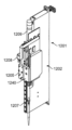
図7に示されるように、第2の分析前処理デッキ26は、バッチ蓄積領域210と加温器230との間に位置する2つ以上のバルクボルテクサー220(図7では、4つのバルクボルテクサーが2×2列に配置される)を含む。しかしながら、より多くの又はより少ないバルクボルテクサー220が含まれていてもよいし、代替的な構成であってもよい。例えば、システム10の一実施形態では、2つのバルクボルテクサー220を第2の分析前処理デッキ26上に配置することができる。各バルクボルテクサー220は、概して、本体222と、プラットフォーム226と、モーター228とを含む(図9に最もよく示される)。本体222は、約30個以下のレセプタクルの四角形アレイに配置された複数のレセプタクル224を含む。各レセプタクル224は、内部で第3のタイプの容器03を収納するような大きさに作られており、容器03の底端に係合して使用中のレセプタクル224内の回転を防止するために、各レセプタクル224の底端に配置された係合機構(図示せず)を含むことができる。本体222は、偏心モーター等のモーター228に結合されたプラットフォーム226上に配置される。モーター228は、オンにされると、プラットフォーム226及び本体222を振動させて、各試料内の微粒子を再懸濁させる。モーター228は、試料容器03内に含まれる試料のタイプによって決定することができる所定の時間間隔の間、動作するように制御される。
Bulk Vortexers As shown in FIG. 7, the second
システム10はまた、渦流コントローラーを含む。試料がボルテクサー220に引き渡される準備ができたとき、コントローラーは、ボルテクサー220が試料を受け取ることができるかどうかを判定する。プログラマー/コントローラーはまた、ボルテクサー220に、所定の時間間隔の間、或る特定の速度で動作するように指示する。渦流コントローラーは、ボルテクサーの動作条件を連続的に監視するフィードバックループを有し、ボルテクサーの動作条件が入力指示と一致しない場合にエラーメッセージを送信する。例えば、特定の動作速度が指示された場合、フィードバックループは実際の動作速度を監視する。動作速度が指示された速度と一致しない場合はエラーとなり、エラーメッセージが生成される。エラーがあれば、第1のエラーメッセージを生成することに加えて、ボルテクサーを再初期化する。第2のエラーメッセージが受信されると、ボルテクサーのサービス/交換のためのコマンドが発行される。このようにして、自動補正が最初に試みられた後、自動補正が成功しなかった場合は、ユーザー介入の要求が送信される。全ての場合において、ロボット410a又は410b等のピックアンドプレースロボットは、完了時にボルテクサー220から容器03を除去する。
加温器
加温器230は、図7に示されるように、バルクボルテクサー220とシャトルハンドリングアセンブリ240との間に配置される。加温器230は、実施されるアッセイによって決定されるような特定の時間の間、特定の温度で試料を加熱する。例えば、一実施形態では、加温器230は、100℃で平衡化した後、約9分~17分間、試料を約100℃~115℃以内まで加熱する。
Warmer A warmer 230 is positioned between the
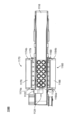
加温器230は、概して、熱伝導材料から作られ、互いの上に緊密な配置で積み重ねられた複数の加温プレート236から構成された本体232を含む。複数のレセプタクル234は、本体232の上面から加温プレート236を通って延在し、約110個以下のレセプタクルの四角形のアレイに配置される。例えば、加温器は、96個のレセプタクル(より多く又はより少ないことも可能)を含むことができ、24個又は32個の容器の複数のバッチを任意の時間に保持することができる。加熱素子237は、本体232の全体を通して均等に熱を分配するように各プレート236の間に挟まれている。熱電対、抵抗温度検出器(「RTD」)、又はサーミスタ等の温度センサー238が、本体232のほぼ中央の高さに配置されており、内部の温度を測定する。温度センサー238及び加熱素子237は、一定の設定点温度を維持するのを助けるために比例積分微分(PID)コントローラーに結合されてもよい。
Warmer 230 generally includes a
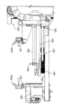
冷却器
冷却器290は、図11に示されるように、概して、ファン296と、1つ以上のプレナム294と、プラットフォーム又は取り付けプレート292と、冷却ラック298とを含む。ファンユニット296は、第2の分析前処理デッキ26の真上に配置され、プレナム294によってファンユニット296の上端部は部分的に囲まれている。プラットフォーム292は、プレナム294の上に着座し、空気を通過可能にする開口部(図示せず)を含む。冷却ラック298は、プラットフォーム292の開口部の上に配置される。冷却ラック298は、シャトル280又はプラットフォーム292に一体形成された構造とすることができる。冷却ラック298は、第3のタイプの容器03を内部で収納するような大きさに作られた複数のレセプタクル299を含む。開口部(図示せず)は、冷却ラック298の底端を通って延在し、レセプタクル299と連通している。これらの開口部は、レセプタクル299よりも小さく、これによって容器03はそこを通って落下しない。この配置により、ファン296の下側からファン296の側部へとファン296に空気を引き込み、プレナム294を通って冷却ラック280に上向きに排出され、試料容器03を対流によって冷却することができる。このボトムアップの冷却アプローチは、汚染物質が容器03のキャップ上に堆積するのを防止するのを助け、容器03が冷却ラック280の内外へ容易に移動することを可能にする。
冷却器290は、図7に示されるように、システム10の後部右隅に、シャトルハンドリングアセンブリ240に隣接して配置される。冷却器290は、概して、シャトルハンドリングアセンブリ240が加温器230と冷却器290との間のバッファーとして機能するようにこの位置に配置される。これは、冷却器280の周囲の空気流が加温器230内の熱分布に影響を及ぼすのを防止するのに役立つ。
シャトルハンドリングアセンブリ
図12A~図12Cは、シャトルハンドリングアセンブリ240を示している。シャトルハンドリングアセンブリ240は、概して、複数のシャトル280と、ベース250と、ベース250から延在する複数のシャトルドッキングステーション260a~260cと、駆動機構251と、移送アームアセンブリ270と、バーコードスキャナー(図示せず)とを含む。シャトルハンドリングシステム240は、試料容器シャトル280が少なくとも部分的に充填されるまで試料容器シャトル280を保持し、シャトル280をシャトル輸送アセンブリ300(後述する)との間で輸送するように構成される。
Shuttle Handling Assembly FIGS. 12A-12C show the
シャトル280は、図12Bに最もよく示されているように、本体284と、本体284の上面から本体284内に延在する複数のレセプタクル283とを含む。図示のシャトル280は、それぞれが第3のタイプの試料容器03を収納するような大きさに作られた12個のレセプタクル283を含む。しかしながら、他の実施形態では、システム10に結合された分析装置の容量に依存してより多い又はより少ないレセプタクル283を含むことができる。また、レセプタクル283は、2つの直線状の列281、282に配置されている。レセプタクル283は、3つ以上の直線状の列に配置することができるが、2列が好ましい。
複数の横方向開口部286が、本体284の両側で本体284を貫通して延在している。より具体的には、各横方向開口部286は、対応するレセプタクル283と交差し、これによって第1の列281のレセプタクル283は、本体284の第1の側部を貫通して延在する横方向開口部286と交差し、第2の列282のレセプタクル283は、本体284の第2の側部を貫通して延在する横方向開口部286と交差する。これらの横方向開口部286は、本体284の下端に配置され、レセプタクル283内に配置された容器03の下端へのアクセスを提供し、下端と連通する。
A plurality of
複数のノッチ288が本体284の底面内に延在している。本体284の周りに対称的に分布した4つのノッチ288があるのが好ましいが、より多くの又はより少ないノッチ288を設けることができる。例えば、3つのノッチ288が本体284内に延在してもよく、これはシャトル280がシステム10全体にわたって所望の向きで確実に配置されるのを助けることができる。各ノッチ288は、概して、半円筒形状を有する。これらのノッチ288は、シャトルハンドリングシステムの表面から延在する円筒形又は円錐台形の突起に係合するように構成され、これによってそのような表面上にシャトル280を保持する。シャトル280は、円筒形又は円錐台形の突起に対応する半円筒形ノッチ288を含むが、表面突起に一致する任意のノッチ形状を選択することができる。
A plurality of
1つ以上のスロット(図示せず)もまた、本体284の底面内に、概して、本体284の中央付近に延在している。これらのスロットは、移送アームアセンブリ270の係合機構又はフランジ(図示せず)に対応して、移送アームアセンブリ270がシャトル280を積み込んで保持するのを助ける。
One or more slots (not shown) also extend into the bottom surface of
ベース250は、駆動機構251と、移送アームアセンブリ270と、シャトルドッキングステーション260a~260cとを支持する構造部材である。駆動機構251は、移送アームアセンブリ270を動作させ、概して、一対のモーター257a及び257bと、一対の駆動シャフト258a及び258bとを含む。第1の駆動シャフト258aは、トルク印加形状を有する細長いシャフトである。例えば、第1の駆動シャフト258aは、正方形シャフト、六角シャフト、又はスプラインシャフトとすることができる。第2の駆動シャフト258bは、概して、細長いリードスクリューである。駆動シャフト258a及び258bは、ベース250の前端及び後端でベース250から延在する一対の端部プレート254a及び254bに回転可能に接続されている。駆動シャフト258a及び258bは、第1の駆動シャフト258aが第2の駆動シャフト258bの真上に位置するように、ベース250の上方で鉛直配置に互いに平行に配置される。レール252は、ベース250の上面に設けられ、第2の駆動シャフト258bの真下に配置される。
第1のプーリー255a及び第2のプーリー255b又は綱車は、第2の端部プレート254bに接続可能であるが、第1の端部プレート254aに接続されており、前後方向に互いにオフセットされている。第1のプーリー255aは第1の駆動シャフト258aに直接接続され、第2のプーリー255bは第2の駆動シャフト258bに直接接続され、これによってこれらのプーリー255a及び255bの回転がシャフト258a及び258bを回転させる。第1のモーター257a及び第2のモーター257bは、回転するステッピングモーターとすることができ、ベース250に接続されている。第1のモーター257aは第1のベルト256aを介して第1のプーリー255aに接続され、第2のモーター257bは第2のベルト256bを介して第2のプーリー255bに接続される。第1のモーター257a及び第2のモーター257bは、独立して動作可能であり、ステップ毎に同じ又は異なる回転角を有することができる。
A
図12Cに最も良く示されているように、移送アームアセンブリ270は、キャリッジ271と、キャリッジ271に回転可能に接続される移送アームとを含む。キャリッジ271は、支持部材271から延在する第1のフランジ部材272及び第2のフランジ部材273を含む。支持部材271は、レール252に摺動可能に接続されている。フランジ部材272及び273は、間に間隙を形成するように互いにオフセットされている。第1のフランジ部材272は、第1の開口部及び第2の開口部(図示せず)を含む。第1の開口部は、第1の駆動シャフト258aを摺動可能に受けるように構成され、同時に、例えば、第1の開口部内に配置された対応する形状のブシュによって、駆動シャフトが内部で自由に回転できるようにも構成される。例えば、第1の駆動シャフト258aが正方形シャフトである場合、第1の開口部は正方形の開口部を有する回転可能なブシュを含むことができ、第1の駆動シャフト258aがスプラインシャフトである場合、第1の開口部は駆動シャフト258aと係合するように構成されたスプラインを有する回転するブシュを含むことができる。第1のフランジ部材272の第2の開口部は、例えば、内部に配置されたねじ付きナットによってねじ山が付けられ、第2の駆動シャフト258bの回転がキャリッジ271を駆動するように第2の駆動シャフト258bと螺合する。
As best shown in FIG. 12C,
第2のフランジ部材273もまた、第1の開口部及び第2の開口部(図示せず)を含む。これらの開口部は、第1のフランジ部材272の第1の開口部及び第2の開口部と同様とすることができる。このように、第2のフランジ部材273の第1の開口部は、駆動シャフト258aがフランジ部材273に対して摺動可能且つ回転可能となるように、第1の駆動シャフト258aを受ける。また、第2のフランジ部材273の第2の開口部は、第2の駆動シャフト258bと螺合するようにねじ切りすることができる。いくつかの実施形態では、第2のフランジ部材273は、第2の開口部を含まなくてもよく、その代わりに、駆動シャフト258bの周りに部分的に位置決めされてその係合を回避するL字型等の形状にすることができる。
移送アームは、第1のアーム部材274と第2のアーム部材276とから構成される。第1のアーム部材274は、その第1の端部に開口部を含む細長いリンク機構である。この開口部は、第1の駆動シャフト258aを摺動可能に受けるように構成され、同時にまた、駆動シャフト258aの回転に連動して第1のアーム部材274を回転させるように駆動シャフト258aから印加されるトルクを受けるように構成される。例えば、第1のアーム部材274の開口部は、正方形、六角形、又は駆動シャフト258aの対応する幾何学的形状に係合するように構成されたスプラインを有することができる。第1のアーム部材274の第1の端部は、第1のフランジ部材272と第2のフランジ部材273との間の間隙内に配置され、これによってアーム部材274の開口部は、第1のフランジ部材272の第1の開口部及び第2のフランジ部材273の第1の開口部と同軸となる。
The transfer arm consists of a
第2のアーム部材276は、第1のアーム部材274の第2の端部に回転可能に取り付けられている。第2のアーム部材276は、第1のアーム部材274から離れた端部に、シャトル280の底端でスロットに係合するように構成された係合機構(図示せず)を含む。
A
ベルト278は、第2のフランジ部材273と第1のアーム部材274との間で第2のフランジ部材273の軸受275と係合している。ベルト278はまた、第2のアーム部材276に係合し、これによって第1の方向に回転する軸受275は、第1のアーム部材274に対して第2のアーム部材276を第1の方向に回転させ、第2の方向に回転する軸受275は、第2のアーム部材276を第2の方向に回転させる。
シャトルドッキングステーション260a~260cは、図12Aに最もよく示されるように、各々がベース250から延在する支持壁262と、支持壁262に対して片持ちであり、支持壁262から延在する横方向支持部材264とを含む。横方向支持部材264は、複数のフィンガー268を含み、その各々は隣接するフィンガー268間に空間269を部分的に画定する。隣接するフィンガー268及び単一の空間269は、単一のシャトル280のためのドッキング位置を画定する。したがって、各フィンガー268は、横並びに配置された2つのシャトル280を支持する大きさに作られている。各空間269は、移送アームアセンブリ270の第1のアーム部材274及び第2のアーム部材276(図12C)を収納するのに十分に大きいが、隣接するフィンガー268上に配置されたときにシャトル280がそこを通って落ちるのを防ぐように十分に小さい。
各フィンガー268は、その上面から延在する少なくとも2つの円筒状突起266を含む。各突起266は、横並びに配置された2つのシャトル280の隣接する凹部288内に部分的に嵌合するように十分に大きな直径を有する。言い換えれば、単一のフィンガー268は、互いに隣接して配置された2つのシャトル280の一部を支持し、各突起266は、そのような隣接するシャトル280によって共有され得る。突起266は、シャトル280を横方向支持部材264上に保持するのを助け、移送アームアセンブリ270による積み込みのためにシャトル280を正確に位置決めするのを助ける。
Each
第1のドッキングステーション260a及び第2のドッキングステーション260bは、それぞれのフィンガー268が互いに向かい合うように、互いに反対側に配置される。第1のドッキングステーション260a及び第2のドッキングステーション260bは、移送アームアセンブリ270が前後方向にベース250を横切るための走路を形成するように間隙によって分離されている。第1のドッキングステーション260a及び第2のドッキングステーション260bはまた、等しい数のシャトル280を保持するために同じ数のドッキング位置を含むことができる。例えば、図示のように、第1のドッキングステーション260a及び第2のドッキングステーション260bは、それぞれ8つのドッキング位置、合計16個のドッキング位置を含む。しかしながら、いくつかの実施形態では、各ドッキングステーション260a及び260bは、より多くの又はより少ないドッキング位置を含んでもよく、第1のドッキングステーション260aは、第2のドッキングステーション260bよりも多くの又は少ない位置を含んでもよい。
The
第3のドッキングステーション260cは、第1のドッキングステーション260aと位置合わせされ、第1のドッキングステーション260aよりもシステム10の正面近くに配置される。第3のドッキングステーション260cは、概して、第1のドッキングステーション260aよりも少ないフィンガー268及び空間269、したがってより少ないドッキング位置を含む。第1のドッキングステーション260a及び第3のドッキングステーション260cは、後述するように、第1の輸送アセンブリ300aに対して横方向の空間242を形成するように、間隙によって互いにオフセットされている。第3のドッキングステーション260cは、第1のドッキングステーション260aと位置合わせされているように示されているが、第3のドッキングステーション260cは、第2のドッキングステーション260bと位置合わせされる等の多数の他の場所に配置することができる。また、いくつかの実施形態では、第4のドッキングステーション(図示せず)を第3のドッキングステーション260cの反対側に設け、第2のドッキングステーション260bと位置合わせすることができる。
A
分析前システムコントローラーは、シャトル内の試料の配置を決定する。シャトルは、シャトルを分析前システムに関連する任意の分析装置に輸送できるようにロードされる。図22Fを参照すると、コントローラーは、各シャトルレセプタクルに関連するシャトルアドレスを有する。これらの「位置」は、図22Fにおいて1、2、...、nと指定されている。例えば、陽性/陰性対照群がシャトルにロードされる場合、対照群の容器はトレイの位置1及び2に配置される。対照群は、一方の側においてラックのシャトルロボット位置に対してラックの遠位位置にあり、他方の側の場合、位置1及び2はシャトルロボットアセンブリに近接しているという点で、位置1及び2は、シャトルハンドリングアセンブリ240に対して異なる位置を有することに留意されたい。このようにロードすることにより、任意のシャトルを任意の分析装置に輸送することが可能になる。シャトルの向きの知識を用いてインテリジェントなロードを可能にするために、シャトルは、分析前システムによって読み取られるバーコードを有する。分析前システムは、バーコードの位置からシャトルのレセプタクルの位置を知るようにプログラミングされている。図22Fに示されるように、分析システムが分析前システムの右側にある場合、シャトル内の1及び2の位置は内部(すなわち、分析装置に入るためのシャトルの最初の部分)になる。分析システムが分析前システムの左側にある場合、シャトルが分析装置に入るとき、シャトル内の1及び2の位置は外部になる。
A pre-analytical system controller determines the placement of samples in the shuttle. The shuttle is loaded so that the shuttle can be transported to any analyzer associated with the pre-analytical system. Referring to Figure 22F, the controller has a shuttle address associated with each shuttle receptacle. These "positions" are labeled 1, 2, . . . , n. For example, if a positive/negative control group is loaded onto the shuttle, the control group containers are placed in positions 1 and 2 of the tray. The control group was located at positions 1 and 2 in that on one side the rack was distal to the shuttle robot position of the rack and on the other side positions 1 and 2 were in close proximity to the shuttle robot assembly. 2 have different positions relative to the
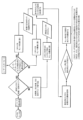
図22Dを参照すると、分析前システム20及び2つ以上の分析装置の動作を調整するワークフローコンピューティング装置1330によって2つ以上の分析装置からの検査が命令された試料のシャトル操作が示されている。本明細書で述べられるように、試料は、分析前システムによって受け取られるとき、一意的な識別子ラベルを有する。その一意的な識別子は、本明細書では受託番号と呼ばれる。シャトルは試料を第1の分析装置に運ぶ。試料を第2の分析装置に経路付けするためのワークフローが示される。
Referring to FIG. 22D, shown is the shuttle operation of samples ordered for testing from two or more analyzers by the
上述したように、シャトルが第1の分析装置から戻ると、シャトルはアンロードされる。一実施形態では、シャトルは完全にアンロードされる。他の実施形態では、第2の検査用の分析装置に経路付けさせるために、試料容器の一部又は全部をシャトル内に残してもよい。第2の検査用の分析装置は、第1の検査を行った分析装置と同じであっても異なっていてもよい。空になると、シャトルは停止場(parking lot)260a~260cに戻される。第2のアッセイ用のシャトル内に空のレセプタクルがある場合、「キューマネージャ(QUEUE MANAGER)」はバッチ蓄積領域210から他の試料を取り出して、指定された検査のためにシャトルを投入する。検査用にサンプリングされたバッチでシャトルがロードされると、シャトルはシャトルハンドリングアセンブリ240によってシャトル輸送アセンブリ上に配置される。
As mentioned above, the shuttle is unloaded when it returns from the first analyzer. In one embodiment, the shuttle is completely unloaded. In other embodiments, some or all of the sample containers may be left in the shuttle to be routed to the analyzer for a second test. The analyzer for the second test may be the same or different than the analyzer that performed the first test. Once empty, the shuttles are returned to
図7に示されるように、シャトルハンドリングアセンブリ240は、概して、加温器230と冷却器290との間に配置される。また、シャトルハンドリングアセンブリ240は、第2のデッキレベルに配置され、主としてシステム10の後部に配置されるが、シャトルハンドリングアセンブリ240の一部は、第1の分析前処理デッキ24の機器とシステム10の同じ側又は前側に配置される。より詳細には、シャトルハンドリングアセンブリ240は、第3のドッキングステーション260cがI/Oポート120及び第1の試料ラック空間110に隣接して配置されるように、システム10の正面に向かって延在し、一方で、第1のドッキングステーション260aは、冷却器290に隣接して配置され、第2のドッキングステーション260bは、加温器230に隣接して配置される。これにより、第2の分析前処理デッキ26に配置された試料容器03は、分析装置に分配するために、且つ分析装置から戻るシャトル280が第3のドッキングステーション260c上に配置され、これによって内部の容器03が空間110でラック50内に容易にロードされることを可能にするために、第1のドッキングステーション260a及び第2のドッキングステーション260b上でシャトル280内に容易にロードすることができる。
As shown in FIG. 7,
シャトル輸送アセンブリ
図13は、シャトル輸送アセンブリ300を示す。シャトル輸送アセンブリ300は、概して、第1の輸送トラック310a及び第2の輸送トラック310bを有するベースフレーム302を含む。しかしながら、いくつかの実施形態では、シャトル輸送アセンブリは1つの輸送トラックのみを有することができる。輸送トラック310a及び310bは、シャトル280の幅よりも僅かに広い側壁304によって画定される。これらの側壁304は、シャトル280が輸送されているときに、シャトル280がトラック310a及び310bのうちの一方から外れて移動することを防止するのに役立つ。一対の凹部306a及び306bは、各凹部が対応するトラック310a及び310bに沿って短い距離だけ延在するように、ベースフレーム302の一端に延在している。これらの凹部306a及び306bは、移送アームアセンブリ270が、下方に回転してトラック310a及び310bのうちの一方の上にシャトル280を配置する際、並びに、上方に回転してトラック310a及び310bのうちの一方からシャトル280を取り出す際の移送アームアセンブリ270のための隙間空間を形成する。
Shuttle Transport Assembly FIG. 13 shows the
凹部306a及び306bを画定する側壁上に複数のプーリー312が配置されている。このようなプーリー312は、それぞれ細長いベルトに接続されている。例えば、第2のトラック310bについては、一対のプーリーが、それぞれのベルト316及び317に接続されている。この点に関して、トラック310bは、凹部306bに隣接して凹部306bに沿って延在する一対の対向するベルトを含む。これにより、シャトルは、凹部306bを遮ることなくトラック310bのこの部分に沿って前進することが可能になる。トラック310aも同様に配置されている。したがって、各トラック310a及び310bは、その端部に少なくとも2つのベルトを含む。この構成は、移送アーム270によって上に配置されたときにシャトル280がベルト313、314上に確実に配置されるのに役立つように、輸送アセンブリ300の凹状端部にできるだけ近くにベルトを到達可能にする。
A plurality of
対向する一対のベルトは、それらのそれぞれのトラック310a及び310bの一部に沿って延在しており、凹部306a及び306bの端部近くで終端する。このような対向する対のベルトは、その後、単一のベルト314に移行し、これによって単一のベルト314は、トラック310bの長さの大部分に沿って延在し、単一のベルト313は、トラック310aの長さの大部分に沿って延在する。ベルト313、314、316、及び317は、コンベヤを含み、各トラックに沿ってシャトル280を移動させるために1つ以上のモーターによって駆動される。図示の実施形態では、第1の輸送トラック310a及び第2の輸送トラック310bのコンベヤは、反対方向に移動する。例えば、第2の輸送トラック310bのコンベヤは、シャトルハンドリングアセンブリ240から離れて、システム10に結合された分析装置に向かってシャトル280を移動させるように動作可能である。逆に、第1の輸送トラック310aのコンベヤは、分析装置から離れて、シャトルハンドリングアセンブリ240に向かってシャトル280を移動させるように動作可能である。
A pair of opposing belts extend along a portion of their
ベースフレーム302はまた、各トラック310a及び310bに対してベースフレーム302の各端部において存在センサー305を含む。したがって、各トラック310a及び310bは、一対の存在センサー305を有する。これらのセンサー305は、光センサーとすることができ、シャトル280が光フィールドを遮断するとき、シャトル280の存在を検出することができる。センサー305がシャトル280の存在により作動すると、信号がコンピューティングシステム(後述)に送られ、これによってシャトル280がトラック310a又は310bのいずれかに移送されたことをシステム10に通知する。コンピューティングシステムは、その後、コンベヤをオン又はオフにする必要があるか否か等の次のステップを決定することができる。
図7に示されるように、システム10は、各々がシャトル280をそれぞれの分析装置A1,...,Anに供給可能な2つのシャトル輸送アセンブリ300a及び300bを含む。2つが示されているが、システム10は、3つ以上の分析装置に供給するためにより多くのシャトル輸送アセンブリ300を含むように構成することができることを理解すべきである。第1のシャトル輸送アセンブリ300a及び第2のシャトル輸送アセンブリ300bは、第2の分析前処理デッキ26とほぼ同じ高さに配置される。さらに、第1のシャトル輸送アセンブリ300a及び第2のシャトル輸送アセンブリ300bは、システム10の長さに沿って延在し、互いに整列されており、間隙301によって分離されている(図7に最も良く示されている)。この間隙301は、シャトル280を第1の輸送アセンブリ300a又は第2の輸送アセンブリ300bのうちの一方に載置させるために、シャトル輸送アセンブリ240の移送アームアセンブリ270に自らを間隙301内に位置決めすることを許容する。さらに、第1の輸送アセンブリ300aは、第1のシャトル保持ステーション260aと第3のシャトル保持ステーション260cとの間に延在し、これによって第1のシャトル保持ステーション260aと第3のシャトル保持ステーション260cは、輸送アセンブリ300aの両側に配置される。
As shown in FIG. 7, the
シャトルのハンドリング及び輸送の方法
シャトルのハンドリング及び輸送の方法において、シャトルハンドリングアセンブリ240は、ロードされたシャトル280をシャトル輸送アセンブリ300a及び300bのうちの一方との間で移動させる。シャトル輸送アセンブリ300a及び300bは、シャトルを分析装置との間で輸送する。
Shuttle Handling and Transport Method In the shuttle handling and transport method,
1つの特定の例では、空のシャトル280が、第1のシャトルドッキングステーション260aの隣接するフィンガー268に着座し、突起266が凹部288内に部分的に配置される。シャトル280の各レセプタクル283は、内部に配置された容器03を有する(これの特定の詳細は後述する)。
In one particular example, an
シャトル280に容器が一旦充填されると、第1のモーター257aがオンにされ、第1のプーリー255a及び第1のシャフト258aを第1の方向に回転させる。この時点で、移送アームアセンブリ270は、概して、横方向空間242と整列して配置される(図12Aに最もよく示されている)。第1のシャフト258aが回転すると、第1のアーム部材274は、横方向空間242に向かう第1の方向に回転し、一方で、第2のアーム部材276は、横方向空間242から離れる第2の方向に回転し、これは、第2のアーム部材276の係合機構を略上方に向けて保持する。第1のアーム部材274は、第1の輸送アセンブリ300aと第1のシャトルドッキングステーション260aとの間の横方向空間242を通過するように連続的に回転される(図7を参照)。第1のモーター257aは、第1のアーム部材274が約90度に配置され、ベース250と略平行になるまで作動される。
Once
その後、第2のモーター257bがオンにされ、第2のプーリー256及び第2のシャフト258bを第1の方向に回転させ、これによって移送アームアセンブリ270はシステム10の後方に向かって駆動される。第1のアーム部材の略水平な位置により、移送アームアセンブリがシステム10の後部へ駆動されるとき、第1のアーム部材274及び第2のアーム部材276は、第1のシャトルドッキングステーション260aの横方向支持部材264の下を通過する。第1のアーム部材274及び第2のアーム部材276が、シャトル280の下の空間269と整列されると、第2のモーター257bは停止する。
次いで、第1のモーター257aがオンにされて、これによって第1のプーリー255a及び第1の駆動シャフト258aは、第2の方向に回転する。これにより、第1のアーム部材274及び第2のアーム部材276は、シャトル280へ向かって回転する。第1のアーム部材274が鉛直位置に向かって連続的に回転するとき、第2のアーム部材276は上方に向いたままであり、シャトル280の底部と係合する。次いで、シャトル280は、第1のシャトルドッキングステーション260aから持ち上げられ、一方で、第2のアーム部材276は、シャトル280を直立状態に維持して上方に向ける。第1のアーム部材275が鉛直位置に達すると、第1のモーター257aは停止する。
その後、第2のモーター257bがオンにされて、これによって第2のプーリー255b及び第2のシャフト258bは、移送アームアセンブリ270をシステム10の前方に向けて駆動する第2の方向に回転する。第1のアームの略鉛直な位置により、移送アームアセンブリ270は、第1のシャトルドッキングステーション260aと第2のシャトルドッキングステーション260bとの間の間隙を通って自由に移動する。第2のモーター257bは、移送アームアセンブリ270が第2のシャトル輸送アセンブリ300bの第2の輸送トラック310bに到達し、第1のアーム部材274及び第2のアーム部材276が第2の凹部306bと整列されるまで作動される。
移送アームアセンブリ270がこの位置にくると、第1のモーター257aがオンになり、これによって第1のアーム部材274を第2のトラック310bに向かって回転させ、第2のアーム部材276を第2のトラック310bから離れて回転させ、これによりシャトル280を直立状態に維持する。第1のアーム部材274及び第2のアーム部材276が凹部306bを通過すると、シャトル280の一端が第2のトラック310bのコンベヤベルト上に着地する。シャトル280が着地しているとき、シャトル280はセンサー305の光フィールドを横切り、システム10に第2のトラック310b上のシャトル280の存在を通知する。次いで、システム10は、別のシャトル280がトラック310bの他端に位置している等の他の状況に応じて、第2のトラック310bをオンにするかどうかを決定する。シャトル280が着地すると、シャトル280は、第2のアーム部材276との係合が解除され、第2のトラック310bの端部に到達するまで、システム10の左側面に結合された分析装置に向かって移動し、第2のトラック310bの端部において、別のセンサー305が作動して、それによりシステム10にシャトルの位置を通知する。この時点で、シャトル280は、アセンブリ300bが分析装置内に延在するか否かに応じて、分析装置の内部にあっても、分析装置の近くにあってもよい。
With the
分析装置による試料の分析が完了すると、シャトル280は、第1のトラック310a上に配置され、その一端に位置するセンサー305を作動させる。これにより、第1のトラック310a上のシャトルの存在がシステム10に通知され、更なる動作のための命令が決定/提供される。シャトル280は、シャトル280が他のセンサー305を作動させる第1のトラック310aの凹んだ端部に向かって移動する。シャトル280の一部が凹部306aの上に着座するように、ベルト313及びベルト314がオフにされる。
When analysis of the sample by the analyzer is completed,
第1のアーム部材274が略水平位置にある移送アームアセンブリ270は、第1のトラック310aと整列するように第2の駆動シャフト258bによって駆動され、これにより第1のアーム部材274及び第2のアーム部材276は、輸送アセンブリ300bの下に配置される。第1のモーター257aが作動され、第1のアーム部材274が鉛直位置に向かって回転する。これが行われるとき、第2のアーム部材276は第1の凹部306aを通過してシャトル280の底部と係合し、それによって第1のアーム部材274が鉛直になるまでシャトル280を第1のトラック310aから持ち上げる。
The
その後、第2のモーター257bは、第3のドッキングステーション260cの空間269と整列されるまで、輸送アセンブリ270をシステム10の前方へ向けて駆動するように再び作動される。次いで、第1のモーター257aは、第3のドッキングステーション260cの横方向支持部材264に向かって第1のアーム部材274及び第2のアーム部材276を回転させ、次いで、隣接するフィンガー268の間を通過し、シャトル280を第3のドッキングステーション260cにドッキングさせる。ベルトが空であるときは、移送アームアセンブリ270は、横方向空間242と整列した位置に戻るように割り出されてもよい。
この方法は、移送アームアセンブリ270及び輸送アセンブリ300bを使用して分析装置との間でシャトルを移動する一例である。移送アームアセンブリ270は、180度の円弧内の様々な角度によって第1のアーム部材274及び第2のアーム部材276を間欠的に回転させ、キャリッジ271をベース250に沿って前後に駆動することによって、第1のドッキングステーション260a、第2のドッキングステーション260b、及び第3のドッキングステーション260c、並びに、第1の輸送アセンブリ300a、及び第2の輸送アセンブリ300bの間において任意の順序でシャトル280を移動することができることを理解すべきである。
This method is an example of using
シャトル輸送の監視及びエラープロトコル
システム10は、シャトルハンドリングアセンブリ240とシャトル輸送アセンブリ300a及び300bとを含むことができるシャトル処理又は輸送モジュール/サブシステム750(図19を参照)の動作を制御するシャトルプロセッサを有する。そのようなプロセッサは、以下でより詳細に説明されるシステム10のコンピューター制御装置802の1つ以上のプロセッサ804に関連付けられてもよい。シャトルプロセッサは、処理エラーを識別し、通知を作業者に送信し、或る特定の検出された処理エラーに応じてサブシステムをシャットダウンする処理ロジックを有する。例えば、ハンドリングアセンブリ240、輸送アセンブリ300a、及び/又は輸送アセンブリ300bは、シャットダウンされてもよい。しかしながら、或る特定の状況に応答して、サブシステムの動作は継続するが、検出された全てのエラーに応答してシャットダウンするのを回避するために調整(再試行、半分の速度での動作等)が行われる。或る特定の検出された条件に応答して、サブシステムは、エラーの原因(すなわち、故障したセンサー、間違った位置のシャトル280等)を特定するために、予めプログラミングされたルーチンを実行する。例えば、シャトルプロセッサは、シャトル輸送アセンブリ300a及び300bが起動時に正しく動作していることを保証するための初期化プロトコルを有する。動作不良表示は、エラーメッセージであって、これに応答してシャトルプロセッサが不良状態に入り、サービスコールが出されるエラーメッセージが出される前に1回再試行することを可能にする。シャトルベルト313、314は、それらが正しく作動していることを保証するために動作中に定期的に初期化される。ここでも、動作不良が検出されると、故障が示される前に再試行され、これがシステム10によって作業者に報告される。
Shuttle Transport Monitoring and
シャトルプロセッサはまた、シャトル輸送アセンブリ300a及び300bの、それぞれの分析装置との動作を監視し調整する。シャトル輸送アセンブリ300a及び300bは、分析装置が前処理された試料のバッチの準備ができているという要求を受信すると、シャトル280が取り出され、アセンブリ300a又は300bのいずれかのベルト上に置かれ、これはシャトルを指定された分析モジュール(A1、A2、又はAn)に輸送する。システム10は、シャトル280を選択されたシャトル輸送アセンブリに移送する前にベルトが空であることを保証し、それぞれの分析装置が試料を受け取る準備ができていることを保証する。そうでなければ、システム10は、前のバッチが取り除かれるまで待つ。
The shuttle processor also monitors and coordinates the operation of
さらに、シャトルハンドリングアセンブリ240の動きは監視され、コンプライアントな動作を保証する。モーションエラー、又はモーター257a及び257bのエンコーダーカウント等のエンコーダーカウントの不一致が、移送アームアセンブリ270の動作に対して検出された場合、1回の再試行が低速で許可され、その後、動作又は応答のエラーが検出され、終了モジュール動作エラーが発行されると、作業者に通知される。正しいシャトル280が輸送されていることを確認するだけでなく、アセンブリ240自体が適切に動作していることを保証するために、アセンブリ240にシャトルバーコードリーダー(図示せず)が設けられる。1回の再試行後にバーコードが依然として読み取られない場合、シャトル280は、エラーがバーコードであるのか又はシャトル280の不在であるのかを判定する位置に移動される。バーコードが読み取られたが予測されたバーコードでない場合、シャトル280は、シャトルアンロード領域260cに輸送され、そこで、その内容物は、ラック空間110に配置された出力ラック内に置かれる。
Additionally, movement of the
同様に、センサーは、分析装置からシステム10へのシャトル280のハンドオフ(handoff:引き継ぎ)の情報をシャトルプロセッサに提供する。アセンブリ300a及び300bのそれぞれのベルト313、314は、正確な操作のために監視される。ベルトエラーが検出されると、ハンドオフ操作は終了し、サービスコールが示される。分析装置から分析前システム10への移行時にモーションエラーが検出された場合、ハンドオフ操作が停止され、作業者にエラーの通知が送信される前に、低減されたベルト速度での1回の再試行が許可される。センサーが、分析装置(A1、A2、An)と分析前システム10との間のインターフェースに設けられ、一方から他方へのシャトルの通過を検出する。
Similarly, the sensors provide information to the shuttle processor of the handoff of
分析装置は、シャトル280が分析装置から分析前システム10に戻されるときに、分析前システム10にハンドオフメッセージを提供する。ハンドオフメッセージがない場合、これは分析装置に問題があることを示す。結果として、分析装置によって処理されている試料のバッチに関連する全ての残りのシャトル280(もしあれば)は、出力ラック260cに送られ、そこで試料は空間110のラック50にアンロードされ、「未処理」と指定される。ハンドオフメッセージが分析装置から受信されると、分析装置から分析前システム10へのアセンブリ300a及び300bのうちの一方の戻りベルトがオンになる。センサーはベルト動作を通達し、モーションエラーが検出された場合、ベルト113、114は一時停止され、エラーメッセージが送信される。
The analyzer provides a handoff message to
センサーはまた、シャトル280が分析装置と分析前システム10との間のインターフェースに存在するかどうかを示す。分析装置がハンドオフメッセージを送信し、分析前システム10がシャトル280を受け取る準備ができている場合、ベルト113、114が起動する。シャトルが受け取られない場合、ハンドオフは停止され、サービスが必要である通知を作業者に送信する。シャトル280がインターフェースで検出された場合、シャトルプロセッサは、ハンドオフが完了したという信号を分析装置(A1、A2、An)に送る。そのようなメッセージが受信されると、プロセスは完了する。メッセージが受信されない場合、これは、シャトルの詰まり、センサーの問題等のエラーを示し、作業者に通知される。
The sensor also indicates whether
或る特定のエラーは、他のエラーと異なる可能性がある特定のプロトコルを有することができる。例えば、分析装置によって使用されるピペット先端がシャトル280内の試料容器に張り付いている場合、分析モジュール(A1、A2、An)は、シャトルを固着した先端を有するものとしてシャトルにフラグを立てる。このようなシャトル280をドッキングステーション260c等の保持領域に運ぶロジックがシャトルプロセッサによって提供される。さらに、シャトルに特別な処理が必要であることが作業者に通知される。保持領域が満杯である場合、分析前システム10は、保持領域が空になるまで、それ以上シャトルを受け取らない。
Certain errors may have specific protocols that may differ from other errors. For example, if a pipette tip used by the analyzer sticks to a sample container in
シャトル280がアンロードされる地点に移送されると、シャトル280の受け取りを確認するメッセージが分析モジュール(A1、A2、An)に送信される。シャトル280がアンロード地点260cに検出されない場合、配置が再試行され、バーコードリーダーを介してシャトル280の存在を確認する。シャトル280が依然として検出されない場合、システム10は、アンロードセンサーが故障しているというエラーを発行する。次に、シャトルプロセッサは、ピックアンドプレースロボット410aに命令して、第3のタイプの試料容器03をシャトル280から(1つずつ)アンロードさせて、第3のタイプのx個の容器03を空間110のラック50に配置させる。
When the
システム10は、分析装置(A1、A2、An)が分析前モジュール10に試料のバッチを受け取る準備ができているという指標を送信するときの処理においてエラーを監視する。これに応答して、分析前システム10(すなわちプロセッサ)は、関連するシャトル280を送る。システムが中断した場合(例えば、作業者の手動介入)、システム10は、試料がロードされ、停止中の処理を待機しているシャトル280上のバーコードを読み取ることによって正しいシャトル280が送られたことを確認する。各シャトル280の位置は、後述のメモリ804等のメモリに記憶され、コマンドがシャトルハンドラー240に送信されて、関連するシャトル280をその既知の位置から取り出し、適切なシャトル輸送アセンブリ300a及び300b上に配置する。
分析前システム10は、特定のシャトル280とその「停止スポット」との間の関連付けを既にメモリに記憶している。検出された不一致がある場合、シャトル280は現在の位置から持ち上げられ、検査位置に移動され、実際のエラー又はセンサーエラーがあるかどうかを判定するために評価される。センサーエラーが生じた場合、分析前システム10は、シャトル280をドッキングステーション260a~260cのうちの1つ等の空の場所に置き、処理を続行する。シャトル280が存在すべきではないときに存在していると判定された場合、又は存在すべきときに存在していないと判定された場合、システムエラーが登録され、シャトルの輸送が停止される。
システム10が、シャトル280の在庫が在庫センサー読取値と一致すると判断した場合、シャトルハンドリングアセンブリ240の移送アームアセンブリ270が正しい側にあるかどうかを判定するためのルーチンに入る。言い換えれば、ルーチンは、移送アームアセンブリ270が、指定されたドッキングステーション260a~260cからシャトル280を取り出す位置にあるかどうかを判定する。例えば、アセンブリ270がドッキングステーション260bの下に位置するように回転される場合、アセンブリ270は、ドッキングステーション260aからシャトル280を取り出すための正しい位置にはない。必要に応じてアセンブリ270を正しい側に移動させるルーチンが提供される。モーションエラーが検出された場合、ロジックは、エラーメッセージが送信される前に低速で1回再試行することを許可する。
If the
移送アームアセンブリ270がシャトル280をピックアップするために位置決めし、シャトル280をピックアップし、シャトル280をバーコードリーダーまで移動させ、輸送アセンブリ300a又は300b上にシャトル280を配置して、分析装置(A1、A2、An)へ送られるとき、移送アームアセンブリ270の移動は、監視され続ける。モーションエラーが検出された場合、動作は減速されて試行される。モーションエラーが再び発生すると、実行が終了し、作業者にエラーが通知される。バーコードリーダーがシャトルのバーコードを読み取ることができないか、又は予測していないコードを読み取った場合は、コードが再び読み取られる。エラーが続く場合、システム10は、得られたシャトル280が正しいシャトルでないと判断する。作業者は介入が必要であることを通知される。
シャトル280がベルト上に置かれると、センサーはその存在を検出する。センサーがシャトル280を検出した場合、移送アセンブリはシャトル280を分析モジュールに移送する。シャトル280の指定された分析装置への進行を監視するために、移送アセンブリ300a及び300bにもセンサーが設けられる。シャトル280が分析装置へ移送されていないとセンサーが判断した場合、システム10が顧客の介入のためにメッセージを送信する前に、減速した1回の再試行が行われる。
When the
システム10はまた、電力損失の場合に再起動時にシャトル輸送を自動的に管理することができる。一実施形態では、分析前システム10は、i)I/O及び分析後モジュール710(以下に更に説明する)、ii)シャトル輸送アセンブリ300a及び300b、iii)シャトルハンドリングアセンブリ240、iv)シャトルドッキングステーション260a及び260b、並びにv)シャトルペナルティボックスを含む、通常の操作に戻る前にシャトル電力回復のための一連の機能を実行するセンサー及びロジックを有する。電力損失の場合に分析前システム10によって開始されるルーチンの例は、以下の通りである。概して、これらのルーチンは、センサー及びシステム10のメモリから再呼び出しされたシステム10の最後の既知の状態と共に、サブシステム750を含むシステム10を予期しない電力損失の後に準備のできた状態に戻すために使用される。
I/O及び分析後モジュール710に関しては、全てのシャトル280が空になるまでフラグが通常処理用にセットされ、シャットダウン時に中に含まれる試料管がステーション110の出力ラック50内に配置される。ステーション260cにおける保持位置もまた、シャトル280の存在に対して感知される。シャトルが保持位置にある場合、シャトルはアーム270によって取り出され、そのバーコードが読み取られ、シャトル280はドッキングステーション260cに戻される。
With respect to the I/O and
シャトル輸送アセンブリ300a及び300bに関して、そのセンサーは、シャトル280がそのベルト上に配置されていることを示すためにスキャンされる。シャトル280が検出されない場合は、輸送ベルト113、114が走行する。内部センサー(すなわち、アセンブリ240に最も近いセンサー)がトリガーされると、シャトル280が検出される。シャトル280が間隙242に隣接するシャトルのピックアップ/ドロップオフ位置に存在することをセンサーが示す場合、シャトルバーコードが読み取られ、シャトル280はその試料容器を場所110のラック50にアンロードするためのキューに入れられる。分析装置に隣接する送達/戻し位置にシャトル280が検出された場合、トラック113、114が走行し、内部センサーがトリガーされた場合、シャトルはバーコードと関連付けられ、アンロードのためのキューに入れられる。内部センサーがシャトル280によってトリガーされない場合、センサー又はトラックのエラーが示される。
For
シャトルプロセッサは、シャトルハンドリングアセンブリ240をリセットする。シャトルハンドリングロボット240のアームアセンブリ270は、そのホーム位置に配置される。アーム270が直立位置にある場合、アーム270は、アーム270に接続されたシャトル280を有する可能性があり、シャトル280は除去する必要がある。これに関して、シャトル280と共にアームアセンブリ270は、次に、シャトルバーコードを読み取ることができるようにバーコードリーダーまで移動される。その後、シャトル280は、シャトル輸送アセンブリ300a及び300b(利用可能であれば)上に配置される。しかしながら、バーコードが読み取れない場合は、シャトル在庫が更新される。次いで、シャトルハンドリングアセンブリ240が利用可能となる。
The shuttle processor resets
ドッキングステーション260a及び260bに関して、そのようなドッキングステーション260a及び260bは、シャトルハンドリングアセンブリ240を使用して空にされ、停止場からシャトル280を持ち上げ、それをバーコードリーダーに提示し、バーコードが読み取られて在庫が更新された後にシャトルをそのそれぞれのドッキングステーションに戻す。バーコードが読み取られない場合、システム10は、シャトルが存在するか否かを判定するセンサーを有する。シャトル280が存在する場合、シャトル280は取り出された空間に戻され、システムはその問題に作業者の注意を向けさせる。シャトル280がない場合、停止スポットは在庫において空であるとマークされる。どちらの場合でも、在庫は情報によって更新される。
With respect to
始動前に、全てのシャトル280は、トラック310a及び310bからアンロード位置又は停止場260a~260cのいずれかに必要に応じて移動される。
Prior to start-up, all
シャトルペナルティボックスは、ペナルティボックス内のシャトル280について作業者にどのように指示するかを決定するプロセスを開始するセンサーを有する。シャトル280が検出された場合、作業者にメッセージが送信され、システム10は一時停止に入る。次いで、作業者は、システム10を開き、シャトル280を取り除くか、又はシャトル280内の試料容器を手でスキャンすることができ、その後、シャトル280が取り除かれた/交換されたことを作業者が示す。シャトル280が検出されない場合、作業者は、対処するように再度メッセージを受け、シャトル280を戻すように再試行する。シャトル280が検出されなければ、システム10をシャットダウンし、作業者に通知し、エラーを報告する。シャトル280が固定又は交換された場合、システム10のドアは閉じられ、システム10は動作を再開する。ドアが閉じることができなければ、システム10の動作は停止し、ドアセンサーの故障が作業者に報告される。ドアが閉じられている場合、シャトルハンドリングシステム240は、試料容器をバーコードスキャンし、容器がアンロード及びバーコード化されるアンロード位置に移動させる。
The shuttle penalty box has sensors that initiate the process of determining how to instruct the operator about the
上述したシャトル輸送エラープロトコル及び電力損失プロトコルに関して上述したセンサーは、当該技術分野で十分に理解されているセンサーを含むことができることを理解すべきである。例えば、光センサーを用いてシャトルの有無を判定することができ、モーターエンコーダーを使用して、アセンブリ300a及び300b並びにラックハンドリングアセンブリ240の輸送アームアセンブリ270のベルト位置を決定することができる。
It should be appreciated that the sensors described above with respect to the shuttle transport error protocol and power loss protocol described above may include sensors well understood in the art. For example, optical sensors can be used to determine the presence or absence of a shuttle, and motor encoders can be used to determine the belt position of
シャトルクランプ
図12Dに示されるように、ドッキングステーション260cは、任意選択的に、シャトルクランプ機構241を含むことができる。この機構241は、ステーション260cにドッキングされたシャトル280を拘束するのを助けるために利用することができ、個々の使用済みの容器03がシャトル280から取り除かれている間に、シャトル280が停止スポットから偶発的に持ち上がることがないようになっている。クランプ機構は、電源によって電力を供給されるものではなく、クランプアーム245と、作動アーム246と、ベース248と、ねじりばねとを含む。クランプアーム245は、クランプ位置にあるときにシャトル280の側部スロット286に係合する突起244を含む。クランプアーム245は、図示のように、ねじりばね247に接続され、クランプアーム245から突出するレバー249とねじりばね247との間の係合を介してクランプ位置に付勢されている。クランプアーム245は、ベース248内のクラッチを介して非クランプ位置(図示せず)にロックされ得る。クランプ位置と非クランプ位置との間のクランプアーム245の移動は、作動アーム246とアームアセンブリ270から延在するパドル279との間の係合を介して達成される。したがって、アームアセンブリ270は、作動アーム246を過ぎて正面方向に移動すると、非クランプ位置に作動アーム246を移動させる。これに関して、アームアセンブリ270は、ドッキングステーション260cでシャトル280を配置又は除去することができる。アームアセンブリ270が後方向に移動すると、パドル279が作動アーム246を作動させてクラッチを解放し、ドッキングステーション260cに存在する場合に、クランプアセンブリ241がシャトル280に係合することを可能にする。
Shuttle Clamp The
傾斜エレベーター
図12Eは、傾斜エレベーター100を示す。傾斜エレベーターは、デッキ24とデッキ26との間でラック50を昇降させる。したがって、容器03がステーション260cでシャトル280から降ろされると、容器03はエレベーター100によって保持されるラック50上にロードされる。この点に関して、エレベーター100は、傾斜軸に沿って延在する細長い部材104に接続されたラック保持構造体102を含む。ラック保持構造体102は、デッキ24のステーション110とステーション260cに隣接する位置との間で細長い部材104に沿って移動する。
Gradient Elevator FIG. 12E shows the
デッキ間ロボット
図14及び図15は、ラックハンドラーロボット320及びラックエレベーター360をそれぞれ示している。ラックハンドラーロボット320、ラックエレベーター360、及び傾斜ラックエレベーター100(上述)は、デッキ間ロボット又はラックエレベーターロボットシステムを含む。このようなラックエレベーターロボットシステムは、デッキ22、24、及び26の間でラック30、40、及び50を輸送することができる。例えば、ラックハンドラーロボット320は、ラック30、40、及び50を格納デッキ22と第1の分析前処理デッキ24との間で移動させる。さらに、ラックエレベーター360は、格納デッキ22と第2の分析前処理デッキ26との間でラック50を輸送し、傾斜ラックエレベーター100は、デッキ24とデッキ26との間でラック50を輸送する。しかしながら、デッキ24及び26が異なる鉛直方向の高さで配置されていない分析前システムでは、ラックエレベーターロボットシステムは、ラックハンドラーロボット320のみを含むことができることを理解すべきである。換言すると、デッキ24とデッキ26との間の鉛直方向高さの差は、システム10が鉛直方向に引き伸ばされたとき、システム10の前後幅を最小にするのに役立つ。したがって、エレベーター100及び360は、この鉛直方向の高低差に対処するのに役立つ。しかしながら、システム10は、デッキ24とデッキ26とが同じ高さにあり、ロボット320を両方のデッキに到達可能にする水平方向の間隙がデッキ24とデッキ26との間に設けられるように構成することができる。
Inter-Deck Robot Figures 14 and 15 show the
ラックハンドラーロボット
ラックハンドラーロボット320は、概して、水平トラック部材330と、鉛直トラック部材340と、ラックキャリッジ350とを含む。水平トラック部材330は、細長いベース332と、ベース332の表面からその長さに沿って延在する1つ以上のレール334とを含む。鉛直トラック部材340は、同様に、細長いベース342と、ベース342の表面からその長さに沿って延在する1つ以上のレール344とを含む。鉛直トラック部材340は、鉛直部材340の底部に接続され、鉛直部材340の底部から延在する水平レールマウント345を介して水平トラック部材330のレール334に摺動可能に接続されている。鉛直トラック部材340は、鉛直部材340が鉛直方向に且つ水平部材330に対してほぼ直角に延在するように、且つ鉛直部材340が水平部材330に沿って左右方向に摺動可能なように、水平レールマウント345に接続される。
Rack Handler Robot The
鉛直トラック部材340は、例えば、Festo Linear Motor Actuator(「FLMA」)(Festo AG&Co. KG Esslingen Neckar、ドイツ)等のリニアモーターを介して水平部材330に沿って磁気的に駆動される。ケーブルスリーブ339は、鉛直トラック部材340が移動されるときに、ケーブルを保護し適所に保持するために、電気ケーブル用に水平部材330に隣接して設けられてもよい。代替的な一実施形態では、プーリー又は綱車が、水平部材330のベース332及び水平レールマウント345に取り付けられ、鉛直トラック部材を左右方向に動かすためにベルトと併用される。
The
ラックキャリッジ350は、ベース351と、鉛直レールマウント352と、第1のラック支持部材354a及び第2のラック支持部材354bと、ラック移動アーム322とを含む。キャリッジ350は、概して、水平レールマウント345の真上に配置され、鉛直レールマウント352を介して水平レールマウント345に対して移動可能である。鉛直レールマウント352は、鉛直部材340のレール344に摺動可能に接続され、ベース351は、鉛直レールマウント352に片持ち支持される。
第1のラック支持部材354a及び第2のラック支持部材354bは、ラック30、40、及び50の下向きの面37、47、及び57に係合するように構成された平坦な上向きの面357を含む細長い梁である。ラック支持部材354a及び354bは、互いに実質的に平行であり、それぞれ実質的に同じ長さ「L」(図14Eに最もよく示されている)を有する。この点に関して、第1のラック支持部材354aはベース351に接続され、第2のラック支持部材は鉛直レールマウント352に接続されて、これによって第1のラック支持部材354a及び第2のラック支持部材354bは、それぞれラック30、40、及び50の対向する周壁34、44、及び54間の距離に実質的に等しい距離だけ離間している(図14Bに最も良く示されている)。これにより、ラック30、40、50の一部が中に嵌合し、ラック支持部材354a及び354bが、それらの周壁を介してラック30、40、50に係合してラック30、40、50を支持する間隙が提供される。さらに、第1のラック支持部材354aと第2のラック支持部材354bとの間のこの間隙は、前後方向に開いている。間隙の前後の長さは、ラック支持部材354a及び354bの長さ「L」によって画定される。
First
図14B~図14Fに最もよく示されるように、ラック移動アーム322は、ラック支持部材354aとラック支持部材354bとの間の間隙内に配置され、ベース351に取り付けられたモーター356に接続される。モーター356は、ラック移動アーム322を、水平トラック部材330の長さを横切る2つの方向のうちの一方の方向に外方に延ばすように動作可能である。図示の実施形態では、ラック移動アーム322は、第1の細長い部材326及び第2の細長い部材328を含む。第1の細長い部材326は、ベース351上に配置された回転カップリング324に接続される。ラック移動アーム322は、支持部材354a及び354bの間に配置される。第2の細長い部材328は、回転カップリング324から離れた第1の細長い部材326の端部に回転可能に接続され、エルボー327を形成する。第2の細長い部材328は、第1の細長い部材326から離れたその端部に係合機構又は突起329を含む。係合機構329は上方に突出しており、ラック30の係合部材39及びラック40及び50の係合部材と係合するように構成され、これによってラック移動アーム322は、ラック支持部材357a及び357b上にラックを引っ張り、ラック支持部材357a及び357bからラックを押すことができる。
As best shown in FIGS. 14B-14F,
この点に関して、プーリー325が、エルボー327において、第2のアーム328に固定して取り付けられるとともに第1の細長いアーム326に回転可能に取り付けられている。ベルト323がプーリー325及び回転カップリング324に接続されており、これによってモーター356の動作を介した回転カップリング324の回転が、第2の細長い部材328を第1の細長い部材326に対して回転させる。この構成により、ラック移動アーム322は、図14E及び図14Fに最もよく示されるように、ラック30、40、50を水平トラック部材330の一方の側から他方の側へと移動させることができる。このように、ラック移動アーム322は、前方位置、後方位置、及び中間位置の少なくとも3つの異なる位置を有する。
In this regard,
中間位置では、第1の細長い部材326及び第2の細長い部材328は、概して、ラック支持部材354a及び354bの長さ「L」に対して垂直に整列され、係合機構329は、ラック支持部材354a及び354bの間の間隙内に配置される。この位置では、エルボー327は、支持部材354aを超えて左右方向に突出することができる(一例として図14Fを参照)。図示の特定の実施形態では、エルボーは、鉛直トラック部材340内の覆われた空間内に突出している。ラック移動アーム322は、ラックがラック支持部材354a及び354b上に配置される場合、及び/又は走路25を横切るために、概して中間位置をとる。
In the intermediate position, first
後方位置(図14Eに最も良く示されている)では、第2の細長い部材328は、第1の細長い部材326に対して斜めに角度付けされ、係合機構329は、前後方向にラック支持部材354a及び354bの長さ「L」を越えて、間隙の外側に位置する。細長い部材326及び328は、ラック移動アーム322が中間位置から後方位置に移動するとき、係合機構329がラック支持部材354a及び354bに平行な直線方向に移動し、間隙を通って前進させるとき、ラック支持部材354a及び354bの間に位置し続けるように構成されることに留意されたい。前方位置は後方位置に類似しているが、相違点は、ラック移動アーム322が後方位置にあるときとは反対側のラック支持部材354a及び354bの端部に係合機構329が位置することである。ラック移動アーム322は、概して、ラックをラック支持部材354a及び354bから移送するか、又はラックをラック支持部材354a及び354b上に移動するときに、これらの位置の1つをとる。
In the rearward position (best shown in FIG. 14E), the second
上述したように、鉛直マウント352は、鉛直トラック部材340に接続されている。複数のプーリー349又は綱車は、水平部材342の1つ以上の側面に及び鉛直マウント352に接続されている。これらのプーリー349は、1つ以上のベルト347を介して接続されている。モーター348は鉛直部材340に取り付けられており、モーター348はベルト347及びプーリー349を駆動し、鉛直マウント352を鉛直トラック部材340のレール344に沿って2つの直線方向(すなわち、上下)に駆動可能にする。これにより、キャリッジ350を鉛直方向に移動させることができる。ケーブルスリーブ341は、キャリッジ350が移動するときにケーブルを保護し適所に保持するために、モーター348に給電する電気ケーブル用に鉛直トラック部材340に隣接して設けることができる。
As noted above,
ラックハンドラーロボット320は、水平トラック部材330がシステム10の長さに沿って左右方向に延在するように、格納デッキ22内に配置された走路25内に位置する。さらに、鉛直部材340は、水平トラック部材330から離れた鉛直トラック部材340の端部が第1の分析前処理デッキ24の上方に延在するように、第1のラック輸送アセンブリ300a及び第2のラック輸送アセンブリ300bの下で上方に延在する。第1の分析前処理デッキ24と第2の分析前処理デッキ26との間の高さの差は、キャリッジ350が第1の分析前処理デッキ24に到達してそこからラック30、40、50を取り出し、ラック30、40、50をその上に配置することを可能にする。したがって、上記のように、キャリッジ350は、格納デッキ22を通って左右方向に、格納デッキ22と第1の分析前処理デッキ24との間を上下方向に移動することができ、前後方向にラック30、40、50を取り出す又は配置するために伸ばすことができる。
ラックエレベーター
ラックエレベーター360は、図15に示されるように、概して、ガイド部材365と、キャリッジ361と、キャリッジ駆動機構370とを含む。ガイド部材365は、ベース366と、ベース366の表面に沿って延在する少なくとも1つのレール367(2つが図示されている)とを含む。
Rack
キャリッジ361は、「U」の形状に共に接続された3つの支持部材を含む(第1の支持部材及び第3の支持部材のみが図示されている)。第1の支持部材362a及び第3の支持部材362cは、互いに対向して配置され、ほぼ同じ方向に延在している。第1の支持部材362a及び第3の支持部材362cは、ラック50の対向する周壁54の間の距離に実質的に等しい距離だけ離間している。これは、ラック50の一部が中に嵌合するための、且つ支持部材362a、362cが、それらの周壁を介してラック50に係合し、ラック50を支持するための間隙を提供する(図15に最も良く示されている)。第3の支持部材362cは、ガイド部材のレール367に摺動可能に取り付けられている。第2の支持部材は、第1の支持部材362aと第3の支持部材362cとの間に配置されたラック50のバックストップを提供する。
駆動機構370は、モーター372と駆動シャフト374とを含む。モーター372は、ブラケット376を介してベース366の下端に取り付けられている。駆動シャフト374は、モーター372及びモーター372から離れた駆動シャフト374の端部の第3の支持部材362cに接続されている。モーター372は、駆動シャフト374を上下方向に操作するように構成されたリニア磁気モーターであってもよい。あるいはまた、モーター372は、回転するステッピングモーターとすることができ、駆動シャフト374は、ねじ切りすることができ、第3の支持部材362cに螺合することができる。このようなステッピングモーターは、反対方向に回転するように構成することができ、これにより、レール367に沿って上下方向にキャリッジ361を駆動するために反対方向に駆動シャフト374を回転させる。
上述したように、ラックエレベーター360は、システム10の後方左隅に配置され、第2の分析前処理デッキ26の下の格納デッキ22内に部分的に配置され、エレベーター360が、ラック50を下方から空間200内に位置決めすることができるように空間200内に部分的に配置される。
As described above, the
ラックのハンドリング及び輸送の方法
ラックのハンドリング及び輸送の方法では、ラックハンドラーロボット320は、ラック格納デッキ22内の指定されたラック格納位置と第1の分析前処理デッキ24との間でラック30、40、又は50を移動させる。ラックハンドラーロボット320はまた、第1の分析前処理デッキ24、格納デッキ22、及びラックエレベーター360の間でラック50を移動させる。ラックエレベーター360は、ラックハンドラーロボット320からラック50を受け取ると、格納デッキ22と第2の分析前処理デッキ26との間で移動させる。
Rack Handling and Transport Method In the rack handling and transport method, the
1つの特定の例示的な方法では、ラック30は、ユーザーによってI/Oポート120内に配置される。モーター346がオンにされ、モーター346は、プーリー336及びベルト338を作動させて、キャリッジ350及び鉛直部材340をレール334に沿ってI/Oポート120に向かう方向に駆動する。キャリッジ350がI/Oポート120と前後方向に整列されると、モーター346はオフにされる。
In one particular exemplary method, rack 30 is placed into I/
モーター348がオンにされ、モーター348は、プーリー349及びベルト347を作動させて、鉛直レールマウント352を格納デッキ22から第1の分析前処理デッキ24に向かって上方に移動させる。モーター348は、キャリッジ350及び鉛直部材340が左右方向に移動している間等にモーター346と同時に作動することができるか、又はキャリッジ350及び鉛直トラック部材340が一旦停止された後等に逐次的に作動することができる。
ラック支持部材354a及び354bが、ラック30の周壁34と整列し、下向きの面37よりも僅かに下の位置に達すると、モーター348が停止する。この時点で、支持部材354a及び354bは、作動モーター356によって克服される距離だけラック30から分離される。これにより、ラック移動アーム322は、ラック30に向かう前方方向の、係合機構329が係合部材39(図14Dに最も良く示されている)の僅かに下方に配置される前方位置内までの距離にわたって移動される。次いで、移動アーム322は、可動アームの係合機構329を介してラック30に係合する。これは、係合機構329が係合部材39を捕捉するようにキャリッジ350を僅かに上方に移動させることによって達成することができる。次に、モーター356が中間位置内へと反対方向に作動され、可動アーム322が後方に移動してラック30を支持部材354a及び354b上に引っ張り、これによって下向きの面37が上向きの面357上に載るようにする。完全に上に配置されると、モーター356は停止する。
When
次いで、モーター346がオンにされ、キャリッジ350、ラック30、及び鉛直部材340が格納デッキ22内のラック格納位置に向かって左右方向に移動する。ラック30が指定されたラック格納位置に位置合わせされると、モーター346はオフにされる。モーター348がモーター346と同時に又は順次にオンにされ、レール344に沿ってキャリッジを移動させ、ラック30をデッキ22内のラック格納位置に向かって下方に移動させる。次いで、モーター356は、ラック格納位置の場所に応じて、ラック移動アーム322を前方又は後方のいずれかの外方に前方又は後方位置に移動させるように動作し、ラック30を支持部材354a及び354bから指定されたラック格納位置にスライドさせる。
ラックのハンドリング及び輸送の別の例示的な方法では、ラックハンドラーロボット320は、上述した同時又は順次のモーター動作のプロセスを繰り返して、第3の試料ラック空間114に位置するラック50と整列した第1の分析前処理デッキ24までキャリッジ350を移動する。ラック移動アーム322は、前方位置で第3の試料ラック空間114に向かって前方に延びて、ラック50に係合する。次いで、可動アーム322が動作して、試料ラック50を後方に引っ張り、ラック50を支持部材354a及び354b上に配置する。
In another exemplary method of rack handling and transport,
次に、キャリッジ350は、ラックハンドラー320の支持部材354a及び354bがラックエレベーター360の支持部材362a、362cと整列するようにラックエレベーター360(図15)に向かって移動される。ラック移動アーム322は、次に、ラック50がキャリッジ361の第2の支持部材によって提供されるバックストップに当接するまで、可動アームがラック50をキャリッジ350から後方にキャリッジ361上にスライドさせるように、中間位置から後部位置まで移動される。言い換えれば、ラック移動アーム322は、ラック50をラックエレベーター360にハンドオフする。
その後、ラックエレベーター360のモーター372を作動させて、キャリッジ361をレール367に沿って上方向に駆動して空間200を充填する。ラック50内に配置された試料容器03はアンロードされ、モーター372はラック50を下げるために逆方向に作動される。ラックハンドラー320は、ラックエレベーター360と再び位置合わせされ、そこからラック50を取り出す。次に、ラックハンドラー320は、格納デッキ22内のラック格納位置又は第1の分析前処理デッキ24までラック50を輸送し、そこでキャリッジ350から取り外される。
After that, the
モーター動作のシーケンスは、以下に説明するコンピューティングシステムによって実施される。ラックハンドラーロボット320は、ラックエレベーター360の機能を実行する(すなわち、ラック50を第2の分析前処理デッキ26の空間200に挿入する)ことができることが考えられるが、そのようなロボットは、試料容器03がラック50から取り除かれている間に上述の機能を実行するようにラックエレベーター360がラックハンドラーロボット320を解放する点で補完的である。
The sequence of motor operations is implemented by the computing system described below. It is envisioned that
さらに、ラックハンドラー320及びラックエレベーター360に関して直前に記載した方法は、ラックハンドラーロボット320及びラックエレベーター360の移動並びにラックハンドラーロボット320とラックエレベーター360との間の相互作用を示す例である。この点に関して、ラックハンドラーロボット320は、ラック30、40、及び50を、格納デッキ22及び第1の分析前処理デッキ24内の任意の場所に、及び任意の場所から移動させることができることを理解すべきである。
Additionally, the methods just described with respect to rack
ラック輸送監視及びエラープロトコル
システム10は、ラックハンドラーロボット320及びラックエレベーター360の動作を制御するラックプロセッサを有する。このようなプロセッサは、以下により詳細に説明するシステム10のコンピューター制御装置802の1つ以上のプロセッサ804に関連付けられてもよい。一実施形態では、ラック30、40、及び50等のラックがラックハンドラーロボット320との間で首尾よく移送されたときにそのシステム10が「認識」するように、ラックハンドラーロボット320を制御するためのプロセッサを介して操作ロジックが提供される。例えば、主格納デッキ22又はラックエレベーター360のいずれかからロボット320にラックを移送する命令がロボット320に発行された後、システム10は移送が成功したかどうかを認識するようにフィードバックループが提供される。この実施形態では、ロボット320は、ロボット320のラック移動アーム322が前方位置、後方位置、又は中間位置にあるか否かを示すセンサーを備えている。ロボット320は、ラックがラックキャリッジ350上のどこに位置付けられているかを感知することができる前後センサーも備えている。このようなセンサーは、光学センサー又は当技術分野で知られている任意の他のセンサーとすることができる。これらのセンサーでは、以下の信号の組み合わせにより、次の動作が示唆される。
Rack Transport Monitoring and

ラックハンドラーロボット320からラック格納領域22又はエレベーター360内にラックを移動させる命令の後の以下の条件は、以下の動作を示す。
The following conditions after a command to move a rack from

ラック格納領域22又はI/Oポート領域120からロボット320へラックが正常に移送されたかどうかを判定するために、ラック格納領域22及びI/Oポート120にセンサーがまた設けられている。「ラック格納領域からロボット上へラックを移動する」命令の実行後の以下の条件は、特定のステータス及び動作を引き起こす。
Sensors are also provided in

システム10は、ラック格納領域22又はI/Oポート120内の位置にラックを移動させるためのロボット320への命令に応答して、以下の動作を提供する。

第1の分析前処理デッキ24は、一実施形態では視覚システムを備えている。この実施形態では、カメラは、処理デッキ上のラックの画像を取得する。画像は、ラックがロードされた方法のエラーを特定するために評価される。このようなエラーの例には、穿孔された試料管、キャッピングエラー、又は混合された容器タイプを伴うラックが含まれる。画像は、ラック30、40、又は50に関するシステム10に格納された情報と比較され、画像内のラックが正しいラックであることを保証する。ラックがエラーを有すると判定された場合、それはシステムソフトウェアのエラーと関連付けられ、ラック格納庫22に経路付けされる。システム10は、任意の従来の通知チャネル(オーディオ/ビジュアル、テキストメッセージ、電子メール等)を介して作業者に(本明細書の他の場所に記載されたグラフィカルユーザーインターフェース820、すなわちGUIを介して)通知され、関連するエラーを有するラックをシステムから取り除くべきであることを助言する。次に、ユーザーは、インターフェース820を介してラックが戻されるという要求を入力することができ、これにより、システム10は、ラックハンドラーロボット320にラックを格納庫22から取り出し、システム10のI/Oスロット120に移送するよう指示する。
The first
懸架ロボットアセンブリ
図1~図3に戻って参照すると、懸架ロボットデッキ28は、第1の分析前処理デッキ24及び第2の分析前処理デッキ26上に配置された試料及び試料容器をハンドリングするように構成された懸架ロボットアセンブリ400を含む。
Suspended Robotic Assembly Referring back to FIGS. 1-3, the suspended
図16Aに示されるように、懸架ロボットアセンブリ400は、複数のロボットと、支持梁又はガントリー402とを含む。支持梁402は、左右方向にシステム10の長さに亘る支持梁であり、構造フレーム20のコンポーネント21を支持梁402の両端部で支持するように取り付けられている。支持梁402は、フレーム20によって支持される場合、前面及び裏面を含む。(ラックアンドピニオン機構の)ラック406及びラック406の直下に配置されたレール(図示せず)は、表面及び裏面の両方の長さに沿って延在する。ケーブル管理のためのトレイ404は、支持梁402の上面に配置され、その長さに沿って延在する。このトレイ404は、ロボットが支持梁402に沿って移動するときに、各ロボットに給電する電気ケーブル用のケーブルスリーブ405を受けるように構成される。
As shown in FIG. 16A, suspended
複数のロボットは、3つのピックアンドプレースロボット410a~410cと、2つのデキャッパーロボット450a及び450bと、ピペットロボット481とを含む。右から左に向かって、支持梁の前面は、第1のピックアンドプレースロボット410aと、第1のデキャッパーロボット450aと、ピペットロボット481と、第2のデキャッパーロボット450bとを含む。さらに、左から右に向かって、支持梁402の裏面は、第2のピックアンドプレースロボット410bと、第3のピックアンドプレースロボット410cとを含む。以下で詳細に説明するように、各デキャッパーロボット450a及び450bは、分析前システム10内で別個の機能を実行する。一実施形態では、第1のキャッパー/デキャッパーは、LBCタイプの容器(タイプ01及び02)用であり、第2のキャッパー/デキャッパーは、試料バッファー管(第3のタイプ03の容器)用である。
The plurality of robots includes three pick-and-
ピックアンドプレースロボット
図16Bは、ピックアンドプレースロボット410を示しており、これはロボット410a~410cに関して実質的に同一である。これらのロボット間の違いは、ピックアンドプレースロボット410b及び410cは、ロボット410aが動作する第1の分析前処理デッキ24に対して第2の分析前処理デッキ26が高い位置にあるので、このデッキ26からアイテムを取り出すためにロボット410aよりも短い移動長さを有するように構成されることである。ピックアンドプレースロボット410は、概して、ハウジング412と、制御ボックス414と、グリッパーアセンブリ430と、輸送機構420とを含む。
Pick and Place Robot FIG. 16B shows a pick and
輸送機構420は、ハウジング412に取り付けられ、その開放端から延在する。輸送機構420は、モーター424と、(上述のラックアンドピニオン機構の)1つ以上のピニオン/アイドラ422と、レールマウント426とを含む。モーター424は、1つ以上のピニオン422に接続され、2つの角度方向のうちのいずれか一方の方向にピニオン422を回転させるように構成される。モーターは、モーターの歯車及びピニオン422に予荷重を維持するスプリングブラケット(図示せず)を用いて取り付けられている。これにより、ゼロバックラッシュ又は低減されたバックラッシュ設定が形成される。レールマウント又はリニアプロファイルベアリング426は、ピニオン422の下でハウジング412に接続され、これによりレールマウント426とピニオン422との間に、ラック406がピニオン422によって割り出されるようにラック406を受ける大きさに作られているリップ付き開口部428を形成する。リップ付き開口部428を部分的に画定するリップ429により、中に配置されたときにリップ付き開口部428内でラック406を整列させて維持するのを助けるチャネルが形成される。レールマウント426は、レール(図示せず)に摺動可能に取り付けられるように構成される。
グリッパーアセンブリ430は、ハウジング412の側面に取り付けられる。特に、ハウジング412の側面は、ハウジング412の上端及び下端に配置された水平レール416a及び416bを含む。摺動プレート440は、水平レール416a及び416bの両方に摺動可能に取り付けられ、鉛直レール442を含む。水平レール416a及び416bに取り付けられたとき、摺動プレート440及び鉛直レール442は、水平レール416aの下方に延在し、グリッパーアセンブリ430のz方向の範囲を拡張する。ベルトプーリー機構445は、摺動プレート440に取り付けられ、摺動プレート440を水平レール416a及び416bに沿って前後に駆動する。
A
グリッパーアセンブリ430は、鉛直レール442及び駆動シャフト448に摺動可能に取り付けられたキャリッジ436を含む。駆動シャフト448は、摺動プレート440の上端に取り付けられたモーター449によって作動され、ベルトプーリー機構445がモーター446によって作動されると摺動プレート440と共に移動する。グリッパーアセンブリ430はまた、グリッパーフィンガー432が容器01、02、及び03等の様々なサイズの試料容器を把持するために互いから接離するように、別のモーター434によって操作される2つのグリッパーフィンガー等のグリッパーフィンガー432を含む。しかしながら、システム10で利用されるグリッパーは、典型的には、容器03を把持し、輸送する。
制御ボックス414は、ハウジング412の内部に取り付けられ、コンピューティングシステム(後述)及びモーター424、434、446、及び449に電気的に結合される。制御ボックス414は、コンピューティングシステムからの命令信号を受信し、それらの命令信号を操作信号に変換し、各種のモーター424、434、446、及び449に操作信号を送信し、命令された操作を実行する電子機器を含む。制御ボックス414はまた、グリッパーアセンブリ430の位置、タスク完了等に関する信号をコンピューティングシステムに送り返す。
Control box 414 is mounted inside
例示的な操作方法では、コンピューティングシステムは、第1の場所から容器03等の容器をピックアップし、その容器を別の場所に輸送するために、制御ボックス414に命令を送る。これらの場所は、標的容器の正確な場所を決定するシステム10全体に配置された光学センサー又は他の手段を介して予めプログラムされているか又は決定されていることが可能である。制御ボックス414は、これらの信号を受信し、これらの信号を、命令されたタスクを実行するためにモーター424、434、446、及び449に送られる操作信号に変換する。次いで、モーター424、434、446、及び449が同時に又は逐次的に操作され、ロボット410を支持梁402に沿って移動させ、摺動プレート440を水平レール416bに沿って移動させ、キャリッジ436を鉛直レール442に沿って移動させ、容器がピックアップされ、目的地場所に移動されるまでグリッパーフィンガー432を移動させる。
In an exemplary method of operation, the computing system picks up a container, such as
デキャッパーの監視及びエラープロトコル
システム10は、ピックアンドプレースロボット410a~410cの動作を制御するピックアンドプレースプロセッサを有する。そのようなプロセッサは、以下でより詳細に説明されるシステム10のコンピューター制御装置802の1つ以上のプロセッサ804に関連付けられてもよい。また、以下により詳細に説明されるように、中に収容された試料が分析された後にシャトル280が分析装置モジュールから受け取られると、シャトル280からラック50に試料容器03をアンロードするための場所110の処理デッキ上にラック50が提供される。ピックアンドプレースロボット410aは、プロセッサによって制御されて、容器03をシャトル280からアンロードする。フィードバックループは、ピックアンドプレースロボット410aを監視して、試料容器がシャトル280内の位置からラック50内の位置にアンロードされたかどうかを判定する。試料容器がシャトル280内の位置からアンロードされなかったことをフィードバックが示す場合、システム10は、エラーメッセージを送信する。
Decapper Monitoring and
容器03が首尾よく把持された場合、容器03が把持されたままであることを確実にするためにフィードバックループが提供される。容器03が落とされると、システム10は一時停止し、エラーメッセージが送信される。試料容器上のバーコードが読み取られる必要があるとシステム10が判断した場合、ピックアンドプレースロボット410aは、容器を容器スピナー(図示せず)に移動させ、中に容器03を配置し、これによって容器が読み取られることができるようにスキャナーの前で容器03を回転させることができる。ピックアンドプレースロボット450aが容器03をスピナー/リーダーに移動させたかどうか、容器03をスピナーに入れたかどうか、容器03を解放したかどうか、容器03を回転させたか否か、そしてバーコードが読み取られたか否かを判定するためにフィードバックループが提供される。これらのステップでモーションエラーが発生した場合は、障害が示される前に再試行が1回行われる。上記において、ガントリーのz/y-移動の障害、ガントリーのZ-移動の障害、グリッパーフィンガーの障害、又はスピナーの障害があり得る。全ての障害は、示されたならば、システム10の動作を停止させる。
If the
バーコードが正常に読み取られない場合、スピナーのモーターエンコーダーエラーが存在する可能性がある。再試行では、容器03が回転され、再び読み取られる。再試行が失敗した場合、容器03はスピナーから取り出される。空のスピナーは、バーコード検査を受ける。読み取りが失敗すると、シーケンスは停止され、障害データが保存される。バーコード読み取り検査が成功すると、容器03がスピナー内で置き換えられ、バーコード読み取りが再試行される。読み取りが成功した場合、プロセスは続行され、容器の管理の連鎖(container chain of custody)が報告される。容器03が正常に読み取られない場合、容器03にフラグが立てられる。
If the barcode is not read successfully, there may be a spinner motor encoder error. In a retry,
一旦読み取られると、容器03は場所110のラック50内に置かれる。再び、容器03は特定のx、y座標に移動され、次いでラック50内の所定の場所に置かれるように(z方向において)下に移動される。グリッパー432は容器03を解放し、次いでグリッパーはz方向において上へその移動高さまで移動して戻る。これらの動きのいずれかについてモーションエラーが検出された場合、1回の再試行が行われる。依然として不成功であれば、障害があり、停止動作が起こり、障害データが保存される。容器03が解放されると、グリッパー432はもはや落下に対して監視されない。シャトル280が空であると判定されると、シャトル280はドッキングステーション260a又は260bのいずれかに戻される。
Once read,
ピックアンドプレースロボット410aは、システムの一時停止又は停止からのその独自の電力回復プロトコルを有する。ここでも実行される離散的な動作は、保持された容器を保持するためにグリッパー432を閉じ、ロボット410aをx、y、及びz軸上のホームに送ることである。モーションエラーが検出された場合は、システムが停止動作を発行し、障害データが記憶される前に1回の再試行が実行される。バーコードリーダーの回復も存在する。これに関して、空のスピナーバーコード再検査が存在する。読み取りに失敗した場合は、障害があると判断される。読み取りが成功すると、バーコードリーダーは準備完了であることが示される。
The pick and
ロボット410aは、空のバーコードスピナーの場所に移動され、成功すると、容器03がスピナー内に着座し、成功すると、グリッパー432はホームに移動する。モーションエラーが検出された場合、障害発生の前に1回試行できる。バーコードが正常に読み取られた場合、スピナー内の容器は取り除かれ、容器はその指定されたラック位置に移動され、上述のようにラック50内に配置される。シーケンスが完了すると、空のロボット410aがその安全な場所に移動され、電力回復が完了し、ロボットは動作の準備が整う。
The
本明細書に記載の管スピナー及びバーコードリーダーは、診断自己検査を有する。他の別個のコンポーネント/装置/サブシステムについて本明細書の他の箇所に記載されているように、診断自己検査は、プロセッサ/コントローラー及びセンサーと通信して実行され、センサーはモーションエラーを報告し、その時点でプロセッサ/コントローラーは再試行を開始する。再試行が失敗した場合、作業者に報告が与えられ、プログラムされた命令に応じて、モジュール、装置、又はシステムは、エラーが訂正されるまで一時停止又はシャットダウンに入ることができる。 The tube spinners and barcode readers described herein have diagnostic self-tests. As described elsewhere herein for other separate components/devices/subsystems, diagnostic self-tests are performed in communication with the processor/controller and the sensors reporting motion errors. , at which point the processor/controller initiates a retry. If the retry fails, the operator is given a report and, depending on programmed instructions, the module, device, or system can enter a pause or shutdown until the error is corrected.
上記のエラープロトコルは、ピックアンドプレースロボット410aに関して説明されているが、ロボット410b及び410cもまた、このようなプロトコルで動作して、診断自己検査を実行して、上記と同様のエラーを解決することができることを理解すべきである。
Although the above error protocol is described with respect to pick and
デキャッパーロボット
図16Cは、ロボット450a及び450bに関して同一であるデキャッパーロボット450を示す。デキャッパーロボット450は、概して、ハウジング452と、制御ボックス454と、デキャッパーアセンブリ470と、輸送機構460とを含む。
Decapper Robot FIG. 16C shows a
輸送機構460は、ハウジング452に取り付けられ、その開放端から延在する。輸送機構460は、モーター464と、(上述したラックアンドピニオン機構の)1つ以上のピニオン462と、レールマウント466とを含む。モーター464は、1つ以上のピニオン462に接続され、ピニオン462を2つの角度方向のうちのいずれか1つの方向に回転させるように構成される。レールマウント466は、ピニオン462の下でハウジング452に接続され、これによりレールマウント466とピニオン462との間に、ラック406がピニオン462によって割り出されるようにラック406を受ける大きさに作られているリップ付き開口部468を形成する。リップ付き開口部468のリップ469は、中に配置されたときにリップ付き開口部468内でラック406を整列させて維持するのを助けるチャネルが形成される。レールマウント466は、ラック406に隣接するレールに摺動可能に取り付けられるように構成される。
デキャッパーアセンブリ470は、ハウジング452の下端に懸架され、概して、一連の歯車474に取り付けられた2本の細長いフィンガー472を含む。歯車474は、駆動シャフト(図示せず)及びデキャッパーモーター476によって駆動され、デキャッパーモーター476は、フィンガー472を互いにより近くに又はより遠くに離れて移動させ、また、容器をデキャップ/再キャップするために、フィンガー472の全てを中心軸の周りに回転させる。デキャッパーモーター476は、それ自体のハウジング内に配置することができるが、デキャッパーモーター476及びデキャッパーアセンブリ470は、摺動プレート456の表面上に配置された鉛直レール458を介して摺動プレート456に取り付けられる。摺動プレート456は、ハウジング452内の支持構造上に配置された水平レール455に摺動可能に取り付けられている。一連の他のモーター(図示せず)は、摺動プレート456を水平レール455に沿って前後方向に駆動し、デキャッパーアセンブリ470を鉛直レール458に沿って駆動する。
制御ボックス454は、ハウジング452の内部に取り付けられ、コンピューティングシステム(後述)及びモーター464、476、及び図示されていないものに電気的に結合される。制御ボックス454は、コンピューティングシステムからの命令信号を受信し、それらの命令信号を操作信号に変換し、各種のモーターに操作信号を送信し、命令された操作を実行する電子機器を含む。制御ボックス454はまた、デキャッパーの位置、タスク完了等に関する信号をコンピューティングシステムに送り返す。
例示的な操作方法では、コンピューティングシステムは、第1の場所(例えば、ラック空間112、又は114/116)から容器01、02、及び03のうちのいずれか1つ等の容器をピックアップし、その容器を別の場所(例えば、一次容器ステーション又は二次容器ステーション)に輸送し、容器をデキャップ及び再キャップするために、制御ボックス454に命令を送る。これらの場所は、標的容器の正確な場所を決定することができるシステム10全体に配置された光学センサー又は他の手段を介して予めプログラムされているか又は決定されていることが可能である。制御ボックス454は、これらの信号を受信し、これらの信号を、命令されたタスクを実行するためにモーター464、476、及び図示されないものに送られる操作信号に変換する。次いで、モーターが同時に又は逐次的に操作され、ロボット450を支持梁402に沿って移動させ、摺動プレート456を水平レール455に沿って移動させ、モーター476及びデキャッパーアセンブリ470を鉛直レール458に沿って移動させ、容器がピックアップされ、目的地場所に移動されるまでデキャッパーフィンガー472を一緒に移動させる。指定された場所は、好ましくは、一次容器ステーション140又は二次容器ステーション150内のもの等の係合機構、又は容器の回転を制限するクランプアセンブリ160等のクランプ機構を含む。容器が拘束されると、デキャッパーアセンブリ470は回転して容器をデキャップする。フィンガー472は、キャップ上に保持し、準備ができたら容器を再キャップする。
In an exemplary method of operation, a computing system picks up a container, such as any one of
デキャッパーの監視及びエラープロトコル
システム10は、デキャッパーロボット450a及び450bの動作を制御するデキャッパープロセッサを有する。そのようなプロセッサは、以下でより詳細に説明されるシステム10のコンピューター制御装置802の1つ以上のプロセッサ804に関連付けられてもよい。さらに、デキャッパープロセッサは、エラーを識別し、予めプログラムされたエラープロセスフローを実装する処理ロジックを有する。本明細書の他の箇所に記載されているように、エラー処理フローの一部として、各デキャッパー450a及び450bの動作がモーションエラーに対して監視される。モーションエラーが検出された場合、エラーメッセージ又は訂正処置が行われる前に1回の再試行が許可される。デキャッパーがそのグリッパーフィンガー472を把持前位置/ホーム位置に移動させるように指示されたとき、デキャッパーは、キャップ又はデキャップされる容器のタイプに基づいて或る場所及び設定に導かれる。zモーションエラーが検出された場合は、上記のようにエラーメッセージが発行される前に再試行が実行される。デキャッパーがzモーションで停止すると、グリッパー472は全て再びホームに戻される。再びホームに戻された時に検出されたモーションエラーは、1回の再試行を可能にし、第2のモーションエラーを検出した際には後続のエラーメッセージを生じる。モーションエラーに対して監視される他の動作は、容器バーコードリーダーへのx及びyの移動、(バーコードを読み取るための)回転/スピン運動、及びバーコードの読み取り自体を含む。また、容器のキャップの動きを監視して、キャップが落ちたことを検出する。
Decapper Monitoring and
デキャッパーの回転運動もまた、モーションエラーに対して監視される。回転が繰り返し失速すると(連続して3回以上)、作業者は潜在的な問題(例えば、容器サイズの不一致)を通知される。具体的には、回転が失速した場合、これは容器が容器レセプタクル(すなわち、容器の入れ子)内に適切に着座されていないことを示すことができる。 The rotational movement of the decapper is also monitored for motion errors. If the rotation stalls repeatedly (three or more times in a row), the operator is notified of a potential problem (eg container size mismatch). Specifically, if rotation stalls, this can indicate that the container is not properly seated in the container receptacle (ie, container nest).
再キャップエラーフローもまた、モーションエラーを監視し、1回の再試行後にエラーが発生した場合にのみエラーメッセージを発行する。再キャップシーケンスにより、デキャッパー450は、再キャップされるべき容器の上方のx、y位置に進み、続いて、デキャッパーの動きを妨げないことを確実にするためにドリップトレイを移送させる。さらに、これに続いて、デキャッパー450をz方向の位置に移動させる。zにモーションエラーがある場合、デキャッパーはzにおいてホームに移動して戻る。
The recap error flow also monitors motion errors and issues an error message only if an error occurs after one retry. The recapping sequence advances the
デキャッパー450はまた、再キャップルーチン中に適切なセグメントでモーターエンコーダーカウント及びモーター電流を監視することによって容器が適切に再キャップされているかどうかを判断する能力を有する。再キャップの失敗の回数が或る特定の閾値を超える場合、システム10は停止し、作業者に通知することができる。容器は除去される。除去した後、デキャッパー450は再びホームへ戻る。ホームへの帰還の失敗は、デキャッパー450又はデキャッパーアセンブリ470を交換する必要があることを示している。
キャップが容器に首尾よく締め付けられると、キャップはデキャッパー450によって解放される。
The cap is released by
一実施形態では、本明細書で説明する分析前システム10は、停電後にデキャッパーを再起動するための予めプログラムされたルーチンを有する。デキャッパー450は、再起動/電源復元中にデキャッパー450が移動する予め設定されたホーム位置(例えば、x、y、及びzのホーム位置)を有する。デキャッパー450が停電中にデキャップ又は再キャッピングの処理中であった場合、回転が起動されて完全にキャップが外された後、デキャッパーはzにおいてホーム位置に戻る。
In one embodiment, the
ピペットロボット
再び図16Aを参照すると、ピペットロボット481は、ピペットアーム483とピペットヘッド500とを含む。ピペットアーム483は、ハウジングと、制御ボックスと、ピックアンドプレースロボット410のものと同様の輸送機構とを含む。このように、輸送機構は、ラック406に取り付けられるピニオン及びレールマウント(図示せず)と、支持梁402を左右方向に横断するための、その前側における支持梁402のレールとを含む。さらに、ピペットアーム483は、水平レール(図示せず)と、ピックアンドプレースロボット410のものと同様に水平レールに摺動可能に取り付けられた摺動プレート(図示せず)とを含む。ピペットヘッド500は、摺動プレートの鉛直レール(図示せず)に、及び駆動シャフト487を介してモーター(図示せず)に接続されている。モーターは、摺動プレート484がベルトプーリー機構(図示せず)を介して水平レールに沿って前後方向に駆動されると、ピペットヘッド500と共に移動するように、摺動プレートに取り付けられている。したがって、図示のように、ピペットヘッド500は、鉛直レールモーター及び駆動シャフト487を含むz軸駆動機構を介してピペットアーム483に結合される。
Pipetting Robot Referring again to FIG. 16A, pipetting
ピペットヘッド500は、概して、メインボード501及びピペットアセンブリ502(図16Aに最もよく示されている)を含む。ピペットアセンブリ502は、ピペットチャネルアセンブリ及びピペット先端エジェクターアセンブリ(図17A~図17Dに最もよく示されている)から構成される。ピペットチャネルアセンブリは、チャネルハウジング510と、ピペット先端アダプタ520と、制御ユニット515と、コネクタアーム517とを含む。
チャネルハウジング510は、貫通して延在するピペットチャネル512を含む(図17Dに最も良く示されている)。ハウジング510は、エジェクターハウジング540に接続するように構成された第1の側面と、制御ユニット515に接続するように構成された第2の側面とを有する。図示のように、チャネル512は、ハウジング510の底端を貫通して延在し、ハウジング510の長さの一部に沿って延在し、(90度~180度の間等の)或る角度で曲がり、ハウジング510の第2の側面を貫通して延在する。
ピペット先端アダプタ520は、ピペット先端アダプタ520のチャネル522がチャネルハウジング510のチャネル512と流体連通して、単一のピペットチャネルを形成するように、チャネルハウジング510の底部から延在している。図示の実施形態では、静電容量検出のためのアイソレータ528が、ピペット先端アダプタ520をチャネルハウジング510に結合する。しかしながら、他の実施形態では、先端アダプタ520は、チャネルハウジング510に直接接続することができる。
チャネルハウジング510から離れたピペット先端アダプタ520の底端では、ピペット先端アダプタ520は、第1のピペット先端係合機構524と第2のピペット先端係合機構526とを含む。図示の実施形態では、これらの係合機構524、526は、アダプタ520から半径方向外方に突出する球状バルブである。第1の係合機構524は、第2の係合機構526よりも小さい直径を有する。これは、そのような先端をアダプタ520に保持するための使い捨てピペット先端との締り嵌めを作り出すのを助ける。他の実施形態では、係合機構524、526は、ルアーロック又はいくつかの他のテーパーのついた幾何学的構造のもののような円錐形部分とすることができる。
At the bottom end of
制御ユニット515は、チャネルハウジング510の第2の表面に接続され、そこから延在している。ピペットチャネル512は、制御ユニット515内に延在しており、ソレノイドバルブ(図示せず)等のバルブが選択的にチャネル512を開閉する。一実施形態では、差圧フローセンサー(図示せず)がバルブの上流に配置され、チャネル512への空気流を測定し、バルブと共に試料の吸引及び分注を制御するのを助ける。
A
コネクタアーム517は、制御ユニット515に、特に、チャネル512に結合される。コネクタアーム517は、制御ユニット515に直接接続することができ、又は制御ユニット515から離れて配置することができる。コネクタアーム517は、2つの入口ポート518、519を含む。第1の入口ポート518は正圧ポートである。第2の入口ポート519は真空ポートである。これらのポート518、519を横切る空気の正及び負の圧力は、試料の吸入及び分注を駆動するのを助ける。
ピペット先端エジェクターアセンブリは、概して、第1のエジェクターハウジングすなわち上部エジェクターハウジング530と、第2のエジェクターハウジングすなわち下部エジェクターハウジング540と、先端エジェクター550と、制御ユニット594と、先端エジェクター駆動機構とを含む。
The pipette tip ejector assembly generally includes a first or
第1のエジェクターハウジングすなわち上部エジェクターハウジング530は、その第1の端部から第2の端部まで貫通して延在する開口部を含む。開口部は、第1の端部を通るモーター駆動シャフト592、第2の端部内のアンギュラ接触軸受534、及び第1の端部と第2の端部との間のハウジング530内のシャフトカップリング536を収納するような大きさに作られている。シャフトカップリング536が第1のエジェクターハウジング530内に配置されるとき、シャフトカップリング536が露出するように、横方向ポート532はハウジング530内に延在して開口部と交差する。これにより、モーター590をピペットヘッド500から切り離し、最小の分解で交換することが可能になる。ハウジング530はまた、その1つの側面で制御ユニット594に接続するように構成されている。
A first or
第2のエジェクターハウジングすなわち下部エジェクターハウジング540は、下部エジェクターハウジング540の長手方向開口部542が上部エジェクターハウジング530の開口部と流体連通するように、上部エジェクターハウジング530の第2の端部に接続される。長手方向開口部542は、第1の端部すなわち上端部から第2の端部すなわち下端部まで下部エジェクターハウジング540の全長を貫通して延在する。長手方向開口部542は、第2の部分すなわち上部541よりも小さい第1の部分すなわち下部543を有し、これによってその間に肩部545を形成する(図17Dを参照)。凹部544は、ハウジング540の第2の端部内に延在している。ホール効果センサー548は、凹部544に隣接してハウジング540内に埋め込まれている。
A second or
ハウジング540の長さに沿って延在する側面546は、メインボード501に接続される(図16A)。メインボード501は、ピペットヘッド500用の電気的接続及び他の接続を含むことができ、ピペットヘッド500をピペットアーム483にz軸機構を介して接続する。ピペットアセンブリ502とメインボード501との間の接続は、剛性接続か、又はピペットアセンブリを鉛直軸の周りで他の位置まで回転させることができるようにノッチ549内に配置されたヒンジを介して等ヒンジ式接続とすることができる。さらに、ハウジング540は、ピペットチャネルハウジング510の一部を収納する切欠き部547をその1つの側面に有する。
先端エジェクター550は、カニューレ状本体552と、本体552から延在するアーム554とを含む。カニューレ状本体552は、第1の端部から第2の端部まで貫通して延在する開口部を有し、先端アダプタ520を摺動可能に収納する大きさに作られている。アーム554は、カニューレ状本体552の上端から延在し、アーム554内に約90度の湾曲を画定する肘部557を有し、水平部分556及び鉛直部分558を形成する。水平部分556は、浮動シャフト560に取り付けるように構成される。水平部分556から離れた鉛直部分558の終端559は、下部エジェクターハウジング540の凹部544内に部分的に収納される大きさに作られている。また、ホール効果センサー548と協働するように構成された磁石551が、鉛直部分558の終端559に配置されている。この磁石551は、ホール効果センサー548と協働して、ピペット先端が先端アダプタ520上に保持されているかどうかを判定する。
先端エジェクター駆動機構は、モーター590と、リードスクリュー580と、プッシャーナット570と、浮動シャフト560とを含む。モーター590は、一体化されたエンコーダー及びギヤボックスを含むことができる電気モーターである。モーター駆動シャフト592がモーター590から延在する。
The tip ejector drive mechanism includes
リードスクリュー580は、上部582と、下部586と、中間部584とを含む。上部582及び下部586は、軸受534を保持するのを助け、プッシャーナット570のためのバックストップを提供する中間部584よりも小さい直径を有する。また、上部582は、カップリング536を介して駆動シャフト592に取り付けるように構成され、アンギュラ接触軸受534内で回転するための略平滑な外面を有する。下部586は、プッシャーナット570を駆動するためにその長さに沿ってねじ切りされている。
プッシャーナット570は、雌ねじが切られ、長手方向開口部542の上部541内に収納される外形寸法となっている。プッシャーナット570の下端は、浮動シャフト560を押すための略平坦な面を有する。
浮動シャフト560は、そのシャンク564よりも大きな直径を有するヘッド562を有する。シャンクの直径は、長手方向開口部542の下部543内に摺動可能に収納されるように十分に小さい。ヘッド562は、長手方向開口部542の下部543内に収納されないように十分に大きいが、長手方向開口部542の上部541内に摺動可能に収納されるように十分に小さい直径を有する。ヘッド562から離れたシャンク564の下端は、水平部分556から延在する締結具を受ける等によって、先端エジェクター550の水平部分556に取り付けるように構成されている。
Floating
制御ユニット594は、上部エジェクターハウジング530に接続され、2つの回転方向のうちの1つの方向にモーター590を駆動するためにモーター590に結合された出力を有する。制御ユニット594はまた、ホール効果センサー548に接続された入力と、ピペット先端が先端アダプタ520から落ちたことをユーザーに通知するためのコンピューティングシステム(後述)に結合された出力とを有する。さらに、制御ユニット594は、ピペットアセンブリ502にスイッチング機能を提供するためのスイッチインターフェースボード(「SIB」)とすることができる。
A
組み立てられるとき、ピペットチャネルアセンブリは、下部エジェクターハウジング540の切欠き部分547内に受けられているチャネルハウジング510を介してピペットエジェクターアセンブリに接続され、下部エジェクターハウジング540に接続される。この点において、先端アダプタ520は、チャネルハウジング510及び下部エジェクターハウジング540の両方の下に延在する。
When assembled, the pipette channel assembly is connected to the pipette ejector assembly through the
浮動シャフト560のシャンク564は、シャンク564の端部が下部エジェクターハウジング540から延在するように、長手方向開口部542の下部543内に収納される。先端アダプタ520は、カニューレ状本体552の開口部内に収納され、水平部分556は、シャンク564の端部に接続され、鉛直アーム558の終端559は、下部エジェクターハウジング540の凹部544内に収納される。
A
この点に関して、浮動シャフト560及び先端エジェクター520は、先端オフ位置及び先端オン位置を有する。先端オフ位置では、ピペット先端は先端アダプタ520に接続されず、先端オン位置では、ピペット先端は先端アダプタ520に接続される。
In this regard, floating
先端オフ位置にあるとき、浮動シャフト564のヘッド562は、下部エジェクターハウジング540の肩部545に当接する。これにより、本体552が第1の係合機構524及び第2の係合機構526の一方又は両方を取り囲むように、先端アダプタ520に対して、その最も低い範囲に、又はその最も低い範囲近くに、カニューレ状本体550が配置される。さらに、終端559及び磁石551は、凹部544内の最も低い範囲に配置される。
When in the tip off position,
先端オン位置にあるとき、カニューレ状本体552が第1の係合機構524及び/又は第2の係合機構526の上方に配置されるように、鉛直部分558の終端559が、凹部544内にその最も低い範囲の上方に配置されるように、及び浮動シャフト560のヘッド562が肩部545の上方の或る距離に配置されるように、ピペット先端はカニューレ状本体552を上方に押す。ピペット先端が先端アダプタ520(図示されている)に取り付けられていないとき、浮動シャフト560及び先端エジェクター550は、それらの自重の下で先端オフ位置に配置されることを理解すべきである。また、先端アダプタ520にピペット先端を装着すると、浮動シャフト560及び先端エジェクター550を先端オン位置に配置するように、先端と先端アダプタ520との間の保持力により、浮動シャフト560及び先端エジェクター550の重量が相殺される。
組み立てを続けると、プッシャーナット570は、長手方向開口部542の上部541内の浮動シャフト560のヘッド562の上方に位置決めされる。リードスクリュー580の下部543は、プッシャーナット570にねじ込まれ、プッシャーナット570から延在し、これによりリードスクリュー580の上部582は、上部エジェクターハウジング530の第2の端部内に位置決めされたアンギュラ軸受534を貫通して延在する。リードスクリュー580の上部582は、カップリング536を介してモーター駆動シャフト592に結合され、モーター590は、上部エジェクターハウジング530の第1の端部に取り付けられる。
Continuing with assembly,
プッシャーナット570は、エジェクト位置とスタンドオフ位置とを有する。エジェクト位置では、リードスクリュー580のネジ山は、プッシャーナット570が浮動シャフト560及び先端エジェクター550を先端オフ位置に押し込むように、長手方向開口部542内にプッシャー570を位置決めする。スタンドオフ位置では、リードスクリュー580のネジ山は、浮動シャフト560がピペット先端を先端アダプタ520に接続することができるのに十分な空間を有するように、長手方向開口部542内にプッシャー570を位置決めする。
ここで、ピペットヘッド500の操作方法について説明する。この方法では、ロボット481は、支持梁402に沿って空間180に配置されたピペット先端ラックまで移動される。先端アダプタ520は、ピペット先端489(先端は図25Aに示されている)と整列され、モーター(図示せず)は、先端アダプタ520がピペット先端489の開口部に係合するまで、ピペットヘッド500をピペット先端に向けて駆動する。モーターは、係合機構524、526の一方又は両方を係止様式で係合させるように、ピペット先端489の開口部内に先端アダプタ520を更に駆動する。これが起こると、ピペット先端489の端部は、カニューレ状本体552を押して、カニューレ状本体552が浮動シャフト560を上向きに駆動し、ヘッド562が肩部545から持ち上げられて、ヘッド562と肩部545との間に或る距離を形成する。さらに、鉛直部分558の終端559は、凹部544内で上方に移動し、磁石551はホール効果センサー548と相互作用し、ホール効果センサー548は、ピペット先端489が係合していることを示す信号を制御ユニット594に送る。この段階では、浮動シャフト560及び先端エジェクター550は、先端オン位置にある。
A method of operating the
次いで、ロボット481は、支持梁402に沿って移動し、容器から試料を吸引する。ピペット先端489が先端アダプタ520から不慮に脱落したときはいつでも、浮動シャフト560及び先端エジェクター550は自動的に先端オフ位置に移動する。この位置への磁石551の移動は、先端489が先端アダプタ520から落ちたことを制御ユニット594に伝え、ユーザーにこのことが警告される。別の言い方をすれば、先端489が先端アダプタ520から偶発的に脱落すると、先端エジェクター550及び浮動シャフト560の重量により、カニューレ状本体552は先端アダプタ520に沿って下方にスライドし、浮動シャフト560はヘッド562が肩部545に接触するように下がり、終端559は凹部544内を下方に移動し、先端オフ警告を引き起こす。
ロボット481が開いた試料容器に到達すると、先端489が試料に接触するまでモーターは先端アダプタ520を下降させ、容量性又は圧力に基づく液体レベル検出センサーをトリガーして吸引を開始させる。試料が吸引されて別の容器に分注された後、ピペットヘッド500は、第1の分析前処理デッキ24を通って配置された開口部に移動される。ピペット先端489が開口部上に整列されると、モーター590がオンになり、スタンドオフ位置からエジェクト位置まで第1の方向にリードスクリュー580を駆動する。リードスクリュー580のねじ山は、肩部545の上方に位置するヘッド562に向かってプッシャーナット570を押す。プッシャーナット570がヘッド562に接触すると、プッシャー570が更に駆動され、浮動シャフト560を下方に押す。シャンク564は、水平部分556を押し、その結果、本体552を先端アダプタに沿って下方に押す。本体552は、ピペット先端489が先端アダプタ520から排出されるように、係合機構524、526からピペット先端489を駆動する。排出が生じると、浮動シャフト560及び先端エジェクター550の重量により、ヘッド562と肩部545との間にどれだけの距離が残されていても、ヘッド562は落下し、その先端489が首尾よく除去されたことを知らせる。先端489は適切な廃棄開口部上に排出されるので、警報は発せられない。次いで、モーター590が第2の方向に操作され、プッシャーナット570をスタンドオフ位置に戻し、これにより別のピペット先端を先端アダプタ520に取り付けることができる。
When
ロボットピペッターは、廃棄レセプタクルに達する前にピペットを落下させると、ロボットピペッターはそのホーム位置に戻り、キャッパー/デキャッパーロボット450がそれぞれのホーム位置に戻る前に、開いた容器が再キャップされる。
If the robotic pipettor drops the pipette before reaching the waste receptacle, the robotic pipettor returns to its home position and the open container is recapped before the capper/
ピペットの監視及びエラープロトコル
システム10は、ピペットロボット481の動作を制御するピペッタープロセッサを有する。このようなプロセッサは、以下でより詳細に説明するシステム10のコンピューター制御装置802の1つ以上のプロセッサ804に関連付けられてもよい。ピペッタープロセッサ/コントローラーは、ピペッター481に電力回復プロトコル及びエラー制御プロトコルの両方を提供する。本明細書内で以前に述べたように、モーションエラーは、検出されると、システムがエラーをログにして作業者に通知する前に、1回の再試行が与えられる。追加のピペッターのエラーには、吸引及び詰まったピペット先端が含まれる。
Pipette Monitoring and
試料の調製/転換中に、ピペッター481は、ピペット先端489を取り出すように命令される。ピペッター481は、先端採取の前後に様々なチェックを行い、これらのチェックには、ピペット481を試料容器に前進させ、調製/転換のための試料のアリコートを得るときの、新たに採取された先端の流れチェックが含まれる。先端を取り出すことが要求されたとき、先端が最初の試行の後に取り出せなかった場合、コントローラーは、先端の取り出し不良のために予めプログラムされたルーチンを実行する。先端センサー548が先端採取でエラーを示す場合、ピペッター481はホームに戻り、再試行を行う。先端センサー548が先端採取でエラーがあったことを再び示した場合、異なるラックのピペット先端が試行される。エラーが続くか、又は別のラックの先端が利用できない場合は、問題が解決されるまで調製/転換は一時停止される。
During sample preparation/conversion,
試料容器01、02、及び03は、本明細書の他の箇所に記載された手順及びエラー制御プロトコルを用いてデキャップされる。希釈剤ボトル14(図8Cを参照)が監視され、バルク希釈剤ボトルレベルが低い場合、作業者にメッセージが送信される。次いで、このようなボトル14に収容された希釈剤は、試料調製/転換のために第3のタイプの容器03に分注される。分注ヘッド172は、希釈剤を容器に分注し、容器内の希釈剤のレベルを監視するために使用される。モーションエラーが検出された場合、レベルチェックの再試行が行われ、エラーが続く場合、バルク希釈剤ヘッド172のエラーが評価される。バルク希釈剤分注ヘッド172が容器内に分注された希釈剤のレベルを首尾よくチェックした場合、試料容器はデキャップされる。希釈剤レベルが低すぎるか高すぎる場合、再試行が1回行われ、失敗した場合には、レベルが高すぎた場合は、作業者にチャネル175の使用を停止する旨のメッセージが表示され、容器14は廃棄される。レベルが低すぎるままである場合は、容器14は廃棄される。
ピペッター400のz運動が監視される。ピペッター400が吸引のための液面に遭遇しなかった場合、試料が再キャップされる前に1回再試行され、試料格納領域22に戻され、試料のないボトルとして指定される。試料が中に分注されるはずであった容器03は廃棄される。
The z-movement of
液面がピペット先端489と接触している場合、ピペット先端489のZ位置が報告され、容器タイプの最小閾値と比較される。最小閾値を下回る場合、ピペット先端489を底部に移動させ、次いでz方向に約0.5mm上昇させる。吸引の間、ピペット先端489は、吸引が進行し、液体レベルが低下すると、或るz座標に留まるか、又はz方向に下方に移動することができる。Zモーションエラー及び吸引エラーは、更なるプロトコルを開始する。Zモーションエラーは、ピペットチャネルのzの障害のためのエラープロトコルに入る前に1回の再試行を可能にする。吸引エラーは、ピペッター481がx、y、又はz方向に漸進的に移動し、その後、より低い速度で吸引が起こる再試行を引き起こす。吸引エラーが継続し、液体レベルがピペット先端489よりも閾値を下回っている場合、内容物は試料容器に再分注され、試料容器は再キャップされ、試料は低容量として報告される。液体レベルが閾値を下回っていない場合、試料は再分注され、試料は交換され、吸引エラーは詰まりとして報告される。
If the liquid surface is in contact with the
吸引が成功すると、ピペッター481は移動空気間隙を引き、休止後に滴が容器内に落ちるようにし、ピペッター481は分注位置に移動する。x、y、又はzのモーションエラーがある場合は、軸のエラーが示される前に1回再試行される。
Upon successful aspiration, the
次いで、分注のエラーが監視される。分注エラーが生じた場合、分注された液体を受け取るように指定された容器03は廃棄される。その後、先端489は廃棄される。分注エラーがなければ、先端489は廃棄され、試料容器及び調製された試料容器は再キャップされ、それぞれのラックに移動される。調製された試料容器が正しく調製されていれば、それはそのままシステム10に記録され、試料調製は完了し、更なる分析前処理のために二次試料が得られる。
Dispensing errors are then monitored. If a dispensing error occurs, the
メインデッキロボットの動作エンベロープ
図18は、第1の分析前処理デッキ24及び第2の分析前処理デッキ26に対する懸架ロボットアセンブリ400の各ロボット410a~410c、450a及び450b、並びに481の動作エンベロープ610a~610c、650a及び650b、並びに680を示す。ロボット410a~410c、450a及び450b、並びに481は、一般的に、これらのエンベロープ内で割り当てられた責任を果たし、これにより、これらのエンベロープが、ロボット410a~410c、450a及び450b、並びに481が割り当てを実行するために移動しなければならない距離を最小化するのを助けることで効率的なパフォーマンスが促進されるとともに、これらのロボットが支持梁402を横切る際のロボットの移動の調整が援助される。これらのロボットは、一般的に、これらのエンベロープ内で動作するが、エンベロープの外側への移動は妨げられない。
Operating Envelopes of Main Deck Robots FIG. 610c, 650a and 650b, and 680 are shown.
図示されているように、ピックアンドプレースロボット410aのための動作エンベロープ610aは、第1の分析前処理デッキ24の上で、シャトルハンドリングアセンブリ240の第1の試料ラック空間110及び第3のシャトルドッキングステーション260cの周囲に確立される。ロボット410aは、第3のシャトルドッキングステーション260c(図12A)のシャトル280から試料容器03を第1の試料ラック空間110に配置されたラック50に移送するためにこのエンベロープ610a内で動作する。
As shown, the
第1のデキャッパーロボット450aのための動作エンベロープ650aは、第1の分析前処理デッキ24の上で、第2の試料ラック空間112及び試料調製/転換アセンブリ130の周囲に確立される。ロボット450aは、容器01及び02をラック30及びラック40と一次試料容器ステーション140との間でそれぞれ移送するためにこのエンベロープ650a内で動作する。デキャッパー450aはまた、このエンベロープ650a内で容器01及び02をデキャップ及び再キャップする。さらに、デキャッパー450aは、調製/転換アセンブリ130におけるバーコードスキャナー(図示せず)の視野内にこれらの容器01及び02を位置決めし、バーコードスキャナーが容器を走査できるようにする。
An
ピペットロボット481のための動作エンベロープ680は、第1の分析前処理デッキ24の上で、ピペット先端ラック空間180及び試料調製/転換アセンブリ130の周囲に確立される。ロボット481は、このエンベロープ680内で動作して、使い捨てピペット先端を回収して処分し、一次試料容器ステーション140の第1のタイプ又は第2のタイプの一次容器01、02から二次試料容器ステーションの第1のタイプの二次容器03にアリコートを吸引して移送する。
An
第2のデキャッパーロボット450bのための動作エンベロープ650bは、試料調製/転換アセンブリ130、ピペット先端ラック空間180、並びに第3の試料ラック空間及び第4の試料ラック空間114/116の周囲に確立される。ロボット450bは、このエンベロープ650b内で動作して、第3のラック空間114/116に配置されたラック50からの空の第3のタイプの容器03及び対照群で接種された第3のタイプの容器03を、二次試料容器ステーション160へ、及び二次試料容器ステーション160から輸送する。第2のデキャッパーロボット450bはまた、これらの容器をこのエンベロープ650b内でデキャップ及び再キャップする。さらに、デキャッパー450bは、バーコードスキャナーが識別バーコードをスキャンできるように、バーコードスキャナーの視野内にこれらの容器を位置決めする。
An
第2のピックアンドプレースロボット410bのための動作エンベロープ610bは、第2の分析前処理デッキ26の上で、空間200、バーコードスキャナー205、バッチ蓄積領域210、及びボルテクサー220の周囲に確立される。ロボット410bは、このエンベロープ610b内で動作して、空間200に配置されたラック50、バッチ蓄積領域210内のレセプタクル212、及びバルクボルテクサー220の中の第3のタイプの一次及び二次容器03を移送する。特に、ロボット410bは、一般的に、容器03を空間200からバッチ蓄積領域210へ、バッチ蓄積領域210から(又は空間200から直接)バルクボルテクサー220へ移送する。ロボット410bはまた、バーコードスキャナーが容器をスキャンできるように、調製/転換アセンブリ130におけるバーコードスキャナー(図示せず)の視野内にこれらの容器03を位置決めする。
An
第3のピックアンドプレースロボット410cのための動作エンベロープ610cは、第2の分析前処理デッキ26の上で、バッチ蓄積領域210、バルクボルテクサー220、加温器230、冷却器290、並びに第1のシャトルドッキングステーション260a及び第2のシャトルドッキングステーション260bの周囲に確立される。ロボット410cは、このエンベロープ610c内で動作して、第3のタイプの一次及び二次容器03を上記の特定された器具及び場所の間で移送する。特に、ロボット410cは、一般的に、容器03をバッチ蓄積領域210及びバルクボルテクサー220から、加温器230、冷却器290、及びシャトルハンドリングアセンブリ240に移送する。したがって、第2のピックアンドプレースロボット410bは、一般的に、容器03をバルクボルテクサー220及びバッチ蓄積領域210に移送するが、第3のピックアンドプレースロボット410cは、一般的に、容器03をバルクボルテクサー220及びバッチ蓄積領域210から離れるように移送する。
システムモジュール
図19は、一般的な機能を実行するためにシステム10内のサブシステムとして共に機能する、上記の識別された機器及び場所/空間の多くのグループであるいくつかのモジュール710、720、730、740、750を示す。言い換えれば、各々の機器及び場所/空間には1つ以上の特定の機能が割り当てられ、モジュール内の他の機器及び場所/空間と連動して操作されると、システム10の全動作を更に促進する、より一般的な機能が達成される。図示のように、システム10は、I/O及び分析後モジュール710、試料転換/調製モジュール720、前々処理モジュール730、前処理モジュール740、シャトル処理モジュール750、及び消耗品蓄積モジュール760を含む。
System Modules FIG. 19 shows
入力/出力及び分析後モジュール
I/O及び分析後モジュール710は、システム10の始点及び終点の両方である。別の言い方をすれば、消耗品は、モジュール710を介してシステム10に入り、いくつかの経路のうちの1つの中でシステム10を通って流れ、このモジュール710に戻り、それによって走行ループを閉じる。モジュール710は、I/Oポート120、第1の試料ラック空間110、容器エレベーター100、第3のシャトルドッキングステーション260c、及び第1のピックアンドプレースロボット410aを含む。
Input/Output and Post-Analysis Module The I/O and
このモジュール710内で、I/Oポート120は、ユーザーから全てのラック及び試料容器を受け取り、命令されたときにこれらのラックをユーザーに出力する。例えば、I/Oポートは、後で二次試料容器として使用される空の第3のタイプの容器03を有する試料ラック50、対照群で接種された第3のタイプの容器03を有する試料ラック50、第3のタイプの一次試料容器03を有する試料ラック50、第1のタイプの一次試料容器01を有する試料ラック30、第2のタイプの一次試料容器02を有する試料ラック40、及び使い捨てピペット先端がロードされたピペット先端ラック182を受け取る。
Within this
I/Oポート120はまた、分析装置を通過した使用済みの第3のタイプの一次容器03を有する試料ラック50と、分析装置を通過した使用済みの第3のタイプの一次容器03を有する試料ラック50と、分析装置を通過した中に対照群を有する使用済みの第3のタイプの容器03を有する試料ラック50と、中からアリコートを抽出した第1のタイプの一次試料容器01を有する試料ラック30と、中からアリコートを抽出した第2のタイプの一次試料容器02を有する試料ラック40と、空の使い捨てピペット先端ラック182を出力する。
The I/
モジュール710はまた、1つ以上の分析装置A1...Anから戻ってくるシャトル280を受け取り、オプションで格納するために中に配置された容器を封止する。例えば、シャトル280は第3のシャトルドッキングステーション260cにおいて受け取られ、その中の容器は第1の試料ラック空間110のラック50に移送され、そこでエレベーター100によって封止される。
試料転換/調製モジュール
試料転換/調製モジュール720は、第2のラック空間112、第3のラック空間及び第4のラック空間114/116、ピペット先端ラック空間180、試料調製/転換アセンブリ130、デキャッパーロボット450a及び450b、並びにピペットロボット481を含む。モジュール720は、一次容器から二次容器へ試料を転換する。試料調製/転換は、一般的に、一次及び二次容器のバーコードの一致、一次容器から二次容器へのアリコートの移送、アッセイ特異的希釈剤でのアリコートの希釈、及び容器の渦流処理を含む。このモジュール720はまた、第3の空間114のラック50を第3のタイプの二次容器03で充填し、所望に応じて1つ以上の対照群内に混合する。そのようなラック50は、試料転換/調製モジュール720から前々処理モジュール730に移動される。
Sample Diversion/Preparation Module Sample Diversion/
前々処理モジュール
前々処理モジュール730は、ラック50のための空間200と、バッチ蓄積領域210と、バーコードスキャナー205と、バルクボルテクサー220と、第2のピックアンドプレースロボット410bとを含む。前々処理モジュール730は、第3のタイプの二次容器03を渦流処理して蓄積し、それらの容器が転換モジュール720を離れた後の制御を行う。さらに、前々処理モジュール730は、調製/転換モジュール720(以下で更に説明する)を迂回する第1のタイプの一次容器03を渦流処理して蓄積する。これらの容器03は、分析装置への最終的な分配のためにバッチに蓄積される。例えば、分析装置は、36個までの容器のバッチで特定のアッセイを行う能力を有することができる。前々処理モジュール730は、各容器03内の試料に対して実行されるべきアッセイを識別し、試料内の微粒子を懸濁させ、試料が前処理を必要とするかどうかを判定し、前処理モジュール740及び/又は試料移送モジュール750に移動される前に36個以下の容器03のアッセイ特異的バッチを蓄積する。例えば、前々処理モジュールは、12個又は24個の一次及び/又は二次容器03のバッチを蓄積することができる。別の一例では、前々処理モジュールは、30個の一次及び/又は二次容器03と2つの対照群容器とを含むバッチを蓄積することができる。
Pre-Preprocessing
前処理モジュール
前処理モジュール740は、前々処理モジュール730を離れる試料容器03の一部を前処理する。前処理は、分析装置に分配する前に試料を予熱及び冷却することを含む。しかしながら、システム10のいくつかの実施形態では、磁気ビーズによる試料の接種等の他の前処理操作を、このモジュール内に含めることができる。モジュール740は、加温器230、冷却器290、及び第3のピックアンドプレースロボット410cを含む。試料が前処理されるかどうかは、一般的に、試料のバッチに対して実施されるアッセイに依存する。さらに、試料が予熱され、冷却される時間量は、一般的に、実施されるアッセイに依存する。例えば、加温は、100℃で平衡化させた後、約9分~17分間、約100℃~115℃で実施することができる。さらに、冷却は、約20分以下又は試料が約40℃の温度に達するまで実施することができる。
Pre-Processing Module The
シャトル処理モジュール
シャトル処理/輸送モジュール750は、前々処理モジュール730又は前処理モジュール740を離れた試料のバッチ又は部分的バッチをシャトル280内にロードし、それらの試料のバッチ又は部分的バッチを分析装置に分配する。シャトル処理モジュール750は、シャトルハンドリングアセンブリ240と、シャトル輸送アセンブリ300a及び300bとを含む。
Shuttle Processing Module The shuttle processing/
消耗品蓄積モジュール
消耗品蓄積モジュール760(図2に示す)は、格納デッキ22、ラックハンドラーロボット320、及びラックエレベーター360を含む。モジュール760は、システム10の消耗品を格納及び蓄積し、第1の分析前処理デッキ24及び第2の分析前処理デッキ26へ並びに第1の分析前処理デッキ24及び第2の分析前処理デッキ26からそれらのシステム10の消耗品を分配する。例えば、モジュール760は、約40個以下のラック、好ましくは36個以下のラックを格納及び蓄積し、約8個以下のバルク希釈剤容器を格納及び蓄積する。このようなラックは、試料ラック30、40、及び50と、ピペット先端ラック182とを含むことができる。このモジュールは、作業シフトの最大で全体にまでわたる装置の無人運転を可能にするのに十分な在庫を提供するのに役立つ。また、それによって、検査室技師がすばやく他の作業に移行できるように、ユーザーは作業シフト全体を通してランダムな間隔でラックを入力したり取り出したりすることができる。
Consumables Storage Module Consumables storage module 760 (shown in FIG. 2) includes
コンピューティングシステム
図20は、内部コンピューティングシステム800の概略的アーキテクチャを示す。コンピューティングシステム800は、1つ以上のコンピューター制御装置802、ユーザー制御/入力インターフェース810、ディスプレイインターフェース820、及びバス801を含む。バス801は、ユーザーインターフェース810、コンピューター制御装置802、及びモジュール710、720、730、740、750を接続し、これによってユーザーインターフェース810及びモジュールは、コンピューター制御装置802と相互に通信することができる。さらに、分析装置830、840は、モジュール式にバスに接続することができるので、分析装置はプロセッサ804と相互に通信することができる。
Computing System FIG. 20 shows the general architecture of the
コンピューター制御装置及びプロセッサ
コンピューター制御装置802は、任意の汎用コンピューターとすることができ、プロセッサ804、メモリ806、及び汎用コンピューター制御装置に典型的に存在する他のコンポーネントを含むことができる。しかしながら、コンピューター制御装置802は、特定のコンピューティングプロセスを実行するための特殊なハードウェアコンポーネントを含むことができる。プロセッサ804は、市販のCPU等の任意の従来のプロセッサとすることができる。あるいはまた、プロセッサ804は、特定用途向け集積回路(「ASIC」)又は他のハードウェアベースのプロセッサ等の専用コンポーネントとすることができる。
Computer Controller and
メモリ
メモリ806は、プロセッサ804によって実行可能な命令808を含む、プロセッサ804によってアクセス可能な情報を格納することができる。メモリ806は、プロセッサ804によって取り出され、操作され、格納され得るデータ809を含むこともできる。メモリ806は、ハードドライブ、メモリカード、ROM、RAM、DVD、CD-ROM、書き込み可能なメモリ、及び読み出し専用メモリ等の、プロセッサ804によってアクセス可能な情報を格納することができる任意の非一時的なタイプのものとすることができる。
命令808は、機械コード等の直接的に、又はスクリプト等の間接的に、プロセッサ804によって実行される命令の任意のセットとすることができる。これに関して、用語「命令」、「アプリケーション」、「ステップ」、及び「プログラム」は、本明細書では相互交換可能に使用することができる。命令808は、プロセッサ804による直接処理のためのオブジェクトコード形式で、又は要求に応じて解釈されるか、又は事前にコンパイルされた独立したソースコードモジュールのスクリプト又はコレクションを含む任意の他のコンピューティング装置言語で格納することができる。
システム10の一実施形態では、コンピューティングシステム800は、各々が動作モードに関連するいくつかの命令のセットを含むことができる。例えば、コンピューティングシステム800は、ロードモード及びアンロードモードを含むことができる。
In one embodiment of
ロードモードは、ユーザー入力と共にプロセッサに命令して、システム10に消耗品をロードすることに関する或る特定のタスクを実行するロード命令のセットを含む。例えば、ユーザーが入力モードを選択すると、プロセッサ804は、ディスプレイインターフェース820を介して、試料容器の内容物(例えば、対照群、空の試料容器、又は試料)を識別するようにプロセッサ804がユーザーに尋ね、次いで、ユーザーによってI/Oポート120を介してシステム10にロードされるときに、ユーザーが識別した情報を用いてこれらの容器を保持するラックにデジタルタグを付ける命令808のセットを実行することができる。更なるロード命令は、ラックハンドラーロボットを動作させて、ラックをラック格納空間22内のラック格納位置に移動させる。プロセッサ804は、ロードモード命令のセットによって更に命令され、システム10内にロードされた各後続のラックにデジタルタグを付け、ユーザーが別のオプションを選択するか又はモードを変更するまで同じ方法で格納デッキ22にそのようなラックを移動する。
Load mode includes a set of load instructions that, along with user input, instruct the processor to perform certain tasks related to loading consumables into
アンロードモードは、プロセッサ804に、ユーザー入力と共にシステム10から消耗品をアンロードすることに関する或る特定のタスクを実行するように命令するための命令のセットである。例えば、ユーザーがアンロードを選択すると、プロセッサ804は、ユーザーに、ディスプレイインターフェース820を介して、ユーザーがアンロードしたい試料容器を尋ねる。ユーザーが所望の情報を入力した後、更なるアンロード命令がラックハンドラーロボット320を操作して、試料容器を含むラックをI/Oポート120に送る。
An unload mode is a set of instructions for directing
ユーザーは、各管と個別に対話する必要なく、試料をロードする。システムは、各試料管を個別にスキャンし、コンピューティングシステム800と対話することによって、その管についてどのような検査が指示されたかを調べる。例えば、ピペット等の消耗品は、検査を行うために機器によって使用されるが患者試料ではないアイテム、又は患者試料をアッセイに及びアッセイから輸送するために使用される、コンピューティングシステム800によって管理されない又はコンピューティングシステム800には知られていないアイテムである。試料/空の間の差異は、装置の前面においてユーザーによって示され(デフォルトでは試料、空に対しては特別な選択)、機器によって確認される。対照群は、同じサイズ及び形状を有してラックにロードされるが、ユーザーが対照群をロードしていることを機器が認識するように特別なバーコードを有する。
The user loads samples without having to interact with each tube individually. The system scans each sample tube individually and interacts with the
データは、グラフィカルユーザーインターフェース(「GUI」)を通して入力され閲覧される。データは、バルク希釈剤容器の希釈剤組成物、試料容器タイプ、アリコート体積、実施されるアッセイ、患者情報、前処理パラメータ(例えば、加温時間、加温温度、冷却時間、及び冷却温度)、試料に対する希釈パラメータ(例えば、希釈剤組成及び体積)、及び分析装置情報(例えば、システム10に対する分析装置の場所、分析装置アッセイメニュー、及び分析装置のバッチ容量)を含むが、これらに限定されない。
Data is entered and viewed through a graphical user interface (“GUI”). Data include diluent composition for bulk diluent containers, sample container type, aliquot volume, assay to be performed, patient information, pretreatment parameters (e.g., warm-up time, warm-up temperature, cool-down time, and cool-down temperature), Dilution parameters for the sample (e.g., diluent composition and volume), and analyzer information (e.g., analyzer location relative to
このデータは、フィールド実装又はリレーショナルデータベース内の特定の識別コード(例えば、バーコードシリアル番号)にデジタルタグを付けることができ、これをメモリ806に格納することもできる。これは、システム10がシステム10内の様々な消耗品を追跡するのを助け、ユーザー入力を必要とせずにプロセッサ命令808の実行中にプロセッサ804に或る特定の情報を提供するのを助ける。例えば、ラック30、40、又は50は、中に配置された容器のタイプ等の或る特定の記憶されたデータでタグ付けすることができる識別コードを有することができる。別の一例では、試料容器01、02又は03は、患者名、実施されるアッセイ、前処理パラメータ、及び希釈剤パラメータ等の或る特定の記憶されたデータでタグ付けすることができる識別コードを有することができる。更なる一例では、システム10に結合された分析装置は、分析装置情報でデジタルタグを付けることができる識別コードを有することができる。
This data can be digitally tagged to a specific identification code (eg, barcode serial number) in a field implementation or relational database, which can also be stored in
図20は、プロセッサ804、メモリ806、及びコンピューター制御装置802の他の要素を同じブロック、コンピューター制御装置802、プロセッサ804、及び/又はメモリ806内にあるものとして機能的に示しているが、それぞれ複数のプロセッサ、コンピューター制御装置、及びメモリから構成することができ、同一の物理的ハウジング内に格納されてもされなくてもよい。例えば、メモリ806は、コンピューター制御装置802のものとは異なるハウジングに配置されたハードドライブ又は他の記憶媒体とすることができる。したがって、プロセッサ804、コンピューター制御装置802、及びメモリ806への参照は、並列に動作しても動作しなくてもよい、プロセッサ、コンピューター制御装置、及びメモリの集合への参照を含むことを理解すべきである。
FIG. 20 functionally illustrates
ディスプレイインターフェース
ディスプレイインターフェース820は、システム10を囲むハウジングの前面パネルに結合された、又はシステム10から離れて位置する、モニター、LCDパネル等(図示せず)を含む。ディスプレイインターフェース820は、GUI、ユーザープロンプト、ユーザー命令、及びユーザーに関連し得る他の情報を表示する。
Display
ユーザー制御/入力インターフェース
ユーザー制御/入力インターフェース810は、ユーザーがGUIをナビゲートし、コマンドを提供し、ユーザーに提供されるプロンプト又は命令に応答することを可能にする。これは、例えば、タッチパネル、キーボード、又はマウスとすることができる。さらに、入力インターフェース810は、プロンプト等を表示する同装置が、ユーザーが上記プロンプトに応答することを可能にするのと同じ装置となるように、ディスプレイインターフェース820に統合することができる。
User Control/Input Interface User control/
接続
図20に示されるように、モジュール710、720、730、740、750、及び760は、バス801を介してコンピューター制御装置に接続される。より詳細には、コンピューター制御装置802のプロセッサ804は、各モジュール内の各々の動作可能な装置を動作させて、プロセッサ命令808に基づいて動作を出力する、又は情報を受け取る。例えば、I/O及び分析後モジュール710に関連して、コンピューター制御装置802は、第1のピックアンドプレースロボット410a、エレベーター100、及びバーコードスキャナー(図示せず)に接続される。試料転換/調製モジュール720に関して、コンピューター制御装置802は、第1のデキャッパーロボット450a及び第2のデキャッパーロボット450b、ピペットロボット481、クランプアセンブリ160、希釈剤投与バルブ176、一次試料容器ステーション及び二次試料容器ステーション、及びバーコードスキャナー(図示せず)に接続される。試料前々処理モジュール730に関して、コンピューター制御装置802は、第2のピックアンドプレースロボット410b、バーコードスキャナー205、及びバルクボルテクサー220に接続される。前処理モジュール740に関して、コンピューター制御装置802は、第3のピックアンドプレースロボット410c、加温器230、及び冷却器290に接続される。シャトル処理モジュール750に関して、コンピューター制御装置802は、ラックハンドラーアセンブリ240、バーコードスキャナー(図示せず)、並びにシャトル輸送アセンブリ300a及び300bに接続される。消耗品蓄積モジュール760に関して、コンピューター制御装置802は、ラックハンドラーロボット320及びラックエレベーター360に接続される。コンピューター制御装置802はまた、システム10内のアイテムを配置及び追跡するために使用可能な、システム10の周囲に分布した他のセンサーに接続されてもよい。
Connections As shown in FIG. 20,
システム動作の方法
上述のように、システム10は、格納デッキ22内に配置されたバルク希釈剤容器14を除いて全ての消耗品を受け取るI/Oポート120を有する。システム10は、ユーザーの限られた援助により消耗品を識別し、その後、内部で消耗品をどのように取り扱うべきかを決定する。この点に関して、各消耗品は、I/Oポート120で始端及び終端するシステム10を通る経路を有し、分析装置への迂回路を含むことができる。以下に、システム10の動作方法を説明する。
Method of System Operation As described above, the
図21に示されるように、方法900は、概して、I/O及び分析後モジュール710のI/Oポート120を介して消耗品を受け取ること(902)を含む。次いで、消耗品は、消耗品蓄積モジュール760に送られ、そこで消耗品は蓄積される(904)か、又は更なる操作のために第1の蓄積領域22内でキューに入れられる。
As shown in FIG. 21,
ピペット先端部、対照群、空の二次容器、及び或る特定の一次容器等の消耗品の一部は、試料調製/転換モジュール720に移動され、そこで試料のアリコートが一次容器から二次容器に移送される(906)。
Some of the consumables, such as pipette tips, controls, empty secondary containers, and certain primary containers, are transferred to sample preparation/
試料調製が完了し、二次試料が作成されると、二次容器及び対照群は、前々処理モジュール730に輸送され、そこで、それらの二次容器及び対照群は第2の蓄積領域210に蓄積される(908)。一次試料容器及び空のラック等の転換モジュール720内に配置された他の消耗品は、消耗品蓄積モジュール760に戻され、そこでそれらの消耗品は、第1の蓄積領域22内に蓄積される(908)。第1の蓄積領域22に戻されたこれらの消耗品は、いつでもユーザーによって取り出され、システム10から出力することができる。また、所望であれば、一次試料容器は、別のアリコートの抽出のために、第1の蓄積領域22から転換モジュール720に戻すことができる。
Once sample preparation is complete and secondary samples are created, the secondary containers and controls are transported to
いくつかの一次試料容器は、転換(906)を迂回し(920)、消耗品蓄積モジュール760から前々処理モジュール730に直接送られる。これらの一次試料容器は、転換モジュール720から前々処理モジュール730に送られた他の容器と共に第2の蓄積領域210に蓄積される(908)。
Some primary sample containers bypass the diversion (906) (920) and are sent directly from the
一次及び二次試料容器並びに対照群の完全なバッチが第2の蓄積領域210に蓄積されるか、又はユーザーが能動的又は受動的に不完全なバッチの即時前処理を要求すると、バッチは前処理モジュール740に送られ、そこで試料/対照群は、予熱される及び冷却される等の前処理が施される。この装置は、当業者に既知の多様な処理条件を提供するように構成されている。特定の処理条件は、本明細書内では説明されない。能動的な処理要求は、ユーザーがユーザーインターフェース810を介してシステム10にリアルタイム要求を入力することを含むことができる。受動的な処理要求は、或る特定の条件が満たされたときに不完全なバッチを直ちに前処理するための予めプログラムされた要求を含むことができる。例えば、ユーザーは毎週金曜日の午後5時に、完全であるか不完全であるかに関わらず、バッチの即時前処理を予めプログラムすることができる。その後、バッチは試料移送モジュール750に送られ、そこでそれらのバッチは、シャトルにロードされ、分析装置に分配される(924)。
A complete batch of primary and secondary sample containers and controls is accumulated in the
前処理が必要ない場合、バッチは前処理(922)を迂回し(926)、シャトル処理モジュール750へ向けられ、そこでそれらのバッチは、シャトル280にロードされ、1つ以上の分析装置のうちの1つに分配される(924)。
If no pretreatment is required, the batches bypass (926) pretreatment (922) and are directed to
分析が完了すると、使用されたバッチが分析装置から取り出され(928)、I/O及び分析後モジュール710に送られ、そこで使用済み試料容器は、シャトル280から取り除かれ、ラック50に置かれ、任意選択的に封止され、その後、消耗品蓄積モジュール760に輸送され、そこでそれらの使用済み試料容器は再び、第1の蓄積領域22に蓄積される(930)。容器の使用済みバッチは、要求時にいつでも第1の蓄積領域22からユーザーに出力する(932)ことができる。
When the analysis is complete, the used batch is removed from the analyzer (928) and sent to the I/O and
受け取り/入力及び第1の蓄積
方法900のより詳細な説明では、システム10によって消耗品が受け取られる(902)。このような消耗品は、第1のタイプの一次試料容器01を運ぶラック30、第2のタイプの一次試料容器02を運ぶラック40、第3のタイプの一次試料容器03を運ぶラック50、対照群で接種された第3のタイプの試料容器03を運ぶラック50、空の第3のタイプの容器03を運ぶラック50、及び使い捨てピペット先端489を運ぶラック182を含む。
Receipt/Input and First Accumulation In a more detailed description of
これらのラックは、ユーザーが望む任意の順序でI/Oポート120を介してシステム10にロードされる。システム10は、ロードされる消耗品のタイプを自動的に判定する。これに関して、ユーザーがI/Oポート120を介して使い捨てピペット先端を運ぶラック182をロードすると、I/Oポート120のバーコードスキャナー(図示せず)がラック182のバーコードをスキャンする。関連する識別番号は、ピペット先端と関連しているものとしてシステム10によって認識される。その後、このID番号は、メモリ806に記憶され、メモリ806内の「ピペット先端」タグでタグ付けされる。これは、プロセッサ804がラック182のプロセスフローを決定するのを助ける。プロセッサ804によって命令されたように、ラックハンドラーロボット320は、I/Oポート120へとシステム10を横切り、係合アーム322を介してI/Oポート120からラック182を取り除く。次いで、ラックハンドラーロボット320は、ラック182を第1の蓄積領域22(ラック格納デッキ)に運び、ラック182をその中のラック格納位置に配置する。このラック格納位置の座標は、メモリ806内のラックの識別番号にタグ付けされる。これは、ラックハンドラーロボット320が、後でラック182の位置を特定するのを助ける。
These racks are loaded into
ユーザーが第1のタイプの一次容器01を含むラック30をI/Oポート120に入力すると、I/Oポート120のバーコードスキャナーがラック30のバーコードをスキャンする。プロセッサ804は、その識別番号を介して、第1のタイプの試料容器01は分析装置と互換性がないので、転換を必要とする容器を運ぶものとして試料ラック30を認識する。ラック30の識別番号は、メモリ806に記憶され、「転換が必要」タグでタグ付けされる。これはプロセッサ804がラック30のためのプロセスフローを決定するのを助ける。プロセッサ804によって命令されたように、ラックハンドラーロボット320は、I/Oポート120へとシステム10を横切り、係合アーム322を介してI/Oポート120からラック30を取り除く。次いで、ラックハンドラーロボット320は、ラック30を第1の蓄積領域22に運び、ラック30をラック格納位置に配置する。このラック格納位置の座標は、メモリ806内のラックの識別番号にタグ付けされる。第2のタイプの一次容器02を含むラック40は、ラック40によって運ばれる第2のタイプの容器02もまた分析装置と互換性がないので、ラック30と同じ方法で取り扱われる。このように、I/Oポート120を介してシステム10に入力されたラック40がスキャンされ、第2のタイプの一次容器02を含むものとして認識され、「転換が必要」とタグ付けされ、格納デッキ22内に格納される。このようなタグ付けは、プロセッサ804がラック30及び40のためのプロセスフローを決定することを可能にする。
When a user enters a
一方、上述したように、ラック50は、空の第3のタイプの試料容器03、中に試料が収容されている第3のタイプの一次容器03、又は各々が対照群を含む第3のタイプの試料容器03を含むことができる。この点に関して、システム10は、システム10内に入力されたとき、又はユーザーの支援を受けて、これらの積載物のうちのどれがラック50によって運ばれるかを自動的に決定することができる。例えば、一実施形態では、各ラック50は、積載物のタイプに関連付けられた識別番号を有することができる。このように、空の容器03を含むラック50は、このようにシステム10によって認識可能なID番号を有することができる。試料及び対照群を含むラック50にも同じことが当てはまる。あるいはまた、システム10は、ラック自体のスキャンを介してI/Oポート120でラック50を識別し、次いで、一旦ラック50として識別されたラック50を、転換モジュール720又は前々処理モジュール730に輸送することができ、そこでラック50内の容器03は、デキャッパーロボット又はピックアンドプレースロボットによって除去され、ラック50内に含まれる積載物のタイプを更に決定するために個別にスキャンされる。したがって、ラック50及びその積載物の自動識別は、ラック自体から抽出された情報又はラック及びその個々の容器からの情報の組み合わせを介して行うことができる。
On the other hand, as mentioned above, the
別の一実施形態では、システム10は、I/Oポート120を介して挿入されたラック50が、内部に試料を含む第3のタイプの一次容器03を含むという仮定をシステム10のデフォルトとするデフォルト設定を有することができる。ユーザーは、ユーザーインターフェース810を介してデフォルト設定を無効にすることができる。例えば、ユーザーは、空の容器03を含むラック50をロードすることができ、ラック50をI/Oポート120に挿入する直前又は直後に、ユーザーインターフェース810上に提示された「空の容器」オプションを選択し、これによりデフォルト設定を無効にすることができる。更に別の一実施形態では、ユーザーは、システム10に入力される各ラック50に対してラック50によって運ばれる積載物のタイプを識別することができる。
In another embodiment, the
ラック50がI/Oポート120でスキャンされ、その積載物が判定されると、ラックハンドラーロボット320は、ラック50を第1の蓄積領域22内のラック格納位置に輸送する。このラック格納位置の座標は、メモリ806内のラックの識別番号にタグ付けされる。
Once
システム10は、数十個の上記ラックを取り扱うように構成することができる。例えば、システム10は、上述したように各ラックをI/Oポート120を介してロードすることによって、第1の蓄積領域22に最大36個のラックを蓄積することができる。これにより、ユーザーは試料容器、対照群、空の容器、又はピペットでラックを簡単に充填し、そのラックをシステム10に入力することができる。例えば、作業シフトの開始時に「入力モード」を選択することができ、各々のラックは、システム10が最大容量に達するまでロードされ得る。その後、ユーザーは全シフトにわたって立ち去ることができる。しかしながら、「入力モード」は、はぐれた試料(straggler samples)又は他の消耗品をロードするために必要に応じて、1日を通して定期的に選択することができる。
上記の特定されたラック、特にラック30、40、及び50が、システム10によって受け取られると、それらのラックは更なる調製及び前処理のためにキューに入れられる。一般的に、そのようなラック及びその中の消耗品は、システム10によって受け取られた順序でキューに入れられる。しかしながら、ユーザーは、ラックがキュー内で上に移動して直ちに調製及び前処理される「優先」であるとラックを識別することができる。これは、ユーザーインターフェース810を介してユーザーによって実行することができる。
Once the above-identified racks, particularly racks 30, 40, and 50, are received by
システム10は、ラックハンドリングのエラーを検出し応答するロジックを有するプロセッサ804を有する。I/Oポート120へのラックの配置は、ラックが空であるか又は容器を運んでいるか(空であるか試料又は試薬を含んでいるか)を分析前システム10によって作業者に尋ねさせるセンサーをトリガーする。作業者によって提供された情報は、ラックマネージャに送られる。ラック内の容器はスキャンされ、スキャンされた情報は、分析前システム10の動作を管理するプロセッサ804に送られる。システムデータが読み取られ、ラックに対して空間があるかどうかが判定される。
The
ラックが先端ラック182である場合、先端ラックのバーコードが読み取られる。バーコードを読み取ることができない場合、先端ラック182はI/Oポート120に戻される。先端コードが正しいか又は先端ラックがスキャンされなかった場合、ラックのための空きがあると判定されたならば、先端ラックは、分析前システム内へ移動される。空きがなければ、先端ラック182は、I/Oポート120に移動して戻る。
If the rack is the
I/Oポート120は、2つのセンサー(図示せず)を有する。前部センサーは、ラック(30、40、50、182)がポート120内に配置されたことを示し、後部センサーは、ラックが分析前システム10内でラックの更なる移動のためにポート120内に十分遠くに配置されたかどうかを判定する。後部センサーがラックを検出しない場合は、エラーメッセージが生じ、作業者に通知される。分析前システム10は、ラックのための空きがあるかどうかを判定する。次に、ラックロボット320は、ロボット320がI/Oポート120からラックを取り出すために利用可能である場合に、I/Oポート120からラックを取り出す。ラックロボット320は、ラックを取り出すためにI/Oポート120に移動する。モーションエラーが検出された場合、ラックロボット320は、モジュール動作が停止して作業者に通知される前に低速で再試行が1回行われる。I/Oポート120内のラックストップは、ラックのロードに先立って解放される。ラックストップに関するモーションエラーが検出された場合、モジュール動作が停止して作業者に通知される前に再試行が1回行われる。ラックハンドリングロボット320は、試料ラックに係合し、I/Oポート120からキャリッジ350上に試料ラックを引き出す。このハンドオフに関するモーションエラーが検出された場合、モジュール動作が停止して作業者に通知される前に再試行が1回行われる。
I/
I/Oポート120の存在センサー、ホテルセンサー、及びラックハンドリングロボットセンサーの状態が評価され、論理テーブルと比較される。センサーの読み取り値が、更なるラック処理に関連する読み取り値と一致しない場合、終了モジュール動作が開始される。センサーの読み取り値が一致する場合、ラックハンドリングロボット320は、移動アーム322をそのホーム位置又は中間位置にもたらす。アーム322がホームに戻らない場合、エラーメッセージが生じる。ラックハンドリングロボット320が、ラックが配置されるべきラック格納領域22内の場所と整列されると、試料ラックストップが係合される。モーションエラーが検出された場合、モジュール動作が停止して作業者に通知される前に、より低速で再試行が1回行われる。次いで、試料ラックは、ラック格納領域22内の指定された場所にアンロードするように位置決めされる。モーションエラーが検出された場合、モジュール動作が停止して作業者に通知される前により低速で再試行が1回行われる。ラック格納領域22内でラックをアンロードする前に、ラック格納領域22が評価され、空であるかどうかが判定される。空でない場合は、障害が発生し、モジュール動作は停止する。ラック位置が空であれば、ラックロボット320はラックをラック格納領域22内のラック位置にスライドさせる。モーションエラーが検出された場合、モジュール動作が停止して作業者に通知される前に、より低速で再試行が1回行われる。ラックがラック格納領域内の正しい場所に適切に配置されたことを確認するためのセンサーが設けられている。ラックがラック格納領域内の正しい場所に適切に配置されたことをセンサーが示さない場合、モジュール動作は停止し、作業者に通知される。
The status of the I/
ラックロボット320のラック移動アーム322がラックから外れた後にその中間/ホーム位置に後退するかどうかを検出するためのセンサーが設けられている。アーム322が後退しない場合、エラーメッセージが送信され、モジュール動作は停止する。その後、ラック在庫が更新される。
A sensor is provided to detect whether the
ラック格納領域22からI/Oポート120にラックを移動させるコマンドに応答して同様の動作及びロジックが提供される。コマンドがある場合、システム10はI/Oセンサーに質問して、I/Oポート120が占有されているかどうかチェックして確認する。ラックハンドリングサブシステムは、I/Oポート120にラックがある場合に休止に入る。I/Oポート120にラックがない場合、システム10は、ロボット320が使用可能であるかどうかを判定する。使用可能でなければ、システム10は待機する。使用可能な場合、ラックロボット320は、格納領域22内のラック位置に移動して、ラックを取り出す。モーションエラーが検出された場合、モジュール動作が停止して作業者に通知される前に、より低速で再試行が1回行われる。システム10は、ラック格納領域22内の場所からのセンサーフィードバックがラック在庫情報と一致することを確認する。その位置が空であることをセンサーが示す場合、障害があり、動作を終了させて、作業者に通知される。その位置が占有されている場合、試料ラックは、本明細書の他の箇所に記載されているように、試料ラックハンドラーロボット320によって係合される。ラック格納センサー及びラックロボット320上の前部センサー及び後部センサーは、ラックがラックハンドリングロボット320に首尾よく移送されたか否かを示す。移動アーム322は、移動アーム322に接続されたラックと共に後退するが、後退しなければ機構障害が示される。アーム322がその中間位置に適切に後退すると、ロボット320はラックをI/Oポート120に移動させ、そのセンサーが協働してラックがラックロボット320からI/Oポート120にうまくアンロードされたかどうかを判定する。一旦I/Oポート120に配置されると、作業者はラックを取り除くように警告を受ける。
Similar operations and logic are provided in response to commands to move racks from
システム10はまた、ラックがラック格納領域22の或る場所から別の場所に移送されたときに発生するエラーを識別するためのセンサー及びルーチンを含む。上述したように、ラック格納領域22のラック位置内のセンサー及びラックハンドリングロボット320上のセンサーは、指定された場所におけるラックの存在(又は不在)をシステム10に通知する。各運動は、モーションエラーについて監視される。モーションエラーが発生すると、動作はより低速で再試行される。再度エラーが発生すると、モジュール動作は終了し、作業者に通知される。上記のように、ラックを或る位置から別の位置に移動すると、ラック在庫は新しい情報で更新される。
試料の調製/転換
ラックが第1の蓄積領域にロードされると、システム10は試料の調製及び前処理を開始する。これは、試料転換(906)を含む。転換(906)に関して、プロセッサ804によって命令されたように、ラックハンドラーロボット320は、ピペット先端ラック182をそのラック格納位置から取り除き、空間180の第1の分析前処理デッキ24上に配置する。ラックハンドラーロボット320はまた、対照群を含むラック50をそのラック格納位置から自動的に取り除き、ラック空間114/116に配置する。同様に、ラックハンドラーロボット320は、空の第3のタイプの容器03を含むラック50をそのラック格納位置から取り除き、第3のラック空間114/116に配置する。また、ラックハンドラーロボット320は、ラック30をそのラック格納位置から取り除き、第2のラック空間112の第1の分析前処理デッキ24上に配置する。しかしながら、事前に穿通されたキャップを有する容器を有するラック40又はラック50もまた、転換のために第2のラック空間112に配置されてもよいことを理解すべきである。
Sample Preparation/Conversion Once the rack is loaded into the first storage area, the
その後、プロセッサ804によって命令されたように、第1のデキャッパーロボット450aは、第1のタイプの一次容器01を把持し、その容器01をラック30から持ち上げて、容器01に配置されたバーコードが読み取られるように、転換モジュール720内のバーコードスキャナー(図示せず)の前にその容器01を配置する。このバーコードは、プロセッサ804に、メモリ806に格納された容器01内に配置された試料に対して実行されるべきアッセイを通知する。デキャッパー450aは、次に、容器01を一次試料容器ステーション140のレセプタクル142に配置する。その後、プロセッサ804は、電動ベース144内のモーターを作動させて、容器を渦流処理して試料を再懸濁させることができる。容器01が渦流処理されるかどうかは、実施されるべきアッセイに依存し得る。さらに、渦流処理条件(例えば、持続時間及び速度)は、容器のタイプ及び実施されるべきアッセイに応じて変化し得る。そのような決定は、プロセッサ804によって行われる。デキャッパー450aは、容器01(図8Aに最もよく示されている)を再把持し、デキャップする。
Thereafter, as directed by
同様に、第2のデキャッパーロボット450bは、プロセッサ804によって命令されたように、ラック50内の空の第3のタイプの容器03を把持し、その容器03をラック50から持ち上げて、容器03に配置されたバーコードが読み取られるように、転換モジュール720内のバーコードスキャナーの前にその容器03を配置する。次に、プロセッサ804は、第1のタイプの一次容器01の識別番号を、空の第3のタイプの容器03に関連付け、これは、実施されるべきアッセイを容器03と関連付けることを含む。デキャッパー450bは、二次試料容器ステーション160内のクランプジョー間に空の第3のタイプの容器03を配置する。デキャッパー450bは、容器01をデキャップする。この時点で、開いた第3のタイプの容器03が、希釈剤分注器170の分注ヘッド172の下に配置される。実行されるべきアッセイに基づいて、プロセッサ804は、実施されるべき特定のアッセイに適した希釈剤を含有する選択されたバルク希釈剤容器14のチャネル175上で投与ポンプ174を作動させる。制御された用量の希釈剤が、選択されたチャネル175から第3のタイプの容器03内に分注される。
Similarly,
その後、ピペットロボット481は、ラック182から使い捨てピペット先端489を回収し、一次試料容器ステーション140の第1のタイプの一次容器01からアリコートを吸引する。その後、ピペットロボット481は、ここで第3のタイプの二次容器03である第3のタイプの容器03にアリコートを分注する。デキャッパー450bは、容器03を再キャップし、プロセッサ804は二次ステーション160の電動ベース内のモーターを作動させて、第3のタイプの二次容器03を渦流処理して希釈剤を試料と混合し、その中の微粒子を懸濁させる。
第1のタイプの一次容器01は、デキャッパーロボット450aによって再キャップされ、空間112でラック30に移送されて戻る。また、第3のタイプの二次容器03は、二次試料容器ステーション160からデキャッパー450bを介して空間114/116でラック50に移送されて戻る。定期的にデキャッパー450bは、対照群を含む第3のタイプの容器03を把持し、その容器03を空間114/116でラック50から取り除く。対照群は、デキャッパーによって空間114でラック50内に配置される。
転換(906)は、空間114でラック50が第3のタイプの二次容器で充填されるまで、ラック30及びラック50内の他の容器によって繰り返される。ラック30はラック50よりも少ない容器を運ぶので、必要に応じて追加のラック30、40、又は50をラック空間112に移動させて、ラック50を二次試料容器で充填し続けることができる。
Diverting (906) is repeated with
容器がデキャップできない場合、プロセッサ804は、デキャッパーロボット450bに容器03を空間114でラック50内に配置して戻すように命令する。更なるデキャップに失敗した容器は、前方の行又はラック50で始まる連続した行に沿って右から左又は左から右の配置で配列される。プロセッサ804は、ディスプレイインターフェース820を介してユーザーに警告し、その後、ユーザーはラック50を呼び出すことができる。デキャップに失敗した容器の配置は、ラック50がシステム10から出力されると、ユーザーがトラブルシューティングのために欠陥のある容器を容易に識別することを可能にする。
If the container cannot be decapped,
第3のタイプの試料容器03が再キャップできない場合、キャップされていない試料はドリップトレイの上に保持される。調製のための一次試料が得られた試料容器は、再キャップされ、入力ラック(30又は40)に戻って配置される。システム10は、ラックが詰まっているときに休止状態に入る。このような休止状態の下では、ラックはペナルティボックス内に配置される。プロセス内の全ての試料転換が完了した後、転換ロボットは全てホーム位置に後退する。
If the third
第2の蓄積
試料転換(906)に続いて、第3のタイプの二次容器03が第1の蓄積領域22に送られて戻り、そこでそれらの容器03は、更なる処理のためにキューに入れられ、次いで第2の蓄積領域210に送られる。あるいはまた、転換(906)が完了すると、第3のタイプの二次容器03は、転換モジュール720から第2の蓄積領域210に直接送られる。この点において、ラック50が第3のタイプの二次容器03(及び対照群)で充填されると、ラックハンドラーロボット320は、空間114からラック50を取り除き、ラックエレベーター360にそのラック50を引き渡す。ラックエレベーター360によって受け取られると、プロセッサ804は、エレベーター360を動作させて、ラック50は空間200で前々処理モジュール730内へと上方に移動する。この場所で、第2のピックアンドプレースロボット410bは、ラック50から第3のタイプの二次容器03(及び対照群)を個別に取り除き、中の試料に対して実行されるべきアッセイを識別するバーコードスキャナー205の視野内にそれらの容器03(及び対照群)を配置する。その後、ピックアンドプレースロボット410bは、これらの容器03を同じアッセイ順序のグループ又はバッチで第2の蓄積領域210に配置する。例えば、腸内細菌アッセイを必要とする試料を含む試料容器03は、同様の容器とともにグループ化することができ、一方で、グループB連鎖球菌アッセイを必要とする試料を含む他の容器03は、別々のバッチで共にグループ化することができる。これにより、他のラック50から少しずつ進入してくる(trickling in)試料容器03を、その後の分析装置への移動のために一緒にバッチ処理することが可能になる。同様の容器をバッチ内で共にグループ化することができるが、コンピューティングシステム800は、バッチ内の各容器がどこに配置されているかを知っており、十分なバッチが蓄積されたときにそれに応じてそれらの容器を取り出すことができるので、異なるアッセイ用に指定された容器をそれらの間に配置することができるように、同様の容器を第2の蓄積領域210内で離して配置することもできる。
Second Accumulation Following sample conversion (906), the third type of
容器のバーコードを読み取ることができない場合、プロセッサ804は、ピックアンドプレースロボット410bに空間200でラック50内に容器03を配置して戻すように命令する。更なるバーコードスキャンに失敗した容器は、前方の行又はラック50で始まる連続する行に沿って、右から左又は左から右への配列で配置される。プロセッサ804は、ディスプレイインターフェース820を介してユーザーに警告し、その後、ユーザーはラック50を呼び出すことができる。バーコードスキャンに失敗した容器の配置は、ラック50がシステム10から出力されると、ユーザーがトラブルシューティングのために欠陥のある容器を容易に識別することを可能にする。
If the container barcode cannot be read,
転換(906)の後に第2の蓄積領域210で第3のタイプの二次容器03を蓄積することに加えて、転換プロセス(906)で利用される他の消耗品は、第1の蓄積領域22に再び蓄積される。これはそれらの供給が尽きたとき、又は尽きる前に行うことができる。より詳細には、ピペット先端ラック182に使い捨てピペット先端489がなくなると、ラックハンドラーロボット320は、ラック182をラック空間180から取り除き、ラック182を第1の蓄積領域22でラック格納位置に配置する。同様に、ラック50に対照群がなくなると、ラックハンドラーロボット320は、ラック空間114/116からラック50を取り除き、第1の蓄積領域22でラック格納位置にラック50を配置する。これらの空ラック50及び182は、第1の蓄積領域から除去して(910)、ユーザーの要求に応じていつでもユーザーに出力する(932)ことができる。
In addition to storing the third type of
さらに、ラック30(又は40)の各容器01(又は02)からアリコートが採取された場合、ラックハンドラーロボット320は、ラック空間112からラック30を取り除き、第1の蓄積領域22でラック格納位置にラック30を配置する。そこからラック30を、ラックハンドラーロボット320を介して転換モジュール720に向け直して(907)、更なる分析のためにその容器の1つ以上から別のアリコートを除去することができる。ラック30はまた、第1の蓄積領域22から除去して(910)、ユーザーの要求に応じてユーザーに出力する(932)ことができる。
Further, when an aliquot has been taken from each container 01 (or 02) of rack 30 (or 40),
システム10にロードされた消耗品の多くは、転換モジュール720を通過するが、或る特定の容器は試料転換(906)を迂回し(920)、更に蓄積されるように送られる(908)。特に、第3のタイプの一次容器03は、転換(906)を迂回(920)することができる。なぜなら、これらの容器03は分析装置に適しており、したがって転換を必要としないからである。これに関して、ラックハンドラー320は、プロセッサ804によって命令されるように、第1の蓄積領域22内でそのラック格納位置から第3のタイプの一次容器03を含むラック50を除去する。ラックハンドラー320は、転換モジュール720を迂回し、ラック50を直接ラックエレベーター360に運ぶ。ラック50は、ラックエレベーター360に引き渡される。ラックエレベーター360によって受け取られると、ラック50が空間200で前々処理モジュール730内へと上方に移動するように、プロセッサ804はエレベーター360を操作する。この場所では、第2のピックアンドプレースロボット410bは、第3のタイプの一次容器03をラック50から個別に除去し、中に含まれる試料に対して実行されるべきアッセイを識別するバーコードスキャナー205の視野内にそれらの容器03を配置する。その後、ピックアンドプレースロボット410bは、これらの容器03を同じアッセイのグループ又はバッチで第2の蓄積領域210内に配置する。バーコードスキャンに失敗した容器は、予め定められた順序でラック50に再び戻って配置される。ラック50が空になったとき、又はバーコードの障害のみを含むとき、ラック50を第1の蓄積領域22内に戻して配置するように、ラック50はラックエレベーター360及びラックハンドラーによって移動される。
Although many of the consumables loaded into the
したがって、上述のように、第2の蓄積領域210は、第3のタイプの一次容器03、第3のタイプの二次容器03、及び蓄積されたバッチ間に分散された対照群を含む第3のタイプの容器03を含むことができる。
Thus, as described above, the
前処理
容器03のバッチがバッチ蓄積領域210に蓄積したら、完全なバッチが分析装置に前処理922及び/又は分配924のために送られる。この点に関して、プロセッサ804は、バッチサイズを追跡し、バッチサイズが指定された分析装置のバッチ容量と一致したとき、プロセッサ804は、容器03のバッチをバルクボルテクサー220にロードするように第2のピックアンドプレースロボット410bに命令する。プロセッサ804は、試料を再懸濁するために設けられたボルテクサー220を作動させる。
Pretreatment Once a batch of
バッチの容器03内に含まれる試料が前処理922を必要とする場合、プロセッサ804によって指示されたように、第3のピックアンドプレースロボット410cは、バルクボルテクサー220から各々の第3のタイプの容器03を取り除き、それらの容器03を加温器230のレセプタクル234内に個別に配置する。これらの容器03がスキャナー205によってバーコードスキャンされたとき、メモリ806内の各容器の識別番号に前処理に関する情報が関連付けられる。そのような情報は、加温時間、加温温度、及び冷却時間を含むことができる。例えば、容器03のバッチは、試料を約9分~17分間、約100℃~115℃に加熱する必要がある場合がある。プロセッサ804は、指定された加熱条件を達成するために、プロセッサが決定した設定点で加温器230を動作させる。割り当てられた時間間隔が経過すると、バッチの容器03は、第3のピックアンドプレースロボット410cによって加温器230内に配置された順序で取り除かれ、冷却器290に移動される。プロセッサ804はファン296を作動させて、容器のタイプ及び実施されるべきアッセイに応じて変わる可能性のある時間間隔の間、試料容器03のバッチを対流によって冷却する。
If the samples contained within the batch's
バッチの容器03内の試料が前処理922を必要としない場合、それらの容器03はバルクボルテクサー220又はバッチ蓄積領域210から第3のピックアンドプレースロボット410cによって除去され、シャトル処理モジュール750に移送され、これにより前処理922を迂回する。
If the samples in the
分配
バッチが前処理922を完了するか、又は前処理922を迂回すると、バッチは、動作エンベロープ610c内の任意の場所から第3のピックアンドプレースロボット410cによって取り出され、第1のドッキングステーション260a又は第2のドッキングステーション260bのうちの1つにおいてドッキングされたシャトル280のレセプタクル283内に配置される。各シャトル280は、バッチ全体よりも少ないレセプタクル283を有することができる。したがって、ピックアンドプレースロボット410cは、単一のバッチに対して複数のシャトル280をロードすることができる。例えば、シャトル280は12個のレセプタクル283を含むことができ、バッチは24個の第3のタイプの容器03を含むことができる。このように、この例では、2つのシャトル280がバッチ用に充填される。
Dispense Once the batch completes or bypasses preprocessing 922, it is picked from anywhere within operating
1つ以上のシャトル280が充填されると、輸送アームアセンブリ270は、ドッキングステーション260a又は260bからシャトル280を取り出し、シャトル280上のバーコードをスキャンする、シャトル処理モジュール750内に位置するバーコードスキャナー(図示せず)を通過してシャトル280を駆動する。プロセッサ804は、シャトルの識別番号を中に配置された容器03の識別番号と結び付け、又はさもなければ関連付け、これは、容器03の場所を追跡するのを助ける。
Once one or
プロセッサ804はまた、実行されるアッセイに関する情報を呼び出し、メモリ806に記憶された分析装置情報に基づいて、システム10に結合されたどの分析装置が特定のアッセイを実行するのに適しているかを判定する。例えば、システム10の右側に結合された第1の分析装置830は、淋菌アッセイ等の第1のアッセイを実行することができ、一方、システム10の左側に結合された第2の分析装置840は、HPVアッセイなどの第2のアッセイを実行することができる。バッチが第1のアッセイを必要とする場合、プロセッサ804は、第1の分析装置830を選択し、移送アーム270がシャトル280を第1のシャトル輸送アセンブリ300a上に配置するように移送アーム270を動作させる。その後、第1の輸送アセンブリ300aは、シャトル280を第1の分析装置830に輸送するために動作される。逆に、バッチが第2のアッセイを必要とする場合、プロセッサ804は、第2の分析装置840を選択し、移送アーム270がシャトル280を第2のシャトル輸送アセンブリ300b上に配置するように移送アーム270を動作させる。その後、第2の輸送アセンブリ300bは、シャトルを第2の分析装置840に輸送するために動作される。バッチが複数のシャトル280を満たすのに十分な大きさであれば、移送アームアセンブリ270は、残りのシャトル280を指定された輸送アセンブリ300a又は300bに移動させ、輸送アセンブリ300a又は300bは、それらのシャトル280を適切な分析装置830又は840に分配する。プロセッサ804は、指定された分析装置と通信して、分析装置がシャトル280を受け取る準備を整えるように分析装置に通知する。このワークフローは、図22Cに示されている。上述したように、図示されたワークフローにおいて、シャトルが、試料の残りの部分を運ぶ試料容器と共に戻る。試料容器を第2の検査のための分析装置に送る場合、それらの試料容器は、第2の分析装置に対して指定されていない試料を運ぶ試料容器をアンロードしている間、シャトル内に留めることができる。バッチを第2の分析装置に運ぶように指定されたシャトル内に空のレセプタクルがある場合、第2の分析装置のために指定された追加の試料容器を加えることができる。
取り出し
分析が完了すると、シャトル280及び中に配置された試料容器03は、分析装置830又は840から取り出される。この点において、分析装置は、プロセッサ804と通信して、シャトル280がシステム10に返送されていることをシステム10に通知し、またアッセイを完了することができなかった容器03、例えば、穿通可能なキャップが穿孔されなかった容器03の全てを識別する。この情報は、プロセッサ804によってメモリ806に記憶され、特定の容器の識別番号に関連付けられる。次いで、シャトル280は、シャトルハンドリングアセンブリ240に到達するまで、輸送アセンブリ300a又は300bに沿って輸送される。プロセッサ804によって命令されたように、移送アーム270は、シャトル280を適切な輸送アセンブリから取り出し、第3のドッキングステーション260c上にシャトル280を配置する。
Removal Once the analysis is complete, the
図22B及び図26を参照すると、試料容器の受入番号が読み取られ、分析前システムコンピューティング装置1350が、ワークフローコンピューティング装置1330からの命令に応じて、同じ又は異なる分析装置によって実行されるべき2つ以上の検査に関連付けられた受入番号を有する場合、本明細書に記載されるように、試料は、調製されて第1の分析装置に送られる。試料が戻されると、試料容器はシャトル280から取り除かれ、図22Bに示される実施形態のラック内に配置される。試料容器バーコードが読み取られ、試料容器は、試料容器が中に配置されているラックに関連付けられる。ラックが満杯のとき、ラックはデッキの下に配置される。分析前システムプロセッサが、このラック内の試料容器を処理キューに呼び出すべきであると判断すると、ラックはラック空間112に呼び出され、ここで試料は、本明細書の他の箇所で説明されるように、調製/ハンドリングされる。
Referring to FIGS. 22B and 26, the accession number of the sample container is read and the pre-analytical
第3の蓄積
この点で、使用済みの第3のタイプの容器03は、穿孔されたキャップを有することができ、第1の蓄積領域22に戻って蓄積される(930)。この点に関して、空の又は部分的に空のラック50は、ラックハンドラーロボット320によって第1の蓄積領域22から移動され、第1の分析前処理デッキ24上の第1のラック空間110に送られる。プロセッサ804によって命令されたように、第1のピックアンドプレースロボット410aは、シャトル280から各々の使用済みの第3のタイプの容器03を取り除き、容器03を識別するために、I/O及び分析後モジュール710に配置されたバーコードスキャナー(図示せず)の前にそれらの容器03を配置する。容器03が分析できないと識別された場合、そのような容器03及びそれに似た他の容器は、ラック50のレセプタクルの列の中で前から後へと充填される。容器03が分析装置によって分析されると識別された場合、ピックアンドプレースロボットは、そのような容器03及びそれに似た他の容器を、ラック50のレセプタクルの列の中で後から前へと配置する。これにより、分析できなかった容器を容易に識別可能な場所にグループ化することができ、ユーザーは失敗した容器を迅速に見つけて問題のトラブルシューティングを行うことができる。
Third Accumulation At this point, used
ラック50が空間110に充填されるか又はほぼ充填されると、エレベーター100は、任意選択で穿孔された容器を封止する。あるいはまた、各々の穿孔された容器は、ラック50内に配置される前に封止されてもよい。その後、ラックハンドラー320は、ラック50を空間110から取り除き、第1の蓄積領域22内のラック格納位置にラック50を移動させる。
Once the
出力
使用済み容器03を有するラック50は、ユーザーがその出力(932)を要求するまで、第1の蓄積領域22に残る。この点に関して、ユーザーはラックハンドラーロボット320からの支援を整理するユーザー制御インターフェース810を介してシステム10を「アンロードモード」にすることができる。プロセッサ804は、ディスプレイインターフェース820を介して、ユーザーにアンロードを希望するアイテムを問い合わせ、削除されるべきアイテムの所定のリストを提供することができるか、又はユーザーが患者の名前、又はアイテムの識別番号に関連してシステム10内でタグ付けされた他の識別子を問い合わせることを可能にする検索バーを提供することができる。ユーザーによって選択されると、ラックハンドラーロボット320は、関心のあるアイテムである可能性があるか、又は関心のあるアイテムを含む可能性のある指定されたラックを除去し、そのラックをI/Oポート120に送り、そこでユーザーはそのラックをシステム10から取り除く。
このような方法の蓄積ステップを含むこの方法800は、いくつかの利点を提供する。このような利点の1つは、蓄積によって、継続的に引き出すことができる消耗品の貯蔵所が作成され、次のステップのためにキューに待機するラック又は容器が頻繁に存在するため、ダウンタイムを最小限に抑えることができることである。別の利点は、蓄積によって、ユーザーが大量の消耗品をシステム10に供給することが可能になり、ユーザーがかなりの時間立ち去ることができることである。記載されるような蓄積の更なる利点は、システム10をバッチプロセッサとランダムアクセスシステムとの両方にすることができることである。より具体的には、分析のために調製された試料容器03は、分析装置の出力を最大にする分析装置の容量に対応するバッチに蓄積される。また、第1の分析前処理デッキ又は第2の分析前処理デッキ上又は分析装置内に存在しない試料容器は、格納デッキ22内に蓄積される。これにより、ユーザーは、試料容器をランダムに出力することができる。さらに、ユーザーは、所望に応じて試料容器、ピペット先端、及び他の消耗品を散発的に入力することができる。
This
本明細書の他の箇所で述べられているように、システム10内の各々のプロセス及びサブプロセスは、ハンドリング及び処理におけるエラーを確認し対処するエラーハンドリングルーチンを有する。本明細書内で説明されるエラーハンドリングルーチンは、個々の管をラックから移動させ、ラック情報を読み取り、ラックから個々の試料容器を取り除き、バーコードスキャナーの前で容器を回転させることによって容器情報を読み取るためのものである。
As discussed elsewhere herein, each process and sub-process within
本明細書に記載のピックアンドプレースロボット410a~410c並びにデキャッパーロボット450a及び450bの各動作が監視される。モーションエラーは、より遅い速度で再試行を1回行うことによって対処され、その後、動作が停止され、動作のエラーが作業者に伝えられる。
Each operation of the pick and
本明細書に記載のより大きな前処理システム10内の機器の各々のサブシステム/装置/部品はまた、それ自体の電力回復プロトコルも有する。例えば、ラックハンドリングロボット320、前処理バーコードリーダー、シャトルハンドリングロボット240、ボルテクサー220、加温器230、及び冷却器290は全て、電力がシステム10に復帰したときの予めプログラムされた電力回復プロトコルを有する。これらの全てはまた、モーションエラーを検出し、いくつかの実施形態では半分の速度で動作を再試行するプロセッサ/コントローラーと通信しているセンサーを有する。モーションエラーが続く場合、エラーが報告され、サブシステム/装置/デバイスの重要度に応じて、エラーが修正されるまで分析装置又は特定のサブシステム/装置/デバイスは、一時停止又は完全にシャットダウンすることができる。このようなプロトコルは、本明細書中では診断自己検査として記載される。加温器230及び冷却器290はまた、リアルタイムのデータチェックを伴う加熱素子及び冷却素子の適切な動作を保証するために診断自己検査を受ける。例えば、冷却器290に使用されるファンユニット296は、ファン速度を監視するタコメーターを有する。ファン速度が所定の範囲外にある場合、システム10は作業者に注意を促す。
Each subsystem/device/component of equipment within the
代替形態
単一管輸送
本発明から逸脱することなく、上記の構成の数多くの変形、追加、及び組み合わせを利用することができる。例えば、一次容器から二次容器にアリコートが移され、そのような二次容器がラック50内に配置されることが上述された。ラック50が二次容器で充填されるか又は部分的に充填されると、ラック50は、転換モジュール720からラックハンドラーロボット320及びラックエレベーター360を介して、第2の分析前処理デッキ26に輸送され、各試料容器03がそこから取り除かれる。図23は、二次容器03で充填されたラック50全体を輸送する代わりに、第3のタイプの二次容器03を転換モジュール720から第2の分析前処理デッキ26に輸送するために、システム10’内に任意選択で含めることができる単一容器輸送機関1000を示している。
Alternative Single Tube Transport Numerous variations, additions, and combinations of the above configurations may be utilized without departing from the invention. For example, it was mentioned above that aliquots are transferred from primary containers to secondary containers and such secondary containers are placed in
単一容器輸送機関1000は、概して、水平レール1010、鉛直レール1002、キャリッジ1020、カップ1006、及びモーターを含む。モーターは、電源1016、固定子1014、及び可動子1022から構成される磁気リニアモーターである。しかしながら、いくつかの実施形態では、モーターは、ラックアンドピニオン機構に結合された回転電気モーターとすることができる。
水平レール1010は、ベース1012と固定子1014とを含む。固定子1014は、ベース1012の長さに沿って延在するようにベース1012に接続される。細長いスロット1013もまた、ベース1012の長さに沿ってその両側で延在する。電源1016は、ベース1012の一端に接続され、固定子1022に給電する。
キャリッジ1020は、横向きの内面から延在する係合部材(図示せず)と、下向きの内面に取り付けられた可動子1022とを含むU字形の構造である。キャリッジ1020は、可動子1022が固定子1014の真上に位置し、係合部材が細長いスロット1013に係合するように、水平レール1010に接続する。
鉛直レール1004は、鉛直レール1002の一部がキャリッジ1020及び水平レール1010よりも低く吊るされるように、鉛直レール1002の一端でキャリッジ1020の外面に接続されている。カップ1006は、中に単一の容器03を収納する大きさに作られたレセプタクルを有し、鉛直レール1004に摺動自在に接続されている。しかしながら、1回の作動で2つ以上の容器03を輸送するために、2つ以上のカップのアレイを鉛直レール1004に取り付けることができると考えられる。一実施形態では、カップ1006は、キャリッジ1020に取り付けられたモーター(図示せず)を介して鉛直レール1004に沿って上昇又は下降することができる。別の一実施形態では、単一容器輸送機関1000がラックエレベーター360と相互作用して、カップ1006をレール1004に沿って持ち上げることができる。
単一容器輸送機関は、水平レール1010が前後方向に延在するように、システム10の左端で支持コンポーネント21に接続することができる。
A single container vehicle may be connected to the
操作の一方法では、第1のタイプの一次容器01又は第2のタイプの一次容器02から一次試料を得て、二次試料を調製するための第3のタイプの二次容器03に移した場合、二次容器03はデキャッパーロボット450bによって二次容器ステーション160からカップ1006に移動される。この時点で、カップ1006は、鉛直レール1004の底端部及び水平レール1010の前端部の近くに配置される。次いで、電源1016は、固定子1014に給電し、固定子1014は、キャリッジ1020をシステム10の後部に向かって移動させる。キャリッジの移動と同時に又は逐次的に、カップ1006は、鉛直レール1004の上部の範囲に達するまで、鉛直レール1004に沿って上方に移動する。キャリッジ1020が水平レール1010の後端に達すると、モーターはキャリッジ1020を停止させる。この時点で、容器03はピックアンドプレースロボット410cが届く範囲内にあり、その後、下降して容器03をカップ1006から取り除き、その容器03をバッチ蓄積領域210に移動する。
In one method of operation, a primary sample was obtained from a first type
その後、可動子1022及び固定子1014は、キャリッジ1020をシステム10の前方に駆動し、カップ1006を別の第3のタイプの二次容器03で充填することができるように、カップ1006を鉛直レール1004の底部の範囲に向かって下げる。このシーケンスは、所望のワークフローを支援するために必要に応じて繰り返される。
第2の分析前処理デッキ26に二次容器を移動させるために、単一容器輸送機関1000をシステム10’に含めることができるが、単一容器輸送機関が第3のタイプの二次容器03を後部に移送する間に、第3のタイプの一次容器03をラックエレベーターに輸送するためにラックハンドラーロボット320を利用することができる。
A single-
試料容器保持アセンブリ
図24A~図24Dは、システム10に追加することができる別の構成である試料容器保持アセンブリ1100を示す。試料容器03はそれぞれ、試料容器03から試料を取り出すために分析装置により穿通される穿通可能なキャップ08(図24Cを参照)を含むことができる。これにより、ピペット先端又は針を試料容器03の穿通可能なキャップ内に突き刺すことができる。先端又は針が容器03から引き抜かれるとき、容器が先端又は針によって運ばれ、場合によっては容器03の内容物をこぼすか、又は容器03がワークフローから外れ、試料の喪失若しくは汚染の問題又はその両方を引き起こす可能性がある。ピペット針が試料容器から引き抜かれるときに試料容器を固定するために、試料容器保持アセンブリ1100は、シャトル輸送アセンブリ300a及び/又はシャトル輸送アセンブリ300bの端部に結合することができ、試料容器保持アセンブリ1100は標的分析装置内又はその近くに配置され、ピペット又は針を試料容器03から除去するとき、シャトル280内に試料容器03を保持するために使用することができる。これは、試料容器03がシャトル280から不用意に取り除かれるのを防止し、試料吸引又は分注後にその内容物がこぼれるのを防止するのに役立つ。
Sample Vessel Holding Assembly FIGS. 24A-24D illustrate another configuration that can be added to
試料容器保持アセンブリ1100は、概して、シャトル輸送アセンブリ1110と、クランプアセンブリ1150と、モーターアセンブリ1140とを含む。シャトル輸送アセンブリは、図24A~図24Dに示される実施形態1110又は図13に関連して上記されたシャトル輸送アセンブリ300等の任意のコンベヤアセンブリとすることができる。
Sample
シャトル輸送アセンブリ1110は、図示のように、概して、細長いコンベヤプラットフォーム1112又はトラックを含む。いくつかの実施形態では、コンベヤプラットフォーム1112は、分析装置に組み込まれ、シャトル輸送アセンブリ300a及び/又はシャトル輸送アセンブリ300bの端部に隣接して配置され、それらの間に小さな間隙を形成するようにすることができる。他の実施形態では、コンベヤプラットフォーム1112は、コンベヤプラットフォームが分析装置とシステム10との間に延在するように、分析装置及びシステム10の両方に及ぶことができる。また更なる実施形態では、コンベヤプラットフォーム1112は、システム10にのみ配置されてもよい。コンベヤプラットフォーム1112は、上面及び底面と側面1114とを含む。コンベヤベルト1116は、上面及び底面の周りに巻き付けられ、コンベヤベルト1116を上面及び底面に対して移動させるベルトプーリー機構1118に結合される。
シャトル輸送アセンブリ1110はまた、アーム1122及びバンパー及び/又は位置アームから構成されるバックストップ1120を含む。アーム1122は、その第1の端部でコンベヤプラットフォーム1112の側面1114に取り付けられ、アーム1122の第2の端部がコンベヤベルト1116の上に位置するように、概して湾曲しているか又は角度をなしている。バンパーは、バンパー部1126と、バンパー部1126から延在するねじ式延長部1124(図24Bを参照)とを含む。バンパーは、ねじ式延長部1124を介してアーム1122の第2の端部に螺合され、これによってアーム1122に対するバンパー部1126の位置は、第1の方向又は第2の方向にバンパーを回転させることによって調整可能となる。そのような調整により、コンベヤベルトの移動方向に平行な方向にバンパー部1126を移動させ、コンベヤベルト1116上に配置されたときにシャトル280を適切に整列させるのを助ける。
第1のガイドレール1130a及び第2のガイドレール1130bは、コンベヤプラットフォーム1112の対応する側面1114から、その長手方向部分1132a及び1132bがシャトル280の幅より僅かに大きい距離だけ離間するように延在している。ガイドレール1130は、コンベヤプラットフォーム1112に取り付けられたときに、コンベヤプラットフォーム1112から長手方向部分1132a及び1132bの底面1134まで延在する開口部1134a及び1134bをそれぞれ画定する(図24A及び図24Dに最もよく示されている)。これらの開口部1134a及び1134bは、コンベヤベルト1116上に配置され、バックストップ1120に当接するとき、シャトル280の横方向開口286を露出するのに十分に大きい。
First and
モーターアセンブリは、モーター1141と、ギヤボックス1142と、駆動シャフト1148とを含む。モーター1141は、コンベヤベルト1116の移動を妨害することなくプラットフォームの底面の下に吊り下がるように、且つギヤボックス1142から延在する出力シャフトがコンベヤプラットフォーム1112の長さに平行な方向に延在するように、側面1114等のコンベヤプラットフォーム1112に接続される。モーター1141は、2つの方向で動作することができる任意の回転電動モーターとすることができる。ギヤボックスは、出力速度を低下させ、モーター1141に対して出力シャフト1143の出力トルクを増加させるように構成することができる。
Motor assembly includes
駆動シャフト1148は、駆動シャフト1148の一端で同軸カップリング1146を介してシャフト1143に結合されている。モーター1141から離れた駆動シャフト1148の他端は、シャトル輸送アセンブリ1110に接続された軸受に結合され、駆動シャフト1148の回転を可能にしながら駆動シャフト1148を支持するのを助ける。駆動シャフト1148は、駆動シャフト1148に接続され、半径方向外側に延在する一対のフランジ1145a及び1145bを含む。フランジ1145a及び1145bは、互いにオフセットされ、駆動シャフト1148と連動して回転可能であり、例えばピンを受ける開口部を有することにより、クランプアセンブリ1150に接続されるように構成される。
クランプアセンブリ1150は、レバレッジブロック1152と、2つのアームアセンブリ1160、1170とを含む。第1のアームアセンブリ1160は、一対の従動部材1162a及び1162bと、一対の中間部材1164a及び1164bとを含む。さらに、第1のアームアセンブリ1160は、係合部材1166を含む。
Clamping
従動部材1162a及び1162bは、それぞれが第1の端部及び第2の端部と、それらの間に延在する長さとを有する棒リンク機構である。同様に、中間部材1164a及び1164bは、それぞれが第1の端部及び第2の端部と、それらの間に延在する長さを有する棒リンク機構である。
Driven
係合部材1166は、第1の端部及び第2の端部と、それらの間に延在する長さとを有する。さらに、係合部材1166は、その長さに直交する幅を有する(図24Cを参照)。係合部材1166の長さは、シャトル280の長さとほぼ同じである。
係合部材1166はまた、その側面から係合部材1166の幅に対して斜めの角度で延在する尖った部材1169のアレイを含む。尖った部材1169の数は、シャトル280の列内のレセプタクルの数に対応する。例えば、図24A及び図24Cに示されるように、シャトル280は、6つのレセプタクル283の第1の列281を含む。したがって、図示の係合部材1166は、6つの尖った部材1169を含む。各々の尖った部材1169は、隣接する尖った部材1169から、シャトル280の横方向スロット286を分離する距離に実質的に等しい距離だけ分離されている。さらに、各々の尖った部材1169は、横方向スロット286を通過し、シャトル280内に配置された容器03の底部と圧力接触又は他の方法で係合するのに十分な長さ及び断面寸法を有する。各々の尖った部材1169の尖った端部は、ピペット先端が容器から引き抜かれるときに容器をシャトル内に固定するために、容器03の底部を窪ませ、場合によっては穿刺するほど十分に鋭利である。しかしながら、図24Cに示されるように、容器03は、好ましくは、底部に配置された円筒状のスカート07を有し、そのようなスカート07を穿刺することによって、試料が中に配置されている容器の部分を穿刺しないようになっている。
レバレッジブロック1152は、概して、その長さに沿って延在する矩形の凹部1154を有する矩形ブロックである。この矩形の凹部1154は、コンベヤプラットフォーム1112の幅より僅かに大きい幅を有し、レバレッジブロックが概してコンベヤプラットフォーム1112の下に配置され、コンベヤプラットフォーム1112を左右に跨ぐようにコンベヤプラットフォーム1112の側面にそれぞれ取り付けられる対向する延長部1156、1157を画定する。矩形の凹部1154は、コンベヤベルト1116が妨げられないように動作するための空間を形成する。
従動部材1162a及び1162bの第1の端部はそれぞれ、駆動シャフト1148の対応するフランジ1145a及び1145bに回転可能に接続されている。中間部材1164a及び1164bはそれぞれ、その第1の端部で対応する従動部材1162a及び1162bの第2の端部に回転可能に接続されている。中間部材1164a及び1164bは、従動部材1162a及び1162bに対して或る角度で上方に延在しており、それぞれ、レバレッジブロック延長部1156の対向する端部に回転可能に接続されている。この接続は、ピン又は他の締結具を中間部材1164a及び1164bの第1の端部と第2の端部との間で各々の中間部材1164a及び1164bに通してレバレッジブロック1152内に挿入することによって行うことができる。さらに、中間部材1164a及び1164bは、その第2の端部で係合部材1166の対向する端部に固定して接続されている。係合部材1166は、中間部材1164a及び1164bの間の距離に亘っており、その長さは、中間部材1164a及び1164bの長さにほぼ直交している。係合部材1166の幅はまた、尖った部材1169がコンベヤベルト1116に向かって下方に傾斜するように、中間部材1164a及び1164bの長さに対してほぼ直角に延在している(図24C及び図24Dに最もよく示されている)。
First ends of driven
第2のアームアセンブリ1170は、第1のアームアセンブリ1160と実質的に同じであり、上述の第1のアームアセンブリ1160と同様に、駆動シャフト1148及びレバレッジブロック1152に結合される。特に、第2のアームアセンブリ1170は、一対の従動部材1172a及び1172bと、一対の中間部材1174a及び1174bと、シャトル280の第2の列282内のレセプタクル283の数と一致する尖った部材1179のアレイを含む係合部材1176とを含む。従動部材1172a及び1172bは、第1のアームアセンブリ1160の従動部材1162a及び1162bに対向する位置で、対応するフランジ1145a及び1145bに枢動可能に接続されている。例えば、従動部材1172a及び1172bの端部は、従動部材1162a及び1162bの接続位置からフランジ1145a及び1145bを中心にして実質的に180度の位置で接続されている。
アーム1160、1170がレバレッジブロック1152及び駆動シャフト1148に接続されているとき、アーム1160、1170は、概して、2つの位置を有する。第1の位置は解放位置であり、第2の位置は係合位置である。解放位置(図24Cに示す)において、駆動シャフト1148は、従動部材1162a及び1162bの第1の端部が従動部材1172a及び1172bの第1の端部の上方に位置するように回転される。また、この位置では、第1のアームアセンブリ1160の従動アーム部材1162a及び1162bと中間部材1164a及び1164bとの間に形成される角度は鋭角であり、一方、第2のアームアセンブリ1170の従動アーム部材1172a及び1172bと中間部材1174a及び1174bとの間に形成される角度は鈍角である。しかしながら、従動端部1172a及び1172bが従動端部1162a及び1162bの上方に位置し、中間部材1174a及び1174bが形成する角度並びに中間部材1164a及び1164bが形成する角度は、それぞれ鋭角及び鈍角である逆の構成もまた、解放位置を構成することができることを理解すべきである。この解放位置では、係合部材1166、1176は、シャトル280がコンベヤベルト1116を下り、バックストップ1120に接触できるように、プラットフォーム1112から外側に押し出される。
When
係合位置(図24Dに示す)において、従動部材1162a及び1162b並びに従動部材1172a及び1172bの第1の端部が水平面内に整列するように、駆動シャフト1148が回転される。また、中間部材1164a及び1164b並びに1174a及び1174bは、この位置で、それぞれ従動部材1162a及び1162b並びに1172a及び1172bに対してほぼ垂直である。この位置では、係合部材1166、1176は、係合部材1166、1176の幅が実質的に水平であり、コンベヤ1116上に配置されたときに、尖った部材1169、1179がそれぞれガイドレール1130a及び1130bの開口部1134a及び1134bと、シャトル280の横方向スロット286とを通って延在するように、プラットフォーム1112に向かって内側に押し込まれる。
In the engaged position (shown in FIG. 24D),
試料容器保持の一方法では、容器03が中に配置されたシャトル280がシャトルハンドリングアセンブリ240等によってシャトル輸送アセンブリ1110上に配置される。ベルトプーリー機構1118が動作して、コンベヤベルト1116及びシャトル280をシャトル輸送アセンブリ1110の一方の端部から他方の端部に移動させる。シャトル280はバックストップ1120に接触し、シャトル280がバックストップ1120に接触したままとなるように、ベルト1116は止められる。
In one method of sample container retention,
この時点で、クランプアセンブリ1150は、上述したように解放位置にある。次に、モーター1141がオンにされ、駆動シャフト1148を第1の方向に回転させる。これにより、第1のアームアセンブリ1160の従動部材1162a及び1162bの第1の端部は、(シャフト1148を二等分する水平面に対して)約90度の位置からゼロ度の位置まで駆動され、第2のアームアセンブリ1170の従動部材1172a及び1172bの第1の端部は、約270度の位置から180度の位置まで駆動される(対比のために図24C及び図24Dを参照)。これが起こると、中間部材1164a及び1164b及び1174a及び1174bは、それぞれ、従動部材1162a及び1162b並びに1172a及び1172bによってプラットフォーム1112に向かって鉛直向きになるように内側に回転する。次に、尖った部材1169、1179は、シャトル280の横方向開口部286を通過し、中に配置された容器03のスカート07に接触する。モーター1141を作動させて、尖った部材1169、1179を容器03内に更に駆動して、尖った部材1169、1179が容器03のスカート07内に押し込まれるようにすることができる。
At this point,
図24Dに示されるように、尖った部材1169、1179は、容器03の1つの側面のみから各容器03に接触して各容器03を把持する。シャトル280自体と、アームアセンブリ1160、1170によって印加される、対向するがほぼ同一の圧力とが、尖った部材1169、1179が容器03に食い込んでいる間、容器03が動くのを防止する。これにより、試料吸引中に容器がシャトル280から鉛直方向に移動するのを防止するために、尖った部材1169、1179が容器のスカート07を窪ませるか又は穿孔することが可能になる。
As shown in FIG. 24D, the pointed
容器03が十分に拘束されると、システム10は、試料が吸引又は分注の準備ができていることを分析装置に伝達する。分析装置内に配置されたピペット(図示せず)は、試料容器03のキャップ08を突き刺して、診断検査のために、容器03から試料を取り出すか、又は試料処理のために、容器03に試薬を加える。ピペットは、容器03にアクセスするためにシステム10内に到達することができる。あるいはまた、好ましくは、クランプアセンブリ1150及びシャトル輸送アセンブリ1110の端部は、分析装置内に配置され、ピペットは、分析装置内の容器03にアクセスする。ピペットが吸引又は分注の後に容器03から引き抜かれるとき、ピペットはキャップのシール09に沿って引きずられる。ピペットが容器を随伴して運ぶ傾向は、クランプアセンブリ1150によって相殺され、それによりピペットの引き抜きの間に容器03をシャトル280に固定する。
When
分析装置が試料の除去を完了すると、分析装置は、シャトル280がシステム10内に輸送し戻す準備が整ったことをシステム10に通信する。その後、モーター1141が駆動シャフト1148を第2の方向(又は再び第1の方向)に回転させる。これにより、第1のアームアセンブリ1160の従動部材1162a及び1162bの端部は、90度の位置に戻り、第2のアームアセンブリ1170の従動部材1172a及び1172bの端部は、270度の位置に戻る。中間部材1164a及び1164b並びに1174a及び1174bは、プラットフォーム1112から外側に離れるように駆動され、係合部材1150は、容器03から外される。次に、コンベヤベルト1116が作動され、シャトル280がシャトルハンドリングアセンブリ240に向かって移動する。
When the analyzer has finished removing the sample, it communicates to
代替の先端エジェクター
図25A~図25Dは、代替のピペットヘッド1200を示している。ピペットヘッド1200は、メインボード1201及びピペットアセンブリ1202を含む点でピペットヘッド500に類似している。しかしながら、ピペットヘッド1200は、ピペットヘッド1200が一体化されたz軸駆動機構を有する点で相違している。言い換えると、ピペットヘッド1200のz軸駆動機構は、メインボード1201をピペットアセンブリ1202に結合し、これに対して、ロボット481のz軸駆動機構は、ピペットヘッド500を、メインボード501を介してピペットアーム483に結合する。ヘッド1200のz軸駆動機構は、鉛直レール1207と、メインボード1201に対して鉛直レール1207に沿ってピペットアセンブリ1202を移動させるモーター1209とを含む。
Alternative Tip Ejector FIGS. 25A-25D show an
さらに、ピペットアセンブリ1202は、先端エジェクターアセンブリ及びピペットチャネルアセンブリを含む点でピペットアセンブリ502と同様である。特に、ピペットチャネルアセンブリは、チャネルハウジング1210、ハウジング1210から延在する先端アダプタ1220、ハウジング1210に接続された制御ユニット1215、及び制御ユニット1215に結合されたコネクタアーム1217を含む点で、ピペットアセンブリ502のピペットチャネルアセンブリと同様である。
Additionally,
しかしながら、ピペットアセンブリ1202は、先端エジェクターアセンブリに関してピペットアセンブリ502と異なる。特に、リードスクリュー540が、ピペット先端を意図的に排出するために先端エジェクター550に接続された浮動シャフト560に係合するプッシャーナット570を作動させることが、アセンブリ502に関して以前に記載されている。しかしながら、図25Dに示されるように、リードスクリュー1280は、先端489を排出するための先端エジェクター1250に直接接続している。
However,
したがって、図示のように、ヘッド1200の先端エジェクターアセンブリは、エジェクターハウジング1240、モーター1290、先端エジェクター1250、及びリードスクリュー1280を含む。ハウジング1240は、その長さを通って延在する開口部と、ハウジング1240の端部を通って延在する凹部1244とを含む。凹部1244は、ハウジング1240全体を貫通して延在してはおらず、したがって、凹部1244の端部に終端面1246を画定する。
Thus, as shown, the tip ejector assembly of
モーター1290は、エジェクターハウジング1240の上端に取り付けられ、モーター1290から延在する駆動シャフト1292を含む。駆動シャフト1292は、スリップカップリング等のカップリング1282を介してリードスクリュー1280に接続される。リードスクリュー1280は、ネジ付き部分1286がハウジング1240の底部から延在するように開口部を通って延在する。
先端エジェクター1250は、カニューレ状本体1252と、水平部分1256及び鉛直部分1258から構成されるアーム1258とを含む点で、エジェクター550と類似している。しかしながら、アーム1258は、その終端に光学センサー1251を含む。組み立てられると、先端アダプタ1220は、カニューレ状本体1252の開口部を通って延在し、カニューレ状本体1252は、先端アダプタ1220の長さに沿って摺動可能である。リードスクリュー1280は、水平部分1256に螺合され、鉛直部分1258は、光学センサー1251が終端面1246に向けられるように、凹部1244内に延在する。
ピペットヘッド1200の動作の一方法では、ピペットヘッド1200は、ピペットアーム483等のピペットアームを介して使い捨てピペット先端489上の位置に移動される。モーター1209は、ピペットアセンブリ1202を鉛直レール1207に沿って先端489に向かって駆動する。この時点で、リードスクリュー1286及び先端エジェクター1250は、先端エジェクター1250の底縁部1259が先端アダプタ1220の係合機構の上方に位置するように、リードスクリューのねじ山が先端エジェクター1250を上方に駆動する先端オン位置にある。この位置では、鉛直部分1258の終端に配置された光学センサー1251は、凹部1244内の終端面1246に近接し、これにより光学センサー1251と表面1246の検出された近接性に起因する先端オフ位置を示す出力信号を生成する。モーター1290は、ピペット先端489が締り嵌め方式で先端アダプタ1220に接続するようにヘッド1200を更に駆動する。
In one method of operation of
ここで、ピペットヘッド1200は、吸引及び分注の準備が整う。吸引及び分注が完了すると、ピペットヘッド1200が第1の分析前処理デッキ24内のレセプタクル開口部の上に配置され、先端489が排出される。より具体的には、モーター1290が第1の方向に動作し、これはリードスクリュー1280を第1の方向に回転させ、それにより、ネジ付き部分1286に沿って先端エジェクター1250の水平部分1256を駆動する。カニューレ状本体1252の縁部1259は、先端489と接触する。モーター1290は、リードスクリュー1280の駆動を継続し、カニューレ状本体1252は、先端アダプタ1220から先端489を押し出す。光学センサー1251は、先端エジェクター1250が先端オフ位置にあるとき、又は先端489を排出するのに予め決めることができる十分な距離を移動したときを判定し、これはモーター1290を止める。モーター1290は、その後、第2の方向に動作して、これはリードスクリュー1280を第2の方向に回転させ、それにより別のピペット先端489を回収するために先端エジェクター1250を上げて先端オン位置に戻す。
さらに、図25C及び図25Dに示されるように、ピペットアセンブリ1202は、ピペットアセンブリ1202がメインボード1201に対して鉛直軸の周りで第1の位置から第2の位置まで回転できるように、メインボード1201にヒンジ接続される。特に、ピペットアセンブリは、鉛直レール1207に摺動可能に接続されたキャリッジ1205にヒンジ接続される。第1の位置では、図25Aに示されるように、エジェクターハウジング1240は、メインボード1201と並んでいるか、又はメインボード1201と対向している。第2の位置では、ピペットアセンブリ1202は、メインボード1201に対して折り畳まれた関係を取るように約180度枢動され、これによりピペットアセンブリ1202によって占有される空間の量を低減することができる。ピペットアセンブリ1202をこの位置に保持するために、ブラケット1208を使用することができる。
Additionally, as shown in FIGS. 25C and 25D,
代替のコンピューティングシステムアーキテクチャ
図26は、本開示の別の一実施形態に係るシステムを支援するコンピューターシステムアーキテクチャ1300を示す。アーキテクチャ1300は、概して、ワークフローコンピューター制御装置1330、分析前システムコンピューター制御装置1350、及び1つ以上の分析装置コンピューター制御装置(ここでは2つのそのような制御装置1360、1370として示され、各分析装置に1つずつ)を含む。図示のように、ワークフローコンピューター制御装置1330は、IPネットワーク1310に接続されており、IPネットワーク1310はまた、ラボ情報システム1340(「LIS」)に接続されている。LIS1340は、とりわけ、患者の記録及び情報を保存及び維持する診断ラボ又は医療施設に関連する既存の汎用又はカスタマイズされたシステムとすることができる。IPネットワーク1310は、ワークフローコンピューター制御装置1330がLIS1340と通信し、それらの間で情報を共有することを可能にする。ワークフローコンピューター制御装置1330はまた、コンピューター制御装置1350、1360、及び1370と共に機器間バス1320に接続される。しかしながら、システム10とともに使用される分析装置の数に応じて、より多くの又はより少ない分析装置コンピューター制御装置を設けることができる。この機器間バス1320により、コンピューター制御装置1350、1360、及び1370はワークフローコンピューター装置1330と通信し、情報を共有することができる。
Alternative Computing System Architecture FIG. 26 illustrates a
ワークフローコンピューター装置1330は、1つ以上のプロセッサ及びメモリを含む。ユーザーインターフェース810と同様のユーザーインターフェース1332は、ワークフローコンピューター装置1330に接続され、ユーザーがワークフローコンピューター装置1330と通信することを可能にする。さらに、システム10内及び分析装置のいずれかの中に配置されたスキャナー205等のバーコードスキャナー1334は、ワークフローコンピューター制御装置1330に接続される。ワークフローコンピューター制御装置1330のメモリは、そのメモリに記憶されたアプリケーションを含むことができる。このアプリケーションは、様々な消費者からのデータの収集、命令どおりのデータのコンパイル、及び様々な消費者へのデータの提示を含む命令を装置1330のプロセッサに提供する。このような消費者は、ユーザーインターフェース1332、LIS1340、バーコードスキャナー1334、分析前システムコンピューター装置1350、及び分析装置コンピューター制御装置1360、1370を介したユーザーを含む。さらに、そのような例示的なデータは、特定の試料に対して実施されるべき単一又は複数のアッセイ(LISから装置1350、1360、及び1370へのデータ)、機器及び試料ステータス(装置1350、1360、1370からユーザーへのデータ)、及びアッセイの結果(装置1360、1370からユーザー及び/又はLISへのデータ)を含むことができる。これに関して、ワークフローコンピューター制御装置1330は、情報ハブとして機能する。
分析前システムコンピューター制御装置1350は、プロセッサとメモリとを含む点で、コンピューター制御装置802と類似している。コンピューター制御装置1350は、機器間バス1320に接続されることに加えて、モジュール710、720、730、740、750、及び760等のシステム10の分析前モジュール1354に接続されるモジュールバス1352に接続され、コンピューター制御装置1350が分析前モジュール1354と通信することを可能にする。コンピューター制御装置1350は、そのメモリに記憶されたアプリケーションを含み、このアプリケーションは、システム10内の試料の調製及び前処理において利用される物理的操作の制御を含む命令をそのプロセッサに提供する。この点に関して、コンピューター制御装置1350のプロセッサを介したアプリケーションは、分析前モジュール1354内の各々の機器/装置を制御するのを助ける。
Pre-analytical
分析装置コンピューター制御装置1360はまた、各々がプロセッサとメモリとを含むことができる。コンピューター制御装置1360は、機器間バス1320に接続されることに加えて、分析装置A1の分析装置モジュールに接続されたモジュールバス1362に接続され、コンピューター制御装置1360が分析装置A1の分析装置モジュールと通信することを可能にする。コンピューター制御装置1360は、そのメモリに記憶されたアプリケーションを含み、このアプリケーションは、システム10を介して分析装置A1に提供される試料の分析に利用される物理的操作の制御を含む命令をそのプロセッサに提供する。この点に関して、コンピューター制御装置1360は、そのプロセッサを介して、分析装置A1内の各々の機器/装置を制御するのを助ける。コンピューター制御装置1370は、そのそれぞれの分析装置に対して同様に構成されている。
このようにして、図26に示されるように、ワークフローコンピューター制御装置1330は、複数の入力から情報を受け取り、必要に応じて情報を分配する。これにより、システム10は、1つ以上の分析装置と、システム10が複数の異なる容器に収容された複数の異なる試料の調製及び前処理をスマートに実行することを可能にする情報共有ネットワークとに完全に統合することができる。しかしながら、完全な統合は必要とされない。分析前システムは独立型システムとして操作することができ、試料は、調製されたら、取り出して分析用の関連する分析装置に運ぶことができる。
Thus, as shown in Figure 26, the
アーキテクチャ1300の別の一実施形態では、分析前システムコンピューター制御装置1350はまた、ワークフローコンピューター制御装置1330として機能することができる。したがって、このような実施形態では、装置1350は、IPネットワークに直接接続され、さらにユーザーインターフェース1332及びバーコードスキャナー1334並びに機器間バス1320及びモジュールバス1352にも直接接続される。
In another embodiment of
ワークフローの実施形態
図26に加えて、図22Aは、分析前システムモジュールによって実行されるプロセスフローの一例を示す。このプロセスフローは、転換を必要とする場合も必要としない場合もある試料(例えば、バッチ処理のために二次容器内に処理され、検査のために分析モジュールに移送される一次試料容器タイプ03内に受け取られた試料)及び転換を必要とする試料(つまり、一次容器タイプ01及び02内のLBC試料)のバッチ処理を可能にする。具体的には、図22Aを参照すると、ユーザーは試料及び消耗品を分析前システムにロードする。受け取られた試料は固有の識別子(すなわち、受入番号)をその表面上に有する。ラックのタイプは、ラック内の試料のタイプをシステムに知らせるが、システムが特定の試料容器に関する情報を読み取るまで、試料の詳細は分析前システムには知られていない。システムの目的はバッチ処理(すなわち、分析装置と通信して分析装置のうちの1つで同じ検査を受ける試料を一緒に集めること)であるので、分析前システムに移送される試料を再グループ化してバッチ要件を満たすことができる。分析前システムは、最初に、消耗品蓄積モジュール(図19Bの760)内の試料のラック及び二次管のラックを集める。
Workflow Embodiments In addition to FIG. 26, FIG. 22A shows an example of the process flow performed by the pre-analytical system module. This process flow includes samples that may or may not require conversion (e.g., primary
分析前システムが消耗品蓄積モジュールからラックをデッキ上に取り出すとき、ラックは、試料管が分析前モジュールを通って分析モジュールへ直接通過するかどうか、又は試料管を通過させることができず、その場合、試料管から一次試料を引き出す必要があり、分析前処理のために二次試料を調製するかどうかを示す情報に対してスキャンされる。分析前コンピューティング装置1350は、指定に応じて異なる処理命令を提供する。
When the pre-analytical system retrieves a rack from the consumable storage module onto the deck, the rack indicates whether the sample tubes pass directly through the pre-analytical module to the analytical module, or the sample tubes cannot pass through and If so, the primary sample should be drawn from the sample tube and scanned for information indicating whether a secondary sample should be prepared for pre-analytical processing.
ピックアンドプレースロボット410(本明細書の他の箇所に記載)は、ラックから試料容器を取り出し、試料容器を一次試料容器ステーション140内に配置する。一次試料容器の試料調製/ハンドリングは、以下の方法で制御される。ラベルリーダーを使用して、リーダーは試料の受入コードを分析前コンピューティング装置1350に送信し、ワークフローコンピューティング装置1330によってその試料について命令されたアッセイワークフローが通知される。試料が更に調製されないならば、その試料のためのワークフローが決定され、その試料が(ラック空間114、116内の)キューに送られる。分析前システムによって完全には取り扱うことができない容器に試料が受け取られたが、試料について試料調製が命令されない場合、その試料容器にはエラーとしてフラグが立てられ、その試料容器は更に処理されない。
A pick-and-place robot 410 (described elsewhere herein) retrieves sample containers from the racks and places the sample containers in the primary
試料を調製する場合には、ピックアンドプレースロボット410によって二次管が取り出され、その予め割り当てられたシリアル番号が、試料についての受入番号と関連付けられる。他の箇所で述べたように、試料を分析前システム内に運んだ容器から一次試料自体が取り除かれた場合、試料は「調製」される。例えば、分析前システムによって完全には取り扱うことができない容器に入った試料がシステムによって受け取られた場合、その一次試料は受け取られたときの容器から取り除かれ、システムによって取り扱うことができる二次試料容器内に配置される。他の例では、一次試料に対する前処理命令は、二次試料を作成するために、一次試料に前処理試薬(例えば、希釈剤、緩衝液等)を添加することを分析前システムに要求する。一例では、コントローラーは、次いで、ロボットピペッターに、試料の所定のアリコートをタイプ03の試料容器から空の管に移させて、それにより二次試料についての国際輸血学会(ISBT:International Society of Blood Transfusion)128標準準拠指定を作成する。ISBT 128規格は、各製品の患者リンクにドナーを提供するために、人起源の医療製品(MPHO)の特別なトレーサビリティのニーズを満たすように特別に設計されたものである。特に、ドナーの識別をこの規格内に組み込んで、この識別が世界的にユニークであり、異なる装置プラットフォーム間で理解される標準フォーマットで提示されることを確実にする。ISBT 128は、当業者には既知であり、ここでは詳細に説明しない。ISBT 128の更なる情報は、www.icbba.org/isbt-128-basicsで見つけることができる。ISBTのラックが完了した後、それはまた、キューへ入れられる。ここで、センサーは、キューが満杯であるかどうかを判断し、どのような更なる処理が必要であるかに関する命令をコントローラーから受け取る。
When preparing a sample, the pick-and-
本明細書の他の箇所に記載されているように、分析前システムは、調製された試料のバッチを処理するために分析装置が利用可能であるかどうかを問い合わせる。これは、分析前コンピューティング装置1350がワークフローコンピューティング装置1330に情報を送信することを要求し、これは分析装置A1及びA2の利用可能な処理リソースを確認することができる。分析前コンピューティング装置1350は、指定された分析装置に所与のバッチを準備することができることを示す信号を受信すると、試料のバッチを備えたラックは、ラックエレベーター360を使用してラック場所200に移動される。移送は、分析前コンピューティング装置1350によって制御される。ワークフローコンピューティング装置1330は、ピックアンドプレースロボット410に命令して、試料管をラックからバッチ蓄積領域210へと降ろす。ワークフローコンピューティング装置1330が命令する場合、ピックアンドプレースロボット410は、加温器230内に試料管を配置する。ワークフローコンピューティング装置1330は、バッチベースでシャトルをロードするようにピックアンドプレースロボット410に命令する。
As described elsewhere herein, the pre-analytical system queries the availability of the analyzer to process batches of prepared samples. This requires the
ワークフローコンピューティング装置1330は、次いで、ピックアンドプレースロボット及びシャトルハンドリングアセンブリ240の動作を調整して、試料のバッチをシャトル内に集める。シャトルハンドリングアセンブリ240及びその動作の詳細は、本明細書の他の箇所に記載されている。バッチ自体は予め決められている。バッチがシャトル内に集められると、ワークフローコンピューティング装置は、シャトル280のシャトル輸送アセンブリ300への配置を制御する。
The
試料調製/転換の更なる詳細は、図22Bに示されている(試料はHPVアッセイ用である)。ラック内に配置された様々な試薬及び容器が図示のステーションで受け取られる。ステーションへの入力の例には、陽性及び/又は陰性のアッセイ結果(すなわち、スパイクのある試料と無い試料)のための対照群を有する容器を運ぶラックが含まれる。調製/転換を必要とするLBC試料を運ぶラックも、転換消耗品(すなわち、タイプ03の容器)と同様に入力される。調製/転換の出力は、対照群(これは乾燥試薬とすることができ、分析処理のための対照群を調製するためにこれに希釈剤のみが添加されてもよい)、調製された試料、及び廃棄物である。試料調製/転換は、分析前システムの外部にあるワークフローコンピューティング装置1330からの命令又は制御なしに、分析前システムコンピューティング装置1350によって制御される。
Further details of sample preparation/transformation are shown in Figure 22B (samples are for HPV assay). Various reagents and containers arranged in racks are received at the illustrated stations. Examples of inputs to the station include racks carrying containers with controls for positive and/or negative assay results (ie samples with and without spikes). Racks carrying LBC samples requiring preparation/conversion are also entered, as well as conversion consumables (
一実施形態では、分析前システムは、1)対照群試料、2)LBC試料、及び3)非LBC試料に対して並行したワークフローを有する。全ての試料は、スピナー/リーダー試料容器ステーション140内に配置されることに留意されたい。LBC試料及び非LBC試料については、図8Aの説明に記載されているように、試料容器を運ぶ試料ラックは、試料ホルダー容器ステーション140、160に隣接して配置され、試料管は、渦流処理されデキャップされるレセプタクル142内に個別に配置される。試料が分析装置に直接通過できる一次試料容器に入っていない場合、試料は、分析前システムコンピューティング装置1350とピペットロボット481との間の通信によって、本明細書の他の箇所に記載されたピペットロボット481を制御することによって、ステーション140内で試料管から吸引される。本明細書の他の箇所に記載されたように、ピペットロボット481は、エンベロープ680内を移動して、使い捨てピペット先端を取り出して処分し、一次試料容器ステーション140の第1のタイプの一次容器01又は第2のタイプの一次容器02からアリコートを吸引して二次試料容器ステーション160の第3のタイプの二次容器03に移送するように制御される。
In one embodiment, the pre-analytical system has parallel workflows for 1) control group samples, 2) LBC samples, and 3) non-LBC samples. Note that all samples are placed in spinner/reader
吸引後、分析前コンピューティング装置1350は、希釈剤の所定のアリコートを二次試料容器に分注するために、希釈剤分注器170に命令を送信する。対照群管に関しては、試料容器上の受入番号を介して対照群試料に関連する命令(ワークフローコンピューティング装置1330から分析前コンピューティング装置1350に伝達されるそのような処理命令)に基づいて、分析前システムは、デキャッパーロボット450に対照群試料をデキャップするよう命令を出す。デキャップした後、分析前コンピューティング装置1350は、希釈剤分注器170に対照群試薬を濡らすよう命令を出し、その後、対照群はデキャッパーロボット450によって再キャップされる。
After aspiration,
試料容器がデキャップされた操作が完了すると、デキャッパーロボット450は、試料容器を再キャップする命令を受け取る。試料が再キャップされた後、ピックアンドプレースロボット410は、再キャップされた試料を試料ラック50に入れる命令を受け取る。いくつかの実施形態では、共通のバッチ指定を有する試料容器を試料ラック50内で共にグループ化することができるが、これは単に効率化のためのものであり、必要なものではない。分析前コンピューティング装置1350は、ピックアンドプレースロボットによるラック50の投入を制御する。分析前コンピューティング装置1350によって提供された命令に従ってラック50が投入され、その情報が分析前コンピューティング装置1350に伝えられると、ラックエレベーター360が作動してラック50を空間200に運び、そこで試料容器はピックアンドプレースロボット410によってバッチ蓄積領域210にアンロードされる。ここでもまた、試料容器のバッチ蓄積領域へのアンロードは、分析前コンピューティング装置1350からの命令に基づいて制御される。
Upon completion of the sample container decapped operation, the
このような命令に従って試料を230内で予熱すべきか否かについてのプロセスフローの一実施形態を図22Aに示す。ここでも、このワークフロー内の「窓」は、試料容器にエンコードされた試料に関する情報である。処理命令を含むその情報は、プロセッサ(例えば、分析前コンピューティングデバイス1350)内のルックアップテーブルから提供される。第1の分析前処理デッキ24内の空間114内の試料ラックから輸送されるべき全ての試料は、転換アセンブリ130内のスキャナーによって読み取られる。上述のように、スキャナーは、分析前コンピューティング装置1350等のプロセッサと通信する。試料が再検査されるものであり、既に予熱されている場合には、分析前コンピューティング装置はこの情報を保持する。特定の試料に関連するワークフローが予熱を必要とする場合、分析前コンピューティング装置1350は、システム内の試料にそのようにフラグを立てる。試料は、アッセイ情報に基づいてバッチに関連付けられる(例えば、HPVアッセイ用の試料のグループは、一緒にバッチされる)。ピックアンドプレースロボット410は、スキャナー130によって読み取られた試料をバッチ内に配置し、試料は、バッチ蓄積領域210へ輸送するためにラック50に投入される。仮想的なキューは、分析前システムコンピューティング装置1350によって準備される。試料のいずれも予熱ステップを必要としないバッチ、一部のみ予熱ステップを必要とする(そして一部は必要としない)バッチ、又は全てが予熱ステップを必要とするバッチに対してキューが作成される。キューが分析前コンピューティング装置によって決定されると、バッチは解放される。このような解放により、ピックアンドプレースロボット410に命令が送信される。解放されたバッチ内の試料は、ボルテクサー220に投入される。渦流処理が完了すると、ボルテクサー220から試料を取り出し、予熱のために送られた後に冷却器へ送られるか、又はピックアンドプレースロボットが分析前システムコンピューティング装置1350によって命令された場合、試料はシャトル280内に直接投入される。シャトルへの投入は、ピックアンドプレースロボットと通信する分析前システムコンピューティング装置1350によって制御される。バッチ試料の一部のみが予熱を必要とする場合、予熱が完了した後、シャトル内のレセプタクルは、シャトル内に投入されるバッチ内の試料用に予約される。バッチ内のいずれの試料も予熱を必要としない場合、バッチ内の試料は、分析前コンピューティング装置1350によって提供される命令により、渦流処理された後、ピックアンドプレースロボットによってシャトル280内に直接投入される。
One embodiment of the process flow for whether or not the sample should be preheated in 230 according to such instructions is shown in FIG. 22A. Again, the "window" in this workflow is the information about the sample encoded in the sample container. That information, including processing instructions, is provided from a lookup table within a processor (eg, pre-analytical computing device 1350). All samples to be transported from sample racks in
一実施形態では、ラック内の試料容器の試料処理の前に、分析前システムコンピューティング装置は、前処理キュー及び転換キューを作成する。これらのキューは、バッチ情報及び処理情報から作成される。 In one embodiment, prior to sample processing of sample containers in a rack, the pre-analytical system computing device creates a pre-processing queue and a diversion queue. These queues are created from batch information and process information.
分析前装置からのキュー命令は、ラック50を主格納デッキから選択させる。(例えば、シュアパス容器、トリパス容器等の試料容器タイプを識別する)ラックタイプから、分析前システムコンピューティング装置は、二重検査を必要とし、転換を必要としない試料を除去するようにピックアンドプレースロボットに命令する。転換を必要とする試料に対しては、それらの試料容器はカメラで検査され、試料管にキャップがないか、又は既に穿孔されている場合、ラックはエラーがあるものとしてフラグが立てられ、ホテルに戻される。分析前コンピューティング装置1350は、この情報で更新される。
A cue command from the pre-analytical device causes a
カメラがエラーを検出しない場合、試料上のバーコードが読み取られ、試料は一次試料容器ステーション内に配置され、そこで渦流処理される。試料ラベルを検査して受入番号を読み取る。受入番号が見つからない場合、試料は処理できないとしてラックに戻され、その試料に関する情報が更新される。受入番号が読み取られる場合、分析前コンピューティング装置1350から試料転換アセンブリ130に提供される処理命令に従って、試料転換アセンブリ130において試料転換が実行される。このプロセスは、ラック内の各試料管に対して繰り返される。ラックから取り除かれた管の数が増加し、増加した管の数がラック内の管の数と等しくなると、試料転換が完了する。試料に対して試料転換が完了すると、二次試料容器が、第3の試料ラック空間114/116内のラックに移送される。転換のために試料のアリコートが得られた試料容器を備えたラック50がホテルに戻される。
If the camera detects no errors, the barcode on the sample is read and the sample is placed in the primary sample container station where it is vortexed. Inspect the sample label to read the accession number. If the accession number is not found, the specimen is returned to the rack as unprocessable and the information about the specimen is updated. If the accession number is read, sample transformation is performed in
受け取ったラックが通過ラックであると判定された場合(すなわち、容器内の試料が転換を必要としない場合)、転換を必要とする可能性のある管(すなわち、採血管)の存在についてカメラがラックを検査する。ラックが採血管を運ぶと判定された場合、その情報は、分析前システムコンピューティング装置1350にそのラックを転換のためのキューに入れさせる。ラックに複数の管が混在している場合、そのラックはそれ以上の処理を妨げる問題を有するとしてフラグが立てられる。そのような情報は、分析前コンピューティング装置とワークフローコンピューティング装置との両方に送られる。
If the received rack is determined to be a transit rack (i.e., the sample in the container does not require diversion), the camera will detect the presence of tubes that may require diversion (i.e., blood collection tubes). Inspect the rack. If the rack is determined to carry blood collection tubes, that information causes the pre-analytical
受け取ったラックに採血管が含まれていない場合、上記のように各試料のバーコードが読み取られる。バーコード情報は、試料調製命令のためにワークフローコンピューティング装置に送信される。管が空であることを示す管コードがある場合、分析前システムコンピューティング装置1350は、空の管にどのようなアッセイ及び試料のタイプが関連しているかを判定する。管コードが受入番号にリンクされている場合、受入番号に割り当てられたアッセイプロトコルに従って管が処理される。図示の実施形態では、アッセイはGBS、HPV、尿等である。空の管コードがない場合、試料は、管が「ニート管(neat tube)」であるかどうかを示す情報のために構成される。そのような管は、調製を必要としない試料を含む。管タイプが何であれ、分析前システムコンピューティング装置は、典型的には、試料容器上のコード又は受入番号と関連するワークフロー命令を有する。試料が「ニート管」ではなく、受入番号が欠けている場合、管はそれ以上処理することなくラックに戻される。受入番号がある場合、試料は受入番号にリンクされた単一又は複数のアッセイに従って処理される。割り当てられたアッセイに応じて、管はキューに入れられ、そのアッセイのために他の試料とともにバッチ化される。このソートは、分析前システムコンピューティング装置1350によって決定される。試料は、バッチ蓄積領域に経路付けされ、アッセイ命令に従って更に処理される(すなわち渦流処理、予熱、シャトル内へのバッチのロード等)。ワークフローは、受入番号及び試料タイプ(例えば、尿、スワブ、LBC等)に割り当てられたアッセイに依存する。HPVアッセイは、他のアッセイで必要とされない予熱等の試料処理ステップを必要とする。或る特定のアッセイでは、一次試料容器が前処理システムによって完全に取り扱うことができるタイプ03の管であっても、試料の調製は必要である。
If the rack received does not contain blood collection tubes, the barcode of each sample is read as described above. The barcode information is sent to the workflow computing device for sample preparation instructions. If there is a tube code indicating that the tube is empty, the pre-analytical
試料は、分析前システムコンピューティング装置によってバッチにソートされる。このようなソートは仮想的である。完全なバッチがバッチ蓄積領域210に存在する場合、分析前コンピューティング装置は、バッチを受け取るためにシャトルが利用可能であるかどうかを判定する。バッチ内の対照群は、分析前システムによって(必要に応じて)再水和される。前述のように、アッセイが予熱を必要とする場合、そのような必要がある試料は予熱され、次にシャトルがバッチでロードされる。ロードされると、シャトル280は、シャトルハンドリングアセンブリ240によって外へ向かうベルトに輸送される。この時点までに、シャトルは、調製された全ての試料、調製を必要としなかった全ての試料(LBC試料)、及びバッチ用の対照群(例えば、HPVアッセイの対照群)を運んでいるべきである。分析前コンピューティング装置は、ワークフローコンピューティング装置と通信して、分析装置コンピューティング装置とバッチに関する情報を交換することによって、バッチでアッセイを実行するために必要とされる分析装置が利用可能であると判断する。このように交換される情報は、バッチ識別情報、シャトルのバーコード情報、及びシャトル内の試料である。次いで、シャトルは、シャトル移送アセンブリによって指定された分析装置に移送される。移送中、分析前システムコンピューティング装置は、ベルトセンサーに問い合わせを行い、その後、分析装置からの信号が完了したハンドオフを示すのを待つ。分析前コンピューティング装置1350は、分析装置コンピューティング装置1360にシャトルを受け取る準備ができているという信号を送る。センサーは、分析前システムコンピューティング装置によって起動され、ベルトが適切に動作していることをセンサーが確認すると、シャトルはシャトルハンドリングアセンブリ240に戻される。受け取られると、分析前コンピューティング装置は、シャトルハンドリングアセンブリ240から信号を受信し、分析前コンピューティング装置1350は、分析装置コンピューティング装置1360に、シャトル280が受け取られたことを示す信号を送信する。1つのバッチは複数のシャトルである可能性があるため、分析前システムは、シャトルがバッチ内で最後であったかどうかを問い合わせる。シャトルがバッチ内で最後でなければ、プロセスは繰り返される。
The samples are sorted into batches by the pre-analytical system computing device. Such sorting is virtual. If a complete batch exists in the
LBC試料及び転換を必要とする試料容器に対するワークフローの一実施形態では、ワークフローは、LBC試料のラック及び転換を必要とする試料容器のラックがシステムにロードされてホテルに格納されていることを前提とする。次いで、分析前システムコンピューティング装置は、試料転換アセンブリ130を通って処理されるLBC試料のラックを呼び出す。複数のこのようなラックがある場合、試料転換アセンブリに関連する全ての利用可能なラック位置にそれらのラックを配置することができる。これにより、複数のデキャッパーの使用が可能になり、複数のLBC容器を処理するために装置を選択して回転させることができる。処理すべきLBC試料ラックがなくなると、分析前システムコンピューティング装置1350は、試料転換を必要とする試料を運ぶラックを順序付けする。存在する場合、そのようなラックはホテルから試料転換アセンブリに移送される。分析前コンピューティング装置は、試料容器から処理用の二次試料容器への試料の転換を制御する。試料のアリコートが得られた試料容器を有するラックは、その後、ホテルに戻される。転換の準備ができているラックがないが、分析前コンピューティング装置が試料キューに空きがあると判断した場合、分析前コンピューティング装置は在庫を照会して、試料転換を必要としないラック(すなわち、通過ラック)があるかどうかを判定する。試料が試料転換アセンブリ130によってラックから処理されると、ラックはホテルに戻される。
In one embodiment of the workflow for LBC samples and sample containers requiring conversion, the workflow assumes that a rack of LBC samples and a rack of sample containers requiring conversion are loaded into the system and stored at the hotel. and The pre-analytical system computing device then calls the rack of LBC samples to be processed through the
処理キューが満杯になると、試料転換アセンブリのリソースを使用して、LBC試料を含むラック及び転換を必要とする試料のラックの両方を在庫確認することができる。図22Eを参照すると、分析前コンピューティング装置は、上述のようにラックからの試料の処理を調整するが、処理された試料又は通過試料は、第1の調製デッキ24上に保持され、キューがそれらを受け入れることができるまで、第2の調製デッキ26に輸送されない。試料が第1の調製デッキ24上で在庫確認されると、試料を試料転換アセンブリに運ぶラックはホテルに戻される。
When the processing queue is full, the resources of the sample diversion assembly can be used to inventory both racks containing LBC samples and racks of samples requiring diversion. Referring to Figure 22E, the pre-analytical computing device coordinates the processing of samples from the racks as described above, but the processed or flow-through samples are retained on the
ワークフローの一実施形態では、分析前コンピューティング装置は、試料が調製されている時点では、受入番号からその特定のアッセイを認識していない。したがって、試料がラックから取り出され、試料転換装置130に配置されたときに、並列処理が行われる。試料は、バーコードリーダーに配置される。バーコードは、試料が試料転換装置のボルテクサー内に置かれると、ワークフローコンピューティング装置に送られる。渦流処理の間、ピックアンドプレース装置410は、空の二次試料処理容器を取り出し、バーコードが読み取られ、その容器は二次試料容器ステーション160内にある間にデキャップされる。これに並行して、ワークフロー情報は、分析前システムコンピューティング装置1350によって受信される。コンピューティング装置は、所定の時間待機し、情報が受信されない場合は、第2の所定の時間待機する。タイムアウトの前に応答が受信された場合、デキャッパー450を使用して試料管はデキャップされ、試料が試料管から吸引され、ロボティックピペッター481を使用して二次試料容器に接種される。次に、分析前コンピューティング装置1350からの命令に従って二次試料容器に希釈剤が分注され、その後、二次試料容器は再キャップされる。二次試料容器は、分析前コンピューティング装置1350によって一次試料容器にリンクされる。
In one embodiment of the workflow, the pre-analytical computing device does not recognize that particular assay from the accession number at the time the sample is being prepared. Thus, parallel processing occurs when samples are removed from the rack and placed in the
ラボ情報システムへのクエリーがタイムアウトすると、試料容器がラックに戻され、別の試料が取り出される。任意選択的に、クエリーを再度試みることができ、応答が最終的に受信された場合は、試料容器はラックから取得されることが必要となる。 When the query to the lab information system times out, the sample container is returned to the rack and another sample is removed. Optionally, the query can be retried, and if a response is finally received, the sample container needs to be retrieved from the rack.
転換を必要としない試料については、並列処理はなく、それらの試料のワークフロー情報を待っている間に、その試料はキューに入れられる。クエリーされた試料のアッセイに関するラボ情報システムからの応答が受信されない場合、試料は最終的にラックに戻される。ラボ情報システムへのクエリーがタイムアウトするまで、試料はキューに入れられたままとすることができる。 For samples that do not require conversion, there is no parallel processing and the samples are queued while waiting for workflow information for those samples. If no response is received from the lab information system regarding the assay of the queried sample, the sample is eventually returned to the rack. Samples can remain queued until the query to the lab information system times out.
ラックをロードするためのプロセスフローが図22Fに示されている。ラックが分析前システムに受け取られると、ラックのバーコードを読み取るバーコードリーダーが存在する。分析前システムコンピューティング装置1350にその情報が提供される。分析前コンピューティング装置は、ラックが試料容器又は試料調製及び検査のための消耗品(例えば、アッセイ対照試薬、ピペット先端、空の二次試料容器等)を含むかどうかをバーコードから判定する。ラックが試料を運んでいると判定された場合、そのラックが優先ラックであることをユーザーインターフェースが示しているかどうかを判断するために、分析前システムコンピューティング装置はそのメモリにクエリーを行う。そうである場合、分析前コンピューティング装置1350は、このラックをその優先度の指定と一致する処理キュー内の場所に配置する。そうでない場合、分析前装置はラックを処理キューの最後に配置する。分析前コンピューティング装置は、通常、先入れ先出し型であるラック処理キューを作成し、ラック優先度指定をユーザーから受け取り、この機構によってラックはキュー内を前進する。
A process flow for loading a rack is shown in FIG. 22F. When a rack is received by the pre-analytical system, there is a barcode reader that reads the rack's barcode. The information is provided to the pre-analytical
消耗品ラックの場合、これらのラックは消耗品を分析前システムに運ぶラック用のキューの後に配置されるのが典型的である。したがって、この実施形態では、分析前コンピューティング装置1350は、2つのキューを管理及び更新し、一方は試料ラックのキューであり、他方は消耗品ラックのキューである。ラックにそのキュー内の場所が割り当てられると、キューは分析前コンピューティング装置1350内で更新され、次にラックハンドラーロボット320に命令を出してラックを格納デッキ22に移動させる。
In the case of consumable racks, these racks are typically placed after the queue for racks that carry consumables to the pre-analytical system. Thus, in this embodiment, the
ピペットヘッド
図27は、本開示の別の一実施形態に係るピペットヘッド1400を示す。ピペットヘッド1400は、メインボード1401及びピペットアセンブリ1402を含む点でピペットヘッド500と同様である。ピペットアセンブリ1402は、ピペットアセンブリ502と同様であるが、以下で説明するコネクタアーム1417に関して異なる。さらに、ピペットヘッド1400は、ピペットヘッド1400が一体化されたz軸駆動機構を有する点で異なる。言い換えれば、ピペットヘッド1400のz軸駆動機構は、メインボード1401をピペットアセンブリ1402に結合するのに対し、ロボット481のz軸駆動機構は、メインボード501を介してピペットヘッド500をピペットアーム483に結合する。これにより、ピペットアセンブリ1402をメインボード1401に対して鉛直に移動させることができる。
Pipette Head FIG. 27 shows a
メインボード1401は、ピペットアセンブリ1402と相互接続する内部に配置された様々なコンポーネントを含むハウジング又はシェル1403を含む。例えば、図示された実施形態では、ハウジング1403は、プリント回路基板(「PCB」)1406と、その中に配置されたバルブ1408とを含む。PCB1406は、相互接続ケーブル1404を介してピペットアセンブリ1402にデータ及び電力を供給する。バルブ1408は、正及び負の圧力入力(図示せず)に接続する。バルブ1408は、これらの入力を組み合わせて、単一の導管1409を介して正又は負の圧力を出力し、導管1409内に配置された液体又は気体の圧力を調節して試料吸引を制御することができる。
これに関して、相互接続ケーブル1404及び導管1409は、ピペットアセンブリ1402のコネクタアーム1417を介してピペットアセンブリ1402に接続される。これは、正及び負の圧力入力がコネクタアーム517に直接的に接続されているという点でアセンブリ502のコネクタアーム517とは異なる。代わりに、導管1409及び相互接続ケーブル1404は、ハウジング1403及びコネクタアーム1417を通ってピペットアセンブリ1402に経路付けされる。ピペットアセンブリ1402では、ケーブル1404が制御ユニット1494及び制御ユニット1415に接続され、導管1409は制御ユニット1409を介してピペットチャネルに接続される。
In this regard, interconnecting
ヘッド1400のz軸駆動機構は、鉛直レール1407と、モーター1409と、駆動シャフト1411とを含む。鉛直レール1407は、ハウジング1403の外面に沿って延在し、駆動シャフト1411は、ハウジング1403内に延在し、鉛直レール1407に近接して鉛直レール1407からオフセットしている。モーター1409は駆動シャフト1411に接続され、メンテナンスを容易にするためにハウジング1403の外面に取り付けられている。しかしながら、モーター1409は、ハウジング1403内に配置されてもよい。コネクタアーム1417は、駆動シャフト1411に螺合され、駆動シャフト1411の回転がピペットアセンブリ1402を鉛直方向又はz軸に沿って上下方向に駆動するようになっている。ケーブル1404及び導管1409には、ケーブル1404及び導管1409に張力をかけて損傷を与える可能性なしに、コネクタアーム1417を鉛直方向に移動できるように緩みが設けられてもよい。モーター1409は、PCB1406に接続され、PCB1406によって制御される。これに関して、コントローラー1494は、使い捨てピペット先端(図示せず)を介して液体レベルを検出し、ケーブル1404を介して検出信号をPCB1406に送ることができる。PCB1406は、このような信号に応答してモーター1409を制御することができ、これには、液体レベル検出に応答してピペットアセンブリ1402の鉛直移動を停止すること、又は調整された方法で使い捨てピペット先端内に試料を吸引するようにそのような信号に応答して所定の速度でピペットアセンブリ1402を移動させることを含むことができる。
The z-axis drive mechanism of
ピペットアセンブリ1402は、ピペットアセンブリ1402に接続されている鉛直レール1407によって、鉛直移動中に安定化される。特に、ピペットアセンブリ1402は、第1のヒンジマウント1405a及び第2のヒンジマウント1405bを介して鉛直レール1407にヒンジ接続される。ヒンジマウント1405a及び1405bは、鉛直レール1407に摺動可能に接続され、コネクタアーム1417がその間に配置されるように、互いに鉛直方向にオフセットされている。これにより、ピペットアセンブリ1402は、コネクタアーム1417による干渉なしにヒンジマウント1405a及び1405bを中心に枢動することが可能になる。
これに関して、ピペットアセンブリ1402は、第1のヒンジ位置及び第2のヒンジ位置を有する。第1のヒンジ位置では、ピペットアセンブリ1402は、図27に示されるように、メインボード1401に対してほぼ平面的に整列しているか、又は0度である。第2の位置では、ピペットアセンブリ1402は、ヒンジマウント1405a及び1405bを中心に第1の位置から約180度回転され、ピペットアセンブリ1402は図28A~図29に示されるようにメインボード1401から平面的にオフセットされている。しかしながら、ピペットアセンブリ1402は、メインボード1401に対して0度~180度の任意の角度に向けることができることが理解されるべきである。
In this regard,
図28A及び図28Bはまた、メインボード1401及びピペットアセンブリ1402がバックプレーンコネクタ1500に接続された代替のピペットヘッドの実施形態1400’を示す。バックプレーンコネクタ1500は、メインボード1401及びピペットアセンブリ1402を、アーム483等のピペットアームに接続する。さらに、バックプレーンコネクタ1500は、1つ以上のコネクタ1506a~1506eを含む。例えば、図示の実施形態では、バックプレーンコネクタ1500は、第1の表面1502及び第2の表面1504を有する。第1の表面1502は、ピペットアセンブリ1402とは反対側でハウジング1401の表面に接続される。第2の表面1504は、ピペットアームに接続する。第1の表面1502は、イーサネットコネクタ1506a、電源コネクタ1506b、マルチピンコネクタ1506c、正圧入力コネクタ1506d、及び真空圧入力コネクタ1506eを含むいくつかのコネクタを含む。したがって、これらのコネクタ1506a~1506eは、ピペットアセンブリ1402に向かう方向に向いている。必要に応じて、この表面1502により多い又はより少ないコネクタを設けることができる。PCB1508は、バックプレーンコネクタ1500内に配置され、コネクタ1506a及び1506bをメインボードハウジング1403内のPCBボード1406に接続する。
28A and 28B also show an alternative pipette head embodiment 1400' in which the
図29は、別の代替のピペットヘッドの一実施形態1400’’を示しており、そこでは、メインボード1401及びピペットアセンブリ1402は、バックプレーンコネクタ1600に接続されている。バックプレーンコネクタ1600は、メインボード1401に接続され、アーム483等のピペットアームに接続している点でバックプレーンコネクタ1500に類似している。しかしながら、コネクタが、バックプレーンコネクタハウジング内に配置され、ピペットアセンブリ1402から離れる方向に向いている点で、バックプレーンコネクタ1600は異なる。
FIG. 29 shows another alternative
本明細書に記載のシステム10は、複数の位置を通って並進する複数のロボット機構を含む。停電又はリセット後にシステムが「再起動」すると、再起動時にロボット機構が全てホーム位置になるように、各機構に対してホーム位置が設けられている。一実施形態では、システム10は、電力回復モジュールを有する。通常の処理に戻る前に、在庫確認が、転換/調製モジュール710、シャトル処理モジュール750、及び消耗品蓄積モジュール760において実行される。在庫に基づいて、システム10は、停電前の最後の既知の消耗品の状態を停電後の在庫と比較する。在庫確認後、システムは、通常の処理を再開する。
The
システム10又はそのコンポーネントが休止状態に入ると、現在進行中の試料処理が可能な限り完了する。加温器230内の試料の場合、加温サイクルがタイムアウトし(サイクル時間が閾値以下である場合)、その後、試料は冷却器290に移送される。試料が診断モジュール(A1、A2、An)に送られるキュー内にある限り、シャトルがホームに戻った後に、それらの試料は移送される。第1の分析前処理デッキ24から試料ラック30、40、50が取り除かれて、ラック格納領域22内に配置される。通常の処理が再開されるまで、試料が1つのデッキレベルから別のデッキレベルに移送されることを禁止する命令が送られる。全てのデッキレベルモーターが停止され、システム10へのドアがロック解除され、その後、システム10が休止状態に入ったというメッセージが作業者に送信される。
When the
休止状態から回復するとき、作業者はまず、休止エラーに応答して作業者によって除去された試料又はシャトル上のバーコードをシステム10に再読み取りさせる。次に、作業者はドアを閉じ、ドアロックを作動させる。次いで、システム10は、作業者にエラーの原因及び作業者の応答を決定するように質問する。次いで、システム10は、可能性のある問題に対処するためにチェックリストを実行する(例えば、シャトルがペナルティボックス内にある場合、詰まったピペット先端を有するかどうかを判断するために評価される)。ピックアンドプレースロボット410b及び410cの位置を検査して、装置の背面が休止中にアクセスされたかどうか、そしてそうする際に、そのようなロボット410b及び410cが移動されたかどうか判定される。ロボット410b及び410cは、上述したようにホーム位置に移行する。ボルテクサー220内に管が存在する場合、システム10は休止状態に再び入り、管を取り除くことができる。管ホルダーに第3のタイプの試料容器03がある場合、システム10を再休止して、第3のタイプの試料容器を取り除くことができる。
When recovering from a pause state, the operator first causes the
図22Gは、作業者が機器アクセスを要求したときのシステム応答の実施形態を示す。一例では、分析前システムは、バッチ移送を実行するプロセス内にある。進行中の全てのバッチ移送は完了される。予熱中の試料があれば、予熱を完了し、予熱中のそれらの管は、加温器の外に移動される。その後、ロボットはホーム位置に移動する。別の一実施形態では、試料が予熱を完了可能にする時間閾値が存在する。予熱時間が指定された閾値を下回るそれらの試料に対して、予熱を完了する。予熱が完了すると、試料は予熱から移動され、ロボットはホームに戻り、その後、アクセスドアはロック解除され、ユーザーはシステムにアクセスすることができる。別の一実施形態では、アクセスのための要求により、バッチ移送を完了することができ、更なるバッチ移送が休止され、ロボットはホームに戻り、アクセスのためにシステムがロック解除される。この実施形態では、予熱は継続することができるが、予熱がタイムアウトした場合にユーザーに通知される。 FIG. 22G shows an embodiment of the system response when a worker requests equipment access. In one example, the pre-analytical system is in the process of performing a batch transfer. All batch transfers in progress are completed. If any samples are preheating, preheating is completed and those tubes that are preheating are moved out of the warmer. The robot then moves to the home position. In another embodiment, there is a time threshold to allow the sample to complete preheating. Preheating is completed for those samples whose preheating time is below the specified threshold. Once preheating is complete, the specimen is removed from preheating and the robot returns home, after which the access door is unlocked and the user can access the system. In another embodiment, a request for access may complete a batch transfer, pause further batch transfers, return the robot home, and unlock the system for access. In this embodiment, preheating can continue, but the user is notified when preheating times out.
シャトル280がプラットフォーム260c上等のアンロードスポットにある場合、シャトルロボット240によって取り出され、そのバーコードが読み取られ、アンロードスポット260cに戻される。シャトル280内の試料容器の全てが処理されている場合、シャトル280はシャトルロボット240によって停止される。全ての試料が処理されていない場合、未処理の試料は排出されるものとしてマークされ、シャトルエラーが処理される。全てのエラーがクリアされると、エレベーター360がオンラインに戻され、ラックハンドラーロボット320はラック30、40、又は50を処理デッキに戻す。
When
上述したように、システム10は、休止状態から再開するときに在庫確認を進める。例えば、システム10内のロボットは、それらのロボットがホーム位置にあるかどうかを判断するために質問される。ロボットがホーム位置になければ、システム10はそれらのロボットをホーム位置に配置する。ロボット/シャトル/ボルテクサーに試料容器が含まれている場合、システム10は試料容器がそこから除去されるまで休止状態に再び入る。
As described above, the
上述したように、システムは、1つ以上の分析装置によって処理されるように既に調製されている試料を通過させることができる。通常、複数の試料がそのラック内にロードされる場合、ラックによって運ばれる試料は、転換が必要な試料か又は転換の必要がない試料のいずれかである。ラックによって運ばれる試料の前処理要件に関する情報は、ラックラベルによって運ばれる。各試料容器はまた、特定の試料の前処理要件に関する情報にリンクされた受入番号を有する。受入番号は、ワークフローコンピューティング装置1330によって試料に関連付けられる。ラックラベル情報及び試料受入番号が分析前システムコンピューティング装置1350に伝達されると、分析前コンピューティング装置1350は、分析前システム10内の様々なサブシステム(例えば、転換アセンブリ130、ラックハンドラーロボット320、ピックアンドプレースロボット410、ロボットピペット481等)のコントローラーと通信する。
As noted above, the system can pass samples that have already been prepared to be processed by one or more analyzers. Typically, when multiple samples are loaded into the rack, the samples carried by the rack are either samples that require conversion or samples that do not require conversion. Information regarding pretreatment requirements for samples carried by the rack is carried by the rack label. Each sample container also has an accession number linked to information regarding the pretreatment requirements for the particular sample. An accession number is associated with the sample by the
オプションのトレイ
図30A~図30Dは、本明細書に記載のシステム10と共に使用するためのオプションのトレイを示す。トレイは、システム10のハウジングの外部で起こり得る容器01、02、及び03のいずれかを輸送するために利用され得る。以下の説明では、このような容器は容器1710と総称される。トレイ1700もまた、複数の容器1710を輸送することができることに加えて、ラック1720と総称されるラック30、40、及び50のいずれかにそれぞれの容器01、02、03をロードするのを助けるために使用することができる。
Optional Trays FIGS. 30A-30D show optional trays for use with the
図30Aに示されるように、トレイ1700は、空の消耗管1710を収納するように構成されたレセプタクル1705を有する。このような試料消耗管1710は、典型的には円筒形である。さらに、トレイ1700は、レセプタクル1705に隣接するその端部に一体化されたハンドル1704を含む。トレイ1700は、試料容器用のキャリアトレイ1700として、及び/又は別のトレイに配置された試料容器1710の頂部に載置される蓋としてトレイ1700を使用可能にする鉛直プロファイルを有する。
As shown in FIG. 30A,
図30Bは、消耗品が、消耗管1710の一端を支持する1つのトレイ1700及び消耗管1710の反対側の端部を保持する第2のトレイ1700によって収納される実施形態を示す。他の実施形態では、消耗管1710は、1つのみのトレイ1700によって支持されて収納される。
FIG. 30B shows an embodiment in which the consumables are contained by one
図30Cは、消耗管1710が1つのトレイ1700内に配置されて収納されている実施形態を示している。この実施形態では、消耗管は逆さまに向いているので、消耗管1710のキャップ端部はトレイ1700によって支持されることに注意されたい。管1710に対してこの向きでは、内部にレセプタクル1725を有するラック1720は、消耗管1710を本明細書に記載の自動分析前システム10内に送達するためにラック1720を使用することができるように、消耗管1710を収納することができる。ラック1720内のレセプタクル1725は、消耗管1710のキャップ端部を収納することができないような大きさに作られている。これにより、消耗管1710が適切な向きでラック1720内に確実に送達される。
FIG. 30C shows an embodiment in which
図30Dは、トレイ1700によって支持された消耗管1710のアレイ上に反転されてもたらされたラック1720を示す。上記のように、ラック1720は、消耗管1710の底端(キャップの付いた端部の反対側の端部)は、ラック1720のレセプタクル1725内に延在するように、消耗管1710の上にもたらされる。それぞれトレイ1700及びラック1720のレセプタクル1705、1725は、消耗管1710を実質的に鉛直な向きに保持するように、しかし消耗管1710をトレイ1700又はラック1720から取り外すのに力が必要であるほどぴったりではないように寸法決めされている。
FIG. 30D shows
図30Eは、トレイ1700によって支持された消耗管1710の上に配置されたラック1720を示す。ラック1720がそのように配置された後、図30Dに示されたアセンブリは反転され、トレイ1700はアセンブリから取り除かれ、キャップ端部を上にして管1710を運ぶラック1720は、本明細書に記載の分析前システム10内に配置される。分析前システム10へのラック1720のロードは、本明細書の他の箇所で説明されている。
FIG. 30E shows
代替のデキャッパーアセンブリ
図31A~図31Lは、デキャッパーアセンブリ470の代替のデキャッパーアセンブリ2000を示す。この点に関して、デキャッパーアセンブリ2000は、デキャッパーロボット450によって運ぶことができる。前述したように、デキャッパーロボット450は、試料容器01、02、及び03をそれぞれラック30、40、及び50へ、及びラック30、40、及び50から移動させるために利用することができる。しかしながら、容器01、02及び03は、レセプタクル32、42、又は52等のラックレセプタクルの高密度アレイ内に配置され、したがって、各容器間の直接的な距離が小さく、グリッパーがそのような容器を把持するための標的容器の周囲の使用可能な空間が制限されるので、これは困難である可能性がある。これは、標的容器を取り出す同じデキャッパーが容器もデキャップするという点で、さらに難題になる。したがって、デキャッパーアセンブリ及びその容器グリッパーは、デキャッパーアセンブリが容器キャップの広い範囲に十分なトルクを供給することができるように、別の状況において容器輸送に対してのみ必要とされるよりも大きくなる可能性がある。このようなトルクは、30in-lbs(3.4Nm)以下とすることができる。さらに、システム10に使用される容器03等の容器の多くは、穿通可能なシールを有し、これは汚染をもたらす可能性のある偶発的で望ましくない穿通を防ぐために回避されるべきである。
Alternative Decapper Assembly FIGS. 31A-31L show an
図31Jに示されるように、試料容器03はラック50のより小さい例示的なバージョンであるラック50’内に配列されている。3つのグリッパーフィンガーを有するデキャッパーの場合、標的容器T及び標的容器を取り囲む容器に対する各グリッパーフィンガーの標的位置A、B、及びCは、容器グリッパーを使用可能な空間内に配置し、穿通可能なシールに接触するのを避けるために、特別に配置されている。このような位置A、B及びCは、それぞれ3つの隣接する試料容器の三角形構成内の空間に対応することができ、そのうちの1つは標的容器Tであり、各容器は三角形の頂点を画定する。デキャッパーアセンブリは、そのような位置A、B、及びCに一貫してグリッパーフィンガーを配置し、数千の容器を確実にハンドリングし、同時に多種多様な容器キャップを開くのに十分なトルクを供給できるように構成される。
As shown in FIG. 31J,
図示されるように、デキャッパーアセンブリ2000は、概して、グリッパーモーター2002a、デキャッパーモーター2002b、複数のギヤ、複数のグリッパーアセンブリ2100、容器接触センサーアセンブリ2060、回転ホームセンサーアセンブリ、及びガイドプレート2050を含む。グリッパーモーター2002aは、グリッパーピニオン2004aに接続されている。デキャッパーモーター2002bは、デキャッパーピニオン2004bに接続されている。複数のギヤは、第1のグリッパーギヤ2010及び第2のグリッパーギヤ2032と、デキャッパーギヤ2020とを含む。図31Kに最もよく示されているように、第2のグリッパーギヤ2032は、第2のグリッパーギヤ2032からその回転軸に平行な方向に延在するメインシャフト2034に接続されている。メインシャフト2034は、以下にさらに説明するプランジャーシャフト2062を受けるように構成された長手方向開口部を有する。そのようなギヤ2010、2032、2020は、黄銅、ステンレス鋼、及びプラスチックを含むいくつかの異なるタイプの材料から作製することができる。
As shown, the
グリッパーアセンブリ2100は、図31G~図31Iに詳細に示されている。デキャッパーアセンブリ2000は、好ましくは、第1のグリッパーアセンブリ2100a、第2のグリッパーアセンブリ2100b、及び第3のグリッパーアセンブリ2100c等の3つのグリッパーアセンブリを含む。しかしながら、より多くの又はより少ないグリッパーアセンブリ2100が考えられる。各グリッパーアセンブリ2100は、グリッパーアーム2120、グリッパーフィンガー2130、及び遊星ギヤ2110を含む。図31Fに示されるように、ねじりばね2140が任意選択でグリッパーアセンブリに設けられる。図31Hに示されるように、グリッパーアーム2120は、上部アーム部分2122と下部アーム部分2124とを含む。上部アーム部分2122は、上方向に延在する円筒状突起2121と、円筒状突起2121を含む上部アーム部分2122の全体を貫通して延在する開口部2123とを含む。軸受2128は、上部アーム部分2122の開口部2123内に圧入される。遊星ギヤ2110は、円筒状突起2123の上に配置され、複数の締結具2104を介して上部アーム2122に固定される。グリッパーアーム2120は、アルミニウム等の金属材料から作製することができ、一方、遊星ギヤ2110は、ポリマー材料から作製することができる。軸受2128を遊星ギヤ2110ではなくグリッパーアームの上部部分2122に接続することは、堅牢性を提供するのに役立つとともに遊びを減少させる。
下部アーム部分2124は、上部アーム部分2122の軸からオフセットした軸を有する。開口部は、下部アーム部分2124を貫通して延在し、図31Iに最もよく示されているように、グリッパーフィンガー2130及び締結具2102を収納するように構成される。ノッチ2126は、ねじりばね2140との係合のために、下部アーム部分2124の外側から下部アーム部分2124内に延在している。グリッパーフィンガー2130は、接続ポスト2132、カラー2134、及びグリッパー部分2136を含む。接続ポスト2132は、ねじ切りされた開口部を含む。グリッパー部分2136は、カラー2134によって接続ポスト2132から分離され、完全に丸みを帯びた端部2138と直線的な刻み部を含む。完全に丸みを帯びた端部2138は、フィンガー2130の標的容器Tへの不整合に対する許容度を提供することによって、容器ピックアップの失敗の発生を低減するのを助ける。下部アーム部分2124に接続されると、グリッパーフィンガー2130のポスト2132は、カラー2134が下部アーム部分2124の底端に接触し、締結具2102がグリッパーフィンガー2130を定位置に固定するように、下部アーム部分2124の開口部内に収納される。この構成により、グリッパーフィンガー2130は、他のコンポーネントの分解を必要とせずに容易に交換することができる。
容器接触センサーアセンブリ2060は、図31K及び図31Lに詳細に示されている。容器接触センサーアセンブリ2060は、センサー2064a及び2064b、プランジャー2061、並びにキー付きプランジャーキャップ2065を含む。プランジャー2061は、プランジャーシャフト2062及びシャフト2062よりも大きな断面寸法を有する端部2063を含む。キー付きプランジャーキャップ2065は、中央本体2067から延在する複数のフィン2066を含む。図示された特定の実施形態では、中央本体2067の周りに近接して対称的なパターンで円周方向に分布された3つのフィン2066がある。これらのフィン2066は、ガイドプレート2050内のスロット2054にキー止めされている。さらに、プランジャーキャップ2065は、各フィン2066の底端から半径方向外向きに延在する延長部材2068を含む。中央本体2067は、その一端にシャフト2061に螺合するねじ切りされた開口部を含む。中央本体2067の他端では、フィン2066及び中央本体2067が、テーパーの付いた凹部2069を画定する。このテーパーの付いた凹部2069は、図31Kに示されるように、試料容器03の円筒形のキャップ091が、キャップ091の半径方向縁部の内側に配置された穿通可能なシールを乱すことなく、キャップ091の半径方向縁部でフィン2066に接触することを可能にする。そのようなテーパーの付いた凹部2069は、このように様々なサイズのキャップがフィン2066に接触することを可能にする。センサー2064は、ホール効果センサー、光学センサー等とすることができる。図示された特定の実施形態では、センサー2064は光センサーであり、間に間隙を形成するように配置された第1のセンサー素子2064a及び第2のセンサー素子2064bを含む。第1のセンサー素子2064aはエミッタとすることができ、第2のセンサー素子2064bは検出器とすることができる。以下で説明するように、シャフト2062の端部2063は、端部2063が間隙を通って延在することで第1のセンサー素子2064a及び第2のセンサー素子2064bの間の放出に干渉して、グリッパーフィンガー2130間にキャップ091の存在を示す信号を生成し、この信号により把持シーケンスを開始するように、センサー2064と連携して使用することができる。
Container
回転ホームセンサーアセンブリは、スロット付きディスク2040及びセンサー2044を含む。センサー2044は、光学センサーとすることができ、センサー2064のものと同様の第1のセンサー素子2044a及び第2のセンサー素子2044bを含むことができる。この点に関して、第1のセンサー素子2044a及び第2のセンサー素子2044bは、間に間隙を形成するように配置される。以下で説明するように、スロット付きディスク2040は、センサー素子2044a及び2044bがスロット2042と整列したときを除いて、ディスク2040が第1のセンサー素子2044aと第2のセンサー素子2044bとの間の放射に干渉し、これによりデキャッパーアセンブリ2000の回転ホームが達成されたという信号を生成するように、センサー2044と連携して利用することができる。
The rotating home sensor assembly includes slotted
デキャッパーアセンブリ2000が完全に組み立てられたとき、グリッパーモーター2002a及びデキャッパーモーター2002bは、取り付けプレート2072に面実装されてもよい。取り付けプレート2072は、ロボット450から懸架することができる支持アーム2070に接続される。取り付けプレート2072は、貫通して延在するノッチ2074と、モーター2002a及び2002bをそのようなノッチにスライドさせ、締結具を介してマウント2072に固定することを可能にするその縁部2074とを含む。これにより、他のコンポーネントを大幅に分解することなく、モーター2002a及び2002bを容易に取り外し、交換することが可能になる。第1のセンサー支持アーム2076もまた、取り付けプレート2072に接続され、取り付けプレート2072から懸架される。センサー素子2064a及び2064bは、第1の支持アーム2076に接続され、間に間隙を形成するように鉛直に配置される。センサー素子2064a及び2064bはまた、取り付けプレート2072の上方に延在する第2のセンサー支持アーム2077を介して取り付けプレート2072によって支持される。センサー素子2064a及び2064bは、間に間隙を形成するように水平に配置される。
図31Eに示されるように、グリッパー駆動アセンブリ2030のメインシャフト2034は、取り付けプレート2072に圧入される第1のアンギュラ接触軸受2079を通って下方に延在する。ねじ付き端部キャップ2078は、メインシャフト2034の端部にねじ込まれ、取り付けプレート2072の上方に配置される。第1のグリッパーギヤ2010は、デキャッパーギヤ2020の上方に積み重ねられており、これらは両方とも、メインシャフト2034の周りに配置される。第1のグリッパーギヤ2010は、第1のグリッパーギヤ2010の回転がグリッパー駆動アセンブリ2030を回転させるように、グリッパー駆動ハブ2012を介してメインシャフト2034に固定される。デキャッパーギヤ2020は、デキャッパーギヤ2020に圧入されたアンギュラ接触軸受2022を介してメインシャフト2034に回転可能に接続される。スロット付きディスク2040もまた、メインシャフト2034の周りに配置され、デキャッパーギヤ2020の下に配置される。この位置におけるスロット付きディスク2040は、センサー素子2044a及び2044bの間に形成された間隙内に部分的に延在するように、デキャッパーギヤ2020を越えて半径方向外向きに突出する。スロット付きディスク2040は、締結具2046を介してデキャッパーギヤ2020の底面に接続されている(図31Eに最もよく示されている)。
The
さらに、グリッパーアセンブリ2100a~2100c及びガイドプレート2050は、複数の接続シャフト2150を介してデキャッパーギヤ2020に接続され、デキャッパーギヤ2020から懸架される。この点に関して、接続シャフト2150は、スロット付きディスク2040を貫通して延在し、且つ各グリッパーアセンブリ2100a~2100cの上部アーム部分2122の開口部2123を貫通して延在し、上部アーム2122が接続シャフト2150の周りに回転できるように、軸受2128と相互作用する。各接続シャフト2150の底端は、ガイドプレート2050に接続される。ねじりばね2140が、ガイドプレート2050とグリッパーアセンブリ2100との間で各接続シャフト2150の周りに配置される。ねじりばね2140の第1のアーム2142はガイドプレート2050に埋め込まれ、ばね2140の第2のアーム2144はグリッパーアーム2124の溝2126内に配置される(図31Fを参照)。各ねじりばね2140は、停電時にキャップ及び容器の制御を維持するように、それぞれのグリッパーフィンガー2130の容器キャップ091に対する圧縮を維持するのに十分なばね剛性を有する。この点に関して、ねじりばね2140は、デキャッパーアセンブリ2000が容器を落下させ、潜在的にシステム10を汚染するのを防止するための電力ロスのフェイルセーフを提供する。下部アーム部分2124及びグリッパーフィンガー2130は、接続シャフト2150からオフセットされたガイドプレート2050内の湾曲スロット2052を通って突出する。各グリッパーアセンブリ2100がそれぞれの接続シャフト2150の周りに回転すると、グリッパーフィンガー2130は、湾曲スロット2052に沿って並進する。
Further, the
プランジャー2062は、グリッパー駆動部材2050の長手方向開口内に摺動可能に配置され、メインシャフト2034及び第2グリッパーギヤ2032を貫通して延在する。プランジャーシャフト2062はまた、端部2063が端部キャップ2078の上方に配置されるように、端部キャップ2078を貫通して延在する。キー付きプランジャーキャップ2065は、ガイドプレート2050内のスロット2054内に配置されたフィン2066を介してガイドプレート2050に摺動可能に接続される。延長部材2068は、ガイドプレートの底面2056に沿って延在し、プランジャー2061が所定の距離だけ軸方向上方に移動するとき、底面2056に当接することにより軸方向ストップとして機能する。グリッパーモーターピニオン2004aは、第1のグリッパーギヤ2010と噛み合っている。第2のグリッパーギヤ2032は、デキャッパーギヤ2020の下に配置され、グリッパーアセンブリ2100a~2100cの各々の遊星ギヤ2110と噛み合っている。デキャッパーモーター2002bは、デキャッパーギヤ2020と噛み合っている。この点に関して、グリッパーモーター2020は、グリッパーフィンガー2130を動かしてキャップ091をグリップ及びグリップ解除するように動作し、デキャッパーモーター2002bは、アセンブリ2000を回転させてキャップ091をデキャップ及び再キャップするように動作する。動作の一方法では、グリッパーロボット450は、ラック50内の高密度アレイに配置された複数の容器03の上方の位置に移動される。ロボット450は、グリッパーフィンガー2130が場所A、B、及びC内の標的容器の周りに配置されるように、デキャッパーアセンブリ2000を標的容器T上に下降させる。ロボット450は、標的容器03のキャップ091がテーパーの付いた凹部2069内に部分的に配置され、キー付きプランジャーキャップ2065のフィン2066に当接するように、デキャッパーアセンブリを下降し続ける。ロボット405が下降し続けると、キャップ091は、プランジャー2061を上方に押し、それにより、プランジャー2061の端部2063がセンサー素子2064a及び2064bの間の間隙内へ移動し、センサー素子2064aからの放射が中断される。そのような中断は、コンピューティング装置1350と通信する電気信号を生成し、この信号により、把持シーケンスを開始する。
A
把持シーケンスにおいて、グリッパーモーター2002aは、グリッパーピニオン2004aを第1の方向に回転させるように動作される。次に、グリッパーピニオン2004aは、第1のグリッパーギヤ2010を駆動し、第1のグリッパーギヤ2010は、第2のグリッパーギヤ2032を回転させる。第2のグリッパーギヤ2032は、遊星ギヤ2110を駆動し、それにより、グリッパーアセンブリ2100a~2100cがそれぞれの接続シャフト2150の周りに回転する。グリッパーアセンブリ2100a~2100cが接続シャフト2150の周りに回転するとき、キャップ091がグリッパーフィンガー2130によってしっかりと把持されるまでグリッパーフィンガーはガイドプレート2050の湾曲スロット2052に沿って並進する。ロボット450は次に、容器03をラック50から持ち上げて、ステーション160でクランプジョーの間等の別の場所に容器03を輸送する。このような輸送動作中の任意の時点でモーター2002aへの電力が止まると、ねじりばね2140は、容器03の把持を維持するように、下部アーム部分2124を押すことにより容器03を保持する。
In a gripping sequence,
一旦容器03がステーション160内に配置され、容器03の底端がその中の係合機構と噛み合うと、デキャップシーケンスが開始される。この点に関して、デキャッパーモーター2002bは、デキャッパーピニオン2004bを第1の方向に回転させるように動作される。デキャッパーピニオン2002bは、デキャッパーギヤ2020を駆動する。上述のように、デキャッパーギヤ2020は、スロット付きディスク2040に固定して接続され、グリッパーアセンブリ2100a~2100c及びガイドプレート2050にも接続される。したがって、デキャッパーギヤ2020がデキャッパーピニオン2004bによって回転されると、スロット付きディスク2040、ガイドプレート2050、及びグリッパーアセンブリ2100a~cがこれに対応して回転され、グリッパーフィンガー2130が容器03をデキャップする。グリッパーアセンブリ2100a~2100cは、容器が再キャップされる準備ができるまでキャップ上に保持する。キャップがグリッパーアセンブリから落ちると、プランジャー2061が自動的に降下し、センサー素子2064a及び2064bを作動させ、システム10にキャップ091が落下したことを示す。
Once
容器03が準備完了状態になると、デキャッパーロボット450はキャップ091を容器03上に戻し、キャップシーケンスが開始され、モーター2002bを作動させてデキャッパーピニオン2004bを第2の方向に回転させて、デキャッパーギヤ2020及びフィンガー2130をデキャッピングシーケンスとは反対方向に回転させる。容器03が再キャップされると、ロボット450は容器03をラック50に戻す。
Once the
デキャッパーモーター2002bを再び作動させて、デキャッパーギヤ2020、スロット付きディスク2040、及びグリッパーアセンブリ2100a~2100cを回転させるホームシーケンスを実行することができる。このような回転は、スロット2042がセンサー素子2044a及び2044bと位置合わせされてセンサー素子2044aからの放射がセンサー素子2002bに通過できるようになるまで行われる。これは、グリッパーフィンガー2130がホーム位置にあることを示している。この位置では、グリッパーフィンガー2130は、第2のグリッパーギヤ2032を貫通して延在する回転軸の周りに角度をなして配置されており、デキャッパーアセンブリ2000がラック50上に降ろされるとき、グリッパーフィンガー2130は場所A、B、及びCに配置される。こうして、回転ホームが示されると、モーター2002bは動作を停止し、容器03はラック50内に下ろされて戻る。ホームに配置されたフィンガー2130は、フィンガー2130が隣接する容器を乱すことを防止する。
容器03がそのラック50内に戻ると、グリップ解除シーケンスが開始され、グリッパーモーター2002aが作動してグリッパーピニオン2004aを第2の方向に回転させて、第1のグリッパーギヤ2010及び第2のグリッパーギヤ2032をグリップシーケンスの時とは反対方向に回転させる。これによりグリッパーアセンブリ2100a~2100cが接続シャフト2150の周りに回転され、グリッパーフィンガー2130がキャップ091から離れるように移動する。隣接する容器に衝突することなくキャップ091をグリップ解除するためのピニオン回転数を予めプログラムし、モーター2002aのエンコーダーによって動作中に確かめることができる。フィンガー2130が依然として回転ホーム位置にある状態で、デキャッパーアセンブリ2000を別の容器に移動して同じ方法を実行することができる。この点において、隣接する容器を乱すことなく容器を把持するのに十分な標的容器に隣接するそれぞれの空間内にフィンガー2130を配置することができるように、次の標的容器に対する場所A、B、及びCにフィンガー2130が配置される。
Once the
代替の加温器
図32A~図32Cは、本開示の別の一実施形態に係るバッチ加温器アレイ2200を示す。バッチ加温器アレイ2200は、加温器230の代替物として利用することができる。バッチ加温器アレイ2200は、互いに隣接して配置された複数のバッチ加温器2210a~2210cを含む。図示されるように、アレイ2200は、第1のバッチ加温器2210a、第2のバッチ加温器2210b、及び第3のバッチ加温器2210cを含むことができる。図32B内の図32Aの断面を参照すると、各加温器2210は、カバー2220、上部絶縁層2232、下部絶縁層2242、上部伝導ブロック2234、下部伝導ブロック2244、及びヒーター2250を含む。この特定の実施形態におけるヒーター2250は、Kapton(商標)ヒーター等の薄型シート発熱体であり、これは、上部絶縁層2232と伝導ブロック2234とで構成される上部層2230と、下部絶縁層2242と伝導ブロック2244とで構成される下部層2240との間に挟まれている。この特定の構成において、加熱は中央から発生し、熱は冷却器の外側に向かって外向きに流れる傾向があるので、絶縁層2232、2242の間の伝導ブロック2234、2244内の熱の均一な分布を生成するのを助ける。伝導ブロック2234及び2244は、アルミニウム等の任意の熱伝導性材料から作製され、上部絶縁層2232及びカバー2220と共に複数の試料容器レセプタクル2212を画定する。レセプタクル2212の数は、典型的にバッチで処理される容器03の数に基づいて選択することができる。したがって、各バッチ加温器2210は、試料の全バッチ又はそれ以下を加温するように構成されている。伝導ブロック2234及び2244は、試料容器03がレセプタクル2212内に配置されたときに、容器03内に収容された試料03’が実質的に伝導ブロック2234及び2244の端部2236及び2246の間に配置され、そこから発散する熱が試料03’を均一に包囲するように組み合わされた高さを有する。一対の抵抗温度検出器等の温度検出器2252が、レセプタクルアレイ2214の中央に及びヒーター2250に隣接して配置されている。バッチ加温器2200の過熱を防止するために、熱遮断器2254が設けられている。カバー2220は、好ましくは、Kydex(商標)等のポリマー材料から作製され、絶縁層2232、2242及び伝導ブロック2234、2244を取り囲んで収容する。したがって、アレイ2200の各加温器2210は互いに熱的に隔離されている。
Alternative Warmers FIGS. 32A-32C illustrate a batch
バッチ加温器アレイ2200は、多くの利点を有し、そのうちの1つは、バッチ処理に対するその適性である。前述したように、システム10は、バッチを予熱することを含むことができる、分析装置に分配されるべき試料のバッチの処理を行うことができる。この点に関して、第1のバッチを第1の加温器2210a内にロードすることができる。後で、第2のバッチが第2の加温器2210b内にロードされてもよい。第2の加温器2210bから第1の加温器2210aを分離することで、第2の加温器2210b内にロードされたときに第1のバッチよりも低温である可能性のある第2のバッチが、第1のバッチの加温サイクルに影響を及ぼすことを防止する。
Batch
冷却器
図33A及び図33Bは、本開示の更なる一実施形態に係る冷却器2300を示す。冷却器2300は、複数のファンユニット2330、プレナム2340、取り付けプレート2320、及び容器ラック/ブロック2310を含む点で冷却器290と同様である。この点に関して、ブロック2310は、プレート2320の一方の側に取り付けられ、プレナム2340及びファン2330は、取り付けプレート2320の他方の側に接続される。しかしながら、冷却器2300は、ファン2330が第2のデッキ26の上方の所定の高さに配置され、ファン2330がブロック2310内に配置された容器03を冷却するのに十分な量の空気をそれぞれの入口2332に引き込むことができるように、冷却器2300を第2の分析前処理デッキ26に取り付けるための取り付けブラケット2350を含む点で異なる。さらに、ブロック2310は、冷却器290の場合のように複数のブロックではなく単一のブロックである。また、ブロック2310は、それぞれが正方形の開口部を有し、その内面に沿って延在する4つのリブ等のリブ2314を含む複数の試料容器レセプタクル2312を画定する。これらのリブ2314の間には、均一な冷却のためにレセプタクル2312内に配置された各試料容器03の上及びその周りを流れる空気のための空気流チャネルが形成されている。
Cooler FIGS. 33A and 33B show a cooler 2300 according to a further embodiment of the present disclosure.
本明細書に記載される1つの例は、分析用の生物学的試料の分析前処理のための方法である。本方法は、i)分析用の一次生物学的試料を前処理するための自動システムに複数の試料容器を運ぶラックを提供するステップであって、ラック内の試料容器の各々は、少なくとも第1のタイプの容器又は第2のタイプの容器のうちの一方であるステップと、ii)ラックのタイプ、ラックによって運ばれる試料容器の1つ以上のタイプのうちの少なくとも一方又はその両方に関する情報について、ラック上のラベルに問い合わせるステップと、iii)ラックラベルの情報のタイプ又はラックによって運ばれる試料容器のタイプに基づいて、ラック内に配置される容器内の試料のために、ラックに分析前の順序を割り当てるプロセッサにラックラベルの情報を伝達するステップとを含む。 One example described herein is a method for analytical pretreatment of a biological sample for analysis. The method comprises the steps of: i) providing a rack carrying a plurality of sample containers to an automated system for preparing a primary biological sample for analysis, each of the sample containers in the rack having at least a first and/or ii) the type of the rack, one or more types of sample vessels carried by the rack, or information relating to iii) interrogating the labels on the rack; and communicating the rack label information to a processor that assigns the rack label.
本明細書に記載される別の例は、分析用の生物学的試料の分析前処理のための方法である。本方法は、i)分析前モジュールにおいて、バッチ処理領域内に配置される生物学的試料を伴う試料容器を蓄積するステップと、ii)複数の試料容器を容器内の試料に対して要求される分析に基づいてバッチとして関連付けるステップであって、バッチ内の各試料に対して要求される分析によって、バッチは分析前モジュールに関連付けられた分析装置に輸送されるステップと、iii)個々の試料容器をレセプタクルアレイから取り除くステップと、iv)試料容器に関するラベルの情報を読み取るステップと、v)各々のアンロードされた試料容器をバッチ処理領域内のレセプタクルアレイ内の1つのレセプタクル内に配置するステップと、vi)レセプタクルアレイ内の試料容器の場所を、分析前モジュール内のプロセッサに伝達するステップと、vii)前処理用の自動システムと自動分析装置との間の通信に基づいて、分析用の自動分析装置が試料容器のバッチをいつ受け取ることができるかを決定するステップと、viii)試料容器をレセプタクルアレイから取り除き、試料容器の割り当てられたバッチに従って共通のシャトル内に試料容器を配置するステップと、ix)試料容器のバッチを運ぶシャトルを、分析前処理用の自動システムから自動分析装置に輸送するステップとを含む。本方法は、蓄積する前に試料を調製するための以下のステップを含むことができる。ステップは、i)分析のための一次生物学的試料を分析前処理する自動システムに、複数の試料容器を運ぶラックを提供するステップであって、試料容器のラック内の試料容器の各々は、少なくとも第1タイプの容器又は第2のタイプの容器のうちの一方であるステップと、ii)ラックのタイプ、ラックによって運ばれる試料容器の1つ以上のタイプのうちの少なくとも一方又はその両方に関する情報について、ラック上のラベルに問い合わせるステップと、iii)ラックラベルの情報に基づいて、ラック内に配置される容器内の試料のために、ラックに分析前処理の順序を割り当てるプロセッサにラックラベルの情報を伝達するステップと、iv)割り当てられた処理順序に基づいて、分析用の一次生物学的試料を自動的に調製することができる自動ステーションに試料のラックを送達するステップとを含み、第1のタイプの試料容器は、自動システムによる更なる処理のために自動ステーションを通過することができず、第2のタイプの試料容器は、自動ステーションを通過して、自動システムによって更に処理することができる。 Another example described herein is a method for pre-analytical treatment of a biological sample for analysis. The method comprises the steps of: i) accumulating, in a pre-analytical module, sample containers with biological samples to be placed in a batch processing area; iii) associating as a batch based on the analysis, the required analysis for each sample in the batch causing the batch to be transported to an analytical instrument associated with a pre-analytical module; iii) individual sample containers; from the receptacle array, iv) reading the label information for the sample container, and v) placing each unloaded sample container into one receptacle in the receptacle array in the batch processing area. vi) communicating the location of the sample container in the receptacle array to a processor in the pre-analytical module; determining when the analyzer can receive a batch of sample containers; viii) removing the sample containers from the receptacle array and placing the sample containers in a common shuttle according to the assigned batch of sample containers; , ix) transporting a shuttle carrying a batch of sample containers from an automated system for analytical pretreatment to an automated analyzer. The method can include the following steps for sample preparation prior to accumulation. The steps of i) providing an automated system for analytical pretreatment of primary biological samples for analysis with a rack carrying a plurality of sample containers, each of the sample containers in the rack of sample containers comprising: information about at least one of the first type of container or the second type of container and/or ii) the type of the rack, one or more types of sample containers carried by the rack; iii) based on the rack label information, assigning the rack label an order of pre-analytical treatments to the processor for the samples in the containers placed in the rack; and iv) delivering the rack of samples to an automated station capable of automatically preparing the primary biological samples for analysis based on the assigned processing order. A type of sample container cannot pass through the automated station for further processing by the automated system, and a second type of sample container can pass through the automated station for further processing by the automated system. can.
本明細書に記載される別の例は、分析用の生物学的試料の分析前処理のための方法である。本方法は、分析前処理システムによって受け取られたラックに割り当てられた処理順序を提供するステップであって、複数の容器を有するラックは、各々が中に配置された生物学的試料を有するステップと、その割り当てられた処理順序に基づいて、分析用の一次生物学的試料を自動的に調製することができる自動ステーションに試料のラックを送達するステップとを含み、第1のタイプの試料容器は、自動システムによるハンドリングのために自動ステーションを通過することができず、第2のタイプの試料容器は、自動ステーションを通過して、自動システムによって直接ハンドリングすることができる。本方法は、以下のロジックに従って進行する。試料のラックが、分析前処理システムによって直接ハンドリングすることができない第1のタイプの容器を含む場合、a)ラック内の各第1のタイプの容器は取り除かれ、b)第1のタイプの容器に関する識別情報が読み取られ、c)識別情報に基づいて、容器内の試料に対して少なくとも分析前処理を決定する、一次試料に対する予め順序付けられた分析アッセイ情報を決定するプロセッサに識別情報が伝達され、d)分析前処理システムによってハンドリングすることができる第3のタイプの空の二次容器が提供され、第3のタイプの容器は第2のタイプの容器と同じか、又は異なっていることが可能であり、e)一次試料が中に配置された第1のタイプの容器に関する識別情報が、空の第3のタイプの二次容器に関する識別情報と関連付けられ、f)第1のタイプの容器から一次試料の所定のアリコートが得られ、得られた一次試料の所定のアリコートが、得られた第3のタイプの二次容器に分注され、g)希釈剤の所定のアリコートが、得られた第3のタイプの試料容器に分注され、それにより二次試料を調製し、h)二次試料を運ぶ第3のタイプの二次試料容器が、試料ハンドリングのための目的地場所でラックに配置される。ラックが分析前処理システムによって直接ハンドリングすることができる第2のタイプの容器を含む場合、a)ラック内の各第2のタイプの容器は取り除かれ、b)第2のタイプの容器に関する識別情報が読み取られ、c)識別情報から、第2のタイプの容器に対して少なくとも分析前処理を決定する、一次試料に対する予め順序付けられた分析アッセイ情報を決定するプロセッサに識別情報が伝達され、d)第2のタイプの容器は、目的地場所でラック内に配置される。 Another example described herein is a method for pre-analytical treatment of a biological sample for analysis. The method comprises the steps of providing a processing order assigned to racks received by an analytical pretreatment system, racks having a plurality of containers each having a biological sample disposed therein; , delivering racks of samples to automated stations that can automatically prepare primary biological samples for analysis based on their assigned processing order, wherein a first type of sample container comprises , cannot pass through the automated station for handling by the automated system, and a second type of sample container can pass through the automated station and be handled directly by the automated system. The method proceeds according to the following logic. If a rack of samples contains first type containers that cannot be directly handled by the analytical pretreatment system, a) each first type container in the rack is removed, b) the first type container is and c) communicating the identification information to a processor that determines pre-ordered analytical assay information for the primary sample that determines at least an analytical pretreatment for the sample in the container based on the identification information. d) providing a third type of empty secondary container that can be handled by the analytical pretreatment system, the third type of container being the same as or different from the second type of container; e) the identification information for the first type container in which the primary sample is placed is associated with the identification information for the empty third type secondary container, f) the first type container a predetermined aliquot of the primary sample is obtained from the obtained primary sample is dispensed into the obtained secondary container of the third type; g) a predetermined aliquot of the diluent is obtained; and h) a third type of secondary sample container carrying the secondary sample is racked at a destination location for sample handling. placed in If the rack contains second type vessels that can be directly handled by the analytical pretreatment system, a) each second type vessel in the rack is removed and b) identifying information about the second type vessel. c) from the identification information is communicated to a processor that determines pre-ordered analytical assay information for the primary sample that determines at least the analytical pretreatment for the second type of container; d) A second type of container is placed in the rack at the destination location.
本明細書に記載される別の例は、分析用の生物学的試料の分析前処理のための方法である。本方法は、i)分析用の一次生物学的試料を前処理するための自動システムに複数の試料容器を運ぶラックを提供するステップであって、ラック内の試料容器の各々は、少なくとも第1のタイプの容器又は第2のタイプの容器のうちの一方であるステップと、ii)ラックのタイプ、ラックによって運ばれる試料容器の1つ以上のタイプのうちの少なくとも一方又はその両方に関する情報について、ラック上のラベルに問い合わせるステップと、iii)ラックラベルの情報に基づいて、ラック内に配置される容器内の試料のために、ラックに処理順序を割り当てるプロセッサにラックラベルの情報を伝達するステップと、iv)処理順序に基づいて、分析用の一次生物学的試料を自動的に調製することができる自動ステーションに試料のラックを送達するステップであって、以下の考察に従って、第1のタイプの試料容器は、分析前処理システムによるハンドリングのために自動ステーションを通過することができず、第2のタイプの試料容器は、自動ステーションを通過して、分析前処理システムによって直接ハンドリングされることができるステップとを含む。試料のラックが、前処理のための自動システムによって直接ハンドリングすることができない第1のタイプの容器を含む場合、a)ラック内の各第1のタイプの容器が取り除かれ、b)第1のタイプの容器に関する識別情報が読み取られ、c)識別情報に基づいて、容器内の試料に対して少なくとも分析前処理を決定する、一次試料に対する予め順序付けられた分析アッセイ情報を決定するプロセッサに識別情報が伝達され、d)自動システムによってハンドリングすることができる第3のタイプの空の二次容器が提供され、第3のタイプの容器は、第2のタイプの容器と同じか、又は異なっていることが可能であり、e)一次試料が中に配置された第1のタイプの容器に関する識別情報が、空の第3のタイプの二次容器に関する識別情報に関連付けられ、f)一次試料の所定のアリコートが第1のタイプの容器から得られ、得られた第3のタイプの二次容器に分注され、g)希釈剤の所定のアリコートが、得られた第3のタイプの試料容器に分注され、それにより二次試料を調製し、h)二次試料を運ぶ第3のタイプの二次試料容器が、試料ハンドリングのための目的地場所でラックに配置される。しかしながら、試料のラックが分析前処理システムによって直接ハンドリングすることができる第2のタイプの容器を含む場合、a)ラック内の各第2のタイプの容器は取り除かれ、b)第2のタイプの容器に関する識別情報が読み取られ、c)識別情報から、第2のタイプの容器に対して少なくとも分析前処理を決定する、一次試料に対する予め順序付けられた分析アッセイ情報を決定するプロセッサに識別情報が伝達され、d)第2のタイプの容器は、目的地場所でラック内に配置される。 Another example described herein is a method for pre-analytical treatment of a biological sample for analysis. The method comprises the steps of: i) providing a rack carrying a plurality of sample containers to an automated system for preparing a primary biological sample for analysis, each of the sample containers in the rack having at least a first and/or ii) the type of the rack, one or more types of sample vessels carried by the rack, or information relating to iii) communicating the rack label information to a processor that assigns a processing order to the racks for samples in containers placed in the rack based on the rack label information; , iv) delivering racks of samples to an automated station capable of automatically preparing primary biological samples for analysis based on a processing sequence, according to the discussion below, of the first type Sample containers cannot pass through the automated station for handling by the pre-analytical processing system, and a second type of sample container can pass through the automated station and be handled directly by the pre-analytical processing system. steps that can be performed. If a rack of samples contains first type containers that cannot be directly handled by an automated system for pretreatment, a) each first type container in the rack is removed, b) the first identification information about the type of container is read; c) the identification information to a processor that determines pre-ordered analytical assay information for the primary sample that determines at least an analytical pretreatment for the sample in the container based on the identification information; and d) providing a third type of empty secondary container that can be handled by an automated system, the third type of container being the same as or different from the second type of container. e) the identification information for the first type container in which the primary sample is placed is associated with the identification information for the empty third type secondary container, f) the predetermined is obtained from the first type of container and dispensed into the resulting third type of secondary container; g) predetermined aliquots of the diluent are dispensed into the resulting third type of sample container; A third type of secondary sample container dispensed thereby preparing a secondary sample and h) carrying the secondary sample is placed in the rack at the destination location for sample handling. However, if the rack of samples contains second type containers that can be directly handled by the analytical pretreatment system, a) each second type container in the rack is removed; Identification information about the container is read, and c) the identification information is communicated to a processor that determines from the identification information pre-ordered analytical assay information for the primary sample that determines at least pre-analytical treatments for the second type of container. and d) containers of the second type are placed in racks at the destination location.
試料が調製された後、本方法は、i)試料容器のラックを目的地場所からバッチ処理領域に輸送するステップと、ii)複数の試料容器をバッチに関連付けるステップと、iii)個々の試料容器をラックから取り除くステップと、iv)試料容器に関するラベルの情報を読み取るステップと、v)各アンロードされた試料容器をバッチ処理領域内のレセプタクルのアレイ内の1つのレセプタクル内に配置するステップと、vi)レセプタクルアレイ内の試料容器の場所をプロセッサに伝達するステップと、vii)分析前処理のための自動システムと自動分析装置との間の通信に基づいて、分析のための自動分析装置が試料容器のバッチをいつ受け取ることができるかを決定するステップと、viii)試料容器をレセプタクルのアレイから取り除き、割り当てられたバッチに従って共通のシャトル内に試料容器を配置するステップと、ix)試料容器のバッチを運ぶシャトルを、分析前処理のための自動システムから自動分析装置に輸送するステップとを更に含む。 After the samples have been prepared, the method includes the steps of: i) transporting a rack of sample containers from a destination location to a batch processing area; ii) associating a plurality of sample containers with a batch; iv) reading the label information on the sample container; v) placing each unloaded sample container in one receptacle in an array of receptacles in the batch processing area; vi) communicating the location of the sample container in the receptacle array to the processor; viii) removing the sample containers from the array of receptacles and placing the sample containers in a common shuttle according to their assigned batches; transporting the shuttle carrying the batch from the automated system for pre-analytical processing to the automated analyzer.
上記方法では、得られた一次試料の所定のアリコートを得られた二次試料容器内に分注するステップは、希釈剤分注器又は自動ピペッターのうちの一方を用いて実行される。自動システムでは、試料のラックがラックロボットによって自動ステーションに運ばれる。本方法は、i)第3のタイプの空の二次容器を提供するステップと、ii)二次試料を運ぶ二次試料容器をラックに配置するステップと、iii)ラック内の各第2のタイプの容器を取り除くステップと、iv)第2のタイプの容器を目的地場所でラック内に配置するステップとを含み、v)移動するステップ、取り除くステップ、及び配置するステップは、全てロボットによって行うことができる。 In the above method, dispensing predetermined aliquots of the obtained primary sample into the obtained secondary sample container is performed using one of a diluent dispenser or an automatic pipettor. In automated systems, racks of samples are brought to an automated station by a rack robot. The method comprises the steps of: i) providing a third type of empty secondary container; ii) placing secondary sample containers carrying secondary samples in a rack; iv) placing a container of a second type into a rack at a destination location, v) moving, removing and placing are all performed by a robot; be able to.
本方法では、分析前処理のための割り当てられた順序に基づいて自動ステーションに試料のラックが送達される。自動ステーションは、分析用の一次生物学的試料を自動的に調製することができる。第1のタイプの試料容器は、自動システムによる更なる処理のために自動ステーションを通過することができず、第2のタイプの試料容器は、自動ステーションを通過して、自動システムによって更に処理することができる。そのような方法では、試料のラックが、分析前処理のための自動システムによって直接ハンドリングすることができない第1のタイプの容器を含む場合、a)ラック内の各第1のタイプの容器は取り除かれ、b)第1のタイプの容器に関する識別情報が読み取られ、c)識別情報に基づいて、容器内の試料に対して少なくとも分析前処理を決定する、一次試料に対する予め順序付けされた分析アッセイ情報を決定するプロセッサに識別情報が伝達され、d)自動システムによって更にハンドリングすることができる第3のタイプの空の二次容器が提供され、第3のタイプの容器は、第2のタイプの容器と同じか、又は異なっていることが可能であり、e)一次試料が中に配置された第1のタイプの容器に関する識別情報は、空の第3のタイプの二次容器に関する識別情報に関連付けられ、f)第1のタイプの容器から一次試料の所定のアリコートが得られ、得られた一次試料の所定のアリコートを、得られた第3のタイプの二次試料容器内に分注し、g)希釈剤の所定のアリコートは、得られた第3のタイプの二次容器内に分注され、これによって二次試料を調製し、h)二次試料を運ぶ第3のタイプの二次容器は、試料ハンドリングのための目的地場所でラックに配置される。試料のラックが、前処理システムによって直接ハンドリングすることができる第2のタイプの容器を含む場合、a)ラック内の各第2のタイプの容器は取り除かれ、b)第2のタイプの容器に関する識別情報が読み取られ、c)識別情報から、第2のタイプの容器に対して少なくとも分析前処理を決定する、一次試料に対する予め順序付けされた分析アッセイ情報を決定するプロセッサに識別情報が伝達され、d)第2のタイプの容器は、目的地場所のラックに配置される。 The method delivers racks of samples to an automated station based on an assigned sequence for pre-analytical processing. Automated stations can automatically prepare primary biological samples for analysis. A first type of sample container cannot pass through the automated station for further processing by the automated system and a second type of sample container passes through the automated station for further processing by the automated system. be able to. In such a method, if a rack of samples contains first type containers that cannot be directly handled by an automated system for pre-analytical processing, a) each first type container in the rack is removed. b) identifying information about the container of the first type is read; and c) pre-ordered analytical assay information for the primary sample that determines at least an analytical pretreatment for the sample in the container based on the identifying information. and d) providing a third type of empty secondary container that can be further handled by the automated system, the third type of container being the second type of container. and e) the identification information for the first type container in which the primary sample is placed is associated with the identification information for the empty third type secondary container f) obtaining a predetermined aliquot of the primary sample from the first type of container and dispensing the obtained predetermined aliquot of the primary sample into the obtained third type of secondary sample container; g) pre-determined aliquots of the diluent are dispensed into the resulting third type of secondary container thereby preparing a secondary sample; h) a third type of secondary carrying the secondary sample; The containers are placed in racks at the destination location for sample handling. If the rack of samples contains second type containers that can be directly handled by the pretreatment system, a) each second type container in the rack is removed; the identification information is read; c) the identification information is communicated to a processor that determines from the identification information pre-ordered analytical assay information for the primary sample that determines at least the analytical pretreatment for the second type of container; d) Containers of the second type are placed in racks at the destination location.
本方法では、同じバッチ内の各試料容器は、同じ分析装置に同時に又は逐次的に輸送される。 In this method, each sample container within the same batch is transported to the same analytical device either simultaneously or sequentially.
一例では、自動分析前試料処理モジュールは、i)エンクロージャと、ii)エンクロージャ内のポートであって、ラックを受け取るように構成された、ポートと、iii)ラックラベルを読み取るように構成されたリーダーであって、ラックの内容物に関するラックラベルの情報は、自動分析前試料調製モジュール内のプロセッサによって受信される、リーダーと、iv)ポートによって受け取られたラックを自動調製モジュールのエンクロージャ内の複数の場所のうちの1つに移動させるように構成されたラックエレベーターロボットを備えるラックエレベーターロボットシステムであって、v)ラックエレベーターロボットシステムは、ラックを第1の処理デッキ及び第2の処理デッキに送達するとともに第1の処理デッキ及び第2の処理デッキから運ぶように構成され、第1の処理デッキ及び第2の処理デッキは、ラックエレベーターロボットシステムが第1のデッキ及び第2のデッキにアクセスできるように分離されている、ラックエレベーターロボットシステムと、vi)複数の区画を有するラック格納ユニットであって、ラックエレベーターロボットは、ラック格納ユニット内の区画内へラックを配置するとともに区画からラックを取り除くように構成される、ラック格納ユニットとを備える。第1の処理デッキは、i)自動二次試料調製ステーションに隣接して位置する複数のラック受け取り領域を備え、二次試料調製ステーションは、ii)第1のタイプの容器を運ぶラックを受け取るための第1のラック受け取り領域と、iii)第2のタイプの容器を運ぶラックを受け取るための第2のラック受け取り領域と、iv)複数のサイズの容器を受け取るための一次容器受け取りステーションと、v)一次容器受け取りステーションによって受け取られた容器のタイプと同じ又は異なるタイプの容器を受け取るための二次容器受け取りステーションと、vi)希釈剤分注器と、vii)試料容器上のラベルを読み取るための複数のリーダーであって、リーダーは、容器ラベルの情報に基づいて容器内の試料に対して少なくとも分析前処理命令を割り当て、該少なくとも分析前処理命令をその試料のためのラベルの情報に関連付けるプロセッサと通信する、リーダーと、viii)任意選択的に、目的地場所とを備える。第2の調製処理デッキは、i)複数のラック受け取り領域と、ii)バッチ蓄積領域と、iii)シャトルハンドリングアセンブリとを備える。シャトルハンドリングアセンブリは、i)複数のシャトルを支持するための1つ以上のシャトルラックであって、シャトルは複数の容器を中に収納するように適合される、シャトルラックと、ii)シャトルラック上に配置されたシャトルと係合して、シャトルをコンベヤ上に配置する移送アームと、iii)懸架ロボットアセンブリであって、以下の機構、すなわち、a)少なくとも1つのピックアンドプレースロボットと、b)少なくとも1つのピペッターロボットと、c)少なくとも1つのデキャッパーロボットとを含む懸架ロボットアセンブリとを備える。この例では、これらのロボットは、第1の処理デッキ及び第2の処理デッキ上に懸架され、処理デッキに近接して並行する支持梁に沿って横方向に移動し、ピックアンドプレースロボットは、第1の処理デッキ及び第2の処理デッキ、一次容器受け取りステーション及び二次容器受け取りステーション、バッチ蓄積領域、及びシャトル上に載置されたラックから容器を取り出すとともにラック内に容器を配置することができる。これらの例では、コンベヤは、少なくとも1つの隣接する分析装置又は複数の分析装置にシャトルを移送するように適合することができる。動作中、割り当てられた分析前処理命令は、システムによって調製された試料をバッチにグループ化させることができる。調製された試料のバッチは、ロボットによってシャトルに投入される。 In one example, the automated pre-analytical sample processing module includes: i) an enclosure; ii) a port within the enclosure configured to receive a rack; and iii) a reader configured to read the rack label. wherein rack label information regarding the contents of the rack is received by a processor within the automated pre-analytical sample preparation module; A rack elevator robotic system comprising a rack elevator robot configured to move to one of locations, wherein: v) the rack elevator robotic system delivers racks to a first processing deck and a second processing deck; and configured to convey from a first processing deck and a second processing deck, the first processing deck and the second processing deck providing access to the first deck and the second deck by a rack elevator robotic system. and vi) a rack storage unit having multiple compartments, wherein the rack elevator robot places racks into and removes racks from compartments within the rack storage unit. a rack storage unit configured to: The first processing deck includes: i) a plurality of rack receiving areas positioned adjacent to an automated secondary sample preparation station, the secondary sample preparation station ii) for receiving racks carrying containers of a first type; iii) a second rack receiving area for receiving racks carrying a second type of container; iv) a primary container receiving station for receiving multiple sizes of containers; vi) a diluent dispenser; and vii) for reading the label on the sample container. a plurality of readers, the readers assigning at least pre-analytical processing instructions to samples in containers based on container label information, and a processor for associating the at least analytical pre-processing instructions with label information for the samples; and viii) optionally a destination location. The second preparation processing deck includes i) a plurality of rack receiving areas, ii) a batch accumulation area, and iii) a shuttle handling assembly. The shuttle handling assembly comprises: i) one or more shuttle racks for supporting a plurality of shuttles, the shuttles being adapted to accommodate a plurality of containers therein; and ii) on the shuttle racks. iii) a suspended robot assembly, comprising the following mechanisms: a) at least one pick and place robot; b) A suspension robot assembly comprising at least one pipettor robot and c) at least one decapper robot. In this example, the robots are suspended over first and second processing decks and move laterally along parallel support beams in close proximity to the processing decks, the pick and place robots: Removing containers from and placing containers in the racks mounted on the first and second processing decks, the primary and secondary container receiving stations, the batch accumulation area, and the shuttle. can. In these examples, the conveyor can be adapted to transport the shuttle to at least one adjacent analytical device or multiple analytical devices. In operation, the assigned pre-analytical processing instructions can cause the samples prepared by the system to be grouped into batches. Batches of prepared samples are loaded onto the shuttle by a robot.
別の例では、自動分析前処理モジュールは、i)エンクロージャと、ii)エンクロージャ内のポートであって、ラックを受け取るための手段を含む、ポートと、iii)ラックラベルを読み取るように構成されたリーダーであって、ラックラベルの情報は、ラックの内容物に関する情報を提供し、リーダーは、自動分析前処理モジュール内のプロセッサにラックラベルの内容を伝達する、リーダーと、iv)ポートによって受け取られたラックを自動分析前処理モジュールのエンクロージャ内の複数の場所のうちの1つに移動させるように適合されたラックエレベーターロボット手段と、v)第1の試料処理デッキ及び第2の試料処理デッキであって、ラックエレベーターロボット手段は、ラックを第1の処理デッキ及び第2の処理デッキに送達するとともに第1の処理デッキ及び第2の処理デッキから運ぶように構成され、第1の処理デッキ及び第2の処理デッキは、ラックエレベーターロボット手段が第1のデッキ及び第2のデッキにアクセスできるように分離されている、第1の試料処理デッキ及び第2の試料処理デッキと、vi)複数の区画を有するラック格納ユニットであって、ラックエレベーターロボット手段は、ラック格納ユニット内の区画内へラックを配置するとともに区画からラックを取り除くように構成されるラック格納ユニットとを有する。第1の処理デッキは、自動試料調製ステーションに隣接して位置する複数のラック受け取り領域を有し、試料調製ステーションは、a)第1のタイプの容器を運ぶラックを受け取るための第1のラック受け取り手段と、b)第2のタイプの容器を運ぶラックを受け取るための第2のラック受け取り手段と、c)複数のサイズの容器を受け取るための一次容器受け取り手段と、d)一次容器受け取りステーションによって受け取られた容器のタイプと同じ又は異なるタイプの容器を受け取るための二次容器受け取り手段と、e)希釈剤分注器手段と、f)試料容器上のラベルを読み取るためのリーダーであって、リーダーは、容器ラベルの情報に基づいて容器内の試料に対して少なくとも分析前処理命令を割り当て、割り当てられた少なくとも分析前処理命令をその試料のためのラベルの情報に関連付けるプロセッサと通信する、リーダーとを有する。第2の調製処理デッキは、a)少なくとも1つのラック受け取り領域と、b)バッチ蓄積領域と、c)シャトルハンドリング手段とを有し、シャトルハンドリング手段は、i)複数のシャトルを支持するための1つ以上のシャトルラックであって、シャトルは複数の容器を中に収納するように適合される、1つ以上のシャトルラックと、ii)シャトルラック上に配置されたシャトルと係合して、シャトルをコンベヤ上に配置する移送アームとを有する。また、システムは、i)少なくとも1つのピックアンドプレースロボットと、ii)少なくとも1つのピペッターロボットと、iii)少なくとも1つのデキャッパーロボットとを含む懸架ロボット手段を有し、これらのロボットは、第1の処理デッキ及び第2の処理デッキ上に懸架され、処理デッキに近接して並行する支持梁手段に沿って横方向に移動し、ピックアンドプレースロボットは、第1の処理デッキ及び第2の処理デッキ、一次容器受け取り手段及び二次容器受け取り手段、バッチ蓄積領域、及びシャトル上に載置されたラックから容器を取り出すとともにラック内に容器を配置することができる。分析前処理モジュールは、少なくとも1つの分析装置と一体化することができ、コンベヤは、分析前処理モジュールから分析装置にシャトルを輸送する。 In another example, the automated analytical pretreatment module is configured to read i) an enclosure, ii) a port within the enclosure, the port including means for receiving a rack, and iii) a rack label. a reader, the information on the rack label providing information about the contents of the rack, the reader communicating the contents of the rack label to a processor in the automated analytical pretreatment module; iv) received by the port; v) a first sample processing deck and a second sample processing deck; A rack elevator robotic means is configured to deliver racks to and from the first processing deck and the second processing deck; vi) a plurality of A rack storage unit having a compartment, wherein the rack elevator robotic means comprises a rack storage unit configured to place racks into and remove racks from the compartment within the rack storage unit. The first processing deck has a plurality of rack receiving areas located adjacent to the automated sample preparation station, the sample preparation station comprising: a) a first rack for receiving racks carrying a first type of container; b) a second rack receiving means for receiving racks carrying containers of a second type; c) primary container receiving means for receiving multiple sizes of containers; d) a primary container receiving station. e) a diluent dispenser means; f) a reader for reading a label on the sample container, comprising: a reader in communication with a processor that assigns at least analytical preprocessing instructions to a sample in a container based on container label information and associates the assigned at least analytical preprocessing instructions with label information for the sample; Have a leader and The second preparation processing deck has a) at least one rack receiving area, b) a batch accumulation area, and c) shuttle handling means, the shuttle handling means comprising: i) a plurality of shuttles for supporting a plurality of shuttles; one or more shuttle racks, wherein the shuttle is adapted to store a plurality of containers therein; ii) engaging the shuttles disposed on the shuttle racks; a transfer arm for placing the shuttle on the conveyor. The system also has suspended robotic means including i) at least one pick-and-place robot, ii) at least one pipettor robot, and iii) at least one decapper robot, which robots are connected to the first and a second processing deck for lateral movement along support beam means adjacent and parallel to the processing decks, the pick and place robot moving between the first processing deck and the second processing deck; Containers can be removed from and placed into racks mounted on decks, primary and secondary container receiving means, batch accumulation areas, and shuttles. The analytical pretreatment module can be integrated with at least one analytical instrument, and a conveyor transports shuttles from the analytical pretreatment module to the analytical instrument.
別の例では、自動分析前処理モジュールは、i)自動分析前処理モジュール内のポートを通して受け取られたラックを自動分析前処理モジュールのエンクロージャ内の複数の場所のうちの1つに移動させるように構成されたラックエレベーターロボットを含むラックエレベーターロボットシステムであって、ii)ラックエレベーターロボットシステムは、ラックを第1の処理デッキ及び第2の処理デッキに送達するとともに第1の処理デッキ及び第2の処理デッキから運ぶように構成され、第1の処理デッキ及び第2の処理デッキは、ラックエレベーターロボットシステムが第1のデッキ及び第2のデッキにアクセスできるように分離されている、ラックエレベーターロボットシステムと、iii)複数の区画を有するラック格納ユニットであって、ラックエレベーターロボットは、ラック格納ユニット内の区画内へラックを配置するとともに区画からラックを取り除くように構成される、ラック格納ユニットとを有する。また、処理モジュールは、自動二次試料調製ステーションに隣接して位置する複数のラック受け取り領域を備えることができる。このような二次試料調製ステーションは、i)第1のタイプの容器を運ぶラックを受け取るための第1のラック受け取り領域と、ii)第2のタイプの容器を運ぶラックを受け取るための第2のラック受け取り領域と、iii)複数のサイズの容器を受け取るための一次容器受け取りステーションと、iv)一次容器受け取りステーションによって受け取られた容器のタイプと同じ又は異なるタイプの容器を受け取るための二次容器受け取りステーションと、v)希釈剤分注器と、vi)試料容器上のラベルを読み取るための複数のリーダーであって、リーダーは、容器ラベルの情報に基づいて容器内の試料に対して少なくとも分析前処理命令を割り当て、該少なくとも分析前処理命令をその試料のためのラベルの情報に関連付けるプロセッサと通信するリーダー、とを備えることができる。 In another example, the automated analytical pretreatment module i) moves racks received through ports in the automated analytical pretreatment module to one of multiple locations within the enclosure of the automated analytical pretreatment module. A rack elevator robotic system comprising a configured rack elevator robot, ii) the rack elevator robotic system delivering racks to a first processing deck and a second processing deck and transporting the racks to the first processing deck and the second processing deck; A rack elevator robotic system configured to transport from a processing deck, wherein the first processing deck and the second processing deck are separated such that the rack elevator robotic system can access the first deck and the second deck. and iii) a rack storage unit having a plurality of compartments, wherein the rack elevator robot is configured to place racks into and remove racks from the compartments within the rack storage unit. have. The processing module can also include multiple rack receiving areas located adjacent to the automated secondary sample preparation station. Such secondary sample preparation stations include i) a first rack receiving area for receiving racks carrying a first type of container and ii) a second rack receiving area for receiving racks carrying a second type of container. iii) a primary container receiving station for receiving multiple sizes of containers; and iv) a secondary container for receiving containers of the same or different type as the type of container received by the primary container receiving station. v) a diluent dispenser; and vi) a plurality of readers for reading labels on sample containers, the readers for at least analyzing samples in the containers based on container label information. a reader in communication with the processor that assigns pre-processing instructions and associates at least the analytical pre-processing instructions with label information for the sample.
第2の調製処理デッキは、i)複数のラック受け取り領域と、ii)バッチ蓄積領域と、iii)シャトルハンドリングアセンブリとを備えることができ、シャトルハンドリングアセンブリは、i)複数のシャトルを支持するための1つ以上のシャトルラックであって、シャトルは複数の容器を中に収納するように適合される、1つ以上のシャトルラックと、ii)シャトルラック上に配置されたシャトルと係合して、シャトルをコンベヤ上に配置する移送アームとを有する。上記モジュールは、i)少なくとも1つのピックアンドプレースロボットと、ii)少なくとも1つのピペッターロボットと、iii)少なくとも1つのデキャッパーロボットとを備えることができる。上記の例では、ロボットは、第1の処理デッキ及び第2の処理デッキ上に懸架され、処理デッキに近接して並行する支持梁に沿って横方向に移動し、ピックアンドプレースロボットは、第1の処理デッキ及び第2の処理デッキ、一次容器受け取りステーション及び二次容器受け取りステーション、バッチ蓄積領域、及びシャトル上に載置されたラックから容器を取り出すとともにラック内に容器を配置することができる。上記モジュールは、i)エンクロージャであって、ラックエレベーターロボットシステムがエンクロージャ内に配置される、エンクロージャと、ii)エンクロージャ内のポートと、iii)ポートに隣接するラック受け取り場所と、iv)ラック受け取り場所にあるラックラベルリーダーと、v)ラックラベルリーダーと通信するプロセッサであって、プロセッサは、ラック受け取り場所で受け取られたラックにラック格納ユニット内の場所を割り当てるように構成された、プロセッサとを更に備えることができ、プロセッサからの命令に応答して、ラックエレベーターロボットシステムは、ポートに隣接するラック受け取り場所からラックを取り出し、ラックをラック格納ユニットに輸送する。この例では、ラックエレベーターロボットシステムは、i)水平トラック部材と、ii)鉛直トラック部材と、iii)ラックキャリッジとを備えることができる。この例では、水平トラック部材は、細長いベースと、水平トラック部材の長さに沿って延在する1つ以上のレールとを備える。鉛直トラック部材は、細長いベースと、鉛直トラック部材の長さに沿って延在する1つ以上のレールとを備え、鉛直トラック部材は、鉛直部材が水平部材に沿って摺動するように、水平トラック部材のレールに摺動可能に接続される。ラックキャリッジは、i)ベースと、ii)レールマウントと、iii)複数のラック支持部材と、iv)複数のラック支持部材の間に配置されたラック移動アームとを備えることができる。ラック移動アームは、i)第1の細長い部材及び第2の細長い部材を更に備え、第1の細長い部材の近位端は、ベースに回転可能に結合され、第2の細長い部材の近位端は、第1の細長い部材の遠位端に枢動可能に結合され、第2の細長い部材は、その遠位端上にラック係合機構を有する。ラック移動アームが、ラックをラックキャリッジ上に又はラックキャリッジから離して2方向のうちの一方に移動させることができるように、ラック移動アームは、少なくとも第1の位置、第2の位置、及び第3の位置を有し、ラック係合機構は、ラック移動アームがラックをラックキャリッジ上に又はラックキャリッジから離して移送するように、ラック上の対応する係合機構と着脱自在に係合するように構成される。 The second preparation processing deck can comprise i) a plurality of rack receiving areas, ii) a batch accumulation area, and iii) a shuttle handling assembly, the shuttle handling assembly i) for supporting the plurality of shuttles. ii) in engagement with the shuttle positioned on the shuttle rack; , and a transfer arm for placing the shuttle on the conveyor. The modules may comprise i) at least one pick-and-place robot, ii) at least one pipettor robot, and iii) at least one decapper robot. In the example above, the robots are suspended over the first and second processing decks and move laterally along support beams parallel to and adjacent to the processing decks, and the pick and place robots are mounted on the second processing deck. Containers can be removed from and placed in racks mounted on one and second processing decks, primary and secondary container receiving stations, batch accumulation areas, and shuttles. . The modules are: i) an enclosure in which the rack elevator robotic system is placed within the enclosure; ii) a port within the enclosure; iii) a rack receiving location adjacent to the port; and iv) a rack receiving location. and v) a processor in communication with the rack label reader, the processor configured to assign a location within the rack storage unit to a rack received at the rack receiving location. A rack elevator robotic system may be provided and in response to instructions from the processor, retrieves the rack from the rack receiving location adjacent to the port and transports the rack to the rack storage unit. In this example, a rack elevator robotic system may comprise i) a horizontal track member, ii) a vertical track member, and iii) a rack carriage. In this example, the horizontal track member comprises an elongated base and one or more rails extending along the length of the horizontal track member. The vertical track member has an elongated base and one or more rails extending along the length of the vertical track member, the vertical track member extending horizontally so that the vertical member slides along the horizontal member. It is slidably connected to the rails of the track member. The rack carriage may comprise i) a base, ii) rail mounts, iii) a plurality of rack support members, and iv) a rack movement arm positioned between the plurality of rack support members. The rack transfer arm further comprises: i) a first elongated member and a second elongated member, the proximal end of the first elongated member being rotatably coupled to the base and the proximal end of the second elongated member; is pivotally coupled to the distal end of the first elongated member and the second elongated member has a rack engagement feature on its distal end. The rack movement arm has at least a first position, a second position and a second position such that the rack movement arm can move the rack onto or away from the rack carriage in one of two directions. With three positions, the rack engaging mechanism is adapted to releasably engage a corresponding engaging mechanism on the rack such that the rack moving arm transports the rack onto or off the rack carriage. configured to
別の例は、i)ベースと、ii)ベースから延在する複数のドッキングステーションと、iii)第1のフランジ及び第2のフランジによってキャリッジから回転可能に支持された移送アームと、iv)ベースによって支持され、ベースに回転可能に結合された少なくとも2つの駆動シャフトであって、第1の駆動シャフトは、第1のフランジ及び第2のフランジ内の第1の開口部内を貫通して自由に回転し、第2の駆動シャフトは、第1のフランジ及び第2のフランジのうちの少なくとも一方と螺合して、第2の駆動シャフトの回転によって第1のシャフト及び第2のシャフトに沿ってキャリッジを駆動する、少なくとも2つの駆動シャフトとを備える、容器シャトル輸送アセンブリである。 Another example is i) a base, ii) a plurality of docking stations extending from the base, iii) a transfer arm rotatably supported from the carriage by first and second flanges, and iv) the base. at least two drive shafts supported by and rotatably coupled to the base, the first drive shaft extending freely through first openings in the first and second flanges; Rotating, the second drive shaft threadingly engages at least one of the first and second flanges such that rotation of the second drive shaft rotates along the first and second shafts. and at least two drive shafts that drive the carriage.
容器シャトル輸送アセンブリの移送アームは、i)少なくとも2つの移送アームリンク機構であって、第1の移送アームリンク機構は細長いリンク機構である、移送アームリンク機構を有し、ii)第1の移送アームリンク機構は第1の駆動シャフトに結合される。第1の移送アームは、第1の駆動シャフトの回転に応じて移動する。第1の移送アームリンク機構は、第1のフランジと第2のフランジとの間に配置される。第2の移送アームリンク機構は、第1の移送アームリンク機構の遠位端に枢動可能に結合され、シャトル輸送アセンブリによって移送されるシャトルの底端に係合する係合機構を更に有する。この例では、駆動シャフトは互いに略平行である。ドッキングステーションは、駆動シャフトに向かって延在する複数のフィンガーを有し、フィンガーは、載置されたシャトルを支持するように構成されるが、移送アームを通過させることができるように離間している。更なる一例では、シャトル輸送アセンブリは、バーコードスキャナーを有する。ドッキングステーションは、ドッキングステーション上に配置されたシャトルの下部におけるノッチと少なくとも部分的に嵌合するのに適した突起を有することができる。 The transfer arm of the container shuttle transport assembly has: i) at least two transfer arm linkages, the first transfer arm linkage being an elongate linkage; and ii) a first transfer An arm linkage is coupled to the first drive shaft. The first transfer arm moves in response to rotation of the first drive shaft. A first transfer arm linkage is positioned between the first and second flanges. The second transfer arm linkage is pivotally coupled to the distal end of the first transfer arm linkage and further has an engagement mechanism for engaging the bottom end of the shuttle transported by the shuttle transport assembly. In this example, the drive shafts are substantially parallel to each other. The docking station has a plurality of fingers extending toward the drive shaft, the fingers configured to support the mounted shuttle but spaced apart to allow passage of the transfer arm. there is In a further example, the shuttle transport assembly has a barcode scanner. The docking station may have projections suitable for at least partially mating with notches in the bottom of a shuttle positioned on the docking station.
上記の例では、第1の駆動シャフトは、正方形シャフト、六角形シャフト、又はスプラインシャフトのうちの1つであり、第2のシャフトは、ねじ付きシャフトである。アセンブリによって輸送されるシャトルは、容器を収納するための複数のレセプタクルと、シャトルを支持プラットフォームに固定するための突起と係合する底部の開口部とを有することができる。 In the example above, the first drive shaft is one of a square shaft, a hexagonal shaft, or a splined shaft, and the second shaft is a threaded shaft. A shuttle transported by the assembly can have a plurality of receptacles for receiving containers and openings in the bottom that engage projections for securing the shuttle to the support platform.
別の例では、分析前処理モジュールは、i)試料が中に配置された容器を運ぶラックを受け取るための第1のラック受け取り場所と、ii)試料が中に配置されていない容器を運ぶラックを受け取るための第2のラック受け取り場所と、iii)希釈剤分注器及びロボットピペッターからなる群から選択される少なくとも1つの流体分注器と、iv)ラベルリーダーと、v)異なるサイズを有する試料容器及び空容器を収納するための複数のレセプタクルであって、レセプタクルのうちの少なくとも1つはボルテクサーである、レセプタクルと、vi)キャップを試料容器から取り外すとともに試料容器上に配置するキャッパー/デキャッパーロボットとを備える。この例では、流体分注器は、希釈剤分注ヘッドと、希釈剤分注ヘッドに流体的に結合された複数の希釈剤移送チャネルとを含む希釈剤分注器である。各希釈剤移送チャネルは、流体リザーバーに流体的に結合された管であり、ポンプを更に備え、希釈剤分注ヘッドは、各チャネルから流体を分注するためのマルチチャネル分注ヘッドである。複数のレセプタクルは、レセプタクル内に配置されたときに容器が回転することを防止する係合機構を備える。上記の例では、希釈剤分注器は、希釈剤の容器内への分注を確認するための超音波センサーを備える。一例では、自動システムは、i)支持梁、鉛直移動用の摺動プレート、及びモーターに移動可能に固定されて支持された輸送リンク機構を備えるピペットアームと、ii)ピペットチャネルアセンブリとピペット先端エジェクターアセンブリとを含むピペットアセンブリを備えるピペットヘッドであって、ピペットチャネルアセンブリは、チャネルハウジングと、ピペット先端アダプタと、制御ユニットと、コネクタアームとを備え、ピペット先端エジェクターアセンブリは、上部エジェクターハウジング及び下部エジェクターハウジングと、先端エジェクターと、リードスクリュー及びプッシャーナットを含む先端エジェクタードライバとを備える、ピペットヘッドとを備える。 In another example, the analytical pretreatment module includes: i) a first rack receiving location for receiving racks carrying containers with samples disposed therein; and ii) racks carrying containers without samples disposed therein. iii) at least one fluid dispenser selected from the group consisting of a diluent dispenser and a robotic pipettor; iv) a label reader; a plurality of receptacles for receiving sample containers and empty containers, wherein at least one of the receptacles is a vortexer; and a capper robot. In this example, the fluid dispenser is a diluent dispenser that includes a diluent dispense head and a plurality of diluent transport channels fluidly coupled to the diluent dispense head. Each diluent transfer channel is a tube fluidly coupled to a fluid reservoir and further comprises a pump, and the diluent dispense head is a multi-channel dispense head for dispensing fluid from each channel. A plurality of receptacles include engagement features that prevent the container from rotating when positioned within the receptacles. In the example above, the diluent dispenser comprises an ultrasonic sensor for confirming the dispensing of diluent into the container. In one example, the automated system includes: i) a pipette arm comprising a support beam, a sliding plate for vertical movement, and a transport linkage movably supported and fixed to a motor; and ii) a pipette channel assembly and pipette tip ejector. the pipette channel assembly comprising a channel housing, a pipette tip adapter, a control unit and a connector arm; and the pipette tip ejector assembly comprising an upper ejector housing and a lower ejector. A pipette head comprising a housing, a tip ejector, and a tip ejector driver including a lead screw and a pusher nut.
本明細書に記載の発明は特定の実施形態を参照しながら本明細書において説明されてきたが、これらの実施形態は本発明の原理及び応用形態を例示するにすぎないことは理解されたい。それゆえ、添付の特許請求の範囲によって規定される本発明の趣旨及び範囲から逸脱することなく、例示的な実施形態に数多くの変更を加えることができること、及び他の構成を考案することができることは理解されたい。 Although the invention described herein has been described herein with reference to particular embodiments, it is to be understood that these embodiments are only illustrative of the principles and applications of the invention. Therefore, many changes may be made to the illustrative embodiments and other arrangements may be devised without departing from the spirit and scope of the invention as defined by the appended claims. be understood.
Claims (17)
エンクロージャと、an enclosure;
前記エンクロージャ内のポートであって、ラックを受け取るように構成された、ポートと、a port in the enclosure configured to receive a rack;
ラックラベルを読み取るように構成されたラックラベルリーダーであって、前記ラックラベルから得られるラックの内容物に関する情報は、該自動分析前試料処理モジュール内のプロセッサによって受信される、ラックラベルリーダーと、a rack label reader configured to read a rack label, wherein information regarding rack contents obtained from the rack label is received by a processor in the automated pre-analytical sample processing module;
前記ポートによって受け取られた前記ラックを該自動分析前試料処理モジュールの前記エンクロージャ内の複数の場所のうちの1つに移動させるように構成されたラックエレベーターロボットを含むラックエレベーターロボットシステムであって、該ラックエレベーターロボットシステムは、ラックを第1の処理デッキ及び第2の処理デッキに送達するとともに該第1の処理デッキ及び該第2の処理デッキから運ぶように構成され、該第1の処理デッキ及び該第2の処理デッキは、該ラックエレベーターロボットシステムが該第1の処理デッキ及び該第2の処理デッキにアクセスできるように分離されている、ラックエレベーターロボットシステムと、A rack elevator robotic system comprising a rack elevator robot configured to move the rack received by the port to one of a plurality of locations within the enclosure of the automated pre-analytical sample processing module, The rack elevator robotic system is configured to deliver racks to and from the first processing deck and the second processing deck; and said second processing deck is separated such that said rack elevator robotic system can access said first processing deck and said second processing deck;
複数の区画を有するラック格納ユニットであって、前記ラックエレベーターロボットは、該ラック格納ユニット内の前記区画内へラックを配置するとともに前記区画からラックを取り除くように構成される、ラック格納ユニットと、A rack storage unit having a plurality of compartments, wherein the rack elevator robot is configured to place racks into and remove racks from the compartments within the rack storage unit;
を備え、with
前記第1の処理デッキは、自動試料調製ステーションに隣接して位置する複数のラック受け取り領域を含み、the first processing deck includes a plurality of rack receiving areas positioned adjacent to an automated sample preparation station;
前記自動試料調製ステーションは、The automated sample preparation station comprises:
第1のタイプの容器を運ぶラックを受け取るための第1のラック受け取り領域と、a first rack receiving area for receiving a rack carrying a first type of container;
第2のタイプの容器を運ぶラックを受け取るための第2のラック受け取り領域と、a second rack receiving area for receiving a rack carrying a second type of container;
複数のサイズの容器を受け取るための一次容器受け取りステーションと、a primary container receiving station for receiving multiple sizes of containers;
前記一次容器受け取りステーションによって受け取られた容器のタイプと同じ又は異なるタイプの容器を受け取るための二次容器受け取りステーションと、a secondary container receiving station for receiving a container of the same or different type than the type of container received by the primary container receiving station;
希釈剤分注器と、a diluent dispenser;
容器上のラベルを読み取るための容器ラベルリーダーであって、該容器ラベルリーダーは、前記容器上のラベルから得られる情報に基づいて前記容器内の試料に対して少なくとも分析前処理命令を割り当て、該少なくとも分析前処理命令を前記容器上のラベルから得られる前記情報に関連付けるプロセッサと通信する容器ラベルリーダーと、A container label reader for reading a label on a container, the container label reader assigning at least preanalytical processing instructions to a sample in the container based on information obtained from the label on the container; a container label reader in communication with a processor that associates at least pre-analytical processing instructions with said information obtained from a label on said container;
を備え、with
前記第2の処理デッキは、The second processing deck includes:
複数のラック受け取り領域と、a plurality of rack receiving areas;
バッチ蓄積領域と、a batch storage area;
シャトルハンドリングアセンブリと、a shuttle handling assembly;
を備え、with
前記シャトルハンドリングアセンブリは、The shuttle handling assembly includes:
複数のシャトルを支持するための1つ以上のシャトルラックであって、シャトルは複数の容器を中に収納するように適合される、1つ以上のシャトルラックと、one or more shuttle racks for supporting a plurality of shuttles, the shuttles being adapted to house a plurality of containers therein;
前記1つ以上のシャトルラック上に配置されたシャトルと係合して、該シャトルをコンベヤ上に配置する移送アームと、a transfer arm that engages a shuttle positioned on the one or more shuttle racks to position the shuttle on the conveyor;
を備え、with
該自動分析前試料処理モジュールは、The automated pre-analytical sample processing module comprises:
少なくとも1つのピックアンドプレースロボットと、at least one pick and place robot;
少なくとも1つのピペッターロボットと、at least one pipettor robot;
少なくとも1つのデキャッパーロボットと、at least one decapper robot;
を含む懸架ロボットアセンブリを更に備え、further comprising a suspended robot assembly comprising
該懸架ロボットアセンブリの該ピックアンドプレースロボット、該ピペッターロボット及び該デキャッパーロボットは、前記第1の処理デッキ及び前記第2の処理デッキ上に懸架され、前記第1の処理デッキ及び前記第2の処理デッキに近接して並行する支持梁に沿って横方向に移動し、前記ピックアンドプレースロボットは、前記第1の処理デッキ及び前記第2の処理デッキ、前記一次容器受け取りステーション及び前記二次容器受け取りステーション、前記バッチ蓄積領域、並びに前記シャトル上に載置されたラックから前記容器を取り出すとともにラック内に前記容器を配置することができる、自動分析前試料処理モジュール。The pick-and-place robot, the pipettor robot and the decapper robot of the suspended robot assembly are suspended on the first processing deck and the second processing deck; Moving laterally along parallel support beams adjacent to the processing deck, the pick and place robot moves between the first processing deck and the second processing deck, the primary container receiving station and the secondary container. An automated pre-analytical sample processing module capable of removing said containers from and placing said containers in racks mounted on a receiving station, said batch accumulation area, and said shuttle.
エンクロージャと、an enclosure;
前記エンクロージャ内のポートであって、ラックを受け取るための手段を含む、ポートと、a port in the enclosure, the port including means for receiving a rack;
ラックラベルを読み取るように構成されたラックラベルリーダーであって、前記ラックラベルから得られる情報は、前記ラックの内容物に関する情報を提供し、該ラックラベルリーダーは、該自動分析前試料処理モジュール内のプロセッサに前記ラックの内容物を伝達する、ラックラベルリーダーと、A rack label reader configured to read a rack label, wherein information obtained from the rack label provides information regarding the contents of the rack, the rack label reader being within the automated pre-analytical sample processing module. a rack label reader for communicating the contents of said rack to a processor of
前記ポートによって受け取られた前記ラックを該自動分析前試料処理モジュールの前記エンクロージャ内の複数の場所のうちの1つに移動させるように適合されたラックエレベーターロボット手段と、rack elevator robotic means adapted to move said rack received by said port to one of a plurality of locations within said enclosure of said automated pre-analytical sample processing module;
第1の処理デッキ及び第2の処理デッキであって、前記ラックエレベーターロボット手段は、ラックを該第1の処理デッキ及び該第2の処理デッキに送達するとともに該第1の処理デッキ及び該第2の処理デッキから運ぶように構成され、該第1の処理デッキ及び該第2の処理デッキは、前記ラックエレベーターロボット手段が該第1の処理デッキ及び該第2の処理デッキにアクセスできるように分離されている、第1の処理デッキ及び第2の処理デッキと、A first processing deck and a second processing deck, wherein the rack elevator robotic means delivers racks to the first processing deck and the second processing deck and to the first processing deck and the second processing deck. configured to carry from two processing decks, the first processing deck and the second processing deck being configured to allow the rack elevator robotic means to access the first processing deck and the second processing deck; a first processing deck and a second processing deck, which are separated;
複数の区画を有するラック格納ユニットであって、前記ラックエレベーターロボット手段は、該ラック格納ユニット内の前記区画内へラックを配置するとともに前記区画からラックを取り除くように構成される、ラック格納ユニットと、A rack storage unit having a plurality of compartments, wherein the rack elevator robotic means is configured to place racks into and remove racks from the compartments within the rack storage unit. ,
を備え、with
前記第1の処理デッキは、自動試料調製ステーションに隣接して位置する複数のラック受け取り領域を含み、the first processing deck includes a plurality of rack receiving areas positioned adjacent to an automated sample preparation station;
前記自動試料調製ステーションは、The automated sample preparation station comprises:
第1のタイプの容器を運ぶラックを受け取るための第1のラック受け取り手段と、a first rack receiving means for receiving a rack carrying a first type of container;
第2のタイプの容器を運ぶラックを受け取るための第2のラック受け取り手段と、a second rack receiving means for receiving a rack carrying a second type of container;
複数のサイズの容器を受け取るための一次容器受け取り手段と、a primary container receiving means for receiving multiple sizes of containers;
該一次容器受け取り手段によって受け取られた容器のタイプと同じ又は異なるタイプの容器を受け取るための二次容器受け取り手段と、a secondary container receiving means for receiving a container of the same or different type than the type of container received by the primary container receiving means;
希釈剤分注手段と、a diluent dispensing means;
容器上のラベルを読み取るための容器ラベルリーダーであって、該容器ラベルリーダーは、前記容器上のラベルから得られる情報に基づいて前記容器内の試料に対して少なくとも分析前処理命令を割り当て、該割り当てられた少なくとも分析前処理命令を前記容器上のラベルから得られる前記情報に関連付けるプロセッサと通信する、容器ラベルリーダーと、A container label reader for reading a label on a container, the container label reader assigning at least preanalytical processing instructions to a sample in the container based on information obtained from the label on the container; a container label reader in communication with a processor that associates at least an assigned pre-analytical processing instruction with said information obtained from a label on said container;
を備え、with
前記第2の処理デッキは、The second processing deck includes:
少なくとも1つのラック受け取り領域と、at least one rack receiving area;
バッチ蓄積領域と、a batch storage area;
シャトルハンドリング手段と、shuttle handling means;
を備え、with
前記シャトルハンドリング手段は、Said shuttle handling means comprises:
複数のシャトルを支持するための1つ以上のシャトルラックであって、シャトルは複数の容器を中に収納するように適合される、1つ以上のシャトルラックと、one or more shuttle racks for supporting a plurality of shuttles, the shuttles being adapted to house a plurality of containers therein;
該1つ以上のシャトルラック上に配置されたシャトルと係合して、該シャトルをコンベヤ上に配置する移送アームと、a transfer arm that engages a shuttle positioned on the one or more shuttle racks to position the shuttle on the conveyor;
を備え、with
該自動分析前試料処理モジュールは、The automated pre-analytical sample processing module comprises:
少なくとも1つのピックアンドプレースロボットと、at least one pick and place robot;
少なくとも1つのピペッターロボットと、at least one pipettor robot;
少なくとも1つのデキャッパーロボットと、at least one decapper robot;
を含む懸架ロボット手段を更に備え、further comprising a suspended robotic means comprising
該懸架ロボット手段の該ピックアンドプレースロボット、該ピペッターロボット及び該デキャッパーロボットは、前記第1の処理デッキ及び前記第2の処理デッキ上に懸架され、前記第1の処理デッキ及び前記第2の処理デッキに近接して並行する支持梁手段に沿って横方向に移動し、前記ピックアンドプレースロボットは、前記第1の処理デッキ及び前記第2の処理デッキ、前記一次容器受け取り手段及び前記二次容器受け取り手段、前記バッチ蓄積領域、並びに前記シャトル上に載置されたラックから前記容器を取り出すとともにラック内に前記容器を配置することができる、自動分析前試料処理モジュール。The pick-and-place robot, the pipettor robot and the decapper robot of the suspended robotic means are suspended on the first processing deck and the second processing deck; Moving laterally along parallel support beam means adjacent to the processing decks, said pick and place robot moves between said first processing deck and said second processing deck, said primary container receiving means and said secondary container receiving means. A container receiving means, said batch accumulation area, and an automated pre-analytical sample processing module capable of removing said containers from and placing said containers in racks mounted on said shuttle.
該自動分析前試料処理モジュール内のポートを通して受け取られたラックを該自動分析前試料処理モジュールのエンクロージャ内の複数の場所のうちの1つに移動させるように構成されたラックエレベーターロボットを含むラックエレベーターロボットシステムであって、該ラックエレベーターロボットシステムは、ラックを第1の処理デッキ及び第2の処理デッキに送達するとともに該第1の処理デッキ及び該第2の処理デッキから運ぶように構成され、該第1の処理デッキ及び該第2の処理デッキは、該ラックエレベーターロボットシステムが該第1の処理デッキ及び該第2の処理デッキにアクセスできるように分離されている、ラックエレベーターロボットシステムと、A rack elevator including a rack elevator robot configured to move racks received through ports in the automated pre-analytical sample processing module to one of a plurality of locations within an enclosure of the automated pre-analytical sample processing module. a robotic system, the rack elevator robotic system configured to deliver racks to and from the first processing deck and the second processing deck; a rack elevator robotic system, wherein the first processing deck and the second processing deck are separated such that the rack elevator robotic system can access the first processing deck and the second processing deck;
複数の区画を有するラック格納ユニットであって、前記ラックエレベーターロボットは、該ラック格納ユニット内の前記区画内へラックを配置するとともに前記区画からラックを取り除くように構成される、ラック格納ユニットと、A rack storage unit having a plurality of compartments, wherein the rack elevator robot is configured to place racks into and remove racks from the compartments within the rack storage unit;
を備える、自動分析前試料処理モジュール。An automated pre-analytical sample processing module, comprising:
前記自動試料調製ステーションは、The automated sample preparation station comprises:
第1のタイプの容器を運ぶラックを受け取るための第1のラック受け取り領域と、a first rack receiving area for receiving a rack carrying a first type of container;
第2のタイプの容器を運ぶラックを受け取るための第2のラック受け取り領域と、a second rack receiving area for receiving a rack carrying a second type of container;
複数のサイズの容器を受け取るための一次容器受け取りステーションと、a primary container receiving station for receiving multiple sizes of containers;
前記一次容器受け取りステーションによって受け取られた容器のタイプと同じ又は異なるタイプの容器を受け取るための二次容器受け取りステーションと、a secondary container receiving station for receiving a container of the same or different type than the type of container received by the primary container receiving station;
希釈剤分注器と、a diluent dispenser;
容器上のラベルを読み取るための容器ラベルリーダーであって、該容器ラベルリーダーは、前記容器上のラベルから得られる情報に基づいて前記容器内の試料に対して少なくとも分析前処理命令を割り当て、該少なくとも分析前処理命令を前記容器上のラベルから得られる前記情報に関連付けるプロセッサと通信する容器ラベルリーダーと、A container label reader for reading a label on a container, the container label reader assigning at least preanalytical processing instructions to a sample in the container based on information obtained from the label on the container; a container label reader in communication with a processor that associates at least pre-analytical processing instructions with said information obtained from a label on said container;
を備える、請求項8に記載の自動分析前試料処理モジュール。9. The automated pre-analytical sample processing module of claim 8, comprising:
複数のラック受け取り領域と、a plurality of rack receiving areas;
バッチ蓄積領域と、a batch storage area;
シャトルハンドリングアセンブリと、a shuttle handling assembly;
を備え、with
該シャトルハンドリングアセンブリは、The shuttle handling assembly includes:
複数のシャトルを支持するための1つ以上のシャトルラックであって、シャトルは複数の容器を中に収納するように適合される、1つ以上のシャトルラックと、one or more shuttle racks for supporting a plurality of shuttles, the shuttles being adapted to house a plurality of containers therein;
前記1つ以上のシャトルラック上に配置されたシャトルと係合して、該シャトルをコンベヤ上に配置する移送アームと、a transfer arm that engages a shuttle positioned on the one or more shuttle racks to position the shuttle on the conveyor;
を備える、請求項8に記載の自動分析前試料処理モジュール。9. The automated pre-analytical sample processing module of claim 8, comprising:
少なくとも1つのピックアンドプレースロボットと、at least one pick and place robot;
少なくとも1つのピペッターロボットと、at least one pipettor robot;
少なくとも1つのデキャッパーロボットと、at least one decapper robot;
を備え、with
該懸架ロボットアセンブリの該ピックアンドプレースロボット、該ピペッターロボット及び該デキャッパーロボットは、前記第1の処理デッキ及び前記第2の処理デッキ上に懸架され、前記第1の処理デッキ及び前記第2の処理デッキに近接して並行する支持梁に沿って横方向に移動し、前記ピックアンドプレースロボットは、前記第1の処理デッキ及び前記第2の処理デッキ、一次容器受け取りステーション及び二次容器受け取りステーション、バッチ蓄積領域、並びにシャトル上に載置されたラックから容器を取り出すとともにラック内に容器を配置することができる、請求項8に記載の自動分析前試料処理モジュール。The pick-and-place robot, the pipettor robot and the decapper robot of the suspended robot assembly are suspended on the first processing deck and the second processing deck; Moving laterally along parallel support beams adjacent to the processing decks, the pick and place robot moves between the first processing deck and the second processing deck, a primary container receiving station and a secondary container receiving station. 9. The automated pre-analytical sample processing module of claim 8, capable of removing containers from and placing containers in racks mounted on the , batch accumulation area, and shuttles.
前記エンクロージャ内の前記ポートと、the port within the enclosure;
前記ポートに隣接するラック受け取り場所と、a rack receiving location adjacent to the port;
前記ラック受け取り場所にあるラックラベルリーダーと、a rack label reader at the rack receiving location;
前記ラックラベルリーダーと通信するプロセッサであって、該プロセッサは、前記ラック受け取り場所で受け取られたラックに前記ラック格納ユニット内の場所を割り当てるように構成された、プロセッサと、a processor in communication with the rack label reader, the processor configured to assign a location within the rack storage unit to a rack received at the rack receiving location;
を更に備え、further comprising
前記プロセッサからの命令に応答して、前記ラックエレベーターロボットシステムは、前記ポートに隣接する前記ラック受け取り場所から前記ラックを取り出し、前記ラックを前記ラック格納ユニットに輸送する、請求項8に記載の自動分析前試料処理モジュール。9. The automation of claim 8, wherein in response to commands from the processor, the rack elevator robotic system retrieves the rack from the rack receiving location adjacent to the port and transports the rack to the rack storage unit. Pre-analytical sample processing module.
水平トラック部材と、a horizontal track member;
鉛直トラック部材と、a vertical track member;
ラックキャリッジと、a rack carriage;
を備え、with
前記水平トラック部材は、細長いベースと、前記水平トラック部材の長さに沿って延在する1つ以上のレールとを備え、the horizontal track member comprises an elongated base and one or more rails extending along the length of the horizontal track member;
前記鉛直トラック部材は、細長いベースと、前記鉛直トラック部材の長さに沿って延在する1つ以上のレールとを備え、前記鉛直トラック部材は、該鉛直トラック部材が前記水平トラック部材に沿って摺動するように、前記水平トラック部材の前記レールに摺動可能に接続される、請求項8に記載の自動分析前試料処理モジュール。The vertical track member comprises an elongated base and one or more rails extending along the length of the vertical track member, the vertical track member extending along the horizontal track member. 9. The automated pre-analytical sample processing module of claim 8, slidably connected to said rails of said horizontal track member in a sliding manner.
ベースと、a base;
レールマウントと、a rail mount;
複数のラック支持部材と、a plurality of rack support members;
該複数のラック支持部材の間に配置されたラック移動アームと、a rack moving arm disposed between the plurality of rack support members;
を備え、with
該ラック移動アームは、The rack moving arm is
第1の細長い部材及び第2の細長い部材を備え、該第1の細長い部材の近位端は、前記ベースに回転可能に結合され、該第2の細長い部材の近位端は、前記第1の細長い部材の遠位端に枢動可能に結合され、前記第2の細長い部材は、その遠位端上にラック係合機構を有し、A first elongated member and a second elongated member are provided, the proximal end of the first elongated member being rotatably coupled to the base, and the proximal end of the second elongated member being coupled to the first elongated member. is pivotally coupled to the distal end of an elongated member of said second elongated member having a rack engagement feature on its distal end;
前記ラック移動アームが、ラックを前記ラックキャリッジ上に又は前記ラックキャリッジから離して2方向のうちの一方に移動させることができるように、前記ラック移動アームは、少なくとも第1の位置、第2の位置、及び第3の位置を有し、前記ラック係合機構は、前記ラック移動アームが前記ラックを前記ラックキャリッジ上に又は前記ラックキャリッジから離して移送するように、ラック上の対応する係合機構と着脱自在に係合するように構成される、請求項13に記載の自動分析前試料処理モジュール。The rack moving arm has at least a first position, a second and a third position, wherein the rack engaging mechanism has a corresponding engaging position on the rack such that the rack moving arm transports the rack onto or off the rack carriage. 14. The automated pre-analytical sample processing module of Claim 13, configured to removably engage a mechanism.
ピペットチャネルアセンブリとピペット先端エジェクターアセンブリとを備えるピペットアセンブリを備えるピペットヘッドであって、該ピペットチャネルアセンブリは、チャネルハウジングと、ピペット先端アダプタと、制御ユニットと、コネクタアームとを備え、前記ピペット先端エジェクターアセンブリは、上部エジェクターハウジング及び下部エジェクターハウジングと、先端エジェクターと、リードスクリュー及びプッシャーナットを備える先端エジェクター駆動装置とを備える、ピペットヘッドと、A pipette head comprising a pipette assembly comprising a pipette channel assembly and a pipette tip ejector assembly, said pipette channel assembly comprising a channel housing, a pipette tip adapter, a control unit and a connector arm, said pipette tip ejector an assembly comprising an upper ejector housing and a lower ejector housing, a tip ejector and a tip ejector drive comprising a lead screw and a pusher nut;
を備える自動ピペットを更に備える、請求項9に記載の自動分析前試料処理モジュール。10. The automated pre-analytical sample processing module of claim 9, further comprising an automated pipette comprising a.
Priority Applications (1)
| Application Number | Priority Date | Filing Date | Title |
|---|---|---|---|
| JP2023094078A JP2023105166A (en) | 2016-02-17 | 2023-06-07 | Automated sample preparation system for diagnostic testing of sample |
Applications Claiming Priority (6)
| Application Number | Priority Date | Filing Date | Title |
|---|---|---|---|
| US201662296349P | 2016-02-17 | 2016-02-17 | |
| US62/296,349 | 2016-02-17 | ||
| US201662409013P | 2016-10-17 | 2016-10-17 | |
| US62/409,013 | 2016-10-17 | ||
| PCT/US2017/018358 WO2017143182A2 (en) | 2016-02-17 | 2017-02-17 | Automated sample preparation system for diagnostic testing of same |
| JP2018543609A JP7120922B2 (en) | 2016-02-17 | 2017-02-17 | Automated sample preparation system for diagnostic testing of samples |
Related Parent Applications (1)
| Application Number | Title | Priority Date | Filing Date |
|---|---|---|---|
| JP2018543609A Division JP7120922B2 (en) | 2016-02-17 | 2017-02-17 | Automated sample preparation system for diagnostic testing of samples |
Related Child Applications (1)
| Application Number | Title | Priority Date | Filing Date |
|---|---|---|---|
| JP2023094078A Division JP2023105166A (en) | 2016-02-17 | 2023-06-07 | Automated sample preparation system for diagnostic testing of sample |
Publications (2)
| Publication Number | Publication Date |
|---|---|
| JP2022066491A JP2022066491A (en) | 2022-04-28 |
| JP7295295B2 true JP7295295B2 (en) | 2023-06-20 |
Family
ID=58231711
Family Applications (3)
| Application Number | Title | Priority Date | Filing Date |
|---|---|---|---|
| JP2018543609A Active JP7120922B2 (en) | 2016-02-17 | 2017-02-17 | Automated sample preparation system for diagnostic testing of samples |
| JP2022035768A Active JP7295295B2 (en) | 2016-02-17 | 2022-03-09 | Automated sample preparation system for diagnostic testing of samples |
| JP2023094078A Pending JP2023105166A (en) | 2016-02-17 | 2023-06-07 | Automated sample preparation system for diagnostic testing of sample |
Family Applications Before (1)
| Application Number | Title | Priority Date | Filing Date |
|---|---|---|---|
| JP2018543609A Active JP7120922B2 (en) | 2016-02-17 | 2017-02-17 | Automated sample preparation system for diagnostic testing of samples |
Family Applications After (1)
| Application Number | Title | Priority Date | Filing Date |
|---|---|---|---|
| JP2023094078A Pending JP2023105166A (en) | 2016-02-17 | 2023-06-07 | Automated sample preparation system for diagnostic testing of sample |
Country Status (8)
| Country | Link |
|---|---|
| US (2) | US11181541B2 (en) |
| EP (2) | EP3408675B1 (en) |
| JP (3) | JP7120922B2 (en) |
| CN (4) | CN207636617U (en) |
| AU (2) | AU2017220028B2 (en) |
| CA (2) | CA3014617C (en) |
| ES (1) | ES2877147T3 (en) |
| WO (1) | WO2017143182A2 (en) |
Families Citing this family (38)
| Publication number | Priority date | Publication date | Assignee | Title |
|---|---|---|---|---|
| SE541776C2 (en) * | 2017-11-10 | 2019-12-10 | Il Granito Ab | Identifying, sorting and manipulating test tubes |
| WO2019113296A1 (en) | 2017-12-07 | 2019-06-13 | Becton, Dickinson And Company | Systems and methods of efficiently performing biological assays |
| WO2019126363A1 (en) * | 2017-12-19 | 2019-06-27 | Beckman Coulter, Inc. | Integrated sample processing system with variable workflows |
| JP7033449B2 (en) * | 2017-12-26 | 2022-03-10 | 川崎重工業株式会社 | Dispensing robot, control method and dispensing method of dispensing robot |
| CN111801871A (en) | 2018-03-01 | 2020-10-20 | 徕卡生物系统成像股份有限公司 | Power-off delay system and method |
| CA3094125C (en) * | 2018-03-16 | 2024-01-09 | Inveox Gmbh | Sample processing system and method for automatically processing histological samples |
| JP7029334B2 (en) * | 2018-03-29 | 2022-03-03 | シスメックス株式会社 | Specimen measurement system, rack transport method |
| JP7095474B2 (en) * | 2018-08-07 | 2022-07-05 | 村田機械株式会社 | Transport device |
| CN112585695A (en) * | 2018-08-16 | 2021-03-30 | 生命技术公司 | System and method for automated reagent validation |
| WO2020069356A1 (en) * | 2018-09-28 | 2020-04-02 | Field Michael P | Automatic sample and standard preparation based on recognition of sample identity and sample type |
| EP3644064B1 (en) * | 2018-10-23 | 2021-08-18 | Roche Diagnostics GmbH | Method of handling laboratory sample containers and apparatus for handling laboratory sample containers |
| FR3089303B1 (en) * | 2018-11-30 | 2022-09-30 | Erba Diagnostics Ltd | Sample transport unit for diagnostic automaton |
| WO2020133066A1 (en) * | 2018-12-27 | 2020-07-02 | 深圳迈瑞生物医疗电子股份有限公司 | Test-tube rack dispatching method, pipeline system and test-tube rack |
| CN111381062A (en) * | 2018-12-27 | 2020-07-07 | 深圳市新产业生物医学工程股份有限公司 | Cup box transmission device, cup box transmission method and sample analyzer |
| DE102019113531B4 (en) * | 2019-05-21 | 2023-10-12 | Brand Gmbh + Co Kg | Control device for automatic pipetting machines |
| CN110376035A (en) * | 2019-07-30 | 2019-10-25 | 益善生物技术股份有限公司 | Cell chip preparing machine |
| US11780676B2 (en) * | 2019-08-14 | 2023-10-10 | Opex Corporation | Systems and methods for managing inventory |
| US11479412B2 (en) * | 2019-08-27 | 2022-10-25 | Target Brands, Inc. | Order sortation systems |
| US11267139B2 (en) | 2019-09-24 | 2022-03-08 | Scinomix | Gripper for automated tube handling |
| FR3101864B1 (en) * | 2019-10-15 | 2021-10-08 | Irelec | Installation for handling and storing biological samples at very low temperatures, comprising at least one Cartesian robot and one robot with at least five axes. |
| TWI756585B (en) * | 2019-11-18 | 2022-03-01 | 瑞基海洋生物科技股份有限公司 | Biochemical reactor, stirring device and extraction method thereof |
| CN115698249A (en) * | 2020-07-23 | 2023-02-03 | 深圳华大智造科技股份有限公司 | Sample pretreatment system |
| US11557373B2 (en) | 2020-08-11 | 2023-01-17 | Specialty Diagnostic (SDI) Laboratories, Inc. | Systems and methods for smart testing of genetic materials |
| US11255762B1 (en) | 2020-08-11 | 2022-02-22 | Specialty Diagnostic (SDI) Laboratories, Inc. | Method and system for classifying sample data for robotically extracted samples |
| CN112198935B (en) * | 2020-09-01 | 2022-03-11 | 杭州丰衡机电有限公司 | Server convenient to install |
| CN112051291A (en) * | 2020-09-17 | 2020-12-08 | 北京山水云图科技有限公司 | Soil heavy metal detector and detection method thereof |
| US11430575B2 (en) | 2020-11-13 | 2022-08-30 | Specialty Diagnostic (SDI) Laboratories, Inc. | Systems and methods for a data driven disease test result prediction |
| USD993445S1 (en) | 2021-08-09 | 2023-07-25 | Becton, Dickinson And Company | Sample rack adapter |
| USD1002867S1 (en) | 2021-08-09 | 2023-10-24 | Becton, Dickinson And Company | Sample rack adapter |
| GB2610564A (en) * | 2021-09-08 | 2023-03-15 | Fei Co | Apparatus for moving sample holders |
| US20230173514A1 (en) * | 2021-12-08 | 2023-06-08 | Corning Incorporated | Spray coating apparatuses with turn nozzle assemblies and methods of coating glass objects |
| US20230185700A1 (en) * | 2021-12-14 | 2023-06-15 | Sap Se | Dynamic test automation prioritization |
| CN114324928B (en) * | 2021-12-31 | 2023-11-14 | 迈克医疗电子有限公司 | Sample rack identification method, sample conveying system and storage medium |
| CN114459799B (en) * | 2022-01-20 | 2023-11-10 | 云南铜业矿产资源勘查开发有限公司 | Hydraulic loop geological investigation sampling method |
| WO2024025900A1 (en) * | 2022-07-28 | 2024-02-01 | Siemens Healthcare Diagnostics Inc. | Dynamic routing algorithms for modular analyzer systems |
| WO2024028868A1 (en) * | 2022-08-01 | 2024-02-08 | Odysight.Ai Ltd. | Monitoring a moving element |
| TWI827367B (en) * | 2022-11-15 | 2023-12-21 | 正基科技股份有限公司 | Correction system and correction method for element position |
| CN116678707B (en) * | 2023-08-04 | 2023-09-29 | 百泉聚兴(北京)科技有限公司 | Automatic pretreatment device for metabonomics samples |
Citations (4)
| Publication number | Priority date | Publication date | Assignee | Title |
|---|---|---|---|---|
| JP2004230328A (en) | 2003-01-31 | 2004-08-19 | Teruaki Ito | Specimen centrifuging system |
| JP2012141287A (en) | 2010-12-28 | 2012-07-26 | Sakura Finetex Usa Inc | Automated system and method of processing biological specimens |
| US20120294766A1 (en) | 2010-11-22 | 2012-11-22 | Roche Molecular Systems, Inc. | Reagent Store |
| US20130116102A1 (en) | 2011-11-08 | 2013-05-09 | Tripath Imaging, Inc. | System and method for automated sample preparation |
Family Cites Families (154)
| Publication number | Priority date | Publication date | Assignee | Title |
|---|---|---|---|---|
| US4250257A (en) * | 1978-08-24 | 1981-02-10 | Technicon Instruments Corporation | Whole blood analyses in porous media |
| JPS5781557U (en) | 1980-11-07 | 1982-05-20 | ||
| JPH0627682B2 (en) | 1987-12-28 | 1994-04-13 | ▲吉▼男 田端 | Automatic staining device for slide specimens |
| US5262049A (en) | 1990-11-14 | 1993-11-16 | Biomedical Devices Company | Fluid collecting and dispensing system |
| TW223593B (en) | 1992-04-09 | 1994-05-11 | Hoffmann La Roche | |
| AU4683593A (en) * | 1993-07-19 | 1995-02-20 | Automed Inc. | System for transporting, classifying and sorting blood specimens |
| JPH07229904A (en) * | 1994-02-22 | 1995-08-29 | Hitachi Ltd | Sample transfer system |
| JP3229915B2 (en) | 1995-01-19 | 2001-11-19 | 日本電子株式会社 | Biochemical automatic analyzer |
| JPH08304408A (en) * | 1995-05-02 | 1996-11-22 | S R L:Kk | Preparative distribution system for specimen |
| US5772962A (en) | 1995-05-29 | 1998-06-30 | Hitachi, Ltd. | Analyzing apparatus using disposable reaction vessels |
| JP3031237B2 (en) | 1996-04-10 | 2000-04-10 | 株式会社日立製作所 | Method of transporting sample rack and automatic analyzer for transporting sample rack |
| US5807523A (en) | 1996-07-03 | 1998-09-15 | Beckman Instruments, Inc. | Automatic chemistry analyzer |
| WO1998001760A2 (en) | 1996-07-05 | 1998-01-15 | Beckman Coulter, Inc. | Automated sample processing system |
| JP3419430B2 (en) | 1996-08-21 | 2003-06-23 | 日本電子株式会社 | Reagent injection mixer for biochemical automatic analyzer |
| JP3032159B2 (en) * | 1996-09-24 | 2000-04-10 | 株式会社日立製作所 | Analysis system |
| CA2271812C (en) | 1996-11-13 | 2006-04-04 | Beckman Coulter, Inc. | Automatic chemistry analyzer with sample cup stopper piercing assembly |
| DE69835181T2 (en) | 1997-04-09 | 2006-11-23 | Hitachi, Ltd. | Automatic sample analysis system and method of operation |
| ES2150339B1 (en) | 1997-07-30 | 2001-06-01 | Grifols Grupo Sa | "UNIVERSAL MACHINE FOR CLINICAL ANALYSIS". |
| AU752927C (en) | 1997-08-01 | 2003-04-10 | Ortho-Clinical Diagnostics, Inc. | Automated blood analysis system |
| DE69840189D1 (en) | 1997-09-11 | 2008-12-18 | Hitachi Ltd | Sample handling system for automatic analyzers |
| JP3062481B2 (en) | 1997-11-19 | 2000-07-10 | グルポ グリフォルス,エス.エー. | Equipment for automatic laboratory testing |
| AUPP058197A0 (en) * | 1997-11-27 | 1997-12-18 | A.I. Scientific Pty Ltd | Pathology sample tube distributor |
| GB9800988D0 (en) | 1998-01-16 | 1998-03-11 | Crs Robotics Corp | Apparatus and process for liquid sample aliquotting |
| DE69939347D1 (en) | 1998-05-01 | 2008-09-25 | Gen Probe Inc | Luminometer for an automatic analyzer |
| US6023982A (en) | 1998-05-01 | 2000-02-15 | Rupprecht & Patashnick Company, Inc. | Sequential air sampler with automatic sample collector changer |
| CA2273729A1 (en) | 1998-07-14 | 2000-01-14 | Bayer Corporation | Robotics for transporting containers and objects within an automated analytical instrument and service tool for servicing robotics |
| US6562299B1 (en) | 1998-09-18 | 2003-05-13 | Cytyc Corporation | Method and apparatus for preparing cytological specimens |
| FI113703B (en) | 1999-03-12 | 2004-05-31 | Innotrac Diagnostics Oy | Diagnostic measuring device |
| US20020009394A1 (en) | 1999-04-02 | 2002-01-24 | Hubert Koster | Automated process line |
| DE19917375C2 (en) | 1999-04-16 | 2001-09-27 | Hamilton Bonaduz Ag Bonaduz | Pipetting unit |
| ES2252925T3 (en) | 1999-05-14 | 2006-05-16 | F. Hoffmann-La Roche Ag | AUTOMATIC ANALYZER SYSTEM. |
| US6919044B1 (en) | 1999-06-17 | 2005-07-19 | Beckman Coulter, Inc. | Sample loading and handling interface to multiple chemistry analyzers |
| JP3737648B2 (en) | 1999-06-22 | 2006-01-18 | 株式会社日立製作所 | Automatic analyzer and automatic analysis method |
| JP2001091523A (en) | 1999-09-21 | 2001-04-06 | Hitachi Ltd | Autoanalyzer |
| US6890487B1 (en) | 1999-09-30 | 2005-05-10 | Science & Technology Corporation ©UNM | Flow cytometry for high throughput screening |
| JP2002014109A (en) | 2000-06-29 | 2002-01-18 | Teruaki Ito | Pretreatment device for specimen inspection |
| JP4873823B2 (en) | 2000-07-21 | 2012-02-08 | ベックマン コールター, インコーポレイテッド | Workstation for integrating automated chemical analyzers |
| DE10049491A1 (en) | 2000-10-06 | 2002-04-11 | Mettler Toledo Gmbh | Analyzer and sample lid |
| CA2423552A1 (en) | 2000-10-13 | 2002-04-18 | Irm Llc | High throughput processing system and method of using |
| US6637473B2 (en) * | 2000-10-30 | 2003-10-28 | Robodesign International, Inc. | Automated storage and retrieval device and method |
| US6588625B2 (en) | 2001-04-24 | 2003-07-08 | Abbott Laboratories | Sample handling system |
| JP2002340912A (en) | 2001-05-14 | 2002-11-27 | Matsushita Electric Ind Co Ltd | Dispenser |
| US6982063B2 (en) | 2001-05-25 | 2006-01-03 | Matrix Technologies Corp | Automated pipetting system |
| US7402282B2 (en) | 2001-07-20 | 2008-07-22 | Ortho-Clinical Diagnostics, Inc. | Auxiliary sample supply for a clinical analyzer |
| US7015042B2 (en) | 2001-07-27 | 2006-03-21 | Dade Behring Inc. | Increasing throughput in an automatic clinical analyzer by partitioning assays according to type |
| CA2462447A1 (en) | 2001-10-19 | 2003-04-24 | Monogen, Inc. | Article handling system and method |
| DE60305439T3 (en) | 2002-01-25 | 2015-09-03 | Thermo Crs Ltd. | MODULAR ROBOT SYSTEM FOR SAMPLING |
| US7288228B2 (en) | 2002-02-12 | 2007-10-30 | Gilson, Inc. | Sample injection system |
| US6723288B2 (en) | 2002-04-29 | 2004-04-20 | Dade Behring Inc. | Method of providing assay processing in a multi-analyzer system |
| JP3931110B2 (en) | 2002-05-29 | 2007-06-13 | 株式会社日立ハイテクノロジーズ | Automatic analyzer |
| JP3990944B2 (en) | 2002-06-28 | 2007-10-17 | 株式会社日立ハイテクノロジーズ | Automatic analyzer |
| JP3914837B2 (en) | 2002-07-10 | 2007-05-16 | 株式会社日立ハイテクノロジーズ | Automatic analyzer |
| CA2503797A1 (en) * | 2002-11-08 | 2004-05-27 | Irm, Llc | Systems and methods of sorting samples |
| US7584019B2 (en) * | 2003-12-15 | 2009-09-01 | Dako Denmark A/S | Systems and methods for the automated pre-treatment and processing of biological samples |
| US7648678B2 (en) | 2002-12-20 | 2010-01-19 | Dako Denmark A/S | Method and system for pretreatment of tissue slides |
| JP2004317269A (en) | 2003-04-16 | 2004-11-11 | Hitachi High-Technologies Corp | Automatic analysis apparatus |
| JP4193566B2 (en) | 2003-05-06 | 2008-12-10 | 東ソー株式会社 | Automatic analyzer |
| JP3848933B2 (en) | 2003-05-14 | 2006-11-22 | 株式会社日立ハイテクノロジーズ | Analysis equipment |
| US8409528B2 (en) | 2003-06-19 | 2013-04-02 | Abbott Laboratories | Apparatus and method for handling fluids for analysis |
| DE20310332U1 (en) | 2003-07-04 | 2004-11-11 | Mwg-Biotech Ag | Device for automatic opening and closing of reaction vessels |
| US7185288B2 (en) | 2003-07-18 | 2007-02-27 | Dade Behring Inc. | Operator interface module segmented by function in an automatic clinical analyzer |
| CA2532790C (en) | 2003-07-18 | 2017-01-17 | Bio-Rad Laboratories, Inc. | System and method for multi-analyte detection |
| US7381370B2 (en) | 2003-07-18 | 2008-06-03 | Dade Behring Inc. | Automated multi-detector analyzer |
| EP1508792B1 (en) | 2003-08-19 | 2012-11-28 | Kurashiki Boseki Kabushiki Kaisha | Extracting apparatus |
| US7501094B2 (en) | 2003-09-15 | 2009-03-10 | Syngenta Limited | Preparation and characterization of formulations in a high throughput mode |
| US20050158212A1 (en) | 2004-01-15 | 2005-07-21 | Michael Yavilevich | Automated laboratory system and analytical module |
| US7850914B2 (en) | 2004-03-05 | 2010-12-14 | Beckman Coulter, Inc. | Specimen-transport module for a multi-instrument clinical workcell |
| US7206667B2 (en) | 2004-06-18 | 2007-04-17 | Siemens Medical Solutions Diagnostics | Robot alignment system and method |
| CN102539737A (en) | 2004-07-27 | 2012-07-04 | 三菱化学美迪恩斯株式会社 | Method for automatic determination of sample |
| DE502004006789D1 (en) | 2004-11-25 | 2008-05-21 | Roche Diagnostics Gmbh | Device for analyzing samples |
| US7326386B2 (en) | 2005-01-31 | 2008-02-05 | Fujifilm Corporation | Apparatus for extracting nucleic acid |
| DE602005016521D1 (en) | 2005-02-04 | 2009-10-22 | Roche Diagnostics Gmbh | Pipette for disposable tips of different sizes |
| JP2008532048A (en) | 2005-03-07 | 2008-08-14 | ノブックス システムズ インコーポレーテッド | Automatic analyzer |
| EP2322940B1 (en) | 2005-03-10 | 2014-10-29 | Gen-Probe Incorporated | Systems amd methods to perform assays for detecting or quantifing analytes within samples |
| CN101151534A (en) | 2005-03-29 | 2008-03-26 | 希森美康株式会社 | Specimen analyzing method and specimen analyzing device |
| JP4476906B2 (en) | 2005-09-02 | 2010-06-09 | 富士フイルム株式会社 | Dispensing device |
| EP1767950B1 (en) | 2005-09-21 | 2008-08-20 | F.Hoffmann-La Roche Ag | Method and apparatus for accurate positioning of a pipetting device |
| JP4768409B2 (en) | 2005-11-15 | 2011-09-07 | シスメックス株式会社 | Sample analysis apparatus, sample analysis main body apparatus, and sample container supply apparatus |
| JP4768410B2 (en) | 2005-11-15 | 2011-09-07 | シスメックス株式会社 | Stirring device and sample analyzer |
| CA2635268C (en) | 2006-01-18 | 2021-02-16 | Argos Therapeutics, Inc. | Systems and methods for processing samples in a closed container, and related devices |
| EP2682189B1 (en) | 2006-01-23 | 2015-03-11 | Nexus Biosystems, Inc., | Automated system for storing, retrieving and managing samples |
| WO2007095366A2 (en) | 2006-02-13 | 2007-08-23 | The Johns Hopkins University | System and methods for sampling materials |
| US7807446B2 (en) | 2006-02-13 | 2010-10-05 | Monsanto Technology Llc | High throughput system and methods for analyzing liquid formulations |
| US8337755B2 (en) | 2006-03-13 | 2012-12-25 | Veridex, Llc | Operator independent programmable sample preparation and analysis system |
| WO2007127270A2 (en) | 2006-04-24 | 2007-11-08 | Protedyne Corporation | Robotic system with autonomously operable tools |
| TW200801879A (en) | 2006-06-15 | 2008-01-01 | Antera Biotech Corp | A uniform flow divider |
| CN101617231B (en) | 2006-10-10 | 2012-02-08 | 英派克埃彼有限公司 | Conveyor of specimen containers with spur units in laboratory automation systems |
| US7814788B2 (en) | 2006-10-20 | 2010-10-19 | Abbott Laboratories, Inc. | Liquid level sensor |
| JP4884187B2 (en) | 2006-11-30 | 2012-02-29 | シスメックス株式会社 | Sample processing system |
| JP4231522B2 (en) | 2006-12-07 | 2009-03-04 | 株式会社アイディエス | Rotary preparative dispenser |
| US7867768B2 (en) | 2007-02-08 | 2011-01-11 | Ortho-Clinical Diagnostics, Inc. | Two dimensional sample handler |
| JP5137436B2 (en) | 2007-03-29 | 2013-02-06 | シスメックス株式会社 | Sample analyzer |
| JP4876010B2 (en) | 2007-03-29 | 2012-02-15 | シスメックス株式会社 | Sample analyzer and reagent aspiration method |
| US7985375B2 (en) | 2007-04-06 | 2011-07-26 | Qiagen Gaithersburg, Inc. | Sample preparation system and method for processing clinical specimens |
| US8357538B2 (en) | 2007-04-06 | 2013-01-22 | Qiagen Gaithersburg, Inc. | Automated assay and system |
| US8703492B2 (en) | 2007-04-06 | 2014-04-22 | Qiagen Gaithersburg, Inc. | Open platform hybrid manual-automated sample processing system |
| JP5038004B2 (en) | 2007-04-12 | 2012-10-03 | キヤノン株式会社 | Analysis equipment |
| EP2030683B1 (en) | 2007-08-17 | 2013-10-02 | Qiagen GmbH | Device and method for removing substances from pre-filled containers |
| JP4528814B2 (en) | 2007-09-10 | 2010-08-25 | 株式会社日立ハイテクノロジーズ | Automatic analyzer and method of operating automatic analyzer |
| JP5170737B2 (en) | 2007-09-20 | 2013-03-27 | シスメックス株式会社 | Sample analyzer |
| JP5486160B2 (en) | 2008-02-27 | 2014-05-07 | シスメックス株式会社 | Sample analyzer, abnormality control method thereof, and program for sample analyzer |
| DE102008022835B3 (en) | 2008-05-12 | 2009-10-22 | Torsten Dr. Matthias | analyzer |
| EP2128627B1 (en) | 2008-05-30 | 2013-01-09 | F. Hoffmann-La Roche AG | Analyzer for performing medical diagnostic analysis |
| WO2010011931A2 (en) | 2008-07-24 | 2010-01-28 | Immco Diagnostics | Automated diagnostic workstation |
| EP2148204B1 (en) | 2008-07-25 | 2013-01-02 | F. Hoffmann-La Roche AG | A laboratory storage and retrieval system and a method to handle laboratory sample tubes |
| US8148163B2 (en) | 2008-09-16 | 2012-04-03 | Ibis Biosciences, Inc. | Sample processing units, systems, and related methods |
| JP5372460B2 (en) | 2008-10-15 | 2013-12-18 | シスメックス株式会社 | Specimen processing system and specimen transport method |
| US9034257B2 (en) | 2008-10-27 | 2015-05-19 | Nodality, Inc. | High throughput flow cytometry system and method |
| JP5355362B2 (en) | 2008-12-22 | 2013-11-27 | シスメックス株式会社 | Specimen inspection system, specimen inspection method and computer program |
| JP5315044B2 (en) | 2008-12-26 | 2013-10-16 | シスメックス株式会社 | Sample testing equipment |
| US7885077B2 (en) | 2009-01-07 | 2011-02-08 | International Business Machines Corporation | Solderless heatsink anchor |
| US8278108B2 (en) | 2009-01-29 | 2012-10-02 | Hitachi High-Technologies Corporation | Automatic analyzer |
| IT1393352B1 (en) | 2009-03-16 | 2012-04-20 | Inpeco Ip Ltd Ora Inpeco Holding Ltd | EQUIPMENT FOR THE MAKING OF CONTAINERS OF BIOLOGICAL MATERIAL. |
| JP5362529B2 (en) | 2009-03-31 | 2013-12-11 | シスメックス株式会社 | Sample analyzer and sample analysis method |
| US8731712B2 (en) | 2009-05-15 | 2014-05-20 | Gen-Probe Incorporated | Method and apparatus for effecting transfer of reaction receptacles in an instrument for multi-step analytical procedures |
| US8309036B2 (en) | 2009-05-15 | 2012-11-13 | Gen-Probe Incorporated | Method for separating viscous materials suspended from a pipette |
| CN101900720B (en) | 2009-05-29 | 2014-09-10 | 希森美康株式会社 | Specimen processing device and specimen processing method |
| US8715574B2 (en) | 2009-06-19 | 2014-05-06 | Abbott Laboratories | System for managing inventory of bulk liquids |
| EP2282213A1 (en) | 2009-08-04 | 2011-02-09 | F. Hoffmann-La Roche AG | Sample preparation dosing unit |
| EP2311563A1 (en) | 2009-08-07 | 2011-04-20 | F. Hoffmann-La Roche AG | Processing units and methods for the processing of liquid samples |
| JP5275182B2 (en) | 2009-09-11 | 2013-08-28 | 株式会社日立ハイテクノロジーズ | Dispensing device and analyzer |
| US8658417B2 (en) | 2009-09-15 | 2014-02-25 | Qiagen Gaithersburg, Inc. | Multiple-input analytical system |
| JP5372678B2 (en) | 2009-09-17 | 2013-12-18 | シスメックス株式会社 | Sample processing equipment |
| CA2724132C (en) | 2009-12-10 | 2018-03-06 | F. Hoffmann-La Roche Ag | Amplification system with spatial separation |
| JP5623888B2 (en) | 2009-12-10 | 2014-11-12 | エフ.ホフマン−ラ ロシュアーゲーF.Hoffmann−La Roche Aktiengesellschaft | Method for separating and detecting analytes |
| US20130029343A1 (en) | 2010-02-22 | 2013-01-31 | 4Titude Ltd. | Multiwell strips |
| US9114399B2 (en) | 2010-08-31 | 2015-08-25 | Canon U.S. Life Sciences, Inc. | System and method for serial processing of multiple nucleic acid assays |
| KR101420094B1 (en) | 2010-10-27 | 2014-07-17 | (주)바이오니아 | Automatic realtime PCR system for the various analysis of biological sample, method for Automatic nucleic acid purification and realtime quantification of gene amplification, method for automatic viable cell count of pathogenic bacteria using realtime quantitative PCR, method for automatically getting antigene density using quantitative immunity PCR |
| JP5400021B2 (en) | 2010-12-20 | 2014-01-29 | 日本電子株式会社 | Automatic analyzer |
| DE102010064049A1 (en) | 2010-12-23 | 2012-06-28 | Hamilton Bonaduz Ag | Pipetting device with linear motor |
| DE102011075036A1 (en) | 2011-04-29 | 2012-10-31 | Hamilton Bonaduz Ag | Punching device with gripping unit |
| CN104023834B (en) | 2011-05-04 | 2016-09-28 | 卢米耐克斯公司 | The apparatus and method for prepared for integrated sample, react and detect |
| EP2538225A1 (en) * | 2011-06-20 | 2012-12-26 | F. Hoffmann-La Roche AG | System for processing closed sample tubes |
| EP2546655B1 (en) | 2011-07-13 | 2019-12-04 | F. Hoffmann-La Roche AG | Instrument and process for the automated processing of liquid samples |
| US10067151B2 (en) | 2015-12-10 | 2018-09-04 | Vanrx Pharmasystems Inc. | Method for protecting and unprotecting the fluid path in a controlled environment enclosure |
| ES2719846T3 (en) | 2011-07-22 | 2019-07-16 | Roche Diagnostics Hematology Inc | Systems and methods for preparing fluid samples |
| WO2013035418A1 (en) * | 2011-09-05 | 2013-03-14 | 株式会社 日立ハイテクノロジーズ | Automatic analysis device |
| JP6097297B2 (en) | 2011-09-09 | 2017-03-15 | ジェン−プローブ・インコーポレーテッド | Automatic sample manipulation instrument, system, process, and method |
| EP2574933A1 (en) | 2011-09-29 | 2013-04-03 | F. Hoffmann-La Roche AG | Handling of sample tubes comprising geometric tube data |
| WO2013070740A1 (en) | 2011-11-07 | 2013-05-16 | Beckman Coulter, Inc. | Aliquotter system and workflow |
| EP2776848B1 (en) * | 2011-11-07 | 2019-12-25 | Beckman Coulter, Inc. | System and method for transporting sample containers |
| EP2623204A1 (en) | 2012-02-03 | 2013-08-07 | F. Hoffmann-La Roche AG | Sample handling system |
| US9164115B2 (en) | 2012-03-16 | 2015-10-20 | Trinity Biotech, primus Corporation | High-speed, automated chromatographic analyzer for determination of nonglycated and glycated proteinaceous species in blood samples |
| WO2013168559A1 (en) | 2012-05-07 | 2013-11-14 | 株式会社島津製作所 | Sampling device |
| CA2791003C (en) | 2012-09-27 | 2013-08-06 | Cinrg Systems Inc. | Liquid sample testing apparatus |
| US9435718B2 (en) * | 2012-10-22 | 2016-09-06 | Qiagen Gaithersburg, Inc. | Automated pelletized sample decanting apparatus and methods |
| ES2719124T3 (en) * | 2012-12-20 | 2019-07-08 | Hoffmann La Roche | Bulk liquids and / or solids management system |
| ES2901756T3 (en) | 2013-03-15 | 2022-03-23 | Abbott Lab | Automated diagnostic analyzers having rear accessible track systems and related methods |
| JP5860908B2 (en) | 2014-01-10 | 2016-02-16 | 株式会社椿本チエイン | Work gripping device |
| US10625255B2 (en) | 2014-01-16 | 2020-04-21 | Universal Bio Research Co., Ltd. | Soft stopper penetrating dispensing device and soft stopper penetrating dispensing method |
| US10493457B2 (en) | 2014-03-28 | 2019-12-03 | Brooks Automation, Inc. | Sample storage and retrieval system |
| US10118177B2 (en) | 2014-06-02 | 2018-11-06 | Seahorse Bioscience | Single column microplate system and carrier for analysis of biological samples |
| EP3078972B1 (en) | 2015-04-07 | 2019-05-15 | F. Hoffmann-La Roche AG | Reagent management system |
| EP3139222B1 (en) | 2015-09-04 | 2022-04-13 | F. Hoffmann-La Roche AG | Analytical test management system and method |
-
2017
- 2017-02-17 CA CA3014617A patent/CA3014617C/en active Active
- 2017-02-17 US US16/077,875 patent/US11181541B2/en active Active
- 2017-02-17 CN CN201720402008.XU patent/CN207636617U/en active Active
- 2017-02-17 AU AU2017220028A patent/AU2017220028B2/en active Active
- 2017-02-17 CN CN201780011630.0A patent/CN108738348B/en active Active
- 2017-02-17 CN CN202311014881.8A patent/CN116859069A/en active Pending
- 2017-02-17 EP EP17709235.0A patent/EP3408675B1/en active Active
- 2017-02-17 JP JP2018543609A patent/JP7120922B2/en active Active
- 2017-02-17 CA CA3197270A patent/CA3197270A1/en active Pending
- 2017-02-17 WO PCT/US2017/018358 patent/WO2017143182A2/en active Application Filing
- 2017-02-17 EP EP21166097.2A patent/EP3862755A1/en active Pending
- 2017-02-17 CN CN202211472185.7A patent/CN115825457A/en active Pending
- 2017-02-17 ES ES17709235T patent/ES2877147T3/en active Active
-
2021
- 2021-10-18 US US17/503,864 patent/US20220137080A1/en active Pending
-
2022
- 2022-03-09 JP JP2022035768A patent/JP7295295B2/en active Active
- 2022-07-25 AU AU2022209211A patent/AU2022209211A1/en active Pending
-
2023
- 2023-06-07 JP JP2023094078A patent/JP2023105166A/en active Pending
Patent Citations (4)
| Publication number | Priority date | Publication date | Assignee | Title |
|---|---|---|---|---|
| JP2004230328A (en) | 2003-01-31 | 2004-08-19 | Teruaki Ito | Specimen centrifuging system |
| US20120294766A1 (en) | 2010-11-22 | 2012-11-22 | Roche Molecular Systems, Inc. | Reagent Store |
| JP2012141287A (en) | 2010-12-28 | 2012-07-26 | Sakura Finetex Usa Inc | Automated system and method of processing biological specimens |
| US20130116102A1 (en) | 2011-11-08 | 2013-05-09 | Tripath Imaging, Inc. | System and method for automated sample preparation |
Also Published As
| Publication number | Publication date |
|---|---|
| JP2023105166A (en) | 2023-07-28 |
| JP7120922B2 (en) | 2022-08-17 |
| WO2017143182A2 (en) | 2017-08-24 |
| JP2022066491A (en) | 2022-04-28 |
| CN108738348A (en) | 2018-11-02 |
| US11181541B2 (en) | 2021-11-23 |
| CN108738348B (en) | 2023-09-01 |
| CA3014617A1 (en) | 2017-08-24 |
| CN207636617U (en) | 2018-07-20 |
| WO2017143182A3 (en) | 2017-12-07 |
| EP3862755A1 (en) | 2021-08-11 |
| EP3408675A2 (en) | 2018-12-05 |
| AU2022209211A1 (en) | 2022-08-18 |
| ES2877147T3 (en) | 2021-11-16 |
| US20220137080A1 (en) | 2022-05-05 |
| AU2017220028B2 (en) | 2022-04-28 |
| AU2017220028A1 (en) | 2018-08-30 |
| CA3197270A1 (en) | 2017-08-24 |
| US20200319219A1 (en) | 2020-10-08 |
| JP2019505812A (en) | 2019-02-28 |
| CN115825457A (en) | 2023-03-21 |
| CN116859069A (en) | 2023-10-10 |
| CA3014617C (en) | 2023-08-22 |
| EP3408675B1 (en) | 2021-03-31 |
Similar Documents
| Publication | Publication Date | Title |
|---|---|---|
| JP7295295B2 (en) | Automated sample preparation system for diagnostic testing of samples | |
| CN211826092U (en) | Robotic sample preparation system for diagnostic testing with automated location learning | |
| US11754582B2 (en) | Automated diagnostic analyzer and method for its operation | |
| CN115754322A (en) | Automatic diagnostic analyzer and method of operating the same | |
| EP3264100B1 (en) | Automated analysis device, and lid opening/closing mechanism |
Legal Events
| Date | Code | Title | Description |
|---|---|---|---|
| A521 | Request for written amendment filed |
Free format text: JAPANESE INTERMEDIATE CODE: A523 Effective date: 20220408 |
|
| A621 | Written request for application examination |
Free format text: JAPANESE INTERMEDIATE CODE: A621 Effective date: 20220408 |
|
| A521 | Request for written amendment filed |
Free format text: JAPANESE INTERMEDIATE CODE: A523 Effective date: 20220413 |
|
| TRDD | Decision of grant or rejection written | ||
| A01 | Written decision to grant a patent or to grant a registration (utility model) |
Free format text: JAPANESE INTERMEDIATE CODE: A01 Effective date: 20230511 |
|
| A61 | First payment of annual fees (during grant procedure) |
Free format text: JAPANESE INTERMEDIATE CODE: A61 Effective date: 20230608 |
|
| R150 | Certificate of patent or registration of utility model |
Ref document number: 7295295 Country of ref document: JP Free format text: JAPANESE INTERMEDIATE CODE: R150 |