JP7287860B2 - cartridge and tape printers - Google Patents
cartridge and tape printers Download PDFInfo
- Publication number
- JP7287860B2 JP7287860B2 JP2019144704A JP2019144704A JP7287860B2 JP 7287860 B2 JP7287860 B2 JP 7287860B2 JP 2019144704 A JP2019144704 A JP 2019144704A JP 2019144704 A JP2019144704 A JP 2019144704A JP 7287860 B2 JP7287860 B2 JP 7287860B2
- Authority
- JP
- Japan
- Prior art keywords
- cartridge
- engaging portion
- core
- winding
- tape
- Prior art date
- Legal status (The legal status is an assumption and is not a legal conclusion. Google has not performed a legal analysis and makes no representation as to the accuracy of the status listed.)
- Active
Links
Images


Classifications
-
- B—PERFORMING OPERATIONS; TRANSPORTING
- B41—PRINTING; LINING MACHINES; TYPEWRITERS; STAMPS
- B41J—TYPEWRITERS; SELECTIVE PRINTING MECHANISMS, i.e. MECHANISMS PRINTING OTHERWISE THAN FROM A FORME; CORRECTION OF TYPOGRAPHICAL ERRORS
- B41J2/00—Typewriters or selective printing mechanisms characterised by the printing or marking process for which they are designed
- B41J2/315—Typewriters or selective printing mechanisms characterised by the printing or marking process for which they are designed characterised by selective application of heat to a heat sensitive printing or impression-transfer material
- B41J2/32—Typewriters or selective printing mechanisms characterised by the printing or marking process for which they are designed characterised by selective application of heat to a heat sensitive printing or impression-transfer material using thermal heads
- B41J2/325—Typewriters or selective printing mechanisms characterised by the printing or marking process for which they are designed characterised by selective application of heat to a heat sensitive printing or impression-transfer material using thermal heads by selective transfer of ink from ink carrier, e.g. from ink ribbon or sheet
-
- B—PERFORMING OPERATIONS; TRANSPORTING
- B41—PRINTING; LINING MACHINES; TYPEWRITERS; STAMPS
- B41J—TYPEWRITERS; SELECTIVE PRINTING MECHANISMS, i.e. MECHANISMS PRINTING OTHERWISE THAN FROM A FORME; CORRECTION OF TYPOGRAPHICAL ERRORS
- B41J17/00—Mechanisms for manipulating page-width impression-transfer material, e.g. carbon paper
- B41J17/02—Feeding mechanisms
-
- B—PERFORMING OPERATIONS; TRANSPORTING
- B41—PRINTING; LINING MACHINES; TYPEWRITERS; STAMPS
- B41J—TYPEWRITERS; SELECTIVE PRINTING MECHANISMS, i.e. MECHANISMS PRINTING OTHERWISE THAN FROM A FORME; CORRECTION OF TYPOGRAPHICAL ERRORS
- B41J17/00—Mechanisms for manipulating page-width impression-transfer material, e.g. carbon paper
- B41J17/32—Detachable carriers or holders for impression-transfer material mechanism
-
- B—PERFORMING OPERATIONS; TRANSPORTING
- B41—PRINTING; LINING MACHINES; TYPEWRITERS; STAMPS
- B41J—TYPEWRITERS; SELECTIVE PRINTING MECHANISMS, i.e. MECHANISMS PRINTING OTHERWISE THAN FROM A FORME; CORRECTION OF TYPOGRAPHICAL ERRORS
- B41J3/00—Typewriters or selective printing or marking mechanisms characterised by the purpose for which they are constructed
- B41J3/36—Typewriters or selective printing or marking mechanisms characterised by the purpose for which they are constructed for portability, i.e. hand-held printers or laptop printers
Description
本発明は、インクリボンが巻き取られる巻取りコアを備えたカートリッジおよびテープ印刷装置に関するものである。
BACKGROUND OF THE
従来、特許文献1が開示するように、二重筒構造の第1動力伝達軸および第2動力伝達軸が、中心軸に対して互いに独立して回転可能に設けられた印字装置が知られている。第1動力伝達軸には、クラッチバネを介して、駆動歯車から第1トルクが伝達され、第2動力伝達軸には、別のクラッチバネを介して、駆動歯車から第1トルクより小さい第2トルクが伝達される。広幅寸法のインクリボンを収容したカートリッジが印字装置に装着されると、リボン巻取りスプールに第1動力伝達軸が係合し、第1トルクでリボン巻取りスプールにインクリボンが巻き取られる。狭幅寸法のインクリボンを収容したカートリッジが印字装置に装着されると、リボン巻取りスプールに第2動力伝達軸が係合し、第2トルクでリボン巻取りスプールにインクリボンが巻き取られる。
Conventionally, as disclosed in
従来の印字装置では、二重筒構造の第1動力伝達軸および第2動力伝達軸を備えているため、リボン巻取りスプールの径が大きくなり、カートリッジが大型化してしまう。 Since the conventional printer includes the first power transmission shaft and the second power transmission shaft having a double cylinder structure, the diameter of the ribbon take-up spool becomes large and the size of the cartridge becomes large.
本発明のカートリッジは、インクリボンが巻き取られる巻取りコアを備えたカートリッジが装着されるカートリッジ装着部と、カートリッジがカートリッジ装着部に装着されたときに、巻取りコアと係合する巻取り回転子と、カートリッジ装着部に設けられ、カートリッジの装着方向手前側に突出したコア凸部と、コア凸部に設けられた開口部に対して装着方向奥側に設けられた装置側係合部と、装置側係合部が設けられた切替作動子を有し、巻取り回転子に伝達されるトルクを、第1トルクとする第1状態と、第1トルクよりも小さい第2トルクとする第2状態と、に状態変化するトルク切替え機構と、を備えたテープ印刷装置に装着されるカートリッジであって、カートリッジの外殻を構成し、印刷テープと、印刷テープが巻回されたテープコアと、インクリボンと、巻取りコアと、を収容するカートリッジケースと、カートリッジケースに設けられ、カートリッジ装着部に装着されたときに、装着方向奥側からコア凸部が挿入されるコア凹部と、コア凹部にコア凸部が挿入されたときに、装置側係合部と係合することで、トルク切替え機構を、第2状態から第1状態に、または第1状態から第2状態に、状態変化させるカートリッジ側係合部と、を備えた。 The cartridge of the present invention comprises a cartridge mounting portion to which the cartridge is mounted and which has a winding core on which an ink ribbon is wound; a core convex portion provided in the cartridge mounting portion and protruding forward in the mounting direction of the cartridge; and a device-side engaging portion provided in the rear side in the mounting direction with respect to the opening provided in the core convex portion. , a switching actuator provided with a device-side engaging portion, a first state in which the torque transmitted to the winding rotor is the first torque, and a second state in which the second torque is smaller than the first torque. A cartridge to be installed in a tape printing device having two states and a torque switching mechanism that changes between two states, wherein the outer shell of the cartridge comprises a printing tape, a tape core around which the printing tape is wound, and A cartridge case that houses an ink ribbon and a winding core; a core recess that is provided in the cartridge case and into which the core protrusion is inserted from the rear side in the mounting direction when the cartridge is mounted in the cartridge mounting portion; and a core recess. When the core protrusion is inserted into the device-side engaging portion, the state of the torque switching mechanism is changed from the second state to the first state or from the first state to the second state. and a cartridge side engaging portion.
本発明のテープ印刷装置は、印刷テープと、印刷テープが巻回されたテープコアと、インクリボンと、インクリボンが巻き取られる巻取りコアと、印刷テープ、テープコア、インクリボンおよび巻取りコアが収容されたカートリッジケースと、カートリッジケースに設けられたコア凹部と、を備えたカートリッジであって、インクリボンの幅が異なる第1カートリッジと第2カートリッジとが択一的に装着されるカートリッジ装着部と、カートリッジがカートリッジ装着部に装着されたときに、巻取りコアと係合する巻取り回転子と、カートリッジ装着部に設けられ、カートリッジがカートリッジ装着部に装着されたときに、カートリッジの装着方向奥側からコア凹部に挿入される段付き円筒状のコア凸部と、コア凸部に設けられた開口部に対して装着方向奥側に設けられた装置側係合部と、装置側係合部が設けられた切替作動子を有し、巻取り回転子に伝達されるトルクを、第1トルクとする第1状態と、第1トルクよりも小さい第2トルクとする第2状態と、に状態変化するトルク切替え機構と、を備え、第1カートリッジおよび第2カートリッジのいずれか一方は、カートリッジ装着部に装着されたときに、装置側係合部と係合するカートリッジ側係合部、を備え、トルク切替え機構は、第1カートリッジおよび第2カートリッジのうちカートリッジ側係合部を備えたカートリッジがカートリッジ装着部に装着されたときに、カートリッジ側係合部が装置側係合部と係合することにより、第2状態から第1状態に、または第1状態から第2状態に、状態変化する。 The tape printing apparatus of the present invention contains a printing tape, a tape core around which the printing tape is wound, an ink ribbon, a winding core around which the ink ribbon is wound, the printing tape, the tape core, the ink ribbon, and the winding core. and a core recess provided in the cartridge case, wherein the cartridge mounting portion selectively mounts a first cartridge and a second cartridge having different ink ribbon widths. a winding rotor that engages with the winding core when the cartridge is mounted in the cartridge mounting portion; a stepped cylindrical core protrusion inserted into the core recess from the side; a device-side engaging portion provided on the rear side in the mounting direction with respect to the opening provided in the core protrusion; and a device-side engaging portion. is provided, and a first state in which the torque transmitted to the winding rotor is the first torque, and a second state in which the second torque is smaller than the first torque. a varying torque switching mechanism, wherein one of the first cartridge and the second cartridge has a cartridge side engaging portion that engages with the device side engaging portion when mounted in the cartridge mounting portion. and the torque switching mechanism engages the cartridge-side engaging portion with the device-side engaging portion when one of the first cartridge and the second cartridge, which has the cartridge-side engaging portion, is mounted in the cartridge mounting portion. As a result, the state changes from the second state to the first state or from the first state to the second state.
以下、添付の図面を参照しつつ、テープ印刷装置およびカートリッジの一実施形態について説明する。なお、以下の図面では、XYZ直交座標系を表示するが、説明の便宜上のものにすぎず、以下の実施形態を何ら限定するものではない。また、各部の個数などを示す数値は、いずれも例示にすぎず、以下の実施形態を何ら限定するものではない。 An embodiment of a tape printer and a cartridge will be described below with reference to the accompanying drawings. In the drawings below, an XYZ orthogonal coordinate system is displayed, but this is only for convenience of explanation and does not limit the following embodiments in any way. Numerical values indicating the number of parts and the like are only examples, and do not limit the following embodiments.
[テープ印刷装置、テープカートリッジおよびリボンカートリッジの概要]
図1ないし図3に示すように、テープ印刷装置1は、テープカートリッジ101およびリボンカートリッジ201が択一的に装着されるカートリッジ装着部2を備えている。なお、図示省略したが、テープ印刷装置1は、カートリッジ装着部2を開閉する装着部カバーを備えている。
[Outline of Tape Printer, Tape Cartridge and Ribbon Cartridge]
As shown in FIGS. 1 to 3, the
図1に示すように、テープカートリッジ101は、テープコア102と、第1プラテンローラー103と、第1繰出しコア104と、第1巻取りコア105と、第1カートリッジケース106とを備えている。テープコア102には、第1印刷テープ107が巻回されている。テープコア102から繰り出された第1印刷テープ107は、第1カートリッジケース106の-X側の周壁部に設けられたテープ送出口108から、第1カートリッジケース106外へ送り出される。第1繰出しコア104には、第1インクリボン109が巻回されている。第1繰出しコア104から繰り出された第1インクリボン109は、第1巻取りコア105に巻き取られる。第1カートリッジケース106は、テープカートリッジ101の外殻を構成しており、テープコア102と、第1プラテンローラー103と、第1繰出しコア104と、第1巻取りコア105と、第1印刷テープ107と、第1インクリボン109とを収容している。第1カートリッジケース106には、第1ヘッド挿通孔111が、Z方向に貫通して設けられている。
As shown in FIG. 1, the
図2に示すように、リボンカートリッジ201は、第2プラテンローラー203と、第2繰出しコア204と、第2巻取りコア205と、第2カートリッジケース206とを備えている。第2繰出しコア204には、第2インクリボン209が巻回されている。第2繰出しコア204から繰り出された第2インクリボン209は、第2巻取りコア205に巻き取られる。第2カートリッジケース206は、リボンカートリッジ201の外殻を構成しており、第2プラテンローラー203と、第2繰出しコア204と、第2巻取りコア205と、第2インクリボン209とを収容している。第2カートリッジケース206には、第2ヘッド挿通孔211が、装着方向に貫通して設けられている。また、第2カートリッジケース206には、第2テープ経路212が設けられている。第2テープ経路212には、図示省略したが、テープ印刷装置1外に設けられたテープロールから繰り出された第2印刷テープが導入される。
As shown in FIG. 2, the
なお、未使用状態のテープロールにおける第2印刷テープの長さおよび未使用状態のリボンカートリッジ201に収容された第2インクリボン209の長さは、特に限定されるものではないが、本実施形態では、未使用状態のテープカートリッジ101に収容された第1印刷テープ107の長さおよび第1インクリボン109の長さよりも長くなっている。このため、例えば、一度に大量のラベルを作成する場合に、リボンカートリッジ201がカートリッジ装着部2に装着される。
Although the length of the second printing tape in the unused tape roll and the length of the
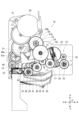
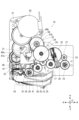
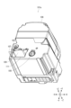
図3および図4に示すように、カートリッジ装着部2は、+Z側が開放された凹状に形成されている。カートリッジ装着部2の底面つまり-Z側の面である装着底面3には、ヘッド部4と、コア凸部5とが、装着方向手前側に突出して設けられている。ヘッド部4は、印刷ヘッド6と、印刷ヘッド6の少なくとも+X側、-Y側および+Z側を覆うヘッドカバー7とを備えている。印刷ヘッド6は、発熱素子を備えたサーマルヘッドである。ヘッドカバー7は、テープカートリッジ101がカートリッジ装着部2に装着される際に、第1ヘッド挿通孔111に挿通され、テープカートリッジ101の装着をガイドする。また、ヘッドカバー7は、リボンカートリッジ201がカートリッジ装着部2に装着される際に、第2ヘッド挿通孔211に挿通され、リボンカートリッジ201の装着をガイドする。なお、コア凸部5については後述する。
As shown in FIGS. 3 and 4, the
また、装着底面3には、-X側から順に、プラテン軸8と、第1巻取り軸11と、第1繰出し軸9と、第2繰出し軸12と、第2巻取り軸13とが、+Z側に突出して設けられている。
Also, on the mounting
プラテン軸8は、印刷ヘッド6の+Y側に設けられている。プラテン軸8は、第1繰出し軸9、第1巻取り軸11、第2繰出し軸12および第2巻取り軸13に比べて、装着方向手前側への突出量が大きい。プラテン軸8は、テープカートリッジ101がカートリッジ装着部2に装着される際に、第1プラテンローラー103に挿通され、ヘッドカバー7と共に、テープカートリッジ101の装着をガイドする。また、プラテン軸8は、リボンカートリッジ201がカートリッジ装着部2に装着される際に、第2プラテンローラー203に挿通され、ヘッドカバー7と共に、リボンカートリッジ201の装着をガイドする。なお、以下では、テープカートリッジ101或いはリボンカートリッジ201の装着方向を、単に、装着方向という。装着方向は、プラテン軸8の延びる方向、すなわちZ方向と平行である。また、装着方向手前側とは、+Z側を意味し、装着方向奥側とは、-Z側を意味する。
A
プラテン軸8、第1繰出し軸9、第1巻取り軸11、第2繰出し軸12および第2巻取り軸13には、それぞれ、プラテン回転子14(図6参照)、第1繰出し回転子15、第1巻取り回転子16、第2繰出し回転子17および第2巻取り回転子18が、回転可能に支持されている。テープカートリッジ101がカートリッジ装着部2に装着されると、テープカートリッジ101に設けられた第1プラテンローラー103、第1繰出しコア104および第1巻取りコア105が、それぞれ、カートリッジ装着部2に設けられたプラテン回転子14、第1繰出し回転子15および第1巻取り回転子16と係合する。また、リボンカートリッジ201がカートリッジ装着部2に装着されると、リボンカートリッジ201に設けられた第2プラテンローラー203、第2繰出しコア204および第2巻取りコア205が、それぞれ、カートリッジ装着部2に設けられたプラテン回転子14、第2繰出し回転子17および第2巻取り回転子18と係合する。プラテン回転子14、第1繰出し回転子15、第1巻取り回転子16、第2繰出し回転子17および第2巻取り回転子18には、送り輪列19を介して、送りモーター20の回転が伝達される。
A platen rotor 14 (see FIG. 6) and a
[送り輪列]
図5ないし図7に示すように、送り輪列19は、モーター側輪列21と、プラテン側輪列22と、リボン側輪列23と、ワンウェイクラッチユニット24と、繰出し側輪列25と、第1巻取り側輪列26と、第2巻取り側輪列27とを備えている。
[Feed gear train]
As shown in FIGS. 5 to 7, the
モーター側輪列21は、送りモーター20の回転を、プラテン側輪列22およびリボン側輪列23に伝達する。プラテン側輪列22は、モーター側輪列21を介して入力された送りモーター20の回転を、プラテン回転子14に伝達する。リボン側輪列23は、モーター側輪列21を介して入力された送りモーター20の回転を、ワンウェイクラッチユニット24に伝達する。
The motor-
ワンウェイクラッチユニット24は、リボン側輪列23を介して入力された送りモーター20の回転の伝達先を、送りモーター20の回転方向に応じて、繰出し側輪列25と、第1巻取り側輪列26および第2巻取り側輪列27とに切り替える。すなわち、ワンウェイクラッチユニット24は、送りモーター20が第1方向に回転したときには、リボン側輪列23を介して入力された送りモーター20の回転を、繰出し側輪列25には伝達せず、第1巻取り側輪列26および第2巻取り側輪列27に伝達する。そのため、送りモーター20が第1方向に回転したときには、第1繰出し回転子15および第2繰出し回転子17は回転せずに、第1巻取り回転子16および第2巻取り回転子18が回転する。なお、第1方向とは、図6および図7において、時計回りの回転となる方向のことを指す。送りモーターが第1方向に回転したとき、第1巻取り回転子16および第2巻取り回転子18は、第1方向と反対方向の回転、すなわち、反時計回りの回転となる。
The one-way
一方、ワンウェイクラッチユニット24は、送りモーター20が第1方向とは反対の第2方向に回転したときには、リボン側輪列23を介して入力された送りモーター20の回転を、繰出し側輪列25に伝達し、第1巻取り側輪列26および第2巻取り側輪列27には伝達しない。そのため、送りモーター20が第2方向に回転したときには、第1繰出し回転子15および第2繰出し回転子17が反時計回りに回転し、第1巻取り回転子16および第2巻取り回転子18は回転しない。なお、図示省略したが、ワンウェイクラッチユニット24は、2つのワンウェイクラッチを備えている。
On the other hand, when the
繰出し側輪列25は、ワンウェイクラッチユニット24を介して入力された送りモーター20の回転を、第1繰出し回転子15および第2繰出し回転子17に伝達する。
The feed-
第1巻取り側輪列26は、ワンウェイクラッチユニット24を介して入力された送りモーター20の回転を、第1巻取り回転子16に伝達する。第1巻取り側輪列26は、ワンウェイクラッチユニット24を介して送りモーター20の回転が入力される第1巻取り側第1歯車28と、第1巻取り側第1歯車28と噛み合った第1巻取り側第2歯車29と、第1トルク切替え機構31を備えている。第1トルク切替え機構31は、第1巻取り回転子16に伝達されるトルクを切り替えるためのものである。なお、第1トルク切替え機構31については、後述する。
The first winding
第2巻取り側輪列27は、ワンウェイクラッチユニット24を介して入力された送りモーター20の回転を、第2巻取り回転子18に伝達する。第2巻取り側輪列27は、ワンウェイクラッチユニット24を介して送りモーター20の回転が入力される第2巻取り側第1歯車32と、第2巻取り側第1歯車32と噛み合った第2巻取り側第2歯車33と、第1トルク切替え機構31と同様に構成された第2トルク切替え機構34とを備えている。
The second winding
[テープカートリッジ装着時の印刷処理]
図1に示すように、テープカートリッジ101がカートリッジ装着部2に装着されると、テープカートリッジ101に設けられた第1プラテンローラー103、第1繰出しコア104および第1巻取りコア105が、それぞれ、図3に示すカートリッジ装着部2に設けられたプラテン回転子14、第1繰出し回転子15および第1巻取り回転子16と係合する。これにより、送りモーター20の回転が、第1プラテンローラー103、第1繰出しコア104および第1巻取りコア105に伝達可能となる。
[Printing process when tape cartridge is installed]
As shown in FIG. 1, when the
また、テープカートリッジ101がカートリッジ装着部2に装着されると、テープカートリッジ101に設けられた第1ヘッド挿通孔111に、カートリッジ装着部2に設けられたヘッド部4が挿通する。テープカートリッジ101がカートリッジ装着部2に装着された後、装着部カバーが閉められると、ヘッド移動機構35(図5参照)により、印刷ヘッド6がプラテン軸8に向けて移動する。これにより、印刷ヘッド6と第1プラテンローラー103との間に、第1印刷テープ107および第1インクリボン109が挟持される。
Also, when the
この状態で、送りモーター20が第1方向に回転すると、送りモーター20の回転が送り輪列19を介してプラテン回転子14および第1巻取り回転子16に伝達され、第1プラテンローラー103が送り方向に回転すると共に、第1巻取りコア105が巻取り方向に回転する。ここで、第1プラテンローラー103の送り方向とは、第1印刷テープ107がテープ送出口108に向けて送られるように、第1プラテンローラー103が回転する方向を意味する。また、第1巻取りコア105の巻取り方向とは、第1繰出しコア104から繰り出された第1インクリボン109が、第1巻取りコア105に巻き取られるように、第1巻取りコア105が回転する方向を意味する。換言すると、図1において、第1プラテンローラー103の送り方向は、時計回りに回転する方向であり、第1巻取りコア105の巻取り方向は、反時計回りに回転する方向である。
In this state, when the
また、送りモーター20が第2方向に回転すると、送りモーター20の回転が送り輪列19を介してプラテン回転子14および第1繰出し回転子15に伝達され、第1プラテンローラー103が引戻し方向に回転すると共に、第1繰出しコア104が巻戻し方向に回転する。ここで、第1プラテンローラー103の引戻し方向とは、テープ送出口108に向けて送られた第1印刷テープ107が引き戻されるように、第1プラテンローラー103が回転する方向を意味する。また、第1繰出しコア104の巻戻し方向とは、第1繰出しコア104から繰り出された第1インクリボン109が、第1繰出しコア104に巻き戻されるように、第1繰出しコア104が回転する方向を意味する。換言すると、図1において、第1プラテンローラー103の引戻し方向および第1繰出しコア104の巻戻し方向は、ともに反時計回りに回転する方向である。
Further, when the
テープ印刷装置1は、送りモーター20を第1方向に回転させると共に、印刷ヘッド6を発熱させることにより、第1印刷テープ107および第1インクリボン109を送りつつ、図示省略したキーボード等から入力された印刷情報を第1印刷テープ107に印刷する。印刷終了後、テープ印刷装置1は、図示省略したが、カートリッジ装着部2とテープ排出口との間に設けられたカッターを切断動作させ、第1印刷テープ107の印刷済み部分を切り離す。その後、テープ印刷装置1は、送りモーター20を第2方向に回転させることにより、第1印刷テープ107の先端が、印刷ヘッド6と第1プラテンローラー103との挟持位置の近傍にくるまで、第1印刷テープ107を引き戻す。これにより、次に印刷される第1印刷テープ107の長さ方向前方に生じる余白を、短くすることができる。
The
なお、テープ印刷装置1は、リボンカートリッジ201がカートリッジ装着部2に装着されたときも、同様にして、印刷処理を行う。すなわち、テープ印刷装置1は、印刷ヘッド6と第2プラテンローラー203との間に挟持した、第2印刷テープおよび第2インクリボン209を送りながら、第2印刷テープに対して印刷を行う。
It should be noted that the
[テープカートリッジ]
テープカートリッジ101には、図8に示すように、幅の広い、例えば50mm幅の、第1印刷テープ107および第1インクリボン109が収容された第1テープカートリッジ101aと、図9に示すように、幅の狭い、例えば36mm幅の、第1印刷テープ107および第1インクリボン109が収容された第2テープカートリッジ101bと、が用意されている。なお、図9では、第1印刷テープ107および第1インクリボン109の図示を省略している。以下では、第1テープカートリッジ101aと第2テープカートリッジ101bとを区別する必要がない場合には、単に、テープカートリッジ101という。第1テープカートリッジ101aと第2テープカートリッジ101bとは、略同様に構成されており、共通の構成については、第1テープカートリッジ101aの図面で代表して説明する。
[Tape cartridge]
As shown in FIG. 8, the
図10に示すように、テープカートリッジ101は、第1カートリッジケース106の装着方向手前側の壁部の内面から装着方向奥側に略円筒状に突出した、手前側コア支軸112を備えている。また、テープカートリッジ101は、第1カートリッジケース106の装着方向奥側の壁部の内面から装着方向手前側に略段付き円筒状に突出した、奥側コア支軸113を備えている。手前側コア支軸112と奥側コア支軸113とは、Z方向において互いに対向するようにして設けられている。手前側コア支軸112と奥側コア支軸113とは、テープコア102を回転可能に支持している。
As shown in FIG. 10, the
手前側コア支軸112および奥側コア支軸113の内部には、逆転防止バネ114が設けられている。逆転防止バネ114は、例えば圧縮コイルバネで構成されており、装着方向奥側の端部がテープコア102と係合することにより、テープカートリッジ101がカートリッジ装着部2に装着されていない状態で、テープコア102が逆回転することを防止するものである。テープカートリッジ101がカートリッジ装着部2に装着されると、テープカートリッジ101に設けられた奥側コア支軸113の内部すなわち後述するコア凹部115に、カートリッジ装着部2に設けられたコア凸部5が挿入される。これにより、手前側コア支軸112および奥側コア支軸113の内部に設けられた逆転防止バネ114が圧縮され、逆転防止バネ114とテープコア102との係合が外れることにより、テープコア102は自由回転が可能となる。
A reverse
図11に示すように、第1カートリッジケース106の装着方向奥側の壁部の外面には、コア凹部115が、装着方向手前側に陥入して設けられている。コア凹部115は、奥側コア支軸113の内部空間により構成されている。コア凹部115は、装着方向奥側の台座凹部116と、装着方向手前側の挿入凹部117とを備えている。台座凹部116は、第1カートリッジケース106の装着方向奥側の壁部の外面から略円形状に陥入している。挿入凹部117は、台座凹部116の底面から台座凹部116よりも小径の略円形状に陥入している。台座凹部116内には、挿入凹部117の内周面から装着方向奥側に突出した環状凸部118が設けられている。
As shown in FIG. 11, a
ここで、第1テープカートリッジ101aと第2テープカートリッジ101bとでは、台座凹部116内の構造が異なっている。すなわち、第2テープカートリッジ101bでは、図12に示すように、環状凸部118の外周面と台座凹部116の内周面との間を接続するようにして、-X側の接続凸部119と、+X側の接続凹部121と、-Y側の第1接続部(図示省略)と、+Y側の第2接続部123とが設けられている。接続凸部119、接続凹部121、第1接続部、および第2接続部123は、台座凹部116の周方向において略等間隔に設けられている。これら接続凸部119、接続凹部121、第1接続部、および第2接続部123の配置は、上記の構成に限定されない。例えば、接続凸部119を-Y側、接続凹部121を+Y側、第1接続部を+X側、第2接続部123を-X側としてもよい。これら接続凸部119、接続凹部121、第1接続部、および第2接続部123の配置を変更することで、第2テープカートリッジ101bを販売する国や地域により、例えば、第1印刷テープ107の仕様が異なる場合の識別等に利用することができる。
Here, the structure inside the pedestal
これに対し、第1テープカートリッジ101aでは、図13に示すように、4つのカートリッジ側係合部124が、接続凸部119、接続凹部121、第1接続部、および第2接続部123の装着方向奥側に位置して、台座凹部116の内周面から突出して設けられている。すなわち、第1テープカートリッジ101aと第2テープカートリッジ101bとでは、4つのカートリッジ側係合部124の有無の点で異なっている。カートリッジ側係合部124が台座凹部116の内周面に設けられていることで、第1テープカートリッジ101aが落下した際にも、カートリッジ側係合部124が破損することを抑制することができる。
On the other hand, in the
4つのカートリッジ側係合部124は、台座凹部116の周方向において、略等間隔に設けられている。カートリッジ側係合部124は、台座凹部116の開口部近傍から、台座凹部116の底面に向かって、装着方向手前側に延在している。4つのカートリッジ側係合部124のうち、-X側のカートリッジ側係合部124を、カートリッジ側第1係合部124aといい、+X側のカートリッジ側係合部124を、カートリッジ側第2係合部124bといい、-Y側のカートリッジ側係合部124を、カートリッジ側第3係合部124cといい、+Y側のカートリッジ側係合部124を、カートリッジ側第4係合部124dという。これらを区別する必要がない場合には、単に、カートリッジ側係合部124という。図11に示すように、カートリッジ側第1係合部124aとカートリッジ側第2係合部124bとは、装着方向奥側から見て、コア凹部115の中心に対して相互に点対称となる位置に設けられている。同様に、カートリッジ側第3係合部124cとカートリッジ側第4係合部124dとは、装着方向奥側から見て、コア凹部115の中心に対して相互に点対称となる位置に設けられている。カートリッジ側第1係合部124aは、後述する装置側第1係合部49a(図15参照)に対応して設けられ、カートリッジ側第2係合部124bは、後述する装置側第2係合部49b(図15参照)に対応して設けられている。
The four cartridge-side engaging portions 124 are provided at approximately equal intervals in the circumferential direction of the
[コア凸部]
図3、図4および図14に示すように、コア凸部5は、全体として略段付き円筒状に形成されており、装着方向奥側の台座凸部36と、装着方向手前側の挿入凸部37とを備えている。台座凸部36は、カートリッジ装着部2の底面から略円筒状に突出している。挿入凸部37は、台座凸部36の先端面から台座凸部36よりも小径の略円筒状に突出している。
[Core protrusion]
As shown in FIGS. 3, 4 and 14, the
台座凸部36には、4つの台座開口部38が設けられている。各台座開口部38は、台座凸部36の先端面と周面との角部を切り欠くようにして、形成されている。4つの台座開口部38は、台座凸部36の周方向において略等間隔に設けられている。以下では、4つの台座開口部38のうち、-X側の台座開口部38を、第1台座開口部38aといい、+X側の台座開口部38を第2台座開口部38bといい、-Y側の台座開口部38を、第3台座開口部38cといい、+Y側の台座開口部38を、第4台座開口部38dという。これらを区別する必要がない場合には、単に、台座開口部38という。図3に示すように、第1台座開口部38aと第2台座開口部38bとは、装着方向手前側から見て、コア凸部5の中心に対して相互に点対称となる位置に設けられている。同様に、第3台座開口部38cと第4台座開口部38dとは、装着方向手前側から見て、コア凸部5の中心に対して相互に点対称となる位置に設けられている。
Four pedestal openings 38 are provided in the
図15および図16に示すように、テープカートリッジ101がカートリッジ装着部2に装着されると、テープカートリッジ101に設けられたコア凹部115に対し、カートリッジ装着部2に設けられたコア凸部5が、装着方向奥側から挿入される。すなわち、台座凹部116に台座凸部36が挿入され、挿入凹部117に挿入凸部37が挿入される。
As shown in FIGS. 15 and 16, when the
ここで、図15に示すように、第1テープカートリッジ101aがカートリッジ装着部2に装着されたときには、台座凹部116の内周面に設けられたカートリッジ側係合部124が、台座開口部38を介して、台座凸部36内に進入する。これにより、4つのカートリッジ側係合部124のうち、カートリッジ側第1係合部124aおよびカートリッジ側第2係合部124bが、それぞれ、後述する装置側第1係合部49aおよび装置側第2係合部49bと係合する。また、図14に示すように、第1テープカートリッジ101aがカートリッジ装着部2から取り外されると、カートリッジ側係合部124が、台座開口部38を介して、台座凸部36外に出る。これにより、カートリッジ側第1係合部124aおよびカートリッジ側第2係合部124bが、それぞれ、装置側第1係合部49aおよび装置側第2係合部49bから外れる。
Here, as shown in FIG. 15 , when the
一方、図16に示すように、カートリッジ側係合部124を有していない第2テープカートリッジ101bがカートリッジ装着部2に装着されたときには、台座凹部116は、装置側第1係合部49aおよび装置側第2係合部49bと係合しない。
On the other hand, as shown in FIG. 16, when the
[第1トルク切替え機構]
第1トルク切替え機構31は、第1テープカートリッジ101aがカートリッジ装着部2に装着されると、第1巻取り回転子16に伝達されるトルクを、第2トルクから、第2トルクより大きい第1トルクに切り替えるためのものである。すなわち、幅の広い第1インクリボン109が収容された第1テープカートリッジ101aがカートリッジ装着部2に装着されると、第1巻取り回転子16に伝達されるトルクが、第1トルク切替え機構31により第2トルクより大きい第1トルクに切り替えられる。このため、印刷ヘッド6と第1プラテンローラー103との間で第1印刷テープ107と共に挟持された幅の広い第1インクリボン109を、第1印刷テープ107から適切に引き剥がし、また、巻き取ることができる。一方、幅の狭い第1インクリボン109が収容された第2テープカートリッジ101bが装着されたとき、第1トルク切替え機構31は、テープカートリッジ101が装着されていない状態からトルク切替えを行わず、第1巻取り回転子16に伝達されるトルクは、第1トルクより小さい第2トルクとなる。このため、幅の狭い第1インクリボン109が破れることを抑制することができる。
[First torque switching mechanism]
When the
図17および図18に示すように、第1トルク切替え機構31は、第1巻取り歯車41と、第2巻取り歯車42と、第1スリップバネ43と、第2スリップバネ44とを備えている。また、第1トルク切替え機構31は、後述する可動歯車46と、2つの切替作動子47と、歯車支持部48とを備えている(図19および図20参照)。
As shown in FIGS. 17 and 18, the first
第1巻取り歯車41は、第1巻取り軸11に回転可能に支持されている。すなわち、第1巻取り歯車41は、第1巻取り回転子16よりも装着方向奥側に位置して、第1巻取り回転子16と同軸上に設けられている。第1巻取り歯車41は、第1スリップバネ43を介して第1巻取り回転子16と連結されており、第1巻取り回転子16を回転させる。
The first winding
第2巻取り歯車42は、第1巻取り軸11に回転可能に支持されている。すなわち、第2巻取り歯車42は、第1巻取り歯車41よりも装着方向奥側に位置して、第1巻取り回転子16と同軸上に設けられている。第2巻取り歯車42は、第2スリップバネ44を介して第1巻取り歯車41と連結されており、第1巻取り歯車41を介して第1巻取り回転子16を回転させる。
The second winding
第1スリップバネ43は、第1巻取り歯車41と第1巻取り回転子16との間に設けられている。第1スリップバネ43は、第1巻取り歯車41から第1巻取り回転子16に伝達されるトルクを、第1トルクに制限する。第2スリップバネ44は、第2巻取り歯車42と第1巻取り歯車41との間に設けられている。第2スリップバネ44は、第2巻取り歯車42から第1巻取り歯車41に伝達されるトルクを、第1トルクよりも小さい第2トルクに制限する。なお、第2巻取り歯車42から第1巻取り歯車41に伝達されるトルクは、第1トルクを超えないものであるため、第1スリップバネ43を介して、さらに第1巻取り回転子16に伝達される。なお、第1スリップバネ43は、「第1トルクリミッター」の一例である。第2スリップバネ44は、「第2トルクリミッター」の一例である。
A
第1巻取り歯車41に対しては、可動歯車46が係脱するのに対し、第2巻取り歯車42に対しては、第1巻取り側第2歯車29が常に噛み合っている。このため、可動歯車46が第1巻取り歯車41と噛み合い、送りモーター20の回転が可動歯車46を介して第1巻取り歯車41に入力すると、第1スリップバネ43により、第1巻取り回転子16に伝達されるトルクが、第1トルクに制限される。一方、可動歯車46が第1巻取り歯車41から外れ、送りモーター20の回転が第2巻取り歯車42を介して第1巻取り歯車41に入力すると、第2スリップバネ44により、第1巻取り回転子16に伝達されるトルクが、第2トルクに制限される。
While the
図19および図20に示すように、可動歯車46は、歯車支持部48に回転可能に支持されており、第1巻取り歯車41に対して係脱可能に構成されている。また、可動歯車46は、第1巻取り側第1歯車28と常に噛み合っている(図6および図7参照)。
As shown in FIGS. 19 and 20 , the
各切替作動子47には、第1テープカートリッジ101aがカートリッジ装着部2に装着されたときに、カートリッジ側係合部124と係合する装置側係合部49が設けられている。ここで、2つの装置側係合部49のうち、-X側の装置側係合部49を、装置側第1係合部49aといい、+X側の装置側係合部49を、装置側第2係合部49bという。装置側第1係合部49aと装置側第2係合部49bとを区別する必要がない場合には、単に、装置側係合部49という。また、2つの切替作動子47のうち、装置側第1係合部49aが設けられた切替作動子47を、第1切替作動子47aといい、装置側第2係合部49bが設けられた切替作動子47を、第2切替作動子47bという。第1切替作動子47aと第2切替作動子47bとを区別する必要がない場合には、単に、切替作動子47という。
Each switching actuator 47 is provided with a device-side engaging portion 49 that engages with the cartridge-side engaging portion 124 when the
第1切替作動子47aは、図示省略した作動子軸に回動可能に設けられている。第1切替作動子47aは、装着方向手前側から見て、略「L」字状に形成されている。第1切替作動子47aの+Y側の端部には、第1作動子軸(図示省略)が挿通した第1作動子側軸挿通部51が設けられている。第1切替作動子47aの+X側の端部には、装着方向奥側に突出した第1作動子側係合部52が設けられている。第1作動子側係合部52は、後述する支持部側第1係合部67と係合している。装置側第1係合部49aは、第1作動子側軸挿通部51の-X側且つ-Y側に位置して、装着方向手前側に突出している。装置側第1係合部49aには、装着方向奥側が-X側となるように傾斜した第1係合斜面54と、第1係合斜面54の装着方向奥側の端部から装着方向奥側に延在する第1作動面55とが設けられている。
The
第1切替作動子47aは、作動子バネ56(図6参照)により、時計回りに回動する方向に、力が付与されている。作動子バネ56は、一端が第1巻取り側第2歯車29の支軸(図示省略)に掛け止めされ、他端が第1切替作動子47aの+X側の端部に掛け止めされている。作動子バネ56としては、例えば、ねじりコイルバネを用いることができる。なお、時計回りとは、装着方向手前側から見たときの時計回りを意味する。同様に、反時計回りとは、装着方向手前側から見たときの反時計回りを意味する。
A force is applied to the
第2切替作動子47bは、第2作動子軸(図示省略)に回動可能に設けられている。第2切替作動子47bは、装着方向手前側から見て、略三角形状に形成されている。第2切替作動子47bの-Y側の端部には、第2作動子軸が挿通した第2作動子側軸挿通部57が設けられている。また、第2切替作動子47bには、第2作動子側軸挿通部57の+X側且つ+Y側に位置して、装着方向奥側に突出した第2作動子側係合部58が設けられている。第2作動子側係合部58は、後述する支持部側第2係合部69と係合している。装置側第2係合部49bは、第2作動子側軸挿通部57の-X側且つ+Y側に位置して、装着方向手前側に突出している。装置側第2係合部49bには、装着方向奥側が+X側となるように傾斜した第2係合斜面61と、第2係合斜面61の装着方向奥側の端部から装着方向奥側に延在する第2作動面62とが設けられている。なお、第1係合斜面54および第2係合斜面61に代えて、カートリッジ側第1係合部124aおよびカートリッジ側第2係合部124bに斜面が設けられた構成でもよい。
The
図14に示すように、装置側第1係合部49aおよび装置側第2係合部49bは、台座凸部36の内部に設けられている。すなわち、装置側第1係合部49aおよび装置側第2係合部49bは、それぞれ、第1台座開口部38aおよび第2台座開口部38bに対して、装着方向奥側に設けられている。装置側第1係合部49aおよび装置側第2係合部49bは、それぞれ、カートリッジ側第1係合部124aおよびカートリッジ側第2係合部124bに対応して設けられている。装置側第1係合部49aおよび装置側第2係合部49bは、第1テープカートリッジ101aがカートリッジ装着部2に装着されたときに、略同時に、それぞれ、カートリッジ側第1係合部124aおよびカートリッジ側第2係合部124bと係合する。また、装置側第1係合部49aと装置側第2係合部49bとは、装着方向手前側から見て、コア凸部5の中心に対して相互に点対称となる位置に設けられている(図3参照)。
As shown in FIG. 14 , the device-side first engaging
図6、図7、図19および図20に示すように、歯車支持部48は、回転可能に支持した可動歯車46が第1巻取り歯車41に対して離接するように、回動可能に構成されている。歯車支持部48は、第1作動子側支持部材63と、第2作動子側支持部材64と、支持部バネ65とを備えている。
As shown in FIGS. 6, 7, 19 and 20, the
第1作動子側支持部材63は、第2作動子軸と略同軸上に設けられたクラッチ軸45(図5参照)に回動可能に設けられている。第1作動子側支持部材63の+Y側の端部には、クラッチ軸45が挿通した支持部側第1軸挿通部66が略円筒状に設けられている。第1作動子側支持部材63の-Y側の端部には、可動歯車46が回転可能に支持されている。第1作動子側支持部材63の略中間部には、支持部側第1係合部67が設けられている。支持部側第1係合部67は、上記の第1作動子側係合部52と係合している。
The first actuator
第2作動子側支持部材64は、クラッチ軸45に回動可能に設けられ、第2作動子側支持部材64の略中間部には、クラッチ軸45が挿通した支持部側第2軸挿通部68が略短円筒状に設けられている。支持部側第2軸挿通部68に支持部側第1軸挿通部66が装着方向奥側から挿入されている。第2作動子側支持部材64の+Y側の端部には、支持部側第2係合部69が設けられている。支持部側第2係合部69は、上記の第2作動子側係合部58と係合している。
The second actuator-
支持部バネ65は、第1作動子側支持部材63と第2作動子側支持部材64とを弾性的に接続している。支持部バネ65は、クラッチ軸45に設けられており、一端が第1作動子側支持部材63に掛け止めされ、他端が第2作動子側支持部材64に掛け止めされている。支持部バネ65は、第1作動子側支持部材63を固定した場合に、第2作動子側支持部材64に対し、時計回りに回動するように、力を付与している。支持部バネ65としては、例えば、ねじりコイルバネを用いることができる。なお、支持部バネ65は、「弾性部材」の一例である。
The
[第1トルク切替え機構の状態変化]
第1テープカートリッジ101aがカートリッジ装着部2に装着されると、上述したように、カートリッジ側第1係合部124aおよびカートリッジ側第2係合部124bが、それぞれ、装置側第1係合部49aおよび装置側第2係合部49bと係合する(図15参照)。
[Change in State of First Torque Switching Mechanism]
When the
このとき、カートリッジ側第1係合部124aは、装置側第1係合部49aに対し、第1係合斜面54および第1作動面55の順に係合する。これにより、装置側第1係合部49aが、+X側に押される。その結果、第1切替作動子47aが、図22に示した状態から、図21に示すように、作動子バネ56の弾性力に抗して反時計回りに回動する。このとき、第1切替作動子47aの第1作動子側係合部52が、+X側に移動するため、第1作動子側係合部52の-X側で第1作動子側係合部52と係合した支持部側第1係合部67が、+X側に移動可能となる。これにより、第1作動子側支持部材63が、反時計回りに、すなわち第1作動子側支持部材63に支持された可動歯車46が第1巻取り歯車41に近づく方向に、回動可能となる。このように、第1切替作動子47aは、カートリッジ側第1係合部124aが装置側第1係合部49aと係合すると、反時計回りに回動することで、第1作動子側支持部材63が反時計回りに回動することを許容する。
At this time, the cartridge-side first engaging
また、カートリッジ側第2係合部124bは、装置側第2係合部49bに対し、第2係合斜面61および第2作動面62の順に係合する。これにより、装置側第2係合部49bが-X側に押される。その結果、第2切替作動子47bが、図22に示した状態から、図21に示すように、反時計回りに回動する。このとき、第2切替作動子47bの第2作動子側係合部58が、第2作動子側支持部材64の支持部側第2係合部69を-X側へ押すため、第2作動子側支持部材64が、反時計回りに回動する。第2作動子側支持部材64が反時計回りに回動すると、支持部バネ65を介して第2作動子側支持部材64と弾性的に接続された第1作動子側支持部材63が、反時計回りに、すなわち第1作動子側支持部材63に支持された可動歯車46が第1巻取り歯車41に近づく方向に、回動する。その結果、図6に示すように、可動歯車46が第1巻取り歯車41と噛み合う。このように、第2切替作動子47bは、カートリッジ側第2係合部124bが装置側第2係合部49bと係合すると、反時計回りに回動することで、第1作動子側支持部材63を反時計回りに回動させる。
Further, the cartridge-side second engaging
ここで、第1作動子側支持部材63と第2作動子側支持部材64とは、支持部バネ65により弾性的に接続されている。このため、第2作動子側支持部材64は、図22に示した状態から、反時計回りに噛合回動量θだけ回動して、可動歯車46が第1巻取り歯車41と噛み合った後も、第1作動子側支持部材63に対し、支持部バネ65の弾性力に抗して、反時計回りにさらに付加回動量αだけ回動可能となっている。ここで、噛合回動量θとは、可動歯車46が第1巻取り歯車41と噛み合うために必要な第2作動子側支持部材64の回動量の最小値を意味する。このため、第2作動子側支持部材64の回動量が、噛合回動量θ以上で、噛合回動量θと付加回動量αとの和(θ+α)以下であれば、適度な荷重で、可動歯車46が第1巻取り歯車41に押し付けられる。したがって、第2作動子側支持部材64の回動量の設計値を、θよりも大きく、(θ+α)よりも小さい値に設定すればよい。これにより、カートリッジ側第2係合部124b等の寸法ばらつきにより、第2作動子側支持部材64の回動量がばらついても、その値がθ以上(θ+α)以下であれば、可動歯車46を第1巻取り歯車41に適切に噛み合わせることができる。すなわち、カートリッジ側第2係合部124b等の寸法ばらつきを、支持部バネ65により吸収することができる。
Here, the first actuator-
このように、第1テープカートリッジ101aがカートリッジ装着部2に装着されると、カートリッジ側第1係合部124aおよびカートリッジ側第2係合部124bが、それぞれ、装置側第1係合部49aおよび装置側第2係合部49bと係合する。これにより、歯車支持部48が反時計回りに回動し、可動歯車46が第1巻取り歯車41と噛み合う。その結果、第1トルク切替え機構31が、送りモーター20の回転が可動歯車46を介して第1巻取り歯車41に入力する状態、すなわち第1巻取り回転子16に伝達されるトルクを第1トルクとする第1状態に状態変化する。
In this manner, when the
続いて、第1テープカートリッジ101aの取外し時における第1トルク切替え機構31の状態変化について説明する。第1テープカートリッジ101aがカートリッジ装着部2から取り外されると、上述したように、カートリッジ側第1係合部124aおよびカートリッジ側第2係合部124bが、それぞれ、装置側第1係合部49aおよび装置側第2係合部49bから外れる。
Next, the state change of the first
カートリッジ側第1係合部124aと装置側第1係合部49aとの係合が外れると、図21に示した状態から、図22に示すように、第1切替作動子47aは、作動子バネ56の弾性力により、時計回りに回動する。これにより、第1切替作動子47aの第1作動子側係合部52が、第1作動子側支持部材63の支持部側第1係合部67を-X側へ押す。このため、第1作動子側支持部材63が、時計回りに、すなわち第1作動子側支持部材63に支持された可動歯車46が第1巻取り歯車41から離れる方向に、回動する。その結果、図7に示すように、可動歯車46が第1巻取り歯車41から外れる。このように、第1切替作動子47aは、カートリッジ側第1係合部124aが装置側第1係合部49aから外れると、時計回りに回動することで、第1作動子側支持部材63を時計回りに回動させ、第1作動子側支持部材63が反時計回りに回動することを阻止する。
When the cartridge-side first engaging
第1作動子側支持部材63が時計回りに回動すると、支持部バネ65を介して第1作動子側支持部材63と弾性的に接続された第2作動子側支持部材64が、時計回りに回動する。これにより、第2作動子側支持部材64の支持部側第2係合部69が、第2切替作動子47bの第2作動子側係合部58を+X側に押す。このとき、上述したように、カートリッジ側第2係合部124bと装置側第2係合部49bとの係合が外れたことにより、装置側第2係合部49bが+X側に移動可能に、すなわち第2切替作動子47bが時計回りに回動可能となっている。このため、第2切替作動子47bは、第2作動子側支持部材64に押され、時計回りに回動する。
When the first actuator-
このように、第1テープカートリッジ101aがカートリッジ装着部2から取り外されると、カートリッジ側第1係合部124aおよびカートリッジ側第2係合部124bが、それぞれ、装置側第1係合部49aおよび装置側第2係合部49bから外れる。これにより、歯車支持部48が時計回りに回動し、可動歯車46が第1巻取り歯車41から外れる。その結果、第1トルク切替え機構31が、送りモーター20の回転が第2巻取り歯車42を介して第1巻取り歯車41に入力する状態、すなわち第1巻取り回転子16に伝達されるトルクを第2トルクとする第2状態に状態変化する。
In this manner, when the
なお、上述したように、第2テープカートリッジ101bがカートリッジ装着部2に装着されたときに、接続凸部119および接続凹部121は、それぞれ装置側第1係合部49aおよび装置側第2係合部49bと係合しない(図16参照)。そのため、第2テープカートリッジ101bがカートリッジ装着部2に装着されたときに、第1トルク切替え機構31は第2状態のままであり、第1巻取り回転子16に伝達されるトルクは、第2トルクのままとなる。
As described above, when the
以上のように、本実施形態の第1テープカートリッジ101aおよびテープ印刷装置1によれば、第1テープカートリッジ101aがカートリッジ装着部2に装着されると、カートリッジ側第1係合部124aおよびカートリッジ側第2係合部124bがそれぞれ装置側第1係合部49aおよび装置側第2係合部49bと係合することで、第1トルク切替え機構31が、第2状態から第1状態へ状態変化する。これにより、第1巻取り回転子16に伝達されるトルクが、第2トルクから第1トルクに切り替えられる。したがって、第1巻取り回転子16が二重筒構造である場合に比べ、第1巻取りコア105の径を小さくすることができ、第1テープカートリッジ101aを小型化することができる。また、第1巻取り回転子16が二重筒構造である場合に比べ、第1巻取り軸11に対する第1巻取り回転子16のガタ量が小さくなる。このため、第1巻取りコア105の中心と第1巻取り軸11の中心とを略一致させることができるため、第1インクリボン109を第1巻取りコア105に適切に巻き取ることができる。
As described above, according to the
また、本実施形態の第1テープカートリッジ101aおよびテープ印刷装置1によれば、第1テープカートリッジ101aと第1トルク切替え機構31とが、1箇所のみで係合するのではなく、カートリッジ側第1係合部124aおよび装置側第1係合部49aと、カートリッジ側第2係合部124bおよび装置側第2係合部49bと、の2箇所で係合する。このため、係合による負荷が、第1テープカートリッジ101aに対してバランス良く作用し、第1テープカートリッジ101aがカートリッジ装着部2に対して傾くことが抑制され、第1印刷テープ107および第1インクリボン109の走行性を向上させることができる。
Further, according to the
なお、本実施形態のように、カートリッジ側第1係合部124aおよびカートリッジ側第2係合部124bは、コア凹部115の中心に対して点対称に配置された構成に限定されず、それぞれ、装置側第1係合部49aおよび装置側第2係合部49bと係合可能であればよい。例えば、カートリッジ側第1係合部124aとコア凹部115の中心との間の寸法と、カートリッジ側第2係合部124bとコア凹部115の中心との間の寸法と、が異なっていてもよい。また、カートリッジ側第1係合部124aと、コア凹部115の中心と、カートリッジ側第2係合部124bとが、装着方向奥側から見て、一直線上に配置されていない構成でもよい。すなわち、カートリッジ側第1係合部124aおよびカートリッジ側第2係合部124bは、装置側第1係合部49aおよび装置側第2係合部49bと係合可能な範囲であれば、コア凹部115の中心を挟んで対向配置されていればよい。また、装着方向奥側から見て、コア凹部115の中心を挟んで対向配置された、カートリッジ側第1係合部124aの形状とカートリッジ側第2係合部124bの形状とが、異なっていてもよい。同様に、装置側第1係合部49aおよび装置側第2係合部49bについても、コア凸部5の中心に対して点対称に配置された構成に限定されない。また、カートリッジ側第1係合部124aにより装置側第1係合部49aが押される方向と、カートリッジ側第2係合部124bにより装置側第2係合部49bが押される方向とは、互いに反対向きであることが好ましい。
Note that the cartridge-side first engaging
[その他の変形例]
上記の実施形態に限定されず、その趣旨を逸脱しない範囲で種々の構成を採用可能であることは言うまでもない。例えば、上記の実施形態は、上述したほか、以下のような形態に変更することができる。
[Other Modifications]
It goes without saying that the present invention is not limited to the above-described embodiments, and that various configurations can be adopted without departing from the spirit of the embodiments. For example, the above embodiment can be modified into the following forms in addition to those described above.
カートリッジ側係合部124は、台座凹部116の内周面に形成された構成に限定されず、装置側係合部49と係合可能であれば、テープカートリッジ101のいずれの箇所に設けられてもよい。例えば、図23に示すように、カートリッジ側第1係合部124aおよびカートリッジ側第2係合部124bが、コア凹部115の縁部に設けられ、装着方向奥側から見て、一部がコア凹部115と重複した構成でもよい。すなわち、カートリッジ側係合部124は、第1カートリッジケース106の装着方向奥側の外面に設けられた構成でもよい。なお、図23に示したカートリッジ側第1係合部124aおよびカートリッジ側第2係合部124bは、略長方形板状であるが、その形状は特に限定されるものではなく、例えば、長円形板状、半球状などでもよい。また、カートリッジ側係合部124は、台座凹部116の底面から装着方向奥側に突出した構成でもよい。その際、カートリッジ側係合部124は、台座凹部116の内周面と一体に形成されていてもよいし、一体に形成されていなくてもよい。
The cartridge side engaging portion 124 is not limited to the configuration formed on the inner peripheral surface of the
第1トルク切替え機構31は、テープカートリッジ101が装着されたときに、第1巻取り回転子16に伝達されるトルクを比較的小さい第2トルクとする第2状態から、第1巻取り回転子16に伝達されるトルクを比較的大きい第1トルクとする第1状態に状態変化する構成に限定されるものではなく、テープカートリッジ101が装着されたときに、第1状態から第2状態に状態変化する構成でもよい。
The first
この構成では、例えば、カートリッジ側係合部124を第2テープカートリッジ101bに設け、第1テープカートリッジ101aには設けないようにする。また、第1トルク切替え機構31は、可動歯車46が第1巻取り歯車41と噛み合った状態にロックするロック部を備える。そして、第2テープカートリッジ101bがカートリッジ装着部2に装着されたときに、カートリッジ側係合部124が装置側係合部49と係合することで、ロック部のロックが外れ、可動歯車46が第1巻取り歯車41から外れるようにする。また、第2テープカートリッジ101bがカートリッジ装着部2に取り外されたときには、ロック部により、可動歯車46が第1巻取り歯車41と噛み合った状態にロックされる。これにより、第1トルク切替え機構31は、第2テープカートリッジ101bがカートリッジ装着部2に装着されたときに、第1状態から第2状態に状態変化する。また、第1トルク切替え機構31は、第2テープカートリッジ101bがカートリッジ装着部2から取り外されたときに、第2状態から第1状態に状態変化する。一方、第1トルク切替え機構31は、第1テープカートリッジ101aがカートリッジ装着部2に装着されたときには、第1状態のままである。
In this configuration, for example, the cartridge-side engaging portion 124 is provided in the
テープ印刷装置1は、第1切替作動子47aおよび第2切替作動子47bの一方が、第3台座開口部38cの装着方向奥側に設けられた装置側第3係合部を備え、第1切替作動子47aおよび第2切替作動子47bの他方が、第4台座開口部38dの装着方向奥側に設けられた装置側第4係合部を備えた構成でもよい。すなわち、テープ印刷装置1は、装置側係合部49として、カートリッジ側第3係合部124cに対応して設けられた装置側第3係合部と、カートリッジ側第4係合部124dに対応して設けられた装置側第4係合部とを備えた構成でもよい。換言すると、テープ印刷装置1は、対向する2つの装置側係合部49を、上記の実施形態のように+X側および-X側に設ける以外に、+Y側および-Y側に設けてもよい。
In the
この構成においても、第1テープカートリッジ101aがカートリッジ装着部2に装着されると、カートリッジ側第3係合部124cおよびカートリッジ側第4係合部124dがそれぞれ装置側第3係合部および装置側第4係合部と係合することで、第1トルク切替え機構31が、第2状態から第1状態へ状態変化する。このように、第1テープカートリッジ101aが、カートリッジ側第1係合部124a、カートリッジ側第2係合部124b、カートリッジ側第3係合部124cおよびカートリッジ側第4係合部124dを備えたことで、装置側第1係合部49aおよび装置側第2係合部49bを備えたテープ印刷装置1にも対応でき、装置側第3係合部および装置側第4係合部を備えたテープ印刷装置1にも対応できる。したがって、テープ印刷装置1は、装置側係合部49として、装置側第1係合部49aおよび装置側第2係合部49bを備えた構成でもよく、装置側第3係合部および装置側第4係合部を備えた構成でもよいため、装置側係合部49の配置の自由度を高めることができる。
Also in this configuration, when the
なお、第1テープカートリッジ101aは、装置側第1係合部49aおよび装置側第2係合部49bを備えたテープ印刷装置1用として、4つのカートリッジ側係合部124のうち、カートリッジ側第1係合部124aおよびカートリッジ側第2係合部124bのみを備えた構成でもよい。また、第1テープカートリッジ101aは、装置側第3係合部および装置側第4係合部を備えたテープ印刷装置1用として、4つのカートリッジ側係合部124のうち、カートリッジ側第3係合部124cおよびカートリッジ側第4係合部124dのみを備えた構成でもよい。
The
装置側係合部49の数は、2つに限定されるものではなく、1つでもよく、3つ以上でもよい。カートリッジ側係合部124の数は、4つに限定されるものではない。例えば、装置側係合部49の数が2つの場合、カートリッジ側係合部124の数は、2つ以上であればよく、さらに、1つのカートリッジ側係合部124が2つの装置側係合部49と係合する構成であれば、カートリッジ側係合部124の数は、1つでもよい。 The number of device-side engaging portions 49 is not limited to two, and may be one or three or more. The number of cartridge side engaging portions 124 is not limited to four. For example, when the number of device-side engaging portions 49 is two, the number of cartridge-side engaging portions 124 may be two or more, and one cartridge-side engaging portion 124 can be used for two device-side engaging portions. The number of the cartridge-side engaging portions 124 may be one as long as it is configured to engage with the portion 49 .
テープカートリッジ101は、カートリッジ側係合部124を形成した台座凹部116に代えて、アタッチメント装着部を備え、アタッチメント装着部に、カートリッジ側係合部124を形成した台座凹部116が設けられたアタッチメントが、着脱可能に装着される構成でもよい。この構成では、アタッチメントは、テープカートリッジ101のアタッチメント装着部に装着されることにより、装置側係合部49と係合するための調整装置として機能する。このとき、テープカートリッジ101とテープカートリッジ101のアタッチメント装着部に装着されたアタッチメントとを備えたカートリッジシステムを、カートリッジ装着部2に装着してもよく、或いは、アタッチメントを、予めテープ印刷装置1のコア凸部5に装着した後、テープカートリッジ101をカートリッジ装着部2に装着する実施形態としてもよい。また、アタッチメントは、例えば、装着方向奥側にフランジ部を設け、第1カートリッジケース106の壁部の一部を補完するような形状としてもよい。
The
カートリッジ装着部2は、テープカートリッジ101とリボンカートリッジ201とが択一的に装着される構成に限定されず、テープカートリッジ101のみが装着される構成でもよい。
また、上記した実施形態や変形例を、それぞれ組み合わせた構成でもよい。
The
Moreover, the structure which combined each above-described embodiment and a modification may be sufficient.
[付記]
以下、カートリッジおよびテープ印刷装置について付記する。
カートリッジは、インクリボンが巻き取られる巻取りコアを備えたカートリッジが装着されるカートリッジ装着部と、カートリッジがカートリッジ装着部に装着されたときに、巻取りコアと係合する巻取り回転子と、カートリッジ装着部に設けられ、カートリッジの装着方向手前側に突出したコア凸部と、コア凸部に設けられた開口部に対して装着方向奥側に設けられた装置側係合部と、装置側係合部が設けられた切替作動子を有し、巻取り回転子に伝達されるトルクを、第1トルクとする第1状態と、第1トルクよりも小さい第2トルクとする第2状態と、に状態変化するトルク切替え機構と、を備えたテープ印刷装置に装着されるカートリッジであって、カートリッジの外殻を構成し、印刷テープと、印刷テープが巻回されたテープコアと、インクリボンと、巻取りコアと、を収容するカートリッジケースと、カートリッジケースに設けられ、カートリッジ装着部に装着されたときに、装着方向奥側からコア凸部が挿入されるコア凹部と、コア凹部にコア凸部が挿入されたときに、装置側係合部と係合することで、トルク切替え機構を、第2状態から第1状態に、または第1状態から第2状態に、状態変化させるカートリッジ側係合部と、を備えた。
[Appendix]
The cartridge and the tape printer are described below.
The cartridge comprises: a cartridge mounting portion to which the cartridge having a winding core on which the ink ribbon is wound is mounted; a winding rotor that engages with the winding core when the cartridge is mounted on the cartridge mounting portion; A core convex portion provided in the cartridge mounting portion and protruding to the near side in the mounting direction of the cartridge, a device side engaging portion provided to the rear side in the mounting direction with respect to the opening provided in the core convex portion, and a device side A first state in which a switching actuator provided with an engaging portion is provided and the torque transmitted to the winding rotor is the first torque, and a second state is in the second state in which the second torque is smaller than the first torque. and a torque switching mechanism that changes the states of the cartridge to be mounted on a tape printer, the outer shell of the cartridge comprising a printing tape, a tape core around which the printing tape is wound, and an ink ribbon. , a winding core, a core recess provided in the cartridge case into which the core projection is inserted from the rear side in the mounting direction when the cartridge is mounted in the cartridge mounting portion, and a core projection in the core recess. When the cartridge-side engaging portion is inserted, the cartridge-side engaging portion engages with the device-side engaging portion to change the state of the torque switching mechanism from the second state to the first state or from the first state to the second state. with joints and .
この構成によれば、カートリッジがカートリッジ装着部に装着されると、カートリッジ側係合部が装置側係合部と係合することで、トルク切替え機構が、第2状態から第1状態に、または第1状態から第2状態に、状態変化する。これにより、巻取り回転子に伝達されるトルクが、第2トルクから第1トルクに、または第1トルクから第2トルクに、切り替えられる。したがって、巻取り回転子を、二重筒構造にする必要がないため、巻取りコアの径を小さくすることができ、カートリッジを小型化することができる。 According to this configuration, when the cartridge is attached to the cartridge attachment portion, the cartridge-side engaging portion engages with the apparatus-side engaging portion, thereby switching the torque switching mechanism from the second state to the first state, or The state changes from the first state to the second state. Thereby, the torque transmitted to the winding rotor is switched from the second torque to the first torque or from the first torque to the second torque. Therefore, since the winding rotor does not need to have a double-cylinder structure, the diameter of the winding core can be reduced, and the size of the cartridge can be reduced.
この場合、テープ印刷装置は、装置側係合部として、装置側第1係合部と、装置側第2係合部と、を備え、カートリッジは、カートリッジ側係合部として、装置側第1係合部に対応して設けられたカートリッジ側第1係合部と、装置側第2係合部に対応して設けられたカートリッジ側第2係合部と、を備え、カートリッジ側第1係合部とカートリッジ側第2係合部とは、装着方向から見たときに、コア凹部の中心に対して点対称に設けられていることが好ましい。 In this case, the tape printer includes the device-side first engaging portion and the device-side second engaging portion as the device-side engaging portion, and the cartridge has the device-side first engaging portion as the cartridge-side engaging portion. a cartridge side first engaging portion provided corresponding to the engaging portion; and a cartridge side second engaging portion provided corresponding to the device side second engaging portion. It is preferable that the joining portion and the cartridge-side second engaging portion are provided point-symmetrically with respect to the center of the core concave portion when viewed from the mounting direction.
この構成によれば、カートリッジとトルク切替え機構とが、1箇所のみで係合するのではなく、カートリッジ側第1係合部および装置側第1係合部と、カートリッジ側第2係合部および装置側第2係合部と、の2箇所で係合する。しかも、この2箇所の係合箇所は、コア凹部の中心に対して点対称に配置されている。このため、係合による負荷が、カートリッジに対してバランス良く作用し、カートリッジがカートリッジ装着部に対して傾くことが抑制され、印刷テープおよびインクリボンの走行性を向上させることができる。 According to this configuration, the cartridge and the torque switching mechanism are not engaged with each other at only one point, but with the cartridge-side first engaging portion, the device-side first engaging portion, the cartridge-side second engaging portion and the torque switching mechanism. The device-side second engaging portion engages at two points. Moreover, these two engagement points are arranged point-symmetrically with respect to the center of the core recess. Therefore, the load due to the engagement acts on the cartridge in a well-balanced manner, the cartridge is prevented from tilting with respect to the cartridge mounting portion, and the running properties of the printing tape and the ink ribbon can be improved.
この場合、他のテープ印刷装置は、装置側係合部として、装置側第3係合部と、装置側第4係合部と、を備え、カートリッジは、カートリッジ側係合部として、カートリッジ側第1係合部と、カートリッジ側第2係合部と、装置側第3係合部に対応して設けられたカートリッジ側第3係合部と、装置側第4係合部に対応して設けられたカートリッジ側第4係合部と、を備え、カートリッジ側第3係合部とカートリッジ側第4係合部とは、装着方向から見たときに、コア凹部の中心に対して点対称に設けられていることが好ましい。 In this case, the other tape printing device includes a device-side third engaging portion and a device-side fourth engaging portion as device-side engaging portions, and the cartridge has a cartridge-side engaging portion as a cartridge-side engaging portion. a first engaging portion; a second cartridge-side engaging portion; a third cartridge-side engaging portion provided corresponding to the third engaging portion; and a cartridge-side fourth engaging portion provided, wherein the cartridge-side third engaging portion and the cartridge-side fourth engaging portion are point-symmetrical with respect to the center of the core concave portion when viewed from the mounting direction. is preferably provided in
この構成によれば、装置側第1係合部および装置側第2係合部を備えたテープ印刷装置にも対応でき、装置側第3係合部および装置側第4係合部を備えたテープ印刷装置にも対応できる。したがって、テープ印刷装置は、装置側係合部として、装置側第1係合部および装置側第2係合部を備えた構成でもよく、装置側第3係合部および装置側第4係合部を備えた構成でもよいため、装置側係合部の配置の自由度を高めることができる。 According to this configuration, it is possible to cope with a tape printer having the device-side first engaging portion and the device-side second engaging portion, and the device-side third engaging portion and the device-side fourth engaging portion are provided. It is also compatible with tape printers. Therefore, the tape printer may be configured to include the device-side first engaging portion and the device-side second engaging portion as the device-side engaging portion, and the device-side third engaging portion and the device-side fourth engaging portion. Since the device-side engaging portion may be arranged with a portion, the degree of freedom in arranging the device-side engaging portion can be increased.
この場合、カートリッジ側係合部は、コア凹部の内周面に設けられていることが好ましい。 In this case, it is preferable that the cartridge side engaging portion is provided on the inner peripheral surface of the core concave portion.
この構成によれば、カートリッジが落下した際にも、カートリッジ側係合部が破損することを抑制することができる。 According to this configuration, it is possible to prevent the cartridge-side engaging portion from being damaged even when the cartridge is dropped.
この場合、カートリッジ側係合部は、コア凹部の縁部に設けられ、装着方向から見たときに、一部がコア凹部と重複していることが好ましい。 In this case, it is preferable that the cartridge-side engaging portion is provided at the edge of the core recess and partly overlaps with the core recess when viewed from the mounting direction.
この構成によれば、コア凹部の外に設けられたカートリッジ側係合部を、装置側係合部と係合させることができる。 According to this configuration, the cartridge-side engaging portion provided outside the core concave portion can be engaged with the device-side engaging portion.
テープ印刷装置は、印刷テープと、印刷テープが巻回されたテープコアと、インクリボンと、インクリボンが巻き取られる巻取りコアと、印刷テープ、テープコア、インクリボンおよび巻取りコアが収容されたカートリッジケースと、カートリッジケースに設けられたコア凹部と、を備えたカートリッジであって、インクリボンの幅が異なる第1カートリッジと第2カートリッジとが択一的に装着されるカートリッジ装着部と、カートリッジがカートリッジ装着部に装着されたときに、巻取りコアと係合する巻取り回転子と、カートリッジ装着部に設けられ、カートリッジがカートリッジ装着部に装着されたときに、カートリッジの装着方向奥側からコア凹部に挿入される段付き円筒状のコア凸部と、コア凸部に設けられた開口部に対して装着方向奥側に設けられた装置側係合部と、装置側係合部が設けられた切替作動子を有し、巻取り回転子に伝達されるトルクを、第1トルクとする第1状態と、第1トルクよりも小さい第2トルクとする第2状態と、に状態変化するトルク切替え機構と、を備え、第1カートリッジおよび第2カートリッジのいずれか一方は、カートリッジ装着部に装着されたときに、装置側係合部と係合するカートリッジ側係合部、を備え、トルク切替え機構は、第1カートリッジおよび第2カートリッジのうちカートリッジ側係合部を備えたカートリッジがカートリッジ装着部に装着されたときに、カートリッジ側係合部が装置側係合部と係合することにより、第2状態から第1状態に、または第1状態から第2状態に、状態変化する。 The tape printer includes a printing tape, a tape core around which the printing tape is wound, an ink ribbon, a take-up core around which the ink ribbon is wound, and a cartridge containing the print tape, the tape core, the ink ribbon, and the take-up core. A cartridge including a case and a core recess provided in the cartridge case, wherein the cartridge mounting portion selectively mounts a first cartridge and a second cartridge having different ink ribbon widths; a winding rotor that engages with the winding core when the cartridge is mounted in the cartridge mounting portion; A stepped cylindrical core projection to be inserted into the recess, a device-side engaging portion provided on the back side in the mounting direction with respect to the opening provided in the core projection, and a device-side engaging portion are provided. The torque is changed between a first state in which the torque transmitted to the winding rotor is the first torque and a second state in which the torque is transmitted to the winding rotor as a second torque smaller than the first torque. a switching mechanism, wherein one of the first cartridge and the second cartridge has a cartridge side engaging portion that engages with the device side engaging portion when mounted in the cartridge mounting portion; and torque switching. In the mechanism, when one of the first cartridge and the second cartridge having the cartridge-side engaging portion is attached to the cartridge mounting portion, the cartridge-side engaging portion engages with the device-side engaging portion to The state changes from the second state to the first state or from the first state to the second state.
この構成によれば、カートリッジがカートリッジ装着部に装着されると、カートリッジ側係合部が装置側係合部と係合することで、トルク切替え機構が、第2状態から第1状態に、または第1状態から第2状態に、状態変化する。これにより、巻取り回転子に伝達されるトルクが、第2トルクから第1トルクに、または第1トルクから第2トルクに、切り替えられる。したがって、巻取り回転子を、二重筒構造にする必要がないため、巻取りコアの径を小さくすることができ、カートリッジを小型化することができる。 According to this configuration, when the cartridge is attached to the cartridge attachment portion, the cartridge-side engaging portion engages with the apparatus-side engaging portion, thereby switching the torque switching mechanism from the second state to the first state, or The state changes from the first state to the second state. Thereby, the torque transmitted to the winding rotor is switched from the second torque to the first torque or from the first torque to the second torque. Therefore, since the winding rotor does not need to have a double-cylinder structure, the diameter of the winding core can be reduced, and the size of the cartridge can be reduced.
この場合、第1カートリッジおよび第2カートリッジのいずれか一方は、カートリッジ側係合部として、カートリッジ側第1係合部と、カートリッジ側第2係合部と、を備え、テープ印刷装置は、装置側係合部として、カートリッジ側第1係合部に対応して設けられた装置側第1係合部と、カートリッジ側第2係合部に対応して設けられた装置側第2係合部と、を含み、装置側第1係合部と装置側第2係合部とは、カートリッジが装着されていない状態において、装着方向から見たときに、コア凸部の中心に対して点対称に設けられていることが好ましい。 In this case, either one of the first cartridge and the second cartridge has a first cartridge-side engaging portion and a second cartridge-side engaging portion as the cartridge-side engaging portions, and the tape printing device As side engaging portions, a device-side first engaging portion provided corresponding to the cartridge-side first engaging portion and a device-side second engaging portion provided corresponding to the cartridge-side second engaging portion. The device-side first engaging portion and the device-side second engaging portion are point symmetrical with respect to the center of the core convex portion when viewed from the mounting direction when the cartridge is not mounted. is preferably provided in
この構成によれば、カートリッジとトルク切替え機構とが、1箇所のみで係合するのではなく、カートリッジ側第1係合部および装置側第1係合部と、カートリッジ側第2係合部および装置側第2係合部と、の2箇所で係合する。しかも、この2箇所の係合箇所は、コア凸部の中心に対して点対称に配置されている。このため、係合による負荷が、カートリッジに対してバランス良く作用し、カートリッジがカートリッジ装着部に対して傾くことが抑制され、印刷テープおよびインクリボンの走行性を向上させることができる。 According to this configuration, the cartridge and the torque switching mechanism are not engaged with each other at only one point, but with the cartridge-side first engaging portion, the device-side first engaging portion, the cartridge-side second engaging portion and the torque switching mechanism. The device-side second engaging portion engages at two points. Moreover, these two engagement points are arranged point-symmetrically with respect to the center of the core protrusion. Therefore, the load due to the engagement acts on the cartridge in a well-balanced manner, the cartridge is prevented from tilting with respect to the cartridge mounting portion, and the running properties of the printing tape and the ink ribbon can be improved.
この場合、トルク切替え機構は、巻取り回転子と同軸上に設けられ、巻取り回転子を回転させる第1巻取り歯車と、巻取り回転子と同軸上に設けられ、第1状態および第2状態のいずれとも、送りモーターの回転が入力され、第1巻取り歯車を介して巻取り回転子を回転させる第2巻取り歯車と、第1巻取り歯車から巻取り回転子へ伝達されるトルクを、第1トルクに制限する第1トルクリミッターと、第2巻取り歯車から第1巻取り歯車へ伝達されるトルクを、第2トルクに制限する第2トルクリミッターと、第1巻取り歯車に対して係脱可能に構成された可動歯車と、を有し、切替作動子は、カートリッジ側係合部が装置側係合部に係合すると、可動歯車を第1巻取り歯車と噛み合わせ、カートリッジ側係合部が装置側係合部から外れると、可動歯車を第1巻取り歯車から遠ざけることが好ましい。 In this case, the torque switching mechanism is provided coaxially with the winding rotor, and is provided coaxially with the first winding gear for rotating the winding rotor, and the first state and the second state. In either state, the rotation of the feed motor is input, the second winding gear rotates the winding rotor via the first winding gear, and the torque is transmitted from the first winding gear to the winding rotor. to a first torque; a second torque limiter that limits the torque transmitted from the second winding gear to the first winding gear to a second torque; a movable gear configured to be engageable/disengageable with respect to the switching actuator, the switching actuator engages the movable gear with the first take-up gear when the cartridge-side engaging portion engages the device-side engaging portion; Preferably, the movable gear is moved away from the first take-up gear when the cartridge-side engagement portion is disengaged from the device-side engagement portion.
この構成によれば、カートリッジ側係合部が装置側係合部に係合し、可動歯車が第1巻取り歯車と噛み合うことで、トルク切替え機構が、送りモーターの回転が可動歯車を介して第1巻取り歯車に入力される状態、すなわち第1状態に状態変化する。一方、カートリッジ側係合部が装置側係合部から外れ、可動歯車が第1巻取り歯車から外れることで、トルク切替え機構が、送りモーターの回転が第2巻取り歯車を介して第1巻取り歯車に入力される状態、すなわち第2状態に状態変化する。 According to this configuration, the cartridge-side engaging portion is engaged with the device-side engaging portion, and the movable gear is engaged with the first take-up gear. The state changes to the state input to the first winding gear, that is, the first state. On the other hand, the cartridge-side engaging portion is disengaged from the device-side engaging portion and the movable gear is disengaged from the first winding gear, so that the torque switching mechanism causes the feed motor to rotate through the second winding gear to the first winding gear. The state changes to the state of being input to the take-up gear, that is, to the second state.
この場合、トルク切替え機構は、回転可能に支持した可動歯車が第1巻取り歯車に対して離接するように、回動可能に構成された歯車支持部、を有し、切替作動子は、装置側第1係合部が設けられ、装置側第1係合部がカートリッジ側第1係合部と係合すると、可動歯車が第1巻取り歯車に近づく方向に歯車支持部が回動することを許容し、装置側第1係合部がカートリッジ側第1係合部から外れると、可動歯車が第1巻取り歯車に近づく方向に歯車支持部が回動することを阻止する第1切替作動子と、装置側第2係合部が設けられ、装置側第2係合部がカートリッジ側第2係合部と係合すると、可動歯車が第1巻取り歯車に近づく方向に歯車支持部を回動させる第2切替作動子と、を有することが好ましい。 In this case, the torque switching mechanism has a gear support portion configured to be rotatable such that the rotatably supported movable gear moves into and out of contact with the first take-up gear, and the switching actuator is the device A side first engaging portion is provided, and when the device side first engaging portion engages with the cartridge side first engaging portion, the gear support portion rotates in a direction in which the movable gear approaches the first winding gear. and when the device-side first engaging portion disengages from the cartridge-side first engaging portion, the first switching operation prevents the gear support portion from rotating in the direction in which the movable gear approaches the first take-up gear. and a device-side second engaging portion are provided, and when the device-side second engaging portion engages with the cartridge-side second engaging portion, the movable gear shifts the gear support portion in a direction approaching the first winding gear. It is preferable to have a 2nd switching actuator made to rotate.
この構成によれば、カートリッジ側第1係合部およびカートリッジ側第2係合部がそれぞれ装置側第1係合部および装置側第2係合部に係合すると、可動歯車が第1巻取り歯車に近づく方向に歯車支持部が回動することで、トルク切替え機構が第1状態に状態変化する。一方、カートリッジ側第1係合部およびカートリッジ側第2係合部が装置側第1係合部および装置側第2係合部から外れると、可動歯車が第1巻取り歯車から遠ざかる方向に歯車支持部が回動することで、トルク切替え機構が第2状態に状態変化する。 According to this configuration, when the cartridge-side first engaging portion and the cartridge-side second engaging portion engage with the device-side first engaging portion and the device-side second engaging portion, respectively, the movable gear is engaged with the first winding. The torque switching mechanism is changed to the first state by rotating the gear support portion in a direction approaching the gear. On the other hand, when the cartridge-side first engaging portion and the cartridge-side second engaging portion are disengaged from the device-side first engaging portion and the device-side second engaging portion, the movable gear moves away from the first take-up gear. Rotation of the supporting portion changes the state of the torque switching mechanism to the second state.
この場合、歯車支持部は、回動可能に設けられ、可動歯車を回転可能に支持した第1作動子側支持部材と、回動可能に設けられ、第2切替作動子と係合した第2作動子側支持部材と、第1作動子側支持部材と第2作動子側支持部材とを弾性的に接続する弾性部材と、を含むことが好ましい。 In this case, the gear support portion includes a first operating member side supporting member that is rotatably provided and rotatably supports the movable gear, and a second operating member that is rotatably provided and is engaged with the second switching operating member. It is preferable to include an actuator-side support member and an elastic member that elastically connects the first actuator-side support member and the second actuator-side support member.
この構成によれば、装置側第2係合部等の寸法ばらつきにより、第2作動子側支持部材の回動量がばらついても、その回動量のばらつきを弾性部材により吸収することができる。これにより、可動歯車を第1巻取り歯車に適切に噛み合わせることができる。 According to this configuration, even if the amount of rotation of the second actuator-side support member varies due to variations in the dimensions of the device-side second engaging portion and the like, the variation in the amount of rotation can be absorbed by the elastic member. Thereby, the movable gear can be appropriately meshed with the first winding gear.
1…テープ印刷装置、2…カートリッジ装着部、5…コア凸部、16…第1巻取り回転子、31…第1トルク切替え機構、38…台座開口部、41…第1巻取り歯車、42…第2巻取り歯車、43…第1スリップバネ、44…第2スリップバネ、46…可動歯車、47…切替作動子、47a…第1切替作動子、47b…第2切替作動子、48…歯車支持部、49…装置側係合部、49a…装置側第1係合部、49b…装置側第2係合部、51…第1作動子側軸挿通部、52…第1作動子側係合部、63…第1作動子側支持部材、64…第2作動子側支持部材、65…支持部バネ、101…テープカートリッジ、102…テープコア、105…第1巻取りコア、106…第1カートリッジケース、107…第1印刷テープ、109…第1インクリボン、115…コア凹部、124…カートリッジ側係合部、124a…カートリッジ側第1係合部、124b…カートリッジ側第2係合部、124c…カートリッジ側第3係合部、124d…カートリッジ側第4係合部。
DESCRIPTION OF
Claims (10)
前記カートリッジの外殻を構成し、印刷テープと、前記印刷テープが巻回されたテープコアと、前記インクリボンと、前記巻取りコアと、を収容するカートリッジケースと、
前記カートリッジケースに設けられ、前記カートリッジ装着部に装着されたときに、前記装着方向奥側から前記コア凸部が挿入されるコア凹部と、
前記コア凹部に前記コア凸部が挿入されたときに、前記装置側係合部と係合することで、前記トルク切替え機構を、前記第2状態から前記第1状態に、または前記第1状態から前記第2状態に、状態変化させるカートリッジ側係合部と、を備えたことを特徴とするカートリッジ。 a cartridge mounting portion to which a cartridge having a winding core on which an ink ribbon is wound is mounted; a winding rotor that engages with the winding core when the cartridge is mounted on the cartridge mounting portion; A core convex portion provided in the cartridge mounting portion and protruding to the near side in the mounting direction of the cartridge, and a device-side engaging portion provided to the rear side in the mounting direction with respect to the opening portion provided in the core convex portion. and a first state in which a switching actuator provided with the apparatus-side engaging portion is provided, and the torque transmitted to the winding rotor is set to a first torque; and a second state smaller than the first torque. A cartridge to be installed in a tape printer, comprising a second state of torque and a torque switching mechanism that changes the state to
a cartridge case that constitutes an outer shell of the cartridge and houses a printing tape, a tape core around which the printing tape is wound, the ink ribbon, and the winding core;
a core concave portion provided in the cartridge case into which the core convex portion is inserted from the rear side in the mounting direction when the cartridge is mounted in the cartridge mounting portion;
When the core convex portion is inserted into the core concave portion, the torque switching mechanism is changed from the second state to the first state or the first state by engaging with the device-side engaging portion. and a cartridge-side engaging portion that changes the state from the second state to the second state.
前記カートリッジは、前記カートリッジ側係合部として、前記装置側第1係合部に対応して設けられたカートリッジ側第1係合部と、前記装置側第2係合部に対応して設けられたカートリッジ側第2係合部と、を備え、
前記カートリッジ側第1係合部と前記カートリッジ側第2係合部とは、前記装着方向から見たときに、前記コア凹部の中心に対して点対称に設けられていることを特徴とする請求項1に記載のカートリッジ。 The tape printing device includes, as the device-side engaging portion, a device-side first engaging portion and a device-side second engaging portion,
In the cartridge, as the cartridge side engaging portion, a cartridge side first engaging portion provided corresponding to the device side first engaging portion and a device side second engaging portion provided corresponding to the device side engaging portion are provided. and a cartridge side second engaging portion,
The cartridge-side first engaging portion and the cartridge-side second engaging portion are provided point-symmetrically with respect to the center of the core recess when viewed from the mounting direction. Item 1. The cartridge according to item 1.
前記カートリッジは、前記カートリッジ側係合部として、前記カートリッジ側第1係合部と、前記カートリッジ側第2係合部と、前記装置側第3係合部に対応して設けられたカートリッジ側第3係合部と、前記装置側第4係合部に対応して設けられたカートリッジ側第4係合部と、を備え、
前記カートリッジ側第3係合部と前記カートリッジ側第4係合部とは、前記装着方向から見たときに、前記コア凹部の中心に対して点対称に設けられていることを特徴とする請求項2に記載のカートリッジ。 The other tape printing device includes a device-side third engaging portion and a device-side fourth engaging portion as the device-side engaging portions,
In the cartridge, as the cartridge-side engaging portions, the cartridge-side first engaging portion, the cartridge-side second engaging portion, and the cartridge-side third engaging portion provided corresponding to the device-side third engaging portion. 3 engaging portion, and a cartridge side fourth engaging portion provided corresponding to the device side fourth engaging portion,
The cartridge-side third engaging portion and the cartridge-side fourth engaging portion are provided point-symmetrically with respect to the center of the core recess when viewed from the mounting direction. Item 3. The cartridge according to item 2.
前記カートリッジが前記カートリッジ装着部に装着されたときに、前記巻取りコアと係合する巻取り回転子と、
前記カートリッジ装着部に設けられ、前記カートリッジが前記カートリッジ装着部に装着されたときに、前記カートリッジの装着方向奥側から前記コア凹部に挿入される段付き円筒状のコア凸部と、
前記コア凸部に設けられた開口部に対して前記装着方向奥側に設けられた装置側係合部と、
前記装置側係合部が設けられた切替作動子を有し、前記巻取り回転子に伝達されるトルクを、第1トルクとする第1状態と、前記第1トルクよりも小さい第2トルクとする第2状態と、に状態変化するトルク切替え機構と、を備え、
前記第1カートリッジおよび前記第2カートリッジのいずれか一方は、前記カートリッジ装着部に装着されたときに、前記装置側係合部と係合するカートリッジ側係合部、を備え、
前記トルク切替え機構は、前記第1カートリッジおよび前記第2カートリッジのうち前記カートリッジ側係合部を備えた前記カートリッジが前記カートリッジ装着部に装着されたときに、前記カートリッジ側係合部が前記装置側係合部と係合することにより、前記第2状態から前記第1状態に、または前記第1状態から前記第2状態に、状態変化することを特徴とするテープ印刷装置。 A printing tape, a tape core around which the printing tape is wound, an ink ribbon, a winding core around which the ink ribbon is wound, the printing tape, the tape core, the ink ribbon, and the winding core are accommodated. A cartridge including a cartridge case and a core recess provided in the cartridge case, wherein the cartridge mounting portion selectively mounts a first cartridge and a second cartridge having different widths of the ink ribbon. ,
a winding rotor that engages with the winding core when the cartridge is mounted on the cartridge mounting portion;
a stepped cylindrical core convex portion provided in the cartridge mounting portion and inserted into the core concave portion from the rear side in the mounting direction of the cartridge when the cartridge is mounted in the cartridge mounting portion;
a device-side engaging portion provided on the rear side in the mounting direction with respect to the opening provided in the core convex portion;
a first state in which a switching actuator provided with the apparatus-side engaging portion is provided, and torque transmitted to the winding rotor is a first torque; and a second torque smaller than the first torque. and a torque switching mechanism that changes the state to
one of the first cartridge and the second cartridge includes a cartridge side engaging portion that engages with the device side engaging portion when mounted on the cartridge mounting portion;
In the torque switching mechanism, when the cartridge having the cartridge-side engaging portion of the first cartridge and the second cartridge is mounted in the cartridge mounting portion, the cartridge-side engaging portion is on the device side. A tape printer characterized by changing from said second state to said first state or from said first state to said second state by engaging with an engaging portion.
前記テープ印刷装置は、前記装置側係合部として、前記カートリッジ側第1係合部に対応して設けられた装置側第1係合部と、前記カートリッジ側第2係合部に対応して設けられた装置側第2係合部と、を含み、
前記装置側第1係合部と前記装置側第2係合部とは、前記カートリッジが装着されていない状態において、前記装着方向から見たときに、前記コア凸部の中心に対して点対称に設けられていることを特徴とする請求項6に記載のテープ印刷装置。 one of the first cartridge and the second cartridge includes, as the cartridge side engaging portion, a cartridge side first engaging portion and a cartridge side second engaging portion;
In the tape printer, as the device-side engaging portions, a device-side first engaging portion provided corresponding to the cartridge-side first engaging portion and a device-side engaging portion provided corresponding to the cartridge-side second engaging portion and a device-side second engaging portion provided,
The device-side first engaging portion and the device-side second engaging portion are point-symmetrical with respect to the center of the core convex portion when viewed from the mounting direction in a state in which the cartridge is not mounted. 7. The tape printing apparatus according to claim 6, wherein the tape printing apparatus is provided in the .
前記巻取り回転子と同軸上に設けられ、前記巻取り回転子を回転させる第1巻取り歯車と、
前記巻取り回転子と同軸上に設けられ、前記第1状態および前記第2状態のいずれとも、送りモーターの回転が入力され、前記第1巻取り歯車を介して前記巻取り回転子を回転させる第2巻取り歯車と、
前記第1巻取り歯車から前記巻取り回転子へ伝達されるトルクを、前記第1トルクに制限する第1トルクリミッターと、
前記第2巻取り歯車から前記第1巻取り歯車へ伝達されるトルクを、前記第2トルクに制限する第2トルクリミッターと、
前記第1巻取り歯車に対して係脱可能に構成された可動歯車と、を有し、
前記切替作動子は、前記カートリッジ側係合部が前記装置側係合部に係合すると、前記可動歯車を前記第1巻取り歯車と噛み合わせ、前記カートリッジ側係合部が前記装置側係合部から外れると、前記可動歯車を前記第1巻取り歯車から遠ざけることを特徴とする請求項7に記載のテープ印刷装置。 The torque switching mechanism is
a first winding gear provided coaxially with the winding rotor for rotating the winding rotor;
It is provided coaxially with the winding rotor, and in both the first state and the second state, the rotation of the feed motor is input to rotate the winding rotor via the first winding gear. a second winding gear;
a first torque limiter that limits the torque transmitted from the first winding gear to the winding rotor to the first torque;
a second torque limiter that limits the torque transmitted from the second winding gear to the first winding gear to the second torque;
a movable gear configured to be engageable/disengageable with respect to the first winding gear;
The switching actuator engages the movable gear with the first winding gear when the cartridge-side engaging portion engages the device-side engaging portion, and the cartridge-side engaging portion engages the device-side engaging portion. 8. The tape printing apparatus of claim 7, wherein disengagement moves the movable gear away from the first take-up gear.
回転可能に支持した前記可動歯車が前記第1巻取り歯車に対して離接するように、回動可能に構成された歯車支持部、を有し、
前記切替作動子は、
前記装置側第1係合部が設けられ、前記装置側第1係合部が前記カートリッジ側第1係合部と係合すると、前記可動歯車が前記第1巻取り歯車に近づく方向に前記歯車支持部が回動することを許容し、前記装置側第1係合部が前記カートリッジ側第1係合部から外れると、前記可動歯車が前記第1巻取り歯車に近づく方向に前記歯車支持部が回動することを阻止する第1切替作動子と、
前記装置側第2係合部が設けられ、前記装置側第2係合部が前記カートリッジ側第2係合部と係合すると、前記可動歯車が前記第1巻取り歯車に近づく方向に前記歯車支持部を回動させる第2切替作動子と、
を有することを特徴とする請求項8に記載のテープ印刷装置。 The torque switching mechanism is
a gear support section configured to be rotatable such that the rotatably supported movable gear is separated from and contacts the first winding gear;
The switching actuator is
The device-side first engaging portion is provided, and when the device-side first engaging portion engages with the cartridge-side first engaging portion, the movable gear moves toward the first take-up gear. When the support portion is allowed to rotate, and the device-side first engagement portion is disengaged from the cartridge-side first engagement portion, the movable gear moves toward the first winding gear toward the gear support portion. A first switching actuator that prevents the rotation of the
The device-side second engaging portion is provided, and when the device-side second engaging portion engages with the cartridge-side second engaging portion, the movable gear moves toward the first take-up gear. a second switching actuator that rotates the support;
9. The tape printing apparatus according to claim 8, comprising:
回動可能に設けられ、前記可動歯車を回転可能に支持した第1作動子側支持部材と、
回動可能に設けられ、前記第2切替作動子と係合した第2作動子側支持部材と、
前記第1作動子側支持部材と前記第2作動子側支持部材とを弾性的に接続する弾性部材と、
を含むことを特徴とする請求項9に記載のテープ印刷装置。 The gear support is
a first actuator-side support member that is rotatably provided and rotatably supports the movable gear;
a second actuator-side support member rotatably provided and engaged with the second switching actuator;
an elastic member that elastically connects the first actuator-side support member and the second actuator-side support member;
10. The tape printing apparatus of claim 9, comprising:
Priority Applications (7)
| Application Number | Priority Date | Filing Date | Title |
|---|---|---|---|
| TW110110821A TW202136071A (en) | 2019-03-19 | 2020-03-16 | Cartridge and tape printing device |
| KR1020217031998A KR20210134028A (en) | 2019-03-19 | 2020-03-16 | cartridge and tape printing unit |
| CN202080021477.1A CN113573910B (en) | 2019-03-19 | 2020-03-16 | Cartridge and tape printing apparatus |
| EP20772709.0A EP3943310A4 (en) | 2019-03-19 | 2020-03-16 | Cartridge and tape printing device |
| TW109108585A TWI725776B (en) | 2019-03-19 | 2020-03-16 | Cartridge and tape printing device |
| PCT/JP2020/011479 WO2020189626A1 (en) | 2019-03-19 | 2020-03-16 | Cartridge and tape printing device |
| US17/439,137 US20220153035A1 (en) | 2019-03-19 | 2020-03-16 | Cartridge and tape printing device |
Applications Claiming Priority (2)
| Application Number | Priority Date | Filing Date | Title |
|---|---|---|---|
| JP2019051755 | 2019-03-19 | ||
| JP2019051755 | 2019-03-19 |
Publications (2)
| Publication Number | Publication Date |
|---|---|
| JP2020157750A JP2020157750A (en) | 2020-10-01 |
| JP7287860B2 true JP7287860B2 (en) | 2023-06-06 |
Family
ID=72641333
Family Applications (1)
| Application Number | Title | Priority Date | Filing Date |
|---|---|---|---|
| JP2019144704A Active JP7287860B2 (en) | 2019-03-19 | 2019-08-06 | cartridge and tape printers |
Country Status (4)
| Country | Link |
|---|---|
| JP (1) | JP7287860B2 (en) |
| KR (1) | KR20210134028A (en) |
| CN (1) | CN113573910B (en) |
| TW (1) | TWI725776B (en) |
Citations (4)
| Publication number | Priority date | Publication date | Assignee | Title |
|---|---|---|---|---|
| JP2008508115A (en) | 2004-07-30 | 2008-03-21 | ダイモ | Cassette fixing and discharging configuration |
| US20100119280A1 (en) | 2007-04-05 | 2010-05-13 | Dymo | Label printer |
| JP2016155246A (en) | 2015-02-23 | 2016-09-01 | セイコーエプソン株式会社 | Tape printer and tape printing system |
| JP2018176714A (en) | 2017-04-13 | 2018-11-15 | セイコーエプソン株式会社 | Ribbon winding mechanism and tape printer |
Family Cites Families (19)
| Publication number | Priority date | Publication date | Assignee | Title |
|---|---|---|---|---|
| JPS5855963U (en) * | 1981-10-09 | 1983-04-15 | 日本電気株式会社 | Ribbon cartridge extra rotation prevention mechanism |
| JPS63221074A (en) * | 1987-03-11 | 1988-09-14 | Hitachi Ltd | Thermal transfer printer |
| JP3066555B2 (en) | 1993-01-29 | 2000-07-17 | ブラザー工業株式会社 | Tape winding mechanism |
| JPH07329385A (en) * | 1994-06-14 | 1995-12-19 | Minolta Co Ltd | Ink film cassette |
| JP3921713B2 (en) * | 1996-08-27 | 2007-05-30 | カシオ計算機株式会社 | Ink ribbon take-up device |
| JP2000218892A (en) * | 1999-01-29 | 2000-08-08 | Mitsubishi Electric Corp | Thermal transfer recording apparatus |
| JP2001047679A (en) * | 1999-08-12 | 2001-02-20 | Seiko Epson Corp | Tape printer |
| US6848845B2 (en) * | 2002-05-08 | 2005-02-01 | Zih Corp. | Thermal ribbon cartridge or roll with slack ribbon retraction |
| JP4604214B2 (en) * | 2005-03-28 | 2011-01-05 | ソニー株式会社 | Rotational torque adjusting device, ink ribbon conveying device, and printer |
| JP2007313681A (en) * | 2006-05-23 | 2007-12-06 | Alps Electric Co Ltd | Ink ribbon cassette |
| CN101239542A (en) * | 2007-02-08 | 2008-08-13 | 诚研科技股份有限公司 | Ink-ribbon tray capable of being drew and pull and printer using the same |
| US20100192806A1 (en) * | 2009-01-23 | 2010-08-05 | Eos Gmbh Electro Optical Systems | Method and system for recycling remaining powder of an equipment for generatively manufacturing three-dimensional objects |
| JP5943817B2 (en) * | 2012-11-30 | 2016-07-05 | 日本電産サンキョー株式会社 | Ink ribbon cassette, ink ribbon cartridge and printing apparatus |
| EP2927008B1 (en) * | 2012-11-30 | 2019-09-18 | Nidec Sankyo Corporation | Ink ribbon cartridge and printing device |
| JP6113207B2 (en) * | 2014-03-24 | 2017-04-12 | セイコーエプソン株式会社 | Tape cartridge |
| JP6397719B2 (en) * | 2014-10-16 | 2018-09-26 | セイコーエプソン株式会社 | Tape cartridge |
| JP6297514B2 (en) * | 2015-03-19 | 2018-03-20 | セイコーエプソン株式会社 | Tape cartridge |
| JP6439615B2 (en) * | 2015-07-13 | 2018-12-19 | ブラザー工業株式会社 | Ribbon cassette |
| CN108724992B (en) * | 2017-04-13 | 2020-05-15 | 精工爱普生株式会社 | Ink ribbon winding mechanism and tape printing apparatus |
-
2019
- 2019-08-06 JP JP2019144704A patent/JP7287860B2/en active Active
-
2020
- 2020-03-16 CN CN202080021477.1A patent/CN113573910B/en active Active
- 2020-03-16 KR KR1020217031998A patent/KR20210134028A/en unknown
- 2020-03-16 TW TW109108585A patent/TWI725776B/en active
Patent Citations (4)
| Publication number | Priority date | Publication date | Assignee | Title |
|---|---|---|---|---|
| JP2008508115A (en) | 2004-07-30 | 2008-03-21 | ダイモ | Cassette fixing and discharging configuration |
| US20100119280A1 (en) | 2007-04-05 | 2010-05-13 | Dymo | Label printer |
| JP2016155246A (en) | 2015-02-23 | 2016-09-01 | セイコーエプソン株式会社 | Tape printer and tape printing system |
| JP2018176714A (en) | 2017-04-13 | 2018-11-15 | セイコーエプソン株式会社 | Ribbon winding mechanism and tape printer |
Also Published As
| Publication number | Publication date |
|---|---|
| CN113573910A (en) | 2021-10-29 |
| CN113573910B (en) | 2023-07-25 |
| TWI725776B (en) | 2021-04-21 |
| KR20210134028A (en) | 2021-11-08 |
| TW202035175A (en) | 2020-10-01 |
| JP2020157750A (en) | 2020-10-01 |
Similar Documents
| Publication | Publication Date | Title |
|---|---|---|
| KR101421118B1 (en) | Tape cartridge and tape printer | |
| JP5109797B2 (en) | Recording paper roll support device and printer | |
| US5897256A (en) | Ink ribbon cartridge retention device for a recording apparatus | |
| JP6351502B2 (en) | Printing unit and thermal printer | |
| JP2023138566A (en) | printing cassette | |
| CN108724992B (en) | Ink ribbon winding mechanism and tape printing apparatus | |
| JP7287860B2 (en) | cartridge and tape printers | |
| JP2023164500A (en) | Printer | |
| WO2020189626A1 (en) | Cartridge and tape printing device | |
| JP2018176714A (en) | Ribbon winding mechanism and tape printer | |
| JP7272030B2 (en) | Ribbon feeding mechanism and tape printer | |
| JP7259442B2 (en) | Ribbon feeding mechanism and tape printer | |
| US11633971B2 (en) | Ribbon reeling mechanism and tape printing apparatus | |
| EP3991980B1 (en) | System of printer and cassette | |
| WO2022202482A1 (en) | Printing cassette and printing device | |
| JP4534646B2 (en) | Roll cassette and tape printer | |
| JP2022110651A (en) | printer | |
| JPH11157192A (en) | Ribbon cassette for thermal transfer printer | |
| CN116669968A (en) | Transfer member | |
| CN114434988A (en) | Printing apparatus | |
| JP2008049478A (en) | Image forming apparatus |
Legal Events
| Date | Code | Title | Description |
|---|---|---|---|
| A621 | Written request for application examination |
Free format text: JAPANESE INTERMEDIATE CODE: A621 Effective date: 20220722 |
|
| TRDD | Decision of grant or rejection written | ||
| A01 | Written decision to grant a patent or to grant a registration (utility model) |
Free format text: JAPANESE INTERMEDIATE CODE: A01 Effective date: 20230502 |
|
| A61 | First payment of annual fees (during grant procedure) |
Free format text: JAPANESE INTERMEDIATE CODE: A61 Effective date: 20230525 |
|
| R150 | Certificate of patent or registration of utility model |
Ref document number: 7287860 Country of ref document: JP Free format text: JAPANESE INTERMEDIATE CODE: R150 |