JP7287112B2 - recording device - Google Patents
recording device Download PDFInfo
- Publication number
- JP7287112B2 JP7287112B2 JP2019097494A JP2019097494A JP7287112B2 JP 7287112 B2 JP7287112 B2 JP 7287112B2 JP 2019097494 A JP2019097494 A JP 2019097494A JP 2019097494 A JP2019097494 A JP 2019097494A JP 7287112 B2 JP7287112 B2 JP 7287112B2
- Authority
- JP
- Japan
- Prior art keywords
- top cover
- carriage
- liquid
- cover
- recording
- Prior art date
- Legal status (The legal status is an assumption and is not a legal conclusion. Google has not performed a legal analysis and makes no representation as to the accuracy of the status listed.)
- Active
Links
Images


Classifications
-
- B—PERFORMING OPERATIONS; TRANSPORTING
- B41—PRINTING; LINING MACHINES; TYPEWRITERS; STAMPS
- B41J—TYPEWRITERS; SELECTIVE PRINTING MECHANISMS, i.e. MECHANISMS PRINTING OTHERWISE THAN FROM A FORME; CORRECTION OF TYPOGRAPHICAL ERRORS
- B41J2/00—Typewriters or selective printing mechanisms characterised by the printing or marking process for which they are designed
- B41J2/005—Typewriters or selective printing mechanisms characterised by the printing or marking process for which they are designed characterised by bringing liquid or particles selectively into contact with a printing material
- B41J2/01—Ink jet
- B41J2/17—Ink jet characterised by ink handling
- B41J2/175—Ink supply systems ; Circuit parts therefor
- B41J2/17566—Ink level or ink residue control
-
- B—PERFORMING OPERATIONS; TRANSPORTING
- B41—PRINTING; LINING MACHINES; TYPEWRITERS; STAMPS
- B41J—TYPEWRITERS; SELECTIVE PRINTING MECHANISMS, i.e. MECHANISMS PRINTING OTHERWISE THAN FROM A FORME; CORRECTION OF TYPOGRAPHICAL ERRORS
- B41J2/00—Typewriters or selective printing mechanisms characterised by the printing or marking process for which they are designed
- B41J2/005—Typewriters or selective printing mechanisms characterised by the printing or marking process for which they are designed characterised by bringing liquid or particles selectively into contact with a printing material
- B41J2/01—Ink jet
- B41J2/17—Ink jet characterised by ink handling
- B41J2/175—Ink supply systems ; Circuit parts therefor
- B41J2/17503—Ink cartridges
- B41J2/17553—Outer structure
-
- B—PERFORMING OPERATIONS; TRANSPORTING
- B41—PRINTING; LINING MACHINES; TYPEWRITERS; STAMPS
- B41J—TYPEWRITERS; SELECTIVE PRINTING MECHANISMS, i.e. MECHANISMS PRINTING OTHERWISE THAN FROM A FORME; CORRECTION OF TYPOGRAPHICAL ERRORS
- B41J2/00—Typewriters or selective printing mechanisms characterised by the printing or marking process for which they are designed
- B41J2/005—Typewriters or selective printing mechanisms characterised by the printing or marking process for which they are designed characterised by bringing liquid or particles selectively into contact with a printing material
- B41J2/01—Ink jet
- B41J2/17—Ink jet characterised by ink handling
- B41J2/175—Ink supply systems ; Circuit parts therefor
- B41J2/17503—Ink cartridges
- B41J2/17506—Refilling of the cartridge
- B41J2/17509—Whilst mounted in the printer
-
- B—PERFORMING OPERATIONS; TRANSPORTING
- B41—PRINTING; LINING MACHINES; TYPEWRITERS; STAMPS
- B41J—TYPEWRITERS; SELECTIVE PRINTING MECHANISMS, i.e. MECHANISMS PRINTING OTHERWISE THAN FROM A FORME; CORRECTION OF TYPOGRAPHICAL ERRORS
- B41J29/00—Details of, or accessories for, typewriters or selective printing mechanisms not otherwise provided for
- B41J29/02—Framework
-
- B—PERFORMING OPERATIONS; TRANSPORTING
- B41—PRINTING; LINING MACHINES; TYPEWRITERS; STAMPS
- B41J—TYPEWRITERS; SELECTIVE PRINTING MECHANISMS, i.e. MECHANISMS PRINTING OTHERWISE THAN FROM A FORME; CORRECTION OF TYPOGRAPHICAL ERRORS
- B41J29/00—Details of, or accessories for, typewriters or selective printing mechanisms not otherwise provided for
- B41J29/12—Guards, shields or dust excluders
- B41J29/13—Cases or covers
Description
本発明は、被記録媒体に記録を行う記録装置に関する。 The present invention relates to a recording apparatus that records on a recording medium.
記録装置の一例としてインクジェットプリンターがあり、インクジェットプリンターには被記録媒体に液体としてのインクを吐出して記録を行う記録ヘッドと、記録ヘッドに供給するインクを収容する液体収容部とを備え、液体収容部が、記録によって消費されるインクを補充できるように構成されるものがある。 An inkjet printer is an example of a recording apparatus. The inkjet printer includes a recording head that performs recording by ejecting ink as a liquid onto a recording medium, and a liquid storage section that stores the ink to be supplied to the recording head. In some cases, the storage section is configured to be replenished with ink consumed by printing.
特許文献1には、液体収容部におけるインクの液面を視認可能に構成された記録装置が開示されている。特許文献1記載の記録装置では、残量確認部が装置前面の右端部に設けられており、外部からインクの液面が視認できる様に構成されている。
Japanese Patent Application Laid-Open No. 2002-200000 discloses a recording apparatus configured to allow the liquid surface of ink in a liquid container to be visually recognized. In the recording apparatus described in
液体収容部にインクを補充する際、ユーザーは操作パネルを操作し、特に操作パネルに表示装置が設けられている場合には表示装置に表示されたユーザーインターフェースに沿って操作パネルの操作とインク補充作業とを行うが、特許文献1記載の記録装置においては、操作パネルの操作とインク補充作業とを行う場合の作業性の観点において改善の余地があった。
When replenishing ink in the liquid container, the user operates the operation panel. Especially when the operation panel is provided with a display device, the user operates the operation panel and ink replenishment according to the user interface displayed on the display device. However, in the recording apparatus described in
上記課題を解決する本発明の記録装置は、被記録媒体の搬送方向と交差する幅方向のうちの一方向である第1方向および前記第1方向に対し反対方向である第2方向に移動可能なキャリッジと、前記キャリッジに設けられ、液体を注入可能に構成されるとともに、内部の液面の位置を視認可能な液面視認部を有する液体収容部と、前記キャリッジに設けられ、前記液体収容部から前記液体が供給されて、前記被記録媒体に前記液体を吐出する記録ヘッドと、前記幅方向に沿った装置側面に設けられる操作パネルと、を備え、前記装置側面を正面視して、前記操作パネル、及び前記液面視認部を露呈させる露呈部が視認可能に配置され、前記キャリッジがホームポジションから前記露呈部に向かって移動することで、前記装置側面を正面視して前記操作パネルと前記液面視認部とが前記幅方向に並ぶことを特徴とする。 A recording apparatus of the present invention that solves the above problems is movable in a first direction, which is one of the width directions intersecting the conveying direction of a recording medium, and in a second direction, which is the opposite direction to the first direction. a carriage provided in the carriage, a liquid containing portion configured to be capable of injecting a liquid and having a liquid level visualizing portion capable of visually confirming the position of the liquid surface inside; a recording head that is supplied with the liquid from a portion and ejects the liquid onto the recording medium; The operation panel and an exposed portion that exposes the liquid level visual recognition portion are arranged so as to be visible, and the operation panel is viewed from the side of the apparatus by moving the carriage from the home position toward the exposed portion. and the liquid level visually recognizing portion are arranged in the width direction.
以下、本発明について概略的に説明する。
第1の態様に係る記録装置は、被記録媒体の搬送方向と交差する幅方向のうちの一方向である第1方向および前記第1方向に対し反対方向である第2方向に移動可能なキャリッジと、前記キャリッジに設けられ、液体を注入可能に構成されるとともに、内部の液面の位置を視認可能な液面視認部を有する液体収容部と、前記キャリッジに設けられ、前記液体収容部から前記液体が供給されて、前記被記録媒体に前記液体を吐出する記録ヘッドと、前記幅方向に沿った装置側面に設けられる操作パネルと、を備え、前記装置側面を正面視して、前記操作パネル、及び前記液面視認部を露呈させる露呈部が視認可能に配置され、前記キャリッジがホームポジションから前記露呈部に向かって移動することで、前記装置側面を正面視して前記操作パネルと前記液面視認部とが前記幅方向に並ぶことを特徴とする。
The present invention will be briefly described below.
A recording apparatus according to a first aspect includes a carriage movable in a first direction, which is one of width directions intersecting a conveying direction of a recording medium, and in a second direction, which is opposite to the first direction. a liquid containing portion provided on the carriage, configured to be capable of injecting liquid, and having a liquid level visualizing portion capable of visually confirming the position of the internal liquid surface; A recording head that is supplied with the liquid and ejects the liquid onto the recording medium; and an operation panel provided on a side surface of the apparatus along the width direction. A panel and an exposed portion that exposes the liquid level visualizing portion are arranged so as to be visible, and the carriage moves from the home position toward the exposed portion, so that the operation panel and the It is characterized by lining up in the width direction.
本態様によれば、前記装置側面を正面視して、前記操作パネル、及び前記液面視認部を露呈させる露呈部が視認可能に配置され、前記キャリッジがホームポジションから前記露呈部に向かって移動することで、前記装置側面を正面視して前記操作パネルと前記液面視認部とが前記幅方向に並ぶので、前記液体収容部に液体を注入する液体注入作業の際には前記操作パネルに対して前記液面視認部が近づくこととなり、前記操作パネルの操作と前記液体注入作業とを行う場合にユーザーの視線の移動量が少なくて済み、前記液体注入作業をより容易に行うことができる。 According to this aspect, when the side surface of the device is viewed from the front, the exposed portion that exposes the operation panel and the liquid surface visible portion are arranged so as to be visible, and the carriage moves from the home position toward the exposed portion. As a result, the operation panel and the liquid level visualizing portion are aligned in the width direction when viewed from the side of the apparatus, so that the operation panel can be easily positioned during the liquid injection work of injecting the liquid into the liquid containing portion. On the other hand, the liquid level visualizing portion is brought closer, and the amount of movement of the user's line of sight is small when performing the operation of the operation panel and the liquid injection work, and the liquid injection work can be performed more easily. .
第2の態様は、第1の態様において、前記装置側面を正面視して前記第2方向の端部から前記第1方向に向かって、前記操作パネル、前記露呈部、前記ホームポジション、がこれらの順に配置されることを特徴とする。 According to a second aspect, in the first aspect, the operation panel, the exposing portion, and the home position are arranged from the end in the second direction toward the first direction when the side surface of the device is viewed from the front. are arranged in the order of
第3の態様は、第1のまたは第2の態様において、前記キャリッジの上部には、閉じた状態において装置の天面を構成し、開くことで前記キャリッジの上部を露呈させる上面カバーが設けられ、前記上面カバーは、閉じた状態において前記操作パネルとともに前記装置側面を構成する側面形成部を備え、前記上面カバーが閉じると前記側面形成部が前記露呈部を覆い、前記上面カバーが開くと前記側面形成部が前記露呈部を露呈させることを特徴とする。 A third aspect is the first or second aspect, wherein a top cover is provided on the top of the carriage, which constitutes a top surface of the apparatus in a closed state and exposes the top of the carriage when opened. The top cover includes a side surface forming portion forming a side surface of the apparatus together with the operation panel when the top cover is closed, the side surface forming portion covers the exposed portion when the top cover is closed, and the side surface forming portion covers the exposed portion when the top cover is opened. The side forming portion exposes the exposed portion.
本態様によれば、前記上面カバーに前記側面形成部が設けられ、前記上面カバーが閉じると前記側面形成部が前記露呈部を覆い、前記上面カバーが開くと前記側面形成部が前記露呈部を露呈させる構成であるので、前記露呈部を開口形状で構成しても前記露呈部を介して装置内部に塵埃等が侵入することを抑制できる。そして前記露呈部を開口形状で形成することで前記液面視認部を直接視認することができ、前記露呈部を例えば透明の板材で形成する様な場合に比して前記液面視認部の視認性が良好となり、前記液面をより正確に視認することができる。更に、前記側面形成部をそれ単体で形成して開閉可能に構成する場合は前記上面カバーの開閉操作に加えて別途前記側面形成部の開閉操作が必要となるが、前記側面形成部は前記上面カバーに設けられているので、1つの操作で前記キャリッジ上部の開放と前記露呈部の露呈とを行うことができ、操作性が向上する。 According to this aspect, the side forming portion is provided on the top cover, the side forming portion covers the exposed portion when the top cover is closed, and the side forming portion covers the exposed portion when the top cover is opened. Since it is configured to be exposed, it is possible to prevent dust and the like from entering the inside of the device through the exposed portion even if the exposed portion is configured in an open shape. By forming the exposed portion in an open shape, the liquid level visually recognizable portion can be directly visually recognized, and the liquid level visibly recognizable portion can be visually recognized as compared with the case where the exposed portion is formed of, for example, a transparent plate material. The liquid surface can be visually recognized more accurately. Furthermore, when the side surface forming portion is formed by itself and configured to be openable and closable, the side surface forming portion needs to be opened and closed separately in addition to the opening and closing operation of the top cover. Since it is provided on the cover, it is possible to open the upper portion of the carriage and expose the exposed portion by one operation, thereby improving operability.
第4の態様は、第3の態様において、前記露呈部は、前記第1方向の端部に位置する第1壁部と、前記第1壁部に対し前記第2方向に位置する第2壁部と、の間の隙間で形成され、前記操作パネルは、第1ヒンジ、及び前記第1ヒンジより前記露呈部から遠い第2ヒンジを介して前記第2壁部に対しチルト可能に設けられることを特徴とする。 In a fourth aspect based on the third aspect, the exposed portion includes a first wall portion located at an end portion in the first direction and a second wall portion located in the second direction with respect to the first wall portion. and the operation panel is provided tiltably with respect to the second wall via a first hinge and a second hinge farther from the exposed portion than the first hinge. characterized by
本態様によれば、前記操作パネルは、第1ヒンジ、及び前記第1ヒンジより前記露呈部から遠い第2ヒンジを介して前記第2壁部に対しチルト可能に設けられる構成において、上述した第1のまたは第2の態様の作用効果が得られる。 According to this aspect, in the configuration in which the operation panel is tiltable with respect to the second wall via the first hinge and the second hinge that is farther from the exposed portion than the first hinge, The effects of the first or second aspect are obtained.
第5の態様は、第4の態様において、前記第1ヒンジ及び前記第2ヒンジのうち、前記第2ヒンジが、前記操作パネルのチルト角を保持するトルクヒンジで構成されることを特徴とする。 A fifth aspect is characterized in that in the fourth aspect, of the first hinge and the second hinge, the second hinge is a torque hinge that holds the tilt angle of the operation panel. .
本態様によれば、前記第2壁部に対し前記第1方向に前記露呈部、つまり隙間が形成されているので、前記第2壁部において前記第1方向は片持ち状態となっており、撓みが生じ易い構成となっている。従ってその様な位置に前記トルクヒンジを設けると、前記操作パネルをチルトさせた際のトルクによって前記第2壁部が撓み易いが、本態様では前記第1ヒンジ及び前記第2ヒンジのうち、前記露呈部から遠い前記第2ヒンジが前記トルクヒンジで構成されるので、前記操作パネルをチルトさせた際の前記第2壁部の撓みを抑制できる。 According to this aspect, since the exposed portion, that is, the gap is formed in the first direction with respect to the second wall portion, the second wall portion is in a cantilevered state in the first direction, The structure is such that bending is likely to occur. Therefore, if the torque hinge is provided at such a position, the second wall portion is likely to bend due to the torque when the operation panel is tilted. Since the second hinge far from the exposed portion is configured by the torque hinge, it is possible to suppress the bending of the second wall when the operation panel is tilted.
第6の態様は、第3から第5の態様のいずれかにおいて、前記側面形成部には、装置の状態を点灯或いは点滅により表示する発光部が設けられることを特徴とする。
本態様によれば、前記側面形成部には、装置の状態を点灯或いは点滅により表示する発光部が設けられるので、装置の状態を容易に把握することができる。
A sixth aspect is characterized in that, in any one of the third to fifth aspects, the side surface forming portion is provided with a light emitting portion for displaying the state of the device by lighting or blinking.
According to this aspect, the side forming portion is provided with the light-emitting portion that indicates the state of the device by lighting or blinking, so that the state of the device can be easily grasped.
第7の態様は、第6の態様において、前記上面カバーには、前記発光部に電気的に接続される配線を覆う配線カバーが設けられ、前記配線カバーの重心位置が、前記上面カバーの回転軸寄りに位置することを特徴とする。 In a seventh aspect based on the sixth aspect, the top cover is provided with a wiring cover that covers wiring electrically connected to the light-emitting portion, and the position of the center of gravity of the wiring cover is aligned with the rotation of the top cover. It is characterized by being positioned near the axis.
本態様によれば、前記上面カバーには、前記発光部に電気的に接続される配線を覆う配線カバーが設けられ、前記配線カバーの重心位置が、前記上面カバーの回転軸寄りに位置するので、前記配線カバーの重心位置が、前記上面カバーの自由端寄りに位置する構成に比して、前記上面カバーが意図せず閉じた際の衝撃を抑制できる。 According to this aspect, the upper surface cover is provided with the wiring cover that covers the wiring electrically connected to the light-emitting portion, and the center of gravity of the wiring cover is located near the rotation axis of the upper surface cover. , the position of the center of gravity of the wiring cover is located near the free end of the upper cover, it is possible to suppress the impact when the upper cover is closed unintentionally.
第8の態様は、第3から第7の態様のいずれかにおいて、前記上面カバーは、閉じた状態から90°より大きい回転角の回転によって開放限度まで開くことを特徴とする。
本態様によれば、前記上面カバーは、閉じた状態から90°より大きい回転角の回転によって開放限度まで開くので、前記上面カバーが開いた状態を良好に維持できる。
According to an eighth aspect, in any one of the third to seventh aspects, the top cover is opened to the open limit by rotating from the closed state by a rotation angle of more than 90°.
According to this aspect, since the top cover is opened to the open limit by rotating the top cover from the closed state by a rotation angle of more than 90°, the top cover can be maintained in an open state.
第9の態様は、第3から第8の態様のいずれかにおいて、前記側面形成部に設けられた突起によって押されることで前記上面カバーの閉状態を検出する開閉センサーを備え、前記開閉センサーは、前記突起が入り込むスリットの内部に設けられ、前記上面カバーが閉じた状態において前記突起と前記スリットとが係わり合うことにより、少なくとも前記上面カバーの前記幅方向における位置が規制されることを特徴とする。 A ninth aspect is any one of the third to eighth aspects, further comprising an open/close sensor that detects the closed state of the top cover by being pushed by a protrusion provided on the side forming portion, wherein the open/close sensor is provided inside a slit into which the projection enters, and by engaging the projection and the slit when the top cover is closed, at least the position of the top cover in the width direction is regulated. do.
本態様によれば、前記側面形成部に前記突起が形成され、前記上面カバーが閉じた状態において前記突起と前記スリットとが係わり合うことにより、少なくとも前記上面カバーの前記幅方向における位置が規制されるので、前記上面カバーのがたつきを抑制できる。 According to this aspect, the protrusion is formed on the side forming portion, and the protrusion and the slit are engaged with each other when the top cover is closed, so that at least the position of the top cover in the width direction is regulated. Therefore, rattling of the upper surface cover can be suppressed.
第10の態様は、第3から第9の態様のいずれかにおいて、前記キャリッジを備えた装置本体部と、原稿を読み取る読み取り手段及び前記読み取り手段に対し前記原稿を搬送する原稿搬送手段を有し、前記装置本体部の上部に設けられる原稿読み取り機構部と、を備え、前記上面カバーが、前記原稿読み取り機構部を構成するフレームに対し回転可能に連結されることを特徴とする。 According to a tenth aspect, in any one of the third to ninth aspects, the apparatus has a main body portion including the carriage, reading means for reading a document, and document conveying means for conveying the document to the reading means. , and a document reading mechanism provided on the upper part of the main body of the apparatus, wherein the top cover is rotatably connected to a frame constituting the document reading mechanism.
本態様によれば、前記上面カバーが、前記原稿読み取り機構部を構成するフレームに対し回転可能に連結される構成において、上述した第2から第8の態様のいずれかの作用効果が得られる。 According to this aspect, in the configuration in which the top cover is rotatably connected to the frame constituting the document reading mechanism section, the effects of any one of the second to eighth aspects described above can be obtained.
第11の態様は、第3から第10の態様のいずれかにおいて、前記上面カバーが開いた状態を保持する保持手段を有し、前記保持手段は、前記上面カバーに設けられ、回転することで開閉する前記上面カバーの回転半径方向にスライド可能であるとともにプランジャと、前記上面カバーに設けられ、前記プランジャを押圧する押圧部材と、と備え、前記プランジャと対向する位置に設けられた当接部に前記プランジャが押し当たることで、前記上面カバーの開いた状態が保持されることを特徴とする。 According to an eleventh aspect, in any one of the third to tenth aspects, the upper cover has a holding means for holding an open state, and the holding means is provided on the upper cover and rotates. a plunger that is slidable in the radial direction of rotation of the top cover that opens and closes; and a pressing member that is provided on the top cover and presses the plunger. The open state of the upper surface cover is maintained by the plunger pressing against the upper surface cover.
第12の態様は、第1から第11の態様のいずれかにおいて、前記キャリッジの移動方向に沿って、前記キャリッジの上部の一部を覆う覆い部材が設けられ、前記覆い部材において前記キャリッジの移動方向における一部には、切り欠き部が設けられ、前記切り欠き部には、取り外し可能なカバー部材が設けられていることを特徴とする。 According to a twelfth aspect, in any one of the first to eleventh aspects, a cover member is provided to cover a part of the upper portion of the carriage along the movement direction of the carriage, and the carriage moves in the cover member. A notch is provided in a part in the direction, and the notch is provided with a removable cover member.
以下、本発明を具体的に説明する。
尚、各図においてX軸方向は装置幅方向であり、-X方向は装置前面をユーザーと対面させた際にユーザーから見て右方向となり、また+X方向は同左方向となる。また本実施形態において-X方向は第1方向であり、+X方向は第2方向である。またX軸方向は、後述する装置本体部2において記録ヘッド22と対向する領域での用紙搬送方向と交差する方向、即ち用紙幅方向となる。
Y軸方向は装置奥行き方向であり、+Y方向は装置背面から前面に向かう方向であり、-Y方向は装置前面から背面に向かう方向である。本実施形態において装置の周囲を構成する複数の側面のうちチルトパネル6が設けられた側面が装置前面となり、その反対の側面が装置背面となる。またY軸方向のうち+Y方向は、後述する装置本体部2において記録ヘッド22と対向する領域での用紙搬送方向となる。
Z軸方向は鉛直方向であり、+Z方向は鉛直上方向、-Z方向は鉛直下方向となる。
The present invention will be specifically described below.
In each drawing, the X-axis direction is the width direction of the device, the -X direction is the right direction as seen from the user when the front of the device faces the user, and the +X direction is the left direction. In this embodiment, the −X direction is the first direction, and the +X direction is the second direction. The X-axis direction is a direction intersecting the paper transport direction in an area facing the
The Y-axis direction is the depth direction of the apparatus, the +Y direction is the direction from the rear surface to the front surface of the apparatus, and the -Y direction is the direction from the front surface to the rear surface of the apparatus. In this embodiment, of the plurality of side surfaces forming the periphery of the apparatus, the side on which the
The Z-axis direction is the vertical direction, the +Z direction is the vertically upward direction, and the −Z direction is the vertically downward direction.
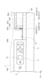
図1及び図2において記録装置の一例であるインクジェットプリンター1は、装置本体部2の上部に、原稿を読み取る読み取り機構部3を備えて成る、所謂複合機である。以下、インクジェットプリンター1は、プリンター1と略称する。
装置本体部2は、被記録媒体の一例である記録用紙に記録を行う機能を有し、読み取り機構部3は、原稿を読み取る機能を有する。
In FIGS. 1 and 2, an
The device
装置本体部2は、周囲を構成する側面のうちX軸方向に沿った側面である装置前面に、プリンター1の電源オンオフ操作を行う為の電源ボタン8及びその他各種操作を行う為の操作部7を有するチルトパネル6を備えている。チルトパネル6は、操作パネルの一例である。操作部7には、各種情報表示を行う表示部7aが設けられている。
チルトパネル6は、装置本体部2の色(例えば白色或いは白色に近い色)に対して暗色系の色、例えば黒色或いは黒色に近い色で形成されている。これにより、チルトパネル6及び操作部7を目立つ様にしている。
チルトパネル6は、図14及び図15に示す左ヒンジ69A及び右ヒンジ69Bを中心に回転することで、チルト可能となっている。
また装置前面には前面カバー9を備えており、前面カバー9は回転軸9a(図11参照)を中心に回転することで、図1乃至図3に示す様に閉じた状態と、図4に示す様に記録が行われて排出される記録用紙の排出経路を開放する開いた状態とを取り得る。
The device
The
The
A
装置本体部2は、上面の前方側が上面カバーとしての前方上面カバー4によって構成されている。前方上面カバー4は、図7に示す左連結部59A及び図8に示す右連結部59Bにおいて、読み取り機構部3を構成する保持フレーム54に対し回転可能に連結されている。左連結部59Aは、図7に示す様に保持フレーム54に形成された左軸部54bと、前方上面カバー4に形成された左軸嵌合部4cとで構成されている。右連結部59Bは、図8に示す様に保持フレーム54に形成された右軸部54cと、前方上面カバー4に形成された右軸嵌合部4dとで構成されている。左軸部54bと右軸部54cは、前方上面カバー4の回転軸を構成する。
そして前方上面カバー4は、回転することで、図1及び図2に示す様に閉じた状態と、図3及び図4に示す様に装置本体部2の内部、特にキャリッジ60を露呈させる開いた状態と、を取り得る。前方上面カバー4を開くことで、例えば詰まった記録用紙の除去や、後述する液体収容部としてのインクタンク61へのインクの注入が実行可能となる。
The front side of the upper surface of the apparatus
1 and 2, and opened to expose the inside of the
前方上面カバー4には、側面形成部4bが一体に設けられている。前方上面カバー4の上面4aと側面形成部4bはほぼ直角を成しており、前方上面カバー4が閉じ且つチルトパネル6が閉じた状態では、図1及び図2に示すように側面形成部4bの表面とチルトパネル6の表面とが面一となる。
側面形成部4bには状態表示部71が設けられている。状態表示部71はLED等の発光手段によってプリンター1の各種状態を表す為の発光部であり、例えば電源投入により点灯し、エラー発生時には点滅する。本実施形態において状態表示部71の点滅によって報知されるエラーには、用紙切れ、紙ジャム、インク切れ、廃液量(後述)が上限に達した、などが含まれる。尚、点滅する際の間隔の違いや表示色の違いを利用してエラー内容を区別することもできる。この様な状態表示部71により、装置の状態を容易に把握することができる。
尚、状態表示部71は、発光を際立たせる為、側面形成部4bの色(例えば白色或いは白色に近い色)に対して暗色系の色、例えば黒色或いは黒色に近い色で形成されている。これにより、装置の状態を容易に把握することができる。
The front
A
The
側面形成部4bにおいて+X方向の側部には、図3、図4、図10に示す様にセンサー押圧部4eが形成されている。センサー押圧部4eは突起状に形成されており、前方上面カバー4が閉じた際、図9に示すスリット68に入り込む。スリット68に入り込んだセンサー押圧部4eは、開閉センサー84(図16参照)を押し、これによりプリンター1の制御部80(図16参照)が、前方上面カバー4が閉じたことを検知できる様に構成されている。
尚、前方上面カバー4が閉じた状態では、センサー押圧部4eとスリット68とが係わり合うことで、前方上面カバー4のX軸方向の位置が規制され、前方上面カバー4のX軸方向のがたつきが抑制される。また同時に、本実施形態では前方上面カバー4のY軸方向の位置も規制され、前方上面カバー4のY軸方向のがたつきも抑制される。
As shown in FIGS. 3, 4, and 10, a
When the front
チルトパネル6及び側面形成部4bの下には前面カバー9が開閉可能に設けられており、図1~図3は前面カバー9が閉じた状態を示し、図4は前面カバー9が開いた状態を示している。前面カバー9が閉じた状態では、前面カバー9の表面、側面形成部4bの表面、チルトパネル6の表面、のこれらが面一となり、垂直に沿った装置側面を形成する。
前面カバー9を開くことで、図4に示す様に装置前方に向けて排出される記録用紙を受ける排出トレイ29を引き出すことができる。
A
By opening the
装置上面における後方側には、後方上面カバー10が設けられている。後方上面カバー10は、回転軸10c(図11、図12参照)を中心に回転することで、図1、図11に示す閉じた状態と、図2、図12に示す開いた状態とを取り得る。
後方上面カバー10を開くと、図2に示す様に読み取り機構部3が露呈し、原稿の読み取りが実行可能となる。また後方上面カバー10を開くと、後述する支持部材12への記録用紙のセットが可能となる。図2において矢印Aは、記録用紙のセット方向を示している。
A rear
When the rear
以下、図11及び図12を参照しつつ、装置本体部2における記録用紙の搬送経路について説明する。
装置後方には支持部材12が設けられており、給送前の記録用紙は、支持部材12と、図12に示す様に開いた状態の後方上面カバー10の裏面で構成される用紙支持面10aとによって傾斜姿勢で支持される。
支持部材12は不図示の揺動軸を中心に揺動可能に構成されており、揺動することで、支持した記録用紙を給送ローラー13に対して進退させる。
The conveying path of the recording paper in the apparatus
A
The
給送ローラー13は不図示のモーターにより回転駆動され、回転することにより、記録用紙を下流に送り出す。給送ローラー13と対向する位置には回転抵抗が付与された分離ローラー14が設けられており、この分離ローラー14が給送ローラー13との間でニップ領域を形成することにより、記録用紙の重送が防止される。
尚、図12において符号Pdで示す二点鎖線は、給送ローラー13により送り出され、搬送される記録用紙の搬送軌跡を示している。
The feeding
In FIG. 12, a two-dot chain line indicated by symbol Pd indicates the transport locus of the recording paper fed and transported by the feeding
給送ローラー13により送り出された記録用紙は、搬送ローラー対17に到達する。搬送ローラー対17は、不図示の駆動源により駆動される駆動ローラー18と、従動回転する従動ローラー19とで構成されており、記録用紙はこの両ローラーによりニップされ、記録ヘッド22と対向する領域、即ち記録領域に送られ、記録が行われる。
The recording paper fed by the
記録ヘッド22を備えるキャリッジ60は、X軸方向に延びるメインフレーム24にガイドされつつ、不図示の動力源によってX軸方向に往復動する。記録ヘッド22は、キャリッジ60の移動動作に伴い、記録用紙に対してインクを吐出する。
キャリッジ60にはインクタンク61が搭載されており、このインクタンク61から記録ヘッド22へとインクが供給される。
尚、本実施形態においてインクタンク61は不図示のインク供給口を備えており、このインク供給口からインクタンク61へのインクの補充が可能に構成されている。インクタンク61へのインクの補充については、後に詳しく説明する。
A
An
In this embodiment, the
メインフレーム24は金属板材により形成されており、側面視において水平方向と交差するフレーム面を形成する鉛直部24aと、鉛直部24aの上部が折り曲げられることで形成された第1水平部24bと、鉛直部24aの下部が折り曲げられることで形成された第2水平部24cと、を備えている。鉛直部24aは、本実施形態では垂直面に沿っている。第1水平部24b及び第2水平部24cは、本実施形態では水平面に沿っている。
メインフレーム24は、第1水平部24bの+Y方向端部が-Z方向に折り曲げられており、また第2水平部24cの+Y方向端部が+Z方向に折り曲げられ、更にその上端部が-Y方向に僅かに折り曲げられており、側面視において全体的に矩形の空間が形成された状態となっている。そしてこの空間にキャリッジ60の一部が入り込み、この入り込んだ部分がメインフレーム24によってX軸方向にガイドされる。
The
In the
記録ヘッド22と対向する位置には支持リブ31が設けられており、記録ヘッド22により記録の行われる記録用紙は、支持リブ31によって支持される。
尚、本実施形態では支持リブ31の周囲には不図示の凹部が形成されており、この凹部には不図示のインク吸収材が配設されていて、用紙端部に余白無く印刷を行う為に用紙端部から外れた領域に吐出されたインクが、インク吸収材により吸収される。吸収されたインクは、不図示のインク流路に沿って図6に示す廃液トレイ77に案内される。この廃液トレイ77は、前面カバー9を開き、そして廃液カバー76を開くことで取り外すことができる。
A
In this embodiment, a concave portion (not shown) is formed around the
図11に戻り、支持部材12に対して搬送方向下流には、記録の行われた記録用紙を装置前方に向けて排出する排出ローラー対26が設けられている。排出ローラー対26は、不図示の駆動源により駆動される駆動ローラー27と、従動回転する従動ローラー28とで構成されており、記録用紙はこの両ローラーによりニップされ、装置前方に向けて排出され、引き出された状態の排出トレイ29によって支持される。
Returning to FIG. 11, a pair of
以上が装置本体部2の構成であり、以下、装置本体部2の上部に設けられた読み取り機構部3について図13を参照しつつ説明する。
読み取り機構部3は、入口トレイ40と、上部ユニット36と、下部ユニット37と、排出トレイ53と、によって全体が構成されている。
The configuration of the apparatus
The
読み取りを行う原稿は、その先端側が入口トレイ40により支持され、後端側が前方上面カバー4(図2参照)の上面4a(図2参照)に支持される。図2において矢印Bは、読み取り原稿のセット方向を示している。また図2において符号Gpは、入口トレイ40と、装置本体部2の上面4aとで支持される、セットされた原稿を示している。また図2において符号38a、38bは、セットされた原稿の側端をガイドするエッジガイドである。
図13に戻り、読み取り機構部3における原稿読み取り時の際の原稿搬送方向は概ね-Y方向であり、入口トレイ40に対し原稿搬送方向の下流には搬送ローラー対41が設けられている。搬送ローラー対41は、不図示の駆動源により駆動される駆動ローラー42と、従動回転する従動ローラー43とで構成されており、原稿はこの両ローラーによりニップされ、原稿搬送方向の下流へと送られる。
A document to be read is supported by the
Returning to FIG. 13, the document transport direction during document reading in the
搬送ローラー対41に対し原稿搬送方向の下流には読み取りガラス58が設けられており、この読み取りガラス58の下側に読み取り手段としてのセンサーモジュール55が設けられている。センサーモジュール55はX軸方向に延設され、押圧ばね57により読み取りラス58の下側から読み取りガラス58の下面に押し当たっている。センサーモジュール55には光学縮小方式(CCD方式)や密着センサー方式(CIS方式)を採用でき、本実施形態では密着センサー方式(CIS方式)を採用する。符号56は、受光素子(不図示)及び発光素子(不図示)が設けられた回路基板である。
センサーモジュール55は、保持フレーム54によって保持されており、保持フレーム54は、下部ユニット37の基体を構成し、また、下部ユニット37の最下面を形成する。
A reading
The
読み取りガラス58の上には押さえ部材45が設けられている。押さえ部材45は、圧縮ばね46によって読み取りガラス58に向けて押圧されている。搬送ローラー対41によって搬送される原稿は、押さえ部材45と読み取りガラス58とで挟まれた状態で、センサーモジュール55によって読み取られる。
従動ローラー43、押さえ部材45、圧縮ばね46、従動ローラー50、のこれらは、上部ユニット36の基体を構成する保持フレーム51に設けられる。
A pressing
The driven
読み取りガラス58の下流には、読み取りの行われた原稿を排出する排出ローラー対48が設けられている。排出ローラー対48は、不図示の駆動源により駆動される駆動ローラー49と、従動回転する従動ローラー50とで構成されており、読み取りの行われた原稿はこの両ローラーによりニップされ、排出トレイ53に向けて排出される。符号Grは、セットされ、読み取りが行われ、排出される原稿の通過軌跡を示している。
A
原稿支持トレイとしての排出トレイ53は、斜め上下方向にスライド変位することで、図11に示す非展開状態と、図2、図12、図13に示す展開状態とを切り換え可能に設けられており、また更にサブトレイ53aを展開可能に構成されている。サブトレイ53aは、回転軸53cを中心に図12の時計回り方向及び反時計回り方向に回転することで、図12において実線で示す展開状態と、2点鎖線及び符号53a_1で示す収納状態と、を取り得る。
尚、長尺の原稿は、排出されるとその先端が排出トレイ53を乗り越え、排出トレイ53の背後に位置する後方上面カバー10の用紙支持面10aによって支持される。
図13において符号Ghで示す実線は、排出トレイ53によって支持される原稿を示している。また、符号53bは、原稿支持面である。
A
When the long document is ejected, the leading end of the document climbs over the
A solid line indicated by symbol Gh in FIG. 13 indicates the document supported by the
以上説明した従動ローラー43、押さえ部材45、圧縮ばね46、従動ローラー50、保持フレーム51、のこれらは、上部ユニット36を構成する。上部ユニット36は、不図示の回転軸を中心にして下部ユニット37に対して回転可能に設けられており、開くことにより、搬送ローラー対41及び排出ローラー対48による原稿ニップ状態が解除できる。
また、以上説明した駆動ローラー42、センサーモジュール55、駆動ローラー49、保持フレーム54、のこれらは、下部ユニット37を構成する。
The driven
Further, the driving
続いてインクタンク61へのインクの補充について説明する。
図3、図4、図10に示す様に、前方上面カバー4を開くと、キャリッジ60及びキャリッジ60に搭載されたインクタンク61が露呈する。インクタンク61は、複数のインクタンク61A、61B、61C、61Dで構成されており、本明細書では各インクタンクを特に区別しない場合にはインクタンク61と総称する。
複数のインクタンク61には、異なる色のインクを収容することができ、例えばブラック、シアン、マゼンタ、イエローのインクを収容することができる。
複数のインクタンク61は、X軸方向に沿って並んで配設されている。
Next, replenishment of ink to the
As shown in FIGS. 3, 4 and 10, when the front
The plurality of
A plurality of
インクタンク61は上部に開閉レバーを備えており、具体的にはインクタンク61Aは開閉レバー62Aを備え、インクタンク61Bは開閉レバー62Bを備え、インクタンク61Cは開閉レバー62Cを備え、インクタンク61Dは開閉レバー62Dを備えている。以下では、各開閉レバーを特に区別しない場合には開閉レバー62と総称する。
開閉レバー62を開くことにより、不図示のインク注入口が露呈し、このインク注入口からインクタンク61内へのインクの補充を行うことができる。
The
By opening the open/
尚、各色の補充用のインクが収容されたインクボトルが、図5に示す様に装置底部に収容できるように構成されている。図5において符号2a、2b、2c、2dは、装置底部に形成された凹部であり、この凹部2a、2b、2c、2dに、補充用のインクが収容されたインクボトル78A、78B、78C、78Dが収容できる様に構成されている。
プリンター1は工場出荷の際、梱包箱内部で凹部2a、2b、2c、2dのそれぞれにインクボトル78A、78B、78C、78Dが収容された状態となる。これにより梱包箱のサイズを抑制することができる。
In addition, ink bottles containing replenishment inks of respective colors are constructed so as to be accommodated in the bottom portion of the apparatus as shown in FIG. In FIG. 5,
When the
続いてインクタンク61は前面、つまり+Y方向の側面に、液面視認部を備えており、具体的には図15に示す様にインクタンク61Aは液面視認部63Aを備え、インクタンク61Bは液面視認部63Bを備え、インクタンク61Cは液面視認部63Cを備え、インクタンク61Dは液面視認部63Dを備えている。以下では、各液面視認部を特に区別しない場合には液面視認部63と総称する。
Next, the
インクタンク61は光を透過可能な材料で形成されており、これにより液面視認部63において、外部からインクタンク61内部のインクの液面を視認することができる。インクタンク61は、例えば無色透明の樹脂材料や、白色系樹脂材料によって形成することができる。インクタンク61を白色系樹脂材料によって形成すれば、内部のインクの色とのコントラストが高まり、インクの液面が視認し易くなる。
キャリッジ60の筐体は、液面視認部63を外部から視認できる様に、液面視認部63の位置が開口形状とされている。
The
The housing of the
次に、図3に示す様にキャリッジ60の移動領域に対し+Y方向には、第1壁部としての右壁部66と、第2壁部としての左壁部65とが設けられている。左壁部65及び右壁部66は、鉛直方向に沿った壁面を成し、右壁部66は-X方向の端部に設けられている。本実施形態において-X方向の端部にキャリッジ60のホームポジションが設定されており、装置の非稼働状態ではキャリッジ60は図3、図4、図14に示す様に-X方向の端部に位置している。尚、ホームポジションには不図示のキャップ機構が設けられており、このキャップ機構により記録ヘッド22がキャップされる。
左壁部65は、右壁部66に対し+X方向に所定の間隔を空けて配置されており、左壁部65と右壁部66との間に露呈部67が形成された状態となっている。即ち露呈部67は、キャリッジ60のホームポジション寄りに位置する右壁部66と、右壁部66よりホームポジションから遠い左壁部65との間の隙間で形成されている。
Next, as shown in FIG. 3, a
The
尚、左壁部65には、図14及び図15に示す左ヒンジ69A及び右ヒンジ69Bを解してチルトパネル6が取り付けられている。即ちチルトパネル6は、第1ヒンジとしての右ヒンジ69B、及び右ヒンジ69Bより露呈部67から遠い第2ヒンジとしての左ヒンジ69Aを介して左壁部65に対しチルト可能に設けられている。
そして左ヒンジ69A及び右ヒンジ69Bのうち、左ヒンジ69Aが、チルトパネル6のチルト角を保持するトルクヒンジで構成される。
これにより、以下の作用効果が得られる。即ち、左壁部65に対し-X方向に露呈部67、つまり隙間が形成されているので、左壁部65において-X方向は片持ち状態となっており、撓みが生じ易い構成となっている。従ってその様な位置にトルクヒンジを設けると、操作パネル6をチルトさせた際のトルクによって左壁部65が撓み易いが、本実施形態では左ヒンジ69A及び右ヒンジ69Bのうち、左ヒンジ69Aが、チルトパネル6のチルト角を保持するトルクヒンジで構成されるので、操作パネル6をチルトさせた際の左壁部65の撓みを抑制できる。
The
Of the
As a result, the following effects are obtained. That is, since the exposed
続いてインクタンク61にインクを補充する際のキャリッジ60の動作について説明する。図16に示す様にプリンター1の各種制御を行う制御部80は、キャリッジ60の動力源であるキャリッジ駆動モーター83、記録ヘッド22、状態表示部71、操作部7を構成する表示部7a、のこれらを制御する。
制御部80は記憶部81を有しており、この記憶部81に、プリンター1の制御に必要な各種プログラムや、プリンター1の制御に必要な各種情報が格納されている。制御部80は、記録ヘッド22の制御に際して吐出したインクのドット数をカウントし、そのカウント値に基づいて複数のインクタンク61毎のインク残量を算出し、算出したインク残量を記憶部81に記憶する。そしてインク残量が所定レベルまで減った場合には、状態表示部71を点滅させてインク残量が所定レベルまで減った旨を報知する。
Next, the operation of the
The
以下、図17を参照してインク補充時に制御部80が実施する制御について説明する。先ず、ユーザーが前方上面カバー4を開くと、上述した不図示の開閉検出センサーの検出信号により、制御部80は前方上面カバー4の閉状態が解消したことを検知する(ステップS101においてYes)。その場合、複数のインクタンク61のうち、インク残量が所定レベル、つまり補充が必要なレベルまで減っているものがあるかを判断し(ステップS102)、インクの補充が必要なインクタンク61がある場合は(ステップS102においてYes)、操作部7の表示部7aに、インク補充ユーザーインターフェースを表示する(ステップS103)。インク補充ユーザーインターフェースは、以下ではインク補充UIと略称する。
The control performed by the
インク補充UIは、例えば補充が必要なインク色の表示と、「インクを補充しますか?」等の確認メッセージの表示で構成できる。これに対しユーザーがOKボタンを押下すると、制御部80はユーザーがインク補充の実施意思があると判断し(ステップS104においてYes)、ホームポジションに位置していたキャリッジ60を、インク補充ポジションまで移動させる(ステップS105)。
キャリッジ60のインク補充ポジションとは、図15に示す様に複数の液面視認部63の全てが露呈部67を介して視認できる位置であり、ホームポジションから+X方向に所定量移動した位置である。
The ink replenishment UI can be configured by, for example, displaying the color of ink that needs to be replenished and displaying a confirmation message such as "Would you like to replenish ink?" On the other hand, when the user presses the OK button, the
The ink replenishment position of the
尚、右壁部66の上端には図3に示す様に覆い部66aが形成されており、この覆い部66aによって開閉レバー62の一部分、より具体的には+Y方向の端部が覆われ、キャリッジ60がホームポジションに位置する際には開閉レバー62を開くことができない様に構成されている。即ち、キャリッジ60がホームポジションに位置する際、インクタンク61へのインクの補充ができない様に構成されている。
A
この状態からキャリッジ60がインク補充ポジションまで移動すると、図15に示す様に複数の開閉レバー62の全てが覆い部66aから外れ、複数の開閉レバー62の全てが開放可能となる。これにより開閉レバー62を開き、インクタンク61へのインクの補充が行える。また上述したように、複数の液面視認部63の全てが露呈部67を介して視認できる。従ってユーザーは、液面視認部63を見ながら、インクタンク61へのインクの補充を行うことができる。
When the
ステップS105の実行後、制御部80は、インク補充UIの表示を例えば「インクの補充を終了しますか?」のメッセージ表示に変更し、これに対しユーザーがOKボタンを押下すると、ユーザーによるインク補充作業が終了したと判断し(ステップS106においてYes)、キャリッジ60をインク補充ポジションからホームポジションに戻すとともに、インク補充の対象となったインクタンク61に関するインク残量情報を、インク残量が最も多いフル状態にセットする。
尚、上述したように前方上面カバー4が閉じられたことを検出する開閉センサー84が設けられているので、前方上面カバー4の閉状態を検出したことをもってキャリッジ60をホームポジションに戻すこともできる。
After executing step S105, the
Since the open/
上述したようにプリンター1は、X軸方向に沿った装置側面である装置前面に設けられる操作パネル6を備え、装置前面を正面視して、+X方向の端部から-X方向に向かって、操作パネル6、液面視認部6を露呈させる露呈部67、キャリッジ60のホームポジション、がこれらの順に配置され、キャリッジ60がホームポジションから露呈部67に向かって移動することで、図14から図15への変化に示す様に装置前面を正面視して操作パネル6と液面視認部63とがX軸方向に並ぶ構成である。
As described above, the
従ってインクタンク61にインクを注入するインク注入作業の際には操作パネル6に対して液面視認部63が近づくこととなり、操作パネル6の操作とインク注入作業とを行う場合にユーザーの視線の移動量が少なくて済み、インク注入作業をより容易に行うことができる。
Therefore, during the ink injection work of injecting ink into the
また本実施形態では、キャリッジ60の上部には、閉じた状態において装置の天面を構成し、開くことでキャリッジ60の上部を露呈させる前方上面カバー4が設けられ、前方上面カバー4は、閉じた状態において操作パネル6とともに装置前面を構成する側面形成部4bを備え、前方上面カバー4が閉じると側面形成部4bが露呈部67を覆い、前方上面カバー4が開くと側面形成部4bが露呈部67を露呈させる構成である。
従って露呈部67を開口形状で構成しても露呈部67を介して装置内部に塵埃等が侵入することを抑制できる。そして露呈部67を開口形状で形成することで液面視認部63を直接視認することができ、露呈部67を例えば透明の板材で形成する様な場合に比して液面視認部63の視認性が良好となり、インクタンク61におけるインクの液面をより正確に視認することができる。更に、側面形成部4bをそれ単体で形成して開閉可能に構成する場合は前方上面カバー4の開閉操作に加えて別途側面形成部4bの開閉操作が必要となるが、側面形成部4bは前方上面カバー4に設けられているので、1つの操作でキャリッジ60上部の開放と露呈部67の露呈とを行うことができ、操作性が向上する。
Further, in this embodiment, a front
Therefore, even if the exposed
尚、本実施形態において前方上面カバー4には、図4に示す様に発光ユニット72に電気的に接続される配線73を覆う配線カバー74が設けられている。発光ユニット72は、図1~図3に示す状態表示部71を構成するユニットである。この配線カバー74は、X軸方向に延びる部位74aが前方上面カバー4の回転軸寄りに位置しており、これによって前方上面カバー4の重心位置が、前方上面カバー4の回転軸寄りに位置する。前方上面カバー4の重心位置は、図10において符号Gで示されている。また、この重心位置Gが前方上面カバー4の回転軸寄りに位置するとは、図10において重心位置Gが、右軸部54c及び左軸部54bと、自由端に位置する側面形成部4bとの中間位置CLよりも、右軸部54c及び左軸部54b側に位置することを意味する。
これにより、前方上面カバー4が意図せず閉じた際の衝撃を抑制できる。
In this embodiment, the front
As a result, it is possible to suppress the impact when the front
また本実施形態において前方上面カバー4は、閉じた状態から図10に示す様に90°より大きい回転角の回転によって開放限度まで開く。具体的には本実施形態において前方上面カバー4は水平に閉じた状態から112.5°回転すると図10の開放限度まで開く。従って前方上面カバー4が開いた状態を良好に維持できる。
Further, in this embodiment, the front
尚、前方上面カバー4が開放限度まで開いた際、後方上面カバー10が閉じていれば、後方上面カバー10の+Y方向端部によって前方上面カバー4を支持することができる。また、前方上面カバー4が開放限度まで開いた際、後方上面カバー10が開いていれば、読み取り機構部3の+Y方向端部である当接部3c、3c(図2参照)によって前方上面カバー4を支持することができる。
When the front
尚、本実施形態では図10に示す様に、前方上面カバー4の回転軸を構成する右軸部54cと左軸部54bは、Y軸方向においてメインフレーム24よりも+Y方向に位置しており、これにより前方上面カバー4を開いても、メインフレーム24が-Y方向に奥まった場所に位置する。メインフレーム24には、キャリッジ60の位置を検出する不図示のリニアスケールが設けられており、ユーザーによって触れられることでリニアスケールが汚れ、検出不良が生じる虞があるが、上記の様に前方上面カバー4を開いても、メインフレーム24が-Y方向に奥まった場所に位置するので、上記の様な不具合の発生を抑制できる。
In this embodiment, as shown in FIG. 10, the
続いて図18~図23を参照してプリンターの他の実施形態について説明する。図18~図13に示すプリンター1Aが上述したプリンター1と異なるのは、主として図18に示す様にカバー部材85と、保持手段86とを備える点にある。尚、プリンター1Aのその他の構成は上述したプリンター1と同様であるので、以下ではその説明は省略する。
保持手段86は、前方上面カバー4が開いた状態を保持する為の手段であり、図19に示す様にカバー部材87と、図20及び図21に示す様にプランジャ90と、押圧部材の一例である圧縮ばね89と、を備えて構成されている。プランジャ90の一部と圧縮ばね89はカバー部材87で覆われており、カバー部材87は固定ねじ88によって前方上面カバー4に固定されている。
Next, another embodiment of the printer will be described with reference to FIGS. 18 to 23. FIG. The printer 1A shown in FIGS. 18 to 13 differs from the
The holding means 86 is means for holding the open state of the front
プランジャ90は、前方上面カバー4の回転半径方向にスライド可能であるとともに、圧縮ばね89によって前方上面カバー4の回転中心に向けて押圧されている。
符号54Aは上述した保持フレーム54に相当する部材であり、保持フレーム54Aには開口部54eと、当接部54dとが形成されている。
前方上面カバー4が閉じた状態では、図21に示す様にプランジャ90は開口部54eに入り込んでおり、圧縮ばね89のばね力は保持フレーム54Aに対して作用していない。
The
When the front
この状態から前方上面カバー4が開くと、プランジャ90が保持フレーム54Aの当接部54dに対向し且つ当接する。前方上面カバー4が全開状態の図20では、圧縮ばね89のばね力によってプランジャ90が当接部54dに押し付けられる力が、前方上面カバー4の全開状態を保持する様に作用する。即ち、圧縮ばね89のばね力によってプランジャ90が当接部54dに押し付けられることで、保持手段86は前方上面カバー4に対し図20の反時計回り方向のモーメントを生じさせる。これにより前方上面カバー4が意図せず閉じることを抑制できる。また、前方上面カバー4を全開状態にした際にクリック感が得られ、ユーザーの操作性が向上する。
When the front
続いて図18、図22、図23に示す様に、覆い部材としての保持フレーム54Aの+Y方向の端部に、図X軸方向に延びる切り欠き部54gが形成されている。切り欠き部54gにはカバー部材85が不図示の固定ねじによって固定される。
キャリッジ60には上部カバー64が設けられており、この上部カバー64を取り外すことによってインクタンク61を取り外すことができ、そして更に記録ヘッド22(図11参照)を取り外すことができる。
Subsequently, as shown in FIGS. 18, 22, and 23, a
The
ここで、カバー部材85が取り付けられた状態では、上部カバー64の一部が保持フレーム54A或いはカバー部材85によって覆われることで、上部カバー64は取り外すことができない状態となっている。しかしながら図22に示す様に、カバー部材85を取り外すことで、キャリッジ60が切り欠き部54gに位置した状態で上部カバー64の全体が露呈する状態となり、上部カバー64を取り外すことができる。
この様に保持フレーム54Aに切り欠き部54gを設けることで、インクタンク61や記録ヘッド22(図11参照)を取り外す際に大掛かりな分解作業を行うことを回避でき、メンテナンス性が向上する。
Here, when the
By providing the
本発明は上記において説明した各実施形態に限定されることなく、特許請求の範囲に記載した発明の範囲内で、種々の変形が可能であり、それらも本発明の範囲内に含まれるものであることは言うまでもない。 The present invention is not limited to the respective embodiments described above, and various modifications are possible within the scope of the invention described in the claims, which are also included in the scope of the present invention. One thing goes without saying.
1…インクジェットプリンター、2…装置本体部、2a、2b、2c、2d…凹部、3…読み取り機構部、4…前方上面カバー、4a…上面、4b…側面形成部、4c…左軸嵌合部、4d…右軸嵌合部、4e…センサー押圧部、6…チルトパネル、7…操作部、7a…表示部、8…電源ボタン、9…前面カバー、10…後方上面カバー、10a…用紙支持面、10b…押圧面、10c…回転軸、12…支持部材、13…給送ローラー、14…分離ローラー、17…搬送ローラー対、18…駆動ローラー、19…従動ローラー、22…記録ヘッド、23…支持部材、24…メインフレーム、24a…鉛直部、24b…第1水平部、24c…第2水平部、24d…折り曲げ部、26…排出ローラー対、27…駆動ローラー、28…従動ローラー、29…排出トレイ、36…上部ユニット、37…下部ユニット、38a、38b…エッジガイド、40…入口トレイ、41…搬送ローラー対、42…駆動ローラー、43…従動ローラー、45…押さえ部材、46…圧縮ばね、48…排出ローラー対、49…駆動ローラー、50…従動ローラー、51…保持フレーム、53…排出トレイ、53a…サブトレイ、53b…原稿支持面、54…保持フレーム、54a…ガイド部、54b…左軸部、54c…右軸部、54d…当接部、54e…穴部、54g…切り欠き部、55…センサーモジュール、56…回路基板、57…押圧ばね、58…読み取りガラス、59A…左連結部、59B…右連結部、60…キャリッジ、61A、61B、61C、61D…インクタンク、62A、62B、62C、62D…開閉レバー、63A、63B、63C、63D…液面視認部、64…上部カバー、65…左壁部、66…右壁部、66a…覆い部、67…露呈部、68…スリット、69A…左ヒンジ、69B…右ヒンジ、71…状態表示部、72…発光ユニット、73…配線、74…配線カバー、76…廃液カバー、77…廃液トレイ、78A、78B、78C、78D…インクボトル、80…制御部、81…記憶部、83…キャリッジ駆動モーター、84…開閉センサー、85…カバー部材、
86…保持手段、87…カバー部品、88…固定ねじ、89…圧縮ばね、90…プランジャ
DESCRIPTION OF
86... Holding means, 87... Cover component, 88... Fixing screw, 89... Compression spring, 90... Plunger
Claims (14)
前記キャリッジに設けられ、液体を注入可能に構成されるとともに、内部の液面の位置を視認可能な液面視認部を有する液体収容部と、
前記キャリッジに設けられ、前記液体収容部から前記液体が供給されて、前記被記録媒体に前記液体を吐出する記録ヘッドと、
前記幅方向に沿った装置側面に設けられる操作パネルと、を備え、
前記装置側面を正面視して、前記操作パネル、及び前記液面視認部を露呈させる露呈部が視認可能に配置され、
前記キャリッジがホームポジションから前記露呈部に向かって移動することで、前記装置側面を正面視して前記操作パネルと前記液面視認部とが前記幅方向に並び、
前記キャリッジの上部には、閉じた状態において装置の天面を構成し、開くことで前記キャリッジの上部を露呈させる上面カバーが設けられ、
前記上面カバーは、閉じた状態において前記操作パネルとともに前記装置側面を構成する側面形成部を備え、
前記上面カバーが閉じると前記側面形成部が前記露呈部を覆い、前記上面カバーが開くと前記側面形成部が前記露呈部を露呈させる、
ことを特徴とする記録装置。 a carriage movable in a first direction that is one of width directions intersecting the conveying direction of the recording medium and a second direction that is opposite to the first direction;
a liquid containing portion provided in the carriage, configured to be capable of injecting liquid, and having a liquid level visualizing portion for visually recognizing the position of the internal liquid surface;
a recording head provided on the carriage, supplied with the liquid from the liquid containing portion, and ejecting the liquid onto the recording medium;
an operation panel provided on the side surface of the device along the width direction,
When the side surface of the device is viewed from the front, the operation panel and the exposing portion for exposing the liquid surface visual recognition portion are arranged so as to be visible,
By moving the carriage from the home position toward the exposed portion, the operation panel and the liquid level viewing portion are aligned in the width direction when viewed from the side of the device,
A top cover is provided on the top of the carriage, which constitutes the top surface of the device when closed and exposes the top of the carriage when opened,
The top cover includes a side surface forming portion that constitutes a side surface of the device together with the operation panel in a closed state,
When the top cover is closed, the side surface forming portion covers the exposed portion, and when the top cover is opened, the side surface forming portion exposes the exposed portion.
A recording device characterized by:
ことを特徴とする記録装置。 2. The recording apparatus according to claim 1, wherein the operation panel, the exposed portion, and the home position are arranged in this order from the end portion in the second direction toward the first direction when the side surface of the device is viewed from the front. to be placed,
A recording device characterized by:
前記操作パネルは、第1ヒンジ、及び前記第1ヒンジより前記露呈部から遠い第2ヒンジを介して前記第2壁部に対しチルト可能に設けられる、
ことを特徴とする記録装置。 3. The recording apparatus according to claim 1 , wherein the exposed portion includes a first wall portion positioned at an end portion in the first direction and a second wall portion positioned in the second direction with respect to the first wall portion. formed in the gap between the two walls and
The operation panel is provided tiltably with respect to the second wall via a first hinge and a second hinge farther from the exposed portion than the first hinge,
A recording device characterized by:
ことを特徴とする記録装置。 4. The recording apparatus according to claim 3 , wherein out of said first hinge and said second hinge, said second hinge comprises a torque hinge that holds a tilt angle of said operation panel.
A recording device characterized by:
ことを特徴とする記録装置。 5. The recording apparatus according to any one of claims 1 to 4 , wherein the side forming portion is provided with a light-emitting portion that indicates the state of the device by lighting or blinking.
A recording device characterized by:
前記配線カバーの重心位置が、前記上面カバーの回転軸寄りに位置する、
ことを特徴とする記録装置。 6. The recording apparatus according to claim 5 , wherein the top cover is provided with a wiring cover that covers wiring electrically connected to the light emitting section,
The center of gravity of the wiring cover is located near the rotation axis of the top cover.
A recording device characterized by:
ことを特徴とする記録装置。 7. The recording apparatus according to any one of claims 1 to 6 , wherein the top cover is opened to the open limit by rotating a rotation angle greater than 90 degrees from the closed state.
A recording device characterized by:
前記開閉センサーは、前記突起が入り込むスリットの内部に設けられ、
前記上面カバーが閉じた状態において前記突起と前記スリットとが係わり合うことにより、少なくとも前記上面カバーの前記幅方向における位置が規制される、
ことを特徴とする記録装置。 8. The recording apparatus according to any one of claims 1 to 7 , further comprising an open/close sensor that detects a closed state of the top cover by being pushed by a protrusion provided on the side forming portion,
The open/close sensor is provided inside a slit into which the projection enters,
At least the position of the top cover in the width direction is regulated by engaging the protrusions and the slits when the top cover is closed.
A recording device characterized by:
原稿を読み取る読み取り手段及び前記読み取り手段に対し前記原稿を搬送する原稿搬送手段を有し、前記装置本体部の上部に設けられる原稿読み取り機構部と、を備え、
前記上面カバーが、前記原稿読み取り機構部を構成するフレームに対し回転可能に連結される、
ことを特徴とする記録装置。 9. The recording apparatus according to any one of claims 1 to 8 , wherein an apparatus body section including the carriage;
a document reading mechanism section provided on the upper part of the device main body, having reading means for reading a document and document conveying means for conveying the document to the reading means;
the top cover is rotatably connected to a frame that constitutes the document reading mechanism;
A recording device characterized by:
前記保持手段は、前記上面カバーに設けられ、回転することで開閉する前記上面カバーの回転半径方向にスライド可能であるプランジャと、
前記上面カバーに設けられ、前記プランジャを押圧する押圧部材と、と備え、
前記プランジャと対向する位置に設けられた当接部に前記プランジャが押し当たることで、前記上面カバーの開いた状態が保持される、
ことを特徴とする記録装置。 10. The recording apparatus according to any one of claims 1 to 9 , further comprising holding means for holding the top cover in an open state,
The holding means is a plunger that is provided on the top cover and is slidable in a rotational radial direction of the top cover that opens and closes by rotating;
a pressing member that is provided on the top cover and presses the plunger;
The open state of the top cover is maintained by the plunger pressing against a contact portion provided at a position facing the plunger.
A recording device characterized by:
前記覆い部材において前記キャリッジの移動方向における一部には、切り欠き部が設けられ、
前記切り欠き部には、取り外し可能なカバー部材が設けられている、
ことを特徴とする記録装置。 11. The recording apparatus according to any one of claims 1 to 10 , further comprising a cover member covering a portion of the upper portion of the carriage along the moving direction of the carriage,
A notch is provided in a part of the cover member in the moving direction of the carriage,
A removable cover member is provided in the notch,
A recording device characterized by:
ことを特徴とする記録装置。 12. The recording apparatus according to any one of claims 1 to 11, wherein the liquid can be injected into the liquid containing section when the liquid level visualizing section is positioned in the exposed section.
A recording device characterized by:
前記キャリッジに設けられ、液体を注入可能に構成されるとともに、内部の液面の位置を視認可能な液面視認部を有する液体収容部と、
前記キャリッジに設けられ、前記液体収容部から前記液体が供給されて、前記被記録媒体に前記液体を吐出する記録ヘッドと、
前記幅方向に沿った装置側面に設けられる操作パネルと、
前記キャリッジの上部に設けられ、閉じた状態において装置の天面を構成し、開くことで前記キャリッジの上部を露呈させる上面カバーと、
前記液面視認部を視認可能にする露呈部と、を備え、
前記露呈部は、前記装置側面を正面視して、前記第1方向の端部に位置する壁部と、前記壁部に対し前記第2方向に位置する前記操作パネルと、の間に配置され、
前記上面カバーは、閉じた状態において前記操作パネルとともに前記装置側面を構成する側面形成部を有し、
前記上面カバーが閉じると前記側面形成部が前記露呈部を覆い、前記上面カバーが開くと前記側面形成部が前記露呈部を露呈させる、
ことを特徴とする記録装置。 a carriage movable in a first direction that is one of width directions intersecting the conveying direction of the recording medium and a second direction that is opposite to the first direction;
a liquid containing portion provided in the carriage, configured to be capable of injecting liquid, and having a liquid level visualizing portion for visually recognizing the position of the internal liquid surface;
a recording head provided on the carriage, supplied with the liquid from the liquid containing portion, and ejecting the liquid onto the recording medium;
an operation panel provided on a side surface of the device along the width direction;
a top cover provided on the top of the carriage, constituting a top surface of the apparatus in a closed state, and exposing the top of the carriage when opened;
and an exposed portion that makes the liquid surface visible portion visible,
The exposed portion is disposed between a wall portion located at an end portion in the first direction and the operation panel located in the second direction with respect to the wall portion when viewed from the side of the device. ,
The top cover has a side surface forming portion forming a side surface of the device together with the operation panel in a closed state,
When the top cover is closed, the side surface forming portion covers the exposed portion, and when the top cover is opened, the side surface forming portion exposes the exposed portion.
A recording device characterized by:
ことを特徴とする記録装置。 14. The recording apparatus according to claim 13, wherein the liquid can be injected into the liquid containing section when the liquid level visualizing section is positioned at the exposed section.
A recording device characterized by:
Priority Applications (4)
| Application Number | Priority Date | Filing Date | Title |
|---|---|---|---|
| JP2019097494A JP7287112B2 (en) | 2019-05-24 | 2019-05-24 | recording device |
| CN202010429750.6A CN111976297B (en) | 2019-05-24 | 2020-05-20 | Recording apparatus |
| US16/880,403 US11351793B2 (en) | 2019-05-24 | 2020-05-21 | Recording apparatus |
| US17/658,319 US11794482B2 (en) | 2019-05-24 | 2022-04-07 | Recording apparatus |
Applications Claiming Priority (1)
| Application Number | Priority Date | Filing Date | Title |
|---|---|---|---|
| JP2019097494A JP7287112B2 (en) | 2019-05-24 | 2019-05-24 | recording device |
Publications (3)
| Publication Number | Publication Date |
|---|---|
| JP2020189474A JP2020189474A (en) | 2020-11-26 |
| JP2020189474A5 JP2020189474A5 (en) | 2022-04-27 |
| JP7287112B2 true JP7287112B2 (en) | 2023-06-06 |
Family
ID=73441802
Family Applications (1)
| Application Number | Title | Priority Date | Filing Date |
|---|---|---|---|
| JP2019097494A Active JP7287112B2 (en) | 2019-05-24 | 2019-05-24 | recording device |
Country Status (3)
| Country | Link |
|---|---|
| US (2) | US11351793B2 (en) |
| JP (1) | JP7287112B2 (en) |
| CN (1) | CN111976297B (en) |
Families Citing this family (2)
| Publication number | Priority date | Publication date | Assignee | Title |
|---|---|---|---|---|
| WO2022071149A1 (en) * | 2020-09-30 | 2022-04-07 | Brother Kogyo Kabushiki Kaisha | Liquid discharging apparatus |
| JP2024049012A (en) * | 2022-09-28 | 2024-04-09 | 株式会社リコー | Liquid ejection device |
Citations (5)
| Publication number | Priority date | Publication date | Assignee | Title |
|---|---|---|---|---|
| US20020140749A1 (en) | 2001-04-03 | 2002-10-03 | Wen-Li Su | Screen color for detecting ink level for foam based ink supplies |
| JP2012232602A (en) | 2003-12-26 | 2012-11-29 | Canon Inc | Ink tank and inkjet recording apparatus |
| JP6106730B2 (en) | 2015-10-02 | 2017-04-05 | 京楽産業.株式会社 | Game machine |
| JP2018161852A (en) | 2017-03-27 | 2018-10-18 | セイコーエプソン株式会社 | Recording apparatus |
| JP2019069550A (en) | 2017-10-10 | 2019-05-09 | セイコーエプソン株式会社 | Liquid jetting device |
Family Cites Families (11)
| Publication number | Priority date | Publication date | Assignee | Title |
|---|---|---|---|---|
| WO1997023352A1 (en) * | 1995-12-25 | 1997-07-03 | Seiko Epson Corporation | Ink-jet recording apparatus for ink cartridge |
| JPH1044396A (en) * | 1996-08-08 | 1998-02-17 | Brother Ind Ltd | Ink jet printer having replaceable ink cartridge |
| DE69739224D1 (en) * | 1996-11-22 | 2009-03-05 | Seiko Epson Corp | Ink jet recording apparatus |
| JP4941110B2 (en) | 2007-06-01 | 2012-05-30 | ブラザー工業株式会社 | Inkjet printer |
| JP6171313B2 (en) * | 2011-12-08 | 2017-08-02 | セイコーエプソン株式会社 | Liquid ejector |
| JP5962886B2 (en) * | 2012-01-23 | 2016-08-03 | セイコーエプソン株式会社 | Recording device |
| JP5605385B2 (en) * | 2012-03-29 | 2014-10-15 | ブラザー工業株式会社 | Image processing device |
| JP6805498B2 (en) * | 2016-01-29 | 2020-12-23 | セイコーエプソン株式会社 | Multifunction device |
| JP6794783B2 (en) * | 2016-11-04 | 2020-12-02 | セイコーエプソン株式会社 | Liquid injection device |
| JP6895055B2 (en) | 2017-03-27 | 2021-06-30 | セイコーエプソン株式会社 | Recording device |
| US10562312B2 (en) * | 2017-10-06 | 2020-02-18 | Seiko Epson Corporation | Liquid ejecting apparatus |
-
2019
- 2019-05-24 JP JP2019097494A patent/JP7287112B2/en active Active
-
2020
- 2020-05-20 CN CN202010429750.6A patent/CN111976297B/en active Active
- 2020-05-21 US US16/880,403 patent/US11351793B2/en active Active
-
2022
- 2022-04-07 US US17/658,319 patent/US11794482B2/en active Active
Patent Citations (5)
| Publication number | Priority date | Publication date | Assignee | Title |
|---|---|---|---|---|
| US20020140749A1 (en) | 2001-04-03 | 2002-10-03 | Wen-Li Su | Screen color for detecting ink level for foam based ink supplies |
| JP2012232602A (en) | 2003-12-26 | 2012-11-29 | Canon Inc | Ink tank and inkjet recording apparatus |
| JP6106730B2 (en) | 2015-10-02 | 2017-04-05 | 京楽産業.株式会社 | Game machine |
| JP2018161852A (en) | 2017-03-27 | 2018-10-18 | セイコーエプソン株式会社 | Recording apparatus |
| JP2019069550A (en) | 2017-10-10 | 2019-05-09 | セイコーエプソン株式会社 | Liquid jetting device |
Also Published As
| Publication number | Publication date |
|---|---|
| US20200369038A1 (en) | 2020-11-26 |
| CN111976297A (en) | 2020-11-24 |
| US11351793B2 (en) | 2022-06-07 |
| JP2020189474A (en) | 2020-11-26 |
| US20220227141A1 (en) | 2022-07-21 |
| US11794482B2 (en) | 2023-10-24 |
| CN111976297B (en) | 2022-06-24 |
Similar Documents
| Publication | Publication Date | Title |
|---|---|---|
| CN108016138B (en) | Liquid ejecting apparatus | |
| EP1800871B1 (en) | Ink cartridge loading device | |
| US8736915B2 (en) | Image reading-recording apparatus | |
| JP7287112B2 (en) | recording device | |
| JP2008534312A (en) | Liquid cartridge, liquid cartridge attaching / detaching device, recording apparatus, and liquid ejecting apparatus | |
| JP2018069698A (en) | Liquid injection device | |
| US10894424B2 (en) | Liquid-consuming apparatus | |
| CN108146077B (en) | Liquid storage unit and liquid ejecting apparatus | |
| JP2008018671A (en) | Ink cartridge holding member and inkjet recorder equipped with the same | |
| JP4092536B2 (en) | Image forming apparatus and manifold cap used therefor | |
| US20120086164A1 (en) | Recording Apparatus | |
| JP6295658B2 (en) | Printing device | |
| JP6897807B2 (en) | Liquid containment | |
| JP6652178B2 (en) | Liquid container | |
| JP4968437B2 (en) | Carriage and liquid ejecting apparatus | |
| JP5928692B2 (en) | Recording device | |
| JP5728898B2 (en) | Panel body tilting mechanism and image recording apparatus having the same | |
| JP7443686B2 (en) | image forming device | |
| JP2005089033A (en) | Printing device | |
| JP2023136539A (en) | printer | |
| JP2015024605A (en) | Recording device | |
| JP2016002700A (en) | Recording device |
Legal Events
| Date | Code | Title | Description |
|---|---|---|---|
| RD07 | Notification of extinguishment of power of attorney |
Free format text: JAPANESE INTERMEDIATE CODE: A7427 Effective date: 20200811 |
|
| RD04 | Notification of resignation of power of attorney |
Free format text: JAPANESE INTERMEDIATE CODE: A7424 Effective date: 20210916 |
|
| RD03 | Notification of appointment of power of attorney |
Free format text: JAPANESE INTERMEDIATE CODE: A7423 Effective date: 20211102 |
|
| A521 | Request for written amendment filed |
Free format text: JAPANESE INTERMEDIATE CODE: A523 Effective date: 20220418 |
|
| A621 | Written request for application examination |
Free format text: JAPANESE INTERMEDIATE CODE: A621 Effective date: 20220418 |
|
| A977 | Report on retrieval |
Free format text: JAPANESE INTERMEDIATE CODE: A971007 Effective date: 20230215 |
|
| A131 | Notification of reasons for refusal |
Free format text: JAPANESE INTERMEDIATE CODE: A131 Effective date: 20230221 |
|
| A521 | Request for written amendment filed |
Free format text: JAPANESE INTERMEDIATE CODE: A523 Effective date: 20230407 |
|
| TRDD | Decision of grant or rejection written | ||
| A01 | Written decision to grant a patent or to grant a registration (utility model) |
Free format text: JAPANESE INTERMEDIATE CODE: A01 Effective date: 20230425 |
|
| A61 | First payment of annual fees (during grant procedure) |
Free format text: JAPANESE INTERMEDIATE CODE: A61 Effective date: 20230508 |
|
| R150 | Certificate of patent or registration of utility model |
Ref document number: 7287112 Country of ref document: JP Free format text: JAPANESE INTERMEDIATE CODE: R150 |