JP6805498B2 - Multifunction device - Google Patents
Multifunction device Download PDFInfo
- Publication number
- JP6805498B2 JP6805498B2 JP2016015319A JP2016015319A JP6805498B2 JP 6805498 B2 JP6805498 B2 JP 6805498B2 JP 2016015319 A JP2016015319 A JP 2016015319A JP 2016015319 A JP2016015319 A JP 2016015319A JP 6805498 B2 JP6805498 B2 JP 6805498B2
- Authority
- JP
- Japan
- Prior art keywords
- operation panel
- housing
- liquid container
- recording
- operating
- Prior art date
- Legal status (The legal status is an assumption and is not a legal conclusion. Google has not performed a legal analysis and makes no representation as to the accuracy of the status listed.)
- Active
Links
Images


Classifications
-
- B—PERFORMING OPERATIONS; TRANSPORTING
- B41—PRINTING; LINING MACHINES; TYPEWRITERS; STAMPS
- B41J—TYPEWRITERS; SELECTIVE PRINTING MECHANISMS, i.e. MECHANISMS PRINTING OTHERWISE THAN FROM A FORME; CORRECTION OF TYPOGRAPHICAL ERRORS
- B41J2/00—Typewriters or selective printing mechanisms characterised by the printing or marking process for which they are designed
- B41J2/005—Typewriters or selective printing mechanisms characterised by the printing or marking process for which they are designed characterised by bringing liquid or particles selectively into contact with a printing material
- B41J2/01—Ink jet
- B41J2/17—Ink jet characterised by ink handling
- B41J2/175—Ink supply systems ; Circuit parts therefor
-
- B—PERFORMING OPERATIONS; TRANSPORTING
- B41—PRINTING; LINING MACHINES; TYPEWRITERS; STAMPS
- B41J—TYPEWRITERS; SELECTIVE PRINTING MECHANISMS, i.e. MECHANISMS PRINTING OTHERWISE THAN FROM A FORME; CORRECTION OF TYPOGRAPHICAL ERRORS
- B41J2/00—Typewriters or selective printing mechanisms characterised by the printing or marking process for which they are designed
- B41J2/005—Typewriters or selective printing mechanisms characterised by the printing or marking process for which they are designed characterised by bringing liquid or particles selectively into contact with a printing material
- B41J2/01—Ink jet
- B41J2/17—Ink jet characterised by ink handling
- B41J2/175—Ink supply systems ; Circuit parts therefor
- B41J2/17503—Ink cartridges
-
- B—PERFORMING OPERATIONS; TRANSPORTING
- B41—PRINTING; LINING MACHINES; TYPEWRITERS; STAMPS
- B41J—TYPEWRITERS; SELECTIVE PRINTING MECHANISMS, i.e. MECHANISMS PRINTING OTHERWISE THAN FROM A FORME; CORRECTION OF TYPOGRAPHICAL ERRORS
- B41J29/00—Details of, or accessories for, typewriters or selective printing mechanisms not otherwise provided for
- B41J29/12—Guards, shields or dust excluders
- B41J29/13—Cases or covers
-
- B—PERFORMING OPERATIONS; TRANSPORTING
- B41—PRINTING; LINING MACHINES; TYPEWRITERS; STAMPS
- B41J—TYPEWRITERS; SELECTIVE PRINTING MECHANISMS, i.e. MECHANISMS PRINTING OTHERWISE THAN FROM A FORME; CORRECTION OF TYPOGRAPHICAL ERRORS
- B41J3/00—Typewriters or selective printing or marking mechanisms characterised by the purpose for which they are constructed
- B41J3/44—Typewriters or selective printing mechanisms having dual functions or combined with, or coupled to, apparatus performing other functions
Description
本発明は、液体を用いて記録を行う記録装置の上に画像読取装置が配置された複合機に関する。 The present invention relates to a multifunction device in which an image reading device is arranged on a recording device that records using a liquid.
従来から、液体の一例であるインクを用いて媒体に記録を行う記録装置の上方に、画像を読み取り可能な画像読取装置を重ねて配置した複合機が知られている。こうした複合機の一例として、特許文献1には、画像読取部(画像読取装置)が画像形成部(記録装置)の筐体に対して筐体内を露出させる開き位置と露出させない閉じ位置との二位置間を開閉動作可能に設けられたインクジェットプリンタ(複合機)が開示されている。また、このインクジェットプリンタは、その画像形成部の筐体内に、用紙(媒体)に向けてインクを吐出する記録ヘッドと、記録ヘッドに供給されるインクを収容するメインタンクとを備えている。 Conventionally, there has been known a multifunction device in which an image reading device capable of reading an image is superposed on a recording device that records on a medium using ink, which is an example of a liquid. As an example of such a multifunction device, Patent Document 1 states that the image reading unit (image reading device) has an opening position that exposes the inside of the housing of the image forming unit (recording device) and a closing position that does not expose the inside of the housing. An inkjet printer (multifunction device) provided so as to be able to open and close between positions is disclosed. Further, this inkjet printer includes a recording head that ejects ink toward paper (medium) and a main tank that houses the ink supplied to the recording head in the housing of the image forming portion.
ところで、特許文献1のインクジェットプリンタの場合、メインタンクに収容されるインクの量が僅少になった際には、メインタンクが有する補充口からメインタンク内にインクが注入される。このとき、ユーザーが画像形成部の筐体内に配置されたメインタンクにアクセスするには、画像読取部を閉じ位置から開き位置に開き動作させて、画像形成部の筐体内を露出させる必要がある。一般的に、画像読取部は重量が大きいため、インクの補充の度に画像読取部を開閉動作させることはユーザーにとって負担となる。 By the way, in the case of the inkjet printer of Patent Document 1, when the amount of ink contained in the main tank becomes very small, the ink is injected into the main tank from the replenishment port of the main tank. At this time, in order for the user to access the main tank arranged in the housing of the image forming unit, it is necessary to open the image reading unit from the closed position to the opening position to expose the inside of the housing of the image forming unit. .. In general, since the image reading unit is heavy, it is a burden for the user to open and close the image reading unit each time the ink is replenished.
本発明は、上記実情に鑑みてなされたものであり、その目的は、上方に画像読取装置が配置された記録装置の内部に設けられた記録用の液体を収容する液体収容体に対して容易にアクセスできる複合機を提供することにある。 The present invention has been made in view of the above circumstances, and an object of the present invention is easily applied to a liquid container for accommodating a liquid for recording provided inside a recording device in which an image reading device is arranged above. The purpose is to provide a multifunction device that can access.
以下、上記課題を解決するための手段及びその作用効果について記載する。
上記課題を解決する複合機は、媒体に記録を行う記録装置と、前記記録装置の上方に配置され、画像の読み取りを行う画像読取装置と、を備える複合機であって、前記記録装置は、液体を用いて記録を行う記録部と、前記記録部に供給される液体を収容可能な液体収容体と、少なくとも前記記録部と前記液体収容体とが内部に設けられる筐体と、前記液体収容体と前記記録部とを接続するチューブと、前記記録装置の外装の一部を構成するとともに、前記記録装置及び前記画像読取装置のうち少なくとも一方を操作するための操作パネルと、を有し、前記操作パネルは、前記筐体に対して同筐体内を露出させる開き位置と露出させない閉じ位置との二位置間を開閉動作可能に設けられ、前記液体収容体の少なくとも一部は、前記操作パネルを開き動作させることで露出される。
Hereinafter, means for solving the above problems and their actions and effects will be described.
The multifunction device that solves the above-mentioned problems is a multifunction device that includes a recording device that records on a medium and an image reading device that is arranged above the recording device and reads an image. A recording unit that records using a liquid, a liquid container that can store the liquid supplied to the recording unit, a housing in which at least the recording unit and the liquid container are provided inside, and the liquid storage. It has a tube for connecting the body and the recording unit, a part of the exterior of the recording device, and an operation panel for operating at least one of the recording device and the image reading device. The operation panel is provided so as to be openable and closable between two positions, an open position that exposes the inside of the housing and a closed position that does not expose the inside of the housing, and at least a part of the liquid container is the operation panel. It is exposed by opening and operating.
この構成によれば、操作パネルを開き動作させることにより、画像読取装置を開き動作させることなく、筐体内に配置された液体収容体が露出される。したがって、上方に画像読取装置が配置された記録装置の内部に設けられた記録用の液体を収容する液体収容体に対して容易にアクセスできる。 According to this configuration, by opening and operating the operation panel, the liquid container arranged in the housing is exposed without opening and operating the image reading device. Therefore, the liquid container provided inside the recording device in which the image reading device is arranged above and containing the liquid for recording can be easily accessed.
上記複合機において、前記液体収容体は、その内部に液体を注入可能な注入口を有し、前記操作パネルを開き動作させることで前記注入口が露出されることが好ましい。
この構成によれば、操作パネルを開き動作させることにより、液体収容体の注入口が露出されるため、画像読取装置を開き動作させることなく筐体内に配置された液体収容体に液体を容易に注入できる。
In the above-mentioned multifunction device, it is preferable that the liquid container has an injection port into which the liquid can be injected, and the injection port is exposed by opening and operating the operation panel.
According to this configuration, the injection port of the liquid container is exposed by opening and operating the operation panel, so that the liquid can be easily supplied to the liquid container arranged in the housing without opening and operating the image reader. Can be injected.
上記複合機において、前記操作パネルには、前記液体収容体の前記注入口を閉栓可能な栓部材が設けられていることが好ましい。
この構成によれば、操作パネルの開閉動作に伴い、液体収容体に対して栓部材を着脱できる。
In the multifunction device, it is preferable that the operation panel is provided with a plug member capable of closing the injection port of the liquid container.
According to this configuration, the stopper member can be attached to and detached from the liquid container as the operation panel opens and closes.
上記複合機において、前記液体収容体は、前記筐体内の隅角に配置されることが好ましい。
この構成によれば、操作パネルを開き動作させたときに、より液体収容体へアクセスし易い構成にできる。
In the multifunction device, the liquid container is preferably arranged at a corner inside the housing.
According to this configuration, it is possible to make it easier to access the liquid container when the operation panel is opened and operated.
また、上記課題を解決する複合機は、媒体に記録を行う記録装置と、前記記録装置の上方に配置され、画像の読み取りを行う画像読取装置と、を備える複合機であって、前記記録装置は、液体を用いて記録を行う記録部と、前記記録部に供給される液体を収容可能な液体収容体と、前記記録部と前記液体収容体とを搭載して移動可能な移動体が内部に設けられる筐体と、前記記録装置の外装の一部を構成するとともに、前記記録装置及び前記画像読取装置のうち少なくとも一方を操作するための操作パネルと、を有し、前記操作パネルは、前記筐体に対して同筐体内を露出させる開き位置と露出させない閉じ位置との二位置間を開閉動作可能に設けられ、前記液体収容体は、その内部に液体を注入可能な注入口を有し、前記注入口は、前記操作パネルを開き動作させることで露出される。 Further, the multifunction device that solves the above-mentioned problems is a multifunction device including a recording device that records on a medium and an image reading device that is arranged above the recording device and reads an image. Contains a recording unit that records using a liquid, a liquid container that can store the liquid supplied to the recording unit, and a movable body that is movable by mounting the recording unit and the liquid storage body. The operation panel comprises a housing provided in the above, a part of the exterior of the recording device, and an operation panel for operating at least one of the recording device and the image reading device. The housing is provided so that it can be opened and closed between two positions, an open position that exposes the inside of the housing and a closed position that does not expose the inside of the housing, and the liquid container has an injection port into which a liquid can be injected. Then, the injection port is exposed by opening and operating the operation panel.
この構成によれば、操作パネルを開き動作させることにより、画像読取装置を開き動作させることなく、移動体に搭載された状態で筐体内に配置された液体収容体が露出される。したがって、上方に画像読取装置が配置された記録装置の内部に設けられた記録用の液体を収容する液体収容体に対して容易にアクセスできる。また、液体収容体の注入口が露出されることで、液体収容体に液体を容易に注入できる。 According to this configuration, by opening and operating the operation panel, the liquid container arranged in the housing while being mounted on the moving body is exposed without opening and operating the image reading device. Therefore, the liquid container provided inside the recording device in which the image reading device is arranged above and containing the liquid for recording can be easily accessed. Further, by exposing the injection port of the liquid container, the liquid can be easily injected into the liquid container.
上記複合機において、前記操作パネルは、前記筐体において前記記録部により記録が行われた前記媒体を前記筐体外に排出するための排出口が設けられる面である前記筐体の前面に設けられることが好ましい。 In the multifunction device, the operation panel is provided on the front surface of the housing, which is a surface provided with a discharge port for discharging the medium recorded by the recording unit in the housing to the outside of the housing. Is preferable.
この構成によれば、前方から見たときの操作パネルの視認性を向上できる。
上記複合機において、前記操作パネルは、前記筐体の上部であって且つ前記画像読取装置と隣り合う位置に配置されていることが好ましい。
According to this configuration, the visibility of the operation panel when viewed from the front can be improved.
In the multifunction device, it is preferable that the operation panel is arranged at the upper part of the housing and at a position adjacent to the image reading device.
この構成によれば、上方から見たときの操作パネルの視認性を向上できる。
上記複合機において、前記記録装置は、前記筐体内において前記媒体が搬送される搬送経路を有し、前記搬送経路の少なくとも一部は、前記操作パネルを開き動作させることで露出されることが好ましい。
According to this configuration, the visibility of the operation panel when viewed from above can be improved.
In the multifunction device, the recording device preferably has a transport path for transporting the medium in the housing, and at least a part of the transport path is exposed by opening and operating the operation panel. ..
この構成によれば、操作パネルを開き動作させることにより、画像読取装置を開き動作させることなく筐体内の搬送経路にアクセスできる。すなわち、例えば搬送経路にて媒体が搬送不良を生じた際に、操作パネルを開き動作させることで搬送不良を生じた媒体を容易に除去することができる。 According to this configuration, by opening and operating the operation panel, the transport path in the housing can be accessed without opening and operating the image reading device. That is, for example, when a medium has a transfer defect in the transfer path, the medium with the transfer defect can be easily removed by opening and operating the operation panel.
上記複合機においては、前記操作パネルの開閉状態を検出する検出センサーを備えていることが好ましい。
この構成によれば、操作パネルの開閉状態の検出結果に基づいて、複合機の動作を制御できる。
It is preferable that the multifunction device is provided with a detection sensor that detects the open / closed state of the operation panel.
According to this configuration, the operation of the multifunction device can be controlled based on the detection result of the open / closed state of the operation panel.
(第一実施形態)
以下、複合機の第一実施形態について図を参照して説明する。
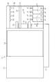
図1に示すように、複合機11は、媒体の一例である用紙Pに対して記録を行う記録装置12と、その上部に配置される画像読取装置13とを備えている。画像読取装置13は、例えばスキャナーなどで構成され、載置台14に載置された原稿を自動的に給送し、原稿に記録されている文字や写真などの画像を読み取り可能に設けられている。一方、記録装置12は、直方体状の筐体15を備え、筐体15の一面(図1において左前方を向く面)には、筐体15内から筐体15外へと用紙Pが排出される排出口16が開口している。ここで、筐体15において排出口16が設けられている面を複合機11の前面とし、その反対側の面を複合機11の背面とする。
(First Embodiment)
Hereinafter, the first embodiment of the multifunction device will be described with reference to the drawings.
As shown in FIG. 1, the
筐体15の前面には、筐体15内から排出される用紙Pが載置される排出トレイ17が、排出口16を通じて筐体15内から記録装置12の前方に向けて延びるように設けられている。また、この排出トレイ17の下方には、用紙Pが積層状態で載置される媒体カセット18が、排出トレイ17と重なるようにして筐体15に装着されている。そして、筐体15の上部であって、記録装置12の前面寄りとなる位置には、記録装置12が行う記録動作や画像読取装置13が行う読取動作を操作するための操作パネル20が設けられている。
On the front surface of the
筐体15の上部において、操作パネル20は、記録装置12の背面側から前面側に向かう方向に沿って画像読取装置13と隣り合うように並んで配置されている。すなわち、記録装置12の筐体15の上部に設けられる画像読取装置13及び操作パネル20は、複合機11を上面視した際に筐体15の上部を覆うように配置されている。この操作パネル20は、例えば電源ボタン21や表示画面22、操作ボタン23等を備え、筐体15の上面の一部として記録装置12の外装の一部を構成している。
In the upper part of the
図2に示すように、記録装置12の筐体15内には、用紙Pを下方から支持する支持台31と、支持台31の上面を含む搬送経路32に沿って用紙Pを搬送する複数のローラー33が設けられている。これらのローラー33は、用紙Pを上下で挟み込み、回転駆動することで、図2において左側から右側へ向かう方向に用紙Pを搬送する。すなわち、記録装置12の背面側から前面側に向かう方向が、用紙Pの搬送方向とされている。
As shown in FIG. 2, in the
また、筐体15内において、用紙Pの搬送方向において上流側となる記録装置12の背面寄りの位置には、媒体カセット18に載置される用紙Pを自動的に一枚ずつ搬送経路32に向けて給紙する自動給紙部34が設けられている。自動給紙部34により給紙された用紙Pは、ローラー33によって支持台31の上面及び排出トレイ17の上面に沿って搬送される。すなわち、支持台31及び排出トレイ17が、搬送経路32を構成している。搬送経路32に沿って用紙Pを搬送するローラー33は、用紙Pの搬送方向において、自動給紙部34と支持台31との間となる位置及び支持台31と排出トレイ17との間となる位置にそれぞれ上下で対をなすよう配置されている。
Further, in the
筐体15内であって、支持台31の上方には、液体の一例であるインクを用いて用紙Pに記録を行う記録ユニット35が設けられている。記録ユニット35は、用紙Pの搬送方向と交差する走査方向に延びるガイド軸36に支持される移動体の一例であるキャリッジ37と、キャリッジ37に搭載され、用紙Pにインクを吐出する記録部の一例である記録ヘッド38とを備えている。すなわち、本実施形態における記録装置12は、インクジェット式のプリンターで構成されている。キャリッジ37は、ガイド軸36に沿って往復移動し、支持台31に支持される用紙Pの上方を走査可能とされている。そして、キャリッジ37に搭載される記録ヘッド38は、支持台31に支持される用紙Pにインクを吐出する。すなわち、記録ユニット35は、記録ヘッド38を搭載するキャリッジ37が走査方向に沿って移動することにより、搬送経路32を搬送される用紙Pの略全域に亘って記録を行うことが可能とされている。
A
筐体15内において、用紙Pの搬送方向において下流側となる記録装置12の前面寄りの位置には、インクを収容可能な液体収容体40が配置されている。液体収容体40は、例えばインクタンクのような樹脂製の容器で構成され、可撓性を有するチューブ41によって記録ヘッド38と接続されている。そして、このチューブ41を介して、液体収容体40側から記録ヘッド38側へ向けてインクが供給可能とされている。すなわち、液体収容体40は、記録ヘッド38に供給されるインクを収容可能に設けられ、筐体15内において所定の位置に配置される所謂オフキャリッジタイプの構成とされている。また、液体収容体40の上部には、液体収容体40内にインクを注入可能な注入口42が設けられている。この注入口42は、上方に向けて突出し、液体収容体40に対向する操作パネル20の下面に取り付けられた栓部材43によって閉栓されている。栓部材43は、例えばゴムなどの弾性材料で構成され、操作パネル20によって注入口42に付勢されている。
A
操作パネル20は、例えばヒンジなどにより、筐体15に対して回動可能に設けられている。本実施形態において、操作パネル20は、用紙Pの搬送方向において上流側となる端部を支点として、筐体15内を露出させる開き位置(図2中の二点鎖線で示す位置)と筐体15内を露出させない閉じ位置(図2中の実線で示す位置)との二位置間を回動(開閉動作)可能とされている。そして、図2において実線で示す閉じ位置から二点鎖線で示す開き位置へと操作パネル20を開き動作させることで、記録装置12の筐体15内における一部分が露出される。すなわち、操作パネル20は、筐体15に対して開閉動作可能に設けられることで、筐体15の上部における一部分を覆うカバーとしても機能する。なお、本実施形態においては、画像読取装置13も操作パネル20の場合と同様に、例えばヒンジなどにより、記録装置12に対して回動可能に設けられている。画像読取装置13を記録装置12に対して開き動作させることで、筐体15内が露出される。
The
操作パネル20を開き動作させることで、筐体15内が露出されると、複合機11を上面視した際に、インクを収容する液体収容体40と、搬送経路32の一部を構成する排出トレイ17が露出される。また、操作パネル20を開き動作させることで、操作パネル20により注入口42に付勢されていた栓部材43が、注入口42から離間する。栓部材43が注入口42から離間することで、閉栓されていた注入口42が開栓される。すなわち、操作パネル20の開閉動作に伴い、栓部材43の着脱が行われる。また、操作パネル20には、操作パネル20の開閉状態を検出する検出センサー44が設けられている。なお、本実施形態における複合機11は、図示しない制御部により、操作パネル20が開き位置にある状態において記録装置12の記録動作を実行させないように、検出センサー44の検出信号に基づいてその動作が制御されている。すなわち、本実施形態における記録装置12は、液体収容体40の注入口42が閉栓され、筐体15内が露出されていない状態で記録動作を行うよう制御されている。
When the inside of the
図3に示すように、記録装置12の筐体15内に配置される液体収容体40は、複数設けられている。本実施形態においては、記録装置12の前面側且つ走査方向の一端側(図3において右側)となる筐体15内の隅角に配置され、用紙Pの搬送方向と交差する走査方向に沿って四個の液体収容体40が並んで設けられている。これらの液体収容体40は、それぞれ異なる色のインクを収容し、それぞれ個別に設けられるチューブ41を介して記録ヘッド38にインクを供給する。また、操作パネル20には、液体収容体40の個数に対応して、液体収容体40の注入口42を閉栓する栓部材43が四個並んで取り付けられている。
As shown in FIG. 3, a plurality of
次に、上記のように構成された複合機11の作用について説明する。
図2及び図3に示すように、複合機11を構成する記録装置12が有する液体収容体40にインクを注入する際には、まず操作パネル20を閉じ位置から開き位置に開き動作させる。操作パネル20を開き動作させることで、筐体15内の隅角に配置された液体収容体40が露出され、液体収容体40に筐体15外からアクセス可能となる。このとき、操作パネル20が開き動作することで、注入口42から栓部材43が一斉に取り外され、液体収容体40がそれぞれ有する注入口42が開栓される。すなわち、操作パネル20を開き動作させることで、露出した注入口42を介して液体収容体40にインクを注入することが可能となる。また、操作パネル20を開き動作させることで、搬送経路32の一部を構成する排出トレイ17の一部が露出されるため、例えば搬送経路32で用紙Pが紙詰まりなどの搬送不良を生じたとしても、筐体15の上部から用紙Pを除去することが可能とされる。
Next, the operation of the
As shown in FIGS. 2 and 3, when injecting ink into the
一般的に、操作パネル20は、スキャナーなどで構成される画像読取装置13と比較して重量が小さいため、開閉動作を行うユーザーの負担が小さい。すなわち、インクの注入や用紙Pの除去など、複合機11を構成する記録装置12をメンテナンスする際に、画像読取装置13を開き動作させる必要がないため、ユーザーの負担が小さくなる。
In general, the
上記実施形態によれば、以下のような効果を得ることができる。
(1)操作パネル20を開き動作させることにより、画像読取装置13を開き動作させることなく筐体15内に配置された液体収容体40が露出される。したがって、上方に画像読取装置13が配置された記録装置12の内部に設けられたインクを収容する液体収容体40に対して容易にアクセスできる。
According to the above embodiment, the following effects can be obtained.
(1) By opening and operating the
(2)操作パネル20を開き動作させることにより、液体収容体40が有する注入口42が露出されるため、画像読取装置13を開き動作させることなく筐体15内に配置された液体収容体40にインクを容易に注入できる。
(2) Since the
(3)操作パネル20に栓部材43を取り付けることで、操作パネル20の開閉動作に伴い、液体収容体40に対して栓部材43を着脱できる。
(4)液体収容体40を筐体15内の隅角に配置することで、操作パネル20を開き動作させたときに、より液体収容体40へアクセスし易い構成にできる。
(3) By attaching the
(4) By arranging the
(5)操作パネル20を筐体15の上部であって画像読取装置13と隣り合う位置に設けることで、複合機11を上方から見たときの操作パネル20の視認性を向上できる。
(6)操作パネル20を開き動作させることにより、搬送経路32の一部である排出トレイ17が露出されるため、画像読取装置13を開き動作させることなく搬送経路32にアクセスできる。すなわち、例えば搬送経路32にて用紙Pが搬送不良を生じた際に、操作パネル20を開き動作させることで搬送不良を生じた用紙Pを容易に除去することができる。
(5) By providing the
(6) Since the
(7)検出センサー44を設けることで、操作パネル20の開閉状態に基づいて、複合機11の動作を制御できる。
(8)操作パネル20が閉じ位置にあるときに記録装置12が記録動作を行うよう制御することで、筐体15内に配置される記録ヘッド38に大気中の塵埃が付着したり、液体収容体40内に大気中の塵埃が混入したりすることによる記録品質の低下を抑制できる。
(7) By providing the
(8) By controlling the
(第二実施形態)
次に、複合機11の第二実施形態について説明する。第二実施形態における複合機11は、操作パネル20の配置が第一実施形態と異なり、その他の構成については第一実施形態と同様である。そのため、同じ構成を備える箇所についてはその説明を省略する。
(Second Embodiment)
Next, the second embodiment of the
図4及び図5に示すように、複合機11を構成する記録装置12及び画像読取装置13を操作するための操作パネル20は、筐体15の前面において筐体15内から用紙Pが排出される排出口16よりも上方に設けられている。すなわち、この操作パネル20は、筐体15の前面の一部として記録装置12の外装の一部を構成し、操作パネル20の下縁が、排出口16の上縁を構成している。また、操作パネル20は、例えばヒンジなどにより、鉛直方向において下端となる端部を支点として回動可能に設けられている。そして、図5において実線で示す閉じ位置から二点鎖線で示す開き位置へと操作パネル20を開き動作させることで、記録装置12の筐体15内における一部分が露出される。すなわち、操作パネル20は、筐体15に対して開閉動作可能に設けられることで、筐体15の前側の一部を覆うカバーとしても機能する。
As shown in FIGS. 4 and 5, in the
筐体15内において、記録装置12の前面寄りとなる位置には、この操作パネル20の背面と対向するように液体収容体40が配置されている。また、液体収容体40の前側且つ上部には、液体収容体40内にインクを注入可能な注入口42が設けられている。この注入口42は、上方に向けて斜め前方に突出し、操作パネル20が閉じ位置にあるとき、液体収容体40に対向する操作パネル20の背面に取り付けられた栓部材43によって閉栓されている。すなわち、操作パネル20が閉じ位置から開き動作することで、液体収容体40の注入口42が開栓され、操作パネル20が閉じ位置へと閉じ動作することで、液体収容体40の注入口42が閉栓される。
A
上記第二実施形態によれば、第一実施形態の効果に加えて、以下のような効果を奏する。
(9)操作パネル20を筐体15の前面に設けることで、複合機11を前方から見たときの操作パネル20の視認性を向上できる。
According to the second embodiment, the following effects are obtained in addition to the effects of the first embodiment.
(9) By providing the
(第三実施形態)
次に、複合機11の第三実施形態について説明する。第三実施形態における複合機11は、操作パネル20の配置が第一実施形態と異なり、その他の構成については第一実施形態と同様である。そのため、同じ構成を備える箇所についてはその説明を省略する。
(Third Embodiment)
Next, a third embodiment of the
図6及び図7に示すように、複合機11を構成する記録装置12及び画像読取装置13を操作するための操作パネル20は、筐体15の上部に設けられている。具体的には、筐体15の上部において、操作パネル20は、用紙Pの搬送方向と交差する走査方向の一端側(図7において右側)に設けられ、画像読取装置13と隣り合うように並んで配置されている。すなわち、この操作パネル20は、筐体の上面の一部として記録装置12の外装の一部を構成している。
As shown in FIGS. 6 and 7, an
また、操作パネル20は、例えばヒンジなどにより、用紙Pの搬送方向において上流側(図7において上側)となる端部を支点として回動可能に設けられている。そして、操作パネル20を図6に示す閉じ位置から図7に示す開き位置へと開き動作させることで、記録装置12の筐体15内における一部分が露出される。すなわち、操作パネル20は、筐体15に対して開閉動作可能に設けられることで、筐体15の上部の一部を覆うカバーとしても機能する。操作パネル20が開き動作することで、操作パネル20の下面に取り付けられた栓部材43が液体収容体40の注入口42から離間され、注入口42が開栓される。一方、操作パネル20が閉じ動作することで、栓部材43が注入口42に付勢され、注入口42が閉栓される。
Further, the
また、操作パネル20が開き動作することで、液体収容体40だけでなく、筐体15内に設けられる排出トレイ17、支持台31、ローラー33及びガイド軸36の一部分(図7において右側部分)もまた露出される。すなわち、搬送経路32の一部を構成する支持台31で用紙Pの搬送不良が生じたとしても、その用紙Pを除去することが可能とされている。さらに、ガイド軸36の一部分が露出されるため、ガイド軸36において走査方向における一端側(図7において右側)に記録ユニット35が位置することで、記録ユニット35もまた露出可能とされている。
Further, when the
上記第三実施形態によれば、第一実施形態の効果に加えて、以下のような効果を奏する。
(10)搬送経路32を構成する支持台31が露出されるため、支持台31と記録ユニット35との間で搬送不良が生じた場合でも、その用紙Pを容易に除去できる。
According to the third embodiment, the following effects are obtained in addition to the effects of the first embodiment.
(10) Since the
(11)記録ユニット35が露出可能に設けられているため、操作パネル20を開き動作させることで、記録ユニット35のメンテナンスを行うことができる。
なお、上述した第一乃至第三実施形態は以下のように変更してもよい。また、上記各実施形態に対して以下の変更例は、適宜組み合わせてもよい。
(11) Since the
The above-mentioned first to third embodiments may be changed as follows. In addition, the following modified examples may be appropriately combined with respect to each of the above embodiments.
・図8、図9及び図10に示すように、上記第一乃至第三実施形態のそれぞれは、内部にインクを収容可能な液体収容体40が、記録ユニット35を構成するキャリッジ37に搭載可能とされる所謂オンキャリッジタイプのものとして構成されていてもよい。すなわち、この液体収容体40は、キャリッジ37とともに移動可能とされている。そして、操作パネル20が開き動作されることにより、キャリッジ37に搭載された液体収容体40の注入口42が露出可能とされている。この変更例によれば、上記実施形態での効果に加えて以下の効果を奏する。
As shown in FIGS. 8, 9 and 10, in each of the first to third embodiments, the
(12)操作パネル20を開き動作させることにより、画像読取装置13を開き動作させることなく、キャリッジ37に搭載された状態で筐体15内に配置された液体収容体40が露出される。したがって、上方に画像読取装置13が配置された記録装置12の内部に設けられたインクを収容する液体収容体40に対して容易にアクセスできる。また、液体収容体40の注入口42が露出されることで、液体収容体40にインクを容易に注入できる。
(12) By opening and operating the
また、このような構成によれば、液体収容体40がキャリッジ37に搭載されない所謂オフキャリッジタイプを採用する複合機11と比較して、液体収容体40と記録ヘッド38とを接続するチューブ41を筐体15内で引き回す必要がないため、構成を簡易にでき、装置の大型化を抑制できる。
Further, according to such a configuration, the
また、図8、図9及び図10に示すように、このような変形例においては、液体収容体40の注入口42を閉栓する栓部材43が、操作パネル20に取り付けられる構成ではなく、操作パネル20とは独立して栓部材43を設ける構成とされている。この構成によれば、操作パネル20の開き動作により露出した複数の液体収容体40のうち、所望の液体収容体40の注入口42から栓部材43を取り外すことができ、他の液体収容体40に収容されているインクの蒸発や液体収容体40内に大気中の塵埃等が混入する虞をより低減できる。なお、この構成は、上記第一乃至第三実施形態に示すようなオンキャリッジタイプのものに採用してもよい。
Further, as shown in FIGS. 8, 9 and 10, in such a modified example, the
・上記各実施形態において、インクを収容する液体収容体40は、筐体15の隅角に配置されなくともよく、例えば、筐体15内において、筐体15の前面側且つ走査方向の中央位置に配置される構成であってもよい。筐体15内における液体収容体40の配置位置は、操作パネル20が開き動作することにより露出される位置であればよい。
In each of the above embodiments, the
・上記各実施形態において、操作パネル20は、記録装置12の側面又は背面に設けられる構成でもよい。
・上記各実施形態において、操作パネル20により操作される対象は、記録装置12だけであってもよいし、画像読取装置13だけであってもよい。
-In each of the above embodiments, the
-In each of the above embodiments, the target operated by the
・上記各実施形態において、液体収容体40が設けられる個数は、三個以下でも五個以上でもよい。
・上記各実施形態において、操作パネル20は、回動することで筐体15に対して開閉動作可能とされる構成に限らず、開き位置と閉じ位置との二位置間を例えばスライド移動することで、筐体15に対して開閉動作される構成でもよい。
-In each of the above embodiments, the number of
-In each of the above embodiments, the
・上記各実施形態において、画像読取装置13を記録装置12に対して開閉動作可能に設けられなくともよい。通常、上記各実施形態のように、重量の大きな画像読取装置13を記録装置12に対して回動させることで記録装置12の筐体15内を露出可能な構成においては、画像読取装置13の姿勢を維持するためにダンパーなどの機構が新たに必要となる。この点、例えば画像読取装置13が記録装置12に対して固定されて設けられる構成とすれば、そのような機構が不要となり、部品点数を減らすことができる。ちなみに、操作パネル20の重量は小さいため、操作パネル20にダンパーなどの機構を設ける必要はない。
-In each of the above embodiments, the
・上記各実施形態において、記録装置12の背面から用紙Pを挿入することで搬送経路32へ用紙Pを給送する構成でもよい。
・上記各実施形態において、チューブ41の一部が筐体15外を延びる構成でもよい。
-In each of the above embodiments, the paper P may be fed to the
-In each of the above embodiments, a part of the
・上記各実施形態において、搬送経路32に沿って用紙Pを搬送するローラー33に替えてベルトコンベヤを採用してもよい。
・上記各実施形態において、記録ユニット35は、記録ヘッド38が走査方向に移動するシリアルヘッド方式に限らず、記録ヘッド38が用紙Pの搬送方向と交差する方向に長尺に設けられるラインヘッド方式でもよい。
-In each of the above embodiments, a belt conveyor may be adopted instead of the
In each of the above embodiments, the
・上記各実施形態において、記録装置12が記録を行う媒体は、用紙Pに限らず、布帛やプラスチックフィルムでもよい。
・上記各実施形態において、複合機11を構成する記録装置12は、インク以外の他の流体(液体や、機能材料の粒子が液体に分散又は混合されてなる液状体、ゲルのような流状体を含む)を噴射したり吐出したりして記録を行う流体噴射装置であってもよい。例えば、液晶ディスプレイ、EL(エレクトロルミネッセンス)ディスプレイ及び面発光ディスプレイの製造などに用いられる電極材や色材(画素材料)などの材料を分散または溶解のかたちで含む液状体を噴射して記録を行う液状体噴射装置であってもよい。また、ゲル(例えば物理ゲル)などの流状体を噴射する流状体噴射装置であってもよい。そして、これらのうちいずれか一種の流体噴射装置に本発明を適用することができる。なお、本明細書において「流体」とは、気体のみからなる流体を含まない概念であり、流体には、例えば液体(無機溶剤、有機溶剤、溶液、液状樹脂、液状金属(金属融液)等を含む)、液状体、流状体などが含まれる。
-In each of the above embodiments, the medium on which the
-In each of the above embodiments, the
11…複合機、12…記録装置、13…画像読取装置、15…筐体、16…排出口、17…排出トレイ、18…媒体カセット、20…操作パネル、31…支持台、32…搬送経路、33…ローラー、34…自動給紙部、35…記録ユニット、36…ガイド軸、37…キャリッジ(移動体)、38…記録ヘッド(記録部)、40…液体収容体、41…チューブ、42…注入口、43…栓部材、44…検出センサー、P…用紙。 11 ... Multifunction device, 12 ... Recording device, 13 ... Image reading device, 15 ... Housing, 16 ... Discharge port, 17 ... Discharge tray, 18 ... Media cassette, 20 ... Operation panel, 31 ... Support stand, 32 ... Transport path , 33 ... Roller, 34 ... Automatic paper feed unit, 35 ... Recording unit, 36 ... Guide shaft, 37 ... Carriage (moving body), 38 ... Recording head (recording unit), 40 ... Liquid container, 41 ... Tube, 42 ... Injection port, 43 ... Plug member, 44 ... Detection sensor, P ... Paper.
Claims (9)
前記記録装置の上方に配置され、画像の読み取りを行う画像読取装置と、を備える複合
機であって、
前記記録装置は、液体を用いて記録を行う記録部と、前記記録部に供給される液体を収
容可能な液体収容体と、少なくとも前記記録部と前記液体収容体とが内部に設けられる筐
体と、前記液体収容体と前記記録部とを接続するチューブと、前記記録装置の外装の一部
を構成するとともに、前記記録装置及び前記画像読取装置のうち少なくとも一方を操作す
るための操作パネルと、を有し、
前記操作パネルは、前記筐体に対して同筐体内を露出させる開き位置と露出させない閉
じ位置との二位置間を開閉動作可能に設けられ、
前記液体収容体の少なくとも一部は、前記画像読取装置を開き動作させることなく、前記操作パネルのみを開き動作させることで露出され、
前記操作パネルは、前記筐体において前記記録部により記録が行われた媒体を前記筐体外に排出するための排出口が設けられる面である前記筐体の前面に立設するように設けられることを特徴とする複合機。 A recording device that records on media and
A multifunction device including an image reading device that is arranged above the recording device and that reads an image.
The recording device includes a recording unit that records using a liquid, a liquid container capable of accommodating a liquid supplied to the recording unit, and a housing in which at least the recording unit and the liquid container are provided inside. A tube connecting the liquid container and the recording unit, a part of the exterior of the recording device, and an operation panel for operating at least one of the recording device and the image reading device. Have,
The operation panel is provided so that it can be opened and closed between two positions, an open position that exposes the inside of the housing and a closed position that does not expose the inside of the housing.
At least a part of the liquid container is exposed by opening and operating only the operation panel without opening and operating the image reader.
The operation panel is provided so as to stand on the front surface of the housing, which is a surface of the housing where a discharge port for discharging the medium recorded by the recording unit to the outside of the housing is provided. A multifunction device that features.
動作させることで前記注入口が露出されることを特徴とする請求項1に記載の複合機。 The multifunction device according to claim 1, wherein the liquid container has an injection port capable of injecting a liquid therein, and the injection port is exposed by opening and operating the operation panel.
ることを特徴とする請求項2に記載の複合機。 The multifunction device according to claim 2, wherein the operation panel is provided with a plug member capable of closing the injection port of the liquid container.
項3のうち何れか一項に記載の複合機。 The multifunction device according to any one of claims 1 to 3, wherein the liquid container is arranged at a corner of the housing.
前記記録装置の上方に配置され、画像の読み取りを行う画像読取装置と、を備える複合
機であって、
前記記録装置は、前記媒体を載置部に載置し、給紙部により給紙したのち、前記媒体に記録を行う記録部と、前記記録部に供給される液体を収容可能な液体収容体と、前記記録部と前記液体収容体とを搭載して移動可能な移動体が内部に設けられる筐体と、前記記録装置の外装の一部を構成するとともに、前記記録装置及び前記画像読取装置のうち少なくとも一方を操作するための操作パネルと、を有し、
前記載置部は前記筐体の奥側に形成され、
前記操作パネルは、前記筐体に対して同筐体内を露出させる開き位置と露出させない閉
じ位置との二位置間を開閉動作可能に設けられ、
前記操作パネルは、前記筐体の上部であって且つ前記画像読取装置と隣り合う位置に配置され、
前記操作パネルのヒンジは前記筐体の奥側に形成され、
前記液体収容体の少なくとも一部は、前記操作パネルを開き動作させることで露出されることを特徴とする複合機。 A recording device that records on media and
A multifunction device including an image reading device that is arranged above the recording device and that reads an image.
The recording device is a recording unit that mounts the medium on a mounting unit, feeds the paper by the paper feeding unit, and then records on the medium, and a liquid container capable of accommodating a liquid supplied to the recording unit. A housing in which a movable body on which the recording unit and the liquid container are mounted and movable is provided, and a part of the exterior of the recording device, and the recording device and the image reading device. Has an operation panel for operating at least one of them,
The above-mentioned resting portion is formed on the back side of the housing.
The operation panel is provided so that it can be opened and closed between two positions, an open position that exposes the inside of the housing and a closed position that does not expose the inside of the housing.
The operation panel is arranged at a position above the housing and adjacent to the image reader.
The hinge of the operation panel is formed on the back side of the housing.
A multifunction device characterized in that at least a part of the liquid container is exposed by opening and operating the operation panel.
動作させることで前記注入口が露出されることを特徴とする請求項5に記載の複合機。 The multifunction device according to claim 5, wherein the liquid container has an injection port capable of injecting a liquid therein, and the injection port is exposed by opening and operating the operation panel.
前記栓部材は、前記操作パネルを開き動作させることで露出されることを特徴とする請求項6に記載の複合機。 It has a plug member that closes the injection port.
The multifunction device according to claim 6, wherein the plug member is exposed by opening and operating the operation panel.
経路の少なくとも一部は、前記操作パネルを開き動作させることで露出されることを特徴
とする請求項1乃至請求項7のうち何れか一項に記載の複合機。 The recording device has a transport path in which the medium is transported in the housing, and at least a part of the transport path is exposed by opening and operating the operation panel. The multifunction device according to any one of claims 7.
項1乃至請求項8のうち何れか一項に記載の複合機。 The multifunction device according to any one of claims 1 to 8, further comprising a detection sensor for detecting an open / closed state of the operation panel.
Priority Applications (7)
| Application Number | Priority Date | Filing Date | Title |
|---|---|---|---|
| JP2016015319A JP6805498B2 (en) | 2016-01-29 | 2016-01-29 | Multifunction device |
| CN201910870739.0A CN110641150B (en) | 2016-01-29 | 2016-12-29 | Compound machine |
| CN201611245252.6A CN107031187B (en) | 2016-01-29 | 2016-12-29 | Recording apparatus |
| US15/398,526 US10293613B2 (en) | 2016-01-29 | 2017-01-04 | Multifunction peripheral |
| PH12017000013A PH12017000013A1 (en) | 2016-01-29 | 2017-01-11 | Multifunction peripheral |
| RU2017102496A RU2728810C2 (en) | 2016-01-29 | 2017-01-26 | Multifunctional peripheral device |
| US16/371,844 US10682859B2 (en) | 2016-01-29 | 2019-04-01 | Multifunction peripheral |
Applications Claiming Priority (1)
| Application Number | Priority Date | Filing Date | Title |
|---|---|---|---|
| JP2016015319A JP6805498B2 (en) | 2016-01-29 | 2016-01-29 | Multifunction device |
Publications (3)
| Publication Number | Publication Date |
|---|---|
| JP2017132179A JP2017132179A (en) | 2017-08-03 |
| JP2017132179A5 JP2017132179A5 (en) | 2019-02-28 |
| JP6805498B2 true JP6805498B2 (en) | 2020-12-23 |
Family
ID=59385990
Family Applications (1)
| Application Number | Title | Priority Date | Filing Date |
|---|---|---|---|
| JP2016015319A Active JP6805498B2 (en) | 2016-01-29 | 2016-01-29 | Multifunction device |
Country Status (5)
| Country | Link |
|---|---|
| US (2) | US10293613B2 (en) |
| JP (1) | JP6805498B2 (en) |
| CN (2) | CN110641150B (en) |
| PH (1) | PH12017000013A1 (en) |
| RU (1) | RU2728810C2 (en) |
Families Citing this family (9)
| Publication number | Priority date | Publication date | Assignee | Title |
|---|---|---|---|---|
| JP6984241B2 (en) * | 2017-08-31 | 2021-12-17 | セイコーエプソン株式会社 | Liquid tank |
| JP7013779B2 (en) * | 2017-10-10 | 2022-02-01 | セイコーエプソン株式会社 | Liquid sprayer |
| JP7089664B2 (en) | 2018-03-23 | 2022-06-23 | セイコーエプソン株式会社 | Recording device |
| JP7172297B2 (en) * | 2018-08-31 | 2022-11-16 | セイコーエプソン株式会社 | inkjet printer |
| JP7099208B2 (en) * | 2018-09-12 | 2022-07-12 | セイコーエプソン株式会社 | Liquid discharge device |
| JP7251309B2 (en) * | 2019-05-21 | 2023-04-04 | セイコーエプソン株式会社 | recording device |
| JP7363094B2 (en) * | 2019-05-22 | 2023-10-18 | セイコーエプソン株式会社 | recording device |
| JP7287112B2 (en) * | 2019-05-24 | 2023-06-06 | セイコーエプソン株式会社 | recording device |
| US11890877B2 (en) * | 2019-08-30 | 2024-02-06 | Primera Technology, Inc. | Food product platform for food product printer |
Family Cites Families (30)
| Publication number | Priority date | Publication date | Assignee | Title |
|---|---|---|---|---|
| US6961152B1 (en) * | 1998-01-08 | 2005-11-01 | Brother Kogyo Kabushiki Kaisha | Multi-functional device having vertically arranged scanner and printer sections |
| US6886928B2 (en) * | 2002-03-28 | 2005-05-03 | Brother Kogyo Kabushiki Kaisha | Ink cartridge and method of production thereof |
| TW592174U (en) * | 2003-04-01 | 2004-06-11 | Lite On Technology Corp | Multi-functional office machine |
| US7417751B2 (en) * | 2003-08-12 | 2008-08-26 | Hewlett-Packard Development Company, L.P. | Scanning to storage medium using scanning device |
| US7712891B2 (en) | 2003-12-26 | 2010-05-11 | Brother Kogyo Kabushiki Kaisha | Image-forming device |
| JP4581429B2 (en) * | 2004-03-05 | 2010-11-17 | ブラザー工業株式会社 | Image recording device |
| JP4437536B2 (en) * | 2004-06-17 | 2010-03-24 | ブラザー工業株式会社 | Image forming apparatus |
| JP2006110946A (en) * | 2004-10-18 | 2006-04-27 | Ricoh Co Ltd | Image forming device |
| KR100788660B1 (en) * | 2005-01-18 | 2007-12-26 | 삼성전자주식회사 | Image scanning/printing apparatus and image scanning/printing method thereof |
| US20070024924A1 (en) | 2005-07-26 | 2007-02-01 | Brother Kogyo Kabushika Kaisha | Image scanning device and multi-function device |
| JP2007036605A (en) | 2005-07-26 | 2007-02-08 | Brother Ind Ltd | Multifunction device |
| US7810916B2 (en) * | 2005-09-29 | 2010-10-12 | Brother Kogyo Kabushiki Kaisha | Ink cartridges |
| TW200737626A (en) * | 2005-11-14 | 2007-10-01 | Applied Materials Inc | Semiconductor device having a laterally injected active region |
| JP4835128B2 (en) * | 2005-11-30 | 2011-12-14 | ブラザー工業株式会社 | Refill unit |
| KR100739771B1 (en) * | 2005-12-08 | 2007-07-13 | 삼성전자주식회사 | Solid ink jet image forming apparatus |
| JP4941110B2 (en) * | 2007-06-01 | 2012-05-30 | ブラザー工業株式会社 | Inkjet printer |
| WO2009119084A1 (en) * | 2008-03-25 | 2009-10-01 | セイコーエプソン株式会社 | Liquid supply channel device and liquid injector using liquid supply channel device |
| JP5454442B2 (en) * | 2010-09-29 | 2014-03-26 | ブラザー工業株式会社 | Liquid ejection device |
| JP6171313B2 (en) * | 2011-12-08 | 2017-08-02 | セイコーエプソン株式会社 | Liquid ejector |
| JP5928692B2 (en) * | 2012-01-23 | 2016-06-01 | セイコーエプソン株式会社 | Recording device |
| JP6051595B2 (en) | 2012-05-21 | 2016-12-27 | セイコーエプソン株式会社 | cartridge |
| JP6103177B2 (en) * | 2012-08-10 | 2017-03-29 | セイコーエプソン株式会社 | Liquid ejecting apparatus and liquid ejecting method |
| JP6016538B2 (en) | 2012-09-07 | 2016-10-26 | キヤノン株式会社 | Printing device |
| US9421781B2 (en) * | 2012-10-15 | 2016-08-23 | Seiko Epson Corporation | Recording apparatus |
| JP2015145089A (en) * | 2014-02-03 | 2015-08-13 | セイコーエプソン株式会社 | Liquid ejection device, liquid supply unit and liquid ejection system |
| JP6287162B2 (en) * | 2013-12-18 | 2018-03-07 | セイコーエプソン株式会社 | Recording device and multifunction device |
| WO2015093008A1 (en) | 2013-12-18 | 2015-06-25 | セイコーエプソン株式会社 | Liquid supply unit |
| US9764557B2 (en) | 2014-03-14 | 2017-09-19 | Seiko Epson Corporation | Recording apparatus |
| JP2015199264A (en) * | 2014-04-08 | 2015-11-12 | ブラザー工業株式会社 | Liquid discharge device |
| CN110138994B (en) * | 2014-10-24 | 2021-04-27 | 精工爱普生株式会社 | Medium conveyance unit, recording apparatus, and post-processing apparatus |
-
2016
- 2016-01-29 JP JP2016015319A patent/JP6805498B2/en active Active
- 2016-12-29 CN CN201910870739.0A patent/CN110641150B/en active Active
- 2016-12-29 CN CN201611245252.6A patent/CN107031187B/en active Active
-
2017
- 2017-01-04 US US15/398,526 patent/US10293613B2/en active Active
- 2017-01-11 PH PH12017000013A patent/PH12017000013A1/en unknown
- 2017-01-26 RU RU2017102496A patent/RU2728810C2/en active
-
2019
- 2019-04-01 US US16/371,844 patent/US10682859B2/en active Active
Also Published As
| Publication number | Publication date |
|---|---|
| US10293613B2 (en) | 2019-05-21 |
| CN110641150B (en) | 2021-10-26 |
| CN110641150A (en) | 2020-01-03 |
| US10682859B2 (en) | 2020-06-16 |
| RU2017102496A (en) | 2018-07-31 |
| US20190224976A1 (en) | 2019-07-25 |
| CN107031187A (en) | 2017-08-11 |
| CN107031187B (en) | 2020-10-27 |
| PH12017000013B1 (en) | 2018-10-08 |
| US20170217194A1 (en) | 2017-08-03 |
| RU2728810C2 (en) | 2020-07-31 |
| RU2017102496A3 (en) | 2020-05-21 |
| PH12017000013A1 (en) | 2018-10-08 |
| JP2017132179A (en) | 2017-08-03 |
Similar Documents
| Publication | Publication Date | Title |
|---|---|---|
| JP6805498B2 (en) | Multifunction device | |
| JP6256555B2 (en) | Recording device | |
| JP4635426B2 (en) | Image forming apparatus | |
| JP6011284B2 (en) | Liquid ejection device | |
| JP6969151B2 (en) | Liquid injection device | |
| CN110605918A (en) | Liquid ejecting apparatus | |
| CN104228356B (en) | Recording equipment | |
| JP5983315B2 (en) | Recording device | |
| JP2016132163A (en) | tank | |
| US9254694B2 (en) | Recording apparatus | |
| TWM466793U (en) | Liquid ejecting apparatus | |
| JP6119338B2 (en) | Image recording device | |
| JP7243048B2 (en) | printer | |
| JP6330355B2 (en) | Recording device | |
| WO2016021171A1 (en) | Composite device | |
| US9090073B2 (en) | Liquid ejection apparatus | |
| JP6349799B2 (en) | Recording device | |
| JP6822546B2 (en) | Recording device | |
| JP6296377B2 (en) | Liquid cartridge | |
| JP2021045976A (en) | Recording device | |
| JP2023152171A (en) | liquid discharge device | |
| JP2024005461A (en) | Liquid discharge apparatus | |
| JP2001310482A (en) | Ink jet recorder | |
| JP2002187290A (en) | Ink jet recording device |
Legal Events
| Date | Code | Title | Description |
|---|---|---|---|
| RD05 | Notification of revocation of power of attorney |
Free format text: JAPANESE INTERMEDIATE CODE: A7425 Effective date: 20180906 |
|
| RD03 | Notification of appointment of power of attorney |
Free format text: JAPANESE INTERMEDIATE CODE: A7423 Effective date: 20181119 |
|
| A521 | Written amendment |
Free format text: JAPANESE INTERMEDIATE CODE: A523 Effective date: 20190111 |
|
| A621 | Written request for application examination |
Free format text: JAPANESE INTERMEDIATE CODE: A621 Effective date: 20190111 |
|
| A977 | Report on retrieval |
Free format text: JAPANESE INTERMEDIATE CODE: A971007 Effective date: 20191011 |
|
| A131 | Notification of reasons for refusal |
Free format text: JAPANESE INTERMEDIATE CODE: A131 Effective date: 20191126 |
|
| A521 | Written amendment |
Free format text: JAPANESE INTERMEDIATE CODE: A523 Effective date: 20191226 |
|
| A131 | Notification of reasons for refusal |
Free format text: JAPANESE INTERMEDIATE CODE: A131 Effective date: 20200519 |
|
| A521 | Written amendment |
Free format text: JAPANESE INTERMEDIATE CODE: A523 Effective date: 20200608 |
|
| RD07 | Notification of extinguishment of power of attorney |
Free format text: JAPANESE INTERMEDIATE CODE: A7427 Effective date: 20200803 |
|
| TRDD | Decision of grant or rejection written | ||
| A01 | Written decision to grant a patent or to grant a registration (utility model) |
Free format text: JAPANESE INTERMEDIATE CODE: A01 Effective date: 20201104 |
|
| A61 | First payment of annual fees (during grant procedure) |
Free format text: JAPANESE INTERMEDIATE CODE: A61 Effective date: 20201117 |
|
| R150 | Certificate of patent or registration of utility model |
Ref document number: 6805498 Country of ref document: JP Free format text: JAPANESE INTERMEDIATE CODE: R150 |