JP7285410B2 - Heat exchange ventilation system with dehumidification function - Google Patents

Heat exchange ventilation system with dehumidification function Download PDF

Info

Publication number
JP7285410B2
JP7285410B2 JP2019010769A JP2019010769A JP7285410B2 JP 7285410 B2 JP7285410 B2 JP 7285410B2 JP 2019010769 A JP2019010769 A JP 2019010769A JP 2019010769 A JP2019010769 A JP 2019010769A JP 7285410 B2 JP7285410 B2 JP 7285410B2
Authority
JP
Japan
Prior art keywords
air
heat exchange
supply
heat
water
Prior art date
Legal status (The legal status is an assumption and is not a legal conclusion. Google has not performed a legal analysis and makes no representation as to the accuracy of the status listed.)
Active
Application number
JP2019010769A
Other languages
Japanese (ja)
Other versions
JP2020118383A (en
Inventor
将秀 福本
善文 末広
剛也 重信
訓央 清本
Current Assignee (The listed assignees may be inaccurate. Google has not performed a legal analysis and makes no representation or warranty as to the accuracy of the list.)
Panasonic Intellectual Property Management Co Ltd
Original Assignee
Panasonic Intellectual Property Management Co Ltd
Priority date (The priority date is an assumption and is not a legal conclusion. Google has not performed a legal analysis and makes no representation as to the accuracy of the date listed.)
Filing date
Publication date
Application filed by Panasonic Intellectual Property Management Co Ltd filed Critical Panasonic Intellectual Property Management Co Ltd
Priority to JP2019010769A priority Critical patent/JP7285410B2/en
Priority to PCT/JP2019/032523 priority patent/WO2020121598A1/en
Priority to CN201980081647.2A priority patent/CN113167490B/en
Publication of JP2020118383A publication Critical patent/JP2020118383A/en
Application granted granted Critical
Publication of JP7285410B2 publication Critical patent/JP7285410B2/en
Active legal-status Critical Current
Anticipated expiration legal-status Critical

Links

Images

Description

本発明は、居住空間などに用いられる除湿機能付き熱交換形換気装置に関するものである。 TECHNICAL FIELD The present invention relates to a heat exchange ventilator with a dehumidification function used in a living space or the like.

従来、冷房あるいは暖房の効果を損なわずに換気できる装置として、換気の際に給気流と排気流との間で熱交換を行う熱交換形換気装置が知られている。 2. Description of the Related Art Conventionally, as a device capable of ventilating without impairing the effect of cooling or heating, there is known a heat exchange type ventilator that exchanges heat between a supply air flow and an exhaust air flow during ventilation.

近年、地球温暖化の影響および住宅の気密性が向上したことにより、特に夏季において、室内の排熱および排湿が不足し、室内が高温多湿になるため、居住者にとって室内の快適性が損なわれることが懸念されている。夏季において室内の快適性を向上させるには、特に室内の湿度低下が重要であることから、室内の湿度を調整しながら熱交換換気を行う除湿機能付き熱交換形換気装置が求められている。このため、我々は、除湿機能付き熱交換形換気装置として、冷凍サイクルと熱交換器とを組み合わせた除湿装置を適用した熱交換形換気装置の開発を進めている。冷凍サイクルと熱交換器とを組み合わせた除湿装置としては、例えば、特許文献1に記載の除湿装置が知られている。 In recent years, due to the effects of global warming and the improvement in the airtightness of houses, there is a shortage of exhaust heat and moisture in the room, especially in the summer, and the indoor comfort is impaired due to the high temperature and humidity. It is feared that In order to improve indoor comfort in summer, it is particularly important to lower the indoor humidity. Therefore, there is a demand for a heat exchange ventilator with a dehumidifying function that performs heat exchange ventilation while adjusting the indoor humidity. For this reason, we are proceeding with the development of a heat exchange ventilator with a dehumidification function, which applies a dehumidifier that combines a refrigeration cycle and a heat exchanger. As a dehumidifier that combines a refrigeration cycle and a heat exchanger, for example, the dehumidifier described in Patent Document 1 is known.

従来の除湿装置について図9を参照して説明する。 A conventional dehumidifier will be described with reference to FIG.

図9に示すように、従来の除湿装置100は、空気吸込口101から本体ケース102内に吸い込んだ空気(空気X、空気Y)を、除湿部103を通過させた後に、空気吹出口104から本体ケース102外に吹き出す構成となっている。除湿部103は、圧縮機105、放熱器106、膨張器107、吸熱器108の順に連結した冷凍サイクルと、吸熱器108と放熱器106との間に配置され、第一流路109を流れる空気Xと第二流路110を流れる空気Yとの間で熱交換する熱交換器111と、を備えている。 As shown in FIG. 9, in the conventional dehumidifier 100, the air (air X, air Y) sucked into the main body case 102 from the air suction port 101 passes through the dehumidifying section 103, and then from the air outlet 104. It is configured to blow out to the outside of the main body case 102 . The dehumidifying section 103 is arranged between the refrigerating cycle in which the compressor 105, the radiator 106, the expander 107, and the heat absorber 108 are connected in this order, and the heat absorber 108 and the heat radiator 106. The air X flowing through the first flow path 109 is and a heat exchanger 111 that exchanges heat between the air Y flowing through the second flow path 110 and the air Y flowing through the second flow path 110 .

そして、第一流路109を流れる空気Xは、吸熱器108で冷却されて結露が発生する。この結露の発生により生じた結露水は回収される。一方、第二流路110を流れる空気Yは、吸熱器108によって冷却された空気Xと熱交換して冷却されて結露が発生する。この結露の発生により生じた結露水もまた回収される。これにより、従来の除湿装置100では、高い除湿性能を確保している。 Then, the air X flowing through the first flow path 109 is cooled by the heat absorber 108 and condensation occurs. Condensed water generated by the occurrence of this dew condensation is recovered. On the other hand, the air Y flowing through the second flow path 110 exchanges heat with the air X cooled by the heat absorber 108, is cooled, and dew condensation occurs. Condensed water generated by the occurrence of this dew condensation is also collected. As a result, the conventional dehumidifier 100 ensures high dehumidification performance.

国際公開第2016/031139号WO2016/031139

しかしながら、従来の除湿装置100は、冷凍サイクルの放熱器106を冷却するために、除湿した空気を放熱器106に通過させる構成となっている。放熱器106では、吸熱器108によって吸熱されるエネルギーに加えて、圧縮機105によって冷凍サイクル内の冷媒を循環させるためのエネルギーが排熱されるため、放熱器106を通過した除湿後の空気の温度は、除湿前の空気の温度以上に上昇することになる。この結果、従来の除湿装置100の除湿機構を熱交換形換気装置の給気風路に配置して除湿した場合には、除湿後の空気(温度上昇した空気)がそのまま給気流として室内に吹き出され、室内の快適性が損なわれるという課題が生じる。 However, the conventional dehumidifier 100 is configured to allow dehumidified air to pass through the radiator 106 in order to cool the radiator 106 of the refrigeration cycle. In the radiator 106, in addition to the energy absorbed by the heat absorber 108, the energy for circulating the refrigerant in the refrigeration cycle is exhausted by the compressor 105, so the temperature of the dehumidified air that has passed through the radiator 106 is will rise above the temperature of the air before dehumidification. As a result, when the dehumidification mechanism of the conventional dehumidifier 100 is arranged in the supply air passage of the heat exchange type ventilation system to perform dehumidification, the dehumidified air (air whose temperature has risen) is blown into the room as it is as the supply air flow. , a problem arises that the comfort in the room is impaired.

本発明は、上記課題を解決するためになされたものであり、除湿に伴って生じる温度上昇が抑制された給気流を送風可能な除湿機能付き熱交換形換気装置を提供するものである。 The present invention has been made to solve the above problems, and provides a heat exchange ventilator with a dehumidification function that can send an air supply flow in which the temperature rise caused by dehumidification is suppressed.

この目的を達成するために、本発明に係る除湿機能付き熱交換形換気装置は、室内の空気を室外に排出するための排気風路を流通する排気流と、室外の空気を室内へ給気するための給気風路を流通する給気流との間で熱交換する熱交換形換気装置と、給気流に対して除湿する除湿装置と、給気風路から熱交換後の給気流が導入されるように構成され、導入された給気流に対して加湿する液体微細化装置と、液体微細化装置に対して外部から水を導入する第一状態と、除湿装置に対して外部から水を導入する第二状態とに切り替える水路切替部と、を備える。除湿装置は、圧縮機と放熱器と膨張器と吸熱器とを含んで構成される冷凍サイクルと、吸熱器と放熱器との間に配置され、第一流路を流れる空気と第二流路を流れる空気との間で熱交換する熱交換器と、放熱器に対して水を吹き付ける水吹付部と、を含む。除湿装置は、給気風路から熱交換後の給気流が導入されるとともに、排気風路から排気流が導入されるように構成される。除湿装置に導入された給気流の一部分は、吸熱器、熱交換器の第一流路の順に流通した後に、放熱器を流通することなく給気風路に導出され、除湿装置に導入された給気流の他の部分は、熱交換器の第二流路を流通した後に、放熱器を流通することなく給気風路に導出される。除湿装置に導入された排気流は、水吹付部によって水が吹き付けられた状態の放熱器を流通した後に、排気風路に導出される。水路切替部は、加湿時に第一状態に切り替えるとともに、除湿時に第二状態に切り替える。 In order to achieve this object, the heat exchange ventilator with dehumidifying function according to the present invention comprises an exhaust flow that flows through an exhaust air passage for discharging indoor air to the outside, and an air supply from the outside to the room. A heat exchange type ventilator that exchanges heat with an air supply flow that circulates in an air supply air passage for performing heat exchange, a dehumidifier that dehumidifies the supply air flow, and the air supply flow after heat exchange is introduced from the air supply air passage. A liquid atomization device that humidifies the supplied air stream, a first state that introduces water from the outside into the liquid atomization device, and a dehumidifier that introduces water from the outside. and a waterway switching unit for switching between the second state and the second state . The dehumidifying device is arranged between a refrigerating cycle including a compressor, a radiator, an expander, and a heat absorber, and between the heat absorber and the heat radiator, and separates the air flowing through the first flow path from the second flow path. It includes a heat exchanger that exchanges heat with flowing air, and a water sprayer that sprays water against the radiator . The dehumidifier is configured such that the supply air flow after heat exchange is introduced from the supply air passage and the exhaust air flow is introduced from the exhaust air passage. A part of the supply airflow introduced into the dehumidifier flows through the first flow path of the heat absorber and the heat exchanger in this order, is led out to the supply airflow path without flowing through the radiator, and is introduced into the dehumidifier. The other part of the air flows through the second flow path of the heat exchanger and then into the supply air passage without passing through the radiator. The exhaust flow introduced into the dehumidifier flows through the radiator to which water is sprayed by the water spraying section, and then is led out to the exhaust air passage. The channel switching unit switches to the first state during humidification and switches to the second state during dehumidification.

本発明によれば、除湿に伴って生じる温度上昇が抑制された給気流を送風可能な除湿機能付き熱交換形換気装置を提供することができる。 Advantageous Effects of Invention According to the present invention, it is possible to provide a heat exchange ventilator with a dehumidification function capable of blowing a supply air flow in which an increase in temperature caused by dehumidification is suppressed.

図1は、本発明の前提例に係る熱交換形換気装置の住宅における設置状態を示す模式図である。FIG. 1 is a schematic diagram showing an installation state in a house of a heat exchange type ventilation system according to a premise example of the present invention. 図2は、本発明の前提例に係る熱交換形換気装置の構成を示す模式図である。FIG. 2 is a schematic diagram showing the configuration of a heat exchange ventilator according to a premise example of the present invention. 図3は、本発明の実施の形態1に係る除湿機能付き熱交換形換気装置の構成を示す模式図である。FIG. 3 is a schematic diagram showing the configuration of the heat exchange ventilator with a dehumidifying function according to Embodiment 1 of the present invention. 図4は、本発明の実施の形態2に係る除湿機能付き熱交換形換気装置の構成を示す模式図である。FIG. 4 is a schematic diagram showing the configuration of a heat exchange ventilator with a dehumidifying function according to Embodiment 2 of the present invention. 図5は、本発明の実施の形態3に係る除湿機能付き熱交換形換気装置の構成を示す模式図である。FIG. 5 is a schematic diagram showing the configuration of a heat exchange ventilator with a dehumidifying function according to Embodiment 3 of the present invention. 図6は、本発明の実施の形態3に係る除湿機能付き熱交換形換気装置における液体微細化装置の構成を示す模式図である。FIG. 6 is a schematic diagram showing the configuration of a liquid atomization device in a heat exchange ventilator with a dehumidifying function according to Embodiment 3 of the present invention. 図7は、本発明の実施の形態4に係る除湿機能付き熱交換形換気装置の構成を示す模式図である。FIG. 7 is a schematic diagram showing the configuration of a heat exchange ventilator with a dehumidifying function according to Embodiment 4 of the present invention. 図8は、本発明の実施の形態5に係る除湿機能付き熱交換形換気装置の構成を示す模式図である。FIG. 8 is a schematic diagram showing the configuration of a heat exchange ventilator with a dehumidifying function according to Embodiment 5 of the present invention. 図9は、従来の除湿装置の構成を示す概略断面図である。FIG. 9 is a schematic cross-sectional view showing the configuration of a conventional dehumidifier.

本発明に係る除湿機能付き熱交換形換気装置は、室内の空気を室外に排出するための排気風路を流通する排気流と、室外の空気を室内へ給気するための給気風路を流通する給気流との間で熱交換する熱交換形換気装置と、給気流に対して除湿する除湿装置と、を備える。除湿装置は、圧縮機と放熱器と膨張器と吸熱器とを含んで構成される冷凍サイクルと、吸熱器と放熱器との間に配置され、第一流路を流れる空気と第二流路を流れる空気との間で熱交換する熱交換器と、を含む。除湿装置は、給気風路から熱交換後の給気流が導入されるとともに、排気風路から排気流が導入されるように構成される。除湿装置に導入された給気流の一部分は、吸熱器、熱交換器の第一流路の順に流通した後に、放熱器を流通することなく給気風路に導出され、除湿装置に導入された給気流の他の部分は、熱交換器の第二流路を流通した後に、放熱器を流通することなく給気風路に導出される。除湿装置に導入された排気流は、放熱器を流通した後に、排気風路に導出される。 A heat exchange ventilator with a dehumidifying function according to the present invention has an exhaust airflow circulating through an exhaust airway for discharging indoor air to the outside and an air supply airway for supplying outdoor air into the room. and a dehumidifier for dehumidifying the supply airflow. The dehumidifying device is arranged between a refrigerating cycle including a compressor, a radiator, an expander, and a heat absorber, and between the heat absorber and the heat radiator, and separates the air flowing through the first flow path from the second flow path. a heat exchanger that exchanges heat with the flowing air. The dehumidifier is configured such that the supply air flow after heat exchange is introduced from the supply air passage and the exhaust air flow is introduced from the exhaust air passage. A part of the supply airflow introduced into the dehumidifier flows through the first flow path of the heat absorber and the heat exchanger in this order, is led out to the supply airflow path without flowing through the radiator, and is introduced into the dehumidifier. The other part of the air flows through the second flow path of the heat exchanger and then into the supply air passage without passing through the radiator. The exhaust flow introduced into the dehumidifier flows through the heat radiator and then is led out to the exhaust air passage.

こうした構成によれば、除湿装置における放熱器の冷却(排熱)に必要なエネルギーを、熱交換形換気装置からの排気流(除湿を必要する夏季において、給気流よりも温度が低い排気流)によって得ることができるため、除湿後の空気(給気流)を放熱器に対して流通させることなく室内に吹き出すことができる。つまり、冷凍サイクルと熱交換器とを組み合わせた除湿装置を適用した場合でも、除湿に伴って生じる温度上昇が抑制された給気流を送風可能な除湿機能付き熱交換形換気装置とすることができる。 According to such a configuration, the energy required for cooling (exhaust heat) of the radiator in the dehumidifier is supplied to the exhaust flow from the heat exchange type ventilator (exhaust flow whose temperature is lower than the supply air flow in the summer when dehumidification is required). Therefore, the dehumidified air (supply air flow) can be blown into the room without being circulated to the radiator. In other words, even when a dehumidifier that combines a refrigeration cycle and a heat exchanger is applied, it is possible to provide a heat exchange ventilator with a dehumidification function that can blow the supply air flow in which the temperature rise caused by dehumidification is suppressed. .

また、除湿装置は、放熱器に対して水を吹き付ける水吹付部をさらに備え、除湿装置に導入された排気流は、水吹付部によって水が吹き付けられた状態の放熱器を流通した後に、排気風路に導出される構成とすることが好ましい。 In addition, the dehumidifying device further includes a water spraying section for spraying water against the radiator, and the exhaust flow introduced into the dehumidifying device flows through the radiator to which water is sprayed by the water spraying section. It is preferable to set it as the structure led|led-out to an air path.

こうした構成とすることで、除湿装置における放熱器の冷却(排熱)に必要なエネルギーを、熱交換形換気装置からの排気流の空気熱と、吹き付けられた水の気化熱とによって得ることができるため、放熱器を効果的に冷却することができ、除湿後の空気(給気流)を放熱器に対して流通させることなく室内に吹き出すことができる。 With such a configuration, the energy required for cooling (exhaust heat) of the radiator in the dehumidifier can be obtained from the air heat of the exhaust flow from the heat exchange type ventilator and the vaporization heat of the sprayed water. Therefore, the radiator can be effectively cooled, and the dehumidified air (supply airflow) can be blown out into the room without being circulated to the radiator.

また、給気風路から熱交換後の給気流が導入されるように構成され、導入された給気流に対して加湿する液体微細化装置と、液体微細化装置に対して外部から水を導入する第一状態と、除湿装置に対して外部から水を導入する第二状態とに切り替える水路切替部と、をさらに備え、水路切替部は、加湿時に第一状態に切り替えるとともに、除湿時に第二状態に切り替える構成としてもよい。 In addition, the liquid atomization device is configured such that the air flow after heat exchange is introduced from the air supply air passage, and the introduced air flow is humidified, and water is introduced from the outside to the liquid atomization device. It further includes a channel switching unit that switches between a first state and a second state in which water is introduced from the outside into the dehumidifier, and the channel switching unit switches to the first state during humidification and the second state during dehumidification. It is good also as a structure switched to.

こうした構成とすることで、加湿のために液体微細化装置に導入される外部からの水を、水路切替部によって容易に除湿装置に導入するように切り替えることができる。つまり、加湿機能付き熱交換形換気装置に対して除湿装置を適用する場合には、外部からの水の供給を液体微細化装置と共通化することができるので、除湿装置における水吹付部による放熱器への水の吹き付け処理を低コストで実現することができる。 With such a configuration, it is possible to easily switch water introduced from the outside into the liquid atomization device for humidification so as to be introduced into the dehumidification device by the channel switching unit. In other words, when a dehumidifier is applied to a heat exchange ventilator with a humidifying function, the supply of water from the outside can be shared with the liquid atomization device, so heat dissipation by the water spray part in the dehumidifier Water can be sprayed onto the vessel at low cost.

また、室外の空気を取り入れ、放熱器を流通した後に、熱交換後の排気風路に導出する送風装置を備えるように構成してもよい。 Moreover, it may be configured to include an air blower that takes in outdoor air, circulates it through the heat radiator, and then leads it out to the exhaust air passage after heat exchange.

こうした構成とすることで、除湿装置における放熱器の冷却(排熱)に必要なエネルギーを、熱交換形換気装置からの排気流の空気熱と、送風装置からの送風気流の空気熱とによって得ることができるため、放熱器を効果的に冷却することができ、除湿後の空気(給気流)を放熱器に対して流通させることなく室内に吹き出すことができる。 With such a configuration, the energy required for cooling (exhaust heat) of the radiator in the dehumidifier is obtained from the air heat of the exhaust flow from the heat exchange type ventilator and the air heat of the air flow from the blower. Therefore, the radiator can be effectively cooled, and the dehumidified air (supply airflow) can be blown out into the room without being circulated to the radiator.

また、除湿時において、除湿装置から室内に供給される給気流の温度は、給気流の一部分の風量と給気流の他の部分の風量の比率を制御することによって調節される構成としてもよい。 Further, during dehumidification, the temperature of the supply airflow supplied from the dehumidifier to the room may be adjusted by controlling the ratio of the air volume of a part of the supply airflow and the air volume of the other part of the supply airflow.

こうした構成によれば、吸熱器によって冷却された気流(第一流路を流通した給気流の一部分)によって、第二流路を流通した給気流の他の部分の温度をさらに低下させることができるので、室内に供給される給気流の温度が所望の温度となるように容易に調整することができる。 According to such a configuration, the airflow cooled by the heat absorber (part of the supply airflow that has passed through the first flow path) can further reduce the temperature of the other part of the supply airflow that has flowed through the second flow path. , the temperature of the supply air stream supplied into the room can be easily adjusted to the desired temperature.

以下、本発明を実施するための形態について添付図面を参照して説明する。なお、以下の実施の形態は、本発明を具体化した一例であって、本発明の技術的範囲を限定するものではない。また、全図面を通して、同一の部位については同一の符号を付して説明を省略している。さらに、本発明に直接には関係しない各部の詳細については重複を避けるために、図面ごとの説明は省略している。 BEST MODE FOR CARRYING OUT THE INVENTION Hereinafter, embodiments for carrying out the present invention will be described with reference to the accompanying drawings. It should be noted that the following embodiment is an example that embodies the present invention, and does not limit the technical scope of the present invention. In addition, throughout the drawings, the same parts are denoted by the same reference numerals, and the description thereof is omitted. Furthermore, in order to avoid duplication of details of each part that is not directly related to the present invention, description for each drawing is omitted.

以下、本発明の実施の形態について図面を参照しながら説明する。 BEST MODE FOR CARRYING OUT THE INVENTION Hereinafter, embodiments of the present invention will be described with reference to the drawings.

(前提例)
まず、図1、図2を参照して、本発明の実施の形態の前提例となる熱交換形換気装置について説明する。図1は、本発明の前提例に係る熱交換形換気装置の住宅における設置状態を示す模式図である。図2は、本発明の前提例に係る熱交換形換気装置の構成を示す模式図である。
(Assumption example)
First, with reference to FIGS. 1 and 2, a heat exchange ventilator, which is a premise example of an embodiment of the present invention, will be described. FIG. 1 is a schematic diagram showing an installation state in a house of a heat exchange type ventilation system according to a premise example of the present invention. FIG. 2 is a schematic diagram showing the configuration of a heat exchange ventilator according to a premise example of the present invention.

図1において、家1の屋内に熱交換形換気装置10が設置されている。熱交換形換気装置10は、屋内の空気と屋外の空気とを熱交換しながら換気する装置である。 In FIG. 1, a heat exchange type ventilator 10 is installed indoors in a house 1 . The heat exchange ventilator 10 is a device that ventilates while exchanging heat between indoor air and outdoor air.

図1に示す通り、排気流2は、黒色矢印のごとく、熱交換形換気装置10を介して屋外に放出される。排気流2は、屋内から屋外に排出される空気の流れである。また、給気流3は、白色矢印のごとく、熱交換形換気装置10を介して室内に取り入れられる。給気流3は、屋外から屋内に取り込まれる空気の流れである。例えば、日本の冬季を挙げると、排気流2は20~25℃であるのに対して、給気流3は氷点下に達することもある。熱交換形換気装置10は、換気を行うとともに、この換気時に、排気流2の熱を給気流3へと伝達し、不用な熱の放出を抑制している。 As shown in FIG. 1, the exhaust stream 2 is discharged outdoors through the heat exchange ventilator 10 as indicated by the black arrows. Exhaust flow 2 is the flow of air discharged from indoors to outdoors. In addition, the supplied air flow 3 is taken into the room via the heat exchange type ventilator 10 as indicated by the white arrow. The supply airflow 3 is a flow of air taken indoors from outdoors. For example, in winter in Japan, the exhaust stream 2 is at 20-25° C., while the intake stream 3 can reach below freezing. The heat exchange type ventilator 10 performs ventilation and transfers the heat of the exhaust flow 2 to the supply air flow 3 during this ventilation, thereby suppressing unnecessary heat release.

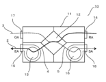
熱交換形換気装置10は、図2に示す通り、本体ケース11、熱交換素子12、排気ファン13、内気口14、排気口15、給気ファン16、外気口17、給気口18、排気風路4、給気風路5を備えている。本体ケース11は、熱交換形換気装置10の外枠である。本体ケース11の外周には、内気口14、排気口15、外気口17、給気口18が形成されている。内気口14は、排気流2を熱交換形換気装置10に吸い込む吸込口である。排気口15は、排気流2を熱交換形換気装置10から屋外に吐き出す吐出口である。外気口17は、給気流3を熱交換形換気装置10に吸い込む吸込口である。給気口18は、給気流3を熱交換形換気装置10から屋内に吐き出す吐出口である。 As shown in FIG. 2, the heat exchange type ventilator 10 includes a main body case 11, a heat exchange element 12, an exhaust fan 13, an inside air port 14, an exhaust port 15, an air supply fan 16, an outside air port 17, an air supply port 18, an exhaust An air passage 4 and an air supply passage 5 are provided. The body case 11 is the outer frame of the heat exchange type ventilator 10 . An inside air port 14 , an exhaust port 15 , an outside air port 17 and an air supply port 18 are formed on the outer periphery of the body case 11 . The internal air inlet 14 is an inlet that draws the exhaust flow 2 into the heat exchange ventilator 10 . The exhaust port 15 is a discharge port that discharges the exhaust flow 2 from the heat exchange type ventilator 10 to the outside. The outside air port 17 is an intake port that draws the supply air flow 3 into the heat exchange ventilator 10 . The air supply port 18 is a discharge port for discharging the supply airflow 3 from the heat exchange type ventilator 10 indoors.

本体ケース11の内部には、熱交換素子12、排気ファン13、給気ファン16が取り付けられている。また、本体ケース11の内部には、排気風路4、給気風路5が構成されている。熱交換素子12は、排気風路4を流通する排気流2と、給気風路5を流通する給気流3との間で熱交換(顕熱と潜熱)を行うための部材である。排気ファン13は、排気流2を内気口14から吸い込み、排気口15から吐出するための送風機である。給気ファン16は、給気流3を外気口17から吸い込み、給気口18から吐出するための送風機である。排気風路4は、内気口14と排気口15とを連通する風路である。給気風路5は、外気口17と給気口18とを連通する風路である。排気ファン13により吸い込まれた排気流2は、排気風路4内の熱交換素子12、排気ファン13を経由し、排気口15から屋外へと排出される。また、給気ファン16により吸い込まれた給気流3は、給気風路5内の熱交換素子12、給気ファン16を経由し、給気口18から屋内へと供給される。 A heat exchange element 12 , an exhaust fan 13 and an air supply fan 16 are mounted inside the body case 11 . Further, an exhaust air passage 4 and an air supply air passage 5 are formed inside the body case 11 . The heat exchange element 12 is a member for performing heat exchange (sensible heat and latent heat) between the exhaust flow 2 flowing through the exhaust air passage 4 and the supply air flow 3 flowing through the supply air passage 5 . The exhaust fan 13 is a blower for sucking the exhaust flow 2 from the internal air port 14 and discharging it from the exhaust port 15 . The air supply fan 16 is a fan for sucking the supply airflow 3 from the outside air port 17 and discharging it from the air supply port 18 . The exhaust air passage 4 is an air passage that connects the internal air port 14 and the air exhaust port 15 . The supply air passage 5 is an air passage that connects the outside air port 17 and the air supply port 18 . The exhaust flow 2 sucked by the exhaust fan 13 passes through the heat exchange element 12 in the exhaust air passage 4 and the exhaust fan 13 and is discharged to the outside through the exhaust port 15 . The air flow 3 sucked by the air supply fan 16 passes through the heat exchange element 12 in the air supply air passage 5 and the air supply fan 16 and is supplied indoors from the air supply port 18 .

熱交換形換気装置10は、熱交換換気を行う場合には、熱交換素子12の排気ファン13および給気ファン16を動作させ、熱交換素子12において排気風路4を流通する排気流2と、給気風路5を流通する給気流3との間で熱交換を行う。これにより、熱交換形換気装置10は、換気を行う際に、室外に放出する排気流2の熱を室内に取り入れる給気流3へと伝達し、不要な熱の放出を抑制し、室内に熱を回収する。この結果、冬季においては、換気を行う際に、屋外の温度が低い空気によって屋内の温度低下を抑制することができる。一方、夏季においては、換気を行う際に、屋外の温度が高い空気によって屋内の温度上昇を抑制することができる。 When performing heat exchange ventilation, the heat exchange type ventilator 10 operates the exhaust fan 13 and the supply air fan 16 of the heat exchange element 12, and the heat exchange element 12 operates the exhaust flow 2 flowing through the exhaust air passage 4. , heat exchange with the supply air flow 3 flowing through the supply air passage 5 . As a result, when performing ventilation, the heat exchange type ventilator 10 transfers the heat of the exhaust flow 2 that is released to the outside to the supply air flow 3 that is taken into the room, suppresses the release of unnecessary heat, and heats the room. recover. As a result, in winter, when ventilation is performed, it is possible to suppress a decrease in the indoor temperature by air having a low outdoor temperature. On the other hand, in the summer, when ventilation is performed, the indoor temperature rise can be suppressed by the outdoor air having a high temperature.

(実施の形態1)
次に、図3を参照して、本実施の形態1に係る除湿機能付き熱交換形換気装置について説明する。図3は、本発明の実施の形態1に係る除湿機能付き熱交換形換気装置の構成を示す模式図である。なお、図3以降の各模式図では、排気風路4および給気風路5を、熱交換形換気装置10内の排気流2および給気流3の流れ(黒矢印)と兼用して表記している。
(Embodiment 1)
Next, referring to FIG. 3, the heat exchange ventilator with a dehumidifying function according to the first embodiment will be described. FIG. 3 is a schematic diagram showing the configuration of the heat exchange ventilator with a dehumidifying function according to Embodiment 1 of the present invention. 3 and subsequent schematic diagrams, the exhaust airflow path 4 and the supply airflow path 5 are also shown as the flows of the exhaust airflow 2 and the air supply airflow 3 (black arrows) in the heat exchange type ventilator 10. there is

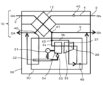
本実施の形態1に係る除湿機能付き熱交換形換気装置50は、図3に示すように、前提例に係る熱交換形換気装置10に対して、除湿機能を付与する手段としての除湿装置30を連結した構成を有している。 As shown in FIG. 3, the heat exchange ventilator 50 with a dehumidification function according to Embodiment 1 includes a dehumidifier 30 as means for imparting a dehumidification function to the heat exchange ventilator 10 according to the premise example. It has a configuration in which

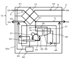
除湿装置30は、熱交換形換気装置10での熱交換後の給気流3の除湿を行うためのユニットである。除湿装置30は、圧縮機31と放熱器32と膨張器33と吸熱器34とを含んで構成される冷凍サイクルと、熱交換器35と、を備えている。そして、本実施の形態の冷凍サイクルは、圧縮機31と放熱器32と膨張器33と吸熱器34とをこの順序で環状に連結して構成されている。冷凍サイクルには、例えば、冷媒として代替フロン(HFC134a)が利用される。また、冷凍サイクルを構成する各機器の連結には、銅管がよく用いられ、溶接方式で連結される。 The dehumidifier 30 is a unit for dehumidifying the supply airflow 3 after heat exchange in the heat exchange ventilator 10 . The dehumidifier 30 includes a refrigeration cycle including a compressor 31 , a radiator 32 , an expander 33 and a heat absorber 34 , and a heat exchanger 35 . The refrigerating cycle of the present embodiment is configured by annularly connecting a compressor 31, a radiator 32, an expander 33, and a heat absorber 34 in this order. The refrigeration cycle uses, for example, a CFC substitute (HFC134a) as a refrigerant. In addition, copper pipes are often used to connect devices that constitute the refrigeration cycle, and are connected by welding.

圧縮機31は、冷凍サイクルにおける低温・低圧の冷媒ガス(作動媒体ガス)を圧縮し、圧力を高めて高温化する機器である。本実施の形態では、圧縮機31は、冷媒ガスの温度を45℃程度にまで高温化している。 The compressor 31 is a device that compresses a low-temperature, low-pressure refrigerant gas (working medium gas) in the refrigeration cycle and increases the pressure to raise the temperature. In this embodiment, the compressor 31 raises the temperature of the refrigerant gas to about 45°C.

放熱器32は、圧縮機31によって高温・高圧となった冷媒ガスと空気(排気流2)との間で熱交換することによって、熱を外部(冷凍サイクル外)に放出させる機器である。このとき、冷媒ガスは、高圧下で凝縮されて液化する。放熱器32では、導入される冷媒ガスの温度(45℃程度)が空気の温度より高いため、熱交換すると、空気は昇温され、冷媒ガスは冷却される。なお、放熱器32は、凝縮器ともいう。 The radiator 32 is a device that releases heat to the outside (outside the refrigeration cycle) by exchanging heat between the refrigerant gas heated to a high temperature and high pressure by the compressor 31 and the air (exhaust flow 2). At this time, the refrigerant gas is condensed and liquefied under high pressure. In the radiator 32, the temperature of the introduced refrigerant gas (approximately 45° C.) is higher than the temperature of the air, so heat exchange raises the temperature of the air and cools the refrigerant gas. Note that the radiator 32 is also called a condenser.

膨張器33は、放熱器32によって液化した高圧の冷媒を減圧して元の低温・低圧の液体とする機器である。なお、膨張器33は、膨張弁ともいう。 The expander 33 is a device that reduces the pressure of the high-pressure refrigerant liquefied by the radiator 32 to the original low-temperature, low-pressure liquid. Note that the expander 33 is also called an expansion valve.

吸熱器34は、膨張器33を流通した冷媒が空気から熱を奪って蒸発し、液状の冷媒を低温・低圧の冷媒ガスとする機器である。吸熱器34では、導入される冷媒の温度が空気の温度より低いため、熱交換すると、空気が冷却され、冷媒が昇温される。なお、吸熱器34は、蒸発器ともいう。 The heat absorber 34 is a device in which the refrigerant flowing through the expander 33 takes heat from the air and evaporates, converting the liquid refrigerant into a low-temperature, low-pressure refrigerant gas. In the heat absorber 34, since the temperature of the introduced refrigerant is lower than the temperature of the air, heat exchange cools the air and raises the temperature of the refrigerant. Note that the heat absorber 34 is also called an evaporator.

熱交換器35は、顕熱型の熱交換素子を備えた熱交換器である。熱交換器35は、従来の除湿装置100における熱交換器111(図9参照)と同様、吸熱器34と放熱器32との間の空間に配置されている。熱交換器35の内部には、所定の方向に空気が流れる第一流路36と、この第一流路36と略直交する方向に空気が流れる第二流路37と、を備える。第一流路36は、吸熱器34から導入される空気を、放熱器32を流通させることなく、給気風路5に導出する流路である。第二流路37は、熱交換形換気装置10から導入された空気を、放熱器32を流通させることなく、給気風路5に導出する流路である。そして、熱交換器35は、第一流路36を流れる空気と第二流路37を流れる空気との間で顕熱のみ交換する。 The heat exchanger 35 is a heat exchanger equipped with a sensible heat exchange element. The heat exchanger 35 is arranged in the space between the heat absorber 34 and the heat radiator 32, like the heat exchanger 111 (see FIG. 9) in the conventional dehumidifier 100. As shown in FIG. Inside the heat exchanger 35 , a first flow path 36 through which air flows in a predetermined direction and a second flow path 37 through which air flows in a direction substantially perpendicular to the first flow path 36 are provided. The first flow path 36 is a flow path that guides the air introduced from the heat absorber 34 to the supply air flow path 5 without circulating the heat radiator 32 . The second flow path 37 is a flow path that leads the air introduced from the heat exchange type ventilator 10 to the supply air flow path 5 without circulating the radiator 32 . The heat exchanger 35 exchanges only sensible heat between the air flowing through the first flow path 36 and the air flowing through the second flow path 37 .

次に、熱交換形換気装置10と除湿装置30との間での気流(排気流2、給気流3)の流れについて図3を参照して説明する。なお、以下の説明では、熱交換後の気流(排気流2、給気流3)または風路(排気風路4、給気風路5)は、熱交換形換気装置10における熱交換素子12を通過した後の気流または風路を示し、熱交換前の気流または風路は、熱交換素子12を通過する前の気流をまたは風路を示すものとする。 Next, the flow of airflow (exhaust airflow 2, supply airflow 3) between the heat exchange type ventilator 10 and the dehumidifier 30 will be described with reference to FIG. In the following description, the air flow (exhaust air flow 2, supply air flow 3) or air passage (exhaust air passage 4, supply air passage 5) after heat exchange passes through the heat exchange element 12 in the heat exchange type ventilator 10. The airflow or airpath before heat exchange indicates the airflow or airpath before passing through the heat exchange element 12 .

図3に示すように、熱交換形換気装置10には、熱交換後の排気風路4に切替ダンパ40が設置され、熱交換後の給気風路5に切替ダンパ41が設置されている。切替ダンパ40は、排気風路4を流通する排気流2を屋外に流す状態と、排気風路4を流通する排気流2を除湿装置30に流す状態とを切り替えるためのダンパである。また、切替ダンパ41は、給気風路5を流通する給気流3を屋内に流す状態と、給気風路5を流通する給気流3を除湿装置30に流す状態とを切り替えるためのダンパである。 As shown in FIG. 3, in the heat exchange type ventilator 10, a switching damper 40 is installed in the exhaust air passage 4 after heat exchange, and a switching damper 41 is installed in the supply air passage 5 after heat exchange. The switching damper 40 is a damper for switching between a state in which the exhaust flow 2 flowing through the exhaust air passage 4 is allowed to flow outdoors and a state in which the exhaust flow 2 flowing through the exhaust air passage 4 is allowed to flow to the dehumidifier 30 . The switching damper 41 is a damper for switching between a state in which the supply air flow 3 flowing through the supply air passage 5 is allowed to flow indoors and a state in which the supply air flow 3 flowing through the supply air passage 5 is allowed to flow to the dehumidifier 30 .

除湿機能付き熱交換形換気装置50では、各切替ダンパによって除湿装置30に気流が流れる状態とすることで、熱交換後の給気流3に対して除湿が実行される。除湿の詳細については後述する。なお、除湿の必要がない冬季などの場合には、各切替ダンパによって除湿装置30に気流が流れない状態とすることで、除湿装置30に起因した圧力損失の上昇が抑制され、除湿機能付き熱交換形換気装置50として、年間を通じての省エネルギーでの運転を実現することができる。 In the heat exchange ventilator 50 with a dehumidification function, each switching damper causes the airflow to flow through the dehumidifier 30, thereby dehumidifying the supplied airflow 3 after heat exchange. Details of dehumidification will be described later. In the winter when dehumidification is not required, each switching damper prevents the airflow from flowing through the dehumidifier 30, thereby suppressing an increase in pressure loss caused by the dehumidifier 30. As the replaceable ventilator 50, energy-saving operation can be realized throughout the year.

また、図3に示すように、除湿装置30には、内部に導入される熱交換後の給気流3を、2つの気流(第一給気流3a、第二給気流3b)に分割する分岐ダンパ42が設置されている。第一給気流3aは、吸熱器34に導入され、第一流路36を流通する気流であり、第二給気流3bは、熱交換器35に導入され、第二流路37を流通する気流である。分岐ダンパ42は、第一給気流3aの風量と第二給気流3bの風量の比率を可変に構成されている。つまり、分岐ダンパ42は、ダンパの角度(熱交換後の給気流3の分岐割合)を調整することによって、第二給気流3bに対する第一給気流3aの割合を容易に増減させることが可能となっている。ここで、第一給気流3aは、請求項の「除湿装置に導入された給気流の一部分」に相当し、第二給気流3bは、請求項の「除湿装置に導入された給気流の他の部分」に相当する。 Further, as shown in FIG. 3, the dehumidifier 30 includes a branch damper that divides the heat-exchanged supply airflow 3 introduced into the inside into two airflows (a first supply airflow 3a and a second supply airflow 3b). 42 are installed. The first supply airflow 3a is an airflow that is introduced into the heat absorber 34 and flows through the first flow path 36, and the second supply airflow 3b is an airflow that is introduced into the heat exchanger 35 and flows through the second flow path 37. be. The branch damper 42 is configured such that the ratio between the air volume of the first air supply flow 3a and the air volume of the second air supply flow 3b is variable. In other words, the branch damper 42 can easily increase or decrease the ratio of the first air supply flow 3a to the second air supply flow 3b by adjusting the angle of the damper (the ratio of the branches of the air supply flow 3 after heat exchange). It's becoming Here, the first supply airflow 3a corresponds to "part of the supply airflow introduced into the dehumidifier" in the claims, and the second supply airflow 3b corresponds to "other than the supply airflow introduced into the dehumidifier" in the claims. "part of".

除湿装置30では、分割された給気流3のうち第一給気流3aは、吸熱器34、熱交換器35の第一流路36の順に流通した後に、放熱器32を流通することなく、熱交換形換気装置10における熱交換後の給気風路5に導出される。一方、第二給気流3bは、熱交換器35の第二流路37を流通した後に、放熱器32を流通することなく、熱交換後の給気風路5に導出される。本実施の形態では、除湿装置30は、熱交換器35を流通した第一給気流3aと熱交換器35を流通した第二給気流3bとを合流させた後に、熱交換後の給気風路5に導出するように構成されている。これにより、室内に送風される給気流3としての温度調整がなされる。室内に送風される給気流3の温度調整方法については後述する。 In the dehumidifier 30, the first supply airflow 3a of the divided supply airflow 3 flows through the heat absorber 34 and the first flow path 36 of the heat exchanger 35 in this order, and then passes through the radiator 32 without heat exchange. After heat exchange in the type ventilator 10 , the air is led out to the supply air passage 5 . On the other hand, the second supply airflow 3 b flows through the second flow path 37 of the heat exchanger 35 and then is led out to the supply airflow path 5 after heat exchange without flowing through the radiator 32 . In the present embodiment, the dehumidifier 30 merges the first supply airflow 3a that has passed through the heat exchanger 35 and the second supply airflow 3b that has passed through the heat exchanger 35, and then performs the heat exchange in the supply airflow path. 5. As a result, the temperature of the supply airflow 3 blown into the room is adjusted. A method for adjusting the temperature of the supply airflow 3 blown into the room will be described later.

一方、除湿装置30に導入された排気流2は、放熱器32を流通した後に、熱交換形換気装置10における熱交換後の排気風路4に導出される。つまり、本実施の形態では、除湿装置30は、熱交換形換気装置10から導入される排気流2によって放熱器32が冷却されるように構成されている。 On the other hand, the exhaust flow 2 introduced into the dehumidifier 30 flows through the heat radiator 32 and then is led out to the exhaust air passage 4 after heat exchange in the heat exchange type ventilator 10 . That is, in this embodiment, the dehumidifier 30 is configured such that the radiator 32 is cooled by the exhaust flow 2 introduced from the heat exchange type ventilator 10 .

次に、本実施の形態1に係る除湿機能付き熱交換形換気装置50の除湿の動作について説明する。 Next, the dehumidification operation of the heat exchange ventilator 50 with dehumidification function according to the first embodiment will be described.

まず、除湿機能付き熱交換形換気装置50を運転することによって、排気ファン13と給気ファン16が駆動し、熱交換形換気装置10の内部には、排気風路4を流通する排気流2と、給気風路5を流通する給気流3とが生じる。 First, by operating the heat exchange type ventilator 50 with dehumidification function, the exhaust fan 13 and the supply air fan 16 are driven, and inside the heat exchange type ventilator 10, there is an exhaust flow 2 flowing through the exhaust air passage 4. , and a supply airflow 3 flowing through the supply airflow path 5 is generated.

例えば、夏季において、排気流2は、エアコンなどによって快適な温度湿度に空調された屋内の空気であり、給気流3は、高温多湿の屋外の空気である。 For example, in summer, the exhaust flow 2 is indoor air conditioned to a comfortable temperature and humidity by an air conditioner or the like, and the supply air flow 3 is hot and humid outdoor air.

排気流2と給気流3とは、熱交換形換気装置10の内部で顕熱と潜熱が交換される。この際、高温多湿の給気流3から排気流2に水分が移動するため、給気流3の水分が除去される。つまり、熱交換形換気装置10の内部での全熱交換によって、給気流3に対する除湿(第一除湿)がなされる。 The exhaust air stream 2 and the supply air stream 3 exchange sensible and latent heat inside the heat exchange ventilator 10 . At this time, moisture moves from the hot and humid air supply stream 3 to the exhaust air stream 2, so the moisture in the air supply stream 3 is removed. That is, dehumidification (first dehumidification) of the supplied air flow 3 is performed by total heat exchange inside the heat exchange type ventilator 10 .

次に、熱交換後の給気流3は、除湿装置30に導入されて除湿される。具体的には、除湿装置30に導入された給気流3のうち第一給気流3aは、吸熱器34によって冷却される。これにより、第一給気流3aの温度が露点温度以下となり、第一給気流3aが結露するので、第一給気流3aの水分が除去される。つまり、吸熱器34を流通することによって、第一給気流3aに対する除湿(第二除湿)がなされる。 Next, the air supply flow 3 after heat exchange is introduced into the dehumidifier 30 and dehumidified. Specifically, the first supply airflow 3 a of the supply airflow 3 introduced into the dehumidifier 30 is cooled by the heat absorber 34 . As a result, the temperature of the first supply airflow 3a becomes equal to or lower than the dew point temperature, and dew condensation occurs in the first supply airflow 3a, so that moisture in the first supply airflow 3a is removed. That is, dehumidification (second dehumidification) of the first supply airflow 3a is performed by circulating the heat absorber 34 .

加えて、除湿装置30に導入された給気流3のうち残りの第二給気流3bは、熱交換器35の第二流路37に流入し、第一流路36内の吸熱器34で冷却された第一給気流3aと熱交換される。これにより、第二流路37内の第二給気流3bが冷却されて結露するので、第二給気流3bの水分が除去される。つまり、熱交換器35で顕熱交換することによって、第二給気流3bに対する除湿(第三除湿)がなされる。 In addition, the remaining second supply airflow 3b of the supply airflow 3 introduced into the dehumidifier 30 flows into the second flow path 37 of the heat exchanger 35 and is cooled by the heat absorber 34 in the first flowpath 36. heat exchange with the first supply air flow 3a. As a result, the second supply airflow 3b in the second flow path 37 is cooled and dew condensation occurs, so that moisture in the second supply airflow 3b is removed. That is, by exchanging sensible heat in the heat exchanger 35, the second supply airflow 3b is dehumidified (third dehumidified).

つまり、除湿機能付き熱交換形換気装置50は、熱交換形換気装置10と吸熱器34と熱交換器35との各機器による除湿(第一除湿~第三除湿)によって、屋外の高温多湿の給気流3から水分を除去し、その際、必要な除湿量を確保している。 In other words, the heat exchange ventilator 50 with dehumidification function dehumidifies (first to third dehumidification) by each device of the heat exchange ventilator 10, the heat absorber 34, and the heat exchanger 35, and dehumidifies the outdoor high temperature and high humidity. Moisture is removed from the supply air stream 3, ensuring the required amount of dehumidification.

さらに、除湿機能付き熱交換形換気装置50における除湿装置30は、熱交換形換気装置10の排気風路4から排気流2を導入し、導入された排気流2が放熱器32を流通する構成となっている。放熱器32では、導入された排気流2によって、吸熱器34において吸熱されるエネルギーと、圧縮機31において冷凍サイクル内の冷媒を循環させるためのエネルギーとに相当する熱量が排熱され、放熱器32から熱を奪った排気流2は排気風路4に導出されてそのまま屋外に排出される。つまり、放熱器32は、導入された排気流2によって冷却される。そして、給気流3(第一給気流3a、第二給気流3b)は、放熱器32を流通することなく給気風路5に導出されるので、除湿処理に起因した給気流3(第一給気流3aと第二給気流3bの混合気流)の温度上昇が生じることはない。 Furthermore, the dehumidifier 30 in the heat exchange ventilator 50 with dehumidification function introduces the exhaust flow 2 from the exhaust air passage 4 of the heat exchange ventilator 10, and the introduced exhaust flow 2 flows through the radiator 32. It has become. In the radiator 32, the amount of heat corresponding to the energy absorbed in the heat absorber 34 and the energy for circulating the refrigerant in the refrigeration cycle in the compressor 31 is exhausted by the introduced exhaust flow 2, and the radiator The exhaust flow 2 that has taken heat from 32 is guided to the exhaust air passage 4 and discharged to the outside as it is. The radiator 32 is thus cooled by the introduced exhaust stream 2 . Since the supply airflow 3 (first supply airflow 3a, second supply airflow 3b) is led out to the supply airflow path 5 without circulating the radiator 32, the supply airflow 3 (first supply airflow) caused by the dehumidification process The temperature of the mixed airflow of the airflow 3a and the second supply airflow 3b does not rise.

次に、本実施の形態1に係る除湿機能付き熱交換形換気装置50における給気流3の温度調整方法について説明する。 Next, a method for adjusting the temperature of the supply airflow 3 in the heat exchange type ventilator 50 with a dehumidifying function according to Embodiment 1 will be described.

除湿機能付き熱交換形換気装置50には、図3に示すように、分岐ダンパ42の分岐割合の制御に関連して、熱交換前の排気流2の空気温度を検出する第一温度センサ45と、除湿装置30の熱交換器35を流通して合流した後の給気流3(第一給気流3aと第二給気流3bの混合気流)の空気温度を検出する第二温度センサ46と、分岐ダンパ42を制御する制御部(図示せず)と、を有する。 The heat exchange ventilator with dehumidification function 50 includes a first temperature sensor 45 for detecting the air temperature of the exhaust flow 2 before heat exchange, in connection with controlling the branch ratio of the branch damper 42, as shown in FIG. and a second temperature sensor 46 that detects the air temperature of the air supply flow 3 (mixed air flow of the first air supply flow 3a and the second air supply flow 3b) after circulating and joining the heat exchanger 35 of the dehumidifier 30; and a control unit (not shown) that controls the branch damper 42 .

制御部は、第一温度センサ45によって検出した温度に基づいて、分岐ダンパ42の分岐割合を調整させ、第二温度センサ46によって検出される温度が所定の温度範囲となるように分岐ダンパ42を制御する。具体的には、制御部は、第一温度センサ45での温度と比べて、第二温度センサ46での温度が高い場合には、第二給気流3bの風量に対する第一給気流3aの風量を増加させ、除湿後の給気流3の温度を下降させる。一方、制御部は、第一温度センサ45での温度と比べて、第二温度センサ46での温度が低い場合には、第二給気流3bの風量に対する第一給気流3aの風量を減少させ、給気流3の温度を上昇させる。これにより、除湿機能付き熱交換形換気装置50では、第一温度センサ45(屋内から吸い込んだ熱交換前の排気流2)と同等の温度となる給気流3を給気することが可能となる。 The control unit adjusts the branch ratio of the branch damper 42 based on the temperature detected by the first temperature sensor 45, and adjusts the branch damper 42 so that the temperature detected by the second temperature sensor 46 falls within a predetermined temperature range. Control. Specifically, when the temperature detected by the second temperature sensor 46 is higher than the temperature detected by the first temperature sensor 45, the controller detects the air volume of the first supply airflow 3a relative to the air volume of the second supply airflow 3b. is increased to lower the temperature of the dehumidified supply airflow 3 . On the other hand, when the temperature detected by the second temperature sensor 46 is lower than the temperature detected by the first temperature sensor 45, the controller reduces the air volume of the first supply airflow 3a relative to the air volume of the second air supply flow 3b. , to increase the temperature of the air supply stream 3 . As a result, the heat exchange ventilator 50 with a dehumidification function can supply the supply air flow 3 having a temperature equivalent to that of the first temperature sensor 45 (the exhaust flow 2 before heat exchange sucked from indoors). .

本実施の形態1に係る除湿機能付き熱交換形換気装置50によれば、除湿装置30における放熱器32の冷却(排熱)に必要なエネルギーを、熱交換形換気装置10からの排気流2(除湿を必要する夏季において、給気流3よりも温度が低い排気流2)によって得ることができるため、除湿後の空気(給気流)を放熱器に対して流通させることなく室内に吹き出すことができる。つまり、冷凍サイクルと熱交換器35とを組み合わせた除湿装置30を適用した場合でも、除湿に伴って生じる温度上昇が抑制された給気流を送風することができる。 According to the heat exchange ventilator 50 with a dehumidifying function according to Embodiment 1, the energy required for cooling (exhaust heat) of the radiator 32 in the dehumidifier 30 is (In the summer when dehumidification is required, it can be obtained by the exhaust flow 2 whose temperature is lower than that of the supply air flow 3). can. In other words, even when the dehumidifier 30 that combines the refrigeration cycle and the heat exchanger 35 is applied, it is possible to blow the supply airflow in which the temperature rise caused by dehumidification is suppressed.

(実施の形態2)
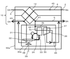
本発明の実施の形態2に係る除湿機能付き熱交換形換気装置50aは、除湿装置30aにおける放熱器32に対して水を吹き付ける水吹付部38が構成されている点で実施の形態1と異なる。これ以外の除湿機能付き熱交換形換気装置50aの構成は、実施の形態1に係る除湿機能付き熱交換形換気装置50と同様である。以下、実施の形態1で説明済みの内容は再度の説明を適宜省略し、実施の形態1と異なる点を主に説明する。
(Embodiment 2)
A heat exchange ventilator 50a with a dehumidifying function according to Embodiment 2 of the present invention differs from Embodiment 1 in that a water spraying section 38 for spraying water onto a radiator 32 in a dehumidifier 30a is configured. . Other configurations of the heat exchange ventilator 50a with dehumidification function are the same as those of the heat exchange ventilator 50 with dehumidification function according to the first embodiment. In the following, repetitive explanations of the contents already explained in the first embodiment will be omitted as appropriate, and differences from the first embodiment will be mainly explained.

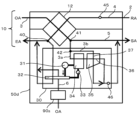
本発明の実施の形態2に係る除湿機能付き熱交換形換気装置50aについて、図4を参照して説明する。図4は、本発明の実施の形態2に係る除湿機能付き熱交換形換気装置の構成を示す模式図である。 A heat exchange ventilator 50a with a dehumidifying function according to Embodiment 2 of the present invention will be described with reference to FIG. FIG. 4 is a schematic diagram showing the configuration of a heat exchange ventilator with a dehumidifying function according to Embodiment 2 of the present invention.

図4に示すように、除湿機能付き熱交換形換気装置50aにおける除湿装置30aには、放熱器32に対して水を吹き付ける水吹付部38と、水吹付部38に対して水を供給するとともに、放熱器32に吹き付けた際に生じる余剰水を排水するための給排水管39と、が設けられている。 As shown in FIG. 4, the dehumidifier 30a in the heat exchange ventilator 50a with a dehumidification function includes a water sprayer 38 that sprays water onto the radiator 32, and supplies water to the water sprayer 38. , and a water supply/drainage pipe 39 for draining excess water generated when the radiator 32 is sprayed.

除湿装置30aでは、冷凍サイクルを構成する放熱器32は全体が排気風路4内に配置され、それ以外の各機器(圧縮機31、膨張器33、吸熱器34、熱交換器35)は排気風路4外に配置される。 In the dehumidifier 30a, the entire radiator 32 constituting the refrigeration cycle is arranged in the exhaust air passage 4, and the other devices (compressor 31, expander 33, heat absorber 34, heat exchanger 35) are exhausted. It is arranged outside the air passage 4 .

水吹付部38は、水ノズルを有し、排気風路4内において水ノズルから放熱器32に対して水を霧状に噴霧する。噴霧された水は、放熱器32を構成する放熱パイプ等の表面に付着し、放熱器32の熱によって気化する。そして、気化した水は、放熱器32を流通する排気流2によって排気風路4に導出されてそのまま屋外に排出される。 The water spraying part 38 has a water nozzle, and sprays water from the water nozzle to the radiator 32 in the exhaust air passage 4 in the form of a mist. The sprayed water adheres to the surface of the radiator pipes and the like that constitute the radiator 32 and is vaporized by the heat of the radiator 32 . Then, the vaporized water is led to the exhaust air passage 4 by the exhaust flow 2 flowing through the radiator 32 and discharged to the outside as it is.

給排水管39は、一方の端部が電磁弁等の開閉手段を介して水吹付部38と接続されるとともに、他方の端部が住宅施設の給水設備および排水設備に接続される。そして、給排水管39は、水吹付部38に対して水を供給するとともに、放熱器32に吹き付けた際に生じる余剰水を排水する。 One end of the water supply and drainage pipe 39 is connected to the water spraying section 38 via an opening/closing means such as an electromagnetic valve, and the other end is connected to the water supply and drainage facilities of the housing facility. The water supply/drainage pipe 39 supplies water to the water spraying portion 38 and drains surplus water generated when water is sprayed to the radiator 32 .

除湿装置30aに導入された排気流2は、水吹付部38によって水が吹き付けられた状態の放熱器32を流通した後に、熱交換形換気装置10における熱交換後の排気風路4に導出されてそのまま屋外に排出される。つまり、本実施の形態では、除湿装置30aは、熱交換形換気装置10から導入される排気流2の空気熱と、吹き付けられた水の気化熱とによって放熱器32が冷却されるように構成されている。 The exhaust flow 2 introduced into the dehumidifier 30a flows through the radiator 32 sprayed with water by the water spraying part 38, and then is introduced into the exhaust air passage 4 after heat exchange in the heat exchange type ventilator 10. It is discharged outside as it is. That is, in the present embodiment, the dehumidifier 30a is configured so that the radiator 32 is cooled by the air heat of the exhaust flow 2 introduced from the heat exchange type ventilator 10 and the vaporization heat of the sprayed water. It is

本実施の形態2に係る除湿機能付き熱交換形換気装置50aによれば、除湿装置30aにおける放熱器32の冷却(排熱)に必要なエネルギーを、熱交換形換気装置10からの排気流2の空気熱と、水吹付部38によって吹き付けられた水の気化熱とによって得ることができるため、放熱器32を効果的に冷却することができ、除湿後の空気(給気流3)を放熱器32に対して流通させることなく室内に吹き出すことができる。つまり、冷凍サイクルと熱交換器35とを組み合わせた除湿装置30aを適用した場合でも、除湿に伴って生じる温度上昇が抑制された給気流3を送風することができる。 According to the heat exchange ventilator 50a with dehumidification function according to the second embodiment, the energy required for cooling (exhaust heat) of the radiator 32 in the dehumidifier 30a is and the vaporization heat of the water sprayed by the water spraying part 38, the radiator 32 can be effectively cooled, and the dehumidified air (supply air flow 3) can be obtained from the radiator It is possible to blow out into the room without circulating to 32. That is, even when the dehumidifier 30a that combines the refrigeration cycle and the heat exchanger 35 is applied, the supply airflow 3 in which the temperature rise caused by dehumidification is suppressed can be blown.

(実施の形態3)
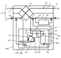
本発明の実施の形態3に係る除湿機能付き熱交換形換気装置50bは、熱交換形換気装置10における熱交換後の給気流3に対して加湿を行う液体微細化装置60が搭載されている点、及び液体微細化装置60に対して外部から水を供給する第一状態と、除湿装置30aに対して外部から水を導入する第二状態とに切り替える水路切替部44とを有して構成されている点で実施の形態2と異なる。これ以外の除湿機能付き熱交換形換気装置50bの構成は、実施の形態2に係る除湿機能付き熱交換形換気装置50aと同様である。以下、実施の形態2で説明済みの内容は再度の説明を適宜省略し、実施の形態2と異なる点を主に説明する。なお、本発明の実施の形態3に係る除湿機能付き熱交換形換気装置50bは、液体微細化装置60を搭載しており、当初の除湿機能に加え、加湿機能も備えるので、調湿機能付き熱交換形換気装置または除加湿機能付き熱交換形換気装置とも言える。
(Embodiment 3)
A heat exchange ventilator 50b with a dehumidifying function according to Embodiment 3 of the present invention is equipped with a liquid atomization device 60 that humidifies the supplied airflow 3 after heat exchange in the heat exchange ventilator 10. and a channel switching unit 44 for switching between a first state in which water is supplied from the outside to the liquid atomization device 60 and a second state in which water is introduced from the outside to the dehumidification device 30a. It is different from the second embodiment in that Other configurations of the heat exchange ventilator 50b with dehumidification function are the same as those of the heat exchange ventilator 50a with dehumidification function according to the second embodiment. In the following, repetitive explanations of the contents already explained in the second embodiment will be omitted as appropriate, and differences from the second embodiment will be mainly explained. The heat exchange ventilator 50b with a dehumidification function according to Embodiment 3 of the present invention is equipped with the liquid atomization device 60 and has a humidification function in addition to the original dehumidification function. It can also be called a heat exchange ventilator or a heat exchange ventilator with dehumidifying and humidifying function.

本発明の実施の形態3に係る除湿機能付き熱交換形換気装置50bについて、図5を参照して説明する。図5は、本発明の実施の形態3に係る除湿機能付き熱交換形換気装置の構成を示す模式図である。 A heat exchange ventilator 50b with a dehumidifying function according to Embodiment 3 of the present invention will be described with reference to FIG. FIG. 5 is a schematic diagram showing the configuration of a heat exchange ventilator with a dehumidifying function according to Embodiment 3 of the present invention.

図5に示すように、除湿機能付き熱交換形換気装置50bには、熱交換形換気装置10における熱交換後の給気流3に対して加湿を行う液体微細化装置60が搭載されている。 As shown in FIG. 5, the heat exchange ventilator 50b with a dehumidifying function is equipped with a liquid atomization device 60 that humidifies the supplied airflow 3 after heat exchange in the heat exchange ventilator 10. As shown in FIG.

そして、熱交換形換気装置10には、熱交換後の給気風路5に切替ダンパ43が設置されている。切替ダンパ43は、給気風路5を流通する給気流3を屋内に流す状態と、給気風路5を流通する給気流3を液体微細化装置60に流す状態とを切り替えるためのダンパである。なお、除湿装置30aを流通した給気流3は、切替ダンパ43よりも上流側(熱交換素子12側)において給気風路5に導出されるように構成されている。 In the heat exchange type ventilator 10, a switching damper 43 is installed in the supply air passage 5 after heat exchange. The switching damper 43 is a damper for switching between a state in which the supply airflow 3 flowing through the supply airflow path 5 is allowed to flow indoors and a state in which the supply airflow 3 flowing through the supply airflow path 5 is allowed to flow to the liquid atomization device 60 . The supply airflow 3 that has flowed through the dehumidifier 30a is configured to be led out to the supply airflow path 5 upstream of the switching damper 43 (on the side of the heat exchange element 12).

除湿機能付き熱交換形換気装置50bでは、切替ダンパ43によって液体微細化装置60に気流が流れる状態とすることで、熱交換後の給気流3に対して加湿が実行される。加湿の詳細については後述する。なお、加湿の必要がない夏季などの場合には、切替ダンパ43によって液体微細化装置60に気流が流れない状態とすることで、液体微細化装置60に起因した圧力損失の上昇が抑制され、除湿機能付き熱交換形換気装置50bとして、年間を通じての省エネルギーでの運転を実現することができる。 In the heat exchange ventilator 50b with a dehumidifying function, the switching damper 43 causes the airflow to flow through the liquid atomization device 60, thereby humidifying the supplied airflow 3 after heat exchange. Details of humidification will be described later. In the summer when humidification is not required, the switching damper 43 prevents airflow from flowing through the liquid atomization device 60, thereby suppressing an increase in pressure loss caused by the liquid atomization device 60. As the heat exchange ventilator 50b with a dehumidifying function, energy-saving operation can be realized throughout the year.

さらに、除湿機能付き熱交換形換気装置50bには、液体微細化装置60に対して外部から水を導入する第一状態と、除湿装置30aに対して外部から水を導入する第二状態とに切り替えるための水路切替部44が設けられている。水路切替部44は、第一状態において液体微細化装置60と給排水管39とを第一通水路44aを介して連通し、第二状態において除湿装置30aと給排水管39とを第二通水路44bを介して連通するように構成されている。そして、水路切替部44は、熱交換後の給気流3に対して加湿処理を行う場合に第一状態に切り替え、熱交換後の給気流3に対して除湿処理を行う場合に第二状態に切り替えられる。 Further, the heat exchange ventilator 50b with a dehumidification function can be in a first state in which water is introduced from the outside to the liquid atomization device 60 and a second state in which water is introduced from the outside to the dehumidifier 30a. A channel switching unit 44 for switching is provided. In the first state, the water channel switching unit 44 connects the liquid atomization device 60 and the water supply/drainage pipe 39 through the first water channel 44a, and in the second state, connects the dehumidifier 30a and the water supply/drainage pipe 39 to the second water channel 44b. is configured to communicate through the Then, the channel switching unit 44 switches to the first state when performing the humidification process on the supplied airflow 3 after heat exchange, and switches to the second state when performing the dehumidification process on the supplied airflow 3 after heat exchange. can be switched.

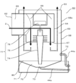
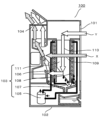
次に、液体微細化装置60について図6を参照して説明する。図6は、本発明の実施の形態3に係る除湿機能付き熱交換形換気装置における液体微細化装置の構成を示す模式図である。 Next, the liquid atomization device 60 will be described with reference to FIG. FIG. 6 is a schematic diagram showing the configuration of a liquid atomization device in a heat exchange ventilator with a dehumidifying function according to Embodiment 3 of the present invention.

図6に示すように、液体微細化装置60は、吸込口62と、吹出口63と、内筒64と、外筒68と、水受け部71と、を備えている。 As shown in FIG. 6 , the liquid atomization device 60 includes a suction port 62 , a blowout port 63 , an inner cylinder 64 , an outer cylinder 68 and a water receiving portion 71 .

吸込口62は、液体微細化装置60の内部に空気を吸い込むための開口であり、液体微細化装置60の側面に設けられている。また、吸込口62は、ダクトが接続可能な形状(例えば、円筒形状)であり、切替ダンパ43を介して熱交換後の給気風路5と接続されている(図5参照)。 The suction port 62 is an opening for sucking air into the liquid atomization device 60 and is provided on the side surface of the liquid atomization device 60 . The suction port 62 has a shape (for example, a cylindrical shape) to which a duct can be connected, and is connected to the supply air passage 5 after heat exchange via the switching damper 43 (see FIG. 5).

吹出口63は、液体微細化装置60の内部を通過した空気を吹き出すための開口であり、液体微細化装置60の上面に設けられている。また、吹出口63は、内筒64と外筒68とによって仕切られる領域(内筒64と外筒68との間の領域)に形成されている。そして、吹出口63は、液体微細化装置60の上面部における内筒64の周囲に設けられる。さらに、吹出口63は、吸込口62よりも上方に位置するように設けられている。また、吹出口63は、筒状のダクトが接続可能な形状であり、熱交換後の給気風路5と接続されている(図5参照)。 The blowout port 63 is an opening for blowing out the air that has passed through the inside of the liquid atomization device 60 , and is provided on the upper surface of the liquid atomization device 60 . Further, the outlet 63 is formed in a region partitioned by the inner cylinder 64 and the outer cylinder 68 (a region between the inner cylinder 64 and the outer cylinder 68). The outlet 63 is provided around the inner cylinder 64 on the upper surface of the liquid atomization device 60 . Furthermore, the blowout port 63 is provided so as to be positioned above the suction port 62 . The outlet 63 has a shape that can be connected to a cylindrical duct, and is connected to the supply air passage 5 after heat exchange (see FIG. 5).

そして、吸込口62から吸い込まれた空気は、後述する液体微細化手段77によって、加湿された空気となって吹出口63から吹き出される。 Then, the air sucked from the suction port 62 is turned into humidified air by the liquid atomizing means 77 to be described later, and is blown out from the blowout port 63 .

内筒64は、液体微細化装置60の内部の中央付近に配置される。また、内筒64は、略鉛直方向下方に向けて開口した通風口67を有し、中空円筒形状に形成されている。 The inner cylinder 64 is arranged near the center inside the liquid atomization device 60 . In addition, the inner cylinder 64 has a ventilation port 67 that opens downward in the substantially vertical direction, and is formed in a hollow cylindrical shape.

外筒68は、円筒形状に形成され、内筒64を内包するように配置されている。また、外筒68の側壁68aには、後述する貯水部70に水を供給するための給水口72が設けられている。そして、給水口72は、第一通水路44aを介して給排水管39と接続されている。なお、給水口72は、貯水部70の上面(貯水部70に貯水され得る最大水位の面:水面80)よりも鉛直方向上方の位置に設けられている。 The outer cylinder 68 is formed in a cylindrical shape and arranged so as to enclose the inner cylinder 64 . A side wall 68a of the outer cylinder 68 is provided with a water supply port 72 for supplying water to a water storage portion 70, which will be described later. The water supply port 72 is connected to the water supply/drainage pipe 39 via the first water passage 44a. The water supply port 72 is provided at a position vertically above the upper surface of the water storage portion 70 (the maximum water level that can be stored in the water storage portion 70: water surface 80).

水受け部71は、液体微細化装置60の底部全面に亘って設けられている。水受け部71は、例えば、装置に異常が生じて水漏れが発生した際に、装置から漏れた水を一時的に溜めることができる。 The water receiving portion 71 is provided over the entire bottom portion of the liquid atomization device 60 . The water receiving part 71 can temporarily store water leaking from the device when, for example, an abnormality occurs in the device and water leakage occurs.

次に、液体微細化装置60の内部構造について説明する。 Next, the internal structure of the liquid atomization device 60 will be described.

図6に示すように、液体微細化装置60は、その内部に、吸込連通風路65と、内筒風路66と、外筒風路69と、貯水部70と、液体微細化手段77と、水受け部71と、を有する。 As shown in FIG. 6, the liquid atomization device 60 includes therein a suction communication air passage 65, an inner cylinder air passage 66, an outer cylinder air passage 69, a water reservoir 70, and a liquid atomization means 77. , and a water receiving portion 71 .

吸込連通風路65は、吸込口62と内筒64(内筒風路66)とを連通するダクト形状の風路であり、吸込口62から吸い込まれた空気は、吸込連通風路65を介して内筒64の内部に至る構成となっている。 The suction communication air passage 65 is a duct-shaped air passage that communicates the suction port 62 and the inner cylinder 64 (inner cylinder air passage 66 ). It is configured to extend to the inside of the inner cylinder 64 .

内筒風路66は、内筒64の内側に設けられた風路であり、内筒64の下端に設けられた開口(通風口67)を介して、内筒64の外側に設けられた外筒風路69(図6の破線矢符で示す風路)と連通している。内筒風路66には、風路内に液体微細化手段77が配置されている。 The inner cylinder air passage 66 is an air passage provided inside the inner cylinder 64 . It communicates with a cylindrical air passage 69 (an air passage indicated by a dashed arrow in FIG. 6). A liquid atomizing means 77 is arranged in the inner cylinder air passage 66 .

外筒風路69は、内筒64と外筒68との間に形成された風路であり、吹出口63と連通している。 The outer cylinder air passage 69 is an air passage formed between the inner cylinder 64 and the outer cylinder 68 and communicates with the outlet 63 .

貯水部70は、液体微細化装置60の下部(内筒64の下部)に設けられ、水を貯留する。貯水部70は、略すり鉢形状に形成されて、貯水部70の側壁は、外筒68の下端と接続されて一体化している。そして、貯水部70は、外筒68の側壁68aに設けられた給水口72から水が供給され、貯水部70の底面に設けられた排水口73から水が排出される構造となっている。ここで、排水口73は、給水口72と同様、別の第一通水路44aを介して給排水管39と接続されている。なお、排水口73は、貯水部70底面の最も低い位置に設けられていることが好ましい。 The water storage part 70 is provided in the lower part of the liquid atomization device 60 (the lower part of the inner cylinder 64) and stores water. The water storage part 70 is formed in a substantially mortar shape, and the side wall of the water storage part 70 is connected to and integrated with the lower end of the outer cylinder 68 . The water reservoir 70 is supplied with water from a water supply port 72 provided on the side wall 68 a of the outer cylinder 68 and discharged from a drain port 73 provided on the bottom surface of the water reservoir 70 . Here, like the water supply port 72, the water discharge port 73 is connected to the water supply/drainage pipe 39 via another first water passage 44a. It should be noted that the drain port 73 is preferably provided at the lowest position on the bottom surface of the water storage section 70 .

液体微細化手段77は、液体微細化装置60の主要部であり、水の微細化を行うところである。具体的には、液体微細化手段77は、揚水管(吸上管)74と、回転板75と、モータ76と、を有する。また、液体微細化手段77は、内筒64の内側すなわち内筒64に覆われる位置に設けられている。 The liquid atomization means 77 is a main part of the liquid atomization device 60 and is where water is atomized. Specifically, the liquid atomization means 77 has a water pump (suction pipe) 74 , a rotating plate 75 and a motor 76 . Further, the liquid atomizing means 77 is provided inside the inner cylinder 64 , that is, at a position covered by the inner cylinder 64 .

揚水管74は、回転により貯水部70から水を吸い上げる。また、揚水管74は中空の円錐台形状に形成され、直径の小さい側の先端が貯水部70に貯水された水の水面80以下になるように設けられている。 The pumping pipe 74 sucks up water from the reservoir 70 by rotation. The pumping pipe 74 is formed in a hollow truncated cone shape, and is provided so that the tip of the smaller diameter side is below the water surface 80 of the water stored in the water reservoir 70 .

回転板75は、中央が開口したドーナツ状の円板形状に形成され、揚水管74の直径の大きい側、言い換えれば揚水管74の上部の周囲に配置されている。揚水管74の直径の大きい側には、その側面に複数の開口(図示せず)が設けられており、吸い上げた水が開口を通過して回転板75に供給されるようになっている。そして、回転板75は、揚水管74により吸い上げられた水を回転面方向に放出する。 The rotating plate 75 is formed in a doughnut-shaped disc shape with an open center, and is arranged around the larger diameter side of the pumping pipe 74 , in other words, around the upper part of the pumping pipe 74 . A plurality of openings (not shown) are provided on the side surface of the large diameter side of the pumping pipe 74 , and the sucked water is supplied to the rotary plate 75 through the openings. Then, the rotating plate 75 discharges the water sucked up by the pumping pipe 74 in the rotating surface direction.

モータ76は、揚水管74および回転板75を回転させる。 A motor 76 rotates the pumping pipe 74 and the rotating plate 75 .

水受け部71は、貯水部70の鉛直方向下方において、液体微細化装置60の底部全面に亘って設けられている。 The water receiving portion 71 is provided vertically below the water storage portion 70 over the entire bottom portion of the liquid atomization device 60 .

次に、図6を用いて液体微細化装置の動作について説明する。 Next, the operation of the liquid atomization device will be described with reference to FIG.

初めに、図示しない給水設備と接続された給排水管39より水が給水口72から貯水部70に供給され、貯水部70に水が貯水される。そして、吸込口62から液体微細化装置60の内部に吸い込まれた空気(熱交換後の給気流3)は、吸込連通風路65、内筒風路66、液体微細化手段77、外筒風路69の順に通過し、吹出口63から外部(例えば、室内)に向けて吹き出される。このとき、液体微細化手段77によって発生した水滴と、内筒風路66を通過する空気とが接触し、水滴が気化することにより空気を加湿することができる。また、貯水部70に貯水された水は、所定時間が経過したのち排水口73から装置外に排出される。 First, water is supplied from the water supply port 72 to the water storage portion 70 through the water supply/drainage pipe 39 connected to a water supply facility (not shown), and the water is stored in the water storage portion 70 . The air sucked into the liquid atomization device 60 from the suction port 62 (supply air flow 3 after heat exchange) passes through the suction communication air passage 65, the inner cylinder air passage 66, the liquid atomization means 77, and the outer cylinder wind. It passes through the path 69 in order and is blown out from the outlet 63 toward the outside (for example, the room). At this time, the water droplets generated by the liquid atomizing means 77 come into contact with the air passing through the inner cylinder air passage 66, and the water droplets evaporate, thereby humidifying the air. Further, the water stored in the water storage part 70 is discharged outside the apparatus from the drain port 73 after a predetermined time has passed.

その詳細な動作を説明する。 The detailed operation will be explained.

吸込口62から吸込連通風路65を通過して内筒風路66の内筒に取り込まれた空気は、液体微細化手段77を通過する。揚水管74および回転板75がモータ76の動作により回転すると、回転により貯水部70に貯水された水が揚水管74の内壁面を伝って上昇する。上昇した水は、回転板75の表面を伝って引き伸ばされ、回転板75の外周端から回転面方向に向かって微細な水滴として放出される。放出された水滴は内筒64の内壁面に衝突して破砕され、さらに微細な水滴となる。この回転板75から放出された水滴と、内筒64の内壁面に衝突し破砕された水滴とが内筒64を通過する空気と接触し、水滴が気化して空気の加湿が行われる。なお、発生した水滴の一部は気化しないが、液体微細化手段77を内筒64で覆われるように配置しているので、気化しなかった水滴は内筒64の内側表面に付着して貯水部70に落下する。 Air taken into the inner tube of the inner tube air path 66 from the suction port 62 through the suction communication air path 65 passes through the liquid atomization means 77 . When the pumping pipe 74 and the rotating plate 75 are rotated by the operation of the motor 76 , the water stored in the water storage part 70 rises along the inner wall surface of the pumping pipe 74 . The rising water is stretched along the surface of the rotating plate 75 and discharged from the outer peripheral edge of the rotating plate 75 in the direction of the rotating surface as fine water droplets. The released water droplets collide with the inner wall surface of the inner cylinder 64 and are crushed into finer water droplets. The water droplets discharged from the rotating plate 75 and the water droplets collided with the inner wall surface of the inner cylinder 64 and crushed come into contact with the air passing through the inner cylinder 64, vaporize the water droplets, and humidify the air. Some of the generated water droplets are not vaporized, but since the liquid atomizing means 77 is arranged so as to be covered with the inner cylinder 64, the water droplets that are not vaporized adhere to the inner surface of the inner cylinder 64 and are stored. Drops to part 70 .

そして、水滴を含んだ空気(加湿された空気)は、内筒64の下端に設けられた通風口67から、下方に設けられた貯水部70に向けて吹き出される。そして、内筒64と外筒68との間に形成された外筒風路69に向かって流れる。ここで、外筒風路69内を通過する空気は鉛直方向上方に向かって送風されるため、内筒風路66内を下方に流れる空気と送風方向が対向する向きに変わることとなる。 Then, the air containing water droplets (humidified air) is blown out from the ventilation port 67 provided at the lower end of the inner cylinder 64 toward the water reservoir 70 provided below. Then, it flows toward the outer tube air passage 69 formed between the inner tube 64 and the outer tube 68 . Here, since the air passing through the outer cylinder air passage 69 is blown upward in the vertical direction, the blowing direction of the air flowing downward inside the inner cylinder air passage 66 changes to the opposite direction.

このとき、通風口67から空気とともに吹き出された水滴はその慣性により空気の流れに追従できず、貯水部70の水面80もしくは外筒68の内側壁面に付着する。この作用は水滴の重量が大きいほど作用が大きく、すなわち、気化しにくい直径の大きな水滴ほど作用が大きいため、これにより大粒の水滴を流れる空気から分離することができる。 At this time, the water droplets blown out together with the air from the vent hole 67 cannot follow the air flow due to their inertia, and adhere to the water surface 80 of the water reservoir 70 or the inner wall surface of the outer cylinder 68 . This effect increases as the weight of the water droplet increases. In other words, the larger the diameter of the water droplet, which is less likely to vaporize, the greater the effect.

そして、内筒風路66から通風口67を介して外筒風路69に流入した空気は、外筒風路69を通って上向きに流れる。そして、吹出口63から外部に吹き出される。このとき、水滴の一部は重力により貯水部70へ落下する、もしくは、内筒64の外壁あるいは外筒68の内壁に付着する。そして、内筒64の外壁や外筒68の内壁に付着した水滴は、内筒64の外側壁面や外筒68の内側壁面を伝って貯水部70へ落下する。 The air that has flowed from the inner cylinder air passage 66 into the outer cylinder air passage 69 through the ventilation port 67 flows upward through the outer cylinder air passage 69 . Then, the air is blown out from the outlet 63 . At this time, some of the water droplets fall into the reservoir 70 due to gravity, or adhere to the outer wall of the inner cylinder 64 or the inner wall of the outer cylinder 68 . Water droplets adhering to the outer wall of the inner cylinder 64 and the inner wall of the outer cylinder 68 run along the outer wall surface of the inner cylinder 64 and the inner wall surface of the outer cylinder 68 and fall into the water reservoir 70 .

以上述べたようにして、液体微細化装置60は、液体微細化手段77によって空気(熱交換後の給気流3)を加湿することができる。 As described above, the liquid atomization device 60 can humidify the air (the supplied airflow 3 after heat exchange) by the liquid atomization means 77 .

本実施の形態3に係る除湿機能付き熱交換形換気装置50bによれば、除湿機能付き熱交換形換気装置50aと同様、放熱器32を効果的に冷却することができ、除湿後の空気(給気流3)を放熱器32に対して流通させることなく室内に吹き出すことができる。また、除湿機能付き熱交換形換気装置50bでは、加湿のために液体微細化装置60に導入される外部からの水を、水路切替部44によって容易に除湿装置30aに導入するように切り替えることができる。つまり、加湿機能付き熱交換形換気装置に対して除湿装置30aを適用する場合には、外部からの水の供給を液体微細化装置60と共通化することができるので、除湿装置30aにおける水吹付部38による放熱器32への水の吹き付け処理を低コストで実現することができる。 According to the heat exchange ventilator 50b with a dehumidifying function according to Embodiment 3, as with the heat exchange ventilator 50a with a dehumidifying function, the radiator 32 can be effectively cooled, and the dehumidified air ( The supply air flow 3) can be blown out into the room without being circulated to the radiator 32 . In addition, in the heat exchange ventilator 50b with a dehumidification function, the water from the outside introduced into the liquid atomization device 60 for humidification can be easily switched to be introduced into the dehumidifier 30a by the channel switching unit 44. can. That is, when the dehumidifier 30a is applied to a heat exchange ventilator with a humidifying function, it is possible to share the supply of water from the outside with the liquid atomization device 60. The process of spraying water onto the radiator 32 by the unit 38 can be realized at low cost.

(実施の形態4)
本発明の実施の形態4に係る除湿機能付き熱交換形換気装置50dは、除湿装置30における放熱器32に対して給気流3(熱交換前の給気流3)を流通させる送風装置90が構成されている点で実施の形態1と異なる。これ以外の除湿機能付き熱交換形換気装置50cの構成は、実施の形態1に係る除湿機能付き熱交換形換気装置50と同様である。以下、実施の形態1で説明済みの内容は再度の説明を適宜省略し、実施の形態1と異なる点を主に説明する。
(Embodiment 4)
A heat exchange ventilator 50d with a dehumidifying function according to Embodiment 4 of the present invention includes a blower 90 that circulates an air supply flow 3 (a supply air flow 3 before heat exchange) to a radiator 32 in the dehumidifier 30. It is different from the first embodiment in that Other configurations of the heat exchange ventilator 50c with dehumidification function are the same as those of the heat exchange ventilator 50 with dehumidification function according to the first embodiment. In the following, repetitive explanations of the contents already explained in the first embodiment will be omitted as appropriate, and differences from the first embodiment will be mainly explained.

本発明の実施の形態4に係る除湿機能付き熱交換形換気装置50cについて、図7を参照して説明する。図7は、本発明の実施の形態4に係る除湿機能付き熱交換形換気装置の構成を示す模式図である。 A heat exchange ventilator 50c with a dehumidifying function according to Embodiment 4 of the present invention will be described with reference to FIG. FIG. 7 is a schematic diagram showing the configuration of a heat exchange ventilator with a dehumidifying function according to Embodiment 4 of the present invention.

図7に示すように、除湿機能付き熱交換形換気装置50cには、除湿装置30の放熱器32に対して給気流3(熱交換前の給気流3)を流通させる送風装置90が搭載されている。 As shown in FIG. 7, the heat exchange ventilator 50c with a dehumidification function is equipped with a blower 90 that circulates the supply air flow 3 (the supply air flow 3 before heat exchange) to the radiator 32 of the dehumidifier 30. ing.

送風装置90は、熱交換形換気装置10の熱交換前の給気風路5から切替ダンパ47によって分岐された給気流3の一部(第三給気流3c)を吸い込み、除湿装置30の放熱器32を流通させた後に、熱交換前の給気風路5に導出するための送風機である。 The blower 90 sucks part of the supply airflow 3 (third supply airflow 3c) branched by the switching damper 47 from the supply airflow path 5 before heat exchange of the heat exchange type ventilator 10, and the radiator of the dehumidifier 30 After circulating the air 32, it is an air blower for deriving it to the supply air passage 5 before heat exchange.

切替ダンパ47は、給気風路5を流通する給気流3の全量を熱交換形換気装置10側に流す状態と、給気風路5を流通する給気流3の一部を送風装置90側に流す状態とを切り替えるためのダンパである。 The switching damper 47 allows the entire amount of the supply air flow 3 flowing through the supply air passage 5 to flow toward the heat exchange type ventilator 10 side, and allows a portion of the supply air flow 3 flowing through the supply air passage 5 to flow toward the blower device 90 side. It is a damper for switching between states.

本実施の形態では、除湿装置30は、熱交換形換気装置10から導入される排気流2の空気熱と、送風装置90から導入される第三給気流3cの空気熱とによって放熱器32が冷却されるように構成されている。 In the present embodiment, the dehumidifier 30 uses the air heat of the exhaust flow 2 introduced from the heat exchange ventilator 10 and the air heat of the third supply air flow 3c introduced from the blower 90 to heat the radiator 32. configured to be cooled.

本実施の形態4に係る除湿機能付き熱交換形換気装置50cによれば、除湿装置30における放熱器32の冷却(排熱)に必要なエネルギーを、熱交換形換気装置10からの排気流2の空気熱と、送風装置90から導入される第三給気流3cの空気熱とによって得ることができるため、放熱器32を効果的に冷却することができ、除湿後の空気(給気流3)を放熱器32に対して流通させることなく室内に吹き出すことができる。つまり、冷凍サイクルと熱交換器35とを組み合わせた除湿装置30を適用した場合でも、除湿に伴って生じる温度上昇が抑制された給気流3を送風することができる。 According to the heat exchange ventilator 50c with dehumidification function according to the fourth embodiment, the energy required for cooling (exhaust heat) of the radiator 32 in the dehumidifier 30 is and the air heat of the third supply airflow 3c introduced from the blower 90, the radiator 32 can be effectively cooled, and the dehumidified air (supply airflow 3) can be blown out into the room without being circulated to the radiator 32. That is, even when the dehumidifier 30 combining the refrigeration cycle and the heat exchanger 35 is applied, the supply airflow 3 in which the temperature rise caused by dehumidification is suppressed can be blown.

(実施の形態5)
本発明の実施の形態5に係る除湿機能付き熱交換形換気装置50dは、除湿装置30における放熱器32に対して屋外の空気(送風気流6)を流通させる送風装置90aが構成されている点で実施の形態1と異なる。これ以外の除湿機能付き熱交換形換気装置50dの構成は、実施の形態1に係る除湿機能付き熱交換形換気装置50と同様である。以下、実施の形態1で説明済みの内容は再度の説明を適宜省略し、実施の形態1と異なる点を主に説明する。
(Embodiment 5)
A heat exchange ventilator 50d with a dehumidification function according to Embodiment 5 of the present invention includes a blower 90a that circulates outdoor air (airflow 6) to the radiator 32 of the dehumidifier 30. It differs from the first embodiment in that. Other configurations of the heat exchange ventilator 50d with dehumidification function are the same as those of the heat exchange ventilator 50 with dehumidification function according to the first embodiment. In the following, repetitive explanations of the contents already explained in the first embodiment will be omitted as appropriate, and differences from the first embodiment will be mainly explained.

本発明の実施の形態5に係る除湿機能付き熱交換形換気装置50dについて、図8を参照して説明する。図8は、本発明の実施の形態5に係る除湿機能付き熱交換形換気装置の構成を示す模式図である。 A heat exchange ventilator 50d with a dehumidifying function according to Embodiment 5 of the present invention will be described with reference to FIG. FIG. 8 is a schematic diagram showing the configuration of a heat exchange ventilator with a dehumidifying function according to Embodiment 5 of the present invention.

図8に示すように、除湿機能付き熱交換形換気装置50dには、除湿装置30の放熱器32に対して屋外の空気(送風気流6)を流通させる送風装置90aが搭載されている。 As shown in FIG. 8 , the heat exchange ventilator 50 d with dehumidification function is equipped with a blower 90 a that circulates the outdoor air (air flow 6 ) to the radiator 32 of the dehumidifier 30 .

送風装置90aは、熱交換形換気装置10とは別に設けた外気口(図示せず)から屋外の空気(送風気流6)を吸い込み、除湿装置30の放熱器32を流通させた後に、熱交換後の排気風路4に導出するための送風機である。 The blower 90a sucks outdoor air (blown airflow 6) from an outside air port (not shown) provided separately from the heat exchange type ventilation device 10, and after circulating the radiator 32 of the dehumidifier 30, heat exchange It is a blower for leading out to the exhaust air passage 4 later.

本実施の形態では、除湿装置30は、熱交換形換気装置10から導入される排気流2の空気熱と、送風装置90aから導入される送風気流6の空気熱とによって放熱器32が冷却されるように構成されている。なお、送風装置90aは、熱交換形換気装置10とは別に設けた外気口(図示せず)から屋外の空気(送風気流6)を吸い込むので、実施の形態4の送風装置90とは異なり、熱交換形換気装置10とは独立して送風気流6の風量制御を行うことが可能となっている。 In the present embodiment, in the dehumidifier 30, the radiator 32 is cooled by the air heat of the exhaust airflow 2 introduced from the heat exchange type ventilator 10 and the air heat of the airflow 6 introduced from the air blower 90a. is configured as follows. Note that the blower 90a draws in outdoor air (blown airflow 6) from an outside air port (not shown) provided separately from the heat exchange type ventilator 10, so unlike the blower 90 of the fourth embodiment, It is possible to control the air volume of the blown airflow 6 independently of the heat exchange type ventilator 10 .

本実施の形態5に係る除湿機能付き熱交換形換気装置50dによれば、除湿装置30における放熱器32の冷却(排熱)に必要なエネルギーを、熱交換形換気装置10からの排気流2の空気熱と、送風装置90aから導入される送風気流6の空気熱とによって得ることができるため、放熱器32を効果的に冷却することができ、除湿後の空気(給気流3)を放熱器32に対して流通させることなく室内に吹き出すことができる。つまり、冷凍サイクルと熱交換器35とを組み合わせた除湿装置30を適用した場合でも、除湿に伴って生じる温度上昇が抑制された給気流3を送風することができる。 According to the heat exchange ventilator 50d with a dehumidifying function according to Embodiment 5, the energy required for cooling (exhaust heat) of the radiator 32 in the dehumidifier 30 is and the air heat of the blown airflow 6 introduced from the blower 90a, the radiator 32 can be effectively cooled, and the dehumidified air (supply airflow 3) can be heat-dissipated. The air can be blown out into the room without being circulated to the vessel 32. - 特許庁That is, even when the dehumidifier 30 combining the refrigeration cycle and the heat exchanger 35 is applied, the supply airflow 3 in which the temperature rise caused by dehumidification is suppressed can be blown.

以上、実施の形態に基づき本発明を説明したが、本発明は上記実施の形態に何ら限定されるものではなく、本発明の趣旨を逸脱しない範囲内で種々の改良変形が可能であることは容易に推察できるものである。例えば、上記実施の形態で挙げた数値は一例であり、他の数値を採用することは当然可能である。 Although the present invention has been described above based on the embodiments, it should be understood that the present invention is not limited to the above-described embodiments, and that various improvements and modifications are possible without departing from the scope of the present invention. It can be easily guessed. For example, the numerical values given in the above embodiment are examples, and it is naturally possible to employ other numerical values.

また、本実施の形態1~5に係る除湿機能付き熱交換形換気装置50、50a~50dでは、熱交換器35として、顕熱型の熱交換素子を用いたが、顕熱型の熱交換素子としては、熱交換素子の第一流路36と第二流路37を構成する部材が撥水性(疎水性)を有することが好ましい。撥水性(疎水性)を有する部材としては、例えば、ポリプロピレン、ポリスチレン等の樹脂部材が用いられる。このようにすることで、熱交換素子の内部で発生した結露水が、熱交換素子の外部に流れ出やすくなるので、結露水に起因した熱交換器35の熱交換効率の低下を招くことなく、除湿することが可能となる。 Further, in the heat exchange ventilators 50, 50a to 50d with a dehumidifying function according to Embodiments 1 to 5, sensible heat type heat exchange elements are used as the heat exchanger 35, but sensible heat type heat exchange As for the element, it is preferable that the members forming the first channel 36 and the second channel 37 of the heat exchange element have water repellency (hydrophobicity). As the member having water repellency (hydrophobicity), for example, a resin member such as polypropylene or polystyrene is used. By doing so, the condensed water generated inside the heat exchange element can easily flow out of the heat exchange element. It is possible to dehumidify.

また、本実施の形態4に係る除湿機能付き熱交換形換気装置50bでは、除湿装置30aとして、除湿処理のみが可能が冷凍サイクルを構成していたが、これに限られない。例えば、四方弁(可逆弁)を用いて除湿装置の冷凍サイクルの構成を切り替え、放熱器(凝縮器)と吸熱器(蒸発器)の機能を反転させるようにしてもよい。このように構成することで、除湿装置は、装置内に導入される空気を除湿することが可能な冷房モードと、装置内に導入される空気を加熱することが可能な暖房モードと、に切り替えることが可能となる。つまり、冬季における加湿時には、暖房モードの除湿装置を流通させることによって、液体微細化装置60に導入される空気(熱交換後の給気流3)の温度を上昇させることができる。このため、熱交換後の給気流3に対する加湿量を増加させることができる。また、乾燥した冬季(除湿ニーズなし)の条件下において、室内へ温風を吹き出すことができるため、暖房(空調・床暖房)の負荷を低減することも可能となる。 Further, in the heat exchange ventilator 50b with a dehumidifying function according to Embodiment 4, the dehumidifier 30a constitutes a refrigeration cycle capable of only dehumidification processing, but the present invention is not limited to this. For example, a four-way valve (reversible valve) may be used to switch the configuration of the refrigeration cycle of the dehumidifier to reverse the functions of the radiator (condenser) and the heat absorber (evaporator). With this configuration, the dehumidifier switches between a cooling mode capable of dehumidifying the air introduced into the device and a heating mode capable of heating the air introduced into the device. becomes possible. That is, during humidification in winter, the temperature of the air introduced into the liquid atomization device 60 (the supplied air flow 3 after heat exchange) can be raised by circulating the dehumidifier in the heating mode. Therefore, it is possible to increase the amount of humidification for the supplied airflow 3 after heat exchange. In addition, since warm air can be blown into the room under dry winter conditions (no need for dehumidification), it is also possible to reduce the load on heating (air conditioning and floor heating).

本発明に係る除湿機能付き熱交換形換気装置は、冷凍サイクルと熱交換器とを組み合わせた除湿装置を用いた場合でも、除湿に伴って生じる温度上昇が抑制された給気流を送風可能とするものであるので、屋内と屋外の熱交換を可能とする熱交換形換気装置として有用である。 The heat exchange ventilator with a dehumidification function according to the present invention can blow a supply air flow in which temperature rise caused by dehumidification is suppressed even when a dehumidifier that combines a refrigeration cycle and a heat exchanger is used. Therefore, it is useful as a heat exchange ventilator that enables heat exchange between indoors and outdoors.

1 家
2 排気流
3 給気流
3a 第一給気流
3b 第二給気流
3c 第三給気流
4 排気風路
5 給気風路
6 送風気流
10 熱交換形換気装置
11 本体ケース
12 熱交換素子
13 排気ファン
14 内気口
15 排気口
16 給気ファン
17 外気口
18 給気口
30 除湿装置
30a 除湿装置
31 圧縮機
32 放熱器
33 膨張器
34 吸熱器
35 熱交換器
36 第一流路
37 第二流路
38 水吹付部
39 給排水管
40 切替ダンパ
41 切替ダンパ
42 分岐ダンパ
43 切替ダンパ
44 水路切替部
44a 第一通水路
44b 第二通水路
45 第一温度センサ
46 第二温度センサ
47 切替ダンパ
50 除湿機能付き熱交換形換気装置
50a 除湿機能付き熱交換形換気装置
50b 除湿機能付き熱交換形換気装置
50c 除湿機能付き熱交換形換気装置
50d 除湿機能付き熱交換形換気装置
60 液体微細化装置
62 吸込口
63 吹出口
64 内筒
65 吸込連通風路
66 内筒風路
67 通風口
68 外筒
68a 側壁
69 外筒風路
70 貯水部
71 水受け部
72 給水口
73 排水口
74 揚水管
75 回転板
76 モータ
77 液体微細化手段
80 水面
90 送風装置
90a 送風装置
100 除湿装置
101 空気吸込口
102 本体ケース
103 除湿部
104 空気吹出口
105 圧縮機
106 放熱器
107 膨張器
108 吸熱器
109 第一流路
110 第二流路
111 熱交換器
REFERENCE SIGNS LIST 1 house 2 exhaust flow 3 supply air flow 3a first supply air flow 3b second supply air flow 3c third supply air flow 4 exhaust air passage 5 supply air passage 6 air flow 10 heat exchange type ventilator 11 body case 12 heat exchange element 13 exhaust fan 14 inside air port 15 exhaust port 16 air supply fan 17 outside air port 18 air supply port 30 dehumidifier 30a dehumidifier 31 compressor 32 radiator 33 expander 34 heat absorber 35 heat exchanger 36 first flow path 37 second flow path 38 water Blowing part 39 Water supply and drainage pipe 40 Switching damper 41 Switching damper 42 Branching damper 43 Switching damper 44 Water channel switching part 44a First water channel 44b Second water channel 45 First temperature sensor 46 Second temperature sensor 47 Switching damper 50 Heat exchange with dehumidifying function Ventilator 50a Heat exchange ventilator with dehumidifying function 50b Heat exchange ventilator with dehumidifying function 50c Heat exchange ventilator with dehumidifying function 50d Heat exchange ventilator with dehumidifying function 60 Liquid atomization device 62 Inlet 63 Outlet 64 Inner cylinder 65 Suction communication air passage 66 Inner cylinder air passage 67 Ventilation port 68 Outer cylinder 68a Side wall 69 Outer cylinder air passage 70 Water storage part 71 Water receiving part 72 Water supply port 73 Drain port 74 Lifting pipe 75 Rotating plate 76 Motor 77 Liquid fine dehumidification means 80 water surface 90 air blower 90a air blower 100 dehumidifier 101 air suction port 102 body case 103 dehumidifying section 104 air outlet 105 compressor 106 radiator 107 expander 108 heat absorber 109 first flow path 110 second flow path 111 heat Exchanger

Claims (3)

室内の空気を室外に排出するための排気風路を流通する排気流と、室外の空気を室内へ給気するための給気風路を流通する給気流との間で熱交換する熱交換形換気装置と、
前記給気流に対して除湿する除湿装置と、
前記給気風路から熱交換後の前記給気流が導入されるように構成され、導入された前記給気流に対して加湿する液体微細化装置と、
前記液体微細化装置に対して外部から水を導入する第一状態と、前記除湿装置に対して外部から水を導入する第二状態とに切り替える水路切替部と、
を備える調湿機能付き熱交換形換気装置であって、
前記除湿装置は、圧縮機と放熱器と膨張器と吸熱器とを含んで構成される冷凍サイクルと、前記吸熱器と前記放熱器との間に配置され、第一流路を流れる空気と第二流路を流れる空気との間で熱交換する熱交換器と、前記放熱器に対して水を吹き付ける水吹付部と、を含み、
前記除湿装置は、前記給気風路から熱交換後の前記給気流が導入されるとともに、前記排気風路から前記排気流が導入されるように構成され、
前記除湿装置に導入された前記給気流の一部分は、前記吸熱器、前記熱交換器の前記第一流路の順に流通した後に、前記放熱器を流通することなく前記給気風路に導出され、
前記除湿装置に導入された前記給気流の他の部分は、前記熱交換器の前記第二流路を流通した後に、前記放熱器を流通することなく前記給気風路に導出され、
前記除湿装置に導入された前記排気流は、前記水吹付部によって水が吹き付けられた状態の前記放熱器を流通した後に、前記排気風路に導出され、
前記水路切替部は、加湿時に前記第一状態に切り替えるとともに、除湿時に前記第二状態に切り替えることを特徴とする調湿機能付き熱交換形換気装置。
Heat-exchange ventilation that exchanges heat between the exhaust flow that circulates through the exhaust air passage for discharging indoor air to the outside and the supply air flow that circulates through the supply air passage for supplying outdoor air to the room. a device;
a dehumidifier that dehumidifies the supplied air flow;
a liquid atomization device configured to introduce the supplied airflow after heat exchange from the supplied airflow path, and humidifying the introduced supplied airflow;
a channel switching unit for switching between a first state in which water is introduced from the outside into the liquid atomization device and a second state in which water is introduced from the outside into the dehumidification device;
A heat exchange ventilator with a humidity control function comprising
The dehumidifying device is arranged between a refrigerating cycle including a compressor, a radiator, an expander, and a heat absorber, and between the heat absorber and the heat radiator, and is arranged between the air flowing through the first flow path and the second flow path. A heat exchanger that exchanges heat with air flowing through a flow path, and a water spraying unit that sprays water against the radiator,
The dehumidifier is configured such that the supply air flow after heat exchange is introduced from the supply air passage and the exhaust flow is introduced from the exhaust air passage,
A portion of the supplied air flow introduced into the dehumidifier flows through the heat absorber and the first flow path of the heat exchanger in this order, and then flows through the radiator without flowing through the supplied air flow path,
The other part of the supplied airflow introduced into the dehumidifier is led out to the supplied airflow path without flowing through the radiator after flowing through the second flow path of the heat exchanger,
The exhaust flow introduced into the dehumidifier flows through the radiator to which water is sprayed by the water spraying unit , and then is led out to the exhaust air passage,
The heat exchange ventilator with a humidity control function, wherein the channel switching unit switches to the first state during humidification and switches to the second state during dehumidification .
室外の空気を取り入れ、前記放熱器を流通した後に、熱交換後の前記排気風路に導出する送風装置をさらに備えることを特徴とする請求項1に記載の調湿機能付き熱交換形換気装置。 2. The heat exchange ventilator with a humidity control function according to claim 1, further comprising a blower for taking in outdoor air, circulating it through the heat radiator, and leading it to the exhaust air passage after heat exchange. . 除湿時において、前記除湿装置から室内に供給される前記給気流の温度は、前記給気流の一部分の風量と前記給気流の他の部分の風量の比率を制御することによって調節される
ことを特徴とする請求項1または2に記載の調湿機能付き熱交換形換気装置。
During dehumidification, the temperature of the supply airflow supplied from the dehumidifier to the room is adjusted by controlling the ratio of the air volume of a part of the supply airflow and the air volume of the other part of the supply airflow. 3. The heat exchange ventilator with a humidity control function according to claim 1 or 2 .
JP2019010769A 2018-12-14 2019-01-25 Heat exchange ventilation system with dehumidification function Active JP7285410B2 (en)

Priority Applications (3)

Application Number Priority Date Filing Date Title
JP2019010769A JP7285410B2 (en) 2019-01-25 2019-01-25 Heat exchange ventilation system with dehumidification function
PCT/JP2019/032523 WO2020121598A1 (en) 2018-12-14 2019-08-21 Heat-exchange-type ventilation apparatus equipped with dehumidifying function
CN201980081647.2A CN113167490B (en) 2018-12-14 2019-08-21 Heat exchange type ventilator with dehumidification function

Applications Claiming Priority (1)

Application Number Priority Date Filing Date Title
JP2019010769A JP7285410B2 (en) 2019-01-25 2019-01-25 Heat exchange ventilation system with dehumidification function

Publications (2)

Publication Number Publication Date
JP2020118383A JP2020118383A (en) 2020-08-06
JP7285410B2 true JP7285410B2 (en) 2023-06-02

Family

ID=71890457

Family Applications (1)

Application Number Title Priority Date Filing Date
JP2019010769A Active JP7285410B2 (en) 2018-12-14 2019-01-25 Heat exchange ventilation system with dehumidification function

Country Status (1)

Country Link
JP (1) JP7285410B2 (en)

Families Citing this family (3)

* Cited by examiner, † Cited by third party
Publication number Priority date Publication date Assignee Title
WO2022054616A1 (en) * 2020-09-10 2022-03-17 パナソニックIpマネジメント株式会社 Air purification device and air purifying function-equipped heat exchange-type ventilation device using same
CN112984653B (en) * 2021-02-08 2022-10-04 珠海格力电器科技有限公司 Air treatment device
JPWO2022264350A1 (en) * 2021-06-17 2022-12-22

Citations (6)

* Cited by examiner, † Cited by third party
Publication number Priority date Publication date Assignee Title
JP2007260524A (en) 2006-03-28 2007-10-11 Matsushita Electric Ind Co Ltd Dehumidifier
JP2007315712A (en) 2006-05-26 2007-12-06 Max Co Ltd Air conditioning system and building
JP2012037216A (en) 2010-08-05 2012-02-23 Sanyo Electric Co Ltd Air conditioner
JP2013193073A (en) 2012-03-23 2013-09-30 Panasonic Corp Dehumidifier
JP2015064171A (en) 2013-09-26 2015-04-09 パナソニック株式会社 Dehumidification and ventilation device
WO2016031139A1 (en) 2014-08-29 2016-03-03 パナソニックIpマネジメント株式会社 Dehumidifying device

Patent Citations (6)

* Cited by examiner, † Cited by third party
Publication number Priority date Publication date Assignee Title
JP2007260524A (en) 2006-03-28 2007-10-11 Matsushita Electric Ind Co Ltd Dehumidifier
JP2007315712A (en) 2006-05-26 2007-12-06 Max Co Ltd Air conditioning system and building
JP2012037216A (en) 2010-08-05 2012-02-23 Sanyo Electric Co Ltd Air conditioner
JP2013193073A (en) 2012-03-23 2013-09-30 Panasonic Corp Dehumidifier
JP2015064171A (en) 2013-09-26 2015-04-09 パナソニック株式会社 Dehumidification and ventilation device
WO2016031139A1 (en) 2014-08-29 2016-03-03 パナソニックIpマネジメント株式会社 Dehumidifying device

Also Published As

Publication number Publication date
JP2020118383A (en) 2020-08-06

Similar Documents

Publication Publication Date Title
JP6091861B2 (en) Spot air conditioner
JP7285410B2 (en) Heat exchange ventilation system with dehumidification function
JP5092647B2 (en) Ventilation air conditioner
KR101825873B1 (en) Heat pipe air conditioning plant using by-pass
CN108692405A (en) The control method of air-conditioning equipment and air-conditioning equipment
CN104613574B (en) Humiture independence control air conditioner system based on cascaded utilization of energy
JP5272360B2 (en) Ventilation air conditioner
CN110748974A (en) Air conditioning system and air conditioning system control method
CN109425063B (en) Air conditioner
JP5228344B2 (en) Ventilation air conditioner
CN206959551U (en) A kind of heat pump drying dehumidifying integrated machine
JP7429835B2 (en) Heat exchange type ventilation device with humidity control function
CN111089340A (en) Air conditioner and control method thereof
CN211503020U (en) Air conditioner
JP7285409B2 (en) Heat exchange ventilation system with dehumidification function
JP7194882B2 (en) Heat exchange ventilation system with dehumidification function
CN113167490B (en) Heat exchange type ventilator with dehumidification function
JP6653431B1 (en) Heat exchange ventilator with dehumidification function
JP7352773B2 (en) Heat exchange type ventilation device with dehumidification function
JP7291876B2 (en) dehumidifier
JP6653428B1 (en) Heat exchange ventilator with dehumidification function
JP7129603B2 (en) Heat exchange ventilation system with dehumidification function
JP5910007B2 (en) Air conditioning system
JP2021021544A (en) Heat exchange type ventilation device with humidity control function
CN109489164A (en) The cooling modular airhandling equipment combined with mechanical refrigeration of evaporation

Legal Events

Date Code Title Description
A621 Written request for application examination

Free format text: JAPANESE INTERMEDIATE CODE: A621

Effective date: 20211110

RD01 Notification of change of attorney

Free format text: JAPANESE INTERMEDIATE CODE: A7421

Effective date: 20221020

A131 Notification of reasons for refusal

Free format text: JAPANESE INTERMEDIATE CODE: A131

Effective date: 20230110

A521 Request for written amendment filed

Free format text: JAPANESE INTERMEDIATE CODE: A523

Effective date: 20230307

TRDD Decision of grant or rejection written
A01 Written decision to grant a patent or to grant a registration (utility model)

Free format text: JAPANESE INTERMEDIATE CODE: A01

Effective date: 20230411

A61 First payment of annual fees (during grant procedure)

Free format text: JAPANESE INTERMEDIATE CODE: A61

Effective date: 20230424

R151 Written notification of patent or utility model registration

Ref document number: 7285410

Country of ref document: JP

Free format text: JAPANESE INTERMEDIATE CODE: R151