JP7277800B2 - vehicle seat - Google Patents
vehicle seat Download PDFInfo
- Publication number
- JP7277800B2 JP7277800B2 JP2021008151A JP2021008151A JP7277800B2 JP 7277800 B2 JP7277800 B2 JP 7277800B2 JP 2021008151 A JP2021008151 A JP 2021008151A JP 2021008151 A JP2021008151 A JP 2021008151A JP 7277800 B2 JP7277800 B2 JP 7277800B2
- Authority
- JP
- Japan
- Prior art keywords
- heater
- seat
- cushion
- side heater
- vehicle seat
- Prior art date
- Legal status (The legal status is an assumption and is not a legal conclusion. Google has not performed a legal analysis and makes no representation as to the accuracy of the status listed.)
- Active
Links
Images


Description
本発明は、車両用シートに係り、特に、シートヒータを備えた車両用シートに関する。 TECHNICAL FIELD The present invention relates to a vehicle seat, and more particularly to a vehicle seat provided with a seat heater.
従来、シート本体にシート状のシートヒータを取り付けることで、着座者の快適性を向上させた車両用シートが知られている。
このような車両用シートの一例として、骨格となるフレームにクッション材を載置して表皮材で被覆して構成されるシート本体を備え、クッション材と表皮材の間にシートヒータが取り付けられているものが知られている(例えば、特許文献1参照)。
2. Description of the Related Art Conventionally, a vehicle seat is known in which a seat heater is attached to a seat body to improve the comfort of a seated person.
An example of such a vehicle seat includes a seat body configured by placing a cushion material on a frame serving as a skeleton and covering the seat body with an upholstery material, and a seat heater is attached between the cushion material and the upholstery material. Some are known (see, for example, Patent Document 1).
特許文献1に記載のシートヒータ付き車両用シートでは、シートヒータが、シート基材と、シート基材上に取り付けられ、電線と接続されているヒータ線と、ヒータ線の温度を調整するサーモスタットと、から主に構成されている。シートヒータは、シートバック及びシートクッションにそれぞれ取り付けられている。
また、ヒータ線は、互いに並列状態で配置される第1ヒータ線及び第2ヒータ線を有し、例えば、第1ヒータ線は、シートバックの本体部分に配置され、第2ヒータ線は、シートバックの両サイドにあるボルスター部分に配置されている。
In the vehicle seat with a seat heater disclosed in
Further, the heater wire has a first heater wire and a second heater wire that are arranged in parallel with each other. For example, the first heater wire is arranged in the main body portion of the seat back, and the second heater wire It is located in the bolster part on both sides of the back.
上記構成により、サーモスタットが作動しているときには、第1ヒータ線のみを通電させ、サーモスタットが停止しているときには第1ヒータ及び第2ヒータ線を通電させることができる。
また、左右のボルスター部分にある第2ヒータ線が、外部からの衝撃等によって変形してしまった場合にも、シートバックの本体部分にある第1ヒータ線はヒータ機能を有するため、シートバック全体のヒータ機能が失われることがない。
With the above configuration, when the thermostat is operating, only the first heater wire can be energized, and when the thermostat is stopped, the first heater and the second heater wire can be energized.
In addition, even if the second heater wires in the left and right bolster portions are deformed due to an external impact or the like, the first heater wires in the main body of the seat back have a heater function, so the entire seat back can be maintained. heating function is not lost.
ところで、特許文献1のようなシートヒータ付き車両用シートでは、シートヒータがクッション材と表皮材の間に取り付けられるため、シートバックやシートクッションの着座面に凹凸が発生してしまい、着座者に違和感を与える虞があった。
一般に、シートバックやシートクッションのシート幅方向の中央部分については、着座者の着座感を良好にすべく、表皮材の裏面に綿状のワディング材が取り付けられているが、サイドボルスター部分については、比較的薄いワディング材が取り付けられているか、そもそもワディング材が取り付けられていない場合が多い。
そのため、特にサイドボルスター部分については、シートヒータの設置の影響によって着座者に違和感を与える虞があった。
By the way, in a vehicle seat with a seat heater as disclosed in
In general, for the center of the seat back and seat cushion in the seat width direction, a cotton-like wadding material is attached to the back surface of the upholstery material in order to improve the seating comfort of the occupant. In many cases, a relatively thin wadding material is attached, or no wadding material is attached at all.
Therefore, there is a possibility that the seated occupant may feel uncomfortable due to the influence of the installation of the seat heater, particularly in the side bolster portion.
また、特許文献1のようなシートヒータ付き車両用シートでは、シート基材上において複数の電線、複数のヒータ線、サーモスタットが少なくとも取り付けられているため、外部からの衝撃によって電線部分や、電線とヒータ線の接続部分が変形してしまった場合には、ヒータ機能を十分に維持できない虞があった。
さらに、サーモスタットが外部からの衝撃によってその機能を失ってしまうと、シートヒータの温度調整ができなくなる虞があった。
In addition, in a vehicle seat with a seat heater as disclosed in
Furthermore, if the thermostat loses its function due to an external impact, there is a possibility that the temperature of the seat heater cannot be adjusted.
本発明は、上記の課題に鑑みてなされたものであり、本発明の目的は、シートヒータを取り付けても着座者に違和感を与えることのないシートヒータ付きの車両用シートを提供することにある。
また、本発明の他の目的は、特にサイドボルスター部分について、着座者に違和感を与えることのないシートヒータ付きの車両用シートを提供することにある。
また本発明の他の目的は、例えば外部から衝撃が加わった場合にも、シートヒータの変形を抑制し、ヒータ機能を十分に維持することが可能なシートヒータ付きの車両用シートを提供することにある。
SUMMARY OF THE INVENTION It is an object of the present invention to provide a vehicle seat with a seat heater that does not make the occupant feel uncomfortable even when the seat heater is attached. .
Another object of the present invention is to provide a vehicular seat with a seat heater that does not give the occupant a sense of discomfort, particularly in the side bolster portions.
Another object of the present invention is to provide a vehicular seat with a seat heater capable of suppressing deformation of the seat heater and sufficiently maintaining the heater function even when an impact is applied from the outside, for example. It is in.
前記課題は、本発明の車両用シートによれば、骨格となるフレームにクッション材を載置して表皮材で被覆されて構成され、前記クッション材と前記表皮材の間にシートヒータを備えた車両用シートであって、該クッション材は、シート幅方向の中央部分にあるクッション本体部と、該クッション本体部の左右外側にあるクッションサイド部と、を有し、該クッションサイド部には、前記シートヒータを収納させるための収納凹部が形成され、前記シートヒータは、前記クッション本体部に配置される中央ヒータ部と、前記クッションサイド部に配置されるサイドヒータ部と、を有し、前記サイドヒータ部は、前記中央ヒータ部と並列接続されて設けられ、前記収納凹部に収納される第1サイドヒータ部と、前記中央ヒータ部及び前記第1サイドヒータ部とは独立して設けられ、シート幅方向において前記第1サイドヒータ部と間隔を空けて配置される第2サイドヒータ部と、を有し、前記収納凹部は、前記第1サイドヒータ部を収納させる第1収納凹部と、前記第2サイドヒータ部を収納させる第2収納凹部と、前記第1収納凹部及び前記第2収納凹部を連結させる連結凹部と、を有し、前記第1サイドヒータ部と前記第2サイドヒータ部とが連結されることなく配置され、かつ、前記第1サイドヒータ部を収納させる前記第1収納凹部と、前記第2サイドヒータ部を収納させる前記第2収納凹部とが連結されて配置されること、により解決される。
上記のように、クッションサイド部には、シートヒータを収納させるための収納凹部が形成されているため、シートの着座面に凹凸が発生することがなく、着座者に違和感を与えることがないシートヒータ付き車両用シートを実現できる。
特に、クッションサイド部においては、一般に表皮材の裏面に対して薄いワディング材が取り付けられるか、そもそもワディング材が取り付けられていないことが多く、シートヒータ設置による着座感の影響が大きくなるため、本発明の効果が際立つようになる。
According to the vehicle seat of the present invention, a cushion material is placed on a frame serving as a skeleton and covered with a skin material, and a seat heater is provided between the cushion material and the skin material. A vehicle seat, wherein the cushion material has a cushion main body portion located in a center portion in a seat width direction and cushion side portions located on left and right outer sides of the cushion main body portion, and the cushion side portions include: A storage recess for storing the seat heater is formed, and the seat heater has a central heater portion arranged in the cushion main body portion and side heater portions arranged in the cushion side portions, A side heater section is provided in parallel connection with the central heater section, and provided independently of the first side heater section accommodated in the accommodation recess and the central heater section and the first side heater section, a second side heater portion arranged with a gap in the seat width direction from the first side heater portion; a second housing recess for housing a second side heater portion; and a connecting recess for connecting the first housing recess and the second housing recess, wherein the first side heater portion and the second side heater portion are arranged without being connected to each other, and the first housing recess for housing the first side heater portion and the second housing recess for housing the second side heater portion are arranged to be connected to each other. , is resolved by
As described above, since the storage recess for storing the seat heater is formed in the side portion of the cushion, the seating surface of the seat does not become uneven, and the seat occupant does not feel uncomfortable. A vehicle seat with a heater can be realized.
In particular, on the side of the cushion, a thin wadding material is generally attached to the back surface of the upholstery material, or no wadding material is attached in the first place. The effect of the invention becomes conspicuous.
このとき、前記第2サイドヒータ部は、前記中央ヒータ部及び前記第1サイドヒータ部とは別の制御装置と接続され、前記第2サイドヒータ部に接続された前記制御装置と、前記連結凹部とが、前記第2サイドヒータ部の長さ方向において前記第2サイドヒータ部に対し互いに反対側に配置され、前記制御装置がシートクッションの後方側に配置され、前記連結凹部が前記シートクッションの前方側に配置されると良い。
また、前記中央ヒータ部、前記第1サイドヒータ部及び前記第2サイドヒータ部のうち、いずれかのヒータ部のヒータ機能が維持できない状態であっても、その他のヒータ部のヒータ機能を維持できると良い。
At this time, the second side heater section is connected to a control device separate from the central heater section and the first side heater section , and the control device connected to the second side heater section and the connecting recess are connected to the control device. are arranged opposite to each other with respect to the second side heater portion in the longitudinal direction of the second side heater portion, the control device is arranged on the rear side of the seat cushion, and the connecting concave portion is located on the seat cushion. It should be placed on the front side .
Further, even if the heater function of any one of the central heater portion, the first side heater portion, and the second side heater portion cannot be maintained, the heater function of the other heater portions can be maintained. and good.
このとき、前記サイドヒータ部は、左右の前記第2サイドヒータ部を有し、左右の前記第2サイドヒータ部は、それぞれ別の制御装置と接続されていると良い。 At this time, it is preferable that the side heater section has left and right second side heater sections, and the left and right second side heater sections are connected to separate control devices, respectively .
このとき、前記第2サイドヒータ部は、シート幅方向において前記第1サイドヒータ部よりも外側位置に配置されていると良い。 At this time, it is preferable that the second side heater portion is arranged outside the first side heater portion in the seat width direction .
このとき、前記収納凹部は、左右の前記第1サイドヒータ部を収納させるための左右の第1収納凹部と、左右の前記第2サイドヒータ部を収納させるための左右の第2収納凹部と、を有し、左右の前記第1収納凹部と、左右の前記第2収納凹部とが、前記クッション本体部に対して左右対称となるように形成されていると良い。 At this time, the storage recesses include left and right first storage recesses for storing the left and right first side heater portions, and left and right second storage recess portions for storing the left and right second side heater portions. , and the left and right first storage recesses and the left and right second storage recesses are preferably formed so as to be bilaterally symmetrical with respect to the cushion main body .
このとき、前記車両用シートは、着座した乗員の頭部を後方から支持するヘッドレストをさらに備えていると良い。
上記構成により、シートヒータの位置決めがし易く、組み付け作業が容易になる。
At this time , the vehicle seat may further include a headrest that supports the head of the seated occupant from behind .
With the above configuration, the seat heater can be easily positioned and the assembly work can be facilitated.
本発明によれば、シートの着座面に凹凸が発生することがなく、着座者に違和感を与えることがないシートヒータ付き車両用シートを実現できる。
特に、クッションサイド部においては、シートヒータ設置による着座感の影響が大きくなるため、本発明の効果が一層際立つ。
また本発明によれば、収納凹部に収納されたシートヒータの変形が一層抑制される。
また本発明によれば、シートヒータにおいて重要なヒータ線の変形が一層抑制される。
According to the present invention, it is possible to realize a vehicle seat with a seat heater that does not cause unevenness on the seating surface of the seat and does not give a sense of discomfort to the seated person.
In particular, the effect of the present invention is more conspicuous in the cushion side portions, since the installation of the seat heater has a greater effect on the seating comfort .
Further, according to the present invention, deformation of the seat heater accommodated in the accommodation recess is further suppressed.
Further, according to the present invention, deformation of the heater wire, which is important in the seat heater, is further suppressed.
以下、本発明の実施形態に係る車両用シートについて、図1~図8を参照しながら説明する。
本実施形態は、クッション材と表皮材の間にシートヒータを備えた車両用シートであって、クッション材の左右外側にあるクッションサイド部には、シートヒータを収納させるための収納凹部が形成されており、この収納凹部が、シート幅方向においてクッション材がフレームと当接している範囲内に配置され、かつ、シート幅方向において当該範囲の外側の端部分よりも内側に位置するように配置されていることを特徴とする車両用シートの発明に関するものである。
なお、車両用シートのシートバックに対して乗員が着座する側がシート前方側となる。
A vehicle seat according to an embodiment of the present invention will be described below with reference to FIGS. 1 to 8. FIG.
This embodiment is a vehicle seat having a seat heater between a cushion material and an upholstery material, and storage recesses for storing the seat heater are formed in the cushion side portions on the left and right outer sides of the cushion material. The storage recess is arranged in the seat width direction within a range where the cushion material is in contact with the frame, and is arranged so as to be positioned inside the outer end portion of the range in the seat width direction. The invention relates to a vehicle seat characterized by:
The side of the seat back of the vehicle seat on which the occupant sits is the front side of the seat.
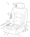
本実施形態の車両用シートSは、図1に示すように、シートバック1と、シートクッション2と、ヘッドレスト3と、シートバック1及びシートクッション2が連結されるシート連結部分4とを備えるシート本体と、シート本体の内部に取り付けられるシート状のシートヒータ40と、から主に構成されている。
なお、シートヒータ40は、ハーネスを介して電源及び制御装置と接続されている。
As shown in FIG. 1, the vehicle seat S of this embodiment includes a
Note that the
シートバック1は、着座者の背中を後方から支持する背もたれ部であって、図1に示すように、骨格となる不図示のバックフレームにクッション材1bを載置して表皮材1cで被覆されて構成されている。
なお、バックフレームは、骨格となる矩形状の枠体からなり、上下方向に所定の間隔を空けてシート幅方向に沿って延びる上部フレーム及び下部フレームと、上部フレームのシート幅方向の両端部からそれぞれ下方へ延出し、下部フレームの両端部と連結される左右のサイドフレームと、左右のサイドフレームを連結する複数の弾性バネと、から主に構成されている。
The
The back frame is composed of a rectangular frame that serves as a skeleton, and includes an upper frame and a lower frame that extend along the seat width direction with a predetermined gap in the vertical direction, and both ends of the upper frame in the seat width direction. It mainly consists of left and right side frames extending downward and connected to both ends of the lower frame, and a plurality of elastic springs connecting the left and right side frames.
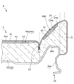
シートクッション2は、乗員を下方から支持する着座部であって、図1、図2に示すように、骨格となるクッションフレーム2aにクッション材2bを載置して表皮材2cで被覆されて構成されている。
クッションフレーム2aは、骨格となる矩形状の枠体からなり、左右側方に配置されるサイドフレーム部2aaと、各サイドフレーム部2aaの前方部分を連結するプレート状のパンフレームと、各サイドフレーム部2aaの後方部分を連結する後方連結フレームと、パンフレーム及び後方連結フレームに掛け止めされる複数の弾性バネと、から主に構成されている。
The
The
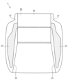
クッション材2bは、発泡ウレタン等からなるパッド部材であって、図2、図3に示すように、そのシート幅方向の中央部分にあるクッション本体部20と、クッション本体部20のシート幅方向の外側にある左右のクッションサイド部21,22と、から主に構成されている。
クッションサイド部21,22は、いわゆるサイドボルスター部分であって、クッション本体部20よりも上方側に突出して設けられ、詳しく言うと、シート幅方向の外側に向かうに従って上方側(表皮材2c側)に一層突出するように形成され、着座者を左右外側から包み込むように配置されるものである。
クッション本体部20とクッションサイド部21,22の間の部分の上面には、表皮材2cを吊り込むための吊り込み溝23が形成されている。
また、クッションサイド部21,22の上面には、シートヒータ40のサイドヒータ部40b,40cを収納させるための収納凹部24が形成されている。詳細は後述する。
The
The
Further, in the upper surfaces of the
表皮材2cは、伸縮性を有するナイロン材料等からなり、クッション材2bを上方側から被覆することが可能な形状に形成されている。
具体的には、表皮材2cは、クッション本体部20及びクッションサイド部21,22に対応する位置において分割されたものであって、分割された表皮材2c同士が、吊り込み溝23内部で縫製されて連結されている。
表皮材2c裏面においてクッション本体部20に対応する位置には、略全面にわたって綿状のワディング材2caが縫製されて取り付けられている。
The
Specifically, the
A cotton-like wadding material 2ca is sewn and attached over substantially the entire surface of the back surface of the
ヘッドレスト3は、乗員の頭を後方から支持する頭部であって、図1に示すように、不図示の芯材にクッション材3bを載置して表皮材3cで被覆されて構成されており、不図示のバックフレームに設けられたヘッドレストピラーによって支持されている。
The
シートヒータ40は、シート本体を暖める面状発熱体であって、図1に示すように、シートバック1及びシートクッション2の内部に取り付けられ、詳しく言うと、図2に示すように、クッション材1b,2bと表皮材1c,2cの間に取り付けられている。
シートヒータ40は、図4に示すように、シート状のシート基材41と、シート基材41上にそれぞれ取り付けられ、電源と接続されている電線42と、電線42と接続されているヒータ線43と、電線42と接続される温度測定センサ44と、電線42と接続される温度調整装置45と、から主に構成されている。
The
As shown in FIG. 4, the
シートヒータ40は、図4に示すように、クッション本体部20上面に載置される略矩形状の中央ヒータ部40aと、左右のクッションサイド部21,22上面に載置される略L字形状のサイドヒータ部40b,40cと、から主に構成されている。
中央ヒータ部40aの後端部分には、電線42、ヒータ線43、温度測定センサ44、及び温度調整装置45が密集して配置されている。
As shown in FIG. 4, the
A
シート基材41は、伸縮可能な布材からなり、シートヒータ40の土台部分である。
シート基材41のシート幅方向の中央部分において前端及び後端には、V字状に切り欠かれた切欠き部41dが位置決め部として形成されている。
シートヒータ40がクッション材2bに正しく載置されたとき、各切欠き部41dのV字状マークと、クッション材2bに設けられた不図示のT字状マークが合わさる配置となっている。
The
V-shaped
When the
電線42は、電源からヒータ線43、温度測定センサ44及び温度調整装置45に向けて電気を供給するものであって、その一端部分において複数の電線42が束ねられることでハーネス42aが形成されている。
ハーネス42aは、その一端部分がシート基材41上に取り付けられ、その他端部分がシート基材41上から突出するように延びて、電源及び制御装置と接続されている。
The
The
ヒータ線43は、シート基材41上に接着固定されており、クッション材2bの後端部分からシート前方側に向かって蛇行しながら延びていき、クッション材2bの前端部分において屈曲して折り返され、再び後端部分に戻るように延びている。
ヒータ線43は、電線42とそれぞれ接続され、互いに並列状態で配置されている第1ヒータ線43a、第2ヒータ線43b、及び第3ヒータ線43cを備えている。
第1ヒータ線43aは、中央ヒータ部40aに配置され、第2ヒータ線43b、第3ヒータ線43cは、中央ヒータ部40aの後端部分からシート幅方向の外側に突出し、それぞれ左側のサイドヒータ部40b、右側のサイドヒータ部40cに配置されている。
なお、ヒータ線43は、接着剤によってシート基材41上に固定されているが、シート基材41の内部に折り込まれるように固定されても良い。
The
The
The
Although the
温度測定センサ44は、ヒータ線43の温度を測定するサーミスタであって、ヒータ温度の測定結果に基づく出力信号を制御装置に向けて出力するものである。
温度調整装置45は、ヒータ線43の温度を調整する熱動式のサーモスタットであって、ヒータ温度が所定値を超えるとヒータ線43への電気供給を遮断することで、ヒータ温度を一定以下に保持するものである。
なお、不図示の制御装置は、ECU(Electronic Control Unit)に相当し、温度測定センサ44で検出された出力信号を受信して、ヒータ温度を設定値と比較することで、電源から各ヒータ線43への電気供給を制御するものである。
The
The
The control device (not shown) corresponds to an ECU (Electronic Control Unit), receives an output signal detected by the
上記構成において、図4に示すように、シートヒータ40は、中央ヒータ部40aと、左右のサイドヒータ部40b,40cと、から構成されている。
そのため、シートクッション2をシート幅方向において中央部分と、左右のサイドボルスター部分とに分けて、それぞれ独立して暖めることが可能なシートヒータ付きシートになる。
In the above configuration, as shown in FIG. 4, the
Therefore, the
また上記構成において、シートヒータ40は、互いに並列状態で配置されている第1ヒータ線43a、第2ヒータ線43b及び第3ヒータ線43cを備えている。
そのため、例えば、第2ヒータ線43b又は第3ヒータ線43cが外部からの衝撃等によって変形してしまった場合にも、第1ヒータ線43aがヒータ機能を有するため、シートヒータ全体のヒータ機能が失われることがない。
In the above configuration, the
Therefore, for example, even if the
<シートヒータを収納させる収納凹部>
次に、クッション材2bのクッションサイド部11,12に形成された収納凹部24について詳細を説明する。
収納凹部24は、図2、図3に示すように、シートヒータ40のうち、左右のサイドヒータ部40b,40cを収納させるための段差部分であって、断面略コ字形状の凹部からなり、クッションサイド部21,22の延出方向に沿って、言い換えれば、シート前後方向に沿って延びている。
詳しく言うと、左右の収納凹部24は、平面視において略L字形状からなり、クッション本体部20の後端部分からシート幅方向の外側へ延びて、それぞれ左右のクッションサイド部11,12に沿ってシート前後方向に延びている。
また、左右の収納凹部24は、クッション本体部20に対して左右対称となるように形成されている。
<Storage recess for storing the seat heater>
Next, details of the storage recesses 24 formed in the cushion side portions 11 and 12 of the
As shown in FIGS. 2 and 3, the
More specifically, the left and right storage recesses 24 are substantially L-shaped in plan view, extend outward in the seat width direction from the rear end portion of the cushion
The left and right storage recesses 24 are formed symmetrically with respect to the cushion
収納凹部24は、図2に示すように、シートヒータ40が収納された状態で、ヒータ線43が収納凹部24の開口部分から外側に張り出さない程度の深さまで形成されている。
また、収納凹部24は、シート幅方向において左右の側壁部24aから中央部分に向かうに従って深くなるように形成されており、言い換えれば、その底壁部24bが縦断面略くの字形状となるように形成されている。
このとき、ヒータ線43は、シート幅方向において収納凹部24の中央部分に寄せた位置に配置されていると良い。
As shown in FIG. 2, the
The
At this time, the
収納凹部24は、図2に示すように、シート幅方向においてクッション材2b(クッションサイド部21)がクッションフレーム2a(サイドフレーム部2aa)と当接している範囲内に配置されている。詳しく言うと、シート幅方向において当該範囲の外側の端部分よりも内側に位置するように配置されている。
このとき、ヒータ線43は、シート幅方向においてサイドフレーム部2aaの外側の端部分よりも内側に位置するように配置されていると良い。
また、収納凹部24は、上下方向においてサイドフレーム部2aaのうち、クッションサイド部21側(上方側)に最も突出している突出部分2abと重なる位置に配置されている。
As shown in FIG. 2, the
At this time, the
In addition, the
収納凹部24は、図2に示すように、クッションサイド部11のうち、表皮材2c側(上方側)に最も突出している部分よりもシート幅方向の内側に配置されている。
また、収納凹部24は、上下方向においてクッション本体部10の上面よりも上方側の位置に配置されている。
As shown in FIG. 2, the
In addition, the
上記構成において、図3に示すように、収納凹部24は、クッションサイド部21の延出方向(シート前後方向)に沿って連続して延びている。
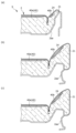
詳しく言うと、図5(a)、図5(b)に示すように、収納凹部24は、当該延出方向においてクッションサイド部21の後端部分から略中央部分に向かうに従って幅広となるように形成されている。
一般にシートクッション2のクッションサイド部21については、そのシート中央部分が、着座者の臀部が支持される部分であって着座荷重が加わる部分である。
そのため、当該シート中央部分が、シートヒータ40によって好適に暖めたい部分であって、かつ、シートヒータ40の変形を抑制したい部分となる。
そこで、上記収納凹部24の形状、配置とすれば、シートヒータ40の好適な形状、配置を実現し、かつ、シートヒータ40の変形を抑制できる。
In the above configuration, as shown in FIG. 3, the
Specifically, as shown in FIGS. 5(a) and 5(b), the
In general, the seat central portion of the
Therefore, the central portion of the seat is a portion desired to be suitably warmed by the
Therefore, if the
また上記構成において、図5(b)、図5(c)に示すように、収納凹部24は、当該延出方向においてクッションサイド部21の略中央部分から前方部分に向かうに従って徐々に幅狭となるように形成されている。
一般にクッションサイド部21については、そのシート前方部分が、着座者が跨がる部分であって繰り返しの着座荷重が加わる部分である。
そのため、当該シート前方部分が、シートヒータ40によって適度に暖めたい部分であって、かつ、シートヒータ40の変形を抑制したい部分となる。一方で、着座者が常に触れている部分ではないため、シートヒータ40の領域を幾分小さくしても良い。
そこで、上記収納凹部24の形状、配置とすれば、シートヒータ40の好適な形状、配置を実現し、かつ、シートヒータ40の変形を抑制できる。
In the above configuration, as shown in FIGS. 5(b) and 5(c), the
In general, the seat front portion of the
Therefore, the front portion of the seat is a portion desired to be moderately warmed by the
Therefore, if the
<車両用シートの第2実施形態>
次に、車両用シートの第2実施例について、図6に基づいて説明する。なお、上述した車両用シートSと重複する内容は説明を省略する。
第2実施形態の車両用シートS2では、シートクッション2のサイドボルスター部分において、クッションサイド部121を通常位置と、通常位置よりも表皮材102c側(上方側)に突出させた図6に示す突出位置との間で移動させることが可能なサイドサポート装置70を備えている点が大きく異なる。
<Second Embodiment of Vehicle Seat>
Next, a second embodiment of the vehicle seat will be described with reference to FIG. In addition, the description of the content overlapping with the above-described vehicle seat S is omitted.
In the vehicle seat S2 of the second embodiment, in the side bolster portion of the
サイドサポート装置70は、エアセル駆動式のユニットからなり、上下方向においてサイドフレーム部102aaとクッションサイド部121との間に取り付けられている。
詳しく言うと、サイドサポート装置70は、上下方向において収納凹部124と重なる位置に配置されている。
サイドサポート装置70は、サイドフレーム部102aaに固定される固定プレート71と、固定プレート71に対して回動軸72を中心として回動可能に取り付けられる可動プレート73と、固定プレート71及び可動プレート73を連結し、自身が膨張することで可動プレート73をクッションサイド部121側に押し上げ可能なエアセル74と、から主に構成されている。
The
Specifically, the
The
上記構成において、図6に示すように、クッションサイド部121が突出位置に移動したときに、収納凹部124は、クッションサイド部121のうち、表皮材102c側(上方斜め内側)に最も突出する部分と重なる位置に配置されている。
また、そのとき、収納凹部124は、当該最も突出する部分と重なる位置において最も深くなるように形成されている。
一般にサイドボルスター部分のうち、サイドサポート装置70によって支持された部分が、着座者に最も当接し易い部分となる。
そのため、この当接し易い部分が、シートヒータ140によって好適に暖めたい部分であって、かつ、シートヒータ140の変形を抑制したい部分となる。
そこで、この当接し易い部分に収納凹部124を形成すれば、シートヒータ140によって着座者の快適性を確保しながらも、シートヒータ140の変形を抑制できる。
In the above configuration, as shown in FIG. 6, when the
Moreover, at that time, the
In general, of the side bolster portion, the portion supported by the
Therefore, the portion that is likely to come into contact with the
Therefore, by forming the
また上記構成において、クッションサイド部121が突出位置に移動すると、表皮材102cが着座者側に突っ張ることになるため、シートヒータ140の設置の影響によって着座面に凹凸が発生し易くなる虞がある。つまり、着座者に違和感を与え易くなる。
そのため、収納凹部124の形成による効果が、サイドサポート装置70を備えたシートにおいて一層際立つようになる。
In the above configuration, when the
Therefore, the effect of forming the storage recessed
<車両用シートの第3実施形態>
次に、車両用シートの第3実施例について、図7、図8に基づいて説明する。
第3実施形態の車両用シートS3では、クッションサイド部221において、互いに間隔を空けて配置される第1サイドヒータ部240ba、及び第2サイドヒータ部240bbを備えている点が大きく異なる。
第1サイドヒータ部240ba、第2サイドヒータ部240bbは、クッションサイド部221の延出方向(シート前後方向)に沿ってそれぞれ延びており、第2サイドヒータ部240bbは、第1サイドヒータ部240baと独立して構成されている。
<Third Embodiment of Vehicle Seat>
Next, a third embodiment of the vehicle seat will be described with reference to FIGS. 7 and 8. FIG.
The vehicle seat S3 of the third embodiment is significantly different in that the
The first side heater portion 240ba and the second side heater portion 240bb each extend along the extension direction of the cushion side portion 221 (the seat front-rear direction). configured independently of the
クッションサイド部221には、第1サイドヒータ部240ba及び第2サイドヒータ部240bをそれぞれ収納させるための第1収納凹部224a及び第2収納凹部224bと、第1収納凹部224a及び第2収納凹部224bを連結させるための連結凹部224cと、が形成されている。
そのため、一般に高級な車両用シートでは、サイドボルスター部分に複数のシートヒータ240が取り付けられているところ、上記収納凹部224の構成により、複数のシートヒータ240が取り付けられても良好な着座感を達成し、かつ、シートヒータ240の変形を抑制できる。
また、上記のように連結凹部224cが形成されることで、シートヒータ240の位置決めがし易くなる。
The
For this reason, although a high-grade vehicle seat generally has a plurality of
Further, the formation of the connecting
<その他の実施形態>
上記実施形態において、図1に示すように、車両用シートSはサイドボルスター部分(クッションサイド部21,22)を有するシートであって、シートヒータ40がクッション本体部20及びクッションサイド部21,22に取り付けられているが、特に限定されることなく、例えば、サイドボルスター部分を有さないシートであっても良い。
その場合、シートヒータ40が、クッション本体部20のみに取り付けられていれば良く、クッション本体部20をシート幅方向に3つの領域に区画しておき、それぞれの領域に各ヒータ線43を延ばして配置すれば良い。
<Other embodiments>
In the above-described embodiment, as shown in FIG. 1, the vehicle seat S is a seat having side bolster portions (
In that case, the
上記実施形態において、図5(a)に示すように、クッションサイド部21のシート後方部分は、シート幅方向においてサイドフレーム部2aaよりも外側に張り出すことなく、サイドフレーム部2aaによって支持されている。
そのため、クッションサイド部21のシート後方部分については、クッション材の変形が比較的小さいことから、必ずしも収納凹部24が形成されていなくても良い。
In the above-described embodiment, as shown in FIG. 5A, the seat rear portion of the
Therefore, the
上記実施形態において、シートヒータ40は、収納凹部24の表面上に両面テープで接着されて取り付けられているが、特に限定されることなく、縫製で取り付けられていても良いし、そのまま載置されて収納されていても良い。
In the above-described embodiment, the
上記実施形態では、具体例として自動車に用いられる車両用シートについて説明したが、特に限定されることなく、電車、バス等に用いられる車両用シートのほか、飛行機、船等に用いられる乗り物用シートとしても利用することができる。
また、乗り物用シートのほか、映画館、プラネタリウム等の商業施設、病院待合室等の公共施設の室内、又は室外に広く用いられるシートとしても利用可能である。
In the above embodiment, a vehicle seat used in an automobile was described as a specific example, but the present invention is not particularly limited to vehicle seats used in trains, buses, etc., but also vehicle seats used in airplanes, ships, etc. can also be used as
In addition to vehicle seats, it can also be used as seats that are widely used indoors or outdoors in commercial facilities such as movie theaters and planetariums, and public facilities such as hospital waiting rooms.
本実施形態では、主として本発明に係る車両用シートに関して説明した。
ただし、上記の実施形態は、本発明の理解を容易にするための一例に過ぎず、本発明を限定するものではない。本発明は、その趣旨を逸脱することなく、変更、改良され得ると共に、本発明にはその等価物が含まれることは勿論である。
In this embodiment, the vehicle seat according to the present invention has been mainly described.
However, the above embodiment is merely an example for facilitating understanding of the present invention, and does not limit the present invention. The present invention can be modified and improved without departing from its spirit, and the present invention includes equivalents thereof.
S,S2,S3 車両用シート
1 シートバック
1b、2b、3b クッション材
1c、2c、3c,102c 表皮材
2ca ワディング材
2 シートクッション
2a クッションフレーム(フレーム)
2aa,102aa サイドフレーム部
2ab 突出部分
3 ヘッドレスト
4 シート連結部分(連結部分)
20 クッション本体部
21,22,121,221 クッションサイド部
23 吊り込み溝
24,124,224 収納凹部
24a 側壁部
24b 底壁部
224a 第1収納凹部
224b 第2収納凹部
224c 連結凹部
40,140,240 シートヒータ
40a 中央ヒータ部
40b,40c サイドヒータ部
240ba 第1サイドヒータ部
240bb 第2サイドヒータ部
41 シート基材
41d 切欠き部
42,142 電線
42a ハーネス
43 ヒータ線
43a 第1ヒータ線
43b 第2ヒータ線
43c 第3ヒータ線
44 温度測定センサ
45,145 温度調整装置
70 サイドサポート装置
71 固定プレート
72 回天軸
73 可動プレート
74 エアセル
S, S2,
2aa, 102aa side frame portion
20
Claims (7)
該クッション材は、シート幅方向の中央部分にあるクッション本体部と、該クッション本体部の左右外側にあるクッションサイド部と、を有し、
該クッションサイド部には、前記シートヒータを収納させるための収納凹部が形成され、
前記シートヒータは、前記クッション本体部に配置される中央ヒータ部と、前記クッションサイド部に配置されるサイドヒータ部と、を有し、
前記サイドヒータ部は、
前記中央ヒータ部と並列接続されて設けられ、前記収納凹部に収納される第1サイドヒータ部と、
前記中央ヒータ部及び前記第1サイドヒータ部とは独立して設けられ、シート幅方向において前記第1サイドヒータ部と間隔を空けて配置される第2サイドヒータ部と、を有し、
前記収納凹部は、前記第1サイドヒータ部を収納させる第1収納凹部と、前記第2サイドヒータ部を収納させる第2収納凹部と、前記第1収納凹部及び前記第2収納凹部を連結させる連結凹部と、を有し、
前記第1サイドヒータ部と前記第2サイドヒータ部とが連結されることなく配置され、かつ、前記第1サイドヒータ部を収納させる前記第1収納凹部と、前記第2サイドヒータ部を収納させる前記第2収納凹部とが連結されて配置されることを特徴とする車両用シート。 A vehicle seat comprising a frame that serves as a skeleton and a cushion material placed thereon and covered with an upholstery material, and comprising a seat heater between the cushion material and the upholstery material,
The cushion material has a cushion main body portion in the central portion in the seat width direction and cushion side portions on the left and right outer sides of the cushion main body portion,
A storage recess for storing the seat heater is formed in the cushion side portion,
The seat heater has a central heater portion arranged in the cushion main body portion and a side heater portion arranged in the cushion side portion,
The side heater section
a first side heater unit connected in parallel with the central heater unit and housed in the housing recess;
a second side heater section that is provided independently of the central heater section and the first side heater section and that is spaced apart from the first side heater section in the seat width direction ;
The storage recess includes a first storage recess for storing the first side heater portion, a second storage recess for storing the second side heater portion, and a connection for connecting the first storage recess and the second storage recess. a recess;
The first side heater section and the second side heater section are arranged without being connected to each other, and the first housing recess for housing the first side heater section and the second side heater section for housing the first side heater section are provided. A vehicle seat , wherein the second storage recess is connected to the vehicle seat.
前記第2サイドヒータ部に接続された前記制御装置と、前記連結凹部とが、前記第2サイドヒータ部の長さ方向において前記第2サイドヒータ部に対し互いに反対側に配置され、
前記制御装置がシートクッションの後方側に配置され、前記連結凹部が前記シートクッションの前方側に配置されることを特徴とする請求項1に記載の車両用シート。 The second side heater section is connected to a control device separate from the central heater section and the first side heater section ,
the control device connected to the second side heater section and the connecting recess are arranged on opposite sides of the second side heater section in the length direction of the second side heater section;
2. The vehicle seat according to claim 1, wherein the control device is arranged on the rear side of the seat cushion, and the connecting recess is arranged on the front side of the seat cushion.
左右の前記第2サイドヒータ部は、それぞれ別の制御装置と接続されていることを特徴とする請求項1乃至3のいずれか一項に記載の車両用シート。 The side heater section has left and right second side heater sections,
The vehicle seat according to any one of claims 1 to 3, wherein the left and right second side heater units are connected to separate control devices.
左右の前記第1収納凹部と、左右の前記第2収納凹部とが、前記クッション本体部に対して左右対称となるように形成されていることを特徴とする請求項1乃至5のいずれか一項に記載の車両用シート。 The storage recesses include left and right first storage recesses for storing the left and right first side heater portions, and left and right second storage recess portions for storing the left and right second side heater portions. have
6. The right and left first storage recesses and the left and right second storage recesses are formed so as to be bilaterally symmetrical with respect to the cushion main body. A vehicle seat according to the above paragraph.
Priority Applications (2)
| Application Number | Priority Date | Filing Date | Title |
|---|---|---|---|
| JP2021008151A JP7277800B2 (en) | 2021-01-21 | 2021-01-21 | vehicle seat |
| JP2023076256A JP2023087068A (en) | 2021-01-21 | 2023-05-02 | vehicle seat |
Applications Claiming Priority (1)
| Application Number | Priority Date | Filing Date | Title |
|---|---|---|---|
| JP2021008151A JP7277800B2 (en) | 2021-01-21 | 2021-01-21 | vehicle seat |
Related Parent Applications (1)
| Application Number | Title | Priority Date | Filing Date |
|---|---|---|---|
| JP2019136098A Division JP6829405B2 (en) | 2019-07-24 | 2019-07-24 | Vehicle seat |
Related Child Applications (1)
| Application Number | Title | Priority Date | Filing Date |
|---|---|---|---|
| JP2023076256A Division JP2023087068A (en) | 2021-01-21 | 2023-05-02 | vehicle seat |
Publications (3)
| Publication Number | Publication Date |
|---|---|
| JP2021062865A JP2021062865A (en) | 2021-04-22 |
| JP2021062865A5 JP2021062865A5 (en) | 2021-10-07 |
| JP7277800B2 true JP7277800B2 (en) | 2023-05-19 |
Family
ID=75487371
Family Applications (2)
| Application Number | Title | Priority Date | Filing Date |
|---|---|---|---|
| JP2021008151A Active JP7277800B2 (en) | 2021-01-21 | 2021-01-21 | vehicle seat |
| JP2023076256A Pending JP2023087068A (en) | 2021-01-21 | 2023-05-02 | vehicle seat |
Family Applications After (1)
| Application Number | Title | Priority Date | Filing Date |
|---|---|---|---|
| JP2023076256A Pending JP2023087068A (en) | 2021-01-21 | 2023-05-02 | vehicle seat |
Country Status (1)
| Country | Link |
|---|---|
| JP (2) | JP7277800B2 (en) |
Citations (4)
| Publication number | Priority date | Publication date | Assignee | Title |
|---|---|---|---|---|
| JP2002083665A (en) | 2000-09-06 | 2002-03-22 | Kurabe Ind Co Ltd | Sheet heater for vehicle |
| JP2004175291A (en) | 2002-11-28 | 2004-06-24 | Aisin Seiki Co Ltd | Seating sensor |
| JP2009153650A (en) | 2007-12-26 | 2009-07-16 | Panasonic Corp | Heating apparatus and seat using it |
| JP2012035671A (en) | 2010-08-04 | 2012-02-23 | Toyota Boshoku Corp | Vehicle seat |
Family Cites Families (2)
| Publication number | Priority date | Publication date | Assignee | Title |
|---|---|---|---|---|
| JPS6219114A (en) * | 1985-07-18 | 1987-01-27 | 松下電器産業株式会社 | Seat for vehicle |
| JPH01145255U (en) * | 1988-03-30 | 1989-10-05 |
-
2021
- 2021-01-21 JP JP2021008151A patent/JP7277800B2/en active Active
-
2023
- 2023-05-02 JP JP2023076256A patent/JP2023087068A/en active Pending
Patent Citations (4)
| Publication number | Priority date | Publication date | Assignee | Title |
|---|---|---|---|---|
| JP2002083665A (en) | 2000-09-06 | 2002-03-22 | Kurabe Ind Co Ltd | Sheet heater for vehicle |
| JP2004175291A (en) | 2002-11-28 | 2004-06-24 | Aisin Seiki Co Ltd | Seating sensor |
| JP2009153650A (en) | 2007-12-26 | 2009-07-16 | Panasonic Corp | Heating apparatus and seat using it |
| JP2012035671A (en) | 2010-08-04 | 2012-02-23 | Toyota Boshoku Corp | Vehicle seat |
Also Published As
| Publication number | Publication date |
|---|---|
| JP2021062865A (en) | 2021-04-22 |
| JP2023087068A (en) | 2023-06-22 |
Similar Documents
| Publication | Publication Date | Title |
|---|---|---|
| US10195971B2 (en) | Vehicle seat | |
| US4865379A (en) | Automotive seat with heating device | |
| WO2016072332A1 (en) | Seat cushion pad and seat | |
| JP2012157651A (en) | Seat heater | |
| JP6829405B2 (en) | Vehicle seat | |
| JP6561544B2 (en) | Vehicle seat | |
| JP7277800B2 (en) | vehicle seat | |
| JP6540170B2 (en) | Vehicle seat | |
| JP2012096560A (en) | Seat with heater | |
| JP2010040186A (en) | Heater apparatus | |
| JP6738034B2 (en) | Vehicle seat | |
| KR101475947B1 (en) | Pillow for headrest of vehicle seat | |
| KR20210002354U (en) | Auxiliary headrest installed on the headrest of a car | |
| JP2023049732A (en) | Vehicular seat | |
| JP4783185B2 (en) | Vehicle seat structure | |
| JP2019177876A5 (en) | ||
| JPH1134704A (en) | Cushion for automobile seat | |
| WO2024010086A1 (en) | Pad material, seat and vehicle seat | |
| JP7342478B2 (en) | air conditioning seat | |
| JP2003250665A (en) | Waist pad for chair | |
| JPS6228932Y2 (en) | ||
| JP6033739B2 (en) | Vehicle seat | |
| JP6770904B2 (en) | Heating element for seat heater, seat heater and seat | |
| JP2011050580A (en) | Seat device for vehicle | |
| JP2017186012A (en) | Vehicle seat |
Legal Events
| Date | Code | Title | Description |
|---|---|---|---|
| A621 | Written request for application examination |
Free format text: JAPANESE INTERMEDIATE CODE: A621 Effective date: 20210219 |
|
| A521 | Request for written amendment filed |
Free format text: JAPANESE INTERMEDIATE CODE: A523 Effective date: 20210825 |
|
| A977 | Report on retrieval |
Free format text: JAPANESE INTERMEDIATE CODE: A971007 Effective date: 20211227 |
|
| A131 | Notification of reasons for refusal |
Free format text: JAPANESE INTERMEDIATE CODE: A131 Effective date: 20220201 |
|
| A601 | Written request for extension of time |
Free format text: JAPANESE INTERMEDIATE CODE: A601 Effective date: 20220330 |
|
| A521 | Request for written amendment filed |
Free format text: JAPANESE INTERMEDIATE CODE: A523 Effective date: 20220601 |
|
| A131 | Notification of reasons for refusal |
Free format text: JAPANESE INTERMEDIATE CODE: A131 Effective date: 20221018 |
|
| A521 | Request for written amendment filed |
Free format text: JAPANESE INTERMEDIATE CODE: A523 Effective date: 20221212 |
|
| TRDD | Decision of grant or rejection written | ||
| A01 | Written decision to grant a patent or to grant a registration (utility model) |
Free format text: JAPANESE INTERMEDIATE CODE: A01 Effective date: 20230404 |
|
| A61 | First payment of annual fees (during grant procedure) |
Free format text: JAPANESE INTERMEDIATE CODE: A61 Effective date: 20230417 |
|
| R150 | Certificate of patent or registration of utility model |
Ref document number: 7277800 Country of ref document: JP Free format text: JAPANESE INTERMEDIATE CODE: R150 |