JP7273510B2 - Washing machine - Google Patents
Washing machine Download PDFInfo
- Publication number
- JP7273510B2 JP7273510B2 JP2018528387A JP2018528387A JP7273510B2 JP 7273510 B2 JP7273510 B2 JP 7273510B2 JP 2018528387 A JP2018528387 A JP 2018528387A JP 2018528387 A JP2018528387 A JP 2018528387A JP 7273510 B2 JP7273510 B2 JP 7273510B2
- Authority
- JP
- Japan
- Prior art keywords
- tip
- main body
- lid
- horn
- vibration
- Prior art date
- Legal status (The legal status is an assumption and is not a legal conclusion. Google has not performed a legal analysis and makes no representation as to the accuracy of the status listed.)
- Active
Links
- 238000005406 washing Methods 0.000 title description 24
- 238000004140 cleaning Methods 0.000 claims description 29
- XLYOFNOQVPJJNP-UHFFFAOYSA-N water Substances O XLYOFNOQVPJJNP-UHFFFAOYSA-N 0.000 description 22
- 238000012856 packing Methods 0.000 description 5
- 230000005540 biological transmission Effects 0.000 description 4
- 230000005484 gravity Effects 0.000 description 4
- 230000002093 peripheral effect Effects 0.000 description 4
- 238000013459 approach Methods 0.000 description 3
- 230000005611 electricity Effects 0.000 description 2
- 238000012423 maintenance Methods 0.000 description 2
- 229910052751 metal Inorganic materials 0.000 description 2
- 239000002184 metal Substances 0.000 description 2
- 229910052782 aluminium Inorganic materials 0.000 description 1
- XAGFODPZIPBFFR-UHFFFAOYSA-N aluminium Chemical compound [Al] XAGFODPZIPBFFR-UHFFFAOYSA-N 0.000 description 1
- 239000000470 constituent Substances 0.000 description 1
- 230000005674 electromagnetic induction Effects 0.000 description 1
- 238000009434 installation Methods 0.000 description 1
- 238000000034 method Methods 0.000 description 1
- 239000011347 resin Substances 0.000 description 1
- 229920005989 resin Polymers 0.000 description 1
- 238000005096 rolling process Methods 0.000 description 1
- 238000007789 sealing Methods 0.000 description 1
Images


Classifications
-
- B—PERFORMING OPERATIONS; TRANSPORTING
- B06—GENERATING OR TRANSMITTING MECHANICAL VIBRATIONS IN GENERAL
- B06B—METHODS OR APPARATUS FOR GENERATING OR TRANSMITTING MECHANICAL VIBRATIONS OF INFRASONIC, SONIC, OR ULTRASONIC FREQUENCY, e.g. FOR PERFORMING MECHANICAL WORK IN GENERAL
- B06B1/00—Methods or apparatus for generating mechanical vibrations of infrasonic, sonic, or ultrasonic frequency
- B06B1/02—Methods or apparatus for generating mechanical vibrations of infrasonic, sonic, or ultrasonic frequency making use of electrical energy
-
- D—TEXTILES; PAPER
- D06—TREATMENT OF TEXTILES OR THE LIKE; LAUNDERING; FLEXIBLE MATERIALS NOT OTHERWISE PROVIDED FOR
- D06F—LAUNDERING, DRYING, IRONING, PRESSING OR FOLDING TEXTILE ARTICLES
- D06F7/00—Washing devices adapted to be used independently of any particular receptacle, e.g. for removable mounting on wash-tubs, bath-tubs, or the like
- D06F7/04—Washing devices adapted to be used independently of any particular receptacle, e.g. for removable mounting on wash-tubs, bath-tubs, or the like of the vibrator type
-
- A—HUMAN NECESSITIES
- A47—FURNITURE; DOMESTIC ARTICLES OR APPLIANCES; COFFEE MILLS; SPICE MILLS; SUCTION CLEANERS IN GENERAL
- A47L—DOMESTIC WASHING OR CLEANING; SUCTION CLEANERS IN GENERAL
- A47L25/00—Domestic cleaning devices not provided for in other groups of this subclass
-
- B—PERFORMING OPERATIONS; TRANSPORTING
- B06—GENERATING OR TRANSMITTING MECHANICAL VIBRATIONS IN GENERAL
- B06B—METHODS OR APPARATUS FOR GENERATING OR TRANSMITTING MECHANICAL VIBRATIONS OF INFRASONIC, SONIC, OR ULTRASONIC FREQUENCY, e.g. FOR PERFORMING MECHANICAL WORK IN GENERAL
- B06B1/00—Methods or apparatus for generating mechanical vibrations of infrasonic, sonic, or ultrasonic frequency
- B06B1/02—Methods or apparatus for generating mechanical vibrations of infrasonic, sonic, or ultrasonic frequency making use of electrical energy
- B06B1/06—Methods or apparatus for generating mechanical vibrations of infrasonic, sonic, or ultrasonic frequency making use of electrical energy operating with piezoelectric effect or with electrostriction
-
- B—PERFORMING OPERATIONS; TRANSPORTING
- B08—CLEANING
- B08B—CLEANING IN GENERAL; PREVENTION OF FOULING IN GENERAL
- B08B7/00—Cleaning by methods not provided for in a single other subclass or a single group in this subclass
- B08B7/02—Cleaning by methods not provided for in a single other subclass or a single group in this subclass by distortion, beating, or vibration of the surface to be cleaned
-
- D—TEXTILES; PAPER
- D06—TREATMENT OF TEXTILES OR THE LIKE; LAUNDERING; FLEXIBLE MATERIALS NOT OTHERWISE PROVIDED FOR
- D06F—LAUNDERING, DRYING, IRONING, PRESSING OR FOLDING TEXTILE ARTICLES
- D06F29/00—Combinations of a washing machine with other separate apparatus in a common frame or the like, e.g. with rinsing apparatus
-
- D—TEXTILES; PAPER
- D06—TREATMENT OF TEXTILES OR THE LIKE; LAUNDERING; FLEXIBLE MATERIALS NOT OTHERWISE PROVIDED FOR
- D06F—LAUNDERING, DRYING, IRONING, PRESSING OR FOLDING TEXTILE ARTICLES
- D06F43/00—Dry-cleaning apparatus or methods using volatile solvents
- D06F43/002—Spotting apparatus
Landscapes
- Engineering & Computer Science (AREA)
- Mechanical Engineering (AREA)
- Textile Engineering (AREA)
- Cleaning By Liquid Or Steam (AREA)
- Apparatuses For Generation Of Mechanical Vibrations (AREA)
- Accessory Of Washing/Drying Machine, Commercial Washing/Drying Machine, Other Washing/Drying Machine (AREA)
- Brushes (AREA)
Description
本発明は、洗浄器に関する。 The present invention relates to cleaners.
特許文献1には、本体部と、この本体部の先端に取り付けられた振動発生部とを備える洗浄器が記載されている。この洗浄器では、振動発生部に振動伝達部を設けており、使用者が本体部を把持し、振動伝達部を衣類等の被洗浄物に押し当てて使用される。 Patent Literature 1 describes a cleaning device that includes a main body and a vibration generator attached to the tip of the main body. In this washing machine, the vibration generating part is provided with the vibration transmitting part, and the user holds the main body part and presses the vibration transmitting part against an object to be washed such as clothes.
本発明の一態様に係る洗浄器は、
把持部及び先端部を有する本体部と、
上記先端部内に設けられ、超音波振動を発生させる振動発生部と、
上記振動発生部で発生した超音波振動を、先端に接触された被洗浄物に伝達するホーン部と、
上記把持部内に設けられ、上記振動発生部に超音波振動を発生させるための電力を供給する電力供給部と、
上記先端部に着脱可能であり、上記先端部に取り付けられた状態で、上記ホーン部の上記先端を覆う蓋体部と、
を備え、
上記蓋体部は、上記先端部に取り付けられた状態で、上記先端部を覆うように一端が開口している凹部を有し、
上記先端部は、先細部と基部とを備え、
上記先細部は、
上記ホーン部の上記先端が貫通するように上記ホーン部を囲み、
上記基部は、
上記基部の先端に向かうにつれて上記基部が狭まるように傾斜した傾斜面と、
上記傾斜面における上記先端と反対側の基端側に形成された突出部と、を有し、
上記蓋体部は、上記蓋体部における上記一端側に形成され、上記先端部に取り付けられた状態において上記突出部と嵌合する溝部を有し、
上記把持部及び上記蓋体部は、上記本体部が延びる方向に交差する方向の断面が、互いに同一の多角形状を有しており、
上記本体部が延びる方向に交差する方向において、上記把持部及び上記蓋体部の寸法は、上記先端部の寸法よりも大きく、
上記先端部は、上記傾斜面から上記本体部が延びる方向に交差する方向に突出した鍔部を有し、
上記鍔部は、上記本体部から延びる方向の一面側に段差を形成し、
上記蓋体部は、上記先端部に取り付けられた状態で、上記蓋体部の縁が上記鍔部の上記一面側の上記段差に当接し、
上記蓋体部は、上記把持部と反対側の端部が、上記本体部が延びる方向に交差する方向に沿った平面であり、
上記把持部は、上記本体部が延びる方向の一端から他端にわたって、上記本体部が延びる方向と交差する方向の形状及び寸法が上記蓋体部と同じ、かつ一定となるように直線の棒状に形成されており、上記ホーン部と反対側の端部が、上記本体部が延びる方向に交差する方向に沿った平面である、
ことを特徴としている。
A cleaning device according to an aspect of the present invention includes
a body having a grip and a tip ;
a vibration generator provided in the tip portion for generating ultrasonic vibration;
a horn portion that transmits the ultrasonic vibration generated by the vibration generating portion to an object to be cleaned that is in contact with the tip;
a power supply unit provided in the gripping unit and supplying power for generating ultrasonic vibrations to the vibration generating unit;
a cover body part that is detachable from the tip part and covers the tip of the horn part in a state attached to the tip part;
with
The lid portion has a concave portion, one end of which is open so as to cover the tip portion when attached to the tip portion ,
the tip portion comprises a tapered portion and a base;
The tip of the above is
surrounding the horn part so that the tip of the horn part penetrates;
The base is
an inclined surface inclined so that the base narrows toward the tip of the base ;
a protruding portion formed on the base end side opposite to the tip end of the inclined surface;
The lid portion has a groove portion formed on the one end side of the lid portion and fitted with the projecting portion when attached to the tip portion ,
The grip portion and the lid portion have the same polygonal shape in cross section in a direction intersecting the direction in which the body portion extends,
In a direction intersecting the direction in which the main body extends, the dimensions of the grip and the lid are larger than the dimensions of the tip ,
The tip portion has a flange projecting in a direction intersecting the direction in which the main body extends from the inclined surface,
The flange portion forms a step on one surface side in a direction extending from the main body portion ,
a rim of the lid portion abuts the step on the one surface side of the flange portion in a state where the lid portion is attached to the tip portion ;
The end of the lid opposite to the grip is a flat surface along a direction intersecting the direction in which the main body extends,
The gripping portion is shaped like a straight rod so that the shape and dimensions in a direction intersecting the extending direction of the main body portion are the same and constant as those of the lid portion from one end to the other end in the direction in which the main body portion extends. is formed, and the end opposite to the horn portion is a plane along a direction intersecting the direction in which the body portion extends,
It is characterized by
以下、本発明の一実施形態を添付図面に従って説明する。なお、以下の説明では、必要に応じて特定の方向あるいは位置を示す用語(例えば、「上」、「下」、「右」、「左」を含む用語)を用いるが、それらの用語の使用は図面を参照した発明の理解を容易にするためであって、それらの用語の意味によって本発明の技術的範囲が限定されるものではない。また、以下の説明は、本質的に例示に過ぎず、本発明、その適用物、あるいは、その用途を制限することを意図するものではない。さらに、図面は模式的なものであり、各寸法の比率等は現実のものとは必ずしも合致していない。 An embodiment of the present invention will be described below with reference to the accompanying drawings. In the following description, terms indicating specific directions or positions (for example, terms including “upper”, “lower”, “right”, and “left”) are used as necessary, but the use of these terms is are intended to facilitate understanding of the invention with reference to the drawings, and the technical scope of the present invention is not limited by the meaning of these terms. Moreover, the following description is essentially merely an example, and is not intended to limit the present invention, its applications, or its uses. Furthermore, the drawings are schematic, and the ratio of each dimension does not necessarily match the actual one.
(第1実施形態)
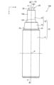
本発明の第1実施形態の洗浄器100は、図1~図3に示すように、棒状を有する本体部10と、この本体部10の内部に設けられた超音波ホーン20と、本体部10の内部に設けられた電力供給部の一例の充電式のバッテリ30(図5にのみ示す)と、を備えている。(First embodiment)
As shown in FIGS. 1 to 3, the
なお、本体部10が延びる方向をY方向とし、このY方向に交差する方向の断面の一辺に平行な方向をX方向とし、X方向およびY方向に交差する方向をZ方向とする。
Note that the direction in which the
本体部10は、図2および図3に示すように、使用者により把持される把持部11と、内部に超音波ホーン20が位置する先端部12とで構成され、Y方向に交差する方向の断面が、四角形状を有している。この本体部10は、Y方向に延びる中心線CLに対して対照に設けられている。
As shown in FIGS. 2 and 3, the
把持部11は、アルミニウム等の金属で構成され、図2および図3に示すように、Y方向の上側の端部に、後述する先端部12の基部13が接続されている。把持部11のY方向の上側の端部には、パッキン111が取り付けられており、これにより、把持部11と先端部12の基部13との間をシールしている。
The
また、この把持部11は、図4および図5に示すように、Y方向に沿った平面視において、各角部が面取りされた正四角形状を有し、そのY方向下側の端部(先端部12が取り付けられている端部の反対側の端部)に押しボタンスイッチ16が設けられている。図3に示すように、押しボタンスイッチ16は弾性を有しており、この弾性により、把持部11と押しボタンスイッチ16との間がシールされている。
As shown in FIGS. 4 and 5, the
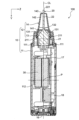
把持部11内の中心部には、図3に示すように、収容部112が設けられ、この収容部112にバッテリ30が収容されている。収容部112のZ方向右側には、マイコンを有するメイン回路基板17が設けられ、Y方向下側には、トランス18が設けられている。メイン回路基板17には、超音波ホーン20、バッテリ30、トランス18、および、押しボタンスイッチ16の各々が接続され、図示しないマイコンにより制御されるようになっている。
As shown in FIG. 3 , a
先端部12は、絶縁性の樹脂で構成され、図2および図3に示すように、把持部11に接続されている基部13と、この基部13に接続されている先細部14とを有している。
The
基部13は、図2に示すように、先端(Y方向の上側)に向かうに従って中心線CLに接近するように傾斜している。この基部13の先端部には、図3に示すように、先細部14を取り付けるための溝部131と、後述する超音波ホーン20のホーン部22が突出する貫通孔132とが設けられている。
As shown in FIG. 2, the
また、基部13の把持部11に近い側(Y方向の下側)には、基部13の表面から突出する突出部15が設けられている。この突出部15を介して、超音波ホーン20を覆う蓋体部(図示せず)を取り付けることができるようになっている。さらに、基部13は、図4に示すように、Y方向に沿った平面視において、各角部が面取りされた正四角形状を有し、その周縁が、把持部11の周縁よりも内側に位置するように設けられている。
A projecting
先細部14は、図2に示すように、基部13に接続された幅広部141と、この幅広部141から中心線CLに沿って延びる幅狭部142とを有し、図3に示すように、両端の各々が開口している。
The
幅広部141は、図3に示すように、そのY方向の下部が基部13の溝部131に嵌合されている。また、幅広部141のY方向の上部には、先端(Y方向の上側)に向かうに従って中心線CLに接近する湾曲面が設けられている。幅狭部142は、図2に示すように、X方向の幅は略同じであるが、図3に示すように、Z方向の幅は先端(Y方向の上側)に向かうに従って中心線CLに接近するように傾斜している。
As shown in FIG. 3 , the
また、先細部14は、図4に示すように、Y方向に沿った平面視において、各角部が面取りされた矩形状を有し、その周縁が、基部13の周縁よりも内側に位置するように設けられている。
Further, as shown in FIG. 4 , the tapered
超音波ホーン20は、図3に示すように、振動発生部21と、振動伝達部の一例のホーン部22とを有している。
The
振動発生部21は、圧電体を有すると共にバッテリ30に電気的に接続され、圧電体に所定の電圧が印加される。この圧電体に所定の電圧を印加することにより、設定された周波数および振幅の超音波振動が発生するようになっている。本実施形態の洗浄器100では、振動発生部21が、衣類の洗浄に適した30~40kHzの周波数を発生させるように設定されている。
The
また、振動発生部21は、図3に示すように、先端部12の基部13の内部に位置している。この振動発生部21の周囲にはパッキン211が設けられており、これにより、振動発生部21と先端部12の基部13との間をシールしている。
Further, the
ホーン部22は、金属で構成され、その先端221が被洗浄物に接触して、振動発生部21で発生した振動を被洗浄物に伝達する。このホーン部22は、図3に示すように、振動発生部21から中心線CLに沿ってY方向の上側に向かって延びており、先端221が、先端部12の基部13に設けられた貫通孔132を通って、先端部12の先細部14のY方向上側の開口143から本体部10の外部に突出している。すなわち、ホーン部22は、本体部10内に設けられ、その一部が本体部10の一端から露出した状態で配置されている。
The
また、ホーン部22は、図4に示すように、Y方向に沿った平面視において、矩形状を有している。Y方向に沿った平面視において、ホーン部22の矩形状の各辺は、本体部10の把持部11の各角部が面取りされた正四角形状の各辺に対して略平行に配置されている。
Further, the
次に、洗浄器100の使用について説明する。
Next, use of the
まず、被洗浄物の汚れが付着した箇所(洗浄箇所)に洗浄媒体を含ませる。この洗浄媒体は、通常の水であってもよいし、洗浄成分を含んだ水であってもよい。 First, a cleaning medium is soaked in a portion of the object to be cleaned where dirt adheres (cleaning portion). The cleaning medium may be normal water or water containing cleaning components.
次に、押しボタンスイッチ16を操作して、洗浄器100の電源をオン状態にする。これにより、超音波ホーン20に電力が供給され、振動発生部21が超音波振動を発生させる。振動発生部21により発生した超音波振動は、振動発生部21からホーン部22に伝達される。
Next, the
続いて、電源をオン状態にした洗浄器100の把持部11を把持して、ホーン部22の先端221を被洗浄物の洗浄箇所に押し当てる。ホーン部22に伝達された超音波振動が被洗浄物の洗浄箇所に伝達され、付着した汚れを浮かせて、洗浄媒体に溶出させる。これにより、被洗浄物に付着した汚れが除去される。
Subsequently, the
第1実施形態の洗浄器100では、本体部10が棒状であると共に、本体部10が延びる方向に交差する方向の断面において、本体部10とホーン部22とが四角形状を有し、かつ、本体部10の四角形状の一辺とホーン部22の四角形状の一辺とが平行である。すなわち、本体部10を用いて、ホーン部22の方向付けを行うことができるので、ホーン部22を正確に方向付けすることができる。
In the
また、本体部10が棒状であることから、使用者が、鉛筆あるいはペン等と同様に洗浄器100を把持して、操作することができる。このため、洗浄器100を容易に操作できる。
Further, since the
また、本体部10が延びる方向に交差する方向において、本体部10の把持部11の断面形状が四角形状であるので、本体部10の断面形状が他の多角形状である場合と比較して、方向付けが容易で、使用者が把持し易く、転がり難い。
In addition, since the
また、本体部10が、使用者により把持される把持部11を有し、洗浄器100の重心が把持部11の中心Pに一致している。これにより、使用者により把持された把持部11の位置と洗浄器100の重心との間の距離を短くすることができるので、ホーン部22の操作性を高めることができる。
Further, the
また、本体部10のホーン部22が突出している端とは反対側の他端に、バッテリ30から超音波ホーン20の振動発生部21への電力の供給をオンオフする押しボタンスイッチ16を有している。これにより、洗浄器100の操作時に、使用者の指等が押しボタンスイッチ16に接触する可能性を低減して、誤操作を防止できる。
A
なお、本体部10が延びる方向に交差する方向の断面における本体部10およびホーン部22の形状は、四角形状に限らず、多角形状であればよい。この場合、少なくとも本体部10の多角形状の一辺とホーン部22の多角形状の一辺とが、平行であればよいが、本体部10とホーン部22の多角形状のうち、最も長い辺同士が平行であるのが、好ましい。これにより、ホーン部22の形状が、本体部10の形状に結びつけられているので、ホーン部22を正確に方向付けすることができる。
Note that the shape of the
また、バッテリ30は、充電式に限らず、可能であれば、充電できないものであってもよい。
Moreover, the
(第2実施形態)
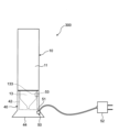
本発明の第2実施形態の洗浄器200は、図6に示すように、本体部10の一端に着脱自在に取り付けられ、超音波ホーン20のホーン部22を覆う蓋体部40を備えた点で、第1実施形態の洗浄器100とは異なっている。なお、第2実施形態では、第1実施形態と同一部分に同一参照番号を付して説明を省略し、第1実施形態と異なる点について説明する。(Second embodiment)
A
蓋体部40は、図6に示すように、棒状で、蓋体部40が延びる方向に交差する方向の断面において、本体部10の把持部11と同一の四角形状を有している。この蓋体部40は、図7に示すように、長手方向(Y方向)の一端に、本体部10の先端部12の基部13に嵌合可能な開口41と、この開口41を介して超音波ホーン20のホーン部22を収容可能な凹部42とを有している。凹部42の開口縁部には、本体部10の先端部12の基部13に設けられた突出部15を嵌合可能な溝部43が設けられている。この溝部43は、凹部42の四角形状の開口縁部の略中央に配置されている。
As shown in FIG. 6 , the
また、図6に示すように、蓋体部40のY方向の開口41の反対側の他端には、平坦面44が設けられている。この平坦面44を下側に向け、開口41を上側に向けた状態で蓋体部40を載置することで、蓋体部40を本体部10の置台にすることができる。すなわち、蓋体部40によって、本体部10をいわゆる縦置きの状態で載置することができる。
Further, as shown in FIG. 6, a
このように、蓋体部40が本体部10を載置する置台を兼ねている。これにより、例えば、本体部10専用の置台が不要になり、洗浄器200の持ち運びが便利になる。
In this manner, the
また、本体部10を縦置きの状態で載置することで、洗浄器200の収納を省スペース化することができる。
In addition, by placing the
なお、蓋体部40は、本体部10を縦置きの状態で載置できるもの限らず、例えば、洗浄器の設置面に対して、所定の角度を成した状態で本体部を載置できるものであってもよい。
Note that the
(第3実施形態)
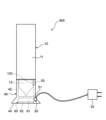
本発明の第3実施形態の洗浄器300は、図8に示すように、蓋体部40が、本体部10が載置された状態で、本体部10のバッテリ30を充電可能な充電部50を有している点で、第2実施形態の洗浄器200とは異なっている。なお、第3実施形態では、第1および第2実施形態と同一部分に同一参照番号を付して説明を省略し、第1および第2実施形態と異なる点について説明する。(Third Embodiment)
As shown in FIG. 8, the
充電部50は、図8に示すように、充電器本体51と、充電器本体51に接続された電源コード52と、蓋体部40の凹部42の内周面に露出した状態で配置されている充電端子部53とを有している。充電器本体51と充電端子部53とは、電気的に接続されている。
As shown in FIG. 8, the charging
また、本体部10の基部13には、表面から露出した状態で配置されている本体端子部133が設けられている。この本体端子部133は、バッテリ30に電気的に接続されている。
Further, the
蓋体部40を本体部10に取り付けて、縦置きに載置した状態では、本体部10の本体端子部133と蓋体部40の充電部50の充電端子部53とが接触して、電気的に接続され、バッテリ30を充電できるようになっている。
When the
このように、蓋体部40が、本体部10が載置された状態で、本体部10のバッテリ30を充電可能な充電部50を有している。このため、バッテリ30を充電することで繰り返し使用することができ、洗浄器300の維持コストを低減できる。
Thus, the
なお、充電部50は、上述のような有接点充電に限らず、電磁誘導方式を用いた無接点充電を行えるものであってもよい。
The charging
(第4実施形態)
本発明の第4実施形態の洗浄器400は、図9に示すように、蓋体部40が、被洗浄物の洗浄を行うときに使用する水を貯留する貯水部60を有している点で、第3実施形態の洗浄器300とは異なっている。なお、第4実施形態では、第1~第3実施形態と同一部分に同一参照番号を付して説明を省略し、第1~第3実施形態と異なる点について説明する。(Fourth embodiment)
In a
貯水部60は、図9に示すように、蓋体部40の平坦面44側の端部(図9の下端部)に設けられている。この貯水部60は、平坦面44に開口する貯水室61と、貯水室61の開口を塞ぐカバー62とを有している。貯水室61は、被洗浄物の洗浄に使用する水が貯留される。カバー62は、蓋体部40に着脱可能に取り付けられている。このカバー62には、図示しないパッキンが取り付けられ、貯水室61とカバー62との間をシールしている。
As shown in FIG. 9, the
このように、蓋体部40に貯水部60を設けることで、水を得ることができない環境であっても、洗浄器400を使用して、被洗浄物の汚れを除去できる。
By providing the
なお、被洗浄物の洗浄に使用する水の貯留は、貯水室61内に貯水することにより行ってもよいし、吸水させたパフ等を貯水室61内に収容することにより行ってもよい。
The water used for washing the object to be washed may be stored in the
(第5実施形態)
本発明の第5実施形態の洗浄器500は、図10に示すように、蓋体部40が、洗濯機1の一部を構成している点で、第3実施形態の洗浄器300とは異なっている。なお、第5実施形態では、第1~第3実施形態と同一部分に同一参照番号を付して説明を省略し、第1~第3実施形態と異なる点について説明する。(Fifth embodiment)
As shown in FIG. 10, the
このように、蓋体部40が、洗濯機1の一部を構成しているので、例えば、部分的に目立つ被洗浄物の汚れに対して洗濯機1による洗濯の前に使用することで、一度の洗濯で被洗浄物の汚れを除去できる。すなわち、洗浄器500の使用性を向上できる。
In this way, since the
(第6実施形態)
本発明の第6実施形態の洗浄器500は、図10に示すように、蓋体部40が、洗濯機1の一部を構成しており、その内部は図8に示すような構造になっている。充電本体51と、蓋体部40の凹部42の内周面に露出した状態で配置されている充電端子部53とを有している。充電器本体51と充電端子部53とは、電気的に接続されている。(Sixth embodiment)
As shown in FIG. 10, a
また、本体部10の基部13には、表面から露出した状態で配置されている本体端子部133が設けられている。この本体端子部133は、バッテリ30に電気的に接続されている。
Further, the
蓋体部40を本体部10に取り付けて、縦置きに載置した状態では、本体部10の本体端子部133と蓋体部40の充電部50の充電端子部53とが接触して、電気的に接続され、バッテリ30を充電できるようになっている。
When the
このように、蓋体部40が、本体部10が載置された状態で、本体部10のバッテリ30を充電可能な充電部50を有している。このため、バッテリ30を充電することで繰り返し使用することができる。すなわち、洗浄器500の使用性を向上できる。
Thus, the
なお、洗濯機1は、縦型でもドラム式でも構わない。 Note that the washing machine 1 may be of a vertical type or a drum type.
本発明および実施形態をまとめると、次のようになる。 The present invention and embodiments are summarized as follows.
本発明の洗浄器100,200,300,400,500は、
棒状を有する本体部10と、
上記本体部10内に設けられ、振動を発生させる振動発生部21と、
上記本体部10内に設けられ、一部が上記本体部10の一端から露出した状態で配置されていると共に、上記振動発生部21で発生した振動を被洗浄物に伝達する振動伝達部22と、
上記本体部10内に設けられ、上記振動発生部21に振動を発生させるための電力を供給する電力供給部30と、
を備え、
上記本体部10が延びる方向に交差する方向の断面において、上記本体部10と上記振動伝達部22とが、それぞれ多角形状を有しており、上記本体部10の上記多角形状の一辺と上記振動伝達部22の上記多角形状の一辺とが、平行であることを特徴としている。The
a
a
a
a
with
In a cross section in a direction intersecting the direction in which the
上記構成によれば、本体部10を用いて、振動伝達部22の方向付けを行うことができるので、振動伝達部22を正確に方向付けすることができる。
According to the above configuration, since the orientation of the
また、一実施形態の洗浄器100,200,300,400,500では、
上記本体部10が、使用者により把持される把持部11を有し、
重心が上記把持部11の中心に一致している。In addition, in the
The
The center of gravity coincides with the center of the
上記実施形態によれば、使用者により把持された把持部11の位置と洗浄器100,200,300,400,500の重心との間の距離を短くすることができるので、振動伝達部22の操作性を高めることができる。
According to the above embodiment, the distance between the position of the
また、一実施形態の洗浄器100.200.300,400,500では、
上記本体部10が、その他端に、上記電力供給部30から上記振動発生部21への電力の供給をオンオフする押しボタンスイッチ16を有している。In addition, in the
The
上記実施形態によれば、洗浄器100,200,300,400,500の操作時に、使用者の指等が押しボタンスイッチ16に接触する可能性を低減して、誤操作を防止できる。
According to the above-described embodiments, it is possible to reduce the possibility that a user's finger or the like touches the
また、一実施形態の洗浄器100,200,300,400,500では、
上記本体部および上記振動伝達部の上記本体部が延びる方向に交差する方向の断面が、それぞれ四角形状である。In addition, in the
Sections of the body portion and the vibration transmission portion in a direction intersecting the direction in which the body portion extends are each rectangular.
上記実施形態によれば、本体部10の断面形状が他の多角形状である場合と比較して、方向付けが容易で、使用者が把持し易く、転がり難い。
According to the above-described embodiment, orientation is easy, the user can easily grip, and rolling is less likely to occur, as compared with the case where the
また、一実施形態の洗浄器200,300,400,500では、
上記本体部の一端に着脱可能に取り付けられ、上記振動発生部を覆う蓋体部を備え、
上記蓋体部が、上記本体部を載置する置台を兼ねる。In addition, in the
a cover body section detachably attached to one end of the main body section and covering the vibration generating section;
The lid portion also serves as a stand on which the main body portion is placed.
上記実施形態によれば、例えば、本体部10専用の置台が不要になり、洗浄器200の持ち運びが便利になる。
According to the above-described embodiment, for example, a stand dedicated to the
ところで、特許文献1に開示されている洗浄器を載置する場合、この洗浄器を載置可能な専用の置台を用いることが考えられる。しかし、上記洗浄器の載置に専用の置台を用いると、例えば、外出先で上記洗浄器を使用する場合、上記洗浄器に加えて、専用の置台を持ち運ばなければならず、持ち運びが不便である。 By the way, when placing the cleaning device disclosed in Patent Document 1, it is conceivable to use a dedicated stand on which the cleaning device can be placed. However, if a dedicated stand is used to place the washer, for example, when using the washer outside, the dedicated stand must be carried in addition to the washer, which is inconvenient to carry. is.
本発明の洗浄器200,300,400,500は、
棒状を有する本体部10と、
上記本体部10内に設けられ、振動を発生させる振動発生部21と、
上記本体部10内に設けられ、一部が上記本体部10の一端から露出した状態で配置されていると共に、上記振動発生部21で発生した振動を被洗浄物に伝達する振動伝達部22と、
上記本体部10内に設けられ、上記振動発生部21に振動を発生させるための電力を供給する電力供給部30と、
上記本体部10の一端に着脱可能に取り付けられ、上記振動発生部21を覆う蓋体部40と、
を備え、
上記蓋体部40が、上記本体部10を上記本体部10が延びる方向に沿った状態で載置可能な縦置台を兼ねていることを特徴としている。The
a
a
a
a
a
with
The
上記構成によれば、例えば、本体部10専用の置台が不要になり、洗浄器200の持ち運びが便利になる。
According to the above configuration, for example, a dedicated stand for the
また、一実施形態の洗浄器300,400,500では、
上記電力供給部30が、充電可能であり、
上記蓋体部40が、上記本体部10が載置された状態で、上記本体部10の上記電力供給部30を充電可能な充電部50を有する。In addition, in the
The
The
上記実施形態によれば、電力供給部30を充電することで繰り返し使用することができ、洗浄器300,400,500の維持コストを低減できる。
According to the above embodiment, the
また、一実施形態の洗浄器400では、
上記蓋体部40が、上記被洗浄物の洗浄を行うときに使用する水を貯留する貯水部60を有する。In addition, in the
The
上記実施形態によれば、水を得ることができない環境であっても、洗浄器400を使用して、被洗浄物の汚れを除去できる。
According to the above-described embodiment, even in an environment where water cannot be obtained, the
また、一実施形態の洗浄器500では、
上記蓋体部40が、洗濯機1の一部を構成している。In addition, in the
The
上記実施形態によれば、例えば、部分的に目立つ被洗浄物の汚れに対して洗濯機1による洗濯の前に使用することで、一度の洗濯で被洗浄物の汚れを除去できる。すなわち、洗浄器500の使用性を向上できる。
According to the above-described embodiment, for example, by using the washing machine 1 for partially conspicuous dirt on the object to be washed, the dirt on the object to be washed can be removed in one washing operation. That is, the usability of the
上記第1~第6実施形態で述べた構成要素は、適宜、組み合わせてもよく、また、適宜、選択、置換、あるいは、削除してもよいことは、勿論である。 Of course, the constituent elements described in the first to sixth embodiments may be combined, selected, replaced, or deleted as appropriate.
10 本体部
11 把持部
111 パッキン
112 収容部
12 先端部
13 基部
131 溝部
132 貫通孔
133 本体端子部
14 先細部
141 幅広部
142 幅狭部
143 開口
15 突出部
16 押しボタンスイッチ
17 メイン回路基板
18 トランス
20 超音波ホーン
21 振動発生部
211 パッキン
22 ホーン部(振動伝達部の一例)
221 先端
30 バッテリ(電力供給部の一例)
40 蓋体部
41 開口
42 凹部
43 溝部
50 充電部
51 充電器本体
52 電源コード
53 充電端子部
60 貯水部
61 貯水室
62 カバー
100,200,300,400,500 洗浄器
CL 中心線10
221
40
Claims (3)
上記先端部内に設けられ、超音波振動を発生させる振動発生部と、
上記振動発生部で発生した超音波振動を、先端に接触された被洗浄物に伝達するホーン部と、
上記把持部内に設けられ、上記振動発生部に超音波振動を発生させるための電力を供給する電力供給部と、
上記先端部に着脱可能であり、上記先端部に取り付けられた状態で、上記ホーン部の上記先端を覆う蓋体部と、
を備え、
上記蓋体部は、上記先端部に取り付けられた状態で、上記先端部を覆うように一端が開口している凹部を有し、
上記先端部は、先細部と基部とを備え、
上記先細部は、
上記ホーン部の上記先端が貫通するように上記ホーン部を囲み、
上記基部は、
上記基部の先端に向かうにつれて上記基部が狭まるように傾斜した傾斜面と、
上記傾斜面における上記先端と反対側の基端側に形成された突出部と、を有し、
上記蓋体部は、上記蓋体部における上記一端側に形成され、上記先端部に取り付けられた状態において上記突出部と嵌合する溝部を有し、
上記把持部及び上記蓋体部は、上記本体部が延びる方向に交差する方向の断面が、互いに同一の多角形状を有しており、
上記本体部が延びる方向に交差する方向において、上記把持部及び上記蓋体部の寸法は、上記先端部の寸法よりも大きく、
上記先端部は、上記傾斜面から上記本体部が延びる方向に交差する方向に突出した鍔部を有し、
上記鍔部は、上記本体部から延びる方向の一面側に段差を形成し、
上記蓋体部は、上記先端部に取り付けられた状態で、上記蓋体部の縁が上記鍔部の上記一面側の上記段差に当接し、
上記蓋体部は、上記把持部と反対側の端部が、上記本体部が延びる方向に交差する方向に沿った平面であり、
上記把持部は、上記本体部が延びる方向の一端から他端にわたって、上記本体部が延びる方向と交差する方向の形状及び寸法が上記蓋体部と同じ、かつ一定となるように直線の棒状に形成されており、上記ホーン部と反対側の端部が、上記本体部が延びる方向に交差する方向に沿った平面である、
ことを特徴とする洗浄器。 a body having a grip and a tip ;
a vibration generator provided in the tip portion for generating ultrasonic vibration;
a horn portion that transmits the ultrasonic vibration generated by the vibration generating portion to an object to be cleaned that is in contact with the tip;
a power supply unit provided in the gripping unit and supplying power for generating ultrasonic vibrations to the vibration generating unit;
a cover body part that is detachable from the tip part and covers the tip of the horn part in a state attached to the tip part;
with
The lid portion has a concave portion, one end of which is open so as to cover the tip portion when attached to the tip portion ,
the tip portion comprises a tapered portion and a base;
The tip of the above is
surrounding the horn part so that the tip of the horn part penetrates;
The base is
an inclined surface inclined so that the base narrows toward the tip of the base ;
a protruding portion formed on the base end side opposite to the tip end of the inclined surface;
The lid portion has a groove portion formed on the one end side of the lid portion and fitted with the projecting portion when attached to the tip portion ,
The grip portion and the lid portion have the same polygonal shape in cross section in a direction intersecting the direction in which the body portion extends,
In a direction intersecting the direction in which the main body extends, the dimensions of the grip and the lid are larger than the dimensions of the tip ,
The tip portion has a flange projecting in a direction intersecting the direction in which the main body extends from the inclined surface,
The flange portion forms a step on one surface side in a direction extending from the main body portion ,
a rim of the lid portion abuts the step on the one surface side of the flange portion in a state where the lid portion is attached to the tip portion ;
The end of the lid opposite to the grip is a flat surface along a direction intersecting the direction in which the main body extends,
The gripping portion is shaped like a straight rod so that the shape and dimensions in a direction intersecting the extending direction of the main body portion are the same and constant as those of the lid portion from one end to the other end in the direction in which the main body portion extends. is formed, and the end opposite to the horn portion is a plane along a direction intersecting the direction in which the body portion extends,
A washer characterized by:
上記電力供給部が、充電可能である、
ことを特徴とする洗浄器。 The washer of claim 1,
wherein the power supply is rechargeable;
A washer characterized by:
上記本体部は、上記突出部である第1突出部と、上記第1突出部と共に上記ホーン部を挟む位置に形成された第2突出部とを有し、
上記蓋体部は、上記本体部に取り付けられた状態において、上記溝部であって上記第1突出部と嵌合する第1溝部と、上記第2突出部と嵌合する第2溝部と、を有する、
ことを特徴とする洗浄器。 The cleaning device according to claim 1 or 2,
The main body portion has a first projecting portion which is the projecting portion, and a second projecting portion formed at a position sandwiching the horn portion together with the first projecting portion,
The lid portion includes a first groove portion that is the groove portion and fits with the first projecting portion, and a second groove portion that fits with the second projecting portion when the lid portion is attached to the main body portion. have
A washer characterized by:
Priority Applications (1)
| Application Number | Priority Date | Filing Date | Title |
|---|---|---|---|
| JP2022026653A JP2022068333A (en) | 2016-07-19 | 2022-02-24 | Cleaning device |
Applications Claiming Priority (5)
| Application Number | Priority Date | Filing Date | Title |
|---|---|---|---|
| JP2016141514 | 2016-07-19 | ||
| JP2016141514 | 2016-07-19 | ||
| JP2016141512 | 2016-07-19 | ||
| JP2016141512 | 2016-07-19 | ||
| PCT/JP2017/003113 WO2018016103A1 (en) | 2016-07-19 | 2017-01-30 | Cleaning device |
Related Child Applications (4)
| Application Number | Title | Priority Date | Filing Date |
|---|---|---|---|
| JP2021009464A Division JP7273870B2 (en) | 2016-07-19 | 2021-01-25 | Washing machine |
| JP2021009465A Division JP7273871B2 (en) | 2016-07-19 | 2021-01-25 | Washing machine |
| JP2021009463A Division JP7216749B2 (en) | 2016-07-19 | 2021-01-25 | Washing machine |
| JP2022026653A Division JP2022068333A (en) | 2016-07-19 | 2022-02-24 | Cleaning device |
Publications (2)
| Publication Number | Publication Date |
|---|---|
| JPWO2018016103A1 JPWO2018016103A1 (en) | 2019-05-09 |
| JP7273510B2 true JP7273510B2 (en) | 2023-05-15 |
Family
ID=60992205
Family Applications (5)
| Application Number | Title | Priority Date | Filing Date |
|---|---|---|---|
| JP2018528387A Active JP7273510B2 (en) | 2016-07-19 | 2017-01-30 | Washing machine |
| JP2021009464A Active JP7273870B2 (en) | 2016-07-19 | 2021-01-25 | Washing machine |
| JP2021009463A Active JP7216749B2 (en) | 2016-07-19 | 2021-01-25 | Washing machine |
| JP2021009465A Active JP7273871B2 (en) | 2016-07-19 | 2021-01-25 | Washing machine |
| JP2022026653A Pending JP2022068333A (en) | 2016-07-19 | 2022-02-24 | Cleaning device |
Family Applications After (4)
| Application Number | Title | Priority Date | Filing Date |
|---|---|---|---|
| JP2021009464A Active JP7273870B2 (en) | 2016-07-19 | 2021-01-25 | Washing machine |
| JP2021009463A Active JP7216749B2 (en) | 2016-07-19 | 2021-01-25 | Washing machine |
| JP2021009465A Active JP7273871B2 (en) | 2016-07-19 | 2021-01-25 | Washing machine |
| JP2022026653A Pending JP2022068333A (en) | 2016-07-19 | 2022-02-24 | Cleaning device |
Country Status (5)
| Country | Link |
|---|---|
| EP (1) | EP3488940A4 (en) |
| JP (5) | JP7273510B2 (en) |
| CN (1) | CN109414734A (en) |
| TW (1) | TWI652123B (en) |
| WO (1) | WO2018016103A1 (en) |
Families Citing this family (6)
| Publication number | Priority date | Publication date | Assignee | Title |
|---|---|---|---|---|
| CN109414734A (en) * | 2016-07-19 | 2019-03-01 | 夏普株式会社 | Washer |
| CN112154232B (en) * | 2018-05-24 | 2023-12-05 | 夏普株式会社 | washing machine |
| CN112189067B (en) * | 2018-05-24 | 2023-10-20 | 夏普株式会社 | washing machine |
| JP7217881B2 (en) * | 2018-12-21 | 2023-02-06 | 青島海爾洗衣机有限公司 | Ultrasonic cleaner and washing machine |
| JP7514243B2 (en) * | 2019-08-22 | 2024-07-10 | シャープ株式会社 | Ultrasonic cleaner |
| JP2023035690A (en) * | 2021-09-01 | 2023-03-13 | 青島海爾洗衣机有限公司 | Mist injector and ultrasonic cleaning machine including the same |
Citations (7)
| Publication number | Priority date | Publication date | Assignee | Title |
|---|---|---|---|---|
| JP3058326U (en) | 1998-10-08 | 1999-06-18 | 隆史 平石 | Liquid impregnating putting brush |
| JP2000308788A (en) | 1999-04-28 | 2000-11-07 | Sharp Corp | Washing machine with partial washing device |
| JP2008212200A (en) | 2007-02-28 | 2008-09-18 | Asahi Irika Kk | Motor-driven toothbrush |
| JP2012249719A (en) | 2011-05-31 | 2012-12-20 | Panasonic Corp | Electric toothbrush |
| JP2015123245A (en) | 2013-12-26 | 2015-07-06 | ライオン株式会社 | Toothbrush and electric toothbrush |
| CN105442237A (en) | 2014-07-23 | 2016-03-30 | 无锡小天鹅股份有限公司 | Washing machine |
| CN105755728A (en) | 2016-04-06 | 2016-07-13 | 无锡小天鹅股份有限公司 | Portable ultrasonic cleaning device |
Family Cites Families (19)
| Publication number | Priority date | Publication date | Assignee | Title |
|---|---|---|---|---|
| JPH0648420U (en) * | 1992-08-20 | 1994-07-05 | 有限会社リッチボーン | Lunch box |
| JPH0670864A (en) * | 1992-08-28 | 1994-03-15 | Hitachi Ltd | Chargeable cleaner |
| JPH08282717A (en) * | 1995-04-10 | 1996-10-29 | Chuo Denki Sangyo Kk | Container for housing highly viscous substance |
| JPH1132971A (en) * | 1997-07-15 | 1999-02-09 | Akira Nagaoka | Clothing stain-removing tool |
| AU1613601A (en) * | 1999-11-16 | 2001-05-30 | Procter & Gamble Company, The | Cleaning process which uses ultrasonic waves |
| JP2001310094A (en) * | 2000-04-28 | 2001-11-06 | Kao Corp | Ultrasonic cleaning device |
| JP2001310095A (en) * | 2000-04-28 | 2001-11-06 | Kao Corp | Ultrasonic cleaning device |
| JP2003049354A (en) * | 2001-08-02 | 2003-02-21 | Kao Corp | Ultrasonic cleaner |
| JP2003164888A (en) * | 2001-12-01 | 2003-06-10 | Ekoru:Kk | Reforming member for potable water |
| JP4237452B2 (en) * | 2002-08-01 | 2009-03-11 | パナソニック株式会社 | Battery pack and manufacturing method thereof |
| JP3768978B2 (en) * | 2003-06-16 | 2006-04-19 | 株式会社クマザキエイム | Ultrasonic cleaner |
| JP2006210787A (en) | 2005-01-31 | 2006-08-10 | Icom Inc | Waterproof construction of portable radio unit |
| WO2006120726A1 (en) | 2005-05-06 | 2006-11-16 | Inter Face Co., Ltd. | Ionic beauty appliance |
| WO2007060741A1 (en) | 2005-11-28 | 2007-05-31 | Laseine Co., Ltd. | Method of substance infiltration and apparatus therefor |
| TWM303317U (en) * | 2006-05-19 | 2006-12-21 | Shyi-Yau Chang | Bat-shaped flashlight |
| JP6139078B2 (en) | 2012-09-03 | 2017-05-31 | 古河機械金属株式会社 | Solid electrolyte material for lithium ion battery, solid electrolyte for lithium ion battery, lithium ion battery, and method for producing solid electrolyte material for lithium ion battery |
| JP6164677B2 (en) * | 2012-09-18 | 2017-07-19 | 株式会社イノアックコーポレーション | Method of manufacturing ceiling interior member with duct |
| JP6469399B2 (en) * | 2014-09-19 | 2019-02-13 | アクア株式会社 | Stain removal apparatus and stain removal unit |
| CN109414734A (en) | 2016-07-19 | 2019-03-01 | 夏普株式会社 | Washer |
-
2017
- 2017-01-30 CN CN201780014203.8A patent/CN109414734A/en active Pending
- 2017-01-30 EP EP17830625.4A patent/EP3488940A4/en not_active Withdrawn
- 2017-01-30 JP JP2018528387A patent/JP7273510B2/en active Active
- 2017-01-30 WO PCT/JP2017/003113 patent/WO2018016103A1/en active Application Filing
- 2017-02-09 TW TW106104224A patent/TWI652123B/en active
-
2021
- 2021-01-25 JP JP2021009464A patent/JP7273870B2/en active Active
- 2021-01-25 JP JP2021009463A patent/JP7216749B2/en active Active
- 2021-01-25 JP JP2021009465A patent/JP7273871B2/en active Active
-
2022
- 2022-02-24 JP JP2022026653A patent/JP2022068333A/en active Pending
Patent Citations (7)
| Publication number | Priority date | Publication date | Assignee | Title |
|---|---|---|---|---|
| JP3058326U (en) | 1998-10-08 | 1999-06-18 | 隆史 平石 | Liquid impregnating putting brush |
| JP2000308788A (en) | 1999-04-28 | 2000-11-07 | Sharp Corp | Washing machine with partial washing device |
| JP2008212200A (en) | 2007-02-28 | 2008-09-18 | Asahi Irika Kk | Motor-driven toothbrush |
| JP2012249719A (en) | 2011-05-31 | 2012-12-20 | Panasonic Corp | Electric toothbrush |
| JP2015123245A (en) | 2013-12-26 | 2015-07-06 | ライオン株式会社 | Toothbrush and electric toothbrush |
| CN105442237A (en) | 2014-07-23 | 2016-03-30 | 无锡小天鹅股份有限公司 | Washing machine |
| CN105755728A (en) | 2016-04-06 | 2016-07-13 | 无锡小天鹅股份有限公司 | Portable ultrasonic cleaning device |
Also Published As
| Publication number | Publication date |
|---|---|
| TWI652123B (en) | 2019-03-01 |
| CN109414734A (en) | 2019-03-01 |
| EP3488940A1 (en) | 2019-05-29 |
| JP7273870B2 (en) | 2023-05-15 |
| JP2021073087A (en) | 2021-05-13 |
| WO2018016103A1 (en) | 2018-01-25 |
| TW201803652A (en) | 2018-02-01 |
| JP2021073088A (en) | 2021-05-13 |
| JPWO2018016103A1 (en) | 2019-05-09 |
| JP2021073089A (en) | 2021-05-13 |
| JP7273871B2 (en) | 2023-05-15 |
| EP3488940A4 (en) | 2020-03-04 |
| JP7216749B2 (en) | 2023-02-01 |
| JP2022068333A (en) | 2022-05-09 |
Similar Documents
| Publication | Publication Date | Title |
|---|---|---|
| JP7273870B2 (en) | Washing machine | |
| TWI480770B (en) | Capacitive pointer | |
| US20140288469A1 (en) | Touch-to-activate structure for make-up pen with function of vibration massage | |
| JP6703126B2 (en) | Beauty device with replaceable application head | |
| KR20160133665A (en) | A Case for an Electronic Cigarette | |
| TWI507572B (en) | Wash the metal container cleaning device | |
| JP3180034U (en) | Ultrasonic sensor device | |
| RU2631206C2 (en) | Manual electrical device for skin care | |
| JP2010279463A5 (en) | ||
| CN210523259U (en) | Ultrasonic cleaning pen | |
| CN212015444U (en) | Dust collector | |
| CN216262591U (en) | Sterilization component and ultrasonic cleaning machine | |
| CN104853888B (en) | Battery-driven razor | |
| CN215218920U (en) | Portable electric quantity measuring instrument | |
| JP2005216512A (en) | Battery, battery holder, and mounting structure of battery | |
| CN204368284U (en) | The automobile trunk button of new type of safe | |
| CN213721735U (en) | Anti-static dust collector | |
| CN110123243A (en) | A kind of the bottom of a pan cleaning device | |
| KR200325557Y1 (en) | Portable Ultrasonic Vibrator | |
| US8585621B1 (en) | Skin exfoliation apparatus | |
| KR200470983Y1 (en) | Portable contact len cleansing device of ball shape | |
| CN104957871A (en) | Electric plate brush vibrated vertically through ultrasonic waves | |
| KR200330789Y1 (en) | Silver ionized water maker. | |
| JP2011095620A (en) | Laser pointer | |
| KR20190063309A (en) | Smart Attachment Secondary Battery |
Legal Events
| Date | Code | Title | Description |
|---|---|---|---|
| A621 | Written request for application examination |
Free format text: JAPANESE INTERMEDIATE CODE: A621 Effective date: 20190920 |
|
| RD02 | Notification of acceptance of power of attorney |
Free format text: JAPANESE INTERMEDIATE CODE: A7422 Effective date: 20200330 |
|
| RD04 | Notification of resignation of power of attorney |
Free format text: JAPANESE INTERMEDIATE CODE: A7424 Effective date: 20200417 |
|
| A521 | Request for written amendment filed |
Free format text: JAPANESE INTERMEDIATE CODE: A523 Effective date: 20201026 |
|
| A131 | Notification of reasons for refusal |
Free format text: JAPANESE INTERMEDIATE CODE: A131 Effective date: 20201124 |
|
| A521 | Request for written amendment filed |
Free format text: JAPANESE INTERMEDIATE CODE: A523 Effective date: 20210125 |
|
| A131 | Notification of reasons for refusal |
Free format text: JAPANESE INTERMEDIATE CODE: A131 Effective date: 20210420 |
|
| A521 | Request for written amendment filed |
Free format text: JAPANESE INTERMEDIATE CODE: A523 Effective date: 20210618 |
|
| A131 | Notification of reasons for refusal |
Free format text: JAPANESE INTERMEDIATE CODE: A131 Effective date: 20210803 |
|
| A521 | Request for written amendment filed |
Free format text: JAPANESE INTERMEDIATE CODE: A523 Effective date: 20211004 |
|
| A02 | Decision of refusal |
Free format text: JAPANESE INTERMEDIATE CODE: A02 Effective date: 20211124 |
|
| A521 | Request for written amendment filed |
Free format text: JAPANESE INTERMEDIATE CODE: A523 Effective date: 20220224 |
|
| C60 | Trial request (containing other claim documents, opposition documents) |
Free format text: JAPANESE INTERMEDIATE CODE: C60 Effective date: 20220224 |
|
| A911 | Transfer to examiner for re-examination before appeal (zenchi) |
Free format text: JAPANESE INTERMEDIATE CODE: A911 Effective date: 20220307 |
|
| C21 | Notice of transfer of a case for reconsideration by examiners before appeal proceedings |
Free format text: JAPANESE INTERMEDIATE CODE: C21 Effective date: 20220308 |
|
| A912 | Re-examination (zenchi) completed and case transferred to appeal board |
Free format text: JAPANESE INTERMEDIATE CODE: A912 Effective date: 20220401 |
|
| C211 | Notice of termination of reconsideration by examiners before appeal proceedings |
Free format text: JAPANESE INTERMEDIATE CODE: C211 Effective date: 20220405 |
|
| C22 | Notice of designation (change) of administrative judge |
Free format text: JAPANESE INTERMEDIATE CODE: C22 Effective date: 20220712 |
|
| C22 | Notice of designation (change) of administrative judge |
Free format text: JAPANESE INTERMEDIATE CODE: C22 Effective date: 20221101 |
|
| C13 | Notice of reasons for refusal |
Free format text: JAPANESE INTERMEDIATE CODE: C13 Effective date: 20221129 |
|
| A521 | Request for written amendment filed |
Free format text: JAPANESE INTERMEDIATE CODE: A523 Effective date: 20230126 |
|
| C23 | Notice of termination of proceedings |
Free format text: JAPANESE INTERMEDIATE CODE: C23 Effective date: 20230314 |
|
| C03 | Trial/appeal decision taken |
Free format text: JAPANESE INTERMEDIATE CODE: C03 Effective date: 20230411 |
|
| C30A | Notification sent |
Free format text: JAPANESE INTERMEDIATE CODE: C3012 Effective date: 20230411 |
|
| A61 | First payment of annual fees (during grant procedure) |
Free format text: JAPANESE INTERMEDIATE CODE: A61 Effective date: 20230428 |
|
| R150 | Certificate of patent or registration of utility model |
Ref document number: 7273510 Country of ref document: JP Free format text: JAPANESE INTERMEDIATE CODE: R150 |