JP6469399B2 - Stain removal apparatus and stain removal unit - Google Patents
Stain removal apparatus and stain removal unit Download PDFInfo
- Publication number
- JP6469399B2 JP6469399B2 JP2014191463A JP2014191463A JP6469399B2 JP 6469399 B2 JP6469399 B2 JP 6469399B2 JP 2014191463 A JP2014191463 A JP 2014191463A JP 2014191463 A JP2014191463 A JP 2014191463A JP 6469399 B2 JP6469399 B2 JP 6469399B2
- Authority
- JP
- Japan
- Prior art keywords
- head
- liquid
- stain
- main body
- liquid storage
- Prior art date
- Legal status (The legal status is an assumption and is not a legal conclusion. Google has not performed a legal analysis and makes no representation as to the accuracy of the status listed.)
- Active
Links
- 239000007788 liquid Substances 0.000 claims description 158
- 238000003860 storage Methods 0.000 claims description 68
- 230000007246 mechanism Effects 0.000 claims description 66
- XLYOFNOQVPJJNP-UHFFFAOYSA-N water Substances O XLYOFNOQVPJJNP-UHFFFAOYSA-N 0.000 claims description 61
- 238000010438 heat treatment Methods 0.000 claims description 33
- 238000001125 extrusion Methods 0.000 claims description 2
- 238000003780 insertion Methods 0.000 description 24
- 230000037431 insertion Effects 0.000 description 24
- 210000000078 claw Anatomy 0.000 description 18
- 230000002745 absorbent Effects 0.000 description 16
- 239000002250 absorbent Substances 0.000 description 16
- 230000000694 effects Effects 0.000 description 13
- 238000010079 rubber tapping Methods 0.000 description 13
- 239000003599 detergent Substances 0.000 description 12
- 239000007787 solid Substances 0.000 description 10
- 238000010521 absorption reaction Methods 0.000 description 9
- 239000011810 insulating material Substances 0.000 description 8
- 239000004744 fabric Substances 0.000 description 7
- 238000004140 cleaning Methods 0.000 description 5
- 238000005406 washing Methods 0.000 description 5
- LFQSCWFLJHTTHZ-UHFFFAOYSA-N Ethanol Chemical compound CCO LFQSCWFLJHTTHZ-UHFFFAOYSA-N 0.000 description 4
- OYPRJOBELJOOCE-UHFFFAOYSA-N Calcium Chemical compound [Ca] OYPRJOBELJOOCE-UHFFFAOYSA-N 0.000 description 3
- 229910052791 calcium Inorganic materials 0.000 description 3
- 239000011575 calcium Substances 0.000 description 3
- 238000005192 partition Methods 0.000 description 3
- 238000003892 spreading Methods 0.000 description 3
- UHOVQNZJYSORNB-UHFFFAOYSA-N Benzene Chemical compound C1=CC=CC=C1 UHOVQNZJYSORNB-UHFFFAOYSA-N 0.000 description 2
- 239000000919 ceramic Substances 0.000 description 2
- 230000007423 decrease Effects 0.000 description 2
- 239000000463 material Substances 0.000 description 2
- 238000000034 method Methods 0.000 description 2
- 239000000203 mixture Substances 0.000 description 2
- 238000012986 modification Methods 0.000 description 2
- 230000004048 modification Effects 0.000 description 2
- 238000003825 pressing Methods 0.000 description 2
- 239000011347 resin Substances 0.000 description 2
- 229920005989 resin Polymers 0.000 description 2
- 239000002904 solvent Substances 0.000 description 2
- 229910001220 stainless steel Inorganic materials 0.000 description 2
- 239000010935 stainless steel Substances 0.000 description 2
- 239000004677 Nylon Substances 0.000 description 1
- 229910000831 Steel Inorganic materials 0.000 description 1
- NIXOWILDQLNWCW-UHFFFAOYSA-N acrylic acid group Chemical group C(C=C)(=O)O NIXOWILDQLNWCW-UHFFFAOYSA-N 0.000 description 1
- 229910052782 aluminium Inorganic materials 0.000 description 1
- XAGFODPZIPBFFR-UHFFFAOYSA-N aluminium Chemical compound [Al] XAGFODPZIPBFFR-UHFFFAOYSA-N 0.000 description 1
- 239000007844 bleaching agent Substances 0.000 description 1
- 239000003795 chemical substances by application Substances 0.000 description 1
- 239000011248 coating agent Substances 0.000 description 1
- 238000000576 coating method Methods 0.000 description 1
- 239000002537 cosmetic Substances 0.000 description 1
- 238000005520 cutting process Methods 0.000 description 1
- 230000007812 deficiency Effects 0.000 description 1
- 238000010586 diagram Methods 0.000 description 1
- 239000011491 glass wool Substances 0.000 description 1
- 230000012447 hatching Effects 0.000 description 1
- 230000020169 heat generation Effects 0.000 description 1
- 238000002347 injection Methods 0.000 description 1
- 239000007924 injection Substances 0.000 description 1
- 230000013011 mating Effects 0.000 description 1
- 229910052751 metal Inorganic materials 0.000 description 1
- 239000002184 metal Substances 0.000 description 1
- 238000002156 mixing Methods 0.000 description 1
- 229910001120 nichrome Inorganic materials 0.000 description 1
- 229920001778 nylon Polymers 0.000 description 1
- 239000003921 oil Substances 0.000 description 1
- 230000000149 penetrating effect Effects 0.000 description 1
- 239000011148 porous material Substances 0.000 description 1
- 229920002379 silicone rubber Polymers 0.000 description 1
- 238000007711 solidification Methods 0.000 description 1
- 230000008023 solidification Effects 0.000 description 1
- 239000007921 spray Substances 0.000 description 1
- 239000010959 steel Substances 0.000 description 1
- 230000002459 sustained effect Effects 0.000 description 1
Images


Classifications
-
- D—TEXTILES; PAPER
- D06—TREATMENT OF TEXTILES OR THE LIKE; LAUNDERING; FLEXIBLE MATERIALS NOT OTHERWISE PROVIDED FOR
- D06F—LAUNDERING, DRYING, IRONING, PRESSING OR FOLDING TEXTILE ARTICLES
- D06F43/00—Dry-cleaning apparatus or methods using volatile solvents
- D06F43/002—Spotting apparatus
-
- A—HUMAN NECESSITIES
- A47—FURNITURE; DOMESTIC ARTICLES OR APPLIANCES; COFFEE MILLS; SPICE MILLS; SUCTION CLEANERS IN GENERAL
- A47L—DOMESTIC WASHING OR CLEANING; SUCTION CLEANERS IN GENERAL
- A47L11/00—Machines for cleaning floors, carpets, furniture, walls, or wall coverings
- A47L11/29—Floor-scrubbing machines characterised by means for taking-up dirty liquid
- A47L11/30—Floor-scrubbing machines characterised by means for taking-up dirty liquid by suction
-
- A—HUMAN NECESSITIES
- A47—FURNITURE; DOMESTIC ARTICLES OR APPLIANCES; COFFEE MILLS; SPICE MILLS; SUCTION CLEANERS IN GENERAL
- A47L—DOMESTIC WASHING OR CLEANING; SUCTION CLEANERS IN GENERAL
- A47L11/00—Machines for cleaning floors, carpets, furniture, walls, or wall coverings
- A47L11/38—Machines, specially adapted for cleaning walls, ceilings, roofs, or the like
-
- A—HUMAN NECESSITIES
- A47—FURNITURE; DOMESTIC ARTICLES OR APPLIANCES; COFFEE MILLS; SPICE MILLS; SUCTION CLEANERS IN GENERAL
- A47L—DOMESTIC WASHING OR CLEANING; SUCTION CLEANERS IN GENERAL
- A47L11/00—Machines for cleaning floors, carpets, furniture, walls, or wall coverings
- A47L11/40—Parts or details of machines not provided for in groups A47L11/02 - A47L11/38, or not restricted to one of these groups, e.g. handles, arrangements of switches, skirts, buffers, levers
- A47L11/4063—Driving means; Transmission means therefor
- A47L11/4069—Driving or transmission means for the cleaning tools
-
- A—HUMAN NECESSITIES
- A47—FURNITURE; DOMESTIC ARTICLES OR APPLIANCES; COFFEE MILLS; SPICE MILLS; SUCTION CLEANERS IN GENERAL
- A47L—DOMESTIC WASHING OR CLEANING; SUCTION CLEANERS IN GENERAL
- A47L25/00—Domestic cleaning devices not provided for in other groups of this subclass
-
- A—HUMAN NECESSITIES
- A47—FURNITURE; DOMESTIC ARTICLES OR APPLIANCES; COFFEE MILLS; SPICE MILLS; SUCTION CLEANERS IN GENERAL
- A47L—DOMESTIC WASHING OR CLEANING; SUCTION CLEANERS IN GENERAL
- A47L25/00—Domestic cleaning devices not provided for in other groups of this subclass
- A47L25/08—Pads or the like for cleaning clothes
-
- D—TEXTILES; PAPER
- D06—TREATMENT OF TEXTILES OR THE LIKE; LAUNDERING; FLEXIBLE MATERIALS NOT OTHERWISE PROVIDED FOR
- D06F—LAUNDERING, DRYING, IRONING, PRESSING OR FOLDING TEXTILE ARTICLES
- D06F7/00—Washing devices adapted to be used independently of any particular receptacle, e.g. for removable mounting on wash-tubs, bath-tubs, or the like
- D06F7/04—Washing devices adapted to be used independently of any particular receptacle, e.g. for removable mounting on wash-tubs, bath-tubs, or the like of the vibrator type
-
- E—FIXED CONSTRUCTIONS
- E01—CONSTRUCTION OF ROADS, RAILWAYS, OR BRIDGES
- E01H—STREET CLEANING; CLEANING OF PERMANENT WAYS; CLEANING BEACHES; DISPERSING OR PREVENTING FOG IN GENERAL CLEANING STREET OR RAILWAY FURNITURE OR TUNNEL WALLS
- E01H1/00—Removing undesirable matter from roads or like surfaces, with or without moistening of the surface
- E01H1/10—Hydraulically loosening or dislodging undesirable matter; Raking or scraping apparatus ; Removing liquids or semi-liquids e.g., absorbing water, sliding-off mud
- E01H1/101—Hydraulic loosening or dislodging, combined or not with mechanical loosening or dislodging, e.g. road washing machines with brushes or wipers
- E01H1/103—Hydraulic loosening or dislodging, combined or not with mechanical loosening or dislodging, e.g. road washing machines with brushes or wipers in which the soiled loosening or washing liquid is removed, e.g. by suction
Description
本発明は、布製品を部分的に叩き洗浄可能なものであり、布製品にできたしみ部分への液体供給及び叩き力の付与を自動化でき、さらに使用する液体の交換を可能にしたしみ除去装置及びしみ除去ユニットに関する。 INDUSTRIAL APPLICABILITY The present invention is a stain removing device that can partially beat and wash a cloth product, can automatically supply liquid to the stain portion formed in the cloth product, and can apply a tapping force, and can exchange the liquid to be used. And a stain removal unit.
布製品に汚れが部分的に付着してしみとなった場合、一般的に、その布製品を丸洗いするよりも、しみ部分のみに対して洗浄処理を行う方が汚れ落ちや作業効率の面から好ましく、布製品を部分的に洗浄可能な装置として非特許文献1のしみ除去システムが挙げられる。
When stains are partially attached to a cloth product, it is generally better to wash the stain only than to clean the cloth product from the standpoint of removing dirt and working efficiency. Preferably, the stain removal system of Non-Patent
非特許文献1のしみ除去システムは、しみとり剤を収容するボトルと吸収シートとで構成され、ボトルの先端にはしみとり剤を供給するための細孔が形成される。このしみ除去システムは、吸収シートを下方に当てた状態でしみ部分を前記ボトルの先端で叩き、この叩き動作を利用してしみとり剤をしみ部分に供給することが可能である。供給されたしみとり剤は、布製品に浸透し、しみ部分を構成する汚れとともに吸収シートに吸収される。
The stain removal system of Non-Patent
しかしながら、非特許文献1のしみ除去システムは、ボトルを保持した手を素早く上下させてしみ除去動作を行うので、叩き力および叩き速度が一定でなく、汚れ落ちの程度にばらつきが生じるという問題や手が疲れるという問題がある。また、ボトル内のしみとり剤を交換することができず、油汚れ又は水性汚れなど、しみの種類や状況に応じてしみとり剤を使い分けることができないので、汚れが落ちにくい場合がある。
However, since the stain removal system of Non-Patent
本発明は、このような課題を有効に解決することを目的としており、手が疲れることなく、常に一定の叩き力および叩き速度でしみ除去作業を行うことができ、さらにしみの種類や状態に応じて異なる種類のしみとり剤等の液体を用いることが可能なしみ除去装置及びしみ除去システムを提供することを目的とする。 The object of the present invention is to effectively solve such problems, and it is possible to always perform stain removal work with a constant tapping force and tapping speed without causing fatigue of the hand. An object of the present invention is to provide a stain removal apparatus and a stain removal system that can use different types of liquids such as stain removers.
本発明は以上のような問題点を鑑み、次のような手段を講じたものである。 The present invention takes the following measures in view of the above problems.
すなわち、本発明のしみ除去装置は、叩き面が形成されたヘッド、液体を収容するための液体用収容部、及び、当該液体用収容部から前記ヘッドに亘って形成された給水路を有するカセット機構と、前記カセット機構を着脱可能に収容するとともに、当該カセット機構を給電によるモータの回転動作で持ち上げ、バネの弾性で押し出す動作を繰り返すことにより前記ヘッドの叩き面とほぼ直交する方向に振動させる振動手段を有する装置本体とを備え、前記振動手段が前記カセット機構を振動させる際のバネの弾性による押し出しに伴って、前記液体用収容部の液体を前記給水路を介して前記ヘッドから供給することを特徴とする。 That is, the stain removing apparatus of the present invention is a cassette having a head formed with a striking surface, a liquid containing portion for containing a liquid, and a water supply channel formed from the liquid containing portion to the head. The mechanism and the cassette mechanism are detachably accommodated, and the cassette mechanism is oscillated in a direction substantially perpendicular to the hitting surface of the head by repeating the operation of lifting the cassette mechanism by the rotating operation of the motor by power feeding and pushing it out by the elasticity of the spring . and a device body having a vibrating means and said vibration means with the extrusion of the elastic spring when vibrating the cassette mechanism, it is supplied from the head of liquid of the liquid storing portion via the water supply path It is characterized by that.
また本発明は、前記カセット機構から前記ヘッドが着脱可能であり、前記液体用収容部が、内部に液体収容空間が形成された収容部本体と前記液体収容空間を開閉する蓋部材とで構成されることが好適である。 According to the present invention, the head can be attached to and detached from the cassette mechanism, and the liquid storage portion includes a storage portion main body in which a liquid storage space is formed and a lid member that opens and closes the liquid storage space. Is preferable.
また本発明は、前記液体用収容部が透明または半透明であることが好適である。 In the invention, it is preferable that the liquid container is transparent or translucent.
また本発明は、前記給水路が、前記液体用収容部から前記ヘッドを貫通して前記叩き面まで延びるとともに、当該叩き面への開口端が拡張した構成であることが好適である。 In the present invention, it is preferable that the water supply channel has a configuration in which the head extends from the liquid storage portion through the head to the hitting surface and an opening end to the hitting surface is expanded.
また本発明は、前記装置本体が、前記ヘッドの側方を囲む非可撓性の防水カバー部をさらに備え、前記振動手段は、前記叩き面とほぼ直交する方向に伸縮可能な弾性部材を有し、この弾性部材の弾性力により前記ヘッドを突出させるものであり、前記ヘッドの一方の動作端が、前記防水カバー部の突出端よりもわずかに突出可能な位置に設定されることが好適である。 In the invention, it is preferable that the apparatus main body further includes a non-flexible waterproof cover portion that surrounds the side of the head, and the vibration means includes an elastic member that can expand and contract in a direction substantially orthogonal to the hitting surface. The head is protruded by the elastic force of the elastic member, and it is preferable that one operating end of the head is set at a position where it can slightly protrude from the protruding end of the waterproof cover portion. is there.
また本発明のしみ除去ユニットは、上記しみ除去装置と、給電により発熱するヒータ、および、前記しみ除去装置を構成するヘッドから外力が付与される被叩き面が形成され、前記ヒータで発生した熱が伝わる加熱板を少なくとも備える加熱装置とを有することを特徴とする。 In addition, the stain removal unit of the present invention includes the above-described stain removal device, a heater that generates heat by power feeding, and a hit surface to which an external force is applied from a head that constitutes the stain removal device, and heat generated by the heater. And a heating device including at least a heating plate through which the light is transmitted.
以上、説明した本発明によれば、振動手段が給電によりカセット機構を叩き面とほぼ直交する方向に振動させ、ヘッドがしみ除去対象物を叩く動作を自動化できるので、叩き力及び叩き速度が均一になるとともに、手を素早く動かす必要がなく、長時間しみ除去作業を行ったとしても手が疲れない。また、装置本体からカセット機構が着脱可能であることから、例えば、液体用収容部にそれぞれ異なる種類の液体が収容されたカセット機構を複数用意しておくことで、しみ部分の状態に適した液体を収容したカセット機構を装置本体に取り付けることもでき、しみ部分の状態に応じて液体の種類を変更することができるので、しみ除去効果を高めることができる。 As described above, according to the present invention described above, since the vibration means vibrates the cassette mechanism in a direction substantially perpendicular to the hitting surface by feeding, the operation of the head hitting the stain removal target can be automated, so that the hitting force and hitting speed are uniform. At the same time, it is not necessary to move the hand quickly, and even if the stain removal work is performed for a long time, the hand does not get tired. In addition, since the cassette mechanism can be attached to and detached from the apparatus main body, for example, by preparing a plurality of cassette mechanisms in which different types of liquid are stored in the liquid storage portion, a liquid suitable for the state of the spot portion is prepared. Can be attached to the main body of the apparatus, and the type of liquid can be changed according to the state of the blot portion, so that the stain removal effect can be enhanced.
特に、前記カセット機構から前記ヘッドが着脱可能であり、前記液体用収容部が収容部本体と蓋部材とで構成される本発明によれば、収容部本体から蓋部材を取り外すことで、液体収容空間に液体を補給したり、液体用収容部内の液体を簡単に別の種類の液体に交換することができるので、しみ除去装置を何度も繰り返して使用することができる。このとき、液体用収容部が装置本体から取り外された状態で液体の補給や交換等を行うことができるので、補給時に装置本体が液体で濡れることがなく、装置本体に防水処理を施す必要がない。また、収容部本体と蓋部材とに分解して液体用収容部の内部を清掃することができ、水アカやカルシウム成分等を簡単に除去できる。さらに、しみ部分の状態に応じて最適なヘッドおよび液体を選択して使用することが可能になるので、しみ除去効果を一層向上させることができる。 In particular, according to the present invention, in which the head is detachable from the cassette mechanism, and the liquid storage portion is composed of a storage portion main body and a lid member, the liquid storage is achieved by removing the lid member from the storage portion main body. Since the liquid can be replenished to the space or the liquid in the liquid container can be easily replaced with another type of liquid, the stain removing device can be used repeatedly. At this time, since the liquid can be replenished or exchanged with the liquid container removed from the apparatus main body, the apparatus main body does not get wet with the liquid during replenishment, and the apparatus main body needs to be waterproofed. Absent. Moreover, it can be decomposed into the housing part main body and the lid member to clean the inside of the liquid housing part, so that water stains, calcium components and the like can be easily removed. Furthermore, since it is possible to select and use the optimum head and liquid according to the state of the spot portion, the stain removal effect can be further improved.
さらに、前記液体用収容部が透明または半透明である本発明によれば、しみ除去作業の途中などでカセット機構を一旦取り出して、液体用収容部内の液体の残量を確認することができるので、利便性が向上する。 Furthermore, according to the present invention in which the liquid container is transparent or semi-transparent, the cassette mechanism can be taken out once during the stain removal operation, etc., so that the remaining amount of liquid in the liquid container can be confirmed. , Improve convenience.
とりわけ、前記給水路の開口端が拡張した本発明であれば、しみ部分を構成する固形物汚れがヘッドからの衝撃で物理的に分解された後、液体に溶解することなく給水路に浸入したとしても、開口端が拡張しているので給水路が固形物汚れによって塞がりにくく、また固形物汚れが詰まったとしても容易に取り除くことができる。 In particular, in the present invention in which the open end of the water supply channel is expanded, solid matter dirt constituting the spot portion is physically decomposed by the impact from the head and then enters the water supply channel without dissolving in the liquid. However, since the open end is expanded, the water supply channel is not easily blocked by solid dirt, and even if the solid dirt is clogged, it can be easily removed.
また、防水カバー部を備える本発明であれば、防水カバー部が液体の飛び散りを遮断して液体が広範囲に広がることを防止するとともに、しみ除去作業中に装置本体から衣類までの距離を常に一定に保って、ヘッドがしみ除去対象物に与える外力(叩き力)を適切かつ均一にすることができる。また、ヘッドが弾性部材の弾性によって突出時にしみ除去対象物を押さえつけるので、手を使ってしみ部分を叩く(押さえる)動作を模擬した動作を自動で実現することができる。 Further, according to the present invention having the waterproof cover portion, the waterproof cover portion prevents the liquid from spreading and prevents the liquid from spreading over a wide range, and the distance from the apparatus main body to the clothing is always constant during the stain removal operation. The external force (striking force) that the head applies to the stain removal target can be made appropriate and uniform. In addition, since the head presses the stain removal target object when it protrudes due to the elasticity of the elastic member, it is possible to automatically realize an operation simulating the operation of hitting (pressing) the stain portion with the hand.
一方、上記しみ除去装置と加熱装置とを有する本発明によれば、ヒータからの熱でしみ除去対象物のしみ部分を継続して温めながらしみ除去作業を行うことができるので、汚れが一層液体に溶けやすい状態にし、しみ除去効果をより一層向上させることができる。 On the other hand, according to the present invention having the stain removal device and the heating device, the stain removal operation can be performed while continuously heating the stain portion of the stain removal target with the heat from the heater. It is possible to further improve the stain removal effect.
<第1実施形態>
以下、本発明の第1実施形態を、図面を参照して説明する。
<First Embodiment>
Hereinafter, a first embodiment of the present invention will be described with reference to the drawings.
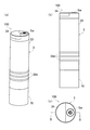
図1,2は、本発明の第1実施形態に係るしみ除去装置100を示す図である。具体的には、図1(a)は、本実施形態のしみ除去装置100を示す斜視図である。図1(b)は、しみ除去装置100を示す側面図である。図1(c)は、しみ除去装置100を示す平面図である。また、図2(a)は、図1(c)に示すしみ除去装置100を切断面線II−IIで切断して示す縦断面図である。図2(b)は、しみ除去装置100の一部分、具体的には係止爪45b2近傍を示す斜視図である。図2(c)は、図2(a)に示すヘッド11および液体用収容部12の一部を拡大して示す縦断面図である。図2(d)は、ヘッド11の底面図である。
1 and 2 are views showing a
図2(a)に示すように、しみ除去装置100は、装置本体3と、カセット機構1と、キャップ部材70と、防水カバー部50とを備える。
As shown in FIG. 2A, the
装置本体3は、カセット機構1を着脱可能に収容するものであり、振動手段31と、バッテリ32と、これらの要素部品が内部に組み込まれた半割り構造のケース本体33とを有する。
The apparatus
振動手段31は、ケース本体33から開口33aを介して突出したカセット機構1を、給電により、ヘッド11の叩き面21aとほぼ直交する方向に振動させるものである。以下、叩き面21aとほぼ直交する方向を振動方向と呼ぶ。また、振動方向のうち、ヘッド11が装置外に突出する方向を突出方向Y1、その逆の方向を戻り方向Y2と呼ぶ。このような振動手段31は、モータ41と、第1〜第3ギア42〜44と、シリンダ45と、コイルバネ46とを有する。
The vibration means 31 vibrates the
モータ41は、電力供給部であるバッテリ32からの給電により回転する駆動ギア41aを備える。
The
第1〜第3ギア42〜44は、モータ41の回転力を伝達するものである。第1ギア42は、モータ41の駆動ギア41aと噛合して軸42cの回りに回転可能な大径部42a及び大径部42aと同軸をなすように一体的に形成された小径部42bを有する。第2ギア43は、第1ギア42と第3ギア44との間に配置され、第1ギア42の小径部42bと噛合して軸43cの回りに回転可能な大径部43a、及び、大径部43aと同軸をなすように一体的に形成されるとともに第3ギア44と噛合する小径部43bを有する。第3ギア44は、第2ギア43の小径部43bと噛合して軸44cの回りに回転可能な大径部44a、及び、大径部44aと同軸をなすように一体的に形成されるとともに、その端面から周方向に等間隔で突出する2つの係合突起44b1を備えた小径部44bを有する。なお、係合突起44b1の数は2つに限定されず、1または3以上であってもよい。
The first to
シリンダ45は、叩き面21aが先端に位置するようにカセット機構1を支持しつつ振動方向に移動可能なものであり、コイルバネ収容部45aと、カセット機構被挿入部45bとを有する。
The
コイルバネ収容部45aは、弾性部材としてのコイルバネ46が振動方向に伸縮可能な状態で収容される有底筒状のものである。
The coil
カセット機構被挿入部45bは、コイルバネ収容部45aの下端部からケース本体33の開口33a近傍まで延びた略円筒状のものである。カセット機構被挿入部45bの側面には、図2(b)に示すシリンダ開口45b´が形成されるとともに、第3ギア44の小径部44bに形成された係合突起44b1と係合可能な図2(a)に示す被係合爪45b1、及び、カセット機構1を係止可能な係止爪45b2が設けられる。係止爪45b2は、図2(b)に示すように、シリンダ開口45b´の縁部から突出方向Y1に向けて延びるとともに、先端部45b3がカセット機構被挿入部45bの中心軸に向けて縦断面略三角形状に突出する。また係止爪45b2は、着脱に伴うカセット機構1からの押圧によって、基端45b4を起点にカセット機構被挿入部45bの外側に向けて弾性変形可能に構成される。このような係止爪45b2は、互いに対向した位置で2箇所に設けられる。
The cassette mechanism inserted
コイルバネ46は、ケース本体33から突出方向Y1にボス状に延びる固定部33bの基端側に一端側が支持されるとともに、他端側がコイルバネ収容部45aに収容される。
One end of the
このようなシリンダ45は、図2(a)に示すように、第3ギア44の係合突起44b1と被係合爪45b1とが係合しない状態では、コイルバネ46がコイルバネ収容部45aの底面45a1に突出方向Y1に向けて弾性力を付与することから、カセット機構1とともに突出方向Y1に押し出される。
As shown in FIG. 2A, such a
一方、第3ギア44の係合突起44b1と被係合爪45b1とが係合する状態では(図4(b)参照)、シリンダ45は、第3ギア44の回転に伴って底面45a1よりコイルバネ46に圧縮力を付与しながら、カセット機構1とともに戻り方向Y2に移動する。その後、係合突起44b1が被係合爪45b1から外れると、シリンダ45及びカセット機構1は、圧縮されたコイルバネ46の弾性によって突出方向Y1へ再度移動する。
On the other hand, in a state where the
このような動作が繰り返されることでカセット機構1、ひいてはヘッド11が振動(振幅運動)する。本実施形態では、前述のように第3ギア44が2つの係合突起44b1を有し、1回転することでヘッド11を2往復させる。
By repeating such an operation, the
図2(a)に示すバッテリ32は、本実施形態では乾電池であり、ケース本体33の一部に形成された開閉蓋34を介して装置本体3内に収容される。開閉蓋34は、ヒンジ34aを介してケース本体33の外側に向けて回動可能に構成される。
A
前記振動手段31によって振動されるカセット機構1は、ヘッド11と、液体用収容部12と、給水路13とを有する。
The
ヘッド11は、叩き部21と、ヘッド挿入部22とを有する。叩き部21は、叩き面21aが形成された縦断面略半円状、より詳細には半円よりもやや円に近い形状の部材であり、叩き面21aからは複数の突起21a1が突出する。各突起21a1は、半球状であり、図2(d)に示すように叩き面21a内で規則的に配置される。
The
ヘッド挿入部22は、図2(c)に示すように、叩き部21から延びて、後述する被挿入部25に抜脱可能に挿入されるものであり、ヘッド挿入部22の側面に、振動方向において互いに離間して形成された複数の円環状の突出部分22aを有する。被挿入部25への挿入時には、突出部分22aが被挿入部25の内面を押圧し、複数回着脱を繰り返しても固定度合が変わることなくヘッド11を安定して固定することができる。
As shown in FIG. 2C, the
なお、本実施形態においてヘッド11は樹脂(例えばナイロン)製であるが、材質は樹脂に限定されず、金属(例えばステンレス鋼(Stainless Used Steel:sus))等であってもよい。
In this embodiment, the
図2(a)に示す液体用収容部12は、液体貯蔵部24と、被挿入部25とを有する。液体貯蔵部24は液体を収容可能な透明または半透明な中空状の部品で、後述するように分解可能に構成される。液体貯蔵部24の側面には、前記係止爪45b2と係止可能な係止凹部12aが設けられる。被挿入部25は、液体貯蔵部24から延び、ヘッド11のヘッド挿入部22が軽い圧入で抜脱可能に挿入される。なお、ヘッド挿入部22は圧入により被挿入部25に挿入される構成に限定されず、ねじ固定により挿入されてもよい。
The
ここで液体としては、水のみ、水および洗剤を一定割合で混合した洗剤混合液、エタノールやベンジン等の一般的な溶剤、又はしみ除去用専用洗剤等を用いることができる。本実施形態では、液体貯蔵部24に収容する液体として水のみを用いており、これによって、後述するように、しみ除去効果に加えてすすぎ効果も発揮することができる。
Here, as the liquid, only water, a detergent mixture obtained by mixing water and a detergent at a certain ratio, a general solvent such as ethanol or benzine, a stain-removing detergent, or the like can be used. In the present embodiment, only water is used as the liquid stored in the
給水路13は、液体用収容部12からヘッド11に亘って形成され、液体用収容部12内の液体をヘッド11の叩き面21aに供給するものであって、図2(c)に示すようにヘッド給水孔27とシリンダ給水孔28とを有する。ヘッド給水孔27は、ヘッド11を貫通して叩き面21aまで延びており、貯水部分27aと拡張部分27bと小径部分27cとで構成される。
The
貯水部分27aは、シリンダ給水孔28と対向してヘッド11の基端11aに開口し、縦断面略長方形でヘッド挿入部22を貫通する。拡張部分27bは、縦断面台形状であり、叩き面21aの中心に向けて拡張しつつ開口した開口端11bを有する。小径部分27cは、貯水部分27aと拡張部分27bとを繋いており、貯水部分27a及び拡張部分27bよりも流路断面が小さく構成される。
The
シリンダ給水孔28は、液体貯蔵部24から被挿入部25を貫通して形成され、ヘッド11の基端11aに向けてテーパ状に開口する。なお、シリンダ給水孔28は、縦断面がテーパ状に限定されずに、始端から終端までが同一径に設定されてもよい。これは後述する他の実施形態でも同様である。
The cylinder
前記液体貯蔵部24内の液体は、シリンダ給水孔28からヘッド11に滴下された後、ヘッド給水孔27を流下して叩き面21aに供給される。
The liquid in the
このようなヘッド11内に形成された給水路13は、振動手段31が振動してカセット機構1が振動している状態で、小径部分27cから液体を安定した流量で少量ずつ(例えば1〜1.5cc/min)拡張部分27bに吐出し、ヘッド11の叩き面21aに液体を供給する。一方、カセット機構1が振動していない状態では、小径部分27cおよびシリンダ給水孔28(特に小径部分27c)において表面張力により液体の滴下が防止される。
The
このように、給水路13は、その流路横断面がヘッド11の振動によって少量の液体が吐出される程度に設計され、スプレー洗浄やブラシ洗浄などの他の洗浄方式よりも液体の使用量が少なくて済むことから、液体の供給が必要ない箇所にまで液体が飛び散りにくくなる。また、給水路13がしみ除去装置100全体に対して限られた一部にのみ配置されていることから、しみ除去装置100全体に亘るように給水路13よりも長く構成された給水路(図示せず)を備えるものに比べて、水アカやカルシウム成分が固まることによる給水路13の詰まりが発生しにくく、しみ除去装置100の煩雑な分解清掃を不要にすることができる。
Thus, the
また、しみ除去装置100は、突出時におけるヘッド11の叩き面21aからケース本体33の開口33aまでの長さβ(図2(a)参照)が、後述するしみ除去作業中にしみ部分が斜め上方から装置本体3に隠れることなく視認可能な長さに設定される。また、後述する防水カバー部50は、この長さβに対応した大きさに設定される。さらに、カセット機構1は、円筒形状のケース本体33に対して偏心して取り付けられており、カセット機構1から最も近い位置にあるケース本体33側面を手前にしてしみ除去作業が行われることで、しみ部分をより確認しやすくすることができる。
Further, in the
前記キャップ部材70は、ケース本体33の端部から着脱可能なものであり、しみ除去装置100を持ち運ぶ際には装置本体3に取り付けられ、後述するしみ除去作業を行う際には図3(a)に示すように装置本体3から取り外される。図3(a)は、しみ除去装置100をキャップ部材70が取り外された状態で示す斜視図である。このようなキャップ部材70により、持ち運び時における装置外への水漏れや、カセット機構1への衝撃等を有効に防ぐことができる。
The
また、図3(b)はしみ除去装置100を防水カバー部50が取り外された状態で示す斜視図であり、防水カバー部50も、図3(b)に示すように、ケース本体33の端部から着脱可能に構成される。なお、防水カバー部50に関する構成については後で詳述する。
FIG. 3B is a perspective view showing the
このようなしみ除去装置100は、図4に示すしみ除去対象物としての衣類Cを部分的に洗浄可能な手持ちサイズの装置である。図4は、しみ除去装置100の使用状態を説明するための縦断面図である。しみ除去作業の際には、衣類Cのしみ部分Spの下方に裏当てとして吸収パッドPが当接されるとともに、しみ除去用の洗剤が衣類Cのしみ部分spに直接塗布される。そして、しみ除去装置100は、ヘッド11の叩き面21aがしみ部分Spと対向する位置において、防水カバー部50の突出端51が衣類Cに押し当てられつつ、ケース本体33の円環状の滑止め部33d近傍を握られた状態で使用される。なお、本実施形態において洗剤は使用されなくてもよい。
Such a
この状態でケース本体33の外側に設けられた電源スイッチSwが操作されると、バッテリ32からの給電によりモータ41が回転し、この回転が第1ギア42および第2ギア43を介して減速されながら第3ギア44に伝達される。係合突起44b1と被係合爪45b1とが係合すると、図4(b)に示すように、シリンダ45とともにカセット機構1が所定寸法δ(本実施形態では約5mm)持ち上げられ、その後、係合突起44b1が被係合爪45b1から外れると、コイルバネ46の弾性によりシリンダ45及びカセット機構1が押し出されて、図4(a)に示すようにヘッド11がしみ部分Spに叩きつけられる。
When the power switch Sw provided outside the
なお、カセット機構1の振動に伴って液体貯蔵部24内で液体と空気が撹拌されるので、液体貯蔵部24内が負圧になることなく、振動開始直後から液体が給水路13を介して徐々に滴下し、叩き面21aからしみ部分Spに供給される。
In addition, since the liquid and air are agitated in the
装置本体3を衣類Cに沿って動かしながらこのような動作が繰り返されると、しみ部分Spに供給された液体(本実施形態では水のみ)は、しみ部分spに塗布された洗剤とともに、しみ部分Spを構成する汚れを溶解しつつ衣類Cから叩き出されて吸収パッドPに吸収される。すなわちしみ除去装置100は、衣類Cの汚れを液体および洗剤とともに吸収パッドPに移すことでしみを除去するものである。
When such an operation is repeated while moving the apparatus
なお、本実施形態では、しみが除去された後も上述の動作をある程度の時間、続けることが有効であり、これによってしみ部分spに残った洗剤を吸収パッドPに移して、すすぎ効果も発揮することができる。 In the present embodiment, it is effective to continue the above-described operation for a certain period of time even after the stain is removed, whereby the detergent remaining in the stain portion sp is transferred to the absorbent pad P and exhibits a rinsing effect. can do.
また、吸収パッドPとしては特に限定されず、液体の吸収速度が速いものであれば種々のものを用いることができ、例えばキッチンペーパーを折りたたんだものを用いることができる。 Moreover, it does not specifically limit as the absorption pad P, A various thing can be used if the absorption speed of a liquid is quick, for example, what folded the kitchen paper can be used.
さらに、しみ除去作業中に吸収パッドPに対するヘッド11の当接位置を定期的に変える作業が行われると、滴下された液体が吸収パッドPに安定して吸収されるので、しみ除去効率の高い状態が維持される。
Further, when the work of periodically changing the contact position of the
以上のような構成のしみ除去装置100は、振動手段31が給電によってカセット機構1を叩き面21aとほぼ直交する方向に振動させ、ヘッド11が衣類Cを叩く動作を自動化できるので、叩き力及び叩き速度が均一になるとともに、手を素早く動かす必要がなく、長時間しみ除去作業を行ったとしても手が疲れないという優れた効果を有する。
In the
また、しみとしては、例えば、衣類Cに塊状に付着して液体と馴染みにくい固形物汚れによるものがあるが、しみ除去装置100は、ヘッド11からの衝撃で固形物汚れを物理的に分解して液体に溶解しやすくすることができる。また、例えば給水路13の流路横断面が適切に設計されることで、振動に伴って適量の液体が衣類Cに向けて継続的に供給され、しみ除去効果を高めることができる。さらに、しみ除去装置100は、振動を利用して液体が滴下する構成なので、例えば液体ポンプを用いて液体を送り出すものよりも構造を簡単かつ小さくすることができる。
Further, as the stain, for example, there is a stain due to solid dirt that adheres to the clothing C in a lump and is not easily compatible with the liquid, but the
したがって、本実施形態のしみ除去装置100は、コンパクトで携帯性が良好なものであり、外出先で食べこぼしや化粧品等が布製品に付着したときに部分的な洗浄に利用することで、しみを目立たなくさせることができる。また、カーテンやマット等、丸洗いが容易でないものを部分的に好適に洗浄することができる。さらに、洗濯機を利用した洗濯の前段階で、しみ除去装置100を用いて衣類Cの襟や袖等の汚れを予備的に洗うことにも好適に利用できる。
Therefore, the
また、前述のように、給水路13は、液体用収容部12からヘッド11を貫通して叩き面21aまで延びるとともに、当該叩き面21aへの開口端11b(図2(c)参照)が拡張したものである。そのため、しみ部分spを構成する固形物汚れがヘッド11からの衝撃で物理的に分解された後、液体に溶解することなく給水路13に進入したとしても、開口端11bが拡張しているので給水路13が固形物汚れによって塞がりにくく、また固形物汚れが詰まったとしても容易に取り除くことができる。
Further, as described above, the
図4に示すように、前記防水カバー部50は、アクリル製で非可撓性かつ略円錐形状(突出端51の円周が基端51´の円周よりも大きい形状)の透明部材であり、ヘッド11の側方を囲む位置において、リブ33a1を介してケース本体33の開口33a近傍に着脱可能に取り付けられる。振動手段31によって突出方向Y1に突出するヘッド11は、そのストロークが調整されることで、一方の動作端が防水カバー部50の突出端51よりもわずかに突出可能な位置に設定される。具体的には、突出位置にあるヘッド11の叩き面21aから防水カバー部50の突出端51までの振動方向における距離t(図4(a)参照)が所定距離(この実施形態では1〜2mm程度)となるように設定される。
As shown in FIG. 4, the
このような防水カバー部50を備えることで、しみ除去作業中に、防水カバー部50がヘッド11の振動により飛び散った液体を遮断して広範囲に液体が広がることを防止するので、衣類Cが濡れる面積を小さくすることができ、しみ除去作業後すぐに衣類Cを着用することが可能となる。また、しみ除去作業中、装置本体3から衣類Cまでの距離を常に一定に保つことができ、ヘッド11が衣類Cに与える外力(叩き力)を適切かつ均一にすることができる。また、ヘッド11の一方の動作端が防水カバー部50の突出端51よりもわずかに突出可能な位置に設定されるとともに、ヘッド11がコイルバネ46の弾性によって突出時に衣類Cを押さえつけるので、手を使ってしみ部分Spを叩く(押さえる)動作を模擬した動作を自動で実現することができる。さらに、防水カバー部50が透明であることから、しみ部分の汚れ落ちの状態がしみ除去作業中に防水カバー部50を介して確認可能となる。
By providing such a
なお、防水カバー部50の形状は略円錐形状に限定されず、例えば円筒形状であってもよい。
The shape of the
ところで、カセット機構1は、前述のように係止爪45b2(図2(b)参照)を介して装置本体3から着脱可能である(ボトルカセット方式)。
By the way, the
具体的には、図5に示すように、防水カバー部50が装置本体3から取り外されたうえで、被挿入部25又はその近傍が掴まれて一定以上の力で引っ張られることで、液体貯蔵部24の係止凹部12aから係止爪45b2の先端部45b3に引っ張り力が伝わり、これによって係止爪45b2が基端45b4を起点にカセット機構被挿入部45bの外側へ一時的に弾性変形して、カセット機構1が装置本体3から抜き取られる。なお、図5は、しみ除去装置100をカセット機構1が取り外された状態で示す縦断面図である。
Specifically, as shown in FIG. 5, the
一方、上記と逆の動作、具体的にはカセット機構1がカセット機構被挿入部45bに一定以上の力で差し込まれることで、液体貯蔵部24の端面24´から係止爪45b2の先端部45b3に差し込み力が伝わり、これによって係止爪45b2が基端45b4を起点にカセット機構被挿入部45bの外側へ弾性変形する。この状態からカセット機構1がさらに差し込まれると、係止爪45b2が液体貯蔵部24の係止凹部12aと対向する位置で弾性復元し、係止凹部12aと係止爪45b2とが係止して抜け止めされ、カセット機構1が装置本体3に取り付けられる。
On the other hand, when the
このようにカセット機構1が着脱であることから、例えば、液体用収容部12にそれぞれ異なる種類の液体が収容されたカセット機構1を複数用意しておくことで、しみ部分spの状態に適した液体を収容したカセット機構1を装置本体3に取り付けることもでき、しみ部分spの状態に応じて液体の種類を変更することができるので、しみ除去効果を高めることができる。
Since the
図6(a),(b)は、装置本体3から取り外した状態でのカセット機構1を示す斜視図である。カセット機構1の液体貯蔵部24は、図6(a)に示すように、収容部本体24aと蓋部材24bとに分解可能に構成される。収容部本体24aは、内部に液体収容空間Sが形成された有底略円筒状部材であり、軸線方向における一部分が径方向に小さく構成され、これにより前記係止凹部12aが形成される。蓋部材24bは、収容部本体24aの開口側に設けられ、ねじ固定により収容部本体24aに取り付けられるものであり、液体収容空間Sを開閉する。また、ヘッド11は、被挿入部25から着脱可能、すなわちカセット機構1から着脱可能に構成される。
6A and 6B are perspective views showing the
このように3分割可能な構成であることで、収容部本体24aから蓋部材24bを取り外して、液体収容空間Sに液体を補給したり、液体用収容部12内の液体を別の種類の液体(例えばエタノールやベンジン等の一般的な溶剤)に簡単に交換することができ、しみ除去装置100を何度も繰り返して使用することができる。このとき、液体用収容部12が装置本体3から取り外された状態で液体の補給や交換等を行うことができるので、補給時に装置本体3が液体で濡れることがなく、装置本体3に防水処理を施す必要がない。また、収容部本体24aと蓋部材24bとに分解して液体用収容部12の内部を清掃することができ、水アカやカルシウム成分等を簡単に除去できる。さらに、しみ部分spの状態等に応じて最適な形状のヘッド11および液体を選択して使用することが可能になるとともに、ヘッド11自体を新しいものに変更でき、しみ除去効果を向上させることができる。
Thus, by being able to divide into three parts, the
さらに、このような液体用収容部12が前述のように透明または半透明であることから、しみ除去作業の途中などにカセット機構1を一旦取り出して、液体用収容部12内の液体の残量を確認することができ、利便性が向上する。
Further, since the
図6(c)は、上記第1実施形態の変形例を示す縦断面図である。具体的に、図6(c)は、変形例であるしみ除去装置110を構成するカセット機構10の一部、すなわち液体用収容部212の一部およびヘッド5を示す縦断面図である。しみ除去装置110は、液体がヘッド5の内部を流下して叩き面21aに到達するのではなく、中実なヘッド5の周囲を伝って叩き面21aに到達するように構成されており、給水路6の構成が第1実施形態と異なる。以下、後述する構成以外は第1実施形態と同様であるため、説明を省略する。
FIG. 6C is a longitudinal sectional view showing a modification of the first embodiment. Specifically, FIG. 6C is a longitudinal sectional view showing a part of the
しみ除去装置110において、給水路6は、シリンダ給水孔28と、給水溝6aと、被挿入部25とで構成される。
In the
給水溝6aは、ヘッド5のヘッド挿入部52の外周に形成されており、軸方向に延びる所定深さ(この実施形態では0.1〜0.3mm程度)のスリットとして間欠的に形成される。液体貯蔵部24(図5等参照)内の液体は、シリンダ給水孔28を介してヘッド5の基端5aに供給され、振動手段31(図5等参照)が振動してヘッド5が振動している状態では、被挿入部25とシリンダ挿入部52との隙間である吐出口6bから少量ずつ(例えば1〜1.5cc/min)叩き部21に吐出され、叩き面21aに到達する。
The
一方、ヘッド5が振動していない状態では、液体は表面張力により給水溝6aと被挿入部25との間に留まり、吐出が防止される。
On the other hand, in a state where the
このように、液体の吐出口6bがヘッド5の叩き面21aではなくヘッド5の周囲に開口し、液体がヘッド5の周囲に供給されるので、しみ部分Spを構成する固形物汚れが叩き面21aに付着したとしても給水路6が塞がらず、しみ除去効果を安定して維持することができる。なお、給水溝6aはヘッド挿入部52でなく被挿入部52に形成されてもよい。
As described above, the
<第2実施形態>
図7は、本発明の第2実施形態であるしみ除去装置120を構成するカセット機構20の一部、具体的には液体用収容部7の一部およびヘッド8を示す斜視図である。図7(a)は、ヘッド8が液体用収容部7に挿入される前のカセット機構20を示し、図7(b)は、ヘッド8が液体用収容部7に挿入された後のカセット機構20を示す。本実施形態のしみ除去装置120は、液体の滴下量を調整可能な液体量調整部9を備える点が第1実施形態と異なる。以下、後述する構成以外は第1実施形態と同様であるため、説明を省略する。なお、説明を容易にするため、液体用収容部7の液体貯蔵部71が分解可能な構成については図示を省略しているが、液体貯蔵部71は、内部に液体収容空間が形成された収容部本体と、液体収容空間を開閉する蓋部材とに分解可能なものである。
Second Embodiment
FIG. 7 is a perspective view showing a part of the
図7に示す液体量調整部9は、液体用収容部7およびヘッド8によって構成される。液体用収容部7は、液体貯蔵部71と被挿入部72とが仕切部分73を介して隣接するとともに、仕切部分73の縁部に等間隔で形成された第1〜第3供給領域73a〜73cを有する。これら供給領域73a〜73cは、仕切部分73を貫通する供給孔73xがそれぞれ異なる数だけ形成され、本実施形態では第1供給領域73aで1つ、第2供給領域73bで3つ、第3供給領域73cで5つの供給孔73xが形成される。なお、供給孔73xの数はこれに限定されるものではない。また、ヘッド8は、ヘッド挿入部8aの端部に切欠き8bが形成されるとともに、ヘッド挿入部8aの側部に切欠き8bから叩き部21に延びる複数の給水溝8cを備える。
The liquid
図8は、図7(b)に示すヘッド8を供給孔73xとともに模式的に示す図である。図8において切欠き8bには斜線を入れて示す。図8に示すように切欠き8bは1つの供給領域73a(73b,73c)に対応する範囲に亘ってヘッド挿入部8aに形成される。図7に示す液体貯蔵部71内の液体は、切欠き8bが対向する何れかの供給領域73a(73b,73c)に形成された供給孔73xから切欠き8bに流れ込み、給水溝8cの吐出口6bを通って叩き部21の周囲に滴下される。そのため、切欠き8bが対向する供給領域73a(73b,73c)に応じて液体の滴下量が変化し、切欠き8bが第1供給領域73aと対向する図8(a)に示す状態、切欠き8bが第2供給領域73bと対向する図8(b)に示す状態、切欠き8bが第3供給領域73cと対向する図8(c)に示す状態の順に液体の滴下量が多くなる。
FIG. 8 is a diagram schematically showing the
このように本実施形態のしみ除去装置120は、給水路6´が供給孔73xと切欠き8bと給水溝8cと被挿入部72とで構成される。そして、振動手段31(図5等参照)による振動を利用して給水溝8cと被挿入部72との隙間である吐出口6bから液体を滴下させるものであり、液体の滴下量を調整可能な図7に示す液体量調整部9を備える。
As described above, in the
給水溝6aの溝深さ等に対する設定だけでは液体の滴下が過多になり、その結果輪じみを生じてしまう場合があるが、液体量調整部9を利用することで衣類Cに向けて液体を過不足なく滴下させることができる。そのため、しみ除去装置120は、液体の供給不足によるしみ除去効果の低下を防止できるとともに、しみ部分Spに多量の液体が一気に供給されることによる輪じみの発生を防止することができる。
If only the setting for the groove depth or the like of the
なお、液体量調整部9としては、液体の滴下量を調整可能な構成であれば前述した構成に限定されない。また、液体量調整部9の構成は、他の実施形態のしみ除去装置100,110に適用されてもよい。また、本実施形態では給水溝8cがヘッド挿入部8aに形成されるが、被挿入部72に形成されてもよい。
The liquid
<第3実施形態>
図9は、本発明の第3実施形態であるしみ除去ユニット130を示す縦断面図である。図10は、図9に示すしみ除去ユニット130を構成する加熱装置101を分解して示す分解図である。図9に示す本実施形態のしみ除去ユニット130は、第1実施形態のしみ除去装置100と加熱装置101とで構成される。
<Third Embodiment>
FIG. 9 is a longitudinal sectional view showing a
図10に示すように、加熱装置101は、吸収パッドセット部材(吸収パッドセット用蓋)103と、本体カバー105と、化粧板107と、加熱板109と、第1断熱材111と、ヒータ113と、第2断熱材115と、加熱装置本体117とを有する。
As shown in FIG. 10, the
吸収パッドセット部材103及び本体カバー105は、中央にそれぞれ開口部103a,105aが形成された平面視円形のものである。吸収パッドセット部材103は、その一面103bと本体カバー105の一面105bとの間に吸収パッドPを挟み込んだ状態で回転させ、互いのねじ部同士105c,103cを係り合わせて本体カバー105に取り付けられる。化粧板107は、中央部107aと端部107bとに段差を有し、加熱装置101内に組み込まれた状態では、中央部107aの隆起面107abが開口部105aから露出して本体カバー105の一面105bと略平行になり、端部107bが本体カバー105の他面105dと加熱装置本体117との間に挟み込まれる。化粧板107は例えばステンレス鋼で構成される。このような化粧板107の端部107bおよび本体カバー105には、後述する安全スイッチ117dが貫通する貫通孔107c,105eがそれぞれ形成される。
The absorbent pad set
加熱板109は、化粧板107の中央部にはめこまれるように配置され、しみ除去装置100のヘッド11から外力が付与される被叩き面109aが化粧板107と対向して形成されるものであり、例えば熱伝導率の高いアルミニウムで構成される。加熱板109の厚さは約1〜2mmに設定される。これによって強度および高い熱伝導性を両立できるので、吸収パッドPに素早くかつ均一にヒータ113からの熱を伝えることができるとともに、しみ除去作業中にヘッド11から外力が付与されることによる吸収パッドPの変形を抑制して高いしみ除去効率を維持することができる。
The
第1断熱材111は、加熱板109の裏側に配置された温度調整用の断熱材であり、例えばシリコンゴムで構成される。第2断熱材115は、加熱装置本体117上に配置されてヒータ113の熱を遮断するものであり、例えばガラスウールで構成される。これらの断熱材の間に配置されるヒータ113としては例えばセラミックヒータが用いられる。なお、加熱板109をコーティングして見た目を良好にすることで、化粧板107を用いない構成とすることも可能である。
The 1st
加熱装置本体117は、電源コード117aと、ヒータ113への給電状態を切り替え可能なメインスイッチ117bと、ヒータ113の温度に応じてヒータ113への給電状態を調整可能なサーモスタット117cと、安全スイッチ117dとを有する。サーモスタット117cは、上限温度(例えば70℃)に達するとヒータ113への給電を停止させてヒータ113を冷まし、下限温度(例えば60℃)まで低下すると再びヒータ113に給電を開始させる。安全スイッチ117dは、前記貫通孔107c,105eを介して本体カバー105部の一面105bから突出するものであり、所定位置に装着された吸収パッドPによって押し付けられている場合はヒータ113への給電を可能とする一方、押し付けられていない場合はヒータ113への給電を停止するように構成される。すなわち加熱装置101は、吸収パッドPが本体カバー105の所定位置にセットされるとともに吸収パッドセット部材103が閉止されることで使用可能となる。
The heating device
このような構成の加熱装置101は、メインスイッチ117bが操作されるとヒータ113が発熱し、その熱が加熱板109に伝わって吸収パッドPの温度を上昇させる。そのため、加熱装置101上に衣類Cが載置されると、加温された吸収パッドPにしみ部分Spが対向する状態で、しみ除去装置100のヘッド11より被叩き面109aに叩き力を付与する動作を行うことができる。したがって、本実施形態のしみ除去ユニット130は、しみ部分Spを50℃程度に継続的に加温して、汚れが液体に一層溶けやすい状態でしみ除去作業を行うことができるので、しみ除去効果をより向上させることができる。また、しみ除去のために強い漂白剤を用いる必要がないので、衣類Cの色落ちを防止することができる。
In the
なお、本実施形態では、加熱装置101は第1実施形態のしみ除去装置100と組み合わせて使用されるが、前述した第2実施形態のしみ除去装置120や変形例のしみ除去装置110など他の構成のしみ除去装置と組み合わせて使用されてもよい。
In this embodiment, the
また、本実施形態では、加熱装置101は平面視円形状であるが、平面視矩形状であってもよい。この場合、吸収パッドセット部材の一辺が加熱装置の他の構成要素(本体カバー、化粧板、加熱板、第1断熱材、ヒータ、第2断熱材、加熱装置本体)とヒンジ等を介して接続された構成とし、加熱装置101の他の構成要素に対して吸収パッドセット部材を吸収パッドを挟んで折りたたみ可能に構成することが好適である。
In the present embodiment, the
以上、本発明の一実施形態について説明したが、各部の具体的な構成は、上述した実施形態のみに限定されるものではない。 As mentioned above, although one Embodiment of this invention was described, the specific structure of each part is not limited only to embodiment mentioned above.
例えば、上記実施形態のしみ除去装置100〜120は、ヘッド11の叩き面21aを下方に向けて使用するものであるが、叩き面21aを横に向けて使用可能な構成としてもよい。この場合、例えば液体がポンプで送り出される構成にする。
For example, the
また、上記実施形態においてヘッド5,8,11(図1,6,7等参照)の叩き面21aには突起21a1が形成されているが、突起21a1が形成されずに、叩き面21aが平らであってもよい。
Further, in the above embodiment, the protrusion 21a1 is formed on the hitting
また、図2等に示す防水カバー部50は、ヒータが内蔵された構成であってもよい。この場合、ヒータとしては、巻回されたニクロム線やセラミックヒータによって構成された環状形状のものを用いることが好ましく、電力供給部を介した給電によって発熱するものとする。なお、ヒータへの供給電力は例えば5W程度であり、発熱時のヒータの温度は80℃〜100℃程度に設定される。
Moreover, the
このような防水カバー部50を備える構成であれば、除去作業を行う際に衣類Cに押し当てられる防水カバー部50がヒータの熱で加熱される構成であるため、図9に示す加熱装置101を別途用いなくても、しみ除去作業中に常時、防水カバー部50を介して衣類Cのしみ部分spおよびその近傍を温めることができ、コンパクト化を実現しつつしみ除去効果をより向上させることが可能となる。
If the
さらに、しみ除去装置駆動時の騒音を抑制するためには、ケース本体33の全体又はほぼ全体を二重構造とし、このようなケース本体33中に振動手段31等の構成要素を組み込んだ構成とすることも有効である。また、ケース本体33が二重構造であることで、ケース内側に固定されたネジ等の固定部材をケース外側で隠すことができ、しみ除去装置100〜120のデザイン性を向上させることができる。
Further, in order to suppress noise when the stain removing device is driven, the entire case
またさらに、上記実施形態では電力供給手段としてバッテリ32を用いるが、これに限定されず、USBケーブルと接続可能なUSBコネクタを有する構成や、プラグを有する電源コードを備える構成等にして、外部電源から電力を供給可能な構成としてもよい。これにより、装置本体3内にバッテリ32を組み込む必要がなく、装置本体3をよりコンパクトにすることが可能となる。
Furthermore, in the above embodiment, the
また、上記実施形態において、ヘッド5,8,11は液体用収容部7,12,212から抜脱可能な構成であるが、抜脱できない構成であってもよい。
In the above embodiment, the
また、上記実施形態では、液体として洗剤混合液が用いられてもよく、この場合、しみ除去作業中に洗剤が衣類Cのしみ部分spに継続的に供給されるので、洗剤が気化や飛散等によりしみ部分spからなくなることがなく、高いしみ除去効果が維持される。また、しみ部分spに洗剤を供給するための手段が別途に設けられる必要がなく、装置構成が簡単になる。 In the above embodiment, a detergent mixture may be used as the liquid. In this case, since the detergent is continuously supplied to the spot portion sp of the clothing C during the stain removal operation, the detergent is vaporized, scattered, etc. Thus, the stain portion sp is not lost, and a high stain removal effect is maintained. Further, it is not necessary to separately provide a means for supplying the detergent to the spot portion sp, and the apparatus configuration is simplified.
また、上記実施形態ではシリンダ給水孔28を介して液体貯蔵部24とヘッド11の基端11a(図2参照)とが接続されているが、シリンダ給水孔28を介することなく液体貯蔵部24とヘッド11とが直接接続されて、液体が液体貯蔵部24からヘッド11にダイレクトで供給される構成であってもよい。
Moreover, in the said embodiment, although the
さらに、カセット機構1,10,20の少なくとも一部が使い捨ての構成(予め液体が液体用収容部7,12,212に収容されていて補給できない構成)であってもよい。
Furthermore, at least a part of the
またさらに、上記しみ除去装置100〜120及び加熱装置101を構成する部材の材質は、各図面のハッチングが示すものに限定されるものではない。
Furthermore, the materials of the members constituting the
その他の構成も、本発明の趣旨を逸脱しない範囲で種々変形が可能である。 Other configurations can be variously modified without departing from the spirit of the present invention.
1,10,20・・・カセット機構
3・・・装置本体
5,8,11・・・ヘッド
6,6´,13・・・給水路
7,12,212・・・液体用収容部
11b・・・開口端
21a・・・叩き面
24a・・・収容部本体
24b・・・蓋部材
31・・・振動手段
41・・・モータ
46・・・弾性部材(コイルバネ)
50・・・防水カバー部
51・・・突出端
100,110,120・・・しみ除去装置
101・・・加熱装置
109・・・加熱板
109a・・・被叩き面
113・・・ヒータ
130・・・しみ除去ユニット
S・・・液体収容空間
1, 10, 20 ...
41 ...
50 ...
Claims (6)
前記カセット機構を着脱可能に収容するとともに、当該カセット機構を給電によるモータの回転動作で持ち上げ、バネの弾性で押し出す動作を繰り返すことにより前記ヘッドの叩き面とほぼ直交する方向に振動させる振動手段を有する装置本体とを備え、
前記振動手段が前記カセット機構を振動させる際のバネの弾性による押し出しに伴って、前記液体用収容部の液体を前記給水路を介して前記ヘッドから供給することを特徴とするしみ除去装置。 A cassette mechanism having a head formed with a striking surface, a liquid storage section for storing liquid, and a water supply channel formed from the liquid storage section to the head;
Vibrating means that detachably accommodates the cassette mechanism and vibrates in a direction substantially perpendicular to the hitting surface of the head by repeating the operation of lifting the cassette mechanism by a rotating operation of a motor by feeding power and pushing it out by the elasticity of a spring. An apparatus main body having
The vibration means is accompanied by the extrusion of the elastic spring when vibrating the cassette mechanism, stain removing device and supplying the liquid in the liquid storing portion from the head through the water supply path.
前記振動手段は、前記叩き面とほぼ直交する方向に伸縮可能な弾性部材を有し、この弾性部材の弾性力により前記ヘッドを突出させるものであり、
前記ヘッドの一方の動作端が、前記防水カバー部の突出端よりもわずかに突出可能な位置に設定される請求項1又は2記載のしみ除去装置。 The apparatus main body further includes a non-flexible waterproof cover portion surrounding a side of the head;
The vibration means has an elastic member that can expand and contract in a direction substantially orthogonal to the hitting surface, and causes the head to protrude by the elastic force of the elastic member,
The stain removing apparatus according to claim 1 or 2, wherein one operating end of the head is set at a position that can slightly protrude from the protruding end of the waterproof cover portion.
給電により発熱するヒータ、および、前記しみ除去装置を構成するヘッドから外力が付与される被叩き面が形成され、前記ヒータで発生した熱が伝わる加熱板を少なくとも備える加熱装置とを有することを特徴とするしみ除去ユニット。 The stain removing apparatus according to claim 1 or 2,
A heater that generates heat by power feeding, and a heating device that includes at least a heating plate on which a hit surface to which an external force is applied from a head that constitutes the stain removal device is formed, and to which heat generated by the heater is transmitted. A stain removal unit.
Priority Applications (6)
| Application Number | Priority Date | Filing Date | Title |
|---|---|---|---|
| JP2014191463A JP6469399B2 (en) | 2014-09-19 | 2014-09-19 | Stain removal apparatus and stain removal unit |
| PCT/CN2015/079047 WO2016041371A1 (en) | 2014-09-19 | 2015-05-15 | Dirt removing device and dirt removing unit |
| US15/512,045 US20170275807A1 (en) | 2014-09-19 | 2015-05-15 | Dirt removing device and dirt removing unit |
| CN201580000159.6A CN104995346B (en) | 2014-09-19 | 2015-05-15 | Greasiness removal device and greasiness removal unit |
| EP15841918.4A EP3196348B1 (en) | 2014-09-19 | 2015-05-15 | Dirt removing device and dirt removing unit |
| KR1020177010669A KR20170055546A (en) | 2014-09-19 | 2015-05-15 | Dirt Removing Device And Dirt Removing Unit |
Applications Claiming Priority (1)
| Application Number | Priority Date | Filing Date | Title |
|---|---|---|---|
| JP2014191463A JP6469399B2 (en) | 2014-09-19 | 2014-09-19 | Stain removal apparatus and stain removal unit |
Publications (2)
| Publication Number | Publication Date |
|---|---|
| JP2016059687A JP2016059687A (en) | 2016-04-25 |
| JP6469399B2 true JP6469399B2 (en) | 2019-02-13 |
Family
ID=55532525
Family Applications (1)
| Application Number | Title | Priority Date | Filing Date |
|---|---|---|---|
| JP2014191463A Active JP6469399B2 (en) | 2014-09-19 | 2014-09-19 | Stain removal apparatus and stain removal unit |
Country Status (5)
| Country | Link |
|---|---|
| US (1) | US20170275807A1 (en) |
| EP (1) | EP3196348B1 (en) |
| JP (1) | JP6469399B2 (en) |
| KR (1) | KR20170055546A (en) |
| WO (1) | WO2016041371A1 (en) |
Families Citing this family (4)
| Publication number | Priority date | Publication date | Assignee | Title |
|---|---|---|---|---|
| JP2017104268A (en) * | 2015-12-09 | 2017-06-15 | 青島海爾洗衣机有限公司QingDao Haier Washing Machine Co.,Ltd. | Stain removing device |
| EP3488940A4 (en) * | 2016-07-19 | 2020-03-04 | Sharp Kabushiki Kaisha | Cleaning device |
| WO2018083096A1 (en) | 2016-11-01 | 2018-05-11 | Koninklijke Philips N.V. | Portable stain removal device |
| US20180171521A1 (en) * | 2016-12-19 | 2018-06-21 | John Mahdessian | Green rejuvenation system and kit |
Family Cites Families (11)
| Publication number | Priority date | Publication date | Assignee | Title |
|---|---|---|---|---|
| US2987906A (en) * | 1958-08-26 | 1961-06-13 | William N Bourland | Device for removing stains from fabric |
| US5402657A (en) * | 1993-08-02 | 1995-04-04 | Technical Advantage | Device for removing stains from fabric |
| ES2243322T3 (en) * | 1999-11-16 | 2005-12-01 | THE PROCTER & GAMBLE COMPANY | ULTRASONIC INSTRUMENT. |
| JP2001310165A (en) * | 2000-04-28 | 2001-11-06 | Kao Corp | Ultrasonic washing apparatus |
| JP2002035485A (en) * | 2000-07-25 | 2002-02-05 | Kao Corp | Ultrasonic cleaning device |
| WO2002049497A2 (en) * | 2000-12-21 | 2002-06-27 | The Procter & Gamble Company | A motorized hand-held scrubbing and dispensing device and a method of use therefor |
| JP3768978B2 (en) * | 2003-06-16 | 2006-04-19 | 株式会社クマザキエイム | Ultrasonic cleaner |
| US7794415B2 (en) * | 2004-07-13 | 2010-09-14 | S.C. Johnson & Son, Inc. | Surface treatment device |
| CN201040803Y (en) * | 2007-04-05 | 2008-03-26 | 陆新进 | Portable washing machine |
| US8468635B2 (en) * | 2009-11-25 | 2013-06-25 | Church & Dwight Co., Inc. | Surface treating device |
| CN103485116B (en) * | 2013-06-24 | 2016-05-25 | 无锡小天鹅股份有限公司 | Washing machine and local greasiness removal device thereof |
-
2014
- 2014-09-19 JP JP2014191463A patent/JP6469399B2/en active Active
-
2015
- 2015-05-15 WO PCT/CN2015/079047 patent/WO2016041371A1/en active Application Filing
- 2015-05-15 EP EP15841918.4A patent/EP3196348B1/en active Active
- 2015-05-15 US US15/512,045 patent/US20170275807A1/en not_active Abandoned
- 2015-05-15 KR KR1020177010669A patent/KR20170055546A/en not_active Application Discontinuation
Also Published As
| Publication number | Publication date |
|---|---|
| US20170275807A1 (en) | 2017-09-28 |
| KR20170055546A (en) | 2017-05-19 |
| WO2016041371A1 (en) | 2016-03-24 |
| JP2016059687A (en) | 2016-04-25 |
| EP3196348A1 (en) | 2017-07-26 |
| EP3196348B1 (en) | 2023-04-26 |
| EP3196348A4 (en) | 2018-05-02 |
Similar Documents
| Publication | Publication Date | Title |
|---|---|---|
| JP6469399B2 (en) | Stain removal apparatus and stain removal unit | |
| WO2016037446A1 (en) | Stain removing device and stain removing unit | |
| WO2015161818A1 (en) | Stain removal apparatus and stain removal unit | |
| JP6023910B2 (en) | Stain remover | |
| KR101078567B1 (en) | Skin washing machine | |
| CN104981564B (en) | Greasiness removal device and greasiness removal unit | |
| CN104995346B (en) | Greasiness removal device and greasiness removal unit | |
| KR20080094091A (en) | Hand-operated device and tools which can be connected to it | |
| CN104981565B (en) | Greasiness removal device and greasiness removal unit | |
| US20170268154A1 (en) | Stain removing device and stain removing unit | |
| CN107923098A (en) | Portable washing unit | |
| JPH11323723A (en) | Stain remover | |
| JP2017018329A (en) | Stain removal device | |
| JP2017104268A (en) | Stain removing device | |
| JP2019088361A (en) | Partial washing device | |
| JP6366991B2 (en) | Beauty Equipment | |
| JP3189015U (en) | Satsuma | |
| JP2017205448A (en) | Application device of cleaning liquid agent for clothes | |
| JP2005237466A (en) | Oscillating cleaning device | |
| KR20170032580A (en) | Cleansing apparatus with steam towel |
Legal Events
| Date | Code | Title | Description |
|---|---|---|---|
| A621 | Written request for application examination |
Free format text: JAPANESE INTERMEDIATE CODE: A621 Effective date: 20170831 |
|
| A977 | Report on retrieval |
Free format text: JAPANESE INTERMEDIATE CODE: A971007 Effective date: 20180621 |
|
| A131 | Notification of reasons for refusal |
Free format text: JAPANESE INTERMEDIATE CODE: A131 Effective date: 20180703 |
|
| A521 | Request for written amendment filed |
Free format text: JAPANESE INTERMEDIATE CODE: A523 Effective date: 20180824 |
|
| TRDD | Decision of grant or rejection written | ||
| A01 | Written decision to grant a patent or to grant a registration (utility model) |
Free format text: JAPANESE INTERMEDIATE CODE: A01 Effective date: 20190115 |
|
| A61 | First payment of annual fees (during grant procedure) |
Free format text: JAPANESE INTERMEDIATE CODE: A61 Effective date: 20190116 |
|
| R150 | Certificate of patent or registration of utility model |
Ref document number: 6469399 Country of ref document: JP Free format text: JAPANESE INTERMEDIATE CODE: R150 |
|
| R250 | Receipt of annual fees |
Free format text: JAPANESE INTERMEDIATE CODE: R250 |
|
| R250 | Receipt of annual fees |
Free format text: JAPANESE INTERMEDIATE CODE: R250 |
|
| R250 | Receipt of annual fees |
Free format text: JAPANESE INTERMEDIATE CODE: R250 |