EP3196348B1 - Dirt removing device and dirt removing unit - Google Patents
Dirt removing device and dirt removing unit Download PDFInfo
- Publication number
- EP3196348B1 EP3196348B1 EP15841918.4A EP15841918A EP3196348B1 EP 3196348 B1 EP3196348 B1 EP 3196348B1 EP 15841918 A EP15841918 A EP 15841918A EP 3196348 B1 EP3196348 B1 EP 3196348B1
- Authority
- EP
- European Patent Office
- Prior art keywords
- head
- dirt removing
- dirt
- liquid
- cassette mechanism
- Prior art date
- Legal status (The legal status is an assumption and is not a legal conclusion. Google has not performed a legal analysis and makes no representation as to the accuracy of the status listed.)
- Active
Links
- XLYOFNOQVPJJNP-UHFFFAOYSA-N water Substances O XLYOFNOQVPJJNP-UHFFFAOYSA-N 0.000 claims description 66
- 230000007246 mechanism Effects 0.000 claims description 65
- 238000010009 beating Methods 0.000 claims description 64
- 238000010438 heat treatment Methods 0.000 claims description 37
- 239000004744 fabric Substances 0.000 claims description 30
- 210000000078 claw Anatomy 0.000 claims description 23
- 230000009471 action Effects 0.000 claims description 12
- 238000005406 washing Methods 0.000 claims description 12
- 239000007788 liquid Substances 0.000 description 148
- 239000003599 detergent Substances 0.000 description 19
- 238000003780 insertion Methods 0.000 description 17
- 230000037431 insertion Effects 0.000 description 17
- 230000000694 effects Effects 0.000 description 16
- 239000007787 solid Substances 0.000 description 14
- 239000011810 insulating material Substances 0.000 description 8
- 210000000476 body water Anatomy 0.000 description 5
- 239000002689 soil Substances 0.000 description 5
- LFQSCWFLJHTTHZ-UHFFFAOYSA-N Ethanol Chemical compound CCO LFQSCWFLJHTTHZ-UHFFFAOYSA-N 0.000 description 4
- 238000007599 discharging Methods 0.000 description 4
- OYPRJOBELJOOCE-UHFFFAOYSA-N Calcium Chemical compound [Ca] OYPRJOBELJOOCE-UHFFFAOYSA-N 0.000 description 3
- 229910052791 calcium Inorganic materials 0.000 description 3
- 239000011575 calcium Substances 0.000 description 3
- 239000000463 material Substances 0.000 description 3
- 238000000034 method Methods 0.000 description 3
- 238000000926 separation method Methods 0.000 description 3
- 239000000919 ceramic Substances 0.000 description 2
- 239000000470 constituent Substances 0.000 description 2
- 238000011109 contamination Methods 0.000 description 2
- 206010016256 fatigue Diseases 0.000 description 2
- 239000000203 mixture Substances 0.000 description 2
- 230000000149 penetrating effect Effects 0.000 description 2
- 230000008569 process Effects 0.000 description 2
- 229920005989 resin Polymers 0.000 description 2
- 239000011347 resin Substances 0.000 description 2
- 239000002904 solvent Substances 0.000 description 2
- 239000004677 Nylon Substances 0.000 description 1
- 229910000831 Steel Inorganic materials 0.000 description 1
- 239000000956 alloy Substances 0.000 description 1
- 229910045601 alloy Inorganic materials 0.000 description 1
- 229910052782 aluminium Inorganic materials 0.000 description 1
- XAGFODPZIPBFFR-UHFFFAOYSA-N aluminium Chemical compound [Al] XAGFODPZIPBFFR-UHFFFAOYSA-N 0.000 description 1
- 239000007844 bleaching agent Substances 0.000 description 1
- 230000001680 brushing effect Effects 0.000 description 1
- 230000015556 catabolic process Effects 0.000 description 1
- 230000008859 change Effects 0.000 description 1
- 238000005345 coagulation Methods 0.000 description 1
- 230000015271 coagulation Effects 0.000 description 1
- 239000011248 coating agent Substances 0.000 description 1
- 238000000576 coating method Methods 0.000 description 1
- 230000006835 compression Effects 0.000 description 1
- 238000007906 compression Methods 0.000 description 1
- 239000002537 cosmetic Substances 0.000 description 1
- 238000000354 decomposition reaction Methods 0.000 description 1
- 238000005202 decontamination Methods 0.000 description 1
- 230000003588 decontaminative effect Effects 0.000 description 1
- 238000006731 degradation reaction Methods 0.000 description 1
- 230000001419 dependent effect Effects 0.000 description 1
- 238000010586 diagram Methods 0.000 description 1
- 238000009792 diffusion process Methods 0.000 description 1
- 238000002845 discoloration Methods 0.000 description 1
- 238000005516 engineering process Methods 0.000 description 1
- 239000010794 food waste Substances 0.000 description 1
- 239000011491 glass wool Substances 0.000 description 1
- 230000012447 hatching Effects 0.000 description 1
- 230000020169 heat generation Effects 0.000 description 1
- 229910052751 metal Inorganic materials 0.000 description 1
- 239000002184 metal Substances 0.000 description 1
- 150000002739 metals Chemical class 0.000 description 1
- 229920001778 nylon Polymers 0.000 description 1
- QQONPFPTGQHPMA-UHFFFAOYSA-N propylene Natural products CC=C QQONPFPTGQHPMA-UHFFFAOYSA-N 0.000 description 1
- 125000004805 propylene group Chemical group [H]C([H])([H])C([H])([*:1])C([H])([H])[*:2] 0.000 description 1
- 229920002379 silicone rubber Polymers 0.000 description 1
- 239000004945 silicone rubber Substances 0.000 description 1
- 239000007921 spray Substances 0.000 description 1
- 239000010935 stainless steel Substances 0.000 description 1
- 229910001220 stainless steel Inorganic materials 0.000 description 1
- 239000010959 steel Substances 0.000 description 1
- 230000003867 tiredness Effects 0.000 description 1
- 208000016255 tiredness Diseases 0.000 description 1
- 238000009834 vaporization Methods 0.000 description 1
- 230000008016 vaporization Effects 0.000 description 1
- 238000004078 waterproofing Methods 0.000 description 1
Images


Classifications
-
- D—TEXTILES; PAPER
- D06—TREATMENT OF TEXTILES OR THE LIKE; LAUNDERING; FLEXIBLE MATERIALS NOT OTHERWISE PROVIDED FOR
- D06F—LAUNDERING, DRYING, IRONING, PRESSING OR FOLDING TEXTILE ARTICLES
- D06F43/00—Dry-cleaning apparatus or methods using volatile solvents
- D06F43/002—Spotting apparatus
-
- A—HUMAN NECESSITIES
- A47—FURNITURE; DOMESTIC ARTICLES OR APPLIANCES; COFFEE MILLS; SPICE MILLS; SUCTION CLEANERS IN GENERAL
- A47L—DOMESTIC WASHING OR CLEANING; SUCTION CLEANERS IN GENERAL
- A47L11/00—Machines for cleaning floors, carpets, furniture, walls, or wall coverings
- A47L11/29—Floor-scrubbing machines characterised by means for taking-up dirty liquid
- A47L11/30—Floor-scrubbing machines characterised by means for taking-up dirty liquid by suction
-
- A—HUMAN NECESSITIES
- A47—FURNITURE; DOMESTIC ARTICLES OR APPLIANCES; COFFEE MILLS; SPICE MILLS; SUCTION CLEANERS IN GENERAL
- A47L—DOMESTIC WASHING OR CLEANING; SUCTION CLEANERS IN GENERAL
- A47L11/00—Machines for cleaning floors, carpets, furniture, walls, or wall coverings
- A47L11/38—Machines, specially adapted for cleaning walls, ceilings, roofs, or the like
-
- A—HUMAN NECESSITIES
- A47—FURNITURE; DOMESTIC ARTICLES OR APPLIANCES; COFFEE MILLS; SPICE MILLS; SUCTION CLEANERS IN GENERAL
- A47L—DOMESTIC WASHING OR CLEANING; SUCTION CLEANERS IN GENERAL
- A47L11/00—Machines for cleaning floors, carpets, furniture, walls, or wall coverings
- A47L11/40—Parts or details of machines not provided for in groups A47L11/02 - A47L11/38, or not restricted to one of these groups, e.g. handles, arrangements of switches, skirts, buffers, levers
- A47L11/4063—Driving means; Transmission means therefor
- A47L11/4069—Driving or transmission means for the cleaning tools
-
- A—HUMAN NECESSITIES
- A47—FURNITURE; DOMESTIC ARTICLES OR APPLIANCES; COFFEE MILLS; SPICE MILLS; SUCTION CLEANERS IN GENERAL
- A47L—DOMESTIC WASHING OR CLEANING; SUCTION CLEANERS IN GENERAL
- A47L25/00—Domestic cleaning devices not provided for in other groups of this subclass
-
- A—HUMAN NECESSITIES
- A47—FURNITURE; DOMESTIC ARTICLES OR APPLIANCES; COFFEE MILLS; SPICE MILLS; SUCTION CLEANERS IN GENERAL
- A47L—DOMESTIC WASHING OR CLEANING; SUCTION CLEANERS IN GENERAL
- A47L25/00—Domestic cleaning devices not provided for in other groups of this subclass
- A47L25/08—Pads or the like for cleaning clothes
-
- D—TEXTILES; PAPER
- D06—TREATMENT OF TEXTILES OR THE LIKE; LAUNDERING; FLEXIBLE MATERIALS NOT OTHERWISE PROVIDED FOR
- D06F—LAUNDERING, DRYING, IRONING, PRESSING OR FOLDING TEXTILE ARTICLES
- D06F7/00—Washing devices adapted to be used independently of any particular receptacle, e.g. for removable mounting on wash-tubs, bath-tubs, or the like
- D06F7/04—Washing devices adapted to be used independently of any particular receptacle, e.g. for removable mounting on wash-tubs, bath-tubs, or the like of the vibrator type
-
- E—FIXED CONSTRUCTIONS
- E01—CONSTRUCTION OF ROADS, RAILWAYS, OR BRIDGES
- E01H—STREET CLEANING; CLEANING OF PERMANENT WAYS; CLEANING BEACHES; DISPERSING OR PREVENTING FOG IN GENERAL CLEANING STREET OR RAILWAY FURNITURE OR TUNNEL WALLS
- E01H1/00—Removing undesirable matter from roads or like surfaces, with or without moistening of the surface
- E01H1/10—Hydraulically loosening or dislodging undesirable matter; Raking or scraping apparatus ; Removing liquids or semi-liquids e.g., absorbing water, sliding-off mud
- E01H1/101—Hydraulic loosening or dislodging, combined or not with mechanical loosening or dislodging, e.g. road washing machines with brushes or wipers
- E01H1/103—Hydraulic loosening or dislodging, combined or not with mechanical loosening or dislodging, e.g. road washing machines with brushes or wipers in which the soiled loosening or washing liquid is removed, e.g. by suction
Definitions
- the present disclosure relates to a dirt removing device and a dirt removing unit, which are capable of beating and washing a local part of a cloth product, providing liquid to a dirt portion on the cloth product and exerting a beating force automatically, and can also replace the used liquid.
- Non-Patent Document 1 An apparatus for locally washing the cloth product can be exemplified by a dirt removing system of Non-Patent Document 1.
- the dirt removing system of Non-Patent Document 1 is composed of a bottle body for containing a detergent and an absorbing sheet, and a fine hole for providing the detergent is formed at a top end of the bottle body.
- the dirt removing system is capable of beating the dirt part through the top end of the bottle body with the absorbing sheet abutting a downward portion, so as to provide the detergent to the dirt part through the beating actions.
- the provided detergent soaks into the cloth product, and is absorbed into the absorbing sheet together with the feculence constituting the dirt portion.
- WO 01/36116 A1 PROCTER & GAMBLE [US]; BODET JEAN FRANCOIS [US]; SCHEPER WILLIAM MICHA 25 May 2001 (2001-05-25) which relates to an ultrasonic implement
- the invention relates to a hand-held implement (1) having an active part (15) vibrating at a frequency of at least 20 kHz with an amplitude of at least 10 mu m and up to 100 mu m, characterized in that the implement (1) has at least two configurations, a first configuration where the active part (15) is hard, and a second configuration where the active part (15) is not hard.
- Non-Patent Document 1 Network ⁇ URL: http: //www.1ion.co.jp/ja/seihin/brand/025/ 06.htm>
- Non-Patent Document 1 has a problem that a beating force and a beating speed are unstable and the degree of decontamination is different or the hand fatigue is caused, since dirt removing actions are performed with a hand holding the bottle body moving up and down.
- the detergent in the bottle body cannot be replaced, it is not possible to use detergents depending on the type or the state of the dirt such as oil contamination or water contamination. Therefore, sometimes it is difficult to remove the dirt.
- the present disclosure aims to effectively solve such problems, that is, aims to provide a dirt removing device and a dirt removing system which can prevent the hand from tiredness, and can perform a dirt removing operation always with a stable beating force and beating speed.
- the device further can use different kinds of detergent according to the type and state of the dirt.
- the head is detachable from the cassette mechanism, and the liquid accommodating portion is composed of an accommodating portion body having a liquid accommodating space therein and a cover member for opening and closing the liquid accommodating space.
- the liquid accommodating portion is transparent or translucent.
- the water supplying passage is started from the liquid accommodating portion, penetrates into the entire head and extends to the beating surface, and expands toward an open end opening to the beating surface.
- the device body further has a non-flexible waterproof cover surrounding a side surface of the head;
- the vibration unit has an elastic member capable of extending and contracting in a direction substantially orthogonal with the beating surface, and the head is protruded by an elastic force of the elastic member; and an action end at a side of the head is set at a position slightly protruding from a protruding end of the waterproof cover.
- the dirt removing unit of the present disclosure includes the above dirt removing device; and a heating device.
- the heating device includes at least a heater that generates heat by power supply and a heating plate that forms a knocked surface, a force is exerted to which by the head constituting the dirt removing device, and conveys a heat generated by the heater.
- the vibration unit causes, by means of supplying power, the cassette mechanism to vibrate in the direction substantially orthogonal with the beating face of the head, the head can automatically perform an action of beating the dirt and removing objects.
- the beating force and the beating speed are homogeneous and the hands are required to move quickly, the hands will not be tired even if the dirt removing operation is performed for a long time.
- the cassette mechanism can be attached and detached from the device body, it is possible to install, on the device body, a cassette mechanism accommodating a liquid corresponding to the state of the dirt, and to change the type of the liquid according to the state of the dirt portion, by means of, for example, preparing in advance a plurality of cassette mechanisms each accommodating a different kind of liquid, respectively, in the liquid accommodating portion, thereby improving the effect of removing dirt.
- the head potion is detachable from the cassette mechanism, and the liquid accommodating portion is composed of an accommodating portion body and a cover member.
- the liquid can be supplied to the liquid accommodating space or the liquid in the liquid accommodating portion can be easily replaced with other kind of liquid, by means of removing the cover member form the accommodating portion body, so that the dirt removing device can be repeatedly used multiple times.
- the liquid supplying, replacement and the like can be performed in a state in which the liquid accommodating portion is removed from the device body, the device body will not be wetted by the liquid when supplying liquid and the device body is not required to be subjected to a waterproof treatment.
- the inside of the liquid accommodating portion can be cleaned by disassembling the liquid accommodating portion into the accommodating portion body and the cover member, thereby easily removing the incrustation, the calcium component, and the like. Further, the dirt removing effect can be further improved, since the most suitable head and liquid can be selected to use according to the state of the dirt portion.
- the cassette mechanism can be temporarily removed so as to confirm the remaining amount of the liquid in the liquid accommodating portion during the process of the dirt removing operation, thereby improving the convenience.
- the water supplying passage in which an open end of the water supplying passage is expanded, even if the solid soil constituting the dirt portion is physically decomposed due to the impact from the head, the decomposed solid soil does not dissolve into the liquid and penetrates into the water supplying passage, the water supplying passage is difficulty to be blocked by the solid soil, since the open end expands. In addition, even if the water supplying passage is blocked and full of solid soil, it is easy to remove the solid soil.
- the waterproof cover can block the liquid from spattering so as to prevent large-scale diffusion of the liquid, and always keep a distance from the device body to the clothe is constant in the dirt removing operation, so that a force (beating force) applied by the head to a dirt removing object is appropriate and uniform.
- a force (beating force) applied by the head to a dirt removing object is appropriate and uniform.
- the head presses against the dirt removing object due to the elasticity of an elastic member when the elastic member is protruding it is possible to automatically simulate the action of beating (pressing) the dirt portion by hands.
- the dirt portion of the dirt removing object can be continuously heated by the heat from the heater and the dirt removing operation can be performed, the dirt is more likely soluble in liquid, thereby further improving the dirt removing effect.
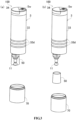
- Figs. 1 and 2 are views showing a dirt removing device 100 according to embodiment I of the present disclosure.
- Fig. 1(A) is a perspective view showing the dirt removing device 100 according to the present embodiment.
- Fig. 1(B) is a side view showing the dirt removing device 100.
- Fig. 1(C) is a top view showing the dirt removing device 100.
- Fig. 2(A) is a longitudinal section view of the dirt removing device 100 along a section line II-II in Fig. 1(C) .
- Fig. 2(B) is a perspective view showing a part of the dirt removing device 100, that is, a part in the vicinity of an engaging claw 45b2.
- Fig. 2(C) is an enlarged longitudinal section view showing a part of a liquid accommodating portion 12 and a head 11 shown in Fig. 2(A).
- Fig. 2(D) is a bottom view of the head 11.
- the dirt removing device 100 includes: a device body 3, a cassette mechanism 1, a cover member 70 and a waterproof cover 50.
- the cassette mechanism 1 is detachably received in the device body 3.
- the device body 3 includes a vibration unit 31, a battery 32 and a housing body 33 having a dimidiate structure in which these components are mounted.
- the vibration unit 31 is a member that causes, while being powered, the cassette mechanism 1, which protrudes from the housing body 33 through an opening 33a, to vibrate in a direction substantially orthogonal with a beating face 21a of the head 11.
- the direction substantially orthogonal with the beating surface 21a is referred to as a vibration direction.
- a direction in which the head 11 protrudes outward the device is referred to as a protruding direction Y1, and the opposite direction is referred to as a return direction Y2.
- the vibration unit 31 has a motor 41, first to third gears 42 ⁇ 44, a cylinder body 45, and a coil spring 46.
- the motor 41 has a driving gear 41a powered by a power supplying portion (namely the battery 32) so as to rotate.
- the first gear 42 includes a large diameter portion 42a which is engaged with the driving gear 41a of the motor 41 and is rotatable about a shaft 42c, and a small diameter portion 42b formed integrally with the large diameter portion 42a and coaxially arranged with the large diameter portion 42a.
- the second gear 43 is disposed between the first gear 42 and the third gear 44.
- the second gear 43 has a large diameter portion 43a which is engaged with the small diameter portion 42b of the first gear 42 and is rotatable about a shaft 43c, and a small diameter portion 43b, which is formed integrally with and coaxially arranged with the large diameter portion 43a and is engaged with the third gear 44.
- the third gear 44 includes a large diameter portion 44a which is engaged with the small diameter portion 43b of the second gear 43 and is rotatable about a shaft 44c, and a small diameter portion 44b.
- the small diameter portion 44b is formed integrally with and coaxially arranged with the large diameter portion 44a, and includes two engaging projections 44b1 protruding from an end face of the small diameter portion 44b in a circumferential direction at equal intervals.
- the number of the engaging projections 44b1 is not limited to two, but may be one or three or more.
- the cylinder body 45 is a member that supports the cassette mechanism 1 in a manner that the beating surface 21a is located at a top end of the cylinder body 45, and is capable of moving in the vibration direction.
- the cylinder body 45 has a coil spring receiving portion 45a and a cassette mechanism inserted portion 45b.
- the coil spring receiving portion 45a is a cylinder member having a bottom surface, in which the coil spring 46 served as an elastic member is received in a manner of being stretchable in the vibration direction.
- the cassette mechanism inserted portion 45b is a substantially cylindrical member extending from a lower end of the coil spring receiving portion 45a to the vicinity of the opening 33a of the housing body 33.
- a cylinder opening 45b' shown in Fig. 2 (B) is formed in a side surface of the cassette mechanism inserted portion 45b.
- the side surface of the cassette mechanism inserted portion 45b is further formed with an engaged claw 45b1 as shown in Fig. 2(A) and an engaging claw 45b2.
- the engaged claw 45b1 is capable of being engaged with the engaging projection 44b1 formed at the small diameter portion 44b of the third gear 44.
- the engaging claw 45b2 is capable of being engaged with the cassette mechanism 1. As shown in Fig.
- the engaging claw 45b2 extends from an edge of the cylinder opening 45b' toward the protruding direction Y1, and a top end 45b3 protrudes to a center axis of the cassette mechanism inserted portion 45b and has a substantially triangular longitudinal section.
- the engaging claw 45b2 is configured to be elastically deformed toward the outside of the cassette mechanism inserted portion 45b with a base end 45b4 as a starting point, along with the pressing of the cassette mechanism 1.
- Such engaging claws 45b2 are provided at two positions opposed to each other.
- One end of the coil spring 46 is supported by a base end of a fixing portion 33b extending in a convex shape from the housing body 33 in the protruding direction Y1, and the other end is received by the coil spring receiving portion 45a.
- the cylinder body 45 exerts a compression force on the coil spring 46 via the bottom surface 45a1 and moves in the return direction Y2 together with the cassette mechanism 1. Then, when the engaging projection 44b1 is disengaged from the engaged claw 45b1, the cylinder body 45 and the cassette mechanism 1 move in the protruding direction Y1 again by means of the elastic force of the compressed coil spring 46.
- the cassette mechanism 1 and the head 11 are enabled to vibrate (an amplitude vibration movement) by repeating such operations.
- the third gear 44 has two engaging projections 44b1 as described above, and the head 11 is caused to shuttle twice through one rotation of the third gear 44.
- the battery 32 shown in Fig. 2 (A) is a dry battery in the present embodiment, and is received in the device body 3 via an opening and closing cover 34 formed at a part of the housing body 33.
- the opening and closing cover 34 is configured to be rotatable toward the outside of the housing body 33 via a pin 34a.
- the cassette mechanism 1 vibrated by the vibration unit 31 has the head 11, the liquid accommodating portion 12, and a water supplying passage 13.
- the head 11 has a beating portion 21 and a head insertion portion 22.
- the beating portion 21 is a member formed with the beating surface 21a, and has a substantially semicircular longitudinal section, more specifically approximately circular longitudinal section).
- a plurality of projections 21a1 protrude from the beating surface 21a.
- Each of the projections 21a1 is hemispherical, and is regularly arranged in the beating surface 21a as shown in Fig. 2 (D) .
- the head insertion portion 22 is a member extending from the beating portion 21 and pluggably inserting into an inserted portion 25 that will be described below.
- a side surface of the head insertion portion 22 is provided with a plurality of annular protrusions 22a which are formed in the vibrating direction and spaced apart from each other.
- the protrusions 22a press against an inner surface of the inserted portion 25. Therefore, the head 11 can be stably fixed with a constant degree even if the head insertion portion 22 has been repeatedly loaded or unloaded for lots of times.
- the head 11 is made of resins such as nylon, but the material of the head 11 is not limited to the resins, it may be metals such as stainless used steel (SUS), etc.
- the liquid accommodating portion 12 shown in Fig. 2 (a) has a liquid storage portion 24 and the inserted portion 25.
- the liquid storage portion 24 is a transparent or translucent hollow member capable of accommodating the liquid, and is configured to be capable of being decomposed as will be described later.
- An engaging recess 12a engageable with the engaging claw 45b2 is provided on a side surface of the liquid storage portion 24.
- the inserted portion 25 extends from the liquid storage portion 24, and the head insertion portion 22 of the head 11 is pluggably inserted into the inserted portion 25 by lightly pressing.
- the head insertion portion 22 is not limited to the structure in which the head insertion portion 22 is inserted into the inserted portion 25 by pressing.
- the head insertion portion 22 may be inserted into the inserted portion 25 by being fixed by a screw.
- the liquid herein may be water, a detergent mixture of water and detergent mixed with a certain ratio, a common solvent such as ethanol or gasoline, or a special detergent for removing dirt, and the like.
- the liquid accommodated in the liquid storage portion 24 can only be water. As a result, a rinsing effect can be exerted in addition to the dirt removal effect, as will be described later.
- the water supplying passage 13 is formed from the liquid accommodating portion 12 and throughout the head 11, and supplies the liquid in the liquid accommodating portion 12 to the beating surface 21a of the head 11. As shown in Fig. 2(C) , the water supplying passage 13 includes a head water supplying hole 27 and a cylinder body water supplying hole 28.
- the head water supplying hole 27 extends through the head 11 to the beating surface 21a, and is composed of a water storage portion 27a, an expansion portion 27b, and a small diameter portion 27c.
- the water storage portion 27a is opposed to the cylinder body water supplying hole 28, opens at a base end 11a of the head 11.
- the water storage portion 27a penetrates the head insertion portion 22, and the longitudinal section thereof is substantially a rectangle.
- the expansion portion 27b a longitudinal section of which is frustum-shaped, and has an open end 11b which expands and opens toward the center of the beating surface 21a.
- the small diameter portion 27c is configured to connect the water storage portion 27a and the expansion portion 27b. A profile of a flow path of the small diameter portion 27c is smaller than that of the water storage portion 27a and that of the expansion portion 27b.
- the cylinder body water supplying hole 28 is formed from the liquid storage portion 24 through the inserted portion 25, and opens in a tapered shape toward the base end 11a of the head 11.
- the longitudinal section of the cylinder body water supplying hole 28 is not limited to the tapered shape, and may be arranged to have a same diameter from the start to the end. This is also true in other embodiments described later.
- the liquid in the liquid storage portion 24 drips from the cylinder body supplying hole 28 to the head 11, and is supplied to the beating surface 21a through the head water supplying hole 27.
- the liquid is discharged to the expansion portion 27b from the small diameter portion 27c little by little (such as 1-1.5 cc/min) with a stable flow rate, so as to supply the liquid to the beating face 21a of the head 11.
- the cassette mechanism 1 does not vibrate, the liquid is prevented from dripping by a surface tension in the small diameter portion 27c and the cylinder body water supplying hole 28 (particularly the small diameter portion 27c).
- the cross-section of the flow path of the water supplying passage 13 is designed to discharge a small amount of liquid through the vibration of the head 11, thus less liquid is used to complete the washing compared with other washing methods such as spray washing, brushing and the like. Therefore, the liquid is hard to spatter to locations where the liquid is not needed.
- the water supplying passage 13 is disposed only at a limited portion relative to the whole dirt removing device 100. Therefore, the clogging of the water supplying passage 13 caused by the incrustation and the coagulation of the calcium component is hard to happen, compared with a structure having a water supplying passage (not shown) longer than the water supplying passage 13 so as to extend throughout the entire dirt removing device 100. As a result, it is not necessary to carry out a complicated decomposition to clean of the dirt removing device 100.
- a length ⁇ (referring to Fig. 2 (A) ) of the dirt removing device 100 from the beating face 21a of the head 11 when protruding to the opening 33a of the housing body 33 is set to be a length that the dirt portion is visible to obliquely upper side without being shielded by the device body 3 in a dirt removing operation described later.
- the waterproof cover 50 described later is set to have a size corresponding to the length ⁇ .
- the cassette mechanism 1 is mounted to be eccentric with respect to the cylindrical housing body 33, and the dirt removing operation is performed by bringing the side surface of the housing body 33 closest to the cassette mechanism 1 closer to the eye, so that it is easier to confirm the dirt portion.
- the cover member 70 is a member that can be attached and detached from an end of the housing body 33, which is attached to the device body 3 when the dirt removing device 100 is carried, and is removed from the device body 3 when performing the dirt removing operation described later as shown in Fig. 3(A).
- Fig. 3(A) is a perspective view showing the dirt removing device 100 with the cover member 70 being removed. With such a cover member 70, the dirt removing device 100 is effectively prevented from leaking water from the device while being carried, impact on the cassette mechanism 1 and the like.
- Fig. 3(B) is a perspective view showing the dirt removing device 100 with the waterproof cover 50 being removed. Also as shown in Fig. 3(B) , the waterproof cover 50 is configured to be detachable from the end of the housing body 33. In addition, the related structure of the waterproof cover 50 will be described later in detail.
- Such dirt removing device 100 is a handheld device that can locally wash a cloth C as the dirt removing object shown in Fig. 4.
- Fig. 4 is a longitudinal section view illustrating a use state of the dirt removing device.
- an absorbing pad P served as a pad abuts the bottom of the dirt portion Sp of the cloth C, and coats a detergent for removing dirt to the dirt portion Sp of the cloth C directly.
- a protruding end 51 of the waterproof cover 50 presses the cloth C at a position, opposed to the dirt portion Sp, of the beating face 21a of the head 11.
- the dirt removing device 100 is used with a region around an annular anti-slip portion 33d of the housing body 33 being held.
- the detergent may not be used in the present embodiment.
- the motor 41 is powered by the battery 32 to rotate, and the rotation is transmitted to the third gear 44 through the first gear 42 and the second gear 43 after being decelerated.
- a power switch Sw provided on the outside of the housing body 33
- the motor 41 is powered by the battery 32 to rotate, and the rotation is transmitted to the third gear 44 through the first gear 42 and the second gear 43 after being decelerated.
- a specified size ⁇ about 5mm in the present embodiment.
- the engaging projection 44b1 is disengaged from the engaged claw 45b1
- the cylinder body 45 and the cassette mechanism 1 are ejected by the elastic force of the coil spring 46, as shown in Fig. 4(A) , the head 11 beats the dirt portion Sp.
- the liquid and air in the liquid storage portion 24 are whisked, therefore, a negative pressure will not generated in the liquid storage portion 24.
- the liquid gradually drops through the water supplying passage 13 immediately after the vibration is started and is supplied to the dirt portion Sp via the beating surface 2 1a.
- the dirt removing device 100 is device that removes the dirt by transferring the feculence of the cloth C together with the liquid and the detergent to the absorbing pad P.
- the absorbing pad P is not particularly limited, and a variety of articles can be used as the absorbing pad P as long as the liquid can be absorbed at a high speed, for example, a product generated by folding a kitchen paper towel.
- such dirt removing device 100 Since the vibration unit 31, while being powered, causes the cassette mechanism 1 to vibrate in the direction substantially orthogonal with the beating surface 21a, the head 11 can automatically perform the action of beating the cloth C. Therefore, such dirt removing device 100 has the following excellent effects: having uniform beating force and beating speed, and it is not required to move the hands quickly, thus the user will not fatigue even if the dirt removing operation is performed for a long time.
- the dirt may be for example a solid feculence in block which is adhered to the cloth C and difficult to be dissolved in the liquid
- the dirt removing device 100 can physically decompose the solid feculence by the impact from the head 11 so that the solid feculence is easily dissolved in the liquid.
- an appropriate amount of liquid is continuously supplied to the cloth C along with the vibration, and the dirt removing effect is improved.
- the dirt removing device 100 is of a structure in which the liquid drops by vibration, the structure is simplified and the size is reduced compared with a device, for example, in which a liquid pump is employed to supply the liquid.
- the dirt removing device 100 of the present embodiment is a small and portable device. Therefore, in the case that food residue, cosmetic or the like is adhered to the cloth when going out, it is enable to make the dirt not obvious by means of local washing.
- the dirt removing device 100 can locally and properly wash goods that are difficult to overall wash, such as curtains, carpet, etc. Further, the dirt removing device 100 can pre-wash the feculence at a collar, cuffs, etc. of the cloth C in an early stage of washing performed by a washing machine.
- the water supplying passage 13 extends from the liquid accommodating portion 12 to the beating face 21a and passes through the head 11, and expands to the open end 11b (as shown in Fig. 2(C) ) opening to the beating face 21a.
- the water supplying passage 13 is hard to be blocked by the solid feculence, since the open end 11b expands.
- the water supplying passage 13 is blocked full of solid feculence, it is easy to remove solid feculence.
- the waterproof cover 50 is a transparent non-flexible member made of propylene and has a substantially conical shape (that is, a shape in which the circumference of the protruding end 51 is larger than the circumference of a base end 51').
- the waterproof cover 50 is detachably mounted around the opening 33a of the housing body 33 at a position on a side surface encircling the head 11via a rib 33a1.
- the head 11 protruding towards the protruding direction Y1 by the vibration unit 31 adjusts the course thereof, so that an action end of one side is arranged at a position slightly protruding from the protruding end 51 of the waterproof cover 50.
- a distance t (referring to Fig. 4 (A) ) in the vibration direction from the beating surface 21a of the head at the protruding position to the protruding end 51 of the waterproof cover 50 is set to be a prescribed distance (about 1 to 2 mm in the present embodiment).
- the waterproof cover 50 shields the liquid scattered by the vibration of the head 11, so as to prevent the liquid from diffusing in a wide range. Therefore, the area where the cloth C is soaked is reduced, thus the cloth C can be wore immediately after the dirt removing operations.
- a distance between the device body 3 and the cloth C can be kept constant, so that the external force (beating force) exerted on the cloth C by the head 11 is appropriate and uniform.
- the action end at a side of the head 11 is arranged at a position slightly protruding from the protruding end of the waterproof cover 50, and the head 11 presses against the cloth C due to the elasticity of the elastic member when protruding, thus it is possible to automatically simulate the action of beating (pressing) the dirt portion Sp by hands.
- the waterproof cover 50 is transparent, it is possible to confirm the removing state of the dirt portion via the waterproof cover 50 during the dirt removing process.
- the shape of the waterproof cover 50 is not limited to a substantially conical shape, but may be, for example, a cylindrical shape.
- the cassette mechanism 1 is detachable to the device body 3 via the engaging claw 45b2 (referring to Fig. 2 (B) ) (bottle cassette type).
- Fig. 5 is a longitudinal section view showing the same dirt removing device with the cassette mechanism 1 being removed.
- the cassette mechanism 1 by inserting the cassette mechanism 1 into the cassette mechanism inserted portion 45b with a certain force, the insertion force is transmitted to the top end 45b3 of the engaging claw 45b2 from an end face 24' of the liquid storage portion 24, and the engaging claw 45b2 is elastically deformed toward the outside of the cassette mechanism inserted portion 45b with the base end 45b4 as a starting point.
- the engaging claw 45b2 is elastically recovered at a position opposed to the engaging recess 12a of the liquid storage portion 24, and the engaging recess 12a is engaged with the engaging claw 45b2 to prevent from detaching, so that the cassette mechanism 1 is mounted on the device body 3.
- a cassette mechanism 1 containing liquid corresponding to the state of the dirt portion Sp can be mounted on the device body 3 by preparing, for example, a plurality of cassette mechanisms 1 in advance, each having a liquid accommodating portion 12 containing a different kind of liquid respectively. Therefore, the type of the liquid can be replaced according to the state of the dirt portion Sp, thereby improving the dirt removing effect.
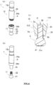
- Fig. 6 (A) and 6 (B) are perspective views showing the cassette mechanism 1 when being detachd from the device body 3.
- the liquid storage portion 24 of the cassette mechanism 1 is disassembly composed of an accommodating portion body 24a and a cover member 24b.
- the accommodating portion body 24a is a substantially cylindrical member having a liquid accommodating space S formed therein and has a bottom.
- the accommodating portion body 24a is arranged in a manner that a part of the accommodating portion body 24a in an axial direction is reduced in a radial direction, thereby forming the engaging recess portion 12a.
- the cover member 24b is a member provided at an opening side of the accommodating portion body 24a, and is fixed and mounted on the accommodating portion body 24a by means of a screw.
- the cover member 24b is configured to open and close the liquid accommodating space S.
- the head 11 is configured to be detachable to the inserted portion 25, that is, the head 11 can be attached and detached to the cassette mechanism 1.
- the cover member 24b can be detached from the accommodating portion body 24a so as to supply the liquid to the liquid accommodating space S, or replace the liquid in the liquid accommodating portion 12 with another kind of liquid (For example, ordinary solvents such as ethanol and gasoline) easily. Therefore, the dirt removing device 100 can be used repeatedly. At this time, since the liquid supplying or replacement can be performed when the liquid accommodating portion 12 is detached from the device body 3, the device body 3 will not be wetted by the liquid when the liquid accommodating portion 12 is supplied. Therefore, it is not necessary to perform waterproofing treatment on the device body 3.
- the liquid storage portion 24 can be disassembled into the accommodating portion body 24a and the cover member 24b so as to clean the inside of the liquid accommodating portion 12, and the incrustation or calcium component can be easily removed.
- the head 11 having the best shape and the best liquid can be selected for use according to the state of the dirt portion Sp and the like, and the head 11 itself can be replaced with a new one, thereby improving the dirt removing effect.
- the cassette mechanism 1 can be temporarily detached during the dirt removing operation so as to confirm the remaining amount of the liquid in the liquid accommodating portion 12, thereby improving the convenience.
- Fig. 6 (C) is a longitudinal section view showing a modified embodiment of embodiment I.
- Fig. 6 (C) is a longitudinal section view showing a part of the cassette mechanism 10 constituting the modified embodiment (that is, the dirt removing device 110), that is, a part of a liquid accommodating portion 212, and a head 5.
- the dirt removing device 110 is configured in a manner that the liquid flows to the periphery of the solid head 5 and reaches the beating surface 21a rather than flowing inside the head 5 and reaching the beating surface 21a. That is, the structure of a water supplying passage 6 is different from that of the first embodiment.
- the modified embodiment is the same as the first embodiment except for the structure described later, and the description of the same structure will be omitted.
- the water supplying passage 6 is composed of a cylinder water supplying hole 28, a water supplying groove 6a, and an inserted portion 25.
- the water supplying groove 6a is formed on the outer circumference of a head insertion portion 52 of the head 5, and is intermittently formed in a manner of slits extending in the axial direction by a prescribed depth (about 0.1 ⁇ 0.3mm in the present embodiment).
- the liquid in the liquid storage portion 24 (as shown in Fig. 5 ) is supplied to a base end 5a of the head 5 via the cylinder water supplying hole 28.
- the liquid is slightly discharged to the beating portion 21 little by little (for example, 1 ⁇ 1.5cc/min) from the gap (that is, a discharging port 6b) between the inserted portion 25 and the cylinder body insertion portion 52 to the beating surface 21a and reaches the beating surface 21a.
- the liquid remains between the inserted portion 25 and the water supplying groove 6a and is prevented from dripping due to a surface tension.
- the discharging port 6b for the liquid is opened at the periphery of the head 5 rather than the beating surface 21a of the head, thus the liquid is supplied to the periphery of the head 5. Therefore, the water supplying passage 6 will not be blocked even if the solid feculence constituting the dirt portion Sp is attached to the beating surface 21a, thereby stably maintaining the dirt removing effect.
- the water supplying groove 6a may be formed on the inserted portion 25 rather than in the head insertion portion 52.
- Fig. 7 shows a part of a cassette mechanism 20 that constitutes embodiment II (that is, a dirt removing device 120) of the present disclosure.
- Fig. 7 is a perspective view showing a part of a liquid accommodating portion 7 and a head 8.
- Fig. 7(A) shows the cassette mechanism 20 before the head 8 is inserted into the liquid accommodating portion 7.
- Fig. 7(B) shows the cassette mechanism 20 after the head 8 is inserted into the liquid accommodating portion 7.
- the dirt removing device 120 of the present embodiment is different from embodiment I in that the dirt removing device 120 has a liquid amount adjustment portion 9 for adjusting the drop amount of the liquid.
- embodiment II is the same as embodiment I except for the structure described later, and the description of the same structure will be omitted.
- the liquid storage portion 71 of the liquid accommodating portion 7 has a decomposable structure
- the liquid storage portion 71 is of a structure that can be disassembled into an accommodating portion body having a liquid accommodating space therein and a cover member for opening and closing the liquid accommodating space.
- the liquid amount adjustment portion 9 shown in Fig. 7 is composed of the liquid accommodating portion 7 and the head 8.
- the liquid storage portion 71 of the liquid accommodating portion 7 adjoins an inserted portion 72 via a separation portion 73, and there is first to third supplying regions 73a ⁇ 73c formed at equal intervals in an edge portion of the separation portion 73.
- Each of these supplying regions 73a ⁇ 73c is provided with a different number of supplying holes 73x penetrating through the separation portion 73.
- the first supplying region 73a is provided with one supplying hole 73x
- the second supplying region 73b is provided with three supplying holes 73x
- the third supplying region 73c is provided with five supplying holes 73x.
- the number of the supplying holes 73x is not limited thereto.
- the head 8 has a notch 8b at an end of the head insertion portion 8a, and a plurality of water supplying grooves 8c extending from the notch 8b to the beating portion 21 are provided in a side portion of the head insertion portion 8a.
- Fig. 8 is a schematic diagram showing the head 8 and the supplying holes 73x shown in Fig. 7 (B) . Slashes are added at the notch 8b in Fig. 8 .
- the notch 8b is formed on the head insertion portion 8a in a range corresponding to one supplying region 73a (73b, 73c).
- the liquid in the liquid storage portion 71 shown in Fig. 7 flows into the notch 8b from the supplying holes 73x formed in any one of the supplying regions 73a (73b, 73c) in alignment with the notch 8b, and drops to the periphery beating portion 21 through the discharging port 6b of the water supplying groove 8c.
- the drop amount of the liquid varies depending on the supplying region 73a (73b, 73c) in alignment with the notch 8b, and the drop amount of the liquid increases in the following order: a state shown in Fig. 8(A) where the notch 8b is in alignment with the first supplying region 73a, a state shown in Fig. 8(B) where the notch 8b is in alignment with the second supplying region 73b and a state shown in Fig. 8(C) where the notch 8b is in alignment with the third supplying region 73c.
- the dirt removing device 120 of the present embodiment is a device, in which the water supplying passage 6' is composed of the supplying holes 73x, the notch 8b, the water supplying groove 8c, and the inserted portion 72; and the liquid drops from the gap (that is, the discharging port 6b) between the water supplying groove 8c and the inserted portion 72 by means of the vibration of the vibration unit 31 (as shown in Fig. 5 ).
- the dirt removing device 120 has the liquid amount adjustment portion 9 as shown in Fig. 7 capable of adjusting the dropping amount of the liquid.
- the dirt removing device 120 is capable of preventing the degradation of the dirt removing effect caused by insufficient supplying of the liquid, and preventing the generation of the circular stain caused by supplying a large amount of liquid to the dirt portion Sp once.
- the liquid amount adjustment portion 9 is not limited to the above-described configuration as long as it can adjust the dropping amount of the liquid.
- the structure of the liquid amount adjustment portion 9 may be applied to the dirt removing devices 100 and 110 of other embodiments.
- the water supplying groove 8c is formed in the head insertion portion 8a in the present embodiment, it may be formed on the inserted portion 72.
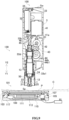
- Fig. 9 is a longitudinal section view showing a dirt removing unit 130 according to embodiment III of the present invention.
- Fig. 10 is an exploded view showing a heating device 101 constituting the dirt removing unit 130 shown in Fig. 9 .
- the dirt removing unit 130 of the present embodiment shown in Fig. 9 is composed of the dirt removing device 100 of embodiment I and the heating device 101.
- the heating device 101 includes a member 103 for arranging an absorbing pad (a cover for arranging an absorbing pad), a device body cover 105, a decorative panel 107, a heating plate 109, a first heat insulating material 111, a heater 113, a second heat insulating material 115 and a heating device body 117.
- the member 103 for arranging an absorbing pad and the device body cover 105 are circular members in which opening portions 103a and 105a are formed at the centers, respectively.
- the member 103 for arranging an absorbing pad rotates in a state in which an absorbing pad P is sandwiched between a surface 103b of the member 103 and a surface 105b of the device body cover 105, and the screw portion of the surface 105b and the crew portion of the surface 103c are engaged with each other and mounted on the device body cover 105.
- the decorative panel 107 has stepped differences between a central portion 107a and an end portion 107b.
- a protuberant surface 107ab of the central portion 107a is exposed via the opening portion 105a and is substantially parallel to the surface 105b of the device body cover 105, the end portion 107b is sandwiched between another surface 105d of the device body cover 105 and the heating device body 117, when being mounted inside the heating device 101.
- the decorative panel 107 is made of, for example, stainless steel. Through holes 107c and 105e penetrating a safety switch 117d which will be described later are formed on the end portion 107b of the decorative panel 107 and the device body cover 105, respectively.
- the heating plate 109 is configured to be embedded in the central portion of the decorative panel 107, and a beaten surface 109a on which a force is exerted by the head 11 of the dirt removing device 100, is opposed to the decorative panel 107.
- the heating plate 109 is made of, for example, aluminum having high thermal conductivity.
- the thickness of the heating plate 109 is set to about 1 to 2 mm. The heat from the heater 113 can be quickly and uniformly transmitted to the absorbing pad P and the deformation of the absorbing pad P during dirt removing operation caused by the force exerted by the head 11 can be suppressed, because both the strength and the high thermal conductivity are taken into account of, thereby maintaining a high dirt removing efficiency.
- the first heat insulating material 111 is a heat insulating material for temperature adjustment disposed on the back side of the heating plate 109, and is made of, for example, silicone rubber.
- the second heat insulating material 115 is a member disposed on the heating device body 117 and configured to insulate the heat of the heater 113, and is made of, for example, glass wool.
- the heater 113 disposed between these heat insulating materials may be a ceramic heater.
- a coating treatment may be applied to the heating plate 109 for a beautiful appearance, so that a structure without the decorative panel 107 can be used.
- the heating device body 117 includes a power line 117a, a main switch 117b for switching a power state of the heater 113, a temperature regulator 117c for adjusting the power state of the heater 113 according to the temperature of the heater 113, and the safety switch 117d.
- the temperature regulator 117c stops supplying power to the heater 113 so as to cool the heater 113.
- the lower limit temperature e.g., 60°C
- the safety switch 117d is a member protruding from the surface 105b of the device body cover 105 via the through holes 107c and 105e, and is configured to supply power to the heater 113 when being pressed by the absorbing pad P mounted at a predetermined position and stop supplying power to the heater 113 when not being pressed. That is, the heating device 101 can be used by disposing the absorbing pad P at the predetermined position of the device body cover 105 and closing the member 103 for arranging the absorbing pad.
- the heater 113 generates heat after operating the main switch 117b, and the heat is transferred to the heating plate 109 so as to increase the temperature of the absorbing pad P. Therefore, when the cloth C is placed on the heating device 101, an action of applying a beating force to the beaten surface 109a by the head 11 of the dirt removing device 100 can be performed in a state in which the heated absorbing pad P is opposed to the dirt portion Sp.
- the dirt removing unit 130 of the present embodiment continuously heats the dirt portion Sp to about 50°C, so that the dirt removing operation is performed in a state in which the dirt is more dissoluble to the liquid, thereby further improving the dirt removing effect. In addition, it is unnecessary to use a strong bleaching agent for dirt removing, so that discoloration of clothes C can be prevented.
- the heating device 101 is used in combination with the dirt removing device 100 of the embodiment I, however, the heating device 101 may be used in combination with dirt removing devices of other structures such as the dirt removing device 120 of the embodiment II, the dirt removing device 110 of the modified embodiment.
- the heating device 101 has a circular shape in plan view, but may be rectangular in plan view.
- one side of the member for arranging the absorbing pad is connected to other constituent elements of the heating device (the device body cover, the decorative plate, the heating plate, the first heat insulating material, the heater, the second heat insulating material, the heating device body) via a hinge or the like.
- the member for arranging the absorbing pad is foldable with the absorbing pad being clamped with respect to other constituent elements of the heating device 101.
- the beating surface 21a of the head 11 faces downward
- a structure in which the beating surface 21a faces laterally may be used.
- the liquid is transferred by, for example, a pump.
- the beating surface 21a may be flat without the projections 21a1.
- the waterproof cover 50 shown in Fig. 2 , etc. may have a built in heater.
- the heater is an annular heater composed of wound nickel-chrome alloy wire or a ceramic heater which generate heat by the power of a power portion.
- the power supplied to the heater is, for example, about 5W, and the temperature of the heater during heat generation is set to about 80°C. to 100°C.
- the waterproof cover 50 presses against the clothing C when performing the dirt removing operation, the cloth C is heated by the heater of the waterproof cover 50, so that even if the heating device 101 shown in Fig.9 is not additionally used, the dirt portion Sp of the cloth C and its periphery can always be heated by the waterproof cover 50 during the dirt removing operation, thereby achieving miniaturization and further improving the dirt removing effect.
- the entirety or nearly entirety of the housing body 33 has a double-layered structure. It is also effective to mount components such as the vibration unit 31 in such a housing body 33.
- the housing body 33 since the housing body 33 has the double-layered structure, it is possible to hide fixing members such as a screw fixed on the inner layer by the outer layer, thereby improving the appearance of the dirt removing devices 100 to 120.
- the battery 32 is used as the power supply unit in the above embodiments, the present disclosure is not limited to this.
- Other configurations may also be used, for example, configuration having a Universal Serial Bus (USB) connector capable of being connected with a USB line, configuration having a power cable having a plug, and configuration of being powered by an external power supply. Therefore, there is no need to install the battery 32 in the device body 3, and the device body 3 can be made more compact.
- USB Universal Serial Bus
- the head 5, 8, 11 is configured to be detachable from the liquid accommodating portion 7, 12, 212, but may be configured to be not detachable.
- the liquid may be a detergent mixture.
- the detergent is continuously supplied to the dirt portion Sp of the cloth C during the dirt removing operation, therefore, the detergent will not disappear from the dirt portion Sp due to vaporization, scattering and the like, thereby maintaining a high dirt removing effect.
- the liquid storage portion 24 and the base end 11a of the head 11 are connected via the cylinder water supplying hole 28 (see Fig. 2 ).
- the liquid storage portion 24 and the head 11 may be directly connected without the cylinder water supplying hole 28, so that the liquid is directly supplied from the liquid storage portion 24 to the head 11.
- the cassette mechanism 1, 10, 20 may be a disposable structure (a structure in which the liquid stored in the liquid storage portions 7, 12, 212 in advance cannot be replenished).
- the materials of the members constituting the dirt removing devices 100 to 120 and the heating device 101 are not limited to those materials shown by hatching in the each accompanying drawing.
Description
- The present disclosure relates to a dirt removing device and a dirt removing unit, which are capable of beating and washing a local part of a cloth product, providing liquid to a dirt portion on the cloth product and exerting a beating force automatically, and can also replace the used liquid.
- In the case that feculence is adhered to a local part of the cloth product to become the dirt, in view of convenience and efficiency of washing off the dirt, it is better to only washing a dirt part compared with washing the entire cloth product. An apparatus for locally washing the cloth product can be exemplified by a dirt removing system of Non-Patent
Document 1. - The dirt removing system of Non-Patent
Document 1 is composed of a bottle body for containing a detergent and an absorbing sheet, and a fine hole for providing the detergent is formed at a top end of the bottle body. The dirt removing system is capable of beating the dirt part through the top end of the bottle body with the absorbing sheet abutting a downward portion, so as to provide the detergent to the dirt part through the beating actions. The provided detergent soaks into the cloth product, and is absorbed into the absorbing sheet together with the feculence constituting the dirt portion. Further relevant technologies are also known fromWO 01/36116 A1 (PROCTER & GAMBLE [US]; BODET JEAN FRANCOIS [US]; SCHEPER WILLIAM MICHA) 25 May 2001 - Non-Patent Document 1: Network <URL: http: //www.1ion.co.jp/ja/seihin/brand/025/ 06.htm>
- Nevertheless, the dirt removing system of Non-Patent
Document 1 has a problem that a beating force and a beating speed are unstable and the degree of decontamination is different or the hand fatigue is caused, since dirt removing actions are performed with a hand holding the bottle body moving up and down. In addition, since the detergent in the bottle body cannot be replaced, it is not possible to use detergents depending on the type or the state of the dirt such as oil contamination or water contamination. Therefore, sometimes it is difficult to remove the dirt. - The present disclosure aims to effectively solve such problems, that is, aims to provide a dirt removing device and a dirt removing system which can prevent the hand from tiredness, and can perform a dirt removing operation always with a stable beating force and beating speed. The device further can use different kinds of detergent according to the type and state of the dirt.
- The above problem is solved by a dirt removing device according to
claim 1, and a dirt removing unit according toclaim 6. Further improvements and embodiments are provided in the dependent claims. In view of the above problems, the following solutions are also proposed. - Preferably, the head is detachable from the cassette mechanism, and the liquid accommodating portion is composed of an accommodating portion body having a liquid accommodating space therein and a cover member for opening and closing the liquid accommodating space.
- Preferably, the liquid accommodating portion is transparent or translucent.
- Preferably, the water supplying passage is started from the liquid accommodating portion, penetrates into the entire head and extends to the beating surface, and expands toward an open end opening to the beating surface.
- Preferably, the device body further has a non-flexible waterproof cover surrounding a side surface of the head; the vibration unit has an elastic member capable of extending and contracting in a direction substantially orthogonal with the beating surface, and the head is protruded by an elastic force of the elastic member; and an action end at a side of the head is set at a position slightly protruding from a protruding end of the waterproof cover.
- In addition, the dirt removing unit of the present disclosure includes the above dirt removing device; and a heating device. The heating device includes at least a heater that generates heat by power supply and a heating plate that forms a knocked surface, a force is exerted to which by the head constituting the dirt removing device, and conveys a heat generated by the heater.
- According to the above described disclosure, the vibration unit causes, by means of supplying power, the cassette mechanism to vibrate in the direction substantially orthogonal with the beating face of the head, the head can automatically perform an action of beating the dirt and removing objects. As a result, the beating force and the beating speed are homogeneous and the hands are required to move quickly, the hands will not be tired even if the dirt removing operation is performed for a long time. In addition, since the cassette mechanism can be attached and detached from the device body, it is possible to install, on the device body, a cassette mechanism accommodating a liquid corresponding to the state of the dirt, and to change the type of the liquid according to the state of the dirt portion, by means of, for example, preparing in advance a plurality of cassette mechanisms each accommodating a different kind of liquid, respectively, in the liquid accommodating portion, thereby improving the effect of removing dirt.
- In particular, according to the present disclosure, the head potion is detachable from the cassette mechanism, and the liquid accommodating portion is composed of an accommodating portion body and a cover member. The liquid can be supplied to the liquid accommodating space or the liquid in the liquid accommodating portion can be easily replaced with other kind of liquid, by means of removing the cover member form the accommodating portion body, so that the dirt removing device can be repeatedly used multiple times. In this case, since the liquid supplying, replacement and the like can be performed in a state in which the liquid accommodating portion is removed from the device body, the device body will not be wetted by the liquid when supplying liquid and the device body is not required to be subjected to a waterproof treatment. In addition, the inside of the liquid accommodating portion can be cleaned by disassembling the liquid accommodating portion into the accommodating portion body and the cover member, thereby easily removing the incrustation, the calcium component, and the like. Further, the dirt removing effect can be further improved, since the most suitable head and liquid can be selected to use according to the state of the dirt portion.
- Further, according to the present disclosure in which the liquid accommodating portion is transparent or translucent, the cassette mechanism can be temporarily removed so as to confirm the remaining amount of the liquid in the liquid accommodating portion during the process of the dirt removing operation, thereby improving the convenience.
- In particular, according to the present disclosure in which an open end of the water supplying passage is expanded, even if the solid soil constituting the dirt portion is physically decomposed due to the impact from the head, the decomposed solid soil does not dissolve into the liquid and penetrates into the water supplying passage, the water supplying passage is difficulty to be blocked by the solid soil, since the open end expands. In addition, even if the water supplying passage is blocked and full of solid soil, it is easy to remove the solid soil.
- In addition, according to the present disclosure, the waterproof cover can block the liquid from spattering so as to prevent large-scale diffusion of the liquid, and always keep a distance from the device body to the clothe is constant in the dirt removing operation, so that a force (beating force) applied by the head to a dirt removing object is appropriate and uniform. In addition, since the head presses against the dirt removing object due to the elasticity of an elastic member when the elastic member is protruding, it is possible to automatically simulate the action of beating (pressing) the dirt portion by hands.
- In another aspect, according to the present disclosure having the above described dirt removing device and a heating device, since the dirt portion of the dirt removing object can be continuously heated by the heat from the heater and the dirt removing operation can be performed, the dirt is more likely soluble in liquid, thereby further improving the dirt removing effect.
-
-
Fig. 1 is a view showing an appearance of a dirt removing device according to embodiment I of the present disclosure; -
Fig. 2 is a view showing the same dirt removing device; -
Fig. 3 is a perspective view showing the same dirt removing device with a cover member being removed; -
Fig. 4 is a longitudinal section view illustrating a use state of the same dirt removing device; -
Fig. 5 is a longitudinal section view showing the same dirt removing device with a cassette mechanism being removed; -
Fig. 6 is a view showing the cartridge mechanism; -
Fig.7 is a perspective view showing a part of a liquid accommodating portion and a head constituting a dirt removing device of embodiment II of the present disclosure; -
Fig. 8 is a schematic view showing the head and a supplying hole shown inFig. 7 (B) ; -
Fig. 9 is a longitudinal section view showing a dirt removing unit according to embodiment III of the present disclosure; and -
Fig. 10 is an exploded view showing a heating device constituting the dirt removing unit shown inFig. 9 . - Hereinafter, embodiment I of the present disclosure will be described with reference to accompanying drawings.
-
Figs. 1 and2 are views showing adirt removing device 100 according to embodiment I of the present disclosure. Specifically,Fig. 1(A) is a perspective view showing thedirt removing device 100 according to the present embodiment.Fig. 1(B) is a side view showing thedirt removing device 100.Fig. 1(C) is a top view showing thedirt removing device 100. In addition,Fig. 2(A) is a longitudinal section view of thedirt removing device 100 along a section line II-II inFig. 1(C) .Fig. 2(B) is a perspective view showing a part of thedirt removing device 100, that is, a part in the vicinity of an engaging claw 45b2.Fig. 2(C) is an enlarged longitudinal section view showing a part of a liquid accommodatingportion 12 and ahead 11 shown inFig. 2(A). Fig. 2(D) is a bottom view of thehead 11. - As shown in
Fig. 2(A) , thedirt removing device 100 includes: adevice body 3, acassette mechanism 1, acover member 70 and awaterproof cover 50. - The
cassette mechanism 1 is detachably received in thedevice body 3. Thedevice body 3 includes avibration unit 31, abattery 32 and ahousing body 33 having a dimidiate structure in which these components are mounted. - The
vibration unit 31 is a member that causes, while being powered, thecassette mechanism 1, which protrudes from thehousing body 33 through anopening 33a, to vibrate in a direction substantially orthogonal with a beatingface 21a of thehead 11. Hereinafter, the direction substantially orthogonal with the beatingsurface 21a is referred to as a vibration direction. In addition, in the vibration direction, a direction in which thehead 11 protrudes outward the device is referred to as a protruding direction Y1, and the opposite direction is referred to as a return direction Y2. According to the invention, thevibration unit 31 has amotor 41, first tothird gears 42~44, acylinder body 45, and acoil spring 46. - The
motor 41 has adriving gear 41a powered by a power supplying portion (namely the battery 32) so as to rotate. - A rotational force of the
motor 41 is transmitted through the first to thethird gear 42~44. Thefirst gear 42 includes alarge diameter portion 42a which is engaged with thedriving gear 41a of themotor 41 and is rotatable about ashaft 42c, and asmall diameter portion 42b formed integrally with thelarge diameter portion 42a and coaxially arranged with thelarge diameter portion 42a. Thesecond gear 43 is disposed between thefirst gear 42 and thethird gear 44. Thesecond gear 43 has alarge diameter portion 43a which is engaged with thesmall diameter portion 42b of thefirst gear 42 and is rotatable about ashaft 43c, and asmall diameter portion 43b, which is formed integrally with and coaxially arranged with thelarge diameter portion 43a and is engaged with thethird gear 44. Thethird gear 44 includes alarge diameter portion 44a which is engaged with thesmall diameter portion 43b of thesecond gear 43 and is rotatable about ashaft 44c, and asmall diameter portion 44b. Thesmall diameter portion 44b is formed integrally with and coaxially arranged with thelarge diameter portion 44a, and includes two engaging projections 44b1 protruding from an end face of thesmall diameter portion 44b in a circumferential direction at equal intervals. In addition, the number of the engaging projections 44b1 is not limited to two, but may be one or three or more. - The
cylinder body 45 is a member that supports thecassette mechanism 1 in a manner that the beatingsurface 21a is located at a top end of thecylinder body 45, and is capable of moving in the vibration direction. Thecylinder body 45 has a coilspring receiving portion 45a and a cassette mechanism insertedportion 45b. - The coil
spring receiving portion 45a is a cylinder member having a bottom surface, in which thecoil spring 46 served as an elastic member is received in a manner of being stretchable in the vibration direction. - The cassette mechanism inserted
portion 45b is a substantially cylindrical member extending from a lower end of the coilspring receiving portion 45a to the vicinity of theopening 33a of thehousing body 33. Acylinder opening 45b' shown inFig. 2 (B) is formed in a side surface of the cassette mechanism insertedportion 45b. The side surface of the cassette mechanism insertedportion 45b is further formed with an engaged claw 45b1 as shown inFig. 2(A) and an engaging claw 45b2. The engaged claw 45b1 is capable of being engaged with the engaging projection 44b1 formed at thesmall diameter portion 44b of thethird gear 44. The engaging claw 45b2 is capable of being engaged with thecassette mechanism 1. As shown inFig. 2(B) , the engaging claw 45b2 extends from an edge of thecylinder opening 45b' toward the protruding direction Y1, and a top end 45b3 protrudes to a center axis of the cassette mechanism insertedportion 45b and has a substantially triangular longitudinal section. In addition, the engaging claw 45b2 is configured to be elastically deformed toward the outside of the cassette mechanism insertedportion 45b with a base end 45b4 as a starting point, along with the pressing of thecassette mechanism 1. Such engaging claws 45b2 are provided at two positions opposed to each other. - One end of the
coil spring 46 is supported by a base end of a fixingportion 33b extending in a convex shape from thehousing body 33 in the protruding direction Y1, and the other end is received by the coilspring receiving portion 45a. - As shown in
Fig. 2(A) , in the case that the engaging projection 44b1 of thethird gear 44 is not engaged with the engaged claw 45b1,such cylinder body 45 is pushed out in the protruding direction Y1 together with thecassette mechanism 1 because an elastic force in the protruding direction Y1 is exerted on the bottom surface 45a1 of the coilspring receiving portion 45a by thecoil spring 46. - On the other hand, in the case that the engaging projection 44b1 of the
third gear 44 is engaged with the engaged claw 45b1 (referring toFig. 4(B) ), along with the rotation of thethird gear 44, thecylinder body 45 exerts a compression force on thecoil spring 46 via the bottom surface 45a1 and moves in the return direction Y2 together with thecassette mechanism 1. Then, when the engaging projection 44b1 is disengaged from the engaged claw 45b1, thecylinder body 45 and thecassette mechanism 1 move in the protruding direction Y1 again by means of the elastic force of thecompressed coil spring 46. - The
cassette mechanism 1 and thehead 11 are enabled to vibrate (an amplitude vibration movement) by repeating such operations. In the present embodiment, thethird gear 44 has two engaging projections 44b1 as described above, and thehead 11 is caused to shuttle twice through one rotation of thethird gear 44. - The
battery 32 shown inFig. 2 (A) is a dry battery in the present embodiment, and is received in thedevice body 3 via an opening and closingcover 34 formed at a part of thehousing body 33. The opening and closingcover 34 is configured to be rotatable toward the outside of thehousing body 33 via apin 34a. - The
cassette mechanism 1 vibrated by thevibration unit 31 has thehead 11, theliquid accommodating portion 12, and awater supplying passage 13. - The
head 11 has a beatingportion 21 and ahead insertion portion 22. The beatingportion 21 is a member formed with the beatingsurface 21a, and has a substantially semicircular longitudinal section, more specifically approximately circular longitudinal section). A plurality of projections 21a1 protrude from the beatingsurface 21a. Each of the projections 21a1 is hemispherical, and is regularly arranged in thebeating surface 21a as shown inFig. 2 (D) . - The
head insertion portion 22, as shown inFig. 2 (C) , is a member extending from the beatingportion 21 and pluggably inserting into an insertedportion 25 that will be described below. A side surface of thehead insertion portion 22 is provided with a plurality ofannular protrusions 22a which are formed in the vibrating direction and spaced apart from each other. When inserting into the insertedportion 25, theprotrusions 22a press against an inner surface of the insertedportion 25. Therefore, thehead 11 can be stably fixed with a constant degree even if thehead insertion portion 22 has been repeatedly loaded or unloaded for lots of times. - In addition, in the present embodiment, the
head 11 is made of resins such as nylon, but the material of thehead 11 is not limited to the resins, it may be metals such as stainless used steel (SUS), etc. - The liquid
accommodating portion 12 shown inFig. 2 (a) has aliquid storage portion 24 and the insertedportion 25. Theliquid storage portion 24 is a transparent or translucent hollow member capable of accommodating the liquid, and is configured to be capable of being decomposed as will be described later. Anengaging recess 12a engageable with the engaging claw 45b2 is provided on a side surface of theliquid storage portion 24. The insertedportion 25 extends from theliquid storage portion 24, and thehead insertion portion 22 of thehead 11 is pluggably inserted into the insertedportion 25 by lightly pressing. In addition, thehead insertion portion 22 is not limited to the structure in which thehead insertion portion 22 is inserted into the insertedportion 25 by pressing. Thehead insertion portion 22 may be inserted into the insertedportion 25 by being fixed by a screw. - The liquid herein may be water, a detergent mixture of water and detergent mixed with a certain ratio, a common solvent such as ethanol or gasoline, or a special detergent for removing dirt, and the like. In the present embodiment, the liquid accommodated in the
liquid storage portion 24 can only be water. As a result, a rinsing effect can be exerted in addition to the dirt removal effect, as will be described later. - The
water supplying passage 13 is formed from the liquidaccommodating portion 12 and throughout thehead 11, and supplies the liquid in theliquid accommodating portion 12 to thebeating surface 21a of thehead 11. As shown inFig. 2(C) , thewater supplying passage 13 includes a headwater supplying hole 27 and a cylinder bodywater supplying hole 28. The headwater supplying hole 27 extends through thehead 11 to thebeating surface 21a, and is composed of awater storage portion 27a, anexpansion portion 27b, and asmall diameter portion 27c. - The
water storage portion 27a is opposed to the cylinder bodywater supplying hole 28, opens at abase end 11a of thehead 11. Thewater storage portion 27a penetrates thehead insertion portion 22, and the longitudinal section thereof is substantially a rectangle. Theexpansion portion 27b, a longitudinal section of which is frustum-shaped, and has anopen end 11b which expands and opens toward the center of thebeating surface 21a. Thesmall diameter portion 27c is configured to connect thewater storage portion 27a and theexpansion portion 27b. A profile of a flow path of thesmall diameter portion 27c is smaller than that of thewater storage portion 27a and that of theexpansion portion 27b. - The cylinder body
water supplying hole 28 is formed from theliquid storage portion 24 through the insertedportion 25, and opens in a tapered shape toward thebase end 11a of thehead 11. In addition, the longitudinal section of the cylinder bodywater supplying hole 28 is not limited to the tapered shape, and may be arranged to have a same diameter from the start to the end. This is also true in other embodiments described later. - The liquid in the
liquid storage portion 24 drips from the cylinderbody supplying hole 28 to thehead 11, and is supplied to thebeating surface 21a through the headwater supplying hole 27. - When the
cassette mechanism 1 is caused to vibrate through the vibrating of thevibration unit 31, through thewater supplying passage 13 formed insuch head 11, the liquid is discharged to theexpansion portion 27b from thesmall diameter portion 27c little by little (such as 1-1.5 cc/min) with a stable flow rate, so as to supply the liquid to thebeating face 21a of thehead 11. On the other hand, when thecassette mechanism 1 does not vibrate, the liquid is prevented from dripping by a surface tension in thesmall diameter portion 27c and the cylinder body water supplying hole 28 (particularly thesmall diameter portion 27c). - In this way, the cross-section of the flow path of the
water supplying passage 13 is designed to discharge a small amount of liquid through the vibration of thehead 11, thus less liquid is used to complete the washing compared with other washing methods such as spray washing, brushing and the like. Therefore, the liquid is hard to spatter to locations where the liquid is not needed. Further, thewater supplying passage 13 is disposed only at a limited portion relative to the wholedirt removing device 100. Therefore, the clogging of thewater supplying passage 13 caused by the incrustation and the coagulation of the calcium component is hard to happen, compared with a structure having a water supplying passage (not shown) longer than thewater supplying passage 13 so as to extend throughout the entiredirt removing device 100. As a result, it is not necessary to carry out a complicated decomposition to clean of thedirt removing device 100. - In addition, a length β (referring to
Fig. 2 (A) ) of thedirt removing device 100 from the beatingface 21a of thehead 11 when protruding to theopening 33a of thehousing body 33 is set to be a length that the dirt portion is visible to obliquely upper side without being shielded by thedevice body 3 in a dirt removing operation described later. In addition, thewaterproof cover 50 described later is set to have a size corresponding to the length β. Further, thecassette mechanism 1 is mounted to be eccentric with respect to thecylindrical housing body 33, and the dirt removing operation is performed by bringing the side surface of thehousing body 33 closest to thecassette mechanism 1 closer to the eye, so that it is easier to confirm the dirt portion. - The
cover member 70 is a member that can be attached and detached from an end of thehousing body 33, which is attached to thedevice body 3 when thedirt removing device 100 is carried, and is removed from thedevice body 3 when performing the dirt removing operation described later as shown inFig. 3(A). Fig. 3(A) is a perspective view showing thedirt removing device 100 with thecover member 70 being removed. With such acover member 70, thedirt removing device 100 is effectively prevented from leaking water from the device while being carried, impact on thecassette mechanism 1 and the like. - In addition,
Fig. 3(B) is a perspective view showing thedirt removing device 100 with thewaterproof cover 50 being removed. Also as shown inFig. 3(B) , thewaterproof cover 50 is configured to be detachable from the end of thehousing body 33. In addition, the related structure of thewaterproof cover 50 will be described later in detail. - Such
dirt removing device 100 is a handheld device that can locally wash a cloth C as the dirt removing object shown inFig. 4. Fig. 4 is a longitudinal section view illustrating a use state of the dirt removing device. When the dirt removing operation is performed, an absorbing pad P served as a pad abuts the bottom of the dirt portion Sp of the cloth C, and coats a detergent for removing dirt to the dirt portion Sp of the cloth C directly. Further, a protrudingend 51 of thewaterproof cover 50 presses the cloth C at a position, opposed to the dirt portion Sp, of the beatingface 21a of thehead 11. Further, thedirt removing device 100 is used with a region around anannular anti-slip portion 33d of thehousing body 33 being held. In addition, the detergent may not be used in the present embodiment. - According to the invention, when a power switch Sw provided on the outside of the
housing body 33 is operated in this state, themotor 41 is powered by thebattery 32 to rotate, and the rotation is transmitted to thethird gear 44 through thefirst gear 42 and thesecond gear 43 after being decelerated. As shown inFig. 4(B) , when the engaging projection 44b1 is engaged with the engaged claw 45b1, thecylinder body 45 and thecassette mechanism 1 are lifted together by a specified size δ (about 5mm in the present embodiment). Then, when the engaging projection 44b1 is disengaged from the engaged claw 45b1, thecylinder body 45 and thecassette mechanism 1 are ejected by the elastic force of thecoil spring 46, as shown inFig. 4(A) , thehead 11 beats the dirt portion Sp. - In addition, along with the vibration of the
cassette mechanism 1, the liquid and air in theliquid storage portion 24 are whisked, therefore, a negative pressure will not generated in theliquid storage portion 24. The liquid gradually drops through thewater supplying passage 13 immediately after the vibration is started and is supplied to the dirt portion Sp via the beating surface 2 1a. - When the
device body 3 moves along the cloth C and repeats such operations, the liquid (only water is used in the present embodiment) supplied to the dirt portion Sp together with the detergent coated on the dirt portion Sp dissolve the feculence constituting the dirt portion Sp, and the feculence is knocked out from the cloth C and absorbed by the absorbing pad P. That is, thedirt removing device 100 is device that removes the dirt by transferring the feculence of the cloth C together with the liquid and the detergent to the absorbing pad P. - In addition, in the present embodiment, after the dirt being removed, it is also effective to proceed with the operation described above for a certain time, thereby transferring the detergent remained in the dirt portion Sp to the absorbing pad P, and a rinsing effect is achieved.
- In addition, the absorbing pad P is not particularly limited, and a variety of articles can be used as the absorbing pad P as long as the liquid can be absorbed at a high speed, for example, a product generated by folding a kitchen paper towel.
- Further, as long as an operation of changing the position where the
head 11 abuts against the absorbing pad P is periodically performed during the dirt removing operation, the dropped liquid will be stably absorbed by the absorbing pad P. Therefore, a high efficiency dirt removing can be maintained. - Since the
vibration unit 31, while being powered, causes thecassette mechanism 1 to vibrate in the direction substantially orthogonal with the beatingsurface 21a, thehead 11 can automatically perform the action of beating the cloth C. Therefore, suchdirt removing device 100 has the following excellent effects: having uniform beating force and beating speed, and it is not required to move the hands quickly, thus the user will not fatigue even if the dirt removing operation is performed for a long time. - In addition, although the dirt may be for example a solid feculence in block which is adhered to the cloth C and difficult to be dissolved in the liquid, the
dirt removing device 100 can physically decompose the solid feculence by the impact from thehead 11 so that the solid feculence is easily dissolved in the liquid. In addition, for example, by appropriately designing the cross-section of the flow path of thewater supplying passage 13, an appropriate amount of liquid is continuously supplied to the cloth C along with the vibration, and the dirt removing effect is improved. Further, since thedirt removing device 100 is of a structure in which the liquid drops by vibration, the structure is simplified and the size is reduced compared with a device, for example, in which a liquid pump is employed to supply the liquid. - As a result, the
dirt removing device 100 of the present embodiment is a small and portable device. Therefore, in the case that food residue, cosmetic or the like is adhered to the cloth when going out, it is enable to make the dirt not obvious by means of local washing. In addition, thedirt removing device 100 can locally and properly wash goods that are difficult to overall wash, such as curtains, carpet, etc. Further, thedirt removing device 100 can pre-wash the feculence at a collar, cuffs, etc. of the cloth C in an early stage of washing performed by a washing machine. - Further, as described above, the
water supplying passage 13 extends from the liquidaccommodating portion 12 to thebeating face 21a and passes through thehead 11, and expands to theopen end 11b (as shown inFig. 2(C) ) opening to thebeating face 21a. As a result, even if the solid feculence constituting the dirt portion Sp, after being physically decomposed by the impact fromhead 11, is not dissolved in the liquid and gets into thewater supplying passage 13, thewater supplying passage 13 is hard to be blocked by the solid feculence, since theopen end 11b expands. In addition, even if thewater supplying passage 13 is blocked full of solid feculence, it is easy to remove solid feculence. - As shown in
Fig. 4 , thewaterproof cover 50 is a transparent non-flexible member made of propylene and has a substantially conical shape (that is, a shape in which the circumference of theprotruding end 51 is larger than the circumference of a base end 51'). Thewaterproof cover 50 is detachably mounted around theopening 33a of thehousing body 33 at a position on a side surface encircling the head 11via a rib 33a1. Thehead 11 protruding towards the protruding direction Y1 by thevibration unit 31 adjusts the course thereof, so that an action end of one side is arranged at a position slightly protruding from the protrudingend 51 of thewaterproof cover 50. Specifically, a distance t (referring toFig. 4 (A) ) in the vibration direction from the beatingsurface 21a of the head at the protruding position to theprotruding end 51 of thewaterproof cover 50 is set to be a prescribed distance (about 1 to 2 mm in the present embodiment). - By providing such
waterproof cover 50, during the dirt removing operation, thewaterproof cover 50 shields the liquid scattered by the vibration of thehead 11, so as to prevent the liquid from diffusing in a wide range. Therefore, the area where the cloth C is soaked is reduced, thus the cloth C can be wore immediately after the dirt removing operations. In addition, during the dirt removing operation, a distance between thedevice body 3 and the cloth C can be kept constant, so that the external force (beating force) exerted on the cloth C by thehead 11 is appropriate and uniform. In addition, the action end at a side of thehead 11 is arranged at a position slightly protruding from the protruding end of thewaterproof cover 50, and thehead 11 presses against the cloth C due to the elasticity of the elastic member when protruding, thus it is possible to automatically simulate the action of beating (pressing) the dirt portion Sp by hands. Further, since thewaterproof cover 50 is transparent, it is possible to confirm the removing state of the dirt portion via thewaterproof cover 50 during the dirt removing process. - In addition, the shape of the
waterproof cover 50 is not limited to a substantially conical shape, but may be, for example, a cylindrical shape. - In addition, as described above, the
cassette mechanism 1 is detachable to thedevice body 3 via the engaging claw 45b2 (referring toFig. 2 (B) ) (bottle cassette type). - Specifically, as shown in
Fig. 5 , after thewaterproof cover 50 is removed from thedevice body 3, the insertedportion 25 or its periphery is pulled out by grasping and pulling with by a certain force. The pulling force is transmitted to a top end 45b3 of the engaging claw 45b2 from the engaging recessedportion 12a of theliquid storage portion 24, therefore, the engaging claw 45b2 is temporarily elastically deformed toward the outside of the cassette mechanism insertedportion 45b with the base end 45b4 as a starting point, and thecassette mechanism 1 is separated from thedevice body 3. In addition,Fig. 5 is a longitudinal section view showing the same dirt removing device with thecassette mechanism 1 being removed. - On the other hand, by an opposite action as described above, specifically, by inserting the
cassette mechanism 1 into the cassette mechanism insertedportion 45b with a certain force, the insertion force is transmitted to the top end 45b3 of the engaging claw 45b2 from an end face 24' of theliquid storage portion 24, and the engaging claw 45b2 is elastically deformed toward the outside of the cassette mechanism insertedportion 45b with the base end 45b4 as a starting point. When thecassette mechanism 1 is further inserted in such state, the engaging claw 45b2 is elastically recovered at a position opposed to theengaging recess 12a of theliquid storage portion 24, and theengaging recess 12a is engaged with the engaging claw 45b2 to prevent from detaching, so that thecassette mechanism 1 is mounted on thedevice body 3. - Since the
cassette mechanism 1 can be attached and detached in such a way, acassette mechanism 1 containing liquid corresponding to the state of the dirt portion Sp can be mounted on thedevice body 3 by preparing, for example, a plurality ofcassette mechanisms 1 in advance, each having a liquidaccommodating portion 12 containing a different kind of liquid respectively. Therefore, the type of the liquid can be replaced according to the state of the dirt portion Sp, thereby improving the dirt removing effect. -
Fig. 6 (A) and 6 (B) are perspective views showing thecassette mechanism 1 when being detachd from thedevice body 3. As shown inFig. 6 (A) , theliquid storage portion 24 of thecassette mechanism 1 is disassembly composed of anaccommodating portion body 24a and acover member 24b. Theaccommodating portion body 24a is a substantially cylindrical member having a liquid accommodating space S formed therein and has a bottom. Theaccommodating portion body 24a is arranged in a manner that a part of theaccommodating portion body 24a in an axial direction is reduced in a radial direction, thereby forming theengaging recess portion 12a. Thecover member 24b is a member provided at an opening side of theaccommodating portion body 24a, and is fixed and mounted on theaccommodating portion body 24a by means of a screw. Thecover member 24b is configured to open and close the liquid accommodating space S. In addition, thehead 11 is configured to be detachable to the insertedportion 25, that is, thehead 11 can be attached and detached to thecassette mechanism 1. - With such a structure which can be divided into three parts, the
cover member 24b can be detached from theaccommodating portion body 24a so as to supply the liquid to the liquid accommodating space S, or replace the liquid in theliquid accommodating portion 12 with another kind of liquid (For example, ordinary solvents such as ethanol and gasoline) easily. Therefore, thedirt removing device 100 can be used repeatedly. At this time, since the liquid supplying or replacement can be performed when the liquidaccommodating portion 12 is detached from thedevice body 3, thedevice body 3 will not be wetted by the liquid when the liquidaccommodating portion 12 is supplied. Therefore, it is not necessary to perform waterproofing treatment on thedevice body 3. In addition, theliquid storage portion 24 can be disassembled into theaccommodating portion body 24a and thecover member 24b so as to clean the inside of the liquidaccommodating portion 12, and the incrustation or calcium component can be easily removed. Further, thehead 11 having the best shape and the best liquid can be selected for use according to the state of the dirt portion Sp and the like, and thehead 11 itself can be replaced with a new one, thereby improving the dirt removing effect. - Further, since such liquid
accommodating portion 12 is transparent or translucent as described above, thecassette mechanism 1 can be temporarily detached during the dirt removing operation so as to confirm the remaining amount of the liquid in theliquid accommodating portion 12, thereby improving the convenience. -
Fig. 6 (C) is a longitudinal section view showing a modified embodiment of embodiment I. Specifically,Fig. 6 (C) is a longitudinal section view showing a part of thecassette mechanism 10 constituting the modified embodiment (that is, the dirt removing device 110), that is, a part of a liquidaccommodating portion 212, and ahead 5. Thedirt removing device 110 is configured in a manner that the liquid flows to the periphery of thesolid head 5 and reaches the beatingsurface 21a rather than flowing inside thehead 5 and reaching thebeating surface 21a. That is, the structure of awater supplying passage 6 is different from that of the first embodiment. The modified embodiment is the same as the first embodiment except for the structure described later, and the description of the same structure will be omitted. - In the
dirt removing device 110, thewater supplying passage 6 is composed of a cylinderwater supplying hole 28, awater supplying groove 6a, and an insertedportion 25. - The
water supplying groove 6a is formed on the outer circumference of ahead insertion portion 52 of thehead 5, and is intermittently formed in a manner of slits extending in the axial direction by a prescribed depth (about 0.1~0.3mm in the present embodiment). The liquid in the liquid storage portion 24 (as shown inFig. 5 ) is supplied to abase end 5a of thehead 5 via the cylinderwater supplying hole 28. When the vibration of the vibration unit 31 (as shown inFig. 5 ) causes thehead 5 to vibrates, the liquid is slightly discharged to the beatingportion 21 little by little (for example, 1~1.5cc/min) from the gap (that is, a dischargingport 6b) between the insertedportion 25 and the cylinderbody insertion portion 52 to thebeating surface 21a and reaches the beatingsurface 21a. - On the other hand, when the
head 5 does not vibrate, the liquid remains between the insertedportion 25 and thewater supplying groove 6a and is prevented from dripping due to a surface tension. - In this way, the discharging
port 6b for the liquid is opened at the periphery of thehead 5 rather than the beatingsurface 21a of the head, thus the liquid is supplied to the periphery of thehead 5. Therefore, thewater supplying passage 6 will not be blocked even if the solid feculence constituting the dirt portion Sp is attached to thebeating surface 21a, thereby stably maintaining the dirt removing effect. In addition, thewater supplying groove 6a may be formed on the insertedportion 25 rather than in thehead insertion portion 52. -
Fig. 7 shows a part of acassette mechanism 20 that constitutes embodiment II (that is, a dirt removing device 120) of the present disclosure. Specifically,Fig. 7 is a perspective view showing a part of a liquidaccommodating portion 7 and ahead 8.Fig. 7(A) shows thecassette mechanism 20 before thehead 8 is inserted into the liquidaccommodating portion 7.Fig. 7(B) shows thecassette mechanism 20 after thehead 8 is inserted into the liquidaccommodating portion 7. Thedirt removing device 120 of the present embodiment is different from embodiment I in that thedirt removing device 120 has a liquid amount adjustment portion 9 for adjusting the drop amount of the liquid. Hereinafter, embodiment II is the same as embodiment I except for the structure described later, and the description of the same structure will be omitted. In addition, for easy description, although it is not shown in the drawings that theliquid storage portion 71 of the liquidaccommodating portion 7 has a decomposable structure, theliquid storage portion 71 is of a structure that can be disassembled into an accommodating portion body having a liquid accommodating space therein and a cover member for opening and closing the liquid accommodating space. - The liquid amount adjustment portion 9 shown in
Fig. 7 is composed of the liquidaccommodating portion 7 and thehead 8. Theliquid storage portion 71 of the liquidaccommodating portion 7 adjoins an insertedportion 72 via aseparation portion 73, and there is first to third supplyingregions 73a~73c formed at equal intervals in an edge portion of theseparation portion 73. Each of these supplyingregions 73a~73c is provided with a different number of supplyingholes 73x penetrating through theseparation portion 73. In the present embodiment, the first supplyingregion 73a is provided with one supplyinghole 73x, the second supplyingregion 73b is provided with three supplyingholes 73x, and the third supplyingregion 73c is provided with five supplyingholes 73x. In addition, the number of the supplyingholes 73x is not limited thereto. In addition, thehead 8 has anotch 8b at an end of thehead insertion portion 8a, and a plurality ofwater supplying grooves 8c extending from thenotch 8b to the beatingportion 21 are provided in a side portion of thehead insertion portion 8a. -
Fig. 8 is a schematic diagram showing thehead 8 and the supplyingholes 73x shown inFig. 7 (B) . Slashes are added at thenotch 8b inFig. 8 . As shown inFig. 8 , thenotch 8b is formed on thehead insertion portion 8a in a range corresponding to one supplyingregion 73a (73b, 73c). The liquid in theliquid storage portion 71 shown inFig. 7 flows into thenotch 8b from the supplyingholes 73x formed in any one of the supplyingregions 73a (73b, 73c) in alignment with thenotch 8b, and drops to theperiphery beating portion 21 through the dischargingport 6b of thewater supplying groove 8c. Therefore, the drop amount of the liquid varies depending on the supplyingregion 73a (73b, 73c) in alignment with thenotch 8b, and the drop amount of the liquid increases in the following order: a state shown inFig. 8(A) where thenotch 8b is in alignment with the first supplyingregion 73a, a state shown inFig. 8(B) where thenotch 8b is in alignment with the second supplyingregion 73b and a state shown inFig. 8(C) where thenotch 8b is in alignment with the third supplyingregion 73c. - As described above, the
dirt removing device 120 of the present embodiment is a device, in which the water supplying passage 6' is composed of the supplyingholes 73x, thenotch 8b, thewater supplying groove 8c, and the insertedportion 72; and the liquid drops from the gap (that is, the dischargingport 6b) between thewater supplying groove 8c and the insertedportion 72 by means of the vibration of the vibration unit 31 (as shown inFig. 5 ). Thedirt removing device 120 has the liquid amount adjustment portion 9 as shown inFig. 7 capable of adjusting the dropping amount of the liquid. - The liquid drops too much and sometimes a circular stain is generated when only the depth of the
water supplying groove 6a is designed, but the liquid will drop to the cloth C in an exact amount by means of using the liquid amount adjustment portion 9. Therefore, thedirt removing device 120 is capable of preventing the degradation of the dirt removing effect caused by insufficient supplying of the liquid, and preventing the generation of the circular stain caused by supplying a large amount of liquid to the dirt portion Sp once. - In addition, the liquid amount adjustment portion 9 is not limited to the above-described configuration as long as it can adjust the dropping amount of the liquid. In addition, the structure of the liquid amount adjustment portion 9 may be applied to the
dirt removing devices water supplying groove 8c is formed in thehead insertion portion 8a in the present embodiment, it may be formed on the insertedportion 72. -
Fig. 9 is a longitudinal section view showing adirt removing unit 130 according to embodiment III of the present invention.Fig. 10 is an exploded view showing aheating device 101 constituting thedirt removing unit 130 shown inFig. 9 . Thedirt removing unit 130 of the present embodiment shown inFig. 9 is composed of thedirt removing device 100 of embodiment I and theheating device 101. - As shown in
Fig. 10 , theheating device 101 includes amember 103 for arranging an absorbing pad (a cover for arranging an absorbing pad), adevice body cover 105, adecorative panel 107, aheating plate 109, a firstheat insulating material 111, aheater 113, a secondheat insulating material 115 and aheating device body 117. - The
member 103 for arranging an absorbing pad and thedevice body cover 105 are circular members in which openingportions member 103 for arranging an absorbing pad rotates in a state in which an absorbing pad P is sandwiched between asurface 103b of themember 103 and asurface 105b of thedevice body cover 105, and the screw portion of thesurface 105b and the crew portion of thesurface 103c are engaged with each other and mounted on thedevice body cover 105. Thedecorative panel 107 has stepped differences between acentral portion 107a and anend portion 107b. A protuberant surface 107ab of thecentral portion 107a is exposed via theopening portion 105a and is substantially parallel to thesurface 105b of thedevice body cover 105, theend portion 107b is sandwiched between anothersurface 105d of thedevice body cover 105 and theheating device body 117, when being mounted inside theheating device 101. Thedecorative panel 107 is made of, for example, stainless steel. Throughholes safety switch 117d which will be described later are formed on theend portion 107b of thedecorative panel 107 and thedevice body cover 105, respectively. - The
heating plate 109 is configured to be embedded in the central portion of thedecorative panel 107, and a beatensurface 109a on which a force is exerted by thehead 11 of thedirt removing device 100, is opposed to thedecorative panel 107. Theheating plate 109 is made of, for example, aluminum having high thermal conductivity. The thickness of theheating plate 109 is set to about 1 to 2 mm. The heat from theheater 113 can be quickly and uniformly transmitted to the absorbing pad P and the deformation of the absorbing pad P during dirt removing operation caused by the force exerted by thehead 11 can be suppressed, because both the strength and the high thermal conductivity are taken into account of, thereby maintaining a high dirt removing efficiency. - The first
heat insulating material 111 is a heat insulating material for temperature adjustment disposed on the back side of theheating plate 109, and is made of, for example, silicone rubber. The secondheat insulating material 115 is a member disposed on theheating device body 117 and configured to insulate the heat of theheater 113, and is made of, for example, glass wool. Theheater 113 disposed between these heat insulating materials, for example, may be a ceramic heater. In addition, a coating treatment may be applied to theheating plate 109 for a beautiful appearance, so that a structure without thedecorative panel 107 can be used. - The
heating device body 117 includes apower line 117a, amain switch 117b for switching a power state of theheater 113, atemperature regulator 117c for adjusting the power state of theheater 113 according to the temperature of theheater 113, and thesafety switch 117d. When the upper limit temperature (e.g., 70°C) is reached, thetemperature regulator 117c stops supplying power to theheater 113 so as to cool theheater 113. When the lower limit temperature (e.g., 60°C) is reached, theheater 113 is powered again. Thesafety switch 117d is a member protruding from thesurface 105b of thedevice body cover 105 via the throughholes heater 113 when being pressed by the absorbing pad P mounted at a predetermined position and stop supplying power to theheater 113 when not being pressed. That is, theheating device 101 can be used by disposing the absorbing pad P at the predetermined position of thedevice body cover 105 and closing themember 103 for arranging the absorbing pad. - According to the
heating device 101 of such structure, theheater 113 generates heat after operating themain switch 117b, and the heat is transferred to theheating plate 109 so as to increase the temperature of the absorbing pad P. Therefore, when the cloth C is placed on theheating device 101, an action of applying a beating force to the beatensurface 109a by thehead 11 of thedirt removing device 100 can be performed in a state in which the heated absorbing pad P is opposed to the dirt portion Sp. Thedirt removing unit 130 of the present embodiment continuously heats the dirt portion Sp to about 50°C, so that the dirt removing operation is performed in a state in which the dirt is more dissoluble to the liquid, thereby further improving the dirt removing effect. In addition, it is unnecessary to use a strong bleaching agent for dirt removing, so that discoloration of clothes C can be prevented. - In addition, according to the present embodiment, the
heating device 101 is used in combination with thedirt removing device 100 of the embodiment I, however, theheating device 101 may be used in combination with dirt removing devices of other structures such as thedirt removing device 120 of the embodiment II, thedirt removing device 110 of the modified embodiment. - Further, in the present embodiment, the
heating device 101 has a circular shape in plan view, but may be rectangular in plan view. In this case, one side of the member for arranging the absorbing pad is connected to other constituent elements of the heating device (the device body cover, the decorative plate, the heating plate, the first heat insulating material, the heater, the second heat insulating material, the heating device body) via a hinge or the like. And it is preferred that the member for arranging the absorbing pad is foldable with the absorbing pad being clamped with respect to other constituent elements of theheating device 101. - Although the embodiment of the present disclosure has been described above, the specific configuration of each part is not limited to the above described embodiment.
- For example, although in the
dirt removing devices 100 to 120 of the above described embodiments, the beatingsurface 21a of thehead 11 faces downward, a structure in which thebeating surface 21a faces laterally may be used. In this case, the liquid is transferred by, for example, a pump. - In the above embodiments, although a projections 21a1 is formed on the
beating surface 21a of theheads Figs. 1 ,6 ,7 , etc.), the beatingsurface 21a may be flat without the projections 21a1. - In addition, the
waterproof cover 50 shown inFig. 2 , etc. may have a built in heater. In this case, preferably, the heater is an annular heater composed of wound nickel-chrome alloy wire or a ceramic heater which generate heat by the power of a power portion. In addition, the power supplied to the heater is, for example, about 5W, and the temperature of the heater during heat generation is set to about 80°C. to 100°C. - With such a
waterproof cover 50, thewaterproof cover 50 presses against the clothing C when performing the dirt removing operation, the cloth C is heated by the heater of thewaterproof cover 50, so that even if theheating device 101 shown inFig.9 is not additionally used, the dirt portion Sp of the cloth C and its periphery can always be heated by thewaterproof cover 50 during the dirt removing operation, thereby achieving miniaturization and further improving the dirt removing effect. - Furthermore, in order to suppress the noise when the dirt removing device is driven, the entirety or nearly entirety of the
housing body 33 has a double-layered structure. It is also effective to mount components such as thevibration unit 31 in such ahousing body 33. In addition, since thehousing body 33 has the double-layered structure, it is possible to hide fixing members such as a screw fixed on the inner layer by the outer layer, thereby improving the appearance of thedirt removing devices 100 to 120. - Still further, although the
battery 32 is used as the power supply unit in the above embodiments, the present disclosure is not limited to this. Other configurations may also be used, for example, configuration having a Universal Serial Bus (USB) connector capable of being connected with a USB line, configuration having a power cable having a plug, and configuration of being powered by an external power supply. Therefore, there is no need to install thebattery 32 in thedevice body 3, and thedevice body 3 can be made more compact. - In the above embodiments, the
head accommodating portion - In the above embodiments, the liquid may be a detergent mixture. In this case, the detergent is continuously supplied to the dirt portion Sp of the cloth C during the dirt removing operation, therefore, the detergent will not disappear from the dirt portion Sp due to vaporization, scattering and the like, thereby maintaining a high dirt removing effect. In addition, there is no need to additionally provide a unit for supplying the detergent to the dirt portion Sp, thereby simplifying the device structure.
- In the above embodiments, the
liquid storage portion 24 and thebase end 11a of thehead 11 are connected via the cylinder water supplying hole 28 (seeFig. 2 ). However, theliquid storage portion 24 and thehead 11 may be directly connected without the cylinderwater supplying hole 28, so that the liquid is directly supplied from theliquid storage portion 24 to thehead 11. - Furthermore, at least a part of the
cassette mechanism liquid storage portions - Still further, the materials of the members constituting the
dirt removing devices 100 to 120 and theheating device 101 are not limited to those materials shown by hatching in the each accompanying drawing. -
- 1, 10, 20: cassette mechanism; 3: device body; 5, 8, 11: head;
- 6, 6', 13: water supplying passage; 7, 12, 212: liquid accommodating portion;
- 11b: open end; 21a: beating surface; 24a: accommodating portion body;
- 24b: cover member; 31: vibration unit; 46: elastic member (coil spring);
- 50: waterproof cover; 51: protruding end; 100, 110, 120: dirt removing device;
- 101: heating device; 109: heating plate; 109a: beaten surface; 113 heater;
- 130: dirt removing unit; S liquid accommodating space.
Claims (6)
- A dirt removing device (100; 110; 120), for washing a local part of a cloth (C), comprising:
a cassette mechanism (1; 10; 20), the cassette mechanism (1; 10; 20) comprises a head (5; 8; 11) formed with a beating surface (21a), a water accommodating portion (7; 12; 212) for accommodating water, and a water supplying passage (6; 6'; 13) which is started from the water accommodating portion (7; 12; 212) and penetrates into the entire head (5; 8; 11); characterized by further comprising:a device body (3), the device body (3) comprises a vibration unit (31), wherein the cassette mechanism (1; 10; 20) is detachably received in the vibration unit (31), and the vibration unit (31), when being powered, causes the cassette mechanism (1; 10; 20) to vibrate in a direction substantially orthogonal with the beating surface (21a) of the head (5; 8; 11),wherein the water is supplied from the water accommodating portion (7; 12; 212) to the beating surface (21a) of the head (5; 8; 11) through the water supplying passage (6; 6'; 13), along with the vibration of the cassette mechanism (1; 10; 20) caused by the vibration unit (31), wherein the vibration unit (31) comprises a motor (41), a first gear (42), a second gear (43), a third gear (44), a cylinder body (45), and a coil spring (46); the motor (41) of the vibration unit (31) is powered by a battery (32) to rotate, and the rotation is transmitted to the third gear (44) through the first gear (42) and the second gear (43) after being decelerated, when an engaging projection (44b1) of the third gear (44) is engaged with an engaged claw 45b1 of the cylinder body (45), the cylinder body (45) and the cassette mechanism (1; 10; 20) are lifted together by a specified size, and when the engaging projection (44b1) of the third gear (44) is disengaged from the engaged claw (45b1) of the cylinder body (45), the cylinder body (45) and the cassette mechanism (1; 10; 20) are ejected by the elastic force of the coil spring (46) and the head (5, 8,11) beats a dirt portion (Sp) of cloth (C). - The dirt removing device according to claim 1, wherein the head (5; 8; 11) is detachable from the cassette mechanism (1; 10; 20), and the water accommodating portion (7; 12; 212) is composed of an accommodating portion body (24a) having a water accommodating space (S) therein and a cover member (24b) for opening and closing the water accommodating space (S).
- The dirt removing device according to claim 1 or 2, wherein the water accommodating portion (7; 12; 212) is transparent or translucent.
- The dirt removing device according to claim 1 or 2, wherein the water supplying passage (6; 6'; 13) is started from the water accommodating portion (7; 12; 212), penetrates into the entire head (5; 8; 11) and extends to the beating surface (21a), and expands toward an open end (11b) opening to the beating surface (21a).
- The dirt removing device according to claim 1 or 2, wherein the device body (3) further comprises a non-flexible waterproof cover (50) surrounding a side surface of the head (5; 8; 11);the vibration unit (31) has an elastic member (46) capable of stretching and contracting in the direction substantially orthogonal with the beating surface (21a), and the head is protruded by an elastic force of the elastic member (46); andan action end at a side of the head is arranged at a position slightly protruding from a protruding end (51) of the waterproof cover (50).
- A dirt removing unit (130), comprising:the dirt removing device (100; 110; 120) according to claim 1 or 2; anda heating device (101) comprising at least a heater (113) that generates heat when being powered and a heating plate (109), wherein the heating plate (109) is formed with a beaten surface (109a) on which an external force is exerted by the head (5; 8; 11) constituting the dirt removing device (100; 110; 120), and transfers the heat generated by the heater (113).
Applications Claiming Priority (2)
| Application Number | Priority Date | Filing Date | Title |
|---|---|---|---|
| JP2014191463A JP6469399B2 (en) | 2014-09-19 | 2014-09-19 | Stain removal apparatus and stain removal unit |
| PCT/CN2015/079047 WO2016041371A1 (en) | 2014-09-19 | 2015-05-15 | Dirt removing device and dirt removing unit |
Publications (3)
| Publication Number | Publication Date |
|---|---|
| EP3196348A1 EP3196348A1 (en) | 2017-07-26 |
| EP3196348A4 EP3196348A4 (en) | 2018-05-02 |
| EP3196348B1 true EP3196348B1 (en) | 2023-04-26 |
Family
ID=55532525
Family Applications (1)
| Application Number | Title | Priority Date | Filing Date |
|---|---|---|---|
| EP15841918.4A Active EP3196348B1 (en) | 2014-09-19 | 2015-05-15 | Dirt removing device and dirt removing unit |
Country Status (5)
| Country | Link |
|---|---|
| US (1) | US20170275807A1 (en) |
| EP (1) | EP3196348B1 (en) |
| JP (1) | JP6469399B2 (en) |
| KR (1) | KR20170055546A (en) |
| WO (1) | WO2016041371A1 (en) |
Families Citing this family (4)
| Publication number | Priority date | Publication date | Assignee | Title |
|---|---|---|---|---|
| JP2017104268A (en) * | 2015-12-09 | 2017-06-15 | 青島海爾洗衣机有限公司QingDao Haier Washing Machine Co.,Ltd. | Stain removing device |
| EP3488940A4 (en) * | 2016-07-19 | 2020-03-04 | Sharp Kabushiki Kaisha | Cleaning device |
| WO2018083096A1 (en) | 2016-11-01 | 2018-05-11 | Koninklijke Philips N.V. | Portable stain removal device |
| US20180171521A1 (en) * | 2016-12-19 | 2018-06-21 | John Mahdessian | Green rejuvenation system and kit |
Family Cites Families (11)
| Publication number | Priority date | Publication date | Assignee | Title |
|---|---|---|---|---|
| US2987906A (en) * | 1958-08-26 | 1961-06-13 | William N Bourland | Device for removing stains from fabric |
| US5402657A (en) * | 1993-08-02 | 1995-04-04 | Technical Advantage | Device for removing stains from fabric |
| ES2243322T3 (en) * | 1999-11-16 | 2005-12-01 | THE PROCTER & GAMBLE COMPANY | ULTRASONIC INSTRUMENT. |
| JP2001310165A (en) * | 2000-04-28 | 2001-11-06 | Kao Corp | Ultrasonic washing apparatus |
| JP2002035485A (en) * | 2000-07-25 | 2002-02-05 | Kao Corp | Ultrasonic cleaning device |
| WO2002049497A2 (en) * | 2000-12-21 | 2002-06-27 | The Procter & Gamble Company | A motorized hand-held scrubbing and dispensing device and a method of use therefor |
| JP3768978B2 (en) * | 2003-06-16 | 2006-04-19 | 株式会社クマザキエイム | Ultrasonic cleaner |
| US7794415B2 (en) * | 2004-07-13 | 2010-09-14 | S.C. Johnson & Son, Inc. | Surface treatment device |
| CN201040803Y (en) * | 2007-04-05 | 2008-03-26 | 陆新进 | Portable washing machine |
| US8468635B2 (en) * | 2009-11-25 | 2013-06-25 | Church & Dwight Co., Inc. | Surface treating device |
| CN103485116B (en) * | 2013-06-24 | 2016-05-25 | 无锡小天鹅股份有限公司 | Washing machine and local greasiness removal device thereof |
-
2014
- 2014-09-19 JP JP2014191463A patent/JP6469399B2/en active Active
-
2015
- 2015-05-15 WO PCT/CN2015/079047 patent/WO2016041371A1/en active Application Filing
- 2015-05-15 EP EP15841918.4A patent/EP3196348B1/en active Active
- 2015-05-15 US US15/512,045 patent/US20170275807A1/en not_active Abandoned
- 2015-05-15 KR KR1020177010669A patent/KR20170055546A/en not_active Application Discontinuation
Also Published As
| Publication number | Publication date |
|---|---|
| US20170275807A1 (en) | 2017-09-28 |
| KR20170055546A (en) | 2017-05-19 |
| JP6469399B2 (en) | 2019-02-13 |
| WO2016041371A1 (en) | 2016-03-24 |
| JP2016059687A (en) | 2016-04-25 |
| EP3196348A1 (en) | 2017-07-26 |
| EP3196348A4 (en) | 2018-05-02 |
Similar Documents
| Publication | Publication Date | Title |
|---|---|---|
| EP3196348B1 (en) | Dirt removing device and dirt removing unit | |
| KR101078567B1 (en) | Skin washing machine | |
| RU2742898C2 (en) | Stain removal device | |
| EP3192911A1 (en) | Stain removing device and stain removing unit | |
| WO2015161818A1 (en) | Stain removal apparatus and stain removal unit | |
| CN104995346A (en) | Stain removing device and stain removing unit | |
| CN104981564B (en) | Greasiness removal device and greasiness removal unit | |
| JP6023910B2 (en) | Stain remover | |
| EP3535449A1 (en) | Portable stain removal device | |
| CN104981565B (en) | Greasiness removal device and greasiness removal unit | |
| US20170268154A1 (en) | Stain removing device and stain removing unit | |
| CN107532362A (en) | Greasiness removal device | |
| JP2003245497A (en) | Washing machine | |
| EP3388567A1 (en) | Stain removal device |
Legal Events
| Date | Code | Title | Description |
|---|---|---|---|
| STAA | Information on the status of an ep patent application or granted ep patent |
Free format text: STATUS: THE INTERNATIONAL PUBLICATION HAS BEEN MADE |
|
| PUAI | Public reference made under article 153(3) epc to a published international application that has entered the european phase |
Free format text: ORIGINAL CODE: 0009012 |
|
| STAA | Information on the status of an ep patent application or granted ep patent |
Free format text: STATUS: REQUEST FOR EXAMINATION WAS MADE |
|
| 17P | Request for examination filed |
Effective date: 20170411 |
|
| AK | Designated contracting states |
Kind code of ref document: A1 Designated state(s): AL AT BE BG CH CY CZ DE DK EE ES FI FR GB GR HR HU IE IS IT LI LT LU LV MC MK MT NL NO PL PT RO RS SE SI SK SM TR |
|
| AX | Request for extension of the european patent |
Extension state: BA ME |
|
| DAV | Request for validation of the european patent (deleted) | ||
| DAX | Request for extension of the european patent (deleted) | ||
| A4 | Supplementary search report drawn up and despatched |
Effective date: 20180405 |
|
| RIC1 | Information provided on ipc code assigned before grant |
Ipc: A47L 11/40 20060101ALN20180326BHEP Ipc: A47L 11/38 20060101ALN20180326BHEP Ipc: A47L 11/30 20060101ALN20180326BHEP Ipc: D06F 7/04 20060101ALN20180326BHEP Ipc: E01H 1/10 20060101ALN20180326BHEP Ipc: D06F 43/00 20060101AFI20180326BHEP Ipc: A47L 25/00 20060101ALN20180326BHEP |
|
| STAA | Information on the status of an ep patent application or granted ep patent |
Free format text: STATUS: EXAMINATION IS IN PROGRESS |
|
| 17Q | First examination report despatched |
Effective date: 20210610 |
|
| STAA | Information on the status of an ep patent application or granted ep patent |
Free format text: STATUS: EXAMINATION IS IN PROGRESS |
|
| REG | Reference to a national code |
Ref country code: DE Ref legal event code: R079 Ref document number: 602015083342 Country of ref document: DE Free format text: PREVIOUS MAIN CLASS: D06F0007040000 Ipc: D06F0043000000 |
|
| GRAP | Despatch of communication of intention to grant a patent |
Free format text: ORIGINAL CODE: EPIDOSNIGR1 |
|
| STAA | Information on the status of an ep patent application or granted ep patent |
Free format text: STATUS: GRANT OF PATENT IS INTENDED |
|
| RIC1 | Information provided on ipc code assigned before grant |
Ipc: E01H 1/10 20060101ALN20221109BHEP Ipc: A47L 11/40 20060101ALN20221109BHEP Ipc: A47L 11/38 20060101ALN20221109BHEP Ipc: A47L 11/30 20060101ALN20221109BHEP Ipc: D06F 7/04 20060101ALN20221109BHEP Ipc: A47L 25/00 20060101ALN20221109BHEP Ipc: A47L 25/08 20060101ALI20221109BHEP Ipc: D06F 43/00 20060101AFI20221109BHEP |
|
| INTG | Intention to grant announced |
Effective date: 20221123 |
|
| GRAS | Grant fee paid |
Free format text: ORIGINAL CODE: EPIDOSNIGR3 |
|
| GRAA | (expected) grant |
Free format text: ORIGINAL CODE: 0009210 |
|
| STAA | Information on the status of an ep patent application or granted ep patent |
Free format text: STATUS: THE PATENT HAS BEEN GRANTED |
|
| AK | Designated contracting states |
Kind code of ref document: B1 Designated state(s): AL AT BE BG CH CY CZ DE DK EE ES FI FR GB GR HR HU IE IS IT LI LT LU LV MC MK MT NL NO PL PT RO RS SE SI SK SM TR |
|
| REG | Reference to a national code |
Ref country code: GB Ref legal event code: FG4D |
|
| REG | Reference to a national code |
Ref country code: CH Ref legal event code: EP |
|
| REG | Reference to a national code |
Ref country code: DE Ref legal event code: R096 Ref document number: 602015083342 Country of ref document: DE |
|
| REG | Reference to a national code |
Ref country code: AT Ref legal event code: REF Ref document number: 1562885 Country of ref document: AT Kind code of ref document: T Effective date: 20230515 |
|
| REG | Reference to a national code |
Ref country code: IE Ref legal event code: FG4D |
|
| PGFP | Annual fee paid to national office [announced via postgrant information from national office to epo] |
Ref country code: DE Payment date: 20230519 Year of fee payment: 9 |
|
| REG | Reference to a national code |
Ref country code: LT Ref legal event code: MG9D |
|
| REG | Reference to a national code |
Ref country code: NL Ref legal event code: MP Effective date: 20230426 |
|
| REG | Reference to a national code |
Ref country code: AT Ref legal event code: MK05 Ref document number: 1562885 Country of ref document: AT Kind code of ref document: T Effective date: 20230426 |
|
| PG25 | Lapsed in a contracting state [announced via postgrant information from national office to epo] |
Ref country code: NL Free format text: LAPSE BECAUSE OF FAILURE TO SUBMIT A TRANSLATION OF THE DESCRIPTION OR TO PAY THE FEE WITHIN THE PRESCRIBED TIME-LIMIT Effective date: 20230426 |
|
| PG25 | Lapsed in a contracting state [announced via postgrant information from national office to epo] |
Ref country code: SE Free format text: LAPSE BECAUSE OF FAILURE TO SUBMIT A TRANSLATION OF THE DESCRIPTION OR TO PAY THE FEE WITHIN THE PRESCRIBED TIME-LIMIT Effective date: 20230426 Ref country code: PT Free format text: LAPSE BECAUSE OF FAILURE TO SUBMIT A TRANSLATION OF THE DESCRIPTION OR TO PAY THE FEE WITHIN THE PRESCRIBED TIME-LIMIT Effective date: 20230828 Ref country code: NO Free format text: LAPSE BECAUSE OF FAILURE TO SUBMIT A TRANSLATION OF THE DESCRIPTION OR TO PAY THE FEE WITHIN THE PRESCRIBED TIME-LIMIT Effective date: 20230726 Ref country code: ES Free format text: LAPSE BECAUSE OF FAILURE TO SUBMIT A TRANSLATION OF THE DESCRIPTION OR TO PAY THE FEE WITHIN THE PRESCRIBED TIME-LIMIT Effective date: 20230426 Ref country code: AT Free format text: LAPSE BECAUSE OF FAILURE TO SUBMIT A TRANSLATION OF THE DESCRIPTION OR TO PAY THE FEE WITHIN THE PRESCRIBED TIME-LIMIT Effective date: 20230426 |
|
| PGFP | Annual fee paid to national office [announced via postgrant information from national office to epo] |
Ref country code: IT Payment date: 20230731 Year of fee payment: 9 Ref country code: GB Payment date: 20230524 Year of fee payment: 9 |
|
| PG25 | Lapsed in a contracting state [announced via postgrant information from national office to epo] |
Ref country code: RS Free format text: LAPSE BECAUSE OF FAILURE TO SUBMIT A TRANSLATION OF THE DESCRIPTION OR TO PAY THE FEE WITHIN THE PRESCRIBED TIME-LIMIT Effective date: 20230426 Ref country code: PL Free format text: LAPSE BECAUSE OF FAILURE TO SUBMIT A TRANSLATION OF THE DESCRIPTION OR TO PAY THE FEE WITHIN THE PRESCRIBED TIME-LIMIT Effective date: 20230426 Ref country code: LV Free format text: LAPSE BECAUSE OF FAILURE TO SUBMIT A TRANSLATION OF THE DESCRIPTION OR TO PAY THE FEE WITHIN THE PRESCRIBED TIME-LIMIT Effective date: 20230426 Ref country code: LT Free format text: LAPSE BECAUSE OF FAILURE TO SUBMIT A TRANSLATION OF THE DESCRIPTION OR TO PAY THE FEE WITHIN THE PRESCRIBED TIME-LIMIT Effective date: 20230426 Ref country code: IS Free format text: LAPSE BECAUSE OF FAILURE TO SUBMIT A TRANSLATION OF THE DESCRIPTION OR TO PAY THE FEE WITHIN THE PRESCRIBED TIME-LIMIT Effective date: 20230826 Ref country code: HR Free format text: LAPSE BECAUSE OF FAILURE TO SUBMIT A TRANSLATION OF THE DESCRIPTION OR TO PAY THE FEE WITHIN THE PRESCRIBED TIME-LIMIT Effective date: 20230426 Ref country code: GR Free format text: LAPSE BECAUSE OF FAILURE TO SUBMIT A TRANSLATION OF THE DESCRIPTION OR TO PAY THE FEE WITHIN THE PRESCRIBED TIME-LIMIT Effective date: 20230727 |
|
| PGFP | Annual fee paid to national office [announced via postgrant information from national office to epo] |
Ref country code: FR Payment date: 20230630 Year of fee payment: 10 |
|
| PG25 | Lapsed in a contracting state [announced via postgrant information from national office to epo] |
Ref country code: FI Free format text: LAPSE BECAUSE OF FAILURE TO SUBMIT A TRANSLATION OF THE DESCRIPTION OR TO PAY THE FEE WITHIN THE PRESCRIBED TIME-LIMIT Effective date: 20230426 |
|
| REG | Reference to a national code |
Ref country code: CH Ref legal event code: PL |
|
| PG25 | Lapsed in a contracting state [announced via postgrant information from national office to epo] |
Ref country code: SK Free format text: LAPSE BECAUSE OF FAILURE TO SUBMIT A TRANSLATION OF THE DESCRIPTION OR TO PAY THE FEE WITHIN THE PRESCRIBED TIME-LIMIT Effective date: 20230426 |
|
| PG25 | Lapsed in a contracting state [announced via postgrant information from national office to epo] |
Ref country code: MC Free format text: LAPSE BECAUSE OF FAILURE TO SUBMIT A TRANSLATION OF THE DESCRIPTION OR TO PAY THE FEE WITHIN THE PRESCRIBED TIME-LIMIT Effective date: 20230426 |
|
| REG | Reference to a national code |
Ref country code: DE Ref legal event code: R097 Ref document number: 602015083342 Country of ref document: DE |
|
| REG | Reference to a national code |
Ref country code: BE Ref legal event code: MM Effective date: 20230531 |
|
| PG25 | Lapsed in a contracting state [announced via postgrant information from national office to epo] |
Ref country code: SM Free format text: LAPSE BECAUSE OF FAILURE TO SUBMIT A TRANSLATION OF THE DESCRIPTION OR TO PAY THE FEE WITHIN THE PRESCRIBED TIME-LIMIT Effective date: 20230426 Ref country code: SK Free format text: LAPSE BECAUSE OF FAILURE TO SUBMIT A TRANSLATION OF THE DESCRIPTION OR TO PAY THE FEE WITHIN THE PRESCRIBED TIME-LIMIT Effective date: 20230426 Ref country code: RO Free format text: LAPSE BECAUSE OF FAILURE TO SUBMIT A TRANSLATION OF THE DESCRIPTION OR TO PAY THE FEE WITHIN THE PRESCRIBED TIME-LIMIT Effective date: 20230426 Ref country code: MC Free format text: LAPSE BECAUSE OF FAILURE TO SUBMIT A TRANSLATION OF THE DESCRIPTION OR TO PAY THE FEE WITHIN THE PRESCRIBED TIME-LIMIT Effective date: 20230426 Ref country code: LU Free format text: LAPSE BECAUSE OF NON-PAYMENT OF DUE FEES Effective date: 20230515 Ref country code: LI Free format text: LAPSE BECAUSE OF NON-PAYMENT OF DUE FEES Effective date: 20230531 Ref country code: EE Free format text: LAPSE BECAUSE OF FAILURE TO SUBMIT A TRANSLATION OF THE DESCRIPTION OR TO PAY THE FEE WITHIN THE PRESCRIBED TIME-LIMIT Effective date: 20230426 Ref country code: DK Free format text: LAPSE BECAUSE OF FAILURE TO SUBMIT A TRANSLATION OF THE DESCRIPTION OR TO PAY THE FEE WITHIN THE PRESCRIBED TIME-LIMIT Effective date: 20230426 Ref country code: CZ Free format text: LAPSE BECAUSE OF FAILURE TO SUBMIT A TRANSLATION OF THE DESCRIPTION OR TO PAY THE FEE WITHIN THE PRESCRIBED TIME-LIMIT Effective date: 20230426 Ref country code: CH Free format text: LAPSE BECAUSE OF NON-PAYMENT OF DUE FEES Effective date: 20230531 |
|
| REG | Reference to a national code |
Ref country code: IE Ref legal event code: MM4A |
|
| PLBE | No opposition filed within time limit |
Free format text: ORIGINAL CODE: 0009261 |
|
| STAA | Information on the status of an ep patent application or granted ep patent |
Free format text: STATUS: NO OPPOSITION FILED WITHIN TIME LIMIT |
|
| 26N | No opposition filed |
Effective date: 20240129 |
|
| PG25 | Lapsed in a contracting state [announced via postgrant information from national office to epo] |
Ref country code: IE Free format text: LAPSE BECAUSE OF NON-PAYMENT OF DUE FEES Effective date: 20230515 |