JP7272782B2 - Rudder blade with modular construction, segment for a rudder blade or for a device to improve propulsion, and method for manufacturing a rudder blade - Google Patents
Rudder blade with modular construction, segment for a rudder blade or for a device to improve propulsion, and method for manufacturing a rudder blade Download PDFInfo
- Publication number
- JP7272782B2 JP7272782B2 JP2018219869A JP2018219869A JP7272782B2 JP 7272782 B2 JP7272782 B2 JP 7272782B2 JP 2018219869 A JP2018219869 A JP 2018219869A JP 2018219869 A JP2018219869 A JP 2018219869A JP 7272782 B2 JP7272782 B2 JP 7272782B2
- Authority
- JP
- Japan
- Prior art keywords
- rudder blade
- segment
- section
- rudder
- sub
- Prior art date
- Legal status (The legal status is an assumption and is not a legal conclusion. Google has not performed a legal analysis and makes no representation as to the accuracy of the status listed.)
- Active
Links
Images


Classifications
-
- B—PERFORMING OPERATIONS; TRANSPORTING
- B29—WORKING OF PLASTICS; WORKING OF SUBSTANCES IN A PLASTIC STATE IN GENERAL
- B29C—SHAPING OR JOINING OF PLASTICS; SHAPING OF MATERIAL IN A PLASTIC STATE, NOT OTHERWISE PROVIDED FOR; AFTER-TREATMENT OF THE SHAPED PRODUCTS, e.g. REPAIRING
- B29C64/00—Additive manufacturing, i.e. manufacturing of three-dimensional [3D] objects by additive deposition, additive agglomeration or additive layering, e.g. by 3D printing, stereolithography or selective laser sintering
- B29C64/20—Apparatus for additive manufacturing; Details thereof or accessories therefor
- B29C64/205—Means for applying layers
- B29C64/209—Heads; Nozzles
-
- B—PERFORMING OPERATIONS; TRANSPORTING
- B33—ADDITIVE MANUFACTURING TECHNOLOGY
- B33Y—ADDITIVE MANUFACTURING, i.e. MANUFACTURING OF THREE-DIMENSIONAL [3-D] OBJECTS BY ADDITIVE DEPOSITION, ADDITIVE AGGLOMERATION OR ADDITIVE LAYERING, e.g. BY 3-D PRINTING, STEREOLITHOGRAPHY OR SELECTIVE LASER SINTERING
- B33Y10/00—Processes of additive manufacturing
-
- B—PERFORMING OPERATIONS; TRANSPORTING
- B63—SHIPS OR OTHER WATERBORNE VESSELS; RELATED EQUIPMENT
- B63B—SHIPS OR OTHER WATERBORNE VESSELS; EQUIPMENT FOR SHIPPING
- B63B1/00—Hydrodynamic or hydrostatic features of hulls or of hydrofoils
- B63B1/32—Other means for varying the inherent hydrodynamic characteristics of hulls
- B63B1/34—Other means for varying the inherent hydrodynamic characteristics of hulls by reducing surface friction
- B63B1/36—Other means for varying the inherent hydrodynamic characteristics of hulls by reducing surface friction using mechanical means
-
- B—PERFORMING OPERATIONS; TRANSPORTING
- B63—SHIPS OR OTHER WATERBORNE VESSELS; RELATED EQUIPMENT
- B63B—SHIPS OR OTHER WATERBORNE VESSELS; EQUIPMENT FOR SHIPPING
- B63B71/00—Designing vessels; Predicting their performance
-
- B—PERFORMING OPERATIONS; TRANSPORTING
- B63—SHIPS OR OTHER WATERBORNE VESSELS; RELATED EQUIPMENT
- B63H—MARINE PROPULSION OR STEERING
- B63H25/00—Steering; Slowing-down otherwise than by use of propulsive elements; Dynamic anchoring, i.e. positioning vessels by means of main or auxiliary propulsive elements
- B63H25/06—Steering by rudders
- B63H25/38—Rudders
-
- B—PERFORMING OPERATIONS; TRANSPORTING
- B33—ADDITIVE MANUFACTURING TECHNOLOGY
- B33Y—ADDITIVE MANUFACTURING, i.e. MANUFACTURING OF THREE-DIMENSIONAL [3-D] OBJECTS BY ADDITIVE DEPOSITION, ADDITIVE AGGLOMERATION OR ADDITIVE LAYERING, e.g. BY 3-D PRINTING, STEREOLITHOGRAPHY OR SELECTIVE LASER SINTERING
- B33Y80/00—Products made by additive manufacturing
-
- B—PERFORMING OPERATIONS; TRANSPORTING
- B63—SHIPS OR OTHER WATERBORNE VESSELS; RELATED EQUIPMENT
- B63B—SHIPS OR OTHER WATERBORNE VESSELS; EQUIPMENT FOR SHIPPING
- B63B2221/00—Methods and means for joining members or elements
- B63B2221/02—Methods and means for joining members or elements by welding
-
- B—PERFORMING OPERATIONS; TRANSPORTING
- B63—SHIPS OR OTHER WATERBORNE VESSELS; RELATED EQUIPMENT
- B63B—SHIPS OR OTHER WATERBORNE VESSELS; EQUIPMENT FOR SHIPPING
- B63B2221/00—Methods and means for joining members or elements
- B63B2221/08—Methods and means for joining members or elements by means of threaded members, e.g. screws, threaded bolts or nuts
-
- B—PERFORMING OPERATIONS; TRANSPORTING
- B63—SHIPS OR OTHER WATERBORNE VESSELS; RELATED EQUIPMENT
- B63B—SHIPS OR OTHER WATERBORNE VESSELS; EQUIPMENT FOR SHIPPING
- B63B2221/00—Methods and means for joining members or elements
- B63B2221/10—Methods and means for joining members or elements using adhesives
-
- B—PERFORMING OPERATIONS; TRANSPORTING
- B63—SHIPS OR OTHER WATERBORNE VESSELS; RELATED EQUIPMENT
- B63B—SHIPS OR OTHER WATERBORNE VESSELS; EQUIPMENT FOR SHIPPING
- B63B2231/00—Material used for some parts or elements, or for particular purposes
- B63B2231/02—Metallic materials
- B63B2231/04—Irons, steels or ferrous alloys
-
- B—PERFORMING OPERATIONS; TRANSPORTING
- B63—SHIPS OR OTHER WATERBORNE VESSELS; RELATED EQUIPMENT
- B63B—SHIPS OR OTHER WATERBORNE VESSELS; EQUIPMENT FOR SHIPPING
- B63B2241/00—Design characteristics
- B63B2241/02—Design characterised by particular shapes
- B63B2241/04—Design characterised by particular shapes by particular cross sections
-
- B—PERFORMING OPERATIONS; TRANSPORTING
- B63—SHIPS OR OTHER WATERBORNE VESSELS; RELATED EQUIPMENT
- B63H—MARINE PROPULSION OR STEERING
- B63H25/00—Steering; Slowing-down otherwise than by use of propulsive elements; Dynamic anchoring, i.e. positioning vessels by means of main or auxiliary propulsive elements
- B63H25/06—Steering by rudders
- B63H25/38—Rudders
- B63H2025/387—Rudders comprising two or more rigidly interconnected mutually spaced blades pivotable about a common rudder shaft, e.g. parallel twin blades mounted on a pivotable supporting frame
Landscapes
- Chemical & Material Sciences (AREA)
- Engineering & Computer Science (AREA)
- Mechanical Engineering (AREA)
- Combustion & Propulsion (AREA)
- Ocean & Marine Engineering (AREA)
- Materials Engineering (AREA)
- Manufacturing & Machinery (AREA)
- Physics & Mathematics (AREA)
- Fluid Mechanics (AREA)
- Optics & Photonics (AREA)
Description
本発明は、船舶の舵のための舵板に関し、詳細には、船の舵板に関する。さらに、本発明は、舵板のためのまたは推進を改善する装置のためのセグメントに関し、また舵板を製造する方法にも関する。 The present invention relates to rudder blades for rudders of ships, in particular to rudder blades of ships. Furthermore, the invention relates to a segment for a rudder blade or for a device for improving propulsion, and to a method for manufacturing a rudder blade.
船舶(watercrafts)、詳細には船(ship)は、進行方向を変更するために、通常、船尾に配置される舵を備える。船舶のための舵は舵板を備え、この舵板は、舵頭材によって船の本体に旋回式に取り付けられる。コンテナ船、石油タンカー、トロール船、タグボート、フェリー、または旅客船などの船舶のための舵板、詳細にはセミスペード舵用またはフルスペード舵用の舵板は、大きい総重量を有する。コンテナ船、または石油タンカーなどの大型船の場合、舵の総重量は、100トンをかなり超えるものであり得る。トロール船、タグボート、またはフェリーなどのより小さい船の場合でも、2桁のトンの範囲内の重量に達し得る。 Watercrafts, in particular ships, are equipped with rudders, usually placed at the stern, to change the direction of travel. A rudder for a ship comprises a rudder blade which is pivotally attached to the body of the ship by a rudder stock. Rudder blades for ships such as container ships, oil tankers, trawlers, tugs, ferries or passenger ships, in particular for semi-spade or full spade rudder blades, have a high gross weight. For large ships such as container ships or oil tankers, the total weight of the rudder can be well over 100 tons. Even smaller vessels such as trawlers, tugs or ferries can reach weights in the double digit ton range.
舵板は、パネル材または外壁を内側ベア・フレーム構造またはリブ構造に溶接することによる知られた方法で製造される。舵板は、複数のセクションで構成されている。第1の舵板セクションは、舵板の主セクションとすることができ、舵板の主セクションは、詳細には、舵頭材に接続する舵板ハブを備える。別の舵板セクションは、前側舵板セクションとして設計することができ、舵板の前縁を備えることができる。さらに、舵板は、後側舵板セクションを備え、後側舵板セクションは、舵板の後縁、または端部側に制御可能に取り付けられた舵付きフィンを備える。それによって、後側舵板セクションは、主セクションの一部として設計することができる。 Rudder blades are manufactured in a known manner by welding paneling or outer walls to an inner bare frame structure or rib structure. The rudder blade consists of multiple sections. The first rudder blade section may be the main section of the rudder blade, the main section of the rudder blade in particular comprising a rudder blade hub that connects to the rudder stock. Another rudder blade section can be designed as a forward rudder blade section and can comprise the leading edge of the rudder blade. Further, the rudder blade comprises a rear rudder blade section, which comprises a rudder fin controllably attached to the trailing edge or end side of the rudder blade. Thereby the rear rudder blade section can be designed as part of the main section.
舵板が船の本体に配置されている状態において、前側舵板セクションは、船の前方進行方向に対して前部に配置され、後側舵板セクションまたは舵付きフィンは、船の前方進行方向に対して後部に配置される。さらに、舵板は、中間セクションなどの他の舵板セクションを備えることができ、この舵板セクションは、船の前方進行方向に見ると、好ましくは前側舵板セクションと後側舵板セクションの間に配置されるとともに、好ましくは主セクションの下方および舵板底部セクションの上方に配置される。船に配置された状態においてにおいて、進行方向前方は、舵板の長手方向に対応する。 With the rudder blades positioned in the body of the ship, the forward rudder blade section is positioned forward relative to the forward heading direction of the ship and the rear rudder blade section or rudder fin is positioned forward relative to the forward heading direction of the ship. positioned posteriorly relative to the Furthermore, the rudder blade may comprise other rudder blade sections, such as intermediate sections, which, viewed in the forward heading direction of the ship, are preferably between the forward and aft rudder blade sections. and preferably below the main section and above the rudder blade bottom section. In the state arranged on the ship, the forward direction in the direction of travel corresponds to the longitudinal direction of the rudder blade.
詳細には、小ボートまたはヨット用などの最小の舵のための舵板よりも大きい舵板を意味するフルスペード舵用またはセミスペード舵用の大きい舵板の場合には、ベア・フレーム(bare framework)またはリブ付き構造をパネル付けすることによって舵板を製造することは難しい。さらに、従来の手段によって製造することができる舵板は、とても重い。これに加えて、舵板のセクションは、様々な強度および安定性の要求を受け、これは、最終的な重量に関する妥協なしには、知られている製造方法を用いて応じることができない。加えて、詳細には、中型船または大型船用のフルスペード舵またはセミスペード舵は、個々のベースに構築されなければならず、それによって費用がかかる。別の知られている問題は、舵板の前縁は変化する半径により従来の溶接法によって製造することが難しい点に存在する。 In particular, in the case of large rudder blades for full spade or semi-spade rudders meaning larger rudder blades than for the smallest rudders such as for small boats or yachts, the bare frame It is difficult to manufacture rudder blades by paneling frameworks or ribbed structures. Moreover, the rudder blades that can be manufactured by conventional means are very heavy. In addition to this, the rudder blade sections are subject to various strength and stability requirements, which cannot be met using known manufacturing methods without compromising on final weight. In addition, in particular full or semi-spade rudders for medium or large ships must be built on an individual basis, which is expensive. Another known problem resides in that the leading edge of the rudder blade is difficult to manufacture by conventional welding methods due to its varying radius.
本発明の目的は、低重量レベルを有し、製造がより容易かつより安価であり、様々な舵板セクションに対する様々な強度および安定性の要求を満たし、自動化方式で少なくとも一部製造することができ、不規則な表面、詳細には、前縁の製造がより容易に行われる舵板を提供することである。さらに、本発明の目的は、舵板のためのまたは推進を改善する装置のためのセグメント、ならびに舵板を製造する方法、または舵板セグメントを提供することであり、それによって前述の利点が実現され得る。 The object of the present invention is to have a low weight level, to be easier and cheaper to manufacture, to meet different strength and stability requirements for different rudder blade sections, and to be manufactured at least partially in an automated manner. The object of the present invention is to provide a rudder blade in which irregular surfaces, in particular the leading edge, can be produced more easily. Furthermore, it is an object of the present invention to provide a segment for a rudder blade or for a device for improving propulsion, as well as a method of manufacturing a rudder blade or a rudder blade segment, whereby the aforementioned advantages are realized. can be
この課題を実現するために、舵板が提案されており、舵板セグメントは、モジュール建造物(module construction)を備え、舵板は、少なくとも2つの組立式舵板セグメントを備えるとともに、少なくとも2つの組立式舵板セグメントで構成される。 To achieve this task, a rudder blade has been proposed, the rudder blade comprising a module construction, the rudder blade comprising at least two prefabricated rudder blade segments and at least two rudder blade segments. It consists of prefabricated rudder blade segments.
舵板は、少なくとも2つの組立式舵板セグメントを備えるとともに、これらで構成されるので、少なくとも2つの舵板セグメントの個々の舵板セグメントは、本発明による舵板に組み込まれる前に別々にまたは独立して製造することができる。したがって、完成した舵板と比較してその重量およびより小さい寸法に関してより好ましく設計された舵板セクションは、より小さいスケールを用いて、およびしたがってより安価な製造ラインを用いて製造することができる。さらに、舵板セグメントは、それらにそれぞれ適用する安定性および強度の要求により良く適合することができる。さらに、個々の舵板セグメントは、例えば、異なる製造技法または異なる材料を用いることによって重量に関して最適化することができる。したがって、組立式舵板セグメントで作製される舵板の組み立ては、該当する場合、個々の舵板セグメントが、自動化方式で少なくとも一部製造することができるという利点を有する。さらに、舵板のセグメント化は、例えば、他の舵板セクションの場合に他の製造方法の利点なしに製造する必要なく、最近の従来技術の範囲内で製造することが難しい表面、詳細には、前縁などの不規則な表面を製造することができる製造方法の使用を可能にする。 Since the rudder blade comprises and consists of at least two prefabricated rudder blade segments, the individual rudder blade segments of the at least two rudder blade segments can be separated before being incorporated into the rudder blade according to the invention or Can be manufactured independently. A rudder blade section which is more favorably designed with respect to its weight and smaller dimensions compared to the complete rudder blade can therefore be produced using a smaller scale and thus using a cheaper production line. Furthermore, the rudder blade segments can be better matched to the stability and strength requirements that apply to them respectively. Furthermore, individual rudder blade segments can be optimized with respect to weight, for example by using different manufacturing techniques or different materials. The assembly of rudder blades made of prefabricated rudder blade segments therefore has the advantage that, where applicable, individual rudder blade segments can be produced at least partially in an automated manner. Moreover, the segmentation of the rudder blades can, for example, be produced without the need to manufacture without the advantage of other manufacturing methods in the case of other rudder blade sections, surfaces which are difficult to manufacture within the current state of the art, in particular , enabling the use of manufacturing methods capable of producing irregular surfaces such as the leading edge.
好ましくは、舵板は、大型船、例えば、コンテナ船、石油タンカー、または旅客船の舵のために与えられる。特に好ましくは、舵板の舵表面は、50m2よりも大きく、さらに好ましくは70m2よりも大きく、最も好ましくは90m2よりも大きく、最も特に好ましくは100m2よりも大きい。 Preferably, the rudder blade is provided for the rudder of a large ship, for example a container ship, an oil tanker or a passenger ship. Particularly preferably, the rudder surface of the rudder blade is greater than 50 m 2 , more preferably greater than 70 m 2 , most preferably greater than 90 m 2 and most particularly preferably greater than 100 m 2 .
さらに好ましくは、本発明による舵板は、50tよりも大きい重量、特に好ましくは、70tよりも大きい重量、最も好ましくは、90tよりも大きい重量を有する。 More preferably, the rudder blade according to the invention has a weight greater than 50 t, particularly preferably greater than 70 t and most preferably greater than 90 t.
好ましくは、舵板は、フルスペード舵用またはセミスペード舵用の舵板として設計されている。 Preferably, the rudder blade is designed as a full spade or semi-spade rudder blade.
有利であるとき、舵板は、主セクションと、前縁を有する前側舵板セクションとを備え、主セクションは、第1の舵板セグメントを備えるまたは第1の舵板セグメントであり、前側舵板セクションは第2の舵板セグメントを備えるまたは第2の舵板セグメントであることが用意されてもよい。 Advantageously, the rudder blade comprises a main section and a forward rudder blade section with a leading edge, the main section comprising or being the first rudder blade segment and the forward rudder blade The section may be provided with or be a second rudder blade segment.
舵板の中で、主セクションは、詳細には、舵頭材または舵システムに接続するように設計されている中心の舵板セクションであり得る。この方法において、中心の舵板セクションまたは主セクションは、舵板を舵頭材に接続する舵板ハブを備えることができる。主セクションは、「主部品」または「中心の舵板セクション」とも呼ばれ得る。主セクションを「堅固な部分に接続された舵板構造」として指すことも可能である。 Within the rudder blade, the main section may in particular be the central rudder blade section which is designed to connect to the rudder stock or rudder system. In this way, the central rudder blade section or main section may comprise a rudder blade hub connecting the rudder blade to the rudder stock. The main section may also be referred to as the "main part" or the "central rudder blade section". It is also possible to refer to the main section as "rudder blade structure connected to rigid part".
前側舵板セクションは、舵板の前縁を備えるとともに、前方進行方向に関して船に配置された状態において、舵板の主セクションの前方に少なくとも一部位置する。しかしながら、前側舵板セクションは、主セクションの下方に少なくとも一部配置することもできる。舵板が2つの舵板セグメント、第1の舵板セグメントおよび第2の舵板セグメントで構成される場合、好ましくは、主セクションは第1の舵板セグメントと同一であるとともに、前側舵板セクションは第2の舵板セグメントと同一である。好ましくは、主セクションまたは第1の舵板セグメントは、例えば、舵板であるまたは舵板に取り付けることができる後側舵板セクションまたは後側舵板セクションもしくは舵付きフィンの後縁を備えることもできる。 The forward rudder blade section comprises the leading edge of the rudder blade and is at least partially forward of the main section of the rudder blade when arranged on the ship with respect to the forward heading direction. However, the forward rudder blade section can also be arranged at least partially below the main section. If the rudder blade consists of two rudder blade segments, a first rudder blade segment and a second rudder blade segment, preferably the main section is identical to the first rudder blade segment and the forward rudder blade section is identical to the second rudder blade segment. Preferably, the main section or the first rudder blade segment also comprises the rear rudder section or the rear rudder blade section or the trailing edge of the rudder fin, which can for example be the rudder blade or be attached to the rudder blade. can.
しかしながら、主セクションおよび前側舵板セクションは、第1の舵板セクションおよび第2の舵板セクションと同一であるように設計されてはならない。例えば、主セクションおよび/または前側舵板セクションは、複数の舵板セグメントを備えることができ、または舵板セグメントは、主セクションの一部であるとともに、前側舵板セクションの一部である。 However, the main section and the forward rudder blade section must not be designed to be identical to the first and second rudder blade sections. For example, the main section and/or the forward rudder blade section may comprise a plurality of rudder blade segments, or the rudder blade segments are part of the main section and part of the forward rudder blade section.
しかしながら、舵板の主セクションについておよび前側舵板セクションについて、異なる強度および安定性の要求に応じなければならないので、主セクションが第1の舵板セグメントを備えるまたは第1の舵板セグメントであり、第1の舵板セグメントが前側舵板セクションの一部でない場合、および前側舵板セクションが第2の舵板セグメントを備えるまたは第2の舵板セグメントであり、第2の舵板セグメントが主セクションの一部でない場合に特に好適である。 However, different strength and stability requirements have to be met for the main section of the rudder blade and for the forward rudder blade section, so that the main section comprises or is the first rudder blade segment, If the first rudder blade segment is not part of the forward rudder blade section and the forward rudder blade section comprises or is the second rudder blade segment and the second rudder blade segment is the main section It is particularly suitable if it is not part of the
それによって、主セクションと前側舵板セクションの両方は、それぞれの該当する強度および安定性の要求に従って自由に形成および建造することができ、該当する場合、様々な製造方法によって製造することができる。これは、簡単な設置、製造コストの削減、重量の削減、および必要な材料の削減を可能にさせる。さらに、第1の舵板セグメントおよび第2の舵板セグメントを有するモジュール建造物は、舵板の製造の少なくとも一部の自動化を可能にさせる。 Thereby both the main section and the forward rudder blade section can be freely shaped and constructed according to the respective applicable strength and stability requirements and, where applicable, manufactured by various manufacturing methods. This allows for easy installation, reduced manufacturing costs, reduced weight, and reduced material requirements. Furthermore, the modular construction with the first rudder blade segment and the second rudder blade segment allows automation of at least part of the production of the rudder blades.
好ましくは、舵板は、後縁を有する後側舵板セクションを備え、舵板は、少なくとも3つの組立式舵板セグメントを備えるとともに、少なくとも3つの組立式舵板セグメントで構成され、後側舵板セクションは、第3の舵板セグメントを備えるまたは第3の舵板セグメントであることが用意されてもよい。 Preferably, the rudder blade comprises a rear rudder blade section with a trailing edge, the rudder blade comprising at least three prefabricated rudder blade segments and consisting of at least three prefabricated rudder blade segments, The blade section may be provided with or be a third rudder blade segment.
さらに、好ましくは、舵板は、中間セクショを備え、舵板は、少なくとも4つの組立式舵板セグメントを備えるとともに、少なくとも4つの組立式舵板セグメントで構成され、中間セクションは、第4の舵板セグメントを備えるまたは第4の舵板セグメントであることが用意されてもよい。 Further preferably, the rudder blade comprises an intermediate section, the rudder blade comprising at least four prefabricated rudder blade segments and consisting of at least four prefabricated rudder blade segments, the intermediate section comprising a fourth rudder blade segment. Provision may be made to comprise a plate segment or to be a fourth rudder blade segment.
舵板の主セクションが後側舵板セクションおよび/または後縁を備えない場合、独立した後側舵板セクションが用意され得る。したがって、船に配置された状態において、および船の前方進行方向に対して、前側舵板セクションは、主セクションの前方に少なくとも一部位置し、主セクションは、後側舵板セクションの前方に少なくとも一部位置する。これによって、前側舵板セクションは、舵板底部セクションを備えることもでき、舵板底部セクションは、主セクションの下方に、該当する場合、後側舵板セクションの下方に延びる。舵板底部セクションは、前縁にほぼ直角に向けられることが好ましい。「ほぼ直角」は、前縁と舵板底部セクションの間の角度が、60°から90°の間、好ましくは70°から90°の間、より好ましくは80°から90°の間にあると理解されたい。角度は、正確に90°とすることもできる。 If the main section of the rudder blade does not comprise a rear rudder blade section and/or a trailing edge, a separate rear rudder blade section may be provided. Thus, in the position on board the ship and with respect to the forward heading direction of the ship, the forward rudder blade section is at least partially forward of the main section, which is at least forward of the rear rudder blade section. partly located. Thereby, the forward rudder blade section may also comprise a rudder blade bottom section, which extends below the main section and, if applicable, below the rear rudder blade section. The rudder blade bottom section is preferably oriented substantially perpendicular to the leading edge. "Substantially perpendicular" means that the angle between the leading edge and the rudder blade bottom section is between 60° and 90°, preferably between 70° and 90°, more preferably between 80° and 90°. be understood. The angle can also be exactly 90°.
さらに、中間セクションが用意される場合、これは、第4の舵板セグメントから形成または製造することができる。中間セクションは、「セミフラット部品」とも呼ばれ得る。前側舵板セクションは、「湾曲部品」とも呼ばれ得るとともに、後側舵板セクションは、「フラット部品」とも呼ばれ得る。 Furthermore, if an intermediate section is provided, this can be formed or manufactured from the fourth rudder blade segment. The middle section may also be referred to as a "semi-flat part". The forward rudder section may also be referred to as a "curved part" and the rear rudder section may also be referred to as a "flat part".
舵板の大まかな概略側面図において、舵板は、以下の構造を有することができる。前縁および舵板底部セクションを備える前側舵板セクションは、ほぼL形である。船に配置された状態において、船の前方進行方向に対して見た方向に、主セクションは、前側舵板セクションの背後におよび舵板底部セクションの上方に位置する。前方進行方向に対して見ると、後側舵板セクションは、主セクションの背後に配置される。後側舵板セクションも、前側舵板セクションの舵板底部セクションの上方に位置する。舵板の長手方向に見ると、中間セクションは、前側舵板セクションの背後におよび後側舵板セクションの前方に配置され、垂直方向に見ると、それは、主セクションの下方におよび前側舵板セクションの舵板底部セクションの上方に位置する。L形の前側舵板セクション、後側舵板セクション、および主セクションは、中間セクションを囲む。 In a rough schematic side view of the rudder blade, the rudder blade can have the following construction. The forward rudder section with the leading edge and the rudder bottom section is generally L-shaped. In the ship's position, viewed relative to the ship's forward heading, the main section lies behind the forward rudder blade section and above the rudder blade bottom section. Seen in the forward direction of travel, the rear rudder blade section is arranged behind the main section. The rear rudder blade section is also located above the rudder bottom section of the front rudder blade section. Viewed longitudinally of the rudder blade, the intermediate section is arranged behind the forward rudder section and forward of the aft rudder section, and viewed vertically it lies below the main section and forward rudder section. above the bottom section of the rudder blade. An L-shaped forward rudder section, aft rudder section and main section surround the intermediate section.
しかしながら、原理的には、4つ以上の舵板セクションまたは舵板セグメントも提供され得る。 In principle, however, more than four rudder blade sections or rudder blade segments could also be provided.
好ましくは、少なくとも2つの舵板セグメントおよび/または舵板セクションは、互いに接続されており、この接続は、接着、溶接、ポジティブ・ロック嵌め(a positive-locking fit)、またはこれらの方法の組み合わせによって行われる。特に好ましくは、第2の舵板セグメントおよび/または前側舵板セクションは、接着剤接続によって、または接着剤接続とポジティブ・ロック嵌めの組み合わせによって、少なくとも1つの他の舵板セグメントおよび/または舵板セクションに接続される。ポジティブ・ロック嵌めは、クリック接続(a click connection)によって、またはプロファイル・レール(profile rail)を用いた接続によって行うことができる。少なくとも2つの舵板セグメントおよび/または舵板セクションの接続のために、異なる接続方法が、接続領域ごとに使用されてもよい。このようにして、例えば、第1の舵板セグメントまたは主セクションは、第3および/または第4の舵板セグメント、詳細には、後側舵板セクションおよび/または中間セクションに溶接することによって接続することができ、一方、第2の舵板セグメント、詳細には、前側舵板セクションは、接着によって、またはポジティブ・ロック嵌めとともに接着によって、他の舵板セグメントまたは舵板セクションに接続することができる。 Preferably, at least two rudder blade segments and/or rudder blade sections are connected to each other by gluing, welding, a positive-locking fit or a combination of these methods. done. Particularly preferably, the second rudder blade segment and/or the front rudder blade section is connected to at least one other rudder blade segment and/or rudder blade by means of an adhesive connection or a combination of an adhesive connection and a positive locking fit. connected to the section. A positive lock fit can be made by a click connection or by a connection using profile rails. For the connection of at least two rudder blade segments and/or rudder blade sections different connection methods may be used per connection area. Thus, for example, the first rudder blade segment or main section is connected by welding to the third and/or fourth rudder blade segment, in particular the rear rudder blade section and/or the intermediate section. while the second rudder blade segment, in particular the forward rudder blade section, can be connected to another rudder blade segment or rudder blade section by gluing or by gluing with a positive lock fit. can.
好適には、少なくとも2つの舵板セグメントのうちの少なくとも1つの舵板セグメントは、少なくとも2つの舵板セグメントのうちの少なくとも1つの他の舵板セグメントとは別の材料で構成され、および/または、別の材料で作製され、および/または別の製造方法によって製造されており、好ましくは、主セクション、詳細には、第1の舵板セグメントは、前側舵板セクション、詳細には、第2の舵板セグメントとは別の材料で構成され、および/または別の製造方法によって製造されることが用意され得る。 Preferably, at least one rudder blade segment of the at least two rudder blade segments consists of a different material than at least one other rudder blade segment of the at least two rudder blade segments and/or , made of a different material and/or manufactured by a different manufacturing method, preferably the main section, in particular the first rudder blade segment, and the forward rudder blade section, in particular the second It can be provided that the rudder blade segment is composed of a different material and/or manufactured by a different manufacturing method.
個々の舵板セグメントについて様々な材料および製造方法を使用することによって、個々の舵板セクションおよび舵板セグメントについての特定の強度および安定性の要求が満たされ得る。さらに、舵板の製造方法の自動化を実現することができる。 By using different materials and manufacturing methods for individual rudder blade segments, specific strength and stability requirements for individual rudder blade sections and rudder blade segments can be met. Furthermore, automation of the manufacturing method of the rudder blade can be realized.
好ましくは、前側舵板セクション、詳細には、第2の舵板セグメントは、舵板底部セクションを備え、および/または前側舵板セクションは、推進バルブを備える。 Preferably, the forward rudder blade section, in particular the second rudder blade segment, comprises the rudder blade bottom section and/or the forward rudder blade section comprises the propulsion valves.
前側舵板セクション、詳細には、第2の舵板セグメントは、舵板底部セクションを備えることができ、側面図でほぼL形であり、舵板底部セクションは、船の前方進行方向に対して見るとき後部の方に向けられ、前側舵板セクションの前縁の下側領域下に配置され、詳細には、前縁は、丸いR部を介して舵板底部セクションの中に通る。 The forward rudder blade section, in particular the second rudder blade segment, may comprise a rudder blade bottom section, which in side view is generally L-shaped, with the rudder blade bottom section extending with respect to the forward heading direction of the ship. Directed towards the rear when viewed, it is located under the lower area of the leading edge of the forward rudder blade section, in particular the leading edge passes into the rudder bottom section via a rounded radius.
好ましくは、主セクション、詳細には、第1の舵板セグメント、および/または前側舵板セクション、詳細には、第2の舵板セグメント、および/または後側舵板セクション、詳細には、第3の舵板セグメント、および/または中間セクション、詳細には、第4の舵板セグメントは、湾曲した外壁を備えることが用意される。 Preferably the main section, in particular the first rudder blade segment and/or the forward rudder blade section, in particular the second rudder blade segment and/or the rear rudder blade section, in particular the first The three rudder blade segments and/or the intermediate section, in particular the fourth rudder blade segment, are provided with curved outer walls.
さらに好ましくは、後側舵板セクション、詳細には、舵板セグメントが平坦な外壁を備えることが用意され得る。 Further preferably it may be provided that the rear rudder blade section, in particular the rudder blade segment, comprises a flat outer wall.
詳細には、それによって、後縁を備える後側舵板セクションまたは第3の舵板セグメントは、平坦な外壁を備えることができる。このようにして、後側舵板セクションは、平面図でほぼV形の後縁に向けて互いの中にやはり延びる2つの平坦な側壁を備えることができる。後縁は、2つの平坦な側壁の接触線に沿って延びる。後側舵板セクションが第3の舵板セグメントとしての組立式である場合、平坦な側壁は湾曲した外面がないので自動化製造に特に適しているので、多大な努力を伴わないと製造できない、舵板の製造の自動化が可能になされる。 In particular, thereby the rear rudder blade section or the third rudder blade segment with the trailing edge can be provided with a flat outer wall. In this way the rear rudder blade section can comprise two flat side walls which also extend into each other towards a generally V-shaped trailing edge in plan view. The trailing edge extends along the line of contact of the two flat sidewalls. If the rear rudder blade section is prefabricated as the third rudder blade segment, the flat sidewalls are particularly suitable for automated production as they do not have curved outer surfaces, so that they can only be produced with great effort. Automation of board manufacturing is made possible.
しかしながら、後側舵板セクションの外壁、詳細には、第3の舵板セグメントの外壁は、少なくとも一部湾曲している、またはよじれを備えるもしくはよじれていることも可能である。 However, it is also possible that the outer wall of the rear rudder blade section, in particular the outer wall of the third rudder blade segment, is at least partially curved or provided with kinks or kinks.
好適には、少なくとも1つの舵板セグメント、詳細には、第1の舵板セグメントは、短手方向リブおよび長手方向リブを有する溶接建造物である。 Preferably, at least one rudder blade segment, in particular the first rudder blade segment, is a welded construction with transverse ribs and longitudinal ribs.
舵板の主セクションが第1の舵板セグメントである場合、主セクションは、やはり短手方向リブおよび長手方向リブを有する溶接建造物である。したがって、主セクションまたは第1の舵板セグメントは、短手方向リブおよび長手方向リブで構成されたベア・フレームまたはリブ付き構造を用意し、外壁を有するリブまたはベア・フレーム構造をパネル付けすることによって知られている製造方法によって製造することができる。そのような製造方法は、主セクションに関する安定性および強度の要求を満すために特に適している。好ましくは、主セクションまたは第1の舵板セグメントは、舵板を舵頭材へ接続するための舵板ハブを備える。したがって、大部分の舵の力は、主セクションから逸らされる。従来技術により知られている舵とは対照的に、しかしながら、好ましくは、主セクションまたは第1の舵板セグメントだけが、短手方向リブおよび長手方向リブを有する溶接建造物として設計され、一方、第2の舵板セグメント、および該当する場合、他の舵板セグメントは、他の製造方法によって製造される。 If the main section of the rudder blade is the first rudder blade segment, the main section is also a welded construction with transverse and longitudinal ribs. Therefore, the main section or first rudder blade segment should be provided with a bare frame or ribbed structure consisting of transverse ribs and longitudinal ribs and paneling the rib or bare frame structure with the outer walls. can be manufactured by the manufacturing method known by Such manufacturing methods are particularly suitable for meeting the stability and strength requirements for the main section. Preferably, the main section or first rudder blade segment comprises a rudder blade hub for connecting the rudder blade to the rudder stock. Therefore, most of the rudder force is diverted away from the main section. In contrast to the rudders known from the prior art, however, preferably only the main section or the first rudder blade segment is designed as a welded construction with transverse and longitudinal ribs, whereas The second rudder blade segment and, if applicable, the other rudder blade segments are manufactured by other manufacturing methods.
少なくとも1つの舵板セグメント、詳細には、第2の舵板セグメントは、切削加工によって製造されることが好ましくは用意され得る。少なくとも1つの舵板セグメント、詳細には、第2の舵板セグメントは、繊維複合材料部分または積層構成部品として設計されていることが用意され得る。 At least one rudder blade segment, in particular the second rudder blade segment, can preferably be provided by machining. It can be provided that at least one rudder blade segment, in particular the second rudder blade segment, is designed as a fiber composite part or as a laminated component.
別の特に好ましい実施形態では、少なくとも1つの舵板セグメント、詳細には、第2の舵板セグメントは、造形製造方法(generative manufacturing method)および/または付加製造方法(additive manufacturing method)によって、詳細には、3Dプリント法によって製造されることが用意される。 In another particularly preferred embodiment, the at least one rudder blade segment, in particular the second rudder blade segment, is produced in detail by a generative manufacturing method and/or an additive manufacturing method. is prepared to be manufactured by a 3D printing method.
造形製造方法および付加製造方法も、ラピッド・ピロトタイピング方法と呼ばれ得る方法を含む。造形および付加製造方法の場合には、好ましくは、製造は、コンピュータによるデータ・モデルに直接基づいて、および好ましくは、化学的プロセスおよび/または物理的プロセスによる定形のない液体、ジェル、粉末、またはニュートラルに帯状の材料、ワイヤ状の材料、またはシートの材料によって行われる。そのような造形または付加法は、3Dプリント法とも呼ばれている。従来技術において、造形、付加、または3Dプリント法の多種多様な実施形態が知られている。例えば、非網羅的なリストには、レーザー溶融、電子ビーム溶融、ビルドアップ溶接およびクラッディング、ステレオリソグラフィ、積層物体モデリング、3次元スクリーン・プリンティング、および光制御電気泳動堆積、または溶融堆積モデリングが含まれる。 Plastic manufacturing methods and additive manufacturing methods also include methods that can be referred to as rapid pilototyping methods. In the case of modeling and additive manufacturing methods, the manufacturing is preferably based directly on a computer data model and preferably an amorphous liquid, gel, powder or liquid by chemical and/or physical processes. Neutral strip material, wire material, or sheet material. Such shaping or additive methods are also called 3D printing methods. A wide variety of embodiments of modeling, additive or 3D printing methods are known in the prior art. For example, a non-exhaustive list includes laser melting, electron beam melting, build-up welding and cladding, stereolithography, layered object modeling, three-dimensional screen printing, and light-controlled electrophoretic deposition, or fused deposition modeling. be
少なくとも1つの舵板セグメントに、詳細には、第2の舵板セグメントに、さらに、前側舵板セクションに造形または付加製造方法を用いることによって、詳細には、舵板セグメント、詳細には、第2の舵板セグメントの迅速な自動化された安価な製造が可能にされ得る。さらに、舵板セクションは、比較的自由に形成することができる。造形、付加、または3Dプリント法を用いるさらなる利点は、前縁の表面または不規則な表面などの従来技術において比較的製造が難しい表面が、より容易におよびより安価な方法で製造することができることにある。 By using shaping or additive manufacturing methods on at least one rudder blade segment, in particular the second rudder blade segment, and also on the forward rudder blade section, in particular the rudder blade segment, in particular the second rudder blade section. Rapid, automated and inexpensive manufacture of two rudder blade segments can be enabled. Furthermore, the rudder blade section can be formed relatively freely. A further advantage of using shaping, additive, or 3D printing methods is that surfaces that are relatively difficult to manufacture in the prior art, such as leading edge surfaces or irregular surfaces, can be manufactured in an easier and cheaper manner. It is in.
好ましい実施形態では、舵板は、主セクションとして設計されている第1の舵板セグメントと、前側舵板セクションとして設計されている第2の舵板セグメントとを備え、第2の舵板セグメントまたは前側舵板セクションは、舵板底部セクションを備えるとともに、ほぼL形である。主セクションまたは第1の舵板セグメントは、L形の前側舵板セクションが開放角で配置される、または第2の舵板セグメントが開放角で配置され、舵板を形成するようにこれに接続されている。それによって、主セクションは、短手方向リブおよび長手方向リブを有する溶接建造物として知られている製造方法によって製造することができ、一方、詳細にはL形で設計されている前側舵板セクションは、造形、付加、または3Dプリント法によって製造される。さらに、上述したように、舵板は、やはり舵板セグメントを備えるまたは舵板セグメントである後側舵板セクションまたは中間セクションなどの他の舵板セクションをさらになお備えることができる。 In a preferred embodiment, the rudder blade comprises a first rudder blade segment designed as the main section and a second rudder blade segment designed as the forward rudder blade section, the second rudder blade segment or The forward rudder blade section comprises a rudder blade bottom section and is generally L-shaped. The main section or first rudder blade segment has an L-shaped front rudder blade section arranged at an open angle or a second rudder blade segment arranged at an open angle and connected to this to form a rudder blade. It is Thereby the main section can be manufactured by a manufacturing method known as welded construction with transverse and longitudinal ribs, while the forward rudder blade section is designed in particular with an L-shape. are manufactured by modeling, additive, or 3D printing methods. Furthermore, as mentioned above, the rudder blade may furthermore comprise other rudder blade sections, such as a rear rudder blade section or an intermediate section, which also comprises or is a rudder blade segment.
別の好適な実施形態では、少なくとも1つの舵板セグメント、詳細には、第3の舵板セグメントは軽量要素であることが用意され得る。 In another preferred embodiment, it can be provided that at least one rudder blade segment, in particular the third rudder blade segment, is a lightweight element.
好適には、後側舵板セクションは、第3の舵板セグメントであってもよい。したがって、後側舵板セクションは、軽量要素として設計されている。さらに、好ましくは、後側舵板セクションまたは第3の舵板セグメントは、船の前方進行方向に見たときに、前側舵板セクションの背後におよび/または主セクションの背後に配置され、さらに、好ましくはL形である前側舵板セクションの舵板底部セクションの上方に配置することができる。 Suitably, the rear rudder blade section may be the third rudder blade segment. The rear rudder blade section is therefore designed as a lightweight element. Furthermore, preferably the rear rudder blade section or the third rudder blade segment is arranged behind the fore rudder blade section and/or behind the main section, when viewed in the forward heading direction of the ship, and It can be arranged above the rudder blade bottom section of the front rudder blade section, which is preferably L-shaped.
後側舵板セクションまたは第3の舵板セグメントは、軽量要素として設計されているのに特に適している。 The rear rudder blade section or the third rudder blade segment is particularly suitable to be designed as a lightweight element.
好ましくは、軽量要素、詳細には第3の舵板セグメントとして設計されている舵板セグメントは、Tハニカム構成部品、パネル構成部品、またはオール・スチール・ハニカム構成部品であり得る。 The light element, in particular the rudder blade segment, which is preferably designed as the third rudder blade segment, can be a T-honeycomb component, a panel component or an all-steel honeycomb component.
リブ付き構造のリブの代わりに、詳細には、水平に向けられた長手方向リブの代わりに、Tハニカム構成部品は、LプロファイルまたはTプロファイルを備える。これは、周方向に閉じられている構造的要素に形成され、形状がほぼ円形、多角形、またはN角形であり、詳細には、八角形である。N角形または八角形の対向した辺は、長さが同じであってはならないことが必須であり、さらに、N角形の辺の間の角度が全て同じである必要はない。TプロファイルまたはLプロファイルの縁は、構造的要素の外面を形成する。TプロファイルまたはLプロファイルのバーは、この縁によって囲まれた内部領域の方向に向けられ、それぞれの構造的要素の内部領域内の開口の境を成す。舵板セグメント、詳細には、第3の舵板セグメントの側壁は、縁によって形成された構造的要素の2つの対向した領域または側面に配置される。 Instead of the ribs of the ribbed structure, in particular instead of the horizontally oriented longitudinal ribs, the T-honeycomb component comprises an L-profile or a T-profile. It is formed in a circumferentially closed structural element and is generally circular, polygonal or N-sided in shape, in particular octagonal. Opposing sides of an N-gon or octagon must not have the same length, nor must the angles between the sides of the N-gon be all the same. The edges of the T-profile or L-profile form the outer surface of the structural element. A T-profile or L-profile bar is oriented toward the interior region bounded by this edge and bounds an opening within the interior region of the respective structural element. The side walls of the rudder blade segment, in particular the third rudder blade segment, are arranged on two opposite regions or sides of the structural element formed by the rim.
後側舵板セクションが第3の舵板セグメントであるとともに、Tハニカム構成部品として設計されている場合、詳細には平坦である側壁は、後縁に対してある角度で互いに共に延びており、後縁に沿って互いに接続または溶接される。短手方向リブおよび長手方向リブからなる知られたリブ付き構造の代わりに、構造要素の中に形成されたLプロファイルまたはTプロファイルからなるフレームは、ほぼV形に配置された後側舵板セクションの側壁間に延びる。 If the rear rudder blade section is the third rudder blade segment and is designed as a T-honeycomb component, the side walls, which are flat in particular, extend together with each other at an angle to the trailing edge, They are connected or welded together along the trailing edge. Instead of the known ribbed structure consisting of transverse and longitudinal ribs, a frame consisting of an L-profile or a T-profile formed in the structural element has a substantially V-shaped rear rudder blade section. extending between the sidewalls of the
舵板セグメント、詳細には、第3の舵板セグメント、およびさらに詳細には、後側舵板セクションがパネル構成部品である場合、詳細には、これは、以下の製造ステップによって製造される。すなわち、これは、
- 第1のパネル・プレートを用意するステップと、
- 第1の個数の補強体を第1のパネル・プレートに配置するステップと、
- 第1の個数の補強体を第1のパネル・プレートに取り付けて第1のパネルを製造するステップと、
- 第2のパネル・プレートを用意するステップと、
- 第2の個数の補強体を第2のパネル・プレートに配置するステップと、
- 第2の個数の補強体を第2のパネル・プレートに取り付けて第2のパネルを製造するステップと、
- 第1のパネル・プレートおよび第2のパネル・プレートが製造される舵板または舵板セグメントの外壁を形成するとともに、第1の個数の補強体および第2の個数の補強体が製造される舵板または舵板セグメントの内部空間内に向けられるように第1のパネルおよび第2のパネルを配置するステップと、
- 第1のパネルおよび第2のパネルを接続するステップとによって製造される。
If the rudder blade segment, in particular the third rudder blade segment, and more specifically the rear rudder blade section are panel components, in particular this is produced by the following production steps. i.e., this
- providing a first panel plate;
- placing a first number of reinforcements on the first panel plate;
- attaching a first number of stiffeners to a first panel plate to produce a first panel;
- providing a second panel plate;
- placing a second number of reinforcements on the second panel plate;
- attaching a second number of reinforcements to a second panel plate to produce a second panel;
- forming the outer wall of the rudder blade or rudder blade segment from which the first panel plate and the second panel plate are manufactured, the first number of reinforcements and the second number of reinforcements being manufactured; positioning the first panel and the second panel so that they are directed into the interior space of the rudder blade or rudder blade segment;
- connecting the first panel and the second panel;
そのようなパネル構成部品は、本特許出願と同日の出願による本出願人の欧州特許出願「舵板または舵板セグメントを製造する方法、舵板および舵板セグメント(Method for manufacturing a rudder blade or a rudder-blade segment, rudder blade and rudder-blade segment)」の目的である。 Such panel components are described in the Applicant's European patent application entitled "Method for manufacturing a rudder blade or a rudder blade or a rudder blade segment" filed on the same date as the present patent application. rudder-blade segment, rudder blade and rudder-blade segment).
パネル構成部品として設計された第3の舵板セグメントでは、補強体は、長手方向リブおよび短手方向リブで構成されるリブ付き構造の機能を引き受ける。それによって、好ましくは、補強体は、舵板セグメントの安定性または堅固さを強化または増大させもする。好ましくは、補強体は、プレートとすることができ、ならびに/あるいはリブ、詳細には、短手方向リブおよび/または長手方向リブとすることができ、ならびに/あるいはリブの部分、詳細には、短手方向リブおよび/または長手方向リブの部分とすることができる。 In the third rudder blade segment designed as a panel component, the reinforcement takes on the function of a ribbed structure consisting of longitudinal and transverse ribs. Thereby, preferably the reinforcement also strengthens or increases the stability or stiffness of the rudder blade segment. Preferably, the reinforcements can be plates and/or ribs, in particular transverse ribs and/or longitudinal ribs, and/or portions of ribs, in particular It can be part of a transverse rib and/or a longitudinal rib.
さらに、好ましくは、パネルは、溶接法、詳細には、ロボット溶接法によって製造され得る。 Further, preferably the panel can be manufactured by a welding method, in particular a robotic welding method.
個々のパネルは、パネル生産ライン上で製造することができ、次いで、後側舵板セクションまたは第3の舵板セグメントの中に配置することによって共に接合される。 The individual panels can be manufactured on a panel production line and then joined together by placement in the rear rudder blade section or third rudder blade segment.
これによって、製造方法のさらなる自動化および費用の削減が達成される。 This achieves further automation and cost reduction of the manufacturing process.
舵板セグメント、詳細には、第3の舵板セグメントが、オール・スチール・ハニカム構成部品として設計されている場合、互いに当接するハニカムで構成されるハニカム構成部品は、第3の舵板セグメントの側壁間に位置する。ハニカム構造は、蜂の巣構造を有することができる。詳細には、ハニカムの縦軸は、側壁間で延びる。ハニカムは、舵板セグメントの中央平面に対してほぼ直角に向けられ、これは、舵板セグメントが船に配置された状態において、船の前方進行方向に対応する垂直方向および長手方向に向けられている。 If the rudder blade segment, in particular the third rudder blade segment, is designed as an all-steel honeycomb component, the honeycomb components made up of mutually abutting honeycombs are of the third rudder blade segment. Located between side walls. The honeycomb structure can have a honeycomb structure. Specifically, the longitudinal axis of the honeycomb extends between the sidewalls. The honeycombs are oriented substantially perpendicular to the mid-plane of the rudder blade segment, which, with the rudder blade segment positioned on the ship, are oriented vertically and longitudinally corresponding to the forward heading direction of the ship. there is
好ましくは、前側舵板セクションの前縁、詳細には、第2の舵板セグメントの前縁は、ねじれた前縁または交互に配置された前縁である。 Preferably, the leading edge of the forward rudder blade section, in particular the leading edge of the second rudder blade segment, is a twisted leading edge or an alternating leading edge.
舵板は、詳細には、ツイスト舵板として設計することができ、このツイスト舵板は、上側舵板領域および下側舵板領域を備える。上側舵板領域および下側舵板領域は、吸込側および圧力側に関するプロファイルをそれぞれ備える。それによって、プラットフォームは、航空機の翼のプロファイルにやや類似している。それによって、プロファイルは、下側舵板領域内のプロファイルに比べて、詳細には、舵板の中央平面に対して、上側舵板領域内で逆さにされる。したがって、ツイスト舵の場合には、前側舵板セクションの前縁は、連続であるように設計されないが、舵板の船に配置された状態において、船のプロペラのプロペラ・ハブの上方にある上側舵板領域内の前縁のセクションは、前縁の上側セクションが右舷方向に向けられる、ねじれている、またはずれている一方で、前縁の下側セクションが左舷方向の方へ向けられる、ねじれている、またはずれているように船に配置された状態において、船のプロペラのプロペラ・ハブの下方にある下側舵板領域内の前縁のセクションに対してずれている。プロペラの回転方向に応じて、前縁の上側セクションは、左舷側の方へ、下側セクションは、右舷側の方へ、向けられる、またはねじれている、またはずれていることもできる。言い換えれば、吸込側が上側舵板領域内の右舷側に位置する場合、吸込側は、左舷側の下側舵板領域に位置し、逆もまた同様である。したがって、圧力側は、左舷側の上側舵板領域内および右舷側の下側舵板領域内に位置し、逆もまた同様である。 The rudder blade can in particular be designed as a twist rudder blade, which comprises an upper rudder blade region and a lower rudder blade region. The upper rudder area and the lower rudder area are provided with profiles on the suction side and the pressure side respectively. The platform thereby somewhat resembles the profile of an aircraft wing. Thereby the profile is inverted in the upper rudder area compared to the profile in the lower rudder area, in particular with respect to the center plane of the rudder blade. Thus, in the case of a twist rudder, the leading edge of the forward rudder blade section is not designed to be continuous, but rather the upper side above the propeller hub of the ship's propeller in the ship's position of the rudder blade. The section of the leading edge within the rudder blade region is twisted, twisted or offset, while the upper section of the leading edge is oriented in the starboard direction, while the lower section of the leading edge is oriented in the port direction. When positioned on the ship so that it is on or off-set, it is off-set with respect to a section of the leading edge in the lower rudder blade region below the propeller hub of the propeller of the ship. Depending on the direction of rotation of the propeller, the upper section of the leading edge can be oriented towards the port side and the lower section towards the starboard side or twisted or offset. In other words, if the suction side is located on the starboard side in the upper rudder area, the suction side is located on the port side in the lower rudder area and vice versa. The pressure side is thus located in the upper rudder area on the port side and in the lower rudder area on the starboard side and vice versa.
好ましくは、前側舵板セクション、詳細には、第2の舵板セグメントは、バイオニック構造(bionic structure)を有する表面を備えることが用意される。 Preferably, the forward rudder blade section, in particular the second rudder blade segment, is provided with a surface having a bionic structure.
バイオニック構造は、例えば、動物または植物の領域において、自然に生じる構造であり、これが、技術的な内容の範囲内においてある目的または目標のために技術システムに移転される。 A bionic structure is a structure that occurs naturally, for example in the animal or plant realm, which is transferred to a technological system for a purpose or goal within the technical context.
好適には、バイオニック構造は、造形製造方法および/または付加製造方法によって、詳細には、3Dプリント法によって製造されることが用意される。 Preferably, it is provided that the bionic structure is manufactured by plastic and/or additive manufacturing methods, in particular by 3D printing methods.
特に好ましくは、前側舵板セクションの前縁の表面、または第2の舵板セグメントの前縁の表面は、バイオニック構造を備える。バイオニック構造を備える舵板セグメント、詳細には第2の舵板セグメント、さらに、特に前側舵板セクションが造形、付加、または3Dプリント法によって製造される場合、それは特に好適である。そのような製造方法は、バイオニック構造を製造するのに特に適切である。詳細には、従来技術により知られている製造方法の場合には、安価な方法で、不規則な表面を製造する、例えば、変化するR部またはバイオニック構造を製造することは可能ではなく、さらに、それらを製造することは本当に比較的難しい。造形または付加または3Dプリント法の組み合わせの好ましい実施形態は、バイオニック表面構造を与えることとともに、詳細には、前側舵板セクションまたは第2の舵板セグメントの前縁の場合に、それによってバイオニック構造を安価に提供する利益を実現する。 Particularly preferably, the leading edge surface of the forward rudder blade section or the leading edge surface of the second rudder blade segment comprises a bionic structure. It is particularly preferred if the rudder blade segment with the bionic structure, in particular the second rudder blade segment, and also in particular the front rudder blade section, is manufactured by shaping, adding or 3D printing methods. Such manufacturing methods are particularly suitable for manufacturing bionic structures. In particular, with the production methods known from the prior art, it is not possible in an inexpensive way to produce irregular surfaces, e.g. Moreover, they are really relatively difficult to manufacture. A preferred embodiment of a combination of shaping or additive or 3D printing methods provides a bionic surface structure and, in particular in the case of the leading edge of the forward rudder blade section or the second rudder blade segment, thereby bionic Realize the benefits of providing structures cheaply.
しかしながら、バイオニック構造を有する表面は、材料除去法によって、例えば、切削加工または鋳造によって用意することもできる。さらに、従来の溶接法によってバイオニック構造を製造することも可能である。しかしながら、好ましくは、バイオニック構造、詳細には、第2の舵板セグメントの前縁のバイオニック構造の製造は、付加、造形、または3Dプリント法によって行われる。 However, surfaces with bionic structures can also be prepared by material removal methods, for example by machining or casting. In addition, it is also possible to manufacture bionic structures by conventional welding methods. Preferably, however, the bionic structure, in particular the bionic structure of the leading edge of the second rudder blade segment, is manufactured by additive, shaping or 3D printing methods.
さらに、他の舵板セグメントがバイオニック表面構造を備えることも当然可能である。 Furthermore, it is of course possible for other rudder blade segments to be provided with a bionic surface structure.
さらに有利なものとして、バイオニック構造は、流れ抵抗を減少させるようにおよび/またはストールを遅らせるように設計されており、好ましくは、バイオニック構造は、シャークスキン構造であり、および/またはバイオニック構造は、フィン構造、詳細には、クジラ・フィン構造である。 Further advantageously, the bionic structure is designed to reduce flow resistance and/or retard stalls, preferably the bionic structure is a sharkskin structure and/or The structure is a fin structure, in particular a whale fin structure.
シャークスキン構造またはフィン構造などのバイオニック構造は、舵板の流れ抵抗を減少させるおよび/またはストールを遅らせるのに特に適している。 Bionic structures, such as sharkskin structures or fin structures, are particularly suitable for reducing flow resistance and/or delaying stalls in rudder blades.
加えて、好ましくは、少なくとも2つの舵板セグメントのうちの少なくとも1つ、好ましくは、第1の舵板セグメント、および/または第2の舵板セグメント、および/または、第3の舵板セグメント、および/または第4の舵板セグメントは、少なくとも2つのサブセグメントを備える。 In addition, preferably at least one of the at least two rudder blade segments, preferably the first rudder blade segment and/or the second rudder blade segment and/or the third rudder blade segment, and/or the fourth rudder blade segment comprises at least two sub-segments.
サブセグメントは、組立式とすることもでき、少なくとも2つの舵板セグメントのうちの少なくとも1つの舵板セグメントは、少なくとも2つのサブセグメントで構成される。次いで、少なくとも2つのサブセグメントで構成される舵板セグメントは、やはりサブセグメントを備えまたはこれらで構成できる他の舵板セグメントを用いて舵板に組み入れられる。例えば、舵板の主セクション、詳細には、第1の舵板セグメントは、2つのサブセグメントで構成される。好ましくは、主セクションまたは第1の舵板セグメントの第1のサブセグメントは、船に配置された状態において船のプロペラのプロペラ・ハブの上方に配置され、第1の舵板セグメントの第2のサブセグメントは、船に配置された状態においてプロペラのプロペラ・ハブの下方に配置される。これは、船に配置された状態において、第1のサブセグメントが第2のサブセグメントの上方にやはり位置することを意味する。 The sub-segments may also be modular and at least one rudder blade segment of the at least two rudder blade segments is composed of at least two sub-segments. The rudder blade segment, which consists of at least two sub-segments, is then incorporated into the rudder blade with other rudder blade segments, which can also comprise or consist of sub-segments. For example, the main section of the rudder blade, in particular the first rudder blade segment, consists of two sub-segments. Preferably, the first sub-segment of the main section or first rudder blade segment is arranged above the propeller hub of the ship's propeller in the ship's position and the second sub-segment of the first rudder blade segment is The sub-segment is positioned below the propeller hub of the propeller in its onboard position. This means that the first sub-segment still lies above the second sub-segment in the ship-mounted condition.
詳細には、ツイスト舵の場合、少なくとも2つのサブセグメントで構成される第1の舵板セグメントまたは主セクションが好適である。次いで、第1のサブセグメントは、上側舵板領域内に配置されることが好ましく、これは前縁を備えることが好ましく、これは右舷方向または左舷方向の方にねじられ、向けられ、またはずらされる一方、第2のサブセグメントは、下側舵板領域内に配置され、これは前縁を備え、これは上側舵板領域とは逆方向に右舷方向または左舷方向の方にねじられ、向けられ、またはずらされる。少なくとも2つのサブセグメント以外に、少なくとも1つの舵板セグメント、詳細には、第1の舵板セグメントまたは主セクションを設計することによって、製造費用を削減することができ、舵板の簡単化された製造を実現することができる。加えて、単純な方法で、ツイスト舵のための上側舵板領域および下側舵板領域を形成することが可能である。 In particular, in the case of twisted rudders, a first rudder blade segment or main section consisting of at least two sub-segments is preferred. The first sub-segment is then preferably located in the upper rudder blade region, which preferably comprises a leading edge, which is twisted, oriented or offset in the starboard or port direction. while the second sub-segment is located in the lower rudder area and has a leading edge which is twisted in the opposite direction to the upper rudder area in the direction of starboard or port and pointing be moved or displaced. By designing at least one rudder blade segment, in particular the first rudder blade segment or main section, in addition to at least two sub-segments, the manufacturing costs can be reduced and the rudder blade simplified. manufacturing can be realized. In addition, it is possible in a simple manner to form upper and lower rudder blade areas for twisted rudders.
しかしながら、他の舵板セグメント、例えば、第2の、第3の、第4の、または他の舵板セグメントは、少なくとも2つのサブセグメントを備えることもできる。例えば、このようにして、また、後側舵板セクション、前側舵板セクション、または中間セクションは、少なくとも2つのサブセグメントで構成することができる。 However, other rudder blade segments, for example second, third, fourth or other rudder blade segments, may also comprise at least two sub-segments. For example, in this way also the rear rudder blade section, the forward rudder blade section or the intermediate section can consist of at least two sub-segments.
好ましくはほぼL形であるとともに、舵板底部セクションを備える前側舵板セクション、詳細には、第2の舵板セグメントは、詳細には、好ましくは少なくとも2つのサブセグメントを備え、または少なくとも2つのサブセグメントで構成することができる。このようにして、特に有利であるとき、舵板底部セクションは、付加、造形、または3Dプリント法によって製造される複数のサブセグメントで構成されることが可能である。別のサブセグメントは、推進バルブとして設計することができる。 The forward rudder blade section, in particular the second rudder blade segment, which is preferably substantially L-shaped and comprises a rudder bottom section, in particular preferably comprises at least two sub-segments or at least two It can consist of subsegments. In this way, when it is particularly advantageous, the rudder blade bottom section can consist of a plurality of sub-segments manufactured by additive, shaping or 3D printing methods. Another sub-segment can be designed as a propulsion valve.
前側舵板セクション、詳細には、第2の舵板セグメントは、サブセグメントを備え、第1のサブセグメントは、前縁の上側セクションを備えることも可能である。前縁の上側セクションは、船に配置された状態において、プロペラ・ハブの上方に配置される。前縁の上側セクションは、例えば、右舷方向にずらされ、ねじられ、または向けられている。第2のサブセグメントは、前縁の下側セクションを備えることができる。前縁の下側セクションは、船に配置された状態において、プロペラ・ハブの下方に配置される。前縁の上側セクションは、例えば、左舷方向にずらされ、ねじられ、または向けられる。 It is also possible that the forward rudder blade section, in particular the second rudder blade segment, comprises sub-segments and the first sub-segment comprises the upper section of the leading edge. The upper section of the leading edge is positioned above the propeller hub in the ship's position. The upper section of the leading edge is, for example, staggered, twisted or oriented in the starboard direction. The second sub-segment may comprise a lower section of the leading edge. The lower section of the leading edge is positioned below the propeller hub in the ship's position. The upper section of the leading edge is for example offset, twisted or oriented in the port direction.
さらに好適であるとき、第1の舵板セグメントは、第1のサブセグメントおよび第2のサブセグメントを備えるとともに、第1のサブセグメントおよび第2のサブセグメントで構成され、好ましくは、接続体、詳細には、安定化プレートは、第1のサブセグメントと第2のサブセグメントの間に配置される。 When further preferred, the first rudder blade segment comprises a first sub-segment and a second sub-segment and is composed of the first sub-segment and the second sub-segment, preferably a connector, Specifically, the stabilizing plate is arranged between the first sub-segment and the second sub-segment.
第1の舵板セグメントの第1のサブセグメントと第2のサブセグメントの間に配置されている接続体は、第1および第2のサブセグメントを接続するように働き、詳細には主セクションの第1の舵板セグメントの安定性をさらに向上させる。詳細には、第1のサブセグメントおよび第2のサブセグメントが実質的に逆のプロファイル形状を有するツイスト舵の場合には、接続体および安定化プレートを設けることは、特に好適である。 A connector arranged between the first sub-segment and the second sub-segment of the first rudder blade segment serves to connect the first and second sub-segments, in particular of the main section. To further improve the stability of the first rudder blade segment. In particular in the case of twisted rudders in which the first sub-segment and the second sub-segment have substantially opposite profile shapes, the provision of the connecting body and the stabilizing plate is particularly preferred.
本発明の課題の別の解決策は、上述した舵板のための舵板セグメントを提供することの中にあるものに基づく。 Another solution to the problem of the present invention is based on what lies in providing a rudder blade segment for the rudder blade described above.
さらに、発明の目的に基づく手近な課題を実現することは、舵板のためのまたは推進を改善する装置ためのセグメント、詳細には、舵板セグメントまたはノズル・セグメントであって、セグメントは、造形製造方法および/または付加製造方法、詳細には、3Dプリント法によって製造されるセグメントを提供することを必要とする。 Furthermore, fulfilling the object at hand according to the object of the invention is a segment for a rudder blade or for a device for improving propulsion, in particular a rudder blade segment or a nozzle segment, the segment being shaped It is necessary to provide segments manufactured by manufacturing and/or additive manufacturing methods, in particular by 3D printing methods.
セグメントは、完全な舵板または完全な推進を改善する装置の一部であってもよい。しかしながら、セグメントは、完全な舵板として、または完全な推進を改善する装置として設計することもでき、詳細には、完全な舵板または完全な推進を改善する装置と同一であってもよい。 The segment may be part of a complete rudder blade or a complete propulsion improving device. However, the segment may also be designed as a complete rudder blade or as a complete propulsion improving device and in particular may be identical to a complete rudder blade or a complete propulsion improving device.
セグメントは、詳細には、上述したモジュール建造物を有する舵のための舵板セグメントであり得る。さらに、セグメントは、推進を改善する装置ためのセグメントでもあり得る。そのような装置は、例えば、プレノズル、コルト・ノズル、Mewis Duct(登録商標)ノズル、またはプロペラ・ノズルとして設計される。推進特性を改善する装置も、舵板と同様の前縁を備える。さらに、セグメントは、フィンまたは安定化フィンとして設計することもできる。詳細には、フィンは、コルト・ノズル、Mewis Ductノズル、プレノズル、またはプロペラ・ノズルなどのノズル内で使用され、通常、ノズルの内部空間内に配置される。しかしながら、フィンは、ノズルの外側に配置することもできる。フィンは、通常、ノズル・ケーシングの方向の中央の中心軸によって、またはノズルのノズル・ケーシングの外壁によって、半径方向外側に向けて配置される。さらに、フィンは、水流に影響を及ぼすのに理想的であるプロファイル形状を備える。詳細には、フィンは、吸込側および圧力側を備える。プロペラの流れ中の乱流は、プロペラの背後に配置されたフィンによって整流することができる。これによって、エネルギーを回収することができるとともに、推進特性を改善することができる。さらに、フィンは、特にプレノズル内で、プロペラの前方に配置することもできる。フィンは、プロペラへ流れる水に予旋回を発生させ、それによって、エネルギーを節約することもでき、推進特性を改善することができる。フィンおよび安定化フィンは、前縁も有する。 The segments may in particular be rudder blade segments for rudders with modular construction as described above. In addition, the segment can also be a segment for devices that improve propulsion. Such devices are designed, for example, as pre-nozzles, Kort nozzles, Mewis Duct® nozzles or propeller nozzles. A device for improving propulsion characteristics also comprises a leading edge similar to the rudder blade. Furthermore, the segments can also be designed as fins or stabilizing fins. In particular, fins are used in nozzles such as Kort nozzles, Mewis Duct nozzles, pre-nozzles, or propeller nozzles, and are typically located within the interior space of the nozzle. However, the fins can also be arranged outside the nozzle. The fins are usually arranged radially outwardly with the central axis in the direction of the nozzle casing or with the outer wall of the nozzle casing of the nozzle. Furthermore, the fins have a profile shape that is ideal for influencing water flow. Specifically, the fins comprise a suction side and a pressure side. Turbulence in the propeller flow can be straightened by fins placed behind the propeller. This allows for energy recovery and improved propulsion characteristics. Furthermore, the fins can also be arranged in front of the propeller, especially in the pre-nozzle. The fins create a pre-swirl in the water flowing to the propeller, which can also save energy and improve propulsion characteristics. The fins and stabilizing fins also have leading edges.
好ましくは、セグメントは、舵板セグメント、詳細には、前側舵板セクションまたは前側ノズル・セクションである。 Preferably the segment is a rudder blade segment, in particular a forward rudder section or a forward nozzle section.
さらに、セグメントは、前縁を備えることが好ましい。 Furthermore, the segment preferably comprises a leading edge.
それは、セグメントが、前側舵板セクションのための舵板セグメントとして設計されているとともに前縁を備える場合に、特に好適である。そのような舵板セグメントは、知られている方法を用いて、非常に努力して高い費用で製造することもできる。詳細には、知られている溶接法を用いて変化するR部を有する前縁を製造することは難しい。付加、造形、または3Dプリント法によって舵板セグメントを製造することによって、前縁を有する、詳細には、変化するR部を有する前側舵板セクションは、簡単で安価な方法で製造することができ、強度の態様から独立して自由に形成することができる。 It is particularly favorable if the segment is designed as a rudder blade segment for the front rudder blade section and comprises a leading edge. Such rudder blade segments can also be manufactured with great effort and at high cost using known methods. Specifically, it is difficult to produce a leading edge with a varying radius using known welding techniques. By manufacturing the rudder blade segments by additive, molding or 3D printing methods, a front rudder blade section with a leading edge, in particular a changing radius, can be produced in a simple and inexpensive manner. , can be freely formed independently from the aspect of strength.
セグメントが、前側ノズル・セクションとして設計されている場合、前縁は、円状に曲げられるように設計される。 If the segment is designed as a front nozzle section, the leading edge is designed to be curved in a circle.
さらに、セグメントは、舵板セグメントであるとともに、推進バルブを備えることが用意され得る。 Furthermore, provision may be made for the segments to be rudder blade segments and to comprise propulsion valves.
推進バルブは、例えば、3Dプリント法によってサブセグメントとして予め作製することもでき、詳細にはやはり予め作製された別のサブセグメントを用いて上述した舵板のために舵板セグメントに組み込まれてもよい。そのような方法で製造される舵板セグメントは、上述した舵板セクションの前側舵板セクションを好適に形成する。 The propulsion valves can also be pre-fabricated as sub-segments, for example by 3D printing methods, and in particular can be incorporated into the rudder blade segments for the rudder blades described above using another sub-segment also pre-fabricated. good. A rudder blade segment manufactured in such a way preferably forms the front rudder blade section of the above-mentioned rudder blade sections.
さらに、好ましくは、セグメントは、バイオニック構造を有する表面を備える。 Further preferably, the segment comprises a surface having a bionic structure.
特に好ましくは、バイオニック構造は流れ抵抗を減少させるように設計されており、バイオニック構造はシャークスキン構造であることが好ましく、および/またはバイオニック構造はフィン構造、詳細には、クジラ・フィン構造であることが用意される。 Particularly preferably, the bionic structure is designed to reduce flow resistance, preferably the bionic structure is a sharkskin structure and/or the bionic structure is a fin structure, in particular a whale fin. It is provided to be a structure.
そのようなバイオニック構造は、流れ抵抗を減少させるのに特に適している。 Such bionic structures are particularly suitable for reducing flow resistance.
特に好ましくは、バイオニック構造は、前縁の表面に配置される。 Particularly preferably, the bionic structure is arranged on the surface of the leading edge.
さらに、好ましくは、バイオニック構造は、造形製造方法および/または付加製造方法によって、詳細には、3Dプリント法によって、および/または材料除去法、詳細には、切削加工によって、および/または鋳造によって製造される。 Further preferably, the bionic structure is manufactured by plastic manufacturing methods and/or additive manufacturing methods, in particular by 3D printing methods, and/or material removal methods, in particular by machining, and/or by casting. manufactured.
それによって、造形、付加、または3Dプリント法がセグメントのバイオニック構造を製造するために使用される場合、それは特に有利である。セグメントの表面、詳細には、
前縁の表面は、バイオニック構造を備えるのに好ましい。セグメントは、3Dプリント法、または付加もしくは造形製造方法によって製造され、付加、造形、または3Dプリント法によってセグメントを製造する場合、詳細には前縁上のバイオニック構造も製造される。
Thereby, it is particularly advantageous when shaping, additive or 3D printing methods are used to manufacture segmental bionic structures. The surface of the segment, in detail,
The surface of the leading edge is preferred to have a bionic structure. The segments are manufactured by 3D printing methods or additive or modeling manufacturing methods, and when manufacturing the segments by additive, molding or 3D printing methods, in particular also the bionic structure on the leading edge is manufactured.
さらなる利点を有するとき、セグメントは、少なくとも2つのサブセグメントを備え、および/またはセグメントは、少なくとも2つのサブセグメントで構成される。 With further advantages, the segment comprises at least two sub-segments and/or the segment consists of at least two sub-segments.
サブセグメント、詳細には組立式のものを舵板のためのまたは推進を改善する装置のためのセグメントに組み込むことによって、そのようなセグメントの製造をさらに簡単化することができ、製造コストを削減することができる。 By incorporating sub-segments, in particular prefabricated ones, into the segment for the rudder blade or for the device to improve propulsion, the manufacture of such segments can be further simplified, reducing manufacturing costs. can do.
特に好ましくは、少なくとも2つのサブセグメントを備えるまたは少なくとも2つのサブセグメントで構成されるセグメントは、上述した舵板のための第2の舵板セグメントとして設計されている。この第2の舵板セグメントは、上述したモジュール舵板のための前側舵板セクションとして設計することができ、前縁を有する第1の上側領域と、第1の領域にほぼ直角に向けられた下側の第2の領域とを備えることができる。好適には、第2の領域は、舵板底部セクションであり、R部内の第1の領域の中に通り過ぎ、第1の領域にほぼ直角に向けられ、舵板セグメントがほぼL形であるようになっている。「ほぼ直角」は、前縁への第1の上側領域と第2の下側領域、舵板底部セクションの間の角度が、60°から90°の間、好ましくは70°から90°の間、より好ましくは80°から90°の間にあると理解されたい。この角度は、正確に90°とすることもできる。 Particularly preferably, a segment comprising at least two sub-segments or consisting of at least two sub-segments is designed as a second rudder blade segment for the aforementioned rudder blade. This second rudder blade segment can be designed as the forward rudder blade section for the modular rudder blades described above and has a first upper region with a leading edge and a and a lower second region. Preferably, the second region is the rudder blade bottom section, passes into the first region in the radius and is oriented substantially perpendicular to the first region, such that the rudder blade segment is substantially L-shaped. It has become. "substantially perpendicular" means that the angle between the first upper region and the second lower region, the rudder blade bottom section to the leading edge is between 60° and 90°, preferably between 70° and 90° , more preferably between 80° and 90°. This angle can also be exactly 90°.
セグメントが、ノズルのためのノズル・セグメントとして設計されている場合、サブセグメントは、前縁または前縁のセクションを備えることができる。ノズル・セグメントのサブセグメントは、ノズルまたはノズルの入口開口の1/16、1/8、1/4、または1/2またはさらに完全な範囲に対応し得る。 If the segment is designed as a nozzle segment for a nozzle, the sub-segment may comprise a leading edge or leading edge section. A sub-segment of a nozzle segment may correspond to 1/16, 1/8, 1/4, or 1/2 or even the full extent of the nozzle or nozzle inlet opening.
サブセグメントが、詳細には、クリック固定システム(click-connection system)、接着、共にねじ止め、または溶接することによって、互いに接続される場合、それは特に好適である。 It is particularly preferred if the sub-segments are connected to each other, in particular by a click-connection system, gluing, screwing together or welding.
サブセグメントが造形、付加、または3Dプリント法によって製造される場合、これらは、特に好適な方法においてクリック接続システムを備えることができ、クリック接続システムによって舵板セグメントまたはノズル・セグメントの中に互いに接続することができる。 If the sub-segments are shaped, added or manufactured by 3D printing methods, they can be provided in a particularly suitable manner with a click connection system and are connected to each other in the rudder blade segment or the nozzle segment by means of the click connection system. can do.
サブセグメントが付加、造形、または3Dプリント法によって製造される場合、共に接着および/またはねじ止めすることによるサブセグメントの接続は、特に好適である。 The connection of sub-segments by gluing and/or screwing them together is particularly preferred if the sub-segments are manufactured by additive, shaping or 3D printing methods.
さらに、セグメントは、前側舵板セクションとして設計されているとともに、舵板底部セクションを備えることが用意され得る。 Furthermore, the segment can be designed as a front rudder blade section and provided with a rudder blade bottom section.
特に好ましくは、舵板底部セクションは、サブセグメントで構成されることが用意される。 Particularly preferably, provision is made for the rudder blade bottom section to consist of sub-segments.
舵板底部セクションのサブセグメントは、クリック固定システムによって、接着、共にねじ止め、または溶接することによって接合することができる。 The sub-segments of the rudder blade bottom section can be joined by gluing, screwing together or welding by means of a click fixing system.
好適な実施形態では、サブセグメントは、ほぼU形であり、別のセグメントに接続するために長手方向に延びる凹部または溝を備えることが用意される。 In a preferred embodiment, the sub-segments are generally U-shaped and provided with longitudinally extending recesses or grooves for connection to another segment.
ほぼU形であるサブセグメントは、特に好適な方法でクリック接続システム、接着、共にねじ止め、または溶接することによって舵板底部セクションに組み込むことができる。好ましくは、凹部または溝は、例えば、上述した主セクション、または上述した中間セクションなどの別の舵板セグメントを受け入れるように働く。 The substantially U-shaped sub-segments can be incorporated into the rudder blade bottom section by means of a click connection system, gluing, screwing together or welding in a particularly suitable manner. Preferably, the recess or groove serves to receive another rudder blade segment, for example the above-mentioned main section or the above-mentioned intermediate section.
このために、対応する舵板セグメントは、凹部または溝に相補的であり、凹部または溝の中に係合することができるリブまたは縁あるいはばねを備えており、詳細には、側方のポジティブ・ロック嵌めという結果になる。前側舵板セクションのために設計されているサブセグメントから組み立てられた舵板セグメントは、他の舵板セグメントを用いてモジュール建造物を有する舵板の中に組み込むことができる。さらに、他の舵板セグメントと舵板セグメントの間の接続は、クリック接続システムによって、接着または溶接または共にねじ止めによって追加的にまたは代替として行われてもよい。 For this purpose the corresponding rudder blade segment is complementary to the recess or groove and is provided with ribs or edges or springs which can be engaged in the recess or groove, in particular lateral positive Resulting in a locking fit. A rudder blade segment assembled from sub-segments designed for the forward rudder blade section can be incorporated into a rudder blade with modular construction using other rudder blade segments. Furthermore, the connection between other rudder blade segments and rudder blade segments may additionally or alternatively be made by a click connection system, by gluing or welding or screwing together.
さらに好適であるとき、サブセグメントは、第1の対向側面および第2の対向側面を備え、接続手段は、2つのサブセグメントをそれらの対向側面にそれぞれ接続するように第1の対向側面および第2の対向側面に配置されることが用意され得る。 When further preferred, the sub-segments comprise first and second opposing sides, and the connecting means comprise first and second opposing sides for respectively connecting the two sub-segments to their opposing sides. It can be provided to be arranged on two opposite sides.
言い換えれば、対向側面を有するサブセグメントは、サブセグメントが単一セグメント、詳細には、舵板セグメントに組み込まれるように、第1のサブセグメントの第1の対向側面の接続手段と第2のサブセグメントの第2の対向側面の接続手段とが、互いに接触して接続することになるように、または互いに接触するようにもたらされるように互いに接合することができる。 In other words, the sub-segments with opposite sides are connected to the connecting means on the first opposite sides of the first sub-segment and the second sub-segment such that the sub-segments are incorporated into a single segment, in particular the rudder blade segment. The connecting means on the second opposite sides of the segments can be joined together such that they come into contact with each other or are brought into contact with each other.
さらに、凹部または溝が、サブセグメント内の中央で延びないことが用意され得る。 Furthermore, it can be provided that the recess or groove does not extend centrally within the sub-segment.
本発明の課題の別の解決策は、モジュール構造(module structure)を用いて舵板を製造する方法であって、
- 第1の舵板セグメントを製造するステップと、
- 第2の舵板セグメントを製造するステップと、
- 少なくとも第1の舵板セグメントおよび第2の舵板セグメントを接合するステップとを含む方法を提供することの中にあるものに基づく。
Another solution to the problem of the invention is a method for manufacturing a rudder blade using a module structure, comprising:
- manufacturing the first rudder blade segment;
- manufacturing the second rudder blade segment;
- based on providing a method comprising joining at least a first rudder blade segment and a second rudder blade segment;
さらに、他の舵板セグメント、詳細には、第3および/または第4の舵板セグメントは、第1の舵板セグメントおよび第2の舵板セグメントを用いてモジュール設計を有する舵板を形成するように組み立てることができる。それによって、舵板セグメントは、上述した舵板セグメント、詳細には、モジュール舵板のための上述した舵板セグメントに従って設計することができる。 Furthermore, the other rudder blade segments, in particular the third and/or fourth rudder blade segment, form a rudder blade with a modular design with the first rudder blade segment and the second rudder blade segment. can be assembled as The rudder blade segments can thereby be designed according to the rudder blade segments described above, in particular the rudder blade segments described above for modular rudder blades.
好ましくは、第1の舵板セグメントは、舵板の主セクションであり、および/または第2の舵板セグメントは、前側舵板セクションであることが用意される。 Preferably, it is provided that the first rudder blade segment is the main section of the rudder blade and/or the second rudder blade segment is the forward rudder blade section.
さらに好ましくは、第3の舵板セグメントは、後側舵板セクションであり、および/または第4の舵板セクションは、製造される舵板の中間セクションであることが用意され得る。 Further preferably it may be provided that the third rudder blade segment is the rear rudder blade section and/or the fourth rudder blade section is the middle section of the produced rudder blade.
特に好ましくは、第1の舵板セグメントは、短手方向リブおよび長手方向リブで構成されるベア・フレーム構造をパネル付けすることによる溶接法によって製造されることが用意され得る。 Particularly preferably, provision can be made for the first rudder blade segment to be manufactured by a welding process by paneling a bare frame structure consisting of transverse and longitudinal ribs.
さらに好ましくは、第2の舵板セグメントは、造形製造方法および/または付加製造方法によって、詳細には、3Dプリント法によって製造されることが用意され得る。 Further preferably, provision may be made for the second rudder blade segment to be manufactured by a plastic manufacturing method and/or an additive manufacturing method, in particular by a 3D printing method.
本発明は、添付図面を参照して以下に詳細に説明される。 The invention is described in detail below with reference to the accompanying drawings.
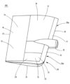
図1は、モジュール構造を有する舵板100の斜視図を示す。舵板100は、組立式舵板セグメント10、11、12、13を備えるとともに、組立式舵板セグメント10、11、12、13で構成される。第1の舵板セグメント10は、主セクション14として設計されている。第2の舵板セグメント11は、前側舵板セクション15として設計されている。第3の舵板セグメントは、後側舵板セクション16として設計されている。第4の舵板セグメント13は、中間セクション17として設計されている。前側舵板セクション15は、前縁18とともに推進バルブ19を備える。第2の舵板セグメント11または前側舵板セクション15は、ほぼL形であり、舵板底部セクション21が、下側領域20に隣り合う。舵板底部セクション21は、前縁18が配置されている第2の舵板セグメント11のセクションに対してほぼ直角に向けられ、R部22を介してこのセクションの中に通り過ぎる。舵板底部セクション21は、第2の舵板セグメント11と単一部品として設計することができ、これは前側舵板セクション15を表す。しかしながら、舵板底部セクション21は、独立した舵板セグメントであることも可能である。第3の舵板セグメント12は、後縁23を備える。後側舵板セクション16および第3の舵板セクション12の外壁24は、平坦であるように設計されている。「セミ・フラット部品」とも呼ばれ得る中間セクション17として設計されている第4の舵板セグメントは、わずかに湾曲した外壁25を主として備える。図示の構成では、第1の舵板セグメント10、第2の舵板セグメント11、および第3の舵板セグメント12は、中間セクション17および第4の舵板セグメント13を囲む。図示の舵100は、ツイスト舵である。これは、前縁18の上側セクション26aが、前縁18の下側セクション26bに対してずれており、そのため、上側セクション26aは左舷方向にずれ、一方、下側セクション26bは右舷方向にずれていることを意味する。
FIG. 1 shows a perspective view of a
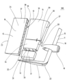
図2は、モジュール構造を有する舵100の分解組立図を示す。前側舵板セクション15として設計されている第2の舵板セグメント11は、前縁18、推進バルブ19、および舵板底部セクション21を備える。主セクション14として設計されている第1の舵板セグメント10は、第1のサブセグメント27および第2のサブセグメント28で構成される。第1のサブセグメント27および第2のサブセグメント28は、安定化プレート29として設計されている接続体30を介して互いに接続される。長手方向リブ32は、主セクション14の第2のサブセグメント28の底部31に見ることができる。主セクション14または第1の舵板セグメント10は、第1のサブセグメント27で構成され、第2のサブセグメント28は、長手方向リブ32および短手方向リブで構成されている外壁34を有するベア・フレーム構造33をパネル付けすることによる従来の製造方法によって製造される。
FIG. 2 shows an exploded view of a
対照的に、前側舵板セクション15を形成する第2の舵板セグメント11は、付加または造形製造方法によって、詳細には3Dプリント法によって製造される。
In contrast, the second
後側舵板セクション16として設計された第3の舵板セグメント12は、内部空間35内にオール・スチール・ハニカム構成部品36を備え、これにより、第3の舵板セグメント12は、軽量要素37として設計されている。中間セクション17として設計されている第4の舵板セグメント13は、ベア・フレーム構造をパネル付けすることによる従来の製造方法によって、3Dプリント法によって、または他の方法によって製造することができる。
The third
異なる製造方法により、舵板セグメント10、11、12、13の材料は異なる。このようにして、3Dプリント法によって製造される第2の舵板セグメント11は、プラスチックまたは金属で作製することができる。対照的に、知られている製造方法によって製造される主セクション14は、鋼鉄以外で製造される。後側舵板セクション16も、従来のまたは知られている製造方法によって製造することができる。しかしながら、後側舵板セクション16がプラスチック以外で製造される、またはプラスチックを含むことも可能である。
Due to different manufacturing methods, the materials of the
図3は、前側舵板セクション15として設計されている第2の舵板セグメント11の斜視図を示す。図3に示された実施形態では、第2の舵板セグメント11は、構造化表面39を備える。詳細には、前縁18は、構造化表面39を備える。それによって、構造化表面39は、バイオニック構造40を備える。例えば、バイオニック構造40は、シャークスキン構造41として設計することができる。
FIG. 3 shows a perspective view of the second
前縁18の構造化表面39のセクションは、詳細図で図4に示されている。バイオニック構造40は、複数の高所42を備えたシャークスキン構造41を備える。
A section of structured
第2の舵板セグメント11の前縁18の構造化表面39およびバイオニック構造40は、造形法、付加法、または3Dプリント法による第2の舵板セグメント11と同じ製造ステップ中に同時に製造されることが好ましい。バイオニック構造40は、例えば切削加工によって、第2の舵板セグメント11以外に続けて機械加工されてはならない。
The structured
図5は、主セクション14の斜視図を示す。主セクション14は、安定化プレート29を介して互いに接続されている第1のサブセグメント27および第2のサブセグメント28で構成される。主セクション14の内部空間内には、長手方向リブ32および短手方向リブ43で構成されているベア・フレーム構造33が配置され、ベア・フレーム構造33は、外壁34を備える。
FIG. 5 shows a perspective view of
図3を参照すると、第2の舵板セグメント11の舵板底部セクション21も、複数のサブセグメント44で構成されることが認識され得る。舵板底部セクション21のサブセグメント44が、図6の斜視図に示されている。舵板底部セクション21のサブセグメント44は、ほぼU形であり、凹部または溝45を備えており、凹部または溝45は、サブセグメント44の長手方向46に延びる。それによって、溝45は、中央に配置されず、サブセグメント44内でわずかにずれて延びる。サブセグメント44の第1の対向側面47は、受入れ開口48として設計されている接続手段49を備える。
With reference to FIG. 3 , it can be appreciated that the rudder
図7aおよび図7bにおいて、サブセグメント44は、正面図(図7a)および背面図(図7b)で示されている。正面図には、サブセグメント44の第2の対向側面50が示されている。受入れ開口51として設計されている接続手段52も、第2の対向側面50内に位置する。図7bに示めされた背面図には、接続手段49が、第1の対向側面47内にやはり示されている。
In Figures 7a and 7b, the sub-segment 44 is shown in front view (Figure 7a) and rear view (Figure 7b). The front view shows the second
図8aおよび図8bは、サブセグメント44の平面図(図8a)および側面図(図8b)を示す。中央に配置されないサブセグメント44の上側53の溝45は、明確に認識することができる。複数のサブセグメント44は、第1のサブセグメント44の第1の対向側面47が第2のサブセグメント44の第2の対向側面50と接触したままとなるように配置することができる。スナップフック、またはクリック接続要素、あるいは該当する場合、ねじ(全て図示せず)は、受入れ開口48、51の中に導かれることができ、それによって複数のサブセグメント44を互いに接続して、舵板底部セクション21を形成する。
8a and 8b show a plan view (FIG. 8a) and a side view (FIG. 8b) of
サブセグメント44は、3Dプリント法によって第2の舵板セグメント11の一部としてやはり製造される。材料は、PET-GまたはABSであることが好ましい。図8aの平面図では、第1の側面54の外形は、第1の側面54の反対側にある第2の側面55の外形よりも強く湾曲していることがさらに認識され得る。異なる外形は、ツイスト舵として設計されそれによって圧力側56および吸込側57を備える舵板100の側面の異なる外形に対応する。
The sub-segment 44 is also manufactured as part of the second
100 舵板
10 第1の舵板セグメント
11 第2の舵板セグメント
12 第3の舵板セグメント
13 第4の舵板セグメント
14 主セクション
15 前側舵板セクション
16 後側舵板セクション
17 中間セクション
18 前縁
19 推進バルブ
20 下側エリア
21 舵板底部セクション
22 R部
23 後縁
24 外壁
25 外壁
26a 上側セクション
26b 下側セクション
27 第1のサブセグメント
28 第2のサブセグメント
29 安定化プレート
30 接続体
31 底部
32 長手方向リブ
33 ベア・フレーム構造
34 外壁
35 内部空間
36 ハニカム要素
37 軽量要素
38 パネル
39 構造化表面
40 バイオニック構造
41 シャークスキン構造
42 突出部
43 短手方向リブ
44 サブセグメント
45 溝
46 長手方向
47 第1の対向側面
48 受入れ開口
49 接続手段
50 第2の対向側面
51 受入れ開口
52 接続手段
53 上側
54 第1の側面
55 第2の側面
56 圧力側
57 吸込側
100
Claims (13)
前記舵板(100)は、前記舵板を舵頭材に接続する舵板ハブを有する主セクション(14)と、前記舵板の前縁(18)を有する前側舵板セクション(15)と、前記舵板の後縁(23)を有する後側舵板セクション(16)と、を備え、
前記主セクション(14)は、第1の舵板セグメント(10)であり、
前記前側舵板セクション(15)は、第2の舵板セグメント(11)であり、
前記後側舵板セクション(16)は、第3の舵板セグメント(12)であり、
前記主セクション(14)は、前記前側舵板セクション(15)とは別の材料で構成され、および/または、別の材料で作製され、および/または別の製造方法によって製造され、
前記第3の舵板セグメント(12)は、Tハニカム構成部品またはオール・スチール・ハニカム構成部品とされている舵板(100)。 A rudder blade (100) of modular construction, comprising at least three prefabricated rudder blade segments (10, 11, 12, 13), the at least three prefabricated rudder blade segments (10, 11, 12, 13),
Said rudder blade (100) comprises a main section (14) having a rudder blade hub connecting said rudder blade to a rudder stock, a forward rudder blade section (15) having a leading edge (18) of said rudder blade; a rear rudder blade section (16) having the trailing edge (23) of said rudder blade;
said main section (14) is the first rudder blade segment (10),
said forward rudder blade section (15) is a second rudder blade segment (11),
said rear rudder blade section (16) is the third rudder blade segment (12);
said main section (14) is composed of and/or made of a different material and/or manufactured by a different manufacturing method than said forward rudder blade section (15),
A rudder blade (100) , wherein said third rudder blade segment (12) is a T-honeycomb component or an all-steel honeycomb component .
少なくとも4つの組立式舵板セグメント(10,11,12,13)であるとともに、該少なくとも4つの組立式舵板セグメント(10,11,12,13)で構成され、前記中間セクション(17)は、第4の舵板セグメント(13)を備えるまたは第4の舵板セグメント(13)である請求項1に記載の舵板(100)。 comprising an intermediate section (17);
at least four prefabricated rudder blade segments (10, 11, 12, 13) and comprising said at least four prefabricated rudder blade segments (10, 11, 12, 13), said intermediate section (17) 2. A rudder blade (100) according to claim 1, comprising or being a fourth rudder blade segment (13).
前記舵板セグメントは、前縁(18)を有する前記前側舵板セクション(15)であり、
造形製造方法および/または付加製造方法によって製造される舵板セグメント。 A rudder blade segment for a rudder blade (100) according to any one of claims 1 to 6,
said rudder blade segment being said forward rudder blade section (15) having a leading edge (18);
Rudder blade segments manufactured by shaped and/or additive manufacturing methods.
該サブセグメント(27,28,44)は、クリック・ファスナ・システムを用いて、接着、共にねじ止め、または溶接することによって、互いに接続される請求項7または8に記載の舵板セグメント。 comprising at least two sub-segments (27, 28, 44) and/or consisting of at least two sub-segments (27, 28, 44),
A rudder blade segment according to claim 7 or 8, wherein the sub-segments (27, 28, 44) are connected to each other by gluing, screwing together or welding using a click fastener system.
該サブセグメント(44)は、U形で設計されるとともに、別の舵板セグメントに接続するために長手方向(46)の延びる凹部または溝(45)を備え、ならびに/あるいは前記サブセグメント(44)は、第1の対向側面(47)および第2の対向側面(50)を備え、接続手段(49,52)は、2つのサブセグメント(44)を前記対向側面(47,50)にそれぞれ接続するように前記第1の対向側面(47)および前記第2の対向側面(50)に配置される請求項10に記載の舵板セグメント。 said rudder blade bottom section (21) is composed of sub-segments (44),
Said sub-segment (44) is designed U-shaped and comprises a longitudinal (46) extending recess or groove (45) for connection to another rudder blade segment and/or said sub-segment (44). ) comprises a first opposing side (47) and a second opposing side (50), connecting means (49, 52) connecting two sub-segments (44) to said opposing sides (47, 50) respectively. 11. A rudder blade segment according to claim 10, arranged on said first opposite side (47) and said second opposite side (50) in a connecting manner.
第1の舵板セグメント(10)を製造するステップと、
第2の舵板セグメント(11)を製造するステップと、
第3の舵板セグメント(12)を製造するステップと、
少なくとも前記第1の舵板セグメント(10)、前記第2の舵板セグメント(11)および前記第3の舵板セグメント(12)を接合するステップと、
を含み、
前記第1の舵板セグメント(10)は、前記舵板(100)の主セクション(14)であり、
前記第2の舵板セグメント(11)は、前側舵板セクション(15)であり、
前記第3の舵板セグメント(12)は、前記舵板の後縁(23)を有する後側舵板セクション(16)であり、
前記第1の舵板セグメント(10)は、短手方向リブ(43)および長手方向リブ(32)で構成されるベア・フレーム構造(33)をパネル付けすることにより溶接法によって製造され、
前記第2の舵板セグメント(11)は、造形製造方法および/または付加製造方法によって製造され、
前記第3の舵板セグメント(12)は、Tハニカム構成部品またはオール・スチール・ハニカム構成部品とされている方法。 A method of manufacturing a rudder blade (100) using modular construction, comprising:
manufacturing a first rudder blade segment (10);
manufacturing a second rudder blade segment (11);
manufacturing a third rudder blade segment (12);
joining at least said first rudder blade segment (10), said second rudder blade segment (11) and said third rudder blade segment (12);
including
said first rudder blade segment (10) is the main section (14) of said rudder blade (100);
said second rudder blade segment (11) is a forward rudder blade section (15),
Said third rudder blade segment (12) is the rear rudder blade section (16) with said rudder blade trailing edge (23),
said first rudder blade segment (10) is manufactured by a welding process by paneling a bare frame structure (33) consisting of transverse ribs (43) and longitudinal ribs (32),
said second rudder blade segment (11) is manufactured by a shaping manufacturing method and/or an additive manufacturing method,
A method, wherein said third rudder blade segment (12) is a T-honeycomb component or an all-steel honeycomb component .
Applications Claiming Priority (2)
| Application Number | Priority Date | Filing Date | Title |
|---|---|---|---|
| EP17204181.6A EP3489128A1 (en) | 2017-11-28 | 2017-11-28 | Blade of an oar with modular structure, segment for a blade of an oar for a device for improving propulsion and method for producing a blade of an oar |
| EP17204181.6 | 2017-11-28 |
Publications (3)
| Publication Number | Publication Date |
|---|---|
| JP2019099143A JP2019099143A (en) | 2019-06-24 |
| JP2019099143A5 JP2019099143A5 (en) | 2021-07-26 |
| JP7272782B2 true JP7272782B2 (en) | 2023-05-12 |
Family
ID=60484220
Family Applications (1)
| Application Number | Title | Priority Date | Filing Date |
|---|---|---|---|
| JP2018219869A Active JP7272782B2 (en) | 2017-11-28 | 2018-11-26 | Rudder blade with modular construction, segment for a rudder blade or for a device to improve propulsion, and method for manufacturing a rudder blade |
Country Status (7)
| Country | Link |
|---|---|
| US (1) | US20190161151A1 (en) |
| EP (1) | EP3489128A1 (en) |
| JP (1) | JP7272782B2 (en) |
| KR (1) | KR102618746B1 (en) |
| CN (1) | CN110001912B (en) |
| CA (1) | CA3025112A1 (en) |
| TW (1) | TW201925028A (en) |
Families Citing this family (5)
| Publication number | Priority date | Publication date | Assignee | Title |
|---|---|---|---|---|
| EP3489128A1 (en) * | 2017-11-28 | 2019-05-29 | Becker Marine Systems GmbH | Blade of an oar with modular structure, segment for a blade of an oar for a device for improving propulsion and method for producing a blade of an oar |
| CN110723263B (en) * | 2019-09-17 | 2020-07-14 | 广州文冲船舶修造有限公司 | Ship rudder blade refitting process |
| CN110877693B (en) * | 2019-11-15 | 2022-04-01 | 沪东中华造船(集团)有限公司 | Intelligent manufacturing method for double-layer bottom section of LNG ship |
| CN111661275B (en) * | 2020-05-29 | 2021-06-08 | 广州文冲船舶修造有限公司 | Rudder stock replacing process |
| CN115675832B (en) * | 2022-12-27 | 2023-03-17 | 成都航空职业技术学院 | Multi-section type space quadrilateral wing framework and bionic aircraft |
Citations (15)
| Publication number | Priority date | Publication date | Assignee | Title |
|---|---|---|---|---|
| JP2000302099A (en) | 1999-04-23 | 2000-10-31 | Yamaha Motor Co Ltd | Rudder plate structure of small ship |
| US20050076819A1 (en) | 2002-10-10 | 2005-04-14 | Hilleman Terry Bruceman | Apparatus and method for reducing hydrofoil cavitation |
| KR100648367B1 (en) | 2005-11-21 | 2006-11-23 | 현대중공업 주식회사 | The ship's rudder for anti-erosion of pressure equalized structure |
| JP2007326502A (en) | 2006-06-09 | 2007-12-20 | Japan Hamuwaaji Kk | Mariner type high-lift two-rudder device |
| US20080035788A1 (en) | 2006-08-11 | 2008-02-14 | Techno-Sciences, Inc. | Cellular support structures used for controlled actuation of fluid contact surfaces |
| JP2008120370A (en) | 2006-11-13 | 2008-05-29 | Becker Marine Systems Gmbh & Co Kg | Rudder for ships |
| JP2009001266A (en) | 2007-06-21 | 2009-01-08 | Becker Marine Systems Gmbh & Co Kg | Rudder for ship |
| JP2009120190A (en) | 2007-11-13 | 2009-06-04 | Becker Marine Systems Gmbh & Co Kg | Rudder assembly for ship with high speed with cavitation reducing twisted rudder, in particular, whole balancing rudder |
| KR101122537B1 (en) | 2011-09-23 | 2012-03-23 | (주)지엠코 | Vessel rudder |
| JP2012162110A (en) | 2011-02-03 | 2012-08-30 | Sumitomo Heavy Industries Marine & Engineering Co Ltd | Rudder with rudder valve, ship, and rudder valve, and method for manufacturing rudder with rudder valve |
| JP2012232736A (en) | 2011-05-04 | 2012-11-29 | Massachusetts Inst Of Technology <Mit> | Propulsion system, method for forming propulsion system, and method for operating propulsion system |
| DE102014101120A1 (en) | 2013-01-30 | 2014-07-31 | Becker Marine Systems Gmbh & Co. Kg | Hollow structure e.g. airfoil for ship, has cavity which is enclosed by two plates forming outer surfaces of hollow casing and is filled with metal foam, whose macro-structure has extension in three mutually perpendicular axes |
| JP2016508923A (en) | 2013-03-08 | 2016-03-24 | ロールス・ロイス、マリン、アクティーゼルスカブ、ラダーズRolls−Royce Marine As Rudders | Rudder |
| US20160319668A1 (en) | 2015-04-28 | 2016-11-03 | The Boeing Company | Textured leading edge for aerospace and nautical structures |
| US20190090454A1 (en) | 2017-09-26 | 2019-03-28 | William Bright | Pet grooming tool |
Family Cites Families (21)
| Publication number | Priority date | Publication date | Assignee | Title |
|---|---|---|---|---|
| US3710749A (en) * | 1971-02-08 | 1973-01-16 | C Duryea | Boat flanking rudder system |
| DE2555098C2 (en) * | 1975-12-08 | 1977-10-13 | Willi Becker Ingenieurbüro, 2000 Hamburg | Rudders, in particular balance profile rudders with one fin, for watercraft |
| DE3041661A1 (en) * | 1980-11-05 | 1982-06-16 | Willi Becker Ingenieurbüro GmbH, 2000 Hamburg | OARS FOR WATER VEHICLES, ESPECIALLY FOR SEA AND INLAND SHIPS, AND FOR FLOATING DEVICE |
| JPH037695A (en) * | 1989-06-05 | 1991-01-14 | Japan Hamuwaaji Kk | Ship rudder and its fabricating method |
| JPH0633079B2 (en) * | 1989-06-12 | 1994-05-02 | ジャパン・ハムワージ株式会社 | Ship rudder assembly method |
| JPH0546698U (en) * | 1991-11-28 | 1993-06-22 | 川崎重工業株式会社 | Marine flap ladder |
| JPH0632290A (en) * | 1992-07-13 | 1994-02-08 | Hitachi Zosen Corp | Helm at vessel |
| FR2693701B1 (en) * | 1992-07-16 | 1994-09-02 | France Etat Armement | Safran for medium and large tonnage ships. |
| JP2888759B2 (en) * | 1994-07-19 | 1999-05-10 | 日本操舵システム株式会社 | Marina type shilling rudder |
| KR200410384Y1 (en) * | 2005-12-21 | 2006-03-08 | 삼성중공업 주식회사 | The spade rudder |
| DE102008005253A1 (en) * | 2007-08-02 | 2009-07-23 | Benz, Gerhard, Dipl.-Ing. | Sailing yacht with a rowing and a non-offensive hull body part, in particular combinable sail yacht and motorboat modular system |
| DE202007016164U1 (en) * | 2007-11-16 | 2008-01-24 | Becker Marine Systems Gmbh & Co. Kg | High efficiency rudder for ships |
| KR20100122537A (en) * | 2009-05-13 | 2010-11-23 | 최정관 | Oriental herbal medicine composition containing magnet ingredient |
| CN101913250A (en) * | 2010-08-17 | 2010-12-15 | 沈阳飞机工业(集团)有限公司 | Rudder wall plate molding process |
| US9359054B2 (en) * | 2010-11-30 | 2016-06-07 | Thomas W Watts | Control mechanism |
| KR101324964B1 (en) * | 2011-02-25 | 2013-11-04 | 삼성중공업 주식회사 | Rudder for Ship |
| KR101267897B1 (en) * | 2011-08-24 | 2013-05-27 | 대우조선해양 주식회사 | Structure for foaming surface layer of rudder in ship and foaming method thereof |
| DE102014217228A1 (en) * | 2014-08-28 | 2016-03-03 | Skf Blohm + Voss Industries Gmbh | Fin stabilizer, method and watercraft |
| CN105599889B (en) * | 2016-01-12 | 2019-12-27 | 中国人民解放军海军工程大学 | High-rigidity light solid composite rudder blade |
| JP2017177885A (en) * | 2016-03-28 | 2017-10-05 | 三菱重工業株式会社 | Rudder plate |
| EP3489128A1 (en) * | 2017-11-28 | 2019-05-29 | Becker Marine Systems GmbH | Blade of an oar with modular structure, segment for a blade of an oar for a device for improving propulsion and method for producing a blade of an oar |
-
2017
- 2017-11-28 EP EP17204181.6A patent/EP3489128A1/en active Pending
-
2018
- 2018-11-23 CA CA3025112A patent/CA3025112A1/en not_active Abandoned
- 2018-11-26 JP JP2018219869A patent/JP7272782B2/en active Active
- 2018-11-26 TW TW107142069A patent/TW201925028A/en unknown
- 2018-11-27 US US16/201,667 patent/US20190161151A1/en not_active Abandoned
- 2018-11-28 CN CN201811436887.3A patent/CN110001912B/en active Active
- 2018-11-28 KR KR1020180149746A patent/KR102618746B1/en active IP Right Grant
Patent Citations (15)
| Publication number | Priority date | Publication date | Assignee | Title |
|---|---|---|---|---|
| JP2000302099A (en) | 1999-04-23 | 2000-10-31 | Yamaha Motor Co Ltd | Rudder plate structure of small ship |
| US20050076819A1 (en) | 2002-10-10 | 2005-04-14 | Hilleman Terry Bruceman | Apparatus and method for reducing hydrofoil cavitation |
| KR100648367B1 (en) | 2005-11-21 | 2006-11-23 | 현대중공업 주식회사 | The ship's rudder for anti-erosion of pressure equalized structure |
| JP2007326502A (en) | 2006-06-09 | 2007-12-20 | Japan Hamuwaaji Kk | Mariner type high-lift two-rudder device |
| US20080035788A1 (en) | 2006-08-11 | 2008-02-14 | Techno-Sciences, Inc. | Cellular support structures used for controlled actuation of fluid contact surfaces |
| JP2008120370A (en) | 2006-11-13 | 2008-05-29 | Becker Marine Systems Gmbh & Co Kg | Rudder for ships |
| JP2009001266A (en) | 2007-06-21 | 2009-01-08 | Becker Marine Systems Gmbh & Co Kg | Rudder for ship |
| JP2009120190A (en) | 2007-11-13 | 2009-06-04 | Becker Marine Systems Gmbh & Co Kg | Rudder assembly for ship with high speed with cavitation reducing twisted rudder, in particular, whole balancing rudder |
| JP2012162110A (en) | 2011-02-03 | 2012-08-30 | Sumitomo Heavy Industries Marine & Engineering Co Ltd | Rudder with rudder valve, ship, and rudder valve, and method for manufacturing rudder with rudder valve |
| JP2012232736A (en) | 2011-05-04 | 2012-11-29 | Massachusetts Inst Of Technology <Mit> | Propulsion system, method for forming propulsion system, and method for operating propulsion system |
| KR101122537B1 (en) | 2011-09-23 | 2012-03-23 | (주)지엠코 | Vessel rudder |
| DE102014101120A1 (en) | 2013-01-30 | 2014-07-31 | Becker Marine Systems Gmbh & Co. Kg | Hollow structure e.g. airfoil for ship, has cavity which is enclosed by two plates forming outer surfaces of hollow casing and is filled with metal foam, whose macro-structure has extension in three mutually perpendicular axes |
| JP2016508923A (en) | 2013-03-08 | 2016-03-24 | ロールス・ロイス、マリン、アクティーゼルスカブ、ラダーズRolls−Royce Marine As Rudders | Rudder |
| US20160319668A1 (en) | 2015-04-28 | 2016-11-03 | The Boeing Company | Textured leading edge for aerospace and nautical structures |
| US20190090454A1 (en) | 2017-09-26 | 2019-03-28 | William Bright | Pet grooming tool |
Also Published As
| Publication number | Publication date |
|---|---|
| EP3489128A1 (en) | 2019-05-29 |
| CN110001912A (en) | 2019-07-12 |
| KR102618746B1 (en) | 2023-12-27 |
| US20190161151A1 (en) | 2019-05-30 |
| KR20190062315A (en) | 2019-06-05 |
| CA3025112A1 (en) | 2019-05-28 |
| TW201925028A (en) | 2019-07-01 |
| CN110001912B (en) | 2023-03-28 |
| JP2019099143A (en) | 2019-06-24 |
Similar Documents
| Publication | Publication Date | Title |
|---|---|---|
| JP7272782B2 (en) | Rudder blade with modular construction, segment for a rudder blade or for a device to improve propulsion, and method for manufacturing a rudder blade | |
| CN100467187C (en) | Laser welding with filler wire method of aluminum alloy T-type shapes for boat | |
| US8991326B2 (en) | Displacement hull form not subject to the limitation of hull speed | |
| CN107021183B (en) | Bulbous bow, marine vessel having such a bow and methods of manufacturing and installing same | |
| TW201529417A (en) | Method for enlarging a ship and enlarged ship | |
| Brizzolara et al. | Hydrodynamic design of a family of hybrid SWATH unmanned surface vehicles | |
| US20210316817A1 (en) | Hybrid chine boat hull and methods of manufacture and use | |
| KR102054241B1 (en) | Flap rudder | |
| US10464654B2 (en) | Rudder blade with a rudder blade hub and rudder blade hub for a rudder blade | |
| KR102055382B1 (en) | Manufacturing method of rudder having composite material | |
| CN114802586A (en) | Three-body ship | |
| CN113443072A (en) | Ship tail post | |
| CN202368755U (en) | Small plastic ship hull | |
| Alessio et al. | Design evaluation and alteration of the Dark Harbor 17.5: Case study of a modern replica | |
| JP6582296B2 (en) | Ship rudder and ship | |
| Souppez | Design and production of a wooden Thames A Rater Class sailing yacht | |
| JP2009149278A (en) | Wings of surface effect craft and their manufacturing method | |
| CN1329243C (en) | Method for designing double-layer modularized structure of outer hull of ship | |
| CN203844946U (en) | Hollow ship stem | |
| Dewavrin | Design of a cruising sailing yacht with an experimental fluid dynamics investigation into hydrofoils | |
| Chahal et al. | Design and manufacturing of a surf foil | |
| IT202000031397A1 (en) | BOAT HULL AND METHOD OF MAKING A BOAT HULL | |
| Ingrassia et al. | Numerical methods in the design process of a sailing yacht | |
| Djurberg | SANDWICH VERSUS SINGLE SKIN: Material Concept of a Patrol Boat in a Life Cycle Cost Perspective | |
| EP3847091A1 (en) | Ship hull having a raised portion in the region of an underside of the ship hull |
Legal Events
| Date | Code | Title | Description |
|---|---|---|---|
| A521 | Request for written amendment filed |
Free format text: JAPANESE INTERMEDIATE CODE: A523 Effective date: 20210528 |
|
| A621 | Written request for application examination |
Free format text: JAPANESE INTERMEDIATE CODE: A621 Effective date: 20210528 |
|
| A977 | Report on retrieval |
Free format text: JAPANESE INTERMEDIATE CODE: A971007 Effective date: 20220208 |
|
| A131 | Notification of reasons for refusal |
Free format text: JAPANESE INTERMEDIATE CODE: A131 Effective date: 20220315 |
|
| A601 | Written request for extension of time |
Free format text: JAPANESE INTERMEDIATE CODE: A601 Effective date: 20220615 |
|
| A521 | Request for written amendment filed |
Free format text: JAPANESE INTERMEDIATE CODE: A523 Effective date: 20220708 |
|
| A131 | Notification of reasons for refusal |
Free format text: JAPANESE INTERMEDIATE CODE: A131 Effective date: 20221108 |
|
| A601 | Written request for extension of time |
Free format text: JAPANESE INTERMEDIATE CODE: A601 Effective date: 20230206 |
|
| A521 | Request for written amendment filed |
Free format text: JAPANESE INTERMEDIATE CODE: A523 Effective date: 20230310 |
|
| TRDD | Decision of grant or rejection written | ||
| A01 | Written decision to grant a patent or to grant a registration (utility model) |
Free format text: JAPANESE INTERMEDIATE CODE: A01 Effective date: 20230404 |
|
| A61 | First payment of annual fees (during grant procedure) |
Free format text: JAPANESE INTERMEDIATE CODE: A61 Effective date: 20230427 |
|
| R150 | Certificate of patent or registration of utility model |
Ref document number: 7272782 Country of ref document: JP Free format text: JAPANESE INTERMEDIATE CODE: R150 |