JP7271520B2 - Real-time monitoring of multi-zone vertical furnaces for early recognition of heating element failure - Google Patents
Real-time monitoring of multi-zone vertical furnaces for early recognition of heating element failure Download PDFInfo
- Publication number
- JP7271520B2 JP7271520B2 JP2020517118A JP2020517118A JP7271520B2 JP 7271520 B2 JP7271520 B2 JP 7271520B2 JP 2020517118 A JP2020517118 A JP 2020517118A JP 2020517118 A JP2020517118 A JP 2020517118A JP 7271520 B2 JP7271520 B2 JP 7271520B2
- Authority
- JP
- Japan
- Prior art keywords
- resistance
- resistor
- voltage
- current
- zone
- Prior art date
- Legal status (The legal status is an assumption and is not a legal conclusion. Google has not performed a legal analysis and makes no representation as to the accuracy of the status listed.)
- Active
Links
Images


Classifications
-
- F—MECHANICAL ENGINEERING; LIGHTING; HEATING; WEAPONS; BLASTING
- F27—FURNACES; KILNS; OVENS; RETORTS
- F27B—FURNACES, KILNS, OVENS, OR RETORTS IN GENERAL; OPEN SINTERING OR LIKE APPARATUS
- F27B17/00—Furnaces of a kind not covered by any preceding group
- F27B17/0016—Chamber type furnaces
- F27B17/0025—Especially adapted for treating semiconductor wafers
-
- F—MECHANICAL ENGINEERING; LIGHTING; HEATING; WEAPONS; BLASTING
- F27—FURNACES; KILNS; OVENS; RETORTS
- F27D—DETAILS OR ACCESSORIES OF FURNACES, KILNS, OVENS, OR RETORTS, IN SO FAR AS THEY ARE OF KINDS OCCURRING IN MORE THAN ONE KIND OF FURNACE
- F27D19/00—Arrangements of controlling devices
-
- F—MECHANICAL ENGINEERING; LIGHTING; HEATING; WEAPONS; BLASTING
- F27—FURNACES; KILNS; OVENS; RETORTS
- F27D—DETAILS OR ACCESSORIES OF FURNACES, KILNS, OVENS, OR RETORTS, IN SO FAR AS THEY ARE OF KINDS OCCURRING IN MORE THAN ONE KIND OF FURNACE
- F27D21/00—Arrangements of monitoring devices; Arrangements of safety devices
- F27D21/0014—Devices for monitoring temperature
-
- G—PHYSICS
- G01—MEASURING; TESTING
- G01R—MEASURING ELECTRIC VARIABLES; MEASURING MAGNETIC VARIABLES
- G01R27/00—Arrangements for measuring resistance, reactance, impedance, or electric characteristics derived therefrom
- G01R27/02—Measuring real or complex resistance, reactance, impedance, or other two-pole characteristics derived therefrom, e.g. time constant
- G01R27/14—Measuring resistance by measuring current or voltage obtained from a reference source
-
- G—PHYSICS
- G01—MEASURING; TESTING
- G01R—MEASURING ELECTRIC VARIABLES; MEASURING MAGNETIC VARIABLES
- G01R31/00—Arrangements for testing electric properties; Arrangements for locating electric faults; Arrangements for electrical testing characterised by what is being tested not provided for elsewhere
- G01R31/50—Testing of electric apparatus, lines, cables or components for short-circuits, continuity, leakage current or incorrect line connections
- G01R31/52—Testing for short-circuits, leakage current or ground faults
-
- H—ELECTRICITY
- H01—ELECTRIC ELEMENTS
- H01L—SEMICONDUCTOR DEVICES NOT COVERED BY CLASS H10
- H01L21/00—Processes or apparatus adapted for the manufacture or treatment of semiconductor or solid state devices or of parts thereof
- H01L21/67—Apparatus specially adapted for handling semiconductor or electric solid state devices during manufacture or treatment thereof; Apparatus specially adapted for handling wafers during manufacture or treatment of semiconductor or electric solid state devices or components ; Apparatus not specifically provided for elsewhere
- H01L21/67005—Apparatus not specifically provided for elsewhere
- H01L21/67011—Apparatus for manufacture or treatment
- H01L21/67098—Apparatus for thermal treatment
- H01L21/67109—Apparatus for thermal treatment mainly by convection
-
- H—ELECTRICITY
- H01—ELECTRIC ELEMENTS
- H01L—SEMICONDUCTOR DEVICES NOT COVERED BY CLASS H10
- H01L21/00—Processes or apparatus adapted for the manufacture or treatment of semiconductor or solid state devices or of parts thereof
- H01L21/67—Apparatus specially adapted for handling semiconductor or electric solid state devices during manufacture or treatment thereof; Apparatus specially adapted for handling wafers during manufacture or treatment of semiconductor or electric solid state devices or components ; Apparatus not specifically provided for elsewhere
- H01L21/67005—Apparatus not specifically provided for elsewhere
- H01L21/67242—Apparatus for monitoring, sorting or marking
- H01L21/67248—Temperature monitoring
-
- H—ELECTRICITY
- H01—ELECTRIC ELEMENTS
- H01L—SEMICONDUCTOR DEVICES NOT COVERED BY CLASS H10
- H01L21/00—Processes or apparatus adapted for the manufacture or treatment of semiconductor or solid state devices or of parts thereof
- H01L21/67—Apparatus specially adapted for handling semiconductor or electric solid state devices during manufacture or treatment thereof; Apparatus specially adapted for handling wafers during manufacture or treatment of semiconductor or electric solid state devices or components ; Apparatus not specifically provided for elsewhere
- H01L21/67005—Apparatus not specifically provided for elsewhere
- H01L21/67242—Apparatus for monitoring, sorting or marking
- H01L21/67288—Monitoring of warpage, curvature, damage, defects or the like
-
- H—ELECTRICITY
- H05—ELECTRIC TECHNIQUES NOT OTHERWISE PROVIDED FOR
- H05B—ELECTRIC HEATING; ELECTRIC LIGHT SOURCES NOT OTHERWISE PROVIDED FOR; CIRCUIT ARRANGEMENTS FOR ELECTRIC LIGHT SOURCES, IN GENERAL
- H05B1/00—Details of electric heating devices
- H05B1/02—Automatic switching arrangements specially adapted to apparatus ; Control of heating devices
- H05B1/0227—Applications
- H05B1/023—Industrial applications
- H05B1/0233—Industrial applications for semiconductors manufacturing
-
- F—MECHANICAL ENGINEERING; LIGHTING; HEATING; WEAPONS; BLASTING
- F27—FURNACES; KILNS; OVENS; RETORTS
- F27D—DETAILS OR ACCESSORIES OF FURNACES, KILNS, OVENS, OR RETORTS, IN SO FAR AS THEY ARE OF KINDS OCCURRING IN MORE THAN ONE KIND OF FURNACE
- F27D19/00—Arrangements of controlling devices
- F27D2019/0006—Monitoring the characteristics (composition, quantities, temperature, pressure) of at least one of the gases of the kiln atmosphere and using it as a controlling value
- F27D2019/0025—Monitoring the temperature of a part or of an element of the furnace structure
-
- G—PHYSICS
- G01—MEASURING; TESTING
- G01R—MEASURING ELECTRIC VARIABLES; MEASURING MAGNETIC VARIABLES
- G01R27/00—Arrangements for measuring resistance, reactance, impedance, or electric characteristics derived therefrom
- G01R27/02—Measuring real or complex resistance, reactance, impedance, or other two-pole characteristics derived therefrom, e.g. time constant
- G01R27/08—Measuring resistance by measuring both voltage and current
Landscapes
- Engineering & Computer Science (AREA)
- Physics & Mathematics (AREA)
- General Physics & Mathematics (AREA)
- Manufacturing & Machinery (AREA)
- Condensed Matter Physics & Semiconductors (AREA)
- Computer Hardware Design (AREA)
- Microelectronics & Electronic Packaging (AREA)
- Power Engineering (AREA)
- General Engineering & Computer Science (AREA)
- Mechanical Engineering (AREA)
- Control Of Resistance Heating (AREA)
- Waste-Gas Treatment And Other Accessory Devices For Furnaces (AREA)
- Testing Of Short-Circuits, Discontinuities, Leakage, Or Incorrect Line Connections (AREA)
- Electric Stoves And Ranges (AREA)
- Investigating Or Analyzing Materials Using Thermal Means (AREA)
Description
本発明は、例えばTEL(Tokyo Electron Limited)のファイブ・ゾーン・オーブンAlpha8SEなどの、マルチゾーン縦型炉における、加熱素子のリアルタイム監視に取り組むものである。アクティブな運転状態におけるサーマル装置(請求項1)では、500℃を超えた値の高温になる。Equipment Datasheet、TEL―Alpha-8SE、2004年8月、2017年9月23日にアクセスしたwww.agsemiconductor.com/files/LM28.pdfを参照。 The present invention addresses real-time monitoring of heating elements in multi-zone vertical furnaces, such as the TEL (Tokyo Electron Limited) five-zone oven Alpha 8SE. Thermal devices (claim 1) in active operating conditions experience high temperatures of values above 500°C. Equipment Datasheet, TEL-Alpha-8SE, August 2004, accessed September 23, 2017 at www. Ag semiconductor. com/files/LM28. See pdf.
ウエハの場合、US2010/14749(Turlure、STM)は、温度センサ29が配置されたウエハオーブン(同文献10ページ、3欄、段落45、46)に関するものである。そこに取り付けられたカメラ26によって測定される温度が、予め設定される測定閾値を上回ると、オーブンが過度に高温になるか、またはオーブンが過度に高温であることでウエハ位置決めのために用いられるカメラが損傷する可能性がある。そこでは、ウエハ用のオーブンの欠陥発生を認識することは、意図されていない(不可能でもある)。
In the case of wafers, US2010/14749 (Turlure, STM) relates to a wafer oven in which a temperature sensor 29 is arranged (ibid p. 10,
US2009/237102A1(Lou、Star Technologies)は、半導体のためのサーマル装置を記載し、オーブンの温度を制御するための温度コントロールを有する。それに加えて、オーブン内の半導体のためのテスト信号が提供される。 US2009/237102A1 (Lou, Star Technologies) describes a thermal apparatus for semiconductors, with a temperature control for controlling the temperature of the oven. Additionally, a test signal for the semiconductors in the oven is provided.
DE3910676A1(Pierburg、Loesing)は、大幅に異なる分野における空気流量の測定装置に関し、これは内燃機関、つまり車両におけるものである。例えば堆積または経年劣化などに起因した運用測定誤差を回避する必要がある。時間間隔をおいて測定が行われ、測定結果が比較され、その比較の結果によって補正が行われる。同文献5欄40~51行、または1欄52行目から、またはオーム抵抗に関する4欄、12行以下を参照。
DE 39 10 676 A1 (Pierburg, Loesing) relates to a device for measuring air flow in a significantly different field, this being in internal combustion engines, ie vehicles. There is a need to avoid operational measurement errors due to, for example, deposition or aging. Measurements are taken at time intervals, the measurement results are compared, and corrections are made according to the results of the comparison. See
一方、特許請求される発明は、冒頭で述べた(それぞれ少なくとも1つの加熱素子が配置されている)それぞれのヒートゾーン、従ってすべてのヒートゾーンを一緒に、早期損耗について監視することに関する。また、複数のシステムのそれぞれに複数のヒートゾーンを有する場合についても同様に監視することに関する。 On the other hand, the claimed invention relates to monitoring each of the heat zones mentioned at the outset (in each of which at least one heating element is arranged), thus all heat zones together, for premature wear. It also relates to monitoring similarly in the case of having multiple heat zones in each of multiple systems.
現在、加熱ゾーン(=ヒートゾーン)の早期破損を認識する可能性はない。従って、1つの設備当たり150個あるウエハが失われるリスクが高い。日本の設備メーカであるTokyo Electron(TEL)では、ヒートゾーンの実際の破損を認識する方法しかない。温度の降下による欠陥の認識および当該設備において温度警報を発するという、この種類の熱の監視は、他のメーカによっても提供される。 There is currently no possibility of recognizing premature failure of the heating zone (=heat zone). Therefore, the risk of losing 150 wafers per facility is high. At the Japanese equipment manufacturer Tokyo Electron (TEL), the only way is to recognize the actual failure of the heat zone. This type of thermal monitoring is also offered by other manufacturers, recognizing faults due to temperature drops and issuing temperature alarms in the equipment.
TELによる上記の加熱装置は、600℃~1150℃の範囲で運転される縦型5ゾーンヒータである。縦型配置と高温とによって、平坦に配置された個々のヒートコイル(巻線)が、時間ととともに変形し、ゾーン内の巻線の隣り合う2つの区分が接触し得るようになっている(図1を参照)。その結果、抵抗が数パーセント低下し、所定の時間が経過すると、その時点で巻線が破断する。 The above heating device by TEL is a vertical 5-zone heater operating in the range of 600°C to 1150°C. Due to the vertical arrangement and high temperature, the flatly arranged individual heating coils (windings) deform over time such that two adjacent sections of the windings within a zone can come into contact ( See Figure 1). As a result, the resistance drops by a few percent, and after a certain amount of time the winding breaks.
従来、設備のスタンバイ状態またはプロセス中に5つのゾーンの加熱装置の破損を検出することは、可能ではなかった。過去には破損が幾度も発生している。こうした事態は、一方ではプロセス中に(そのプロセス中断につながる)温度警報を発することで生じたが、スタンバイ状態においても、そのような中断が生じていた。 Conventionally, it has not been possible to detect failure of the five zone heating equipment during standby or in process of the facility. Damage has occurred many times in the past. This happened on the one hand by issuing a temperature alarm during the process (which led to the process being interrupted), but such interruptions also occurred in the standby state.
スタンバイ状態での破損時にも、設備において警報が発せられなかったので、ウエハの温度調節のプロセスを開始することができた。高価値のウエハを予め積載したプロセスが開始され、而してそれは温度警報によって中断されていた。 No alarms were raised in the equipment during the stand-by failure, so the wafer temperature conditioning process could be initiated. A high value wafer preloading process was started which was interrupted by a temperature alarm.
あらゆるプロセス中断は、結果として少なくとも150枚のウエハ(300,000ユーロの損失コスト)、ロット全体(またはバッチ)の生産が損われ、また設備の約12日に及ぶ長期使用不能を伴うこととなっていた。 Any process interruption would result in the loss of production of at least 150 wafers (loss cost of €300,000), an entire lot (or batch), and a prolonged outage of the facility of about 12 days. was
本発明は、上記で説明した先行技術を出発点とし、以下の技術的課題に基づく。本発明が問題としているのは、1バッチ当たり150,000ユーロの価値のウエハ損失を回避するということである。さらに、サーマル装置の予定外の破損が生じないようにするとともに、リソースのより良好な計画可能性が生じるべきである。 The present invention takes the above-described prior art as a starting point and is based on the following technical problems. The problem with the present invention is to avoid losing wafers worth €150,000 per batch. In addition, there should be better planning possibilities for resources while avoiding unplanned failures of thermal equipment.
特許請求される発明(請求項1または請求項18または請求項20)は、ウエハ損失を最小化する、または完全に回避する、および人員および材料の可用性をより良好に計画できるようにするために、損耗(ヒートコイルの素子または領域の接触またはヒートコイルにおける点状伝導箇所(punktuelle Leitstelle)の発生)を早期に認識する。
The claimed invention (
本発明によれば、そのために、各ヒートゾーンの(電圧および電流の測定から得られる)抵抗の継続的測定が行われる。抵抗の現在値が、その前の値と比較される。抵抗値における僅かな偏差でも、ヒートコイル全体が破損するよりも時間的に遥か以前に設備のための警報(警告)が発せられる。 According to the invention, this is done by continuous measurements of the resistance (obtained from voltage and current measurements) of each heat zone. The current value of resistance is compared to its previous value. Even small deviations in resistance value will alert the installation well in time before the entire heating coil fails.
本発明は、リアルタイム検出が個々の加熱ゾーンで恒久的に実施され、従って巻線内の接触が、巻線が最終的に壊れる前の早い段階で認識されるという効果を使用する。これらは、予想されるエラー(すでにアラームメッセージとして出力されているもの)と実際のエラー(巻線の破断として発生)である。 The present invention uses the advantage that real-time detection is permanently implemented in the individual heating zones, so that contact within the windings is recognized early on before the windings finally fail. These are expected errors (which have already been output as alarm messages) and actual errors (which occur as winding breaks).
予想される欠陥を実際の運転の前(いわゆるスタンバイモード)に検出することも可能である(請求項5)。ここで欠陥予想が生じると、最初から全くオンにされない。 It is also possible to detect possible faults before the actual operation (so-called standby mode) (claim 5). If a fault prediction occurs here, it is not turned on at all from the beginning.
本発明によって得られる利点は、特に目前に迫った破損を検出した場合に設備を迅速に停止させ、例えば5ゾーンヒータを予防的に交換することができるか、または個々の加熱ソーンも新しいものと交換するか、あるいは修理が行われないうちはサーマル装置を全く始動させないことにより、ウエハ損失のリスクを最小限に抑えることを可能にする、ということである。 An advantage provided by the present invention is that the installation can be shut down quickly, especially if an imminent failure is detected, for example a 5-zone heater can be proactively replaced or even individual heating zones can be replaced with new ones. It is possible to minimize the risk of wafer loss by replacing or not starting the thermal device at all until repairs are made.
特許請求される画面表示(例えば請求項20)は、複数のサーマル装置の一目で把握できる監視を可能にすると共に、多数の設備または設備に含まれる抵抗を監視しなければならない場合でもユーザがシステムの状態を即座に認識できるようにする。 The claimed screen display (e.g., claim 20) allows for at-a-glance monitoring of multiple thermal devices, while allowing the user to configure the system even when a large number of installations or resistances contained in installations must be monitored. to instantly recognize the status of
請求項1~17のいずれか1項に記載の方法を実行するためにも、画像表示が(効率的に)適している。 Image displays are also (efficiently) suitable for carrying out the method according to any one of claims 1-17.
画面表示は、サーマル装置の技術パラメータを表示するための構成窓領域と、サーマル装置の技術的測定値から算出された値を表示するための測定検出窓領域、好ましくは複数の独立した後者の窓領域とを有し、これらの窓領域のそれぞれ1つが、ただ1つのサーマル設備に割り当てられている。このようにして、複数の設備は、画面上に個別に表示されるが、混同されることはない。 The screen display includes a configuration window area for displaying technical parameters of the thermal device and a measurement detection window area for displaying values calculated from technical measurements of the thermal device, preferably a plurality of independent latter windows. and each one of these window areas is assigned to only one thermal installation. In this way, multiple installations are displayed separately on the screen, but are not confused.
ここで、それぞれの従属請求項が考慮される。 Here the respective dependent claims are considered.
本発明の具体的な実施例については図(画像も)を参照されたい。しかし、これらの実施例は、それゆえに主な請求項に取り込まれるか、そこに不可避に現れる強制的な要素を含むと読み取られるべきでない。 Please refer to the figures (and images) for specific embodiments of the present invention. These embodiments, however, should not, therefore, be read as including mandatory elements that are incorporated into or inevitably appear in the main claims.
このことも、例が請求項を補足するために適している開示を含まないことを意味しない。 This, too, does not mean that the examples do not contain suitable disclosure to supplement the claims.
各箇所および各分において「特に」または「例えば」という用語が読み取れない場合でも、好意的な当業者たる読み手においては、特許請求される発明の以下に記載される実施例が例示的要素、値、および機能を伴う実施例であるものと解されたい。 Even if the terms "particularly" or "for example" fail to read at each place and minute, the reader, one of ordinary skill in the art, will find the following described examples of the claimed invention exemplary elements, values , and examples with functions.
記載されていない要素について、その存在が特許請求から除かれるものと解されてはならない。要素、値、または機能の一例しか開示されない場合でも、当該分野の当業者によれば、それらを自明な仕方で変更することができる。 Any element not listed should not be construed as excluding its presence from a claim. Where only one example of an element, value or function is disclosed, it can be modified in an obvious manner by those skilled in the art.
以下、各図(および画像)に本発明の実施例を示す。 The following figures (and images) illustrate embodiments of the present invention.
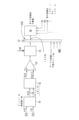
巻線の、すなわち巻回され平坦な形態のヒートコイル1としての、抵抗器1の拡大図が、図1に明確に示されている。ここには、2つの隣り合う加熱ワイヤ区分(黒色と暗色に見える)の接触によって生じる巻線損傷Fの領域(円内)において発生した巻線接触F1が示されている。
An enlarged view of the
本明細書中に記載される発明、特に本明細書中に記載される実施例は、そのような損傷が生じる前に、その損傷を生じせとしめることとなる損傷として、予測することができる。 The invention described herein, particularly the examples described herein, can predict the damage that would cause the damage before such damage occurs. .
コイルの中心は示されていないが、その中心は、上方に、画像の略2倍の高さのところにあると考えられる。詳細が(右)下の縁領域に示されており、そのようなコイルについてヒートゾーン1’における抵抗器1を元にして説明する。加熱ワイヤは、巻線形状またはコイル形状に、中心から外に向かって渦状に巻回されている、連続した一本の線である。
The center of the coil is not shown, but it is believed to be above, at approximately twice the height of the image. Details are shown in the (right) lower edge area and such a coil will be described on the basis of
図1において、明色に見て取れる径方向に向いたウェブは、この暗色で示された加熱ワイヤの位置を安定させる。加熱ワイヤの、それぞれ径方向に隣り合う2つの区分間(画像において暗色に見える)には、絶縁材料(画像において明色)が設けられている。縁領域において、この加熱ワイヤの符号が付された個々の区分を認識することができる。区分1.4、1.3、1.2、1.1は、加熱ワイヤ、すなわち巻線の隣り合う区分の全部である。最外側のワイヤ区分または導線区分1.1は、すべてのウェブ1.10~1.14の下を通っている。この最外側の導線区分は、画像の左、ウェブ1.10の下で始まって右へ続き、ウェブ1.11、1.12に達し、すぐ次に続くウェブ1.13、1.14に達する。 In FIG. 1, the radially oriented web, visible in light color, stabilizes the position of this heating wire, shown in dark color. An insulating material (light in the image) is provided between two respective radially adjacent sections of the heating wire (appearing dark in the image). In the edge area, individual labeled sections of this heating wire can be recognized. Sections 1.4, 1.3, 1.2, 1.1 are all adjacent sections of the heating wire or winding. The outermost wire section or conductor section 1.1 passes under all webs 1.10-1.14. This outermost wire segment starts at the left of the image, below web 1.10 and continues to the right, reaching webs 1.11, 1.12 and the immediately following webs 1.13, 1.14. .
これらのウェブは、周方向に略等しい間隔角度を有するが、(径方向に)その長手方向の延在長さは同じではなく、画像に見て取れるように、短めのものと、より長めのものとが、交互に配置されている。 These webs have approximately equal spacing angles in the circumferential direction, but their longitudinal extensions (in the radial direction) are not the same, and as can be seen in the image, the shorter and the longer are arranged alternately.
区分1.3の内側の縁には、絶縁ゾーン1.6がある。ウェブは、加熱ワイヤ区分間にある絶縁ゾーン(より明色に示される)で支持されている。さらに内側には、加熱ワイヤの区分1.4に隣接して、次の絶縁ゾーン1.5がある。右に続く径方向ウェブ1.12と径方向ウェブ1.13との間の区分において、加熱ワイヤの前述の導線区分1.4、1.3、1.2、1.1が続く。 At the inner edge of section 1.3 there is an insulating zone 1.6. The web is supported by insulation zones (shown in lighter color) between the heating wire segments. Further inside, next to the section 1.4 of the heating wire, there is the next insulation zone 1.5. In the section between the radial webs 1.12 and 1.13 that follow to the right, the aforementioned conductor sections 1.4, 1.3, 1.2, 1.1 of the heating wire follow.
この中間ウェブ領域において、絶縁部1.6の幅が格段に広くなっている(区分1.6’)ことが見て取れる、すなわち、ヒートコイルの区分1.3および1.4が互いに遠ざかり、αFで示される次のウェブ間区分において、丸で囲んだ欠陥領域Fにおいてウェブ間区分αFにおける2つの導線区分1.3および1.4の接触F1が起こるまでに区分1.4が外側へ明らかにずれている。 In this intermediate web region it can be seen that the insulation 1.6 is significantly widened (section 1.6'), i.e. sections 1.3 and 1.4 of the heating coil move away from each other and at αF In the next interweb section shown, section 1.4 is clearly outward until contact F1 of the two conductor sections 1.3 and 1.4 in the interweb section αF occurs in the circled defect area F. out of alignment.
円周コイル(約360°)の短絡につながる、この接触の局所的発生が、欠陥発生につながることとなる。この欠陥発生は、一箇所F1で導線破断につながり得る過度な昇温が生じた場合に、全ヒートコイル1が破損するという結果をもたらす。
This localized occurrence of contact, which leads to shorting of the circumferential coil (approximately 360°), will lead to defect generation. This defect occurrence results in the failure of the
このことが、破線で示した(左縁の)領域F’に見て取れる。ワイヤ区分1.1.および1.2を襲う(迫り来る)さらなる欠陥発生がある。 This can be seen in the dashed (left edge) area F'. Wire Section 1.1. and 1.2 there is a further defect occurrence looming.
ハードウェアの実施例について、以下に説明する。 A hardware implementation is described below.
図2には、構造の原理回路図が明確に示されている。 FIG. 2 clearly shows the principle circuit diagram of the structure.
抵抗器1~5の各々における電圧が、各加熱ゾーン1’~5’で直接それぞれ1つの光学的に電位分離された(図3の)電圧変換器20によって測定される。各ゾーン1’~5’の電流検出30は、フェーズA~EとSCRユニット40(サイリスレジスタカードロックまたはヒータ制御器)との間の(図4の)それぞれ1つの非接触式ホール電流センサにより実現される。図2は、変換器のそれぞれ1つの群20、30を示し、変換器21、31の2つがゾーン1’に割り当てられている。それぞれ1つの電流検出器31と電圧変換器21(合わせて「変換器」とも呼ばれる)は、ヒートゾーン1’の抵抗器1の測定値を表す。ゾーン2’(変換器22、32)および他のゾーンについても同じである。
The voltage at each of the resistors 1-5 is measured directly at each heating zone 1'-5' by one optically potential-isolated (FIG. 3)
非接触測定により、センサの欠陥発生時に加熱ゾーンに影響が及ばない。両方のタイプのセンサ(電流センサ30、電圧センサ20)が、電位分離供給電圧として、±15Vの直流電圧を使用する。
Non-contact measurement ensures that the heating zone is not affected in the event of sensor failure. Both types of sensors (
電流および電圧の信号を評価するべく、モジュールm1~m7のために8スロット筐体が使用され、各モジュールにおいて電流のためのアナログ検出領域30aと電圧のためのアナログ検出領域20aとが設けられている。8スロット筐体は、この例示的な構造においてはNational InstrumentsのNI-cDAQ9188である。
To evaluate current and voltage signals, an 8-slot housing is used for modules m1-m7, provided in each module with an
筐体は、7個のアナログ入力モジュール(モジュールごとに16個のアナログ入力)と、8個のSSRリレー61~68を有するソリッド・ステート・リレーモジュール60とを、収容している(図5を参照)。
The enclosure houses seven analog input modules (16 analog inputs per module) and a solid
このハードウェアを用いて、異なった設備のそれぞれ5つのゾーンの7個のヒータ(すなわち、少なくとも5つのゾーンを有する図2の7つの加熱設備100)を同時に監視することができる。
Using this hardware, seven heaters of five zones each in different facilities (ie, seven
警報90を生成するために、リレー60を介してそれぞれのサーマル設備100への接続を形成することができる。
A connection can be made to each
ハードウェアの電気配線は、図6に見ることができる(例えば(全)設備100の例、そのうちの7つが本明細書中に提示される拡張段(Ausbaustufe)に設けられていてもよい)。設備100は、図面6-1の右上の図6のように示される、4つの図面に分けられている。システム状態に応じた4つの図または1つの図である。各設備には、±15V(DCV)の電圧変換器20と電圧供給器80とが実装されている、配電箱がある。
The electrical wiring of the hardware can be seen in FIG. 6 (eg an example of the (whole)
干渉の影響を回避するために、電流センサ30に干渉除去コンデンサが繋がれてもよい。このような障害除去コンデンサは、設備における電力変圧器のすぐ近くに組み付けられる。これに加えて、遮蔽された多心線ケーブルを使用することができる。
An interference elimination capacitor may be connected to the
電圧を取り出すために、不燃性の導線を使用することができる。 A non-combustible wire can be used to pick up the voltage.
上記に手短に説明した全設備100の個々のコンポーネントについて、参照符号を用いつつ、より詳しく説明する。
The individual components of the
図2にサイリスレジスタカードロック40の前に見ることができる電流センサ30については、先に手短に言及した。サーマル設備100の5つのゾーン1’、2’、3’、4’、5’の実施例では、トライアックとして接続されてもよい5つの双方向サイリスタが用いられる。これらの双方向サイリスタは、一般にヒータ制御器とも呼ばれている。双方向サイリスタの制御は、通常の手法に相当し、ここでは詳しく説明しない。その制御の作用については、既に説明した。
Reference was made briefly above to
図2のサーマル設備100において、5つのゾーン1’~5’が見て取れ、そこでは、それらのゾーンが5つの抵抗器1~5とともに示されており、それらの5つの抵抗器の各抵抗器が、1つのゾーンに設けられている。その抵抗器は、各ゾーンとして、つまりゾーン1’における抵抗器1、ゾーン2’における抵抗器2、ゾーン3’における抵抗器3、ゾーン4’における抵抗器4、およびゾーン5’における抵抗器5と呼ばれる。実施例において、これらの抵抗器は、全て直列に接続されているので、上の抵抗器(Top)および下の抵抗器(Bottom)とも言うことができる。これらの抵抗器は、ヒータ100に相応に配置されている。図1を見ると、各抵抗器、例えば抵抗器1は、コイル(ヒートコイル)として形成されている。
In the
抵抗器における電圧、すなわち各抵抗器における各電圧は、上記の電圧センサ20によって検知される。ここで、電圧センサ21は、ヒートゾーン1’において抵抗器1に設けられている。他のすべての電圧センサ22、23、24、25は、ヒートゾーン2’、3’、4’、5’に、もしくは関連する抵抗器2、3、4、5に対応する。
The voltage across the resistors, ie each voltage across each resistor, is sensed by the
サイリスレジスタカードロック40における各サイリスタ、あるいはサイリスタのそれぞれの逆並列対、例えば41は、1つの抵抗器、実施例ではヒートゾーン1’における抵抗器1(ヒートコイル1)を制御する。ここでは、電流iAが描かれており、この電流は(後から)説明される無電位の二次負荷電圧Aから、電流測定部31と、双方向に接続されたサイリスタ41と、関連する導線とを介して、BNに、次いでヒートゾーン1’に入って、抵抗器1を通り、最後に端子線ANから外へ流れる。この電流は、交流電流であり、図2aに基づいて以下に説明される電圧に由来する。
Each thyristor, or respective anti-parallel pair of thyristors, eg 41, in the
この電圧Aは、フェーズと、ここで「Top(Top)」と呼ばれる中間導体(Nullleiter)ANとを有している。この電圧は、共通の変圧器コア(Trafokern)における巻線に由来し、実施例では、これらの巻線が5つある。これらの巻線および巻線の、それぞれフェーズと中間導体とからの出力は、それぞれ無電位であり、A、B、C、D、Eで示される。図2において、これらはサイリスレジスタカードロック40の関連するフェーズ入力A、B、C、D、Eに接続され(それぞれフェーズ)、それぞれの中間導体AN、BN、CN等々が、それぞれ中間導体AN、BN、CN等々に接続されている。 This voltage A has a phase and an intermediate conductor (Nullleiter) AN , here called "Top". This voltage originates from windings in a common transformer core (Trafokern), in the example there are five of these windings. The outputs from these windings and windings, respectively, from the phases and intermediate conductors, respectively, are potential-free and are denoted by A, B, C, D, E. In FIG. 2, these are connected to the associated phase inputs A, B, C, D, E of the thyris register cardlock 40 (phases respectively), and the respective intermediate conductors AN , BN , CN , etc. It is connected to conductors A N , B N , C N and so on.
加熱変圧器110(HT110)は、300V~600Vであってもよく、好ましくは380Vの定格交流電圧である一次の高入力電圧を有する。フェーズU、V、Wからの関連する入力回路は、共通のコアに巻回された三角回路における3つの巻線W1、W2、W3に接続されている。この変圧器コアは二次側に、サーマル設備100における加熱ゾーンの数に適合する5つの無電位二次巻線を有する。
The heating transformer 110 (HT110) has a primary high input voltage, which may be 300V-600V, preferably 380V rated AC voltage. The associated input circuits from phases U, V, W are connected to three windings W1, W2, W3 in a triangular circuit wound on a common core. This transformer core has five potential-free secondary windings on the secondary side, matching the number of heating zones in the
各二次巻線は、1つのヒートゾーンに供給し、そのヒートゾーンが抵抗器と直列に接続されているので、各巻線によって、サイリスレジスタカードロック40およびサイリスレジスタカードロックにおける双方向サイリスタを介して、それぞれのゾーンの個別の加熱を行うことができる。
Each secondary winding feeds one heat zone, which is connected in series with a resistor, so that each winding feeds through a
図2aに描かれたスイッチは、ヒートゾーンとその供給電圧とをオンにするもので、ここではスイッチを略して「Sch」と呼び、図6の4つ1組の図の左下に示されている。そこに描かれた電圧は、電圧A~Eに相当する(上から下へ)。右側にはサイリスレジスタカードロック40のサイリスタが見える。
The switch depicted in FIG. 2a turns on the heat zone and its supply voltage, here the switch is abbreviated "Sch" and is shown in the bottom left of the quadruplet in FIG. there is The voltages drawn there correspond to voltages A to E (from top to bottom). The thyristors of the
加熱変圧器(Heiztrofos)110の供給の電流レベルは、抵抗器1~5の電流耐性に適合させてある。その電流レベルは30A~55Aである。加熱変圧器110の二次巻線の電圧も関連付けて適合させてあり、75V~165Vである。ヒートゾーンにおける抵抗器は、中温度範囲では1.8Ω~4.5Ωの値、高温度範囲では0.25Ωから0.9Ωの値を有する。
The current level of the supply of the heating transformer (Heiztrophos) 110 is adapted to the current carrying capacity of resistors 1-5. Its current level is 30A-55A. The voltage of the secondary winding of the
その電流は、150A以下であり得る。その抵抗器は、抵抗値として1Ω未満を有することができる。 The current may be 150A or less. The resistor can have a resistance of less than 1Ω.
以下の説明を整合させるために、今一度明確にしておきたいのは、ヒートゾーン1’が(物理的または物的な抵抗器としての)抵抗器1を具備するということである。図1に見えるように、抵抗器は、コイルとして形成されている。抵抗器の動作値(ここでは抵抗値と呼ぶ)は、R1である。 To be consistent with the discussion below, it should be clarified once again that heat zone 1' comprises resistor 1 (as a physical or physical resistor). As can be seen in FIG. 1, the resistor is formed as a coil. The operating value of the resistor (referred to here as the resistance value) is R1 .
この実施例では、ヒートゾーン1’は上ヒートゾーン「Top」であり、センサ21による物理的抵抗器1における電圧測定を有する。図示された例では、この抵抗値R1を有する抵抗器1には、電流iAが流れる。電圧測定21と電流測定31とによって検知される抵抗値は、R1として算出され、測定の継続において複数の抵抗値が「推量(ermessen)」および算出される。なぜなら、抵抗器1のオーム値は変化し、その結果として、複数の測定抵抗値が継続する測定のi番目の測定値として生じるからであり、従って、R1(i)、R1(i+1)であり、ここにi=1~n、nはサンプリング時間(厳密にはサンプリングインターバル)の倍数である。
In this example,
物理的抵抗器2およびそのオーム抵抗値R2を有するヒートゾーン2’についても上記と同じことが当てはまり、時間に対してR2(i)として連続し、ここにi=1~nである。同じように、この説明は、それぞれ適切な添え字3、4もしくは5を有する図2の他の3つの抵抗器3、4、5にも適用される。
The same applies for heat zone 2' with
図3において、電圧変換器20が物理的に(図示されないスナップ方式のレールのための)嵌合筐体として示されている。電圧変換器は、無電位の入力端子と出力端子と有する。
In FIG. 3,
電流センサ30については、図4が無電位で電流を測定する電流センサ31の一例を示し、電流は、例えばサイリスレジスタカードロック40からのバイポーラサイリスタ41に供給される。
With respect to the
複数の電流センサが、実施例では、サーマル設備100のための5つのゾーンに対応して5つの電流センサが使用される。より多くの設備が使用される場合、これに対応して、より多くの電流センサがある。実施例において、前の方に7つの設備100がある。
A plurality of current sensors are used, in the example, five current sensors corresponding to five zones for the
電流センサ30および電圧センサ20の数が非常に多くなり得るので、電流および電圧の測定信号を評価するために、入力モジュールが設けられ、実施例では、図5の入力モジュールが8スロット筐体30a(電流用)と20a(電圧用)として図6に示されている。ここでは、上記の7つの設備が実施例では例えばそれぞれ5つのヒートゾーンを有する。
Since the number of
モジュールごとに16個のアナログ入力が利用可能であるので、ここで実施例において接続されているよりもさらに多くのヒートゾーンをモジュールごとに収容することもできる。ここでは、電流信号用の5つの入力と電圧信号用の5つの入力とが使用され、図6の実施例では、物理的モジュールm1において機能領域30a(電流用)および20a(電圧用)がある。従って、1つのモジュールに1つのサーマル設備100が割り当てられていてもよい。
With 16 analog inputs available per module, more heat zones can be accommodated per module than are connected in the example here. Here five inputs for current signals and five inputs for voltage signals are used, in the example of FIG. 6 there are
図6aから、1つのゾーン、およびそこに配置された抵抗器について実現することができる(回路としての)模式的ブロック回路図が見て取れる。 From FIG. 6a, one can see a schematic block circuit diagram (as a circuit) that can be realized for one zone and the resistors placed there.
複数のゾーンが監視される場合、この模式図を複数のゾーンに適用することもでき、または多次元的に、複数のサーマル設備、たとえば、それぞれが5つのヒートゾーンを有する7つの設備100、100.1から100.6などの複数の設備が監視される場合、サーマル設備100内または設備全体のいずれかで、サーマル設備で測定される抵抗が存在するのと同じ頻度で存在する。
This schematic can also be applied to multiple zones if multiple zones are monitored, or multi-dimensionally, multiple thermal installations, e.g., seven
ここでは、図6aに基づいて、サーマル設備100におけるゾーン1’の監視について説明する。
The monitoring of zone 1' in
電圧測定21、および電流測定31に基づき、時間に対してそれぞれ割り当てられた時点iに存在する測定値が検出される(iは、デジタル検出の連続的変数であり、「time stamp(タイムスタンプ)」とも呼ばれる)。交流電圧は、好ましくは実効値であって瞬時値ではない。時点iの2つの測定信号、電圧、および電流は計算ユニット50に送られ、そこからtime stamp iとしての時間値に関連して関連する抵抗値R1(i)が算出される。
Based on the
この測定、およびこの算出は、設備100の運転中に持続的に行われ、その際、継続的に検知された抵抗値R1(i)が、中間記憶装置52に記憶される。この中間記憶装置52は、現在値とその前の値、特に直前の値とを出力し、それを比較器または差分演算器54に供給する。
This measurement, as well as this calculation, takes place continuously during operation of the
2つの抵抗値R1(i)およびR1(i-1)は減算されるか、または値が比較され、これらの2つの値の比較結果、特に差分ΔR1(i)が出力される。一般に、抵抗値差分ΔRj(i)であり、ここでj=1~mであり、実施例においてm=5は5つのヒートゾーンを表す。 The two resistance values R 1 (i) and R 1 (i−1) are subtracted or compared and the result of the comparison of these two values, in particular the difference ΔR 1 (i), is output. In general, the resistance difference ΔR j (i), where j=1 to m, m=5 representing 5 heat zones in the example.
差分ΔRj(i)は、閾値スイッチ56に出力され、その閾値スイッチ56は、所定の差分値ΔRを上回ると応答し(さらに上限と下限とを有する窓とも呼ばれる)、そして、閾値スイッチ56は、SSRリレー60の1つ61に信号を送信し、それは、警報信号90をトリガする。いくつかのSSRリレー60は、図5(61から68として)に見られ、そのうちの1つ、SSR61は、ここでは、サーマル設備100の加熱コイル1でアクティブである。他のSSRリレー62、63、64、・・・は、他の設備100.1から100.6でアクティブであり、これもまた、警報信号90をトリガする。
The difference ΔR j (i) is output to a
入力された偏差ΔRは、応答感度を規定し、かつ領域F1における2つの隣り合う加熱ワイヤ区分の接触によって引き起こされた欠陥発生Fが起こりかけているか、またはすでに起こっているかを示す。すなわち、認識されたこの欠陥発生に関する警報90は、ここでは例として図6aおよび図1に示されている全加熱巻線またはヒートコイル1の破損よりも、かなり前の時点で発せられる。
The input deviation ΔR defines the response sensitivity and indicates whether a defect initiation F caused by contact of two adjacent heating wire sections in region F1 is about to occur or has already occurred. An
連続する抵抗値の測定および算出により、巻線(より良くは:コイル)内の接触を、最終的な巻線破断または最終的に巻線破断に至る前に、早期に認識することができる。 Continuous resistance measurements and calculations allow contact in the winding (better: coil) to be recognized early, before it leads to eventual winding breakage or eventual winding breakage.
割り当てられた措置としては、例えば、修理が行われる前に設備がオンにされないようにする、ということなどが可能である。設備は、破損の前にすでに停止され、全加熱装置が存在するすべての、特に5つのゾーンの、全加熱装置が新しくされてもよい。あるいは別の可能性は、スタンバイモードにおいて監視が行われること、および、迫り来る実際の欠陥発生(起こりかけている巻線破断)が(警報を生成する監視の「欠陥発生」として)認識されるとサーマル設備の始動が阻止されることである。 An assigned action could be, for example, to prevent equipment from being turned on before repairs have been made. The installation may already be shut down before the break down and all heating units in all existing heating units may be renewed, especially in the 5 zones. Alternatively, another possibility is that the monitoring is performed in standby mode, and an impending actual fault occurrence (imminent winding breakage) is recognized (as the monitoring "fault occurrence" generating an alarm). and the start-up of the thermal installation is prevented.
ソフトウェア的実現(プログラム技術的実現)について、以下に説明する。 Software realization (programming technical realization) will be described below.
測定データ検出と監視は、図6bが説明するプログラム技術によっても行うことができる。190は、プログラミングされた技術的フローチャートである。このフローチャートは、運転過程の実測定値で(抽象的データを処理せず、従って、「データ処理設備自体」ではない技術分野に割り当てられるプロセスコンピュータのように)動作する。 Measurement data detection and monitoring can also be done by programming techniques as illustrated in FIG. 6b. 190 is a programmed technical flow chart. This flow chart operates on actual measurements of the driving process (like a process computer assigned to a technical field that does not process abstract data and is therefore not "the data processing equipment itself").
電流信号および電圧信号(すなわち測定値)の検出は、プログラミングされた機能110によって、アナログ入力ごとに、5,000値/secで以て全ての設備100について同時に実現される。その測定インターバルは4secであり、このことは、1アナログ入力当たり全部で20,000値に相当する。完全な測定データパケットは、例えばイーサネット(図示せず)などのネットワークを介して(技術的)ソフトウェアでプログラミングされた制御器に伝送されてもよく、制御器は、回路として示された図6aの機能を実装するか、またはソフトウェアフローチャート190において検出されるようにしてよい。
Detection of current and voltage signals (ie measured values) is achieved simultaneously for all
フィルタおよび評価
個々の加熱ゾーンの温度制御は、それぞれの設備100のサイリスタ制御器40が引き受ける。サイリスタ制御器は、出力設定(0%~100%)に応じて、特定数のミリ秒の間、複数の電圧周期を通す(durchschalten)(例えば図7を参照)。
Filters and Ratings Temperature control of the individual heating zones is taken over by the
電流および電圧のための正確なRMS演算130(Root Mean Square、RMS、実行値)を実現するために、そのためにプログラミングされたフィルタによってゼロ通過がフィルタリングされ(UおよびIのゼロ通過点に段部241aを有する図12を参照)、評価のために負の半波のみが利用される、機能125。電力に応じてヒートゾーンが正の半波において相互に影響を及ぼし得るので、かつそれにより不正確な信号がもたらされかねないのでこのようにする。 To achieve an accurate RMS calculation 130 (Root Mean Square, RMS, root mean square) for current and voltage, the zero crossings are filtered by the filters programmed for it (steps at the zero crossing points of U and I). 12 with 241a), function 125, in which only the negative half-wave is utilized for the evaluation. This is done because depending on the power the heat zones can influence each other at the positive half-waves and this can lead to inaccurate signals.
機能122において、最低数の周期、例えば5周期が存在するかどうか検査されてもよい。存在しない場合、分岐122aとして、これらのデータは無視される。加熱装置の冷却時に電力が3%未満であり得、それにより最適なRMS演算のために十分な数の生データ(第1閾値)が存在しないかもしれないので、これは特に有意義である。
In
RMS演算130後に、機能140によって各加熱素子の抵抗値がオームの法則により求められ、タイムスタンプとともに適当なデータファイル、特にテキストデータファイルに記憶される。
After the
続いて、さらに信号の干渉を不可能にするために、機能142により、検知された電圧および電流からの二乗値を有する抵抗値から電力プロファイルが検査される。比較144時の差分が設定値より大きい場合(第2閾値)、当該加熱ゾーンの(測定インターバルの)測定データが、分岐144a、機能145として、同様に無視される。
Subsequently, function 142 examines the power profile from the resistance values with squared values from the sensed voltages and currents to further rule out signal interference. If the difference during the
警報生成
プロセスデータ(「データ自体」ではない)が検知された後に、プロセスデータは警報ルーチンによって評価される。その際、機能150において、現在抵抗値が最後の値と比較される。第3閾値として、範囲外の偏差(例えば、単位パーセントで窓ΔRより±2.5%)である場合、照会151の後に、分岐151aを通って、機能161による関連する設備のSSRリレーの回路による警報発生90に進む。
Alarm Generation After the process data (not the "data itself") is sensed, the process data is evaluated by an alarm routine. Then in
必ずしも無電位のSSRリレーではなく、同電位のリレーによる別の警報生成も可能である。 A separate alarm generation by a relay of the same potential, not necessarily a potential-free SSR relay, is also possible.
これに加えて、後から信号プロファイルの分析を実行できるようにするために生データが記憶される。同様に、正の半波または負の半波用のサイリスタ対に不具合があるかどうかが評価されてもよい。このことは経過中に検知され、テキスト形式で表示される。 In addition to this, the raw data is stored to allow analysis of the signal profile to be performed at a later time. Similarly, it may be evaluated whether the thyristor pair for the positive half-wave or the negative half-wave is faulty. This is detected in progress and displayed in text form.
フローチャートにおいてまだ言及されていないのは、測定された生データのスケール設定(または正規化)が行われる機能120である。それによって、続く算出を妥当な大きさの値を用いて行うことができ、場合によっては、異なったゾーンの異なった電流の大きさを考慮する必要さえない。正規化によって、30A~60Aの電流を、次の算出および欠陥検出のために同じ最大値または同じ実行値を有するように調整することができる。機能150による欠陥検出のためにパーセントの単位での偏差が重要である。
Not yet mentioned in the flow chart is
従って、パーセントによりΔRrelativとして表現するために、差分抵抗ΔRabsolutが前または現在の測定値Rj(i)またはRj(iー1)に関係付けられてもよく、すなわち、ゾーンjのi番目の測定については{Rj(i)-Rj(i-1)}/Rj(i)となる。機能150においてΔRrelativが得られる。
Therefore, the differential resistance ΔR absolute may be related to the previous or current measurements R j (i) or R j (i−1) to express as ΔR relative in percent, i.e. i For the th measurement {R j (i)-R j (i-1)}/R j (i). ΔR relative is obtained in
偏差が閾値外であり、例えば窓ΔRrelativより±2.5%の場合、経過において、経路151aに進み、閾値外でない場合は機能110に戻る分岐151bに進み、分岐する帰路122aおよび145aも閾値が達成されない結果である。
If the deviation is outside the threshold, for example ±2.5% from the window ΔR relative , then the course takes
挿入された種々の閾値がもう一度取り出される。閾値は結果を検証するために用いられる。結果は、151、151aにより警報欠陥発生および警報生成161と簡単に考えられるのではなく、(予想される現実の欠陥という意味で)真正な欠陥であるのかどうか、単に誤った測定値ではないのか、または外乱ではないのかの妥当性検査を受けることができる。
The various inserted thresholds are retrieved once again. A threshold is used to validate the results. The result is whether it is a genuine defect (in the sense of an expected real defect) or not simply an erroneous measurement, rather than simply being considered an alarm defect occurrence and an
(a)照会122における周期の数は、十分に測定結果が得られるようにする。サイリスタ制御器40は、ここでは実施例において想定されたパルスパケット制御で動作し、すなわち、常に全正弦波を通過させ、1つまたは複数の正弦波を遮断するので、例えば3%未満の小さい電力で、360°の多数の全波がサンプリングされ、1つまたはいくつかの全波だけが通されてもよく、例えば1つの通された全波、および5つのトレースされた全波でもよい。後者の場合、照会122が、実効値算出のために十分な測定値があるということを支持し、表す。これは、ここでは抽象的に「第1閾値」とも呼ばれる第1検査ステップである。
(a) The number of cycles in
(b)第2閾値は、電流および電圧に関する有効電力の検査である。機能140において抵抗が算出されると、この抵抗とともに、さらに設備またはゾーンに出力された、厳密には電圧に関しても電流に関しても有効電力が算出される。算出された有効電力の2つのプロセス値は、干渉を認識するために利用可能であり助けとなる。このことは第2閾値と呼ばれ、第2閾値は、本当の閾値ではなく、干渉がそれ以上生じないか、または干渉を欠陥警報としてトリガすることを防ぐべき閾値またはスイッチング閾値にすぎない。
(b) The second threshold is a test of real power with respect to current and voltage. When the resistance is calculated in
(c)第3閾値は照会151にある。ここで、測定された、および前に測定された抵抗値(または以前に測定された抵抗値)の検出されるべき差分に偏差の最低限度が割り当てられる。この最低限度は、警報ルーチン151、151aおよび161により欠陥を本当の警報90としてトリガするために満たされなければならないものである。
(c) the third threshold is in
閾値のうちの1つ、2つ、または3つ全部が、欠陥認識の確実性と信頼性とを向上させ、かつ誤った警報を大幅に、または略完全に回避する助けとなる。その際、設備の停止が、そこに含まれるウエハを失う危険と結びついているということが記憶に残っているかもしれない。まさにそれゆえ、早期の認識が可能あると同時に信頼性の高い認識も達成されなければならない。制御技術から、システムは、これが敏感に反応すればするほどそれだけ動作時に干渉され易いことが知られている。これらの2つの基準をともに満たすことは、警報161を実際にトリガしなければならないときに、克服されなければならないと上記された閾値に何度も持ち堪える(Vorhaltung)ことを実現する。
One, two, or all three of the thresholds help improve certainty and reliability of defect recognition and largely or almost completely avoid false alarms. It may then be remembered that a shutdown of the equipment is associated with the risk of losing the wafers contained therein. Precisely therefore, early recognition is possible while at the same time reliable recognition must be achieved. It is known from control technology that the more sensitive a system is to react, the more likely it is to be interfered with during operation. Satisfying these two criteria together realizes that many times the above-mentioned threshold must be overcome when the
周期の最小数に適した値は、少なくとも5つの連続する電圧周期の数である。(電流に関して算出される)有効電力の検査のため、および(電圧から算出される)有効電力をそれぞれ前に算出された抵抗値と比較するために適した数は、5%未満、好ましくは2%未満の範囲である。欠陥発生のために抵抗差分が出なければならない窓または検査窓のために適した値は±2.5%である。この場合、言及しておきたいのは、欠陥発生を見逃さないため、または欠陥発生をなくすために、閾値(すなわち窓)を過度に大きく選択してはならず、またその一方で、頻繁に欠陥発生を受け付けても、図1において領域Fにおいて示されるような(または領域F’において起こりかけているような)実際の欠陥発生はそのうちのいくつかしかないので過度に小さく選択されるべきでない。 A suitable value for the minimum number of cycles is a number of at least 5 consecutive voltage cycles. A suitable number for checking the active power (calculated in terms of current) and for comparing the active power (calculated from the voltage) with each previously calculated resistance value is less than 5%, preferably 2 % range. A value of ±2.5% is suitable for the window or inspection window through which the resistance difference must appear for defect generation. In this case, it should be mentioned that the threshold (i.e. window) should not be chosen too large in order not to miss or eliminate the occurrence of defects, and on the other hand Accepting occurrences should not be chosen too small as there are only a few actual defect occurrences such as those shown in region F in FIG. 1 (or nearly occurring in region F').
機能的ソフトウェア面(GUI、操作パネル)
GUI(Grafic User Interface)は、複数のレジスタカード210から構成されていてもよい。スタートページ211(図8を参照)には、以下の特性が設定されていてもよい。
Functional software (GUI, operation panel)
A GUI (Graphic User Interface) may consist of a plurality of
測定システムの構成221について、
サンプリングレート、フィールド221a
値の数、フィールド221b
グラフの表示および記憶のための時間インターバル、フィールド221c、(単位:時間、24hに設定)
上記の第3閾値として、8つの窓の形態の警報限界、フィールド222、プラス/マイナス 単位:パーセント、
設備10ごとのデータ検出 アクティブ/非アクティブ、フィールド223、
個々の加熱ゾーン(ヒートゾーン)の警報評価から機能的取り出し、フィールド224。
Regarding the
Sampling rate,
number of values,
Time interval for display and storage of graphs,
8 window form alarm limits,
Data Detection per
Functional Derivation from Alarm Evaluation of Individual Heat Zones (Heat Zones),
タブ211を有するスタートページにおいて規定された、実施例では8つのサーマル設備PHOT-0400~PHOT-1400を有する全設備の上方200は、上記の抽象的な記述からより具体的に示される。
The top of all
測定システムは、221(サブタブ)で構成される。(第3閾値の)範囲は、サブタブ222において構成または決定され、厳密には+/-範囲により決定され、例えばPHOT-0400のためのここで設定された±2.5%の範囲は、警告または警報が出力されない範囲を示す。
The measurement system consists of 221 (sub-tab). The range (of the third threshold) is configured or determined in
別個のタブなしに操作面上に直接、m表示可能なボタンおよび領域を有するフィールド223がオンにされ、このフィールドにおいて、データ検出のために8つの上記の設備がアクティブにされる。グラフィック表示の下部分のサブタブ224に評価があり、には、サブタブ224があり、PHOT-0400~PHOT-1400の各設備は、すべてのゾーン、ここではそれぞれ5つのゾーンとともに領域224aに表示される(Bottom、CTR1、CTR2、CTR3およびTop)。
A
すなわちタブ211により呼び出されたグラフィックレジスタカードは、測定システムの構成の、範囲の構成の、警報評価およびさらに、複数のサーマル設備の各々におけるデータ検出をアクティブにするフィールドの各構成を有する。
That is, the graphics register card called up by
特別に、ここでは、システムを構成するためのすべての有意義なデータが挙げられ光学的に可視化される。重要な基準は、それぞれ警告が行われない個々の設備における抵抗差分のための窓サイズの設定である。タブ224によりフィールドにおいてアクティブにすることによって、またはオフにすることによって全ゾーンまたは全設備が警告から取り除かれてもよい。そのような評価は、多数のプロセスデータを外観できるようにし、サンプリングレート221a、サンプル221bの数、および予め設定された時間インターバルを認識可能にし、そのために測定データがグラフとして記憶されなければならない。それでも設備(単数または複数)および設備の欠陥発生を監視すること、予め設定すること、そして作動および停止することをユーザに可能にする機能的に容易に把握できる全体像が得られる。
In particular, all meaningful data for configuring the system are listed and optically visualized here. An important criterion is the window size setting for the resistance difference in each individual installation without warning. Entire zones or installations may be removed from the alert by activating them in the field via
後続のレジスタカード212、212a、212b、...(図9を参照)は、設備PHOT-0400、PHOT-0500...等々に割り当てられている。これらのレジスタカードには、現在検知されるデータが表示され、抵抗値がグラフ表示される。テキストフィールド、警報報知91において警報発生90が通知される。
レジスタ 履歴213(図10)において、個々の設備の過去の抵抗値を読み取ることができる。 In the register history 213 (Fig. 10), past resistance values for individual installations can be read.
抵抗変化(これについては図11)は、時間上に見ることができる。なぜなら各時間インターバルにおいて平均値が計算および記憶されるからである。 The resistance change (FIG. 11 for this) can be seen over time. This is because the average value is calculated and stored at each time interval.
U1評価(これについては図12)の下にはエラー発生時の電圧および電流の生データを見ることができる。 Underneath the U1 evaluation (see FIG. 12 for this) the raw voltage and current data at the time of error can be seen.
次のタブ212、212a、212b等々におる機能認識は、ここでは図9をもとにして示される。各設備がここではより具体的に図示され、時間に対する抵抗プロファイルを示すチャート232を有する。ここではタブ212についてのみ説明する。タブ212a、212bは同様に形成され機能的に実現される。ユーザがタブ211のスタートページから離れると、タブ212のクリックによって設備PHOT-400が目に見えるように示される。
The function recognition in the
3つの比較的大きいフィールドが見て取れ、これらは実際のプロセスデータ(測定データおよび算出値)がフィールド230に、警報報知90がフィールド91に(現在は警報がフェードインされていず、すなわち設備は欠陥なしに動いている)、そして視覚的に理解を助ける少なくとも4つの抵抗プロファイル232のチャートが時間上に見て取れ、時間プロファイルにおいて2つの抵抗値が上下に、4.25Ohmと4.5Ohmとの間に位置してもよい。
Three relatively large fields can be seen, these being the actual process data (measured data and calculated values) in
実際の測定窓230において、この設備PHOT-400については、そこに設けられた5つのゾーン(Bottom、CTR1、RTR2、CTR3、およびTop)について、そこにあるすべての物理量である算出された抵抗、検出された電圧、測定された電流、算出された有効電力が目に見える。視覚的表示、例えばLEDシンボルは、警報がアクティブであるかどうかを表し、すでに行われた警報は、5つのゾーンの各々について比較的小さい窓に付加的に示されてもよい。
In the
表示された各サーマル設備の個別化は、ユーザがプロセスで起こっていることを非常に具体的に、かつ詳細に理解できるようにし、さらに、1つまたは複数のプロセスの測定および他の結果を非常に抽象的に上位において概観できるようにし、示された結果を視覚的に評価できるようにし、これを非常に迅速に行うことができるようにする。ここに示された他の7つの設備PHOT-0500~PHOT-1400を増やして、タブ212を例にとると、ユーザが簡単に把握して評価できるようにどれだけのデータ量が処理されるべきかがすぐにわかる。当然、警報イベントの自動評価はこれと独立しているが、自動評価は、GUIのスタートページ211のパラメータの設定に依存する。
The individualization of each displayed thermal installation allows the user to understand in a very specific and detailed manner what is happening in the process, and also allows the user to view the measurements and other results of one or more processes very easily. to allow an abstract high-level overview and to be able to visually evaluate the results shown, and to be able to do this very quickly. Increasing the other seven facilities PHOT-0500 to PHOT-1400 shown here, taking
その構成は、スタートページ211に集中している。それぞれの設備の、および設備内の、そしてそこに設けられたすべてのゾーン、実施例では全設備100における設備10ごとの5つのゾーンの関連する警報報知90とともにレジスタカード212、212a上にある。
Its configuration is centered on the
オプションで、破損に至る抵抗コイルの検出だけでなく、(電力スイッチの例として)サイリスタユニット40の欠陥報知も警報と解することができる。 Optionally, not only detection of a resistive coil leading to failure, but also failure indication of the thyristor unit 40 (as an example of a power switch) can be taken as an alarm.
タブ213(図10および図11)とUI評価214(図12)は、欠陥発生を検査するため、および後から観察するために用いられる。多くの場合、欠陥発生の正確な経緯を後からもう一度表示して観察することは、有意義であり、多くの場合、欠陥がなぜ認識されたのか、またはどのように認識されたのかを分析することも有益であり、特に、誤って報知された警報が認識されるべきでないのになぜ認識されたのか、ということを分析することが有意義である。こうした全ての課題に対して、過去の記録(履歴、タブ213)、および抵抗が長期的にとる抵抗のドリフトの測定値の記録が、役立つ。このために、例えば図11によれば、毎日の平均値が記入されて、それぞれ図9、図10、図11において2つの垂直方向の区分間でx軸の図示されたスケール設定が次第に大きくなっていく。図9ではさらに、x軸のスケール設定が(タブ212、212a、212bにおけるそれぞれの設備ごとに)2minで区分されるので、タブ213における履歴表示は、スケールユニット当たり2hにまで拡大され、ドリフトは、2カ月というさらに長い時間に亘ってスケール設定されている。
Tabs 213 (FIGS. 10 and 11) and UI evaluation 214 (FIG. 12) are used to inspect defect occurrences and for later observation. In many cases, it is meaningful to view and observe the exact history of how the defect occurred at a later time, and in many cases to analyze why or how the defect was recognized. It is also useful to analyze why false alarms were recognized when they should not have been. For all these challenges, historical records (history, tab 213) and measurements of the resistance drift that the resistor takes over time are helpful. For this purpose, for example, according to FIG. 11, daily average values are entered and the illustrated scale setting of the x-axis is progressively increased between two vertical divisions in FIGS. 9, 10 and 11, respectively. To go. Further in FIG. 9, since the x-axis scale setting is partitioned by 2 min (for each installation in
測定データは、次第に圧縮され、それにより、測定データの長期的ステートメントおよび評価、同様に分グリッドでの短期的な確認も可能となる。 The measurement data are progressively compressed, which allows long-term statements and evaluation of the measurement data as well as short-term review on a minute grid.
蓄積されたデータは、フィールド235上で読み取ることができる(テキストデータファイルが表示され、これらのデータを利用可能にする)。さらに、ドリフトデータをフィールド236で読み取ることができ、図11に、機能フィールド237として示すように、それぞれ設備に関連付けられる。1日を超える比較的長い期間に亘るドリフトデータの読み取り(図10の履歴データは、24時間の略1日を示す)は、図11の2カ月のグリッド、チャートドリフトデータ234’によって達成可能である。
The accumulated data can be read on field 235 (a text data file is displayed to make these data available). In addition, drift data can be read in
ここに記載される全てのフィールドは、割り当てられたアクションをトリガするためにタッチセンシティブまたはクリックセンシティブとなっている。 All fields described here are touch or click sensitive to trigger assigned actions.
監視および検査のために、アクティブ化可能なフィールド240による抵抗値と同等の電圧プロファイルの記録も役立つ。その際に現れる電圧プロファイル241は、データサンプルの数に関するx軸上にスケール設定される。
For monitoring and inspection purposes, it is also useful to record voltage profiles equivalent to resistance values by the
ゼロ通過がフェードアウトされていることが目につくが、このことについては、図6bに基づいて、機能121によるものとして既に説明した。これらの箇所のうちの1つが241aによって取り出されている。電圧の実効値の値、および電流の対応する値を算出するために4つまたは5つの周期が必要な場合には、UI評価のために電圧および電流のためのデータサンプルが遥かに多く記憶され、より厳密には、すべての設備の履歴213のときよりも長期的に記憶されることは明らかである。
It can be seen that the zero crossing is faded out, which has already been described as due to function 121 on the basis of FIG. 6b. One of these locations is taken out by 241a. Much more data samples for voltage and current are stored for UI evaluation if 4 or 5 cycles are required to calculate the rms value of voltage and the corresponding value of current. , more precisely, is stored for a longer period than the
図13および図14から、上述のとおり巻線接触の早期の検出が可能であったことが理解され、それは図13においては第1イベントと呼ばれ、図14においては第2イベントと呼ばれる。 From FIGS. 13 and 14 it can be seen that early detection of winding contact was possible as described above, which is called the first event in FIG. 13 and the second event in FIG.
ここで、履歴とそれに関連するタブ213とを用いて検証が行われ、上述した図10からの機能の経過に基づいて、発生した事象を後から、および振り返ってもう一度、分析することができる。図1にも示されているとおり、2hの時間グリッドが想定されて表示され、その際、図13の警報発生のための機能選択フィールド237に、設備PHOT-0900が示される。
Here, the history and associated
図14における第2イベントについては、機能選択フィールド237において設備PHOT-1000が選択され、2つの表示においてスケールグリッドごとに2hのスケール設定が使用される。
For the second event in FIG. 14, facility PHOT-1000 is selected in
図13では、時点310での欠陥発生の開始(7%の抵抗変化が生じる)を明らかにするために、部分拡大により、時間領域300が拡大されて300’とされる。抵抗器の破断は、5h後の320に現実の欠陥発生として示される。それにもかかわらず(迫り来る)現実の欠陥発生が観察されたときの警報生成は、時間的に早期であり、現実の欠陥がサーマルシステムを破損させる(そして積載物のバッチを使用不能にする)以前に、すでに当該システムによって、欠陥発生と評価されることとなる。
In FIG. 13, the
図14では、第2イベント(欠陥発生2)の開始(ここでも時点310’に7%の抵抗変化が生じる)を明らかにするために、同等の部分拡大によって、時間領域300が拡大され300’’とされる。抵抗器の破断は、3.5h後の320’に、第2の現実の欠陥発生として示される。警報生成は、3.5h前に行われる。
In FIG. 14, the
早期の認識の検証
出願人の内部設備におけるヒータ監視が設置されて以来、巻線接触の早期の認識の2つのイベント(第1イベントおよび第2イベント)が検証できた(図13および図14に示す)。
Verification of Early Recognition Since heater monitoring in applicant's internal equipment was installed, two events (first event and second event) of early recognition of winding contact could be verified (see FIGS. 13 and 14). show).
どちらの場合も、約7%の抵抗の変化があり、約3.5hもしくは5h後に巻線破断が起こった(サーマル設備におけるヒートコイルの破断)。 In both cases there was a change in resistance of about 7% and winding breakage occurred after about 3.5h or 5h (heating coil breakage in thermal installations).
設備における警報報知(単数または複数)によって、生産ロットが救われた。 Production lots have been saved by alarm(s) in equipment.
Claims (15)
前記サーマル装置(100)の複数のヒートゾーン(1’、2’、3’、4’、5’)のうちの少なくとも1つのヒートゾーン(1’)における抵抗値(R1)の継続的に適用される検出が行われ、
関連する前記ヒートゾーン(1’)における抵抗器(1)の、それぞれの現在の測定値(R1(i))が、同一の前記抵抗器(1)の、その前の測定値(R1(i-1))と比較され、かつ、前記抵抗器(1)はヒートコイルであり、
前記比較によって検出された2つの時間的に間隔を置いた抵抗値(R1(i);R1(i1))の偏差(ΔR1)は、同じヒートゾーンに由来する抵抗差(ΔR1)の少なくとも2.5%であり、前記抵抗差(ΔR1)は同じヒートゾーン(1')に由来し、ヒートコイルの隣接する点(1.3、1.4)の電気的接触(F1)によって発生し、
その結果、前記サーマル装置(100)に対して警告または警報(90)が生成され、これは、前記ヒートコイル(1)の電流遮断(310、320)の時間より前である、
方法。 A method for monitoring a thermal apparatus (100) for receiving and conditioning a batch of wafers, comprising:
continuously the resistance value (R 1 ) in at least one heat zone (1′) of the plurality of heat zones (1′, 2′, 3′, 4′, 5′) of the thermal device (100) Applied detections are made and
Each current measured value (R 1 (i)) of a resistor (1) in the associated heat zone (1′) is equal to the previous measured value (R 1 (i-1)), and said resistor (1) is a heating coil,
The deviation (ΔR 1 ) between the two time-spaced resistance values (R 1 (i) ; R 1 (i1)) detected by said comparison is the resistance difference (ΔR 1 ) originating from the same heat zone. and said resistance difference (ΔR 1 ) originates from the same heat zone (1′) and the electrical contact (F 1 ) caused by
As a result, a warning or alarm (90) is generated for said thermal device (100), which is prior to the time of current interruption (310, 320) of said heating coil (1),
Method.
請求項1に記載の方法。 From a plurality of measurements of the voltage (21) and current (31) of said resistor (1) and respective calculations of said resistance (R 1 ) of said resistor (1), said resistance (R 1 ) Continuously applied detection is made,
The method of claim 1.
請求項2に記載の方法。 said continuously applied sensing of said resistance (R 1 ) produces a time profile of said resistance (R 1 (i)) of said resistor (1);
3. The method of claim 2.
請求項1に記載の方法。 the generated warning or the generated alarm (90) for the thermal device results in replacement of the resistor (1) in the heat zone (1');
The method of claim 1.
請求項1に記載の方法。 said continuously applied sensing of said resistance value (R 1 ) extends to a time range prior to actual operation of said thermal device (100);
The method of claim 1.
請求項1に記載の方法。 said deviation (ΔR 1 ) detected by said comparison of said two time-spaced resistance values is less than 10% of said resistance value (R 1 ) of an intact, undamaged heating coil (1); be,
The method of claim 1.
請求項6に記載の方法。 said deviation (ΔR 1 ) detected by said comparison of said two time-spaced resistance values is less than 7% of the value of an intact, undamaged heating coil (1);
7. The method of claim 6.
請求項2~7のいずれか1項に記載の方法。 A rupture of the heating coil (1) is a deviation ( ΔR 1 ) is more than 1 hour after the recognition of
The method according to any one of claims 2-7.
請求項1または請求項8に記載の方法。 said detected deviation (ΔR 1 ) is well before failure of said heat zone (1′) with associated heating resistor as heating coil (1);
9. A method according to claim 1 or claim 8.
請求項1~9のいずれか1項に記載の方法。 continuously detecting and comparing the respective resistance values in the plurality of heat zones (1′, 2′, 3′, 4′, 5′) of the plurality of thermal devices (100);
The method according to any one of claims 1-9.
請求項1~10のいずれか1項に記載の方法。 said continuously applied detection also occurs when said thermal device (100) is cooling or in a cooling mode;
The method according to any one of claims 1-10.
請求項1~11のいずれか1項に記載の方法。 one of the thresholds for number of voltage cycles, active power, and resistance difference that must be overcome in the course of said detection in order to automatically conclude (151a) an alarm or warning trigger (90); A plurality of thresholds are provided (122, 142, 151),
The method according to any one of claims 1-11.
および/または
(b)前記検出された抵抗から、ならびにそれぞれ測定された電圧および測定された電流から有効電力が算出され(140)、かつ比較され(144)、
および/または
(c)前記検出された抵抗差(ΔR1)がコントロール窓にかけられ、またはさらされ、前記抵抗差は前記コントロール窓から離さなければならない、
請求項12に記載の方法。 (a) a minimum number of cycles of the voltage feeding said respective resistor (1) must be sequentially switched by an associated power controller (40), in particular a thyristor controller;
and/or (b) real power is calculated (140) and compared (144) from the sensed resistance and from the measured voltage and measured current , respectively;
and/or (c) the detected resistance difference (ΔR 1 ) must be applied or exposed to a control window, and the resistance difference must be away from the control window;
13. The method of claim 12.
請求項13に記載の方法。 at least 4 cycles are switched and/or the calculated active powers deviate by less than 2% when compared to each other;
14. The method of claim 13.
請求項1~14のいずれか1項に記載の方法。 In order to determine the exact RMS of the currents and voltages in the resistor or resistors, the zero crossing is filtered and only the half-waves, in particular the negative half-waves, are utilized for the evaluation.
A method according to any one of claims 1-14.
Priority Applications (1)
| Application Number | Priority Date | Filing Date | Title |
|---|---|---|---|
| JP2023071909A JP2023109763A (en) | 2017-09-25 | 2023-04-26 | Real-time monitoring of multi-zone vertical furnace with early recognition of failure of heating element |
Applications Claiming Priority (5)
| Application Number | Priority Date | Filing Date | Title |
|---|---|---|---|
| DE102017122205 | 2017-09-25 | ||
| DE102017122205.7 | 2017-09-25 | ||
| DE102018101010.9A DE102018101010A1 (en) | 2017-09-25 | 2018-01-18 | Real-time monitoring of a multi-zone vertical furnace with early detection of a failure of a heating zone element |
| DE102018101010.9 | 2018-01-18 | ||
| PCT/IB2018/057414 WO2019058358A1 (en) | 2017-09-25 | 2018-09-25 | Real-time monitoring of a multi-zone vertical furnace with early detection of a failure of a heating zone element |
Related Child Applications (1)
| Application Number | Title | Priority Date | Filing Date |
|---|---|---|---|
| JP2023071909A Division JP2023109763A (en) | 2017-09-25 | 2023-04-26 | Real-time monitoring of multi-zone vertical furnace with early recognition of failure of heating element |
Publications (3)
| Publication Number | Publication Date |
|---|---|
| JP2020535646A JP2020535646A (en) | 2020-12-03 |
| JP2020535646A5 JP2020535646A5 (en) | 2021-10-14 |
| JP7271520B2 true JP7271520B2 (en) | 2023-05-11 |
Family
ID=65638366
Family Applications (2)
| Application Number | Title | Priority Date | Filing Date |
|---|---|---|---|
| JP2020517118A Active JP7271520B2 (en) | 2017-09-25 | 2018-09-25 | Real-time monitoring of multi-zone vertical furnaces for early recognition of heating element failure |
| JP2023071909A Withdrawn JP2023109763A (en) | 2017-09-25 | 2023-04-26 | Real-time monitoring of multi-zone vertical furnace with early recognition of failure of heating element |
Family Applications After (1)
| Application Number | Title | Priority Date | Filing Date |
|---|---|---|---|
| JP2023071909A Withdrawn JP2023109763A (en) | 2017-09-25 | 2023-04-26 | Real-time monitoring of multi-zone vertical furnace with early recognition of failure of heating element |
Country Status (8)
| Country | Link |
|---|---|
| US (1) | US20200411343A1 (en) |
| EP (1) | EP3688394A1 (en) |
| JP (2) | JP7271520B2 (en) |
| KR (1) | KR102598971B1 (en) |
| CN (1) | CN111433547A (en) |
| DE (1) | DE102018101010A1 (en) |
| TW (1) | TWI808996B (en) |
| WO (1) | WO2019058358A1 (en) |
Families Citing this family (2)
| Publication number | Priority date | Publication date | Assignee | Title |
|---|---|---|---|---|
| CN113063999B (en) * | 2021-03-11 | 2023-08-18 | 北京北方华创微电子装备有限公司 | Method and system for diagnosing heater in semiconductor process equipment |
| CN116302773A (en) * | 2021-12-03 | 2023-06-23 | 株洲瑞德尔智能装备有限公司 | Fault monitoring method and device for sintering equipment |
Citations (7)
| Publication number | Priority date | Publication date | Assignee | Title |
|---|---|---|---|---|
| JP2006085907A (en) | 2004-09-14 | 2006-03-30 | Kokusai Electric Semiconductor Service Inc | Power supply device and semiconductor manufacturing apparatus |
| JP2006165200A (en) | 2004-12-06 | 2006-06-22 | Kokusai Electric Semiconductor Service Inc | Resistance value detecting device of resistance heating heater in semiconductor manufacturing device and deterioration diagnosis device of resistance heating heater and network system in semiconductor manufacturing device |
| JP2009281837A (en) | 2008-05-21 | 2009-12-03 | Tokyo Electron Ltd | Wire breaking prediction apparatus and thermal treatment apparatus of electric power using system |
| WO2012165174A1 (en) | 2011-06-01 | 2012-12-06 | シャープ株式会社 | Device and method for detecting degradation of resistance heating heater |
| JP2013008677A (en) | 2011-06-22 | 2013-01-10 | Wacker Chemie Ag | Temperature processing device for corrosive gas and temperature processing method |
| JP2013206618A (en) | 2012-03-27 | 2013-10-07 | Tokyo Electron Ltd | Method of inspecting heater element wire, heating device, and substrate processing device having the device |
| JP2014502037A (en) | 2010-10-22 | 2014-01-23 | ラム リサーチ コーポレーション | Method of fault detection for multiple heater arrays |
Family Cites Families (12)
| Publication number | Priority date | Publication date | Assignee | Title |
|---|---|---|---|---|
| DE3910676C2 (en) * | 1989-04-03 | 1999-03-04 | Pierburg Ag | Air mass flow measuring device |
| DE19643698C2 (en) * | 1996-05-11 | 2000-04-13 | Aeg Hausgeraete Gmbh | Device for shielding conductor tracks of a hob used for capacitive measurements |
| JP2002352938A (en) * | 2001-05-28 | 2002-12-06 | Tokyo Electron Ltd | Disconnection predicting method for heater element wire of heat treatment device, and the heat-treating device |
| JP3988942B2 (en) * | 2003-03-31 | 2007-10-10 | 株式会社国際電気セミコンダクターサービス | Heater inspection apparatus and semiconductor manufacturing apparatus equipped with the same |
| JP4326570B2 (en) * | 2007-04-17 | 2009-09-09 | 東京エレクトロン株式会社 | Heater wire life prediction method, heat treatment apparatus, recording medium, heater wire life prediction processing system |
| US20090035463A1 (en) * | 2007-08-03 | 2009-02-05 | Tokyo Electron Limited | Thermal processing system and method for forming an oxide layer on substrates |
| TWI348726B (en) * | 2007-08-07 | 2011-09-11 | United Microelectronics Corp | Semiconductor equipment and breakdown precautionary system and method thereof |
| US7675307B2 (en) * | 2008-03-18 | 2010-03-09 | Star Technologies Inc. | Heating apparatus for semiconductor devices |
| FR2934083B1 (en) * | 2008-07-17 | 2010-09-10 | St Microelectronics Rousset | METHOD AND DEVICE FOR ADJUSTING THE DEPOSITION POSITION OF A SEMICONDUCTOR WAFER IN AN OVEN |
| JP5567318B2 (en) * | 2009-11-20 | 2014-08-06 | 株式会社国際電気セミコンダクターサービス | Power supply system, substrate processing apparatus, semiconductor manufacturing apparatus, and deterioration diagnosis method |
| JP2017073498A (en) * | 2015-10-08 | 2017-04-13 | 株式会社ニューフレアテクノロジー | Vapor phase epitaxial device and malfunction detection method |
| DE102016120569B4 (en) * | 2016-10-27 | 2018-07-19 | Hermann Betz | Electrically adjustable temperature sensor device of a heating system |
-
2018
- 2018-01-18 DE DE102018101010.9A patent/DE102018101010A1/en active Pending
- 2018-09-20 TW TW107133185A patent/TWI808996B/en active
- 2018-09-25 WO PCT/IB2018/057414 patent/WO2019058358A1/en unknown
- 2018-09-25 KR KR1020207010728A patent/KR102598971B1/en active IP Right Grant
- 2018-09-25 EP EP18799591.5A patent/EP3688394A1/en active Pending
- 2018-09-25 US US16/649,833 patent/US20200411343A1/en active Pending
- 2018-09-25 CN CN201880062066.XA patent/CN111433547A/en active Pending
- 2018-09-25 JP JP2020517118A patent/JP7271520B2/en active Active
-
2023
- 2023-04-26 JP JP2023071909A patent/JP2023109763A/en not_active Withdrawn
Patent Citations (7)
| Publication number | Priority date | Publication date | Assignee | Title |
|---|---|---|---|---|
| JP2006085907A (en) | 2004-09-14 | 2006-03-30 | Kokusai Electric Semiconductor Service Inc | Power supply device and semiconductor manufacturing apparatus |
| JP2006165200A (en) | 2004-12-06 | 2006-06-22 | Kokusai Electric Semiconductor Service Inc | Resistance value detecting device of resistance heating heater in semiconductor manufacturing device and deterioration diagnosis device of resistance heating heater and network system in semiconductor manufacturing device |
| JP2009281837A (en) | 2008-05-21 | 2009-12-03 | Tokyo Electron Ltd | Wire breaking prediction apparatus and thermal treatment apparatus of electric power using system |
| JP2014502037A (en) | 2010-10-22 | 2014-01-23 | ラム リサーチ コーポレーション | Method of fault detection for multiple heater arrays |
| WO2012165174A1 (en) | 2011-06-01 | 2012-12-06 | シャープ株式会社 | Device and method for detecting degradation of resistance heating heater |
| JP2013008677A (en) | 2011-06-22 | 2013-01-10 | Wacker Chemie Ag | Temperature processing device for corrosive gas and temperature processing method |
| JP2013206618A (en) | 2012-03-27 | 2013-10-07 | Tokyo Electron Ltd | Method of inspecting heater element wire, heating device, and substrate processing device having the device |
Also Published As
| Publication number | Publication date |
|---|---|
| WO2019058358A1 (en) | 2019-03-28 |
| EP3688394A1 (en) | 2020-08-05 |
| TWI808996B (en) | 2023-07-21 |
| JP2020535646A (en) | 2020-12-03 |
| CN111433547A (en) | 2020-07-17 |
| DE102018101010A1 (en) | 2019-03-28 |
| JP2023109763A (en) | 2023-08-08 |
| US20200411343A1 (en) | 2020-12-31 |
| TW201923368A (en) | 2019-06-16 |
| KR102598971B1 (en) | 2023-11-03 |
| KR20200100602A (en) | 2020-08-26 |
Similar Documents
| Publication | Publication Date | Title |
|---|---|---|
| JP2023109763A (en) | Real-time monitoring of multi-zone vertical furnace with early recognition of failure of heating element | |
| CN102054539B (en) | Detection method and device for nuclear power station temperature signal abrupt change | |
| JP6709338B2 (en) | Leakage detection method | |
| US10074973B2 (en) | Overvoltage protection apparatus with monitoring function | |
| US20100109883A1 (en) | Temperature monitoring system for power transformers submerged in oil | |
| CN101071521B (en) | Method and device for monitoring detector line of fire detection system for faults | |
| KR100476982B1 (en) | System for fault diagnosing of transformer and method thereof | |
| CN114585931A (en) | Method for testing load circuits in a technical installation | |
| CN106802384B (en) | Electrical equipment fault detection method based on infrared and ultraviolet photoelectric sensing fusion | |
| CN204373813U (en) | A kind of electric thermo-couple test furnace protective device | |
| CN116859186A (en) | Capacitor breakdown fault real-time monitoring system and real-time monitoring method | |
| CN110702246A (en) | Method and system for monitoring connection state of main loop of switch cabinet | |
| KR101073056B1 (en) | A system and method for detecting faults of gas insulated switchgear | |
| KR20110139001A (en) | Monitoring system for relay | |
| KR20210029057A (en) | Terminal block with CT / VT protection device for switch gear based on IoT technology | |
| US3222663A (en) | Ground fault detecting device | |
| CN103901873A (en) | Safety instrument system and method for permitting PST | |
| CN217304184U (en) | Temperature measuring device and equipment monitoring system | |
| CN216285512U (en) | Intelligent detection surge protector system | |
| CN116026479B (en) | Data processing method and device suitable for infrared temperature measurement system | |
| Kanase et al. | Condition Monitoring and Controlling of Induction Motors based on PIC Microcontroller and GSM System | |
| US20230358799A1 (en) | Arrester system of parallel-connected arresters, and method for detecting faults of the arresters | |
| Ren et al. | A portable prognostic instrument for power distribution unit used in aircraft | |
| JP6262418B2 (en) | POWER DIAGNOSIS DEVICE, POWER DIAGNOSIS SYSTEM, POWER DIAGNOSIS METHOD, AND POWER DIAGNOSIS PROGRAM | |
| JP2022113975A (en) | Circuit breaker fault detection system |
Legal Events
| Date | Code | Title | Description |
|---|---|---|---|
| A521 | Request for written amendment filed |
Free format text: JAPANESE INTERMEDIATE CODE: A523 Effective date: 20210831 |
|
| A621 | Written request for application examination |
Free format text: JAPANESE INTERMEDIATE CODE: A621 Effective date: 20210831 |
|
| A131 | Notification of reasons for refusal |
Free format text: JAPANESE INTERMEDIATE CODE: A131 Effective date: 20221101 |
|
| A521 | Request for written amendment filed |
Free format text: JAPANESE INTERMEDIATE CODE: A523 Effective date: 20221125 |
|
| TRDD | Decision of grant or rejection written | ||
| A01 | Written decision to grant a patent or to grant a registration (utility model) |
Free format text: JAPANESE INTERMEDIATE CODE: A01 Effective date: 20230328 |
|
| A61 | First payment of annual fees (during grant procedure) |
Free format text: JAPANESE INTERMEDIATE CODE: A61 Effective date: 20230426 |
|
| R150 | Certificate of patent or registration of utility model |
Ref document number: 7271520 Country of ref document: JP Free format text: JAPANESE INTERMEDIATE CODE: R150 |