JP7266400B2 - Cooling system, its control method, control program, and waste heat utilization system - Google Patents
Cooling system, its control method, control program, and waste heat utilization system Download PDFInfo
- Publication number
- JP7266400B2 JP7266400B2 JP2018238279A JP2018238279A JP7266400B2 JP 7266400 B2 JP7266400 B2 JP 7266400B2 JP 2018238279 A JP2018238279 A JP 2018238279A JP 2018238279 A JP2018238279 A JP 2018238279A JP 7266400 B2 JP7266400 B2 JP 7266400B2
- Authority
- JP
- Japan
- Prior art keywords
- cooling
- electronic device
- refrigerant
- pressure
- cooling line
- Prior art date
- Legal status (The legal status is an assumption and is not a legal conclusion. Google has not performed a legal analysis and makes no representation as to the accuracy of the status listed.)
- Active
Links
Images


Description
本開示は、冷却システム並びにその制御方法及び制御プログラムに関する。 The present disclosure relates to a cooling system and its control method and control program.
従来、例えば、電子デバイス等の冷却においては、冷媒の循環系統を設け、電子デバイス等の発熱部で生じた熱を大気等に放出するための冷却システムが使用されている。 2. Description of the Related Art Conventionally, in cooling electronic devices and the like, for example, a cooling system is used in which a refrigerant circulation system is provided and heat generated in a heat generating portion of the electronic device or the like is released to the atmosphere or the like.
例えば、特許文献1には、パワー半導体の冷却に液を使用した冷却システムが記載されている。
For example,
ところで、電子デバイスの発熱は、通過する電流値の二乗に比例するため、運転状況すなわち通電量による発熱量の変動が大きく、また、応答時間も短いという傾向がある。一方で、例えば、チラー等の冷凍サイクルは、冷却能力の時間変動の応答時間が電子デバイスに比べて長く、電子デバイスによる発熱量の変動に応じた負荷の調整が困難である。このため、チラーは一定負荷での連続運転が必要となり、エネルギーの損失が大きいという問題がある。
この点、特許文献1に開示された冷却システムは、上記のような問題を解決するための具体的な構成について何ら開示されていない。
By the way, since the heat generated by an electronic device is proportional to the square of the value of the passing current, the amount of heat generated tends to fluctuate greatly depending on the operating conditions, ie, the amount of current applied, and the response time tends to be short. On the other hand, for example, a refrigerating cycle such as a chiller has a longer response time to temporal fluctuations in cooling capacity than an electronic device, and it is difficult to adjust the load according to fluctuations in the amount of heat generated by the electronic device. For this reason, the chiller must be operated continuously at a constant load, which poses a problem of large energy loss.
In this respect, the cooling system disclosed in
上述した問題に鑑み、本開示の少なくとも一実施形態は、エネルギー損失を抑制し得る冷却システムを提供することを目的とする。 In view of the problems described above, at least one embodiment of the present disclosure aims to provide a cooling system capable of suppressing energy loss.
(1)本開示の少なくとも一実施形態に係る冷却システムは、
電子デバイスを冷却するための冷却システムであって、
冷媒を貯留するタンクと、
前記タンクと前記電子デバイスとの間で前記冷媒を循環可能な第1冷却ラインと、
前記タンクから前記第1冷却ラインとは別系統で設けられ、前記冷媒を冷却するための第2冷却ラインと、
前記第1冷却ラインにおける前記冷媒の流量を調節可能な第1ポンプと、
前記第2冷却ラインにおける前記冷媒の流量を調節可能な流量調節器と、
を備えている。
(1) A cooling system according to at least one embodiment of the present disclosure,
A cooling system for cooling an electronic device, comprising:
a tank that stores a refrigerant;
a first cooling line capable of circulating the coolant between the tank and the electronic device;
a second cooling line for cooling the refrigerant, which is provided in a system separate from the first cooling line from the tank;
a first pump capable of adjusting the flow rate of the refrigerant in the first cooling line;
a flow controller capable of adjusting the flow rate of the refrigerant in the second cooling line;
It has
上記(1)の構成によれば、冷媒を循環させて電子デバイスを冷却する第1冷却ラインと、冷媒を冷却するための第2冷却ラインとが、タンクを介して別系統に設けられる。各冷却ラインは、第1冷却ラインの第1ポンプと、第2冷却ラインの流量調節器とにより、それぞれ独立に冷媒流量を調節することができる。よって、第1冷却ラインの冷媒流量及びその調節タイミングと、第2冷却ラインの冷媒流量及びその調整タイミングとを異ならせて冷却システムを運用することができる。これにより、例えば、応答時間の遅い冷媒の第2冷却ラインの運転負荷を、変動周期の速い電子デバイスの長周期変動成分に応じて調整することができる。これにより、ランニングコストの低減及び省エネルギー化を図ることができ、エネルギー損失を抑制し得る冷却システムを提供することができる。 According to the configuration (1) above, the first cooling line that circulates the coolant to cool the electronic device and the second cooling line that cools the coolant are provided in separate systems via the tank. Each cooling line can independently regulate the refrigerant flow rate by the first pump on the first cooling line and the flow regulator on the second cooling line. Therefore, the cooling system can be operated by making the refrigerant flow rate of the first cooling line and its adjustment timing different from the refrigerant flow rate of the second cooling line and its adjustment timing. As a result, for example, the operating load of the second cooling line for the refrigerant with a slow response time can be adjusted according to the long-period fluctuation component of the electronic device with a fast fluctuation period. As a result, it is possible to reduce running costs and save energy, and to provide a cooling system capable of suppressing energy loss.
(2)幾つかの実施形態では、上記(1)に記載の構成において、
前記冷却システムは、前記第1ポンプに接続されたコントローラを備え、
前記コントローラは、前記電子デバイスの発熱量に応じて前記第1冷却ラインを流れる冷媒の流量を調節するように前記第1ポンプを駆動するように構成されていてもよい。
(2) In some embodiments, in the configuration described in (1) above,
the cooling system comprises a controller connected to the first pump;
The controller may be configured to drive the first pump so as to adjust the flow rate of coolant flowing through the first cooling line according to the amount of heat generated by the electronic device.
上記(2)の構成によれば、コントローラにより、電子デバイスの発熱量に応じて第1冷却ライン内の冷媒流量が調節される。したがって、例えば、電子デバイスの駆動状況に応じて、該電子デバイスの発熱量が多いタイミングでは第1ポンプを迅速に高出力で駆動して電子デバイスを適切に冷却することができる。このように、第1冷却ラインの冷媒流量の調節の応答速度を、電子デバイスの駆動状況に合わせて適切に制御することができる。 With configuration (2) above, the controller adjusts the flow rate of the coolant in the first cooling line according to the amount of heat generated by the electronic device. Therefore, for example, depending on the driving state of the electronic device, the first pump can be quickly driven with high output at the timing when the electronic device generates a large amount of heat, and the electronic device can be cooled appropriately. In this way, the response speed of adjusting the coolant flow rate of the first cooling line can be appropriately controlled in accordance with the driving conditions of the electronic device.
(3)幾つかの実施形態では、上記(2)に記載の構成において、
前記コントローラは、前記電子デバイスの通電量に基づき、前記第1冷却ラインを流れる前記冷媒の流量を調節するように前記第1ポンプを駆動するように構成されてもよい。
(3) In some embodiments, in the configuration described in (2) above,
The controller may be configured to drive the first pump to adjust the flow rate of the coolant flowing through the first cooling line based on the amount of power supplied to the electronic device.
上記(3)の構成によれば、コントローラにより、電子デバイスの通電量に基づき第1冷却ライン内の冷媒流量が調節される。電子デバイスの発熱量は、この電子デバイスを通過する電流値の二乗に比例するから、該電子デバイスの通電量に基づいて冷媒流量を調節することで、電子デバイスの発熱量に合わせて該電子デバイスを適切に冷却することができる。また、通電量に基づく流量制御を行うことで、電子デバイスの発熱タイミングに遅れることなく、より迅速な流量調節を行うことができる。 With configuration (3) above, the controller adjusts the flow rate of the coolant in the first cooling line based on the amount of power supplied to the electronic device. Since the amount of heat generated by an electronic device is proportional to the square of the value of the current passing through the electronic device, the amount of heat generated by the electronic device can be matched to the amount of heat generated by the electronic device by adjusting the coolant flow rate based on the amount of current flowing through the electronic device. can be properly cooled. Further, by controlling the flow rate based on the amount of electricity, it is possible to adjust the flow rate more quickly without delaying the heat generation timing of the electronic device.
(4)幾つかの実施形態では、上記(2)又は(3)に記載の構成において、
前記冷却システムは、前記電子デバイスの発熱量を検出可能な第1温度センサを含み、
前記コントローラは、前記第1温度センサからの検出信号に基づき、前記第1冷却ラインを流れる前記冷媒の流量を調節するように前記第1ポンプを駆動するように構成されていてもよい。
(4) In some embodiments, in the configuration described in (2) or (3) above,
The cooling system includes a first temperature sensor capable of detecting the amount of heat generated by the electronic device,
The controller may be configured to drive the first pump to adjust the flow rate of the coolant flowing through the first cooling line based on the detection signal from the first temperature sensor.
上記(4)の構成によれば、コントローラにより、第1温度センサで検出された電子デバイスの発熱量に応じて、第1冷却ラインの冷媒流量を調節することができる。したがって、電子デバイスの駆動状況に適切に対応した流量制御を行うことができる。 With configuration (4) above, the controller can adjust the coolant flow rate in the first cooling line according to the amount of heat generated by the electronic device detected by the first temperature sensor. Therefore, it is possible to perform flow rate control appropriately corresponding to the driving situation of the electronic device.
(5)幾つかの実施形態では、上記(1)~(4)の何れか1つに記載の構成において、
冷却システムは複数の前記電子デバイスを備え、
前記第1冷却ラインは、各々が複数の前記電子デバイスを個別に冷却可能、且つ、互いに並列な複数のサブ経路を含み、
各々の前記サブ経路には、前記冷媒の流量を個別に調節可能に前記第1ポンプが配置されていてもよい。
(5) In some embodiments, in the configuration according to any one of (1) to (4) above,
a cooling system comprising a plurality of said electronic devices;
the first cooling line includes a plurality of sub-passages that are parallel to each other and each can individually cool a plurality of the electronic devices;
The first pump may be arranged in each of the sub-paths so as to be able to individually adjust the flow rate of the refrigerant.
上記(5)の構成によれば、第1冷却ラインが、互いが並列な複数のサブ経路を含んで構成され、各サブ経路にそれぞれ第1ポンプと電子デバイスとが配置される。すなわち、各々の電子デバイスは、あるタイミングにおいて各々に要求される処理動作に応じてそれぞれ動作状況が異なるため、発熱量も異なるが、上記(5)の構成により、各電子デバイスの発熱量に個別に対応してサブ経路に流れる冷媒流量を適切に調節することができる。 According to the configuration (5) above, the first cooling line includes a plurality of parallel sub-paths, and the first pump and the electronic device are arranged in each sub-path. That is, each electronic device has different operating conditions depending on the processing operation required for each at a certain timing, and thus the amount of heat generated is also different. can appropriately adjust the flow rate of the refrigerant flowing through the sub-path corresponding to .
(6)幾つかの実施形態では、上記(1)~(5)の何れか一つに記載の構成において、
前記第2冷却ラインは、
前記タンクからの前記冷媒を前記タンクに還流させるための1次循環ラインと、
前記1次循環ラインに配置された前記流量調節器としての第2ポンプと、
前記1次循環ラインが通過する第1熱交換器と、
前記第1熱交換器を介して前記1次循環ライン内の前記冷媒を冷却するための2次循環ラインと、
前記2次循環ライン内の前記冷媒を冷却するための第2熱交換器と、を含んでもよい。
(6) In some embodiments, in the configuration described in any one of (1) to (5) above,
The second cooling line is
a primary circulation line for returning the refrigerant from the tank to the tank;
a second pump as the flow controller arranged in the primary circulation line;
a first heat exchanger through which the primary circulation line passes;
a secondary circulation line for cooling the refrigerant in the primary circulation line via the first heat exchanger;
and a second heat exchanger for cooling the refrigerant in the secondary circulation line.
上記(6)の構成によれば、タンクから第2冷却ラインの1次循環ラインに流入した冷媒は、第1熱交換器を介して、2次循環ラインを流れる冷媒により冷却される。そして、2次循環ライン内の冷媒は、第2熱交換器により冷却される。このような構成により、タンクに還流されるまでにおける第2冷却ラインと冷媒との伝熱量を大きく確保することができるから、冷却効率の高い冷却システムを実現することができる。 According to the configuration (6) above, the refrigerant flowing from the tank into the primary circulation line of the second cooling line is cooled by the refrigerant flowing through the secondary circulation line via the first heat exchanger. Then, the refrigerant in the secondary circulation line is cooled by the second heat exchanger. With such a configuration, a large amount of heat can be transferred between the second cooling line and the refrigerant until the refrigerant is returned to the tank, so a cooling system with high cooling efficiency can be realized.
(7)幾つかの実施形態では、上記(1)~(6)の何れか一つに記載の構成において、
前記第2冷却ラインは、
前記タンク内に配置された第1熱交換器と、
前記タンクからの前記冷媒を冷却するための第2熱交換器と、を含んでもよい。
(7) In some embodiments, in the configuration described in any one of (1) to (6) above,
The second cooling line is
a first heat exchanger disposed within the tank;
and a second heat exchanger for cooling the refrigerant from the tank.
上記(7)の構成によれば、第1熱交換器がタンク内に配置されることで、該第1熱交換器とタンクとを一体に構成することができる。よって、第2冷却ラインを小型化してコンパクトな冷却システムを実現することができる。 According to the configuration of (7) above, the first heat exchanger and the tank can be configured integrally by arranging the first heat exchanger in the tank. Therefore, a compact cooling system can be realized by downsizing the second cooling line.
(8)幾つかの実施形態では、上記(1)~(7)の何れか一つに記載の構成において、
前記タンク内に不凝縮ガスが封入されていてもよい。
(8) In some embodiments, in the configuration described in any one of (1) to (7) above,
A non-condensable gas may be sealed in the tank.
上記(8)の構成によれば、タンク内に不凝縮ガスが封入されたことにより、冷却システムにおいてタンクに冷媒圧力の緩衝領域の機能を持たせることができる。すなわち、この不凝縮ガスにより、タンクが冷媒の圧力変動のバッファないしアキュムレータのように機能する。これにより、例えば、電子デバイスの発熱に伴い、第1冷却ライン内で冷媒の沸騰などが生じたとしても、第1冷却ラインの配管系統内に大きな圧力変動が生じることを効果的に防止することができる。 According to the above configuration (8), since the non-condensable gas is sealed in the tank, the tank can have the function of buffering the pressure of the refrigerant in the cooling system. This non-condensable gas causes the tank to act like a buffer or accumulator for pressure fluctuations in the refrigerant. As a result, for example, even if the refrigerant boils in the first cooling line due to the heat generation of the electronic device, it is possible to effectively prevent large pressure fluctuations in the piping system of the first cooling line. can be done.
(9)幾つかの実施形態では、上記(1)~(8)の何れか一つに記載の構成において、
前記冷却システムは、前記タンク内の前記冷媒の温度を検出可能な第2温度センサを含み、
前記コントローラは、前記第2温度センサからの検出信号に基づき、前記第2冷却ラインを流れる前記冷媒の流量を調節するように前記流量調節器を駆動するように構成されていてもよい。
(9) In some embodiments, in the configuration according to any one of (1) to (8) above,
the cooling system includes a second temperature sensor capable of detecting the temperature of the refrigerant in the tank;
The controller may be configured to drive the flow controller to adjust the flow rate of the coolant flowing through the second cooling line based on the detection signal from the second temperature sensor.
上記(9)の構成によれば、コントローラにより、第2温度センサで検出されたタンク内の冷媒温度に応じて、第2冷却ラインの冷媒流量を調節することができる。したがって、タンク内の冷媒温度延いては電子デバイスの発熱量、すなわち電子デバイスの駆動状況に適切に対応した流量制御を行うことができる。 With configuration (9) above, the controller can adjust the flow rate of refrigerant in the second cooling line according to the temperature of the refrigerant in the tank detected by the second temperature sensor. Therefore, it is possible to perform flow rate control appropriately corresponding to the temperature of the coolant in the tank and the amount of heat generated by the electronic device, that is, the driving state of the electronic device.
(10)幾つかの実施形態では、上記(1)~(9)に記載の構成において、
前記第1冷却ラインに設けられた、前記電子デバイスを冷却するための冷却部の内部における前記冷媒の圧力を調節するための圧力調節手段を、さらに備える。
(10) In some embodiments, in the configurations described in (1) to (9) above,
It further comprises pressure adjusting means for adjusting the pressure of the coolant inside the cooling section for cooling the electronic device, which is provided in the first cooling line.
電子デバイスがパワーデバイスである場合などには、パワーデバイス(電力制御装置)においては生じる大量のエネルギー損失は、パワーデバイスの温度を上昇させ、機器の故障の原因となるため、通常、液体(例えば水)やガス(例えば空気)などの冷媒によって冷却される。例えば冷媒に水などの液体を用いてパワーデバイスを冷却する場合、パワーデバイスを冷却する冷却部の内部において気泡が発生すると、電子デバイスを直接的に冷却する冷却部における流量分配の不均一が生じ、電子デバイスの冷却が適切になされない場合が生じ得る。 When the electronic device is a power device, the large amount of energy loss that occurs in the power device (power control device) raises the temperature of the power device and causes equipment failure. It is cooled by a coolant such as water) or gas (eg air). For example, when a liquid such as water is used as a coolant to cool a power device, if air bubbles are generated inside the cooling unit that cools the power device, uneven flow distribution will occur in the cooling unit that directly cools the electronic device. , the electronic device may not be properly cooled.
上記(10)の構成によれば、圧力調節手段により、冷却部の内部における冷媒の圧力を高める。これによって、冷媒の沸点をより高くすることができ、冷却部の内部における気泡の発生を抑制することができる。したがって、冷却部における冷媒の流れの均一化を図ることができ、パワーデバイスなどの電子デバイスの冷却をより適切に行うことができる。 With configuration (10) above, the pressure regulating means increases the pressure of the refrigerant inside the cooling section. As a result, the boiling point of the coolant can be made higher, and the generation of air bubbles inside the cooling section can be suppressed. Therefore, the flow of the coolant in the cooling section can be made uniform, and electronic devices such as power devices can be cooled more appropriately.
(11)幾つかの実施形態では、上記(10)に記載の構成において、
前記圧力調節手段は、前記第1冷却ラインにおける前記電子デバイスの下流側と前記タンクとの間に設けられた、上流側の圧力を下流側の圧力よりも高くすることが可能な第1調節手段を含む。
(11) In some embodiments, in the configuration described in (10) above,
The pressure adjusting means is a first adjusting means provided between the downstream side of the electronic device and the tank in the first cooling line and capable of making the pressure on the upstream side higher than the pressure on the downstream side. including.
上記(11)の構成によれば、第1冷却ラインにおける前記電子デバイスの下流側と前記タンクとの間に設けられ第1調節手段により、第1冷却ラインにおける電子デバイスが存在する側の圧力を高めることができる。よって、冷却部の内部における冷媒の圧力を高めることができる。 According to the configuration (11) above, the pressure on the side of the first cooling line where the electronic device exists is adjusted by the first adjusting means provided between the downstream side of the electronic device and the tank in the first cooling line. can be enhanced. Therefore, the pressure of the refrigerant inside the cooling section can be increased.
(12)幾つかの実施形態では、上記(11)に記載の構成において、
前記第1調節手段は、制御弁である。
(12) In some embodiments, in the configuration described in (11) above,
The first adjusting means is a control valve.
上記(12)の構成によれば、制御弁の弁開度を調節することにより、第1冷却ラインにおける制御弁の上流側の圧力を調節することができ、冷却部の内部における冷媒の圧力を調節することができる。 According to the configuration (12) above, by adjusting the valve opening of the control valve, the pressure on the upstream side of the control valve in the first cooling line can be adjusted, and the pressure of the refrigerant inside the cooling unit can be adjusted. can be adjusted.
(13)幾つかの実施形態では、上記(11)~(12)に記載の構成において、
前記圧力調節手段は、前記第1冷却ラインにおける前記電子デバイスの上流側と前記タンクとの間に設けられた、下流側の圧力を上流側の圧力よりも高くすることが可能な第2調節手段を、さらに含み、
前記圧力調節手段は、前記第1冷却ラインにおける前記第1調節手段と前記第2調節手段との間の圧力を調節するようになっている。
(13) In some embodiments, in the configuration described in (11) to (12) above,
The pressure adjusting means is a second adjusting means provided between the upstream side of the electronic device and the tank in the first cooling line and capable of making the pressure on the downstream side higher than the pressure on the upstream side. further including
The pressure regulating means are adapted to regulate the pressure between the first regulating means and the second regulating means in the first cooling line.
上記(13)の構成によれば、第1調節手段により、第1冷却ラインにおける制御弁の上流側の圧力をその下流側よりも高くなるようにした上で、調節手段(例えば、上記の第1ポンプなど)の回転数を調節することで、冷却部の内部における冷媒の圧力を調節することができる。 According to the configuration (13) above, the pressure on the upstream side of the control valve in the first cooling line is made higher than that on the downstream side by the first adjustment means, and then the adjustment means (for example, the above-mentioned first 1 pump, etc.), the pressure of the refrigerant inside the cooling unit can be adjusted.
(14)幾つかの実施形態では、上記(11)~(13)に記載の構成において、
前記圧力調節手段に接続される第2コントローラを、さらに備え、
前記第2コントローラは、
前記冷却部の内部における前記冷媒の圧力の測定値を取得する圧力取得部と、
前記測定値が規定値以上になるように、前記圧力調節手段を制御する制御部と、を有する。
(14) In some embodiments, in the configuration described in (11) to (13) above,
further comprising a second controller connected to the pressure regulating means;
The second controller is
a pressure acquisition unit that acquires a measured value of the pressure of the refrigerant inside the cooling unit;
and a control unit that controls the pressure adjusting means so that the measured value becomes equal to or greater than a specified value.
上記(14)の構成によれば、冷却部の内部における冷媒の圧力の測定値と、規定値(閾値)とに基づいて、圧力調節手段が自動で制御される。これによって、冷却部の内部における冷媒の圧力を適切に高めることで、冷却部の内部における気泡の発生を抑制することができる。 With configuration (14) above, the pressure adjusting means is automatically controlled based on the measured value of the pressure of the refrigerant inside the cooling unit and the prescribed value (threshold value). Accordingly, by appropriately increasing the pressure of the refrigerant inside the cooling unit, it is possible to suppress the generation of air bubbles inside the cooling unit.
(15)幾つかの実施形態では、上記(14)に記載の構成において、
前記圧力取得部は、前記第1冷却ラインにおける前記電子デバイスの上流側と前記第1調節手段との間に設置された圧力計に接続される。
(15) In some embodiments, in the configuration described in (14) above,
The pressure acquisition unit is connected to a pressure gauge installed between the upstream side of the electronic device and the first adjustment means in the first cooling line.
上記(15)の構成によれば、第2コントローラは、第1冷却ラインにおける電子デバイスの上流側と第1調節手段との間に設置された圧力計によって測定された圧力に基づいて、圧力調節手段の制御を行う。これによって、冷却部の内部における冷媒の圧力を、容易に取得することができる。 According to the configuration (15) above, the second controller adjusts the pressure based on the pressure measured by the pressure gauge installed between the upstream side of the electronic device in the first cooling line and the first adjusting means. Control means. This makes it possible to easily obtain the pressure of the refrigerant inside the cooling unit.
(16)幾つかの実施形態では、上記(10)~(15)に記載の構成において、
前記第1冷却ラインにおける前記電子デバイスの下流側を流れる前記冷媒の気相と液相とを分離するための気液分離器を、さらに備える。
(16) In some embodiments, in the configuration described in (10) to (15) above,
A gas-liquid separator for separating a gas phase and a liquid phase of the refrigerant flowing downstream of the electronic device in the first cooling line is further provided.
例えば、現在、蒸気ボイラを有する工場や大型エンジンを有する船舶等では、ボイラやエンジンの廃熱を利用して低温・低圧の蒸気を生成し、暖房や加湿用途に使用している。今後、世界的なCO2削減要求に伴い再生可能エネルギーの普及が進み、主力のエネルギー源が化石燃料から電力となると(電化社会)、上述のようなボイラやエンジンの廃熱がなくなるが、例えば蒸気は専用の装置を用いて生成すると、その分だけコストやエネルギーが必要となる。 For example, at present, in factories with steam boilers and ships with large engines, waste heat from the boilers and engines is used to generate low-temperature, low-pressure steam, which is used for heating and humidification. In the future, as the spread of renewable energy progresses along with the global demand for CO2 reduction, and the main energy source changes from fossil fuels to electric power (an electrified society), waste heat from boilers and engines as described above will disappear. When steam is generated using a dedicated device, the cost and energy are required accordingly.
上記(16)の構成によれば、パワーデバイスなどの電子デバイスの廃熱を熱源に、蒸気を生成する。これによって、例えば蒸気を生成するための専用の装置を設けることや、冷却システムの冷却性能を損なうことなく、蒸気を生成することができる。よって電化社会においても、効率的に蒸気を生成することができる。 According to configuration (16) above, steam is generated using waste heat from an electronic device such as a power device as a heat source. As a result, steam can be generated without, for example, providing a dedicated device for generating steam or impairing the cooling performance of the cooling system. Therefore, steam can be efficiently generated even in an electrified society.
(17)本開示の少なくとも一実施形態に係る冷却システムの制御方法は、
電子デバイスを冷却するための冷却システムの制御方法であって、
冷媒を貯留するタンクと前記電子デバイスとの間で前記冷媒を循環可能な第1冷却ラインを流れる冷媒の流量を、前記電子デバイスの発熱量に応じて調節するステップと、
前記タンクから前記第1冷却ラインとは別系統で設けられている第2冷却ラインであって、前記冷媒を冷却するための第2冷却ラインを流れる冷媒の流量を、前記タンク内の冷媒の温度に応じて調節するステップと、を有する。
(17) A cooling system control method according to at least one embodiment of the present disclosure includes:
A method of controlling a cooling system for cooling an electronic device, comprising:
adjusting the flow rate of coolant flowing through a first cooling line through which the coolant can be circulated between a tank storing the coolant and the electronic device, according to the amount of heat generated by the electronic device;
A second cooling line provided in a system separate from the first cooling line from the tank, the flow rate of the refrigerant flowing through the second cooling line for cooling the refrigerant, the temperature of the refrigerant in the tank and adjusting according to.
上記(17)の方法によれば、上記(1)で述べたように、冷媒を循環させて電子デバイスを冷却する第1冷却ラインと、冷媒を冷却するための第2冷却ラインとが、タンクを介して別系統に設けられる。各冷却ラインは、それぞれ独立に冷媒流量を調節することができるから、第1冷却ラインの冷媒流量及びその調節タイミングと、第2冷却ラインの冷媒流量及びその調節タイミングとを異ならせて冷却システムを運用することができる。これにより、例えば、応答時間の遅い冷媒の第2冷却ラインの運転負荷を、変動周期の速い電子デバイスの長周期変動成分に応じて調節することができるから、ランニングコストの低減及び省エネルギー化を図ることができるとともに、エネルギー損失を抑制し得る冷却システムを提供することができる。 According to the method (17), as described in (1) above, the first cooling line for circulating the coolant to cool the electronic device and the second cooling line for cooling the coolant are connected to the tank. provided in a separate system via Since the refrigerant flow rate of each cooling line can be adjusted independently, the cooling system can be operated by making the refrigerant flow rate of the first cooling line and its adjustment timing different from the refrigerant flow rate of the second cooling line and its adjustment timing. can be operated. As a result, for example, the operating load of the second cooling line for the refrigerant with a slow response time can be adjusted according to the long-period fluctuation component of the electronic device with a fast fluctuation period, thereby reducing running costs and saving energy. It is possible to provide a cooling system capable of suppressing energy loss.
(18)本開示の少なくとも一実施形態に係る冷却システムの制御プログラムは、
電子デバイスを冷却するための冷却システムの制御プログラムであって、
冷媒を貯留するタンクと前記電子デバイスとの間で前記冷媒を循環可能な第1冷却ラインを流れる冷媒の流量を、前記電子デバイスの発熱量に応じて調節するステップと、
前記タンクから前記第1冷却ラインとは別系統で設けられている第2冷却ラインであって、前記冷媒を冷却するための第2冷却ラインを流れる冷媒の流量を、前記タンク内の冷媒の温度に応じて調節するステップと、をコンピュータに実行させるように構成される。
(18) A control program for a cooling system according to at least one embodiment of the present disclosure,
A control program for a cooling system for cooling an electronic device,
adjusting the flow rate of coolant flowing through a first cooling line through which the coolant can be circulated between a tank storing the coolant and the electronic device, according to the amount of heat generated by the electronic device;
A second cooling line provided in a system separate from the first cooling line from the tank, the flow rate of the refrigerant flowing through the second cooling line for cooling the refrigerant, the temperature of the refrigerant in the tank and adjusting according to.
上記(18)の構成によれば、上記(1)及び(17)で述べたように、冷媒を循環させて電子デバイスを冷却する第1冷却ラインと、冷媒を冷却するための第2冷却ラインとが、タンクを介して別系統に設けられる。各冷却ラインは、それぞれ独立に冷媒流量を調節することができるから、第1冷却ラインの冷媒流量及びその調節タイミングと、第2冷却ラインの冷媒流量及びその調整タイミングとを異ならせて冷却システムを運用することができる。これにより、例えば、応答時間の遅い冷媒の第2冷却ラインの運転負荷を、変動周期の速い電子デバイスの長周期変動成分に応じて調整することができるから、ランニングコストの低減及び省エネルギー化を図ることができるとともに、エネルギー損失を抑制し得る冷却システムを提供することができる。 According to the configuration (18) above, as described in (1) and (17) above, the first cooling line that circulates the coolant to cool the electronic device and the second cooling line that cools the coolant is provided in a separate system via a tank. Since each cooling line can independently adjust the refrigerant flow rate, the cooling system can be operated by making the refrigerant flow rate of the first cooling line and its adjustment timing different from the refrigerant flow rate of the second cooling line and its adjustment timing. can be operated. As a result, for example, the operating load of the second cooling line for the refrigerant with a slow response time can be adjusted according to the long-period fluctuation component of the electronic device with a fast fluctuation period, thereby reducing running costs and saving energy. It is possible to provide a cooling system capable of suppressing energy loss.
(19)本開示の少なくとも一実施形態に係る冷却システムは、
電子デバイスを冷却するための冷却システムであって、
冷媒を貯留するタンクと、
前記タンクと前記電子デバイスとの間で前記冷媒を循環可能な第1冷却ラインと、
前記第1冷却ラインに設けられた、前記電子デバイスを冷却するための冷却部の内部における前記冷媒の圧力を調節するための圧力調節手段と、を備える。
上記(19)の構成によれば、上記(10)と同様の効果を奏する。
(19) A cooling system according to at least one embodiment of the present disclosure,
A cooling system for cooling an electronic device, comprising:
a tank that stores a refrigerant;
a first cooling line capable of circulating the coolant between the tank and the electronic device;
pressure adjusting means for adjusting the pressure of the coolant inside the cooling section for cooling the electronic device, provided in the first cooling line.
According to the configuration of (19) above, the same effect as that of (10) above is achieved.
(20)本開示の少なくとも一実施形態に係る冷却システムの制御方法は、
電子デバイスを冷却するための冷却システムの制御方法であって、
冷媒を貯留するタンクと前記電子デバイスとの間で前記冷媒を循環可能な第1冷却ラインに設けられた、前記電子デバイスを冷却するための冷却部の内部における前記冷媒の圧力の測定値を取得するステップと、
前記測定値が規定値以上になるように、前記冷却部の内部における前記冷媒の圧力を調節するための圧力調節手段を制御するステップと、を備える。
上記(20)の構成によれば、上記(14)と同様の効果を奏する。
(20) A cooling system control method according to at least one embodiment of the present disclosure includes:
A method of controlling a cooling system for cooling an electronic device, comprising:
Obtaining a measurement value of the pressure of the coolant inside a cooling unit for cooling the electronic device provided in a first cooling line capable of circulating the coolant between a tank storing the coolant and the electronic device and
and controlling pressure adjusting means for adjusting the pressure of the refrigerant inside the cooling unit so that the measured value becomes equal to or greater than a specified value.
According to the configuration of (20) above, the same effect as that of (14) above is achieved.
(21)本開示の少なくとも一実施形態に係る冷却システムの制御プログラムは、
電子デバイスを冷却するための冷却システムの制御プログラムであって、
コンピュータに、
冷媒を貯留するタンクと前記電子デバイスとの間で前記冷媒を循環可能な第1冷却ラインに設けられた、前記電子デバイスを冷却するための冷却部の内部における前記冷媒の圧力の測定値を取得するステップと、
前記測定値が規定値以上になるように、前記冷却部の内部における前記冷媒の圧力を調節するための圧力調節手段を制御するステップと、を実行させる。
上記(21)の構成によれば、上記(14)と同様の効果を奏する。
(21) A control program for a cooling system according to at least one embodiment of the present disclosure,
A control program for a cooling system for cooling an electronic device,
to the computer,
Obtaining a measurement value of the pressure of the coolant inside a cooling unit for cooling the electronic device provided in a first cooling line capable of circulating the coolant between a tank storing the coolant and the electronic device and
and a step of controlling pressure adjusting means for adjusting the pressure of the refrigerant inside the cooling unit so that the measured value becomes equal to or greater than a specified value.
According to the configuration of (21) above, the same effect as that of (14) above is achieved.
(22)本開示の少なくとも一実施形態に係る廃熱利用システムは、
上記(16)に記載の冷却システムと、
前記冷却システムが備える気液分離器で分離された前記冷媒の気相が供給される蒸気利用装置と、備える。
(22) A waste heat utilization system according to at least one embodiment of the present disclosure,
The cooling system according to (16) above;
and a vapor utilization device to which the vapor phase of the refrigerant separated by the gas-liquid separator provided in the cooling system is supplied.
上記(22)の構成によれば、パワーデバイスなどの電子デバイスの廃熱で生成した蒸気を、蒸気利用装置に供給するように構成される。これによって、電子デバイスの廃熱を適切に利用(回収)することができる。 According to the above configuration (22), steam generated by waste heat of an electronic device such as a power device is configured to be supplied to the steam utilization apparatus. As a result, the waste heat of the electronic device can be appropriately utilized (recovered).
本開示の少なくとも一実施形態によれば、エネルギー損失を抑制し得る冷却システムを提供することができる。 According to at least one embodiment of the present disclosure, it is possible to provide a cooling system capable of suppressing energy loss.
以下、添付図面に従って本開示の幾つかの実施形態について説明する。ただし、以下の実施形態に記載されている構成部品の寸法、材質、形状、その相対的配置等は、特定的な記載がない限り本発明の範囲をこれに限定する趣旨ではなく、単なる説明例にすぎない。 Several embodiments of the present disclosure will be described below with reference to the accompanying drawings. However, unless there is a specific description, the dimensions, materials, shapes, relative arrangements, etc. of the components described in the following embodiments are not meant to limit the scope of the present invention, but are merely illustrative examples. It's nothing more than
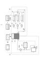
図1は本開示の少なくとも一実施形態に係る冷却システムの構成例を示す概略図である。図2は本開示の少なくとも一実施形態に係る冷却システムにおける制御系の構成を示すブロック図である。図3は他の実施形態に係る冷却システムの構成例を示す概略図である。図4は他の実施形態に係る冷却システムの構成例を示す概略図である。 FIG. 1 is a schematic diagram showing a configuration example of a cooling system according to at least one embodiment of the present disclosure. FIG. 2 is a block diagram showing the configuration of the control system in the cooling system according to at least one embodiment of the present disclosure. FIG. 3 is a schematic diagram showing a configuration example of a cooling system according to another embodiment. FIG. 4 is a schematic diagram showing a configuration example of a cooling system according to another embodiment.
図1(後述する図3~図8も同様)に非限定的に例示するように、本開示の少なくとも一実施形態に係る冷却システム1は、電子デバイス5を冷却するための冷却システム1であって、冷媒60を貯留するタンク6と、タンク6と電子デバイス5との間で冷媒60を循環可能な第1冷却ライン40と、タンク6から第1冷却ライン40とは別系統で設けられ、冷媒60を冷却するための第2冷却ライン50と、第1冷却ライン40における冷媒60の流量を調節可能な第1ポンプ7Aと、第2冷却ライン50における冷媒60の流量を調節可能な流量調節器8と、を備えている。
電子デバイス5は1つ以上含まれていてもよく、上記電子デバイス5を冷却する第1冷却ライン40は、少なくとも一本以上の循環路で構成され得る。なお、ベース5bは、電子デバイス5が設置される基板などである。
上記第1冷却ライン40及び第2冷却ライン50は、冷媒60としての流体(例えば、液体又は気体)を気密又は液密に案内し得るものであればよく、例えば、配管やチューブ等を含んで構成され得る。
流量調節器8は、例えば、第2ポンプ7Bを含み得る。
第1ポンプ7A及び第2ポンプ7Bには、流体を移送可能な種々の構成が適用され得る。
As non-limitingly illustrated in FIG. 1 (as well as in FIGS. 3 to 8 described later), the
One or more
The
The
Various configurations capable of transferring fluid can be applied to the
上記構成によれば、冷媒60を循環させて電子デバイス5を冷却する第1冷却ライン40と、冷媒60を冷却するための第2冷却ライン50とが、タンク6を介して別系統に設けられる。各冷却ライン40,50は、第1冷却ライン40の第1ポンプ7Aと、第2冷却ライン50の第2ポンプ7Bとにより、それぞれ独立に冷媒60の流量を調節することができる。よって、第1冷却ライン40の冷媒流量及びその調節タイミングと、第2冷却ライン50の冷媒流量及びその調整タイミングとを異ならせて冷却システム1を運用することができる。これにより、例えば、応答時間の遅い冷媒60の第2冷却ライン50の運転負荷を、変動周期の速い電子デバイス5の長周期変動成分に応じて調整することができる。これにより、ランニングコストの低減及び省エネルギー化を図ることができ、エネルギー損失を抑制し得る冷却システム1を提供することができる。
According to the above configuration, the
幾つかの実施形態では、上記の構成において、第1ポンプ7Aと第2ポンプ7Bとに接続されたコントローラ10を備えていてもよい。そして、コントローラ10は、電子デバイス5の発熱量に応じて第1冷却ライン40を流れる冷媒60の流量を調節するように第1ポンプ7Aを駆動するように構成されていてもよい。
In some embodiments, the configuration described above may include a
ここで、本開示の少なくとも一実施形態におけるコントローラ10の詳細について説明する。
図2は、幾つかの実施形態に係るコントローラ10における制御系の構成を示すブロック図である。
図2に非限定的に例示するように、コントローラ10は、例えば、コンピュータであり、CPU11、該CPU11が実行する各種プログラムやテーブル等のデータを記憶するための記憶部としてのROM(Read Only Memory)13、各プログラムを実行する際の展開領域や演算領域としてのワーク領域として機能するRAM(Random Access Memory)12の他、図示しない大容量記憶装置としてのハードディスクドライブ(HDD)、通信ネットワークに接続するための通信インターフェース、及び外部記憶装置が装着されるアクセス部などを備えていてもよい。
Details of the
FIG. 2 is a block diagram showing the configuration of the control system in the
As non-limitingly illustrated in FIG. 2, the
幾つかの実施形態では、コントローラ10は、種々のデータベース17を含んでもよく、データベース17には例えば冷媒の流量調節を行うための種々のテーブル18等が格納されていてもよい。これらは全て、バス14を介して接続される。更に、コントローラ10は、例えば、キーボードやマウス等からなる入力部(図示省略)及びデータを表示する液晶表示装置等からなる表示部(図示省略)等と接続されていてもよい。
In some embodiments, the
幾つかの実施形態において、コントローラ10には、第1冷却ライン40に設けられた第1温度センサ31や、タンク6に設けられた第2温度センサ32の各々から、冷媒温度に関する検出信号が送信されてもよい。
In some embodiments, detection signals regarding the coolant temperature are transmitted to the
幾つかの実施形態において、ROM13には、コントローラ10が、本開示の何れかの実施形態において冷媒流量を適切に制御するための冷媒流量管理プログラム15等が格納されていてもよい。
In some embodiments, the
上記構成によれば、コントローラ10により、電子デバイス5の発熱量に応じて第1冷却ライン40内の冷媒流量が調節される。したがって、例えば、電子デバイス5の駆動状況に応じて、該電子デバイス5の発熱量が多いタイミングでは第1ポンプ7Aを迅速に高出力で駆動して電子デバイス5を適切に冷却することができる。このように、第1冷却ライン40の冷媒流量の調節の応答速度を、電子デバイス5の駆動状況に合わせて適切に制御することができる。
According to the above configuration, the
幾つかの実施形態では、上記構成において、コントローラ10は、電子デバイス5の通電量に基づき、第1冷却ライン40を流れる冷媒60の流量を調節するように第1ポンプ7Aを駆動するように構成されてもよい。
In some embodiments, in the above configuration, the
上記構成によれば、コントローラ10により、電子デバイス5の通電量に基づき第1冷却ライン40内の冷媒流量が調節される。電子デバイス5の発熱量は、この電子デバイス5を通過する電流値の二乗に比例するから、該電子デバイス5の通電量に基づいて冷媒流量を調節することで、電子デバイス5の発熱量に合わせて該電子デバイス5を適切に冷却することができる。また、通電量に基づく流量制御を行うことで、電子デバイス5の発熱タイミングに遅れることなく、より迅速な流量調節を行うことができる。
According to the above configuration, the
幾つかの実施形態では、上記何れかに記載の構成において、電子デバイス5の発熱量を検出可能な第1温度センサ31を含み、コントローラ10は、第1温度センサ31からの検出信号に基づき、第1冷却ライン40を流れる冷媒60の流量を調節するように第1ポンプ7Aを駆動するように構成されていてもよい。
In some embodiments, any one of the above configurations includes a
上記構成によれば、コントローラ10により、第1温度センサ31で検出された電子デバイス5の発熱量に応じて、第1冷却ライン40の冷媒流量を調節することができる。したがって、電子デバイス5の駆動状況に適切に対応した流量制御を行うことができる。
According to the above configuration, the
幾つかの実施形態では、上記何れかに記載の構成において、冷却システム1は、複数の電子デバイス5を備えていてもよく、第1冷却ライン40は、各々が複数の電子デバイス5を個別に冷却可能、且つ、互いに並列な複数のサブ経路42を含み、各々のサブ経路42には、冷媒60の流量を個別に調節可能に第1ポンプ7Aが配置されていてもよい。
In some embodiments, in any of the configurations described above, the
上記構成によれば、第1冷却ライン40が、互いが並列な複数のサブ経路42を含んで構成され、各サブ経路42にそれぞれ第1ポンプ7Aと電子デバイス5とが配置される。すなわち、各々の電子デバイス5は、あるタイミングにおいて各々に要求される処理動作に応じてそれぞれ動作状況が異なるため、発熱量も異なるが、上記の構成により、各電子デバイス5の発熱量に個別に対応してサブ経路42に流れる冷媒流量を適切に調節することができる。
According to the above configuration, the
幾つかの実施形態では、上記何れかに記載の構成において、第2冷却ライン50は、タンク6からの冷媒60をタンク6に還流させるための1次循環ライン51と、1次循環ライン51に配置された流量調節器8としての第2ポンプ7Bと、1次循環ライン51が通過する第1熱交換器53と、第1熱交換器53を介して1次循環ライン51内の冷媒を冷却するための2次循環ライン52と、2次循環ライン52内の冷媒を冷却するための第2熱交換器54と、を含んでもよい(図1及び図4参照)。
第1熱交換器53は、所謂サブクーラーとして機能し、第2熱交換器54は、所謂チラーとして機能し得る。
In some embodiments, in any one of the configurations described above, the
The
上記構成によれば、タンク6から第2冷却ライン50の1次循環ライン51に流入した冷媒60は、第1熱交換器53を介して、2次循環ライン52を流れる冷媒60により冷却される。そして、2次循環ライン52内の冷媒60は、第2熱交換器54により冷却される。このような構成により、タンク6に還流されるまでにおける第2冷却ライン50と冷媒60との伝熱量を大きく確保することができるから、冷却効率の高い冷却システム1を実現することができる。
According to the above configuration, the refrigerant 60 flowing from the
図3に非限定的に例示するように、幾つかの実施形態では、上記何れかに記載の構成において、第2冷却ライン50は、タンク6内に配置された第1熱交換器53と、タンク6からの冷媒60を冷却するための第2熱交換器54と、を含んでもよい。
第2熱交換器54は、所謂チラーであってもよく、第2冷却ライン50内の冷媒を循環させるとともに、その流量を調節可能な流量調節器8として機能し得る。
In some embodiments, as non-limitingly illustrated in FIG. 3, in any of the above configurations, the
The
上記構成によれば、第1熱交換器53がタンク6内に配置されることで、該第1熱交換器53とタンク6とを一体に構成することができる。よって、第2冷却ライン50を小型化してコンパクトな冷却システム1を実現することができる。
According to the above configuration, the
図4は他の実施形態に係る冷却システム1の構成例を示す概略図である。
図4に非限定的に例示するように、幾つかの実施形態では、上記何れかに記載の構成において、タンク6内に不凝縮ガス65が封入されていてもよい。
FIG. 4 is a schematic diagram showing a configuration example of a
As non-limitingly illustrated in FIG. 4, in some embodiments, in any of the configurations described above, the
このようにすれば、タンク6内に不凝縮ガス65が封入されたことにより、冷却システム1においてタンク6に冷媒圧力の緩衝領域の機能を持たせることができる。すなわち、この不凝縮ガス65により、タンク6が冷媒60の圧力変動のバッファないしアキュムレータのように機能する。これにより、例えば、電子デバイス5の発熱に伴い、第1冷却ライン40内で冷媒60の沸騰などが生じたとしても、第1冷却ライン40の配管系統内に大きな圧力変動が生じることを効果的に防止することができる。
In this way, the
幾つかの実施形態では、上記何れかに記載の構成において、冷却システム1は、タンク6内の冷媒60の温度を検出可能な第2温度センサ32(図2参照)を含み、コントローラ10は、第2温度センサ32からの検出信号に基づき、第2冷却ライン50を流れる冷媒60の流量を調節するように第2ポンプ7B(流量調節器8)を駆動するように構成されていてもよい。
In some embodiments, in any of the configurations described above, the
上記構成によれば、コントローラ10により、第2温度センサ32で検出されたタンク6内の冷媒温度に応じて、第2冷却ライン50の冷媒流量を調節することができる。したがって、タンク6内の冷媒温度延いては電子デバイス5の発熱量、すなわち電子デバイス5の駆動状況に適切に対応した流量制御を行うことができる。
なお、本開示の少なくとも一実施形態に係る冷却システム1は、例えば、高密度発熱体(例えば、パワー半導体(パワーデバイス)を含む)の冷却技術に用いて有効である。
According to the above configuration, the
It should be noted that the
次に、上述したような冷却システム1による冷却性能の向上、および、パワーデバイス(電力制御装置)などの電子デバイス5で発生する排熱を利用した廃熱利用システムSに関する実施形態について、図5~図10を用いて説明する。
図5は、他の実施形態に係る冷却システム1の構成例を示す概略図である。図6~図8は、図5の冷却システム1が備える第1冷却ライン40の一部を抜き出して示す概略図である。図9は、冷媒60の温度と飽和圧力との関係を示す例示である。また、図10は、本開示の少なくとも一実施形態に係る第2コントローラ2の機能を示すブロック図である。
Next, an embodiment related to a waste heat utilization system S that utilizes waste heat generated by an
FIG. 5 is a schematic diagram showing a configuration example of a
図5~図8に非限定的に例示するように、幾つかの実施形態では、冷却システム1は、上記のタンク6と、このタンク6と電子デバイス5との間で冷媒60を循環可能な第1冷却ライン40と、第1冷却ライン40に設けられた、電子デバイス5を冷却するための冷却部44の内部における冷媒60の圧力(以下、冷却部44の内部圧力P)を調節するための圧力調節手段9と、を備えても良い。
In some embodiments, the
上記の冷却部44は、第1冷却ライン40を循環する冷媒60により電子デバイス5を直接的に冷却する部分であり、電子デバイス5の発熱部の近傍に設けられる。つまり、第1冷却ライン40を循環する冷媒60は、冷却部44を介して電子デバイス5と熱交換する。このため、第1冷却ライン40における冷却部44の下流側(冷却部44の通過後)の冷媒60の温度は、冷却部44の上流側(冷却部44への流入前)よりも上昇することになる。
The cooling
この冷却部44は、電子デバイス5(半導体)に冷媒60の流路pを形成するなど、電子デバイス5の内部に設けられても良いし、電子デバイス5の発熱部の外部に接触して設置されるなど、電子デバイス5の外部に設けられても良い。この際、冷却部44に絶縁処理を施しても良い。具体的には、流路pを形成する部分の内面あるは外面などに、例えばダイヤモンドによるコーティング層を形成することにより、絶縁処理を施しても良い。これによって、冷却部44を、電子デバイス5の通電部に設けることが可能となる。
The cooling
図6~図8に示す実施形態では、冷却部44は、複数の流路pを有している。そして、冷媒60は、冷却部44の内部あるいはその入口などにおいて、上記の複数の流路pに分配されると共に、複数の流路pを通過後に合流されて下流に流れるようになっている。ただし、本実施形態に本発明は限定されず、他の幾つかの実施形態では、冷却部44の有する流路pは1つであっても良い。
In the embodiment shown in FIGS. 6-8, the
他方、上記の圧力調節手段9は、冷却部44の内部圧力Pを調節するよう構成されることにより、電子デバイス5で発生する熱によって冷媒60が沸騰するなど、冷媒60の気化による気泡が冷却部44の内部で発生するのを抑制する。一般に、液体の沸点は圧力が高いほど高くなるなど、圧力に依存する(図9参照)。冷却部44の内部おける冷媒60の気泡の発生も冷却部44の圧力に依存するので、圧力調節手段9によって、冷却部44の内部圧力Pが飽和圧力(図9参照)よりも高くなるように調節することで、冷却部44の内部における気泡の発生を抑制することが可能となる。
On the other hand, the pressure adjusting means 9 is configured to adjust the internal pressure P of the cooling
例えば、冷却部44の流路pの断面積(以下、流路面積)が例えばミクロンオーダーなど極めて小さい場合などにおいて、流路p内の冷媒60が電子デバイス5の発熱部との熱交換により気化すると、気化により生じた気泡が表面張力により流路pの内壁面にくっつくなどして外部に抜けないような場合が生じ得る。このような場合、例えば流路pが複数ある場合には、冷媒60がスムーズに流れる流路pと、気泡のために冷媒60がスムーズに流れない流路pとが生じるため、複数の流路pへの冷媒60の流量分配の不均一が生じ、電子デバイス5に対する冷却が適切に行われないようになる可能性がある。よって、冷却部44の内部における気泡の発生を抑制することにより、冷却部44の内部における流量分配の不均一を防止し、パワーデバイスなどの電子デバイス5の冷却をより適切に行うことが可能となる。
For example, when the cross-sectional area (hereinafter referred to as the flow area) of the flow path p of the cooling
具体的には、圧力調節手段9は、幾つかの実施形態では、図6に示すように、第1冷却ライン40における電子デバイス5の下流側とタンク6との間に設けられた第1調節手段91を含んでいる。この第1調節手段91は、その上流側の圧力を下流側の圧力よりも高くすることが可能な手段である。ここで、第1冷却ライン40における第1調節手段91の上流側には冷却部44が位置している。よって、第1調節手段91により、第1調節手段91の上流側の第1冷却ライン40における冷媒60の圧力を高めることで、第1冷却ライン40における圧力が高められる部分に位置する冷却部44の内部圧力Pも高められる。
Specifically, the pressure regulating means 9 is, in some embodiments, a first regulating pressure provided between the downstream side of the
図6に示す実施形態では、圧力調節手段9(第1調節手段91)はバルブ91mであり、バルブ91mを通過時の流路面積を、その上流側における第1冷却ライン40の流路面積よりも小さくすることにより、バルブ91mの上流側の圧力を高めるように構成されている。具体的には、バルブ91mの開度が0(全閉)よりも大きい状態にしておく。バルブ91mの開度が100%(全開)の時でも、その際のバルブ91mの流路面積が、バルブの上流側における第1冷却ライン40の流路面積よりも小さい場合には、バルブ91mの開度は100%であっても良い。
In the embodiment shown in FIG. 6, the pressure regulating means 9 (first regulating means 91) is a
この第1調節手段91であるバルブ91mは、幾つかの実施形態では、その開度の設定を手動で行うことが可能に構成されていても良い。他の幾つかの実施形態では、上記のバルブ91mは、後述する第2コントローラ2などからの指令値に応じた開度の設定が可能な制御弁91cであっても良い(後述する図8参照)。制御弁91cは、全閉と全開との2位置での切り替えが可能なON-OFF弁であっても良いし、全閉と全開と間の開度を例えば連続的などで設定可能な調節弁であっても良い。そして、冷却部44の内部圧力Pが、気泡の発生の抑制が可能となる目標圧力(後述する規定値Pcよりも高い圧力)になるように調節弁の開度を調節しても良い。その他の幾つかの実施形態では、第1調節手段91は、オリフィスなど、流路面積が上流側よりも一旦狭くなり、再度、それよりも広くなるように形成された圧力差形成手段(不図示)であっても良い。
In some embodiments, the
また、圧力調節手段9は、他の幾つかの実施形態では、図7に示すように、第1冷却ライン40における電子デバイス5の上流側とタンク6との間に設けられた、下流側の圧力を上流側の圧力よりも高くすることが可能な第2調節手段92を、さらに含んでも良い。つまり、圧力調節手段9は、上述した第1調節手段91と、第2調節手段92とで構成されており、第1冷却ライン40における第1調節手段91と第2調節手段92との間の圧力を調節するようになっている。図7に示す実施形態では、第2調節手段92は、上述した第1ポンプ7Aであり、第1調節手段91が電子デバイス5の下流側に位置しており、第1ポンプ7Aの回転数を高くするなどして調節することで、第1冷却ライン40における、第1ポンプ7Aの下流側を流れる冷媒60の圧力を高めることが可能である。よって、第1冷却ライン40における圧力が高められる部分に位置する冷却部44の内部圧力Pも高められる。なお、第2調節手段92は、第1ポンプ7Aの下流側などに設置された、第1ポンプ7Aとは異なる他のポンプであっても良い。
In some other embodiments, the pressure adjusting means 9 is provided on the downstream side of the
なお、本実施形態では、圧力調節手段9が第1ポンプ7Aであるため、第1調節手段91は、所定の開度に設定された制御弁91c、全開状態でも流路面積が第1冷却ライン40のものよりも小さいON-OFF弁、あるいは、上述した圧力差形成手段(不図示)のいずれであっても良い。そして、幾つかの実施形態では、第1ポンプ7Aの回転数を調節することで、冷却部44の内部圧力Pが目標圧力になるようにしても良い。他の幾つかの実施形態では、第1調節手段91は、制御弁91cであり、制御弁91cの弁開度、および第1ポンプ7Aの回転数を調節することで、冷却部44の内部圧力Pが目標圧力になるようにしても良い。
In this embodiment, since the pressure adjusting means 9 is the
上記の構成によれば、圧力調節手段9により、冷却部44の内部圧力Pを高める。これによって、冷却部44の内部における冷媒60の沸点をより高くすることができる。よって、冷却部44の内部圧力Pを高めることで、冷却部44の内部における冷媒60の気泡の発生を抑制することができる。したがって、パワーデバイスなどの電子デバイス5の冷却を適切に行うことができる。
According to the above configuration, the internal pressure P of the
また、幾つかの実施形態では、上述した圧力調節手段9を自動で制御しても良い。
すなわち、幾つかの実施形態では、図7~図8に示すように、冷却システム1は、上述した圧力調節手段9に接続される第2コントローラ2を、さらに備える。この第2コントローラ2は、図10に示すように、上述した冷却部44の内部における冷媒60の圧力(上述した冷却部44の内部圧力P)の測定値Pmを取得する圧力取得部21と、この測定値Pmが規定値Pc以上になるように、圧力調節手段9を制御する制御部22と、を有する。なお、第2コントローラ2は、例えば、上述したようなコンピュータである。
Also, in some embodiments, the pressure adjusting means 9 described above may be automatically controlled.
That is, in some embodiments, as shown in FIGS. 7-8, the
上記の規定値Pcは、幾つかの実施形態では、電子デバイス5の発熱量と、冷却部44に供給される冷媒60の流量とに基づいて、決定しても良い。より具体的には、電子デバイス5の発熱量と、冷却部44に供給される冷媒60の流量(冷媒流量)とに基づいて、冷却部44の内部の温度を予測する。そして、使用している冷媒60に関する図9に示すような温度と飽和圧力との関係に基づいて、予測した温度に対応する飽和圧力を求め、飽和圧力よりも大きい圧力値を規定値Pc(目標圧力)とする。
In some embodiments, the specified value Pc may be determined based on the amount of heat generated by the
なお、上記の予測値の算出には、電子デバイス5の発熱量の最大値を用いると良い。また、第1ポンプ7Aの回転数が変化する場合などには、冷却部44に供給される冷媒60の流量の最小値を用いると良い。これによって、より正確な温度予測が可能となる。また、電子デバイス5の発熱量や冷却部44への冷媒流量は予測値であっても良いし、測定値であっても良い。また、電子デバイス5の発熱量に代えて、発熱量に相関関係を有する電子デバイス5への通電量であっても良い(以下同様)。
It should be noted that the maximum value of the amount of heat generated by the
また、上記の規定値Pcは、幾つかの実施形態では、固定値であっても良い。この場合、第2コントローラ2はオペレータなどから入力されるなどした規定値Pcを取得する。他の幾つかの実施形態では、上記の規定値Pcは運転状況に応じて更新されても良い。この場合、第2コントローラ2は、例えば周期的などの所定のタイミングで運転中に電子デバイス5の発熱量や冷却部44への冷媒流量といった指標値(測定値あるいは予測値)を取得し、この結果から求められる温度に基づいて規定値Pcを決定する。
Also, the above specified value Pc may be a fixed value in some embodiments. In this case, the
また、規定値Pcが更新される(固定値ではない)実施形態において、幾つかの実施形態では、第2コントローラ2は、上記の指標に代えて、冷却部44の内部における冷媒60の温度の測定値を取得しても良い。温度の測定値を取得することで、その測定値に応じた気泡の発生を抑制可能な圧力が図9などの関係を用いて得られる。よって、規定値Pcを、温度の測定値に対応する飽和圧力よりも大きい圧力値とすることで、冷却部44の内部における気泡の発生をより確実に抑制することが可能となる。この場合、第2コントローラ2は、上述した冷却部44の内部における冷媒60の測定温度を取得する温度取得部をさらに備え、上記の制御部22などは、規定値Pcを測定温度に基づいて更新する。なお、温度計は、電子デバイス5の下流側と第1調節手段91との間に設置しても良いし、冷却部44に設置するなどしても良い。
Also, in embodiments where the specified value Pc is updated (not a fixed value), in some embodiments, the
図10に示す実施形態では、上記の圧力取得部21は、冷却部44の内部圧力Pを測定するための圧力計26に接続されており、圧力計26による圧力の測定値Pmが入力されるようになっている。この圧力計26は、幾つかの実施形態では、図7~図8に示すように、第1冷却ライン40における電子デバイス5の上流側と第1調節手段91との間に設置されても良い。これによって、冷却部44の内部圧力Pを容易に測定することが可能となる。ただし、本実施形態に本発明は限定されない。圧力計26は、冷却部44の内部圧力P、あるいは、内部圧力Pとみなせる圧力、内部圧力Pを所定の演算などにより推定可能となるような圧力を測定できれば良い。例えば、冷却部44の内部圧力Pを直接測定しても良い。
In the embodiment shown in FIG. 10, the
また、図10に示す実施形態では、制御部22は、圧力取得部21に接続されており、この圧力の測定値Pmが入力されると、圧力の測定値Pmに基づいて圧力調節手段9に対する指令値Iを生成し、圧力調節手段9に送信するようになっている。そして、圧力調節手段9は、受信した指令値Iに従って動作する。すなわち、圧力調節手段9が制御弁91cの場合には、指令値Iで指令された開度を設定する。圧力調節手段9が第1ポンプ7Aの場合には、指令値Iで指令された回転数を設定する。
In addition, in the embodiment shown in FIG. 10, the
より具体的には、図7に示す実施形態では、圧力調節手段9は、調整可能な手段として、少なくとも第1ポンプ7Aを含んで構成されている。よって、第2コントローラ2は、圧力計26から測定値Pmが入力されると、その測定値Pmに基づいて算出した指令値I(回転数指令など)を、少なくとも第1ポンプ7Aに送信するようになっている。なお、他の幾つかの実施形態において、圧力調節手段9が、第1ポンプ7Aと、第1調節手段91である制御弁91cとで構成される場合には、第2コントローラ2は、第1ポンプ7Aまたは第1調節手段91の少なくとも一方に指令値Iを送信しても良い。
More specifically, in the embodiment shown in FIG. 7, the pressure regulating means 9 comprises at least a
他方、図8に示す実施形態では、圧力調節手段9は、第1調節手段91である制御弁91cを含んで構成されている。よって、第2コントローラ2は、圧力計26から測定値Pmが入力されると、その測定値Pmに基づいて算出した指令値I(弁開度指令など)を、制御弁91cに送信するようになっている。
On the other hand, in the embodiment shown in FIG. 8, the pressure regulating means 9 includes a
上記の構成によれば、冷却部44の内部における冷媒の圧力(内部圧力P)の測定値Pmと、規定値(閾値)とに基づいて、圧力調節手段9が自動で制御される。これによって、冷却部44の内部における冷媒60の圧力を適切に高めることで、冷却部44の内部における気泡の発生を抑制することができる。
なお、他の幾つかの実施形態では、圧力調節手段9の調節は手動であっても良い。
According to the above configuration, the pressure adjusting means 9 is automatically controlled based on the measured value Pm of the refrigerant pressure (internal pressure P) inside the
It should be noted that in some other embodiments the adjustment of the pressure adjusting means 9 may be manual.
引き続き、電子デバイス5の廃熱を利用する廃熱利用システムSに関する実施形態について、説明する。
現在、蒸気ボイラを有する工場や大型エンジンを有する船舶等では、ボイラやエンジンの廃熱を利用して低温・低圧の蒸気を生成し、暖房や加湿用途に使用している。今後、世界的なCO2削減要求に伴い再生可能エネルギーの普及が進み、主力のエネルギー源が化石燃料から電力となると(電化社会)、上述のようなボイラやエンジンの廃熱がなくなる。この際、例えば蒸気は専用の装置を用いて生成すると、その分だけコストやエネルギーが必要となる。そこで、パワーデバイスなどの電子デバイス5は200℃から300℃以上に発熱するなど発熱量が高いことから、その廃熱を熱源に蒸気を生成する。
Next, an embodiment related to the waste heat utilization system S that utilizes the waste heat of the
Currently, in factories with steam boilers and ships with large engines, waste heat from the boilers and engines is used to generate low-temperature, low-pressure steam, which is used for heating and humidification. In the future, as the spread of renewable energy advances along with the global demand for CO2 reduction, and the main energy source shifts from fossil fuels to electric power (an electrified society), waste heat from boilers and engines as described above will disappear. At this time, for example, if steam is generated using a dedicated device, costs and energy are required accordingly. Therefore, since the
具体的には、幾つかの実施形態では、図5~図8に示すように、冷却システム1は、第1冷却ライン40における電子デバイス5の下流側を流れる冷媒60の気相と液相とを分離するための気液分離器72を、さらに備える。ここで、第1冷却ライン40(配管内部)における冷媒60の圧力は、上記の第1調節手段91の通過後には、第1調節手段91の上流側よりも小さくなるように構成されている。そして、圧力が小さくなると冷媒60はより気化しやすくなる。この現象を利用することで、第1調節手段91の下流側において冷媒60を積極的に気化させ、気液二相流を生成する。こうして生成された気液二相流を気液分離器72に供給し、気相(蒸気)と液相(温水)に分離することで、気相(蒸気)を取り出すことが可能となる。他方、気液分離器72において分離した液相は、第1冷却ライン40を通って、タンク6に循環するように構成される。
Specifically, in some embodiments, as shown in FIGS. 5 to 8, the
図5~図8に示す実施形態では、気液分離器72において分離された冷媒60の気相は、気液分離器72に配管などにより接続された蒸気利用装置74に供給されるようになっている。この蒸気利用装置74は、例えば、暖房システム、給湯システムなど、暖房や加湿などを行うシステムであっても良い。また、蒸気利用装置74は、工場や、船舶などに設置されたシステムであっても良い。そして、上記の冷却システム1と、上記の蒸気利用装置74とによって、廃熱利用システムSが構成されている。
5 to 8, the vapor phase of the refrigerant 60 separated by the gas-
上記の構成によれば、パワーデバイスなどの電子デバイス5の廃熱を熱源に、蒸気を生成する。これによって、例えば蒸気を生成するための専用の装置を設けることや、冷却システム1の冷却性能を損なうことなく、蒸気を生成することができる。よって電化社会においても、効率的に蒸気を生成することができる。
According to the above configuration, steam is generated using waste heat from the
次に、冷却システムの制御方法について説明する。
本開示の少なくとも一実施形態に係る冷却システムの制御方法は、電子デバイス5を冷却するための冷却システム1の制御方法であって、冷媒60を貯留するタンク6と電子デバイス5との間で冷媒60を循環可能な第1冷却ライン40を流れる冷媒60の流量を、電子デバイス5の発熱量に応じて調節するステップと、タンク6から第1冷却ライン40とは別系統で設けられている第2冷却ライン50であって、冷媒60を冷却するための第2冷却ライン50を流れる冷媒60の流量を、タンク6内の冷媒60の温度に応じて調節するステップと、を備えている。
Next, a method of controlling the cooling system will be described.
A control method of a cooling system according to at least one embodiment of the present disclosure is a control method of a
上記方法によれば、冷媒60を循環させて電子デバイス5を冷却する第1冷却ライン40と、冷媒60を冷却するための第2冷却ライン50とが、タンク6を介して別系統に設けられる。各冷却ライン40,50は、それぞれ独立に冷媒の流量を調節することができるから、第1冷却ライン40の冷媒流量及びその調節タイミングと、第2冷却ライン50の冷媒流量及びその調節タイミングとを異ならせて冷却システム1を運用することができる。これにより、例えば、応答時間の遅い冷媒の第2冷却ライン50の運転負荷を、変動周期の速い電子デバイス5の長周期変動成分に応じて調節することができるから、ランニングコストの低減及び省エネルギー化を図ることができるとともに、エネルギー損失を抑制し得る冷却システム1を提供することができる。
According to the above method, the
本開示の少なくとも一実施形態に係る冷却システムの制御プログラム(例えば、上記冷媒流量管理プログラム15)は、電子デバイス5を冷却するための冷却システム1の制御プログラムであって、冷媒60を貯留するタンク6と電子デバイス5との間で冷媒60を循環可能な第1冷却ライン40を流れる冷媒60の流量を、電子デバイス5の発熱量に応じて調節するステップと、タンク6から第1冷却ライン40とは別系統で設けられている第2冷却ライン50であって、冷媒60を冷却するための第2冷却ライン50を流れる冷媒60の流量を、タンク6内の冷媒60の温度に応じての調節するステップと、をコンピュータに実行させるように構成される。
A cooling system control program (for example, the coolant flow rate management program 15) according to at least one embodiment of the present disclosure is a control program for the
このような構成により、上記何れかの実施形態で述べたように、冷媒60を循環させて電子デバイス5を冷却する第1冷却ライン40と、冷媒60を冷却するための第2冷却ライン50とが、タンク6を介して別系統に設けられる。各冷却ライン40,50は、それぞれ独立に冷媒の流量を調節することができるから、第1冷却ライン40の冷媒流量及びその調節タイミングと、第2冷却ライン50の冷媒流量及びその調節タイミングとを異ならせて冷却システム1を運用することができる。これにより、例えば、応答時間の遅い冷媒の第2冷却ライン50の運転負荷を、変動周期の速い電子デバイス5の長周期変動成分に応じて調節することができるから、ランニングコストの低減及び省エネルギー化を図ることができるとともに、エネルギー損失を抑制し得る冷却システム1を提供することができる。
With such a configuration, as described in any of the above embodiments, the
また、本開示の少なくとも一実施形態に係る冷却システムの制御方法は、電子デバイス5を冷却するための冷却システム1の制御方法であって、上述した第1冷却ライン40に設けられた、電子デバイス5を冷却するための冷却部44の内部における冷媒60の圧力の測定値Pmを取得するステップ(圧力取得ステップ)と、測定値Pmが規定値Pc以上になるように、上記の圧力調節手段9を制御するステップ(制御ステップ)と、を備えても良い。
Further, a method for controlling a cooling system according to at least one embodiment of the present disclosure is a method for controlling a
なお、上述した幾つかの実施形態に係る冷却システム1は、複数の情報処理装置を備えてもよく、これらの情報処理装置は、各処理を分散して行ってもよい。
また、上述した幾つかの実施形態の各処理を実行するためのプログラムをコンピュータ読み取り可能な記録媒体に記録して、当該記録媒体に記録されたプログラムをコンピュータシステムに読み込ませ、実行することにより、上述した種々の処理を行ってもよい。
Note that the
In addition, by recording a program for executing each process of the above-described several embodiments on a computer-readable recording medium and causing a computer system to read and execute the program recorded on the recording medium, Various processes described above may be performed.
なお、ここでいう「コンピュータシステム」とは、OS(Operating System)や周辺機器等のハードウェアを含むものであってもよい。また、「コンピュータシステム」は、WWW(World Wide Web)システムを利用している場合であれば、ホームページ提供環境(あるいは表示環境)も含むものとする。また、「コンピュータ読み取り可能な記録媒体」とは、フレキシブルディスク、光磁気ディスク、ROM(Read-only Memory)、フラッシュメモリ等の書き込み可能な不揮発性メモリ、CD(Compact Disc)-ROM等の可搬媒体、コンピュータシステムに内蔵されるハードディスク等の記憶装置のことをいう。 Note that the “computer system” referred to here may include hardware such as an OS (Operating System) and peripheral devices. Also, the "computer system" includes a home page providing environment (or display environment) if the WWW (World Wide Web) system is used. In addition, "computer-readable recording medium" means flexible disk, magneto-optical disk, ROM (Read-only Memory), writable non-volatile memory such as flash memory, portable such as CD (Compact Disc)-ROM It refers to a storage device such as a hard disk built into a medium or computer system.
さらに「コンピュータ読み取り可能な記録媒体」とは、インターネット等のネットワークや電話回線等の通信回線を介してプログラムが送信された場合のサーバやクライアントとなるコンピュータシステム内部の揮発性メモリ(例えばDRAM(Dynamic Random Access Memory))のように、一定時間プログラムを保持しているものも含むものとする。また、上記プログラムは、このプログラムを記憶装置等に格納したコンピュータシステムから、伝送媒体を介して、あるいは、伝送媒体中の伝送波により他のコンピュータシステムに伝送されてもよい。ここで、プログラムを伝送する「伝送媒体」は、インターネット等のネットワーク(通信網)や電話回線等の通信回線(通信線)のように情報を伝送する機能を有する媒体のことをいう。また、上記プログラムは、前述した機能の一部を実現するためのものであってもよい。さらに、前述した機能をコンピュータシステムにすでに記録されているプログラムとの組み合わせで実現できるもの、いわゆる差分ファイル(差分プログラム)であってもよい。 Furthermore, "computer-readable recording medium" means a volatile memory (e.g., DRAM (Dynamic Random Access Memory)), which holds a program for a certain period of time. Further, the above program may be transmitted from a computer system storing this program in a storage device or the like to another computer system via a transmission medium or by a transmission wave in a transmission medium. Here, the "transmission medium" for transmitting the program refers to a medium having a function of transmitting information, such as a network (communication network) such as the Internet or a communication line (communication line) such as a telephone line. Further, the program may be for realizing part of the functions described above. Further, it may be a so-called difference file (difference program) that can realize the above-described functions in combination with a program already recorded in the computer system.
上述した本開示の少なくとも一実施形態によれば、エネルギー損失を抑制し得る冷却システム1を提供することができる。
According to at least one embodiment of the present disclosure described above, it is possible to provide the
本発明は上述した実施形態に限定されることはなく、上述した実施形態に変更を加えた形態や、これらの形態を組み合わせた形態も含む。 The present invention is not limited to the above-described embodiments, and includes modifications of the above-described embodiments and combinations of these embodiments.
1 冷却システム
10 コントローラ
11 CPU
12 RAM
13 ROM
14 バス
15 冷媒流量管理プログラム
17 データベース
18 テーブル
2 第2コントローラ
21 圧力取得部
22 制御部
26 圧力計
31 第1温度センサ
32 第2温度センサ
40 第1冷却ライン(電子デバイスの冷却ライン)
42 サブ経路
44 冷却部
5 電子デバイス(被冷却体)
5b ベース
50 第2冷却ライン(冷媒の冷却ライン)
51 1次循環ライン
52 2次循環ライン
53 第1熱交換器(サブクーラー)
54 第2熱交換器(チラー)
6 タンク(冷媒容器)
60 冷媒(冷却流体)
65 不凝縮ガス
7A 第1ポンプ(第2)
7B 第2ポンプ
72 気液分離器
74 蒸気利用装置
8 流量調節器
9 圧力調節手段
91 第1調節手段
91c 制御弁
91m バルブ
92 第2調節手段
S 廃熱利用システム
I 指令値
P 冷却部の内部における冷媒の圧力
Pm 圧力の測定値
Pc 規定値
p 流路
1 cooling
12 RAMs
13 ROMs
14
42
51
54 second heat exchanger (chiller)
6 tank (refrigerant container)
60 refrigerant (cooling fluid)
65
S Waste heat utilization system I Command value P Refrigerant pressure Pm inside the cooling unit Measured pressure value Pc Specified value p Flow path
Claims (21)
冷媒を貯留するタンクと、
前記タンクと前記電子デバイスとの間で前記冷媒を循環可能な第1冷却ラインと、
前記タンクから前記第1冷却ラインとは別系統で設けられ、前記冷媒を冷却するための第2冷却ラインと、
前記第1冷却ラインにおける前記冷媒の流量を調節可能な第1ポンプと、
前記第2冷却ラインにおける前記冷媒の流量を調節可能な流量調節器と、
前記第1ポンプおよび前記流量調節器に接続されたコントローラと、
前記タンク内の前記冷媒の温度を検出可能な第2温度センサと、
を備え、
前記第1冷却ラインは、前記電子デバイスとの熱交換により温度上昇した前記冷媒を冷却せずに前記タンクに戻すように構成され、
前記コントローラは、前記電子デバイスの発熱量に応じて前記第1冷却ラインを流れる冷媒の流量を調節するように前記第1ポンプを駆動するとともに、前記第2温度センサからの検出信号に基づき、前記第2冷却ラインを流れる前記冷媒の流量を調節するように前記流量調節器を駆動することで、前記第1冷却ラインと前記第2冷却ラインにおける前記冷媒の流量調節をそれぞれ独立して行うように構成され、
前記コントローラは、前記電子デバイスの前記発熱量が多いタイミングで前記第1ポンプを高出力で駆動して前記第1冷却ラインを流れる冷媒の流量を増やすように構成された
ことを特徴とする冷却システム。 A cooling system for cooling an electronic device, comprising:
a tank that stores a refrigerant;
a first cooling line capable of circulating the coolant between the tank and the electronic device;
a second cooling line for cooling the refrigerant, which is provided in a system separate from the first cooling line from the tank;
a first pump capable of adjusting the flow rate of the refrigerant in the first cooling line;
a flow controller capable of adjusting the flow rate of the refrigerant in the second cooling line;
a controller connected to the first pump and the flow regulator;
a second temperature sensor capable of detecting the temperature of the refrigerant in the tank;
with
The first cooling line is configured to return the refrigerant whose temperature has increased due to heat exchange with the electronic device to the tank without cooling,
The controller drives the first pump so as to adjust the flow rate of the coolant flowing through the first cooling line according to the amount of heat generated by the electronic device, and based on the detection signal from the second temperature sensor, the By driving the flow controller to adjust the flow rate of the refrigerant flowing through the second cooling line, the flow rate of the refrigerant in the first cooling line and the flow rate of the refrigerant in the second cooling line are independently adjusted. configured,
The cooling system, wherein the controller is configured to increase the flow rate of the coolant flowing through the first cooling line by driving the first pump at a high output when the amount of heat generated by the electronic device is large. .
冷媒を貯留するタンクと、
前記タンクと前記電子デバイスとの間で前記冷媒を循環可能な第1冷却ラインと、
前記タンクから前記第1冷却ラインとは別系統で設けられ、前記冷媒を冷却するための第2冷却ラインと、
前記第1冷却ラインにおける前記冷媒の流量を調節可能な第1ポンプと、
前記第2冷却ラインにおける前記冷媒の流量を調節可能な流量調節器と、
前記第1冷却ラインに設けられた、前記電子デバイスを冷却するための冷却部の内部における前記冷媒の圧力を調節するための圧力調節手段と、
前記圧力調節手段に接続される第2コントローラと、
を備え、
前記圧力調節手段は、前記第1冷却ラインにおける前記電子デバイスの下流側と前記タンクとの間に設けられた、上流側の圧力を下流側の圧力よりも高くすることが可能な第1調節手段を含み、
前記第2コントローラは、
前記冷却部の内部における前記冷媒の圧力の測定値を取得する圧力取得部と、
前記冷却部の内部における気泡の発生が抑制されるよう、前記測定値が規定値以上になるように、前記圧力調節手段を制御する制御部と、を有する
冷却システム。 A cooling system for cooling an electronic device, comprising:
a tank that stores a refrigerant;
a first cooling line capable of circulating the coolant between the tank and the electronic device;
a second cooling line for cooling the refrigerant, which is provided in a system separate from the first cooling line from the tank;
a first pump capable of adjusting the flow rate of the refrigerant in the first cooling line;
a flow controller capable of adjusting the flow rate of the refrigerant in the second cooling line;
pressure adjusting means for adjusting the pressure of the coolant inside the cooling section for cooling the electronic device, provided in the first cooling line;
a second controller connected to the pressure regulating means;
with
The pressure adjusting means is a first adjusting means provided between the downstream side of the electronic device and the tank in the first cooling line and capable of making the pressure on the upstream side higher than the pressure on the downstream side. including
The second controller is
a pressure acquisition unit that acquires a measured value of the pressure of the refrigerant inside the cooling unit;
and a control unit that controls the pressure adjustment means such that the measured value becomes equal to or greater than a specified value so as to suppress the generation of air bubbles inside the cooling unit.
前記コントローラは、前記電子デバイスの発熱量に応じて前記第1冷却ラインを流れる冷媒の流量を調節するように前記第1ポンプを駆動するように構成されていてもよいことを特徴とする請求項2に記載の冷却システム。 the cooling system comprises a controller connected to the first pump;
The controller may be configured to drive the first pump so as to adjust the flow rate of coolant flowing through the first cooling line in accordance with the amount of heat generated by the electronic device. 3. The cooling system according to 2.
前記コントローラは、前記第1温度センサからの検出信号に基づき、前記第1冷却ラインを流れる前記冷媒の流量を調節するように前記第1ポンプを駆動するように構成されていてもよいことを特徴とする請求項4に記載の冷却システム。 The cooling system includes a first temperature sensor capable of detecting the amount of heat generated by the electronic device,
The controller may be configured to drive the first pump so as to adjust the flow rate of the coolant flowing through the first cooling line based on the detection signal from the first temperature sensor. 5. The cooling system of claim 4, wherein
前記第1冷却ラインは、各々が複数の前記電子デバイスを個別に冷却可能、且つ、互いに並列な複数のサブ経路を含み、
各々の前記サブ経路には、前記冷媒の流量を個別に調節可能に前記第1ポンプが配置されていてもよいことを特徴とする請求項1~5のいずれか1項に記載の冷却システム。 a cooling system comprising a plurality of said electronic devices;
the first cooling line includes a plurality of sub-passages that are parallel to each other and each can individually cool a plurality of the electronic devices;
The cooling system according to any one of claims 1 to 5, wherein the first pump may be arranged in each of the sub-paths so as to be able to individually adjust the flow rate of the refrigerant.
前記タンクからの前記冷媒を前記タンクに還流させるための1次循環ラインと、
前記1次循環ラインに配置された前記流量調節器としての第2ポンプと、
前記1次循環ラインが通過する第1熱交換器と、
前記第1熱交換器を介して前記1次循環ライン内の前記冷媒を冷却するための2次循環ラインと、
前記2次循環ライン内の前記冷媒を冷却するための第2熱交換器と、を含んでもよいことを特徴とする請求項1~6のいずれか1項に記載の冷却システム。 The second cooling line is
a primary circulation line for returning the refrigerant from the tank to the tank;
a second pump as the flow controller arranged in the primary circulation line;
a first heat exchanger through which the primary circulation line passes;
a secondary circulation line for cooling the refrigerant in the primary circulation line via the first heat exchanger;
and a second heat exchanger for cooling the refrigerant in the secondary circulation line.
前記タンク内に配置された第1熱交換器と、
前記タンクからの前記冷媒を冷却するための第2熱交換器と、を含んでもよいことを特徴とする請求項1~7のいずれか1項に記載の冷却システム。 The second cooling line is
a first heat exchanger disposed within the tank;
and a second heat exchanger for cooling the refrigerant from the tank.
前記コントローラは、前記第2温度センサからの検出信号に基づき、前記第2冷却ラインを流れる前記冷媒の流量を調節するように前記流量調節器を駆動するように構成されていてもよいことを特徴とする請求項3に記載の冷却システム。 the cooling system includes a second temperature sensor capable of detecting the temperature of the refrigerant in the tank;
The controller may be configured to drive the flow controller to adjust the flow rate of the refrigerant flowing through the second cooling line based on the detection signal from the second temperature sensor. 4. The cooling system of claim 3, wherein
前記圧力調節手段は、前記第1冷却ラインにおける前記第1調節手段と前記第2調節手段との間の圧力を調節するようになっていることを特徴とする請求項12または13に記載の冷却システム。 The pressure adjusting means is a second adjusting means provided between the upstream side of the electronic device and the tank in the first cooling line and capable of making the pressure on the downstream side higher than the pressure on the upstream side. further including
14. Cooling according to claim 12 or 13, characterized in that the pressure regulating means are adapted to regulate the pressure between the first regulating means and the second regulating means in the first cooling line. system.
前記電子デバイスの発熱量が多いタイミングで、冷媒を貯留するタンクと前記電子デバイスとの間で前記冷媒を循環可能な第1冷却ラインを流れる冷媒の流量が増えるように、前記電子デバイスの前記発熱量に応じて前記第1冷却ラインを流れる前記冷媒の流量を調節するステップと、
前記第1冷却ラインにおける前記電子デバイスとの熱交換により温度上昇した前記冷媒を冷却せずに前記第1冷却ラインから前記タンクに戻すステップと、
前記タンクから前記第1冷却ラインとは別系統で設けられている第2冷却ラインであって、前記冷媒を冷却するための第2冷却ラインを流れる冷媒の流量を、前記タンク内の冷媒の温度に応じて調節するステップと、を有し、
前記第1冷却ラインと前記第2冷却ラインにおける前記冷媒の流量調節をそれぞれ独立して行う
ことを特徴とする冷却システムの制御方法。 A method of controlling a cooling system for cooling an electronic device, comprising:
The heat generation of the electronic device is performed so that the flow rate of the coolant flowing through the first cooling line in which the coolant can be circulated between the tank storing the coolant and the electronic device increases at the timing when the electronic device generates a large amount of heat. adjusting the flow rate of the refrigerant flowing through the first cooling line according to the amount;
a step of returning the coolant whose temperature has been raised by heat exchange with the electronic device in the first cooling line to the tank from the first cooling line without cooling;
A second cooling line provided in a system separate from the first cooling line from the tank, the flow rate of the refrigerant flowing through the second cooling line for cooling the refrigerant, the temperature of the refrigerant in the tank and adjusting according to
A control method for a cooling system, comprising independently adjusting flow rates of the refrigerant in the first cooling line and the second cooling line.
前記電子デバイスの発熱量が多いタイミングで、冷媒を貯留するタンクと前記電子デバイスとの間で前記冷媒を循環可能な第1冷却ラインを流れる冷媒の流量が増えるように、前記電子デバイスの前記発熱量に応じて前記第1冷却ラインを流れる前記冷媒の流量を調節するステップと、
前記第1冷却ラインにおける前記電子デバイスとの熱交換により温度上昇した前記冷媒を冷却せずに前記第1冷却ラインから前記タンクに戻すステップと、
前記タンクから前記第1冷却ラインとは別系統で設けられている第2冷却ラインであって、前記冷媒を冷却するための第2冷却ラインを流れる冷媒の流量を、前記タンク内の冷媒の温度に応じて調節するステップと、をコンピュータに実行させ、前記第1冷却ラインと前記第2冷却ラインにおける前記冷媒の流量調節をそれぞれ独立して行うように構成されることを特徴とする冷却システムの制御プログラム。 A control program for a cooling system for cooling an electronic device,
The heat generation of the electronic device is performed so that the flow rate of the coolant flowing through the first cooling line in which the coolant can be circulated between the tank storing the coolant and the electronic device increases at the timing when the electronic device generates a large amount of heat. adjusting the flow rate of the refrigerant flowing through the first cooling line according to the amount;
a step of returning the coolant whose temperature has been raised by heat exchange with the electronic device in the first cooling line to the tank from the first cooling line without cooling;
A second cooling line provided in a system separate from the first cooling line from the tank, the flow rate of the refrigerant flowing through the second cooling line for cooling the refrigerant, the temperature of the refrigerant in the tank A cooling system characterized in that it is configured to independently adjust the flow rate of the refrigerant in the first cooling line and the second cooling line by causing a computer to execute a step of adjusting according to control program.
冷媒を貯留するタンクと前記電子デバイスとの間で前記冷媒を循環可能な第1冷却ラインに設けられた、前記電子デバイスを冷却するための冷却部の内部における前記冷媒の圧力の測定値を取得するステップと、
前記冷却部の内部における気泡の発生が抑制されるよう、前記測定値が規定値以上になるように、前記冷却部の内部における前記冷媒の圧力を調節するための圧力調節手段を制御するステップと、を備えることを特徴とする冷却システムの制御方法。 A method of controlling a cooling system for cooling an electronic device, comprising:
Obtaining a measurement value of the pressure of the coolant inside a cooling unit for cooling the electronic device provided in a first cooling line capable of circulating the coolant between a tank storing the coolant and the electronic device and
a step of controlling a pressure adjusting means for adjusting the pressure of the refrigerant inside the cooling unit so that the measured value becomes equal to or higher than a specified value so as to suppress the generation of air bubbles inside the cooling unit; A control method for a cooling system, comprising:
コンピュータに、
冷媒を貯留するタンクと前記電子デバイスとの間で前記冷媒を循環可能な第1冷却ラインに設けられた、前記電子デバイスを冷却するための冷却部の内部における前記冷媒の圧力の測定値を取得するステップと、
前記冷却部の内部における気泡の発生が抑制されるよう、前記測定値が規定値以上になるように、前記冷却部の内部における前記冷媒の圧力を調節するための圧力調節手段を制御するステップと、を実行させる冷却システムの制御プログラム。 A control program for a cooling system for cooling an electronic device,
to the computer,
Obtaining a measurement value of the pressure of the coolant inside a cooling unit for cooling the electronic device provided in a first cooling line capable of circulating the coolant between a tank storing the coolant and the electronic device and
a step of controlling a pressure adjusting means for adjusting the pressure of the refrigerant inside the cooling unit so that the measured value becomes equal to or higher than a specified value so as to suppress the generation of air bubbles inside the cooling unit; , the control program for the cooling system.
前記冷却システムが備える気液分離器で分離された前記冷媒の気相が供給される蒸気利用装置と、備えることを特徴とする廃熱利用システム。 a cooling system according to claim 16;
A waste heat utilization system, comprising: a vapor utilization device to which the vapor phase of the refrigerant separated by the gas-liquid separator provided in the cooling system is supplied.
Applications Claiming Priority (2)
| Application Number | Priority Date | Filing Date | Title |
|---|---|---|---|
| JP2018083732 | 2018-04-25 | ||
| JP2018083732 | 2018-04-25 |
Publications (2)
| Publication Number | Publication Date |
|---|---|
| JP2019195042A JP2019195042A (en) | 2019-11-07 |
| JP7266400B2 true JP7266400B2 (en) | 2023-04-28 |
Family
ID=68469071
Family Applications (1)
| Application Number | Title | Priority Date | Filing Date |
|---|---|---|---|
| JP2018238279A Active JP7266400B2 (en) | 2018-04-25 | 2018-12-20 | Cooling system, its control method, control program, and waste heat utilization system |
Country Status (1)
| Country | Link |
|---|---|
| JP (1) | JP7266400B2 (en) |
Families Citing this family (4)
| Publication number | Priority date | Publication date | Assignee | Title |
|---|---|---|---|---|
| CN111698875B (en) * | 2020-06-15 | 2022-10-21 | 江西鑫铂瑞科技有限公司 | Switch power supply waste heat recycling system |
| KR102557650B1 (en) * | 2021-11-18 | 2023-07-19 | 현대로템 주식회사 | Phase change thermal management system for multiple heating elements |
| KR102581056B1 (en) * | 2021-12-16 | 2023-09-20 | 현대로템 주식회사 | A phase change thermal management system for multiple heating elements including a flow equalization resistor |
| JP2023118182A (en) * | 2022-02-15 | 2023-08-25 | 三菱重工業株式会社 | Control device, control system and control method |
Citations (8)
| Publication number | Priority date | Publication date | Assignee | Title |
|---|---|---|---|---|
| JP2007003108A (en) | 2005-06-24 | 2007-01-11 | Fujitsu Ltd | Liquid cooling device for electronic equipment |
| JP2007294655A (en) | 2006-04-25 | 2007-11-08 | Hitachi Ltd | Cooler and electronic device using it |
| JP2010533979A (en) | 2007-07-19 | 2010-10-28 | アメリカン パワー コンバージョン コーポレイション | A / V cooling system and cooling method |
| JP2011257978A (en) | 2010-06-09 | 2011-12-22 | Kawamura Electric Inc | Cooling system for server rack |
| JP2012099694A (en) | 2010-11-04 | 2012-05-24 | Toyota Motor Corp | Cooler |
| JP2014220419A (en) | 2013-05-09 | 2014-11-20 | 富士通株式会社 | Electronic apparatus cooling system |
| JP2016224747A (en) | 2015-06-01 | 2016-12-28 | 富士通株式会社 | Cooling system, cooling method, and information processing system |
| JP2017204580A (en) | 2016-05-12 | 2017-11-16 | ローム株式会社 | Power module, connection structure of power module, and electric vehicle or hybrid car |
Family Cites Families (3)
| Publication number | Priority date | Publication date | Assignee | Title |
|---|---|---|---|---|
| JPS583358Y2 (en) * | 1977-09-19 | 1983-01-20 | 株式会社東芝 | Boiling cooling device |
| JP2560559B2 (en) * | 1991-04-05 | 1996-12-04 | 株式会社日立製作所 | Electronic computer |
| JPH05141831A (en) * | 1991-11-15 | 1993-06-08 | Nec Corp | Structure of controlling liquid coolant circulation volume |
-
2018
- 2018-12-20 JP JP2018238279A patent/JP7266400B2/en active Active
Patent Citations (8)
| Publication number | Priority date | Publication date | Assignee | Title |
|---|---|---|---|---|
| JP2007003108A (en) | 2005-06-24 | 2007-01-11 | Fujitsu Ltd | Liquid cooling device for electronic equipment |
| JP2007294655A (en) | 2006-04-25 | 2007-11-08 | Hitachi Ltd | Cooler and electronic device using it |
| JP2010533979A (en) | 2007-07-19 | 2010-10-28 | アメリカン パワー コンバージョン コーポレイション | A / V cooling system and cooling method |
| JP2011257978A (en) | 2010-06-09 | 2011-12-22 | Kawamura Electric Inc | Cooling system for server rack |
| JP2012099694A (en) | 2010-11-04 | 2012-05-24 | Toyota Motor Corp | Cooler |
| JP2014220419A (en) | 2013-05-09 | 2014-11-20 | 富士通株式会社 | Electronic apparatus cooling system |
| JP2016224747A (en) | 2015-06-01 | 2016-12-28 | 富士通株式会社 | Cooling system, cooling method, and information processing system |
| JP2017204580A (en) | 2016-05-12 | 2017-11-16 | ローム株式会社 | Power module, connection structure of power module, and electric vehicle or hybrid car |
Also Published As
| Publication number | Publication date |
|---|---|
| JP2019195042A (en) | 2019-11-07 |
Similar Documents
| Publication | Publication Date | Title |
|---|---|---|
| JP7266400B2 (en) | Cooling system, its control method, control program, and waste heat utilization system | |
| JP5462979B2 (en) | Control of thermal cycle process | |
| JP2013088031A (en) | Cooling system, and method for controlling the same | |
| WO2013051642A1 (en) | System using solar energy | |
| Eiland et al. | Flow Rate and inlet temperature considerations for direct immersion of a single server in mineral oil | |
| CN108882654B (en) | Phase change cooling system, cooling system and converter cabinet cooling system | |
| JPWO2019017297A1 (en) | Phase change cooling device and phase change cooling method | |
| JP2013170753A (en) | Refrigerator system | |
| Pollock et al. | Dryout avoidance control for multi-evaporator vapor compression cycle cooling | |
| KR101736913B1 (en) | Thermal power upgrade facility | |
| JPS6148062B2 (en) | ||
| JP2007017010A (en) | Method and apparatus for controlling refrigerating capacity of turbine type refrigerator | |
| US6862895B2 (en) | Semiconductor cooling device and method of controlling same | |
| JPH05222906A (en) | Controller for power plant utilizing exhaust heat | |
| CN113038807B (en) | Control method of liquid-cooled electric energy system, liquid-cooled electric energy system and storage medium | |
| JP6719370B2 (en) | Heat source system, control device, control method, and program | |
| JP6399202B2 (en) | Binary power generation system, control device and program | |
| JP2022036051A (en) | Water recovery system, device, control method, and program | |
| RU2691777C1 (en) | Method of controlling temperature of a liquid coolant at the outlet of an evaporator of a vapor pressure refrigeration unit | |
| CN107992127B (en) | High-precision constant-temperature circulating cooling water device based on dynamic heat capacity filtering | |
| JP2007517184A (en) | Effective control for smooth and rapid start-up of the absorbent system | |
| JP7057710B2 (en) | Cooling system | |
| KR101977170B1 (en) | Control method of thermostat and cooling system using phase change | |
| US20230403821A1 (en) | Pressure Based Phase Immersion Cooling System | |
| WO2016006604A1 (en) | Distillation equipment, distillation method and distillation equipment modification method |
Legal Events
| Date | Code | Title | Description |
|---|---|---|---|
| A621 | Written request for application examination |
Free format text: JAPANESE INTERMEDIATE CODE: A621 Effective date: 20211001 |
|
| A977 | Report on retrieval |
Free format text: JAPANESE INTERMEDIATE CODE: A971007 Effective date: 20220829 |
|
| A131 | Notification of reasons for refusal |
Free format text: JAPANESE INTERMEDIATE CODE: A131 Effective date: 20220906 |
|
| A521 | Request for written amendment filed |
Free format text: JAPANESE INTERMEDIATE CODE: A523 Effective date: 20220928 |
|
| A131 | Notification of reasons for refusal |
Free format text: JAPANESE INTERMEDIATE CODE: A131 Effective date: 20230124 |
|
| A521 | Request for written amendment filed |
Free format text: JAPANESE INTERMEDIATE CODE: A523 Effective date: 20230227 |
|
| A131 | Notification of reasons for refusal |
Free format text: JAPANESE INTERMEDIATE CODE: A131 Effective date: 20230314 |
|
| A521 | Request for written amendment filed |
Free format text: JAPANESE INTERMEDIATE CODE: A523 Effective date: 20230329 |
|
| TRDD | Decision of grant or rejection written | ||
| A01 | Written decision to grant a patent or to grant a registration (utility model) |
Free format text: JAPANESE INTERMEDIATE CODE: A01 Effective date: 20230411 |
|
| A61 | First payment of annual fees (during grant procedure) |
Free format text: JAPANESE INTERMEDIATE CODE: A61 Effective date: 20230418 |
|
| R150 | Certificate of patent or registration of utility model |
Ref document number: 7266400 Country of ref document: JP Free format text: JAPANESE INTERMEDIATE CODE: R150 |