JP7264238B2 - motor rotor - Google Patents
motor rotor Download PDFInfo
- Publication number
- JP7264238B2 JP7264238B2 JP2021513548A JP2021513548A JP7264238B2 JP 7264238 B2 JP7264238 B2 JP 7264238B2 JP 2021513548 A JP2021513548 A JP 2021513548A JP 2021513548 A JP2021513548 A JP 2021513548A JP 7264238 B2 JP7264238 B2 JP 7264238B2
- Authority
- JP
- Japan
- Prior art keywords
- peripheral surface
- magnet
- motor rotor
- outer peripheral
- resin
- Prior art date
- Legal status (The legal status is an assumption and is not a legal conclusion. Google has not performed a legal analysis and makes no representation as to the accuracy of the status listed.)
- Active
Links
- 229920005989 resin Polymers 0.000 claims description 53
- 239000011347 resin Substances 0.000 claims description 53
- 230000002093 peripheral effect Effects 0.000 claims description 40
- 230000007423 decrease Effects 0.000 claims description 3
- 239000000463 material Substances 0.000 description 14
- 239000011241 protective layer Substances 0.000 description 10
- 229920000106 Liquid crystal polymer Polymers 0.000 description 5
- 239000004977 Liquid-crystal polymers (LCPs) Substances 0.000 description 5
- 238000001746 injection moulding Methods 0.000 description 5
- 238000000034 method Methods 0.000 description 5
- 239000005011 phenolic resin Substances 0.000 description 4
- 238000002485 combustion reaction Methods 0.000 description 3
- 229920005992 thermoplastic resin Polymers 0.000 description 3
- 229920001187 thermosetting polymer Polymers 0.000 description 3
- 239000004918 carbon fiber reinforced polymer Substances 0.000 description 2
- 230000007547 defect Effects 0.000 description 2
- 239000003822 epoxy resin Substances 0.000 description 2
- 229910052751 metal Inorganic materials 0.000 description 2
- 239000002184 metal Substances 0.000 description 2
- 239000007769 metal material Substances 0.000 description 2
- 229920000647 polyepoxide Polymers 0.000 description 2
- XEEYBQQBJWHFJM-UHFFFAOYSA-N Iron Chemical group [Fe] XEEYBQQBJWHFJM-UHFFFAOYSA-N 0.000 description 1
- 229910000831 Steel Inorganic materials 0.000 description 1
- 229910000883 Ti6Al4V Inorganic materials 0.000 description 1
- RTAQQCXQSZGOHL-UHFFFAOYSA-N Titanium Chemical compound [Ti] RTAQQCXQSZGOHL-UHFFFAOYSA-N 0.000 description 1
- 230000005540 biological transmission Effects 0.000 description 1
- 230000010485 coping Effects 0.000 description 1
- 238000006073 displacement reaction Methods 0.000 description 1
- 230000007613 environmental effect Effects 0.000 description 1
- 239000012634 fragment Substances 0.000 description 1
- 238000002347 injection Methods 0.000 description 1
- 239000007924 injection Substances 0.000 description 1
- 238000004519 manufacturing process Methods 0.000 description 1
- 150000002739 metals Chemical class 0.000 description 1
- 238000012986 modification Methods 0.000 description 1
- 230000004048 modification Effects 0.000 description 1
- 229910001172 neodymium magnet Inorganic materials 0.000 description 1
- 229910000938 samarium–cobalt magnet Inorganic materials 0.000 description 1
- 239000010959 steel Substances 0.000 description 1
- 239000010936 titanium Substances 0.000 description 1
- 229910052719 titanium Inorganic materials 0.000 description 1
- -1 titanium (eg Chemical class 0.000 description 1
- 238000001721 transfer moulding Methods 0.000 description 1
Images


Classifications
-
- H—ELECTRICITY
- H02—GENERATION; CONVERSION OR DISTRIBUTION OF ELECTRIC POWER
- H02K—DYNAMO-ELECTRIC MACHINES
- H02K7/00—Arrangements for handling mechanical energy structurally associated with dynamo-electric machines, e.g. structural association with mechanical driving motors or auxiliary dynamo-electric machines
- H02K7/14—Structural association with mechanical loads, e.g. with hand-held machine tools or fans
-
- H—ELECTRICITY
- H02—GENERATION; CONVERSION OR DISTRIBUTION OF ELECTRIC POWER
- H02K—DYNAMO-ELECTRIC MACHINES
- H02K1/00—Details of the magnetic circuit
- H02K1/06—Details of the magnetic circuit characterised by the shape, form or construction
- H02K1/22—Rotating parts of the magnetic circuit
- H02K1/28—Means for mounting or fastening rotating magnetic parts on to, or to, the rotor structures
- H02K1/30—Means for mounting or fastening rotating magnetic parts on to, or to, the rotor structures using intermediate parts, e.g. spiders
-
- F—MECHANICAL ENGINEERING; LIGHTING; HEATING; WEAPONS; BLASTING
- F02—COMBUSTION ENGINES; HOT-GAS OR COMBUSTION-PRODUCT ENGINE PLANTS
- F02C—GAS-TURBINE PLANTS; AIR INTAKES FOR JET-PROPULSION PLANTS; CONTROLLING FUEL SUPPLY IN AIR-BREATHING JET-PROPULSION PLANTS
- F02C3/00—Gas-turbine plants characterised by the use of combustion products as the working fluid
- F02C3/02—Gas-turbine plants characterised by the use of combustion products as the working fluid using exhaust-gas pressure in a pressure exchanger to compress combustion-air
-
- F—MECHANICAL ENGINEERING; LIGHTING; HEATING; WEAPONS; BLASTING
- F02—COMBUSTION ENGINES; HOT-GAS OR COMBUSTION-PRODUCT ENGINE PLANTS
- F02C—GAS-TURBINE PLANTS; AIR INTAKES FOR JET-PROPULSION PLANTS; CONTROLLING FUEL SUPPLY IN AIR-BREATHING JET-PROPULSION PLANTS
- F02C6/00—Plural gas-turbine plants; Combinations of gas-turbine plants with other apparatus; Adaptations of gas-turbine plants for special use
- F02C6/04—Gas-turbine plants providing heated or pressurised working fluid for other apparatus, e.g. without mechanical power output
- F02C6/10—Gas-turbine plants providing heated or pressurised working fluid for other apparatus, e.g. without mechanical power output supplying working fluid to a user, e.g. a chemical process, which returns working fluid to a turbine of the plant
- F02C6/12—Turbochargers, i.e. plants for augmenting mechanical power output of internal-combustion piston engines by increase of charge pressure
-
- H—ELECTRICITY
- H02—GENERATION; CONVERSION OR DISTRIBUTION OF ELECTRIC POWER
- H02K—DYNAMO-ELECTRIC MACHINES
- H02K1/00—Details of the magnetic circuit
- H02K1/06—Details of the magnetic circuit characterised by the shape, form or construction
- H02K1/22—Rotating parts of the magnetic circuit
- H02K1/27—Rotor cores with permanent magnets
- H02K1/2706—Inner rotors
- H02K1/272—Inner rotors the magnetisation axis of the magnets being perpendicular to the rotor axis
- H02K1/2726—Inner rotors the magnetisation axis of the magnets being perpendicular to the rotor axis the rotor consisting of a single magnet or two or more axially juxtaposed single magnets
- H02K1/2733—Annular magnets
-
- H—ELECTRICITY
- H02—GENERATION; CONVERSION OR DISTRIBUTION OF ELECTRIC POWER
- H02K—DYNAMO-ELECTRIC MACHINES
- H02K7/00—Arrangements for handling mechanical energy structurally associated with dynamo-electric machines, e.g. structural association with mechanical driving motors or auxiliary dynamo-electric machines
- H02K7/18—Structural association of electric generators with mechanical driving motors, e.g. with turbines
- H02K7/1807—Rotary generators
- H02K7/1823—Rotary generators structurally associated with turbines or similar engines
-
- F—MECHANICAL ENGINEERING; LIGHTING; HEATING; WEAPONS; BLASTING
- F05—INDEXING SCHEMES RELATING TO ENGINES OR PUMPS IN VARIOUS SUBCLASSES OF CLASSES F01-F04
- F05D—INDEXING SCHEME FOR ASPECTS RELATING TO NON-POSITIVE-DISPLACEMENT MACHINES OR ENGINES, GAS-TURBINES OR JET-PROPULSION PLANTS
- F05D2220/00—Application
- F05D2220/40—Application in turbochargers
-
- F—MECHANICAL ENGINEERING; LIGHTING; HEATING; WEAPONS; BLASTING
- F05—INDEXING SCHEMES RELATING TO ENGINES OR PUMPS IN VARIOUS SUBCLASSES OF CLASSES F01-F04
- F05D—INDEXING SCHEME FOR ASPECTS RELATING TO NON-POSITIVE-DISPLACEMENT MACHINES OR ENGINES, GAS-TURBINES OR JET-PROPULSION PLANTS
- F05D2220/00—Application
- F05D2220/70—Application in combination with
- F05D2220/76—Application in combination with an electrical generator
-
- Y—GENERAL TAGGING OF NEW TECHNOLOGICAL DEVELOPMENTS; GENERAL TAGGING OF CROSS-SECTIONAL TECHNOLOGIES SPANNING OVER SEVERAL SECTIONS OF THE IPC; TECHNICAL SUBJECTS COVERED BY FORMER USPC CROSS-REFERENCE ART COLLECTIONS [XRACs] AND DIGESTS
- Y02—TECHNOLOGIES OR APPLICATIONS FOR MITIGATION OR ADAPTATION AGAINST CLIMATE CHANGE
- Y02T—CLIMATE CHANGE MITIGATION TECHNOLOGIES RELATED TO TRANSPORTATION
- Y02T10/00—Road transport of goods or passengers
- Y02T10/10—Internal combustion engine [ICE] based vehicles
- Y02T10/12—Improving ICE efficiencies
Landscapes
- Engineering & Computer Science (AREA)
- Power Engineering (AREA)
- Chemical & Material Sciences (AREA)
- Combustion & Propulsion (AREA)
- Mechanical Engineering (AREA)
- General Engineering & Computer Science (AREA)
- Chemical Kinetics & Catalysis (AREA)
- General Chemical & Material Sciences (AREA)
- Permanent Field Magnets Of Synchronous Machinery (AREA)
Description
本開示は、モーターローターに関するものである。 The present disclosure relates to motor rotors.
従来、軸部の周囲に配置された円筒磁石を備えるモーターローターが知られている。(例えば、特許文献1参照。)この種のモーターローターの製造方法として、軸部に対して円筒磁石を接着して固定する方法がある。
2. Description of the Related Art Conventionally, a motor rotor is known that includes cylindrical magnets arranged around a shaft. (For example, see
上記のように軸部に対して円筒磁石を接着固定する手法によれば、軸部と円筒磁石との調心が比較的良好に図られる。しかしながら、軸部と円筒磁石との良好な接着状態を得るために、円筒磁石の内周面を研削して寸法を調整した上で、軸部と接着することが必要であり、研削処理の手間が発生する。本開示は、簡易な手法によって軸部と磁石との調心を図ることができるモーターローターを説明する。 According to the technique of adhesively fixing the cylindrical magnet to the shaft portion as described above, the shaft portion and the cylindrical magnet can be aligned relatively well. However, in order to obtain a good bonding state between the shaft and the cylindrical magnet, it is necessary to grind the inner peripheral surface of the cylindrical magnet to adjust the dimensions before bonding to the shaft. occurs. The present disclosure describes a motor rotor capable of aligning a shaft portion and a magnet by a simple method.
本開示の一態様に係るモーターローターは、軸部と、前記軸部の周囲に配置された円筒状の磁石と、前記軸部と前記磁石との隙間に充填された樹脂からなる樹脂部と、を備え、前記軸部は、軸方向における前記磁石の端部の内周面に対向して位置し、前記軸方向における前記磁石の中央部の内周面に対向する部位よりも小径になるように形成された小径部を有する、モーターローターである。 A motor rotor according to an aspect of the present disclosure includes a shaft portion, a cylindrical magnet arranged around the shaft portion, a resin portion made of resin filled in a gap between the shaft portion and the magnet, wherein the shaft portion is located facing the inner peripheral surface of the end portion of the magnet in the axial direction and has a smaller diameter than the portion facing the inner peripheral surface of the central portion of the magnet in the axial direction. A motor rotor having a reduced diameter portion formed in the .
本開示のモーターローターによれば、簡易な手法によって軸部と磁石との調心を図ることができる。 According to the motor rotor of the present disclosure, it is possible to align the shaft portion and the magnet with a simple method.
本開示の一態様に係るモーターローターは、軸部と、前記軸部の周囲に配置された円筒状の磁石と、前記軸部と前記磁石との隙間に充填された樹脂からなる樹脂部と、を備え、前記軸部は、軸方向における前記磁石の端部の内周面に対向して位置し、前記軸方向における前記磁石の中央部の内周面に対向する部位よりも小径になるように形成された小径部を有する、モーターローターである。 A motor rotor according to an aspect of the present disclosure includes a shaft portion, a cylindrical magnet arranged around the shaft portion, a resin portion made of resin filled in a gap between the shaft portion and the magnet, wherein the shaft portion is located facing the inner peripheral surface of the end portion of the magnet in the axial direction and has a smaller diameter than the portion facing the inner peripheral surface of the central portion of the magnet in the axial direction. A motor rotor having a reduced diameter portion formed in the .
前記軸部の外周面には、周方向成分を含む方向に延在する溝が形成されていることとしてもよい。前記小径部は、前記磁石の前記中央部から前記軸方向に離れるほど縮径するように形成されたテーパ部であってもよい。前記小径部は、前記磁石の前記中央部に対向する部位との間に段差をもって小径に形成されていることとしてもよい。 A groove extending in a direction including a circumferential component may be formed on the outer peripheral surface of the shaft portion. The small-diameter portion may be a tapered portion formed so as to decrease in diameter with distance from the central portion of the magnet in the axial direction. The small-diameter portion may be formed to have a small diameter with a step between the portion facing the central portion of the magnet.
図面を参照しながら、一実施形態に係るモーターローターについて説明する。図1は、過給機1の回転軸線Hを含む断面を取った断面図である。過給機1は、実施形態に係るモーターローターを備えた車両用過給機である。以下の説明で、単に「軸方向」、「径方向」、「周方向」と言うときは、後述する回転軸14の軸方向、径方向、周方向をそれぞれ意味する。
A motor rotor according to one embodiment will be described with reference to the drawings. FIG. 1 is a cross-sectional view of a
過給機1は、車両等の内燃機関に適用されるものである。図1に示されるように、過給機1は、タービン2とコンプレッサ3とを備えている。タービン2は、タービンハウジング4と、タービンハウジング4に収納されたタービン翼車6と、を備えている。タービンハウジング4は、タービン翼車6の周囲において周方向に延びるスクロール流路16を有している。コンプレッサ3は、コンプレッサハウジング5と、コンプレッサハウジング5に収納されたコンプレッサ翼車7と、を備えている。コンプレッサハウジング5は、コンプレッサ翼車7の周囲において周方向に延びるスクロール流路17を有している。
A
タービン翼車6は回転軸14の一端に設けられており、コンプレッサ翼車7は回転軸14の他端に設けられている。タービンハウジング4とコンプレッサハウジング5との間には、軸受ハウジング13が設けられている。回転軸14は、軸受15を介して軸受ハウジング13に回転可能に支持されており、回転軸14、タービン翼車6及びコンプレッサ翼車7が一体の回転体12として回転軸線H周りに回転する。
The
タービンハウジング4には、排気ガス流入口(図示せず)及び排気ガス流出口10が設けられている。内燃機関(図示せず)から排出された排気ガスが、排気ガス流入口を通じてタービンハウジング4内に流入する。その後、排気ガスは、スクロール流路16を通じてタービン翼車6に流入し、タービン翼車6を回転させる。その後、排気ガスは、排気ガス流出口10を通じてタービンハウジング4外に流出する。
The
コンプレッサハウジング5には、吸入口9及び吐出口(図示せず)が設けられている。上記のようにタービン翼車6が回転すると、回転軸14を介してコンプレッサ翼車7が回転する。回転するコンプレッサ翼車7は、吸入口9を通じて外部の空気を吸入する。この空気が、コンプレッサ翼車7及びスクロール流路17を通過して圧縮され吐出口から吐出される。吐出口から吐出された圧縮空気は、前述の内燃機関に供給される。
The
更に、過給機1は電動機21を備えている。例えば車両の加速時など、回転軸14のトルクが不足する場合に、不足を補うように電動機21が回転軸14にトルクを付与する。電動機21は、例えばブラシレス直流電動機である。電動機21は、回転子であるモーターローター25と、固定子であるモータステータ27とを備えている。電動機21の駆動源として、車両のバッテリを使用することができる。また、車両の減速時においては、電動機21が回転体12の回転エネルギによって回生発電してもよい。電動機21は、回転軸14の高速回転(例えば10万~20万rpm)に対応可能な特性を有する。
Furthermore, the
モーターローター25は、軸方向において軸受15とコンプレッサ翼車7との間に配置されている。モーターローター25は、回転軸14に固定され回転軸14と共に回転可能である。モータステータ27は、軸受ハウジング13に収容されモーターローター25を周方向に囲むように配置されている。モータステータ27は、複数のコイル及び鉄心(図示せず)を備えている。上記コイルに電流が供給され、モータステータ27が磁場を生じさせると、この磁場によってモーターローター25の永久磁石37に周方向の力が作用し、その結果、回転軸14にトルクが付与される。
The
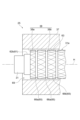
続いて、図2を参照しながら、モーターローター25について説明する。モーターローター25は、インナースリーブ31と、永久磁石37と、エンドリング39,41と、保護層43と、樹脂部50と、を備える組立体である。インナースリーブ31と、永久磁石37と、エンドリング39,41と、保護層43と、樹脂部50と、は、回転軸線Hを中心軸とする回転体形状をなしている。
Next, the
インナースリーブ31は大径部33を備えている。大径部33は、インナースリーブ31の軸方向の中央部でやや大径に設けられている。永久磁石37は、円筒状をなし、大径部33の周囲に設置されている。保護層43は円筒状の部材であり、「アーマーリング」などと呼ばれる場合もある。保護層43は、円筒状をなし、永久磁石37の周囲に設置されている。保護層43は、永久磁石37が破損した場合に破片が径方向へ飛散することを防止する。また、保護層43は、永久磁石37のひずみを抑えて永久磁石37の破損の可能性を低減するために、ある程度の剛性を持つことが必要である。
The
インナースリーブ31(軸部)と永久磁石37との間には僅かな隙間が存在している。当該隙間は樹脂部50の樹脂材料によって樹脂充填される。例えば、樹脂部50は射出成形又はトランスファー成形によって形成される。この樹脂部50を介して、インナースリーブ31と永久磁石37とが一体的に連結される。そして、インナースリーブ31と永久磁石37との間のトルク伝達は、樹脂部50によって可能である。この過給機1において、伝達される上記のトルクは、例えば約0.5Nmである。
A slight gap exists between the inner sleeve 31 (shaft portion) and the
なお、永久磁石37と保護層43との隙間にも樹脂充填されることで永久磁石37と保護層43とが連結されてもよい。その他、エンドリング39,41も充填される樹脂部を介してインナースリーブ31及び保護層43に連結されてもよい。
The
上記のように、モーターローター25は一体の組立体である。このようなモーターローター25のインナースリーブ31の中空部に回転軸14が挿通され、モーターローター25とコンプレッサ翼車7とが一緒に、ナット18(図1参照)によって、回転軸14に締結されている。
As noted above,
インナースリーブ31の材料としては、例えばSCM435H等の鋼材が採用され得る。永久磁石37の材料としては、例えば、ネオジム磁石(Nd-Fe-B)、サマリウムコバルト磁石などが採用され得る。保護層43の材料としては、金属材料や樹脂材料が採用され得る。上記の金属材料としては、チタン(例えばTi-6Al-4V)等の非磁性体金属が採用され得る。また、上記の樹脂材料としては、CFRP(炭素繊維強化プラスチック)などが採用され得る。エンドリング39,41の材料としては、例えばSUS等の非磁性体金属、熱硬化性樹脂、熱可塑性樹脂などが採用され得る。
As the material of the
樹脂部50の材料としては、熱硬化性樹脂、熱可塑性樹脂等が採用され得る。更に具体的には、樹脂部50の材料としては、熱硬化性樹脂であるフェノール樹脂やエポキシ樹脂、又は熱可塑性樹脂であるLCP(液晶ポリマー)が採用され得る。なお、本発明者らの試験によれば、LCPは、フェノール樹脂に比べて射出成形時の流動性が高い点において、樹脂部50の材料として好ましい。また、LCPは、フェノール樹脂に比べて比較的入手が容易である点においても、樹脂部50の材料として好ましい。一方、フェノール樹脂は、LCPに比べて耐熱性、剛性、及び耐環境性に優れる点において、樹脂部50の材料として好ましい。また、エポキシ樹脂は、素材自体に密着性があるので樹脂部50の材料として好ましい。
A thermosetting resin, a thermoplastic resin, or the like can be used as the material of the
図3は、モーターローター25のうちインナースリーブ31と永久磁石37のみを示す側面図である。なお、図3では説明に係る特徴部分が誇張して描写され、他の図とは各部位の寸法比が一致しない場合がある。
3 is a side view showing only the
図3に示されるように、永久磁石37の内周面38は円柱内周面をなしている。以下、内周面38のうち、軸方向における永久磁石37の端部の内周面を内周面38aとし、軸方向における永久磁石37の中央部の内周面を内周面38bとする。インナースリーブ31は、小径部61を有している。小径部61は、内周面38aに対して径方向に対向する位置に形成されている。小径部61は、インナースリーブ31の中央部位63よりも小径に形成されている。中央部位63は、永久磁石37の内周面38bに対向する部位である。
As shown in FIG. 3, the inner
図3の例では、小径部61は、テーパ部62aである。テーパ部62aは、中央部位63から軸方向に離れるほど縮径するように形成されている。テーパ部62aの外周面は円錐面をなす。なお、小径部61はテーパ部62aには限定されない。例えば、図4に示されるように、小径部61は、中央部位63との間に段差をもって小径に形成された段差小径部62bであってもよい。段差小径部62bの外周面は円柱面をなす。
In the example of FIG. 3, the
また、図3に示されるように、インナースリーブ31の外周面31aには、周方向成分を含む方向に延在する溝65が形成されている。図3の例では、溝65には、周方向溝66aと、綾目ローレット溝66bと、が含まれる。周方向溝66aは、外周面31a上で周方向に延びている。綾目ローレット溝66bは、外周面31a上で互いに交差する2方向に螺旋状に延びている。なお溝65としては、周方向溝66aと綾目ローレット溝66bとが両方設けられることは必須ではなく、何れか一方のみ設けられてもよい。また、綾目ローレット溝66bに代えて、一方向に延びる螺旋状の溝からなるローレット溝が採用されてもよい。
Further, as shown in FIG. 3, the outer
図5は、射出成形によって樹脂部50を形成するときの金型70の状態の一例を示す断面図である。図5に示されるように、金型70内には、インナースリーブ31と、永久磁石37と、が収納される。永久磁石37はインナースリーブ31の周囲に配置される。インナースリーブ31と永久磁石37との間には隙間69が存在する。金型70の左方から軸方向に溶融樹脂71が射出されると、隙間69を溶融樹脂71が右方に流動しながら当該隙間69に充填される。この溶融樹脂71が硬化して樹脂部50が形成される。
FIG. 5 is a cross-sectional view showing an example of the state of the
ここで、隙間69に溶融樹脂71が導入される際には、溶融樹脂71の流動状態が周方向で不均一になるおそれがある。そうすると、図6に示されるように、インナースリーブ31と永久磁石37とが心ずれした状態で溶融樹脂71が硬化するおそれがある。この場合、隙間69が狭くなった箇所(図中の符号73)には、樹脂が行き渡らず欠陥になる可能性がある。そして、上記欠陥が樹脂部50の剥離の要因となる場合もある。
Here, when the
これに対し、図3及び図4に示されるように、インナースリーブ31が小径部61を有している。これにより、溶融樹脂71の入口である永久磁石37の端部の位置において、隙間69が径方向に拡がっている。この構造によれば、小径部61と内周面38aとの隙間が比較的広いので、当該隙間において溶融樹脂71の射出速度は比較的遅い。従って、小径部61と内周面38aとの隙間で、溶融樹脂71は周方向全体に行き渡り易い。そして溶融樹脂71は、周方向全体に行き渡ると共に軸方向に流動して隙間69に充填される。このように、隙間69への溶融樹脂71の入口を広くすることで、溶融樹脂71は隙間69に対して周方向に均等に行き渡り易い。その結果、インナースリーブ31と永久磁石37との調心が図られる。
On the other hand, as shown in FIGS. 3 and 4, the
以上のように、本実施形態のモーターローター25の構造によれば、インナースリーブ31に小径部61を設けるといった簡易な手法によってインナースリーブ31と永久磁石37との調心を図ることができる。
As described above, according to the structure of the
また、インナースリーブ31の外周面31aに形成された溝65は、周方向成分を含む方向に延在する。これにより、溝65は、周方向成分を含む方向に溶融樹脂71の流動を案内する。従って、溝65は、隙間69内における溶融樹脂71の周方向の流動を促進する。従って、溝65の存在によっても、溶融樹脂71が隙間69に対して周方向に均等に行き渡り易くなる。また、図5に示されるように、射出成形時には、永久磁石37の左端面37aと金型70との間に空間75が形成されている。この空間75が樹脂溜まりとして機能し、溶融樹脂71を周方向に行き渡らせる。従って、隙間69内における溶融樹脂71の周方向の流動がさらに促進される。
Also, the
また、樹脂部50が溝65に入り込んで形成されることにより、樹脂部50とインナースリーブ31との密着性が高められ、ひいては、インナースリーブ31と永久磁石37との密着性が高められる。溝65が周方向成分を含む方向に延在するので、特に軸方向の密着性が高められる。その結果、インナースリーブ31に対して永久磁石37が軸方向に位置ずれすることが抑制される。また、溝65が綾目ローレット溝66bを含むので、インナースリーブ31に対して永久磁石37が周方向に位置ずれすることも抑制される。
Further, since the
本開示は、上述した実施形態を始めとして、当業者の知識に基づいて種々の変更、改良を施した様々な形態で実施することができる。また、上述した実施形態に記載されている技術的事項を利用して変形例を構成することも可能である。各実施形態の構成を適宜組み合わせて使用してもよい。 The present disclosure can be embodied in various forms with various modifications and improvements based on the knowledge of those skilled in the art, including the embodiments described above. Moreover, it is also possible to configure a modified example using the technical matters described in the above-described embodiments. You may use it, combining the structure of each embodiment suitably.
実施形態では、中空構造のインナースリーブ31と永久磁石37との連結について説明したが、例えば、中実構造の軸部に永久磁石37を連結させる場合にも、前述の構造が適用可能である。
In the embodiment, the connection between the
25 モーターローター
31 インナースリーブ(軸部)
31a 外周面
37 永久磁石
38a 内周面
38b 内周面
50 樹脂部
61 小径部
62a テーパ部
62b 段差小径部
63 中央部位
65 溝
66a 周方向溝
66b 綾目ローレット溝
25
31a outer
Claims (10)
前記軸部は、軸方向における前記磁石の端部の内周面に対向して位置し、前記軸方向における前記磁石の中央部の内周面に対向する部位よりも小径になるように形成された小径部を有し、
前記軸部において、前記磁石の中央部の内周面に対向する中央部位の全面と前記磁石との間には、前記樹脂部が充填されている、モーターローター。 a shaft portion, a cylindrical magnet disposed around the shaft portion, and a resin portion made of resin filled in a gap between the shaft portion and the magnet;
The shaft portion is positioned facing the inner peripheral surface of the end portion of the magnet in the axial direction, and is formed to have a smaller diameter than the portion facing the inner peripheral surface of the central portion of the magnet in the axial direction. has a small diameter portion,
The motor rotor, wherein the resin portion is filled between the entire surface of the central portion of the shaft portion facing the inner peripheral surface of the central portion of the magnet and the magnet.
周方向成分を含む方向に延在する前記溝は、前記大径部の外周面に形成されている、請求項2に記載のモーターローター。 the shaft portion has a large-diameter portion that faces the inner peripheral surface of the central portion of the magnet in the axial direction;
3. The motor rotor according to claim 2, wherein said groove extending in a direction including a circumferential component is formed on the outer peripheral surface of said large diameter portion.
前記ローレット溝は、前記大径部の外周面に形成されている、請求項4に記載のモーターローター。 the shaft portion has a large-diameter portion that faces the inner peripheral surface of the central portion of the magnet in the axial direction;
5. The motor rotor according to claim 4, wherein the knurled grooves are formed on the outer peripheral surface of the large diameter portion.
前記磁石の前記中央部から前記軸方向に離れるほど縮径するように形成されたテーパ部である、請求項1~6の何れか一項に記載のモーターローター。 The small diameter portion is
7. The motor rotor according to any one of claims 1 to 6, wherein the tapered portion is formed such that the diameter of the magnet decreases with increasing distance from the central portion of the magnet in the axial direction.
前記磁石の前記中央部に対向する部位との間に段差をもって小径に形成されている、請求項1~6の何れか一項に記載のモーターローター。 The small diameter portion is
7. The motor rotor according to any one of claims 1 to 6, wherein the magnet is formed to have a small diameter with a step between the portion facing the central portion of the magnet.
10. The motor rotor according to claim 9, wherein the outer peripheral surface of the small diameter portion forms a cylindrical surface.
Applications Claiming Priority (3)
| Application Number | Priority Date | Filing Date | Title |
|---|---|---|---|
| JP2019074828 | 2019-04-10 | ||
| JP2019074828 | 2019-04-10 | ||
| PCT/JP2020/013110 WO2020209050A1 (en) | 2019-04-10 | 2020-03-24 | Motor rotor |
Publications (2)
| Publication Number | Publication Date |
|---|---|
| JPWO2020209050A1 JPWO2020209050A1 (en) | 2020-10-15 |
| JP7264238B2 true JP7264238B2 (en) | 2023-04-25 |
Family
ID=72750684
Family Applications (1)
| Application Number | Title | Priority Date | Filing Date |
|---|---|---|---|
| JP2021513548A Active JP7264238B2 (en) | 2019-04-10 | 2020-03-24 | motor rotor |
Country Status (5)
| Country | Link |
|---|---|
| US (1) | US11664694B2 (en) |
| JP (1) | JP7264238B2 (en) |
| CN (1) | CN113661636B (en) |
| DE (1) | DE112020001824T5 (en) |
| WO (1) | WO2020209050A1 (en) |
Families Citing this family (1)
| Publication number | Priority date | Publication date | Assignee | Title |
|---|---|---|---|---|
| KR20210064851A (en) * | 2019-11-26 | 2021-06-03 | 삼성전자주식회사 | Brushless Direct Current Motor |
Citations (5)
| Publication number | Priority date | Publication date | Assignee | Title |
|---|---|---|---|---|
| JP2002010545A (en) | 2000-06-23 | 2002-01-11 | Mitsubishi Electric Corp | Permanent magnet rotor |
| JP2007159191A (en) | 2005-12-01 | 2007-06-21 | Denso Corp | Motor |
| JP2011239546A (en) | 2010-05-10 | 2011-11-24 | Makita Corp | Dc brushless motor |
| WO2012089470A2 (en) | 2010-12-29 | 2012-07-05 | Arcelik Anonim Sirketi | Rotor part of a permanent magnet synchronous motor |
| JP2013074736A (en) | 2011-09-28 | 2013-04-22 | Toyota Motor Corp | Rotor of rotary electric machine, and rotary electric machine using the same |
Family Cites Families (27)
| Publication number | Priority date | Publication date | Assignee | Title |
|---|---|---|---|---|
| US2488729A (en) * | 1946-10-18 | 1949-11-22 | Int Harvester Co | Magneto rotor |
| JPS6165839A (en) | 1984-09-07 | 1986-04-04 | Nippon Petrochem Co Ltd | Production of alpha-(p-isobutylphenyl)propionic acid |
| JPS6165839U (en) * | 1984-10-04 | 1986-05-06 | ||
| JPH0294444A (en) | 1988-09-30 | 1990-04-05 | Toshiba Corp | Manufacture of semiconductor device |
| JPH0294444U (en) * | 1989-01-10 | 1990-07-26 | ||
| JP3398977B2 (en) * | 1992-07-14 | 2003-04-21 | 株式会社安川電機 | Permanent magnet field rotor |
| JPH0799743A (en) * | 1993-09-27 | 1995-04-11 | Hitachi Metals Ltd | Permanent magnet type rotor |
| JP3287113B2 (en) * | 1994-05-23 | 2002-05-27 | 株式会社安川電機 | Manufacturing method of permanent magnet type rotor |
| JPH1014147A (en) * | 1996-06-24 | 1998-01-16 | Fuji Electric Co Ltd | Rotary machine having circumferentially magnetized rotor and manufacture thereof |
| JPH10201152A (en) * | 1997-01-17 | 1998-07-31 | Mitsubishi Electric Corp | Permanent-magnet rotor and its manufacture |
| JP2000014062A (en) | 1998-06-16 | 2000-01-14 | Denso Corp | Torque motor |
| JP2000324769A (en) * | 1999-05-13 | 2000-11-24 | Matsushita Electric Ind Co Ltd | Stepping motor |
| JP2002209352A (en) * | 2001-01-12 | 2002-07-26 | Mitsubishi Electric Corp | Permanent magnet rotor of rotating electric machine and method for manufacturing the same |
| DE50213151D1 (en) * | 2002-07-26 | 2009-02-05 | Ms Technologie Gmbh | High-speed rotor |
| JP4352766B2 (en) * | 2003-06-09 | 2009-10-28 | 三菱電機株式会社 | Method for manufacturing brushless motor for electric power steering apparatus |
| JP3810074B2 (en) | 2004-01-09 | 2006-08-16 | 日本サーボ株式会社 | Rotor |
| JP2006109676A (en) * | 2004-10-08 | 2006-04-20 | Jtekt Corp | Rotor and manufacturing method therefor |
| JP4222310B2 (en) | 2005-01-13 | 2009-02-12 | 三菱マテリアルシ−エムアイ株式会社 | Stepping motor |
| KR100683595B1 (en) * | 2005-06-21 | 2007-02-20 | 주식회사 대우일렉트로닉스 | Rotor structure of motor |
| JP4893991B2 (en) | 2005-09-06 | 2012-03-07 | 株式会社デンソー | Fuel pump |
| DE102006000446B4 (en) | 2005-09-06 | 2013-04-18 | Denso Corporation | Fluid pump and electric motor and their manufacturing process |
| JP2007116767A (en) | 2005-10-18 | 2007-05-10 | Denso Corp | Fuel pump |
| DE102006000447A1 (en) | 2005-09-06 | 2007-03-08 | Denso Corp., Kariya | Fluid pump with bearing hole |
| US9664050B2 (en) * | 2013-10-25 | 2017-05-30 | Ecomotors, Inc. | Bearings for a turbomachine having an electric motor |
| JP5820046B2 (en) * | 2013-12-27 | 2015-11-24 | ファナック株式会社 | Rotor of electric motor having magnet holding structure and electric motor having the same |
| JP2016208724A (en) | 2015-04-24 | 2016-12-08 | 株式会社豊田自動織機 | Rotor and method of manufacturing the same, and electric motor and compressor |
| JP6402231B2 (en) | 2017-11-09 | 2018-10-10 | 日本電産テクノモータ株式会社 | Motor and motor manufacturing method |
-
2020
- 2020-03-24 CN CN202080026173.4A patent/CN113661636B/en active Active
- 2020-03-24 JP JP2021513548A patent/JP7264238B2/en active Active
- 2020-03-24 DE DE112020001824.5T patent/DE112020001824T5/en active Pending
- 2020-03-24 WO PCT/JP2020/013110 patent/WO2020209050A1/en active Application Filing
-
2021
- 2021-10-01 US US17/491,560 patent/US11664694B2/en active Active
Patent Citations (5)
| Publication number | Priority date | Publication date | Assignee | Title |
|---|---|---|---|---|
| JP2002010545A (en) | 2000-06-23 | 2002-01-11 | Mitsubishi Electric Corp | Permanent magnet rotor |
| JP2007159191A (en) | 2005-12-01 | 2007-06-21 | Denso Corp | Motor |
| JP2011239546A (en) | 2010-05-10 | 2011-11-24 | Makita Corp | Dc brushless motor |
| WO2012089470A2 (en) | 2010-12-29 | 2012-07-05 | Arcelik Anonim Sirketi | Rotor part of a permanent magnet synchronous motor |
| JP2013074736A (en) | 2011-09-28 | 2013-04-22 | Toyota Motor Corp | Rotor of rotary electric machine, and rotary electric machine using the same |
Also Published As
| Publication number | Publication date |
|---|---|
| JPWO2020209050A1 (en) | 2020-10-15 |
| CN113661636B (en) | 2024-04-16 |
| DE112020001824T5 (en) | 2021-12-23 |
| WO2020209050A1 (en) | 2020-10-15 |
| CN113661636A (en) | 2021-11-16 |
| US11664694B2 (en) | 2023-05-30 |
| US20220021255A1 (en) | 2022-01-20 |
Similar Documents
| Publication | Publication Date | Title |
|---|---|---|
| JP6817275B2 (en) | Rotor with cooling function | |
| KR101164576B1 (en) | Electric supercharger | |
| EP3300219B1 (en) | Motor and method for manufacturing same | |
| JP2015144550A (en) | Rotor of electric motor with magnet holding structure and electric motor including the rotor | |
| US11979064B2 (en) | Motor rotor with surface treatment | |
| JP7264238B2 (en) | motor rotor | |
| US11569713B2 (en) | Axial flux motor including system for circulating coolant through air gap between stator and rotor | |
| JP2007205246A (en) | Water pump and hybrid vehicle | |
| CN111654129A (en) | Rotor and rotating electrical machine | |
| US20230198355A1 (en) | Motor rotor with end ring | |
| JP6255861B2 (en) | Rotor and electric motor | |
| JP2007202363A (en) | Rotary-electric machine | |
| US20190027979A1 (en) | Salient-pole rotor and rotor manufacturing method | |
| JP6672741B2 (en) | Motor and electric supercharger having the same | |
| JP2010193568A (en) | Integral assembly composed of motor case and magnet in electric motor, and method of manufacturing the same | |
| CN116670987A (en) | Electric disc motor for driving rim | |
| WO2016203783A1 (en) | Axial-gap type rotary electric machine | |
| KR102632406B1 (en) | Rotor for elecric motor, electric motor having the same, supercharger having electric motor, and assembling method for electric motor | |
| WO2023162172A1 (en) | Rotor, rotary electrical machine, electric compressor, and method for producing rotor | |
| CN210431058U (en) | Rotating electrical machine | |
| WO2023162171A1 (en) | Rotor, rotary electrical machine, electric compressor, and method for producing rotor | |
| JP7131457B2 (en) | Electric motor manufacturing method | |
| US20230231431A1 (en) | Motor rotor with fractured magnet | |
| JP5757082B2 (en) | Electric pump | |
| EP3629456A1 (en) | Method for manufacturing a rotor of an electric motor |
Legal Events
| Date | Code | Title | Description |
|---|---|---|---|
| A521 | Request for written amendment filed |
Free format text: JAPANESE INTERMEDIATE CODE: A523 Effective date: 20211001 |
|
| A621 | Written request for application examination |
Free format text: JAPANESE INTERMEDIATE CODE: A621 Effective date: 20211001 |
|
| A131 | Notification of reasons for refusal |
Free format text: JAPANESE INTERMEDIATE CODE: A131 Effective date: 20220906 |
|
| A521 | Request for written amendment filed |
Free format text: JAPANESE INTERMEDIATE CODE: A523 Effective date: 20221024 |
|
| TRDD | Decision of grant or rejection written | ||
| A01 | Written decision to grant a patent or to grant a registration (utility model) |
Free format text: JAPANESE INTERMEDIATE CODE: A01 Effective date: 20230314 |
|
| A61 | First payment of annual fees (during grant procedure) |
Free format text: JAPANESE INTERMEDIATE CODE: A61 Effective date: 20230327 |
|
| R151 | Written notification of patent or utility model registration |
Ref document number: 7264238 Country of ref document: JP Free format text: JAPANESE INTERMEDIATE CODE: R151 |