JP7257140B2 - Brake cylinder and unit brake - Google Patents
Brake cylinder and unit brake Download PDFInfo
- Publication number
- JP7257140B2 JP7257140B2 JP2018234822A JP2018234822A JP7257140B2 JP 7257140 B2 JP7257140 B2 JP 7257140B2 JP 2018234822 A JP2018234822 A JP 2018234822A JP 2018234822 A JP2018234822 A JP 2018234822A JP 7257140 B2 JP7257140 B2 JP 7257140B2
- Authority
- JP
- Japan
- Prior art keywords
- latch
- braking force
- brake
- spring
- spring brake
- Prior art date
- Legal status (The legal status is an assumption and is not a legal conclusion. Google has not performed a legal analysis and makes no representation as to the accuracy of the status listed.)
- Active
Links
Images


Classifications
-
- B—PERFORMING OPERATIONS; TRANSPORTING
- B60—VEHICLES IN GENERAL
- B60T—VEHICLE BRAKE CONTROL SYSTEMS OR PARTS THEREOF; BRAKE CONTROL SYSTEMS OR PARTS THEREOF, IN GENERAL; ARRANGEMENT OF BRAKING ELEMENTS ON VEHICLES IN GENERAL; PORTABLE DEVICES FOR PREVENTING UNWANTED MOVEMENT OF VEHICLES; VEHICLE MODIFICATIONS TO FACILITATE COOLING OF BRAKES
- B60T13/00—Transmitting braking action from initiating means to ultimate brake actuator with power assistance or drive; Brake systems incorporating such transmitting means, e.g. air-pressure brake systems
- B60T13/10—Transmitting braking action from initiating means to ultimate brake actuator with power assistance or drive; Brake systems incorporating such transmitting means, e.g. air-pressure brake systems with fluid assistance, drive, or release
- B60T13/24—Transmitting braking action from initiating means to ultimate brake actuator with power assistance or drive; Brake systems incorporating such transmitting means, e.g. air-pressure brake systems with fluid assistance, drive, or release the fluid being gaseous
- B60T13/26—Compressed-air systems
- B60T13/38—Brakes applied by springs or weights and released by compressed air
- B60T13/385—Control arrangements therefor
Description
本発明は、ブレーキシリンダ及びユニットブレーキに関する。 The present invention relates to brake cylinders and unit brakes.
ユニットブレーキでは、ばねの付勢力によって制動状態を維持するばねブレーキを備えるものがある(例えば、特許文献1参照)。そして、このようなばねブレーキを有するユニットブレーキでは、ばねブレーキのブレーキ力を手動で開放する手動開放機構が更に備えられている。 Some unit brakes include a spring brake that maintains a braking state by the biasing force of a spring (see, for example, Patent Document 1). A unit brake having such a spring brake is further provided with a manual release mechanism for manually releasing the braking force of the spring brake.
ユニットブレーキは、押棒が軸方向に移動することで車輪に制動力を付与し、このばねブレーキのブレーキ力を押棒に伝達及び遮断するクラッチを備えている。このクラッチは、手動解放機構の操作によって回転し、ばねブレーキのブレーキ力との伝達が解放されることで、ユニットブレーキの制動力を解放することができる。 A unit brake applies a braking force to a wheel by moving a push rod in the axial direction, and has a clutch that transmits and interrupts the braking force of the spring brake to the push rod. This clutch is rotated by the operation of the manual release mechanism, and by releasing the transmission of the braking force of the spring brake, the braking force of the unit brake can be released.
ところで、上記のユニットブレーキは、手動解放機構が操作されてクラッチが回転したときに手動解放機構が傾いて、手動解放後にばねブレーキのブレーキ力が復帰しない、リセット不良となることがある。 By the way, in the unit brake, when the manual release mechanism is operated and the clutch rotates, the manual release mechanism tilts, and the braking force of the spring brake does not recover after manual release, resulting in reset failure.
本発明は、こうした実情に鑑みてなされたものであり、その目的は、ばねブレーキのブレーキ力を解放した後にばねブレーキのブレーキ力が復帰しない、リセット不良を抑制することのできるブレーキシリンダ及びユニットブレーキを提供することにある。 SUMMARY OF THE INVENTION The present invention has been made in view of these circumstances, and its object is to provide a brake cylinder and a unit brake that can suppress reset failures in which the braking force of the spring brake does not return after the braking force of the spring brake is released. is to provide
上記課題を解決するブレーキシリンダは、ばねブレーキのブレーキ力を解放する操作が行われる操作部と、前記ばねブレーキのブレーキ力を駆動部に伝達するブレーキ力伝達部と、前記ばねブレーキのブレーキ力を前記ブレーキ力伝達部に伝達及び遮断するクラッチ機構と、前記操作部と前記クラッチ機構とを接続し、前記操作部の操作によって回転するラッチと、前記ラッチの回転軸の軸方向に前記ラッチが傾くことを抑制する位置規制部とを備える。 A brake cylinder that solves the above problems comprises an operating portion for releasing the braking force of the spring brake, a braking force transmission portion for transmitting the braking force of the spring brake to a driving portion, and a braking force of the spring brake. a clutch mechanism for transmitting and interrupting transmission to and from the braking force transmitting portion; a latch that connects the operation portion and the clutch mechanism and rotates when the operation portion is operated; and the latch tilts in the axial direction of the rotation shaft of the latch. and a position regulating portion that suppresses this.
上記課題を解決するユニットブレーキは、ばねブレーキのブレーキ力を解放する操作が行われる操作部と、前記ばねブレーキのブレーキ力を駆動部に伝達するブレーキ力伝達部と、前記ばねブレーキのブレーキ力を前記ブレーキ力伝達部に伝達又は遮断するクラッチ機構と、前記操作部と前記クラッチ機構とを接続し、前記操作部の操作によって回転するラッチと、前記ラッチの回転軸の軸方向に前記ラッチが傾くことを規制する位置規制部と、前記ブレーキ力伝達部を介して前記ブレーキ力が伝達される前記駆動部としての制輪子頭とを備える。 A unit brake which solves the above problems comprises an operating portion for releasing the braking force of the spring brake, a braking force transmission portion for transmitting the braking force of the spring brake to a driving portion, and a braking force of the spring brake. a clutch mechanism for transmitting or interrupting transmission to or from the braking force transmission section; a latch that connects the operating section and the clutch mechanism and rotates by operating the operating section; and the latch tilts in the axial direction of the rotation shaft of the latch. and a brake shoe head as the driving unit to which the braking force is transmitted via the braking force transmission unit.
上記構成によれば、操作部が操作されたときに位置規制部によってラッチが傾くことが抑制されるため、ばねブレーキのブレーキ力が解放された後にばねブレーキのブレーキ力が復帰しない、リセット不良を抑制することができる。 According to the above configuration, the tilting of the latch is suppressed by the position regulating portion when the operating portion is operated, so that the braking force of the spring brake does not recover after the braking force of the spring brake is released, thereby preventing a reset failure. can be suppressed.
上記ブレーキシリンダについて、前記ラッチの回転軸に直交する方向に延出する板部材を備え、前記位置規制部は、前記板部材に取り付けられ前記ラッチとの距離を変更する変更部を有することが好ましい。 It is preferable that the brake cylinder includes a plate member extending in a direction orthogonal to the rotation axis of the latch, and the position regulating portion has a changing portion that is attached to the plate member and changes a distance from the latch. .
上記構成によれば、操作部が操作されたときに、位置規制部の変更部がラッチとの距離を変更するため、部材毎の誤差や組み付けによる差異に合わせて変更することができ、ラッチが傾くことを更に抑制することができる。 According to the above configuration, when the operating portion is operated, the changing portion of the position regulating portion changes the distance from the latch. Tilting can be further suppressed.
上記ブレーキシリンダについて、前記変更部は、回転量で距離が変更されるねじを有することが好ましい。
上記構成によれば、ねじの回転量で位置規制部とラッチとの距離を容易に変更することができる。
Regarding the brake cylinder, it is preferable that the changing portion has a screw whose distance is changed by the amount of rotation.
According to the above configuration, the distance between the position regulating portion and the latch can be easily changed by the amount of rotation of the screw.
上記ブレーキシリンダについて、前記位置規制部は、前記操作部が操作されるときの前記ラッチの回転量を所定量に規制する回転規制部を兼ねることが好ましい。
上記構成によれば、位置規制部によってラッチの傾きを抑制しつつ、操作部の操作量を所定量に規制することができるため、部品点数を低減することができる。
Regarding the brake cylinder, it is preferable that the position regulating portion also serve as a rotation regulating portion that regulates the amount of rotation of the latch to a predetermined amount when the operating portion is operated.
According to the above configuration, the tilt of the latch can be suppressed by the position regulating portion, and the amount of operation of the operating portion can be regulated to a predetermined amount, so the number of parts can be reduced.
上記ブレーキシリンダについて、前記ラッチと、前記ラッチが取り付けられる前記ブレーキシリンダのケースとの間に設けられる軸受を備えることが好ましい。
上記構成によれば、ラッチとケースとの間に軸受が設けられるため、ラッチの回転性能を向上させることができ、ラッチが傾いて止まることを抑制することができる。
Preferably, the brake cylinder is provided with a bearing provided between the latch and a case of the brake cylinder to which the latch is attached.
According to the above configuration, since the bearing is provided between the latch and the case, it is possible to improve the rotation performance of the latch and prevent the latch from tilting and stopping.
上記ブレーキ装置は、前記位置規制部と前記ラッチとの間に前記ラッチが復帰可能な変位を許容する隙間を有することが好ましい。
上記構成によれば、位置規制部とラッチとの間に隙間があるので、位置規制部がラッチの復帰可能な変位を許容しつつ、位置規制部がラッチの過度な変位を規制することでリセット不良を抑制することができる。
It is preferable that the brake device has a gap between the position regulating portion and the latch that allows the latch to be displaced for restoration.
According to the above configuration, since there is a gap between the position restricting portion and the latch, the position restricting portion restricts excessive displacement of the latch while the position restricting portion allows the latch to be displaced so that it can be reset. Defects can be suppressed.
本発明によれば、ばねブレーキのブレーキ力を解放した後にばねブレーキのブレーキ力が復帰しない、リセット不良を抑制することができる。 ADVANTAGE OF THE INVENTION According to this invention, the reset failure that the braking force of a spring brake does not return after releasing the braking force of a spring brake can be suppressed.
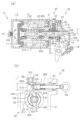
以下、図1~図9を参照して、ブレーキシリンダを備えるユニットブレーキの一実施形態について説明する。ユニットブレーキは、車輪の踏面に制輪子を接触させることで制動を得るトレッドブレーキタイプのユニットブレーキである。 An embodiment of a unit brake comprising a brake cylinder will now be described with reference to FIGS. 1 to 9. FIG. A unit brake is a tread brake type unit brake that obtains braking by bringing a brake shoe into contact with the tread surface of a wheel.
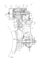
(ユニットブレーキ1)
図1~図3に示すように、ユニットブレーキ1は、ブレーキばね12によるブレーキ力を出力するばねブレーキシリンダ10と、空気によるブレーキ力を出力する空気ブレーキシリンダ20とを備えている。ユニットブレーキ1は、ばねブレーキシリンダ10及び空気ブレーキシリンダ20から出力されたブレーキ力を制輪子頭37に伝達する伝達駆動部30を備えている。伝達駆動部30は、中空状の本体31を備えている。
(Unit brake 1)
As shown in FIGS. 1 to 3, the
(ばねブレーキシリンダ10)
ばねブレーキシリンダ10は、有底筒状の第1シリンダ11を備えている。第1シリンダ11は、本体31の上部の図中左側に接続されている。このため、本体31の一部が第1シリンダ11のケースの一部を兼ねている。ばねブレーキシリンダ10は、ブレーキばね12と、ブレーキばね12によって付勢される第1ピストン13と、ブレーキ力を伝達駆動部30に伝達するブレーキ力伝達部としての第1押棒14とを備えている。第1押棒14は、本体31内に突出している。
(Spring brake cylinder 10)
The
第1ピストン13は、第1シリンダ11の中心軸Pに沿って移動する。第1押棒14の基端は、第1ピストン13に連結される。また、第1押棒14の先端は、連結ピン15を介してばねブレーキレバー16に回動可能に連結されている。ばねブレーキレバー16は、本体31に固定される第1支軸17を回転中心として回転する。ばねブレーキレバー16の基端は、第1押棒14に連結ピン15を介して連結されている。ばねブレーキレバー16には、ブレーキばね12によってブレーキ力が出力されていることを外部に表示するばねブレーキ表示器18が接続されている。
The
第1シリンダ11の底部(図中左側)には、圧縮空気を第1シリンダ11内に供給する供給口10Aが設けられている。圧縮空気は、第1シリンダ11と第1ピストン13とに囲まれた第1作動室11Aに供給される。ばねブレーキシリンダ10は、第1作動室11Aに供給口10Aから圧縮空気が供給されると、第1ピストン13及び第1押棒14が第1シリンダ11から突出する方向(図中右側)に移動して、ばねブレーキレバー16を図中時計回りに回転させる。一方、ばねブレーキシリンダ10は、第1作動室11Aから供給口10Aを介して圧縮空気が排出されると、第1ピストン13及び第1押棒14がブレーキばね12によって第1シリンダ11の底面側(図中左側)に移動して、ばねブレーキレバー16を図中反時計回りに回転させる。ばねブレーキ表示器18は、ばねブレーキレバー16が図中反時計回りに回転すると、本体31の外部に突出することで表示する。
A
ばねブレーキシリンダ10は、ブレーキばね12の付勢力を第1押棒14に伝達及び遮断するクラッチ機構40を備えている。クラッチ機構40は、第1ピストン13と第1押棒14との連結と遮断とを切り替える。
The
ばねブレーキシリンダ10は、ブレーキばね12によるブレーキ力を手動で開放する手動開放機構50を備えている。手動開放機構50は、クラッチ機構40を操作して、第1ピストン13と第1押棒14との連結を遮断することでブレーキ力を解放する。
The
(空気ブレーキシリンダ20)
空気ブレーキシリンダ20は、有底筒状の第2シリンダ21を備えている。第2シリンダ21は、本体31のばねブレーキシリンダ10の下方の図中左側に接続されている。空気ブレーキシリンダ20は、ばね22と、ばね22によって付勢される第2ピストン23とを備えている。第2ピストン23の先端は、本体31内に突出して、連結ピン23Aを介してブレーキ梃子32に回動可能に連結されている。ブレーキ梃子32は、本体31に固定される第2支軸33を回転中心として回転する。ブレーキ梃子32の一端(図中上側)は、第2ピストン23に連結されている。
(Air brake cylinder 20)
The
第2シリンダ21の底部(図中左側)には、圧縮空気を第2シリンダ21内に供給する供給口20Aが設けられている。圧縮空気は、第2シリンダ21と第2ピストン23とに囲まれた第2作動室21Aに供給される。空気ブレーキシリンダ20は、第2作動室21Aに圧縮空気が供給されると、第2ピストン23が第2シリンダ21から突出する方向(図中右側)に移動して、ブレーキ梃子32を図中時計回りに回転させる。一方、空気ブレーキシリンダ20は、第2作動室21Aから圧縮空気が排出されると、第2ピストン23がばね22によって第2シリンダ21の底面側(図中左側)に移動して、ブレーキ梃子32を図中反時計回りに回転させる。
A
ばねブレーキレバー16の先端は、ブレーキ梃子32と第2ピストン23とを連結する連結ピン23Aに当接している。ばねブレーキレバー16が第1支軸17を回転中心として回転すると、ブレーキ梃子32が第2支軸33を回転中心として回転する。
The tip of the
(伝達駆動部30)
伝達駆動部30は、上記ブレーキ梃子32と、ブレーキ梃子32の他端に設けられる球面貫通孔32Aに嵌合する球面軸受34と、球面軸受34が外周面に固定される円筒状のさや棒35とを備えている。伝達駆動部30は、さや棒35の内面に螺合して設けられる第2押棒36と、さや棒35の外周面に設けられる隙間調整部39とを備えている。第2押棒36の基端側は、さや棒35の内部に挿入されている。第2押棒36の先端側には、制輪子頭37が連結ピン36Aを介して回動可能に取り付けられている。制輪子頭37は、本体31に連結ピン31Bを介して回転可能に設けられるハンガー38に回動可能に取り付けられている。制輪子頭37には、車輪3の踏面3Aに押し当てられる制輪子2が取り付けられる。
(Transmission drive unit 30)
The
制輪子2が摩耗して制輪子2と車輪3の踏面3Aとの隙間が増えると、ブレーキ梃子32が隙間調整部39に当接して、隙間調整部39がさや棒35を回転させる。そして、さや棒35が回転すると、第2押棒36のさや棒35からの突出量が増加することで、制輪子2と車輪3の踏面3Aとの隙間が調整される。
When the
ブレーキ梃子32が第2支軸33を中心に図中時計回りに回転すると、さや棒35及び第2押棒36とともに制輪子2が車輪3の踏面3A側へ押されて、制輪子2が車輪3の踏面3Aに押し当てられ、車輪3の回転が制動される。なお、空気ブレーキシリンダ20によってブレーキ梃子32が図中時計回りに回転されるときは、回転量が大きいほど制輪子2が車輪3の踏面3Aに押し当てられる量、言い換えれば摩擦量が大きくなる。一方、ブレーキ梃子32が第2支軸33を中心に図中反時計回りに回転すると、さや棒35及び第2押棒36とともに制輪子2が車輪3の踏面3Aから離間する側へ移動して、車輪3の回転の制動が解除される。
When the
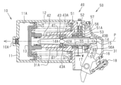
(クラッチ機構40)
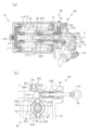
図4及び図5に示すように、クラッチ機構40は、第1押棒14と第1ピストン13とを連結する一対のボール41を備えている。ボール41は、第1ピストン13に連結される円筒状のボール受42の貫通孔42Aに保持されている。ボール受42の中心軸は、第1シリンダ11の中心軸Pと同一となるように連結されている。本体31は、ばねブレーキシリンダ10の内部に突出する円筒状の保持部31Aを備えている。第1押棒14及びボール受42は、保持部31A内に挿入されている。
(Clutch mechanism 40)
As shown in FIGS. 4 and 5, the
第1押棒14には、ボール41を嵌合する溝14Aが設けられている。ボール41が第1押棒14の溝14A及びボール受42の貫通孔42Aの両方に嵌合することで第1押棒14と第1ピストン13とが連結されて一緒に移動する。なお、第1押棒14は、第1支軸17を中心に回転するばねブレーキレバー16に連結されているため、第1シリンダ11の中心軸Pの軸方向からずれて移動する。
The
クラッチ機構40は、ボール41を第1押棒14の溝14Aから逃がす円筒状のクラッチ43を備えている。クラッチ43は、本体31の保持部31Aの内周とボール受42の外周との間に装着されている。なお、クラッチ43の基端が本体31の保持部31A内に位置し、クラッチ43の先端がばねブレーキシリンダ10から突出して本体31内に位置している。クラッチ43の中心軸は、第1シリンダ11の中心軸Pと同一となるように連結されている。図6に示すように、クラッチ43の内周面には、ボール41をボール受42の径方向外側へ移動させる嵌合溝43Aが形成されている。クラッチ43は、ボール受42の軸方向に移動不可能に設けられるとともに、ボール受42に対して周方向へ回転可能に設けられている。そして、ボール41がクラッチ43の嵌合溝43Aのない部分に当接しているときには、第1押棒14と第1ピストン13とが連結される(図6参照)。一方、クラッチ43が周方向に回転されて、ボール41がクラッチ43の嵌合溝43Aに嵌合すると、ボール41が第1押棒14の溝14Aから外れることで、第1押棒14と第1ピストン13との連結が遮断される(図8参照)。
The
(手動開放機構50)
図4及び図5に示すように、手動開放機構50は、第1ピストン13の中心軸P上に位置しつつ、本体31内に設けられている。手動開放機構50は、クラッチ機構40のクラッチ43の外周に固定される円筒状のラッチ51と、ラッチ51に取り付けられて本体31の外部に突出する引棒52とを備えている。なお、引棒52が操作部に相当する。
(Manual opening mechanism 50)
As shown in FIGS. 4 and 5 , the
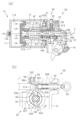
図6及び図7に示すように、手動開放機構50は、ラッチ51の回転を規制する爪58及び爪58を付勢する爪ばね59を備えている。爪58及び爪ばね59は、ラッチ51の上方に設置されている。爪58は、爪ばね59に付勢されてラッチ51と係合している。ブレーキばね12の付勢力がボール41を介してラッチ51に伝達され始めると、ボール41がクラッチ43の嵌合溝43Aに逃げ込もうとする分力が発生して、ラッチ51が図7(b)中時計回りに回転しようとする。そこで、爪58がラッチ51に係合することでラッチ51の図7(b)中時計周りの回転を阻止している。
As shown in FIGS. 6 and 7, the
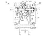
ラッチ51は、ガイドキー53によってクラッチ43の外周に固定されている。ラッチ51の回転軸と、第1シリンダ11の中心軸Pが同一となるように固定されている。すなわち、図5に示すように、ガイドキー53は、ラッチ51の内周面に固定されつつ、クラッチ43の左側外周面部分に設けられる。なお、断面図である図4では、図5のガイドキー53の位置では図示することができないため、ラッチ51とクラッチ43との接続関係を説明するために上側外周面に仮想的に図示している。クラッチ43の左側外周面には、クラッチ43の移動範囲に合わせてガイドキー53が嵌装されるガイド溝43Bが第1シリンダ11の中心軸Pの軸方向に延出している。クラッチ43は、ラッチ51に対して第1シリンダ11の中心軸Pの軸方向に移動可能であるとともに、ラッチ51と一体に回転可能である。
The
ラッチ51は、本体31の保持部31Aの基端内面とクラッチ43の外周面との間に支持されている。本体31の保持部31Aの内面とラッチ51との間には、針状ころ軸受55が設置されている。ラッチ51は、針状ころ軸受55によって本体31に対する回転が容易となっている。
The
ラッチ51の上部には、引棒52が連結される連結部51Aが設けられている。引棒52の基端は、ピン52Aによってラッチ51の連結部51Aに遊びがある状態で連結されている。引棒52の先端には、使用者に引っ張られる引輪54が取り付けられている。引棒52は、第1押棒14とボール受42とが連結状態となるようにラッチ51を付勢する付勢ばね52Bを備えている。ラッチ51は、付勢ばね52Bによって第1押棒14とボール受42とを連結状態に維持している。一方、引棒52は、使用者が付勢ばね52Bの付勢力に抗して引輪54を引っ張ることで、ばねブレーキシリンダ10のブレーキ力を開放する操作が行われる。ラッチ51は、引棒52とクラッチ機構40とを接続し、引棒52の操作によって回転する。
A
図6及び図7に示すように、引棒52は、爪58に当接して、爪58を上昇させる引棒斜面部52Cを備えている。爪58は、引棒52の引棒斜面部52Cと当接する凹み斜面部58Aを備えている。引棒52が操作されると、引棒斜面部52Cが爪58の凹み斜面部58Aに当接して爪58を爪ばね59の付勢力に抗して上昇させて、ラッチ51と爪58との係合が外れる。
As shown in FIGS. 6 and 7, the
そして、図8に示すように、ボール41がクラッチ43の嵌合溝43Aに逃げ込もうとする分力でラッチ51の連結部51Aが図8(b)中時計回りに回転してボール41がクラッチ43の嵌合溝43Aに入り込み、第1押棒14とボール受42の連結が外れることでブレーキばね12によるブレーキ力は消滅する。また、ボール受42は、第1ピストン13と一体に第1シリンダ11の底部側に移動する。
Then, as shown in FIG. 8, the
手動開放機構50は、ラッチ51を保持するラッチ保持板56を備えている。なお、ラッチ保持板56が板部材に相当する。ラッチ保持板56は、第1シリンダ11の中心軸Pに直交する方向に延出する板材である。ラッチ保持板56は、ラッチ51を回転可能な状態で、ラッチ51の上部の連結部51Aを本体31のばねブレーキシリンダ10が取り付けられた部分の内壁と挟むことでラッチ51を保持する。ラッチ保持板56の中央には、クラッチ43及び第1押棒14を貫装する貫通孔56Aが設けられている。ラッチ保持板56は、ラッチ51を本体31の内壁と挟むとともに、クラッチ43及び第1押棒14を貫通させた状態で本体31の内壁にねじ57によって固定されている。
The
手動開放機構50は、第1シリンダ11の中心軸Pに直交する方向に対してラッチ51が傾くことを抑制する位置規制部としてのラッチ押えねじ60を備えている。ラッチ押えねじ60は、ラッチ51の端面に対向するように、第1シリンダ11の中心軸Pの軸線方向と平行に設けられる。すなわち、図5に示すように、ラッチ押えねじ60は、ラッチ保持板56の右側上方部分に設けられる。なお、断面図である図4では、図5のラッチ押えねじ60の位置では図示することができないため、ラッチ押えねじ60とラッチ51との位置関係を説明するために下側部分に仮想的に図示している。
The
ラッチ51には、ラッチ51の回転量を所定量に規定する切欠51Bが設けられている(図5参照)。切欠51Bは、ラッチ押えねじ60が位置する右側上方部分に設けられ、所定量に相当する回転量の範囲に設けられている。ラッチ押えねじ60は、ラッチ51の切欠51Bの部分に設けられ、ラッチ51の回転を規制する回転規制部として機能する。
The
ラッチ押えねじ60は、ねじを有し、ラッチ保持板56に螺合して、ラッチ保持板56のばねブレーキシリンダ10と離間する側から挿入されて、ばねブレーキシリンダ10側に突出する。ラッチ押えねじ60のねじは、回転量(ねじ込み量)によってラッチ51との距離を変更する変更部として機能する。ラッチ押えねじ60は、ドライバーで回転させることで距離を変更することができる。ラッチ押えねじ60の先端とラッチ51の端面との間には、例えば0.1~0.2mmの隙間Wが設けられている。ラッチ押えねじ60は、引棒52が引かれて回転したときに、ラッチ51が本体31やクラッチ43との接触によって第1シリンダ11の中心軸Pに直交する方向に対してラッチ51が傾かないように、ラッチ51の端面に接触する。なお、ラッチ51は、通常は、第1シリンダ11の中心軸Pに直交する方向に対して傾かずに回転する。
The
ラッチ押えねじ60には、ナット61が螺合される。ナット61は、ラッチ押えねじ60のばねブレーキシリンダ10から離間する側に螺合される。ラッチ押えねじ60は、ナット61と皿ばね座金で固定される。ラッチ押えねじ60は、ナット61がラッチ保持板56に当接することでばねブレーキシリンダ10側への移動が規制され、ラッチ押えねじ60とラッチ51との位置(距離)を維持することができる。
A
次に、図6~図9を併せ参照して、上記ユニットブレーキ1の動作について説明する。
図6では、ばねブレーキシリンダ10によるブレーキ力を解放した「緩め状態」を示している。ばねブレーキシリンダ10の供給口10Aから圧縮空気を第1シリンダ11の第1作動室11Aに供給することで、ブレーキばね12の付勢力に抗して第1ピストン13が第1シリンダ11の底部から離間する側、図6(a)中右側へ移動する。そして、第1ピストン13に連結されたボール受42とボール41と第1押棒14とが図6(a)中右側へ移動すると、第1支軸17を回転中心としてばねブレーキレバー16が図中時計回りに回転する。
Next, the operation of the
FIG. 6 shows a "relaxed state" in which the braking force of the
ばねブレーキレバー16が図中時計回りに回転すると、ばねブレーキレバー16の先端がブレーキ梃子32と第2ピストン23とを連結する連結ピン23Aから離間することで、ばねブレーキシリンダ10によるブレーキ力が解放される。
When the
図6(b)に示すように、引棒52(引輪54)が操作されていない状態では、引棒52の付勢ばね52Bによってラッチ51が図6(b)中左側に付勢されているため、ボール受42とボール41と第1押棒14とが連結された状態が維持されている。
As shown in FIG. 6(b), when the pull rod 52 (pull ring 54) is not operated, the
図7では、ばねブレーキシリンダ10によるブレーキ力を出力する「ばねブレーキ作用状態」を示している。ばねブレーキシリンダ10の第1シリンダ11の第1作動室11Aから圧縮空気を排出することで、ブレーキばね12の付勢力によって第1ピストン13が第1シリンダ11の底部側、図7(a)中左側へ移動する。そして、第1ピストン13に連結されたボール受42とボール41と第1押棒14とが図7(a)中左側へ一体に移動すると、第1支軸17を回転中心としてばねブレーキレバー16が図中反時計回りに回転する。
FIG. 7 shows the "spring brake applied state" in which the braking force by the
ばねブレーキレバー16が図中反時計回りに回転すると、ばねブレーキレバー16の先端がブレーキ梃子32と第2ピストン23とを連結する連結ピン23Aに当接して、ブレーキ梃子32が第2支軸33を時計回りに回転する。そして、ばねブレーキシリンダ10によるブレーキ力をさや棒35、第2押棒36、及び制輪子頭37を介して制輪子2に伝達して、制輪子2が車輪3の踏面3Aに当接する。
When the
図7(b)に示すように、引棒52(引輪54)が操作されていない状態では、ラッチ51と爪58とが係合しているため、ボール受42とボール41と第1押棒14とが連結された状態が維持されている。
As shown in FIG. 7B, when the pull rod 52 (pull ring 54) is not operated, the
ばねブレーキシリンダ10は、第1シリンダ11の第1作動室11Aに圧縮空気を供給することと、第1作動室11Aから圧縮空気を排出することとを切り替えることで、「緩め状態」と「ばねブレーキ作用状態」とを切り替えることができる。
The
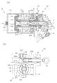
図8では、ばねブレーキシリンダ10によるブレーキ力を手動で解放する「手動緩め作用状態」を示している。図8(b)に示すように、引棒52(引輪54)が引かれるとラッチ51と爪58との係合が外れることで、ラッチ51が時計回りに回転して、ボール41が嵌合溝43Aに入り込み、第1押棒14とボール受42の連結が外れることで第1押棒14が無力となる。なお、図8(b)は、手動開放時に抵抗力等でラッチ51の回転が不十分でボール41が嵌合溝43Aに入り込み途中の状況下で引輪54の引く力を増すことでラッチ51の連結部51Aの回転を追加している例である。このとき、ラッチ51は、針状ころ軸受55によって、本体31の保持部31Aの基端内面に対して滑らかに回転することができ、本体31の保持部31A等にこじることを抑制することができる。なお、ラッチ51が時計回りに回転されると、ラッチ51の切欠51Bがラッチ押えねじ60と当接することで、ラッチ51の回転量が所定量に規制され、ラッチ51が本体31とこじることを抑制することができる。
FIG. 8 shows a "manual release action state" in which the braking force of the
また、ラッチ51が引棒52を介して回転されたときに、ラッチ51が第1シリンダ11の中心軸Pの軸方向、図8(a)の左右方向に傾きかけると、ラッチ押えねじ60の先端がラッチ51の端面に当接することで、ラッチ51が傾くことを抑制する。このため、ラッチ51が傾いて、本体31の保持部31A等にこじることを抑制することができる。その結果、手動解放後にばねブレーキシリンダ10のブレーキ力が復帰しない、リセット不良となることを抑制することができる。
Also, when the
クラッチ43に設けられた嵌合溝43Aがボール41の位置まで回転すると、ボール41がクラッチ43の径方向に移動して嵌合溝43Aに嵌合することで、ボール41が第1押棒14の溝14Aから外れる。これにより、第1押棒14とボール受42との連結が解除される。ばねブレーキレバー16は、空気ブレーキシリンダ20のばね22の付勢力によって第1支軸17を回転中心として時計回りに回転する。第1押棒14は、ばねブレーキレバー16の時計回りの回転によって図8(a)中右側へ移動する。このとき、クラッチ機構40のボール41は、第1押棒14の先端付近に位置している。よって、ばねブレーキシリンダ10によるブレーキ力が解放される。
When the
図9では、ばねブレーキシリンダ10によるブレーキ力を手動で解放した後、圧縮空気の供給によって第1ピストン13と第1押棒14との連結が自動復帰する「自動復帰作用状態」を示している。ばねブレーキシリンダ10の供給口10Aから圧縮空気を第1シリンダ11の第1作動室11Aに供給すると、ブレーキばね12の付勢力に抗して第1ピストン13が第1シリンダ11の底部から離間する側、図9(a)中右側へ移動する。そして、第1ピストン13に連結されたボール受42とボール41とが図9(a)中右側へ移動して、ボール41が第1押棒14の溝14Aまで移動する。
FIG. 9 shows an "automatic return action state" in which the connection between the
図9(b)に示すように、引棒52(引輪54)の引っ張りが解除されると、付勢ばね52Bに付勢力によって引棒52が元に戻る方向に付勢されている。そして、ボール41が第1押棒14の溝14Aまで移動すると、付勢ばね52Bの付勢力によって、ラッチ51が反時計回りに回転して、ガイドキー53によってラッチ51と連結されたクラッチ43も反時計回りに回転する。このとき、ラッチ51は、針状ころ軸受55によって、本体31の保持部31Aの基端内面に対して滑らかに回転することができ、本体31の保持部31A等にこじることを抑制することができる。
As shown in FIG. 9(b), when the tension of the pull rod 52 (pull ring 54) is released, the
また、ラッチ51が反時計回りに回転するときに、ラッチ51が第1シリンダ11の中心軸Pの軸方向、図9(a)の左右方向に傾きかけると、ラッチ押えねじ60の先端がラッチ51の端面に当接することで、ラッチ51が傾くことを抑制する。このため、ラッチ51が傾いて、本体31の保持部31A等にこじることを抑制することができる。その結果、手動解放後にばねブレーキシリンダ10のブレーキ力が復帰しない、リセット不良となることを抑制することができる。
Also, when the
そして、ボール41が第1押棒14の溝14Aに嵌合すると、ボール41がクラッチ43の嵌合溝43Aから外れる。これにより、第1押棒14とボール受42とが連結される。よって、ボール受42、ボール41、及びクラッチ43は、第1ピストン13とともに一体に移動可能となる。
When the
次に、本実施形態の効果について説明する。
(1)引棒52(引輪54)が操作されたときにラッチ押えねじ60によってラッチ51が傾くことが抑制されるため、ばねブレーキシリンダ10のブレーキ力が解放された後にばねブレーキシリンダ10のブレーキ力が復帰しない、リセット不良を抑制することができる。
Next, the effects of this embodiment will be described.
(1) When the pull rod 52 (pull ring 54) is operated, the
(2)引棒52(引輪54)が操作されたときに、ラッチ押えねじ60のねじ部がラッチ51との距離を変更するため、部材毎の誤差や組み付けによる差異に合わせて変更することができ、ラッチ51が傾くことを更に抑制することができる。
(2) When the pull rod 52 (pull ring 54) is operated, the threaded portion of the
(3)ラッチ押えねじ60のねじ部の回転量でラッチ押えねじ60とラッチ51との距離を容易に変更することができる。
(4)ラッチ押えねじ60によってラッチ51の傾きを抑制しつつ、引棒52(引輪54)の操作量を所定量に規制することができるため、部品点数を低減することができる。
(3) The distance between the
(4) The amount of operation of the pull rod 52 (pull ring 54) can be restricted to a predetermined amount while suppressing the inclination of the
(5)ラッチ押えねじ60とラッチ51との間に隙間Wがあるので、ラッチ押えねじ60がラッチ51の復帰可能な変位を許容しつつ、ラッチ押えねじ60がラッチ51の過度な変位を規制することでリセット不良を抑制することができる。
(5) Since there is a gap W between the
(他の実施形態)
上記実施形態は、以下のように変更して実施することができる。上記実施形態及び以下の変更例は、技術的に矛盾しない範囲で互いに組み合わせて実施することができる。
(Other embodiments)
The above embodiment can be implemented with the following modifications. The above embodiments and the following modifications can be combined with each other within a technically consistent range.
・上記実施形態において、ガイドキー53の設置位置は、ラッチ51とクラッチ43との接続関係を維持することができれば、任意に設定してもよい。
・上記実施形態において、ラッチ押えねじ60の設置位置は、ラッチ51の傾きを抑制することができれば、任意に設定してもよい。
- In the above embodiment, the installation position of the
- In the above-described embodiment, the installation position of the
・上記実施形態では、ラッチ押えねじ60の先端とラッチ51の端面との間に隙間を有したが、ラッチ押えねじ60の先端とラッチ51の端面との隙間を省略してもよい。このようにすれば、ラッチ51の傾きを限りなく少なくすることができる。
- In the above embodiment, there is a gap between the tip of the
・上記実施形態では、ラッチ51と本体31の保持部31Aとの間に針状ころ軸受55を設けたが、ラッチ51と本体31の保持部31Aとの相対移動が滑らかであれば、他の軸受であってもよい。また、軸受を省略して、直接接触であってもよい。
- In the above-described embodiment, the
・上記実施形態では、ラッチ51の切欠51Bがラッチ押えねじ60と当接することで、ラッチ51の回転量がラッチ押えねじ60によって所定量に規制するようにした。しかし、ラッチ51の回転量をラッチ押えねじ60が規制しない構成でもよい。また、ラッチ51の回転量をラッチ押えねじ60に限らず他の部材でも規制しなくてもよい。
- In the above-described embodiment, the
・上記実施形態では、ラッチ押えねじ60をラッチ51の切欠51Bの部分に設けたが、ラッチ押えねじ60をラッチ51の切欠51Bではない部分に設けて、ラッチ押えねじ60の先端がラッチ51の端面に対向するようにしてもよい。
- In the above embodiment, the
・上記実施形態では、位置規制部としてのラッチ押えねじ60がねじを有する構成としたが、ねじを有さないラッチ押えピンを位置規制部としてもよい。ラッチ押えピンは、ラッチ保持板56に設けられた貫通孔に打ち込まれることで、ラッチ保持板56に取り付けられる。また、ラッチ押えピンの打ち込み量を変更することで、ラッチ押えピンの先端とラッチ51の端面との距離を変更することができる。
- In the above-described embodiment, the
・上記実施形態では、ラッチ押えねじ60(ラッチ押えピン)の先端とラッチ51の端面との距離をラッチ押えねじ60のねじの回転量(ラッチ押えピンの打ち込み量)によって変更することができる変更部を備えたが、ラッチ押えねじ60(ラッチ押えピン)の先端とラッチ51の端面との距離を変更することができなくてもよい。
- In the above embodiment, the distance between the tip of the latch presser screw 60 (latch presser pin) and the end surface of the
1…ユニットブレーキ、2…制輪子、3…車輪、3A…踏面、10…ばねブレーキシリンダ、10A…供給口、11…第1シリンダ、11A…第1作動室、12…ブレーキばね、13…第1ピストン、14…第1押棒、14A…溝、15…連結ピン、16…ばねブレーキレバー、17…第1支軸、18…ばねブレーキ表示器、20…空気ブレーキシリンダ、20A…供給口、21…第2シリンダ、21A…第2作動室、22…ばね、23…第2ピストン、23A…連結ピン、30…伝達駆動部、31…本体、31A…保持部、31B…連結ピン、32…ブレーキ梃子、32A…球面貫通孔、33…第2支軸、34…球面軸受、35…さや棒、36…第2押棒、36A…連結ピン、37…制輪子頭、38…ハンガー、39…隙間調整部、40…クラッチ機構、41…ボール、42…ボール受、42A…貫通孔、43…クラッチ、43A…嵌合溝、43B…ガイド溝、50…手動開放機構、51…ラッチ、51A…連結部、51B…切欠、52…引棒、52A…ピン、52B…付勢ばね、52C…引棒斜面部、53…ガイドキー、54…引輪、55…針状ころ軸受、56…ラッチ保持板、56A…貫通孔、57…ねじ、58…爪、58A…凹み斜面部、59…爪ばね、60…位置規制部としてのラッチ押えねじ、61…ナット、W…隙間。
REFERENCE SIGNS
Claims (8)
前記ばねブレーキのブレーキ力を駆動部に伝達するブレーキ力伝達部と、
前記ばねブレーキのブレーキ力を前記ブレーキ力伝達部に伝達及び遮断するクラッチ機構と、
前記操作部と前記クラッチ機構とを接続し、前記操作部の操作によって回転するラッチと、
前記ラッチの回転軸の軸方向に前記ラッチが傾くことを抑制する位置規制部と、
前記ラッチの回転軸に直交する方向に延出する板部材とを備え、
前記位置規制部は、前記板部材に取り付けられ前記ラッチとの距離を変更する変更部を有する
ブレーキシリンダ。 an operation part in which an operation for releasing the braking force of the spring brake is performed;
a braking force transmission unit that transmits the braking force of the spring brake to the driving unit;
a clutch mechanism that transmits and interrupts the braking force of the spring brake to the braking force transmission unit;
a latch that connects the operating section and the clutch mechanism and rotates by operating the operating section;
a position restricting portion that prevents the latch from tilting in the axial direction of the rotation axis of the latch ;
a plate member extending in a direction orthogonal to the rotation axis of the latch ,
The position restricting portion has a changing portion that is attached to the plate member and changes a distance from the latch. Brake cylinder.
請求項1に記載のブレーキシリンダ。 The brake cylinder according to claim 1 , wherein the changing portion has a screw whose distance is changed by the amount of rotation.
請求項1又は2に記載のブレーキシリンダ。 3. The brake cylinder according to claim 1 , wherein the position restricting portion also serves as a rotation restricting portion that restricts the amount of rotation of the latch to a predetermined amount when the operating portion is operated.
前記ばねブレーキのブレーキ力を駆動部に伝達するブレーキ力伝達部と、
前記ばねブレーキのブレーキ力を前記ブレーキ力伝達部に伝達及び遮断するクラッチ機構と、
前記操作部と前記クラッチ機構とを接続し、前記操作部の操作によって回転するラッチと、
前記ラッチの回転軸の軸方向に前記ラッチが傾くことを抑制する位置規制部とを備え、
前記位置規制部は、前記操作部が操作されるときの前記ラッチの回転量を所定量に規制する回転規制部を兼ねる
ブレーキシリンダ。 an operation part in which an operation for releasing the braking force of the spring brake is performed;
a braking force transmission unit that transmits the braking force of the spring brake to the driving unit;
a clutch mechanism that transmits and interrupts the braking force of the spring brake to the braking force transmission unit;
a latch that connects the operating section and the clutch mechanism and rotates by operating the operating section;
a position regulating portion that suppresses tilting of the latch in the axial direction of the rotation axis of the latch ;
The brake cylinder, wherein the position restricting portion also serves as a rotation restricting portion that restricts the amount of rotation of the latch to a predetermined amount when the operation portion is operated.
請求項1~4のいずれか一項に記載のブレーキシリンダ。 The brake cylinder according to any one of claims 1 to 4, further comprising a bearing provided between the latch and a case of the brake cylinder to which the latch is attached.
請求項1~5のいずれか一項に記載のブレーキシリンダ。 The brake cylinder according to any one of claims 1 to 5, wherein a gap is provided between the position regulating portion and the latch to allow a displacement that allows the latch to return.
前記ばねブレーキのブレーキ力を駆動部に伝達するブレーキ力伝達部と、
前記ばねブレーキのブレーキ力を前記ブレーキ力伝達部に伝達又は遮断するクラッチ機構と、
前記操作部と前記クラッチ機構とを接続し、前記操作部の操作によって回転するラッチと、
前記ラッチの回転軸の軸方向に前記ラッチが傾くことを規制する位置規制部と、
前記ブレーキ力伝達部を介して前記ブレーキ力が伝達される前記駆動部としての制輪子頭と、
前記ラッチの回転軸に直交する方向に延出する板部材とを備え、
前記位置規制部は、前記板部材に取り付けられ前記ラッチとの距離を変更する変更部を有する
ユニットブレーキ。 an operation part in which an operation for releasing the braking force of the spring brake is performed;
a braking force transmission unit that transmits the braking force of the spring brake to the driving unit;
a clutch mechanism that transmits or interrupts the braking force of the spring brake to the braking force transmission unit;
a latch that connects the operating section and the clutch mechanism and rotates by operating the operating section;
a position restricting portion that restricts tilting of the latch in the axial direction of the rotation axis of the latch;
a brake shoe head as the driving portion to which the braking force is transmitted via the braking force transmission portion ;
a plate member extending in a direction orthogonal to the rotation axis of the latch ,
The position regulating part has a changing part that is attached to the plate member and changes a distance from the latch. A unit brake.
前記ばねブレーキのブレーキ力を駆動部に伝達するブレーキ力伝達部と、
前記ばねブレーキのブレーキ力を前記ブレーキ力伝達部に伝達又は遮断するクラッチ機構と、
前記操作部と前記クラッチ機構とを接続し、前記操作部の操作によって回転するラッチと、
前記ラッチの回転軸の軸方向に前記ラッチが傾くことを規制する位置規制部と、
前記ブレーキ力伝達部を介して前記ブレーキ力が伝達される前記駆動部としての制輪子頭とを備え、
前記位置規制部は、前記操作部が操作されるときの前記ラッチの回転量を所定量に規制する回転規制部を兼ねる
ユニットブレーキ。 an operation part in which an operation for releasing the braking force of the spring brake is performed;
a braking force transmission unit that transmits the braking force of the spring brake to the driving unit;
a clutch mechanism that transmits or interrupts the braking force of the spring brake to the braking force transmission unit;
a latch that connects the operating section and the clutch mechanism and rotates by operating the operating section;
a position restricting portion that restricts tilting of the latch in the axial direction of the rotation axis of the latch;
a brake shoe head as the drive unit to which the braking force is transmitted via the braking force transmission unit ;
The position regulating portion also serves as a rotation regulating portion that regulates the amount of rotation of the latch to a predetermined amount when the operating portion is operated.
Priority Applications (3)
| Application Number | Priority Date | Filing Date | Title |
|---|---|---|---|
| JP2018234822A JP7257140B2 (en) | 2018-12-14 | 2018-12-14 | Brake cylinder and unit brake |
| TW108141340A TWI779249B (en) | 2018-12-14 | 2019-11-14 | Brake cylinders and brake units |
| CN201911111072.2A CN111319593B (en) | 2018-12-14 | 2019-11-14 | Brake cylinder and unit brake |
Applications Claiming Priority (1)
| Application Number | Priority Date | Filing Date | Title |
|---|---|---|---|
| JP2018234822A JP7257140B2 (en) | 2018-12-14 | 2018-12-14 | Brake cylinder and unit brake |
Publications (3)
| Publication Number | Publication Date |
|---|---|
| JP2020094674A JP2020094674A (en) | 2020-06-18 |
| JP2020094674A5 JP2020094674A5 (en) | 2022-01-06 |
| JP7257140B2 true JP7257140B2 (en) | 2023-04-13 |
Family
ID=71085562
Family Applications (1)
| Application Number | Title | Priority Date | Filing Date |
|---|---|---|---|
| JP2018234822A Active JP7257140B2 (en) | 2018-12-14 | 2018-12-14 | Brake cylinder and unit brake |
Country Status (3)
| Country | Link |
|---|---|
| JP (1) | JP7257140B2 (en) |
| CN (1) | CN111319593B (en) |
| TW (1) | TWI779249B (en) |
Families Citing this family (1)
| Publication number | Priority date | Publication date | Assignee | Title |
|---|---|---|---|---|
| JP2022117697A (en) * | 2021-02-01 | 2022-08-12 | ナブテスコ株式会社 | Brake system, control method for brake device, control program for brake device and control device for brake device |
Citations (2)
| Publication number | Priority date | Publication date | Assignee | Title |
|---|---|---|---|---|
| JP2010164193A (en) | 2008-12-17 | 2010-07-29 | Nabtesco Corp | Unit brake |
| WO2014162960A1 (en) | 2013-04-03 | 2014-10-09 | ナブテスコ株式会社 | Brake cylinder device and brake device |
Family Cites Families (5)
| Publication number | Priority date | Publication date | Assignee | Title |
|---|---|---|---|---|
| JPS62227847A (en) * | 1986-03-28 | 1987-10-06 | Nippon Air Brake Co Ltd | Spring brake cylinder |
| JPS62227848A (en) * | 1986-03-28 | 1987-10-06 | Nippon Air Brake Co Ltd | Spring brake cylinder |
| DE19744141C1 (en) * | 1997-10-07 | 1999-03-04 | Roto Frank Ag | Handle for door or window |
| CN201895670U (en) * | 2010-12-08 | 2011-07-13 | 青岛四方车辆研究所有限公司 | Spring braking device for railway vehicle unit brake |
| EP3032128B1 (en) * | 2013-08-06 | 2021-02-24 | Nabtesco Corporation | Brake cylinder device and disc brake device |
-
2018
- 2018-12-14 JP JP2018234822A patent/JP7257140B2/en active Active
-
2019
- 2019-11-14 CN CN201911111072.2A patent/CN111319593B/en active Active
- 2019-11-14 TW TW108141340A patent/TWI779249B/en active
Patent Citations (2)
| Publication number | Priority date | Publication date | Assignee | Title |
|---|---|---|---|---|
| JP2010164193A (en) | 2008-12-17 | 2010-07-29 | Nabtesco Corp | Unit brake |
| WO2014162960A1 (en) | 2013-04-03 | 2014-10-09 | ナブテスコ株式会社 | Brake cylinder device and brake device |
Also Published As
| Publication number | Publication date |
|---|---|
| CN111319593A (en) | 2020-06-23 |
| JP2020094674A (en) | 2020-06-18 |
| CN111319593B (en) | 2022-07-01 |
| TW202028033A (en) | 2020-08-01 |
| TWI779249B (en) | 2022-10-01 |
Similar Documents
| Publication | Publication Date | Title |
|---|---|---|
| RU2681110C1 (en) | Vehicle brake, in particular vehicle disc brake | |
| US7703582B2 (en) | Device for adjusting a dual-servo drum brake with internal shoes | |
| KR930000191B1 (en) | Disk brake caliper assembly | |
| JP5587880B2 (en) | Adjustment device for disc brake | |
| JP5628801B2 (en) | Adjustment device for disc brake | |
| JP6649699B2 (en) | Double bearing reel | |
| CN105494278B (en) | Dual-bearing reel | |
| JP6486490B2 (en) | Disc brakes for commercial vehicles | |
| US8573370B2 (en) | Disk brake device | |
| CN108026994B (en) | Brake device | |
| US5029687A (en) | Self adjuster for pull-type clutch | |
| JP4355311B2 (en) | Disc brake device | |
| JP7257140B2 (en) | Brake cylinder and unit brake | |
| CN111201386B (en) | Expansion unit with wear stroke adjustment for a drum brake and drum brake | |
| JP2013087838A (en) | Mechanical arresting disk brake | |
| JP6382340B2 (en) | Drum brake device | |
| US20160152214A1 (en) | Electric parking brake device | |
| JP5064781B2 (en) | Disc brake device | |
| JP4469801B2 (en) | Disc brake device | |
| JP7079724B2 (en) | Fishing reel | |
| JP7223519B2 (en) | Brake cylinder device and brake device | |
| JP4357385B2 (en) | Electric brake device | |
| JPH07229527A (en) | Disc brake device | |
| JP2008068840A (en) | Electric parking brake system | |
| KR101808141B1 (en) | Drum brake |
Legal Events
| Date | Code | Title | Description |
|---|---|---|---|
| A521 | Request for written amendment filed |
Free format text: JAPANESE INTERMEDIATE CODE: A523 Effective date: 20211122 |
|
| A621 | Written request for application examination |
Free format text: JAPANESE INTERMEDIATE CODE: A621 Effective date: 20211122 |
|
| A977 | Report on retrieval |
Free format text: JAPANESE INTERMEDIATE CODE: A971007 Effective date: 20220927 |
|
| A131 | Notification of reasons for refusal |
Free format text: JAPANESE INTERMEDIATE CODE: A131 Effective date: 20221004 |
|
| A521 | Request for written amendment filed |
Free format text: JAPANESE INTERMEDIATE CODE: A523 Effective date: 20221205 |
|
| TRDD | Decision of grant or rejection written | ||
| A01 | Written decision to grant a patent or to grant a registration (utility model) |
Free format text: JAPANESE INTERMEDIATE CODE: A01 Effective date: 20230314 |
|
| A61 | First payment of annual fees (during grant procedure) |
Free format text: JAPANESE INTERMEDIATE CODE: A61 Effective date: 20230403 |
|
| R151 | Written notification of patent or utility model registration |
Ref document number: 7257140 Country of ref document: JP Free format text: JAPANESE INTERMEDIATE CODE: R151 |