CN105494278B - Dual-bearing reel - Google Patents
Dual-bearing reel Download PDFInfo
- Publication number
- CN105494278B CN105494278B CN201510647408.2A CN201510647408A CN105494278B CN 105494278 B CN105494278 B CN 105494278B CN 201510647408 A CN201510647408 A CN 201510647408A CN 105494278 B CN105494278 B CN 105494278B
- Authority
- CN
- China
- Prior art keywords
- spool shaft
- spool
- disposed
- way clutch
- outer ring
- Prior art date
- Legal status (The legal status is an assumption and is not a legal conclusion. Google has not performed a legal analysis and makes no representation as to the accuracy of the status listed.)
- Active
Links
- 230000009977 dual effect Effects 0.000 title claims abstract description 31
- 230000007246 mechanism Effects 0.000 claims abstract description 60
- 238000005096 rolling process Methods 0.000 claims abstract description 32
- 238000004804 winding Methods 0.000 claims abstract description 27
- 230000002093 peripheral effect Effects 0.000 claims abstract description 23
- 230000004044 response Effects 0.000 claims description 5
- 230000004048 modification Effects 0.000 description 12
- 238000012986 modification Methods 0.000 description 12
- OKTJSMMVPCPJKN-UHFFFAOYSA-N Carbon Chemical compound [C] OKTJSMMVPCPJKN-UHFFFAOYSA-N 0.000 description 7
- 229910052799 carbon Inorganic materials 0.000 description 6
- 239000004744 fabric Substances 0.000 description 6
- 230000005540 biological transmission Effects 0.000 description 3
- 238000005266 casting Methods 0.000 description 3
- 230000008878 coupling Effects 0.000 description 2
- 238000010168 coupling process Methods 0.000 description 2
- 238000005859 coupling reaction Methods 0.000 description 2
- 230000001105 regulatory effect Effects 0.000 description 2
- 238000007789 sealing Methods 0.000 description 2
- 210000003813 thumb Anatomy 0.000 description 2
- 230000009471 action Effects 0.000 description 1
- 230000004323 axial length Effects 0.000 description 1
- 230000001276 controlling effect Effects 0.000 description 1
- 230000007423 decrease Effects 0.000 description 1
- 230000000694 effects Effects 0.000 description 1
- 229910002804 graphite Inorganic materials 0.000 description 1
- 239000010439 graphite Substances 0.000 description 1
- 239000000463 material Substances 0.000 description 1
Images

Classifications
-
- A—HUMAN NECESSITIES
- A01—AGRICULTURE; FORESTRY; ANIMAL HUSBANDRY; HUNTING; TRAPPING; FISHING
- A01K—ANIMAL HUSBANDRY; AVICULTURE; APICULTURE; PISCICULTURE; FISHING; REARING OR BREEDING ANIMALS, NOT OTHERWISE PROVIDED FOR; NEW BREEDS OF ANIMALS
- A01K89/00—Reels
- A01K89/003—Devices for transferring line to a reel
-
- A—HUMAN NECESSITIES
- A01—AGRICULTURE; FORESTRY; ANIMAL HUSBANDRY; HUNTING; TRAPPING; FISHING
- A01K—ANIMAL HUSBANDRY; AVICULTURE; APICULTURE; PISCICULTURE; FISHING; REARING OR BREEDING ANIMALS, NOT OTHERWISE PROVIDED FOR; NEW BREEDS OF ANIMALS
- A01K89/00—Reels
- A01K89/02—Brake devices for reels
- A01K89/033—Brake devices for reels with a rotary drum, i.e. for reels with a rotating spool
- A01K89/05—Brakes connected to the spool by one-way clutch
-
- A—HUMAN NECESSITIES
- A01—AGRICULTURE; FORESTRY; ANIMAL HUSBANDRY; HUNTING; TRAPPING; FISHING
- A01K—ANIMAL HUSBANDRY; AVICULTURE; APICULTURE; PISCICULTURE; FISHING; REARING OR BREEDING ANIMALS, NOT OTHERWISE PROVIDED FOR; NEW BREEDS OF ANIMALS
- A01K89/00—Reels
- A01K89/015—Reels with a rotary drum, i.e. with a rotating spool
- A01K89/0155—Antibacklash devices
-
- A—HUMAN NECESSITIES
- A01—AGRICULTURE; FORESTRY; ANIMAL HUSBANDRY; HUNTING; TRAPPING; FISHING
- A01K—ANIMAL HUSBANDRY; AVICULTURE; APICULTURE; PISCICULTURE; FISHING; REARING OR BREEDING ANIMALS, NOT OTHERWISE PROVIDED FOR; NEW BREEDS OF ANIMALS
- A01K89/00—Reels
- A01K89/02—Brake devices for reels
- A01K89/033—Brake devices for reels with a rotary drum, i.e. for reels with a rotating spool
- A01K89/045—Spool bearing brake
-
- A—HUMAN NECESSITIES
- A01—AGRICULTURE; FORESTRY; ANIMAL HUSBANDRY; HUNTING; TRAPPING; FISHING
- A01K—ANIMAL HUSBANDRY; AVICULTURE; APICULTURE; PISCICULTURE; FISHING; REARING OR BREEDING ANIMALS, NOT OTHERWISE PROVIDED FOR; NEW BREEDS OF ANIMALS
- A01K89/00—Reels
- A01K89/02—Brake devices for reels
- A01K89/033—Brake devices for reels with a rotary drum, i.e. for reels with a rotating spool
- A01K89/057—Axially engaged
- A01K89/058—Coaxial with spool
Landscapes
- Life Sciences & Earth Sciences (AREA)
- Environmental Sciences (AREA)
- Animal Husbandry (AREA)
- Biodiversity & Conservation Biology (AREA)
- Braking Arrangements (AREA)
Abstract
The invention provides a dual-bearing reel, which can obtain large braking force and does not generate rotation resistance relative to a spool shaft during online winding in a braking device for braking the spool shaft by using a one-way clutch. The throwing control mechanism has a one-way clutch, an operation member and a pressing member. The one-way clutch has: a first inner ring rotatable integrally with the spool shaft; a first outer ring disposed on an outer peripheral side of the first inner ring and rotatably attached to the reel unit; and a first rolling element disposed between the first inner ring and the first outer ring, the one-way clutch transmitting only rotation in the spool axial direction to the first outer ring. The operating member is disposed on the outer peripheral side of the first end of the spool shaft, and is engaged with the reel unit so as to be movable in the spool shaft direction by a rotational operation. The pressing member presses the first outer ring. The first outer ring is restricted from moving relative to the reel unit in the spool axial direction away from the pressing member.
Description
Technical Field
The present invention relates to a dual-bearing reel, and more particularly to a brake device for braking a spool shaft of the dual-bearing reel.
Background
A dual-bearing reel is provided with a brake device called a throwing control mechanism, which is brought into contact with both ends of a spool shaft to brake the spool shaft. The conventional braking device for controlling throwing also functions during winding of the wire, and therefore, rotation resistance is generated during winding. Therefore, a brake device is known which does not generate a braking force when wound up using a one-way clutch (for example, see patent document 1). A conventional brake device includes a conical cylinder that is provided in parallel with a gear and rotates integrally with a spool shaft, a conical coil spring that can contact an outer peripheral portion of the conical cylinder, and an operating member that extends and contracts the coil spring. One end of the coil spring is locked to the operating member, and the other end thereof is in contact with the gear. In the conventional brake device, when the spool rotates in the wire unwinding direction, the winding diameter of the coil spring decreases, the coil spring is wound around the cone, and the spool is braked via the cone. When the spool shaft rotates in the wire winding direction, the winding diameter of the coil spring increases, and the coil spring separates from the conical tube, thereby releasing the brake of the spool shaft. Here, the coil spring functions as a one-way clutch and a brake member.
Documents of the prior art
Patent document 1: japanese patent laid-open No. 10-174540.
In a conventional brake device using a one-way clutch, a leading end portion of a coil spring is fixed to a brake adjustment knob. Therefore, at the time of braking action, a rotational force acts on the brake adjustment knob, and thus an adjustment position may be shifted to make the braking force unstable. Further, since the tip end portion of the spring is in contact with the gear that rotates integrally with the drum, a frictional force is inevitably generated between the gear and the one-way clutch even if the brake adjustment knob is released. Therefore, the brake device generates rotational resistance with respect to the spool shaft when the wire is wound.
Disclosure of Invention
The present invention addresses the problem of enabling a brake device to obtain a large braking force in a dual-bearing reel that brakes a spool shaft using a one-way clutch, and that does not generate rotational resistance with respect to the spool shaft when the brake device is wound on a spool.
A dual-bearing reel includes a reel body, a spool for winding, a spool shaft, and a brake device. The spool for winding is rotatable with respect to the reel body. The spool shaft is rotatably supported by the reel unit and rotates integrally with the spool. The brake device brakes the spool shaft. The brake device includes a one-way clutch, an operation member, and a pressing member. The one-way clutch has a first inner race, a first outer race, and first rolling elements. The first inner race is rotatable integrally with the spool shaft. The first outer ring is disposed on the outer peripheral side of the first inner ring, and is rotatable with respect to the reel body. The first rolling element is arranged between the first inner ring and the first outer ring. The one-way clutch transmits only rotation in the spool axial line unwinding direction to the first outer race. The operating member is disposed on the outer peripheral side of the first end of the spool shaft, and is engaged with the reel unit so as to be movable in the spool shaft direction by a rotational operation. The pressing member presses the first outer race in response to movement of the operating member. The first outer ring is restricted from moving relative to the reel unit in the spool axial direction away from the pressing member.
In this dual-bearing reel, when the spool shaft rotates in the spool winding direction, the first inner ring idles and the rotation of the spool shaft is not transmitted to the first outer ring, so the brake device does not apply rotational resistance to the spool shaft. When the spool shaft rotates in the spool unwinding direction, the rotation of the spool shaft is transmitted from the first inner ring to the first outer ring via the first rolling elements. When the rotation is transmitted to the first outer ring, which is pressed by the pressing member and whose movement relative to the reel unit in the spool shaft direction away from the pressing member is restricted, is braked, thereby braking the spool shaft. Here, since the roller type one-way clutch is used, the brake device does not generate rotational resistance with respect to the spool shaft at the time of line winding. Further, since the first outer ring is braked, the diameter of the braking force increases, a large braking force can be obtained by the braking device, and the friction area increases, so that the braking force is stabilized, and the durability is increased.
The first inner race may also be provided integrally with the spool shaft. In this case, the structure of the one-way clutch becomes simple.
The pressing member may be a friction plate attached to the operating member. In this case, the first outer ring can be braked on the side where the operation member is arranged.
The spool shaft may be rotatably supported by a rolling bearing having a second outer ring non-rotatably attached to the reel body on the side opposite to the operating member via a one-way clutch, a second inner ring attached to the first side of the spool shaft and disposed on the outer periphery of the spool shaft, and a second rolling element disposed between the second outer ring and the second inner ring. The movement of the second inner race relative to the spool in the direction axially away from the pressing member may be restricted. In this case, the movement of the first outer ring in the axial direction can be regulated by the rolling bearing and the pressing member, and the movement of the rolling bearing in the direction away from the pressing member in the axial direction of the spool can be regulated.
The brake device may further include a biasing member disposed between the one-way clutch and the rolling bearing. In this case, since the range of adjusting the braking force of the operating member is expanded, the braking force can be finely adjusted.
The braking device may further include a washer member that is disposed on the opposite side of the operating member with the one-way clutch interposed therebetween and that is mounted to the reel unit so as to be immovable in a direction away from the pressing member. In this case, since the one-way clutch can be prevented from directly contacting the reel unit, the first outer ring can be braked with high accuracy.
The brake apparatus may further include a biasing member disposed between the one-way clutch and the washer member. In this case, since the range of adjusting the braking force of the operating member is expanded, the braking force can be finely adjusted.
The operating member may press a first end side of the spool shaft, and the one-way clutch may be disposed on a second end side of the spool shaft opposite to the first end. The pressing member may be disposed on the spool shaft so as to be able to press the one-way clutch toward the second end side. In this case, the one-way clutch can be disposed on the opposite side of the dual-bearing reel from the side on which the operating member is disposed (for example, the handle side). Therefore, an increase in the spool axial dimension of the dual-bearing reel can be suppressed.
The brake device may further include an urging member disposed between the pressing member and the one-way clutch. In this case, since the range of adjusting the braking force of the operating member is expanded, the braking force can be finely adjusted.
In this case, since the biasing member can be disposed in a minute gap in the spool axial direction, even if the biasing member is provided, an increase in the dimension of the brake device in the spool axial direction can be suppressed.
Effects of the invention
According to the present invention, since the roller type one-way clutch is used, the brake device does not generate rotational resistance with respect to the spool shaft during the wire winding. Further, since the first outer ring is braked, the diameter of the braking force increases, and the friction area increases, so that a large braking force can be obtained by the braking device.
Drawings
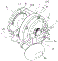
Fig. 1 is a perspective view of a dual-bearing reel according to a first embodiment of the present invention.
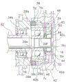
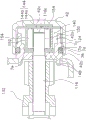
Fig. 2 is a cross-sectional view of the dual-bearing reel.
Fig. 3 is an enlarged sectional view of the throwing control mechanism of the first embodiment.
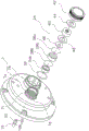
Fig. 4 is an exploded perspective view of the throwing control mechanism of the first embodiment.
Fig. 5 is an enlarged cross-sectional view of the throwing control mechanism according to modification 1 of the first embodiment.
Fig. 6 is an enlarged cross-sectional view of the throwing control mechanism according to modification 2 of the first embodiment.
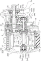
Fig. 7 is a perspective view of a dual-bearing reel according to a second embodiment of the present invention.
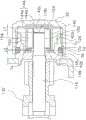
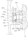
Fig. 8 is an enlarged sectional view of the throwing control mechanism of the second embodiment.
Description of the reference numerals
1 reel body
12 reel
16. 116, 216 reel shaft
16c, 116c, 216c first end
24. 124, 224 throwing control mechanism
29b bearing
29d second outer ring
29e second inner ring
29f second rolling element
40. 140, 240 one-way clutch
42 operating part
44. 144, 244 pressing member
46. 146, 246 force application part
48. 148, 248 gasket parts
50. 150, 250 first inner ring
52. 152, 252 first outer ring
54. 154, 254 first rolling element
100 dual bearing reel
216d second end.
Detailed Description
< general Structure of Dual-bearing reel >
In fig. 1 and 2, a dual-bearing reel 100 to which an embodiment of the present invention is applied includes a reel body 1, a handle 2, a spool 12, a spool shaft 16, and a throwing control mechanism (an example of a braking device) 24.
The reel body 1 has a frame 5, first and second side covers 6, 7 fitted to both sides of the frame 5, and a mechanism mounting plate 13. The frame 5 includes a first side plate 8 and a second side plate 9 arranged to face each other with a predetermined gap therebetween, and a front coupling portion 10a and a lower coupling portion 10b that couple the first side plate 8 and the second side plate 9. The lower connecting portion 10b is integrally formed with a rod fitting leg 4 for assembling a fishing rod.
The first side cover 6 is substantially circular when viewed from the outside in the spool shaft direction, and the second side cover 7 is formed of two eccentric outer circles having different outer diameters. The first side cover 6 is integrally formed with the first side plate 8 as shown in fig. 2. A cylindrical bearing housing portion 8a that houses a bearing 29a is formed at the center of the first side plate 8.
The second side cover 7 is fixed to the second side plate 9 by, for example, three screws. The second side cover 7 has a first boss portion 7a for supporting a spool shaft 16 described later and a second boss portion 7b for supporting a drive shaft 30 described later. The first boss portion 7a is provided at a position rearward and upward of the second boss portion 7 b. As shown in fig. 3 and 4, an external thread portion 7c and an annular groove 7d adjacent to the external thread portion 7c are formed on the outer peripheral surface of the first boss portion 7 a. The male screw portion 7c is screwed to an operation member 42 described later. A sealing member 36 having elasticity, for example, in the form of a 0-ring is fitted in the annular groove 7 d.
The mechanism mounting plate 13 is provided to support a drive shaft 30, a pinion gear 32, and a spool shaft 16, which will be described later. The mechanism mounting plate 13 is detachably mounted on the second side cover 7, and is integrally detachable with the second side cover 7 with respect to the second side plate 9. The mechanism mounting plate 13 has a support portion 13a projecting in a cylindrical shape on both surfaces, and the support portion 13a rotatably supports the pinion gear 32 and the spool shaft 16.
As shown in fig. 1, the handle 2 includes a handle arm 2a integrally rotatably attached to a drive shaft 30 (see fig. 2), and a handle grip 2b rotatably attached to a distal end of the handle arm 2 a. The handle arm 2a is disposed axially outward of the star drag device 3.
As shown in fig. 2, a spool 12, a clutch lever 17 serving as a pad of a thumb when pressed by the thumb, and a level wind mechanism 18 for uniformly winding a fishing line into the spool 12 are disposed in the frame 5. A rotation transmission mechanism 19, a clutch mechanism 21, a clutch control mechanism 22, a drag mechanism 23, and a throwing control mechanism 24 are disposed between the frame 5 and the second side cover 7. The throwing control mechanism 24 is an example of the braking device according to the present invention. A centrifugal brake mechanism 25 for suppressing entanglement at the time of throwing is disposed between the frame 5 and the first side cover 6.
The rotation transmitting mechanism 19 transmits the rotational force from the handle 2 to the drum 12 and the winding mechanism 18. As shown in fig. 2, the rotation transmission mechanism 19 includes a drive shaft 30, a drive gear 31 fixed to the drive shaft 30, and a cylindrical pinion gear 32 meshed with the drive gear 31. The handle 2 is integrally rotatably coupled to a distal end of the drive shaft 30. The drive gear 31 is integrally rotatably coupled to the drive shaft 30 via the drag mechanism 23. When the drag mechanism 23 is operated, the drive gear 31 rotates relative to the drive shaft 30. The pinion gear 32 is disposed on the outer peripheral side of the spool shaft 16 and also functions as the clutch mechanism 21. The pinion gear 32 is supported by the reel unit 1 by bearings 34a and 34b so as to be rotatable and axially movable. The bearing 34a is attached to the support portion 13a of the mechanism attachment plate 13, and the bearing 34b is attached to the first boss portion 7a so as to be axially aligned with a bearing 29b described later as shown in fig. 3.
As shown in fig. 2, the clutch mechanism 21 is provided in the middle of the rotation transmission mechanism 19, and is switchable between a clutch engaged state in which the drive shaft 30 is coupled to the drum 12 and a clutch disengaged state in which the drive shaft 30 is disengaged from the drum 12. The clutch control mechanism 22 controls the clutch mechanism 21 to a clutch engaged state and a clutch disengaged state in response to an operation of the clutch lever 17. When the clutch mechanism 21 is in the clutch disengaged state, the spool 12 is free to rotate, and the fishing line can be paid out. When the clutch is engaged, the fishing line can be wound around the spool 12 by rotating the handle 2.
The spool 12 is a winding device that is rotatable with respect to the reel unit 1. The spool 12 is integrally rotatably coupled to a spool shaft 16. The spool 12 includes a spool body 12a around which a fishing line is wound, and a pair of flange portions 12b integrally formed on both sides of the spool body 12a with a large diameter. A spool shaft 16 is connected to the inner peripheral side of the winding body 12a of the spool 12.
The spool shaft 16 is rotatably supported by the reel unit 1. The spool shaft 16 is rotatably supported by the reel unit 1 via three bearings 29a, 29b, and 29 c. The first end 16c of the spool shaft 16 on the handle 2 side and the second end 16d on the opposite side of the first end 16c are arranged with a gap. The bearing 29a is housed in the bearing housing portion 8a of the first side plate 8 as described above. The bearing 29b is accommodated in the first boss portion 7a of the second side cover 7. The bearings 29a and 29b are rolling bearings, for example. As shown in fig. 4, the bearing 29b and the bearing 34b arranged in parallel on the first boss portion 7a are prevented from coming off by the slip-off preventing members 38a and 38 b.
The bearing 29c is attached to the support portion 13a of the mechanism attachment plate. The bearing 29c is, for example, a slide bearing. As shown in fig. 3, a gap is formed at both ends of the spool shaft 16. A first step portion 16a (see fig. 2) and a second step portion 16b (see fig. 3) for restricting the movement of the spool shaft 16 in the axial direction are provided at the mounting portions of the bearing 29a and the bearing 29b of the spool shaft 16, respectively.
< Structure of throwing control mechanism >
The casting control mechanism 24 brakes the spool shaft 16. As shown in fig. 3 and 4, the throwing control mechanism 24 includes a roller clutch type one-way clutch 40, an operating member 42, a pressing member 44, an urging member 46, and a washer member 48.
The one-way clutch 40 is disposed in the first boss portion 7a so as to be axially aligned with the bearing 29 b. The one-way clutch 40 has a first inner race 50, a first outer race 52, and first rolling elements 54 that are rotatable integrally with the spool shaft 16. The first outer ring 52 is disposed on the outer peripheral side of the first inner ring 50, and is rotatable with respect to the reel unit 1. The first rolling elements 54 are disposed between the first inner race 50 and the first outer race 52. The first rolling elements 54 are, for example, cylindrical rollers. Only the rotation of the spool shaft 16 in the wire unwinding direction is transmitted to the first outer race 52 by the one-way clutch 40. The first inner race 50 is provided integrally with the spool shaft 16 in the first embodiment. The first outer ring 52 is restricted from moving relative to the reel unit 1 in the direction away from the spool shaft 16 of the pressing member 44. The first outer ring 52 is disposed with a gap from the inner peripheral surface of the first boss portion 7a, and the movement of the first outer ring 52 in the spool shaft 16 direction away from the pressing member 44 is restricted by the biasing member 46 via the washer member 48.
The bearing 29b is fitted to the spool shaft 16 on the first end (the end on the handle side of the spool shaft 16 on the right end side in fig. 2) 16c side. The bearing 29b has a second outer race 29d, a second inner race 29e, and second rolling elements 29f that are non-rotatably mounted to the first boss portion 7a of the reel unit 1 on the side opposite to the operating member 42 with the one-way clutch 40 interposed therebetween. The second inner race 29e is disposed on the outer periphery of the spool shaft 16. The second rolling elements 29f are disposed between the second outer ring 29d and the second inner ring 29 e. The movement of the second inner race 29e relative to the spool shaft 16 in the direction away from the pressing member 44 is restricted by the second step portion 16 b. Further, the movement of the spool shaft 16 in the direction away from the pressing member 44 is restricted by the first step portion 16 a.
The operating member 42 is disposed on the outer peripheral side of the first end 16c of the spool shaft 16, and is engaged with the first boss portion 7a of the reel unit 1 so as to be movable in the spool shaft direction by a rotational operation. The operation member 42 is a bottomed cylindrical member, and is attached to the outer peripheral surface of the first boss portion 7 a. The operating member 42 has a female screw portion 42a screwed with the male screw portion 7c and a seal contact portion 42b contactable with the seal member 36 on the inner peripheral surface. The operating member 42 has a circular fitting recess 42c at the bottom thereof, into which the pressing member 44 is fitted. The sealing member 36 is provided to prevent foreign matter from entering the reel unit 1, and to apply rotation resistance to prevent the operating member 42 from rotating against the fishing person's will.
The pressing member 44 presses the first outer race 52 in response to the rotation of the operating member 42. The pressing member 44 is made of, for example, carbon cloth. The pressing member 44 is a washer-shaped annular friction plate fitted in the fitting recess 42c of the operating member 42.
The urging member 46 is, for example, a disc spring arranged between the one-way clutch 40 and the bearing 29b so as to be capable of compressing and expanding. The urging member 46 is in contact with the first outer race 52 on the outer peripheral side thereof and with the second inner race 29e on the inner peripheral side thereof via the washer member 48. The biasing member 46 is provided to expand the range of the braking force of the adjustment operation member 42, so that the braking force can be finely adjusted.
Here, the distance L1 between the first end 16c of the spool shaft 16 and the fitting recess 42c of the operating member 42 is greater than the moving distance L2 of the urging member 46 between the uncompressed state and the maximally compressed state (L1 > L2). Thus, even if the urging member 46 is fully compressed, the first end 16c of the spool shaft 16 does not contact the fitting recess 42 c. The gasket member 48 is a member having high sliding performance made of carbon cloth, for example.
< operation of the throwing control mechanism >
When a fishing line is cast by the weight of the fishing tackle, the spool shaft 16 rotates in the line-releasing direction. The spool shaft 16 rotates in the wire unwinding direction, and the first outer race 52 rotates as the first rolling elements 54 of the one-way clutch 40 are transmitted to the first outer race 52. The first outer race 52 is pressed by the pressing member 44 and is braked by a braking force corresponding to the operation position of the operation member 42. Since the braking force at this time is generated by sandwiching both side surfaces of the first outer ring 52, a large braking force can be obtained.
On the other hand, when the fishing line is wound, the spool shaft 16 does not rotate in the line winding direction and is not transmitted to the first outer race 52, and the spool shaft 16 runs idle, so that no braking force is generated at the time of line winding. Therefore, the throwing control mechanism 24 does not generate rotational resistance with respect to the spool shaft 16 at the time of line winding.
< modification 1 of the first embodiment >
In the following description, the same reference numerals as in the first embodiment are given to members having the same configuration as in the first embodiment, and members having different configurations are denoted by the same reference numerals as in the first embodiment with the latter two-digit reference numeral.
In modification 1 of the first embodiment shown in fig. 5, the spool shaft 116 is supported by the one-way clutch 140 and the bearing 29 a. The pinion gear 132 is supported by the bearing 34 a.
The throwing control mechanism 124 has a one-way clutch 140, an operating member 42, a pressing member 144, an urging member 146, and a washer member 148. The one-way clutch 140 is an inner race idle type roller clutch, and includes a first inner race 150, a first outer race 152, and first rolling elements 154 provided integrally with the spool shaft 116. The first outer ring 152 is disposed on the outer peripheral side of the first inner ring 150, is disposed with a gap from the inner peripheral surface of the first boss portion 7a, and is rotatable with respect to the first boss portion 7 a. The first rolling element 154 is disposed between the first inner ring 150 and the first outer ring 152.
The operation member 42 has the same structure as that of the first embodiment, and has a fitting recess 42c recessed in a circular shape.
The pressing member 144 includes a first pressing member 144a fitted in the fitting recess 42c of the operation member 42, and a second pressing member 144b disposed between the first pressing member 144a and the first outer ring 152. The first pressing member 144a and the second pressing member 144b are, for example, disk-shaped members made of carbon cloth.
The urging member 146 is, for example, a disc spring arranged between the first outer race 152 and the washer member 148 so as to be capable of compressing and expanding. The urging member 146 has an outer peripheral side contacting the wall surface 7e of the first boss portion 7a via the washer member 148, and an inner peripheral side contacting the side surface of the first outer ring 152.
Here, the distance L1 between the first end 116c of the spool shaft 116 and the second pressing member 144b is greater than the moving distance L2 of the urging member 146 between the uncompressed state and the maximum compressed state (L1 > L2). Thus, even if the urging member 146 is completely compressed, the first end 116c of the spool shaft 116 does not contact the second pressing member 144 b.
The washer part 148 is, for example, a part made of carbon graphite cloth. The washer member 148 is in contact with the wall surface 7e of the first boss portion 7a, and movement in a direction away from the pressing member 144 is restricted.
In the throwing control mechanism 124 of modification 1 having such a configuration, when the spool shaft 116 rotates in the wire unwinding direction, the rotation is transmitted to the first outer ring 152 via the first rolling elements 154 of the one-way clutch 140, and the first outer ring 152 rotates. The first outer race 152 is pressed by the pressing member 144 and is braked by a braking force corresponding to the operation position of the operation member 42. Since the braking force at this time is generated by sandwiching both side surfaces of the first outer ring 152, a large braking force can be obtained.
On the other hand, when the fishing line is wound, the spool shaft 116 rotates in the line winding direction without being transmitted to the first outer ring 152, and the spool shaft 116 idles, so that no braking force is generated at the time of line winding. Therefore, the cast control mechanism 124 does not generate rotational resistance with respect to the spool shaft 116 when the wire is wound.
< modification 2 of the first embodiment >
< second embodiment >
In fig. 7, the tossing control mechanism 224 of the second embodiment includes a one-way clutch 240, an operating member 42, a pressing member 244, an urging member 246, and a washer member 248. The operation member 42 has the same configuration as that of the first embodiment, and is provided on the handle 2 side. Two disk-shaped friction plates 152a and 152b are attached to the operating member 42 in the same manner as in the conventional throwing control mechanism.
The structure of the throwing control mechanism 224 other than the operating member 42 is provided in the bearing housing 208a of the first side plate 208 on the first side cover 206 side opposite to the handle 2. The axial length of the bearing housing portion 208a is longer than the bearing housing portion 8a of the first embodiment.
The first end 216c of the spool shaft 216 is pressed by the friction plates 152a, 152b provided on the operating member 42. Therefore, the spool shaft 216 can move in the axial direction in accordance with the amount of movement of the operating member 42. The spool shaft second end 216d is disposed with a gap from the bearing housing 208 a.
As shown in fig. 8, the one-way clutch 240 is disposed closer to the first side cover 206 than the bearing 29a on the second end 216d side of the spool shaft 216. The one-way clutch 240 is an inner race idle type roller clutch, and includes a first inner race 250, a first outer race 252, and first rolling elements 254 provided integrally with the spool shaft 216. The first outer ring 252 is disposed with a gap from the inner circumferential surface of the bearing housing portion 208a, and is rotatable with respect to the bearing housing portion 208 a. Movement of the first outer race 252 in a direction away from the pressing member 244 is restricted by the washer member 248.
The pressing member 244 includes a retainer ring 244a made of a spring material and fitted in an annular fitting groove 216e formed on the second end 216d side of the bearing 29a of the spool shaft 216 so as to be immovable in the axial direction, and a main body member 244b arranged in contact with the retainer ring 244 a. The main body member 244b is a washer-shaped member made of carbon cloth, for example.
The urging member 246 is a disc spring arranged between the pressing member 244 and the first outer race 252 so as to be capable of compressing and expanding. The gasket member 248 is a gasket-shaped member made of carbon cloth, for example. The washer member 248 and the biasing member 246 are disposed with the first outer ring 252 therebetween, and contact the bottom of the bearing housing portion 208 a.
Here, the distance L1 between the second end 216d of the spool shaft 216 and the washer member 248 is larger than the moving distance L2 of the urging member 246 between the uncompressed state and the maximally compressed state (L1 > L2). Thus, even if the force application member 246 is fully compressed, the second end 216d of the spool shaft 216 does not contact the washer member 248.
In the throwing control mechanism 224 of the second embodiment having such a configuration, when the spool shaft 216 rotates in the unwinding direction, the rotation thereof is transmitted to the first outer race 252 via the first rolling elements 254 of the one-way clutch 240, and the first outer race 252 rotates. The first outer race 252 is pressed by the pressing member 244 and is braked by a braking force corresponding to the operation position of the operation member 42. Since the braking force at this time is generated by sandwiching both side surfaces of the first outer ring 252, a large braking force can be obtained.
On the other hand, when the fishing line is wound, the spool shaft 216 does not rotate in the line winding direction and is not transmitted to the first outer ring 252, and the spool shaft 216 idles, so that no braking force is generated at the time of line winding. Therefore, the cast control mechanism 224 does not generate rotational resistance with respect to the spool shaft 216 when the wire is wound.
< feature >
The above embodiments can be expressed as follows.
(A) The dual-bearing reel 100 includes a reel body 1, a spool 12 for winding, a spool shaft 16, and a throwing control mechanism (an example of a brake device) 24. The spool 12 for winding is rotatable with respect to the reel body 1. The spool shaft 16 is rotatably supported by the reel unit 1 and rotates integrally with the spool 12. The casting control mechanism 24 brakes the spool shaft. The throwing control mechanism 24 has a one-way clutch 40, an operating member 42, and a pressing member 44. The one-way clutch 40 has: a first inner ring 50 rotatable integrally with the spool shaft 16; a first outer ring 52 that is disposed on the outer peripheral side of the first inner ring 50 and is rotatable with respect to the reel unit 1; and a first rolling element 54 disposed between the first inner race 50 and the first outer race 52, and the one-way clutch 40 transmits only the rotation of the spool shaft 16 in the wire unwinding direction to the first outer race 52. The operating member 42 is disposed on the outer peripheral side of the first end 16c of the spool shaft 16, and is rotatably engaged with the reel unit 1 so as to be movable in the spool shaft direction by a rotational operation. The pressing member 44 presses the first outer race 52 in response to the movement of the operating member 42. The first outer ring 52 is restricted from moving relative to the reel unit 1 in the spool axial direction away from the pressing member 44.
In this dual-bearing reel 100, when the spool shaft 16 rotates in the line winding direction, the first inner ring 50 idles, and the rotation of the spool shaft 16 is not transmitted to the first outer ring 52, so the throwing control mechanism 24 does not apply rotational resistance to the spool shaft 16. When the spool shaft 16 rotates in the wire unwinding direction, the rotation of the spool shaft 16 is transmitted from the first inner ring 50 to the first outer ring 52 via the first rolling elements 54. When the rotation is transmitted to the first outer ring 52, which is pressed by the pressing member 44 and whose movement relative to the reel unit 1 in the spool axial direction away from the pressing member 44 is restricted, is braked, thereby braking the spool shaft 16. Here, since the roller type one-way clutch is used, the throwing control mechanism 24 does not generate rotational resistance with respect to the spool shaft 16 during the wire winding. Further, since the first outer ring 52 is braked, the diameter of the braking force increases, and a large braking force can be obtained by the throwing control mechanism 24. Further, the friction area is increased, so that the braking force is stabilized and the durability is increased.
(B) The first inner race 50 may also be provided integrally with the spool shaft 16. In this case, the structure of the one-way clutch 40 becomes simple.
(C) The pressing member 44 may be a friction plate attached to the operating member 42. In this case, the first outer race 52 can be braked on the side where the operation member 42 is disposed.
(D) The spool shaft 16 may be rotatably supported by a bearing 29b having a second outer ring 29d, a second inner ring 29e, and a second rolling element 29f, the second outer ring 29d being non-rotatably attached to the reel body 1 on the side opposite to the operating member 42 via the one-way clutch 40, the second inner ring 29e being attached to the spool shaft 16 on the first end 16c side and being disposed on the outer periphery of the spool shaft 16, and the second rolling element 29f being disposed between the second outer ring 29d and the second inner ring 29 e. The movement of the second inner race 29e with respect to the spool shaft 16 in the direction away from the pressing member 44 may be restricted. In this case, the first outer ring 52 can be braked by restricting the movement of the first outer ring 52 in the axial direction by the bearing 29b and the pressing member 44, and the movement of the bearing 29b in the direction away from the pressing member 44 with respect to the spool shaft 16 can be restricted.
(E) The tossing control mechanism 24 may further include an urging member 46 disposed between the one-way clutch 40 and the bearing 29 b. In this case, since the range of the braking force of the adjustment operation member 42 is expanded, the braking force can be finely adjusted.
(F) The casting control mechanism 124 may further include a washer member 148, and the washer member 148 may be disposed on the opposite side of the operating member 42 with the one-way clutch 140 interposed therebetween, and may be mounted to the reel body 1 so as not to be movable in a direction away from the pressing member 144. In this case, since the one-way clutch 140 may not be brought into direct contact with the reel unit 1, the first outer ring 152 can be braked with high accuracy.
(G) The tossing control mechanism 124 may also include a force application member 146 disposed between the one-way clutch 140 and a washer member 148. In this case, since the range of the braking force of the adjustment operation member 42 is expanded, the braking force can be finely adjusted.
(H) The operating member 42 may be pressed against the first end 216c of the spool shaft 216, and the one-way clutch 240 may be disposed on the second end 216d of the spool shaft 216 opposite to the first end 216 c. The pressing member 244 may be disposed on the spool shaft 216 so as to be able to press the one-way clutch 240 toward the second end 216 d. In this case, the one-way clutch 240 can be disposed on the opposite side of the dual-bearing reel 100 from the side (e.g., the handle side) on which the operating member 42 is disposed. Therefore, an increase in the spool axial dimension of the dual-bearing reel 100 can be suppressed.
(I) The tossing control mechanism 224 may further include a biasing member 246 disposed between the pressing member 244 and the one-way clutch 240. In this case, since the range of the braking force of the adjustment operation member 42 is expanded, the braking force can be finely adjusted.
(J) Since the biasing member 46 is a disk spring disposed so as to be compressible, in this case, the biasing members 46, 146, 246 can be disposed in the minute gaps in the spool axis direction, and therefore, even if the biasing members 46, 146, 246 are provided, the increase in the dimension of the throwing control mechanisms 24, 124, 224 in the spool axis direction can be suppressed.
< other embodiment >
While one embodiment of the present invention has been described above, the present invention is not limited to the above embodiment, and various modifications can be made without departing from the scope of the invention. In particular, the plurality of embodiments and modifications described in the present specification can be arbitrarily combined as needed.
(a) In the above embodiment, the first inner ring 50, 150, 250 is provided integrally with the spool shaft 16, 116, 216, but the first inner ring may be provided separately from the spool shaft.
(b) In the above embodiment, the operating member 42 is disposed on the second side cover 7 on the handle side, but the present invention is not limited thereto. The operating member may be disposed on the first side cover side opposite to the handle.
(c) In the second embodiment, the biasing member 246 is disposed between the pressing member 244 and the first outer ring 252, but the present invention is not limited thereto. The biasing member 246 may be disposed between the first outer ring 252 and the washer member 248. The urging member 246 may be disposed between the first end 216c of the spool shaft 216 and the operating member 42.
(d) In the above embodiment, the disc springs are exemplified as the urging members 46, 146, 246, but the urging members are not limited to the disc springs. For example, a coil spring, a wave plate spring, or the like may be used. When there is a space, a plurality of biasing members may be arranged in series or in parallel. Further, when the throwing control mechanism is present on the handle 2 side, the biasing member may be disposed between the pressing member and the one-way clutch.
Claims (10)
1. A dual-bearing reel, comprising:
a reel body;
a spool for winding, which is rotatable with respect to the reel body;
a spool shaft that is rotatably supported by the reel unit and rotates integrally with the spool;
a drive shaft rotatably supported by the reel unit;
a clutch mechanism that is switchable between a clutch engaged state in which the drive shaft and the spool are coupled to each other and a clutch disengaged state in which the drive shaft and the spool are disconnected from each other; and
a brake device for braking only the rotation of the spool shaft in the wire unwinding direction when the clutch is in the disengaged state,
the braking device includes: a one-way clutch having a first inner race rotatable integrally with the spool shaft; a first outer ring disposed on an outer peripheral side of the first inner ring and rotatable with respect to the reel body; and a first rolling element disposed between the first inner ring and the first outer ring, the one-way clutch transmitting only rotation in the spool axial direction to the first outer ring;
an operating member disposed on an outer peripheral side of the first end of the spool shaft, and engaged with the reel unit so as to be movable in the spool shaft direction by a rotational operation; and
a pressing member for pressing the first outer ring in response to movement of the operating member,
movement of the first outer ring relative to the reel unit in the spool axial direction away from the pressing member is restricted.
2. The dual-bearing reel of claim 1,
the first inner ring is provided integrally with the spool shaft.
3. The dual-bearing reel according to claim 1 or 2,
the pressing member is a friction plate attached to the operating member.
4. The dual-bearing reel according to claim 1 or 2,
the spool shaft is rotatably supported by a rolling bearing having a second outer ring, a second inner ring, and a second rolling element, the second outer ring being non-rotatably attached to the reel body on the opposite side of the operating member with the one-way clutch interposed therebetween, the second inner ring being attached to the first end side of the spool shaft and disposed on the outer periphery of the spool shaft, the second rolling element being disposed between the second outer ring and the second inner ring,
movement of the second inner race in a direction away from the pressing member with respect to the axial direction of the spool is restricted.
5. The dual-bearing reel of claim 4,
the brake device includes a biasing member disposed between the one-way clutch and the rolling bearing.
6. The dual-bearing reel according to claim 1 or 2,
the braking device includes a washer member that is disposed on the opposite side of the operating member with the one-way clutch interposed therebetween and that is mounted to the reel unit so as to be immovable in a direction away from the pressing member.
7. The dual-bearing reel of claim 6,
the brake device includes a biasing member disposed between the one-way clutch and the washer member.
8. The dual-bearing reel of claim 2,
the operating member presses the first end side of the spool shaft,
the one-way clutch is disposed on a second end side of the spool shaft opposite to the first end,
the pressing member is disposed on the spool shaft so as to be capable of pressing the one-way clutch toward the second end side.
9. The dual-bearing reel of claim 8,
the brake device includes a biasing member disposed between the pressing member and the one-way clutch.
10. The dual-bearing reel according to any one of claims 5, 7, and 9,
the urging member is a disc spring disposed so as to be compressible.
Applications Claiming Priority (2)
| Application Number | Priority Date | Filing Date | Title |
|---|---|---|---|
| JP2014-209304 | 2014-10-10 | ||
| JP2014209304A JP6488098B2 (en) | 2014-10-10 | 2014-10-10 | Double bearing reel |
Publications (2)
| Publication Number | Publication Date |
|---|---|
| CN105494278A CN105494278A (en) | 2016-04-20 |
| CN105494278B true CN105494278B (en) | 2020-05-05 |
Family
ID=53539469
Family Applications (1)
| Application Number | Title | Priority Date | Filing Date |
|---|---|---|---|
| CN201510647408.2A Active CN105494278B (en) | 2014-10-10 | 2015-10-09 | Dual-bearing reel |
Country Status (7)
| Country | Link |
|---|---|
| US (1) | US9861085B2 (en) |
| EP (1) | EP3005870B1 (en) |
| JP (1) | JP6488098B2 (en) |
| KR (1) | KR102186887B1 (en) |
| CN (1) | CN105494278B (en) |
| MY (1) | MY174257A (en) |
| TW (1) | TWI657738B (en) |
Families Citing this family (11)
| Publication number | Priority date | Publication date | Assignee | Title |
|---|---|---|---|---|
| JP6560904B2 (en) * | 2015-05-27 | 2019-08-14 | 株式会社シマノ | Double bearing reel |
| JP6560903B2 (en) * | 2015-05-27 | 2019-08-14 | 株式会社シマノ | Double bearing reel |
| JP6649801B2 (en) * | 2016-02-26 | 2020-02-19 | 株式会社シマノ | Double bearing reel |
| KR101884236B1 (en) * | 2017-02-03 | 2018-08-01 | 유한책임회사 도요엔지니어링 | Fishing reel |
| JP6829654B2 (en) * | 2017-06-05 | 2021-02-10 | 株式会社シマノ | Fishing reel |
| KR102083429B1 (en) * | 2017-10-26 | 2020-03-02 | 유한책임회사 도요엔지니어링 | Fishing reel |
| JP7262167B2 (en) * | 2017-11-22 | 2023-04-21 | 株式会社シマノ | Double bearing reel |
| JP7100990B2 (en) | 2018-02-26 | 2022-07-14 | 株式会社シマノ | Electric reel |
| JP7122897B2 (en) * | 2018-07-19 | 2022-08-22 | 株式会社シマノ | fishing reel |
| CN112192778A (en) * | 2020-09-17 | 2021-01-08 | 丘群香 | Slipper manufacturing is with mixing unloader |
| JP2022167022A (en) * | 2021-04-22 | 2022-11-04 | 株式会社シマノ | fishing reel |
Citations (4)
| Publication number | Priority date | Publication date | Assignee | Title |
|---|---|---|---|---|
| JP2000157120A (en) * | 1998-11-27 | 2000-06-13 | Shimano Inc | Braking mechanism for double sealed bearing |
| CN1406476A (en) * | 2001-09-10 | 2003-04-02 | 株式会社岛野 | Rotary reel |
| JP2007029015A (en) * | 2005-07-28 | 2007-02-08 | Daiwa Seiko Inc | Double bearing type reel for fishing |
| CN101622979A (en) * | 2008-07-08 | 2010-01-13 | 株式会社岛野 | Drag mechanism for dual-bearing reel |
Family Cites Families (31)
| Publication number | Priority date | Publication date | Assignee | Title |
|---|---|---|---|---|
| DE874224C (en) * | 1945-12-19 | 1953-04-20 | Urfabriken Ab | Device on fishing winches |
| JPS59139072U (en) * | 1983-03-08 | 1984-09-17 | 株式会社シマノ | double bearing reel |
| JPH0418377Y2 (en) * | 1986-09-22 | 1992-04-23 | ||
| JP2562712Y2 (en) * | 1989-12-05 | 1998-02-16 | 株式会社シマノ | Fishing reel |
| US5161750A (en) | 1989-12-05 | 1992-11-10 | Shimano Industrial Co., Ltd. | Fishing reel with transmission switching mechanism |
| JP2502204Y2 (en) * | 1990-11-13 | 1996-06-19 | リョービ株式会社 | Breaking mechanism for both bearing reels |
| JPH10174540A (en) * | 1996-12-18 | 1998-06-30 | Mamiya Op Co Ltd | Double bearing reel |
| US6053444A (en) * | 1997-03-18 | 2000-04-25 | Diawa Seiko, Inc. | Fishline guide device for double bearing type reel |
| JPH10327722A (en) * | 1997-05-30 | 1998-12-15 | Shimano Inc | Braking apparatus for double-bearing reel |
| JPH11215940A (en) | 1997-11-28 | 1999-08-10 | Mamiya Op Co Ltd | Double bearing reel |
| JPH11276034A (en) * | 1998-03-27 | 1999-10-12 | Daiwa Seiko Inc | Fishing reel |
| JP3562976B2 (en) * | 1998-10-07 | 2004-09-08 | ダイワ精工株式会社 | Fishing reel |
| JP2001025341A (en) * | 1999-07-14 | 2001-01-30 | Mamiya Op Co Ltd | Fishing reel |
| US6354525B1 (en) * | 1999-11-05 | 2002-03-12 | Shin A Sports Co., Ltd. | Spinning reel with drag brake mechanism and clutch |
| US6530535B2 (en) * | 2000-03-16 | 2003-03-11 | Daiwa Seiko, Inc. | Fishing reel |
| US6896216B2 (en) * | 2001-08-27 | 2005-05-24 | Daiwa Seiko, Inc. | Fishing reel |
| JP2003339283A (en) * | 2002-05-30 | 2003-12-02 | Daiwa Seiko Inc | Double bearing type reel for fishing |
| JP4916696B2 (en) * | 2005-10-13 | 2012-04-18 | シマノコンポネンツ マレーシア エスディーエヌ.ビーエッチディー. | Double bearing reel |
| JP2009124942A (en) * | 2007-11-19 | 2009-06-11 | Daiwa Seiko Inc | Fishing reel |
| TW200930289A (en) * | 2008-01-08 | 2009-07-16 | wen-xiang Li | Fishing reel with second brake device |
| JP5097630B2 (en) * | 2008-07-08 | 2012-12-12 | 株式会社シマノ | Double bearing reel sound generator |
| EP2143329B1 (en) * | 2008-07-08 | 2011-12-28 | Shimano, Inc. | Drag mechanism for dual-bearing reel |
| JP5143648B2 (en) * | 2008-07-08 | 2013-02-13 | 株式会社シマノ | Lever drag type double bearing reel |
| JP5590986B2 (en) * | 2010-06-23 | 2014-09-17 | 株式会社シマノ | Fishing reel one-way clutch |
| MY164166A (en) * | 2010-09-02 | 2017-11-30 | Shimano Kk | Dual-bearing reel |
| JP5536594B2 (en) | 2010-09-02 | 2014-07-02 | 株式会社シマノ | Double bearing reel |
| JP5718119B2 (en) * | 2011-03-29 | 2015-05-13 | 株式会社シマノ | Centrifugal braking device for double-bearing reel |
| JP5755044B2 (en) | 2011-06-20 | 2015-07-29 | 株式会社シマノ | Double-bearing reel drag mechanism |
| JP5926564B2 (en) * | 2012-01-18 | 2016-05-25 | 株式会社シマノ | Double-bearing reel spool braking device and double-bearing reel |
| JP6200287B2 (en) * | 2013-11-14 | 2017-09-20 | シマノコンポネンツ マレーシア エスディーエヌ.ビーエッチディー. | Double bearing reel |
| JP6352756B2 (en) * | 2014-09-30 | 2018-07-04 | 株式会社シマノ | Torque limiting device for fishing reel |
-
2014
- 2014-10-10 JP JP2014209304A patent/JP6488098B2/en active Active
-
2015
- 2015-06-08 US US14/733,045 patent/US9861085B2/en active Active
- 2015-06-11 EP EP15171723.8A patent/EP3005870B1/en active Active
- 2015-06-19 MY MYPI2015702088A patent/MY174257A/en unknown
- 2015-06-24 TW TW104120342A patent/TWI657738B/en active
- 2015-07-03 KR KR1020150095136A patent/KR102186887B1/en active IP Right Grant
- 2015-10-09 CN CN201510647408.2A patent/CN105494278B/en active Active
Patent Citations (4)
| Publication number | Priority date | Publication date | Assignee | Title |
|---|---|---|---|---|
| JP2000157120A (en) * | 1998-11-27 | 2000-06-13 | Shimano Inc | Braking mechanism for double sealed bearing |
| CN1406476A (en) * | 2001-09-10 | 2003-04-02 | 株式会社岛野 | Rotary reel |
| JP2007029015A (en) * | 2005-07-28 | 2007-02-08 | Daiwa Seiko Inc | Double bearing type reel for fishing |
| CN101622979A (en) * | 2008-07-08 | 2010-01-13 | 株式会社岛野 | Drag mechanism for dual-bearing reel |
Also Published As
| Publication number | Publication date |
|---|---|
| TWI657738B (en) | 2019-05-01 |
| US9861085B2 (en) | 2018-01-09 |
| EP3005870B1 (en) | 2018-05-02 |
| TW201616963A (en) | 2016-05-16 |
| JP2016077174A (en) | 2016-05-16 |
| US20160100563A1 (en) | 2016-04-14 |
| CN105494278A (en) | 2016-04-20 |
| MY174257A (en) | 2020-04-01 |
| EP3005870A1 (en) | 2016-04-13 |
| KR20160042754A (en) | 2016-04-20 |
| JP6488098B2 (en) | 2019-03-20 |
| KR102186887B1 (en) | 2020-12-07 |
Similar Documents
| Publication | Publication Date | Title |
|---|---|---|
| CN105494278B (en) | Dual-bearing reel | |
| JP2016077174A5 (en) | ||
| CN106172292B (en) | Dual-bearing fishing reel | |
| JP6560903B2 (en) | Double bearing reel | |
| US9901084B2 (en) | Dual-bearing reel | |
| JP7142133B2 (en) | Double-bearing reel operating lever | |
| CN109105345B (en) | Dual-bearing reel | |
| CN108967378B (en) | Reel for fishing | |
| CN106172291B (en) | Dual-bearing fishing reel | |
| CN108935358B (en) | Dual-bearing reel | |
| JP2019115360A (en) | Operation lever of double bearing reel | |
| JP6876159B2 (en) | Double bearing reel | |
| JP2004298006A (en) | Reel for fishing | |
| JP2019170221A (en) | Double bearing type reel for fishing | |
| JP2019115359A (en) | Double bearing reel | |
| JP2019146497A (en) | Electric reel | |
| JP2019170220A (en) | Double bearing type reel for fishing | |
| JP2019170219A (en) | Double bearing type reel for fishing | |
| JP2006075108A (en) | Spinning double bearing type reel |
Legal Events
| Date | Code | Title | Description |
|---|---|---|---|
| C06 | Publication | ||
| PB01 | Publication | ||
| SE01 | Entry into force of request for substantive examination | ||
| SE01 | Entry into force of request for substantive examination | ||
| GR01 | Patent grant | ||
| GR01 | Patent grant |