JP7244012B2 - game machine - Google Patents
game machine Download PDFInfo
- Publication number
- JP7244012B2 JP7244012B2 JP2019220696A JP2019220696A JP7244012B2 JP 7244012 B2 JP7244012 B2 JP 7244012B2 JP 2019220696 A JP2019220696 A JP 2019220696A JP 2019220696 A JP2019220696 A JP 2019220696A JP 7244012 B2 JP7244012 B2 JP 7244012B2
- Authority
- JP
- Japan
- Prior art keywords
- display
- effect
- frame
- unit
- door frame
- Prior art date
- Legal status (The legal status is an assumption and is not a legal conclusion. Google has not performed a legal analysis and makes no representation as to the accuracy of the status listed.)
- Active
Links
Images


Description
本発明は、弾球遊技機(一般的に「パチンコ機」とも称する。)や回胴式遊技機(一般的に「パチスロ機」とも称する。)等の遊技機に関するものである。 The present invention relates to a game machine such as a pinball game machine (generally called a "pachinko machine") and a reel-type game machine (generally called a "pachislot machine").
近年、保留画像を表示可能な表示手段を備えた遊技機が知られている(例えば、特許文献1)。
In recent years, there has been known a game machine provided with display means capable of displaying a pending image (for example, Patent Document 1).
このような遊技機においては、表示手段において保留画像を表示するにあたって実行される表示制御について改善の余地があった。
In such a game machine, there is room for improvement in the display control that is executed when displaying the pending image on the display means .
本発明は、保留画像の表示について好適な表示制御を実行することが可能な遊技機を提供することを目的とする。
SUMMARY OF THE INVENTION An object of the present invention is to provide a gaming machine capable of executing suitable display control for displaying a pending image .
[手段1]に係る遊技機は、
利益付与に係る抽選を行う抽選手段と、
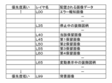
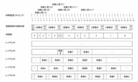
各種演出画像を表示優先度の異なる複数のレイヤに配置することによって表示優先度を異ならせ、表示優先度の高いレイヤに配置された演出画像を、表示優先度の低いレイヤに配置された演出画像よりも手前に表示させる表示手段と、
前記抽選手段による抽選結果に基づいて図柄変動表示を行う図柄変動手段と、
前記図柄変動手段による図柄変動表示の実行数を示す保留表示を、通常表示態様から前記利益付与に関する期待度を示唆する期待度態様へと変化させうる特別演出手段と、
を備え、
前記保留表示には、実行中の図柄変動表示に対応して表示される当該対応表示と、実行が保留されている図柄変動表示の個数に対応して表示される保留対応表示とが含まれ、
前記特別演出手段は、
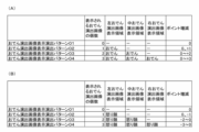
前記保留表示の態様を、該保留表示が通常表示態様で表示されたときのレイヤから変更することなく、該通常表示態様で表示されたときのレイヤのままで期待度態様へと変化させる第1特別演出と、
前記保留表示の態様を、該保留表示が通常表示態様で表示されたときのレイヤから異なるレイヤへ変更し、その後、期待度態様へと変化させる第2特別演出と、を実行可能であり、
前記保留表示が表示されるレイヤの変更は、前記図柄変動表示の実行開始に合わせて行うことが可能とされ、
前記保留表示が通常表示態様で表示されたときのレイヤのままで該保留表示を期待度態様へと変化させる前記第1特別演出の実行確率と、前記保留表示が通常表示態様で表示されたときのレイヤから異なるレイヤへ変更したのちに該保留表示を期待度態様へと変化させる前記第2特別演出の実行確率とが異なり、前記保留表示は、前記当該対応表示または前記保留対応表示のいずれかで表示されるが、前記当該対応表示として表示されているときに前記期待度態様で表示されている割合が高い
ことを特徴とする遊技機である。
The game machine according to [means 1] is
Lottery means for performing a lottery for granting profits;
By arranging various effect images on multiple layers with different display priorities, the display priority is differentiated, and the effect image placed on the layer with the higher display priority is replaced with the effect image placed on the layer with the lower display priority. a display means for displaying in front of the
A symbol variation means for performing a symbol variation display based on the result of the lottery by the lottery means;
a special effect means capable of changing a pending display indicating the number of executions of symbol variation display by the symbol variation means from a normal display mode to an expectation level mode suggesting an expectation level regarding the awarding of the profit;
with
The pending display includes a corresponding display displayed corresponding to the symbol variation display being executed, and a suspension corresponding display displayed corresponding to the number of symbol variation displays whose execution is suspended,
The special production means is
The mode of the pending display is changed to the expectation level mode while maintaining the layer when the pending display is displayed in the normal display mode without changing the layer when the pending display is displayed in the normal display mode. special performances and
A second special effect of changing the mode of the pending display from the layer when the pending display is displayed in the normal display mode to a different layer, and then changing it to the expectation level mode,
The layer on which the pending display is displayed can be changed in accordance with the start of execution of the symbol variation display,
Execution probability of the first special effect for changing the pending display to the expectation degree mode while maintaining the layer when the pending display is displayed in the normal display mode, and when the pending display is displayed in the normal display mode. The execution probability of the second special effect that changes the pending display to the degree of expectation mode after changing from the layer to a different layer is different, and the pending display is either the corresponding display or the pending display. is displayed as the corresponding display, the ratio of the display in the expectation mode is high when the corresponding display is displayed.
本発明によれば、保留画像の表示について好適な表示制御を実行することが可能な遊技機を提供することができる。 According to the present invention, it is possible to provide a gaming machine capable of executing suitable display control for displaying a pending image .
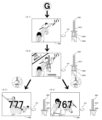
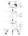
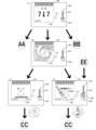
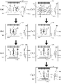
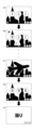
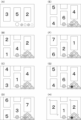
[1.パチンコ機の全体構造]
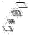
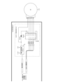
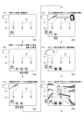
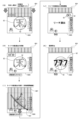
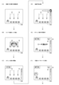
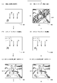
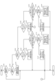
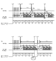
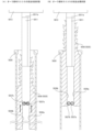
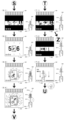
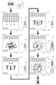
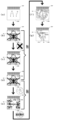
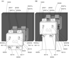
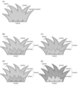
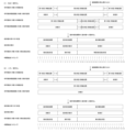
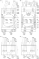
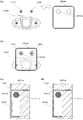
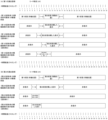
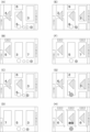
本発明の一実施形態であるパチンコ機1について、図面を参照して詳細に説明する。まず、図1乃至図10を参照して本実施形態のパチンコ機1の全体構成について説明する。図1は本発明の一実施形態であるパチンコ機の正面図である。図2はパチンコ機の右側面図であり、図3はパチンコ機の左側面図であり、図4はパチンコ機の背面図である。図5はパチンコ機を右前から見た斜視図であり、図6はパチンコ機を左前から見た斜視図であり、図7はパチンコ機を後ろから見た斜視図である。また、図8は本体枠から扉枠を開放させると共に、外枠から本体枠を開放させた状態で前から見たパチンコ機の斜視図である。図9はパチンコ機を扉枠、遊技盤、本体枠、及び外枠に分解して前から見た分解斜視図であり、図10はパチンコ機を扉枠、遊技盤、本体枠、及び外枠に分解して後ろから見た分解斜視図である。
[1. Overall Structure of Pachinko Machine]
A
本実施形態のパチンコ機1は、遊技ホールの島設備(図示しない)に設置される枠状の外枠2と、外枠2の前面を開閉可能に閉鎖する扉枠3と、扉枠3を開閉可能に支持していると共に外枠2に開閉可能に取付けられている本体枠4と、本体枠4に前側から着脱可能に取付けられると共に扉枠3を通して遊技者側から視認可能とされ遊技者によって遊技球が打込まれる遊技領域5aを有した遊技盤5と、を備えている。
The
パチンコ機1の外枠2は、図9及び図10等に示すように、上下に離間しており左右に延びている上枠部材10及び下枠部材20と、上枠部材10及び下枠部材20の両端同士を連結しており上下に延びている左枠部材30及び右枠部材40と、を備えている。上枠部材10、下枠部材20、左枠部材30、及び右枠部材40は、前後の幅が同じ幅に形成されている。また、上枠部材10及び下枠部材20の左右の長さに対して、左枠部材30及び右枠部材40の上下の長さが、長く形成されている。
The
また、外枠2は、左枠部材30及び右枠部材40の下端同士を連結し下枠部材20の前側に取付けられる幕板部材50と、上枠部材10の正面視左端部側に取付けられている外枠側上ヒンジ部材60と、幕板部材50の正面視左端側上部と左枠部材30とに取付けられている外枠側下ヒンジ部材70と、を備えている。外枠2の外枠側上ヒンジ部材60と外枠側下ヒンジ部材70とによって、本体枠4及び扉枠3が開閉可能に取付けられている。
The
パチンコ機1の扉枠3は、正面視の外形が上下に延びた四角形で前後に貫通している貫通口111を有した枠状の扉枠ベースユニット100と、扉枠ベースユニット100の貫通口111よりも下側で前面右下隅に取付けられており遊技球を遊技盤5の遊技領域5a内へ打込むために遊技者が操作可能なハンドルユニット300と、扉枠ベースユニット100の貫通口111よりも下側で前面下部に取付けられている皿ユニット320と、皿ユニット320の中央に取付けられており遊技領域5a内に遊技球が打込まれることで変化する遊技状態に応じて遊技者に参加型の演出を提示することが可能な演出操作ユニット400と、皿ユニット320の上側で扉枠ベースユニット100における貫通口111よりも左側の前面左部に取付けられている扉枠左サイドユニット530と、皿ユニット320の上側で扉枠ベースユニット100における貫通口111よりも右側の前面右部に取付けられている扉枠右サイドユニット550と、扉枠左サイドユニット530及び扉枠右サイドユニット550の上側で扉枠ベースユニット100における貫通口111よりも上側の前面上部に取付けられている扉枠トップユニット570と、を備えている。
The
パチンコ機1の本体枠4は、一部が外枠2の枠内に挿入可能とされると共に遊技盤5の外周を支持可能とされた枠状の本体枠ベース600と、本体枠ベース600の正面視左側の上下両端に取付けられ外枠2の外枠側上ヒンジ部材60及び外枠側下ヒンジ部材70に夫々回転可能に取付けられると共に扉枠3の扉枠側上ヒンジ部材140及び扉枠側下ヒンジ部材150が夫々回転可能に取付けられる本体枠側上ヒンジ部材620及び本体枠側下ヒンジ部材640と、本体枠ベース600の正面視左側面に取付けられる補強フレーム660と、本体枠ベース600の前面下部に取付けられており遊技盤5の遊技領域5a内に遊技球を打込むための球発射装置680と、本体枠ベース600の正面視右側面に取付けられており外枠2と本体枠4、及び扉枠3と本体枠4の間を施錠する施錠ユニット700と、本体枠ベース600の正面視上辺及び左辺に沿って後側に取付けられており遊技者側へ遊技球を払出す逆L字状の払出ユニット800と、本体枠ベース600の後面下部に取付けられている基板ユニット900と、本体枠ベース600の後側に開閉可能に取付けられ本体枠ベース600に取付けられた遊技盤5の後側を覆う裏カバー980と、を備えている。
The
本体枠4の払出ユニット800は、本体枠ベース600の後側に取付けられる逆L字状の払出ユニットベース801と、払出ユニットベース801の上部に取付けられており上方へ開放された左右に延びた箱状で図示しない島設備から供給される遊技球を貯留する球タンク802と、球タンク802の下側で払出ユニットベース801に取付けられており球タンク802内の遊技球を正面視左方向へ誘導する左右に延びたタンクレール803と、払出ユニットベース801における正面視左側上部の後面に取付けられタンクレール803からの遊技球を蛇行状に下方へ誘導する球誘導ユニット820と、球誘導ユニット820の下側で払出ユニットベース801から着脱可能に取付けられており球誘導ユニット820により誘導された遊技球を払出制御基板ボックス950に収容された払出制御基板951からの指示に基づいて一つずつ払出す払出装置830と、払出ユニットベース801の後面に取付けられ払出装置830によって払出された遊技球を下方へ誘導すると共に皿ユニット320における上皿321での遊技球の貯留状態に応じて遊技球を通常放出口850d又は満タン放出口850eの何れかから放出させる上部満タン球経路ユニット850と、払出ユニットベース801の下端に取付けられ上部満タン球経路ユニット850の通常放出口850dから放出された遊技球を前方へ誘導して前端から扉枠3の貫通球通路273へ誘導する通常誘導路861及び満タン放出口850eから放出された遊技球を前方へ誘導して前端から扉枠3の満タン球受口274へ誘導する満タン誘導路862を有した下部満タン球経路ユニット860と、を備えている。
The dispensing
本体枠4の基板ユニット900は、本体枠ベース600の後側に取付けられる基板ユニットベース910と、基板ユニットベース910の正面視左側で本体枠ベース600の後側に取付けられ内部に低音用の下部スピーカ921を有したスピーカユニット920と、基板ユニットベース910の後側で正面視右側に取付けられ内部に電源基板が収容されている電源基板ボックス930と、スピーカユニット920の後側に取付けられており内部にインターフェイス制御基板が収容されているインターフェイス制御基板ボックス940と、電源基板ボックス930及びインターフェイス制御基板ボックス940に跨って取付けられており内部に遊技球の払出しを制御する払出制御基板951が収容された払出制御基板ボックス950と、を備えている。
The
パチンコ機1の遊技盤5は、図9及び図10等に示すように、遊技球が打込まれる遊技領域5aの外周を区画し球発射装置680から発射された遊技球を遊技領域5aの上部に案内する外レール1001及び内レール1002を有した前構成部材1000と、前構成部材1000の後側に取付けられると共に遊技領域5aの後端を区画する平板状の遊技パネル1100と、を備えている。
As shown in FIGS. 9 and 10, the
本実施形態のパチンコ機1は、上皿321に遊技球を貯留した状態で、遊技者がハンドル302を回転操作すると、球発射装置680によってハンドル302の回転角度に応じた強さで遊技球が遊技盤5の遊技領域5a内へ打込まれる。そして、遊技領域5a内に打込まれた遊技球が、入賞口に受入れられると、受入れられた入賞口に応じて、所定数の遊技球が払出装置830によって上皿321に払出される。この遊技球の払出しによって遊技者の興趣を高めることができるため、上皿321内の遊技球を遊技領域5a内へ打込ませることができ、遊技者に遊技を楽しませることができる。
In the
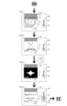
[2.外枠の全体構成]
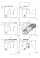
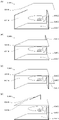
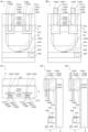
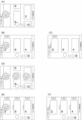
パチンコ機1の外枠2について、図11乃至図16を参照して説明する。図11はパチンコ機における外枠の正面図であり、図12は外枠の右側面図である。また、図13は外枠を前から見た斜視図であり、図14は外枠を後ろから見た斜視図である。図15は、外枠を分解して前から見た分解斜視図である。図16(a)は外枠における外枠側上ヒンジ部材の部位を、左枠部材を省略して下側から見た斜視図であり、(b)は(a)を分解して示す分解斜視図である。外枠2は、遊技ホール等のパチンコ機1が設置される島設備(図示は省略)に取付けられるものである。
[2. Overall configuration of the outer frame]
The
外枠2は、図示するように、上下に離間しており左右に延びている上枠部材10及び下枠部材20と、上枠部材10及び下枠部材20の両端同士を連結しており上下に延びている左枠部材30及び右枠部材40と、を備えている。上枠部材10、下枠部材20、左枠部材30、及び右枠部材40は、前後の幅が同じ幅に形成されている。また、上枠部材10及び下枠部材20の左右の長さに対して、左枠部材30及び右枠部材40の上下の長さが、長く形成されている。また、外枠2は、上枠部材10及び下枠部材20の左右両端面と、左枠部材30及び右枠部材40の左右方向の外側を向いた側面とが、同一面となるように組立てられている。
As shown in the figure, the
また、外枠2は、上枠部材10の正面視左端部側に取付けられている外枠側上ヒンジ部材60と、外枠側上ヒンジ部材60の下面に取付けられているロック部材66と、幕板部材50の正面視左端側上部と左枠部材30とに取付けられている外枠側下ヒンジ部材70と、を備えている。外枠2の外枠側上ヒンジ部材60と外枠側下ヒンジ部材70とによって、本体枠4及び扉枠3を開閉可能に取付けることができる。
In addition, the
また、外枠2は、左枠部材30及び右枠部材40の下端同士を連結し下枠部材20の前側に取付けられる幕板部材50と、幕板部材50の後側に取付けられていると共に両端が左枠部材30及び右枠部材40に夫々取付けられる幕板補強部材80と、幕板部材50の上面における左右中央から左寄りの位置に取付けられている平板状の左滑り部材81と、幕板部材50の上面における右端付近の位置に取付けられている平板状の右滑り部材82と、を備えている。幕板補強部材80は、中実の部材(例えば、木材、合板、等)によって形成されており、下枠部材20、左枠部材30、及び右枠部材40に、取付けられている。
In addition, the
更に、外枠2は、上枠部材10と左枠部材30、上枠部材10と右枠部材40、下枠部材20と左枠部材30、及び下枠部材20と右枠部材40を、夫々連結している連結部材85を備えている。また、外枠2は、右枠部材40の内側(左側面側)に取付けられており後述する施錠ユニット700の外枠用鉤703が係止される上鉤掛部材90及び下鉤掛部材91を、備えている。
Further, the
[2-1.上枠部材]
外枠2の上枠部材10は、所定厚さの無垢(中実)の材料(例えば、木材、合板、等)によって形成されている。この上枠部材10は、左右両端における前後方向の中央に、上下に貫通しており左右方向中央側へ窪んだ係合切欠部11を備えている。この係合切欠部11内には、連結部材85の後述する左上連結部材85A及び右上連結部材85Bの上横固定部87が取付けられる。また、上枠部材10は、正面視左側端部の上面と前面に、一般面よりも窪んだ取付段部12を備えている。この取付段部12には、外枠側上ヒンジ部材60が取付けられる。
[2-1. Upper frame member]
An
[2-2.下枠部材]
外枠2の下枠部材20は、所定厚さの無垢(中実)の材料(例えば、木材、合板、等)によって形成されている。この下枠部材20は、左右の長さ及び上下の厚さが、上枠部材10の左右の長さ及び上下の厚さと同じ寸法に形成されていると共に、前後の幅が、上枠部材10の前後の幅よりも長く形成されている。下枠部材20は、左右両端における前後方向の中央よりも後側寄りの位置に、上下に貫通しており左右方向中央側へ窪んだ係合切欠部21を備えている。この係合切欠部21内には、連結部材85の後述する左下連結部材85C及び右下連結部材85Dの下横固定部88が取付けられる。
[2-2. Lower frame member]
A
また、下枠部材20は、左右両端の前面から後方へ窪んだ前端切欠部22を備えている。下枠部材20において、前端切欠部22の後端から下枠部材20の後面までの前後方向の幅が、上枠部材10の前後方向の幅と同じ寸法に形成されている。この下枠部材20は、外枠2に組立てた状態で、左右の前端切欠部22同士の間の部位が、幕板部材50内に挿入される。
In addition, the
[2-3.左枠部材及び右枠部材]
外枠2の左枠部材30及び右枠部材40は、一定の断面形状で上下に延びており、アルミ合金等の金属の押出形材によって形成されている。左枠部材30及び右枠部材40は、平面視において互いに対称の形状に形成されている。左枠部材30及び右枠部材40は、外枠2として組立てた時に、左右方向の外側となる側面において、前後方向中央に対して後寄りの位置から後端付近までの間に、内側へ窪んだ凹部31,41と、凹部31,41の反対側の側面から膨出しており内部が空洞に形成されている突出部32,42と、を備えている。この左枠部材30及び右枠部材40は、突出部32,42によって、強度・剛性が高められている。また、突出部32,42内には、連結部材85の後述する左上連結部材85A及び右上連結部材85Bの後側の下横固定部88が挿入されて取付けられる。
[2-3. Left frame member and right frame member]
The
また、左枠部材30及び右枠部材40は、表面に上下に延びた複数の溝が形成されている。この複数の溝によって、パチンコ機1を遊技ホール等の島設備に設置したり運搬したりする等の際に、作業者の指掛りとなってパチンコ機1を持ち易くすることができると共に、パチンコ機1の外観の意匠性を高めることとができる。
In addition, the
[2-4.幕板部材]
外枠2の幕板部材50は、後側が開放された箱状に形成されている。幕板部材50は、上面における正面視左端付近に後方へ平板状に延出している後方延出部51と、後方延出部51の左端から遊技球が通過可能な大きさでU字状に切欠かれており上下に貫通している左排出孔52と、後方延出部51における左排出孔52の右側において遊技球が通過可能な大きさで上下に貫通している右排出孔53と、後方延出部51の後端を含む幕板部材50の上面の後端から上方へ平板状に延出している立壁部54と、立壁部54の上端付近から前方へ膨出しており前面が上方へ向かうに従って後方へ向かうように傾斜している返し部55と、を備えている。
[2-4. Curtain plate member]
The
幕板部材50は、後方延出部51の前側の上面と、後方延出部51の上面とに、外枠側下ヒンジ部材70が載置されるように、外枠側下ヒンジ部材70の後述する水平部71が取付けられる。また、幕板部材50の左排出孔52は、外枠2に組立てた状態で外枠側下ヒンジ部材70の後述する排出孔74と一致する位置に形成されている。また、右排出孔53は、外枠2に組立てた状態で外枠側下ヒンジ部材70よりも右側となる位置に形成されている。右排出孔53は、左排出孔52よりも大きく形成されている。
The
また、幕板部材50は、後方延出部51よりも右側の上面が、前端側が低くなるように傾斜している。また、幕板部材50は、上面における後方延出部51よりも右側の部位に左滑り部材81を取付けるための左取付部56と、上面における右端付近に右滑り部材82を取付けるための右取付部57と、を備えている。幕板部材50は、上面に、左滑り部材81及び右滑り部材82を介して本体枠4の下面が載置される。
Further, the upper surface of the
この幕板部材50は、図示するように、前面に浅いレリーフ状の装飾が形成されている。また、幕板部材50は、図示は省略するが、箱状の内部が複数のリブによって格子状に仕切られており、強度・剛性が高められている。また、幕板部材50は、幕板補強部材80の前側半分を、内部に収容可能に形成されている。
As shown in the figure, the
[2-5.外枠側上ヒンジ部材]
外枠2の外枠側上ヒンジ部材60は、図示するように、水平に延びた平板状で外形が四角形の上固定部61と、上固定部61の前端から前方へ延出している平板状の前方延出部62と、前方延出部62の右端から前方へ向かうに従って前方延出部62の左右中央へ延びており上下に貫通している軸受溝63と、上固定部61の平面視左辺から下方へ延びている平板状の横固定部64と、前方延出部62の左端から前端を周って軸受溝63が開口している部位までの端辺から下方へ延びており横固定部64と連続している平板状の垂下部65と、を備えている(図16(b)等を参照)。
[2-5. Outer frame side upper hinge member]
As shown in the figure, the outer frame side
外枠側上ヒンジ部材60は、外枠2が組立てられた状態で、上固定部61が、上枠部材10の取付段部12の上面に載置されており、図示しないビスによって固定されている。また、前方延出部62は、上枠部材10の前端よりも前方へ延出している。また、横固定部64は、左枠部材30の外側側面の凹部31内に上側から挿入された状態で、ビスによって左枠部材30に固定されている。
In the outer frame side
この外枠側上ヒンジ部材60は、軸受溝63内に本体枠側上ヒンジ部材620の本体枠上ヒンジピン622を挿入させることで、外枠側下ヒンジ部材70と協働して本体枠4を開閉可能に支持することができる。この外枠側上ヒンジ部材60は、金属板をプレス成型により屈曲させて形成されている。
The outer frame side
[2-6.ロック部材]
外枠2のロック部材66は、図16に示すように、左右が所定幅で前後に延びている帯板状のロック本体66aと、ロック本体66aの後端から右方へ突出している操作部66bと、ロック本体66aの後端から左方へ延びた後に斜め左前方へ延びている弾性変形可能な棒状の弾性部66cと、ロック本体66aの後端付近で上下に貫通している取付孔66dと、を備えている。このロック部材66は、合成樹脂によって形成されている。ロック部材66は、取付ビス67によって、外枠側上ヒンジ部材60における前方延出部62の下面に回動可能に取付けられる。
[2-6. lock member]
As shown in FIG. 16, the
このロック部材66は、取付孔66dを通して、ロック本体66aの後端が、外枠側上ヒンジ部材60の前方延出部62における軸受溝63よりも後側の位置に取付けられる。また、ロック部材66を外枠側上ヒンジ部材60に取付けた状態では、ロック本体66aが、平面視で軸受溝63を遮ることができると共に、前端付近の右側面が、外枠側上ヒンジ部材60の垂下部65における軸受溝63の開口まで延びている部位と当接可能となるように前方へ延びている(図18を参照)。
The rear end of the
また、ロック本体66aの後端から左方へ延びている弾性部66cの先端は、外枠側上ヒンジ部材60における垂下部65の内周面に当接している。このロック部材66は、弾性部66cの付勢力によって取付孔66dを中心に、前端が左方へ回動する方向に付勢されている。従って、通常の状態では、ロック部材66のロック本体66aの前端付近の右側面が、垂下部65に当接している(図18を参照)。この状態では、軸受溝63におけるロック本体66aよりも前側の部位に、本体枠側上ヒンジ部材620の後述する本体枠上ヒンジピン622を収容可能な空間が形成される。
The tip of the
このロック部材66は、操作部66bを操作することで、弾性部66cの付勢力に抗してロック本体66aを回動させることができる。そして、操作部66bの操作によって、ロック本体66aを、その前端が左方へ移動する方向へ回動させることで、平面視において軸受溝63からロック本体66aを後退させることができ、軸受溝63が全通している状態とすることができる。これにより、軸受溝63内に本体枠上ヒンジピン622を挿入したり、軸受溝63内から本体枠上ヒンジピン622を外したりすることができる。
By operating the
[2-7.外枠側下ヒンジ部材]
外枠2の外枠側下ヒンジ部材70は、図示するように、水平に延びている平板状の水平部71と、水平部71の左辺において前後方向中央よりも後側の部位から上方へ立上っている平板状の立上り部72と、水平部71の前端付近から上方へ突出している外枠下ヒンジピン73と、水平部71を上下に貫通しており遊技球が一つのみ通過可能な大きさの排出孔74と、を備えている。この外枠側下ヒンジ部材70は、金属板をプレス成型により屈曲させて形成されている。
[2-7. Outer frame side lower hinge member]
As shown in the figure, the outer frame side
外枠側下ヒンジ部材70の水平部71は、平面視において、左辺を底辺とした台形に形成されている。外枠下ヒンジピン73は、円柱状で、上下方向中央よりも上部が、上端が窄まった円錐台状に形成されている。この外枠下ヒンジピン73は、水平部71の前端付近における左寄りの位置に取付けられている。排出孔74は、水平部71において、立上り部72の前後方向中央の部位と接し、水平部71の左辺から右方へ逆U字状に延びるように形成されている。この排出孔74は、幕板部材50の左排出孔52と、略同じ大きさに形成されている。
The
外枠側下ヒンジ部材70は、外枠2が組立てられた状態では、水平部71が、幕板部材50の左端付近の上面と後方延出部51上に載置されており、水平部71が、幕板部材50の上面を貫通する図示しないビスによって幕板補強部材80に固定されている。また、外枠2が組立てられた状態では、立上り部72が、左枠部材30の内側側面における突出部32よりも前側の部位に、図示しないビスによって取付けられている。この外枠側下ヒンジ部材70は、外枠下ヒンジピン73を、本体枠4の本体枠側下ヒンジ部材640における本体枠用下ヒンジ孔(図示は省略)に挿通させることで、外枠側上ヒンジ部材60と協働して本体枠4を開閉可能に取付けることができる。
When the
また、外枠2が組立てられた状態では、排出孔74が、幕板部材50の左排出孔52と一致している。これにより、水平部71上の遊技球を、排出孔74及び左排出孔52を通して、幕板部材50の後側へ落下(排出)させることができる。詳述すると、外枠2に対して本体枠4を閉じる時に、外枠2と本体枠4との間に落下した遊技球が、本体枠4が閉じられるのに従って、外枠2と本体枠4との間が徐々に狭くなることから、間隔が広い後方側へ転動とすることとなり、排出孔74から排出させることができる。この際に、排出孔74が、パチンコ機1に組立てた状態で、外枠2に対して本体枠4を閉じた時に、本体枠4の後端と略同じとなる位置に形成されているため、外枠2と本体枠4との間に落下した遊技球を、排出孔74から排出させることで本体枠4よりも後側へ転動するのを阻止し易くすることができ、外枠側下ヒンジ部材70の部位に遊技球が留まり難くすることができる。
In addition, when the
[2-8.連結部材]
外枠2の連結部材85は、上枠部材10と左枠部材30とを連結する左上連結部材85Aと、上枠部材10と右枠部材40とを連結する右上連結部材85Bと、下枠部材20と左枠部材30とを連結する左下連結部材85Cと、下枠部材20と右枠部材40とを連結する右下連結部材85Dと、がある。
[2-8. Connection member]
The connecting
連結部材85は、水平に延びた平板状の水平固定部86と、水平固定部86の左右側辺の何れか一方から上方へ延出している平板状の上横固定部87と、水平固定部86における上横固定部87が延出している部位と同じ側から下方へ延出している平板状の下横固定部88と、を備えている。この連結部材85は、平板状の金属板を屈曲させて形成されている。
The
左上連結部材85A及び右上連結部材85Bでは、水平固定部86の前後方向の中央から上横固定部87が上方へ延出していると共に、上横固定部87の前後両側から下横固定部88が下方へ延出している。つまり、左上連結部材85A及び右上連結部材85Bでは、下横固定部88が前後に離間して二つ備えられている。左上連結部材85A及び右上連結部材85Bの水平固定部86は、上枠部材10の下面に当接した状態で上枠部材10に固定される。また、左上連結部材85A及び右上連結部材85Bの上横固定部87は、上枠部材10の係合切欠部21内に挿入されて、上枠部材10の左右方向の端部に固定される。また、左上連結部材85A及び右上連結部材85Bの前側の下横固定部88は、左枠部材30及び右枠部材40の突出部32,42よりも前側の内側側面に夫々固定される。更に、左上連結部材85A及び右上連結部材85Bの後側の下横固定部88は、左枠部材30及び右枠部材40の突出部32,42内に挿入されて外側側面から捩じ込まれるビスにより左枠部材30及び右枠部材40に夫々固定される。
In the upper
左下連結部材85C及び右下連結部材85Dでは、上横固定部87の後端が、水平固定部86の後端よりも後方へ突出していると共に、上横固定部87の水平固定部86よりも後方へ突出している部位の下端から下横固定部88が水平固定部86よりも下方へ延出している。また、左下連結部材85C及び右下連結部材85Dでは、上横固定部87の後端から水平固定部86と同じ側へ突出している屈曲部89を更に備えている。左下連結部材85C及び右下連結部材85Dの水平固定部86は、下枠部材20の上面に当接した状態で固定される。また、左下連結部材85C及び右下連結部材85Dの上横固定部87は、左枠部材30及び右枠部材40の突出部32,42よりも前側の内側側面に夫々固定される。更に、左下連結部材85C及び右下連結部材85Dの下横固定部88は、下枠部材20の係合切欠部21内に挿入されて下枠部材20の左右方向の端部面に夫々固定される。
In the lower
[2-9.外枠側上ヒンジ部材のロック機構]
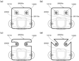
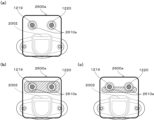
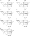
次に、本実施形態のパチンコ機1の外枠2において、外枠側上ヒンジ部材60におけるロック部材66による本体枠4の本体枠側上ヒンジ部材620に対するロック機構について、図17及び図18を参照して説明する。図17(a)は外枠の外枠側上ヒンジ部材に対して本体枠の本体枠側上ヒンジ部材が取外されている状態を拡大して示す斜視図であり、(b)は外側上ヒンジ部材に本体側上ヒンジ部材が取付けられている状態を拡大して示す斜視図である。図18は、外枠におけるロック部材の作用を示す説明図である。
[2-9. Lock Mechanism of Upper Hinge Member on Outer Frame Side]
Next, in the
外枠2におけるロック部材66は、外枠側上ヒンジ部材60の前方延出部62に取付けた状態(通常の状態)では、弾性部66cの先端が垂下部65の内周面と当接しており、ロック本体66aがく字状に屈曲した軸受溝63の一部を閉塞するようになっていると共に、ロック本体66aの先端部分が、軸受溝63の最深部分を閉塞した状態とはならず、軸受溝63の最深部分に本体枠4の本体枠側上ヒンジ部材620の本体枠上ヒンジピン622を挿入可能な空間が形成された状態となっている。
When the
本実施形態における外枠側上ヒンジ部材60とロック部材66とを用いた本体枠上ヒンジピン622の支持機構は、本体枠上ヒンジピン622が軸受溝63の最深部分に挿入されてロック本体66aの前端の右側面が、右側の垂下部65と接近している状態(この状態ではロック本体66aの前端の右側面と右側の垂下部65との間に僅かな隙間があり当接した状態となっていない)である通常の軸支状態においては、屈曲している軸受溝63の最深部分に位置する本体枠上ヒンジピン622とロック本体66aの前端面との夫々の中心が斜め方向にずれて対向した状態となっている。
The support mechanism of the main body frame
そして、この通常の軸支状態においては、重量のある本体枠4を軸支している本体枠上ヒンジピン622が軸受溝63の前端部分に当接した状態となっているので、本体枠上ヒンジピン622からロック本体66aの前端面への負荷がほとんどかかっていない。つまり、ロック部材66の弾性部66cに対し負荷がかかっていない状態となっている。なお、ロック本体66aの前端面が円弧状に形成されているため、ロック部材66を回動させるために操作部66bを回動操作した時に、ロック部材66がスムーズに回動するようになっている。また、図示では、ロック本体66aの前端面の円弧中心が、取付孔66dの中心(ロック部材66の回転中心)とされている。
In this normal axially supported state, the main body
従って、本体枠上ヒンジピン622がく字状に形成された軸受溝63の傾斜に沿って抜ける方向に作用力Fがかかって、ロック本体66aの円弧状の前端面に当接したとき、その作用力Fを、本体枠上ヒンジピン622と円弧状の前端面との当接部分に作用する分力F1(ロック本体66aの前端面の円弧の法線方向)と、本体枠上ヒンジピン622と軸受溝63の一側内面との当接部分に作用する分力F2と、に分けたときに、分力F1の方向が取付孔66d(取付ビス67)の中心(ロック部材66の回転中心)を向くため、ロック部材66のロック本体66aの前端が、右側の垂下部65から離れる方向に回転させるモーメントが働かず、本体枠上ヒンジピン622がロック部材66のロック本体66aの前端部と軸受溝63の一側内面との間に挟持された状態が保持される。
Therefore, when the body frame
このため、通常の軸支状態、或は、本体枠上ヒンジピン622の作用力がロック部材66にかかった状態でも、ロック部材66の弾性部66cに常時負荷がかからず、合成樹脂で一体形成される弾性部66cのクリープによる塑性変形を防止し、長期間に亘って本体枠上ヒンジピン622の軸受溝63からの脱落を防止することができる。なお、仮に無理な力がかかってロック部材66のロック本体66aの前端部が右方へ移動する方向へ回転させられても、ロック本体66aの前端右側面が垂下部65に当接してそれ以上回転しないので、ロック部材66が前方延出部62の外側にはみ出ないようになっている。
For this reason, even in a normal axially supported state or a state in which the acting force of the
なお、ロック本体66aの前端面の形状は円弧状でなくても、上記した分力F1の作用により回転モーメントが生じない位置又はロック部材66をその前端部が前方延出部62の外側に向って回転させる回転モーメントが生ずる位置にロック部材66の回転中心(取付ビス67により固定される軸)を位置させることにより、常時ロック部材66の弾性部66cに対しても負荷がかかることはないし、ロック部材66が回転してもロック本体66aの前端の右側面が垂下部65に当接するだけであるため、ロック部材66が前方延出部62の外側にはみ出ることもない。
Even if the shape of the front end surface of the
外枠側上ヒンジ部材60の軸受溝63に、本体枠側上ヒンジ部材620の本体枠上ヒンジピン622を支持させる場合は、軸受溝63の開放されている側から軸受溝63内に本体枠上ヒンジピン622を挿入する。軸受溝63内に本体枠上ヒンジピン622を挿入すると、ロック部材66のロック本体66aの右側面に本体枠上ヒンジピン622が当接し、弾性部66cの付勢力に抗してロック本体66aの前端が左方へ移動するようにロック部材66が取付ビス67を中心に回動する。これにより、軸受溝63を閉鎖していたロック本体66aが後退して軸受溝63が開放され、軸受溝63の最深部(前端)へ本体枠上ヒンジピン622を移動させることができるようになる。
When the bearing
そして、軸受溝63の最深部に本体枠上ヒンジピン622を移動させると、本体枠上ヒンジピン622とロック部材66のロック本体66aとの当接が解除され、弾性部66cの付勢力によってロック本体66aの前端が右方へ移動するようにロック部材66が回動し、ロック部材66が通常の状態に復帰する。これにより、本体枠上ヒンジピン622が、軸受溝63内におけるロック本体66aの前端よりも前側の空間に収容された状態となり、本体枠上ヒンジピン622が、軸受溝63の最深部において回動可能な状態で保持(ロック)された状態となる。
When the body
軸受溝63内から本体枠上ヒンジピン622を取外す場合は、ロック部材66の操作部66bを操作して、ロック本体66aの前端が左方へ移動するようにロック部材66を回動させ、弾性部66cの付勢力に抗して軸受溝63からロック本体66aを後退させる。これにより、軸受溝63の最深部と開口部とが連通した状態となり、軸受溝63から本体枠上ヒンジピン622を取外すことができる。
When removing the body frame
[2-10.外枠側下ヒンジ部材の部位における防犯機構と球噛み防止機構]
本実施形態のパチンコ機1における外枠2の外枠側下ヒンジ部材70の部位における防犯機構と外枠2と本体枠4との間に遊技球が挟まれるのを防止するための球噛み防止機構について説明する。
[2-10. Crime Prevention Mechanism and Ball Engagement Prevention Mechanism at the Location of the Lower Hinge Member on the Outer Frame Side]
Ball biting prevention for preventing a game ball from being caught between a crime prevention mechanism at a portion of the outer frame side
外枠2は、組立てた状態では、幕板部材50の上面における正面視左端部に外枠側下ヒンジ部材70が取付けられている。外枠側下ヒンジ部材70の水平部71は、幕板部材50の上面の左端付近と後方延出部51の上面とに載置された状態で取付けられている。この幕板部材50には、上面の後端から上方へ立上っている立壁部54を備えている。これにより、外枠側下ヒンジ部材70と本体枠側下ヒンジ部材640との間の隙間を通して、本体枠4(パチンコ機1)の後側へピアノ線等の不正な工具を侵入させようとしても、不正な工具の先端が幕板部材50の上面の後端から上方へ延出している立壁部54に当接するため、不正な工具がこれ以上後側へ挿入されるのを阻止することができ、外枠側下ヒンジ部材70の部位を介して不正行為が行われるのを防止することができる。
In the assembled state of the
また、立壁部54の上端に、前方へ延出している返し部55を備えているため、立壁部54に当接した不正な工具が上方へ曲がった場合、返し部55によって不正な工具の先端を更に前方へ折返させることができるため、本体枠4の後側に不正な工具が侵入させられるのを阻止することができ、外枠側下ヒンジ部材70の部位を介して不正行為が行われるのを確実に阻止することができる。
In addition, since the upper end of the standing
ところで、幕板部材50の上面の後端に上方へ延出している立壁部54を備えるようにした場合、外枠2に対して本体枠4を開いている状態で、遊技球が外枠側下ヒンジ部材70(水平部71)上に落下した場合、水平部71上の遊技球が、立壁部54の存在によって水平部71の後端から後方へ排出されないため、外枠2と本体枠4との間に挟まれてしまう虞がある。これに対して、本実施形態では、外枠側下ヒンジ部材70の水平部71と、幕板部材50の後方延出部51とに、遊技球が通過可能な排出孔74、左排出孔52、及び右排出孔53を備えているため、外枠側下ヒンジ部材70の水平部71上の遊技球を、排出孔74等から下方へ排出することができ、外枠2と本体枠4との間に遊技球が挟まれるのを低減させることができる。
By the way, when the standing
従って、外枠2と本体枠4との間に遊技球が挟まれることで、外枠側下ヒンジ部材70の周りが破損したり、本体枠4が正常な状態で閉まらずに外枠2と本体枠4との間に隙間ができてしまい、その隙間を使って不正行為が行われてしまったりするのを防止することができる。
Therefore, if a game ball is caught between the
[3.扉枠の全体構成]
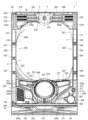
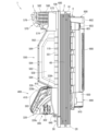
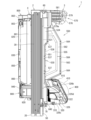
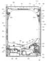
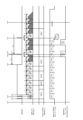
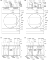
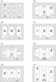
パチンコ機1の扉枠3について、図19乃至図30を参照して説明する。図19はパチンコ機における扉枠の正面図であり、図20は扉枠の右側面図であり、図21は扉枠の左側面図であり、図22は扉枠の背面図である。図23は扉枠を右前から見た斜視図であり、図24は扉枠を左前から見た斜視図であり、図25は扉枠を後ろから見た斜視図である。図26は図19におけるA-A線で切断した断面図であり、図27は図19におけるB-B線で切断した断面図であり、図28は図19におけるC-C線で切断した断面図である。図29は扉枠を主な部材毎に分解して前から見た分解斜視図であり、図30は扉枠を主な部材毎に分解して後ろから見た分解斜視図である。
[3. Overall configuration of door frame]
The
扉枠3は、図29及び図30等に示すように、正面視の外形が上下に延びた四角形で枠状の扉枠ベースユニット100と、扉枠ベースユニット100の前面右下隅に取付けられているハンドルユニット300と、扉枠ベースユニット100の前面下部に取付けられている皿ユニット320と、皿ユニット320の中央に取付けられている演出操作ユニット400と、皿ユニット320の上側で扉枠ベースユニット100の前面左部に取付けられている扉枠左サイドユニット530と、皿ユニット320の上側で扉枠ベースユニット100の前面右部に取付けられている扉枠右サイドユニット550と、扉枠左サイドユニット530及び扉枠右サイドユニット550の上側で扉枠ベースユニット100の前面上部に取付けられている扉枠トップユニット570と、を備えている。
As shown in FIGS. 29 and 30, the
扉枠3の扉枠ベースユニット100は、詳細は後述するが、正面視の外形が上下に延びた長方形(四角形)で前後に貫通している貫通口111を有した板状の扉枠ベース110と、扉枠ベース110の後側に取付けられている枠状の補強ユニット130と、補強ユニット130の正面視左端側の上下両端に取付けられており本体枠4に対してヒンジ回転可能に取付けられる扉枠側上ヒンジ部材140及び扉枠側下ヒンジ部材150と、扉枠ベース110の後面に取付けられ貫通口111を閉鎖するガラスユニット190と、ガラスユニット190の後面下部を覆う防犯カバー200と、扉枠ベース110の後面に扉枠ベース110を貫通して前方に突出するように取付けられ開閉可能とされている扉枠3と本体枠4、及び本体枠4と外枠2との間を施錠するための開閉シリンダユニット210と、扉枠ベース110の後面下部に取付けられ遊技球を球発射装置680に送るための球送りユニット250と、扉枠ベース110の後面下部に取付けられ球発射装置680により発射されて遊技領域5a内に到達しなかった遊技球を受けて下皿322へ排出させるファールカバーユニット270と、を備えている。
The door
扉枠3のハンドルユニット300は、詳細は後述するが、回転可能なハンドル302を遊技者が回転操作することで、上皿321内に貯留されている遊技球を、ハンドル302の回転角度に応じた強さで遊技盤5の遊技領域5a内に打込むことができるものである。
The
扉枠3の皿ユニット320は、詳細は後述するが、扉枠ベースユニット100における扉枠ベース110の前面において貫通口111の下側の部位に取付けられ、前面が前方へ膨出していると共に、左右方向中央の前端に演出操作ユニット400が取付けられる。皿ユニット320は、遊技領域5a内に打込むための遊技球を貯留する上皿321と、上皿321の下側に配置されており上皿321やファールカバーユニット270から供給される遊技球を貯留可能な下皿322と、上皿321に貯留されている遊技球を下皿322へ抜くための上皿球抜きボタン327と、球貸機に投入した現金やプリペイドカードの残金の範囲内で遊技者に遊技球を貸し出すための球貸ボタン328と、球貸機から貸出された遊技球の分を差し引いた現金やプリペイドカードを返却させるための返却ボタン329と、球貸機に投入した現金やプリペイドカードの残数等を表示する球貸返却表示部330と、演出提示時に遊技者の操作が受付可能とされている演出選択左ボタン331及び演出選択右ボタン332と、下皿322内の遊技球を皿ユニット320の下方へ排出するための下皿球抜きボタン333と、を備えている。
The
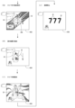
扉枠3の演出操作ユニット400は、皿ユニット320の正面視左右方向中央の前部に取付けられるものであり、遊技者が押圧操作することができると共に、遊技者に対して演出画像を提示することができるものである。この演出操作ユニット400は、詳細は後述するが、遊技者が操作可能な大型の操作ボタン410と、操作ボタン410内に遊技者側から視認可能に配置され演出画像を表示可能な扉枠側演出表示装置460と、を備えている。
The
扉枠3の扉枠左サイドユニット530は、詳細な内容は後述するが、皿ユニット320の上側で扉枠ベースユニット100における貫通口111よりも左側の前面左部に取付けられ、貫通口111(遊技領域5a)の左外側を装飾するものである。扉枠左サイドユニット530は、発光装飾可能な左ユニット装飾レンズ部材(図示は省略)を備えている。
The door frame left
扉枠3の扉枠右サイドユニット550は、詳細な内容は後述するが、皿ユニット320の上側で扉枠ベースユニット100における貫通口111よりも右側の前面右部に取付けられ、貫通口111(遊技領域5a)の右外側を装飾するものである。この扉枠右サイドユニット550は、扉枠左サイドユニット530よりも前方へ大きく突出しており、左右両面側に備えられている右ユニット左装飾部材554及び右ユニット右装飾部材557と、前端に備えられている右ユニット装飾レンズ部材561と、を備えている。扉枠右サイドユニット550は、右ユニット左装飾部材554、右ユニット右装飾部材557、及び右ユニット装飾レンズ部材561を発光装飾させることができる。
The door frame
扉枠3の扉枠トップユニット570は、扉枠左サイドユニット530及び扉枠右サイドユニット550の上側で扉枠ベースユニット100の扉枠ベース110の前面における貫通口111の上側に取付けられ、扉枠3の上部を装飾するものである。扉枠トップユニット570は、詳細な内容は後述するが、左右に離間した一対の上部スピーカ573と、前面中央で前方へ突出しているトップ中装飾部材576と、トップ中装飾部材576の左右両側を装飾しているトップ左装飾レンズ部材579及びトップ右装飾レンズ部材580と、を備えている。扉枠トップユニット570は、トップ中装飾部材576、トップ左装飾レンズ部材579、及びトップ右装飾レンズ部材580を発光装飾させることができる。
The door
[3-1.扉枠ベースユニットの全体構成]
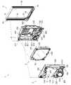
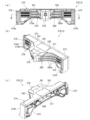
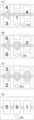
扉枠3の扉枠ベースユニット100について、図31乃至図33を参照して詳細に説明する。図31(a)は扉枠における扉枠ベースユニットを前から見た斜視図であり、(b)は扉枠ベースユニットを後ろから見た斜視図である。図32は扉枠ベースユニットを主な部材毎に分解して前から見た分解斜視図であり、図33は扉枠ベースユニットを主な部材毎に分解して後ろから見た分解斜視図である。
[3-1. Overall configuration of door frame base unit]
The door
扉枠ベースユニット100は、正面視左辺側が本体枠4の前面を閉鎖するように本体枠4に対して開閉可能(ヒンジ回転可能)に取付けられるものである。扉枠ベースユニット100は、前面下隅にハンドルユニット300が、貫通口111の下側前面に演出操作ユニット400が取付けられる皿ユニット320が、貫通口111の左外側前面に扉枠左サイドユニット530が、貫通口111の右外側前面に扉枠右サイドユニット550が、貫通口111の上外側前面に扉枠トップユニット570が、夫々取付けられるものである。
The door
扉枠ベースユニット100は、図32及び図33に等に示すように、正面視の外形が上下に延びた長方形で前後に貫通している貫通口111を有した板状の扉枠ベース110と、扉枠ベース110の後側に取付けられている枠状の補強ユニット130と、補強ユニット130の正面視左端側の上下両端に取付けられており扉枠ベース110から前方へ突出して本体枠4の本体枠側上ヒンジ部材620及び本体枠側下ヒンジ部材640に回転可能に取付けられる扉枠側上ヒンジ部材140及び扉枠側下ヒンジ部材150と、扉枠ベース110の前面で貫通口111の正面視左側に取付けられており前面に複数のLEDが実装されている扉枠左サイド装飾基板160と、扉枠ベース110の後側に回動可能に取付けられておりガラスユニット190を着脱可能に取付けるためのガラスユニット取付部材170と、を備えている。
As shown in FIGS. 32 and 33, the door
また、扉枠ベースユニット100は、扉枠ベース110の前面で正面視右下隅に取付けられておりハンドルユニット300を取付けるための筒状のハンドル取付部材180と、扉枠ベース110の後面に取付けられ貫通口111を閉鎖するガラスユニット190と、ガラスユニット190の後面下部を覆う防犯カバー200と、扉枠ベース110の後面に扉枠ベース110を貫通して前方に突出するように取付けられる開閉シリンダユニット210と、扉枠ベース110の後面下部に取付けられる球送りユニット250と、扉枠ベース110の後面下部に取付けられるファールカバーユニット270と、を備えている。
Further, the door
更に、扉枠ベースユニット100は、図示は省略するが、扉枠3に備えられている各種の装飾基板、球送ソレノイド255、ハンドル回転検知センサ307、ハンドルタッチセンサ310、単発ボタン操作センサ312、球貸ボタン328、返却ボタン329、球貸返却表示部330、演出選択左ボタン331、演出選択右ボタン332、振動モータ424、押圧検知センサ440、扉枠側演出表示装置460(液晶表示装置461)、上部スピーカ573、等と、本体枠4における基板ユニット900の扉枠用中継基板911との接続を中継するための扉本体中継基板を備えている。
Further, although illustration is omitted, the door
[3-1a.扉枠ベース]
扉枠3における扉枠ベースユニット100の扉枠ベース110について、主に図31乃至図33を参照して詳細に説明する。扉枠ベース110は、正面視の外形が上下に延びた四角形(長方形)に形成されている。扉枠ベース110は、前後に貫通しており、正面視における内周形状が上下に延びた略四角形に形成された貫通口111を備えている。貫通口111は、内周を形成している上辺及び左右両辺が、扉枠ベース110の外周辺に夫々接近しており、内周を形成している下辺が、扉枠ベース110の下端から上下方向の約1/3の高さに位置している。従って、扉枠ベース110は、前後に貫通している貫通口111により全体が枠状に形成されている。この扉枠ベース110は、合成樹脂により一体成形されている。
[3-1a. door frame base]
The
扉枠ベース110は、前面における正面視右下隅に形成されており左端側が右端側よりも前方へやや突出するように傾斜しているハンドル取付座面112と、ハンドル取付座面112と貫通口111との間で正面視右端付近に後面から前方へ向かって窪み、開閉シリンダユニット210のシリンダ取付板金213が取付けられるシリンダ取付部113と、シリンダ取付部113において前後に貫通しており開閉シリンダユニット210のシリンダ錠211が挿通されるシリンダ挿通孔114と、シリンダ挿通孔114及びハンドル取付座面112の正面視左側で前後に貫通しており球送りユニット250の進入口251a及び球抜口251bを前方に臨ませるための球送り開口115と、を備えている。
The
また、扉枠ベース110は、扉枠ベース110の左右方向中央より左寄りで且つハンドル取付座面112と略同じ高さで前後に貫通しておりファールカバーユニット270の球放出口276を前方に臨ませる下皿用通過口116と、扉枠ベース110の正面視左端付近で貫通口111の下辺に隣接するように前後に貫通しておりファールカバーユニット270の貫通球通路273を前方に臨ませる上皿用通過口117と、貫通口111の内周に沿って後面から前方へ向かって窪み、ガラスユニット190のガラス枠191が挿入されるガラスユニット取付部118と、扉枠ベース110の左右両上隅において前後に貫通しており扉枠トップユニット570の上部スピーカ573の後端が挿通されるスピーカ挿通口119と、を備えている。
In addition, the
[3-1b.補強ユニット]
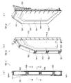
扉枠ベースユニット100の補強ユニット130について、図31及び図33等を参照して詳細に説明する。補強ユニット130は、扉枠ベース110の後側に取付けられることで扉枠ベース110を補強して、扉枠ベース110(扉枠3)の強度剛性を高めている。補強ユニット130は、扉枠ベース110の後面における上辺に沿って取付けられる左右に延びた上補強板金131と、扉枠ベース110の後面における貫通口111の下側に取付けられる左右に延びた中補強板金132と、扉枠ベース110の後面における正面視左辺に沿って取付けられる上下に延びた左補強板金133と、扉枠ベース110の後面における正面視右辺に沿って取付けられる上下に延びた右補強板金134と、右補強板金134の後面に取付けられており施錠ユニット700の扉枠用鉤702が係止される施錠係止部135と、を備えている。
[3-1b. reinforcement unit]
The
補強ユニット130は、上補強板金131の左右両端が左補強板金133及び右補強板金134の夫々の上端にビスによって連結固定されており、中補強板金132の左端が左補強板金133にビスによって連結固定されている。中補強板金132の右端は、後述する開閉シリンダユニット210のシリンダ取付板金213を介して右補強板金134に連結固定されている。従って、補強ユニット130は、上補強板金131、中補強板金132、左補強板金133、及び右補強板金134等によって、枠状に形成されている。
In the
補強ユニット130の上補強板金131、中補強板金132、左補強板金133、右補強板金134、及び施錠係止部135は、夫々金属板を適宜屈曲させて形成されている。中補強板金132は、扉枠ベース110の上皿用通過口117と対応する位置に、前後に貫通した切欠部132aが形成されている。
The upper reinforcing
補強ユニット130は、詳細な図示は省略するが、各上補強板金131、中補強板金132、左補強板金133、及び右補強板金134において、夫々前後方向に屈曲された部位を有しており、その部位によって、強度剛性が高められていると共に、外部からのピアノ線やマイナスドライバー等の不正な工具の侵入を防止している。
Although not shown in detail, the
[3-1c.扉枠側上ヒンジ部材]
扉枠ベースユニット100の扉枠側上ヒンジ部材140について、主に図31乃至図33等を参照して詳細に説明する。扉枠側上ヒンジ部材140は、扉枠ベース110に取付けられ上下に離間している一対の突出片141aを有した扉枠上ヒンジ軸ブラケット141と、扉枠上ヒンジ軸ブラケット141の一対の突出片141aを貫通しており、上端が本体枠側上ヒンジ部材620の扉枠用上ヒンジ孔623に挿入される円柱状の扉枠上ヒンジピン142と、扉枠上ヒンジピン142における一対の突出片141aの間の位置に取付けられている円盤状の鍔部材143と、鍔部材143と一対の突出片141aのうちの下側の突出片141aとの間に介装されていると共に扉枠上ヒンジピン142が挿通されており、扉枠上ヒンジピン142を上方へ付勢しているロックバネ144と、を備えている。
[3-1c. Door frame side upper hinge member]
The door frame side
扉枠上ヒンジ軸ブラケット141は、図示は省略するが一対の突出片141aの後端同士を連結している平板状の取付片を有しており、側面視の形状が前方へ開放されたコ字状に形成されている。扉枠上ヒンジ軸ブラケット141は、一対の突出片141a同士を連結している取付片が、ビスによって扉枠ベース110の後面に取付けられている。
Although not shown, the door frame upper
扉枠上ヒンジピン142は、上側の突出片141aよりも上方に突出している部位(上端)が、本体枠側上ヒンジ部材620の扉枠用上ヒンジ孔623に対して回転可能に挿入される。また、扉枠上ヒンジピン142は、図示は省略するが、下側の突出片141aよりも下方に突出している部位が水平方向に屈曲している。この屈曲している部位が下側の突出片141aの下面に当接することで、扉枠上ヒンジピン142の上方への移動を規制している。
The door frame
鍔部材143は、Eリングとされており、扉枠上ヒンジピン142の外周に形成されている溝内に挿入保持されている。ロックバネ144は、扉枠上ヒンジピン142を挿通可能なコイルスプリングとされており、上端が鍔部材143に当接していると共に、下端が下側の突出片141aに当接している。このロックバネ144は、鍔部材143と下側の突出片141aとの間に、圧縮された状態で介装されており、鍔部材143を介して扉枠上ヒンジピン142を上方へ付勢している。
The
扉枠側上ヒンジ部材140は、扉枠上ヒンジピン142がロックバネ144により上方へ付勢された状態となっており、扉枠上ヒンジピン142における下端の水平に屈曲している部位が下側の突出片141aの下面に当接することで、これ以上の上方への移動が規制されている。この状態では、扉枠上ヒンジピン142の上端が、上側の突出片141aの上面よりも所定量上方に突出している。
In the door-frame-side
扉枠側上ヒンジ部材140は、扉枠上ヒンジピン142における下端の水平に屈曲している部位を作業者が持って、ロックバネ144の付勢力に抗してその部位を下方へ引っ張ると、扉枠上ヒンジピン142を全体的に下方へ移動させることができ、扉枠上ヒンジピン142の上端を、上側の突出片141aの上面よりも下方へ没入させることができる。従って、扉枠側上ヒンジ部材140は、扉枠上ヒンジピン142の上端を、本体枠側上ヒンジ部材620の扉枠用上ヒンジ孔623に対して下方から挿入させたり、下方へ抜いたりすることができる。これにより、扉枠側上ヒンジ部材140の扉枠上ヒンジピン142の上端を、本体枠側上ヒンジ部材620の扉枠用上ヒンジ孔623に挿入させることで、扉枠3の正面視上部左端を、本体枠4に対してヒンジ回転可能に支持させることができる。
When an operator holds the horizontally bent portion of the lower end of the door frame
また、扉枠側上ヒンジ部材140は、扉枠上ヒンジピン142における扉枠上ヒンジ軸ブラケット141の一対の突出片141aにより支持されている部位が、後述する扉枠側下ヒンジ部材150の扉枠下ヒンジピン152と同軸上に支持されている。これにより、扉枠側上ヒンジ部材140と扉枠側下ヒンジ部材150とによって、扉枠3を本体枠4に対して良好な状態でヒンジ回転させることができる。
Further, in the door-frame-side
[3-1d.扉枠側下ヒンジ部材]
扉枠ベースユニット100の扉枠側下ヒンジ部材150について、主に図31及び図32等を参照して詳細に説明する。扉枠側下ヒンジ部材150は、扉枠ベース110に取付けられ前方に延出している平板状の延出片151aを有している扉枠下ヒンジ軸ブラケット151と、扉枠下ヒンジ軸ブラケットにおける延出片151aの前端部付近から下方に突出している円柱状の扉枠下ヒンジピン152(図21及び図22を参照)と、を備えている。
[3-1d. Door frame side lower hinge member]
The door frame side
扉枠下ヒンジ軸ブラケット151は、水平に延びた平板状の延出片151aの後端から上方に延出した平板状の取付片(図示は省略)を有しており、側面視の全体形状が略L字状に形成されている。この扉枠下ヒンジ軸ブラケット151は、図示しない取付片がビスによって扉枠ベース110の後面に取付けられている。
The door frame lower
扉枠下ヒンジピン152は、下端部が、下方へ向かうほど窄まる円錐台状に形成されている。この扉枠下ヒンジピン152は、後述する本体枠4における本体枠側下ヒンジ部材640の扉枠用ヒンジ孔644に、上方から回転可能に挿入される。扉枠下ヒンジピン152は、扉枠側上ヒンジ部材140の扉枠上ヒンジピン142と同軸上に配置されている。
The lower door
この扉枠側下ヒンジ部材150は、扉枠下ヒンジピン152が本体枠側下ヒンジ部材640の扉枠用ヒンジ孔644に挿入されることで、扉枠3を本体枠4に対してヒンジ回転可能に支持することができる。
The door frame side
[3-1e.扉枠左サイド装飾基板]
扉枠ベースユニット100の扉枠左サイド装飾基板160について、主に図31及び図32等を参照して詳細に説明する。扉枠左サイド装飾基板160は、扉枠ベース110の前面において、貫通口111の正面視左側に取付けられている。扉枠左サイド装飾基板160は、扉枠ベース110における正面視左側のスピーカ挿通口119よりも下側の位置の高さから貫通口111の上下方向の中央付近の高さまで上下に延びている扉枠左サイド上装飾基板161と、扉枠左サイド上装飾基板161の下側の位置の高さから上皿用通過口117の下端と略同じ高さまで上下に延びている扉枠左サイド下装飾基板162と、を備えている。
[3-1e. Door frame left side decorative board]
The door frame left side
扉枠左サイド装飾基板160の扉枠左サイド上装飾基板161及び扉枠左サイド下装飾基板162は、夫々前面に、前方へ光を照射可能な複数のLED161a,162aを備えている。これらLED161a,162aは、フルカラーLEDとされている。
A door-frame left-side upper
扉枠左サイド装飾基板160は、扉枠3を組立てた状態で、後述する扉枠左サイドユニット530の後方に位置しており、前面に備えられた(実装された)複数のLED161a,162aを適宜発光させることで、扉枠左サイドユニット530の左ユニット装飾レンズ部材を発光装飾させることができる。
The door frame left side
[3-1f.ガラスユニット取付部材]
扉枠ベースユニット100のガラスユニット取付部材170について、主に図31(b)等を参照して詳細に説明する。ガラスユニット取付部材170は、扉枠ベース110の後側に回動可能に取付けられておりガラスユニット190を着脱可能に取付けるためのものである。ガラスユニット取付部材170は、扉枠ベース110の後側で前後に延びた軸線周りに対して回転可能に取付けられる円盤状の基部171と、基部171から回転軸線に対して直角方向へ棒状に突出している突出部172と、を有している。
[3-1f. Glass unit mounting member]
The glass
ガラスユニット取付部材170は、扉枠ベース110の後面における一対のスピーカ挿通口119の下側で、ガラスユニット取付部118よりも外側の部位に、夫々回転可能に取付けられている。
The glass
ガラスユニット取付部材170は、突出部172が基部171から上方へ突出するように回転させた状態とすることで、背面視において扉枠ベース110のガラスユニット取付部118よりも突出部172が外側に位置した状態となり、扉枠ベース110のガラスユニット取付部118に対してガラスユニット190を挿入したり、ガラスユニット取付部118からガラスユニット190を取外したりすることができる。
The glass
ガラスユニット取付部材170は、ガラスユニット190を扉枠ベース110のガラスユニット取付部118に挿入させた状態で、突出部172が基部171から下方へ突出するように回転させると、突出部172がガラスユニット190の取付片191aの後側と当接し、ガラスユニット190上部の後方への移動を規制した状態となり、ガラスユニット190を扉枠ベース110に取付けることができる。
With the
ガラスユニット取付部材170は、扉枠ベース110に回転可能に取付けられる円盤状の基部171から突出部172が突出しているため、ガラスユニット取付部材170の重心位置が突出部172内に位置している。このことから、ガラスユニット取付部材170が自由に回転できる状態では、突出部172が基部171から下方へ突出した状態で安定することとなる。そして、ガラスユニット取付部材170では、突出部172が基部171から下方へ突出している回転位置の時に、突出部172によりガラスユニット190の後方への移動を規制させるようにしているため、ガラスユニット取付部材170に振動等が作用しても、突出部172が基部171から上方へ突出するように全体が回転することはなく、ガラスユニット190の後方への移動の規制が自然に解除されることはない。
The center of gravity of the glass
なお、扉枠ベース110からガラスユニット190を取外す場合は、ガラスユニット取付部材170を、突出部172が基部171から上方へ突出するように回転させて、突出部172をガラスユニット190の取付片191aよりも外側へ移動させることで、ガラスユニット190の上部側を後方へ移動させることができるようになり、扉枠ベース110からガラスユニット190を取外すことができる。
When removing the
[3-1g.ハンドル取付部材]
扉枠ベースユニット100のハンドル取付部材180について、主に図31乃至図33等を参照して詳細に説明する。ハンドル取付部材180は、扉枠ベース110の前面にハンドルユニット300を取付けるためのものである。ハンドル取付部材180は、図32及び図33等に示すように、前後方向へ延びた円筒状の筒部181と、筒部181の後端から筒部181の軸に対して直角方向外方へ延びた円環状のフランジ部182と、筒部181内に突出していると共に筒部181の軸方向全長に亘って延びており筒部181の周方向に対して不等間隔に配置された複数(本例では三つ)の突条183と、筒部181の外周面とフランジ部182の前面とを繋ぎ、筒部181の周方向に対して複数配置された補強リブ184と、を備えている。
[3-1 g. Handle mounting member]
The
ハンドル取付部材180は、フランジ部182の後面を、扉枠ベース110におけるハンドル取付座面112の前面に当接させた状態で、ビスによってハンドル取付座面112に取付けられる。
The
筒部181は、内径がハンドルユニット300におけるハンドルベース301の基部301aの外径よりも若干大きく形成されている。三つの突条183は、一つが筒部181内の上側に備えられており、残り二つが筒部181内の下側に備えられている。これら三つの突条183は、ハンドルベース301における三つの溝部301cと対応する位置に形成されている。従って、ハンドル取付部材180は、三つの突条183と、ハンドルベース301の三つの溝部301cとを一致させた状態でのみ、筒部181内にハンドルベース301の基部301aを挿入させることができ、扉枠ベース110に対してハンドルベース301(ハンドルユニット300)の回転位置を規制することができる。
The
なお、ハンドル取付部材180は、フランジ部182の後面に対して、筒部181の軸線が垂直に延びていることから、扉枠ベース110の傾斜したハンドル取付座面112に取付けることで、筒部181の軸線が右前方へ延びるように傾いた状態となり、ハンドルユニット300を同様に傾いた状態で扉枠ベース110に取付けることができる。
Since the axis of the
[3-1h.ガラスユニット]
扉枠ベースユニット100のガラスユニット190について、主に図31乃至図33等を参照して詳細に説明する。ガラスユニット190は、扉枠ベース110の貫通口111を、前方から後方が視認できるように閉鎖するものである。ガラスユニット190は、扉枠ベース110の貫通口111の内周形状よりも大きくガラスユニット取付部118に取付可能な枠状のガラス枠191と、ガラス枠191の枠内を閉鎖し外周がガラス枠191に取付けられている透明な二つのガラス板192と、を備えている。二つのガラス板192は、ガラス枠191の前端側と後端側とに夫々取付けられており、互いの間に空間が形成されるように前後に離間している(図26等を参照)。
[3-1h. glass unit]
The
ガラス枠191は、正面視左右上隅よりも下側の位置から外方へ平板状に延出している一対の取付片191aと、下端から下方へ突出していると共に下辺に沿って延びている帯板状の係止片191bと、を有している。ガラス枠191の取付片191aは、ガラスユニット取付部材170の突出部172と当接可能とされている。係止片191bは、扉枠ベース110と補強ユニット130の中補強板金132との間の空間内に挿入可能とされている(図26を参照)。
The
このガラスユニット190は、扉枠ベース110の後側から、ガラス枠191の係止片191bを、扉枠ベース110と補強ユニット130の中補強板金132との間の隙間に上方から挿入した上で、ガラス枠191の前端を扉枠ベース110のガラスユニット取付部118の後面に当接させ、ガラスユニット取付部材170を回転させてガラスユニット取付部材170の突出部172をガラス枠191の取付片191aの後面と当接させることで、扉枠ベース110に取付けられる。
This
ガラスユニット190を扉枠ベース110から取外す場合は、上記と逆の手順により、取外すことができる。これにより、ガラスユニット190は、扉枠ベース110に対して着脱可能となっている。
When removing the
[3-1i.防犯カバー]
扉枠ベースユニット100の防犯カバー200について、主に図31乃至図33等を参照して詳細に説明する。防犯カバー200は、ガラスユニット190の後面下部を覆うように扉枠ベース110の後側に取付けられ、透明な合成樹脂により形成されている。防犯カバー200は、外周が所定形状に形成された平板状の本体部201と、本体部201の外周縁に沿って後方へ短く突出した平板状の後方突片202と、左右に離間して配置され本体部201よりも前方に突出し、扉枠ベース110の後側に係止可能とされている一対の係止片203と、を備えている。
[3-1i. Security cover]
The
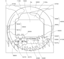
防犯カバー200の本体部201は、扉枠ベース110に取付けた状態で下端がガラスユニット190の下端よりも下方へ突出するように形成されている。また、本体部201は、上端が、パチンコ機1に組立てた状態で、遊技盤5における遊技領域5aの下端に沿った形状に形成されている。詳述すると、本体部201の上端は、後述する前構成部材1000の内レール1002の一部、アウト誘導部1003、右下レール1004の一部、及び右レール1005に沿った形状に形成されており、パチンコ機1に組立てた状態で遊技領域5a内に突出しないように形成されている。
The
後方突片202は、本体部201の外周縁の略全周に亘って形成されている。従って、防犯カバー200は、本体部201と後方突片202とによって、後方へ開放された浅い箱状に形成されており、強度・剛性が高くなっている。また、後方突片202は、図33に示すように、本体部201の外周縁とは異なる本体部201の後面の一部からも後方に突出している。この本体部201の後面の一部から後方に突出している後方突片202は、パチンコ機1に組立てた状態で遊技盤5の前構成部材1000における外レール1001の一部と沿うように形成されている。
The rear projecting
なお、後方突片202は、パチンコ機1に組立てた状態で、遊技盤5における外レール1001と内レール1002との間に位置する部位には形成されていない。これにより、外レール1001と内レール1002との間を通る遊技球(球発射装置680により発射された遊技球)が、防犯カバー200の後方突片202に当接することはなく、遊技領域5a内への遊技球の打込みを阻害することはない。
Note that the rear projecting
一対の係止片203は、扉枠ベース110の後側に弾性係止される。これにより、防犯カバー200は、扉枠ベース110に対して容易に着脱することができる。
A pair of locking
防犯カバー200は、パチンコ機1に組立てた状態で、本体部201の前面がガラスユニット190の後面(ガラス枠191の後端)と当接し、本体部201の下辺から後方へ突出している部位を除いた後方突片202が、後述する前構成部材1000の防犯凹部1008内に挿入された状態となる。また、防犯カバー200は、本体部201の下辺から後方に突出している後方突片202が、前構成部材1000の下面と接するように前構成部材1000の前面よりも後方へ突出している状態となる。これにより、防犯カバー200と遊技盤5(前構成部材1000)との間が、防犯カバー200の後方突片202と前構成部材1000の防犯凹部1008とによって複雑に屈曲した状態となるため、遊技盤5の前面下方より防犯カバー200と前構成部材1000との間を通してピアノ線等の不正な工具を遊技領域5a内に侵入させようとしても、後方突片202や防犯凹部1008に阻まれることとなり、遊技領域5a内への不正な工具の侵入を阻止することができる。
When the
[3-1j.開閉シリンダユニット]
扉枠ベースユニット100の開閉シリンダユニット210について、主に図31乃至図33等を参照して説明する。開閉シリンダユニット210は、正面視において扉枠ベース110の右端付近で貫通口111とハンドル取付座面112との間の位置のシリンダ取付部113に後側から取付けられ、後述する施錠ユニット700と協働して、扉枠3と本体枠4との開閉、及び、外枠2と本体枠4との開閉に使用されるものである。
[3-1j. Open/close cylinder unit]
The opening/
開閉シリンダユニット210は、前面に鍵穴211aを有し前後に延びた円筒状のシリンダ錠211と、シリンダ錠211の後端に取付けられており鍵穴211aに挿入された鍵の回動操作を施錠ユニット700の鍵シリンダ710に伝達させる回転伝達部材212と、シリンダ錠211を扉枠ベース110(補強ユニット130)に取付けるシリンダ取付板金213と、を備えている。
The opening/
シリンダ錠211は、対応する鍵(図示は省略)を鍵穴211aに差し込むことで、鍵を回転させることができるものであり、対応する鍵であれば、正面視において時計回り及び反時計回りの何れの方向へも所定角度回転させることができる。
The
回転伝達部材212は、後方が開放された円筒状(詳しくは、後方へ向かうに従って直径が大きくなる円錐筒状)に形成されており、中心軸を挟んで対向した位置に後端から前方へ向かって切欠かれた一対の切欠部212aを有している。この回転伝達部材212は、本体枠4における施錠ユニット700の鍵シリンダ710が後方から挿入されるように形成されており、施錠ユニット700の鍵シリンダ710の突起が一対の切欠部212a内に挿入されることで、回転伝達部材212(シリンダ錠211の鍵穴211aに挿入された鍵)の回転を、施錠ユニット700の鍵シリンダ710に伝達させて鍵シリンダ710を回転させることができる。
The
シリンダ取付板金213は、一枚の金属板を屈曲させて形成されており、平面視の形状が前方へ突出している凸形状に形成されている。詳述すると、シリンダ取付板金213は、正面視において上下に延びた長方形で平板状の前板部213aと、前板部213aの左右両辺から後方へ平板状に延出している一対の側板部213bと、一対の側板部213bの夫々の後辺から互いに遠ざかる方向へ平板状に延出している一対の取付板部213cと、を備えている。シリンダ取付板金213の前板部213aは、上下方向略中央の位置で後方からシリンダ錠211が貫通し、前板部213aの後面にシリンダ錠211の後端が取付けられる。シリンダ取付板金213の一対の取付板部213cは、正面視左側の取付板部213cが補強ユニット130の中補強板金132の右端部に取付けられ、正面視右側の取付板部213cが補強ユニット130の右補強板金134に取付けられる。これにより、シリンダ取付板金213によって、補強ユニット130の中補強板金132と右補強板金134とが連結される。
The cylinder mounting
開閉シリンダユニット210は、扉枠ベースユニット100に組立てた状態では、シリンダ取付板金213の前板部213aから前方に突出しているシリンダ錠211の前端が、扉枠ベース110の後側からシリンダ挿通孔114に挿通されて扉枠ベース110の前方へ突出していると共に、シリンダ取付板金213の前板部213a及び一対の側板部213bが後方へ開放されている箱状のシリンダ取付部113内に収容されている。
When the opening/
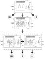
[3-4.演出操作ユニットの全体構成]
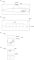
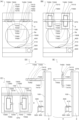
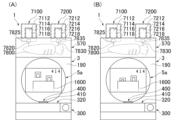
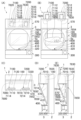
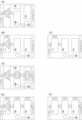
扉枠3における演出操作ユニット400の全体構成について、主に図34乃至図41等を参照して詳細に説明する。図34(a)は扉枠における演出操作ユニットの正面図であり、(b)は演出操作ユニットの右側面図である。また、図35(a)は演出操作ユニットを前から見た斜視図であり、(b)は演出操作ユニットを後ろから見た斜視図である。図36は、演出操作ユニットを操作ボタンの中心軸の延びている方向から見た説明図である。図37は図34(a)におけるD-D線で切断した断面図であり、図38は図34(b)におけるE-E線で切断した断面図である。図39(a)は図34(b)におけるF-F線で切断した断面図であり、(b)は(a)におけるA部の拡大図である。図40は演出操作ユニットを主な部材毎に分解して前から見た分解斜視図であり、図41は演出操作ユニットを主な部材毎に分解して後ろから見た分解斜視図である。演出操作ユニット400は、皿ユニット320の正面視左右方向中央の前部に取付けられるものであり、遊技者が押圧操作することができると共に、遊技者に対して演出画像を提示することができるものである。
[3-4. Overall configuration of production operation unit]
The overall configuration of the
演出操作ユニット400は、外形が円形で外周縁を除いた中央側が透明に形成されており遊技者が押圧操作可能な操作ボタン410と、操作ボタン410の外周を囲み皿ユニットカバー326の演出操作ユニット取付部326aに取付けられる枠状のフレームユニット415と、操作ボタン410よりも後方に配置されており操作ボタン410の外周縁及びフレームユニット415を発光装飾させることが可能な装飾基板ユニット420と、フレームユニット415の後側に取付けられており操作ボタン410及び装飾基板ユニット420が前面に取付けられているベースユニット430と、操作ボタン410を通して遊技者側から視認可能にベースユニット430に取付けられており演出画像を表示可能な扉枠側演出表示装置460と、を備えている。
The
[3-4a.操作ボタン]
演出操作ユニット400の操作ボタン410について、主に図39乃至図42等を参照して詳細に説明する。図42(a)は操作ボタンを分解して前から見た分解斜視図であり、(b)は操作ボタンを分解して後ろから見た分解斜視図である。操作ボタン410は、外形が皿ユニット320の上下方向の高さよりも若干小さい直径の円形に形成されており、外周縁を除いた中央側が透明に形成されている。操作ボタン410は、外周が円形で中央側が前方へ膨出するように湾曲面状(球面の一部の形状)に形成されている透明なボタンレンズ411と、ボタンレンズ411の外周縁の前側に取付けられている円環状のボタンフレーム412と、ボタンフレーム412の後側にボタンレンズ411の外周縁を挟持するように取付けられている円筒状のボタンベース413と、を備えている。ボタンフレーム412及びボタンベース413は、光を通し難い部材によって形成されている。
[3-4a. Manual operation button]
The
ボタンレンズ411は、全体が略一定の厚さに形成されている。また、ボタンレンズ411は、表面側が凹凸の無い滑らかな湾曲面状に形成されている。ボタンレンズ411は、ボタンフレーム412の内周側となる位置に裏面から断面W字状に窪んだ状態で中央側(内側)へ所定長さで延びていると共に周方向に列設されている第一ボタン装飾部411aと、第一ボタン装飾部411aよりも外周側の位置に裏面から断面円弧状に窪んだ状態で中央側へ向かう軸線上に延びていると共に周方向に所定角度範囲内で列設されている複数(六つ)の第二ボタン装飾部411bと、を備えている。
The
ボタンレンズ411の第一ボタン装飾部411aは、図示するように、操作ボタン410に組立てた状態では、ボタンフレーム412の内周から中央側へ延びており、左右両側の一群が、上下両側の一群よりも中央側へ長く延びている。
As shown in the drawing, the first button
ボタンレンズ411の複数の第二ボタン装飾部411bは、夫々が同一の円周上において円弧状に延びており、左右両側に夫々三つずつ形成されている。これらの第二ボタン装飾部411bは、ボタンフレーム412のフレーム開口部412aから臨むように形成されていると共に、前面側がボタンフレーム412の前面と略同一面上となるように前方へ突出している。
The plurality of second button
ボタンレンズ411は、第一ボタン装飾部411a及び第二ボタン装飾部411bの部位において、裏面に形成されている断面W字状や断面円弧状の凹凸により、光が屈折するレンズ効果が発揮されるため、後側が明瞭に見えないようになっている。
The
ボタンフレーム412は、円環状に形成されており、前後方向に貫通し周方向へ所定長さで円弧状に延びた複数(六つ)のフレーム開口部412aを備えている。六つのフレーム開口部412aは、左右両側に夫々三つずつ備えられており、ボタンレンズ411の六つの第二ボタン装飾部411bと対応している。このボタンフレーム412は、表面に金属光沢を有したメッキ層を備えている。
The
ボタンベース413は、前後方向に短く延びた略円筒状の本体部413aと、本体部413aの前端から外方へ突出している円環状のフランジ部413bと、フランジ部413bの後側から本体部413aの外周に沿って後方へ円柱状に突出しており周方向に略等間隔で複数(四つ)配置されているガイドボス部413cと、フランジ部413bの後側から本体部413aの外周に沿って後方へ帯板状に突出しており周方向に複数(三つ)配置されている検知片413dと、本体部413aよりも外側でフランジ部413bを前後に貫通していると共に外周に沿って所定長さで延びており周方向に複数(六つ)形成されているベース開口部413eと、本体部413aの前端から前方へ筒状に延出しており前端側がボタンレンズ411の内面に沿うように内側(中央側)へ窄まっている内側延出部413fと、を備えている。
The
ボタンベース413における内側延出部413fの外周面と、フランジ部413bの前面とにボタンレンズ411の外周縁及びボタンフレーム412が取付けられる。四つのガイドボス部413cは、本体部413aの周方向に対して、上下左右の四隅に相当する部位に夫々配置されている。これら四つのガイドボス部413cは、ベースユニット430におけるユニットベース431の保持孔431b内に夫々摺動可能に挿入される。三つの検知片413dは、本体部413aの周方向に対して、上側に二つ、下側に一つ、配されるように、周方向へ略等間隔に配置されている。これら三つの検知片413dは、操作ボタン410が押圧されると、ベースユニット430の押圧検知センサ440により検知される。
The outer peripheral edge of the
六つのベース開口部413eは、左右両側に夫々三つずつ備えられており、ボタンレンズ411の第二ボタン装飾部411b及びボタンフレーム412のフレーム開口部412aと対応している。ボタンベース413におけるベース開口部413eの部位では、本体部413a及び内側延出部413fの一部が、外周側から内側へ窪んでいる。内側延出部413fは、内側へ窄まっている前端の内径が、ボタンフレーム412の内径と略一致している。
The six
この操作ボタン410は、前面が前方へ湾曲面状(略球面の一部の形状)に膨出していると共に、透明に形成されており、後側に配置されている扉枠側演出表示装置460の表示画面を前方から視認することができる。操作ボタン410は、四つのガイドボス部413cがベースユニット430におけるユニットベース431の保持孔431bに摺動可能に挿入されていると共に、ユニットベース431の保持孔に431bに挿入されている操作ボタンバネ438により前方へ付勢されている。操作ボタン410は、ベースユニット430の操作ボタンバネ438の付勢力により、外周縁の前面側がフレームユニット415に当接することで、前方へのこれ以上の移動が規制されており、操作ボタンバネ438の付勢力に抗して押圧操作することで、後端がベースユニット430の前面に当接するまで後方へ移動する。操作ボタン410は、押圧操作して後方へ移動させると、三つの検知片413dの少なくとも一つがベースユニット430の押圧検知センサ440に検知される。この押圧検知センサ440による検知片413dの検知によって、操作ボタン410が操作されたこととなる。
The front surface of the
また、操作ボタン410は、演出操作ユニット400を組立てた状態で、透明なボタンレンズ411におけるボタンフレーム412の内周端から中央側へ延びるように全周に亘って形成されている第一ボタン装飾部411aによって、ボタンベース413の内周面と、ベースユニット430の操作ボタン内装飾部材432との間の隙間を、遊技者側から見え難くすることができる。
In addition, the
更に、操作ボタン410は、円筒状のボタンベース413の前端開口を、ボタンレンズ411とボタンフレーム412とで閉鎖しており、ボタンレンズ411の外周縁に取付けられているボタンフレーム412により、操作ボタン410の外径に対して、後方が視認可能な透明な部分が、外周から内側へ窄まったように形成されている。このボタンフレーム412の存在によっても、ボタンベース413の内周面と、ベースユニット430の操作ボタン内装飾部材432との間の隙間を、遊技者側から見え難くしている。
Further, the
また、操作ボタン410は、演出操作ユニット400に組立てた状態では、筒状のボタンベース413(本体部413a)の後端が、装飾基板ユニット420の内周側を通して装飾基板ユニット420の前面よりも後方へ突出した状態となる。これにより、装飾基板ユニット420の操作ボタン左外装飾基板422及び操作ボタン右外装飾基板423に夫々実装されている第一LED422a,423a及び第二LED422b,423bから前方へ照射された光が、ボタンベース413の外側から内側へ漏れるのを防止することができると共に、ベースユニット430の操作ボタン左内装飾基板433、操作ボタン右内装飾基板434、操作ボタン上内装飾基板435、及び操作ボタン下内装飾基板436に実装されたLEDから前方へ照射された光がボタンベース413の内側から外側へ漏れるのを防止することができる。従って、装飾基板ユニット420の第一LED422a,423a及び第二LED422b,423bやベースユニット430の操作ボタン左内装飾基板433、操作ボタン右内装飾基板434、操作ボタン上内装飾基板435、及び操作ボタン下内装飾基板436に実装されたLEDが、発光装飾対象としている部位以外が発光装飾されてしまうのを防止することができ、見栄え良く発光装飾を行うことができる。
In addition, when the
[3-4b.フレームユニット]
演出操作ユニット400のフレームユニット415について、主に図39乃至図41等を参照して詳細に説明する。フレームユニット415は、操作ボタン410の前方側から外周を囲むように、皿ユニット320における皿ユニットカバー326の演出操作ユニット取付部326aに前側から取付けられ、操作ボタン410の外側を装飾している。フレームユニット415は、外形が演出操作ユニット取付部326aの前端側に合せた形状に形成されている。
[3-4b. frame unit]
The
フレームユニット415は、皿ユニット320における皿ユニットカバー326の演出操作ユニット取付部326aに取付けられ円形の中央開口部416aを有する枠状のフレーム本体416と、中央開口部416aの左右両側でフレーム本体416に後側から取付けられる透光性を有した一対のフレームサイドレンズ417と、中央開口部416aの上側でフレーム本体416に前側から取付けられる透光性を有したフレームトップレンズ418と、を備えている。
The
フレーム本体416は、操作ボタン410の外径よりも小径で前後に貫通している円形の中央開口部416aと、中央開口部416aよりも左右両外側で前後に貫通していると共に中央開口部416aの周縁に沿って円弧状に延びており周方向に列設されている複数(六つ)の外周開口部416bと、中央開口部416aの上側前面において所定幅で切欠かれている切欠部416cと、を備えている。中央開口部416aは、操作ボタン410におけるボタンフレーム412のフレーム開口部412aの外周側の直径と略同じ大きさに形成されている。これにより、フレーム開口部412aの外周後側に操作ボタン410におけるボタンベース413のフランジ部413bの前端側が当接できるようになっている。
The frame
六つの外周開口部416bは、中央開口部416aの左右両外側に、夫々三つずつ備えられており、後側からフレームサイドレンズ417によって閉鎖されている。切欠部416cは、前後方向にも貫通しており、前側からフレームトップレンズ418が嵌込まれている。
The six outer
また、フレーム本体416は、中央開口部416aの周縁よりも若干外側の位置から後方へ延出している略筒状の内側筒部416dを備えている。内側筒部416dは、中央開口部416aと外周開口部416bとの間の位置から後方へ延出しており、切欠部416cと対応している部位が切欠かれている。内側筒部416dは、演出操作ユニット400を組立てた状態では、装飾基板ユニット420の操作ボタン左外装飾基板422及び操作ボタン右外装飾基板423における夫々の第一LED422a,423aと第二LED422b,423bとの間に位置しており、第一LED422a,423aと第二LED422b,423bとの間を仕切っている(図38を参照)。
The frame
更に、フレーム本体416は、外周の左右両側上部において夫々外方へ延出しており、皿ユニット320の皿ユニットカバー326の演出操作ユニット取付部326aに取付けられる一対の取付部416eを備えている。フレーム本体416(演出操作ユニット400)は、一対の取付部416eと切欠部416cの左右両側の部位が、皿ユニット320における皿ユニットカバー326の演出操作ユニット取付部326aに取付けられる。
Further, the
フレーム本体416は、中央開口部416aを間にして切欠部416c側(フレームトップレンズ418が取付けられる側)とは反対側で切欠部416cと同じ幅の部位を除いて、表面の略全体に金属光沢を有したメッキ層が形成されている。
The frame
フレームサイドレンズ417は、フレーム本体416の左右に夫々三つずつ形成されている外周開口部416bを後側から閉鎖している。フレームサイドレンズ417は、前面側が凹凸の無い滑らかな面に形成されており、後面側に中央開口部416aの周縁に沿った複数の凹凸が形成されている(図39及び図46を参照)。これら複数の凹凸によって光が屈折することで、フレームサイドレンズ417の後側が見えないようになっている。
The
フレームトップレンズ418は、フレーム本体416の切欠部416cに前側から嵌込まれるように、外形が略四角形に形成されている。フレームトップレンズ418は、前面側が滑らかに形成されている。また、フレームトップレンズ418は、後面側に中央開口部416aの周縁に沿ってジグザグ状に延びた複数の凹凸が中央開口部416aの半径方向に複数列設されている(図37及び図46を参照)。これら複数の凹凸によって光が屈折することで、フレームトップレンズ418の後側が見えないようになっている。
The
フレームユニット415は、演出操作ユニット400を組立てた状態で、一対のフレームサイドレンズ417が装飾基板ユニット420の操作ボタン左外装飾基板422及び操作ボタン右外装飾基板423における夫々の第二LED422b,423bの前方に位置すると共に、フレームトップレンズ418がベースユニット430のフレームトップレンズ装飾基板437の前方に位置し、それらに実装されている第二LED422b,423b等によって夫々が発光装飾可能となっている。
In the
[3-4c.装飾基板ユニット]
演出操作ユニット400の装飾基板ユニット420について、主に図39乃至図43等を参照して詳細に説明する。図43は、演出操作ユニットの装飾基板ユニットを分解して前から見た分解斜視図である。装飾基板ユニット420は、フレームユニット415の下方でベースユニット430の前面に取付けられ、操作ボタン410の第二ボタン装飾部411b及びフレームユニット415のフレームサイドレンズ417を発光装飾させることができると共に、演出操作ユニット400に振動を付与させることができるものである。
[3-4c. Decoration board unit]
The
装飾基板ユニット420は、上方側が開放されたC字状の基板ベース421と、基板ベース421における左右両側の前面に夫々取付けられている操作ボタン左外装飾基板422及び操作ボタン右外装飾基板423と、基板ベース421の前面下部に取付けられている振動モータ424と、振動モータ424の前側を覆うように基板ベース421の前面に取付けられているモータカバー425と、を備えている。
The
基板ベース421は、内周側が操作ボタン410のボタンベース413における筒状の本体部413aの外径よりも若干大きく形成されていると共に、外周側がボタンベース413におけるフランジ部413bの外径よりも大きく且つフレームユニット415の外径よりも小さく形成されている。
The
操作ボタン左外装飾基板422は、基板ベース421の前面に沿って円弧状に延びている。操作ボタン左外装飾基板422は、前面側に、基板ベース421の内周に沿って実装された複数の第一LED422aと、複数の第一LED422aよりも半径方向外側で基板ベース421の内周に沿って実装された複数の第二LED422bと、を備えている。操作ボタン右外装飾基板423は、基板ベース421の前面に沿って円弧状に延びている。操作ボタン右外装飾基板423は、前面側に、基板ベース421の内周に沿って実装された複数の第一LED423aと、複数の第一LED423aよりも半径方向外側で基板ベース421の内周に沿って実装された複数の第二LED423bと、を備えている。これら操作ボタン左外装飾基板422及び操作ボタン右外装飾基板423は、前後両面が白色とされている。
The operation button left
振動モータ424は、回転軸に偏芯した錘424aが取付けられており、この錘424aを回転させることで振動を発生させることができる。
The
装飾基板ユニット420は、演出操作ユニット400に組立てた状態では、基板ベース421の内側に、操作ボタン410におけるボタンベース413の筒状の本体部413a後端側が挿入されている。また、装飾基板ユニット420は、操作ボタン左外装飾基板422及び操作ボタン右外装飾基板423における夫々の第一LED422a,423aが操作ボタン410の第二ボタン装飾部411bの後方に位置し、夫々の第二LED422b,423bがフレームユニット415のフレームサイドレンズ417の後方に位置している。また、演出操作ユニット400に組立てた状態では、操作ボタン左外装飾基板422及び操作ボタン右外装飾基板423の夫々の第一LED422a,423aと、夫々の第二LED422b,423bとの間に、フレームユニット415の内側筒部416dが位置している(図38を参照)。
When the
従って、装飾基板ユニット420は、操作ボタン左外装飾基板422及び操作ボタン右外装飾基板423における夫々の第一LED422a,423aからの光によって操作ボタン410の第二ボタン装飾部411bのみを発光装飾させることができると共に、夫々の第二LED422b,423bからの光によってフレームユニット415のフレームサイドレンズ417のみを発光装飾させることができる。
Therefore, the
また、装飾基板ユニット420は、振動モータ424の錘424aを回転させることで、振動を発生させて、演出操作ユニット400全体を振動させることができる。
Further, the
[3-4f.演出操作ユニットの作用効果]
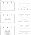
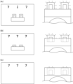
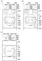
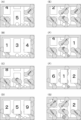
演出操作ユニット400の作用効果について、主に図44乃至図46等を参照して詳細に説明する。図44は、図37の演出操作ユニットの断面図において操作ボタンを押圧した状態を示す説明図である。図45(a)は演出操作ユニットを操作ボタンの中心軸の延びている方向から見た図において操作ボタンの一部を切欠いて操作ボタンの第一ボタン装飾部やボタンフレーム等によって隠そうとしている部位を示す説明図であり、(b)は演出操作ユニットの断面図において操作ボタンの第一ボタン装飾部やボタンフレーム等によって隠そうとしている部位を示す説明図である。図46(a)は演出操作ユニットの外観を前から見た斜視図で示す説明図であり、(b)は演出操作ユニットの外観を操作ボタンの中心軸の延びている方向から見た説明図である。
[3-4f. Effects of production operation unit]
The effects of the
本実施形態の演出操作ユニット400は、遊技盤5の遊技領域5a内に遊技球が打込まれることで変化する遊技状態に応じて演出画像を遊技者に見せることができると共に、遊技者に操作ボタン410の操作をさせて遊技者に提示した演出に遊技者を参加させて楽しませることができるものである。
The
演出操作ユニット400は、全高が、扉枠3の扉枠ベースユニット100における扉枠ベース110の貫通口111の下側の部位の高さと略同じ高さに形成されている。また、演出操作ユニット400は、全幅が、扉枠3の全幅の1/3よりも若干大きく形成されている。演出操作ユニット400は、正面視において、遊技領域5a(扉枠ベース110の貫通口111)の下側で左右方向の中央に配置されている。
The
演出操作ユニット400は、フレームユニット415のフレーム本体416の上部が、皿ユニット320における皿ユニットカバー326の演出操作ユニット取付部326aに取付けられている。演出操作ユニット400は、皿ユニット320に取付けた状態で、底面となる中継基板カバー442の脚部442aの下面が、皿ユニット320の皿ユニットカバー326における底板部326iの上面との間に、隙間が形成されている。つまり、演出操作ユニット400は、皿ユニット320に対して上部のみが取付けられており、吊下げられた状態に取付けられている。
The
また、演出操作ユニット400は、フレームユニット415の前面(フレーム本体416の中央開口部416aの前端内周により形成される面)が、演出操作ユニット取付部326aの前端開口の傾斜面と平行になるように取付けられている。これにより、演出操作ユニット400は、湾曲面状(略球面の一部の形状)に前方へ膨出している透明な操作ボタン410の中心軸線CLが、垂直線に対して63度の角度で、前方へ向かうに従って上方へ移動するように傾斜している。これにより、本パチンコ機1を用いて遊技を行うために本パチンコ機1の前で遊技者が着座すると、遊技者の頭部が皿ユニット320(演出操作ユニット400)の上方に配置されている遊技盤5における遊技領域5aの中央の前方に位置するため、操作ボタン410の中心軸線CLが、遊技者の頭部付近を通ることとなる。従って、遊技者が遊技領域5aから演出操作ユニット400(操作ボタン410)に視線を落すと、操作ボタン410がその正面視(中心軸線CLと平行な方向からの投影視)に可及的に近い状態で見えることとなり、操作ボタン410や操作ボタン410内の扉枠側演出表示装置460等を良好な状態で視認することができる。
In addition, in the
演出操作ユニット400は、操作ボタン410の四つのガイドボス部413cがベースユニット430の四つの保持孔431bに夫々摺動可能に挿入されていると共に、操作ボタンバネ438により前方へ付勢されている。演出操作ユニット400は、通常の状態(操作ボタン410を押圧操作していない状態)では、操作ボタンバネ438の付勢力によって、操作ボタン410のボタンベース413のフランジ部413bの前端が、フレームユニット415のフレーム本体416の後面における中央開口部416a付近の部位に当接している。
The
演出操作ユニット400は、通常の状態では、操作ボタン410におけるボタンフレーム412の内周付近から中央側(中心軸線CL側)が、フレームユニット415におけるフレーム本体416の中央開口部416aから前方へ突出している。換言すると、操作ボタン410における湾曲面状(略球面の一部の形状)に前方へ膨出している透明なボタンレンズ411において、ボタンフレーム412の内周(内側)から前方へ突出している部位が、フレームユニット415のフレーム本体416の中央開口部416aから前方へ突出している(図37等を参照)。
In the normal state, the
因みに、本実施形態では、フレームユニット415におけるフレーム本体416の中央開口部416aの直径が約15cmとされており、操作ボタン410の中心軸線CL方向に対してボタンレンズ411(の前端)がフレームユニット415の前面から約4cm前方へ突出している。
Incidentally, in this embodiment, the diameter of the
通常の状態において、遊技者が演出操作ユニット400の操作ボタン410を押圧操作すると、操作ボタン410は操作ボタンバネ438の付勢力に抗して中心軸線CLに沿って後方へ移動する。そして、操作ボタン410の後端がベースユニット430のユニットベース431の前面に当接すると、後方への移動が規制されて操作ボタン410の後方への移動が停止する。遊技者が操作ボタン410を押圧操作する時には、湾曲面状(略球面の一部の形状)に前方へ膨出しているボタンレンズ411を押圧する。
In a normal state, when the player presses the
この操作ボタン410は、従来のパチンコ機に備えられている演出用の操作ボタンと比較して、外径が非常に大きく形成されているため、ボタンレンズ411の中央部分から離れた周縁付近が押圧される可能性が高い。詳述すると、従来のパチンコ機における演出用の操作ボタンは、その中心軸線が垂直線と略平行に延びるように取付けられているのに対して、本実施形態の演出操作ユニット400の操作ボタン410は、中心軸線CLが垂直線に対して傾いて取付けられているため、遊技者が従来のパチンコ機と同様に上方から操作ボタン410を押圧すると、図44において白抜きの矢印で示すように、操作ボタン410の中心軸線CLから離れた部位を押圧することとなる。
Since the
ところで、従来のパチンコ機における演出用の操作ボタンは、遊技者が押圧操作する面が平坦な面に形成されていることから、押圧操作する部位を平坦な面としたまま操作ボタンを大きくした場合、操作ボタンの中央から外れた部位を押圧すると、その押圧された部位が先に後退するように押圧操作する面が傾いてしまい、操作ボタンが真直ぐに後退することができなくなって、操作ボタンを押圧操作することができなくなる虞がある。 By the way, since the operation buttons for performance in the conventional pachinko machine are formed on a flat surface to be pressed by the player, if the operation buttons are enlarged while the portions to be pressed are flat surfaces, When a part of the operation button deviated from the center is pressed, the surface to be pressed is tilted so that the pressed part retreats first, and the operation button cannot retreat straight. There is a possibility that the pressing operation becomes impossible.
これに対して、本実施形態の演出操作ユニット400の操作ボタン410は、遊技者が押圧操作する部位(ボタンレンズ411)が、前方へ膨出した湾曲面状(略球面の一部の形状)としているため、操作ボタン410の中央から離れた位置を押圧操作した場合、その力が操作ボタン410の全体に分散されて操作ボタン410が傾き難くなり、操作ボタン410が真直ぐに後方へ移動することができる。従って、操作ボタン410の前面側のどの位置を押圧操作しても、操作ボタン410が傾くことなくスムーズに後退することができるため、押圧操作を確実に検知させることができ、操作ボタン410を押圧操作する演出を十分に楽しませることができる。
On the other hand, in the
また、演出操作ユニット400は、装飾基板ユニット420における基板ベース421の前面下部に振動モータ424が取付けられている上で、上述したように、演出操作ユニット400が吊下げられるように上部のみが皿ユニットカバー326の演出操作ユニット取付部326aに取付けられているため、振動モータ424により錘424aを回転させて振動を発生させると、取付けられている部位から最も離れた部位で振動が発生することから、演出操作ユニット400全体を大きく(強く)振動させることができ、演出操作ユニット400に触れている遊技者に対して振動を伝達させることができる。また、振動モータ424を、比較的遊技者が押圧操作し易い位置(図44において白抜きの矢印の位置)の直下に配置しているため、操作ボタン410を押圧操作している遊技者に対して強い振動を伝達させることができ、遊技者を驚かせて演出を楽しませることができる。
In addition, the
更に、演出操作ユニット400は、吊下げられたような状態で皿ユニットカバー326に取付けられていると共に、下面を形成している中継基板カバー442の脚部442aの下面と皿ユニットカバー326の底板部326iの上面との間に隙間が形成されているため、操作ボタン410を強く下方へ押圧したり叩いたりした時に、脚部442aの下面が底板部326iの上面に当接するまでの間、フレームユニット415の取付部416eや皿ユニットカバー326の演出操作ユニット取付部326a等が下方へ撓むことで衝撃を吸収することができる。また、脚部442aの下面が底板部326iの上面に当接した後では、演出操作ユニット400の下方への移動を規制し、フレームユニット415の取付部416eや皿ユニットカバー326の演出操作ユニット取付部326a等に無理な力が作用するのを回避させることができ、演出操作ユニット400等の破損を防止することができる。従って、演出操作ユニット400の操作ボタン410を押圧操作する演出を遊技者に提示した時等に、強い力で操作ボタン410が押圧操作されたり叩かれたりしても、操作ボタン410や演出操作ユニット400等が破損することはないため、破損による遊技の中断を回避させることができ、遊技者の興趣の低下を抑制させることができると共に、破損し難くすることで遊技ホール側の負担の増加を抑制させることができる。
Furthermore, the
なお、上述したように、遊技者が押圧操作する操作ボタン410のボタンレンズ411を、前方へ突出している湾曲面状(略球面の一部の形状)に形成しているため、平板状とした場合と比較して強度・剛性が高くなっていると共に、強く叩かれても、その衝撃をボタンレンズ411全体へ分散させることができ、破損し難くなっている。
As described above, the
また、演出操作ユニット400は、図46に示すように、ボタンレンズ411、フレームサイドレンズ417、フレームトップレンズ418、及び操作ボタン内装飾部材432が、透明な部材で構成されているため、それらの裏面側に形成されている第一ボタン装飾部411a、第二ボタン装飾部411b、第一ボタン内装飾部432f、及び第二ボタン内装飾部432g等の凹凸による装飾が、前方側(遊技者側)から視認することができる。また、それら凹凸の装飾が形成されている部位では、板厚が変化していることら光が複雑に屈折するため、凹凸の装飾が形成されている部位を通しては後側が視認し難くなっている。
46, the
演出操作ユニット400は、操作ボタン410のボタンレンズ411におけるボタンフレーム412の内周から中央側へ延びている第一ボタン装飾部411aを備えているため、この第一ボタン装飾部411aの凹凸の装飾によりボタンレンズ411の内側となる部位の外周縁の部位において後方を見え辛くすることができる。第一ボタン装飾部411aが形成されている部位の後方(中心軸線CL方向の後方)には、操作ボタン410のボタンベース413の本体部413aの内周面と操作ボタン内装飾部材432の周壁部432aの外周面との間の隙間が位置しているが、その隙間の前方に位置する第一ボタン装飾部411aによって前方側(遊技者側)から、操作ボタン内装飾部材432の外周の隙間を見え難くすることができる。これにより、押圧操作可能な操作ボタン410内に、位置が固定されている操作ボタン内装飾部材432を備えても、操作ボタン410の見栄えの悪化を防止することができ、操作ボタン410を見た遊技者が不快感を抱くのを防止することができると共に、透明な操作ボタン410内に操作ボタン内装飾部材432を問題なく配置することができ、操作ボタン410の見栄えを良くすることができる。
Since the
詳述すると、演出操作ユニット400は、操作ボタン410におけるボタンレンズ411の第一ボタン装飾部411a、第二ボタン装飾部411b、及びボタンフレーム412によって、ベースユニット430の操作ボタン内装飾部材432の外周よりも外側で後方側(奥側)にあるユニットベース431や装飾基板ユニット420等が、透明なボタンレンズ411を通して遊技者側から見えないように形成されている。具体的には、図45において、一点鎖線で囲んだクロスハッチの部位が、遊技者側から見えないようにしている。このように、操作ボタン410に第一ボタン装飾部411a、第二ボタン装飾部411b、及びボタンフレーム412等を備えているため、操作ボタン内装飾部材432の外側や奥側を見え難くして隠すことができ、操作ボタン410、ひいては、演出操作ユニット400全体の見栄えを良くすることができる。
More specifically, the
また、演出操作ユニット400は、操作ボタン410におけるボタンレンズ411の第一ボタン装飾部411aが、操作ボタン410の中心軸線CLへ向かうように延びていると共に周方向に列設されているのに対して、操作ボタン410の内側後方に配置されている操作ボタン内装飾部材432の前板部432bに形成されている第二ボタン内装飾部432gが中心軸線CLを中心とした変八角形状に延びていると共に同心円状に列設されているため、図46に示すように、第一ボタン装飾部411aの凹凸線と第二ボタン内装飾部432gの凹凸線とが交差することとなり、幾何学的な装飾を遊技者に見せることができる。
In addition, in the
また、演出操作ユニット400は、第一ボタン装飾部411aと第二ボタン内装飾部432gとが、前後方向(中心軸線CLの延びている方向)に離れているため、第一ボタン装飾部411aと第二ボタン内装飾部432gとによって奥行のある立体的な感じの幾何学模様を遊技者に見せることができ、操作ボタン410内を含む装飾を楽しませることができる。
In addition, in the
更に、演出操作ユニット400では、第一ボタン装飾部411aと第二ボタン内装飾部432gとが前後方向に離れているため、遊技者の目の位置が移動すると、第一ボタン装飾部411aの凹凸線と、第二ボタン内装飾部432gの凹凸線との重なり具合が変化するため、動きのある装飾を遊技者に見せることができ、遊技者を楽しませることができる。
Furthermore, in the
このように、演出操作ユニット400は、操作ボタン410の第一ボタン装飾部411aと操作ボタン内装飾部材432の第二ボタン内装飾部432gとによって、動きがあり立体感のある装飾を遊技者に見せることができるため、遊技者の関心を強く引付けることができ、訴求力の高いパチンコ機1とすることができる。
In this way, the
また、演出操作ユニット400は、操作ボタン410内(ボタンフレーム412の内側)で、操作ボタン内装飾部材432の後方には、操作ボタン左内装飾基板433、操作ボタン右内装飾基板434、操作ボタン上内装飾基板435、及び操作ボタン下内装飾基板436が配置されており、それらの前面に実装されている複数のLEDを発光させることで、操作ボタン410内の操作ボタン内装飾部材432を発光装飾させることができる。つまり、操作ボタン左内装飾基板433、操作ボタン右内装飾基板434、操作ボタン上内装飾基板435、及び操作ボタン下内装飾基板436によって、操作ボタン410内を発光装飾させることができる。これら操作ボタン左内装飾基板433、操作ボタン右内装飾基板434、操作ボタン上内装飾基板435、及び操作ボタン下内装飾基板436の前面に実装されているLEDは、図38に示すように、中心軸線CLの延びている方向から見て、操作ボタン410のボタンベース413における筒状の本体部413aの内側に配置されているため、それらからの光が本体部413aの外側に漏れることはなく、操作ボタン410内のみを良好に発光装飾させることができる。
In addition, in the operation button 410 (inside the button frame 412), behind the operation button inner
また、演出操作ユニット400は、操作ボタン410の外周付近に位置するボタンフレーム412のフレーム開口部412aから臨む第二ボタン装飾部411bの後方に、装飾基板ユニット420における操作ボタン左外装飾基板422の第一LED422a及び操作ボタン右外装飾基板423の第一LED423aが配置されており、それら第一LED422a,423aを発光させることで、操作ボタン410の六つの第二ボタン装飾部411bを発光装飾させることができる。操作ボタン左外装飾基板422の第一LED422a及び操作ボタン右外装飾基板423の第一LED423aは、図38に示すように、操作ボタン410のボタンベース413における筒状の本体部413aと、フレームユニット415のフレーム本体416における筒状の内側筒部416dとの間に位置しており、第一LED422a,423aからの光が本体部413aの内側や内側筒部416dの外側へ漏れることはなく、操作ボタン410の第二ボタン装飾部411bのみを良好に発光装飾させることができる。
In addition, the
更に、演出操作ユニット400は、フレームユニット415におけるフレーム本体416の六つの外周開口部416bから臨むフレームサイドレンズ417の後方に、操作ボタン左外装飾基板422の第二LED422b及び操作ボタン右外装飾基板423の第二LED423bが配置されており、それら第二LED422b,423bを発光させることでフレームサイドレンズ417を発光装飾させることができる。操作ボタン左外装飾基板422の第二LED422b及び操作ボタン右外装飾基板423の第二LED423bは、フレームユニット415のフレーム本体416における筒状の内側筒部416dとフレーム本体416の外周との間に位置しており、第二LED422b,423bからの光が内側筒部416dの内側やフレーム本体416の外側へ漏れることはなく、フレームユニット415のフレームサイドレンズ417のみを良好に発光装飾させることができる。
Furthermore, the
また、演出操作ユニット400は、フレームユニット415のフレームトップレンズ418の後方に、ベースユニット430におけるフレームトップレンズ装飾基板437が配置されており、フレームトップレンズ装飾基板437の前面に実装されている複数のLEDを発光させることで、フレームトップレンズ418を発光装飾させることができる。ベースユニット430におけるユニットベース431のフレームトップレンズ装飾基板437が取付けられている部位の下側からは、フレームトップレンズ418の下端後方付近まで平板状の遮光壁部431cが前方へ突出しており、フレームトップレンズ装飾基板437のLEDからの光が操作ボタン410やフレームサイドレンズ417側へ漏れることはなく、フレームユニット415のフレームトップレンズ418のみを良好に発光装飾させることができる。
In addition, the
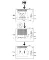
[3-5.扉枠左サイドユニット]
扉枠3の扉枠左サイドユニット530について、主に図47乃至図50を参照して詳細に説明する。図47(a)は扉枠における扉枠左サイドユニットの正面図であり、(b)は扉枠左サイドユニットを前から見た斜視図であり、(c)は扉枠左サイドユニットを後ろから見た斜視図である。図48は扉枠左サイドユニットを分解して前から見た分解斜視図であり、図49は扉枠左サイドユニットを分解して後ろから見た分解斜視図である。図50は図47(a)におけるL-L線で切断した断面図である。扉枠左サイドユニット530は、皿ユニット320の上側で扉枠左サイド上装飾基板161及び扉枠左サイド下装飾基板162(扉枠左サイド装飾基板160)の前側を覆うように扉枠ベースユニット100における貫通口111よりも左側の前面左部に取付けられるものである。扉枠左サイドユニット530は、扉枠ベース110の貫通口111の正面視左側を装飾するためのものである。
[3-5. Door frame left side unit]
The door frame left
扉枠左サイドユニット530は、扉枠ベースユニット100における扉枠ベース110の前面で貫通口111の正面視左側に取付けられる上下に延びた帯板状の左ユニットベース531と、左ユニットベース531の前面に取付けられている透明な帯板状の左ユニット拡散レンズ部材532と、左ユニット拡散レンズ部材532の前方に配置されており前端部に多面体状の装飾を有している透光性を有する左ユニット装飾レンズ部材(図示は省略)と、左ユニット装飾レンズ部材の前側から左ユニットベース531の前面上部に取付けられており前方へ筒枠状に突出していると共に上下に延びている左ユニット上装飾ベース534と、左ユニット装飾レンズ部材の前側から左ユニットベース531の前面下部に取付けられており左ユニット上装飾ベース534よりも短く前方へ枠状に突出している左ユニット下装飾ベース535と、左ユニット上装飾ベース534及び左ユニット下装飾ベース535の前側から左ユニット装飾レンズ部材の前端側を覆うように左ユニットベース531の前側に取付けられている透明な左ユニット装飾カバー536と、左ユニット装飾カバー536の前側に取付けられている複数の飾り部材537と、を備えている。
The door frame left
扉枠左サイドユニット530の左ユニットベース531は、後側が開放された浅い箱状に形成されており、前面に前後に貫通している複数の開口部531aを有している。複数の開口部531aは、図示するように、円形状の穴と、上下に延びた四角形状の穴とがある。左ユニットベース531は、扉枠左サイド装飾基板160(扉枠左サイド上装飾基板161及び扉枠左サイド下装飾基板162)の前面に実装されているLED161a,162aが、複数の開口部531aから前方へ臨むように、扉枠ベース110の前面左側に取付けられる。左ユニットベース531の各開口部531aは、扉枠3に組立てた時に、扉枠左サイド装飾基板160の各LED161a,162aが上下方向の略中央に位置するように夫々形成されている。この左ユニットベース531は、不透光性の部材によって形成されている。
A
また、左ユニットベース531は、上記貫通口111を塞ぐように配設されるガラス板192から手前側に向けて立設された左側反射立壁部538(図5、図23を参照)を有している。この左側反射立壁部538では、平らな面状をなし上記貫通口111に対して臨むように設けられる内側面が光を反射可能な反射面として設けられている。なお、この反射面は、左側反射立壁部538の内側面これ自体を金属や樹脂などの反射用素材から設けることのほか、同内側面に対して反射用シールを取り付けることなどによっても設けることが可能である。そして後述するが、この左側反射立壁部538は、左ユニットベース531によって形成されて、上述した反射立壁部33の一部(左側部分)を担う部分となっている。
In addition, the
左ユニット拡散レンズ部材532は、透明な部材によって形成されており、上拡散レンズ部材532Aと下拡散レンズ部材532Bとに上下に分割されている。左ユニット拡散レンズ部材532は、左ユニットベース531における円形状の開口部531aと対応している正面視円形の円形レンズ部532aと、四角形状の開口部531aと対応している正面視四角形の角形レンズ部532bと、を備えている。扉枠左サイドユニット530は、扉枠3に組立てた状態で、円形レンズ部532a及び角形レンズ部532bの中央の直後に、扉枠左サイド装飾基板160の夫々のLED161a,162aが位置するように形成されている。
The left unit
左ユニット拡散レンズ部材532の円形レンズ部532aは、前面及び後面が滑らかな凸レンズ状に形成されている。この円形レンズ部532aによって、後方に配置されているLED161a,162aからの光を、点状のまま前方へ照射させることができる。この円形レンズ部532aから前方へ照射された光によって、左ユニット装飾レンズ部材の円形装飾部を発光装飾させることができる。
A
左ユニット拡散レンズ部材532の角形レンズ部532bは、前面中央において円錐状に後方へ窪んだ中央拡散反射部532cと、前面における中央拡散反射部532cの外側に形成されている前面拡散レンズ部532dと、後面中央(中央拡散反射部532cの直後)において湾曲面状に後方へ膨出している入力レンズ部532eと、後面における入力レンズ部532eの外側で全体的に入力レンズ部532eから遠ざかるに従って前方へ移動するように傾斜している前方反射部532fと、を備えている。
The
角形レンズ部532bの前面拡散レンズ部532dは、中央拡散反射部532cを中心にした放射状に延びている線により周方向へ分割されている同心円弧状の複数の溝により形成されている。更に詳述すると、前面拡散レンズ部532dは、半径方向に沿って切断した時の断面形状に、溝の部分が後方へ円弧状に窪んでおり、溝と溝の間の山の部分が前方へ円弧状に膨出しており、前面が滑らかな波状に形成されている。また、前面拡散レンズ部532dは、周方向へ分割している放射状に延びた線を境に、溝の部分と山の部分とが周方向へ交互に位置するように形成されている。
The front
角形レンズ部532bの前方反射部532fは、入力レンズ部532eを中心にした放射状に延びている線により周方向へ分割されている同心円弧状の複数の溝により形成されている。これら複数の溝は、後方から前方へ向かってV字状に窪んでおり、最深部が円弧状に形成されている。前方反射部532fは、半径方向に沿って切断した時の断面形状が、溝と溝との間の山の部分が後方へ尖った三角形状に形成されており、鋸状に形成されている。前方反射部532fは、中心から遠ざかるに従って溝及び山の部分が前方へ移動するように形成されている。また、前方反射部532fは、周方向へ分割している放射状に延びた線を境に、溝の部分と山の部分とが周方向へ交互に位置するように形成されている。この周方向へ分割している放射状に延びた線は、前面拡散レンズ部532dにおける放射状に延びた分割線と一致している。
The
この角形レンズ部532bは、扉枠3に組立てた状態で、入力レンズ部532eの直後に、扉枠左サイド装飾基板160の対応しているLED161a,162aが位置している。
When this
角形レンズ部532bは、LED161a,162aから前方へ照射された光が、入力レンズ部532eから角形レンズ部532b内に入力される。この入力レンズ部532eは、後方へ湾曲面状(凸レンズ状)に膨出していることから、LED161a,162aから前方へ広がる光を、前方へ平行に進むように屈折させて、入力された光の略全てを円錐状の中央拡散反射部532cへ導くことができる。そして、中央拡散反射部532cへ導かれた光は、中央拡散反射部532cの傾斜している円錐面により、前後に延びた軸線に対して直角方向(扉枠左サイド装飾基板160の前面と平行な方向)へ拡散するように反射させられ、角形レンズ部532b内をその前面に沿って中央側から外側へ向かって進むこととなる。また、中央拡散反射部532cで反射した光は、角形レンズ部532bの前後方向の厚さ全体に亘って、中央側から外側(中央拡散反射部532cの中心線から遠ざかる方向)へ進む。
Light emitted forward from the
角形レンズ部532b内を扉枠左サイド装飾基板160の前面と略平行に中央側から外側へ向かって反射した光が、鋸状の前方反射部532fに到達すると、前方反射部532fの面により前方側へ反射する。この際に、前方反射部532fは、後面が中央拡散反射部532cから遠ざかるに従って前方へ移動するように傾斜していることから、角形レンズ部532bの前後方向の厚が、中央から遠ざかるに従って薄くなっている(図50を参照)。これにより、中央拡散反射部532cにおいて角形レンズ部532bの前後方向の厚さ全体に亘って外側へ向かって反射している光を、中心側から外側へ向かうに従って、前方反射部532fにより順次前方へ反射させることができる。
When the light reflected outward from the central side in the
そして、前方反射部532fにより前方へ向かって反射させられた光は、前面拡散レンズ部532dを通って角形レンズ部532bから前方へ照射される。この際に、前面拡散レンズ部532dは、断面が波状に形成されているため、前方反射部532fで前方へ向かって反射させられた光を様々な方向へ拡散させることができ、角形レンズ部532bの前面から略均一に光を前方(左ユニット装飾レンズ部材の後面)へ照射させることができる。
The light reflected forward by the
この角形レンズ部532bは、前面拡散レンズ部532d及び前方反射部532fでは、同心円状の複数の溝を放射状に延びた複数の線で分割した上で、分割線を境に同心円弧状の複数の溝を半径方向へずらして、同心円弧状の溝を周方向において交互に配置するようにしているため、角形レンズ部532bの前面から前方へ照射される光が、同心円状の縞模様の濃淡を有した光となるのを回避させることができ、より濃淡の均一な光を前方へ照射させることができる。これにより、左ユニット装飾レンズ部材における角形レンズ部532bの前方の多面装飾部を略均一に発光装飾させることができる。
In the front
図示しない左ユニット装飾レンズ部材は、左ユニット装飾カバー536の前面に沿うように形成されている。左ユニット装飾レンズ部材は、左ユニット拡散レンズ部材532の円形レンズ部532aの前方の位置する部位に形成されている円形装飾部と、左ユニット拡散レンズ部材532の角形レンズ部532bの前方に位置する部位に形成されている多面装飾部と、を備えている。円形装飾部は、前面が窪み前後に短く延びた円柱状の部位の外周に三角形のリブを周方向に複数備えた形状に形成されている。多面装飾部は、上下に延びた直方体の前面に四角錘状の部位が上下方向に複数列設されていると共に、直方体の部位の左右両側に複数の三角形からなる多面体が上下方向に複数列設したような形状に形成されている。円形装飾部及び多面装飾部は、扉枠右サイドユニット550における右ユニット装飾レンズ部材561の円形装飾部561a及び多面装飾部561bと、同じ形状に形成されている。
A left unit decorative lens member (not shown) is formed along the front surface of the left unit
左ユニット装飾レンズ部材は、透明な左ユニット装飾カバー536を通して前方側(遊技者側)から視認することができる。また、左ユニット装飾レンズ部材は、円形装飾部が左ユニット拡散レンズ部材532の円形レンズ部532aから前方へ照射された光により、多面装飾部が左ユニット拡散レンズ部材532の角形レンズ部532bから前方へ照射された光により、夫々発光装飾させられる。
The left unit decorative lens member can be visually recognized from the front side (player side) through the transparent left unit
左ユニット上装飾ベース534は、正面視の形状が上下に延びた四角形で、前後に延びた角筒状に形成されている。左ユニット上装飾ベース534は、外周における下面を構成する部位が、前端側から後端側へ向かうに従って下方へ突出するように傾斜しており、その部位の下部が前後に貫通している。この左ユニット上装飾ベース534は、不透光性の部材によって形成されている。
The left unit upper
左ユニット下装飾ベース535は、正面視の形状が、上方へ開放されているコ字状に形成されている。左ユニット下装飾ベース535は、前端における上下方向略中央から上側が、上方へ向かうに従って後方へ移動するように後端まで傾斜している。この左ユニット下装飾ベース535は、不透光性の部材によって形成されている。
The left unit lower
左ユニット装飾カバー536は、扉枠左サイドユニット530の全高に亘って上下に延びている。左ユニット装飾カバー536は、上下方向の中間部が後方へ凹むように屈曲しており、左ユニット上装飾ベース534の前端に沿うように下部が後方へ折れ曲がっているく字状の部位と、左ユニット下装飾ベース535の前端に沿うように上部が後方へ折れ曲がっているく字状の部位と、上側のく字状の部位の下端と下側のく字状の部位の上端とを結んでいる直線状の部位と、で構成されている。
The left unit
左ユニット装飾カバー536は、上下両端が左ユニット上装飾ベース534の前面と、左ユニット下装飾ベース535の前面とに夫々取付けられる。この左ユニット装飾カバー536は、透明な部材によって形成されており、後側に配置されている左ユニット装飾レンズ部材を前方側から視認することができる。
The left unit
飾り部材537は、上下に短く延びており、上下方向へ所定間隔で左ユニット装飾カバー536の前面に取付けられている。飾り部材537は、不透光性の部材によって形成されている。
The
[3-6.扉枠右サイドユニット]
扉枠3の扉枠右サイドユニット550について、主に図51乃至図55等を参照して詳細に説明する。図51(a)は扉枠における扉枠右サイドユニットの正面図であり、(b)は扉枠右サイドユニットを前から見た斜視図であり、(c)は扉枠右サイドユニットを後ろから見た斜視図である。図52は扉枠右サイドユニットを分解して前から見た分解斜視図であり、図53は扉枠右サイドユニットを分解して後ろから見た分解斜視図である。図54は、図51(a)におけるM-M線で切断した断面図である。図55(a)は図51(a)におけるN-N線で切断した断面図であり、(b)は図51(a)におけるO-O線で切断した断面図である。扉枠右サイドユニット550は、皿ユニット320の上側で扉枠ベースユニット100の扉枠ベース110の前面における貫通口111の右側に取付けられるものである。
[3-6. Door frame right side unit]
The door frame
扉枠右サイドユニット550は、扉枠ベースユニット100における扉枠ベース110の前面で貫通口111の正面視右側に取付けられる上下に延びた箱状の右ユニットベース551と、右ユニットベース551の前面に取付けられている扉枠右サイド装飾基板552と、扉枠右サイド装飾基板552の前側で右ユニットベース551の前面における正面視中央より左側に取付けられており上下方向及び前後方向に延びている透明平板状の右ユニット左拡散レンズ部材553と、右ユニット左拡散レンズ部材553の左側面に取付けられており装飾が施されているシート状の右ユニット左装飾部材554と、右ユニット左装飾部材554の左側を覆うように右ユニット左拡散レンズ部材553に取付けられている透明平板状の右ユニット左カバー555と、を備えている。
The door frame
また、扉枠右サイドユニット550は、扉枠右サイド装飾基板552の前側且つ右ユニット左拡散レンズ部材553の正面視右側で右ユニットベース551の前面における正面視中央より右側と右ユニット左拡散レンズ部材553とに取付けられており上下方向及び前後方向に延びている透明平板状の右ユニット右拡散レンズ部材556と、右ユニット右拡散レンズ部材556の右側面に取付けられており装飾が施されているシート状の右ユニット右装飾部材557と、右ユニット右装飾部材557の右側を覆うように右ユニット右拡散レンズ部材556に取付けられている透明平板状の右ユニット右カバーと558、を備えている。
In addition, the door frame
更に、扉枠右サイドユニット550は、右ユニット左拡散レンズ部材553と右ユニット右拡散レンズ部材556との間に配置されており前方及び右方が開放された上下方向及び前後方向に延びた浅い箱状で不透光性の右ユニット左遮光部材559と、右ユニット右拡散レンズ部材556の左側で右ユニット左遮光部材559の開放されている右側を閉鎖するように取付けられている不透光性で平板状の右ユニット右遮光部材560と、を備えている。
Further, the door frame
また、扉枠右サイドユニット550は、右ユニット左拡散レンズ部材553及び右ユニット右拡散レンズ部材556の前端に取付けられており前端部に多面体状の装飾を有している透光性を有する右ユニット装飾レンズ部材561と、右ユニット装飾レンズ部材561の左右両側と右ユニット左拡散レンズ部材553及び右ユニット右拡散レンズ部材556の前端側を覆うように右ユニットベース551の前面に取付けられている前後に貫通した枠状の右ユニット装飾ベース562と、右ユニット装飾ベース562の前端開口を閉鎖するように右ユニット装飾ベース562の前側に取付けられている透明な右ユニットカバー563と、右ユニットカバー563の前側に取付けられている複数の飾り部材564と、を備えている。なお、図示は省略するが、扉枠右サイドユニット550は、右ユニットベース551を上下に貫通するように取付けられ、扉枠ベースユニット100の扉本体中継基板と、扉枠トップユニット570の扉枠トップユニット中継基板589とを接続するための接続ケーブルを備えている。
The door frame
扉枠右サイドユニット550の右ユニットベース551は、正面視の形状が上下に長く延びた四角形で、前後に短く角筒状に延びており、前後方向の中央付近が閉鎖された箱状に形成されている。この右ユニットベース551は、不透光性の部材によって形成されている。
The
また、右ユニットベース551は、上記貫通口111を塞ぐように配設されるガラス板192から手前側に向けて立設された右側反射立壁部568(図6、図24を参照)を有している。この右側反射立壁部568では、平らな面状をなし上記貫通口111に対して臨むように設けられる内側面が光を反射可能な反射面として設けられている。なお、この反射面は、左側反射立壁部538の内側面と同様、右側反射立壁部568の内側面これ自体を金属や樹脂などの反射用素材から設けることのほか、同内側面に対して反射用シールを取り付けることなどによっても設けることが可能である。そして後述するが、この右側反射立壁部568は、右ユニットベース551によって形成されて、上述した反射立壁部33の一部(右側部分)を担う部分となっている。
In addition, the
扉枠右サイド装飾基板552は、上下に延びた帯板状に形成されている。扉枠右サイド装飾基板552は、前面における左右方向中央より左側に実装されている複数の左LED552aと、前面における左右方向中央より右側に実装されている右LED552bと、前面における左右方向中央に実装されている複数の中LED552cと、を備えている。扉枠右サイド装飾基板552の左LED552aは、右ユニット左拡散レンズ部材553を介して右ユニット左装飾部材554を発光装飾させためのものである。また、右LED552bは、右ユニット右拡散レンズ部材556を介して右ユニット右装飾部材557を発光装飾させるためのものである。中LED552cは、右ユニット装飾レンズ部材561を発光装飾させるためのものである。
The door frame right side
扉枠右サイド装飾基板552は、前後両面が白色に形成されている。扉枠右サイド装飾基板552は、上側の扉枠右サイド上装飾基板552Aと、下側の扉枠右サイド下装飾基板552Bとに上下に分割されている。図示は省略するが、扉枠右サイド下装飾基板552Bは、扉枠ベースユニット100の扉本体中継基板に接続されており、扉枠右サイド上装飾基板552Aは、扉枠右サイド下装飾基板552Bに接続されている。
The door frame right side
右ユニット左拡散レンズ部材553は、上下方向及び前後方向に延びた平板状の本体部553aと、本体部553aの後辺から正面視右方へ短く平板状に突出している後壁部553bと、後壁部553bの正面視右端側から左方へ四角形状に切欠かれており上下方向に所定間隔で複数形成されている切欠部553cと、本体部553aの正面視左面側において右ユニット左装飾部材554を収容可能に浅く窪んでいる収容凹部553dと、本体部553aの後端面から後方へ突出しており上下方向に複数備えられている入力レンズ部553eと、本体部553aの正面視右面側において各入力レンズ部553eが上下方向の中央となるように上下方向に複数配置されている側面反射部553fと、を備えている。
The right unit left diffusing
右ユニット左拡散レンズ部材553の本体部553aは、側面視の形状が、上下に延びた四角形の前端側の上隅がC面取り状に斜めに切欠かれていると共に、下辺が前方へ向かうに従って上方へ移動するように傾斜している形状に形成されている。また、本体部553aは、図55に示すように、後端側から前方へ向かうに従って、正面視右方へ移動するように全体が、扉枠右サイド装飾基板552の前面の垂直線に対して僅かに傾斜している。本体部553aの前端は、扉枠3に組立てた状態で、扉枠左サイドユニット530の前端よりも大きく前方へ突出している。
The
後壁部553bは、扉枠右サイドユニット550に組立てた状態で、その右端が、右ユニットベース551の左右方向略中央まで延びている。この後壁部553bの右端には、右ユニット右拡散レンズ部材556の後壁部556bの左端が当接する。
The right end of the
複数の切欠部553cは、上下方向へ所定間隔で複数形成されており、一部が扉枠右サイド装飾基板552の中LED552cと対応している。扉枠右サイドユニット550に組立てた状態では、複数の切欠部553cから扉枠右サイド装飾基板552の中LED552cが前方に臨んでおり、複数の中LED552cによって右ユニット装飾レンズ部材561を良好に発光装飾させることができる。
A plurality of
収容凹部553dは、底面が平坦面に形成されており、外周の形状が右ユニット左装飾部材554の外形形状に略一致している。これにより、右ユニット左装飾部材554を収容することができる。
The
複数の入力レンズ部553eは、本体部553aの後端面から上下方向へ所定間隔で後方へ突出している。具体的には、右ユニット左拡散レンズ部材553を上下方向へ6等分した時の夫々の上下方向略中央に形成されている。入力レンズ部553eは、詳細な図示は省略するが、上下に延びた四角形が後方へ突出した直方体の部位と、その直方体の部位の後面から球面状に湾曲するように前方へ向かって窪んでいる部位と、を有している。これら入力レンズ部553eは、扉枠右サイドユニット550に組立てた状態で、扉枠右サイド装飾基板552の左LED552aの直前に夫々位置している。これにより、左LED552aからの光を、本体部553a内で広く拡散されるように入力させることができる。
The plurality of
側面反射部553fは、上下方向に複数(六つ)備えられている。各側面反射部553fは、入力レンズ部553eを中心にした放射状に延びている線により周方向へ分割されている同心円弧状の複数の溝により形成されている。これら同心円弧状の複数の溝は、夫々の溝において、入力レンズ部553eに近い側の面が本体部553aの面に対して傾斜していると共に、入力レンズ部553eから遠い側の面が本体部553aの面に対して垂直に延びており、最深部が円弧状に形成されている。側面反射部553fは、入力レンズ部553eを中心とした半径方向に切断した時に断面形状が、溝と溝との間の山の部分が中心側へ向くような尖った三角形状に形成されており、全体が鋸状に形成されている。また、側面反射部553fは、複数の同心円弧状の溝を周方向に分割している放射状の線を境に、溝の部分と山の部分とが周方向へ交互に配置されるように形成されている。
A plurality (six) of the
この右ユニット左拡散レンズ部材553は、扉枠右サイド装飾基板552の左LED552aから前方へ照射された光が、入力レンズ部553eの後面から右ユニット左拡散レンズ部材553の本体部553a内へと入射される。この入力レンズ部553eの後端は、前方へ向かって湾曲状に窪んでいることから、その湾曲面により左LED552aからの光が広がるように屈折し、本体部553a内において、各入力レンズ部553eを中心として前方へ向かって放射状に拡散することとなる。
In this right unit left
本体部553aは、全体が前方へ向かうに従って正面視右方へ移動するように、扉枠右サイド装飾基板552の前面から垂直に延びている線に対して僅かに傾斜しているため、扉枠右サイド装飾基板552の前面に実装されている左LED552aから照射されて入力レンズ部553eから本体部553a内に入射された光が、本体部553a内の平坦な左面に当ることとなる。しかしながら、左LED552aからの直接光は、本体部553aの左面に対する入射角度の関係で、本体部553aの左面から外部へ放射されることはなく、左面の内面で側面反射部553f側へ反射することとなる。
The
そして、入力レンズ部553eから本体部553a内に前方へ向かって入射された光は、鋸状の側面反射部553fに当ることで正面視左方へ反射し、本体部553aの左面から外方へ照射されることとなる。なお、本体部553aの右面(側面反射部553f)からも外方(正面視右方)へ光が照射されるが、本体部553aの右側に配置されている右ユニット左遮光部材559が白色の部材とされているため、右ユニット左遮光部材559の左面が明るく照らされることとなり、右ユニット左遮光部材559で反射した間接光が本体部553aを通って左方側へ照射されることとなる。従って、本体部553aの左面からは、本体部553a内において側面反射部553fにより左方へ反射された光と、側面反射部553fから右方へ照射されて右ユニット左遮光部材559の左面で左方へ反射して本体部553aを通過した光とが、左方へ照射されるため、本体部553aの左側に取付けられている右ユニット左装飾部材554を良好な明るさで発光装飾させることができる。
The light incident forward into the
また、側面反射部553fでは、同心円状の複数の溝を放射状に延びた複数の線で分割した上で、分割線を境に同心円弧状の複数の溝を半径方向へずらして、同心円弧状の溝を周方向において交互に配置するようにしているため、本体部553aの左面から外方(左方)へ照射される光が、同心円状の縞模様の濃淡を有した光となるのを回避させることができ、より濃淡の均一な光を左方へ照射させることができる。これにより、本体部553aの左面の収容凹部553dに収容されている右ユニット左装飾部材554を、略均一に発光装飾させることができる。
In the
なお、右ユニット左拡散レンズ部材553は、透明な部材により形成されているため、本体部553aの正面視左側(収容凹部553dが形成されている側)から、反対側に形成されている側面反射部553fの複数の同心円弧状の溝と放射状に延びている線とからなる模様を視認することができる。従って、右ユニット左装飾部材554において、透明な部分を形成した場合、その透明な部分を通して右ユニット左拡散レンズ部材553の側面反射部553fの模様が視認できることとなり、右ユニット左装飾部材554における透明な部分を側面反射部553fによって装飾することができる。
Since the right unit left diffusing
右ユニット左装飾部材554は、薄いシート状に形成されており、パチンコ機1のメーカーロゴや、遊技盤5において遊技者に提示する演出のコンセプトに沿ったロゴ、等の装飾が、透光性を有するように施されている。右ユニット左カバー555は、扉枠右サイドユニット550に組立てた状態で、右ユニット左装飾部材554の外面を保護している。
The right unit left
右ユニット右拡散レンズ部材556は、右ユニット左拡散レンズ部材553とは略左右対称に形成されており、同じような構成を備えている。詳述すると、右ユニット右拡散レンズ部材556は、上下方向及び前後方向に延びた平板状の本体部556aと、本体部556aの後辺から正面視左方へ短く平板状に突出している後壁部556bと、後壁部556bの正面視左端側から右方へ四角形状に切欠かれており上下方向に所定間隔で複数形成されている切欠部556cと、本体部556aの正面視右面側において右ユニット右装飾部材557を収容可能に浅く窪んでいる収容凹部556dと、本体部556aの後端面から後方へ突出しており上下方向に複数備えられている入力レンズ部556eと、本体部556aの正面視左面側において各入力レンズ部556eが上下方向の中央となるように上下方向に複数配置されている側面反射部556fと、を備えている。
The right unit right diffusing
右ユニット右拡散レンズ部材556の本体部556aは、側面視の形状が、上下に延びた四角形の前端側の上隅がC面取り状に斜めに切欠かれていると共に、下辺が前方へ向かうに従って上方へ移動するように傾斜している形状に形成されており、右ユニット左拡散レンズ部材553の本体部553aと外形が略同じ形状に形成されている。また、本体部556aは、図55に示すように、後端側から前方へ向かうに従って、正面視左方へ移動するように全体が、扉枠右サイド装飾基板552の前面の垂直線に対して僅かに傾斜している。本体部556aの前端は、扉枠3に組立てた状態で、扉枠左サイドユニット530の前端よりも大きく前方へ突出している。
The
後壁部556bは、扉枠右サイドユニット550に組立てた状態で、その左端が、右ユニットベース551の左右方向略中央まで延びている。この後壁部556bの左端には、右ユニット左拡散レンズ部材553の後壁部553bの右端が当接する。
The left end of the
複数の切欠部556cは、上下方向へ所定間隔で複数形成されており、一部が扉枠右サイド装飾基板552の中LED552cと対応している。これら複数の切欠部556cは、右ユニット左拡散レンズ部材553の複数の切欠部553cと対応した位置に形成されている。従って、扉枠右サイドユニット550に組立てた状態では、右ユニット左拡散レンズ部材553の切欠部553cと、右ユニット右拡散レンズ部材556の切欠部556cとで、前後に貫通している四角い開口部が形成され、その開口部から扉枠右サイド装飾基板552の中LED552cが前方に臨み、複数の中LED552cによって右ユニット装飾レンズ部材561を良好に発光装飾させることができる。
A plurality of
収容凹部556dは、底面が平坦面に形成されており、外周の形状が右ユニット右装飾部材557の外形形状に略一致している。これにより、右ユニット右装飾部材557を収容することができる。
The
複数の入力レンズ部556eは、本体部556aの後端面から上下方向へ所定間隔で後方へ突出している。具体的には、右ユニット右拡散レンズ部材556を上下方向へ6等分した時の夫々の上下方向略中央に形成されている。入力レンズ部556eは、詳細な図示は省略するが、上下に延びた四角形が後方へ突出した直方体の部位と、その直方体の部位の後面から球面状に湾曲するように前方へ向かって窪んでいる部位と、を有している。これら入力レンズ部556eは、扉枠右サイドユニット550に組立てた状態で、扉枠右サイド装飾基板552の右LED552bの直前に夫々位置している。これにより、右LED552bからの光を、本体部556a内で広く拡散されるように入力させることができる。
The plurality of
側面反射部556fは、上下方向に複数(六つ)備えられている。各側面反射部556fは、入力レンズ部556eを中心にした放射状に延びている線により周方向へ分割されている同心円弧状の複数の溝により形成されている。これら同心円弧状の複数の溝は、夫々の溝において、入力レンズ部556eに近い側の面が本体部556aの面に対して傾斜していると共に、入力レンズ部556eから遠い側の面が本体部556aの面に対して垂直に延びており、最深部が円弧状に形成されている。側面反射部556fは、入力レンズ部556eを中心とした半径方向に切断した時に断面形状が、溝と溝との間の山の部分が中心側へ向くような尖った三角形状に形成されており、全体が鋸状に形成されている。また、側面反射部556fは、複数の同心円弧状の溝を周方向に分割している放射状の線を境に、溝の部分と山の部分とが周方向へ交互に配置されるように形成されている。
A plurality (six) of the
この右ユニット右拡散レンズ部材556は、扉枠右サイド装飾基板552の右LED552bから前方へ照射された光が、入力レンズ部556eの後面から右ユニット右拡散レンズ部材556の本体部556a内へと入射される。この入力レンズ部556eの後端は、前方へ向かって湾曲状に窪んでいることから、その湾曲面により右LED552bからの光が広がるように屈折し、本体部556a内において、各入力レンズ部556eを中心として前方へ向かって放射状に拡散することとなる。
In this right unit right
本体部556aは、全体が前方へ向かうに従って正面視左方へ移動するように、扉枠右サイド装飾基板552の前面から垂直に延びている線に対して僅かに傾斜しているため、扉枠右サイド装飾基板552の前面に実装されている右LED552bから照射されて入力レンズ部556eから本体部556a内に入射された光が、本体部556a内の平坦な右面に当ることとなる。しかしながら、右LED552bからの直接光は、本体部556aの右面に対する入射角度の関係で、本体部556aの左面から外部へ放射されることはなく、右面の内面で側面反射部556f側へ反射することとなる。
The
そして、入力レンズ部556eから本体部556a内に前方へ向かって入射された光は、鋸状の側面反射部556fに当ることで正面視右方へ反射し、本体部556aの右面から外方へ照射されることとなる。なお、本体部556aの右面(側面反射部556f)からも外方(正面視左方)へ光が照射されるが、本体部556aの左側に配置されている右ユニット右遮光部材560が白色の部材とされているため、右ユニット右遮光部材560の右面が明るく照らされることとなり、右ユニット右遮光部材560で反射した間接光が本体部556aを通って右方側へ照射されることとなる。従って、本体部556aの右面からは、本体部556a内において側面反射部556fにより右方へ反射された光と、側面反射部556fから左方へ照射されて右ユニット右遮光部材560の右面で右方へ反射して本体部556aを通過した光とが、右方へ照射されるため、本体部556aの右側に取付けられている右ユニット右装飾部材557を良好な明るさで発光装飾させることができる。
The light incident forward into the
また、側面反射部556fでは、同心円状の複数の溝を放射状に延びた複数の線で分割した上で、分割線を境に同心円弧状の複数の溝を半径方向へずらして、同心円弧状の溝を周方向において交互に配置するようにしているため、本体部556aの右面から外方(右方)へ照射される光が、同心円状の縞模様の濃淡を有した光となるのを回避させることができ、より濃淡の均一な光を右方へ照射させることができる。これにより、本体部556aの右面の収容凹部556dに収容されている右ユニット右装飾部材557を、略均一に発光装飾させることができる。
In the
なお、右ユニット右拡散レンズ部材556は、透明な部材により形成されているため、本体部556aの正面視右側(収容凹部556dが形成されている側)から、反対側に形成されている側面反射部556fの複数の同心円弧状の溝と放射状に延びている線とからなる模様を視認することができる。従って、右ユニット右装飾部材557において、透明な部分を形成した場合、その透明な部分を通して右ユニット右拡散レンズ部材556の側面反射部556fの模様が視認できることとなり、右ユニット右装飾部材557における透明な部分を側面反射部556fによって装飾することができる。
In addition, since the right unit right
右ユニット右装飾部材557は、薄いシート状に形成されており、パチンコ機1のメーカーロゴや、遊技盤5において遊技者に提示する演出のコンセプトに沿ったロゴ、等の装飾が、透光性を有するように施されている。右ユニット右カバー558は、扉枠右サイドユニット550に組立てた状態で、右ユニット右装飾部材557の外面を保護している。右ユニット右装飾部材557及び右ユニット右カバー558は、右ユニット左装飾部材554及び右ユニット左カバー555とは、略左右対称に形成されている。また、右ユニット左装飾部材554と右ユニット右装飾部材557とに施される装飾は、同じ装飾であっても良いし、異なる装飾であっても良い。
The right
右ユニット左遮光部材559は、側面視の形状が右ユニット左拡散レンズ部材553及び右ユニット右拡散レンズ部材556の側面視の形状と、略同じ形状に形成されている。右ユニット左遮光部材559は、前方及び右方が開放された浅い箱状に形成されている。右ユニット左遮光部材559は、上下方向及び前後方向に延びた平板状の本体部559aと、本体部559aの後辺から正面視右方へ短く平板状に突出している後壁部559bと、後壁部559bの正面視右端側から左方へ四角形状に切欠かれており上下方向に所定間隔で複数形成されている切欠部559cと、本体部559aの右面から右方へ延出していると共に後壁部559bから本体部559aの前端まで延びている平板状の複数の補強部559dと、を備えている。
The right unit left
右ユニット左遮光部材559の本体部559aは、側面視の形状が、上下に延びた四角形の前端側の上隅がC面取り状に斜めに切欠かれていると共に、下辺が前方へ向かうに従って上方へ移動するように傾斜している形状に形成されており、右ユニット左拡散レンズ部材553及び右ユニット右拡散レンズ部材556の本体部553a,556aと外形が略同じ形状に形成されている。
The
後壁部559bは、扉枠右サイドユニット550に組立てた状態で、その左端が、右ユニットベース551の左右方向略中央よりも右側へ延出している。この後壁部559bの右端には、右ユニット右遮光部材560の左面が当接する。
The left end of the
複数の切欠部559cは、上下方向へ所定間隔で複数形成されており、一部が扉枠右サイド装飾基板552の中LED552cと対応している。これら複数の切欠部559cは、右ユニット左拡散レンズ部材553及び右ユニット右拡散レンズ部材556の複数の切欠部553c,556cと対応した位置に形成されている。従って、扉枠右サイドユニット550に組立てた状態では、複数の切欠部559cから扉枠右サイド装飾基板552の中LED552cが前方に臨み、複数の中LED552cによって右ユニット装飾レンズ部材561を良好に発光装飾させることができる。
A plurality of
複数の補強部559dは、左右の幅と略同じ高さで上下方向に離間している一対の補強部559dを一組として、上下方向へ所定距離離間して三組備えられている。各組の補強部559dは、右ユニットカバー563に取付けられる飾り部材564の後方となる位置に夫々形成されている。これら複数の補強部559dによって、扉枠右サイドユニット550の全体の強度・剛性を高めている。
The plurality of reinforcing
右ユニット右遮光部材560は、側面視の形状が、上下に延びた四角形の前端側の上隅がC面取り状に斜めに切欠かれていると共に、下辺が前方へ向かうに従って上方へ移動するように傾斜している形状に形成されており、右ユニット左遮光部材559における本体部559aと略同じ形状に形成されている。右ユニット右遮光部材560は、扉枠右サイドユニット550に組立てた状態で、浅い箱状に形成されている右ユニット左遮光部材559の右方へ開放されている右側開口を閉鎖している。
The right
右ユニット左遮光部材559及び右ユニット右遮光部材560は、白色の部材によって夫々形成されている。右ユニット左遮光部材559及び右ユニット右遮光部材560は、図55に示すように、扉枠右サイドユニット550に組立てた状態で、夫々の本体部559a及び右ユニット右遮光部材560が、右ユニット左拡散レンズ部材553及び右ユニット右拡散レンズ部材556の本体部553a,556aと近接するように配置されている。これにより、右ユニット左遮光部材559の本体部559a及び右ユニット右遮光部材560同士が左右方向に離間しており、左右方向に所定幅で上下方向及び前後方向に延びた空間を形成している。この右ユニット左遮光部材559の本体部559a及び右ユニット右遮光部材560同士の間に形成された空間を通して、扉枠右サイド装飾基板552の中LED552cから前方へ放射された光が、右ユニット装飾レンズ部材561の後側に照射される。
The right unit left
また、右ユニット左遮光部材559及び右ユニット右遮光部材560は、不透光性の部材によって形成されており、扉枠右サイド装飾基板552における左LED552a、中LED552c、右LED552bから夫々前方へ照射される光が、互いに干渉するのを防止しており、右ユニット左装飾部材554、右ユニット右装飾部材557、及び右ユニット装飾レンズ部材561を、夫々対応している左LED552a、右LED552b、及び中LED552cによってのみ発光装飾させることができる。
In addition, the right unit left
更に、右ユニット左遮光部材559及び右ユニット右遮光部材560は、三組の補強部559dによって内部空間が上下方向へ四つに分割されているため、分割された夫々の空間の後側に配置されている扉枠右サイド装飾基板552の中LED552cによって、各空間同士の間で光が干渉しないようにすることができ、右ユニット装飾レンズ部材561の各空間の前方に位置している部位を、夫々独立して発光装飾させることができる。つまり、扉枠右サイドユニット550の前端側において、上下方向へ複数(四つ)の領域に分割して夫々を独立して発光装飾させることができる。
Further, the right unit left
右ユニット装飾レンズ部材561は、右ユニット左拡散レンズ部材553及び右ユニット右拡散レンズ部材556の前端形状に沿った形状に形成されている。右ユニット装飾レンズ部材561は、正面視において円形状に形成されている円形装飾部561aと、上下に延びており複数の多面体が形成されている多面装飾部561bと、を備えている。円形装飾部561aは、前面が窪み前後に短く延びた円柱状の部位の外周に三角形のリブを周方向に複数備えた形状に形成されている。多面装飾部561bは、上下に延びた直方体の前面に四角錘状の部位が上下方向に複数列設されていると共に、直方体の部位の左右両側に複数の三角形からなる多面体が上下方向に複数列設したような形状に形成されている。
The right unit
詳述すると、右ユニット装飾レンズ部材561は、複数の円形装飾部561a及び多面装飾部561bが、右ユニット左遮光部材559における三組の補強部559dによって四つに分割されている夫々の空間の前方に位置する部位において、上から三つの部位では、上下方向の中央に配置された円形装飾部561aの上下両側に一つずつ多面装飾部561bが配置され、最も下側の部位では、多面装飾部561bのみが配置されるように形成されている。
More specifically, the right unit
右ユニット装飾レンズ部材561は、右ユニット左拡散レンズ部材553及び右ユニット右拡散レンズ部材556の前端に取付けられている。右ユニット装飾レンズ部材561は、透明な右ユニットカバー563を通して前方側(遊技者側)から視認することができる。この右ユニット装飾レンズ部材561は、後方に配置されている扉枠右サイド装飾基板552の中LED552cによって、発光装飾させられる。
The right unit
右ユニット装飾ベース562は、前後方向に貫通している筒枠状に形成されている。右ユニット装飾ベース562は、右ユニット左拡散レンズ部材553及び右ユニット右拡散レンズ部材556の前端及び上端の形状に沿った形状に形成されている。右ユニット装飾ベース562は、右ユニット左拡散レンズ部材553及び右ユニット右拡散レンズ部材556における前端付近の左右両外側と、右ユニット装飾レンズ部材561の左右両側を被覆可能に形成されている。扉枠右サイドユニット550に組立てた状態で、右ユニット装飾ベース562の前端よりも、右ユニット装飾レンズ部材561の前端が、僅かに前方へ突出している。この右ユニット装飾ベース562は、不透光性の部材によって形成されている。
The right
右ユニットカバー563は、右ユニット装飾ベース562の前端開口を閉鎖可能に形成されている。この右ユニットカバー563は、透明な部材によって形成されており、後側に配置されている右ユニット装飾レンズ部材561を前方側から視認することができる。
The
飾り部材564は、上下に短く延びており、上下方向へ所定間隔で右ユニットカバー563の前面に取付けられている。飾り部材564は、不透光性の部材によって形成されている。三つの飾り部材564は、右ユニットカバー563(右ユニット装飾レンズ部材561)を上下方向へ四つに分割している。
The
扉枠右サイドユニット550は、扉枠3に組立てた状態で、扉枠左サイドユニット530よりも前方へ大きく板状に突出しており、皿ユニット320の上皿321前端よりも若干前方へ突出している。扉枠右サイドユニット550は、突出した左右両面側に備えられている右ユニット左装飾部材554及び右ユニット右装飾部材557と、前端に備えられている右ユニット装飾レンズ部材561と、を夫々独立して発光装飾させることができる。
When the door frame
扉枠右サイドユニット550は、板状で前方へ大きく突出していることから、本パチンコ機1を遊技ホールの島設備に設置すると、扉枠右サイドユニット550が右側に隣接しているパチンコ機との間で仕切りのような作用効果を発揮することができる。これにより、本パチンコ機1で遊技する遊技者に対して、個室で遊技しているように錯覚させることができ、周りの他の遊技者に気兼ねすることなくリラックスした雰囲気で遊技を行わせることができる。
Since the door frame
また、扉枠右サイドユニット550は、前方へ大きく突出していることから、パチンコ機1が並んだ状態で設置される遊技ホールでは、本パチンコ機1の前方に位置していなくても、島設備に沿った横方向からでも視認することができ、多数のパチンコ機が列設されている遊技ホール内において本パチンコ機1を目立たせることができる。従って、扉枠右サイドユニット550の左右両面側の右ユニット左装飾部材554や右ユニット右装飾部材557を発光装飾させると、本パチンコ機1の前方近辺に位置していなくても、遠くから本パチンコ機1の存在を知らせることができ、遊技者に対する訴求力の高いパチンコ機1とすることができる。
In addition, since the door frame
更に、扉枠右サイドユニット550において、本パチンコ機1で球詰りやエラー等の不具合が発生した時に、左右両面側の右ユニット左装飾部材554や右ユニット右装飾部材557、及び右ユニット装飾レンズ部材561等を特有な態様で発光装飾させるようにすることで、遊技ホールの係員に対して、不具合の発生を直ちに知らせて認識させることができ、不具合に対して素早い対応ができるようになることから、遊技者の遊技の中断を早期に解決させることができ、遊技者が苛立ちを覚えて遊技に対する興趣の低下を抑制させることができる。
Furthermore, in the door frame
[3-7.扉枠トップユニット]
扉枠3の扉枠トップユニット570について、主に図56乃至図59等を参照して詳細に説明する。図56(a)は扉枠における扉枠トップユニットの正面図であり、(b)は扉枠トップユニットを前から見た斜視図であり、(c)は扉枠トップユニットを後ろから見た斜視図である。図57は扉枠トップユニットを分解して前から見た分解斜視図であり、図58は扉枠トップユニットを分解して後ろから見た分解斜視図である。図59は、図56におけるP-P線で切断した断面図である。扉枠トップユニット570は、扉枠左サイドユニット530及び扉枠右サイドユニット550の上側で扉枠ベースユニット100の扉枠ベース110の前面における貫通口111の上側に取付けられるものである。
[3-7. Door frame top unit]
The door
扉枠トップユニット570は、扉枠ベースユニット100の扉枠ベース110の前面における貫通口111の上側で左右方向の中央に取付けられる中央ベース571と、中央ベース571の左右両側に取付けられていると共に扉枠ベース110の前面に取付けられる一対のサイドベース572と、一対のサイドベース572の前面に夫々取付けられている一対の上部スピーカ573と、左右に延びていると共に左右方向中央が前方へ突出しており後方が開放されている箱状で一対の上部スピーカ573の前方位置で前後に夫々貫通している一対の開口部574a、及び一対の開口部574aよりも左右方向中央寄りの位置から中央付近まで夫々延びていると共に前後方向に夫々貫通しており上下に離間している複数(左右夫々三つ)のスリット574bを有しており中央ベース571及び一対のサイドベース572の前側に取付けられているユニット本体271と、一対の上部スピーカ573の前側に夫々配置されており一対の開口部574aを閉鎖するようにユニット本体271の後側に取付けられているパンチングメタルからなるスピーカカバー575と、を備えている。
The door
ここで、図示は割愛するが、一対のサイドベース572(左側サイドベース572a,右側サイドベース572b)では、開口窓の設けられる側に向けてのみ開口された内部空間をそれぞれ有しており、これらの内部空間において、開口窓の外周内へと外周外から発光するように設けられる上記外周外発光部34(左側外周外発光部34a,右側外周外発光部34b)と、開口窓の外周内からの光をその外周外で検出する外周外光検出部35(左側外周外光検出部35a,右側外周外光検出部35b)とがそれぞれ設けられる構造となっている。
Here, although illustration is omitted, the pair of side bases 572 (the
すなわち後述するが、このような構造によれば、外周外発光部34と外周外光検出部35とが上記開口窓の外周外にて配設されるようになることから、正面視で上記開口窓の略全域を遊技者による操作を受ける部分(操作受け部)として機能させることができるようになる。また、外周外光検出部35を、露な状態で配設せず、開口窓の設けられる側に向けてのみ開口されたサイドベース572の内部空間3435(図119参照)にて配設するようにしたことから、該外周外光検出部35にて光を検出するにあたり、外乱になりうる演出光を好適に排除することができるようになる。
That is, as will be described later, according to such a structure, the outer peripheral
また、扉枠トップユニット570は、ユニット本体271の左右方向中央の前面に取付けられており透光性を有しているトップ中装飾部材576と、トップ中装飾部材576の後側に取付けられており前面に複数のLEDが実装されている扉枠トップ中装飾基板577と、ユニット本体271の前面に夫々取付けられており複数のスリット574bを夫々閉鎖していると共にトップ中装飾部材576の左右両端付近から開口部574aを跨いでユニット本体271の左右両端付近まで夫々延びている透明平板状の複数(左右夫々三つ)の導光部材578と、ユニット本体271の前面におけるトップ中装飾部材576の左右両側に夫々取付けられており複数(三つ)の導光部材578の前面を夫々覆っているトップ左装飾レンズ部材579及びトップ右装飾レンズ部材580と、トップ左装飾レンズ部材579及びトップ右装飾レンズ部材580の夫々の前方側からユニット本体271の前面に夫々取付けられておりトップ中装飾部材576の左右両側から開口部574aの中央側端部付近まで夫々延びているトップ中左装飾部材581及びトップ中右装飾部材582と、を備えている。
Further, the door
更に、扉枠トップユニット570は、ユニット本体271における左右両側面の内側に夫々取付けられており複数(三つ)の導光部材578における左右方向外側端部と対面する部位にLEDが夫々実装されている扉枠トップ左装飾基板583及び扉枠トップ右装飾基板584と、ユニット本体271の後側における左右方向中央の左右両側に夫々形成されている複数(三つの)スリット574bが貫通している部位に夫々取付けられている一対の基板ベース585と、一対の基板ベース585の前面に夫々取付けられておりユニット本体271のスリット574bの後方となる位置に複数のLED586a,587aが実装されている扉枠トップ中左装飾基板586及び扉枠トップ中右装飾基板587と、扉枠トップ中左装飾基板586及び扉枠トップ中右装飾基板587の前側でユニット本体271の後側に夫々取付けられている一対の遮光部材588と、を備えている。
Further, the door
また、扉枠トップユニット570は、ユニット本体271内で中央ベース571の前面に取付けられている扉枠トップユニット中継基板589と、扉枠トップユニット中継基板589の前面を覆うように中央ベース571に取付けられている中継基板カバー590と、ユニット本体271の上開口部574cを閉鎖するようにユニット本体271に取付けられている上カバー591と、ユニット本体271の下開口部574dを閉鎖するようにユニット本体271に取付けられている下カバー592と、を備えている。
In addition, the door
扉枠トップユニット570の中央ベース571は、正面視の形状が左右に延びた四角形に形成されている。中央ベース571は、後方へ開放された箱状に形成されており、前面に複数の凹凸を備えている。一対のサイドベース572は、中央ベース571の左右両端に夫々取付けられる。一対の上部スピーカ573は、各サイドベース572の前面に夫々取付けられる。一対の上部スピーカ573は、扉枠トップユニット570に組立てた状態で、夫々の前面が、扉枠トップユニット570の左右方向中央に近い側が後方へ移動するように斜めに取付けられている。一対の上部スピーカ573は、広い周波数帯域で音を出力可能なフルレンジのコーン型スピーカである。
A
ユニット本体271は、正面視の形状が、左右に延びた四角形の左右両端付近の下部が下方へ膨出したような形状に形成されている。換言すると、ユニット本体271は、正面視の形状が、左右に延びた四角形を、下端辺側から上方へ窄まった台形で切欠いたような形状に形成されている。ユニット本体271は、平面視の形状が、左右に延びた四角形と、その四角形の前端辺側における左右方向中央を中心にして全幅(左右方向の長さ)の約1/2の部位を底辺とする前方へ突出した台形と、その台形の前端辺を長辺として前方へ短く突出した四角形と、を組合せた形状に形成されている。従って、ユニット本体271は、前面における左右方向中央で前方へ突出した部位の両側が、ユニット本体271の左右方向の端部と、前方へ突出した部位の前端の左右方向端部とを結んだ線よりも後方に位置している(窪んでいる)。
The unit
ユニット本体271は、前面における左右方向両端から前方へ突出している部位よりも外側の位置までの部位に、夫々前後に貫通している開口部574aが形成されている。また、ユニット本体271は、前面における前方へ台形に突出している部位の斜めに延びている部位に、上下方向に所定の高さで左右に延びていると共に前後方向に貫通している複数のスリット574bが形成されている。複数のスリット574bは、ユニット本体271の前面における前方へ斜めに延びている部位の前端付近から、開口部574a付近まで左右に延びている。また、複数のスリット574bは、ユニット本体271の左右方向中央の両側に、夫々三つずつ上下に離間して形成されている。
The unit
また、ユニット本体271は、上面における左右方向中央に後端から前方へ向かって四角く切欠かれた上開口部574cと、下面における左右方向に後端から前方へ向かって切欠かれた下開口部574dと、を備えている。ユニット本体271の上開口部574cは、上カバー591によって閉鎖される。また、下開口部574dは、下カバー592によって閉鎖される。
The unit
また、ユニット本体271は、左右両端に上下に延びたトップ左装飾部574e及びトップ右装飾部574fを備えている。トップ左装飾部574eは、その前面が、開口部574aの形成されている部位の前面と、前後方向が略同じ位置に形成されている。トップ右装飾部574fは、その前面が、開口部574aの形成されている部位の前面よりも前方へ位置するように形成されている。このユニット本体271は、不透光性の部材によって形成されている。
The unit
トップ中装飾部材576は、ユニット本体271の前面における左右方向中央において前方へ突出している部位の前端に取付けられる。トップ中装飾部材576は、正面視の形状が、略正方形の下辺の左右方向中央部が下方へ位置するように折れ曲がった変五角形と、変五角形の左右の辺の上端から左右方向外側へ延出した辺の先端と辺五角形の左右の辺の下端とを結んだ略直角三角形と、を組合せたような形状に形成されている。トップ中装飾部材576は、前面の変五角形の部位が、下方へ向かうに従って後方へ移動するように傾斜している。このトップ中装飾部材576は、全体が立体的な形状に形成されており、透光性を有している。
The top middle
扉枠トップ中装飾基板577は、前面が、トップ中装飾部材576の変五角形の部位の前面と沿うように、下方へ向かうに従って後方へ移動するように傾斜した状態でトップ中装飾部材576の後側に取付けられる。扉枠トップ中装飾基板577は、前面に複数のLEDが実装されており、それらLEDを発光させることで、トップ中装飾部材576を発光装飾させることができる。
The door frame top middle
導光部材578は、透明な部材によって形成されている。導光部材578は、ユニット本体271の前面における前方へ突出した部位の前端よりも左右両外側の形状に沿った形状に形成されている。ユニット本体271の左右方向両端部に近い側を端部側、中央に近い側を中央側として説明すると、導光部材578は、端部側から中央側へ向かって左右に真っすぐに延びた直部578aと、直部578aの中央側の端部側から中央側へ向かうに従って前方へ移動するように半径の大きい円弧状に延びた円弧部578bと、で構成されている。導光部材578は、直部578aでは前後方向の奥行きが上下方向の高さよりも小さく形成されており、円弧部578bでは前後方向の奥行きが上下方向の高さよりも大きく形成されている。また、導光部材578は、直部578aでは上下方向の高さが一定に形成されており、円弧部578bでは上下方向の高さが中央側へ向かうに従って小さくなるように形成されている。導光部材578は、扉枠トップユニット570に組立てた状態で、直部578aがユニット本体271の開口部574aの直前に位置し、円弧部578bがユニット本体271のスリット574bを前方から閉鎖している。
The
導光部材578は、直部578aの後面に形成されている鋸状の凹凸からなる拡散反射部578cと、円弧部578bの後面側に形成されている複数の凹凸からなる拡散入力部578dと、を備えている。
The
導光部材578は、扉枠トップユニット570に組立てた状態で、左右方向両外側の端部が、扉枠トップ左装飾基板583又は扉枠トップ右装飾基板584のLED583a,584aと対面していると共に、拡散入力部578dが扉枠トップ中左装飾基板586又は扉枠トップ中右装飾基板587のLED586a,587aと対面している。この導光部材578は、左右方向両外側の端部から、扉枠トップ左装飾基板583又は扉枠トップ右装飾基板584のLED583a,584aからの光が入射されると、その光が直部578a内を中央側へ進むと共に、直部578aの後面に形成されている拡散反射部578cにより端部側から順次前方へ反射され、直部578aの前面全体から光が前方へ照射される。導光部材578の前方にはトップ左装飾レンズ部材579又はトップ右装飾レンズ部材580が配置されており、それらのうちの直部578aの前方となる部位が発光装飾させられる。
When the
また、導光部材578は、円弧部578bの後面に形成されている拡散入力部578dから、扉枠トップ中左装飾基板586又は扉枠トップ中右装飾基板587のLED586a,587aからの光が入射されると、その光が拡散入力部578dの凹凸により円弧部578b内へ広く拡散され、円弧部578bの前面全体から光が前方へ照射される。これにより、トップ左装飾レンズ部材579又はトップ右装飾レンズ部材580における円弧部578bの前方に位置している部位を発光装飾させることができる。
Light from the
このように、導光部材578は、扉枠トップ左装飾基板583及び扉枠トップ中左装飾基板586のLED583a,586a、又は、扉枠トップ右装飾基板584及び扉枠トップ中右装飾基板587のLED584a,587a、からの光を導いて、前方に配置されているトップ左装飾レンズ部材579又はトップ右装飾レンズ部材580の全体を良好(均一)な状態で発光装飾させることができる。
In this way, the
トップ左装飾レンズ部材579は、ユニット本体271の前面における左右方向中央より左側に配置される三つの導光部材578の前方を覆うように、ユニット本体271の前面に取付けられる。トップ左装飾レンズ部材579は、三つの導光部材578を夫々独立して前方から収容する三つの装飾レンズ部579aを有している。トップ左装飾レンズ部材579の装飾レンズ部579aは、導光部材578に倣った形状に形成されており、導光部材578の前面及び上下両面を被覆している。各装飾レンズ部579aの前面には、前方へ突出した四角錘台の凹凸が左右に列設されている。
The top left
トップ左装飾レンズ部材579は、扉枠トップユニット570におけるトップ中装飾部材576の左端から、ユニット本体271のトップ左装飾部574eの右端まで延びている。つまり、トップ左装飾レンズ部材579は、扉枠トップユニット570におけるトップ中装飾部材576よりも左側の略全体を装飾している。このトップ左装飾レンズ部材579は、三つの導光部材578を介して扉枠トップ左装飾基板583及び扉枠トップ中左装飾基板586のLED583a,586aによって発光装飾させられる。
The top left
トップ右装飾レンズ部材580は、ユニット本体271の前面における左右方向中央より右側に配置される三つの導光部材578の前方を覆うように、ユニット本体271の前面に取付けられる。トップ右装飾レンズ部材580は、三つの導光部材578を夫々独立して前方から収容する三つの装飾レンズ部580aを有している。トップ右装飾レンズ部材580の装飾レンズ部580aは、導光部材578に倣った形状に形成されており、導光部材578の前面及び上下両面を被覆している。各装飾レンズ部580aの前面には、前方へ突出した四角錘台の凹凸が左右に列設されている。
The top right
トップ右装飾レンズ部材580は、扉枠トップユニット570におけるトップ中装飾部材576の右端から、ユニット本体271のトップ右装飾部574fの左端まで延びている。つまり、トップ右装飾レンズ部材580は、扉枠トップユニット570におけるトップ中装飾部材576よりも右側の略全体を装飾している。このトップ右装飾レンズ部材580は、三つの導光部材578を介して扉枠トップ右装飾基板584及び扉枠トップ中右装飾基板587のLED584a,587aによって発光装飾させられる。
The top right
トップ中左装飾部材581は、ユニット本体271の前面における左側の開口部574aとトップ中装飾部材576との間で、トップ左装飾レンズ部材579の前方からユニット本体271の前面に取付けられる。トップ中左装飾部材581は、扉枠トップユニット570に組立てた状態で、トップ左装飾レンズ部材579の三つの装飾レンズ部579aの間を埋めるように取付けられており、前面の中央寄りがトップ左装飾レンズ部材579の前面よりも前方に突出している。このトップ中左装飾部材581は、不透光性の部材によって形成されている。
The top middle left
トップ中右装飾部材582は、ユニット本体271の前面における右側の開口部574aとトップ中装飾部材576との間で、トップ右装飾レンズ部材580の前方からユニット本体271の前面に取付けられる。トップ中右装飾部材582は、扉枠トップユニット570に組立てた状態で、トップ右装飾レンズ部材580の三つの装飾レンズ部580aの間を埋めるように取付けられており、前面の中央寄りがトップ右装飾レンズ部材580の前面よりも前方に突出している。このトップ中右装飾部材582は、不透光性の部材によって形成されている。
The top middle right
扉枠トップ左装飾基板583は、ユニット本体271内における左側面(トップ左装飾部574e)の内側に、LED583aが実装されている面を右方へ向けて取付けられている。扉枠トップ左装飾基板583は、ユニット本体271の左右方向中央より左側の前面に取付けられている三つの導光部材578の左端面と対向する位置にLED583aが実装されている(図59を参照)。三つのLED583aは、夫々独立して発光させることができる。扉枠トップ左装飾基板583のLED583aにより、三つの導光部材578の直部578aを介して、トップ左装飾レンズ部材579におけるユニット本体271の左側の開口部574aの前方に位置している部位を発光装飾させることができる。
The door frame top left
扉枠トップ右装飾基板584は、ユニット本体271内における右側面(トップ右装飾部574f)の内側に、LED584aが実装されている面を左方へ向けて取付けられている。扉枠トップ右装飾基板584は、ユニット本体271の左右方向中央より右側の前面に取付けられている三つの導光部材578の右端面と対向する位置にLED584aが実装されている(図59を参照)。三つのLED584aは、夫々独立して発光させることができる。扉枠トップ右装飾基板584のLED584aにより、三つの導光部材578の直部578aを介して、トップ右装飾レンズ部材580におけるユニット本体271の右側の開口部574aの前方に位置している部位を発光装飾させることができる。
The door frame top right
一対の基板ベース585は、ユニット本体271内における複数のスリット574bが形成されている部位の後側に取付けられるものである。一対の基板ベース585は、互いが略左右対称に形成されている。基板ベース585は、上下及び前後に延びた辺を有する側面視略正方形の側壁と、側壁の後辺から直角に左右方向外方へ延びた正面視四角形の後壁と、側壁の上辺の前端から側壁の上辺途中までを結んだ線を斜辺として側壁と後壁の上辺同士を結んでいる略直角三角形の上壁と、上壁とは反対側で側壁と後壁の下辺同士を結んでいる略直角三角形の下壁と、を備え、上下の斜辺同士の間が開放された三角柱状の箱状に形成されている。基板ベース585は、開放されている部位が、ユニット本体271によって閉鎖されるようにユニット本体271に取付けられる。この基板ベース585は、開放されている部位が閉鎖されるように、扉枠トップ中左装飾基板586又は扉枠トップ中右装飾基板587が取付けられる。
The pair of
扉枠トップ中左装飾基板586は、ユニット本体271における左右中央より左側の後側に取付けられる基板ベース585において、箱状の開放されている部位を前方から閉鎖するように、基板ベース585に取付けられる。扉枠トップ中左装飾基板586は、基板ベース585の前面に取付けられることで、前面が、ユニット本体271の左右方向中央側へ向かうに従って前方へ移動するように、左右に延びた面に対して傾斜した状態となる。これにより、扉枠トップ中左装飾基板586は、扉枠トップユニット570に組立てた状態で、その前面が、ユニット本体271の左右方向中央より左側の三つのスリット574bが形成されている部位の面と略平行な状態となる。
The door frame top center left
扉枠トップ中左装飾基板586は、ユニット本体271の三つのスリット574bと対応している位置に、複数のLED586aが実装されている。これにより、扉枠トップ中左装飾基板586は、扉枠トップユニット570に組立てた状態で、ユニット本体271の中央より左側の三つのスリット574bから、複数のLED586aが前方に臨んだ状態となる。扉枠トップ中左装飾基板586は、複数のLED586aを発光させることで、導光部材578の円弧部578bを介して、トップ左装飾レンズ部材579のトップ中装飾部材576に近い部位を発光装飾させることができる。
A plurality of
扉枠トップ中右装飾基板587は、ユニット本体271における左右中央より右側の後側に取付けられる基板ベース585において、箱状の開放されている部位を前方から閉鎖するように、基板ベース585に取付けられる。扉枠トップ中右装飾基板587は、基板ベース585の前面に取付けられることで、前面が、ユニット本体271の左右方向中央側へ向かうに従って前方へ移動するように、左右に延びた面に対して傾斜した状態となる。これにより、扉枠トップ中右装飾基板587は、扉枠トップユニット570に組立てた状態で、その前面が、ユニット本体271の左右方向中央より右側の三つのスリット574bが形成されている部位の面と略平行な状態となる。
The door frame top middle right
扉枠トップ中右装飾基板587は、ユニット本体271の三つのスリット574bと対応している位置に、複数のLED587aが実装されている。これにより、扉枠トップ中右装飾基板587は、扉枠トップユニット570に組立てた状態で、ユニット本体271の中央より右側の三つのスリット574bから、複数のLED587aが前方に臨んだ状態となる。扉枠トップ中右装飾基板587は、複数のLED587aを発光させることで、導光部材578の円弧部578bを介して、トップ右装飾レンズ部材580のトップ中装飾部材576に近い部位を発光装飾させることができる。
A plurality of
一対の遮光部材588は、扉枠トップ中左装飾基板586及び扉枠トップ中右装飾基板587とユニット本体271との間の位置で、ユニット本体271の前面後側に取付けられるものである。一対の遮光部材588は、不透光性の部材によって、互いが略左右対称に形成されている。遮光部材588は、ユニット本体271における三つのスリット574bと対応して列設されている扉枠トップ中左装飾基板586及び扉枠トップ中右装飾基板587の複数のLED586a,587aの上下の間を仕切っている。この遮光部材588により、各導光部材578の直後に位置しているLED586a,587aによってのみ、その導光部材578により光を前方へ誘導させることができ、トップ左装飾レンズ部材579及びトップ右装飾レンズ部材580の夫々の装飾レンズ部579a,580aを夫々独立させた状態で良好に発光装飾させることができる。
A pair of
扉枠トップユニット中継基板589は、中央ベース571の前面に取付けられている。扉枠トップユニット中継基板589は、一対の上部スピーカ573、扉枠トップ中装飾基板577、扉枠トップ左装飾基板583、扉枠トップ右装飾基板584、扉枠トップ中左装飾基板586、及び扉枠トップ中右装飾基板587と、扉枠ベースユニット100の扉本体中継基板との接続を中継している。扉枠トップユニット中継基板589は、扉枠右サイドユニット550に備えられている図示しない接続ケーブルを介して、扉本体中継基板と接続されている。この扉枠トップユニット中継基板589は、前側が中継基板カバー590によって覆われている。
The door frame top
この扉枠トップユニット570は、左右方向中央において前方へ突出したトップ中装飾部材576を備えていると共に、トップ中装飾部材576の左右両側の前面が後方へ抉れているように湾曲しているため、トップ中装飾部材576のみが前方へ大きく突出しているように遊技者を錯覚させることができ、遊技者の関心を本パチンコ機1に対して強く引付けさせることができる。
The door
また、扉枠トップユニット570は、中央に配置されているトップ中装飾部材576の左右両側を装飾しているトップ左装飾レンズ部材579及びトップ右装飾レンズ部材580を、トップ中装飾部材576の左右両側から、ユニット本体271の左右両端に形成されているトップ左装飾部574e及びトップ右装飾部574fまで延びるように形成している。これにより、扉枠トップユニット570によって、扉枠3の前面上部を全体的に装飾することができる。
In addition, the door
この際に、扉枠トップユニット570では、トップ左装飾レンズ部材579及びトップ右装飾レンズ部材580が配置されている左右方向両端付近の夫々の後方に、パンチングメタルからなるスピーカカバー575により前面が保護された上部スピーカ573を備え、トップ左装飾レンズ部材579及びトップ右装飾レンズ部材580の上下に離間している三つの装飾レンズ部579a,580aの間からスピーカカバー575が前方へ臨むようにしているため、左右の上部スピーカ573から出力されるサウンドを、良好な状態で遊技者に聴かせることができ、良質なステレオサウンドを楽しませることができる。
At this time, in the door
また、扉枠トップユニット570は、トップ左装飾レンズ部材579及びトップ右装飾レンズ部材580の後側に備えられた複数の導光部材578により、扉枠トップ左装飾基板583、扉枠トップ右装飾基板584、扉枠トップ中左装飾基板586、及び扉枠トップ中右装飾基板587からの光を、トップ左装飾レンズ部材579及びトップ右装飾レンズ部材580に導くことができ、トップ左装飾レンズ部材579及びトップ右装飾レンズ部材580の前面全体を良好に発光装飾させることができる。従って、扉枠トップユニット570は、左右の上部スピーカ573の前方を含む扉枠3の上部の前面全体を発光装飾させることができる。
Further, the door-
[3-8.扉枠の作用効果]
扉枠3の作用効果について説明する。本実施形態のパチンコ機1における扉枠3は、扉枠ベースユニット100における扉枠ベース110の前後に貫通している貫通口111を、従来のパチンコ機よりは上下及び左右方向へ大きくしており、貫通口111の拡大に合せて、皿ユニット320及び扉枠トップユニット570の上下方向の高さを小さくしていると共に、扉枠左サイドユニット530及び扉枠右サイドユニット550の左右方向の幅を小さくしている。これにより、貫通口111(ガラスユニット190)を通して、本体枠4に取付けられた遊技盤5(遊技領域5a)の前面を、可及的に広く遊技者(前方)から見えるようにすることができ、遊技領域5aの広い遊技盤5に対応している。
[3-8. Effects of door frame]
Effects of the
扉枠3は、貫通口111の下側において、前方へ膨出している皿ユニット320の左右方向中央に大きな半球面状の操作ボタン410を有した演出操作ユニット400(第二演出操作ユニット400A)を備え、演出操作ユニット400の左右両側における下半分(上皿321よりも下側の部分)の前面(皿前下装飾部326cの前面)を、後方へ抉れるように窪んだ形状(皿ユニット320の左右両端の前端と、演出操作ユニット400の左右両端の前端とを結んだ直線よりも、演出操作ユニット400の左右両側の前面が後方へ位置するように凹状に湾曲した形状)に形成されている。これにより、皿ユニット320の左右方向中央の前面に取付けられている演出操作ユニット400が前方へ大きく突出しているように見えるため、遊技者に対して演出操作ユニット400を目立たせて強調して見せることができ、演出操作ユニット400に強く注目させることができる。
The
扉枠3は、貫通口111よりも下側の皿ユニット320の前面に配置されている演出操作ユニット400を、大きな半球面状の透明な操作ボタン410が、斜め上前方を向くように傾けた状態で取付けているため、本パチンコ機1の前で遊技者が着座すると、操作ボタン410が遊技者の頭部(顔)を向いた状態となり、遊技者が視線を落として演出操作ユニット400を見ると、操作ボタン410が略正面に近い状態で見えることとなり、大きくて丸い操作ボタン410を強烈に視認させることができ、操作ボタン410を用いた演出に対して期待感を高めさせることができると共に、透明な操作ボタン410内に配置されている扉枠側演出表示装置460に表示される演出画像を良好な状態で視認させることができ、演出画像を十分に楽しませることができる。
The
また、扉枠3は、皿ユニット320の全高と略同じ直径の大きくて前方へ丸く膨出した操作ボタン410を備えているため、操作ボタン410を操作する際に、短い距離の手の移動で操作ボタン410の何れかの部位に触れることができ、操作ボタン410の「早押し」を比較的容易に行うことができる。また、大径で前方へ丸く膨出した操作ボタン410を、傾けた状態で取付けているため、従来のパチンコ機の操作ボタンのように上から押圧操作することができるだけでなく、左方や右方、或いは、前方からでも良好に操作することができ、操作性の良い操作ボタン410によって操作ボタン410を用いた演出をより楽しませることができる。
Further, since the
また、扉枠3は、皿ユニット320によって演出操作ユニット400を、吊り下げたような状態で取付けていると共に、演出操作ユニット400の下部に振動を発生させる振動モータ424を備えているため、遊技状態に応じて振動モータ424を回転させて振動を発生させると、操作ボタン410の上部に触れている遊技者の手に対して、強い振動を伝達させることができ、遊技者を驚かせて操作ボタン410を用いた演出をより一層楽しませることができる。
Further, the
更に、扉枠3は、皿ユニット320の前面中央に、皿ユニット320の全高に亘る大きな操作ボタン410(演出操作ユニット400)を備えていることから、従来のパチンコ機と比較して上皿321の下にある下皿322が目立ち難くなるため、従来のパチンコ機を見慣れた遊技者に対して、明らかに異なっていると認識させ易くすることができ、遊技者の関心を強く引付けられる訴求力の高いパチンコ機1とすることができる。
Further, the
また、扉枠3は、皿ユニット320の前面における演出操作ユニット400の左側に開口している下皿開口部326dに対して、下皿322を、演出操作ユニット400の後側へ回り込むように形成しているため、下皿開口部326dの大きさに対して、下皿322の容積を大きくすることができ、下皿322での遊技球の貯留数を十分に確保することができる。また、下皿322の後部が演出操作ユニット400の後側へ回り込んでいることから、遊技者が下皿322内に左手を入れたり、下皿開口部326dに左手の指を掛けたりした時に、指先が下皿322の後の壁に触れ難くなるため、遊技者に対して違和感を与え難くすることができ、遊技に対する興趣の低下を抑制させることができると共に、下皿開口部326dの大きさに比べて下皿322の容積が大きいことを触覚でも認識させることができる。
In addition, the
更に、扉枠3は、上皿321からの遊技球が下皿322に放出される下皿球供給口323cと下皿322の遊技球を皿ユニット320の下方のドル箱等に抜くための下皿球抜き孔322aとを、前後に直線状に配置すると共に、正面視において下皿開口部326dの右外側(演出操作ユニット400のフレームユニット415の左端よりも右側)に配置している。つまり、下皿球供給口323c及び下皿球抜き孔322aを、演出操作ユニット400、皿ユニットカバー326における演出操作ユニット取付部326a(下皿開口部326dの右外側)、下皿カバー340の前端側、等の後方に配置しているため、遊技者側から下皿球供給口323cや下皿球抜き孔322aが見えず、皿ユニット320(パチンコ機1)の外観をスッキリさせることができ、パチンコ機1の見栄えを良くすることができる。
Further, the
また、扉枠3は、下皿322において、下皿球供給口323cの前方(真正面)の下方に下皿球抜き孔322aを配置しているため、下皿球抜き孔322aを開いた状態とすると、上皿321等から下皿322へ放出された遊技球が、下皿322に入ると直ぐに下皿球抜き孔322aから下方のドル箱等へ排出されることとなる。この際に、遊技者側からは、下皿球供給口323cや下皿球抜き孔322aが見えないため、上皿321等から下皿322を通ってドル箱へ排出される遊技球の流れも見ることができない。これにより、遊技者に対して上皿321の遊技球や上皿321が満タンな状態で払出装置830から払出された遊技球等が、直接ドル箱へ排出されているように錯覚させることができるため、遊技球が下皿322を通る煩わしさを感じさせ難くすることができ、遊技者を遊技(遊技球の打込操作や演出画像等)に専念させて興趣の低下を抑制させることができる。
Further, in the
また、扉枠3は、下皿322において、下皿球供給口323cの前方左寄りの位置に下皿球抜き孔322aを配置すると共に、下皿球抜き孔322aよりも右側の下皿322の立上った壁部を下皿球抜き孔322aの方向を向くように斜めに湾曲させているため、下皿球供給口323cから下皿322へ供給された遊技球を、直接的に下皿球抜き孔322aへ誘導したり、右側の壁部に反射させて間接的に下皿球抜き孔322aへ誘導したりすることができる。これにより、下皿球抜き孔322aが開いたままの状態では、下皿球供給口323cから下皿322に供給された遊技球が、下皿322における下皿球抜き孔322aよりも左側の領域(下皿第一領域A1)へ侵入することなく、下皿球抜き孔322aから下方へ排出させることができるため、下皿322内を流通する遊技球を遊技者に見せることなく下皿322の下方(ドル箱)へ遊技球を排出させることができ、上述と同様の作用効果を奏することができる。
In the
また、扉枠3は、下皿322が前方へ臨む皿ユニットカバー326の下皿開口部326dを、演出操作ユニット取付部326a(演出操作ユニット400)と下スピーカ口326eとの間に備えているため、遊技者が下皿開口部326dに手を掛けたり、下皿322に手を入れたりしても、下スピーカ口326eの前方が遊技者の手によって遮られることはないため、本体枠4の基板ユニット900における下部スピーカ921からのサウンドを、良好に前方へ出力させることができ、本パチンコ機1によるサウンドを楽しませることができる。また、遊技者が下皿322に手を入れたり近付けたりすると、下スピーカ口326eから前方へ出力される下部スピーカ921からの重低音による振動を、遊技者に触覚的に感じさせることができ、遊技者を楽しませて興趣の低下を抑制させることができる。
In addition, the
また、扉枠3は、貫通口111の右側から板状で前方へ大きく突出している扉枠右サイドユニット550を備えていることから、本パチンコ機1を遊技ホールの島設備に設置すると、扉枠右サイドユニット550が右側に隣接しているパチンコ機との間で仕切りのような作用効果を発揮することができるため、本パチンコ機1で遊技する遊技者に対して、個室で遊技しているような感じに錯覚させることができ、周りの他の遊技者に気兼ねすることなくリラックスした雰囲気で遊技を行わせることができる。
Further, since the
更に、扉枠3は、板状で前方へ大きく突出している扉枠右サイドユニット550の前端や左右両面を、発光装飾させることができるため、パチンコ機1が並んだ状態で設置される遊技ホール内において、本パチンコ機1の前方に位置していなくても、島設備に沿った横方向から等の遠くからでも本パチンコ機1の存在を知らせることができ、遊技者に対する訴求力の高いパチンコ機1とすることができる。
Further, the
また、扉枠3は、貫通口111の上側の扉枠トップユニット570において、左右方向中央で前方へ突出しているトップ中装飾部材576を備えると共に、トップ中装飾部材576の左右両側の前面を、後方へ抉れるように窪んだ形状(扉枠トップユニット570の左右両端の前端と、トップ中装飾部材576の左右両端の前端とを結んだ直線よりも、扉枠トップユニット570におけるトップ中装飾部材576の左右両側の前面が後方へ位置するように凹状に湾曲した形状)に形成されている。これにより、扉枠トップユニット570のトップ中装飾部材576のみが前方へ大きく突出しているように見えるため、遊技者に対してトップ中装飾部材576を目立たせて強調して見せることができ、トップ中装飾部材576に強く注目させることができる。
Further, the
ところで、従来のパチンコ機における扉枠の上部には、左右に離間した一対の上部スピーカが備えられており二つの上部スピーカが目立っていた。これに対して、本実施形態の扉枠3は、貫通口111の上側に取付けられている扉枠トップユニット570において、左右両端にパンチングメタルからなるスピーカカバー575により前面が保護された一対の上部スピーカ573を備えた上で、中央のトップ中装飾部材576の左右両側からスピーカカバー575の前を通って左右方向両端まで延びたトップ左装飾レンズ部材579及びトップ右装飾レンズ部材580を備え、トップ左装飾レンズ部材579及びトップ右装飾レンズ部材580の前面全体を、発光装飾できるようにしている。これにより、扉枠3の前面上部を全体的に装飾することができるため、扉枠3の上部において、一対の上部スピーカ573が目立たなくなり、従来のパチンコ機とは明らかに異なる装飾が施されていることを一見して遊技者に認識させることができ、遊技者に対する訴求力の高いパチンコ機1とすることができると共に、一対の上部スピーカ573により良質なステレオサウンドを遊技者に楽しませることができる。
By the way, the upper part of the door frame in the conventional pachinko machine is equipped with a pair of upper speakers spaced apart from each other to the left and right, and the two upper speakers stand out. On the other hand, in the
このように、本実施形態の扉枠3は、貫通口111より下側と上側において、皿ユニット320に取付けられている演出操作ユニット400と、扉枠トップユニット570のトップ中装飾部材576とが、夫々左右方向の中央で前方へ大きく突出しているため、左右方向中央を通る仮想線が目立つような上下において統一感のある装飾を遊技者に見せることができると共に、洗練された感じの装飾により他のパチンコ機よりも目立たせることができ、訴求力の高いパチンコ機1とすることができる。
In this way, the
また、扉枠3は、左右方向の中央において上下に配置されている扉枠トップユニット570のトップ中装飾部材576と演出操作ユニット400とを、前方へ突出させているため、トップ中装飾部材576及び演出操作ユニット400を発光装飾させると、扉枠3の前面の左右方向中央で上下に延びたような発光ラインを遊技者に見せることができ、遊技者の視線を左右方向中央に配置された演出操作ユニット400の操作ボタン410等に誘導させることができる。
In addition, since the
[5.遊技盤の全体構成]
次に、パチンコ機1の遊技盤5の全体構成について、図60乃至図66等を参照して詳細に説明する。図60は、遊技盤の正面図である。図61は遊技盤を主な構成毎に分解して前から見た分解斜視図であり、図62は遊技盤を主な構成毎に分解して後ろから見た分解斜視図である。図63は表ユニットと裏ユニットを除いた遊技盤の正面図であり、図64は図63の遊技盤を分解して前から見た分解斜視図であり、図65は図63の遊技盤を分解して後ろから見た分解斜視図である。図66は、遊技盤をパチンコ機に取付けた状態で機能表示ユニットの部位を正面から拡大して示す説明図である。
[5. Overall configuration of the game board]
Next, the overall configuration of the
遊技盤5は、遊技者がハンドルユニット300のハンドル302を操作することで遊技球が打込まれる遊技領域5aを有している。また、遊技盤5は、遊技領域5aの外周を区画し外形が正面視略四角形状とされた前構成部材1000と、前構成部材1000の後側に取付けられており遊技領域5aの後端を区画する板状の遊技パネル1100と、遊技パネル1100の後側下部に取付けられている基板ホルダ1200と、基板ホルダ1200の後面に取付けられており遊技球を遊技領域5a内へ打込むことで行われる遊技内容を制御する主制御基板1310を有している主制御ユニット1300と、を備えている。遊技パネル1100の前面において遊技領域5a内となる部位には、遊技球と当接する複数の障害釘が所定のゲージ配列で植設されている(図示は省略)。
The
また、遊技盤5は、主制御基板1310からの制御信号に基づいて遊技状況を表示し前構成部材1000の左下隅に遊技者側へ視認可能に取付けられている機能表示ユニット1400と、遊技パネル1100の後側に取付けられている周辺制御ユニット1500と、正面視において遊技領域5aの中央に配置されており所定の演出画像を表示可能な遊技盤側演出表示装置1600と、遊技パネル1100の前面に取付けられる表ユニット2000と、遊技パネル1100の後面に取付けられる裏ユニット3000と、を更に備えている。裏ユニット3000の後面に遊技盤側演出表示装置1600が取付けられていると共に、遊技盤側演出表示装置1600の後面に周辺制御ユニット1500が取付けられている。
The
遊技パネル1100は、外周が枠状の前構成部材1000の内周よりもやや大きく形成されていると共に透明な平板状のパネル板1110と、パネル板1110の外周を保持しており前構成部材1000の後側に取付けられると共に後面に裏ユニット3000が取付けられる枠状のパネルホルダ1120と、を備えている。
The
表ユニット2000は、遊技領域5a内に打込まれた遊技球を受入可能に常時開口している複数の一般入賞口2001と、複数の一般入賞口2001とは遊技領域5a内の異なる位置で遊技球を受入可能に常時開口している第一始動口2002と、遊技領域5a内の所定位置に取付けられており遊技球の通過を検知するゲート部2003と、遊技球がゲート部2003を通過することにより抽選される普通抽選結果に応じて遊技球の受入れが可能となる第二始動口2004と、第一始動口2002又は第二始動口2004への遊技球の受入れにより抽選される第一特別抽選結果又は第二特別抽選結果に応じて遊技球の受入れが何れかにおいて可能となる大入賞口2005と、を備えている。
The
また、表ユニット2000は、遊技領域5a内の左右方向中央でアウト口1126の直上に取付けられており第一始動口2002及び大入賞口2005を有している始動口ユニット2100と、始動口ユニット2100の正面視左方で内レール1002に沿って取付けられており複数の一般入賞口2001を有しているサイドユニット下2200と、サイドユニット下2200の正面視左端上方に取付けられているサイドユニット上2300と、遊技領域5a内の略中央に取付けられておりゲート部2003、及び第二始動口2004を有している枠状のセンター役物2500と、を備えている。
In addition, the
裏ユニット3000は、パネルホルダ1120の後面に取付けられ前方が開放されている箱状で後壁に四角い開口部3010aを有している裏箱3010と、裏箱3010の後面に取付けられており遊技盤側演出表示装置1600を着脱可能に取付けるためのロック機構3020と、を備えている。
The
更に、裏ユニット3000は、裏箱3010内の前端で正面視左辺側の上下方向中央から上寄りに取付けられている裏左中装飾ユニット3050と、裏箱3010内における開口部3010aの下方で裏箱3010の後壁付近に取付けられている裏下後可動演出ユニット3100と、裏箱3010内における開口部3010aの上方で正面視左側に取付けられている裏上左可動演出ユニット3200と、裏箱3010内で開口部3010aの正面視左側に取付けられている裏左可動演出ユニット3300と、裏箱3010内における開口部3010aの上方で左右方向中央から正面視右端までにかけて取付けられている裏上中可動演出ユニット3400と、裏箱3010内における開口部3010aの下方で裏下後可動演出ユニット3100の前方に取付けられている裏下前可動演出ユニット3500と、を備えている。
Further, the
[5-1.前構成部材]
次に、前構成部材1000について、主に図64及び図65等を参照して説明する。前構成部材1000は、正面視の外形が略正方形とされ、内形が略円形状に前後方向へ貫通しており、内形の内周によって遊技領域5aの外周を区画している。この前構成部材1000は、正面視で左右方向中央から左寄りの下端から時計回りの周方向へ沿って円弧状に延び正面視左右方向中央上端を通り過ぎて右斜め上部まで延びた外レール1001と、外レール1001に略沿って前構成部材1000の内側に配置され正面視左右方向中央下部から正面視左斜め上部まで円弧状に延びた内レール1002と、内レール1002の下端の正面視右側で遊技領域5aの最も低くなった位置に形成されており後方へ向かって低くなるように傾斜しているアウト誘導部1003と、を備えている。
[5-1. Front component]
Next, the
また、前構成部材1000は、アウト誘導部1003の正面視右端から前構成部材1000の右辺付近まで右端側が僅かに高くなるように直線状に傾斜している右下レール1004と、右下レール1004の右端から前構成部材1000の右辺に沿って外レール1001の上端の下側まで延びており上部が前構成部材1000の内側へ湾曲している右レール1005と、右レール1005の上端と外レール1001の上端とを繋いでおり外レール1001に沿って転動して来た遊技球が当接する衝止部1006と、を備えている。
In addition, the
また、前構成部材1000は、内レール1002の上端に回動可能に軸支され、外レール1001との間を閉鎖するように内レール1002の上端から上方へ延出した閉鎖位置と正面視時計回りの方向へ回動して外レール1001との間を開放した開放位置との間でのみ回動可能とされると共に閉鎖位置側へ復帰するように図示しないバネによって付勢された逆流防止部材1007を、備えている。
The front
更に、前構成部材1000は、外レール1001及び内レール1002における下端から略垂直に延びた付近の部位の外側、アウト誘導部1003及び右下レール1004の下側、及び右レール1005の外側、の夫々の部位において、前端から後方へ窪んだ防犯凹部1008を備えている。この防犯凹部1008は、遊技盤5を本体枠4に取付けて、本体枠4に対して扉枠3を閉じた状態とすると、扉枠3における防犯カバー200の後方へ突出した後方突片202が挿入された状態となる。これにより、防犯カバー200と遊技盤5(前構成部材1000)との間が、防犯カバー200の後方突片202と前構成部材1000の防犯凹部1008とによって複雑に屈曲した状態となるため、遊技盤5の前面下方より防犯カバー200と前構成部材1000との間を通してピアノ線等の不正な工具を遊技領域5a内に侵入させようとしても、後方突片202や防犯凹部1008に阻まれることとなり、遊技領域5a内への不正な工具の侵入を阻止することができる。
Further, the front
また、前構成部材1000は、内レール1002の後端から後方へ突出している複数の位置決め突起1009を備えている。これら位置決め突起1009は、遊技パネル1100におけるパネル板1110に形成されている内レール固定孔1116に挿入させることで、内レール1002をパネル板1110の前面に位置決め固定することができる。
The
更に、前構成部材1000は、後面から後方へ突出している複数の取付ボス1010を備えている。複数の取付ボス1010は、遊技パネル1100におけるパネルホルダ1120の取付孔1128に挿入されることで、パネルホルダ1120(遊技パネル1100)との間を位置決めすることができる。
Further, the
また、前構成部材1000は、正面視左下隅において下端から上方へ切欠かれている切欠部1011を備えている。この切欠部1011は、遊技パネル1100におけるパネルホルダ1120の切欠部1127と一致しており、遊技盤5を本体枠4に取付けた時に、これら切欠部1011,1127を貫通して下部満タン球経路ユニット860の通常誘導路861及び満タン誘導路862の前端開口が前方へ臨むようになっている。
The front
[5-2.遊技パネル]
次に、遊技パネル1100について、主に図61及び図62、図64及び図65等を参照して説明する。遊技パネル1100は、外周が枠状の前構成部材1000の内周よりもやや大きく形成されていると共に透明な合成樹脂で形成されている平板状のパネル板1110と、パネル板1110の外周を保持しており前構成部材1000の後側に取付けられると共に後面に裏ユニット3000が取付けられる枠状のパネルホルダ1120と、を備えている。
[5-2. Game panel]
Next, the
遊技パネル1100のパネル板1110は、アクリル樹脂、ポリカーボネイト樹脂、ポリアリレート樹脂、メタクリル樹脂等の合成樹脂板や、ガラスや金属等の無機質板により形成されている。このパネル板1110の板厚は、パネルホルダ1120(遊技パネル1150)よりも薄く、障害釘を前面に植設したり表ユニット2000を取付けたりしても十分に保持可能な必要最低限の厚さ(8~10mm)とされている。なお、本例では、透明な合成樹脂板によってパネル板1110が形成されている。
A
パネル板1110は、遊技領域5a内において最も低い位置となる部位に下端から上方へ窪んだアウト凹部1111が形成されている。また、パネル板1110には、前後に貫通しており表ユニット2000を取付けるための開口部1112が複数形成されている。
The
また、パネル板1110は、外周近傍に配置され前後方向に貫通する丸孔からなる複数の嵌合孔1113と、左下部の外周近傍に配置され前後方向に貫通し上下方向に延びる長孔1114と、を備えている。これら嵌合孔1113及び長孔1114は、遊技領域5aよりも外側に配置されており、パネルホルダ1120との位置決めを行うものである。また、パネル板1110は、上辺の両端と下辺の両端に、前側が窪んだ段状の係合段部1115が夫々備えられている。これら係合段部1115は、パネル板1110の板厚の略半分まで切欠いた形態とされると共に、嵌合孔1113及び長孔1114と同様に、遊技領域5aよりも外側に配置されており、パネル板1110をパネルホルダ1120へ係合固定するためのものである。
In addition, the
また、パネル板1110は、所定位置に内レール固定孔1116が複数備えられている。この内レール固定孔1116に内レール1002の後側から突出する位置決め突起1009を嵌合固定させることで、内レール1002を所定の位置に固定することができる。
In addition, the
遊技パネル1100のパネルホルダ1120は、パネル板1110を包含する大きさで外形が略四角形状とされ、パネル板1110よりも厚く(本例では、約20mm)形成されている。パネルホルダ1120は、合成樹脂(例えば、熱可塑性合成樹脂)により形成されている。このパネルホルダ1120は、パネル板1110を着脱可能に保持し前面側から後方側に向かって凹んだ保持段部1121と、保持段部1121の内側において略遊技領域5aと同等の大きさで前後方向に貫通する貫通口1122と、を備えている。
The
パネルホルダ1120の保持段部1121は、前面からの深さがパネル板1110の厚さと略同じ深さとされており、保持段部1121内に保持されたパネル板1110の前面が、パネルホルダ1120の前面と略同一面となる。また、保持段部1121は、その前側内周面が、パネル板1110の外周面に対して所定量のクリアランスが形成される大きさに形成されている。このクリアランスにより、温度変化や経時変化により相対的にパネル板1110が伸縮しても、その伸縮を吸収できるようになっている。
The depth from the front surface of the holding
また、パネルホルダ1120は、保持段部1121に保持されるパネル板1110に形成されている嵌合孔1113及び長孔1114と対応する位置に配置され、保持段部1121の前面から前方に向かって延びており、パネル板1110の嵌合孔1113及び長孔1114に嵌合及び挿通可能な複数の突出ピン1123を備えている。これらの突出ピン1123をパネル板1110の嵌合孔1113及び長孔1114に嵌合及び挿通することで、パネルホルダ1120とパネル板1110とを互いに位置決めすることができる。
Further, the
更に、パネルホルダ1120は、パネル板1110の係合段部1115と対応する位置に、係合段部1115と係合する係合爪1124及び係合片1125を備えている。詳述すると、係合爪1124は、パネルホルダ1120の保持段部1121の上部に配置されており、パネル板1110における上側の係合段部1115と対応し、保持段部1121の前面から前方に向かって突出し、係合段部1115と弾性係合するようになっている。この係合爪1124は、先端がパネルホルダ1120の前面から突出しない大きさとされている。
Further, the
パネルホルダ1120の係合片1125は、パネルホルダ1120の保持段部1121の下部に配置され、パネル板1110における下側の係合段部1115と対応している。この係合片1125は、保持段部1121の前面との間にパネル板1110の係合段部1115が挿入可能な大きさの隙間を形成した状態で、パネルホルダ1120の前面に沿って上側(中心側)に向かって所定量延びている。これら係合爪1124及び係合片1125にパネル板1110の係合段部1115を係合させることで、パネル板1110がパネルホルダ1120に対して着脱可能に保持される。
The engaging
また、パネルホルダ1120は、遊技領域5a内において最も低い位置となる部位に前後に貫通しているアウト口1126を備えている。パネルホルダ1120は、アウト口1126の後面下側が、アウト口1126と同じ幅で下端まで前方へ窪んでいる。
In addition, the
更に、パネルホルダ1120は、正面視左下隅において下端から上方へ切欠かれている切欠部1127を備えている。この切欠部1127は、前構成部材1000の切欠部1011と一致しており、遊技盤5を本体枠4に取付けた時に、これら切欠部1011,1127を貫通して下部満タン球経路ユニット860の通常誘導路861及び満タン誘導路862の前端開口が前方へ臨むようになっている。
Further, the
また、パネルホルダ1120は、前構成部材1000における複数の取付ボス1010と対応している位置に、前後に貫通した複数の取付孔1128を備えている。これら複数の取付孔1128に、前構成部材1000の取付ボス1010を挿入することで、パネルホルダ1120を前構成部材1000の後側に取付けることができると共に、前構成部材1000との間でパネルホルダ1120(遊技パネル1100)を位置決めすることができる。
The
また、パネルホルダ1120は、切欠部1127の上側で前後方向に貫通している四角い挿通孔1129を備えている。この挿通孔1129は、機能表示ユニット1400の後端が挿通される。
In addition, the
遊技パネル1100は、前構成部材1000の後側に取付けた状態では、前構成部材1000のアウト誘導部1003の後側にパネルホルダ1120のアウト口1126が開口した状態となる。これにより、遊技領域5aの下端へ流下した遊技球が、アウト誘導部1003によって後側のアウト口1126へ誘導され、アウト口1126を通って遊技パネル1100の後側へ排出される。
When the
[5-2a.遊技パネルの第二実施形態]
次に、上記の遊技パネル1100とは異なる実施形態の遊技パネル1150について、主に図67及び図68を参照して詳細に説明する。図67は、図63とは異なる形態の遊技パネルを、前構成部材、基板ホルダ、及び主制御ユニットと共に前から見た分解斜視図である。図68は、図67を後ろから見た分解斜視図である。この遊技パネル1150は、所定厚さ(例えば、18mm~21mm)のベニヤ合板等の木質板材によって形成されている。この遊技パネル1150は、上記の遊技パネル1100のパネルホルダ1120と同じ厚さに形成されている。
[5-2a. Second embodiment of game panel]
Next, a
遊技パネル1150は、外形が前構成部材1000の外形と略同形状に形成されている。遊技パネル1150は、正面視左右方向略中央の下部で前構成部材1000のアウト誘導部1003と対応した位置に前後方向へ貫通するアウト口1151を備えている。遊技パネル1150は、アウト口1151の後面下側が、アウト口1151と同じ幅で下端まで前方へ窪んでいる。
The
また、遊技パネル1150は、下端の正面視左側に前後方向へ横長に貫通すると共に下方へ開放され前構成部材1000の切欠部1011と同形状の切欠部1152と、切欠部1152の上側で上下方向に貫通しており機能表示ユニット1400の後端が挿通される四角い挿通孔1153と、を備えている。
In addition, the
また、遊技パネル1150は、前構成部材1000の内レール1002から後方へ突出している複数の位置決め突起1009と対応する位置に、位置決め突起1009を嵌合可能な前後に貫通している複数の内レール固定孔1154を備えている。また、遊技パネル1150は、前構成部材1000における複数の取付ボス1010と対応している位置に、前後に貫通した複数の取付孔1155を備えている。これら複数の取付孔1155に、前構成部材1000の取付ボス1010を挿入することで、遊技パネル1150を前構成部材1000の後側に取付けることができると共に、前構成部材1000との間で遊技パネル1150を位置決めすることができる。
In addition, the
更に、遊技パネル1150は、図示は省略するが、上記の遊技パネル1100におけるパネル板1110の開口部1112と同様に、表ユニット2000を取付けるための前後に貫通している複数の開口部が備えられている。
Furthermore, although illustration is omitted, the
遊技パネル1150は、前構成部材1000の後側に取付けた状態で、前構成部材1000のアウト誘導部1003の後側にアウト口1151が開口した状態となる。これにより、遊技領域5aの下端へ流下した遊技球が、アウト誘導部1003によって後側のアウト口1151へ誘導され、アウト口1151を通って遊技パネル1150の後側へ排出される。
The
[5-3.基板ホルダ]
次に、基板ホルダ1200について、主に図64乃至図65等を参照して説明する。基板ホルダ1200は、上方及び前方が開放された横長の箱状に形成されており、底面が左右方向中央へ向かって低くなるように傾斜している。この基板ホルダ1200は、遊技盤5に組立てた状態で、遊技パネル1100の後側に取付けられている裏ユニット3000の下部を下側から覆うことができる。これにより、アウト口1126を通って遊技パネル1100の後側へ排出された遊技球、及び、表ユニット2000及び裏ユニット3000から下方へ排出された遊技球、を全て受けることができ、底面に形成された排出部1201から下方へ排出させることができる。
[5-3. Substrate holder]
Next, the
[5-4.主制御基板ユニット]
次に、主制御ユニット1300について、主に図64乃至図65等を参照して説明する。主制御ユニット1300は、基板ホルダ1200の後面に着脱可能に取付けられている。この主制御ユニット1300は、遊技内容及び遊技球の払出し等を制御する主制御基板1310と、主制御基板1310を収容しており基板ホルダ1200に取付けられる主制御基板ボックス1320と、を備えている。
[5-4. Main control board unit]
Next, the
主制御基板ボックス1320は、複数の封印機構を備えており、一つの封印機構を用いて主制御基板ボックス1320を閉じると、次に、主制御基板ボックス1320を開けるためにはその封印機構を破壊する必要があり、主制御基板ボックス1320の開閉の痕跡を残すことができる。従って、開閉の痕跡を見ることで、主制御基板ボックス1320の不正な開閉を発見することができ、主制御基板1310への不正行為に対する抑止力が高められている。
The main
なお、主制御基板ボックス1320をはじめとした各種の基板ボックス930,950,1320,1520,3042はいずれも、外部からの目視確認が可能とされるように透過性をもった部材として設けられている。すなわち後述するが、この実施の形態にかかるパチンコ機1では、特に、上記払出制御基板ボックス950内の払出制御基板951や上記主制御基板ボックス1320内の主制御基板1310において不正抑制性能で劣る表面実装領域が設けられるようになっていることから、後述の不正対策に関わる各種の作用効果を得る上でこのような透過性を確保しておくことは重要である。
Each of the
[5-5.機能表示ユニット]
次に、機能表示ユニット1400について、主に図64乃至図66等を参照して説明する。機能表示ユニット1400は、図示するように、遊技領域5aの外側で前構成部材1000の左下隅に取付けられている。機能表示ユニット1400は、遊技盤5をパチンコ機1に組立てた状態で、扉枠3の貫通口111を通して前方(遊技者側)から視認することができる(図66を参照)。この機能表示ユニット1400は、主制御基板1310からの制御信号に基づき複数のLEDを用いて、遊技状態(遊技状況)や、普通抽選結果や特別抽選結果等を表示するものである。
[5-5. Function display unit]
Next, the
機能表示ユニット1400は、図66に示すように、遊技状態を表示する一つのLEDからなる状態表示器1401と、ゲート部2003に対する遊技球の通過により抽選される普通抽選結果を表示する四つのLEDからなる普通図柄表示器1402と、ゲート部2003に対する遊技球の通過に係る保留数を表示する二つのLEDからなる普通保留表示器1408と、第一始動口2002への遊技球の受入れにより抽選された第一特別抽選結果を表示する八つのLEDからなる第一特別図柄表示器1403と、第一始動口2002への遊技球の受入れに係る保留数を表示する二つのLEDからなる第一特別保留数表示器1404と、第二始動口2004への遊技球の受入れにより抽選された第二特別抽選結果を表示する八つのLEDからなる第二特別図柄表示器1405と、第二始動口2004への遊技球の受入れに係る保留数を表示する二つのLEDからなる第二特別保留数表示器1406と、第一特別抽選結果又は第二特別抽選結果が「大当り」等の時に、大入賞口2005の開閉パターンの繰返し回数(ラウンド数)を表示する三つのLEDからなるラウンド表示器1407と、を主に備えている。
As shown in FIG. 66, the
この機能表示ユニット1400では、備えられているLEDを、適宜、点灯、消灯、及び、点滅、等させることにより、保留数や図柄等を表示することができる。
In this
[5-6.周辺制御ユニット]
次に、周辺制御ユニット1500について、図62を参照して説明する。周辺制御ユニット1500は、裏ユニット3000の裏箱3010の後面に取付けられる遊技盤側演出表示装置1600の後側に取付けられている。周辺制御ユニット1500は、主制御基板1310からの制御信号に基いて遊技者に提示する演出を制御する周辺制御基板1510と、周辺制御基板1510を収容している周辺制御基板ボックス1520と、を備えている。周辺制御基板1510は、図示は省略するが、発光演出、サウンド演出、及び可動演出、等を制御するための周辺制御部と、演出画像を制御するための演出表示制御部と、を備えている。
[5-6. Peripheral control unit]
Next,
[5-7.遊技盤側演出表示装置]
次に、遊技盤側演出表示装置1600について、図61乃至図62を参照して説明する。遊技盤側演出表示装置1600は、正面視において遊技領域5aの中央に配置されており、遊技パネル1100の後側に、裏ユニット3000の裏箱3010を介して取付けられている。詳述すると、遊技盤側演出表示装置1600は、裏箱3010の後壁の略中央の後面に対して、着脱可能に取付けられている。この遊技盤側演出表示装置1600は、遊技盤5を組立てた状態で、枠状のセンター役物2500の枠内を通して、前側(遊技者側)から視認することができる。この遊技盤側演出表示装置1600は、白色LEDをバックライトとしたフルカラーの液晶表示装置であり、静止画像や動画を表示することができる。
[5-7. Game board side effect display device]
Next, the game board side
遊技盤側演出表示装置1600は、正面視左側面から外方へ突出している二つの左固定片1601と、正面視右側面から外方へ突出している右固定片1602と、を備えている。この遊技盤側演出表示装置1600は、液晶画面を前方へ向けた状態で、後述する裏箱3010の枠状の液晶取付部3010b内の正面視左内周面に開口している二つの固定溝3010cに、裏箱3010の斜め後方から二つの左固定片1601を挿入した上で、右固定片1602側を前方へ移動させて、右固定片1602をロック機構3020の開口部内に挿入し、ロック機構3020を下方へスライドさせることにより、裏箱3010に取付けられる。
The game board side
[5-8.表ユニット]
次に、表ユニット2000について、図60乃至図62を参照して説明する。遊技盤5の表ユニット2000は、遊技パネル1100におけるパネル板1110に、前方から取付けられており、前端がパネル板1110の前面よりも前方へ突出していると共に、後端が開口部1112を貫通してパネル板1110の後面よりも後方へ突出している。
[5-8. front unit]
Next, the
本実施形態の表ユニット2000は、遊技領域5a内に打込まれた遊技球を受入可能としており常時開口している複数の一般入賞口2001と、複数の一般入賞口2001とは遊技領域5a内の異なる位置で遊技球を受入可能に常時開口している第一始動口2002と、遊技領域5a内の所定位置に取付けられており遊技球の通過を検知するゲート部2003と、遊技球がゲート部2003を通過することにより抽選される普通抽選結果に応じて遊技球の受入れが可能となる第二始動口2004と、第一始動口2002又は第二始動口2004への遊技球の受入れにより抽選される第一特別抽選結果又は第二特別抽選結果に応じて遊技球の受入れが可能となる大入賞口2005と、を備えている。
The
複数の一般入賞口2001は、遊技領域5a内の下部に配置されている。第一始動口2002は、遊技領域5a内の左右方向中央でアウト口1126の直上に配置されている。ゲート部2003は、遊技領域5a内における正面視右上で衝止部1006の略直下に配置されている。第二始動口2004は、ゲート部2003の直下から正面視右寄りに配置されている。大入賞口2005は、第一始動口2002とアウト口1126との間に配置されている。
A plurality of general winning
また、表ユニット2000は、遊技領域5a内の左右方向中央でアウト口1126の直上に取付けられており第一始動口2002及び大入賞口2005を有している始動口ユニット2100と、始動口ユニット2100の正面視左方で内レール1002に沿って取付けられており複数の一般入賞口2001を有しているサイドユニット下2200と、サイドユニット下2200の正面視左端上方に取付けられているサイドユニット上2300と、遊技領域5a内の略中央に取付けられており、ゲート部2003、及び第二始動口2004を有している枠状のセンター役物2500と、を備えている。
In addition, the
始動口ユニット2100は、遊技領域5a内において、左右方向中央の下端部付近でアウト口1126の直上に配置されており、パネル板1110に前方から取付けられている。この始動口ユニット2100は、第一始動口2002が、遊技球を一度に一つのみ受入可能な大きさで上方に向かって開口しており、大入賞口2005が、遊技球を一度に複数(例えば、4個~6個)受入可能な大きさで左右に延びており、遊技状態に応じて開閉可能に形成されている。
The starting
サイドユニット下2200は、遊技領域5a内において、始動口ユニット2100の左方で内レール1002に沿って円弧状に延びており、パネル板1110に前方から取付けられている。サイドユニット下2200は、常時遊技球を受入可能な複数の一般入賞口2001を有している。
The
サイドユニット上2300は、遊技領域5a内において、サイドユニット下2200の正面視左上方で上下方向中央からやや下寄りに前方からパネル板1110に取付けられている。サイドユニット上2300は、パネル板1110の前面に取付けた状態で、棚部の左端が内レール1002に接近しており、内レール1002に沿って流下してきた遊技球を、右方(遊技領域5aの左右方向中央)へ誘導させることができる。
The
センター役物2500は、遊技領域5a内において、始動口ユニット2100、及びサイドユニット下2200よりも上方で、正面視略中央やや上寄りに配置されており、遊技パネル1100のパネル板1110の前面に取付けられている。センター役物2500は、枠状に形成されており、枠内を通して遊技パネル1100の後方に配置された遊技盤側演出表示装置1600や裏ユニット3000に備えられている演出ユニット等を前方から視認することができる。センター役物2500は、ゲート部2003、及び第二始動口2004を有している。
The
枠状のセンター役物2500は、下辺を除いた全周が、遊技パネル1100のパネル板1110の前面よりも前方へ突出しており、遊技領域5a内に打込まれた遊技球が、枠内に侵入できないようになっている。
The frame-shaped
センター役物2500は、正面視左側の外周面に、遊技領域5a内の遊技球が進入可能に開口しているワープ入口2520と、ワープ入口2520に進入した遊技球を放出可能とされ枠内に開口しているワープ出口2522と、ワープ出口2522から放出された遊技球を左右方向に転動させた後に遊技領域5a内へ放出するステージ2530と、を備えている。ステージ2530の直下に始動口ユニット2100が配置されており、ステージ2530の中央から遊技球が下方へ放出されると、極めて高い確率で第一始動口2002に遊技球が受入れられる。
The
[5-9.裏ユニット]
次に、遊技盤5における裏ユニット3000について、図60乃至図62を参照して説明する。裏ユニット3000は、遊技パネル1100におけるパネルホルダ1120の後面に取付けられている。また、裏ユニット3000の後側に遊技盤側演出表示装置1600及び周辺制御ユニット1500が取付けられている。
[5-9. back unit]
Next, the
裏ユニット3000は、パネルホルダ1120の後面に取付けられ前方が開放されている箱状で後壁に四角い開口部3010aを有している裏箱3010と、裏箱3010の後面で開口部3010aの下辺に沿って左右に延びた軸周りに回動可能に取付けられており演出駆動基板を収容している箱状の演出駆動基板ボックス3042と、を備えている。
The
また、裏ユニット3000は、裏箱3010内の前端で正面視左辺側の上下方向中央から上寄りに取付けられている裏左中装飾ユニット3050と、裏箱3010内における開口部3010aの下方で裏箱3010の後壁付近に取付けられている裏下後可動演出ユニット3100と、裏箱3010内における開口部3010aの上方で正面視左側に取付けられている裏上左可動演出ユニット3200と、裏箱3010内で開口部3010aの正面視左側に取付けられている裏左可動演出ユニット3300と、裏箱3010内における開口部3010aの上方で左右方向中央から正面視右端までにかけて取付けられている裏上中可動演出ユニット3400と、裏箱3010内における開口部3010aの下方で裏下後可動演出ユニット3100の前方に取付けられている裏下前可動演出ユニット3500と、を備えている。
The
裏ユニット3000の裏箱3010は、前方が開放されている箱状で後壁に四角く貫通している開口部3010aと、開口部3010aの周縁から間隔を開けて後方へ突出している平板枠状の液晶取付部3010bと、液晶取付部3010bにおける背面視左辺において枠内の内側から外方へ向かって窪んでおり遊技盤側演出表示装置1600の左固定片1601が挿入される二つの固定溝3010cと、液晶取付部3010bの背面視右辺の上下方向中央において後端から裏箱3010の後壁まで切欠かれロック機構3020が取付けられる切欠部3010dと、を備えている。
The
開口部3010aは、遊技盤側演出表示装置1600の表示画面と略同じ大きさに形成されている。また、液晶取付部3010bは、枠内に遊技盤側演出表示装置1600を嵌め込むことが可能な大きさに形成されている。裏箱3010は、後面における切欠部3010dの背面視左側にロック機構3020が上下にスライド可能に取付けられる。
The
また、裏箱3010は、前端から外方へ延出している平板状の固定片部3010eを備えている。この固定片部3010eは、前面が遊技パネル1100のパネルホルダ1120の後面に当接した状態で、パネルホルダ1120に取付けられる。裏箱3010は、各可動演出ユニット等を取付けるためのボスや取付孔等が適宜位置に形成されている。
In addition, the
裏ユニット3000は、裏下後可動演出ユニット3100、裏上左可動演出ユニット3200、裏左可動演出ユニット3300、裏上中可動演出ユニット3400、及び裏下前可動演出ユニット3500、等を適宜用いて、発光演出、可動演出、表示演出、等を行うことが可能であり、各種の演出によっても遊技者を楽しませることができ、遊技者の遊技に対する興趣が低下するのを抑制することができる。
The
[6.遊技内容]
次に、本実施形態のパチンコ機1による遊技内容について、図60等を参照して説明する。本実施形態のパチンコ機1は、扉枠3の前面右下隅に配置されたハンドルユニット300のハンドル302を遊技者が回転操作することで、皿ユニット320の上皿321に貯留された遊技球が、遊技盤5における外レール1001と内レール1002との間を通って遊技領域5a内の上部へと打ち込まれて、遊技球による遊技が開始される。遊技領域5a内の上部へ打ち込まれた遊技球は、その打込強さによってセンター役物2500の左側、或いは、右側の何れかを流下する。なお、遊技球の打込み強さは、ハンドル302の回転量によって調整することができ、時計回りの方向へ回転させるほど強く打込むことができ、連続で一分間に最大100個の遊技球、つまり、0.6秒間隔で遊技球を打込むことができる。
[6. Game content]
Next, game contents by the
また、遊技領域5a内には、適宜位置に所定のゲージ配列で複数の障害釘(図示は省略)が遊技パネル1100(パネル板1110)の前面に植設されており、遊技球が障害釘に当接することで、遊技球の流下速度が抑制されると共に、遊技球に様々な動きが付与されて、その動きを楽しませられるようになっている。また、遊技領域5a内には、障害釘の他に、遊技球の当接により回転する風車(図示は省略)が適宜位置に備えられている。
In addition, in the
センター役物2500の上部へ打込まれた遊技球は、センター役物2500の外周面のうち、最も高くなった部位よりも正面視左側へ進入すると、図示しない複数の障害釘に当接しながら、センター役物2500よりも左側の領域を流下することとなる。そして、センター役物2500の左側の領域を流下する遊技球が、センター役物2500の外周面に開口しているワープ入口2520に進入すると、ワープ出口2522からステージ2530に供給される。
When the game ball hit to the upper part of the
ステージ2530に供給された遊技球は、ステージ2530上を転動して左右に行ったり来たりして前方へ放出される。ステージ2530の中央から遊技球が遊技領域5a内に放出されと、第一始動口2002の直上に位置していることから、高い確率で第一始動口2002に受入れられる。この第一始動口2002に遊技球が受入れられると、主制御基板1310及び払出制御基板951を介して払出装置830から所定数(例えば、3個)の遊技球が、上皿321に払出される。
The game ball supplied to the
ステージ2530を転動している遊技球が、中央以外から遊技領域5a内に放出されと、始動口ユニット2100へ向かって流下する。センター役物2500のステージ2530から遊技領域5a内に放出された遊技球は、始動口ユニット2100の第一始動口2002や、開状態の大入賞口2005等に受入れられる可能性がある。
When the game ball rolling on the
ところで、センター役物2500の左側へ流下した遊技球が、ワープ入口2520に進入しなかった場合、サイドユニット上2300により左右方向中央側へ寄せられ、サイドユニット下2200の一般入賞口2001や第一始動口2002等に受入れられる可能性がある。そして、一般入賞口2001に遊技球が受入れられると、主制御基板1310及び払出制御基板951を介して払出装置830から所定数(例えば、10個)の遊技球が、上皿321に払出される。
By the way, if the game ball that has flowed down to the left side of the
一方、遊技領域5a内においてセンター役物2500の上部に打込まれた遊技球が、センター役物2500の外周面の最も高くなった部位よりも右側に進入する(所謂、右打ちする)と、その下流側に、ゲート部2003と第二始動口2004とが備えられている領域を流下することとなる。
On the other hand, when the game ball hit to the upper part of the
そして、右打した遊技球が、ゲート部2003を通過すると、主制御基板1310において普通抽選が行われ、抽選された普通抽選結果が「普通当り」の場合、第二始動口2004が所定時間(例えば、0.3~10秒)の間、開状態となり、第二始動口2004への遊技球の受入れが可能となる。そして、第二始動口2004に遊技球が受入れられると、主制御基板1310及び払出制御基板951を介して払出装置830から所定数(例えば、4個)の遊技球が、上皿321に払出される。
Then, when the right-handed game ball passes through the
本実施形態では、ゲート部2003を遊技球が通過することで行われる普通抽選において、普通抽選を開始してから普通抽選結果を示唆するまでにある程度の時間を設定している(例えば、0.01~60秒、普通変動時間とも称す)。この普通抽選結果の示唆は、遊技盤5の機能表示ユニット1400に表示される。第二始動口2004では、普通変動時間の経過後に開状態となる。
In the present embodiment, in the normal lottery performed by passing game balls through the
また、遊技球がゲート部2003を通過してから普通抽選結果が示唆されるまでの間に、遊技球がゲート部2003を通過すると、普通抽選結果の示唆を開始することができないため、普通抽選結果の示唆の開始を、先の普通抽選結果の示唆が終了するまで保留するようにしている。また、普通抽選結果の保留数は、4つまでを上限とし、それ以上については、ゲート部2003を遊技球が通過しても、保留せずに破棄している。これにより、保留が貯まることで遊技ホール側の負担の増加を抑制している。
If the game ball passes through the
本実施形態のパチンコ機1は、第一始動口2002及び第二始動口2004に遊技球が受入れられると、主制御基板1310において、遊技者に有利な有利遊技状態(例えば、「大当り」、「中当り」、「小当り」、「確率変動当り」、「時間短縮当り」、等)を発生させる特別抽選結果の抽選が行われる。そして、抽選された特別抽選結果を、所定時間(例えば、0.1~360秒、特別変動時間とも称す)かけて遊技者に示唆する。なお、第一始動口2002及び第二始動口2004に遊技球が受入れられることで抽選される特別抽選結果には、「ハズレ」、「小当り」、「2R大当り」、「5R大当り」、「15R大当り」、「確変(確率変更)当り」、「時短(時間短縮)当り」、「確変時短当り」、「確変時短無し当り」、等がある。
In the
第一始動口2002及び第二始動口2004への遊技球の受入れにより抽選された特別抽選結果(第一特別抽選結果及び第二特別抽選結果)が、有利遊技状態を発生させる特別抽選結果の場合、特別変動時間の経過後に、大入賞口2005が所定の開閉パターンで遊技球の受入れが可能な状態となる。大入賞口2005が開状態の時に、大入賞口2005に遊技球が受入れられると、主制御基板1310及び払出基板によって払出装置830から所定数(例えば、10個、又は、13個)の遊技球が、上皿321に払出される。従って、大入賞口2005が遊技球を受入可能としている時に、大入賞口2005に遊技球を受入れさせることで、多くの遊技球を払出させることができ、遊技者を楽しませることができる。
If the special lottery result (first special lottery result and second special lottery result) drawn by accepting the game ball into the
特別抽選結果が「小当り」の場合、大入賞口2005が、所定短時間(例えば、0.2秒~0.6秒の間)の間、遊技球を受入可能な開状態となってから閉鎖する開閉パターンを複数回(例えば、2回)繰返す。一方、特別抽選結果が「大当り」の場合、大入賞口2005が、遊技球を受入可能な開状態となった後に、所定時間(例えば、約30秒)経過、或いは、大入賞口2005への所定個数(例えば、10個)の遊技球の受入れ、の何れかの条件が充足すると、遊技球を受入不能な閉状態とする開閉パターン(一回の開閉パターンを1ラウンドと称す)を、所定回数(所定ラウンド数)繰返す。例えば、「2R大当り」であれば2ラウンド、「5R大当り」であれば5ラウンド、「15R大当り」であれば15ラウンド、夫々繰返して、遊技者に有利な有利遊技状態を発生させる。
If the special lottery result is a "small win", the
なお、「大当り」では、大当り遊技の終了後に、「大当り」等の特別抽選結果が抽選される確率を変更(「確変当り」)したり、特別抽選結果を示唆する演出画像の表示時間を変更(「時短当り」)したりする「当り」がある。 In addition, in the "big hit", after the end of the big win game, change the probability that the special lottery result such as "big hit" will be drawn ("variable hit"), or change the display time of the effect image that suggests the special lottery result. There is a "hit" to do ("time saving hit").
本実施形態では、第一始動口2002及び第二始動口2004への遊技球の受入れにより特別抽選の開始から抽選された特別抽選結果が示唆されるまでの間に、第一始動口2002及び第二始動口2004に遊技球が受入れられると、特別抽選結果の示唆を開始することができないため、先に抽選された特別抽選結果の示唆が完了するまで、特別抽選結果の示唆の開始が保留される。この保留される特別抽選結果の保留数は、第一始動口2002及び第二始動口2004に対して、夫々4つまでを上限とし、それ以上については、第一始動口2002及び第二始動口2004に遊技球が受入れられても特別抽選結果を保留せずに、破棄している。これにより、保留が貯まることで遊技ホール側の負担の増加を抑制している。
In this embodiment, from the start of the special lottery to the acceptance of the game ball into the
この特別抽選結果の示唆は、機能表示ユニット1400と遊技盤側演出表示装置1600とで行われる。機能表示ユニット1400では、主制御基板1310によって直接制御されて特別抽選結果の示唆が行われる。機能表示ユニット1400での特別抽選結果の示唆は、複数のLEDを、点灯・消灯を繰返して所定時間点滅させ、その後に、点灯しているLEDの組合せによって特別抽選結果を示唆する。
This special lottery result is suggested by the
一方、遊技盤側演出表示装置1600では、主制御基板1310からの制御信号に基いて、周辺制御基板1510によって間接的に制御され演出画像として特別抽選結果の示唆が行われる。遊技盤側演出表示装置1600での特別抽選結果を示唆する演出画像は、複数の図柄からなる図柄列を、左右方向へ三つ並べて表示した状態で、各図柄列を変動させ、変動表示されている図柄列を順次停止表示させ、停止表示される三つの図柄列の図柄が、特別抽選結果と対応した組合せとなるように夫々の図柄列が停止表示される。特別抽選結果が「ハズレ」以外の場合は、三つの図柄列が停止して各図柄が停止表示された後に、特別抽選結果を示唆する確定画像が遊技盤側演出表示装置1600に表示されて、抽選された特別抽選結果に応じた有利遊技状態(例えば、小当り遊技、大当り遊技、等)が発生する。
On the other hand, the game board side
なお、機能表示ユニット1400での特別抽選結果を示唆する時間(LEDの点滅時間(変動時間))と、遊技盤側演出表示装置1600での特別抽選結果を示唆する時間(図柄列が変動して確定画像が表示されるまでの時間)とは、異なっており、機能表示ユニット1400の方が長い時間に設定されている。
It should be noted that the time indicating the special lottery result on the function display unit 1400 (LED flashing time (fluctuation time)) and the time indicating the special lottery result on the game board side effect display device 1600 (the pattern row fluctuates). A longer time is set for the
また、周辺制御基板1510では、遊技盤側演出表示装置1600による特別抽選結果を示唆するための演出画像の表示の他に、抽選された特別抽選結果に応じて、扉枠3における演出操作ユニット400の操作ボタン410や扉枠側演出表示装置460、センター役物2500の各種装飾体、裏ユニット3000の各種装飾体、裏下後可動演出ユニット3100、裏上左可動演出ユニット3200、裏左可動演出ユニット3300、裏上中可動演出ユニット3400、及び裏下前可動演出ユニット3500、等を適宜用いて、発光演出、可動演出、表示演出、等を行うことが可能であり、各種の演出によっても遊技者を楽しませることができ、遊技者の遊技に対する興趣が低下するのを抑制することができる。
In addition, in the
[本実施形態と本発明の関係]
本実施形態における扉枠3は本発明の扉ユニットに、本実施形態における本体枠4は本発明の本体ユニットに、本実施形態の扉枠3における扉枠ベースユニット100の貫通口111は本発明の窓部に、本実施形態の扉枠3における皿ユニット320の皿ユニットカバー326は本発明の膨出部に、本実施形態の演出操作ユニット400及び第二演出操作ユニット400Aにおける操作ボタン410のボタンレンズ411は本発明の第一装飾体に、本実施形態におけるボタンレンズ411の第一ボタン装飾部411aは本発明の第一装飾部に、夫々相当している。
[Relationship between the present embodiment and the present invention]
The
また、本実施形態におけるベースユニットの操作ボタン内装飾部材、扉枠側第二演出表示装置460Aにおけるスクリーンユニット470のメインスクリーン471及びサブスクリーン472は本発明の第二装飾体に、本実施形態における操作ボタン内装飾部材432の第二ボタン内装飾部432g、スクリーンユニット470の周縁装飾部472a、サブスクリーン装飾部材476、及び周縁装飾部材478は本発明の第二装飾部に、夫々相当している。
In addition, the decorative member inside the operation button of the base unit in this embodiment, the main screen 471 and sub-screen 472 of the screen unit 470 in the door frame side second effect display device 460A are the second decorations of the present invention, The second button
更に、本実施形態における操作ボタン左内装飾基板433、操作ボタン右内装飾基板434、操作ボタン上内装飾基板435、及び操作ボタン下内装飾基板436に実装されている各LEDとサブスクリーン装飾基板477のLED477aとは本発明の発光体に、本実施形態における扉枠側演出表示装置460は本発明の奥側装飾手段に、本実施形態におけるフレームユニット415、ベースユニット430のユニットベース431、及び第二ベースユニット450のユニットベース451は本発明のベース部に、夫々相当している。
Further, each LED and sub-screen decoration substrate mounted on the operation button left
[8.本実施形態の特徴的な作用効果]
このように、本実施形態のパチンコ機1によると、扉枠3における前方に膨出している皿ユニット320の前面に取付けられている演出操作ユニット400(或いは、第二演出操作ユニット400A)の操作ボタン410のボタンレンズ411を外方から見ると、第一ボタン装飾部411aと操作ボタン内装飾部材432の第二ボタン内装飾部432g(或いは、扉枠側第二演出表示装置460Aにおけるスクリーンユニット470の周縁装飾部472a、サブスクリーン装飾部材476、周縁装飾部材478、等)とが重なった装飾、第一ボタン装飾部411aと扉枠側演出表示装置460とが重なった装飾、等のこれまでにない遠近感のある装飾性に溢れた装飾を遊技者に見せることができるため、遊技者の関心を強く引付けることができ、他のパチンコ機との差別化を図ることが可能な訴求力の高いパチンコ機1とすることができる。
[8. Characteristic effects of the present embodiment]
Thus, according to the
また、ボタンレンズ411(操作ボタン410)の移動方向に操作ボタン内装飾部材432(或いは、扉枠側第二演出表示装置460A(スクリーンユニット470))、及び扉枠側演出表示装置460等を配置していると共に、ユニットベース431(ユニットベース451)によりボタンレンズ411を遊技者の操作によって移動させることができるように支持されているため、遊技者がボタンレンズ411を操作(押圧)して移動させると、第一ボタン装飾部411aと第二ボタン内装飾部432g(或いは、周縁装飾部472a、サブスクリーン装飾部材476、周縁装飾部材478、等)とが近付いたり離れたりすることとなるため、第一ボタン装飾部411aと第二ボタン内装飾部432g(或いは、周縁装飾部472a、サブスクリーン装飾部材476、周縁装飾部材478、等)との距離の変化により第一ボタン装飾部411aと第二ボタン内装飾部432g(或いは、周縁装飾部472a、サブスクリーン装飾部材476、周縁装飾部材478、等)とが重なって見える装飾の遠近感を変化させることが可能となり、第一ボタン装飾部411aと第二ボタン内装飾部432g(或いは、周縁装飾部472a、サブスクリーン装飾部材476、周縁装飾部材478、等)とによる装飾(交差態様)を、遊技者自身によって変化させることができ、遊技者を楽しませて興趣の低下を抑制させることができる。
In addition, the operation button internal decorative member 432 (or the door frame side second effect display device 460A (screen unit 470)), the door frame side
また、ボタンレンズ411の中央を、操作ボタン内装飾部材432(或いは、扉枠側第二演出表示装置460A)とは反対側となる外方へ膨出させていることから、第一装飾体と第二装飾体との間に空間が形成されることとなるため、遊技者から見た時に、ボタンレンズ411の第一ボタン装飾部411aまでの距離と、操作ボタン内装飾部材432の第二ボタン内装飾部432g(或いは、スクリーンユニット470の周縁装飾部472a、サブスクリーン装飾部材476、周縁装飾部材478、等)までの距離とが、より大きく異なることとなり、ボタンレンズ411を操作して移動させていない状態でも、遊技者の目の位置が移動すると、第一ボタン装飾部411aと第二ボタン内装飾部432g(或いは、周縁装飾部472a、サブスクリーン装飾部材476、周縁装飾部材478、等)との交差態様(重なり具合)が変化するため、動きのある装飾を遊技者に見せることができ、遊技者の関心を強く引付けることができる。
In addition, since the center of the
更に、透明なボタンレンズ411の外周縁に、中央へ向かう放射状の装飾を有した第一ボタン装飾部411aを備えているため、ボタンレンズ411における第一ボタン装飾部411aが備えられていない中央側を通して奥側の操作ボタン内装飾部材432(或いは、扉枠側第二演出表示装置460A)や扉枠側演出表示装置460を、良好に視認させることができると共に、第一ボタン装飾部411aの放射状の装飾によって遊技者の視線をボタンレンズ411の中央へ向けさせることができ、透明なボタンレンズ411の中央を通して操作ボタン内装飾部材432(或いは、扉枠側第二演出表示装置460A)や扉枠側演出表示装置460に対して遊技者の関心を強く向けさせることができる。
Furthermore, since the outer peripheral edge of the
また、操作ボタン内装飾部材432に、中央を中心とした同心円状の複数の多角形の装飾を有した第二ボタン内装飾部432gを備えているため、外方から見た時に、ボタンレンズ411の第一ボタン装飾部411aの装飾と、操作ボタン内装飾部材432の第二ボタン内装飾部432gの装飾とが、互いに交差することとなり、第一ボタン装飾部411aと第二ボタン内装飾部432gとによる装飾の遠近感を確実に発揮させることができ、第一ボタン装飾部411aと第二ボタン内装飾部432gとによる装飾を目立たせて遊技者に対する訴求力の高いパチンコ機1とすることができる。
In addition, since the operation button inner
また、操作ボタン内装飾部材432の第二ボタン内装飾部432gの装飾に、中央を中心とした同心円状の複数の多角形の装飾を有するようにしているため、第二ボタン内装飾部432gの装飾によって遊技者の視線や関心を操作ボタン内装飾部材432の中央に見える扉枠側演出表示装置460へ向けさせることができ、扉枠側演出表示装置の装飾(演出画像)を楽しませることができる。
In addition, since the decoration of the second button
更に、操作ボタン左内装飾基板433、操作ボタン右内装飾基板434、操作ボタン上内装飾基板435、及び操作ボタン下内装飾基板436に実装されている各LED(或いは、サブスクリーン装飾基板477のLED477a)を発光させると、その光によって操作ボタン内装飾部材432(或いは、サブスクリーン装飾部材476)を発光装飾させることができると共に、更に、ボタンレンズ411も発光装飾させることができるため、第一ボタン装飾部411aや第二ボタン内装飾部432g(或いは、サブスクリーン装飾部材476)の装飾に加えて発光装飾によっても遊技者を楽しませることができる。この際に、第二ボタン内装飾部432g(或いは、サブスクリーン装飾部材476)によって操作ボタン左内装飾基板433、操作ボタン右内装飾基板434、操作ボタン上内装飾基板435、及び操作ボタン下内装飾基板436の各LED(或いは、LED477a)からの光を拡散させることができることから、第二ボタン内装飾部432gでは、操作ボタン左内装飾基板433、操作ボタン右内装飾基板434、操作ボタン上内装飾基板435、及び操作ボタン下内装飾基板436の各LED(或いは、LED477a)からの直接的な光により発光装飾させられるのに対して、第一ボタン装飾部411aでは、第二ボタン内装飾部432g(或いは、サブスクリーン装飾部材476)により拡散された間接的な光により発光装飾させられることとなり、第二ボタン内装飾部432g(サブスクリーン装飾部材476)が強く発光装飾されるのに対して第一ボタン装飾部411aが弱く発光装飾されるため、操作ボタン左内装飾基板433、操作ボタン右内装飾基板434、操作ボタン上内装飾基板435、及び操作ボタン下内装飾基板436の各LED(或いは、LED477a)を発光させた状態で、外方から第一ボタン装飾部411aと第二ボタン内装飾部432g(或いは、サブスクリーン装飾部材476)とを見ると、より遠近感が強調された装飾を遊技者に見せることができ、遊技者の関心を強く引付けさせられる訴求力の高いパチンコ機1とすることができる。
Furthermore, each LED mounted on the operation button left
また、ボタンレンズ411の移動する方向に操作ボタン内装飾部材432(或いは、扉枠側第二演出表示装置460A)を配置しているため、ボタンレンズ411や操作ボタン内装飾部材432(或いは、扉枠側第二演出表示装置460A)の外周りよも外側の部位に、ボタンレンズ411が移動するためのスペースを確保する必要がなく、ボタンレンズ411や操作ボタン内装飾部材432(或いは、扉枠側第二演出表示装置460A)を外側に広げて、可及的に大きくすることが可能となり、大型化できることでボタンレンズ411や操作ボタン内装飾部材432(或いは、扉枠側第二演出表示装置460A)を目立たせることができる。また、上述したように、ボタンレンズ411の外側に、移動させるためのスペースを確保する必要がないため、ボタンレンズ411の外側の部位に、フレームユニット415を配置することで、パチンコ機1全体の装飾性を高めることができ、見栄えを良くして遊技者の関心を強く引付けられる訴求力の高いパチンコ機1とすることができる。
In addition, since the operation button inner decorative member 432 (or the door frame side second effect display device 460A) is arranged in the moving direction of the
また、ボタンレンズ411の中央を外方へ膨出させていることから、遊技者がボタンレンズ411を叩いたりして表面の一部に衝撃を加えた場合、ボタンレンズ411を平坦な形状とした場合と比較して、加えられた衝撃力が、ボタンレンズ411の全体に分散し易くなるため、ボタンレンズ411を壊れ難く(破損し難く)することができる。従って、遊技中にボタンレンズ411が破損することで、遊技が中断してしまい、遊技者によっては苛立ちを覚えて興趣を低下させてしまうのを回避させることができると共に、ボタンレンズ411が破損し難くなることで、本パチンコ機1を設置している遊技ホール側の負担の増加を抑制させることができる。
In addition, since the center of the
更に、本実施形態のパチンコ機1によると、本体枠4内に配置されている遊技盤5の遊技領域5aを、前方から貫通口111を通して視認可能としている扉枠3において、貫通口111の下側で前方に膨出している皿ユニット320の皿ユニットカバー326に取付けられている演出操作ユニット400(第二演出操作ユニット400A)のユニットベース431(第二ベースユニット450)に、外径が10cm~30cmの範囲内である約15cmの円形状で遊技者が操作することで可動する(進退する)操作ボタン410と、操作ボタン410の透明なボタンレンズ411を通して前方から視認可能な操作ボタン内装飾部材432及び扉枠側演出表示装置460(扉枠側第二演出表示装置460A)と、操作ボタン410が枠内に配置される枠状のフレームユニット415と、を取付けていることから、従来のパチンコ機において遊技球の貯留皿が目立った位置に、可及的に大きな操作ボタン410を有した演出操作ユニット400(第二演出操作ユニット400A)が見えるため、遊技者に対して一見しただけで従来のパチンコ機とは異なっていることを認識させることができ、訴求力の高いパチンコ機1とすることができる。そして、フレームユニット415に透光性を有したフレームサイドレンズ417を備えると共に、フレームサイドレンズ417と隣接するように操作ボタン410(ボタンレンズ411)の外縁に透光性を有した第二ボタン装飾部411bを備え、フレームサイドレンズ417と第二ボタン装飾部411bの後側でユニットベース431(第二ベースユニット450)に取付けられた操作ボタン左外装飾基板422及び操作ボタン右外装飾基板423に第二ボタン装飾部411bを発光装飾させるための第一LED422a,423aと、フレームサイドレンズ417を発光装飾させるための第二LED422b,423bと、を備えた上で、フレームサイドレンズ417と第二ボタン装飾部411bとの間を仕切るフレーム本体416の内側筒部416dと、第二ボタン装飾部411bとボタンレンズ411の中央側とを仕切るボタンベース413の本体部413a及び内側延出部413fとを備えるようにしているため、内側筒部416dと本体部413a及び内側延出部413fとにより、第一LED422a,423aからの光がフレームサイドレンズ417やボタンレンズ411の中央側を照らしたり、第二LED422b,423bからの光が第二ボタン装飾部411bを照らしたりするのを防止することができ、隣接しているフレームサイドレンズ417と第二ボタン装飾部411bとを夫々独立させて発光装飾させることができる。従って、フレームサイドレンズ417や第二ボタン装飾部411bを、夫々くっきりと発光装飾させることができ、見栄えの良い発光演出を行うことができる。また、隣接しているフレームサイドレンズ417と第二ボタン装飾部411bとに対して、消灯、点灯、点滅、明るさ、色、等を適宜組合せることで、多彩なパターンの発光演出を行うことができ、遊技者を飽きさせ難くすることができると共に、遊技者を楽しませることができ、遊技者の遊技に対する興趣の低下を抑制させることができる。
Furthermore, according to the
また、操作ボタン410の第二ボタン装飾部411bを発光装飾させる第一LED422a,423aと、フレームユニット415のフレームサイドレンズ417を発光装飾させる第二LED422b,423bとを、一つの操作ボタン左外装飾基板422及び操作ボタン右外装飾基板423に備え、操作ボタン左外装飾基板422及び操作ボタン右外装飾基板423をユニットベース431(第二ベースユニット450)に取付けているため、第二ボタン装飾部411b(操作ボタン410)に基板を備えた場合と比較して、第二ボタン装飾部411bから第一LED422a,423aを可及的に遠ざけることができ、第一LED422a,423aからの光を十分に拡散させた状態で第二ボタン装飾部411bに照射させることができる。従って、第二ボタン装飾部411bを均一に発光装飾させることができるため、第二ボタン装飾部411bやフレームサイドレンズ417の発光装飾の見栄えを良くすることができ、遊技者の関心を強く引付けさせることができると共に、遊技者を楽しませることができ、遊技者の興趣の低下を抑制させることができる。
In addition, the
更に、操作ボタン左外装飾基板422及び操作ボタン右外装飾基板423を、ユニットベース431(第二ベースユニット450)に取付けているため、操作ボタン410の進退に伴って操作ボタン左外装飾基板422及び操作ボタン右外装飾基板423に接続されている配線が屈曲したり伸展したりすることはなく、疲労による配線の断線を無くすことができる。従って、操作ボタン410(第二ボタン装飾部411b)を可動させても、配線が断線することはないため、操作ボタン410の可動(操作)や、フレームサイドレンズ417及び第二ボタン装飾部411bの発光装飾を、問題なく遊技者に楽しませることができ、遊技者の興趣の低下を抑制させることができる。
Furthermore, since the operation button left
また、操作ボタン410の透明なボタンレンズ411の外縁に第二ボタン装飾部411bが備えられていることから、透明なボタンレンズ411を通して後方の操作ボタン内装飾部材432及び扉枠側演出表示装置460(扉枠側第二演出表示装置460A)を見た時に、操作ボタン内装飾部材432及び扉枠側演出表示装置460(扉枠側第二演出表示装置460A)の外縁を第二ボタン装飾部411bが装飾している状態となり、パチンコ機1の見栄えを良くすることができる。そして、第一LED422a,423aや第二LED422b,423bを適宜発光させることで、後方に操作ボタン内装飾部材432及び扉枠側演出表示装置460(扉枠側第二演出表示装置460A)が見える透明なボタンレンズ411の外縁を装飾している第二ボタン装飾部411bやフレームサイドレンズ417を、上述したように、様々なパターンで発光装飾させることができるため、遊技者の関心を操作ボタン410や扉枠側演出表示装置460(扉枠側第二演出表示装置460A)に強く引付けさせることができ、発光演出や操作ボタン410の操作、及び扉枠側演出表示装置460(扉枠側第二演出表示装置460A)による演出画像等を楽しませて興趣の低下を抑制させることができる。
In addition, since the second button
また、外縁に第二ボタン装飾部411bが備えられたボタンレンズ411(操作ボタン410)を、遊技者によって操作可能としているため、遊技者参加型演出の実行中に、操作ボタン410を遊技者に操作させるようにすることで、遊技者に対して操作ボタン410の操作(遊技者参加型演出)を楽しませることができ、遊技者の遊技に対する興趣の低下を抑制させることができる。そして、遊技者参加型演出の実行時に、操作ボタン410の第二ボタン装飾部411bやフレームユニット415のフレームサイドレンズ417を発光装飾させることで、遊技者の関心を操作ボタン410に引付けることができるため、遊技者に対して操作ボタン410の操作を促すことができ、遊技者を遊技者参加型演出に参加させて楽しませることができる。
In addition, since the button lens 411 (operation button 410) provided with the second button
更に、操作ボタン410の第二ボタン装飾部411bのみを第一LED422a,423aによって発光装飾可能としている不透光性の本体部413a及び内側延出部413fを備えていため、操作ボタン410における第二ボタン装飾部411bよりも中央側の部位が第一LED422a,423aによって発光装飾させられる(照らされる)ことはなく、操作ボタン410(ボタンレンズ411)の中央側が明るくなることで後方に配置されている操作ボタン内装飾部材432及び扉枠側演出表示装置460(扉枠側第二演出表示装置460A)が前方から見辛くなるのを防止することができる。従って、第二ボタン装飾部411bを良好な状態で発光装飾させることができると共に、透明なボタンレンズ411を通して後方の操作ボタン内装飾部材432及び扉枠側演出表示装置460(扉枠側第二演出表示装置460A)を良好な状態で視認させることができ、遊技者に対して装飾や発光演出等を十分に楽しませて遊技に対する興趣の低下を抑制させることができる。
Furthermore, since only the second
また、内側筒部416dを、フレームサイドレンズ417を備えたフレームユニット415の後側から延びるようにしているため、フレームユニット415の後側では、フレームサイドレンズ417と操作ボタン410の第二ボタン装飾部411bとの間を内側筒部416dによって完全に仕切ることができる。一方、内側筒部416dにおける操作ボタン左外装飾基板422及び操作ボタン右外装飾基板423に近い側の端部(後端部)では、第一LED422a,423aや第二LED422b,423bからの光が拡散範囲よりも内側筒部416dの後端が、操作ボタン左外装飾基板422及び操作ボタン右外装飾基板423に近い側に位置しているため、操作ボタン左外装飾基板422及び操作ボタン右外装飾基板423の前面との間に隙間が形成されていても、第一LED422a,423aからの光がフレームサイドレンズ417を照らしたり、第二LED422b423bからの光が第二ボタン装飾部411bを照らしたりすることはない。従って、内側筒部416dによって光を確実に遮ることができ、上述した作用効果を確実に奏するパチンコ機1を具現化することができる。
In addition, since the inner
また、ボタンベース413の本体部413a及び内側延出部413fを、操作ボタン410(ボタンレンズ411)の後側から延びるようにしているため、操作ボタン410の後側では、第二ボタン装飾部411bとボタンレンズ411の中央側との間を、本体部413a及び内側延出部413fによって完全に仕切ることができる。一方、本体部413aにおける操作ボタン左外装飾基板422及び操作ボタン右外装飾基板423に近い側の端部(後端部)では、操作ボタン左外装飾基板422及び操作ボタン右外装飾基板423よりも後方へ延びているため、第一LED422a,423aからの光が本体部413aの後端を潜ることはなく、操作ボタン410のボタンレンズ411の中央側への光の浸入を完全に遮断することができる。従って、第一LED422a,423aによって第二ボタン装飾部411bを良好な状態で発光装飾させることができると共に、透明なボタンレンズ411を通して後方の操作ボタン内装飾部材432及び扉枠側演出表示装置460(扉枠側第二演出表示装置460A)を良好な状態で視認させることができ、遊技者に対して装飾や発光演出等を十分に楽しませて遊技に対する興趣の低下を抑制させることができる。
In addition, since the
また、前方から見た時に、操作ボタン410(ボタンレンズ411)の後方に配置された操作ボタン内装飾部材432(扉枠側第二演出表示装置460A)の外側の部位の前方に第二ボタン装飾部411bが位置することとなるため、ボタンレンズ411と操作ボタン内装飾部材432(扉枠側第二演出表示装置460A)との間の隙間から、操作ボタン内装飾部材432(扉枠側第二演出表示装置460A)の外側にある部材や後側(奥側)を第二ボタン装飾部411bによって見え難くすることができ、操作ボタン410の見栄えの悪化を防止することができる。また、この際に、第一LED422a,423aによって第二ボタン装飾部411bを発光装飾させると、第二ボタン装飾部411bの明るさに対して、操作ボタン内装飾部材432(扉枠側第二演出表示装置460A)の外側や後側が相対的に暗くなるため、操作ボタン内装飾部材432(扉枠側第二演出表示装置460A)の外側や後側にある部材を見え難くすることができる。従って、操作ボタン410、フレームユニット415、操作ボタン内装飾部材432及び扉枠側演出表示装置460(扉枠側第二演出表示装置460A)、等の見栄えをより向上させることができ、遊技者の興趣の低下を抑制させることができる。
In addition, when viewed from the front, the second button decoration is placed in front of the outer portion of the operation button inner decorative member 432 (door frame side second effect display device 460A) arranged behind the operation button 410 (button lens 411). Since the
また、操作ボタン410の外周形状を円形状としているため、操作ボタン410(ボタンレンズ411)の外縁に備えられている第二ボタン装飾部411bと、第二ボタン装飾部411bに隣接しているフレームサイドレンズ417が、円弧状に延びた形態となる。従って、第一LED422a,423aや第二LED422b,423bを適宜発光させることで、操作ボタン410の外縁を光がグルグル回るような発光演出や、操作ボタン410の内側から外側へ光が広がるような発光演出や、操作ボタン410の外側から内側へ光が収束するような発光演出、等を遊技者に見せることができるため、多彩な発光演出によって遊技者を飽き難くさせることができ、遊技者を楽しませて興趣の低下を抑制させることができる。
In addition, since the outer peripheral shape of the
更に、本実施形態のパチンコ機1によると、扉枠3における皿ユニット320の皿ユニットカバー326に、貯留されている遊技球が遊技領域5a内に打込まれて遊技に用いられる上皿321を取付けると共に、上皿321の前側且つ下方に演出操作ユニット400(第二演出操作ユニット400A)を着脱可能に取付けて演出操作ユニット400(第二演出操作ユニット400A)の後方に所定広さの取付空間326jの残りの空間を形成し、その取付空間326jの残りの空間の左側に下皿本体325における下皿第一領域A1に対応する部位を配置すると共に、その部位から取付空間326jの残りの空間内に下皿本体325における下皿第二領域A2に対応する部位を延出させて遊技球を貯留可能な下皿322を取付けるようにしているため、前方から見た時に下皿322が小さく見えることとなり、下皿322を目立ち難くすることができ、相対的に演出操作ユニット400(第二演出操作ユニット400A)を目立ち易くすることができる。従って、本パチンコ機1を前方から見た時に、従来のパチンコ機では上皿と下皿とが上下に並んで見えていた位置に、演出操作ユニット400(第二演出操作ユニット400A)が見えるため、遊技者に対して一見しただけで従来のパチンコ機とは異なっていることを認識させることができ、遊技者の関心を強く引付けることが可能な訴求力の高いパチンコ機1とすることができる。
Furthermore, according to the
また、下皿322の下皿本体325における下皿第二領域A2の部位において、外周から上方へ延出した本体立壁部325bの上端から上方へ延出し、取付空間326jの残りの空間側への遊技球の移動を規制する下皿カバー340,340Aを備えているため、下皿322内の遊技球が演出操作ユニット400(第二演出操作ユニット400A)の後側に接触するのを阻止することができ、下皿322内に供給された遊技球や下皿322に貯留されている遊技球が、演出操作ユニット400(第二演出操作ユニット400A)の後側に当接したり押圧したりするのを防止することができる。従って、遊技球が演出操作ユニット400(第二演出操作ユニット400A)の後側に当接することはなく、遊技球によって演出操作ユニット400(第二演出操作ユニット400A)の後側が破損することはないため、演出操作ユニット400(第二演出操作ユニット400A)の破損により遊技が中断することで遊技者の興趣を低下させてしまうのを防止することができると共に、本パチンコ機1を設置している遊技ホール側の負担の増加を抑制させることができる。
In addition, in the portion of the lower plate second region A2 of the
また、下皿322の下皿本体325における下皿第二領域A2の部位に、本体立壁部325bと取付空間326jの残りの空間側へ遊技球が移動するのを規制する下皿カバー340,340Aとを備えているため、遊技球が下皿本体325から取付空間326jの残りの空間内へ侵入する(こぼれる)のを防止することがでる。従って、遊技球が取付空間326jの残りの空間内に侵入することで、遊技者が損した気分になったり、不快な気分になったりするのを防止することができ、遊技者の遊技に対する興趣の低下を抑制させることができる。
Also, lower plate covers 340, 340A for restricting movement of game balls to the remaining space side of the main body standing
また、下皿カバー340,340Aによって、下皿322における下皿本体325の下皿第二領域A2の部位を覆っているため、下皿322内に供給され遊技球が、下皿322内で跳ねて飛び上がっても、取付空間326jの残りの空間側へ侵入するのを確実に防止することができ、上述した作用効果を確実に奏することができる。また、下皿カバー340,340Aによって下皿本体325の下皿第二領域A2の部位を覆っていることから、遊技者が、下皿本体325の下皿第一領域A1側(下皿開口部326d)から下皿第二領域A2の部位内に手を入れた時に、下皿カバー340,340Aにより指先等が取付空間326jの残りの空間側へ侵入するのを規制することができるため、指先等が上皿321の下面や演出操作ユニット400(第二演出操作ユニット400A)の後側等に触れて怪我をするのを防止することができ、遊技者に対して安全な状態で遊技させることができる。
In addition, since the portion of the lower plate second region A2 of the lower plate
更に、下皿カバー340,340Aと演出操作ユニット400(第二演出操作ユニット400A)との間に隙間を有しているため、下皿カバー340,340Aに遊技球の当接による衝撃や圧力等が作用しても、下皿カバー340,340Aから演出操作ユニット400(第二演出操作ユニット400A)へ伝達されることはなく、演出操作ユニット400(第二演出操作ユニット400A)の破損を確実に防止することができる。 Furthermore, since there is a gap between the lower plate covers 340, 340A and the effect operation unit 400 (second effect operation unit 400A), impact and pressure due to the contact of the game ball against the lower plate covers 340, 340A Even if is acted, it is not transmitted from the lower tray covers 340, 340A to the production operation unit 400 (second production operation unit 400A), and the production operation unit 400 (second production operation unit 400A) is surely damaged. can be prevented.
また、下皿322の下皿本体325における下皿第二領域A2の部位において、下皿球供給口323cの前方に下皿球抜き孔322aを備えているため、下皿球抜き孔322aが開いている状態では、下皿球供給口323cから放出された遊技球をそのまま下皿球抜き孔322aに進入させて下方(ドル箱)へ排出させることができ、遊技球を下皿本体325の本体立壁部325bの前端側に到達し難くすることができる。たとえ、遊技球が下皿球抜き孔322aを飛び越えたとしても、上述したように下皿カバー340,340Aを備えていることから、遊技球が演出操作ユニット400(第二演出操作ユニット400A)の後側に当接するのを阻止することができるため、演出操作ユニット400(第二演出操作ユニット400A)の破損を防止することができ、遊技の中断を低減させて遊技者の遊技に対する興趣の低下を抑制させることができる。
Further, in the portion of the lower tray second region A2 in the lower tray
また、下皿322の前端付近の下皿本体325の底壁部325aが、前方へ向かうほど高くなっているため、下皿本体325の本体立壁部325bの前端側へ向かう遊技球が、傾斜した底面を登ることとなり、遊技球の移動速度を減衰させることができる。従って、下皿カバー340,340Aに当接する遊技球の速度を遅くすることができるため、下皿カバー340,340Aによって遊技球が取付空間326jの残りの空間側へ移動するのを確実に規制することができると共に、遊技球が下皿カバー340,340Aや本体立壁部325bに当接した時の衝撃を小さくしてそれらが破損するのを抑制させることができる。
In addition, since the
また、少なくとも下皿カバー340,340Aを別部材としているため、下皿カバー340,340Aが破損した時に、下皿カバー340,340Aを交換するだけで、容易に修復することができ、本パチンコ機1を設置している遊技ホール側の負担の増加を軽減させることができる。 Further, since at least the lower tray covers 340, 340A are formed as separate members, when the lower tray covers 340, 340A are damaged, they can be easily repaired only by replacing the lower tray covers 340, 340A. 1 can be reduced.
更に、本実施形態のパチンコ機1によると、一般入賞口2001等に遊技球を受入させるような遊技が行われる遊技盤5の遊技領域5aの下方に、前面の左右方向中央が最も前方へ膨出した皿ユニット320の皿ユニットカバー326に備えた上で、その最も前方へ膨出した部位に演出操作ユニット400や第二演出操作ユニット400A着脱可能に取付けると共に、皿ユニットカバー326に上皿321と下皿322とからなる遊技球を貯留可能な貯留皿を備え、貯留皿(上皿321及び下皿322)に、正面視において演出操作ユニット400(第二演出操作ユニット400A)の外方に位置する下皿第一領域A1と正面視において演出操作ユニット400(第二演出操作ユニット400A)の後方となる取付空間326jの後部の空間内に位置する下皿第二領域A2とを有するようにしているため、前方から見た時に、演出操作ユニット400(第二演出操作ユニット400A)を目立たせることができると共に、貯留皿(上皿321及び下皿322)を小さく見せて目立ち難くすることができる。従って、従来のパチンコ機では上皿と下皿とが見えていた部位に目立つ演出操作ユニット400(第二演出操作ユニット400A)が見えるため、遊技者に対して従来のパチンコ機とは異なる遊技機であることを一見して認識させることができ、遊技者の関心を強く引付けることが可能な訴求力の高いパチンコ機1とすることができる。
Furthermore, according to the
また、皿ユニットカバー326の前面の左右方向中央に演出操作ユニット400(第二演出操作ユニット400A)が取付けられていることから、皿ユニットカバー326の表面における下皿322が開口している部位が小さくなるが、正面視において演出操作ユニット400(第二演出操作ユニット400A)の後方となる取付空間326jの後部の空間内に位置する下皿第二領域A2を有した下皿本体325の第一増設部325B、第二増設部325C、及び下皿カバー340,340Aを、備えているため、下皿322における前方から見えない範囲(下皿第二領域A2)にも遊技球を貯留することができる。従って、前方からの見た目に反して遊技球の貯留量を十分に確保することができるため、遊技者に対して、下皿322内における遊技球の残量を気にさせることなく遊技に専念させることができ、遊技を楽しませて興趣の低下を抑制させることができる。
In addition, since the effect operation unit 400 (second effect operation unit 400A) is attached to the center of the front surface of the
更に、下皿第一領域A1を有している下皿本体325や本体部325Aに、下皿第二領域A2を有している下皿カバー340,340Aや第一増設部325B及び第二増設部325Cを取付けて(組合せて)下皿322を構成しているため、予め大きさの異なる複数の下皿カバー340,340Aや第一増設部325B及び第二増設部325C等を用意しておき、パチンコ機1のコンセプトや皿ユニットカバー326内の取付空間326jの広さ等に応じた大きさの下皿カバー340,340Aや第一増設部325B及び第二増設部325Cを取付けることで、下皿322の容積を最適なものとすることができる。また、上述したように、下皿カバー340,340Aや第一増設部325B及び第二増設部325Cを組替える(取替える)ことで、取付空間326jの後部の空間の広さに対応させることができ、この後部の空間の広さが演出操作ユニット400(第二演出操作ユニット400A)の後方への突出量に依存していることから、後方の突出量の異なる様々な演出操作ユニット400(第二演出操作ユニット400A)に対応可能な下皿322とすることができ、パチンコ機1の汎用性を高めることができる。
Further, the lower tray
また、下皿322に、底壁部325aと、底壁部325aの外周端から立上った本体立壁部325bとを備えているため、下皿322が下方へ窪んだ容器状となり、遊技球を確実に貯留させることができる。また、下皿カバー340,340Aに、下皿本体325の本体立壁部325bの上端から立上ったカバー立壁部340aを有しているため、予め様々な形状の下皿カバー340,340Aを用意しておき、パチンコ機1のコンセプトや取付空間326jの後部の空間の広さ(形状)等に応じた形状の下皿カバー340,340Aを組合せる(取付ける)ことで、様々な形態に対応させることができ、上述と同様の作用効果を奏することができる。
In addition, since the
また、下皿本体325と下皿カバー340,340Aとで構成されている下皿322において、下皿本体325の本体立壁部325bの上端に下皿カバー340,340Aを組合せて(取付けて)いることから、下皿322における遊技球が載置される部位が下皿本体325となるため、貯留により多くの遊技球の荷重がかかる部位に、下皿本体325と下皿カバー340,340Aとの境界(繋ぎ目、分割線PL)が位置することはない。従って、貯留された遊技球の荷重を下皿本体325でのみ受けることとなるため、多くの遊技球を貯留させても下皿本体325から下皿カバー340,340Aが引離されるような力が作用することはなく、下皿本体325から下皿カバー340,340Aが外れるのを防止することができる。
In the
更に、本実施形態のパチンコ機1によると、一般入賞口2001等に遊技球を受入させるような遊技が行われる遊技盤5の遊技領域5aの下方且つ前方に、遊技球を貯留可能な上皿321と下皿322とを備えていると共に、左右方向中央に配置された演出操作ユニット400(第二演出操作ユニット400A)によって下皿322内の下皿球供給口323cと下皿球抜き孔322aとを含む下皿322の半分以上を前方(遊技者)から視認困難としている(見え難くしている)ため、パチンコ機1の外観をすっきりさせて見栄えを良くすることができ、遊技者の関心を強く引付けることが可能な訴求力の高いパチンコ機1とすることができる。また、演出操作ユニット400(第二演出操作ユニット400A)によって下皿球供給口323cから下皿球抜き孔322aへ向かう遊技球を視認困難としているため、遊技者に対して下皿322内における遊技球の流れに気付かせ難くして気が散るのを防止することができ、遊技に対する興趣の低下を抑制させることができる。
Furthermore, according to the
また、演出操作ユニット400(第二演出操作ユニット400A)によって、下皿球供給口323cから下皿球抜き孔322aへ遊技球を誘導する下皿322における底面の下皿球供給口323cと下皿球抜き孔322aとの間の部位、球誘導部322c及び緩衝部322d等の誘導手段により誘導されている遊技球を視認困難としているため、下皿球抜き孔322aを開いたままの状態とすると、下皿球供給口323cから下皿322に供給された遊技球が、誘導手段に誘導されてスムーズ(即座)に下皿球抜き孔322aから下方へ排出されることとなり、遊技者に対して下皿322を通ることなく遊技球が下皿322の下方(ドル箱)へ排出されているように錯覚させることができる。これにより、遊技者に対して、遊技球が下皿322を通る煩わしさを感じさせ難くすることができ、遊技者を遊技に専念させて興趣の低下を抑制させることができる。
In addition, by the effect operation unit 400 (second effect operation unit 400A), the lower plate
更に、演出操作ユニット400(第二演出操作ユニット400A)によって、下皿球供給口323cや下皿球抜き孔322a等を含む下皿322の半分以上を前方から視認困難としていることから、蓋然的に、下皿球供給口323cや下皿球抜き孔322a等が演出操作ユニット400(第二演出操作ユニット400A)の後方に位置している。つまり、下皿322の半分以上を、演出操作ユニット400(第二演出操作ユニット400A)の後方へ回り込ませるようにしているため、前方から見える下皿322の大きさに対して、実際の下皿322の大きさ(容量)が大きくなっているため、見た目に比べて下皿322内における遊技球の貯留量を十分に確保することができる。
Furthermore, the effect operation unit 400 (second effect operation unit 400A) makes more than half of the
また、下皿球抜き孔322aが開いている状態では、下皿球供給口323cから下皿322内に放出された遊技球を、下皿322における底面の下皿球供給口323cと下皿球抜き孔322aとの間の部位、球誘導部322c及び緩衝部322d等の誘導手段によって下皿球抜き孔322aへスムーズに誘導して下皿322の下方(ドル箱)へ排出させることができるため、遊技球が下皿322内を回るように流通するのを防止することができ、下皿322内を流通する遊技球を前方(遊技者)から確実に視認困難な状態とすることができる。従って、遊技者に対して下皿322内における遊技球の流れに気付かせ難くすることができ、遊技者の気が散るのを防止して遊技に対する興趣の低下を抑制させることができる。
Also, in the state where the lower tray
更に、下皿球抜き孔322aを開いたままの状態とすると、下皿球供給口323cから下皿322に供給された遊技球を、球誘導部322c等によって遊技者に気付かせることなく即座に下皿球抜き孔322aから下方へ排出させることができるため、遊技者に対して下皿322を通ることなく遊技球が下皿322の下方(ドル箱)へ排出されているように錯覚させることができる。これにより、遊技者に対して、遊技球が下皿322を通る煩わしさを感じさせ難くすることができ、遊技者を遊技に専念させて興趣の低下を抑制させることができる。
Furthermore, when the lower tray
また、演出操作ユニット400(第二演出操作ユニット400A)によって、下皿322の平面視における遊技球の貯留領域(貯留面積)の半分以上を前方から視認困難としていることから、前方から見える下皿322の大きさに対して、実際の下皿322は、見える大きさの倍以上あるため、従来のパチンコ機の下皿と同様に、遊技球の貯留量を十分に確保することができる。
In addition, by the effect operation unit 400 (second effect operation unit 400A), more than half of the storage area (storage area) of the game ball in the plan view of the
更に、本実施形態のパチンコ機1によると、一般入賞口2001等に遊技球を受入させるような遊技が行われる遊技盤5の遊技領域5aの正面視下方で前方へ膨出している扉枠3の皿ユニット320における皿ユニットカバー326の前面の左右方向中央に、皿ユニットカバー326の全高と同じ高さの大型の演出操作ユニット400(第二演出操作ユニット400A)を取付けるための演出操作ユニット取付部326aを備えていると共に、皿ユニットカバー326の前面における演出操作ユニット取付部326aの左右両側で上下方向略中央よりも下側の皿前下装飾部326cを、後方へ抉れるように凹んだ形状としているため、演出操作ユニット取付部326aに取付けられた演出操作ユニット400(第二演出操作ユニット400A)が、前方へ大きく突出しているように見せることができ、演出操作ユニット400(第二演出操作ユニット400A)を目立たせることができる。従って、従来のパチンコ機において上皿と下皿とが上下に並んで見えていた位置に、大型の演出操作ユニット400(第二演出操作ユニット400A)が強調された状態で見えるため、遊技者に対して一見しただけで従来のパチンコ機とは異なっていることを認識させることができ、訴求力の高いパチンコ機1とすることができる。そして、皿ユニットカバー326の前面における演出操作ユニット400(第二演出操作ユニット400A)の左右両外側で後方へ凹んでいる皿前下装飾部326cから、下皿322を後方へ窪ませていると共に一部を演出操作ユニット400(第二演出操作ユニット400A)の後方へ回り込ませており、下皿322内における遊技球の貯留量(下皿322の容積)を十分に確保することができるため、下皿322が遊技球で満杯になるのを気にしながら遊技しなくても良く、遊技者を遊技に専念させることができ、遊技を楽しませて興趣の低下を抑制させることができる。
Further, according to the
また、下皿322の一部が演出操作ユニット400(第二演出操作ユニット400A)の後方へ回り込んでいるため、遊技者が前方から下皿322内に手を入れた時に、指先が下皿322の後壁(皿ユニットベース323の前面)や下皿カバー340等に触れ難くすることができる。これにより、遊技者に対して触覚でも遊技球の貯留量が十分に確保されていることを認識させることができると共に、下皿322内に遊技球が貯留されている状態では、下皿322内に多くの遊技球が貯留されていることを認識できるため、遊技者に対して満足感を付与させることができ、遊技を楽しませて興趣の低下を抑制させることができる。また、下皿322に入れた手の指先が、下皿322の後壁や下皿カバー340等に触れ難いことから、遊技者に対して従来のパチンコ機における下皿と同じような感覚を与えることができるため、従来のパチンコ機に慣れた遊技者に対して、違和感を与えてしまうのを低減させることができ、遊技者を安心させて遊技に対する興趣の低下を抑制させることができる。
In addition, since a part of the
更に、下皿322を、奥側(後方)へ行くほど広くなるように形成しているため、前側が小さくても、遊技球の貯留量を十分に確保することができる。換言すると、下皿322の前端側の部位を小さくしているため、下皿322が開口している皿ユニットカバー326の前面(皿前下装飾部326c)において、下皿322を目立ち難くすることができ、相対的に、演出操作ユニット400(第二演出操作ユニット400A)を目立ち易くすることができる。従って、下皿322における遊技球の貯留量を十分に確保しつつ演出操作ユニット400(第二演出操作ユニット400A)を備えることができ、遊技者に対する訴求力を高めることができると共に、遊技者を楽しませて興趣の低下を抑制させることができる。
Furthermore, since the
また、下皿322における演出操作ユニット400(第二演出操作ユニット400A)の後方に回り込んでいる部位の側方及び上方を下皿カバー340で覆っているため、遊技者が下皿322内に手を入れた時に、指先等が皿ユニットカバー326の内面や演出操作ユニット400(第二演出操作ユニット400A)の後面等に触れて怪我をするのを防止することができ、遊技者に対して安全な状態で遊技させることができる。また、下皿カバー340により、下皿322から皿ユニットカバー326内へ遊技球が侵入する(こぼれる)のを防止することができる。
In addition, since the
更に、演出操作ユニット400(第二演出操作ユニット400A)を、皿ユニットカバー326の前面の左右方向中央に配置しているため、遊技者側から演出操作ユニット400(第二演出操作ユニット400A)をより目立たせることができ、遊技者の関心を強く引付けることが可能な訴求力の高いパチンコ機1とすることができると共に、演出操作ユニット400(第二演出操作ユニット400A)による装飾を見え易くするとことができ、演出操作ユニット400(第二演出操作ユニット400A)の装飾や演出を楽しませて遊技者の興趣の低下を抑制させることができる。
Furthermore, since the effect operation unit 400 (second effect operation unit 400A) is arranged in the center in the left-right direction on the front surface of the
また、下皿322に、上皿321と連通可能な下皿球供給口323cと、開閉可能に上下へ貫通している下皿球抜き孔322aと、を備えていることから、従来のパチンコ機における下皿と同じ機能を有しているため、従来のパチンコ機に慣れた遊技者が、本パチンコ機1で遊技した時に、下皿322の機能に対して戸惑うことはなく、従来と同じような感じで遊技を行うことができ、遊技者を遊技に専念させて遊技を楽しませることができる。また、下皿球供給口323cと下皿球抜き孔322aとを演出操作ユニット400(第二演出操作ユニット400A)の後方に夫々配置しているため、正面から見ると下皿球供給口323cと下皿球抜き孔322aとが、遊技者側から見えず、パチンコ機1の外観をすっきりさせて見栄えを良くすることができ、遊技者の関心を強く引付けることが可能な訴求力の高いパチンコ機1とすることができる。
In addition, since the
更に、本実施形態のパチンコ機1によると、扉枠3における遊技領域5aが臨む扉枠ベースユニット100の扉枠ベース110の貫通口111の下側で、前方に膨出している皿ユニット320の皿ユニットカバー326に取付けられている演出操作ユニット400(第二演出操作ユニット400A)のベースユニット430(第二ベースユニット450)に、遊技者に演出を提示可能な扉枠側演出表示装置460の外側を装飾している操作ボタン内装飾部材432(扉枠側第二演出表示装置460Aのスクリーンユニット470)を取付けると共に、操作ボタン内装飾部材432(スクリーンユニット470)の外周を囲むように外径が約15cmで中央がベースユニット430(第二ベースユニット450)から遠ざかる方向(外方)へ膨出している透明なボタンレンズ411を有した操作ボタン410を取付け、ボタンレンズ411の外周縁に第一ボタン装飾部411a、第二ボタン装飾部411b、及びボタンフレーム412を備えていると共に、ボタンレンズ411側からベースユニット430(第二ベースユニット450)側へ突出している筒状のボタンベース413を備えているため、第一ボタン装飾部411aやボタンベース413等によってボタンレンズ411と操作ボタン内装飾部材432(スクリーンユニット470)との間の隙間から操作ボタン内装飾部材432(扉枠側第二演出表示装置460Aのスクリーンユニット470)の外縁や奥側(後側)等が見えるのを低減させることができ、操作ボタン410の見栄えを良くすることができる。従って、操作ボタン410や内部に備えられた操作ボタン内装飾部材432や扉枠側演出表示装置460(扉枠側第二演出表示装置460A)等の見栄えをより向上させることができ、遊技者の興趣の低下を抑制させることができる。
Furthermore, according to the
また、操作ボタン410における第一ボタン装飾部411a、第二ボタン装飾部411b、ボタンフレーム412、及びボタンベース413によってボタンレンズ411と操作ボタン内装飾部材432(スクリーンユニット470)との間の隙間から操作ボタン内装飾部材432(スクリーンユニット470)の外縁や奥側等を見え難くすることができることから、操作ボタン410の外径を大きくすることでボタンレンズ411と操作ボタン内装飾部材432(スクリーンユニット470)との間の隙間が相対的に大きくなっても、第一ボタン装飾部411a等によって良好に隠すことができるため、見栄えの悪化を防止しつも、外径が約15cmの大型の操作ボタン410(ボタンレンズ411)を問題なく具現化することができる。従って、操作ボタン410や扉枠側演出表示装置460(扉枠側第二演出表示装置460A)を大型化することができるため、本パチンコ機1を目立たせることができ、遊技者の関心を強く引付けて訴求力の高いパチンコ機1とすることができる。
In addition, the first
更に、ボタンレンズ411側からベースユニット430(第二ベースユニット450)側へ筒状に突出しているボタンベース413(本体部413a)を備えているため、ボタンレンズ411と操作ボタン内装飾部材432(スクリーンユニット470)の間の隙間を斜めから見た時に、ボタンベース413の内壁によって操作ボタン内装飾部材432(スクリーンユニット470)よりも外側にあるものを遮蔽して見えなくすることができ、操作ボタン410の見栄えをより一層良くすることができる。
Further, since the button base 413 (
また、透明なボタンレンズ411を、ベースユニット430(第二ベースユニット450)から遠ざかる方向(外方)へ膨出した立体形状(半球面体状)としていることから、ボタンレンズ411の外周縁付近の表面が、ボタンベース413の前端側の開口により形成される平面(ベースユニット430(第二ベースユニット450)とボタンレンズ411とが並んでいる方向と直交する平面、つまり、操作ボタン410の進退方向と直交する平面)に対して傾斜している状態となるため、遊技者側から見ると光が屈折し易くなる。従って、外周縁に備えられている第一ボタン装飾部411a、第二ボタン装飾部411b、及びボタンフレーム412とボタンベース413とを合せて、ボタンレンズ411と操作ボタン内装飾部材432(スクリーンユニット470)との間の隙間から操作ボタン内装飾部材432(スクリーンユニット470)の外縁や奥側等を見え難くすることができ、上述した作用効果を確実に奏することができる。
In addition, since the
また、ボタンレンズ411を外方へ膨出した立体形状に形成していることから、操作ボタン410内の容積が大きくなるため、操作ボタン410内に配置される操作ボタン内装飾部材432や扉枠側演出表示装置460(扉枠側第二演出表示装置460A)を、より大きくしたり可動させ易くしたりすることが可能となり、操作ボタン410内により遊技者を楽しませられる扉枠側演出表示装置460(扉枠側第二演出表示装置460A)を備え易くすることができ、より遊技者を楽しませられるパチンコ機1を具現化することができる。
In addition, since the
更に、ボタンレンズ411を立体形状に形成しているため、操作ボタン410に意匠性(装飾性)が付与されることとなるため、本パチンコ機1において操作ボタン410を目立たせて遊技者の関心を向けさせることができ、遊技するパチンコ機として本パチンコ機1を選択させ易くすることができる。
Furthermore, since the
また、ボタンレンズ411の外周縁に備えられている第一ボタン装飾部411a、第二ボタン装飾部411b、及びボタンフレーム412において、ボタンフレーム412を不透明としているため、ボタンフレーム412の部位では、ボタンレンズ411と操作ボタン内装飾部材432(スクリーンユニット470)との間の隙間から操作ボタン410や操作ボタン内装飾部材432(スクリーンユニット470)等の奥側が見えるのを確実に隠すことができ、操作ボタン410等の見栄えの悪化を低減させて見栄えを良くすることができる。
In the first
また、ボタンレンズ411の外周端から内側へ所定幅で全周に亘って不透明なボタンフレーム412を備えており、第一ボタン装飾部411a及び第二ボタン装飾部411bと協働して、遊技者側から操作ボタン410におけるボタンベース413の本体部413aと操作ボタン内装飾部材432(スクリーンユニット470)との間の隙間を見え難くすることができるため、本体部413aと操作ボタン内装飾部材432(スクリーンユニット470)との間の隙間を大きくすることが可能となり、その分、操作ボタン410や扉枠側第二演出表示装置460Aのスクリーンユニット470が動くスペースを確保し易くすることができ、それらを良好に可動させることができる。
In addition, the
更に、ボタンレンズ411の外周を円筒状としているため、多角形状とした場合と比較して、外周に方向性が無くなることから操作ボタン410をスムーズに可動させ易くすることができる。従って、操作ボタン410を大型化しても問題なく押圧操作することができ、遊技者に対して操作ボタン410を用いる遊技者参加型演出を確実に楽しませて興趣の低下を抑制させることができる。
Furthermore, since the outer periphery of the
また、操作ボタン410を大型化していることから、遊技者に対して操作ボタン410を操作させる遊技者参加型演出を実行した時に、操作ボタン410の位置を確認しながら操作しなくても容易に操作ボタン410に触れて押圧操作させ易くすることができるため、遊技者に対して操作ボタン410を用いた遊技者参加型演出に参加させ易くすることができ、遊技者を楽しませて興趣の低下を抑制させることができる。
In addition, since the
更に、操作ボタン410内に扉枠側演出表示装置460(扉枠側第二演出表示装置460A)を備えているため、遊技状態に応じて演出画像を提示することで、遊技者の関心を操作ボタン410内の扉枠側演出表示装置460(扉枠側第二演出表示装置460A)に強く引付けさせることができ、扉枠側演出表示装置460(扉枠側第二演出表示装置460A)による演出を楽しませることができると共に、扉枠側演出表示装置460(扉枠側第二演出表示装置460A)による演出画像や発光演出等により遊技者に対して操作ボタン410の操作を促すことができ、遊技者参加型演出に遊技者を積極的に参加させて楽しませることで興趣の低下を抑制させることができる。また、操作ボタン410内で演出が実行されることで、遊技者によっては何か良いことがあるのではないかと思わせることができ、遊技に対する期待感を高めさせて興趣の低下を抑制させることができる。
Furthermore, since the door frame side effect display device 460 (door frame side second effect display device 460A) is provided in the
また、大型の操作ボタン410の透明なボタンレンズ411(第一ボタン装飾部411aよりも内側の部位)を通して扉枠側演出表示装置460(扉枠側第二演出表示装置460A)を視認することができるため、遊技者に対して本パチンコ機1の操作ボタン410が、従来のパチンコ機の操作ボタンとは明らかに異なるものであることを即座に認識させることができ、遊技者に対する訴求力の高いパチンコ機1とすることができると共に、遊技者の操作ボタン410や操作ボタン410内の扉枠側演出表示装置460(扉枠側第二演出表示装置460A)を用いた演出に対する期待感を高めさせることができ、遊技者の興趣の低下を抑制させることができる。
In addition, the door frame side effect display device 460 (door frame side second effect display device 460A) can be visually recognized through the transparent button lens 411 (the portion inside the first
以上、本発明について好適な実施形態を挙げて説明したが、本発明はこれらの実施形態に限定されるものではなく、以下に示すように、本発明の要旨を逸脱しない範囲において、種々の改良及び設計の変更が可能である。 Although the present invention has been described above with reference to preferred embodiments, the present invention is not limited to these embodiments. and design changes are possible.
すなわち、上記の実施形態では、遊技機としてパチンコ機1に適用したものを示したが、これに限定するものではなく、パチスロ機や、パチンコ機とパチスロ機とを融合させてなる遊技機に、適用しても良く、この場合でも、上記と同様の作用効果を奏することができる。
That is, in the above-described embodiment, the game machine is applied to the
また、上記の実施形態では、操作ボタン410におけるボタンレンズ411において、ボタンフレーム412の内周側となる部位に第一ボタン装飾部411aを形成したものを示したが、これに限定するものではなく、第一ボタン装飾部411aが形成されていないボタンレンズ411しても良い。
In the above-described embodiment, the
また、上記の実施形態では、操作ボタン410におけるボタンレンズ411の外周縁に不透明なボタンフレーム412を取付けたものを示したが、これに限定するものではなく、ボタンフレーム412を取付けずに、ボタンレンズ411におけるボタンフレーム412と対応する部位に、全周に亘って後側を隠すための装飾部を形成するようにしても良い。
Further, in the above-described embodiment, the
更に、上記の実施形態では、操作ボタン410において、ボタンレンズ411の外周縁から操作ボタン内装飾部材432や扉枠側第二演出表示装置460Aの外周の全周を囲むようにベースユニット430(第二ベースユニット450)側へ筒状に突出したボタンベース413(本体部413a)を備えたものを示したが、これに限定するものではなく、操作ボタン内装飾部材432や扉枠側第二演出表示装置460Aの外周の全周に対して一部のみ囲むように少なくとも一つベースユニット430(第二ベースユニット450)側へ突出したものであっても良い。このボタンベース413の形状としては、ボタンレンズ411の外周に沿った形状としても良いし、ボタンレンズ411の外周に沿っていない形状としても良い。ボタンベース413は、少なくとも内壁側に装飾(シールの貼付けや印刷等による平面的な装飾、レリーフ等の凹凸による立体的な装飾)を有していても良い。更に、ボタンベース413は、透光性であっても良いし、不透光性であっても良い。また、ボタンベース413は、有色であっても良いし、無色透明であっても良い。また、ボタンベース413を透明とした場合、内壁側又は外壁側の少なくとも一方に、シボ、スリット、プリズム、等の光拡散加工を施すことが望ましい。
Furthermore, in the above-described embodiment, in the
また、上記の実施形態では、下皿322が、皿ユニットカバー326の前面における演出操作ユニット400(第二演出操作ユニット400A)の左外側の部位からのみ後方へ窪んだ例を示したが、これに限定するものではなく、演出操作ユニット400(第二演出操作ユニット400A)の左右両側から後方へ窪み、演出操作ユニット400(第二演出操作ユニット400A)の後方において互いに繋がっているような下皿322としても良いし、演出操作ユニット400(第二演出操作ユニット400A)の右外側の部位からのみ後方へ窪み、一部が演出操作ユニット400(第二演出操作ユニット400A)の後方へ回り込んでいるようにしても良い。
In addition, in the above embodiment, an example in which the
更に、上記の実施形態では、皿ユニットカバー326の前面における下皿322が後方へ窪んでいる部位(皿前下装飾部326c)の形状(下皿322の前端の形状)を、後方へ湾曲面状に凹んだ例を示したが、これに限定するものではなく、多角柱面状、或いは、多面体状に凹んだ前面としても良い。
Furthermore, in the above-described embodiment, the shape of the portion (front lower
また、上記の実施形態では、皿ユニットカバー326の前面に演出操作ユニット400(第二演出操作ユニット400A)を取付けた例を示したが、これに限定するものではなく、「操作ダイヤル、タッチパネル等の操作装置を備えたもの」、「表面に装飾を有した回転体を備えたもの」、「装飾を有した装飾体と、装飾体を可動させる可動装置と、を備えたもの」、「遊技機のコンセプトに沿ったキャラクタ、アイテム、ロゴ、及びシーン(ジオラマ)等を立体的に模した装飾体を備えたもの」、「遊技機のコンセプトに沿ったキャラクタ、アイテム、ロゴや、所定の模様、等の装飾がシールや印刷等によって施されたもの」、等を備えたユニット或いはパネル等の部材を取付けても良い。また、取付空間326j(演出操作ユニット取付部326a)に取付けられる部材は、一つである必要はなく、複数(二つ以上)の部材を取付けても良い。例えば、取付空間326jの上半分に取付けられる部材と、取付空間326jの下半分に取付けられる部材とのように、別々の部材を取付けるようにしても良い。
Further, in the above-described embodiment, an example in which the effect operation unit 400 (second effect operation unit 400A) is attached to the front surface of the
また、上記の実施形態では、皿ユニットカバー326に、演出操作ユニット400(第二演出操作ユニット400A)を取付けるための前方へ開口した演出操作ユニット取付部326aを形成したものを示したが、これに限定するものではなく、演出操作ユニット400(第二演出操作ユニット400A)を取付けるための開口(演出操作ユニット取付部326a)を有していない皿ユニットカバー(例えば、パネル状のカバー部)とし、皿ユニットカバーの後方に、取付空間326j(或いは、取付空間326jの残りの空間)に相当する空間を形成する構成としても良い。なお、このような皿ユニットカバーの前面には、遊技機のコンセプトに沿ったキャラクタ、アイテム、ロゴ、所定の模様、等の装飾を、シール、印刷、装飾部材の取付け、等によって施すことが望ましい。
In the above-described embodiment, the
更に、上記の実施形態では、下皿322の平面視における遊技球の貯留領域(貯留面積)の半分よりも若干大きい領域を、被覆部としての演出操作ユニット400(第二演出操作ユニット400A)により前方から視認困難に被覆する例を示したが、これに限定するものではなく、下皿322における遊技球の貯留領域の半分以下の領域を前方から視認困難とするようにしても良いし、下皿322の全体を前方から視認困難とするようにしても良い。
Furthermore, in the above-described embodiment, an area slightly larger than half of the storage area (storage area) of the game balls in the plan view of the
また、上記の実施形態では、操作ボタン410の第二ボタン装飾部411b、及びフレームユニット415のフレームサイドレンズ417を、周方向に対して部分的に備えた円弧状のものを示したが、これに限定するものではなく、第二ボタン装飾部411bやフレームサイドレンズ417が全周に亘って延びた円環状のものとしても良い。
In addition, in the above-described embodiment, the second button
また、上記の実施形態では、演出操作ユニット400における操作ボタン内装飾部材432の第二ボタン内装飾部432gとして、中央を中心とした同心円状の複数の多角形を有した装飾を示したが、これに限定するものではなく、第二ボタン内装飾部432gとして、中央を中心とした同心円状の複数の円形(楕円形を含む)を有した装飾としても良い。
Further, in the above-described embodiment, as the second button inner
更に、上記の実施形態では、操作ボタン410の透明なボタンレンズ411(前部材)を通して、後側に配置された操作ボタン内装飾部材432や扉枠側演出表示装置460、扉枠側第二演出表示装置460A等の後部材が常に視認できるようにしたものを示したが、これに限定するものではなく、前後(又は上下)に配置された、前部材及び後部材の少なくとも一方を、所定条件の充足により後側が視認可能となる可変光透過手段を有した構成としても良い。ここで、可変光透過手段としては、「マジックミラーのように、前側と後側の明るさの違いにより後側が視認可能となるもの」、「液晶フィルムのように、電源のON/OFFにより透明となったり不透明となったりして後側が視認可能となるもの」、等が挙げられる。なお、前部材と後部材とは、相対的に移動可能としても良いし、相対的に移動できないようにしても良い。
Furthermore, in the above-described embodiment, through the transparent button lens 411 (front member) of the
前部材及び後部材の少なくとも一方に可変光透過手段を有するようにすることで、通常の状態では、前部材のみが、或いは、前部材と後部材とが、視認可能な状態となっており、視認可能な部材の装飾を遊技者に見せることができる。そして、特別な状態では、所定条件を充足させることで、通常の状態では見えなかった後側の部材(後部材、或いは、後部材の後側に配置されている部材)が見えることで、前部材と後部材が、或いは、前部材と後部材と後部材の後側の部材とが、重なった装飾を見せることができる。従って、前部材と後部材とを用いて様々な装飾(装飾演出)を遊技者に見せることができ、遊技者を飽きさせ難くすることができると共に、遊技者を楽しませることができ、遊技者の興趣の低下を抑制させることができる。 At least one of the front member and the rear member has a variable light transmission means, so that only the front member or both the front member and the rear member are visible in a normal state, The decoration of the visible member can be shown to the player. In a special state, by satisfying a predetermined condition, a rear member (a rear member or a member arranged behind the rear member) that cannot be seen in a normal state can be seen. A member and a back member, or a front member, a back member and a member behind the back member can show overlapping decorations. Therefore, various decorations (decorative effects) can be shown to the player using the front member and the rear member, making it difficult for the player to get tired of the game and entertaining the player. It is possible to suppress the decline in interest in.
具体的に詳述すると、例えば、前部材にマジックミラーのような可変光透過手段を有するようにした場合、通常の状態では、前部材の後側を暗くすることで、前部材の装飾のみを遊技者に視認させることができる。そして、前部材と後部材との間、或いは、後部材の後側、をLED等の発光部の光により明るくすると、前部材における可変光透過手段の充足条件が満たされて、前部材を通して後部材が視認できるようになり、前部材の装飾と後部材の装飾とが重なった装飾を遊技者に見せることができる。 More specifically, for example, when the front member has a variable light transmitting means such as a magic mirror, in a normal state, only the front member is decorated by darkening the rear side of the front member. It can be visually recognized by the player. Then, when the space between the front member and the rear member or the rear side of the rear member is brightened by light from a light emitting part such as an LED, the conditions for satisfying the variable light transmitting means in the front member are satisfied, and the rear member passes through the front member. The member can be visually recognized, and the player can see the decoration in which the decoration of the front member and the decoration of the rear member are superimposed.
或いは、前部材を透明とし、後部材にマジックミラーのような可変光透過手段を有するようにした場合、通常の状態では、前部材を通して後部材の表面が見えるため、前部材の装飾と後部材の表面とによる装飾を遊技者に見せることができる。そして、後部材の後側を、LED等の発光部の光により明るくすると、後部材における可変光透過手段の充足条件が満たされて、後部材を通して後側が視認できるようになり、前部材及び後部材を通して、後部材の後側の部材(例えば、表示装置、キャラクタ等の装飾体)を遊技者に見せることができる。 Alternatively, if the front member is transparent and the rear member has variable light transmitting means such as a magic mirror, the surface of the rear member can be seen through the front member in a normal state. A player can be shown the surface and decoration of the Then, when the rear side of the rear member is brightened by the light from the light emitting part such as the LED, the condition for satisfying the variable light transmission means in the rear member is satisfied, and the rear side can be visually recognized through the rear member. Through the member, the member on the rear side of the rear member (for example, a display device, a decoration such as a character) can be seen by the player.
更には、前部材と後部材の両方に、マジックミラーのような可変光透過手段を有するようにした場合、通常の状態では、前部材の装飾のみを遊技者に見せることができ、前部材と後部材との間を、LED等の発光部の光により明るくすると、前部材における可変光透過手段の充足条件が満たされて、前部材を通して後部材の表面が視認できるようになり、前部材と後部材とによる装飾を遊技者に見せることができる。一方、後部材の後側を、LED等の発光部の光により明るくする(或いは、前部材と後部材との間と後部材の後側とを同時に、LED等の発光部の光により明るくする)と、前部材及び後部材における夫々の可変光透過手段の充足条件が夫々満たされて、前部材及び後部材を通して、後部材の後側の部材(例えば、表示装置、キャラクタ等の装飾体)を遊技者に見せることができる。これにより、発光部の光により明るくする部位を適宜選択することで、視認可能となる範囲を多段階に変化させることができ、多彩な装飾を遊技者に楽しませることができる。 Furthermore, when both the front member and the rear member have variable light transmitting means such as a magic mirror, in a normal state, only the decoration of the front member can be seen by the player, When the space between the rear member and the rear member is brightened by light emitted from a light-emitting portion such as an LED, the sufficient condition of the variable light transmission means in the front member is satisfied, and the surface of the rear member can be visually recognized through the front member. The decoration by the rear member can be shown to the player. On the other hand, the rear side of the rear member is brightened by the light emitted from the LED or the like (or the space between the front member and the rear member and the rear side of the rear member are simultaneously brightened by the light emitted from the LED or the like). ), and the satisfaction conditions of the respective variable light transmission means in the front member and the rear member are satisfied, respectively, and the member behind the rear member (for example, a display device, a decoration such as a character) through the front member and the rear member can be shown to the player. Accordingly, by appropriately selecting the portion to be brightened by the light of the light emitting portion, the visible range can be changed in multiple stages, and the player can enjoy various decorations.
なお、上記の具体例では、可変光透過手段を、マジックミラーのようなものとしていることから、後側を暗くしている状態では、鏡のように見えるため、前部材や後部材の表面においてキラキラした装飾を遊技者に見せることができる。 In the above specific example, since the variable light transmission means is like a magic mirror, it looks like a mirror when the rear side is darkened. A glittering decoration can be shown to the player.
また、上記の具体例では、可変光透過手段を、マジックミラーのようなものとして説明したが、液晶フィルムのようなものとした場合でも、同様の作用効果を奏することができる。また、液晶フィルムのようなものを可変光透過手段とした場合、不透明な状態でも光を透過させることができる(透光性を有している)ため、前部材と後部材との間や後部材の後側を、LED等の発光部の光により明るくさせる(又は、発光装飾させる)ことができるようにすれば、より多彩な発光演出や装飾演出等の演出を遊技者に見せることができる。 Further, in the above specific example, the variable light transmission means is explained as something like a magic mirror. In addition, if a liquid crystal film or the like is used as the variable light transmission means, it can transmit light even in an opaque state (it has translucency). If the rear side of the member can be brightened (or decorated with light) by the light of the light emitting part such as an LED, it is possible to show the player a variety of effects such as light emitting effects and decorative effects. .
[7.主制御基板、払出制御基板及び周辺制御基板]
次に、パチンコ機1の各種制御を行う制御基板について、図69~図74を参照して説明する。図69は主制御基板、払出制御基板及び周辺制御基板のブロック図であり、図70は図69のつづきを示すブロック図であり、図71は主基板を構成する払出制御基板とCRユニット及び度数表示板との電気的な接続を中継する遊技球等貸出装置接続端子板に入出力される各種検出信号の概略図であり、図72は図69のつづきを示すブロック図であり、図73は周辺制御MPUの概略を示すブロック図であり、図74は液晶表示制御部における音源内蔵VDP周辺のブロック図である。
[7. Main control board, payout control board and peripheral control board]
Next, the control board for performing various controls of the
パチンコ機1は、その制御構成として、図69に示すように、制御用電源(例えば、+5Vなど)の生成処理のほか、賞球の払出しを含めた遊技に関する制御を行う第1制御部MCGと、該第1制御部MCGによって進行される遊技に関する演出を行う第2制御部SCGとを備えている。
The
より具体的には、この実施の形態にかかるパチンコ機1では、複数の基板を用意することにより各種制御が分担される構造を採用しており、上記第1制御部MCGとして、主制御基板1310、払出制御基板951、及び電源基板931を備えており、上記第2制御部SCGとして、周辺制御基板1510を備えている。以下、この実施の形態にかかるパチンコ機1の制御構成を説明するにあたり、まず、主制御基板1310、払出制御基板951、電源基板931の順に上記第1制御部MCGについて説明し、その後、上記第2制御部SCG(周辺制御基板1510)について説明する。
More specifically, the
[7-1.主制御基板]
上記第1制御部MCGのうち、遊技の進行を制御する主制御基板1310は、図69に示すように、電源投入時に実行される電源投入時処理を制御するとともに電源投入時から所定時間が経過した後に実行されるとともに遊技動作を制御するメイン制御プログラムなどの各種制御プログラムや各種コマンドを記憶するROMや一時的にデータを記憶するRAM等が内蔵されるマイクロプロセッサである主制御MPU1310aと、各種検出スイッチからの検出信号が入力される主制御入力回路1310bと、各種信号を外部の基板等へ出力するための主制御出力回路1310cと、各種ソレノイドを駆動するための主制御ソレノイド駆動回路1310dと、予め定めた電圧の停電又は瞬停の兆候を監視する停電監視回路1310eと、を主として備えている。
[7-1. Main control board]
Of the first control unit MCG, the
主制御MPU1310aには、その内蔵されているRAM(以下、「主制御内蔵RAM」と記載する。)や、その内蔵されているROM(以下、「主制御内蔵ROM」と記載する。)のほかに、その動作(システム)を監視するウォッチドックタイマ1310af(以下、「主制御内蔵WDT1310af」と記載する。)や不正を防止するための機能等も内蔵されている。
The
また、主制御MPU1310aは、不揮発性のRAMが内蔵されている。この不揮発性のRAMには、主制御MPU1310aを製造したメーカによって個体を識別するためのユニークな符号(世界で1つしか存在しない符号)が付された固有のIDコードが予め記憶されている。この一度付されたIDコードは、不揮発性のRAMに記憶されるため、外部装置を用いても書き換えることができない。主制御MPU1310aは、不揮発性のRAMからIDコードを取り出して参照することができるようになっている。
In addition, the
また、主制御MPU1310aは、遊技に関する各種乱数のうち、大当り遊技状態を発生させるか否かの決定に用いるための大当り判定用乱数をハードウェアにより更新するハード乱数回路1310an(以下、「主制御内蔵ハード乱数回路1310an」と記載する。)が内蔵されている。この主制御内蔵ハード乱数回路1310anは、予め定めた数値範囲(本実施形態では、最小値として値0~最大値として値32767という数値範囲が予め設定されている。)内において乱数を生成し、初期値として予め定めた値が固定されておらず(つまり、初期値が固定されておらず)、主制御MPU1310aがリセットされるごとに異なる値がセットされるように回路構成されている。具体的には、主制御内蔵ハード乱数回路1310anは、主制御MPU1310aがリセットされると、まず、予め定めた数値範囲内における一の値を初期値として、主制御MPU1310aに入力されるクロック信号(後述する主制御水晶発振器から出力されるクロック信号)に基づいて高速に予め定めた数値範囲内における他の値を重複することなく次々に抽出し、予め定めた数値範囲内におけるすべての値を抽出し終えると、再び、予め定めた数値範囲内における一の値を抽出して、主制御MPU1310aに入力されるクロック信号に基づいて高速に予め定めた数値範囲内における他の値を重複することなく次々に抽出する。このような高速な抽選を主制御内蔵ハード乱数回路1310anが繰り返し行い、主制御MPU1310aは、主制御内蔵ハード乱数回路1310anから値を取得する時点における主制御内蔵ハード乱数回路1310anが抽出した値を大当り判定用乱数としてセットするようになっている。
In addition, the
主制御入力回路1310bは、その各種入力端子に各種検出スイッチからの検出信号がそれぞれ入力された情報を強制的にリセットするためのリセット端子が設けられず、リセット機能を有していない。このため、主制御入力回路1310bは、後述する主制御システムリセットからのシステムリセット信号が入力されない回路として構成されている。つまり、主制御入力回路1310bは、その各種入力端子に入力されている各種検出スイッチからの検出信号に基づく情報が後述する主制御システムリセットによりリセットされないことによって、その情報に基づく各種信号がその各種出力端子から出力される回路として構成されている。
The main
主制御出力回路1310cは、エミッタ端子がグランド(GND)と接地されたオープンコレクタ出力タイプとして回路構成されており、その各種入力端子に各種信号を外部の基板等へ出力するための各種信号が入力された情報を強制的にリセットするためのリセット端子が設けられるリセット機能を有するリセット機能付き主制御出力回路1310caと、リセット端子が設けられていないリセット機能を有しないリセット機能なし主制御出力回路1310cbと、から構成されている。リセット機能付き主制御出力回路1310caは、後述する主制御システムリセットからのシステムリセット信号が入力される回路として構成されている。つまり、リセット機能付き主制御出力回路1310caは、その各種入力端子に入力されている各種信号を外部の基板等へ出力するための情報が後述する主制御システムリセットによりリセットされることによって、その情報に基づく信号がその各種出力端子から全く出力されない回路として構成されている。これに対して、リセット機能なし主制御出力回路1310cbは、後述する主制御システムリセットからのシステムリセット信号が入力されない回路として構成されている。つまり、リセット機能なし主制御出力回路1310cbは、その各種入力端子に入力されている各種信号を外部の基板等へ出力するための情報が後述する主制御システムリセットによりリセットされないことによって、その情報に基づく信号がその各種出力端子から出力される回路として構成されている。
The main
図60に示した、第一始動口2002に入球した遊技球を検出する第一始動口センサ4002、第二始動口2004に入球した遊技球を検出する第二始動口センサ4004、及び一般入賞口2001に入球した遊技球を検出する一般入賞口センサ4020からの検出信号や停電監視回路1310eからの信号は、主制御入力回路1310bを介して主制御MPU1310aの所定の入力ポートの入力端子に入力されている。また、図60に示した、ゲート部2003を通過した遊技球を検出するゲートセンサ4003、大入賞口2005に入球した遊技球を検出するカウントセンサ4005、及び図9に示した裏ユニット3000に取り付けられて磁石を用いた不正行為を検出する磁気検出センサ4024からの検出信号は、遊技盤5に取り付けられたパネル中継基板4161、そして主制御入力回路1310bを介して主制御MPU1310aの所定の入力ポートの入力端子に入力されている。
As shown in FIG. 60, a first
主制御MPU1310aは、これらの各スイッチからの検出信号に基づいて、その所定の出力ポートの出力端子からリセット機能付き主制御出力回路1310caに駆動信号を出力することにより、リセット機能付き主制御出力回路1310caから主制御ソレノイド駆動回路1310dに制御信号を出力し、主制御ソレノイド駆動回路1310dからパネル中継基板4161を介して始動口ソレノイド2107及びアタッカソレノイド2108に駆動信号を出力したり、その所定の出力ポートの出力端子からリセット機能付き主制御出力回路1310caに駆動信号を出力することにより、リセット機能付き主制御出力回路1310caからパネル中継基板4161、そして機能表示ユニット1400を介して第一特別図柄表示器1403、第二特別図柄表示器1405、第一特別保留数表示器1404、第二特別保留数表示器1406、普通図柄表示器1402、状態表示器1401、及びラウンド表示器1407に駆動信号を出力したりする。
The
また、主制御MPU1310aは、その所定の出力ポートの出力端子からリセット機能付き主制御出力回路1310caに遊技に関する各種情報(遊技情報)を出力することにより、リセット機能付き主制御出力回路1310caから払出制御基板951に遊技に関する各種情報(遊技情報)を出力したり、その所定の出力ポートの出力端子からリセット機能付き主制御出力回路1310caに信号(停電クリア信号)を出力することにより、リセット機能付き主制御出力回路1310caから停電監視回路1310eに信号(停電クリア信号)を出力したりする。
In addition, the
なお、本実施形態において、第一始動口センサ4002、第二始動口センサ4004、ゲートセンサ4003、及びカウントセンサ4005には、非接触タイプの電磁式の近接スイッチを用いているのに対して、一般入賞口センサ4020,4020には、接触タイプのON/OFF動作式のメカニカルスイッチを用いている。これは、遊技球が第一始動口2002や第二始動口2004に頻繁に入球するし、ゲート部2003を頻繁に通過するため、第一始動口センサ4002、第二始動口センサ4004、及びゲートセンサ4003による遊技球の検出も頻繁に発生する。このため、第一始動口センサ4002、第二始動口センサ4004、及びゲートセンサ4003には、寿命の長い近接スイッチを用いている。また、遊技者にとって有利となる大当り遊技状態が発生すると、大入賞口2005が開放されて遊技球が頻繁に入球するため、カウントセンサ4005による遊技球の検出も頻繁に発生する。このため、カウントセンサ4005にも、寿命の長い近接スイッチを用いている。これに対して、遊技球が頻繁に入球しない一般入賞口2001,2201には、一般入賞口センサ4020,4020による検出も頻繁に発生しない。このため、一般入賞口センサ4020,4020には、近接スイッチより寿命が短いメカニカルスイッチを用いている。
In this embodiment, non-contact type electromagnetic proximity switches are used for the
また、主制御MPU1310aは、その所定のシリアル出力ポートの出力端子からリセット機能なし主制御出力回路1310cbに払い出しに関する各種コマンドをシリアルデータとして送信することにより、リセット機能なし主制御出力回路1310cbから払出制御基板951に各種コマンドをシリアルデータとして送信する。払出制御基板951は、主制御基板1310からの各種コマンドをシリアルデータとして正常受信完了すると、その旨を伝える信号(払主ACK信号)を主制御基板1310に出力する。この信号(払主ACK信号)が主制御入力回路1310bを介して主制御MPU1310aの所定の入力ポートの入力端子に入力されるようになっている。
In addition, the
また、主制御MPU1310aは、払出制御基板951からのパチンコ機1の状態に関する各種コマンドをシリアルデータとして主制御入力回路1310bで受信することにより、主制御入力回路1310bからその所定のシリアル入力ポートの入力端子で各種コマンドをシリアルデータとして受信する。主制御MPU1310aは、払出制御基板951からの各種コマンドをシリアルデータとして正常受信完了すると、その旨を伝える信号(主払ACK信号)を、その所定の出力ポートの出力端子からリセット機能付き主制御出力回路1310caに出力し、リセット機能付き主制御出力回路1310caから払出制御基板951に信号(主払ACK信号)を出力する。
In addition, the
また、主制御MPU1310aは、その所定のシリアル出力ポートの出力端子からリセット機能なし主制御出力回路1310cbに遊技演出の制御に関する各種コマンド及びパチンコ機1の状態に関する各種コマンドをシリアルデータとして送信することにより、リセット機能なし主制御出力回路1310cbから周辺制御基板1510に各種コマンドをシリアルデータとして送信する。
In addition, the
ここで、周辺制御基板1510へ各種コマンドをシリアルデータとして送信する主周シリアル送信ポートについて簡単に説明する。主制御MPU1310aは、主制御CPUコア1310aaを中心として構成されており、主制御内蔵RAMのほかに、主制御各種シリアルI/Oポートの1つである主周シリアル送信ポート1310ae等がバス1310ahを介して回路接続されている(図79を参照)。主周シリアル送信ポート1310aeは、周辺制御基板1510へ各種コマンドを主周シリアルデータとして送信するものであり、送信シフトレジスタ1310aea、送信バッファレジスタ1310aeb、シリアル管理部1310aec等を主として構成されている(図79を参照)。主制御CPUコア1310aaは、コマンドを送信バッファレジスタ1310aebにセットして送信開始信号をシリアル管理部1310aecに出力すると、このシリアル管理部1310aecが送信バッファレジスタ1310aebにセットされたコマンドを送信バッファレジスタ1310aebから送信シフトレジスタ1310aeaに転送して主周シリアルデータとして周辺制御基板1510に送信開始する。本実施形態では、送信バッファレジスタ1310aebの記憶容量として32バイトを有している。主制御CPUコア1310aaは、送信バッファレジスタ1310aebに複数のコマンドをセットした後にシリアル管理部1310aecに送信開始信号を出力することによって複数のコマンドを連続的に周辺制御基板1510に送信している。
Here, the main peripheral serial transmission port for transmitting various commands as serial data to the
なお、主制御基板1310に各種電圧を供給する電源基板931は、電源遮断時にでも所定時間、主制御基板1310に電力を供給するためのバックアップ電源としての電気二重層キャパシタ(以下、単に「キャパシタ」と記載する。)BC0(図75を参照)を備えている。このキャパシタBC0により主制御MPU1310aは、電源遮断時にでも電源断時処理において各種情報を主制御内蔵RAMに記憶することができるようになっている。主制御内蔵RAMに記憶される各種情報は、電源投入時から予め定めた期間内に後述する払出制御基板951の操作スイッチ954が操作されると、操作スイッチ954からの操作信号(RAMクリア信号)が払出制御基板951から出力され、主制御入力回路1310bを介して、主制御MPU1310aの所定の入力ポートの入力端子に入力され、これを契機として、主制御MPU1310aによって主制御内蔵RAMから完全に消去(クリア)されるようになっている。
The
[7-2.払出制御基板]
上記第1制御部MCGのうち、遊技球の払い出し等を制御する払出制御基板951は、図70に示すように、払い出しに関する各種制御を行う払出制御部952と、各種機能を兼用する操作スイッチ954と、パチンコ機1の状態を表示するエラーLED表示器860bと、を備えている。また、RAMクリアスイッチとしての機能を兼ね備える操作スイッチ954は、操作されることによって出力された検出信号に基づいて、主制御MPU1310aに内蔵されているRAM(以下、「主制御内蔵RAM」と記載する。)に記憶された情報を完全に消去するためのRAMクリア信号を出力する。
[7-2. Payout control board]
Out of the first control unit MCG, a payout control board 951 for controlling the payout of game balls, etc. includes, as shown in FIG. and an
[7-2-1.払出制御部]
払い出しに関する各種制御を行う払出制御部952は、図70に示すように、電源投入時に実行される電源投入時処理を制御するとともに電源投入時から所定時間が経過した後に実行される遊技媒体の払出動作を制御する払出制御プログラムを含む各種制御プログラムや各種コマンドを記憶するROMや一時的にデータを記憶するRAM等が内蔵されるマイクロプロセッサである払出制御MPU952aと、払い出しに関する各種検出スイッチからの検出信号が入力される払出制御入力回路952bと、各種信号を外部の基板等へ出力するための払出制御出力回路952cと、払出装置830の払出モータ834に駆動信号を出力するための払出モータ駆動回路952dと、CRユニット6との各種信号をやり取りするためのCRユニット入出力回路952eと、を備えている。払出制御MPU952aには、その内蔵されているRAM(以下、「払出制御内蔵RAM」と記載する。)や、その内蔵されているROM(以下、「払出制御内蔵ROM」と記載する。)のほかに、その動作(システム)を監視するウォッチドックタイマや不正を防止するための機能等も内蔵されている。
[7-2-1. Payout control unit]
As shown in FIG. 70, a payout control unit 952 that performs various controls related to payout controls power-on processing that is executed when the power is turned on, and also controls the payout of game media that is executed after a predetermined time has passed since the power is turned on. A
払出制御プログラムは、払出制御MPU952aの制御によって、主制御基板1310からの遊技に関する各種情報(遊技情報)及び払い出しに関する各種コマンドをそれぞれ払出制御入力回路952bを介して主払シリアルデータ受信信号としてシリアル方式でシリアルデータを受信する。また、払出制御プログラムは、遊技球の払出動作にエラーが発生したことを契機として枠状態1コマンド(第1のエラー発生コマンドに相当)を生成したり、エラー解除部としての操作スイッチ954の操作信号(検出信号)に基づいて16ビット(2バイト)のエラー解除ナビコマンド(第1のエラー解除コマンドに相当)を作成し、これらエラー発生コマンド及びエラー解除ナビコマンドをそれぞれ、払主シリアルデータ送信信号としてシリアル方式のシリアルデータとして、払出制御I/Oポート952bを介して主制御基板1310の受信ポートに対して出力する(コマンド送信手段)。また、この払出制御プログラムは、電源投入時から所定時間が経過した後、即ち、払出制御部メイン処理が実行されたり払出制御部タイマ割り込み処理が実行されて払出制御が開始された後に、その払出動作に関してエラーが発生した場合、操作スイッチ954の操作に伴って発生した検出信号に基づいて当該エラーを解除するとともに当該エラーに応じた警告情報の出力などを停止させる(エラー解除制御手段)。
Under the control of the
また、この払出制御プログラムは、扉枠開放スイッチ618からその開放操作に伴う検出信号(扉枠開放検出信号)が入力されると扉枠開放コマンドの(第1の扉開放コマンド)を出力するともに、本体枠開放スイッチ619からその開放操作に伴う検出信号(本体枠開放検出信号)が入力されると本体枠開放コマンド(第1の本体枠開放コマンド)を出力する。一方、また、この払出制御プログラムは、扉枠開放スイッチ618からその閉鎖操作に伴う検出信号(扉枠閉鎖検出信号)が入力されると扉枠閉鎖コマンド(第1の扉枠閉鎖コマンド)のを出力するともに、本体枠開放スイッチ619からその閉鎖操作に伴う検出信号(本体枠閉鎖検出信号)が入力されると本体枠閉鎖コマンド(第1の本体枠閉鎖コマンド)を出力する。
In addition, this payout control program outputs a door frame open command (first door open command) when a detection signal (door frame open detection signal) associated with the opening operation is input from the door frame
払出制御入力回路952bは、その各種入力端子に各種検出スイッチからの検出信号がそれぞれ入力された情報を強制的にリセットするためのリセット端子が設けられず、リセット機能を有していない。このため、払出制御入力回路952bは、後述する払出制御システムリセットからのシステムリセット信号が入力されない回路として構成されている。つまり、払出制御入力回路952bは、その各種入力端子に入力されている各種検出スイッチからの検出信号に基づく情報が後述する払出制御システムリセットによりリセットされないことによって、その情報に基づく各種信号がその各種出力端子から出力される回路として構成されている。
The payout
払出制御出力回路952cは、エミッタ端子がグランド(GND)と接地されたオープンコレクタ出力タイプとして回路構成されており、その各種入力端子に各種信号を外部の基板等へ出力するための各種信号が入力された情報を強制的にリセットするためのリセット端子が設けられるリセット機能を有するリセット機能付き払出制御出力回路952caと、リセット端子が設けられていないリセット機能を有しないリセット機能なし払出制御出力回路952cbと、から構成されている。リセット機能付き払出制御出力回路952caは、後述する払出制御システムリセットからのシステムリセット信号が入力される回路として構成されている。つまり、リセット機能付き払出制御出力回路952caは、その各種入力端子に入力されている各種信号を外部の基板等へ出力するための情報が後述する払出制御システムリセットによりリセットされることによって、その情報に基づく信号がその各種出力端子から全く出力されない回路として構成されている。これに対して、リセット機能なし払出制御出力回路952cbは、後述する払出制御システムリセットからのシステムリセット信号が入力されない回路として構成されている。つまり、リセット機能なし払出制御出力回路952cbは、その各種入力端子に入力されている各種信号を外部の基板等へ出力するための情報が後述する払出制御システムリセットによりリセットされないことによって、その情報に基づく信号がその各種出力端子から出力される回路として構成されている。
The payout
払出ユニット800の球誘導ユニット820の供給通路内の遊技球の球切れを検知する球切れ検知センサ827、及び払出装置830の払出出口831b,832bから放出される遊技球を検知する払出検知センサ842、払出羽根839の回転を検知する羽根回転検知センサ840からの検出信号は、払出制御入力回路952bを介して払出制御MPU952aの所定の入力ポートの入力端子に入力されている。なお、後述の説明上、羽根回転検知センサ840を、この明細書において単に回転検知センサ840ということにする。
A ball run-
また、本体枠4に対する扉枠3の開放を検出する扉枠開放スイッチ618、及び外枠2に対する本体枠4の開放を検出する本体枠開放スイッチ619からの検出信号は、払出制御入力回路952bを介して払出制御MPU952aの所定の入力ポートの入力端子に入力されている。
Detection signals from the door frame
また、図1に示したファールカバーユニット270の収容空間が貯留された遊技球で満タンであるか否かを検出する満タン検知センサ279からの検出信号は、まずハンドル中継端子板315、電源基板931、そして払出制御入力回路952bを介して払出制御MPU952aの所定の入力ポートの入力端子に入力されている。
Further, a detection signal from a full
払出制御MPU952aは、主制御基板1310からの払い出しに関する各種コマンドを、払出制御入力回路952bを介して、そのシリアル入力ポートの入力端子でシリアルデータ方式で受信したり、操作スイッチ954の操作信号(検出信号)を払出制御入力回路952bを介して主制御基板1310に対して出力する。払出制御MPU952aは、主制御基板1310からの各種コマンドをシリアルデータとして正常受信完了すると、その旨を伝える信号(払主ACK信号)を、その所定の出力ポートの出力端子からリセット機能付き払出制御出力回路952caに出力することにより、リセット機能付き払出制御出力回路952caから主制御基板1310に信号(払主ACK信号)を出力する。
The
また、払出制御MPU952aは、そのシリアル出力ポートの出力端子から、パチンコ機1の状態を示すための各種コマンドをシリアルデータとしてリセット機能なし払出制御出力回路952cbに送信することにより、リセット機能なし払出制御出力回路952cbから主制御基板1310に各種コマンドをシリアルデータとして送信する。
主制御基板1310は、払出制御基板951からの各種コマンドをシリアルデータとして正常受信完了すると、その旨を伝える信号(主払ACK信号)を払出制御基板951に出力する。この信号(主払ACK信号)が払出制御入力回路952bを介して払出制御MPU952aの所定の入力ポートの入力端子に入力されるようになっている。
In addition, the
When the
また、払出制御MPU952aは、その所定の出力ポートの出力端子から、払出モータ834を駆動するための駆動信号をリセット機能付き払出制御出力回路952caに出力することにより、リセット機能付き払出制御出力回路952caから駆動信号を払出モータ駆動回路952dに出力し、払出モータ駆動回路952dから駆動信号を払出モータ834に出力したり、その所定の出力ポートの出力端子から、パチンコ機1の状態をエラーLED表示器860bに表示するための駆動信号をリセット機能付き払出制御出力回路952caに出力することにより、リセット機能付き払出制御出力回路952caから駆動信号をエラーLED表示器860bに出力したりする。
In addition, the
エラーLED表示器860bは、セグメント表示器であり、英数字や図形等を表示してパチンコ機1の状態を表示している。エラーLED表示器860bが表示して報知する内容としては、次のようなものがある。例えば、図形「-」が表示されているときには「正常」である旨を報知し、数字「0」が表示されているときには「接続異常」である旨(具体的には、主制御基板1310と払出制御基板951との基板間において電気的な接続に異常が生じている旨)を報知し、数字「1」が表示されているときには「球切れ」である旨(具体的には、球切れ検知センサ827からの検出信号に基づいて払出装置830の供給通路内に遊技球がない旨)を報知し、数字「2」が表示されているときには「球がみ」である旨(具体的には、回転検知センサ840からの検出信号に基づいて払出装置830の供給通路と連通する振分空間の入り口において払出回転体と遊技球とがその入り口近傍でかみ合って払出回転体が回転困難となっている旨)を報知し、数字「3」が表示されているときには「払出検知センサエラー」である旨(具体的には、払出検知センサ842からの検出信号に基づいて払出検知センサ842に不具合が生じている旨)を報知し、数字「5」が表示されているときには「リトライエラー」である旨(具体的には、払い出し動作のリトライ回数が予め設定された上限値に達した旨)を報知し、数字「6」が表示されているときには「満タン」である旨(具体的には、満タン検知センサ279からの検出信号に基づいてファールカバーユニット270の収容空間が貯留された遊技球で満タンである旨)を報知し、数字「7」が表示されているときには「CR未接続」である旨(払出制御基板951からCRユニット6までに亘るいずれかにおいて電気的な接続が切断されている旨)を報知し、数字「9」が表示されているときには「ストック中(賞球ストック(未払出)あり)」である旨(具体的には、まだ払い出していない遊技球の球数が予め定めた球数に達している旨)を報知している。
The
また、払出制御MPU952aは、その所定の出力ポートの出力端子から、実際に払い出した遊技球の球数等をリセット機能付き払出制御出力回路952caに出力することにより、リセット機能付き払出制御出力回路952caから図示しない抵抗を介して外部端子板784に実際に払い出した遊技球の球数等を出力したりする。
In addition, the
また、払出制御基板951は、主制御基板1310からの遊技に関する各種情報(遊技情報)を図示しない抵抗を介して外部端子板784に出力している。外部端子板784は、図示しない複数のフォトカプラ(赤外LEDとフォトICとが内蔵されて構成されている。)が設けられており、これらの複数のフォトカプラを介して、遊技場(ホール)に設置されたホールコンピュータに遊技球の球数等及び各種情報(遊技情報、遊技球の払出動作に関するエラー内容或いはエラーがあった旨)をそれぞれ伝えるようになっている。
外部端子板784とホールコンピュータとは、複数のフォトカプラにより電気的に絶縁された状態となっており、パチンコ機1の外部端子板784を経由してホールコンピュータへ異常な電圧が印加されてホールコンピュータが誤動作したり故障したりしないようになっているし、ホールコンピュータからパチンコ機1の外部端子板784を経由して遊技を進行する主制御基板1310や払出等を制御する払出制御基板951に異常な電圧が印加されて誤動作したり故障したりしなしようになっている。ホールコンピュータは、パチンコ機1が払い出した遊技球の球数等やパチンコ機1の遊技情報を把握することにより遊技者の遊技を監視している。
In addition, the payout control board 951 outputs various information (game information) regarding the game from the
The external terminal board 784 and the hall computer are in a state of being electrically insulated by a plurality of photocouplers. It is designed to prevent the computer from malfunctioning or breaking down, and the
球貸ボタン328からの遊技球の球貸要求信号、及び返却ボタン329からのプリペイドカードの返却要求信号は、まず度数表示板365、主扉中継端子板880、そして遊技球等貸出装置接続端子板869を介してCRユニット6に入力されるようになっている。CRユニット6は、球貸要求信号に従って貸し出す遊技球の球数を指定した信号を、遊技球等貸出装置接続端子板869を介して払出制御基板951にシリアル方式で送信し、この信号がCRユニット入出力回路952eを介して払出制御MPU952aの所定の入力ポートの入力端子に入力されるようになっている。また、CRユニット6は、貸し出した遊技球の球数に応じて挿入されたプリペイドカードの残度を更新するとともに、その残度を球貸返却表示部330に表示するための信号を、遊技球等貸出装置接続端子板869、主扉中継端子板880、そして度数表示板365に出力し、この信号が球貸返却表示部330に入力されるようになっている。また、球貸返却表示部330に隣接するCRユニットランプ365dは、CRユニット6からの供給電圧が遊技球等貸出装置接続端子板869そして主扉中継端子板880を介して入力されるようになっている。
A game ball lending request signal from the
なお、払出制御基板951に各種電圧を供給する電源基板931は、電源遮断時にでも所定時間、払出制御基板951に電力を供給するためのバックアップ電源としてのキャパシタBC1(図75を参照)を備えている。このキャパシタBC1により払出制御MPU952aは、電源遮断時にでも電源断時処理において各種情報を払出制御内蔵RAM(払出記憶部)に記憶することができるようになっている。払出制御内蔵RAMに記憶される各種情報は、電源投入時から予め定めた期間内に操作スイッチ954が操作されると、その操作信号が払出制御入力回路952bを介して、払出制御MPU952aの所定の入力ポートの入力端子に入力され、払出制御MPU952aは払出制御内蔵RAMに記憶された情報を完全に消去するためのRAMクリア信号として判断し、これを契機として、払出制御MPU952aによって払出制御内蔵RAMから完全に消去(クリア)されるようになっている。この操作信号(RAMクリア信号)は、リセット機能なし払出制御出力回路952cbに出力され、リセット機能なし払出制御出力回路952cbから主制御基板1310に出力されるようにもなっている。
In addition, the
[7-2-2.遊技球等貸出装置接続端子板との各種信号のやり取り]
ここで、払出制御部952とCRユニット6とにおける各種信号のやり取り、及びCRユニット6と度数表示板365とにおける各種信号のやり取りについて、図71に基づいて説明する。遊技球等貸出装置接続端子板869は、図71に示すように、CRユニット6と払出制御基板951との基板間の電気的な接続を中継するほかに、CRユニット6と度数表示板365との基板間の電気的な接続も中継している(正確には、遊技球等貸出装置接続端子板869は、主扉中継端子板880を介して度数表示板365と電気的に接続されており、CRユニット6と遊技球等貸出装置接続端子板869とが電気的に接続され、遊技球等貸出装置接続端子板869と主扉中継端子板880とが電気的に接続され、そして主扉中継端子板880と度数表示板365とが電気的に接続されている)。CRユニット6と遊技球等貸出装置接続端子板869との基板間、遊技球等貸出装置接続端子板869と払出制御基板951との基板間、遊技球等貸出装置接続端子板869と主扉中継端子板880との基板間、及び遊技球等貸出装置接続端子板869と度数表示板365との基板間は、各配線(ハーネス)によって電気的にそれぞれ接続されている。また、電源基板931からの後述するAC24Vが遊技球等貸出装置接続端子板869を介してCRユニット6に供給されている。CRユニット6は、この供給されたAC24Vから所定電圧VL(本実施形態では、直流+12V(DC+12V、以下「+12V」記載する。))を、内蔵する図示しない電圧作成回路により作成してグランドLGとともに、遊技球等貸出装置接続端子板869を介して払出制御基板951に供給する一方、遊技球等貸出装置接続端子板869そして主扉中継端子板880を介して度数表示板365に供給している。
[7-2-2. Exchanging various signals with the connection terminal board for rental equipment such as game balls]
Here, exchange of various signals between the payout control section 952 and the
度数表示板365は、その部品面に、の球貸ボタン328と対応する位置に押ボタンスイッチである球貸ボタン328が実装され、貸球ユニット360の返却ボタン329と対応する位置に押ボタンスイッチである返却ボタン329が実装され、貸球ユニット360の貸出残表示部363と対応する位置にセグメント表示器である球貸返却表示部330が実装されている。
A
球貸ボタン328及び返却ボタン329は、CRユニット6からのグランドLGが遊技球等貸出装置接続端子板869そして主扉中継端子板880を介して電気的に接続されている。球貸ボタン328は、球貸ボタン328が押圧操作されると、球貸ボタン328のスイッチが入り(ONし)、球貸ボタン328からの球貸操作信号TDSが主扉中継端子板880そして遊技球等貸出装置接続端子板869を介してCRユニット6に入力されるようになっている。返却ボタン329は、返却ボタン329が押圧操作されると、返却ボタン329のスイッチが入り(ONし)、返却ボタン329からの返却操作信号RESが主扉中継端子板880そして遊技球等貸出装置接続端子板869を介してCRユニット6に入力されるようになっている。
The
球貸返却表示部330は、セグメント表示器が3個一列に並設されたものであり、これら3桁のセグメント表示器のうち1桁のセグメント表示器ずつ順次駆動する、いわゆるダイナミック点灯方式によって3桁のセグメント表示器が点灯制御されるようになっている。このような点灯制御によって、球貸返却表示部330は、CRユニット6に挿入されたプリペイドカードの残額を表示したり、CRユニット6のエラーを表示したりする。球貸返却表示部330は、3桁のセグメント表示器のうち1桁のセグメント表示器を指定するためのデジット信号DG0~DG2(計3本の信号)と、この指定した1桁のセグメント表示器を点灯させて表示させる内容を指定するためのセグメント駆動信号SEG-A~SEG-G(計7本の信号)と、がCRユニット6から遊技球等貸出装置接続端子板869そして主扉中継端子板880を介して入力されると、この入力された、デジット信号DG0~DG2及びセグメント駆動信号SEG-A~SEG-Gに従って1桁のセグメント表示器が順次発光され、これらの3桁のセグメント表示器の発光による内容が貸出残表示部363を通して視認することができるようになっている。
The ball lending/returning
なお、球貸返却表示部330に隣接してCRユニットランプ365dが度数表示板365に実装されている。このCRユニットランプ365dは、CRユニット6からの所定電圧VLが遊技球等貸出装置接続端子板869そして主扉中継端子板880を介して入力されている。所定電圧VLは、CRユニットランプ365dを介して遊技球等貸出装置接続端子板869に実装された電流制限抵抗を通って球貸可能信号TDLとしてCRユニット6に入力されている。CRユニット6は、内蔵する電圧作成回路で電源基板931から供給されたAC24Vから所定電圧VLを作成しており、球貸ボタン328及び返却ボタン329が有効である球貸可能な状態である場合には球貸可能信号TDLの論理を制御してCRユニットランプ365dを発光させ、この発光が貸出残表示部363を通して視認することができるようになっている。また、セグメント駆動信号SEG-A~SEG-Gは、遊技球等貸出装置接続端子板869に実装された電流制限抵抗を通って球貸返却表示部330に入力されている。
A
CRユニット6は、球貸ボタン328が押圧操作されて球貸ボタン328からの球貸操作信号TDSが度数表示板365から主扉中継端子板880そして遊技球等貸出装置接続端子板869を介して入力されると、貸球要求信号であるBRDYを、遊技球等貸出装置接続端子板869を介して、払出制御基板951(払出制御MPU952a)に出力するようになっている。そしてCRユニット6は、1回の払出動作で所定の貸球数(本実施形態では、25球であり、金額として100円に相当する。)を払い出すための1回の払出動作開始要求信号であるBRQを、遊技球等貸出装置接続端子板869を介して、払出制御基板951(払出制御MPU952a)に出力するようになっている。BRDY及びBRQが入力される払出制御基板951(払出制御MPU952a)は、1回の払出動作を開始した旨又は終了した旨を伝えるための信号であるEXSを、遊技球等貸出装置接続端子板869を介して、CRユニット6に出力したり、貸球を払い出すための払出動作が可能である旨又は不可能である旨を伝えるための信号であるPRDYを、遊技球等貸出装置接続端子板869を介して、CRユニット6に出力したりする。なお、例えば、球貸ボタン328が押圧操作されると、200円分の遊技球が払い出されるように、ホールの店員等がCRユニット6に予め設定している場合には、1回の払出動作が連続して2回行われるようになっており、100円分の25球が払い出されると、続けて100円分の25球が払い出され、計200円分の50球が払い出されることとなる。
In the
CRユニット6は、返却ボタン329が押圧操作されて返却ボタン329からの返却操作信号RESが度数表示板365から主扉中継端子板880そして遊技球等貸出装置接続端子板869を介して入力されると、プリペイドカードを図示しない挿入口から排出して返却するようになっている。この返却されたプリペイドカードは、球貸ボタン328が押圧操作された結果、払い出された遊技球の球数に相当する金額が減算された残額が記憶されている。
In the
[7-3.電源基板931]
次に、上記第1制御部MCGのうち、電源基板931について簡単に説明する。電源基板931は、パチンコ島設備から供給され交流24ボルト(AC24V)を電気的に接続したり、電気的に遮断したりすることができる電源スイッチ934と、各種電源を生成する電源制御部935と、図5に示した打球発射装置650の発射ソレノイド682による発射制御及び図1に示した球送りユニット250の球送ソレノイド255による球送制御を行う発射制御部953と、を備えている。
[7-3. Power supply board 931]
Next, the
[7-3-1.電源制御部]
電源制御部935は、電源スイッチ934が操作されてパチンコ島設備から供給される交流24ボルト(AC24V)を整流する同期整流回路935aと、同期整流回路935aで整流された電力の力率を改善する力率改善回路935bと、力率改善回路935bで力率が改善された電力を平滑化する平滑化回路935cと、平滑化回路935cで平滑化された電力から各種基板に供給するための各種直流電源を作成する電源作成回路935dと、を備えている。
[7-3-1. Power supply controller]
The power control unit 935 operates a
[7-3-2.発射制御部]
発射ソレノイド682による発射制御と、球送ソレノイド255による球送制御と、を行う発射制御部953は、発射制御回路953aを主として構成されている。発射制御回路953aは、ハンドル302の回転位置に応じて遊技球を遊技領域5aに向かって打ち出す強度(発射強度)を電気的に調節するハンドル回転検知センサ307からの操作信号と、ハンドル302に手のひらや指が触れているか否かを検出するハンドルタッチセンサ310からの検出信号と、遊技者の意志によって遊技球の打ち出し(発射)を強制的に停止するか否かを検出する単発ボタン操作センサ312からの検出信号と、がハンドル中継端子板315を介して、入力されている。また、発射制御回路953aは、CRユニット6と遊技球等貸出装置接続端子板869とが電気的に接続されると、その旨を伝えるCR接続信号が払出制御基板951を介して入力されている。
[7-3-2. Launch control section]
A firing control section 953 that performs firing control by the firing
発射制御回路953aは、ハンドル回転検知センサ307からの操作信号に基づいて遊技球を遊技領域5aに向かって打ち出す(発射する)ための駆動電流を調整して発射ソレノイド682に出力する制御を行っている一方、ハンドル中継端子板315を介して球送ソレノイド255に一定電流を出力することにより球送りユニット250の球送部材が皿ユニット320の上皿321に貯留された遊技球を1球受け入れ、球送部材が受け入れた遊技球を打球発射装置650側へ送る制御を行っている。
The
[7-4.周辺制御基板]
こうした第1制御部MCGに対し、上記第2制御部SCGのうちの周辺制御基板1510では、図72に示すように、主制御基板1310からの各種コマンドに基づいて演出制御を行い、かつ、図19に示す扉枠側演出表示装置460の表示領域の描画を行う演出表示駆動基板4450と制御コマンドや各種情報(各種データ)をやり取りする周辺制御部1511と、遊技盤側演出表示装置1600及び扉枠側演出表示装置460の描画制御を行う一方、下部スピーカ921及び上部スピーカ573から流れる音楽や効果音等の音制御を行う液晶表示制御部1512と、年月日を特定するカレンダー情報と時分秒を特定する時刻情報とを保持するリアルタイムクロック(以下、「RTC」と記載する。)制御部4165と、下部スピーカ921及び上部スピーカ573から流れる音楽や効果音等の音量をつまみ部を回動操作することにより調節する音量調整ボリューム1510aと、を備えている。
[7-4. Peripheral control board]
As shown in FIG. 72, the
[7-4-1.周辺制御部]
演出制御を行う周辺制御部1511は、図72に示すように、マイクロプロセッサとしての周辺制御MPU1511aと、電源投入時に実行される電源投入時処理を制御するとともに電源投入時から所定時間が経過した後に実行されるとともに演出動作を制御するサブ制御プログラムなどの各種制御プログラム、各種データ、各種制御データ及び各種スケジュールデータを記憶する周辺制御ROM1511bと、後述する液晶表示制御部1512の音源内蔵VDP1512aからのVブランク信号が入力されるごとに実行される周辺制御部定常処理をまたいで継続される各種情報(例えば、遊技盤側演出表示装置1600に描画する画面を規定するスケジュールデータや各種LED等の発光態様を規定するスケジュールデータなどを管理するための情報など)を記憶する周辺制御RAM1511cと、日をまたいで継続される各種情報(例えば、大当り遊技状態が発生した履歴を管理するための情報や特別な演出フラグの管理するための情報など)を記憶する周辺制御SRAM1511dと、周辺制御MPU1511aが正常に動作しているか否かを監視するための周辺制御外部ウォッチドックタイマ1511e(以下、「周辺制御外部WDT1511e」と記載する。)と、を備えている。
[7-4-1. Peripheral control unit]
As shown in FIG. 72, the
周辺制御RAM1511cは、瞬停が発生して電力がすぐ復帰する程度の時間しか記憶された内容を保持することができず、電力が長時間遮断された状態(長時間の電断が発生した場合)ではその内容を失うのに対して、周辺制御SRAM1511dは、電源基板931に設けられた図示しない大容量の電解コンデンサ(以下、「SRAM用電解コンデンサ」と記載する。)によりバックアップ電源が供給されることにより、記憶された内容を50時間程度、保持することができるようになっている。電源基板931にSRAM用電解コンデンサが設けられることにより、遊技盤5をパチンコ機1から取り外した場合には、周辺制御SRAM1511dにバックアップ電源が供給されなくなるため、周辺制御SRAM1511dは、記憶された内容を保持することができなくなってその内容を失う。
The
周辺制御外部WDT1511eは、周辺制御MPU1511aのシステムが暴走していないかを監視するためのタイマであり、このタイマがタイマアップすると、ハードウェア的にリセットをかけるようになっている。つまり、周辺制御MPU1511aは、一定期間内(タイマがタイマアップするまで)に周辺制御外部WDT1511eのタイマをクリアするクリア信号を周辺制御外部WDT1511eに出力しないときには、リセットがかかることとなる。周辺制御MPU1511aは、一定期間内にクリア信号を周辺制御外部WDT1511eに出力するときには、周辺制御外部WDT1511eのタイマカウントを再スタートさせることができるため、リセットがかからない。
The peripheral control
周辺制御MPU1511aは、パラレルI/Oポート、シリアルI/Oポート等を複数内蔵しており、主制御基板1310からの各種コマンドを受信すると、この各種コマンドに基づいて、遊技盤5の各装飾基板に設けた複数のLED等への点灯信号、点滅信号又は階調点灯信号を出力するための遊技盤側発光データをランプ駆動基板用シリアルI/Oポートから図示しない周辺制御出力回路を介してランプ駆動基板4170に送信したり、遊技盤5に設けた各種可動体を作動させるモータやソレノイド等の電気的駆動源への駆動信号を出力するための遊技盤側モータ駆動データをモータ駆動基板用シリアルI/Oポートから周辺制御出力回路を介してモータ駆動基板4180に送信したり、扉枠3に設けたダイヤル駆動モータ414等の電気的駆動源への駆動信号を出力するための扉側モータ駆動データを枠装飾駆動アンプ基板モータ用シリアルI/Oポートから周辺制御出力回路、枠周辺中継端子板868、そして周辺扉中継端子板882を介して枠装飾駆動アンプ基板194に送信したり、扉枠3の各装飾基板に設けた複数のLED等への点灯信号、点滅信号又は階調点灯信号を出力するための扉側発光データを枠装飾駆動アンプ基板LED用シリアルI/Oポートから周辺制御出力回路、枠周辺中継端子板868、そして周辺扉中継端子板882を介して枠装飾駆動アンプ基板194に送信したりする。
The
主制御基板1310からの各種コマンドは、図示しない周辺制御入力回路を介して、周辺制御MPU1511aの主制御基板用シリアルI/Oポートに入力されている。また、演出操作ユニット400に設けられた、ダイヤル操作部401の回転(回転方向)を検出するための回転検出スイッチからの検出信号、及び押圧操作部405の操作を検出するための押圧検出スイッチからの検出信号は、枠装飾駆動アンプ基板194に設けた図示しない扉側シリアル送信回路でシリアル化され、このシリアル化された演出操作ユニット検出データが扉側シリアル送信回路から、周辺扉中継端子板882、枠周辺中継端子板868、そして周辺制御入力回路を介して、周辺制御MPU1511aの演出操作ユニット検出用シリアルI/Oポートに入力されている。
Various commands from the
遊技盤5に設けた各種可動体の原位置や可動位置等を検出するための各種検出スイッチ(例えば、フォトセンサなど。)からの検出信号は、モータ駆動基板4180に設けた図示しない遊技盤側シリアル送信回路でシリアル化され、このシリアル化された可動体検出データが遊技盤側シリアル送信回路から周辺制御入力回路を介して、周辺制御MPU1511aのモータ駆動基板用シリアルI/Oポートに入力されている。周辺制御MPU1511aは、モータ駆動基板用シリアルI/Oポートの入出力を切り替えることにより周辺制御基板1510とモータ駆動基板4180との基板間における各種データのやり取りを行うようになっている。
Detection signals from various detection switches (for example, photo sensors) for detecting the original positions and movable positions of various movable bodies provided on the
なお、周辺制御MPU1511aは、ウォッチドックタイマを内蔵(以下、「周辺制御内蔵WDT」と記載する。)しており、周辺制御内蔵WDTと周辺制御外部WDT1511eとを併用して自身のシステムが暴走しているか否かを診断している。
The
[7-4-1a.周辺制御MPU]
次に、マイクロコンピュータである周辺制御MPU1511aについて説明する。周辺制御MPU1511aは、図73に示すように、周辺制御CPUコア1511aaを中心として、周辺制御内蔵RAM1511ab、周辺制御DMA(Direct Memory Accessの略)コントローラ1511ac、周辺制御バスコントローラ1511ad、周辺制御各種シリアルI/Oポート1511ae、周辺制御内蔵WDT1511af、周辺制御各種パラレルI/Oポート1511ag、及び周辺制御アナログ/デジタルコンバータ(以下、周辺制御A/Dコンバータと記載する)1511ak等から構成されている。
[7-4-1a. Peripheral control MPU]
Next, the
周辺制御CPUコア1511aaは、周辺制御内蔵RAM1511ab、周辺制御DMAコントローラ1511acに対して、内部バス1511ahを介して、各種データを読み書きする一方、周辺制御各種シリアルI/Oポート1511ae、周辺制御内蔵WDT1511af、周辺制御各種パラレルI/Oポート1511ag、及び周辺制御A/Dコンバータ1511akに対して、内部バス1511ah、周辺制御バスコントローラ1511ad、そして周辺バス1511aiを介して、各種データを読み書きする。 The peripheral control CPU core 1511aa reads/writes various data from/to the peripheral control built-in RAM 1511ab and the peripheral control DMA controller 1511ac via the internal bus 1511ah. Various data are read from and written to the peripheral control various parallel I/O ports 1511ag and the peripheral control A/D converter 1511ak via the internal bus 1511ah, the peripheral control bus controller 1511ad, and the peripheral bus 1511ai.
また、周辺制御CPUコア1511aaは、周辺制御ROM1511bに対して、内部バス1511ah、周辺制御バスコントローラ1511ad、そして外部バス1511hを介して、各種データを読み込む一方、周辺制御RAM1511c、及び周辺制御SRAM1511dに対して、内部バス1511ah、周辺制御バスコントローラ1511ad、そして外部バス1511hを介して、各種データを読み書きする。
The peripheral control CPU core 1511aa reads various data from the
周辺制御DMAコントローラ1511acは、周辺制御内蔵RAM1511ab、周辺制御ROM1511b、周辺制御RAM1511c、及び周辺制御SRAM1511d等の記憶装置と、周辺制御各種シリアルI/Oポート1511ae、周辺制御内蔵WDT1511af、周辺制御各種パラレルI/Oポート1511ag、及び周辺制御A/Dコンバータ1511ak等の入出力装置と、の装置間において、周辺制御CPUコア1511aaを介すことなく、独立してデータ転送を行う専用のコントローラであり、DMA0~DMA3という4つのチャンネルを有している。
The peripheral control DMA controller 1511ac includes storage devices such as a peripheral control built-in RAM 1511ab, a
具体的には、周辺制御DMAコントローラ1511acは、周辺制御MPU1511aに内蔵される周辺制御内蔵RAM1511abの記憶装置と、周辺制御MPU1511aに内蔵される、周辺制御各種シリアルI/Oポート1511ae、周辺制御内蔵WDT1511af、周辺制御各種パラレルI/Oポート1511ag、及び周辺制御A/Dコンバータ1511ak等の入出力装置と、の装置間において、周辺制御CPUコア1511aaを介すことなく、独立してデータ転送を行うために、周辺制御内蔵RAM1511abの記憶装置に対して、内部バス1511ahを介して、読み書きする一方、周辺制御各種シリアルI/Oポート1511ae、周辺制御内蔵WDT1511af、周辺制御各種パラレルI/Oポート1511ag、及び周辺制御A/Dコンバータ1511ak等の入出力装置に対して、周辺制御バスコントローラ1511ad及び周辺バス1511aiを介して、読み書きする。
Specifically, the peripheral control DMA controller 1511ac includes a storage device of a peripheral control built-in RAM 1511ab built into the
また、周辺制御DMAコントローラ1511acは、周辺制御MPU1511aに外付けされる、周辺制御ROM1511b、周辺制御RAM1511c、及び周辺制御SRAM1511d等の記憶装置と、周辺制御MPU1511aに内蔵される、周辺制御各種シリアルI/Oポート1511ae、周辺制御内蔵WDT1511af、周辺制御各種パラレルI/Oポート1511ag、及び周辺制御A/Dコンバータ1511ak等の入出力装置と、の装置間において、周辺制御CPUコア1511aaを介すことなく、独立してデータ転送を行うために、周辺制御ROM1511b、周辺制御RAM1511c、及び周辺制御SRAM1511d等の記憶装置に対して、周辺制御バスコントローラ1511ad及び外部バス1511hを介して、読み書きする一方、周辺制御各種シリアルI/Oポート1511ae、周辺制御内蔵WDT1511af、周辺制御各種パラレルI/Oポート1511ag、及び周辺制御A/Dコンバータ1511ak等の入出力装置に対して、周辺制御バスコントローラ1511ad及び周辺バス1511aiを介して、読み書きする。
The peripheral control DMA controller 1511ac includes storage devices such as a
周辺制御バスコントローラ1511adは、内部バス1511ah、周辺バス1511ai、及び外部バス1511hをコントロールして周辺制御MPUコア1511aaの中央処理装置と、周辺制御内蔵RAM1511ab、周辺制御ROM1511b、周辺制御RAM1511c、及び周辺制御SRAM1511d等の記憶装置と、周辺制御各種シリアルI/Oポート1511ae、周辺制御内蔵WDT1511af、周辺制御各種パラレルI/Oポート1511ag、及び周辺制御A/Dコンバータ1511ak等の入出力装置と、の各種装置間において、各種データのやり取りを行う専用のコントローラである。
A peripheral control bus controller 1511ad controls an internal bus 1511ah, a peripheral bus 1511ai, and an external bus 1511h to control a central processing unit of a peripheral control MPU core 1511aa, a peripheral control built-in RAM 1511ab, a
周辺制御各種シリアルI/Oポート1511aeは、ランプ駆動基板用シリアルI/Oポート、モータ駆動基板用シリアルI/Oポート、枠装飾駆動アンプ基板モータ用シリアルI/Oポート、枠装飾駆動アンプ基板LED用シリアルI/Oポート、枠装飾駆動アンプ基板モータ用シリアルI/Oポート、主制御基板用シリアルI/Oポート、演出操作ユニット情報取得用シリアルI/Oポートを有している。 Peripheral control various serial I/O ports 1511ae are serial I/O port for lamp drive board, serial I/O port for motor drive board, serial I/O port for frame decoration drive amplifier board motor, frame decoration drive amplifier board LED , a serial I/O port for the frame decoration driving amplifier board motor, a serial I/O port for the main control board, and a serial I/O port for obtaining the performance operation unit information.
周辺制御内蔵ウォッチドックタイマ(周辺制御内蔵WDT)1511afは、周辺制御MPU1511aのシステムが暴走していないかを監視するためのタイマであり、このタイマがタイマアップすると、ハードウェア的にリセットをかけるようになっている。つまり、周辺制御CPUコア1511aaは、ウォッチドックタイマをスタートさせた場合には、一定期間内(タイマがタイマアップするまで)にそのタイマをクリアするクリア信号を周辺制御内蔵WDT1511afに出力しないときには、リセットがかかることとなる。周辺制御CPUコア1511aaは、ウォッチドックタイマをスタートさせて一定期間内にクリア信号を周辺制御内蔵WDT1511afに出力するときには、タイマカウントを再スタートさせることができるため、リセットがかからない。
A peripheral control built-in watchdog timer (peripheral control built-in WDT) 1511af is a timer for monitoring whether the system of the
周辺制御各種パラレルI/Oポート1511agは、遊技盤側モータ駆動ラッチ信号、扉側モータ駆動発光ラッチ信号等の各種ラッチ信号を出力するほかに、周辺制御外部WDT1511eにクリア信号を出力したり、遊技盤5に設けた各種可動体の原位置や可動位置等を検出するための各種検出スイッチからの検出信号をモータ駆動基板4180に設けた図示しない遊技盤側シリアル送信回路でシリアル化して、このシリアル化された可動体検出データを遊技盤側シリアル送信回路から周辺制御MPU1511aのモータ駆動基板用シリアルI/Oポートで受信するための可動体情報取得ラッチ信号を出力したりする。このLEDは、高輝度の白色LEDであり、大当り遊技状態の発生が確定している旨を伝えるための確定告知ランプとなっている。本実施形態では、LEDと周辺制御各種パラレルI/Oポート1511agとが電気的に直接接続された構成を採用することにより、LEDと周辺制御各種パラレルI/Oポート1511agとの経路を短くすることで遊技上重量な意味を持つLEDの点灯制御についてノイズ対策を講ずることができる。なお、LEDの点灯制御については、後述する周辺制御部1msタイマ割り込み処理において実行されるようになっており、このLEDを除く他のLED等は、後述する周辺制御部定常処理において実行されるようになっている。
The peripheral control parallel I/O port 1511ag outputs various latch signals such as the game board side motor drive latch signal and the door side motor drive light emission latch signal. Detection signals from various detection switches for detecting the original positions and movable positions of various movable bodies provided on the
周辺制御A/Dコンバータ1511akは、音量調整ボリューム1510aと電気的に接続されており、音量調整ボリューム1510aのつまみ部が回動操作されることにより抵抗値が可変し、つまみ部の回転位置における抵抗値により分圧された電圧を、アナログ値からデジタル値に変換して、値0~値1023までの1024段階の値に変換している。本実施形態では、1024段階の値を7つに分割して基板ボリューム0~6として管理している。基板ボリューム0では消音、基板ボリューム6では最大音量に設定されており、基板ボリューム0から基板ボリューム6に向かって音量が大きくなるようにそれぞれ設定されている。基板ボリューム0~6に設定された音量となるように液晶表示制御部1512(後述する音源内蔵VDP1512a)を制御して下部スピーカ921及び上部スピーカ573から音楽や効果音が流れるようになっている。このように、つまみ部の回動操作に基づく音量調整により下部スピーカ921及び上部スピーカ573から音楽や効果音が流れるようになっている。
The peripheral control A/D converter 1511ak is electrically connected to the volume control volume 1510a, and its resistance value is varied by rotating the knob of the volume control volume 1510a. The voltage divided by the value is converted from an analog value to a digital value and converted to a value of 1024 steps from
なお、本実施形態では、音楽や効果音のほかに、パチンコ機1の不具合の発生やパチンコ機1に対する不正行為をホールの店員等に報知するための報知音や、遊技演出に関する内容等を告知する(例えば、遊技盤側演出表示装置1600に繰り広げられている画面をより迫力あるものとして演出したり、遊技者にとって有利な遊技状態に移行する可能性が高いこと告知したりする等。)ための告知音も下部スピーカ921及び上部スピーカ573から流れるが、報知音や告知音は、つまみ部の回動操作に基づく音量調整に全く依存されずに流れる仕組みとなっており、消音から最大音量までの音量をプログラムにより液晶表示制御部1512(後述する音源内蔵VDP1512a)を制御して調整することができるようになっている。このプログラムにより調整される音量は、上述した7段階に分けられた基板ボリュームと異なり、消音から最大音量までを滑らかに変化させることができるようになっている。
これにより、例えば、ホールの店員等が音量調整ボリューム1510aのつまみ部を回動操作して音量を小さく設定した場合であっても、下部スピーカ921及び上部スピーカ573から流れる音楽や効果音等の演出音が小さくなるものの、パチンコ機1に不具合が発生しているときや遊技者が不正行為を行っているときには大音量(本実施形態では、最大音量)に設定した報知音を流すことができる。したがって、演出音の音量を小さくしても、報知音によりホールの店員等が不具合の発生や遊技者の不正行為を気付き難くなることを防止することができる。また、つまみ部の回動操作に基づく音量調整により設定されている現在の基板ボリュームに基づいて、広告音を流す音量を小さくして音楽や効果音の妨げとならないようにしたりする一方、広告音を流す音量を大きくして音楽や効果音に加えて遊技盤側演出表示装置1600で繰り広げられている画面をより迫力あるものとして演出したり、遊技者にとって有利な遊技状態に移行する可能性が高いこと告知したりすることもできる。
In the present embodiment, in addition to music and sound effects, notification sounds for notifying
As a result, for example, even if the hall clerk or the like rotates the knob of the volume control volume 1510a to set the volume to a low level, the music, sound effects, etc. that flow from the lower speaker 921 and the
[7-4-1b.周辺制御ROM]
周辺制御ROM1511bは、周辺制御部1511、液晶表示制御部1512、RTC制御部4165等を制御する各種制御プログラム、各種データ、各種制御データ、及び各種スケジュールデータを予め記憶されている。各種スケジュールデータには、遊技盤側演出表示装置1600及び扉枠側演出表示装置460に描画する画面を生成する画面生成用スケジュールデータ、各種LEDの発光態様を生成する発光態様生成用スケジュールデータ、音楽や効果音等を生成する音生成用スケジュールデータ、及びモータやソレノイド等の電気的駆動源の駆動態様を生成する電気的駆動源スケジュールデータ等がある。画面生成用スケジュールデータは、画面の構成を規定する画面データが時系列に配列されて構成されており、遊技盤側演出表示装置1600及び扉枠側演出表示装置460に描画する画面の順序が規定されている。発光態様生成用スケジュールデータは、各種LEDの発光態様を規定する発光データが時系列に配列されて構成されている。音生成用スケジュールデータは、音指令データが時系列に配列されて構成されており、音楽や効果音が流れる順番が規定されている。この音指令データには、後述する液晶表示制御部1512の音源内蔵VDP1512aの内蔵音源における複数の出力チャンネルのうち、どの出力チャンネルを使用するのかを指示するための出力チャンネル番号と、音源内蔵VDP1512aの内蔵音源における複数のトラックのうち、どのトラックに音楽及び効果音等の音データを組み込むのかを指示するためのトラック番号と、が規定されている。電気的駆動源スケジュールデータは、モータやソレノイド等の電気的駆動源の駆動データが時系列に配列されて構成されており、モータやソレノイド等の電気的駆動源の動作が規定されている。
[7-4-1b. Peripheral control ROM]
The
なお、周辺制御ROM1511bに記憶されている各種制御プログラムは、周辺制御ROM1511bから直接読み出されて実行されるものもあれば、後述する周辺制御RAM1511cの各種制御プログラムコピーエリアに電源投入時等においてコピーされたものが読み出されて実行されるものもある。また周辺制御ROM1511bに記憶されている、各種データ、各種制御データ及び各種スケジュールデータも、周辺制御ROM1511bから直接読み出されるものもあれば、後述する周辺制御RAM1511cの各種制御データコピーエリアに電源投入時等においてコピーされたものが読み出されるものもある。
Some of the various control programs stored in the
また、周辺制御ROM1511bには、RTC制御部4165を制御する各種制御プログラムの1つとして、遊技盤側演出表示装置1600の使用時間に応じて遊技盤側演出表示装置1600の輝度を補正するための輝度補正プログラムが含まれている。この輝度補正プログラムは、遊技盤側演出表示装置1600のバックライトがLEDタイプのものが装着されている場合には、遊技盤側演出表示装置1600の経年変化にともなう輝度低下を補正するものであり、後述するRTC制御部4165の内蔵RAMから遊技盤側演出表示装置1600を最初に電源投入した日時、現在の日時、輝度設定情報等を取得して、この取得した輝度設定情報を補正情報に基づいて補正する。この補正情報は、周辺制御ROM1511bに予め記憶されている。輝度設定情報は、後述するように、遊技盤側演出表示装置1600のバックライトであるLEDの輝度が100%~70%までに亘る範囲を5%刻みで調節するための輝度調節情報と、現在設定されている遊技盤側演出表示装置1600のバックライトであるLEDの輝度と、が含まれているものであり、例えば、遊技盤側演出表示装置1600を最初に電源投入した日時と現在の日時とから、遊技盤側演出表示装置1600を最初に電源投入した日時からすでに6月を経過している場合には、周辺制御ROM1511bから対応する補正情報(例えば、5%)を取得するとともに、輝度設定情報に含まれるLEDの輝度が75%で遊技盤側演出表示装置1600のバックライトを点灯するときには、この75%に対して取得した補正情報である5%だけさらに上乗せした80%の輝度となるように、輝度設定情報に含まれる輝度調節情報に基づいて遊技盤側演出表示装置1600のバックライトの輝度を調節して点灯し、遊技盤側演出表示装置1600を最初に電源投入した日時からすでに12月を経過している場合には、周辺制御ROM1511bから対応する補正情報(例えば、10%)を取得するとともに、輝度設定情報に含まれるLEDの輝度が75%で遊技盤側演出表示装置1600のバックライトを点灯するときには、この75%に対して取得した補正情報である10%だけさらに上乗せした85%の輝度となるように、輝度設定情報に含まれる輝度調節情報に基づいて遊技盤側演出表示装置1600のバックライトの輝度を調節して点灯する。
In addition, in the
[7-4-1c.周辺制御RAM]
周辺制御MPU1511aに外付けされる周辺制御RAM1511cは、図73に示すように、各種制御プログラムが実行されることにより更新される各種情報のうち、バックアップ対象となっているものを専用に記憶するバックアップ管理対象ワークエリア1511caと、このバックアップ管理対象ワークエリア1511caに記憶されている各種情報がコピーされたものを専用に記憶するバックアップ第1エリア1511cb及びバックアップ第2エリア1511ccと、周辺制御ROM1511bに記憶されている各種制御プログラムがコピーされたものを専用に記憶する各種制御プログラムコピーエリア1511cdと、周辺制御ROM1511bに記憶されている、各種データ、各種制御データ、及び各種スケジュールデータ等がコピーされたものを専用に記憶する各種制御データコピーエリア1511ceと、各種制御プログラムが実行されることにより更新される各種情報のうち、バックアップ対象となっていないものを専用に記憶するバックアップ非管理対象ワークエリア1511cfと、が設けられている。
[7-4-1c. Peripheral control RAM]
As shown in FIG. 73, the
なお、パチンコ機1の電源投入時(瞬停や停電による復電時も含む。)には、バックアップ非管理対象ワークエリア1511cfに対して値0が強制的に書き込まれてゼロクリアされる一方、バックアップ管理対象ワークエリア1511ca、バックアップ第1エリア1511cb、及びバックアップ第2エリア1511ccについては、パチンコ機1の電源投入時に主制御基板1310からの電源投入時状態コマンド(図89を参照)がRAMクリア演出開始及び遊技状態を指示するものである(例えば、電源投入時から予め定めた期間内に図69に示した操作スイッチ954が操作された時における演出の開始を指示したりするものである)であるときにはゼロクリアされる。
When the power of the
バックアップ管理対象ワークエリア1511caは、後述する液晶表示制御部1512の音源内蔵VDP1512aからのVブランク信号が入力されるごとに実行される周辺制御部定常処理において更新される各種情報である演出情報(1fr)をバックアップ対象として専用に記憶するBank0(1fr)と、後述する1msタイマ割り込みが発生するごとに実行される周辺制御部1msタイマ割り込み処理において更新される各種情報である演出情報(1ms)をバックアップ対象として専用に記憶するBank0(1ms)と、から構成されている。ここで、Bank0(1fr)及びBank0(1ms)の名称について簡単に説明すると、「Bank」とは、各種情報を記憶するための記憶領域の大きさを表す最小管理単位であり、「Bank」に続く「0」は、各種制御プログラムが実行されることにより更新される各種情報を記憶するための通常使用する記憶領域であることを意味している。つまり「Bank0」とは、通常使用する記憶領域の大きさを最小管理単位としているという意味である。そして、後述するバックアップ第1エリア1511cbからバックアップ第2エリア1511ccに亘るエリアに設けられる、「Bank1」、「Bank2」、「Bank3」、及び「Bank4」とは、「Bank0」と同一の記憶領域の大きさを有していることを意味している。「(1fr)」は、後述するように、音源内蔵VDP1512aが1画面分(1フレーム分)の描画データを遊技盤側演出表示装置1600及び扉枠側演出表示装置460に出力すると、周辺制御MPU1511aからの画面データを受け入れることができる状態である旨を伝えるVブランク信号を周辺制御MPU1511aに出力するようになっているため、Vブランク信号が入力されるごとに、換言すると、1フレーム(1frame)ごとに周辺制御部定常処理が実行されるところから、「Bank0」、「Bank1」、「Bank2」、「Bank3」、及び「Bank4」にそれぞれ付記されている(演出情報(1fr)や後述する演出バックアップ情報(1fr)についても、同一の意味で用いる)。「(1ms)」は、後述するように、1msタイマ割り込みが発生するごとに周辺制御部1msタイマ割り込み処理が実行されるところから、「Bank0」、「Bank1」、「Bank2」、「Bank3」、及び「Bank4」にそれぞれ付記されている(演出情報(1ms)や後述する演出バックアップ情報(1ms)についても、同一の意味で用いる)。
The backup management target work area 1511ca is performance information (1fr ) as a backup target, and effect information (1ms), which is various information updated in the peripheral control unit 1ms timer interrupt processing executed each time a 1ms timer interrupt described later occurs, is backed up. Bank 0 (1 ms) which is exclusively stored as an object. Here, to briefly explain the names of Bank0 (1fr) and Bank0 (1ms), "Bank" is the minimum management unit representing the size of the storage area for storing various information. The following "0" means a normally used storage area for storing various information updated by executing various control programs. In other words, "Bank0" means that the size of the normally used storage area is the minimum management unit. "
Bank0(1fr)には、ランプ駆動基板側送信データ記憶領域1511caa、枠装飾駆動アンプ基板側LED用送信データ記憶領域1511cab、受信コマンド記憶領域1511cac、RTC情報取得記憶領域1511cad、及びスケジュールデータ記憶領域1511cae等が設けられている。ランプ駆動基板側送信データ記憶領域1511caaには、遊技盤5の各装飾基板に設けた複数のLEDへの点灯信号、点滅信号又は階調点灯信号を出力するための遊技盤側発光データSL-DATがセットされる記憶領域であり、枠装飾駆動アンプ基板側LED用送信データ記憶領域1511cabには、扉枠3の各装飾基板に設けた複数のLED等への点灯信号、点滅信号又は階調点灯信号を出力するための扉側発光データSTL-DATがセットされる記憶領域であり、受信コマンド記憶領域1511cacには、主制御基板1310から送信される各種コマンドを受信してその受信した各種コマンドがセットされる記憶領域であり、RTC情報取得記憶領域1511cadには、RTC制御部4165(後述するRTC4165aのRTC内蔵RAM4165aa)から取得した各種情報がセットされる記憶領域であり、スケジュールデータ記憶領域1511caeには、主制御基板1310(主制御MPU1310a)から受信したコマンドに基づいて、この受信したコマンドと対応する各種スケジュールデータがセットされる記憶領域である。スケジュールデータ記憶領域1511caeには、周辺制御ROM1511bから各種制御データコピーエリア1511ceにコピーされた各種スケジュールデータが読み出されてセットされるものもあれば、周辺制御ROM1511bから各種スケジュールデータが直接読み出されてセットされるものもある。
Bank0 (1fr) includes a lamp drive board side transmission data storage area 1511caa, a frame decoration drive amplifier board side LED transmission data storage area 1511cab, a reception command storage area 1511cac, an RTC information acquisition storage area 1511cad, and a schedule data storage area 1511cae. etc. are provided. In the lamp drive board side transmission data storage area 1511caa, game board side light emission data SL-DAT for outputting a lighting signal, a blinking signal or a gradation lighting signal to a plurality of LEDs provided on each decoration board of the
Bank0(1ms)には、枠装飾駆動アンプ基板側モータ用送信データ記憶領域1511caf、モータ駆動基板側送信データ記憶領域1511cag、可動体情報取得記憶領域1511cah、及び演出操作ユニット情報取得記憶領域1511cai、及び描画状態情報取得記憶領域1511cak等が設けられている。枠装飾駆動アンプ基板側モータ用送信データ記憶領域1511cafには、扉枠3に設けたダイヤル駆動モータ414等の電気的駆動源への駆動信号を出力するための扉側モータ駆動データSTM-DATがセットされる記憶領域であり、モータ駆動基板側送信データ記憶領域1511cagには、遊技盤5に設けた各種可動体を作動させるモータやソレノイド等の電気的駆動源への駆動信号を出力するための遊技盤側モータ駆動データSM-DATがセットされる記憶領域であり、可動体情報取得記憶領域1511cahには、遊技盤5に設けた各種検出スイッチからの検出信号に基づいて遊技盤5に設けた各種可動体の原位置や可動位置等を取得した各種情報がセットされる記憶領域であり、演出操作ユニット情報取得記憶領域1511caiには、演出操作ユニット400に設けられた各種検出スイッチからの検出信号に基づいてダイヤル操作部401の回転(回転方向)及び押圧操作部405の操作等を取得した各種情報(例えば、演出操作ユニット400に設けられた各種検出スイッチからの検出信号に基づいて作成するダイヤル操作部401の回転(回転方向)履歴情報、及び押圧操作部405の操作履歴情報など。)がセットされる記憶領域であり、描画状態情報取得記憶領域1511cakには、演出表示駆動基板4450が周辺制御基板1510の音源内蔵VDP1512aからの描画データを受信し、この受信した描画データが異常なデータであると判断すると、その旨を伝えるために出力する後述するLOCKN信号に基づいて周辺制御基板1510と演出表示駆動基板4450との接続間における不具合の頻度や不具合の発生状態を取得した各種情報がセットされる記憶領域である。
Bank 0 (1 ms) includes frame decoration drive amplifier board side motor transmission data storage area 1511caf, motor drive board side transmission data storage area 1511cag, movable body information acquisition storage area 1511cah, presentation operation unit information acquisition storage area 1511cai, and A drawing state information acquisition storage area 1511cak and the like are provided. Door-side motor drive data STM-DAT for outputting a drive signal to an electric drive source such as the
なお、Bank0(1fr)のランプ駆動基板側送信データ記憶領域1511caa及び枠装飾駆動アンプ基板側LED用送信データ記憶領域1511cabと、Bank0(1ms)の枠装飾駆動アンプ基板側モータ用送信データ記憶領域1511caf及びモータ駆動基板側送信データ記憶領域1511cagとは、第1領域及び第2領域という2つの領域にそれぞれ分割されている。
The lamp drive board side transmission data storage area 1511caa in Bank 0 (1 fr), the frame decoration drive amplifier board side LED transmission
ランプ駆動基板側送信データ記憶領域1511caaは、後述する周辺制御部定常処理が実行されると、ランプ駆動基板側送信データ記憶領域1511caaの第1領域に、遊技盤側発光データSL-DATがセットされ、次の周辺制御部定常処理が実行されると、ランプ駆動基板側送信データ記憶領域1511caaの第2領域に遊技盤側発光データSL-DATがセットされるようになっており、周辺制御部定常処理が実行されるごとに、ランプ駆動基板側送信データ記憶領域1511caaの第1領域、第2領域に遊技盤側発光データSL-DATが交互にセットされる。周辺制御部定常処理が実行され、例えば、今回の周辺制御部定常処理においてランプ駆動基板側送信データ記憶領域1511caaの第2領域に遊技盤側発光データSL-DATがセットされるときには、前回の周辺制御部定常処理が実行された際に、ランプ駆動基板側送信データ記憶領域1511caaの第1領域にセットした遊技盤側発光データSL-DATに基づいて処理を進行するようになっている。 In the lamp drive board side transmission data storage area 1511caa, game board side light emission data SL-DAT is set in the first area of the lamp drive board side transmission data storage area 1511caa when the peripheral controller steady-state processing described later is executed. , when the next peripheral control unit steady-state processing is executed, the game board side light emission data SL-DAT is set in the second area of the lamp driving board side transmission data storage area 1511caa, and the peripheral control unit steady-state Each time the process is executed, the game board side emission data SL-DAT are alternately set in the first area and the second area of the lamp driving board side transmission data storage area 1511caa. Peripheral control unit steady processing is executed, for example, when game board side emission data SL-DAT is set in the second area of the lamp drive board side transmission data storage area 1511caa in the current peripheral control unit steady process, the previous peripheral When the control unit steady process is executed, the process proceeds based on the game board side emission data SL-DAT set in the first area of the lamp driving board side transmission data storage area 1511caa.
枠装飾駆動アンプ基板側LED用送信データ記憶領域1511cabは、周辺制御部定常処理が実行されると、枠装飾駆動アンプ基板側LED用送信データ記憶領域1511cabの第1領域に、扉側発光データSTL-DATがセットされ、次の周辺制御部定常処理が実行されると、枠装飾駆動アンプ基板側LED用送信データ記憶領域1511cabの第2領域に扉側発光データSTL-DATがセットされるようになっており、周辺制御部定常処理が実行されるごとに、枠装飾駆動アンプ基板側LED用送信データ記憶領域1511cabの第1領域、第2領域に扉側発光データSTL-DATが交互にセットされる。周辺制御部定常処理が実行され、例えば、今回の周辺制御部定常処理において枠装飾駆動アンプ基板側LED用送信データ記憶領域1511cabの第2領域に扉側発光データSTL-DATがセットされるときには、前回の周辺制御部定常処理が実行された際に、枠装飾駆動アンプ基板側LED用送信データ記憶領域1511cabの第1領域にセットした扉側発光データSTL-DATに基づいて処理を進行するようになっている。 In the frame decoration drive amplifier board side LED transmission data storage area 1511cab, when the peripheral controller steady-state processing is executed, the door side light emission data STL is stored in the first area of the frame decoration drive amplifier board side LED transmission data storage area 1511cab. -When DAT is set and the next peripheral control unit steady process is executed, the door side light emission data STL-DAT is set in the second area of the frame decoration drive amplifier board side LED transmission data storage area 1511cab. Every time the peripheral control unit steady process is executed, the door-side light emission data STL-DAT are alternately set in the first area and the second area of the frame-decoration driving amplifier board-side LED transmission data storage area 1511cab. be. Peripheral control unit steady processing is executed, for example, when door side light emission data STL-DAT is set in the second area of frame decoration drive amplifier board side LED transmission data storage area 1511cab in this peripheral control unit steady process, When the previous peripheral controller steady-state processing was executed, the process proceeds based on the door-side light emission data STL-DAT set in the first area of the frame-decoration driving amplifier board-side LED transmission data storage area 1511cab. It's becoming
枠装飾駆動アンプ基板側モータ用送信データ記憶領域1511cafは、後述する周辺制御部1msタイマ割り込み処理が実行されると、枠装飾駆動アンプ基板側モータ用送信データ記憶領域1511cafの第1領域に、扉側モータ駆動データSTM-DATがセットされ、次の周辺制御部1msタイマ割り込み処理が実行されると、枠装飾駆動アンプ基板側モータ用送信データ記憶領域1511cafの第2領域に扉側モータ駆動データSTM-DATがセットされるようになっており、周辺制御部1msタイマ割り込み処理が実行されるごとに、枠装飾駆動アンプ基板側モータ用送信データ記憶領域1511cafの第1領域、第2領域に扉側モータ駆動データSTM-DATが交互にセットされる。周辺制御部1msタイマ割り込み処理が実行され、例えば、今回の周辺制御部1msタイマ割り込み処理において枠装飾駆動アンプ基板側モータ用送信データ記憶領域1511cafの第2領域に扉側モータ駆動データSTM-DATがセットされるときには、前回の周辺制御部1msタイマ割り込み処理が実行された際に、枠装飾駆動アンプ基板側モータ用送信データ記憶領域1511cafの第1領域にセットした扉側モータ駆動データSTM-DATに基づいて処理を進行するようになっている。
In the frame decoration drive amplifier board side motor transmission data storage area 1511caf, when the peripheral control unit 1ms timer interrupt process described later is executed, the door When the side motor drive data STM-DAT is set and the next
モータ駆動基板側送信データ記憶領域1511cagは、周辺制御部1msタイマ割り込み処理が実行されると、モータ駆動基板側送信データ記憶領域1511cagの第1領域に、遊技盤側モータ駆動データSM-DATがセットされ、次の周辺制御部1msタイマ割り込み処理が実行されると、モータ駆動基板側送信データ記憶領域1511cagの第2領域に遊技盤側モータ駆動データSM-DATがセットされるようになっており、周辺制御部1msタイマ割り込み処理が実行されるごとに、モータ駆動基板側送信データ記憶領域1511cagの第1領域、第2領域に遊技盤側モータ駆動データSM-DATが交互にセットされる。周辺制御部1msタイマ割り込み処理が実行され、例えば、今回の周辺制御部1msタイマ割り込み処理においてモータ駆動基板側送信データ記憶領域1511cagの第2領域に遊技盤側モータ駆動データSM-DATがセットされるときには、前回の周辺制御部1msタイマ割り込み処理が実行された際に、モータ駆動基板側送信データ記憶領域1511cagの第1領域にセットした遊技盤側モータ駆動データSM-DATに基づいて処理を進行するようになっている。
In the motor drive board side transmission data storage area 1511cag, game board side motor drive data SM-DAT is set in the first area of the motor drive board side transmission data storage area 1511cag when the peripheral control unit 1ms timer interrupt processing is executed. Then, when the next
次に、バックアップ管理対象ワークエリア1511caに記憶されている各種情報である演出情報がコピーされたものを専用に記憶するバックアップ第1エリア1511cb及びバックアップ第2エリア1511ccについて説明する。バックアップ第1エリア1511cb及びバックアップ第2エリア1511ccは、2つのバンクを1ペアとする2ペアが1ページとして管理されている。通常使用する記憶領域であるBank0(1fr)に記憶される内容である演出情報(1fr)は、演出バックアップ情報(1fr)として、1フレーム(1frame)ごとに周辺制御部定常処理が実行されるごとに、バックアップ第1エリア1511cb及びバックアップ第2エリア1511ccに周辺制御DMAコントローラ1511acにより高速にコピーされるとともに、通常使用する記憶領域であるBank0(1ms)に記憶される内容である演出情報(1ms)は、演出バックアップ情報(1ms)として、1msタイマ割り込みが発生するごとに周辺制御部1msタイマ割り込み処理が実行されるごとに、バックアップ第1エリア1511cb及びバックアップ第2エリア1511ccに周辺制御DMAコントローラ1511acにより高速にコピーされる。1ページの整合性は、そのページを構成する2つのバンクの内容が一致しているか否かにより行う。 Next, a backup first area 1511cb and a backup second area 1511cc dedicated to storing copies of performance information, which are various types of information stored in the backup management target work area 1511ca, will be described. In the first backup area 1511cb and the second backup area 1511cc, two pairs of two banks are managed as one page. Effect information (1fr), which is the content stored in Bank0 (1fr), which is a storage area that is normally used, is used as effect backup information (1fr) every time the peripheral control unit steady process is executed. Effect information (1 ms), which is copied to the first backup area 1511cb and the second backup area 1511cc at high speed by the peripheral control DMA controller 1511ac and stored in Bank0 (1 ms), which is the normally used storage area. , as effect backup information (1 ms), is sent to the backup first area 1511cb and the backup second area 1511cc by the peripheral control DMA controller 1511ac every time a 1ms timer interrupt occurs and the peripheral control unit 1ms timer interrupt processing is executed. Copied quickly. Consistency of one page is determined by whether or not the contents of two banks that constitute the page match.
具体的には、バックアップ第1エリア1511cbは、Bank1(1fr)及びBank2(1fr)を1ペアとし、Bank1(1ms)及びBank2(1ms)を1ペアとする、計2ペアが1ページとして管理されている。通常使用する記憶領域であるBank0(1fr)に記憶される内容は、1フレーム(1frame)ごとに周辺制御部定常処理が実行されるごとに、Bank1(1fr)及びBank2(1fr)に周辺制御DMAコントローラ1511acにより高速にコピーされるとともに、通常使用する記憶領域であるBank0(1ms)に記憶される記憶は、1msタイマ割り込みが発生するごとに周辺制御部1msタイマ割り込み処理が実行されるごとに、Bank1(1ms)及びBank2(1ms)に周辺制御DMAコントローラ1511acにより高速にコピーされ、このページの整合性は、Bank1(1fr)及びBank2(1fr)の内容が一致しているか否かにより行うとともに、Bank1(1ms)及びBank2(1ms)の内容が一致しているか否かにより行う。
Specifically, in the backup first area 1511cb, Bank1 (1 fr) and Bank2 (1 fr) are set as one pair, and Bank1 (1 ms) and Bank2 (1 ms) are set as one pair, and a total of two pairs are managed as one page. ing. The contents stored in Bank0 (1fr), which is a storage area that is normally used, are transferred to Bank1 (1fr) and Bank2 (1fr) each time peripheral control unit steady-state processing is executed for each frame (1frame). Memory that is copied at high speed by the controller 1511ac and stored in Bank0 (1 ms), which is a storage area that is normally used, each time a 1 ms timer interrupt occurs and the
また、バックアップ第2エリア1511ccは、Bank3(1fr)及びBank4(1fr)を1ペアとし、Bank3(1ms)及びBank4(1ms)を1ペアとする、計2ペアが1ページとして管理されている。通常使用する記憶領域であるBank0(1fr)に記憶される内容は、1フレーム(1frame)ごとに周辺制御部定常処理が実行されるごとに、Bank3(1fr)及びBank4(1fr)に周辺制御DMAコントローラ1511acにより高速にコピーされるとともに、通常使用する記憶領域であるBank0(1ms)に記憶される記憶は、1msタイマ割り込みが発生するごとに周辺制御部1msタイマ割り込み処理が実行されるごとに、Bank3(1ms)及びBank4(1ms)に周辺制御DMAコントローラ1511acにより高速にコピーされ、このページの整合性は、Bank3(1fr)及びBank4(1fr)の内容が一致しているか否かにより行うとともに、Bank3(1ms)及びBank4(1ms)の内容が一致しているか否かにより行う。
In the backup second area 1511cc, one pair of Bank3 (1fr) and Bank4 (1fr) and one pair of Bank3 (1ms) and Bank4 (1ms) are managed as one page. The contents stored in Bank0 (1fr), which is a storage area that is normally used, are transferred to Bank3 (1fr) and Bank4 (1fr) each time peripheral control unit steady processing is executed for each frame (1frame). Memory that is copied at high speed by the controller 1511ac and stored in Bank0 (1 ms), which is a storage area that is normally used, each time a 1 ms timer interrupt occurs, the
このように、本実施形態では、バックアップ第1エリア1511cbは、Bank1(1fr)及びBank2(1fr)を1ペアとし、Bank1(1ms)及びBank2(1ms)を1ペアとする、計2ペアを1ページとして管理するためのエリアであり、バックアップ第2エリア1511ccは、Bank3(1fr)及びBank4(1fr)を1ペアとし、Bank3(1ms)及びBank4(1ms)を1ペアとする、計2ペアを1ページとして管理するためのエリアである。各ページの先頭と終端とには、つまりバックアップ第1エリア1511cb及びバックアップ第2エリア1511ccの先頭と終端とには、それぞれ異なるIDコートが記憶されるようになっている。 In this way, in the present embodiment, the first backup area 1511cb has Bank1 (1fr) and Bank2 (1fr) as one pair, and Bank1 (1ms) and Bank2 (1ms) as one pair. This is an area for managing pages, and the backup second area 1511cc has a total of 2 pairs, with Bank 3 (1 fr) and Bank 4 (1 fr) as one pair, and Bank 3 (1 ms) and Bank 4 (1 ms) as one pair. This is an area for managing as one page. Different ID codes are stored at the beginning and end of each page, that is, at the beginning and end of the first backup area 1511cb and the second backup area 1511cc.
また、本実施形態では、通常使用する記憶領域であるBank0(1fr)に記憶される内容である演出情報(1fr)は、演出バックアップ情報(1fr)として、1フレーム(1frame)ごとに周辺制御部定常処理が実行されるごとに、バックアップ第1エリア1511cb及びバックアップ第2エリア1511ccに周辺制御DMAコントローラ1511acにより高速にコピーされるとともに、通常使用する記憶領域であるBank0(1ms)に記憶される内容である演出情報(1ms)は、演出バックアップ情報(1ms)として、1msタイマ割り込みが発生するごとに周辺制御部1msタイマ割り込み処理が実行されるごとに、バックアップ第1エリア1511cb及びバックアップ第2エリア1511ccに周辺制御DMAコントローラ1511acにより高速にコピーされるようになっているが、これらの周辺制御DMAコントローラ1511acによる高速コピーを実行するプログラムは共通化されている。つまり本実施形態では、演出情報(1fr)、演出情報(1ms)を、共通の管理手法(共通のプログラムの実行)で情報を管理している。 In addition, in this embodiment, the performance information (1fr), which is the content stored in Bank0 (1fr), which is a storage area that is normally used, is stored as performance backup information (1fr) by the peripheral control unit every 1 frame. Each time a routine process is executed, the peripheral control DMA controller 1511ac copies at high speed to the first backup area 1511cb and the second backup area 1511cc, and the contents stored in Bank0 (1 ms), which is the normally used storage area. is backup first area 1511cb and backup second area 1511cc each time a 1ms timer interrupt occurs and a peripheral control unit 1ms timer interrupt process is executed as effect backup information (1ms). The peripheral control DMA controller 1511ac executes high-speed copying by the peripheral control DMA controller 1511ac in common. In other words, in this embodiment, the performance information (1fr) and the performance information (1ms) are managed by a common management method (common program execution).
[7-4-1d.周辺制御SRAM]
周辺制御MPU1511aに外付けされる周辺制御SRAM1511dは、各種制御プログラムが実行されることにより更新される各種情報のうち、バックアップ対象となっているものを専用に記憶するバックアップ管理対象ワークエリア1511daと、このバックアップ管理対象ワークエリア1511daに記憶されている各種情報がコピーされたものを専用に記憶するバックアップ第1エリア1511db及びバックアップ第2エリア1511dcと、が設けられている。なお、周辺制御SRAM1511dに記憶された内容は、パチンコ機1の電源投入時(瞬停や停電による復電時も含む。)に主制御基板1310からの電源投入時状態コマンド(図89を参照)がRAMクリア演出開始及び遊技状態を指示するものである(例えば、電源投入時から予め定めた期間内に図69に示した操作スイッチ954が操作された時における演出の開始を指示したりするものである)ときにおいても、ゼロクリアされない。この点については、上述した周辺制御RAM1511cのバックアップ管理対象ワークエリア1511ca、バックアップ第1エリア1511cb、及びバックアップ第2エリア1511ccがゼロクリアされる点と、全く異なる。また、パチンコ機1の電源投入後、所定時間内において、演出操作ユニット400のダイヤル操作部401や押圧操作部405を操作すると、設定モードを行うための画面が遊技盤側演出表示装置1600に表示されるようになっている。この設定モードの画面に従って演出操作ユニット400のダイヤル操作部401や押圧操作部405を操作することで、周辺制御SRAM1511dに記憶されている内容(項目)ごとに(例えば、大当り遊技状態が発生した履歴など。)クリアすることができる一方、周辺制御RAM1511cに記憶されている内容(項目)については、全く表示されず、設定モードにおいてクリアすることができないようになっている。この点についても、周辺制御RAM1511cと周辺制御SRAM1511dとで全く異なる。
[7-4-1d. Peripheral control SRAM]
A
バックアップ管理対象ワークエリア1511daは、日をまたいで継続される各種情報である演出情報(SRAM)(例えば、大当り遊技状態が発生した履歴を管理するための情報や特別な演出フラグの管理するための情報など)をバックアップ対象として専用に記憶するBank0(SRAM)から構成されている。ここで、Bank0(SRAM)の名称について簡単に説明すると、「Bank」とは、上述したように、各種情報を記憶するための記憶領域の大きさを表す最小管理単位であり、「Bank」に続く「0」は、各種制御プログラムが実行されることにより更新される各種情報を記憶するための通常使用する記憶領域であることを意味している。つまり「Bank0」とは、通常使用する記憶領域の大きさを最小管理単位としているという意味である。そして、後述するバックアップ第1エリア1511dbからバックアップ第2エリア1511dcに亘るエリアに設けられる、「Bank1」、「Bank2」、「Bank3」、及び「Bank4」とは、「Bank0」と同一の記憶領域の大きさを有していることを意味している。「(SRAM)」は、周辺制御MPU1511aに外付けされる周辺制御SRAM1511dに記憶されている各種情報がバックアップ対象となっていることから、「Bank0」、「Bank1」、「Bank2」、「Bank3」、及び「Bank4」にそれぞれ付記されている(演出情報(SRAM)や後述する演出バックアップ情報(SRAM)についても、同一の意味で用いる)。
The backup management target work area 1511da includes performance information (SRAM), which is various information that continues over the course of the day (for example, information for managing the history of the occurrence of a big hit game state and for managing a special performance flag). information, etc.) to be backed up. Here, the name of Bank0 (SRAM) will be briefly explained. As described above, "Bank" is the minimum management unit representing the size of the storage area for storing various information. The following "0" means a normally used storage area for storing various information updated by executing various control programs. In other words, "Bank0" means that the size of the normally used storage area is the minimum management unit. "
次に、バックアップ管理対象ワークエリア1511daに記憶されている各種情報である演出情報(SRAM)がコピーされたものを専用に記憶するバックアップ第1エリア1511db及びバックアップ第2エリア1511dcについて説明する。バックアップ第1エリア1511db及びバックアップ第2エリア1511dcは、2つのバンクを1ペアとする、この1ペアを1ページとして管理されている。通常使用する記憶領域であるBank0(SRAM)に記憶される内容である演出情報(SRAM)は、演出バックアップ情報(SRAM)として、1フレーム(1frame)ごとに周辺制御部定常処理が実行されるごとに、バックアップ第1エリア1511db及びバックアップ第2エリア1511dcに周辺制御DMAコントローラ1511acにより高速にコピーされる。1ページの整合性は、そのページを構成する2つのバンクの内容が一致しているか否かにより行う。 Next, a backup first area 1511db and a backup second area 1511dc dedicated to storing a copy of performance information (SRAM), which is various information stored in the backup management target work area 1511da, will be described. The first backup area 1511db and the second backup area 1511dc are managed as one page, with two banks forming one pair. Effect information (SRAM), which is the content stored in Bank 0 (SRAM), which is a storage area that is normally used, is stored as effect backup information (SRAM) every time the peripheral control unit steady process is executed. Then, it is copied to the backup first area 1511db and the backup second area 1511dc at high speed by the peripheral control DMA controller 1511ac. Consistency of one page is determined by whether or not the contents of two banks that constitute the page match.
具体的には、バックアップ第1エリア1511dbは、Bank1(SRAM)及びBank2(SRAM)を1ペアとする、この1ペアが1ページとして管理されている。通常使用する記憶領域であるBank0(SRAM)に記憶される内容は、1フレーム(1frame)ごとに周辺制御部定常処理が実行されるごとに、Bank1(SRAM)及びBank2(SRAM)に周辺制御DMAコントローラ1511acにより高速にコピーされ、このページの整合性は、Bank1(SRAM)及びBank2(SRAM)の内容が一致しているか否かにより行う。 Specifically, in the first backup area 1511db, a pair of Bank1 (SRAM) and Bank2 (SRAM) is managed as one page. The contents stored in Bank0 (SRAM), which is a storage area that is normally used, are transferred to Bank1 (SRAM) and Bank2 (SRAM) by peripheral control DMA each time the peripheral control unit routine processing is executed for each frame. This page is copied at high speed by the controller 1511ac, and consistency of this page is determined by whether or not the contents of Bank1 (SRAM) and Bank2 (SRAM) match.
また、バックアップ第2エリア1511dcは、Bank3(SRAM)及びBank4(SRAM)を1ペアとする、この1ペアが1ページとして管理されている。通常使用する記憶領域であるBank0(SRAM)に記憶される内容は、1フレーム(1frame)ごとに周辺制御部定常処理が実行されるごとに、Bank3(SRAM)及びBank4(SRAM)に周辺制御DMAコントローラ1511acにより高速にコピーされ、このページの整合性は、Bank3(SRAM)及びBank4(SRAM)の内容が一致しているか否かにより行う。 In the backup second area 1511dc, Bank3 (SRAM) and Bank4 (SRAM) are paired, and this pair is managed as one page. The contents stored in Bank0 (SRAM), which is a storage area that is normally used, are transferred to Bank3 (SRAM) and Bank4 (SRAM) by peripheral control DMA each time the peripheral control unit routine processing is executed for each frame. This page is copied at high speed by the controller 1511ac, and consistency of this page is determined by whether or not the contents of Bank3 (SRAM) and Bank4 (SRAM) match.
このように、本実施形態では、バックアップ第1エリア1511dbは、Bank1(SRAM)及びBank2(SRAM)を1ペアとする、この1ペアを1ページとして管理するためのエリアであり、バックアップ第2エリア1511dcは、Bank3(SRAM)及びBank4(SRAM)を1ペアとする、この1ペアを1ページとして管理するためのエリアである。各ページの先頭と終端とには、つまりバックアップ第1エリア1511db及びバックアップ第2エリア1511dcの先頭と終端とには、それぞれ異なるIDコートが記憶されるようになっている。 As described above, in this embodiment, the first backup area 1511db is an area for managing a pair of Bank1 (SRAM) and Bank2 (SRAM) as one page. 1511dc is an area for managing a pair of Bank3 (SRAM) and Bank4 (SRAM) as one page. Different ID codes are stored at the beginning and end of each page, that is, at the beginning and end of the first backup area 1511db and the second backup area 1511dc.
[7-4-2.液晶表示制御部]
遊技盤側演出表示装置1600及び扉枠側演出表示装置460の描画制御と下部スピーカ921及び上部スピーカ573から流れる音楽や効果音等の音制御とを行う液晶表示制御部1512は、図72に示すように、音楽や効果音等の音制御を行うための音源が内蔵(以下、「内蔵音源」と記載する。)されるとともに遊技盤側演出表示装置1600及び扉枠側演出表示装置460の描画制御を行う音源内蔵VDP(Video Display Processorの略)1512aと、遊技盤側演出表示装置1600及び扉枠側演出表示装置460に表示される画面の各種キャラクタデータに加えて音楽や効果音等の各種音データを記憶する液晶及び音制御ROM1512bと、シリアル化された音楽や効果音等をオーディオデータとして枠装飾駆動アンプ基板194に向かって送信するオーディオデータ送信IC1512cと、扉枠側演出表示装置460へシリアル化された描画データを扉枠3の皿ユニット320の右側に取り付けられている扉枠側演出表示装置460の下方近傍に配置されて皿ユニット320内に収納される演出表示駆動基板4450へ向かって送信する扉枠側演出用トランスミッタIC1512dと、周辺制御部1511の周辺制御MPU1511aから出力されるシリアルデータであるLOCKN信号出力要求データをプラス信号とマイナス信号とに差動化する差動化回路1512eと、扉枠側演出用トランスミッタIC1512dから出力される信号のほかに、差動化回路1512eからの信号が入力されるとともに、差動化回路1512eからの信号が入力されているときには、この信号を伝送するように回路接続する一方、差動化回路1512eからの信号が入力されていないときには、扉枠側演出用トランスミッタIC1512dから出力される信号を伝送するように回路接続する強制切替回路1512fと、を備えている。この液晶及び音制御ROM1512bには、後述する画面や画像の表示に用いるスプライトデータとして、例えばリング状表示物(環状の表示物)の表示に用いる環状画像データ、後述する操作メニュー背景画像の表示に用いる操作メニュー背景画像データ、後述する少なくとも1つの選択表示物の表示に用いる選択表示物画像データ、後述するボリュームスケールを含む音量調整画面の表示に用いる音調調整背景画像データ、後述する音量調整アイコンの表示に用いる音量設定アイコン画像データ等の他、遊技者から見て本体枠4の背面における各部位の位置が視認可能な本体枠背面画像の表示に用いる本体枠背面画像データ、サービスモード画面の表示に用いるサービスモード画面画像データ、休憩タイマー設定画面の表示に用いる休憩タイマー設定画面画像データ、及び、休憩中画面の表示に用いる休憩中画面画像データが格納されている。なお、液晶及び音制御ROM1512bは、演出操作ユニット400の押圧操作部405(操作部)を操作すべき旨を促すための示唆表示物の表示に用いる示唆表示物画像データをも格納している。
[7-4-2. Liquid crystal display control unit]
A liquid crystal display control unit 1512 for performing drawing control of the game board side
周辺制御部1511の周辺制御MPU1511aは、主制御基板1310からのコマンドと対応する画面生成用スケジュールデータを、周辺制御部1511の周辺制御ROM1511b又は周辺制御RAM1511cの各種制御データコピーエリア1511ceから抽出して周辺制御RAM1511cのスケジュールデータ記憶領域に1511caeにセットし、このスケジュールデータ記憶領域1511caeにセットされた画面生成用スケジュールデータの先頭の画面データを、周辺制御部1511の周辺制御ROM1511b又は周辺制御RAM1511cの各種制御データコピーエリア1511ceから抽出して音源内蔵VDP1512aに出力した後に、後述するVブランク信号が入力されたことを契機として、スケジュールデータ記憶領域1511caeにセットされた画面生成用スケジュールデータに従って先頭の画面データに続く次の画面データを、周辺制御部1511の周辺制御ROM1511b又は周辺制御RAM1511cの各種制御データコピーエリア1511ceから抽出して音源内蔵VDP1512aに出力する。このように、周辺制御MPU1511aは、スケジュールデータ記憶領域1511caeにセットされた画面生成用スケジュールデータに従って、この画面生成用スケジュールデータに時系列に配列された画面データを、Vブランク信号が入力されるごとに、先頭の画面データから1つずつ音源内蔵VDP1512aに出力する。
The
また、周辺制御MPU1511aは、主制御基板1310からのコマンドと対応する音生成用スケジュールデータの先頭の音指令データを、周辺制御部1511の周辺制御ROM1511b又は周辺制御RAM1511cの各種制御データコピーエリア1511ceから抽出して周辺制御RAM1511cのスケジュールデータ記憶領域に1511caeにセットし、このスケジュールデータ記憶領域1511caeにセットされた音生成用スケジュールデータの先頭の音指令データを、周辺制御部1511の周辺制御ROM1511b又は周辺制御RAM1511cの各種制御データコピーエリア1511ceから抽出して音源内蔵VDP1512aに出力した後に、Vブランク信号が入力されたことを契機として、スケジュールデータ記憶領域1511caeにセットされた音生成用スケジュールデータに従って先頭の音指令データに続く次の音指令データを、周辺制御部1511の周辺制御ROM1511b又は周辺制御RAM1511cの各種制御データコピーエリア1511ceから抽出して音源内蔵VDP1512aに出力する。このように、周辺制御MPU1511aは、スケジュールデータ記憶領域1511caeにセットされた音生成用スケジュールデータに従って、この音生成用スケジュールデータに時系列に配列された音指令データを、Vブランク信号が入力されるごとに、先頭の音指令データから1つずつ音源内蔵VDP1512aに出力する。
Also, the
[7-4-2a.音源内蔵VDP]
音源内蔵VDP1512aは、上述した内蔵音源のほかに、周辺制御MPU1511aから画面データが入力されると、この入力された画面データに基づいて、図74に示すように、液晶及び音制御ROM1512bから遊技盤側キャラクタデータ及び上皿側キャラクタデータを抽出してスプライトデータを作成して遊技盤側演出表示装置1600及び扉枠側演出表示装置460に表示する1画面分(1フレーム分)の描画データを生成するためのVRAMも内蔵(以下、「内蔵VRAM」と記載する。)している。音源内蔵VDP1512aは、内蔵VRAM上に生成した描画データのうち、遊技盤側演出表示装置1600に対する描画データをチャンネルCH1から遊技盤側演出表示装置1600に出力するとともに、扉枠側演出表示装置460に対する描画データをチャンネルCH2から、図示しない周辺制御出力回路、枠周辺中継端子板868、周辺扉中継端子板882、そして扉枠3の皿ユニット320内に収納される演出表示駆動基板4450を介して、扉枠側演出表示装置460に出力(送信)することで、遊技盤側演出表示装置1600と扉枠側演出表示装置460との同期化を図っている。
[7-4-2a. Sound source built-in VDP]
When screen data is input from the
チャンネルCH1から出力される描画データは、周辺制御基板1510から遊技盤側演出表示装置1600に出力されるのに対して、チャンネルCH2から出力される描画データは、周辺制御基板1510から、枠周辺中継端子板868、周辺扉中継端子板882、そして扉枠3の皿ユニット320の右側に取り付けられている扉枠側演出表示装置460の下方近傍に配置されて皿ユニット320内に収納される演出表示駆動基板4450を介して扉枠側演出表示装置460に出力(送信)される。このように、チャンネルCH1から出力される描画データは、上述したように、周辺制御基板1510から遊技盤側演出表示装置1600に出力されるため、周辺制御基板1510及び遊技盤側演出表示装置1600は遊技盤5にそれぞれ取り付けられていることによりチャンネルCH1から遊技盤側演出表示装置1600までの経路に要する配線の長さが短いものの、チャンネルCH2から出力される描画データは、上述したように、周辺制御基板1510から扉枠3の皿ユニット320内に収納される演出表示駆動基板4450を介して扉枠側演出表示装置460に出力されるため、周辺制御基板1510は遊技盤5に取り付けられているのに対して、演出表示駆動基板4450は扉枠3の皿ユニット320内に収納されていることによりチャンネルCH2から枠周辺中継端子板868、周辺扉中継端子板882、そして演出表示駆動基板4450までの経路に要する配線の長さがチャンネルCH1と比べて極めて長くなることでノイズの影響を極めて受けやすくなる。このため、描画データを送るための配線の長さがチャンネルCH1と比べて極めて長くなるというチャンネルCH2に対しては、扉枠側演出用トランスミッタIC1512dにおいてザインエレクトロニクス株式会社の「V-by-One(登録商標)」というディファレンシャル方式の通信を採用することにより、ノイズの影響を受け難い仕組みとなっている。
The drawing data output from the channel CH1 is output from the
チャンネルCH1は、LVDS(Low Voltage Differential Signaling)というシリアル方式による差動インターフェースを使用しているのに対して、チャンネルCH2は、パラレル方式によるインターフェースを使用している。チャンネルCH2から出力される描画データは、赤色映像信号、緑色映像信号、及び青色映像信号という3つの映像信号と、水平同期信号、垂直同期信号、及びクロック信号という3つの同期信号と、から構成されており、扉枠側演出用トランスミッタIC4610dでシリアル化されて、図示しない周辺制御出力回路、枠周辺中継端子板868、周辺扉中継端子板882、そして扉枠3の皿ユニット320内に収納される演出表示駆動基板4450に送信される。そして、このシリアル化された各種信号は、演出表示駆動基板4450においてパラレル信号に復元されて扉枠側演出表示装置460に出力されるようになっている。
Channel CH1 uses a serial differential interface called LVDS (Low Voltage Differential Signaling), whereas channel CH2 uses a parallel interface. The drawing data output from channel CH2 is composed of three video signals, a red video signal, a green video signal, and a blue video signal, and three synchronization signals, a horizontal synchronization signal, a vertical synchronization signal, and a clock signal. is serialized by the door frame side performance transmitter IC 4610d and stored in the peripheral control output circuit (not shown), the frame peripheral relay terminal plate 868, the peripheral door relay terminal plate 882, and the
このように、周辺制御MPU1511aが遊技盤側演出表示装置1600及び扉枠側演出表示装置460に表示する1画面分(1フレーム分)の画面データを音源内蔵VDP1512aに出力すると、音源内蔵VDP1512aは、この入力された画面データに基づいて液晶及び音制御ROM1512bからキャラクタデータを抽出してスプライトデータを作成して遊技盤側演出表示装置1600及び扉枠側演出表示装置460に表示する1画面分(1フレーム分)の描画データを内蔵VRAM上で生成し、この生成した描画データうち、遊技盤側演出表示装置1600に対する画像データをチャンネルCH1から遊技盤側演出表示装置1600に出力するとともに、扉枠側演出表示装置460に対する画像データをチャンネルCH2から図示しない周辺制御出力回路、枠周辺中継端子板868、周辺扉中継端子板882、そして扉枠3の皿ユニット320内に収納される演出表示駆動基板4450を介して扉枠側演出表示装置460に出力(送信)する。つまり、「1画面分(1フレーム分)の画面データ」とは、遊技盤側演出表示装置1600及び扉枠側演出表示装置460に表示する1画面分(1フレーム分)の描画データを内蔵VRAM上で生成するためのデータのことである。
In this way, when the
また、音源内蔵VDP1512aは、1画面分(1フレーム分)の描画データを、チャンネルCH1から遊技盤側演出表示装置1600に出力するとともに、扉枠側演出表示装置460に対する画像データをチャンネルCH2から図示しない周辺制御出力回路、枠周辺中継端子板868、周辺扉中継端子板882、そして扉枠3の皿ユニット320内に収納される演出表示駆動基板4450を介して扉枠側演出表示装置460に出力(送信)すると、周辺制御MPU1511aからの画面データを受け入れることができる状態である旨を伝えるVブランク信号を周辺制御MPU1511aに出力する。本実施形態では、遊技盤側演出表示装置1600及び扉枠側演出表示装置460のフレーム周波数(1秒間あたりの画面更新回数)として概ね秒間30fpsに設定しているため、Vブランク信号が出力される間隔は、約33.3ms(=1000ms÷30fps)となっている。周辺制御MPU1511aは、このVブランク信号が入力されたことを契機として、後述する周辺制御部Vブランク信号割り込み処理を実行するようになっている。ここで、Vブランク信号が出力される間隔は、遊技盤側演出表示装置1600及び扉枠側演出表示装置460の液晶サイズによって多少変化する。また、周辺制御MPU1511aと音源内蔵VDP1512aとが実装された周辺制御基板1510の製造ロットにおいてもVブランク信号が出力される間隔が多少変化する場合がある。
In addition, the
なお、音源内蔵VDP1512aは、フレームバッファ方式が採用されている。この「フレームバッファ方式」とは、遊技盤側演出表示装置1600及び扉枠側演出表示装置460の画面に描画する1画面分(1フレーム分)の描画データをフレームバッファ(内蔵VRAM)に保持し、このフレームバッファ(内蔵VRAM)に保持した1画面分(1フレーム分)の描画データを、遊技盤側演出表示装置1600及び扉枠側演出表示装置460に出力する方式である。
Note that the
また、音源内蔵VDP1512aは、主制御基板1310からのコマンドに基づいて周辺制御MPU1511aから上述した音指令データが入力されると、図74に示すように、液晶及び音制御ROM1512bに記憶されている音楽や効果音等の音データを抽出して内蔵音源を制御することにより、音指令データに規定された、トラック番号に従って音楽及び効果音等の音データをトラックに組み込むとともに、出力チャンネル番号に従って使用する出力チャンネルを設定して下部スピーカ921及び上部スピーカ573から流れる音楽や効果音等をシリアル化してオーディオデータとしてオーディオデータ送信IC1512cに出力する。
In addition, when the sound command data described above is input from the
なお、音指令データには、音データを組み込むトラックの音量を調節するためのサブボリューム値も含まれており、音源内蔵VDP1512aの内蔵音源における複数のトラックには、音楽や効果音等の演出音の音データとその音量を調節するサブボリューム値のほかに、パチンコ機1の不具合の発生やパチンコ機1に対する不正行為をホールの店員等に報知するための報知音の音データとその音量を調節するサブボリューム値が組み込まれる。具体的には、演出音に対しては、上述した、音量調整ボリューム1510aのつまみ部が回動操作されて調節された基板ボリュームがサブボリューム値として設定され、報知音に対しては、音量調整ボリューム1510aのつまみ部の回動操作に基づく音量調整に全く依存されず最大音量がサブボリューム値として設定されるようになっている。
演出音のサブボリューム値は、演出操作ユニット400のダイヤル操作部401や押圧操作部405を操作することで後述する設定モードへ移行して調節することができるようになっている。
The sound command data also includes a sub-volume value for adjusting the volume of the track in which the sound data is incorporated. In addition to the sound data and the sub-volume value for adjusting the sound volume, the sound data and the sound volume of the notification sound for notifying the hall clerk of the occurrence of a malfunction of the
The sub-volume value of the effect sound can be adjusted by operating the dial operation section 401 and the
また、音指定データには、出力するチャンネルの音量を調節するためのマスターボリューム値も含まれており、音源内蔵VDP1512aの内蔵音源における複数の出力チャンネルには、音源内蔵VDP1512aの内蔵音源における複数のトラックうち、使用するトラックに組み込まれた演出音の音データと、使用するトラックに組み込まれた演出音の音量を調節するサブボリューム値と、を合成して、この合成した演出音の音量を、実際に、下部スピーカ921及び上部スピーカ573から流れる音量となるマスターボリューム値まで増幅し、この増幅した演出音をシリアル化してオーディオデータとしてオーディオデータ送信IC1512cに出力するようになっている。
The sound specification data also includes a master volume value for adjusting the volume of the channel to be output. Of the tracks, the sound data of the effect sound incorporated in the track to be used and the sub-volume value for adjusting the volume of the effect sound incorporated in the track to be used are synthesized, and the volume of the synthesized effect sound is Actually, it is amplified up to the master volume value which is the sound volume flowing from the lower speaker 921 and the
本実施形態では、マスターボリューム値は一定値に設定されており、合成した演出音の音量が最大音量であるときに、マスターボリューム値まで増幅されることにより、下部スピーカ921及び上部スピーカ573から流れる音量が許容最大音量となるように設定されている。具体的には、演出音に対しては、複数のトラックのうち、使用するトラックに組み込まれた演出音の音データと、使用するトラックに組み込まれた演出音の音量を調節するサブボリューム値として設定された音量調整ボリューム1510aのつまみ部が回動操作されて調節された基板ボリュームと、を合成して、この合成した演出音の音量を、実際に、下部スピーカ921及び上部スピーカ573から流れる音量となるマスターボリューム値まで増幅し、この増幅した演出音をシリアル化してオーディオデータとしてオーディオデータ送信IC1512cに出力し、報知音に対しては、使用するトラックに組み込まれた報知音の音データと、使用するトラックに組み込まれた報知音の音量を調節するサブボリューム値として設定された音量調整ボリューム1510aのつまみ部の回動操作に基づく音量調整に全く依存されず最大音量と、を合成して、この合成した報知音の音量を、実際に、下部スピーカ921及び上部スピーカ573から流れる音量となるマスターボリューム値まで増幅し、この増幅した報知音をシリアル化してオーディオデータとしてオーディオデータ送信IC1512cに出力する。
In this embodiment, the master volume value is set to a constant value, and when the volume of the synthesized effect sound is the maximum volume, it is amplified to the master volume value, so that it flows from the lower speaker 921 and the
ここで、演出音が下部スピーカ921及び上部スピーカ573から流れている場合に、パチンコ機1の不具合の発生やパチンコ機1に対する不正行為をホールの店員等に報知するため報知音を流す制御について簡単に説明すると、まず演出音が組み込まれているトラックのサブボリューム値を強制的に消音に設定し、この演出音が組み込まれたトラックの音データと、その消音に設定したサブボリューム値と、報知音が組み込まれたトラックの音データと、報知音の音量が最大音量に設定されたサブボリューム値と、を合成し、この合成した演出音の音量と報知音の音量とを、実際に、下部スピーカ921及び上部スピーカ573から流れる音量となるマスターボリューム値まで増幅し、この増幅した演出音及び報知音をシリアル化してオーディオデータとしてオーディオデータ送信IC1512cに出力する。
Here, when the performance sound is being played from the lower speaker 921 and the
つまり、実際に、下部スピーカ921及び上部スピーカ573から流れる音は、最大音量の報知音だけが流れることとなる。このとき、演出音は消音となっているため、下部スピーカ921及び上部スピーカ573から流れないものの、演出音は、上述した音生成用スケジュールデータに従って進行している。本実施形態では、報知音は所定期間(例えば、90秒)だけ下部スピーカ921及び上部スピーカ573から流れるようになっており、この所定期間経過すると、これまで消音に強制的に設定された音生成用スケジュールデータに従って進行している演出音の音量が、音量調整ボリューム1510aのつまみ部が回動操作されて調節された基板ボリュームがサブボリューム値として再び設定され(このとき、演出操作ユニット400のダイヤル操作部401や押圧操作部405を操作することで設定モードへ移行して調節されている場合には、その調節された演出音のサブボリューム値に設定され)、下部スピーカ921及び上部スピーカ573から流れるようになっている。
In other words, the sounds that actually flow from the lower speaker 921 and the
このように、演出音が下部スピーカ921及び上部スピーカ573から流れている場合に、パチンコ機1の不具合の発生やパチンコ機1に対する不正行為をホールの店員等に報知するため報知音が流れるときには、演出音の音量が消音になって報知音が下部スピーカ921及び上部スピーカ573から流れるものの、この消音となった演出音は、音生成用スケジュールデータに従って進行しているため、報知音が所定期間経過して下部スピーカ921及び上部スピーカ573から流れなくなると、演出音は、報知音が流れ始めたところから再び流れ始めるのではなく、報知音が流れ始めて所定期間経過した時点まで音生成用スケジュールデータに従って進行したところから再び流れ始めるようになっている。
In this way, when the performance sound is played from the lower speaker 921 and the
[7-4-2b.液晶及び音制御ROM]
液晶及び音制御ROM1512bは、図74に示すように、遊技盤側演出表示装置1600の表示領域に描画するための遊技盤側キャラクタデータと、扉枠側演出表示装置460の表示領域に描画するための上皿側キャラクタデータと、が予め記憶されるとともに、音楽、効果音、報知音、及び告知音等の各種の音データも予め記憶されている。
[7-4-2b. Liquid crystal and sound control ROM]
The liquid crystal and
[7-4-2c.オーディオデータ送信IC]
オーディオデータ送信IC1512cは、音源内蔵VDP1512aからのシリアル化したオーディオデータが入力されると、右側オーディオデータをプラス信号、マイナス信号とする差分方式のシリアルデータとして、図示しない周辺制御出力回路、枠周辺中継端子板868、そして周辺扉中継端子板882を介して、枠装飾駆動アンプ基板194に送信するとともに、左側オーディオデータをプラス信号、マイナス信号とする差分方式のシリアルデータとして、図示しない周辺制御出力回路、枠周辺中継端子板868、そして周辺扉中継端子板882を介して、枠装飾駆動アンプ基板194に送信する。これにより、下部スピーカ921及び上部スピーカ573から各種演出に合わせた音楽や効果音等がステレオ再生されるようになっている。
[7-4-2c. Audio data transmission IC]
The audio
なお、オーディオデータ送信IC1512cは、周辺制御基板1510から枠装飾駆動アンプ基板194に亘る基板間を、左右それぞれ差分方式のシリアルデータとしてオーディオデータを出力することにより、例えば、左側オーディオデータのプラス信号、マイナス信号にノイズの影響を受けても、プラス信号に乗ったノイズ成分と、マイナス信号に乗ったノイズ成分と、を枠装飾駆動アンプ基板194で合成して1つの左側オーディオデータにする際に、互いにキャンセルし合ってノイズ成分が除去されるようになっているため、ノイズ対策を講じることができる。
The audio
[7-4-2d.扉枠側演出用トランスミッタIC]
扉枠側演出用トランスミッタIC1512dは、図74に示すように、音源内蔵VDP1512aのチャンネルCH2から出力される描画データが入力されている。チャンネルCH2は、上述したように、パラレル方式によるインターフェースが使用されている。描画データは、赤色映像信号、緑色映像信号、及び青色映像信号という3つの映像信号と、水平同期信号、垂直同期信号、及びクロック信号という3つの同期信号と、から構成されており、赤色映像信号、緑色映像信号、及び青色映像信号がそれぞれ8ビット、計24ビットで構成されている。本実施形態では、扉枠側演出用トランスミッタIC1512dに入力可能な赤色映像信号、緑色映像信号、及び青色映像信号がそれぞれ6ビット、計18ビットであるため、各映像信号における上位6ビットが扉枠側演出用トランスミッタIC1512dに入力されている。下位2ビットは、人間の目にとって判別困難な極めて微弱な色情報であるため、音源内蔵VDP1512aから出力されているものの、微弱な色情報を含む下位2ビットを無効化している。
[7-4-2d. Transmitter IC for door frame side production]
As shown in FIG. 74, the door-frame-side
音源内蔵VDP1512aのチャンネルCH2から出力される描画データである、赤色映像信号、緑色映像信号、及び青色映像信号という3つの映像信号と、水平同期信号、垂直同期信号、及びクロック信号という3つの同期信号と、が扉枠側演出用トランスミッタIC1512dに入力されると、扉枠側演出用トランスミッタIC1512dは、赤色映像信号、緑色映像信号、及び青色映像信号という3つの映像信号と、水平同期信号、垂直同期信号、及びクロック信号という3つの同期信号と、がザインエレクトロニクス株式会社の「V-by-One(登録商標)」というディファレンシャル方式のシリアル信号(シリアルデータ)にシリアル化して差動1ペアケーブルのみでこれらの各種信号を、周辺制御基板1510から枠周辺中継端子板868、周辺扉中継端子板882、そして扉枠3の皿ユニット320内に収納される演出表示駆動基板4450に送信する。
Three video signals, a red video signal, a green video signal, and a blue video signal, and three synchronization signals, a horizontal synchronization signal, a vertical synchronization signal, and a clock signal, which are drawing data output from the channel CH2 of the
上述したように、音源内蔵VDP1512aのチャンネルCH1から出力される描画データは、周辺制御基板1510から遊技盤側演出表示装置1600に出力されるため、チャンネルCH1から遊技盤側演出表示装置1600までの経路(第1経路)に要する配線の長さが短いものの、音源内蔵VDP1512aのチャンネルCH2から出力される描画データは、周辺制御基板1510から枠周辺中継端子板868、周辺扉中継端子板882、そして扉枠3の皿ユニット320内に収納される演出表示駆動基板4450を介して扉枠側演出表示装置460に出力(送信)されるため、チャンネルCH2から扉枠側演出表示装置460までの経路(第2経路)に要する配線の長さが第1経路に要する配線の長さより極めて長くなることによりノイズの影響を極めて受けやすくなる。
As described above, since the drawing data output from the channel CH1 of the
具体的には、図1に示した本体枠4に対して開閉自在に扉枠3が軸支されているため、本体枠4の開放側辺に沿って図5に示した施錠ユニット700の反対側である閉塞側に、例えば本体枠4に装着される遊技盤5に備える周辺制御基板1510から扉枠3に備える皿ユニット320に収納される演出表示駆動基板4450などの、本体枠4側に備える各種基板と扉枠3側に備える各種基板とを電気的に接続する各種配線を通す必要がある。ところが、本体枠4の閉塞側には、払出装置830のほかに、この払出装置830によって払出された遊技球を、皿ユニット320の上皿321へ誘導することができると共に上皿321が遊技球で満タンになると払出された遊技球を下皿322側へ分岐誘導することができる満タン分岐ユニット770が配置されている。
また、本体枠4の下側には、パチンコ島設備から電源が供給される図6に示した電源基板931等を一纏めにしてユニット化した図5に示した払出ユニット800が配置されている。このように、本体枠4側に備える各種基板と扉枠3側に備える各種基板とを電気的に接続する各種配線は、払出装置830、満タン分岐ユニット770、電源基板931等の近傍に引き回されることとなり、払出装置830に備える払出モータ834が駆動されることによるノイズのほかに、遊技球による静電放電によるノイズやパチンコ機1が設置されるパチンコ島設備から供給される電源ラインに侵入したノイズ等を受ける環境下にある。
Specifically, since the
Further, below the
このため、描画データを送るための配線の長さがチャンネルCH1と比べて極めて長くなるというチャンネルCH2に対しては、周辺制御基板1510に備える扉枠側演出用トランスミッタIC1512dにおいてザインエレクトロニクス株式会社の「V-by-One(登録商標)」というディファレンシャル方式の通信を採用することにより、ノイズの影響を受け難い仕組みとなっている。本実施形態では、周辺制御基板1510に備える扉枠側演出用トランスミッタIC1512dと、扉枠3の皿ユニット320内に収納される演出表示駆動基板4450に備える後述する扉枠側演出用レシーバICSDIC0と、の接続間、つまりトランスミッタとレシーバとの間を電気的に接続するための配線として、上述したように、差動1ペアケーブルを用いているが、この差動1ペアケーブルは、2本の配線が単に平行に設けられる平行線ではなく、ツイストペアケーブルである。このツイストペアケーブルは、2本の配線を撚り合わせたケーブルであって、撚り対線とも呼ばれるものである。
For this reason, for channel CH2, in which the length of the wiring for sending drawing data is much longer than channel CH1, the
ここで、トランスミッタとレシーバとの間を電気的に接続する差動1ペアケーブルとして平行線を採用した場合について簡単に説明する。描画データを送るための配線の長さが音源内蔵VDP1512aのチャンネルCH1と比べて極めて長くなるという音源内蔵VDP1512aのチャンネルCH2に対して、周辺制御基板1510に備える扉枠側演出用トランスミッタIC1512dにおいてザインエレクトロニクス株式会社の「V-by-One(登録商標)」というディファレンシャル方式の通信を採用してノイズの影響を受け難い仕組みとしても、このようなハードウェアによる構成だけでは、遊技球の静電放電によるノイズ、パチンコ機1が設置されるパチンコ島設備から供給される電源ラインに侵入したノイズ等により、平行線におけるシリアルデータが影響を受けると、扉枠3の皿ユニット320内に収納される演出表示駆動基板4450に備える扉枠側演出用レシーバICSDIC0で受信する際にそのノイズがキャンセル(除去)されないため、シリアルデータが影響を受けた状態のまま扉枠側演出用レシーバICSDIC0で受信されることとなり、音源内蔵VDP1512aのチャンネルCH2から出力される描画データが正規なものと異なる乱れたものとして扉枠側演出用レシーバICSDIC0で受信され、扉枠側演出表示装置460の表示領域では、いわゆる砂嵐のような画像が表示されて何の画像であるのかを全く認識することができなくなるという問題がある。
Here, a case in which parallel lines are used as a differential one-pair cable for electrically connecting a transmitter and a receiver will be briefly described. For the channel CH2 of the
そこで、本実施形態では、描画データを送るための配線の長さが音源内蔵VDP1512aのチャンネルCH1と比べて極めて長くなるという音源内蔵VDP1512aのチャンネルCH2に対して、周辺制御基板1510に備える扉枠側演出用トランスミッタIC1512dにおいてザインエレクトロニクス株式会社の「V-by-One(登録商標)」というディファレンシャル方式の通信を採用してノイズの影響を受け難い仕組みとするとともに、このようなハードウェアによる構成に加えて、ディファレンシャル方式によるシリアルデータが配線に侵入したノイズの影響を受けたとしても受信側においてそのノイズをキャンセル(除去)することができるツイストペアケーブルを、トランスミッタとレシーバとの間を電気的に接続する差動1ペアケーブルとして採用した。これにより、遊技球の静電放電によるノイズ、パチンコ機1が設置されるパチンコ島設備から供給される電源ラインに侵入したノイズ等により、ツイストペアケーブルにおいてシリアルデータが影響を受けたとしても、扉枠3の皿ユニット320内に収納される演出表示駆動基板4450に備える扉枠側演出用レシーバICSDIC0で受信する際にそのノイズがキャンセル(除去)されるようになっているため、音源内蔵VDP1512aのチャンネルCH2から出力される描画データは、扉枠3の皿ユニット320内に収納される演出表示駆動基板4450に備える扉枠側演出用レシーバICSDIC0で確実に受信されて扉枠側演出表示装置460に出力されることにより、扉枠側演出表示装置460において、液晶表示制御部1512の音源内蔵VDP1512aが生成した画像を確実に表示することができる。ノイズをキャンセル(除去)することにより、砂嵐のような何の画像であるのかを全く認識することができなくなるような画像が扉枠側演出表示装置460で表示されることを防止することができるため、遊技者の遊技意欲の低下を抑制することができる。したがって、ノイズの影響による遊技者の遊技意欲の低下を抑制することができる。
Therefore, in this embodiment, the door frame side provided in the
なお、本実施形態では、周辺制御基板1510に備える扉枠側演出用トランスミッタIC1512dと、扉枠3の皿ユニット320内に収納される演出表示駆動基板4450に備える後述する扉枠側演出用レシーバICSDIC0と、の接続間、つまりトランスミッタとレシーバとの間においては、枠周辺中継端子板868、そして周辺扉中継端子板882が介在している。これは、本体枠4と扉枠3とが一体的に構成されるものではなく、別々に組み立てられたものを、本体枠4に扉枠3を取り付けるという構造を採用しているため、本体枠4に扉枠3を取り付ける作業のあとに、扉枠3側に備える各種基板からのハーネスやツイストケーブルなどの各種配線を本体枠4側に備える周辺扉中継端子板882に電気的に接続することによって、本体枠4側に備える各種基板と、扉枠3側に備える各種基板と、を電気的に接続することができるようになっている。このような構成により、本体枠4から扉枠3を開放して各種配線を取り外す作業を行ったあとに、本体枠4から扉枠3を取り外すことで、本体枠4や扉枠3のメンテナンスを行うことができるし、扉枠3に生じた不具合が解消することができない場合には、この不具合のある扉枠3に替えて他の扉枠3’を本体枠4に取り付けて、扉枠3’側に備える各種基板からの各種配線を本体枠4側に備える周辺扉中継端子板882に電気的に接続することによって、本体枠4側に備える各種基板と、扉枠3’側に備える各種基板と、を電気的に接続することができる。
In this embodiment, the door frame side
また、本実施形態では、上述したように、周辺制御基板1510に備える扉枠側演出用トランスミッタIC1512dにおいてザインエレクトロニクス株式会社の「V-by-One(登録商標)」というディファレンシャル方式の通信を採用してノイズの影響を受け難い仕組みとするとともに、このようなハードウェアによる構成に加えて、ディファレンシャル方式によるシリアルデータが配線に侵入したノイズの影響を受けたとしても受信側においてそのノイズをキャンセル(除去)することができるツイストペアケーブルを、トランスミッタとレシーバとの間を電気的に接続する差動1ペアケーブルとして採用した。具体的には、周辺制御基板1510と枠周辺中継端子板868との基板間、枠周辺中継端子板868と周辺扉中継端子板882との基板間、そして周辺扉中継端子板882と演出表示駆動基板4450との基板間においては、それぞれツイストペアケーブルにより電気的に接続されているのに対して、電源配線やその他の各種信号を伝える配線においては、それぞれハーネスにより電気的に接続されている。これにより、枠周辺中継端子板868と周辺扉中継端子板882とには、扉枠側演出用トランスミッタIC1512dにより送信されるディファレンシャル方式によるシリアルデータを伝送するための映像伝送用配線パターンのほかに、電源用配線パターンやその他の各種信号を伝送するための各種信号用配線パターンと、が混在している。このため、枠周辺中継端子板868、及び周辺扉中継端子板882には、電源用配線パターンや各種信号用配線パターンから所定寸法だけ離して上述した映像伝送用配線パターンがそれぞれ形成されている。トランスミッタからレシーバまでの経路には、枠周辺中継端子板868、及び周辺扉中継端子板882という複数の中継端子板をまたぐこととなるため、これらの複数の中継端子板に形成される映像伝送用配線パターンの入出力間において、扉枠側演出用トランスミッタIC1512dにより送信されるディファレンシャル方式によるシリアルデータを伝送する信号の一部が反射されてノイズとなったり、その信号の出力レベルが低下するという問題が生ずる。そこで、本実施形態では、これらの複数の中継端子板に形成される映像伝送用配線パターンには、インピーダンス整合が施されている。
Further, in this embodiment, as described above, the
また、本実施形態では、上述したように、周辺制御基板1510と枠周辺中継端子板868との基板間、枠周辺中継端子板868と周辺扉中継端子板882との基板間、そして周辺扉中継端子板882と演出表示駆動基板4450との基板間においては、それぞれツイストペアケーブルにより電気的に接続されているのに対して、電源配線やその他の各種信号を伝える配線においては、それぞれハーネスにより電気的に接続されているが、ツイストペアケーブルのうち、一方の配線を赤色とし、他方の配線を灰色とするとともに、ハーネスのうち、電源を供給する配線を赤色とし、他の複数の配線を灰色としている。なお、電源を供給する配線を赤色とせず、黄色としてもよい。
Further, in this embodiment, as described above, between the substrates between the
[7-4-2e.強制切替回路、差動化回路]
扉枠側演出用トランスミッタIC1512dから出力される信号は、強制切替回路1512f、図示しない周辺制御出力回路、枠周辺中継端子板868、周辺扉中継端子板882、そして扉枠3の皿ユニット320内に収納される演出表示駆動基板4450に送信されるようになっている。この強制切替回路1512fには、扉枠側演出用トランスミッタIC1512dから出力される信号のほかに、周辺制御基板1510の周辺制御部1511の周辺制御MPU1511aから出力されるシリアルデータであるLOCKN信号出力要求データが差動化回路1512eにおいてプラス信号とマイナス信号とに差動化されて入力されている。この差動化回路1512eでは、LOCKN信号出力要求データをディファレンシャル方式のシリアル信号(シリアルデータ)にシリアル化している。このLOCKN信号出力要求データは、パチンコ機1の電源投入時における起動画面を遊技盤側演出表示装置1600に表示している期間や、客待ち状態となって遊技盤側演出表示装置1600によるデモンストレーションを行っている期間において、周辺制御基板1510に備える扉枠側演出用トランスミッタIC1512dと、扉枠3の皿ユニット320内に収納される演出表示駆動基板4450に備える後述する扉枠側演出用レシーバICSDIC0と、の接続間、つまりトランスミッタとレシーバとの間の接続に不具合が発生しているか否かを確認するために、扉枠側演出表示装置460の動作確認要求として送信されるものである。強制切替回路1512fは、差動化回路1512eにおいてプラス信号とマイナス信号とに差動化された2つの信号が入力されているときには、この2つの信号を伝送するように回路接続する一方、差動化回路1512eにおいてプラス信号とマイナス信号とに差動化された2つの信号が入力されていないときには、扉枠側演出用トランスミッタIC1512dから出力される信号を伝送するように回路接続するように回路構成されている。これにより、差動化回路1512eにおいてプラス信号とマイナス信号とに差動化された2つの信号が入力されているときには、その2つの信号を伝送するように回路接続するため、その2つの信号が、周辺制御基板1510から枠周辺中継端子板868、周辺扉中継端子板882、そして扉枠3の皿ユニット320内に収納される演出表示駆動基板4450に送信される一方、差動化回路1512eにおいてプラス信号とマイナス信号とに差動化された2つの信号が入力されていないときには、扉枠側演出用トランスミッタIC1512dから出力される信号を伝送するように回路接続するため、扉枠側演出用トランスミッタIC1512dから出力される信号が、周辺制御基板1510から枠周辺中継端子板868、周辺扉中継端子板882、そして扉枠3の皿ユニット320内に収納される演出表示駆動基板4450に送信される。周辺制御MPU1511aは、パチンコ機1の電源投入時における起動画面を遊技盤側演出表示装置1600に表示している期間や、客待ち状態となって遊技盤側演出表示装置1600によるデモンストレーションを行っている期間において、LOCKN信号出力要求データを、扉枠3の皿ユニット320内に収納される演出表示駆動基板4450(実際には、周辺制御基板1510に備える差動化回路1512e)に向かって送信する。
[7-4-2e. Forced switching circuit, differential circuit]
Signals output from the door frame side
扉枠3の皿ユニット320内に収納される演出表示駆動基板4450は、周辺制御基板1510からのシリアル信号(シリアルデータ)を後述する扉枠側演出用レシーバICSDIC0で受信すると、シリアル化された各種信号をパラレル信号に復元して扉枠側演出表示装置460に出力する液晶モジュール回路4450Vと、から主として構成されている。
When a serial signal (serial data) from the
扉枠側演出用レシーバICSDIC0は、音源内蔵VDP1512aからの描画データを受信し、この受信した描画データが異常なデータであると判断すると、その旨を伝える後述するLOCKN信号を周辺扉中継端子板882、そして枠周辺中継端子板868を介して、周辺制御基板1510に出力する。このLOCKN信号は、周辺制御基板1510の図示しない周辺制御入力回路を介して、周辺制御基板1510の周辺制御部1511の周辺制御MPU1511aに入力される。周辺制御MPU1511aは、入力されるLOCKN信号に基づいて、所定の条件が成立すると、その旨を伝えるための画像を音源内蔵VDP1512aを制御して生成して遊技盤側演出表示装置1600に出力することにより遊技盤側演出表示装置1600の表示領域に表示して報知する。
Door frame side presentation receiver IC SDIC0 receives the drawing data from
また、扉枠側演出用レシーバICSDIC0は、受信したその2つの信号がLOCKN信号出力要求データであると判断したときには、後述するLOCKN信号を周辺扉中継端子板882、そして枠周辺中継端子板868を介して、周辺制御基板1510に出力する。このLOCKN信号は、周辺制御基板1510の図示しない周辺制御入力回路を介して、周辺制御基板1510の周辺制御部1511の周辺制御MPU1511aに入力される。これにより、周辺制御MPU1511aは、LOCKN信号出力要求データの送信に対する応答信号として、LOCKN信号が入力されているときにはトランスミッタとレシーバとの間の接続に不具合が発生していないとして扉枠3の皿ユニット320内に収納される演出表示駆動基板4450に不具合が発生していないと判断することができる一方、LOCKN信号が入力されていないときにはトランスミッタとレシーバとの間の接続に不具合が発生しているとして扉枠3の皿ユニット320内に収納される演出表示駆動基板4450に不具合が発生していると判断して、その旨を伝える報知画像(例えば、「上皿側液晶表示装置に不具合が発生しました。店員をお呼びください。」)を、音源内蔵VDP1512aを制御して遊技盤側演出表示装置1600に出力するとともに、その旨を伝える報知音(例えば、「上皿側液晶表示装置に不具合が発生しています。」)を、音源内蔵VDP1512aを制御してオーディオデータ送信IC1512cに出力することにより扉枠3に設けたスピーカから報知音が流れる。これにより、遊技盤側演出表示装置1600の表示領域に表示される報知画像と、扉枠3に設けたスピーカ等から繰り返し流れる報知音と、により報知を行うことができるようになっている。このとき、扉枠3に備える発光装飾用のLEDや遊技盤5に備える各種装飾基板に実装される各種LEDをすべて点灯してもよい。
Further, when the door frame side performance receiver IC SDIC0 determines that the received two signals are LOCKN signal output request data, it outputs a LOCKN signal, which will be described later, to the peripheral door relay terminal plate 882 and the frame peripheral relay terminal plate 868. output to the
[7-4-3.RTC制御部]
年月日を特定するカレンダー情報と時分秒を特定する時刻情報とを保持するRTC制御部4165は、図72に示すように、RTC4165aを中心として構成されている。このRTC4165aには、カレンダー情報と時刻情報とが保持されるRAM4165aaが内蔵(以下、「RTC内蔵RAM4165aa」と記載する。)されている。RTC4165aは、駆動用電源及びRTC内蔵RAM4165aaのバックアップ用電源として電池4165b(本実施形態では、ボタン電池を採用している。)から電力が供給されるようになっている。つまりRTC4165aは、周辺制御基板1510(パチンコ機1)からの電力が全く供給されずに、周辺制御基板1510(パチンコ機1)と独立して電池4165bから電力が供給されている。これにより、RTC4165aは、パチンコ機1の電力が遮断されても、電池4165bからの電力供給により、カレンダー情報や時刻情報を更新保持することができるようになっている。
[7-4-3. RTC control unit]
As shown in FIG. 72, the RTC control unit 4165, which holds calendar information specifying the date and time information specifying the hour, minute, and second, is mainly composed of the
周辺制御部1511の周辺制御MPU1511aは、RTC4165aのRTC内蔵RAM4165aaからカレンダー情報や時刻情報を取得して上述した周辺制御RAM1511cのRTC情報取得記憶領域1511cadにセットし、この取得したカレンダー情報や時刻情報に基づく演出を遊技盤側演出表示装置1600及び扉枠側演出表示装置460で繰り広げることができるようになっている。このような演出としては、例えば、12月25日であればクリスマスツリーやトナカイの画面が遊技盤側演出表示装置1600及び扉枠側演出表示装置460で繰り広げられたり、大晦日であれば新年カウントダウンを実行する画面が遊技盤側演出表示装置1600及び扉枠側演出表示装置460で繰り広げられたりする等を挙げることができる。カレンダー情報や時刻情報は、工場出荷時に設定される。
The
なお、RTC内蔵RAM4165aaには、カレンダー情報や時刻情報のほかに、遊技盤側演出表示装置1600のバックライトがLEDタイプのものが装着されている場合にはLEDの輝度設定情報が記憶保持されている。周辺制御MPU1511aは、遊技盤側演出表示装置1600のバックライトがLEDタイプのものが装着されている場合には、RTC内蔵RAM4165aaから輝度設定情報を取得してバックライトの輝度調整をPWM制御により行う。輝度設定情報は、遊技盤側演出表示装置1600のバックライトであるLEDの輝度が100%~70%までに亘る範囲を5%刻みで調節するための輝度調節情報と、現在設定されている遊技盤側演出表示装置1600及び扉枠側演出表示装置460のバックライトであるLEDの輝度と、が含まれている。
In addition to calendar information and time information, the RTC built-in RAM 4165aa stores and holds LED brightness setting information when the game board side
また、RTC内蔵RAM4165aaには、カレンダー情報、時刻情報や輝度設定情報のほかに、カレンダー情報、時刻情報、及び輝度設定情報をRTC内蔵RAM4165aaに最初に記憶した年月日及び時分秒の情報として入力日時情報も記憶されている。 In addition to the calendar information, time information, and brightness setting information, the RTC built-in RAM 4165aa also stores the calendar information, time information, and brightness setting information as information on the date and hour, minute, and second first stored in the RTC built-in RAM 4165aa. Input date and time information is also stored.
周辺制御MPU1511aは、遊技盤側演出表示装置1600及び扉枠側演出表示装置460のバックライトが冷陰極管タイプのものが装着されている場合には、バックライトのON/OFF制御もしくはONのみとするようになっている。
The
RTC内蔵RAM4165aaに記憶される、カレンダー情報、時刻情報、輝度設定情報、及び入力日時情報等の各種情報は、遊技機メーカの製造ラインにおいて設定される。製造ラインにおいては、例えば遊技盤側演出表示装置1600の表示テスト等の各種テストを行うため、遊技盤側演出表示装置1600を最初に電源投入した日時として入力日時情報が製造ラインで入力された年月日及び時分秒である製造日時に設定される。
Various types of information such as calendar information, time information, brightness setting information, and input date and time information stored in the RTC built-in RAM 4165aa are set on the production line of the game machine manufacturer. In order to perform various tests such as a display test of the game board side
このように、RTC内蔵RAM4165aaには、カレンダー情報や時刻情報のほかに、遊技盤側演出表示装置1600のバックライトがLEDタイプのものが装着されている場合における輝度設定情報、及び入力日時情報等、パチンコ機1の機種情報(例えば、低確率や高確率における大当り遊技状態が発生する確率など)とは独立して維持が必要な情報を記憶保持することができるようになっている。
In this way, the RTC built-in RAM 4165aa stores, in addition to calendar information and time information, brightness setting information and input date and time information when the backlight of the game board side
また、RTC内蔵RAM4165aaに記憶保持される輝度設定情報等は、パチンコ機1が設置されるホールの環境によっては製造日時に設定された遊技盤側演出表示装置1600のバックライトの輝度では明るすぎたり、暗すぎたりする場合もある。そこで、演出操作ユニット400のダイヤル操作部401や押圧操作部405を操作することで設定モードへ移行してバックライトの輝度を所定の輝度に調節することができるようになっている。パチンコ機1の電源投入後、所定時間内において、演出操作ユニット400のダイヤル操作部401や押圧操作部405を操作すると、設定モードを行うための画面が遊技盤側演出表示装置1600に表示されるほかに、客待ち状態となって遊技盤側演出表示装置1600によるデモンストレーションが行われている期間内において、演出操作ユニット400のダイヤル操作部401や押圧操作部405を操作すると、設定モードを行うための画面が遊技盤側演出表示装置1600に表示されるようになっている。この設定モードの画面に従って演出操作ユニット400のダイヤル操作部401や押圧操作部405を操作することでカレンダー情報、時刻情報を再設定したり、遊技盤側演出表示装置1600のバックライトの輝度を所望の輝度に調節したりすることができる。この調節された遊技盤側演出表示装置1600のバックライトの所望の輝度は、輝度設定情報に記憶されるLEDの輝度としてそれぞれ上書き(更新記憶)されるようになっている。
In addition, depending on the environment of the hall where the
なお、設定モードでは、周辺制御MPU1511aは、上述した輝度補正プログラムを実行することにより、遊技盤側演出表示装置1600のバックライトがLEDタイプのものが装着されている場合には、遊技盤側演出表示装置1600の経年変化にともなう輝度低下を補正する。周辺制御MPU1511aは、RTC制御部4165のRTC内蔵RAM4165aaから、入力日時情報を取得して遊技盤側演出表示装置1600を最初に電源投入した日時を特定し、年月日を特定するカレンダー情報と時分秒を特定する時刻情報とを取得して現在の日時を特定し、遊技盤側演出表示装置1600のバックライトであるLEDの輝度が100%~70%までに亘る範囲を5%刻みで調節するための輝度調節情報と現在設定されている遊技盤側演出表示装置1600のバックライトであるLEDの輝度とを有する輝度設定情報を取得する。この取得した輝度設定情報を周辺制御ROM1511bに予め記憶されている補正情報に基づいて補正する。
In the setting mode, the
例えば、遊技盤側演出表示装置1600を最初に電源投入した日時と現在の日時とから、遊技盤側演出表示装置1600を最初に電源投入した日時からすでに6月を経過している場合には、周辺制御ROM1511bから対応する補正情報(例えば、5%)を取得するとともに、輝度設定情報に含まれるLEDの輝度が75%で遊技盤側演出表示装置1600のバックライトを点灯するときには、この75%に対して取得した補正情報である5%だけさらに上乗せした80%の輝度となるように、輝度設定情報に含まれる輝度調節情報に基づいて遊技盤側演出表示装置1600のバックライトの輝度を調節して点灯し、遊技盤側演出表示装置1600を最初に電源投入した日時からすでに12月を経過している場合には、周辺制御ROM1511bから対応する補正情報(例えば、10%)を取得するとともに、輝度設定情報に含まれるLEDの輝度が75%で遊技盤側演出表示装置1600のバックライトを点灯するときには、この75%に対して取得した補正情報である10%だけさらに上乗せした85%の輝度となるように、輝度設定情報に含まれる輝度調節情報に基づいて遊技盤側演出表示装置1600のバックライトの輝度を調節して点灯する。
For example, based on the date and time when the game board side
なお、RTC制御部4165のRTC内蔵RAM4165aaから、直接、年月日を特定するカレンダー情報と時分秒を特定する時刻情報とを取得して現在の日時を特定してもいいし、後述する周辺制御部電源投入時処理におけるステップS1002の現在時刻情報取得処理において周辺制御RAM1511cのRTC情報取得記憶領域1511cadにおける、カレンダー情報記憶部にセットされて周辺制御基板1510のシステムにより更新される現在のカレンダー情報と、時刻情報記憶部にセットされて周辺制御基板1510のシステムにより更新される現在の時刻情報と、を取得して現在の日時を特定してもいい。
The current date and time may be specified by directly acquiring calendar information specifying the date and time information specifying the hour, minute, and second from the RTC built-in RAM 4165aa of the RTC control unit 4165. Current calendar information set in the calendar information storage unit and updated by the system of the
[834.音量調整ボリューム]
音量調整ボリューム1510aは、上述したように、下部スピーカ921及び上部スピーカ573から流れる音楽や効果音等の音量をつまみ部を回動操作することにより調節することができるようになっている。音量調整ボリューム1510aは、上述したように、そのつまみ部が回動操作されることにより抵抗値が可変するようになっており、電気的に接続された周辺制御A/Dコンバータ1511akがつまみ部の回転位置における抵抗値により分圧された電圧を、アナログ値からデジタル値に変換して、値0~値1023までの1024段階の値に変換している。本実施形態では、上述したように、1024段階の値を7つに分割して基板ボリューム0~6として管理している。基板ボリューム0では消音、基板ボリューム6では最大音量に設定されており、基板ボリューム0から基板ボリューム6に向かって音量が大きくなるようにそれぞれ設定されている。基板ボリューム0~6に設定された音量となるように液晶表示制御部1512(音源内蔵VDP1512a)を制御して下部スピーカ921及び上部スピーカ573から音楽や効果音が流れるようになっている。
[834. Volume adjustment volume]
As described above, the volume control volume 1510a can adjust the volume of music, sound effects, etc., which are output from the lower speaker 921 and the
このように、つまみ部の回動操作に基づく音量調整により下部スピーカ921及び上部スピーカ573から音楽や効果音が流れるようになっている。また、本実施形態では、上述したように、音楽や効果音のほかに、パチンコ機1の不具合の発生やパチンコ機1に対する不正行為をホールの店員等に報知するための報知音や、遊技演出に関する内容等を告知する(例えば、遊技盤側演出表示装置1600に繰り広げられている画面をより迫力あるものとして演出したり、遊技者にとって有利な遊技状態に移行する可能性が高いこと告知したり等。)ための告知音も下部スピーカ921及び上部スピーカ573から流れるが、報知音や告知音は、つまみ部の回動操作に基づく音量調整に全く依存されずに流れる仕組みとなっており、消音から最大音量までの音量をプログラムにより液晶表示制御部1512(音源内蔵VDP1512a)を制御して調整することができるようになっている。
In this manner, music and sound effects are played from the lower speaker 921 and the
このプログラムにより調整される音量は、上述した7段階に分けられた基板ボリュームと異なり、消音から最大音量までを滑らかに変化させることができるようになっている。これにより、例えば、ホールの店員等が音量調整ボリューム1510aのつまみ部を回動操作して音量を小さく設定した場合であっても、下部スピーカ921及び上部スピーカ573から流れる音楽や効果音等の演出音が小さくなるものの、パチンコ機1に不具合が発生しているときや遊技者が不正行為を行っているときには大音量(本実施形態では、最大音量)に設定した報知音を流すことができる。したがって、演出音の音量を小さくしても、報知音によりホールの店員等が不具合の発生や遊技者の不正行為を気付き難くなることを防止することができる。
The volume adjusted by this program can be changed smoothly from mute to maximum volume, unlike the substrate volume divided into 7 steps described above. As a result, for example, even if the hall clerk or the like rotates the knob of the volume control volume 1510a to set the volume to a low level, the music, sound effects, etc. that flow from the lower speaker 921 and the
また、つまみ部の回動操作に基づく音量調整により設定されている現在の基板ボリュームに基づいて、広告音を流す音量を小さくして音楽や効果音の妨げとならないようにしたりする一方、広告音を流す音量を大きくして音楽や効果音に加えて遊技盤側演出表示装置1600及び扉枠側演出表示装置460で繰り広げられている画面をより迫力あるものとして演出したり、遊技者にとって有利な遊技状態に移行する可能性が高いこと告知したりすることもできる。
In addition, based on the current board volume set by adjusting the volume based on the turning operation of the knob, the volume of the advertising sound is reduced so as not to interfere with the music and sound effects. In addition to the music and sound effects, the screen displayed on the game board side
なお、本実施形態では、音量調整ボリューム1510aのつまみ部を回動操作することにより音楽や効果音の音量を調節するようになっていることに加えて、演出操作ユニット400のダイヤル操作部401や押圧操作部405を操作することで設定モードへ移行して音楽や効果音の音量を調節することができるようになっている。パチンコ機1の電源投入後、所定時間内において、演出操作ユニット400のダイヤル操作部401や押圧操作部405を操作すると、設定モードを行うための画面が遊技盤側演出表示装置1600に表示されるほかに、客待ち状態となって遊技盤側演出表示装置1600によるデモンストレーションが行われている期間内において、演出操作ユニット400のダイヤル操作部401や押圧操作部405を操作すると、設定モードを行うための画面が遊技盤側演出表示装置1600に表示されるようになっている。この設定モードの画面に従って演出操作ユニット400のダイヤル操作部401や押圧操作部405を操作することで音楽や効果音の音量を所望の音量に調節することができる。具体的には、音量調整ボリューム1510aのつまみ部の回転位置における抵抗値により分圧された電圧を、周辺制御A/Dコンバータ1511akがアナログ値からデジタル値に変換して、この変換した値に対して、演出操作ユニット400のダイヤル操作部401や押圧操作部405の操作に応じて所定値を加算又は減算することによって、基板ボリュームの値を増やしたり、又は減らしたりすることができるようになっている。この調節された音量は、音源内蔵VDP1512aの内蔵音源における複数のトラックのうち、音楽や効果音等の演出音の音データが組み込まれたトラックに対して、サブボリューム値として設定更新されて演出音の音量の調節に反映されるものの、上述した報知音や告知音の音量に調節に反映されないようになっている。
In this embodiment, in addition to adjusting the volume of music and sound effects by rotating the knob of the volume adjustment volume 1510a, the dial operation unit 401 of the
このように、本実施形態では、音量調整ボリューム1510aのつまみ部を直接回動操作することにより音楽や効果音の音量を調節する場合と、演出操作ユニット400のダイヤル操作部401や押圧操作部405の操作に応じて所定値を加算又は減算することによって、基板ボリュームの値を増やしたり、又は減らしたりすることにより音楽や効果音の音量を調節する場合と、の2つの方法がある。音量調整ボリューム1510aは、周辺制御基板1510に実装されているため、本体枠4を外枠2から必ず開放した状態にする必要がある。そうすると、音量調整ボリューム1510aのつまみ部を回動操作することができるのは、ホールの店員となる。ところが、ホールの店員が調節した音量では、遊技者にとって小さく感じて音楽や効果音を聞き取り難い場合もあるし、遊技者にとって大きく感じて音楽や効果音をうるさく感じる場合もある。そこで、パチンコ機1の電源投入後、所定時間内において、演出操作ユニット400のダイヤル操作部401や押圧操作部405を操作したり、客待ち状態となって遊技盤側演出表示装置1600によるデモンストレーションが行われている期間内において、演出操作ユニット400のダイヤル操作部401や押圧操作部405を操作したりした場合には、設定モードを行うための画面が遊技盤側演出表示装置1600に表示され、この設定モードの画面に従って演出操作ユニット400のダイヤル操作部401や押圧操作部405を操作することで音楽や効果音の音量を所望の音量に調節することができるようになっている。これにより、遊技者は所望の音量に音楽や効果音の音量を調節することができるため、ホールの店員が調節した音量を小さく感じて音楽や効果音を聞き取り難い場合には、演出操作ユニット400のダイヤル操作部401や押圧操作部405を操作して所望の音量まで大きくすることができるし、ホールの店員が調節した音量を大きく感じて音楽や効果音をうるさく感じる場合には、演出操作ユニット400のダイヤル操作部401や押圧操作部405を操作して所望の音量まで小さくすることができる。
As described above, in the present embodiment, the volume of music or sound effects is adjusted by directly rotating the knob of the volume adjustment volume 1510a, and the dial operation unit 401 or
また、本実施形態では、パチンコ機1において遊技が行われていない状態が所定時間継続され、客待ち状態となって遊技盤側演出表示装置1600によるデモンストレーションが繰り返し行われると(例えば、10回)、前回、パチンコ機1の前面に着座して遊技を行っていた遊技者が調節した音量がキャンセルされて、音量が初期化されるようになっている。この音量の初期化では、ホールの店員が調節した音量、つまりホールの店員が音量調整ボリューム1510aのつまみ部を直接回動操作して調節した音量となるようになっている。これにより、前回、パチンコ機1の前面に着座して遊技を行っていた遊技者が調節した音量を小さく感じて音楽や効果音を聞き取り難い場合には、今回、パチンコ機1の前面に着座して遊技を行う遊技者が演出操作ユニット400のダイヤル操作部401や押圧操作部405を操作して所望の音量まで大きくすることができるし、前回、パチンコ機1の前面に着座して遊技を行っていた遊技者が調節した音量を大きく感じて音楽や効果音をうるさく感じる場合には、今回、パチンコ機1の前面に着座して遊技を行う遊技者が演出操作ユニット400のダイヤル操作部401や押圧操作部405を操作して所望の音量まで小さくすることができる。
Further, in the present embodiment, when the
[8.電源システム]
次に、パチンコ機1の電源システムについて、図75及び図76を参照して説明する。図75はパチンコ機の電源システムを示すブロック図であり、図76は図75のつづきを示すブロック図である。まず、電源基板931について説明し、続いて各制御基板等に供給される電源について説明する。なお、各種基板のグランド(GND)や各種端子板のグランド(GND)は、電源基板931のグランド(GND)と電気的に接続されており、同一グランド(GND)となっている。
[8. power supply system]
Next, the power supply system of the
[8-1.電源基板931]
電源基板931は、電源コードと電気的に接続されており、この電源コードのプラグがパチンコ島設備の電源コンセントに差し込まれている。電源スイッチ934を操作すると、パチンコ島設備から供給されている電力が電源基板931に供給され、パチンコ機1の電源投入を行うことができる。
[8-1. Power supply board 931]
The
電源基板931は、図75に示すように、電源制御部935、発射制御部953を備えている。電源制御部935は、パチンコ島設備から供給される交流24ボルト(AC24V)から各種直流電圧を作成したり、主制御基板1310や払出制御基板951へのバックアップ電源を供給する回路であり、発射制御部953は、図5に示した打球発射装置650の発射ソレノイド682や図1に示した球送りユニット250の球送ソレノイド255を駆動制御する回路である。
The
電源制御部935は、同期整流回路935a、力率改善回路935b、平滑化回路935c、電源作成回路935d、キャパシタBC0,BC1を備えている。パチンコ島設備から供給されているAC24Vは、電源基板931を介して遊技球等貸出装置接続端子板869に供給されるとともに、同期整流回路935aに供給されている。この同期整流回路935aは、パチンコ島設備から供給され交流24ボルト(AC24V)を整流して力率改善回路935bに供給している。この力率改善回路935bは、整流された電力の力率を改善して直流+37V(DC+37V、以下、「+37V」と記載する。)を作成して平滑化回路935cに供給している。この平滑化回路935cは、供給される+37Vのリップルを除去して+37Vを平滑化させて発射制御部953の発射制御回路953a及び電源作成回路935dにそれぞれ供給している。
The power control unit 935 includes a
キャパシタBC0は、主制御基板1310の主制御MPU1310aに内蔵されたRAM(主制御内蔵RAM)へのバックアップ電源を供給し、キャパシタBC1は、払出制御基板951における払出制御部952の払出制御MPU952aに内蔵されたRAM(払出制御内蔵RAM)へのバックアップ電源を供給している。
Capacitor BC0 supplies backup power to the RAM (main control built-in RAM) built in the
発射制御部953の発射制御回路953aは、平滑化回路935cから供給される+37Vを駆動電源として、ハンドル302の回転位置に見合う打ち出し強度(発射強度)で遊技球を図1に示した遊技領域5aに向かって打ち出す(発射する)ための駆動電流を調整して発射ソレノイド682に出力する制御を行う一方、球送りユニット250の球送ソレノイド255に一定電流を出力することにより球送りユニット250の球送部材が皿ユニット320の上皿321に貯留された遊技球を1球受け入れ、球送部材が受け入れた遊技球を打球発射装置650側へ送る制御を行う。
A
電源作成回路935dは、平滑化回路935cから供給される+37Vから直流+5V(DC+5V、以下、「+5V」と記載する。)、直流+12V(DC+12V、以下、「+12V」と記載する。)、及び直流+24V(DC+24V、以下、「+24V」と記載する。)をそれぞれ作成して払出制御基板951及び枠周辺中継端子板868にそれぞれ供給している。+5Vが印加されて供給される電源系統が+5V電源ライン、+12Vが印加されて供給される電源系統が+12V電源ライン、そして+24Vが印加されて供給される電源系統が+24V電源ラインとなる。
The power
電源作成回路935dで作成される+5Vは、後述するように、払出制御基板951に供給されている。払出制御基板951に供給される+5Vは、払出制御フィルタ回路951aを介して払出制御MPU952aの電源端子に印加されるとともに、ダイオードPD0を介して払出制御内蔵RAMの電源端子に印加されるようになっている。電源作成回路935dで作成される+12Vは、払出制御基板951を介して主制御基板1310の+5V作成回路1310gに供給されている。この+5V作成回路1310gは、払出制御基板951からの+12Vから主制御MPU1310aの制御基準電圧である+5Vを作成している。+5V作成回路1310gで作成される+5Vは、主制御フィルタ回路1310hを介して主制御MPU1310aの電源端子に供給されるとともに、ダイオードMD0を介して主制御内蔵RAMの電源端子に供給されるようになっている。
The +5V generated by the
電源基板931のキャパシタBC1のマイナス端子は、グランド(GND)と接地される一方、キャパシタBC1のプラス端子は、払出制御基板951の払出制御内蔵RAMの電源端子と電気的に接続されるとともに、払出制御基板951のダイオードPD0のカソード端子とも電気的に接続されている。つまり、電源基板931の電源作成回路935dで作成される+5Vは、払出制御MPU952aの電源端子に向かって電流が流れるとともに、ダイオードPD0により順方向である払出制御内蔵RAMの電源端子と、キャパシタBC1のプラス端子と、に向かって電流が流れるようになっている。このように、キャパシタBC1は、電源基板931の電源作成回路935dで作成される+5Vが払出制御基板951、そして再び払出制御基板951から電源基板931に戻ってくるという電気的な接続方法により、+5Vが供給されて充電することができるようになっている。これにより、電源作成回路935dで作成される+5Vが払出制御基板951に供給されなくなった場合には、キャパシタBC1に充電された電荷が払VBBとして払出制御基板951に供給されるようになっているため、払出制御MPU952aの電源端子にはダイオードPD0により電流が妨げられて流れず払出制御MPU952aが作動しないものの、払出制御内蔵RAMの電源端子には払VBBが供給されることにより記憶内容が保持されるようになっている。
The negative terminal of the capacitor BC1 of the
電源基板931のキャパシタBC0のマイナス端子は、グランド(GND)と接地される一方、キャパシタBC0のプラス端子は、払出制御基板951を介して主制御基板1310の主制御内蔵RAMの電源端子と電気的に接続されるとともに、主制御基板1310のダイオードMD0のカソード端子とも電気的に接続されている。つまり、+5V作成回路1310gで作成される+5Vは、主制御MPU1310aの電源端子に向かって電流が流れるとともに、ダイオードMD0により順方向である主制御内蔵RAMの電源端子と、キャパシタBC0のプラス端子と、に向かって電流が流れるようになっている。このように、キャパシタBC0は、+5V作成回路1310gで作成される+5Vが主制御基板1310、そして払出制御基板951から電源基板931に供給されるという電気的な接続方法により、+5Vが供給されて充電することができるようになっている。これにより、電源基板931の電源作成回路935dで作成される+12Vが払出制御基板951を介して主制御基板1310の+5V作成回路1310gに供給されなくなって+5V作成回路1310gが+5Vを作成することができなくなった場合には、キャパシタBC0に充電された電荷が主VBBとして、払出制御基板951を介して、主制御基板1310に供給されるようになっているため、主制御MPU1310aの電源端子にはダイオードMD0により電流が妨げられて流れず主制御MPU1310aが作動しないものの、主制御内蔵RAMの電源端子には主VBBが供給されることにより記憶内容が保持されるようになっている。このように、この実施の形態にかかるパチンコ機1にあって、主制御内蔵RAMに対してバックアップ電源を供給するバックアップ電源回路は、上記ダイオードMD0と上記キャパシタBC0とによって構成されている。
The negative terminal of the capacitor BC0 of the
[8-2.各制御基板等に供給される電圧]
次に、各制御基板等に供給される電圧についての概要を説明し、続いて、主として払出制御基板に供給される電圧、そして主制御基板に供給される電圧について説明する。
[8-2. Voltage supplied to each control board, etc.]
Next, the outline about the voltage supplied to each control board etc. is demonstrated, Then, the voltage mainly supplied to the payout control board and the voltage supplied to the main control board are demonstrated.
電源基板931の電源作成回路935dで作成された+5V、+12V、及び+24Vという3種類の電圧は、図75に示すように、払出制御基板951に供給され、これら3種類の電圧のうち、+12V及び+24Vという2種類の電圧は、払出制御基板951を介して主制御基板1310に供給されている。また電源基板931の電源作成回路935dで作成された+5V、+12V、及び+24Vという3種類の電圧は、枠周辺中継端子板868に供給されるとともに、この枠周辺中継端子板868を介して、周辺制御基板1510及び周辺扉中継端子板882にそれぞれ供給されている。
The three types of voltages +5V, +12V, and +24V generated by the
周辺制御基板1510に供給される+5V、+12V、及び+24Vという3種類の電圧は、図76(a)に示すように、ランプ駆動基板4170のランプ駆動回路4170a及びモータ駆動基板4180の駆動源駆動回路4180aにそれぞれ供給されている。ランプ駆動基板4170のランプ駆動回路4170aは、遊技盤5の各種装飾基板に点灯信号、点滅信号や階調点灯信号等の各種信号を出力し、モータ駆動基板4180の駆動源駆動回路4180aは、遊技盤5のモータやソレノイド等の電気的駆動源に駆動信号を出力する。
The three voltages of +5V, +12V, and +24V supplied to the
周辺制御基板1510は、枠周辺中継端子板868から供給される+5Vから直流3.3V(DC+3.3V、以下、「+3.3V」と記載する。)を作成する+3.3V作成回路1510bを備えている。+3.3V作成回路1510bが作成する+3.3Vは、遊技盤側演出表示装置1600の液晶モジュール1600aに供給されている。また、周辺制御基板1510に供給される+12Vは、遊技盤側演出表示装置1600のバックライト電源1600bに供給されている。
The
これに対して、周辺扉中継端子板882に供給される+5V、+12V、及び+24Vという3種類の電圧は、図76(b)に示すように、枠装飾駆動アンプ基板194に供給されている。枠装飾駆動アンプ基板194は、周辺扉中継端子板882から供給される+12Vから直流+9V(DC+9V、以下、「+9V」と記載する。)を作成する+9V作成回路194aを備えている。+9V作成回路194aが作成する+9Vとともに、周辺扉中継端子板882から供給される+5V、+12V、及び+24Vという計4種類の電圧が扉枠3の各種装飾基板等に供給されている。
On the other hand, the three voltages +5V, +12V, and +24V supplied to the peripheral door relay terminal plate 882 are supplied to the frame decoration driving amplifier board 194 as shown in FIG. 76(b). The frame decoration drive amplifier board 194 has a +9V generating circuit 194a that generates DC +9V (DC+9V, hereinafter referred to as "+9V") from +12V supplied from the peripheral door relay terminal plate 882. +9V generated by the +9V generating circuit 194a and +5V, +12V, and +24V supplied from the peripheral door relay terminal plate 882 are supplied to various decorative substrates of the
また、周辺扉中継端子板882に供給される+12Vは、上皿側液晶モジュール電源回路4450xに供給されている。上皿側液晶モジュール電源回路4450xは、+12Vから+3.3Vを作成している。上皿側液晶モジュール電源回路4450xが作成した+3.3Vは、図74に示した液晶モジュール回路4450Vを構成する各種電子部品にそれぞれ供給されているほかに、上皿側液晶モジュールバックライト電源回路4450yや扉枠側演出表示装置460にそれぞれ供給されている。上皿側液晶モジュールバックライト電源回路4450yが作成した電圧は、扉枠側演出表示装置460に供給されている。
In addition, +12V supplied to the peripheral door relay terminal plate 882 is supplied to the upper tray side liquid crystal module power supply circuit 4450x. The upper plate side liquid crystal module power supply circuit 4450x generates +3.3V from +12V. The +3.3 V generated by the upper tray liquid crystal module power supply circuit 4450x is supplied to various electronic components constituting the liquid crystal module circuit 4450V shown in FIG. and the door frame side
[8-2-1.払出制御基板に供給される電圧]
払出制御基板951は、図75に示すように、払出制御MPU952a等のほかに、払出制御フィルタ回路951a等を備えている。この払出制御フィルタ回路951aは、電源基板931からの+5Vが供給されており、この+5Vからノイズを除去している。この+5Vは、ダイオードPD0を介して電源基板931のキャパシタBC1に供給されるほかに、例えば、払出制御部952の払出制御MPU952a等に供給されている。電源基板931からの+12Vは、例えば、払出制御部952の払出制御入力回路952b等に供給されるとともに、払出制御基板951を介して、外部端子板784の外部通信回路784aに供給されている。この外部端子板784の外部通信回路784aは、パチンコ機1が払い出した遊技球の球数やパチンコ機1の遊技情報等を伝える信号を遊技場(ホール)に設置されたホールコンピュータへ出力する回路である。ホールコンピュータは、外部通信回路784aから出力される信号から、パチンコ機1が払い出した遊技球の球数やパチンコ機1の遊技情報等を把握することにより遊技者の遊技を監視している。なお、電源基板931からの+24は、払出制御基板951において何ら使用されずに、払出制御基板951を介して、主制御基板1310に供給されている。
[8-2-1. Voltage supplied to payout control board]
As shown in FIG. 75, the payout control board 951 includes a payout control filter circuit 951a and the like in addition to the
[8-2-2.主制御基板に供給される電圧]
主制御基板1310は、図75に示すように、主制御MPU1310a等のほかに、+5V作成回路1310g、主制御フィルタ回路1310h、停電監視回路1310e等を備えている。+5V作成回路1310gは、電源基板931からの+12Vが払出制御基板951を介して供給され、この+12Vから主制御MPU1310aの制御基準電圧である+5Vを作成している。主制御基板1310において、+5V作成回路1310gが作成する+5Vが印加されて供給される電源系統が+5V電源ラインとなる。本実施形態では、電源基板931の電源作成回路935dで作成される+5V電源ラインと、主制御基板1310の+5V作成回路1310gで作成される+5V電源ラインと、が電気的に接続されることがないように回路構成されているため、電源基板931の電源作成回路935dで作成される+5V電源ラインが主制御基板1310の各種電子部品と電気的に接続されることがないし、主制御基板1310の+5V作成回路1310gで作成される+5V電源ラインが主制御基板1310を除く他の基板等の各種電子部品と電気的に接続されることもない。
[8-2-2. Voltage supplied to the main control board]
As shown in FIG. 75, the
主制御フィルタ回路1310hは、+5V作成回路1310gで作成される+5Vが供給されており、この+5Vからノイズを除去している。この+5Vは、ダイオードMD0を介して電源基板931のキャパシタBC0に供給されるほかに、例えば、主制御MPU1310a等に供給されている。払出制御基板951からの+12Vは、例えば、主制御入力回路1310b等に供給され、払出制御基板951からの+24Vは、例えば、主制御ソレノイド駆動回路1310d等に供給されている。
The main control filter circuit 1310h is supplied with +5V produced by the +5V production circuit 1310g, and removes noise from this +5V. This +5V is supplied to the capacitor BC0 of the
停電監視回路1310eは、電源基板931からの+12V及び+24Vが払出制御基板951を介して供給されており、これら+12V及び+24Vの停電又は瞬停の兆候を監視している。停電監視回路1310eは、+12V及び+24Vの停電又は瞬停の兆候を検出すると、停電予告として停電予告信号を主制御MPU1310aに出力する。停電予告信号は、主制御基板1310、そして払出制御基板951の払出制御入力回路952bを介して払出制御MPU952aに入力される。また、停電予告信号は、主制御基板1310を介して周辺制御基板1510に入力される。また、停電予告信号は、周辺制御基板1510、枠周辺中継端子板868、そして周辺扉中継端子板882を介して、図76(b)に示すように、枠装飾駆動アンプ基板194に入力されるとともに、この枠装飾駆動アンプ基板194を介して、扉枠の装飾基板等にそれぞれ入力されるようになっている。
The power
本実施形態では、停電監視回路1310eは、+12V電源ラインと+24V電源ラインとの2つの電源ラインに印加される電圧をそれぞれ監視することによって、+12V電源ライン又は+24V電源ラインの一方の電源ラインに印加される電圧を監視する場合と比べて、停電又は瞬停等の電源断の兆候をより正確に把握することができる。
In this embodiment, the power
[9.主制御基板の回路]
次に、図69に示した主制御基板1310の回路等について、図77~図79を参照して説明する。図77は主制御基板の回路を示す回路図であり、図78は停電監視回路を示す回路図であり、図79は主制御基板と周辺制御基板との基板間の通信用インターフェース回路を示す回路図である。まず、図75に示した主制御フィルタ回路1310hについて説明し、続いて主制御基板1310で作成された電源、主制御システムリセット、主制御水晶発振器、主制御入力回路、停電監視回路、主制御MPUへの各種入出力信号、そして主制御基板1310と周辺制御基板1510との基板間の通信用インターフェース回路について説明する。
[9. Main control board circuit]
Next, the circuit etc. of the
主制御基板1310は、図69及び図75に示した、主制御MPU1310a、主制御入力回路1310b、主制御出力回路1310c、主制御ソレノイド駆動回路1310d、停電監視回路1310e、+5V作成回路1310g、及び主制御フィルタ回路1310hのほかに、周辺回路として、図77に示すように、リセット信号を出力する主制御システムリセットMIC1、クロック信号を出力する主制御水晶発振器MX0(本実施形態では、24メガヘルツ(MHz))を主として構成されている。
The
[9-1.主制御フィルタ回路]
主制御フィルタ回路1310hは、図77に示すように、主制御3端子フィルタMIC0を主として構成されている。この主制御3端子フィルタMIC0は、T型フィルタ回路であり、フェライトで磁気シールドした減衰特性の優れたものである。主制御3端子フィルタMIC0は、その1番端子に、+5V作成回路1310gで作成される+5Vが印加され、その2番端子がグランド(GND)と接地され、その3番端子からノイズ成分を除去した+5Vが出力されている。1番端子に印加される+5Vは、一端がグランド(GND)と接地されるコンデンサMC0の他端と電気的に接続されることにより、まずリップル(電圧に畳重された交流成分)が除去されて平滑化されている。
[9-1. Main control filter circuit]
As shown in FIG. 77, the main control filter circuit 1310h mainly includes a main control 3-terminal filter MIC0. This main control 3-terminal filter MIC0 is a T-type filter circuit, magnetically shielded with ferrite, and has excellent attenuation characteristics. The main control 3-terminal filter MIC0 has its 1st terminal applied with +5V generated by the +5V generation circuit 1310g, its 2nd terminal connected to the ground (GND), and noise components removed from its 3rd terminal. +5V is output. The +5V applied to the No. 1 terminal is electrically connected to the other end of the capacitor MC0, one end of which is grounded (GND), so that the ripple (AC component superimposed on the voltage) is first removed. are smoothed.
3番端子から出力される+5Vは、一端がグランド(GND)と接地される、コンデンサMC1及び電解コンデンサMC2(本実施形態では、静電容量:470マイクロファラッド(μF))の他端とそれぞれ電気的に接続されることにより、さらにリップルが除去されて平滑化されている。この平滑化された+5Vは、主制御システムリセットMIC1の電源端子、主制御水晶発振器MX0の電源端子であるVDD端子、主制御MPU1310aの電源端子であるVDD端子等にそれぞれ印加されている。なお、主制御MPU1310aの電源端子であるVDD端子には、停電又は瞬停が発生してパチンコ島設備からの電源が遮断された場合に、電解コンデンサMC2に充電された電荷が停電又は瞬停が発生してから約7ミリ秒(ms)という期間に亘って+5Vとして印加されるようになっている。
The +5 V output from the third terminal is electrically connected to the other ends of the capacitor MC1 and the electrolytic capacitor MC2 (in this embodiment, capacitance: 470 microfarads (μF)), one end of which is grounded (GND). , the ripple is further removed and smoothed. This smoothed +5V is applied to the power terminal of the main control system reset MIC1, the VDD terminal of the main control crystal oscillator MX0, the VDD terminal of the
主制御MPU1310aのVDD端子は一端がグランド(GND)と接地されるコンデンサMC3の他端と電気的に接続され、VDD端子に印加される+5Vはさらにリップルが除去されて平滑化されている。主制御MPU1310aの接地端子であるVSS端子はグランド(GND)と接地されている。
The VDD terminal of the
また、主制御MPU1310aのVDD端子は、コンデンサMC3と電気的に接続されるほかに、ダイオードMD0のアノード端子と電気的に接続されている。ダイオードMD0のカソード端子は、主制御MPU1310aに内蔵されているRAM(主制御内蔵RAM)の電源端子であるVBB端子と電気的に接続されるとともに、一端がグランド(GND)と接地されるコンデンサMC4の他端と電気的に接続されている。この主制御内蔵RAMのVBB端子は、ダイオードMD0のカソード端子及びコンデンサMC4の他端と電気的に接続されるほかに、抵抗MR0を介して、図75に示した電源基板931のキャパシタBC0のプラス端子と電気的に接続されている。つまり、主制御フィルタ回路1310hによりノイズ成分が除去されて平滑化された+5Vは、主制御MPU1310aのVDD端子に印加されるとともに、ダイオードMD0を介して、主制御内蔵RAMのVBB端子と、キャパシタBC0のプラス端子と、に印加されるようになっている。これにより、上述したように、図75に示した電源基板931の電源作成回路935dで作成される+12Vが払出制御基板951を介して主制御基板1310の+5V作成回路1310gに供給されなくなって+5V作成回路1310gが+5Vを作成することができなくなった場合には、キャパシタBC0に充電された電荷が主VBBとして主制御基板1310に供給されるようになっているため、主制御MPU1310aのVDD端子にはダイオードMD0により電流が妨げられて流れず主制御MPU1310aが作動しないものの、主制御内蔵RAMのVBB端子には主VBBが印加されることにより記憶内容が保持されるようになっている。
The VDD terminal of the
[9-2.主制御システムリセット]
主制御フィルタ回路1310hによりノイズ成分が除去されて平滑化された+5Vは、図77に示すように、主制御システムリセットMIC1の電源端子に印加されている。主制御システムリセットMIC1は、主制御MPU1310a及びリセット機能付き主制御出力回路1310caにそれぞれリセットをかけるものであり、遅延回路が内蔵されている。主制御システムリセットMIC1の遅延容量端子には、一端がグランド(GND)と接地されるコンデンサMC5の他端と電気的に接続されており、このコンデンサMC5の容量によって遅延回路による遅延時間を設定することができるようになっている。具体的には、主制御システムリセットMIC1は、電源端子に入力された+5Vがしきい値(例えば、4.25V)に達すると、遅延時間経過後に出力端子からシステムリセット信号を出力する。
[9-2. Main control system reset]
The +5 V from which noise components have been removed and smoothed by the main control filter circuit 1310h is applied to the power terminal of the main control system reset MIC1 as shown in FIG. The main control system reset MIC1 resets the
主制御システムリセットMIC1の出力端子は、主制御MPU1310aのリセット端子であるSRST端子及びリセット機能付き主制御出力回路1310caのリセット端子とそれぞれ電気的に接続されている。出力端子は、オープンコレクタ出力タイプであり、一端が+5V電源ラインと電気的に接続されるプルアップ抵抗MR1の他端と電気的に接続されるとともに、一端がグランド(GND)と接地されるコンデンサMC6の他端と電気的に接続されている。このコンデンサMC6によりリップルが除去されて平滑化されている。出力端子は、電源端子に入力される電圧がしきい値より大きいときにはプルアップ抵抗MR1により+5V側に引き上げられて論理がHIとなり、この論理が主制御MPU1310aのSRST端子及びリセット機能付き主制御出力回路1310caのリセット端子にそれぞれ入力される一方、電源端子に入力される電圧がしきい値より小さいときには論理がLOWとなり、この論理が主制御MPU1310aのSRST端子及びリセット機能付き主制御出力回路1310caのリセット端子にそれぞれ入力される。主制御MPU1310aのSRST端子及びリセット機能付き主制御出力回路1310caのリセット端子はそれぞれ負論理入力であるため、電源端子に入力される電圧がしきい値より小さい状態となると、主制御MPU1310a及びリセット機能付き主制御出力回路1310caにリセットがかかる。なお、電源端子は一端がグランド(GND)と接地されるコンデンサMC7の他端と電気的に接続されており、電源端子に入力される+5Vはリップルが除去されて平滑化されている。また、接地端子はグラント(GND)と接地されており、NC端子は外部と電気的に未接続の状態となっている。
The output terminal of the main control system reset MIC1 is electrically connected to the SRST terminal, which is the reset terminal of the
[9-3.主制御水晶発振器]
主制御フィルタ回路1310hによりノイズ成分が除去されて平滑化された+5Vは、図77に示すように、主制御水晶発振器MX0の電源端子であるVDD端子に印加されている。このVDD端子は、一端がグランド(GND)と接地されるコンデンサMC8の他端と電気的に接続されており、VDD端子に入力される+5Vは、さらにリップルが除去されて平滑化されている。また、この平滑化された+5Vは、VDD端子のほかに、出力周波数選択端子であるA端子、B端子、C端子及びST端子にもそれぞれ印加されている。主制御水晶発振器MX0は、これらのA端子、B端子、C端子及びST端子に+5Vがそれぞれ印加されることにより、24MHzのクロック信号を出力端子であるF端子から出力する。
[9-3. Main control crystal oscillator]
The +5 V from which noise components have been removed and smoothed by the main control filter circuit 1310h is applied to the VDD terminal, which is the power supply terminal of the main control crystal oscillator MX0, as shown in FIG. This VDD terminal is electrically connected to the other end of a capacitor MC8, one end of which is grounded (GND), and the +5V input to the VDD terminal is further smoothed by removing ripples. In addition to the VDD terminal, this smoothed +5 V is also applied to the A terminal, B terminal, C terminal and ST terminal, which are output frequency selection terminals. The main controlled crystal oscillator MX0 outputs a 24 MHz clock signal from the F terminal, which is an output terminal, by applying +5V to these A terminal, B terminal, C terminal and ST terminal.
主制御水晶発振器MX0のF端子は、主制御MPU1310aのクロック端子であるCLK端子と電気的に接続されており、24MHzのクロック信号が入力されている。なお、主制御水晶発振器MX0の接地端子であるGND端子はグランド(GND)と接地されており、主制御水晶発振器MX0のF端子の分周波を出力するD端子は外部と電気的に未接続の状態となっている。
The F terminal of the main control crystal oscillator MX0 is electrically connected to the CLK terminal, which is the clock terminal of the
[9-4.主制御入力回路]
主制御入力回路1310bは、図69に示した、一般入賞口センサ4020,4020、第一始動口センサ4002、第二始動口センサ4004、磁気検出センサ4024、カウントセンサ4005、ゲートセンサ4003からの検出信号のほかに、図70に示した払出制御基板951に備える操作スイッチ954からの操作信号(RAMクリア信号)等が入力される回路である。各スイッチからの検出信号が入力される回路構成は、同一であるため、ここでは、操作スイッチ954からの操作信号(RAMクリア信号)が入力される回路について説明する。
[9-4. Main control input circuit]
The main
[9-4-1.操作スイッチからの操作信号(RAMクリア信号)が入力される回路]
まず、操作スイッチ954は、上述したように、電源投入時から予め定めた期間内において払出制御基板951の払出制御MPU952aに内蔵されるRAM(払出制御内蔵RAM)、及び主制御基板1310の主制御MPU1310aに内蔵されるRAM(主制御内蔵RAM)をクリアする場合に操作されたり、電源投入後においてエラー報知されている際に、そのエラーを解除するために操作されたりするようになっており、電源投入時から予め定めた期間内におけるRAMクリアを行う機能と、電源投入後(RAMクリアとして機能を奏する期間を経過した後、つまり電源投入時から予め定めた期間が経過した後)におけるエラー解除を行う機能と、を有している。主制御基板1310には、払出制御基板951が有するエラー解除を行う機能を有していないため、電源投入時から予め定めた期間内に操作スイッチ954からの操作信号が入力されると、主制御内蔵RAMをクリアするためのRAMクリア信号として判断して主制御内蔵RAMをクリアする処理を行う。
[9-4-1. Circuit to which the operation signal (RAM clear signal) from the operation switch is input]
First, as described above, the
主制御基板1310には、操作スイッチ954が操作されていないときには払出制御基板951から論理がLOWとなった操作信号が入力される一方、操作スイッチ954が操作されているときには払出制御基板951から論理がHIとなった操作信号が払出制御基板951から入力されるようになっている(この点の詳細な説明について後述する)。
The
電源投入時から予め定めた期間内において払出制御基板951に備える操作スイッチ954からの操作信号を伝える伝送ラインは、図77に示すように、一端が+12V電源ラインと電気的に接続されるプルアップ抵抗MR2の他端と電気的に接続されるとともに抵抗MR3を介してトランジスタMTR0のベース端子と電気的に接続されている。トランジスタMTR0のベース端子は、抵抗MR3と電気的に接続されるほかに、一端がグランド(GND)と接地される抵抗MR4の他端と電気的に接続されている。トランジスタMTR0のエミッタ端子は、グランド(GND)と接地され、トランジスタMTR0のコレクタ端子は、一端が+5V電源ラインと電気的に接続される抵抗MR5の他端と電気的に接続されるとともに非反転バッファICMIC10(非反転バッファICMIC10は、8つの非反転バッファ回路を備えており、その1つ(MIC10A)に入力された信号波形の論理を反転させることなく整形して出力する。)を介して主制御MPU1310aの入力ポートPAの入力端子PA0と電気的に接続されている。
The transmission line that transmits the operation signal from the
払出制御基板951における操作スイッチ954からの操作信号を出力する回路は、エミッタ端子がグランド(GND)と接地されるオープンコレクタ出力タイプとして回路構成されており、操作スイッチ954からの操作信号を伝える伝送ラインがプルアップ抵抗MR2により+12V側に引き上げられている。主制御基板1310は、操作スイッチ954が操作されていないときには払出制御基板951からの操作信号がグランド(GND)側に引き下げられて論理がLOWとなって入力される一方、操作スイッチ954が操作されているときには払出制御基板951からの操作信号がプルアップ抵抗MR2により+12V側に引き上げられて論理がHIとなって入力される。
The circuit that outputs the operation signal from the
抵抗MR3,MR4、及びトランジスタMTR0から構成される回路は、操作スイッチ954からの操作信号によりON/OFFするスイッチ回路である。
A circuit composed of the resistors MR3 and MR4 and the transistor MTR0 is a switch circuit that is turned ON/OFF by an operation signal from the
操作スイッチ954が操作されていないときには、論理がLOWとなった操作信号がトランジスタMTR0のベース端子に入力されることでトランジスタMTR0がOFFし、スイッチ回路もOFFすることとなる。これにより、トランジスタMTR0のコレクタ端子に印加される電圧が抵抗MR5により+5V側に引き上げられて論理がHIとなった操作スイッチ954からの操作信号が主制御MPU1310aの入力ポートPAの入力端子PA0に入力される。主制御MPU1310aは、入力端子PA0に入力される操作スイッチ954からの操作信号の論理値がHIであるときには主制御内蔵RAMに記憶される情報を消去するRAMクリアを行うことを指示するものでないと判断する。
When the
一方、操作スイッチ954が操作されているときには、プルアップ抵抗MR2により+12V側に引き上げられて論理がHIとなった操作信号がトランジスタMTR0のベース端子に入力されることでトランジスタMTR0がONし、スイッチ回路もONすることとなる。これにより、トランジスタMTR0のコレクタ端子に印加される電圧がグランド(GND)側に引き下げられて論理がLOWとなった操作スイッチ954からの操作信号が主制御MPU1310aの入力ポートPAの入力端子PA0に入力される。主制御MPU1310aは、入力端子PA0に入力される操作スイッチ954からの操作信号の論理値がLOWであるときには主制御内蔵RAMに記憶される情報を消去するRAMクリアを行うことを指示するものであると判断する。
On the other hand, when the
なお、操作スイッチ954からの操作信号は、プルアップ抵抗MR2により+12V側に引き上げられている。これは、操作スイッチ954からの操作信号が払出制御基板951を介して入力されているためである。つまり、主制御基板1310と払出制御基板951との基板間においては、基板間を電気的に接続する配線(ハーネス)に侵入するノイズの影響を抑えるために、制御基準電圧である+5Vよりも高い電圧である+12Vを用いて信号の信頼性を高めている。そこで、本実施形態では、主制御基板1310に直接入力される、一般入賞口センサ4020、第一始動口センサ4002、及び第二始動口センサ4004からの検出信号は、プルアップ抵抗により+5V側に引き上げられる一方、図69に示したパネル中継基板4161を介して入力される、磁気検出センサ4024、カウントセンサ4005、一般入賞口センサ4020、及びゲートセンサ4003からの検出信号は、主制御基板1310に直接入力されないため、操作スイッチ954からの操作信号と同様に、プルアップ抵抗により+12V側に引き上げられている。
The operation signal from the
[9-5.停電監視回路]
主制御基板1310は、図75に示したように、電源基板931から+12V及び+24Vという2種類の電圧が払出制御基板951を介して供給されており、+12V及び+24Vが停電監視回路1310eに入力されている。停電監視回路1310eは、+12V及び+24Vの停電又は瞬停の兆候を監視しており、停電又は瞬停の兆候を検出すると、停電予告として停電予告信号を、主制御MPU1310aのほかに、払出制御基板951の払出制御MPU952aや周辺制御基板1510に出力する。ここでは、まず停電監視回路の構成について説明し、続いて+24Vの停電又は瞬停の監視、+12Vの停電又は瞬停の監視、そして停電予告信号の出力について説明する。
[9-5. Power failure monitoring circuit]
As shown in FIG. 75, the
[9-5-1.停電監視回路の構成]
停電監視回路1310eは、図78に示すように、シャント式安定化電源回路MIC20、オープンコレクタ出力タイプのコンパレータMIC21、DタイプフリップフロップMIC22、トランジスタMTR20~MTR23を主として構成されている。
[9-5-1. Configuration of blackout monitoring circuit]
As shown in FIG. 78, the power
シャント式安定化電源回路MIC20の基準電圧入力端子であるREF端子、及びカソード端子であるK端子は、一端が+5V電源ラインと電気的に接続される抵抗MR20の他端と電気的に接続されて+5Vが印加されており、REF端子に入力される電流が抵抗MR20により制限されている。K端子は、コンパレータMIC21の比較基準電圧となるリファレンス電圧Vref(本実施形態では、2.495Vが設定されている。)を出力する。K端子は、一端がグランド(GND)と接地されるコンデンサMC20の他端と電気的に接続されており、K端子から出力されるリファレンス電圧Vrefは、コンデンサMC20によりリップル(電圧に畳重された交流成分)が除去されて平滑化されている。なお、シャント式安定化電源回路MIC20のアノード端子であるA端子はグランド(GND)と接地されている。 The REF terminal, which is the reference voltage input terminal, and the K terminal, which is the cathode terminal, of the shunt-type stabilized power supply circuit MIC20 are electrically connected to the other end of the resistor MR20, one end of which is electrically connected to the +5V power supply line. +5V is applied, and the current input to the REF terminal is limited by the resistor MR20. The K terminal outputs a reference voltage Vref (2.495 V is set in this embodiment) that serves as a comparison reference voltage for the comparator MIC21. The K terminal is electrically connected to the other end of a capacitor MC20, one end of which is grounded (GND). AC component) is removed and smoothed. The A terminal, which is the anode terminal of the shunt-type stabilized power supply circuit MIC20, is grounded (GND).
コンパレータMIC21は、2つの電圧比較回路を備えており、その1つ(MIC21A)を、+24Vの監視電圧V1とリファレンス電圧Vrefとを比較するために用いているとともに、残りの1つ(MIC21B)を、+12Vの監視電圧V2とリファレンス電圧Vrefとを比較するために用いている。MIC21Aのプラス端子である3番端子は、+24Vの監視電圧V1が印加され、MIC21Aのマイナス端子である2番端子は、リファレンス電圧Vrefが印加されている。MIC21Bのプラス端子である5番端子は、+12Vの監視電圧V2が印加され、MIC21Bのマイナス端子である6番端子は、リファレンス電圧Vrefが印加されている。これらの比較結果は、DタイプフリップフロップMIC22に入力されている。このDタイプフリップフロップMIC22は、2つのDタイプフリップフロップ回路を備えており、その1つ(MIC22A)を本実施形態に用いている。コンパレータMIC21の電源端子であるVcc端子は、一端がグランド(GND)と接地されるコンデンサMC21の他端と電気的に接続されており、コンパレータMIC21の電源端子であるVcc端子に印加される+5Vは、コンデンサMC21によりリップルが除去されて平滑化され、コンパレータMIC21のグランド端子であるGND端子は、グランド(GND)と接地されている。 The comparator MIC21 has two voltage comparison circuits, one of which (MIC21A) is used to compare the monitoring voltage V1 of +24V with the reference voltage Vref, and the other one (MIC21B) , +12V are used to compare the monitor voltage V2 and the reference voltage Vref. A monitoring voltage V1 of +24 V is applied to the third terminal, which is the positive terminal of the MIC 21A, and a reference voltage Vref is applied to the second terminal, which is the negative terminal of the MIC 21A. A monitoring voltage V2 of +12 V is applied to the fifth terminal, which is the positive terminal of the MIC 21B, and a reference voltage Vref is applied to the sixth terminal, which is the negative terminal of the MIC 21B. These comparison results are input to the D-type flip-flop MIC22. This D-type flip-flop MIC22 has two D-type flip-flop circuits, one of which (MIC22A) is used in this embodiment. The Vcc terminal, which is the power supply terminal of the comparator MIC21, is electrically connected to the other end of the capacitor MC21, one end of which is grounded (GND). , the ripple is removed and smoothed by the capacitor MC21, and the GND terminal, which is the ground terminal of the comparator MIC21, is connected to the ground (GND).
[9-5-2.+24Vの停電又は瞬停の監視]
+24Vの停電又は瞬停の監視は、上述したように、コンパレータMIC21のMIC21Aが+24Vの監視電圧V1とリファレンス電圧Vrefとを比較することにより行われている。+24Vの監視電圧V1が印加されるコンパレータMIC21のMIC21Aのプラス端子である3番端子は、図78に示すように、一端が+24V電源ラインと電気的に接続される抵抗MR21の他端と、一端がグランド(GND)に接地される抵抗MR22の他端と、が電気的に接続されるとともに抵抗MR21,MR22の他端と、一端がグランド(GND)と接地されるコンデンサMC23の他端と、が電気的に接続されている。コンパレータMIC21のMIC21Aのプラス端子である3番端子に印加される+24Vの監視電圧V1は、抵抗MR21,MR22による抵抗比によって+24Vが分圧され、コンデンサMC23によりリップルが除去されて平滑化されている。抵抗MR21,MR22の値は、+24Vが停電又は瞬停した際に、その電圧が+24Vから落ち始めて予め設定した停電検知電圧V1pf(本実施形態では、21.40Vに設定されている。)となったときに、+24Vの監視電圧V1がリファレンス電圧Vrefと同値になるように設定されている。
[9-5-2. +24V blackout or momentary blackout monitoring]
The +24V power failure or momentary power failure is monitored by the MIC21A of the comparator MIC21 comparing the +24V monitor voltage V1 and the reference voltage Vref as described above. As shown in FIG. 78, the third terminal, which is the positive terminal of MIC21A of the comparator MIC21 to which the monitoring voltage V1 of +24V is applied, is a resistor MR21 whose one end is electrically connected to the +24V power supply line. is electrically connected to the other end of the resistor MR22 grounded to the ground (GND), the other ends of the resistors MR21 and MR22 and the other end of the capacitor MC23 grounded to the ground (GND); are electrically connected. The monitoring voltage V1 of +24V applied to the No. 3 terminal, which is the positive terminal of MIC21A of the comparator MIC21, is divided by +24V according to the resistance ratio of the resistors MR21 and MR22, and the ripple is removed and smoothed by the capacitor MC23. . The values of the resistors MR21 and MR22 are such that when +24V is interrupted or instantaneously interrupted, the voltage starts to drop from +24V and becomes the preset power failure detection voltage V1pf (in this embodiment, it is set to 21.40V). The monitor voltage V1 of +24 V is set to have the same value as the reference voltage Vref when the voltage is applied.
コンパレータMIC21のMIC21Aの出力端子である1番端子は、オープンコレクタ出力となっており、一端が+5V電源ラインと電気的に接続されるプルアップ抵抗MR23の他端と電気的に接続されるとともに、一端がグランド(GND)と接地されるコンデンサMC24の他端と電気的に接続されてDタイプフリップフロップMIC22のプリセット端子であるPR端子と電気的に接続されている。コンデンサMC24は、ローパスフィルタとしての役割を担っている。 The first terminal, which is the output terminal of MIC21A of the comparator MIC21, is an open collector output, one end of which is electrically connected to the other end of a pull-up resistor MR23 electrically connected to the +5V power supply line. It is electrically connected to the other end of a capacitor MC24, one end of which is grounded (GND), and is electrically connected to the PR terminal, which is the preset terminal of the D-type flip-flop MIC22. Capacitor MC24 plays a role as a low-pass filter.
+24Vの電圧が停電検知電圧V1pfより大きいときには、+24Vの監視電圧V1がリファレンス電圧Vrefより大きくなり、コンパレータMIC21のMIC21Aの出力端子である1番端子に印加される電圧は、プルアップ抵抗MR23により+5V側に引き上げられ、論理がHIとなった信号がDタイプフリップフロップMIC22のプリセット端子であるPR端子に入力される。 When the +24V voltage is greater than the power failure detection voltage V1pf, the +24V monitoring voltage V1 becomes greater than the reference voltage Vref, and the voltage applied to the No. 1 terminal, which is the output terminal of the MIC21A of the comparator MIC21, is +5V by the pull-up resistor MR23. A signal that has been pulled up to the side and has a logic HI is input to the PR terminal, which is a preset terminal of the D-type flip-flop MIC22.
一方、+24Vの電圧が停電検知電圧V1pfより小さいときには、+24Vの監視電圧V1がリファレンス電圧Vrefより小さくなり、コンパレータMIC21のMIC21Aの出力端子である1番端子に印加される電圧は、グランド(GND)側に引き下げられ、論理がLOWとなった信号がDタイプフリップフロップMIC22のプリセット端子であるPR端子に入力される。 On the other hand, when the +24V voltage is smaller than the power failure detection voltage V1pf, the +24V monitoring voltage V1 becomes smaller than the reference voltage Vref, and the voltage applied to the first terminal, which is the output terminal of the MIC21A of the comparator MIC21, is the ground (GND). A signal whose logic is LOW is input to the PR terminal, which is a preset terminal of the D-type flip-flop MIC22.
[9-5-3.+12Vの停電又は瞬停の監視]
+12Vの停電又は瞬停の監視は、上述したように、コンパレータMIC21のMIC21Bが+12Vの監視電圧V2とリファレンス電圧Vrefとを比較することにより行われている。+12Vの監視電圧V2が印加されるコンパレータMIC21のMIC21Bのプラス端子である5番端子は、図78に示すように、一端が+12V電源ラインと電気的に接続される抵抗MR24の他端と、一端がグランド(GND)に接地される抵抗MR25の他端と、が電気的に接続されるとともに抵抗MR24,MR25の他端と、一端がグランド(GND)と接地されるコンデンサMC25の他端と、が電気的に接続されている。コンパレータMIC21のMIC21Bのプラス端子である5番端子に印加される+12Vの監視電圧V2は、抵抗MR24,MR25による抵抗比によって+12Vが分圧され、コンデンサMC25によりリップルが除去されて平滑化されている。抵抗MR24,MR25の値は、+12Vが停電又は瞬停した際に、その電圧が+12Vから落ち始めて予め設定した停電検知電圧V2pf(本実施形態では、10.47Vに設定されている。)となったときに、+12Vの監視電圧V2がリファレンス電圧Vrefと同値になるように設定されている。
[9-5-3. +12V blackout or momentary blackout monitoring]
The +12V power failure or momentary power failure is monitored by the MIC21B of the comparator MIC21 comparing the +12V monitor voltage V2 and the reference voltage Vref as described above. As shown in FIG. 78, the fifth terminal, which is the positive terminal of MIC21B of the comparator MIC21 to which the +12V monitor voltage V2 is applied, is a resistor MR24 whose one end is electrically connected to the +12V power supply line. is electrically connected to the other end of the resistor MR25 grounded to the ground (GND), the other ends of the resistors MR24 and MR25 and the other end of the capacitor MC25 grounded to the ground (GND); are electrically connected. The monitoring voltage V2 of +12V applied to the fifth terminal, which is the positive terminal of MIC21B of the comparator MIC21, is divided by +12V according to the resistance ratio of the resistors MR24 and MR25, and the ripple is removed by the capacitor MC25 and smoothed. . The values of the resistors MR24 and MR25 are such that, when +12V power failure or momentary power failure occurs, the voltage starts to drop from +12V and becomes the preset power failure detection voltage V2pf (in this embodiment, it is set to 10.47V). The monitor voltage V2 of +12V is set to have the same value as the reference voltage Vref when the reference voltage Vref is applied.
コンパレータMIC21のMIC21Bの出力端子である7番端子は、オープンコレクタ出力となっており、上述したMIC21Aの出力端子である1番端子と電気的に接続されているため、一端が+5V電源ラインと電気的に接続されるプルアップ抵抗MR23の他端と電気的に接続されるとともに、一端がグランド(GND)と接地されるコンデンサMC24の他端と電気的に接続されてDタイプフリップフロップMIC22のプリセット端子であるPR端子と電気的に接続されている。コンデンサMC24は、上述したように、ローパスフィルタとしての役割を担っている。 The 7th terminal, which is the output terminal of the MIC21B of the comparator MIC21, is an open collector output, and is electrically connected to the 1st terminal, which is the output terminal of the MIC21A. A preset D-type flip-flop MIC22 is electrically connected to the other end of a pull-up resistor MR23 which is electrically connected to the ground (GND) and the other end of a capacitor MC24 having one end grounded to the ground (GND). It is electrically connected to the PR terminal which is a terminal. Capacitor MC24 plays a role as a low-pass filter as described above.
+12Vの電圧が停電検知電圧V2pfより大きいときには、+12Vの監視電圧V2がリファレンス電圧Vrefより大きくなり、コンパレータMIC21のMIC21Bの出力端子である7番端子に印加される電圧は、プルアップ抵抗MR23により+5V側に引き上げられ、論理がHIとなった信号がDタイプフリップフロップMIC22のプリセット端子であるPR端子に入力される。 When the +12V voltage is greater than the power failure detection voltage V2pf, the +12V monitoring voltage V2 becomes greater than the reference voltage Vref, and the voltage applied to the 7th terminal, which is the output terminal of the MIC21B of the comparator MIC21, is +5V by the pull-up resistor MR23. A signal that has been pulled up to the side and has a logic HI is input to the PR terminal, which is a preset terminal of the D-type flip-flop MIC22.
一方、+12Vの電圧が停電検知電圧V2pfより小さいときには、+12Vの監視電圧V2がリファレンス電圧Vrefより小さくなり、コンパレータMIC21のMIC21Bの出力端子である7番端子に印加される電圧は、グランド(GND)側に引き下げられ、論理がLOWとなった信号がDタイプフリップフロップMIC22のプリセット端子であるPR端子に入力される。 On the other hand, when the +12V voltage is lower than the power failure detection voltage V2pf, the +12V monitoring voltage V2 is lower than the reference voltage Vref, and the voltage applied to the 7th terminal, which is the output terminal of the MIC21B of the comparator MIC21, is the ground (GND). A signal that has been pulled down to the side and has a logic LOW is input to the PR terminal, which is a preset terminal of the D-type flip-flop MIC22.
[9-5-4.停電予告信号の出力]
DタイプフリップフロップMIC22は、クロック入力端子である1CK端子に入力されるクロック信号のエッジの変化により、D入力端子である1D端子に入力される信号の値(論理)を記憶し、この記憶値(論理)を、出力端子である1Q端子から出力するとともに、その記憶値(論理)を反転させた値を、出力端子である負論理1Q端子から出力する。また、DタイプフリップフロップMIC22は、クリア端子であるCLR端子に論理がLOWとなった信号が入力されると、ラッチ状態を解除してプリセット端子であるPR端子に入力されている信号の論理を反転させた信号を出力端子である1Q端子から出力する(このとき、1Qから出力される信号の論理を反転させた信号、つまりプリセット端子であるPR端子に入力されている信号の論理と同一の論理となった信号を負論理1Q端子から出力する)一方、クリア端子であるCLR端子に論理がHIとなった信号が入力されると、ラッチ状態をセットする。また、DタイプフリップフロップMIC22は、クリア端子であるCLR端子に論理がHIとなった信号が入力されてラッチ状態をセットするようになっている際に、プリセット端子であるPR端子に論理がLOWとなった信号が入力されると、論理をHIとする信号を出力端子である1Q端子から出力する状態を維持する(このとき、1Qから出力される信号の論理を反転させた信号を負論理1Q端子から出力する状態を維持する)。
[9-5-4. Power failure warning signal output]
The D-type flip-flop MIC22 stores the value (logic) of the signal input to the 1D terminal, which is the D input terminal, according to the change in the edge of the clock signal input to the 1CK terminal, which is the clock input terminal, and stores this stored value. (logic) is output from the 1Q terminal, which is an output terminal, and a value obtained by inverting the stored value (logic) is output from the
DタイプフリップフロップMIC22は、本実施形態において、D入力端子である1D端子、及びクロック入力端子である1CK端子は、グランド(GND)とそれぞれ接地されているため、クロック入力端子である1CK端子に入力されるクロック信号のエッジの変化がなく、D入力端子である1D端子に入力される信号の値(論理)を記憶して出力端子である1Q端子から出力することがないように回路構成されている。DタイプフリップフロップMIC22は、プリセット端子であるPR端子に、上述したように、+24Vの停電又は瞬停の監視を行うコンパレータMIC21のMIC21Aの出力端子である1番端子からの信号と、+12Vの停電又は瞬停の監視を行うコンパレータMIC21のMIC21Bの出力端子である7番端子からの信号と、が入力され、これらの信号に基づいて、出力端子である1Q端子から信号を出力する。なお、電源端子であるVcc端子は、一端がグランド(GND)と接地されるコンデンサMC22の他端と電気的に接続されており、DタイプフリップフロップMIC22の電源端子であるVcc端子に印加される+5Vは、コンデンサMC22によりリップルが除去されて平滑化され、接地端子であるGND端子は、グランド(GND)と接地され、出力端子である1Q端子の論理を反転する負論理1Q端子は外部と電気的に未接続の状態となっている。
In the present embodiment, the D-type flip-flop MIC22 has a
DタイプフリップフロップMIC22は、本実施形態において、クリア端子であるCLR端子に主制御MPU1310aからの停電クリア信号がリセット機能付き主制御出力回路1310caを介して入力されている。この停電クリア信号は、主制御MPU1310aが行う後述する主制御側電源投入時処理において、出力開始されて所定時間経過後に停止されるようになっている。CLR端子は負論理入力であるため、主制御MPU1310aからの停電クリア信号は、リセット機能付き主制御出力回路1310caを介してその論理がLOWとなってCLR端子に入力される。DタイプフリップフロップMIC22は、CLR端子に停電クリア信号が入力されると、ラッチ状態を解除するようになっており、このとき、プリセット端子であるPR端子に入力された論理を反転して出力端子である1Q端子から出力する。
In the present embodiment, the D-type flip-flop MIC22 receives a power failure clear signal from the
一方、主制御MPU1310aからの停電クリア信号の出力が停止されると、リセット機能付き主制御出力回路1310caを介してその論理がHIとなってCLR端子に入力される。DタイプフリップフロップMIC22は、CLR端子に停電クリア信号が入力されないときには、ラッチ状態をセットするようになっており、PR端子に論理がLOWとなって入力された状態をラッチする。
On the other hand, when the output of the power failure clear signal from the
DタイプフリップフロップMIC22の出力端子である1Q端子は、主制御入力回路1310bを介して主制御MPU1310aの入力ポートPAの入力端子PA1と電気的に接続され、DタイプフリップフロップMIC22の出力端子である1Q端子から出力される信号が停電予告信号として主制御MPU1310aの入力ポートPAの入力端子PA1に入力されるようになっている。また、DタイプフリップフロップMIC22の出力端子である1Q端子は、リセット機能なし主制御出力回路1310cbと電気的に接続され、DタイプフリップフロップMIC22の出力端子である1Q端子から出力される信号をリセット機能なし主制御出力回路1310cbから払出制御基板951に払出停電予告信号として出力するとともに、周辺制御基板1510に周辺停電予告信号として出力する。
The 1Q terminal, which is the output terminal of the D-type flip-flop MIC22, is electrically connected to the input terminal PA1 of the input port PA of the
DタイプフリップフロップMIC22の出力端子である1Q端子と、主制御MPU1310aの入力ポートPAの入力端子PA1と、を電気的に接続する主制御入力回路1310bは、図78に示すように、DタイプフリップフロップMIC22の出力端子である1Q端子が、一端が+5V電源ラインと電気的に接続される抵抗MR26の他端と電気的に接続されるとともに抵抗MR27を介してトランジスタMTR20のベース端子と電気的に接続されている。トランジスタMTR20のベース端子は、抵抗MR27と電気的に接続されるほかに、一端がグランド(GND)と接地される抵抗MR28の他端と電気的に接続されている。トランジスタMTR20のエミッタ端子は、グランド(GND)と接地され、トランジスタMTR20のコレクタ端子は、一端が+5V電源ラインと電気的に接続される抵抗MR29の他端と電気的に接続されるとともに非反転バッファICMIC23(非反転バッファICMIC23は、8つの非反転バッファ回路を備えており、その1つ(MIC23A)に入力された信号波形の論理を反転させることなく整形して出力する。)を介して主制御MPU1310aの入力ポートPAの入力端子PA1と電気的に接続されている。
The main
抵抗MR27,MR28、及びトランジスタMTR20から構成される回路は、DタイプフリップフロップMIC22の出力端子である1Q端子から出力される信号によりON/OFFするスイッチ回路である。 A circuit composed of the resistors MR27, MR28 and the transistor MTR20 is a switch circuit that is turned ON/OFF by a signal output from the 1Q terminal, which is the output terminal of the D-type flip-flop MIC22.
DタイプフリップフロップMIC22の出力端子である1Q端子から出力される信号の論理がLOWであるときには、トランジスタMTR20のベース端子に印加される電圧がグランド(GND)側に引き下げられてトランジスタMTR20がOFFし、スイッチ回路もOFFすることとなる。一方、DタイプフリップフロップMIC22の出力端子である1Q端子から出力される信号の論理がHIであるときには、トランジスタMTR20のベース端子に印加される電圧が+5V側に引き上げられてトランジスタMTR20がONし、スイッチ回路もONすることとなる。 When the logic of the signal output from the 1Q terminal, which is the output terminal of the D-type flip-flop MIC22, is LOW, the voltage applied to the base terminal of the transistor MTR20 is pulled down to the ground (GND) side, turning off the transistor MTR20. , the switch circuit is also turned off. On the other hand, when the logic of the signal output from the 1Q terminal, which is the output terminal of the D-type flip-flop MIC22, is HI, the voltage applied to the base terminal of the transistor MTR20 is pulled up to the +5V side, turning on the transistor MTR20. The switch circuit is also turned ON.
+24Vの電圧が停電検知電圧V1pfより大きいという条件、及び+12Vの電圧が停電検知電圧V2pfより大きいという条件の両方の条件が成立したときには、論理がHIとなった信号がDタイプフリップフロップMIC22のプリセット端子であるPR端子に入力されるため、DタイプフリップフロップMIC22の出力端子である1Q端子から出力される信号がその論理がLOWとなってトランジスタMTR20のベース端子に入力されることでトランジスタMTR20がOFFする。これにより、トランジスタMTR20のコレクタ端子に印加される電圧が抵抗MR29により+5V側に引き上げられて非反転バッファICMIC23を介して論理がHIとなった停電予告信号が主制御MPU1310aの入力ポートPAの入力端子PA1に入力される。
When both the condition that the voltage of +24V is higher than the power failure detection voltage V1pf and the condition that the voltage of +12V is higher than the power failure detection voltage V2pf are satisfied, the logic HI signal is preset to the D-type flip-flop MIC22. Since the signal is input to the PR terminal which is the terminal, the signal output from the 1Q terminal which is the output terminal of the D-type flip-flop MIC22 becomes LOW in logic and is input to the base terminal of the transistor MTR20. Turn off. As a result, the voltage applied to the collector terminal of the transistor MTR20 is pulled up to the +5V side by the resistor MR29, and the power failure warning signal whose logic becomes HI through the non-inverting buffer ICMIC23 is output to the input terminal of the input port PA of the
一方、+24Vの電圧が停電検知電圧V1pfより小さいという条件、及び+12Vの電圧が停電検知電圧V2pfより小さいという条件のうち、いずれか一方の条件が成立したときには、論理がLOWとなった信号がDタイプフリップフロップMIC22のプリセット端子であるPR端子に入力されるため、DタイプフリップフロップMIC22の出力端子である1Q端子から出力される信号がその論理がHIとなってトランジスタMTR20のベース端子に入力されることでトランジスタMTR20がONする。これにより、トランジスタMTR20のコレクタ端子に印加される電圧がグランド(GND)側に引き下げられて非反転バッファICMIC23を介して論理がLOWとなった停電予告信号が主制御MPU1310aの入力ポートPAの入力端子PA1に入力される。
On the other hand, when either one of the condition that the voltage of +24V is lower than the power failure detection voltage V1pf and the condition that the voltage of +12V is lower than the power failure detection voltage V2pf is satisfied, the signal whose logic is LOW is D. Since the signal is input to the PR terminal, which is the preset terminal of the type flip-flop MIC22, the signal output from the 1Q terminal, which is the output terminal of the D-type flip-flop MIC22, becomes HIGH in logic and is input to the base terminal of the transistor MTR20. This turns on the transistor MTR20. As a result, the voltage applied to the collector terminal of the transistor MTR20 is pulled down to the ground (GND) side, and the power failure warning signal whose logic becomes LOW through the non-inverting buffer ICMIC23 is output to the input terminal of the input port PA of the
また、DタイプフリップフロップMIC22の出力端子である1Q端子から出力される信号を払出制御基板951に払出停電予告信号として出力するリセット機能なし主制御出力回路1310cbは、図78に示すように、オープンコレクタ出力タイプとして回路構成されており、DタイプフリップフロップMIC22の出力端子である1Q端子が上述した主制御入力回路1310bの抵抗MR26と電気的に接続されて抵抗MR30を介して前段のトランジスタMTR21のベース端子と電気的に接続されている。前段のトランジスタMTR21のベース端子は、抵抗MR30と電気的に接続されるほかに、一端がグランド(GND)と接地される抵抗MR31の他端と電気的に接続されている。前段のトランジスタMTR21のエミッタ端子は、グランド(GND)と接地され、前段のトランジスタMTR21のコレクタ端子は、一端が+5V電源ラインと電気的に接続される抵抗MR32の他端と電気的に接続されるとともに抵抗MR33を介して後段のトランジスタMTR22のベース端子と電気的に接続されている。後段のトランジスタMTR22のベース端子は、抵抗MR33と電気的に接続されるほかに、一端がグランド(GND)と接地される抵抗MR34の他端と電気的に接続されている。後段のトランジスタMTR22のエミッタ端子は、グランド(GND)と接地され、後段のトランジスタMTR22のコレクタ端子は、一端がグランド(GND)と接地されるコンデンサMC26の他端と電気的に接続され、そして配線(ハーネス)を介して払出制御基板951と電気的に接続されている。なお、後段のトランジスタMTR22のコレクタ端子は、配線(ハーネス)を介して、払出制御基板951と電気的に接続されると、払出制御基板951における図70に示した払出制御部952の払出制御入力回路952bにおいて、一端が+12V電源ラインと電気的に接続される図示しないプルアップ抵抗の他端と電気的に接続されるとともに図70に示した払出制御MPU952aの所定の入力ポートの入力端子と電気的に接続される。
In addition, the main control output circuit 1310cb without reset function that outputs the signal output from the 1Q terminal, which is the output terminal of the D-type flip-flop MIC22, to the payout control board 951 as the payout power outage warning signal is open as shown in FIG. The circuit is configured as a collector output type, and the 1Q terminal, which is the output terminal of the D-type flip-flop MIC22, is electrically connected to the resistor MR26 of the main
抵抗MR30,MR31、及び前段のトランジスタMTR21から構成される回路は前段のスイッチ回路であり、抵抗MR33,MR34、及び後段のトランジスタMTR22から構成される回路は後段のスイッチ回路であり、DタイプフリップフロップMIC22の出力端子である1Q端子から出力される信号によりON/OFFするものである。
A circuit composed of the resistors MR30 and MR31 and the transistor MTR21 of the preceding stage is a switching circuit of the preceding stage, and a circuit composed of the resistors MR33, MR34 and the transistor MTR22 of the succeeding stage is a switching circuit of the latter stage, and is a D-type flip-flop. It is turned ON/OFF by a signal output from the 1Q terminal, which is the output terminal of the
DタイプフリップフロップMIC22の出力端子である1Q端子から出力される信号の論理がLOWであるときには、前段のトランジスタMTR21のベース端子に印加される電圧がグランド(GND)側に引き下げられて前段のトランジスタMTR21がOFFし、前段のスイッチ回路もOFFすることとなり、後段のトランジスタMTR22のベース端子に印加される電圧である、前段のトランジスタMTR21のコレクタ端子に印加される電圧が抵抗MR32により+5V側に引き上げられることで後段のトランジスタMTR22がONし、後段のスイッチ回路もONすることとなる。一方、DタイプフリップフロップMIC22の出力端子である1Q端子から出力される信号の論理がHIであるときには、トランジスタMTR21のベース端子に印加される電圧が+5V側に引き上げられてトランジスタMTR21がONし、前段のスイッチ回路もONすることとなり、後段のトランジスタMTR22のベース端子に印加される電圧である、前段のトランジスタMTR21のコレクタ端子に印加される電圧がグランド(GND)側に引き下げられることで後段のトランジスタMTR22がOFFし、後段のスイッチ回路もOFFすることとなる。 When the logic of the signal output from the 1Q terminal, which is the output terminal of the D-type flip-flop MIC22, is LOW, the voltage applied to the base terminal of the transistor MTR21 in the previous stage is pulled down to the ground (GND) side and the transistor in the previous stage is pulled down. MTR21 is turned off, and the switch circuit in the previous stage is also turned off, and the voltage applied to the collector terminal of the transistor MTR21 in the previous stage, which is the voltage applied to the base terminal of the transistor MTR22 in the subsequent stage, is pulled up to the +5V side by the resistor MR32. As a result, the transistor MTR22 in the latter stage is turned on, and the switch circuit in the latter stage is also turned on. On the other hand, when the logic of the signal output from the 1Q terminal, which is the output terminal of the D-type flip-flop MIC22, is HI, the voltage applied to the base terminal of the transistor MTR21 is pulled up to the +5V side, turning on the transistor MTR21. The switch circuit in the previous stage is also turned on, and the voltage applied to the collector terminal of the transistor MTR21 in the previous stage, which is the voltage applied to the base terminal of the transistor MTR22 in the subsequent stage, is pulled down to the ground (GND) side, thereby The transistor MTR22 is turned off, and the subsequent switch circuit is also turned off.
+24Vの電圧が停電検知電圧V1pfより大きいという条件、及び+12Vの電圧が停電検知電圧V2pfより大きいという条件の両方の条件が成立したときには、論理がHIとなった信号がDタイプフリップフロップMIC22のプリセット端子であるPR端子に入力されるため、DタイプフリップフロップMIC22の出力端子である1Q端子から出力される信号がその論理がLOWとなって前段のトランジスタMTR21のベース端子に入力されることで前段のトランジスタMTR21がOFFする。これにより、前段のトランジスタMTR21のコレクタ端子に印加される電圧が抵抗MR32により+5V側に引き上げられて後段のトランジスタMTR22のベース端子に印加されることで後段のトランジスタMTR22がONする。これにより、後段のトランジスタMTR22のコレクタ端子に印加される電圧が配線(ハーネス)を介して払出制御基板951においてグランド(GND)側に引き下げられることで論理がLOWとなった払出停電予告信号が払出制御基板951に入力される。 When both the condition that the voltage of +24V is higher than the power failure detection voltage V1pf and the condition that the voltage of +12V is higher than the power failure detection voltage V2pf are satisfied, the logic HI signal is preset to the D-type flip-flop MIC22. Since the signal is input to the PR terminal, which is the terminal PR, the signal output from the 1Q terminal, which is the output terminal of the D-type flip-flop MIC22, becomes LOW and is input to the base terminal of the transistor MTR21 in the previous stage. transistor MTR21 is turned off. As a result, the voltage applied to the collector terminal of the transistor MTR21 in the preceding stage is pulled up to +5 V by the resistor MR32 and applied to the base terminal of the transistor MTR22 in the subsequent stage, thereby turning on the transistor MTR22 in the subsequent stage. As a result, the voltage applied to the collector terminal of the subsequent transistor MTR22 is pulled down to the ground (GND) side in the payout control board 951 via the wiring (harness), so that the payout power outage warning signal whose logic becomes LOW is issued. It is input to the control board 951 .
一方、+24Vの電圧が停電検知電圧V1pfより小さいという条件、及び+12Vの電圧が停電検知電圧V2pfより小さいという条件のうち、いずれか一方の条件が成立したときには、論理がLOWとなった信号がDタイプフリップフロップMIC22のプリセット端子であるPR端子に入力されるため、DタイプフリップフロップMIC22の出力端子である1Q端子から出力される信号がその論理がHIとなって前段のトランジスタMTR21のベース端子に入力されることで前段のトランジスタMTR21がONする。これにより、前段のトランジスタMTR21のコレクタ端子に印加される電圧がグランド(GND)に引き下げられて後段のトランジスタMTR22のベース端子に印加されることで後段のトランジスタMTR22がOFFする。これにより、後段のトランジスタMTR22のコレクタ端子に印加される電圧が配線(ハーネス)を介して払出制御基板951における払出制御部952の払出制御入力回路952bにおいてプルアップ抵抗により+12V側に引き上げられることで論理がHIとなった払出停電予告信号が払出制御基板951に入力される。
On the other hand, when either one of the condition that the voltage of +24V is lower than the power failure detection voltage V1pf and the condition that the voltage of +12V is lower than the power failure detection voltage V2pf is satisfied, the signal whose logic is LOW is D. Since the signal is input to the PR terminal, which is the preset terminal of the type flip-flop MIC22, the signal output from the 1Q terminal, which is the output terminal of the D-type flip-flop MIC22, becomes HIGH in logic and is applied to the base terminal of the preceding transistor MTR21. The input turns ON the transistor MTR21 in the previous stage. As a result, the voltage applied to the collector terminal of the transistor MTR21 in the previous stage is pulled down to the ground (GND) and applied to the base terminal of the transistor MTR22 in the subsequent stage, thereby turning off the transistor MTR22 in the subsequent stage. As a result, the voltage applied to the collector terminal of the subsequent transistor MTR22 is pulled up to the +12V side by the pull-up resistor in the payout
また、DタイプフリップフロップMIC22の出力端子である1Q端子から出力される信号を周辺制御基板1510に周辺停電予告信号として出力するリセット機能なし主制御出力回路1310cbは、図78に示すように、オープンコレクタ出力タイプとして回路構成されており、DタイプフリップフロップMIC22の出力端子である1Q端子が上述した主制御入力回路1310bの抵抗MR26と電気的に接続されて抵抗MR35を介してトランジスタMTR23のベース端子と電気的に接続されている。トランジスタMTR23のベース端子は、抵抗MR35と電気的に接続されるほかに、一端がグランド(GND)と接地される抵抗MR36の他端と電気的に接続されている。トランジスタMTR23のエミッタ端子は、グランド(GND)と接地され、トランジスタMTR23のコレクタ端子は、配線(ハーネス)を介して周辺制御基板1510と電気的に接続されている。なお、トランジスタMTR23のコレクタ端子は、配線(ハーネス)を介して周辺制御基板1510と電気的に接続されると、図72に示した周辺制御基板1510における周辺制御部1511の図示しない周辺制御入力回路において、一端が+12V電源ラインと電気的に接続される図示しないプルアップ抵抗の他端と電気的に接続されるとともに図72に示した周辺制御MPU1511aの所定の入力ポートの入力端子と電気的に接続される。
In addition, the main control output circuit 1310cb without reset function that outputs the signal output from the 1Q terminal, which is the output terminal of the D-type flip-flop MIC22, to the
抵抗MR35,MR36、及びトランジスタMTR23から構成される回路は、DタイプフリップフロップMIC22の出力端子である1Q端子から出力される信号によりON/OFFするスイッチ回路である。 A circuit composed of the resistors MR35 and MR36 and the transistor MTR23 is a switch circuit that is turned ON/OFF by a signal output from the 1Q terminal, which is the output terminal of the D-type flip-flop MIC22.
DタイプフリップフロップMIC22の出力端子である1Q端子から出力される信号の論理がLOWであるときには、トランジスタMTR23のベース端子に印加される電圧がグランド(GND)側に引き下げられてトランジスタMTR23がOFFし、スイッチ回路もOFFすることとなる。一方、DタイプフリップフロップMIC22の出力端子である1Q端子から出力される信号の論理がHIであるときには、トランジスタMTR23のベース端子に印加される電圧が+5V側に引き上げられてトランジスタMTR23がONし、スイッチ回路もONすることとなる。 When the logic of the signal output from the 1Q terminal, which is the output terminal of the D-type flip-flop MIC22, is LOW, the voltage applied to the base terminal of the transistor MTR23 is pulled down to the ground (GND) side, turning off the transistor MTR23. , the switch circuit is also turned off. On the other hand, when the logic of the signal output from the 1Q terminal, which is the output terminal of the D-type flip-flop MIC22, is HI, the voltage applied to the base terminal of the transistor MTR23 is pulled up to the +5V side to turn on the transistor MTR23. The switch circuit is also turned ON.
+24Vの電圧が停電検知電圧V1pfより大きいという条件、及び+12Vの電圧が停電検知電圧V2pfより大きいという条件の両方の条件が成立したときには、論理がHIとなった信号がDタイプフリップフロップMIC22のプリセット端子であるPR端子に入力されるため、DタイプフリップフロップMIC22の出力端子である1Q端子から出力される信号がその論理がLOWとなってトランジスタMTR23のベース端子に入力されることでトランジスタMTR23がOFFする。これにより、トランジスタMTR23のコレクタ端子に印加される電圧が配線(ハーネス)を介して周辺制御基板1510における周辺制御部1511の払出制御入力回路においてプルアップ抵抗により+12V側に引き上げられることで論理がHIとなった周辺停電予告信号が周辺制御基板1510に入力される。
When both the condition that the voltage of +24V is higher than the power failure detection voltage V1pf and the condition that the voltage of +12V is higher than the power failure detection voltage V2pf are met, the logic HI signal is preset to the D-type flip-flop MIC22. Since the signal output from the 1Q terminal, which is the output terminal of the D-type flip-flop MIC22, is input to the PR terminal, which is the terminal PR, the signal output from the 1Q terminal, which is the output terminal of the D-type flip-flop MIC22, becomes LOW and is input to the base terminal of the transistor MTR23. Turn off. As a result, the voltage applied to the collector terminal of the transistor MTR23 is pulled up to the +12V side by the pull-up resistor in the payout control input circuit of the
一方、+24Vの電圧が停電検知電圧V1pfより小さいという条件、及び+12Vの電圧が停電検知電圧V2pfより小さいという条件のうち、いずれか一方の条件が成立したときには、論理がLOWとなった信号がDタイプフリップフロップMIC22のプリセット端子であるPR端子に入力されるため、DタイプフリップフロップMIC22の出力端子である1Q端子から出力される信号がその論理がHIとなってトランジスタMTR23のベース端子に入力されることでトランジスタMTR23がONする。これにより、トランジスタMTR23のコレクタ端子に印加される電圧が配線(ハーネス)を介して周辺制御基板1510においてグランド(GND)側に引き下げられることで論理がLOWとなった周辺停電予告信号が周辺制御基板1510に入力される。
On the other hand, when either one of the condition that the voltage of +24V is lower than the power failure detection voltage V1pf and the condition that the voltage of +12V is lower than the power failure detection voltage V2pf is satisfied, the signal whose logic is LOW is D. Since the signal is input to the PR terminal, which is the preset terminal of the type flip-flop MIC22, the signal output from the 1Q terminal, which is the output terminal of the D-type flip-flop MIC22, becomes HIGH in logic and is input to the base terminal of the transistor MTR23. As a result, the transistor MTR23 is turned on. As a result, the voltage applied to the collector terminal of the transistor MTR23 is pulled down to the ground (GND) side in the
このように、DタイプフリップフロップMIC22の出力端子である1Q端子から出力される信号を主制御MPU1310aに停電予告信号として伝える主制御入力回路1310bと、DタイプフリップフロップMIC22の出力端子である1Q端子から出力される信号を周辺制御基板1510に周辺停電予告信号として出力するリセット機能なし主制御出力回路1310cbと、にはトランジスタがそれぞれ1つであり、主制御MPU1310aに入力される停電予告信号と周辺制御基板1510に入力される周辺停電予告信号との論理が同一論理となっているのに対して、DタイプフリップフロップMIC22の出力端子である1Q端子から出力される信号を払出制御基板951に払出停電予告信号として出力するリセット機能なし主制御出力回路1310cbにはトランジスタが前段と後段との2つであり、払出停電予告信号の論理は、主制御MPU1310aに入力される停電予告信号の論理と周辺制御基板1510に入力される周辺停電予告信号の論理とを反転させた論理となっており、停電予告信号の論理及び周辺停電予告信号の論理と異なっている。
In this way, a main
また、主制御入力回路1310bのトランジスタMTR20のコレクタ端子は、一端が+5V電源ラインと電気的に接続される抵抗MR29の他端と電気的に接続されるとともに非反転バッファICMIC23を介して主制御MPU1310aの入力ポートPAの入力端子PA1と電気的に接続されているのに対して、リセット機能なし主制御出力回路1310cbの後段のトランジスタMTR22のコレクタ端子は、配線(ハーネス)を介して、払出制御基板951における払出制御部952の払出制御入力回路952bにおいて、一端が+12V電源ラインと電気的に接続されるプルアップ抵抗の他端と電気的に接続されているとともに、リセット機能なし主制御出力回路1310cbのトランジスタMTR23のコレクタ端子は、配線(ハーネス)を介して、周辺制御基板1510における周辺制御部1511の払出制御入力回路において、一端が+12V電源ラインと電気的に接続されるプルアップ抵抗と電気的に接続されている。これは、主制御入力回路1310bのトランジスタMTR20のコレクタ端子と主制御MPU1310aの入力ポートPAの入力端子PA1との端子間においては、主制御入力回路1310bのトランジスタMTR20と主制御MPU1310aとが主制御基板1310に実装されているため、主制御MPU1310aの制御基準電圧である+5Vを用いた停電予告信号の論理(ON/OFF信号)によって停電予告を行うのに対して、主制御基板1310と払出制御基板951との基板間、及び主制御基板1310と周辺制御基板1510との基板間においては、基板間を電気的に接続する配線(ハーネス)に侵入するノイズの影響を抑えるために、主制御MPU1310a、払出制御MPU952a、及び周辺制御MPU1511aの制御基準電圧である+5Vよりも高い電圧である+12Vを用いた停電予告信号の論理(ON/OFF信号)によって停電予告を行っている。
The collector terminal of the transistor MTR20 of the main
[9-6.主制御MPUへの各種入出力信号]
次に、主制御MPU1310aへの各種入出力信号について、図77を参照して説明する。主制御MPU1310aのシリアル入力ポートのシリアルデータ入力端子であるRXA端子は、図69に示した払出制御基板951からのシリアルデータが主制御入力回路1310bを介して払主シリアルデータ受信信号として受信される。一方、主制御MPU1310aのシリアル出力ポートのシリアルデータ出力端子であるTXA端子及びTXB端子は、TXA端子から、払出制御基板951に送信するシリアルデータを主払シリアルデータ送信信号としてリセット機能なし主制御出力回路1310cbに送信してリセット機能なし主制御出力回路1310cbから払出制御基板951に主払シリアルデータ送信信号を送信し、TXB端子から、図69に示した周辺制御基板1510に送信するシリアルデータを主周シリアルデータ送信信号としてリセット機能なし主制御出力回路1310cbに送信してリセット機能なし主制御出力回路1310cbから周辺制御基板1510に主周シリアルデータ送信信号を送信する。
[9-6. Various input/output signals to the main control MPU]
Next, various input/output signals to the
主制御MPU1310aの所定の入力ポートの各入力端子には、上述した操作信号(RAMクリア信号)が入力されるほかに、例えば、上述した主払シリアルデータ受信信号の正常受信完了の旨を伝える払出制御基板951からの払主ACK信号が主制御入力回路1310bを介して入力されたり、図69に示した第一始動口センサ4002等の各種スイッチからの検出信号が主制御入力回路1310bを介してそれぞれ入力されたり等する。
In addition to the above-described operation signal (RAM clear signal) being input to each input terminal of a predetermined input port of the
一方、主制御MPU1310aの所定の出力ポートの各出力端子からは、例えば、上述した払主シリアルデータ受信信号の正常受信完了の旨を伝える主払ACK信号をリセット機能付き主制御出力回路1310caに出力してリセット機能付き主制御出力回路1310caから主払ACK信号を払出制御基板951に出力したり、図69に示した、始動口ソレノイド2107に対して、リセット機能付き主制御出力回路1310caに駆動信号を出力してリセット機能付き主制御出力回路1310caから主制御ソレノイド駆動回路1310dを介して始動口ソレノイド2107に駆動信号を出力したり、図69に示した第一特別図柄表示器1403等の各種表示器に対して、リセット機能付き主制御出力回路1310caにそれぞれ駆動信号を出力してリセット機能付き主制御出力回路1310caから各種表示器に駆動信号をそれぞれ出力したり、遊技に関する各種情報(遊技情報)をリセット機能付き主制御出力回路1310caに出力してリセット機能付き主制御出力回路1310caから遊技に関する各種情報(遊技情報)を払出制御基板951に出力したり等する。
On the other hand, from each output terminal of a predetermined output port of the
[9-7.主制御基板と周辺制御基板との基板間の通信用インターフェース回路]
次に、主制御基板1310と周辺制御基板1510との基板間の通信用インターフェース回路について、図79を参照して説明する。主制御基板1310は、図75に示した電源基板931からの+12Vが払出制御基板951を介して供給され、+5V作成回路1310gは、この+12Vから主制御MPU1310aの制御基準電圧である+5Vを作成している。主制御基板1310から周辺制御基板1510へ送信される主周シリアルデータ送信信号は、主制御基板1310と周辺制御基板1510との基板間を電気的に接続する配線(ハーネス)に侵入するノイズの影響を抑えるために、主制御MPU1310aの制御基準電圧である+5Vよりも高い電圧である+12Vを用いて送信されることによってその信頼性が高められている。
[9-7. Interface circuit for communication between main control board and peripheral control board]
Next, an interface circuit for communication between
具体的には、主制御基板1310は、リセット機能なし主制御出力回路1310cbを通信用インターフェース回路として機能させており、通信用インターフェース回路は、抵抗MR50、抵抗MR51,MR52、及びトランジスタMTR50を主として構成されている。これに対して、周辺制御基板1510には、通信用インターフェース回路として、ダイオードAD10、電解コンデンサAC10(本実施形態では、静電容量:47μF)、フォトカプラAIC10(赤外LEDとフォトICとが内蔵されて構成されている。)を主として構成されている。
Specifically, the
主制御基板1310のダイオードMD50のアノード端子には、電源基板931から供給される+12Vが払出制御基板951を介して印加され、ダイオードMD50のカソード端子には、マイナス端子がグランド(GND)と接地される電解コンデンサMC50(本実施形態では、静電容量:220マイクロファラッド(μF))のプラス端子と電気的に接続されている。ダイオードMD50のカソード端子は、電解コンデンサMC50のプラス端子と電気的に接続されるほかに、配線(ハーネス)を介して、周辺制御基板1510のフォトカプラAIC10のアノード端子(1番端子)と電気的に接続されている。
これにより、例えば停電又は瞬停が発生することにより、電源基板931からの電力が払出制御基板951を介して主制御基板1310に供給されなくなった場合には、電解コンデンサMC50に充電された電荷が+12Vとして主制御基板1310から周辺制御基板1510のフォトカプラAIC10のアノード端子に印加し続けることができるようになっている。
+12 V supplied from the
As a result, for example, due to a power failure or momentary power failure, when the power from the
このように、主制御MPU1310aの電源端子であるVDD端子には、停電又は瞬停が発生した場合に、図77に示した電解コンデンサMC2(本実施形態では、静電容量:470μF)に充電された電荷が+5Vとして印加されるようになっているため、主制御MPU1310aに内蔵される主周シリアル送信ポート1310aeは、少なくとも、その送信バッファレジスタ1310aebに主制御CPUコア1310aaがセットしたコマンドをシリアル管理部1310aecにより送信シフトレジスタ41aeaに転送して送信シフトレジスタ1310aeaから主周シリアルデータとして送信完了することができる。
As described above, the VDD terminal, which is the power supply terminal of the
主制御基板1310から周辺制御基板1510へ送信される主周シリアルデータ送信信号は、上述したように、主制御基板1310と周辺制御基板1510との基板間を電気的に接続する配線(ハーネス)に侵入するノイズの影響を抑えるために、主制御MPU1310aの制御基準電圧である+5Vよりも高い電圧である+12Vを用いて送信されることによってその信頼性が高められている。
The main peripheral serial data transmission signal transmitted from the
そこで、本実施形態では、停電又は瞬停が発生した場合に、電解コンデンサMC50に充電された電荷が+12Vとして主制御基板1310から周辺制御基板1510のフォトカプラAIC10のアノード端子に印加されるようになっているため、主制御MPU1310aに内蔵される主周シリアル送信ポート1310aeは、その送信バッファレジスタ1310aebに主制御CPUコア1310aaがセットしたコマンドをシリアル管理部1310aecにより送信シフトレジスタ41aeaに転送して送信シフトレジスタ1310aeaから主周シリアルデータとして送信すると、トランジスタMTR50のコレクタ端子から+12Vにより論理をHIとする主周シリアルデータ送信信号を送信することができるようになっている。
Therefore, in this embodiment, when a power failure or momentary power failure occurs, +12 V is charged in the electrolytic capacitor MC50 so that it is applied from the
なお、本実施形態では、主制御MPU1310aに内蔵される主周シリアル送信ポート1310aeの送信バッファレジスタ1310aebの記憶容量が32バイトを有しており、また1パケットが3バイトのデータから構成されているため、送信バッファレジスタ1310aebに最大で10パケット分のデータが記憶されるようになっている。また、本実施形態では、主制御MPU1310aから送信される主周シリアルデータの転送ビットレートが19200bpsに設定されている。
In this embodiment, the storage capacity of the transmission buffer register 1310aeb of the main peripheral serial transmission port 1310ae incorporated in the
フォトカプラAIC10のカソード端子(3番端子)は、抵抗AR10、そしてその配線(ハーネス)を介して、主制御基板1310のトランジスタMTR50のコレクタ端子と電気的に接続されている。周辺制御基板1510の抵抗AR10は、フォトカプラAIC10の内蔵赤外LEDに流れる電流を制限するための制限抵抗である。
The cathode terminal (third terminal) of the photocoupler AIC10 is electrically connected to the collector terminal of the transistor MTR50 on the
図77に示した主制御MPU1310aから主周シリアルデータ送信信号を出力するTXB端子は、一端が+5V電源ラインと電気的に接続される抵抗MR50の他端と電気的に接続されるとともに抵抗MR51を介してトランジスタMTR50のベース端子と電気的に接続されている。トランジスタMTR50のベース端子は、抵抗MR51と電気的に接続されるほかに、一端がグランド(GND)と接地される抵抗MR52の他端と電気的に接続されている。トランジスタMTR50のエミッタ端子は、グランド(GND)と接地されている。
A TXB terminal for outputting a main peripheral serial data transmission signal from the
抵抗MR51,MR52、及びトランジスタMTR50から構成される回路はスイッチ回路であり、主周シリアルデータ送信信号の論理がHIであるときには、トランジスタMTR50のベース端子に印加される電圧がグランド(GND)側に引き下げられてトランジスタMTR50がOFFし、スイッチ回路もOFFすることとなる。これにより、周辺制御基板1510のフォトカプラAIC10の内蔵赤外LEDに順方向の電流が流れないため、フォトカプラAIC10がOFFする。一方、主周シリアルデータ送信信号の論理がLOWであるときには、トランジスタMTR50のベース端子に印加される電圧が抵抗MR50により+5V側に引き上げられてトランジスタMTR50がONし、スイッチ回路もONすることとなる。これにより、周辺制御基板1510のフォトカプラAIC10の内蔵赤外LEDに順方向の電流が流れるため、フォトカプラAIC10がONする。
A circuit composed of the resistors MR51 and MR52 and the transistor MTR50 is a switch circuit, and when the logic of the main peripheral serial data transmission signal is HI, the voltage applied to the base terminal of the transistor MTR50 is grounded (GND). As a result, the transistor MTR50 is turned off, and the switch circuit is also turned off. As a result, forward current does not flow through the built-in infrared LED of the photocoupler AIC10 of the
周辺制御基板1510のダイオードAD10のアノード端子には、電源基板931から供給される+5Vが枠周辺中継端子板868を介して印加されて、ダイオードAD10のカソード端子が、マイナス端子がグランド(GND)と接地される電解コンデンサAC10のプラス端子と電気的に接続されている。ダイオードAD10のカソード端子は、電解コンデンサAC10のプラス端子と電気的に接続されるほかに、フォトカプラAIC10の電源端子であるVcc端子(6番端子)と電気的に接続されている。フォトカプラAIC10のエミッタ端子(4番端子)は、グランド(GND)と接地され、フォトカプラAIC10のコレクタ端子(5番端子)は、電解コンデンサAC10のプラス端子と電気的に接続されるプルアップ抵抗AR11により+5V側に引き上げられて周辺制御MPU1511aの主制御基板用シリアルI/Oポートの入力端子と電気的に接続されている。フォトカプラAIC10がON/OFFすることによりフォトカプラAIC10のコレクタ端子から出力される信号の論理が変化し、その信号が主周シリアルデータ送信信号として周辺制御MPU1511aの主制御基板用シリアルI/Oポートの入力端子に入力される。
+5 V supplied from the
これにより、上述したように、例えば停電又は瞬停が発生することにより、電源基板931から供給される+5Vが枠周辺中継端子板868を介して周辺制御基板1510に供給されなくなった場合には、電解コンデンサAC10に充電された電荷が+5VとしてフォトカプラAIC10のVcc端子に印加し続けることができるようになっている。電又は瞬停が発生した際に、電解コンデンサAC10からの+5Vが印加されることにより、主制御MPU1310aのTXB端子から周辺制御基板1510へ送信される主周シリアルデータ送信信号は、主制御MPU1310aに内蔵される主周シリアル送信ポート1310aeの送信バッファレジスタ1310aebにセットされたデータが送信完了することができるようになっており、送信途中の主周シリアルデータ送信信号、つまり主周シリアルデータが寸断されることなく、また欠落されることなく周辺制御基板1510で確実に受信されるようになっている。
As a result, as described above, when the +5 V supplied from the
主制御MPU1310aのTXB端子から周辺制御基板1510へ送信される主周シリアルデータ送信信号の論理がHIであるときには、トランジスタMTR50のベース端子に印加される電圧がグランド(GND)側に引き下げられてトランジスタMTR50がOFFすることでフォトカプラAIC10がOFFするようになっているため、フォトカプラAIC10のコレクタ端子に印加される電圧がプルアップ抵抗AR11により+5V側に引き上げられて論理がHIとなった主周シリアルデータ送信信号が周辺制御MPU1511aの主制御基板用シリアルI/Oポートの入力端子に入力される一方、主制御MPU1310aのTXB端子から周辺制御基板1510へ送信される主周シリアルデータ送信信号の論理がLOWであるときには、トランジスタMTR50のベース端子に印加される電圧が抵抗MR50により+5V側に引き上げられてトランジスタMTR50がONすることでフォトカプラAIC10がONするようになっているため、フォトカプラAIC10のコレクタ端子に印加される電圧がグランド(GND)側に引き下げられて論理がLOWとなった主周シリアルデータ送信信号が周辺制御MPU1511aの主制御基板用シリアルI/Oポートの入力端子に入力される。このように、フォトカプラAIC10のコレクタ端子から出力される主周シリアルデータ送信信号の論理は、主制御MPU1310aのTXB端子から周辺制御基板1510へ送信される主周シリアルデータ送信信号の論理と、同一の論理となっている。
When the logic of the main peripheral serial data transmission signal transmitted from the TXB terminal of the
このように、本実施形態では、主制御MPU1310aの制御基準電圧である+5Vが印加される+5V電源ラインと、ダイオードMD50を介して印加される通信用電圧である+12Vが印加される+12V電源ラインと、が停電又は瞬停が発生して制御基準電圧及び通信用電圧が低下した際の対策が施されている。つまり、主制御MPU1310aに内蔵される主周シリアル送信ポート1310aeに対しては、+5V電源ラインと、主制御フィルタ回路1310hの電解コンデンサMC2を第1の補助電源とする電解コンデンサMC2のプラス端子と、が電気的に並列接続されることにより、停電又は瞬停が発生して+5V電源ラインから印加される制御基準電圧が低下しても、第1の補助電源である主制御フィルタ回路1310hの電解コンデンサMC2のプラス端子からの制御基準電圧が印加されることによって、制御基準電圧が印加された状態を維持することができるようになっているし、抵抗MR50、抵抗MR51,MR52、及びトランジスタMTR50から構成されて通信用インターフェース回路として機能させるリセット機能なし主制御出力回路1310cbに対しては、+12V電源ラインに印加される+12Vが通信用電圧としてダイオードMD50のアノード端子に印加され、このダイオードMD50のカソード端子と、第2の補助電源である電解コンデンサMC50のプラス端子と、が電気的に並列接続されることにより、停電又は瞬停が発生して+12V電源ラインからダイオードMD50を介して印加される通信用電圧が低下しても、第2の補助電源である電解コンデンサMC50のプラス端子からの通信用電圧が印加されることによって、通信用電圧が印加された状態を維持することができるようになっている。これにより、主制御基板1310から周辺制御基板1510へ送信中のコマンドの寸断を防止することができ、また欠落を防止することができるため、周辺制御基板1510は、送信中のコマンドを確実に受信することができる。したがって、停電の発生直後や瞬停時におけるコマンドの取りこぼしを解消することができる。
Thus, in this embodiment, a +5V power line to which +5V, which is the control reference voltage of the
また、主制御MPU1310aに内蔵される主周シリアル送信ポート1310aeの送信バッファレジスタ1310aebにセットされた複数のコマンドを主周シリアルデータとしてすべて、抵抗MR50、抵抗MR51,MR52、及びトランジスタMTR50から構成されて通信用インターフェース回路として機能させるリセット機能なし主制御出力回路1310cbを介して、周辺制御基板1510へ送信完了することができるように、主制御フィルタ回路1310hの電解コンデンサMC2の静電容量として470μFが設定され、電解コンデンサMC50の静電容量として220μFが設定されている。これにより、主制御基板1310から周辺制御基板1510へ送信中に停電又は瞬停が発生しても、送信バッファレジスタ1310aebにセットされた複数のコマンドを主周シリアルデータとしてすべてインターフェース回路として機能させるリセット機能なし主制御出力回路1310cbを介して周辺制御基板1510へ送信完了することができるため、周辺制御基板1510は、送信バッファレジスタ1310aebにセットされた複数のコマンドを寸断することなく、また欠落することなく確実に受信することができる。
In addition, a plurality of commands set in the transmission buffer register 1310aeb of the main peripheral serial transmission port 1310ae built in the
[10.払出制御基板の回路]
次に、図70に示した払出制御基板951の回路等について、図80~図85を参照して説明する。図80は払出制御部の回路等を示す回路図であり、図81は払出制御入力回路を示す回路図であり、図82は図81の続きを示す回路図であり、図83は払出モータ駆動回路を示す回路図であり、図84はCRユニット入出力回路を示す回路図であり、図85は主制御基板との各種入出力信号、及び外部端子板への各種出力信号を示す入出力図である。まず、払出制御フィルタ回路について説明し、続いて払出制御部の回路、そして主制御基板との各種入出力信号及び外部端子板への各種出力信号について説明する。
[10. Circuit of Payout Control Board]
Next, the circuit etc. of the payout control board 951 shown in FIG. 70 will be described with reference to FIGS. 80 to 85. FIG. FIG. 80 is a circuit diagram showing the circuit of the payout control unit, etc., FIG. 81 is a circuit diagram showing the payout control input circuit, FIG. 82 is a circuit diagram continuing from FIG. 81, and FIG. 83 is a payout motor drive. FIG. 84 is a circuit diagram showing a CR unit input/output circuit, and FIG. 85 is an input/output diagram showing various input/output signals to/from the main control board and various output signals to the external terminal board. is. First, the payout control filter circuit will be described, and then the circuit of the payout control unit, various input/output signals with the main control board, and various output signals to the external terminal board will be described.
[10-1.払出制御フィルタ回路]
払出制御フィルタ回路951aは、図80に示すように、払出制御3端子フィルタPIC0を主として構成されている。この払出制御3端子フィルタPIC0は、T型フィルタ回路であり、フェライトで磁気シールドした減衰特性の優れたものである。払出制御3端子フィルタPIC0の1番端子は、図75に示した電源基板931からの+5Vが印加されるとともに、一端がグランド(GND)と接地されるコンデンサPC0の他端と電気的に接続されており、電源基板931からの+5VがコンデンサPC0により、まずリップル(電圧に畳重された交流成分)が除去されて平滑化されている。払出制御3端子フィルタPIC0の2番端子は、グランド(GND)と接地され、払出制御3端子フィルタPIC0の3番端子は、ノイズ成分を除去した+5Vを出力している。
[10-1. Dispensing Control Filter Circuit]
As shown in FIG. 80, the payout control filter circuit 951a is mainly composed of a payout control 3-terminal filter PIC0. This payout control three-terminal filter PIC0 is a T-type filter circuit, magnetically shielded with ferrite, and has excellent attenuation characteristics. The 1st terminal of the payout control 3-terminal filter PIC0 is applied with +5V from the
払出制御3端子フィルタPIC0の3番端子は、一端がグランド(GND)と接地される、コンデンサPC1、及び電解コンデンサPC2(本実施形態では、静電容量:180マイクロファラッド(μF))の他端とそれぞれ電気的に接続されることにより、払出制御3端子フィルタPIC0の3番端子から出力される+5Vからさらにリップルが除去されて平滑化されている。この平滑化された+5Vは、後述する、払出制御システムリセットPIC1の電源端子、払出制御水晶発振器PX0の電源端子であるVCC端子、払出制御MPU952aの電源端子であるVDD端子等にそれぞれ印加されている。なお、払出制御MPU952aの電源端子であるVDD端子には、停電又は瞬停が発生してパチンコ島設備からの電源が遮断された場合に、電解コンデンサPC2に充電された電荷が停電又は瞬停が発生してから約7ミリ秒(ms)という期間に亘って+5Vとして印加されるようになっている。
The third terminal of the payout control three-terminal filter PIC0 has one end connected to the ground (GND), and the other end of the capacitor PC1 and the electrolytic capacitor PC2 (capacitance: 180 microfarads (μF) in this embodiment). By being electrically connected to each other, the +5V output from the third terminal of the payout control three-terminal filter PIC0 is further smoothed by removing ripples. This smoothed +5V is applied to the power supply terminal of the payout control system reset PIC1, the VCC terminal that is the power supply terminal of the payout control crystal oscillator PX0, the VDD terminal that is the power supply terminal of the
払出制御MPU952aのVDD端子は、一端がグランド(GND)と接地されるコンデンサPC3の他端と電気的に接続され、VDD端子に印加される+5VはコンデンサPC3によりさらにリップルが除去されて平滑化されている。払出制御MPU952aの接地端子であるVSS端子はグランド(GND)と接地されている。
The VDD terminal of the
また、払出制御MPU952aのVDD端子は、コンデンサPC3と電気的に接続されるほかに、ダイオードPD0のアノード端子と電気的に接続されている。ダイオードPD0のカソード端子は、払出制御MPU952aに内蔵されているRAM(払出制御内蔵RAM)の電源端子であるVBB端子と電気的に接続されるとともに、一端がグランド(GND)と接地されるコンデンサPC4の他端と電気的に接続されている。この払出制御内蔵RAMのVBB端子は、ダイオードPD0のカソード端子及びコンデンサPC4の他端と電気的に接続されるほかに、抵抗PR0を介して、図75に示した電源基板931のキャパシタBC1のプラス端子と電気的に接続されている。つまり、払出制御フィルタ回路951aによりノイズ成分が除去されて平滑化された+5Vは、払出制御MPU952aのVDD端子に印加されるとともに、ダイオードPD0を介して、払出制御内蔵RAMのVBB端子と、キャパシタBC1のプラス端子と、に印加されるようになっている。これにより、上述したように、図75に示した電源基板931の電源作成回路935dで作成される+5Vが払出制御基板951に供給されなくなった場合には、キャパシタBC1に充電された電荷が払VBBとして払出制御基板951に供給されるようになっているため、払出制御MPU952aのVDD端子にはダイオードPD0により電流が妨げられて流れず払出制御MPU952aが作動しないものの、払出制御内蔵RAMのVBB端子には払VBBが印加されることにより記憶内容が保持されるようになっている。このように、この実施の形態にかかるパチンコ機1にあって、払出制御内蔵RAMに対してバックアップ電源を供給するバックアップ電源回路は、上記ダイオードPD0と上記キャパシタBC1とによって構成されている。
Moreover, the VDD terminal of the
[10-2.払出制御部の回路]
払出制御部952は、払出制御MPU952a、払出制御入力回路952b、払出制御出力回路952c、払出モータ駆動回路952d、CRユニット入出力回路952eのほかに、周辺回路として、図80に示すように、リセット信号を出力する払出制御システムリセットPIC1、クロック信号を出力する払出制御水晶発振器PX0(本実施形態では、8メガヘルツ(MHz))を主として構成されている。ここでは、まず払出制御システムリセットについて説明し、続いて払出制御水晶発振器、払出制御入力回路、払出モータ駆動回路、CRユニット入出力回路、そして払出制御MPUへの各種入出力信号について説明する。
[10-2. Circuit of Payout Control Unit]
The payout control unit 952 includes a
[10-2-1.払出制御システムリセット]
払出制御フィルタ回路951aによりノイズ成分が除去されて平滑化された+5Vは、図80に示すように、払出制御システムリセットPIC1の電源端子に印加されている。払出制御システムリセットPIC1は、払出制御MPU952a及びリセット機能付き払出制御出力回路952caにそれぞれリセットをかけるものであり、遅延回路が内蔵されている。払出制御システムリセットPIC1の遅延容量端子には、一端がグランド(GND)と接地されるコンデンサPC5の他端と電気的に接続されており、このコンデンサPC5の容量によって遅延回路による遅延時間を設定することができるようになっている。具体的には、払出制御システムリセットPIC1は、電源端子に入力された+5Vがしきい値(例えば、4.25V)に達すると、遅延時間経過後に出力端子からシステムリセット信号を出力する。
[10-2-1. Dispensing control system reset]
+5V smoothed by removing the noise component by the payout control filter circuit 951a is applied to the power supply terminal of the payout control system reset PIC1, as shown in FIG. The payout control system reset PIC1 resets the
払出制御システムリセットPIC1の出力端子は、払出制御MPU952aのリセット端子であるSRT0端子及びリセット機能付き払出制御出力回路952caのリセット端子とそれぞれ電気的に接続されている。出力端子は、オープンコレクタ出力タイプであり、一端が+5V電源ラインと電気的に接続されるプルアップ抵抗PR1の他端と電気的に接続されるとともに、一端がグランド(GND)と接地されるコンデンサPC6の他端と電気的に接続されている。このコンデンサPC6は、ローパスフィルタとしての役割を担っている。出力端子は、電源端子に入力される電圧がしきい値より大きいときにはプルアップ抵抗PR1により+5V側に引き上げられて論理がHIとなり、この論理が払出制御MPU952aのSRT0端子及びリセット機能付き払出制御出力回路952caのリセット端子にそれぞれ入力される一方、電源端子に入力される電圧がしきい値より小さいときには論理がLOWとなり、この論理が払出制御MPU952aのSRT0端子及びリセット機能付き払出制御出力回路952caのリセット端子にそれぞれ入力される。払出制御MPU952aのSRT0端子及びリセット機能付き払出制御出力回路952caのリセット端子はそれぞれ負論理入力であるため、電源端子に入力される電圧がしきい値より小さい状態となると、払出制御MPU952a及びリセット機能付き払出制御出力回路952caにリセットがかかる。なお、電源端子は一端がグランド(GND)と接地されるコンデンサPC7の他端と電気的に接続されており、電源端子に入力される+5Vはリップルが除去されて平滑化されている。また、接地端子はグラント(GND)と接地されており、NC端子は外部と電気的に未接続の状態となっている。
The output terminal of the payout control system reset PIC1 is electrically connected to the SRT0 terminal, which is the reset terminal of the
[10-2-2.払出制御水晶発振器]
払出制御フィルタ回路951aによりノイズ成分が除去されて平滑化された+5Vは、図80に示すように、払出制御水晶発振器PX0の電源端子であるVCC端子に入力されている。このVCC端子は、一端がグランド(GND)と接地されるコンデンサPC8の他端と電気的に接続されており、VCC端子に入力される+5Vはさらにリップルが除去されて平滑化されている。また、この平滑化された+5Vは、VCC端子のほかに、払出制御水晶発振器PX0の出力許可(Output Enable)端子であるOE端子にも印加されている。払出制御水晶発振器PX0は、そのOE端子に+5Vが印加されることにより、8MHzのクロック信号を出力端子であるOUT端子から出力する。
[10-2-2. Dispensing Control Crystal Oscillator]
+5V from which the noise component has been removed and smoothed by the payout control filter circuit 951a is input to the VCC terminal, which is the power supply terminal of the payout control crystal oscillator PX0, as shown in FIG. This VCC terminal is electrically connected to the other end of a capacitor PC8, one end of which is grounded (GND), and the +5V input to the VCC terminal is further smoothed by removing ripples. In addition to the VCC terminal, this smoothed +5V is also applied to the OE terminal, which is the output enable terminal of the payout controlled crystal oscillator PX0. The payout controlled crystal oscillator PX0 outputs a clock signal of 8 MHz from the OUT terminal, which is an output terminal, by applying +5V to its OE terminal.
払出制御水晶発振器PX0のOUT端子は、払出制御MPU952aのクロック端子であるMCLK端子と電気的に接続されており、8MHzのクロック信号が払出制御MPU952aに入力されている。なお、払出制御水晶発振器PX0の接地端子であるGND端子はグラント(GND)と接地されている。
The OUT terminal of the payout control crystal oscillator PX0 is electrically connected to the MCLK terminal, which is the clock terminal of the
[10-2-3.払出制御入力回路]
払出制御入力回路952bは、図70に示した、扉枠開放スイッチ618、本体枠開放スイッチ619、図75に示した主制御基板1310に備える停電監視回路1310eからの払出停電予告信号が入力される回路、図70に示したハンドル中継端子板315、そして電源基板931を介して満タン検知センサ279からの検出信号が入力される回路、操作スイッチ954からの操作信号が入力される回路等である。まず、扉枠開放スイッチからの検出信号が入力される回路について説明し、続いて本体枠開放スイッチからの検出信号が入力される回路、停電監視回路からの払出停電予告信号が入力される回路、満タン検知センサからの検出信号が入力される回路、そして操作スイッチからの操作信号が入力される回路について説明する。なお、満タン検知センサ279や、図70に示した、球切れ検知センサ827、払出検知センサ842、回転検知センサ840等の各種検出スイッチは、出力端子がオープンコレクタ出力タイプであるため、各種検出スイッチからの検出信号が入力される回路構成はほぼ同一であるため、ここでは、満タン検知センサからの検出信号が入力される回路について説明する。
[10-2-3. Payout control input circuit]
The payout
[10-2-3(a).扉枠開放スイッチからの検出信号が入力される回路]
扉枠開放スイッチ618は、常閉形(ノーマルクローズ(NC))を用いており、図1に示した、扉枠3が本体枠4から開放された状態でスイッチがON(導通)し、扉枠3が本体枠4に閉鎖された状態でスイッチがOFF(切断)するようになっている。扉枠開放スイッチ618の2番端子は、グランド(GND)に接地される一方、扉枠開放スイッチ618の1番端子は、一端が+5V電源ラインと電気的に接続されるプルアップ抵抗PR20の他端と電気的に接続されるとともに抵抗PR21を介してトランジスタPTR20のベース端子と電気的に接続されている。トランジスタPTR20のベース端子は抵抗PR21と電気的に接続されるほかに、一端がグランド(GND)と接地される抵抗PR22の他端と電気的に接続されている。また、扉枠開放スイッチ618の1番端子は、プルアップ抵抗PR20と電気的に接続されるほかに、一端がグランド(GND)と接地されるコンデンサPC20の他端と電気的に接続されている。トランジスタPTR20のエミッタ端子は、グランド(GND)と接地され、トランジスタPTR20のコレクタ端子は、一端が+5V電源ラインと電気的に接続される抵抗PR23の他端と電気的に接続されるとともに非反転バッファICPIC20(非反転バッファICPIC20は、8つの非反転バッファ回路を備えており、その1つ(PIC20A)に入力された信号波形の論理を反転させることなく整形して出力する。)を介して払出制御MPU952aの入力ポートPAの入力端子PA0と電気的に接続されている。トランジスタPTR20がON/OFFすることによりトランジスタPTR20のコレクタ端子から出力される信号の論理が変化し、その信号が扉開放信号として払出制御MPU952aの入力ポートPAの入力端子PA0に入力される。
[10-2-3(a). Circuit where the detection signal from the door frame open switch is input]
The door frame
また、扉枠開放スイッチ618の1番端子は、プルアップ抵抗PR20により+5V側に引き上げられて抵抗PR21を介してトランジスタPTR20のベース端子と電気的に接続されるほか、プルアップ抵抗PR20により+5V側に引き上げられて抵抗PR24を介してトランジスタPTR21のベース端子と電気的に接続されている。トランジスタPTR21のベース端子は抵抗PR24と電気的に接続されるほかに、一端がグランド(GND)と接地される抵抗PR25の他端と電気的に接続されている。トランジスタPTR21のエミッタ端子は、グランド(GND)と接地され、トランジスタPTR21のコレクタ端子は、配線(ハーネス)を介して外部端子板784と電気的に接続されている。なお、トランジスタPTR21のコレクタ端子は、配線(ハーネス)を介して外部端子板784と電気的に接続されると、外部端子板784において、一端が+12V電源ラインと電気的に接続される図示しないプルアップ抵抗の他端と電気的に接続される。トランジスタPTR21がON/OFFすることによりトランジスタPTR21のコレクタ端子から出力される信号の論理が変化し、その信号が外端枠扉開放情報出力信号として外部端子板784に入力される。
Further, the first terminal of the door
更に、扉枠開放スイッチ618の1番端子は、プルアップ抵抗PR20により+5V側に引き上げられて抵抗PR21を介してトランジスタPTR20のベース端子と電気的に接続されるとともに、プルアップ抵抗PR20により+5V側に引き上げられて抵抗PR24を介してトランジスタPTR21のベース端子と電気的に接続されるほか、プルアップ抵抗PR20により+5V側に引き上げられて抵抗PR26を介してトランジスタPTR22のベース端子と電気的に接続されている。トランジスタPTR22のベース端子は抵抗PR26と電気的に接続されるほかに、一端がグランド(GND)と接地される抵抗PR27の他端と電気的に接続されている。トランジスタPTR22のエミッタ端子は、グランド(GND)と接地され、トランジスタPTR22のコレクタ端子は、配線(ハーネス)を介して図69に示した主制御基板1310と電気的に接続されている。なお、トランジスタPTR22のコレクタ端子は、配線(ハーネス)を介して主制御基板1310と電気的に接続されると、図69に示した主制御基板1310の主制御入力回路1310bにおいて、一端が+12V電源ラインと電気的に接続される図示しないプルアップ抵抗の他端と電気的に接続される。トランジスタPTR22がON/OFFすることによりトランジスタPTR22のコレクタ端子から出力される信号の論理が変化し、その信号が主枠扉開放信号として主制御基板1310に入力される。
Further, the No. 1 terminal of the door frame
プルアップ抵抗PR20及びコンデンサPC20から構成される回路は、スイッチ信号発生回路であり、扉枠3が本体枠4から開放される際に、又は扉枠3が本体枠4に閉鎖される際に、扉枠開放スイッチ618を構成する接点が短時間ON/OFFを繰り返すバタつき現象による扉枠開放スイッチ618からの電圧の変動を吸収する機能も有する回路として構成されている。
A circuit composed of a pull-up resistor PR20 and a capacitor PC20 is a switch signal generating circuit, and when the
抵抗PR21,PR22、及びトランジスタPTR20から構成される回路と、抵抗PR24,PR25、及びトランジスタPTR21から構成される回路と、抵抗PR26,PR27、及びトランジスタPTR22から構成される回路と、は扉枠開放スイッチ618からの検出信号によりON/OFFするスイッチ回路である。 A circuit composed of resistors PR21, PR22 and transistor PTR20, a circuit composed of resistors PR24, PR25 and transistor PTR21, and a circuit composed of resistors PR26, PR27 and transistor PTR22 are door frame opening switches. It is a switch circuit that is turned on/off by a detection signal from 618 .
扉枠3が本体枠4から開放された状態では、扉枠開放スイッチ618がONしているため、トランジスタPTR20のベース端子に印加される電圧がグランド(GND)側に引き下げられることでトランジスタPTR20がOFFし、スイッチ回路もOFFすることとなる。これにより、トランジスタPTR20のコレクタ端子に印加される電圧がプルアップ抵抗PR23により+5V側に引き上げられて論理がHIとなった扉枠開放信号が払出制御MPU952aの入力ポートPAの入力端子PA0に入力される。また、扉枠3が本体枠4から開放された状態では、扉枠開放スイッチ618がONしているため、トランジスタPTR21のベース端子に印加される電圧がグランド(GND)側に引き下げられることでトランジスタPTR21がOFFし、スイッチ回路もOFFすることとなる。
これにより、トランジスタPTR21のコレクタ端子に印加される電圧が配線(ハーネス)を介して外部端子板784のプルアップ抵抗により+12V側に引き上げられて論理がHIとなった外端枠扉開放情報出力信号が外部端子板784に入力される。また、扉枠3が本体枠4から開放された状態では、扉枠開放スイッチ618がONしているため、トランジスタPTR22のベース端子に印加される電圧がグランド(GND)側に引き下げられることでトランジスタPTR22がOFFし、スイッチ回路もOFFすることとなる。これにより、トランジスタPTR22のコレクタ端子に印加される電圧が配線(ハーネス)を介して主制御基板1310の主制御入力回路1310bのプルアップ抵抗により+12V側に引き上げられて論理がHIとなった主枠扉開放信号が主制御基板1310に入力される。
When the
As a result, the voltage applied to the collector terminal of the transistor PTR21 is pulled up to the +12V side by the pull-up resistor of the external terminal plate 784 through the wiring (harness), and the outer end frame door open information output signal whose logic becomes HI. is input to the external terminal plate 784 . Further, when the
一方、扉枠3が本体枠4から閉鎖された状態では、扉枠開放スイッチ618がOFFしているため、トランジスタPTR20のベース端子に印加される電圧がプルアップ抵抗PR20により+5V側に引き上げられることでトランジスタPTR20がONし、スイッチ回路もONすることとなる。これにより、トランジスタPTR20のコレクタ端子に印加される電圧がグランド(GND)側に引き下げられて論理がLOWとなった扉枠開放信号が払出制御MPU952aの入力ポートPAの入力端子PA0に入力される。また、扉枠3が本体枠4から閉鎖された状態では、扉枠開放スイッチ618がOFFしているため、トランジスタPTR21のベース端子に印加される電圧が+5V側に引き上げられることでトランジスタPTR21がONし、スイッチ回路もONすることとなる。これにより、トランジスタPTR21のコレクタ端子に印加される電圧がグランド(GND)側に引き下げられて論理がLOWとなった外端枠扉開放情報出力信号が外部端子板784に入力される。また、扉枠3が本体枠4から閉鎖された状態では、扉枠開放スイッチ618がOFFしているため、トランジスタPTR22のベース端子に印加される電圧が+5V側に引き上げられることでトランジスタPTR22がONし、スイッチ回路もONすることとなる。これにより、トランジスタPTR22のコレクタ端子に印加される電圧がグランド(GND)側に引き下げられて論理がLOWとなった主枠扉開放信号が主制御基板1310に入力される。
On the other hand, when the
このように、扉枠3が本体枠4から開放された状態では、扉枠開放スイッチ618がONすることにより、論理がHIとなった扉枠開放信号が払出制御MPU952aの入力ポートPAの入力端子PA0に入力され、論理がHIとなった外端枠扉開放情報出力信号が外部端子板784に入力され、論理がHIとなった主枠扉開放信号が主制御基板1310に入力される一方、扉枠3が本体枠4に閉鎖された状態では、扉枠開放スイッチ618がOFFすることにより、論理がLOWとなった扉枠開放信号が払出制御MPU952aの入力ポートPAの入力端子PA0に入力され、論理がLOWとなった外端枠扉開放情報出力信号が外部端子板784に入力され、論理がLOWとなった主枠扉開放信号が主制御基板1310に入力される。
In this way, when the
[10-2-3(b).本体枠開放スイッチからの検出信号が入力される回路]
本体枠開放スイッチ619は、常閉形(ノーマルクローズ(NC))を用いており、図1に示した、本体枠4が外枠2から開放された状態でスイッチがON(導通)し、本体枠4が外枠2に閉鎖された状態でスイッチがOFF(切断)するようになっている。本体枠開放スイッチ619の2番端子は、グランド(GND)に接地される一方、本体枠開放スイッチ619の1番端子は、一端が+5V電源ラインと電気的に接続されるプルアップ抵抗PR28の他端と電気的に接続されるとともに抵抗PR29を介してトランジスタPTR23のベース端子と電気的に接続されている。トランジスタPTR23のベース端子は抵抗PR29と電気的に接続されるほかに、一端がグランド(GND)と接地される抵抗PR30の他端と電気的に接続されている。また、本体枠開放スイッチ619の1番端子は、プルアップ抵抗PR28と電気的に接続されるほかに、一端がグランド(GND)と接地されるコンデンサPC21の他端と電気的に接続されている。トランジスタPTR23のエミッタ端子は、グランド(GND)と接地され、トランジスタPTR23のコレクタ端子は、上述したトランジスタPTR21のコレクタ端子と電気的に接続されるとともに、配線(ハーネス)を介して外部端子板784と電気的に接続されている。なお、トランジスタPTR23のコレクタ端子は、配線(ハーネス)を介して外部端子板784と電気的に接続されると、外部端子板784において、一端が+12V電源ラインと電気的に接続される図示しないプルアップ抵抗の他端と電気的に接続される。トランジスタPTR23がON/OFFすることによりトランジスタPTR23のコレクタ端子から出力される信号の論理が変化し、その信号が外端枠扉開放情報出力信号として外部端子板784に入力される。
[10-2-3(b). Circuit where the detection signal from the body frame open switch is input]
The body
また、本体枠開放スイッチ619の1番端子は、プルアップ抵抗PR28により+5V側に引き上げられて抵抗PR29を介してトランジスタPTR23のベース端子と電気的に接続されるほか、プルアップ抵抗PR28により+5V側に引き上げられて抵抗PR31を介してトランジスタPTR24のベース端子と電気的に接続されている。トランジスタPTR24のベース端子は抵抗PR31と電気的に接続されるほかに、一端がグランド(GND)と接地される抵抗PR32の他端と電気的に接続されている。トランジスタPTR24のエミッタ端子は、グランド(GND)と接地され、トランジスタPTR24のコレクタ端子は、上述したトランジスタPTR22のコレクタ端子と電気的に接続されるとともに、配線(ハーネス)を介して図69に示した主制御基板1310と電気的に接続されている。なお、トランジスタPTR24のコレクタ端子は、配線(ハーネス)を介して主制御基板1310と電気的に接続されると、図69に示した主制御基板1310の主制御入力回路1310bにおいて、一端が+12V電源ラインと電気的に接続される図示しないプルアップ抵抗の他端と電気的に接続される。トランジスタPTR24がON/OFFすることによりトランジスタPTR24のコレクタ端子から出力される信号の論理が変化し、その信号が主枠扉開放信号として主制御基板1310に入力される。
The first terminal of the body frame
プルアップ抵抗PR28及びコンデンサPC21から構成される回路は、スイッチ信号発生回路であり、本体枠4が外枠2から開放される際に、又は本体枠4が外枠2に閉鎖される際に、本体枠開放スイッチ619を構成する接点が短時間ON/OFFを繰り返すバタつき現象による本体枠開放スイッチ619からの電圧の変動を吸収する機能も有する回路として構成されている。
A circuit composed of a pull-up resistor PR28 and a capacitor PC21 is a switch signal generating circuit. It is configured as a circuit that also has a function of absorbing fluctuations in voltage from the body frame
抵抗PR29,PR30、及びトランジスタPTR23から構成される回路と、抵抗PR31,PR32、及びトランジスタPTR24から構成される回路と、は本体枠開放スイッチ619からの検出信号によりON/OFFするスイッチ回路である。
A circuit made up of resistors PR29, PR30 and transistor PTR23 and a circuit made up of resistors PR31, PR32 and transistor PTR24 are switch circuits that are turned ON/OFF by a detection signal from body frame
本体枠4が外枠2から開放された状態では、本体枠開放スイッチ619がONしているため、トランジスタPTR23のベース端子に印加される電圧がグランド(GND)側に引き下げられることでトランジスタPTR23がOFFし、スイッチ回路もOFFすることとなる。これにより、トランジスタPTR23のコレクタ端子に印加される電圧が配線(ハーネス)を介して外部端子板784のプルアップ抵抗により+12V側に引き上げられて論理がHIとなった外端枠扉開放情報出力信号が外部端子板784に入力される。また、本体枠4が外枠2から開放された状態では、本体枠開放スイッチ619がONしているため、トランジスタPTR24のベース端子に印加される電圧がグランド(GND)側に引き下げられることでトランジスタPTR24がOFFし、スイッチ回路もOFFすることとなる。これにより、トランジスタPTR24のコレクタ端子に印加される電圧が配線(ハーネス)を介して主制御基板1310の主制御入力回路1310bのプルアップ抵抗により+12V側に引き上げられて論理がHIとなった主枠扉開放信号が主制御基板1310に入力される。
When the
一方、本体枠4が外枠2に閉鎖された状態では、本体枠開放スイッチ619がOFFしているため、トランジスタPTR23のベース端子に印加される電圧がプルアップ抵抗PR28により+5V側に引き上げられることでトランジスタPTR23がONし、スイッチ回路もONすることとなる。これにより、トランジスタPTR23のコレクタ端子に印加される電圧が配線(ハーネス)を介して外部端子板784においてグランド(GND)側に引き下げられて論理がLOWとなった外端枠扉開放情報出力信号が外部端子板784に入力される。また、本体枠4が外枠2に閉鎖された状態では、本体枠開放スイッチ619がOFFしているため、トランジスタPTR24のベース端子に印加される電圧がプルアップ抵抗PR28により+5V側に引き上げられることでトランジスタPTR24がONし、スイッチ回路もONすることとなる。これにより、トランジスタPTR24のコレクタ端子に印加される電圧が配線(ハーネス)を介して主制御基板1310においてグランド(GND)側に引き下げられて論理がLOWとなった主枠扉開放信号が主制御基板1310に入力される。
On the other hand, when the
このように、本体枠4が外枠2から開放された状態では、本体枠開放スイッチ619がONすることにより、論理がHIとなった外端枠扉開放情報出力信号が外部端子板784に入力され、論理がHIとなった主枠扉開放信号が主制御基板1310に入力される一方、本体枠4が外枠2に閉鎖された状態では、本体枠開放スイッチ619がOFFすることにより、論理がLOWとなった外端枠扉開放情報出力信号が外部端子板784に入力され、論理がLOWとなった主枠扉開放信号が主制御基板1310に入力される。
In this way, when the
本実施形態では、上述したように、扉枠3が本体枠4に閉鎖された状態と、本体枠4が外枠2から開放された状態と、のうち、いずれか一方の状態又は両方の状態となった場合でも、主制御基板1310に対しては主枠扉開放信号が入力されるようになっているため、図69に示した主制御基板1310の主制御MPU1310aは、主枠扉開放信号に基づいて、扉枠3が本体枠4から開放された状態であるか、それとも本体枠4が外枠2から開放された状態であるかを判別することができないものの、扉枠3及び/又は本体枠4が開放されているという遊技者が通常遊技中に生じない状態が発生していることを判断することができるし、外部端子板784に対しては外端枠扉開放情報出力信号が入力されるようになっているため、この外端枠扉開放情報出力信号が外部端子板784を介してホールコンピュータに伝わり、ホールコンピュータは、外端枠扉開放情報出力信号に基づいて、扉枠3が本体枠4から開放された状態であるか、それとも本体枠4が外枠2から開放された状態であるかを判別することができないものの、扉枠3及び/又は本体枠4が開放されているという遊技者が通常遊技中に生じない状態が発生していることを判断することができる。
In this embodiment, as described above, one or both of the state in which the
また、本実施形態では、上述したように、扉枠開放スイッチ618、本体枠開放スイッチ619をノーマルクローズのスイッチを採用したことにより、何らかの原因により扉枠開放スイッチ618が短絡してスイッチがON(導通)する状態となっても、扉枠3が本体枠4から開放された状態となり、何らかの原因により本体枠開放スイッチ619が短絡してスイッチがON(導通)する状態となっても、本体枠4が外枠2から開放された状態となる。このように、扉枠開放スイッチ618及び本体枠開放スイッチ619をノーマルクローズのスイッチを採用することにより、短絡時にでも、主枠扉開放信号を主制御基板1310に出力することができるとともに、外端枠扉開放情報出力信号を外部端子板784を介してホールコンピュータに伝えることができる。
In this embodiment, as described above, the door frame
なお、扉枠開放スイッチ618及び本体枠開放スイッチ619をノーマルクローズのスイッチから、常開形(ノーマルオープン(NO))のスイッチ(扉枠開放スイッチ618’及び本体枠開放スイッチ619’)に替えると、扉枠開放スイッチ618’は、扉枠3が本体枠4から閉鎖された状態でスイッチがON(導通)し、扉枠3が本体枠4に開放された状態でスイッチがOFF(切断)する。本体枠開放スイッチ619’は、本体枠4が外枠2から閉鎖された状態でスイッチがON(導通)し、本体枠4が外枠2に開放された状態でスイッチがOFF(切断)する。そうすると、何らかの原因により扉枠開放スイッチ618’が断線してスイッチがOFF(切断)する状態となっても、扉枠3が本体枠4から開放された状態となるし、また、何らかの原因により本体枠開放スイッチ619’が断線してスイッチがOFF(切断)する状態となっても、本体枠4が外枠2から開放された状態となる。このように、扉枠開放スイッチ618’及び本体枠開放スイッチ619’をノーマルオープンのスイッチを採用しても、断線時にでも、主枠扉開放信号を主制御基板1310に出力することができるとともに、外端枠扉開放情報出力信号を外部端子板784を介してホールコンピュータに伝えることができる。
If the door frame
[10-2-3(c).停電監視回路からの払出停電予告信号が入力される回路]
主制御基板1310に備える停電監視回路1310eからの払出停電予告信号を伝える伝送ラインは、一端が+12V電源ラインと電気的に接続されるプルアップ抵抗PR40の他端と電気的に接続されるとともに抵抗PR41を介してトランジスタPTR40のベース端子と電気的に接続されている。トランジスタPTR40のベース端子は抵抗PR41と電気的に接続されるほかに、一端がグランド(GND)と接地される抵抗PR42の他端と電気的に接続されている。トランジスタPTR40のエミッタ端子は、グランド(GND)と接地され、トランジスタPTR40のコレクタ端子は、一端が+5V電源ラインと電気的に接続される抵抗PR43の他端と電気的に接続されるとともに非反転バッファICPIC40(非反転バッファICPIC40は、8つの非反転バッファ回路を備えており、その1つ(PIC40A)に入力された信号波形の論理を反転させることなく整形して出力する。)を介して払出制御MPU952aの入力ポートPAの入力端子PA1と電気的に接続されている。トランジスタPTR40がON/OFFすることによりトランジスタPTR40のコレクタ端子から出力される信号の論理が変化し、その信号が払出停電予告信号として払出制御MPU952aの入力ポートPAの入力端子PA1に入力される。
[10-2-3(c). Circuit to which output power failure warning signal from power failure monitoring circuit is input]
A transmission line for transmitting a power outage warning signal from a power
抵抗PR41,PR42、及びトランジスタPTR40から構成される回路は、主制御基板1310に備える停電監視回路1310eからの払出停電予告信号によりON/OFFするスイッチ回路である。
A circuit composed of resistors PR41, PR42, and transistor PTR40 is a switch circuit that is turned ON/OFF by an output power failure warning signal from a power
停電監視回路1310eは、上述したように、電源基板931からの+12V及び+24Vという2種類の電圧の停電又は瞬停の兆候を監視しており、停電又は瞬停の兆候を検出すると、リセット機能なし主制御出力回路1310cbを介して停電予告として払出停電予告信号を払出制御基板951に出力する。停電監視回路1310eは、+12V及び+24Vの電圧の停電又は瞬停の兆候を監視し、上述したように、+24Vの電圧が停電検知電圧V1pfより大きいという条件、及び+12Vの電圧が停電検知電圧V2pfより大きいという条件の両方の条件が成立したときには、後段のトランジスタMTR22のコレクタ端子に印加される電圧が配線(ハーネス)を介して払出制御基板951においてグランド(GND)側に引き下げられて論理がLOWとなった払出停電予告信号が払出制御基板951に入力される一方、+24Vの電圧が停電検知電圧V1pfより小さいという条件、及び+12Vの電圧が停電検知電圧V2pfより小さいという条件のうち、いずれか一方の条件が成立したときには、後段のトランジスタMTR22のコレクタ端子に印加される電圧が配線(ハーネス)を介して上述したプルアップ抵抗PR40により+12V側に引き上げられることで論理がHIとなった払出停電予告信号が払出制御基板951に入力される。
As described above, the power
+24Vの電圧が停電検知電圧V1pfより大きいという条件、及び+12Vの電圧が停電検知電圧V2pfより大きいという条件の両方の条件が成立したときには、つまり+12V及び+24Vの電圧の停電又は瞬停の兆候がないときには、論理がLOWとなった払出停電予告信号が払出制御基板951に入力されるため、トランジスタPTR40のベース端子に印加される電圧がグランド(GND)側に引き下げられることでトランジスタPTR40がOFFし、トランジスタPTR40のコレクタ端子に印加される電圧が抵抗PR43により+5V側に引き上げられる。これにより、トランジスタPTR40のコレクタ端子から論理がHIとなった払出停電予告信号が払出制御MPU952aの入力ポートPAの入力端子PA1に入力される。
When both the condition that the voltage of +24V is greater than the power failure detection voltage V1pf and the condition that the voltage of +12V is greater than the power failure detection voltage V2pf are satisfied, that is, there is no sign of power failure or momentary power failure of the voltages of +12V and +24V. Occasionally, since a payout power outage notice signal whose logic is LOW is input to the payout control board 951, the voltage applied to the base terminal of the transistor PTR40 is pulled down to the ground (GND) side, thereby turning off the transistor PTR40. The voltage applied to the collector terminal of transistor PTR40 is pulled up to the +5V side by resistor PR43. As a result, the payout power outage notice signal whose logic is HI is input from the collector terminal of the transistor PTR40 to the input terminal PA1 of the input port PA of the
一方、+24Vの電圧が停電検知電圧V1pfより小さいという条件、及び+12Vの電圧が停電検知電圧V2pfより小さいという条件のうち、いずれか一方の条件が成立したときには、つまり+12V及び/又は+24Vの電圧の停電又は瞬停の兆候があるときには、論理がHIとなった払出停電予告信号が払出制御基板951に入力されるため、停電監視回路1310eからの払出停電予告信号によりトランジスタPTR40のベース端子に印加される電圧がプルアップ抵抗PR40により+12V側に引き上げられることでトランジスタPTR40がONし、トランジスタPTR40のコレクタ端子に印加される電圧がグランド(GND)側に引き下げられる。これにより、トランジスタPTR40のコレクタ端子の論理がLOWとなった払出停電予告信号が払出制御MPU952aの入力ポートPAの入力端子PA1に入力される。
On the other hand, when either one of the condition that the voltage of +24V is smaller than the power failure detection voltage V1pf and the condition that the voltage of +12V is smaller than the power failure detection voltage V2pf is satisfied, that is, the voltage of +12V and/or +24V. When there is a sign of a power failure or momentary power failure, a payout power failure warning signal whose logic is HI is input to the payout control board 951, so that the power failure warning signal from the power
このように、+12V及び/又は+24Vの電圧の停電又は瞬停の兆候があるときには、論理がHIとなった払出停電予告信号が払出制御MPU952aの入力ポートPAの入力端子PA1に入力される一方、+12V及び+24Vの電圧の停電又は瞬停の兆候がないときには、論理がLOWとなった払出停電予告信号が払出制御MPU952aの入力ポートPAの入力端子PA1に入力されるようになっている。これは、上述したように、+12V及び/又は+24Vの電圧の停電又は瞬停の兆候があるときには、論理がHIとなった停電予告信号が主制御MPU1310aの入力ポートPAの入力端子PA1に入力される一方、+12V及び+24Vの電圧の停電又は瞬停の兆候がないときには、停電予告信号が主制御MPU1310aの入力ポートPAの入力端子PA1に入力されるようになっているため、停電監視回路1310eからの停電予告による、払出制御MPU952aに入力される払出停電予告信号の論理と、主制御MPU1310aに入力される停電予告信号の論理と、が同一論理となっている。
Thus, when there is a sign of power failure or instantaneous power failure of the voltage of +12V and / or +24V, a payout power failure warning signal whose logic is HI is input to the input terminal PA1 of the input port PA of the
[10-2-3(d).満タン検知センサからの検出信号が入力される回路]
図1に示したファールカバーユニット270に備える満タン検知センサ279からの検出信号は、図1に示したハンドル中継端子板315、そして図6に示した電源基板931を介して、払出制御基板951に入力されている。この満タン検知センサ279の出力端子は、エミッタ端子がグランド(GND)と接地されるオープンコレクタ出力タイプとして回路構成されており、払出制御基板951において、一端が+12V電源ラインと電気的に接続されるプルアップ抵抗PR44aの他端と電気的に接続されるとともに満タン検知センサ用3端子フィルタPIC50の1番端子と電気的に接続されている。この満タン検知センサ用3端子フィルタPIC50は、T型フィルタ回路であり、フェライトで磁気シールドした減衰特性の優れたものである。
[10-2-3(d). Circuit to which the detection signal from the full tank detection sensor is input]
A detection signal from the full
満タン検知センサ用3端子フィルタPIC50の2番端子は、グランド(GND)と接地され、満タン検知センサ用3端子フィルタPIC50の3番端子は、抵抗PR44bを介して、満タン検知センサ用3端子フィルタPIC50の1番端子と電気的に接続されるとともに、抵抗PR45を介してトランジスタPTR41のベース端子と電気的に接続されている。これにより、満タン検知センサ279の検出信号は、満タン検知センサ用3端子フィルタPIC50において、ノイズ成分が除去されてトランジスタPTR41のベース端子に入力される。トランジスタPTR41のベース端子は、抵抗PR45が電気的に接続されるほかに、一端がグランド(GND)に接地される抵抗PR46の他端と電気的に接続されるとともに、一端がグランド(GND)と電気的に接続されるコンデンサPC40の他端と電気的に接続されている。コンデンサPC40は、ローパスフィルタとしての役割を担っている。トランジスタPTR41のエミッタ端子は、グランド(GND)に接地され、トランジスタPTR41のコレクタ端子は、一端が+5V電源ラインと電気的に接続される抵抗PR47の他端と電気的に接続されるとともに非反転バッファICPIC40(非反転バッファICPIC40は、8つの非反転バッファ回路を備えており、その1つ(PIC40B)に入力された信号波形の論理を反転させることなく整形して出力する。)を介して払出制御MPU952aの入力ポートPAの入力端子PA2と電気的に接続されている。トランジスタPTR41がON/OFFすることによりトランジスタPTR41のコレクタ端子から出力される信号の論理が変化し、その信号が満タン信号として払出制御MPU952aの入力ポートPAの入力端子PA2に入力される。
The 2nd terminal of the full tank detection sensor 3-terminal filter PIC50 is grounded (GND), and the 3rd terminal of the full tank detection sensor 3-terminal filter PIC50 is connected to the full
抵抗PR45,PR46、及びトランジスタPTR41から構成される回路は、満タン検知センサ279からの検出信号によりON/OFFするスイッチ回路である。
A circuit composed of resistors PR45, PR46, and transistor PTR41 is a switch circuit that is turned ON/OFF by a detection signal from the full
満タン検知センサ279は、上述したように、ファールカバーユニット270の第二球通路における収容空間が貯留された遊技球で満タンとなっているか否かを検出するものである。本実施形態では、収容空間が貯留された遊技球で満タンとなっていないときには、満タン検知センサ279の出力端子に印加される電圧がハンドル中継端子板315、そして電源基板931を介して、払出制御基板951においてプルアップ抵抗44aにより+12V側に引き上げられて論理がHIとなった信号が払出制御基板951に入力される一方、収容空間が貯留された遊技球で満タンとなっているときには、満タン検知センサ279の出力端子に印加される電圧がハンドル中継端子板315、そして電源基板931を介して、払出制御基板951においてグランド(GND)側に引き下げられて論理がLOWとなった信号が払出制御基板951に入力される。
As described above, the full
収容空間が貯留された遊技球で満タンとなっていないときには、満タン検知センサ279の出力端子に印加される電圧がハンドル中継端子板315、そして電源基板931を介して、払出制御基板951においてプルアップ抵抗44aにより+12V側に引き上げられて論理がHIとなった信号が上述したトランジスタPTR41のベース端子に入力されることでトランジスタPTR41がONし、スイッチ回路もONすることとなる。これにより、トランジスタPTR41のコレクタ端子に印加される電圧がグランド(GND)側に引き下げられて論理がLOWとなった満タン信号が払出制御MPU952aの入力ポートPAの入力端子PA2に入力される。
When the accommodation space is not full of stored game balls, the voltage applied to the output terminal of the full-
一方、収容空間が貯留された遊技球で満タンとなっているときには、満タン検知センサ279の出力端子に印加される電圧がハンドル中継端子板315、そして電源基板931を介して、払出制御基板951においてグランド(GND)側に引き下げられて論理がLOWとなった信号が上述したトランジスタPTR41のベース端子に入力されることでトランジスタPTR41がOFFし、スイッチ回路もOFFすることとなる。これにより、トランジスタPTR41のコレクタ端子に印加される電圧が抵抗PR47により+5V側に引き上げられて論理がHIとなった満タン信号が払出制御MPU952aの入力ポートPAの入力端子PA2に入力される。
On the other hand, when the accommodation space is full of stored game balls, the voltage applied to the output terminal of the full-
なお、本実施形態では、満タン検知センサ279からの検出信号は、満タン検知センサ用3端子フィルタPIC50を介して、抵抗PR45、抵抗PR46、及びトランジスタPTR41から構成されるスイッチ回路に入力される回路構成としていたが、図70に示した、球切れ検知センサ827、払出検知センサ842等の各種検出スイッチからの検出信号は、満タン検知センサ用3端子フィルタPIC50のようなT型フィルタ回路を介さずに各スイッチ回路に直接入力される回路構成となっている。満タン検知センサ279は、扉枠3に取り付けられるファールカバーユニット270に設けられているため、本体枠4に取り付けられる払出装置830に設けられる球切れ検知センサ827、払出検知センサ842等と比べると、検出信号を伝送する経路が極めて長くなり、ノイズの影響を極めて受けやすい。
In this embodiment, the detection signal from the full
満タン検知センサ279は、ファールカバーユニット270の第二球通路における収容空間が貯留された遊技球で満タンとなっているか否かを検出するものであり、払出制御MPU952aは、満タン検知センサ279からの検出信号に基づいて、収容空間が貯留された遊技球で満タンであると判断すると、払出モータ834の駆動制御を強制的に停止して払出回転体による遊技球の払い出しを停止する制御を行うようになっている。つまり、満タン検知センサ279からの検出信号を伝える伝送経路(伝送ライン)にノイズが侵入すると、払出制御MPU952aは、収容空間が貯留された遊技球で満タンでもないのに、払出モータ834の駆動制御を強制的に停止して払出回転体による遊技球の払い出しを停止するという場合もあるし、収容空間が貯留された遊技球で満タンであるにもかからず、払出モータ834を駆動制御して払出回転体を回転させて遊技球の払い出しを継続することにより上述した賞球通路の上流側まで遊技球で満たされると、払出回転体そのものが回転することができなくなって払出モータ834に負荷が異常にかかり、払出モータ834が過負荷となって異常発熱して故障したり、払出モータ834の回転軸を払出回転体の回転運動に伝達する機構等が故障したりするという場合もある。そこで、本実施形態では、このような問題が発生しないように、満タン検知センサ279からの検出信号を、まず満タン検知センサ用3端子フィルタPIC50において、ノイズ成分が除去するように回路構成を採用した。
The full
[10-2-3(e).操作スイッチからの操作信号が入力される回路]
操作スイッチ954の出力端子である1番端子及び2番端子は、グランド(GND)に接地され、操作スイッチ954の出力端子である3番端子及び4番端子は、プルアップ抵抗PR48により+5V側に引き上げられて抵抗PR49を介して前段のトランジスタPTR42のベース端子と電気に接続されている。前段のトランジスタPTR42のベース端子は、抵抗PR49と電気的に接続されるほかに、一端がグランド(GND)と接地される抵抗PR50の他端と電気的に接続されている。また、操作スイッチ954の出力端子である4番端子は、プルアップ抵抗PR48と電気的に接続されるほかに、一端がグランド(GND)と接地されるコンデンサPC41の他端と電気的に接続されている。前段のトランジスタPTR42のエミッタ端子は、グランド(GND)と接地され、前段のトランジスタPTR42のコレクタ端子は、一端が+5V電源ラインと電気的に接続される抵抗PR51の他端と電気的に接続されるとともに抵抗PR52を介して後段のトランジスタPTR43のベース端子と電気的に接続されている。後段のトランジスタPTR43のベース端子は、抵抗PR52と電気的に接続されるほかに、一端がグランド(GND)と接地される抵抗PR53の他端と電気的に接続されている。後段のトランジスタPTR43のエミッタ端子は、グランド(GND)と接地され、後段のトランジスタPTR43のコレクタ端子は、一端が+5V電源ラインと電気的に接続される抵抗PR54の他端と電気的に接続されるとともに非反転バッファICPIC40(非反転バッファICPIC40は、8つの非反転バッファ回路を備えており、その1つ(PIC40C)に入力された信号波形の論理を反転させることなく整形して出力する。)を介して払出制御MPU952aの入力ポートPAの入力端子PA3と電気的に接続されている。前段及び後段のトランジスタPTR42,PTR43がON/OFFすることにより後段のトランジスタPTR43のコレクタ端子から出力される信号の論理が変化し、その信号がRWMCLR信号として払出制御MPU952aの入力ポートPAの入力端子PA3に入力される。
[10-2-3(e). Circuit to which the operation signal from the operation switch is input]
The first and second output terminals of the
また、操作スイッチ954の出力端子である3番端子及び4番端子は、プルアップ抵抗PR48により+5V側に引き上げられて抵抗PR49を介して前段のトランジスタPTR42のベース端子と電気に接続されるほか、プルアップ抵抗PR48により+5V側に引き上げられて抵抗PR55を介してトランジスタPTR44のベース端子と電気に接続されている。トランジスタPTR44のベース端子は、抵抗PR55と電気的に接続されるほかに、一端がグランド(GND)と接地される抵抗PR56の他端と電気的に接続されている。トランジスタPTR44のエミッタ端子は、グランド(GND)と接地され、トランジスタPTR44のコレクタ端子は、配線(ハーネス)を介して主制御基板1310と電気的に接続されている。なお、トランジスタPTR44のコレクタ端子は、配線(ハーネス)を介して主制御基板1310と電気的に接続されると、図77に示した、主制御基板1310の主制御入力回路1310bにおいて、一端が+12V電源ラインと電気的に接続されるプルアップ抵抗MR2の他端と電気的に接続される。トランジスタPTR44がON/OFFすることによりトランジスタPTR44のコレクタ端子から出力される信号の論理が変化し、その信号がRAMクリア信号として主制御MPU1310aの入力ポートPAの入力端子PA0に入力される。
The third and fourth output terminals of the
プルアップ抵抗PR48及びコンデンサPC41から構成される回路は、スイッチ信号発生回路であり、操作スイッチ954が押圧操作される際に、操作スイッチ954を構成する接点が短時間ON/OFFを繰り返すバタつき現象による操作スイッチ954からの電圧の変動を吸収する機能も有する回路として構成されている。
A circuit composed of a pull-up resistor PR48 and a capacitor PC41 is a switch signal generation circuit, and when the
抵抗PR49,PR50、及びトランジスタPTR42から構成される回路は前段のスイッチ回路であり、抵抗PR52,PR53、及びトランジスタPTR43から構成される回路は後段のスイッチ回路であり、抵抗PR55,PR56、及びトランジスタPTR44から構成される回路はスイッチ回路であり、操作スイッチ954からの操作信号によりON/OFFするものである。
A circuit composed of resistors PR49, PR50 and transistor PTR42 is a switch circuit in the previous stage, a circuit composed of resistors PR52, PR53 and transistor PTR43 is a switch circuit in the latter stage, and resistors PR55, PR56 and transistor PTR44. is a switch circuit, which is turned on/off by an operation signal from the
操作スイッチ954は、上述したように、電源投入時から予め定めた期間内において払出制御基板951の払出制御MPU952aに内蔵されるRAM(払出制御内蔵RAM)、及び主制御基板1310の主制御MPU1310aに内蔵されるRAM(主制御内蔵RAM)をクリアする場合に操作されたり、電源投入後においてエラー報知されている際に、そのエラーを解除するために操作されたりするようになっており、電源投入時から予め定めた期間内におけるRAMクリアを行う機能と、電源投入後(RAMクリアとして機能を奏する期間を経過した後、つまり電源投入時から予め定めた期間が経過した後)におけるエラー解除を行う機能と、を有している。操作スイッチ954からの操作信号は、電源投入時から予め定めた期間内におけるRAMクリアを行う機能においては、RAMクリア信号となる一方、電源投入後(電源投入時から予め定めた期間が経過した後)におけるエラー解除を行う機能においては、エラー解除信号となる。
As described above, the
操作スイッチ954が操作されていないときには、操作スイッチ954の出力端子である3番端子及び4番端子がプルアップ抵抗PR48により+5V側に引き上げられることで論理がHIとなった操作信号が前段のトランジスタPTR42のベース端子に入力されて前段のトランジスタPTR42がONし、前段のスイッチ回路もONすることとなり、後段のトランジスタPTR43のベースに印加される電圧である、前段のトランジスタPTR43のコレクタ端子に印加される電圧がグランド(GND)側に引き下げられることで後段のトランジスタPTR43がOFFし、後段のスイッチ回路もOFFすることとなる。これにより、後段のトランジスタPTR43のコレクタ端子に印加される電圧が抵抗PR54により+5V側に引き上げられて論理がHIとなったRWMCLR信号が払出制御MPU952aの入力ポートPAの入力端子PA3に入力される。払出制御MPU952aは、電源投入時から予め定めた期間内において、入力端子PA3に入力されるRWMCLR信号の論理がHIであるときには払出制御内蔵RAMに記憶される情報を消去するRAMクリアを行うことを指示するものではないと判断し、電源投入後(電源投入時から予め定めた期間が経過した後)において、入力端子PA3に入力されるRWMCLR信号の論理がHIであるときにはエラー解除を行うことを指示するものではないと判断する。
When the
また、操作スイッチ954が操作されていないときには、操作スイッチ954の出力端子である3番端子及び4番端子がプルアップ抵抗PR48により+5V側に引き上げられて論理がHIとなった操作信号がトランジスタPTR44のベース端子に入力されてトランジスタPTR44がONし、スイッチ回路もONすることとなる。これにより、トランジスタPTR44のコレクタ端子に印加される電圧が配線(ハーネス)を介して主制御基板1310においてグランド(GND)側に引き下げられて論理がLOWとなったRAMクリア信号が主制御基板1310に入力される。主制御基板1310の主制御MPU1310aは、電源投入時から予め定めた期間内に論理がLOWであるRAMクリア信号が入力されているときには、上述したように、図77に示した、この論理がLOWであるRAMクリア信号がトランジスタMTR0のベース端子に入力されることでトランジスタMTR0がOFFし、スイッチ回路もOFFすることとなる。これにより、トランジスタMTR0のコレクタ端子に印加される電圧が抵抗MR5により+5V側に引き上げられて論理がHIとなったRAMクリア信号が主制御MPU1310aの入力ポートPAの入力端子PA0に入力される。主制御MPU1310aは、入力端子PA0に入力されるRAMクリア信号の論理がHIであるときには主制御内蔵RAMに記憶される情報を消去するRAMクリアを行うことを指示するものではないと判断する。
Further, when the
一方、操作スイッチ954が操作されているときには、操作スイッチ954の出力端子である3番端子及び4番端子がグランド(GND)側に引き下げられることで論理がLOWとなった操作信号が前段のトランジスタPTR42のベース端子に入力されて前段のトランジスタPTR42がOFFし、前段のスイッチ回路もOFFすることとなり、後段のトランジスタPTR43のベースに印加される電圧である、前段のトランジスタPTR42のコレクタ端子に印加される電圧が抵抗PR51により+5V側に引き上げられることで後段のトランジスタPTR43がONし、後段のスイッチ回路もONすることとなる。これにより、後段のトランジスタPTR43のコレクタ端子に印加される電圧がグランド(GND)側に引き下げられて論理がLOWとなったRWMCLR信号が払出制御MPU952aの入力ポートPAの入力端子PA3に入力される。払出制御MPU952aは、電源投入時から予め定めた期間内において、入力端子PA3に入力されるRWMCLR信号の論理がLOWであるときには払出制御内蔵RAMに記憶される情報を消去するRAMクリアを行うことを指示するものであると判断し、電源投入後(電源投入時から予め定めた期間が経過した後)において、入力端子PA3に入力されるRWMCLR信号の論理がLOWであるときにはエラー解除を行うことを指示するものであると判断する。
On the other hand, when the
また、操作スイッチ954が操作されているときには、操作スイッチ954の出力端子である3番端子及び4番端子がプルアップ抵抗PR48によりグランド(GND)側に引き下げられることで論理がLOWとなった操作信号がトランジスタPTR44のベース端子に入力されてトランジスタPTR44がOFFし、スイッチ回路もOFFすることとなる。これにより、トランジスタPTR44のコレクタ端子に印加される電圧が配線(ハーネス)を介して主制御基板1310の主制御入力回路1310bのプルアップ抵抗MR2により+12V側に引き上げられて論理がHIとなったRAMクリア信号が主制御基板1310に入力される。主制御基板1310の主制御MPU1310aは、電源投入時から予め定めた期間内に論理がHIであるRAMクリア信号が入力されているときには、上述したように、図77に示した、この論理がHIであるRAMクリア信号がトランジスタMTR0のベース端子に入力されることでトランジスタMTR0がONし、スイッチ回路もONすることとなる。これにより、トランジスタMTR0のコレクタ端子に印加される電圧がグランド(GND)側に引き下げられて論理がLOWとなったRAMクリア信号が主制御MPU1310aの入力ポートPAの入力端子PA0に入力される。主制御MPU1310aは、入力端子PA0に入力されるRAMクリア信号の論理がLOWであるときには主制御内蔵RAMに記憶される情報を消去するRAMクリアを行うことを指示するものであると判断する。
Further, when the
[10-2-4.払出モータ駆動回路]
次に、図5に示した払出装置830の払出モータ834に駆動信号を出力するための払出モータ駆動回路952dについて説明する。払出モータ駆動回路952dは、図83に示すように、電圧切替回路952da、ドライブICPIC60を主として構成されている。電圧切替回路952daの電源入力端子1,2は、+12V電源ライン及び+5V電源ラインとそれぞれ電気的に接続されて+12及び+5Vがそれぞれ印加され、電圧切替回路952daの接地端子は、グランド(GND)と接地されている。電圧切替回路952daの電源切替入力端子は、電圧切替信号が入力される。この電圧切替信号は、払出制御MPU952aの所定の出力ポートの出力端子からリセット機能付き払出制御出力回路952caに出力され、リセット機能付き払出制御出力回路952caから電圧切替回路952daの電源切替入力端子に出力されるようになっている。電圧切替回路952daの電源出力端子は、ツェナーダイオードPZD60を介して、ドライブICPIC60のカソード端子である3番端子及び10番端子とそれぞれ電気的に接続されるとともに、払出モータ834の電源端子と電気的に接続され、電圧切替回路952daの電圧切替入端子に入力される電圧切替信号に基づいて、+12V又は+5Vを、モータ駆動電圧として、ツェナーダイオードPZD60を介して、ドライブICPIC60のカソード端子である3番端子及び10番端子にそれぞれ供給するとともに、払出モータ834に供給する。
[10-2-4. Dispensing motor drive circuit]
Next, a payout
ドライブICPIC60は、4つのダーリントンパワートランジスタを備えており、本実施形態では、ドライブICPIC60のエミッタ端子である6番端子及び7番端子は、それぞれグランド(GND)と接地され、ドライブICPIC60のベース端子である1番端子、5番端子、8番端子、そして12番端子は、払出モータ駆動信号が抵抗PR60~PR63を介してそれぞれ入力される。ドライブICPIC60のコレクタ端子である2番端子、4番端子、9番端子、そして11番端子は、ドライブICPIC60のベース端子である1番端子、5番端子、8番端子、そして12番端子とそれぞれ対応しており、ドライブICPIC60のベース端子である1番端子、5番端子、8番端子、そして12番端子に払出モータ駆動信号が抵抗PR60~PR63を介してそれぞれ入力されると、励磁信号である駆動パルスを払出モータ834と対応する各相(/B相、B相、A相、/A相)にそれぞれ出力する。この払出モータ駆動信号は、払出制御MPU952aの所定の出力ポートの出力端子からリセット機能付き払出制御出力回路952caに出力され、リセット機能付き払出制御出力回路952caから抵抗PR60~PR63を介してドライブICPIC60のベース端子である1番端子、5番端子、8番端子、そして12番端子にそれぞれ出力されるようになっている。これらの駆動パルスは、払出モータ834の各相(/B相、B相、A相、/A相)に流す励磁電流のスイッチングにより行われ、払出モータ834を回転させる。なお、このスイッチングにより各相(/B相、B相、A相、/A相)の駆動パルス(励磁信号)を遮断したときには逆起電力が発生する。この逆起電力がドライブICPIC60の耐圧を超えると、ドライブICPIC60が破損するため、保護として、ドライブICPIC60のカソード端子である3番端子及び10番端子の前段に上述したツェナーダイオードPZD0を電気的に接続する回路構成を採用した。
The
[10-2-5.CRユニット入出力回路]
次に、図71に示したCRユニット6との各種信号を入出力するためのCRユニット入出力回路952eについて説明する。払出制御基板951は、CRユニット6から、上述したように、遊技球等貸出装置接続端子板869を介して、貸球要求信号であるBRDYと、1回の払出動作開始要求信号であるBRQと、が入力され、また図71に示した電源基板931から供給されるAC24Vから作成した、所定電圧VL(+12V)及びグランドLGが供給される一方、払出制御基板951から、遊技球等貸出装置接続端子板869を介して、1回の払出動作を開始した旨又は終了した旨を伝えるEXS信号と、貸球を払い出すための払出動作が可能である旨又は不可能である旨を伝えるPRDY信号と、を出力する。これらの各種信号等を入出力する入出力回路は、図84に示すように、フォトカプラPIC70~PIC74(赤外LEDとフォトトランジスタとが内蔵されている。)を主として構成されている。
[10-2-5. CR unit input/output circuit]
Next, a CR unit input/
CRユニット6からの所定電圧VLは、抵抗PR70を介して、フォトカプラPIC70のアノード端子に印加されている。フォトカプラPIC70のカソード端子は、CRユニット6からのグランドLGと電気的に接続されている。抵抗PR60は、フォトカプラPIC70の内蔵赤外LEDに流れる電流を制限するための制限抵抗である。フォトカプラPIC70のアノード端子にCRユニット6からの所定電圧VLが印加されているときには、フォトカプラPIC70がONする一方、フォトカプラPIC70のアノード端子にCRユニット6からの所定電圧VLが印加されていないときには、フォトカプラPIC70がOFFするようになっている。フォトカプラPIC70のエミッタ端子は、グランド(GND)と接地され、フォトカプラPIC70のコレクタ端子は、抵抗PR71を介してトランジスタPTR70のベース端子と電気的に接続されるほかに、抵抗PR72を介してトランジスタPTR71のベース端子と電気的に接続されている。フォトカプラPIC70のコレクタ端子は、抵抗PR71と電気的に接続されるほかに、一端が+5V電源ラインと電気的に接続されるプルアップ抵抗PR73の他端と電気的に接続されている。
A predetermined voltage VL from the
トランジスタPTR70のベース端子は、抵抗PR71と電気的に接続されるほかに、一端がグランド(GND)と接地される抵抗PR74の他端と電気的に接続されている。トランジスタPTR70のエミッタ端子は、グランド(GND)に接地され、トランジスタPTR70のコレクタ端子は、一端が+5V電源ラインと電気的に接続される抵抗PR75の他端と電気的に接続されるとともに非反転バッファICPIC80(非反転バッファICPIC80は、8つの非反転バッファ回路を備えており、その1つ(PIC80A)に入力された信号波形の論理を反転させることなく整形して出力する。)を介して図80に示した払出制御MPU952aの所定の入力ポートの入力端子と電気的に接続されている。トランジスタPTR70がON/OFFすることによりトランジスタPTR70のコレクタ端子から出力される信号の論理が変化し、その信号がCR接続信号1として払出制御MPU952aの所定の入力ポートの入力端子に入力される。
The base terminal of the transistor PTR70 is electrically connected to the resistor PR71, and is also electrically connected to the other end of the resistor PR74, one end of which is grounded (GND). The emitter terminal of the transistor PTR70 is grounded (GND), the collector terminal of the transistor PTR70 is electrically connected to the other end of a resistor PR75 having one end electrically connected to the +5V power supply line, and is a non-inverting buffer. 80 through ICPIC80 (the non-inverting buffer ICPIC80 has eight non-inverting buffer circuits, and shapes and outputs the logic of the signal waveform input to one of them (PIC80A) without inverting it). is electrically connected to an input terminal of a predetermined input port of the
一方、トランジスタPTR71のベース端子は、抵抗PR72と電気的に接続されるほかに、一端がグランド(GND)と接地される抵抗PR76の他端と電気的に接続されている。トランジスタPTR71のエミッタ端子は、グランド(GND)に接地され、トランジスタPTR71のコレクタ端子は、配線(ハーネス)を介して電源基板931と電気的に接続されている。なお、トランジスタPTR71のコレクタ端子は、配線(ハーネス)を介して電源基板931と電気的に接続されると、電源基板931において、一端が+12V電源ラインと電気的に接続される図示しないプルアップ抵抗の他端と電気的に接続される。トランジスタPTR71がON/OFFすることによりトランジスタPTR71のコレクタ端子から出力される信号の論理が変化し、その信号がCR接続信号として電源基板931に入力される。
On the other hand, the base terminal of the transistor PTR71 is not only electrically connected to the resistor PR72, but also electrically connected to the other end of the resistor PR76 whose one end is grounded (GND). The emitter terminal of the transistor PTR71 is grounded (GND), and the collector terminal of the transistor PTR71 is electrically connected to the
抵抗PR71,PR74、及びトランジスタPTR70から構成される回路は、フォトカプラPIC70のON/OFFによりON/OFFするスイッチ回路である。 A circuit composed of resistors PR71, PR74, and transistor PTR70 is a switch circuit that is turned on/off by turning on/off the photocoupler PIC70.
CRユニット6からの所定電圧VLがフォトカプラPIC70のアノード端子に印加されていないときには、フォトカプラPIC70がOFFし、プルアップ抵抗PR73により+5V側に引き上げられることでトランジスタPTR70がONし、スイッチ回路もONすることとなる。これにより、トランジスタPTR70のコレクタ端子に印加される電圧がグランド(GND)側に引き下げられて論理がLOWとなったCR接続信号1が払出制御MPU952aの所定の入力ポートの入力端子に入力される。
When the predetermined voltage VL from the
一方、CRユニット6からの所定電圧VLがフォトカプラPIC70のアノード端子に印加されているときには、フォトカプラPIC70がONし、トランジスタPTR70のベース端子に印加される電圧がグランド(GND)側に引き下げられることでトランジスタPTR70がOFFし、スイッチ回路もOFFすることとなる。これにより、トランジスタPTR70のコレクタ端子に印加される電圧がプルアップ抵抗PTR75により+5V側に引き上げられて論理がHIとなったCR接続信号1が払出制御MPU952aの所定の入力ポートの入力端子に入力される。
On the other hand, when the predetermined voltage VL from the
抵抗PR72,PR76、及びトランジスタPTR71から構成される回路も、フォトカプラPIC70のON/OFFによりON/OFFするスイッチ回路である。 A circuit composed of resistors PR72, PR76 and transistor PTR71 is also a switch circuit that is turned on/off by turning on/off the photocoupler PIC70.
CRユニット6からの所定電圧VLがフォトカプラPIC70のアノード端子に印加されていないときには、フォトカプラPIC70がOFFし、プルアップ抵抗PR73により+5V側に引き上げられることでトランジスタPTR71がONし、スイッチ回路もONすることとなる。これにより、トランジスタPTR71のコレクタ端子に印加される電圧が配線(ハーネス)を介して電源基板931においてグランド(GND)側に引き下げられて論理がLOWとなったCR接続信号が電源基板931に入力される。
When the predetermined voltage VL from the
一方、CRユニット6からの所定電圧VLがフォトカプラPIC70のアノード端子に印加されているときには、フォトカプラPIC70がONし、トランジスタPTR71のベース端子に印加される電圧がグランド(GND)側に引き下げられることでトランジスタPTR71がOFFし、スイッチ回路もOFFすることとなる。これにより、トランジスタPTR71のコレクタ端子に印加される電圧が配線(ハーネス)を介して電源基板931のプルアップ抵抗により+12V側に引き上げられて論理がHIとなったCR接続信号が電源基板931に入力される。
On the other hand, when the predetermined voltage VL from the
CRユニット6からの所定電圧VLは、フォトカプラPIC70のアノード端子のほかに、抵抗PR77を介して、フォトカプラPIC71のアノード端子にも印加されている。フォトカプラPIC71のカソード端子は、CRユニット6からのBRDYが入力されている。抵抗PR77は、フォトカプラPIC71の内蔵赤外LEDに流がれる電流を制限するための制限抵抗である。フォトカプラPIC71のアノード端子にCRユニット6からの所定電圧VLが印加されているときであって、CRユニット6からのBRDYの論理がLOWとなっているときには、フォトカプラPIC71がONする一方、フォトカプラPIC71のアノード端子にCRユニット6からの所定電圧VLが印加されているときであって、CRユニット6からのBRDYの論理がHIとなっているときには、フォトカプラPIC71がOFFするようになっている。フォトカプラPIC71のエミッタ端子は、グランド(GND)と接地され、フォトカプラPIC71のコレクタ端子は、一端が+5V電源ラインと電気的に接続されるプルアップ抵抗PR78の他端と電気的に接続されるとともに非反転バッファICPIC80(非反転バッファICPIC80は、8つの非反転バッファ回路を備えており、その1つ(PIC80B)に入力された信号波形の論理を反転させることなく整形して出力する。)を介して払出制御MPU952aの所定の入力ポートの入力端子と電気的に接続されている。フォトカプラPIC71がON/OFFすることによりフォトカプラPIC71のコレクタ端子から出力される信号の論理が変化し、その信号がBRDY信号として払出制御MPU952aの所定の入力ポートの入力端子に入力される。
A predetermined voltage VL from the
フォトカプラPIC71のアノード端子にCRユニット6からの所定電圧VLが印加されているときであって、CRユニット6からのBRDYの論理がLOWとなっているときには、フォトカプラPIC71がONするため、フォトカプラPIC71のコレクタ端子に印加される電圧がグランド(GND)側に引き下げられて論理がLOWとなったBRDY信号が払出制御MPU952aの所定の入力ポートの入力端子に入力される。一方、フォトカプラPIC71のアノード端子にCRユニット6からの所定電圧VLが印加されているときであって、CRユニット6からのBRDYの論理がHIとなっているときには、フォトカプラPIC71がOFFするため、フォトカプラPIC71のコレクタ端子に印加される電圧がプルアップ抵抗PR78により+5V側に引き上げられて論理がHIとなったBRDY信号が払出制御MPU952aの所定の入力ポートの入力端子に入力される。このように、フォトカプラPIC71のコレクタ端子から出力されるBRDY信号の論理は、CRユニット6からのBRDYの論理と同一の論理となっている。
When the predetermined voltage VL from the
CRユニット6からの所定電圧VLは、フォトカプラPIC70のアノード端子、及びフォトカプラPIC71のアノード端子のほかに、抵抗PR79を介して、フォトカプラPIC72のアノード端子にも印加されている。フォトカプラPIC72のカソード端子は、CRユニット6からのBRQが入力されている。抵抗PR79は、フォトカプラPIC72の内蔵赤外LEDに流がれる電流を制限するための制限抵抗である。フォトカプラPIC72のアノード端子にCRユニット6からの所定電圧VLが印加されているときであって、CRユニット6からのBRQの論理がLOWとなっているときには、フォトカプラPIC72がONする一方、フォトカプラPIC72のアノード端子にCRユニット6からの所定電圧VLが印加されているときであって、CRユニット6からのBRQの論理がHIとなっているときには、フォトカプラPIC72がOFFするようになっている。フォトカプラPIC72のエミッタ端子は、グランド(GND)と接地され、フォトカプラPIC72のコレクタ端子は、一端が+5V電源ラインと電気的に接続されるプルアップ抵抗PR80の他端と電気的に接続されるとともに非反転バッファICPIC80(非反転バッファICPIC80は、8つの非反転バッファ回路を備えており、その1つ(PIC80C)に入力された信号波形の論理を反転させることなく整形して出力する。)を介して払出制御MPU952aの所定の入力ポートの入力端子と電気的に接続されている。フォトカプラPIC72がON/OFFすることによりフォトカプラPIC72のコレクタ端子から出力される信号の論理が変化し、その信号がBRQ信号として払出制御MPU952aの所定の入力ポートの入力端子に入力される。
A predetermined voltage VL from the
フォトカプラPIC72のアノード端子にCRユニット6からの所定電圧VLが印加されているときであって、CRユニット6からのBRQの論理がLOWとなっているときには、フォトカプラPIC72がONするため、フォトカプラPIC72のコレクタ端子に印加される電圧がグランド(GND)側に引き下げられて論理がLOWとなったBRQ信号が払出制御MPU952aの所定の入力ポートの入力端子に入力される。一方、フォトカプラPIC72のアノード端子にCRユニット6からの所定電圧VLが印加されているときであって、CRユニット6からのBRQの論理がHIとなっているときには、フォトカプラPIC72がOFFするため、フォトカプラPIC72のコレクタ端子に印加される電圧がプルアップ抵抗PR80により+5V側に引き上げられて論理がHIとなったBRQ信号が払出制御MPU952aの所定の入力ポートの入力端子に入力される。このように、フォトカプラPIC72のコレクタ端子から出力されるBRQ信号の論理は、CRユニット6からのBRQの論理と同一の論理となっている。
When the predetermined voltage VL from the
払出制御MPU952aの所定の出力ポートの出力端子から1回の払出動作を開始した旨又は終了した旨を伝えるEXS信号は、リセット機能なし払出制御出力回路952cbに出力され、リセット機能なし払出制御出力回路952cbから抵抗PR81を介してフォトカプラPIC73のカソード端子に入力されている。フォトカプラPIC73のアノード端子は、一端が+12V電源ラインと電気的に接続される抵抗PR82の他端と電気的に接続されている。抵抗PR82は、フォトカプラPIC73の内蔵赤外LEDに流がれる電流を制限するための制限抵抗である。フォトカプラPIC73のアノード端子に抵抗PR82を介して+12Vが印加されているときであって、払出制御MPU952aの所定の出力ポートの出力端子からリセット機能なし払出制御出力回路952cbを介して出力されるEXS信号の論理がLOWとなっているときには、フォトカプラPIC73がONする一方、フォトカプラPIC73のアノード端子に抵抗PR82を介して+12Vが印加されているときであって、払出制御MPU952aの所定の出力ポートの出力端子からリセット機能なし払出制御出力回路952cbを介して出力されるEXS信号の論理がHIとなっているときには、フォトカプラPIC73がOFFするようになっている。フォトカプラPIC73のエミッタ端子は、CRユニット6からのグランドLGと接地され、フォトカプラPIC73のコレクタ端子は、プルアップ抵抗PR83により、遊技球等貸出装置接続端子板869を介して、CRユニット6内において所定電圧VLに引き上げられてその内蔵制御装置と電気的に接続されている。フォトカプラPIC73がON/OFFすることによりフォトカプラPIC73のコレクタ端子から出力される信号の論理が変化し、その信号がEXSとしてCRユニット6の内蔵制御装置に入力される。
An EXS signal that tells that one payout operation has started or ended from the output terminal of a predetermined output port of the
フォトカプラPIC73のアノード端子に抵抗PR82を介して+12Vが印加されているときであって、払出制御MPU952aの所定の出力ポートの出力端子からリセット機能なし払出制御出力回路952cbを介して出力されるEXS信号の論理がLOWとなっているときには、フォトカプラPIC73がONするため、フォトカプラPIC73のコレクタ端子に印加される電圧がグランド(GND)側に引き下げられて論理がLOWとなったEXSがCRユニット6の内蔵制御装置に入力される。一方、フォトカプラPIC73のアノード端子に抵抗PR82を介して+12Vが印加されているときであって、払出制御MPU952aの所定の出力ポートの出力端子からリセット機能なし払出制御出力回路952cbを介して出力されるEXS信号の論理がHIとなっているときには、フォトカプラPIC73がOFFするため、フォトカプラPIC73のコレクタ端子に印加される電圧がプルアップ抵抗PR83により所定電圧VLに引き上げられて論理がHIとなったEXSがCRユニット6の内蔵制御装置に入力される。このように、フォトカプラPIC73のコレクタ端子から出力されるEXSの論理は、払出制御MPU952aの所定の出力ポートの出力端子からリセット機能なし払出制御出力回路952cbを介して出力されるEXS信号の論理と同一の論理となっている。
When +12 V is applied to the anode terminal of the photocoupler PIC73 through the resistor PR82, EXS output from the output terminal of the predetermined output port of the
払出制御MPU952aの所定の出力ポートの出力端子から貸球を払い出すための払出動作が可能である旨又は不可能である旨を伝えるPRDY信号は、抵抗PR84を介して、フォトカプラPIC74のカソード端子に入力されている。フォトカプラPIC74のアノード端子は、一端が+12V電源ラインと電気的に接続される抵抗PR85の他端と電気的に接続されている。抵抗PR85は、フォトカプラPIC74の内蔵赤外LEDに流がれる電流を制限するための制限抵抗である。フォトカプラPIC74のアノード端子に抵抗PR85を介して+12Vが印加されているときであって、払出制御MPU952aの所定の出力ポートの出力端子からリセット機能なし払出制御出力回路952cbを介して出力されるPRDY信号の論理がLOWとなっているときには、フォトカプラPIC74がONする一方、フォトカプラPIC74のアノード端子に抵抗PR85を介して+12Vが印加されているときであって、払出制御MPU952aの所定の出力ポートの出力端子からリセット機能なし払出制御出力回路952cbを介して出力されるPRDY信号の論理がHIとなっているときには、フォトカプラPIC74がOFFするようになっている。フォトカプラPIC74のエミッタ端子は、CRユニット6からのグランドLGと接地され、フォトカプラPIC74のコレクタ端子は、プルアップ抵抗PR86により、遊技球等貸出装置接続端子板869を介して、CRユニット6内において所定電圧VLに引き上げられてその内蔵制御装置と電気的に接続されている。フォトカプラPIC74がON/OFFすることによりフォトカプラPIC74のコレクタ端子から出力される信号の論理が変化し、その信号がPRDYとしてCRユニット6の内蔵制御装置に入力される。
A PRDY signal that indicates that the payout operation for paying out rental balls from the output terminal of a predetermined output port of the
フォトカプラPIC74のアノード端子に抵抗PR85を介して+12Vが印加されているときであって、払出制御MPU952aの所定の出力ポートの出力端子からリセット機能なし払出制御出力回路952cbを介して出力されるPRDY信号の論理がLOWとなっているときには、フォトカプラPIC74がONするため、フォトカプラPIC74のコレクタ端子に印加される電圧がグランド(GND)側に引き下げられて論理がLOWとなったPRDYがCRユニット6の内蔵制御装置に入力される。一方、フォトカプラPIC74のアノード端子に抵抗PR85を介して+12Vが印加されているときであって、払出制御MPU952aの所定の出力ポートの出力端子からリセット機能なし払出制御出力回路952cbを介して出力されるPRDY信号の論理がHIとなっているときには、フォトカプラPIC74がOFFするため、フォトカプラPIC74のコレクタ端子に印加される電圧がプルアップ抵抗PR86により所定電圧VLに引き上げられて論理がHIとなったPRDYがCRユニット6の内蔵制御装置に入力される。このように、フォトカプラPIC74のコレクタ端子から出力されるPRDYの論理は、払出制御MPU952aの所定の出力ポートの出力端子からリセット機能なし払出制御出力回路952cbを介して出力されるPRDY信号の論理と同一の論理となっている。
When +12 V is applied to the anode terminal of the photocoupler PIC74 through the resistor PR85, PRDY output from the output terminal of the predetermined output port of the
[10-2-6.払出制御MPUへの各種入出力信号]
次に、払出制御MPU952aの各種入出力ポートの入出力端子から入出力される各種入出力信号について説明する。
[10-2-6. Various input/output signals to payout control MPU]
Next, various input/output signals input/output from input/output terminals of various input/output ports of the
払出制御MPU952aのシリアル入力ポートのシリアルデータ入力端子であるRXD端子は、図80に示すように、主制御基板1310からのシリアルデータが払出制御入力回路952bを介して主払シリアルデータ受信信号として受信される。一方、払出制御MPU952aのシリアル出力ポートのシリアルデータ出力端子であるTXD端子からは、主制御基板1310に送信するシリアルデータを払主シリアルデータ送信信号としてリセット機能なし払出制御出力回路952cbに送信してリセット機能なし払出制御出力回路952cbから主制御基板1310に払主シリアルデータ送信信号を送信する。
As shown in FIG. 80, the RXD terminal, which is the serial data input terminal of the serial input port of the
払出制御MPU952aの所定の入力ポートの各入力端子には、上述した、RWMCLR信号、払出停電予告信号、扉開放信号、満タン信号、CRユニット6からの各種信号(BRQ信号、BRDY信号、CR接続信号1等)等がそれぞれ入力されるほかに、例えば、上述した払主シリアルデータ受信信号の正常受信完了の旨を伝える主制御基板1310からの主払ACK信号が払出制御入力回路952bを介して入力されたり、図70に示した、球切れ検知センサ827、払出検知センサ842、回転検知センサ840等からの検出信号が払出制御入力回路952bを介してそれぞれ入力されたり等する。
Each input terminal of a predetermined input port of the
一方、払出制御MPU952aの所定の出力ポートの各出力端子からは、上述したEXS信号及びPRDY信号をリセット機能なし払出制御出力回路952cbにそれぞれ出力してリセット機能なし払出制御出力回路952cbからEXS信号及びPRDY信号をCRユニット入出力回路952eに出力したり、上述した電圧切替信号をリセット機能付き払出制御出力回路952caに出力してリセット機能付き払出制御出力回路952caから電圧切替信号を電圧切替回路952daに出力したり、払出モータ駆動信号をリセット機能付き払出制御出力回路952caに出力してリセット機能付き払出制御出力回路952caから払出モータ駆動信号を払出モータ駆動回路952dを介して払出モータ834に出力したりするほかに、例えば、上述した主払シリアルデータ受信信号の正常受信完了の旨を伝える払主ACK信号をリセット機能付き払出制御出力回路952caに出力してリセット機能付き払出制御出力回路952caから払主ACK信号を主制御基板1310に出力したり、図70に示したエラーLED表示器860bの駆動信号をリセット機能付き払出制御出力回路952caに出力してリセット機能付き払出制御出力回路952caから駆動信号をエラーLED表示器860bに出力したり等する。
On the other hand, from each output terminal of a predetermined output port of the
[10-3.主制御基板との各種入出力信号及び外部端子板への各種出力信号]
次に、払出制御基板951と主制御基板1310との各種入出力信号と、払出制御基板951から外部端子板784への各種出力信号について、図85を参照して説明する。
[10-3. Various input/output signals with the main control board and various output signals to the external terminal board]
Next, various input/output signals between the payout control board 951 and the
[10-3-1.主制御基板との各種入出力信号]
払出制御基板951は、主制御基板1310と各種入出力信号のやり取りを行う。具体的には、図85(a)に示すように、払出制御基板951は、上述した、払主シリアルデータ送信信号、払主ACK信号、操作信号(RAMクリア信号)、主枠扉開放信号等を、主制御基板1310に出力する。これらの出力される信号は、主制御基板1310の主制御入力回路1310bのプルアップ抵抗により+12V側に引き上げられている。
[10-3-1. Various input/output signals with the main control board]
The payout control board 951 exchanges various input/output signals with the
一方、払出制御基板951は、上述した、主払シリアルデータ受信信号、主払ACK信号、及び操作信号(RAMクリア信号)のほかに、メイン賞球数情報出力信号、15ラウンド大当り情報出力信号、及び2ラウンド大当り情報出力信号等の大当り情報出力信号、確率変動中情報出力信号、特別図柄表示情報出力信号、普通図柄表示情報出力信号、時短中情報出力信号、始動口入賞情報出力信号等の遊技に関する遊技情報信号や払出停電予告信号等が主制御基板1310から入力される。これらの入力される信号は、払出制御基板951の払出制御部952の払出制御入力回路952bのプルアップ抵抗により+12V側に引き上げられている。
On the other hand, the payout control board 951 provides, in addition to the above-described main payment serial data reception signal, main payment ACK signal, and operation signal (RAM clear signal), a main prize number information output signal, a 15 round big hit information output signal, And 2 rounds jackpot information output signal such as jackpot information output signal, information output signal during probability fluctuation, special pattern display information output signal, normal pattern display information output signal, time saving medium information output signal, starting entrance winning information output signal etc. A game information signal, a payout blackout warning signal, and the like are input from the
[10-3-2.外部端子板への各種出力信号]
払出制御基板951は、外部端子板784に各種信号を出力する。具体的には、図85(b)に示すように、上述した外端枠扉開放情報出力信号のほかに、払出モータ834が賞球として実際に払い出した遊技球の球数が10球に達するごとに出力される賞球数情報出力信号、主制御基板1310から払出制御基板951を介して、メイン賞球数情報出力信号、15ラウンド大当り情報出力信号と2ラウンド大当り情報出力信号との大当り情報出力信号、確率変動中情報出力信号、特別図柄表示情報出力信号、普通図柄表示情報出力信号、時短中情報出力信号、及び始動口入賞情報出力信号等の遊技情報信号を、外部端子板784に出力する。これらの出力される信号は、外部端子板784のプルアップ抵抗により+12V側に引き上げられている。つまり外部端子板784には、払出制御基板951側からの外端枠扉開放情報出力信号、及び賞球数情報出力信号という2つの信号が出力され、主制御基板1310側からのメイン賞球数情報出力信号、15ラウンド大当り情報出力信号、2ラウンド大当り情報出力信号、確率変動中情報出力信号、特別図柄表示情報出力信号、普通図柄表示情報出力信号、時短中情報出力信号、及び始動口入賞情報出力信号という8つの信号が払出制御基板951を介して(通過して)出力されるようになっている。
[10-3-2. Various output signals to external terminal board]
The payout control board 951 outputs various signals to the external terminal board 784 . Specifically, as shown in FIG. 85(b), in addition to the above-described outer end frame door open information output signal, the number of game balls actually paid out as prize balls by the
外部端子板784から出力される信号は、図示しない遊技場(ホール)に設置されたホールコンピュータに伝わるようになっており、ホールコンピュータは、遊技者の遊技等を監視している。なお、15ラウンド大当り情報出力信号又は2ラウンド大当り情報出力信号を1つの大当り情報出力信号としてホールコンピュータに出力する場合には、ホールコンピュータは、ラウンドが2回となった大当りの回数(2ラウンド大当りの発生回数)と、ラウンドが15回となった大当りの回数(15ラウンド大当りの発生回数)と、が合算されたものがパチンコ機1の大当りの回数となる。このため、ホールコンピュータは、その合算された大当り回数から、2ラウンド大当りの発生回数や15ランド大当りの発生回数を把握することができないので、実際にパチンコ機1で発生した大当り回数が多いのが、2ラウンド大当りであるのか、それとも15ラウンド大当りであるのかを、把握することができない。またパチンコ機1の上方に図示しないデータカウンタが配置されており、遊技者の中には、このデータカウンタに表示された大当り遊技状態の発生回数等を参考にして遊技を行うか否かを選択する者もいる。
A signal output from the external terminal plate 784 is transmitted to a hall computer installed in a game hall (not shown), and the hall computer monitors the games played by the players. When the 15-round big-hit information output signal or the 2-round big-hit information output signal is output to the hall computer as one big-hit information output signal, the hall computer outputs the number of big hits with two rounds (2-round big-hit ) and the number of big wins with 15 rounds (the number of occurrences of 15-round big wins) is the sum of the number of big wins of the pachinko machine 1.例文帳に追加For this reason, the hall computer cannot grasp the number of occurrences of 2-round big wins and the number of occurrences of 15-land big wins from the total number of big wins. , it is not possible to grasp whether it is a 2-round jackpot or a 15-round jackpot. A data counter (not shown) is arranged above the
ところが、データカウンタに表示された大当り遊技状態の発生回数は、実際には2ラウンド大当りの発生回数に偏っている場合もあるので、遊技者が遊技を開始しても、2ラウンド大当りばかり発生して15ラウンド大当りがなかなか発生しないこともある。このように、データカウンタに表示された大当り遊技状態の発生回数は、遊技者に期待感を与えることはできるものの、必要以上に遊技者の射幸心をあおりかねない。 However, the number of occurrences of the big win game state displayed on the data counter may actually be biased toward the number of occurrences of the two-round big win, so even when the player starts playing, only the two-round big wins occur. Sometimes the 15 round jackpot doesn't happen easily. In this way, the number of occurrences of the big win game state displayed on the data counter can give the player a sense of expectation, but may unnecessarily stir up the gambling spirit of the player.
そこで、本実施形態では、大当り情報出力信号として、15ラウンド大当り情報出力信号と2ラウンド大当り情報出力信号とを別々にホールコンピュータに出力することにより、ホールコンピュータは、2ラウンド大当りの発生回数と、15ラウンド大当り発生回数と、を正確に把握することができるようになっている。したがって、ホールコンピュータは、実際にパチンコ機1で発生した大当り回数の多いのが、2ラウンド大当りであるのか、それとも15ラウンド大当りであるのかを、把握することができるし、データカウンタには15ラウンド大当りの発生回数と2ラウンド大当りの発生回数とを別々に又は15ラウンド大当りの発生回数のみを大当り遊技状態の発生回数として表示することができるので、必要以上に遊技者の射幸心をあおることもない。
Therefore, in the present embodiment, by separately outputting the 15 round big win information output signal and the 2 round big win information output signal as the big win information output signal to the hall computer, the hall computer can output the number of occurrences of the 2 round big win, The number of 15-round big hits and the number of occurrences can be accurately grasped. Therefore, the hall computer can grasp whether the number of big wins actually occurring in the
なお、本実施形態では、2ラウンド大当り情報出力信号は2ラウンド大当りが発生して終了するまでの期間においてホールコンピュータに出力された状態となっており、15ラウンド大当り情報出力信号も15ラウンド大当りが発生して終了するまでの期間においてホールコンピュータに出力された状態となっている。本実施形態のように、2ラウンド大当り情報出力信号及び15ラウンド大当り情報出力信号をホールコンピュータに出力する方法のほかに、例えば、2ラウンド大当りが発生すると、2ラウンド大当り情報出力信号が所定期間だけホールコンピュータに出力される状態とし、15ラウンド大当りが発生すると、15ラウンド大当り情報出力信号が所定期間だけホールコンピュータに出力される状態とする、このような2ラウンド大当り情報出力信号及び15ラウンド大当り情報出力信号を同一の所定期間だけホールコンピュータに出力する方法も挙げることができる。 In the present embodiment, the 2-round big win information output signal is output to the hall computer during the period from the occurrence of the 2-round big win to the end of the 2-round big win, and the 15-round big win information output signal is also in the state where the 15-round big win occurs. It is in a state of being output to the hall computer during the period from generation to termination. In addition to the method of outputting the 2-round big win information output signal and the 15-round big win information output signal to the hall computer as in the present embodiment, for example, when a 2-round big win occurs, the 2-round big win information output signal is output for a predetermined period. The 2-round big win information output signal and the 15-round big win information are output to the hall computer, and when the 15-round big win occurs, the 15-round big win information output signal is outputted to the hall computer for a predetermined period. A method of outputting the output signal to the hall computer only for the same predetermined period can also be mentioned.
[11.外部端子板の出力端子の配列]
次に、遊技場(ホール)に設置されたホールコンピュータへ各種信号を出力する外部端子板784の出力端子の配列について、図86を参照して説明する。外部端子板784は、、本体枠ベース600の後面に取り付けられる賞球ベースの後面に取り付けられるとともに、その後側が外部端子板カバー786により覆われている。図86は外部端子板の出力端子の配列を示す図である。
[11. Arrangement of Output Terminals on External Terminal Board]
Next, the arrangement of the output terminals of the external terminal board 784 for outputting various signals to the hall computer installed in the game hall (hall) will be described with reference to FIG. The external terminal plate 784 is attached to the rear surface of the prize ball base attached to the rear surface of the
外部端子板784は、上述したように、外端枠扉開放情報出力信号、賞球数情報出力信号、メイン賞球数情報出力信号、15ラウンド大当り情報出力信号と2ラウンド大当り情報出力信号との大当り情報出力信号、確率変動中情報出力信号、特別図柄表示情報出力信号、普通図柄表示情報出力信号、時短中情報出力信号、及び始動口入賞情報出力信号を払出制御基板951から入力されると、パチンコ機1の外部へ出力するものである。
As described above, the external terminal plate 784 outputs the outer end frame door opening information output signal, the prize ball number information output signal, the main prize ball number information output signal, the 15 round big win information output signal, and the 2 round big win information output signal. When the jackpot information output signal, the probability fluctuation information output signal, the special symbol display information output signal, the normal symbol display information output signal, the time saving information output signal, and the start opening winning information output signal are input from the payout control board 951, It outputs to the outside of the
これらの各種信号について、簡単に説明すると、外端枠扉開放情報出力信号は、図1に示した扉枠3及び/又は本体枠4が開放されているという遊技者が通常遊技中に生じない状態が発生していることを伝える信号であり、賞球数情報出力信号は、図5に示した払出モータ834が賞球として実際に払い出した遊技球の球数が10球に達するごとにその旨を伝える信号であり、メイン賞球数情報出力信号は、図8に示した第一始動口2002、第二始動口2004、一般入賞口2001,2201、及び大入賞口2005等の各種入賞口に入球した遊技球に基づいて賞球として払い出す予定の遊技球の球数が10球に達するごとにその旨を伝える信号であり、15ラウンド大当り情報出力信号は、15ラウンド大当りが発生している状態である旨を伝える信号であり、2ラウンド大当り情報出力信号は、2ラウンド大当りが発生している状態である旨を伝える信号であり、確率変動中情報出力信号は、確率変動が発生している状態である旨を伝える信号であり、特別図柄表示情報出力信号は、図10に示した機能表示ユニット1400の第一特別図柄表示器1403や第二特別図柄表示器1405で特別図柄の変動表示を終了(停止)した状態である旨を伝える信号であり、普通図柄表示情報出力信号は、図10に示した機能表示ユニット1400の普通図柄表示器1402で普通図柄の変動表示を終了(停止)した状態である旨を伝える信号であり、時短中情報出力信号は、時短状態が発生している旨を伝える信号であり、始動口入賞情報出力信号は、図8に示した第一始動口2002又は第二始動口2004に遊技球が入球するごとにその旨を伝える信号である。
Briefly describing these various signals, the outer end frame door open information output signal is not generated during a normal game when the player says that the
外部端子板784には、図86に示すように、出力端子PT1~PT10が一列に水平に並んで配置されている。出力端子PT1は、白色に施されて賞球数情報出力信号が出力されるものである。賞球数情報出力信号は、上述したように、図5に示した払出モータ834が賞球として実際に払い出した遊技球の球数が10球に達するごとにその旨を伝える信号であり、本実施形態では、出力端子PT1から0.105秒間、出力されるようになっている。外部端子板784からの賞球数情報出力信号がホールコンピュータへ入力されると、ホールコンピュータは、賞球数情報出力信号が入力されるごとに、パチンコ機1の払出モータ834が賞球として10球の遊技球を賞球として払い出したことを把握することができるとともに、その払い出した遊技球の球数をカウントしてパチンコ機1が払い出した遊技球の総球数を把握することができる。
As shown in FIG. 86, the output terminals PT1 to PT10 are horizontally arranged in a line on the external terminal plate 784 . The output terminal PT1 is colored white and outputs a prize number information output signal. As described above, the prize ball number information output signal is a signal that notifies each time the number of game balls actually paid out as prize balls by the
出力端子PT2は、緑色に施されて外端枠扉開放情報出力信号が出力されるものである。外端枠扉開放情報出力信号は、上述したように、図1に示した扉枠3及び/又は本体枠4が開放されているという遊技者が通常遊技中に生じない状態が発生していることを伝える信号であり、本実施形態では、出力端子PT2から扉枠3及び/又は本体枠4が開放されている間、出力されるようになっている。外部端子板784からの外端枠扉開放情報出力信号がホールコンピュータへ入力されると、ホールコンピュータは、外端枠扉開放情報出力信号が入力されている間、パチンコ機1の扉枠3及び/又は本体枠4が開放されていることを把握することができる。
The output terminal PT2 is colored green and outputs an outer end frame door open information output signal. As described above, the outer end frame door open information output signal indicates that the
出力端子PT3は、灰色に施されて特別図柄表示情報出力信号が出力されるものである。特別図柄表示情報出力信号は、上述したように、図10に示した機能表示ユニット1400の第一特別図柄表示器1403や第二特別図柄表示器1405で特別図柄の変動表示を終了(停止)した状態である旨を伝える信号であり、本実施形態では、出力端子PT3から機能表示ユニット1400の第一特別図柄表示器1403や第二特別図柄表示器1405における特別図柄の変動表示の終了(停止)時に0.128秒間、出力されるようになっている。外部端子板784からの特別図柄表示情報出力信号がホールコンピュータへ入力されると、ホールコンピュータは、特別図柄表示情報出力信号が入力されると、パチンコ機1の機能表示ユニット1400の第一特別図柄表示器1403や第二特別図柄表示器1405において特別図柄の変動表示が終了(停止)したことを把握することができるとともに、その回数をカウントしてパチンコ機1の機能表示ユニット1400の第一特別図柄表示器1403や第二特別図柄表示器1405において特別図柄を変動表示した総回数を把握することができる。
The output terminal PT3 is colored gray and outputs a special symbol display information output signal. As described above, the special symbol display information output signal terminates (stops) the variable display of special symbols on the first special
出力端子PT4は、黄色に施されて始動口入賞情報出力信号が出力されるものである。始動口入賞情報出力信号は、上述したように、図8に示した第一始動口2002又は第二始動口2004に遊技球が入球するごとにその旨を伝える信号であり、本実施形態では、出力端子PT4から第一始動口2002又は第二始動口2004に遊技球が入球するごとに0.128秒間、出力されるようになっている。外部端子板784からの始動口入賞情報出力信号がホールコンピュータへ入力されると、ホールコンピュータは、始動口入賞情報出力信号が入力されるごとに、パチンコ機1の第一始動口2002又は第二始動口2004に遊技球が入球したことを把握することができるとともに、始動口入賞情報出力信号が入力された回数をカウントしてパチンコ機1の第一始動口2002又は第二始動口2004に入球した遊技球の総球数を把握することができる。
The output terminal PT4 is colored yellow and outputs a start winning prize information output signal. As described above, the starting hole winning information output signal is a signal that notifies each time a game ball enters the
出力端子PT5は、黒色に施されて15ラウンド大当り情報出力信号が出力されるものである。15ラウンド大当り情報出力信号は、上述したように、15ラウンド大当りが発生している状態である旨を伝える信号であり、本実施形態では、出力端子PT5から15ラウンド大当りが発生している間、出力されるようになっている。外部端子板784からの15ラウンド大当り情報出力信号がホールコンピュータへ入力されると、ホールコンピュータは、15ラウンド大当り情報出力信号が入力されている間、パチンコ機1に15ラウンド大当りが発生している状態であることを把握することができるとともに、15ラウンド大当り情報出力信号が入力された回数をカウントしてパチンコ機1に15ラウンド大当りが発生した総回数を把握することができる。
The output terminal PT5 is colored black and outputs a 15-round jackpot information output signal. The 15-round jackpot information output signal is, as described above, a signal that indicates that a 15-round jackpot is occurring. It is designed to be output. When the 15-round big win information output signal from the external terminal board 784 is input to the hall computer, the hall computer keeps the
出力端子PT6は、桃色に施されて2ラウンド大当り情報出力信号が出力されるものである。2ラウンド大当り情報出力信号は、上述したように、2ラウンド大当りが発生している状態である旨を伝える信号であり、本実施形態では、出力端子PT6から2ラウンド大当りが発生している間、出力されるようになっている。外部端子板784からの2ラウンド大当り情報出力信号がホールコンピュータへ入力されると、ホールコンピュータは、2ラウンド大当り情報出力信号が入力されている間、パチンコ機1に2ラウンド大当りが発生している状態であることを把握することができるとともに、2ラウンド大当り情報出力信号が入力された回数をカウントしてパチンコ機1に2ラウンド大当りが発生した総回数を把握することができる。
The output terminal PT6 is colored pink and outputs a 2-round jackpot information output signal. As described above, the 2-round big win information output signal is a signal that indicates that a 2-round big win is occurring. It is designed to be output. When the 2-round big win information output signal from the external terminal board 784 is inputted to the hall computer, the hall computer keeps the 2-round big win in the
出力端子PT7は、青色に施されて普通図柄表示情報出力信号が出力されるものである。普通図柄表示情報出力信号は、上述したように、図10に示した機能表示ユニット1400の普通図柄表示器1402で普通図柄の変動表示を終了(停止)した状態である旨を伝える信号であり、本実施形態では、出力端子PT7から機能表示ユニット1400の普通図柄表示器1402における普通図柄の変動表示の終了(停止)時に0.128秒間、出力されるようになっている。外部端子板784からの普通図柄表示情報出力信号がホールコンピュータへ入力されると、ホールコンピュータは、普通図柄表示情報出力信号が入力されると、パチンコ機1の機能表示ユニット1400の普通図柄表示器1402において普通図柄の変動表示が終了(停止)したことを把握することができるとともに、その回数をカウントしてパチンコ機1の機能表示ユニット1400の普通図柄表示器1402において普通図柄を変動表示した総回数を把握することができる。
The output terminal PT7 is colored blue and outputs a normal symbol display information output signal. The normal symbol display information output signal is, as described above, a signal that informs that the variable display of normal symbols has ended (stopped) on the
出力端子PT8は、赤色に施されて時短中情報出力信号が出力されるものである。時短中情報出力信号は、上述したように、時短状態が発生している旨を伝える信号であり、本実施形態では、出力端子PT8から時短状態が発生している間、出力されるようになっている。外部端子板784からの時短中情報出力信号がホールコンピュータへ入力されると、ホールコンピュータは、時短中情報出力信号が入力されると、パチンコ機1に時短状態が発生していることを把握することができるとともに、時短中情報出力信号が入力された回数をカウントしてパチンコ機1に時短状態が発生した総回数を把握することができる。
The output terminal PT8 is colored red and outputs a time saving information output signal. As described above, the information output signal during time saving is a signal that conveys that the time saving state has occurred, and in this embodiment, it is output from the output terminal PT8 while the time saving state is occurring. ing. When the time saving information output signal from the external terminal plate 784 is input to the hall computer, the hall computer grasps that the
出力端子PT9は、橙色に施されて確率変動中情報出力信号が出力されるものである。確率変動中情報出力信号は、上述したように、確率変動が発生している状態である旨を伝える信号であり、本実施形態では、出力端子PT9から確率変動が発生している間、出力されるようになっている。外部端子板784からの確率変動中情報出力信号がホールコンピュータへ入力されると、ホールコンピュータは、確率変動中情報出力信号が入力されると、パチンコ機1に確率変動が発生している状態であることを把握することができるとともに、確率変動中情報出力信号が入力された回数をカウントしてパチンコ機1に確率変動が発生した総回数を把握することができる。
The output terminal PT9 is colored orange and outputs a probability fluctuation information output signal. As described above, the information output signal during probability fluctuation is a signal that indicates that a probability fluctuation is occurring. It has become so. When the information output signal during probability fluctuation is input from the external terminal plate 784 to the hall computer, the hall computer receives the information output signal during probability fluctuation, and the
出力端子PT10は、水色に施されてメイン賞球数情報出力信号が出力されるものである。メイン賞球数情報出力信号は、上述したように、図8に示した第一始動口2002、第二始動口2004、一般入賞口2001,2201、及び大入賞口2005等の各種入賞口に入球した遊技球に基づいて賞球として払い出される予定の遊技球の球数が10球に達するごとにその旨を伝える信号であり、本実施形態では、出力端子PT10から0.128秒間、出力されるようになっている。外部端子板784からのメイン賞球数情報出力信号がホールコンピュータへ入力されると、ホールコンピュータは、メイン賞球数情報出力信号が入力されるごとに、パチンコ機1が賞球として10球の遊技球を賞球として払い出す予定であることを把握することができるとともに、その払い出す予定の遊技球の球数をカウントしてパチンコ機1が払い出す予定の遊技球の総球数を把握することができる。なお、例えば第一始動口2002、第二始動口2004、一般入賞口2001,2201、及び大入賞口2005等の各種入賞口に入球した遊技球に基づいて賞球として払い出す予定の遊技球の球数が20球以上に達してメイン賞球数情報出力信号を複数回出力するとき場合には、メイン賞球数情報出力信号が0.256(=0.128秒間×2回)秒間、1つの連続した信号とならにように、0.128秒間という間隔をあけて出力するようになっている。
The output terminal PT10 is colored light blue and outputs a main prize number information output signal. As described above, the main prize ball number information output signal is input to various winning openings such as the
外部端子板784の出力端子PT1~PT10のうち、出力端子PT1,PT2は、払出制御基板951側において出力される各種信号が出力されるのに対して、出力端子PT3~PT10は、主制御基板1310側において出力される各種信号が払出制御基板951を介して(通過して)出力されるように配置されている。出力端子PT1~PT10は、それぞれ色が施され、これらの色と同一色に施されたコネクタを有する配線を出力端子PT1~PT10にそれぞれ電気的に接続することにより、他の配線を誤って電気的に接続することを防止することができるようになっている。そして、払出制御基板951側において出力される各種信号と、主制御基板1310側において出力される各種信号と、を混在しないように、払出制御基板951側において出力される各種信号をホールコンピュータへ伝えるための出力端子PT1,PT2を外部端子板784の左側に一列に配置するとともに、主制御基板1310側において出力される各種信号をホールコンピュータへ伝えるための出力端子PT3~PT10を外部端子板784の中央左寄りから右側に向かって一列に配置することにより、この点においても、払出制御基板951側において出力される各種信号をホールコンピュータへ伝えるための配線と、主制御基板1310側において出力される各種信号をホールコンピュータへ伝えるための配線と、を誤って電気的に接続することを防止することができるようになっている。
Of the output terminals PT1 to PT10 of the external terminal plate 784, the output terminals PT1 and PT2 output various signals output on the payout control board 951 side, while the output terminals PT3 to PT10 output the main control board. Various signals output on the 1310 side are arranged to be output via (pass through) the payout control board 951 . The output terminals PT1 to PT10 are colored, respectively. By electrically connecting wirings having connectors colored in the same colors to the output terminals PT1 to PT10, respectively, it is possible to mistakenly connect other wirings. can be prevented from being connected to each other. Various signals output on the payout control board 951 side and various signals output on the
なお、本実施形態では、払出制御基板951側において出力される賞球数情報出力信号と、主制御基板1310側において出力されるメイン賞球数情報出力信号と、がそれぞれ外部端子板784からホールコンピュータへ伝えるように構成されている。これは、例えば、パチンコ島設備に何らかのトラブルにより図1に示した賞球タンク720にパチンコ島設備側からの遊技球が供給されなくなっている状態において、賞球タンク720に貯留されている遊技球が残り少なくなった時点において、たまたまパチンコ機1に15ラウンド大当りが発生すると、遊技球を賞球として払い出すための賞球タンク720に貯留されている遊技球の球数が不足するため、払い出すことができなくなる(また、例えば払出装置830内において球詰まりや球がみが発生すると、これを解消することができないと、遊技球を払い出すことができない)。そうすると、払出制御基板951側において出力される賞球数情報出力信号は、上述したように、図5に示した払出モータ834が賞球として実際に払い出した遊技球の球数が10球に達するごとにその旨を伝える信号であるため、遊技球を払い出すことができなくなることにより払出制御基板951は賞球数情報出力信号を出力して外部端子板784を介してホールコンピュータへ伝えることができなくなる。遊技球が払い出されない状態となると、遊技者がホールの店員等を呼び出す。ホールの店員などは、例えば、パチンコ島設備から賞球タンク720へ遊技球を供給するためのホース状の補給ノズル等をチェックして球詰まりの位置を特定(また、例えば払出装置830内において発生した、球詰まりの位置や球がみの位置を特定)して解消することにより、遊技球が払い出される状態に復帰することとなる。
In addition, in this embodiment, the winning ball number information output signal output on the payout control board 951 side and the main winning ball number information output signal output on the
しかし、ホールの店員等が作業をすすめている状況であっても、主制御基板1310による遊技は進行しているため、15ラウンド大当り終了したのちに、ホールの店員等の作業により遊技球が払い出される状態に復帰すると、払出制御基板951は未払い出しの遊技球を次々と払い出すこととなり、15ラウンド大当り終了して15ラウンド大当りが発生していない時期であるにもかかわらず、払出制御基板951は、払出モータ834が賞球として実際に払い出した遊技球の球数が10球に達するごとにその旨を伝える賞球数情報出力信号を出力して外部端子板784を介してホールコンピュータへ伝えることとなる。そうすると、15ラウンド大当りが発生していない時期であるにもかかわらず、極めて多くの遊技球を払い出すこととなるため、パチンコ機1の遊技状態と、パチンコ機1が払い出した遊技球の球数と、の関係をホールコンピュータが正確に把握することができないという問題が生ずる。
However, since the game by the
そこで、本実施形態では、払出制御基板951により払出モータ834が駆動制御されて賞球として実際に払い出したか否かに関係なく、つまり払出制御基板951が出力する賞球数情報出力信号とは別の信号として、主制御基板1310は、図8に示した第一始動口2002、第二始動口2004、一般入賞口2001,2201、及び大入賞口2005等の各種入賞口に入球した遊技球に基づいて賞球として払い出す予定の遊技球の球数が10球に達するごとにその旨を伝える信号としてメイン賞球数情報出力信号を出力して払出制御基板951、そして外部端子板784を介して、ホールコンピュータへ伝えるという仕組みを採用した。これにより、仮に、上述したトラブル(補給ノズル等における球詰まり、払出装置830内における球詰まりや球がみ等のトラブル)が発生したとしても、パチンコ機1の遊技状態と、この遊技状態における払い出す予定の遊技球の球数と、の関係を正確にホールコンピュータへ伝えることができる。したがって、パチンコ機1の遊技状態と、遊技状態における払い出される遊技球の球数と、の関係をホールコンピュータが正確に把握することができる。
Therefore, in this embodiment, regardless of whether or not the
[12.演出表示駆動基板の回路]
次に、扉枠側演出表示装置460の表示領域の描画を行う演出表示駆動基板4450の回路について、図87を参照して説明する。演出表示駆動基板4450は、上述したように、扉枠3の皿ユニット320の右側に取り付けられている扉枠側演出表示装置460の下方近傍に配置されて皿ユニット320内に収納されており、扉枠側演出表示装置460の表示領域の描画を行う液晶モジュール回路450Vを主として構成されている。図87は上皿側液晶表示装置の表示領域の描画を行う液晶モジュール回路を示す回路図である。
[12. Circuit of effect display drive board]
Next, the circuit of the effect display drive board 4450 for drawing the display area of the door frame side
[12-1.液晶モジュール回路]
演出表示駆動基板4450の液晶モジュール回路450Vは、図87に示すように、扉枠側演出用レシーバICSDIC0を主として構成されている。
[12-1. Liquid crystal module circuit]
As shown in FIG. 87, the liquid crystal module circuit 450V of the effect display drive board 4450 is mainly composed of the door frame side effect receiver IC SDIC0.
液晶モジュール回路450Vは、図74に示した周辺制御基板1510の扉枠側演出用トランスミッタIC1512dからザインエレクトロニクス株式会社の「V-by-One(登録商標)」というディファレンシャル方式によるシリアル信号(シリアルデータ)がプラス信号とマイナス信号として送信されると、枠周辺中継端子板868、そして周辺扉中継端子板882を介して、コモンモードチョークコイルSDL0にそれぞれ入力され、このコモンモードチョークコイルSDL0によりプラス信号とマイナス信号とからノイズをそれぞれ分離することができるようになっている。ノイズが分離されたプラス信号とマイナス信号とは、扉枠側演出用レシーバICSDIC0のRXIN+端子とRXIN-端子とにそれぞれ入力されている。RXIN+端子とRXIN-端子との間には抵抗SDR0が電気的に接続されている。この抵抗SDR0は、終端抵抗(ターミネータ)であり、プラス信号とマイナス信号とがRXIN+端子とRXIN-端子とにおいてそれぞれ反射するのを防ぎ、シリアル信号の乱れを防止している。
The liquid crystal module circuit 450V is a serial signal (serial data) by a differential method called "V-by-One (registered trademark)" of Thine Electronics Co., Ltd. from the door frame side
扉枠側演出用レシーバICSDIC0は、RXIN+端子とRXIN-端子とにおいてそれぞれ入力されたシリアル信号(シリアルデータ)に基づいて、赤色映像信号、緑色映像信号、及び青色映像信号という3つの映像信号と、水平同期信号、垂直同期信号、及びクロック信号という3つの同期信号と、に復元する(つまり、シリアル化される前のパラレル信号に復元する)。なお、赤色映像信号、緑色映像信号、及び青色映像信号は、上述したように、音源内蔵VDP1512aのチャンネルCH2から出力される赤色映像信号、緑色映像信号、及び青色映像信号がそれぞれ8ビットであるものの、扉枠側演出用トランスミッタIC1512dに入力可能な赤色映像信号、緑色映像信号、及び青色映像信号がそれぞれ6ビット、計18ビットであるため、各映像信号における上位6ビットの信号となっている。
The door frame side effect receiver ICSDIC0 outputs three video signals, a red video signal, a green video signal, and a blue video signal, based on the serial signals (serial data) respectively input to the RXIN+ terminal and the RXIN- terminal, and It restores to three synchronizing signals, a horizontal synchronizing signal, a vertical synchronizing signal, and a clock signal (that is, restores to a parallel signal before being serialized). Although the red video signal, the green video signal, and the blue video signal output from the channel CH2 of the
液晶モジュール回路450Vは、周辺制御基板1510の扉枠側演出用トランスミッタIC1512dからの信号のほかに、上述したように、周辺制御基板1510の周辺制御部1511の周辺制御MPU1511aから出力されるシリアルデータであるLOCKN信号出力要求データが周辺制御基板1510の差動化回路1512eにおいてプラス信号とマイナス信号とに差動化された2つの信号も入力されるようになっている。周辺制御基板1510の強制切替回路1512fは、上述したように、差動化回路1512eにおいてプラス信号とマイナス信号とに差動化された2つの信号が入力されているときには、この2つの信号を伝送するように回路接続する一方、差動化回路1512eにおいてプラス信号とマイナス信号とに差動化された2つの信号が入力されていないときには、扉枠側演出用トランスミッタIC1512dから出力される信号を伝送するように回路接続するように回路構成されている。これにより、差動化回路1512eにおいてプラス信号とマイナス信号とに差動化された2つの信号が入力されているときには、その2つの信号を伝送するように回路接続するため、その2つの信号が、周辺制御基板1510から枠周辺中継端子板868、周辺扉中継端子板882、そして扉枠3の皿ユニット320内に収納される演出表示駆動基板4450の液晶モジュール回路450Vに送信される一方、差動化回路1512eにおいてプラス信号とマイナス信号とに差動化された2つの信号が入力されていないときには、扉枠側演出用トランスミッタIC1512dから出力される信号を伝送するように回路接続するため、扉枠側演出用トランスミッタIC1512dから出力される信号が、周辺制御基板1510から枠周辺中継端子板868、周辺扉中継端子板882、そして扉枠3の皿ユニット320内に収納される演出表示駆動基板4450の液晶モジュール回路450Vに送信される。
The liquid crystal module circuit 450V receives serial data output from the
強制切替回路1512fは、差動化回路1512eにおいてプラス信号とマイナス信号とに差動化された2つの信号が入力されていないときには、扉枠側演出用トランスミッタIC1512dから出力される信号、つまり扉枠側演出用トランスミッタIC1512dからザインエレクトロニクス株式会社の「V-by-One(登録商標)」というディファレンシャル方式によるシリアル信号(シリアルデータ)がプラス信号とマイナス信号として、周辺制御基板1510から枠周辺中継端子板868、そして周辺扉中継端子板882を介して、コモンモードチョークコイルSDL0に入力され、そして扉枠側演出用レシーバICSDIC0のRXIN+端子とRXIN-端子とにそれぞれ入力される一方、差動化回路1512eにおいてプラス信号とマイナス信号とに差動化された2つの信号が周辺制御基板1510から枠周辺中継端子板868、そして周辺扉中継端子板882を介して入力されているときには、この2つの信号がコモンモードチョークコイルSDL0に入力され、そして扉枠側演出用レシーバICSDIC0のRXIN+端子とRXIN-端子とにそれぞれ入力される。扉枠側演出用レシーバICSDIC0は、差動化回路1512eにおいてプラス信号とマイナス信号とに差動化された2つの信号が入力されているときには、LOCKN信号の出力要求であることを判断して、後述するLOCKN端子からLOCKN信号を周辺扉中継端子板882、そして枠周辺中継端子板868を介して、周辺制御基板1510に出力する。このLOCKN信号は、周辺制御基板1510の図示しない周辺制御入力回路を介して、周辺制御基板1510の周辺制御部1511の周辺制御MPU1511aに入力される。
The forced
なお、周辺制御基板1510の周辺制御部1511の周辺制御MPU1511aから出力されるシリアルデータであるLOCKN信号出力要求データは、上述したように、パチンコ機1の電源投入時における起動画面を遊技盤側演出表示装置1600に表示している期間や、客待ち状態となって遊技盤側演出表示装置1600によるデモンストレーションを行っている期間において、周辺制御基板1510に備える扉枠側演出用トランスミッタIC1512dと、演出表示駆動基板4450に備える扉枠側演出用レシーバICSDIC0と、の接続間、つまりトランスミッタとレシーバとの間の接続に不具合が発生しているか否かを確認するために、扉枠側演出表示装置460の動作確認要求として送信されるものである。本実施形態におけるLOCKN信号出力要求データは、差動化回路1512eにおいてプラス信号とマイナス信号とに差動化されるものの、扉枠側演出用トランスミッタIC1512dから出力される信号、つまり上述したザインエレクトロニクス株式会社の「V-by-One(登録商標)」というディファレンシャル方式のシリアル信号(シリアルデータ)とデータ形式が全く異なる構造としている。このため、LOCKN信号出力要求データが扉枠側演出用レシーバICSDIC0で受信されると、扉枠側演出用レシーバICSDIC0が扉枠側演出用トランスミッタIC1512dから出力される信号でないものと判断し、異常なデータであるとして、後述するLOCKN端子からLOCKN信号を出力することとなる。換言すると、本実施形態では、受信したデータが異常なデータであると判断したときにLOCKN信号を出力するという扉枠側演出用レシーバICSDIC0の機能を利用して、後述するLOCKN端子からLOCKN信号を強制的に出力させるために、わざわざ、扉枠側演出用トランスミッタIC1512dから出力される信号とデータ形式が異なる構造のLOCKN信号出力要求データを、周辺制御基板1510の周辺制御部1511の周辺制御MPU1511aから出力することにより、扉枠側演出用レシーバICSDIC0というデバイスが正常に動作しているか否かを確認することができるようになっている。これにより、トランスミッタとレシーバとの間の接続に不具合が発生しているか否かを確認することができる。
As described above, the LOCKN signal output request data, which is serial data output from the
扉枠側演出用レシーバICSDIC0のVDD端子、VDDO端子、LVDSVDD端子、PLLVDD端子、及びPDWN端子は、図76に示した上皿側液晶モジュール電源回路4450xが作成した+3.3Vがそれぞれ供給され、扉枠側演出用レシーバICSDIC0のGND端子、GNDO端子、LVDSGND願紙、PLLGND端子、EDGE端子、OE端子、MODE0、及びMODE1端子がそれぞれグランドに接地されている。 The VDD terminal, VDDO terminal, LVDSVDD terminal, PLLVDD terminal, and PDWN terminal of the door frame side effect receiver ICSDIC0 are each supplied with +3.3 V generated by the upper plate side liquid crystal module power supply circuit 4450x shown in FIG. The GND terminal, GNDO terminal, LVDSGND application form, PLLGND terminal, EDGE terminal, OE terminal, MODE0, and MODE1 terminals of the frame-side effect receiver ICSDIC0 are grounded.
VDD端子は、デジタル回路用の電源端子であり、このデジタル回路用のグランドとなるGND端子との端子間にコンデンサSDC0が電気的に接続されており、VDD端子に供給される+3.3Vの電源ラインから高周波ノイズを除去している。 The VDD terminal is a power supply terminal for a digital circuit, and a capacitor SDC0 is electrically connected between the terminal and the GND terminal that serves as the ground for this digital circuit, and the +3.3 V power supply is supplied to the VDD terminal. It removes high frequency noise from the line.
VDDO端子は、TTL(Transistor-Transistor Logic)出力用の電源端子であり、このTTL出力用のグランドとなるGNDO端子との端子間にコンデンサSDC1が電気的に接続されており、VDDO端子に供給される+3.3Vの電源ラインから高周波ノイズを除去している。 The VDDO terminal is a power supply terminal for TTL (Transistor-Transistor Logic) output, and a capacitor SDC1 is electrically connected between the terminal and the GNDO terminal that serves as the ground for this TTL output. It removes high frequency noise from the +3.3V power supply line.
LVDSVDD端子は、LVDS(Low Voltage Differential Signaling)入力用の電源端子であり、このLVDS入力用のグランドとなるLVDSGND端子との端子間にコンデンサSDC2が電気的に接続されており、LVDSVDD端子に供給される+3.3Vの電源ラインから高周波ノイズを除去している。 The LVDSVDD terminal is a power supply terminal for LVDS (Low Voltage Differential Signaling) input, and a capacitor SDC2 is electrically connected between the terminal and the LVDSGND terminal that serves as the ground for this LVDS input, and the capacitor SDC2 is supplied to the LVDSVDD terminal. It removes high frequency noise from the +3.3V power supply line.
PLLVDD端子は、PLL(Phase Locked Loop)回路用の電源端子であり、このPLL回路用のグランドとなるPLLGND端子との端子間にコンデンサSDC3が電気的に接続されており、PLLVDD端子に供給される+3.3Vの電源ラインから高周波ノイズを除去している。 The PLLVDD terminal is a power supply terminal for a PLL (Phase Locked Loop) circuit, and a capacitor SDC3 is electrically connected between the terminal and the PLLGND terminal that serves as the ground for this PLL circuit, and the power is supplied to the PLLVDD terminal. High frequency noise is removed from the +3.3V power supply line.
PDWN端子は、+3.3Vが供給(印加)されることにより論理がHIとなって通常動作する旨を伝える一方、+3.3の供給が停止されて論理がLOWとなってパワーダウンする旨を伝える端子である。PDWN端子は、+3.3Vが抵抗SDR1を介して供給されるとともに、一端がグランドに接地されたバリスタSDZ0の他端と電気的に接続されている。このバリスタSDZ0は、抵抗SDR1を介して供給される+3.3Vの電電ラインのノイズや過電圧を抑えている。 When +3.3 V is supplied (applied) to the PDWN terminal, the logic becomes HI, indicating normal operation. It is a terminal to transmit. The PDWN terminal is supplied with +3.3V via a resistor SDR1 and is electrically connected to the other end of a varistor SDZ0, one end of which is grounded. This varistor SDZ0 suppresses noise and overvoltages on the +3.3V electrical line supplied through resistor SDR1.
EDGE端子は、後述する、CLKOUT端子から出力されるクロック信号DCLKに基づく各種出力端子(DE端子、SYNC0端子~SYNC2端子、及びD0端子~D17端子)から出力される各種信号の伝送を、立ち上がりエッジとする(論理がLOWからHIへ遷移する)場合、又は立ち下がりエッジとする(論理がHIからLOWへ遷移する)場合のいずれかを指定するための端子であり、本実施形態では、上述したように、EDGE端子をグランドに接地することにより立ち下がりエッジを指定している。因みに、EDGE端子を+3.3Vに接続すると、立ち上がりエッジを指定することができる。 The EDGE terminal transmits various signals output from various output terminals (DE terminal, SYNC0 terminal to SYNC2 terminal, and D0 terminal to D17 terminal) based on the clock signal DCLK output from the CLKOUT terminal, which will be described later. (logic transitions from LOW to HI) or falling edge (logic transitions from HI to LOW). As shown, the falling edge is specified by grounding the EDGE terminal. By the way, if the EDGE terminal is connected to +3.3V, a rising edge can be specified.
OE端子は、後述する各種出力端子(DE端子、SYNC0端子~SYNC2端子、D0端子~D17端子、及びCLKOUT端子)の出力を許可するか否かを指示するものであり、本実施形態では、上述したように、OE端子をグランドに接地することにより、常に、出力可能状態としている。因みに、OE端子を+3.3Vに接続すると、出力することができない状態となる。 The OE terminal instructs whether or not to permit output from various output terminals (DE terminal, SYNC0 to SYNC2 terminals, D0 to D17 terminals, and CLKOUT terminal) to be described later. As described above, by grounding the OE terminal, the output is always enabled. By the way, if the OE terminal is connected to +3.3V, it will be in a state where it cannot be output.
MODE0端子、及びMODE1端子は、動作モードを選択する端子であり、ともにグランドに接地することで動作モードを選択することができる。動作モードには、ノーマルモードとシェイクハンドモードとがある。ノーマルモードでは、RXIN+端子とRXIN-端子とにおいてそれぞれ入力されたシリアル信号(シリアルデータ)に基づいて、赤色映像信号、緑色映像信号、及び青色映像信号という3つの映像信号(18ビットの映像信号)と、水平同期信号、垂直同期信号、及びクロック信号という3つの同期信号(3ビットの同期信号)と、から構成されるパラレル信号に扉枠側演出用レシーバICSDIC0が復元するという通常動作するモードである。シェイクハンドモードでは、周辺制御基板1510に備える扉枠側演出用トランスミッタIC1512dと、演出表示駆動基板4450に備える扉枠側演出用レシーバICSDIC0と、の接続間、つまりトランスミッタとレシーバとの間の接続を確認(回復)するための所定のデータパターン(SYNCパターン)を送信要求する旨をLOCKN端子からLOCKN信号を出力するモードである。このシェイクハンドモードは、自動的に切り替わるようになっている。
The MODE0 terminal and the MODE1 terminal are terminals for selecting an operation mode, and the operation mode can be selected by grounding both of them. Operation modes include a normal mode and a handshake mode. In normal mode, three video signals (18-bit video signals) of a red video signal, a green video signal, and a blue video signal are generated based on serial signals (serial data) respectively input to the RXIN+ terminal and the RXIN- terminal. and three synchronous signals (3-bit synchronous signals) of a horizontal synchronous signal, a vertical synchronous signal, and a clock signal. be. In the shake hand mode, the connection between the door frame side
例えば、RXIN+端子とRXIN-端子とにおいてそれぞれ入力されたシリアル信号(シリアルデータ)に基づいて、赤色映像信号、緑色映像信号、及び青色映像信号という3つの映像信号(18ビットの映像信号)と、水平同期信号、垂直同期信号、及びクロック信号という3つの同期信号(3ビットの同期信号)と、から構成されるパラレル信号に扉枠側演出用レシーバICSDIC0が復元したものが、何らかの理由により、異常なデータで扉枠側演出表示装置460に描画することが困難である場合には、ノーマルモードからシェイクハンドモードに自動的に切り替わってLOCKN端子からLOCKN信号を出力する。このLOCKN信号は、ダンピング抵抗である抵抗SDR2、周辺扉中継端子板882、そして枠周辺中継端子板868を介して、周辺制御基板1510に入力され、周辺制御基板1510の図示しない周辺制御入力回路を介して、周辺制御基板1510の周辺制御部1511の周辺制御MPU1511aに入力される。周辺制御MPU1511aは、入力されるLOCKN信号に基づいて、所定の条件が成立すると、その旨を扉枠側演出用トランスミッタIC1512dに伝えるために、扉枠側演出用トランスミッタIC1512dのINIT端子に接続確認信号を出力する。この接続確認信号がINIT端子に入力されると、扉枠側演出用トランスミッタIC1512dは、演出表示駆動基板4450に備える扉枠側演出用レシーバICSDIC0との接続間、つまりトランスミッタとレシーバとの間の接続を回復するための所定のデータパターン(SYNCパターン)を、周辺制御基板1510から枠周辺中継端子板868、そして周辺扉中継端子板882を介して、演出表示駆動基板4450に備える扉枠側演出用レシーバICSDIC0に送信する。このような所定のデータパターン(SYNCパターン)が扉枠側演出用レシーバICSDIC0で受信されることにより、トランスミッタとレシーバとの間の接続を容易に回復することができるようになっている。所定のデータパターン(SYNCパターン)は、扉枠側演出用トランスミッタIC1512dに予め記憶されている。なお、周辺制御基板1510に備える扉枠側演出用トランスミッタIC1512dのINIT端子と、演出表示駆動基板4450に備える扉枠側演出用レシーバICSDIC0のLOCKN端子と、を枠周辺中継端子板868、そして周辺扉中継端子板882を介して電気的に直接接続してもよい。
For example, three video signals (18-bit video signals) of a red video signal, a green video signal, and a blue video signal based on serial signals (serial data) respectively input to the RXIN+ terminal and the RXIN- terminal, For some reason, the parallel signal restored by the door frame side effect receiver ICSDIC0 is abnormal. When it is difficult to draw on the door frame side
LOCKN端子は、上述したように、周辺制御基板1510に備える扉枠側演出用トランスミッタIC1512dと、演出表示駆動基板4450に備える扉枠側演出用レシーバICSDIC0と、の接続間、つまりトランスミッタとレシーバとの間の接続を確認(回復)するための所定のデータパターン(SYNCパターン)を送信要求する旨を出力する端子である。LOCKN端子から出力されるLOCKN信号は、演出表示駆動基板4450のダンピング抵抗である抵抗SDR2、周辺扉中継端子板882、そして枠周辺中継端子板868を介して、周辺制御基板1510に入力され、周辺制御基板1510の図示しない周辺制御入力回路を介して、周辺制御基板1510の周辺制御部1511の周辺制御MPU1511aに入力される。
As described above, the LOCKN terminal is connected between the door frame side
SYNC0端子~SYNC2端子は、RXIN+端子とRXIN-端子とにおいてそれぞれ入力されたシリアル信号(シリアルデータ)に基づいて復元された水平同期信号、垂直同期信号、及びクロック信号という3つの同期信号を出力する端子である。本実施形態では、復元された、水平同期信号、垂直同期信号、及びクロック信号という3つの同期信号を使用しないため、SYNC0端子~SYNC2端子が未接続端子となっている。 The SYNC0 to SYNC2 terminals output three synchronizing signals, a horizontal synchronizing signal, a vertical synchronizing signal, and a clock signal, which are restored based on serial signals (serial data) respectively input to the RXIN+ terminal and the RXIN- terminal. terminal. In this embodiment, since the restored three synchronization signals, ie, the horizontal synchronization signal, the vertical synchronization signal, and the clock signal, are not used, the SYNC0 to SYNC2 terminals are unconnected terminals.
DE端子は、後述する、CLKOUT端子から出力されるクロック信号、データ出力端子であるD0端子~D17端子から出力されるデータが有効又は無効であることを伝えるDE信号を出力する端子である。DE端子から出力されるDE信号は、ダンピング抵抗である抵抗SDR3を介して扉枠側演出表示装置460に入力される。
The DE terminal outputs a clock signal output from the CLKOUT terminal and a DE signal that indicates whether the data output from the D0 to D17 terminals, which are data output terminals, are valid or invalid. A DE signal output from the DE terminal is input to the door frame side
CLKOUT端子は、扉枠側演出用レシーバICSDIC0に内蔵されるPLL回路により生成されるクロック信号DCLKを出力する端子である。CLKOUT端子から出力されるクロック信号DCLKは、ダンピング抵抗である抵抗SDR4を介して扉枠側演出表示装置460に入力される。
The CLKOUT terminal is a terminal for outputting a clock signal DCLK generated by a PLL circuit incorporated in the door frame side effect receiver IC SDIC0. The clock signal DCLK output from the CLKOUT terminal is input to the door frame side
D0端子~D17端子は、RXIN+端子とRXIN-端子とにおいてそれぞれ入力されたシリアル信号(シリアルデータ)に基づいて復元された赤色映像信号、緑色映像信号、及び青色映像信号という3つの映像信号(18ビットの映像信号)を出力するデータ出力端子である。D0端子~D5端子という6ビットのデータ出力端子から青色映像信号B0~B5(6ビット)をクロック信号DCLKと同期して出力し、この青色映像信号B0~B5の各信号線がダンピング抵抗であるラダー抵抗SDRA0を介して扉枠側演出表示装置460にそれぞれ入力される。D6端子~D11端子という6ビットのデータ出力端子から緑色映像信号G0~G5(6ビット)をクロック信号DCLKと同期して出力し、この緑色映像信号G0~G5の各信号線がダンピング抵抗であるラダー抵抗SDRA1を介して扉枠側演出表示装置460にそれぞれ入力される。D12端子~D17端子という6ビットのデータ出力端子から赤色映像信号R0~R5(6ビット)をクロック信号DCLKと同期して出力し、この赤色映像信号R0~R5の各信号線がダンピング抵抗であるラダー抵抗SDRA2を介して扉枠側演出表示装置460にそれぞれ入力される。
The D0 to D17 terminals receive three video signals (18 This is a data output terminal for outputting a 1-bit video signal). Blue video signals B0 to B5 (6 bits) are output from 6-bit data output terminals D0 to D5 in synchronization with the clock signal DCLK, and each signal line of the blue video signals B0 to B5 is a damping resistor. They are respectively input to the door frame side
なお、周辺制御基板1510、枠周辺中継端子板868、周辺扉中継端子板882、演出表示駆動基板4450、及び扉枠側演出表示装置460のグランドは、電気的に接続されており、同一グランドとなっている。
The
[第1制御部MCG,第2制御部SCGが有する各電子部品の実装態様]
ところで、一般に、電子部品を表面実装した場合、集積化によってハードウェア回路の小型化を好適に図ることができる点で有益であることが知られている。ただし、電子部品のうちの集積回路部品(複数種別の単機能素子(抵抗素子、ダイオード素子、若しくはコンデンサ素子など)が集積化されるかたちで相対的に大きいパッケージに封入される部品)では、その性質上、ディスクリート部品(一の単機能素子が相対的に小さいパッケージに封入される部品)よりもパッケージが自ずと大きくなることから、パッケージの裏側には比較的大きなスペースが生み出される。そして、このようなパッケージの裏側のスペースは、表面実装の状態では、視認によって確認し難い箇所(電子部品(不正部品)が不正に搭載され易い箇所)になってしまう。このため、遊技機の分野においては、長年にわたって、電子部品をベース板(いわゆるベース基板など)に対して表面実装ではなく挿入実装することがなされている。
[Mounting mode of each electronic component possessed by the first control unit MCG and the second control unit SCG]
By the way, it is generally known that surface-mounting electronic components is advantageous in that it is possible to suitably reduce the size of hardware circuits through integration. However, among electronic components, integrated circuit components (components in which multiple types of single-function elements (resistive elements, diode elements, capacitor elements, etc.) are integrated and enclosed in a relatively large package) A relatively large amount of space is created on the back side of the package because the package is naturally larger than a discrete component (a component in which a single single function element is enclosed in a relatively small package). Such a space on the back side of the package becomes a location that is difficult to visually confirm in a surface-mounted state (a location where electronic components (unauthorized components) are likely to be mounted illegally). For this reason, in the field of gaming machines, for many years, electronic components have been inserted into a base board (so-called base board) instead of being surface-mounted.
すなわち、挿入実装される電子部品は、パッケージとベース板との間に比較的大きな隙間を生み出す傾向にある。したがって、電子部品を挿入実装するようにすることで、実装状態においても、パッケージの裏側のスペースを視認によって確認し易い箇所として維持することが可能であり、これによって不正部品が搭載されることが好適に抑制されるようにしている。 That is, an electronic component that is inserted and mounted tends to create a relatively large gap between the package and the base plate. Therefore, by inserting and mounting electronic components, it is possible to maintain the space on the back side of the package as a place where it is easy to visually confirm even in the mounted state, thereby preventing unauthorized components from being mounted. It is preferably suppressed.
ただし近年、遊技機の分野では、演出に供される空間のさらなる大型化が進んでいることなどもあり、電子部品の不正な搭載に対するセキュリティ性能を維持しつつも、ハードウェア回路の小型化を図ることが求められるようになってきている。 However, in recent years, in the field of amusement machines, the space used for presentations has become even larger. It is becoming necessary to plan.
そこで、この実施の形態にかかるパチンコ機1では、図69に示される上記第1制御部MCGと上記第2制御部SCGとのうち、遊技に関する演出制御を行うものでしかない上記第2制御部SCGについては遊技者が得る特典とは直接的に関係しておらず不正の対象とされ難いことに鑑み、まず、当該第2制御部SCGについてはこれを表面実装によって構成することとしている。
Therefore, in the
すなわち上述の通り、この実施の形態にかかる第2制御部SCGは、図69に示されるように、上記周辺制御基板1510を備えて構成されている。そして、第2制御部SCGは、周辺制御基板1510のベース基板に対して実装される各種の集積回路部品や各種のディスクリート部品を用いることによって上記遊技の進行処理の結果に応じた演出の進行処理が実行可能とされている。
That is, as described above, the second control unit SCG according to this embodiment is configured including the
ここで、周辺制御基板1510のベース基板に対して実装される各種の集積回路部品としては、例えば、図72に示される周辺制御MPU1511aや、周辺制御ROM1511bなどがある。また、周辺制御基板1510のベース基板に対して実装される各種のディスクリート部品としては、例えば、図79に示される抵抗AR10,AR11や、ダイオードAD10、電解コンデンサAC10などがある。
Various integrated circuit components mounted on the base board of the
この点、この実施の形態にかかる第2制御部SCGでは、そのベース板(ここでは、周辺制御基板1510のベース基板)に、各種の電子部品のリード部が当該ベース板の表面上に置かれるかたちで実装される表面実装領域のみが形成されるようにしている。すなわちこの場合、周辺制御基板1510が有する上述した各種の電子部品としても、表面実装タイプの部品(SMD)がそれぞれ用いられることとなる。ただし、これらの電子部品は、遊技者が得る特典とは直接的に関係しておらず不正の対象とされ難いものであることから、電子部品の不正な搭載に対するセキュリティ性能を落とすことなく、当該パチンコ機1に搭載されるハードウェア回路の小型化を図ることができるようになる。
In this regard, in the second control unit SCG according to this embodiment, lead portions of various electronic components are placed on the surface of the base plate (here, the base plate of the peripheral control board 1510). Only the surface mounting area that is mounted in form is formed. That is, in this case, the various electronic components of the
これに対し、この実施の形態にかかる第1制御部MCGは、図69に示されるように、上記主制御基板1310、上記払出制御基板951、及び上記電源基板931を備えて構成されている。そして、第1制御部MCGは、これら基板1310,951,931のベース基板に対して実装される各種の集積回路部品や各種のディスクリート部品を用いることによって上記制御用電源(例えば、+5Vなど)の生成処理や、賞球の払出しを含めた遊技に関する処理が実行可能とされている。しかしながら、第1制御部MCG側におけるこうした処理は、遊技者の特典付与に直結するものであることから、当該第1制御部MCGは不正の対象とされ易いものとなっている。したがって、ハードウェア回路の小型化が求められるとは言え、第1制御部MCGを単純に表面実装によって集積化してしまうと、電子部品の不正な搭載に対するセキュリティ性能が著しく低下してしまい、遊技興趣の低下が避けられなくなるといった実情にある。
On the other hand, the first control unit MCG according to this embodiment comprises the
ただしその一方で、このような第1制御部MCGであっても、そのベース板(主制御基板1310のベース基板や、払出制御基板951のベース基板、電源基板931のベース基板)に実装される各種の電子部品のうちのディスクリート部品は、集積回路部品よりもパッケージが小さくなっており、その裏側に電子部品が不正に搭載されたとしても視認によって容易に確認することが可能であることから、電子部品の不正な搭載に対するセキュリティ性能として比較的高い性能を有した部品であるといえる。
However, on the other hand, even such a first control unit MCG is mounted on its base board (the base board of the
すなわち、発明者は、第1制御部MCGに搭載される電子部品のなかには、不正に対するセキュリティ性能の高い部品(ディスクリート部品)と、不正に対するセキュリティ性能の低い部品(集積回路部品)とが混在していることに着目し、ハードウェア回路としてのさらなる集積化を、不正に対するセキュリティ性能の高い部品(ディスクリート部品)のみで図るようにすれば、不正の対象となり易い上記第1制御部MCG側においても、電子部品の不正な搭載に対するセキュリティ性能を維持しつつも、ハードウェア回路の小型化を図ることが可能であることを見出した。 That is, the inventor believes that the electronic components mounted on the first control unit MCG include components with high security performance against fraud (discrete components) and components with low security performance against fraud (integrated circuit components). If further integration as a hardware circuit is attempted using only components (discrete components) with high security performance against fraud, even on the first control unit MCG side, which is likely to be targeted for fraud, We have found that it is possible to reduce the size of the hardware circuit while maintaining security performance against unauthorized mounting of electronic components.
図117は、第1制御部MCGにあって、不正に対するセキュリティ性能の高い部品(ディスクリート部品)のみで集積化が図られている様子を模式的に示す図である。以下、同図117を参照して、不正の対象となり易い上記第1制御部MCG側においても、電子部品の不正な搭載に対するセキュリティ性能を維持しつつ、ハードウェア回路の小型化を図ることが可能であることについて説明する。 FIG. 117 is a diagram schematically showing how the first control unit MCG is integrated only with components (discrete components) having high security performance against fraud. Hereinafter, referring to FIG. 117, even on the side of the first control unit MCG, which is likely to be the target of fraudulence, it is possible to reduce the size of the hardware circuit while maintaining security performance against fraudulent mounting of electronic components. I will explain that it is.
同図117に示されるように、この実施の形態にかかる第1制御部MCGは、ベース板BBと、該ベース板BBに対して実装される各種の電子部品Dとを備えて構成されている。なお、同図117は、本願にかかる特徴的な技術の原理を説明するための模式図でしかなく、例えば、ベース板BBは、実際には、主制御基板1310のベース基板と、払出制御基板951のベース基板と、電源基板931のベース基板との3つのベース基板を有して構成されるものであるが、本願にかかる特徴的な技術をこのような実施形態に適用した例については後述することとして、ここでは、まず、説明の便宜上、それらが1つのベース基板により構成される例を想定して説明することとする。
As shown in FIG. 117, the first control unit MCG according to this embodiment includes a base plate BB and various electronic components D mounted on the base plate BB. . Note that FIG. 117 is only a schematic diagram for explaining the principle of the characteristic technique according to the present application. 951 base board and
ここで、上記ベース板BBには、
・電子部品に設けられたリード部が当該ベース板BB内に挿入されるかたちで実装されて、集積性能では劣るものの不正抑制性能に優れる挿入実装領域THと、
・電子部品に設けられたリード部が当該ベース板BBの表面上に置かれるかたちで実装されて、配線パターンの多段積層化などによって集積性能には優れるものの不正抑制性能で劣る表面実装領域SMと
の両方が区分けされるかたちでそれぞれ設けられている。
Here, on the base plate BB,
An insertion mounting region TH where lead portions provided on electronic components are mounted by being inserted into the base plate BB, and is inferior in integration performance but excellent in fraud prevention performance;
A surface mounting area SM in which the leads provided on the electronic component are mounted on the surface of the base plate BB, and the integration performance is excellent due to multi-layered wiring patterns, but the fraud suppression performance is inferior. are provided in a separate manner.
このような構成によれば、不正対象にされ難い電子部品を表面実装領域SMに実装可能としつつも、集積化よりも不正抑制を追及するべき電子部品についてはこれを挿入実装領域TH側に実装することが可能とされることから、ハードウェア回路の小型化を実現可能としつつも、不正部品の搭載に対する抑制性能についてはこれを好適に維持することができるようになる。 According to such a configuration, while electronic components that are unlikely to be targeted for fraud can be mounted in the surface mounting area SM, electronic components that should be pursued to prevent fraud rather than integration are mounted in the insertion mounting area TH. Since it is possible to reduce the size of the hardware circuit, it is possible to preferably maintain the performance of suppressing mounting of illegal components.
すなわち上述の通り、この実施の形態にかかる第1制御部MCGでは、上記各種の電子部品Dとして、
・複数種別の単機能素子が集積化されるかたちで相対的に大きいパッケージに封入されており、不正な搭載に対するセキュリティ性能の低い集積回路部品D1と、
・単機能素子が相対的に小さいパッケージに封入されるだけであり、不正な搭載に対するセキュリティ性能の高いディスクリート部品D2と
を備えている。
That is, as described above, in the first control unit MCG according to this embodiment, as the various electronic components D,
An integrated circuit component D1 in which multiple types of single-function elements are integrated and enclosed in a relatively large package, and has low security performance against unauthorized mounting;
・Since the single-function element is enclosed in a relatively small package, it is equipped with a discrete component D2 with high security performance against unauthorized mounting.
この点、本願にかかる特徴的な1つ目の技術として、この実施の形態にかかる第1制御部MCGでは、上記セキュリティ性能の低い集積回路部品D1についてはこれを上記挿入実装領域THと上記表面実装領域SMとのうちの不正抑制性能に優れる挿入実装領域THのみに実装するとともに、不正抑制性能に劣る表面実装領域SMにおいては、上記セキュリティ性能の高いディスクリート部品のみを実装することとしている。これにより、不正の対象となり易い上記第1制御部MCG側においても、電子部品の不正な搭載に対するセキュリティ性能を維持しつつ、ハードウェア回路の小型化を図ることを可能ならしめている。 In this respect, as a first characteristic technique according to the present application, the first control unit MCG according to this embodiment places the integrated circuit component D1 with low security performance in the insertion mounting area TH and the surface area TH. Among the mounting areas SM, only the insertion mounting area TH, which has superior tampering prevention performance, is mounted, and only the discrete components with high security performance are mounted in the surface mounting area SM, which has inferior tampering prevention performance. As a result, even on the side of the first control unit MCG, which is likely to be a target of fraudulence, it is possible to reduce the size of the hardware circuit while maintaining security performance against fraudulent mounting of electronic components.
また、この実施の形態にかかる第1制御部MCGでは、同図117に示されるように、上記セキュリティ性能の高いディスクリート部品D2として、表面実装領域SMに実装される表面実装タイプのディスクリート部品D2aと、挿入実装領域THに実装される挿入実装タイプのディスクリート部品D2bとを有している。 In the first control unit MCG according to this embodiment, as shown in FIG. 117, the discrete component D2 with high security performance is a surface mount type discrete component D2a mounted in the surface mount area SM. , and an insertion mounting type discrete component D2b mounted in the insertion mounting area TH.
すなわち上述の通り、電子部品に関しては、一般的に、挿入実装タイプではなく、表面実装タイプを用いたほうが集積化を図ることはできる。ただし、上記ベース板BBとして、挿入実装領域THと表面実装領域SMとの両方を区分けして備えるようにした場合、回路設計上、例えば、電気的に接続される集積回路部品D1の設けられる位置や、これに関連した配線パターンの設けられるスペースなどとの兼ね合いから、表面実装領域SMではなく、挿入実装領域THに電子部品を配置させるようにしたほうが集積化を逆に図ることができるような場合も生じうる。 That is, as described above, with regard to electronic components, in general, integration can be achieved by using the surface mounting type rather than the insertion mounting type. However, if both the insertion mounting area TH and the surface mounting area SM are separately provided as the base plate BB, the position where the integrated circuit component D1 to be electrically connected, for example, is provided in terms of circuit design. Also, considering the space in which wiring patterns are provided, it is better to place the electronic components in the insertion mounting area TH instead of the surface mounting area SM. can also occur.
この点、この実施の形態にかかる第1制御部MCGでは、ディスクリート部品D2の全てを表面実装タイプのディスクリート部品D2aとして用いるのではなく、集積化を図る上で最も適した態様となるようにその一部に挿入実装タイプのディスクリート部品D2bをあえて用いることとしている。これにより、電子部品の不正な搭載に対するセキュリティ性能を維持しつつ、ハードウェア回路の小型化をより好適に図ることが期待されるようになる。 In this regard, in the first control unit MCG according to this embodiment, instead of using all the discrete components D2 as the surface-mount type discrete components D2a, they are designed to be the most suitable mode for integration. An insertion mounting type discrete component D2b is intentionally used in part. As a result, it is expected that the hardware circuit will be made more compact while maintaining security performance against unauthorized mounting of electronic components.
なお、図117に示されるように、不正抑制性能に優れる挿入実装領域THは、基板の一方側(裏側)の面には形成されず、且つ他方側(表側)の面に形成されてディスクリート部品と集積回路部品との両方がそれぞれ実装されるようにする。これに対し、不正抑制性能に劣る表面実装領域SMは、基板の一方側(裏側)の面には形成されず、且つ他方側(表側)の面に形成されて集積回路部品とディスクリート部品とのうちの集積回路部品は実装されずディスクリート部品のみが実装されるようにすることが望ましい。すなわちこの場合、まず、不正部品が搭載されているかの確認に際して死角となり易い裏面側への実装用電子部品の実装が排除されることとなる。そしてこの上で、不正抑制性能に優れる挿入実装領域THには、不正対象にされ易い集積回路部品と不正対象にされ難いディスクリート部品との両方が実装されるようにする一方で、不正抑制性能に劣る表面実装領域SMには、不正対象にされ難いディスクリート部品のみを実装することとしたことから、不正部品の搭載に対する抑制性能を維持しつつ、ハードウェア回路の小型化を図ることが期待されるようになる。 It should be noted that, as shown in FIG. 117, the insertion mounting area TH, which is excellent in fraud prevention performance, is not formed on one side (back side) of the board, but is formed on the other side (front side) of the board, and is a discrete component. and integrated circuit components are respectively mounted. On the other hand, the surface mount area SM, which is inferior in fraud prevention performance, is not formed on one side (back side) of the substrate, but is formed on the other side (front side) of the substrate, and is formed between the integrated circuit component and the discrete component. It is desirable that the integrated circuit components are not mounted and only the discrete components are mounted. That is, in this case, first, the mounting of electronic components for mounting on the back side, which is likely to become a blind spot when checking whether an illegal component is mounted, is eliminated. On top of this, both integrated circuit components that are likely to be targeted for fraud and discrete components that are less likely to be targeted for fraud are mounted in the insertion mounting region TH, which has excellent fraud prevention performance. Since only discrete parts that are difficult to be targeted for fraud are mounted in the inferior surface mounting area SM, it is expected that the hardware circuit will be miniaturized while maintaining the performance of suppressing the mounting of fraudulent parts. become.
またさらに、この実施の形態にかかる第1制御部MCGでは、同図117に示されるように、上記セキュリティ性能の高いディスクリート部品D2であっても、コンデンサ素子のうち容量値の大きいコンデンサ素子(バックアップ電源用など)については、その他の素子(抵抗素子やダイオード素子、容量値の小さいコンデンサ素子(フィルタ回路用など)など)よりも相対的に大きい形状とされていることに鑑みて、表面実装領域SMに実装される表面実装タイプのディスクリート部品D2aとしては用いず、挿入実装領域THに実装される挿入実装タイプのディスクリート部品D2b-Cとしてのみ用意することとしている。これにより、ハードウェア回路の小型化を図るにあたり、電子部品の不正な搭載に対するセキュリティ性能をより好適に維持することができるようになる。 Furthermore, in the first control unit MCG according to this embodiment, as shown in FIG. 117, even if the discrete component D2 has a high security performance, the capacitor element having a large capacitance value (backup For power supplies, etc.), considering that the shape is relatively larger than other elements (resistive elements, diode elements, capacitor elements with small capacitance values (for filter circuits, etc.), etc.), the surface mounting area is It is not used as the surface mounting type discrete component D2a mounted on the SM, but is prepared only as the insertion mounting type discrete component D2b-C mounted in the insertion mounting region TH. This makes it possible to more preferably maintain security performance against unauthorized mounting of electronic components when miniaturizing hardware circuits.
ただし、容量値の大きいコンデンサ素子が他の素子(ディスクリート部品)よりも大型であるとは言え、集積回路部品D1と比較すれば、パッケージとベース板との間にそれほど大きな隙間が生まれることもない。したがって、該コンデンサ素子を、表面実装領域SMに実装される表面実装タイプのディスクリート部品D2aとして用いるようにしてもよく、この場合であっても、電子部品の不正な搭載に対するセキュリティ性能を維持することは可能である。 However, although the capacitor element with a large capacitance value is larger than the other elements (discrete parts), compared to the integrated circuit part D1, there is not a large gap between the package and the base plate. . Therefore, the capacitor element may be used as a surface mount type discrete component D2a mounted in the surface mount area SM. Even in this case, security performance against unauthorized mounting of electronic components can be maintained. is possible.
しかも、この実施の形態にかかる第1制御部MCGでは、上述した本願にかかる特徴的な1つ目の技術とは異なる観点をもとになされた、特徴的な2つ目の技術が内在されている。 Moreover, the first control unit MCG according to this embodiment incorporates a characteristic second technique based on a different viewpoint from the characteristic first technique according to the present application described above. ing.
すなわち、同図117に示されるように、この実施の形態にかかる第1制御部MCGでは、特定の電気的機能(例えば、バックアップ電源供給機能)を発揮することを目的とした一のハードウェア回路を、ディスクリート部品D2によって電気的に構成されるディスクリート回路(集積回路部品D1を用いないハードウェア回路)DHCとして有している。ただし、このディスクリート回路DHCは、挿入実装領域THと表面実装領域SMとに分けられるかたちでそれぞれ実装された複数のディスクリート部品D2によって構成される電気的構造をもって設けられている。 That is, as shown in FIG. 117, in the first control unit MCG according to this embodiment, one hardware circuit for the purpose of exhibiting a specific electrical function (for example, backup power supply function) as a discrete circuit (hardware circuit using no integrated circuit component D1) DHC electrically configured by the discrete component D2. However, this discrete circuit DHC is provided with an electrical structure composed of a plurality of discrete components D2 each mounted in a manner divided into an insertion mounting area TH and a surface mounting area SM.
すなわちこの場合、特定の電気的機能(例えば、バックアップ電源供給機能)を発揮することを目的とした一のディスクリート回路DHCであるにもかかわらず、ベース板BB上では、挿入実装領域THに対する実装を可能ならしめる形状を持った電子部品D2bと、表面実装領域SMに対する実装を可能ならしめる形状を持った電子部品D2aとが混在するようになる。したがって、第1制御部MCGのベース板BBを第三者が視認したときに、それらが特定の電気的機能(例えば、バックアップ電源供給機能)を発揮するために電気的に密接な役割を持っていることを想起し難くさせることができるようになり、こうした回路理解の困難性が高められることでも不正の抑制が期待されうるようになる。また、表面実装領域SMに対して電子部品の一部が実装されることで、ハードウェア回路の小型化も期待されうるようになる。 That is, in this case, although the discrete circuit DHC is intended to perform a specific electrical function (for example, a backup power supply function), it is not mounted on the insertion mounting area TH on the base plate BB. An electronic component D2b having a shape that enables mounting and an electronic component D2a having a shape that enables mounting on the surface mounting area SM coexist. Therefore, when a third party visually recognizes the base plate BB of the first control unit MCG, they have an electrically close role to perform a specific electrical function (for example, a backup power supply function). It will be possible to make it difficult to remember that there is such a circuit. Further, by mounting a part of the electronic component on the surface mounting area SM, it can be expected to reduce the size of the hardware circuit.
以上、説明したとおり、この実施の形態にかかるパチンコ機1によれば、電子部品に対する不正を抑制しつつ、ハードウェア回路の小型化を図ることができるようになる。
As described above, according to the
ただし上述の通り、図117に示した例は、本願にかかる特徴的な2つの技術の原理を説明するためのものであるから、次に、上記各技術を本願の実施形態に適用した例について説明する。 However, as described above, the example shown in FIG. 117 is for explaining the principles of the two characteristic techniques according to the present application. explain.
この実施の形態にかかるパチンコ機1にあって、まず、第1制御部MCGのベース板BBは、主制御基板1310のベース基板と、払出制御基板951のベース基板と、電源基板931のベース基板との3つのベース基板を有して構成されている。そして、これらのベース基板に、挿入実装領域THと表面実装領域SMとの両方が区分けされるかたちで設けられるようにしている。
In the
ただし、この実施の形態にかかるパチンコ機1では、上記3つのベース基板のうち、上記電源基板931についてはそのベース基板に上記挿入実装領域THのみが形成されており、上記主制御基板1310のベース基板と上記払出制御基板951のベース基板とにおいて、挿入実装領域THと表面実装領域SMとの両方がそれぞれ区分けされるかたちで設けられる。
However, in the
そして、第1制御部MCGのベース板BBに実装される各種の電子部品Dのうち、上述した「主制御内蔵RAMに対してバックアップ電源を供給するバックアップ電源回路」のうちのダイオードMD0(図75参照)を、上記主制御基板1310のベース基板のうちの表面実装領域SMに対し、表面実装タイプのディスクリート部品D2aとして実装することとしている。また、これと同様、上述した「払出制御内蔵RAMに対してバックアップ電源を供給するバックアップ電源回路」のうちのダイオードPD0(図75参照)を、上記払出制御基板951のベース基板のうちの表面実装領域SMに対し、表面実装タイプのディスクリート部品D2aとして実装することとしている。
Among the various electronic components D mounted on the base plate BB of the first controller MCG, the diode MD0 (FIG. 75 ) is mounted on the surface mounting area SM of the base board of the
このような構成によれば、上記セキュリティ性能の低い集積回路部品D1と上記セキュリティ性能の高いディスクリート部品D2とのうち、ディスクリート部品D2(ダイオードMD0,ダイオードPD0)のみが表面実装タイプのディスクリート部品D2aとして表面実装領域SM(主制御基板1310,払出制御基板951)にそれぞれ実装されるようになる。これにより、不正の対象となり易い上記第1制御部MCG側においても、電子部品の不正な搭載に対するセキュリティ性能を維持しつつ、ハードウェア回路の小型化を図ることが可能とされるようになる(本願にかかる特徴的な1つ目の技術)。
According to such a configuration, of the integrated circuit component D1 with low security performance and the discrete component D2 with high security performance, only the discrete component D2 (diode MD0, diode PD0) is the surface mount type discrete component D2a. They are mounted in the surface mounting area SM (
しかも、この実施形態に適用した例では、第1制御部MCGのベース板BBに形成される表面実装領域SMには、特定種類のディスクリート部品(ここでは、ダイオードMD0及びダイオードPD0はいずれもショットキーダイオード素子)のみが複数個実装されるようになる。すなわちこの場合、不正抑制性能で劣る表面実装領域SMに実装される電子部品はいずれも同じ形状を持つこととなることから、不正確認に要する手間が省かれることが期待されるようになる。 Moreover, in the example applied to this embodiment, the surface mount area SM formed on the base plate BB of the first control unit MCG includes a specific type of discrete component (here, the diode MD0 and the diode PD0 are both Schottky diode element) will be mounted in plurality. That is, in this case, all the electronic components mounted on the surface mount area SM having inferior fraud prevention performance have the same shape, so it is expected that the labor required for fraud confirmation can be saved.
また、上記構成では、電源基板931が本来は有するべきディスクリート部品(電源供給機能の一部を担う電子部品)を、該電源基板931とは異なる基板(主制御基板1310)側にあえて実装するようにしている。すなわち、電源基板931に表面実装領域SMを形成するだけのスペース的な余裕が無かったとしても、他の基板に表面実装領域SMを形成してそこに表面実装タイプのディスクリート部品D2として実装することが可能であり、第1制御部MCG全体としての回路設計にかかる自由度の向上を図ることができるようになる。
Further, in the above configuration, the discrete components (the electronic components responsible for part of the power supply function) that should originally be included in the
またさらに、上記構成では、バックアップ電源供給機能を発揮することを目的として、複数のディスクリート部品D2(ここでは、コンデンサ素子、及びショットキーダイオード素子)を有した一のディスクリート回路DHC(バックアップ電源回路)が設けられるにもかかわらず、該ディスクリート回路DHCを構成する上記複数のディスクリート部品D2については、挿入実装領域TH(コンデンサ素子)と表面実装領域SM(ショットキーダイオード素子)とに分けてそれぞれ実装することとしている。 Furthermore, in the above configuration, one discrete circuit DHC (backup power supply circuit) having a plurality of discrete components D2 (capacitor element and Schottky diode element here) for the purpose of exhibiting a backup power supply function. is provided, the plurality of discrete components D2 constituting the discrete circuit DHC are separately mounted in an insertion mounting area TH (capacitor element) and a surface mounting area SM (Schottky diode element). I'm doing it.
このような構成によれば、バックアップ電源供給機能を発揮することを目的とした一のディスクリート回路DHC(バックアップ電源回路)であるにもかかわらず、ベース板BB上では、挿入実装領域TH(電源基板931)に対する実装を可能ならしめる形状を持った電子部品D2bと、表面実装領域SM(主制御基板1310,払出制御基板951)に対する実装を可能ならしめる形状を持った電子部品D2aとが混在するようになる。したがって、第1制御部MCGのベース板BBを第三者が視認したときに、それらが特定の電気的機能(例えば、バックアップ電源供給機能)を発揮するために電気的に密接な役割を持っていることを想起し難くさせることができるようになり、こうした回路理解の困難性が高められることでも不正の抑制が期待されうるようになる(本願にかかる特徴的な2つ目の技術)。
According to such a configuration, although the discrete circuit DHC (backup power supply circuit) is intended to exhibit a backup power supply function, on the base plate BB, the insertion mounting area TH (power supply board 931) and an electronic component D2a having a shape that enables mounting on the surface mounting area SM (
しかも、この実施形態に適用した例では、バックアップ電源供給機能を発揮することを目的とした一のディスクリート回路DHC(バックアップ電源回路)が有する複数のディスクリート部品D2を、挿入実装領域TH(コンデンサ素子)と表面実装領域SM(ショットキーダイオード素子)とに分けて実装することのみならず、それらディスクリート部品D2を異なる2つの基板(主制御基板1310,払出制御基板951(ショットキーダイオード素子)、電源基板931(コンデンサ素子)にさらに分けて実装することとしている。すなわちこの場合、表面実装用と挿入実装用とで混在する電子部品D2a,D2bが、さらに異なるベース基板にそれぞれ実装されるようになることから、回路理解の困難性が益々高められるようになり、不正の抑制がさらに期待されうるようになる。
Moreover, in the example applied to this embodiment, a plurality of discrete components D2 of one discrete circuit DHC (backup power supply circuit) intended to exhibit a backup power supply function are placed in the insertion mounting area TH (capacitor element). and surface mounting area SM (Schottky diode element), and these discrete components D2 can be mounted on two different boards (
また、上記実施形態では、図117から明らかであるように、第1制御部MCGのベース板BBにおける表面実装領域SMの実装面は、第1制御部MCGのベース板BBにおける挿入実装領域THの実装面よりも小さい面積となるように設けられている。したがって、不正抑制性能に劣る表面実装領域SMが設けられるものであることが第三者に気付き難くされるようになり、不正行為の抑制が期待されうるようになる。 Further, in the above embodiment, as is clear from FIG. 117, the mounting surface of the surface mounting area SM on the base plate BB of the first control unit MCG is the same as the insertion mounting area TH on the base plate BB of the first control unit MCG. It is provided so as to have an area smaller than the mounting surface. Therefore, it becomes difficult for a third party to notice that the surface mount area SM having inferior anti-fraud performance is provided, and anti-fraud can be expected to be suppressed.
また、上記実施形態では、図117から明らかであるように、第1制御部MCGのベース板BBにおける表面実装領域SMに実装される電子部品の種類の数は、第1制御部MCGのベース板BBにおける挿入実装領域THに実装される電子部品の種類の数よりも少なくなるように設けられている。したがって、相対的にセキュリティ性能に劣る表面実装領域SMに実装される電子部品に対して不正な行為がなされていないかの目視チェックの対象とされる電子部品の種類が相対的に少なくされることで、目視チェックの容易化を図ることができるようになる。 Further, in the above embodiment, as is clear from FIG. 117, the number of types of electronic components mounted on the surface mounting area SM on the base plate BB of the first control unit MCG is The number of types of electronic components to be mounted in the insertion mounting area TH in the BB is smaller than that of the electronic components. Therefore, the number of types of electronic components to be visually checked to see if any illegal activity has been performed on the electronic components mounted in the surface mounting area SM, which is relatively inferior in security performance, is relatively reduced. This makes it possible to facilitate visual checks.
また、上記実施形態では、図117から明らかであるように、第1制御部MCGのベース板BBにおける表面実装領域SMに実装される電子部品の総数は、第1制御部MCGのベース板BBにおける挿入実装領域THに実装される電子部品の総数よりも少なくなるように設けられている。したがって、相対的にセキュリティ性能に劣る表面実装領域に実装される電子部品に対して不正な行為がなされていないかの目視チェックの対象とされる電子部品の総数が相対的に少なくされることで、目視チェックにかかる負荷を軽減させることができるようになる。 Further, in the above embodiment, as is clear from FIG. 117, the total number of electronic components mounted in the surface mounting area SM on the base plate BB of the first control unit MCG is It is provided so as to be smaller than the total number of electronic components to be mounted in the insertion mounting area TH. Therefore, by relatively reducing the total number of electronic components that are subject to visual checks to see if there is any fraudulent activity on the electronic components mounted in the surface mounting area with relatively inferior security performance. , it is possible to reduce the load on visual checks.
なお、この実施の形態にかかるパチンコ機1では、表面実装領域SMを、主制御基板1310のベース基板と払出制御基板951のベース基板とにそれぞれ設けることとしたが、電源基板931のベース基板に形成してもよい。
In the
また、特定のベース基板にのみ表面実装領域SMを形成し、該特定のベース基板に、他のベース基板に本来は実装されるべき表面実装タイプのディスクリート部品D2もまとめて配設するようにしてもよい。このような構成によれば、不正な搭載がされていないか否かを確認するに際して、特定のベース基板に形成された表面実装領域SMのみを重点的に確認すればよくなることから、不正確認に要する手間が省かれることが期待されるようになる。 In addition, the surface mounting area SM is formed only on a specific base board, and the surface mounting type discrete components D2 which should be originally mounted on other base boards are collectively arranged on the specific base board. good too. According to such a configuration, when confirming whether or not unauthorized mounting is performed, only the surface mounting area SM formed on the specific base substrate needs to be confirmed intensively. It is expected that the required time and effort will be saved.
ただし、上記3つのベース基板のいずれにおいても集積回路部品D1が実装されることに鑑みれば、不正を好適に抑制する上では、3つのベース基板のいずれにおいても少なくとも挿入実装領域THは形成されなければならない。 However, in view of the fact that the integrated circuit component D1 is mounted on any of the three base substrates, at least the insertion mounting region TH must be formed on any of the three base substrates in order to appropriately suppress fraud. must.
また、この実施の形態にかかるパチンコ機1では、第1制御部MCGのベース板BBを、主制御基板1310のベース基板と、払出制御基板951のベース基板と、電源基板931のベース基板との3つのベース基板によって構成されるものとしたが、図117に模式的に示したように、それらを一のベース基板上でまとめて構成するようにしてもよい。
Further, in the
また、本願にかかる「第1制御部MCGのベース板BB」とは、要は、表面実装領域SMと挿入実装領域THとが区分けされるものであればよく、これを複数のベース基板によって設けるようにしてもよいし、一のベース基板によって設けるようにしてもよい。 In addition, the "base board BB of the first control unit MCG" according to the present application is essentially a board in which the surface mounting area SM and the insertion mounting area TH are separated, which are provided by a plurality of base substrates. , or may be provided by one base substrate.
例えば、主制御基板1310のベース基板として、挿入実装領域THのみが形成された第1のベース基板と、表面実装領域SMのみが形成された第2のベース基板とを備え、該第2のベース基板を、上記第1のベース基板の挿入実装領域THに対して挿入実装することによって、電子部品の不正な搭載に対するセキュリティ性能を維持しつつ、上記第1のベース基板に挿入実装されている電子部品と上記第2のベース基板に表面実装されている電子部品とが互いに電気的に接続されるような構造が採用されることも想定されうるが、この場合における「第1制御部MCGのベース板BB」とは、挿入実装領域THのみが形成された第1のベース基板と、表面実装領域SMのみが形成された第2のベース基板との両方を少なくとも含む概念である。すなわち、このような態様も、「第1制御部MCGのベース板BBには、挿入実装領域THと表面実装領域SMとの両方がそれぞれ区分けされるかたちで設けられる」といった態様のうちの一の態様として含まれるものである。
For example, the
なお、挿入実装領域THのみが形成された第1のベース基板と、表面実装領域SMのみが形成された第2のベース基板とを備えるようにする場合は、挿入実装領域THと表面実装領域SMとが異なる方向(好ましくは、直交する方向)を向くように第1のベース基板及び第2のベース基板をそれぞれ配設するようにすることが望ましい。 Note that when the first base substrate on which only the insertion mounting region TH is formed and the second base substrate on which only the surface mounting region SM is formed, the insertion mounting region TH and the surface mounting region SM It is desirable to dispose the first base substrate and the second base substrate so that they are oriented in different directions (preferably orthogonal directions).
すなわち上述の通り、この実施の形態にかかるパチンコ機1では、不正抑制性能に劣る表面実装領域SMに実装される部品(表面実装部品)として、相対的に小さいパッケージに封入される電子部品であるディスクリート部品のみが用いられるようにすることで、不正部品が搭載されるだけのスペースを排除(裏面側のスペースを小さく)しつつ、ハードウェア回路の小型化を実現可能としている。
That is, as described above, in the
ただし、このようなセキュリティ性能に優れたディスクリート部品(表面実装部品)であっても、その裏側には、小さいスペースではあるものの、表面実装領域SMに実装された状態では視認によって確認し難い箇所が依然として残される。したがって、パチンコ機1の運用・管理を行うホール側としては、「ディスクリート部品(表面実装部品)の裏側には不正部品が搭載されるだけのスペースは残されていない」といったことは理解できたとしても、「極めて小さな不正部品が生み出されてこれが不正に搭載されるかもしれない」などといった不安感を完全に捨て切ることはできず、視認によって確認することが困難とされる状況のなかでの確認を強いられるなど、当該パチンコ機1の運用・管理が煩雑になってしまうことが懸念される。
However, even with such a discrete component (surface mount component) with excellent security performance, there is a small space on the back side of the component, but it is difficult to visually confirm it when mounted in the surface mount area SM. still left. Therefore, the pachinko hall side, which operates and manages the
そこで、主制御基板1310や払出制御基板951の各ベース基板については、上述した態様に代えて、以下の態様で設けるようにすることがより望ましい。
Therefore, it is more desirable to provide each base board of the
[主制御基板1310や払出制御基板951の各ベース基板についての変形例]
図118は、変形例にかかる主制御基板1310のベース基板MBについて、該ベース基板MBにおける一部領域を示す図である。以下、同図118を参照して、主制御基板1310のベース基板MBについての変形例を説明する。なお、払出制御基板951のベース基板の変形例については説明を割愛することとするが、以下に説明する主制御基板1310のベース基板MBと同様の内容で変形させることが可能である。
[Modified example of each base board of the
FIG. 118 is a diagram showing a partial region of the base board MB of the
同図118に示されるように、この変形例にかかる主制御基板1310のベース基板MBは、集積性能では劣るものの不正抑制性能に優れる挿入実装基板THBを少なくとも備えて構成されている。
As shown in FIG. 118, the base board MB of the
そして、この変形例にかかる挿入実装基板THBにおいても、上記実施形態の挿入実装基板THと同様、複数種の電子部品(挿入実装部品)が挿入されるかたちで実装されている。また、これも同様、それらの電子部品(挿入実装部品)のなかには、上記セキュリティ性能の低い集積回路部品D1と、上記セキュリティ性能の高いディスクリート部品D2bとの両方が含まれている。 Also in the insertion mounting board THB according to this modified example, a plurality of types of electronic components (insertion mounting components) are mounted in an inserted manner in the same manner as in the insertion mounting board TH of the above-described embodiment. Similarly, these electronic components (insertion mounting components) include both the integrated circuit component D1 with low security performance and the discrete component D2b with high security performance.
ただし、同図118を見ると明らかであるように、この変形例にかかる主制御基板1310のベース基板MBでは、挿入実装基板THBと、該挿入実装基板THBに対して挿入実装用リード部が挿入されるかたちで実装される電子部品とがそれぞれ設けられるに留まっている。すなわち、この変形例にかかる主制御基板1310のベース基板MBは、表面実装領域と該領域に実装される表面実装部品とをそれぞれ有するものであるにもかかわらず、一見するだけでは、それらのいずれもが設けられていないように見える特殊な実装構造を採用することとしている。
However, as is clear from FIG. 118, in the base board MB of the
より具体的には、この変形例にかかる主制御基板1310のベース基板MBは、上記挿入実装部品としての集積回路部品D1やディスクリート部品D2bのほか、特殊実装部品D3(図中では、特殊実装部品D3a,特殊実装部品D3b)を有している。この特殊実装部品D3は、不正抑制性能に劣る表面実装領域に実装される電子部品(表面実装部品)を内蔵しているにもかかわらずこれが隠匿された状態にて上記挿入実装基板THBに対して後述の特殊挿入実装用リード部TLを介して挿入実装されるものとなっている。
More specifically, the base board MB of the
このような特殊実装部品D3によれば、後述の表面実装領域と該表面実装領域に実装される電子部品(表面実装部品)とがその内部にそれぞれ設けられるものであるにもかかわらず、不正抑制性能に優れる挿入実装基板THBに実装される一の挿入実装部品であるかのように見える外観形状を有するようになることから、悪意のある者による不正目的の対象部品から外されることが期待されうるようになる。なお、この変形例にかかる主制御基板1310のベース基板MBにおいては、上記挿入実装基板THBのうち、このような特殊実装部品D3が挿入実装される部分が、表面実装部品が実装される表面実装領域として機能することとなる。
According to such a special mounting component D3, although a surface mounting region to be described later and an electronic component (surface mounting component) mounted in the surface mounting region are respectively provided inside the special mounting component D3, fraud prevention is performed. Since it has an external shape that looks like an insertion mounting component mounted on the insertion mounting board THB with excellent performance, it is expected that it will be excluded from the target component for illegal purposes by malicious persons. be able to be In addition, in the base board MB of the
しかも、この変形例にかかる主制御基板1310のベース基板MBでは、このような特殊実装部品D3を、1箇所に纏めて(隣接して)配設せず、当該ベース基板MB上における複数箇所に分散させるとともに、特殊実装部品D3の少なくとも1つ(図中では、特殊実装部品D3a)は、挿入実装部品D1,D2bが挿入実装される比較的大きな領域(挿入実装領域)に囲まれるように配設することとしている。
Moreover, in the base board MB of the
すなわちこの場合、不正抑制性能に劣る表面実装領域や該表面実装領域に実装される電子部品(表面実装部品)が小分けになって目立たなくなることはもとより、上述の外観形状と相まって、不正抑制性能に優れて相対的に大きな領域として設けられる挿入実装領域のなかにうまく紛れ込むようになることから、悪意のある者が主制御基板1310のベース基板MBを見たときに表面実装領域が存在していることにさらに気付き難くさせることができるようになり、これによって不正部品の搭載に対する抑制性能をより好適に維持しつつ、ハードウェア回路の小型化を図ることが期待されるようになる。
In other words, in this case, surface mount areas with inferior anti-tamper performance and electronic components (surface mount components) mounted in the surface mount areas are subdivided into small pieces to make them inconspicuous. The surface mounting area is present when a malicious person sees the base board MB of the
また後述するが、この変形例にかかる特殊実装部品D3aの内部には、図117にて示した表面実装タイプのディスクリート部品D2aとしてのダイオードMD0(図75参照)が封入されている。そして、このようなダイオードMD0が、バックアップ電源供給機能を発揮することを目的とした一のディスクリート回路(バックアップ電源回路)に用いられるものであることは上述した通りである。それにもかかわらず、この変形例においても、一のディスクリート回路(バックアップ電源回路)を構成する複数のディスクリート部品については、挿入実装領域(コンデンサ素子(キャパシタBC0))と表面実装領域(ショットキーダイオード素子(ダイオードMD0))とに分けてそれぞれ実装することとしている。しかも、挿入実装領域に挿入実装されるコンデンサ素子(キャパシタBC0)については、挿入実装領域のうち、ショットキーダイオード素子(ダイオードMD0)を内蔵する特殊実装部品D3aと隣接しない位置(電源基板931など)にて実装されるようにしている。 As will be described later, a diode MD0 (see FIG. 75) as the surface-mounted discrete component D2a shown in FIG. 117 is sealed inside the special mounting component D3a according to this modified example. As described above, such a diode MD0 is used in a discrete circuit (backup power supply circuit) intended to provide a backup power supply function. Nevertheless, even in this modified example, for a plurality of discrete components constituting one discrete circuit (backup power supply circuit), the insertion mounting area (capacitor element (capacitor BC0)) and the surface mounting area (Schottky diode element (Diode MD0)) and mounted separately. Moreover, for the capacitor element (capacitor BC0) inserted and mounted in the insertion mounting area, a position (such as the power supply board 931) not adjacent to the special mounting component D3a containing the Schottky diode element (diode MD0) in the insertion mounting area. It is designed to be implemented in
このように、特殊実装部品D3aに内蔵されている電子部品が特定の電気的機能(バックアップ電源供給機能)を発揮するものであることを想起し難くさせて回路理解の困難性を高めるようにしたことで、不正抑制性能に劣る表面実装領域が存在していることに気付かれた場合であっても、不正の抑制が期待されうるようになる。 In this way, the difficulty of understanding the circuit is increased by making it difficult to remember that the electronic component built into the special mounting component D3a exhibits a specific electrical function (backup power supply function). As a result, even if it is noticed that there is a surface-mounted area with inferior anti-fraud performance, anti-fraud can be expected.
次に、この変形例にかかる特殊実装部品D3aの構造についてその一例を説明する。なお、図118には、説明の便宜上、特殊実装部品D3aが実装されている部分を拡大するとともに、特殊実装部品D3aの外側パッケージOPが一部割愛されてその内部構造が露にされている説明図(点線で囲まれている部分)が含まれている。 Next, an example of the structure of the special mounting component D3a according to this modified example will be described. In FIG. 118, for convenience of explanation, the portion where the special mounting component D3a is mounted is enlarged, and the outer package OP of the special mounting component D3a is partially omitted to expose its internal structure. Figures (indicated by dotted lines) are included.
同説明図に併せて示されるように、この変形例にかかる特殊実装部品D3aは、表面実装タイプの電子部品(表面実装部品)が実装される表面実装基板としての特殊表面実装基板SMBと、該特殊表面実装基板SMBに実装される表面実装タイプのディスクリート部品D2aと、上記挿入実装基板THBのスルーホール(特定の挿入孔)内に挿入される挿入実装用リード部としての特殊挿入実装用リード部TLと、これらの各部位をモールド樹脂によってモールドする外側パッケージOPとを備えている。 As also shown in the explanatory diagram, the special mounting component D3a according to this modified example includes a special surface mounting board SMB as a surface mounting board on which a surface mounting type electronic component (surface mounting component) is mounted; A surface mounting type discrete component D2a mounted on a special surface mounting board SMB, and a special insertion mounting lead part as an insertion mounting lead part inserted into a through hole (specific insertion hole) of the insertion mounting board THB. It has a TL and an outer package OP that molds these parts with molding resin.
ここで、上記特殊表面実装基板SMBは、当該基板上に実装される電子部品(表面実装タイプのディスクリート部品D2a)に設けられる表面実装用リード部SLと上記特殊挿入実装用リード部TLとを電気的に接続するように形成された配線パターンHPを有するとともに、その実装面が上記挿入実装基板THBにおける実装面と概ね直交する関係となるように設けられている。 Here, the special surface mounting board SMB electrically connects the surface mounting lead portions SL provided in the electronic components (surface mounting type discrete components D2a) mounted on the board and the special insertion mounting lead portions TL. The wiring pattern HP is formed so as to be directly connected, and the mounting surface of the wiring pattern HP is provided so as to be substantially perpendicular to the mounting surface of the insertion mounting board THB.
特殊表面実装基板SMBの実装面における表面積は、表面実装タイプのディスクリート部品D2aが実装されるだけの大きさに留まっており、例えば、主制御MPU1310aを構成する集積回路部品が実装されるときに必要とされる面積よりも小さな面積の実装面しか持たないようにされている。すなわち、挿入実装基板THBでは、パチンコ機1を稼動させるために要する全ての電子部品が実装された状態においても他の電子部品をさらに実装するだけの余裕スペースが残されているのに対し、特殊表面実装基板SMBにおいては、その小型化を図るために、実装対象とされる電子部品(表面実装タイプのディスクリート部品D2a)が実装された状態では他の電子部品をさらに実装するだけの余裕スペースは残されていない。
The surface area of the mounting surface of the special surface mount board SMB is only large enough to mount the surface mount type discrete component D2a. It is designed to have a mounting surface with a smaller area than the assumed area. That is, in the insertion mounting board THB, even when all the electronic parts necessary for operating the
このような構成によれば、特殊表面実装基板SMBに対して何らかの不正を施すことが困難とされるようになることから、不正部品の搭載に対する抑制を図りつつ、ハードウェア回路のさらなる小型化が期待されるようになる。 With such a configuration, it is difficult to tamper with the special surface mount board SMB. come to be expected.
また、上記表面実装タイプのディスクリート部品D2aは、これ自体がモールド樹脂によりモールドされるパッケージ構造(内側パッケージ)を有している。そして、その内部では、一のディスクリート回路(バックアップ電源回路)に含まれるショットキーダイオード素子(ダイオードMD0)がボンディングワイヤによって表面実装用リード部SLと電気的に接続されている。すなわち、表面実装タイプのディスクリート部品D2aには、内側パッケージ(モールド樹脂)の外側へと引き出されるように形成された上記表面実装用リード部SLが設けられており、この表面実装用リード部SLが上記特殊表面実装基板SMB上に形成された配線パターンHPを介して上記特殊挿入実装用リード部TLと電気的に接続されることで、上記挿入実装基板THBに実装されている他の電子部品と上記ショットキーダイオード素子(ダイオードMD0)とが電気的に接続されて互いに連携した処理を行いうるようになっている。 The surface mount type discrete component D2a itself has a package structure (inner package) molded with molding resin. Inside, a Schottky diode element (diode MD0) included in one discrete circuit (backup power supply circuit) is electrically connected to the surface mounting lead portion SL by a bonding wire. That is, the surface-mounting type discrete component D2a is provided with the surface-mounting lead portions SL formed so as to be pulled out to the outside of the inner package (mold resin). Other electronic components mounted on the insertion mounting board THB are electrically connected to the special insertion mounting lead portions TL via the wiring patterns HP formed on the special surface mounting board SMB. The Schottky diode element (diode MD0) is electrically connected to perform processing in cooperation with each other.
またさらに、上記表面実装タイプのディスクリート部品D2aは、扁平な外観形状(パッケージ形状)をなして設けられており、上記特殊表面実装基板SMBに対してその扁平面が対向するかたちで半田付けされることにより表面実装されている。ただし上述の通り、表面実装タイプのディスクリート部品D2aが実装される特殊表面実装基板SMBは、その実装面が上記挿入実装基板THBにおける実装面と概ね直交する関係となっている。したがって、当該特殊実装部品D3内に設けられる表面実装タイプのディスクリート部品D2aは、上記挿入実装基板THBに対しては、その扁平面ではなく、肉薄とされる側の面(肉薄面)が対向するかたちとなるように実装されることとなる。 Furthermore, the surface mount type discrete component D2a is provided in a flat external shape (package shape), and is soldered to the special surface mount board SMB in such a manner that its flat surface faces the special surface mount board SMB. It is surface mounted. However, as described above, the mounting surface of the special surface mounting board SMB on which the surface mounting type discrete component D2a is mounted is substantially orthogonal to the mounting surface of the insertion mounting board THB. Therefore, the surface mounting type discrete component D2a provided in the special mounting component D3 faces the insertion mounting board THB not by its flat surface but by its thin surface (thin surface). It will be implemented so that it becomes a form.
このような構成では、相対的に大きな面積を有する扁平面ではなく、相対的に小さな面積しか有していない肉薄面が上記挿入実装基板THBと対向するようになる。したがって、図118に示されるように、挿入実装基板THBにおいて、1個分のディスクリート部品(挿入実装タイプ)が実装可能とされるだけのような僅かな領域(スルーホール2個分)しか残されていない状況であっても、該僅かな領域(スルーホール2個分)に対して上記特殊実装部品D3を配設することができるようになる。 In such a configuration, the thin surface having a relatively small area, rather than the flat surface having a relatively large area, faces the insertion mounting board THB. Therefore, as shown in FIG. 118, only a small area (equivalent to two through holes) is left on the insertion mounting board THB so that one discrete component (insertion mounting type) can be mounted. Even in a situation where the mounting component D3 is not mounted, the special mounting component D3 can be arranged in the small area (for two through holes).
なお、この変形例にかかる表面実装タイプのディスクリート部品D2aこれ自体の大きさ(図中、横方向の長さ)は、当該特殊実装部品D3aが上記挿入実装基板THBに対して実装されるときに上記特殊挿入実装用リード部TLが挿入されるスルーホール間のピッチ(特定の挿入孔の設置間隔)よりも小さいものとなっている。 It should be noted that the size of the surface-mounted discrete component D2a itself (length in the horizontal direction in the drawing) according to this modification is the same as when the special-mounted component D3a is mounted on the insertion mounting board THB. It is smaller than the pitch between the through-holes into which the lead parts TL for special insertion mounting are inserted (the spacing between specific insertion holes).
また、上記特殊挿入実装用リード部TLは、一端側が、上記特殊表面実装基板SMBをその両面側から挟み込む二股構造になっており、上記特殊表面実装基板SMBのうち上記配線パターンHPが形成されている箇所において半田付けされることで、上記特殊表面実装基板SMBに対して固着されるとともに、上記配線パターンHPを介して上記表面実装用リード部SLと電気的に接続されるようになっている。これに対し、他端側は、上記挿入実装基板THBのスルーホールに挿入された状態にて半田付けされることで、上記挿入実装基板THBに対して固着されるとともに、該挿入実装基板THB側の配線パターンを介して各種の電子部品と電気的に接続されるようになっている。 One end of the special insertion mounting lead portion TL has a bifurcated structure in which the special surface mounting board SMB is sandwiched from both sides thereof, and the wiring pattern HP is formed on the special surface mounting board SMB. It is fixed to the special surface-mounting board SMB by soldering at the location where it is mounted, and is electrically connected to the surface-mounting lead portion SL via the wiring pattern HP. . On the other hand, the other end side is fixed to the insertion mounting board THB by being inserted into the through hole of the insertion mounting board THB and soldered to the insertion mounting board THB side. are electrically connected to various electronic components via the wiring patterns.
また、上記外側パッケージOPは、上記表面実装タイプのディスクリート部品D2aこれ自体がモールド樹脂によりモールドされるパッケージ構造(内側パッケージ)を有しているにもかかわらず、該モールド樹脂とは別のモールド樹脂によって、その実装対象とされる上記特殊表面実装基板SMB共々に上記表面実装タイプのディスクリート部品D2aをさらにモールド(二重モールド)するものとなっている。 In addition, although the outer package OP has a package structure (inner package) in which the surface-mounted discrete component D2a itself is molded with a mold resin, a mold resin other than the mold resin is used. Accordingly, the surface mount type discrete component D2a is further molded (double molded) together with the special surface mount board SMB to be mounted.
このような構成では、不正抑制性能に劣る表面実装基板に対して何らかの不正を施すことが極めて困難とされるようになる。 With such a configuration, it is extremely difficult to tamper with a surface mount board that is inferior in tampering prevention performance.
特に、この変形例にかかる特殊実装部品D3aでは、二重モールドのうちの外側パッケージOPによって生み出される外観形状は、内部で表面実装される特定種別の表面実装部品これ自体の外観形状と異なっている。すなわちこの場合、ディスクリート部品D2aこれ自体の外観形状を隠匿した状態にて実装することができるようになることから、当該特殊実装部品D3aに内蔵される特定種別の表面実装部品が実装されていないように見えるなど、回路理解の困難性が高められるようになり、不正の抑制が期待されうるようになる。 In particular, in the special mounting component D3a according to this modified example, the appearance shape produced by the outer package OP of the double mold is different from the appearance shape of the specific type of surface mounting component itself surface-mounted inside. . That is, in this case, since the discrete component D2a itself can be mounted in a state where the external shape thereof is concealed, it is possible to prevent the specific type of surface mounted component contained in the special mounted component D3a from being mounted. The circuit becomes more difficult to understand, for example, it looks like a
しかも、上記外側パッケージOPは、その内部に設けられる上記特殊挿入実装用リード部TLと上記表面実装用リード部SLとのうち上記特殊挿入実装用リード部TLのみが当該外側パッケージOP(モールド樹脂)の外側に引き出されるかたちとなるように上記表面実装タイプのディスクリート部品D2aを上記特殊表面実装基板SMBとともに一体にモールドしており、これによって当該特殊実装部品D3aが挿入実装用リード部(特殊挿入実装用リード部TL)を有する一の電子部品として挿入実装基板THBに実装されるようにしている。 Moreover, of the special insertion mounting lead portions TL and the surface mounting lead portions SL provided inside the outer package OP, only the special insertion mounting lead portions TL are formed by the outer package OP (mold resin). The surface-mounted discrete component D2a is integrally molded with the special surface-mounted board SMB so that the surface-mounted discrete component D2a is pulled out to the outside of the surface-mounted component D3a. It is mounted on the insertion mounting board THB as one electronic component having lead portions TL).
このような構成によれば、不正抑制性能に劣る表面実装基板や該基板に実装される電子部品(表面実装部品)が内部に設けられるものであるにもかかわらず、当該特殊実装部品D3aを、不正抑制性能に優れる挿入実装領域に実装される一の挿入実装部品であるかのように機能させることができるようになることから、悪意のある者の不正目的の対象から外されることが期待されうるようになる。また、物流面や実装時などにおいても一の挿入実装タイプのディスクリート部品と同等に扱うことが可能であるから、このような扱い易さの面でも優れているといえる。 According to such a configuration, although a surface-mounted board inferior in fraud prevention performance and an electronic component mounted on the board (surface-mounted component) are provided inside, the special mounted component D3a is Since it can function as if it were an insertion mount component mounted in an insertion mount area with excellent fraud prevention performance, it is expected that it will be excluded from fraudulent purposes by malicious persons. be able to be Also, in terms of physical distribution and mounting, it can be handled in the same manner as an insertion-mounting type discrete component, so it can be said that it is also superior in terms of ease of handling.
またさらに、上記外側パッケージOPは、スルーホール間のピッチよりも小さい横幅とされる上記表面実装タイプのディスクリート部品D2aに対し、該ディスクリート部品D2aこれ自体のモールド樹脂とは別のモールド樹脂によってその実装対象とされる特殊表面実装基板SMBとともに一体にモールドすることで、スルーホール間のピッチ内に収まらない大きさをもった一の電子部品としての外観形状を持たせるようにもしている。 Furthermore, the outer package OP is mounted on the surface-mount type discrete component D2a having a width smaller than the pitch between the through-holes using a molding resin different from the molding resin of the discrete component D2a itself. By integrally molding with the target special surface mount board SMB, it has an external shape as an electronic component having a size that does not fit within the pitch between the through holes.
すなわち、図117に示されるように、表面実装タイプのディスクリート部品を、挿入実装領域におけるスルーホール間のピッチ(挿入孔の設置間隔)よりも小さい外観形状のままにしておいた場合、主制御基板1310のベース基板MB内に不正抑制性能で劣る表面実装領域が設けられていることを第三者に気付かれやすくなってしまい、ひいては不正行為を助長しかねない。 That is, as shown in FIG. 117, when the surface mount type discrete component is left as it is in an external shape smaller than the pitch between the through holes in the insertion mounting area (the interval between the insertion holes), the main control board A third party is likely to notice that a surface mounting area having inferior anti-tampering performance is provided in the base board MB of 1310, which may encourage fraud.
この点、上記構成では、スルーホール間のピッチよりも小さい横幅とされる上記表面実装タイプのディスクリート部品D2aについては、スルーホール間のピッチ内に収まらない大きさをもった一の電子部品としての外観形状を持たせた上で実装させるようにしている。すなわちこの場合、図118に示されるように、主制御基板1310のベース基板MB上には、スルーホール間のピッチよりも小さい横幅とされる外観形状をもった電子部品が存在しなくなり、挿入実装タイプの電子部品(挿入実装部品)のみが実装されているかのように見せることができるようになることから、不正部品の搭載に対する抑制性能を向上させることができるようになる。
In this regard, in the above configuration, the surface mount type discrete component D2a, which has a width smaller than the pitch between the through holes, is an electronic component having a size that does not fit within the pitch between the through holes. It is designed to be mounted after giving it an external shape. That is, in this case, as shown in FIG. 118, on the base board MB of the
またさらに、このような外側パッケージOPによって生み出される外観形状は、内部で表面実装される電子部品の外観形状と異なっていることはもとより、挿入実装基板THBに実装される全ての挿入実装部品(特殊実装部品D3を除く電子部品)のいずれとも異なるユニークな外観形状とされている。すなわち、この変形例にかかる特殊実装部品D3aでは、演算処理装置などと比較して限定的な機能しか持ち得ない単なるディスクリート部品D2aに対し、二重のモールド樹脂で保護するといった過剰なセキュリティ性能を付与した上で、悪意ある者の注意をあえて引きつける外観形状としてユニークであり且つ比較的大きな外観形状を持たせるようにしている。 Furthermore, the external shape produced by such an outer package OP is different from the external shape of electronic components that are surface-mounted inside. It has a unique external shape that is different from any of the electronic components (excluding the mounting component D3). That is, in the special mounting component D3a according to this modified example, the excessive security performance of protecting the mere discrete component D2a, which can only have a limited function compared to an arithmetic processing unit, with double molding resin is provided. In addition to this, a unique and relatively large external shape is given as an external shape that dares to attract the attention of malicious persons.
このような構成によれば、主制御基板1310のベース基板MB上にて施された過剰なセキュリティ性能を第三者に見せ付けることができるようになることから、不正行為を行おうとする意欲の減退が期待されうるようになる。
According to such a configuration, the excessive security performance provided on the base board MB of the
またさらに、外側パッケージOPには、当該特殊実装部品D3aとしての電子部品の種別を示す識別番号が付されるが、この変形例では、該識別番号の内容(○3213)を、上記内側パッケージ(特殊表面実装基板SMBに実装される表面実装タイプのディスクリート部品D2a)に付される識別番号の内容(SD)と異ならせるようにしている。 Furthermore, the outer package OP is given an identification number indicating the type of the electronic component as the special mounting component D3a. It is made different from the content (SD) of the identification number attached to the surface mount type discrete component D2a) mounted on the special surface mount board SMB.
このような構成によれば、特定種別の表面実装部品に対して付される識別番号の内容(SD)が現れないようになることから、外側パッケージOPによって生み出される外観形状と内部で表面実装される特定種別の表面実装部品の外観形状とが異なっていることと相まって(二重モールドの構造と相まって)、特定種別の表面実装部品が実装されていないように見せることができるようになる。また、挿入実装タイプの電子部品(挿入実装部品)のみが実装されているかのようにも見せることができるようになり、不正部品の搭載に対する抑制性能を向上させることができるようになる。 According to such a configuration, since the content (SD) of the identification number attached to the specific type of surface-mounted component does not appear, the external shape produced by the outer package OP and the surface-mounted component inside are Combined with the fact that the appearance shape of the specific type of surface mount component is different from that of the surface mount component (combined with the structure of the double mold), it becomes possible to make it appear that the specific type of surface mount component is not mounted. In addition, it becomes possible to make it look as if only insertion mounting type electronic components (insertion mounting components) are mounted, and it is possible to improve the performance of suppressing mounting of illegal components.
また、この変形例にかかる特殊実装部品D3aでは、特殊表面実装基板SMBの厚さ方向の長さを、表面実装タイプのディスクリート部品D2aの厚さ方向の長さよりも小さくなるようにしている。そしてこの上で、特殊表面実装基板SMBの扁平面における一方側にのみ電子部品や配線パターンが設けられる実装面が形成されるようにしており、その裏面側にはモールド樹脂が直接付されるようになっている。 Further, in the special mounting component D3a according to this modified example, the length in the thickness direction of the special surface mounting board SMB is made smaller than the length in the thickness direction of the surface mounting type discrete component D2a. On top of this, a mounting surface on which electronic components and wiring patterns are provided is formed only on one side of the flat surface of the special surface mounting board SMB, and a molding resin is directly attached to the back side thereof. It has become.
すなわち、このような構成を採用することによって、ユニークであり非対称性の外観形状をかたちづくることはもとより、特殊実装部品D3aの厚さ方向の長さが、挿入実装領域THに実装される挿入実装タイプのディスクリート部品D2bの厚さ方向の長さよりも小さくなっている。これにより、互いの実装面を直交させる上述の構造と相まって、挿入実装基板THBに対して特殊実装部品D3aを実装するにあたり、特別な実装スペースを確保しておくなどの必要性がなくなり、多くの挿入実装部品が実装されるなかに当該特殊実装部品D3aを紛れ込ませることができるようになる。 That is, by adopting such a configuration, not only a unique and asymmetric external shape is formed, but also the length in the thickness direction of the special mounting part D3a is an insertion mounting type mounted in the insertion mounting area TH. is smaller than the length in the thickness direction of the discrete component D2b. As a result, together with the above-described structure in which the mounting surfaces are perpendicular to each other, there is no need to secure a special mounting space when mounting the special mounting component D3a on the insertion mounting board THB. The special mounting component D3a can be mixed into the mounting of the insertion mounting component.
なお、この変形例にかかる特殊実装部品D3aは、上述の通り、外観上は、一の挿入実装タイプのディスクリート部品として見えるものであるが、実際は、特殊表面実装基板SMBと表面実装タイプのディスクリート部品D2aとをその内部にそれぞれ含んでいるものである。すなわち、特殊実装部品D3aでは、特殊挿入実装用リード部TLがその内部にて特殊表面実装基板SMBに対して固着されて上記配線パターンHPを介して上記表面実装用リード部SLと電気的に接続される構造となっているのに対し、挿入実装部品では、挿入実装用リード部がその内部にてボンディングワイヤによって特定の電子部品と電気的に接続される構造となっている。 As described above, the special mounting component D3a according to this modified example looks like one insertion-mounting type discrete component from the outside, but actually, the special surface-mounting board SMB and the surface-mounting type discrete component D2a and D2a are included therein. That is, in the special mounting component D3a, the special insertion mounting lead portion TL is internally fixed to the special surface mounting board SMB and electrically connected to the surface mounting lead portion SL through the wiring pattern HP. On the other hand, the insertion mounting component has a structure in which the insertion mounting lead portion is electrically connected to a specific electronic component by a bonding wire inside.
また、この変形例にかかる主制御基板1310のベース基板MBにおいては、図118に示されるように、このような内部構造を有する特殊実装部品D3として、ショットキーダイオード素子(ダイオードMD0)を内部で表面実装する特殊実装部品D3aのほか、容量値の小さいコンデンサ素子を内部で表面実装する特殊実装部品D3bが設けられている。
Further, in the base board MB of the
すなわち、この変形例にかかる特殊実装部品D3bは、挿入実装領域THに実装される挿入実装タイプのディスクリート部品D2bのうち、抵抗素子として設けられるディスクリート部品D2bとの間で、特定のデータラインに対するフィルタ回路を形成するものとなっている。このようなフィルタ回路にかかる構成であっても、一のディスクリート回路に含まれる電子部品が特定の電気的機能(フィルタ機能)を発揮するために電気的に密接な役割を持っていることを想起し難くさせることが可能であり、こうした回路理解の困難性を高めることで、不正の抑制が期待されうるようになる。 That is, the special mounting component D3b according to this modified example has a filter for a specific data line between it and the discrete component D2b provided as a resistance element among the insertion mounting type discrete components D2b mounted in the insertion mounting area TH. It forms a circuit. Recall that even with such a filter circuit configuration, the electronic components included in one discrete circuit have an electrically close role in order to exhibit a specific electrical function (filter function). By increasing the difficulty of understanding such circuits, fraud can be expected to be suppressed.
なお、特殊実装部品D3bについては、フィルタ回路を構成する抵抗素子とコンデンサ素子との両方が内部で特殊表面実装基板SMBに対してそれぞれ表面実装されるものであってもよい。ただしこの場合、各電子部品については横並びで一列に配設されるようにするなど、少なくとも、挿入実装基板THBに挿入実装される電子部品(挿入実装部品)のうち最も高さのある電子部品(例えば、図中は割愛されているコンデンサ素子など)よりも低い外観形状のままにしておくことが、主制御基板1310のベース基板MBの小型化を図る上で望ましい。
As for the special mounting component D3b, both the resistor element and the capacitor element forming the filter circuit may be internally surface-mounted on the special surface-mounting board SMB. However, in this case, the electronic components are arranged side by side in a row. For example, it is desirable to keep the external shape lower than the capacitor element (not shown in the drawing) in order to reduce the size of the base board MB of the
また、特殊実装部品D3については、このように複数種の電子部品を内蔵するものであってもよいし、一種類の電子部品を複数内蔵するものであってもよい。いずれにしろ、複数個の電子部品が内蔵される場合は、それら複数個の電子部品が一枚の特殊表面実装基板SMBに対して横並びに一列で表面実装されるようにするとともに、それらの電子部品と特殊表面実装基板SMBとを纏めてモールド樹脂によりモールドしてパッケージ化するようにすることが望ましい。 Further, the special mounting component D3 may contain a plurality of types of electronic components as described above, or may contain a plurality of electronic components of one type. In any case, when a plurality of electronic components are embedded, the plurality of electronic components are surface-mounted side by side in a row on one special surface mount board SMB, and the electronic components are It is desirable to package the parts and the special surface mount board SMB together by molding with molding resin.
ただし、特殊実装部品D3内に複数の電子部品を内蔵するようにした場合は、その外観形状が自ずと大きくなり、「この程度の大きさ且つ形状で挿入実装されるタイプの電子部品なのだから、一の挿入実装タイプのディスクリート部品なのだろう」などといった、先入観を利用した幻惑効果を期待することができなくなってしまう懸念が生じる。したがって、このような先入観を利用した幻惑効果を好適に得る上では、一の表面実装タイプのディスクリート部品をこれ単体で、上述の二重モールドの構造によって、その外観形状を異ならしめ、且つその肉薄面を挿入実装基板THに対して対向させるかたちで実装させるようにすることが望ましい。 However, if a plurality of electronic components are built into the special mounting component D3, the external shape of the component naturally becomes large. There is a concern that it will no longer be possible to expect a dazzling effect using preconceptions such as "It must be an insertion mounting type discrete component." Therefore, in order to suitably obtain the dazzling effect using such a prejudice, it is necessary to make a single surface-mount type discrete component different in external shape and thin by the above-mentioned double mold structure. It is desirable to mount them so that their faces face the insertion mounting board TH.
また、上述の二重モールドの外側パッケージOPをモールド樹脂などの透明でない材料で形成することはもとより、一の表面実装タイプのディスクリート部品これ自体に付される識別番号とは異なる識別番号を外側パッケージOPに付すようにすることで、回路理解の困難性を高めるようにすることも重要であるといえる。 In addition, the above-described double-molded outer package OP may be formed of a non-transparent material such as a mold resin, and an identification number different from the identification number attached to one surface-mount type discrete component itself may be assigned to the outer package. It is also important to make it more difficult to understand the circuit by adding it to the OP.
なお、この変形例にかかる特殊実装部品D3とは、その内部に、「一の挿入実装タイプのディスクリート部品」よりも小さい「一の表面実装タイプのディスクリート部品」を有する構造であるから、これを二重モールドしたときの大きさが「一の挿入実装タイプのディスクリート部品」と同じくらいの大きさになり、これによって上述のような優れた作用効果を奏することが期待できるようになるものである。したがって、その内部に「一の挿入実装タイプのディスクリート部品」を有してこれを二重モールドするような構成では、その大きさが「一の挿入実装タイプのディスクリート部品」よりも大きくなってしまうことが明らかであるから、上述のような優れた作用効果を奏することは期待できない。 It should be noted that the special mounting component D3 according to this modification has a structure in which "one surface mounting type discrete component" smaller than "one insertion mounting type discrete component" is included. When double-molded, the size is about the same as that of a single insertion-mounting type discrete component, and it can be expected that the above-mentioned excellent effects will be achieved. . Therefore, in a configuration in which "one insertion-mounting type discrete component" is provided inside and is double-molded, the size becomes larger than "one insertion-mounting type discrete component". Therefore, it cannot be expected that the above-described excellent effects will be achieved.
以下、図117や図118を参照しつつ説明した技術について総括する。なお、以下に説明する各内容は、特に説明がない限り、図117を参照しつつ説明した技術及びその別例や、図118を参照しつつ説明した技術及びその別例のいずれによっても採用可能とされる構成であり、奏されうる作用効果である。 The techniques described with reference to FIGS. 117 and 118 will be summarized below. It should be noted that each content described below can be adopted by any of the technology described with reference to FIG. 117 and another example thereof, or the technology described with reference to FIG. 118 and another example thereof, unless otherwise specified. It is a configuration that is assumed to be, and it is a function and effect that can be achieved.
上述の通り、図117や図118を参照しつつ説明した技術とは、
・複数の実装用電子部品が実装される基板を有し、それらの電子部品を用いることによって制御用電源(例えば、+5Vなど)の生成処理のほか、賞球の払出しを含めた遊技の進行処理に関する制御を行う第1制御部MCG、及び
・複数の実装用電子部品が実装される基板を有し、それらの電子部品を用いることによって上記第1制御部MCGにより進行される遊技に関する演出を行う第2制御部SCG
を備える遊技機にあって、「実装用電子部品の不正な搭載に対するセキュリティ性能を維持しつつ、ハードウェア回路の小型化を図ること」といった課題を解決することを趣旨としたものとなっている。
As described above, the techniques described with reference to FIGS. 117 and 118 are:
・It has a board on which multiple mounting electronic components are mounted, and by using these electronic components, in addition to the generation processing of the control power supply (for example, +5V, etc.), the progress processing of the game including the payout of prize balls and a board on which a plurality of electronic components for mounting are mounted, and by using these electronic components, an effect related to the game progressed by the first control unit MCG is performed. Second control unit SCG
It is intended to solve the problem of ``miniaturizing hardware circuits while maintaining security performance against unauthorized mounting of electronic components for mounting'' in gaming machines equipped with .
より具体的には、図117や図118を参照しつつ説明した技術では、まず、「図69に示される上記第1制御部MCGと上記第2制御部SCGとのうち、遊技に関する演出制御を行うものでしかない上記第2制御部SCGについては遊技者が得る特典とは直接的に関係しておらず不正の対象とされ難いものとなっている」ことに鑑み、当該第2制御部SCGについてはこれを表面実装のみによって構成するようにすることを技術的特徴の1つとしている。すなわちこの場合、周辺制御基板1510が有する上述した各種の実装用電子部品としても、表面実装タイプの部品(SMD)がそれぞれ用いられることとなるが、これらの実装用電子部品は、遊技者が得る特典とは直接的に関係しておらず不正の対象とされ難いものであることから、実装用電子部品の不正な搭載に対するセキュリティ性能を落とすことなく、当該パチンコ機1に搭載されるハードウェア回路の小型化を図ることができるようになる。
More specifically, in the technique described with reference to FIGS. The above-mentioned second control unit SCG, which is only performed, is not directly related to the benefits that the player obtains, and is unlikely to be the target of fraud. One of the technical features of is that it is configured only by surface mounting. That is, in this case, surface mount type components (SMD) are used as the above-described various mounting electronic components of the
これに対し、第1制御部MCG側における処理は、遊技者の特典付与に直結するものであることから、当該第1制御部MCGは不正の対象とされ易いものとなっている。したがって、ハードウェア回路の小型化が求められるとは言え、第1制御部MCGを単純に表面実装によって集積化してしまうと、実装用電子部品の不正な搭載に対するセキュリティ性能が著しく低下してしまい、遊技興趣の低下が避けられなくなるといった実情にある。 On the other hand, the processing on the side of the first control unit MCG is directly linked to awarding of benefits to the player, so the first control unit MCG is likely to be a target of fraud. Therefore, although miniaturization of the hardware circuit is required, if the first control unit MCG is simply integrated by surface mounting, the security performance against unauthorized mounting of electronic components for mounting will be remarkably lowered. The reality is that the decline in interest in gaming is inevitable.
そこで、図117や図118を参照しつつ説明した技術では、第1制御部MCGが有する基板上に、
・実装用電子部品に設けられたリード部が当該ベース板BB内に挿入されるかたちで実装されて、集積性能では劣るものの不正抑制性能に優れる挿入実装領域と、
・実装用電子部品に設けられたリード部が当該ベース板BBの表面上に置かれるかたちで実装されて、配線パターンの多段積層化などによって集積性能には優れるものの不正抑制性能で劣る表面実装領域と
の両方をまずは設けることとしている。そしてこの上で、性質の異なる下記2タイプの実装用電子部品を、上述の課題を解決可能とするかたちで上記性質をもった挿入実装領域または表面実装領域へと選別実装することを技術的特徴の1つとしている。
Therefore, in the technique described with reference to FIGS. 117 and 118, on the substrate of the first control unit MCG,
An insertion mounting region where lead portions provided on mounting electronic components are mounted by being inserted into the base plate BB, and is inferior in integration performance but excellent in fraud prevention performance;
・A surface mounting area where the leads provided on the electronic component for mounting are placed on the surface of the base plate BB, and the wiring pattern is multi-layered, resulting in excellent integration performance but inferior fraud prevention performance. First of all, it is decided to establish both. On top of this, the technical feature is to select and mount the following two types of mounting electronic components with different properties in the insertion mounting region or the surface mounting region having the above properties in a manner that can solve the above problems. is one of
・複数種別の単機能素子が集積化されるかたちで相対的に大きいパッケージに封入されており、不正な搭載に対するセキュリティ性能の低い集積回路部品
・単機能素子が相対的に小さいパッケージに封入されるだけであり、不正な搭載に対するセキュリティ性能の高いディスクリート部品
・Multiple types of single-function elements are integrated and enclosed in a relatively large package, so integrated circuit components with low security performance against unauthorized mounting ・Single-function elements are enclosed in a relatively small package Discrete components with high security performance against unauthorized mounting
より具体的には、第1制御部MCGでは、上記セキュリティ性能の低い集積回路部品についてはこれを上記挿入実装領域THと上記表面実装領域とのうちの不正抑制性能に優れる挿入実装領域のみに実装するとともに、不正抑制性能に劣る表面実装領域においては、上記セキュリティ性能の高いディスクリート部品のみを実装することとしている。これにより、不正の対象となり易い上記第1制御部MCG側においても、実装用電子部品の不正な搭載に対するセキュリティ性能を維持しつつ、ハードウェア回路の小型化を図ることを可能ならしめている。 More specifically, in the first control unit MCG, the integrated circuit component with low security performance is mounted only in the insertion mounting region, which is superior in fraud prevention performance, out of the insertion mounting region TH and the surface mounting region. At the same time, only the discrete components with high security performance are mounted in the surface mounting area where the anti-fraud performance is inferior. As a result, even on the side of the first control unit MCG, which is likely to be the target of fraudulence, it is possible to reduce the size of the hardware circuit while maintaining security performance against fraudulent mounting of mounting electronic components.
ただし、このように実装用電子部品の不正な搭載に対するセキュリティ性能を維持するように構成した場合であっても、第1制御部MCGが有する基板は、不正の対象とされ易いものであることに変わりはない。したがって、第1制御部MCGが有する基板については、基本的には、図4や図7、図62などに示されるように、透過性のあるカバー部材(各種の基板ボックス930,950,1320など)によって覆われた状態で、当該パチンコ機1の後方側に対してその実装面(扁平面)を向けるかたちで配設するようにすることが望ましい。すなわちこの場合、透過性のあるカバー部材によって実装面(扁平面)に対する不正行為を困難化させることができることはもとより、外枠2から本体枠4を開放させる操作を行うだけで第1制御部MCGに対して不正部品が搭載されているかの監視(目視)を行うことが可能とされるようになることから、不正対象になり易い集積回路部品が実装される基板(第1基板)として不正部品の搭載に対する抑制性能と監視容易性とをそれぞれ好適に確保することができるようになる。
However, even if the security performance is maintained against unauthorized mounting of electronic components for mounting in this way, the board of the first control unit MCG is likely to be the object of unauthorized use. No change. Therefore, the substrates of the first control unit MCG are basically covered with transparent cover members (
なお、このような作用効果を得る上では、図117や図118で図示したように、第1制御部MCGが有する基板については、一方側の面(裏側面)に実装用電子部品は実装されず、他方側の面(表側面)にのみ実装用電子部品が実装されるようにし、上記透過性のあるカバー部材(各種の基板ボックス930,950,1320など)によって覆われた状態で、当該パチンコ機1の後方側に対してその他方側の面(表側面)を向けるかたちで配設するようにするべきであることは言うまでもない。
In order to obtain such effects, as shown in FIGS. 117 and 118, electronic components for mounting are mounted on one surface (rear surface) of the substrate of the first control unit MCG. First, the electronic component for mounting is mounted only on the other side (front side), and in a state covered with the transparent cover member (
また、第1制御部MCGのうち、特に、主制御基板1310が遊技者の特典付与に直結する処理を行う部分であることに鑑みれば、上述した各構成については、第1制御部MCGが有する基板のうち、特に、主制御基板1310が有する基板に対してそれぞれ適用するようにすることが望ましいといえる。
In addition, considering that the
またさらに、実装用電子部品の不正な搭載に対するセキュリティ性能をより好適に維持する上では、まず、主制御基板1310が有する基板として、不正抑制性能に優れる挿入実装領域が形成されて集積回路部品とディスクリート部品との両方が挿入実装される第1基板と、不正抑制性能に劣る表面実装領域が形成されて集積回路部品は実装されずディスクリート部品が表面実装される第2基板とを少なくとも用意するようにする。そして、それら基板のうち上記第1基板については、上記透過性のあるカバー部材(各種の基板ボックス930,950,1320など)によって覆われた状態で、上記一方側の面(電子部品が実装されない裏側面)と上記他方側の面(電子部品が実装された表側面)とのうち他方側の面が当該パチンコ機1の後方側を向くように配設するのに対し、上記第2基板については、上記一方側の面(電子部品が実装されない裏側面)と上記他方側の面(電子部品が実装された表側面)とのいずれもが当該パチンコ機1の後方側を向かずこれと直交する方向を向くように配設するようにすることが望ましい。すなわちこの場合、不正抑制性能に劣る表面実装領域(第2基板)の存在を後方側から視認し難くすることができるようになることから、実装用電子部品の不正な搭載に対するセキュリティ性能をより好適に維持することが期待されるようになる。
Furthermore, in order to more preferably maintain the security performance against unauthorized mounting of electronic components for mounting, first, as a board possessed by the
ただし、このような構成であっても、悪意ある者が「不正抑制性能に劣る表面実装領域がどこかに形成されていないか」に執着するようなことがあれば、不正抑制性能に劣る表面実装領域が形成された第2基板に気付かれてしまうことが懸念される。そしてこの場合、第2基板の表面実装領域には、上記集積回路部品と上記ディスクリート部品とのうちセキュリティ性能の高いディスクリート部品のみが実装されているとは言え、ホール側が未だ想起していない不正行為(例えば、極小の不正チップが開発されているなど)が用いられるようなことがあれば、損失が発生する事態にもなりかねない。 However, even with such a configuration, if a malicious person insists on ``whether a surface mounting area with inferior anti-tampering performance is formed somewhere,'' There is a concern that the second substrate on which the mounting area is formed may be noticed. In this case, even though only the discrete components with high security performance among the integrated circuit components and the discrete components are mounted on the surface mounting area of the second substrate, fraudulent acts that the hall side has not yet thought of. (For example, the development of microscopic fraudulent chips) could lead to losses.
そこで、不正抑制性能に優れる挿入実装領域に対して集積回路部品とディスクリート部品との両方が挿入実装される第1基板の他方側面(表側面)については、該挿入実装領域のみならず、不正抑制性能に劣る表面実装領域もあえて同一面(表側面)上に形成するようにする。そして、該表面実装領域には何らの実装用電子部品も実装されず当該表面実装領域としてのパターン配線が露にされた状態のままで、第1基板の他方側面(表側面)を当該パチンコ機1の後方側を向くかたちで配設するようにすることが望ましい。すなわちこの場合、後方側を向くように配設される第1基板の他方側面(表側面)のうち表面実装領域は、当該パチンコ機1の後方側から悪意ある者が不正行為を行おうとするときに「不正抑制性能に劣る表面実装領域には何らの実装用電子部品も実装しないようにしており、パチンコ機1として高い不正抑制性能が備わっている」ことをアピールする広告塔としての役割を担うようになり、これによって不正抑制性能に劣る表面実装領域が形成された第2基板を悪意ある者が見つけ出そうとする気力を喪失させることができるようになる。なお、第1基板に形成される表面実装領域については、当該第1基板を見たときにその存在に気付き易い位置(第1基板の端部など)に設けるようにすることが望ましい。
Therefore, regarding the other side surface (front side) of the first substrate where both the integrated circuit component and the discrete component are inserted and mounted in the insertion mounting area with excellent tampering prevention performance, not only the insertion mounting area but also the tampering prevention A surface mounting area with inferior performance should be intentionally formed on the same surface (front surface). Then, the other side surface (front side surface) of the first substrate is mounted on the pachinko machine while the pattern wiring as the surface mounting area is exposed without mounting any electronic component for mounting on the surface mounting area. It is desirable to arrange it in such a manner that it faces the rear side of 1. That is, in this case, the surface mounting area of the other side surface (front side surface) of the first substrate arranged to face the rear side is used when a malicious person attempts to commit fraud from the rear side of the
また、第1基板に形成される表面実装領域としてのパターン配線については、該表面実装領域と同一面上に形成される挿入実装領域との間で電気的に接続されない独立した形状となっているか、該挿入実装領域との間で電気的に接続されるものの当該表面実装領域に対して不正部品が搭載されたとしても上記挿入実装領域側には影響が及ぼされないように形成(遊技を進行させる上で使用する必要の無い出力信号上に形成するなど)することが重要である。これに対し、この説明例にかかる第2基板では、上記第1基板とは異なり、上記挿入実装領域と上記表面実装領域とのうち不正抑制性能に劣る表面実装領域のみが形成されており、この表面実装領域に対して実装用電子部品(ここでは、ディスクリート部品)が表面実装されるようになっている。 Also, regarding the pattern wiring as the surface mounting area formed on the first substrate, does it have an independent shape that is not electrically connected to the insertion mounting area formed on the same surface as the surface mounting area? Although it is electrically connected to the insertion mounting area, even if an illegal part is mounted on the surface mounting area, the insertion mounting area is not affected (the game progresses). It is important to form on output signals that do not need to be used above). On the other hand, in the second substrate according to this illustrative example, unlike the first substrate, only the surface mounting region, which is inferior in fraud prevention performance, is formed between the insertion mounting region and the surface mounting region. Mounting electronic components (here, discrete components) are surface-mounted on the surface-mounting area.
なお、上述した各構成を採用した場合であっても、「不正抑制性能に劣る表面実装領域に対してディスクリート部品が表面実装されている第2基板」が悪意ある者によって見つけ出されてしまう可能性を完全に排除することはできない。したがって、主制御基板1310が有する表面実装領域のうち、「上記第1基板の他方側の面だけに形成されており何らの実装用電子部品も実装されない表面実装領域」については、当該表面実装領域としてのパターン配線を露にした状態のままで当該パチンコ機1の後方側を向くかたちで配設させる一方で、「上記第2基板の他方側の面だけに形成されている表面実装領域」については、ディスクリート部品と集積回路部品とのうち不正対象にされ難いディスクリート部品のみが表面実装された状態で上記第2基板共々にモールド部材(非透過性部材)によりモールドし、上記一方側の面(何らの電子部品も実装されない裏側面)と上記他方側の面(表側面)とのいずれもが当該パチンコ機1の後方側を向かずこれと直交する方向を向くように配設するようにすることが望ましい。すなわちこの場合、第2基板に表面実装領域が形成されていることや、該表面実装領域に対して表面実装されているディスクリート部品がいずれの種別であるのかを秘匿にすることが可能とされることはもとより、モールド部材によって実装面に対する不正行為を困難化(不正抑制性能に劣る表面実装領域を、不正部品の搭載が実質的に不可能とされる特別な領域として機能させて、不正部品の搭載に対する監視が必要とされる対象から外すことが可能)させることができるようになることから、「実装用電子部品の不正な搭載に対するセキュリティ性能を維持しつつ、ハードウェア回路の小型化を図ること」といった課題を好適に解決することが期待されるようになる。
Even if each of the above-described configurations is adopted, there is a possibility that a malicious person will find out "the second substrate on which discrete components are surface-mounted in the surface-mounted area with inferior anti-fraud performance". Gender cannot be completely ruled out. Therefore, among the surface mounting areas of the
ただしより好ましくは、上記表面実装領域に表面実装されている実装部品(ここでは、ディスクリート部品)については、図118にそのモールド構造の一例を示したように、上記第2基板共々にモールド部材(非透過性部材)によりモールドした状態で、上記第1基板の挿入実装領域THに対して挿入実装するようにするべきである。このような構成によれば、当該パチンコ機1の後方側を向くように配設される第1基板(「パチンコ機1では表面実装部品は実装されない」ことを印象付ける表面実装領域と、電子部品が実装される挿入実装領域とがそれぞれ形成された基板)のうち、挿入実装領域には、「ディスクリート部品」、「集積回路部品」、及び「第2基板共々にモールド部材(非透過性部材)によりモールドされた状態にある表面実装領域」がそれぞれ挿入実装されて互いの各電子部品の間で電気的に接続されることとなる。すなわちこの場合、後方側から第1基板を視認したときには、ディスクリート部品と集積回路部品との両方が実装されて不正抑制性能に優れる挿入実装領域のなかに、不正抑制性能に劣る表面実装領域(第2基板)をモールド部材により視認困難としてこれがあたかも挿入実装部品に見えるかたちで紛れ込ませて電気的に機能させることができるようになることから、「実装用電子部品の不正な搭載に対するセキュリティ性能を維持しつつ、ハードウェア回路の小型化を図ること」といった課題をより好適に解決することが期待されるようになる。
However, more preferably, as for mounting components (discrete components in this case) surface-mounted in the surface-mounting region, as shown in FIG. 118, a molding member ( It should be inserted and mounted in the insertion mounting region TH of the first substrate while being molded with a non-transparent member). According to such a configuration, the first board arranged to face the rear side of the pachinko machine 1 (a surface mounting area that gives an impression that "surface mounting parts are not mounted in the
また、表面実装部品が実装された第2基板については、該基板の薄肉面が後方側を向くように上記第1基板に対して挿入実装(第1基板に対して互いの基板面が直交されるかたちで挿入実装)されるようになることから、該第1基板との間に大きな死角を生み出すことなく上記モールドされた状態の第2基板を実装することが可能とされるようになる。 In addition, the second substrate on which the surface-mounted components are mounted is inserted and mounted into the first substrate so that the thin surface of the substrate faces the rear side (both substrate surfaces are orthogonal to the first substrate). Therefore, it becomes possible to mount the second substrate in the molded state without creating a large dead angle with the first substrate.
ここで、上記各構成を採用した場合であっても、「モールド部材(非透過性部材)によりモールドされた状態にある上記第2基板これ自体を、不正部品共々にモールド部材(非透過性部材)によりモールドされた状態にある別基板に置き換える」といった不正行為がなされていないかを定期的に確認することがホール側には求められる。この点、上述したモールド構造を単純に採用してしまうと、モールド部材の色や材質などを同じように構成した別基板へと置き換えられる上述の不正行為がなされたときに、該不正行為が行われた状態にあることを見抜くことが困難となり、実装用電子部品の不正な搭載に対するセキュリティ性能が逆に低下することにもなりかねない。 Here, even if each of the above configurations is adopted, "the second substrate itself in a state of being molded by a mold member (non-permeable member) is attached to the mold member (non-permeable member) together with the unauthorized parts. ), the hall side is required to periodically check whether there is any fraudulent act such as replacing it with another board that is in a molded state. In this regard, if the above-described mold structure is simply adopted, when the above-described fraudulent act of replacing the mold member with another board having the same configuration such as color and material is performed, the fraudulent act is committed. It becomes difficult to see that it is in a broken state, and the security performance against unauthorized mounting of electronic components for mounting may conversely deteriorate.
そこで、モールド対象とされる上記第2基板の表面実装領域には、主制御基板1310が有する基板に対して実装される各種のディスクリート部品のうち特定種別のディスクリート部品(実装用電子部品)のみが表面実装されるようにし、それ以外の種別については当該第2基板上に表面実装せず、これとは異なる基板上にのみ実装されるようにすることが望ましい。このような構成によれば、上記第2基板の表面実装領域には特定形状を持ったディスクリート部品のみが表面実装された状態でモールドされるようになることから、モールド部材における起伏部分の形状(ディスクリート部品の実装位置におけるモールド部材の膨らみ具合(例えば、図118などを参照))が単一化されるようになる。すなわち、特定種別のディスクリート部品のほか、不正部品もさらに実装された別基板をモールド部材によりモールドした場合には、不正部品の実装位置におけるモールド部材の膨らみ具合が、特定種別のディスクリート部品の実装位置におけるモールド部材の膨らみ具合と異なるようになることから、こうしたモールド部材に現れる形状違い(膨らみ具合が単一でなくなる)によって上述の不正行為に対する監視を容易化し、実装用電子部品の不正な搭載に対するセキュリティ性能を好適に維持することが期待されるようになる。
Therefore, in the surface mounting area of the second substrate to be molded, only a specific type of discrete component (electronic component for mounting) among various discrete components mounted on the substrate of the
そしてこの場合、上記第1制御部MCGのうち少なくとも主制御基板1310が有する基板においては、特定種別のディスクリート部品については上記第2基板の表面実装領域のみにまとめて実装されるようにし、該第2基板とは異なる基板には実装されないようにすることが、ハードウェア回路の小型化(集積化)を図る上でより望ましいといえる。
In this case, in the substrate included in at least the
ただし、上述の作用効果を好適に得る上での「特定種別のディスクリート部品」とは、形状的に同じ実装用電子部品であることが求められることから、例えば、「特定種別のディスクリート部品」として「ショットキーバリアダイオード」を第2基板に対して表面実装するのであれば、「PNダイオード」は「特定種別とは異なるディスクリート部品」であり、第2基板には実装されずこれとは異なる基板に実装することが求められることとなる。また、厳密には、「特定種別のディスクリート部品」として「ショットキーバリアダイオード」を第2基板に対して表面実装する場合は、いずれも同じ製品の「ショットキーバリアダイオード」を第2基板に対して表面実装するようにすることが求められ、異なる製品の「ショットキーバリアダイオード」については、第2基板には実装せずこれとは異なる基板に実装するようにすることが望ましい。 However, since the "specific type of discrete component" is required to be an electronic component for mounting that has the same shape in order to preferably obtain the above-mentioned effects, for example, the "specific type of discrete component" If the "Schottky barrier diode" is surface-mounted on the second substrate, the "PN diode" is a "discrete component different from the specific type", and is not mounted on the second substrate and is a different substrate. is required to be implemented in Strictly speaking, when surface-mounting a "Schottky barrier diode" as a "specific type of discrete component" to the second board, the same product "Schottky barrier diode" must be mounted on the second board. It is desirable that the "Schottky barrier diode" of a different product is not mounted on the second substrate but is mounted on a different substrate.
しかしながら、主制御基板1310が有する基板においては、特定種別のディスクリート部品以外にも多くの種別のディスクリート部品を実装することが求められる。したがって、ハードウェア回路の小型化(集積化)をより好適に図るようにする上では、表面実装されるディスクリート部品の種別が異なるだけでそれ以外の構造(挿入実装領域が形成されていないことや、片面側だけに実装されることや、モールド構造など)は上述した第2基板と同じとされている第3基板を用意し、特定種別とは異なる一の種別のディスクリート部品のみが表面実装された当該第3基板を、上記第1基板の挿入実装領域に対して挿入実装して他の実装用電子部品と電気的に接続されるようにすることが望ましい。このような構成によれば、ディスクリート部品の種別毎に上述のモールド構造を持った基板(第2基板、第3基板)が各別の電子部品(図118の例では、特殊実装部品D3a、特殊実装部品D3bに相当)として用意されることとなり、モールド構造を持った各基板毎に監視すべき形状(モールド部材における膨らみ具合)が単一化されて上述の不正行為に対する監視(該当の基板に実装されるべきでない種別の電子部品が実装されていないかの確認)を容易化することができるようになることから、「実装用電子部品の不正な搭載に対するセキュリティ性能を維持しつつ、ハードウェア回路の小型化を図ること」といった課題を好適に解決することができるようになる。第2基板や第3基板のほかにも、それら基板に実装されるディスクリート部品とは異なる種別のディスクリート部品のみが表面実装される基板を同様に用意するようにしてもよい。
However, in the board included in the
なお、第2基板や第3基板に対し、図118に示したように1つのディスクリート部品のみが表面実装されるようにした場合は、監視のさらなる容易化や、上述の2重モールドの構造とも相まって、「実装用電子部品の不正な搭載に対するセキュリティ性能を維持しつつ、ハードウェア回路の小型化を図ること」といった課題をより好適に解決することができるようになる。 If only one discrete component is surface-mounted on the second and third substrates as shown in FIG. In combination, it is possible to more preferably solve the problem of "miniaturizing hardware circuits while maintaining security performance against unauthorized mounting of electronic components for mounting".
また、こうしてモールドされた複数の基板(ここでは、第2基板、第3基板(図118の例では、特殊実装部品D3a、特殊実装部品D3bに相当))を備えるようにする場合、それら基板については、各表面実装面(上述した他方側の面)がいずれも特定方向を向くように配設されるようにすることが望ましい。このような構成によれば、各基板のモールド部材における膨らみ具合を同じ方向から一括確認することが可能とされることから、上述の不正行為に対する監視(該当の基板に実装されるべきでない種別の電子部品が実装されていないかの確認)を容易化させることができるようになる。 Further, when a plurality of substrates molded in this way (here, the second substrate and the third substrate (corresponding to the special mounting component D3a and the special mounting component D3b in the example of FIG. 118)) are provided, these substrates Preferably, each surface mounting surface (the surface on the other side described above) is arranged so as to face a specific direction. According to such a configuration, since it is possible to collectively check the degree of swelling of the molding member of each substrate from the same direction, it is possible to monitor the above-mentioned fraudulent activity (e.g. confirmation of whether or not an electronic component is mounted) can be facilitated.
またさらに、第2基板及び第3基板をモールドする各部材(モールド部材)には、それらの基板に対してそれぞれ表面実装されているディスクリート部品の種別に応じた部品側識別表示がそれぞれ付されるようにするとともに、それら部品側識別表示の付される面についても、いずれも同じ方向を向くようにそれぞれ配されるようにすることが望ましい。すなわちこの場合、第2基板、第3基板に対してそれぞれ付されている「部品側識別表示の種別」と「モールド部材に現れるべき形状」とを一対一対応させることができるようになることから、部品のすり替えが発生していないかについての不正監視を容易化させることができるようになる。なおこの際、部品側識別表示についてはいずれも表面実装領域が形成される側とは逆側となるモールド面(モールド部材に膨らみが生じない側の面)に付されるようにすることが、該識別表示としての歪みをなくして確認間違いを生じさせないようにする上で望ましい。 Furthermore, each member (mold member) that molds the second substrate and the third substrate is provided with a component side identification mark corresponding to the type of the discrete component surface-mounted on each of the substrates. In addition, it is desirable that the surfaces on which the component side identification marks are attached face the same direction. That is, in this case, it is possible to make one-to-one correspondence between the "type of component side identification mark" attached to each of the second substrate and the third substrate and the "shape to appear on the mold member". , it becomes possible to facilitate fraud monitoring as to whether replacement of parts has occurred. In this case, it is preferable that the component side identification mark is attached to the mold surface opposite to the side where the surface mounting area is formed (the surface on which the mold member does not bulge). It is desirable to eliminate the distortion as the identification mark so as not to cause an erroneous confirmation.
また、上記構成によれば、不正抑制性能に劣る表面実装領域が形成される上記第2基板や上記第3基板については、基板に対して表面実装されるディスクリート部品共々にモールドされた1つの電子部品としてそれぞれ設けられて、且つ第1基板に形成された挿入実装領域に対して互いの基板面が直交するかたちで挿入実装されるようにしている。すなわちこの場合、表面実装部品として本来は設けられるディスクリート部品が実装される第2基板や第3基板を、第1基板との間に大きなスペースを生み出すことなく、あたかも挿入実装部品であるかのように第1基板に対して挿入実装させることができるようになることから、不正部品の搭載に対する抑制性能を好適に維持しつつ、ハードウェア回路の小型化を図ることが期待されるようになる。 Further, according to the above configuration, for the second substrate and the third substrate in which the surface mounting region inferior in fraud suppression performance is formed, one electronic component molded together with the discrete components surface-mounted on the substrate is formed. They are provided as components and are inserted and mounted in an insertion mounting region formed on the first substrate so that their substrate surfaces are perpendicular to each other. That is, in this case, the second board and the third board on which the discrete components originally provided as surface-mounted components are mounted are treated as if they were insertion-mounted components without creating a large space between them and the first board. Therefore, it is expected that the hardware circuit will be miniaturized while maintaining the performance of suppressing mounting of illegal components.
ただし、不正部品の搭載に対する抑制性能を好適に維持する上では、「あたかも挿入実装部品であるかのように第1基板に対して挿入実装される電子部品」としての外観を上記第2基板や上記第3基板に対してそれぞれ持たせて、表面実装領域が形成された基板には見えないようにすることが求められる。したがって、第2基板や第3基板については、複数種別のディスクリート部品が表面実装されないようにすることや、集積回路部品が表面実装されないようにすることや、さらには図118に示したように1つのディスクリート部品のみが表面実装されるようにすることなどは、当該基板としての大きさを抑えてこれを1つの挿入実装部品(電気素子がボンディングワイヤによって挿入実装用リード部と接続される構造を持った一般的な電子部品(ディスクリート部品))であるかのように見せる上で極めて重要であるといえる。すなわち、第2基板や第3基板に形成される表面実装領域は、少なくとも第1基板に形成される挿入実装領域や、該第1基板に形成されるが何も実装されずに空きの状態とされている表面実装領域よりも小さい面積とされることが求められる。 However, in order to preferably maintain the performance of suppressing the mounting of illegal components, the appearance of "an electronic component inserted and mounted on the first board as if it were an insertion mounted component" should be changed to the second board or the second board. It is required that they are held by the third substrate so as not to be seen on the substrate on which the surface mounting area is formed. Therefore, the second and third substrates should be designed so that multiple types of discrete components are not surface-mounted, integrated circuit components are not surface-mounted, and furthermore, as shown in FIG. To make only one discrete component surface-mounted is to suppress the size of the board and convert it into one insertion-mounting component (a structure in which an electric element is connected to an insertion-mounting lead portion by a bonding wire). It can be said that it is extremely important in making it look as if it is a general electronic component (discrete component) that has been used. That is, the surface mounting area formed on the second substrate and the third substrate includes at least an insertion mounting area formed on the first substrate and an empty state where nothing is mounted on the first substrate. It is required that the area be made smaller than the surface mounting area provided.
またさらに、こうして第2基板や第3基板についてのコンパクト化を図るようにした上で、第1基板には、当該第1基板に対して上記第2基板や上記第3基板がそれぞれ1つの電子部品として挿入実装されたときのそれら電子部品よりも低い実装高で実装される挿入実装部品(ディスクリート部品(電気素子がボンディングワイヤによって挿入実装用リード部と接続される構造を持った一般的な電子部品))と、それら電子部品よりも高い実装高で実装される挿入実装部品(ディスクリート部品(電気素子がボンディングワイヤによって挿入実装用リード部と接続される構造を持った一般的な電子部品))とがそれぞれ配設されるようにすることがより望ましい。このような構成によれば、不正抑制性能に劣る表面実装領域が形成された第2基板や第3基板を、上記第1基板に形成された不正抑制性能に優れる挿入実装領域に挿入実装される1つの電子部品であるかのようにより好適に見せることができるようになる。この意味では、第2基板や第3基板については、第1基板に挿入実装される集積回路部品のいずれよりも小さい電子部品(モールド部品)として設けられるようにすることや、第1基板に挿入実装されるディスクリート部品のうち最大のものよりも小さい電子部品(モールド部品)として設けられるようにすることも重要であるといえる。 Furthermore, after making the second substrate and the third substrate compact in this way, the first substrate has the second substrate and the third substrate each having one electron. Insertion mount components (discrete components) that are mounted at a lower mounting height than those electronic components that are inserted and mounted as components (discrete components (general electronic components that have a structure in which electrical elements are connected to lead parts for insertion mounting by bonding wires) components)), and insertion mounting components that are mounted at a higher mounting height than these electronic components (discrete components (general electronic components with a structure in which electrical elements are connected to insertion mounting leads by bonding wires)) and are preferably arranged respectively. According to such a configuration, the second substrate and the third substrate in which the surface mounting region having inferior fraud prevention performance is formed are inserted and mounted in the insertion mounting region formed on the first substrate and having excellent fraud prevention performance. It becomes possible to make it look more suitable as if it were a single electronic component. In this sense, the second substrate and the third substrate may be provided as electronic components (mold components) smaller than any of the integrated circuit components inserted and mounted on the first substrate, or may be inserted into the first substrate. It can also be said that it is important to provide an electronic component (mold component) that is smaller than the largest discrete component to be mounted.
また、この実施の形態にかかる挿入実装領域が形成される基板(第1基板)を含めて、一般には、電子部品が実装される基板上にも該実装される電子部品の種別に対応した基板側識別表示が付されることが多く、例えば、ショットキーバリアダイオードが実装される箇所付近には、ショットキーバリアダイオードに応じた電気用図記号が付与されることとなる。ただし、この実施の形態にかかる上記第2基板や上記第3基板については、いずれの種別の電子部品として機能するものであるかを秘匿にして回路理解の困難性を高めるようにすることが、不正部品の搭載に対する抑制性能を好適に維持する上で望ましいといえる。 In addition to the substrate (first substrate) on which the insertion mounting area according to this embodiment is formed, in general, substrates on which electronic components are mounted also have substrates corresponding to the types of the electronic components to be mounted. In many cases, a side identification indication is attached, and for example, an electrical symbol corresponding to the Schottky barrier diode is attached near the location where the Schottky barrier diode is mounted. However, with respect to the second board and the third board according to the present embodiment, it is possible to conceal which type of electronic component it functions as, thereby increasing the difficulty of understanding the circuit. It can be said that this is desirable in terms of suitably maintaining the suppression performance against mounting of illegal components.
そこで、第1基板の挿入実装面のうちそれら第2基板や第3基板が1つの電子部品としてそれぞれ挿入実装される各位置の近傍には、互いに異なる基板側識別表示がそれぞれ付されるようにするが、それら基板側識別表示はいずれも、同種の実装用電子部品に対応して付される基板側識別表示を含めて、第1制御部MCGが有する挿入実装領域内におけるいずれの基板側識別表示とも異なるユニークな態様(例えば、「?」や「*」などの特別の表示態様)とされるようにすることが望ましい。すなわちこの場合、第2基板や第3基板がそれぞれ挿入実装される位置近傍に付される基板側識別表示(第1基板の実装面)を確認したとしても、その態様は、同種の実装用電子部品に対応して付されている基板側識別表示とも異なるユニークな態様とされていることから、第2基板や第3基板に表面実装されているディスクリート部品としていずれの種別がそれぞれ実装されているかを認識し難くすることが可能とされるようになる。 Therefore, in the insertion mounting surface of the first substrate, in the vicinity of each position where the second substrate and the third substrate are inserted and mounted as one electronic component, different substrate side identification marks are attached respectively. However, any of these board-side identification marks, including the board-side identification marks attached corresponding to mounting electronic components of the same type, is any board-side identification mark within the insertion mounting area of the first control unit MCG. It is desirable to use a unique mode different from the display (for example, a special display mode such as "?" or "*"). That is, in this case, even if the board side identification mark (mounting surface of the first board) attached near the position where the second board and the third board are respectively inserted and mounted is confirmed, the mode is the same type of mounting electronic device. Since it is a unique aspect that is different from the board-side identification marking attached corresponding to the component, which type is mounted as the discrete component surface-mounted on the second board or the third board, respectively. It becomes possible to make it difficult to recognize
ただし、このように上記第2基板や上記第3基板がいずれの種別の電子部品として機能するものであるかを秘匿にして回路理解の困難性を高める構造を採用するようにした場合、その種別を把握するために、悪意を持った者にモールド部材が削られて内部素子の確認を試みるような行為がなされることが懸念される。 However, in the case of adopting a structure that increases the difficulty of circuit understanding by concealing which type of electronic component the second board and the third board function as in this way, the type There is concern that a person with malicious intent may try to check the internal elements by scraping the mold member.
したがって、上記第2基板や上記第3基板については、まず、それら基板上に形成される表面実装面(モールドされた状態にある表面実装面)において基板側識別表示が何ら付されないようにすることが、悪意を持った者にモールド部材が削られてその内部の確認を試みるような行為がなされたとしても、該ディスクリート部品としていずれの種別が実装されているかを認識し難くするようにする上で望ましい。 Therefore, with respect to the second substrate and the third substrate, first, the surface mounting surface (surface mounting surface in a molded state) formed on these substrates should not be provided with any substrate side identification indication. However, even if a person with malicious intent scrapes the mold member and tries to check the inside of it, it is difficult to recognize which type is mounted as the discrete component. is desirable.
またさらに、上記第2基板や上記第3基板に形成された表面実装領域に表面実装される各ディスクリート部品については、第1基板に形成された挿入実装領域に挿入実装されるディスクリート部品の多くとは異なる色の第1モールド部材によってモールドして構成されるようにした上で、その実装対象とされる第2基板または第3基板共々に該特定色と同じまたは同系色の第2モールド部材によってさらにモールドされた1つの電子部品として、上記第1基板に形成された挿入実装領域に対して挿入実装されるようにすることが望ましい。このような構成によれば、不正抑制性能に劣る表面実装領域が形成された第2基板や第3基板を、他の挿入実装部品と同じような形態でモールドして上記第1基板に対して挿入実装した場合であっても、ホール側の管理者は、それら第2基板や第3基板がどこにあるのかを容易に発見可能であり、第2基板や第3基板に対して不正がなされているか否かの確認を容易化させることができるようになる。 Furthermore, with respect to each discrete component surface-mounted in the surface-mounting area formed on the second substrate and the third substrate, most of the discrete components inserted-mounted in the insertion-mounting area formed on the first substrate is configured by molding with a first mold member of a different color, and then both the second substrate and the third substrate to be mounted are molded with a second mold member of the same or similar color as the specific color Further, it is desirable that the molded electronic component is inserted and mounted in an insertion mounting region formed on the first substrate. According to such a configuration, the second substrate and the third substrate having the surface mounting region inferior in fraud prevention performance are molded in the same manner as other insertion mounting components and mounted on the first substrate. Even in the case of insertion mounting, the manager on the hall side can easily find out where the second board and the third board are. It becomes possible to facilitate confirmation of whether or not there is.
なおこの場合、悪意のある者に対しても、不正抑制性能に劣る表面実装領域(第2基板または第3基板)がいずれに設けられているのかについての情報把握の手助けをしてしまうことになりかねない。この点、上記構成では、表面実装領域に対して表面実装されているディスクリート部品を上記第2基板または上記第3基板共々に第2モールド部材によってモールドすることにより該電子部品としての種別を秘匿にして回路理解の困難性を高めていることはもとより、該第2モールド部材を、当該表面実装されているディスクリート部品が有する第1モールド部材に配される特定色と同じまたは同系色によって設けるようにしている。すなわちこの場合、表面実装領域に対して表面実装されているディスクリート部品の種別を把握するために、第2モールド部材が悪意を持った者に削られてその内部の確認を試みるような行為がなされたとしても、第2基板または第3基板共々にモールドしている第2モールド部材を削っている状態にあるのか、その内部にある第1モールド部材を削っている状態にあるのかを把握し難くすることができるようになり、これによって該電子部品としての種別を秘匿にして回路理解の困難性を好適に維持することが期待されるようになる。 In this case, even a malicious person will be helped to grasp information about which surface mounting area (second substrate or third substrate) having inferior anti-fraud performance is provided. could become In this regard, in the above configuration, the type of the discrete component as the electronic component is concealed by molding the discrete component surface-mounted on the surface-mounting area with the second molding member together with the second substrate or the third substrate. In addition, the second mold member is provided in the same or similar color as the specific color assigned to the first mold member of the surface-mounted discrete component. ing. That is, in this case, in order to ascertain the type of the discrete component surface-mounted in the surface-mounting area, a person with malicious intent scrapes the second mold member and attempts to confirm the inside thereof. Even so, it is difficult to determine whether the second mold member molded together with the second substrate or the third substrate is being scraped, or whether the first mold member inside the second mold member is being scraped. As a result, it is expected that the type of the electronic component will be concealed and the difficulty of understanding the circuit will be favorably maintained.
また上述の通り、この説明例では、第1基板の挿入実装面のうち、第2基板や第3基板が1つの電子部品としてそれぞれ挿入実装される各位置の近傍には、同じ実装面上におけるいずれの基板側識別表示とも異なるユニークな態様(例えば、「?」や「*」などの特別の表示態様)をもった基板側識別表示が付されるようにしている。ただし、このようなユニークな態様をもった基板側識別表示のみが付されるようにしてしまうと、ホール側としてもいずれの種別の電子部品として機能するものであるかを把握できず、保守・管理に悪影響を及ぼしてしまう懸念がある。そこで、第1基板の挿入実装面のうち、第2基板や第3基板が1つの電子部品としてそれぞれ挿入実装される各位置の近傍では、比較的視認し易い位置にユニークな態様をもった基板側識別表示が付されるようにするほか、比較的視認し難い位置(モールドされた第2基板や第3基板の直下など)に同じ実装面上にある同種の実装用電子部品(または、異なる基板上にある同種の実装用電子部品)に対応して付されている基板側識別表示と同じ態様をもった基板側識別表示も秘かに付されるようにしておくことが望ましい。 Further, as described above, in this illustrative example, of the insertion mounting surface of the first substrate, in the vicinity of each position where the second substrate and the third substrate are inserted and mounted as one electronic component, on the same mounting surface A board-side identification display having a unique mode (for example, a special display mode such as "?" or "*") different from any board-side identification display is attached. However, if only the board-side identification display with such a unique aspect is attached, it is impossible for the hall side to grasp which type of electronic component it functions as. There is concern that it may adversely affect management. Therefore, in the vicinity of each position where the second board and the third board are inserted and mounted as one electronic component on the insertion mounting surface of the first board, a board having a unique aspect is placed at a relatively easily visible position. In addition to attaching a side identification mark, electronic components for mounting of the same type (or different It is desirable to secretly attach a board-side identification mark having the same form as the board-side identification mark attached corresponding to the same type of mounted electronic component on the board.
また上述の通り、この説明例では、上記第2基板の表面実装領域には、主制御基板1310が有する基板に対して実装される各種のディスクリート部品のうち特定種別(例えば、ショットキーバリアダイオード)のディスクリート部品(実装用電子部品)のみが表面実装されている。また、上記第3基板の表面実装領域には、主制御基板1310が有する基板に対して実装される各種のディスクリート部品のうち特定種別とは異なる一の種別(例えば、比較的小さな特定容量をもったコンデンサ)のディスクリート部品(実装用電子部品)のみが表面実装されている。これらの構成によれば、上記第2基板や上記第3基板これら単体では、特定機能を持ったディスクリート回路(例えば、バックアップ回路やフィルタ回路など)として機能し得ないことは明らかである。すなわち、モールドされた基板(第2基板または第3基板)に形成された表面実装領域に表面実装される実装用電子部品と、該基板(第2基板または第3基板)とは異なる基板(ここでは、第1基板)に形成された挿入実装領域に表面実装される実装用電子部品とによって特定のディスクリート回路を構成するようにすることで、回路理解の困難性を高めたり、モールドされた基板(第2基板または第3基板)これ自体の差し替えが困難化(モールド内の構造が秘匿化されることはもとより、特定の回路機能を持たないモールド部品を自作する必要が生じるため)されて不正対策に供されることが期待されるようになる。
Further, as described above, in this illustrative example, the surface mounting area of the second board includes a specific type (for example, a Schottky barrier diode) of various discrete components mounted on the board of the
なお上述の通り、図117や図118を参照しつつ説明した技術を総括するにあたり、相乗効果を発揮することが期待できる順番でいくつかの技術的特徴を有する構成を説明してきたが、これらの各構成については、最良の実施形態として記載したものにすぎず、実施に際しては、それらの構成の全てを必ずしも用いなくてもよいことはもとより、それらの構成を記載した順序に関係なく適宜に組み合わせて実施することが可能である。 As described above, in summarizing the techniques described with reference to FIGS. 117 and 118, configurations having several technical features have been described in the order in which synergistic effects can be expected. Each configuration is merely described as the best embodiment, and it is not always necessary to use all of the configurations when implementing, and the configurations can be appropriately combined regardless of the order in which they are described. It is possible to implement
次に、上記実施形態及び変形例から把握できる技術的思想を以下に記載する。 Next, technical ideas that can be grasped from the above embodiment and modifications will be described below.
[技術思想1-1]
複数の電子部品が実装されるベース板を有し、それらの電子部品を用いることによって制御用電源の生成処理と遊技の進行処理とがそれぞれ実行されうる特定制御部を備え、
前記遊技の進行処理が実行された結果として特別の遊技結果が得られた場合、遊技者に対して特典を付与しうる遊技機であって、
前記特定制御部のベース板は、
電子部品に設けられたリード部が当該ベース板内に挿入されるかたちで実装される挿入実装領域と、
電子部品に設けられたリード部が当該ベース板の表面上に置かれるかたちで実装される表面実装領域と
を有しており、
前記複数の電子部品のうち前記表面実装領域に実装される表面実装部品の少なくとも1つは、当該表面実装部品これ自体がモールド樹脂によってモールドされてなるものであるにもかかわらず、該モールド樹脂とは別のモールド樹脂によっても、その実装対象とされる前記表面実装領域共々にモールドされる
ことを特徴とする遊技機。
[Technical concept 1-1]
A specific control unit having a base plate on which a plurality of electronic components are mounted and capable of executing control power source generation processing and game progress processing by using the electronic components,
A gaming machine capable of awarding a privilege to a player when a special game result is obtained as a result of executing the game progress process,
The base plate of the specific control unit is
an insertion mounting region in which the lead provided on the electronic component is mounted by being inserted into the base plate;
a surface mounting area in which leads provided on the electronic component are mounted on the surface of the base plate;
At least one of the surface-mounted components among the plurality of electronic components mounted in the surface-mounting region is molded with a mold resin, even though the surface-mounted component itself is molded with the mold resin. is also molded with another molding resin together with the surface mounting area to be mounted thereon.
[技術思想1-2]
複数の電子部品が実装されるベース板を有し、それらの電子部品を用いることによって制御用電源の生成処理と遊技の進行処理とがそれぞれ実行されうる第1制御部と、
複数の電子部品が実装されるベース板を有し、それらの電子部品を用いることによって前記遊技の進行処理の結果に応じた演出の進行処理が実行されうる第2制御部と
を備え、
前記遊技の進行処理の結果として特別の遊技結果が得られた場合、遊技者に対して特典を付与しうる遊技機であって、
前記第2制御部のベース板には、電子部品に設けられたリード部が当該ベース板内に挿入されるかたちで実装される挿入実装領域と、電子部品に設けられたリード部が当該ベース板の表面上に置かれるかたちで実装される表面実装領域とのうち、前記表面実装領域のみが設けられており、
前記第1制御部のベース板には、前記挿入実装領域と前記表面実装領域との両方が設けられており、
前記複数の電子部品のうち前記第1制御部のベース板に設けられる前記表面実装領域に実装される第1側表面実装部品と、前記第2制御部のベース板に設けられる前記表面実装領域に実装される第2側表面実装部品とはいずれもそれ自体がモールド樹脂によってモールドされてなるものであるにもかかわらず、前記第1側表面実装部品と前記第2側表面実装部品とのうちの前記第1側表面実装部品については、さらに、当該第1側表面実装部品それ自体のモールド樹脂とは別のモールド樹脂によっても、その表面実装領域共々にモールドされる
ことを特徴とする遊技機。
[Technical concept 1-2]
a first control unit having a base plate on which a plurality of electronic components are mounted and capable of executing control power source generation processing and game progression processing by using the electronic components;
a second control unit having a base plate on which a plurality of electronic components are mounted, and by using the electronic components, a performance progress process can be executed according to the result of the game progress process;
A gaming machine capable of awarding a privilege to a player when a special game result is obtained as a result of the game progress processing,
The base plate of the second control unit has an insertion mounting region in which lead portions provided on the electronic component are mounted by being inserted into the base plate, and an insertion mounting region in which the lead portions provided on the electronic component are mounted on the base plate. Only the surface mounting area is provided among the surface mounting areas mounted on the surface of the
both the insertion mounting area and the surface mounting area are provided on the base plate of the first control unit,
Among the plurality of electronic components, a first-side surface-mounted component mounted on the surface-mounted area provided on the base plate of the first control section and the surface-mounted area provided on the base plate of the second control section. In spite of the fact that the mounted second-side surface-mounted components are themselves molded with a mold resin, the first-side surface-mounted components and the second-side surface-mounted components A gaming machine, wherein the surface mounting area of the first side surface mounting component is further molded with a mold resin different from the molding resin of the first side surface mounting component itself.
このような技術思想1-1,1-2では、不正抑制性能に劣る表面実装領域に実装される表面実装部品については、これ自体がモールド樹脂によってモールドされてなるものであるにもかかわらず、該モールド樹脂とは別のモールド樹脂によって、その実装対象とされる上記表面実装領域とともに一体にモールドされるようにしたことから、不正抑制性能に劣る表面実装領域に対して何らかの不正を施すことが極めて困難とされるようになる。 In such technical concepts 1-1 and 1-2, the surface-mounted parts mounted in the surface-mounted area inferior in fraud prevention performance are themselves molded with molding resin. Since it is integrally molded with the surface mounting area to be mounted by a mold resin different from the mold resin, it is possible to perform some kind of tampering on the surface mounting area that is inferior in tampering prevention performance. becomes extremely difficult.
[技術思想2]
複数の電子部品が実装されるベース板を有し、それらの電子部品を用いることによって制御用電源の生成処理と遊技の進行処理とがそれぞれ実行されうる特定制御部を備え、
前記遊技の進行処理が実行された結果として特別の遊技結果が得られた場合、遊技者に対して特典を付与しうる遊技機であって、
前記特定制御部のベース板は、
電子部品のうちの挿入実装部品に設けられた挿入実装用リード部が挿入されるかたちで実装される挿入実装板と、
電子部品のうちの表面実装部品に設けられた表面実装用リード部が表面上に置かれるかたちで実装される表面実装板と
を有しており、
前記表面実装板には、
当該表面実装板から外側へと延びて前記挿入実装板に挿入可能とされるように形成された特殊挿入実装用リード部を有する特殊表面実装板
が少なくとも含まれており、
前記特殊表面実装板上には、
当該特殊表面実装板に実装される表面実装部品の表面実装用リード部と前記特殊挿入実装用リード部とを電気的に接続するように形成された配線部
が設けられており、
前記特殊表面実装板に実装される表面実装部品は、
前記表面実装用リード部と前記特殊挿入実装用リード部とのうち前記特殊挿入実装用リード部のみがモールド樹脂の外側に引き出されるかたちとなるように前記特殊表面実装板とともに一体にモールドされ、前記特殊挿入実装用リード部を有する一の電子部品として前記挿入実装板に実装される
ことを特徴とする遊技機。
[Technical concept 2]
A specific control unit having a base plate on which a plurality of electronic components are mounted and capable of executing control power source generation processing and game progress processing by using the electronic components,
A gaming machine capable of awarding a privilege to a player when a special game result is obtained as a result of executing the game progress process,
The base plate of the specific control unit is
an insertion mounting board on which the insertion mounting lead portions provided on the insertion mounting component of the electronic component are mounted so as to be inserted;
a surface-mounting board on which surface-mounting leads provided on the surface-mounting component of the electronic component are mounted so as to be placed on the surface;
The surface mounting board includes:
at least a special surface mounting board having a lead portion for special insertion mounting formed so as to extend outward from the surface mounting board and be insertable into the insertion mounting board,
On the special surface mounting board,
a wiring portion formed to electrically connect the lead portion for surface mounting of the surface-mounted component to be mounted on the special surface-mounting board and the lead portion for special insertion mounting;
The surface mount components mounted on the special surface mount board are
Only the lead portion for special insertion mounting out of the lead portion for surface mounting and the lead portion for special insertion mounting is integrally molded together with the special surface mounting plate so that only the lead portion for special insertion mounting is pulled out to the outside of the molding resin, A game machine characterized by being mounted on the insertion mounting board as one electronic component having a lead portion for special insertion mounting.
このような技術思想2では、不正抑制性能に劣る表面実装領域に実装される表面実装部品を、不正抑制性能に優れる挿入実装領域に実装される一の挿入実装部品であるかのように機能させることができるようになることから、悪意のある者の不正目的の対象から外されることが期待されうるようになる。
In
[技術思想3]
複数の電子部品が実装されるベース板を有し、それらの電子部品を用いることによって制御用電源の生成処理と遊技の進行処理とがそれぞれ実行されうる特定制御部を備え、
前記遊技の進行処理が実行された結果として特別の遊技結果が得られた場合、遊技者に対して特典を付与しうる遊技機であって、
前記特定制御部のベース板は、
電子部品のうちの挿入実装部品に設けられた挿入実装用リード部が挿入されるかたちで実装される挿入実装板と、
電子部品のうちの表面実装部品に設けられた表面実装用リード部が表面上に置かれるかたちで実装される表面実装板と
を有しており、
前記表面実装部品には、
単機能素子がモールド樹脂によりモールドされてなるディスクリート表面実装部品が少なくとも含まれており、
前記ディスクリート表面実装部品は、
当該ディスクリート表面実装部品これ自体のモールド樹脂とは別のモールド樹脂によってその実装対象とされる表面実装板とともに一体にモールドされることにより相対的に大きな外観形状であり、且つ前記特定制御部のベース板に実装される全ての電子部品のいずれとも異なる外観形状を有する
ことを特徴とする遊技機。
[Technical concept 3]
A specific control unit having a base plate on which a plurality of electronic components are mounted and capable of executing control power source generation processing and game progress processing by using the electronic components,
A gaming machine capable of awarding a privilege to a player when a special game result is obtained as a result of executing the game progress process,
The base plate of the specific control unit is
an insertion mounting board on which the insertion mounting lead portions provided on the insertion mounting component of the electronic component are mounted so as to be inserted;
a surface-mounting board on which surface-mounting leads provided on the surface-mounting component of the electronic component are mounted so as to be placed on the surface;
The surface mount component includes:
at least a discrete surface mount component in which a single function element is molded with a mold resin,
The discrete surface mount component comprises:
The discrete surface-mounted component is integrally molded together with the surface-mounted board on which it is to be mounted using a mold resin different from the mold resin of the discrete surface-mounted component itself, and thus has a relatively large external shape and a base of the specific control unit. A game machine characterized by having an external shape different from any of all electronic components mounted on a board.
このような技術思想3では、演算処理装置などと比較して限定的な機能しか持ち得ない単なるディスクリート表面実装部品に対し、二重のモールド樹脂で保護するといった過剰なセキュリティ性能を付与した上で、悪意ある者の注意をあえて引きつける外観形状としてユニークであり且つ比較的大きな外観形状を持たせるようにしている。すなわちこの場合、特定制御部内にて施された過剰なセキュリティ性能を第三者に見せ付けることができるようになることから、不正行為を行おうとする意欲の減退が期待されうるようになる。
In this
[技術思想4]
複数の電子部品が実装されるベース板を有し、それらの電子部品を用いることによって制御用電源の生成処理と遊技の進行処理とがそれぞれ実行されうる特定制御部を備え、
前記遊技の進行処理が実行された結果として特別の遊技結果が得られた場合、遊技者に対して特典を付与しうる遊技機であって、
前記特定制御部のベース板は、
電子部品に設けられたリード部が当該ベース板内に挿入されるかたちで実装される挿入実装領域と、
電子部品に設けられたリード部が当該ベース板の表面上に置かれるかたちで実装される表面実装領域と
を有しており、
前記特定制御部のベース板において、前記表面実装領域は、各々の領域が相対的に小さな領域となるように複数箇所に分散して設けられるのに対し、前記挿入実装領域は、前記分散して設けられる表面実装領域の少なくとも1つを囲む相対的に大きな領域として設けられる
ことを特徴とする遊技機。
[Technical concept 4]
A specific control unit having a base plate on which a plurality of electronic components are mounted and capable of executing control power source generation processing and game progress processing by using the electronic components,
A gaming machine capable of awarding a privilege to a player when a special game result is obtained as a result of executing the game progress process,
The base plate of the specific control unit is
an insertion mounting region in which the lead provided on the electronic component is mounted by being inserted into the base plate;
a surface mounting area in which leads provided on the electronic component are mounted on the surface of the base plate;
In the base plate of the specific control unit, the surface mounting areas are provided dispersedly in a plurality of locations so that each area is a relatively small area, while the insertion mounting areas are dispersedly provided. A gaming machine provided as a relatively large area surrounding at least one of the provided surface mounting areas.
このような技術思想4では、不正抑制性能に劣る表面実装領域を、一箇所に纏めず、分散させることによりこれを小分けにして目立たなくさせた上で、不正抑制性能に優れて相対的に大きな領域として設けられる挿入実装領域のなかに紛れ込ませるかたちで配置させるようにしている。したがって、悪意のある者が特定制御部のベース板を見たときに表面実装領域が存在していることに気付き難くさせることができるようになり、不正部品の搭載に対する抑制性能を維持しつつ、ハードウェア回路の小型化を図ることが期待されるようになる。
In such a
[技術思想5]
複数の電子回路が形成されるベース板を有し、それらの電子回路を用いることによって制御用電源の生成処理と遊技の進行処理とがそれぞれ実行されうる特定制御部を備え、
前記遊技の進行処理が実行された結果として特別の遊技結果が得られた場合、遊技者に対して特典を付与しうる遊技機であって、
前記複数の電子回路には、
前記制御用電源が遮断されるときに所定の記憶部に対してバックアップ電源を供給するバックアップ電源回路が、いずれも単機能素子の電子部品であるコンデンサ及びダイオードを少なくとも有するディスクリート回路として含まれており、
前記特定制御部のベース板は、
電子部品に設けられたリード部が当該ベース板内に挿入されるかたちで実装される挿入実装領域と、
電子部品に設けられたリード部が当該ベース板の表面上に置かれるかたちで実装される表面実装領域と
を有し、
前記挿入実装領域は、
前記表面実装領域に実装される電子部品が当該挿入実装領域に実装される電子部品のいくつかと隣接するように、前記表面実装領域を囲む相対的に大きな領域として設けられており、
前記バックアップ電源回路は、
前記制御用電源が遮断されるときに所定の記憶部に対してバックアップ電源を供給するバックアップ電源供給機能をもったディスクリート回路として設けられるにもかかわらず、該ディスクリート回路が有する前記コンデンサ及び前記ダイオードのうちの一方の電子部品は、前記挿入実装領域によって囲まれる前記表面実装領域に対して実装され、他方の電子部品は、前記挿入実装領域のうち、前記表面実装領域に実装される前記一方の電子部品と隣接しない位置にて実装される
ことを特徴とする遊技機。
[Technical concept 5]
A specific control unit having a base plate on which a plurality of electronic circuits are formed and capable of executing control power supply generation processing and game progress processing by using the electronic circuits,
A gaming machine capable of awarding a privilege to a player when a special game result is obtained as a result of executing the game progress process,
The plurality of electronic circuits include:
A backup power supply circuit that supplies backup power to a predetermined storage unit when the control power supply is cut off is included as a discrete circuit having at least a capacitor and a diode, both of which are single-function electronic components. ,
The base plate of the specific control unit is
an insertion mounting region in which the lead provided on the electronic component is mounted by being inserted into the base plate;
a surface mounting area in which leads provided on the electronic component are mounted on the surface of the base plate;
The insertion mounting area is
provided as a relatively large area surrounding the surface mounting area so that electronic components mounted in the surface mounting area are adjacent to some of the electronic components mounted in the insertion mounting area;
The backup power supply circuit
Although the discrete circuit is provided as a discrete circuit having a backup power supply function that supplies backup power to a predetermined storage unit when the control power supply is cut off, the capacitor and the diode included in the discrete circuit One of the electronic components is mounted on the surface mounting area surrounded by the insertion mounting area, and the other electronic component is mounted on the surface mounting area in the insertion mounting area. A game machine characterized by being mounted at a position not adjacent to a part.
このような技術思想5では、特定の電気的機能(バックアップ電源供給機能)を発揮することを目的とした一のディスクリート回路であるにもかかわらず、ベース板上では、挿入実装領域に対する実装を可能ならしめる形状を持った電子部品と、表面実装領域に対する実装を可能ならしめる形状を持った電子部品とが混在するようになる。したがって、特定制御部のベース板を第三者が視認したときに、それらが特定の電気的機能(バックアップ電源供給機能)を発揮するために電気的に密接な役割を持っていることを想起し難くさせることができるようになり、こうした回路理解の困難性を高めることで、不正の抑制が期待されうるようになる。
In this
しかも、不正抑制性能に劣る表面実装領域を、不正抑制性能に優れて相対的に大きな領域として設けられる挿入実装領域のなかに紛れ込ませるかたちで配置させた上で、特定の電気的機能(バックアップ電源供給機能)を発揮することを目的とした一のディスクリート回路に含まれるコンデンサ及びダイオードを互いに隣接させないかたちとなるように配置させるようにしている。したがって、不正抑制性能に劣る表面実装領域の存在に気付き難くさせることができるとともに、該存在に気付かれた場合であっても、表面実装領域に実装されている電子部品が他の電子部品と連携して、いかなる電気的機能を発揮するために実装されているものであるかを想起し難くさせることができるようになり、こうした回路理解の困難性を一層高めることで、不正の抑制が好適に期待されうるようになる。 Moreover, the surface mounting area, which has inferior anti-tampering performance, is arranged in such a way that it can be blended into the insertion mounting area, which is provided as a relatively large area with excellent anti-tampering performance. The capacitors and diodes included in one discrete circuit for the purpose of exhibiting the power supply function) are arranged so as not to be adjacent to each other. Therefore, it is possible to make it difficult to notice the existence of the surface mounting area that is inferior in fraud prevention performance, and even if the existence is noticed, the electronic components mounted in the surface mounting area cooperate with other electronic components. As a result, it becomes possible to make it difficult to remember what kind of electrical function the circuit is implemented for. can be expected.
[技術思想6]
複数の電子部品が実装されるベース板を有し、それらの電子部品を用いることによって制御用電源の生成処理と遊技の進行処理とがそれぞれ実行されうる特定制御部を備え、
前記遊技の進行処理が実行された結果として特別の遊技結果が得られた場合、遊技者に対して特典を付与しうる遊技機であって、
前記特定制御部のベース板は、
電子部品に設けられた挿入実装用リード部が挿入されるかたちで実装される挿入実装板と、
電子部品に設けられた表面実装用リード部が表面上に置かれるかたちで実装される表面実装板と
を有しており、
前記表面実装板には、
当該表面実装板から外側へと延びて前記挿入実装板に挿入可能とされるように形成された特殊挿入実装用リード部を有する特殊表面実装板
が少なくとも含まれており、
前記特殊表面実装板は、
当該特殊表面実装板に実装される電子部品の表面実装用リード部と前記特殊挿入実装用リード部とを電気的に接続するように形成された配線部を有するとともに、前記挿入実装板に対して互いの実装面が概ね直交するかたちとなるように前記特殊挿入実装用リード部が前記挿入実装板に挿入されて配設される。
[Technical concept 6]
A specific control unit having a base plate on which a plurality of electronic components are mounted and capable of executing control power source generation processing and game progress processing by using the electronic components,
A gaming machine capable of awarding a privilege to a player when a special game result is obtained as a result of executing the game progress process,
The base plate of the specific control unit is
an insertion mounting board mounted in such a manner that lead portions for insertion mounting provided on the electronic component are inserted;
a surface mounting board on which surface mounting leads provided on the electronic component are mounted so as to be placed on the surface;
The surface mounting board includes:
at least a special surface mounting board having a lead portion for special insertion mounting formed so as to extend outward from the surface mounting board and be insertable into the insertion mounting board,
The special surface mounting board is
a wiring portion formed to electrically connect the lead portion for surface mounting of an electronic component to be mounted on the special surface mounting board and the lead portion for special insertion mounting; The special insertion mounting lead portions are inserted into the insertion mounting board so that the mounting surfaces are substantially orthogonal to each other.
ことを特徴とする遊技機。 A gaming machine characterized by:
一般に、表面実装板に実装される部品は、扁平な形状を有していることが多い。この点、上記技術思想6では、挿入実装板に対して互いの実装面が概ね直交するかたちとなるように上記特殊表面実装板を配設するようにしている。すなわちこの場合、相対的に大きい面積を有する扁平面ではなく、相対的に小さな面積しか有していない肉薄面が上記挿入実装板に対向するようになることから、挿入実装板として電子部品を実装可能な領域(表面積)が僅かしか残されていない状況においても上記特殊表面実装板を配設することができるようになる。
In general, components mounted on a surface mounting board often have a flat shape. In this regard, in the
[技術思想7]
複数の電子部品が実装されるベース板を有し、それらの電子部品を用いることによって制御用電源の生成処理と遊技の進行処理とがそれぞれ実行されうる特定制御部を備え、
前記遊技の進行処理が実行された結果として特別の遊技結果が得られた場合、遊技者に対して特典を付与しうる遊技機であって、
前記特定制御部のベース板は、
電子部品に設けられた挿入実装用リード部が挿入されるかたちで実装される挿入実装板と、
電子部品に設けられた表面実装用リード部が当該ベース板の表面上に置かれるかたちで実装される表面実装板と
を有しており、
前記複数の電子部品のうち前記表面実装板に実装される表面実装部品には、前記挿入実装板に設けられる特定の挿入孔の設置間隔内に収まる大きさをもった特定の表面実装部品が含まれており、
前記特定の表面実装部品は、
前記特定の挿入孔の設置間隔内に収まる大きさであるにもかかわらず、当該特定の表面実装部品これ自体のモールド樹脂とは別のモールド樹脂によってその実装対象とされる表面実装板とともに一体にモールドされることにより、前記特定の挿入孔の設置間隔内に収まらない大きさをもった一の電子部品としての外観形状を有する
ことを特徴とする遊技機。
[Technical concept 7]
A specific control unit having a base plate on which a plurality of electronic components are mounted and capable of executing control power source generation processing and game progress processing by using the electronic components,
A gaming machine capable of awarding a privilege to a player when a special game result is obtained as a result of executing the game progress process,
The base plate of the specific control unit is
an insertion mounting board on which the insertion mounting lead provided on the electronic component is mounted so as to be inserted;
a surface mounting board on which surface mounting leads provided on the electronic component are mounted so as to be placed on the surface of the base board,
Among the plurality of electronic components, the surface-mounted components mounted on the surface-mounted board include specific surface-mounted components having a size that fits within installation intervals of specific insertion holes provided on the insertion mounting board. and
The specific surface mount component is
Although the size is within the installation interval of the specific insertion hole, the specific surface mount component is integrated with the surface mount board to be mounted by a mold resin different from the mold resin of the specific surface mount component itself. A game machine characterized by having an external shape as an electronic component having a size that does not fit within the installation interval of the specific insertion holes by being molded.
すなわち、特定の表面実装部品を上記挿入実装板における挿入孔の設置間隔よりも小さい外観形状のままにしておいた場合、特定制御部内に不正抑制性能に劣る表面実装領域が設けられていることを第三者に気付かれやすくなってしまい、ひいては不正行為を助長しかねない。 In other words, if the specific surface-mounted component is left with an external shape that is smaller than the installation interval of the insertion holes in the insertion-mounting board, a surface-mounted area with inferior tampering prevention performance is provided in the specific control unit. It becomes easy for a third party to notice it, and it may encourage fraudulent acts.
この点、上記技術思想7では、特定の表面実装部品を、当該特定の表面実装部品これ自体のモールド樹脂とは別のモールド樹脂によってその実装対象とされる表面実装板とともに一体にモールドすることで、特定の挿入孔の設置間隔内に収まらない大きさをもった一の電子部品としての外観形状が現れるようにしたことから、特定制御部内に不正抑制性能に劣る表面実装領域が設けられていることを第三者に気付かれ難くすることができるようになる。
In this regard, in the
[技術思想8]
複数の実装用電子部品が実装されるベース板を有し、それらの電子部品を用いることによって遊技の進行処理が実行されうる第1制御部と、
複数の実装用電子部品が実装されるベース板を有し、それらの電子部品を用いることによって前記遊技の進行処理の結果に応じた演出の進行処理が実行されうる第2制御部と
を備え、
前記遊技の進行処理が実行された結果として特別の遊技結果が得られた場合、遊技者に対して特典を付与しうる遊技機であって、
前記複数の実装用電子部品には、
単機能素子が相対的に小さいパッケージに封入されるディスクリート部品と、複数種別の単機能素子が集積化されるかたちで相対的に大きいパッケージに封入される集積回路部品とが含まれており、
前記第1制御部のベース板は、
実装用電子部品に設けられたリード部が当該ベース板内に挿入されるかたちで実装される挿入実装領域と、
実装用電子部品に設けられたリード部が当該ベース板の表面上に置かれるかたちで実装される表面実装領域と
を有しており、
前記第1制御部のベース板には、前記表面実装領域が形成された基板として少なくとも第1基板と第2基板とが含まれており、
前記第1基板は、
その表面実装領域に対して前記ディスクリート部品と前記集積回路部品とのいずれもが実装されず、該表面実装領域としてのパターン配線が露にされた状態のままで当該遊技機の後方側を向くかたちで配設されており、
前記第2基板は、
その表面実装領域に対して前記集積回路部品と前記ディスクリート部品とのうちの前記集積回路部品は実装されず前記ディスクリート部品のみが実装されて、当該遊技機の後方側とは異なる方向を向くかたちで配設される
ことを特徴とする遊技機。
[Technical concept 8]
a first control unit having a base plate on which a plurality of mounting electronic components are mounted, and capable of executing a game progress process by using the electronic components;
a second control unit having a base plate on which a plurality of electronic components for mounting are mounted, and by using these electronic components, a production progress process according to the result of the game progress process can be executed,
A gaming machine capable of awarding a privilege to a player when a special game result is obtained as a result of executing the game progress process,
The plurality of electronic components for mounting include:
It includes discrete components in which single-function elements are enclosed in relatively small packages, and integrated circuit components in which multiple types of single-function elements are integrated and enclosed in relatively large packages,
The base plate of the first control unit,
an insertion mounting region in which the lead portions provided on the electronic component for mounting are mounted by being inserted into the base plate;
a surface mounting area in which lead portions provided on the electronic component for mounting are mounted on the surface of the base plate;
the base plate of the first control unit includes at least a first substrate and a second substrate as substrates on which the surface mounting area is formed;
The first substrate is
Neither the discrete component nor the integrated circuit component is mounted on the surface mounting area, and the pattern wiring as the surface mounting area is exposed, and faces the rear side of the gaming machine. It is arranged in
The second substrate is
Of the integrated circuit component and the discrete component, the integrated circuit component is not mounted on the surface mounting area, but only the discrete component is mounted, and is oriented in a direction different from the rear side of the gaming machine. A game machine characterized by being arranged.
このような技術思想8では、何らの実装用電子部品も実装されず空きの状態になっている表面実装領域が形成された第1基板をあえて用意し、この第1基板を、該表面実装領域としてのパターン配線が露にされた状態のままで当該遊技機の後方側を向くかたちで配設するようにしている。すなわちこの場合、遊技機の後方側から悪意ある者が不正行為を行おうとするときに、「不正抑制性能に劣る表面実装領域には何らの実装用電子部品も実装されず、遊技機として高い不正抑制性能が備わっている」ことをアピールする広告塔としての役割を担うようになり、これによって不正部品が搭載されることを抑制することが期待されるようになる。
In this
またその一方で、第2基板では、当該遊技機の後方側とは異なる方向を向くかたちで配設させてその存在が気付かれ難くなるようにした上で、その表面実装領域に対して集積回路部品とディスクリート部品とのうち不正対象になり易い集積回路部品は実装されず不正対象になり難いディスクリート部品のみが実装されるようにしている。すなわちこの場合、上記第1基板が存在することとも相まって当該第2基板これ自体の存在に気付かれ難くすることができることはもとより、該存在に気付かれた場合であっても、不正抑制性能に劣る表面実装領域には不正対象になり難いディスクリート部品のみが実装されていることから、不正部品の搭載に対する抑制性能を好適に維持しつつ、ハードウェア回路の小型化を図ることが期待されるようになる。 On the other hand, on the second substrate, the integrated circuit is arranged in a direction different from the rear side of the game machine so that its existence is hardly noticed, and the integrated circuit is mounted on the surface mounting area. Among components and discrete components, integrated circuit components that are likely to be targets of fraud are not mounted, and only discrete components that are unlikely to be targets of fraud are mounted. That is, in this case, coupled with the existence of the first substrate, it is possible to make it difficult for the existence of the second substrate itself to be noticed, and even if the existence is noticed, the fraud prevention performance is inferior. Since only discrete components that are unlikely to be targeted for fraud are mounted in the surface mounting area, it is expected that the hardware circuit will be miniaturized while maintaining the performance of suppressing the mounting of illegal components. Become.
[技術思想9]
複数の実装用電子部品が実装される基板を有し、それらの電子部品を用いることによって遊技の進行処理が実行されうる第1制御部と、
複数の実装用電子部品が実装される基板を有し、それらの電子部品を用いることによって前記遊技の進行処理の結果に応じた演出の進行処理が実行されうる第2制御部と
を備え、
前記遊技の進行処理が実行された結果として特別の遊技結果が得られた場合、遊技者に対して特典を付与しうる遊技機であって、
前記複数の実装用電子部品には、
単機能素子が相対的に小さいパッケージに封入されるディスクリート部品と、複数種別の単機能素子が集積化されるかたちで相対的に大きいパッケージに封入される集積回路部品とが含まれており、
前記第1制御部の基板は、
実装用電子部品に設けられたリード部が当該基板内に挿入されるかたちで実装される挿入実装領域が形成された第1基板、及び
実装用電子部品に設けられたリード部が当該基板の表面上に置かれるかたちで実装される表面実装領域と、外側へと延びて前記第1基板の挿入実装領域に挿入可能とされる特殊挿入実装用リード部とがそれぞれ形成された第2基板
を有しており、
前記第1基板には、
前記挿入実装部品に設けられた挿入実装用リード部が挿入されるかたちで実装可能とされる挿入実装領域と、前記表面実装部品に設けられた表面実装用リード部が表面上に置かれるかたちで実装可能とされる表面実装領域との両方が形成されるが、当該第1基板に形成されている表面実装領域には何らの実装用電子部品も実装されず該表面実装領域としてのパターン配線が露にされた状態のままとされており、
前記第2基板には、
前記挿入実装領域と前記表面実装領域とのうち前記表面実装領域のみが形成されており、前記ディスクリート部品と前記集積回路部品とのうち前記ディスクリート部品のみがその実装対象とされる当該第2基板共々にモールドされた1つの電子部品として、前記第1基板の挿入実装領域に対して前記特殊挿入実装用リード部が挿入されることで、前記第1基板に実装される各種の挿入実装部品との間で電気的に接続される
ことを特徴とする遊技機。
[Technical concept 9]
a first control unit having a board on which a plurality of mounting electronic components are mounted, and capable of executing a game progress process by using the electronic components;
a second control unit having a board on which a plurality of electronic components for mounting are mounted, and by using the electronic components, a performance progress process according to the result of the game progress process can be executed,
A gaming machine capable of awarding a privilege to a player when a special game result is obtained as a result of executing the game progress process,
The plurality of electronic components for mounting include:
It includes discrete components in which single-function elements are enclosed in relatively small packages, and integrated circuit components in which multiple types of single-function elements are integrated and enclosed in relatively large packages,
The substrate of the first control unit is
A first substrate formed with an insertion mounting area in which the lead provided on the electronic component for mounting is mounted by being inserted into the substrate, and the lead provided on the electronic component for mounting is provided on the surface of the substrate. a second substrate formed with a surface mounting area to be mounted on top and a special insertion mounting lead portion extending outward and capable of being inserted into the insertion mounting area of the first substrate; and
The first substrate has
An insertion mounting region into which the insertion mounting lead provided on the insertion mounting component can be mounted, and a surface mounting region on which the surface mounting lead provided on the surface mounting component is placed. Although both the surface mounting area that can be mounted is formed, no mounting electronic component is mounted on the surface mounting area formed on the first substrate, and the pattern wiring as the surface mounting area is not mounted. It is said to remain exposed,
The second substrate has
Only the surface mounting area is formed out of the insertion mounting area and the surface mounting area, and only the discrete component out of the discrete component and the integrated circuit component is mounted together with the second substrate. By inserting the special insertion mounting lead part into the insertion mounting area of the first substrate as one electronic component molded in the above, various insertion mounting components mounted on the first substrate A gaming machine characterized by being electrically connected between them.
このような技術思想9では、不正抑制性能に劣る表面実装領域として、何らの実装用電子部品も実装されず該表面実装領域としてのパターン配線が露にされた状態になっている表面実装領域(第1基板)と、ディスクリート部品と集積回路部品とのうち不正対象にされ難いディスクリート部品のみが表面実装された状態で基板共々にモールドされた状態になっている表面実装領域(第2基板)とを備えている。すなわちこの場合、遊技機の後方側から悪意ある者が不正行為を行おうとするときに、実装用電子部品が実装されている表面実装領域についてはこれを視認困難とした状態で、何らの実装用電子部品も実装されていない表面実装領域のみが視認可能とされるようになることから、該表面実装領域が、「不正抑制性能に劣る表面実装領域には何らの実装用電子部品も実装されず、遊技機として高い不正抑制性能が備わっている」ことをアピールする広告塔としての役割を担うようになり、これによって不正部品が搭載されることを抑制することが期待されるようになる。
In this
しかも、上記広告塔としての役割を担う表面実装領域が形成された第1基板には、該表面実装領域のほか、不正抑制性能に優れる挿入実装領域が形成されており、該挿入実装領域に対して、上記基板共々にモールドされた状態になっている表面実装領域(第2基板)を挿入実装するようにしている。すなわちこの場合、「表面実装部品が実装されていない」ことを印象付けた基板(第1基板)内のうち不正抑制性能に優れる挿入実装領域のなかに、不正抑制性能に劣る表面実装領域(第2基板)をモールドにより視認困難とされるかたちで紛れ込ませるようにしたことから、不正部品の搭載に対する抑制性能を好適に維持しつつ、ハードウェア回路の小型化を図ることが期待されるようになる。 Moreover, in addition to the surface mounting area, the first substrate formed with the surface mounting area that plays the role of the advertising tower is also formed with an insertion mounting area that is excellent in fraud prevention performance. Then, the surface mounting area (second substrate) molded together with the substrate is inserted and mounted. That is, in this case, among the board (first board) giving the impression that "no surface-mounted components are mounted", the insertion mounting region with excellent fraud prevention performance is replaced with the surface mount region (first substrate) with inferior fraud prevention performance. 2 substrates) are incorporated into the mold in such a way that it is difficult to see, so it is expected that the hardware circuit will be miniaturized while maintaining the performance of suppressing the mounting of illegal parts. Become.
[技術思想10]
複数の実装用電子部品が実装される基板を有し、それらの電子部品を用いることによって遊技の進行処理が実行されうる第1制御部と、
複数の実装用電子部品が実装される基板を有し、それらの電子部品を用いることによって前記遊技の進行処理の結果に応じた演出の進行処理が実行されうる第2制御部と
を備え、
前記遊技の進行処理が実行された結果として特別の遊技結果が得られた場合、遊技者に対して特典を付与しうる遊技機であって、
前記複数の実装用電子部品には、
単機能素子が相対的に小さいパッケージに封入されるディスクリート部品と、複数種別の単機能素子が集積化されるかたちで相対的に大きいパッケージに封入される集積回路部品とが含まれており、
前記第1制御部の基板は、
実装用電子部品に設けられたリード部が当該基板内に挿入されるかたちで実装される挿入実装領域が形成された第1基板、及び
実装用電子部品に設けられたリード部が当該基板の表面上に置かれるかたちで実装される表面実装領域が形成された第2基板
を有しており、
前記第1基板では、
一方側の面に実装用電子部品は実装されず、且つ他方側の面に前記ディスクリート部品と前記集積回路部品との両方がそれぞれ実装された状態で、該他方側の面が当該遊技機の後方側を向くかたちで配設されるのに対し、
前記第2基板では、
一方側の面に実装用電子部品は実装されず、且つ他方側の面に前記集積回路部品と前記ディスクリート部品とのうちの前記集積回路部品は実装されず前記ディスクリート部品のみが実装されてモールド部材によりモールドされた状態で、前記一方側の面と前記他方側の面とのいずれもが当該遊技機の後方側とは異なる方向を向くかたちで前記第1基板に対して実装される
ことを特徴とする遊技機。
[Technical concept 10]
a first control unit having a board on which a plurality of mounting electronic components are mounted, and capable of executing a game progress process by using the electronic components;
a second control unit having a board on which a plurality of electronic components for mounting are mounted, and by using the electronic components, a performance progress process according to the result of the game progress process can be executed,
A gaming machine capable of awarding a privilege to a player when a special game result is obtained as a result of executing the game progress process,
The plurality of electronic components for mounting include:
It includes discrete components in which single-function elements are enclosed in relatively small packages, and integrated circuit components in which multiple types of single-function elements are integrated and enclosed in relatively large packages,
The substrate of the first control unit is
A first substrate formed with an insertion mounting area in which the lead provided on the electronic component for mounting is mounted by being inserted into the substrate, and the lead provided on the electronic component for mounting is provided on the surface of the substrate. a second substrate having a surface mounting area mounted thereon,
In the first substrate,
Electronic components for mounting are not mounted on one surface, and both the discrete components and the integrated circuit components are mounted on the other surface, and the other surface is the rear of the gaming machine. While it is arranged in a form facing the side,
In the second substrate,
Electronic components for mounting are not mounted on one surface, and only the discrete components are mounted on the other surface without the integrated circuit components among the integrated circuit components and the discrete components. is mounted on the first substrate in such a manner that both the one side surface and the other side surface are oriented in a direction different from the rear side of the game machine in a state molded by Amusement machine.
このような技術思想10では、不正抑制性能に優れる挿入実装領域が形成された第1基板については、一方側の面に実装用電子部品は実装されず、且つ他方側の面にディスクリート部品と集積回路部品との両方がそれぞれ実装された状態で、該他方側の面が当該遊技機の後方側を向くかたちで配設されるようにしたことから、不正対象になり易い集積回路部品が実装される基板(第1基板)として不正部品の搭載に対する抑制性能と監視容易性とをそれぞれ好適に確保することができるようになる。
In this
また、不正抑制性能に劣る表面実装領域が形成された第2基板については、一方側の面に実装用電子部品は実装されず、且つ他方側の面に不正対象になり易い集積回路部品は実装されず不正対象になり難いディスクリート部品のみが実装されるようにしていることから、不正部品の搭載に対する抑制性能を好適に維持しつつ、ハードウェア回路の小型化を図ることが期待されるようになる。 In addition, regarding the second substrate on which the surface mounting area inferior in fraud prevention performance is formed, electronic components for mounting are not mounted on one surface, and integrated circuit components that are likely to be subject to fraud are mounted on the other surface. Since only discrete parts that are difficult to be illegally targeted are mounted, it is expected that the hardware circuit will be miniaturized while maintaining the performance of suppressing the mounting of illegal parts. Become.
しかも、上記第2基板では、ディスクリート部品が実装される表面実装領域を、当該基板共々にモールド部材によりモールドした状態で、上記一方側の面と上記他方側の面とのいずれもが当該遊技機の後方側とは異なる方向を向くかたちで配設されるようにしている。すなわちこの場合、不正抑制性能に劣る表面実装領域を、不正部品の搭載が実質的に不可能とされる特別な領域として機能させて、不正部品の搭載に対する監視が必要とされる対象(遊技機後方側からの確認対象)から外すことができるようになる。 Moreover, in the second substrate, the surface mounting area on which the discrete components are mounted is molded together with the substrate by the molding member, and both the surface on the one side and the surface on the other side are mounted on the gaming machine. It is arranged so as to face in a different direction from the rear side of the. In other words, in this case, the surface mounting area, which is inferior in fraud prevention performance, is made to function as a special area where it is practically impossible to mount unauthorized parts, and the target (gaming machine) that requires monitoring for mounting unauthorized parts confirmation target from the rear side).
また、こうして不正部品の搭載に対する監視対象から外した表面実装領域(第2基板)については、該基板の薄肉部が後方側を向く(一方側の面と他方側の面とのいずれもが当該遊技機の後方側とは異なる方向を向く)ように上記第1基板に対して実装されるようにしたことから、該第1基板との間に大きなスペースを生み出すことなく上記モールドされた状態の第2基板を実装することが可能とされるようになる。 In addition, regarding the surface mounting area (second substrate) excluded from the monitoring target for mounting of illegal components, the thin portion of the substrate faces the rear side (both the one side surface and the other side surface are subject to the monitoring). facing a direction different from the rear side of the game machine), the molded state can be maintained without creating a large space between the first substrate and the first substrate. It becomes possible to mount a second substrate.
[技術思想11]
複数の実装用電子部品が実装される基板を有し、それらの電子部品を用いることによって遊技の進行処理が実行されうる第1制御部と、
複数の実装用電子部品が実装される基板を有し、それらの電子部品を用いることによって前記遊技の進行処理の結果に応じた演出の進行処理が実行されうる第2制御部と
を備え、
前記遊技の進行処理が実行された結果として特別の遊技結果が得られた場合、遊技者に対して特典を付与しうる遊技機であって、
前記複数の実装用電子部品には、
単機能素子が相対的に小さいパッケージに封入されるディスクリート部品と、複数種別の単機能素子が集積化されるかたちで相対的に大きいパッケージに封入される集積回路部品とが含まれており、
前記第1制御部の基板は、
前記ディスクリート部品と前記集積回路部品との両方がそれぞれ挿入実装される挿入実装領域が形成された第1基板、
前記ディスクリート部品と前記集積回路部品とのうち前記集積回路部品は実装されず、前記ディスクリート部品のうち特定種別の実装用電子部品が表面実装される表面実装領域が形成された第2基板、及び
前記ディスクリート部品と前記集積回路部品とのうち前記集積回路部品は実装されず、前記ディスクリート部品のうち特定種別とは異なる種別の実装用電子部品が表面実装される表面実装領域が形成された第3基板
を有しており、
前記第2基板及び前記第3基板は、
それらの基板に対してそれぞれ表面実装されるディスクリート部品共々にモールドされた各別の電子部品として設けられて、且つ前記第1基板に形成された挿入実装領域に対してそれぞれ挿入実装されることにより前記第1基板に実装される各種の挿入実装部品との間で電気的に接続可能とされており、
前記第2基板及び前記第3基板をモールドする各部材には、それらの基板に対してそれぞれ表面実装されているディスクリート部品の種別に応じた部品側識別表示がそれぞれ付されており、該部品側識別表示の付された面がいずれも特定方向を向くようにそれぞれ配される
ことを特徴とする遊技機。
[Technical concept 11]
a first control unit having a board on which a plurality of mounting electronic components are mounted, and capable of executing a game progress process by using the electronic components;
a second control unit having a board on which a plurality of electronic components for mounting are mounted, and by using the electronic components, a performance progress process according to the result of the game progress process can be executed,
A gaming machine capable of awarding a privilege to a player when a special game result is obtained as a result of executing the game progress process,
The plurality of electronic components for mounting include:
It includes discrete components in which single-function elements are enclosed in relatively small packages, and integrated circuit components in which multiple types of single-function elements are integrated and enclosed in relatively large packages,
The substrate of the first control unit is
a first substrate having an insertion mounting area in which both the discrete component and the integrated circuit component are inserted and mounted;
a second substrate formed with a surface mounting area where the integrated circuit component out of the discrete component and the integrated circuit component is not mounted, and a specific type of electronic component for mounting out of the discrete component is surface-mounted; and A third substrate on which a surface mounting area is formed in which the integrated circuit component is not mounted among the discrete components and the integrated circuit component, and an electronic component for mounting of a type different from the specific type among the discrete components is surface-mounted. and
The second substrate and the third substrate are
Provided as separate electronic components molded together with discrete components surface-mounted on the substrates, and mounted by insertion into insertion mounting regions formed on the first substrate electrically connectable to various insertion mounting components mounted on the first substrate,
Each member for molding the second substrate and the third substrate is provided with a component side identification mark according to the type of the discrete component surface-mounted on each of the substrates. A gaming machine characterized by being arranged so that all faces with identification marks face in a specific direction.
このような技術思想11では、不正抑制性能に優れる挿入実装領域が形成された第1基板には、不正対象にされ易い集積回路部品と不正対象にされ難いディスクリート部品との両方が実装される一方で、不正抑制性能に劣る表面実装領域が形成された第2,第3基板には、不正対象にされ難いディスクリート部品のみが各基板の別に異なる種別でそれぞれ実装されることとなる。
In
したがって、不正抑制性能に優れる挿入実装領域側に実装される実装用電子部品についてはこれまで通りの不正抑制機能が維持されることはもとより、不正抑制性能に劣る表面実装領域側に実装される実装用電子部品についても、第2,第3基板毎にそれらに応じた種別の形状をもった実装用電子部品がそれぞれ実装されているかの確認(該当の基板に実装されるべきでない種別の電子部品が実装されていないかの確認)が容易とされるようになることから、仮に不正がなされたとしてもそれを容易に発見可能としつつ、ハードウェア回路の小型化を図ることが期待されるようになる。 Therefore, electronic components for mounting mounted on the insertion mounting area side, which has excellent tampering prevention performance, can be mounted on the surface mounting area side, which has inferior tampering prevention performance. Regarding electronic components for mounting, it is checked whether electronic components for mounting with shapes of types corresponding to each of the second and third boards are mounted (Electronic components of types that should not be mounted on the corresponding board) is not implemented), it is expected that even if fraud is done, it will be possible to detect it easily, and the hardware circuit will be miniaturized. become.
しかも、不正抑制性能に劣る表面実装領域が形成される第2基板及び第3基板については、それらの基板に対してそれぞれ表面実装されるディスクリート部品共々にモールドされた各別の電子部品として設けられて、且つ第1基板に形成された挿入実装領域に対してそれぞれ挿入実装されることにより第1基板に実装される各種の挿入実装部品との間で電気的に接続可能とされるようにしている。すなわちこの場合、表面実装部品として本来は設けられる特定種別のディスクリート部品と該特定種別とは異なる種別のディスクリート部品とを、あたかも挿入実装部品であるかのように第1基板に対してそれぞれ挿入実装させることができるようになることから、不正部品の搭載に対する抑制性能を好適に維持しつつ、ハードウェア回路の小型化を図ることが期待されるようになる。 Moreover, the second and third substrates, on which the surface-mounted regions having inferior anti-fraud performance are formed, are provided as separate electronic components molded together with the discrete components surface-mounted on these substrates. and are inserted and mounted in respective insertion mounting regions formed on the first substrate, so that they can be electrically connected to various insertion mounting components mounted on the first substrate. there is That is, in this case, a discrete component of a specific type originally provided as a surface mount component and a discrete component of a different type from the specific type are inserted and mounted on the first substrate as if they were insertion mounted components. Therefore, it is expected to reduce the size of the hardware circuit while suitably maintaining the performance of suppressing mounting of illegal components.
またさらに、第2基板及び第3基板をモールドする各部材には、それらの基板に対してそれぞれ表面実装されているディスクリート部品の種別に応じた部品側識別表示がそれぞれ付されており、該部品側識別表示の付された面がいずれも特定方向を向くようにそれぞれ配されるようにしている。すなわちこの場合、第1基板に対してそれぞれ挿入実装された第2基板、第3基板に対して付されている「部品側識別表示の種別」と「モールド部材に現れるべき形状」とが一対一対応させることができるようになることから、部品のすり替えが発生していないかについての不正監視を容易化させることができるようになる。 Further, each member for molding the second substrate and the third substrate is provided with a component-side identification mark according to the type of the discrete component surface-mounted on each of the substrates. They are arranged so that the surfaces with the side identification markings all face a specific direction. That is, in this case, the "type of component side identification mark" attached to the second board and the third board inserted and mounted on the first board and the "shape to appear on the mold member" are one-to-one. Since it becomes possible to correspond, it becomes possible to facilitate fraud monitoring as to whether replacement of parts has occurred.
[技術思想12]
複数の実装用電子部品が実装される基板を有し、それらの電子部品を用いることによって遊技の進行処理が実行されうる第1制御部と、
複数の実装用電子部品が実装される基板を有し、それらの電子部品を用いることによって前記遊技の進行処理の結果に応じた演出の進行処理が実行されうる第2制御部と
を備え、
前記遊技の進行処理が実行された結果として特別の遊技結果が得られた場合、遊技者に対して特典を付与しうる遊技機であって、
前記複数の実装用電子部品には、
単機能素子が相対的に小さいパッケージに封入されるディスクリート部品と、複数種別の単機能素子が集積化されるかたちで相対的に大きいパッケージに封入される集積回路部品とが含まれており、
前記第1制御部の基板は、
前記ディスクリート部品と前記集積回路部品との両方がそれぞれ挿入実装される挿入実装領域が形成された第1基板、及び
前記ディスクリート部品と前記集積回路部品とのうち前記集積回路部品は実装されず、前記ディスクリート部品が表面実装される表面実装領域が形成された第2基板
を有しており、
前記第2基板は、
当該基板に対して表面実装されるディスクリート部品共々にモールドされた1つの電子部品として設けられ、且つ前記第1基板に形成された挿入実装領域に対して互いの基板面が直交するかたちで挿入実装されることにより前記第1基板に実装される各種の挿入実装部品との間で電気的に接続可能とされており、
前記第1基板には、
当該基板に対して前記第2基板が1つの電子部品として挿入実装されたときの該電子部品よりも低い実装高で実装される挿入実装部品と、該電子部品よりも高い実装高で実装される挿入実装部品とがそれぞれ配設される
ことを特徴とする遊技機。
[Technical concept 12]
a first control unit having a board on which a plurality of mounting electronic components are mounted, and capable of executing a game progress process by using the electronic components;
a second control unit having a board on which a plurality of electronic components for mounting are mounted, and by using the electronic components, a performance progress process according to the result of the game progress process can be executed,
A gaming machine capable of awarding a privilege to a player when a special game result is obtained as a result of executing the game progress process,
The plurality of electronic components for mounting include:
It includes discrete components in which single-function elements are enclosed in relatively small packages, and integrated circuit components in which multiple types of single-function elements are integrated and enclosed in relatively large packages,
The board of the first control unit,
a first substrate formed with insertion mounting regions into which both the discrete component and the integrated circuit component are inserted and mounted; a second substrate having a surface mounting area on which discrete components are surface mounted;
The second substrate is
Discrete components to be surface-mounted on the substrate are provided as one electronic component molded together, and insertion mounting is performed in such a manner that the substrate surfaces are perpendicular to the insertion mounting area formed on the first substrate. are electrically connected to various insertion mounting components mounted on the first substrate,
The first substrate has
When the second substrate is inserted and mounted as one electronic component on the substrate, an insertion mounting component mounted at a lower mounting height than the electronic component, and an insertion mounting component mounted at a higher mounting height than the electronic component. A gaming machine characterized in that insertion mounting components are arranged respectively.
このような技術思想12では、不正抑制性能に優れる挿入実装領域が形成された第1基板には、不正対象にされ易い集積回路部品と不正対象にされ難いディスクリート部品との両方が実装される一方で、不正抑制性能に劣る表面実装領域が形成された第2基板には、不正対象にされ難いディスクリート部品のみが実装されるから、不正部品の搭載に対する抑制性能を好適に維持しつつ、ハードウェア回路の小型化を図ることが期待されるようになる。
In
しかも、不正抑制性能に劣る表面実装領域が形成される第2基板は、該基板に対して表面実装されるディスクリート部品共々にモールドされた1つの電子部品として設けられて、且つ第1基板に形成された挿入実装領域に対して互いの基板面が直交するかたちで挿入実装されるようにしている。すなわちこの場合、表面実装部品として本来は設けられるディスクリート部品が実装される第2基板を、第1基板との間に大きなスペースを生み出すことなく、あたかも挿入実装部品であるかのように第1基板に対して挿入実装させることができるようになることから、不正部品の搭載に対する抑制性能を好適に維持しつつ、ハードウェア回路の小型化を図ることが期待されるようになる。 Moreover, the second substrate on which the surface mounting area inferior in fraud prevention performance is formed is provided as one electronic component molded together with the discrete components surface-mounted on the substrate, and is formed on the first substrate. They are inserted and mounted in such a manner that their substrate surfaces are orthogonal to each other in the inserted mounting area. That is, in this case, the second substrate on which the discrete components that are originally provided as surface-mounted components are mounted can be mounted on the first substrate as if it were insertion-mounted components without creating a large space between the first board and the first board. Therefore, it is expected that the hardware circuit will be miniaturized while maintaining the performance of suppressing the mounting of illegal parts.
またさらに、第1基板には、当該基板に対して上記第2基板が1つの電子部品として挿入実装されたときの該電子部品よりも低い実装高で実装される挿入実装部品と、該電子部品よりも高い実装高で実装される挿入実装部品とがそれぞれ配設されるようにしたことから、不正抑制性能に劣る表面実装領域が形成された第2基板が、第1基板に形成された不正抑制性能に優れる挿入実装領域に実装されていることを認識し難くすることができるようになる。 Furthermore, an insertion mounting component mounted on the first substrate at a lower mounting height than the electronic component when the second substrate is inserted and mounted on the substrate as one electronic component, and the electronic component Since the insertion mounting components mounted at a higher mounting height than the second substrate formed with the surface mounting area having inferior fraud prevention performance are arranged, the second substrate formed with the surface mounting area having the inferior fraud prevention performance is placed on the first substrate. It is possible to make it difficult to recognize that the device is mounted in an insertion mounting region with excellent suppression performance.
[技術思想13]
複数の実装用電子部品が実装される基板を有し、それらの電子部品を用いることによって遊技の進行処理が実行されうる第1制御部と、
複数の実装用電子部品が実装される基板を有し、それらの電子部品を用いることによって前記遊技の進行処理の結果に応じた演出の進行処理が実行されうる第2制御部と
を備え、
前記遊技の進行処理が実行された結果として特別の遊技結果が得られた場合、遊技者に対して特典を付与しうる遊技機であって、
前記複数の実装用電子部品には、
単機能素子が相対的に小さいパッケージに封入されるディスクリート部品と、複数種別の単機能素子が集積化されるかたちで相対的に大きいパッケージに封入される集積回路部品とが含まれており、
前記第1制御部の基板は、
前記ディスクリート部品と前記集積回路部品との両方がそれぞれ挿入実装される挿入実装領域が形成された第1基板、及び
前記ディスクリート部品と前記集積回路部品とのうち前記集積回路部品は実装されず、前記ディスクリート部品が表面実装される表面実装領域が形成された第2基板
を有しており、
前記第2基板に対して表面実装される前記ディスクリート部品は、前記第1基板に対して挿入実装される前記ディスクリート部品の多くとは異なる特定色の第1モールド部材によってモールドされて構成されるものであり、
前記第2基板は、
当該基板に対して表面実装されるディスクリート部品共々に前記特定色と同じまたは同系色の第2モールド部材によりモールドされた1つの電子部品として設けられ、且つ前記第1基板に形成された挿入実装領域に対して挿入実装されることにより前記第1基板に実装される各種の挿入実装部品との間で電気的に接続可能とされる
ことを特徴とする遊技機。
[Technical concept 13]
a first control unit having a board on which a plurality of mounting electronic components are mounted, and capable of executing a game progress process by using the electronic components;
a second control unit having a board on which a plurality of electronic components for mounting are mounted, and by using the electronic components, a performance progress process according to the result of the game progress process can be executed,
A gaming machine capable of awarding a privilege to a player when a special game result is obtained as a result of executing the game progress process,
The plurality of electronic components for mounting include:
It includes discrete components in which single-function elements are enclosed in relatively small packages, and integrated circuit components in which multiple types of single-function elements are integrated and enclosed in relatively large packages,
The substrate of the first control unit is
a first substrate formed with insertion mounting regions into which both the discrete component and the integrated circuit component are inserted and mounted; a second substrate having a surface mounting area on which discrete components are surface mounted;
The discrete component surface-mounted on the second substrate is molded with a first molding member having a specific color different from most of the discrete components inserted and mounted on the first substrate. and
The second substrate is
Discrete components surface-mounted on the substrate are provided as one electronic component molded with a second molding member having the same or similar color as the specific color, and an insertion mounting area formed on the first substrate. A game machine characterized by being electrically connectable to various insertion-mounted components mounted on the first substrate by being inserted-mounted to the first substrate.
このような技術思想13では、不正抑制性能に優れる挿入実装領域が形成された第1基板には、不正対象にされ易い集積回路部品と不正対象にされ難いディスクリート部品との両方が実装される一方で、不正抑制性能に劣る表面実装領域が形成された第2基板には、不正対象にされ難いディスクリート部品のみが実装されるから、不正部品の搭載に対する抑制性能を好適に維持しつつ、ハードウェア回路の小型化を図ることが期待されるようになる。
In this
しかも、不正抑制性能に劣る表面実装領域が形成される第2基板は、該基板に対して表面実装されるディスクリート部品共々にモールドされた1つの電子部品として設けられて、且つ第1基板に形成された挿入実装領域に対して挿入実装されるようにしている。すなわちこの場合、表面実装部品として本来は設けられるディスクリート部品が実装される第2基板を、あたかも挿入実装部品であるかのように第1基板に対して挿入実装させることができるようになることから、不正部品の搭載に対する抑制性能を好適に維持しつつ、ハードウェア回路の小型化を図ることが期待されるようになる。 Moreover, the second substrate on which the surface mounting area inferior in fraud prevention performance is formed is provided as one electronic component molded together with the discrete components surface-mounted on the substrate, and is formed on the first substrate. It is designed to be inserted and mounted for the inserted insertion mounting area. That is, in this case, the second substrate on which the discrete components that are originally provided as surface-mounted components are mounted can be inserted and mounted on the first substrate as if they were insertion-mounted components. Therefore, it is expected to reduce the size of the hardware circuit while maintaining the performance of suppressing mounting of illegal parts.
また、第2基板に形成された表面実装領域に表面実装されるディスクリート部品については、第1基板に形成された挿入実装領域に挿入実装されるディスクリート部品の多くとは異なる色の第1モールド部材によってモールドして構成されるようにした上で、その実装対象とされる第2基板共々に該特定色と同じまたは同系色の第2モールド部材によってさらにモールドされた1つの電子部品として構成するようにしている。 Further, for discrete components to be surface-mounted in the surface-mounting area formed on the second substrate, the first molding member has a color different from most of the discrete components to be inserted-mounted in the insertion-mounting area formed on the first substrate. After that, it is configured as one electronic component that is further molded with a second mold member that is the same as or similar to the specific color together with the second substrate to be mounted. I have to.
したがって、不正抑制性能に劣る表面実装領域が形成された第2基板を、他の挿入実装部品と同じような形態でモールドして上記第1基板に対して挿入実装した場合であっても、ホール側の管理者は、該第2基板がどこにあるのかを容易に発見可能であり、該第2基板に対して不正がなされているか否かの確認を容易化させることができるようになる。ただしこの場合、悪意のある者に対しても、不正抑制性能に劣る表面実装領域(第2基板)がいずれに設けられているのかについての情報把握の手助けをしてしまうことになりかねない。 Therefore, even if the second board on which the surface mounting area inferior in fraud prevention performance is formed is molded in the same form as other insertion mounting components and is inserted and mounted on the first board, the hole The administrator on the side can easily find out where the second board is, and can easily confirm whether or not the second board has been tampered with. However, in this case, even a malicious person may be helped to grasp information about where the surface mounting area (second substrate) inferior in fraud suppression performance is provided.
この点、上記構成では、表面実装領域に対して表面実装されているディスクリート部品を上記第2基板共々に第2モールド部材によってモールドすることにより該電子部品としての種別を秘匿にして回路理解の困難性を高めていることはもとより、該第2モールド部材を、当該表面実装されているディスクリート部品が有する第1モールド部材に配される特定色と同じまたは同系色によって設けるようにしている。すなわちこの場合、表面実装領域に対して表面実装されているディスクリート部品の種別を把握するために、第2モールド部材が悪意を持った者に削られてその内部の確認を試みるような行為がなされたとしても、第2基板共々にモールドしている第2モールド部材を削っている状態にあるのか、その内部にある第1モールド部材を削っている状態にあるのかを把握し難くすることができるようになり、これによって該電子部品としての種別を秘匿にして回路理解の困難性を好適に維持することが期待されるようになる。 In this regard, in the above configuration, the discrete components surface-mounted on the surface-mounting area are molded together with the second substrate by the second molding member, thereby concealing the type of the electronic component and making it difficult to understand the circuit. The second mold member is provided with the same or similar color as the specific color assigned to the first mold member of the surface-mounted discrete component. That is, in this case, in order to ascertain the type of the discrete component surface-mounted in the surface-mounting area, a person with malicious intent scrapes the second mold member and attempts to confirm the inside thereof. Even so, it is possible to make it difficult to grasp whether the second mold member molded together with the second substrate is being scraped or the first mold member inside it is being scraped. As a result, it is expected that the type of the electronic component will be concealed and the difficulty of understanding the circuit will be favorably maintained.
[技術思想14]
複数の実装用電子部品が実装される基板を有し、それらの電子部品を用いることによって遊技の進行処理が実行されうる第1制御部と、
複数の実装用電子部品が実装される基板を有し、それらの電子部品を用いることによって前記遊技の進行処理の結果に応じた演出の進行処理が実行されうる第2制御部と
を備え、
前記遊技の進行処理が実行された結果として特別の遊技結果が得られた場合、遊技者に対して特典を付与しうる遊技機であって、
前記複数の実装用電子部品には、
単機能素子が相対的に小さいパッケージに封入されるディスクリート部品と、複数種別の単機能素子が集積化されるかたちで相対的に大きいパッケージに封入される集積回路部品とが含まれており、
前記第1制御部の基板は、
前記ディスクリート部品と前記集積回路部品との両方がそれぞれ挿入実装される挿入実装領域が形成された第1基板、及び
前記ディスクリート部品と前記集積回路部品とのうち前記集積回路部品は実装されず、前記ディスクリート部品が表面実装される表面実装領域が形成された第2基板
を有しており、
前記第2基板は、
該基板に対して表面実装されるディスクリート部品共々にモールドされた1つの電子部品として設けられて、且つ前記第1基板に形成された挿入実装領域に対して挿入実装されることにより前記第1基板に実装される各種の挿入実装部品との間で電気的に接続可能とされており、
前記第2基板の実装面には、該基板に対して表面実装されるディスクリート部品に対応した基板側識別表示が何ら付されず、且つ前記第1基板の実装面には、前記1つの電子部品としての前記第2基板が挿入実装される位置に対応して特定の基板側識別表示が付されるが、該特定の基板側識別表示は、同種の実装用電子部品に対応して付される基板側識別表示を含めて、当該遊技機の挿入実装領域内で付されている基板側識別表示のいずれとも異なるユニークな態様とされる
ことを特徴とする遊技機。
[Technical concept 14]
a first control unit having a board on which a plurality of mounting electronic components are mounted, and capable of executing a game progress process by using the electronic components;
a second control unit having a board on which a plurality of electronic components for mounting are mounted, and by using the electronic components, a performance progress process according to the result of the game progress process can be executed,
A gaming machine capable of awarding a privilege to a player when a special game result is obtained as a result of executing the game progress process,
The plurality of electronic components for mounting include:
It includes discrete components in which single-function elements are enclosed in relatively small packages, and integrated circuit components in which multiple types of single-function elements are integrated and enclosed in relatively large packages,
The substrate of the first control unit is
a first substrate formed with insertion mounting regions into which both the discrete component and the integrated circuit component are inserted and mounted; a second substrate having a surface mounting area on which discrete components are surface mounted;
The second substrate is
The first substrate is provided as one electronic component molded together with discrete components surface-mounted on the substrate, and is inserted and mounted in an insertion mounting area formed on the first substrate. It is possible to electrically connect with various insertion mounting parts mounted on the
The mounting surface of the second substrate is not provided with any substrate-side identification markings corresponding to the discrete components surface-mounted on the substrate, and the mounting surface of the first substrate is provided with the one electronic component. A specific board-side identification mark is attached corresponding to the position where the second board is inserted and mounted, and the specific board-side identification mark is attached corresponding to the same type of electronic component for mounting. A game machine characterized by having a unique aspect that is different from any of the board-side identification marks attached within the insertion mounting area of the game machine, including the board-side identification marks.
このような技術思想14では、不正抑制性能に優れる挿入実装領域が形成された第1基板には、不正対象にされ易い集積回路部品と不正対象にされ難いディスクリート部品との両方が実装される一方で、不正抑制性能に劣る表面実装領域が形成された第2基板には、不正対象にされ難いディスクリート部品のみが実装されるから、不正部品の搭載に対する抑制性能を好適に維持しつつ、ハードウェア回路の小型化を図ることが期待されるようになる。
In this
しかも、不正抑制性能に劣る表面実装領域が形成される第2基板は、該基板に対して表面実装されるディスクリート部品共々にモールドされた1つの電子部品として設けられて、且つ第1基板に形成された挿入実装領域に対して挿入実装されるようにしている。すなわちこの場合、表面実装部品として本来は設けられるディスクリート部品が実装される第2基板を、あたかも挿入実装部品であるかのように第1基板に対して挿入実装させることができるようになることから、不正部品の搭載に対する抑制性能を好適に維持しつつ、ハードウェア回路の小型化を図ることが期待されるようになる。 Moreover, the second substrate on which the surface mounting area inferior in fraud prevention performance is formed is provided as one electronic component molded together with the discrete components surface-mounted on the substrate, and is formed on the first substrate. It is designed to be inserted and mounted for the inserted insertion mounting area. That is, in this case, the second substrate on which the discrete components that are originally provided as surface-mounted components are mounted can be inserted and mounted on the first substrate as if they were insertion-mounted components. Therefore, it is expected to reduce the size of the hardware circuit while maintaining the performance of suppressing mounting of illegal components.
またさらに、第2基板の実装面(表面実装面)には、該基板に対して表面実装されるディスクリート部品に対応した基板側識別表示が何ら付されず、且つ前記第1基板の実装面には、前記1つの電子部品としての前記第2基板が挿入実装される位置に対応して特定の基板側識別表示が付されるが、該特定の基板側識別表示は、同種の実装用電子部品に対応して付される基板側識別表示を含めて、第1制御部や第2制御部内で付される基板側識別表示のいずれとも異なるユニークな態様とされるようにしている。すなわちこの場合、第1基板の実装面に付される特定の基板側識別表示を確認したとしても、その態様は、同種の実装用電子部品に対応して付されている基板側識別表示とも異なるユニークな態様とされていることから、第2基板に表面実装されているディスクリート部品としていずれの種別が実装されているかを認識し難くすることが可能である。また、表面実装領域に対して表面実装されているディスクリート部品の種別を把握するために、悪意を持った者にモールド部材が削られてその内部の確認を試みるような行為がなされたとしても、該ディスクリート部品としていずれの種別が実装されているかを認識し難くすることが可能である。 Furthermore, the mounting surface (surface mounting surface) of the second substrate is not provided with any substrate-side identification markings corresponding to the discrete components to be surface-mounted on the substrate, and the mounting surface of the first substrate is is attached with a specific board-side identification mark corresponding to the position where the second board as the one electronic component is inserted and mounted, and the specific board-side identification mark is an electronic component for mounting of the same type. Including the board-side identification mark attached corresponding to the , it is a unique aspect different from any of the board-side identification marks attached in the first control section and the second control section. That is, in this case, even if the specific board-side identification mark attached to the mounting surface of the first board is confirmed, the aspect thereof is different from the board-side identification mark attached corresponding to the same type of mounting electronic component. Since it is a unique aspect, it is possible to make it difficult to recognize which type is mounted as the discrete component surface-mounted on the second substrate. In addition, even if a person with malicious intent scrapes the mold member and attempts to check the inside of the mold member in order to grasp the type of the discrete component that is surface-mounted in the surface-mounting area, It is possible to make it difficult to recognize which type is mounted as the discrete component.
[技術思想15]
複数の電子回路が形成されるベース板を有し、それらの電子回路を用いることによって制御用電源の生成処理と遊技の進行処理とがそれぞれ実行されうる第1制御部と、
複数の電子回路が形成されるベース板を有し、それらの電子回路を用いることによって前記遊技の進行処理の結果に応じた演出の進行処理が実行されうる第2制御部と
を備え、
前記遊技の進行処理が実行された結果として特別の遊技結果が得られた場合、遊技者に対して特典を付与しうる遊技機であって、
前記第1制御部に設けられる前記複数の電子回路には、
単機能素子の実装用電子部品から構成されて、特定の電気的機能を発揮することを目的とした特定のディスクリート回路が含まれており、
前記第1制御部のベース板は、互いに異なる基板上に形成された挿入実装領域と表面実装領域とを有するものであり、
前記ベース板のうち前記表面実装領域が形成される特定基板では、前記特定のディスクリート回路を構成する複数種別の実装用電子部品のうち特定種別の実装用電子部品のみが表面実装されて該特定種別の実装用電子部品共々にモールドされた1つの電子部品として設けられ、且つ当該特定基板とは異なる基板上に形成された前記挿入実装領域に挿入実装されることにより該異なる基板に実装される各種の挿入実装部品との間で電気的に接続可能とされるものであり、
前記特定のディスクリート回路を構成する複数種別の実装用電子部品のうち前記特定種別とは異なる他の実装用電子部品は、前記特定基板とは異なる基板上に形成された前記挿入実装領域に挿入実装される
ことを特徴とする遊技機。
[Technical concept 15]
a first control unit having a base plate on which a plurality of electronic circuits are formed and capable of executing control power source generation processing and game progression processing by using the electronic circuits;
a second control unit having a base plate on which a plurality of electronic circuits are formed, and by using the electronic circuits, a production progress process according to the result of the game progress process can be executed,
A gaming machine capable of awarding a privilege to a player when a special game result is obtained as a result of executing the game progress process,
The plurality of electronic circuits provided in the first control unit include:
Consists of electronic components for mounting single-function elements, and includes a specific discrete circuit intended to perform a specific electrical function,
the base plate of the first control unit has an insertion mounting area and a surface mounting area formed on different substrates;
On the specific substrate on which the surface mounting area is formed in the base plate, only a specific type of mounting electronic component among the plurality of types of mounting electronic components constituting the specific discrete circuit is surface-mounted. and mounted on a substrate different from the specific substrate by being inserted and mounted in the insertion mounting area formed on the substrate different from the specific substrate. is electrically connectable between the insertion mounting parts of
Electronic components for mounting other than the specific type among the plurality of types of electronic components for mounting constituting the specific discrete circuit are inserted and mounted in the insertion mounting area formed on a substrate different from the specific substrate. A game machine characterized by being
このような技術思想15では、不正抑制性能に劣る表面実装領域が形成された特定基板には、不正対象にされ難いディスクリート部品(特定のディスクリート回路を構成する実装用電子部品)のみが実装されることから、不正部品の搭載に対する抑制性能を好適に維持しつつ、ハードウェア回路の小型化を図ることが期待されるようになる。
According to
しかも、不正抑制性能に劣る表面実装領域が形成される特定基板では、特定のディスクリート回路を構成する複数種別の実装用電子部品のうち特定種別の実装用電子部品のみが表面実装されて該特定種別の実装用電子部品共々にモールドされた1つの電子部品として設けられ、且つ当該特定基板とは異なる基板上に形成された上記挿入実装領域に挿入実装されることにより該異なる基板に実装される各種の挿入実装部品との間で電気的に接続可能とされるようになっている。 Moreover, in a specific substrate in which a surface mounting area inferior in fraud prevention performance is formed, only a specific type of mounting electronic component among a plurality of types of mounting electronic components constituting a specific discrete circuit is surface-mounted. and mounted on a substrate different from the specific substrate by being inserted and mounted in the insertion mounting area formed on the substrate different from the specific substrate. It is designed to be electrically connectable with the insertion mount component of the.
すなわちこの場合、表面実装部品が実装される特定基板を、あたかも挿入実装部品であるかのように第1基板に対して挿入実装させることができるようになることから、不正部品の搭載に対する抑制性能を好適に維持しつつ、ハードウェア回路の小型化を図ることが期待されるようになる。また、上記特定基板では、特定のディスクリート回路を構成する実装用電子部品のうち特定種別の実装用電子部品のみが表面実装されることから、表面実装領域に対して不正がなされているかの確認を容易化することができるようになる。また、上記特定基板を、特定種別の実装用電子部品共々にモールドした状態で、その他の実装用電子部品が挿入実装される別基板に対して挿入実装するようにしたことから、モールドされた特定基板内に形成された表面実装領域と、該特定基板とは異なる基板に形成された挿入実装領域とにわたって形成される特定のディスクリート回路に対する回路理解の困難性を高めて不正対策に供されることが期待されるようになる。 That is, in this case, the specific substrate on which the surface-mounted component is mounted can be inserted and mounted on the first substrate as if it were an insertion-mounted component. It is expected that the hardware circuit will be miniaturized while maintaining the In addition, since only a specific type of mounting electronic component among the mounting electronic components constituting the specific discrete circuit is surface-mounted on the above-mentioned specific board, it is necessary to check whether the surface mounting area has been tampered with. can be made easier. In addition, since the specific board is molded together with the specific type of mounting electronic components, it is inserted and mounted on another board on which other mounting electronic components are inserted and mounted. To increase the difficulty of understanding a specific discrete circuit formed over a surface mounting area formed in a substrate and an insertion mounting area formed in a substrate different from the specific substrate, and serve as an anti-fraud measure. is expected.
[13.主制御基板の送受信に関する各種コマンド]
次に、主制御基板1310から払出制御基板951へ送信される各種コマンドと、主制御基板1310から周辺制御基板1510へ送信される各種コマンドについて、図88~図91を参照して説明する。図88は主制御基板から払出制御基板へ送信される各種コマンドの一例を示すテーブルであり、図89は主制御基板から周辺制御基板へ送信される各種コマンドの一例を示すテーブルであり、図90は図89の主制御基板から周辺制御基板へ送信される各種コマンドのつづきを示すテーブルであり、図91は主制御基板が受信する払出制御基板からの各種コマンドの一例を示すテーブルである。まず、主制御基板から払出制御基板へ送信される払い出しに関するコマンドである賞球コマンドについて説明し、続いて主制御基板から周辺制御基板へ送信される各種コマンドについて説明し、主制御基板が受信する払出制御基板からの各種コマンドについて説明する。
[13. Various commands related to transmission and reception of the main control board]
Next, various commands transmitted from the
[13-1.主制御基板から払出制御基板へ送信される各種コマンド]
主制御基板1310の主制御MPU1310aは、図69に示した、一般入賞口センサ4020,4020、第一始動口センサ4002、第二始動口センサ4004、及びカウントセンサ4005等の各種入賞スイッチからの検出信号が入力されると、これらの検出信号に基づいて、予め定めた球数の遊技球を賞球として払い出すための賞球コマンドを払出制御基板へ送信する。この賞球コマンドは、1バイト(8ビット)の記憶容量を有するコマンドである。本実施形態では、パチンコ機1とCRユニット6(パチンコ機1と通信して、パチンコ機1(払出装置830)の払出モータ834を駆動して貯留皿である、上皿321や下皿322に貸球として遊技球を払い出す装置)とが電気的に接続されている場合には(このようなパチンコ機を「CR機」という。)、図88(a)に示すように、主制御基板1310から払出制御基板951に送信する賞球コマンドには、コマンド10H~コマンド1EH(「H」は16進数を表す。)が用意されており、コマンド10Hでは賞球1個が指定され、コマンド11Hでは賞球2個が指定され、・・・、コマンド1EHでは賞球15個が指定されている。この指定された賞球数だけ、払出制御基板951は、払出モータ834を駆動して遊技球を払い出す制御を行う。
[13-1. Various commands sent from the main control board to the payout control board]
The
また、パチンコ機1と球貸し機(遊技球を貯留皿である、上皿321や下皿322に貸球として直接払い出す装置)とが遊技場(ホール)に隣接して設置され、パチンコ機1と球貸し機が電気的に接続されている場合には(このようなパチンコ機を「一般機」という。)、図88(b)に示すように、主制御基板1310から払出制御基板951に送信する賞球コマンドには、コマンド20H~コマンド2EHが用意されており、コマンド20Hでは賞球1個が指定され、コマンド21Hでは賞球2個が指定され、・・・、コマンド2EHでは賞球15個が指定されている。この指定された賞球数だけ、払出制御基板951は、払出モータ834を駆動して遊技球を払い出す制御を行う。
In addition, the
なお、CR機及び一般機の共通のコマンドとして、図88(c)に示すように、コマンド30Hが用意されており、このコマンド30Hではセルフチェックが指定されている。送信側は、コマンド送信後、所定期間、受信側からコマンドの受け取り確認として出力するACK信号が入力されない場合に、コマンド30Hを送信して、ACK信号が入力されるか否かをチェックすることで接続状態を確認する。本実施形態におけるCR機の場合では、払出制御基板951がCRユニット6との接続状態を確認する。
As a command common to the CR machine and the general machine, a
[13-2.主制御基板から周辺制御基板へ送信される各種コマンド]
次に、主制御基板1310から周辺制御基板1510へ送信される各種コマンドについて説明する。主制御基板1310の主制御MPU1310aは、遊技の進行に基づいて周辺制御基板1510に各種コマンドを送信する。これらの各種コマンドは、2バイト(16ビット)の記憶容量を有するコマンドであり、図89及び図90に示すように、1バイト(8ビット)の記憶容量を有するコマンドの種類を示すステータスと、1バイト(8ビット)の記憶容量を有する演出のバリエーションを示すモードと、から構成されている。
[13-2. Various commands sent from the main control board to the peripheral control board]
Next, various commands transmitted from the
各種コマンドは、図89及び図90に示すように、特図1同調演出関連、特図2同調演出関連、大当り関連、電源投入、普図同調演出関連、普通電役演出関連、報知表示、状態表示、及びその他に区分されている。 Various commands, as shown in FIGS. 89 and 90, are related to special figure 1 synchronization effect, special figure 2 synchronization effect related, jackpot related, power on, normal figure synchronization effect related, normal electric role effect related, notification display, status classified into display and others.
[13-2-1.特図1同調演出関連]
特図1同調演出関連は、図69に示した第一始動口センサ4002からの検出信号に基づくものであり、その区分には、図89に示すように、図69に示した機能表示ユニット1400の第一特別図柄表示器1403に関する、特図1同調演出開始、特別図柄1指定、特図1同調演出終了、及び変動時状態指定という名称のコマンドから構成されている。これらの各種コマンドには、ステータスとして「A*H」、モードとして「**H」(「H」は16進数を表す。)が割り振られている(「*」は、特定の16進数であることを示し、パチンコ機1の仕様内容によって予め定められたものである)。
[13-2-1. Special figure 1 synchronization production related]
The special figure 1 synchronization effect relation is based on the detection signal from the first
特図1同調演出開始コマンドは、モードで指定された演出パターンで特図同調演出開始を指示するものであり、特別図柄1指定コマンドは、はずれ、特定大当り、非特定大当りを指定するものであり、特図1同調演出終了コマンドは、特図1同調演出終了を指示するものであり、変動時状態指定コマンドは、確率及び時短状態を指示するものである。なお、確率及び時短状態には、低確率状態であって時短状態であることを指示する低確率時短状態と、高確率状態であって時短状態であるを指示する高確率時短状態と、低確率状態であって時短状態でないことを指示する低確率非時短状態と、高確率状態であって時短状態でないことを指示する高確率非時短状態と、から構成されている(通常遊技状態としては、低確率非時短状態が設定されている)。ここで、高確率状態は、大当りする確率が低確率状態(通常遊技状態)と比べて高く設定されるという状態であり、時短状態は、例えば、図10に示した普通図柄表示器1402による普通図柄を変動表示する時間を、非時短状態(通常遊技状態)と比べて、短くして普通抽選結果に対応した発光パターンで停止表示することにより、所定時間における後述する普通抽選による普通抽選結果の停止表示回数を非時短状態と比べて多くするとともに、さらに、図8に示した一対の可動片を開閉動作させる期間を、非時短状態(通常遊技状態)と比べて、長くして図8に示した第二始動口2004への遊技球の受入率(入球率)を高めることにより持ち球を減らさず特別図柄の抽選機会を得ることができるという状態(換言すると、非時短状態と比べて、一対の可動片を開閉動作させるか否かの決定を多くするとともに、一対の可動片を開閉動作させる場合には一対の可動片の開閉動作の期間を長くすることにより、第二始動口2004への遊技球の受入率(入球率)を高めるという状態)である。
The special figure 1 synchronization production start command instructs the start of the special figure synchronization production with the production pattern specified in the mode, and the
これらの各種コマンドの送信タイミングとして、特図1同調演出開始コマンドは、特別図柄1変動開始時に送信され、特別図柄1指定コマンドは、特図1同調演出開始の直後に送信され、特図1同調演出終了コマンドは、特別図柄1変動時間経過時(特別図柄1確定時)に送信され、変動時状態指定コマンドは、特図当落情報指定の直後に送信される。なお、これらの各種コマンドは、実際には後述する主制御側タイマ割り込み処理におけるステップS120の周辺制御基板コマンド送信処理で送信される。
As the transmission timing of these various commands, the
[13-2-2.特図2同調演出関連]
特図2同調演出関連は、図69に示した第二始動口センサ4004からの検出信号に基づくものであり、その区分には、図89に示すように、図69に示した機能表示ユニット1400の第二特別図柄表示器1405に関する、特図2同調演出開始、特別図柄2指定、及び特図2同調演出終了という名称のコマンドから構成されている。これらの各種コマンドには、ステータスとして「B*H」、モードとして「**H」(「H」は16進数を表す。)が割り振られている(「*」は、特定の16進数であることを示し、パチンコ機1の仕様内容によって予め定められたものである)。
[13-2-2. Special Figure 2 Synchronization Production Related]
The special figure 2 synchronization effect related is based on the detection signal from the second
特図2同調演出開始コマンドは、モードで指定された演出パターンで特図同調演出開始を指示するものであり、特別図柄2指定コマンドは、はずれ、特定大当り、非特定大当りを指定するものであり、特図2同調演出終了は、特図2同調演出終了を指示するものである。
The special figure 2 synchronization production start command instructs the start of the special figure synchronization production with the production pattern specified in the mode, and the
これらの各種コマンドの送信タイミングとして、特図2同調演出開始コマンドは、特別図柄2変動開始時に送信され、特別図柄2指定コマンドは、特図2同調演出開始の直後に送信され、特図2同調演出終了コマンドは、特別図柄2変動時間経過時(特別図柄2確定時)に送信される。なお、これらの各種コマンドは、実際には主制御側タイマ割り込み処理におけるステップS120の周辺制御基板コマンド送信処理で送信される。
As the transmission timing of these various commands, the special figure 2 tuning effect start command is transmitted at the start of the
[13-2-3.大当り関連]
大当り関連という区分には、図89に示すように、大当りオープニング、大入賞口1開放N回目表示、大入賞口1閉鎖表示、大入賞口1カウント表示、大当りエンディング、大当り図柄表示、小当りオープニング、小当り開放表示、小当りカウント表示、及び小当りエンディングという名称のコマンドから構成されている。これらの各種コマンドには、ステータスとして「C*H」、モードとして「**H」(「H」は16進数を表す。)が割り振られている(「*」は、特定の16進数であることを示し、パチンコ機1の仕様内容によって予め定められたものである)。
[13-2-3. Jackpot related]
As shown in FIG. 89, the section related to big win includes big win opening,
大当りオープニングコマンドは、大当りオープニング開始を指示するものであり、大入賞口1開放N回目表示コマンドは、1~16ラウンド目の大入賞口1開放中開始(図8に示した、始動口ユニット2100の大入賞口2005のN回目のラウンドの開放中又は開放開始)を指示するものであり、大入賞口1閉鎖表示コマンドは、ラウンド間の大入賞口1閉鎖中開始(始動口ユニット2100の大入賞口2005のラウンド間の閉鎖中又は閉鎖開始)を指示するものであり、大入賞口1カウント表示コマンドは、カウント0~10個の遊技球の球数をカウントした旨(図69に示したカウントセンサ4005によって検出された、大入賞口2005に入球した遊技球の球数)を伝えるものであり、大当りエンディングコマンドは、大当りエンディング開始を指示するものであり、大当り図柄表示コマンドは、大当り図柄情報表示を指示するものである。
The jackpot opening command instructs the start of jackpot opening. During or start of opening of the N-th round of the large winning opening 2005), the large winning
また、小当りオープニングコマンドは、小当りオープニング開始を指示するものであり、小当り開放表示コマンドは、小当り開放中開始(小当り時における、始動口ユニット2100の大入賞口2005の開放中又は開放開始)を指示するものであり、小当りカウント表示コマンドは、小当り中大入賞口入賞演出(小当り中における、大入賞口2005に入球した遊技球がカウントセンサ4005によって検出された場合における演出)を指示するものであり、小当りエンディングコマンドは、小当りエンディング開始を指示するものである。
In addition, the small hit opening command instructs the start of the small hit opening, and the small hit opening display command is the start of the small hit opening (during the opening of the
これらの各種コマンドの送信タイミングとして、大当りオープニングコマンドは、大当りオープニング開始時に送信され、大入賞口1開放N回目表示コマンドは、1~16ラウンド目の大入賞口1開放時(始動口ユニット2100の大入賞口2005のN回目のラウンドの開放時)に送信され、大入賞口1閉鎖表示コマンドは、大入賞口1閉鎖時(始動口ユニット2100の大入賞口2005の閉鎖開始)に送信され、大入賞口1カウント表示コマンドは、大入賞口1開放時及び大入賞口1へのカウント変化時(始動口ユニット2100の大入賞口2005の開放時、及び大入賞口2005に入球した遊技球がカウントセンサ4005によって検出された時)に送信され、大当りエンディングコマンドは、大当りエンディング開始時に送信され、大当り図柄表示コマンドは、大入賞口開放時(始動口ユニット2100の大入賞口2005の開放時)に送信される。
As the transmission timing of these various commands, the jackpot opening command is sent at the start of the jackpot opening, and the
また、小当りオープニングコマンドは、小当りオープニング開始時に送信され、小当り開放表示コマンドは、小当り開放時(小当り時における、始動口ユニット2100の大入賞口2005の開放時)に送信され、小当りカウント表示コマンドは、小当り中大入賞口入賞時(小当り中における、大入賞口2005に入球した遊技球がカウントセンサ4005によって検出された時)に送信され、小当りエンディングコマンドは、小当りエンディング開始時に送信される。なお、これらの各種コマンドは、実際には主制御側タイマ割り込み処理におけるステップS120の周辺制御基板コマンド送信処理で送信される。
In addition, the small winning opening command is transmitted at the start of the small winning opening, and the small winning opening display command is transmitted at the time of opening the small winning (at the time of opening the
[13-2-4.電源投入]
電源投入という区分には、図89に示すように、電源投入時状態、及び電源投入時主制御復帰先という名称のコマンドから構成されている。これらの各種コマンドには、ステータスとして「D*H」、モードとして「**H」(「H」は16進数を表す。)が割り振られている(「*」は、特定の16進数であることを示し、パチンコ機1の仕様内容によって予め定められたものである)。
[13-2-4. Power on]
As shown in FIG. 89, the category of power-on consists of a command named "power-on state" and "return destination of main control at power-on". These various commands are assigned a status of "D*H" and a mode of "**H"("H" represents a hexadecimal number) ("*" is a specific hexadecimal number). , which is predetermined according to the specifications of the pachinko machine 1).
電源投入時状態コマンドは、RAMクリア演出開始及び遊技状態を指示するものである。電源投入時状態コマンドは、電源投入時(電源投入する場合のほかに、停電や瞬停が発生して電力が回復する復電時も含む。)に、図70に示した払出制御基板951の操作スイッチ954が操作されてRAMクリアを行う場合にその旨を指示する情報と、電源投入時(電源投入する場合のほかに、停電や瞬停が発生して電力が回復する復電時も含む。)に、上述した、低確率時短状態、高確率時短状態、低確率非時短状態、及び高確率非時短状態のうち、いずれの状態(確率及び時短状態)で復帰するかを指示する情報と、パチンコ機の機種コードを示す情報と、から構成されている。このパチンコ機の機種コードは、例えば、いわゆる、マックスタイプ、ミドルタイプ、甘デジタイプをそれぞれ作成するときに、どの作品の版権に対するものであるのか、どのような遊技仕様(例えば、確率変動が生ずると、次回大当り遊技状態が発生するまでその状態が継続されるという遊技仕様のほかに、特別図柄の変動回数が限定(例えば、30回や70回)された状態で確率変動が生ずるという遊技仕様(いわゆる、ST機)など)であるのか、を特定するものである。つまり、パチンコ機の機種コードの情報は、機種タイプを示すマックスタイプ、ミドルタイプ、及び甘デジタイプのうち、いずれのタイプであるかを特定するためのシリーズコードと、作品の版権を特定するための版権コードと、遊技仕様(例えば、確率変動が生ずると、次回大当り遊技状態が発生するまでその状態が継続されるという遊技仕様のほかに、特別図柄の変動回数が限定された状態で確率変動が生ずるという遊技仕様(ST機)など)を特定するための遊技仕様コードと、から主として構成されている。
The power-on state command instructs the start of the RAM clear effect and the game state. When the power is turned on (including when the power is restored when the power is restored due to a power failure or momentary power failure in addition to when the power is turned on), the payout control board 951 shown in FIG. Information to instruct when the
電源投入時主制御復帰先コマンドは、主制御基板1310自体の復帰先を指示するものである。電源投入時主制御復帰先コマンドは、図69に示した始動口ソレノイド2107の駆動状態を指示する情報と、図69に示したアタッカソレノイド2108の駆動状態を指示する情報と、を主としてから構成されている。
The main control return destination command at power-on instructs the return destination of the
電源投入時状態コマンドと電源投入時主制御復帰先コマンドとの送信タイミングとして、主制御基板電源投入時(電源投入する場合のほかに、停電や瞬停が発生して電力が回復する復電時も含む。)に送信される。具体的には、パチンコ機1の電源投入時、停電又は瞬停から復帰するときに、後述する主制御側電源投入時処理が実行されて主制御側タイマ割り込み処理におけるステップS120の周辺制御基板コマンド送信処理で電源投入時状態コマンドと電源投入時主制御復帰先コマンドとが送信される。
As for the transmission timing of the power-on state command and the main control recovery target command at power-on, when the main control board power is turned on ) is sent to Specifically, when the power of the
[13-2-5.普図同調演出関連]
普図同調演出関連は、図69に示したゲートセンサ4003からの検出信号に基づくものであり、その区分には、図89に示すように、図69に示した機能表示ユニット1400の普通図柄表示器1402に関する、普図同調演出開始、普図柄指定、普図同調演出終了、及び変動時状態指定という名称のコマンドから構成されている。これらの各種コマンドには、ステータスとして「E*H」、モードとして「**H」(「H」は16進数を表す。)が割り振られている(「*」は、特定の16進数であることを示し、パチンコ機1の仕様内容によって予め定められたものである)。
[13-2-5. Related to Futsuzu Synchronization Production]
The general pattern synchronization production relation is based on the detection signal from the
普図同調演出開始コマンドは、モードで指定された演出パターンで普図同調演出開始を指示するものであり、普図柄指定コマンドは、はずれ、特定大当り、非特定大当りを指定するものであり、普図同調演出終了コマンドは、普図同調演出終了を指示するものであり、変動時状態指定コマンドは、確率及び時短状態を指示するものである。なお、確率及び時短状態には、上述したように、低確率状態であって時短状態であることを指示する低確率時短状態と、高確率状態であって時短状態であるを指示する高確率時短状態と、低確率状態であって時短状態でないことを指示する低確率非時短状態と、高確率状態であって時短状態でないことを指示する高確率非時短状態と、から構成されている(通常遊技状態としては、低確率非時短状態が設定されている)。 The normal pattern synchronization production start command instructs the start of the general pattern synchronization production with the production pattern specified in the mode, and the general pattern specification command specifies a loss, a specific jackpot, and a non-specific jackpot. The figure synchronous production end command indicates the end of the normal figure synchronous production, and the state designation command at the time of fluctuation indicates the probability and the time saving state. In the probability and time saving state, as described above, a low probability time saving state indicating that it is a low probability state and a time saving state, and a high probability state indicating that it is a time saving state High probability time saving state It consists of a state, a low-probability non-time-saving state that indicates that it is a low-probability state and not a time-saving state, and a high-probability non-time-saving state that indicates that it is a high-probability state and not a time-saving state (usually As a game state, a low probability non-time saving state is set).
これらの各種コマンドの送信タイミングとして、普図同調演出開始コマンドは、普通図柄1変動開始時に送信され、普図柄指定コマンドは、普図同調演出開始の直後に送信され、普図同調演出終了コマンドは、普通図柄変動時間経過時(普通図柄確定時)に送信され、変動時状態指定コマンドは、普図当落情報指定の直後に送信される。なお、これらの各種コマンドは、実際には主制御側タイマ割り込み処理におけるステップS120の周辺制御基板コマンド送信処理で送信される。
As the transmission timing of these various commands, the general pattern synchronization production start command is sent at the start of
[13-2-6.普通電役演出関連]
普通電役演出関連は、図69に示した始動口ソレノイド2107の駆動により開閉される図8に示した一対の可動片に関するものであり、その区分には、図89に示すように、普図当りオープニング、普電開放表示、及び普図当りエンディングという名称のコマンドから構成されている。これらの各種コマンドには、ステータスとして「F*H」、モードとして「**H」(「H」は16進数を表す。)が割り振られている(「*」は、特定の16進数であることを示し、パチンコ機1の仕様内容によって予め定められたものである)。
[13-2-6. Ordinary electric role production related]
8, which are opened and closed by driving the
普図当りオープニングコマンドは、普図当りオープニング開始を指示するものであり、普電開放表示コマンドは、普電開放中開始(一対の可動片が始動口ソレノイド2107の駆動により左右方向へ拡開した状態、又は拡開する時)を指示するものであり、普図当りエンディングコマンドは、普図当りエンディング開始を指示するものである。 The general pattern per opening command is to instruct the general pattern per opening to start, and the general pattern open display command is the start of general pattern open state, or when expanding), and the ending command per normal pattern instructs the start of ending per normal pattern.
これらの各種コマンドの送信タイミングとして、普図当りオープニングコマンドは、普図当りオープニング開始時に送信され、普電開放表示コマンドは、普電開放時(一対の可動片が始動口ソレノイド2107の駆動により左右方向へ拡開する時)に送信され、普図当りエンディングコマンドは、普図当りエンディング開始時に送信される。なお、これらの各種コマンドは、実際には主制御側タイマ割り込み処理におけるステップS120の周辺制御基板コマンド送信処理で送信される。
As for the transmission timing of these various commands, the general pattern opening command is sent at the start of the general pattern opening, and the general pattern open display command is sent when the general pattern is opened (a pair of movable pieces are left and right by driving the
[13-2-7.報知表示]
報知表示の区分には、図90に示すように、入賞異常表示、接続異常表示、断線・短絡異常表示、磁気検出スイッチ異常表示、扉開放、及び扉閉鎖という名称のコマンドから構成されている。これらの各種コマンドには、ステータスとして「6*H」、モードとして「**H」(「H」は16進数を表す。)が割り振られている(「*」は、特定の16進数であることを示し、パチンコ機1の仕様内容によって予め定められたものである)。
[13-2-7. Notification display]
As shown in FIG. 90, the classification of the notification display consists of commands named Winning Abnormal Display, Connection Abnormal Display, Disconnection/Short Circuit Abnormal Display, Magnetic Detection Switch Abnormal Display, Door Open, and Door Close. These various commands are assigned a status of "6*H" and a mode of "**H"("H" represents a hexadecimal number) ("*" is a specific hexadecimal number). , which is predetermined according to the specifications of the pachinko machine 1).
入賞異常表示コマンドは、大当り中(条件装置作動中)以外に大入賞口に入賞した時(大当り中でもないのに、始動口ユニット2100の大入賞口2005に遊技球が入球してその遊技球をカウントセンサ4005が検出した時)に入賞異常報知の開始を指示するものであり、接続異常表示コマンドは、例えば、主制御基板1310と払出制御基板951との基板間に亘る経路において電気的な接続異常がある場合に接続異常報知の開始を指示するものであり、断線・短絡異常表示コマンドは、例えば、主制御基板1310と、第一始動口センサ4002、第二始動口センサ4004、カウントセンサ4005等との電気的な接続の断線・短絡が生じた場合に断線・短絡異常表示の開始を指示するものであり、磁気検出スイッチ異常表示コマンドは、図69に示した磁気検出センサ4024に異常が生じた場合に磁気検出スイッチ異常報知の開始を指示するものである。
The winning abnormality display command is issued when the game ball enters the
また、扉開放コマンドは、図70に示した、払出制御基板951を介して入力される扉枠開放スイッチ618からの検出信号(開放信号)に基づいて、扉枠3が本体枠4に対して開放された状態である場合に、扉開放報知を指示するものであり、扉枠閉鎖コマンドは、その扉枠開放スイッチ618からの検出信号に基づいて、扉枠3が本体枠4に対して閉鎖された状態である場合に扉開放報知終了を指示するものである。一方、本体枠開放コマンドは、図70に示した、払出制御基板951を介して入力される本体枠開放スイッチ619からの検出信号(開放信号)に基づいて、本体枠4が外枠2に対して開放された状態である場合に、本体枠開放報知を指示するものであり、本体枠閉鎖コマンドは、その本体枠開放スイッチ619からの検出信号に基づいて、本体枠4が外枠2に対して閉鎖された状態である場合に本体枠開放報知終了を指示するものである。
Further, the door open command is based on the detection signal (open signal) from the door frame
これらの各種コマンドの送信タイミングとして、入賞異常表示コマンドは、大当り中(条件装置作動中)以外に大入賞口に入賞した時に送信され、接続異常表示コマンドは、主制御基板1310から払出制御基板951へのコマンド送信時に払出制御基板951からのACK返信(ACK信号)がなかった時に送信され、断線・短絡異常表示コマンドは、第一始動口センサ4002、第二始動口センサ4004、カウントセンサ4005等のうち、いずれが断線または短絡状態となった時に送信され、磁気検出スイッチ異常表示コマンドは、磁気検出センサ4024の異常を検知した時に送信される。また、扉開放コマンドは、扉開放を検知した時(扉枠開放スイッチ618からの検出信号に基づいて、扉枠3が本体枠4に対して開放された状態である場合)に送信され、扉枠閉鎖コマンドは、扉閉鎖を検知した時(扉枠開放スイッチ618からの検出信号に基づいて、扉枠3が本体枠4に対して閉鎖された状態である場合)に送信される。本体枠開放コマンドは、本体枠開放を検知した時(本体枠開放スイッチ619からの検出信号に基づいて、本体枠4が外枠2に対して開放された状態である場合)に送信され、本体枠閉鎖コマンドは、本体枠閉鎖を検知した時(本体枠開放スイッチ619からの検出信号に基づいて、本体枠4が外枠2に対して閉鎖された状態である場合)に送信される。なお、これらの各種コマンドは、実際には主制御側タイマ割り込み処理におけるステップS120の周辺制御基板コマンド送信処理で送信される。
As the transmission timing of these various commands, the winning abnormality display command is transmitted when winning a large winning opening other than during the jackpot (during operation of the condition device), and the connection abnormality display command is transmitted from the
[13-2-8.状態表示]
状態表示の区分には、図90に示すように、枠状態1コマンド(エラー発生コマンドに相当)、エラー解除ナビコマンド(エラー解除コマンドに相当)及び枠状態2コマンドという名称のコマンドから構成されている。これらの各種コマンドには、ステータスとして「7*H」、モードとして「**H」(「H」は16進数を表す。)が割り振られている(「*」は、特定の16進数であることを示し、パチンコ機1の仕様内容によって予め定められたものである)。
[13-2-8. Status display]
As shown in FIG. 90, the status display is divided into commands named
枠状態1コマンド、エラー解除ナビコマンド及び枠状態2コマンドは、それぞれ、払出制御基板951から送信された1バイト(8ビット)の記憶容量を有するコマンドであり、これらの詳細な説明は、後述する。なお、主制御基板1310の主制御MPU1310aは、払出制御基板951からの枠状態1コマンド、エラー解除ナビコマンド、及び枠状態2コマンドを受信すると、図90に示すように、「7*H」をステータスとして設定するとともに、その受信したコマンドをそのままモードとして設定する。つまり、主制御MPU1310aは、払出制御基板951からの枠状態1コマンド、エラー解除ナビコマンド、及び枠状態2コマンドを受信すると、これら受信したコマンドに付加情報である「7*H」を付加することにより、2バイト(16ビット)の記憶容量を有するコマンドに整形する。
The
整形された、枠状態1コマンドは、電源復旧時、枠状態の変化時、及びエラー解除ナビ時に送信され、エラー解除ナビコマンドは、エラー解除ナビ時に送信され、枠状態2コマンドは、電源復旧時、及び枠状態の変化時に送信される。なお、これら整形された、枠状態1コマンド、エラー解除ナビコマンド、及び枠状態2コマンドは、実際には主制御側タイマ割り込み処理におけるステップS120の周辺制御基板コマンド送信処理で送信される。
The formatted
[13-2-9.テスト関連]
テスト関連の区分には、図90に示すように、テストという名称の各種コマンドから構成されている。このテストコマンドには、ステータスとして「8*H」、モードとして「**H」(「H」は16進数を表す。)が割り振られている(「*」は、特定の16進数であることを示し、パチンコ機1の仕様内容によって予め定められたものである)。
[13-2-9. test related]
As shown in FIG. 90, the test-related section consists of various commands named test. This test command is assigned a status of "8*H" and a mode of "**H"("H" represents a hexadecimal number) ("*" indicates a specific hexadecimal number). , which is predetermined according to the specifications of the pachinko machine 1).
テストコマンドは、周辺制御基板1510の各種検査を指示するものである(例えば、図72に示した、周辺制御部1511、液晶表示制御部1512、ランプ駆動基板4170、モータ駆動基板4180、及び枠装飾駆動アンプ基板194等の各種基板の検査を行うものである)。
The test command instructs various tests of the peripheral control board 1510 (for example, the
テストコマンドの送信タイミングとして、主制御基板電源投入時RAMクリア及びRAMクリア以外の時に送信される。具体的には、パチンコ機1の電源投入時、停電又は瞬停から復帰するときであって、払出制御基板951の操作スイッチ954が操作されたときに、後述する主制御側電源投入時処理が実行されて主制御側タイマ割り込み処理におけるステップS120の周辺制御基板コマンド送信処理でテストコマンドが送信される。
As for the transmission timing of the test command, it is transmitted at times other than the RAM clear when the main control board power is turned on and the RAM clear. Specifically, when the power of the
[13-2-10.その他]
その他の区分には、図90に示すように、始動口入賞、変動短縮作動終了指定、高確率終了指定、特別図柄1記憶、特別図柄2記憶、普通図柄記憶、特別図柄1記憶先読み演出、及び特別図柄2記憶先読み演出という名称のコマンドから構成されている。これらの各種コマンドには、ステータスとして「9*H」、モードとして「**H」(「H」は16進数を表す。)が割り振られている(「*」は、特定の16進数であることを示し、パチンコ機1の仕様内容によって予め定められたものである)。
[13-2-10. others]
As shown in FIG. 90, the other divisions include start-up winning, variable reduction operation end designation, high probability end designation,
始動口入賞コマンドは、始動口入賞演出開始を指示するものであって、第一始動口センサ4002からの検出信号に基づいて第一始動口2002に遊技球が入球した場合における演出の開始と、第二始動口センサ4004からの検出信号に基づいて第二始動口2004に遊技球が入球した場合における演出の開始と、をそれぞれ指示するものであり、変動短縮作動終了指定コマンドは、変動短縮作動状態から変動短縮非作動状態への状態移行を指示するものであり、高確率終了指定コマンドは、高確率状態から低確率状態への状態移行を指示するものであり、特別図柄1記憶コマンドは、特別図柄1保留0~4個(図8に示した第一始動口2002に遊技球が入球して機能表示ユニット1400の第一特別図柄表示器1403で特別図柄の変動表示に未だ使用されていない球数(保留数))を伝えるものであり、特別図柄2記憶コマンドは、特別図柄2保留0~4個(図8に示した第二始動口2004に遊技球が入球して機能表示ユニット1400の第二特別図柄表示器1405で特別図柄の変動表示に未だ使用されていない球数(保留数))を伝えるものであり、普通図柄記憶コマンドは、普通図柄1保留0~4個(図8に示したゲート部2003を遊技球が通過して機能表示ユニット1400の普通図柄表示器1402で普通図柄の変動表示に未だ使用されていない球数(保留数))を伝えるものであり、特別図柄1記憶先読み演出コマンドは、特別図柄1保留が機能表示ユニット1400の第一特別図柄表示器1403で特別図柄の変動表示に使用される前に、先読みしてその特別図柄1保留に基づく第一特別図柄表示器1403による表示結果の予告を報知する先読み演出開始を指示するものであり、特別図柄2記憶先読み演出コマンドは、特別図柄2保留が機能表示ユニット1400の第二特別図柄表示器1405で特別図柄の変動表示に使用される前に、先読みしてその特別図柄2保留に基づく第二特別図柄表示器1405による表示結果の予告を報知する先読み演出開始を指示するものである。
The start opening winning command instructs the start of starting opening winning effect, and starts the effect when the game ball enters the
これらの各種コマンドの送信タイミングとして、始動口入賞コマンドは、始動口入賞時(第一始動口センサ4002からの検出信号に基づいて第一始動口2002に遊技球が入球した時や、第二始動口センサ4004からの検出信号に基づいて第二始動口2004に遊技球が入球した時)に、図5に示した下部スピーカ921及び図2に示した上部スピーカ573から主に音声でその旨を報知するために送信され、変動短縮作動終了指定コマンドは、規定回数の変動短縮を消化した変動確定後の停止期間終了時(はずれ停止期間経過後)に送信され、高確率終了指定コマンドは、「高確率N回」の場合の高確率回数を消化した変動確定後の停止期間終了時(はずれ停止期間経過後)に送信され、特別図柄1記憶コマンドは、特別図柄1作動保留球数変化時(第一始動口2002に遊技球が入球して機能表示ユニット1400の第一特別図柄表示器1403で特別図柄の変動表示に未だ使用されていない保留数がある状態において、さらに第一始動口2002に遊技球が入球して保留数が増加した時や、その保留数から第一特別図柄表示器1403で特別図柄の変動表示に使用してその保留数が減少した時)に送信され、特別図柄2記憶コマンドは、特別図柄2作動保留球数変化時(第二始動口2004に遊技球が入球して機能表示ユニット1400の第二特別図柄表示器1405で特別図柄の変動表示に未だ使用されていない保留数がある状態において、さらに第二始動口2004に遊技球が入球して保留数が増加した時や、その保留数から第二特別図柄表示器1405で特別図柄の変動表示に使用してその保留数が減少した時)に送信され、普通図柄記憶コマンドは、普通図柄1作動保留球数変化時(ゲート部2003を遊技球が通過して機能表示ユニット1400の普通図柄表示器1402で普通図柄の変動表示に未だ使用されていない保留数がある状態において、さらにゲート部2003を遊技球が通過して保留数が増加した時や、その保留数から普通図柄表示器1402で普通図柄の変動表示に使用してその保留数が減少した時)に送信され、特別図柄1記憶先読み演出コマンドは、特別図柄1作動保留球数増加時(第一始動口2002に遊技球が入球して保留数が増加した時)に送信され、特別図柄2記憶先読み演出コマンドは、特別図柄2作動保留球数増加時(第二始動口2004に遊技球が入球して保留数が増加した時)に送信される。なお、これらの各種コマンドは、実際には主制御側タイマ割り込み処理におけるステップS120の周辺制御基板コマンド送信処理で送信される。
As the transmission timing of these various commands, the starting entrance winning command is issued at the time of starting entrance winning (when the game ball enters the
ところで、始動口入賞コマンドは、上述したように、始動口入賞時(第一始動口センサ4002からの検出信号に基づいて第一始動口2002に遊技球が入球した時や、第二始動口センサ4004からの検出信号に基づいて第二始動口2004に遊技球が入球した時)に、下部スピーカ921及び上部スピーカ573から主に音声でその旨を報知するために送信されるが、図72に示した周辺制御基板1510が始動口入賞コマンドをどのように利用するかについては、パチンコ機の仕様によって異なる場合もある。例えば、本実施形態におけるパチンコ機1では、下部スピーカ921及び上部スピーカ573から音声で報知するほかに、不正行為の有無を監視するためにも利用するという仕様のものである。これに対して、他のパチンコ機では、周辺制御基板1510が始動口入賞コマンドを単に受信するだけで、下部スピーカ921及び上部スピーカ573から音声で報知しない仕様のものもある。
By the way, as described above, the starting opening winning command is issued when the starting opening wins (when the game ball enters the
[13-3.主制御基板が受信する払出制御基板からの各種コマンド]
次に、主制御基板1310が受信する払出制御基板951からの各種コマンドについて説明する。
[13-3. Various commands from the payout control board received by the main control board]
Next, various commands from the payout control board 951 received by the
払出制御基板951からの各種コマンドの区分には、図91に示すように、枠状態1、エラー解除ナビ及び枠状態2という名称のコマンドから構成されており、枠状態1、エラー解除ナビ、そして枠状態2の順で優先順位が設定されている。
As shown in FIG. 91, various commands from the payout control board 951 are divided into commands named
枠状態1コマンド(エラー発生コマンドに相当)には、球切れ、満タン、50個以上のストック中、接続異常及びCR未接続が用意されており、球切れではビット0(B0、「B」はビットを表す。)に値1がセットされ、満タンではビット1(B1)に値1がセットされ、50個以上のストック中ではビット2(B2)に値1がセットされ、接続異常ではビット3(B3)に値1がセットされ、CR未接続ではビット4(B4)に値1がセットされる。枠状態1コマンドのビット5(B5)~ビット7(B7)には、B5に値1、B6に値0、そしてB7に値0がセットされている。
The
エラー解除ナビコマンド(エラー解除コマンドに相当)には、球がみ、払出検知センサエラー及びリトライエラーが用意されており、球がみではビット2(B2)に値1がセットされ、払出検知センサエラーではビット3(B3)に値1がセットされ、リトライエラーではビット4(B4)に値1がセットされる。ここで、「払出検知センサエラー」とは、図70に示した払出検知センサ842の不具合が生じているか否かを示すものである。「リトライエラー」とは、リトライ動作によるつじつまの合わない遊技球の払い出しが繰り返し行われたことを示すものである。エラー解除ナビコマンドのビット(B0)、ビット(B1)、及びビット5(B5)~ビット7(B7)には、B0に値0、B1に値0、B5に値0、B6に値1、そしてB7に値0がセットされている。
The error cancellation navigation command (equivalent to the error cancellation command) is prepared for ball catching, payout detection sensor error, and retry error. An error sets bit 3 (B3) to the
枠状態2コマンドには、球抜き中が用意されており、球抜き中ではビット0(B0)に値1がセットされる。枠状態2コマンドのビット1(B1)~ビット7(B7)には、B1に値0、B2に値0、B3に値0、B4に値0、B5に値1、B6に値1、そしてB7に値0がセットされている。
The
これらの各種コマンドの送信タイミングとして、枠状態1コマンドは、電源復旧時、枠状態の変化時、及びエラー解除ナビ時に送信され、エラー解除ナビコマンドは、エラー解除ナビ時に送信され、枠状態2コマンドは、電源復旧時、及び枠状態の変化時に送信される。なお、これらの各種コマンドは、実際には後述する払出制御部電源投入時処理の払出制御部メイン処理におけるステップS558のコマンド送信処理で送信される。
As transmission timings for these various commands, the
[14.主制御基板の各種制御処理]
次に、パチンコ機1の遊技の進行に応じて、図69に示した主制御基板1310が行う各種制御処理について、図92~図94を参照して説明する。図92は主制御側電源投入時処理の一例を示すフローチャートであり、図93は図92の主制御側電源投入時処理のつづきを示すフローチャートであり、図94は主制御側タイマ割り込み処理の一例を示すフローチャートである。まず、遊技制御に用いられる各種乱数について説明し、続いて初期値更新型のカウンタの動き、主制御側電源投入時処理、主制御側タイマ割り込み処理について説明する。
[14. Various control processing of the main control board]
Next, various control processes performed by the
[14-1.各種乱数]
遊技制御に用いられる各種乱数として、大当り遊技状態を発生させるか否かの決定に用いるための大当り判定用乱数と、大当り遊技状態を発生させないときにリーチ(リーチはずれ)を発生させるか否かの決定に用いるためのリーチ判定用乱数と、図69に示した、第一特別図柄表示器1403及び第二特別図柄表示器1405で変動表示される特別図柄の変動表示パターンの決定に用いるための変動表示パターン用乱数と、大当り遊技状態を発生させるときに第一特別図柄表示器1403及び第二特別図柄表示器1405で導出表示される大当り図柄の決定に用いるための大当り図柄用乱数と、この大当り図柄用乱数の初期値の決定に用いるための大当り図柄用初期値決定用乱数、小当り遊技状態を発生させるときに第一特別図柄表示器1403及び第二特別図柄表示器1405で導出表示される小当り図柄の決定に用いるための小当り図柄用乱数、この小当り図柄用乱数の初期値の決定に用いるための小当り図柄用初期値決定用乱数等が用意されている。またこれらの乱数に加えて、図8に示した可動片を開閉動作させるか否かの決定に用いるための普通図柄当り判定用乱数と、この普通図柄当り判定用乱数の初期値の決定に用いるための普通図柄当り判定用初期値決定用乱数と、図69に示した普通図柄表示器1402で変動表示される普通図柄の変動表示パターンの決定に用いるための普通図柄変動表示パターン用乱数等が用意されている。
[14-1. Various random numbers]
As various random numbers used for game control, a random number for judging a big hit for use in determining whether or not to generate a big hit game state, and a reach (reach loss) when not generating a big hit game state. Reach determination random number for use in determination, shown in FIG. 69, the variation for use in determining the variation display pattern of the special symbol that is variably displayed in the first special
このような遊技制御に用いられる各種乱数のうち、大当り判定用乱数はハードウェアにより更新されるものに対して、他の各種乱数はソフトウェアにより更新されるようになっている。 Of the various random numbers used for such game control, the big hit determination random numbers are updated by hardware, while the other random numbers are updated by software.
例えば、大当り判定用乱数は、図69に示した主制御MPU1310aに内蔵される主制御内蔵ハード乱数回路1310anによりハードウェアにより直接更新されるようになっている。この主制御内蔵ハード乱数回路1310anは、上述したように、主制御MPU1310aがリセットされると、まず、予め定めた数値範囲内における一の値を初期値として、主制御MPU1310aに入力されるクロック信号(図77に示した主制御水晶発振器MX0から出力されるクロック信号)に基づいて高速に予め定めた数値範囲内における他の値を次々に抽出し、予め定めた数値範囲内におけるすべての値を抽出し終えると、再び、予め定めた数値範囲内における一の値を抽出して、主制御MPU1310aに入力されるクロック信号に基づいて高速に予め定めた数値範囲内における他の値を次々に抽出する。このような高速な抽選を主制御内蔵ハード乱数回路1310anが繰り返し行い、主制御MPU1310aは、主制御内蔵ハード乱数回路1310anから値を取得する時点における主制御内蔵ハード乱数回路1310anが抽出した値を大当り判定用乱数としてセットするようになっている。
For example, the big hit judging random number is directly updated by hardware by a main control internal hardware random number circuit 1310an incorporated in the
これに対して、普通図柄当り判定用乱数を更新するカウンタは、最小値から最大値までに亘る予め定めた固定数値範囲内において更新され、この最小値から最大値までに亘る範囲を、後述する主制御側タイマ割り込み処理が行われるごとに値1ずつ加算されることでカウントアップする。このカウンタは、普通図柄当り判定用初期値決定用乱数から最大値に向かってカウントアップし、続いて最小値から普通図柄当り判定用初期値決定用乱数に向かってカウントアップする。普通図柄当り判定用乱数の最小値から最大値までに亘る範囲をカウンタがカウントアップし終えると、普通図柄当り判定用初期値決定用乱数は更新される。このようなカウンタの更新方法を「初期値更新型のカウンタ」という。普通図柄当り判定用初期値決定用乱数は、普通図柄当り判定用乱数を更新するカウンタの固定数値範囲から一の値を抽選する初期値抽選処理を実行して得ることができるようになっている。 On the other hand, the counter for updating the random number for determining a normal symbol is updated within a predetermined fixed numerical range from the minimum value to the maximum value, and the range from the minimum value to the maximum value will be described later. Each time the main control side timer interrupt processing is performed, the value is incremented by 1 to count up. This counter counts up from the normal symbol hit determination initial value determination random number toward the maximum value, and then counts up from the minimum value toward the normal symbol hit determination initial value determination random number. When the counter finishes counting up the range from the minimum value to the maximum value of the normal symbol hit determination random number, the normal symbol hit determination initial value determination random number is updated. Such a counter update method is called an "initial value update type counter". The random number for determining the initial value for normal pattern hit determination can be obtained by executing an initial value lottery process for drawing one value from the fixed numerical range of the counter for updating the normal symbol hit determination random number. .
なお、本実施形態では、図70に示した払出制御基板951の操作スイッチ954が電源投入時に操作された場合や、後述する、主制御側電源投入時処理において図69に示した主制御MPU1310aの主制御内蔵RAMに記憶されている遊技情報を数値とみなしてその合計を算出して得たチェックサムの値(サム値)が主制御側電源断時処理(電源断時)において記憶されているチェックサムの値(サム値)と一致していない場合など、主制御内蔵RAMの全領域をクリアする場合には、普通図柄当り判定用初期値決定用乱数は、図69に示した主制御MPU1310aがその内蔵する不揮発性のRAMからIDコードを取り出し、この取り出したIDコードに基づいて普通図柄当り判定用乱数を更新するカウンタの固定数値範囲から常に同一の固定値を導出する初期値導出処理を実行し、この導出した固定値がセットされる仕組みとなっている。つまり、普通図柄当り判定用初期値決定用乱数は、初期値導出処理の実行によりIDコードに基づいて導出された同一の固定値が常に上書き更新されるようになっている。このように、普通図柄当り判定用初期値決定用乱数にセットされる値は、IDコードを利用して導出されており、主制御MPU1310aを製造したメーカによって主制御MPU1310aに内蔵する不揮発性のRAMにIDコードを記憶させるとIDコードが外部装置を用いても書き換えられないという第1のセキュリティー対策と、主制御内蔵RAMの全領域をクリアする場合に初期値導出処理を実行することによってIDコードに基づいて同一の固定値を導出するという第2のセキュリティー対策と、による2段階のセキュリティー対策が講じられることよって解析されるのを防止している。
In this embodiment, when the
ここで、主制御MPU1310aに内蔵する不揮発性のRAMからIDコードを取り出し、この取り出したIDコードを普通図柄当り判定用初期値決定用乱数として用いる利点について説明する。例えば、賞球として払い出される遊技球を不正に獲得しようとする者が何らかの方法で遊技盤5を入手して分解し、主制御MPU1310aに内蔵する不揮発性のRAMに予め記憶されているIDコードを不正に取得し、普通図柄当り判定用乱数を更新するカウンタの値と普通図柄当り判定値とが一致するタイミングを把握することができたとしても、そのIDコードが個体を識別するためのユニークな符号が付されたものであるため、他の遊技盤5’に備える主制御MPU1310a’に内蔵する不揮発性のRAMに予め記憶されているIDコードとまったく異なるものとなる。つまり他の遊技盤5’においては、普通図柄当り判定用乱数を更新するカウンタの値と普通図柄当り判定値とが一致するタイミングも、入手した遊技盤5のものとまったく異なる。換言すると、入手した遊技盤5を分解して解析して得たIDコードは、他の遊技盤5’、つまり他のパチンコ機1’において、まったく役に立たないものであるため、分解して解析した得た所定間隔ごとに瞬停を発生させ、その所定間隔ごとに、図8に示したゲート部2003に遊技球を通過させたとしても、図8に示した可動片を開閉動作させて第二始動口2004へ遊技球が受入可能となる遊技状態を発生させることができない。
Here, the advantage of taking out the ID code from the non-volatile RAM built in the
[14-2.主制御側電源投入時処理]
まず、パチンコ機1に電源が投入されると、デフォルトとして予め定めたアドレスにスタックポインタが設定されるように主制御MPU1310aが回路構成されている。
このスタックポインタは、例えば、使用中の記憶素子(レジスタ)の内容を一時記憶するためにスタックに積んだアドレスを示したり、サブルーチンを終了して本ルーチンに復帰するときの本ルーチンの復帰アドレスを一時記憶するためにスタックに積んだアドレスを示したりするものであり、スタックが積まれるごとにスタックポインタが進む。
[14-2. Main control side power-on processing]
First, when the
This stack pointer indicates, for example, the address stacked on the stack to temporarily store the contents of the memory element (register) in use, or the return address of this routine when returning to this routine after terminating a subroutine. It indicates the address stacked on the stack for temporary storage, and the stack pointer advances each time the stack is stacked.
そして上述したメイン制御プログラムが、主制御基板1310の主制御MPU1310aによる制御の下、図92及び図93に示すように、主制御側電源投入時処理を行う。この主制御側電源投入時処理が開始されると、メイン制御プログラムは、主制御MPU1310aの制御の下、RAMアクセス許可の設定を行う(ステップS10)。このRAMアクセス許可の設定により主制御内蔵RAM(遊技記憶部)に対する更新を行うことができる。
92 and 93, the main control program described above performs main control side power-on processing under the control of the
ステップS10に続いて、メイン制御プログラムは、図69に示した主制御内蔵WDT1310afの初期値設定及び起動設定を行う(ステップS12)。ここでは、主制御MPU1310aの動作(システム)が正常動作しているか否かを監視する主制御内蔵WDT1310afに初期値を設定するために主制御MPU1310aに内蔵されるウオッチドックタイマコントロールレジスタ(以下、「WDTコントロールレジスタ」と記載する。)にタイマ設定値を設定して主制御内蔵WDT1310afを起動させて主制御MPU1310aをリセットするまでの計時を開始する。主制御内蔵WDT1310afが起動すると、主制御内蔵WDT1310afによる計時が開始され、この計時された時間がタイマ設定値で設定された時間に達するまでに、主制御MPU1310aに内蔵されるウオッチドックタイマクリアレジスタ(以下、「WDTクリアレジスタ」と記載する。)にタイマクリア設定値をセットしないと、主制御内蔵WDT1310afにより主制御MPU1310aが強制的にリセットされるようになっている。これに対して、主制御内蔵WDT1310afが起動して計時が開始されると、この計時された時間がタイマ設定値で設定された時間に達するまでにWDTクリアレジスタにタイマクリア設定値をセットすると、主制御内蔵WDT1310afによる計時がクリアされて、再び計時が開始されるようになっている。このように、主制御内蔵WDT1310afによる計時をタイマ設定値で設定された時間に達するまでにクリアして再び計時を開始するという処理を繰り返し行うことにより主制御MPU1310aの動作(システム)が正常動作しているか否かを監視することができる。
Following step S10, the main control program performs initial value setting and activation setting of the main control built-in WDT 1310af shown in FIG. 69 (step S12). Here, a watchdog timer control register (hereinafter referred to as " A timer setting value is set in the WDT control register), the main control built-in WDT 1310af is activated, and time measurement is started until the
ステップS12に続いて、メイン制御プログラムは、停電クリア処理を行う(ステップS14)。この電電クリア処理では、まず、図78に示した停電監視回路1310eに停電クリア信号の出力を開始する。この停電監視回路1310eは、電圧比較回路であるコンパレータMIC21と、DタイプフリップフロップMIC22と、から構成されている。電圧比較回路であるコンパレータMIC21は、+24Vとリファレンス電圧との電圧を比較したり、+12Vとリファレンス電圧との電圧を比較したりすることで、その比較結果を出力する。この比較結果は、停電又は瞬停が発生していない場合ではその論理がHIとなってDタイプフリップフロップMIC22のプリセット端子であるPR端子に入力される一方、停電又は瞬停が発生した場合ではその論理がLOWとなってDタイプフリップフロップMIC22のプリセット端子であるPR端子に入力されるようになっている。
Following step S12, the main control program performs power failure clear processing (step S14). In this power clearing process, first, output of a power failure clear signal to the power
電電クリア処理では、まず停電監視回路1310eに停電クリア信号の出力を開始することにより、このDタイプフリップフロップMIC22のクリア端子であるCLR端子に停電クリア信号の出力を開始する。この停電クリア信号は、主制御MPU1310aの所定の出力ポートの出力端子からその論理をLOWとして、リセット機能付き主制御出力回路1310caを介して、DタイプフリップフロップICのクリア端子であるCLR端子に入力される。これにより、主制御MPU1310aは、DタイプフリップフロップMIC22のラッチ状態を解除することができ、ラッチ状態をセットするまでの間、DタイプフリップフロップMIC22のプリセット端子であるPR端子に入力された論理を反転して出力端子である1Q端子から出力する状態とすることができ、その1Q端子からの信号を監視することができる。
In the power clearing process, first, by starting to output a power failure clear signal to the power
続いて、電電クリア処理では、ウェイトタイマ処理を行い、停電予告信号が入力されているか否かを判定する。電源投入時から所定電圧となるまでの間では電圧がすぐに上がらない。一方、停電又は瞬停(電力の供給が一時停止する現象)となるときでは電圧が下がり、停電予告電圧より小さくなると、停電監視回路1310eから停電予告として停電予告信号が入力される。電源投入時から所定電圧に上がるまでの間では同様に電圧が停電予告電圧より小さくなると、停電監視回路1310eから停電予告信号が入力される。そこで、ウェイトタイマ処理では、電源投入後、電圧が停電予告電圧より大きくなって安定するまで待つための処理であり、本実施形態では、待ち時間(ウェイトタイマ)として200ミリ秒(ms)が設定されている。停電予告信号が入力されているか否かの判定では、停電予告信号として、上述したDタイプフリップフロップMIC22の出力端子である1Q端子から出力されている信号に基づいて行う。
Subsequently, in the power clearing process, wait timer processing is performed to determine whether or not a power failure warning signal has been input. The voltage does not rise immediately after the power is turned on until it reaches the predetermined voltage. On the other hand, when a power failure or momentary power failure occurs (phenomenon in which the supply of power is temporarily stopped), the voltage drops, and when it becomes smaller than the power failure forecast voltage, a power failure forecast signal is input as a power failure forecast from the power
電源投入後に電圧が停電予告電圧より大きくなって安定するまで待っても停電予告信号の入力がなかったときには、メイン制御プログラムは、DタイプフリップフロップMIC22のクリア端子であるCLR端子に停電クリア信号の出力を停止する。ここでは、停電クリア信号は、主制御MPU1310aの所定の出力ポートの出力端子からその論理をHIとして、リセット機能付き主制御出力回路1310caを介して、DタイプフリップフロップICのクリア端子であるCLR端子に入力される。これにより、主制御MPU1310aは、DタイプフリップフロップMIC22をラッチ状態にセットすることができる。DタイプフリップフロップMIC22は、そのプリセット端子であるPR端子に論理がLOWとなって入力された状態をラッチすると、出力端子である1Q端子から停電予告信号を出力する。
If the power failure warning signal is not input even after waiting until the voltage becomes higher than the power failure warning voltage after the power is turned on and stabilized, the main control program outputs the power failure clear signal to the CLR terminal, which is the clear terminal of the D-type flip-flop MIC22. Stop output. Here, the power failure clear signal is sent from the output terminal of a predetermined output port of the
ステップS14に続いて、メイン制御プログラムは、電源投入時から所定時間に亘って主制御内蔵RAM(遊技記憶部)の初期化を行うRAMクリア処理を実行可能な状態とする(遊技側電源投入時操作制御手段)。具体的には、メイン制御プログラムは、まず、図70に示した払出制御基板951の操作スイッチ954が操作されているか否かを判定する(ステップS16)。この判定では、メイン制御プログラムが、払出制御基板951の操作スイッチ954が操作されたことに伴う操作信号(検出信号)に基づくエラー解除ナビコマンド(第1のエラー解除コマンド)が主制御MPU1310aに入力されているか否かにより行う。メイン制御プログラムは、その操作信号の論理値に基づいて、操作スイッチ954からの操作信号の論理値がHIであるときにはRAMクリアを行うことを指示するものではないと判断して操作スイッチ954が操作されていないと判定する一方、操作スイッチ954からの操作信号の論理値がLOWであるときにはRAMクリアを行うことを指示するものであると判断して操作スイッチ954が操作されていると判定する。
Following step S14, the main control program makes it possible to execute RAM clear processing for initializing the main control built-in RAM (game storage unit) for a predetermined time after the power is turned on (when the game side power is turned on). operation control means). Specifically, the main control program first determines whether or not the
ステップS16において、メイン制御プログラムは、上記操作スイッチ954が操作されているときには、RAMクリア報知フラグRCL-FLGに値1をセットする(ステップS18)。一方、メイン制御プログラムは、ステップS16で操作スイッチ954が操作されていないときには、RAMクリア報知フラグRCL-FLGに値0をセットする(ステップS20)。即ち、メイン制御プログラムは、電源投入時から所定時間に亘って、主制御MPU1310aに内蔵されたRAM(つまり、主制御内蔵RAM(遊技記憶部))の初期化を行うRAMクリア処理を実行可能な状態とする(遊技制御側電源投入時操作制御手段)。上述したRAMクリア報知フラグRCL-FLGは、主制御MPU1310aの主制御内蔵RAM(遊技記憶部)に記憶されている、確率変動、未払い出し賞球等の遊技に関する遊技情報を消去するか否かを示すフラグであり、遊技情報を消去するとき値1、遊技情報を消去しないとき値0にそれぞれ設定される。なお、ステップS18及びステップS20でセットされたRAMクリア報知フラグRCL-FLGの値は、主制御MPU1310aの汎用記憶素子(汎用レジスタ)に記憶される。
In step S16, the main control program sets the
ステップS18又はステップS20に続いて、メイン制御プログラムは、ウェイト時間待機処理を行う(ステップS22)。このウェイト時間待機処理では、図72に示した、周辺制御基板1510の液晶表示制御部1512による遊技盤側演出表示装置1600及び扉枠側演出表示装置460の描画制御を行うシステムが起動する(ブートする)まで待っている。本実施形態では、ブートするまでの待機時間(ブートタイマ)として2.5秒(s)が設定されている。
Following step S18 or step S20, the main control program performs wait time standby processing (step S22). In this wait time waiting process, the system for performing drawing control of the game board side
ステップS22に続いて、メイン制御プログラムは、停電予告信号が入力されているか否かを判定する(ステップS24)。上述したように、パチンコ機1の電源を遮断したり、停電又は瞬停したりするときには、電圧が停電予告電圧以下となると、停電予告として停電予告信号が停電監視回路1310eから入力される。ステップS24の判定は、この停電予告信号に基づいて行う。ステップS24の判定で停電予告信号の入力があるときには、メイン制御プログラムは、ステップS24の判定に再び戻り、停電予告信号の入力があり続ける限り、ステップS24の判定を繰り返し行う。これにより、ステップS12において起動した主制御内蔵WDT1310afに対して主制御MPU1310aに内蔵されるWDTクリアレジスタにタイマクリア設定値をセットし、主制御内蔵WDT1310afによる計時をクリアして再び計時を開始させることができなくなることによって、主制御内蔵WDT1310afにより主制御MPU1310aが強制的にリセットされることとなる。その後メイン制御プログラムが、主制御基板1310の主制御MPU1310aによる制御の下、この主制御側電源投入時処理を再び行う。なお、ステップS24の判定がステップS22のウェイト時間待機処理に続いて行われる点についての詳細な説明を後述する。
Following step S22, the main control program determines whether or not a power failure warning signal has been input (step S24). As described above, when the power to the
ステップS24の判定で停電予告信号の入力がないときには、メイン制御プログラムは、RAMクリア報知フラグRCL-FLGが値0である否かを判定する(ステップS26)。上述したように、RAMクリア報知フラグRCL-FLGは、遊技情報を消去するとき値1、遊技情報を消去しないとき値0にそれぞれ設定される。ステップS26でRAMクリア報知フラグRCL-FLGが値0であるとき、つまり遊技情報を消去しないときには、チェックサムの算出を行う(ステップS28)。このチェックサムは、主制御内蔵RAMに記憶されている遊技情報を数値とみなしてその合計を算出するものである。 When it is determined in step S24 that there is no power failure warning signal input, the main control program determines whether or not the RAM clear notification flag RCL-FLG is 0 (step S26). As described above, the RAM clear notification flag RCL-FLG is set to a value of 1 when the game information is erased, and is set to a value of 0 when the game information is not erased. When the RAM clear notification flag RCL-FLG is 0 in step S26, that is, when the game information is not erased, a checksum is calculated (step S28). This checksum is calculated by regarding the game information stored in the main control built-in RAM as numerical values and calculating the total.
ステップS28に続いて、メイン制御プログラムは、算出したチェックサムの値(サム値)が後述する主制御側電源断時処理(電源断時)において記憶されているチェックサムの値(サム値)と一致しているか否かを判定する(ステップS30)。一致しているときには、このメイン制御プログラムは、バックアップフラグBK-FLGが値1であるか否かを判定する(ステップS32)。このバックアップフラグBK-FLGは、遊技情報、チェックサムの値(サム値)及びバックアップフラグBK-FLGの値等の遊技バックアップ情報を後述する主制御側電源断時処理において主制御内蔵RAMに記憶保持したか否かを示すフラグであり、主制御側電源断時処理を正常に終了したとき値1、主制御側電源断時処理を正常に終了していないとき値0にそれぞれ設定される。なお、主制御基板1310の製造ラインの検査工程において、検査のために製造してから最初に主制御基板1310が電源投入される際における、ステップS28のチェックサムの算出と、ステップS30の判定と、についての詳細な説明を後述する。
Following step S28, the main control program compares the calculated checksum value (sum value) with the checksum value (sum value) stored in the main control side power-off processing (at power-off) described later. It is determined whether or not they match (step S30). If they match, the main control program determines whether the backup flag BK-FLG is 1 (step S32). This backup flag BK-FLG stores and retains game backup information such as game information, checksum value (sum value) and backup flag BK-FLG value in the main control built-in RAM in the main control side power failure processing described later. It is set to a value of 1 when the main-control-side power-off process has been completed normally, and set to a value of 0 when the main-control-side power-off process has not been completed normally. In the inspection process of the manufacturing line of the
ステップS32でバックアップフラグBK-FLGが値1であるとき、つまり主制御側電源断時処理を正常に終了したときには、メイン制御プログラムは、復電時として主制御内蔵RAMの作業領域を設定する(ステップS34)。この設定は、主制御MPU1310aに内蔵されたROM(つまり、主制御内蔵ROM)から復電時情報を読み出し、この復電時情報を主制御内蔵RAMの作業領域にセットする。これにより、遊技バックアップ情報から遊技情報を読み出してこの遊技情報に応じた各種コマンドを主制御内蔵RAMの所定記憶領域に記憶する。なお、「復電」とは、電源を遮断した状態から電源を投入した状態のほかに、停電又は瞬停からその後の電力の復旧した状態、不正手段(例えば、不正行為者が腕の裾に隠した高周波出力装置)からの高周波が主制御基板1310に照射されて主制御MPU1310a自体がリセットし、その後に復帰した状態も含める。
When the backup flag BK-FLG has a value of 1 in step S32, that is, when the main-control-side power-off process is normally terminated, the main control program sets the work area of the main-control built-in RAM as when power is restored ( step S34). For this setting, the power recovery information is read from the ROM built in the
ステップS34に続いて、メイン制御プログラムは、バックアップフラグBK-FLGに値0をセットする(ステップS36)。これにより、これ以後の各種処理が行われることにより遊技情報、チェックサムの値(サム値)等が変更されるため、後述する主制御側電源断時処理を正常に終了してバックアップフラグBK-FLGに値1がセットされないと、後述するように、主制御内蔵RAMの全領域がクリアされることとなる。 Following step S34, the main control program sets the backup flag BK-FLG to 0 (step S36). As a result, the game information, the checksum value (sum value), etc. are changed as a result of the subsequent various processes being performed. If FLG is not set to 1, the entire area of the main control built-in RAM will be cleared, as will be described later.
一方、ステップS26でRAMクリア報知フラグRCL-FLGが値0でない(値1である)とき、つまり遊技情報を消去するときには、或いはステップS30でチェックサムの値(サム値)が一致していないときには、又はステップS32でバックアップフラグBK-FLGが値1でない(値0である)とき、つまり主制御側電源断時処理を正常に終了していないときには、メイン制御プログラムは、主制御内蔵RAMの全領域をクリアする(ステップS38)。即ち、メイン制御プログラムは、上述した操作スイッチ954の操作に伴う検出信号の入力を契機として遊技制御側RAMクリア処理を実行している(払出制御側電源投入時操作制御手段)。具体的には、メイン制御プログラムは、値0を主制御内蔵RAMに書き込むことよって行う。なお、その代わりに、メイン制御プログラムは、初期値として主制御内蔵ROMから所定値を読み出して、セットしてもよい。また、主制御MPU1310aは、操作スイッチ954からの操作信号の論理値がRAMクリアを指示するもので遊技情報を消去するとき、サム値が一致していないとき、又は主制御側電源断時処理を正常に終了していないときには、主制御MPU1310aの不揮発性のRAMに予め記憶された固有のIDコードを取り出し、この取り出したIDコードに基づいて普通図柄当り判定用乱数を更新するカウンタの固定数値範囲から常に同一の固定値を導出する初期値導出処理を行い、この固定値を、上述した普通図柄当り判定用乱数の初期値の決定に用いるための普通図柄当り判定用初期値決定用乱数にセットする。
On the other hand, when the RAM clear notification flag RCL-FLG is not 0 (is 1) in step S26, that is, when game information is erased, or when the checksum value (sum value) does not match in step S30 , or when the backup flag BK-FLG is not 1 (is 0) in step S32, that is, when the main control side power failure processing is not normally completed, the main control program writes all of the main control built-in RAM. Clear the area (step S38). That is, the main control program executes the game control side RAM clear processing triggered by the input of the detection signal associated with the operation of the operation switch 954 (payout control side power-on operation control means). Specifically, the main control program writes the
ステップS38に続いて、メイン制御プログラムは、初期設定として主制御内蔵RAMの作業領域を設定する(ステップS40)。この設定は、主制御内蔵ROMから初期情報を読み出してこの初期情報を主制御内蔵RAMの作業領域にセットされることにより実施される。 Following step S38, the main control program sets the working area of the main control built-in RAM as an initial setting (step S40). This setting is carried out by reading the initial information from the main control built-in ROM and setting this initial information in the work area of the main control built-in RAM.
ステップS36又はステップS40に続いて、メイン制御プログラムは、割り込み初期設定を行う(ステップS42)。この設定は、後述する主制御側タイマ割り込み処理が行われるときの割り込み周期を設定するものである。本実施形態では、4ミリ秒(ms)に設定されている。 Following step S36 or step S40, the main control program performs interrupt initialization (step S42). This setting is to set the interrupt period when the main control side timer interrupt processing, which will be described later, is performed. In this embodiment, it is set to 4 milliseconds (ms).
ステップS42に続いて、メイン制御プログラムは、シリアル通信初期設定を行う(ステップS44)。ここでは、主制御MPU1310aに内蔵される各種シリアル入出力ポート(例えば、払出制御基板951に対するシリアル入出力ポート(受信チャンネル及び送信チャンネル)、周辺制御基板1510に対するシリアル入出力ポート(受信チャンネル及び送信チャンネル)に対応する、送信シリアルポートプリスケーラに通信速度の設定やパリティ有無の設定等を行うとともに、送信シリアルポートコントロールレジスタに送信回路の初期化の設定や送信許可の設定等を行う。
Following step S42, the main control program performs serial communication initialization (step S44). Here, various serial input/output ports built in the
ステップS44に続いて、メイン制御プログラムは、試験信号出力ポート初期化設定を行う(ステップS46)。ここでは、遊技機の試験機関において、各種検査情報を出力するための図示しない試験信号出力ポートを、電源投入時に初期化設定(OFFデータ出力に設定)等を行う。 Following step S44, the main control program initializes the test signal output port (step S46). Here, a test signal output port (not shown) for outputting various test information is initialized (set to OFF data output) when the power is turned on in the game machine testing facility.
ステップS46に続いて、メイン制御プログラムは、図69に示した主制御内蔵ハード乱数回路1310anの起動設定を行う(ステップS48)。ここでは、遊技に関する各種乱数のうち、大当り遊技状態を発生させるか否かの決定に用いるための大当り判定用乱数を、ハードウェアにより更新するために主制御MPU1310aに内蔵される、ハード乱数コントロールレジスタに乱数をラッチして取得するという設定等を行うとともに、ハード乱数設定レジスタに主制御内蔵ハード乱数回路1310anの起動等を設定する。これらの設定により主制御内蔵ハード乱数回路1310anが起動すると、主制御MPU1310aに入力されるクロック信号(図77に示した主制御水晶発振器MX0から出力されるクロック信号)に基づいて高速に予め定めた数値範囲内における他の値を重複することなく次々に抽出し、予め定めた数値範囲内におけるすべての値を抽出し終えると、再び、予め定めた数値範囲内における一の値を抽出して、主制御MPU1310aに入力されるクロック信号に基づいて高速に予め定めた数値範囲内における他の値を重複することなく次々に抽出する。なお、主制御MPU1310aは、主制御内蔵ハード乱数回路1310anから乱数(乱数値)を取得するときには、主制御内蔵ハード乱数回路1310anにラッチ信号を出力し、このラッチ信号が入力された際における主制御内蔵ハード乱数回路1310anが抽出した乱数(乱数値)を、主制御内蔵主制御MPU1310aに内蔵されるハード乱数ラッチレジスタから取得するようになっている。主制御MPU1310aは、この取得した乱数値を大当り判定用乱数としてセットする。
Following step S46, the main control program performs activation setting of the main control built-in hard random number circuit 1310an shown in FIG. 69 (step S48). Here, among various random numbers related to the game, a hardware random number control register built in the
ステップS48に続いて、メイン制御プログラムは、電源投入時に送信するコマンドの予約設定を行う(ステップS50)。ここでは、ステップS34の主制御内蔵RAMの作業領域の設定において主制御内蔵RAMの作業領域にセットされた復電時情報に基づいて、電源投入(復電)した旨を伝えるために、図89に示した電源投入に区分される電源投入時状態コマンドと電源投入時主制御復帰先コマンドとを作成して送信情報として主制御内蔵RAMの送信情報記憶領域に記憶する。主制御内蔵RAMの送信情報記憶領域には、ステップS34の主制御内蔵RAMの作業領域の設定において、遊技バックアップ情報から遊技情報を読み出してこの遊技情報に応じた各種コマンドが記憶されている場合もある。このような場合には、まず遊技情報に応じた各種コマンドの送信完了後に、続いて電源投入時状態コマンドと電源投入時主制御復帰先コマンドとが送信されることとなる。これらのコマンドは、後述する主制御側タイマ割り込み処理において送信されるようになっている。なお、ステップS50において電源投入時に送信するコマンドの予約設定が行われる点についての詳細な説明を後述する。 Following step S48, the main control program sets a reservation for a command to be transmitted when the power is turned on (step S50). Here, based on the power recovery time information set in the work area of the main control built-in RAM in the setting of the work area of the main control built-in RAM in step S34, in order to notify that the power has been turned on (power has been restored), FIG. A power-on state command and a main control return destination command at power-on are created and stored as transmission information in the transmission information storage area of the main control built-in RAM. In the transmission information storage area of the main control built-in RAM, in the setting of the work area of the main control built-in RAM in step S34, even if the game information is read from the game backup information and various commands corresponding to this game information are stored. be. In such a case, after completion of transmission of various commands corresponding to the game information, the power-on state command and the power-on main control return destination command are subsequently transmitted. These commands are transmitted in main control side timer interrupt processing, which will be described later. A detailed description of the reservation setting of the command to be transmitted when the power is turned on in step S50 will be given later.
ステップS50に続いて、メイン制御プログラムは、割り込み許可設定を行う(ステップS52)。この設定によりステップS42で設定した割り込み周期、つまり4msごとに後述する主制御側タイマ割り込み処理が繰り返し行われる。 Following step S50, the main control program performs interrupt permission setting (step S52). By this setting, the main control-side timer interrupt processing, which will be described later, is repeatedly performed at the interrupt period set at step S42, that is, every 4 ms.
ステップS52に続いて、メイン制御プログラムは、電源投入時から所定時間を経過すると、つまり、主制御側メイン処理が開始されると、操作スイッチ954(操作スイッチ)の操作に伴うエラー解除ナビコマンドの受け取りを契機とした遊技制御側RAMクリア処理の実行を規制することとなる(通常時操作制御手段)。以上のように、メイン制御プログラムは、操作スイッチ954の操作に伴って入力される検出信号を、タイムシェアリングの概念により、上述のように電源投入時から所定時間に亘ってエラー解除ナビコマンドの入力を契機としてRAMクリア処理を実行させたり(遊技制御側電源投入時操作制御手段)、当該所定時間の経過後は当該エラー解除ナビコマンドの入力があってもRAMクリア処理の実行を規制し(遊技制御側通常時操作制御手段)、発生したエラーに伴うエラー報知を解除するための解除スイッチとして取り扱っている。つまり、本来、払出動作に関して発生したエラーを解除するために使用されるはずであった操作スイッチ954(エラー解除部)を、電源投入時から所定時間に亘って、その代わりに、遊技記憶部としての主制御内蔵RAM(及び後述する払出記憶部としての払出制御内蔵RAM)の初期化を開始させるためのRAMクリア処理を実行するための操作部として機能させたり、当該所定時間の経過後に、遊技球の払出動作に関して発生したエラーを解除するための操作部として機能させることができるようになっている。
Subsequent to step S52, the main control program issues an error cancellation navigation command associated with the operation of the operation switch 954 (operation switch) when a predetermined time has passed since the power was turned on, that is, when the main control side main processing is started. Execution of game control side RAM clear processing triggered by receipt will be regulated (normal operation control means). As described above, the main control program uses the concept of time sharing based on the concept of time-sharing to use the detection signal input in accordance with the operation of the
次にメイン制御プログラムは、停電予告信号が入力されているか否かを判定する(ステップS54)。上述したように、パチンコ機1の電源を遮断したり、停電又は瞬停したりするときには、電圧が停電予告電圧以下となると、停電予告として停電予告信号が停電監視回路1310eから入力される。ステップS54の判定は、この停電予告信号に基づいて行う。
Next, the main control program determines whether or not a power failure warning signal has been input (step S54). As described above, when the power to the
ステップS54で停電予告信号の入力がないときには、メイン制御プログラムは非当落乱数更新処理を行う(ステップS56)。この非当落乱数更新処理では、上述した、リーチ判定用乱数、変動表示パターン用乱数、大当り図柄用初期値決定用乱数、及び小当り図柄用初期値決定用乱数等を更新する。このように、非当落乱数更新処理では、当落判定(大当り判定)にかかわらない乱数をソフトウェアにより更新する。なお、上述した、普通図柄当り判定用乱数、普通図柄当り判定用初期値決定用乱数及び普通図柄変動表示パターン用乱数等もこの非当落乱数更新処理により更新される。 When there is no power failure warning signal input in step S54, the main control program performs non-hit-lose random number update processing (step S56). In this non-hit-lose random number update process, the above-described ready-to-win determination random number, variable display pattern random number, big win symbol initial value determination random number, small winning symbol initial value determination random number, etc. are updated. In this way, in the non-hit-lose random number update process, software updates the random numbers that are not related to the hit-lose determination (big hit determination). Incidentally, the above-mentioned normal symbol hit determination random number, normal symbol hit determination initial value determination random number, normal symbol variation display pattern random number, etc. are also updated by this non-hit-lose random number update process.
ステップS56に続いて、再びステップS54に戻り、メイン制御プログラムは、停電予告信号の入力があるか否かを判定し、この停電予告信号の入力がなければ、ステップS56で非当落乱数更新処理を行い、ステップS54~ステップS56を繰り返し行う。なお、このステップS54~ステップS56の処理を「主制御側メイン処理」という。 After step S56, the process returns to step S54, and the main control program determines whether or not a power failure warning signal has been input. Then, steps S54 to S56 are repeated. The processing of steps S54 to S56 is called "main control side main processing".
一方、ステップS54で停電予告信号の入力があったときには、メイン制御プログラムは、割り込み禁止設定を行う(ステップS58)。この設定により後述する主制御側タイマ割り込み処理が行われなくなり、主制御内蔵RAMへの書き込みを防ぎ、遊技情報の書き換えを保護している。 On the other hand, when the power failure warning signal is input in step S54, the main control program performs interrupt prohibition setting (step S58). With this setting, the main control side timer interrupt processing, which will be described later, is not performed, preventing writing to the main control built-in RAM and protecting the game information from being rewritten.
ステップS58に続いて、メイン制御プログラムは、停電クリア信号を出力開始する(ステップS60)。ここでは、ステップS14の停電クリア処理において停電クリア信号を出力開始した処理と同一の処理を行う。これにより、メイン制御プログラムは、主制御MPU1310aの制御の下、DタイプフリップフロップMIC22のラッチ状態を解除することができる。
Following step S58, the main control program starts outputting a power failure clear signal (step S60). Here, the same process as the process of starting to output the power failure clear signal in the power failure clear process of step S14 is performed. Thereby, the main control program can release the latch state of the D-type flip-flop MIC22 under the control of the
ステップS60に続いて、メイン制御プログラムは、図69に示した、始動口ソレノイド2107、アタッカソレノイド2108、第一特別図柄表示器1403、第二特別図柄表示器1405、第一特別保留数表示器1404、第二特別保留数表示器1406、普通図柄表示器1402、普通図柄記憶表示器1188、状態表示器1401、ラウンド表示器1407等に出力している駆動信号を停止する(ステップS62)。
Following step S60, the main control program is shown in FIG. , 2nd special
ステップS62に続いて、メイン制御プログラムは、チェックサムの算出を行ってこの算出した値を記憶する(ステップS64)。このチェックサムは、上述したチェックサムの値(サム値)及びバックアップフラグBK-FLGの値の記憶領域を除く、主制御内蔵RAMの作業領域の遊技情報を数値とみなしてその合計を算出する。 Following step S62, the main control program calculates a checksum and stores the calculated value (step S64). This checksum is calculated by considering the game information in the work area of the main control built-in RAM, excluding the storage area for the checksum value (sum value) and the value of the backup flag BK-FLG, as numerical values.
ステップS64に続いて、メイン制御プログラムは、バックアップフラグBK-FLGに値1をセットする(ステップS66)。これにより、遊技バックアップ情報の記憶が完了する。 Following step S64, the main control program sets the backup flag BK-FLG to 1 (step S66). This completes the storage of the game backup information.
ステップS66に続いて、メイン制御プログラムは、RAMアクセス禁止の設定を行う(ステップS68)。このRAMアクセス禁止の設定により主制御内蔵RAM(遊技記憶部)に対するアクセスが行うことができなくなることよって主制御内蔵RAM(遊技記憶部)の内容の更新を防止することができる。 Following step S66, the main control program sets RAM access prohibition (step S68). By setting the RAM access prohibition, access to the main control built-in RAM (game storage section) becomes impossible, so that updating of the contents of the main control built-in RAM (game storage section) can be prevented.
ステップS68に続いて、無限ループに入る。この無限ループでは、ステップS12において起動した主制御内蔵WDT1310afに対して主制御MPU1310aに内蔵されるWDTクリアレジスタにタイマクリア設定値をセットし、主制御内蔵WDT1310afによる計時をクリアして再び計時を開始させることができなくなることによって、主制御内蔵WDT1310afにより主制御MPU1310aが強制的にリセットされることとなる。その後メイン制御プログラムが、主制御基板1310の主制御MPU1310aによる制御の下、この主制御側電源投入時処理を再び行う。なお、ステップS58~ステップS68の処理及び無限ループを「主制御側電源断時処理」という。
Following step S68, an infinite loop is entered. In this infinite loop, the timer clear set value is set in the WDT clear register built into the
パチンコ機1(主制御MPU1310a)は、停電したとき又は瞬停したときにはリセットがかかり、その後の電力の復旧により主制御側電源投入時処理を行う。
The pachinko machine 1 (
なお、ステップS30では主制御内蔵RAMに記憶されている遊技バックアップ情報が正常なものであるか否かを検査し、続いてステップS32では主制御側電源断時処理が正常に終了された否かを検査している。このように、主制御内蔵RAMに記憶されている遊技バックアップ情報を2重にチェックすることにより遊技バックアップ情報が不正行為により記憶されたものであるか否かを検査している。 In step S30, it is checked whether or not the game backup information stored in the main control internal RAM is normal. are inspecting. In this way, by double checking the game backup information stored in the main control internal RAM, it is inspected whether or not the game backup information has been stored by a fraudulent act.
ここで、ステップS24の停電予告信号の有無の判定をステップS22のウェイト時間待機処理に続いて行う点について説明する。まず、ステップS24の停電予告信号の有無の判定がない場合における問題点について、つまりステップS22のウェイト時間待機処理に続いてステップS26のRAMクリアフラグの値の判定を行ってその後の処理をすすめる場合における問題点について説明する。 Here, it will be described that the determination of the presence/absence of the power failure warning signal in step S24 is performed following the wait time standby process in step S22. First, regarding the problem in the case where there is no determination of the presence or absence of the power failure warning signal in step S24, that is, when the value of the RAM clear flag is determined in step S26 following the wait time standby processing in step S22, and the subsequent processing proceeds. I will explain the problems in
主制御MPU1310aの電源端子であるVDD端子には、上述したように、停電又は瞬停が発生してパチンコ島設備からの電源が遮断された場合に、図77に示した電解コンデンサMC2に充電された電荷が停電又は瞬停が発生してから約7ミリ秒(ms)という期間に亘って+5Vとして印加されるようになっている。つまり、瞬停や停電によりパチンコ島設備からの電源が遮断された状態であっても、電解コンデンサMC2というハードウェアに充電された電荷が+5Vとして印加されることにより、パチンコ島設備からの電源が遮断されてから約7msという時間が経過するまでの期間内に、主制御側電源断時処理を完了することができるようになっている。これは、遊技者が遊技を行っている際に、つまり、主制御側メイン処理又は後述する主制御側タイマ割り込み処理を行っている際に、停電又は瞬停が発生してパチンコ島設備からの電源が遮断された場合において、主制御側電源断時処理を確実に完了することができるようになっている。
The VDD terminal, which is the power supply terminal of the
ところが、極めて稀な現象として、復電時にステップS22のウェイト時間待機処理において、図72に示した、周辺制御基板1510の液晶表示制御部1512による遊技盤側演出表示装置1600及び扉枠側演出表示装置460の描画制御を行うシステムが起動する(ブートする)までの待機時間(ブートタイマ:本実施形態では、2.5秒が設定されている。)を計時開始し、その待機時間に達する直前で、仮に瞬停又は停電が発生すると、主制御MPU1310aの電源端子であるVDD端子に電解コンデンサMC2というハードウェアに充電された電荷が+5Vとして印加されるものの、約7msという期間内に、ステップS42で割り込み初期設定が行われ、その後、ステップS52で割り込み許可設定が行われることにより、後述する主制御側タイマ割り込み処理が行われて、主制御内蔵RAMの内容が更新されても、主制御側電源投入時処理における主制御側電源断時処理を完了することができなくなる場合がある。このため、主制御内蔵RAMの内容に基づく、チェックサムを算出した値が記憶されることなく再び復電時に主制御側電源投入時処理を開始することとなる。
However, as an extremely rare phenomenon, during the wait time standby process of step S22 when power is restored, the game board side
そうすると、今回の復電時において主制御側電源投入時処理を開始して、瞬停や停電が発生することなく、ステップS22のウェイト時間待機処理を完了し、その後、ステップS28で主制御内蔵RAMの内容に基づくチェックサムを算出した値と、瞬停又は停電が発生した直前における主制御内蔵RAMに記憶されている値と、をステップS30で比較判定すると、チェックサムの値が一致するはずがなく、ステップS38で主制御内蔵RAMの全領域をクリアすることなる。換言すると、復電時に操作スイッチ954がホールの店員等により操作されてRAMクリアというホールの店員等による意思表示がなくても、強制的に主制御内蔵RAMに記憶されている情報を消去(クリア)することとなるという問題がある。
Then, when the power is restored this time, the main control side power-on processing is started, and the wait time standby processing of step S22 is completed without occurrence of an instantaneous power failure or power failure. and the value stored in the main control built-in RAM immediately before the momentary power failure or power failure occurred. Instead, the entire area of the main control built-in RAM is cleared in step S38. In other words, when power is restored, the
そこで、本実施形態では、ステップS22のウェイト時間待機処理の直後に、停電予告信号が入力されているか否かの判定を行う処理をステップ24として設けて、停電予告信号が入力されているときには、ステップS24の判定に再び戻り、停電予告信号の入力があり続ける限り、ステップS24の判定を繰り返し行うようになっている。これにより、ステップS12において起動した主制御内蔵WDT1310afに対して主制御MPU1310aに内蔵されるWDTクリアレジスタにタイマクリア設定値をセットし、主制御内蔵WDT1310afによる計時をクリアして再び計時を開始させることができなくなることによって、主制御内蔵WDT1310afにより主制御MPU1310aが強制的にリセットさせることができるようになっている。ステップS22のウェイト時間待機処理を行う前に、ステップS18又はステップS20においてRAMクリア報知フラグRCL-FLGに値が設定されるものの、RAMクリア報知フラグRCL-FLGの値は、上述したように、主制御MPU1310aの汎用記憶素子(汎用レジスタ)に記憶されるため、ステップS10でRAMアクセス許可の設定が行われていても、主制御内蔵RAMの内容(遊技情報)が全く変更されない。
Therefore, in the present embodiment, immediately after the wait time standby process of step S22, a process for determining whether or not the power failure warning signal is input is provided as
このように、ステップS22のウェイト時間待機処理の直後に、停電予告信号が入力されているか否かの判定を行う処理をステップ24として設けて、停電予告信号が入力されているときには(つまり、ステップS22のウェイト時間待機処理で待機した後にパチンコ機1への電源が遮断されるとステップS24の判定により判定されたときには)、ステップS24の判定に再び戻り、停電予告信号の入力があり続ける限り、ステップS24の判定を繰り返し行うことにより、主制御基板1310の主制御MPU1310aを強制的にリセットして主制御基板1310を再起動することができるようになっているため、遊技の進行を行うことができず、遊技情報が更新されることを防止することができ、チェックサムの算出結果に変動が生ずることがないようになっている。これにより、主制御基板1310の主制御MPU1310aは、再起動した際に、ステップS28のチェックサムの算出結果と、ステップS64のチェックサムの算出記憶した値と、が一致していると判定することとなるため、主制御内蔵RAMに記憶保持される瞬停や停電が発生する直前の遊技情報を初期化することがない。したがって、復電時において、瞬停や停電が発生する直前の遊技情報が初期化されることを防止することができる。
In this way, immediately after the wait time standby process of step S22, a process for determining whether or not the power failure warning signal is input is provided as
また、ステップS22のウェイト時間待機処理の直後に、停電予告信号が入力されているか否かの判定を行う処理をステップ24として設けて、停電予告信号が入力されていないときには(つまり、ステップS22のウェイト時間待機処理で待機した後にパチンコ機1への電源が遮断されないとステップS24の判定により判別されたときには)、主制御基板1310の主制御MPU1310aが遊技の進行を行っている際に、パチンコ機1への電源が遮断されても、主制御MPU1310aの電源端子であるVDD端子に、図77に示した電解コンデンサMC2による電源の供給により、この遊技の進行による遊技情報を記憶するためのバックアップ処理であるステップS58~ステップS68の処理及び無限ループにより構成される主制御側電源断時処理を主制御基板1310の主制御MPU1310aが完了することができるようになっているため、主制御MPU1310aの主制御MPU1310aは、再起動した際に、ステップS28のチェックサムの算出結果と、バックアップ処理においてチェックサムの算出結果(つまり、ステップS64のチェックサムの算出記憶した値)と、が一致していると判定することとなるため、主制御内蔵RAMに記憶保持される瞬停や停電が発生する直前の遊技情報を初期化することがない。つまり、瞬停や停電が発生する直前の遊技情報に復元されて主制御基板1310を起動することができるようになっている。
Further, immediately after the wait time standby process of step S22, a process for determining whether or not a power failure warning signal is input is provided as
更に、ステップS22のウェイト時間待機処理の直後に、ステップS24で停電予告信号が入力されていると判定したときには主制御内蔵WDT1310afにより主制御MPU1310aが強制的にリセットさせることで主制御内蔵RAMの内容を全く更新することなく再び主制御側電源断時処理を開始することができる一方、ステップS22のウェイト時間待機処理の直後に、ステップS24で停電予告信号が入力されていないと判定したときにはこれまで通りハードウェアによる約7msという「瞬停又は停電時電源確保期間」以内に主制御側電源断時処理を確実に完了することができるようになっている。つまり、本実施形態では、復電時に主制御側電源投入時処理を行っている際に瞬停や停電が発生してパチンコ島設備からの電源が遮断された場合であって、主制御MPU1310aの電源端子であるVDD端子に、図77に示した電解コンデンサMC2に充電された電荷が停電又は瞬停が発生してから約7ミリ秒(ms)という期間に亘って+5Vとして印加されるようになっているため、電解コンデンサMC2というハードウェアによる約7msという「瞬停又は電源確保期間」内において主制御側電源断時処理を完了することができない場合においては、ステップS22のウェイト時間待機処理の直後におけるステップ24で停電予告信号が入力されているか否かの判定を行い、停電予告信号が入力されているときには、ステップS24の判定に再び戻り、停電予告信号の入力があり続ける限り、ステップS24の判定を繰り返し行うことにより、ステップS12において起動した主制御内蔵WDT1310afに対して主制御MPU1310aに内蔵されるWDTクリアレジスタにタイマクリア設定値をセットし、主制御内蔵WDT1310afによる計時をクリアして再び計時を開始させることができなくなることによって、主制御内蔵WDT1310afにより主制御MPU1310aが強制的にリセットさせることができるようになっている。このようなソフトウェアによる主制御内蔵WDT1310afにより主制御MPU1310aが強制的にリセットされることでステップS24より後のステップ(具体的には、ステップS42で割り込み初期設定を行って、その後に、ステップS52で割り込み許可を設定して後述する主制御側タイマ割り込み処理を開始するという制御フロー)への進行を阻止することで主制御内蔵RAMの内容(遊技情報)が更新されることを回避することができるという仕組みを採用した。このように停電又は瞬停が発生してパチンコ島設備からの電源が遮断された際に、主制御内蔵RAMの内容(遊技情報)が全く変更されないようにソフトウェアで賄う部分と、主制御側電源断時処理を確実に完了して主制御内蔵RAMの内容(遊技情報)が全く変更されないようにハードウェアで賄う部分と、に2つに分けて構成することにより、主制御内蔵RAMの内容(遊技情報)が変更されることを確実に防止することができるようになっている。
Furthermore, immediately after the wait time standby process in step S22, when it is determined in step S24 that a power failure warning signal has been input, the main control built-in WDT 1310af causes the
次に、ステップS50において電源投入時に送信するコマンドの予約設定が行われる点について説明する。ステップS50では、上述したように、ステップS34の主制御内蔵RAMの作業領域の設定において主制御内蔵RAMの作業領域にセットされた復電時情報に基づいて、電源投入(復電)した旨を伝えるために、図89に示した電源投入に区分される電源投入時状態コマンドと電源投入時主制御復帰先コマンドとを作成して送信情報として主制御内蔵RAMの送信情報記憶領域に記憶する。この電源投入時主制御復帰先コマンドは、上述したように、始動口ソレノイド2107の駆動状態を指示する情報と、図69に示したアタッカソレノイド2108の駆動状態を指示する情報と、主として構成されている。ここでは、まず電源投入時主制御復帰先コマンドに、始動口ソレノイド2107の駆動状態を指示する情報と、図69に示したアタッカソレノイド2108の駆動状態を指示する情報と、が含まれていない場合における問題点、つまり、ステップS50において電源投入時主制御復帰先コマンドが電源投入時に送信するコマンドの予約設定が行われない場合における問題点について説明する。
Next, a description will be given of the fact that a command to be transmitted at power-on is reserved in step S50. In step S50, as described above, based on the power recovery time information set in the work area of the main control built-in RAM in the setting of the work area of the main control built-in RAM in step S34, it is determined that the power has been turned on (power has been restored). In order to convey this, the power-on state command and the main control return destination command at power-on shown in FIG. As described above, the main control return destination command at power-on mainly consists of information instructing the drive state of the
例えば、周辺制御基板1510が大当り遊技状態の画面(例えば、大当り遊技演出の画面)を図8に示した遊技盤側演出表示装置1600の表示領域に表示制御している際に、主制御基板1310がアタッカソレノイド2108を駆動して図8に示した大入賞口2005が開閉部材2107により開放されているときに瞬停や停電が発生して、その後に復電すると、主制御基板1310は、ステップS34の主制御内蔵RAMの作業領域の設定において主制御内蔵RAMの作業領域にセットされた復電時情報に基づいて、瞬停又は停電が発生する直前の遊技状態に復元されることにより、アタッカソレノイド2108の駆動を開始して大入賞口2005が開閉部材2107により閉鎖されている状態から開放されている状態へ移行することとなる。
For example, when the
ところが、瞬停や停電が発生すると、周辺制御基板1510は、復電時において、主制御基板1310からの各種コマンドを受信して復帰するようになっているため、瞬停や停電が発生して、その後に復電すると、周辺制御基板1510は、復電時において主制御基板1310から受信した電源投入時状態コマンドが指示する確率及び時短状態に基づいて復帰することができる。しかし、主制御基板1310が遊技状態として大当り遊技状態を発生させているときに、瞬停や停電が発生して、その後に復電すると、周辺制御基板1510は、復電時において主制御基板1310から受信した電源投入時状態コマンドが指示する確率及び時短状態に基づいて、確率及び時短状態に応じて画面を遊技盤側演出表示装置1600の表示領域に表示して復帰することができても、大当り遊技状態のどのラウンドであるか全く表示することができない。つまり、例えば大入賞口2005に遊技球が入球して図69に示したカウントセンサ4005によって検出され、大入賞口2005に入球した遊技球の球数を伝える大入賞口1カウント表示コマンドを主制御基板1310が周辺制御基板1510に送信して周辺制御基板1510が受信したとしても、周辺制御基板1510は、確率及び時短状態に応じて画面に大入賞口2005に入球した遊技球の球数が遊技盤側演出表示装置1600の表示領域に表示することができても、大当り遊技状態のどのラウンド(つまり、何回目のラウンド)であるか全く表示することができない。
However, when an instantaneous power failure or power failure occurs, the
このような状況において、主制御基板1310は、例えば大当り遊技状態の4ラウンド(4回目のラウンド)を終了するときには、アタッカソレノイド2108の駆動を停止して大入賞口2005が開閉部材2107により開放されている状態から閉鎖されている状態へ移行する旨(つまり、始動口ユニット2100の大入賞口2005のラウンド間の閉鎖開始)を指示する大入賞口1閉鎖表示コマンドを主制御基板1310から周辺制御基板1510に送信し、主制御基板1310が大当り遊技状態の5ラウンド(5回目のラウンド)を開始するときには、アタッカソレノイド2108の駆動を開始して大入賞口2005が開閉部材2107により閉鎖されている状態から開放されている状態へ移行する旨(つまり、大入賞口2005の5回目のラウンドの開放開始)を指示する大入賞口開放5回目表示コマンドを主制御基板1310から周辺制御基板1510へ送信する。これにより、周辺制御基板1510は、大当り遊技状態の5ラウンドの開始という画面を、上述した確率及び時短状態に応じた画面からようやく切り替えて遊技盤側演出表示装置1600の表示領域に表示することととなる。
In such a situation, the
また、例えば、第二始動口2004へ遊技球が受入可能となる遊技状態となって遊技者に有利な遊技状態となっている旨を伝える画面(例えば、可動片が拡開されている旨を遊技者に伝える画面)を周辺制御基板1510が遊技盤側演出表示装置1600の表示領域に表示制御している際に、主制御基板1310が始動口ソレノイド2107を駆動して図8に示した一対の可動片を左右方向へ拡開させた状態となっているときに瞬停や停電が発生して、その後に復電すると、主制御基板1310は、ステップS34の主制御内蔵RAMの作業領域の設定において主制御内蔵RAMの作業領域にセットされた復電時情報に基づいて、瞬停又は停電が発生する直前の遊技状態に復元されることにより、始動口ソレノイド2107の駆動を開始して一対の可動片が略垂直に立上った状態から左右方向へ拡開させた状態へ移行することとなる。
In addition, for example, a screen that informs the player that the game state is such that the game ball can be received into the
ところが、瞬停や停電が発生すると、周辺制御基板1510は、復電時において、主制御基板1310からの各種コマンドを受信して復帰するようになっているため、瞬停や停電が発生して、その後に復電すると、周辺制御基板1510は、復電時において主制御基板1310から受信した電源投入時状態コマンドに基づいて復帰することができる。しかし、主制御基板1310が遊技状態として第二始動口2004へ遊技球が受入可能となる遊技状態となって遊技者に有利な遊技状態を発生させているときに、瞬停や停電が発生して、その後に復電すると、周辺制御基板1510は、復電時において主制御基板1310から受信した電源投入時状態コマンドが指示する確率及び時短状態に基づいて、確率及び時短状態に応じて画面を遊技盤側演出表示装置1600の表示領域に表示して復帰することができても、第二始動口2004へ遊技球が受入可能となる遊技状態となって遊技者に有利な遊技状態となっている旨を伝える画面を周辺制御基板1510が遊技盤側演出表示装置1600の表示領域に全く表示することができない。このため、パチンコ機の前面に着座する遊技者は、瞬停や停電が発生したことに驚いて、復電時において、瞬停や停電が発生する直前における第二始動口2004へ遊技球が受入可能となる遊技状態であることを忘れている場合もあり、このような場合には、復電時における遊技状態として第二始動口2004へ遊技球が受入可能となる遊技状態に復帰されているにもかかわらず、復電時に遊技盤側演出表示装置1600の表示領域に遊技を指示する画面(つまり、第二始動口2004へ遊技球を入球させるという遊技を指示する画面)が表示されないことにより、遊技者がどのような遊技を行えば分からなくなるという問題もあった。
However, when an instantaneous power failure or power failure occurs, the
このように、上述した2つ例においては、瞬停又は停電直前における遊技状態に、復電後、速やかに復帰することができないという問題があった。換言すると、パチンコ機の前面に着座する遊技者は、瞬停や停電が発生して、その後に復電すると、パチンコ機のシステムがかたまった状態、いわゆるフリーズした状態に見えて故障したと勘違いするという問題があった。 Thus, in the two examples described above, there is a problem that the game state immediately before the momentary power failure or power failure cannot be quickly restored after the power is restored. In other words, a player sitting in front of the pachinko machine, when an instantaneous power failure or power failure occurs and then the power is restored, the system of the pachinko machine appears to be in a stuck state, a so-called frozen state, and misunderstands that it has failed. There was a problem.
そこで、本実施形態では、主制御基板1310が電源投入時(電源投入する場合のほかに、停電や瞬停が発生して電力が回復する復電時も含む。)において、電源投入時状態コマンドと電源投入時主制御復帰先コマンドとを周辺制御基板1510に送信するために、ステップS50において、図89に示した電源投入に区分される電源投入時状態コマンドと電源投入時主制御復帰先コマンドとを作成して送信情報として主制御内蔵RAMの送信情報記憶領域に記憶するようになっている。そして、これらのコマンドは、後述する主制御側タイマ割り込み処理において送信されるようになっている。
Therefore, in the present embodiment, when the
これにより、周辺制御基板1510は、主制御基板1310から受信した電源投入時状態コマンドと電源投入時主制御復帰先コマンドとに基づいて、例えば、上述した例では、大当り遊技状態の4ラウンドにおいて、瞬停や停電が発して、その後に復電すると、主制御基板1310の復帰先として、アタッカソレノイド2108の駆動を開始して大入賞口2005が開閉部材2107により閉鎖されている状態から開放されている状態へ移行する旨を周辺制御基板1510に伝えることができるため、周辺制御基板1510は、大当り遊技状態の4ラウンドである旨を特定した画面(つまり、何回目のラウンドであるかを示す画面)を遊技盤側演出表示装置1600の表示領域に表示することができないものの、大当り遊技状態であってアタッカソレノイド2108の駆動を開始して大入賞口2005が開閉部材2107により開放されている状態である旨を伝える画面(例えば、「大当りです。大入賞口が開放されています。大入賞口に遊技球を入球させるように遊技を行ってください。」というメッセージを遊技者に伝える画面)を遊技盤側演出表示装置1600の表示領域に表示してパチンコ機の前面に着座する遊技者に復電後において大入賞口2005に遊技球を入球させるという遊技を指示することができるし、また例えば、上述した例では、第二始動口2004へ遊技球が受入可能となる遊技状態となって遊技者に有利な遊技状態となっている状態において、瞬停や停電が発して、その後に復電すると、主制御基板1310の復帰先として、始動口ソレノイド2107の駆動を開始して一対の可動片を左右方向へ拡開させた状態となっている旨を伝える画面(例えば、「可動片を拡開させています。下始動口に遊技球を入球させるように遊技を行ってください。」というメッセージを遊技者に伝える画面)を周辺制御基板1510が遊技盤側演出表示装置1600の表示領域に表示してパチンコ機の前面に着座する遊技者に復電後において第二始動口2004へ遊技球を入球させるという遊技を指示することができる。これにより、瞬停や停電が発して、その後に復電する際に、周辺制御基板1510の復帰先を主制御基板1310側で細かく指示することができる。したがって、瞬停又は停電直前における遊技状態に、復電後、速やかに復帰することができる。換言すると、パチンコ機の前面に着座する遊技者は、瞬停や停電が発生して、その後に復電すると、パチンコ機のシステムがかたまった状態、いわゆるフリーズした状態に見えて故障したと勘違いすることを防止することができる。
As a result, the
次に、主制御基板1310の製造ラインの検査工程である主制御基板検査工程において、検査のために製造してから最初に主制御基板1310が電源投入される際における、ステップS28のチェックサムの算出と、ステップS30の判定と、について説明する。主制御基板検査工程において、検査のために製造してから最初に主制御基板1310が電源投入されると、上述した、バックアップ処理であるステップS58~ステップS68の処理及び無限ループにより構成される主制御側電源断時処理を主制御基板1310の主制御MPU1310aは、一度も実行していない状態であるため、ステップS28で主制御内蔵RAMの内容に基づくチェックサムを算出しても、ステップS30で比較判定において、チェックサムの値が一致するはずがなく、ステップS38で主制御内蔵RAMの全領域を必ずクリアすることなる。これにより、ステップS50において電源投入時に送信するコマンドの予約設定が行われると、図89に示した電源投入に区分される電源投入時状態コマンドと電源投入時主制御復帰先コマンドとを作成して送信情報として主制御内蔵RAMの送信情報記憶領域に記憶することにより、電源投入時状態コマンドと電源投入時主制御復帰先コマンドという2つのコマンドのみが送信情報として主制御内蔵RAMの送信情報記憶領域に記憶される状態となる。そして、これらのコマンドは、後述する主制御側タイマ割り込み処理において、まず電源投入時状態コマンドが送信され、続いて電源投入時主制御復帰先コマンドが送信されるようになっている。これを利用して、主制御基板検査工程においては、検査のために製造してから最初に主制御基板1310が電源投入されると、主制御基板1310から最初のコマンドとして電源投入時状態コマンドが主制御基板検査工程の検査装置へ送信されることとなる。
Next, in the main control board inspection process, which is the inspection process of the manufacturing line of the
ところで、電源投入時状態コマンドは、上述したように、電源投入時(電源投入する場合のほかに、停電や瞬停が発生して電力が回復する復電時も含む。)に、図70に示した払出制御基板951の操作スイッチ954が操作されてRAMクリアを行う場合にその旨を指示する情報と、電源投入時(電源投入する場合のほかに、停電や瞬停が発生して電力が回復する復電時も含む。)に、上述した、低確率時短状態、高確率時短状態、低確率非時短状態、及び高確率非時短状態のうち、いずれの状態(確率及び時短状態)で復帰するかを指示する情報と、パチンコ機の機種コードを示す情報と、から構成されている。ここでは、電源投入時状態コマンドにパチンコ機の機種コードを示す情報が含まれていない場合における問題点について説明する。
By the way, as described above, the power-on status command is shown in FIG. When the
パチンコ機の機種コードは、上述したように、パチンコ機1(正確には、主制御基板1310)として、いわゆる、マックスタイプ、ミドルタイプ、甘デジタイプをそれぞれ作成するときに、どの作品の版権に対するものであるのか、どのような遊技仕様(例えば、確率変動が生ずると、次回大当り遊技状態が発生するまでその状態が継続されるという遊技仕様のほかに、特別図柄の変動回数が限定(例えば、30回や70回)された状態で確率変動が生ずるという遊技仕様(いわゆる、ST機)など))であるのか、を特定することができるものである。 As described above, the model code of the pachinko machine is used for the copyright of any work when creating the so-called max type, middle type, and sweet digital type as the pachinko machine 1 (more precisely, the main control board 1310). What kind of game specifications (for example, when a probability change occurs, in addition to the game specification that the state continues until the next big hit game state occurs, the number of times the special symbol changes is limited (for example, It is possible to specify whether it is a game specification (such as a so-called ST machine) in which a probability change occurs in a state where the game is played 30 times or 70 times).
パチンコ機1を製造するメーカの製造ラインにおいては、主制御基板1310を製造する際に、複数種類の作品の版権に対する主制御基板1310が混在する場合がある。
そうすると、製造ラインの作業者は、複数種類の作品の版権(例えば、映画A、映画B、ドラマC、映画D、漫画E、及び漫画Fという作品の版権)のうち、どの作品の版権に対する主制御基板1310を製造するために主制御基板1310が製造ラインに流れているのか分からなくなったり、複数種類の作品の版権のうち、一の版権(例えば、映画Dという作品の版権)に対する主制御基板1310を製造するために主制御基板1310が製造ラインに流れているにもかかわらず、他の版権(例えば、漫画Fという作品の版権)に対する主制御基板1310を製造するために主制御基板1310が製造ラインに流れているという思い込みや勘違いもある。このため、パチンコ機1を製造するメーカの製造ラインにおいて、主制御基板1310を製造する際に、複数種類の作品の版権に対する主制御基板1310が混在すると、製造ラインの作業者は、製造ラインで製造した主制御基板1310がどの作品の版権に対するものなのかを確認することができないし、同一作品の版権に対しても、どの機種タイプ(マックスタイプ、ミドルタイプ、甘デジタイプのうち、いずれのタイプ)であるのか、そしてどのような遊技仕様(確率変動が生ずると、次回大当り遊技状態が発生するまでその状態が継続されるという遊技仕様やST機)であるのかを確認することもできない。これにより、パチンコ機1を製造するメーカの製造ラインにおいて、主制御基板1310を製造する際に、複数種類の作品の版権に対する主制御基板1310が混在すると、複数種類の作品の版権に対する主制御基板1310が混在したまま、遊技盤5に主制御基板1310を取り付けるための遊技盤組立ラインへ送られることとなる。このため、遊技盤組立ラインの作業者は、作品の版権に対する遊技盤5と対応しない主制御基板1310を遊技盤5に取り付ける場合もあった。これにより、結果として、遊技盤5の生産効率が低下するという問題があった。
In the production line of the manufacturer that manufactures the
Then, the worker of the production line is the owner of the copyright of which work out of the copyrights of multiple types of works (for example, the copyright of works such as movie A, movie B, drama C, movie D, manga E, and manga F). It becomes unclear whether the
そこで、本実施形態では、主制御基板1310が電源投入時(電源投入する場合のほかに、停電や瞬停が発生して電力が回復する復電時も含む。)において、パチンコ機の機種コードを示す情報を含む電源投入時状態コマンドを周辺制御基板1510に送信するために、ステップS50において、図89に示した電源投入に区分される電源投入時状態コマンドと電源投入時主制御復帰先コマンドとを作成して送信情報として主制御内蔵RAMの送信情報記憶領域に記憶するようになっている。そして、これらのコマンドは、後述する主制御側タイマ割り込み処理において送信されるようになっている。
Therefore, in this embodiment, when the
これにより、パチンコ機1を製造するメーカの製造ラインの作業者は、製造ラインの検査工程である主制御基板検査工程において、主制御基板1310を電源投入することにより、検査装置が主制御基板1310から受信した電源投入時状態コマンドに含まれるパチンコ機の機種コードを示す情報に基づいて、つまり、パチンコ機の機種コードを示す情報を構成する、上述した、機種タイプを示すマックスタイプ、ミドルタイプ、及び甘デジタイプのうち、いずれのタイプであるかを特定するためのシリーズコードと、作品の版権を特定するための版権コードと、遊技仕様(例えば、確率変動が生ずると、次回大当り遊技状態が発生するまでその状態が継続されるという遊技仕様のほかに、特別図柄の変動回数が限定された状態で確率変動が生ずるという遊技仕様(ST機)など)を特定するための遊技仕様コードと、に基づいて、検査モニタに表示する詳細な機種情報を目視することにより、主制御基板1310がどの作品の版権に対するものなのかを判別することができるとともに、同一作品の版権に対しても、どの機種タイプ(マックスタイプ、ミドルタイプ、及び甘デジタイプのうち、いずれのタイプ)であるのか、そしてどのような遊技仕様(確率変動が生ずると、次回大当り遊技状態が発生するまでその状態が継続されるという遊技仕様やST機)であるのかを判別することもできるようになっている。これにより、パチンコ機1を製造するメーカの製造ラインにおいて、主制御基板1310を製造する際に、複数種類の作品の版権に対する主制御基板1310が混在しても、製造ラインの主制御基板検査工程の作業者は、検査モニタを目視して主制御基板1310の機種タイプ、作品の版権、及び遊技仕様を正確に判別することができることによって、作品の版権に対する主制御基板1310ごとに分別して後続の遊技盤組立ラインへ送ることができる。そして、遊技盤組立ラインの作業者は、作品の版権に対する遊技盤5と対応する主制御基板1310を遊技盤5に確実に取り付けることができ、作品の版権に対する遊技盤5と対応しない主制御基板1310を遊技盤5に取り付けるという作業によって生ずる遊技盤5の生産効率の低下を防止することができる。したがって、遊技盤5の生産効率の向上に寄与することができる。
As a result, an operator on the production line of the maker that manufactures the
[14-3.主制御側タイマ割り込み処理]
次に、主制御側タイマ割り込み処理について説明する。この主制御側タイマ割り込み処理は、図92及び図93に示した主制御側電源投入時処理において設定された割り込み周期(本実施形態では、4ms)ごとに繰り返し行われる。
[14-3. Main control side timer interrupt processing]
Next, main control side timer interrupt processing will be described. This main-control-side timer interrupt processing is repeatedly performed at an interrupt cycle (4 ms in this embodiment) set in the main-control-side power-on processing shown in FIGS. 92 and 93 .
主制御側タイマ割り込み処理が開始されると、主制御基板1310では、メイン制御プログラムが、主制御MPU1310aの制御の下、図94に示すように、レジスタバンクの切替を行う(ステップS100)。主制御MPU1310aの汎用記憶素子(汎用レジスタ)には、第1のレジスタバンクと第2のレジスタバンクとから構成される2つのレジスタバンクがある。第1のレジスタバンクは上述した主制御側電源投入時処理における主制御メイン処理において使用される一方、第のレジスタバンクは本ルーチンである主制御側タイマ割り込み処理において使用される。ステップS100では、本ルーチンである主制御側タイマ割り込み処理において第2のレジスタバンクを使用するため、主制御側電源投入時処理における主制御メイン処理において使用されている第1のレジスタバンクから第2のレジスタタンクへのレジスタバンクの切り替えを行う。なお、本実施形態では、本ルーチンである主制御側タイマ割り込み処理が開始されるときに、各レジスタをスタックに退避する処理は必要ないようになっている。
When the main control side timer interrupt processing is started, in the
ステップS100に続いて、メイン制御プログラムは、タイマ減算処理を行う(ステップS102)。このタイマ減算処理では、例えば、後述する特別図柄及び特別電動役物制御処理で決定される変動表示パターンに従って第一特別図柄表示器1403及び第二特別図柄表示器1405が点灯する時間、後述する普通図柄及び普通電動役物制御処理で決定される普通図柄変動表示パターンに従って普通図柄表示器1402が点灯する時間のほかに、主制御基板1310(主制御MPU1310a)が送信した各種コマンドを払出制御基板951が正常に受信した旨を伝える払主ACK信号が入力されているか否かを判定する際にその判定条件として設定されているACK信号入力判定時間等の時間管理を行う。具体的には、変動表示パターン又は普通図柄変動表示パターンの変動時間が5秒間であるときには、タイマ割り込み周期が4msに設定されているので、このタイマ減算処理を行うごとに変動時間を4msずつ減算し、その減算結果が値0になることで変動表示パターン又は普通図柄変動表示パターンの変動時間を正確に計っている。
Following step S100, the main control program performs timer subtraction processing (step S102). In this timer subtraction process, for example, the time when the first
本実施形態では、ACK信号入力判定時間が100msに設定されている。このタイマ減算処理を行うごとにACK信号入力判定時間が4msずつ減算し、その減算結果が値0になることでACK信号入力判定時間を正確に計っている。なお、これらの各種時間及びACK信号入力判定時間は、時間管理情報として主制御内蔵RAMの時間管理情報記憶領域に記憶される。 In this embodiment, the ACK signal input determination time is set to 100 ms. Each time this timer subtraction process is performed, the ACK signal input determination time is subtracted by 4 ms, and the subtraction result becomes 0, thereby accurately measuring the ACK signal input determination time. These various times and the ACK signal input determination time are stored as time management information in the time management information storage area of the main control built-in RAM.
ステップS102に続いて、メイン制御プログラムは、スイッチ入力処理を行う(ステップS104)。このスイッチ入力処理では、主制御MPU1310aの各種入力ポートの入力端子に入力されている各種信号を読み取り、入力情報として主制御内蔵RAMの入力情報記憶領域に記憶する。具体的には、このメイン制御プログラムは、例えば、図8に示した一般入賞口2001,2201に入球した遊技球を検出する図69に示した一般入賞口センサ4020,4020からの検出信号、図8に示した大入賞口2005に入球した遊技球を検出する図69に示したカウントセンサ4005からの検出信号、図8に示した第一始動口2002に入球した遊技球を検出する図69に示した第一始動口センサ4002からの検出信号、図8に示した第二始動口2004に入球した遊技球を検出する図69に示した第二始動口センサ4004からの検出信号、図8に示したゲート部2003を通過した遊技球を検出する図69に示したゲートセンサ4003からの検出信号、図69に示した磁石を用いた不正行為を検出する磁気検出センサ4024からの検出信号や後述する賞球制御処理で送信した賞球コマンドを図69に示した払出制御基板951が正常に受信した旨を伝える払出制御基板951からの払主ACK信号、をそれぞれ読み取り、入力情報として入力情報記憶領域に記憶する。また、第一始動口2002に入球した遊技球を検出する第一始動口センサ4002からの検出信号、第二始動口2004に入球した遊技球を検出する第二始動口センサ4004からの検出信号をそれぞれ読み取ると、これと対応する図90に示したその他に区分される始動口入賞コマンドを送信情報として上述した送信情報記憶領域に記憶する。つまり、第一始動口センサ4002からの検出信号があると、これと対応する始動口入賞コマンドが送信情報として送信情報記憶領域に記憶されるし、第二始動口センサ4004からの検出信号があると、これと対応する始動口入賞コマンドが送信情報として送信情報記憶領域に記憶されるようになっている。
Following step S102, the main control program performs switch input processing (step S104). In this switch input process, various signals input to input terminals of various input ports of the
なお、本実施形態では、一般入賞口2001,2201に入球した遊技球を検出する一般入賞口センサ4020,4020からの検出信号、大入賞口2005に入球した遊技球を検出するカウントセンサ4005からの検出信号、第一始動口2002に入球した遊技球を検出する第一始動口センサ4002からの検出信号、第二始動口2004に入球した遊技球を検出する第二始動口センサ4004からの検出信号、及びゲート部2003を通過した遊技球を検出するゲートセンサ4003からの検出信号は、このスイッチ入力処理が開始されると、まず1回目としてそれぞれ読み取られ、所定時間(例えば、10μs)経過した後、2回目としてそれぞれ再び読み取られる。そして、この2回目に読み取られた結果と、1回目に読み取られた結果と、を比較する。この比較結果のうち、同結果となっているものがあるか否かを判定する。同結果でないものについては、さらに、3回目として再び読み取られ、この3回目に読み取られた結果と、2回目に読み取られた結果と、を比較する。この比較結果のうち、同結果となっているものがあるか否かを再び判定する。同結果でないものについては、さらに、4回目として再び読み取られ、この4回目に読み取られた結果と、3回目に読み取られた結果と、を比較する。この比較結果のうち、同結果となっているものがあるか否かを再び判定する。同結果とならいものについては、遊技球の入球がないものとして扱う。
In this embodiment, detection signals from general winning
このように、スイッチ入力処理では、メイン制御プログラムが、一般入賞口センサ4020,4020、カウントセンサ4005、第一始動口センサ4002、第二始動口センサ4004、及びゲートセンサ4003からの検出信号を、1回目~3回目に亘って比較する2度読み取りと、2回目~4回目に亘って比較する2度読み込みと、による計2回の2度読み取りを行うことによって、チャタリングやノイズ等の影響による誤検出を回避することができるようになっているため、一般入賞口センサ4020,4020、カウントセンサ4005、第一始動口センサ4002、第二始動口センサ4004、及びゲートセンサ4003からの検出信号の信頼性を高めることができる。
Thus, in the switch input process, the main control program receives the detection signals from the general winning
ステップS104に続いて、メイン制御プログラムは、当落乱数更新処理を行う(ステップS106)。この当落乱数更新処理では、上述した、大当り図柄用乱数、及び小当り図柄用乱数を更新する。またこれらの乱数に加えて、図93に示した主制御側電源投入時処理(主制御側メイン処理)におけるステップS56の非当落乱数更新処理で更新される、大当り図柄用初期値決定用乱数、及び小当り図柄用初期値決定用乱数も更新する。これらの大当り図柄用初期値決定用乱数、及び小当り図柄用初期値決定用乱数は、主制御側メイン処理及びこの主制御側タイマ割り込み処理においてそれぞれ更新されることでランダム性をより高めている。これに対して、大当り図柄用乱数、及び小当り図柄用乱数は、当落判定(大当り判定)にかかわる乱数であるためこの当落乱数更新処理が行われるごとにのみ、それぞれのカウンタがカウントアップする。なお、上述した、普通図柄当り判定用乱数、普通図柄当り判定用初期値決定用乱数もこの当落乱数更新処理により更新される。 Following step S104, the main control program performs win/lose random number update processing (step S106). In this win-lose random number update process, the above-described random numbers for the big-hit design and random numbers for the small-hit design are updated. Also, in addition to these random numbers, the random number for determining the initial value for the jackpot symbol, which is updated in the non-win/lose random number update process of step S56 in the main control side power-on process (main control side main process) shown in FIG. And the random number for determining the initial value for the small winning symbol is also updated. These big hit symbol initial value determination random numbers and small winning symbol initial value determination random numbers are updated in the main control side main processing and this main control side timer interrupt processing, respectively, thereby enhancing the randomness. . On the other hand, since the random number for the big win pattern and the random number for the small win pattern are related to the win/lose judgment (big win judgment), each counter counts up only each time the win/lose random number update process is performed. Incidentally, the above-described normal symbol hit determination random number and normal symbol hit determination initial value determination random number are also updated by this win/lose random number update process.
例えば、普通図柄当り判定用乱数を更新するカウンタは、上述したように、初期値更新型のカウンタであり、最小値から最大値までに亘る予め定めた固定数値範囲内において更新され、この最小値から最大値までに亘る範囲を、この主制御側タイマ割り込み処理が行われるごとに値1ずつ加算されることでカウントアップする。普通図柄当り判定用初期値決定用乱数から最大値に向かってカウントアップし、続いて最小値から普通図柄当り判定用初期値決定用乱数に向かってカウントアップする。普通図柄当り判定用乱数の最小値から最大値までに亘る範囲をカウンタがカウントアップし終えると、この当落乱数更新処理により大当り判定用初期値決定用乱数は更新される。普通図柄当り判定用初期値決定用乱数は、普通図柄当り判定用乱数を更新するカウンタの固定数値範囲から一の値を抽選する初期値抽選処理を実行して得ることができるようになっている。 For example, the counter for updating the random number for determining per normal symbol is, as described above, an initial value update type counter, and is updated within a predetermined fixed numerical range ranging from the minimum value to the maximum value, and this minimum value to the maximum value is counted up by incrementing the value by 1 each time this main control side timer interrupt processing is performed. The random number for determining the initial value for judging normal symbol hit is counted up to the maximum value, and then the random number for determining the initial value for judging normal symbol hit is counted up from the minimum value. When the counter finishes counting up the range from the minimum value to the maximum value of the normal symbol hit determination random number, the hit/lose random number update process updates the initial value determination random number for big hit determination. The random number for determining the initial value for judging a normal pattern hit can be obtained by executing an initial value lottery process for drawing one value from a fixed numerical range of a counter for updating the random number for judging a normal pattern hit. .
本実施形態では、大当り図柄用初期値決定用乱数、及び小当り図柄用初期値決定用乱数を、図93に示した主制御側電源投入時処理(主制御側メイン処理)におけるステップS56の非当落乱数更新処理、及び本ルーチンである主制御側タイマ割り込み処理におけるステップS106の当落乱数更新処理でそれぞれ更新しているが、割り込みタイマが発生するごとに本ルーチンの処理時間にムラが生じて次の割り込みタイマが発生するまでの残り時間内において主制御側メイン処理を繰り返し実行することによりステップS56の非当落乱数更新処理の実行回数がランダムとなる場合には、大当り図柄用初期値決定用乱数、及び小当り図柄用初期値決定用乱数をステップS56の非当落乱数更新処理においてのみ更新する仕組みとしてもよい。 In this embodiment, the random number for determining the initial value for the big hit symbol and the random number for determining the initial value for the small winning symbol are set to the non The win/lose random number update process and the win/lose random number update process of step S106 in the main control side timer interrupt process, which is this routine, are updated respectively, but each time an interrupt timer occurs, the processing time of this routine becomes uneven. If the number of executions of the non-win-lose random number update process in step S56 is random by repeatedly executing the main control side main process within the remaining time until the interrupt timer is generated, the random number for determining the initial value for the jackpot symbol , and the small-hit symbol initial value determination random number may be updated only in the non-hit-lose random number update process of step S56.
ステップS106に続いて、メイン制御プログラムは、賞球制御処理を行う(ステップS108)。この賞球制御処理では、上述した入力情報記憶領域から入力情報を読み出してこの入力情報に基づいて遊技球を払い出すための図88に示した賞球コマンドを作成するとともに、賞球として払い出す予定の遊技球の球数が10球に達している場合には、その旨を伝えるためにメイン賞球数情報出力信号の出力を設定し、出力情報として出力情報記憶領域に記憶したり、主制御基板1310と払出制御基板951との基板間の接続状態を確認するための図88に示したセルフチェックコマンドを作成したりする。そして作成した賞球コマンドやセルフチェックコマンドを主払シリアルデータとして払出制御基板951に送信する。例えば、図8に示した大入賞口2005に遊技球が1球、入球すると、賞球として15球を払い出す賞球コマンドを作成するとともに、賞球として払い出す予定の遊技球の球数が10球に達しているため、その旨を伝えるためにメイン賞球数情報出力信号の出力を設定し、出力情報として出力情報記憶領域に記憶し、賞球コマンドを払出制御基板951に送信したり、この賞球コマンドを払出制御基板951が正常に受信完了した旨を伝える払主ACK信号が所定時間内に入力されないときには主制御基板1310と払出制御基板951との基板間の接続状態を確認するセルフチェックコマンドを作成して払出制御基板951に送信したりする。なお、賞球として15球を払い出す賞球コマンドを作成する場合のように、賞球として払い出す遊技球の球数が10球を超える場合には、その超えた球数に、次回のこの賞球制御処理において、上述した入力情報記憶領域から入力情報を読み出してこの入力情報に基づいて賞球として払い出す予定の遊技球の球数が加算されて、この加算された遊技球の球数がに達しているときには、その旨を伝えるためにメイン賞球数情報出力信号の出力を設定し、出力情報として出力情報記憶領域に記憶することとなる。
Following step S106, the main control program performs prize ball control processing (step S108). In this prize ball control process, input information is read out from the above-described input information storage area, and based on this input information, a prize ball command shown in FIG. When the number of scheduled game balls reaches 10, the output of the main prize number information output signal is set to notify that effect, and the output information is stored in the output information storage area, or A self-check command shown in FIG. 88 for checking the connection state between the
ステップS108に続いて、メイン制御プログラムは、枠コマンド受信処理を行う(ステップS110)。払出制御基板951では、払出制御プログラムが、図91に示した状態表示に区分される1バイト(8ビット)の各種コマンド(例えば、枠状態1コマンド、エラー解除ナビコマンド、及び枠状態2コマンド)を送信する。一方、後述するように払出制御プログラムは、払出動作にエラーが発生した場合にエラー発生コマンドを出力したり、操作スイッチ954の検出信号に基づいてエラー解除ナビコマンドを出力する。
上述した枠コマンド受信処理では、メイン制御プログラムが、この各種コマンドを払主シリアルデータとして正常に受信すると、その旨を払出制御基板951に伝える情報を、出力情報として主制御内蔵RAMの出力情報記憶領域に記憶する。また、メイン制御プログラムは、その正常に払主シリアルデータとして受信したコマンドを2バイト(16ビット)のコマンドに整形し(図90の状態表示に区分される各種コマンド(枠状態1コマンド、エラー解除ナビコマンド、及び枠状態2コマンド))、送信情報として上述した送信情報記憶領域に記憶する。なお、ここでいう枠状態1コマンドは第1のエラー発生コマンドに相当するとともに、エラー解除ナビコマンドは第1のエラー解除コマンドに相当する。
Following step S108, the main control program performs frame command reception processing (step S110). In the payout control board 951, the payout control program executes various 1-byte (8-bit) commands (eg,
In the frame command reception process described above, when the main control program normally receives these various commands as payer serial data, the information to notify the payout control board 951 is stored as output information in the main control built-in RAM. store in the area. In addition, the main control program formats the command normally received as the payer serial data into a 2-byte (16-bit) command (various commands classified by state display in FIG. 90 (
ステップS110に続いて、メイン制御プログラムは、不正行為検出処理を行う(ステップS112)。この不正行為検出処理では、賞球に関する異常状態を確認する。例えば、上述した入力情報記憶領域から入力情報を読み出し、大当り遊技状態でない場合にカウントセンサ4005からの検出信号が入力されているとき(大入賞口2005に遊技球が入球するとき)等には、異常状態として図90に示した報知表示に区分される入賞異常表示コマンドを作成し、送信情報として上述した送信情報記憶領域に記憶する。
Following step S110, the main control program performs fraud detection processing (step S112). In this fraudulent act detection process, an abnormal state regarding the prize balls is checked. For example, when the input information is read out from the above-described input information storage area, and the detection signal from the
ステップS112に続いて、メイン制御プログラムは、特別図柄及び特別電動役物制御処理を行う(ステップS114)。この特別図柄及び特別電動役物制御処理では、図69に示した主制御内蔵ハード乱数回路1310anにラッチ信号を出力し、ラッチ信号が入力された際における主制御内蔵ハード乱数回路1310anが抽出した乱数(乱数値)を、主制御内蔵主制御MPU1310aに内蔵されるハード乱数ラッチレジスタから取得し、この取得した乱数値を大当り判定用乱数としてセットする。そして大当り判定用乱数(つまり、主制御内蔵主制御MPU1310aに内蔵されるハード乱数ラッチレジスタから取得した乱数値)と、主制御内蔵ROMに予め記憶されている大当り判定値と、が一致するか否かを判定(大当り遊技状態を発生させるか否かを判定(「特別抽選」という。))したり、大当り図柄用乱数を更新するカウンタの値を取り出して主制御内蔵ROMに予め記憶されている確変当り判定値と一致するか否かを判定(確率変動を発生させるか否かの判定)したりする。ここで、「確率変動」とは、大当りする確率が通常時(低確率)にくらべて高く設定された高確率(確変時)に変化することである。本実施形態では、上述した大当り判定値の範囲(大当り判定範囲)として、低確率では値32668~値32767が設定されており、通常時判定テーブルから読み出されるのに対して、高確率では値31768~値32767が設定されており、確変時判定テーブルから読み出される。このように、ステップS114の特別図柄及び特別電動役物制御処理では、大当り判定用乱数(つまり、主制御内蔵主制御MPU1310aに内蔵されるハード乱数ラッチレジスタから取得した乱数値)と、主制御内蔵ROMに予め記憶されている大当り判定値と、が一致するか否かを判定するときには、大当り判定用乱数(つまり、主制御内蔵主制御MPU1310aに内蔵されるハード乱数ラッチレジスタから取得した乱数値)が大当り判定範囲に含まれているか否かにより行う。
Following step S112, the main control program performs special symbol and special electric accessory control processing (step S114). In this special symbol and special electric accessory control process, a latch signal is output to the main control built-in hard random number circuit 1310an shown in FIG. (random number) is acquired from the hard random number latch register built into the main control built-in
これらの判定結果が第一始動口センサ4002によるものである場合には図89に示した特図1同調演出関連の各種コマンドを作成する一方、その抽選結果が第二始動口センサ4004によるものである場合には図89に示した特図2同調演出関連の各種コマンドを作成し、送信情報として送信情報記憶領域に記憶するするとともに、その決定した特別図柄の変動表示パターンに従って第一特別図柄表示器1403又は第二特別図柄表示器1405を点灯させるよう第一特別図柄表示器1403又は第二特別図柄表示器1405への点灯信号の出力を設定し、出力情報として上述した出力情報記憶領域に記憶する。また、発生させる遊技状態に応じて、例えば大当り遊技状態となるときには、図89に示した大当り関連に区分される各種コマンド(大当りオープニングコマンド、大入賞口1開放N回目表示コマンド、大入賞口1閉鎖表示コマンド、大入賞口1カウント表示コマンド、大当りエンディングコマンド、及び大当り図柄表示コマンド)を作成し、送信情報として送信情報記憶領域に記憶したり、図8に示した開閉部材2107を開閉動作させるようアタッカソレノイド2108への駆動信号の出力を設定し、出力情報として出力情報記憶領域に記憶したり、大入賞口2005が閉鎖状態から開放状態となる回数(ラウンド)が2回であるときには、図10に示したラウンド表示器1407の2ラウンド表示ランプ1407aを点灯させるよう2ラウンド表示ランプ1407aへの点灯信号の出力を設定し、出力情報として出力情報記憶領域に記憶したり、ラウンドが15回であるときには、図10に示したラウンド表示器1407の15ラウンド表示ランプ1407bを点灯させるよう15ラウンド表示ランプ1407bへの点灯信号の出力を設定し、出力情報として出力情報記憶領域に記憶したり、確率変動の発生の有無を所定の色で点灯させるよう状態表示器1401への点灯信号の出力を設定し、出力情報として出力情報記憶領域に記憶したりする。
When these determination results are based on the
ステップS114に続いて、メイン制御プログラムは、普通図柄及び普通電動役物制御処理を行う(ステップS116)。この普通図柄及び普通電動役物制御処理では、上述した入力情報記憶領域から入力情報を読み出してこの入力情報に基づいてゲート入賞処理を行う。このゲート入賞処理では、入力情報からゲートセンサ4003からの検出信号が入力端子に入力されていたか否かを判定する。この判定結果に基づいて、検出信号が入力端子に入力されていたときには、上述した普通図柄当り判定用乱数を更新するカウンタの値等を抽出してゲート情報として主制御内蔵RAMのゲート情報記憶領域に記憶する。
Following step S114, the main control program performs normal symbol and normal electric accessory control processing (step S116). In this normal symbol and normal electric accessary product control process, the input information is read from the above-described input information storage area, and the gate winning process is performed based on this input information. In this gate winning process, it is determined from the input information whether or not the detection signal from the
このゲート情報記憶領域には、第0区画~第3区画(4つの区画)が設けられており、第0区画、第1区画、第2区画、そして第3区画の順にゲート情報が格納されるようになっている。例えばゲート情報がゲート情報記憶の第0区画~第2区画に格納されている場合、ゲートセンサ4003からの検出信号が入力端子に入力されていたときにはゲート情報をゲート情報記憶の第3区画に格納する。
This gate information storage area has 0th to 3rd divisions (four divisions), and the gate information is stored in the order of the 0th division, the 1st division, the 2nd division, and the 3rd division. It's like For example, if the gate information is stored in the 0th to 2nd sections of the gate information storage, and the detection signal from the
ゲート情報はゲート情報記憶の第0区画に格納されているものが主制御内蔵RAMの作業領域にセットされる。このゲート情報がセットされると、ゲート情報記憶の第1区画のゲート情報がゲート情報記憶の第0区画に、ゲート情報記憶の第2区画のゲート情報がゲート情報記憶の第1区画に、ゲート情報記憶の第3区画のゲート情報がゲート情報記憶の第2区画に、それぞれシフトされてゲート情報記憶の第3区画が空き領域となる。例えば、ゲート情報記憶の第1区画~第2区画にゲート情報が記憶されている場合には、ゲート情報記憶の第1区画のゲート情報がゲート情報記憶の第0区画に、ゲート情報記憶の第2区画のゲート情報がゲート情報記憶の第1区画にそれぞれシフトされてゲート情報記憶の第2区画及びゲート情報記憶の第3区画が空き領域となる。ここで、ゲート情報記憶の第1区画~第3区画にゲート情報が格納されていると、格納されたゲート情報の総数を保留球として普通図柄記憶表示器1188を点灯させるよう、上述したゲート情報に基づいて普通図柄記憶表示器1188の点灯信号の出力を設定し、出力情報として上述した出力情報記憶領域に記憶する。 The gate information stored in the 0th section of the gate information storage is set in the work area of the main control built-in RAM. When this gate information is set, the gate information in the first section of the gate information storage is stored in the 0th section of the gate information storage, the gate information in the second section of the gate information storage is stored in the first section of the gate information storage, and the gate information is stored in the first section of the gate information storage. The gate information in the third partition of the information storage is shifted to the second partition of the gate information storage, respectively, and the third partition of the gate information storage becomes a free area. For example, when gate information is stored in the first and second sections of the gate information storage, the gate information of the first section of the gate information storage is stored in the 0th section of the gate information storage, and the gate information of the first section is stored in the 0th section of the gate information storage. The gate information of the two partitions is shifted to the first partition of the gate information storage, and the second partition of the gate information storage and the third partition of the gate information storage become empty areas. Here, when the gate information is stored in the first section to the third section of the gate information storage, the above-described gate information so that the total number of the stored gate information is used as a holding ball and the normal symbol storage display 1188 is lit. Based on this, the output of the lighting signal of the normal symbol memory display 1188 is set, and stored as the output information in the output information storage area described above.
ゲート入賞処理に続いて、主制御内蔵RAMの作業領域にセットされたゲート情報を読み出し、この読み出したゲート情報から普通図柄当り判定用乱数の値を取り出して主制御内蔵ROMに予め記憶されている普通図柄当り判定値と一致するか否かを判定する(「普通抽選」という)。この判定結果(普通抽選による抽選結果)により可動片を開閉動作させるか否かが決定する。この決定で開閉動作をさせる場合には、一対の可動片が左右方向へ拡開した状態となることで第二始動口2004へ遊技球が受入可能となる遊技状態となって遊技者に有利な遊技状態なる。この決定と対応する普通図柄の変動表示パターンを上述した普通図柄変動表示パターン用乱数に基づいて決定し、図89に示した普図同調演出関連に区分される各種コマンドを作成し、送信情報として上述した送信情報記憶領域に記憶するとともに、その決定した普通図柄の変動表示パターンに従って普通図柄表示器1402を点灯させるよう普通図柄表示器1402への点灯信号の出力を設定し、出力情報として上述した出力情報記憶領域に記憶する。また、例えばその取り出した普通図柄当り判定用乱数の値が主制御内蔵ROMに予め記憶されている普通図柄当り判定値と一致しているときには、図89に示した普通電役演出関連の各種コマンドを作成し、送信情報として送信情報記憶領域に記憶するとともに、可動片を開閉動作させるよう始動口ソレノイド2107への駆動信号の出力を設定し、出力情報として上述した出力情報記憶領域に記憶する一方、その取り出した普通図柄当り判定用乱数の値が主制御内蔵ROMに予め記憶されている普通図柄当り判定値と一致していないときには、上述した普通図柄変動表示パターン用乱数に基づいて普通図柄変動表示パターンを決定し、図89に示した普図同調演出関連に区分される各種コマンドを作成し、送信情報として上述した送信情報記憶領域に記憶するとともに、その決定した普通図柄変動表示パターンに従って普通図柄表示器1402を点灯させるよう普通図柄表示器1402への点灯信号の出力を設定し、出力情報として上述した出力情報記憶領域に記憶する。
Following the gate winning process, the gate information set in the working area of the main control built-in RAM is read, and the value of the random number for determining per normal symbol is taken out from the read gate information and stored in advance in the main control built-in ROM. It is determined whether or not it matches the normal symbol hit determination value (referred to as "normal lottery"). Whether or not to open and close the movable piece is determined based on the determination result (lottery result by ordinary lottery). When the opening/closing operation is performed by this determination, the pair of movable pieces are expanded in the left-right direction, so that the second start opening 2004 becomes a game state in which the game ball can be received, which is advantageous to the player. It becomes a game state. The normal symbol variation display pattern corresponding to this determination is determined based on the random number for the normal symbol variation display pattern described above, and various commands classified into the normal symbol synchronization effect shown in FIG. 89 are created and sent as transmission information. While storing in the above-described transmission information storage area, set the output of the lighting signal to the normal
ステップS116に続いて、メイン制御プログラムは、ポート出力処理を行う(ステップS118)。このポート出力処理では、主制御MPU1310aの各種出力ポートの出力端子から、上述した出力情報記憶領域から出力情報を読み出してこの出力情報に基づいて各種信号を出力する。このメイン制御プログラムは、例えば、出力情報に基づいて主制御MPU1310aの所定の出力ポートの出力端子から、払出制御基板951からの各種コマンドを正常に受信完了したときには主払ACK信号を払出制御基板951に出力したり、大当り遊技状態であるときには大入賞口2005の開閉部材2107の開閉動作を行うアタッカソレノイド2108に駆動信号を出力したり、可動片の開閉動作を行う始動口ソレノイド2107に駆動信号を出力したりするほかに、メイン賞球数情報出力信号、15ラウンド大当り情報出力信号、2ラウンド大当り情報出力信号、確率変動中情報出力信号、特別図柄表示情報出力信号、普通図柄表示情報出力信号、時短中情報出力情報、始動口入賞情報出力信号等の遊技に関する各種情報(遊技情報)信号を払出制御基板951に出力したりする。
Following step S116, the main control program performs port output processing (step S118). In this port output process, output information is read from the output information storage area described above from the output terminals of various output ports of the
ステップS118に続いて、メイン制御プログラムは、周辺制御基板コマンド送信処理を行う(ステップS120)。この周辺制御基板コマンド送信処理では、このメイン制御プログラムが、上述した送信情報記憶領域から送信情報を読み出してこの送信情報を主周シリアルデータとして周辺制御基板1510に送信する。この送信情報には、本ルーチンである主制御側タイマ割り込み処理で作成した、図89に示した、特図1同調演出関連に区分される各種コマンド、特図2同調演出関連に区分される各種コマンド、大当り関連に区分される各種コマンド(例えば、大入賞口2005(図8参照)に入球した遊技球を検出した際にカウントセンサ4005(図69参照)からの検出信号に基づ大入賞口カウントコマンドに相当する大入賞口1カウント表示コマンド)、電源投入に区分される各種コマンド、普図同調演出関連に区分される各種コマンド、普通電役演出関連に区分される各種コマンド、図90に示した、報知表示に区分される各種コマンド(扉開放コマンド、扉枠閉鎖コマンド、本体枠開放コマンド、本体枠閉鎖コマンドなど)、状態表示に区分される各種コマンド(枠状態1コマンド、エラー解除ナビコマンド及び枠状態2コマンド)、テスト関連に区分される各種コマンド及びその他に区分される各種コマンドが記憶されている。主周シリアルデータは、1パケットが3バイトに構成されている。具体的には、主周シリアルデータは、1バイト(8ビット)の記憶容量を有するコマンドの種類を示すステータスと、1バイト(8ビット)の記憶容量を有する演出のバリエーションを示すモードと、ステータス及びモードを数値とみなしてその合計を算出したサム値と、から構成されており、このサム値は、送信時に作成されている。
Following step S118, the main control program performs peripheral control board command transmission processing (step S120). In the peripheral control board command transmission process, the main control program reads transmission information from the transmission information storage area and transmits the transmission information to the
この周辺制御基板コマンド送信処理では、メイン制御プログラムが、主周シリアルデータとして各種コマンドを構成する、ステータス、モード、そしてサム値という順番で周辺制御基板1510に送信する。主制御MPU1310aの電源端子であるVDD端子には、上述したように、停電又は瞬停が発生した場合に、図77に示した電解コンデンサMC2に充電された電荷が+5Vとして印加されるようになっているため、図79に示した、主制御MPU1310aに内蔵される主周シリアル送信ポート1310aeは、少なくとも、その送信バッファレジスタ1310aebに主制御CPUコア1310aaがセットしたコマンドをシリアル管理部1310aecにより送信シフトレジスタ41aeaに転送して送信シフトレジスタ1310aeaから主周シリアルデータとして送信完了することができるようになっている。停電又は瞬停が発生して電力が回復する復電時には、図93に示した主制御側電源投入時処理におけるステップS50の電源投入時に送信するコマンドの予約設定において、復電した旨を伝えるために、図89に示した電源投入に区分される電源投入時状態コマンドと電源投入時主制御復帰先コマンドとを作成して送信情報として主制御内蔵RAMの送信情報記憶領域に記憶しているため、主周シリアルデータとして、電源投入時状態コマンドを構成する、ステータス、モード、そしてサム値という順番で周辺制御基板1510に送信し、続いて電源投入時主制御復帰先コマンドを構成する、ステータス、モード、そしてサム値という順番で周辺制御基板1510に送信する。なお、主制御内蔵RAMの送信情報記憶領域には、主制御側電源投入時処理におけるステップS34の主制御内蔵RAMの作業領域の設定において、遊技バックアップ情報から遊技情報を読み出してこの遊技情報に応じた各種コマンドが記憶されている場合もある。このような場合には、まず遊技情報に応じた各種コマンドの送信完了後に、続いて電源投入時状態コマンドと電源投入時主制御復帰先コマンドとが送信されることとなる。
In this peripheral control board command transmission processing, the main control program transmits to the
この周辺制御基板コマンド送信処理では、メイン制御プログラムが、RXA端子の受信ポートによって払出制御基板951から枠状態1コマンド(第1のエラー発生コマンド)を受信した場合、周辺制御基板1510(演出制御部)に対して枠状態1コマンド(第2のエラー発生コマンド)を送信する(エラーコマンド送出手段)。この場合、メイン制御プログラムは、払出制御基板951から受け取った図91に示す形態である枠状態1コマンドを、図90に示す形態の枠状態1コマンドとして周辺制御基板1510に転送している。
In this peripheral control board command transmission process, when the main control program receives a
またその一方、この周辺制御基板コマンド送信処理では、メイン制御プログラムが、RXA端子の受信ポートによって払出制御基板951からエラー解除ナビコマンド(第1のエラー解除コマンド)を受信した場合、周辺制御基板1510に対してエラー解除ナビコマンド(第2のエラー解除コマンド)を送信する(エラーコマンド送出手段)。この場合、メイン制御プログラムは、払出制御基板951から受け取った図91に示す形態であるエラー解除ナビコマンドを、図90に示す形態のエラー解除ナビコマンドとして周辺制御基板1510に転送している。
On the other hand, in this peripheral control board command transmission process, when the main control program receives an error cancellation navigation command (first error cancellation command) from the payout control board 951 through the reception port of the RXA terminal, the peripheral control board 1510 (error command sending means). In this case, the main control program transfers the error cancellation navigation command in the form shown in FIG. 91 received from the payout control board 951 to the
またさらに、この周辺制御基板コマンド送信処理では、メイン制御プログラムが、RXA端子の受信ポートによって払出制御基板951から本体枠開放コマンド(第1の本体枠開放コマンド)を受信した場合、周辺制御基板1510(演出制御部)に対して本体枠開放コマンド(第2の本体枠開放コマンド)を送信する(本体枠コマンド送出手段、第2の本体枠送出手段)。この場合、メイン制御プログラムは、払出制御基板951から受け取った図91に示す形態である本体枠開放コマンドを、図90に示す形態である本体枠開放コマンドとして周辺制御基板1510に転送している。一方、この周辺制御基板コマンド送信処理では、メイン制御プログラムが、RXA端子の受信ポートによって払出制御基板951から本体枠閉鎖コマンド(第1の本体枠閉鎖コマンド)を受信した場合、周辺制御基板1510(演出制御部)に対して本体枠閉鎖コマンド(第2の本体枠閉鎖コマンド)を送信する(本体枠コマンド送出手段、第2の本体枠コマンド送出手段)。この場合、メイン制御プログラムは、払出制御基板951から受け取った図91に示す形態である本体枠閉鎖コマンドを、図90に示す形態である本体枠閉鎖コマンドとして周辺制御基板1510に転送している。
Furthermore, in this peripheral control board command transmission process, when the main control program receives a main body frame open command (first main body frame open command) from the payout control board 951 through the reception port of the RXA terminal, the peripheral control board 1510 A main body frame open command (second main body frame open command) is transmitted to (rendering control unit) (main body frame command sending means, second main body frame sending means). In this case, the main control program transfers the body frame open command in the form shown in FIG. 91 received from the payout control board 951 to the
また、この周辺制御基板コマンド送信処理では、メイン制御プログラムが、RXA端子の受信ポートによって払出制御基板951から扉開放コマンド(第1の扉開放コマンド)を受信した場合、周辺制御基板1510(演出制御部)に対して扉開放コマンド(第2の扉枠開放コマンド)を送信する(扉枠コマンド送出手段、第2の扉枠コマンド送出手段)。この場合、メイン制御プログラムは、払出制御基板951から受け取った図91に示す形態である扉枠閉鎖コマンドを、図90に示す形態である扉閉鎖コマンドとして周辺制御基板1510に転送している。一方、この周辺制御基板コマンド送信処理では、メイン制御プログラムが、RXA端子の受信ポートによって払出制御基板951から扉閉鎖コマンド(第1の扉閉鎖コマンド)を受信した場合、周辺制御基板1510(演出制御部)に対して扉閉鎖コマンド(第2の扉閉鎖コマンド)を送信する(扉枠コマンド送出手段、第2の扉枠コマンド送出手段)。この場合、メイン制御プログラムは、払出制御基板951から受け取った図91に示す形態である扉閉鎖コマンドを、図90に示す形態である扉閉鎖コマンドとして周辺制御基板1510に転送している。
In addition, in this peripheral control board command transmission process, when the main control program receives a door opening command (first door opening command) from the payout control board 951 through the receiving port of the RXA terminal, the peripheral control board 1510 (effect control (door frame command sending means, second door frame command sending means). In this case, the main control program transfers the door frame closing command in the form shown in FIG. 91 received from the payout control board 951 to the
ステップS120に続いて、メイン制御プログラムは、図69に示した主制御内蔵WDT1310afのクリアを行い(ステップS122)、このルーチンを終了する。ステップS22の主制御内蔵WDT1310afのクリアは、主制御MPU1310aに内蔵されるWDTクリアレジスタにタイマクリア設定値をセットすることにより行う。これにより、主制御内蔵WDT1310afによる計時がクリアされる。そして、主制御内蔵WDT1310afによる計時が再び開始されることによって、主制御内蔵WDT1310afにより主制御MPU1310aが強制的にリセットされずに済む。
Following step S120, the main control program clears the main control built-in WDT 1310af shown in FIG. 69 (step S122), and ends this routine. The clearing of the main control built-in WDT 1310af in step S22 is performed by setting the timer clear set value in the WDT clear register built into the
なお、主制御基板1310は、上述したように、遊技の進行を行っている際に、パチンコ機1への電源が遮断される前に、遊技の進行による遊技情報を記憶するための上述したバックアップ処理を実行して完了することができるとともに、復電時において、主制御基板1310による遊技の進行の復帰先として、バックアップ処理を実行した遊技情報に基づいて、パチンコ機1への電源が遮断される際における、本ルーチンにおけるステップS118のポート出力処理による電気的駆動源である始動口ソレノイド2107やアタッカソレノイド2108の駆動状態を指示する図89の電源投入時主制御復帰先コマンドを周辺制御基板1510へ出力することができるようになっている。つまり、主制御基板1310は、図93の主制御側電源投入時処理におけるステップS50の電源投入時に送信するコマンドの予約設定において、同処理におけるステップS34の主制御内蔵RAMの作業領域の設定において主制御内蔵RAMの作業領域にセットされた復電時情報に基づいて、電源投入(復電)した旨を伝えるために、図89の電源投入に区分される電源投入時状態コマンドと電源投入時主制御復帰先コマンドとを作成して送信情報として主制御内蔵RAMの送信情報記憶領域に記憶し、本ルーチンにおけるステップS120の周辺制御基板コマンド送信処理において、主周シリアルデータとして、電源投入時状態コマンドを構成する、ステータス、モード、そしてサム値という順番で周辺制御基板1510に送信し、続いて電源投入時主制御復帰先コマンドを構成する、ステータス、モード、そしてサム値という順番で周辺制御基板1510に送信する。このため、周辺制御基板1510は、主制御基板1310からの電源投入時主制御復帰先コマンドに基づいて、復電時における主制御基板1310による遊技の進行の復帰先を遊技盤側演出表示装置1600の表示領域において演出表示することができる。これにより、遊技者が遊技を行っている際に、瞬停や停電が発生して、その後に復電するときに、瞬停又は停電直前における遊技状態に、復電後、速やかに復帰することができるとともに、主制御基板1310による遊技の進行の復帰先を遊技盤側演出表示装置1600の表示領域において演出表示して報知することができるため、パチンコ機1のシステムがかたまった状態、いわゆるフリーズした状態に遊技者に見えて故障したと勘違いされることを防止することができる。したがって、瞬停又は停電直前における遊技状態に、復電後、速やかに復帰することにより、遊技者に故障したと勘違いされることを防止することができる。
In addition, as described above, the
また、主制御基板1310の製造ラインの検査工程である主制御基板検査工程において、検査のために製造してから最初に主制御基板1310が電源投入されると、上述したように、図92の主制御側電源投入時処理におけるステップS38で主制御内蔵RAMの全領域を必ずクリアすることなる。これにより、同処理におけるステップS50の電源投入時に送信するコマンドの予約設定において、電源投入時に送信するコマンドの予約設定が行われると、図89に示した電源投入に区分される電源投入時状態コマンドと電源投入時主制御復帰先コマンドとを作成して送信情報として主制御内蔵RAMの送信情報記憶領域に記憶することにより、電源投入時状態コマンドと電源投入時主制御復帰先コマンドという2つのコマンドのみが送信情報として主制御内蔵RAMの送信情報記憶領域に記憶される状態となり、本ルーチンにおけるステップS120の周辺制御基板コマンド送信処理において、主周シリアルデータとして、電源投入時状態コマンドを構成する、ステータス、モード、そしてサム値という順番で主制御基板検査工程の検査装置に送信し、続いて電源投入時主制御復帰先コマンドを構成する、ステータス、モード、そしてサム値という順番で主制御基板検査工程の検査装置に送信する。主制御基板検査工程の検査装置は、主制御基板1310から受信した電源投入時状態コマンドに含まれるパチンコ機の機種コードを示す情報に基づいて、つまり、パチンコ機の機種コードを示す情報を構成する、上述した、機種タイプを示すマックスタイプ、ミドルタイプ、及び甘デジタイプのうち、いずれのタイプであるかを特定するためのシリーズコードと、作品の版権を特定するための版権コードと、遊技仕様(例えば、確率変動が生ずると、次回大当り遊技状態が発生するまでその状態が継続されるという遊技仕様のほかに、特別図柄の変動回数が限定された状態で確率変動が生ずるという遊技仕様(ST機)など)を特定するための遊技仕様コードと、に基づいて、主制御基板検査工程の検査モニタに詳細な機種情報を表示するようになっている。
In addition, in the main control board inspection process, which is the inspection process of the manufacturing line of the
[16-1.周辺制御部の各種制御処理]
[16-1-1.周辺制御部電源投入時処理]
まず、周辺制御部電源投入時処理について、図95を参照して説明する。パチンコ機1に電源が投入されると、図72に示した周辺制御部1511の周辺制御MPU1511aは、図95に示すように、周辺制御部電源投入時処理を行う。この周辺制御部電源投入時処理が開始されると、演出制御プログラムが周辺制御MPU1511aの制御の下、初期設定処理を行う(ステップS1000)。この初期設定処理では、演出制御プログラムが、周辺制御MPU1511a自身を初期化する処理と、ホットスタート/コールドスタートの判定処理と、リセット後のウェイトタイマを設定する処理等を行う。周辺制御MPU1511aは、まず自身を初期化する処理を行うが、この周辺制御MPU1511aを初期化する処理にかかる時間は、マイクロ秒(μs)オーダーであり、極めて短い時間で周辺制御MPU1511aを初期化することができる。これにより、周辺制御MPU1511aは、割り込み許可が設定された状態となることによって、例えば、後述する周辺制御部コマンド受信割り込み処理において、主制御基板1310から出力される、図89及び図90に示した、遊技演出の制御に関するコマンドやパチンコ機1の状態に関するコマンド等の各種コマンドを受信することができる状態となる。
[16-1. Various control processing of the peripheral control unit]
[16-1-1. Peripheral control unit power-on processing]
First, the peripheral controller power-on process will be described with reference to FIG. When the
ホットスタート/コールドスタートの判定処理では、図73に示した周辺制御RAM1511cついては、そのバックアップ第1エリア1511cbにおける、Bank1(1fr)及びBank2(1fr)にバックアップされている内容である演出バックアップ情報(1fr)を比較するとともに、Bank1(1ms)及びBank2(1ms)にバックアップされている内容である演出バックアップ情報(1ms)を比較し、そのバックアップ第2エリア1511ccにおける、Bank3(1fr)及びBank4(1fr)にバックアップされている内容である演出バックアップ情報(1fr)を比較するとともに、Bank3(1ms)及びBank4(1ms)にバックアップされている内容である演出バックアップ情報(1ms)を比較し、この比較した内容が一致しているときには図73に示した周辺制御RAM1511cの通常使用する記憶領域である、Bank0(1fr)に対してBank1(1fr)に記憶されている内容である演出バックアップ情報(1fr)と、Bank0(1ms)に対してBank1(1ms)に記憶されている内容である演出バックアップ情報(1ms)と、をそれぞれコピーバックしてホットスタートとする一方、比較した内容が一致していないとき(つまり、不一致であるとき)には周辺制御RAM1511cの通常使用する記憶領域である、Bank0(1fr)及びBank0(1ms)に対してそれぞれ値0を強制的に書き込んでコールドスタートとする。
In the hot start/cold start determination process, the
またホットスタート/コールドスタートの判定処理では、図73に示した周辺制御SRAM1511dについても、そのバックアップ第1エリア1511dbにおける、Bank1(SRAM)及びBank2(SRAM)にバックアップされている内容である演出バックアップ情報(SRAM)を比較するとともに、そのバックアップ第2エリア1511dcにおける、Bank3(SRAM)及びBank4(SRAM)にバックアップされている内容である演出バックアップ情報(SRAM)を比較する。この比較した内容が一致しているときには図73に示した周辺制御SRAM1511dの通常使用する記憶領域であるBank0(SRAM)に対してBank0(SRAM)に記憶されている内容である演出バックアップ情報(SRAM)をコピーバックしてホットスタートとする一方、比較した内容が一致していないとき(つまり、不一致であるとき)には周辺制御SRAM1511dの通常使用する記憶領域であるBank0(SRAM)に対して値0を強制的に書き込んでコールドスタートとする。このようなホットスタート又はコールドスタートに続いて、図73に示した周辺制御RAM1511cのバックアップ非管理対象ワークエリア1511cfに対して値0を強制的に書き込んでゼロクリアする。そして周辺制御MPU1511aは、この初期化設定処理を行った後に、図73に示した周辺制御内蔵WDT1511afと、図72に示した周辺制御外部WDT1511eと、にクリア信号を出力して周辺制御MPU1511aにリセットがかからないようにしている。
In the hot start/cold start determination process, the
ステップS1000に続いて、演出制御プログラムは現在時刻情報取得処理を行う(ステップS1002)。この現在時刻情報取得処理では、図72に示したRTC制御部4165のRTC41654aのRTC内蔵RAM4165aaから、年月日を特定するカレンダー情報と時分秒を特定する時刻情報とを取得して、図73に示した周辺制御RAM1511cのRTC情報取得記憶領域1511cadに、現在のカレンダー情報としてカレンダー情報記憶部にセットするとともに、現在の時刻情報として時刻情報記憶部にセットする。また、現在時刻情報取得処理では、液晶表示装置の輝度設定処理も行う。この液晶表示装置の輝度設定処理では、周辺制御MPU1511aがRTC制御部4165のRTC内蔵RAM4165aaから輝度設定情報を取得して、この取得した輝度設定情報に含まれるLEDの輝度となるように、遊技盤側演出表示装置1600のバックライトの輝度を調節して点灯する処理を行う。輝度設定情報は、上述したように、遊技盤側演出表示装置1600のバックライトであるLEDの輝度が100%~70%までに亘る範囲を5%刻みで調節するための輝度調節情報と、現在設定されている遊技盤側演出表示装置1600のバックライトであるLEDの輝度と、が含まれているものである。
Following step S1000, the effect control program performs current time information acquisition processing (step S1002). In this current time information acquisition process, calendar information specifying the date and time information specifying the hour, minute, and second are acquired from the RTC built-in RAM 4165aa of the RTC 41654a of the RTC control unit 4165 shown in FIG. is set in the RTC information acquisition storage area 1511cad of the
液晶表示装置の輝度設定処理では、具体的には、RTC制御部4165のRTC内蔵RAM4165aaに記憶されている輝度設定情報に含まれるLEDの輝度が75%で遊技盤側演出表示装置1600のバックライトを点灯するときには、輝度設定情報に含まれる輝度調節情報に基づいて遊技盤側演出表示装置1600のバックライトの輝度を調節して点灯し、RTC制御部4165のRTC内蔵RAM4165aaに記憶されている輝度設定情報に含まれるLEDの輝度が80%で遊技盤側演出表示装置1600のバックライトを点灯するときには、輝度設定情報に含まれる輝度調節情報に基づいて遊技盤側演出表示装置1600のバックライトの輝度を調節して点灯する。なお、この液晶表示装置の輝度設定処理では、上述した、遊技盤側演出表示装置1600の使用時間に応じて遊技盤側演出表示装置1600の輝度を補正するための輝度補正プログラムと同様な補正が全く行われないようになっている。これは、この液晶表示装置の輝度設定処理に輝度補正プログラムと同様な補正プログラムが組み込まれることにより、液晶表示装置の輝度設定処理が実行されるごとに、LEDの輝度が100%に向かって補正されるのを防止するためである。
Specifically, in the brightness setting process of the liquid crystal display device, the brightness of the LED included in the brightness setting information stored in the RTC built-in RAM 4165aa of the RTC control unit 4165 is 75%, and the backlight of the game board side
本実施形態では、周辺制御MPU1511aがRTC4165aのRTC内蔵RAM4165aaからカレンダー情報と時刻情報とを取得するのは、電源投入時の1回のみとなっている。また周辺制御MPU1511aは、この現在時刻情報取得処理を行った後に、周辺制御内蔵WDT1511afと周辺制御外部WDT1511eとにクリア信号を出力して周辺制御MPU1511aにリセットがかからないようにしている。
In this embodiment, the
ステップS1002に続いて、演出制御プログラムは、Vブランク信号検出フラグVB-FLGに値0をセットする(ステップS1006)。このVブランク信号検出フラグVB-FLGは、後述する周辺制御部定常処理を実行するか否かを決定するためのフラグであり、周辺制御部定常処理を実行するとき値1、周辺制御部定常処理を実行しないとき値0にそれぞれ設定される。Vブランク信号検出フラグVB-FLGは、周辺制御MPU1511aからの画面データを受け入れることができる状態である旨を伝えるVブランク信号が音源内蔵VDP1512aから入力されたことを契機として実行される後述する周辺制御部Vブランク信号割り込み処理において値1がセットされるようになっている。このステップS1006では、Vブランク信号検出フラグVB-FLGに値0をセットすることによりVブランク信号検出フラグVB-FLGを一度初期化している。また周辺制御MPU1511aは、このVブランク信号検出フラグVB-FLGに値0をセットした後に、周辺制御内蔵WDT1511afと周辺制御外部WDT1511eとにクリア信号を出力して周辺制御MPU1511aにリセットがかからないようにしている。
Following step S1002, the effect control program sets the
ステップS1006に続いて、演出制御プログラムは、Vブランク信号検出フラグVB-FLGが値1であるか否かを判定する(ステップS1008)。このVブランク信号検出フラグVB-FLGが値1でない(値0である)ときには、再びステップS1008に戻ってVブランク信号検出フラグVB-FLGが値1であるか否かを繰り返し判定する。このような判定を繰り返すことにより、周辺制御部定常処理を実行するまで待機する状態となる。また周辺制御MPU1511aは、このVブランク信号検出フラグVB-FLGが値1であるか否かを判定した後に、周辺制御内蔵WDT1511afと周辺制御外部WDT1511eとにクリア信号を出力して周辺制御MPU1511aにリセットがかからないようにしている。
Following step S1006, the effect control program determines whether or not the V blank signal detection flag VB-FLG is value 1 (step S1008). When the V blank signal detection flag VB-FLG is not 1 (is 0), the process returns to step S1008 to repeatedly determine whether the V blank signal detection flag VB-FLG is 1 or not. By repeating such a determination, a standby state is established until the peripheral controller steady-state processing is executed. After determining whether or not the V blank signal detection flag VB-FLG is 1, the
ステップS1008でVブランク信号検出フラグVB-FLGが値1であるとき、つまり周辺制御部定常処理を実行するときには、まず定常処理中フラグSP-FLGに値1をセットする(ステップS1009)。この定常処理中フラグSP-FLGは、周辺制御部定常処理を実行中であるとき値1、周辺制御部定常処理を実行完了したとき値0にそれぞれセットされる。 When the V blank signal detection flag VB-FLG has a value of 1 in step S1008, that is, when the peripheral controller steady-state processing is executed, the steady-state processing flag SP-FLG is set to a value of 1 (step S1009). The steady-processing flag SP-FLG is set to a value of 1 when the peripheral control unit steady processing is being executed, and set to a value of 0 when the peripheral control unit steady processing is completed.
ステップS1009に続いて、演出制御プログラムは1ms割り込みタイマ起動処理を行う(ステップS1010)。この1ms割り込みタイマ起動処理では、後述する周辺制御部1msタイマ割り込み処理を実行するための1ms割り込みタイマを起動するとともに、この1ms割り込みタイマが起動して周辺制御部1msタイマ割り込み処理が実行された回数をカウントするための1msタイマ割り込み実行回数STNに値1をセットして1msタイマ割り込み実行回数STNの初期化も行う。この1msタイマ割り込み実行回数STNは周辺制御部1msタイマ割り込み処理で更新される。
Following step S1009, the effect control program performs 1 ms interrupt timer activation processing (step S1010). In this 1 ms interrupt timer start processing, a 1 ms interrupt timer for executing
ステップS1010に続いて、演出制御プログラムは、ランプデータ出力処理を行う(ステップS1012)。このランプデータ出力処理では、演出制御プログラムが図72に示したランプ駆動基板4170へのDMAシリアル連続送信を行う。ここでは、図73に示した周辺制御MPU1511aの周辺制御DMAコントローラ1511acを利用してランプ駆動基板用シリアルI/Oポート連続送信を行う。このランプ駆動基板用シリアルI/Oポート連続送信が開始されるときには、図73に示した周辺制御MPU1511aに外付けされる周辺制御RAM1511cのランプ駆動基板側送信データ記憶領域1511caaに、図8に示した遊技盤5に設けた各種装飾基板の複数のLEDへの点灯信号、点滅信号、又は階調点灯信号を出力するための遊技盤側発光データSL-DATが後述するランプデータ作成処理で作成されてセットされた状態となっている。
Following step S1010, the effect control program performs lamp data output processing (step S1012). In this lamp data output process, the effect control program performs continuous DMA serial transmission to the lamp drive board 4170 shown in FIG. Here, serial I/O port serial transmission for the lamp drive board is performed using the peripheral control DMA controller 1511ac of the
図73に示した周辺制御MPU1511aの周辺制御CPUコア1511aaは、周辺制御DMAコントローラ1511acの要求要因にランプ駆動基板用シリアルI/Oポートの送信を指定し、ランプ駆動基板側送信データ記憶領域1511caaの先頭アドレスに格納された遊技盤側発光データSL-DATのうちの最初の1バイトを、外部バス1511h、周辺制御バスコントローラ1511ad、そして周辺バス1511aiを介して、ランプ駆動基板用シリアルI/Oポートの送信バッファレジスタに転送して書き込む。これにより、ランプ駆動基板用シリアルI/Oポートは、この書き込まれた送信バッファレジスタのデータを送信シフトレジスタに転送し、遊技盤側発光クロック信号SL-CLKと同期して送信シフトレジスタの1バイトのデータを、1ビットずつ送信開始する。
The peripheral control CPU core 1511aa of the
周辺制御DMAコントローラ1511acは、ランプ駆動基板用シリアルI/Oポートの送信割り込み要求が発生するごとに、これを契機として(本実施形態では、ランプ駆動基板用シリアルI/Oポートの送信バッファレジスタに書き込まれた1バイトのデータが送信シフトレジスタに転送され、その送信バッファレジスタに1バイトのデータがなくなって空となったことを契機としている。)、周辺制御CPUコア1511aaがバスを使用していない場合に、ランプ駆動基板側送信データ記憶領域1511caaに格納された残りの遊技盤側発光データSL-DATを1バイトずつ、外部バス1511h、周辺制御バスコントローラ1511ad、そして周辺バス1511aiを介して、ランプ駆動基板用シリアルI/Oポートの送信バッファレジスタに転送して書き込むことで、ランプ駆動基板用シリアルI/Oポートは、この書き込まれた送信バッファレジスタのデータを送信シフトレジスタに転送し、遊技盤側発光クロック信号SL-CLKと同期して送信シフトレジスタの1バイトのデータを、1ビットずつ送信開始し、ランプ駆動基板用シリアルI/Oポートによる連続送信を行っている。 Every time a transmission interrupt request for the serial I/O port for the lamp drive board occurs, the peripheral control DMA controller 1511ac uses this as a trigger (in this embodiment, the transmission buffer register for the serial I/O port for the lamp drive board The 1-byte data written is transferred to the transmission shift register, and the transmission buffer register becomes empty because there is no more 1-byte data.), the peripheral control CPU core 1511aa is using the bus. If not, the remaining game board side light emission data SL-DAT stored in the lamp driving board side transmission data storage area 1511caa is transmitted 1 byte at a time via the external bus 1511h, the peripheral control bus controller 1511ad, and the peripheral bus 1511ai, By transferring and writing to the transmission buffer register of the serial I/O port for the lamp driving board, the serial I/O port for the lamp driving board transfers the written data of the transmission buffer register to the transmission shift register, In synchronism with the board-side light emission clock signal SL-CLK, transmission of 1-byte data in the transmission shift register is started bit by bit, and continuous transmission is performed through the serial I/O port for the lamp driving board.
またランプデータ出力処理では、演出制御プログラムが、図72に示した枠装飾駆動アンプ基板194へのDMAシリアル連続送信処理を行う。ここでも、周辺制御MPU1511aの周辺制御DMAコントローラ1511acを利用して枠装飾駆動アンプ基板LED用シリアルI/Oポート連続送信を行う。この枠装飾駆動アンプ基板LED用シリアルI/Oポート連続送信が開始されるときには、図73に示した周辺制御MPU1511aに外付けされる周辺制御RAM1511cの枠装飾駆動アンプ基板側LED用送信データ記憶領域1511cabに、扉枠3に設けた各種装飾基板の複数のLEDへの点灯信号、点滅信号又は階調点灯信号を出力するための扉側発光データSTL-DATが後述するランプデータ作成処理で作成されてセットされた状態となっている。
In the lamp data output process, the effect control program performs DMA serial continuous transmission process to the frame decoration driving amplifier board 194 shown in FIG. Here too, the peripheral control DMA controller 1511ac of the
周辺制御MPU1511aの周辺制御CPUコア1511aaは、周辺制御DMAコントローラ1511acの要求要因に枠装飾駆動アンプ基板LED用シリアルI/Oポートの送信を指定し、枠装飾駆動アンプ基板側LED用送信データ記憶領域1511cabの先頭アドレスに格納された扉側発光データSTL-DATのうちの最初の1バイトを、外部バス1511h、周辺制御バスコントローラ1511ad、そして周辺バス1511aiを介して、枠装飾駆動アンプ基板LED用シリアルI/Oポートの送信バッファレジスタに転送して書き込む。これにより、枠装飾駆動アンプ基板LED用シリアルI/Oポートは、この書き込まれた送信バッファレジスタのデータを送信シフトレジスタに転送し、扉側発光クロック信号STL-CLKと同期して送信シフトレジスタの1バイトのデータを、1ビットずつ送信開始する。
The peripheral control CPU core 1511aa of the
周辺制御DMAコントローラ1511acは、枠装飾駆動アンプ基板LED用シリアルI/Oポートの送信割り込み要求が発生するごとに、これを契機として(本実施形態では、枠装飾駆動アンプ基板LED用シリアルI/Oポートの送信バッファレジスタに書き込まれた1バイトのデータが送信シフトレジスタに転送され、その送信バッファレジスタに1バイトのデータがなくなって空となったことを契機としている。)、周辺制御CPUコア1511aaがバスを使用していない場合に、枠装飾駆動アンプ基板側LED用送信データ記憶領域1511cabに格納された残りの扉側発光データSTL-DATを1バイトずつ、外部バス1511h、周辺制御バスコントローラ1511ad、そして周辺バス1511aiを介して、枠装飾駆動アンプ基板LED用シリアルI/Oポートの送信バッファレジスタに転送して書き込むことで、枠装飾駆動アンプ基板LED用シリアルI/Oポートは、この書き込まれた送信バッファレジスタのデータを送信シフトレジスタに転送し、扉側発光クロック信号STL-CLKと同期して送信シフトレジスタの1バイトのデータを、1ビットずつ送信開始し、枠装飾駆動アンプ基板LED用シリアルI/Oポートによる連続送信を行っている。 The peripheral control DMA controller 1511ac receives a transmission interrupt request for the frame-decoration drive amplifier board LED serial I/O port (in this embodiment, the frame-decoration drive amplifier board LED serial I/O port). 1-byte data written in the transmission buffer register of the port is transferred to the transmission shift register, and the transmission buffer register becomes empty because there is no more 1-byte data.), peripheral control CPU core 1511aa is not using the bus, the remaining door-side light emission data STL-DAT stored in the transmission data storage area 1511cab for the frame decoration drive amplifier board-side LED is transferred 1 byte at a time to the external bus 1511h and the peripheral control bus controller 1511ad. , and by transferring and writing to the transmission buffer register of the frame decoration drive amplifier board LED serial I/O port via the peripheral bus 1511ai, the frame decoration drive amplifier board LED serial I/O port receives this written data. The data in the transmission buffer register is transferred to the transmission shift register, and in synchronization with the door side light emission clock signal STL-CLK, transmission of 1 byte data in the transmission shift register is started bit by bit, and the frame decoration drive amplifier board LED Continuous transmission is performed by the serial I/O port.
ステップS1012に続いて、演出制御プログラムは、演出操作ユニット監視処理を行う(ステップS1014)。この演出操作ユニット監視処理では、後述する周辺制御部1msタイマ割り込み処理における演出操作ユニット情報取得処理において、演出操作ユニット400に設けられた各種検出スイッチからの検出信号に基づいて操作ボタン410の操作等を取得した各種情報がセットされる図73に示した周辺制御RAM1511cの演出操作ユニット情報取得記憶領域1511caiに基づいて、操作ボタン410の操作有無を監視し、操作ボタン410の操作の状態を遊技演出に反映するか否かを適宜決定する。
Following step S1012, the production control program performs production operation unit monitoring processing (step S1014). In this production operation unit monitoring process, in the production operation unit information acquisition process in the
ステップS1014に続いて、演出制御プログラムは、表示データ出力処理を行う(ステップS1016)。この表示データ出力処理では、後述する表示データ作成処理で音源内蔵VDP1512aの内蔵VRAM上に生成した1画面分(1フレーム分)の描画データを音源内蔵VDP1512aが図74に示したチャンネルCH1,2から遊技盤側演出表示装置1600及び扉枠側演出表示装置460に出力する。これにより、遊技盤側演出表示装置1600及び扉枠側演出表示装置460にさまざまな画面が描画される。なお、表示データ出力処理では、音源内蔵VDP1512aの描画能力を超える描画を行った場合には、生成した1画面分(1フレーム分)の描画データを遊技盤側演出表示装置1600及び扉枠側演出表示装置460に出力することをキャンセルするようになっている。これにより、処理時間の遅れを防止することができるが、いわゆるコマ落ちが発生することとなるものの、ステップS1012のランプデータ出力処理による、図8に示した遊技盤5に設けた各種装飾基板の複数のLED、及び扉枠3に設けた各種装飾基板の複数のLEDによる演出と、後述する音データ出力処理による、図5に示した下部スピーカ921及び図2に示した上部スピーカ573から各種演出に合わせた音楽や効果音等による演出と、の同期を優先することができる仕組みとなっている。
Following step S1014, the effect control program performs display data output processing (step S1016). In this display data output process, the VDP with built-in
ステップS1016に続いて、演出制御プログラムは、音データ出力処理を行う(ステップS1018)。この音データ出力処理では、演出制御プログラムが、後述する音データ作成処理で音源内蔵VDP1512aに設定された音楽及び効果音等の音データをシリアル化したオーディオデータとしてオーディオデータ送信IC1512cに出力したり、音楽及び効果音のほかに報知音や告知音の音データをシリアル化したオーディオデータとしてオーディオデータ送信IC1512cに出力したりする。このオーディオデータ送信IC1512cは、音源内蔵VDP1512aからのシリアル化したオーディオデータが入力されると、右側オーディオデータを、プラス信号及びマイナス信号とする差分方式のシリアルデータとして枠装飾駆動アンプ基板194に向かって送信するとともに、左側オーディオデータを、プラス信号及びマイナス信号とする差分方式のシリアルデータとして枠装飾駆動アンプ基板194に向かって送信する。これにより、下部スピーカ921及び上部スピーカ573から各種演出に合わせた音楽や効果音等がステレオ再生されたりするほかに報知音や告知音もステレオ再生されたりする。
Following step S1016, the effect control program performs sound data output processing (step S1018). In this sound data output process, the effect control program outputs sound data such as music and sound effects set in the sound source built-in
ステップS1018に続いて、演出制御プログラムはスケジューラ更新処理を行う(ステップS1020)。このスケジューラ更新処理では、演出制御プログラムが図73に示した周辺制御RAM1511cのスケジュールデータ記憶領域1511caeにセットされた各種スケジュールデータを更新する。例えば、スケジューラ更新処理では、スケジュールデータ記憶領域1511caeにセットされた画面生成用スケジュールデータを構成する時系列に配列された画面データのうち、先頭の画面データから何番目の画面データを音源内蔵VDP1512aに出力するのかを指示するために、ポインタを更新する。
Following step S1018, the effect control program performs scheduler update processing (step S1020). In this scheduler update process, the performance control program updates various schedule data set in the schedule data storage area 1511cae of the
またスケジューラ更新処理では、スケジュールデータ記憶領域1511caeにセットされた発光態様生成用スケジュールデータを構成する時系列に配列された発光データのうち、先頭の発光データから何番目の発光データを各種LEDの発光態様とするのかを指示するために、ポインタを更新する。 Further, in the scheduler update process, among the light emission data arranged in time series that constitute the light emission mode generation schedule data set in the schedule data storage area 1511cae, the number of light emission data from the head light emission data is changed to light emission of various LEDs. Update the pointer to indicate which mode to use.
またスケジューラ更新処理では、スケジュールデータ記憶領域1511caeにセットされた音生成用スケジュールデータを構成する時系列に配列された、音楽や効果音等の音データ、報知音や告知音の音データを指示する音指令データのうち、先頭の音指令データから何番目の音指令データを音源内蔵VDP1512aに出力するのかを指示するために、ポインタを更新する。
In the scheduler update process, the sound data such as music and sound effects, and the sound data of the notification sound and notification sound, which are arranged in time series and constitute the sound generation schedule data set in the schedule data storage area 1511cae, are instructed. Of the sound command data, the pointer is updated to indicate what order of the sound command data from the top sound command data is to be output to the sound source built-in
またスケジューラ更新処理では、スケジュールデータ記憶領域1511caeにセットされた電気的駆動源スケジュールデータを構成する時系列に配列されたモータやソレノイド等の電気的駆動源の駆動データのうち、先頭の駆動データから何番目の駆動データを出力対象とするのかを指示するために、ポインタを更新する。電気的駆動源スケジュールデータを構成する時系列に配列されたモータやソレノイド等の電気的駆動源の駆動データは、後述する、1msタイマ割り込みが発生するごとに繰り返し実行される周辺制御部1msタイマ割り込み処理におけるモータ及びソレノイド駆動処理で更新される。この1msタイマ割り込みが発生するごとに繰り返し実行されるモータ及びソレノイド駆動処理では、ポインタが指示する駆動データに従ってモータやソレノイド等の電気的駆動源を駆動するとともに、時系列に規定された次の駆動データにポインタを更新し、自身の処理を実行するごとに、ポインタを更新する。つまり、モータ及びソレノイド駆動処理において更新したポインタの指示する駆動データは、スケジューラ更新処理において強制的に更新される仕組みとなっているため、仮に、モータ及びソレノイド駆動処理においてポインタが何らかの原因で本来指示するはずの駆動データから他の駆動データを指示することとなっても、スケジューラ更新処理において強制的に本来指示するはずの駆動データに指示するように強制的に更新されるようになっている。
In the scheduler update process, among the drive data of the electric drive sources such as motors and solenoids arranged in time series constituting the electric drive source schedule data set in the schedule data storage area 1511cae, the first drive data is The pointer is updated to indicate which drive data is to be output. The drive data of the electric drive sources such as motors and solenoids arranged in time series, which constitute the electric drive source schedule data, are repeatedly executed each time a 1 ms timer interrupt is generated by the
ステップS1020に続いて、演出制御プログラムは、受信コマンド解析処理を行う(ステップS1022)。この受信コマンド解析処理では、演出制御プログラムが、演出表示駆動基板4450から周辺扉中継端子板882、そして枠周辺中継端子板868を介して送信された情報や、主制御基板1310から送信された各種コマンドを、後述する周辺制御部コマンド受信割り込み処理(コマンド受信手段)において受信した各種コマンドの解析を行う(コマンド解析手段)。演出制御プログラムは、演出表示駆動基板4450から周辺扉中継端子板882、そして枠周辺中継端子板868を介して送信された情報に基づいて、画面生成用スケジュールデータ、発光態様生成用スケジュールデータ、音生成用スケジュールデータ、及び電気的駆動源スケジュールデータ等を、周辺制御部1511の周辺制御ROM1511b又は周辺制御RAM1511cの各種制御データコピーエリア1511ceから抽出して周辺制御RAM1511cのスケジュールデータ記憶領域に1511caeにセットする。また、演出制御プログラムは、この周辺制御部コマンド割り込み処理で受信された主制御基板1310からのコマンドが、例えば、始動口入賞演出の開始を指示するための始動口入賞コマンド、普通図柄の保留数(0~4個)を識別するための普通図柄記憶コマンド、図柄同調演出の開始を指示するための図柄同調演出開始コマンド、始動保留数が変化すると出力される図柄記憶コマンド、大入賞口2005に遊技球が受け入れられる度に出力された大入賞口1カウント表示コマンド(大入賞口カウントコマンド)、または、図90に示される満タンという内容を示す枠状態1コマンド(第2のエラー発生コマンド、満タンエラー発生コマンド)であるか否かを解析し(コマンド解析手段)、現在、どの遊技状態であるかを認識する。また、この演出制御プログラムは、電源投入時から所定時間が経過した後、この周辺制御部コマンド受信割り込み処理によって受信されたコマンドが本体枠開放コマンド、本体枠閉鎖コマンド、扉開放コマンドまたは扉枠閉鎖コマンドであるか否かを解析する。主制御基板1310からの各種コマンドは、周辺制御部コマンド受信割り込み処理で受信されて図73に示した周辺制御RAM1511cの受信コマンド記憶領域1511cacに記憶されるようになっており、受信コマンド解析処理では、演出制御プログラムが、受信コマンド記憶領域1511cacに記憶された各種コマンドの解析を行う。各種コマンドには、図89に示した、特図1同調演出関連に区分される各種コマンド、特図2同調演出関連に区分される各種コマンド、大当り関連に区分される各種コマンド、電源投入に区分される各種コマンド、普図同調演出関連に区分される各種コマンド、普通電役演出関連に区分される各種コマンド、図90に示した、報知表示に区分される各種コマンド、上述した扉枠開放コマンド、扉枠閉鎖コマンド、本体枠開放コマンド及び本体枠閉鎖コマンド並びにエラー解除ナビコマンド(第2のエラー解除コマンドに相当)及び枠状態1コマンド(第2のエラー発生コマンドに相当)などの状態表示に区分される各種コマンド、テスト関連に区分される各種コマンド及びその他に区分される各種コマンドがある。
Following step S1020, the effect control program performs received command analysis processing (step S1022). In this received command analysis process, the effect control program, the information transmitted from the effect display drive board 4450 via the peripheral door relay terminal board 882 and the frame peripheral relay terminal board 868, various Various commands received in the peripheral controller command reception interrupt processing (command receiving means), which will be described later, are analyzed (command analyzing means). Based on the information transmitted from the performance display drive board 4450 via the peripheral door relay terminal plate 882 and the frame peripheral relay terminal plate 868, the performance control program generates screen generation schedule data, light emission mode generation schedule data, sound. The schedule data for generation, the electric drive source schedule data, etc. are extracted from the
ステップS1022に続いて、演出制御プログラムが警告処理を行う(ステップS1024)。この警告処理では、さらに、演出制御プログラムが、上述のようにステップS1022の受信コマンド解析処理で解析したコマンドに、図90に示した報知表示に区分される各種コマンドが含まれているときには、各種異常報知を実行するための異常表示態様に設定されている、画面生成用スケジュールデータ、発光態様生成用スケジュールデータ、音生成用スケジュールデータ、及び電気的駆動源スケジュールデータ等を、周辺制御部1511の周辺制御ROM1511b又は周辺制御RAM1511cの各種制御データコピーエリア1511ceから抽出して周辺制御RAM1511cのスケジュールデータ記憶領域に1511caeにセットする。なお、警告処理では、複数の異常が同時に発生した場合には、予め登録した優先度の高い順から異常報知から行われ、その異常が解決して残っている他の異常報知に自動的に遷移するようになっている。これにより、一の異常が発生した後であってその異常を解決する前に他の異常が発生して一の異常が発生しているという情報を失うことなく、複数の異常を同時に監視することができる。
Following step S1022, the effect control program performs warning processing (step S1024). In this warning process, furthermore, when the command analyzed by the received command analysis process of step S1022 as described above includes various commands classified into the notification display shown in FIG. The schedule data for screen generation, the schedule data for emission mode generation, the schedule data for sound generation, the electric drive source schedule data, etc., which are set in the abnormality display mode for executing the abnormality notification, are sent to the
またさらに、この警告処理では、電源投入時から所定時間が経過した後に、演出制御プログラムが、上述した受信コマンド解析処理(ステップS1022)において解析したコマンドが、図90に示した状態表示に区分される各種コマンド、例えばエラー解除ナビコマンド(第2のエラー解除コマンド)である場合、演出動作に伴う通常の演出態様とは異なる態様で液晶表示制御部1512を制御することにより、例えば、遊技盤側演出表示装置1600(演出装置)、扉枠側演出表示装置460(演出装置)、ランプ(演出装置)を用いて視覚的に外部に警告したり、スピーカを用いて聴覚的に外部に警告する(エラー報知手段)。このようにすると、悪意のある遊技者が、遊技状態であるにも拘わらず払出制御基板951の操作スイッチ954を操作することにより主制御基板1310にエラー解除ナビコマンドを入力しようと試行した際に、パチンコ機1が外部に警告を行う構成となっているため、遊技の進行に影響を及ぼしかねない主制御基板1310に対する不正行為が抑止されるようになる。
Furthermore, in this warning process, after a predetermined period of time has elapsed since the power was turned on, the commands analyzed by the effect control program in the received command analysis process (step S1022) described above are classified into the status displays shown in FIG. In the case of various commands, for example, an error cancellation navigation command (second error cancellation command), by controlling the liquid crystal display control unit 1512 in a mode different from the normal presentation mode accompanying the presentation operation, for example, the game board side Effect display device 1600 (effect device), door frame side effect display device 460 (effect device), lamp (effect device) is used to visually warn the outside, or a speaker is used to audibly warn the outside ( error reporting means). By doing so, when a malicious player tries to input an error cancellation navigation command to the
次に、上述したステップS1024に続いて、演出制御プログラムはRCT取得情報更新処理を行う(ステップS1026)。このRTC取得情報更新処理では、演出制御プログラムが、ステップS1002の現在時刻情報取得処理で取得して図73に示した周辺制御RAM1511cのRTC情報取得記憶領域1511cadにセットした、カレンダー情報記憶部に記憶されたカレンダー情報と時刻情報記憶部に記憶された時刻情報とを更新する。このRCT取得情報更新処理により、時刻情報記憶部に記憶される時刻情報である時分秒が更新され、この更新される時刻情報に基づいてカレンダー情報記憶部に記憶されるカレンダー情報である年月日が更新される。
Next, following step S1024 described above, the effect control program performs RCT acquisition information update processing (step S1026). In this RTC acquisition information update process, the performance control program stores in the calendar information storage unit acquired in the current time information acquisition process of step S1002 and set in the RTC information acquisition storage area 1511cad of the
ステップS1026に続いて、演出制御プログラムは先読み演出制御処理を行う(ステップS1027)。先読み演出制御処理は、ステップS1022の受信コマンド解析処理において解析された演出コマンドに基づいて、先読み演出にかかる処理を実行する。具体的には、図30に示したように、特別図柄1記憶先読み演出コマンド又は特別図柄2記憶先読み演出コマンド(以下、「先読み演出コマンド」)を受信した場合に、先読み演出を実行するための設定を行う。先読み演出制御処理の詳細については後述する。
Following step S1026, the effect control program performs prefetch effect control processing (step S1027). The look-ahead effect control process executes the process related to the look-ahead effect based on the effect command analyzed in the received command analysis process of step S1022. Specifically, as shown in FIG. 30, when receiving a
先読み演出コマンドは、始動口2101,2102に遊技球が入賞した場合に主制御基板4100から周辺制御基板4140に送信される。本実施形態では、周辺制御基板4140が先読み演出コマンドを受信すると、ステップS1022の受信コマンド解析処理において先読み演出実行フラグが設定される。先読み演出制御処理では、先読み演出実行フラグが設定されていると、先読み演出コマンドの内容に基づいて、先読み演出を実行するか否かを決定する。すなわち、本実施形態では、主制御基板4100から先読み演出コマンドを受信した場合であっても、周辺制御基板4140において実際に先読み演出を実行するか否かを決定する。 The look-ahead effect command is transmitted from the main control board 4100 to the peripheral control board 4140 when the game ball wins the starting ports 2101 and 2102 . In this embodiment, when the peripheral control board 4140 receives the prefetch effect command, the prefetch effect execution flag is set in the received command analysis process of step S1022. In the look-ahead effect control process, if the look-ahead effect execution flag is set, it is determined whether to execute the look-ahead effect based on the content of the look-ahead effect command. That is, in this embodiment, even when a prefetch effect command is received from the main control board 4100, the peripheral control board 4140 determines whether or not to actually execute the prefetch effect.
そして、先読み演出を実行する場合には、該先読み演出として始動記憶の保留表示の態様を変更する(通常先読み演出)。また、通常先読み演出が実行された後、所定の条件を充足した場合には、先行して変動表示が実行される始動記憶が消化されるたびに保留表示の態様を変更させる連続先読み演出を実行する。先読み演出制御処理では、通常先読み演出を実行するための処理が行われるとともに、連続先読み演出を実行するか否かを決定する。所定の条件は、例えば、消化されていない始動記憶数が一定数以上の場合であってもようし、先読み対象の始動記憶に基づく変動表示ゲームの結果が大当りとなる期待度が高い場合であってもよい。 Then, when the look-ahead effect is to be executed, the state of the pending display of the starting memory is changed as the look-ahead effect (normal look-ahead effect). In addition, when a predetermined condition is satisfied after the normal look-ahead effect is executed, a continuous look-ahead effect is executed to change the state of the pending display each time the starting memory for the preceding execution of the variable display is consumed. do. In the look-ahead effect control process, a process for executing a normal look-ahead effect is performed, and it is determined whether or not to execute a continuous look-ahead effect. The predetermined condition may be, for example, the case where the number of starting memories that have not been digested is equal to or greater than a certain number, or the case where there is a high degree of expectation that the result of the variable display game based on the starting memories to be read ahead will be a big win. may
なお、先読み演出の内容は、始動記憶の表示態様を変更するだけでなく、キャラクタの表示や背景の変更などの上皿側液晶表示装置470における表示演出やランプなどの発光、スピーカーからの音声出力、可動体の動作などの演出であってもよい。 The content of the look-ahead effect is not only to change the display mode of the starting memory, but also to display effects on the upper tray side liquid crystal display device 470 such as character display and background change, light emission of lamps, and voice output from the speaker. , the motion of a movable body, and the like.
ステップS1027に続いて、演出制御プログラムはランプデータ作成処理を行う(ステップS1028)。このランプデータ作成処理では、この演出制御プログラムが、ステップS1020のスケジューラ更新処理においてポインタが更新されて、発光態様生成用スケジュールデータを構成する時系列に配列された発光データのうち、そのポインタが指示する発光データに基づいて、図8に示した遊技盤5に設けた各種装飾基板の複数のLEDへの点灯信号、点滅信号、又は階調点灯信号を出力するための遊技盤側発光データSL-DATを、周辺制御部1511の周辺制御ROM1511b又は周辺制御RAM1511cの各種制御データコピーエリア1511ceから抽出して作成するとともに、図73に示した周辺制御RAM1511cのランプ駆動基板側送信データ記憶領域1511caaにセットするとともに、扉枠3に設けた各種装飾基板の複数のLEDへの点灯信号、点滅信号又は階調点灯信号を出力するための扉側発光データSTL-DATを、周辺制御部1511の周辺制御ROM1511b又は周辺制御RAM1511cの各種制御データコピーエリア1511ceから抽出して作成して、図73に示した周辺制御RAM1511cの枠装飾駆動アンプ基板側LED用送信データ記憶領域1511cabにセットする。
Following step S1027, the effect control program performs lamp data creation processing (step S1028). In this lamp data creation process, the effect control program updates the pointer in the scheduler update process of step S1020, and the pointer is designated among the light emission data arranged in time series constituting the light emission mode generation schedule data. game board side light emission data SL- for outputting a lighting signal, a blinking signal, or a gradation lighting signal to a plurality of LEDs of various decoration boards provided on the
ステップS1028に続いて、演出制御プログラムは表示データ作成処理を行う(ステップS1030)。この表示データ作成処理では、演出制御プログラムが、ステップS1020のスケジューラ更新処理においてポインタが更新されて、画面生成用スケジュールデータを構成する時系列に配列された画面データのうち、そのポインタが示す画面データを、周辺制御部1511の周辺制御ROM1511b又は周辺制御RAM1511cの各種制御データコピーエリア1511ceから抽出して音源内蔵VDP1512aに出力する。音源内蔵VDP1512aは、周辺制御MPU1511aから画面データが入力されると、この入力された画面データに基づいて液晶及び音制御ROM1512bからキャラクタデータを抽出してスプライトデータを作成して遊技盤側演出表示装置1600及び扉枠側演出表示装置460に表示する1画面分(1フレーム分)の描画データを内蔵VRAM上に生成する。
Following step S1028, the effect control program performs display data creation processing (step S1030). In this display data creation process, the presentation control program updates the pointer in the scheduler update process of step S1020, and out of the screen data arranged in time series constituting the schedule data for screen generation, the screen data indicated by the pointer are extracted from the
ステップS1030に続いて、演出制御プログラムは音データ作成処理を行う(ステップS1032)。この音データ作成処理では、演出制御プログラムが、ステップS1020のスケジューラ更新処理においてポインタが更新されて、音生成用スケジュールデータを構成する時系列に配列された音指令データのうち、そのポインタが指示する音指令データを、周辺制御部1511の周辺制御ROM1511b又は周辺制御RAM1511cの各種制御データコピーエリア1511ceから抽出して音源内蔵VDP1512aに出力する。音源内蔵VDP1512aは、周辺制御MPU1511aから音指令データが入力されると、液晶及び音制御ROM1512bに記憶されている音楽や効果音等の音データを抽出して内蔵音源を制御することにより、音指令データに規定された、トラック番号に従って音楽及び効果音等の音データを組み込むとともに、出力チャンネル番号に従って使用する出力チャンネルを設定する。
Following step S1030, the effect control program performs sound data creation processing (step S1032). In this sound data creation process, the presentation control program updates the pointer in the scheduler update process of step S1020, and the pointer points out of the sound instruction data arranged in time series constituting the schedule data for sound generation. The sound command data is extracted from the
なお、音データ作成処理では、この音データ作成処理を行うごとに(つまり、周辺制御部定常処理を行うごとに)、図73に示した周辺制御A/Dコンバータ1511akを起動し、音量調整ボリューム1510aのつまみ部の回転位置における抵抗値により分圧された電圧を、値0~値1023までの1024段階の値に変換している。本実施形態では、1024段階の値を7つに分割して基板ボリューム0~6として管理しており、基板ボリューム0では消音、基板ボリューム6では最大音量に設定されており、基板ボリューム0から基板ボリューム6に向かって音量が大きくなるようにそれぞれ設定されている。基板ボリューム0~6に設定された音量となるように液晶表示制御部1512の音源内蔵VDP1512aを制御して、上述したステップS1018の音データ出力処理で音データをシリアル化したオーディオデータとしてオーディオデータ送信IC1512cに出力することにより、下部スピーカ921及び上部スピーカ573から音楽や効果音が流れるようになっている。
In the sound data creation process, each time this sound data creation process is performed (that is, each time the peripheral control unit steady process is performed), the peripheral control A/D converter 1511ak shown in FIG. The voltage divided by the resistance value at the rotational position of the knob 1510a is converted into 1024 steps of values from 0 to 1023. In this embodiment, the values in 1024 steps are divided into 7 and managed as
また、報知音や告知音は、つまみ部の回動操作に基づく音量調整に全く依存されずに流れる仕組みとなっており、消音から最大音量までの音量をプログラムにより液晶表示制御部1512の音源内蔵VDP1512aを制御して調整することができるようになっている。このプログラムにより調整される音量は、上述した7段階に分けられた基板ボリュームと異なり、消音から最大音量までを滑らかに変化させることができるようになっている。例えば、ホールの店員等が音量調整ボリューム1510aのつまみ部を回動操作して音量を小さく設定した場合であっても、下部スピーカ921及び上部スピーカ573から流れる音楽や効果音等の演出音が小さくなるものの、パチンコ機1に不具合が発生しているときや遊技者が不正行為を行っているときには大音量(本実施形態では、最大音量)に設定した報知音を流すことができる。したがって、演出音の音量を小さくしても、報知音によりホールの店員等が不具合の発生や遊技者の不正行為を気付き難くなることを防止することができる。また、つまみ部の回動操作に基づく音量調整により設定されている現在の基板ボリュームに基づいて、広告音を流す音量を小さくして音楽や効果音の妨げとならないようにしたりする一方、広告音を流す音量を大きくして音楽や効果音に加えて遊技盤側演出表示装置1600及び扉枠側演出表示装置460で繰り広げられている画面をより迫力あるものとして演出したり、遊技者にとって有利な遊技状態に移行する可能性が高いこと告知したりすることもできる。
In addition, the notification sound and notification sound are designed to flow without depending on the volume adjustment based on the turning operation of the knob. The
ステップS1032に続いて、演出制御プログラムはバックアップ処理を行う(ステップS1034)。このバックアップ処理では、演出制御プログラムが、図73に示した、周辺制御MPU1511aと外付けされる周辺制御RAM1511cに記憶されている内容を、バックアップ第1エリア1511cbと、バックアップ第2エリア1511ccと、にそれぞれコピーしてバックアップするとともに、周辺制御MPU1511aと外付けされる周辺制御SRAM1511dに記憶されている内容を、バックアップ第1エリア1511dbと、バックアップ第2エリア1511dcと、にそれぞれコピーしてバックアップする。
Following step S1032, the effect control program performs backup processing (step S1034). In this backup process, the effect control program stores the contents stored in the
具体的には、バックアップ処理では、周辺制御RAM1511cについて、図73に示した、バックアップ対象ワークエリア1511caにおける、1フレーム(1frame)ごとに、つまり周辺制御部定常処理が実行されるごとに、バックアップ対象となっているBank0(1fr)に含まれる、ランプ駆動基板側送信データ記憶領域1511caa、枠装飾駆動アンプ基板側LED用送信データ記憶領域1511cab、受信コマンド記憶領域1511cac、RTC情報取得記憶領域1511cad、及びスケジュールデータ記憶領域1511caeに記憶されている内容である演出情報(1fr)を、演出バックアップ情報(1fr)として、バックアップ第1エリア1511cbのBank1(1fr)及びBank2(1fr)に周辺制御DMAコントローラ1511acが高速にコピーし、そしてバックアップ第2エリア1511ccのBank3(1fr)及びBank4(1fr)に周辺制御DMAコントローラ1511acが高速にコピーする。
Specifically, in the backup process, the
この周辺制御DMAコントローラ1511acによるBank0(1fr)に記憶されている内容の高速コピーについて簡単に説明すると、図73に示した周辺制御MPU1511aの周辺制御MPUコア1511aaが周辺制御DMAコントローラ1511acの要求要因にBank0(1fr)に記憶されている内容を、バックアップ第1エリア1511cbのBank1(1fr)へのコピーを指定し、Bank0(1fr)の先頭アドレスに格納された内容からBank0(1fr)の終端アドレスに格納された内容までを、所定バイト(例えば、1バイト)ずつ連続してバックアップ第1エリア1511cbのBank1(1fr)の先頭アドレスから順番にすべてコピーし、そして周辺制御MPUコア1511aaが周辺制御DMAコントローラ1511acの要求要因にBank0(1fr)に記憶されている内容を、バックアップ第1エリア1511cbのBank2(1fr)へのコピーを指定し、Bank0(1fr)の先頭アドレスに格納された内容からBank0(1fr)の終端アドレスに格納された内容までを、所定バイト(例えば、1バイト)ずつ連続してバックアップ第1エリア1511cbのBank2(1fr)の先頭アドレスから順番にすべてコピーする。
Briefly explaining the high-speed copying of the contents stored in Bank0 (1fr) by the peripheral control DMA controller 1511ac, the peripheral control MPU core 1511aa of the
続いて、周辺制御MPUコア1511aaが周辺制御DMAコントローラ1511acの要求要因にBank0(1fr)に記憶されている内容を、バックアップ第2エリア1511ccのBank3(1fr)へのコピーを指定し、Bank0(1fr)の先頭アドレスに格納された内容からBank0(1fr)の終端アドレスに格納された内容までを、所定バイト(例えば、1バイト)ずつ連続してバックアップ第2エリア1511ccのBank3(1fr)の先頭アドレスから順番にすべてコピーし、そして周辺制御MPUコア1511aaが周辺制御DMAコントローラ1511acの要求要因にBank0(1fr)に記憶されている内容を、バックアップ第2エリア1511ccのBank4(1fr)へのコピーを指定し、Bank0(1fr)の先頭アドレスに格納された内容からBank0(1fr)の終端アドレスに格納された内容までを、所定バイト(例えば、1バイト)ずつ連続してバックアップ第2エリア1511ccのBank4(1fr)の先頭アドレスから順番にすべてコピーする。 Subsequently, the peripheral control MPU core 1511aa designates copying of the contents stored in Bank0 (1fr) to Bank3 (1fr) of the backup second area 1511cc as a request factor of the peripheral control DMA controller 1511ac, ) to the content stored at the end address of Bank0 (1fr) are successively stored by a predetermined byte (for example, 1 byte) at the start address of Bank3 (1fr) of the backup second area 1511cc. , and the peripheral control MPU core 1511aa designates copying of the contents stored in Bank0 (1fr) to Bank4 (1fr) of the backup second area 1511cc as a request factor of the peripheral control DMA controller 1511ac. Then, the contents stored at the start address of Bank0 (1fr) to the contents stored at the end address of Bank0 (1fr) are continuously transferred to Bank4 ( 1fr) are copied in order from the first address.
またバックアップ処理では、周辺制御SRAM1511dについて、図73に示した、バックアップ対象ワークエリア1511daにおける、1フレーム(1frame)ごとに、つまり周辺制御部定常処理が実行されるごとに、バックアップ対象となっているBank0(SRAM)に記憶されている内容である演出情報(SRAM)を、演出バックアップ情報(SRAM)として、バックアップ第1エリア1511dbのBank1(SRAM)及びBank2(SRAM)に周辺制御DMAコントローラ1511acが高速にコピーし、そしてバックアップ第2エリア1511dcのBank3(SRAM)及びBank4(SRAM)に周辺制御DMAコントローラ1511acが高速にコピーする。
In the backup process, the
この周辺制御DMAコントローラ1511acによるBank0(SRAM)に記憶されている内容の高速コピーについて簡単に説明すると、図73に示した周辺制御MPU1511aの周辺制御MPUコア1511aaが周辺制御DMAコントローラ1511acの要求要因にBank0(SRAM)に記憶されている内容を、バックアップ第1エリア1511dbのBank1(SRAM)へのコピーを指定し、Bank0(SRAM)の先頭アドレスに格納された内容からBank0(SRAM)の終端アドレスに格納された内容までを、所定バイト(例えば、1バイト)ずつ連続してバックアップ第1エリア1511dbのBank1(SRAM)の先頭アドレスから順番にすべてコピーし、そして周辺制御MPUコア1511aaが周辺制御DMAコントローラ1511acの要求要因にBank0(SRAM)に記憶されている内容を、バックアップ第1エリア1511dbのBank2(SRAM)へのコピーを指定し、Bank0(SRAM)の先頭アドレスに格納された内容からBank0(SRAM)の終端アドレスに格納された内容までを、所定バイト(例えば、1バイト)ずつ連続してバックアップ第1エリア1511dbのBank2(SRAM)の先頭アドレスから順番にすべてコピーする。
Briefly explaining the high-speed copying of the contents stored in Bank0 (SRAM) by the peripheral control DMA controller 1511ac, the peripheral control MPU core 1511aa of the
続いて、周辺制御MPUコア1511aaが周辺制御DMAコントローラ1511acの要求要因にBank0(SRAM)に記憶されている内容を、バックアップ第2エリア1511dcのBank3(SRAM)へのコピーを指定し、Bank0(SRAM)の先頭アドレスに格納された内容からBank0(SRAM)の終端アドレスに格納された内容までを、所定バイト(例えば、1バイト)ずつ連続してバックアップ第2エリア1511dcのBank3(SRAM)の先頭アドレスから順番にすべてコピーし、そして周辺制御MPUコア1511aaが周辺制御DMAコントローラ1511acの要求要因にBank0(SRAM)に記憶されている内容を、バックアップ第2エリア1511dcのBank4(SRAM)へのコピーを指定し、Bank0(SRAM)の先頭アドレスに格納された内容からBank0(SRAM)の終端アドレスに格納された内容までを、所定バイト(例えば、1バイト)ずつ連続してバックアップ第2エリア1511dcのBank4(SRAM)の先頭アドレスから順番にすべてコピーする。 Subsequently, the peripheral control MPU core 1511aa designates copying of the contents stored in Bank0 (SRAM) to Bank3 (SRAM) of the backup second area 1511dc as a request factor of the peripheral control DMA controller 1511ac, ) to the end address of Bank0 (SRAM) are continuously backed up by a predetermined number of bytes (for example, 1 byte) at the start address of Bank3 (SRAM) of the second area 1511dc. , and the peripheral control MPU core 1511aa designates copying of the contents stored in Bank0 (SRAM) to Bank4 (SRAM) of the backup second area 1511dc as a request factor of the peripheral control DMA controller 1511ac. Then, the contents stored at the start address of Bank0 (SRAM) to the contents stored at the end address of Bank0 (SRAM) are continuously transferred to Bank4 of the backup second area 1511dc by a predetermined byte (for example, 1 byte). SRAM) are copied in order from the first address.
ステップS1034に続いて、WDTクリア処理を行う(ステップS1036)。このWDTクリア処理では、周辺制御内蔵WDT1511afと、周辺制御外部WDT1511eと、にクリア信号を出力して周辺制御MPU1511aにリセットがかからないようにしている。
Following step S1034, WDT clear processing is performed (step S1036). In this WDT clearing process, a clear signal is output to the peripheral control built-in WDT 1511af and the peripheral control
ステップS1036に続いて、演出制御プログラムが、周辺制御部定常処理の実行完了として定常処理中フラグSP-FLGに値0をセットし(ステップS1038)、再びステップS1006に戻り、Vブランク信号検出フラグVB-FLGに値0をセットして初期化し、後述する周辺制御部Vブランク信号割り込み処理においてVブランク信号検出フラグVB-FLGに値1がセットされるまで、ステップS1008の判定を繰り返し行う。つまりステップS1008では、Vブランク信号検出フラグVB-FLGに値1がセットされるまで待機し、ステップS1008でVブランク信号検出フラグVB-FLGが値1であると判定されると、ステップS1009~ステップS1038の処理を行い、再びステップS1006に戻る。このように、ステップS1008でVブランク信号検出フラグVB-FLGが値1であると判定されると、ステップS1009~ステップS1038の処理を行うようになっている。ステップS1009~ステップS1038の処理を「周辺制御部定常処理」という。
Following step S1036, the effect control program sets the
この周辺制御部定常処理は、演出制御プログラムが、まずステップS1009で周辺制御部定常処理を実行中であるとして定常処理中フラグSP-FLGに値1をセットすることから開始し、ステップS1010で1ms割り込みタイマ起動処理を行い、ステップS1012、ステップS1014、・・・、そしてステップS1036の各処理を行って最後にステップS1038において周辺制御部定常処理の実行完了として定常処理中フラグSP-FLGに値0をセットすると、完了することとなる。周辺制御部定常処理は、ステップS1008でVブランク信号検出フラグVB-FLGが値1であるときに実行される。このVブランク信号検出フラグVB-FLGは、上述したように、周辺制御MPU1511aからの画面データを受け入れることができる状態である旨を伝えるVブランク信号が音源内蔵VDP1512aから入力されたことを契機として実行される後述する周辺制御部Vブランク信号割り込み処理において値1がセットされるようになっている。本実施形態では、遊技盤側演出表示装置1600及び扉枠側演出表示装置460のフレーム周波数(1秒間あたりの画面更新回数)として、上述したように、概ね秒間30fpsに設定しているため、Vブランク信号が入力される間隔は、約33.3ms(=1000ms÷30fps)となっている。つまり、周辺制御部定常処理は、約33.3msごとに繰り返し実行されるようになっている。
This peripheral control unit steady processing, effect control program, first step S1009 peripheral control unit steady processing is being executed and starts from setting the
[16-1-2.周辺制御部Vブランク信号割り込み処理]
次に、図72に示した、周辺制御部1511の周辺制御MPU1511aからの画面データを受け入れることができる状態である旨を伝えるVブランク信号が液晶表示制御部1512の音源内蔵VDP1512aから入力されたことを契機として実行する周辺制御部Vブランク信号割り込み処理について説明する。この周辺制御部Vブランク信号割り込み処理が開始されると、周辺制御部1511の周辺制御MPU1511aは、図96に示すように、定常処理中フラグSP-FLGが値0であるかを判定する(ステップS1045)。この定常処理中フラグSP-FLGは、上述したように、図95の周辺制御部電源投入時処理におけるステップS1009~ステップS1038の周辺制御部定常処理を実行中であるとき値1、周辺制御部定常処理を実行完了したとき値0にそれぞれセットされる。
[16-1-2. Peripheral control unit V blank signal interrupt processing]
Next, as shown in FIG. 72, the V-blank signal indicating that the screen data from the
ステップS1045で定常処理中フラグSP-FLGが値0でない(値1である)とき、つまり周辺制御部定常処理を実行中であるときには、そのままこのルーチンを終了する。一方、ステップS1045で定常処理中フラグSP-FLGが値0であるとき、つまり周辺制御部定常処理を実行完了したときには、Vブランク信号検出フラグVB-FLGに値1をセットし(ステップS1050)、このルーチンを終了する。このVブランク信号検出フラグVB-FLGは、上述したように、周辺制御部定常処理を実行するか否かを決定するためのフラグであり、周辺制御部定常処理を実行するとき値1、周辺制御部定常処理を実行しないとき値0にそれぞれ設定される。 If the steady-state processing flag SP-FLG is not 0 (is 1) in step S1045, that is, if the peripheral controller steady-state processing is being executed, this routine ends. On the other hand, when the steady-state processing flag SP-FLG is 0 in step S1045, that is, when the execution of the peripheral control unit steady-state processing is completed, the V blank signal detection flag VB-FLG is set to 1 (step S1050), Exit this routine. As described above, the V blank signal detection flag VB-FLG is a flag for determining whether or not to execute the peripheral control unit steady processing. Each of them is set to a value of 0 when no part-stationary processing is executed.
本実施形態では、ステップS1045で定常処理中フラグSP-FLGが値0であるか否か、つまり周辺制御部定常処理を実行完了したか否かを判定し、周辺制御部定常処理を実行完了したときにはステップS1050でVブランク信号検出フラグVB-FLGに値1をセットするようになっているが、これは、周辺制御部定常処理を実行中であるときに、Vブランク信号が入力されてVブランク信号検出フラグVB-FLGに値1をセットすると、図95の周辺制御部電源投入時処理におけるステップS1008の判定で周辺制御部定常処理を実行するものとして、現在実行中の周辺制御部定常処理を途中で強制的にキャンセルして周辺制御部定常処理を最初から実行開始するため、これを防止する目的で、図95の周辺制御部電源投入時処理(周辺制御部定常処理)におけるステップS1009で定常処理中フラグSP-FLGに値1をセットすることで周辺制御部定常処理を実行中である旨を、本ルーチンである周辺制御部Vブランク信号割り込み処理に伝えるとともに、図95の周辺制御部電源投入時処理(周辺制御部定常処理)におけるステップS1038で定常処理中フラグSP-FLGに値0をセットすることで周辺制御部定常処理を実行完了した旨を、本ルーチンである周辺制御部Vブランク信号割り込み処理に伝えることにより、本ルーチンである周辺制御部Vブランク信号割り込み処理におけるステップS1045の判定で定常処理中フラグSP-FLGが値0であるか否か、つまり周辺制御部定常処理を実行完了したか否かを判定するようになっている。換言すると、Vブランク信号が入力されて次のVブランク信号が入力されるまでに周辺制御部定常処理を実行完了することができず、いわゆる処理落ちした場合の処置である。
In this embodiment, in step S1045, it is determined whether or not the steady-state processing flag SP-FLG is 0, that is, whether or not the peripheral control unit steady-state processing has been completed. In some cases, the V blank signal detection flag VB-FLG is set to 1 in step S1050. When the signal detection flag VB-FLG is set to a value of 1, it is determined in step S1008 in the peripheral control unit power-on processing of FIG. Since the peripheral controller steady-state processing is forcibly canceled halfway and the execution of the peripheral controller steady-state processing is started from the beginning, in order to prevent this, in step S1009 in the peripheral controller power-on processing (peripheral controller steady-state processing) of FIG. By setting the
これにより、今回の周辺制御部定常処理においては、約33.3msという時間でその処理を完了できず処理落ちした場合には、図95の周辺制御部電源投入時処理におけるステップS1008の判定で次回のVブランク信号が入力されるまで待機する状態となる。つまり、処理落ちした今回の周辺制御部定常処理を実行するための時間が約66.6msとなる。通常、図95の周辺制御部電源投入時処理(周辺制御部定常処理)におけるステップS1010で1ms割り込みタイマの起動により1ms割り込みタイマが発生するごとに繰り返し実行する、後述する周辺制御部1msタイマ割り込み処理は1回の周辺制御部定常処理に対して32回だけ実行されるものの、上述した処理落ちした今回の周辺制御部定常処理が存在する場合には、周辺制御部1msタイマ割り込み処理が64回ではなく、32回だけ実行されるようになっている。つまり、周辺制御部定常処理が処理落ちした場合であっても、周辺制御部定常処理による演出の進行状態とタイマ割り込み制御である周辺制御部1msタイマ割り込み処理による演出の進行状態との整合性が崩れないようになっている。したがって、周辺制御部定常処理が処理落ちした場合であっても演出の進行状態を確実に整合させることができる。
As a result, in the current peripheral control unit steady-state processing, if the processing cannot be completed within a time of about 33.3 ms and the processing fails, the next time is determined in step S1008 in the peripheral control unit power-on processing in FIG. is in a standby state until the V blank signal is input. That is, the time required to execute the current peripheral controller steady-state processing that has failed is approximately 66.6 ms.
[16-1-3.周辺制御部1msタイマ割り込み処理]
次に、図95の周辺制御部電源投入時処理の周辺制御部定常処理におけるステップS1010で1ms割り込みタイマの起動により1ms割り込みタイマが発生するごとに繰り返し実行する周辺制御部1msタイマ割り込み処理について説明する。この周辺制御部1msタイマ割り込み処理が開始されると、図72に示した周辺制御部1511の周辺制御MPU1511aは、図97に示すように、1msタイマ割り込み実行回数STNが33回より小さいか否かを判定する(ステップS1100)。この1msタイマ割り込み実行回数STNは、上述したように、図95の周辺制御部電源投入時処理の周辺制御部定常処理におけるステップS1010の1ms割り込みタイマ起動処理で1ms割り込みタイマが起動して本ルーチンである周辺制御部1msタイマ割り込み処理が実行された回数をカウントするカウンタである。本実施形態では、遊技盤側演出表示装置1600及び扉枠側演出表示装置460のフレーム周波数(1秒間あたりの画面更新回数)として、上述したように、概ね秒間30fpsに設定しているため、Vブランク信号が入力される間隔は、約33.3ms(=1000ms÷30fps)となっている。つまり、周辺制御部定常処理は、約33.3msごとに繰り返し実行されるようになっているため、周辺制御部定常処理におけるステップS1010で1ms割り込みタイマを起動した後、次の周辺制御部定常処理が実行されるまでに、周辺制御部1msタイマ割り込み処理が32回だけ実行されるようになっている。具体的には、周辺制御部定常処理におけるステップS1010で1ms割り込みタイマが起動されると、まず1回目の1msタイマ割り込みが発生し、2回目、・・・、そして32回目の1msタイマ割り込みが順次発生することとなる。
[16-1-3.
Next, the
ステップS1100で1msタイマ割り込み実行回数STNが33回より小さくないとき、つまり33回目の1msタイマ割り込みが発生してこの周辺制御部1msタイマ割り込み処理が開始されたときには、そのままこのルーチンを終了する。33回目の1msタイマ割り込みの発生が次回のVブランク信号の発生よりたまたま先行した場合には、本実施形態では、割り込み処理の優先順位として、周辺制御部1msタイマ割り込み処理の方が周辺制御部Vブランク割り込み処理と比べて高く設定されているものの、この33回目の1msタイマ割り込みによる周辺制御部1msタイマ割り込み処理の開始を強制的にキャンセルするようになっている。換言すると、本実施形態では、Vブランク信号が周辺制御基板1510のシステム全体を支配する信号であるため、33回目の1msタイマ割り込みの発生が次回のVブランク信号の発生よりたまたま先行した場合には、周辺制御部Vブランク割り込み処理を実行するために33回目の1msタイマ割り込みによる周辺制御部1msタイマ割り込み処理の開始が強制的にキャンセルさせられている。そして、Vブランク信号の発生により周辺制御部定常処理におけるステップS1010で1ms割り込みタイマを再び起動した後、新たに1回目の1msタイマ割り込みの発生による周辺制御部1msタイマ割り込み処理を開始するようになっている。
If the 1ms timer interrupt execution count STN is not less than 33 in step S1100, that is, if the 33rd 1ms timer interrupt occurs and the peripheral controller 1ms timer interrupt processing is started, this routine ends. If the occurrence of the 33rd 1 ms timer interrupt happens to precede the next occurrence of the V blank signal, in the present embodiment, the priority of the interrupt processing is given to the
一方、ステップS1100で1msタイマ割り込み実行回数STNが33回より小さいときには、1msタイマ割り込み実行回数STNに値1だけ足す(インクリメントする、ステップS1102)。この1msタイマ割り込み実行回数STNに値1が足されることにより、図95の周辺制御部電源投入時処理の周辺制御部定常処理におけるステップS1010の1ms割り込みタイマ起動処理で1ms割り込みタイマが起動して本ルーチンである周辺制御部1msタイマ割り込み処理が実行された回数が1回分だけ増えることとなる。
On the other hand, when the 1 ms timer interrupt execution count STN is smaller than 33 in step S1100, the 1 ms timer interrupt execution count STN is incremented by 1 (step S1102). By adding the
ステップS1102に続いて、モータ及びソレノイド駆動処理を行う(ステップS1104)。このモータ及びソレノイド駆動処理では、図73に示した、周辺制御MPU1511aと外付けされる周辺制御RAM1511cのスケジュールデータ記憶領域1511caeにセットされた電気的駆動源スケジュールデータを構成する時系列に配列されたモータやソレノイド等の電気的駆動源の駆動データのうち、ポインタが指示する駆動データに従って、図72に示した、枠装飾駆動アンプ基板194及びモータ駆動基板4180のモータやソレノイド等の電気的駆動源を駆動するとともに、時系列に規定された次の駆動データにポインタを更新し、このモータ及びソレノイド駆動処理を実行するごとに、ポインタを更新する。
Following step S1102, motor and solenoid drive processing is performed (step S1104). In this motor and solenoid drive processing, the electric drive source schedule data set in the schedule data storage area 1511cae of the
具体的には、モータ及びソレノイド駆動処理では、枠装飾駆動アンプ基板194へのDMAシリアル連続送信処理を行う。ここでは、図73に示した周辺制御MPU1511aの周辺制御DMAコントローラ1511acを利用して枠装飾駆動アンプ基板モータ用シリアルI/Oポート連続送信を行う。この枠装飾駆動アンプ基板モータ用シリアルI/Oポート連続送信が開始されるときには、まず周辺制御MPU1511aと外付けされる周辺制御RAM1511cのスケジュールデータ記憶領域1511caeにセットされた電気的駆動源スケジュールデータを構成する時系列に配列されたモータやソレノイド等の電気的駆動源の駆動データのうち、ポインタが指示する駆動データに基づいて、演出操作ユニット400のダイヤル駆動モータ414への駆動信号を出力するための扉側モータ駆動データSTM-DATを、周辺制御部1511の周辺制御ROM1511b又は周辺制御RAM1511cの各種制御データコピーエリア1511ceから抽出して作成するとともに、図73に示した周辺制御RAM1511cの枠装飾駆動アンプ基板側モータ用送信データ記憶領域1511cafにセットする。そして周辺制御MPU1511aの周辺制御CPUコア1511aaは、周辺制御DMAコントローラ1511acの要求要因に枠装飾駆動アンプ基板モータ用シリアルI/Oポートの送信を指定し、枠装飾駆動アンプ基板側モータ用送信データ記憶領域1511cafの先頭アドレスに格納された扉側モータ駆動データSTM-DATのうちの最初の1バイトを、外部バス1511h、周辺制御バスコントローラ1511ad、そして周辺バス1511aiを介して、枠装飾駆動アンプ基板モータ用シリアルI/Oポートの送信バッファレジスタに転送して書き込む。これにより、枠装飾駆動アンプ基板モータ用シリアルI/Oポートは、この書き込まれた送信バッファレジスタのデータを送信シフトレジスタに転送し、扉側モータ駆動クロック信号STM-CLKと同期して送信シフトレジスタの1バイトのデータを、1ビットずつ送信開始する。
Specifically, in the motor and solenoid drive processing, DMA serial continuous transmission processing to the frame decoration drive amplifier board 194 is performed. Here, serial I/O port continuous transmission for the frame decoration driving amplifier board motor is performed using the peripheral control DMA controller 1511ac of the
周辺制御DMAコントローラ1511acは、枠装飾駆動アンプ基板モータ用シリアルI/Oポートの送信割り込み要求が発生するごとに、これを契機として(本実施形態では、枠装飾駆動アンプ基板モータ用シリアルI/Oポートの送信バッファレジスタに書き込まれた1バイトのデータが送信シフトレジスタに転送され、その送信バッファレジスタに1バイトのデータがなくなって空となったことを契機としている。)、周辺制御CPUコア1511aaがバスを使用していない場合に、枠装飾駆動アンプ基板側モータ用送信データ記憶領域1511cafに格納された残りの扉側モータ駆動データSTM-DATを1バイトずつ、外部バス1511h、周辺制御バスコントローラ1511ad、そして周辺バス1511aiを介して、枠装飾駆動アンプ基板モータ用シリアルI/Oポートの送信バッファレジスタに転送して書き込むことで、枠装飾駆動アンプ基板モータ用シリアルI/Oポートは、この書き込まれた送信バッファレジスタのデータを送信シフトレジスタに転送し、扉側モータ駆動クロック信号STM-CLKと同期して送信シフトレジスタの1バイトのデータを、1ビットずつ送信開始し、枠装飾駆動アンプ基板モータ用シリアルI/Oポートによる連続送信を行っている。 The peripheral control DMA controller 1511ac receives a transmission interrupt request for the frame-decoration drive amplifier board motor serial I/O port (in this embodiment, the frame-decoration drive amplifier board motor serial I/O 1-byte data written in the transmission buffer register of the port is transferred to the transmission shift register, and the transmission buffer register becomes empty because there is no more 1-byte data.), peripheral control CPU core 1511aa is not using the bus, the remaining door-side motor drive data STM-DAT stored in the frame decoration drive amplifier board-side motor transmission data storage area 1511caf is transferred 1 byte at a time to the external bus 1511h and the peripheral control bus controller. 1511ad and via the peripheral bus 1511ai to the transmission buffer register of the frame decoration drive amplifier board motor serial I/O port for writing, the frame decoration drive amplifier board motor serial I/O port receives this write data. transfer the data in the transmission buffer register to the transmission shift register, start transmitting the 1-byte data of the transmission shift register bit by bit in synchronization with the door-side motor drive clock signal STM-CLK, and frame decoration drive amplifier board Continuous transmission is performed by the motor serial I/O port.
またモータ及びソレノイド駆動処理では、モータ駆動基板4180へのDMAシリアル連続送信処理を行う。ここでも、図73に示した周辺制御MPU1511aの周辺制御DMAコントローラ1511acを利用してモータ駆動基板用シリアルI/Oポート連続送信を行う。このモータ駆動基板用シリアルI/Oポート連続送信が開始されるときには、まず周辺制御MPU1511aと外付けされる周辺制御RAM1511cのスケジュールデータ記憶領域1511caeにセットされた電気的駆動源スケジュールデータを構成する時系列に配列されたモータやソレノイド等の電気的駆動源の駆動データのうち、ポインタが指示する駆動データに基づいて、図8に示した遊技盤5に設けられる各種可動体を可動させるためのモータやソレノイドへの駆動信号を出力するための遊技盤側モータ駆動データSM-DATを、周辺制御部1511の周辺制御ROM1511b又は周辺制御RAM1511cの各種制御データコピーエリア1511ceから抽出して作成するとともに、図73に示した周辺制御RAM1511cのモータ駆動基板側送信データ記憶領域1511cagにセットする。そして周辺制御MPU1511aの周辺制御CPUコア1511aaは、周辺制御DMAコントローラ1511acの要求要因にモータ駆動基板用シリアルI/Oポートの送信を指定し、モータ駆動基板側送信データ記憶領域1511cagの先頭アドレスに格納された遊技盤側モータ駆動データSM-DATのうちの最初の1バイトを、外部バス1511h、周辺制御バスコントローラ1511ad、そして周辺バス1511aiを介して、モータ駆動基板用シリアルI/Oポートの送信バッファレジスタに転送して書き込む。これにより、モータ駆動基板用シリアルI/Oポートは、この書き込まれた送信バッファレジスタのデータを送信シフトレジスタに転送し、遊技盤側モータ駆動クロック信号SM-CLKと同期して送信シフトレジスタの1バイトのデータを、1ビットずつ送信開始する。
In the motor and solenoid drive processing, DMA serial continuous transmission processing to the motor drive board 4180 is performed. Here too, the peripheral control DMA controller 1511ac of the
周辺制御DMAコントローラ1511acは、モータ駆動基板用シリアルI/Oポートの送信割り込み要求が発生するごとに、これを契機として(本実施形態では、モータ駆動基板用シリアルI/Oポートの送信バッファレジスタに書き込まれた1バイトのデータが送信シフトレジスタに転送され、その送信バッファレジスタに1バイトのデータがなくなって空となったことを契機としている。)、周辺制御CPUコア1511aaがバスを使用していない場合に、モータ駆動基板側送信データ記憶領域1511cagに格納された残りの遊技盤側モータ駆動データSM-DATを1バイトずつ、外部バス1511h、周辺制御バスコントローラ1511ad、そして周辺バス1511aiを介して、モータ駆動基板用シリアルI/Oポートの送信バッファレジスタに転送して書き込むことで、モータ駆動基板用シリアルI/Oポートは、この書き込まれた送信バッファレジスタのデータを送信シフトレジスタに転送し、遊技盤側モータ駆動クロック信号SM-CLKと同期して送信シフトレジスタの1バイトのデータを、1ビットずつ送信開始し、モータ駆動基板用シリアルI/Oポートによる連続送信を行っている。 Every time a transmission interrupt request for the serial I/O port for the motor drive board occurs, the peripheral control DMA controller 1511ac uses this as a trigger (in this embodiment, the transmission buffer register for the serial I/O port for the motor drive board The 1-byte data written is transferred to the transmission shift register, and the transmission buffer register becomes empty because there is no more 1-byte data.), the peripheral control CPU core 1511aa is using the bus. If not, the remaining game board side motor drive data SM-DAT stored in the motor drive board side transmission data storage area 1511cag are transferred byte by byte via the external bus 1511h, the peripheral control bus controller 1511ad, and the peripheral bus 1511ai. , by transferring and writing to the transmission buffer register of the serial I/O port for the motor drive board, the serial I/O port for the motor drive board transfers the written data of the transmission buffer register to the transmission shift register, In synchronization with the game board side motor drive clock signal SM-CLK, 1-byte data of the transmission shift register is started to be transmitted bit by bit, and continuous transmission is performed through the serial I/O port for the motor drive board.
ステップS1104に続いて、可動体情報取得処理を行う(ステップS1106)。この可動体情報取得処理では、遊技盤5に設けた各種検出スイッチからの検出信号が入力されているか否かを判定することにより各種検出スイッチからの検出信号の履歴情報(例えば、原位置履歴情報、可動位置履歴情報など。)を作成し、図73に示した、周辺制御MPU1511aと外付けされる周辺制御RAM1511cの可動体情報取得記憶領域1511cahにセットする。この可動体情報取得記憶領域1511cahにセットされる各種検出スイッチからの検出信号の履歴情報から遊技盤5に設けた各種可動体の原位置や可動位置等を取得することができる。
Following step S1104, movable body information acquisition processing is performed (step S1106). In this movable object information acquisition process, history information (for example, original position history information) of detection signals from various detection switches is determined by determining whether or not detection signals from various detection switches provided on the
ステップS1106に続いて、演出操作ユニット情報取得処理を行う(ステップS1108)。この演出操作ユニット情報取得処理では、演出操作ユニット400に設けられた各種検出スイッチからの検出信号が入力されているか否かを判定することにより各種検出スイッチからの検出信号の履歴情報(例えば、操作ボタン410の操作履歴情報など。)を作成し、図73に示した、周辺制御MPU1511aと外付けされる周辺制御RAM1511cの演出操作ユニット情報取得記憶領域1511caiにセットする。この演出操作ユニット情報取得記憶領域1511caiにセットされる各種検出スイッチからの検出信号の履歴情報から操作ボタン410の操作有無を取得することができる。
Following step S1106, effect operation unit information acquisition processing is performed (step S1108). In this production operation unit information acquisition process, history information (for example, operation Operation history information of the
ステップS1108に続いて、描画状態情報取得処理を行う(ステップS1110)。この描画状態情報取得処理では、図87に示した演出表示駆動基板4450に備える扉枠側演出用レシーバICSDIC0のLOCKN端子から出力されるLOCKN信号の履歴情報を作成し、図73に示した、周辺制御MPU1511aと外付けされる周辺制御RAM1511cの描画状態情報取得記憶領域1511cakにセットする。LOCKN信号は、上述したように、演出表示駆動基板4450に備える扉枠側演出用レシーバICSDIC0が、周辺制御基板1510に備える扉枠側演出用トランスミッタIC1512dから受信した描画データが異常なデータであると判断すると、その旨を伝えるために出力する信号であり、具体的には、周辺制御基板1510に備える扉枠側演出用トランスミッタIC1512dと、演出表示駆動基板4450に備える扉枠側演出用レシーバICSDIC0と、の接続間、つまりトランスミッタとレシーバとの間の接続を確認(回復)するための所定のデータパターン(SYNCパターン)を送信要求するために出力する信号である。描画状態情報取得記憶領域1511cakにセットされるLOCKN信号の履歴情報から周辺制御基板1510と演出表示駆動基板4450との接続間における不具合の頻度や不具合の発生状態を取得して扉枠側演出表示装置460の描画状態を取得することができる。
Following step S1108, drawing state information acquisition processing is performed (step S1110). In this drawing state information acquisition process, the history information of the LOCKN signal output from the LOCKN terminal of the door frame side effect receiver ICSD0 provided in the effect display drive board 4450 shown in FIG. It is set in the
ステップS1110に続いて、バックアップ処理を行い(ステップS1112)、このルーチンを終了する。このバックアップ処理では、図73に示した、周辺制御MPU1511aと外付けされる周辺制御RAM1511cに記憶されている内容を、バックアップ第1エリア1511cbと、バックアップ第2エリア1511ccと、にそれぞれコピーしてバックアップするとともに、周辺制御MPU1511aと外付けされる周辺制御SRAM1511dに記憶されている内容を、バックアップ第1エリア1511dbと、バックアップ第2エリア1511dcと、にそれぞれコピーしてバックアップする。
Following step S1110, backup processing is performed (step S1112), and this routine ends. In this backup process, the contents stored in the
具体的には、バックアップ処理では、周辺制御RAM1511cについて、図73に示した、バックアップ対象ワークエリア1511caにおける、1ms割り込みタイマが発生するごとに、つまり本ルーチンである周辺制御部1msタイマ割り込み処理が実行されるごとに、バックアップ対象となっているBank0(1ms)に含まれる、枠装飾駆動アンプ基板側モータ用送信データ記憶領域1511caf、モータ駆動基板側送信データ記憶領域1511cag、可動体情報取得記憶領域1511cah、及び演出操作ユニット情報取得記憶領域1511caiに記憶されている内容である演出情報(1ms)を、演出バックアップ情報(1ms)として、バックアップ第1エリア1511cbのBank1(1ms)及びBank2(1ms)に周辺制御DMAコントローラ1511acが高速にコピーし、そしてバックアップ第2エリア1511ccのBank3(1ms)及びBank4(1ms)に周辺制御DMAコントローラ1511acが高速にコピーする。
Specifically, in the backup process, the
この周辺制御DMAコントローラ1511acによるBank0(1ms)に記憶されている内容の高速コピーについて簡単に説明すると、図73に示した周辺制御MPU1511aの周辺制御MPUコア1511aaが周辺制御DMAコントローラ1511acの要求要因にBank0(1ms)に記憶されている内容を、バックアップ第1エリア1511cbのBank1(1ms)へのコピーを指定し、Bank0(1ms)の先頭アドレスに格納された内容からBank0(1ms)の終端アドレスに格納された内容までを、所定バイト(例えば、1バイト)ずつ連続してバックアップ第1エリア1511cbのBank1(1ms)の先頭アドレスから順番にすべてコピーし、そして周辺制御MPUコア1511aaが周辺制御DMAコントローラ1511acの要求要因にBank0(1ms)に記憶されている内容を、バックアップ第1エリア1511cbのBank2(1ms)へのコピーを指定し、Bank0(1ms)の先頭アドレスに格納された内容からBank0(1ms)の終端アドレスに格納された内容までを、所定バイト(例えば、1バイト)ずつ連続してバックアップ第1エリア1511cbのBank2(1ms)の先頭アドレスから順番にすべてコピーする。
Briefly explaining the high-speed copying of the contents stored in Bank0 (1 ms) by the peripheral control DMA controller 1511ac, the peripheral control MPU core 1511aa of the
続いて、周辺制御MPUコア1511aaが周辺制御DMAコントローラ1511acの要求要因にBank0(1ms)に記憶されている内容を、バックアップ第2エリア1511ccのBank3(1ms)へのコピーを指定し、Bank0(1ms)の先頭アドレスに格納された内容からBank0(1ms)の終端アドレスに格納された内容までを、所定バイト(例えば、1バイト)ずつ連続してバックアップ第2エリア1511ccのBank3(1ms)の先頭アドレスから順番にすべてコピーし、そして周辺制御MPUコア1511aaが周辺制御DMAコントローラ1511acの要求要因にBank0(1ms)に記憶されている内容を、バックアップ第2エリア1511ccのBank4(1ms)へのコピーを指定し、Bank0(1ms)の先頭アドレスに格納された内容からBank0(1ms)の終端アドレスに格納された内容までを、所定バイト(例えば、1バイト)ずつ連続してバックアップ第2エリア1511ccのBank4(1ms)の先頭アドレスから順番にすべてコピーする。 Subsequently, the peripheral control MPU core 1511aa designates copying of the contents stored in Bank0 (1ms) to Bank3 (1ms) of the backup second area 1511cc as a request factor of the peripheral control DMA controller 1511ac, ) to the content stored at the end address of Bank0 (1 ms) are continuously stored in units of predetermined bytes (for example, 1 byte) from the start address of Bank3 (1 ms) of the backup second area 1511cc. , and the peripheral control MPU core 1511aa designates copying of the contents stored in Bank0 (1ms) to Bank4 (1ms) of the backup second area 1511cc as a request factor of the peripheral control DMA controller 1511ac. Then, the contents stored at the start address of Bank0 (1ms) to the contents stored at the end address of Bank0 (1ms) are continuously transferred to Bank4 of the backup second area 1511cc (1 1ms) are copied in order from the first address.
このように、周辺制御部1msタイマ割り込み処理では、1msという期間内において、演出の進行として上述したステップS1104~ステップS1108の演出に関する各種処理を実行している。これに対して、図95の周辺制御部電源投入時処理における周辺制御部定常処理では、約33.3msという期間内において、演出の進行として上述したステップS1012~ステップS1032の演出に関する各種処理を実行している。周辺制御部1msタイマ割り込み処理では、ステップS1100で1msタイマ割り込み実行回数STNが値33より小さくないとき、つまり33回目の1msタイマ割り込みが発生してこの周辺制御部1msタイマ割り込み処理が開始されたときには、そのままこのルーチンを終了するようになっているため、仮に、33回目の1msタイマ割り込みの発生が次回のVブランク信号の発生よりたまたま先行した場合でも、この33回目の1msタイマ割り込みによる周辺制御部1msタイマ割り込み処理の開始を強制的にキャンセルし、Vブランク信号の発生により周辺制御部定常処理におけるステップS1010で1ms割り込みタイマを再び起動した後、新たに1回目の1msタイマ割り込みの発生による周辺制御部1msタイマ割り込み処理を開始するようになっている。つまり、周辺制御部定常処理による演出の進行状態とタイマ割り込み制御である周辺制御部1msタイマ割り込み処理による演出の進行状態との整合性が崩れないようになっている。したがって、演出の進行状態を確実に整合させることができる。
As described above, in the peripheral control unit 1ms timer interrupt process, various processes related to the effects of steps S1104 to S1108 described above are executed within a period of 1ms as the progress of the effects. On the other hand, in the peripheral control unit steady-state processing in the peripheral control unit power-on processing of FIG. are doing. In the
また、上述したように、Vブランク信号が出力される間隔は、遊技盤側演出表示装置1600及び扉枠側演出表示装置460の液晶サイズによって多少変化するし、周辺制御MPU1511aと音源内蔵VDP1512aとが実装された周辺制御基板1510の製造ロットにおいてもVブランク信号が出力される間隔が多少変化する場合もある。本実施形態では、Vブランク信号が周辺制御基板1510のシステム全体を支配する信号であるため、33回目の1msタイマ割り込みの発生が次回のVブランク信号の発生よりたまたま先行した場合には、周辺制御部Vブランク割り込み処理を実行するために33回目の1msタイマ割り込みによる周辺制御部1msタイマ割り込み処理の開始が強制的にキャンセルさせられている。つまり本実施形態では、Vブランク信号が出力される間隔が多少変化する場合であっても、33回目の1msタイマ割り込みによる周辺制御部1msタイマ割り込み処理の開始を強制的にキャンセルすることによって、このVブランク信号が出力される間隔が多少変化することによる時間ズレを吸収することができるようになっている。
Also, as described above, the interval at which the V blank signal is output varies somewhat depending on the liquid crystal sizes of the game board side
[16-1-4.周辺制御部コマンド受信割り込み処理]
次に、主制御基板1310からの各種コマンドを受信する周辺制御部コマンド受信割り込み処理について説明する。図72に示した周辺制御部1511の周辺制御MPU1511aは、主制御基板1310からの各種コマンドがシリアルデータとして送信開始されると、これを契機として主周シリアルデータを周辺制御MPU1511aに内蔵する主制御基板用シリアルI/Oポートで1バイト(8ビット)の情報を受信バッファに取り込み、この取り込みが完了すると、これを契機として割り込みが発生し、周辺制御部コマンド受信割り込み処理を行う。主周シリアルデータは、1パケットが3バイトに構成されており、1バイト目としてステータスが割り振られ、2バイト目としてモードが割り振られ、3バイト目としてステータスとモードとを数値とみなしてその合計を算出したサム値が割り振られている。
[16-1-4. Peripheral control unit command reception interrupt processing]
Next, the peripheral controller command reception interrupt processing for receiving various commands from the
周辺制御部コマンド受信割り込み処理が開始されると、周辺制御部1511の周辺制御MPU1511aは、図98に示すように、1バイト受信期間タイマがタイムアウトしたか否かを判定する(ステップS1200)。この1バイト受信期間タイマは、主制御基板1310から送信される主周シリアルデータのうち、1バイト(8ビット)の情報を受信し得る期間を設定するものである。
When the peripheral control unit command reception interrupt processing is started, the
ステップS1200で1バイト受信期間タイマがタイムアウトしていないとき、つまり主制御基板1310から送信される主周シリアルデータのうち、1バイト(8ビット)の情報を受信し得る期間内であるときには、周辺制御MPU1511aの内蔵する主制御基板用シリアルI/Oポートの受信バッファから受信した1バイトの情報を取り込み(ステップS1202)、受信カウンタSRXCに値1を加える(インクリメントする、ステップS1204)。この受信カウンタSRXCは、受信バッファから取り出した回数を示すカウンタであり、主周シリアルデータの1バイト目であるステータスを受信バッファから取り出すと値1、主周シリアルデータの2バイト目であるモードを受信バッファから取り出すと値2、主周シリアルデータの3バイト目であるサム値を受信バッファから取り出すと値3となる。なお、受信カウンタSRXCは、電源投入時等に初期値0がセットされる。
When the 1-byte reception period timer has not timed out in step S1200, that is, when it is within the period during which 1-byte (8-bit) information of the main peripheral serial data transmitted from the
ステップS1204に続いて、受信カウンタSRXCが値3であるか否か、つまり主周シリアルデータの3バイト目であるサム値を受信バッファから取り出したか否かを判定する(ステップS1206)。この判定では、主周シリアルデータの1バイト目であるステータスに続いて、主周シリアルデータの2バイト目であるモード、そして主周シリアルデータの3バイト目であるサム値を、順に受信バッファから取り出したか否かを判定している。 Following step S1204, it is determined whether or not the reception counter SRXC is 3, that is, whether or not the sum value, which is the third byte of the main circumferential serial data, has been extracted from the reception buffer (step S1206). In this determination, following the status, which is the first byte of the main-circumference serial data, the mode, which is the second byte of the main-circumference serial data, and the sum value, which is the third byte of the main-circumference serial data, are sequentially sent from the receive buffer. It is determined whether or not it has been taken out.
ステップS1206で受信カウンタSRXCが値3でないとき、つまり主周シリアルデータの1バイト目であるステータスに続いて、まだ主周シリアルデータの2バイト目であるモード、そして主周シリアルデータの3バイト目であるサム値を、順に受信バッファから取り出していないときには、1バイト受信期間タイマのセットを行い(ステップS1208)、このルーチンを終了する。ステップS1208で1バイト受信期間タイマがセットされることで、主周シリアルデータの2バイト目であるモード又は主周シリアルデータの3バイト目であるサム値を受信し得る期間が設定される。 When the value of the reception counter SRXC is not 3 in step S1206, that is, following the status, which is the first byte of the main circumference serial data, the mode, which is the second byte of the main circumference serial data, and the third byte of the main circumference serial data. is not taken out from the reception buffer in order, a 1-byte reception period timer is set (step S1208), and this routine ends. A 1-byte reception period timer is set in step S1208, thereby setting a period during which the mode, which is the second byte of the main cycle serial data, or the sum value, which is the third byte of the main cycle serial data, can be received.
一方、ステップS1206で受信カウンタSRXCが値3であるとき、つまり主周シリアルデータの1バイト目であるステータスに続いて、主周シリアルデータの2バイト目であるモード、そして主周シリアルデータの3バイト目であるサム値を、順に受信バッファから取り出したときには、受信カウンタSRXCに初期値0をセットし(ステップS1210)、サム値を算出する(ステップS1212)。この算出は、ステップS1202で受信バッファからすでに取り出した、主周シリアルデータの1バイト目であるステータスと、主周シリアルデータの2バイト目であるモードと、を数値とみなしてその合計(サム値)を算出する。
On the other hand, when the value of the reception counter SRXC is 3 in step S1206, that is, the status, which is the first byte of the main circumference serial data, is followed by the mode, which is the second byte of the main circumference serial data, and then the 3 bytes of the main circumference serial data. When the sum value of the byte is sequentially taken out from the reception buffer, the
ステップS1212に続いて、ステップS1202で受信バッファからすでに取り出した主周シリアルデータの3バイト目であるサム値と、ステップS1212で算出したサム値と、が一致しているか否かを判定する(ステップS1214)。ステップS1202で受信バッファからすでに取り出した主周シリアルデータの3バイト目であるサム値は、主制御基板1310からの主周シリアルデータのうち、主周シリアルデータの3バイト目として割り振られたサム値であるため、ステップS1212で算出したサム値と一致しているはずである。ところが、パチンコ機1は、パチンコ島設備から遊技球が供給されており、遊技球は、互いにこすれ合って帯電すると、静電放電してノイズを発生するため、パチンコ機1はノイズの影響を受けやすり環境下にある。そこで、本実施形態では、周辺制御部1511側において、受信した主周シリアルデータの1バイト目として割り振られたステータスと、主周シリアルデータの2バイト目として割り振られたモードと、を数値とみなしてその合計(サム値)を算出し、この算出したサム値が、主制御基板1310からの主周シリアルデータのうち、主周シリアルデータの3バイト目として割り振られたサム値と一致しているか否かを判定している。これにより、周辺制御MPU1511aは、主制御基板1310と周辺制御基板1510との基板間において、主周シリアルデータがノイズの影響を受けて正規と異なる主周シリアルデータに変化したか否かを判定することができる。
Following step S1212, it is determined whether or not the sum value, which is the third byte of the main circumferential serial data already extracted from the reception buffer in step S1202, matches the sum value calculated in step S1212 (step S1214). The sum value, which is the third byte of the main-circumference serial data already extracted from the reception buffer in step S1202, is the sum value assigned as the third byte of the main-circumference serial data among the main-circumference serial data from the
ステップS1214で、ステップS1202で受信バッファからすでに取り出した主周シリアルデータの3バイト目であるサム値と、ステップS1212で算出したサム値と、が一致しているときには、受信した、主周シリアルデータの1バイト目として割り振られたステータスと、主周シリアルデータの2バイト目として割り振られたモードとを、図73に示した、周辺制御MPU1511aと外付けされる周辺制御RAM1511cの受信コマンド記憶領域1511cacに記憶し(ステップS1216)、このルーチンを終了する。この受信コマンド記憶領域1511cacは、リングバッファとして用いており、主周シリアルデータの1バイト目として割り振られたステータスと、主周シリアルデータの2バイト目として割り振られたモードとは、受信コマンド記憶領域1511cacの周辺制御部受信リングバッファに記憶される。この「周辺制御部受信リングバッファ」とは、バッファの最後と先頭が繋がっているように使われるバッファのことであり、バッファの先頭から順次データを記憶し、バッファの最後まできたら最初に戻って記憶する。なお、周辺制御MPU1511aは、ステップS1216で周辺制御部受信リングバッファに記憶する際に、受信した、主周シリアルデータの1バイト目として割り振られたステータスと、主周シリアルデータの2バイト目として割り振られたモードと、を対応付けて記憶しており、3バイト目として割り振られたサム値を破棄する。
In step S1214, when the sum value, which is the third byte of the main-circumference serial data already extracted from the reception buffer in step S1202, matches the sum value calculated in step S1212, the received main-circumference serial data and the mode allocated as the second byte of the main peripheral serial data are stored in the received command storage area 1511cac of the
一方、ステップS1200で1バイト受信期間タイマがタイムアウトしていないとき、つまり主制御基板1310から送信される主周シリアルデータのうち、1バイト(8ビット)の情報を受信し得る期間を超えているときには、又はステップS1214で、ステップS1202で受信バッファからすでに取り出した主周シリアルデータの3バイト目であるサム値と、ステップS1212で算出したサム値と、が一致していないときには、そのままこのルーチンを終了する。
On the other hand, when the 1-byte reception period timer has not timed out in step S1200, that is, the period for receiving 1-byte (8-bit) information out of the main peripheral serial data transmitted from the
[16-1-5.周辺制御部停電予告信号割り込み処理]
次に、図75に示した、主制御基板1310の停電監視回路1310eからの停電予告信号(周辺停電予告信号)が主制御基板1310から入力されたことを契機として実行する周辺制御部停電予告信号割り込み処理について説明する。この周辺制御部停電予告信号割り込み処理が開始されると、図72に示した周辺制御部1511の周辺制御MPU1511aは、まず2マイクロ秒タイマを起動し(ステップS1320)、停電予告信号(周辺停電予告信号)が入力されているか否かを判定する(ステップS1302)。この判定で停電予告信号(周辺停電予告信号)が入力されていないときには、そのままこのルーチンを終了する。
[16-1-5. Peripheral control unit blackout warning signal interrupt processing]
Next, as shown in FIG. 75, a power failure warning signal (peripheral power failure warning signal) from the power
一方、ステップS1302で停電予告信号が入力されているときには、2マイクロ秒経過したか否かを判定する(ステップS1304)。この判定では、ステップS1320で起動したタイマが2マイクロ秒経過した否かを判定している。ステップS1304で2マクロ秒経過していないときには、ステップS1302に戻り、停電予告信号が入力されているか否かを判定し、停電予告信号が入力されていないときにはそのままこのルーチンを終了する一方、停電予告信号が入力されているときには、再びステップS1304で2マイクロ秒経過したか否かを判定する。つまりステップS1304の判定では、本ルーチンである周辺制御部停電予告信号割り込み処理が開始されて2マイクロ秒間、停電予告信号が入力され続けているか否かを判定している。 On the other hand, when the power failure warning signal is input in step S1302, it is determined whether or not 2 microseconds have passed (step S1304). In this determination, it is determined whether or not the timer started in step S1320 has passed 2 microseconds. If two macroseconds have not elapsed in step S1304, the routine returns to step S1302 to determine whether or not a power failure warning signal has been input. If the signal has been input, it is determined again in step S1304 whether or not 2 microseconds have elapsed. In other words, in the determination of step S1304, it is determined whether or not the power failure warning signal has been input for 2 microseconds after the start of the peripheral control unit power failure warning signal interrupt process, which is this routine.
ステップS1304で本ルーチンである周辺制御部停電予告信号割り込み処理が開始されて2マイクロ秒間、停電予告信号が入力され続けているときには、節電処理を行う(ステップS1306)。この節電処理では、遊技盤側演出表示装置1600及び扉枠側演出表示装置460のバックライトの消灯、遊技盤5に設けられるモータやソレノイドへの励磁OFF、各種LEDの消灯等を順次実行することによりパチンコ機1のシステム全体の消費電力を抑えることによって、パチンコ機1の電力が遮断されても周辺制御MPU1511aが動作可能な時間である20ミリ秒の期間だけ安定動作を確保している。
If the power failure warning signal continues to be input for 2 microseconds after the peripheral control unit power failure warning signal interrupt processing, which is the main routine, is started in step S1304, power saving processing is performed (step S1306). In this power saving process, the backlight of the game board side
ステップS1306に続いて、コマンド受信待機処理を行う(ステップS1308)。このコマンド受信待機処理では、主制御基板1310が送信中の各種コマンドがある場合を想定して、送信中のコマンドを周辺制御MPU1511aが受信することができるように、少なくとも、17ミリ秒の期間だけ待機するようになっている。コマンドを受信すると、上述した、周辺制御部コマンド受信割り込み処理が開始されて、図73に示した、周辺制御MPU1511aと外付けされる周辺制御RAM1511cの受信コマンド記憶領域1511cac(周辺制御部受信リングバッファ)に受信したコマンドが記憶される。
Following step S1306, command reception standby processing is performed (step S1308). In this command reception waiting process, assuming that there are various commands being transmitted by the
ステップS1308に続いて、コマンドのバックアップ処理を行う(ステップS1310)。このコマンドのバックアップ処理では、図73に示した、バックアップ対象ワークエリア1511caにおけるBank0(1fr)に含まれる受信コマンド記憶領域1511cacに記憶されている内容を、バックアップ第1エリア1511cbのBank1(1fr)及びBank2(1fr)に周辺制御DMAコントローラ1511acが高速にコピーし、そしてバックアップ第2エリア1511ccのBank3(1fr)及びBank4(1fr)に周辺制御DMAコントローラ1511acが高速にコピーする。 Following step S1308, command backup processing is performed (step S1310). In this command backup process, the contents stored in the received command storage area 1511cac included in Bank0 (1fr) in the backup target work area 1511ca shown in FIG. The peripheral control DMA controller 1511ac copies to Bank2 (1fr) at high speed, and the peripheral control DMA controller 1511ac copies to Bank3 (1fr) and Bank4 (1fr) of the backup second area 1511cc at high speed.
この周辺制御DMAコントローラ1511acによるBank0(1fr)に含まれる受信コマンド記憶領域1511cacに記憶されている内容の高速コピーについて簡単に説明すると、図73に示した周辺制御MPU1511aの周辺制御MPUコア1511aaが周辺制御DMAコントローラ1511acの要求要因にBank0(1fr)に含まれる受信コマンド記憶領域1511cacに記憶されている内容を、バックアップ第1エリア1511cbのBank1(1fr)に含まれる受信コマンド記憶領域へのコピーを指定し、Bank0(1fr)に含まれる受信コマンド記憶領域1511cacの先頭アドレスに格納された内容からBank0(1fr)に含まれる受信コマンド記憶領域1511cacの終端アドレスに格納された内容までを、所定バイト(例えば、1バイト)ずつ連続してバックアップ第1エリア1511cbのBank1(1fr)に含まれる受信コマンド記憶領域の先頭アドレスから順番にすべてコピーし、そして周辺制御MPUコア1511aaが周辺制御DMAコントローラ1511acの要求要因にBank0(1fr)に含まれる受信コマンド記憶領域1511cacに記憶されている内容を、バックアップ第1エリア1511cbのBank2(1fr)に含まれる受信コマンド記憶領域へのコピーを指定し、Bank0(1fr)に含まれる受信コマンド記憶領域1511cacの先頭アドレスに格納された内容からBank0(1fr)に含まれる受信コマンド記憶領域1511cacの終端アドレスに格納された内容までを、所定バイト(例えば、1バイト)ずつ連続してバックアップ第1エリア1511cbのBank2(1fr)に含まれる受信コマンド記憶領域の先頭アドレスから順番にすべてコピーする。
Briefly explaining the high-speed copying of the contents stored in the received command storage area 1511cac included in Bank0 (1fr) by the peripheral control DMA controller 1511ac, the peripheral control MPU core 1511aa of the
続いて、周辺制御MPUコア1511aaが周辺制御DMAコントローラ1511acの要求要因にBank0(1fr)に含まれる受信コマンド記憶領域1511cacに記憶されている内容を、バックアップ第2エリア1511ccのBank3(1fr)に含まれる受信コマンド記憶領域へのコピーを指定し、Bank0(1fr)に含まれる受信コマンド記憶領域1511cacの先頭アドレスに格納された内容からBank0(1fr)に含まれる受信コマンド記憶領域1511cacの終端アドレスに格納された内容までを、所定バイト(例えば、1バイト)ずつ連続してバックアップ第2エリア1511ccのBank3(1fr)に含まれる受信コマンド記憶領域の先頭アドレスから順番にすべてコピーし、そして周辺制御MPUコア1511aaが周辺制御DMAコントローラ1511acの要求要因にBank0(1fr)に含まれる受信コマンド記憶領域1511cacに記憶されている内容を、バックアップ第2エリア1511ccのBank4(1fr)に含まれる受信コマンド記憶領域へのコピーを指定し、Bank0(1fr)に含まれる受信コマンド記憶領域1511cacの先頭アドレスに格納された内容からBank0(1fr)に含まれる受信コマンド記憶領域1511cacの終端アドレスに格納された内容までを、所定バイト(例えば、1バイト)ずつ連続してバックアップ第2エリア1511ccのBank4(1fr)に含まれる受信コマンド記憶領域の先頭アドレスから順番にすべてコピーする。 Subsequently, the peripheral control MPU core 1511aa stores the content stored in the received command storage area 1511cac included in Bank0 (1fr) in the request factor of the peripheral control DMA controller 1511ac, and includes it in Bank3 (1fr) of the backup second area 1511cc. specified to be copied to the received command storage area 1511cac included in Bank0 (1fr), and stored from the start address of the received command storage area 1511cac included in Bank0 (1fr) to the end address of the received command storage area 1511cac included in Bank0 (1fr). 1511cc of the backup second area 1511cc in sequence from the head address of the received command storage area contained in Bank 3 (1fr) of the backup second area 1511cc, and then copy all of the received command storage area sequentially by a predetermined byte (for example, 1 byte), and then the peripheral control MPU core 1511aa transfers the contents stored in the received command storage area 1511cac included in Bank0 (1fr) as a request factor of the peripheral control DMA controller 1511ac to the received command storage area included in Bank4 (1fr) of the backup second area 1511cc. Copying is specified, and the content stored at the start address of the received command storage area 1511cac included in Bank0 (1fr) to the content stored at the end address of the received command storage area 1511cac included in Bank0 (1fr) is specified. Bytes (for example, 1 byte) are successively copied from the start address of the received command storage area contained in Bank 4 (1fr) of the second backup area 1511cc.
ステップS1310に続いて、停電予告信号(周辺停電予告信号)が入力されているか否かを判定する(ステップS1312)。この判定で停電予告信号が入力されているときには、WDTクリア処理を行う(ステップS1314)。このWDTクリア処理では、周辺制御MPU1511aは、図73に示した周辺制御内蔵WDT1511afと、図72に示した周辺制御外部WDT1511eと、にクリア信号を出力して周辺制御MPU1511aにリセットがかからないようにする。
After step S1310, it is determined whether or not a power failure warning signal (peripheral power failure warning signal) has been input (step S1312). When the power failure warning signal is input in this determination, WDT clear processing is performed (step S1314). In this WDT clearing process, the
一方、ステップS1312で停電予告信号が入力されていないとき、又はステップS1314に続いて、再びステップS1312に戻り、停電予告信号が入力されているか否かを判定する。つまり、停電予告信号(周辺停電予告信号)が入力されているか否かを無限に判定し続けることとなる。このように無限に判定し続けることにより、ステップS1312で停電予告信号(周辺停電予告信号)が入力されていないときには、周辺制御MPU1511aは、周辺制御内蔵WDT1511afと、周辺制御外部WDT1511eと、にクリア信号を出力することができなくなり、周辺制御MPU1511aにリセットがかかる一方、ステップS1312で停電予告信号が入力されているときには、ステップS1314でWDTクリア処理を行い、周辺制御MPU1511aにリセットがかからない。なお、周辺制御MPU1511aにリセットがかかると、図95に示した周辺制御部電源投入時処理が再び開始されることとなる。
On the other hand, when the power failure warning signal has not been input in step S1312, or following step S1314, the process returns to step S1312 to determine whether or not the power failure warning signal has been input. In other words, it is endlessly determined whether or not a power failure warning signal (peripheral power failure warning signal) is input. By endlessly continuing determination in this way, when the power failure warning signal (peripheral power failure warning signal) is not input in step S1312, the
このように、ステップS1312による判定で無限ループにおいて停電予告信号(周辺停電予告信号)の入力が継続する場合には、ステップS1314でWDTクリア処理が実行されることによって停電状態になる直前で周辺制御MPU1511aにリセットがかからないようになっている。これに対して、ステップS1312による判定で無限ループにおいて停電予告信号の入力が継続されず解除された場合には、WDTクリア処理が実行されないため、周辺制御内蔵WDT1511afと、周辺制御外部WDT1511eと、にクリア信号を出力が中断されるようになっている。これにより、ノイズなどで本ルーチンである周辺制御部停電予告信号割り込み処理が誤って開始され、そのノイズが2マイクロ秒の期間を超えて発生することでステップS1302の判定を通過したとしても、ステップS1312による判定で無限ループにおいて停電予告信号(周辺停電予告信号)の入力が継続されず解除された場合には、ステップS1314のWDTクリア処理が実行されないことにより周辺制御MPU1511aにリセットがかかるようになっているため、そのようなノイズに対して自動的にリセット復帰することで対応することができるようになっている。
As described above, when the input of the power failure warning signal (peripheral power failure warning signal) continues in the infinite loop in the determination in step S1312, the WDT clearing process is executed in step S1314 to perform the peripheral control immediately before the power failure state. The
[16-1-6.LOCKN信号履歴作成処理]
次に、図97に示した周辺制御部1msタイマ割り込み処理におけるステップS1110の描画状態情報取得処理の一処理として実行するLOCKN信号履歴作成処理について説明する。このLOCKN信号履歴作成処理では、図87に示した演出表示駆動基板4450に備える扉枠側演出用レシーバICSDIC0のLOCKN端子から出力されるLOCKN信号の履歴を作成する。このLOCKN信号は、上述したように、演出表示駆動基板4450に備える扉枠側演出用レシーバICSDIC0が、図74に示した周辺制御基板1510に備える扉枠側演出用トランスミッタIC1512dから受信した描画データが異常なデータであると判断すると、その旨を伝えるために出力する信号であり、具体的には、周辺制御基板1510に備える扉枠側演出用トランスミッタIC1512dと、演出表示駆動基板4450に備える扉枠側演出用レシーバICSDIC0と、の接続間、つまりトランスミッタとレシーバとの間の接続を確認(回復)するための所定のデータパターン(SYNCパターン)を送信要求するために出力する信号である。
[16-1-6. LOCKN signal history creation process]
Next, the LOCKN signal history creation process executed as one process of the drawing state information acquisition process of step S1110 in the peripheral control unit 1ms timer interrupt process shown in FIG. 97 will be described. In this LOCKN signal history creating process, the history of the LOCKN signal output from the LOCKN terminal of the door frame side effect receiver ICSD0 provided in the effect display drive board 4450 shown in FIG. 87 is created. As described above, the LOCKN signal is the drawing data received by the door frame side effect receiver IC SDIC0 provided on the effect display drive board 4450 from the door frame side
LOCKN信号履歴作成処理が開始されると、図72に示した周辺制御部1511の周辺制御MPU1511aは、図100に示すように、図73に示した、周辺制御MPU1511aと外付けされる周辺制御RAM1511cの描画状態情報取得記憶領域1511cakからLOCKN信号検出履歴情報LOCKN-HISTを読み出す(ステップS1500)。このLOCKN信号検出履歴情報LOCKN-HISTは、1バイト(8ビット:最上位ビットB7、B6、B5、B4、B3、B2、B1、最下位ビットB0、「B」はビットを表す。)の記憶容量を有しており、演出表示駆動基板4450に備える扉枠側演出用レシーバICSDIC0のLOCKN端子から出力されるLOCKN信号の履歴がLOCKN信号検出履歴情報LOCKN-HISTとして描画状態情報取得記憶領域1511cakに記憶されている。
When the LOCKN signal history creation process is started, the
ステップS1500に続いて、演出表示駆動基板4450に備える扉枠側演出用レシーバICSDIC0のLOCKN端子から出力されるLOCKN信号があるか否かを判定する(ステップS1502)。この判定は、扉枠側演出用レシーバICSDIC0からのLOCKN信号があるときには、扉枠側演出用レシーバICSDIC0が、扉枠側演出用トランスミッタIC1512dから受信した描画データが異常なデータであると判断して、扉枠側演出用トランスミッタIC1512dと扉枠側演出用レシーバICSDIC0との接続間、つまりトランスミッタとレシーバとの間の接続を確認(回復)するための所定のデータパターン(SYNCパターン)を送信要求していると判定する一方、扉枠側演出用レシーバICSDIC0からのLOCKN信号がないときには、扉枠側演出用レシーバICSDIC0が、扉枠側演出用トランスミッタIC1512dから受信した描画データが異常なデータでない(正常なデータである)と判断して、扉枠側演出用トランスミッタIC1512dと扉枠側演出用レシーバICSDIC0との接続間、つまりトランスミッタとレシーバとの間の接続を確認(回復)するための所定のデータパターン(SYNCパターン)を送信要求していないと判定する。
Following step S1500, it is determined whether or not there is a LOCKN signal output from the LOCKN terminal of the door frame side effect receiver ICSDIC0 provided in the effect display drive board 4450 (step S1502). In this determination, when there is a LOCKN signal from the door-frame-side effect receiver ICSDIC0, the door-frame-side effect receiver ICSDIC0 judges that the drawing data received from the door-frame-side effect transmitter IC1512d is abnormal data. , a transmission request for a predetermined data pattern (SYNC pattern) for confirming (recovering) the connection between the door frame side effect transmitter IC1512d and the door frame side effect receiver IC SDIC0, that is, the connection between the transmitter and the receiver. On the other hand, when there is no LOCKN signal from the door frame side effect receiver ICSDIC0, the drawing data received from the door frame side
ステップS1502で扉枠側演出用レシーバICSDIC0からのLOCKN信号があるときには、LOCKN信号検出履歴情報のシフト処理を行う(ステップS1504)。このLOCKN信号検出履歴情報のシフト処理では、扉枠側演出用レシーバICSDIC0からのLOCKN信号があるときには、ステップS1500で読み出したLOCKN信号検出履歴情報LOCKN-HISTを、最上位ビットB7←B6、B6←B5、B5←B4、B4←B3、B3←B2、B2←B1、B1←最下位ビットB0という具合に、最下位ビットB0から最上位ビットB7に向かって1ビットずつシフトする。 When there is a LOCKN signal from the door frame side effect receiver ICSDIC0 in step S1502, the LOCKN signal detection history information is shifted (step S1504). In this LOCKN signal detection history information shift process, when there is a LOCKN signal from the door frame side effect receiver IC SDIC0, the LOCKN signal detection history information LOCKN-HIST read in step S1500 is shifted to the highest bit B7←B6, B6←. B5, B5.rarw.B4, B4.rarw.B3, B3.rarw.B2, B2.rarw.B1, B1.rarw.least significant bit B0.
ステップS1504でLOCKN信号検出履歴情報LOCKN-HISTをシフトした場合には、LOCKN信号検出履歴情報LOCKN-HISTの最下位ビットB0に値1をセットし(ステップS1506)、このルーチンを終了する。 If the LOCKN signal detection history information LOCKN-HIST is shifted in step S1504, the least significant bit B0 of the LOCKN signal detection history information LOCKN-HIST is set to 1 (step S1506), and this routine ends.
一方、ステップS1502で扉枠側演出用レシーバICSDIC0からのLOCKN信号がないときには、LOCKN信号検出履歴情報のシフト処理を行う(ステップS1508)。このLOCKN信号検出履歴情報のシフト処理では、ステップS1504のLOCKN信号検出履歴情報のシフト処理と同一の処理を行い、扉枠側演出用レシーバICSDIC0からのLOCKN信号がないときには、ステップS1500で読み出したLOCKN信号検出履歴情報LOCKN-HISTを、最上位ビットB7←B6、B6←B5、B5←B4、B4←B3、B3←B2、B2←B1、B1←最下位ビットB0という具合に、最下位ビットB0から最上位ビットB7に向かって1ビットずつシフトする。 On the other hand, when there is no LOCKN signal from the door frame side effect receiver ICSDIC0 in step S1502, shift processing of the LOCKN signal detection history information is performed (step S1508). In the shift processing of the LOCKN signal detection history information, the same processing as the shift processing of the LOCKN signal detection history information in step S1504 is performed. The signal detection history information LOCKN-HIST is converted to the least significant bit B0 in such a manner that the most significant bit B7←B6, B6←B5, B5←B4, B4←B3, B3←B2, B2←B1, B1←least significant bit B0. , toward the most significant bit B7 by one bit.
ステップS1508でLOCKN信号検出履歴情報LOCKN-HISTをシフトした場合には、LOCKN信号検出履歴情報LOCKN-HISTの最下位ビットB0に値0をセットし(ステップS1510)、このルーチンを終了する。 If the LOCKN signal detection history information LOCKN-HIST is shifted in step S1508, the least significant bit B0 of the LOCKN signal detection history information LOCKN-HIST is set to 0 (step S1510), and this routine ends.
このように、このLOCKN信号履歴作成処理が実行されるごとに、LOCKN信号検出履歴情報LOCKN-HISTを最下位ビットB0から最上位ビットB7に向かって1ビットずつシフトしたのち、最下位ビットB0に値1又は値0がセットされるため、扉枠側演出用レシーバICSDIC0からのLOCKN信号の履歴を作成することができる。 In this manner, each time the LOCKN signal history creation process is executed, the LOCKN signal detection history information LOCKN-HIST is shifted by one bit from the least significant bit B0 toward the most significant bit B7, and then shifted to the least significant bit B0. Since a value of 1 or 0 is set, it is possible to create a history of the LOCKN signal from the door frame side effect receiver ICSDIC0.
[16-1-7.接続不具合判定処理]
次に、図95に示した周辺制御部電源投入時処理の周辺制御部定常処理におけるステップS1024の警告処理の一処理として実行する接続不具合判定処理について説明する。この接続不具合判定処理では、図87に示した演出表示駆動基板4450に備える扉枠側演出用レシーバICSDIC0のLOCKN端子から出力されるLOCKN信号の履歴に基づいて、周辺制御基板1510に備える扉枠側演出用トランスミッタIC1512dと、演出表示駆動基板4450に備える扉枠側演出用レシーバICSDIC0と、の接続間、つまりトランスミッタとレシーバとの間の接続に不具合が発生しているか否か判定する。
[16-1-7. Connection failure determination process]
Next, a description will be given of connection failure determination processing executed as one processing of the warning processing in step S1024 in the peripheral control unit steady-state processing of the peripheral control unit power-on processing shown in FIG. In this connection failure determination process, based on the history of the LOCKN signal output from the LOCKN terminal of the door frame side effect receiver ICSD0 provided in the effect display drive board 4450 shown in FIG. It is determined whether or not there is a problem between the connection between the effect transmitter IC1512d and the door frame side effect receiver IC SDIC0 provided on the effect display drive board 4450, that is, the connection between the transmitter and the receiver.
接続不具合判定処理が開始されると、図72に示した周辺制御部1511の周辺制御MPU1511aは、図101に示すように、図73に示した、周辺制御MPU1511aと外付けされる周辺制御RAM1511cの描画状態情報取得記憶領域1511cakからLOCKN信号検出履歴情報LOCKN-HISTを読み出す(ステップS1520)。このLOCKN信号検出履歴情報LOCKN-HISTには、上述したように、演出表示駆動基板4450に備える扉枠側演出用レシーバICSDIC0のLOCKN端子から出力されるLOCKN信号の履歴が記憶されている。このLOCKN信号は、上述したように、演出表示駆動基板4450に備える扉枠側演出用レシーバICSDIC0が、周辺制御基板1510に備える扉枠側演出用トランスミッタIC1512dから受信した描画データが異常なデータであると判断すると、その旨を伝えるために出力する信号であり、具体的には、周辺制御基板1510に備える扉枠側演出用トランスミッタIC1512dと、演出表示駆動基板4450に備える扉枠側演出用レシーバICSDIC0と、の接続間、つまりトランスミッタとレシーバとの間の接続を確認(回復)するための所定のデータパターン(SYNCパターン)を送信要求するために出力する信号である。
72, the
ステップS1520に続いて、扉枠側演出用レシーバICSDIC0からのLOCKN信号があるか否かを判定する(ステップS1522)。この判定は、ステップS1520で読み出したLOCKN信号検出履歴情報LOCKN-HISTが接続確認判定値と一致しているか否かを判定する。この接続確認判定値は、図72に示した周辺制御ROM1511bに予め記憶されており、本実施形態では、「00001111B(「B」はビットを表す。)」であり、上位4ビットのB7~B4が値0、下位4ビットのB3~B0が値1となっている。ステップS1522の判定では、LOCKN信号検出履歴情報LOCKN-HISTの下位4ビットB3~B0と接続確認判定値の下位4ビットB3~B0とが一致しているか否かの判定を行う。
Subsequent to step S1520, it is determined whether or not there is a LOCKN signal from the door frame side effect receiver ICSD0 (step S1522). This determination is to determine whether or not the LOCKN signal detection history information LOCKN-HIST read in step S1520 matches the connection confirmation determination value. This connection confirmation determination value is stored in advance in the
ステップS1522で、ステップS1520で読み出したLOCKN信号検出履歴情報LOCKN-HISTの下位4ビットB3~B0と接続確認判定値の下位4ビットB3~B0とが一致していないときには、周辺制御基板1510に備える扉枠側演出用トランスミッタIC1512dと、演出表示駆動基板4450に備える扉枠側演出用レシーバICSDIC0と、の接続間、つまりトランスミッタとレシーバとの間の接続に不具合が発生していない状態であると判定して、そのままこのルーチンを終了する。
In step S1522, when the lower 4 bits B3 to B0 of the LOCKN signal detection history information LOCKN-HIST read out in step S1520 do not match the lower 4 bits B3 to B0 of the connection confirmation determination value, the
一方、ステップS1522で、ステップS1520で読み出したLOCKN信号検出履歴情報LOCKN-HISTの下位4ビットB3~B0と接続確認判定値の下位4ビットB3~B0とが一致しているときには、周辺制御基板1510に備える扉枠側演出用トランスミッタIC1512dと、演出表示駆動基板4450に備える扉枠側演出用レシーバICSDIC0と、の接続間、つまりトランスミッタとレシーバとの間の接続に不具合が発生している状態であると判定して通信チェックカウンタCC-CNTに値1だけ足す(インクリメントする、ステップS1524)。この通信チェックカウンタCC-CNTは、本ルーチンが実行されるごとに、ステップS1522の判定において、トランスミッタとレシーバとの間の接続に不具合が発生している状態であると判定した回数をカウントアップする(累積回数を数える)ものである。なお、通信チェックカウンタCC-CNTは、パチンコ機1が電源投入されると、値0がセットされてリセットされるようになっているのに対して、瞬停や停電によってリセットされず、復電時において瞬間や停電となる直前の通信チェックカウンタCC-CNTの値に復元されるようになっている。
On the other hand, in step S1522, when the lower 4 bits B3 to B0 of the LOCKN signal detection history information LOCKN-HIST read out in step S1520 match the lower 4 bits B3 to B0 of the connection confirmation determination value, the
ステップS1524に続いて、通信チェックカウンタCC-CNTの値が累積回数上限値CC-LMTより小さいか否かを判定する(ステップS1526)。この判定では、通信チェックカウンタCC-CNTの値が累積回数上限値CC-LMTより小さいときには、トランスミッタとレシーバとの間の接続に不具合が発生している状態であると判定した累積回数が累積回数上限値CC-LMTに達していないと判定する一方、通信チェックカウンタCC-CNTの値が累積回数上限値CC-LMTより小さくない(大きい)ときには、トランスミッタとレシーバとの間の接続に不具合が発生している状態であると判定した累積回数が累積回数上限値CC-LMTに達していると判定する。 Following step S1524, it is determined whether or not the value of the communication check counter CC-CNT is smaller than the accumulated count upper limit value CC-LMT (step S1526). In this determination, when the value of the communication check counter CC-CNT is smaller than the cumulative count upper limit value CC-LMT, the cumulative number of times it is determined that there is a failure in the connection between the transmitter and the receiver is the cumulative count. While it is determined that the upper limit value CC-LMT has not been reached, if the value of the communication check counter CC-CNT is not smaller (larger) than the accumulated count upper limit value CC-LMT, a problem occurs in the connection between the transmitter and the receiver. It is determined that the cumulative number of times determined to be in the state of having reached the cumulative number upper limit value CC-LMT.
ステップS1526で通信チェックカウンタCC-CNTの値が累積回数上限値CC-LMTより小さいとき、つまりトランスミッタとレシーバとの間の接続に不具合が発生している状態であると判定した累積回数が累積回数上限値CC-LMTに達していないときには、通信異常フラグCC-FLGに値0をセットし(ステップS1528)、このルーチンを終了する。一方、ステップS1526で通信チェックカウンタCC-CNTの値が累積回数上限値CC-LMTより小さくない(大きい)とき、つまりトランスミッタとレシーバとの間の接続に不具合が発生している状態であると判定した累積回数が累積回数上限値CC-LMTに達しているときには、通信異常フラグCC-FLGに値1をセットし(ステップS1530)、このルーチンを終了する。通信異常フラグCC-FLGは、トランスミッタとレシーバとの間の接続に不具合が発生している状態であると判定した累積回数が累積回数上限値CC-LMTに達してトランスミッタとレシーバとの間の接続に確実に不具合が発生しているか否かを示すフラグであり、トランスミッタとレシーバとの間の接続に確実に不具合が発生しているとき値1、トランスミッタとレシーバとの間の接続に不具合が発生している状態であると判定した累積回数が累積回数上限値CC-LMTに達していないとき値0にそれぞれ設定される。なお、通信異常フラグCC-FLGは、パチンコ機1が電源投入されると、値0がセットされてリセットされるようになっているのに対して、瞬停や停電によってリセットされず、復電時において瞬間や停電となる直前の通信異常フラグCC-FLGの値に復元されるようになっている。
In step S1526, when the value of the communication check counter CC-CNT is smaller than the cumulative count upper limit value CC-LMT, that is, the cumulative number of times it is determined that a failure has occurred in the connection between the transmitter and the receiver is the cumulative number of times. If the upper limit value CC-LMT has not been reached, the communication error flag CC-FLG is set to 0 (step S1528), and this routine ends. On the other hand, in step S1526, when the value of the communication check counter CC-CNT is not smaller (larger) than the accumulated count upper limit value CC-LMT, it is determined that there is a problem in the connection between the transmitter and the receiver. When the calculated cumulative number reaches the cumulative number upper limit CC-LMT, the communication error flag CC-FLG is set to 1 (step S1530), and this routine ends. The communication error flag CC-FLG indicates that the connection between the transmitter and the receiver is not established when the cumulative number of times it is determined that there is a problem in the connection between the transmitter and the receiver reaches the upper limit value CC-LMT of the accumulated number of times. is a flag that indicates whether or not a problem has definitely occurred in the connection between the transmitter and the receiver. When the accumulated number of times determined to be in the state of being in the accumulated state has not reached the accumulated number upper limit value CC-LMT, the value is set to 0 respectively. The communication error flag CC-FLG is set to 0 and reset when the power of the
[16-1-8.接続回復処理]
次に、図95に示した周辺制御部電源投入時処理の周辺制御部定常処理におけるステップS1024の警告処理の一処理として実行する接続回復処理について説明する。この接続回復処理では、図101に示した接続不具合判定処理に続いて実行され、周辺制御基板1510に備える扉枠側演出用トランスミッタIC1512dと、演出表示駆動基板4450に備える扉枠側演出用レシーバICSDIC0と、の接続間、つまりトランスミッタとレシーバとの間の接続を確認(回復)するために所定のデータパターン(SYNCパターン)を出力する一方、トランスミッタとレシーバとの間の接続が異常であるときにその旨を報知する。
[16-1-8. Connection recovery process]
Next, the connection recovery process executed as one process of the warning process of step S1024 in the peripheral control unit steady process of the peripheral control unit power-on processing shown in FIG. 95 will be described. This connection recovery process is executed following the connection failure determination process shown in FIG. and to confirm (restore) the connection between the transmitter and the receiver. We will notify you to that effect.
接続回復処理が開始されると、図72に示した周辺制御部1511の周辺制御MPU1511aは、図102に示すように、図95に示した周辺制御部電源投入時処理の周辺制御部定常処理におけるステップS1020のスケジューラ更新処理において、図73に示した周辺制御RAM1511cのスケジュールデータ記憶領域1511caeにセットされた各種スケジュールデータのうち、画面生成用スケジュールデータを起動中であるか否かを判定する(ステップS1540)。この判定では、スケジューラ更新処理において、画面生成用スケジュールデータを構成する時系列に配列された画面データのうち、先頭の画面データから何番目の画面データを音源内蔵VDP1512aに出力するのかを指示するために、ポインタが更新されているか否かを判定する。換言すると、スケジューラ更新処理において、ポインタを更新しているときには画面生成用スケジュールデータに沿って演出が進行しているため、画面生成用スケジュールデータが起動中であると判定する一方、画面生成用スケジュールデータに沿って演出が完了してポインタの更新がすべて終了しているときには画面生成用スケジュールデータが未起動であると判定する。なお、この判定では、パチンコ機1の電源投入時における起動画面を遊技盤側演出表示装置1600に表示している期間や、客待ち状態となって遊技盤側演出表示装置1600によるデモンストレーションを行っている期間であるか否かを、画面生成用スケジュールデータに基づいて判断することができるようになっており、パチンコ機1の電源投入時における起動画面を遊技盤側演出表示装置1600に表示している期間や、客待ち状態となって遊技盤側演出表示装置1600によるデモンストレーションを行っている期間であるときには、後述するステップS1542へ進む一方、パチンコ機1の電源投入時における起動画面を遊技盤側演出表示装置1600に表示している期間や、客待ち状態となって遊技盤側演出表示装置1600によるデモンストレーションを行っている期間でないとき(単なる、客待ちの待機した状態であるとき)には、そのままこのルーチンを終了するようになっている。
When the connection recovery process is started, the
ステップS1540で画面生成用スケジュールデータに沿って演出が進行しているとき、つまり画面生成用スケジュールデータが起動中であるときには、そのままこのルーチンを終了する一方、ステップS1540で画面生成用スケジュールデータに沿って演出が完了してポインタの更新がすべて終了しているとき、つまり画面生成用スケジュールデータが未起動であるときには、通信チェックカウンタCC-CNTの値が値0でないか否かを判定する(ステップS1542)。この通信チェックカウンタCC-CNTは、上述したように、図101に示した接続不具合判定処理が実行されるごとに、同処理におけるステップS1522の判定において、周辺制御基板1510に備える扉枠側演出用トランスミッタIC1512dと、演出表示駆動基板4450に備える扉枠側演出用レシーバICSDIC0と、の接続間、つまりトランスミッタとレシーバとの間の接続に不具合が発生している状態であると判定した回数をカウントアップする(累積回数を数える)ものである。この判定では、トランスミッタとレシーバとの間の接続に不具合が発生している状態であると判定した回数が1回でもあったか否かを判定する。
In step S1540, when the effect is progressing according to the schedule data for screen generation, that is, when the schedule data for screen generation is being activated, this routine ends as it is. When the presentation is completed and the pointer has been completely updated, that is, when the schedule data for screen generation has not been activated, it is determined whether or not the value of the communication check counter CC-CNT is 0 (step S1542). 101. As described above, the communication check counter CC-CNT is set to the door frame side presentation counter provided in the
ステップS1542で通信チェックカウンタCC-CNTの値が値0であるとき、つまりトランスミッタとレシーバとの間の接続に不具合が発生している状態であると判定した回数が1回もないときには、そのままこのルーチンを終了する一方、ステップS1542で通信チェックカウンタCC-CNTの値が値0でないとき、つまりトランスミッタとレシーバとの間の接続に不具合が発生している状態であると判定した回数が1回でもあったときには、通信異常フラグCC-FLGの値が値0であるか否かを判定する(ステップS1544)。この通信異常フラグCC-FLGは、上述したように、トランスミッタとレシーバとの間の接続に不具合が発生している状態であると判定した累積回数が累積回数上限値CC-LMTに達してトランスミッタとレシーバとの間の接続に確実に不具合が発生しているか否かを示すフラグであり、トランスミッタとレシーバとの間の接続に確実に不具合が発生しているとき値1、トランスミッタとレシーバとの間の接続に不具合が発生している状態であると判定した累積回数が累積回数上限値CC-LMTに達していないとき値0にそれぞれ設定される。 If the value of the communication check counter CC-CNT is 0 in step S1542, that is, if it has not been determined that there is a problem with the connection between the transmitter and the receiver, then this process is performed as it is. While the routine is terminated, if the value of the communication check counter CC-CNT is not 0 in step S1542, that is, even if it is determined that there is a problem in the connection between the transmitter and the receiver, even once. If there is, it is determined whether or not the value of the communication error flag CC-FLG is 0 (step S1544). As described above, this communication error flag CC-FLG is set when the accumulated number of times that it is determined that there is a problem in the connection between the transmitter and the receiver reaches the accumulated number upper limit value CC-LMT. A flag that indicates whether or not a problem has definitely occurred in the connection between the transmitter and the receiver. is set to 0 when the accumulated number of times that it is determined that there is a problem in the connection of , does not reach the accumulated number upper limit value CC-LMT.
ステップS1544で通信異常フラグCC-FLGの値が値0であるとき、つまりトランスミッタとレシーバとの間の接続に不具合が発生している状態であると判定した累積回数が累積回数上限値CC-LMTに達していないときには、SYNCパターン出力処理を行い(ステップS1546)、このルーチンを終了する。このSYNCパターン出力処理では、周辺制御MPU1511aが周辺制御基板1510に備える扉枠側演出用トランスミッタIC1512dのINIT端子に対して接続確認信号を出力することにより、周辺制御基板1510に備える扉枠側演出用トランスミッタIC1512dが演出表示駆動基板4450に備える扉枠側演出用レシーバICSDIC0に対して所定のデータパターン(SYNCパターン)を出力する。この所定のデータパターン(SYNCパターン)は、扉枠側演出用トランスミッタIC1512dに予め記憶されているものであって扉枠側演出用レシーバICSDIC0に対して出力されるものであり、扉枠側演出用トランスミッタIC1512dと扉枠側演出用レシーバICSDIC0との接続間、つまりトランスミッタとレシーバとの間の接続を回復するものである。
When the value of the communication error flag CC-FLG is 0 in step S1544, that is, when it is determined that there is a problem in the connection between the transmitter and the receiver, the accumulated number of times is the accumulated number upper limit value CC-LMT. If not, SYNC pattern output processing is performed (step S1546), and this routine ends. In this SYNC pattern output process, the
一方、ステップS1544で通信異常フラグCC-FLGの値が値0でない(値1である)とき、つまりトランスミッタとレシーバとの間の接続に確実に不具合が発生しているときには、通信エラー表示処理を行い(ステップS1548)、このルーチンを終了する。この通信エラー表示処理では、トランスミッタとレシーバとの間の接続に確実に不具合が発生している旨を伝えるために、図8に示した遊技盤5に備える遊技盤側演出表示装置1600の表示領域に描画する処理を行う。例えば、遊技盤側演出表示装置1600の表示領域に「上皿側液晶表示装置に不具合が発生しました。店員をお呼びください。」というメッセージが表示される。また、通信エラー表示処理では、パチンコ機1の電源投入時における起動画面を遊技盤側演出表示装置1600に表示している期間や、客待ち状態となって遊技盤側演出表示装置1600によるデモンストレーションを行っている期間において、周辺制御基板1510に備える扉枠側演出用トランスミッタIC1512dと、演出表示駆動基板4450に備える扉枠側演出用レシーバICSDIC0と、の接続間、つまりトランスミッタとレシーバとの間の接続に不具合が発生しているか否かを確認するために、扉枠側演出表示装置460の動作確認要求として、周辺制御MPU1511aからLOCKN信号出力要求データを送信し、扉枠側演出用レシーバICSDIC0がLOCKN信号出力要求データの送信に対する応答信号として、LOCKN端子からLOCKN信号を周辺制御MPU1511aに出力し、このLOCKN信号が入力されていないときには、トランスミッタとレシーバとの間の接続に不具合が発生しているとして扉枠側演出表示装置460に不具合が発生していると判断し、その旨を、報知画像(例えば、「上皿側液晶表示装置に不具合が発生しました。店員をお呼びください。」)が遊技盤側演出表示装置1600の表示領域に表示する処理を行うとともに、報知音(例えば、「上皿側液晶表示装置に不具合が発生しています。」)が扉枠3に設けたスピーカ等から繰り返し流れる処理を行う。このとき、扉枠3に備える発光装飾用のLEDや遊技盤5に備える各種装飾基板に実装される各種LEDをすべて点灯する処理を行うようにしてもよい。
On the other hand, when the value of the communication error flag CC-FLG is not 0 (it is 1) in step S1544, that is, when there is definitely a problem in the connection between the transmitter and the receiver, communication error display processing is executed. (step S1548) and terminate this routine. In this communication error display process, the display area of the game board side
次に、周辺制御MPU1511aが図74に示した周辺制御基板1510に備える扉枠側演出用トランスミッタIC1512dのINIT端子に対して接続確認信号を出力するタイミングについて図103のタイミングチャートを用いて説明する。
Next, the timing at which the
まず、図8に示した遊技盤5に備える遊技盤側演出表示装置1600の表示領域に変動表示される装飾図柄について簡単に説明すると、図95に示した周辺制御部電源投入時処理の周辺制御部定常処理等により装飾図柄の変動表示が実行されるようになっており、図69に示した主制御基板1310の主制御MPU1310aよる図93に示した主制御側電源投入時処理の主制御側メイン処理や図94に示した主制御側タイマ割り込み処理等により図8に示した第一始動口2002への遊技球の受入れにより抽選された第一特別抽選結果、又は図8に示した第二始動口2004への遊技球の受入れにより抽選された第二特別抽選結果が「大当り」となると、図8に示した大入賞口2005の開閉動作の繰返し回数(ラウンド数)が1ラウンド~15ラウンドまでの計15ラウンドとなり、各ラウンドでは、所定時間(例えば、30秒間)内において、大入賞口2005に遊技球が入球して、その球数が所定個数(例えば、9球)となると、そのラウンドが消化するようになっており、大入賞口2005に遊技球が1球入球するごとに、所定個数(例えば、15球)の遊技球が払い出されるようになっている。
First, a brief description will be given of the decorative symbols variably displayed in the display area of the game board side
第一始動口2002への遊技球の受入れにより抽選された第一特別抽選結果、又は第二始動口2004への遊技球の受入れにより抽選された第二特別抽選結果は、主制御基板1310からのコマンドに基づいて、周辺制御基板1510の周辺制御部1511が液晶表示制御部1512を制御することにより、遊技盤側演出表示装置1600の表示領域の左側には左側装飾図柄、中央には中央装飾図柄、そして右側には右側装飾図柄の変動表示が開始され、所定時間経過した後に左側装飾図柄、中央装飾図柄、及び右側装飾図柄の変動表示が停止されて第一特別抽選結果又は第二特別抽選結果を遊技者が認識することができるようになっており、このとき、図66に示した機能表示ユニット1400の第一特別図柄表示器1403又は第二特別図柄表示器1405で表示された第一特別図柄又は第二特別図柄においても第一特別抽選結果又は第二特別抽選結果を確認することができるようになっている。左側装飾図柄、中央装飾図柄、及び右側装飾図柄が変動表示されているときには背景画像が視認できる程度に左側装飾図柄、中央装飾図柄、及び右側装飾図柄が半透明な態様となり、左側装飾図柄は表示領域の左上側から左下側に向かって、中央装飾図柄は表示領域の中央上側から中央下側に向かって、右側装飾図柄は表示領域の右上側から右下側に向かってそれぞれリールが回転しているかのような態様で変動表示されるとともに、左側装飾図柄、中央装飾図柄、及び右側装飾図柄が停止表示されると、停止表示された左側装飾図柄、中央装飾図柄、及び右側装飾図柄と対応する位置における背景画像が視認困難となるように左側装飾図柄、中央装飾図柄、及び右側装飾図柄が不透明な態様となるようになっている。このように、図66に示した機能表示ユニット1400の第一特別図柄表示器1403又は第二特別図柄表示器1405において変動表示開始されて停止表示される第一特別図柄又は第二特別図柄と、遊技盤側演出表示装置1600の表示領域で変動表示開始されて停止表示される左側装飾図柄、中央装飾図柄、及び右側装飾図柄と、が同期化されている。
The first special lottery result drawn by accepting the game ball to the
周辺制御基板1510の周辺制御部1511は、第一始動口2002への遊技球の受入れにより抽選された第一特別抽選結果、又は第二始動口2004への遊技球の受入れにより抽選された第二特別抽選結果を伝える主制御基板1310からのコマンドを受信すると、この受信したコマンドに基づいて、液晶表示制御部1512を制御することにより、図103に示すように、図8に示した遊技盤側演出表示装置1600の表示領域に左側装飾図柄、中央装飾図柄、及び右側装飾図柄の変動表示が開始されると(タイミングK0)、図95に示した周辺制御部電源投入時処理の周辺制御部定常処理におけるステップS1020のスケジューラ更新処理において、図73に示した周辺制御RAM1511cのスケジュールデータ記憶領域1511caeにセットされた画面生成用スケジュールデータを構成する時系列に配列された画面データのうち、先頭の画面データから何番目の画面データを音源内蔵VDP1512aに出力するのかを指示するために、ポインタが更新されているため、つまりスケジューラ更新処理において、ポインタを更新しているときには画面生成用スケジュールデータに沿って演出が進行しているため、画面生成用スケジュールデータが起動中であり、画面生成用スケジュールデータが起動中である間、つまり左側装飾図柄、中央装飾図柄、及び右側装飾図柄の変動表示が開始されて停止表示されるまでの間においては、図95に示した周辺制御部電源投入時処理の周辺制御部定常処理におけるステップS1024の警告処理において、図102に示した接続回復処理を実行しても、この接続回復処理におけるステップS1540の判定で、そのままルーチンを強制的に終了するようになっている。
これにより、遊技盤側演出表示装置1600の表示領域に左側装飾図柄、中央装飾図柄、及び右側装飾図柄の変動表示が開始されて停止表示されるまでの間においては、通信チェックカウンタCC-CNTの値が値0でないときであっても、つまり周辺制御基板1510に備える扉枠側演出用トランスミッタIC1512dと、演出表示駆動基板4450に備える扉枠側演出用レシーバICSDIC0と、の接続間(つまりトランスミッタとレシーバとの間の接続)に不具合が発生している状態であると判定した回数が1回でもある場合であっても、接続回復処理におけるステップS1546のSYNCパターン出力処理を行わず、トランスミッタとレシーバとの間の接続を回復する処理を行わないようになっているし、接続回復処理におけるステップS1548の通信エラー表示処理を行わず、例えば、遊技盤側演出表示装置1600の表示領域に「上皿側液晶表示装置に不具合が発生しました。店員をお呼びください。」というメッセージが表示されないようになっているため、扉枠側演出用トランスミッタIC1512dから受信した描画データが異常なデータであることを伝える扉枠側演出用レシーバICSDIC0からのLOCKN信号を無効化するとともに、扉枠側演出表示装置460は、扉枠側演出用レシーバICSDIC0が扉枠側演出用トランスミッタIC1512dから受信した描画データに基づいて画像を表示する。
As a result, the communication check counters CC-CNT are counted during the period from the start of the variable display of the left decorative pattern, the central decorative pattern, and the right decorative pattern in the display area of the game board side
遊技盤側演出表示装置1600の表示領域に左側装飾図柄、中央装飾図柄、及び右側装飾図柄の変動表示が開始されて停止表示されると(タイミングK1)、図95に示した周辺制御部電源投入時処理の周辺制御部定常処理におけるステップS1020のスケジューラ更新処理において、図73に示した周辺制御RAM1511cのスケジュールデータ記憶領域1511caeにセットされた画面生成用スケジュールデータに沿って演出が完了してポインタの更新がすべて終了しているため、つまりスケジューラ更新処理において、画面生成用スケジュールデータが未起動であり、画面生成用スケジュールデータが未起動である間においては、図95に示した周辺制御部電源投入時処理の周辺制御部定常処理におけるステップS1024の警告処理の一処理として実行する図102に示した接続回復処理におけるステップS1540の判定で、同処理におけるステップS1542の処理へ進み、通信チェックカウンタCC-CNTの値が値0であるとき、つまりトランスミッタとレシーバとの間の接続に不具合が発生している状態であると判定した回数が1回もないときには、そのままルーチンを終了する一方、通信チェックカウンタCC-CNTの値が値0でないとき、つまりトランスミッタとレシーバとの間の接続に不具合が発生している状態であると判定した回数が1回でもあったときには、同処理におけるステップS1544の処理へ進み、通信異常フラグCC-FLGの値が値0であるとき、つまりトランスミッタとレシーバとの間の接続に不具合が発生している状態であると判定した累積回数が累積回数上限値CC-LMTに達していないときには、同処理におけるステップS1546の処理へ進み、上述したSYNCパターン出力処理を行い、ルーチンを終了する一方、通信異常フラグCC-FLGの値が値0でない(値1である)とき、つまりトランスミッタとレシーバとの間の接続に確実に不具合が発生しているときには、同処理におけるステップS1548の処理へ進み、上述した通信エラー表示処理を行い、ルーチンを終了する。換言すると、遊技盤側演出表示装置1600の表示領域に左側装飾図柄、中央装飾図柄、及び右側装飾図柄が停止表示されている間においては、扉枠側演出用トランスミッタIC1512dと扉枠側演出用レシーバICSDIC0との接続間、つまりトランスミッタとレシーバとの間の接続に不具合が発生している状態が1回でもある場合であって、トランスミッタとレシーバとの間の接続に不具合が発生している状態であると判定した累積回数が累積回数上限値CC-LMTに達していないときには、SYNCパターン出力処理を必ず行うことにより、扉枠側演出用トランスミッタIC1512dと扉枠側演出用レシーバICSDIC0との接続間、つまりトランスミッタとレシーバとの間の接続を回復する処理を行う一方、トランスミッタとレシーバとの間の接続に不具合が発生している状態であると判定した累積回数が累積回数上限値CC-LMTに達しているとき(つまりトランスミッタとレシーバとの間の接続に確実に不具合が発生している)には、通信エラー表示処理を必ず行うことにより、例えば、遊技盤側演出表示装置1600の表示領域に「上皿側液晶表示装置に不具合が発生しました。店員をお呼びください。」というメッセージを表示して報知する処理を行うようになっており、扉枠側演出用トランスミッタIC1512dから受信した描画データが異常なデータであることを伝える扉枠側演出用レシーバICSDIC0からのLOCKN信号を有効化している。
When the variable display of the left decorative pattern, the central decorative pattern, and the right decorative pattern is started and stopped in the display area of the game board side effect display device 1600 (timing K1), the peripheral control section shown in FIG. 95 is turned on. In the scheduler update process of step S1020 in the peripheral control unit steady process of the hour process, the effect is completed in accordance with the schedule data for screen generation set in the schedule data storage area 1511cae of the
遊技盤側演出表示装置1600の表示領域に左側装飾図柄、中央装飾図柄、及び右側装飾図柄の変動表示が開始されて停止表示され、再び左側装飾図柄、中央装飾図柄、及び右側装飾図柄の変動表示が開始されるまでのインターバル期間においては、遊技盤側演出表示装置1600の表示領域に左側装飾図柄、中央装飾図柄、及び右側装飾図柄が停止表示されている間であるため、上述したように、扉枠側演出用トランスミッタIC1512dから受信した描画データが異常なデータであることを伝える扉枠側演出用レシーバICSDIC0からのLOCKN信号が有効化され、扉枠側演出用トランスミッタIC1512dと扉枠側演出用レシーバICSDIC0との接続間、つまりトランスミッタとレシーバとの間の接続に不具合が発生している状態が1回でもある場合であって、トランスミッタとレシーバとの間の接続に不具合が発生している状態であると判定した累積回数が累積回数上限値CC-LMTに達していないときには、SYNCパターン出力処理を必ず行うことにより、扉枠側演出用トランスミッタIC1512dと扉枠側演出用レシーバICSDIC0との接続間、つまりトランスミッタとレシーバとの間の接続を回復する処理を行う一方、トランスミッタとレシーバとの間の接続に不具合が発生している状態であると判定した累積回数が累積回数上限値CC-LMTに達しているとき(つまりトランスミッタとレシーバとの間の接続に確実に不具合が発生している)には、通信エラー表示処理を必ず行うことにより、例えば、遊技盤側演出表示装置1600の表示領域に「上皿側液晶表示装置に不具合が発生しました。店員をお呼びください。」というメッセージを表示して報知する処理を行うようになっている。
In the display area of the game board side
再び左側装飾図柄、中央装飾図柄、及び右側装飾図柄の変動表示が開始されると(タイミングK2)、上述したように、画面生成用スケジュールデータが起動中であるため、左側装飾図柄、中央装飾図柄、及び右側装飾図柄が停止表示される(タイミングK3)までの間においては、通信チェックカウンタCC-CNTの値が値0でないときであっても、つまり周辺制御基板1510に備える扉枠側演出用トランスミッタIC1512dと、演出表示駆動基板4450に備える扉枠側演出用レシーバICSDIC0と、の接続間(つまりトランスミッタとレシーバとの間の接続)に不具合が発生している状態であると判定した回数が1回でもある場合であっても、接続回復処理におけるステップS1546のSYNCパターン出力処理を行わず、トランスミッタとレシーバとの間の接続を回復する処理を行わないようになっているし、接続回復処理におけるステップS1548の通信エラー表示処理を行わず、例えば、遊技盤側演出表示装置1600の表示領域に「上皿側液晶表示装置に不具合が発生しました。店員をお呼びください。」というメッセージが表示されないようになっているため、扉枠側演出用トランスミッタIC1512dから受信した描画データが異常なデータであることを伝える扉枠側演出用レシーバICSDIC0からのLOCKN信号を無効化するとともに、扉枠側演出表示装置460は、扉枠側演出用レシーバICSDIC0が扉枠側演出用トランスミッタIC1512dから受信した描画データに基づいて画像を表示する。
When the variable display of the left decorative design, the central decorative design, and the right decorative design is started again (timing K2), as described above, the schedule data for screen generation is being activated, so the left decorative design and the central decorative design are displayed. , and until the right side decorative pattern is stopped and displayed (timing K3), even when the value of the communication check counter CC-CNT is not 0, that is, the door frame side presentation provided on the
このように、遊技盤側演出表示装置1600の表示領域に左側装飾図柄、中央装飾図柄、及び右側装飾図柄の変動表示が開始されて停止表示され、再び左側装飾図柄、中央装飾図柄、及び右側装飾図柄の変動表示が開始されるまでのインターバル期間においては、扉枠側演出用トランスミッタIC1512dから受信した描画データが異常なデータであることを伝える扉枠側演出用レシーバICSDIC0からのLOCKN信号が有効化される一方、遊技盤側演出表示装置1600の表示領域に左側装飾図柄、中央装飾図柄、及び右側装飾図柄の変動表示が開始されて停止表示されるまでの間においては、扉枠側演出用トランスミッタIC1512dから受信した描画データが異常なデータであることを伝える扉枠側演出用レシーバICSDIC0からのLOCKN信号が無効化されるようになっている。これは、遊技盤側演出表示装置1600の表示領域において左側装飾図柄、中央装飾図柄、及び右側装飾図柄の停止表示される組み合わせ結果が遊技者には最も関心のある情報であり、遊技者に利益が付与される大当り遊技状態が発生するか否かを遊技者が判断することができるため、遊技盤側演出表示装置1600の表示領域に左側装飾図柄、中央装飾図柄、及び右側装飾図柄が変動表示されると、左側装飾図柄、中央装飾図柄、及び右側装飾図柄が停止表示されるまでは、扉枠側演出表示装置460の表示領域に描画される演出の画像がノイズの影響等により乱れて正しく描画できない状態となったとしても、途中で演出を中断し、正しく描画できる状態に回復する処理を行うのではなく、遊技盤側演出表示装置1600の表示領域に左側装飾図柄、中央装飾図柄、及び右側装飾図柄を停止表示させることにより、遊技者の最も関心のある情報を描画完了させている。
In this way, the variable display of the left decorative pattern, the central decorative pattern, and the right decorative pattern is started in the display area of the game board side
この点においては、周辺制御基板1510の周辺制御部1511の周辺制御MPU1511aが、パチンコ機1の電源投入時における起動画面を遊技盤側演出表示装置1600に表示している期間や、客待ち状態となって遊技盤側演出表示装置1600によるデモンストレーションを行っている期間において、LOCKN信号出力要求データを、周辺制御基板1510に備える差動化回路1512eに送信する場合と大きく異なっている。このLOCKN信号出力要求データは、パチンコ機1の電源投入時における起動画面を遊技盤側演出表示装置1600に表示している期間や、客待ち状態となって遊技盤側演出表示装置1600によるデモンストレーションを行っている期間において、周辺制御MPU1511aから送信されるものであって、周辺制御基板1510に備える扉枠側演出用トランスミッタIC1512dと、演出表示駆動基板4450に備える扉枠側演出用レシーバICSDIC0と、の接続間、つまりトランスミッタとレシーバとの間の接続に不具合が発生しているか否かを確認するために、扉枠側演出表示装置460の動作確認要求として送信されるものである。
In this respect, the
周辺制御MPU1511aから出力されるシリアルデータであるLOCKN信号出力要求データが周辺制御基板1510に備える差動化回路1512eにおいてプラス信号とマイナス信号とに差動化されると、上述したように、差動化回路1512eにおいてプラス信号とマイナス信号とに差動化された2つの信号が周辺制御基板1510に備える強制切替回路1512fに入力される。強制切替回路1512fは、差動化回路1512eにおいてプラス信号とマイナス信号とに差動化された2つの信号が入力されているときには、その2つの信号を伝送するように回路接続するため、その2つの信号が、周辺制御基板1510から扉枠3の皿ユニット320内に収納される演出表示駆動基板4450に送信される。そして演出表示駆動基板4450に備える液晶モジュール回路4450Vの扉枠側演出用レシーバICSDIC0は、受信したその2つの信号がLOCKN信号出力要求データであると判断したときには、そもそも、LOCKN信号出力要求データは、上述したように、扉枠側演出用トランスミッタIC1512dから出力される信号とデータ形式が異なる構造であるため、異常なデータであると判断され、LOCKN信号を周辺制御基板1510の周辺制御部1511の周辺制御MPU1511aに出力する。これにより、周辺制御MPU1511aは、LOCKN信号出力要求データの送信に対する応答信号として、LOCKN信号が入力されているときにはトランスミッタとレシーバとの間の接続に不具合が発生していないとして演出表示駆動基板4450に不具合が発生していないと判断することができる一方、LOCKN信号が入力されていないときにはトランスミッタとレシーバとの間の接続に不具合が発生しているとして演出表示駆動基板4450に不具合が発生していると判断して、その旨を伝える報知画像(例えば、「上皿側液晶表示装置に不具合が発生しました。店員をお呼びください。」)を、音源内蔵VDP1512aを制御して遊技盤側演出表示装置1600に出力するとともに、その旨を伝える報知音(例えば、「上皿側液晶表示装置に不具合が発生しています。」)を、音源内蔵VDP1512aを制御してオーディオデータ送信IC1512cに出力することにより扉枠3に設けたスピーカ等から報知音が流れる。これにより、遊技盤側演出表示装置1600の表示領域に表示される報知画像と、扉枠3に設けたスピーカ等から繰り返し流れる報知音と、により報知を行うことができるようになっている。このとき、扉枠3に備える発光装飾用のLEDや遊技盤5に備える各種装飾基板に実装される各種LEDをすべて点灯してもよい。
When the LOCKN signal output request data, which is serial data output from the
このように、周辺制御部1511の周辺制御MPU1511aは、シリアルデータであるLOCKN信号出力要求データを送信すると、強制切替回路1512fがLOCKN信号出力要求データを扉枠側演出用レシーバICSDIC0で受信することができるように回路接続し、LOCKN信号出力要求データを受信した扉枠側演出用レシーバICSDIC0が応答信号として扉枠側演出用レシーバICSDIC0のLOCKN端子からLOCKN信号を周辺制御MPU1511aに出力するようになっているため、LOCKN信号が入力されているときにはトランスミッタとレシーバとの間の接続に不具合が発生していないとして扉枠側演出表示装置460に不具合が発生していないと判断することができる一方、LOCKN信号が入力されていないときにはトランスミッタとレシーバとの間の接続に不具合が発生しているとして扉枠側演出表示装置460に不具合が発生していると判断することができる。そして、周辺制御MPU1511aは、扉枠側演出表示装置460に不具合が発生していると判断したときには報知処理として、図102の接続回復処理におけるステップS1548の通信エラー表示処理を実行することができるようになっている。換言すると、周辺制御MPU1511aは、扉枠側演出表示装置460の不具合を発見すると、その旨を、報知処理を実行することにより、ホールの店員等に報知することができるようになっているため、ホールの店員等は、遊技者が遊技を行う前に、扉枠側演出表示装置460に不具合が発生しているか否かを極めて簡単にチェックすることができ、そのチェックに手間がかからないようになっている。したがって、扉枠側演出表示装置460の不具合を手間をかけずに発見することができる。
In this way, when the
また、LOCKN信号は、上述したように、演出表示駆動基板4450に備える扉枠側演出用レシーバICSDIC0が、周辺制御基板1510に備える扉枠側演出用トランスミッタIC1512dから受信した描画データが異常なデータであると判断すると、その旨を伝えるために出力する信号であり、具体的には、周辺制御基板1510に備える扉枠側演出用トランスミッタIC1512dと、演出表示駆動基板4450に備える扉枠側演出用レシーバICSDIC0と、の接続間、つまりトランスミッタとレシーバとの間の接続を確認(回復)するための所定のデータパターン(SYNCパターン)を送信要求するために出力する信号であるため、扉枠側演出用レシーバICSDIC0は、扉枠側演出用トランスミッタIC1512dから送信される画像を正常に受信できないときには扉枠側演出用レシーバICSDIC0と扉枠側演出用トランスミッタIC1512dとの画像通信間において通信不具合が発生して受信した描画データが異常なデータとなる旨を伝えるために、LOCKN信号を周辺制御部1511の周辺制御MPU1511aに出力することができるようになっている。これにより、LOCKN信号が入力される周辺制御MPU1511aは、所定のデータパターン(SYNCパターン)を扉枠側演出用トランスミッタIC1512dから扉枠側演出用レシーバICSDIC0へ送信開始する旨を伝える接続確認信号を扉枠側演出用トランスミッタIC1512dに出力することにより、画像通信間における通信不具合を解消させることができるようになっている。換言すると、周辺制御MPU1511aは、画像通信間における通信不具合による扉枠側演出表示装置460の不具合を早期に発見して、その不具合を解消させるように扉枠側演出用トランスミッタIC1512dに働きかけることができるようになっている。したがって、扉枠側演出表示装置460の不具合を発見して解消することにより遊技者の遊技意欲の低下を抑制することができる。
In addition, as described above, the LOCKN signal indicates that the drawing data received by the door frame side effect receiver IC SDIC0 provided on the effect display drive board 4450 from the door frame side
更に、扉枠側演出用トランスミッタIC1512dから送信される画像を受信して扉枠側演出表示装置460に出力する扉枠側演出用レシーバICSDIC0は、扉枠側演出用トランスミッタIC1512dから送信される画像を正常に受信できないときには扉枠側演出用レシーバICSDIC0と扉枠側演出用トランスミッタIC1512dとの画像通信間において通信不具合が発生している旨を伝える通信不具合発生信号であるLOCKN信号を演出制御マイクロプロセッサである周辺制御部1511の周辺制御MPU1511aに出力することができるようになっているため、LOCKN信号が入力される周辺制御MPU1511aは、液晶表示制御部1512の音源内蔵VDP1512aを制御して通信不具合が発生している旨を伝える画像である「上皿側液晶表示装置に不具合が発生しました。店員をお呼びください。」というメッセージを生成し、この生成した画像を遊技盤側演出表示装置1600の表示領域に表示して報知することができるようになっている。換言すると、周辺制御MPU1511aは、画像通信間における通信不具合による扉枠側演出表示装置460の不具合を早期に発見して、その旨を、パチンコ機1の前面に着座する遊技者に報知してその遊技者がホールの店員等に伝えたり、パチンコ機1の前をたまたま通りかかったホールの店員等に直接報知することができるようになっているため、ホールの店員等は、その不具合が発生して早い段階でその不具合を解消するための作業に取り掛かることができる。したがって、扉枠側演出表示装置460の不具合を早期発見して解消することにより遊技者の遊技意欲の低下を抑制することができる。
Further, the door frame side effect receiver IC SDIC0 which receives the image transmitted from the door frame side
更にまた、周辺制御部1511の周辺制御MPU1511aは、タイミングK1~タイミングK2の期間(インターバル期間)において、周辺制御基板1510に備える扉枠側演出用トランスミッタIC1512dと、演出表示駆動基板4450に備える扉枠側演出用レシーバICSDIC0と、の接続間、つまりトランスミッタとレシーバとの間の接続に不具合が発生している状態が1回でもある場合であって、トランスミッタとレシーバとの間の接続に不具合が発生している状態であると判定した累積回数が累積回数上限値CC-LMTに達していないときには、LOCKN信号を有効化して画像通信間における通信不具合を解消するための所定のデータパターン(SYNCパターン)を扉枠側演出用トランスミッタIC1512dから扉枠側演出用レシーバICSDIC0に送信開始する旨を伝える接続確認信号を扉枠側演出用トランスミッタIC1512dに、その累積回数が累積回数上限値CC-LMTに達するまで、繰り返し出力し続けることができるようになっている。これにより、周辺制御部1511の周辺制御MPU1511aは、主制御基板1310の主制御MPU1310aが第一特別図柄表示器1403又は第二特別図柄表示器1405において第一特別図柄又は第二特別図柄遊技を変動開始して停止表示して遊技の進行を実行していない期間に限って、繰り返し接続確認信号を出力し続けることができるため、通信不具合が解消される方向へ向かわせることができる。
Furthermore, the
そして、周辺制御部1511の周辺制御MPU1511aは、タイミングK1~タイミングK2の期間(インターバル期間)において、周辺制御基板1510に備える扉枠側演出用トランスミッタIC1512dと、演出表示駆動基板4450に備える扉枠側演出用レシーバICSDIC0と、の接続間、つまりトランスミッタとレシーバとの間の接続に不具合が発生している状態が1回でもある場合であって、トランスミッタとレシーバとの間の接続に不具合が発生している状態であると判定した累積回数が累積回数上限値CC-LMTに達していないときには、LOCKN信号を有効化して画像通信間における通信不具合を解消するための所定のデータパターン(SYNCパターン)を扉枠側演出用トランスミッタIC1512dから扉枠側演出用レシーバICSDIC0に送信開始する旨を伝える接続確認信号を扉枠側演出用トランスミッタIC1512dに、その累積回数が累積回数上限値CC-LMTに達するまで、繰り返し出力し続けている際に、主制御基板1310の主制御MPU1310aが第一特別図柄表示器1403又は第二特別図柄表示器1405において第一特別図柄又は第二特別図柄遊技を変動開始して遊技の進行を再び実行開始したときには接続確認信号の出力を停止し、扉枠側演出用トランスミッタIC1512dは、周辺制御MPU1511aから出力される接続確認信号が停止されて接続確認信号が入力されなくなると、所定のデータパターン(SYNCパターン)を扉枠側演出用レシーバICSDIC0に送信するのを停止して液晶表示制御部1512の音源内蔵VDP1512aが生成する画像を扉枠側演出用レシーバICSDIC0に出力することができるようになっている。これにより、周辺制御部1511の周辺制御MPU1511aは、主制御基板1310の主制御MPU1310aが第一特別図柄表示器1403又は第二特別図柄表示器1405において第一特別図柄又は第二特別図柄遊技を変動開始して停止表示して遊技の進行を実行していない期間に限って、繰り返し不具合解消信号である接続確認信号を出力し続けることにより、通信不具合が解消される方向へ向かわせることができるようになっているため、主制御基板1310の主制御MPU1310aが第一特別図柄表示器1403又は第二特別図柄表示器1405において第一特別図柄又は第二特別図柄遊技を変動開始して停止表示して遊技の進行を実行していない期間に限って、繰り返し接続確認信号を出力し続けている際に、主制御基板1310の主制御MPU1310aが第一特別図柄表示器1403又は第二特別図柄表示器1405において第一特別図柄又は第二特別図柄遊技を変動開始して遊技の進行を再び実行開始したとしても、扉枠側演出表示装置460の表示画面において進行する演出の歪み(画像の乱れ)は、主制御基板1310の主制御MPU1310aが遊技の進行を再び実行開始して終了するごと(タイミングK1~タイミングK2の期間(インターバル期間)となるごと)に、解消する方向へ向かわせることができる。
Then, the
以上のような実施形態によれば、パチンコ機1が図69の主制御基板1310及び図70の払出制御基板951を備えている。主制御基板1310は、遊技盤5に区画形成される遊技領域5aに向かって打球発射装置650によって発射される遊技球が遊技領域5aに設けられる始動領域である第一始動口2002や第二始動口2004に入球したことに基づいて遊技の進行を制御する遊技制御マイクロプロセッサである図69の主制御MPU1310aが実装されている。払出制御基板951は、主制御基板1310からの払出指令である図88(a),(b)の賞球コマンドに基づいて払出装置830による遊技球の払い出しを制御する払出制御マイクロプロセッサである図70の払出制御MPU952aが実装されている。
According to the above embodiment, the
遊技制御マイクロプロセッサである主制御MPU1310aは、少なくとも、主制御MPU1310aに内蔵されているRAM(主制御内蔵RAM)を備えている。主制御内蔵RAMは、電源遮断後においても遊技に関する情報を記憶することができるようになっている。
The
払出制御マイクロプロセッサである払出制御MPU952aは、少なくとも、払出制御MPU952aに内蔵されているRAM(払出制御内蔵RAM)を備えている。払出制御内蔵RAMは、電源遮断後においても払い出しに関する情報を記憶することができるようになっている。
The
本実施形態のパチンコ機1は、さらに、図70の操作スイッチ954を備えている。操作スイッチ954は、電源投入時から図92の主制御側電源投入時処理におけるステップS16の判定処理が行われる期間内に操作されると、主制御内蔵RAMに記憶されている遊技に関する情報を消去するための図77のRAMクリア信号を遊技制御マイクロプロセッサである主制御MPU1310a出力するとともに、電源投入時から払出制御部電源投入時処理が行われる期間内に操作されると、払出制御内蔵RAMに記憶されている払い出しに関する情報を消去するためのRAMクリア信号として図82のRWMCLR信号を払出制御マイクロプロセッサである払出制御MPU952aに出力するRAMクリア機能と、電源投入時から図92の主制御側電源投入時処理におけるステップS16の判定処理が行われる期間(又は、電源投入時から払出制御部電源投入時処理が行われる期間)が経過した後に操作されると、払出装置830に関して発生したエラーを解除するためのエラー解除信号として図82のRWMCLR信号を遊技制御マイクロプロセッサである主制御MPU1310aに出力せずに払出制御マイクロプロセッサである払出制御MPU952aに出力するエラー解除機能と、を兼備するものである。
The
このように、操作スイッチ954は、電源投入時から図92の主制御側電源投入時処理におけるステップS16の判定処理が行われる期間内に操作されると、主制御内蔵RAMに記憶されている遊技に関する情報を消去するための図77のRAMクリア信号を遊技制御マイクロプロセッサである主制御MPU1310aに出力するとともに、電源投入時から払出制御部電源投入時処理が行われる期間内に操作されると、払出制御内蔵RAMに記憶されている払い出しに関する情報を消去するためのRAMクリア信号として図82のRWMCLR信号を払出制御マイクロプロセッサである払出制御MPU952aに出力するRAMクリア機能と、電源投入時から図92の主制御側電源投入時処理におけるステップS16の判定処理が行われる期間(又は、電源投入時から払出制御部電源投入時処理が行われる期間)が経過した後に操作されると、払出装置830に関して発生したエラーを解除するためのエラー解除信号として図82のRWMCLR信号を遊技制御マイクロプロセッサである主制御MPU1310aに出力せずに払出制御マイクロプロセッサである払出制御MPU952aに出力するエラー解除機能と、を兼備しているため、1つの操作スイッチ954による操作により、RAMクリア機能とエラー解除機能との2つの異なる機能をそれぞれパチンコ機1に設けることができる。したがって、コスト削減に寄与しながらRAMクリア機能及びエラー解除機能を設けることができる。
In this way, when the
[パネル中継基板4161のセンサ信号入力部]
パネル中継基板4161のセンサ信号入力部は、遊技盤に配された各種検出センサ、例えば、一般入賞口センサ4020、第一始動口センサ4002、第二始動口センサ4004、カウントセンサ4005、振動検出センサ、磁気検出センサ4024等からの検出信号が入力される回路である。各検出センサからの検出信号が入力される回路構成は、同一であるため、ここでは、検出センサの一例として磁気検出センサ4024を挙げ、磁気検出センサ4024からの検出信号が入力される回路について説明する。
[Sensor signal input section of panel relay board 4161]
The sensor signal input part of the
遊技機において、遊技領域に打ち込まれた遊技球に対し、磁石(例えば、永久磁石や電磁石)を近づける等して、遊技球の流下状態を欲しいがままに操り、不当な利益を得ようとする不正な遊技行為が後を絶たない。 Attempts to gain unfair profits by manipulating the falling state of game balls at will by bringing magnets (e.g., permanent magnets or electromagnets) closer to game balls hit into the game area in a game machine. There is no end to illegal gaming behavior.
このような不正な遊技行為を検知し、発光手段や音声による警報等によって不正行為を抑制するために、遊技領域の所定位置に対応させて、磁気を検出可能な磁気検出センサ4024が設けられている。
In order to detect such fraudulent gaming behavior and suppress fraudulent behavior by means of light-emitting means, sound alarms, etc.,
[従来の磁気センサ入力回路]
図104は遊技機に配備された従来の磁気センサ入力回路の一例を示す回路図である。遊技機は主制御基板1310とパネル中継基板4161とを有している。図示するように、磁気検出センサ4024には、+5V作成回路1310gで作成された電圧+5Vが供給されている。
[Conventional magnetic sensor input circuit]
FIG. 104 is a circuit diagram showing an example of a conventional magnetic sensor input circuit arranged in a game machine. The gaming machine has a
磁気検出センサ4024は、磁気センサMGSと内蔵型のトランジスタSTRとにより構成されている。磁気センサMGSは、例えば、磁気抵抗効果素子等からなり、所定値以上の磁気を検出しないときは所定の電圧(例えば、+5V)を出力し、所定値以上の磁気を検出したときは電圧を出力しない(0V)ようになっている。
The
トランジスタSTRのベース端子は磁気センサMGSの出力端子に接続され、トランジスタSTRのエミッタ端子は接地されている。トランジスタSTRのコレクタ端子はコネクタCON1を介してパネル中継基板4161に配備されたプルアップ抵抗IR0の一端に接続され、プルアップ抵抗IR0の他端には+12Vが印加されている。これにより、トランジスタSTRがオフ状態である場合には、トランジスタSTRのコレクタ端子は、プルアップ抵抗IR0により+12V側に引き上げられている(第1の電圧に相当する)。
The base terminal of the transistor STR is connected to the output terminal of the magnetic sensor MGS, and the emitter terminal of the transistor STR is grounded. A collector terminal of the transistor STR is connected via a connector CON1 to one end of a pull-up resistor IR0 provided on the
トランジスタSTRは、磁気センサMGSが磁気を検出しない非検出状態のときは、磁気センサMGSから出力される電圧によりオンし、コレクタ端子からエミッタ端子を経由して接地に電流が流れる。また、トランジスタSTRは、磁気センサMGSが磁気を検出した検出状態のときは、磁気センサMGSからの出力が停止されることによりオフし、コレクタ端子からエミッタ端子への電流の流れが停止される。 The transistor STR is turned on by the voltage output from the magnetic sensor MGS when the magnetic sensor MGS is in a non-detecting state in which it does not detect magnetism, and current flows from the collector terminal to the ground via the emitter terminal. When the magnetic sensor MGS detects magnetism, the transistor STR is turned off by stopping the output from the magnetic sensor MGS, and the current flow from the collector terminal to the emitter terminal is stopped.
また、トランジスタSTRのコレクタ端子は、プルアップ抵抗IR0と接続されるほかに、抵抗IR1の一端と接続され、抵抗IR1の他端はトランジスタITR0のベース端子に接続されている。トランジスタITR0のエミッタ端子は接地され、トランジスタITR0のコレクタ端子はプルアップ抵抗IR2の一端に接続され、プルアップ抵抗IR2の他端には+12Vが印加されている。これにより、トランジスタITR0がオフ状態である場合には、トランジスタITR0のコレクタ端子は、プルアップ抵抗IR2により+12V側に引き上げられている。 The collector terminal of the transistor STR is connected to one end of the resistor IR1 in addition to being connected to the pull-up resistor IR0, and the other end of the resistor IR1 is connected to the base terminal of the transistor ITR0. The emitter terminal of the transistor ITR0 is grounded, the collector terminal of the transistor ITR0 is connected to one end of the pull-up resistor IR2, and +12 V is applied to the other end of the pull-up resistor IR2. As a result, when the transistor ITR0 is in the off state, the collector terminal of the transistor ITR0 is pulled up to the +12V side by the pull-up resistor IR2.
また、トランジスタITR0のコレクタ端子は、プルアップ抵抗IR2と接続されるほかに、後段にあるトランジスタITR1のベース端子と接続されている。トランジスタITR1のエミッタ端子は接地され、トランジスタITR1のコレクタ端子は、コネクタCON2を介して主制御基板1310の主制御入力回路1310bに接続されている。
The collector terminal of the transistor ITR0 is connected to the pull-up resistor IR2 and also to the base terminal of the subsequent transistor ITR1. The emitter terminal of the transistor ITR1 is grounded, and the collector terminal of the transistor ITR1 is connected to the main
主制御入力回路1310bは、プルアップ抵抗NR1、抵抗NR2、トランジスタNTR1により構成されており、プルアップ抵抗NR1の一端がコネクタCON2を介してパネル中継基板4161の前段のトランジスタITR1のコレクタ端子と接続され、プルアップ抵抗NR1の他端には、+12Vが印加されている。これにより、前段のトランジスタITRがオフ状態である場合には、トランジスタITR1のコレクタ端子は、プルアップ抵抗NR1により+12V側に引き上げられている。
The main
また、トランジスタITR1のコレクタ端子は、プルアップ抵抗NR1と接続されるほかに、抵抗NR2の一端と接続され、抵抗NR2の他端はトランジスタNTR1のベース端子に接続されている。トランジスタNTR1のエミッタ端子は接地され、トランジスタNTR1のコレクタ端子は、主制御MPU1310aの入力ポートに電気的に接続されている。
The collector terminal of the transistor ITR1 is connected to the pull-up resistor NR1 as well as to one end of the resistor NR2, and the other end of the resistor NR2 is connected to the base terminal of the transistor NTR1. The emitter terminal of the transistor NTR1 is grounded, and the collector terminal of the transistor NTR1 is electrically connected to the input port of the
同図において、検出センサ部は磁気検出センサ4024が該当し、電圧出力部4163は、磁気検出センサ4024と接続され、+12Vが印加されたプルアップ抵抗IR0が該当する。また、検知回路部4164は、トランジスタITR1のコレクタ端子に接続されると共に、+12Vが印加されたプルアップ抵抗IR2と、トランジスタITR0のコレクタ端子にベース端子が接続されたトランジスタITR1とにより構成された回路が該当する。
In the figure, the detection sensor section corresponds to the
また、検知回路部4164の前段において、コネクタCON1、電圧出力部4163、抵抗IR1及びトランジスタITR0により構成された回路によりセンサ信号入力部4162が構成されている。このように、パネル中継基板4161には、センサ信号入力部4162及び検知回路部4164が配備されていることになる。
Further, in the preceding stage of the
[検出動作]
磁気検出センサ4024の磁気センサMGSが磁気を検出しない非検出状態のときは、磁気センサMGSから出力される電圧が内蔵のトランジスタSTRのベース端子に印加されることで内蔵のトランジスタSTRがオンする。トランジスタSTRがオンすると、プルアップ抵抗IR0、コネクタCON1、トランジスタSTRのコレクタ端子、トランジスタSTRのエミッタ端子を経由して接地に電流が流れる。また、トランジスタSTRのコレクタ端子に印加される電圧が接地側に引き下げられる(第2の電圧に相当する)。また、トランジスタSTRのコレクタ端子にトランジスタITR0のベース端子が接続されていることで、トランジスタITR0のベース端子に印加される電圧も接地側に引き下げられる。これにより、トランジスタITR0がオフする。
[Detection operation]
When the magnetic sensor MGS of the
トランジスタITR0がオフすると、プルアップ抵抗IR2により+12V側に引き上げられた電圧がトランジスタITR1のベース端子に印加されることで、トランジスタITR1がオンする。トランジスタITR1がオンすると、プルアップ抵抗NR1、コネクタCON2、トランジスタITR1のコレクタ端子、トランジスタITR1のエミッタ端子を経由して接地に電流が流れる。 When the transistor ITR0 is turned off, the transistor ITR1 is turned on by applying a voltage pulled up to the +12V side by the pull-up resistor IR2 to the base terminal of the transistor ITR1. When the transistor ITR1 is turned on, current flows to ground through the pull-up resistor NR1, the connector CON2, the collector terminal of the transistor ITR1, and the emitter terminal of the transistor ITR1.
また、トランジスタITR1がオンすることで、トランジスタITR1のコレクタ端子に接続されているトランジスタNTR1のベース端子に印加される電圧が接地側に引き下げられ、トランジスタNTR1がオフする。トランジスタNTR1がオフとなっているコレクタ端子の論理がLOW(オフ)となった磁気検出スイッチ信号が主制御MPU1310aの入力ポートに入力される。
Also, when the transistor ITR1 is turned on, the voltage applied to the base terminal of the transistor NTR1 connected to the collector terminal of the transistor ITR1 is lowered to the ground side, and the transistor NTR1 is turned off. A magnetism detection switch signal in which the logic of the collector terminal with the transistor NTR1 turned off is LOW (off) is input to the input port of the
磁気センサMGSが磁気を検出した検出状態のときは、磁気センサMGSからの電圧の出力が停止され、トランジスタSTRのベース端子に印加される電圧がなくなることで内蔵のトランジスタSTRがオフする。トランジスタSTRがオフすることで、内蔵のトランジスタSTRのコレクタ端子に印加される電圧が+12V側に引き上げられる。また、トランジスタSTRのコレクタ端子にトランジスタITR0のベース端子が接続されていることで、トランジスタITR0のベース端子に印加される電圧も+12V側に引き上げられる(第1の電圧に相当する)。これにより、トランジスタITR0がオンする。 When the magnetic sensor MGS detects magnetism, voltage output from the magnetic sensor MGS is stopped, and no voltage is applied to the base terminal of the transistor STR, thereby turning off the built-in transistor STR. By turning off the transistor STR, the voltage applied to the collector terminal of the built-in transistor STR is pulled up to the +12V side. Further, since the base terminal of the transistor ITR0 is connected to the collector terminal of the transistor STR, the voltage applied to the base terminal of the transistor ITR0 is also raised to the +12V side (corresponding to the first voltage). This turns on the transistor ITR0.
トランジスタITR0がオンすると、プルアップ抵抗IR2、トランジスタITR0のコレクタ端子、トランジスタITR0のエミッタ端子を経由して接地に電流が流れる。また、トランジスタITR0がオンすることで、トランジスタITR0のコレクタ端子に接続されているトランジスタITR1のベース端子に印加される電圧が接地側に引き下げられ、トランジスタITR1がオフする。 When the transistor ITR0 is turned on, current flows to ground through the pull-up resistor IR2, the collector terminal of the transistor ITR0, and the emitter terminal of the transistor ITR0. Also, when the transistor ITR0 is turned on, the voltage applied to the base terminal of the transistor ITR1 connected to the collector terminal of the transistor ITR0 is pulled down to the ground side, and the transistor ITR1 is turned off.
トランジスタITR1がオフすると、主制御入力回路1310bのプルアップ抵抗NR2により+12V側に引き上げられた電圧がトランジスタNTR1のベース端子に印加されることで、トランジスタNTR1がオンする。トランジスタNTR1がオンすることで、トランジスタNTR1のコレクタ端子に接続されている論理がHI(オン)となった磁気検出スイッチ信号が主制御MPU1310aの入力ポートに入力される。
When the transistor ITR1 is turned off, a voltage pulled up to +12 V by the pull-up resistor NR2 of the main
以上に説明した、磁気センサMGS、内蔵のトランジスタSTR、トランジスタITR0、トランジスタITR1、トランジスタNTR1の作動状態を図108に表形式で示している。なお、磁気検出センサ4024がパネル中継基板4161に対して断線した場合も磁気センサMGSが磁気を検出したときの作動と同様に、トランジスタITR0がオンし、トランジスタITR1がオフし、トランジスタNTR1がオンする。
The operation states of the magnetic sensor MGS, built-in transistor STR, transistor ITR0, transistor ITR1, and transistor NTR1 described above are shown in tabular form in FIG. When the
ところで、コネクタ部材によって信号伝達を行っている場合、コネクタ部材が腐食したり、コネクタ接続部分に塵埃が入り込むと、接触抵抗が発生する。コネクタ部材には、コネクタ部材の接触部端子の形状によってピンコンタクトタイプとベローズコンタクトとがあるが、ベローズコンタクトタイプの場合では、接続作業等の際にコネクタ部材に付帯するハーネスを引っ張ると、ピンコンタクトタイプに比べ隙間が開きやすい。隙間が開くと、この部分から塵埃等が入り込みやすくなる。 By the way, when signal transmission is performed by a connector member, contact resistance occurs when the connector member corrodes or when dust enters the connector connecting portion. Connector members are classified into pin contact type and bellows contact depending on the shape of the contact portion terminal of the connector member. The gap is easier to open than the type. When the gap is opened, dust and the like are likely to enter from this portion.
また、コネクタ部材に振動が加わる場合も同様に接触抵抗が発生する。例えば、右打ちをして遊技しているとき、多数の遊技球が連続的に集中して流下する遊技領域の特定部分からの振動がコネクタ部材に加わることで微摺動摩耗が発生した場合にも、これによって接触抵抗が発生する虞がある。 Contact resistance is also generated when vibration is applied to the connector member. For example, when a game is played with a right hand, fine sliding wear occurs due to vibrations applied to the connector member from a specific portion of the game area where a large number of game balls flow down continuously in a concentrated manner. However, this may cause contact resistance.
ここで、磁気検出センサ4024とパネル中継基板4161の電圧出力部4163とを電気的に接続しているコネクタ部材(コネクタCON1)にこのような接触抵抗RRが発生した場合の従来の磁気センサ入力回路の動作について説明する。例えば、図104においては、コネクタ部材に接触抵抗RRが発生した場合、接触抵抗RRが鎖線にて示されている。なお、接触抵抗RRの大きさは、コネクタの接触が正常な場合の100倍~1000倍となる。
Here, the conventional magnetic sensor input circuit when such contact resistance RR occurs in the connector member (connector CON1) electrically connecting the
先に説明したように、磁気検出センサ4024の磁気センサMGSが磁気を検出しない非検出状態のときは、内蔵のトランジスタSTRがオンする。内蔵のトランジスタSTRがオンすると、プルアップ抵抗IR0、接触抵抗RR(コネクタCON1)、トランジスタSTRのコレクタ端子、トランジスタSTRのエミッタ端子を経由して接地に電流が流れる。これにより、内蔵のトランジスタSTRのコレクタ端子に印加される電圧が接地側に引き下げられるものの(第2の電圧に相当する)、接触抵抗RRに電流が流れることで、接触抵抗RRの上流側の電位が持ち上がってしまう。図104においては、接触抵抗RRの上流側の電位が持ち上がってしまう箇所として、プルアップ抵抗IR0と抵抗IR1との接続点が黒丸として例示されている。
As described above, when the magnetic sensor MGS of the
つまり、コネクタ部の接触状態に起因して発生する接触抵抗RRに電流が流れることで第2の電圧よりも高く第1の電圧よりも低い電圧がトランジスタITR0のベース端子に印加されることになる。そして、接触抵抗RRによって持ち上げられた電圧がトランジスタITR0のベース端子とエミッタ端子間の規定電圧に達することが起こると、トランジスタITR0がオン状態となる。そのため、磁気検出センサ4024が非検出状態であるにもかかわらず、トランジスタITR0がオン状態となる虞がある。即ち、パネル中継基板4161に配備された従来のセンサ信号入力部4162では、接触抵抗RRが発生するとセンサの信号を誤検知する虞がある。
In other words, a voltage higher than the second voltage and lower than the first voltage is applied to the base terminal of the transistor ITR0 by current flowing through the contact resistance RR generated due to the contact state of the connector portion. . Then, when the voltage raised by the contact resistance RR reaches a specified voltage between the base terminal and the emitter terminal of the transistor ITR0, the transistor ITR0 is turned on. Therefore, the transistor ITR0 may be turned on even though the
[磁気センサ入力回路の実施例1]
図105は実施形態の遊技機に配備された磁気センサ入力回路の一例(実施例1)を示す回路図である。本実施形態における実施例1の磁気センサ入力回路は、図104の従来の磁気センサ入力回路の磁気検出センサ4024、コネクタCON1、パネル中継基板4161の電圧出力部4163、検知回路部4164、主制御基板1310の主制御入力回路1310bは同一の回路構成である。そのため、同一の回路構成部分には、同一の符号を使用する。
[
FIG. 105 is a circuit diagram showing an example (Example 1) of the magnetic sensor input circuit arranged in the game machine of the embodiment. The magnetic sensor input circuit of Example 1 in this embodiment includes the
なお、磁気検出センサ4024は遊技領域内の複数箇所、例えば、第一始動口2002、第二始動口2004、一般入賞口2001、大入賞口2005、アウト口1126等の近傍にそれぞれ設置されることになる。
In addition, the
本実施形態の磁気センサ入力回路が従来の磁気センサ入力回路と異なる点は、電圧出力部4163と検知回路部4164との間に、磁気検出センサ4024が磁気を検出しない非検出状態のときに、内蔵のトランジスタSTRのコレクタ端子が接地側に引き下げられる電圧(第2の電圧)よりも高く第1の電圧よりも低い所定の電圧が印加されても、検知回路部4164に対する前記所定の電圧による作用を回避する電圧かさ上げ部4166が備えられ、電圧かさ上げ部4166を介して電圧出力部4163と検知回路部4164とが電気的に接続されている点である。
The magnetic sensor input circuit of this embodiment differs from the conventional magnetic sensor input circuit in that when the
この実施例1では、電圧かさ上げ部4166は、前記所定の電圧よりもツェナー電圧が高いツェナーダイオードZD0で構成されている例である。具体的には、ツェナーダイオードZD0のカソード端子は電圧出力部4163のプルアップ抵抗IR0の一端と接続され、接続部分の前段においてコネクタCON1を介して磁気検出センサ4024の内蔵のトランジスタSTRのコレクタ端子と接続されている。
The first embodiment is an example in which the
ツェナーダイオードZD0のアノード端子は、後段に配されているトランジスタITR0のベース端子と接続されている。また、プルアップ抵抗IR0の他端には+12Vが印加されている。トランジスタITR0のエミッタ端子は接地され、トランジスタITR0のコレクタ端子は、検知回路部4164において、+12Vが他端に印加されたプルアップ抵抗IR2の一端に接続されるとともに、検知回路部4164のトランジスタITR1のベース端子に接続されている。トランジスタITR1のエミッタ端子は接地され、トランジスタITR1のコレクタ端子は、コネクタCON2を介して主制御基板1310の主制御入力回路1310bと接続されている。なお、コネクタCON1、電圧出力部4163、電圧かさ上げ部4166によりセンサ信号入力部4162が構成されている。
The anode terminal of Zener diode ZD0 is connected to the base terminal of transistor ITR0 arranged in the subsequent stage. +12 V is applied to the other end of the pull-up resistor IR0. The emitter terminal of the transistor ITR0 is grounded, and the collector terminal of the transistor ITR0 is connected to one end of a pull-up resistor IR2 to which +12V is applied to the other end in the
[コネクタの接触が正常な場合の検出動作]
磁気検出センサ4024の磁気センサMGSが磁気を検出しない非検出状態のときは、磁気センサMGSから出力される電圧が内蔵のトランジスタSTRのベース端子に印加されることで内蔵のトランジスタSTRがオンする。トランジスタSTRがオンすると、プルアップ抵抗IR0、コネクタCON1、トランジスタSTRのコレクタ端子、トランジスタSTRのエミッタ端子を経由して接地に電流が流れる。
[Detection operation when connector contact is normal]
When the magnetic sensor MGS of the
これにより、トランジスタSTRのコレクタ端子に印加される電圧が接地側に引き下げられる(第2の電圧に相当する)。また、トランジスタSTRのコレクタ端子はツェナーダイオードZD0を介してトランジスタITR0のベース端子が接続されていることで、ツェナー電圧が第2の電圧よりも高いため、ツェナーダイオードZD0は非導通状態を維持する。このため、トランジスタITR0のベース端子に電圧が印加されることはない(0V)。これにより、トランジスタITR0がオフする。 As a result, the voltage applied to the collector terminal of the transistor STR is pulled down to the ground side (corresponding to the second voltage). Also, since the collector terminal of the transistor STR is connected to the base terminal of the transistor ITR0 via the Zener diode ZD0, the Zener voltage is higher than the second voltage, so the Zener diode ZD0 maintains a non-conducting state. Therefore, no voltage is applied to the base terminal of the transistor ITR0 (0 V). This turns off the transistor ITR0.
トランジスタITR0がオフすると、プルアップ抵抗IR2により+12V側に引き上げられた電圧が検知回路部4164のトランジスタITR1のベース端子に印加されることで、トランジスタITR1がオンする。トランジスタITR1がオンすると、プルアップ抵抗NR1、コネクタCON2、トランジスタITR1のコレクタ端子、トランジスタITR1のエミッタ端子を経由して接地に電流が流れる。
When the transistor ITR0 is turned off, the voltage pulled up to +12 V by the pull-up resistor IR2 is applied to the base terminal of the transistor ITR1 of the
また、トランジスタITR1がオンすることで、トランジスタITR1のコレクタ端子に接続されている主制御入力回路1310bのトランジスタNTR1のベース端子に印加される電圧が接地側に引き下げられ、トランジスタNTR1がオフする。トランジスタNTR1がオフとなっているコレクタ端子の論理がLOW(オフ)となった磁気検出スイッチ信号が主制御MPU1310aの入力ポートに入力される。
Also, by turning on the transistor ITR1, the voltage applied to the base terminal of the transistor NTR1 of the main
磁気センサMGS部が磁気を検出した検出状態のときは、磁気センサMGSからの電圧の出力が停止され、トランジスタSTRのベース端子に印加される電圧がなくなることで内蔵のトランジスタSTRがオフする。トランジスタSTRがオフすることで、内蔵のトランジスタSTRのコレクタ端子に印加される電圧が+12V側に引き上げられる。また、トランジスタSTRのコレクタ端子はツェナーダイオードZD0を介してトランジスタITR0のベース端子と接続されていることで、トランジスタITR0のベース端子にはツェナー電圧が印加される(第1の電圧に相当する)。これにより、トランジスタITR0がオンする。 When the magnetic sensor MGS section detects magnetism, the voltage output from the magnetic sensor MGS is stopped, and the voltage applied to the base terminal of the transistor STR disappears, thereby turning off the built-in transistor STR. By turning off the transistor STR, the voltage applied to the collector terminal of the built-in transistor STR is pulled up to the +12V side. Also, since the collector terminal of the transistor STR is connected to the base terminal of the transistor ITR0 via the Zener diode ZD0, a Zener voltage (corresponding to the first voltage) is applied to the base terminal of the transistor ITR0. This turns on the transistor ITR0.
トランジスタITR0がオンすると、プルアップ抵抗IR2、トランジスタITR0のコレクタ端子、トランジスタITR0のエミッタ端子を経由して接地に電流が流れる。また、トランジスタITR0がオンすることで、トランジスタITR0のコレクタ端子に接続されている検知回路部4164のトランジスタITR1のベース端子に印加される電圧が接地側に引き下げられ、トランジスタITR1がオフする。
When the transistor ITR0 is turned on, current flows to ground through the pull-up resistor IR2, the collector terminal of the transistor ITR0, and the emitter terminal of the transistor ITR0. Also, when the transistor ITR0 is turned on, the voltage applied to the base terminal of the transistor ITR1 of the
トランジスタITR1がオフすると、主制御入力回路1310bのプルアップ抵抗NR1により+12V側に引き上げられた電圧がトランジスタNTR1のベース端子に印加されることで、トランジスタNTR1がオンする。トランジスタNTR1がオンすることで、トランジスタNTR1のコレクタ端子に接続されている論理がHI(オン)となった磁気検出スイッチ信号が主制御MPU1310aの入力ポートに入力される。
When the transistor ITR1 is turned off, a voltage pulled up to +12 V by the pull-up resistor NR1 of the main
そして、主制御MPU1310aが、このような異常な状態であると判定した場合には、上記の例では、磁気検出スイッチ信号の論理がHIであると判定した場合には、主制御部MPU1310aが周辺制御部1511にエラーコマンドを送信し、外部端子板784からホールコンピュータにその旨の信号を出力する処理等を行う。周辺制御部1511がエラーコマンドに応じて、遊技盤側演出表示装置1600や扉枠側演出表示装置460、警報ランプ、音声等で異常を報知する。
Then, when the
[コネクタの接触が異常な場合の検出動作]
磁気検出センサ4024の磁気センサMGSが磁気を検出しない非検出状態のときは、磁気センサMGSから出力される電圧が内蔵のトランジスタSTRのベース端子に印加されることで内蔵のトランジスタSTRがオンする。
[Detection operation when connector contact is abnormal]
When the magnetic sensor MGS of the
内蔵のトランジスタSTRがオンすると、プルアップ抵抗IR0、接触抵抗RR(コネクタCON1)、トランジスタSTRのコレクタ端子、トランジスタSTRのエミッタ端子を経由して接地に電流が流れる。これにより、内蔵のトランジスタSTRのコレクタ端子に印加される電圧が接地側に引き下げられるものの(第2の電圧に相当する)、接触抵抗RRに電流が流れることで、接触抵抗RRの上流側の電位が持ち上がる。図105においては、接触抵抗RRの上流側の電位が持ち上がってしまう箇所として、プルアップ抵抗IR0とツェナーダイオードZD0との接続点が黒丸として例示されている。 When the built-in transistor STR is turned on, a current flows to the ground through the pull-up resistor IR0, the contact resistor RR (connector CON1), the collector terminal of the transistor STR, and the emitter terminal of the transistor STR. As a result, although the voltage applied to the collector terminal of the built-in transistor STR is pulled down to the ground side (corresponding to a second voltage), current flows through the contact resistance RR, causing the potential on the upstream side of the contact resistance RR to rise. is lifted. In FIG. 105, a connection point between the pull-up resistor IR0 and the Zener diode ZD0 is illustrated as a black dot as a location where the potential on the upstream side of the contact resistance RR rises.
つまり、コネクタ部の接触状態に起因して発生する接触抵抗に電流が流れることで第2の電圧よりも高く第1の電圧よりも低い所定の電圧がツェナーダイオードZD0のカソード端子に印加されることになる。第2の電圧よりも高い所定の電圧が印加されても、所定の電圧よりもツェナー電圧が高いため、ツェナーダイオードZD0は非導通状態を維持する。このため、トランジスタITR0のベース端子に電圧が印加されることはない(0V)。これにより、トランジスタITR0がオフする。つまり、電圧かさ上げ部4166により検知回路部4164に対する前記所定の電圧による作用を回避している。
That is, a predetermined voltage higher than the second voltage and lower than the first voltage is applied to the cathode terminal of the Zener diode ZD0 by current flowing through the contact resistance generated due to the contact state of the connector portion. become. Even if a predetermined voltage higher than the second voltage is applied, the Zener diode ZD0 maintains a non-conducting state because the Zener voltage is higher than the predetermined voltage. Therefore, no voltage is applied to the base terminal of the transistor ITR0 (0 V). This turns off the transistor ITR0. That is, the
なお、後段の検知回路部4164と主制御入力回路1310bの動作は、コネクタの接触が正常な場合の検出動作と同じとなる。
The operation of the subsequent
これにより、検知回路部4164の電圧に影響を与えないため(電圧変化がないため)、コネクタ部材の微摺動摩耗等が原因で接触抵抗が発生したとき、接触抵抗による検出センサからの信号の誤検知を防止することができる。 Since this does not affect the voltage of the detection circuit section 4164 (because there is no voltage change), when contact resistance occurs due to fine sliding wear of the connector member, etc., the signal from the detection sensor due to the contact resistance False detection can be prevented.
なお、従来と同様に、磁気センサMGSによる異常が検知された場合には、主制御MPU1310aが周辺制御部1511にエラーコマンドを送信し、周辺制御部1511が送信されたエラーコマンドに応じて、磁石を用いた不正な遊技行為が行われたこと、または磁気検出センサ4024に断線が生じていることを遊技盤側演出表示装置1600や扉枠側演出表示装置460、警告表示器、音声等で報知する。また、外部端子板784からホールコンピュータにエラー信号を出力する。
As in the conventional art, when an abnormality is detected by the magnetic sensor MGS, the
[磁気センサ入力回路の実施例2]
図106は実施形態の遊技機に配備された磁気センサ入力回路の一例(実施例2)を示す回路図である。実施例2の磁気センサ入力回路は、図104の従来の磁気センサ入力回路の磁気検出センサ4024、コネクタCON1、パネル中継基板4161の電圧出力部4163、検知回路部4164、主制御基板1310の主制御入力回路1310bは同一の回路構成である。そのため、同一の回路構成部分には、同一の符号を使用する。
[
FIG. 106 is a circuit diagram showing an example (Example 2) of the magnetic sensor input circuit arranged in the game machine of the embodiment. The magnetic sensor input circuit of the second embodiment includes the
この実施例2では、電圧かさ上げ部4166は、一端が電圧出力部4163に接続された第1の抵抗IR1と、第1の抵抗IR1の他端に一端が接続され、他端が接地された第2の抵抗IR3とを含んで構成されている。本実施例2のセンサ信号入力部4162と、図104の従来のセンサ信号入力部4162とを比較すると、他端が接地された抵抗IR3の一端が、抵抗IR1の他端と後段に配されたトランジスタITR0のベース端子との接続点に、接続されている点で異なっている。すなわち、実施例2では、電圧かさ上げ部4166は、前記所定の電圧が印加されたときに接地に電流を流して落としてしまう抵抗IR3で構成されている例である。
In the second embodiment, the
なお、第1の抵抗IR1の一端は、電圧出力部4163のプルアップ抵抗IR0の一端と接続され、接続部分の前段においてコネクタCON1を介して磁気検出センサ4024の内蔵トランジスタSTRのコレクタ端子と接続されている。
One end of the first resistor IR1 is connected to one end of the pull-up resistor IR0 of the
また、トランジスタITR0のコレクタ端子は、検知回路部4164において、+12Vが他端に印加されたプルアップ抵抗IR1の一端に接続されるとともに、トランジスタITR1のベース端子に接続されている。トランジスタITR1のエミッタ端子は接地され、トランジスタITR1のコレクタ端子は、コネクタCON2を介して主制御基板1310の主制御入力回路1310bと接続されている。なお、コネクタCON1、電圧出力部4163、電圧かさ上げ部4166によりセンサ信号入力部4162が構成されている。
In the
[コネクタの接触が正常な場合の検出動作]
磁気検出センサ4024の磁気センサMGSが磁気を検出しない非検出状態のときは、磁気センサMGSから出力される電圧が内蔵のトランジスタSTRのベース端子に印加されることで内蔵のトランジスタSTRがオンする。トランジスタSTRがオンすると、プルアップ抵抗IR0、コネクタCON1、トランジスタSTRのコレクタ端子、トランジスタSTRのエミッタ端子を経由して接地に電流が流れる。
[Detection operation when connector contact is normal]
When the magnetic sensor MGS of the
これにより、トランジスタSTRのコレクタ端子に印加される電圧が接地側に引き下げられる(第2の電圧に相当する)。また、トランジスタSTRのコレクタ端子はトランジスタITR0のベース端子に接続されていることで、接地側に引き下げられた電圧がトランジスタITR0のベース端子に印加される。これにより、トランジスタITR0がオフする。 As a result, the voltage applied to the collector terminal of the transistor STR is pulled down to the ground side (corresponding to the second voltage). Also, since the collector terminal of the transistor STR is connected to the base terminal of the transistor ITR0, a voltage pulled down to the ground side is applied to the base terminal of the transistor ITR0. This turns off the transistor ITR0.
トランジスタITR0がオフすると、プルアップ抵抗IR2により+12V側に引き上げられた電圧がトランジスタITR1のベース端子に印加されることで、トランジスタITR1がオンする。トランジスタITR1がオンすると、プルアップ抵抗NR1、コネクタCON2、トランジスタITR1のコレクタ端子、トランジスタITR1のエミッタ端子を経由して接地に電流が流れる。 When the transistor ITR0 is turned off, the transistor ITR1 is turned on by applying a voltage pulled up to the +12V side by the pull-up resistor IR2 to the base terminal of the transistor ITR1. When the transistor ITR1 is turned on, current flows to ground through the pull-up resistor NR1, the connector CON2, the collector terminal of the transistor ITR1, and the emitter terminal of the transistor ITR1.
また、トランジスタITR1がオンすることで、トランジスタITR1のコレクタ端子に接続されている主制御入力回路1310bのトランジスタNTR1のベース端子に印加される電圧が接地側に引き下げられ、トランジスタNTR1がオフする。トランジスタNTR1がオフとなっているコレクタ端子の論理がLOW(オフ)となった磁気検出スイッチ信号が主制御MPU1310aの入力ポートに入力される。
Also, by turning on the transistor ITR1, the voltage applied to the base terminal of the transistor NTR1 of the main
磁気検出センサ4024が磁気を検出した検出状態のときは、磁気センサMGSからの電圧の出力が停止され、トランジスタSTRのベース端子に印加される電圧がなくなることで内蔵のトランジスタSTRがオフする。トランジスタSTRがオフすることで、内蔵のトランジスタSTRのコレクタ端子に印加される電圧が+12V側に引き上げられる。
When the
また、+12Vの電圧がプルアップ抵抗IR0、電圧かさ上げ部4166の第1の抵抗IR1、第2の抵抗IR3で構成された直列抵抗回路に印加され、プルアップ抵抗IR0、電圧かさ上げ部4166の第1の抵抗IR1、第2の抵抗IR3を経由して電流が接地に流れる。第2の抵抗IR3に電流が流れることにより、第2の抵抗IR3の両端間に発生する電位差が、トランジスタITR0のベース端子とエミッタ端子間に印加されることで、トランジスタITR0がオンする。
A voltage of +12 V is applied to a series resistor circuit composed of a pull-up resistor IR0, a first resistor IR1 of the
トランジスタITR0がオンすると、プルアップ抵抗IR2、トランジスタITR0のコレクタ端子、トランジスタITR0のエミッタ端子を経由して接地に電流が流れる。また、トランジスタITR0がオンすることで、トランジスタITR0のコレクタ端子に接続されている検知回路部4164のトランジスタITR1のベース端子に印加される電圧が接地側に引き下げられ、トランジスタITR1がオフする。
When the transistor ITR0 is turned on, current flows to ground through the pull-up resistor IR2, the collector terminal of the transistor ITR0, and the emitter terminal of the transistor ITR0. Also, when the transistor ITR0 is turned on, the voltage applied to the base terminal of the transistor ITR1 of the
トランジスタITR1がオフすると、主制御入力回路1310bのプルアップ抵抗NR1により+12V側に引き上げられた電圧がトランジスタNTR1のベース端子に印加されることで、トランジスタNTR1がオンする。トランジスタNTR1がオンすることで、トランジスタNTR1のコレクタ端子に接続されている論理がHI(オン)となった磁気検出スイッチ信号が主制御MPU1310aの入力ポートに入力される。
When the transistor ITR1 is turned off, a voltage pulled up to +12 V by the pull-up resistor NR1 of the main
[コネクタの接触が異常な場合の検出動作]
磁気検出センサ4024の磁気センサMGSが磁気を検出しない非検出状態のときは、磁気センサMGSから出力される電圧が内蔵のトランジスタSTRのベース端子に印加されることで内蔵のトランジスタSTRがオンする。
[Detection operation when connector contact is abnormal]
When the magnetic sensor MGS of the
内蔵のトランジスタSTRがオンすると、プルアップ抵抗IR0、接触抵抗(コネクタCON1)、トランジスタSTRのコレクタ端子、トランジスタSTRのエミッタ端子を経由して接地に電流が流れる。これにより、内蔵のトランジスタSTRのコレクタ端子に印加される電圧が接地側に引き下げられるものの(第2の電圧に相当する)、接触抵抗RRに電流が流れることで、接触抵抗RRの上流側の電位が持ち上がる。図106においては、接触抵抗RRの上流側の電位が持ち上がってしまう箇所として、プルアップ抵抗IR0と第1の抵抗IR1との接続点が黒丸として例示されている。 When the built-in transistor STR is turned on, a current flows to the ground through the pull-up resistor IR0, the contact resistor (connector CON1), the collector terminal of the transistor STR, and the emitter terminal of the transistor STR. As a result, although the voltage applied to the collector terminal of the built-in transistor STR is pulled down to the ground side (corresponding to a second voltage), current flows through the contact resistance RR, causing the potential on the upstream side of the contact resistance RR to rise. is lifted. In FIG. 106, a connection point between the pull-up resistor IR0 and the first resistor IR1 is illustrated as a black dot as a location where the potential on the upstream side of the contact resistance RR rises.
つまり、コネクタ部の接触状態に起因して発生する接触抵抗RRに電流が流れることで第2の電圧よりも高く第1の電圧よりも低い所定の電圧が第1の抵抗の一端に印加されることになる。この電圧は、磁気検出センサ4024の内蔵のトランジスタがオフしたときに印加される電圧に比べて十分に低い電圧となる。
That is, a predetermined voltage that is higher than the second voltage and lower than the first voltage is applied to one end of the first resistor as a current flows through the contact resistance RR that is generated due to the contact state of the connector portion. It will be. This voltage is sufficiently lower than the voltage applied when the built-in transistor of the
第2の電圧よりも高い所定の電圧が第1の抵抗の一端に印加されると、第1の抵抗IR1に電流が流れ、さらにこの電流は第2の抵抗IR3を通じて接地に流れる。つまり、第2の抵抗IR3の他端が接地されているため、印加された第2の電圧よりも高く第1の電圧よりも低い所定の電圧による電流がほぼ接地に落ちて、第2の抵抗IR3の後段のトランジスタITR0のベース端子には電流がほとんど流れ込まない。よって、後段のトランジスタITR0はオンしない。この結果、後段のトランジスタITR0はオフ状態を維持する。つまり、電圧かさ上げ部4166により、検知回路部4164に対する前記所定の電圧による作用を回避している。
When a predetermined voltage higher than the second voltage is applied to one end of the first resistor, current flows through the first resistor IR1, which in turn flows to ground through the second resistor IR3. That is, since the other end of the second resistor IR3 is grounded, the current due to the predetermined voltage which is higher than the applied second voltage and lower than the first voltage substantially drops to the ground and the second resistor IR3 is grounded. Almost no current flows into the base terminal of the transistor ITR0 in the subsequent stage of IR3. Therefore, the subsequent transistor ITR0 is not turned on. As a result, the subsequent transistor ITR0 is kept off. That is, the
なお、後段の検知回路部4164と主制御入力回路1310bの動作は、コネクタの接触が正常な場合の検出動作と同じとなる。
The operation of the subsequent
これにより、検知回路部4164の電圧に影響を与えないため(電圧変化がないため)、コネクタ部材の微摺動摩耗等が原因で接触抵抗が発生したとき、接触抵抗による検出センサからの信号の誤検知を防止することができる。 This does not affect the voltage of the detection circuit section 4164 (because there is no voltage change). False detection can be prevented.
[磁気センサ入力回路の実施例3]
図107は実施形態の遊技機に配備された磁気センサ入力回路の一例(実施例3)を示す回路図である。実施例3の磁気センサ入力回路は、図104の従来の磁気センサ入力回路の磁気検出センサ4024、コネクタ、パネル中継基板4161の電圧出力部4163、検知回路部4164、主制御基板1310の主制御入力回路1310bは同一の回路構成である。そのため、同一の回路構成部分には、同一の符号を使用する。
[
FIG. 107 is a circuit diagram showing an example (Example 3) of the magnetic sensor input circuit arranged in the gaming machine of the embodiment. The magnetic sensor input circuit of Example 3 includes the
この実施例3では、電圧かさ上げ部4166は、第2の電圧よりも高く第1の電圧よりも低い所定の電圧よりも高い動作電圧に設定されたダーリントン回路を構成する2つのトランジスタITR0、ITR2と抵抗IR1、IR4、IR5を含んで構成されている。前述の実施例2と比較すると、実施例3では、他端が接地された抵抗IR3に代えて直列接続した抵抗IR4と抵抗IR5とをダーリントン回路を構成する2つのトランジスタITR0、ITR2に各々並列に接続している。すなわち、実施例3では、電圧かさ上げ部4166は、前記所定の電圧が印加されたときに接地に電流を流して落としてしまう抵抗IR4と抵抗IR5で構成されている例である。
In this
より具体的には、抵抗IR1の一端が電圧出力部4163のプルアップ抵抗IR0の一端に接続され、抵抗IR1の他端がダーリントン回路の前段のトランジスタITR0のベース端子に接続されている。トランジスタITR0のエミッタ端子は、ダーリントン回路の後段のトランジスタITR2のベース端子と接続され、トランジスタITR2のエミッタ端子は接地されている。
More specifically, one end of the resistor IR1 is connected to one end of the pull-up resistor IR0 of the
また、抵抗IR1の他端は前段のトランジスタITR0のベース端子と接続されるほかに、抵抗IR4の一端に接続され、抵抗IR4の他端は前段のトランジスタITR0のエミッタ端子と接続されている。また、前段のトランジスタITR0のエミッタ端子には、抵抗IR5の一端が接続され、抵抗IR5の他端は接地されている。 The other end of the resistor IR1 is connected to the base terminal of the preceding transistor ITR0, and also connected to one end of the resistor IR4, and the other end of the resistor IR4 is connected to the emitter terminal of the preceding transistor ITR0. One end of the resistor IR5 is connected to the emitter terminal of the preceding transistor ITR0, and the other end of the resistor IR5 is grounded.
つまり、前段のトランジスタITR0のベース端子とエミッタ端子間に抵抗IR4が並列接続され、後段のトランジスタITR2のベース端子とエミッタ端子間に抵抗IR5が並列接続されていることになる。また、2つのトランジスタITR0、ITR2のコレクタ端子は、検知回路部4164の+12Vが他端に印加されたプルアップ抵抗IR2の一端にされるとともに、トランジスタITR1のベース端子と接続されている。
That is, the resistor IR4 is connected in parallel between the base terminal and the emitter terminal of the transistor ITR0 in the preceding stage, and the resistor IR5 is connected in parallel between the base terminal and the emitter terminal of the transistor ITR2 in the subsequent stage. The collector terminals of the two transistors ITR0 and ITR2 are connected to one end of a pull-up resistor IR2 to the other end of which +12 V of the
[コネクタの接触が正常な場合の検出動作]
磁気検出センサ4024の磁気センサMGSが磁気を検出しない非検出状態のときは、磁気センサMGSから出力される電圧が内蔵のトランジスタSTRのベース端子に印加されることで内蔵のトランジスタSTRがオンする。トランジスタSTRがオンすると、プルアップ抵抗IR0、コネクタCON1、トランジスタSTRのコレクタ端子、トランジスタSTRのエミッタ端子を経由して接地に電流が流れる。また、トランジスタSTRのコレクタ端子に印加される電圧が接地側に引き下げられる(第2の電圧に相当する)。トランジスタSTRのコレクタ端子にトランジスタのベース端子が接続されていることで、トランジスタITR0のベース端子に印加される電圧も接地側に引き下げられる。これにより、トランジスタITR0がオフし、トランジスタITR2もオフする。
[Detection operation when connector contact is normal]
When the magnetic sensor MGS of the
トランジスタITR0がオフすると、プルアップ抵抗IR2により+12V側に引き上げられた電圧が検知回路部4164のトランジスタITR1のベース端子に印加されることで、トランジスタITR1がオンする。トランジスタITR1がオンすると、プルアップ抵抗NR1、コネクタCON2、トランジスタITR1のコレクタ端子、トランジスタITR1のエミッタ端子を経由して接地に電流が流れる。
When the transistor ITR0 is turned off, the voltage pulled up to +12 V by the pull-up resistor IR2 is applied to the base terminal of the transistor ITR1 of the
また、トランジスタITR1がオンすることで、トランジスタITR1のコレクタ端子に接続されている主制御入力回路1310bのトランジスタNTR1のベース端子に印加される電圧が接地側に引き下げられ、トランジスタNTR1がオフする。トランジスタNTR1がオフとなっているコレクタ端子の論理がLOW(オフ)となった磁気検出スイッチ信号が主制御MPU1310aの入力ポートに入力される。
Also, by turning on the transistor ITR1, the voltage applied to the base terminal of the transistor NTR1 of the main
磁気検出センサ4024が磁気を検出した検出状態のときは、磁気センサMGSからの電圧の出力が停止され、トランジスタSTRのベース端子に印加される電圧がなくなることで内蔵のトランジスタSTRがオフする。トランジスタSTRがオフすることで、内蔵のトランジスタSTRのコレクタ端子に印加される電圧が+12V側に引き上げられる。
When the
また、+12Vの電圧がプルアップ抵抗IR0、電圧かさ上げ部4166の抵抗IR1、抵抗IR4、抵抗IR5で構成された直列抵抗回路に印加され、プルアップ抵抗IR0、電圧かさ上げ部4166の抵抗IR1、抵抗IR4、抵抗IR5を経由して電流が接地に流れる。抵抗IR4に電流が流れることにより、抵抗IR4の両端間に発生する電位差が、前段のトランジスタITR0のベース端子とエミッタ端子間に印加される。これにより、前段のトランジスタITR0がオンする。
A voltage of +12 V is applied to a series resistor circuit composed of the pull-up resistor IR0, the resistor IR1 of the
前段のトランジスタITR0がオンすると、プルアップ抵抗IR2、トランジスタITR0のコレクタ端子、トランジスタITR0のエミッタ端子、抵抗IR5を経由して接地に電流が流れる。抵抗IR5に電流が流れることにより、抵抗IR5の両端間に発生する電位差が、後段のトランジスタITR2のベース端子とエミッタ端子間に印加される。これにより、後段のトランジスタITR2がオンする。 When the preceding transistor ITR0 is turned on, a current flows to the ground through the pull-up resistor IR2, the collector terminal of the transistor ITR0, the emitter terminal of the transistor ITR0, and the resistor IR5. Due to the current flowing through the resistor IR5, a potential difference generated across the resistor IR5 is applied between the base terminal and the emitter terminal of the subsequent transistor ITR2. As a result, the subsequent transistor ITR2 is turned on.
後段のトランジスタITR2がオンすると、プルアップ抵抗IR2、後段のトランジスタITR2のコレクタ端子、トランジスタITR2のエミッタ端子を経由して接地に電流が流れる。また、トランジスタITR2がオンすることで、後段のトランジスタITR2のコレクタ端子に接続されている検知回路部4164のトランジスタITR1のベース端子に印加される電圧が接地側に引き下げられ、トランジスタITR1がオフする。
When the subsequent transistor ITR2 is turned on, current flows to the ground via the pull-up resistor IR2, the collector terminal of the subsequent transistor ITR2, and the emitter terminal of the transistor ITR2. Also, when the transistor ITR2 is turned on, the voltage applied to the base terminal of the transistor ITR1 of the
トランジスタITR1がオフすると、主制御入力回路1310bのプルアップ抵抗NR1により+12V側に引き上げられた電圧がトランジスタNTR1のベース端子に印加されることで、トランジスタNTR1がオンする。トランジスタNTR1がオンすることで、トランジスタNTR1のコレクタ端子に接続されている論理がHI(オン)となった磁気検出スイッチ信号が主制御MPU1310aの入力ポートに入力される。
When the transistor ITR1 is turned off, a voltage pulled up to +12 V by the pull-up resistor NR1 of the main
[コネクタの接触が異常な場合の検出動作]
磁気検出センサ4024の磁気センサMGSが磁気を検出しない非検出状態のときは、磁気センサMGSから出力される電圧が内蔵のトランジスタSTRのベース端子に印加されることで内蔵のトランジスタSTRがオンする。
[Detection operation when connector contact is abnormal]
When the magnetic sensor MGS of the
内蔵のトランジスタSTRがオンすると、プルアップ抵抗IR0、接触抵抗RR(コネクタCON1)、トランジスタSTRのコレクタ端子、トランジスタSTRのエミッタ端子を経由して接地に電流が流れる。これにより、内蔵のトランジスタSTRのコレクタ端子に印加される電圧が接地側に引き下げられるものの(第2の電圧に相当する)、接触抵抗RRに電流が流れることで、接触抵抗RRの上流側の電位が持ち上がる。図107においては、接触抵抗RRの上流側の電位が持ち上がってしまう箇所として、プルアップ抵抗IR0と抵抗IR1との接続点が黒丸として例示されている。 When the built-in transistor STR is turned on, a current flows to the ground through the pull-up resistor IR0, the contact resistor RR (connector CON1), the collector terminal of the transistor STR, and the emitter terminal of the transistor STR. As a result, although the voltage applied to the collector terminal of the built-in transistor STR is pulled down to the ground side (corresponding to a second voltage), current flows through the contact resistance RR, causing the potential on the upstream side of the contact resistance RR to rise. is lifted. In FIG. 107, a connection point between the pull-up resistor IR0 and the resistor IR1 is illustrated as a black circle as a portion where the potential on the upstream side of the contact resistance RR rises.
つまり、コネクタ部の接触状態に起因して発生する接触抵抗に電流が流れることで第2の電圧よりも高く第1の電圧よりも低い所定の電圧が抵抗IR1の一端に印加されることになる。この電圧は、磁気検出センサ4024の内蔵のトランジスタがオフしたときに印加される電圧に比べて十分に低い電圧となる。
That is, a predetermined voltage higher than the second voltage and lower than the first voltage is applied to one end of the resistor IR1 by current flowing through the contact resistance generated due to the contact state of the connector portion. . This voltage is sufficiently lower than the voltage applied when the built-in transistor of the
第2の電圧よりも高く第1の電圧よりも低い所定の電圧が抵抗IR1の一端に印加されると、抵抗IR1に電流が流れ、さらにこの電流は抵抗IR4及び抵抗IR5を通じて接地に流れる。つまり、抵抗IR5の他端が接地されているため、印加された所定の電圧による電流のほとんどが接地に落ちて、抵抗IR1の後段にあたるダーリントン回路の前段のトランジスタITR0のベース端子にはほとんど電流が流れ込まない。よって、前段のトランジスタITR0はオンしない。また、後段のトランジスタITR2もオンしない。この結果、ダーリントン回路の2つのトランジスタITR0、ITR2はオフ状態を維持する。つまり、電圧かさ上げ部4166が検知回路部4164に対する前記所定の電圧による作用を回避している。
When a predetermined voltage that is higher than the second voltage and lower than the first voltage is applied to one end of resistor IR1, current flows through resistor IR1 and through resistor IR4 and resistor IR5 to ground. That is, since the other end of the resistor IR5 is grounded, most of the current due to the applied predetermined voltage drops to the ground, and most of the current flows to the base terminal of the transistor ITR0 in the front stage of the Darlington circuit, which is the rear stage of the resistor IR1. do not flow. Therefore, the preceding transistor ITR0 is not turned on. In addition, the subsequent transistor ITR2 is not turned on. As a result, the two transistors ITR0 and ITR2 of the Darlington circuit remain off. That is, the voltage raising
なお、後段の検知回路部4164と主制御入力回路1310bの動作は、コネクタの接触が正常な場合の検出動作と同じとなる。
The operation of the subsequent
これにより、検知回路部4164の電圧に影響を与えないため(電圧変化がないため)、コネクタ部材の微摺動摩耗等が原因で接触抵抗が発生したとき、接触抵抗による検出センサからの信号の誤検知を防止することができる。 This does not affect the voltage of the detection circuit section 4164 (because there is no voltage change). False detection can be prevented.
また、図109に示すように、複数の磁気検出センサ4024の各々にそれぞれ接続された複数のオープンコレクタ型のセンサ信号入力部4162が検知回路部4164のトランジスタITR1のベース端子に複数並列に接続されている。これらセンサ信号入力部4162のいずれか1つが、磁気を検出してオンしたときに、検知回路部4164のトランジスタITR1がオフするものである。
Further, as shown in FIG. 109, a plurality of open collector type sensor
なお、磁気検出センサ4024とセンサ信号入力部4162との結線のいずれか1つが断線した場合も同様に、断線した磁気検出センサ4024に対応するセンサ信号入力部4162がオンすることで検知回路部4164のトランジスタITR1がオフする。また、センサが複数ある場合、これら複数のセンサに対して電圧出力部4163をそれぞれ設け、それぞれ設けた電圧出力部4163を、ダーリントン回路を複数有するトランジスタアレイ、例えば「TD62083AP」(市販品、TOSHIBA社製)に接続して用いることができる。
Similarly, when any one of the connections between the
以上、本実施形態のパネル中継基板4161に配備されたセンサ信号入力部4162について説明したが、センサ信号入力部4162に適用できる検出センサは、磁気検出センサ4024に限定されるものではなく、コネクタ部材により検出センサからセンサ信号の伝達を行うものであればよく、各種センサ、例えば、一般入賞口センサ4020、第一始動口センサ4002、第二始動口センサ4004、カウントセンサ4005、振動検出センサ、接触センサ等を適用することが可能である。
The sensor
[パネル中継基板4161のセンサ信号入力部4162が適用可能である応用例]
以上に説明した実施例1~実施例3のセンサ信号入力部4162は、コネクタの接触が異常な場合に発生する接触抵抗による検出センサからの信号の誤検知を防止するものとして説明した。ところで、実施例1~実施例3のセンサ信号入力部4162の適用可能な部位は、コネクタの接触部分に限られるものではない。
[Application example to which the sensor
The sensor
先に説明したが、遊技機では、検出センサは遊技領域内の複数箇所(例えば、始動口、入賞口、大入賞口、アウト口等の近傍にそれぞれ配置させる)を設置対象とする事情がある。そのため、検出センサと検出センサからの検出信号を検出する検出回路部(例えば、パネル中継基板のトランジスタ等)との電気的接続は、検出センサの設置個所により、種々の回路パターンや配線(ハーネス)の長さが適宜選択される。この点については、遊技機の機種の違いにより様々な形態を取ることになる。 As described above, in the gaming machine, there is a situation in which the detection sensors are installed at a plurality of locations in the game area (for example, they are arranged near the starting gate, the winning gate, the big winning gate, the out gate, etc.). . Therefore, the electrical connection between the detection sensor and the detection circuit unit that detects the detection signal from the detection sensor (for example, the transistor of the panel relay board, etc.) can be made by various circuit patterns and wiring (harness) depending on the installation location of the detection sensor. is selected as appropriate. Regarding this point, it takes various forms depending on the model of the gaming machine.
ところで、使用されている電気部品(例えば、コネクタや検出センサ)並びに配線パターンの経年変化や、配線(ハーネス)の長さにより、抵抗値が変化することで検出センサに流れる電流が変化して設計値と異なることで正常に回路が動作しなくなる虞がある。また、開発途中の仕様変更により、例えば、検出センサの種類、配置箇所、配線(ハーネス)の長さを設計変更するような場合にも、抵抗値が変化する。そのため、検出センサに流れる電流が変化する。また、検出センサの配置箇所の変更したり、ハーネスの長さを延長したり、ハーネスを引き回す場所が変わることによっては、ノイズを拾いやすい箇所がある場合があり、ノイズの影響度も変化する。 By the way, the electrical parts (for example, connectors and detection sensors) and the wiring patterns that are used change over time, and the length of the wiring (harness) changes the resistance value, which changes the current that flows through the detection sensor. If the values are different, the circuit may not operate normally. Moreover, the resistance value also changes when, for example, the type of detection sensor, location of arrangement, and the length of wiring (harness) are changed due to specification changes during development. Therefore, the current flowing through the detection sensor changes. Also, by changing the location of the detection sensor, extending the length of the harness, or changing the location where the harness is routed, there may be locations where noise is likely to be picked up, and the degree of influence of noise will also change.
このようなことが原因となって変化する抵抗値に電流が流れると、検出センサに流れる電流が本来の設計値と異なる虞がある。即ち、検出センサの信号を誤検知する虞がある。また、ノイズの影響によっても、正常に回路が動作しなくなって、検出センサの信号を誤検知する虞がある。 If the current flows through the resistance value that changes due to such a cause, the current flowing through the detection sensor may differ from the originally designed value. That is, there is a possibility of erroneously detecting the signal of the detection sensor. In addition, the circuit may not operate normally due to the influence of noise, and there is a possibility that the signal of the detection sensor may be erroneously detected.
実施例1~実施例3の電圧かさ上げ部4166を備えたセンサ信号入力部4162は、使用されている電気部品(例えば、コネクタや検出センサ)並びに配線パターンの経年変化や、配線(ハーネス)の長さにより、抵抗値が変化する場合においても、経年変化やノイズによる検出センサからの信号の誤検知を防止でき、検出回路を汎用化できるものでもある。なお、図104の従来例及び図105の実施例において、変化する抵抗値を二点鎖線による囲みで示した。
The sensor
以下では、ハーネスにノイズが載った場合を一例として説明することとする。また、図110(A)は従来例におけるセンサ信号入力部4162に入力される信号波形を示し、図110(B)は実施例におけるセンサ信号入力部4162に入力される信号波形を示している。図110(A)の左側はノイズがない場合に入力される信号波形であり、右側はノイズが載った場合に入力される信号波形である。
In the following, a case where noise appears on the harness will be described as an example. Also, FIG. 110(A) shows the signal waveform input to the sensor
図110(A)に示すように、従来例では、ノイズなしの場合、磁気検出センサ4024が磁気を検出していない状態では、ローレベル(0.4V)であり、図104のトランジスタITR0がオンする電圧(0.8V)よりも低いレベルを維持できる。磁気検出センサ4024が磁気を検出した状態では、ハイレベル(12V)であり、トランジスタITR0がオンする電圧(0.8V)よりも高いレベルとなり、トランジスタITR0はオンする。
As shown in FIG. 110(A), in the conventional example, when there is no noise, the
一方、従来例では、ノイズが載った場合、磁気検出センサ4024が磁気を検出していない状態であっても、ハッチング部分で示すようにノイズ波形のピークがトランジスタITR0がオンする電圧(0.8V)を超えてしまうため、トランジスタITR0がオンしてしまい、オフ状態を維持できない。よって、センサの信号を誤検出してしまう。
On the other hand, in the conventional example, when noise is present, even when the
また、ノイズに限らず、例えば、図110(A)に示すように、オーバーシュートが発生した場合、磁気を検出した状態では、誤検出にならないが、アンダーシュートが発生した場合、トランジスタITR0がオンしてしまい、オフ状態を維持できない。よって、センサの信号を誤検出してしまう。 In addition to noise, for example, as shown in FIG. 110A, when overshoot occurs, erroneous detection does not occur when magnetism is detected. and the off state cannot be maintained. Therefore, the sensor signal is erroneously detected.
図110(B)に示すように、実施例では、電圧かさ上げ部4166により、図105のトランジスタITR0のベース端子に入力可能な電圧が、0.8Vよりも高い電圧の一例として2Vにかさ上げされている。検出動作は、ノイズなしの場合、磁気検出センサ4024が磁気を検出していない状態では、ローレベル(0.4V)であり、かさ上げされた電圧2Vよりも低いので、トランジスタITR0がオンする電圧(0.8V)よりも低いレベルを維持できる。磁気検出センサ4024が磁気を検出した状態では、ハイレベル(12V)であって、かさ上げされた電圧2Vよりも高いので、電圧かさ上げ部4166がオンするとともにトランジスタITR0がオンする電圧(0.8V)よりも高いレベルとなり、トランジスタITR0はオンする。
As shown in FIG. 110B, in the embodiment, the
一方、実施例では、ノイズが載った場合、磁気検出センサ4024が磁気を検出していない状態であっても、ノイズ波形のピークがトランジスタITR0がオンする電圧(0.8V)を超えてしまっても、かさ上げされた電圧2Vよりも低いので、電圧かさ上げ部4166がオフ状態を維持する。そのため、トランジスタITR0はオフ状態を維持できる。よって、誤検出を防止できる。
On the other hand, in the embodiment, when noise is present, the peak of the noise waveform exceeds the voltage (0.8 V) at which the transistor ITR0 turns on even when the
次に、例えば、経年変化によって抵抗値が上昇したことによる電圧上昇が起きた場合を一例として説明することとする。また、図111(A)は従来例におけるセンサ信号入力部4162に入力される信号波形を示し、図111(B)は実施例におけるセンサ信号入力部4162に入力される信号波形を示している。図111(A)の左側は正常な場合に入力される信号波形であり、右側は経年変化によって抵抗値が上昇したことによる電圧上昇が起きた場合に入力される信号波形である。
Next, for example, a case where a voltage rise occurs due to an increase in resistance value due to aging will be described as an example. Also, FIG. 111(A) shows the signal waveform input to the sensor
従来例では、経年変化によって抵抗値が上昇したことによる電圧上昇が起きた場合、磁気検出センサ4024が磁気を検出していない状態であっても、ハッチング部分で示すように入力される電圧がトランジスタITR0がオンする電圧(0.8V)を超えてしまうため、トランジスタITR0がオンしっぱなしになってしまい、オフ状態を維持できない。よって、センサの信号を誤検出してしまう。
In the conventional example, when a voltage rise occurs due to an increase in the resistance value due to aging, even if the
一方、実施例では、経年変化によって抵抗値が上昇したことによる電圧上昇が起きた場合であっても、磁気検出センサ4024が磁気を検出していない状態では、入力される電圧がトランジスタITR0がオンする電圧(0.8V)を超えてしまっても、かさ上げされた電圧2Vよりも低いので、電圧かさ上げ部4166がオフ状態を維持する。そのため、トランジスタITR0はオフ状態を維持できる。よって、誤検出を防止できる。
On the other hand, in the embodiment, even if the voltage rises due to an increase in the resistance value due to aging, the input voltage does not turn on the transistor ITR0 when the
このように、実施例1~実施例3のセンサ信号入力部4162は、電圧かさ上げ部4166を備えているため、経年変化やノイズによる検出センサからの信号の誤検知を防止できる。また、センサ信号入力部4162は、電圧かさ上げ部4166を備えているため、検出センサの配置箇所の変更したり、ハーネスの長さを延長したり、ハーネスを引き回す場所が変わることによっては、ノイズを拾いやすい箇所がある場合があっても、センサ信号入力部4162はノイズの影響を防止できる。このため、パネル中継基板4161に配備される回路部(センサ信号入力部4162及び検知回路部4164)を汎用化できる。そのため、開発途中での設計変更に余裕度を持たすことが可能になる。
As described above, since the sensor
[別実施例のセンサ信号入力部4162′]
以上に説明した実施例1~実施例3で示した磁気検出センサ4024は、内蔵のトランジスタSTRを備え、磁気を検出しないときに内蔵のトランジスタSTRがオンする一方、磁気を検出したときに内蔵のトランジスタSTRがオフするものを用いているが、換言すると、センサ信号入力部4162では、磁気を検出しないときに入力がロー、磁気を検出したときに入力がハイとなるものを用いているが、これに代えて、磁気を検出しないときに入力がハイ、磁気を検出したときに入力がローとなる磁気センサ、換言すると、磁気を検出しないときにはオフし、磁気を検出したときにオンする磁気センサを用いることも可能である。
[Sensor signal input unit 4162' of another embodiment]
The
図112は、別実施例の磁気センサ入力回路の一例を示す回路図である。磁気センサMGSは、所定値以上の磁気を検出しないときはオフし、所定値以上の磁気を検出したときはオンするようになっている。 FIG. 112 is a circuit diagram showing an example of a magnetic sensor input circuit of another embodiment. The magnetic sensor MGS is turned off when no magnetism of a predetermined value or more is detected, and is turned on when magnetism of a predetermined value or more is detected.
磁気センサMGSの入力端子は、コネクタCON1を介してパネル中継基板4161に配備されたプルアップ抵抗IR0の一端に接続され、プルアップ抵抗IR0の他端には+12Vが印加されている。また、磁気センサMGSの出力端子は接地されている。
An input terminal of the magnetic sensor MGS is connected to one end of the pull-up resistor IR0 provided on the
電圧かさ上げ部4166は、先に説明した実施例1~実施例3のものを用いることが可能である。この別実施例では、電圧かさ上げ部4166は、前記所定の電圧よりもツェナー電圧が高いツェナーダイオードZD0で構成されている例である。具体的には、ツェナーダイオードZD0のカソード端子は電圧出力部4163のプルアップ抵抗IR0の一端と接続され、接続部分の前段においてコネクタCON1を介して磁気センサMGSの入力端子に接続されている。
As the
ツェナーダイオードZD0のアノード端子は、後段に配されているトランジスタITR0のベース端子と接続されている。なお、別実施例では、検知回路部4164′はトランジスタITR0で構成されている。また、プルアップ抵抗IR0の他端には+12Vが印加されている。トランジスタITR1のエミッタ端子は接地され、トランジスタITR1のコレクタ端子は、コネクタCON2を介して主制御基板1310の主制御入力回路1310bと接続され、+12Vが一端に印加されたプルアップ抵抗NRに接続されている。ここで、主制御基板1310の主制御入力回路1310bの回路構成は実施例1~実施例3と同様である。なお、別実施例では、電圧出力部4163と電圧かさ上げ部4166とによりセンサ信号入賞部4162′が構成され、トランジスタITR0によって検知回路部4164′が構成されている。
The anode terminal of Zener diode ZD0 is connected to the base terminal of transistor ITR0 arranged in the subsequent stage. It should be noted that in another embodiment, the detection circuit portion 4164' is composed of the transistor ITR0. +12 V is applied to the other end of the pull-up resistor IR0. The emitter terminal of the transistor ITR1 is grounded, the collector terminal of the transistor ITR1 is connected to the main
[正常な場合の検出動作]
磁気センサMGSが磁気を検出しない非検出状態のときは、磁気センサMGSはオフしている。これにより、プルアップ抵抗IR0により+12V側に引き上げられた電圧が、ツェナーダイオードZD0のカソード端子に印加される(第1の電圧に相当する)。この印加電圧はツェナー電圧よりも高いため、ツェナーダイオードZD0はオンとなり、ツェナーダイオードZD0のアノード端子を介して検知回路部4164のトランジスタITR0のベース端子に印加されることで、トランジスタITR0がオンする。
[Detection operation when normal]
When the magnetic sensor MGS is in a non-detection state in which it does not detect magnetism, the magnetic sensor MGS is off. As a result, the voltage pulled up to the +12V side by the pull-up resistor IR0 is applied to the cathode terminal of the Zener diode ZD0 (corresponding to the first voltage). Since this applied voltage is higher than the Zener voltage, the Zener diode ZD0 is turned on, and is applied to the base terminal of the transistor ITR0 of the
トランジスタITR0がオンすると、主制御入力回路1310bのプルアップ抵抗NR1、コネクタCON2、検知回路部4164′のランジスタITR0のコレクタ端子、トランジスタITR0のエミッタ端子を経由して接地に電流が流れる。
When the transistor ITR0 turns on, a current flows to the ground via the pull-up resistor NR1 of the main
また、トランジスタITR0がオンすることで、トランジスタITR0のコレクタ端子に接続されている主制御入力回路1310bのトランジスタNTR1のベース端子に印加される電圧が接地側に引き下げられ、トランジスタNTR1がオフする。トランジスタNTR1がオフとなっているコレクタ端子の論理がLOW(オフ)となった磁気検出スイッチ信号が主制御MPU1310aの入力ポートに入力される。
Also, by turning on the transistor ITR0, the voltage applied to the base terminal of the transistor NTR1 of the main
磁気センサMGSが磁気を検出した検出状態のときは、磁気センサMGSはオンする。磁気センサMGSがオンすると、+12Vが印加されているプルアップ抵抗IR0、コネクタCON1、磁気センサMGSの入力端子、磁気センサMGSの出力端子を経由して接地に電流が流れる。 When the magnetic sensor MGS is in the detection state of detecting magnetism, the magnetic sensor MGS is turned on. When the magnetic sensor MGS is turned on, a current flows to ground through the pull-up resistor IR0 to which +12 V is applied, the connector CON1, the input terminal of the magnetic sensor MGS, and the output terminal of the magnetic sensor MGS.
これにより、電圧出力部4163のプルアップ抵抗IR0の一端の電圧が接地側に引き下げられる(第2の電圧に相当する)。また、プルアップ抵抗IR0の一端はツェナーダイオードZD0を介してトランジスタITR1のベース端子が接続されていることで、ツェナー電圧が第2の電圧よりも高いため、ツェナーダイオードZD0はオフ状態を維持する。このため、トランジスタITR0のベース端子に電圧が印加されることはない(0V)。これにより、トランジスタITR0がオフする。
As a result, the voltage at one end of the pull-up resistor IR0 of the
トランジスタITR0がオフすると、主制御入力回路1310bのプルアップ抵抗NR1により+12V側に引き上げられた電圧がトランジスタNTR1のベース端子に印加されることで、トランジスタNTR1がオンする。トランジスタNTR1がオンすることで、トランジスタNTR1のコレクタ端子に接続されている論理がHI(オン)となった磁気検出スイッチ信号が主制御MPU1310aの入力ポートに入力される。
When the transistor ITR0 is turned off, the transistor NTR1 is turned on by applying a voltage pulled up to the +12V side by the pull-up resistor NR1 of the main
[抵抗値の変化に起因する異常な場合の検出動作]
磁気センサMGSが磁気を検出しない非検出状態のときは、磁気センサMGSはオフしている。これにより、プルアップ抵抗IR0により+12V側に引き上げられた電圧が、ツェナーダイオードZD0のカソード端子に印加される(第1の電圧に相当する)。この印加電圧はツェナー電圧よりも高いため、ツェナーダイオードZD0はオンとなり、ツェナーダイオードZD0のアノード端子を介して検知回路部4164のトランジスタITR0のベース端子に印加されることで、トランジスタITR0がオンする。
[Detection operation in case of abnormality caused by change in resistance value]
When the magnetic sensor MGS is in a non-detection state in which it does not detect magnetism, the magnetic sensor MGS is off. As a result, the voltage pulled up to the +12V side by the pull-up resistor IR0 is applied to the cathode terminal of the Zener diode ZD0 (corresponding to the first voltage). Since this applied voltage is higher than the Zener voltage, the Zener diode ZD0 is turned on, and is applied to the base terminal of the transistor ITR0 of the
このときに、磁気センサMGSからのハーネスにノイズが載っていたとしても、ツェナーダイオードZD0のカソード端子に印加される(第1の電圧に相当する)の方が高い電圧であるため、ツェナーダイオードZD0のアノード端子を介して検知回路部4164のトランジスタITR1のベース端子に印加される電圧に影響はなく、トランジスタITR0がオンすることに変わりはない。つまり、電圧かさ上げ部4166により検知回路部4164′に対する前記所定の電圧による作用を回避している。
At this time, even if there is noise on the harness from the magnetic sensor MGS, since the voltage applied to the cathode terminal of the Zener diode ZD0 (corresponding to the first voltage) is higher, the Zener diode ZD0 There is no effect on the voltage applied to the base terminal of the transistor ITR1 of the
一方、磁気センサMGSが磁気を検出した検出状態のときは、磁気センサMGSはオンする。磁気センサMGSがオンすると、+12Vが印加されているプルアップ抵抗IR0、コネクタCON1、磁気センサMGSの入力端子、磁気センサMGSの出力端子を経由して接地に電流が流れる。 On the other hand, when the magnetic sensor MGS is in the detection state of detecting magnetism, the magnetic sensor MGS is turned on. When the magnetic sensor MGS is turned on, a current flows to ground through the pull-up resistor IR0 to which +12 V is applied, the connector CON1, the input terminal of the magnetic sensor MGS, and the output terminal of the magnetic sensor MGS.
これにより、電圧出力部4163のプルアップ抵抗IR0の一端の電圧が接地側に引き下げられる(第2の電圧に相当する)。また、プルアップ抵抗IR0の一端はツェナーダイオードZD0を介してトランジスタITR1のベース端子が接続されていることで、ツェナー電圧が第2の電圧よりも高いため、ツェナーダイオードZD0はオフ状態を維持する。このため、トランジスタITR0のベース端子に電圧が印加されることはない(0V)。これにより、トランジスタITR0がオフする。
As a result, the voltage at one end of the pull-up resistor IR0 of the
このときに、磁気センサMGSからのハーネスにノイズが載っていたとしても、ツェナーダイオードZD0のカソード端子に印加されるノイズによる所定の電圧は、第2の電圧よりも高く第1の電圧よりも低い所定の電圧であり、この所定の電圧がツェナーダイオードZD0のカソード端子に印加されることになる。第2の電圧よりも高い所定の電圧が印加されても、所定の電圧よりもツェナー電圧が高いため、ツェナーダイオードZD0はオフ状態を維持する。このため、トランジスタITR0のベース端子に電圧が印加されることはない(0V)。これにより、トランジスタITR0がオフする。つまり、電圧かさ上げ部4166により検知回路部4164に対する前記所定の電圧による作用を回避している。なお、主制御入力回路1310bの動作は、正常な場合の検出動作と同じとなる。
At this time, even if there is noise on the harness from the magnetic sensor MGS, the predetermined voltage due to the noise applied to the cathode terminal of the Zener diode ZD0 is higher than the second voltage and lower than the first voltage. It is a predetermined voltage, and this predetermined voltage is applied to the cathode terminal of the Zener diode ZD0. Even if a predetermined voltage higher than the second voltage is applied, the Zener diode ZD0 maintains the off state because the Zener voltage is higher than the predetermined voltage. Therefore, no voltage is applied to the base terminal of the transistor ITR0 (0 V). This turns off the transistor ITR0. That is, the
[パネル中継基板4161に複数のセンサ信号入力部4162を配置した例]
次に、図113は、請求項1に係る発明の回路構成の一例を示す図である。図113に示すように、同一基板(パネル中継基板4161上に)、電圧出力部4163と電圧かさ上げ部4166と、検知回路部4164との3つを配置している例をしめしているが、これに限られることはなく、例えば、同一の基板上に、電圧かさ上げ部4166と、電圧出力部4163と検知回路部4166との少なくとも一方が配置されている、構成としてもよい。図114は、同一の基板(パネル中継基板4161)上に電圧かさ上げ部4166と検知回路部とを4164を配置し、電圧出力部4163を別基板(例えば、センサ基板)に配置した回路構成の例を示す図である。
[Example in which a plurality of sensor
Next, FIG. 113 is a diagram showing an example of the circuit configuration of the invention according to
また、図115は、同一の基板(パネル中継基板4161)上に電圧出力部4163と電圧かさ上げ部4166とを配置し、検知回路部4164を別基板(例えば、メイン制御基板1310)上に配置した回路構成の例を示す図である。このように、電圧出力部4163と検知回路部4164との配置位置は種々に変更が可能である。
In FIG. 115, the
図114は、本発明の実施例に係る発明の回路構成の別の一例を示す図である。経年変化や配線長さにより変化する抵抗値は、磁気検出センサ4024又は磁気センサMGSと、これらからパネル中継基板4161までの配線(ハーネス)と、コネクタCON1とを含むものである。遊技盤5aにおける所定位置に配置された検出センサ部は、図113では実施例1~実施例3の磁気検出センサ4024で構成されている。
FIG. 114 is a diagram showing another example of the circuit configuration of the invention according to the embodiment of the present invention. The resistance value that changes with age and wiring length includes the
電圧出力部4163は、検出センサ部が第1の状態のときは第1の電圧を出力する一方、検出センサ部が第2の状態のときは第1の電圧よりも低い電圧である第2の電圧を出力する。例えば、図113に示す回路では、磁気検出センサ4024が磁気を検出しない状態のときは、ローレベルの電圧(例えば、0.4V)を出力する一方、磁気検出センサ4024が磁気を検出した状態のときは、ハイレベルの電圧(例えば、12V)を出力する。
検知回路部4164は、電圧出力部4163から出力された第1の電圧または第2の電圧に対応して検出信号の出力のオンオフを切り換える。図113の検知回路部4164では、実施例1~実施例3で説明した検知回路部4164を用いているため、+12Vにプルアップされたプルアップ抵抗IR2がトランジスタITR1のベース端子の前段に接続されている。
The
そうして、電圧出力部4163の後段に対して、第2の電圧(各実施例においては例えば0.4Vとなっている)よりも高く第1の電圧(各実施例においては例えば12Vとなっている)よりも低い所定の電圧(一例として0.8V以上で2.0V未満の電圧を図111にて図示した)が印加されても、検知回路部4164に対する所定の電圧による作用を回避する電圧かさ上げ部4166が備えられている。
Then, the first voltage (for example, 12 V in each embodiment) higher than the second voltage (for example, 0.4 V in each embodiment) is applied to the subsequent stage of the
さらに、図113に示すように、同一の基板(パネル中継基板4161上)上に、一つの検知回路部4164と、複数の電圧出力部4163及び複数の電圧かさ上げ部4166とが配置されている。なお、本例では、電圧出力部4163と、電圧出力部4163の後段に配された電圧かさ上げ部4166とでセンサ信号入力部4162が構成されている。また、複数の電圧かさ上げ部4166、・・・各々が一つの検知回路部4164に電気的に並列接続されている。
Furthermore, as shown in FIG. 113, one
具体的には、図113に示すように、複数の磁気検出センサ4024または磁気センサMGSの各々にそれぞれ接続された複数のオープンコレクタ型のセンサ信号入力部4162が検知回路部4164のトランジスタITR1のベース端子に複数並列に接続されている。トランジスタITR1のエミッタ端子は接地され、トランジスタITR1のコレクタ端子は、コネクタCON2を介して主制御基板1310の主制御入力回路1310bと接続されている。
Specifically, as shown in FIG. 113, a plurality of open-collector type sensor
図113において、これらセンサ信号入力部4162のいずれか1つでも磁気を検出してオンしたときには、検知回路部4164のトランジスタITR1がオフし、これにより主制御入力回路1310bのトランジスタNTR1がオンするものである。よって、複数の検出センサ部のいずれについても誤検知することなく検出信号を検知することができる。このように、電圧かさ上げ部4166を備えたセンサ信号入力部4162を用いると、図示するように変化する抵抗値を考慮する必要がなくなる。そのため、一つの基板上(パネル中継基板4161上)に複数のセンサ信号入力部4162を集約させることができ、様々な機種の遊技機にパネル中継基板4161を共通して使用(汎用化)することが可能となる。そのため、開発途中の設計変更や製造に係る工数の削減に貢献するものである。
In FIG. 113, when any one of these sensor
図116は、図112で説明した別実施例の磁気センサMGSを複数個を設け、複数個の磁気センサMGSを電圧出力部4163に電気的に各々並列に接続した例を示している。また、図116では別実施例の磁気センサMGSで構成されている。図116の別例では、磁気センサMGSが磁気を検出した状態のときは(磁気センサMGSがオン)、電圧出力部4163はローレベルの電圧(例えば、0.4V)を出力する一方、磁気センサMGSが磁気を検出しない状態のときは(磁気センサMGSがオフ)、電圧出力部4163はハイレベルの電圧(例えば、12V)を出力する。
FIG. 116 shows an example in which a plurality of magnetic sensors MGS of another embodiment explained with reference to FIG. Further, in FIG. 116, it is configured with a magnetic sensor MGS of another embodiment. In another example of FIG. 116, when the magnetic sensor MGS detects magnetism (the magnetic sensor MGS is on), the
一方、図116では、別実施例で説明した検知回路部4164′を用いているため、+12Vにプルアップされたプルアップ抵抗IR2がない点が異なっており、主制御入力回路1310aの一端に+12Vが印加されたプルアップ抵抗NR1によって、トランジスタITR0のコレクタ端子が+12Vに引き上げられている。 On the other hand, in FIG. 116, since the detection circuit section 4164' described in another embodiment is used, the difference is that there is no pull-up resistor IR2 pulled up to +12V. The collector terminal of transistor ITR0 is pulled up to +12V by pull-up resistor NR1.
図116おいて、これら磁気センサMGSのいずれか1つでも磁気を検出してオンしたときには、検知回路部4164′のトランジスタITR0か゛オフし、これにより主制御入力回路1310bのトランジスタNTR1がオンするものである。 In FIG. 116, when any one of these magnetic sensors MGS detects magnetism and is turned on, the transistor ITR0 of the detection circuit section 4164' is turned off, thereby turning on the transistor NTR1 of the main control input circuit 1310b. is.
以下、この実施の形態にかかるパチンコ機1において、遊技進行や演出にかかる制御について総括する。
In the
上述の通り、主制御基板1310は、パチンコ機1全体を制御するための各種処理を実行するとともに、該処理結果に応じた各種の制御信号(制御コマンド)を出力する。また、周辺制御基板1510は、主制御基板1310が出力した制御信号(制御コマンド)に基づいて、演出表示装置1600の表示態様(図柄、各種背景画像、文字、キャラクタなどの表示画像など)や、演出に寄与する各種部材(演出操作ユニット400や可動部材など)の表示態様や動作態様を制御する。
As described above, the
特に、主制御基板1310では、割込処理が行われる都度、特別図柄プロセス処理を行う。この特別制御処理では、まず、第一・第二始動口入賞処理を行う。この第一・第二始動口入賞処理では、始動口に遊技球が入賞したか否かの判断が行われ、入賞した旨判断したときには該当する特別図柄側の保留数を1増加させる処理などが行われる。
In particular, the
第一・第二始動口入賞処理を終えたとき、処理フラグが0であれば、変動開始処理を実行する。この変動開始処理では、保留数が1以上であることを条件に、保留状態にある大当り判定を消化してこれを実行し、この大当り判定(当落や、その種別など)の結果を記憶した後、処理フラグを「1」に更新する。 If the processing flag is 0 when finishing the first and second starting opening winning processing, the fluctuation start processing is executed. In this fluctuation start process, on the condition that the number of reservations is 1 or more, the jackpot determination in the pending state is digested and executed, and after memorizing the result of this jackpot determination (hitting or losing, its type, etc.) , update the processing flag to "1".
一方、第一・第二始動口入賞処理を終えたとき、処理フラグが1であれば、変動パターン設定処理を実行する。この変動パターン設定処理では、上記記憶した大当り判定の結果や現在の遊技状態などに基づいて第一特別図柄表示器または第二特別図柄表示器に表示される特別図柄(識別図柄)の変動パターン(特別図柄の変動表示を開始してから停止表示するまでの変動時間など)や停止図柄(大当り図柄やハズレ図柄など)を決定・設定した後、処理フラグを「2」に更新する。 On the other hand, if the processing flag is 1 when finishing the first and second starting opening winning processing, the variation pattern setting processing is executed. In this variation pattern setting process, the variation pattern of the special symbol (identification symbol) displayed on the first special symbol display device or the second special symbol display device based on the stored result of the big hit determination and the current game state ( After determining and setting the fluctuation time from the start of the variable display of the special pattern until the stop display, etc., and the stop pattern (jackpot pattern, losing pattern, etc.), the processing flag is updated to "2".
また一方、第一・第二始動口入賞処理を終えたとき、処理フラグが2であれば、変動中処理を実行する。この変動中処理では、変動パターン設定処理にて決定・設定された変動時間をタイマにより監視し、タイムアウトしたことに基づいて第一特別図柄表示器または第二特別図柄表示器における特別図柄の変動表示を停止させる。そしてこの後、変動開始処理にて記憶した大当り判定の結果が大当りであるときには、処理選択フラグを「3」に更新し、変動開始処理にて記憶した大当り判定の結果が大当りでないとき(ハズレ)には、処理選択フラグを「0」に更新する。すなわちこの場合、次の割込処理では、変動開始処理から再びやり直すこととなる。 On the other hand, if the processing flag is 2 when the first and second starting opening winning processing is finished, the processing during fluctuation is executed. In this process during fluctuation, the fluctuation time determined and set in the fluctuation pattern setting process is monitored by a timer, and based on the time-out, the fluctuation display of the special symbol in the first special symbol display device or the second special symbol display device to stop After that, when the result of the big win determination stored in the variation start process is a big win, the process selection flag is updated to "3", and when the result of the big win determination stored in the change start process is not a big win (loss). , the process selection flag is updated to "0". That is, in this case, in the next interrupt process, the process is restarted from the fluctuation start process.
また一方、第一・第二始動口入賞処理を終えたとき、処理フラグが3であれば、大当り遊技処理を実行する。この大当り遊技処理では、大当り遊技を実行するための条件の一つである条件装置を作動させて、当選した大当りの種別に基づいて決定された大当り遊技の態様(例えばラウンド数)をセットし、これに基づいて開閉部材2106にかかる開閉動作が制御される。また、大当り遊技が終了する場合には、条件装置の作動を停止させる処理を行ったり、当選した大当りの種別が特別種別であるときには時短状態や確変状態などの有利状態に制御されていることを示すように遊技状態フラグの更新を行った後、処理フラグが「0」に更新される。すなわちこの場合、次の割込処理では、変動開始処理から再びやり直すこととなる。 On the other hand, if the processing flag is 3 when the first and second starting opening winning processing is finished, the jackpot game processing is executed. In this jackpot game processing, a condition device, which is one of the conditions for executing the jackpot game, is operated to set the mode of the jackpot game (for example, the number of rounds) determined based on the type of jackpot won, Based on this, the opening/closing operation of the opening/closing member 2106 is controlled. In addition, when the jackpot game ends, processing is performed to stop the operation of the condition device, and when the type of the jackpot won is a special type, it is controlled to be in an advantageous state such as a time-saving state or a variable probability state. After updating the game state flag as shown, the processing flag is updated to "0". That is, in this case, in the next interrupt process, the fluctuation start process is restarted.
なお、変動パターンとしては、複数種類の変動パターンが記憶されている。変動パターンは、特別図柄の図柄変動が開始してから終了するまでの時間を決定付けるものであるほか、周辺制御基板1510に対してその情報が送信されることで、演出表示装置1600において現れる演出パターンの種類を決定しうるものである。本実施形態において、複数種類の変動パターンは、大当り変動用変動パターン、はずれリーチ変動用変動パターン、及びはずれ変動用変動パターンに分類できる。大当り変動は、大当り判定の結果が大当りであるときに行われる変動であり、演出表示装置1600では、リーチ演出を経て、装飾図柄の変動表示が最終的に大当り図柄を確定停止表示させるように展開される演出が実行される。はずれリーチ変動は、大当り判定の結果がハズレであり、且つリーチ乱数に基づくリーチ判定にてリーチを行う旨判断されたときに行われる変動であり、演出表示装置1600では、リーチ演出を経て、装飾図柄の変動表示が最終的にはずれ図柄を確定停止表示させるように展開される演出が実行される。はずれ変動は、大当り判定の結果がハズレであり、且つリーチ乱数に基づくリーチ判定にてリーチを行う旨判断されなかったときに行われる変動であり、演出表示装置1600では、リーチ演出を経ないで、装飾図柄の変動表示が最終的にはずれ図柄を確定停止表示させるように展開される演出が実行される。また、変動パターンは、第1特別図柄側と第2特別図柄側とのいずれの変動パターンであるかを特定可能なように規定されている。
As the variation pattern, a plurality of types of variation patterns are stored. The variation pattern determines the time from the start to the end of the symbol variation of the special symbol, and the effect that appears in the
すなわち、周辺制御基板1510では、主制御基板1310から大当り判定の結果などの遊技情報を取得してこれを参照することで、こうした装飾図柄の変動パターンを出現可能としている。また、周辺制御基板1510では、該取得した遊技情報に基づいて演出表示装置1600にて装飾図柄の変動パターンを出現させるほか、期待度に関わる演出表示(背景や保留画像)を変化させたり、演出操作ユニット400における態様(表示や動き)を変化させたり、裏下後可動演出ユニット3100などの可動部材を動作させたりする制御を実行する。
That is, the
また、周辺制御基板1510では、操作ボタン410に対する操作情報や、開口窓近傍における遊技者の操作情報を取得し、これらの情報に応じた演出にかかる制御も実行しうる。
In addition, the
ここで、開口窓近傍における操作情報の取得原理について説明する。図119は、開口窓近傍における操作情報の取得原理を説明するための模式図であり、操作情報の取得原理を説明する上で関係のない部材を割愛しているほか、関係のある部材についてもこれらを模式的に示している。また、図120は、図119におけるA-A矢視断面図である。 Here, the principle of acquiring operation information in the vicinity of the opening window will be described. FIG. 119 is a schematic diagram for explaining the principle of acquiring operation information in the vicinity of the opening window. These are shown schematically. 120 is a cross-sectional view taken along the line AA in FIG. 119. FIG.
すなわち上述の通り、この実施の形態にかかるパチンコ機1では、本体枠4内に収められ、遊技球が流下する遊技領域5aが形成された遊技盤5と、遊技領域5aが視認可能とされる開口窓を有し本体枠4に対して開閉可能に設けられる扉枠3とを備えている。そして、扉枠3には、図119及び図120に示されるように、開口窓の外周に沿うように立設されて少なくともその内側面で光を反射可能に形成された反射立壁部33が設けられている。なお、開口窓は、貫通口111のうちガラス板192よりも手前側(表側)となる部分である。
That is, as described above, in the
ここで、反射立壁部33は、枠装飾として設けられている。より具体的には、反射立壁部33は、下皿ユニットベース323によって形成される下側反射立壁部338と、左ユニットベース531によって形成される左側反射立壁部538と、右ユニットベース551によって形成される右側反射立壁部568とを備えており、これらの部材を、開口窓の外周周縁に沿うように略コの字状(開口窓の上方側には反射立壁部を設置しない態様)で配することによって構成されている。そして、下側反射立壁部338、左側反射立壁部538、及び右側反射立壁部568では、それらの内側面が、一の特定仮想平面P(図120)に対していずれも略垂直の関係となる光の反射面となるように設けられている。
Here, the reflecting standing
このような構成によれば、略コの字状に形成された反射立壁部33のうち、下側反射立壁部338、左側反射立壁部538、及び右側反射立壁部568のいずれも設けられていない部分(開口窓の上方側)が、「開口窓の外周外にある所定光源からの光が、上記一の特定仮想平面P上を進行して開口窓の外周内に取り込まれ、ひいては反射立壁部33で反射されるようにする」ことを可能ならしめる第一部分として機能するとともに、「反射立壁部33で反射された光が上記一の特定仮想平面P上を進行して開口窓の外周外で検出されるようにする」ことを可能ならしめる第二部分としても機能するようになる。
According to such a configuration, none of the lower
またさらに、この実施の形態にかかる反射立壁部33では、3つの別部材(下側反射立壁部338、左側反射立壁部538、右側反射立壁部568)の各内側面に跨って一の反射用部材36(例えば、反射用シール)が取り付けられる構造を採用しており、これによって3つの別部材のつなぎ目も含めて当該反射立壁部33としての反射性能を好適に確保するようにしている。
Furthermore, in the reflective
この点、この実施の形態にかかるパチンコ機1では、図119に示されるように、扉枠3のうち上記開口窓の外周外となる上部左側にて設けられる左側サイドベース572a(図23参照)の内部空間3435aにおいて、左側外周外発光部34aと左側外周外光検出部35aとを備えている。なお、左側サイドベース572aこれ自体は、光の透過率が極めて低い(若しくは、0)部材によって設けられている。
In this regard, in the
ここで、上記内部空間3435aは、下側反射立壁部338、左側反射立壁部538、及び右側反射立壁部568とそれぞれ交わる上記一の特定仮想平面Pを含む空間であり、且つ開口窓の設けられる側に向けてのみ開口されて該開口窓側に向けて光が進行可能とされるとともに該開口窓側からの光が取り入れられる空間として設けられている。ただし、この実施の形態にかかるパチンコ機1では、このような内部空間3435aを左側上部スピーカ573裏に設けるようにしつつも該スピーカ573裏からの不正行為を抑制するべく、開口窓との間に透過性が極めて高く且つ光の進行方向への影響も極めて低くなるように設計された透過部材3436aを配設するようにしている。
Here, the
また、上記左側外周外発光部34aは、上記左側外周外光検出部35aとユニット化されており、上記一の特定仮想平面P上のうち少なくとも開口窓の設けられる側の広い範囲に向けて光が進行可能とされるように設けられている。
Further, the left outer peripheral outer
また、上記左側外周外光検出部35aは、上記左側外周外発光部34aとユニット化されており、開口窓の設けられる側からの光を少なくとも上記一の特定仮想平面P上にて検出可能とされるように設けられている。
Further, the left outer peripheral ambient
このような構成によれば、左側外周外発光部34aからの光は、開口窓側へと進行した後に反射立壁部33で反射され、該反射立壁部33からの反射光となって上記内部空間3435aに取り入れられる。この点、内部空間3435aでは、上記左側サイドベース572aによって開口窓側からの光のみが取り入れられるようになっていることから、外乱が好適に抑制されているなかで、上記左側外周外発光部34aから発光されて上記反射立壁部33で反射された光を上記左側外周外光検出部35aによって検出することが可能とされるようになる。
According to such a configuration, the light from the left outer peripheral outer
またさらに、この実施の形態にかかるパチンコ機1では、図119に示されるように、扉枠3のうち上記開口窓の外周外となる上部右側にて設けられる右側サイドベース572b(図23参照)の内部空間3435bにおいて、右側外周外発光部34bと右側外周外光検出部35bとを備えている。なお、右側サイドベース572bこれ自体も、光の透過率が極めて低い(若しくは、0)部材によって設けられている。
Furthermore, in the
ここで、上記内部空間3435bは、内部空間3435aと同様、下側反射立壁部338、左側反射立壁部538、及び右側反射立壁部568とそれぞれ交わる位置にある上記一の特定仮想平面Pを含む空間であり、且つ開口窓の設けられる側に向けてのみ開口されて該開口窓側に向けて光が進行可能とされるとともに該開口窓側からの光が取り入れられる空間として設けられている。ただし、この実施の形態にかかるパチンコ機1では、このような内部空間3435bを右側上部スピーカ573裏に設けるようにしつつも該スピーカ573裏からの不正行為を抑制するべく、開口窓との間に透過率が極めて高く且つ光の進行方向への影響も極めて低くなるように設計された透過部材3436bを配設するようにしている。
Here, like the
また、上記右側外周外発光部34bは、上記右側外周外光検出部35bとユニット化されており、上記一の特定仮想平面P上のうち少なくとも開口窓の設けられる側の広い範囲に向けて光が進行可能とされるように設けられている。
In addition, the right outer peripheral outer
また、上記右側外周外光検出部35bは、上記右側外周外発光部34bとユニット化されており、開口窓の設けられる側からの光を少なくとも上記一の特定仮想平面P上にて検出可能とされるように設けられている。
The right outer peripheral ambient
このような構成によれば、右側外周外発光部34bからの光は、開口窓側へと進行した後に反射立壁部33で反射され、該反射立壁部33からの反射光となって上記内部空間3435bに取り入れられる。この点、内部空間3435bでは、上記右側サイドベース572bによって開口窓側からの光のみが取り入れられるようになっていることから、外乱が好適に抑制されているなかで、上記右側外周外発光部34bから発光されて上記反射立壁部33で反射された光を上記右側外周外光検出部35bによって検出することが可能とされるようになる。
According to such a configuration, the light from the right outer peripheral outer
すなわち、この実施の形態にかかるパチンコ機1にあっては、下側反射立壁部338、左側反射立壁部538、及び右側反射立壁部568によってそれらの高さ幅分だけ三方向から囲まれる領域(図120において点々模様で記されている領域)が、遊技者による操作を検出可能な特別操作受け部3333として機能しており、この特別操作受け部3333に対する遊技者の操作態様が判定されることで、該判定に応じた演出制御が実行可能とされている。
That is, in the
例えば、特別操作受け部3333に対して遊技者による操作が行われない場合、左側外周外発光部34aから広い角度範囲で照射される光は、何らかの物理オブジェクトによって遮られることなく、反射立壁部33における様々な角度(少なくとも一の特定仮想平面P上における様々な角度)からの反射光となって左側外周外光検出部35aに向かうこととなる。すなわち、左側外周外光検出部35aでは、光学レンズなどを用いてこのような様々な角度からの反射光を複数の受光素子(少なくとも一の特定仮想平面P上に並んでいる複数の受光素子)にて別個に検出可能な構造を有しており、該別個の検出信号に基づいて特別操作受け部3333において物理オブジェクトが何ら存在していない旨の情報を周辺制御基板1510に対して出力する。
For example, when the special
またこの際、右側外周外発光部34bから広い角度範囲で照射される光も、何らかの物理オブジェクトによって遮られることなく、反射立壁部33における様々な角度(少なくとも一の特定仮想平面P上における様々な角度)からの反射光となって右側外周外光検出部35bに向かうこととなる。すなわち、右側外周外光検出部35bも、光学レンズなどを用いてこのような様々な角度からの反射光を複数の受光素子(少なくとも一の特定仮想平面P上に並んでいる複数の受光素子)にて別個に検出可能な構造を有しており、該別個の検出信号に基づいて特別操作受け部3333において物理オブジェクトが何ら存在していない旨の情報を周辺制御基板1510に対して出力する。
At this time, the light emitted in a wide angle range from the right outer circumference outer light-emitting
一方、特別操作受け部3333に対して図119に示される態様で遊技者による操作があった場合、左側外周外発光部34aから広い角度範囲で照射される光の一部が遊技者の指(物理オブジェクト)によって遮られることとなり、その遮られた方向(角度範囲)に向かった光以外の光のみが反射立壁部33における反射光となって左側外周外光検出部35aに向かうこととなる。すなわちこの場合、左側外周外光検出部35aでは、上記複数の受光素子(少なくとも一の特定仮想平面P上に並んでいる複数の受光素子)からの情報に基づいて、上記左側外周外発光部34aから発光された光の遮られた方向(角度)とその大きさ(角度範囲)を判定することで、上記左側外周外発光部34aから見たときにいずれの方向にどれだけの大きさの物理オブジェクトが存在しているかについての情報を周辺制御基板1510に対して出力する。
On the other hand, when the special
またこの際、右側外周外発光部34bから広い角度範囲で照射される光の一部も遊技者の指(物理オブジェクト)によって遮られることとなり、その遮られた方向(角度範囲)に向かった光以外の光のみが反射立壁部33における反射光となって右側外周外光検出部35bに向かうこととなる。すなわちこの場合、右側外周外光検出部35bでは、上記複数の受光素子(少なくとも一の特定仮想平面P上に並んでいる複数の受光素子)からの情報に基づいて、上記右側外周外発光部34bから発光された光の遮られた方向(角度)とその大きさ(角度範囲)を判定することで、上記右側外周外発光部34bから見たときにいずれの方向にどれだけの大きさの物理オブジェクトが存在しているかについての情報を周辺制御基板1510に対して出力する。
At this time, part of the light emitted in a wide angular range from the right outer circumference outer
周辺制御基板1510では、このような左側外周外光検出部35aからの情報と右側外周外光検出部35bからの情報とをそれぞれ取得してこれを解析することで、特別操作受け部3333において物理オブジェクトが存在しているか否かの情報(特別操作受け部3333に対する操作が行われたか)はもとより、特別操作受け部3333において物理オブジェクトが存在しているときにはその座標位置(x、y)及び大きさに関わる情報を取得することができるようになる。そして後述するが、この実施の形態にかかる周辺制御基板1510では、こうした情報を定期的に取得するようにしており、これによって特別操作受け部3333における物理オブジェクトの移動や、物理オブジェクトの大きさの変化などの操作ジェスチャーを判定可能しており、該判定に応じた演出制御を実行するものとなっている。
The
なお、これらの解析処理については、周辺制御基板1510側で必ずしも行わなくてもよく、左側外周外光検出部35a及び右側外周外光検出部35bからの情報を取得する外部手段で行うようにして該外部手段から周辺制御基板1510がその解析結果を取得するようにしてもよいし、外部手段と周辺制御基板1510とで分担して解析するようにしてもよい。
Note that these analysis processes do not necessarily have to be performed on the side of the
また、左側外周外発光部34aからの発光と右側外周外発光部34bからの発光とをそれぞれ点滅態様とし、左側外周外発光部34aが発光状態にあり且つ右側外周外発光部34bが消灯状態にある期間と、左側外周外発光部34aが消灯状態にあり且つ右側外周外発光部34bが発光状態にある期間とが交互に発生するようにしてもよい。すなわちこの場合、左側外周外発光部34aが発光状態にあるときの反射光を左側外周外光検出部35a側で検出し、右側外周外発光部35aが発光状態にあるときの反射光を右側外周外光検出部35b側で検出してこれらの情報をもとに解析するようにすれば、左側外周外発光部34aからの光と右側外周外発光部34bからの光とが干渉することがなくなりその分だけより精度の高い検出情報を得ることが期待されるようになる。
In addition, the light emission from the left outer peripheral
またさらに、左側外周外発光部34aからの発光と右側外周外発光部34bからの発光とをそれぞれ点滅態様とし、左側外周外発光部34aが発光状態にあり且つ右側外周外発光部34bが消灯状態にある期間と、左側外周外発光部34aが消灯状態にあり且つ右側外周外発光部34bが発光状態にある期間と、左側外周外発光部34aが消灯状態にあり且つ右側外周外発光部34bも消灯状態にある期間とが順次に発生する1つのサイクルが繰り返し現れるようにしてもよい。すなわちこの場合、左側外周外発光部34aが発光状態にあるときの反射光を左側外周外光検出部35a側で検出し、右側外周外発光部35aが発光状態にあるときの反射光を右側外周外光検出部35b側で検出し、左側外周外発光部34a及び右側外周外発光部35aが消灯状態にあるときのオフセット分も検出してこれらの情報をもとに解析するようにすれば、左側外周外発光部34aからの光と右側外周外発光部34bからの光とが干渉することがなくなるとともに検出したオフセット分も排除してから判定することができるようになりその分だけより精度の高い検出情報を得ることが期待されるようになる。
Further, the light emission from the left outer peripheral
また、左側外周外発光部34a及び右側外周外発光部34bからの光として可視光線を用いるようにしてもよい。ただし、パチンコ機1にあっては、様々な箇所で光による演出を行っていることに鑑みれば、赤外線などの不可視光線を用いるようにすることが、これらの演出光からの外乱や該演出光に対する悪影響を好適に抑制する上でより望ましい。
Visible light may be used as the light emitted from the left outer peripheral
また、この実施の形態にかかるパチンコ機1では、「開口窓の外周外にある所定光源からの光が、上記一の特定仮想平面P上を進行して開口窓の外周内に取り込まれ、ひいては反射立壁部33で反射されるようにする」ことを可能ならしめる第一部分と、「反射立壁部33で反射された光が上記一の特定仮想平面P上を進行して開口窓の外周外で検出されるようにする」ことを可能ならしめる第二部分とを、略コの字状に形成された反射立壁部33のうちの同じ部位として設けることとした。ただし、開口窓の外周内と外周外との間で光の進行が許容される領域を、反射立壁部33に対して複数設けて、それらの領域の別に外周外発光部と外周外光検出部とをそれぞれ配置するようにしてもよい。
In addition, in the
また、この実施の形態にかかるパチンコ機1では、反射立壁部33を、上方が開口された略コの字状に形成することとしたが、開口窓上部のうち内部空間3435aと内部空間3435bの間の周縁にも反射立壁部33を形成するようにしてもよい。ただし、内部空間3435a及び内部空間3435bが開口される方向は下向きの方向となるように設けられるようにすることが、照明などからの直接光が取り込まれて外乱となることを抑制する上で望ましい。
In addition, in the
また、この実施の形態にかかるパチンコ機1では、左側外周外発光部34a及び左側外周外光検出部35aと、右側外周外発光部34b及び右側外周外光検出部35bとを用いることで、特別操作受け部3333における操作を検出可能ならしめるようにしたがこれに限られない。すなわち、特別操作受け部3333における操作を検出可能ならしめる構造であればよく、例えば、左側外周外発光部34aからの反射光と右側外周外光検出部35bからの反射光とを1つの外周外光検出部で検出し、その検出結果から物理オブジェクトの座標(x、y)や大きさを判定するようなものであってもよい。
Further, in the
このように、この実施の形態にかかるパチンコ機1では、開口窓の外周外に設けられる外周外発光部34(左側外周外発光部34a,右側外周外発光部34b)からの光を、開口窓の外周に沿うように立設されて少なくともその内側面で光を反射可能に形成された反射立壁部33からの反射光として、開口窓の外周外に設けられる外周外光検出部35(左側外周外光検出部35a,右側外周外光検出部35b)で検出することで、開口窓近傍を特別操作受け部3333として機能させ、該特別操作受け部3333における遊技者の操作態様に応じた演出を実行可能としている。
As described above, in the
そして、外周外光検出部35を、露な状態で配設せず、開口窓の設けられる側に向けて開口されたサイドベース572の内部空間3435にて配設することで、外周外光検出部35にて光を検出するにあたり、外乱になりうる演出光を好適に排除することができるようにしていることも上述した。
By arranging the outer peripheral external
ただし、このような構成であったとしても、内部空間3435のうち開口窓の設けられる側に向けて開口された部分からは、外周外発光部34からの光が反射立壁部33によって反射された光のほか、演出光も取り込まれうる構造となっていることから、こうした演出光が外乱となって外周外光検出部35による検出精度に悪影響を及ぼすことが懸念される。
However, even with such a configuration, the light from the outer peripheral
そこで、この実施の形態にかかるパチンコ機1では、図120に示されるように、本体枠4の右ユニットベース551に設けられる枠側発光部L1については、まず、上記一の特定仮想平面P上を進行する光を照射することができない位置にて配設されるようにしている。より具体的には、枠側発光部L1は、特別操作受け部3333よりも前方側となる位置にて設けられて光の透過率が極めて低い(若しくは、0)ベース部BL1に対し、その前方側に取り付けられている。ベース部BL1は、枠側発光部L1よりも幅広形状になっていることから、枠側発光部L1からの光が後方側(開口窓の設けられる側)に進行することは困難とされており、これによって上記枠側発光部L1からの光は上記内部空間3435に取り込まれ難くなっている。
Therefore, in the
しかも、この実施の形態にかかる右ユニットベース551では、上記枠側発光部L1からの光が高い透過率で進行可能とされる素材によって設けられた第1右側飾りベース部551aと、上記枠側発光部L1からの光の進行を妨げる低い透過率(若しくは、透過率が0)の素材(例えば、金属)によって設けられた第2右側飾りベース部551bとを有している。そして、第1右側飾りベース部551aは、上記枠側発光部L1を囲むように形成されて枠側発光部L1からの光が演出光として寄与しうるようにするのに対し、第2右側飾りベース部551bは、上記枠側発光部L1と開口窓との間にて形成されて上記枠側発光部L1からの光が開口窓の設けられる側に向けて進行し難くなるようにしており、これによっても上記枠側発光部L1からの光は上記内部空間3435に取り込まれ難くなっている。
Moreover, in the
特に、この実施の形態にかかる第2右側飾りベース部551bは、上記枠側発光部L1からの光が第1右側飾りベース部551aを通して遊技者側に進行可能となるようにしつつも、第1右側飾りベース部551aに対してその前面側の一部にまで延びるように設けられており、これによって枠側発光部L1からの光が開口窓に進行することを好適に抑制するようにしている。
In particular, the second right
なお、この実施の形態に係るパチンコ機1では、右ユニットベース551において、ベース部BL1と第2右側飾りベース部551bとの両方を備えるようにしたが、これらのいずれかのみを備えるようにした場合であっても、上記枠側発光部L1からの光を上記内部空間3435に取り込まれ難くすることは可能である。
In the
これに対し、本体枠4の左ユニットベース531に設けられる枠側発光部L2は、光の透過率が極めて低い(若しくは、0)ベース部BL2に対し、その前方側に取り付けられるが、上記一の特定仮想平面P上を進行する光を照射することができる位置にある。ただし、図120から明らかであるように、枠側発光部L2と開口窓との間には上記反射用部材36が設けられることから、該枠側発光部L2からの光が開口窓の設けられる側に進行することは困難とされており、これによって上記枠側発光部L2からの光は上記内部空間3435に取り込まれ難くなっている。
On the other hand, the frame-side light-emitting portion L2 provided on the
ただし、上記反射用部材36は、高さ幅が低くなっていることから、枠側発光部L2からの光が他の部材などで反射されて開口窓のほうに向かうことが懸念される。そこで、この実施の形態にかかる左ユニットベース531でも、上記枠側発光部L2からの光が高い透過率で進行可能とされる素材によって設けられた第1左側飾りベース部531aと、上記枠側発光部L2からの光の進行を妨げる低い透過率(若しくは、透過率が0)の素材(例えば、金属)によって設けられた第2左側飾りベース部531bとを有している。そして、第1左側飾りベース部531aは、上記枠側発光部L2を囲むように形成されて枠側発光部L2からの光が演出光として寄与しうるようにするのに対し、第2左側飾りベース部531bは、上記枠側発光部L2と開口窓との間にて形成されて上記枠側発光部L2からの光が開口窓の設けられる側に向けて進行し難くなるようにしており、これによっても上記枠側発光部L2からの光は上記内部空間3435に取り込まれ難くなっている。
However, since the height and width of the reflecting
特に、この実施の形態にかかる第2左側飾りベース部531bは、上記枠側発光部L2からの光が第1左側飾りベース部531aを通して遊技者側に進行可能となるようにしつつも、第1左側飾りベース部531aに対してその前面側の一部にまで延びるように設けられており、これによって枠側発光部L2からの光が開口窓に進行することを好適に抑制するようにしている。
In particular, the second left decorative base portion 531b according to this embodiment allows the light from the frame-side light-emitting portion L2 to travel toward the player side through the first left
なお、この実施の形態にかかるパチンコ機1では、左ユニットベース531にて第2左側飾りベース部531bを設けるとともに、右ユニットベース551にて第2右側飾りベース部551bを設けることとしたが、これらの部材については必ずしも設けなくてもよく、この場合であっても、上記内部空間3435に演出光が取り込まれ難くなっていることは上述した通りである。そして、第2左側飾りベース部531bと第2右側飾りベース部551bとを設けないようにした場合、上記反射用部材36については、第1左側飾りベース部531aや第1右側飾りベース部551aの外面(外部から接触可能な面)に取り付けるのではなく、第1左側飾りベース部531aや第1右側飾りベース部551aの内面(外部から接触不可能な面)に取り付けるようにすれば、外部からの直接的な物理的接触によって反射性能が劣化することを回避することが期待されるようになる。なおこの場合、外周外発光部34(左側外周外発光部34a,右側外周外発光部34b)からの光は、第1左側飾りベース部531aや第1右側飾りベース部551aを透過してから上記反射用部材36で反射されて、第1左側飾りベース部531aや第1右側飾りベース部551aを再び透過してから上記内部空間3435に取り込まれるようになる。
In the
また、左ユニットベース531にて第2左側飾りベース部531bを設けるとともに、右ユニットベース551にて第2右側飾りベース部551bを設けるようにする場合は、反射用部材36を割愛し、第2左側飾りベース部531b及び第2右側飾りベース部551b自体を金属などの素材を用いた反射用部材としても機能させるようにしてもよい。このような構成によれば、反射用部材(第2左側飾りベース部531b、第2右側飾りベース部551b)を備えるだけで、枠側発光部L1,L2からの演出光が外乱になることを好適に抑制しつつ、反射用部材(第2左側飾りベース部531b、第2右側飾りベース部551b)からの反射光によって外周外光検出部35による検出精度を好適に確保することができるようになる。
When the second left decorative base portion 531b is provided on the
この実施の形態にかかる周辺制御基板1510では、このような開口窓近傍における操作情報の取得原理を利用することで、開口窓近傍に位置する物理オブジェクトの座標や大きさなどの情報を得ることができるようになっており、これによって開口窓の略全域(ガラス板192の正面視で視認可能とされる略全域)を特別操作受け部3333として用いた、よりダイナミックで自由度の高い操作性とこれに適した演出性とを実現可能としている。
In the
以下、このような特別操作受け部3333を用いることにより実現可能とされる操作性と演出性とについて説明する。図121~図127は、特別操作受け部3333を用いることにより実現可能とされる操作性と演出性とを説明するための模式図であり、操作性と演出性とを説明する上で関係のない部材を割愛しているほか、関係のある部材についてもこれらを模式的に示している。
The operability and performance that can be realized by using such a special
図121は、パチンコ機1を正面視で見たときの特別操作受け部3333と、該特別操作受け部3333に対して正面視で重なる位置にて配されている各種の演出部材A~Eとを模式的に示している。なお、同図中における矢印は、演出部材A~Eのうちの各種可動体の可動範囲を簡単に示すものである。
FIG. 121 shows the special
同図121に示されるように、この説明例にかかる特別操作受け部3333を正面視で見た場合、ガラス板192を挟んだ奥側には、大当り判定の結果に応じた演出に寄与しうる部材として、可動体A1,A2,B,Cと、表示部Dと、遊技球が流下しうる部分やそれ以外の部分にて発光可能に設けられた盤面発光部Eとが配設されている。図121中の矢印は、可動体A1,A2,B,Cの可動範囲を模式的に示したものである。
As shown in FIG. 121, when the special
なお、これらの部材は、本願の技術説明をするための一例として示したものであり、図60などを用いて先に説明した実施例とは必ずしも一致しない。ただし基本的には、可動体A1,A2,B,Cは、「裏下後可動演出ユニット3100や裏上左可動演出ユニット3200、裏左可動演出ユニット3300、裏上中可動演出ユニット3400、裏下前可動演出ユニット3500などの可動部材」に相当するものであり、表示部Dは、「演出表示装置1600」に相当するものであり、盤面発光部Eは、「遊技盤5に備える各種装飾基板に実装される各種LED」に相当するものである。なお、盤面発光部Eは、遊技盤5に必ずしも備えられなくてもよく、例えば、遊技盤5よりも前側に設けられる部材(導光板など)であってもよい。
It should be noted that these members are shown as an example for explaining the technology of the present application, and do not necessarily match the embodiment previously described with reference to FIG. 60 and the like. However, basically, the movable bodies A1, A2, B, and C are composed of "back bottom rear
ここで、周辺制御基板1510では、まず、大当り判定の結果に応じた演出表示が行われる表示部Dを操作演出の対象として位置付けており、特別操作受け部3333のうち表示部Dと正面視で重なる座標領域に対して遊技者が操作を行ってこれが物理オブジェクトとして検出されると、該操作に応じた演出変化が表示部Dにて現れるように制御可能となっている。
Here, in the
以下、特別操作受け部3333に対する操作によって表示部Dで演出変化を生じさせる場合の演出制御の例について説明する。
An example of effect control in the case of causing a change in effect on the display portion D by an operation on the special
[表示部Dに対する第1の操作制御態様]
例えば、この実施の形態にかかる周辺制御基板1510では、図121及び図122(a)に示されるように、大当り判定の結果に基づいて第1の演出条件が満たされた場合、特別操作受け部3333を正面視で見たときの全座標領域(図119を参照)のうち、表示部Dの第1表示領域と対向する第1座標領域Z1を演出受付可能に設定(制御)するとともに、表示部Dの第1表示領域において特定の操作指示画像S1を表示する。そして、該特定の操作指示画像S1が表示されている所定期間において、特別操作受け部3333のうちの第1座標領域Z1内のどこかに対して操作(例えば、ガラス板192に対するタッチ操作(厳密には、特別操作受け部3333内に指などあればよく、必ずしもタッチしなくてもよい))が行われてこれが物理オブジェクトとして検出されると、上記特定の操作指示画像S1を非表示にして第1座標領域Z1に対する演出受付を終了させるとともに上記表示部Dにおいて演出変化を生じさせ、該生じた演出変化の種別によって大当り判定の結果に対する期待度が示唆されうる制御を実行可能としている。
[First operation control mode for display unit D]
For example, in the
この際、特別操作受け部3333のうちの第1座標領域Z1内のどこかに対して操作が行われたことに基づいて演出変化を生じさせるにあたり、該演出変化を、少なくとも上記表示部Dのうちの第1座標領域Z1と対向する第1表示領域内において生じさせるようにすることが望ましい。すなわちこの場合、遊技者が自らの指などによって第1表示領域を正面視で視認し難くしているときに少なくとも該第1表示領域内にて演出変化が生じるようになることから、遊技者が自らの指をずらしたり、正面視ではなく斜め方向から(ガラス板192と表示部Dとの間の空間を利用して)第1表示領域を視認するまでの間、該第1表示領域にて現れている演出変化を認識し難くさせることができるようになる。若しくは、遊技者は、第1座標領域Z1に対して指を置いたままで自らは第1表示領域内の演出変化を確認せずに遊技を進行させたり、当該パチンコ機1の正面に位置していない第3者に対して該第1表示領域内の演出変化を確認してもらうなどの楽しみ方も選択することができるようになり、遊技興趣の向上を図ることが期待されるようになる。
At this time, when the effect change is caused based on the fact that the special
なお、特定の操作指示画像S1が出現してから所定期間が経過(特定のタイミングが到来)するまでの間、遊技者による操作が検出されなかった場合は、特定の操作指示画像S1が非表示にされるとともに、第1座標領域Z1に対する演出受付が終了されるようになっている。このとき、第1座標領域Z1に対する演出受付があった場合に現れる演出変化を生じさせるようにしてもよいし、第1座標領域Z1に対する演出受付があったときに現れる演出変化を生じさせずに第1座標領域Z1に対する演出受付を終了させるようにしてもよい。 Note that if the player's operation is not detected during the lapse of a predetermined period of time (the arrival of a specific timing) after the appearance of the specific operation instruction image S1, the specific operation instruction image S1 is not displayed. , and reception of the effect for the first coordinate area Z1 is terminated. At this time, it is possible to cause a change in the effect that appears when the reception of the effect for the first coordinate area Z1 is made, or without causing a change in the effect that appears when the reception of the effect for the first coordinate area Z1 is received. It is also possible to terminate reception of the effect for the first coordinate area Z1.
[表示部Dに対する第2の操作制御態様]
また、この実施の形態にかかる周辺制御基板1510では、図121及び図122(b)に示されるように、大当り判定の結果に基づいて第2の演出条件が満たされた場合、特別操作受け部3333を正面視で見たときの全座標領域(図119を参照)のうち、「上記表示部Dの第2表示領域と対向する第2座標領域Z2」と「上記表示部Dの第3表示領域と対向する第3座標領域Z3」との両方を演出受付可能に設定(制御)するとともに、上記表示部Dの第2表示領域において第2の操作指示画像S2を表示し、第3表示領域において第3の操作指示画像S3を表示する。そして、第2の操作指示画像S2と第3の操作指示画像S3との両方が表示されている所定期間において、特別操作受け部3333のうちの第2座標領域Z2または第3座標領域Z3内のどこかに対して操作(例えば、ガラス板192に対するタッチ操作(厳密には、特別操作受け部3333内に指などあればよく、必ずしもタッチしなくてもよい))が行われてこれが物理オブジェクトとして検出されると、第2の操作指示画像S2と第3の操作指示画像S3との両方を非表示にして第2座標領域Z2及び第3座標領域Z3の演出受付を終了させるとともに上記表示部Dにおいて特定演出(選択した側(物理オブジェクトが検出された座標領域側)に応じた演出)を発生させ、該生じた特定演出において大当り判定の結果に対する期待度が示唆されうる制御を実行可能としている。
[Second operation control mode for display unit D]
Further, in the
なお、第2の操作指示画像S2と第3の操作指示画像S3との両方が出現してから所定期間が経過(特定のタイミングが到来)するまでの間、遊技者による操作が検出されなかった場合は、第2の操作指示画像S2と第3の操作指示画像S3との両方が非表示にされるとともに、第2座標領域Z2及び第3座標領域Z3に対する演出受付が終了されるようになっている。この際、第2座標領域Z2または第3座標領域Z3に対する演出受付があった場合に現れる特定演出を生じさせるようにしてもよいし、特定演出を生じさせないようにしてもよい。ただし、第2座標領域Z2または第3座標領域Z3に対する演出受付があった場合に現れる特定演出を生じさせる場合は、該特定演出の実行に先立って、第2の操作指示画像S2に対する操作が受け付けられたときに発生させる表示(エフェクトなど)、または第3の操作指示画像S3に対する操作が受け付けられたときに発生させる表示(エフェクトなど)を出現させるようにすることが望ましい。すなわちこの場合、第2座標領域Z2及び第3座標領域Z3のいずれに対しても操作していないなかで、エフェクトが発生した側の演出が強制実行されていることを把握することができるようになることから、何の演出が実行されているのかがわからずに遊技興趣が低下することが抑制されるようになる。 It should be noted that the operation by the player was not detected until a predetermined period of time passed (a specific timing arrived) after both the second operation instruction image S2 and the third operation instruction image S3 appeared. In this case, both the second operation instruction image S2 and the third operation instruction image S3 are hidden, and reception of effects for the second coordinate area Z2 and the third coordinate area Z3 is terminated. ing. At this time, a specific effect that appears when there is an effect acceptance for the second coordinate area Z2 or the third coordinate area Z3 may be generated, or the specific effect may not be generated. However, in the case of generating a specific effect that appears when there is an effect acceptance for the second coordinate area Z2 or the third coordinate area Z3, the operation for the second operation instruction image S2 is accepted prior to the execution of the specific effect. It is desirable to display a display (effect etc.) that is generated when the third operation instruction image S3 is received or a display (effect etc.) that is generated when an operation on the third operation instruction image S3 is accepted. That is, in this case, it is possible to grasp that the rendering on the side where the effect is generated is forcibly executed while neither the second coordinate area Z2 nor the third coordinate area Z3 is operated. As a result, it is possible to suppress the decrease in interest in the game due to the lack of knowledge of what effect is being executed.
また、表示部Dに対する第1の操作制御態様や第2の操作制御態様では、第1座標領域Z1や、第2座標領域Z2、第3座標領域Z3に対する演出受付を許容するのみならず、同じ期間内において、操作ボタン410などの他の操作手段に対しても同じ演出受付を許容するようにしてもよい。
In addition, in the first operation control mode and the second operation control mode for the display unit D, not only is the reception of the effect for the first coordinate area Z1, the second coordinate area Z2, and the third coordinate area Z3 allowed, but also the same During the period, other operation means such as the
例えば、表示部Dに対する第1の操作制御態様では、上記第1の演出条件が満たされた場合、第1座標領域Z1と操作ボタン410との両方を演出受付可能とし、特定の操作指示画像S1が表示されている所定期間において、第1座標領域Z1に対する操作(物理オブジェクトの検出)ではなく、操作ボタン410に対する押圧操作(ボタンスイッチの検出)が行われた場合であっても、上記特定の操作指示画像S1を非表示にして第1座標領域Z1及び操作ボタン410の演出受付を終了させるとともに上記表示部Dにおいて演出変化を生じさせ、該生じた演出変化の種別によって大当り判定の結果に対する期待度が示唆されうる制御を実行可能とする。
For example, in the first operation control mode for the display unit D, when the first effect condition is satisfied, both the first coordinate area Z1 and the
なお、第1座標領域Z1に対する操作(物理オブジェクトの検出)があった場合も、上記特定の操作指示画像S1を非表示にして第1座標領域Z1及び操作ボタン410の演出受付を終了させるとともに上記表示部Dにおいて演出変化を生じさせ、該生じた演出変化の種別によって大当り判定の結果に対する期待度が示唆されうる制御を実行可能とする。
Note that even when there is an operation (detection of a physical object) with respect to the first coordinate area Z1, the specific operation instruction image S1 is not displayed, and the acceptance of the effect of the first coordinate area Z1 and the
また、表示部Dに対する第2の操作制御態様では、上記第2の演出条件が満たされた場合、第2座標領域Z2及び第3座標領域Z3と、操作ボタン410とをいずれも演出受付可能とする。そして、特定の操作指示画像S2及び特定の操作指示画像S3が表示されている所定期間において、第2座標領域Z2及び第3座標領域Z3のいずれかに対する操作(物理オブジェクトの検出)ではなく、操作ボタン410に対する押圧操作(ボタンスイッチの検出)が行われた場合、特定の操作指示画像S2を選択している状態にあることを示す第2選択画像と、特定の操作指示画像S3を選択している状態にあることを示す第3選択画像との間での切り替え表示を行う。そして、第2選択画像と第3選択画像とのいずれかが表示されている状態で、特定の操作指示画像S2及び特定の操作指示画像S3が表示されてからの所定期間が経過すると、選択画像が現れている側の操作指示画像S2,S3に対する操作が受け付けられたことを把握可能な表示(エフェクトなど)を発生させるとともに、第2の操作指示画像S2と第3の操作指示画像S3と選択画像(第2選択画像、第3選択画像)をいずれも非表示にして第2座標領域Z2及び第3座標領域Z3と操作ボタン410とに対する演出受付を終了させる。そしてこの後、上記表示部Dにおいて特定演出(選択した側の演出)を発生させ、該生じた特定演出において大当り判定の結果に対する期待度が示唆されうる制御を実行可能とする。
In addition, in the second operation control mode for the display unit D, when the second effect condition is satisfied, both the second coordinate area Z2 and the third coordinate area Z3 and the
なお、上記所定の期間内に、さらに別の操作手段に対する操作(いずれかの決定を受け付ける操作)を演出受付可能とし、該別の操作手段に対する操作があった場合に、選択画像が現れている側の操作指示画像S2,S3に対する操作が受け付けられたことを把握可能な表示(エフェクト)を発生させるとともに、第2の操作指示画像S2と第3の操作指示画像S3と選択画像(第2選択画像、第3選択画像)をいずれも非表示にして第2座標領域Z2及び第3座標領域Z3や、操作ボタン410や、さらに別の操作手段に対する演出受付を終了させるようにしてもよい。そしてこの後、上記表示部Dにおいて特定演出(選択した側の演出)を発生させ、該生じた特定演出において大当り判定の結果に対する期待度が示唆されうる制御を実行可能とする。
It should be noted that, within the above-mentioned predetermined period, it is made possible to accept an operation (an operation for accepting any decision) for another operating means, and when there is an operation for the other operating means, the selected image appears. The second operation instruction image S2, the third operation instruction image S3, and the selection image (second selection image and the third selected image) may be hidden, and reception of effects for the second coordinate area Z2 and the third coordinate area Z3, the
また、特定演出が出現されるまでの上記所定の期間内であれば、第2選択画像と第3選択画像とのいずれが現れている場合であっても、第2座標領域Z2及び第3座標領域Z3は演出受付可能とされている。そして、第2座標領域Z2及び第3座標領域Z3のいずれかに対する操作が検出された場合は、第2選択画像と第3選択画像とのいずれが現れている状態にあったかは関係無しで、演出受付がなされた側の表示(エフェクトなど)を出現させ、第2の操作指示画像S2と第3の操作指示画像S3と選択画像(第2選択画像、第3選択画像)とをいずれも非表示にして第2座標領域Z2及び第3座標領域Z3や、操作ボタン410や、さらに別の操作手段に対する演出受付を終了させる。なおこの際、第2の操作指示画像S2と第3の操作指示画像S3と選択画像(第2選択画像、第3選択画像)とをいずれも非表示にするのに先立って、操作が検出された側の選択画像(第2選択画像、第3選択画像)が現れるように切り替え表示を行うようにしてもよい。そしてこの後、上記表示部Dにおいて特定演出(選択した側の演出)を発生させ、該生じた特定演出において大当り判定の結果に対する期待度が示唆されうる制御を実行可能とする。
Further, within the predetermined period until the specific effect appears, the second coordinate area Z2 and the third coordinate area Z2 and the third coordinate area Z2 are displayed regardless of whether the second selected image or the third selected image appears. The area Z3 can receive an effect. Then, when an operation on either the second coordinate area Z2 or the third coordinate area Z3 is detected, the rendering is performed regardless of which of the second selected image and the third selected image appears. The display (effect, etc.) on the side on which the acceptance is made appears, and the second operation instruction image S2, the third operation instruction image S3, and the selection images (second selection image, third selection image) are all hidden. Then, reception of effects for the second coordinate area Z2 and the third coordinate area Z3, the
このような構成によれば、第1座標領域Z1や、第2座標領域Z2、第3座標領域Z3に対する演出受付を許容するのみならず、操作ボタン410などの他の操作手段に対しても、同じ演出受付が可能とされる。この点、第2の操作制御態様では、同じ演出受付を可能としつつも、第2座標領域Z2または第3座標領域Z3に対する操作を行うようにした場合は、第2座標領域Z2または第3座標領域Z3に対して1度の操作(物理オブジェクトの検出)が受け付けられるだけで、遊技者による好みに応じた側の演出を発生させることが可能である。すなわち、他の操作手段を用いた場合には、「特定の操作指示画像S2及び特定の操作指示画像S3が表示されてからの所定期間が経過するまでの間、遊技者による好みに応じた側の演出を発生させることができない」か、「少なくとも2回以上の操作を複数の操作手段を用いて行う」ことが求められるのに対し、特定の操作受け部3333を用いた場合にはこれよりも少ない回数(この演出例では、1回)の操作だけで遊技者による好みに応じた表示態様を出現させることが可能であるから、より複雑な演出性を簡単な操作性で実現することが期待されるようになる。
According to such a configuration, it is possible not only to accept effects for the first coordinate area Z1, the second coordinate area Z2, and the third coordinate area Z3, but also for other operation means such as the
また、こうした効率的な操作性を提供しつつも、少なくとも2回以上の操作を複数の操作手段を用いて行うことによって所望の操作を達成しうる操作性をも同時提供するようにした場合、遊技者は、所望の操作に至るまでの過程段階にある操作を行いながら、所望の操作としていずれを選択すべきかを悩むことができるようになる。すなわちこの場合、所望の操作に至るまでの過程段階にある操作を行うなかで、選択した後の演出状況をイメージし易くなり、所定の期間内で余裕を持っていずれの操作にすべきかを悩むことができるようになる。このように、遊技者が、即決できる状態にあるか、悩んでいる状態にあるかに応じて、求められる操作回数の異なる操作手段を選択的に用いることができることから、遊技興趣が維持されうるようになる。 In addition, while providing such efficient operability, when simultaneously providing operability that can achieve a desired operation by performing at least two or more operations using a plurality of operation means, The player can ponder which operation to select as the desired operation while performing operations in the process steps leading up to the desired operation. That is, in this case, while performing the operation in the process stage leading to the desired operation, it becomes easier to imagine the effect situation after the selection, and it becomes difficult to decide which operation to perform within a predetermined period of time. be able to In this way, the player can selectively use operation means requiring different numbers of operations depending on whether the player is ready to make a quick decision or is in a troubled state, thereby maintaining the interest in the game. become.
このように、周辺制御基板1510では、表示部Dを、特別操作受け部3333を用いた操作演出の対象とすることで、これまでにない面白みのある演出を実現可能としている。ただし上述の通り、この実施の形態にかかる周辺制御基板1510では、特別操作受け部3333を、表示部Dよりも正面視で大きな操作受付範囲(検出対象とされる座標範囲は、ガラス板192の略全域)を持つように設けており、このような特殊な関係性を利用した演出を実現することによって、よりダイナミックで自由度の高い操作性とこれに適した演出性とを実現可能としている。
In this way, in the
[表示部Dに対する第3の操作制御態様]
例えば、この実施の形態にかかる周辺制御基板1510では、図121及び図123(a)に示されるように、大当り判定の結果に基づいて第3の演出条件が満たされた場合、特別操作受け部3333を正面視で見たときの全座標領域(図119を参照)のうち、表示部Dの第4表示領域と対向する第4座標領域Z4を演出受付可能に設定(制御)するとともに、表示部Dの第4表示領域において特定の操作対象画像S4を表示し、表示部Dの他の表示領域において特定の操作対象画像S4を可動体Bまで動かすように操作すべきことを促す特定画像を表示する。
[Third operation control mode for display unit D]
For example, in the
そして、該特定の操作対象画像S4が表示されてからの所定期間において、特別操作受け部3333のうちの第4座標領域Z4内のどこかに対して操作(例えば、ガラス板192に対するタッチ操作(厳密には、特別操作受け部3333内に指などがあればよく、必ずしもタッチしなくてもよい))が行われてこれが物理オブジェクトとして検出されると、図123(b)に示されるように、演出受付可能とされる座標領域を、表示部D内の限られた第4座標領域Z4ではなく、少なくとも表示部D外に設けられる可動体Bと対向する座標領域を含む大きな第5座標領域Z5に設定変更する。なお、この説明例の第5座標領域Z5は、第4表示領域と対向する座標領域(第4座標領域Zと必ずしも一致しなくてもよい)から表示部D外に設けられる可動体Bと対向する座標領域までを含むものとなっており、可動体B、表示部D、及び盤面発光部Eを跨ぐかたちで設定されている。
Then, during a predetermined period after the specific operation target image S4 is displayed, an operation (for example, a touch operation on the glass plate 192 (for example, a Strictly speaking, it is sufficient if there is a finger or the like in the special
なおこの際、特別操作受け部3333のうちの第4座標領域Z4内のどこかに対して操作があったことに基づいて、特定の操作対象画像S4の表示態様を変化(例えば、色を変化させたり、振動態様で表示)させて、当該特定の操作対象画像S4が、遊技者による操作によって移動可能な状態になっていることを認識可能とするようにしてもよい。
Note that at this time, the display mode of the specific operation target image S4 is changed (for example, the color is changed) based on the fact that an operation has been performed on any part of the special
すなわち、この第3の操作制御態様では、特別操作受け部3333内に指などの物理オブジェクトを留めた状態で、該物理オブジェクトを、第5座標領域Z5内の上記可動体Bと対向する座標位置まで移動させると、表示部D内にて現れていた特定の操作対象画像S4が、表示部D外にて設けられる可動体Bに作用して該可動体Bにおける演出が開始されるかのような演出を実現している。
That is, in the third operation control mode, a physical object such as a finger is held in the special
したがって、特別操作受け部3333内に指などの物理オブジェクトを留めた状態で該物理オブジェクトを第5座標領域Z5内で移動させると、周辺制御基板1510では、こうした物理オブジェクトの移動を検出し、該検出された物理オブジェクトの移動に追従するように上記特定の操作対象画像S4を上記表示部D内で移動させる制御を実行可能としている。これにより、特定の操作対象画像S4は、物理オブジェクトが上記可動体Bと対向する座標位置まで移動し終わっていない移動途中の段階にあるときから、こうした物理オブジェクトの上記特別操作受け部3333内における正面視での移動に追従するように上記表示部D内を移動するようになる。
Therefore, when a physical object such as a finger is held in the special
より具体的には、特別操作受け部3333内に指などの物理オブジェクトを留めた状態で、該物理オブジェクトを第5座標領域Z5内の図123(b)に示される位置から図124(a)に示される位置まで移動させると、周辺制御基板1510では、このような物理オブジェクトの移動に追従するように上記特定の操作対象画像S4を上記表示部D内で移動させる。ただし、指などの物理オブジェクトが図124(a)に示される位置にある場合に、該位置に対向する表示領域において特定の操作対象画像S4を表示しようとすると、該特定の操作対象画像S4の一部が上記表示部Dからはみ出てしまい、その全体を表示することはできない。そこで、この実施の形態にかかる周辺制御基板1510では、上記表示部Dにおいては表示することのできる部分だけ特定の操作対象画像S4を表示し、表示部Dからはみ出ている部分については、その存在が認識可能とされるように盤面発光部Eのうちの該当する部分を発光させる制御を行うこととしている。より具体的には、表示部Dの縁部と対向する座標位置に物理オブジェクトが近づくにつれて、特定の操作対象画像S4が上記表示部Dに表示される部分を少なくさせていき、盤面発光部Eの発光領域として該当する部分を多くさせていくように制御することとなる。
More specifically, while a physical object such as a finger is held within the special
このような構成によれば、表示部Dにおける特定の操作対象画像S4が、遊技者による操作によって今まさに表示部D外に飛び出そうとしている様子を表現することができるようになり、表示部Dこれ単体に収まらない、よりダイナミックで自由度の高い操作性とこれに適した演出性とが実現されるようになる。 With such a configuration, it is possible to express a state in which the specific operation target image S4 on the display section D is about to jump out of the display section D due to the player's operation. More dynamic and highly flexible operability and performance suitable for this, which cannot be contained in a single unit, will be realized.
特に、この実施の形態にかかる周辺制御基板1510では、図124(a)に示されるように、遊技者の指などの物理オブジェクトが第5座標領域Z5内の表示部Dと対向する座標位置に置かれている状態にあるにもかかわらず、該表示部Dだけではなく、該表示部Dとは異なる部材(盤面発光部E)に対して演出制御を行うようにしている。したがって、特別操作受け部3333のうち複数の部材と対向する座標領域で物理オブジェクトを移動させた場合であっても、該移動に応じた演出が出現していることを認識し易くなり、これによってダイナミックな操作性に適した演出性を好適に実現することができるようになる。
Especially, in the
なお、遊技者の指などの物理オブジェクトを第5座標領域Z5内の図124(a)に示される位置から少しだけ上方に移動させた場合、該物理オブジェクトは、表示部Dではなく遊技盤5(ここでは、盤面発光部E)と対向する座標位置に置かれる状態になる。ただしこの場合も、特定の操作対象画像S4の全てを突然に非表示にして盤面発光部Eのみを発光させるのではなく、表示部Dと対向する座標位置から物理オブジェクトが離れるにつれて、特定の操作対象画像S4が上記表示部Dにおいて表示される部分を少なくさせていき、盤面発光部Eの発光領域として該当する部分を多くさせていくように制御する。すなわちこの場合、表示部Dと対向する座標位置から物理オブジェクトが特定距離だけ離れたときに、表示部Dと盤面発光部Eとのうちの盤面発光部Eのみに演出(ここでは、発光)を生じさせることとなり、これによって特定の操作対象画像S4が表示部D外に移動したかのような演出を表現することができるようになる。 Note that when a physical object such as a player's finger is moved slightly upward from the position shown in FIG. (Here, board surface light-emitting part E) is placed at a coordinate position facing it. However, in this case as well, instead of suddenly hiding all of the specific operation target image S4 and causing only the board surface light emitting unit E to emit light, as the physical object moves away from the coordinate position facing the display unit D, the specific operation Control is performed so that the portion where the target image S4 is displayed on the display portion D is reduced, and the portion corresponding to the light emitting area of the board surface light emitting portion E is increased. That is, in this case, when the physical object is separated from the coordinate position facing the display section D by a specific distance, only the board surface light emitting section E out of the display section D and the board surface light emitting section E is given an effect (here, light emission). As a result, an effect as if the specific operation target image S4 has moved out of the display unit D can be expressed.
そして、遊技者の指などの物理オブジェクトが第5座標領域Z5内をさらに上方に移動して図124(b)に示される位置に到達すると、周辺制御基板1510では、該物理オブジェクトと対向する位置にある盤面発光部Eと可動体Bとの両方を発光させる制御を行う。すなわち、この実施の形態にかかる周辺制御基板1510では、盤面発光部Eと可動体Bとの間でも、表示部Dと盤面発光部Eとの間で行った上述の演出制御と同様の制御を行うようにしている。より具体的には、遊技盤5(ここでは、盤面発光部E)と対向する座標領域内にある物理オブジェクトが上記可動体Bと対向する座標領域に対して所定距離まで近づくと、物理オブジェクトこれ自体は盤面発光部Eと対向する座標領域内にあるにもかかわらず、該盤面発光部Eだけではなく、該盤面発光部Eとは異なる部材(可動体B)に対して演出制御を行うようにしている。したがって、特別操作受け部3333のうち盤面発光部Eと可動体Bとの両方と対向する座標領域内で物理オブジェクトを移動させた場合であっても、該移動に応じた演出(ここでは、表示部D外に移動した特定の操作対象画像S4)が出現(移動)していることを認識し易くなり、これによってダイナミックな操作性に適した演出性を好適に実現することができるようになる。
Then, when the physical object such as the player's finger moves further upward within the fifth coordinate area Z5 and reaches the position shown in FIG. The control is performed so that both the board surface light-emitting portion E and the movable body B in the position are caused to emit light. That is, in the
そして、遊技者の指などの物理オブジェクトが第5座標領域Z5内をさらに上方に移動して図125に示される位置に到達すると、周辺制御基板1510では、特定の操作対象画像S4を可動体Bまで移動させたかのような操作が適正に行われた旨判断し、当該第3の操作制御態様における条件が満たされたとして、上記第5座標領域Z5に対する演出受付を終了させる。また、当該第3の操作制御態様における条件(特定の操作対象画像S4を可動体Bまで移動させる)が満たされたことを認識可能な表示を表示部Dにおいて出現させ、可動体Bを用いた演出を開始させる制御を実行する。可動体Bを用いた演出は、例えば、可動体Bを所定の態様で発光させる演出や、可動体Bを所定の態様で動作させる演出などとして実現することが可能であり、こうした演出を通じて大当り判定の結果に対する期待度が示唆されうるようにする。 Then, when the physical object such as the player's finger moves further upward within the fifth coordinate area Z5 and reaches the position shown in FIG. It is determined that the operation as if moving to Z5 has been properly performed, and the conditions in the third operation control mode are satisfied, and the acceptance of the effect for the fifth coordinate area Z5 is ended. In addition, a display that allows recognition of the fact that the condition (the specific operation target image S4 is moved to the movable body B) in the third operation control mode is satisfied appears on the display unit D, and the movable body B is used. Execute the control to start the production. The effect using the movable body B can be realized, for example, by causing the movable body B to emit light in a predetermined manner, or by causing the movable body B to operate in a predetermined manner. It should be possible to suggest the degree of expectation for the results of
なお、当該第3の操作制御態様において物理オブジェクトが上記特別操作受け部3333内を移動しているなかで、該物理オブジェクトが第5座標領域Z5から外れた場合(特別操作受け部3333から指を離した場合も含む)は、図123(a)に示した状態からやり直しにすることが望ましい。すなわち後述するが、周辺制御基板1510は、基本的には、演出の実行状況にかかわらず物理オブジェクトの位置情報などを定期的に取得しており、これによって物理オブジェクトが第5座標領域Z5内を移動している旨の情報や、第5座標領域Z5外に移動した旨の情報などを得るようになっている。
Note that in the third operation control mode, when the physical object moves within the special
また、物理オブジェクトの移動に追従するように上記特定の操作対象画像S4を移動させるようにしたが、これに限られず、例えば、物理オブジェクトの特定方向成分の移動のみに追従するように上記特定の操作対象画像S4を移動させるようにしてもよい。 In addition, although the specific operation target image S4 is moved so as to follow the movement of the physical object, the present invention is not limited to this. The operation target image S4 may be moved.
また、第5座標領域Z5については、特別操作受け部3333の全座標領域であってもよい。また、物理オブジェクトの置かれた座標位置と対抗する側に、特定の操作対象画像S4が存在することを示唆する演出表現のできる部位が無かった場合は、物理オブジェクトの置かれた座標位置と近い部位にて特定の操作対象画像S4が存在することを示唆する演出表現を行うようにしてもよい。
Further, the fifth coordinate area Z5 may be the entire coordinate area of the special
また、この説明例では、表示部Dと可動体Bとの間に、演出表現(発光)することが可能な盤面発光部Eが置かれているが、該盤面発光部Eは必ずしもなくてもよい。すなわちこの場合、表示部Dに特定の操作対象画像S4が表示されなくなってから、可動体Bと対向する座標位置(若しくは、近傍の座標位置)に物理オブジェクトが移動されるまでの間、遊技者は、特定の操作対象画像S4が移動しているイメージを頭の中で持ちながら操作を継続することとなる。 In addition, in this example of explanation, a board surface light-emitting part E capable of effect expression (light emission) is placed between the display part D and the movable body B. good. That is, in this case, after the specific operation target image S4 is no longer displayed on the display unit D, until the physical object is moved to a coordinate position facing the movable body B (or a nearby coordinate position), the player , the operation is continued while holding in mind the image that the specific operation target image S4 is moving.
また、表示部Dにおいて、表示部Dと可動体Bとの位置関係を把握可能なマップを表示し、物理オブジェクトの移動に応じて特定の操作対象画像S4がどの位置に存在するかをマップ内で示唆する演出表示を行うようにしてもよい。 In addition, the display unit D displays a map that enables a grasp of the positional relationship between the display unit D and the movable body B, and the position of the specific operation target image S4 is displayed in the map according to the movement of the physical object. You may make it perform the production|presentation display suggested by.
なお、図122~図125の図中では、各座標領域Z1~Z5が記されているが、実際には、遊技者が視認することができないものである。 122 to 125, the respective coordinate areas Z1 to Z5 are shown, but the player cannot actually see them.
一方、周辺制御基板1510では、図121に示される各種の演出部材のうち、大当り判定の結果に応じた演出動作が行われる可動体A1,A2,Cも操作演出の対象として位置付けており、特別操作受け部3333のうち可動体A1,A2,Cと正面視で重なる座標領域に対して遊技者が操作を行ってこれが物理オブジェクトとして検出されると、該操作に応じた演出動作が現れるように制御可能となっている。したがって、遊技者は、複数の可動体のいずれか1つを選択しながら適宜の態様(速度、移動量)で操作することが可能である。
On the other hand, in the
[可動体Cに対する第4の操作制御態様]
例えば、この実施の形態にかかる周辺制御基板1510では、図121及び図126(a)に示されるように、大当り判定の結果に基づいて第4の演出条件が満たされた場合、特別操作受け部3333を正面視で見たときの全座標領域(図119を参照)のうち、可動体Cの一部と対向する第6座標領域Z6を演出受付可能に設定(制御)する。なおこの際、可動体Cを動作させるべく第6座標領域Z6が演出受付可能とされていることを遊技者側が認識可能とすべく、表示部Dにおいて特定の表示画像を出現させたり、可動体Cを第1態様で発光(例えば、点滅態様での発光)させたり、振動させたりすることが望ましい。
[Fourth Manipulation Control Mode for Movable Body C]
For example, in the
そして、第6座標領域Z6が演出受付可能に設定されてからの所定期間において、該第6座標領域Z6内のどこかに対して操作(例えば、ガラス板192に対するタッチ操作(厳密には、特別操作受け部3333内に指などあればよく、必ずしもタッチしなくてもよい))が行われてこれが物理オブジェクトとして検出されると、図126(b)に示されるように、演出受付可能とされる座標領域を、上記第6座標領域Z6ではなく、少なくとも可動体Cの可動範囲CTを含む大きな第7座標領域Z7に設定変更する。なおここでは、第7座標領域Z7は、第6座標領域Z6の全てを含む座標領域として設定されている。
Then, during a predetermined period after the sixth coordinate area Z6 is set to be capable of receiving effects, an operation (for example, a touch operation on the glass plate 192 (strictly speaking, a special It is sufficient if there is a finger or the like in the
すなわち、この第4の操作制御態様では、特別操作受け部3333内に指などの物理オブジェクトを留めた状態で、該物理オブジェクトを、第7座標領域Z7内の可動体Cの可動範囲CTの末端部分と対向する座標位置まで移動させると、該物理オブジェクトの移動に追従するように可動体Cを移動させうる演出を実現している。
That is, in the fourth operation control mode, a physical object such as a finger is held in the special
したがって、図126(b)に示される状態になった場合は、第7座標領域Z7において指などの物理オブジェクトが検出されており、該物理オブジェクトの移動によって可動体Cを移動させる状態にあることを認識可能とする制御を行うようにすることが望ましい。なお、図126(b)に示される例では、可動体Cを第2態様で発光(例えば、常時態様での発光)させるようにしている。 Therefore, when the state shown in FIG. 126(b) is reached, a physical object such as a finger is detected in the seventh coordinate area Z7, and the movable body C is moved by the movement of the physical object. It is desirable to perform control that enables recognition of In the example shown in FIG. 126(b), the movable body C is caused to emit light in the second mode (for example, light in the constant mode).
ただし、遊技者側からすれば、該可動体Cにどのような可動範囲CTが設けられているのかを把握しておらず、第6座標領域Z6において指などの物理オブジェクトが検出されてから該物理オブジェクトを可動体Cの可動範囲CTに沿うように移動させようとしてもこれを適正に行うことができないことが懸念される。そしてこの結果、可動体Cの可動範囲CTに沿うように操作を行う意思はあるにもかかわらず、遊技者の指などの物理オブジェクトが第7座標領域Z7から外れてしまうと(特別操作受け部3333から指を離した場合も含む)、遊技者の意図に反して図126(a)に示した状態からやり直しになり、遊技興趣が低下しかねない。 However, the player does not know what kind of movable range CT is provided for the movable body C, and the player does not know what kind of movable range CT is provided in the movable body C. There is a concern that even if the physical object is to be moved along the movable range CT of the movable body C, this cannot be done properly. As a result, if the physical object such as the player's finger deviates from the seventh coordinate area Z7 (special operation receiving unit 126(a) against the player's intention, and the interest in the game may decrease.
この点、この実施の形態にかかる周辺制御基板1510では、図126(a)、(b)に示されるように、当該第4の操作制御態様における第7座標領域Z7を、その制御対象とされる可動体Cの可動範囲CTが延びる上方側とは逆側となる方向を含めて、第6座標領域Z6が正面視での全方位にわたって少なくとも第1距離分は拡大された範囲にて設定することとしている。
In this regard, in the
このような構成によれば、可動体Cにどのような可動範囲CTが設けられているのかを遊技者が把握していなかった場合であっても、可動体Cの可動範囲CTからズレた方向側へと指(物理オブジェクト)を移動させたときには、演出受付がなされているにもかかわらず(図126(a)に示した状態からやり直しにならないにもかかわらず)、可動体Cが移動しない現象が生じるようになることから、こうした現象の確認を通じて可動体Cの可動範囲CTを推測して操作を行うことができるようになる。 According to such a configuration, even if the player does not grasp what kind of movable range CT is provided for the movable body C, the direction deviated from the movable range CT of the movable body C When the finger (physical object) is moved to the side, the movable body C does not move even though the effect has been accepted (even though the state shown in FIG. 126(a) is not redone). Since the phenomenon occurs, it becomes possible to estimate the movable range CT of the movable body C and perform the operation through confirmation of such a phenomenon.
また、周辺制御基板1510では、可動体Cに対して設定されている可動範囲CTのなかで、該可動体Cを、予め定められた複数位置(図126(b)に示される第1位置(原位置)、図126(c)に示される第2位置、図127(a)に示される第3位置、及び図127(b)に示される第4位置(末端位置))のいずれかに位置させる制御を実行可能とする。そしてこの上で、第7座標領域Z7を、第1位置(原位置)と対向する部分を含んだ第1駆動座標領域Z7-1、第2位置と対向する部分を含んだ第2駆動座標領域Z7-2、第3位置と対向する部分を含んだ第3駆動座標領域Z7-3、及び第4位置と対向する部分を含んだ第4駆動座標領域Z7-4に分類可能とし、それらの駆動座標領域Z7-1~Z7-4のいずれまで上記第6座標領域Z6にて検出された物理オブジェクトが移動したかを判定することで、該判定に応じた駆動座標領域まで可動体Cを移動させる制御を実行可能としている。
Further, in the
ここで、可動範囲CT内の第1位置(原位置)と対向する部分を含んだ第1駆動座標領域Z7-1は、図126(a)、(b)に示されるように、その制御対象とされる可動体Cの可動範囲CTが延びる上方側を除いた左、右、下方向に対して上記第6座標領域Z6から少なくとも第1距離分だけ広がった範囲として設定されている。 Here, as shown in FIGS. 126(a) and 126(b), the first drive coordinate area Z7-1 including the portion facing the first position (original position) within the movable range CT is the object to be controlled. The movable range CT is set as a range extending from the sixth coordinate area Z6 by at least the first distance in the left, right, and downward directions except for the upper side where the movable range CT of the movable body C extends.
このような構成によれば、第6座標領域Z6(図126(a))において指などの物理オブジェクトが検出されて第7座標領域Z7(図126(b))に設定変更された以降、該物理オブジェクトを可動体Cの可動範囲CTが延びる方向とは異なる方向に移動(第1距離未満の移動)させたとしても、該物理オブジェクトは、単一の第1駆動座標領域Z7-1内にて検出されるだけであるから、可動体Cは、移動することなく、該物理オブジェクトが検出された第1駆動座標領域Z7-1に対応する第1位置(原位置)にて留まり続けるようになる。すなわちこの場合、遊技者による操作が演出受付がなされているにもかかわらず(図126(a)に示した状態からやり直しにならないにもかかわらず)、可動体Cが移動しない現象が生じるようになることから、こうした現象の確認を通じて可動体Cの可動範囲CTが延びる方向を推測して操作を行うことができるようになる。 According to such a configuration, after a physical object such as a finger is detected in the sixth coordinate area Z6 (FIG. 126(a)) and the setting is changed to the seventh coordinate area Z7 (FIG. 126(b)), the Even if the physical object is moved in a direction different from the direction in which the movable range CT of the movable body C extends (moves less than the first distance), the physical object remains within the single first drive coordinate area Z7-1. Therefore, the movable body C does not move and remains at the first position (original position) corresponding to the first driving coordinate area Z7-1 where the physical object was detected. Become. That is, in this case, even though the operation by the player has received the effect (even though the state shown in FIG. 126(a) is not redone), the movable body C does not move. Therefore, by confirming such a phenomenon, the direction in which the movable range CT of the movable body C extends can be estimated and the operation can be performed.
その一方で、第6座標領域Z6(図126(a))において指などの物理オブジェクトが検出されて第7座標領域Z7(図126(b))に設定変更された以降、該物理オブジェクトを可動体Cの可動範囲CTが延びる方向に移動(第1距離未満の移動)させた場合は、該物理オブジェクトは、上記第1距離よりも短い第2距離を移動するだけで、図126(b)に示される第1駆動座標領域Z7-1から図126(c)に示される第2駆動座標領域Z7-2に到達するようになる。すなわちこの場合、該物理オブジェクトが第2駆動座標領域Z7-2内にて検出されたことに基づいて、可動体Cは、第1駆動座標領域Z7-1に対応する第1位置(図126(b))から、第2駆動座標領域Z7-2に対応する第2位置(図126(c))に移動することとなる。 On the other hand, after a physical object such as a finger is detected in the sixth coordinate area Z6 (FIG. 126(a)) and the setting is changed to the seventh coordinate area Z7 (FIG. 126(b)), the physical object is moved. When the body C is moved in the direction in which the movable range CT of the body C extends (moves less than the first distance), the physical object only moves the second distance shorter than the first distance, and the physical object shown in FIG. from the first drive coordinate area Z7-1 shown in FIG. 126C to reach the second drive coordinate area Z7-2 shown in FIG. 126(c). That is, in this case, based on the fact that the physical object is detected within the second driving coordinate area Z7-2, the movable body C moves to the first position corresponding to the first driving coordinate area Z7-1 (Fig. 126 ( b)) to the second position (FIG. 126(c)) corresponding to the second drive coordinate area Z7-2.
ここで、図126(c)に示されるように、可動範囲CT内の第2位置と対向する部分を含んだ第2駆動座標領域Z7-2も、可動体Cの可動範囲CTが延びる上下方向と直交する左、右方向については上記第1駆動座標領域Z7-1と同じ距離分だけ広がる範囲を有している。これに対し、可動体Cの可動範囲CTが延びる上下方向は、左右方向の長さよりも短くなるように設定されている。 Here, as shown in FIG. 126(c), the second drive coordinate region Z7-2 including the portion facing the second position within the movable range CT also extends in the vertical direction in which the movable range CT of the movable body C extends. In the left and right directions orthogonal to , it has a range that extends by the same distance as the first drive coordinate area Z7-1. On the other hand, the vertical direction in which the movable range CT of the movable body C extends is set to be shorter than the length in the horizontal direction.
このような構成によれば、第2駆動座標領域Z7-2にて検出されている物理オブジェクトを可動体Cの可動範囲CTが延びる上下方向のいずれとも異なる方向に移動させる場合、該物理オブジェクトは、単一の第2駆動座標領域Z7-2内にて検出されるに留まり易くなり、可動体Cは、移動することなく、該物理オブジェクトが検出された第2駆動座標領域Z7-2に対応する第2位置にて留まり続けるようになる。すなわちこの場合、遊技者による操作が演出受付がなされているにもかかわらず(図126(a)に示した状態からやり直しにならないにもかかわらず)、可動体Cが移動しない現象が生じるようになることから、こうした現象の確認を通じて可動体Cの可動範囲CTが延びる方向を推測して操作を行うことができるようになる。 According to such a configuration, when the physical object detected in the second driving coordinate area Z7-2 is moved in a direction different from the vertical direction in which the movable range CT of the movable body C extends, the physical object is , it is likely to be detected within a single second driving coordinate area Z7-2, and the movable body C corresponds to the second driving coordinate area Z7-2 in which the physical object is detected without moving. It will continue to stay at the second position to do. That is, in this case, even though the operation by the player has received the effect (even though the state shown in FIG. 126(a) is not redone), the movable body C does not move. Therefore, by confirming such a phenomenon, the direction in which the movable range CT of the movable body C extends can be estimated and the operation can be performed.
しかも、このように可動体Cの可動範囲CTからズレた左右の範囲にまで第2駆動座標領域Z7-2が広げられて設定されることで、第6座標領域Z6(図126(a))において指などの物理オブジェクトが検出されてから該物理オブジェクトを可動体Cの可動範囲CTに沿うように移動させるときの操作として適正と判断される基準が緩和されるようになる。これにより、可動体Cにどのような可動範囲CTが設けられているのかを把握していないなかでこれを推測しながら物理オブジェクトを移動させるときの困難性を和らげることができるようになり、遊技興趣の維持を図ることができるようになる。 Moreover, by setting the second drive coordinate area Z7-2 to the left and right ranges shifted from the movable range CT of the movable body C in this way, the sixth coordinate area Z6 (FIG. 126(a)) can be obtained. After a physical object such as a finger is detected in , the criteria for determining an appropriate operation for moving the physical object along the movable range CT of the movable body C are relaxed. As a result, it is possible to alleviate the difficulty in moving the physical object while guessing what kind of movable range CT is provided for the movable body C without grasping it, and the game is improved. You will be able to maintain your interest.
なお、可動体Cが第2駆動座標領域Z7-2に対応する第2位置に移動したときには、可動体Cが第1駆動座標領域Z7-1に対応する第1位置に位置していたときの発光態様(例えば、青色)とは異なる態様(例えば、緑色)で発光させるようにしてもよい。またこの際、可動体Cが第2駆動座標領域Z7-2に対応する第2位置まで移動し終わるよりも前の、第2駆動座標領域Z7-2内で物理オブジェクトが検出されたとき(可動体Cが第2駆動座標領域Z7-2に向けて移動し始めるとき)に発光態様を変化(例えば、青色から緑色)させるようにすれば、遊技者による操作が適正に演出受付されたことを早い段階から認識することができるようになり、遊技者の指などによる素早い操作に対して発生することが避けられない可動体の挙動遅れによるイライラ感を抑制することができるようになる。 Note that when the movable body C moves to the second position corresponding to the second driving coordinate area Z7-2, the movable body C is positioned at the first position corresponding to the first driving coordinate area Z7-1. It may be made to emit light in a mode (for example, green) different from the light emission mode (for example, blue). Also, at this time, when the physical object is detected within the second driving coordinate area Z7-2 before the movable body C finishes moving to the second position corresponding to the second driving coordinate area Z7-2 (the When the body C starts to move toward the second drive coordinate area Z7-2, the light emission mode is changed (for example, from blue to green) to indicate that the operation by the player has been properly received. It becomes possible to recognize this from an early stage, and it is possible to suppress the frustration caused by the delay in behavior of the movable body, which is unavoidable in response to a quick operation by the player's finger or the like.
また、可動体の移動速度を超える速度で物理オブジェクトの移動があった場合、該物理オブジェクトに追従させるように可動体を移動させることはできないが、この場合は、予め定められた移動速度で、最新の検出位置まで移動させる制御を行うこととなる。 Also, when the physical object moves at a speed exceeding the moving speed of the movable body, the movable body cannot be moved so as to follow the physical object. Control is performed to move to the latest detected position.
そして、遊技者による指などの操作によって第2駆動座標領域Z7-2(図126(c))内にある物理オブジェクトが上方側へと移動して第3駆動座標領域Z7-3(図127(a))内にて検出されると、可動体Cは、第2駆動座標領域Z7-2に対応する第2位置(図126(c))から、第3駆動座標領域Z7-3に対応する第3位置(図127(a))に移動することとなる。 Then, the physical object in the second drive coordinate area Z7-2 (FIG. 126(c)) is moved upward by the player's finger operation or the like, and the physical object in the third drive coordinate area Z7-3 (FIG. 127 ( a)), the movable body C moves from the second position (FIG. 126(c)) corresponding to the second driving coordinate area Z7-2 to the third driving coordinate area Z7-3. It will move to the third position (FIG. 127(a)).
ここで、図126(c)に示されるように、可動範囲CT内の第3位置と対向する部分を含んだ第3駆動座標領域Z7-3は、可動体Cの可動範囲CTが延びる上下方向と直交する左、右方向については上記第1駆動座標領域Z7-1や第2駆動座標領域Z7-2よりも長い距離にわたって広がる範囲を有している。これに対し、可動体Cの可動範囲CTが延びる当該第3駆動座標領域Z7-3内の上下方向は、左右方向の長さよりも短くなるように設定されている。 Here, as shown in FIG. 126(c), the third drive coordinate area Z7-3 including the portion facing the third position within the movable range CT is the vertical direction in which the movable range CT of the movable body C extends. In the left and right directions orthogonal to , it has a range that extends over a longer distance than the first drive coordinate area Z7-1 and the second drive coordinate area Z7-2. On the other hand, the vertical direction within the third driving coordinate area Z7-3 in which the movable range CT of the movable body C extends is set to be shorter than the length in the horizontal direction.
すなわち上述の通り、表示手段などとは異なり操作方向を指示し得る術を持たない可動体を操作対象とする場合、どのような可動範囲が設けられているのかを把握していないなかでこれを推測しながら物理オブジェクトを移動させなければならない。そこで、この実施の形態にかかる周辺制御基板1510では、第1駆動座標領域Z7-1及び第2駆動座標領域Z7-2において、可動体Cの可動範囲CTからズレた左右の範囲にまで演出受付範囲を広げることで、可動体Cの可動範囲CTに沿うように移動させるときの操作として適正と判断される基準を緩和していることも上述した。
That is, as described above, when a movable body that does not have a technique to indicate the operation direction unlike a display means, etc., is to be operated, it is necessary to understand what kind of movable range is provided. You have to move physics objects by guessing. Therefore, in the
しかしながら、第6座標領域Z6(図126(a))において指などの物理オブジェクトが検出されてから該物理オブジェクトを可動体Cの可動範囲CTに沿うように移動させる場合、該第6座標領域Z6から離れるにつれて可動範囲CTからのズレが大きくなる傾向がある。したがって、第3駆動座標領域Z7-3(図127(a))では、可動体Cの可動範囲CTが延びる上下方向と直交する左、右方向に、第1駆動座標領域Z7-1や第2駆動座標領域Z7-2よりも長い距離にわたって広がる範囲を有することで、第6座標領域Z6からの物理オブジェクトの移動距離が大きくなり可動範囲CTからのズレも次第に大きくなるような操作であったとしても、これを適正な演出操作として受け付け可能としている。これにより、可動体Cにどのような可動範囲CTが設けられているのかを把握していないなかでこれを推測しながら物理オブジェクトを長い距離にわたって移動させるときの困難性を和らげることができるようになり、遊技興趣の維持を図ることができるようになる。例えば、可動体Cの可動範囲CTとは対向しない座標範囲を物理オブジェクトが上方向に移動した場合であっても、可動体Cは、上方向へと移動するようになる。 However, when a physical object such as a finger is detected in the sixth coordinate area Z6 (FIG. 126(a)) and then the physical object is moved along the movable range CT of the movable body C, the sixth coordinate area Z6 (FIG. 126(a)) There is a tendency for the deviation from the movable range CT to increase as the distance from . Therefore, in the third driving coordinate region Z7-3 (FIG. 127(a)), the first driving coordinate region Z7-1 and the second driving coordinate region Z7-1 and the second By having a range that extends over a longer distance than the driving coordinate area Z7-2, it is assumed that the movement distance of the physical object from the sixth coordinate area Z6 increases and the deviation from the movable range CT gradually increases. Also, this can be accepted as a proper performance operation. As a result, the difficulty in moving the physical object over a long distance while estimating what kind of movable range CT is provided for the movable body C without grasping it can be alleviated. It becomes possible to maintain the interest in the game. For example, even if the physical object moves upward within a coordinate range that does not face the movable range CT of the movable body C, the movable body C moves upward.
なお、可動体Cが第3駆動座標領域Z7-3に対応する第3位置に移動するときには、可動体Cが第1位置に位置していたときの発光態様(例えば、青色)や第2位置に位置していたときの発光態様(例えば、緑色)とのいずれとも異なる発光態様(例えば、赤色)で発光させるようにしてもよい。また、可動体Cが第3駆動座標領域Z7-3に対応する第3位置まで移動し終わるよりも前の、第3駆動座標領域Z7-3内で物理オブジェクトが検出されたとき(可動体Cが第3駆動座標領域Z7-3に向けて移動し始めるとき)に発光態様を変化(例えば、青色から緑色)させるようにしてもよい。 Note that when the movable body C moves to the third position corresponding to the third driving coordinate area Z7-3, the light emission mode (for example, blue) when the movable body C is positioned at the first position or the second position It may be made to emit light in a light emission mode (eg, red) that is different from the light emission mode (eg, green) when it is positioned at the position. Also, when a physical object is detected within the third driving coordinate area Z7-3 (movable body C starts to move toward the third drive coordinate area Z7-3), the light emission mode may be changed (for example, from blue to green).
そして、第4駆動座標領域Z7-4も、これと同様の理由で、可動体Cの可動範囲CTが延びる上下方向と直交する左、右方向に、第3駆動座標領域Z7-3よりもさらに長い距離にわたって広がる範囲を有している。ただし、この実施の形態にかかる周辺制御基板1510では、遊技者による指などの操作によって第3駆動座標領域Z7-3内にある物理オブジェクトが上方側へと移動して第4駆動座標領域Z7-4内にて検出された場合、可動体Cを、第3駆動座標領域Z7-3に対応する第3位置(図127(a))から、第4駆動座標領域Z7-4に対応する第4位置(図127(b))へと必ずしも移動させない。そればかりか、遊技者による指などの操作によって第3駆動座標領域Z7-3内にある物理オブジェクトが上方側へと移動して第4駆動座標領域Z7-4内にて検出された場合、可動体Cを、第3駆動座標領域Z7-3に対応する第3位置(図127(a))から、第1駆動座標領域Z7-1に対応する第1位置(図127(c))へと移動させうるものとなっている。
For the same reason, the fourth driving coordinate area Z7-4 also extends further to the left and right than the third driving coordinate area Z7-3, perpendicular to the vertical direction in which the movable range CT of the movable body C extends. It has a range that extends over long distances. However, in the
すなわち、この実施の形態にかかる周辺制御基板1510では、大当り判定の結果に基づいて、可動体Cを、第4駆動座標領域Z7-4に対応する第4位置まで移動可能とするか否かを決定しており、該決定済みとされているなかで、可動体Cを用いたこのような演出を遊技者に対して提供するものとなっている。そして、第6座標領域Z6で検出された物理オブジェクトが遊技者による指などの操作によって第4駆動座標領域Z7-4で検出されたときに、該可動体Cが、第4位置(図127(b))まで移動する演出が現れるのか、それとも第4位置まで移動することなく第1位置(図127(c))に戻ってしまう演出が現れるのかによって期待度(特定結果が得られていることを確定的に示すものであってもよい)を示唆するようにしている。
That is, in the
なお、周辺制御基板1510では、遊技者による指などの操作によって第3駆動座標領域Z7-3内にある物理オブジェクトが上方側へと移動して第4駆動座標領域Z7-4内にて検出された場合、当該第4の操作制御態様における条件が満たされたとして、上記第7座標領域Z7に対する演出受付を終了させる。そして、可動体Cが第4位置まで移動可能である旨決定されているときは、図127(b)に示されるように、演出受付可能とされる領域が設定されていないなかで可動体Cを第4位置まで移動させる制御を行うこととなる。これに対し、可動体Cが第4位置まで移動可能でない旨決定されているときは、図127(c)に示されるように、演出受付可能とされる領域が設定されていないなかで可動体Cを第1位置まで移動させる制御を行うこととなる。
In the
ただしこの際、可動体Cが第4位置まで移動可能である旨決定されている場合であっても、可動体Cが下方向へと一旦移動する動き(可動体Cが第4位置(図127(b))まで移動するか否かの演出)を見せるようにしたり、可動体Cが第4位置まで移動可能でない旨決定されている場合であっても、可動体Cが上方向へと一旦移動する動き(可動体Cが第4位置(図127(b))まで移動するか否かの演出)を見せるようにすることが、遊技興趣の向上を図る上で望ましい。 However, at this time, even if it is determined that the movable body C can move up to the fourth position, the movement of the movable body C once moving downward (the movement of the movable body C to the fourth position (Fig. 127) (b)) is displayed, and even if it is determined that the movable body C cannot move to the fourth position, the movable body C is once moved upward. It is desirable to show the moving movement (the effect of whether or not the movable body C moves to the fourth position (FIG. 127(b))) in order to improve the amusement of the game.
そして、可動体Cが第4駆動座標領域Z7-4に対応する第4位置に移動するときには、可動体Cが第1位置に位置していたときの発光態様(例えば、青色)や第2位置に位置していたときの発光態様(例えば、緑色)や第3位置に位置していたときの発光態様(例えば、赤色)とのいずれとも異なる発光態様(例えば、レインボー色)で発光させるようにしてもよいが、そのタイミングとしては、第1~第3位置の場合とは異なり、第4駆動座標領域Z7-4で物理オブジェクトが検出されたときではなく、それよりも遅いタイミング(可動体Cの動きから第4位置まで移動することが確定的に把握可能となるタイミング)以降で出現させるようにすることが望ましい。また、これと同様、可動体Cが第1駆動座標領域Z7-1に対応する第1位置に移動するときも、第4駆動座標領域Z7-4で物理オブジェクトが検出されたときではなく、それよりも遅いタイミング(可動体Cの動きから第4位置まで移動しないことが確定的に把握可能となるタイミング)以降で発光を終了させるようにすることが望ましい。
Then, when the movable body C moves to the fourth position corresponding to the fourth driving coordinate area Z7-4, the light emission mode (for example, blue) when the movable body C is positioned at the first position or the second position The luminescence mode (e.g., green) when positioned in the
周辺制御基板1510は、可動体Cを、第4駆動座標領域Z7-4に対応する第4位置に移動させた後は、所定時間の経過後、第1位置(原位置)まで移動させる制御を行うことで、当該第4の操作制御態様が終了されるようになる。
After moving the movable body C to the fourth position corresponding to the fourth drive coordinate area Z7-4, the
ところで、この第4の操作制御態様では、大当りの期待度にかかわらず、可動範囲CTの第1位置(図126(b))~第3位置(図127(a))までの間は可動体Cを自在に動かすことが可能である。例えば、可動体Cを第2位置(図126(c))まで移動させた後に物理オブジェクトを第1駆動座標領域Z7-1側に戻すように操作した場合、周辺制御基板1510は、第1駆動座標領域Z7-1で物理オブジェクトが再び検出されたことに基づいて、可動体Cを、第2位置(図126(c))から第1位置(図126(b))まで移動させる制御を行う。また、可動体Cを第3位置(図127(a))まで移動させた後に物理オブジェクトを第2駆動座標領域Z7-2側に戻すように操作した場合、周辺制御基板1510は、第2駆動座標領域Z7-2で物理オブジェクトが再び検出されたことに基づいて、可動体Cを、第3位置(図127(a))から第2位置(図126(c))まで移動させる制御を行うこととなる。
By the way, in this fourth operation control mode, regardless of the degree of expectation of the big hit, the movable body is between the first position (FIG. 126(b)) and the third position (FIG. 127(a)) of the movable range CT. It is possible to move C freely. For example, after moving the movable body C to the second position (FIG. 126(c)), when the physical object is operated to return to the first drive coordinate area Z7-1 side, the
このような構成によれば、可動体Cが第4位置(図127(b))まで移動するか否かの演出として、可動体Cを上下に小刻みに移動させる駆動態様を、遊技者の好みに応じて出現させたり、遊技者の好みに合った時間だけ行うことができるようになることから、演出で最終結果が現れるまでの「間」を操ることができるようになり、遊技興趣の向上を図ることが期待されるようになる。なお、第4駆動座標領域Z7-4で物理オブジェクトが検出された以降は、当該第4の操作制御態様に対する演出受付は終了されることから、可動体Cを自在に操ることはできなくなる。 According to such a configuration, as an effect of whether or not the movable body C moves to the fourth position (FIG. 127(b)), the driving mode of moving the movable body C up and down in small steps can be selected by the player's preference. Since it can be made to appear according to the situation and can be performed only for a time that suits the player's taste, it will be possible to manipulate the "pause" until the final result appears in the production, improving the game's interest. It is expected that Note that after the physical object is detected in the fourth drive coordinate area Z7-4, the reception of the effect for the fourth operation control mode is terminated, so the movable body C cannot be freely manipulated.
なお、第6座標領域Z6(図126(a))が演出受付可能に設定(制御)されてから所定期間が経過(特定のタイミングが到来)するまでの間に第4駆動座標領域Z7-4で物理オブジェクトが適正に検出されなかった場合は、第6座標領域Z6または第7座標領域Z7に対する演出受付が終了されるようになっている。この際、第4駆動座標領域Z7-4で物理オブジェクトが適正に検出された場合に現れる可動体Cの挙動を生じさせるようにしてもよいし、こうした挙動を生じさせることなく、可動体Cを、予め定められた複数位置(図126(b)に示される第1位置(原位置)に位置させるように制御してもよい。 It should be noted that the fourth drive coordinate area Z7-4 is set (controlled) to be capable of accepting effects until a predetermined period of time elapses (a specific timing arrives). If the physical object is not properly detected in , reception of the effect for the sixth coordinate area Z6 or the seventh coordinate area Z7 is terminated. At this time, the behavior of the movable body C that appears when the physical object is properly detected in the fourth drive coordinate area Z7-4 may be caused, or the movable body C may be moved without causing such behavior. , a plurality of predetermined positions (the first position (original position) shown in FIG. 126(b)).
また、この説明例にかかる第4の操作制御態様では、大当りの期待度にかかわらず、可動範囲CTの第1位置(図126(b))~第3位置(図127(a))までの間は可動体Cを自在に動かすことを可能としたが、これに代えて、可動範囲CTの第1位置(図126(b))~第4位置(図127(b))の範囲内で上方側に位置するほど示唆される大当りの期待度が高くなるようにしてもよい。すなわちこの場合、周辺制御基板1510では、大当り判定の結果に基づいて大当り期待度の異なる複数の演出パターンのいずれかを選択し、該選択した演出パターンにより定められる位置(第1位置~第4位置)まで可動体Cを動作可能に制御することとなる。なおこの際、物理オブジェクトが第1駆動座標領域Z7-1から第2駆動座標領域Z7-2に移動するときや、第2駆動座標領域Z7-2から第3駆動座標領域Z7-3に移動するときにも、可動体Cが次の位置まで移動するか否かの演出(行ったり来たりする挙動)を出現させるようにしてもよい。
In addition, in the fourth operation control mode according to this illustrative example, regardless of the degree of expectation of the big hit, from the first position (FIG. 126 (b)) to the third position (FIG. 127 (a)) of the movable range CT 126(b)) to the fourth position (FIG. 127(b)) of the movable range CT. The degree of expectation for a big hit suggested may be higher as the position is higher. That is, in this case, the
また、表示部Dに対する第1~第3の操作制御態様では、画像S1~S4を演出受付可能にするときに正面視でこれら画像S1~S4よりも大きな座標領域Z1~4を発生させるのに対し、可動体Cに対する第4の操作制御態様では、可動体Cを演出受付可能にするときに正面視で該可動体Cよりも小さな第6座標領域Z6を発生させることとした。すなわち、可動体では、相対的に大きな移動量をもった部位と相対的に小さな移動量をもった部位などを含むことが多いことから、例えば、相対的に小さな移動量をもった部位を演出受付の対象から外すようにすることが遊技興趣の低下を抑制する上で望ましい。これに対し、表示部では、演出受付可能にする画像の大きさに合わせて座標領域を設定しようとすると、操作性を好適に維持するために大きな画像にすることが求められることとなり、他の表示画像とのバランスが悪くなったりすることが懸念されることから、演出受付可能にする画像については座標領域の設定範囲と切り離してその大きさを独自設定するようにすることが望ましい。 In addition, in the first to third operation control modes for the display unit D, when the images S1 to S4 are made available for effect reception, coordinate areas Z1 to Z4 larger than the images S1 to S4 in the front view are generated. On the other hand, in the fourth operation control mode for the movable body C, when the movable body C is enabled to receive the effect, a sixth coordinate area Z6 smaller than the movable body C in the front view is generated. In other words, the movable body often includes a part with a relatively large amount of movement and a part with a relatively small amount of movement. It is desirable to exclude it from the acceptance target in order to suppress the decline in the interest in the game. On the other hand, in the display unit, if the coordinate area is set according to the size of the image that can receive the effect, a large image is required in order to maintain the operability. Since there is a concern that the balance with the display image may be deteriorated, it is desirable to independently set the size of the image to be made available for effect reception separately from the setting range of the coordinate area.
ただし、特定の座標領域(ここでは、第1駆動座標領域Z7-1~第4駆動座標領域Z7-4)内で物理オブジェクトの移動を検出してこれに応じた演出を出現させる制御を行う場合は、例えば、第1駆動座標領域Z7-1で検出されていた物理オブジェクトが移動して、第2駆動座標領域Z7-2や第3駆動座標領域Z7-3を経ることなく第4駆動座標領域Z7-4で突然に検出される事態が生じるようなことも想定される。こうした事態は、例えば、第1駆動座標領域Z7-1で右手を検出対象とした後、この右手を移動させずに第4駆動座標領域Z7-4で左手を検出対象とした場合などに生じうるものであるから、物理オブジェクトは移動していないと判定し、該移動に応じた演出(可動体Cの移動など)を実行すべきではない。 However, when the movement of the physical object is detected within a specific coordinate area (here, the first driving coordinate area Z7-1 to the fourth driving coordinate area Z7-4) and control is performed to make an effect appear accordingly. , for example, the physical object detected in the first driving coordinate area Z7-1 moves and moves to the fourth driving coordinate area without passing through the second driving coordinate area Z7-2 or the third driving coordinate area Z7-3. It is conceivable that a situation in which Z7-4 is suddenly detected may occur. Such a situation can occur, for example, when the right hand is set as the detection target in the first drive coordinate area Z7-1, and then the left hand is set as the detection target in the fourth drive coordinate area Z7-4 without moving the right hand. Therefore, it should be determined that the physical object is not moving, and an effect (such as moving the movable body C) according to the movement should not be executed.
この点、この実施の形態にかかる周辺制御基板1510では、上述の周辺制御部定常処理(33.3ms毎)を実行しているなかで、4ms毎の割込タイマ処理を発生させ、この割込タイマ処理内で左側外周外光検出部35aからの情報と右側外周外光検出部35bからの情報とをそれぞれ取得して物理オブジェクトが検出された座標位置が示される座標情報として記憶する。そして、上述の周辺制御部定常処理内で、前回の周辺制御部定常処理が終了してから4ms毎に記憶された複数個(8,9個)の座標情報を解析することで特定の座標領域(例えば、第1駆動座標領域Z7-1~第4駆動座標領域Z7-4)内で物理オブジェクトが適正に移動しているか否かを判定するとともに、該判定の結果に応じてアクチュエータに対する制御データをセットする。そして、1ms毎の割込処理内において、こうしてセットされた制御データに基づいて可動体Cを駆動させる制御が行われることで、可動体Cが、物理オブジェクトが第4駆動座標領域Z7-4まで移動し終わっていない移動途中の段階にあるときから、物理オブジェクトの上記第6座標領域Z6内における正面視での移動に追従するように移動するようになる。なお、座標情報は、座標位置が取得された時系列順に記憶されている。
In this respect, the
例えば、第1駆動座標領域Z7-1で物理オブジェクトが検出された後に第4駆動座標領域Z7-4内で物理オブジェクトが検出された場合であっても、該第4駆動座標領域Z7-4内で物理オブジェクトが検出されるよりも前のタイミングで、第2駆動座標領域Z7-2内で物理オブジェクトが検出されたことを示す座標情報と、第3駆動座標領域Z7-3内で物理オブジェクトが検出されたことを示す座標情報とがそれぞれ存在しなければ、物理オブジェクトは適正に移動しなかった旨判定されて、可動体Cを動作させないように制御することとなる。 For example, even if a physical object is detected in the fourth driving coordinate area Z7-4 after the physical object is detected in the first driving coordinate area Z7-1, coordinate information indicating that the physical object was detected in the second driving coordinate area Z7-2 and the physical object was detected in the third driving coordinate area Z7-3 at a timing before the physical object was detected in If the coordinate information indicating the detection does not exist, it is determined that the physical object did not move properly, and the movable body C is controlled so as not to move.
すなわち、上記第4の操作制御態様にあって、可動体Cが、第1駆動座標領域Z7-1に対応する第1位置から第4駆動座標領域Z7-4に対応する第4位置までの移動を行う場合とは、第1駆動座標領域Z7-1で検出された物理オブジェクトが、第2駆動座標領域Z7-2内、第3駆動座標領域Z7-3内、及び第4駆動座標領域Z7-4内で時系列順でそれぞれ検出されている場合であり、例えば、第3駆動座標領域Z7-3内での検出がなければ、第2駆動座標領域Z7-2に対応する第2位置までしか可動体Cは移動しないようになっている。これにより、特別操作受け部3333に対して適正な操作があった場合に限り、適正な演出を出現させることができるようになる。
That is, in the fourth operation control mode, the movable body C moves from the first position corresponding to the first driving coordinate area Z7-1 to the fourth position corresponding to the fourth driving coordinate area Z7-4. is performed when the physical object detected in the first driving coordinate area Z7-1 is in the second driving coordinate area Z7-2, in the third driving coordinate area Z7-3, and in the fourth driving coordinate area Z7- 4 in chronological order. For example, if there is no detection in the third driving coordinate area Z7-3, only up to the second position corresponding to the second driving coordinate area Z7-2. The movable body C is designed not to move. As a result, only when a proper operation is performed on the special
また、第4の操作制御態様では、各座標領域Z7-1~Z7-4で物理オブジェクトが検出されたかに応じて可動体Cを移動させる制御を行うこととしたが、これに限られず、例えば、可動体Cの可動範囲CT内で、第4駆動座標領域Z7-4に向かう方向へのベクトル成分をもった物理オブジェクトの移動が検出されたかに応じて可動体Cを移動させる制御を行うようにしてもよい。すなわちこの場合、取得された時系列順に記憶されている座標位置に基づいて物理オブジェクトのベクトル成分を解析することとなる。 In addition, in the fourth operation control mode, the movable body C is controlled to move depending on whether the physical object is detected in each of the coordinate areas Z7-1 to Z7-4. , movement of the movable body C is controlled according to whether or not movement of a physical object having a vector component in the direction toward the fourth drive coordinate area Z7-4 is detected within the movable range CT of the movable body C. can be That is, in this case, the vector component of the physical object is analyzed based on the acquired coordinate positions stored in chronological order.
なお、この第4の操作制御態様で用いられた座標領域の設定制御や、物理オブジェクトの移動検出や、可動体Cの演出制御については、例えば、上述の第3の操作制御態様において、表示部内の画像S4に対して適用するようにしてもよい。 It should be noted that the setting control of the coordinate area, the movement detection of the physical object, and the effect control of the movable body C used in the fourth operation control mode, for example, can be performed in the display section in the third operation control mode described above. may be applied to the image S4 of .
また、上記第3の操作制御態様や第4の操作制御態様では、特別操作受け部3333において物理オブジェクトの移動が開始されてからの該移動に関する検出(演出受付)が終了しておらず未だ継続されている間に、既に検出済みとされた物理オブジェクトの少なくとも移動方向と移動量とに応じた態様で演出対象(表示画像や可動体)を移動させる制御を行うこととした。このような構成では、遊技者自らが演出を作り上げるかのような演出性を生み出すことができるようになることから、遊技興趣の低下が抑制されうるようになる。
Further, in the third operation control mode and the fourth operation control mode, the detection (acceptance of effect) related to the movement of the physical object after the start of the movement of the physical object in the special
ところで、第1の操作制御態様、第2の操作制御態様、第3の操作制御態様、及び第4の操作制御態様において、特別操作受け部3333に対する演出受付は、その際に設定されている座標領域内に限られる。ただし、特別操作受け部3333における物理オブジェクトの検出これ自体は常時(4ms毎に)行われており、検出された座標情報は、取得された時系列に対応付けして記憶されている。そして、周辺制御基板1510では、周辺制御部定常処理(33.3ms毎)内で、時系列に対応付けして記憶されている座標情報に基づいて物理オブジェクトの位置や動きなどを解析する。この点、この実施の形態にかかる周辺制御基板1510では、特別操作受け部3333内に物理オブジェクトが検出された場合、解析内容が異なる複数の解析処理のいずれかを実行可能としており、特別操作受け部3333における物理オブジェクトの動きとして同じ動きが検出されたとしても解析結果に応じて異なる制御を行いうるものとなっている。
By the way, in the first operation control mode, the second operation control mode, the third operation control mode, and the fourth operation control mode, the effect reception for the special
図128は、周辺制御部定常処理内で実行される物理オブジェクトの検出情報解析処理について、その制御例を示すフローチャートである。 FIG. 128 is a flowchart showing a control example of the physical object detection information analysis processing executed in the peripheral control unit regular processing.
すなわち、周辺制御基板1510では、まず、大当り判定の結果に応じた特定の演出条件が満たされたことに基づいて発生する操作演出受付期間にあるか否かを判断する(ステップS3301)。そしてこの結果、操作演出受付期間にある場合は、上述の通り、時系列に対応付けして記憶されている座標情報に基づいて、演出受付可能とされる座標領域内で物理オブジェクトが検出されているか否かを解析するとともに、演出受付可能とされる座標領域内に物理オブジェクトが検出されている場合には該物理オブジェクトの移動態様や大きさなどをさらに解析する(ステップS3302)。そして、こうした演出用の解析結果に基づいて、演出受付可能とされる座標領域に関する制御(再設定や、終了)や、表示画像や可動体などの演出対象に演出変化を生じさせる制御や、現状の演出状態を維持する制御を行うこととなる(ステップS3303)。なお、ステップS3302の処理が行われた結果、演出受付可能とされる座標領域内に物理オブジェクトが検出されなかった場合であっても、演出受付可能とされる座標領域に関する制御(再設定や、終了)や、表示画像や可動体などの演出対象を原位置に戻す制御(例えば、可動体Cを図126(a)に示される第1位置に移動させる制御)などを行う場合がある。
That is, in the
これに対し、ステップS3301の処理において、特別操作受け部3333に対して演出受付可能とされる座標領域が設定されている操作演出受付期間にない旨判断された場合は、上記演出用の解析内容とは異なる内容で解析を行う(ステップS3312)。すなわち、この実施の形態にかかる特別操作受け部3333は、遊技盤5全域と対向するかたちで設けられている。したがって、遊技球の入賞を不正に容易化させるべく特別操作受け部3333のうち各種の入賞口と対向する座標位置に磁石を置く行為や、扉枠3とガラス板192との隙間から針金などを侵入させて不正時に警報音を発するスピーカを破壊するような行為などが行われることが想定されうる。
On the other hand, in the processing of step S3301, if it is determined that the coordinate area in which the special
そこで、上記ステップS3312の処理では、時系列に対応付けして記憶されている座標情報に基づいて、特別操作受け部3333内で不正行為が行われている可能性があるかについての解析を行うようにしている。例えば、特別操作受け部3333内で物理オブジェクトが検出されているか否かを判断するとともに、特別操作受け部3333内で物理オブジェクトが検出されている場合には該物理オブジェクトの移動態様や大きさなどが不正行為が行われているときに現れうる移動態様や大きさなどと一致するかを解析する。そして、こうした不正対策用の解析結果、不正行為が行われている可能性がある旨判定された場合は、不正行為が行われている旨を示す外部出力を実行したり警報音や警報光を発するなどの不正対策が行われるように制御し(ステップS3313)、不正行為が行われている可能性がある旨判定されなかった場合は、こうした不正対策が行われないように制御する(ステップS3313)。
Therefore, in the process of step S3312, it is analyzed whether or not there is a possibility that a fraudulent act is being performed in the special
このような不正対策用の解析手順(ステップS3312)としては、例えば、まず、特別操作受け部3333内で物理オブジェクトが検出されたときに、該検出された座標位置を解析用基準位置として設定(記憶)する。次いで、該解析用基準位置を含んで該解析用基準位置から所定距離分だけ広がる解析用座標範囲を設定し、上記検出された物理オブジェクトが該解析用座標範囲内に所定時間(例えば、30秒)にわたって留まり続けるか(物理オブジェクトがほとんど移動しないか)を監視する。そしてこの結果、上記検出された物理オブジェクトが該解析用座標範囲内に所定時間(例えば、30秒)にわたって留まり続けた場合は、該解析用座標範囲内で何らかの不正行為が行われている可能性がある旨判定するようにする手法を採用することが可能である。なおこの際、物理オブジェクトの大きさが不正行為を行い得ない大きさ(極めて薄い形状をしているなど)であるときには、こうした移動態様が検出された場合であっても不正行為が行われている可能性がある旨判定しないようにしてもよい。これにより、ガラス板192に汚れなどが付着したときに誤って不正報知されるようなことを抑制することができるようになる。
As an analysis procedure (step S3312) for such fraud countermeasures, for example, when a physical object is detected in the special
このような構成によれば、操作演出受付期間にある場合は、あらゆる行為が行われていたとしても不正行為として判断されることはなく、演出行為としてのみの解析が行われて該解析の結果に応じた演出制御が行われるのに対し、操作演出受付期間にない場合は、あらゆる行為を不正行為の解析対象として判定し、該解析の結果に応じた不正対策用の制御が行われうるようになる。したがって、特別操作受け部3333において一の事象(例えば、30秒にわたって特定の座標領域にて物理オブジェクトが検出される事象)が発生してこれが検出された場合であっても、演出状況によっては、演出行為とみなされて特定の演出変化を生じさせることもあれば、不正行為とみなされて不正報知されてしまうこともありえるようになる。このように、一の検出情報を、異なる複数の目的(ここでは、演出目的と不正対策目的)に遊技や演出の状況に応じて使い分けるようにしたことで、より少ない検出情報でより多くの目的を達成し得るようになり、効率的な制御構造を実現することができるようになる。
According to such a configuration, during the operation presentation acceptance period, even if any action is performed, it is not judged as a fraudulent act, and the analysis is performed only as a presentation act, and the result of the analysis is performed. On the other hand, if it is not during the operation effect acceptance period, all actions are determined as fraudulent analysis targets, and anti-fraud control can be performed according to the results of the analysis. become. Therefore, even if one event (for example, an event in which a physical object is detected in a specific coordinate area for 30 seconds) occurs in the special
なお、この説明例では、大当り判定の結果に応じた特定の演出条件が満たされたことに基づいて発生する操作演出受付期間にないときは、特別操作受け部3333に対する操作によって演出変化を生じさせないものとして説明したが、該操作演出受付期間にないときにも(常時)、特別操作受け部3333における物理オブジェクトの検出によって表示画像が変化したり、可動体が発光、移動したりするようにしてもよい。ただしこの場合、操作演出受付期間にないときは、あらゆる行為を不正行為の解析対象として判定するほか、演出行為の解析対象としても判定し、これらの判定の結果に応じた制御をそれぞれ行うこととなる。したがって、特別操作受け部3333において一の事象が発生したときに演出変化と不正報知との両方が出現しうるようになる。
In addition, in this example of explanation, when it is not in the operation effect acceptance period that occurs based on the satisfaction of the specific effect condition according to the result of the big hit determination, the effect change is not caused by the operation of the special
また、物理オブジェクトが解析用座標範囲内に所定時間(例えば、30秒)にわたって留まり続けるかの監視をしている途中段階で、大当り判定の結果に応じた特定の演出条件が満たされたことに基づいて操作演出受付期間が発生した場合は、当該不正対策用の解析処理を終了させず、物理オブジェクトが解析用座標範囲内に所定時間(例えば、30秒)にわたって留まり続けるかの監視を、該操作演出受付期間が発生した以降も継続して行うようにすることが望ましい。すなわちこの場合、操作演出受付期間にあるときに、演出用の解析処理とその結果に応じた制御を行うほか、物理オブジェクトが解析用座標範囲内に所定時間(例えば、30秒)にわたって留まり続けるかの監視を継続し、該監視の結果によっては不正報知を行うこととなる。 Also, in the middle of monitoring whether the physical object continues to stay within the analysis coordinate range for a predetermined time (for example, 30 seconds), it is determined that a specific effect condition according to the result of the big hit determination is satisfied. If the operation effect acceptance period occurs based on the above, the analysis process for countermeasures against fraud is not terminated, and the physical object continues to stay within the coordinate range for analysis for a predetermined time (for example, 30 seconds). It is desirable to continue even after the operation effect acceptance period has occurred. In other words, in this case, in addition to performing analysis processing for presentation and control according to the results during the operation presentation acceptance period, the physical object continues to stay within the coordinate range for analysis for a predetermined time (for example, 30 seconds). will continue to be monitored, and depending on the results of the monitoring, fraudulent reporting will be carried out.
ところで、特別操作受け部3333において第1の演出事象(例えば、可動体を移動させる演出)に関する演出受付が許容される第1演出期間にあるときに、特別操作受け部3333とは異なる操作手段(例えば、操作ボタン410)において第2の演出事象(例えば、表示画像を変化させる演出)に関する演出受付が許容される第2演出期間をさらに発生させる制御を行うようにしてもよい。
By the way, when the special
例えば、図129(a)に示されるように、タイミングt1において、特別操作受け部3333において第1の演出事象(例えば、可動体を移動させる演出)に関する演出受付(パネル操作受付)が許容される第1演出期間が発生したとする。なお、この第1演出期間では、当該期間が発生してから第1の受付時間が経過したタイミングt2が到来するまでの間、特別操作受け部3333において物理オブジェクトの移動が開始されてからの該移動に関する検出(解析)が終了しておらず未だ継続されている間に、既に検出(解析)済みとされた物理オブジェクトの少なくとも移動方向と移動量とに応じた態様で可動体を動作させる制御(例えば、物理オブジェクトの移動に追従するように特定の可動体を移動させる制御など)が実行可能とされる。
For example, as shown in FIG. 129(a), at timing t1, the special
この点、周辺制御基板1510では、大当り判定の結果に基づいて特定の演出条件が満たされた旨判断した場合は、上記第1演出期間を発生させてこれが未だ終了されずに継続されている間に、特別操作受け部3333とは異なる操作手段(例えば、操作ボタン410)において第2の演出事象(例えば、表示画像を変化させる演出)に関する演出受付(ボタン操作受付)が許容される第2演出期間を発生させるように定められている演出パターンや予告演出などを設定する制御を実行可能としている。
In this regard, in the
すなわちこの場合、第1演出期間が発生している間にタイミングt11が到来すると、操作ボタン410において第2の演出事象(例えば、表示画像を変化させる演出)に関する演出受付(ボタン操作受付)が許容される第2演出期間を発生させる制御を行う。そして、こうして第2演出期間が発生してから第2の受付時間が経過したタイミングt12が到来するまでの間に操作ボタン410に対する操作が受け付けられたときには、その時点で当該第2演出期間を終了させる。若しくは、タイミングt12が到来するまでの間に操作ボタン410に対する操作が受け付けられたなかったときには、タイミングt12が到来したときに当該第2演出期間を終了させることとなる。
That is, in this case, when the timing t11 arrives while the first effect period is occurring, the reception of effect (reception of button operation) related to the second effect event (for example, the effect of changing the display image) is permitted with the
このような構成によれば、第1の演出事象に関する演出受付が第1の操作部位(ここでは、特別操作受け部3333)で許容される第1演出期間と、第2の演出事象に関する演出受付が第2の操作部位(ここでは、操作ボタン410)で許容される第2演出期間との両方が同時発生するようになる(図129(a)に示されるタイミングt11~t12)。しかも、上記構成では、第1演出期間と第2演出期間との終了タイミングが異なっており、第1演出期間に遅れて発生した第2演出期間のほうが先に終了されるようになっている。すなわちこの場合、第1演出期間に遅れて第2演出期間が発生すると、第1の操作部位を操作している途中であったとしても該操作を中断して第2の操作部位を操作するか、第1の操作部位と第2の操作部位とを同時に異なる態様で操作することが求められることとなり、これまでに無い面白みのある演出操作性を提供して遊技興趣の低下を抑制することが期待されるようになる。 According to such a configuration, the first effect period during which the reception of the effect related to the first effect event is allowed by the first operation part (here, the special operation receiving unit 3333) and the reception of the effect related to the second effect event. and the second rendering period allowed by the second operation part (here, operation button 410) occur simultaneously (timings t11 to t12 shown in FIG. 129(a)). Moreover, in the above configuration, the end timings of the first performance period and the second performance period are different, so that the second performance period generated later than the first performance period is ended earlier. That is, in this case, when the second effect period occurs after the first effect period, even if the first operation part is being operated, the operation is interrupted and the second operation part is operated. Therefore, it is required to simultaneously operate the first operation part and the second operation part in different modes, and it is possible to suppress the decline in the interest in the game by providing an unprecedented interesting performance operability. come to be expected.
なお、このような演出操作性を好適に実現する上では、図129(b)に示されるように、第2の演出事象に関する演出受付(相対的に短時間の経過で終了される側の演出受付)については、第2の操作部位(ここでは、操作ボタン410)で所定回数(好ましくは1回)や所定量の操作(有限量の操作)が行われたことが検出されたときに演出実行条件が満たされたとして、それ以降は操作を必要とせずに第2の演出事象(例えば、表示画像を変化させる演出動作)を発生させる制御を行うようにすることが望ましい。例えば、操作ボタン410に対して1回の押圧操作が検出されると、タイミングt12が到来するよりも前に第2演出期間を終了させ、これ以降は操作を必要とせず、表示画像に演出変化を生じさせる制御などがこれに該当する。
It should be noted that, in order to suitably realize such effect operability, as shown in FIG. Reception) is produced when it is detected that a predetermined number of times (preferably once) or a predetermined amount of operation (a finite amount of operation) has been performed on the second operation portion (here, the operation button 410). Assuming that the execution condition is satisfied, it is desirable to perform control to generate a second effect event (for example, effect action that changes the display image) without requiring any subsequent operation. For example, when one pressing operation is detected for the
これに対し、第1の演出事象に関する演出受付(相対的に長時間の経過で終了される側の演出受付)については、少なくとも第2演出期間が終了するまでの間、さらにはそれ以降も第1の操作部位に対する操作回数や操作量などにかかわらず第1の演出事象に関する演出受付を終了させずに継続し、該継続されている間に第1の操作部位に対する操作が行われる都度、該操作に応じた演出変化を反映させる制御を行うようにすることが望ましい。例えば、特別操作受け部3333内で検出される物理オブジェクトの移動を解析し、該物理オブジェクトの移動態様(移動量など)に応じて演出受付を終了させることなくこれを継続し、こうして物理オブジェクトの移動が定期的(33.3ms毎)に解析される都度、該解析された最新の座標位置まで可動体を移動させる処理を繰り返し実行する制御などがこれに該当する。
On the other hand, regarding the production reception related to the first production event (the production reception on the side that ends after a relatively long period of time has passed), at least until the second production period ends, and even after that Regardless of the number of operations and the amount of operation for one operation part, the reception of the effect related to the first effect event is continued without being terminated, and each time the first operation part is operated during the continuation, the operation is performed. It is desirable to perform control to reflect the change in performance according to the operation. For example, the movement of the physical object detected in the special
このような構成によれば、第1演出期間に遅れて第2演出期間が発生したときに第1の操作部位に対する操作を中断した場合であっても、第1の操作部位に対する操作機会は失われないことを好適に保証することができることから、該中断による遊技興趣の低下が抑制されるようになる。また、第1の操作部位に対する操作を中断した後、第2の操作部位を操作すれば比較的早い段階で第2演出期間を終了させることができ、それ以降は該第2の操作部位に対する操作を必要とせずに該操作に応じた演出変化(第2の演出事象)が生じるようになることから、第1の操作部位に対する操作を比較的早い段階で再開させることができるようになり、第1の操作部位に対する操作機会についてもこれが好適に確保されるようになる。 According to such a configuration, even if the operation of the first operation portion is interrupted when the second effect period occurs after the first effect period, the opportunity to operate the first operation portion is lost. Since it is possible to suitably guarantee that the game will not be broken, the decrease in interest in the game due to the interruption can be suppressed. Further, if the second operation part is operated after interrupting the operation of the first operation part, the second effect period can be terminated at a relatively early stage, and after that, the second operation part is operated. Since the effect change (second effect event) corresponding to the operation occurs without requiring the This is also suitably ensured for the operation opportunity for one operation portion.
そしてこの場合、第1の操作部位に対する操作が再開される状況では、第2の操作部位に対する操作に応じた演出変化(第2の演出事象)が今まさに開始されるところとなり、第1の操作部位に対する操作機会が提供されるなかで第2の演出事象を楽しむことができる、といった特殊な演出状況を発生させることができるようになる。この点、「第2の操作部位に対する操作を行うと特定表示画像の大きさが変化する演出事象が発生するようにしておき、第1の操作部位に対する操作を行うと特定表示画像が特定位置まで移動する演出事象が発生するようにする」など、上記第2の演出事象の演出対象の態様に影響を及ぼすこと(変化させること)を上記第1の演出事象として設定するようにすれば、上記特殊な演出状況において、第1の操作部位に対する操作によって上記第2の演出事象の演出対象の態様を変化させながら、第2の演出事象を楽しむことができるようになり、よりダイナミックで自由度の高い操作性とこれに適した演出性とが実現されるようになる。 In this case, when the operation on the first operation part is restarted, the effect change (second effect event) corresponding to the operation on the second operation part is about to start, and the first operation is started. It is possible to generate a special performance situation such that the second performance event can be enjoyed while the operation opportunity for the part is provided. In this regard, "When an operation is performed on the second operation part, a performance event in which the size of the specific display image changes occurs, and when the first operation part is operated, the specific display image is moved to a specific position. If the first effect event is set to affect (change) the aspect of the effect object of the second effect event, such as "make the effect event to move" occur, In a special performance situation, the second performance event can be enjoyed while changing the aspect of the performance object of the second performance event by operating the first operation part, and the second performance event can be enjoyed more dynamically and freely. High operability and performance suitable for this are realized.
ここで、第1の操作部位に対する操作を行ったときに上記第2の演出事象の演出対象の態様に影響を及ぼすこと(変化させること)の例としては、例えば、第2の演出事象の演出対象(表示画像や、可動体など)の移動量、移動方向、移動速度、発光態様(光の色や進行方向、光量など)、大きさ、または形状の少なくとも1つを変更することを挙げることができるが、これらに限られず、第2の演出事象の演出対象(表示画像や音響演出、可動体など)に何らかの影響を及ぼすことができるものであればよい。すなわち、第1の操作部位に対する操作演出の対象と、第2の操作部位に対する操作演出の対象とを同じ演出対象にしながらも、該演出対象に生じさせる演出の態様(例えば、第1の操作部位に対する操作演出では大きさを変化させ、第2の操作部位に対する操作演出では表示位置を変化させる)を互いに異ならせるようにしておけばよい。また、第1演出期間については、必ずしも有限の時間として設定されるものでなくてもよく、第2演出期間が終了した以降も第1の操作部位に対する操作を受け付けるものであり、第2の演出事象が発生しているときに第1の操作部位に対する操作を行うことができるものであればよい。 Here, as an example of influencing (changing) the aspect of the object to be rendered of the second effect event when an operation is performed on the first operation part, for example, the effect of the second effect event Changing at least one of the movement amount, movement direction, movement speed, light emission mode (light color, traveling direction, light intensity, etc.), size, or shape of an object (display image, movable body, etc.) However, it is not limited to these, as long as it can have some influence on the object of the second effect event (display image, sound effect, movable body, etc.). In other words, even though the target of the operation effect for the first operation part and the target of the operation effect for the second operation part are the same target of the effect, the aspect of the effect produced on the target of the effect (for example, the first operation part The size is changed in the operation effect for the second operation part, and the display position is changed in the operation effect for the second operation part). Further, the first effect period does not necessarily have to be set as a finite time, and the operation to the first operation part is accepted even after the second effect period ends. Any device may be used as long as the first operation portion can be operated when an event is occurring.
また、第1演出期間と第2演出期間との両方が同時発生している期間では、第1の演出事象に関する演出受付と第2の演出事象に関する演出受付とのうち、第2の演出事象に関する演出受付についてのみ、操作指示を促す表示や、上記第2演出期間としての最大残り時間を示唆する表示を行うようにすることが、第1の操作部位に対する操作の中断を好適に促すようにする上で望ましい。 Further, in a period in which both the first effect period and the second effect period occur simultaneously, the effect reception related to the first effect event and the effect reception related to the second effect event are related to the second effect event. Only with respect to reception of the performance, a display prompting an operation instruction or a display suggesting the maximum remaining time as the second performance period preferably prompts interruption of the operation of the first operation portion. desirable above.
なお、この実施の形態にかかる周辺制御基板1510では、こうした演出の関係性を好適に実現するために、第1演出期間に遅れて第2演出期間を発生させる制御を行うことはあっても、第2演出期間に遅れて第1演出期間を発生させることはないように制御することとしている。
In addition, in the
また、上記説明例では、第1演出期間と第2演出期間との両方が同時発生するようにしたが、第1演出期間に遅れて第2演出期間が発生する場合は、第1演出期間を一時終了させ、第2演出期間が終了するときに第1演出期間を再び発生させるようにしてもよい。この場合であっても、第1の操作部位に対する操作を行ったときに上記第2の演出事象の演出対象の態様に影響を及ぼすようにした上述の操作性と演出性とを実現することは可能である。 Also, in the above explanation example, both the first effect period and the second effect period are generated at the same time. It may be temporarily terminated, and when the second presentation period ends, the first presentation period may be generated again. Even in this case, it is impossible to realize the above-described operability and performance in such a manner that the mode of the performance object of the second performance event is affected when the first operation site is operated. It is possible.
また、上記説明例では、第1の操作部位に対する操作が行われる都度、該操作に応じた演出変化を反映させる制御を行うこととしたが、第1の操作部位に対して複数回の操作があったときに、該操作に応じた演出変化を反映させる制御を行うようにしてもよい。 Further, in the above-described example, each time the operation is performed on the first operation part, control is performed to reflect the effect change corresponding to the operation. When there is, control may be performed to reflect the effect change corresponding to the operation.
そして、この実施の形態にかかる周辺制御基板1510では、上述した各説明例にかかる制御手法を適宜に用いて、以下のような様々な操作受付演出を実現可能としている。
Further, in the
[特別操作受け部3333を用いた演出例1]
例えば、いま、図130(a)に示されるように、大当り判定の結果に基づいて演出例1の演出パターン(演出例1の変動パターン)が設定され、表示部Dにおいて該演出例1の演出パターンで装飾図柄SZの変動が行われているとする。すると、周辺制御基板1510では、該演出例1の演出パターンが現れている期間内において、特別操作受け部3333のうち可動体A1,A2と対向する座標領域(図示略)を演出受付可能に設定(制御)する操作演出期間を発生させる。
[Production example 1 using the special operation receiving unit 3333]
For example, as shown in FIG. 130(a), the effect pattern of the effect example 1 (variation pattern of the effect example 1) is set based on the result of the big hit determination, and the effect of the effect example 1 is set on the display unit D. It is assumed that the decorative design SZ is varied in the pattern. Then, the
ここで、演出例1の演出パターンとしては、少なくとも、可動体A1を動作させるように定められている演出例1の演出パターンA1と、可動体A2を動作させるように定められている演出例1の演出パターンA2とが含まれている。ただし、可動体A1は、遊技盤5の表側にて遊技者側から視認可能に設けられているのに対し、可動体A2は、遊技盤5の背後側で遊技者側から視認し難くされており且つ正面視で可動体A1と重なる位置にて設けられている。したがって、周辺制御基板1510では、上記演出例1の演出パターンとしていずれの演出パターンA1,A2が行われる場合であっても、表示部Dにおいては、可動体A1と対向する座標領域(図示略)において可動体A1の可動方向(ここでは、左方向)にスライドさせる操作を行うべき旨を示唆する示唆画像HG1を表示することとしている。またこれも同様、いずれの演出パターンA1,A2が行われている場合であっても、可動体A1を発光させてこれと対向する座標領域(図示略)を操作すべき旨を示唆するようにしている。
Here, as the effect pattern of the effect example 1, at least the effect pattern A1 of the effect example 1 that is determined to move the movable body A1 and the effect example 1 that is determined to move the movable body A2 production pattern A2 is included. However, while the movable body A1 is provided on the front side of the
そして、演出パターンA1が行われているなかでこうしたスライド操作が適正に受け付けられた場合、周辺制御基板1510では、図130(b)に示されるように、遊技者によるスライド操作に追従させるかたちで可動体A1の左方向への移動を開始させるように制御する。なおこの状況においても、表示部Dでは、可動体A1と対向する座標領域(図示略)において可動体A1の可動方向(ここでは、左方向)にスライド操作を行うべき旨を示唆する示唆画像HG1が表示されるとともに、可動体A1は、発光状態にされている。
Then, when such a slide operation is properly accepted while the effect pattern A1 is being performed, the
そして、演出パターンA1が行われているなかでこうしたスライド操作が特定箇所まで達すると、周辺制御基板1510では、図131(a)に示されるように、遊技者によるスライド操作に追従させるかたちで可動体A1を特定の演出位置まで移動させた後、該可動体A1に対する演出受付が許容される操作演出期間を終了させるように制御する。なおこの状況においては、表示部Dでは、可動体A1を特定の演出位置まで移動させることに成功して大当り判定に対する期待度が高いことが示唆される表示が現れるとともに、可動体A1では、発光の態様や形状が変化するなどの演出が行われるようにすることが望ましい。
Then, when such a slide operation reaches a specific position while the effect pattern A1 is being performed, the
ただし、演出パターンA1が行われているなかで遊技者によるスライド操作が特定箇所まで達した場合であっても、所定の演出条件が満たされていない場合は、周辺制御基板1510では、図131(b)に示されるように、遊技者のスライド操作に対する可動体A1の追従移動が中断されるべく可動体A1に対する演出受付が許容される操作演出期間を終了させ、該可動体A1を原位置に戻すように移動させる制御を行う。そしてこの場合、表示部Dでは、可動体A1を特定の演出位置まで移動させることに失敗して大当り判定に対する期待度が低いことが示唆される表示が現れるとともに、可動体A1では、発光が終了されるように制御することとなる。
However, even if the slide operation by the player reaches a specific position while the effect pattern A1 is being performed, if the predetermined effect condition is not satisfied, the
これに対し、演出パターンA2が行われているなかで遊技者のスライド操作が適正に受け付けられた場合、周辺制御基板1510では、図130(c)に示されるように、遊技者によるスライド操作に追従させるかたちで可動体A2の左方向への移動を開始させるように制御する。なおこの状況においても、表示部Dでは、可動体A1と対向する座標領域(図示略)において可動体A1の可動方向(ここでは、左方向)にスライド操作を行うべき旨を示唆する示唆画像HG1が表示されるとともに、可動体A1は、発光状態にされている。ただしこれに加えて、可動体A2も、発光状態にされるように制御されている。
On the other hand, when the player's slide operation is properly accepted while the effect pattern A2 is being performed, the
そして、演出パターンA2が行われているなかでこうしたスライド操作が特定箇所まで達すると、周辺制御基板1510では、図131(c)に示されるように、遊技者によるスライド操作に追従させるかたちで可動体A2を特定の演出位置まで移動させた後、該可動体A2に対する演出受付が許容される操作演出期間を終了させるように制御する。なおこの状況においては、表示部Dでは、可動体A2を特定の演出位置まで移動させることに成功して大当り判定に対する期待度が極めて高いことが示唆される表示が現れるとともに、可動体A2では、発光の態様や形状が変化するなどの演出が行われるようにすることが望ましい。
Then, when such a slide operation reaches a specific position while the effect pattern A2 is being performed, the
ただし、演出パターンA2が行われているなかで遊技者によるスライド操作が特定箇所まで達した場合であっても、所定の演出条件が満たされていない場合は、周辺制御基板1510では、図131(b)に示されるように、遊技者のスライド操作に対する可動体A2の追従移動が中断されるべく可動体A2に対する演出受付が許容される操作演出期間を終了させ、該可動体A2を原位置に戻すように移動させる制御を行う。そしてこの場合、表示部Dでは、可動体A2を特定の演出位置まで移動させることに失敗して大当り判定に対する期待度が低いことが示唆される表示が現れるとともに、可動体A1,A2では、発光が終了されるように制御することとなる。
However, even if the slide operation by the player reaches a specific position while the effect pattern A2 is being performed, if the predetermined effect condition is not satisfied, the
このような演出例1によれば、可動体A1が動作するかのように見せる図130(a)に示される状況が現れているなかで、遊技者によるスライド操作が行われると、可動体A1ではなく、視認し難くされていた可動体A2が突然に登場するかたちで移動するようになることから、このような演出対象が入れ替わったかのようなサプライズ性のある可動演出によって遊技興趣の低下が抑制されうるようになる。 According to this production example 1, when the player performs the slide operation while the situation shown in FIG. Instead, the movable body A2, which was made difficult to see, suddenly appears and moves, so the decline in the interest in the game is suppressed by the movable effect with a surprise as if the object of the effect has been replaced. be able to be
また、図示は割愛するが、このような演出例1によれば、図130(a)の状況が現れてから図130(c)の状況が現れるまでの期間内で、遊技者によるスライド操作によって可動体A2が移動開始しているもののこれが未だ視認し難い位置(遊技盤5の背後側)にあり、遊技者側から見ると、何らの演出変化も発生していないかのように見える状況が現れうるようになる。すなわちこの場合、遊技者によるスライド操作が適正に行われているにもかかわらず何らの演出変化も発生していないことへの落胆を生じさせてから、可動体A2が表示部Dの前方側へと出現するようになることから、このようなサプライズ性のある可動演出によって遊技興趣の低下がより好適に抑制されうるようになる。 Further, although illustration is omitted, according to such production example 1, within the period from the appearance of the situation of FIG. 130(a) to the appearance of the situation of FIG. Although the movable body A2 has started to move, it is still at a position (behind the game board 5) that is difficult to see, and from the player's point of view, there is a situation where it seems as if no change in performance has occurred. become able to appear. That is, in this case, the movable body A2 moves forward of the display section D after causing disappointment that no effect change has occurred even though the slide operation is performed properly by the player. Therefore, the decline in interest in the game can be more suitably suppressed by such a surprise movable effect.
また、上記演出例1では、図131(a),(c)に示されるように、可動体A1,A2を、変動状態にある装飾図柄SZと重なる位置にまで進出させるようにしていることから、装飾図柄SZから可動体A1,A2へと遊技者による注視を移すことが促されるようになり、可動体A1,A2のいずれが出現したのかを見逃し難くすることができるようになる。 In addition, in the production example 1, as shown in FIGS. 131(a) and 131(c), the movable bodies A1 and A2 are advanced to a position overlapping the decorative pattern SZ in the fluctuating state. , the player is encouraged to shift his gaze from the decoration pattern SZ to the movable bodies A1 and A2, and it becomes difficult to overlook which of the movable bodies A1 and A2 has appeared.
しかも、上記構成では、可動体A1が出現した場合と可動体A2が出現した場合とで装飾図柄SZと重なる態様が異なるようになっていることから、装飾図柄SZから可動体A1,A2へと遊技者による注視を移すことに失敗した場合であっても、装飾図柄SZが視認し難くされた部分の大きさや位置などを確認することで、可動体A1,A2のいずれが出現したのかを予測することができるようになり、可動体A1,A2のいずれが出現したのかを見逃したときの遊技興趣の低下を抑制することができるようになる。 Moreover, in the above configuration, the mode of overlap with the decorative symbol SZ differs depending on whether the movable body A1 appears or the movable body A2 appears. Even if the player fails to shift his/her gaze, it is possible to predict which of the movable bodies A1 and A2 has appeared by confirming the size, position, etc. of the part where the decorative pattern SZ is made difficult to visually recognize. This makes it possible to suppress the loss of interest in the game when the player misses which of the movable bodies A1 and A2 has appeared.
なお、上記演出例1では、可動体A1を遊技盤5よりも前側に配設するとともに、可動体A2を遊技盤5よりも背後側に配設することとしたが、遊技盤5よりも前側に可動体A1,A2をいずれも配設することとしてもよいし、遊技盤5よりも背後側に可動体A1,A2をいずれも配設することとしてもよい。
It should be noted that, in the production example 1, the movable body A1 is arranged on the front side of the
ここで、遊技盤5よりも前側に可動体A1,A2をいずれも配設する場合は、可動体A2を視認し難くなるようにその前側に可動体A1を配設することとなり、該可動体A1が移動するときにもその可動ベース部(移動しない部分)などが可動体A2の前側にて位置し続けるようにすることで、可動体A2の視認し難さを維持することが望ましい。
Here, when both the movable bodies A1 and A2 are arranged on the front side of the
これに対し、遊技盤5よりも背後側に可動体A1,A2をいずれも配設する場合は、遊技者による操作によって可動体A1,A2のいずれが現れるかについての楽しみを付与することができるようになる。なおこの場合は、遊技盤5のうち可動体A1,A2の前側に位置する部分を発光させるようにして、該部分に対向する座標領域(特別操作受け部3333)への操作を促すようにすることが望ましい。
On the other hand, when both the movable bodies A1 and A2 are arranged on the back side of the
また、上記演出例1では、可動体A1,A2の可動方向(左方向)が同じになるように設定することとしたが、これに限られない。例えば、可動体A1の可動方向を左方向に設定し、可動体A2の可動方向を上方向に設定した場合は、左方向を示唆する操作指示(示唆画像HG1)に促されて左方向に遊技者によるスライド操作が行われたにもかかわらず、可動体A2が上方向に移動することとなり、このようなサプライズ性のある可動演出によって遊技興趣の低下がより好適に抑制されうるようになる。若しくは、可動方向が左方向に設定されている可動体A1に対する操作が促されているにもかかわらず、上方向を示唆する操作指示を出現させるようにして、上方向に遊技者によるスライド操作が行われると、視認し難くされていた可動体A2が上方向に移動して出現するようにしてもよい。 Further, in the production example 1, the movable bodies A1 and A2 are set so as to move in the same direction (to the left), but the present invention is not limited to this. For example, when the movable direction of the movable body A1 is set to the left direction and the movable direction of the movable body A2 is set to the upward direction, the player is prompted by an operation instruction (suggestion image HG1) suggesting the left direction to play the game in the left direction. Although the slide operation is performed by the player, the movable body A2 moves upward, and the decline in the interest in the game can be more preferably suppressed by such a surprise movable effect. Alternatively, even though the player is prompted to operate the movable body A1 whose movable direction is set to the left, an operation instruction suggesting an upward direction appears so that the player can perform an upward slide operation. When this is done, the movable body A2, which has been made difficult to see, may move upward and appear.
また、上記演出例1では、遊技者による操作によって可動体A2が出現するとき、可動体A1が動作しないようにしたが、これに限られない。例えば、遊技者による操作によって可動体A2を移動させるときに可動体A1も遊技者によるスライド操作に追従して移動させるようにする。そして、可動体A1,A2が所定距離だけ移動した後、可動体A1のみを原位置まで戻るように移動させるようにしても、サプライズ性のある可動演出によって遊技興趣の低下がより好適に抑制されうるようになる。若しくは、遊技者による操作によって可動体A2を移動させるにあたり、まずは、可動体A1のみを遊技者によるスライド操作に追従して移動させるようにする。そして、可動体A1が所定距離だけ移動した後、可動体A1を原位置まで戻るように移動させるとともに、可動体A2を遊技者によるスライド操作に追従して移動させるようにしても、サプライズ性のある可動演出によって遊技興趣の低下がより好適に抑制されうるようになる。ただし、遊技者による操作対象を可動体A1,A2の間で入れ替える際には、遊技者による操作を所定箇所にて所定時間(可動体A2が所定箇所に移動するまでに要する時間)にわたって留まらせる演出を実行するようにすることが望ましい。 Further, in the production example 1, when the movable body A2 appears by the player's operation, the movable body A1 does not move, but the present invention is not limited to this. For example, when the movable body A2 is moved by the player's operation, the movable body A1 is also moved following the player's slide operation. Even if only the movable body A1 is moved back to the original position after the movable bodies A1 and A2 have moved by a predetermined distance, the decline in the interest in the game can be more suitably suppressed by the surprise movable performance. become nauseous. Alternatively, when moving the movable body A2 by the player's operation, first, only the movable body A1 is moved following the player's slide operation. After moving the movable body A1 by a predetermined distance, the movable body A1 is moved back to the original position, and the movable body A2 is moved following the slide operation by the player. Decrease in game interest can be more suitably suppressed by a certain movable effect. However, when the player's operation target is switched between the movable bodies A1 and A2, the player's operation is kept at a predetermined position for a predetermined time (the time required for the movable body A2 to move to the predetermined position). It is desirable to execute the production.
また、上記演出例1では、可動体A2が移動している状況において(図130(c)、図131(c)を参照)、可動体A1及び可動体A2をそれぞれ発光させることとしたが、該状況においては可動体A1は必ずしも発光しなくてもよい。すなわちこの場合、可動体A1と対向する座標領域(特別操作受け部3333)で物理オブジェクトの検出があったタイミングや、可動体A2が表示部Dの前方側へと進出を開始して原位置にあるときよりも視認し易くされたタイミング(所定位置まで移動したタイミング)などで可動体A1の発光を終了させる制御を行うこととなる。 Also, in the production example 1 above, when the movable body A2 is moving (see FIGS. 130(c) and 131(c)), the movable bodies A1 and A2 are caused to emit light. In this situation, the movable body A1 does not necessarily have to emit light. That is, in this case, when the physical object is detected in the coordinate area (special operation receiving section 3333) facing the movable body A1, or when the movable body A2 starts advancing to the front side of the display section D and returns to the original position Control is performed to end the light emission of the movable body A1 at a timing that is easier to see than a certain time (timing at which the movable body A1 has moved to a predetermined position).
また、上記演出例1やその別例では、可動体A2を、可動体A1と正面視で重なる後方側に配設することとしたが、可動体A1に代えて盤面発光部Eを配設するようにしてもよい。すなわちこの場合、可動体A2を移動させるにあたり(図130(a)に示される状況において)、可動体A2の前側に位置する盤面発光部Eを発光させることで、視認し難い状態にある可動体A2と対向する座標領域(特別操作受け部3333)への操作を促すこととなる。 Also, in the production example 1 and its other examples, the movable body A2 is arranged on the rear side overlapping the movable body A1 in front view, but instead of the movable body A1, the board surface light emitting part E is arranged. You may do so. That is, in this case, when the movable body A2 is moved (in the situation shown in FIG. 130(a)), the board surface light-emitting part E located in front of the movable body A2 is made to emit light, so that the movable body A2 is in a state that is difficult to see. An operation to the coordinate area (special operation receiving portion 3333) facing A2 is prompted.
また、上記演出例1にかかる表示部Dでは、図130(a)~(c)に示される各状況において、可動体A1,A2の位置する箇所にかかわらず、示唆画像HG1においては一の演出状況(いずれの可動体も動作していない初期状況)を示すようにした。ただしこれに代えて、可動体A1,A2の位置する箇所に応じて示唆画像HG1の表示態様を変化させ、該示唆画像HG1を見るだけでも可動体A1,A2の移動状況を認識可能とするようにしてもよい。 Further, in the display section D according to the example 1 of presentation, in each of the situations shown in FIGS. The situation (initial situation where none of the movable bodies are moving) is shown. However, instead of this, the display mode of the suggestive image HG1 is changed according to the locations where the movable bodies A1 and A2 are positioned, so that the movement status of the movable bodies A1 and A2 can be recognized just by looking at the suggestive image HG1. can be
[特別操作受け部3333を用いた演出例2]
例えば、いま、図132(a)に示されるように、大当り判定の結果に基づいて演出例2の演出パターン(演出例2の変動パターン)が設定され、表示部Dにおいて該演出例2の演出パターンで装飾図柄SZの変動が行われているとする。すると、周辺制御基板1510では、該演出例2の演出パターンが現れている期間内において、特別操作受け部3333のうち可動体A1と対向する座標領域(図示略)を演出受付可能に設定(制御)する操作演出期間を発生させる。
[Production example 2 using the special operation receiving part 3333]
For example, now, as shown in FIG. 132(a), the effect pattern of effect example 2 (variation pattern of effect example 2) is set based on the result of the big hit determination, and the effect of effect example 2 is displayed on display unit D. It is assumed that the decorative design SZ is varied in the pattern. Then, the
ここで、演出例2の演出パターンとしては、少なくとも、可動体A1を動作させるように定められている演出例2の演出パターンA1と、可動体A1と可動体Bとをそれぞれ動作させるように定められている演出例2の演出パターンABとが含まれている。そして、演出例2の演出パターンA1では、上述の演出例1の演出パターンA1の場合と同様、図130(a),(b)、及び図131(a)(若しくは、図131(b))に示される態様で可動体A1に対する操作演出の受付機会が提供されて、可動体A1が移動するようになっている。これに対し、演出例2の演出パターンABでは、可動体A1に対する操作演出の受付機会が提供された後、可動体Bに対する操作演出の受付機会が提供されるようになっている。したがって、周辺制御基板1510では、上記演出例2の演出パターンとしていずれの演出パターンA1,ABが行われる場合であっても、表示部Dにおいては、可動体A1と対向する座標領域(図示略)において可動体A1の可動方向(ここでは、左方向)にスライドさせる操作を行うべき旨を示唆する示唆画像HG1を表示することとしている。またこれも同様、いずれの演出パターンA1,ABが行われている場合であっても、可動体A1を発光させてこれと対向する座標領域(図示略)を操作すべき旨を示唆するようにしている。
Here, as the production pattern of production example 2, at least the production pattern A1 of production example 2, in which the movable body A1 is set to move, and the production pattern A1 in which the movable body A1 and the movable body B are set to move respectively. Effect pattern AB of example 2 of effect shown is included. 130(a), (b), and FIG. 131(a) (or FIG. 131(b)). In the mode shown in 1, an opportunity to receive an operation presentation for the movable body A1 is provided, and the movable body A1 moves. On the other hand, in the effect pattern AB of effect example 2, the opportunity to receive the operation effect for the movable body B is provided after the opportunity for receiving the operation effect for the movable body A1 is provided. Therefore, in the
ただし、演出例2の演出パターンABでは、可動体A1と対向する座標領域(図示略)への操作が受け付けられると(物理オブジェクトが検出されると)、可動体A1に対して特定の演出事象を発生させず、まずは、図132(b)に示されるように、表示部Dにおける示唆画像HG1を非表示にし、可動体A1と対向する座標領域における演出受付を中断させる制御を行う。なおこの際、表示部Dにおける装飾図柄SZについては、視認可能ではあるものの視認し難い態様で表示(半透明での表示など)されるようにすることが望ましく、可動体A1の発光状態も中断させるようにすることが望ましい。 However, in the effect pattern AB of effect example 2, when an operation to a coordinate area (not shown) facing the movable body A1 is accepted (when a physical object is detected), a specific effect event is generated for the movable body A1. is not generated, first, as shown in FIG. 132(b), the suggestive image HG1 on the display unit D is hidden, and control is performed to interrupt the reception of the effect in the coordinate area facing the movable body A1. At this time, it is desirable that the decorative pattern SZ on the display section D is displayed in a manner that is visible but difficult to visually recognize (such as semi-transparent display), and the luminous state of the movable body A1 is also interrupted. It is desirable to let
そして次に、図132(c)に示されるように、こうして示唆画像HG1が非表示にされた表示部Dにおいて、特別操作受け部3333とは別の操作手段(操作ボタン410など)に対する操作を促す操作指示画像SGを表示するとともに、該別の操作手段(操作ボタン410など)を用いた特定演出の操作受付期間を発生させる。そして、該特定演出の操作受付期間において別の操作手段(操作ボタン410など)に対する操作が受け付けられると、図133(a)に示されるように、表示部Dにおける操作指示画像SGを非表示にするとともに、当初演出対象として示されていた可動体A1とは異なる可動体Bを動作させるように制御する。なお、この演出例2では、表示部Dの前方側まで可動体Bを所定時間だけ進出させるようにしている。
Then, as shown in FIG. 132(c), in the display section D in which the suggestive image HG1 is thus hidden, an operation means (such as the operation button 410) other than the special
そして、演出例2の演出パターンABでは、こうして可動体Bが動作した後に、図133(b)に示されるように、表示部Dにおいて、可動体A1と対向する座標領域(図示略)において可動体A1の可動方向(ここでは、左方向)にスライドさせる操作を行うべき旨を示唆する示唆画像HG2を表示するとともに、特別操作受け部3333のうち可動体A1と対向する座標領域(図示略)を演出受付可能に設定(制御)する操作演出期間を再び発生させる。なおこの際、可動体A1の演出操作の機会が再び付与されることとなるが、図132(a)に示される状況が現れた以降、可動体Bが動作せずに可動体A1が動作する上記演出例2の演出パターンA1よりも、可動体Bが動作した後に可動体A1が動作する当該演出例2の演出パターンABのほうが期待度が高くなるように設定することが望ましい。そしてこの場合、図133(b)に示されるように、示唆画像HG2の表示態様を、図132(a)に示した示唆画像HG1と異なるようにして期待度が高い演出パターンであることを示唆するようにしたり、可動体A1の発光態様を、図132(a)に示した可動体A1の発光態様と異なるようにして期待度が高い演出パターンであることを示唆するようにすることが望ましい。
Then, in the effect pattern AB of effect example 2, after the movable body B moves in this way, as shown in FIG. Along with displaying a suggestive image HG2 suggesting that an operation of sliding body A1 in the moving direction (here, leftward) should be performed, a coordinate area (not shown) facing movable body A1 in special
なお、演出例2の演出パターンABでは、図133(b)に示される状況が現れた以降は、上述の演出例1の演出パターンA1の場合と同様、図130(b)、及び図131(a)(若しくは、図131(b))に示される態様で可動体A1に対する操作演出の受付機会が提供されて、可動体A1が移動するようになっている。また、図133(b)に示される状況が現れた以降、上述の演出例1の演出パターンA2の場合と同様、図130(c)、及び図131(c)(若しくは、図131(b))に示される態様で可動体A1に対する操作演出の受付機会が提供されて、可動体A1が移動する演出パターンが現れるようにしてもよい。 In addition, in the production pattern AB of production example 2, after the situation shown in FIG. In the mode shown in a) (or FIG. 131(b)), an opportunity to receive an operation presentation for the movable body A1 is provided, and the movable body A1 moves. Further, after the situation shown in FIG. 133(b) appears, as in the case of the effect pattern A2 of the above-described effect example 1, FIG. 130(c) and FIG. ), an opportunity to receive an operation effect for the movable body A1 may be provided, and the effect pattern in which the movable body A1 moves may appear.
特に、この演出例2の演出パターンABでは、図133(b)に示したように、期待度が高い演出パターンであることを示唆する示唆画像HG2を出現させたり、可動体A1の発光態様を異ならせるようにしていることから、可動体A1と対向する座標領域(図示略)において可動体A1の可動方向(ここでは、左方向)にスライドさせる操作を行ったときに現れる可動演出としてもこれを演出例2の演出パターンA1の場合とは異なる特別な実行態様で行うようにすることが望ましい。 In particular, in the production pattern AB of this production example 2, as shown in FIG. Since they are made different, this is also the movement effect that appears when the operation of sliding the movable body A1 in the movable direction (here, leftward direction) is performed in the coordinate area (not shown) facing the movable body A1. is preferably performed in a special execution mode different from the case of effect pattern A1 of example 2 of effect.
このような演出例2の演出パターンABによれば、第1の操作部位(ここでは、特別操作受け部3333)を用いた第1の演出機会をまずは付与する(この状況では、第2の操作部位(例えば、操作ボタン410)に対する第2の演出機会は付与されていない)にもかかわらず、第1の操作部位を操作してこれが演出受付されると、該第1の操作部位とは異なる第2の操作部位(例えば、操作ボタン410)に対する第2の演出機会が付与されて上記第1の演出機会は一旦喪失されるようになる。そして、第1の演出機会が一旦喪失されている状況において第2の操作部位(例えば、操作ボタン410)を操作してこれが演出受付されると、該演出受付に応じた第2の演出事象(ここでは、可動体Bの動作)が発生するようになる。すなわちこの場合、第1の操作部位に対する演出受付がなされたときに第2の操作部位に対する第2の演出機会が付与されるか否かについての演出性を生じさせることができるようになり、複数の操作部位を用いた斬新な操作性が提供されるようになる。 According to the production pattern AB of production example 2, the first production opportunity using the first operation part (here, the special operation receiving unit 3333) is given first (in this situation, the second operation Although the second performance opportunity for the site (for example, the operation button 410) is not granted), when the first operation site is operated and the performance is accepted, it is different from the first operation site. A second performance opportunity for the second operation part (for example, the operation button 410) is provided, and the first performance opportunity is temporarily lost. Then, when the second operation part (for example, the operation button 410) is operated in a situation where the first performance opportunity is temporarily lost and the performance is accepted, a second performance event ( Here, the movement of the movable body B) occurs. That is, in this case, it is possible to generate a performance as to whether or not the second performance opportunity for the second operation part is granted when the performance reception for the first operation part is made. A novel operability using the operation part of is provided.
なお、このような複数の操作部位を用いた斬新な操作性を好適に実現する上では、第2の操作部位については常には物理的に操作し難い態様にて設けるようにすることが望ましい。そして、第2の操作部位に対する第2の演出機会を付与する旨判断された場合は、第1の操作部位に対する演出受付がなされたことに基づいて第2の操作部位を物理的に操作し難い態様から操作し易い態様へと制御し、該操作し易い態様にあるときに該第2の操作部位に対する演出受付を許容するようにすることが望ましい。ここで、「物理的に操作し難い態様」とは、例えば、第2の操作部位(例えば、操作ボタン410)が他の部材によって覆われて操作困難とされる態様や、第2の操作部位が既に操作されたときの状態で位置している態様などのことであり、「物理的に操作し難い態様から操作し易い態様へと制御」とは、例えば、第2の操作部位これ自体を他の部材によって覆われない位置まで動作させる制御や、第2の操作部位を覆っている他の部材を該第2の操作部位を覆わない位置まで動作させる制御や、第2の操作部位を操作されたときの状態とは異なる位置まで動作させる制御などとして実現可能である。またこの場合、第2の操作部位を物理的に操作し難い態様から操作し易い態様へと制御する契機としては、必ずしも第1の操作部位に対する演出受付がなされたときでなくてもよく、特定の演出パターンが実行されてから特定の時間が経過したときなどであってもよい。いずれにしろ、第1の操作部位に対する演出受付がなされたときに第2の操作部位に対する第2の演出機会を付与するにあたり、第2の操作部位これ自体やその近傍に設けられる部材を動作させるようにすることは、第1の操作部位から第2の操作部位へと操作の対象が変更されたことや該変更によって期待度が高くなることを示唆する上で望ましい。 It should be noted that, in order to suitably realize novel operability using such a plurality of operation parts, it is desirable to always provide the second operation part in a form that is physically difficult to operate. Then, when it is determined that the second performance opportunity for the second operation part is given, it is difficult to physically operate the second operation part based on the reception of the performance for the first operation part. It is desirable to perform control from a mode to an easy-to-operate mode, and to allow acceptance of an effect for the second operation portion when in the easy-to-operate mode. Here, the term "physically difficult to operate" refers to, for example, a mode in which the second operation part (for example, the operation button 410) is covered with another member to make it difficult to operate, or a mode in which the second operation part is difficult to operate is positioned in the same state as when the is already operated, and "control from a physically difficult to operate to an easy to operate" means, for example, that the second operation part itself is Control to operate to a position where it is not covered by other members, control to operate another member covering the second operation portion to a position where the second operation portion is not covered, and operation of the second operation portion It can be realized as a control to operate to a position different from the state when it is pressed. Further, in this case, the trigger for controlling the second operation portion from the state in which it is physically difficult to operate to the state in which it is easy to operate does not necessarily have to be the time when the performance reception for the first operation portion is performed. It may be the time when a specific time has passed since the production pattern of is executed. In any case, in providing the second performance opportunity for the second operation part when the performance reception for the first operation part is made, the second operation part itself or a member provided in the vicinity thereof is operated. It is preferable to do so in order to suggest that the target of operation has been changed from the first operation portion to the second operation portion and that the change will increase the degree of expectation.
また、上記演出例2の演出パターンABでは、第1の操作部位(ここでは、特別操作受け部3333)を用いた第1の演出機会を付与した後、第1の操作部位を操作してこれが演出受付されたことに基づいて第2の演出機会を付与することとした。ただし、第1の操作部位(ここでは、特別操作受け部3333)を用いた第1の演出機会を付与してから(若しくは、示唆画像HG1を表示してから)所定時間の経過後に該第1の操作部位とは異なる第2の操作部位(例えば、操作ボタン410)に対する第2の演出機会が付与されて上記第1の演出機会が一旦喪失されるようにしてもよい。なおこの場合、所定時間が経過するまでの間は第1の操作部位に対する操作によって第1の演出事象を発生させることとなるが、所定時間が経過したことに基づいて第1の演出事象を終了(演出対象が可動体である場合は、可動体を原位置まで戻すように制御)させることとなる。若しくは、第1の操作部位を用いた第1の演出機会は付与せず、示唆画像HG1を表示してから所定時間の経過後に該第1の操作部位とは異なる第2の操作部位(例えば、操作ボタン410)に対する第2の演出機会が付与されるようにしてもよい。すなわちこの場合、示唆画像HG1が表示されているにもかかわらず第1の操作部位に対する操作によって演出受付がなされないときの遊技興趣の向上を図ることができるようになる。 Further, in the production pattern AB of the production example 2, after giving the first production opportunity using the first operation part (here, the special operation receiving part 3333), the first operation part is operated to A second performance opportunity is provided based on the fact that the performance has been accepted. However, after a predetermined time has elapsed after the first performance opportunity using the first operation part (here, the special operation receiving part 3333) is provided (or after the suggestive image HG1 is displayed), the first A second performance opportunity may be provided for a second operation portion (for example, the operation button 410) different from the operation portion of , and the first performance opportunity may be temporarily lost. In this case, until the predetermined time elapses, the first effect event is generated by the operation of the first operating part, but the first effect event ends when the predetermined time elapses. (If the object to be rendered is a movable body, the movable body is controlled to return to its original position). Alternatively, the first performance opportunity using the first operation part is not provided, and a second operation part different from the first operation part (for example, A second performance opportunity for the operation button 410) may be provided. That is, in this case, it is possible to improve the amusement of the game when the effect reception is not performed by the operation of the first operation portion even though the suggestive image HG1 is displayed.
また、上記演出例2の演出パターンABでは、示唆画像HG1を表示した後、該示唆画像HG1を非表示にすることとしたがこれに限られず、例えば、示唆画像HG1を表示したままで図132に示される操作指示画像SGをさらに表示するようにしてもよい。このような構成によれば、示唆画像HG1がより期待度の高い示唆画像HG2に変化する様子を描写することができることから、遊技興趣の低下が抑制されうるようになる。ただしこの際、第1の操作部位に対する演出受付が行われない状態において示唆画像HG1を表示する場合は、該示唆画像HG1の表示態様を変化(例えば、カラー表示から白黒表示にしたり、半透明などの相対的に視認し難い表示態様にしたりするなど)させるようにすることが望ましい。またさらに、示唆画像HG1の表示残り時間(第1の操作部位に対する演出受付がなされる残り時間)が示される計時画像を併せて表示させておき、第1の操作部位に対する演出受付が行われない状態においては該残り時間が減少しない様子を該計時画像によって示すようにすれば、第1の操作部位に対する演出受付が行われる残り期間が減らない状態にあることを遊技者に認識させることができるようになり、安心して別の操作手段(例えば、操作ボタン410)を用いた遊技を楽しませることができるようになる。なおこの場合、第1の操作部位に対する演出受付が行われない状態にあるにもかかわらず該演出受付がなされる残り時間が所定量だけ減少したように見せてから、該残り時間が減少しない様子を上記計時画像によって示すようにすれば、より面白みのある演出性を提供することができるようになる。 Further, in the production pattern AB of the production example 2, after the suggestive image HG1 is displayed, the suggestive image HG1 is hidden. , may be further displayed. According to such a configuration, it is possible to depict how the suggestive image HG1 changes to the suggestive image HG2 with a higher degree of expectation, so that the decline in the interest in the game can be suppressed. However, at this time, if the suggestive image HG1 is displayed in a state in which no effect is received for the first operation part, the display mode of the suggestive image HG1 is changed (for example, from color display to black-and-white display, translucent display, etc.). It is desirable to use a display mode that is relatively difficult to see). In addition, a timing image showing the remaining display time of the suggestive image HG1 (remaining time for receiving the effect for the first operation part) is also displayed, so that the reception for the effect for the first operation part is not performed. In this state, if the timer image indicates that the remaining time does not decrease, the player can be made to recognize that the remaining period for accepting the effect for the first operation portion does not decrease. Thus, the player can enjoy a game using another operating means (for example, the operating button 410) with peace of mind. In this case, even though the effect is not received for the first operation part, the remaining time for receiving the effect is shown to have decreased by a predetermined amount, and then the remaining time does not decrease. is indicated by the timing image, it is possible to provide a more interesting effect.
また、上記演出例2の演出パターンABでは、示唆画像HG1を表示した後、第1の操作部位に対する演出受付が行われたことに基づいて第1の操作部位に対する演出受付が行われない所定の期間を発生させ、該所定の期間において示唆画像HG1の表示態様を変化(例えば、カラー表示から白黒表示にしたり、半透明などの相対的に視認し難い表示態様にしたりするなど)させるとともに、計時画像によって残り時間が減少しない様子(表示メータが減少せず静止状態になるなど)を示すようにしてもよい。またこの際、表示部Dにおける示唆画像HG1とは異なる画像の表示態様も変化させるようにすることが望ましい。なおこの場合、第2の演出機会が提供された後に所定の期間が終了すると、示唆画像HG1の表示態様をより期待度の高い態様に変化させ、第1の操作部位に対する演出受付が再び行われるようにしてもよい。 Further, in the effect pattern AB of the effect example 2, after the suggestion image HG1 is displayed, based on the fact that the effect reception for the first operation part is performed, a predetermined effect is not received for the first operation part. A period is generated, and the display mode of the suggestive image HG1 is changed (for example, from color display to black-and-white display, or to a display mode that is relatively difficult to see, such as translucent display, etc.) in the predetermined period, and clocking is performed. The image may indicate that the remaining time does not decrease (eg, the display meter does not decrease and becomes stationary). Also, at this time, it is desirable to change the display mode of the image different from the suggestive image HG1 on the display unit D. In this case, when the predetermined period ends after the second opportunity for effect is provided, the display mode of the suggestion image HG1 is changed to a mode with a higher degree of expectation, and the reception of the effect for the first operation site is performed again. You may do so.
また、上記演出例2の演出パターンでは、可動体A1を演出対象とする操作を促す示唆画像HG1を表示した後(若しくは、示唆画像HG1が表示されている状態で)、可動体Bを動作させうるようにしたが、該可動体Bについては、遊技者による操作によって動作するものでなくてもよく、例えば、所定の動作条件が満たされるかの判定で特別結果が得られたことに基づいて動作する非操作可動体であってもよい。このような非操作可動体を採用する場合、動作することが決定された(特別結果が得られた)としても該非操作可動体についての操作指示が行われることはなく、操作受付がなされることもない。この点、非操作可動体についての所定の動作条件が満たされるかの判定を、演出パターンの実行状況に関わらずに適宜に発生させるようにしておけば、他の演出対象(可動体や表示画像など)についての示唆画像HG1が表示されている状態で非操作可動体を動作させる旨の決定が密かに行われうるようになることから、他の演出対象に関する操作指示が出現して操作が受け付け可能とされているなかで、これとは関係のない非操作可動体が突如として動作する可能性や、特殊可動体と他の演出対象とが同時に動作する可能性などを持たせることができるようになり、こうした意外性のある操作演出によって遊技興趣の向上が図られることを期待できるようになる。 Further, in the production pattern of production example 2, after the suggestive image HG1 prompting the operation with the movable body A1 as the object to be produced is displayed (or while the suggestive image HG1 is being displayed), the movable body B is operated. However, the movable body B does not have to be operated by the player. It may be a non-operable movable body that moves. When such a non-operable movable body is adopted, even if it is determined to operate (a special result is obtained), no operation instruction is issued for the non-operable movable body, and the operation is accepted. Nor. In this regard, if the determination of whether or not the predetermined operating conditions for the non-operating movable object are satisfied is appropriately generated regardless of the execution status of the production pattern, other objects to be produced (movable objects, display images, etc.) etc.) is displayed, the decision to operate the non-operable movable body can be secretly made, so that an operation instruction related to another performance object appears and the operation is accepted. While it is possible, it is possible to have the possibility that non-operable movable bodies that are not related to this will suddenly move, and the possibility that special movable bodies and other objects will move at the same time. Therefore, it can be expected that the game interest will be improved by such unexpected operation effects.
また、表示部D内に示唆画像HG1,HG2や、操作指示画像SGが現れている場合、その対象とされる操作部位(特別操作受け部3333のうちの特定の座標領域や、操作ボタン410など)のみを演出受付可能とするのではなく、示唆画像HG1,HG2や、操作指示画像SGが現れている部分と対向する座標領域(特別操作受け部3333)においても演出受付可能とするようにしてもよい。このような構成によれば、操作部位を認識することができなかった場合であっても、表示部D内に現れる特定画像(示唆画像HG1,HG2や、操作指示画像S)を操作するだけで同様の演出を発生させることができるようになり、遊技興趣の低下が抑制されうるようになる。
Further, when the suggestive images HG1 and HG2 and the operation instruction image SG appear in the display portion D, the target operation portion (the specific coordinate area of the special
上記実施の形態では、特別操作受け部3333において物理オブジェクトの移動が開始されてからの該移動に関する検出が終了しておらず未だ継続されている間に、既に検出済みとされた物理オブジェクトの少なくとも移動方向と移動量とに応じた態様で演出対象(表示画像や可動体)を移動させる制御を実行可能としたが、該演出対象の移動にかかる制御を行うにあたり、物理オブジェクトの移動速度を検出し、該移動速度の高低を可動体の動きに反映させるようにしてもよい。
In the above-described embodiment, while the special
また、上記実施の形態にかかるパチンコ機1では、特別操作受け部3333を用いた操作演出を実現するにあたり、該特別操作受け部3333のうち操作対象とされる部位と対向する座標領域にて演出受付がなされるようにしたが、必ずしも操作対象とされる部位と対向する座標領域でなくてもよく、特別操作受け部3333のうちの特定の座標領域にて演出受付がなされるようにしてもよい。
In addition, in the
また、上記実施の形態にかかるパチンコ機1では、特別操作受け部3333に対する操作(指などの物理オブジェクト)によって生じる光の変化を外周外光検出部35で検出してこれを周辺制御基板1510で解析することで、特別操作受け部3333に対する操作態様(指などの物理オブジェクトの移動情報など)を判定することとしたが、例えば、ガラス板192に対して設置されたタッチパネルを用いて特別操作受け部3333に対する操作態様(この場合は、ガラス板192に対するタッチ操作の態様)を判定するようにしてもよい。ただしこの場合、ガラス板192を通した遊技領域や表示領域などの視認性に悪影響が及ぼされる懸念はある。
In addition, in the
次に、本実施例におけるパチンコ機1の遊技制御について詳述する。図134は、特別図柄及び特別電動役物制御処理(図94:ステップS114)についてその手順を示すフローチャートである。
Next, game control of the
いま、メイン制御プログラムにおいて、特別図柄及び特別電動役物制御処理(図94:ステップS114)に移行されたとすると、主制御基板1310の主制御MPU1310aはまず、図134に示されるように、上記第一始動口センサ4002による検出信号がオン状態(第一始動口2002への入球あり)にあることを条件に(ステップS5231におけるYES)、第一大当り判定用乱数を上記乱数カウンタから取得してこれを主制御内蔵RAMの第一特別図柄保留記憶領域に格納するなどの第一始動口通過処理を実行する(ステップS5232)。また、上記第二始動口センサ4004による検出信号がオン状態(第二始動口2004への入球あり)にあることを条件に(ステップS5233におけるYES)、第二特別図柄の第二特別乱数(第二大当り判定用乱数)を上記乱数カウンタから取得してこれを主制御内蔵RAMの第二特別図柄保留記憶領域に格納するなどの第二始動口通過処理を実行する(ステップS5234)。
Now, assuming that the main control program is shifted to the special symbol and special electric accessory control process (FIG. 94: step S114), the
次いで、大当り遊技状態に制御している旨を示す大当り実行中フラグがセットされているか否かを判別し(ステップS5235)、大当り実行中フラグがセットされていれば、大当り遊技状態の制御を行う大当り制御処理(ステップS5240a)を実行する。 Next, it is determined whether or not a big-hit execution flag indicating that the big-hit game state is being controlled is set (step S5235), and if the big-hit execution flag is set, the big-hit game state is controlled. Big hit control processing (step S5240a) is executed.
なお、この実施の形態にかかる大当り制御処理では、図140に示されるように、
・第一特別図柄の変動表示停止時における表示態様についての判定処理の結果が「8R確変大当りA」、及び「8R通常大当り」のいずれかを示唆する態様となったときに、大入賞口2005を長時間開放(例えば28.5秒)した後又は大入賞口2005に遊技球が9個入賞したことが上記カウントセンサ4005で検出されたときに閉鎖させる開閉パターン(ラウンド遊技)を8回繰り返す8R大当り遊技状態に制御し、
・第二特別図柄の変動表示停止時における表示態様についての判定処理の結果が「16R確変大当り」を示唆する態様となったときに、大入賞口2005を長時間開放(例えば28.5秒)した後又は大入賞口2005に遊技球が9個入賞したことが上記カウントセンサ4005で検出されたときに閉鎖させる開閉パターン(ラウンド遊技)を16回繰り返す16R大当り遊技状態に制御し、
・第二特別図柄の変動表示停止時における表示態様についての判定処理の結果が「8R確変大当りB」を示唆する態様となったときに、大入賞口2005を長時間開放(例えば28.5秒)した後又は大入賞口2005に遊技球が9個入賞したことが上記カウントセンサ4005で検出されたときに閉鎖させる開閉パターン(ラウンド遊技)を8回繰り返す8R大当り遊技状態に制御し、
・第二特別図柄の変動表示停止時における表示態様についての判定処理の結果が「2R通常大当り」を示唆する態様となったときに、大入賞口2005を短時間開放(例えば0.6秒)した後に閉鎖させる開閉パターン(ラウンド遊技)を2回繰り返す2R大当り遊技状態に制御する。
In addition, in the jackpot control process according to this embodiment, as shown in FIG.
・When the result of the judgment processing for the display mode when the variable display of the first special symbol is stopped is a mode suggesting either "8R probability variable jackpot A" or "8R normal jackpot", the
・When the result of the judgment processing for the display mode when the variable display of the second special symbol is stopped becomes a mode that suggests "16R probability variable jackpot", the
・When the result of the judgment process for the display mode at the time of stopping the variable display of the second special symbol is a mode that suggests "8R probability variable jackpot B", the
・When the result of the judgment processing for the display mode at the time of stopping the variable display of the second special symbol is a mode suggesting "2R normal jackpot", the
すなわち、この実施の形態にかかるパチンコ機1では、上記時短制御が実行される状況においては左打ちよりも右打ちが遊技者にとって有利であり、上記時短制御が実行されない状況においては右打ちよりも左打ちが遊技者にとって有利であることは上述した通りである。この点、左打ち状態では、第一始動口2002への遊技球の受け入れに応じた第一特別図柄についての抽選の結果として大当りが当選されたとしても最大で8ラウンドの長時間開放の大当り遊技状態(概ね1000個の遊技球が獲得可能)しか発生しない。
That is, in the
これに対し、右打ち状態では、第二始動口2004への遊技球の受け入れに応じた第二特別図柄についての抽選において、大当りが当選されると、概ね50%の確率(当選種の割り振り率)で16ラウンドの長時間開放の大当り遊技状態(概ね2000個の遊技球が獲得可能)が実行されるようになっているなど、大当りに当選したときに獲得可能とされる賞球の期待値が多くなっているため、右打ち状態に移行制御された場合には左打ち状態にあるときよりも多量の賞球獲得が期待できるようになっている。
On the other hand, in the right-handed state, if the jackpot is won in the lottery for the second special symbol corresponding to the acceptance of the game ball into the
なお、大当り制御処理では、このような大入賞口2005の開放制御を開始させるにあたり、まず、条件装置の作動を開始させる処理、後述の変動回数カウンタをリセットする処理、等々といった処理が行われる。
In the big hit control process, when starting the opening control of such a
また、大当り制御処理では、このような大入賞口2005の開放制御を行った後、図140に示されるように、当該大当り遊技が行われる契機となった大当りの当選種に応じて、高確率フラグ、時短フラグの各セット処理を実行する。
In addition, in the jackpot control process, after such opening control of the
高確率フラグは、高確率状態であることを示すフラグであって、後述する図139に示す大当り判定処理で用いられるものであり、大当り遊技状態終了後に確変制御する大当り(8R確変大当りA、16R確変大当り、8R確変大当りB)に基づく大当り遊技状態を終了するときにセットされ、次に大当りとなったときに後述する図144に示す第一特別図柄停止処理又は図示しない第二特別図柄停止処理でリセットされる。 The high-probability flag is a flag indicating a high-probability state, and is used in the big-hit determination process shown in FIG. 139 to be described later. It is set when the big hit game state based on the probability variable big hit, 8R probability variable big hit B) is ended, and when the next big hit occurs, the first special symbol stop processing shown in FIG. 144 to be described later or the second special symbol stop processing (not shown) is reset by
時短フラグは、時短制御の実行中(低確率時短状態、高確率時短状態)であることを示すフラグであり、図140に示されるように、大当り遊技状態終了後に時短制御(高確率時短状態)する大当り(8R確変大当りA、16R確変大当り、8R確変大当りB)に基づく大当り遊技状態を終了するときにセットされ、次に大当りとなったときに後述する図144に示す第一特別図柄停止処理又は図示しない第二特別図柄停止処理でリセットされる。若しくは、低確率時短状態が発生してから大当りに当選しないままで特別図柄(第一特別図柄、第二特別図柄)が100回消化されたときに後述する図144に示す第一特別図柄停止処理又は図示しない第二特別図柄停止処理でリセットされる。 The time saving flag is a flag indicating that the time saving control is being executed (low probability time saving state, high probability time saving state), and as shown in FIG. 140, time saving control (high probability time saving state) after the jackpot game state ends It is set when ending the big hit game state based on the big hit (8R probability variable big hit A, 16R probability variable big hit, 8R probability variable big hit B), and when the next big hit occurs, the first special symbol stop processing shown in FIG. 144 to be described later. Or it is reset by the second special symbol stop processing (not shown). Alternatively, when the special symbol (first special symbol, second special symbol) is digested 100 times without winning the jackpot after the occurrence of the low-probability time-saving state, the first special symbol stop processing shown in FIG. 144 to be described later. Or it is reset by the second special symbol stop processing (not shown).
変動回数カウンタは、該変動回数カウンタがリセットされてからの特別図柄の変動回数を示すカウンタであって、後述する図142に示す第1変動パターン設定処理(第2変動パターン設定処理)で用いられるものであり、特別図柄(第一特別図柄、第二特別図柄)の変動が行われるときに更新(例えば、カウントアップ)されるとともに、少なくとも特定種別の大当り(16R確変大当り、8R確変大当りB)に基づく大当り遊技状態を開始するときにリセットされる。 The variation number counter is a counter that indicates the number of variations of the special symbols after the variation number counter is reset, and is used in the first variation pattern setting process (second variation pattern setting process) shown in FIG. 142 to be described later. It is updated (for example, counted up) when the special symbols (first special symbol, second special symbol) are changed, and at least a specific type of jackpot (16R probability variation jackpot, 8R probability variation jackpot B) It is reset when starting a big hit game state based on.
また、大当り実行中フラグがセットされていなければ(ステップS5235におけるNO)、次にステップS5236の処理として、小当り遊技状態に制御している旨を示す小当り実行中フラグがセットされているか否かを判別する。そしてこの結果、小当り実行中フラグがセットされていれば、小当り遊技状態の制御を行う小当り制御処理(ステップS5240b)を実行する。なお、小当り制御処理では、大入賞口2005を特定の開放時間(例えば1.8秒)だけ開放させる処理が行われる。
Also, if the big hit executing flag is not set (NO in step S5235), then as the process of step S5236, whether or not the small hitting executing flag indicating that the small hitting game state is controlled is set. determine whether And as a result, if the small hit execution flag is set, small hit control processing (step S5240b) for controlling the small hit game state is executed. In addition, in the small hit control process, the process of opening the
ここで、小当り制御処理(ステップS5240b)では、大当り制御処理(ステップS5240a)の場合とは異なり、このような大入賞口2005の開放制御が行われた後、高確率フラグ、時短フラグ、時短回数カウンタなどの各セット処理が行われることはない。ただし、この実施の形態にかかるパチンコ機1では、図140(a)に示されるように、大当り判定にて小当りに当選することはない。
Here, in the small hit control process (step S5240b), unlike the case of the big hit control process (step S5240a), after the opening control of such a
また、小当り実行中フラグがセットされていなければ(ステップS5236におけるNO)、第二特別図柄保留記憶領域に記憶される第二大当り判定用乱数の個数を示す第二特別保留数カウンタの値が「0」であることを条件に(ステップS5237)、第一特別図柄の変動表示停止時における表示態様にかかる抽選処理を含む第一特別図柄プロセス処理を実行する(ステップS5238)。 Also, if the small hit running flag is not set (NO in step S5236), the value of the second special reservation number counter indicating the number of random numbers for the second big hit determination stored in the second special symbol reservation storage area is On the condition that it is "0" (step S5237), the first special symbol process including the lottery process related to the display mode when the variable display of the first special symbol is stopped is executed (step S5238).
これに対し、第二特別図柄保留記憶領域に記憶される第二大当り判定用乱数の個数を示す第二特別保留数カウンタの値が「0」でない場合は(ステップS5237)、第二特別図柄の変動表示停止時における表示態様にかかる抽選処理を含む第二特別図柄プロセス処理を実行する(ステップS5239)。これにより、保留状態にされている第二特別図柄についての抽選が無くならないように遊技している限りは(第二特別保留数カウンタの値が「0」でない限りは)、第一特別図柄についての抽選の保留状況にかかわらず、第二大当り判定用乱数についての抽選のみが途切れることなく連続して行われるようになる(優先実行)。 On the other hand, if the value of the second special reservation number counter indicating the number of the second big hit determination random numbers stored in the second special design reservation storage area is not "0" (step S5237), the second special design 2nd special design process processing including the lottery processing concerning the display mode at the time of fluctuation display stop is executed (step S5239). As a result, as long as the game is played so as not to lose the lottery for the second special symbol in the pending state (unless the value of the second special pending number counter is "0"), the first special symbol Only the lottery for the random number for judging the second big hit is performed continuously without interruption (priority execution), regardless of the pending status of the lottery.
したがって、この実施の形態にかかるパチンコ機1では、遊技者は、時短状態(高確率時短状態)においてはセンター役物2500の右側への遊技球の打込み(右打ち)を維持するだけで、第二大当り判定用乱数についての抽選(判定処理)のみを途切れることなく連続して行うことができるようになる。
Therefore, in the
なお、第2特図(第二特別図柄)を用いた特図ゲーム(図柄変動)が第1特図(第一特別図柄)を用いた特図ゲームよりも優先して実行されるものに限定されず、例えば、第一始動口2002や第二始動口2004を遊技球が進入(通過)して始動入賞が発生した順に、特図ゲームの実行が開始されるようにしてもよい。この場合には、始動入賞が発生した順番を特定可能なデータを記憶するテーブルを設けて、その記憶データから第1特図と第2特図のいずれを用いた特図ゲームの実行を開始するかを決定できればよい。
In addition, the special game (symbol variation) using the second special symbol (second special symbol) is limited to those that are executed with priority over the special symbol game using the first special symbol (first special symbol) Instead, for example, the execution of the special figure game may be started in the order in which the game ball enters (passes) the
図135は、上記第一始動口通過処理(ステップS5232)についてその手順を示すフローチャートである。 FIG. 135 is a flow chart showing the procedure of the above-mentioned first starting opening passage processing (step S5232).
いま、上記ステップS5231の処理において、上記第一始動口センサ4002がオン状態にあり、上記第一始動口2002への遊技球の入球があったと判断されたとすると、同図135に示されるように、上記主制御基板1310の主制御MPU1310aは、ステップS5241の処理として、まず、第一特別図柄側の各乱数(大当り判定用乱数、リーチ判定用乱数、大当り図柄用乱数、変動表示パターン用乱数)を上記乱数カウンタから取得する。
Now, in the process of step S5231, if it is determined that the first
次いで、上記主制御基板1310の主制御MPU1310aは、上記第一特別保留数カウンタによるカウンタ値を主制御内蔵RAMから取得し、このカウンタ値に基づいて上記第一特別図柄の保留数がその最大値(上限値)である「4」であるか否かの判断を行う(ステップS5242)。このステップS5242の処理において、上記第一特別図柄の保留数がその最大値でないと判断された場合には、上記第一特別図柄の変動表示(第一特別図柄についての判定処理)を新たに保留の状態とすべく、以下のステップS5243~S5245の処理を行うこととなる。
Next, the
すなわち、まず、上記ステップS5243の処理として、上記第一特別保留数カウンタをカウントアップ(1加算)する。次いで、ステップS5244の処理として、上記ステップS5241で取得された各乱数を、上記主制御内蔵RAMの記憶領域のうちの上記第一特別保留数カウンタによるカウンタ値に対応する第一特別図柄保留記憶領域に格納する。 That is, first, as the process of step S5243, the first special reservation number counter is counted up (1 is added). Then, as the process of step S5244, each random number obtained in step S5241, the first special design reservation storage area corresponding to the counter value by the first special reservation number counter of the storage area of the main control built-in RAM store in
そして次に、第1特図側の先読み演出を実行するための第1特図先読み処理を実行し、処理を終了する(ステップS5245)。後述するが、第1特図側の先読み演出は、第一特別図柄の変動表示を開始する前に第一特別図柄の判定結果(若しくは、その期待度)を事前に示唆する演出である。この第1特図先読み処理では、周辺制御基板1510側で先読み演出の実行有無や演出内容などを決定するために必要とされる情報(先読み判定用の当落に関する情報、先読み判定用の図柄種別に関する情報、先読み判定用の変動パターン番号に関する情報等)を生成し、周辺制御基板1510に対する送信情報として対応する記憶領域に記憶する。この際、第一特別図柄の判定結果そのものの代わりに、大当り遊技の種別を示唆している情報として特別図柄の停止図柄に関する情報をコマンドに含めるようにしてもよい。例えば、変動パターンのうちのSPリーチ群、ノーマルリーチ群、図柄種別のうちの潜確当り群、小当り群といった、最終的に決定される前の段階の情報を先読みコマンドとして送信してもよい。
And then, the first special figure prefetching process for executing the first special figure side prefetching effect is executed, and the process is terminated (step S5245). As will be described later, the look-ahead effect on the side of the first special symbol is an effect that suggests in advance the determination result (or its degree of expectation) of the first special symbol before starting the variable display of the first special symbol. In this first special figure look-ahead processing, the
一方、上記ステップS5242の処理において、上記第一特別図柄の保留数がその最大値であると判断された場合には、上記第一特別図柄の変動表示は新たに保留されない。すなわち、ステップS5243~ステップS5245の処理を実行することなく処理を終了することで、上記第一特別図柄の変動表示を新たに保留の状態としない。 On the other hand, in the process of step S5242, when it is determined that the number of reserved first special symbols is the maximum value, the variable display of the first special symbol is not newly reserved. That is, by ending the processing without executing the processing of steps S5243 to S5245, the variable display of the first special symbol is not newly suspended.
図136は、上記第二始動口通過処理(ステップS5234)についてその手順を示すフローチャートである。 FIG. 136 is a flow chart showing the procedure of the second start opening passing process (step S5234).
いま、上記ステップS5233の処理において、上記第二始動口センサ4004がオン状態にあり、上記第二始動口2004への遊技球の入球があったと判断されたとすると、同図136に示されるように、上記主制御基板1310の主制御MPU1310aは、ステップS5251の処理として、まず、上記第二特別図柄側の各乱数(第二大当り判定用乱数、第二リーチ判定用乱数、第二大当り図柄用乱数、第二変動表示パターン用乱数)を上記乱数カウンタから取得する。
Now, in the processing of step S5233, if it is determined that the second
次いで、上記主制御基板1310の主制御MPU1310aは、上記第二特別保留数カウンタによるカウンタ値を主制御内蔵RAMから取得し、このカウンタ値に基づいて上記第二特別図柄の保留数がその最大値である「4」であるか否かの判断を行う(ステップS5252)。このステップS5252の処理において、上記第二特別図柄の保留数がその最大値でないと判断された場合には、上記第二特別図柄の変動表示制御(第二特別図柄についての抽選)を新たに保留の状態とすべく、以下のステップS5253~S5255の処理を行うこととなる。
Next, the
すなわち、まず、上記ステップS5253の処理として、上記第二特別保留数カウンタをカウントアップ(1加算)する。次いで、ステップS5254の処理として、上記ステップS5251で取得された各乱数を、上記主制御内蔵RAMの記憶領域のうちの上記第二特別保留数カウンタによるカウンタ値に対応する第二特別図柄保留記憶領域に格納する。 That is, first, as the process of step S5253, the second special reservation number counter is counted up (1 is added). Then, as the process of step S5254, each random number obtained in step S5251, the second special design reservation storage area corresponding to the counter value by the second special reservation number counter of the storage area of the main control built-in RAM store in
そして次に、第2特図側の先読み演出を実行するための第2特図先読み処理を実行し、処理を終了する(ステップS5255)。後述するが、第2特図側の先読み演出は、第二特別図柄の変動表示を開始する前に第二特別図柄の判定結果(若しくは、その期待度)を事前に示唆する演出である。この第2特図先読み処理では、周辺制御基板1510側で先読み演出の実行有無や演出内容などを決定するために必要とされる情報(当落情報、図柄種別、変動パターン番号等)を生成し、周辺制御基板1510に対する送信情報として対応する記憶領域に記憶する。この際、第二特別図柄の判定結果そのものの代わりに、大当り遊技の種別を示唆している情報として特別図柄の停止図柄に関する情報をコマンドに含めるようにしてもよい。例えば、変動パターンのうちのSPリーチ群、ノーマルリーチ群、図柄種別のうちの潜確当り群、小当り群といった、最終的に決定される前の段階の情報を先読みコマンドとして送信してもよい。また、このステップS5255の処理内では後述の一変演出を実現するための処理(図176)が行われうる。
And next, the second special figure prefetching process for executing the second special figure side prefetching effect is executed, and the process is terminated (step S5255). As will be described later, the look-ahead effect on the side of the second special symbol is an effect that preliminarily suggests the determination result (or its degree of expectation) of the second special symbol before starting the variable display of the second special symbol. In this second special figure look-ahead processing, the
一方、上記ステップS5252の処理において、上記第二特別図柄の保留数がその最大値であると判断された場合には、上記第二特別図柄の変動表示制御は新たに保留されない。すなわち、ステップS5253~ステップS5255の処理を実行することなく処理を終了することで、上記第二特別図柄の変動表示制御を新たに保留の状態としない。 On the other hand, in the processing of step S5252, when it is determined that the number of pending second special symbols is the maximum value, the variable display control of the second special symbol is not newly suspended. That is, by ending the processing without executing the processing of steps S5253 to S5255, the variable display control of the second special symbol is not newly suspended.
第一始動口2002へ遊技球が入球したことに基づいて第一特別図柄の保留数が変化すると上記周辺制御基板コマンド送信処理(ステップS120)にて第一特別図柄の保留数を指示するコマンド(第一保留数指定コマンド0~4)をセットして周辺制御基板1510に送信する。また、第二始動口2004へ遊技球が入球したことに基づいて第二特別図柄の保留数が変化すると上記周辺制御基板コマンド送信処理(ステップS120)にて第二特別図柄の保留数を指示するコマンド(第二保留数指定コマンド0~4)をセットして周辺制御基板1510に送信する。
When the number of reserved first special symbols changes based on the gaming ball entering the
図137は、第一特別図柄プロセス処理(ステップS5238)についてその手順を示すフローチャートである。なお、特別図柄及び特別電動役物制御処理のステップS5238で実行される第一特別図柄プロセス処理と特別図柄及び特別電動役物制御処理のステップS5239で実行される第二特別図柄プロセス処理とは同様のプログラムモジュールであり、判定に用いる乱数やテーブルが異なるだけであるため、ここでは特別図柄及び特別電動役物制御処理のステップS5238で実行される第一特別図柄プロセス処理についてのみ説明する。第一特別図柄プロセス処理では、上記第一特別図柄プロセスフラグに応じて、以下の5つのプロセス処理のうち1つを選択的に実行することとなる。 FIG. 137 is a flow chart showing the procedure for the first special symbol process (step S5238). In addition, the first special symbol process processing executed in step S5238 of the special symbol and special electric auditors control processing and the second special symbol process processing executed in step S5239 of the special symbol and special electric auditors control processing are the same. , and only the random numbers and tables used for determination are different, so only the first special symbol process processing executed in step S5238 of the special symbol and special electric auditors product control processing will be described here. In the first special symbol process, one of the following five processes is selectively executed according to the first special symbol process flag.
1.主制御内蔵RAMに格納されている第一特別図柄に対応する大当り判定用乱数を読み出し、読み出した大当り判定用乱数に基づいて上記第一特別図柄の変動制御停止時における表示態様についての抽選処理などが行われる第一特別図柄通常処理(ステップS5280) 1. A random number for judging a big hit corresponding to the first special symbol stored in the main control built-in RAM is read out, and based on the random number for judging a big hit, a lottery process for a display mode when the fluctuation control of the first special symbol is stopped, etc. is performed first special symbol normal processing (step S5280)
2.第一特別図柄の変動制御停止時における表示態様についての判定処理の結果に基づいて第一特別図柄の変動制御停止時の態様の決定処理などが行われる第一特別図柄停止図柄設定処理(ステップS5281) 2. First special symbol stop symbol setting process (step S5281 )
3.変動表示パターン用乱数に基づいて上記第一特別図柄表示器1403に表示される第一特別図柄の変動態様や、上記演出表示装置(遊技盤側演出表示装置)1600に特別図柄に対応して実行される演出表示の変動態様についての抽選処理などが行われる第一変動パターン設定処理(ステップS5282)
3. Executed in correspondence with the variation mode of the first special symbol displayed on the first special
4.第一特別図柄表示器1403における上記第一特別図柄の変動表示が停止されるまで待機する第一特別図柄変動処理(ステップS5283)
4. 1st special design fluctuation processing (step S5283) which waits until the fluctuation display of the 1st special design in 1st
5.第一特別図柄の変動制御停止時における表示態様についての判定処理の結果に基づいて決定された第一特別図柄の変動制御停止時の態様が上記第一特別図柄表示器1403に表示されるように上記第一特別図柄の変動表示を停止させる第一特別図柄停止処理(ステップS5284)
5. So that the mode when the variation control of the first special symbol is stopped determined based on the result of the determination process for the display mode when the variation control of the first special symbol is stopped is displayed on the first
なお、上記第一特別図柄プロセスフラグの初期値は、上記第一特別図柄通常処理(ステップS5280)を行うべき旨を示すよう操作されている。 In addition, the initial value of the first special symbol process flag is operated to indicate that the first special symbol normal process (step S5280) should be performed.
図138は、上記第一特別図柄通常処理(ステップS5280)についてその手順を示すフローチャートである。 FIG. 138 is a flow chart showing the procedure for the first special symbol normal process (step S5280).
上記第一特別図柄プロセスフラグが当該第一特別図柄通常処理を行うべき旨を示しているときは、同図138に示されるように、上記主制御基板1310の主制御MPU1310aは、まず、ステップS5301の処理として、上記第一特別保留数カウンタによるカウンタ値に基づいて保留の状態にある第一特別図柄の変動表示があるか否かの判断を行う。この結果、保留の状態にある第一特別図柄の変動表示があると判断された場合には、次にステップS5302の処理として、上記主制御内蔵RAMの第一特別図柄保留記憶領域に格納されている第一特別図柄の表示態様に関わる乱数(例えば、第一大当り判定用乱数、第一リーチ判定用乱数、第一大当り図柄用乱数、第一変動表示パターン用乱数)のうちの最先の記憶領域に格納された乱数を同主制御内蔵RAMから読み出す。そして次に、ステップS5303及びS304の処理として、上記第一特別保留数カウンタをカウントダウンするとともに、上記主制御内蔵RAMの第一特別図柄保留記憶領域の各記憶領域に格納されている上記第一特別図柄の変動表示停止時における表示態様に関わる乱数(例えば、第一大当り判定用乱数、第一リーチ判定用乱数、第一大当り図柄用乱数、第一変動表示パターン用乱数)を先入れ先出し(First-In First-Out)の態様にてシフト操作する。 When the first special symbol process flag indicates that the first special symbol normal process should be performed, as shown in FIG. As the process of 2, it is determined whether or not there is a variable display of the first special symbol in the pending state based on the counter value of the first special pending number counter. As a result, if it is determined that there is a variable display of the first special symbol in the pending state, then as the process of step S5302, it is stored in the first special symbol pending storage area of the main control built-in RAM. The earliest memory of the random numbers related to the display mode of the first special symbol (for example, the first jackpot determination random number, the first reach determination random number, the first jackpot symbol random number, and the first fluctuation display pattern random number) The random number stored in the area is read from the same main control built-in RAM. And then, as the processing of steps S5303 and S304, while counting down the first special reservation number counter, the first special stored in each storage area of the first special symbol reservation storage area of the main control built-in RAM First-in first-in random numbers related to the display mode when the fluctuation display of the pattern is stopped (for example, the first jackpot judgment random number, the first reach judgment random number, the first jackpot pattern random number, the first fluctuation display pattern random number) Shift operation is performed in the First-Out mode.
具体的には、第一特別図柄保留記憶領域は4つの記憶領域(第一特別図柄保留記憶領域a~第一特別図柄保留記憶領域d)を有し、第一始動口2002への始動入賞の発生に応じて抽出した乱数を1番目(最先)の領域から順に記憶する。そして、n番目(n=1~3)の記憶領域に乱数が記憶されている場合に始動入賞が発生するとn+1番目(n=1~3)の記憶領域に抽出した乱数を記憶し、1番目の記憶領域に格納された乱数に基づく変動表示の開始条件が成立すると1番目の記憶領域に記憶されている各種乱数を読み出すとともにN番目(N=2~4)の記憶領域に記憶されている各種乱数をN-1番目(N=2~4)番目の記憶領域に移動させる。これにより、上記第一特別図柄の変動表示の保留が発生した順序を特定可能に記憶されるとともに最先の保留(最も先に発生した保留)から順に変動表示の保留が解除されるようになる。同様に第二特別図柄保留記憶領域は4つの記憶領域(第二特別図柄保留記憶領域a~第二特別図柄保留記憶領域d)を有し、第二始動口2004への始動入賞の発生に応じて抽出した乱数を1番目(最先)の領域から順に記憶する。そして、n番目(n=1~3)の記憶領域に乱数が記憶されている場合に始動入賞が発生するとn+1番目(n=1~3)の記憶領域に抽出した乱数を記憶し、1番目の記憶領域に格納された乱数に基づく変動表示の開始条件が成立すると1番目の記憶領域に記憶されている各種乱数を読み出すとともにN番目(N=2~4)の記憶領域に記憶されている各種乱数をN-1番目(N=2~4)番目の記憶領域に移動させる。これにより、上記第二特別図柄の変動表示の保留が発生した順序を特定可能に記憶されるとともに最先の保留(最も先に発生した保留)から順に変動表示の保留が解除されるようになる。
Specifically, the first special symbol reservation storage area has four storage areas (first special symbol reservation storage area a to first special symbol reservation storage area d), and the start winning prize to the
そしてその後、ステップS5305の処理として、上記読み出された第一大当り判定用乱数に基づいて上記大当りの当落についての判定処理である大当り判定処理を行う。その後、上記第一特別図柄停止図柄設定処理(ステップS5281)にプロセス移行されるよう上記第一特別図柄プロセスフラグが更新された時点で(ステップS5306)、この処理を終了する。 After that, as the process of step S5305, a big hit determination process, which is a process of determining whether or not the big win is hit or lost, is performed based on the read-out first big hit determination random number. After that, when the first special symbol process flag is updated (step S5306) so that the process shifts to the first special symbol stop symbol setting process (step S5281), this process is terminated.
図139は、上記大当り判定処理(ステップS5305)についてその手順を示すフローチャートである。 FIG. 139 is a flow chart showing the procedure of the big hit determination process (step S5305).
上記主制御基板1310の主制御MPU1310aは、現在の遊技状態が高確率状態(高確率時短状態、高確率非時短状態)であれば(ステップS5311)、図140(A)に示す高確率時の大当り判定テーブルを選択し(ステップS5312)、現在の遊技状態が低確率状態であれば(ステップS5311)、図140(A)に示す低確率時の大当り判定テーブルを選択し(ステップS5313)、選択した大当り判定テーブルと第一特別図柄通常処理のステップS5302で読み出した大当り判定用乱数とを比較する(ステップS5314)。
The
図140(A)に示すように大当り判定テーブルは、上記主制御内蔵ROMに記憶され、特別乱数の種類毎(第一大当り判定用乱数、第二大当り判定用乱数)に遊技状態が低確率時(低確率非時短状態、低確率時短状態)の場合に使用する低確率時の大当り判定テーブルと、遊技状態が高確率時(高確率非時短状態、高確率時短状態)の場合に使用する高確率時の大当り判定テーブルと、を備えている。そして、第一大当り判定用乱数と比較するために参照される低確率時の大当り判定テーブルでは、204種類の第一大当り判定用乱数が大当りに当選したことを示す大当り判定値と一致し、65332種類の第一大当り判定用乱数が上記ハズレであることを示すはずれ判定値と一致するように上記第一大当り判定用乱数(65536種類)がそれぞれ関連付けされている(低確率時の大当り確率;概ね「321分の1」)。これに対し、特別図柄及び特別電動役物制御処理のステップS5239で実行される第二特別図柄プロセス処理内において第二特別図柄の大当り判定用乱数(第二大当り判定用乱数)と比較するために参照される低確率時の大当り判定テーブルでは、204種類の第二大当り判定用乱数が大当りに当選したことを示す大当り判定値と一致し、65332種類の第二大当り判定用乱数が上記ハズレであることを示すはずれ判定値と一致するように上記第二大当り判定用乱数がそれぞれ関連付けされている(低確率時の大当り確率;概ね「321分の1」)。 As shown in FIG. 140 (A), the jackpot determination table is stored in the main control built-in ROM, and when the game state is low probability for each type of special random number (random number for first jackpot determination, random number for second jackpot determination) (Low probability non-time-saving state, low probability time-saving state) Jackpot judgment table at low probability used in the case, and high probability to use when the game state is high probability (high probability non-time-saving state, high probability time-saving state) and a jackpot determination table at the time of probability. In the low-probability jackpot determination table referred to for comparison with the first jackpot determination random numbers, 204 kinds of first jackpot determination random numbers match the jackpot determination value indicating that the jackpot has been won, and 65332 The random numbers for judging the first big hit (65536 types) are respectively associated so that the random number for judging the first big hit of the type matches the loss judgment value indicating that it is a loss (the probability of a big hit at low probability; "1/321"). On the other hand, in order to compare with the second special symbol jackpot determination random number (second jackpot determination random number) in the second special symbol process process executed in step S5239 of the special symbol and special electric auditors control process In the low-probability jackpot determination table to be referred to, 204 types of second jackpot determination random numbers match the jackpot determination value indicating that the player won the jackpot, and 65,332 types of second jackpot determination random numbers are the losers. The random numbers for judging the second big hit are associated with each other so as to coincide with the judgment value indicating that the odds are the same (probability of a big hit at a low probability; roughly "1/321").
また、第一大当り判定用乱数と比較するために参照される高確率時の大当り判定テーブルでは、2040種類の第一大当り判定用乱数が大当り判定値と一致し、63496種類の第一大当り判定用乱数がはずれ判定値と一致するように上記第一大当り判定用乱数がそれぞれ関連付けされている(高確率時の大当り確率;概ね「32分の1」)。これに対し、特別図柄及び特別電動役物制御処理のステップS5239で実行される第二特別図柄プロセス処理内において第二大当り判定用乱数と比較するために参照される高確率時の大当り判定テーブルでは、2040種類の第二大当り判定用乱数が大当りに当選したことを示す大当り判定値と一致し、63496種類の第二大当り判定用乱数が上記ハズレであることを示すはずれ判定値と一致するように上記第二大当り判定用乱数がそれぞれ関連付けされている(高確率時の大当り確率;概ね「32分の1」)。なお、第一大当り判定用乱数と比較するために参照される大当り判定テーブルと、第二大当り判定用乱数と比較するために参照される大当り判定テーブルに設定される大当り判定値(大当り判定値の個数を同数として大当り判定値を異ならせるものであってもよいし(大当り確率は同一)、大当り判定値の個数を異ならせるものであってもよい(大当り確率を異ならせる))を異ならせるようにしてもよく、この場合には低確率時の大当り判定テーブルと高確率時の大当り判定テーブルのうち少なくとも一方の大当り判定値を異ならせるようにすればよい(両方異ならせるようにしてもよい)。 In addition, in the high-probability jackpot determination table referred to for comparison with the first jackpot determination random numbers, 2,040 types of first jackpot determination random numbers match the jackpot determination values, and 63,496 types of first jackpot determination random numbers match. The random numbers for judging the first big hits are associated with each other so that the random numbers match the judgment value for winning (big hit probability at high probability; approximately "1/32"). On the other hand, in the high-probability jackpot determination table referred to for comparison with the second jackpot determination random number in the second special symbol process process executed in step S5239 of the special symbol and special electric auditors control process , 2040 kinds of random numbers for judging the second big hit match the big hit judging value indicating that the big hit has been won, and the random numbers for judging the second big hit of 63496 kinds match with the judgment value showing that the above-mentioned loss. The random numbers for judging the second big hit are associated with each other (probability of big win at high probability; approximately "1/32"). It should be noted that the jackpot determination value set in the jackpot determination table referenced for comparison with the first jackpot determination random number and the jackpot determination table referenced for comparison with the second jackpot determination random number (jackpot determination value The number may be the same and the jackpot judgment values may be different (the jackpot probability is the same), or the number of jackpot judgment values may be different (the jackpot probability is different)). In this case, at least one of the low-probability jackpot determination table and the high-probability jackpot determination table may have different jackpot determination values (both may be made different). .
上記主制御基板1310の主制御MPU1310aは、選択した大当り判定テーブルと第一特別図柄通常処理のステップS5302で読み出した大当り判定用乱数との比較の結果、大当りとすると判定した場合には(ステップS5315)、当該変動が大当りに当選していることを示す大当りフラグをセットし(ステップS5316)、大当り判定処理を終了する。
The
また、上記ステップS5315で、大当りに落選した旨判断された場合は、選択した大当り判定テーブルに基づいて、上記読み出した大当り判定用乱数が小当りに当選したことを示す小当り判定値と一致するか否かの判断を行う(ステップS5317)。ただし上述の通り、本例の第一特別図柄通常処理(第二特別図柄プロセス処理)のステップS5302においては小当り判定値と一致する大当り判定用乱数が読み出されることはないので(小当り確率;65536分の0)、このステップS5317では、小当りに当選されていない旨判断される(ハズレ判定される)こととなる。 Further, in step S5315, when it is determined that the big hit has been lost, the read-out big-hit determination random number coincides with the small-hit determination value indicating that the small-hit has been won based on the selected big-hit determination table. It is determined whether or not (step S5317). However, as described above, in step S5302 of the first special symbol normal processing (second special symbol process processing) of this example, since the random number for big hit determination that matches the small hit determination value is not read out (small hit probability; 0/65536), and in this step S5317, it is determined that a small hit has not been won (determined as a loss).
一方、上記ステップS5317で、ハズレとすると判定した場合には、リーチ判定テーブルとステップS5302で読み出したリーチ判定用乱数とを比較する(ステップS5319)。 On the other hand, if it is determined to be lost in step S5317, the reach determination table is compared with the reach determination random number read out in step S5302 (step S5319).
図示しないリーチ判定テーブルは、上記主制御内蔵ROMに記憶され、遊技状態が高確率非時短状態時の場合に使用する高確率非時短状態時のリーチ判定テーブルと、遊技状態が高確率時短状態時の場合に使用する高確率時短状態時のリーチ判定テーブルと、遊技状態が低確率状態時(低確率非時短状態)の場合に使用する低確率状態時のリーチ判定テーブルと、を備えている。 The reach determination table (not shown) is stored in the main control built-in ROM, and is used when the game state is in a high probability non-time-saving state. A ready-to-reach judgment table in a high-probability time-saving state used in the case of 1 and a ready-to-reach judgment table in a low-probability state used in a case of a low-probability state of a game state (low-probability non-time-saving state) are provided.
ここで、高確率時短状態時のリーチ判定テーブルでは、1種類のリーチ判定用乱数がリーチすることを示すリーチ判定値と一致し、71種類のリーチ判定用乱数がリーチしないことを示すリーチ判定値と一致するように上記リーチ判定用乱数がそれぞれ関連付けされている。ただし、高確率時短状態時のリーチ判定テーブルでは、時短状態にあるときの遊技の進行スピードを最大限まで高めるべく、72種類のリーチ判定用乱数の全てがリーチしないことを示すリーチ判定値と一致するようにして、リーチすることを示すリーチ判定値と一致することがないようにしてもよい。 Here, in the reach determination table during the high probability time saving state, one type of reach determination random number matches the reach determination value indicating that the reach is reached, and the reach determination value indicating that the 71 types of reach determination random numbers do not reach The random numbers for reach determination are associated with each other so as to match with . However, in the reach determination table in the high-probability time-saving state, in order to maximize the progress speed of the game when in the time-saving state, all 72 types of reach determination random numbers match the reach determination value that indicates that the reach is not reached. By doing so, it may be prevented from matching with the reach determination value indicating reach.
また、低確率状態時のリーチ判定テーブルでは、高確率時短状態時のリーチ判定テーブルに設定されるリーチ判定用乱数と同一のリーチ判定用乱数を含む5種類のリーチ判定用乱数がリーチすることを示すリーチ判定値と一致し、67種類のリーチ判定用乱数がリーチしないことを示すリーチ判定値と一致するように上記リーチ判定用乱数がそれぞれ関連付けされている。このように、この実施の形態では、低確率状態時では、リーチすることを示すリーチ判定値が高確率時短状態時よりも高められ、所定の確率で得られるようになっている。 In addition, in the reach determination table in the low probability state, five types of reach determination random numbers including the same reach determination random number as the reach determination random number set in the reach determination table in the high probability time saving state reach. The random numbers for reach determination are associated with each other so as to match the reach determination value shown and match the reach determination value indicating that the 67 types of random numbers for reach determination do not reach. Thus, in this embodiment, at the time of the low probability state, the reach determination value indicating reaching is increased from the time of the high probability time saving state, and is obtained with a predetermined probability.
さらに、高確率非時短状態時のリーチ判定テーブルでは、高確率時短状態時及び低確率状態時のリーチ判定テーブルに設定されるリーチ判定用乱数と同一のリーチ判定用乱数を含む5種類のリーチ判定用乱数がリーチすることを示すリーチ判定値と一致し、67種類のリーチ判定用乱数がリーチしないことを示すリーチ判定値と一致するように上記リーチ判定用乱数がそれぞれ関連付けされている。このように、この実施の形態では、高確率非時短状態時では、リーチすることを示すリーチ判定値が低確率非時短状態と同じとされている。 Furthermore, in the reach determination table in the high probability non-time saving state, the same reach determination random number as the reach determination random number set in the reach determination table in the high probability time saving state and the low probability state Five types of reach determination including random numbers The random numbers for reach determination are associated so that the random numbers for reach match with the reach determination values indicating reach, and the random numbers for reach determination of 67 kinds match with the reach determination values indicating that the random numbers for reach do not reach. Thus, in this embodiment, in the high probability non-working time saving state, the reach determination value indicating reaching is made the same as the low probability non-working time saving state.
上記主制御基板1310の主制御MPU1310aは、選択したリーチ判定テーブルとステップS5302で読み出したリーチ判定用乱数との比較の結果(ステップS5319)、リーチハズレとすると判定した場合には(ステップS5120におけるYES)、当該変動がリーチとなることを示すリーチフラグをセットして処理を終了する(ステップS5121)。
The
図141は、上記第一特別図柄停止図柄設定処理(ステップS5281)についてその手順を示すフローチャートである。 FIG. 141 is a flow chart showing the procedure of the first special symbol stop symbol setting process (step S5281).
上記第一特別図柄プロセスフラグが当該第一特別図柄停止図柄設定処理を行うべき旨を示しているときは、同図141に示されるように、上記主制御基板1310の主制御MPU1310aは、まず、第一特別図柄の変動表示停止時における表示態様の抽選処理の結果、すなわち上記大当り判定処理(ステップS5305)の結果を判別する。抽選処理結果の判別は、大当りフラグがセットされているか否か(ステップS5331)を判別することにより行う。
When the first special symbol process flag indicates that the first special symbol stop symbol setting process should be performed, as shown in FIG. 141, the
主制御MPU1310aは、ステップS5331で大当りフラグがセットされていれば、図140(B)に示す図柄決定テーブルを選択して、第一特別図柄通常処理のステップS5302で読み出した第一大当り図柄用乱数と選択した図柄決定テーブルとを比較することにより第一特別図柄の変動制御停止時の態様(第一特別図柄の停止図柄)としての大当り図柄を決定する(ステップS5332)。
If the big hit flag is set in step S5331, the
図140(B)に示すように、第一特別図柄側の図柄決定テーブルには、判定結果(8R確変大当りA,8R通常大当り)に対して第一大当り図柄用乱数(ここでは、総数200個の第一大当り図柄用乱数)がそれぞれ関連付けされるかたちで記憶されている。なお、図140(C)に示すように、第二特別図柄側の図柄決定テーブルには、判定結果(16R確変大当り,8R確変大当りB,2R通常大当り)に対して第二大当り図柄用乱数(ここでは、総数200個の第二大当り図柄用乱数)がそれぞれ関連付けされるかたちで記憶されている。 As shown in FIG. 140 (B), in the symbol determination table on the first special symbol side, the first big hit symbol random number (here, total 200 (random number for the first jackpot pattern) are stored in a form associated with each other. In addition, as shown in FIG. 140 (C), the symbol determination table on the side of the second special symbol contains a random number for the second big hit symbol ( Here, a total of 200 second jackpot symbol random numbers) are stored in association with each other.
主制御基板1310の主制御MPU1310aでは、取得した大当り図柄用乱数に対応して関連付けされている判定結果を特定することにより、大当りの種類を決定する。なお、本例の図柄決定テーブルでは、第一大当り図柄用乱数に基づいて決定される大当りの種類と第二大当り図柄用乱数に基づいて決定される大当りの種類とが異なるように設定している。より具体的には、高確率状態への移行契機となる確変大当りと、高確率状態への移行契機とならない通常大当りとの振分け率(割り振り)は同じとされているが、第一大当り図柄用乱数に基づいて決定される大当りによって獲得可能とされる遊技球の期待値よりも、第二大当り図柄用乱数に基づいて決定される大当りによって獲得可能とされる遊技球の期待値のほうが大きくなっている。
The
大当りの種類毎の具体的な遊技・演出内容を簡潔にまとめると以下の通りである。 The following is a concise summary of specific game and performance contents for each type of jackpot.
1.演出表示装置1600において大当り図柄組合わせが現れてから、大入賞口2103を長時間開放(例えば28.5秒)した後又は大入賞口2103に遊技球が9個入賞したことが上記カウントセンサ4005で検出されたときに閉鎖させる開閉パターン(ラウンド遊技)を8回繰り返すことで遊技球が大入賞口2103に入球可能(容易)な8R大当り遊技状態に制御し、この8R大当り遊技状態の後は、次に大当り遊技状態が発生するまで高確率時短状態に制御するとともに、8R大当り遊技状態の実行期間中は特定のキャラクタが勝利するバトル演出(バトル勝利演出)を行い、高確率時短状態においては相対的に有利な状態であることが演出表示装置1600において示される演出モードに制御される8R確変大当りA
1. After the big winning symbol combination appears on the
2.演出表示装置1600において大当り図柄組合わせが現れてから、大入賞口2103を長時間開放(例えば28.5秒)した後又は大入賞口2103に遊技球が9個入賞したことが上記カウントセンサ4005で検出されたときに閉鎖させる開閉パターン(ラウンド遊技)を8回繰り返すことで遊技球が大入賞口2103に入球可能(容易)な8R大当り遊技状態に制御し、この8R大当り遊技状態の後は、特別図柄の変動表示が100回消化される(若しくは、100回消化されるまでの期間内で大当りに当選する)まで低確率時短状態に制御するとともに、8R大当り遊技状態の実行期間中は特定のキャラクタが敗北するバトル演出(バトル敗北演出)を行い、低確率時短状態においては、相対的に不利な状態であることが演出表示装置1600において示される演出モードに制御される8R通常大当り
2. After the big winning symbol combination appears on the
3.演出表示装置1600において大当り図柄組合わせが現れてから、大入賞口2103を長時間開放(例えば28.5秒)した後又は大入賞口2103に遊技球が9個入賞したことが上記カウントセンサ4005で検出されたときに閉鎖させる開閉パターン(ラウンド遊技)を16回繰り返すことで遊技球が大入賞口2103に入球可能(容易)な16R大当り遊技状態に制御し、この16R大当り遊技状態の後は、次に大当り遊技状態が発生するまで高確率時短状態に制御するとともに、16R大当り遊技状態の実行期間中はラウンド数が8ラウンドを超えるか(16ラウンドになるか)についての演出(成功演出)が行われる上乗せチャレンジ演出を行い、高確率時短状態に制御されてからの所定期間が経過した以降は相対的に有利な状態であることが演出表示装置1600において示される演出モードに制御される16R確変大当り
3. After the big winning symbol combination appears on the
4.演出表示装置1600において大当り図柄組合わせが現れてから、大入賞口2103を長時間開放(例えば28.5秒)した後又は大入賞口2103に遊技球が9個入賞したことが上記カウントセンサ4005で検出されたときに閉鎖させる開閉パターン(ラウンド遊技)を8回繰り返すことで遊技球が大入賞口2103に入球可能(容易)な8R大当り遊技状態に制御し、この8R大当り遊技状態の後は、次に大当り遊技状態が発生するまで高確率時短状態に制御するとともに、8R大当り遊技状態の実行期間中はラウンド数が8ラウンドを超えるか(16ラウンドになるか)についての演出(失敗演出)が行われる上乗せチャレンジ演出を行い、高確率時短状態に制御されてからの所定期間が経過した以降は相対的に有利な状態であることが演出表示装置1600において示される演出モードに制御される8R確変大当りB
4. After the big winning symbol combination appears on the
5.演出表示装置1600において大当り図柄組合わせが現れてから、大入賞口2103を短時間開放(例えば0.6秒)した後又は大入賞口2103に遊技球が9個入賞したことが上記カウントセンサ4005で検出されたときに閉鎖させる開閉パターン(ラウンド遊技)を2回繰り返すことで遊技球が大入賞口2103に入球され難い2R大当り遊技状態に制御し、この2R大当り遊技状態の後は、特別図柄の変動表示が100回消化される(若しくは、100回消化されるまでの期間内で大当りに当選する)まで低確率時短状態に制御するとともに、2R大当り遊技状態の実行期間中は特定のキャラクタが敗北するバトル演出(バトル敗北演出)を行い、低確率時短状態においては、相対的に不利な状態であることが演出表示装置1600において示される演出モードに制御される2R通常大当り
5. After the big winning symbol combination appears on the
なお、上記左打ち状態では遊技球がゲート部2003を通過することがなく、第二始動口2004を開状態にする可動片(図示略)の駆動は行われない。そのため、左打ち状態では第二始動口2004への遊技球の入賞は発生せず、第一始動口2002への遊技球の入賞のみが発生することになり、第二特別図柄の保留球がある場合を除き第一特別図柄表示器1403における第一特別図柄の変動表示のみが実行され、第一特別図柄に関連した大当り(8R確変大当りA,8R通常大当り)が発生することになる。同様に、上記右打ち状態では第一始動口2002に遊技球は入賞しない。そのため、右打ち状態では第二始動口2004への遊技球の入賞のみが発生することになり、第一特別図柄の保留球がある場合を除き第二特別図柄表示器1186における第二特別図柄の変動表示のみが実行され、第二特別図柄に関連した大当り(16R確変大当り,8R確変大当りB,2R通常大当り)が発生することになる。
In the left-handed state, the game ball does not pass through the
また、第一特別図柄に関連した大当りでは最大で大入賞口2103を長時間開放(例えば28.5秒)する開閉パターンを8回繰り返して概ね1000個の遊技球しか払い出されないのに対し、第二特別図柄に関連した大当りでは最大で大入賞口2103を長時間開放(例えば28.5秒)する開閉パターンを16回繰り返して概ね2000個の遊技球を払い出し可能である。 In addition, in the big hit related to the first special symbol, the opening and closing pattern of opening the big winning hole 2103 for a long time (for example, 28.5 seconds) is repeated eight times at maximum, and only about 1000 game balls are paid out. In the big hit related to the second special symbol, it is possible to pay out about 2000 game balls by repeating 16 times the opening and closing pattern in which the big winning opening 2103 is opened for a long time (for example, 28.5 seconds) at maximum.
なお、第一特別図柄停止図柄設定処理において8R確変大当りAに決定した場合には大当り図柄として8R確変大当りA図柄に決定し、8R通常大当りに決定した場合には大当り図柄として8R通常大当り図柄に決定する。また、図示しないが第二特別図柄停止図柄設定処理において16R確変大当りに決定した場合には大当り図柄として16R確変大当り図柄に決定し、8R確変大当りBに決定した場合には大当り図柄として8R確変大当りB図柄に決定し、2R通常大当りに決定した場合には大当り図柄として2R通常大当り図柄に決定する。 In addition, when the 8R probability variation big hit A is determined in the first special symbol stop pattern setting process, the 8R probability variation big hit A symbol is determined as the jackpot pattern, and when the 8R normal jackpot is determined, the 8R normal jackpot pattern is determined as the jackpot pattern. decide. In addition, although not shown, when the 16R probability variation big hit is determined in the second special symbol stop symbol setting process, the 16R probability variation big hit pattern is determined as the big hit pattern, and when the 8R probability variation big hit B is determined, the 8R probability variation big hit pattern is determined as the big hit symbol. The B symbol is determined, and when the 2R normal jackpot is determined, the 2R normal jackpot pattern is determined as the jackpot pattern.
また、主制御基板1310の主制御MPU1310aは、ステップS5331で大当りフラグがセットされていなければ、次にステップS5333の処理として、小当りフラグがセットされているか否かを判断する。そしてこの結果、第二特別図柄プロセス処理(ステップS5239)内の当該ステップS5333に相当する処理にて小当りフラグがセットされていれば、第二特別図柄の変動停止時の態様として小当り図柄(特有の図柄停止態様)に決定した後(ステップS5334)、ステップS5337に移行する。
Also, if the big hit flag is not set in step S5331, the
またさらに、主制御基板1310の主制御MPU1310aは、ステップS5333で小当りフラグがセットされていなければ、特別図柄の変動停止時の態様としてハズレ図柄に決定した後(ステップS5336)、ステップS5337に移行する。
Furthermore, if the small hit flag is not set in step S5333, the
そして、こうして停止図柄についての決定処理が行われた後は、主制御基板1310の主制御MPU1310aは、ステップS5337の処理として、上記抽選結果(大当りの種類、小当り、リーチはずれ、はずれのいずれかを指示(第一特別図柄の停止図柄の態様を指示するものであってもよい))が上記周辺制御基板1510に送信されるよう抽選結果それぞれに応じた判定結果通知コマンドをセットする。そしてその後は、ステップS5338の処理として、上記第1変動パターン設定処理(ステップS5282)にプロセス移行されるよう上記第一特別図柄プロセスフラグを更新した時点で、この処理を終了する。
Then, after the determination process for the stop symbol is performed in this way, the
なお、周辺制御MPU1511aは、受信した判定結果通知コマンド及び変動パターンコマンドに基づいて演出表示装置1600を表示制御する(左・中・右の装飾図柄を変動表示して左装飾図柄→右装飾図柄→中装飾図柄の順序で停止表示させる(なお左・中・右の装飾図柄を同一図柄で同期して変動表示し同時に停止表示する場合もある))。例えば、周辺制御MPU1511aは、大当りとして2R通常大当り以外の種別に当選した場合には左・中・右の装飾図柄が3つ揃いとなる組合わせに決定する。これに対し、2R通常大当りが得られた場合は、特定の図柄組合わせ(左・中・右の装飾図柄の少なくとも1つが他の図柄と同じとならない組合わせ)に決定する。また、リーチはずれを特定した場合にはリーチを伴ったはずれ図柄(左・右の装飾図柄が「0」~「9」の同一の図柄の組み合わせであって中装飾図柄が異なる図柄の組み合わせ;リーチハズレ図柄)に決定し、はずれを特定した場合には、リーチを伴わないはずれ図柄(左・中・右の装飾図柄のうち少なくとも左・右の装飾図柄が異なる図柄となる組合せ)に決定する。こうして決定された停止図柄は、変動パターンコマンドから特定される変動時間の経過時(遊技演出の終了時)において演出表示装置1600に表示される。
In addition, the
いずれにせよ、周辺制御MPU1511aは、遊技が進行された結果として当りが得られたときは、大当り遊技が開始されるよりも前に当り時の演出表示(特別表示態様)を出現させ、大当り遊技が開始された後に大当り遊技中の演出表示を出現させるようになっている。
In any case, when a win is obtained as a result of progress of the game, the
図142は、上記第一変動パターン設定処理(ステップS5282)についてその手順を示すフローチャートである。 FIG. 142 is a flow chart showing the procedure of the first variation pattern setting process (step S5282).
上記第一特別図柄プロセスフラグが当該第一変動パターン設定処理を行うべき旨を示しているときは、同図142に示されるように、上記主制御基板1310の主制御MPU1310aは、大当りフラグがセットされていれば(ステップS5341)、第一特別図柄停止図柄設定処理のステップS5332で決定した大当りの種類に応じた大当り時の変動パターンテーブル(図示しない)を選択し(ステップS5342)、小当りフラグがセットされていれば(ステップS5343)、小当り時の変動パターンテーブル(図示しない)を選択し(ステップS5344)、リーチフラグがセットされていれば(ステップS5345)、リーチ時の変動パターンテーブル(図示しない)を選択し(ステップS5346)、大当りフラグと小当りフラグとリーチフラグとのいずれもセットされていない場合、すなわち通常のはずれ(リーチ演出を実行しないはずれ)となる場合には、はずれ時の変動パターンテーブル(図示しない)を選択する(ステップS5347)。
When the first special symbol process flag indicates that the first variation pattern setting process should be performed, the
そして、選択した変動パターンテーブルと第一特別図柄通常処理のステップS5302で読み出した変動表示パターン用乱数とを比較することにより実行する変動パターンを決定し(ステップS5348)、決定した変動パターンを開始することを周辺制御基板1510に通知する変動パターンコマンドをセットして第一特別図柄表示器1403に表示される第一特別図柄の変動表示を開始する(ステップS5349)。また、主制御MPU1310aは、変動パターンを決定すると決定した変動パターンに対応して設定されている変動時間を変動タイマに設定する(ステップS5350)。そして、上記第一特別図柄変動処理(ステップS5283)にプロセス移行されるよう上記第一特別図柄プロセスフラグを更新した時点で(ステップS5355)、この処理を終了する。これにより、こうして決定された変動時間だけ第一特別図柄表示器1403にて第一特別図柄の変動表示制御が行われるとともに該特別図柄の変動表示に同期して上記演出表示装置1600にて演出制御が行われるようになる。
Then, the variation pattern to be executed is determined by comparing the selected variation pattern table and the random number for the variation display pattern read in step S5302 of the first special symbol normal process (step S5348), and the determined variation pattern is started. A variation pattern command for notifying the
なお、本例の変動パターンテーブルは、大当り判定用乱数(第一大当り判定用乱数、第二大当り判定用乱数)及び大当り図柄用乱数(第一大当り図柄用乱数、第二大当り図柄用乱数)に基づく判定結果毎に複数種類設けられている。また、各変動パターンテーブルに設定される変動パターンには上記特別図柄(第一特別図柄、第二特別図柄)の変動表示制御に要する所定の時間(変動時間)を示す複数の変動時間情報が上記第一変動表示パターン用乱数にそれぞれ対応して関連付けされるかたちで記憶されている。しかして、主制御MPU1310aは、大当り判定用乱数及び大当り図柄用乱数に基づく判定結果に応じた複数種類の変動パターンテーブルのうち、選択した変動パターンテーブルと第一特別図柄通常処理のステップS5302で読み出した変動表示パターン用乱数とを比較し、上記読み出した変動表示パターン用乱数に関連付けされている変動時間情報をこのテーブルから取得することで、上記特別図柄(第一特別図柄、第二特別図柄)の変動パターンを決定する。これにより、上記特別図柄(第一特別図柄、第二特別図柄)の変動パターンについての判定処理が行われるようになる。なお、上記変動パターンテーブルは、上記主制御内蔵ROMに記憶されている。
In addition, the variation pattern table of this example is a random number for judging the big hit (random number for judging the first big hit, random number for judging the second big hit) and random number for the big hit design (random number for the first big hit design, random number for the second big hit design). A plurality of types are provided for each determination result based on. In addition, the variation pattern set in each variation pattern table includes a plurality of variation time information indicating a predetermined time (variation time) required for variation display control of the special symbol (first special symbol, second special symbol). They are stored so as to be associated with the random numbers for the first variation display pattern. Thus, the
ただし上述の通り、本例では小当りに当選することがないことから、小当り時の変動パターンテーブルが用いられることはない。本例では、小当りに当選することはないが、小当りに当選するようにしてもよい。 However, as described above, in this example, since there is no winning of a small hit, the variation pattern table at the time of a small win is not used. In this example, a small win is not won, but a small win may be won.
また、本例のリーチ時の変動パターンテーブルでは、いずれのリーチ演出を実行するかを示す判定値と変動表示パターン用乱数とを比較することにより実行するリーチ演出の態様種別を決定するように設定されている。例えば、非時短状態においては、241種類の変動表示パターン用乱数のうち164種類の変動表示パターン用乱数がノーマルリーチ演出のいずれかを実行することを示す判定値(0~163)として設定され、59種類の変動表示パターン用乱数が大当り期待度の低いスーパーリーチ演出のいずれかを実行することを示す判定値(164~222)として設定され、18種類の変動表示パターン用乱数が大当り期待度の高いスーパーリーチ演出のいずれかを実行することを示す判定値(223~240)として設定される。 In addition, in the variation pattern table at the time of reach in this example, it is set so that the mode type of reach effect to be executed is determined by comparing the judgment value indicating which reach effect is to be executed and the random number for the variation display pattern. It is For example, in the non-time saving state, 164 types of variable display pattern random numbers out of 241 types of variable display pattern random numbers are set as determination values (0 to 163) indicating that one of the normal reach effects is executed, and 59 Random numbers for variation display patterns of types are set as determination values (164 to 222) indicating execution of one of super ready-to-win performances with low expectations for big wins, and 18 types of random numbers for variation display patterns have high expectations for big wins. It is set as a determination value (223 to 240) indicating that one of the super ready-to-win effects is executed.
なお、スーパーリーチ演出(SP演出)とは、ノーマルリーチ演出よりも大当り期待度が高く、大当り遊技状態の発生を望む遊技者に対してはスーパーリーチ演出が実行されたときに大当り遊技状態に対する遊技者の期待度が高まるようになっている。すなわち、このようなスーパーリーチ演出は、大当り時の変動パターンテーブルにおいて最も選択率が高いものとなっており、これによって最終的にはハズレが表示されたとしても大当り遊技状態に対する遊技者の期待度を高めることができるようになる。ただし実際には、大当り遊技状態に対する遊技者の期待度を十分に高める上では、スーパーリーチ演出が実行されている期間中に、変動パターンとは別抽選とされている高期待の予告演出が出現する(複合する)ことが求められる。 In addition, the super reach performance (SP performance) is a player who has a higher expectation of a big hit than the normal reach performance, and a player who wants to generate a big hit game state when the super reach performance is executed. expectations are rising. That is, such a super ready-to-win effect has the highest selection rate in the variation pattern table at the time of the big win, and even if a loss is finally displayed by this, the player's expectation of the big win game state. will be able to increase However, in reality, in order to sufficiently raise the player's expectations for the jackpot game state, during the period when the super reach effect is being executed, a high-expectation notice effect that is drawn separately from the fluctuation pattern appears. It is required to do (combine).
また、第一大当り判定用乱数及び第一大当り図柄用乱数に対応して設けられて第一特別図柄の変動時間を決定するときに用いられるはずれ時の変動パターンテーブルでは、非時短状態と時短状態とに共通して12秒の変動時間が設定されている。一方、第二大当り判定用乱数及び第二図柄乱数に対応して設けられて第二特別図柄の変動時間を決定するときに用いられるはずれ時の変動パターンテーブルでは、時短状態として0.1秒~12秒の変動時間が設定可能とされ、非時短状態として12秒の変動時間が設定されている。このように第一特別図柄の変動時間は、時短状態中と非時短状態中とで同一とされ、時短状態において第一特別図柄の変動中に、第二始動口2004への遊技球の入賞を促すとともに遊技者が第二始動口2004へ遊技球を入賞させるための時間を確保している。
In addition, in the fluctuation pattern table at the time of loss used when determining the fluctuation time of the first special symbol provided corresponding to the random number for the first big hit determination and the random number for the first big hit pattern, the non-time saving state and the time saving state , and a fluctuation time of 12 seconds is set in common. On the other hand, in the variation pattern table at the time of loss provided corresponding to the second big hit determination random number and the second symbol random number and used when determining the variation time of the second special symbol, 0.1 seconds to as a time saving state A variable time of 12 seconds can be set, and a variable time of 12 seconds is set as a non-time saving state. In this way, the fluctuation time of the first special symbol is the same during the time saving state and during the non-working time saving state, and during the fluctuation of the first special symbol in the time saving state, the winning of the game ball to the
また、第二特別図柄のハズレ時の変動時間のうち0.1秒が選択される場合、時短状態(高確率時短状態など)において遊技領域5aに0.6秒間隔で打ち込まれる各遊技球が抽選処理に供されないままで排出されてしまうようなことが抑制されるようになる。
Also, if 0.1 seconds is selected from the variation time at the time of losing the second special symbol, each game ball that is driven into the
すなわち、右打ちされた遊技球は、ゲート部2003の直上となる領域に供給される。そして、時短状態(高確率時短状態など)にあるときに、この領域からゲート部2003に同遊技球が受け入れられると、普通図柄としての当りが得られて(例えば、当選確率が100%)、第二始動口2004の開閉に関わる可動片が長期間(本例では5.5秒間)に亘って開状態にて維持されるようになる。これにより、第二始動口2004に連続して次々と受け入れられうる状況下(センター役物2500の右側へ打込まれた遊技球の略全てが第二始動口2004に受け入れられうる時短状態)にあっても、それら遊技球の受け入れがある都度、「概ね32分の1」前後の高い大当り確率(高確率状態での確率)で第二特別図柄側の抽選が次々と消化されうる制御が実行可能とされるようになる。
That is, the right-handed game ball is supplied to the area directly above the
そして本例では、遊技者がハンドル302を操作しているときには0.6秒間隔で遊技球が発射されるようになっていることから、時短状態(高確率時短状態など)においては、第二始動口2004には0.6秒間隔で遊技球が受け入れられることが多くなる。この点、本例では上記したように第二始動口2004への遊技球の入賞に基づく第二特別図柄のはずれ時の変動パターンテーブルには時短状態(高確率時短状態など)の変動時間として極めて短い0.1秒に設定可能とされている。すなわちこの場合、ハズレが得られたときは、遊技球の発射間隔(0.6秒)未満の時間(0.1秒)だけで図柄変動が終了されるようになることから、0.6秒間隔で打ち出される遊技球が第二始動口2004に次々と受け入れるような状況であっても、それらの遊技球が抽選処理に供されないままで排出されてしまうようなことが抑制されるようになる。
And in this example, since the game ball is fired at intervals of 0.6 seconds when the player is operating the
図143は、上記第一特別図柄変動処理(ステップS5283)についてその手順を示すフローチャートである。 FIG. 143 is a flow chart showing the procedure of the first special symbol variation process (step S5283).
上記第一特別図柄プロセスフラグが当該第一特別図柄変動処理を行うべき旨を示しているときは、同図143に示されるように、上記主制御基板1310の主制御MPU1310aは、まず、ステップS5371の処理として、上記変動パターンについての抽選処理(ステップS5282)で決定した変動パターンに応じた変動時間が設定される変動タイマを1減算する。そしてこの結果、変動時間タイマが0、すなわち、上記抽選された変動時間が経過したと判断されると(ステップS5372)、次にステップS5373の処理に移行する。すなわち、このステップS5373の処理において、上記第一特別図柄停止処理(ステップS5284)にプロセス移行されるよう上記第一特別図柄プロセスフラグを更新した時点で、この処理を終了する。 When the first special symbol process flag indicates that the first special symbol variation process should be performed, as shown in FIG. As a process of (1), 1 is subtracted from the variable timer in which the variable time corresponding to the variable pattern determined in the lottery process (step S5282) for the variable pattern is set. As a result, when it is determined that the variable time timer is 0, that is, the randomly selected variable time has passed (step S5372), the process proceeds to step S5373. That is, in the process of this step S5373, this process is terminated when the first special symbol process flag is updated so that the process is shifted to the first special symbol stop process (step S5284).
なお、変動タイマを1減算したにもかかわらず(ステップS5371)、変動時間タイマが0になっていないときは、変動時間タイマが0になるまで(図柄を確定停止させるべき時間になるまで)、当該タイマ割り込み処理が行われる都度、上記ステップS5371,S5372の処理が行われることとなる。 If the variable time timer has not reached 0 even though the variable timer has been decremented by 1 (step S5371), Each time the timer interrupt process is performed, the processes of steps S5371 and S5372 are performed.
図144は、上記第一特別図柄停止処理(ステップS5284)についてその手順を示すフローチャートである。 FIG. 144 is a flow chart showing the procedure of the first special symbol stop process (step S5284).
上記第一特別図柄プロセスフラグが当該第一特別図柄停止処理を行うべき旨を示しているときは、同図144に示されるように、上記主制御基板1310の主制御MPU1310aは、まず、ステップS5381の処理として、上記第一特別図柄停止図柄設定処理にて決定された停止図柄を上記第一特別図柄表示器1403に表示させるための表示制御を行うとともに、上記演出表示装置1600に第一特別図柄の停止図柄に応じた装飾図柄の表示結果の導出表示を指示する停止表示コマンドを上記周辺制御基板1510へのコマンドとしてセットする(ステップS5382)。
When the first special symbol process flag indicates that the first special symbol stop process should be performed, as shown in FIG. As the process of , display control is performed to display the stop symbol determined by the first special symbol stop symbol setting process on the first special
また、上記主制御基板1310の主制御MPU1310aは、上記大当りフラグがセットされているときは(ステップS5386におけるYES)、大当り遊技状態を開始することを示す大当り開始コマンドをセットし(ステップS5387)、大当り遊技状態の開始までの待機時間(大当り遊技状態を開始する旨の表示等を行う時間)をインターバルタイマにセットする(ステップS5388)。そして、大当り遊技状態の実行中であることを示す大当り実行中フラグをセットするとともに上記高確率フラグがセットされていれば当該高確率フラグをリセットし、また、上記時短フラグがセットされていれば当該時短フラグをリセットし(ステップS5389)、さらに上記変動回数カウンタをリセットし、第一特別図柄プロセスフラグを初期値である第一特別図柄通常処理にプロセス移行されるように更新した時点で(ステップS5394)、この処理を終了する。すなわちこの場合、次の割り込み制御が行われる際に、上記ステップS5235の処理にて大当り実行中フラグがセットされている旨判断されることとなり、上述の大当り制御処理(ステップS5240a)にて大当り遊技状態が実行されるようになる。
Further, when the big hit flag is set (YES in step S5386), the
なお、大当り開始コマンドは、周辺制御基板1510に送信されるコマンドであり、大当りの種類に応じて個々に用意されている。ステップS5387では、大当りの種類(8R確変大当りA、8R通常大当り、16R確変大当り、8R確変大当りB、2R通常大当り)に応じた大当り開始コマンド(8R確変大当りAコマンド、8R通常大当りコマンド、16R確変大当りコマンド、8R確変大当りBコマンド、2R通常大当りコマンド)をセットする。これにより、大当り開始コマンドによって指示された大当りの種類に応じた大当り遊技状態の演出(バトル演出や上乗せチャレンジ演出)が演出表示装置1600、各ランプ・LED及び各スピーカ等により実行される。
Incidentally, the jackpot start command is a command to be transmitted to the
一方、上記ステップS5386の処理において、大当りフラグがセットされていない旨判断されたときは(ステップS5386におけるNO)、まず、低確率時短状態にあるか否かを判断する(ステップS5390)。そして、低確率時短状態にあるときには、低確率時短状態に制御されてから消化した特別図柄の変動回数が予め定められている上限値(ここでは100回)に達したか否かを判断する(ステップS5391)。すなわち、低確率時短状態に制御されてから消化した特別図柄の変動回数が予め定められている上限値(100回)に達したときには、低確率時短状態を終了させるべき条件が成立したとして、時短機能を停止させて通常遊技状態(低確率非時短遊技状態)に移行させることとなる(ステップS5392)。 On the other hand, in the process of step S5386, when it is determined that the jackpot flag is not set (NO in step S5386), first, it is determined whether or not the low probability time saving state (step S5390). Then, when it is in the low-probability time-saving state, it is determined whether the number of fluctuations of the special symbols digested after being controlled in the low-probability time-saving state has reached a predetermined upper limit value (here, 100 times) ( step S5391). That is, when the number of fluctuations of the special symbol digested after being controlled to the low probability time saving state reaches the predetermined upper limit value (100 times), the conditions for ending the low probability time saving state are satisfied, and time saving The function is stopped and the normal game state (low-probability non-time-saving game state) is entered (step S5392).
そして、こうして時短機能に関する処理が行われた後は、小当りフラグがセットされているか否かを判断する(ステップS5393)。そしてこの結果、小当りフラグがセットされている旨判断されたときは(ステップS5393におけるYES)、小当り遊技状態を開始することを示す小当り開始コマンドをセットし(ステップS5394)、小当り遊技状態の開始までの待機時間(小当り遊技状態を開始する旨の表示等を行う時間)をインターバルタイマにセットする(ステップS5395)。そして、小当り遊技状態の実行中であることを示す小当り実行中フラグをセットし(ステップS5396)、第一特別図柄プロセスフラグを初期値である第一特別図柄通常処理にプロセス移行されるように更新した時点で(ステップS5394)、この処理を終了する。すなわちこの場合、次の割り込み制御が行われる際に、上記ステップS5236の処理にて小当り実行中フラグがセットされている旨判断されることとなり、上述の小当り制御処理(ステップS5240b)にて小当り遊技状態が実行されるようになる。ちなみに、大当りが当選された場合とは異なり、このような小当り遊技状態の実行に際しては、遊技状態が変更されるようなことはない。 Then, after the processing related to the time saving function is performed in this way, it is determined whether or not the small hit flag is set (step S5393). And as a result, when it is determined that the small hit flag is set (YES in step S5393), a small hit start command indicating starting the small hit game state is set (step S5394), and the small hit game is set. Waiting time until the start of the state (time for displaying the effect of starting the small winning game state, etc.) is set in the interval timer (step S5395). Then, set a small winning in-execution flag indicating that the small winning game state is being executed (step S5396), so that the process is shifted to the first special symbol normal processing which is the initial value of the first special symbol process flag (step S5394), this process ends. That is, in this case, when the next interrupt control is performed, it is determined that the flag during execution of the small hit is set in the process of step S5236, and in the small hit control process (step S5240b). A small winning game state is executed. Incidentally, unlike when a big win is won, the game state is not changed when such a small win game state is executed.
他方、大当りフラグと小当りフラグとのいずれもセットされていない旨判断されたときは(ステップS5393におけるNO)、ハズレであるとして、大当りや小当りに関する処理を行うことなく、第一特別図柄プロセスフラグを初期値である第一特別図柄通常処理にプロセス移行されるように更新した時点で(ステップS5394)、この処理を終了する。すなわちこの場合、次の割り込み制御が行われる際に、大当り実行中フラグや小当り実行中フラグがセットされていない旨判断されることとなり(ステップS5235,S236)、保留の状況にしたがって新たな遊技(抽選や、図柄制御)の進行にかかる処理が行われるようになる(ステップS5237~S5239)。 On the other hand, when it is determined that neither the big hit flag nor the small hit flag is set (NO in step S5393), the first special symbol process is performed without performing the processing related to the big hit or the small hit as a loss. When the flag is updated so that the process shifts to the first special symbol normal process which is the initial value (step S5394), this process is terminated. That is, in this case, when the next interrupt control is performed, it is determined that the flag during execution of the big hit or the flag during execution of the small hit is not set (steps S5235, S236), and a new game is started according to the state of suspension. (Lottery and symbol control) processing related to progress is performed (steps S5237 to S5239).
図145は、上記普通図柄及び普通電動役物制御処理(ステップS116)についてその手順を示すフローチャートである。 FIG. 145 is a flow chart showing the procedure of the normal symbol and normal electric accessory control process (step S116).
いま、ステップS5401の処理において、上記ゲートセンサ4003による検出信号がオン状態にあり、上記ゲート部2003への遊技球の通過があったと判断されたとすると、同図145に示されるように、上記主制御基板1310の主制御MPU1310aは、ステップS5402の処理として、まず、普通図柄の普通乱数を上記乱数カウンタから取得してこれをRAMの普通図柄保留記憶領域に格納するなどのゲート部通過処理を実行する。
Now, in the process of step S5401, if it is determined that the detection signal by the
次いで、普通図柄プロセス処理では、普通図柄プロセスフラグに応じて、以下の5つのプロセス処理の1つを選択的に実行する。 Then, in the normal design process processing, one of the following five process processing is selectively executed according to the normal design process flag.
1.主制御MPU1310aのRAMに格納されている普通乱数を読み出し、読み出した普通乱数に基づいて上記普通図柄の変動制御停止時における表示態様についての抽選処理などが行われる普通図柄通常処理(ステップS5403)
2.普図変動乱数に基づいて上記普通図柄表示器1402に表示される普通図柄の変動態様(変動時間)についての抽選処理などが行われる普通図柄変動時間決定処理(ステップS5404)
3.普通図柄表示器1402における上記普通図柄の変動表示が停止されるまで待機する普通図柄変動処理(ステップS5405)
4.普通図柄の変動制御停止時における表示態様についての抽選処理の結果に基づいて決定された普通図柄の変動制御停止時の態様が上記普通図柄表示器1402に表示されるように上記普通図柄の変動表示を停止させる普通図柄停止処理(ステップS5406)
5.普通図柄の変動制御停止時の態様についての抽選処理の結果が「普図当り」を示唆する態様となったとき、上記可動片が開状態になって第二始動口2004への遊技球の受け入れを可能に制御する処理を実行する普通電動役物開放処理(ステップS5407)
1. Ordinary symbol normal processing (step S5403) in which the ordinary random number stored in the RAM of the
2. Ordinary design fluctuation time determination processing (step S5404) in which lottery processing etc. are performed for the fluctuation mode (variation time) of the ordinary design displayed on the ordinary
3. Ordinary design fluctuation processing (step S5405) to wait until the fluctuation display of the ordinary design in the
4. Variation display of the normal symbols so that the mode when the variation control of the normal symbols is stopped determined based on the result of the lottery process for the display mode when the variation control of the normal symbols is stopped is displayed on the normal
5. When the result of the lottery process for the mode at the time of stopping the variation control of the normal pattern becomes a mode suggesting "normal pattern winning", the movable piece is opened and the game ball is accepted to the
なお、上記普通図柄プロセスフラグは、その初期値が、上記普通図柄通常処理(ステップS5403)を行うべき旨を示すよう操作されている。 In addition, the normal design process flag is operated so that the initial value indicates that the normal design normal process (step S5403) should be performed.
図146は、上記ゲート部通過処理(ステップS5402)についてその手順を示すフローチャートである。 FIG. 146 is a flow chart showing the procedure of the gate passage processing (step S5402).
いま、上記ステップS5401の処理において、上記ゲートセンサ4003による検出信号がオン状態にあり、上記ゲート部2003への遊技球の通過があったと判断されたとすると、同図146に示されるように、上記主制御基板1310の主制御MPU1310aは、ステップS5411の処理として、まず、上記普通保留数カウンタによるカウンタ値を主制御MPU1310aのRAMから取得する。そして、このカウンタ値に基づいて普通図柄の保留数がその最大値である「4」であるか否かの判断を行う。
Now, in the process of step S5401, if it is determined that the detection signal from the
このステップS5411の処理において、上記普通図柄の保留数がその最大値でないと判断された場合には、上記普通図柄の変動表示制御を新たに保留の状態とすべく、以下のステップS5412~S5414の処理を行うこととなる。すなわち、まず、上記ステップS5412の処理として、上記普通保留数カウンタをカウントアップ(1加算)する。次いで、ステップS5413の処理として、上記普通乱数、上記普図変動乱数を上記乱数カウンタから取得する。そして次に、ステップS5414の処理として、こうして取得された各乱数を、上記主制御MPU1310aのRAMの記憶領域のうちの上記普通保留数カウンタによるカウンタ値に対応する普通図柄保留記憶領域に格納する。
In the processing of this step S5411, when it is determined that the number of suspensions of the normal symbols is not the maximum value, the following steps S5412 to S5414 in order to newly suspend the variable display control of the normal symbols processing will be performed. That is, first, as the process of step S5412, the normal pending number counter is counted up (1 is added). Next, as the process of step S5413, the normal random number and the normal pattern fluctuation random number are obtained from the random number counter. Then, as the process of step S5414, each random number thus obtained is stored in the normal symbol reservation storage area corresponding to the counter value of the normal reservation number counter in the storage area of the RAM of the
ただし、上記ステップS5411の処理において、上記普通図柄の保留数がその最大値であると判断された場合には、上記普通図柄の変動表示制御は新たに保留されない。すなわち、ステップS5412~ステップS5414の処理を実行しないことで、上記普通図柄の変動表示制御を新たに保留の状態としない。 However, in the process of step S5411, when it is determined that the number of reserved normal symbols is the maximum value, the fluctuation display control of the normal symbols is not newly reserved. That is, by not executing the processing of steps S5412 to S5414, the variable display control of the normal symbols is not newly suspended.
図147は、上記普通図柄通常処理(ステップS5403)についてその手順を示すフローチャートである。 FIG. 147 is a flow chart showing the procedure of the normal symbol normal process (step S5403).
上記普通図柄プロセスフラグが当該普通図柄通常処理を行うべき旨を示しているときは、同図147に示されるように、上記主制御基板1310の主制御MPU1310aは、まず、ステップS5421の処理として、上記普通保留数カウンタによるカウンタ値に基づいて保留の状態にある普通図柄の変動表示制御があるか否かの判断を行う。この結果、保留の状態にある普通図柄の変動表示制御があると判断された場合には、次にステップS5422の処理として、上記主制御MPU1310aのRAMの普通図柄保留記憶領域に格納されている普通図柄の表示態様に関わる乱数(例えば、普通乱数、普図変動乱数)のうちの最先の記憶領域に格納された乱数を同RAMから読み出す。そして次に、ステップS5423及びS5424の処理として、上記普通保留数カウンタをカウントダウンするとともに、上記主制御MPU1310aのRAMの普通保留記憶領域の各記憶領域に格納されている上記普通図柄の変動表示停止時における表示態様に関わる乱数(普通乱数、普図変動乱数)を先入れ先出し(First-In First-Out)の態様にてシフト操作する。
When the normal symbol process flag indicates that the normal symbol normal process should be performed, as shown in FIG. Based on the counter value of the normal reserved number counter, it is determined whether or not there is a variable display control of the normal symbols in the reserved state. As a result, if it is determined that there is a variable display control of the normal symbols in the pending state, then as the process of step S5422, the normal symbols stored in the normal symbol pending storage area of the RAM of the
具体的には、普通図柄保留記憶領域は1~4の4つの記憶領域を有し、上記ゲート部2003への遊技球の通過に応じて抽出した乱数を1番目(最先)の領域から順に記憶する。そして、n番目(n=1~3)の記憶領域に乱数が記憶されている場合に上記ゲート部2003に遊技球が通過するとn+1番目(n=1~3)の記憶領域に抽出した乱数を記憶し、1番目の記憶領域に格納された乱数に基づく変動表示の開始条件が成立すると1番目の記憶領域に記憶されている各種乱数を読み出すとともにN番目(N=2~4)の記憶領域に記憶されている各種乱数をN-1番目(N=2~4)番目の記憶領域に移動させる。これにより、上記普通図柄の変動表示制御の保留が発生した順序を特定可能に記憶されるとともに最先の保留(最も先に発生した保留)から順に変動表示制御の保留が解除されるようになる。
Specifically, the normal symbol reservation storage area has four
次いで、上記主制御基板1310の主制御MPU1310aは、現在の遊技状態が時短状態(高確率時短状態)であれば(ステップS5426)、時短時の普図当り判定テーブル(図示しない)を選択し(ステップS5426)、現在の遊技状態が非時短状態(低確率非時短状態、高確率非時短状態)であれば(ステップS5425)、非時短時の普図当り判定テーブル(図示しない)を選択し(ステップS5427)、選択した普図当り判定テーブルと普通図柄通常処理のステップS5422で読み出した普通乱数とを比較する(ステップS5428)。
Next, the
なお、普図当り判定テーブルは、上記主制御MPU1310aのROMに記憶され、遊技状態が時短時(高確率時短状態)の場合に使用する時短時の普図当り判定テーブルと、遊技状態が非時短時(低確率非時短状態、高確率非時短状態)の場合に使用する非時短時の普図当り判定テーブルと、を備えている。そして、普通乱数と比較するために参照される時短時の普図当り判定テーブルでは、255種類の全ての普通乱数が普図当りに当選したことを示す普図当り判定値と一致し、普図はずれであることを示す普図はずれ判定値と一致することがないように上記普通乱数がそれぞれ関連付けされている。このように、時短時では、上記ゲート部2003への遊技球の通過があったとき、普図当りに必ず当選し、上記可動片が開状態になって第二始動口2004への遊技球の受け入れを可能に制御している。255種類の全てではなく、非時短状態のときよりも多くの普通乱数が普図当りに当選したことを示す普図当り判定値と一致するようにしてもよい。
In addition, the normal pattern hit determination table is stored in the ROM of the
また、普通乱数と比較するために参照される非時短時の普図当り判定テーブルでは、255種類の全ての普通乱数が普図当りに当選したことを示す普図当り判定値と一致することがなく、普図はずれであることを示す普図はずれ判定値と一致するように上記普通乱数がそれぞれ関連付けされている。このように、非時短時では、上記ゲート部2003への遊技球の通過があったとしても、普図当りに当選することがないため、上記可動片2106が開状態になって第二始動口2004への遊技球の受入れを可能に制御することがない。ただし上述の通り、非時短状態においても普通図柄の当りが得られるようにしてもよく、この場合には時短状態よりも低い当選確率(例えば50%)とし、普通図柄の抽選結果が当りとなったときに上記第二始動口2004の可動片を時短状態よりも短い時間、例えば、2秒間開状態にさせて第二始動口2004への遊技球の受入れを可能とした後に再び前進させて第二始動口2004への遊技球の受入れを不能にするようにしてもよい。
In addition, in the non-short-time normal pattern hit determination table that is referenced for comparison with the normal random numbers, all 255 types of normal random numbers can match the normal pattern per decision value indicating that they have been elected per normal pattern. Instead, the normal random numbers are associated with each other so as to coincide with the normal pattern deviation determination value indicating that the normal pattern is out. In this way, in the non-working hours, even if there is a passage of the game ball to the
上記主制御基板1310の主制御MPU1310aは、選択した普図当り判定テーブルと普通図柄通常処理のステップS5422で読み出した普通乱数との比較の結果、普図当りとすると判定した場合には(ステップS5429)、当該変動が普図当りに当選していることを示す普図当りフラグをセットした後(ステップS5430)、普通図柄の変動制御停止時の態様(普通図柄の停止図柄)としての普図当り図柄を決定する(ステップS5431)、一方、選択した普図当り判定テーブルと普通図柄通常処理のステップS5422で読み出した普通乱数との比較の結果、はずれとすると判定した場合には、普通図柄の変動制御停止時の態様(普通図柄の停止図柄)としての普図はずれ図柄を決定する(ステップS5432)。そしてその後、上記普通図柄変動時間決定処理(ステップS5404)にプロセス移行されるよう上述の普通図柄プロセスフラグが更新された時点で(ステップS5433)、この処理を終了する。
The
そして、このような主制御MPU1310aによる制御が行われるなかで、周辺制御MPU1511aでは、該主制御MPU1310aから送信される上述の各種コマンドを取得することで上記周辺制御部定常処理(受信コマンド解析処理(ステップS1022))内でその都度の遊技状況を把握し、該遊技状況に応じた演出を実行可能としている。
While such control by the
より具体的には、周辺制御MPU1511aは、まず、始動入賞が発生した状況にあるかを判断し、該状況にあるときには始動入賞に応じた保留表示や先読み演出に関する制御を行う。そしてこの後、把握した遊技状況に基づいてプロセスフラグを更新することで、以下の変動パターン指定コマンド受信待ち処理、演出図柄変動開始処理、演出図柄変動中処理、演出図柄変動停止処理、大当り表示処理、大当り遊技中処理、及び大当り終了演出処理のいずれかを実行する。
More specifically, the
変動パターン指定コマンド受信待ち処理:主制御MPU1310aから変動パターンに関する変動パターンコマンドを受信するまでの間、図柄が変動状態になく且つ大当りに関する制御が行われていないときの演出(デモ演出など)にかかる制御を行うとともに、主制御MPU1310aから変動パターンに関する変動パターンコマンドを受信するとプロセスフラグを演出図柄変動開始処理に対応した値に変更する。
Variation pattern specification command reception waiting process: During the period until the variation pattern command related to the variation pattern is received from the
演出図柄変動開始処理:変動パターンコマンドなどに基づいて図柄変動期間における各種の演出内容(演出パターンや予告演出など)を決定するとともに、該決定した演出内容に基づいて装飾図柄の変動が開始されるように制御する。そしてこの後、プロセスフラグの値を演出図柄変動中処理に対応した値に更新する。 Production pattern variation start process: Various production contents (production pattern, advance notice production, etc.) in the pattern fluctuation period are determined based on the fluctuation pattern command, etc., and the variation of the decoration pattern is started based on the determined production contents. to control. After that, the value of the process flag is updated to a value corresponding to the process during effect symbol fluctuation.
演出図柄変動中処理:演出図柄変動開始処理にて決定した各種の演出内容を、図柄変動期間中のそれぞれのタイミングで開始させる制御などを行うとともに、変動時間が終了するとプロセスフラグの値を演出図柄変動停止処理に対応した値に更新する。 Production design fluctuation processing: Various production contents determined in production design fluctuation start processing are controlled to start at each timing during the design fluctuation period, and when the fluctuation time ends, the value of the process flag is changed to production design Update to the value corresponding to the fluctuation stop processing.
演出図柄変動停止処理:全図柄停止を指示するコマンド(図柄確定コマンド)の受信に基づいて装飾図柄の変動を停止し表示結果(停止図柄)を導出表示する制御などを行う。そして、装飾図柄を大当り図柄で停止させる場合はプロセスフラグの値を大当り表示処理に対応した値に更新し、装飾図柄をハズレ図柄で停止させる場合はプロセスフラグの値を変動パターン指定コマンド受信待ち処理に対応した値に更新する。 Effect design fluctuation stop processing: Based on the reception of a command (design determination command) instructing to stop all designs, stop the fluctuation of the decorative design and perform control such as deriving and displaying the display result (stop design). When the decorative pattern is to be stopped by the big win pattern, the value of the process flag is updated to the value corresponding to the big win display process, and when the decorative pattern is to be stopped by the losing pattern, the value of the process flag is changed to the variation pattern specification command reception waiting process. Update to the corresponding value.
大当り表示処理:装飾図柄が大当り図柄で停止してから大当り遊技が開始されるまでの期間における演出(演出表示装置1600に大当りの発生を報知する表示演出など)を制御する。そしてこの後、プロセスフラグの値を大当り遊技中処理に対応した値に更新する。
Big win display processing: Controls effects (display effects for informing the occurrence of a big win on the
大当り遊技中処理:大当り遊技状態の発生期間中における各種演出にかかる制御を行う。大当り遊技状態が終了すると、プロセスフラグの値を大当り終了演出処理に対応した値に更新する。 During jackpot game processing: Various effects are controlled during the occurrence of the jackpot game state. When the jackpot game state ends, the value of the process flag is updated to a value corresponding to the jackpot end effect processing.
大当り終了演出処理:演出表示装置1600において、大当り遊技状態が終了してから変動許容状態になるまでの期間における演出(大当り遊技状態が終了したことを遊技者に報知する表示演出など)を制御する。そして、プロセスフラグの値を変動パターン指定コマンド受信待ち処理に対応した値に更新する。
Big hit end effect processing: In the
図148は、通常遊技状態にあるときに上記演出図柄変動開始処理で参照される演出パターン(変動演出)の判定テーブルT1を示す図である。 FIG. 148 is a diagram showing a determination table T1 of the effect pattern (fluctuation effect) referred to in the effect symbol variation start process when the game is in the normal game state.
同図148に示されるように、判定テーブルT1では、変動パターンコマンドにより示される変動番号1~22の各別にそれぞれ演出パターン(変動演出)が対応付けされている。したがって、周辺制御MPU1511aでは、主制御MPU1310aから変動パターンコマンドを取得すると、該変動パターンコマンドに対応付けされている演出パターン(変動演出)を上記判定テーブルT1に基づいて決定し、該決定した演出パターン(変動演出)に基づいて装飾図柄の変動が開始されるように制御することとなる。
As shown in FIG. 148, in the determination table T1, an effect pattern (variation effect) is associated with each of the
なお、演出パターン(変動演出)については、上記変動パターンコマンドにより示される変動番号との間で必ずしも一対一で対応するものでなくてもよい。例えば、変動パターンコマンドによって示される一の変動番号に対して複数の演出パターン(変動演出)を対応付けておき、これら演出パターン(変動演出)のいずれかを演出抽選や遊技状況などに基づいて決定するようにしてもよい。後述するが、この実施の形態にかかる周辺制御MPU1511aも、変動番号1~22のうちの一部については複数の演出パターンが対応付けられるようにしている。
Note that the effect pattern (variation effect) does not necessarily have to correspond one-to-one with the variation number indicated by the variation pattern command. For example, one variation number indicated by a variation pattern command is associated with a plurality of production patterns (variation production), and one of these production patterns (variation production) is determined based on the production lottery or game situation. You may make it As will be described later, the
また、これも後述するが、周辺制御MPU1511aでは、こうして演出パターン(変動演出)を決定した後に、大当り判定の結果や図柄種別、変動パターンに基づいて予告抽選(予告演出の判定処理)を行うとともに、該予告抽選で当選した予告演出を、上記決定された演出パターン(変動演出)が行われるなかでの所定タイミングで出現させる制御(演出図柄変動中処理)を行うことで、複数の演出内容を複合可能としてそれらの出現態様などによって大当り図柄の現れる期待度を示唆するようにしている。
In addition, although this will also be described later, in the
そして従来、このような複合演出のなかには、同じ特定予告演出(例えば、タイマ演出)でありながらも一の演出パターン(変動演出)が実行されている間に複数出現させて実行することがあり、これによって遊技興趣の維持を図ることが期待されるようにしている。しかしながら、大当り図柄の現れる期待度が高いときにしか予告演出は複合可能とされないため、一の演出パターン(変動演出)が実行されている間に複数のタイマ演出が実行される頻度は自ずと低くなり、遊技興趣の向上を十分に図ることは困難とされていた。 And conventionally, among such composite effects, there are cases where the same specific advance notice effect (for example, timer effect) is executed by making a plurality of appearances while one effect pattern (variable effect) is being executed. Thus, it is expected that the interest in the game will be maintained. However, since the advance notice effect can be combined only when the expectation for the appearance of the big hit pattern is high, the frequency of executing a plurality of timer effects while one effect pattern (fluctuation effect) is being executed naturally decreases. , it was considered difficult to sufficiently improve the interest in gaming.
なお後述するが、「タイマ演出」とは、演出パターン(変動演出)の実行中に現れる所定の演出を対象とし、該所定の演出が行われるタイミングに向けてのカウント表示を第一の所定数値(例えば「60秒」)から第二の所定数値(例えば「0秒」)まで行うカウント演出表示として実行されたり、カウント表示を開始する前の待機表示(準備中など)として実行されたりするものである。すなわちこの場合、タイマ演出として第一の所定数値からのカウント表示(例えば、カウントダウン)が開始されると、第二の所定数値になったときに何らかの演出が必ず発生することが保証されるようになる。若しくは、遊技者にとって相対的に不利な演出態様(期待度の低い演出態様)と有利な演出態様(期待度の高い演出態様)とのいずれかを出現させる演出(例えば、会話予告やカットインA,Bなど)がタイマ演出の対象とされる場合には、第二の所定数値になったときに有利な演出結果が必ず発生することが保証されるようになる。ただし、タイマ演出(特に、予告抽選の結果として実行される予告側タイマ演出)においては、少なくともカウント表示が開始される時点ではその演出対象となっている演出がいずれであるのかについて秘匿とされるようにすることが望ましい。また、「タイマ演出の演出対象」とは、タイマ演出として第一の所定数値からのカウント表示(例えば、カウントダウン)が第二の所定数値(例えば「0秒」)になったときに現れる演出のことであり、タイマ演出では、該演出対象の発生するタイミングに向けてカウント表示を行うこととなる。 As will be described later, the "timer effect" refers to a predetermined effect that appears during execution of the effect pattern (variable effect), and the count display toward the timing at which the predetermined effect is performed is set to a first predetermined numerical value. (e.g. "60 seconds") to a second predetermined value (e.g. "0 seconds"). is. That is, in this case, when the count display (for example, countdown) from the first predetermined numerical value is started as the timer effect, it is guaranteed that some effect will always occur when the second predetermined value is reached. Become. Alternatively, an effect (for example, a conversation notice or a cut-in A , B, etc.) are subject to the timer effect, it is guaranteed that an advantageous effect result will always occur when the second predetermined value is reached. However, in the timer effect (particularly, the advance notice side timer effect executed as a result of the advance notice lottery), at least when the count display is started, which effect is the object of the effect is kept secret. It is desirable to In addition, the ``target of the timer effect'' is the effect that appears when the count display (for example, countdown) from the first predetermined value as the timer effect reaches the second predetermined value (for example, "0 seconds"). That is, in the timer effect, a count display is performed toward the timing at which the effect object occurs.
なお、この実施の形態にかかる「タイマ演出」では、カウント開始されてからの時間経過を小数点第2位まで表示して秒数などを正確に表示するものとなっている。ただし、必ずしもこのようなタイマ演出として実行されるものでなくてもよく、カウントアップまたはカウントダウンなどによるカウント表示が行われるカウント演出として実行されるものであれば、カウント開始されてからの時間経過(秒数など)を正確に示すものでなくてもよい。 In the "timer effect" according to this embodiment, the elapsed time from the start of counting is displayed to the second decimal place, and the number of seconds and the like are displayed accurately. However, it does not necessarily have to be executed as such a timer effect, and if it is executed as a count effect in which a count display such as count up or countdown is performed, the elapsed time after the count starts ( seconds, etc.).
そこで、この実施の形態にかかる周辺制御MPU1511aでは、予告抽選で当選したときにのみ現れる演出内容としてのタイマ演出(予告側タイマ演出)のほか、判定テーブルT1に基づいて決定された上記演出パターン(変動演出)の演出内容として予め組み込まれているタイマ演出(変動側タイマ演出)を実行可能としている。すなわちこの場合、カウント演出表示を、「変動パターンコマンドに基づいて決定された演出パターンに対し、大当り期待度が上積みされるように機能する予告演出の演出内容」として実行する予告側タイマ演出のみならず、「変動パターンコマンドに基づいて決定された演出パターンそのものの演出内容」としても実行するようにしたことで、変動パターンコマンドに基づいて決定された演出パターンによって示される大当り期待度からその期待度を無駄に上積み(「予告抽選での当選」という条件を満たすことによる期待度の上積み)することなくカウント演出表示(タイマ演出)を出現させることが可能とされるようになる。例えば、変動パターンコマンドに基づいて決定された特定の演出パターンが出現したときの大当り期待度が「20%」である場合、予告側タイマ演出をさらに実行すると複合演出の機能によって大当り期待度が上積みされて例えば「40%」になってしまいその分だけ出現頻度を低くせざるを得ないのに対し、特定の演出パターンこれ自体の演出内容として変動側タイマ演出が実行される場合には大当り期待度を「20%」としたままでタイマ演出を実行することが可能(特定の変動パターンが選択されるだけで出現可能)であり出現頻度を好適に維持することができるようになる。
Therefore, in the
なお、判定テーブルT1において演出パターン(変動演出)が出現したときの大当り期待度は、変動番号(さらには演出パターン)に応じてそれぞれ異なっており、基本的には変動番号が大きくなるにつれて大当り期待度が高くなる傾向が持たされている。例えば、変動番号5(6),9(10),17(18)に対応する演出パターンではその演出内容としていずれも「会話予告」が演出対象とされる変動側タイマ演出が実行されるが、その出現比率は、変動番号5(6)>変動番号9(10)>変動番号17(18)であるのに対し、出現時の大当り期待度は、変動番号5(6)<変動番号9(10)<変動番号17(18)となるように設定されている。またここでは、説明の便宜上、通常遊技状態のときに参照される判定テーブルしか詳述しないが、低確率時短状態や高確率時短状態において参照される判定テーブルにおいても、演出パターンこれ自体の演出内容として変動側タイマ演出が実行されうる演出パターン(カウント変動パターン)が含まれるようになっており、通常遊技状態にあるときとは異なる確率で出現可能とされている。 It should be noted that the degree of expectation for a big hit when an effect pattern (variable effect) appears in the determination table T1 differs depending on the variation number (further, the effect pattern), and basically, the greater the variation number, the greater the expectation for a big win. It tends to be higher. For example, in the effect patterns corresponding to the variable numbers 5 (6), 9 (10), and 17 (18), variable side timer effects are executed in which "conversation notice" is the effect target for all of the effect contents. The appearance ratio is variation number 5 (6) > variation number 9 (10) > variation number 17 (18), while the jackpot expectation at the time of appearance is variation number 5 (6) < variation number 9 ( 10) It is set so that <variation number 17 (18). Also here, for convenience of explanation, only the determination table referred to in the normal game state will be described in detail, but even in the determination table referred to in the low probability time saving state and high probability time saving state, the effect content of the effect pattern itself A production pattern (count fluctuation pattern) in which a variable side timer production can be executed is included, and can appear at a probability different from that in the normal game state.
また、判定テーブルT1において、変動番号3~6はいずれも同じノーマルリーチ演出が行われる点で同じであるが、変動番号5,6は、会話予告を演出対象とした変動側タイマ演出が実行されうる点で変動番号3,4と異なっている。また、変動番号7~14はいずれも同じキャラリーチ演出が行われる点で同じであるが、変動番号9,10は、会話予告を演出対象とした変動側タイマ演出が実行され、変動番号11,12は、カットインAを演出対象とした変動側タイマ演出が実行され、変動番号13,14は、会話予告とカットインAとが実行されるとともにそれらを演出対象とした変動側タイマ演出が実行されうる点で異なっている。また、変動番号15~22はいずれも同じSPリーチ演出が行われる点で同じであるが、変動番号17,18は、会話予告を演出対象とした変動側タイマ演出が実行され、変動番号19,20は、カットインBを演出対象とした変動側タイマ演出が実行され、変動番号21,22は、会話予告とカットインBとが実行されるとともにそれらを演出対象とした変動側タイマ演出が実行されうる点で異なっている。なお、会話予告を演出対象とした変動側タイマ演出が実行される場合よりも、カットインA,Bを演出対象とした変動側タイマ演出が実行される場合のほうが大当り期待度が高くなり、さらには会話予告とカットインA,Bとの両方を演出対象とした変動側タイマ演出が実行される場合のほうが大当り期待度が高くなる傾向を持つように設定されている。
Also, in the determination table T1, all of the
なお、「会話予告」とは、演出パターン(装飾図柄の変動演出)が実行されてから相対的に早い段階で出現可能とされ、且つ相対的に低い期待度の上積みがなされることが多い演出であるのに対し、カットインA,Bとは、演出パターン(装飾図柄の変動演出)が実行されてから相対的に遅い段階で出現可能とされ、且つ相対的に高い期待度の上積みがなされることが多い演出(若しくは、相対的に高い期待度の上積みが必ずなされる演出)である。したがって、「会話予告」は、これよりも期待度の高い他の演出(カットインA,Bや、後述の役物A動作,Bなど)よりも出現割合(実行確率)が高くなるように設定されるものとなっている。また、変動演出の内容として出現する「カットイン」は、キャラリーチでは、予告演出の演出内容として出現するカットインAに相当するように実行されるものであるのに対し、SPリーチでは、予告演出の演出内容として出現するカットインAではなくカットインBに相当するように実行されるものである。 In addition, "conversation notice" is a production that can appear at a relatively early stage after the production pattern (decorative pattern variation production) is executed, and is often accompanied by a relatively low level of expectation. On the other hand, cut-ins A and B can appear at a relatively late stage after the performance pattern (decorative design variation performance) is executed, and have a relatively high degree of expectation. It is a production that is often performed (or a production that always builds up a relatively high degree of expectation). Therefore, the "conversation notice" is set to have a higher appearance rate (execution probability) than other effects (cut-ins A and B, character A and B described later) with higher expectations than this. It is supposed to be In addition, the "cut-in" that appears as the content of the variable production is executed to correspond to the cut-in A that appears as the production content of the notice production in character reach, whereas in SP reach, the notice It is executed so as to correspond to cut-in B instead of cut-in A appearing as the effect content of the effect.
しかも、この実施の形態にかかる判定テーブルT1では、同図148に示されるように、複数の変動パターン(変動番号5,6,9~14,17~22)に対してその演出内容(演出パターン)を変動側タイマ演出として割り当てるようにしている。そしてこの上で、変動パターンが「短縮変動や期待度の低いノーマルリーチ演出などの予め定められた種別(例えば、変動番号1~6など)」である場合は予告側タイマ演出としてのカウント演出表示が演出当選されないようにして(プレミアム度合いを高めて)該予告側タイマ演出が出現したときの期待度UPを好適に確保しているなかで、変動パターンが「変動側タイマ演出を実行する変動パターン(変動番号5,6,9~14,17~22などのカウント変動パターン)」である場合は、このようなカウント変動パターンでない場合に比べて当該変動パターンが上記予め定められた種別(例えば、変動番号1~6など)に該当する割合が低くなるようにしている。
Moreover, in the determination table T1 according to this embodiment, as shown in FIG. 148, the effect contents (effect pattern ) is assigned as a variable side timer effect. On top of this, if the variation pattern is "predetermined type such as shortened variation or normal reach effect with low expectation (for example,
なおここでは、変動側タイマ演出が実行されるカウント変動パターンとしては14個の変動パターン(変動番号5,6,9~14,17~22)が用意されているが、そのうちの2個(0個に設定してもよい)の変動パターン(変動番号5,6)しか上記予め定められた種別(変動番号1~6など)に該当しないから、その該当割合は「2/14」である。これに対し、変動側タイマ演出が実行されない変動パターンとしては8個の変動パターン(変動番号1~4,7,8,15,16)が用意されており、そのうちの4個の変動パターン(変動番号1~4)が上記予め定められた種別(変動番号1~6など)に該当するから、その該当割合は「4/8」である。
Here, 14 variation patterns (
このような構成では、変動パターンの演出内容がカウント演出表示(変動側タイマ演出)を行いうるもの(カウント変動パターン)であるときには、変動側タイマ演出を行わない変動パターンである場合よりも、予告演出の演出内容としてカウント演出表示(予告側タイマ演出)が実行し得ないと判断される割合が低くなる。したがって、期待度を無駄に上積みさせて出現頻度を低くすることなく、一の演出パターン(変動演出)内で複数のカウント表示が出現することを促すことができるようになる。 In such a configuration, when the effect content of the variation pattern is one that can perform the count effect display (variation side timer effect) (count variation pattern), the advance notice is higher than the case of the variation pattern that does not perform the variable side timer effect. The ratio of determining that the count effect display (notice-side timer effect) cannot be executed as the effect content of the effect is reduced. Therefore, it is possible to encourage the appearance of a plurality of count displays within one production pattern (variable production) without increasing the level of expectation uselessly and lowering the frequency of appearance.
また後述するが、この実施の形態にかかる周辺制御MPU1511aでは、上記演出図柄変動開始処理において決定された演出パターン(変動演出)がカウント変動パターン(変動番号5,6,9~14,17~22)である場合であっても、該カウント変動パターンがいずれのカウント変動パターンであるかに応じて上記予告側タイマ演出の出現する割合が異なるようにしている。例えば、同図148に示されるように、変動番号5,6に対応する演出パターンが実行されるときには上記予告側タイマ演出は全く出現されず、変動番号9~14に対応する演出パターンが実行されるときには上記予告側タイマ演出は中程度の抽選確率で出現可能とされており、変動番号17~22に対応する演出パターンが実行されるときには上記予告側タイマ演出は高い抽選確率で出現可能とされている。
As will be described later, in the
なお、変動番号5,6に対応する演出パターンが実行されるときにも、低確率で上記予告側タイマ演出が出現されるようにしてもよい。また、高い抽選確率で上記予告側タイマ演出が出現可能とされる変動番号15~22に対応する演出パターンのいずれかが実行される場合であっても、実際には、ハズレの場合よりも大当りに当選している演出パターンのほうがより高い抽選確率で上記予告側タイマ演出が出現可能とされるし、変動番号16よりも変動番号22のほうがさらに高い抽選確率で出現可能とされるようになっている。
It should be noted that even when the effect patterns corresponding to the
このような構成では、変動パターンが第1のカウント変動パターン(例えば、変動番号10)及び第2のカウント変動パターン(例えば、変動番号22)のいずれであるかによっても、カウント演出表示を予告演出の演出内容(予告側タイマ演出)として実行する割合が異なるようになる。したがって、一の演出パターン(変動演出)内で複数のカウント表示の出現する割合が高くされている上記カウント変動パターン(変動番号5,6,9~14,17~22)のなかでも、その種別によっては複数のカウント表示が出現する割合をより一層高くすることができるようになることから、遊技興趣の好適な維持を図ることが期待されるようになる。
In such a configuration, the count effect display can be performed in advance depending on whether the change pattern is the first count change pattern (for example, change number 10) or the second count change pattern (for example, change number 22). The ratio of execution as the effect content (notice side timer effect) will be different. Therefore, among the count variation patterns (
特に、後述するが、この実施の形態にかかる周辺制御MPU1511aでは、同じリーチ種別の演出内容が現れる演出パターン(例えば、キャラリーチ、SPリーチ)であっても、変動側タイマ演出が演出内容として含まれる演出パターン(例えば、変動番号17~22)では、変動側タイマ演出が演出内容として含まれない演出パターン(例えば、変動番号15,16)に比べて当該演出パターンの実行期間内に予告側タイマ演出の出現する割合(予告抽選にて予告側タイマ演出を実行する旨決定される割合)が高くなるようにしている。すなわちこの場合、予告抽選にて一の予告側タイマ演出が当選されるだけの大当り期待度を要するだけで一の演出パターン内に2つのタイマ演出(変動側タイマ演出、予告側タイマ演出)を出現させることができるようになり、ひいてはダブルタイマの演出機会を、大当り期待度の無駄な上積みをすることなく実現することができるようになる。
In particular, as will be described later, in the
また、この実施の形態にかかる周辺制御MPU1511aでは、上記演出図柄変動開始処理において決定された演出パターン(変動演出)がカウント変動パターン(変動番号5,6,9~14,17~22)である場合であっても、「会話予告」が演出対象とされる変動側タイマ演出(変動側カウント演出表示)と「カットイン」が演出対象とされる変動側タイマ演出(変動側カウント演出表示)とではカウント表示の態様(カウント数字の形態や色など)が異なるようにしている。すなわちこの場合、同じリーチ演出を演出内容とする演出パターン(例えば、変動番号9,11)が実行される場合であっても変動側タイマ演出(変動側カウント演出表示)のカウント表示の態様を確認することで、「いずれのカウント変動パターンであるかに応じて上記予告側タイマ演出の出現する割合が異なるようにされていること」と相まって、予告側タイマ演出の出現し易さを認識して期待することができるようになる。
In addition, in the
なお、予告側タイマ演出(予告側カウント演出表示)で現れるカウント表示の態様については、その演出対象が同じ(会話予告、カットイン)であるか否かにかかわらず、変動側タイマ演出(変動側カウント演出表示)で現れるカウント表示の態様(会話予告、カットイン)と異なる(若しくは、少なくともいずれかと異なる)ようにしてもよいし、同態様と同じ(若しくは、少なくともいずれかと同じ)にしてもよい。 Regarding the mode of the count display that appears in the notice-side timer effect (prediction-side count effect display), regardless of whether or not the effect target is the same (conversation notice, cut-in), the variable-side timer effect (variation-side It may be different from (or at least different from) the count display mode (conversation notice, cut-in) appearing in the count effect display), or may be the same as the same mode (or at least the same as either) .
ただし、予告側タイマ演出(予告側カウント演出表示)として実行されるカウント表示については、その演出対象となる演出の種別にかかわらず共通の態様で実行されるようにすることが、相対的に期待度が高く設定される予告側タイマ演出が出現している状態にあることを遊技者に認識させて期待感の向上を図る上で有益である。この意味では、予告側タイマ演出については、変動側タイマ演出(変動側カウント演出表示)で現れるカウント表示の態様(会話予告、カットイン)のいずれとも異なるようにすることがより望ましい。予告側タイマ演出(予告側カウント演出表示)としての上記共通の態様については、期待度の異なる複数の態様(例えば、青色カウントや赤色カウントなど)が用意されており、それらのいずれかを実行するようにしてもよい。 However, it is relatively expected that the count display executed as the notice-side timer effect (preview-side count effect display) will be executed in a common manner regardless of the type of effect that is the object of the effect. This is useful in improving the player's sense of anticipation by making the player aware that the forewarning-side timer effect set to a high degree is appearing. In this sense, it is more desirable that the notice-side timer effect be different from any of the count display modes (conversation notice, cut-in) appearing in the variable-side timer effect (variation-side count effect display). A plurality of modes with different expectations (for example, blue count, red count, etc.) are prepared for the above-mentioned common aspect of the advance notice side timer effect (prediction side count effect display), and one of them is executed. You may do so.
また、予告側タイマ演出が実行されていることをより好適に認識可能とする上では、予告側タイマ演出が実行されるときのカウント表示と、変動側タイマ演出が実行されるときのカウント表示とでカウント速度(例えば、カウントアップやカウントダウンにおいて数字が変化する速度)を異ならしめるようにすることが望ましい。このような構成では、タイマ演出が開始された以降、カウント表示が進行されている期間中においても当該タイマ演出のカウント速度に注視させて、相対的に期待度の低い変動側タイマ演出と相対的に期待度の高い予告側タイマ演出とのいずれが実行されているのかについての興味を持たせることができるようになり、タイマ消化期間中における遊技興趣を好適に維持することができるようになる。 In addition, in order to more preferably recognize that the advance notice-side timer effect is being executed, the count display when the advance notice-side timer effect is executed and the count display when the variable timer effect is executed are displayed. It is desirable to make the count speed (for example, the speed at which numbers change during count-up and count-down) different. With such a configuration, after the timer effect is started, even during the period in which the count display is in progress, the count speed of the timer effect is made to be watched, and the expectation is relatively low. It is possible to make the player interested in which one of the advance notice side timer performance with a high degree of expectation is being executed and to suitably maintain the game interest during the timer expiration period.例文帳に追加
またこの際、変動側タイマ演出においては、その演出対象(会話予告、カットイン)に応じて、予告側タイマ演出のカウント速度と相対的に近い速度(若しくは同じ速度)でカウント表示される態様(カットイン)と、予告側タイマ演出のカウント速度と相対的に近くない速度でカウント表示される態様(会話予告)とでカウント表示するようにすれば、予告側タイマ演出が実行されているか否かの判断し難さを異ならせて面白みを付与することができるようになる。また、変動側タイマ演出(または予告側タイマ演出)においてはカウント数字の出現と消去の繰り返しによってカウント表示するのに対し、予告側タイマ演出(または変動側タイマ演出)においてはカウント数字を継続的に表示することによってカウント表示するようにしてもよい。 Also, at this time, in the variable timer effect, depending on the effect target (conversation notice, cut-in), the count display is performed at a speed relatively close to (or the same speed as) the count speed of the advance notice timer effect ( cut-in) and a mode (conversation notice) in which the count is displayed at a speed not relatively close to the counting speed of the timer effect on the advance notice side, it is possible to determine whether the timer effect on the notice side is being executed. It is possible to make it more interesting by varying the difficulty of judging. In addition, in the variable side timer effect (or advance notice side timer effect), the count number is displayed by repeating the appearance and disappearance of the count number, whereas in the notice side timer effect (or fluctuation side timer effect), the count number is displayed continuously. You may make it count-display by displaying.
このような構成によれば、変動側タイマ演出のカウント表示と予告側タイマ演出のカウント表示とが同時に実行される状況が発生すると、予告側タイマ演出が実行されているのか否かを容易に把握することができるようになり、遊技興趣の向上が図られることが期待される。 According to such a configuration, when a situation occurs in which the count display of the variable-side timer effect and the count display of the advance notice-side timer effect are executed at the same time, it is possible to easily grasp whether or not the advance notice-side timer effect is being executed. It is expected that it will be possible to play games, and that the interest in games will be improved.
この点、この実施の形態にかかる周辺制御MPU1511aでは、変動側タイマ演出に対応する変動パターン(変動番号5,6,9~14,17~22などのカウント変動パターン)に対しては、カウント表示の開始タイミングまたは終了タイミング(カウント総数、または全カウント消化に要する時間)が異なる複数の演出パターンを選択可能な演出パターンとして設定している。そして、変動側タイマ演出に対応する変動パターンを取得した場合は、演出用の乱数などに基づいて上記複数の演出パターンのいずれかを決定するようにして変動側タイマ演出のカウント表示と予告側タイマ演出のカウント表示との同時実行のし易さ(例えば、カウント総数が大きいほうが重なり易いなど)を異ならせるようにすることで、予告側タイマ演出が実行されているか否かの判断容易性を異ならせて面白みを付与するようにしている
In this regard, in the
なお、この実施の形態では、一の変動パターンに対してカウント表示の開始タイミングまたは終了タイミング(カウント総数、または全カウント消化に要する時間)が異なる複数の演出パターン(タイマ演出の演出対象と、リーチ演出の内容は同じ)を用意することとしたが、カウント表示の開始タイミングまたは終了タイミング(カウント総数、または全カウント消化に要する時間)が異なる複数の演出パターン(ただし、タイマ演出の演出対象にされる演出の種別と、変動パターンの演出内容として実行されるリーチ演出の種別とは、各演出パターンで同じ)の別に異なる複数の変動パターンを用意して一対一対応させるようにしてもよい。 In addition, in this embodiment, a plurality of production patterns (the production target of the timer production and the reach The content of the production is the same), but there are multiple production patterns with different start timings or end timings of the count display (total count or time required to complete all counts) (however, they are not subject to timer production. The type of effect to be executed and the type of ready-to-win effect to be executed as the effect content of the variation pattern may be the same for each effect pattern), and a plurality of different variation patterns may be prepared for one-to-one correspondence.
また、変動側タイマ演出と予告側タイマ演出とで出現したときのカウント表示数(カウント総数)を異ならせるようにしたり、同じ特定カウント表示数を選択可能であったとしても変動側タイマ演出と予告側タイマ演出とで特定カウント表示数の選択率を異ならせるようにすれば、予告側タイマ演出が実行されているか否かの判断し難さを異ならせて面白みを付与することができるようになる。 In addition, the number of counts displayed (total number of counts) when appearing in the variable side timer effect and the notice side timer effect are different, or even if the same specific count display number can be selected, the variable side timer effect and the notice By making the selection rate of the specific count display number different between the side timer effect and the side timer effect, the difficulty of judging whether or not the advance notice side timer effect is being executed can be differentiated to add interest. .
また、予告側タイマ演出をカウントダウン表示で実行するのに対し、変動側タイマ演出についてはカウントアップ表示で実行するようにすれば、予告側タイマ演出が実行されているのか否かを確定的に把握することができるようになり、遊技興趣の向上を大幅に図ることが期待される。また、予告側タイマ演出をカウントダウン表示で実行するのに対し、特定演出(例えば、会話予告)を対象とした変動側タイマ演出についてはカウントアップ表示で実行し、特定演出とは異なる演出(例えば、カットイン)を対象とした変動側タイマ演出についてはカウントダウン表示で実行するようにすれば、予告側タイマ演出が実行されているか否かの判断し難さを演出対象に応じて異ならせて面白みを付与することができるようになる。 Further, if the timer effect on the notice side is executed by countdown display, and the timer effect on the variable side is executed by the countup display, it is possible to definitely grasp whether or not the timer effect on the notice side is being executed. It is expected that it will become possible to play games and greatly improve the interest in games. In addition, while the notice-side timer effect is executed with a countdown display, the variable-side timer effect for a specific effect (for example, conversation notice) is executed with a count-up display, and a different effect from the specific effect (for example, (Cut-in) is executed with countdown display, the difficulty of judging whether or not the notice-side timer effect is being executed is made different depending on the effect object, making it more interesting. be able to give.
また、後述するが、この実施の形態にかかる周辺制御MPU1511aでは、変動側タイマ演出と予告側タイマ演出とで同じ演出を演出対象にする場合と、異なる演出を演出対象にする場合とがあるように制御する。そして、変動側タイマ演出と予告側タイマ演出とで同じ演出(例えば、会話予告)を演出対象にする場合は、変動側タイマ演出と予告側タイマ演出とで異なる演出を対象にする場合に比べて大当り期待度が低くなる割合が高くなるように設定するとともに、変動側タイマ演出と予告側タイマ演出とで同じ演出(例えば、会話予告)を演出対象にする場合であっても、各カウント表示の終了タイミングを異ならせるようにしている。
Further, as will be described later, in the
すなわちこの場合、変動側タイマ演出と予告側タイマ演出とで同じ演出(例えば、会話予告)が演出対象にされていたとしても、変動側タイマ演出と予告側タイマ演出との一方が先に所定数値に達して終了されるのに対し他方のカウント表示は継続されるようになることから、この時点では、あたかも異なる演出を演出対象としている(相対的に期待度の高い態様でタイマ演出が実行されている)かのように見える。そしてこの後、継続されていた他方のカウント表示も同じ演出(例えば、会話予告)を演出対象としていることが明らかとされる態様で所定数値に達して終了されるようになることから、先に終了した側のタイマ演出によって相対的に期待度の低い会話予告が演出対象とされていることが明らかにされた場合であっても、その後に出現可能とされる異なる演出を演出対象としている(相対的に期待度の高い態様でタイマ演出が実行されている)ことへの期待感を維持して遊技興趣の向上を図ることが期待されるようになる。 That is, in this case, even if the same effect (for example, a conversation notice) is the object of effect in the variable timer effect and the advance notice timer effect, one of the variable timer effect and the advance notice timer effect is displayed first by a predetermined value. , and the other count display continues, so at this point, it is as if a different effect is being performed (the timer effect is executed in a relatively high-expectation mode). It looks as if Then, after that, the other count display that has been continued will reach a predetermined value in a manner that makes it clear that the same effect (for example, a conversation notice) is the object of effect and will be terminated. Even if the timer effect on the end side reveals that a relatively low-expectation conversation announcement is targeted for effect, a different effect that can appear after that is targeted for effect ( It is expected that the sense of anticipation for the fact that the timer effect is being executed in a manner with a relatively high degree of expectation will be maintained, and that the interest in the game will be improved.
また、このように変動側タイマ演出と予告側タイマ演出とで同じ演出(例えば、会話予告)が演出対象にされる場合、変動側タイマ演出が所定数値に達するタイミングと、予告側タイマ演出が所定数値に達するタイミングとでそれぞれ別個のカウント終了対応表示(例えば、「カウント成功!」、「チャンスUP!」など)を出現させるようにすることが望ましい。 Also, in this way, when the same effect (for example, conversation notice) is targeted for effect in the variable timer effect and the advance notice timer effect, the timing when the variable timer effect reaches a predetermined value and the advance notice timer effect are predetermined. It is desirable to display separate indications corresponding to the end of the count (for example, "count successful!", "chance up!", etc.) at the timing when the numerical value is reached.
より具体的には、変動側または予告側の演出として実行される「会話予告」を演出対象にした変動側タイマ演出と予告側タイマ演出とを一の演出パターン内でそれぞれ出現させる。そしてこの場合、変動側タイマ演出のカウント表示と予告側タイマ演出のカウント表示とがそれぞれ同時進行されることとなるが、変動側タイマ演出では、「会話予告」に関連して変動側の演出として発生する変動側特定演出(「カウント成功!」や、会話予告の出現に合わせたエフェクトなど)に合わせてカウント表示を進行させるのに対し、予告側タイマ演出では、「会話予告」に関連して予告側の演出として発生する予告側特定演出(「チャンスUP!」や、会話予告の開始タイミング(若しくは、演出開始の所定数秒前)に合わせて出現するタイマ終了表示など)に合わせてカウント表示を進行させることで、それぞれ別個のカウント終了対応表示を異なるタイミングで出現させることとなる。 More specifically, a variable-side timer effect and an advance-notice-side timer effect for effecting "conversation notice" executed as a change-side or advance-notice-side effect appear within one effect pattern. In this case, the count display of the variable side timer effect and the count display of the advance notice side timer effect are performed simultaneously. While the count display progresses according to the fluctuation side specific production ("Count success!", Effects according to the appearance of the conversation notice, etc.), the notice side timer production is related to the "conversation notice" Count display according to the notice-side specific effects that occur as the notice-side effects ("Chance Up!", Timer end display that appears according to the start timing of the conversation notice (or a predetermined number of seconds before the start of the effect), etc.) By advancing the game, different indications corresponding to the end of the count will appear at different timings.
ところで、会話予告及びカットインの各演出については、変動側タイマ演出の演出対象にされる場合(カウント変動パターンが決定された場合)は必ず実行されることが求められるものである。特に、会話予告やカットインは、期待度の異なる複数の態様で実行可能とされる演出であるから、変動側タイマ演出の演出対象とされる場合にはカウント表示が所定数値に達するときに相対的に期待度の高い態様で出現させることが求められる。したがって、変動側タイマ演出の演出対象にされる演出については、上記演出パターン(変動演出)の演出内容として予め組み込んでおき、該演出パターンが実行されるだけで変動側タイマ演出とその演出対象とされる演出(相対的に期待度の高い態様)とがそれぞれ出現可能とされるようにすることが望ましい。ただしこれに代えて、変動側タイマ演出が実行されるときには予告抽選にてその演出対象にされる演出(相対的に期待度の高い態様)が必ず選択されるように制御することも可能である。 By the way, the effects of the conversation notice and the cut-in are required to be executed without fail when they are the object of the variable-side timer effect (when the count variation pattern is determined). In particular, conversation notice and cut-in are effects that can be executed in a plurality of modes with different degrees of expectation. It is required to appear in a highly anticipated manner. Therefore, the effect to be the effect target of the variable timer effect is incorporated in advance as the effect content of the above effect pattern (variable effect), and the variable timer effect and the effect object can be changed only by executing the effect pattern. It is desirable to make it possible for each of the effects to be performed (a mode with a relatively high degree of expectation) to appear. However, instead of this, it is also possible to perform control so that when the variable-side timer effect is executed, the effect (a mode with a relatively high degree of expectation) to be targeted for the effect is always selected in the advance notice lottery. .
なお、会話予告及びカットインの各演出は、変動側タイマ演出の演出対象にされない場合は、後述の予告抽選において予告側の演出内容として出現させるか否かの判定が行われることはもとより、予告側の演出内容としていかなる態様(相対的に期待度の高い態様または低い態様)で出現させるかについての判定が行われ、該判定の結果に基づいて出現にかかる制御が行われるようになっている。 In addition, if each effect of the conversation notice and cut-in is not subject to the effect of the variable timer effect, it will be determined whether or not it will appear as the effect content of the notice in the notice lottery described later. A judgment is made as to what mode (relatively high or low expectations) should be made to appear as the content of the side effect, and the appearance is controlled based on the result of the determination. .
以下、図148を用いた演出パターンの決定処理について総括する。 Hereinafter, the production pattern determination processing using FIG. 148 will be summarized.
すなわち、周辺制御MPU1511aでは、主制御MPU1310aから変動パターンコマンドや図柄種別コマンドなどを取得すると、まず、変動パターンコマンドにより示される変動番号や図柄種別コマンドにより示される図柄種別などに基づいて、現在の遊技状態に応じた判定テーブルを参照する。例えば、図柄種別に基づいて演出パターンを決定するようにすれば、特定の演出パターンが出現したときの確変期待度や大当り遊技状態におけるラウンド数などに偏り(期待度)を持たせることができるようになる。
That is, when the
そして次に、変動番号に対応付けされている演出パターンとして、複数の演出パターン(変動側タイマ演出で出現するカウント表示の開始タイミングまたは終了タイミングが異なる複数の演出パターンなど)が選択可能に用意されている場合には、大当り判定の当落に基づいてカウント表示の開始タイミングまたは終了タイミングが異なる複数の演出パターンのいずれかを選択する。なおこの際、大当り判定に当選している場合にはカウント表示の開始タイミングまたは終了タイミングが遅くなる割合が高くなるように演出パターンを設定することとしており、これによってカウント表示の開始タイミングまたは終了タイミングが遅くなるほど大当り図柄が現れる可能性が高くなる傾向を持たせるようにしている。 Then, as the effect pattern associated with the variable number, a plurality of effect patterns (such as a plurality of effect patterns with different start timings or end timings of the count display that appears in the variable timer effect, etc.) are prepared to be selectable. If so, one of a plurality of performance patterns with different start timings or end timings of the count display is selected based on the hit/loss of the big hit determination. At this time, if the jackpot judgment is won, the production pattern is set so that the start timing or end timing of the count display is delayed at a high rate, and by this, the start timing or end timing of the count display is set. The later it is, the higher the possibility that a big hit pattern will appear.
また後述するが、この実施の形態にかかる周辺制御MPU1511aでは、特別な演出条件が成立しているときには、カウント変動パターン(変動番号5,6,9~14,17~22)が取得されている場合であっても、複数の演出パターンのうち、変動側タイマ演出が出現しないように設定されている演出パターンを選択する。
Also, as will be described later, in the
そして、周辺制御MPU1511aでは、図柄変動中に現れる演出パターン(装飾図柄の変動開始から変動停止までの演出)がこうして選択された後に、該演出パターンの実行期間内でどのような予告演出をどのような態様で付加的に実行するのか(複合させるのか)を決定することとなる(予告抽選)。
Then, in the
図149は、演出パターンの実行期間(図柄の変動時間)内で現れる予告演出に関する抽選(演出図柄変動開始処理内で行われる予告抽選)について、その処理手順の一例を示すフローチャートである。なお、以下に説明する予告抽選の処理手順はあくまでも一例にすぎず、予告演出としての所期の目的を達成しうるものであれば、予告抽選の処理手順としてはこれに限られない。 FIG. 149 is a flow chart showing an example of the processing procedure for a lottery (announcement lottery performed in the effect symbol variation start process) relating to the foretelling effect appearing within the effect pattern execution period (symbol fluctuation time). It should be noted that the processing procedure of the advance notice lottery described below is merely an example, and the processing procedure of the advance notice lottery is not limited to this as long as the desired purpose of the advance notice effect can be achieved.
同図149に示されるように、予告抽選に際しては、まず、開始待ちとなっている当該変動(消化される保留)が後述するタイマ先読み演出の対象になっているか否かを判断する(ステップS5501)。そしてこの結果、タイマ先読み演出の対象になっている場合は第1タイマ予告抽選を行うのに対し(ステップS5502)、タイマ先読み演出の対象になっていない場合は第2タイマ予告抽選を行う(ステップS5521)。 As shown in FIG. 149, at the time of the advance notice lottery, first, it is determined whether or not the variation waiting for the start (suspension to be digested) is subject to the timer prefetch effect to be described later (step S5501). ). As a result, when the timer prefetch effect is targeted, the first timer advance notice lottery is performed (step S5502), and when the timer prefetch effect is not targeted, the second timer advance notice lottery is conducted (step S5502). S5521).
すなわち、タイマ先読み演出の対象になっている場合(第1タイマ予告抽選)は、タイマ先読み演出の対象になっていない場合(第2タイマ予告抽選)に比べて予告側タイマ演出を実行する旨の決定がなされる割合が高くなるように設定されている。なお、該割合については100%で決定される割合も含むようにしてもよい。また、第1タイマ予告抽選と第2タイマ予告抽選とのいずれにおいても、遊技状態の別に異なる決定テーブルが用意されており、これによって遊技状態に応じて予告側タイマ演出を実行する旨の決定がなされる割合(例えば、高確率時短遊技状態においては、通常遊技状態よりも低い割合(0%で決定される割合も含む)で予告側タイマ演出を実行する旨の決定がなされる)が異なるようになっている。 That is, when the timer prefetch effect is targeted (first timer advance notice lottery), compared to the case where the timer prefetch effect is not targeted (second timer advance notice lottery), the notice side timer effect is executed. It is designed to increase the rate at which decisions are made. Note that the ratio may include a ratio determined by 100%. In addition, in both the first timer advance notice lottery and the second timer advance notice lottery, different decision tables are prepared for each game state, thereby making a decision to execute the advance notice side timer effect according to the game state. (For example, in the high-probability time-saving gaming state, it is decided to execute the notice side timer effect at a lower rate than the normal gaming state (including the rate determined at 0%)) is different It has become.
図150は、通常遊技状態において当該変動(消化される保留)がタイマ先読み演出の対象になっていない場合(第2タイマ予告抽選)に参照されるタイマ予告決定テーブルT2の一例を示す図である。 FIG. 150 is a diagram showing an example of the timer advance notice determination table T2 that is referred to when the change (holding to be consumed) is not targeted for the timer prefetch effect in the normal game state (second timer advance notice lottery). .
同図150に示されるように、この実施の形態にかかる第2タイマ予告抽選では、予め定められた種別の変動パターンコマンド(ここでは変動番号1~6)が取得されているときには予告側タイマ演出を実行する旨の決定をすることはない。この点については、第1タイマ予告抽選や他の遊技状態にある場合においても同様である。
As shown in FIG. 150, in the second timer advance notice lottery according to this embodiment, when a predetermined type of variation pattern command (
また、図148に併せて示されるように、第2タイマ予告抽選では、同じリーチ種別の演出内容が現れる演出パターン(例えば、変動番号15~22に対応するSPリーチ)であっても、変動側タイマ演出が演出内容として含まれる演出パターン(例えば、変動番号17~22)では、変動側タイマ演出が演出内容として含まれない演出パターン(例えば、変動番号15,16に対応するSPリーチ)に比べて予告側タイマ演出を実行する旨の決定がなされる割合が高くなるように設定されている。すなわちこの場合、予告抽選にて後述のダブルタイマ演出に当選せずとも、一の演出パターン内に2つのタイマ演出(変動側タイマ演出、予告側タイマ演出)を出現させることができるようになり、ひいてはダブルタイマの演出機会を、大当り期待度の無駄な上積み(ダブルタイマ演出に当選)をすることなく実現することができるようになる。この点については、第1タイマ予告抽選や他の遊技状態にある場合においても同様である。
Also, as shown in FIG. 148, in the second timer advance notice lottery, even if the effect pattern (for example, the SP reach corresponding to the
ただし、第1タイマ予告抽選では、このような第2タイマ予告抽選で参照されるタイマ予告決定テーブルT2に比べて予告側タイマ演出を実行する旨の決定がなされる割合が総じて高くなっている。より具体的には、第1タイマ予告抽選では、変動番号7~22のいずれが選択されている場合であっても、第2タイマ予告抽選で参照されるタイマ予告決定テーブルT2に比べて予告側タイマ演出を実行する旨の決定がなされる割合が高くなっている。
However, in the first timer advance notice lottery, the percentage of decisions to execute the advance notice side timer effect is generally higher than in the timer advance notice determination table T2 referred to in the second timer advance notice lottery. More specifically, in the first timer advance notice lottery, even if any of the
また、後述するが、この実施の形態にかかるタイマ先読み演出では、該先読みの対象とされる変動において予告側タイマ演出の実行される割合が異なる複数の態様(低期待態様、高期待態様、確定態様)のいずれかで実行されるようになっている。そして、第1タイマ予告抽選では、まず、タイマ先読み演出がいずれの態様で実行されているかを判定するとともに、該先読みが低期待態様で実行されている場合であっても、第2タイマ予告抽選で参照されるタイマ予告決定テーブルT2に比べて予告側タイマ演出を実行する旨の決定がなされる割合が総じて高くなるように設定されている。なお、タイマ先読み演出が高期待態様で実行される場合は、低期待態様で実行される場合に比べて予告側タイマ演出を実行する旨の決定がなされる割合が総じて高くなり、タイマ先読み演出が確定態様で実行される場合は、変動パターン(変動番号1~22)にかかわらず予告側タイマ演出を実行する旨の決定が必ずなされるように設定されている。
Further, as will be described later, in the timer prefetch effect according to this embodiment, there are a plurality of modes (low expectation mode, high expectation mode, fixed mode). In the first timer advance notice lottery, first, it is determined in which mode the timer prefetch effect is executed, and even if the prefetch effect is executed in the low expectation mode, the second timer advance notice lottery is performed. Compared to the timer advance notice determination table T2 referred to in , the ratio of decisions to execute the advance notice timer effect is generally set to be higher. Note that when the timer look-ahead effect is executed in the high-expectation mode, the percentage of decisions to execute the advance notice-side timer effect is generally higher than when the timer look-ahead effect is executed in the low-expectation mode, and the timer look-ahead effect is executed. In the case of execution in the definite mode, it is set so that the decision to execute the advance notice-side timer effect is always made regardless of the variation pattern (
そして、こうしたタイマ予告抽選(第1タイマ予告抽選、第2タイマ予告抽選)の結果として予告側タイマ演出を実行する旨の決定がなされた場合は(ステップS5503におけるYES)、ステップS5504の処理として第1ミッション演出抽選を行うのに対し、予告側タイマ演出を実行する旨の決定がなされなかった場合は(ステップS5503におけるNO)、ステップS5551の処理として第2ミッション演出抽選を行う。 As a result of the timer advance notice lottery (first timer advance notice lottery, second timer advance notice lottery), if it is determined to execute the advance notice timer effect (YES in step S5503), step S5504 is processed as the first timer effect. While the 1st mission effect lottery is performed, if it is not decided to execute the advance notice side timer effect (NO in step S5503), the 2nd mission effect lottery is performed as the process of step S5551.
すなわち上述の通り、タイマ演出では、カウント表示が開始されるときに表示されるカウント表示数(カウント総数)が大きいほど(タイマの時間消費に要する時間が長いほど)、大当り期待度が高くなる傾向を持つように設定される。ただしこれでは、カウント表示が開始されるときに表示されるカウント表示数(カウント総数)が小さかったときには、大当り期待度が低い傾向になってしまうことからタイマ演出が実行されるにもかかわらず遊技興趣の低下が懸念されていた。 That is, as described above, in the timer effect, the larger the count display number (count total number) displayed when the count display is started (the longer the time required for the timer to consume time), the higher the expectation of a big hit tends to be. is set to have However, in this case, when the count display number (count total number) displayed when the count display is started is small, the expectation of a big hit tends to be low, so the timer effect is executed. It was feared that interest would decline.
そこで、後述するが、この実施の形態にかかる周辺制御MPU1511aでは、演出表示装置1600において「第一演出を出現させろ」といったような「第一演出に関連した特定表示」を表示させ、該特定表示の表示中に第一演出が発生(出現)すると「ミッション成功」といったような特別表示を出現させることで、大当りに当選していることを確定示唆するミッション演出を実行可能としている。
Therefore, as will be described later, the
この点、この実施の形態にかかる周辺制御MPU1511aでは、上記タイマ演出の演出対象にされる演出種別のうち相対的に早い段階で出現する演出種別(ここでは、会話予告)を上記第一演出として採用することとしている。すなわちこの場合、「会話予告(第一演出)を出現させろ」といったような特定表示が出現しているなかで(ミッション演出が出現しているなかで)タイマ演出が実行された場合は、カウント表示が開始されるときに表示されるカウント表示数(カウント総数)が仮に小さかったとしても当該タイマ予告の演出対象が「相対的に早い段階で出現する会話予告」であること(ミッション成功によって大当りに当選していることが確定示唆されること)を期待できるし、カウント表示が開始されるときに表示されるカウント表示数(カウント総数)が大きくて会話予告が終了した以降もカウント表示が継続される場合であっても大当り期待度が高くなることを期待できることから、タイマ演出が実行されたときの遊技興趣を安定的に高めることができるようになる。
In this regard, in the
しかも、この実施の形態にかかる周辺制御MPU1511aでは、このようなタイマ演出とミッション演出とによって生じる相乗効果をより好適に奏するようにするべく、第一演出に関連した特定表示(会話予告を出現させろ)が表示されるときには、第一演出に関連した特定表示(会話予告を出現させろ)が表示されないときに比べてタイマ演出の出現割合が高くなるように予告抽選(図149に示される各処理)を行うこととしている。これにより、第一演出に関連した特定表示(会話予告を出現させろ)が表示されるだけでタイマ演出が実行されることへの期待感を持つことができることから、遊技興趣の低下を好適に抑制することができるようになる。ミッション表示の対象にされる第一演出については、「会話予告」でなくてもよく、例えば、図160に示される各演出のいずれかに代えて実行するようにしてもよい。
Moreover, in the
なお、第一演出に関連した特定表示(会話予告を出現させろ)が表示されるときには、第一演出に関連した特定表示(会話予告を出現させろ)が表示されないときに比べてタイマ演出の出現割合を高くする方法としてはいかなる方法を採用してもよいが、例えば、以下の方法のいずれかを採用することによって実現可能である。
a.ミッション演出を行うかをまずは決定するとともに、該ミッション演出を行うことが決定されたときには、ミッション演出を行うことが決定されなかったときに比べてタイマ演出の出現率が高くなるようにタイマ演出を出現させるかを決定する手法
b.タイマ演出を行うかをまずは決定するとともに、該タイマ演出を行うことが決定されたときには、タイマ演出を行うことが決定されなかったときに比べてミッション演出の出現率が高くなるようにミッション演出を出現させるかを決定する手法
In addition, when the specific display related to the first effect (make the conversation notice appear) is displayed, the appearance ratio of the timer effect compared to when the specific display related to the first effect (make the conversation notice appear) is not displayed Although any method may be adopted as a method for increasing , it can be realized by adopting, for example, any one of the following methods.
a. Whether or not to perform the mission performance is first determined, and when it is determined to perform the mission performance, the timer performance is performed so that the appearance rate of the timer performance is higher than when it is not determined to perform the mission performance. A method for determining whether or not to appear b. Whether or not to perform the timer performance is first determined, and when it is determined to perform the timer performance, the mission performance is performed so that the appearance rate of the mission performance is higher than when it is not determined to perform the timer performance. How to decide whether to spawn
この点、この実施の形態にかかる周辺制御MPU1511aでは、上記手法bを採用している。したがって、ステップS5503の処理において予告側タイマ演出に当選している旨判断した場合における第1ミッション演出抽選(ステップS5504)では、ステップS5503の処理において予告側タイマ演出に当選している旨判断しなかった場合における第2ミッション演出抽選(ステップS5551)に比べて第一演出に関連した特定表示(会話予告を出現させろ)を表示(ミッション表示)する旨の決定がなされる割合が高くなるように、当該変動(演出パターン)内においてミッション表示するか否かの判定が行われる。
In this respect, the
なお、第一演出に関連した特定表示(会話予告を出現させろ)と、予告側タイマ演出が実行されることを示唆する後述のタイマ先読み演出(第1先行態様、第2先行態様、第3先行態様)とは同時に表示されうるものとなっている。また、所定条件下では、出現すると第一演出に関連した特定表示(会話予告を出現させろ)が現れる割合が高くなる所定表示(ミッション示唆表示)を表示するようにしてもよい。 In addition, a specific display related to the first effect (make the conversation notice appear) and a timer prefetch effect (first precedent mode, second precedence mode, third precedence mode) that suggests that the notice side timer effect will be executed mode) can be displayed at the same time. Further, under a predetermined condition, a predetermined display (mission suggestive display) may be displayed in which, when it appears, a specific display related to the first effect (appear the advance notice of the conversation) is more likely to appear.
また、第一演出に関連した特定表示(会話予告を出現させろ)については、例えば、該ミッション演出の対象になる保留情報(ミッション演出を発生させる保留情報)が得られたときに該保留情報が消化されるまでの複数回の変動表示に跨って表示されうるようにしてもよい。またこの際、ミッション演出の対象になる保留情報(ミッション演出を発生させる保留情報)が大当りになる保留情報であるときには、該大当りになる保留情報が消化されるよりも前に実行されている変動表示内において会話予告を出現させて特別表示(ミッション成功)を表示するようにしてもよい。ただし、このように特別表示(ミッション成功)を先行して表示させる場合(ミッション演出を発生させる保留情報が未だ消化されていないときにミッション成功を表示させる場合)は、ハズレ変動表示が実行されているときに限られるようにすることが望ましい。すなわちこの場合、特別表示(ミッション成功)が表示されたにもかかわらず該特別表示の現れた変動表示ではハズレ図柄(ハズレ演出)が現れることとなるが、こうして特別表示(ミッション成功)が表示されている状態でミッション演出の対象になる保留情報が消化されて該変動表示において大当り図柄(大当り演出)が表示されるようにすることで、遊技興趣の向上を図ることができるようになる。 In addition, regarding the specific display related to the first effect (make the conversation notice appear), for example, when the hold information that is the target of the mission effect (hold information that generates the mission effect) is obtained, the hold information It may be arranged to be displayed over a plurality of times of variable display until it is digested. Further, at this time, when the pending information to be the target of the mission performance (the pending information for generating the mission performance) is the pending information for the big win, the variation executed before the pending information for the big win is digested. A special display (mission successful) may be displayed by making a conversation notice appear in the display. However, if the special display (mission success) is displayed in advance in this way (when the mission success is displayed when the pending information that causes the mission effect is not yet digested), the losing variation display is executed. should be limited to when That is, in this case, even though the special display (mission successful) is displayed, the changing display in which the special display appears will show a lost pattern (losing effect), and thus the special display (mission successful) is displayed. The game amusement can be improved by digesting the reservation information to be the object of the mission performance in a state where the player is in a state where the game is played and displaying a big win pattern (big win performance) in the variable display.
このような構成によれば、複数変動にわたってミッション演出とタイマー先読み演出とが実行されるなかで、タイマー演出のカウント表示が開始されるよりも前にミッション成功したとしてもその変動表示ではハズレ図柄を表示させて、タイマー演出のカウント表示が開始される変動表示が現れるまで大当り図柄の現れる変動表示が持ち越されているかのような演出を実現することができるようになる。 According to such a configuration, even if the mission is successful before the count display of the timer effect is started while the mission effect and the timer look-ahead effect are executed over a plurality of fluctuations, the change display shows the missing pattern. It is possible to realize a performance as if the variable display in which the big win pattern appears is carried over until the variable display for starting the count display of the timer performance appears.
図151(a)は、通常遊技状態において予告側タイマ演出が行われるときに参照される第1ミッション演出決定テーブルT3a(第1ミッション演出抽選)の一例を示す図であり、図151(b)は、通常遊技状態において予告側タイマ演出が行われないときに参照される第2ミッション演出決定テーブルT3b(第2ミッション演出抽選)の一例を示す図である。 FIG. 151(a) is a diagram showing an example of the first mission effect determination table T3a (first mission effect lottery) referred to when the notice-side timer effect is performed in the normal game state, and FIG. 151(b). 10 is a diagram showing an example of a second mission effect determination table T3b (second mission effect lottery) that is referred to when the advance notice-side timer effect is not performed in the normal game state.
同図151(a),(b)から明らかであるように、まず、予告側タイマ演出が行われるときに参照される第1ミッション演出決定テーブルT3aでは、予告側タイマ演出が行われないときに参照される第2ミッション演出決定テーブルT3bに比べて第一演出に関連した特定表示(会話予告を出現させろ)を表示(ミッション表示)する旨の決定がなされる割合が高くなるように設定されている。この点については、他の遊技状態にあるときに参照される各テーブルにおいても同様である。 As is clear from 151(a) and (b) in FIG. 151, first, in the first mission effect determination table T3a, which is referred to when the advance notice-side timer effect is performed, when the advance notice-side timer effect is not performed, Compared to the second mission effect determination table T3b to be referred to, it is set so that the ratio of the determination to display (mission display) the specific display (make the conversation notice appear) related to the first effect is higher. there is This point is the same for each table referred to in other gaming states.
また、図148に併せて示されるように、変動番号5,6は「会話予告」を変動演出として出現させる変動パターンに対応するものであるにもかかわらず、該変動番号5,6が取得されているときには、第1ミッション演出決定テーブルT3a及び第2ミッション演出決定テーブルT3bのいずれにおいても第一演出に関連した特定表示(会話予告を出現させろ)が表示されるミッション演出を実行しないように設定されている。すなわち、変動番号5,6とは、いわゆるノーマルリーチ演出(期待度の低いリーチ種別)であるから、このような期待度の低いリーチ演出でタイマ演出とミッション演出との両方が発生してミッション成功になると、「より期待度の高い種別のリーチ演出でこのような演出を見たかった」といった願望が満たされなかったことによって遊技興趣が低下してしまう懸念がある。このため、変動番号5,6では、「会話予告」を演出対象にした変動側タイマ演出が行われるリーチ演出ではあるものの、第1ミッション演出決定テーブルT3a及び第2ミッション演出決定テーブルT3bのいずれにおいても第一演出に関連した特定表示(会話予告を出現させろ)が表示される演出を実行しないように設定することが望ましい。この点については、他の遊技状態にあるときに参照される各テーブルにおいても同様である。
Also, as shown in FIG. 148, even though the
また、図148に併せて示されるように、変動番号9,13,17,21も「会話予告」を変動演出として出現させる変動パターンに対応するものではあるが、これらの変動番号が取得されているときも、第1ミッション演出決定テーブルT3a及び第2ミッション演出決定テーブルT3bのいずれにおいても第一演出に関連した特定表示(会話予告を出現させろ)が表示されるミッション演出を実行しないように設定されている。これは、変動番号9,13,17,21がハズレ時の変動パターンであり、演出上、ミッション成功(大当りに当選していることを確定示唆)の旨を表示することはできないからである。この点についても、他の遊技状態にあるときに参照される各テーブルにおいても同様である。
Also, as shown in FIG. 148, the
また、図148に併せて示されるように、変動番号10,14,18,22は「会話予告」を変動演出として出現させる当り変動パターンに対応するものであり、これらの変動番号10,14,18,22が取得されているときに第一演出に関連した特定表示(会話予告を出現させろ)が表示されると、ミッション成功(大当りに当選していることを確定示唆)の旨が表示されることとなる。したがって、予告側タイマ演出が行われるときに参照される第1ミッション演出抽選(ステップS5504)では、「会話予告」を変動演出の演出内容として出現させる当り変動パターン(変動番号10,14,18,22)が取得されているときには、予告側タイマ演出が行われないときに参照される第2ミッション演出抽選(ステップS5551)に比べて実行確率が大幅に高くなるように設定(3倍)されている。このような制御を通じて、タイマ演出が出現するときにはミッション演出が出現し易くなっているという印象を持たせることができるようになる。この点についても、他の遊技状態にあるときに参照される各テーブルにおいても同様である。
Also, as shown in FIG. 148, the
これに対し、「会話予告」を変動演出の演出内容として出現させない当り変動パターン(変動番号8,12,16,20)の実行中に第一演出に関連した特定表示(会話予告を出現させろ)が表示されると、「ミッション表示されたにもかかわらず会話予告を出現させることができず、ミッション失敗となった後に大当り図柄が表示される」といったような違和感のある演出状況が発生しかねない。したがって、予告側タイマ演出が行われるときに参照される第1ミッション演出抽選(ステップS5504)であっても、「会話予告」を変動演出として出現させない当り変動パターン(変動番号8,12,20など)が取得されているときには、予告側タイマ演出が行われないときに参照される第2ミッション演出抽選(ステップS5551)に比べて実行確率がそれほど高確率化されないように設定(2倍)されている。この点についても、他の遊技状態にあるときに参照される各テーブルにおいても同様である。
On the other hand, during the execution of the winning variation patterns (
ただし後述するが、「会話予告」を変動演出として出現させない当り変動パターン(変動番号8,12,20など)が取得されてミッション演出が実行されることが決定されたときには、相対的に高い確率で予告演出の演出内容として「会話予告」が実行される確率が高くなるように制御されることとなる(後述のステップS5509やステップS5534)。このような制御が行われることに鑑みれば、「会話予告」を変動演出の演出内容として出現させない当り変動パターン(変動番号8,12,20など)についても、「会話予告」を変動演出の演出内容として出現させる当り変動パターン(変動番号8,12,20など)と比べて同程度の実行確率でミッション演出を行うようにしてもよい。
However, as will be described later, when it is determined that a winning variation pattern (
これに対し、変動番号7,11,15,19は「会話予告」を変動演出の演出内容として出現させないハズレ時のリーチ演出である。このようなリーチ演出は、「会話予告」を出現させずミッション演出が失敗とされるかたちでハズレ時の演出を実行することができるものであることから、予告側タイマ演出が行われるときに参照される第1ミッション演出抽選では、予告側タイマ演出が行われないときに参照される第2ミッション演出抽選(ステップS5551)に比べて実行確率が大幅に高くなるように設定(3倍)されている。このような制御を通じて、タイマ演出が出現するときにはミッション演出が出現し易くなっているという印象を持たせることができるようになる。この点についても、他の遊技状態にあるときに参照される各テーブルにおいても同様である。
On the other hand, the
なお後述するが、「会話予告」を変動演出の演出内容として出現させないハズレ時のリーチ演出(変動番号7,11,15,19など)が取得されてミッション演出が実行されることが決定されたときには、予告演出の演出内容として「会話予告」が実行される確率が0になるように制御されることとなる。これは、ハズレ時のリーチ演出では、演出上、ミッション成功(大当りに当選していることを確定示唆)の旨を表示することはできないからである。
As will be described later, it was decided that a reach effect (
このようなミッション演出にかかる構成によれば、常には(ミッション演出が出現しないときには)、タイマ演出(カウント演出表示)の演出対象は、第一演出(会話予告)よりも第二演出(会話予告よりも期待度の高い演出(例えば、カットインや後述の役物動作))であることのほうが期待感を得る上で望ましくなっており、タイマ演出(カウント演出表示)の演出対象が第一演出(会話予告)であるときには期待感を好適に得ることはできない。ただし、第一演出(会話予告)に関わる特定表示(会話予告を出現させろ)が表示されたときにタイマ演出(カウント演出表示)が実行された場合は、該タイマ演出の演出対象が第一演出(会話予告)と第二演出(カットイン)とのいずれであっても、少なくとも第二演出(カットイン)で得られる期待感以上の期待感を得ることができるようになることから、タイマ演出を安心して楽しむことができるようになる。 According to such a configuration of the mission production, always (when the mission production does not appear), the production target of the timer production (count production display) is the second production (conversation notice) rather than the first production (conversation notice). It is more desirable to have a higher expectation (for example, a cut-in or a character action described later) in order to get a sense of expectation, and the timer effect (count effect display) is the first effect. When it is (conversation advance notice), it is not possible to obtain a good sense of expectation. However, if the timer effect (count effect display) is executed when the specific display (appear the conversation preview) related to the first effect (conversation notice) is displayed, the target of the timer effect is the first effect. In both (conversation notice) and the second production (cut-in), it is possible to get a sense of expectation higher than the expectation obtained in at least the second production (cut-in), so timer production can be enjoyed with peace of mind.
しかも、このような第一演出(会話予告)に関わる特定表示(会話予告を出現させろ)が表示されたときには、図柄演出において第一演出(会話予告)に関わる特定表示(会話予告を出現させろ)が表示されないときに比べてタイマ演出(カウント演出表示)の出現割合が高くなっていることから、第一演出(会話予告)に関わる特定表示(会話予告を出現させろ)が表示されるだけで遊技興趣の低下を好適に抑制することができるようになる。なお、このような演出制御を実現する上で、変動側タイマ演出は必ずしも実行可能に用意しなくてもよく、予告側タイマ演出のみによってこれを実現するようにしてもよい。 Moreover, when such a specific display (appear the conversation notice) related to the first effect (conversation notice) is displayed, the specific display (appear the conversation notice) related to the first effect (conversation notice) in the pattern production Since the appearance ratio of the timer effect (count effect display) is higher than when is not displayed, the specific display related to the first effect (conversation notice) (Appear the conversation notice) It becomes possible to suitably suppress the decrease in interest. In order to realize such effect control, it is not always necessary to prepare the variable timer effect so that it can be executed.
また、この実施の形態では、一の演出パターン内で会話予告とカットイン(または、後述の役物動作)との両方が実行可能とされており、会話予告はカットイン(または、後述の役物動作)よりも前のタイミングで出現されるようになっている。したがって、ミッション表示(会話予告を出現させろ)が実行されている場合、タイマ演出のカウント表示が開始されるときに表示されるカウント表示数(カウント総数)が小さかったとしてもミッション成功の可能性が意識されることから期待感の低下が抑制されるようになる。また、タイマ演出のカウント表示が開始されるときに表示されるカウント表示数(カウント総数)が大きいときにはそれだけで期待感を好適に維持することができることから、タイマ演出が出現したときの遊技興趣を安定的に維持することが期待されるようになる。 In addition, in this embodiment, both a conversation notice and a cut-in (or a character action to be described later) can be executed within one production pattern, and the conversation notice is a cut-in (or a role to be described later). It is designed to appear at the timing before the object action). Therefore, if the mission display (make the conversation notice appear) is being executed, even if the count display number (count total) displayed when the count display of the timer effect starts is small, there is a possibility that the mission will succeed. By being conscious, the decline in expectations will be suppressed. In addition, when the number of displayed counts (the total number of counts) displayed when the count display of the timer effect is started is large, the sense of anticipation can be suitably maintained by itself. expected to remain stable.
また、これも後述するが、第一演出に関連した特定表示(会話予告を出現させろ)を表示(ミッション表示)するタイミングとしては、該特定表示の対象とされる図柄変動が行われている期間中のみならず、該特定表示の対象とされる図柄変動が未だ保留の状態にされている期間中においても出現しうるようになっている。また、当該ミッション演出の対象とされる図柄変動が未だ保留の状態にされている期間中に第一演出に関連した特定表示(会話予告を出現させろ)が表示されている状況において第一演出が発生(出現)して「ミッション成功」といったような特別表示を出現させうる場合があることについても後述することとする。 In addition, although this will also be described later, the timing of displaying (mission display) the specific display (make the conversation notice appear) related to the first effect is the period during which the pattern change targeted for the specific display is performed. Not only during the period, but also during the period in which the pattern variation targeted for the specific display is still in a pending state. In addition, in a situation where a specific display related to the first production (make the conversation notice appear) is displayed during the period in which the pattern variation targeted for the mission production is still in a pending state, the first production will be It will also be described later that there are cases where a special display such as "Mission Successful" can be generated (appeared).
そして、図149に示されるように、こうして第1ミッション演出抽選(ステップS5504)が行われると、次にステップS5505の処理として予告側タイマ演出の実行態様を決定するべく予告側タイマ種別抽選を行う。 Then, as shown in FIG. 149, when the first mission effect lottery (step S5504) is performed in this way, next, as the process of step S5505, the advance notice timer type lottery is performed to determine the execution mode of the advance notice timer effect. .
図152は、予告側タイマ種別抽選(ステップS5505)において参照される予告側タイマ種別決定テーブルT4の一例を示す図である。 FIG. 152 is a diagram showing an example of an announcement-side timer type determination table T4 referred to in the announcement-side timer type lottery (step S5505).
同図152に示されるように、この予告側タイマ種別決定テーブルT4では、シングルタイマの態様で予告側タイマ演出を実行するのかそれともダブルタイマの態様で予告側タイマ演出を実行するのかが、取得されている変動番号の別に異なる配分にて演出乱数が割り振られている。この点、この実施の形態にかかる周辺制御MPU1511aでは、変動パターンコマンドにより示される変動番号に基づいて予告側タイマ種別決定テーブルT4を参照し、取得した演出乱数の値がシングルタイマの態様とダブルタイマの態様とのいずれに割り振られているかを判定することで、当該予告側タイマ種別抽選(ステップS5505)を実行する。
As shown in FIG. 152, in this advance notice timer type determination table T4, it is acquired whether the advance notice timer effect is to be executed in the single timer mode or in the double timer mode. A production random number is assigned in a different distribution for each variable number. In this regard, the
なお、当該予告側タイマ種別抽選において判定対象とされる「シングルタイマ」とは「一の演出パターン内に一の予告側タイマ演出が実行される態様」に相当するものであり、「ダブルタイマ」とは「一の演出パターン内に演出対象の異なる2つの予告側タイマ演出が実行される態様」に相当するものである。この予告側タイマ種別決定テーブルT4では、「シングルタイマ」よりも「ダブルタイマ」のほうが出現したときの大当り期待度が高くなるように各変動番号毎の演出乱数の割り振りがなされている。 In addition, the "single timer" to be judged in the announcement timer type lottery corresponds to "a mode in which one announcement timer effect is executed within one effect pattern", and is equivalent to "double timer". corresponds to "a mode in which two advance notice-side timer effects with different effects are executed within one effect pattern". In this notice-side timer type determination table T4, performance random numbers are allocated for each variation number so that the degree of expectation for a big hit is higher when a ``double timer'' appears than a ``single timer''.
また上述の通り、この実施の形態にかかる周辺制御MPU1511aでは、変動パターンの種別(変動番号)によっては上述の変動側タイマ演出を実行しうるものとなっている。したがって、このようなカウント変動パターンが選択されているときに予告側タイマ演出がシングルタイマの態様で実行する旨決定されると、一の演出パターン内に変動側タイマ演出及び予告側タイマ演出が現れることによってダブルタイマ(若しくは、トリプルタイマ)の態様でタイマ演出が実行されることとなる。また、これと同様、カウント変動パターンが選択されているときに予告側タイマ演出がダブルタイマの態様で実行する旨決定されると、一の演出パターン内に変動側タイマ演出及び予告側タイマ演出が現れることによってトリプルタイマ(若しくは、クアドラプルタイマ)の態様でタイマ演出が実行されることとなる。
Further, as described above, the
すなわちこの場合、カウント変動パターンが選択されているか否かにかかわらず予告側タイマ演出の出現数(シングル、ダブル)を決定するようにしてしまうと、「一の演出パターン内に現れるタイマ演出の出現数が多いほど大当り期待度が高くなる」といった関係性が崩壊しかねず、これではタイマ演出が実行されたときの演出の意味合い(いずれの態様が高期待度であるのか)を理解できなくなることによる遊技興趣の低下が懸念される。 That is, in this case, if the number of appearances of the advance notice timer effect (single, double) is determined regardless of whether or not the count variation pattern is selected, then "the appearance of the timer effect appearing within one effect pattern The larger the number, the higher the expectation of a big hit." This relationship may collapse, and this makes it impossible to understand the meaning of the performance when the timer performance is executed (which mode is the high expectation?). There is concern that the interest in gaming will decline due to
そこで、この実施の形態にかかる予告側タイマ種別抽選(ステップS5505)では、図148に併せて示されるように、予告側タイマ演出が出現可能とされる変動パターン(変動番号7~22)のうち変動側タイマ演出を実行しない変動パターン(変動番号7,8,15,16)が選択されているときには、リーチ種別(相対的に期待度の低いキャラリーチ、相対的に期待度の高いSPリーチ)に応じて相対的に期待度の高いSPリーチのほうがダブルタイマの態様が選択され易くなるようにしている。
Therefore, in the advance notice timer type lottery (step S5505) according to this embodiment, as shown in FIG. When the variation patterns (
一方、予告側タイマ演出が出現可能とされる変動パターン(変動番号7~22)のうち、演出対象の異なる2つの変動側タイマ演出を実行する変動パターン(変動番号13,14,21,22)が選択されているときには、リーチ種別(相対的に期待度の低いキャラリーチ、相対的に期待度の高いSPリーチ)に応じて相対的に期待度の高いSPリーチの場合に限りダブルタイマの態様が選択されるようにしている。すなわちこの場合、一の演出パターン内に演出対象の異なる2つの変動側タイマ演出と2つの予告側タイマ演出が現れることによってクアドラプルタイマの態様が現れると、相対的に期待度の高いSPリーチの種別で演出パターンが実行されることが確定的に示唆されるようになり、遊技興趣の向上を図ることができるようになる。ただしこれに代えて、一の演出パターン内に演出対象の異なる2つの変動側タイマ演出と2つの予告側タイマ演出が現れることによってクアドラプルタイマの態様が現れると、大当り図柄が現れることが確定的に示唆されるようにしてもよい。
On the other hand, among the variation patterns (
なお、演出対象の異なる2つの変動側タイマ演出を実行する変動パターン(変動番号13,14,21,22)が選択されているときには、当該予告側タイマ種別抽選(ステップS5505)においてシングルタイマの態様が選択された場合であっても、一の演出パターン内に演出対象の異なる2つの変動側タイマ演出と1つの予告側タイマ演出が現れることによってトリプルタイマの態様が現れることとなる。このようなトリプルタイマの態様が出現したときの期待度を維持するべく、上述のタイマ予告抽選(第1タイマ予告抽選、第2タイマ予告抽選)では、相対的に期待度の低い変動パターンに相当する変動番号13,14が選択されているときには、同じキャラリーチの変動番号7~12と比較して相対的に低い確率でしか予告側タイマ演出を実行する旨の決定(トリプルタイマにする決定)がなされないようにしている(図150の変動番号13の振分態様を参照)。
When the variation patterns (
また一方、予告側タイマ演出が出現可能とされる変動パターン(変動番号7~22)のうち、1つの変動側タイマ演出を実行する変動パターン(変動番号9~12,17~20)が選択されているときには、相対的に期待度の低いキャラリーチ(変動番号9~12)の場合におけるダブルタイマの態様の選択確率を大幅に低く設定するとともに、相対的に期待度の高いSPリーチ(変動番号17~20)のほうがダブルタイマの態様の選択確率が大幅に高くなるように設定されている。すなわちこの場合、上述した図150の変動番号13の振分態様と相まって、一の演出パターン内にトリプルタイマの態様(1つの変動側タイマ演出と2つの予告側タイマ演出、または2つの変動側タイマ演出と1つの予告側タイマ演出)が現れると、相対的に期待度の低いキャラリーチではなく相対的に期待度の高いSPリーチの出現する割合が高くなることから、遊技興趣の向上を図ることができるようになる。
On the other hand, among the variation patterns (
なお、この実施の形態にかかる予告側タイマ種別抽選(ステップS5505)では、予告側タイマ演出の種別として、シングルタイマとダブルタイマとのいずれかを選択する処理のみを行うこととした。ただし、当該予告側タイマ種別抽選(ステップS5505)については、トリプルタイマ以上の予告側タイマ演出が実行されうるように抽選処理を行ってもよいし、予告側タイマ演出のカウント表示の態様を期待度の異なる複数態様(例えば、色違いなど)のいずれで実行するかについての抽選処理として実行するようにしてもよい。 Note that in the announcement timer type lottery (step S5505) according to this embodiment, only the process of selecting either the single timer or the double timer as the announcement timer effect type is performed. However, with respect to the advance notice timer type lottery (step S5505), the lottery processing may be performed so that the advance notice timer effect of the triple timer or more can be executed, or the count display mode of the advance notice timer effect can be changed according to the degree of expectation. It may be executed as a lottery process as to which one of a plurality of different modes (for example, different colors) is executed.
そして、図149に示されるように、こうして予告側タイマ種別抽選(ステップS5505)が行われた後は、該予告側タイマ種別抽選(ステップS5505)の結果としてシングルタイマの態様とダブルタイマの態様とのいずれで予告側タイマ演出を行う旨の決定がなされたか(ステップS5506)、さらには第1ミッション演出抽選(ステップS5504)の結果としてミッション演出を行う旨の決定がなされたか(ステップS5507,S532)の各結果に応じた内容(テーブル)でタイマ対象候補演出(予告側タイマ演出の演出対象になりうる予告演出)を対象にした演出抽選(ステップS5508,S5509,S5523,S5524,S5533,S5534,S5543,S5544)を行う。 Then, as shown in FIG. 149, after the announcement side timer type lottery (step S5505) is thus performed, the result of the announcement side timer type lottery (step S5505) is the single timer mode and the double timer mode. In which of the above is it decided to perform the advance notice side timer effect (step S5506), or is it determined to perform the mission effect as a result of the first mission effect lottery (step S5504) (steps S5507, S532)? A production lottery (steps S5508, S5509, S5523, S5524, S5533, S5534, S5543) targeting the timer object candidate production (announcement production that can be the production target of the advance notice side timer production) in the content (table) according to each result of , S5544).
より具体的には、以下のいずれかの処理を実行することとなる。
・シングルタイマの態様であり(ステップS5506におけるYES)、且つミッション演出(会話予告を出現させろ)を実行する旨の決定(ステップS5507におけるYES)がなされている第1の処理状況にある場合は、まず、該第1の処理状況にあるときに参照される予告数決定テーブルに基づいて、一の演出パターンの実行中にどれだけの数の上記タイマ対象候補演出を予告演出の演出内容として出現させるかについての判定処理を行う(ステップS5508)。次いで、該判定処理にて判定された数だけ上記タイマ対象候補演出としていずれの種別の予告演出を出現させるか、さらにはそのうちのいずれの予告演出をタイマ演出の演出対象にするかについての判定処理を行う(ステップS5509)。
More specifically, one of the following processes is executed.
If it is in the first processing state in which it is in the single timer mode (YES in step S5506) and it is decided (YES in step S5507) to execute the mission effect (make the conversation notice appear), First, based on the notice number determination table referred to when in the first processing state, how many timer object candidate effects are made to appear as the effect contents of the notice effect during the execution of one effect pattern. Determination processing as to whether or not is performed (step S5508). Next, determination processing regarding which types of advance notice effects are to appear as timer object candidate effects by the number determined in the determination process, and furthermore, which advance notice effects among them are to be targeted for timer effect effects. (step S5509).
・シングルタイマの態様であり(ステップS5506におけるYES)、且つミッション演出(会話予告を出現させろ)を実行しない旨の決定(ステップS5507におけるNO)がなされている第2の処理状況にある場合は、まず、該第2の処理状況にあるときに参照される予告数決定テーブルに基づいて、一の演出パターンの実行中にどれだけの数の上記タイマ対象候補演出を予告演出の演出内容として出現させるかについての判定処理を行う(ステップS5523)。次いで、該判定処理にて判定された数だけ上記タイマ対象候補演出としていずれの種別の予告演出を出現させるか、さらにはそのうちのいずれの予告演出をタイマ演出の演出対象にするかについての判定処理を行う(ステップS5524)。 In the case of the second processing situation in which it is in the single timer mode (YES in step S5506) and a decision (NO in step S5507) to the effect that the mission effect (make the conversation announcement appear) is not executed, First, based on the notice number determination table referred to when in the second processing state, how many timer object candidate effects are made to appear as the effect contents of the notice effect during the execution of one effect pattern. Determination processing as to whether or not is performed (step S5523). Next, determination processing regarding which type of advance notice effect is to appear as the timer target candidate effect by the number determined in the determination process, and which of the advance notice effects is to be the target of the timer effect effect. (step S5524).
・ダブルタイマの態様であり(ステップS5506におけるNO)、且つミッション演出(会話予告を出現させろ)を実行する旨の決定(ステップS5532におけるYES)がなされている第3の処理状況にある場合は、まず、該第3の処理状況にあるときに参照される予告数決定テーブルに基づいて、一の演出パターンの実行中にどれだけの数の上記タイマ対象候補演出を予告演出の演出内容として出現させるかについての判定処理を行う(ステップS5533)。次いで、該判定処理にて判定された数だけ上記タイマ対象候補演出としていずれの種別の予告演出を出現させるか、さらにはそのうちのいずれの予告演出をタイマ演出の演出対象にするかについての判定処理を行う(ステップS5534)。 In the case of the third processing situation in which the mode is the double timer (NO in step S5506) and the execution of the mission effect (appear the conversation notice) has been determined (YES in step S5532), First, based on the notice number determination table referred to when in the third processing state, how many timer object candidate effects are made to appear as the effect contents of the notice effect during the execution of one effect pattern. Determination processing as to whether or not is performed (step S5533). Next, determination processing regarding which types of advance notice effects are to appear as timer object candidate effects by the number determined in the determination process, and furthermore, which advance notice effects among them are to be targeted for timer effect effects. (step S5534).
・ダブルタイマの態様であり(ステップS5506におけるNO)、且つミッション演出(会話予告を出現させろ)を実行しない旨の決定(ステップS5532におけるNO)がなされている第4の処理状況にある場合は、まず、該第4の処理状況にあるときに参照される予告数決定テーブルに基づいて、一の演出パターンの実行中にどれだけの数の上記タイマ対象候補演出を予告演出の演出内容として出現させるかについての判定処理を行う(ステップS5543)。次いで、該判定処理にて判定された数だけ上記タイマ対象候補演出としていずれの種別の予告演出を出現させるか、さらにはそのうちのいずれの予告演出をタイマ演出の演出対象にするかについての判定処理を行う(ステップS5544)。 ・If it is in the fourth processing state in which it is in the form of a double timer (NO in step S5506) and it is decided not to execute the mission effect (make the conversation notice appear) (NO in step S5532), First, based on the notice number determination table referred to when in the fourth processing state, how many timer object candidate effects are made to appear as the effect contents of the notice effect during the execution of one effect pattern. Determination processing as to whether or not is performed (step S5543). Next, determination processing regarding which types of advance notice effects are to appear as timer object candidate effects by the number determined in the determination process, and furthermore, which advance notice effects among them are to be targeted for timer effect effects. (step S5544).
図153は、ミッション演出(会話予告を出現させろ)を実行する旨の決定がなされているときとミッション演出(会話予告を出現させろ)を実行する旨の決定がなされていないときとで、リーチ種別や処理状況(第1~第4の処理状況のほか、後述の第5の処理状況及び第6の処理状況)などに応じて定められるタイマ対象候補演出の出現上限数を比較して示す図である。 FIG. 153 shows the reach type when it is decided to execute the mission effect (make the conversation notice appear) and when it is not decided to carry out the mission effect (make the conversation notice appear). , and the upper limit number of appearances of the timer target candidate effects determined according to the processing status (the first to fourth processing statuses, as well as the fifth processing status and the sixth processing status described later). be.
同図153に示されるように、この実施の形態にかかる周辺制御MPU1511aでは、ミッション演出(会話予告を出現させろ)を実行する旨の決定がなされているときは、ミッション演出(会話予告を出現させろ)を実行する旨の決定がなされていないときに比べてタイマ対象候補演出の出現上限数(平均出現数)が多くなるように制御するようにしている。
As shown in FIG. 153, in the
すなわち、予告側タイマ演出を実行するか否かや、予告側タイマ演出がシングルタイマの態様で実行されるか否かや、リーチ種別が相対的に期待度の高いリーチ演出であるか否か、等々といった判定結果がいずれの場合であっても、ミッション演出(会話予告を出現させろ)を実行する旨の決定がなされているときは、ミッション演出(会話予告を出現させろ)を実行する旨の決定がなされていないときに比べてタイマ対象候補演出の出現上限数(平均出現数)が多くなるようになっている。 That is, whether or not the advance notice-side timer effect is executed, whether or not the advance notice-side timer effect is executed in a single timer mode, whether the reach type is a reach effect with a relatively high degree of expectation, In any case, if the decision to execute the mission production (appear the conversation notice) is made, the decision to execute the mission production (appear the conversation notice) The upper limit number of appearances (average number of appearances) of the timer target candidate effects is increased compared to when is not performed.
なお、このような処理設定は、上述の予告側タイマ演出実行時の演出抽選(ステップS5508,S5509,S5523,S5524,S5533,S5534,S5543,S5544)や、後述の予告側タイマ演出非実行時の演出抽選(ステップS5553,S5554,S5563,S5564)で参照される各テーブルの設定を通じて実現される。 Incidentally, such processing settings are the effect lottery (steps S5508, S5509, S5523, S5524, S5533, S5534, S5543, S5544) when the above-mentioned notice side timer effect is executed, and when the notice side timer effect is not executed, which will be described later. It is realized through the setting of each table referred to in the effect lottery (steps S5553, S5554, S5563, S5564).
このような構成によれば、ミッション演出(会話予告を出現させろ)が実行されると予告演出の出現割合が高くなって平均出現数が多くなることによる遊技興趣の向上を図ることが期待されることはもとより、「これだけ予告演出が頻出するのであれば、それら予告演出のなかでも相対的に期待度の低い会話予告も出現してミッション成功になるかもしれない」といった期待感を持たせることができるようになる。なお上述の通り、ミッション表示の対象にされる演出は、会話予告などの相対的に期待度の低い演出であることが求められるが、必ずしも期待度が最も低いものでなくてもよく、予告側タイマ演出の演出対象とされうる演出の種別を期待度に応じて2つのグループに分類したときに相対的に期待度が低い側のグループに分類される程度のものであってもよい。若しくは、リーチ演出が開始された後に現れる相対的に期待度の高い特定演出と比較して、これよりも期待度が低くてリーチ演出が開始されるよりも前のタイミングで現れる予告演出であってもよい。 According to such a configuration, when the mission effect (make the conversation notice appear) is executed, the appearance rate of the notice effect increases and the average number of appearances increases, so it is expected that the game interest will be improved. Of course, it is also possible to create a sense of expectation such as, ``If there are so many announcement effects, even among those announcement effects, conversation announcements with relatively low expectations may appear, and the mission may be successful.'' become able to. As mentioned above, the production targeted for the mission display is required to be a production with a relatively low expectation such as a conversation notice, but it does not necessarily have to be the one with the lowest expectation. When the types of effects that can be the targets of the timer effects are classified into two groups according to the degree of expectation, it may be classified into a group with a relatively low degree of expectation. Alternatively, compared with a specific performance with a relatively high degree of expectation that appears after the start of the ready-to-win effect, it is a notice effect that has a lower degree of expectation and appears at a timing before the start of the ready-to-win effect. good too.
図154は、シングルタイマの態様であり(ステップS5506におけるYES)、且つミッション演出(会話予告を出現させろ)を実行する旨の決定(ステップS5507におけるYES)がなされている第1の処理状況にある場合にステップS5508の処理において参照されるテーブルT5aの一例を示す図である。 FIG. 154 shows the first processing state in which the mode of single timer (YES in step S5506) and the execution of the mission effect (make the conversation notice appear) has been determined (YES in step S5507). FIG. 15 is a diagram showing an example of a table T5a that is referred to in the process of step S5508 in this case.
まず、同図154に示されるように、テーブルT5aは、予告側タイマ演出やミッション演出が実行される場合に参照されるものであるから、予告側タイマ演出を実行し得ない変動パターンに相当する変動番号1~6や、変動演出の演出内容として会話予告を出現させるハズレ変動パターン(ミッション成功し得ない変動パターン)に相当する変動番号9,13,17,21が取得されているときには当該テーブルT5aが参照されることはない。
First, as shown in FIG. 154, the table T5a is referred to when the advance notice-side timer effect or the mission effect is executed, so it corresponds to a variation pattern in which the advance notice-side timer effect cannot be executed. When the
また、テーブルT5aでは、シングルタイマの態様で予告側タイマ演出が実行される場合に参照されるものであるから、少なくとも1つのタイマ対象候補演出は選択されるように各変動番号の別に演出乱数が割り振られている。ただし、変動演出の演出内容としてタイマ対象候補演出(会話予告やカットイン)が出現する変動番号については、必ずしも予告演出の演出内容としてタイマ対象候補演出が選択されないようにしてもよい。 In addition, since the table T5a is referred to when the advance notice timer effect is executed in the single timer mode, effect random numbers are set for each variation number so that at least one timer object candidate effect is selected. Allocated. However, for a variable number in which a timer target candidate effect (conversation notice or cut-in) appears as the effect content of the variable effect, the timer target candidate effect may not necessarily be selected as the effect content of the advance notice effect.
また、テーブルT5aでは、キャラリーチ演出に相当する変動番号7,8,10~12,14のなかでも、変動番号7,8のうちの当り演出に対しては最大4つのタイマ対象候補演出が割り振られているのに対し、変動番号10~12のうちの当り演出に対しては最大3つのタイマ対象候補演出が割り振られており、変動番号14に至っては最大2つのタイマ対象候補演出しか割り振られていない。ただし、変動番号7,8では、変動演出の演出内容としてタイマ対象候補演出(会話予告やカットインA)が現れないものであるのに対し、変動番号10~12では、変動演出の演出内容として1つのタイマ対象候補演出(会話予告またはカットインA)が現れるようになっており、変動番号14に至っては変動演出の演出内容として2つのタイマ対象候補演出(会話予告及びカットインA)が現れるようになっている。したがって、変動番号10~12では、実質的に1つ多くの予告演出がそれぞれ割り振られているようになっているのと同義であり、変動番号14では、実質的に2つ多くの予告演出がそれぞれ割り振られているようになっているのと同義である。
In addition, in the table T5a, among the
そうすると、例えば、変動番号14では、実質的には、予告数3に対して「400」の演出乱数が割り振られており、予告数4に対して「600」の演出乱数が割り振られているのと同義になることから、当該キャラリーチ演出に相当する変動番号7,8,10~12,14のなかでは最も予告演出が数多く出現し易くなるように割り振られていると言える。
Then, for example, in
ちなみに、変動番号10のときに現れる演出パターン(キャラリーチ+会話予告)は、変動番号11,12のときに現れる演出パターン(キャラリーチ+カットインA)に比べて大当り期待度が低く設定されていることは上述した通りである。ただし、上記第1の処理状況にあるときに参照される当該テーブルT5aにあって、変動番号10とは、「ミッション成功(特別表示)が表示され、その後に大当り図柄で停止される演出パターンとして実行されるもの」であることに鑑み、変動番号11,12の場合(ミッション成功(特別表示)が表示されない場合)に比べて予告演出の出現数や出現確率が高くなるようにしており、これによってミッション成功(特別表示)が表示されたときの遊技興趣の向上が図られるようにしている。
Incidentally, the performance pattern (character reach + conversation notice) that appears at
これに対し、相対的に期待度の高いSPリーチ(変動番号15,16,18~20,22)においても、このようなキャラリーチ内の各変動番号の関係と概ね同じ関係が設定されている。ただし、SPリーチのうち変動番号18が上記変動番号10に相当し、変動番号19,20が上記変動番号11,12に相当するものであるが、上記キャラリーチの場合とは異なり、当り時の変動番号18よりも当り時の変動番号20のほうが予告演出の出現数や出現確率が高くなっている(大当り期待度の高い変動番号ほど予告数が多くなり易くなっている)。また、SPリーチでは、キャラリーチに比べて予告数の出現割合(平均出現数)が高くなっている。
On the other hand, even in SP reach (
なお後述するが、第1の処理状況にあるときのキャラリーチでは、図柄変動が停止されるまでの間に最大5つのタイマ対象候補演出(会話予告、保留変化、カットインA、役物A動作、特別タイマ)が出現しうるタイミングが到来するようになっている。ただし、最大5つのタイマ対象候補演出のうち1つは大当り確定演出(特別タイマ)であるほか、会話予告が選択されたときにもミッション成功による大当り演出として機能することとなることから、タイマ対象候補演出が4つ以上出現するときには大当り確定の予告演出が現れることとなる。したがって、テーブルT5aでは、ハズレ時のキャラリーチである変動番号7では、タイマ対象候補演出が最大3つまでしか出現可能とされておらず、ハズレ時のキャラリーチ(カットインA)である変動番号11では、タイマ対象候補演出が最大2つ(実質では最大3つ)までしか出現可能とされていない。
As will be described later, in the character reach when in the first processing state, up to five timer target candidate effects (conversation notice, pending change, cut-in A, role A action , a special timer) can appear. However, one of the maximum five timer target candidate effects is a jackpot confirmation effect (special timer), and when a conversation notice is selected, it will function as a jackpot effect due to mission success, When four or more candidate performances appear, the advance notice performance of fixing the big win appears. Therefore, in the table T5a, with the
これに対し、第1の処理状況にあるときのSPリーチでは、図柄変動が停止されるまでの間に最大6つのタイマ対象候補演出(会話予告、保留変化、カットインA、役物A動作、カットインB、役物B動作)が出現しうるタイミングが到来するようになっている。ただし、会話予告が選択されたときにはミッション成功による大当り演出として機能することとなることから、タイマ対象候補演出が6つ出現するときには大当り確定の予告演出が現れることとなる。したがって、テーブルT5aでは、ハズレ時のSPリーチである変動番号15では、タイマ対象候補演出が最大5つまでしか出現可能とされておらず、ハズレ時のキャラリーチ(カットインB)である変動番号19では、タイマ対象候補演出が最大4つ(実質では最大5つ)までしか出現可能とされていない。
On the other hand, in the SP reach when in the first processing state, up to six timer target candidate effects (conversation notice, pending change, cut-in A, character A action, The timing is such that the cut-in B, character B action) can appear. However, when the conversation notice is selected, it functions as a jackpot performance by mission success, so when six timer object candidate performances appear, the jackpot determination notice performance appears. Therefore, in the table T5a, with the
なお、上記タイマ対象候補演出として用意されている各演出についてその一例を下記に記載する。
・会話予告:演出表示装置1600において所定キャラクタのセリフが表示されるものでありセリフの内容に応じて大当り期待度が変化しうるが、当該会話予告が出現したときの大当り期待度は、他の演出(保留変化、カットインA、役物A動作、カットインB、役物B動作)に比べて低く設定されている。
・保留変化:保留消化に応じて行われる図柄変動中においても該消化対象になった保留表示に対応した表示(既に保留状態ではないが、保留状態にあったときの保留表示に対応した表示)が表示されているなかで、該消化対象になった保留表示の表示態様(色など)を変化させるものであり変化後の表示態様に応じて示唆される大当り期待度が変化しうるが、当該保留変化が出現した時点での大当り期待度は、カットインA、役物A動作、カットインB、役物B動作に比べて低く設定されている。
・カットインA:図柄変動中に行われている演出に対して優先表示されるかたちで特定画像Aを表示させるものであり、当該カットインAが出現したときの大当り期待度は、役物A動作、カットインB、役物B動作に比べて低く設定されている。
・役物A動作:上述した演出用可動体のいずれかを動作させるものであり、当該役物A動作が出現したときの大当り期待度は、役物B動作に比べて低く設定されている。
・カットインB:図柄変動中に行われている演出に対して優先表示されるかたちで特定画像Bを表示させるものであり、当該カットインBが出現したときの大当り期待度は、役物A動作、役物B動作に比べて低く設定されている。
・役物B動作:上述した演出用可動体のいずれかを動作させるものであり、当該役物B動作が出現したときの大当り期待度は、他の演出(会話予告、保留変化、カットインA、役物A動作、カットインB)に比べて高く設定されている。当該役物B動作で動作させる演出用可動体については、役物A動作で用いられる演出用可動体と異なっていても同じであってもよいが、同じ演出用可動体を用いる場合には動作態様を異ならせることとなる。
An example of each effect prepared as the timer target candidate effect will be described below.
・Conversation notice: The lines of a predetermined character are displayed on the
・Reservation change: Display corresponding to the reservation display that became the target of digestion even during the pattern change performed according to the reservation digestion (display corresponding to the reservation display when it was in the reservation state, although it was not already in the reservation state) While is displayed, the display mode (color, etc.) of the pending display that became the target of digestion is changed, and the suggested jackpot expectation may change depending on the display mode after the change. The degree of expectation for a big win at the time when the pending change appears is set lower than that of cut-in A, role A motion, cut-in B and role B motion.
・Cut-in A: The specific image A is displayed in a manner that is prioritized over the effect that is being performed during the pattern change. It is set lower than the motion, cut-in B, and character B motion.
- Accessory A action: Any of the above-described performance movable bodies is operated, and the degree of expectation for a big hit when the Accessory A action appears is set lower than that of the Accessory B action.
・Cut-in B: The specific image B is displayed in a manner that is prioritized over the effect that is being performed during the pattern change. It is set lower than the action and role B action.
・Accessory B action: Any of the above-mentioned performance movable bodies is operated. , Character A, and Cut-in B). The movable body for effect to be operated in the action of the role product B may be different from or the same as the movable body for effect used in the action of the role product A; The mode will be different.
なお、これらの各演出は、タイマ対象の演出として実行されうるものであることはもとより、カウント表示が実行される前や、実行中、実行された後の期間、若しくはタイマ演出が実行されない変動期間においてもタイマ対象でない演出として実行されうるものとなっている。また、これらの各演出は、例えば、青色のカットインA、赤色のカットインAなど、期待度の異なる複数の演出態様のいずれかで実行可能とされるものであってもよい。また、保留変化については、出現すると大当り確定となるプレミア態様(特別態様)を含むようにしてもよい。ただしこの場合、カウント表示の実行中にプレミア態様(特別態様)が現れるとカウント表示が所定値になったときにタイマ演出の対象として保留変化が実行されることはなくなることとなる。 It should be noted that each of these effects can be executed as a timer-targeted effect, and the period before, during, or after the count display is executed, or the variable period during which the timer effect is not executed. Even in , it can be executed as an effect that is not timer-targeted. Further, each of these effects may be executed in any one of a plurality of effects with different degrees of expectation, such as cut-in A in blue and cut-in A in red. Further, the pending change may include a premium mode (special mode) in which a big hit is confirmed when it appears. However, in this case, if the premium mode (special mode) appears while the count display is being executed, the pending change will not be executed as the target of the timer effect when the count display reaches a predetermined value.
図155は、シングルタイマの態様であり(ステップS5506におけるYES)、且つミッション演出(会話予告を出現させろ)を実行しない旨の決定(ステップS5507におけるNO)がなされている第2の処理状況にある場合にステップS5523の処理において参照されるテーブルT5bの一例を示す図である。 FIG. 155 shows the second processing state in which the single timer is used (YES in step S5506) and the mission effect (make the conversation announcement appear) is not executed (NO in step S5507). FIG. 16 is a diagram showing an example of a table T5b referred to in the process of step S5523 in this case.
まず、同図155に示されるように、テーブルT5bは、予告側タイマ演出が実行される場合に参照されるものであるから、予告側タイマ演出を実行し得ない変動パターンに相当する変動番号1~6が取得されているときには当該テーブルT5bが参照されることはない。ただし、ミッション演出が実行されないときに参照されるものであるから、変動演出の演出内容として会話予告を出現させるハズレ変動パターン(ミッション成功し得ない変動パターン)に相当する変動番号9,13,17,21が取得されているときにも当該テーブルT5bは参照される。したがって、テーブルT5bでは、変動番号9,13,17,21に対しても演出乱数が各予告数の別にそれぞれ割り振られている。
First, as shown in FIG. 155, the table T5b is referred to when the advance notice-side timer effect is executed. The table T5b is not referred to when .about.6 is acquired. However, since it is referred to when the mission production is not executed, the
また、テーブルT5bも同様、シングルタイマの態様で予告側タイマ演出が実行される場合に参照されるものであるから、少なくとも1つのタイマ対象候補演出は選択されるように各変動番号の別に演出乱数が割り振られている。ただし、変動演出の演出内容としてタイマ対象候補演出(会話予告やカットイン)が出現する変動番号については、必ずしも予告演出の演出内容としてタイマ対象候補演出が選択されないようにしてもよい。 Similarly, the table T5b is also referred to when the advance notice-side timer effect is executed in the single timer mode, so that at least one timer target candidate effect is selected. is allocated. However, for a variable number in which a timer target candidate effect (conversation notice or cut-in) appears as the effect content of the variable effect, the timer target candidate effect may not necessarily be selected as the effect content of the advance notice effect.
また、これも同様、テーブルT5bでは、キャラリーチ演出に相当する変動番号7~14のなかでも、変動番号7~12に対しては最大2つのタイマ対象候補演出が割り振られているのに対し、相対的に期待度の高い変動番号13,14に対しては最大1つのタイマ対象候補演出しか割り振られていない。ただし、変動番号7,8では、変動演出の演出内容としてタイマ対象候補演出(会話予告やカットイン)が現れないものであるのに対し、変動番号9~12では、変動演出の演出内容として1つのタイマ対象候補演出(会話予告またはカットイン)が現れるようになっており、変動番号13,14に至っては変動演出の演出内容として2つのタイマ対象候補演出(会話予告及びカットイン)が現れるようになっている。したがって、変動番号9~12では、実質的に1つ多くの予告演出がそれぞれ割り振られているようになっているのと同義であり、変動番号13,14では、実質的に2つ多くの予告演出がそれぞれ割り振られているようになっているのと同義である。
Similarly, in the table T5b, among the
そうすると、例えば、変動番号14では、実質的には、予告数3に対して「1000」の演出乱数が割り振られているのと同義になることから、当該キャラリーチ演出に相当する変動番号7~14のなかでは最も予告演出が数多く出現し易くなるように割り振られていると言える。
Then, for example, with the
なお、相対的に期待度の高いSPリーチ(変動番号15~22)においても、このようなキャラリーチ内の各変動番号の関係と概ね同じ関係が設定されている。ただし、SPリーチでは、キャラリーチに比べて予告数の出現割合(平均出現数)が高くなっている。
It should be noted that in the SP reach (
その他、テーブルT5bでは、テーブルT5aと概ね同じ態様で演出乱数の振り分けがなされているが、ミッション演出が実行されないときに参照されるものであることから、ミッション演出が実行されないときに参照されるテーブルT5aよりもタイマ対象候補演出の出現上限数(平均出現数)が少なくなるようになっている。 In addition, in the table T5b, the effect random numbers are distributed in substantially the same manner as in the table T5a, but since it is referred to when the mission effect is not executed, the table is referred to when the mission effect is not executed. The upper limit number of appearances (average number of appearances) of the timer target candidate effects is set to be smaller than in T5a.
図156は、ダブルタイマの態様であり(ステップS5506におけるNO)、且つミッション演出(会話予告を出現させろ)を実行する旨の決定(ステップS5532におけるYES)がなされている第3の処理状況にある場合にステップS5533の処理において参照されるテーブルT5cの一例を示す図である。 FIG. 156 shows the third processing situation in which the double timer is used (NO in step S5506) and the execution of the mission effect (make the conversation announcement appear) has been determined (YES in step S5532). FIG. 16 is a diagram showing an example of a table T5c referred to in the process of step S5533 in the case of FIG.
まず、同図156に示されるように、テーブルT5cも、予告側タイマ演出やミッション演出が実行される場合に参照されるものであるから、予告側タイマ演出を実行し得ない変動パターンに相当する変動番号1~6や、変動演出の演出内容として会話予告を出現させるハズレ変動パターン(ミッション成功し得ない変動パターン)に相当する変動番号9,13,17,21が取得されているときには当該テーブルT5cが参照されることはない。
First, as shown in FIG. 156, the table T5c is also referred to when the advance notice-side timer effect or the mission effect is executed, so it corresponds to a variation pattern in which the advance notice-side timer effect cannot be executed. When the
ただし、テーブルT5cでは、ダブルタイマの態様で予告側タイマ演出が実行される場合に参照されるものであるから、少なくとも2つのタイマ対象候補演出は選択されるように各変動番号の別に演出乱数が割り振られている。ただし、変動演出の演出内容としてタイマ対象候補演出(会話予告やカットイン)が出現する変動番号については、必ずしも予告演出の演出内容として2つのタイマ対象候補演出を割り振らなくてもよく、変動演出の演出内容に応じて予告演出の演出内容として1つのタイマ対象候補演出(変動番号9,17)を割り振ったり、タイマ対象候補演出を割り振らない(変動番号13,21)ようにしてもよい。
However, since the table T5c is referred to when the advance notice-side timer effect is executed in the form of a double timer, effect random numbers are set for each variation number so that at least two timer target candidate effects are selected. Allocated. However, for a variable number where a timer target candidate effect (conversation notice or cut-in) appears as the effect content of the variable effect, it is not necessary to assign two timer target candidate effects as the effect content of the advance notice effect. One timer target candidate effect (
また、テーブルT5cでは、キャラリーチ演出に相当する変動番号7,8,10~12,14のなかでも、変動番号7,8のうちの当り演出に対しては最大5つのタイマ対象候補演出が割り振られているのに対し、変動番号10~12のうちの当り演出に対しては最大4つのタイマ対象候補演出が割り振られており、変動番号14に至っては最大3つのタイマ対象候補演出しか割り振られていない。ただし、変動番号7,8では、変動演出の演出内容としてタイマ対象候補演出(会話予告やカットイン)が現れないものであるのに対し、変動番号10~12では、変動演出の演出内容として1つのタイマ対象候補演出(会話予告またはカットイン)が現れるようになっており、変動番号14に至っては変動演出の演出内容として2つのタイマ対象候補演出(会話予告及びカットイン)が現れるようになっている。したがって、変動番号10~12では、実質的に1つ多くの予告演出がそれぞれ割り振られているようになっているのと同義であり、変動番号14では、実質的に2つ多くの予告演出がそれぞれ割り振られているようになっているのと同義である。
In addition, in the table T5c, among the
そうすると、例えば、変動番号14では、実質的には、予告数4に対して「400」の演出乱数が割り振られており、予告数5に対して「600」の演出乱数が割り振られているのと同義になることから、当該キャラリーチ演出に相当する変動番号7,8,10~12,14のなかでは最も予告演出が数多く出現し易くなるように割り振られていると言える。
Then, for example, in
また、第3の処理状況にあるときのキャラリーチでは、図柄変動が停止されるまでの間に最大5つのタイマ対象候補演出(会話予告、保留変化、カットインA、役物A動作、特別タイマ)が出現しうるタイミングが到来するようになっている。ただし、最大5つのタイマ対象候補演出のうち1つは大当り確定演出(特別タイマ)であるとともに、会話予告が選択されたときにはミッション成功による大当り演出として機能することとなることから、タイマ対象候補演出が4つ以上出現するときには大当り確定の予告演出(ミッション成功または特別タイマ)が現れることとなる。したがって、テーブルT5cでは、ハズレ時の変動番号では最大でも3つまで(変動側のタイマ対象候補演出の数と、予告側のタイマ対象候補演出の数の合計が3つまで)しかタイマ対象候補演出が出現可能とされていない。 Also, in the character reach when in the third processing state, up to five timer target candidate effects (conversation notice, pending change, cut-in A, character A action, special timer ) will come. However, one of the maximum five timer target candidate effects is a jackpot confirmation effect (special timer), and when the conversation notice is selected, it will function as a jackpot effect due to mission success, so the timer target candidate effects When four or more appear, an advance notice effect (mission success or special timer) of the determination of the big hit appears. Therefore, in the table T5c, there are only up to three variable numbers at the time of losing (the total number of timer target candidate effects on the variable side and the number of timer target candidate effects on the notice side is up to three). is not allowed to appear.
しかも、最大5つのタイマ対象候補演出のうち1つは大当り確定演出(特別タイマ)であるから、変動番号8のときに予告数5が選択された場合や、変動番号10,12のときに予告数4が選択された場合、変動番号14のときに予告数3が選択された場合は、大当り確定演出(特別タイマ)を実行することが確定されることとなる。このように、ダブルタイマの態様で予告側タイマ演出が実行される場合は、シングルタイマの態様で予告側タイマ演出が実行される場合に比べて後述の特別タイマの出現する割合が高くなることから、大当りに当選することだけではなく高確率時短状態に移行することや16ラウンドの大当り遊技が実行されることへの期待感を持つことができるようになる。特に、ダブルタイマの態様であり且つミッション演出が実行されるときには、より一層、このような期待感を持つことができるようになることから、そもそも期待度の低いミッション演出をうまく利用して効果的な演出状況を生み出すことができるようになる。
Moreover, one of the maximum five timer object candidate performances is a jackpot fixed performance (special timer), so when the number of
ちなみに、変動番号10のときに現れる演出パターン(キャラリーチ+会話予告)は、変動番号11,12のときに現れる演出パターン(キャラリーチ+カットイン)に比べて大当り期待度が低く設定されていることは上述した通りである。ただし、上記第3の処理状況にあるときに参照される当該テーブルT5cにあって、変動番号10とは、「ミッション成功(特別表示)が表示され、その後に大当り図柄で停止される演出パターンとして実行されるもの」であることに鑑み、変動番号11,12の場合(ミッション成功(特別表示)が表示されない場合)に比べて予告演出の出現数や出現確率が高くなるようにしており、これによってミッション成功(特別表示)が表示されたときの遊技興趣の向上が図られるようにしている。
Incidentally, the performance pattern (character reach + conversation notice) that appears at
これに対し、相対的に期待度の高いSPリーチ(変動番号15,16,18~20,22)においても、このようなキャラリーチ内の各変動番号の関係と概ね同じ関係が設定されている。ただし、SPリーチのうち変動番号18が上記変動番号10に相当し、変動番号19,20が上記変動番号11,12に相当するものであるが、上記キャラリーチの場合とは異なり、当り時の変動番号18よりも当り時の変動番号20のほうが予告演出の出現数や出現確率が高くなっている(大当り期待度の高い変動番号ほど予告数が多くなり易くなっている)。また、SPリーチでは、キャラリーチに比べて予告数の出現割合(平均出現数)が高くなっている。
On the other hand, even in SP reach (
なお後述するが、第3の処理状況にあるときのSPリーチでは、図柄変動が停止されるまでの間に最大6つのタイマ対象候補演出(会話予告、保留変化、カットインA、役物A動作、カットインB、役物B動作)が出現しうるタイミングが到来するようになっている。ただし、会話予告が選択されたときにはミッション成功による大当り演出として機能することとなることから、タイマ対象候補演出が6つ出現するときには大当り確定の予告演出が現れることとなる。したがって、テーブルT5cでは、ハズレ時のSPリーチに相当する変動番号では最大でも5つまで(変動側のタイマ対象候補演出の数と、予告側のタイマ対象候補演出の数の合計が5つまで)しかタイマ対象候補演出が出現可能とされていない。 As will be described later, in the SP reach when in the third processing situation, up to six timer target candidate effects (conversation notice, pending change, cut-in A, role A action , cut-in B, character B action) will come. However, when the conversation notice is selected, it functions as a jackpot performance by mission success, so when six timer object candidate performances appear, the jackpot determination notice performance appears. Therefore, in the table T5c, the variation number corresponding to the SP reach at the time of losing is up to 5 at most (the total number of timer target candidate effects on the variable side and the number of timer target candidate effects on the notice side is up to 5). Only timer target candidate effects are allowed to appear.
図157は、ダブルタイマの態様であり(ステップS5506におけるNO)、且つミッション演出(会話予告を出現させろ)を実行しない旨の決定(ステップS5532におけるNO)がなされている第4の処理状況にある場合にステップS5543の処理において参照されるテーブルT5dの一例を示す図である。 FIG. 157 shows the fourth processing state in which the double timer mode is used (NO in step S5506), and a decision (NO in step S5532) is made not to execute the mission effect (make the conversation notice appear). FIG. 20 is a diagram showing an example of a table T5d referred to in the processing of step S5543 in the case of FIG.
まず、同図157に示されるように、テーブルT5dは、予告側タイマ演出が実行される場合に参照されるものであるから、予告側タイマ演出を実行し得ない変動パターンに相当する変動番号1~6が取得されているときには当該テーブルT5dが参照されることはない。ただし、ミッション演出が実行されないときに参照されるものであるから、変動演出の演出内容として会話予告を出現させるハズレ変動パターン(ミッション成功し得ない変動パターン)に相当する変動番号9,13,17,21が取得されているときにも当該テーブルT5bは参照される。したがって、テーブルT5dでは、変動番号9,13,17,21に対しても演出乱数が各予告数の別にそれぞれ割り振られている。
First, as shown in FIG. 157, the table T5d is referred to when the advance notice-side timer effect is executed. The table T5d is not referred to when .about.6 is acquired. However, since it is referred to when the mission production is not executed, the
また、テーブルT5dも同様、ダブルタイマの態様で予告側タイマ演出が実行される場合に参照されるものであるから、少なくとも2つのタイマ対象候補演出は選択されるように各変動番号の別に演出乱数が割り振られている。ただし、変動演出の演出内容としてタイマ対象候補演出(会話予告やカットイン)が出現する変動番号については、必ずしも予告演出の演出内容として2つのタイマ対象候補演出を割り振らなくてもよく、変動演出の演出内容に応じて予告演出の演出内容として1つのタイマ対象候補演出(変動番号9,17)を割り振ったり、タイマ対象候補演出を割り振らない(変動番号13,21)ようにしてもよい。
Similarly, the table T5d is also referred to when the advance notice-side timer effect is executed in the form of a double timer, so that at least two timer target candidate effects are selected. is allocated. However, for a variable number where a timer target candidate effect (conversation notice or cut-in) appears as the effect content of the variable effect, it is not necessary to assign two timer target candidate effects as the effect content of the advance notice effect. One timer target candidate effect (
また、これも同様、テーブルT5dでは、キャラリーチ演出に相当する変動番号7~14のなかでも、変動番号7,8のうちの当り演出に対しては最大4つのタイマ対象候補演出が割り振られているのに対し、変動番号10~12のうちの当り演出に対しては最大3つのタイマ対象候補演出が割り振られており、変動番号13,14の当り演出に至っては最大2つのタイマ対象候補演出しか割り振られていない。ただし、変動番号7,8では、変動演出の演出内容としてタイマ対象候補演出(会話予告やカットイン)が現れないものであるのに対し、変動番号9~12では、変動演出の演出内容として1つのタイマ対象候補演出(会話予告またはカットイン)が現れるようになっており、変動番号13,14に至っては変動演出の演出内容として2つのタイマ対象候補演出(会話予告及びカットイン)が現れるようになっている。したがって、変動番号9~12では、実質的に1つ多くの予告演出がそれぞれ割り振られているようになっているのと同義であり、変動番号13,14では、実質的に2つ多くの予告演出がそれぞれ割り振られているようになっているのと同義である。
Similarly, in the table T5d, among the
そうすると、例えば、変動番号14では、実質的には、予告数4に対して「1000」の演出乱数が割り振られているのと同義になることから、当該キャラリーチ演出に相当する変動番号7~14のなかでは最も予告演出が数多く出現し易くなるように割り振られていると言える。
Then, for example, with the
なお、相対的に期待度の高いSPリーチ(変動番号15~22)においても、このようなキャラリーチ内の各変動番号の関係と概ね同じ関係が設定されている。ただし、SPリーチでは、キャラリーチに比べて予告数の出現割合(平均出現数)が高くなっている。
It should be noted that in the SP reach (
その他、テーブルT5dでは、テーブルT5cと概ね同じ態様で演出乱数の振り分けがなされているが、ミッション演出が実行されないときに参照されるものであることから、ミッション演出が実行されないときに参照されるテーブルT5cよりもタイマ対象候補演出の出現上限数(平均出現数)が少なくなるようになっている。 In addition, in table T5d, random numbers are distributed in substantially the same manner as in table T5c. The upper limit number of appearances (average number of appearances) of the timer target candidate effects is set to be smaller than in T5c.
そして、図149に示されるように、こうして予告側タイマ種別抽選(ステップS5505)の結果としてシングルタイマの態様とダブルタイマの態様とのいずれで予告側タイマ演出を行う旨の決定がなされたか(ステップS5506)、さらには第1ミッション演出抽選(ステップS5504)の結果としてミッション演出を行う旨の決定がなされたか(ステップS5507,S5532)の各結果に応じた内容(テーブルT5a~d)でタイマ対象候補演出(予告側タイマ演出の演出対象になりうる予告演出)の出現数を決定した後に(ステップS5508,S5523,S5533,S5543)、該決定された数だけ上記タイマ対象候補演出としていずれの種別の予告演出を出現させるか、さらにはそのうちのいずれの予告演出をタイマ演出の演出対象にするかについての判定処理を行う(ステップS5509,S5524,S5534,S5544)。 Then, as shown in FIG. 149, as a result of the announcement timer type lottery (step S5505), it is determined whether the announcement timer effect is to be performed in the single timer mode or the double timer mode (step S5505). S5506), and furthermore, as a result of the first mission effect lottery (step S5504), it is determined whether the mission effect is to be performed (steps S5507, S5532). After determining the number of appearances of effects (notice effects that can be the effect target of the notice-side timer effect) (steps S5508, S5523, S5533, and S5543), any type of notice is given as the timer target candidate effects by the determined number. Determination processing is performed as to whether an effect is to appear, and which of the advance notice effects is to be the object of the timer effect (steps S5509, S5524, S5534, S5544).
図158は、シングルタイマの態様であり(ステップS5506におけるYES)、且つミッション演出(会話予告を出現させろ)を実行する旨の決定(ステップS5507におけるYES)がなされている第1の処理状況において、ステップS5508の処理を実行した結果として予告数を1にすることが決定された場合(ステップS5509)に参照されるテーブルT6a-1の一例を示す図である。 FIG. 158 shows the single-timer mode (YES in step S5506), and in the first processing situation in which it has been decided (YES in step S5507) to execute the mission effect (make the conversation notice appear), FIG. 16 is a diagram showing an example of a table T6a-1 that is referred to when it is decided to set the number of advance notices to 1 as a result of executing the process of step S5508 (step S5509);
例えば、同図158に示されるように、このテーブルT6a-1(ステップS5509:予告数1)では、シングルタイマの態様で予告側タイマ演出を実行することが決定されているときに参照されるものであることから、タイマ対象候補演出として実行することが決定された1つの予告演出が、予告側タイマ演出の演出対象として自ずと設定されることとなる(図中、○印が予告側タイマ演出の演出対象として実行されることを示している)。これに対し、図示は割愛するが、タイマ対象候補演出としてN個(2以上)の予告演出を決定することが求められる場合は(ステップS5509:予告数N)、タイマ対象候補演出としてN個の予告演出を決定するとともにそのうちの1つを予告側タイマ演出の演出対象として決定することとなる。 For example, as shown in FIG. 158, in this table T6a-1 (step S5509: advance notice number 1), what is referred when it is decided to execute the advance notice side timer effect in the single timer mode. Therefore, one notice effect determined to be executed as a timer object candidate effect is automatically set as the effect object of the notice side timer effect (in the figure, the ○ mark is the notice side timer effect). It indicates that it is executed as a production target). On the other hand, although illustration is omitted, when it is required to determine N (2 or more) advance notice effects as timer target candidate effects (step S5509: number of notices N), N as timer target candidate effects The notice effect is determined and one of them is decided as the effect object of the notice side timer effect.
なお、タイマ対象候補演出としてN個(2以上)の予告演出を決定することが求められる場合であって、そのうちのN-1個(シングル態様のときは1個、ダブル態様のときは2個)以下の数の演出を予告側タイマ演出の演出対象とするときには(ステップS5509,S524,S534,S544)、タイマ対象候補演出としてN個分の同じ演出組み合わせの演出を選択した場合であっても、それら演出のいずれを予告側タイマ演出として決定するかに応じて大当り期待度が異なるようにすることが望ましい。例えば、一の演出パターンのなかで相対的に早いタイミングで出現する先演出(例えば、会話予告)と、一の演出パターンのなかで相対的に遅いタイミングで出現する後演出(例えば、役物A動作)とがタイマ対象候補演出として選択された場合は、先演出(例えば、会話予告)を予告側演出タイマの演出対象にするときよりも後演出(例えば、役物A動作)を予告側演出タイマの演出対象にするときのほうが大当り図柄(特別表示態様)の現れる割合が高くなるように設定することとなる(ステップS5509,S5524,S5534,S5544)。 In addition, when it is required to determine N (2 or more) advance notice effects as timer target candidate effects, N-1 of them (1 in single mode, 2 in double mode) ) When the following numbers of effects are to be the effects of the advance notice side timer effects (steps S5509, S524, S534, S544), even if the effects of the same combination of effects for N pieces are selected as the timer object candidate effects, , and it is desirable that the degree of expectation for a big win is different depending on which of these effects is determined as the foretelling-side timer effect. For example, one production pattern appears at a relatively early timing (e.g., conversation notice), and one production pattern appears at a relatively late timing (e.g., character A). is selected as a candidate effect for the timer, the later effect (for example, character A motion) is selected as the effect for the announcement side rather than the preceding effect (for example, conversation notice) as the effect target of the advance notice side effect timer. The setting is made so that the ratio of the appearance of the big-hit symbols (special display mode) is higher when the timer is used for the effect (steps S5509, S5524, S5534, S5544).
また、この実施の形態にかかる周辺制御MPU1511aでは、変動演出の演出内容として「会話予告」や「カットインA,B」を実行する変動番号が取得されている場合であっても、予告演出の演出内容として「会話予告」や「カットインA,B」を決定しうるものとなっている。ただしこの結果、変動演出の演出内容と予告演出の演出内容との両方で同じ演出を出現させることが決定された場合は、予告演出の演出内容としてこれを別個に出現させる制御はせず、変動演出の演出内容として現れる演出(会話予告、カットインA,B)を予告側タイマ演出の演出対象として設定する処理が行われる(ステップS5509,S524,S534,S544)。
Further, in the
例えば、テーブルT6a-1(予告数1)の例では、変動番号10,14,18,22で「会話予告」が予告演出の演出内容として決定された場合や、変動番号11~14で「カットインA」が予告演出の演出内容として決定された場合や、変動番号19~22で「カットインB」が予告演出の演出内容として決定された場合は、変動演出の演出内容と予告演出の演出内容との両方で同じ演出を出現させることが決定されることとなる。ただしここでは、予告演出の演出内容として別個に出現させる制御は行われず、変動演出の演出内容として現れる演出(会話予告、カットインAまたはカットインB)を予告側タイマ演出の演出対象として設定する処理が行われるようになっている。
For example, in the example of the table T6a-1 (notice number 1), when "conversation notice" is determined as the effect content of the notice effect with the
なお、変動演出の演出内容と予告演出の演出内容との両方で特定演出(会話予告、カットインAまたはカットインB)を出現させることが決定された場合、予告演出の演出内容としてこれを別個に出現させる制御を行うようにして、該別個に出現させる側の特定演出(予告演出の演出内容)を予告側タイマ演出の演出対象として設定するようにしてもよい。 In addition, if it is decided that a specific effect (conversation notice, cut-in A or cut-in B) will appear in both the effect content of the variable effect and the effect content of the advance notice effect, this will be separately added as the effect content of the advance notice effect. , and the specific effect (contents of the advance notice effect) on the side to appear separately may be set as the effect target of the advance notice timer effect.
また、このテーブルT6a-1(予告数1)では、ミッション演出(会話予告を出現させろ)を実行することが決定されているときに参照されるものであることから、図148に併せて示されるように、変動演出の内容として「会話予告」を実行する変動番号10,14,18,22が取得されている場合や、タイマ対象候補演出(予告演出の内容)として「会話予告」を選択した場合(PTN1)は、特別表示(ミッション成功)が表示されて大当り図柄が現れることが確定的に示唆されるようになる。
In addition, since this table T6a-1 (notice number 1) is referred to when it is decided to execute the mission effect (make the conversation notice appear), it is also shown in FIG. As shown, when the
この点、変動演出の内容として「会話予告」を実行する当り時の変動番号10,14,18,22では、変動演出の内容として「会話予告」を実行しない当り時の変動番号8,12,16,20に比べて予告演出の演出内容として「会話予告」を決定する割合が低くなるように設定されている。すなわち上述の通り、変動番号10,14,18,22において予告演出の演出内容として「会話予告」が決定されると変動側タイマ演出と予告側タイマ演出との両方が「会話予告」を演出対象として実行されることとなるが、このように2つのタイマ演出が同じ演出を演出対象にする場合は、基本的には、2つのタイマ演出が異なる演出を演出対象にする場合に比べて大当り期待度が低くなるように設定しているためである。これにより、変動側タイマ演出と予告側タイマ演出との両方が「会話予告」を演出対象とする場合における特別表示(ミッション成功)の出現割合を相対的に低くすることができるようになる。
In this regard, the
このような「会話予告」以外の変動演出の演出内容なども同様であり、例えば、SPリーチに相当する変動番号15~22のうち変動演出の演出内容として「カットインB」を実行しない変動番号15,16のうち、ハズレ時の変動番号15には150個の演出乱数が割り振られているのに対し、当り時の変動番号16には250個もの演出乱数が割り振られている。一方、SPリーチに相当する変動番号15~22のうち変動演出の演出内容として「カットインB」を実行する変動番号19,20のうち、ハズレ時の変動番号19には250個の演出乱数が割り振られているのに対し、当り時の変動番号20には200個の演出乱数しか割り振られていない。
The same applies to the production contents of the variable production other than such "conversation notice". Of 15 and 16, 150 performance random numbers are assigned to the
すなわちこの場合、変動番号15,16で変動側タイマ演出によってのみ「カットインB」が演出対象にされる場合は、変動番号19,20で変動側タイマ演出及び予告側タイマ演出の両方が出現してこれらの両方が「カットインB」を演出対象にする場合に比べて大当り図柄の現れる割合が高くなるようになる。これにより、2つのタイマ演出が同時にカウント表示される状況においてはそれらのタイマ演出が同じ演出対象で所定数値に達してしまうのか否かが重要な演出要素として機能するようになり、カウント表示中における遊技興趣を好適に維持することができるようになる。
That is, in this case, when "Cut-in B" is targeted for effect only by the variable timer effect at
また、キャラリーチに相当する変動番号7~14のうち当り時の変動番号8,10,12,14では、演出パターンにおいて大当り図柄(特別表示態様)が停止されるまでの間(図柄変動中)に出現する演出ではなく演出パターンにおいて大当り図柄(特別表示態様)が停止された後に現れる演出(例えば、大当り遊技中の確変示唆演出や高ラウンド示唆演出など)を演出対象にする特別タイマの態様で予告側タイマ演出を実行することが決定されうるようになっている。この特別タイマについては後述することとするが、この実施の形態では、当該ステップS5509の処理において特別タイマを発生させることが決定された場合であっても特別タイマを出現させないことがあり、その実行の有無を含めて、特別タイマの実行態様については後のステップS5514の処理にて決定されることとなる。
In addition, in the
ここで、予告側タイマ演出は、カウント表示が開始されてから終了されるまでのカウント総数が少なくても大当り期待度が相対的に高い場合(変動表示の途中から開始される場合など)があるのに対し、変動側タイマ演出では、カウント表示が開始されてから終了されるまでのカウント総数が少ない場合は多い場合よりも該タイマ演出にて示唆される期待度が必ず低くなるように制御してもよい。 Here, even if the total number of counts from the start of the count display to the end of the count display is small, the prediction side timer effect may have a relatively high degree of expectation for a big hit (such as when it starts in the middle of the variable display). On the other hand, in the variable timer effect, when the total number of counts from the start of the count display to the end is small, the degree of expectation indicated by the timer effect is always lower than when it is large. may
なお後述するが、このような特別タイマは、演出パターンにおいて大当り図柄(特別表示態様)が現れることを確定的に示唆するものであることはもとより、出現したときには高確率時短遊技状態や16ラウンド大当り遊技が実行される割合が相対的に高くなる点で、他の演出を演出対象にするタイマ演出に比べて遊技者にとって有益なものであると言える。なお、該割合については100%を含むようにしてもよい。 As will be described later, such a special timer definitely suggests that a jackpot pattern (special display mode) will appear in the production pattern, and when it appears, a high-probability short-time gaming state or a 16-round jackpot It can be said that this is more beneficial to the player than the timer effect, which targets other effects, in that the rate at which the game is executed is relatively high. In addition, you may make it include 100% about this ratio.
この点、この実施の形態にかかる周辺制御MPU1511aでは、ミッション演出において特別表示(ミッション成功)が現れるときには、特別表示(ミッション成功)が現れないときに比べて特別タイマの出現割合が高くなるように制御することで、特別表示(ミッション成功時)が現れたときの期待感がより好適に奏されるようにしている(ステップS5509,S5534)。例えば、テーブルT6a-1(予告数1)においては、特別タイマが出現しうるキャラリーチに相当する変動番号7~14のうち、会話予告を演出対象にした変動側タイマ演出(ミッション成功)が出現する当り時の変動番号10、14には100個の演出乱数が特別タイマに対して割り振られているのに対し、会話予告を演出対象にした変動側タイマ演出(ミッション成功)が出現しない当り時の変動番号8、12には50個の演出乱数しか特別タイマに対して割り振られていない。
In this regard, in the
またさらに、この実施の形態にかかる周辺制御MPU1511aでは、特別表示(ミッション成功)が現れなかったとしてもミッション演出(会話予告を出現させろ)が行われるときには(ステップS5509,S5534)、ミッション演出(会話予告を出現させろ)が行われないとき(ステップS5524、S5544)に比べて特別タイマの出現割合が高くなるように制御することで、ミッション演出(会話予告を出現させろ)が現れたときの期待感がより好適に奏されるようにしている。
Furthermore, in the
また、変動側タイマ演出と予告側タイマ演出とによるダブルの態様でタイマ演出が行われる場合は、予告側タイマ演出のみによるダブルの態様でタイマ演出が行われる場合に比べて特別タイマの出現割合が低くなるように設定されている。また、1つの変動側タイマ演出と2つの予告側タイマ演出とによるトリプルの態様でタイマ演出が行われる場合であっても、予告側タイマ演出の1つが変動側タイマ演出と同じ演出を演出対象にする場合には、予告側タイマ演出と変動側タイマ演出とで同じ演出を演出対象にしない場合に比べて特別タイマの出現割合が低くなるように設定されている。 Further, when the timer effect is performed in a double mode by the variable side timer effect and the advance notice side timer effect, the appearance rate of the special timer is higher than in the case where the timer effect is performed in the double mode by only the notice side timer effect. set to be low. Further, even when the timer effects are performed in a triple mode with one variable side timer effect and two advance notice side timer effects, one of the advance notice side timer effects is the same effect as the fluctuation side timer effect. In this case, the rate of appearance of the special timer is set to be lower than in the case where the same effect is not targeted for the timer effect on the advance notice side and the timer effect on the variable side.
図159は、シングルタイマの態様であり(ステップS5506におけるYES)、且つミッション演出(会話予告を出現させろ)を実行しない旨の決定(ステップS5507におけるNO)がなされている第2の処理状況において、ステップS5523の処理を実行した結果として予告数を1にすることが決定された場合(ステップS5524)に参照されるテーブルT6b-1の一例を示す図である。 FIG. 159 shows a second processing situation in which a single timer is used (YES in step S5506) and a decision (NO in step S5507) is made to not execute the mission effect (make the conversation notice appear). FIG. 16 is a diagram showing an example of a table T6b-1 that is referred to when it is decided to set the number of advance notices to 1 as a result of executing the process of step S5523 (step S5524);
同図159に示されるように、このテーブルT6b-1(ステップS5524:予告数1)では、特別タイマが出現しうるキャラリーチに相当する変動番号7~14のうち、変動番号10、14には50個の演出乱数が割り振られており、変動番号8、12には20個の演出乱数が割り振られている。このように、ミッション演出(会話予告を出現させろ)が行われないとき(テーブルT6b-1)では、ミッション演出(会話予告を出現させろ)が行われるとき(テーブルT6b-1)に比べて特別タイマの出現割合が低くなるように設定されていることは明らかである。
As shown in FIG. 159, in this table T6b-1 (step S5524: number of notices 1), out of the
また、このテーブルT6b-1(ステップS5524:予告数1)は、ミッション演出(会話予告を出現させろ)が実行されないときに参照されるものであるから、変動演出の演出内容として会話予告を出現させるハズレ変動パターン(ミッション成功し得ない変動パターン)に相当する変動番号9,13,17,21が取得されているときにも当該テーブルT6b-1(予告数1)は参照される。したがって、テーブルT6b-1(ステップS5524:予告数1)では、変動番号9,13,17,21に対しても演出乱数が各予告数の別にそれぞれ割り振られている。
In addition, since this table T6b-1 (step S5524: number of notices 1) is referred to when the mission effect (appear the notice of conversation) is not executed, the notice of conversation is made to appear as the effect content of the variable effect. The table T6b-1 (notice number 1) is also referred to when the
しかも、変動番号9,10,13,14,17,18,21,22では、変動演出の演出内容として「会話予告」を演出対象にした変動側タイマ演出を出現させるものであるから、予告演出の演出内容として「会話予告」が選択されるときには変動側タイマ演出と予告側タイマ演出との両方が「会話予告」を演出対象として実行されることとなるものである。したがって、テーブルT6b-1(ステップS5524:予告数1)では、変動番号9,10,13,14,17,18,21,22において「会話予告」が選択されるときには、その他の変動番号において「会話予告」が選択されるときに比べて大当り期待度が低くなるように演出乱数の振り分けがなされている。
In addition, in the
このような「会話予告」以外の変動演出の演出内容なども同様であり、例えば、SPリーチにおいて変動側タイマ演出と予告側タイマ演出との両方が演出対象にしうる「カットインB」についても、上述のテーブルT6a-1(予告数1)の場合と同じ態様での割り振りがなされている。 The same applies to the production contents of the variable production other than the "conversation notice". Allocation is made in the same manner as in the above table T6a-1 (1 advance notice).
また、これも同様、このテーブルT6b-1(ステップS5524:予告数1)も、シングルタイマの態様で予告側タイマ演出を実行することが決定されているときに参照されるものであることから、タイマ対象候補演出として実行することが決定された1つの予告演出が、予告側タイマ演出の演出対象として自ずと設定されることとなる。これに対し、図示は割愛するが、タイマ対象候補演出としてN個(2以上)の予告演出を決定することが求められる場合は(ステップS5524:予告数N)、タイマ対象候補演出としてN個の予告演出を決定するとともにそのうちの1つを予告側タイマ演出の演出対象として決定する点も同様である。 Similarly, since this table T6b-1 (step S5524: number of notices 1) is also referred to when it is decided to execute the notice-side timer effect in the single timer mode, One advance notice effect determined to be executed as a timer object candidate effect is naturally set as the effect target of the advance notice side timer effect. On the other hand, although illustration is omitted, when it is required to determine N (2 or more) advance notice effects as timer target candidate effects (step S5524: number of notices N), N as timer target candidate effects The same applies to the determination of the advance notice effect and the determination of one of them as the effect target of the advance notice side timer effect.
このようなシングルの態様で予告側演出タイマが行われるときのタイマ対象予告抽選(ステップS5509,S5524)に対し、ダブルの態様で予告側演出タイマが行われるときのタイマ対象予告抽選(ステップS5534,S5544)においても、変動側タイマ演出と予告側タイマ演出との両方が同じ演出を演出対象にする場合、変動側タイマ演出と予告側タイマ演出とが異なる演出を演出対象にする場合に比べて大当り期待度が低くなるように設定されている点など、基本的には同じ態様で演出乱数の振り分けがなされている。 In contrast to the timer-targeted advance notice lottery (steps S5509, S5524) when the advance notice-side effect timer is performed in the single mode, the timer-targeted advance notice lottery (steps S5534, S5524) when the advance notice-side effect timer is performed in the double mode In S5544) as well, when both the variable side timer effect and the notice side timer effect target the same effect, the big hit is compared to the case where the variable side timer effect and the advance notice side timer effect target different effects. The effect random numbers are basically distributed in the same manner, such as the fact that the degree of expectation is set to be low.
図160は、ダブルタイマの態様であり(ステップS5506におけるNO)、且つミッション演出(会話予告を出現させろ)を実行しない旨の決定(ステップS5532におけるNO)がなされている第4の処理状況において、ステップS5543の処理を実行した結果として予告数を2にすることが決定された場合(ステップS5544)に参照されるテーブルT6d-2の一例を示す図である。 FIG. 160 shows the mode of the double timer (NO in step S5506), and in the fourth processing situation in which it has been determined (NO in step S5532) not to execute the mission effect (make the conversation notice appear), FIG. 20 is a diagram showing an example of a table T6d-2 that is referred to when it is decided to set the number of advance notices to 2 as a result of executing the process of step S5543 (step S5544);
同図160に示されるように、このテーブルT6d-2f(ステップS5544:予告数2)では、ダブルタイマの態様で予告側タイマ演出を実行することが決定されているときに参照されるものであることから、タイマ対象候補演出として実行することが決定された2つの予告演出はいずれも、予告側タイマ演出の演出対象としてそれぞれ自ずと設定されることとなる。これに対し、図示は割愛するが、タイマ対象候補演出としてN個(3以上)の予告演出を決定することが求められる場合は(ステップS5544:予告数N)、タイマ対象候補演出としてN個の予告演出を決定するとともにそのうちの2つを予告側タイマ演出の演出対象として決定することとなる。このような処理は、他の演出状況におけるタイマ対象予告抽選においても実行されるものである。 As shown in FIG. 160, this table T6d-2f (step S5544: advance notice number 2) is referred to when it is decided to execute the advance notice side timer effect in the form of a double timer. Therefore, both of the two advance notice effects determined to be executed as timer target candidate effects are naturally set as the effect targets of the advance notice side timer effect. On the other hand, although illustration is omitted, when it is required to determine N (three or more) advance notice effects as timer target candidate effects (step S5544: number of notices N), N number of timer target candidate effects The notice effect is determined, and two of them are decided as the effect objects of the notice side timer effect. Such processing is also executed in the timer-targeted advance notice lottery in other production situations.
また、同図160に示されるように、このテーブルT6d-2fにおいても、変動側タイマ演出と予告側タイマ演出との両方が同じ演出を演出対象にする場合、変動側タイマ演出と予告側タイマ演出とが異なる演出を演出対象にする場合に比べて大当り期待度が低くなるように設定されている。 Further, as shown in FIG. 160, also in this table T6d-2f, when both the variable side timer effect and the notice side timer effect target the same effect, the variable side timer effect and the advance notice side timer effect The degree of expectation for a big hit is set to be lower than in the case where a different performance is targeted for performance.
また、予告側演出タイマとして選択される2つの予告演出の一方が変動側演出タイマと同じ演出対象になっている場合は、特別予告側演出タイマとして選択される2つの予告演出の一方が変動側演出タイマと同じ演出対象になっていない場合に比べて特別タイマの選択割合が低くなっている。 Further, when one of the two notice effects selected as the notice-side effect timer is the same effect target as the variable-side effect timer, one of the two notice effects selected as the special notice-side effect timer is the variable side. The selection ratio of the special timer is low compared to the case where it is not the same effect target as the effect timer.
特に、変動番号13,14,21,22において、予告側演出タイマとして選択される2つの予告演出の両方が一の演出パターン内で現れる2つの変動側演出タイマと同じ演出対象になっている場合は、大当り期待度が大幅に低くなっている。
In particular, in the
そして、図149に示されるように、こうしたタイマ対象予告抽選(ステップS5509,S5524,S5534,S5544)が行われた結果、タイマ対象候補演出のいずれの演出を出現させるかと、予告側タイマ演出の演出対象をいずれにするかがそれぞれ決定されると、次にステップ510の処理としてカウント表示抽選を行う。 Then, as shown in FIG. 149, as a result of such a timer-targeted advance notice lottery (steps S5509, S5524, S5534, S5544), which of the timer-targeted candidate effects is to appear and the effect of the advance-notice-side timer effect is determined. When it is determined which one to choose, next, a count display lottery is performed as the process of step 510 .
このカウント表示抽選(ステップ510)では、タイマ対象候補演出として出現させる旨の決定がなされた各演出を一の演出パターン(変動パターン)内のいずれのタイミングでそれぞれ出現させるか、さらには演出対象に向けてカウント表示する予告側タイマ演出を一の演出パターン(変動パターン)内のいずれのタイミングから実行させるかについての決定が行われる。なお、この決定では、予告側タイマ演出の演出対象とされる演出の出現タイミングが遅いときには、予告側タイマ演出の演出対象とされる演出の出現タイミングが早いときに比べて大当り図柄(特別表示態様)の出現割合が高くなるように行われることが望ましい。 In this count display lottery (step 510), it is determined at which timing within one performance pattern (fluctuation pattern) each performance, which has been determined to appear as a timer target candidate performance, will appear, and furthermore, whether the performance is to be performed. A determination is made as to which timing within one performance pattern (fluctuation pattern) the announcement-side timer effect to be counted and displayed is to be executed. In addition, in this determination, when the appearance timing of the effect targeted for the effect of the advance notice-side timer effect is late, the big hit pattern (special display mode) is compared to when the appearance timing of the effect targeted for the effect of the advance notice-side timer effect is early. ) is desirable to be performed so that the appearance ratio of
図161は、シングルタイマの態様であり(ステップS5506におけるYES)、且つミッション演出(会話予告を出現させろ)を実行しない旨の決定(ステップS5507におけるNO)がなされている第2の処理状況において、キャラリーチに相当する変動番号が選択されているときに行われるカウント表示抽選(ステップ510)の具体的内容を説明するためのタイムチャートである。 FIG. 161 shows a second processing situation in which a single timer is used (YES in step S5506) and a decision (NO in step S5507) is made not to execute the mission effect (make the conversation notice appear). FIG. 10 is a time chart for explaining specific contents of a count display lottery (step 510) that is performed when a variable number corresponding to character reach is selected; FIG.
例えば、このような第2の処理状況においてキャラリーチに相当する変動番号7~14が選択されているときには、同図161に示されるように、まず、変動演出(演出パターン)側の演出として、
・通常演出が行われる通常演出期間、
・通常演出時の背景のもとで装飾図柄がリーチ態様になった以降の通常リーチ演出期間、・通常演出時とは異なる背景に切り替わって演出進展されるキャラリーチ演出期間、及び・大当りの当落が示されるように装飾図柄が確定停止(大当り図柄、ハズレ図柄)される図柄停止期間
といった各期間が、50秒の変動時間(図柄変動が行われる期間)内で順次に現れることが決定済みとされている処理状況にある(同図中における「変動時間」、「変動PTN演出」の行を参照)。
For example, when
・Normal production period during which normal production is performed,
・Normal ready-to-win production period after the decoration pattern becomes ready-to-win with the background of normal production, Character ready-to-win production period in which the production progresses by switching to a different background from the normal production, and winning the jackpot As shown, it has been decided that each period such as a symbol stop period in which decorative symbols are fixed and stopped (big hit symbols, losing symbols) will appear sequentially within a 50 second variation time (period during which symbol variation is performed). (See the lines of "variable time" and "variable PTN effect" in the figure).
また、この処理状況においては、例えば、変動番号14が取得されているときには、演出パターンとして、図柄変動の開始に合わせて変動側タイマ演出を開始させてこれを10秒にわたって表示した後に「会話予告」を出現させることと、所定時間経過後に変動側タイマ演出を再び開始させてこれを10秒にわたって表示した後に「カットインA」を出現させることなども決定済みとされている。
In addition, in this processing situation, for example, when the
なお上述の通り、一の変動パターン(変動番号)であったとしても演出パターンについてはこれに限られず、図柄変動の開始から所定時間後に変動側タイマ演出を開始させてこれを5秒にわたってカウント表示した後に「会話予告」を出現させるような、他の演出パターンも選択可能とされている。また、これも上述したが、このような演出パターンの選択は、当該予告演出に関する抽選(図149に示される各処理)よりも前に実行済みとなっている。 As described above, even if it is one variation pattern (variation number), the effect pattern is not limited to this, and after a predetermined time from the start of pattern variation, the variable side timer effect is started and this is counted and displayed for 5 seconds. It is also possible to select other production patterns such as making the "conversation notice" appear after the Also, as described above, the selection of such an effect pattern has been executed before the lottery (each process shown in FIG. 149) regarding the advance notice effect.
そして、カウント表示抽選(ステップ510)では、このような各演出期間が順次現れることや変動側の演出内容が決定済みとされているなかで、タイマ対象予告抽選(ここでは、ステップS5524)で決定された予告側演出タイマの演出対象と、該演出対象に向けてカウント表示する予告側演出タイマとをどのようなタイミングでそれぞれ出現させるかについての判定が行われることとなる。なお、タイマ対象予告抽選において予告側演出タイマの演出対象になるタイマ対象候補演出のほか、演出対象にならないタイマ対象候補演出がさらに決定されている場合には該演出対象にならないタイマ対象候補演出の出現タイミングについても当該カウント表示抽選(ステップ510)で決定することとなる。 Then, in the count display lottery (step 510), while the appearance of each effect period and the content of the effect on the variable side have been decided, it is determined in the timer target advance notice lottery (here, step S5524). Determination is made as to at what timing the performance target of the advance notice-side performance timer and the prediction-side performance timer count-displayed toward the performance target are to appear respectively. In addition to the timer target candidate effects that are the target of the effect of the advance timer effect in the timer target advance notice lottery, if timer target candidate effects that are not subject to the effect are further determined, the timer target candidate effects that are not the target of the effect are determined. The appearance timing is also determined by the count display lottery (step 510).
例えば、上記タイマ対象予告抽選(ここでは、ステップS5524)において上記予告演出の演出内容として「会話予告」が決定されている場合は、同図161に示されるように、会話予告1~4のいずれの態様で会話予告と予告側タイマ演出とをそれぞれ実行するのかを決定する。なお、この実施の形態では、図中における会話予告1~4のうち会話予告1の態様が最も大当り期待度の低い態様になっており、数が大きくなるにつれて大当り期待度が高くなるように選択確率が設定されている。したがって、このカウント表示抽選(ステップ510)では、大当りの当落や変動パターン(変動番号7~14)などに基づいて会話予告1~4のいずれか1つを選択することとなり、大当りの当落の別に異なる選択テーブルに基づいて当該カウント表示抽選を行うようにすることが望ましい。
For example, when "conversation notice" is determined as the effect content of the notice effect in the timer object notice lottery (here, step S5524), as shown in FIG. It is determined whether the conversation notice and the notice-side timer effect are to be executed respectively in the mode of . In this embodiment, out of conversation notices 1 to 4 in the figure,
ただしこの際、変動演出の演出内容として会話予告が出現する変動番号9,10,13,14が取得されているときに、上記タイマ対象予告抽選(ここでは、ステップS5524)においても上記予告演出の演出内容として「会話予告」が決定されている場合は、会話予告1の態様を必ず選択する。そしてこの場合、変動演出の演出内容として行われる会話予告とは別に、変動演出の演出内容として会話予告を出現させず、変動演出の演出内容として行われる会話予告に向けてタイマ演出のカウント表示が行われる制御を実行することとなる(図中における会話予告1の態様)。
However, at this time, when the
また、同図161に示されるように、キャラリーチに相当する変動番号7~14が取得されているときに上記タイマ対象予告抽選(ここでは、ステップS5524)において上記予告演出の演出内容として「保留変化」が決定されている場合は保留変化1~5のいずれの態様で保留変化と予告側タイマ演出とをそれぞれ実行するのかを決定し、上記予告演出の演出内容として「カットインA」が決定されている場合はカットインA1~3のいずれの態様でカットインAと予告側タイマ演出とをそれぞれ実行するのかを決定し、上記予告演出の演出内容として「役物A動作」が決定されている場合は役物A動作1~4のいずれの態様で役物A動作と予告側タイマ演出とをそれぞれ実行するのかを決定し、上記予告演出の演出内容として「特別タイマ」が決定されている場合は特別タイマ1,2のいずれの態様で予告側タイマ演出を実行するのかを決定することとなる。
Further, as shown in FIG. 161, when the
なお、この実施の形態では、図中における保留変化1~5、カットインA演出1~3、役物A動作1~4のいずれの演出選択においても、最も数の小さい態様が最も大当り期待度の低い態様になっており、数が大きくなるにつれて大当り期待度が高くなるようにそれぞれ選択確率が設定されている。これに対し、特別タイマ1,2はいずれも大当り図柄(特別表示態様)が必ず現れることを示す演出である。
In addition, in this embodiment, in any of the pending
また、同図161に示されるように、この実施の形態にかかる周辺制御MPU1511aでは、一の演出パターン(ここでは、キャラリーチ)が行われるなかで予告側タイマ演出の出現しうるタイミングを3つ用意しているが(変動開始時、予告E2の出現タイミングの少し前、予告Fの出現タイミングの少し前)、それらの出現タイミングは、複数種のタイマ対象予告(会話予告、保留変化、カットインA、役物A動作、特別タイマ)でそれぞれ兼用されるかたちとなっている。そして、こうした複数の出現タイミング(変動開始時、予告E2の出現タイミングの少し前、予告Fの出現タイミングの少し前)では、予告側タイマ演出が出現するときのカウント表示総数としてもこれが複数用意(10秒、20秒、30秒、40秒、50秒、70秒など)されるとともに、それらのカウント表示総数のいずれが表示されたとしても、その演出対象がいずれの演出であるのかを予測し難い構成とされるようにしている。
Further, as shown in FIG. 161, the
例えば、同図161に示されるように、キャラリーチに相当する変動番号7~14が取得されているときには、上記複数の出現タイミングのうち予告E2の出現タイミングの少し前に到来するタイミングで10秒,20秒,30秒のいずれかのカウント表示総数をもった予告側タイマ演出が出現しうるようになっている。ただし、10秒のカウント表示総数をもった予告側タイマ演出が出現したときには、キャラリーチの演出パターンのなかだけでも会話予告3及び保留変化3のいずれの態様が実行されているのかを予測し難くなっているし、20秒のカウント表示総数をもった予告側タイマ演出が出現したときにも、キャラリーチの演出パターンのなかだけでも保留変化4及びカットインA2のいずれの態様が実行されているのかを予測し難くなっている。
For example, as shown in FIG. 161, when
この点、上記複数の出現タイミングのうち予告E2の出現タイミングの少し前に到来するタイミングで30秒のカウント表示総数をもった予告側タイマ演出が出現したときには、キャラリーチの演出パターンのなかだけを見ると役物A動作2の態様しか実行され得ない。ただし、後述のSPリーチの演出パターン(図162を参照)を見ると変動開始から同じタイミングで役物A動作2の態様が実行されうるようになっていることから、予告E2の出現タイミングの少し前に到来するタイミングで30秒のカウント表示総数をもった予告側タイマ演出が出現した場合であっても、キャラリーチであるのかSPリーチであるのかも含めていずれの態様で予告側タイマ演出が実行されるのかを予測することは困難とされている。
In this regard, when the advance notice timer effect having a count display total of 30 seconds appears at the timing that arrives slightly before the appearance timing of the notice E2 among the plurality of appearance timings, only the character reach effect pattern is displayed. As you can see, only the mode of Role A
このような構成によれば、予告側タイマ演出が出現したときにいずれの演出を演出対象としているのか(演出対象とされる演出の種別によって大当り期待度が異なる)を不明のままとすることができることから、当該タイマ演出のカウント表示が特定数値(ここでは0)になるまで遊技興趣を好適に維持することができるようになる。なお、この実施の形態では、同じタイミングで同じカウント表示総数をもった予告側タイマ演出が出現した場合、基本的には(ミッション演出などとの兼ね合いがなければ)、演出対象が会話予告であるときが最も大当り期待度が低くなっており、保留変化、カットインA、役物A動作、カットインB、役物B動作の順に次第に大当り期待度が高くなるように設定されている。 According to such a configuration, it is possible to keep unclear which effect is to be produced when the advance notice-side timer effect appears (the degree of expectation for a big hit differs depending on the type of effect to be produced). Since it is possible, the game interest can be preferably maintained until the count display of the timer effect reaches a specific numerical value (here, 0). Incidentally, in this embodiment, when the notice-side timer effect with the same total number of count display appears at the same timing, basically (unless there is a balance with the mission effect, etc.), the object of effect is the conversation notice. The degree of expectation for a big hit is the lowest at time, and the degree of expectation for a big hit is set to gradually increase in the order of hold change, cut-in A, action A, cut-in B, action B.
また、上記構成によれば、予告側タイマ演出が出現するときには、いずれの出現タイミングであっても複数のカウント表示総数(秒数の長さによって大当り期待度が異なる)が用意されていることから、予告側タイマ演出が出現するときにはカウント表示総数がいずれであるのかについての興味を持たせることができるようになり、予告側タイマ演出の出現時の遊技興趣の向上を図ることができるようになる。 Further, according to the above configuration, when the advance notice side timer effect appears, a plurality of count display totals (the degree of expectation for a big hit differs depending on the length of seconds) is prepared regardless of the appearance timing. When the advance notice side timer effect appears, it is possible to make the player interested in which count display total is, and to improve the game interest when the advance notice side timer effect appears. .
なお、この実施の形態では、いずれのタイミングで出現する予告側タイマ演出であっても、出現時にはその演出対象が予測困難とされるようにしているが、カウント表示総数に対して一の演出対象(例えば、特別タイマ)しか対応付けせずに演出対象を予測可能として設定された態様も含まれるようにしてもよい。また、予告側タイマ演出が出現しうる出現タイミングとして、一のカウント表示総数しか現れない出現タイミングが含まれるようにしてもよい。 In this embodiment, it is difficult to predict the effect target at the time of appearance, regardless of the timing of the advance notice timer effect that appears. (For example, a special timer) may be associated only with a mode in which the performance target is set to be predictable. Further, the appearance timings at which the advance notice-side timer effect can appear may include appearance timings at which only one count display total number appears.
また、図161に示される例(キャラリーチ:予告数1)では、説明の便宜上、変動側タイマ演出と予告側タイマ演出とで同じ演出を演出対象にしている場合に、図中においては、変動側タイマ演出と予告側タイマ演出とで同じ秒数分だけカウント表示したり、同じタイミングでカウント表示が終了されるかのように記載している。ただし上述の通り、実際は、変動側タイマ演出と予告側タイマ演出とで同じ演出(例えば、会話予告)を演出対象にする場合であっても、各カウント表示の終了タイミングを異ならせるようにしており、変動側タイマ演出と予告側タイマ演出との一方が先に特定数値(ここでは0)に達して終了されるのに対し他方のカウント表示は継続させるようにしている。 Also, in the example shown in FIG. 161 (character reach: notice number 1), for convenience of explanation, when the same effect is targeted for the variable timer effect and the advance notice timer effect, It is described as if the count display for the same number of seconds is displayed in the side timer effect and the advance notice side timer effect, and the count display ends at the same timing. However, as mentioned above, in reality, even if the same effect (for example, a conversation notice) is targeted for the variable timer effect and the advance notice timer effect, the end timing of each count display is made different. , one of the variable side timer effect and the advance notice side timer effect reaches a specific numerical value (here, 0) first and ends, whereas the count display of the other is continued.
また、図161に示される例(キャラリーチ:予告数1)では、秒単位でタイマ演出のカウント表示がなされるかのように記載されているが、カウント表示で現れる数字の単位としては「秒」に限られない。したがって、例えば、変動側タイマ演出と予告側タイマ演出とでカウント表示の数字変化に要する時間が異なっていてもよいし、変動側タイマ演出で現れるカウント表示において各数字の変化に要する時間が一定でなくてもよい。 Also, in the example shown in FIG. 161 (character reach: notice number 1), it is described as if the count display of the timer effect is performed in units of seconds, but the unit of the numbers appearing in the count display is "seconds is not limited to Therefore, for example, the time required for the numbers to change in the count display may differ between the variable timer effect and the advance notice timer effect, or the time required for each number to change in the count display that appears in the variable timer effect is constant. It doesn't have to be.
また、図161に示される例(キャラリーチ:予告数1)では、上記予告演出の演出内容として「特別タイマ」が決定されている場合は特別タイマ1,2のいずれの態様で予告側タイマ演出を実行するのかを決定することとしている。すなわちこの場合、当該演出パターン(キャラリーチ)において大当り図柄(特別表示態様)が現れた後、20秒が経過したとき(大当り遊技の実行期間中)にカウント表示が特定数値(ここでは0)に達することとなる。そしてこの後、大当りの種別として遊技者に有利な種別であることを示唆する演出(例えば、高確率時短状態に移行させる当り種別や、16ラウンドの大当り遊技が行われる当り種別など)が開始されることとなるが、このような特別タイマの態様については後述のステップS5514にて設定される。
Also, in the example shown in FIG. 161 (character reach: notice number 1), when "special timer" is determined as the content of the notice effect, the notice side timer effect is performed in either mode of
なお、この実施の形態では、カウント表示抽選(ステップS5511)内にて特別タイマ1,2の態様のいずれを選択するかを決定することとしているが、この決定にかかる処理も含めて、後述のステップS5514にて設定するようにしてもよい。
In this embodiment, it is determined in the count display lottery (step S5511) which of the modes of the
また、保留情報に応じた変動表示が開始されるタイミングではなく、変動表示が開始されてから所定時間経過後にカウント表示を開始させるときは、後述のタイマ先読み演出が実行されていない場合であっても該カウント表示が開始されるまでの所定時間にわたって後述のタイマ先読み演出で表示される態様(例えば、タイマ準備中)を出現(例えば、所定確率で出現)させるようにしてもよい。 Also, when the count display is started after a predetermined time has passed since the start of the variable display, instead of the timing at which the variable display corresponding to the hold information is started, the timer prefetch effect described later is not being executed. Also, for a predetermined period of time until the count display is started, a state (for example, timer preparation) displayed in a timer prefetch effect (for example, timer preparation) may appear (for example, appear at a predetermined probability).
図162は、シングルタイマの態様であり(ステップS5506におけるYES)、且つミッション演出(会話予告を出現させろ)を実行しない旨の決定(ステップS5507におけるNO)がなされている第2の処理状況において、SPリーチに相当する変動番号が選択されているときに行われるカウント表示抽選(ステップ510)の具体的内容を説明するためのタイムチャートである。 FIG. 162 shows a second processing situation in which a single timer is used (YES in step S5506) and a decision (NO in step S5507) is made to not execute the mission effect (make the conversation notice appear). FIG. 10 is a time chart for explaining specific contents of a count display lottery (step 510) that is performed when a variable number corresponding to SP reach is selected; FIG.
例えば、このような第2の処理状況においてSPリーチに相当する変動番号15~22が選択されているときには、同図162に示されるように、まず、変動演出(演出パターン)側の演出として、
・通常演出が行われる通常演出期間、
・通常演出時の背景のもとで装飾図柄がリーチ態様になった以降の通常リーチ演出期間、・通常演出時とは異なる背景に切り替わって演出進展されるキャラリーチ演出期間、
・キャラリーチ演出期間内で装飾図柄が確定停止されず、さらに演出進展されるかたちで現れるSPリーチ演出期間、及び
・大当りの当落が示されるように装飾図柄が確定停止(大当り図柄、ハズレ図柄)される図柄停止期間
といった各期間が、90秒の変動時間(図柄変動が行われる期間)内で順次に現れることが決定済みとされている処理状況にある(同図中における「変動時間」、「変動PTN演出」の行を参照)。
For example, when variation numbers 15 to 22 corresponding to SP reach are selected in such a second processing situation, as shown in FIG.
・Normal production period during which normal production is performed,
・Normal ready-to-reach effect period after the decorative pattern changes to the ready-to-win mode under the background of the normal effect, ・Character ready-to-win effect period in which the background changes to a different background from the normal effect and progresses,
・Decorative patterns are not fixed and stopped during the character reach production period, and the SP reach production period that appears in the form of further development, and ・Decorative patterns are fixed and stopped so that the winning or losing of the jackpot is shown (big hit pattern, lost pattern) Each period, such as a symbol stop period, is determined to appear sequentially within a variation time of 90 seconds (period in which symbol variation is performed) (“variation time” in the figure, See the "Variable PTN Rendition" row).
また、この処理状況においては、例えば、変動番号22が取得されているときには、演出パターンとして、図柄変動の開始に合わせて変動側タイマ演出を開始させてこれを10秒にわたって表示した後に「会話予告」を出現させることと、所定時間経過後に変動側タイマ演出を再び開始させてこれを10秒にわたって表示した後に「カットインB」を出現させることなども決定済みとされている。
In addition, in this processing situation, for example, when the
なお、この例(SPリーチ:予告数1)においても、図161に示される例(キャラリーチ:予告数1)の場合と同様、一の変動パターン(変動番号)であったとしても演出パターンについてはこれに限られず、図柄変動の開始から所定時間後に変動側タイマ演出を開始させてこれを5秒にわたってカウント表示した後に「会話予告」を出現させるような、他の演出パターンも選択可能とされている。 In addition, even in this example (SP reach: number of notices 1), as in the case of the example (character reach: number of notices 1) shown in FIG. is not limited to this, it is also possible to select other production patterns such as starting the fluctuation side timer production after a predetermined time from the start of the pattern fluctuation, displaying it for 5 seconds, and then appearing "conversation notice". ing.
そして、この例(SPリーチ:予告数1)においては、例えば、上記タイマ対象予告抽選(ここでは、ステップS5524)において上記予告演出の演出内容として「会話予告」が決定されている場合は、同図162に示されるように、会話予告1~6のいずれの態様で会話予告と予告側タイマ演出とをそれぞれ実行するのかを決定する。なお、この実施の形態では、図中における会話予告1~6のうち会話予告1の態様が最も大当り期待度の低い態様になっており、数が大きくなるにつれて大当り期待度が高くなるように選択確率が設定されている。したがって、このカウント表示抽選(ステップ510)では、大当りの当落や変動パターン(変動番号15~22)などに基づいて会話予告1~6のいずれか1つを選択することとなり、大当りの当落の別に異なる選択テーブルに基づいて当該カウント表示抽選を行うようにすることが望ましい。
Then, in this example (SP reach: notice number 1), for example, when "conversation notice" is determined as the effect content of the notice effect in the timer target notice lottery (here, step S5524), the same As shown in FIG. 162, it is determined in which mode among conversation notices 1 to 6 the conversation notice and the notice-side timer effect are to be executed respectively. In this embodiment, out of the conversation notices 1 to 6 in the figure, the mode of
ただし、これも同様、変動演出の演出内容として会話予告が出現する変動番号17,18,21,22が取得されているときに、上記タイマ対象予告抽選(ここでは、ステップS5524)においても上記予告演出の演出内容として「会話予告」が決定されている場合は、会話予告1の態様を必ず選択する。そしてこの場合、変動演出の演出内容として行われる会話予告とは別に、変動演出の演出内容として会話予告を出現させず、変動演出の演出内容として行われる会話予告に向けてタイマ演出のカウント表示が行われる制御を実行することとなる(図中における会話予告1の態様)。
However, similarly, when the
また、同図162に示されるように、キャラリーチに相当する変動番号15~22が取得されているときに上記タイマ対象予告抽選(ここでは、ステップS5524)において上記予告演出の演出内容として「保留変化」が決定されている場合は保留変化1~7のいずれの態様で保留変化と予告側タイマ演出とをそれぞれ実行するのかを決定し、上記予告演出の演出内容として「カットインA」が決定されている場合はカットインA1~5のいずれの態様でカットインAと予告側タイマ演出とをそれぞれ実行するのかを決定し、上記予告演出の演出内容として「役物A動作」が決定されている場合は役物A動作1~4のいずれの態様で役物A動作と予告側タイマ演出とをそれぞれ実行するのかを決定し、上記予告演出の演出内容として「カットインB」が決定されている場合はカットインB1~5のいずれの態様でカットインBと予告側タイマ演出とをそれぞれ実行するのかを決定し、上記予告演出の演出内容として「役物B動作」が決定されている場合は役物B動作1~4のいずれの態様で役物B動作と予告側タイマ演出とをそれぞれ実行するのかを決定することとなる。
Also, as shown in FIG. 162, when the
なお、このSPリーチの例でも、図中における保留変化1~7、カットインA1~5、役物A動作1~4、カットインB1~5、役物B動作1~4のいずれの演出選択においても、最も数の小さい態様が最も大当り期待度の低い態様になっており、数が大きくなるにつれて大当り期待度が高くなるようにそれぞれ選択確率が設定されている。
In addition, even in this example of SP reach, any of the holding
また、図162に示される例では、一の演出パターン(ここでは、SPリーチ)が行われるなかで予告側タイマ演出の出現しうるタイミングを6つ用意しているが(変動開始時、予告E2の出現タイミングの少し前、予告Fの出現タイミングの少し前、通常リーチ演出期間が終了する少し前、キャラリーチ演出期間内、SPリーチ演出期間が開始されるタイミング)、これらのタイミングにおいて予告側タイマ演出が出現されるときにはその演出対象がいずれの演出であるのかを予測し難い構成とされている点なども、図161に示した例の場合と同様である。 In addition, in the example shown in FIG. 162, six timings at which the advance notice timer effect can appear are prepared while one effect pattern (here, SP reach) is being performed (at the start of fluctuation, notice E2 A little before the appearance timing of the notice F, a little before the appearance timing of the notice F, a little before the end of the normal reach effect period, within the character reach effect period, the timing of the start of the SP reach effect period), the notice side timer at these timings It is the same as the example shown in FIG. 161 that it is difficult to predict which effect will be the target of the effect when the effect appears.
ただし、図162に示される例では、カウント表示総数に対して一の演出対象しか対応付けせずに演出対象を予測可能として設定された態様(例えば、カットインBのタイマ40秒)や、予告側タイマ演出が出現しうる出現タイミングとして、一のカウント表示総数しか現れない出現タイミング(例えば、SPリーチ演出期間が開始されるタイミングでの10秒)が含まれている。
However, in the example shown in FIG. 162, only one effect target is associated with the count display total number, and the effect target is set to be predictable (for example, cut-in
このように、カウント表示抽選(ステップS5510)では、タイマ対象予告抽選で決定された予告演出や予告側タイマ演出の出現時期などが決定される。この点、タイマ対象予告抽選で決定された予告演出の数が2つ以上の場合には予告側タイマ演出の演出対象とされる演出のほか、予告側タイマ演出の演出対象とされない演出の出現時期なども併せて決定される。また、ダブルタイマの態様で予告側タイマ演出が実行される場合には、2つの予告側タイマ演出とそれらの演出対象となる演出をそれぞれどのようなタイミングで出現させるか(2つの予告側タイマ演出のカウント表示を重なる時期に実行するか否かも含めて)などもさらに決定されることとなる。 In this way, in the count display lottery (step S5510), the appearance timing of the advance notice effect and the advance notice side timer effect determined by the timer target advance notice lottery is determined. In this regard, when the number of advance notice effects determined by the timer target advance notice lottery is two or more, in addition to the effects that are subject to the advance notice-side timer effects, the timing of the appearance of effects that are not targeted for the advance notice-side timer effects. are also determined together. In addition, when the advance notice-side timer effect is executed in the double timer mode, at what timing are the two advance notice-side timer effects and their object effects to appear (two advance notice-side timer effects (including whether or not to perform the count display at the same time) will be further determined.
ただし、このカウント表示抽選(ステップS5510)では、タイマ対象予告抽選で決定された予告演出の数や、ダブルタイマの態様であるか否かや、ミッション演出(会話予告を出現させろ)が実行されるか否かなどの処理状況に応じて、タイマ対象予告抽選で決定された予告演出や予告側タイマ演出の出現時期などが異なる態様で決定されるようにすることが望ましい。例えば、ミッション演出(会話予告を出現させろ)が実行される処理状況においては、変動開始されてから比較的早い段階で会話予告が出現すると演出的な盛り上がりに欠けることから、変動開始されてから比較的遅い段階で出現する会話予告が選択され易くすることが望ましい。また、ダブルタイマの態様では、一の演出パターン内で各カウント表示が重ならない期間でそれぞれ実行される場合よりも、各カウント表示が同時に進行される状況が現れたほうが2つのタイマ演出が実行されていることへの実感を持たせることができることから、各カウント表示が同時に進行される状況が現れない場合よりも各カウント表示が同時に進行される状況が現れる場合のほうが選択割合が高くなるようにすることが望ましい。また、タイマ対象予告抽選で決定された予告演出の数が2つ以上の場合には、予告演出が同時期に出現しないようにそれらの予告演出の出現時期を決定することとなる。 However, in this count display lottery (step S5510), the number of advance notice effects determined by the timer target advance notice lottery, whether or not it is in the mode of a double timer, and mission effects (appear a conversation notice) are executed. It is desirable that the appearance timing of the advance notice effect determined by the timer target advance notice lottery and the timing of appearance of the advance notice side timer effect be determined in different manners depending on the processing status such as whether or not the For example, in a processing situation where a mission production (make a conversation notice appear) is executed, if the conversation notice appears relatively early after the start of the fluctuation, the production lacks excitement. It is desirable to make it easier to select conversational announcements that appear at a later stage. In addition, in the double timer mode, two timer effects are executed when a situation in which each count display proceeds simultaneously rather than when each count display is executed in a non-overlapping period within one effect pattern. Since it is possible to give a sense of the fact that each count display is progressing at the same time, the selection rate will be higher when there is a situation where each count display progresses at the same time than when there is no situation where each count display progresses at the same time. It is desirable to In addition, when the number of advance notice performances determined by the timer-targeted advance notice lottery is two or more, the appearance times of the advance notice performances are determined so that the advance notice performances do not appear at the same time.
なお、予告側タイマ演出の出現しうるタイミング(例えば、変動開始時、予告E2の出現タイミングの少し前、予告Fの出現タイミングの少し前、通常リーチ演出期間が終了する少し前、キャラリーチ演出期間内、SPリーチ演出期間が開始されるタイミング)については、各予告演出(会話予告、保留変化、カットインA、役物A動作、カットインB、役物B動作)が行われうる期間内に設定することが望ましい。すなわちこの場合、特定のタイミングで予告演出が出現しなかったとしても予告側タイマ演出が開始されたり、特定のタイミングで予告側タイマ演出が開始されなかったとしても予告演出が行われたりすることで遊技興趣の低下が抑制されることが期待できるようになる。また、特定のタイミングで予告演出が出現し、さらには予告側タイマ演出が開始される演出状況も発生しうることから、遊技興趣の向上を図ることも期待されるようになる。そしてこの場合、変動開始から所定時間が経過しているときに(特定のタイミングで)予告演出が実行されているときには、変動開始から所定時間が経過しているときに予告演出が実行されていないときよりも予告側タイマ演出が開始される割合が高くなるように設定することが望ましい。 In addition, the timing at which the notice-side timer effect can appear (for example, at the start of fluctuation, slightly before the timing of the appearance of notice E2, slightly before the timing of the appearance of notice F, slightly before the end of the normal reach effect period, character reach effect period Of these, the timing at which the SP reach production period starts) is within the period in which each notice production (conversation notice, hold change, cut-in A, role A action, cut-in B, role B action) can be performed It is desirable to set That is, in this case, even if the advance notice effect does not appear at the specific timing, the advance notice timer effect is started, or even if the advance notice timer effect is not started at the specific timing, the advance notice effect is performed. It can be expected that the decrease in interest in games is suppressed. In addition, an advance notice effect appears at a specific timing, and furthermore, an effect situation in which the notice side timer effect is started can occur, so that it is expected that the game interest will be improved. And in this case, when the notice effect is being executed when the predetermined time has passed since the fluctuation start (at a specific timing), the notice effect is not executed when the predetermined time has passed since the change start. It is desirable to set so that the rate at which the advance notice side timer effect is started is higher than when.
そして、図149に示されるように、こうしてカウント表示抽選(ステップS5510)が行われると、次にステップS5511の処理として、上記カウント表示抽選で決定された予告側タイマ演出の態様が特殊タイマになりうるものであるかを判定する。 Then, as shown in FIG. 149, when the count display lottery (step S5510) is performed in this way, next, as the process of step S5511, the form of the advance notice timer effect determined by the count display lottery becomes a special timer. determine if it is possible.
すなわち、この実施の形態にかかる周辺制御MPU1511aでは、図161及び図162に併せて示されるように、タイマ対象候補演出(予告側タイマ演出の演出対象になりうる予告演出)とは別に、非対象予告演出(予告側タイマ演出の演出対象になりえない予告演出)として非対象予告E1,E2,E3及び非対象予告Fを実行可能としている。そしてこのうち、非対象予告E2は、予告側タイマ演出のカウント表示が行われていない状況では非対象予告Fと比べて大当り期待度が低くなるように設定されるのに対し、予告側タイマ演出のカウント表示が行われている状況では非対象予告Fと比べて大当り期待度が高くなるように設定されるものとなっている。
That is, in the
このような構成では、カウント表示が行われていない間に非対象予告E2(第一演出)が実行されたときにはカウント表示が行われていない間に非対象予告F(第二演出)が実行されたときに比べて大当り図柄(特定の図柄態様)が現れる期待度が低くなる関係があるなかで、カウント表示が行われている間に非対象予告E2(第一演出)が実行されたときにはカウント表示が行われている間に非対象予告F(第二演出)が実行されたときに比べて大当り図柄(特定の図柄態様)が現れる期待度が高くされるように、予告側タイマ演出(カウント演出表示)が実行可能とされるようになる。そこで、このように非対象予告E2(第一演出)が出現したときの期待度を大幅に高くするかたちでカウント表示が行われる予告側タイマ演出(カウント表示の実行期間中に非対象予告E2(第一演出)が開始され且つ終了されるタイマ演出)を「特殊タイマ」と呼称することとしている。 In such a configuration, when the non-target notice E2 (first effect) is executed while the count display is not performed, the non-target notice F (second effect) is executed while the count display is not performed. When the non-target notice E2 (first effect) is executed while the count display is being performed, the count is counted. A notice-side timer effect (count effect) is provided so that the expectation for the appearance of a big hit pattern (specific pattern mode) is increased compared to when the non-target notice F (second effect) is executed while the display is being performed. display) becomes executable. Therefore, in this way, the advance notice timer effect (non-target advance notice E2 (during the execution period of the count display) in which the count display is performed in such a manner as to significantly increase the expectation level when the non-target notice E2 (first effect) appears A timer effect) in which the first effect) is started and ended is called a "special timer".
すなわちこの場合、カウント表示が行われていない間は、非対象予告E2(第一演出)が非対象予告F(第二演出)よりも期待度の低い演出として機能するのに対し、カウント表示が行われている間は、非対象予告E2(第一演出)が非対象予告F(第二演出)よりも期待度の高い演出として機能するようになる。したがって、予告側タイマ演出(カウント演出表示)の演出対象にならず本来関係のない非対象予告E2(第一演出)ではあるものの、カウント表示が消化されるまでの間に該非対象予告E2(第一演出)が出現するか否かの興味を抱かせることができるようになり、これによってカウント表示が消化されて所定の演出(タイマ対象候補演出)が行われるまでの期間における遊技興趣の維持を図ることが期待されるようになる。 That is, in this case, while the count display is not performed, the non-target announcement E2 (first effect) functions as an effect with a lower degree of expectation than the non-target announcement F (second effect), whereas the count display is performed. While being performed, the untargeted notice E2 (first effect) functions as an effect with a higher degree of expectation than the untargeted notice F (second effect). Therefore, although it is a non-target notice E2 (first effect) that does not become the target of the notice-side timer effect (count effect display) and is originally irrelevant, the non-target notice E2 (first effect) is displayed before the count display is completed. This makes it possible to arouse the interest of whether or not a certain effect will appear, thereby maintaining the interest in the game during the period until the count display is completed and the predetermined effect (timer target candidate effect) is performed. It is expected that
また、予告側タイマ演出が少ないカウント総数でカウント表示を開始した場合、予告側タイマ演出が多いカウント総数でカウント表示を開始した場合よりも大当り期待度が低くなる傾向に設定されているなかで、このような特殊タイマにかかる制御を実現するようにしたことで、予告側タイマ演出が少ないカウント総数でカウント表示を開始した場合であっても該カウント表示が実行されている間に非対象予告E2が出現する可能性を意識させることができるようになり、遊技興趣の低下を抑制することができるようになる。この意味では、カウント表示が実行されている間に非対象予告E2が出現する場合は、その後のタイマ演出の対象となる演出(会話予告やカットイン、役物動作など)で大当り確定のプレミア態様が出現する割合が高くなるように制御することが望ましい。なお、該割合については100%を含むようにしてもよい。 In addition, when the count display is started with a small count total number of timer effects on the advance notice side, the expectation of a big hit tends to be lower than when the count display is started with a total count count value with a large amount of timer effects on the notice side. By realizing the control related to such a special timer, even if the count display is started with a small count total number of the timer effect on the notice side, the non-target notice E2 is executed while the count display is being executed. It becomes possible to make the player aware of the possibility of appearing, and it is possible to suppress the decline in the interest in the game. In this sense, if the non-target notice E2 appears while the count display is being executed, the subsequent timer effect (conversation notice, cut-in, character action, etc.) is a premium mode in which the big hit is confirmed. It is desirable to control so that the appearance ratio of is high. In addition, you may make it include 100% about this ratio.
なお、この実施の形態では、非対象予告E1~E3は、いわゆるステップ演出として実行されるものとなっており、非対象予告E2(第一演出)は、非対象予告E1が出現したことを条件に出現可能とされるものとなっている。また、非対象予告E3は、非対象予告E1,E2がそれぞれ出現したことを条件に出現可能とされるものとなっており、この実施の形態では該非対象予告E3が出現すると必ず大当り図柄が現れるようにしている。このような構成によれば、予告側タイマ演出のカウント表示が行われている間に非対象予告E1(特定の演出)が出現すると、非対象予告E2が出現するかについての興味を持たせることができるようになり、カウント消化期間中における遊技興趣を好適に維持することができるようになる。 In this embodiment, the non-target notices E1 to E3 are executed as a so-called step effect, and the non-target notice E2 (first effect) is performed on the condition that the non-target notice E1 has appeared. It is possible to appear in Further, the non-target notice E3 can appear on the condition that the non-target notices E1 and E2 respectively appear, and in this embodiment, when the non-target notice E3 appears, the jackpot pattern always appears. I'm trying According to such a configuration, if the non-target notice E1 (specific effect) appears while the count display of the notice-side timer effect is being performed, the player is interested in whether or not the non-target notice E2 will appear. can be performed, and the amusement of the game can be preferably maintained during the count consumption period.
ただし、非対象予告E1~E3は、いわゆるステップ演出として必ずしも実行されるものでなくてもよいし、非対象予告E2と非対象予告Fとの間での上述した演出関係を実現する上では非対象予告E1,E3については必ずしも用意されなくてもよい。また、非対象予告E2(第一演出)が出現した後に非対象予告Fを出現させる順番になっているが、これに限られず、例えば、非対象予告F(第二演出)が出現した後に非対象予告E2(第一演出)が出現するようにしてもよい。要は、非対象予告E2は、全ての予告演出の中で最初に出現するものであってもよいし、全ての予告演出の中で最後に出現するものであってもよく、その出現タイミングについては適宜に設定すればよい。また、非対象予告E2は、当該変動表示にて実行されるリーチ演出の種別に関連(示唆)する画像であってもよい。 However, the non-target notices E1 to E3 may not necessarily be executed as a so-called step effect, and the above-described effect relationship between the non-target notice E2 and the non-target notice F is not realized. The target notices E1 and E3 do not necessarily have to be prepared. In addition, although the order is such that the non-target notice F appears after the non-target notice E2 (first effect) appears, the present invention is not limited to this. A target announcement E2 (first effect) may appear. In short, the non-target notice E2 may appear first in all the notice effects, or may appear last in all the notice effects. should be set appropriately. Also, the non-target announcement E2 may be an image related (suggesting) to the type of ready-to-win effect executed in the variable display.
また、非対象予告E2をいわゆるステップ演出として実現しない場合は、大当り期待度の異なる複数の態様のいずれかで当該非対象予告E2が行われるようにすることが望ましい。そしてこの際、非対象予告E2が最も大当り期待度の高い態様で出現したときには、カウント表示が行われていない状況にあったとしても非対象予告Fより大当り期待度が高くなるようにしてもよい。ただし、カウント表示が行われていない状況での非対象予告E2の出現時に期待できる大当り期待度(全態様を含めた期待度)と非対象予告Fの出現時に期待できる大当り期待度とで比較すると、非対象予告Fの出現時のほうが大当り期待度が高くなっていることが求められる。 In addition, when the non-target notice E2 is not realized as a so-called step performance, it is desirable that the non-target notice E2 is performed in one of a plurality of modes with different degrees of expectation for big wins. At this time, when the non-objective advance notice E2 appears in the mode with the highest degree of expectation for the big win, the degree of expectation for the big hit may be higher than the non-objective advance notice F even if the count display is not performed. . However, when comparing the degree of expectation of a big hit (expectation including all aspects) that can be expected when the non-target notice E2 appears in a situation where the count display is not performed and the degree of expectation of a big win that can be expected when the non-target notice F appears , the degree of expectation for a big hit is required to be higher at the time of appearance of the non-target notice F.
この点、カウント表示が行われている状況で非対象予告E2を出現させる場合(特殊タイマの場合)、非対象予告E2を、大当り期待度の低い態様も含めて複数の態様のいずれかで出現させるようにするとともに、いずれの態様が出現した場合であっても非対象予告Fよりも大当り期待度が高くなるようにすることが望ましい。すなわちこの場合、大当り期待度の低い態様で非対象予告E2が実行されているにもかかわらず大当り期待度が飛躍的に高くなる演出状況が創出されるようになることから、低期待の態様が現れたことで一瞬がっかりすることがあったとしてもカウント表示が実行されていることが確認されることでサプライズ的に遊技興趣の向上を図ることが期待されるようになる。この意味では、このような特殊タイマの状況であっても大当り期待度の低い態様で非対象予告E2が実行されうるようにした上で、該低い態様を含めたいずれの態様で非対象予告E2が実行されたとしても(さらには、他の予告演出が発生したか否かにかかわらず)大当り図柄の現れる期待度が同じになるようにすることが望ましい。なお、該期待度については100%を含むようにしてもよい。ただしこの場合であっても、カウント表示が行われている状況で非対象予告E2を出現させる場合は、複数の態様のうち高期待の態様が出現し易くなるように設定することが望ましい。 In this regard, when the non-target notice E2 appears in a situation where the count display is performed (in the case of a special timer), the non-target notice E2 appears in one of a plurality of modes including modes with low expectations for big hits. In addition, it is desirable to make the degree of expectation for a big hit higher than the non-target announcement F regardless of which mode appears. That is, in this case, even though the non-target notice E2 is executed in a mode with a low degree of expectation for a big hit, the performance situation is created in which the degree of expectation for a big hit is dramatically increased. Even if you are disappointed for a moment by the appearance, it is expected that the confirmation that the count display is being executed will improve the interest in the game in a surprise way. In this sense, even in such a special timer situation, the non-target notice E2 can be executed in a mode with a low degree of expectation for a big hit, and then in any mode including the low expectation, the non-target notice E2 is executed (furthermore, regardless of whether or not another foretelling effect has occurred), it is desirable that the degree of expectation for the appearance of the big hit pattern be the same. Note that the degree of expectation may include 100%. However, even in this case, when the non-target announcement E2 appears while the count display is being performed, it is desirable to set the high-expectation mode to appear more easily among the plurality of modes.
また、非対象予告E2を跨ぐカウント表示を実行する場合、例えば、カウント表示が異なるカウント総数(例えば、「10」、「5」)のいずれで開始される場合であっても、同じ数字(例えば「1」)になっているときに非対象予告E2が出現されるように制御することが望ましい。またこの際、カウント表示の開始時に現れるカウント総数としての候補(例えば、「20」、「10」、「5」)のうち、最もカウント総数の小さい候補(例えば、「5」)の半分未満の数字(2.5未満の数字)になっているときに非対象予告E2が出現されるように制御することが望ましい。このように、カウント表示が消化し終わるギリギリまで非対象予告E2が出現されないようにすることで、カウント表示が消化し終わるまでの期間における遊技興趣を好適に維持することができるようになる。 Also, when executing the count display across the non-target notice E2, for example, even if the count display starts with a different count total number (for example, "10" or "5"), the same number (for example, "1"), it is desirable to control so that the non-target announcement E2 appears. Also at this time, among the candidates for the total count appearing at the start of the count display (eg, "20", "10", "5"), less than half of the candidate with the smallest total count (eg, "5") It is desirable to control so that the non-target announcement E2 appears when the number is a number (a number less than 2.5). In this way, by preventing the non-target notice E2 from appearing until the end of the count display, it is possible to preferably maintain the game interest during the period until the end of the count display.
なお、非対象予告Fについても大当り期待度の異なる複数の態様のいずれかで実行可能とされるようにしてもよいが、特殊タイマの状況では、当該非対象予告Fが最も大当り期待度の高い態様で出現していたとしても、該非対象予告Fが非対象予告E2(例えば、最も大当り期待度の低い態様)よりも大当り期待度が高くならないように設定することが求められる。 It should be noted that the non-target notice F may also be made executable in one of a plurality of modes with different degrees of expectation for the big win, but in the situation of the special timer, the non-target notice F has the highest degree of expectation for the big win. Even if it appears in the mode, it is required to set the non-target prediction F so that the degree of expectation for the big win is not higher than the non-target prediction E2 (for example, the mode with the lowest degree of expectation for the big win).
また、非対象予告E2については、変動表示が開始されたときから複数のタイミングのいずれかで出現可能とされるようにしてもよい。すなわちこの場合、同じタイミングでカウント表示が同じカウント総数で出現したとしても、非対象予告E2を跨ぐときと跨がないときとが生じるようになり、カウント表示が実行されているときの遊技興趣の維持を図ることが期待されるようになる。 Also, the non-target announcement E2 may be made to appear at any of a plurality of timings from the start of the variable display. That is, in this case, even if the count display appears at the same timing with the same total number of counts, there are times when the non-target notice E2 is straddled and times when it is not straddled, and the game interest when the count display is executed is lost. It is hoped that it will be maintained.
また、この実施の形態にかかる周辺制御MPU1511aでは、変動側タイマ演出については、その実行態様(演出パターン)として選択可能な候補のなかにカウント表示の実行期間内で非対象予告E2が現れる関係となるような態様が含まれないようにしている。
In addition, in the
そして、図149に示されるように、ステップS5511の処理において、上記カウント表示抽選(ステップS5510)で決定された予告側タイマ演出の態様が特殊タイマになりうるものである旨判定した場合はステップS5512の処理として第1のタイマ非対象予告抽選を行うとともに、上記カウント表示抽選(ステップS5510)で決定された予告側タイマ演出の態様が特殊タイマになりうるものでない旨判定した場合はステップS5525の処理として第2のタイマ非対象予告抽選を行うこととなる。 Then, as shown in FIG. 149, when it is determined in the process of step S5511 that the form of the advance notice side timer effect determined in the count display lottery (step S5510) can be a special timer, step S5512. As the processing of step S5525, when it is determined that the mode of the advance notice side timer effect determined in the count display lottery (step S5510) cannot be a special timer, the processing of step S5525 is performed. As a result, the second timer non-target advance notice lottery will be performed.
なお、特殊タイマになりうるものである旨判定される場合とは、例えば、図161や図162に示される例では、複数の演出態様のうち太字且つ斜字で示される演出態様(例えば、図161に示される会話予告2,3、保留変化2~4、カットインA1,2、役物動作1,2など)が選択されている場合であり、特殊タイマになりうる演出態様であるか否かは予め分類されている。
In addition, in the examples shown in FIGS. 161 and 162, for example, the case where it is determined that the timer can be a special timer is the production mode shown in bold and italic letters among the plurality of production modes (for example, the 161, conversation notices 2 and 3, pending
図163は、第1のタイマ非対象予告抽選(ステップS5512)で参照されるテーブルT7aの一例を示す図であり、図164は、第2のタイマ非対象予告抽選(ステップS5525)で参照されるテーブルT7bの一例を示す図である。 FIG. 163 is a diagram showing an example of the table T7a referred to in the first non-timer advance notice lottery (step S5512), and FIG. 164 is referred to in the second timer non-target advance notice lottery (step S5525). It is a figure which shows an example of table T7b.
同図163及び図164に示されるように、タイマ非対象予告抽選(ステップS5512、S5525)では、大当りの当落結果や変動パターン(変動番号)などに基づいて予告側タイマ演出の演出対象となりえない演出として用意されている非対象演出E1~E3,Fのうちいずれの演出を実行するかについての判定処理が行われる。 As shown in FIG. 163 and FIG. 164, in the non-timer-target announcement lottery (steps S5512, S5525), the announcement-side timer effect cannot be performed based on the result of the big hit or the variation pattern (variation number). Determination processing is performed as to which of the non-objective effects E1 to E3 and F prepared as effects is to be executed.
そしてこのうち、特殊タイマ時に参照されるテーブルT7a(第1のタイマ非対象予告抽選)では、特殊タイマでないときに参照されるテーブルT7b(第2のタイマ非対象予告抽選)に比べて予告E2を実行する態様(PTN3,4,8)が選択されたときの大当り期待度が大幅に高くなっている。より具体的には、予告E2を実行する態様(PTN3,4,8)が選択されたときには、予告Fを実行する態様(PTN5,6)が選択されたときに比べて大当り期待度が高くなっている。 Of these, in the table T7a (first timer non-target advance notice lottery) referred to when the special timer is used, the advance notice E2 is higher than the table T7b (second timer non-target advance notice lottery) referred to when the special timer is not used. The degree of expectation for a big hit when the mode of execution (PTN3, 4, 8) is selected is significantly high. More specifically, when the mode (PTN3, 4, 8) of executing the notice E2 is selected, the degree of expectation for the big win is higher than when the mode (PTN5, 6) of executing the notice F is selected. ing.
これに対し、特殊タイマでないときに参照されるテーブルT7b(第2のタイマ非対象予告抽選)では、予告E2を実行する態様(PTN3,4,8)が選択されたときには、予告Fを実行する態様(PTN5,6)が選択されたときに比べて大当り期待度が低くなっている。 On the other hand, in the table T7b (second timer-untargeted advance notice lottery) that is referred to when the special timer is not used, the advance notice F is executed when the mode (PTN3, 4, 8) of executing the advance notice E2 is selected. Compared to when mode (PTN5, 6) is selected, the degree of expectation for big hit is low.
なお、この実施の形態では、特殊タイマ時に参照されるテーブルT7aと特殊タイマでないときに参照されるテーブルT7bとを比較すると、予告E2を実行する態様(PTN3,4,8)が選択されたときには演出乱数の振り分けに変化があり大当り期待度に変化があるが、予告Fを実行する態様(PTN5,6)が選択されたときには大当り期待度に変化がないことはもとより演出乱数の振り分けにすら変化はなく同じになっている。 In this embodiment, comparing the table T7a referred to when the special timer is used and the table T7b referred to when the special timer is not used, when the mode (PTN3, 4, 8) of executing the advance notice E2 is selected, There is a change in the distribution of performance random numbers and a change in the degree of expectation of a big hit, but when the mode (PTN5, 6) of executing the notice F is selected, there is no change in the degree of expectation of a big hit and even the distribution of the performance random numbers is changed. It's not the same.
このような特殊タイマによる演出によれば、非対象予告E2を跨ぐ態様(特殊タイマの態様)でカウント表示を実行する場合は、非対象予告E2を跨がずに非対象予告Fを跨ぐ態様(特殊タイマではない態様)でカウント表示を実行する場合に比べて、カウント表示が所定値に達したときに期待度の高い演出態様が現れる割合や、図柄演出が停止されるときに大当り図柄が現れる割合が高くされるようになる。 According to the effect by such a special timer, when the count display is executed in the manner of straddling the non-target notice E2 (the aspect of the special timer), the manner of straddling the non-target notice F without crossing the non-target notice E2 ( Compared to the case of executing the count display in a mode other than a special timer), the ratio of appearance of highly expected performance mode when the count display reaches a predetermined value, and the appearance of the big hit pattern when the pattern performance is stopped. The percentage will be increased.
さらに言えば、カウント演出が実行されない一の図柄演出において非対象予告E2(第一演出)及び非対象予告F(第二演出)の両方がそれぞれ実行されるときには、カウント演出が実行されない一の図柄演出において非対象予告F(第二演出)が実行されず非対象予告E2(第一演出)が実行されるときに比べて大当り図柄が現れる割合が高くなる関係があるなかで、非対象予告F(第二演出)が実行されず非対象予告E2(第一演出)が一の図柄演出内で実行される場合であっても該非対象予告E2(第一演出)を跨ぐ第一態様でカウント演出が実行されるときには、非対象予告E2(第一演出)及び非対象予告F(第二演出)の両方が一の図柄演出内でそれぞれ実行され且つ非対象予告F(第二演出)を跨ぐ第二態様でカウント演出が実行されるときに比べて大当り図柄が現れる割合が高くされるようになる。 Furthermore, when both non-target notice E2 (first effect) and non-target notice F (second effect) are executed in one symbol effect in which count effect is not executed, one symbol in which count effect is not executed. While there is a relationship that the ratio of appearance of the big hit pattern is higher than when the non-target notice F (second performance) is not executed and the non-target notice E2 (first performance) is executed in the performance, the non-target notice F Even if the (second effect) is not executed and the non-target notice E2 (first effect) is executed within one pattern effect, the count effect is performed in the first mode that straddles the non-target notice E2 (first effect). is executed, both the non-target notice E2 (first effect) and the non-target notice F (second effect) are executed within one symbol effect, and the non-target notice F (second effect) is straddled. As compared with the case where the count performance is executed in two modes, the ratio of appearance of the big win pattern is increased.
すなわちこの場合、「非対象予告E2(第一演出)」と「カウント演出」とがそれぞれ実行される図柄演出であったとしても、そのカウント演出が、「非対象予告E2(第一演出)」を跨いでいたか、それとも「非対象予告E2(第一演出)」を跨いでおらず本来は期待度がさらに上がったことを示唆するように実行される「非対象予告F(第二演出)」を跨いでいたかによって、一の図柄演出において「非対象予告F(第二演出)」が行われる場合よりも「非対象予告F(第二演出)」が行われない場合のほうが期待度が高くなることとなる。したがって、カウント演出の演出対象(非対象予告E2(第一演出)及び非対象予告F(第二演出)のいずれとも異なる演出(会話予告、保留変化、カットインA、役物A動作、カットインB、役物B動作など)に設定されておらず、本来関係のない非対象予告E2(第一演出)や非対象予告F(第二演出)でありながらも、「カウント演出が終了されるまでの間に非対象予告E2(第一演出)が出現するか」や、「カウント演出が終了された後に非対象予告E2(第一演出)が出現したとしてもその後に非対象予告F(第二演出)がさらに実行されるか」などに興味を抱かせることができるようになり、これによってカウント表示が消化されて所定の演出(タイマ対象候補演出)が行われるまでの期間における遊技興趣の維持を図ることが期待されるようになる。 That is, in this case, even if the "non-target notice E2 (first effect)" and the "count effect" are symbol effects executed respectively, the count effect is "non-target notice E2 (first effect)". Or, "Non-target notice F (second production)" is executed to suggest that the expectation level has risen further without crossing "Non-target notice E2 (first production)" ”, the degree of expectation is higher when “non-target notice F (second effect)” is not performed than when “non-target notice F (second effect)” is performed in one pattern effect will be higher. Therefore, effects (conversation notice, pending change, cut-in A, role A action, cut-in B, role B action, etc.), and even though it is a non-target notice E2 (first effect) or non-target notice F (second effect) that is originally unrelated, "Count effect is ended Whether the non-target notice E2 (first effect) will appear before” or “Even if the non-target notice E2 (first effect) appears after the count effect is finished, the non-target notice F It is possible to arouse interest in whether the second effect) will be further executed, thereby increasing the interest in the game during the period until the count display is completed and the predetermined effect (timer target candidate effect) is performed. It is hoped that it will be maintained.
なお、この実施の形態では、カウント演出の演出対象として実行されることがない非対象予告E2(第一演出)をカウント演出が跨いだときと、カウント演出の演出対象として実行されることがない非対象予告F(第二演出)をカウント演出が跨いだときとではそれら期待度にかかる関係性が、いずれもカウント演出が跨がなかったときのそれら期待度にかかる関係性から逆転される演出として例示することとしたが、非対象予告E2(第一演出)や非対象予告F(第二演出)は、カウント演出の演出対象として実行されうるものであってもよい。このような構成によれば、カウント演出が実行されたときに、該カウント演出が、非対象予告E2(第一演出)や非対象予告F(第二演出)を跨ぐか否かについての演出性も付加されるようになる。 In this embodiment, when the count effect straddles the non-target announcement E2 (first effect) which is not executed as the effect object of the count effect, it is not executed as the effect object of the count effect. The relationship between the expectations when the count performance straddles the non-target announcement F (second performance) is reversed from the relationship between the expectations when the count performance does not straddle. However, the non-target announcement E2 (first effect) and the non-target announcement F (second effect) may be executed as the effect target of the count effect. According to such a configuration, when the count effect is executed, the effect of whether or not the count effect straddles the non-target announcement E2 (first effect) and the non-target announcement F (second effect) will also be added.
また、非対象予告E2(第一演出)及び非対象予告F(第二演出)のいずれか一方がカウント演出の演出対象として実行されうるものであり、他方は、カウント演出の演出対象として実行されることがないものであってもよい。 Also, either one of the non-target announcement E2 (first effect) and the non-target announcement F (second effect) can be executed as an effect target of the count effect, and the other can be executed as an effect object of the count effect. It may be something that does not occur.
また、予告E2(第一演出)をカウント演出が跨いだときは、予告F(第二演出)をカウント演出が跨いだときに比べて、大当り期待度が高くなることはもとより、遊技者に有利な遊技状態(高確率時短遊技状態など)に移行される割合が高くなるように構成してもよい。この際、遊技者に有利な遊技状態(高確率時短遊技状態など)に移行される割合は100%であってもよい。 In addition, when the count performance straddles the notice E2 (first performance), compared with the case where the count performance straddles the notice F (second performance), not only is the degree of expectation for the big hit higher, but it is advantageous to the player. It may be configured so that the ratio to be shifted to a game state (such as a high-probability time-saving game state) is high. At this time, the rate of transition to a game state advantageous to the player (high-probability time-saving game state, etc.) may be 100%.
また上述の通り、カウント演出は、複数態様(カウント数の総数や、表示態様や、カウント開始されるタイミングなど)のいずれかで実行されるものである。この点、特定態様のカウント演出については、予告E2(第一演出)を跨ぎ且つ予告F(第二演出)を跨がないように実行される場合と、予告E2(第一演出)を跨がず且つ予告F(第二演出)を跨ぐように実行される場合とが少なくともあるように実行されるようにすることが望ましい。このような構成によれば、例えば、同じ秒数のカウント演出が開始されたとしても、予告E2(第一演出)のみを跨ぐ場合と、予告F(第二演出)のみを跨ぐ場合とのいずれであるかを不明としたままでカウント演出を進展させることができるようになることから、該カウント演出が実行されている期間中における遊技興趣を好適に維持することができるようになる。 Also, as described above, the count effect is executed in one of a plurality of manners (total number of counts, display manner, timing of starting counting, etc.). In this regard, regarding the count effect of the specific mode, when it is executed so as to straddle the notice E2 (first effect) and not straddle the notice F (second effect), and when it straddles the notice E2 (first effect) It is desirable that the performance be executed so that there is at least a case where it is executed so as to straddle the advance notice F (second effect). According to such a configuration, for example, even if the count effect of the same number of seconds is started, either the case where only the notice E2 (first effect) is straddled or the case where only the notice F (second effect) is straddled. Since it is possible to advance the count performance while it is unclear whether the count performance is being executed, the game interest can be favorably maintained.
またさらに、特定態様のカウント演出については、予告E2(第一演出)を跨ぎ且つ予告F(第二演出)を跨がないように実行される場合と、予告E2(第一演出)を跨がず且つ予告F(第二演出)を跨ぐように実行される場合とのほか、予告E2(第一演出)と予告F(第二演出)とのいずれも跨がないように実行される場合もあるようにすることが望ましい。このような構成によれば、カウント演出が開始されてから終了されるまでの全期間にわたって、予告E2(第一演出)や予告F(第二演出)が現れることに対する期待感を持たせることができるようになる。なおこの場合、予告E2(第一演出)や予告F(第二演出)は、特定態様のカウント演出が実行された同一の図柄変動内で出現するようにしてもよいが、同一の図柄変動内で出現されないようにしてもよい。 Furthermore, with respect to the specific aspect of the count effect, when it is executed so as to straddle the notice E2 (first effect) and not straddle the notice F (second effect), and when it is executed so as to straddle the notice E2 (first effect) In addition to the case where it is executed so as to straddle the notice F (second effect) and the case where it is executed so that neither the notice E2 (first effect) nor the notice F (second effect) is straddled It is desirable to have According to such a configuration, it is possible to create a sense of anticipation for the appearance of the notice E2 (first effect) or the notice F (second effect) over the entire period from the start of the count effect to the end of the count effect. become able to. In this case, notice E2 (first effect) and notice F (second effect) may appear within the same symbol variation in which the specific mode count effect is executed, but within the same symbol variation You can make it not appear in .
また、この実施の形態では、予告E2(第一演出)をカウント演出が跨いだときは、予告F(第二演出)をカウント演出が跨いだときに比べて、大当り図柄が現れる割合が高くなるように構成した。ただし、予告E2(第一演出)をカウント演出が跨いだときには、該カウント演出がいずれの態様で実行されるものであったとしても、大当り図柄が現れる割合に変化はないようにすることが望ましい。このような構成によれば、「カウント演出としていずれの態様が現れるか」といった演出性による影響を受けない、完全に独立した演出性を提供することができるようになり、カウント演出が実行されたときの演出性を好適に高めることができるようになる。 In addition, in this embodiment, when the count effect straddles the notice E2 (first effect), the ratio of the appearance of the big hit pattern becomes higher than when the count effect straddles the notice F (second effect). configured as However, when the count effect straddles the notice E2 (first effect), it is desirable that the ratio of the appearance of the big hit pattern does not change regardless of the manner in which the count effect is executed. . According to such a configuration, it is possible to provide a completely independent performance that is not affected by the performance such as "which aspect appears as the count performance", and the count performance is executed. It is possible to suitably enhance the performance of the time.
これに対し、予告F(第二演出)をカウント演出が跨いだときには、該カウント演出がいずれの態様で実行されるかに応じて、大当り図柄が現れる割合に変化を生じさせるようにすることが望ましい。このような構成によれば、カウント演出の跨ぐ対象が予告E2(第一演出)と予告F(第二演出)とのいずれであるかに応じて、該カウント演出としての態様が大当り期待度に影響を及ぼすかの演出性を異ならせることができるようになることから、カウント演出が行われている期間中における遊技興趣を好適に維持することが期待されるようになる。 On the other hand, when the count performance straddles the notice F (second performance), it is possible to change the ratio of appearance of the big-hit symbols according to the mode in which the count performance is executed. desirable. According to such a configuration, depending on which of the notice E2 (first effect) and the notice F (second effect) is the object to be crossed by the count effect, the aspect of the count effect is the degree of expectation for the big hit. Since it is possible to change the performance of whether or not it has an effect, it is expected that the interest in the game will be favorably maintained during the period in which the count performance is being performed.
ただし、予告F(第二演出)を跨いだカウント演出が複数態様のうち最も期待度の高い態様であったとしても、予告E2(第一演出)をカウント演出が跨いだときの期待度は超えないようにすることが望ましく、例えば、それらの期待度が同じになるようにすることが望ましい。該期待度は100%であってもよい。 However, even if the count effect that straddles the notice F (second effect) is the aspect with the highest degree of expectation among the plurality of modes, the expectation level when the count effect straddles the notice E2 (first effect) is exceeded. It is desirable that they are not, for example, that their expectations are the same. The degree of expectation may be 100%.
また、複数態様のカウント演出のうち、少なくとも一部の態様のカウント演出では、予告F(第二演出)を跨ぐことはあっても、予告E2(第一演出)を跨ぐことはないように構成することが望ましい。このように、予告E2(第一演出)を跨ぐことができるカウント演出としての態様の数を、予告F(第二演出)を跨ぐことができるカウント演出としての態様の数よりも少なくするようにすることで、カウント演出がいずれの態様で行われるかに応じて、予告F(第二演出)を跨ぐ可能性を示唆することができるようになる。ただし、予告E2(第一演出)を跨ぐことができるカウント演出の態様については、少なくとも2以上の複数態様を用意するようにすることが望ましい。 In addition, in at least some of the count effects of the plurality of modes, even if it crosses the notice F (second effect), it is configured not to cross the notice E2 (first effect). It is desirable to In this way, the number of modes of the count effect that can cross the notice E2 (first effect) is made smaller than the number of modes of the count effect that can cross the notice F (second effect). By doing so, it is possible to suggest the possibility of crossing the advance notice F (second effect) depending on which mode the count effect is performed. However, it is desirable to prepare at least two or more modes of the count effect that can straddle the notice E2 (first effect).
また、予告F(第二演出)については、予告E2(第一演出)よりも先に実行されるようにし、該予告F(第二演出)が終了された後に予告E2(第一演出)が実行されるようにしてもよいことは上述した通りである。そしてこの際、予告F(第二演出)の実行に際してこれを跨ぐカウント演出が現われたときには、予告F(第二演出)は実行されたもののこれを跨ぐカウント演出が現われなかったときと比べて、予告E2(第一演出)を跨ぐカウント演出が出現される割合が高くなるようにすることが望ましい。このような構成によれば、カウント演出が実行されたときにこれが予告E2(第一演出)ではなく予告F(第二演出)を跨いで終了されたとしても、予告E2(第一演出)を跨ぐカウント演出がさらに出現されることを期待することができるようになり、遊技興趣が好適に維持されうるようになる。 Further, the notice F (second effect) is executed before the notice E2 (first effect), and the notice E2 (first effect) is executed after the notice F (second effect) is finished. What may be executed is as described above. At this time, when the count effect that straddles the announcement F (second effect) appears when the announcement F (second effect) is executed, compared to the case where the announcement F (second effect) is executed but the count effect that crosses this does not appear, It is desirable to increase the rate at which the count effect that straddles the notice E2 (first effect) appears. According to such a configuration, when the count effect is executed, even if this ends over the notice F (second effect) instead of the notice E2 (first effect), the notice E2 (first effect) is not executed. It becomes possible to anticipate that the crossing count effect will appear further, and the interest in the game can be favorably maintained.
またさらに、この実施の形態にかかるパチンコ機1は、大当り判定の結果に基づいて演出パターンを実行するものであることは上述した通りである。この点、予告F(第二演出)が出現しない演出パターンであったとしても、予告E2(第一演出)とこれを跨ぐカウント演出とはそれぞれ出現しうるようにすることが望ましい。このような構成によれば、予告F(第二演出)が出現しなかったとしても、予告E2(第一演出)を跨ぐカウント演出が出現することに対する期待感を維持することが可能とされるようになる。ただし、予告F(第二演出)が出現しなかったときには、予告F(第二演出)は実行されたもののこれを跨ぐカウント演出が現われなかったときと比べて、予告E2(第一演出)を跨ぐカウント演出が出現される割合が低くなるようにすることが望ましい。
Furthermore, as described above, the
また、予告F(第二演出)を跨ぐことが可能とされるカウント演出の態様(カウント数の総数や、表示態様や、カウント開始されるタイミングなど)として複数の態様が用意されることについては上述したが、該複数の態様のいずれかでカウント演出が実行された場合であっても、該カウント演出が実行されている期間内に予告F(第二演出)が必ずしも実行されないようにすることが望ましい。このような構成によれば、カウント演出が所望の態様で実行された場合であっても、該カウント演出が実行されている期間内に予告F(第二演出)が出現するか否かについても面白みを持たせることができるようになり、該カウント演出が行われている間における遊技興趣が好適に維持されうるようになる。 In addition, regarding the preparation of a plurality of aspects as aspects of the count effect (the total number of counts, the display mode, the timing at which the count is started, etc.) that can cross the notice F (second effect) As described above, even if the count performance is executed in any one of the plurality of modes, the advance notice F (second performance) is not necessarily executed within the period during which the count performance is being executed. is desirable. According to such a configuration, even if the count effect is executed in a desired manner, whether or not the notice F (second effect) appears within the period during which the count effect is being executed is also determined. Amusement can be provided, and the game interest can be favorably maintained while the count effect is being performed.
また、予告E2(第一演出)を跨ぐことが可能とされるカウント演出の態様(カウント数の総数や、表示態様や、カウント開始されるタイミングなど)も複数の態様が用意されることについては上述したが、該複数の態様のいずれかでカウント演出が実行された場合は、該カウント演出が実行されている期間内に予告E2(第一演出)が必ず実行されるようにすることが望ましい。このような構成によれば、カウント演出が所望の態様で実行されると、該カウント演出が予告E2(第一演出)を跨いで期待度が大幅に高められることが先行示唆されるようになることから、該カウント演出が行われている間における遊技興趣を好適に向上させることができるようになる。 In addition, regarding the preparation of a plurality of aspects of the count effect (the total number of counts, the display mode, the timing at which the count is started, etc.) that can cross the notice E2 (first effect) As described above, when the count effect is executed in any one of the plurality of modes, it is desirable to ensure that the notice E2 (first effect) is always executed within the period during which the count effect is being executed. . According to such a configuration, when the count effect is executed in a desired manner, it is suggested in advance that the count effect straddles the notice E2 (first effect) and the degree of expectation is greatly increased. As a result, it is possible to favorably improve the amusement of the game while the count effect is being performed.
そして、こうしてタイマ非対象予告抽選(第1のタイマ非対象予告抽選、第2のタイマ非対象予告抽選)が行われて非対象予告のいずれを実行するかが決定されると、次にステップS5513の処理として上述の特別タイマを実行する旨決定された状態にあるか否かを判断する。 Then, when the timer non-target advance notice lottery (first timer non-target advance notice lottery, second timer non-target advance notice lottery) is performed in this way and it is determined which of the non-target advance notices is to be executed, next step S5513. As the process of (1), it is determined whether or not it is determined that the above-mentioned special timer is to be executed.
すなわち上述の通り、この実施の形態にかかる周辺制御MPU1511aでは、特定種別のリーチ演出(キャラリーチ)が選択されている状況において、大当り判定の結果(当落や変動パターンなど)に基づいて予告側タイマ演出(カウント演出表示)を開始してそのカウント表示を演出パターン(演出表示)において大当り図柄(特別表示態様)が現れた以降も継続させる制御を実行可能としている。すなわちこの場合、大当り判定の結果に応じた演出パターン(演出表示)が終了して非表示とされた以降も、カウント表示が継続されるようになることから、カウント表示の残り時間などから特別図柄の変動時間(リーチの種別)を予測することが困難とされるようになり、例えば、図柄停止後の大当り遊技状態中の演出に図柄変動中に開始されたカウント表示が関わっていく演出が実現可能とされるなど、その後の演出展開に面白みを持たせることができるようになる。
That is, as described above, in the
より具体的には、この実施の形態にかかる周辺制御MPU1511aでは、まず、大当り図柄(特別表示態様)が現れた以降(例えば、図柄が確定停止された以降の大当り遊技の開始インターバル期間や大当り遊技期間)において、出現すると高確率時短遊技状態に移行させる種別に当選している割合が高くなる第1特別演出や、出現すると賞として獲得可能な量の期待値が大きいラウンド数(16ラウンド)が実行される割合が高くなる第2特別演出を実行可能としている。なお、これらの割合については100%を含むようにしてもよい。そして、このような大当り図柄(特別表示態様)が現れた以降に開始される演出を演出対象とした予告側タイマ演出を、大当り図柄(特別表示態様)が現れるよりも前から開始させてそのカウント表示を大当り図柄(特別表示態様)が現れた以降も継続的に実行する制御を行うこととしている。
More specifically, in the
すなわちこの場合、大当り図柄(特別表示態様)が現れるよりも前から開始された予告側タイマ演出のカウント表示が大当り図柄(特別表示態様)が現れるときに終了されず該大当り図柄(特別表示態様)が現れた以降も継続的に実行された後に特定数値(ここでは0)に達すると、上記第1特別演出または上記第2特別演出が出現するようになる。したがって、このような特別タイマが現れると、演出パターンにおいて大当り図柄(特別表示態様)が現れることを確定的に示唆するものであることはもとより、出現したときには高確率時短遊技状態や16ラウンド大当り遊技が実行される割合が相対的に高くなることから、遊技興趣の低下を抑制することができるようになる。 That is, in this case, the count display of the advance notice side timer effect started before the appearance of the jackpot pattern (special display mode) is not terminated when the jackpot pattern (special display mode) appears and the jackpot pattern (special display mode) appears. When a specific numerical value (here, 0) is reached after continuous execution even after appears, the first special effect or the second special effect appears. Therefore, when such a special timer appears, it definitely suggests that a big hit pattern (special display mode) will appear in the production pattern, and when it appears, a high probability time-saving game state or a 16-round big hit game Since the ratio of execution of is relatively high, it is possible to suppress the decline in the interest in the game.
ただし、このような特別タイマを実現するためには、まず、大当り判定で大当りに当選していることはもとより、該大当りが特定種別(高確率時短遊技状態を発生させる種別や、16ラウンド大当り遊技を発生させる種別)であるか否かを判断し、該特定種別である旨判断したときには、該特定種別でない旨判断したときに比べて高い実行確率で特別タイマを出現させるように制御することが求められる。 However, in order to realize such a special timer, first of all, the jackpot has been elected in the jackpot judgment, and the jackpot is of a specific type (a type that generates a high-probability short-time gaming state, or a 16-round jackpot game ), and when it is determined that it is the specific type, control is performed so that the special timer appears with a higher execution probability than when it is determined that it is not the specific type. Desired.
したがって、この実施の形態にかかる周辺制御MPU1511aでは、ステップS5513の処理において上述の特別タイマの実行が決定されているときには、次にステップS5514の処理として、特別タイマを出現させるか否かの実行の有無を含めて、特別タイマの実行態様を決定することとしている。
Therefore, in the
例えば、このステップS5514の処理では、まず、大当りが特定種別(高確率時短遊技状態を発生させる種別や、16ラウンド大当り遊技を発生させる種別)であるか否かを判断する。そしてこの結果、大当りが特定種別でないときには所定の確率で特別タイマを出現させない旨の決定を行うことで、こうして間引きされる分だけ、特別タイマが出現すると大当りが特定種別である期待度を高くすることができるようになる。なお、該期待度は100%であってもい。また、特別タイマを出現させない旨の決定を行った場合、特別タイマではなく他の予告演出(タイマ対象候補演出、非対象予告)や予告側タイマ演出を出現させるようにしてもよい。 For example, in the process of step S5514, it is first determined whether or not the jackpot is a specific type (a type that generates a high-probability time-saving gaming state or a type that generates a 16-round jackpot game). As a result, when the big win is not of the specific type, it is determined with a predetermined probability that the special timer is not to appear, so that when the special timer appears, the degree of expectation that the big win is of the specific type is increased by the thinning-out amount. be able to Note that the degree of expectation may be 100%. In addition, when it is decided not to make the special timer appear, instead of the special timer, other notice effects (timer target candidate effect, non-target notice) or notice-side timer effects may appear.
なお、この実施の形態では、タイマ対象予告抽選にて特別タイマを実行する旨の決定を一旦行った後のステップS5514の処理において、大当りの種別を判定してその結果に基づいて特別タイマを実行するか否かを改めて決定し直すこととしたが、大当りの当落のほか、大当りの種別にも基づいてタイマ対象予告抽選を行うようにすることで、ステップS5514の処理において特別タイマを実行するか否かを改めて決定し直さないようにしてもよい。 It should be noted that, in this embodiment, in the process of step S5514 after once the decision to run the special timer in the advance notice lottery targeted for the timer, the type of big hit is determined and the special timer is run based on the result. It was decided to re-determine whether or not to execute a special timer in the processing of step S5514 by performing a timer target advance notice lottery based on the type of the jackpot in addition to the hit or loss of the jackpot. It is also possible not to re-determine whether or not.
また、大当り図柄(特別表示態様)が現れた以降(例えば、図柄が確定停止された以降の大当り遊技の開始インターバル期間や大当り遊技期間)の第1特別演出または第2特別演出については、大当りが特別種別である期待度の異なる複数の態様のいずれかで実行するようにしてもよい。すなわちこの場合、特別タイマが現れたときにはそのカウント表示が特定数値(ここでは0)に達すると、上記第1特別演出または上記第2特別演出が複数の態様のうち高期待の態様で実行されることとなる。 In addition, after the big hit pattern (special display mode) appears (for example, the start interval period of the big win game after the pattern is fixed and stopped or the big win game period), the first special effect or the second special effect It may be executed in any one of a plurality of modes with different expectations, which are special types. That is, in this case, when the special timer appears and its count display reaches a specific numerical value (here, 0), the first special effect or the second special effect is executed in a highly anticipated mode among the plurality of modes. It will happen.
また、この実施の形態では、大当り図柄(特別表示態様)が現れた以降の演出(第1特別演出または第2特別演出)については、大当り図柄(特別表示態様)が現れてから所定時間が経過したタイミング(図161に示す例では、20秒が経過したタイミング)で出現させることとしたが、大当り図柄(特別表示態様)が現れてからの複数のタイミング(例えば、15秒が経過した第1タイミングと、30秒が経過した第2タイミング)で出現させるようにしてもよい。すなわちこの場合、特別タイマとしては、大当り図柄(特別表示態様)が現れてから15秒が経過するとき(若しくは、その少し前)に特定数値(ここでは0)に達する第1態様と、大当り図柄(特別表示態様)が現れてから30秒が経過するとき(若しくは、その少し前)に特定数値(ここでは0)に達する第2態様とのいずれかを選択して出現させることとなる。 Further, in this embodiment, regarding the performance (first special performance or second special performance) after the appearance of the big hit pattern (special display mode), a predetermined time has passed since the big win pattern (special display mode) appeared. (In the example shown in FIG. 161, the timing after 20 seconds have passed). and a second timing after 30 seconds have passed). That is, in this case, as a special timer, when 15 seconds have passed since the appearance of the big hit pattern (special display mode) (or just before that), a first mode that reaches a specific numerical value (here, 0), and a big win pattern When 30 seconds have passed since the appearance of the (special display mode) (or shortly before that), the second mode that reaches a specific numerical value (here, 0) is selected and made to appear.
なおこの際、第1タイミングで演出が現れる場合よりも第2タイミングで演出が現れる場合のほうが特別種別の大当りが得られている割合が高くなるように設定しておき、大当りが特定種別であるときには、第1態様よりも第2態様で特別タイマを出現させる割合が高くなるように実行するようにすれば、大当り図柄(特別表示態様)が現れた以降のカウント表示がどこまで継続されるかの面白みを付加的に持たせることができるようになる。なお、これらの割合については100%を含むようにしてもよい。ちなみに、第1タイミングと第2タイミングとのいずれにおいても演出が出現しなかった場合、第1タイミングで演出が現れる場合よりも特別種別の大当りが得られている割合が低く設定されることとなる。 In this case, setting is made so that the ratio of the special type of jackpot is higher when the performance appears at the second timing than when the performance appears at the first timing, and the jackpot is of the specific type. Sometimes, if it is executed so that the ratio of the special timer to appear in the second mode is higher than in the first mode, it is possible to determine how long the count display after the appearance of the jackpot symbol (special display mode) will continue. It becomes possible to add interest. Note that these percentages may include 100%. Incidentally, if the effect does not appear at either the first timing or the second timing, the ratio of the special type of jackpot is set lower than when the effect appears at the first timing. .
また、特別タイマについては、大当り図柄(特別表示態様)が現れるよりも前の変動表示の実行期間においては、例えば、「タイマ準備中」として表示しておき、該「タイマ準備中」と表示されているままで大当り図柄(特別表示態様)を出現させた後にカウント表示を開始するようにしてもよい。すなわち、大当り遊技中は、各ラウンド遊技の消化に要する時間が遊技進行に応じて変動するようになっていることから、大当り図柄(特別表示態様)が現れるよりも前の変動表示の実行期間においてカウント表示を開始させてしまうと、特定のラウンド遊技中に特別タイマのカウント表示が所定数値に達するようにすること、さらには演出対象になる演出を開始させるように設定することは困難である。この点、大当り図柄(特別表示態様)を出現させた後にカウント表示を開始させるようにすれば、例えば、大当り遊技中の特定のラウンド遊技が開始されるまでは「タイマ準備中」の状態を維持し、該特定のラウンド遊技が開始されるのに合わせてカウント表示を開始させるようにすることで、特定のラウンド遊技中にカウント表示が所定数値に達して演出対象になる演出が実行されるように設定することが可能とされるようになる。なおこの際、大当り図柄(特別表示態様)を出現させた後にカウント表示が開始されるまでの間、「タイマ準備中」などの表示を何ら行わないようにしてもよい。 Further, regarding the special timer, during the execution period of the variable display before the big hit pattern (special display mode) appears, for example, it is displayed as "timer preparation", and the "timer preparation" is displayed. The count display may be started after the jackpot pattern (special display mode) is made to appear while the player is standing. That is, during the jackpot game, since the time required to digest each round game fluctuates according to the progress of the game, during the execution period of the variable display before the jackpot pattern (special display mode) appears Once the count display is started, it is difficult to set the count display of the special timer to reach a predetermined value during a specific round game, and to start the performance to be the performance target. In this regard, if the count display is started after the jackpot pattern (special display mode) appears, for example, the state of "timer preparation" is maintained until a specific round game in the jackpot game is started. Then, by starting the count display in accordance with the start of the specific round game, the count display reaches a predetermined value during the specific round game, and the effect to be the object of effect is executed. It becomes possible to set to In this case, the display of "timer preparation" or the like may not be performed until the count display is started after the big hit pattern (special display mode) appears.
また、このように大当り図柄(特別表示態様)を出現させた後にカウント表示を開始するようにした場合、大当り図柄(特別表示態様)を出現させるよりも前の変動表示の実行期間中においても別の予告側タイマ演出のカウント表示を開始させるようにしてもよい。該別の予告側タイマ演出については、大当り図柄(特別表示態様)が出現するよりも前にそのカウント表示が消化し終わって演出対象になる演出が現れるものであってもよいし、大当り図柄(特別表示態様)が出現した後にそのカウント表示が消化し終わって演出対象になる演出が現れるもの(ダブル特別タイマ)であってもよい。 In addition, if the count display is started after the big-hit symbols (special display mode) appear in this way, it will be different during the execution period of the variable display before the big-hit symbols (special display mode) appear. The count display of the advance notice side timer effect may be started. As for the other notice-side timer effect, the count display may be completed before the big hit pattern (special display mode) appears, and the effect to be the target of the effect may appear, or the big win pattern ( After the special display mode) appears, the count display is finished and the effect to be the target of the effect appears (double special timer).
なお、変動表示中の演出と大当り遊技中の演出とは異なる演出内容が現れるものであり、通常、それらの間にはいずれの演出とも異なる演出切替時の演出(例えば、オープニング演出など)が実行されることが多い。この点、このような演出切替時の演出が実行される切替期間内ではいずれのタイマ演出もそのカウント表示が所定数値に達しないように設定した上で、該切替期間内ではカウント表示が非表示にされるようにすることが、2つの演出(ここでは、変動表示中の演出と大当り遊技中の演出)が互いに繋がっていないことを遊技者に認識させるようにする上で望ましい。ただしこの場合、タイマ演出のカウント表示が非表示にされている間も、時間が経過した分だけカウント表示が消化されるようにして、カウント表示が再び表示されるときには非表示にされた時点での数値よりも少ない値(カウントダウンではなく、カウントアップのときは多い値)になっているように制御することが望ましい。 In addition, different effects appear between the effect during the variable display and the effect during the jackpot game, and usually between them, a different effect at the time of switching between the effects (for example, the opening effect, etc.) is executed. It is often done. In this respect, during the switching period during which the effects at the time of effect switching are executed, the count display of any timer effect is set so that it does not reach a predetermined value, and the count display is not displayed during the switching period. It is desirable for the player to recognize that the two effects (here, the effect during the variable display and the effect during the jackpot game) are not connected to each other. However, in this case, even while the count display of the timer effect is hidden, the count display will be digested for the amount of time that has elapsed, and when the count display is displayed again, it will be hidden at the time it is hidden. It is desirable to control so that the value is smaller than the numerical value of (larger value when counting up rather than counting down).
そして、こうして特別タイマの実行態様が決定されるか(ステップS5514)、特別タイマの実行が決定されていないとき(ステップS5513におけるNO)は、次にステップS5515の処理として上記タイマ対象予告抽選やカウント表示抽選などで決定された予告演出を所定の記憶領域にセットした後、当該予告抽選にかかる処理を終了する。これにより、当該予告抽選にて決定された演出に相当する描画データなどが作成されて演出図柄変動中処理においてそれぞれの演出を出現させるべきタイミングで開始させる制御が行われるようになる。 Then, if the mode of execution of the special timer is determined in this way (step S5514), or if the execution of the special timer is not determined (NO in step S5513), next step S5515 is performed as the aforementioned advance notice lottery for the timer and counting. After the advance notice effect determined by the display lottery or the like is set in a predetermined storage area, the processing related to the advance notice lottery is terminated. As a result, the drawing data corresponding to the performance determined by the advance notice lottery is created, and control is performed to start each performance at the timing when the performance pattern is being changed.
一方、予告側タイマ演出に当選していない旨判断した場合(ステップS5503におけるNO)における上記第2ミッション演出抽選(ステップS5551)が行われた後は、予告側タイマ演出に関する各種の抽選(予告側タイマ種別抽選やシングル抽選など)を行うことなく、該第2ミッション演出抽選の結果としてミッション演出を行う旨の決定がなされたか(ステップS5552)に応じた内容(テーブル)でタイマ対象候補演出(予告側タイマ演出の演出対象になりうる予告演出)を対象にした演出抽選(ステップS5553,S5554,S5563,S5564)を行う。 On the other hand, after the second mission effect lottery (step S5551) is performed when it is determined that the advance notice side timer effect has not been won (NO in step S5503), various lotteries (notice side A timer target candidate effect (announcement An effect lottery (steps S5553, S5554, S5563, S5564) targeting the notice effect that can be the effect target of the side timer effect is performed.
より具体的には、以下のいずれかの処理を実行することとなる。
・予告側タイマ演出を実行させず(ステップS5503におけるNO)、且つミッション演出(会話予告を出現させろ)を実行する旨の決定(ステップS5552におけるYES)がなされている第5の処理状況にある場合は、まず、該第5の処理状況にあるときに参照される予告数決定テーブルに基づいて、一の演出パターンの実行中にどれだけの数の上記タイマ対象候補演出を予告演出の演出内容として出現させるかについての判定処理を行う(ステップS5553)。次いで、該判定処理にて判定された数だけ上記タイマ対象候補演出としていずれの種別の予告演出を出現させるかについての判定処理を行う(ステップS5554)。
More specifically, one of the following processes is executed.
In the case of the fifth processing situation in which it is decided (YES in step S5552) to not execute the advance notice timer effect (NO in step S5503) and to execute the mission effect (make the conversation advance notice appear). First, based on the notice number determination table referred to when in the fifth processing state, how many timer target candidate effects are used as the effect contents of the notice effect during the execution of one effect pattern. Determination processing as to whether or not to appear is performed (step S5553). Next, determination processing is performed as to which types of advance notice effects are to appear as the timer target candidate effects by the number determined in the determination process (step S5554).
・予告側タイマ演出を実行させず(ステップS5503におけるNO)、且つミッション演出(会話予告を出現させろ)を実行しない旨の決定(ステップS5552におけるNO)がなされている第6の処理状況にある場合は、まず、該第6の処理状況にあるときに参照される予告数決定テーブルに基づいて、一の演出パターンの実行中にどれだけの数の上記タイマ対象候補演出を予告演出の演出内容として出現させるかについての判定処理を行う(ステップS5563)。次いで、該判定処理にて判定された数だけ上記タイマ対象候補演出としていずれの種別の予告演出を出現させるかについての判定処理を行う(ステップS5564)。 In the case of the sixth processing situation where it is decided not to execute the advance notice timer effect (NO in step S5503) and not to execute the mission effect (appear the conversation advance notice) (NO in step S5552). First, based on the notice number determination table referred to in the sixth processing situation, how many timer object candidate effects are used as the effect contents of the notice effect during the execution of one effect pattern. Determination processing as to whether or not to appear is performed (step S5563). Next, determination processing is performed as to which type of advance notice effect is to appear as the timer target candidate effect by the number determined in the determination process (step S5564).
そして、図153を参照して上述した通り、予告側タイマ演出を実行しない第5,第6の処理状況であっても(ステップS5503におけるNO)、ミッション演出(会話予告を出現させろ)を実行する旨の決定がなされているときは、ミッション演出(会話予告を出現させろ)を実行する旨の決定がなされていないときに比べてタイマ対象候補演出の出現上限数(平均出現数)が多くなるように制御するようにしている。 Then, as described above with reference to FIG. 153, even in the fifth and sixth processing situations in which the advance notice timer effect is not executed (NO in step S5503), the mission effect (appear the conversation advance notice) is executed. When the decision is made, the upper limit number of timer target candidate effects (average number of appearances) will increase compared to when the decision to execute the mission effect (appear the conversation notice) is not made. I'm trying to control it.
図165は、予告側タイマ演出を実行させず(ステップS5503におけるNO)、且つミッション演出(会話予告を出現させろ)を実行する旨の決定(ステップS5552におけるYES)がなされている第5の処理状況にある場合にステップS5553の処理において参照されるテーブルT5eの一例を示す図である。また、図166は、予告側タイマ演出を実行させず(ステップS5503におけるNO)、且つミッション演出(会話予告を出現させろ)を実行しない旨の決定(ステップS5552におけるNO)がなされている第6の処理状況にある場合にステップS5563の処理において参照されるテーブルT5fの一例を示す図である。 FIG. 165 shows the fifth processing situation in which it is decided not to execute the advance notice timer effect (NO in step S5503) and to execute the mission effect (appear the conversation advance notice) (YES in step S5552). FIG. 15 is a diagram showing an example of a table T5e referred to in the process of step S5553 when the . In addition, FIG. 166 shows a sixth timer effect in which it is determined (NO in step S5552) not to execute the advance notice-side timer effect (NO in step S5503) and not to execute the mission effect (appear the conversation advance notice). FIG. 20 is a diagram showing an example of a table T5f that is referred to in the processing of step S5563 when in a processing state; FIG.
まず、図165に示されるように、テーブルT5eは、ミッション演出が実行される場合に参照されるものであるから、変動演出の演出内容として会話予告を出現させるハズレ変動パターン(ミッション成功し得ない変動パターン)に相当する変動番号9,13,17,21が取得されているときには当該テーブルT5eが参照されることはない。これに対し、図166に示されるように、テーブルT5fでは、ミッション演出が実行されない場合に参照されるものであるから、変動演出の演出内容として会話予告を出現させるハズレ変動パターン(ミッション成功し得ない変動パターン)に相当する変動番号9,13,17,21が取得されているときにも当該テーブルT5fは参照される。したがって、テーブルT5fでは、変動番号9,13,17,21に対しても演出乱数が各予告数の別にそれぞれ割り振られている。
First, as shown in FIG. 165, the table T5e is referred to when the mission effect is executed. When the
また、テーブルT5e及びテーブルT5fではいずれも、予告側タイマ演出が実行されない第5,第6の処理状況にあるときに参照されるものであり、これらの処理状況においては、予告側タイマ演出の演出対象になりうるタイマ対象候補演出のいずれかを選択することが必須ではない。したがって、テーブルT5e及びテーブルT5fではいずれも、タイマ対象候補演出を必ずしも選択しなくてもいいように各変動番号の別に演出乱数が割り振られている(予告数0)。 Further, both the table T5e and the table T5f are referred to in the fifth and sixth processing situations in which the advance notice-side timer effect is not executed. It is not essential to select any of the timer target candidate effects that can be targets. Therefore, in both the table T5e and the table T5f, a random number for effect is assigned to each variation number so that it is not always necessary to select a timer target candidate effect (announcement number 0).
その他、テーブルT5e及びテーブルT5fにおいて同じリーチ演出の内容(キャラリーチやSPリーチ)のなかでも、変動演出の演出内容としてタイマ対象候補演出(会話予告やカットインA)が現れない変動番号では、変動演出の演出内容としてタイマ対象候補演出(会話予告やカットインA)が現れない変動番号に比べて多くの数のタイマ対象候補演出が選択される割合が高くなっている点や、ハズレ時のキャラリーチである変動番号7では、タイマ対象候補演出が最大3つまでしか出現可能とされない点や、ハズレ時のSPリーチである変動番号15では、タイマ対象候補演出が最大5つまでしか出現可能とされない点などは、上述したテーブルT5aなどと同じである。
In addition, among the contents of the same reach effect (character reach and SP reach) in the table T5e and table T5f, the variable number that does not appear as the effect content of the variable effect (conversation notice and cut-in A) can be changed. Compared to variable numbers where timer target candidate effects (conversation notice and cut-in A) do not appear as the effect content of the effect, the ratio of selecting a large number of timer target candidate effects is high, and the character at the time of failure With
そして、図149に示されるように、こうして予告側タイマ演出が実行されない第5,第6の処理状況にあるときにどれだけの数の上記タイマ対象候補演出を予告演出の演出内容として出現させるかについての判定処理(ステップS5553,S5563)が行われた後に、該決定された数だけ上記タイマ対象候補演出としていずれの種別の予告演出を出現させるかについての判定処理(ステップS5554,S5564)を行う。ただし、上記予告数決定処理(ステップS5553,S5563)の結果としていずれのタイマ対象候補演出も出現させない旨の決定がなされた場合(予告数0)、タイマ対象予告抽選(ステップS5554,S5564)では、変動番号にかかわらずタイマ対象候補演出をいずれも選択しない一の処理結果を必ず選択することとなる。 Then, as shown in FIG. 149, in the fifth and sixth processing situations in which the advance notice side timer effect is not executed, how many timer object candidate effects are to appear as the effect contents of the advance notice effect. After the determination processing (steps S5553, S5563) is performed, determination processing (steps S5554, S5564) is performed as to which type of advance notice effect is to appear as the timer target candidate effect for the determined number. . However, if it is determined that none of the timer target candidate effects will appear as a result of the above-mentioned number of notice determination processing (steps S5553, S5563) (the number of notices is 0), in the timer target notice lottery (steps S5554, S5564), Regardless of the variable number, one processing result that does not select any of the timer target candidate effects is always selected.
図167は、予告側タイマ演出を実行させず(ステップS5503におけるNO)、且つミッション演出(会話予告を出現させろ)を実行する旨の決定(ステップS5552におけるYES)がなされている第5の処理状況において、ステップS5553の処理を実行した結果として予告数を1にすることが決定された場合(ステップS5554)に参照されるテーブルT6e-1の一例を示す図である。また、図168は、予告側タイマ演出を実行させず(ステップS5503におけるNO)、且つミッション演出(会話予告を出現させろ)を実行する旨の決定(ステップS5552におけるYES)がなされている第5の処理状況において、ステップS5553の処理を実行した結果として予告数を2にすることが決定された場合(ステップS5554)に参照されるテーブルT6e-2の一例を示す図である。 FIG. 167 shows the fifth processing situation in which it is decided not to execute the advance notice timer effect (NO in step S5503) and to execute the mission effect (appear the conversation advance notice) (YES in step S5552). 14 is a diagram showing an example of a table T6e-1 that is referred to when it is determined that the number of advance notices is set to 1 as a result of executing the process of step S5553 (step S5554) in FIG. In addition, FIG. 168 shows a fifth timer effect in which it is determined (YES in step S5552) not to execute the advance notice timer effect (NO in step S5503) and to execute the mission effect (appear the conversation advance notice). FIG. 20 is a diagram showing an example of a table T6e-2 that is referred to when it is decided to set the number of advance notices to 2 as a result of executing the process of step S5553 in the processing status (step S5554);
また、図169は、予告側タイマ演出を実行させず(ステップS5503におけるNO)、且つミッション演出(会話予告を出現させろ)を実行しない旨の決定(ステップS5552におけるNO)がなされている第6の処理状況において、ステップS5563の処理を実行した結果として予告数を1にすることが決定された場合(ステップS5564)に参照されるテーブルT6f-1の一例を示す図である。また、図170は、予告側タイマ演出を実行させず(ステップS5503におけるNO)、且つミッション演出(会話予告を出現させろ)を実行しない旨の決定(ステップS5552におけるNO)がなされている第6の処理状況において、ステップS5563の処理を実行した結果として予告数を2にすることが決定された場合(ステップS5564)に参照されるテーブルT6f-2の一例を示す図である。 In addition, FIG. 169 shows a sixth timer effect in which it is determined (NO in step S5552) not to execute the advance notice timer effect (NO in step S5503) and not to execute the mission effect (appear the conversation advance notice). FIG. 20 is a diagram showing an example of a table T6f-1 that is referred to when it is decided to set the number of advance notices to 1 as a result of executing the process of step S5563 in the processing status (step S5564); In addition, FIG. 170 shows a sixth timer effect (NO in step S5552) in which it is determined not to execute the advance notice timer effect (NO in step S5503) and not to execute the mission effect (make the conversation advance notice appear). FIG. 20 is a diagram showing an example of a table T6f-2 that is referred to when it is decided to set the number of advance notices to 2 as a result of executing the process of step S5563 in the processing status (step S5564);
例えば、同図167~図170に示されるように、第5,第6の処理状況にあるときに参照されるテーブルT6e,T6fは、予告側タイマ演出を実行しないことが決定されているときに参照されるものであることから、タイマ対象候補演出として実行することが決定されたN個の予告演出がいずれも予告側タイマ演出の演出対象として設定されることはなく、それらの全てが通常の予告演出の態様として実行されることとなる(図中、×印が通常の予告演出の態様として実行されることを示している)。 For example, as shown in FIGS. 167 to 170, tables T6e and T6f, which are referred to in the fifth and sixth processing situations, are those when it is decided not to execute the advance notice timer effect. Since it is referred to, none of the N advance notice effects determined to be executed as the timer object candidate effects are set as the effect targets of the advance notice side timer effect, and all of them are normal. It will be executed as a form of advance notice effect (in the drawing, the x mark indicates that it is executed as a form of normal advance notice effect).
また、同図167~図170に示されるように、第5,第6の処理状況にあるときに参照されるテーブルT6e,T6fでは、変動側タイマ演出と予告側タイマ演出とで同じ演出を演出対象にすることがないことから、変動演出の演出内容として会話予告を出現させる変動パターンに相当する変動番号9,10,13,14,17,18,21,22が取得されているときには、実行すべき予告演出として会話予告が選択されることがないように各変動番号の別に演出乱数が割り振られている。また、これも同様、該テーブルT6e,T6fでは、変動演出の演出内容としてカットインA,Bを出現させるハズレ変動パターン(ミッション成功し得ない変動パターン)に相当する変動番号11~14,19~22が取得されているときには、実行すべき予告演出としてカットインA,Bが選択されることがないように各変動番号の別に演出乱数が割り振られている。
Further, as shown in FIGS. 167 to 170, in the tables T6e and T6f referred to in the fifth and sixth processing situations, the same effect is produced in the variable side timer effect and the advance notice side timer effect. Since it is not targeted, when the
また、同図167~図170に示されるように、第5,第6の処理状況にあるときに参照されるテーブルT6e,T6fは、予告側タイマ演出が実行されないときに参照されるものであるから、選択対象とされる予告演出のなかに予告側タイマ演出を行うことを前提とした演出(ここでは、特別タイマ)が含まれていない。 Further, as shown in FIGS. 167 to 170, tables T6e and T6f that are referred to when the fifth and sixth processing situations are present are referred to when the advance notice timer effect is not executed. Therefore, the announcement effects to be selected do not include an effect (here, a special timer) on the premise that the announcement side timer effect is performed.
その他、第5の処理状況にあるときに参照されるテーブルT6eでは、ミッション演出(会話予告を出現させろ)を実行することが決定されているときに参照されるものであることから、図148に併せて示されるように、変動演出の内容として「会話予告」を実行する変動番号10,14,18,22が取得されている場合や、タイマ対象候補演出(予告演出の内容)として「会話予告」を選択した場合(PTN1)は、特別表示(ミッション成功)が表示されて大当り図柄が現れることが確定的に示唆される点などは、上述のテーブル6aの場合と同じである。
In addition, the table T6e that is referred to when the fifth processing state is in effect is referred to when it is decided to execute the mission effect (make the conversation notice appear). As shown together, when the
また、第6の処理状況にあるときに参照されるテーブルT6fでは、ミッション演出(会話予告を出現させろ)が実行されないときに参照されるものであるから、変動演出の演出内容として会話予告を出現させるハズレ変動パターン(ミッション成功し得ない変動パターン)に相当する変動番号9,13,17,21に対しても演出乱数が各予告数の別にそれぞれ割り振られている点などは、上述のテーブル6aの場合と同じである。
Also, in the table T6f that is referred to in the sixth processing state, it is referred to when the mission effect (appear the conversation notice) is not executed, so the conversation notice appears as the effect content of the variable effect. The effect random numbers are assigned to the respective notice numbers for the
そして、図149に示されるように、上記ステップS5503の処理において予告側タイマ演出を実行しないことが決定された場合においても、こうしてタイマ対象予告抽選(ステップS5554,S5564)が行われた後は、大当りの当落結果や変動パターン(変動番号)などに基づいて予告側タイマ演出の演出対象となりえない演出として用意されている非対象演出E1~E3,Fのうちいずれの演出を実行するかについての判定処理(第3のタイマ非対象予告抽選:ステップS5555)が行われる。 Then, as shown in FIG. 149, even if it is determined in the process of step S5503 that the advance notice-side timer effect is not executed, after the timer target advance notice lottery (steps S5554 and S5564) is performed, Which of the non-objective effects E1 to E3 and F prepared as effects that cannot be the target of the timer effect on the advance notice side based on the result of the big hit and the variation pattern (variation number) is to be executed. Determination processing (third timer non-target advance notice lottery: step S5555) is performed.
なお、ステップS5555で参照されるテーブルは割愛するが、基本的には、特殊タイマでないときに参照されるテーブルT7b(第2のタイマ非対象予告抽選)と同じ態様になっており、例えば、予告E2を実行する態様(PTN3,4,8)が選択されたときには、予告Fを実行する態様(PTN5,6)が選択されたときに比べて大当り期待度が低くなっている。 Although the table referred to in step S5555 is omitted, it is basically in the same manner as the table T7b (second timer non-target advance notice lottery) referred to when the special timer is not used. When the mode of executing E2 (PTN3, 4, 8) is selected, the degree of expectation for a big win is lower than when the mode of executing advance notice F (PTN5, 6) is selected.
そして、こうして第3のタイマ非対象予告抽選(ステップS5555)が行われた後は、次にステップS5515の処理として上記タイマ対象予告抽選(ステップS5554,S5564)や第3のタイマ非対象予告抽選(ステップS5555)などで決定された予告演出を所定の記憶領域にセットした後、当該予告抽選にかかる処理を終了する。これにより、当該予告抽選にて決定された演出に相当する描画データなどが作成されて演出図柄変動中処理においてそれぞれの演出を出現させるべきタイミングで開始させる制御が行われるようになる。 Then, after the third timer non-target advance notice lottery (step S5555) is performed in this way, the timer target advance notice lottery (steps S5554 and S5564) and the third timer non-target advance notice lottery ( After setting the advance notice effect determined in step S5555) and the like in a predetermined storage area, the processing related to the advance notice lottery is terminated. As a result, the drawing data corresponding to the performance determined by the advance notice lottery is created, and control is performed to start each performance at the timing when the performance pattern is being changed.
なお、この実施の形態にかかる周辺制御MPU1511aでは、ステップS5503の処理において予告側タイマ演出を実行しないことが決定された場合、タイマ対象予告抽選と第3のタイマ非対象予告抽選とを別の処理として行うこととした。ただし、ステップS5503の処理において予告側タイマ演出を実行しないことが決定された場合は、予告側タイマ演出との関係で非対象演出E1~E3,Fの実行態様を決定する必要がないことから、タイマ対象予告抽選と第3のタイマ非対象予告抽選とを一の抽選処理内で実行するようにしてもよい。
In the
また、上述の特殊タイマの態様(非対象予告E2は、予告側タイマ演出のカウント表示が行われていない状況では非対象予告Fと比べて大当り期待度が低くなるように設定されるのに対し、予告側タイマ演出のカウント表示が行われている状況では非対象予告Fと比べて大当り期待度が高くなるように設定される)を採用しないようにする場合も、予告側タイマ演出との関係で非対象演出E1~E3,Fの実行態様を決定する必要がないことから、タイマ対象予告抽選と第3のタイマ非対象予告抽選とを一の抽選処理内で実行するようにしてもよい。 In addition, the aspect of the above-mentioned special timer (non-target notice E2 is set so that the expectation of a big hit is lower than the non-target notice F in a situation where the count display of the notice side timer effect is not performed. , In the situation where the count display of the advance notice side timer effect is performed, the expectation of the big hit is set to be higher than the non-target notice F) is not adopted. Since there is no need to determine the execution modes of the non-objective performances E1 to E3, F, the timer-targeted advance notice lottery and the third timer-nontargeted advance notice lottery may be executed in one lottery processing.
また、この実施の形態では、予告側タイマ演出の実行有無を決定した後に、予告演出としていずれの演出をどのような態様で実行するかについての判定処理を行うこととしたが、予告演出としていずれの演出をどのような態様で実行するかを決定した後に予告側タイマ演出の実行有無や実行態様を決定するようにしてもよい。 Further, in this embodiment, after determining whether or not to execute the advance notice-side timer effect, the judgment processing is performed as to which effect is to be executed as the advance notice effect and in what manner. It is also possible to decide whether or not to execute the advance notice side timer effect and the mode of execution after determining in what manner the effect of (1) is to be executed.
ところで、この実施の形態にかかる周辺制御MPU1511aでは、上述の通り、始動口2002,2004への入賞(遊技球の受け入れ)が発生したとき、該入賞に応じた保留情報についての先読み演出を行うか否かについての判定処理を行う(ステップS5245,S5255)。この点、この判定処理では、保留情報に含まれる大当り判定の当落や変動パターンにかかる情報などに基づいて、先読み演出の対象とされる保留表示の表示態様(色や形態など)を変化させる保留変化演出についての抽選(実行の有無や、表示態様についての抽選)や、複数変動に跨る先読みゾーン演出についての抽選(実行の有無や、実行態様(色や連続実行数など)についての抽選)などを行うほか、該保留情報に応じた変動表示を「タイマ先読み演出」の対象にするか否かについての抽選を行うこととしている。
By the way, in the
ここで、タイマ先読み演出とは、出現すると保留状態にあった変動表示(演出対象の変動表示)が実行中になったときに該変動時間内で予告側タイマ演出が出現する割合が高くなる演出のことであり、例えば、演出表示装置1600などにおいて、入賞したタイミング(タイマ先読み演出に当選したタイミング)以降に開始される特別図柄の変動表示の開始タイミングで、所定画像(例えば、「タイマ準備中」など)を表示することによって実行される。なお、入賞したタイミング(タイマ先読み演出に当選したタイミング)で所定画像(例えば、「タイマ準備中」など)を出現させない理由は、いずれの保留情報に対応したタイマ先読み演出であるのかを遊技者側に認識し難くするためである。
Here, the timer look-ahead effect is an effect in which, when the variable display (variable display targeted for effect) that has been in a suspended state when it appears is being executed, the rate of appearance of the timer effect on the advance notice side increases within the variable time. For example, in the
このようなタイマ先読み演出によれば、いずれの保留表示に対応したものであるかを不特定としたままで複数回の変動表示にわたって予告側タイマ演出の出現する割合が高いことを示唆することができるようになることから、複数回の変動表示にわたって遊技興趣の維持を図ることが期待されるようになる。しかしながら、先行演出(先読み演出)のうち、このようなタイマ先読み演出を含めて、いずれの保留表示に対応したものであるかを特定せず複数回の変動表示にわたって連続(または継続)させるタイプの演出(先行期間演出)を実行する場合は、同じタイプの演出(先行期間演出)とその実行期間が重なってしまうようなことがあると、演出が複雑になりすぎて何を対象・目的にした演出であるのかを理解できず遊技興趣が低下してしまう懸念がある。 According to such a timer look-ahead effect, it is possible to suggest that the proportion of appearance of the advance notice timer effect is high over a plurality of times of variable displays while unspecified which of the pending displays it corresponds to. Therefore, it is expected that the interest in the game will be maintained over a plurality of times of variable display. However, among the preceding effects (read-ahead effects), including such a timer-reading effect, it is a type that continues (or continues) over multiple variable displays without specifying which pending display it corresponds to. When executing a production (preceding period production), if the same type of production (preceding period production) and its execution period overlap, the production will become too complicated, and what is the target/purpose There is a concern that the player will not be able to understand whether it is a performance or not, and the interest in the game will decrease.
したがって、このような先行期間演出を実行するか否かの判断(入賞時の先読み判定)に際しては、先に入賞された他の保留情報に応じた先行期間演出が実行されておらず且つ実行待ちの状態にもなっていないかについての判断を行う。そして、先に入賞された他の保留情報に応じた先行期間演出が実行されておらず且つ実行待ちの状態にもなっていないことを少なくとも条件として、上記タイマ先読み演出などの先行期間演出を新たに発生させる旨の判断を行いうるようにしている。これにより、2つの先行期間演出が重なって実行されることが回避されるようになり、遊技興趣の低下が抑制されうるようになる。 Therefore, when determining whether or not to execute such a preceding period effect (prefetching determination at the time of winning), the preceding period effect corresponding to other pending information that has previously won a prize is not executed and is waiting for execution. make a judgment as to whether it is also in the state of Then, on the condition that at least the preceding period effect corresponding to the other pending information that has been won earlier is not executed and is not in a state of waiting for execution, the preceding period effect such as the timer prefetch effect is renewed. It is possible to make a judgment to the effect that it will occur. As a result, overlapping execution of the two preceding period effects can be avoided, and a decrease in interest in the game can be suppressed.
なお、先行期間演出としては、例えば、上記タイマ先読み演出のほか、複数変動にわたって停止図柄の少なくとも一部を同じ態様(数字の色など)として出現させる同態連続先読み演出や、複数変動にわたって背景画像を特別な態様に変化させる先読みゾーン演出などを採用することが可能である。そして、上記処理(入賞時の先読み判定)では、これらの先行期間演出のうち、同種別の先行期間演出が重なって出現しないことはもとより、異種別の先行期間演出であってもこれらの実行期間が重ならないように制御されることとなる。先読み演出のうち、いずれの保留表示に対応したものであるかを特定して複数回の変動表示にわたって行われるタイプの演出(例えば、保留変化演出など)については、これらの先行期間演出の実行状況にかかわらず出現可能としうるようにすることが望ましいが、先行期間演出が実行中または実行待ちの状況にあるときに新たな入賞が発生した場合は、該状況にないときに新たな入賞が発生した場合に比べて該入賞に応じた先読み演出として当該タイプの演出(例えば、保留変化演出など)の出現割合が低くなるように、上記入賞時の先読み判定を行うようにすることが望ましい。 In addition, as the preceding period effect, for example, in addition to the above timer look-ahead effect, a simultaneous continuous look-ahead effect in which at least a part of the stop pattern appears in the same mode (number color, etc.) over multiple fluctuations, and a background image over multiple changes It is possible to adopt a look-ahead zone effect that changes the to a special mode. Then, in the above process (prediction determination at the time of winning), among these preceding period effects, the preceding period effects of the same type do not overlap, and even if the preceding period effects are of different types, these execution periods are controlled so that they do not overlap. Of the look-ahead effects, for a type of effect that is performed over multiple variable displays by specifying which pending display it corresponds to (for example, pending change effect, etc.), the execution status of these preceding period effects It is desirable to be able to appear regardless of the situation, but if a new win occurs while the preceding period effect is being executed or is waiting to be executed, a new win will occur when this situation does not exist. It is preferable that the prefetching determination at the time of winning is performed so that the appearance ratio of the relevant type of performance (for example, pending change performance, etc.) as the prefetching performance corresponding to the winning is lower than in the case of winning.
このように、タイマ先読み演出などの先行期間演出(いずれの保留表示に対応したものであるかを特定せず複数回の変動表示にわたって連続(または継続)させるタイプの演出)が実行されている間は遊技球の入賞が新たに発生したとしてもこれに対応する先行期間演出についてはこれが発生しないようにする禁止制御を行うようにしたことで、2つの先行期間演出が干渉してしまうことによる遊技興趣の低下が抑制されうるようになる。しかしながら、このような禁止制御を行うようにすると先行期間演出が禁止制御の対象にされる分だけ、上記先行演出として先行期間演出が行われる頻度が低くなってしまい、遊技興趣の低下が懸念される。 In this way, while a preceding period effect such as a timer look-ahead effect (a type of effect that continues (or continues) over multiple variable displays without specifying which pending display corresponds) is being executed Even if a game ball wins a new prize, the preceding period effect corresponding to this is prohibited by performing prohibition control so that this does not occur, so that the two preceding period effects interfere. A decrease in interest can be suppressed. However, if such prohibition control is performed, the frequency of performing the preceding period effect as the preceding effect is reduced by the amount that the preceding period effect is subject to the prohibition control, and there is a concern that the interest in the game will decrease. be.
そこで、この実施の形態にかかる周辺制御MPU1511aでは、保留情報に対応する特別図柄の変動表示が未だ開始されていないなかで該保留情報に対応した先行期間演出を実行するときには、まず、特定の演出制限状況にある旨を示す情報を設定する。そして、先に記憶された保留情報によって該情報が設定されているときに保留情報が新たに記憶された場合、該先に記憶された保留情報に対応する特別図柄の変動表示が少なくとも終了されるまでの間は上記新たに記憶された保留情報に対応した先行期間演出は実行されない一方で、上記先に記憶された保留情報に対応する特別図柄の変動表示が終了した以降に上記新たに記憶された保留情報に対応した先行期間演出が実行されうるように制御することとしている。
Therefore, in the
すなわちこの場合、保留情報が新たに記憶された時点では該保留情報に対応した先行期間演出の実行が許容されない旨の判断が一旦なされたとしても、その後、遊技が進行されて先に記憶された保留情報に対応した先行期間演出との間での演出干渉が発生する懸念がなくなった遊技状況になると、実行が許容されない旨の判断が一旦なされた上記先行期間演出の実行が許容されるようになることから、先行期間演出に対する禁止制御を行いつつも該先行期間演出が行われる頻度を好適に維持することができるようになり、これによって遊技興趣の低下が抑制されうるようになる。 That is, in this case, even if it is once determined that execution of the performance for the preceding period corresponding to the suspension information is not allowed at the time when the suspension information is newly stored, the game is progressed and stored first. When the game situation becomes such that there is no fear of interference with the preceding period performance corresponding to the hold information, execution of the preceding period performance once determined not to be permitted is permitted. As a result, it is possible to preferably maintain the frequency of performance of the preceding period performance while performing prohibition control for the preceding period performance, thereby suppressing the decline in the interest in the game.
より具体的には、新たな入賞が発生した場合における第1特図先読み処理(図135:ステップS5245)や第2特図先読み処理(図136:ステップS5255)では、まず、上記第一特別保留数カウンタまたは上記第二特別保留数カウンタによるカウンタ値などに基づいて該新たな入賞の保留順位(消化順位)が何番目であるかを判断する。例えば、第1特図先読み処理の場合であれば、まず、新たな入賞に応じた保留情報が上記第一特別図柄保留記憶領域a~第一特別図柄保留記憶領域dのいずれに記憶されている状態にあるかを判断する。そしてこの後、新たな入賞よりも先に記憶されており変動表示が実行中の状態にある保留情報と変動表示が未実行の状態にある保留情報とのなかに上記先行期間演出の実行対象になっているものがあるかを判断する。そしてこの結果、上記先行期間演出の実行対象になっている特定の保留情報がある場合であっても新たな入賞に応じた先行期間演出の実行を全面的に禁止にするのではなく、上記特定の保留情報に応じた変動表示が終了した以降の期間においては新たな入賞に応じた先行期間演出の実行が許容されるように制御することとしている。 More specifically, in the first special figure prefetching process (Fig. 135: step S5245) and the second special figure prefetching process (Fig. 136: step S5255) when a new winning occurs, first, the first special hold Based on the counter value of the number counter or the second special reservation number counter, it is determined what the reservation order (digestion order) of the new winning prize is. For example, in the case of the first special symbol pre-reading process, first, the reservation information corresponding to the new winning is stored in any of the first special symbol reservation storage area a to the first special symbol reservation storage area d Determine if you are in a state. Then, after that, in the hold information in which the variable display is being executed and the hold information in which the variable display is not executed, which is stored prior to the new winning, the execution target of the preceding period effect Determine if there is something wrong. As a result, even if there is specific pending information for which the preceding period production is to be executed, execution of the preceding period production in response to a new winning is not completely prohibited, and the specified In the period after the end of the variable display according to the pending information, control is performed so that the execution of the preceding period effect according to the new winning is permitted.
以下、こうした制御を実現する手法について、より詳細な遊技状況を例に挙げて説明する。 Hereinafter, a method for realizing such control will be described in more detail by taking a game situation as an example.
図171(a)は、変動表示が実行中の状態にある保留情報(第1特別図柄)と変動表示が未実行の状態にある3つの保留情報(いずれも第1特別図柄)とが記憶されている状態において新たな入賞(第1特別図柄)が発生したときに第1特図先読み処理内で参照されるテーブルT7aについてその一例を示す図である。また、図171(b)は、変動表示が実行中の状態にある保留情報(第1特別図柄)と変動表示が未実行の状態にある2つの保留情報(いずれも第1特別図柄)とが記憶されている状態において新たな入賞(第1特別図柄)が発生したときに第1特図先読み処理内で参照されるテーブルT7bについてその一例を示す図である。 FIG. 171(a) stores hold information (first special symbol) in the state where the variable display is being executed and three hold information (both first special symbols) in the state where the variable display is not executed. It is a diagram showing an example of the table T7a referred to in the first special figure prefetching process when a new winning prize (first special symbol) occurs in the state of being. In addition, FIG. 171(b) shows two pieces of pending information (both first special symbols) in a state where the variable display is being executed (the first special symbol) and the variable display is in a non-executing state. It is a diagram showing an example of the table T7b referred to in the first special figure prefetching process when a new winning (first special symbol) occurs in the stored state.
同図171(a)に示されるように、このテーブルT7aでは、変動表示が実行中の状態にある保留情報(第1特別図柄)と変動表示が未実行の状態にある3つの保留情報(いずれも第1特別図柄)とのうちのいずれが先行期間演出の対象になっているのか、またはいずれも先行期間演出の対象になっていないのかに応じて、新たな入賞(第1特別図柄)に応じた保留情報をどのタイミングから先行期間演出の対象にすることができるのか(先読み可能変動数)についての判定を行いうるものとなっている。 As shown in the same figure 171 (a), in this table T7a, the holding information (first special symbol) in which the variable display is being executed and the three holding information in which the variable display is not executed (any Also the 1st special pattern), depending on which one is the target of the preceding period production, or whether none of them are the target of the preceding period production, a new winning prize (1st special pattern) It is possible to determine from which timing the corresponding pending information can be the target of the preceding period effect (the number of fluctuations that can be read ahead).
例えば、テーブルT7aにおいては、変動表示が実行中の状態にある保留情報(第1特別図柄)と変動表示が未実行の状態にある3つの保留情報(いずれも第1特別図柄)とのいずれもが先行期間演出の対象になっていなければ、保留1(第一特別図柄保留記憶領域aに記憶されている1番目の保留情報)に応じた変動表示と、保留2(第一特別図柄保留記憶領域bに記憶されている2番目の保留情報)に応じた変動表示と、保留3(第一特別図柄保留記憶領域bに記憶されている3番目の保留情報)に応じた変動表示と、当該新たな入賞に応じた保留4(第一特別図柄保留記憶領域dに記憶されている4番目の保留情報)に応じた変動表示との4つの変動表示期間にわたって、当該新たな入賞を対象にした先行期間演出を実行可能であることが判定(先読み変動可能数が4である旨の判定)される。すなわちこの場合、実行中の状態にあった変動表示が終了し、1番目の保留情報に応じた変動表示が開始される以降のタイミングで、当該新たな入賞に応じた保留4に応じた変動表示を対象にした先行期間演出の実行が許容されることとなる。
For example, in the table T7a, both of the pending information (first special symbol) in the state where the variable display is being executed and the three pending information (both first special symbols) in the state where the variable display is not executed is not the object of the preceding period production, change display according to suspension 1 (first suspension information stored in the first special symbol suspension storage area a), suspension 2 (first special symbol suspension storage The second pending information stored in the area b) and the variable display according to the pending 3 (the third pending information stored in the first special symbol pending storage area b), and the Over four variable display periods with variable display according to suspension 4 (fourth suspension information stored in the first special symbol suspension storage area d) according to the new winning, targeting the new winning It is determined that the preceding period effect can be executed (determined that the predictive variable number is 4). That is, in this case, at the timing after the variable display in the state of execution ends and the variable display according to the first pending information is started, the variable display according to the
また、テーブルT7aにおいて、変動表示が実行中の状態にある保留情報が先行期間演出の対象になっている場合は、保留2に応じた変動表示と、保留3に応じた変動表示と、当該新たな入賞に応じた保留4に応じた変動表示との3つの変動表示期間にわたって、当該新たな入賞を対象にした先行期間演出を実行可能であることが判定(先読み変動可能数が3である旨の判定)される。すなわちこの場合、実行中の状態にあった変動表示が終了し、1番目の保留情報に応じた変動表示がさらに終了して、2番目の保留情報に応じた変動表示が開始される以降のタイミングで、当該新たな入賞に応じた保留4に応じた変動表示を対象にした先行期間演出の実行が許容されることとなる。
Further, in the table T7a, when the hold information in the state where the variable display is being executed is the object of the preceding period effect, the variable display according to the
ここで、変動表示が実行中の状態にある保留情報が先行期間演出の対象になっている場合であっても、保留1に応じた変動表示と、保留2に応じた変動表示と、保留3に応じた変動表示と、当該新たな入賞に応じた保留4に応じた変動表示との4つの変動表示期間にわたって、当該新たな入賞を対象にした先行期間演出を実行可能であることを判定(先読み変動可能数が4である旨の判定)するようにしてもよい。ただしこの場合、実行中の状態にある変動表示で現れていた先行期間演出と、保留1に応じた変動表示で開始される新たな先行期間演出とが連続して実行されることとなり、これらの先行期間演出が同じ演出であるのか(前の先行期間演出が継続しているのか)、それとも別の先行期間演出が新たに開始されているのか(前の先行期間演出は終了しているのか)の見分けがし難くなることから、先行期間演出が終了してからの最初の変動表示では先行期間演出が新たに発生しないようにこれを禁止期間として設定する手法(テーブルT7aで採用される手法)を採用するようにすることがより望ましい。なお、こうした手法は、テーブルT7aのみならず、他のテーブルT7(テーブルT7bのほか、図示しないテーブル)においても採用されている。
Here, even if the hold information in which the variable display is being executed is subject to the presentation during the preceding period, the variable display according to the
また、テーブルT7aにおいて、保留1が先行期間演出の対象になっている場合は、保留3に応じた変動表示と、当該新たな入賞に応じた保留4に応じた変動表示との2つの変動表示期間にわたって、当該新たな入賞を対象にした先行期間演出を実行可能であることが判定(先読み変動可能数が2である旨の判定)される。すなわちこの場合、実行中の状態にあった変動表示が終了し、1番目の保留情報に応じた変動表示が終了し、2番目の保留情報に応じた変動表示がさらに終了して、3番目の保留情報に応じた変動表示が開始される以降のタイミングで、当該新たな入賞に応じた保留4に応じた変動表示を対象にした先行期間演出の実行が許容されることとなる。
In addition, in the table T7a, when
また、テーブルT7aにおいて、保留2が先行期間演出の対象になっている場合は、当該新たな入賞に応じた保留4に応じた変動表示の期間のみで、当該新たな入賞を対象にした先行期間演出を実行可能であることが判定(先読み変動可能数が1である旨の判定)される。すなわちこの場合、実行中の状態にあった変動表示が終了し、1番目の保留情報に応じた変動表示が終了し、2番目の保留情報に応じた変動表示が終了し、3番目の保留情報に応じた変動表示がさらに終了して、4番目の保留情報に応じた変動表示が開始される以降のタイミングで、当該新たな入賞に応じた保留4に応じた変動表示を対象にした先行期間演出の実行が許容されることとなる。
In addition, in the table T7a, if the
また、テーブルT7aにおいて、保留3が先行期間演出の対象になっている場合は、当該新たな入賞を対象にした先行期間演出が実行可能でないことが判定(先読み変動可能数が0である旨の判定)される。すなわちこの場合、当該新たな入賞に応じた保留4に応じた変動表示を対象にした先行期間演出の実行は許容されない。
In addition, in the table T7a, if the
これに対し、テーブルT7bでは、先行期間演出の対象になっているかの判定対象として保留3が含まれておらず、上記テーブルT7aと比べるとその分だけ判定結果として得られる先読み可能変動数が少なくなっているが、基本的には、テーブルT7aと同様であるから、説明は割愛することとする。また、保留2入賞時や保留1入賞時にもこれらと同様のテーブルが用意されているが説明は割愛する。
On the other hand, in the table T7b, the
ちなみに、保留4の入賞時などには、先行期間演出の対象になっている保留情報が2つ存在する場合も想定されるが、この場合は、保留順の遅い側の保留情報に基づいていずれの先読み可能変動数にするかを決定する。例えば、保留4の入賞時、テーブルT7aにおいて、変動保留と保留2とがそれぞれ別の先行期間演出の対象になっている場合は、保留順の遅い側の保留2が先行期間演出の対象になっているときの「先読み可能変動数=1」を決定することとなる。
By the way, at the time of winning the
また上述の通り、このような先行期間演出の禁止期間にかかる制御は、いずれの保留表示に対応したものであるかを特定せず複数回の変動表示にわたって連続(または継続)させるタイプの演出の実行状況をもとに、該タイプの演出の禁止期間を設定することを目的としてなされるものである。したがって、いずれの保留表示に対応したものであるかを特定するタイプの演出(保留変化演出)などの実行状況によって先行期間演出の禁止期間が発生することはないし、先行期間演出の実行状況(先読み可能変動数=0であったとしても)によっていずれの保留表示に対応したものであるかを特定するタイプの演出(保留変化演出)が禁止にされることはない。 Also, as described above, the control related to the prohibition period of the preceding period effect is a type of effect that continues (or continues) over multiple variable displays without specifying which hold display it corresponds to. This is done for the purpose of setting the prohibition period for the type of presentation based on the execution status. Therefore, the prohibition period of the preceding period production does not occur depending on the execution status of the type of production (holding change production) that specifies which suspension display corresponds, and the execution status of the preceding period production (prefetching Even if the number of possible variations is 0), the type of effect (suspended change effect) that specifies which of the pending displays it corresponds to is not prohibited.
また、先行期間演出の禁止期間にある場合であっても、タイマ先読み演出のうち、後述の第1先行態様や第2先行態様で行われるタイマ先読み演出については予告側タイマ演出を出現させることに確実性が求められないことからこれを出現させるようにしてもよい。 In addition, even when the preceding period effect is prohibited, the timer effect on the advance notice side is made to appear for the timer prefetch effect performed in the first preceding mode and the second preceding mode among the timer prefetch effects, which will be described later. Since certainty is not required, it may be made to appear.
なお、先行期間演出の禁止制御として、変動表示が未実行の状態にある保留情報のなかに第2特別図柄側の保留情報が含まれている場合、該第2特別図柄側の保留情報が先行期間演出の対象になっていなかったとしても、該第2特別図柄側の保留情報に応じた変動表示が終了されるまでの間は新たな先行期間演出が開始されないように制御するようにしてもよい。またこの際、第2特別図柄側の保留情報に応じた変動表示が終了した次の変動表示の期間を禁止期間とする必要はなく、該次の変動表示が実行されるときから新たな先行期間演出が開始されることを許容するようにすることが望ましい。 In addition, as the prohibition control of the preceding period production, if the holding information on the second special symbol side is included in the holding information in the state where the variable display is not executed, the holding information on the second special symbol side precedes. Even if it is not the target of the period performance, it may be controlled so that the new preceding period performance is not started until the variable display corresponding to the holding information on the second special symbol side is finished. good. Also, at this time, it is not necessary to set the period of the next variable display after the variable display according to the reserved information on the second special symbol side to the prohibited period, and a new preceding period from the time when the next variable display is executed. It is desirable to allow the performance to start.
また、このように保留に対して設定されている先読み演出の状況を確認してその結果に応じて先読み変動可能数を決定する処理については、保留消化される都度、または新たな入賞が発生する都度に行うようにすることが望ましい。 In addition, regarding the process of checking the status of the prefetch effect set for the hold and determining the possible number of prefetch fluctuations according to the result, each time the hold is digested or a new prize is generated It is desirable to do this every time.
そして、第1特図先読み処理(図135:ステップS5245)や第2特図先読み処理(図136:ステップS5255)では、こうして先読み可能変動数が決定されると、該決定された期間(先読み可能変動数)でどのような態様の先行期間演出を実行するか(実行の有無も含めて)についての判定処理を行う。 Then, in the first special figure prefetching process (Fig. 135: step S5245) and the second special figure prefetching process (Fig. 136: step S5255), when the number of prefetchable fluctuations is determined in this way, the determined period (prefetchable The number of variations) determines in what form the preceding period effect is to be executed (including whether or not to execute it).
例えば、まず、新たな入賞に応じた保留情報を対象にしていずれの種別の先行期間演出を実行するかを判定する。上述の通り、先行期間演出の種別としては、複数変動に跨って関連した背景画像を表示する先読みゾーン演出や、予告側タイマ演出が実行される可能性が高いことを示唆する特定先行表示を複数変動に跨って表示するタイマ先読み演出などを選択候補として用意することが可能である。そしてこの結果、先行期間演出の種別が決定されると、該決定された種別の先行期間演出をどのような態様で実行するかについての判定処理が行われることとなる。 For example, first, it is determined which type of preceding period effect is to be executed for the pending information corresponding to the new winning. As described above, the types of preceding period effects include a pre-reading zone effect that displays related background images across multiple fluctuations, and a specific preceding display that suggests that there is a high possibility that the advance notice side timer effect will be executed. It is possible to prepare a selection candidate such as a timer look-ahead effect displayed across fluctuations. As a result, when the type of the preceding period effect is determined, determination processing is performed as to how the determined type of preceding period effect is to be executed.
図172(a),(b)は、先読み変動可能数が4である状況においてタイマ先読み演出の実行態様を決定するときに参照されるテーブルT8a-1,テーブルT8a-2についてその一例を示す図である。図173(a),(b)は、先読み変動可能数が3である状況においてタイマ先読み演出の実行態様を決定するときに参照されるテーブルT8b-1,テーブルT8b-2についてその一例を示す図である。 FIGS. 172(a) and 172(b) are diagrams showing an example of tables T8a-1 and T8a-2 referred to when determining the mode of execution of the timer prefetch effect in a situation where the prefetch variable number is 4. is. FIGS. 173(a) and 173(b) are diagrams showing an example of tables T8b-1 and T8b-2 which are referred to when determining the mode of execution of the timer prefetch effect in a situation where the prefetch variable number is 3. is.
上述の通り、タイマ先読み演出とは、出現すると先読み対象になっている保留情報が消化されたときに予告側タイマ演出が出現する割合が高くなる演出のことであり、この実施の形態にかかる周辺制御MPU1511aでは、予告側タイマ演出の出現する割合が異なる第1先行態様や第2先行態様、第3先行態様などでタイマ先読み演出を実行するようにしている。
As described above, the timer look-ahead effect is an effect that increases the probability that the advance notice-side timer effect will appear when the hold information that is the target of pre-reading is consumed when it appears. In the
ここで、第1先行態様とは、例えば、演出表示装置1600において「タイマ発生の予感」といった第一態様が表示されるものであり、該第1先行態様でタイマ先読み演出が実行されたときに予告側タイマ演出が実行される確率は概ね20%に設定されている(ステップS5502)。
Here, the first preceding mode is, for example, the first mode such as "premonition of timer occurrence" being displayed on the
また、第2先行態様とは、例えば、演出表示装置1600において「タイマ発生チャンス」といった第二態様が表示されるものであり、該第2先行態様でタイマ先読み演出が実行されたときに予告側タイマ演出が実行される確率は概ね80%に設定されている(ステップS5502)。
Further, the second preceding mode is, for example, a second mode such as "timer generation chance" is displayed on the
また、第3先行態様とは、例えば、演出表示装置1600において「タイマ準備中」といった第三態様が表示されるものであり、該第3先行態様でタイマ先読み演出が実行されたときには予告側タイマ演出が必ず(100%でなくても、第2先行態様よりも高い確率であってもよい)実行されるようになっている(ステップS5502)。
Further, the third preceding mode is, for example, a third mode such as "preparing timer" is displayed on the
そして、先読み判定用の大当りの当落に関する情報や、先読み判定用の変動パターン番号に関する情報などに基づいて、タイマ先読み演出としていずれの実行態様で実行するかを決定することとなる。例えば、先読み変動可能数が4である状況においては、図172(a),(b)に示されるテーブルT8a-1,T8a-2を参照して、変動番号1~22に相当する先読み用の情報と該情報に対して割り振られている演出乱数とに基づいていずれかの態様を選択するとともに、先読み変動可能数が3である状況においては、図173に示されるテーブルT8b-1,T8b-2を参照して、変動番号1~22に相当する先読み用の情報と該情報に対して割り振られている演出乱数とに基づいていずれかの態様を選択する。
Then, based on the information on the hit/loss of the big hit for the lookahead determination, the information on the variation pattern number for the lookahead determination, and the like, it is determined which execution mode to execute as the timer lookahead effect. For example, in a situation where the prefetch variable number is 4, tables T8a-1 and T8a-2 shown in FIGS. In a situation where one of the modes is selected based on the information and the effect random number assigned to the information, and the number of predictable variable numbers is 3, tables T8b-1 and T8b- shown in FIG. 2, one of the modes is selected based on the look-ahead information corresponding to the
同図172(a)に示されるように、テーブルT8a-1では、最終的に第1先行態様が現れている状態で当該タイマ先読み演出の対象になっている保留情報の変動表示が開始される態様として以下の3つの態様が用意されている。
・当該タイマ先読み演出の対象になっている保留情報の変動表示が保留3及び保留2の状態にあるときにはタイマ先読み演出をいずれの態様によっても出現させず、当該タイマ先読み演出の対象になっている保留情報の変動表示が保留1の状態にあるときにタイマ先読み演出を第1先行態様(タイマ発生の予感)で表示する態様
・当該タイマ先読み演出の対象になっている保留情報の変動表示が保留3の状態にあるときにはタイマ先読み演出をいずれの態様によっても出現させず、当該タイマ先読み演出の対象になっている保留情報の変動表示が保留2の状態にあるときにタイマ先読み演出を第1先行態様(タイマ発生の予感)で表示してこれを保留1の状態においても継続させる態様
・当該タイマ先読み演出の対象になっている保留情報の変動表示が保留3の状態にあるときにタイマ先読み演出を第1先行態様(タイマ発生の予感)で表示してこれを保留2、保留1の状態においても継続させる態様
As shown in FIG. 172(a), in the table T8a-1, the variable display of the pending information targeted for the timer prefetch effect is started in a state where the first preceding mode is finally appearing. The following three modes are prepared as modes.
・When the variable display of the hold information that is the target of the timer prefetch effect is in the states of
また、テーブルT8a-1では、最終的に第2先行態様が現れている状態で当該タイマ先読み演出の対象になっている保留情報の変動表示が開始される態様としては、以下の6つの態様が用意されている。
・当該タイマ先読み演出の対象になっている保留情報の変動表示が保留3及び保留2の状態にあるときにはタイマ先読み演出をいずれの態様によっても出現させず、当該タイマ先読み演出の対象になっている保留情報の変動表示が保留1の状態にあるときにタイマ先読み演出を第2先行態様(タイマ発生チャンス)で表示する態様
・当該タイマ先読み演出の対象になっている保留情報の変動表示が保留3の状態にあるときにはタイマ先読み演出をいずれの態様によっても出現させず、当該タイマ先読み演出の対象になっている保留情報の変動表示が保留2の状態にあるときにタイマ先読み演出を第2先行態様(タイマ発生チャンス)で表示してこれを保留1の状態においても継続させる態様
・当該タイマ先読み演出の対象になっている保留情報の変動表示が保留3の状態にあるときにタイマ先読み演出を第2先行態様(タイマ発生チャンス)で表示してこれを保留2、保留1の状態においても継続させる態様
・当該タイマ先読み演出の対象になっている保留情報の変動表示が保留3の状態にあるときにはタイマ先読み演出をいずれの態様によっても出現させず、当該タイマ先読み演出の対象になっている保留情報の変動表示が保留2の状態にあるときにタイマ先読み演出を第1先行態様(タイマ発生の予感)で表示するとともに、当該タイマ先読み演出の対象になっている保留情報の変動表示が保留1の状態にあるときにタイマ先読み演出を第1先行態様(タイマ発生の予感)から第2先行態様(タイマ発生チャンス)に変化させて表示させる態様
・当該タイマ先読み演出の対象になっている保留情報の変動表示が保留3の状態にあるときにタイマ先読み演出を第1先行態様(タイマ発生の予感)で表示してこれを保留2の状態においても継続させるが、当該タイマ先読み演出の対象になっている保留情報の変動表示が保留1の状態にあるときにタイマ先読み演出を第1先行態様(タイマ発生の予感)から第2先行態様(タイマ発生チャンス)に変化させて表示させる態様
・当該タイマ先読み演出の対象になっている保留情報の変動表示が保留3の状態にあるときにタイマ先読み演出を第1先行態様(タイマ発生の予感)で表示するとともに、当該タイマ先読み演出の対象になっている保留情報の変動表示が保留2の状態にあるときにタイマ先読み演出を第1先行態様(タイマ発生の予感)から第2先行態様(タイマ発生チャンス)に変化させて表示してこれを保留1の状態においても継続させる態様
In addition, in the table T8a-1, the following six modes are used as modes in which the variable display of the hold information targeted for the timer prefetch effect is started in a state where the second preceding mode is finally appearing. prepared.
・When the variable display of the hold information that is the target of the timer prefetch effect is in the states of
なお、これらの第1先行態様及び第2先行態様のタイマ先読み演出については保留1の状態において表示された後、該保留情報が消化されて変動表示が開始された以降も継続して表示されるようにすることが望ましい。また、該保留情報が消化されて開始された変動表示においてさらに態様が変化しうるようにしてもよい。また、当該変動表示において予告側タイマ演出が開始されるときに第1先行態様及び第2先行態様のタイマ先読み演出を非表示にするようにしてもよいが、予告側タイマ演出が開始される場合であっても、該予告側タイマ演出が開始されるよりも前に第1先行態様及び第2先行態様を非表示にする態様や、該予告側タイマ演出が開始された以降も表示が継続されてその後の所定のタイミングで非表示にされるようにすれば、面白みを付与することができるようになる。なお、第1先行態様及び第2先行態様のいずれかでタイマ先読み演出を実行したにもかかわらず予告側タイマ演出が実行されない場合は、図柄変動が開始されてから所定時間が経過したときに非表示にされることとなる。また、この非表示にされるタイミングについては、予告側タイマ演出が実行される場合に非表示にされるタイミング(上記所定のタイミングなど)と同じであることがより望ましい。
Note that the timer look-ahead effect of these first preceding mode and second preceding mode is displayed in the state of
この実施の形態にかかる周辺制御MPU1511aでは、いずれも出現すると予告側タイマ演出の実行割合が高くなるタイマ先読み演出であるにもかかわらず、第1先行態様(タイマ発生の予感)または第2先行態様(タイマ発生チャンス)のタイマ先読み演出と、第3先行態様(タイマ準備中)のタイマ先読み演出とを、互いに別の異なる演出として出現させるようにしている。したがって、テーブルT8a-1の内容からも明らかであるように、第1先行態様や第2先行態様が表示されている状態において、タイマ先読み演出をこれらの先行態様から第3先行態様に変更させて表示する態様についてはこれを採用しないようにしている。また、第3先行態様(タイマ準備中)のタイマ先読み演出が出現している状況において第1先行態様(タイマ発生の予感)または第2先行態様(タイマ発生チャンス)のタイマ先読み演出が出現することや、第1先行態様(タイマ発生の予感)または第2先行態様(タイマ発生チャンス)のタイマ先読み演出が出現している状況において第3先行態様(タイマ準備中)のタイマ先読み演出が出現することが生じうるようになっている。
In the
したがって、先読み変動可能数が4である状況においては、図172(a)に示されるテーブルT8a-1を参照して第1先行態様(タイマ発生の予感)または第2先行態様(タイマ発生チャンス)のタイマ先読み演出に関する実行態様を決定することはもとより、図172(b)に示されるテーブルT8a-2を参照して第3先行態様(タイマ準備中)のタイマ先読み演出に関する実行態様をさらに決定することとなる。 Therefore, in the situation where the predictive variable number is 4, the table T8a-1 shown in FIG. In addition to determining the execution mode regarding the timer look-ahead effect, the execution mode regarding the timer look-ahead effect of the third preceding mode (timer preparation) is further determined with reference to the table T8a-2 shown in FIG. 172(b). It will happen.
ここで、図172(b)に示されるように、この実施の形態にかかるテーブルT8aでは、最終的に第3先行態様が現れている状態で当該タイマ先読み演出の対象になっている保留情報の変動表示が開始される態様としては、以下の一の態様しか用意していない。
・当該タイマ先読み演出の対象になっている保留情報の変動表示が保留3の状態にあるときにタイマ先読み演出を第3先行態様(タイマ準備中)で表示してこれを保留2、保留1の状態においても継続させる態様
Here, as shown in FIG. 172(b), in the table T8a according to this embodiment, the hold information that is the target of the timer prefetch effect in the state that the third preceding mode is finally appearing Only the following one mode is prepared as a mode in which the variable display is started.
・When the variable display of the hold information that is the target of the timer prefetch effect is in the state of
ただし、第3先行態様の場合も、上記一の態様に限らず、上述の第1先行態様の場合と同様、保留3や保留2の状態にあるときにはいずれのタイマ先読み演出も出現させず、途中から第3先行態様を表示させる態様なども選択しうるようにしてもよい。
However, in the case of the third preceding aspect, as in the case of the above-described first preceding aspect, not limited to the above-described first aspect, when in the state of
このような構成によれば、第1先行態様(タイマ発生の予感)または第2先行態様(タイマ発生チャンス)のタイマ先読み演出が実行される場合と、第3先行態様(タイマ発生チャンス)のタイマ先読み演出が実行される場合と、第1先行態様(タイマ発生の予感)または第2先行態様(タイマ発生チャンス)のタイマ先読み演出及び第3先行態様(タイマ準備中)のタイマ先読み演出の両方がそれぞれ実行される場合とが現れるようになる。そして、第1先行態様(タイマ発生の予感)または第2先行態様(タイマ発生チャンス)のタイマ先読み演出及び第3先行態様(タイマ準備中)のタイマ先読み演出の両方がそれぞれ実行される場合は、予告側タイマ演出が実行されることが確定的に示唆されている状況にあることから、第1先行態様から第2先行態様に変化するかなどの演出を余裕や安心感のあるなかで楽しむことができるようになる。 According to such a configuration, when the timer prefetch effect of the first precedent mode (premonition of timer occurrence) or the second precedence mode (timer chance) is executed, and the timer of the third precedence mode (timer chance) is executed. When the look-ahead effect is executed, both the timer look-ahead effect of the first precedent mode (premonition of timer occurrence) or the second precedent mode (timer chance) and the timer look-ahead effect of the third precedent mode (timer preparation) When and where each is executed will appear. Then, when both the timer prefetch effect of the first precedent mode (premonition of timer occurrence) or the second precedent mode (timer chance) and the timer prefetch effect of the third precedent mode (timer preparation) are executed, Since the execution of the advance notice-side timer effect is definitely suggested, the user enjoys the effect such as whether the first preceding mode is changed to the second preceding mode, etc., in a relaxed atmosphere and a sense of security. will be able to
また、第1先行態様のタイマ先読み演出と、第2先行態様のタイマ先読み演出と、第3先行態様のタイマ先読み演出とが同時に出現しうるように制御してもよい。 Further, control may be performed such that the timer prefetch effect of the first preceding mode, the timer prefetch effect of the second preceding mode, and the timer prefetch effect of the third preceding mode can appear simultaneously.
なお、上記第3先行態様(タイマ準備中)のタイマ先読み演出についても対象になる保留情報が消化されて変動表示が開始された以降も継続して表示されるようにすることが望ましい。そしてこの場合、対象になる保留情報が消化されて変動表示が開始された以降、予告側タイマ演出が開始されるときに第3先行態様(タイマ準備中)が非表示にされることとなる。 It is desirable that the timer prefetch effect of the third preceding mode (timer preparation) is also continuously displayed even after the target pending information is digested and the variable display is started. In this case, after the target hold information is digested and the variable display is started, the third preceding mode (timer preparation) is hidden when the announcement side timer performance is started.
また、この実施の形態では、タイマ先読み演出の第3先行態様を、演出表示装置1600において「タイマ準備中」を表示する態様として採用することとしたが、例えば、保留1の状態において、予告側タイマ演出の演出対象にされている演出(未実行の変動表示内で現れる演出)に向けてのカウント表示を開始する態様として採用するようにしてもよい。すなわちこの場合、例えば、保留1の状態が継続される残り時間(保留1の状態にあるときに変動表示の状態にある特別図柄の残り変動時間)と、保留1が消化されてその変動表示が開始されてから予告側タイマ演出の演出対象にされている演出が開始されるまでの時間とを合算した時間にわたってカウント表示が行われることとなり、タイマ先読み演出(第3先行態様)と予告側タイマ演出とが2つの変動表示で連なった一のカウント表示として実行されるようになる。
Further, in this embodiment, the third preceding aspect of the timer prefetch effect is adopted as a mode of displaying "timer preparation" in the
この点、第3先行態様をこのような予告側タイマ演出と連なった一のカウント表示として実現する場合、保留3や保留2ではカウント表示を実行せず、保留1の状態にあるときにカウント表示を実行するようにすることが望ましい。すなわち、保留3や保留2にあるときにカウント表示を開始するようにしてしまうと、保留1の状態になったときの保留数に応じて「予告側タイマ演出の演出対象にされている演出(未実行の変動表示内の演出)が開始されるまでの残り時間」が変化することで、同演出に向けてのカウント表示(所定数になるまでのカウント表示)を適切に実行することができなくなる懸念があるためである。
In this respect, when the third preceding mode is realized as one count display connected to such a notice-side timer effect, the count display is not executed in the
なお、図173(a)に示されるテーブルT8b-1や図173(b)に示されるテーブルT8b-2については、図172(a)に示されるテーブルT8a-1や図172(b)に示されるテーブルT8a-2と基本的に同じ関係にあることから、詳述は割愛することとする。 Note that the table T8b-1 shown in FIG. 173(a) and the table T8b-2 shown in FIG. 173(b) are the table T8a-1 shown in FIG. Since it has basically the same relationship as the table T8a-2 that is described in Table T8a-2, the detailed description is omitted.
また上述の通り、この実施の形態にかかる周辺制御MPU1511aでは、第1特図先読み処理(図135:ステップS5245)や第2特図先読み処理(図136:ステップS5255)において保留変化演出についての判定処理も行う。この保留変化演出とは、入賞に応じて取得される保留情報に対応する保留表示の態様を通常保留の態様とは異なる複数の態様のいずれかに変化させることで、いずれの態様で保留表示が表示されるかによって該保留表示が消化されたときの大当り期待度を示唆するようにしたものである。 Also as described above, in the peripheral control MPU1511a according to this embodiment, the first special figure look-ahead processing (Figure 135: step S5245) and the second special figure look-ahead processing (Figure 136: step S5255) in the determination of the pending change effect Also process. This pending change effect is to change the mode of the pending display corresponding to the pending information acquired according to the winning to one of a plurality of modes different from the normal pending mode, so that the pending display is displayed in any mode. Depending on whether it is displayed, the degree of expectation for a big win when the reserved display is completed is suggested.
より具体的には、この実施の形態にかかる保留表示としては、保留変化演出が行われないときの通常保留の態様のほかに、白点滅で表示する態様、青色で表示する態様、緑色で表示する態様、赤色で表示する態様、レインボー色で表示する態様のいずれかで表示することが可能となっており、基本的には、白点滅で表示する態様で保留表示されたときの大当り期待度が低くなっており、青色、緑色、赤色の順番で次第に大当り期待度が高くなる関係にあり、レインボー色で表示する態様で保留表示されると保留消化されたときに大当り図柄が現れる確率が100%になる関係となるように設定されている。なお、通常保留の態様に対しても自ずと大当り期待度が設定されることとなるが、該通常保留が表示されているときの大当り期待度については、白点滅で表示する態様より低くするようにしてもよいし、白点滅で表示する態様と同じかそれよりも高くするようにしてもよい。 More specifically, as the hold display according to this embodiment, in addition to the normal hold mode when the hold change effect is not performed, the mode of displaying in white blinking, the mode of displaying in blue, and the mode of displaying in green It can be displayed in any of the mode of displaying in red, the mode of displaying in rainbow color, and the mode of displaying in rainbow color. is low, and there is a relationship in which the degree of expectation for a big win gradually increases in the order of blue, green, and red. %. In addition, the expectation level of the jackpot is naturally set for the mode of normal suspension, but the expectation level of the jackpot when the normal suspension is displayed should be lower than the mode in which white blinking is displayed. Alternatively, it may be set to be the same as or higher than the white blinking mode.
したがって、通常は、例えば白点滅や青色で表示する態様が現れると、緑色や赤色で表示するときよりも大当り期待度の低い第一の演出状況が提供されることとなる。ただし、この実施の形態にかかる周辺制御MPU1511aでは、所定条件下では緑色や赤色ではなく、白点滅や青色で表示する態様が現れると大当り期待度が高くなる第二の演出状況を提供しうる制御を実行可能としている。
Therefore, normally, when a mode of displaying in white flashing or blue appears, the first performance situation is provided in which the expectation of a big hit is lower than in the case of displaying in green or red. However, in the
図174は、変動表示が実行中の状態にある保留情報と変動表示が未実行の状態にある保留情報(例えば、保留1~保留3)とのなかに大当り図柄を出現させるものがないときに参照される通常時保留変化テーブルT9aを示す図である。また、図175は、変動表示が実行中の状態にある保留情報と変動表示が未実行の状態にある保留情報(例えば、保留1~保留3)とのなかに大当り図柄を出現させるものがあるときに参照される特別時保留変化テーブルT9bを示す図である。
FIG. 174 shows that when there is no holding information in which the variable display is being executed and the holding information in which the variable display is not being executed (for example,
この実施の形態にかかる周辺制御MPU1511aでは、始動口2002,2004への新たな入賞(遊技球の受け入れ)が発生したとき、第1特図先読み処理(図135:ステップS5245)や第2特図先読み処理(図136:ステップS5255)において、該新たな入賞よりも先に記憶されており変動表示が実行中の状態にある保留情報と変動表示が未実行の状態にある保留情報(例えば、保留1~保留3)とのなかに大当り図柄を出現させるもの(大当り判定または先読み判定の結果として大当りに当選する旨の判定がなされたもの)があるかを判断する。そしてこの結果、大当り図柄を出現させるものがない旨判断した場合は、白点滅、青色、緑色、赤色、レインボー色の順番で次第に大当り期待度が高くなる関係に設定されている通常時テーブルT9a(図174)を参照して保留変化演出を実行することで、通常は、例えば白点滅や青色で表示する態様が現れると、赤色で表示するときよりも大当り期待度の低い第一の演出状況が提供されるようにしている。
In the
ただし、新たな入賞よりも先に記憶されており変動表示が実行中の状態にある保留情報と変動表示が未実行の状態にある保留情報とのなかに大当り図柄を出現させるものがある旨判断した場合(稀な事象が発生した場合)は、特別時保留変化テーブルT9b(図175)を参照して保留変化演出を実行することで、上記第二の演出状況を提供するようにしている。 However, it is determined that there is a big hit pattern in the reserved information in which the variable display is being executed and the reserved information in which the variable display is not executed, which is stored prior to the new winning. When it does (when a rare event occurs), the second effect situation is provided by executing the hold change effect with reference to the special hold change table T9b (FIG. 175).
すなわち、図175に示されるように、特別時保留変化テーブルT9bでは、まず、保留表示の態様に関する赤色及びレインボー色については、新たな入賞に応じた保留情報として取得されている「大当りの当落に関する先読み情報」や「変動パターンに関する先読み情報」がいずれの内容を示していたとしてもこれらが選択されることがないように演出乱数の振り分けがなされている。 That is, as shown in FIG. 175, in the special-time pending change table T9b, first, red and rainbow colors related to the mode of pending display are acquired as pending information corresponding to a new winning prize " The production random numbers are distributed so that the prefetch information and the prefetch information regarding the fluctuation pattern will not be selected regardless of what they indicate.
また、保留表示の態様に関する緑色については、通常時保留変化テーブルT9aでは選択可能とされるように演出乱数が振り分けられている変動パターン(変動番号7~14)であっても、特別時保留変化テーブルT9bでは選択されることがないように演出乱数の振り分けがなされている。この点、変動パターンに関する先読み情報がSPリーチに相当するものである場合は(変動番号15~22)、特別時保留変化テーブルT9bにおいても緑色が選択されうるようになっているが、通常時保留変化テーブルT9aと比べて大当りに当選するときも落選するときも緑色の出現確率が低くなるように演出乱数の振り分けがなされている。
In addition, regarding the green color related to the form of the hold display, even if it is a variation pattern (
これに対し、保留表示の態様に関する白点滅や青色について、特別時保留変化テーブルT9bでは、通常時保留変化テーブルT9aと比べて大当りに当選するときも落選するときもそれらの出現確率が高くなるように演出乱数の振り分けがなされている。また、保留表示の態様に関する白点滅や青色については、通常時保留変化テーブルT9aにおいて選択されることがない変動番号1,2であっても、特別時保留変化テーブルT9bでは、選択可能とされるように演出乱数の振り分けがなされている。
On the other hand, with respect to white blinking and blue color related to the form of the pending display, in the special pending change table T9b, the probability of their appearance is higher both when winning the jackpot and when losing the lottery than in the normal pending change table T9a. The performance random numbers are distributed to . In addition, with respect to the white blinking and blue colors related to the mode of the hold display, even the
このような構成によれば、例えば、大当り図柄の現れる期待度の高い演出(例えば、SPリーチの変動パターンで役物B動作を対象にした予告側タイマ演出が出現される演出)が実行されている間に新たな入賞が発生した場合(所定条件下にある場合)、該新たな入賞に応じた保留表示として緑色または赤色の態様が現れると当該実行中の高期待演出で大当り図柄が現れることへの期待を持ち難くなってしまうのに対し、白点滅や青色の態様が現れると当該実行中の高期待演出で大当り図柄が現れることへの期待を相対的に持ち易くなる第二の演出状況を提供することができるようになる。 According to such a configuration, for example, an effect with a high degree of expectation for the appearance of a big hit pattern (for example, an effect in which a notice-side timer effect appears for the character B action in the fluctuation pattern of the SP reach) is executed. When a new winning occurs (under prescribed conditions) while the game is in progress, when a green or red mode appears as a pending display corresponding to the new winning, a jackpot pattern appears in the high-expectation performance being executed. While it becomes difficult to have expectations for , when white flashing or blue mode appears, it is relatively easy to have expectations for the appearance of a big hit pattern in the high-expectation performance being executed Second production situation will be able to provide
特に、この実施の形態にかかる周辺制御MPU1511aでは、上述の通り、タイマ先読み演出の第3先行態様として、保留1の状態が継続される残り時間(保留1の状態にあるときに変動表示の状態にある特別図柄の残り変動時間)と、保留1が消化されてその変動表示が開始されてから予告側タイマ演出の演出対象にされている演出が開始されるまでの時間とを合算した時間にわたってのカウント表示を実行可能としている。すなわちこの場合、演出表示装置1600においてカウント表示が現れたとしても該カウント表示が所定数値に達するよりも前に変動表示が終了して次の変動表示が開始される可能性が生じるようになることから、上述の特別時保留変化テーブルT9bを用いた制御と相まって遊技興趣の向上を図ることが期待されるようになる。
In particular, in the
例えば、保留1として白点滅または青色の保留表示が現れている状況において変動表示(例えば、SPリーチ)の実行中に予告側タイマ演出のカウント表示(若しくは、タイマ準備中)が現れているとすると、以下の第1の遊技進行よりも第2の遊技進行のほうが大当り図柄が現れることへの期待感を持つことができるようになる。
・予告側タイマ演出が、低期待度(白点滅または青色)しか示していない保留1内の演出を演出対象としており、実行中の変動表示(例えば、SPリーチ)がハズレ態様で終了した後に保留1の保留情報に応じた変動表示が開始される第1の遊技進行
・予告側タイマ演出が、低期待度(白点滅または青色)しか示していない保留1内の演出ではなく、実行中の変動表示(例えば、SPリーチ)内の演出を演出対象にしている第2の遊技進行
For example, in a situation where white flashing or blue pending display is displayed as
・The announcement-side timer effect targets the effect in Suspend 1 that only shows low expectations (white flashing or blue), and suspends it after the running variable display (for example, SP reach) ends in a failing mode. The first game progress/notice side timer effect, in which the variable display corresponding to the hold information of 1 is started, is not the effect in the
すなわち、大当り期待度の高い予告側タイマ演出(例えば、出現すると十%以上の確率で大当り図柄が現れる)が実行されるにもかかわらず、該予告側タイマ演出が低期待度(例えば、出現しても数%程度の確率でしか大当り図柄が現れない白点滅または青色)の保留1内の演出を演出対象にするようなことがあると、大当り図柄が現れる可能性が大幅に低減してしまうかのような演出状況になるが、上記第2の遊技進行によれば、このような演出状況が発生することを回避したことによるチャンスアップと、実行中の変動表示が大当りであるからこそ特別時保留変化テーブルT9b(図175)が参照されて保留1の保留表示が(出現確率の高い)白点滅または青色になっている演出状況にあることを期待できることによるチャンスアップ(大当り期待度の高い予告側タイマ演出が「実行中の変動表示内の演出」を演出対象としていることも「実行中の変動表示が大当りである」ことを裏付けているかのように機能する)とのダブルでチャンスアップが生じるようになることから、遊技興趣の向上を図ることができるようになる。
That is, even though the advance notice-side timer effect with a high expectation for a big hit (for example, a jackpot pattern appears with a probability of 10% or more when it appears) is executed, the advance notice-side timer effect has a low expectation (for example, does not appear). Even if the big hit pattern appears only with a probability of about a few percent, if the production in the
なお、タイマ先読み演出の第3先行態様はカウント表示ではなく「タイマ準備中」として実行されるようにしてもよい。すなわちこの場合、「タイマ準備中」が表示されている状況からカウント表示に切り替わった時点で当該変動表示内の演出を演出対象にした予告側タイマ演出が実行されることを認識することができるようになることから、該カウント表示が現れた時点で白点滅または青色になっている保留表示があるときには当該変動表示で大当り図柄が現れることを期待することができるようになる。 It should be noted that the third preceding aspect of the timer prefetch effect may be executed as "timer preparation" instead of the count display. That is, in this case, when the state where "timer preparation" is displayed is switched to the count display, it is possible to recognize that the advance notice side timer effect is executed with the effect in the variable display as the effect target. Therefore, when the count display appears, when there is a white blinking or blue holding display, it can be expected that a big hit pattern will appear in the variable display.
これに対し、緑色や赤色(特に赤色)の保留表示が表示されている状況において「タイマ準備中」が非表示になってカウント表示が開始されると、予告側タイマ演出が行われるにもかかわらず当該変動表示内で大当り図柄が現れることへの期待感を持ち難くなってしまうことはもとより、緑色や赤色(特に赤色)の保留表示に対してさらなる期待度アップを生じさせるように予告側タイマ演出が機能し得なくなってしまう。したがって、緑色や赤色(特に赤色)の保留表示が表示されている状況において「タイマ準備中」が表示されている場合は、緑色や赤色(特に赤色)の保留表示が消化されるまでの間はカウント表示が開始されないことを願うようになり、カウント表示(予告側タイマ演出)が開始されるまでの期間内での遊技興趣を維持することが期待されるようになる。 On the other hand, in the situation where green or red (especially red) pending display is displayed, when "preparing timer" is hidden and the count display is started, the notice side timer effect is performed. Not only does it become difficult to have a sense of expectation for the appearance of the big hit pattern in the variable display, but the advance notice side timer is added so as to further increase the expectation for the green and red (especially red) pending display. The performance will not work. Therefore, if "preparing timer" is displayed in a situation where green or red (especially red) pending display is displayed, until the green or red (especially red) pending display is digested It is hoped that the count display will not be started, and it is expected that the game interest will be maintained within the period until the count display (notice side timer effect) is started.
また、このような構成によれば、実行中の変動表示で大当り期待度の高い演出が出現したときには、新たな入賞を発生させて白点滅、青色、緑色、赤色などのいずれの態様の保留表示が現れるかを確認するようにすることで、実行中の変動表示で大当り図柄が現れるか否かを所定確率で予測可能となることから遊技興趣の低下が抑制されうるようになる。 In addition, according to such a configuration, when an effect with a high degree of expectation for a big hit appears in the variable display during execution, a new prize is generated and the pending display in any mode such as white flashing, blue, green, red, etc. By confirming whether or not appears, it becomes possible to predict with a predetermined probability whether or not a big win pattern will appear in the variable display during execution, so that the decline in the interest in the game can be suppressed.
また、このような特別時保留変化テーブルT9bを用いた保留変化演出は、新たな入賞に応じた保留表示に対して実行されるものではあるが、その演出対象は、実際には、「新たな入賞に応じた保留情報(保留変化のあった保留情報)の変動表示で大当り図柄が現れるか」ではなく、「新たな入賞よりも前に記憶されている保留情報(保留変化の対象にならない保留情報)の変動表示で大当り図柄が現れるか」についての演出として機能するようになっている。したがって、新たな入賞が発生したときに何らの保留変化が実行されなかったり上述の先行期間演出の禁止対象にされたりした場合であっても、その後に入賞した保留情報によって特別時保留変化テーブルT9bを用いた保留変化演出が実行されると、何らの先読み演出も実行されなかった保留情報に対して先読み演出が事後的に生じたかのような演出として機能しうるようになることから、先読み演出が行われないことによる遊技興趣を低下させることが期待されるようになる。 In addition, although the suspension change effect using such a special time suspension change table T9b is executed for the suspension display according to the new winning, the effect target is actually "new "Does the big hit pattern appear in the variable display of the hold information (hold information with hold change) according to the winning?" (Information) will function as a production for whether a big hit pattern will appear in the variable display. Therefore, even if no hold change is executed when a new prize is won or if the above-described preceding period effect is prohibited, the special hold change table T9b is determined by the hold information that is won after that. When a pending change effect using It is expected that the amusement of the game will decrease due to the fact that it is not performed.
なお、特別時保留変化テーブルT9bでは、緑色の態様について、一部のリーチ種別では選択されうるようにしたが、赤色の態様と同様、いずれの変動パターンであっても選択されないようにしてもよい。要は、保留表示として出現しうる期待度の高い態様の出現する割合が、通常時保留変化テーブルT9aに比べて低い割合(0も含む)になっていれば、カウント表示が現れた時点で白点滅または青色になっている保留表示があるときの遊技興趣の向上を図ることができるようになる。 In addition, in the special hold change table T9b, the green mode can be selected in some reach types, but as with the red mode, it may not be selected in any variation pattern. . In short, if the appearance ratio of the highly expected mode that can appear as the hold display is a lower ratio (including 0) than the normal hold change table T9a, the white color is displayed when the count display appears. It is possible to improve the amusement of the game when there is a blinking or blue pending display.
また、保留変化については、入賞時や、変動開始時、変動途中の所定タイミングで生じさせることが可能であり、その回数についても複数回にわたって生じさせるようにしてもよい。すなわちこの場合、白点滅または青色になっている保留表示に応じた変動表示において予告側タイマ演出のカウント表示が開始された場合であっても、白点滅または青色が緑色や赤色に変化する可能性があることから、遊技興趣の低下が抑制されうるようになる。なお、この実施の形態では、保留消化に応じて行われる図柄変動中においても該消化対象になった保留表示に対応した表示(既に保留状態ではないが、保留状態にあったときの保留表示に対応した表示)が表示されることや、該保留表示に対応した表示の態様がさらに変化(保留変化)することは上述した通りである。 Further, the pending change can be generated at a predetermined timing when winning a prize, at the start of variation, or during variation, and may be performed multiple times. In other words, in this case, even if the count display of the notice-side timer effect is started in the variable display corresponding to the pending display that is blinking white or blue, there is a possibility that blinking white or blue will change to green or red. Since there is, it becomes possible to suppress the decline in game interest. It should be noted that in this embodiment, the display corresponding to the pending display that became the target of digestion even during the pattern change performed in response to the pending digestion (although it is not already in the pending state, the pending display when it was in the pending state The corresponding display) is displayed, and the mode of display corresponding to the suspension display is further changed (suspension change) as described above.
ただし、このような特別時保留変化テーブルT9bを用いた保留変化演出を実現した場合、変動表示の実行中に高期待度の特定演出が実行されているなかで新たな入賞が発生して該入賞に応じた保留表示が赤色であるようなことが生じると、高期待度の特定演出(例えば、役物B動作を演出対象にしているタイマ演出など)が実行されている変動表示で大当り図柄が現れないことを確定的に示唆する状況にもなりかねず、遊技興趣の低下が懸念される。 However, when the suspension change effect using such a special time suspension change table T9b is realized, a new prize is generated while the high-expectation specific effect is being executed during the execution of the variable display, and the prize is won. When the pending display corresponding to the event happens to be red, the big hit pattern is displayed in the variable display in which the high-expectation specific effect (for example, the timer effect that targets the action of the character B) is being executed. It may lead to a situation that definitely suggests that it will not appear, and there is concern that the interest in gaming will decline.
そこで、タイマ演出のうち少なくとも役物B動作を演出対象にしている特定のタイマ演出が実行されている期間中(高期待度の特定演出が実行されている期間中)では、新たな入賞が発生したとしても該入賞に応じた保留表示が演出表示装置1600において現れずに保留変化の態様が非表示にされるように制御することが望ましい。また、カウント表示が所定数値に達して消化し終わった以降も該保留表示に対する非表示の状態を維持するようにすることが望ましい。
Therefore, during the period in which the specific timer effect that targets at least the action of the accessory B is being executed (during the period in which the specific effect with a high degree of expectation is being executed) among the timer effects, a new prize is generated. Even if it does, it is desirable to control so that the pending display corresponding to the winning does not appear on the
ただしこの場合、非表示にした保留表示を変動表示が終了されるまで継続して非表示にするのではなく、例えば、当該変動表示の期間内において、大当りの当選を示唆する当り演出またはハズレ(大当りの落選)を示唆するハズレ演出が現れるタイミング以降で非表示になっていた保留表示を出現させてその保留変化の態様を表示するようにすることが望ましい。このような構成によれば、新たな入賞に応じた保留表示が赤色であったとしても既にハズレであることが示唆されている状況にあることから遊技興趣が低下しないことはもとより、該保留表示が赤色であることによって保留内に大当り期待度の高い保留情報が含まれていることによる遊技興趣の向上を図ることができるようになる。 However, in this case, instead of continuing to hide the hidden display until the end of the variable display, for example, during the period of the variable display, a hit production or loss ( It is desirable to make the pending display that has been hidden appear after the timing of the appearance of the losing effect suggesting the loss of the jackpot, and to display the state of the pending change. According to such a configuration, even if the pending display corresponding to the new winning is red, it is already suggested that the player has lost the game. is red, it is possible to improve the amusement of the game by including reservation information with a high degree of expectation for a big hit in the reservation.
なお、このような保留表示の非表示にかかる制御は、タイマ演出(予告演出)の全てを対象にするのではなく、タイマ演出のうち役物B動作を演出対象にするものなどの比較的大当り期待度の高い特定のタイマ演出(高期待度の予告演出)のみを対象にして実行するようにすることが望ましい。 It should be noted that the control related to the non-display of such pending display does not target all of the timer effects (notice effects), but relatively big hits such as those targeting the action of the character B among the timer effects. It is desirable to target and execute only a specific timer effect with a high degree of expectation (announcement effect with a high degree of expectation).
また上述の通り、特別時保留変化テーブルT9bを用いた保留変化演出を実現した場合、例えば、青色の保留表示が現れているなかで第3先行態様(タイマ準備中など)でタイマ先読み演出が実行されている場合、青色の保留表示が消化されるよりも前の変動表示においてカウント表示(タイマ演出)が開始されて大当り図柄が現れる遊技進行が望まれることとなる。この点、このような遊技進行が行われる遊技状況にある場合であっても、当該変動中にカウント表示(タイマ演出)が開始されるのか、それとも開始されずに青色の保留表示に応じた変動表示でカウント表示が開始されるのかについてのドキドキ感が付与されるように、青色の保留表示が消化されるよりも前にカウント表示(タイマ演出)が開始されて大当り図柄が現れる変動表示においては、該変動表示の開始タイミングに合わせてカウント表示(タイマ演出)が開始される割合(0%も含む)よりも該変動表示が開始されてから所定時間が経過したときにカウント表示(タイマ演出)が開始される割合のほうが高くなるように制御することが望ましい。なお、該割合については100%を含むようにしてもよい。若しくは、赤色の保留表示が現れている場合と比べて該変動表示が開始されてから所定時間が経過したときにカウント表示(タイマ演出)が開始される割合が高くなるように制御することが望ましい。なお、該割合については100%を含むようにしてもよい。 Further, as described above, when the suspension change effect using the special time suspension change table T9b is realized, for example, while the blue suspension display is appearing, the timer prefetch effect is executed in the third preceding mode (timer preparation etc.) If so, it is desired that the game progresses in which the count display (timer effect) is started in the variable display before the blue pending display is terminated and the big win pattern appears. In this regard, even if the game progresses as described above, is the count display (timer effect) started during the change, or is it not started and the change according to the blue pending display? In the variable display, the count display (timer effect) is started before the blue pending display is completed and the jackpot pattern appears, so that the display gives a feeling of excitement as to whether the count display is started. , count display (timer effect) when a predetermined time has passed since the start of the variable display relative to the ratio (including 0%) at which the count display (timer effect) is started in accordance with the start timing of the variable display. It is desirable to control the rate at which is started to be higher. In addition, you may make it include 100% about this ratio. Alternatively, it is desirable to control so that the rate at which the count display (timer effect) is started when a predetermined time has passed since the start of the variable display is higher than when the red pending display is displayed. . In addition, you may make it include 100% about this ratio.
このようなダブルでチャンスアップが生じるカウント演出(特別時保留変化テーブルT9bを用いた保留変化演出)とは、要は、「複数の態様のうち第2の態様で表示された保留情報(例えば、赤色の先読み保留)が消化されることにより開始された識別情報の可変表示では、複数の態様のうち第1の態様で表示された保留情報(例えば、青色の先読み保留)が消化されることにより開始された識別情報の可変表示よりも大当り図柄(特定表示結果)が導出表示される割合が高くされる」が、「識別情報の可変表示が実行される期間内で少なくとも特定カウント演出を実行しているときに該実行状態にある可変表示よりも消化順序の遅い保留情報(可変表示の実行期間内で特定カウント演出が実行されているときに、未だ実行されていない状態にある可変表示に対する先読み保留)が第2の態様(例えば、赤色の先読み保留)で表示されている場合は、該保留情報が第1の態様(例えば、青色の先読み保留)で表示されている場合よりも該実行状態にある可変表示において特定表示結果が導出表示される割合が低くされる」といったことに特徴を有するものである。 The count effect (holding change effect using the special hold change table T9b) that causes a chance up with such a double is, in short, "holding information displayed in the second mode among a plurality of modes (for example, In the variable display of the identification information started by digesting the red prefetch pending), the pending information displayed in the first mode among the plurality of modes (for example, blue prefetch pending) is digested The ratio of deriving and displaying the jackpot pattern (specific display result) is higher than the started variable display of the identification information”, but “at least the specific count effect is executed within the period in which the variable display of the identification information is performed hold information whose execution order is later than that of the variable display in the execution state (prefetch hold for the variable display in the state that has not yet been executed when the specific count effect is executed within the execution period of the variable display ) is displayed in the second manner (e.g., red prefetch pending), the execution state is more likely than when the pending information is displayed in the first manner (e.g., blue prefetch pending). It is characterized in that the ratio of derivation display of a specific display result in a certain variable display is reduced.
このような構成によれば、消化順序が遅く未だ実行されていない可変表示に対して赤色の保留表示(第2の態様)がされているときに、既に実行状態にある可変表示内で特定カウント演出のカウント表示が所定値(ここでは「0」)に達して終了されたとすると、消化順序が遅く未だ実行されていない可変表示に対して青色の保留表示(第1の態様)がされているときに、既に実行状態にある可変表示内で特定カウント演出のカウント表示が所定値(ここでは「0」)に達して終了されたときよりも、その演出対象として期待度の低い演出態様が現れる割合が高くなってしまう。すなわちこの場合、特定カウント演出が実行されている期間中は、未だ実行されていない可変表示に対して赤色の保留表示(第2の態様)が現れるか否かが重要な演出的要素として機能しうるようになり、このようなカウント演出と先読み演出との間での特殊な演出関係性を通じて、特定カウント演出が開始されてから終了されるまでの長い期間にわたって遊技興趣を好適に維持することが期待されるようになる。この意味では、特定カウント演出が実行されている期間中、新たな入賞時や、保留変化演出(例えば、青色の保留表示を、赤色の保留表示に格上げする演出)などを契機として、未だ実行されていない可変表示に対する保留表示を、青色の保留表示(第1の態様)や赤色の保留表示(第2の態様)などの複数の態様のいずれかで出現可能とするようにすることが重要であると言える。 According to such a configuration, when a red pending display (second mode) is given to a variable display that has not yet been executed because the execution order is late, a specific count is made in the variable display that is already in the execution state. If the count display of the effect reaches a predetermined value ("0" in this case) and ends, blue pending display (first mode) is given to the variable display that has not yet been executed because the execution order is late. Occasionally, when the count display of the specific count effect reaches a predetermined value ("0" in this case) and ends within the variable display already in the execution state, a performance mode with a lower degree of expectation as the effect object appears. the percentage will be higher. That is, in this case, during the period in which the specific count effect is being executed, whether or not the red pending display (second aspect) appears for the variable display that has not yet been executed functions as an important effect factor. Through the special performance relationship between the count performance and the look-ahead performance, it is possible to preferably maintain the game interest over a long period from the start to the end of the specific count performance. come to be expected. In this sense, during the period when the specific count effect is being executed, it is still executed at the time of new winning or pending change effect (for example, the effect of upgrading the blue pending display to the red pending display). It is important that the pending display for the variable display that is not displayed can appear in any of a plurality of modes such as the blue pending display (first mode) and the red pending display (second mode). I can say that there is.
このようなカウント演出と先読み演出との間での特殊な演出関係性によれば、未だ実行されていない可変表示に対して赤色の保留表示(第2の態様)が現れたときには、当該実行中の可変表示でカウント演出が終了されず、次回以降の可変表示にまで継続されるほうが、カウント演出が終了したときに期待度が高い演出態様が現れる割合が高くなることから、特定カウント演出が終了されないことを期待するようになる。これに対し、未だ実行されていない可変表示に対して青色の保留表示(第1の態様)が現れたときには、当該実行中の可変表示でカウント演出が終了されるほうが、期待度の低い青色保留の可変表示内で終了されるときよりも、カウント演出が終了したときに期待度が高い演出態様が現れる割合が高くなることから、特定カウント演出が早期終了されることを期待するようになる。 According to such a special effect relationship between the count effect and the look-ahead effect, when the red pending display (second mode) appears for the variable display that has not yet been executed, If the variable display does not end the count effect and continues until the next variable display, the probability that the highly anticipated effect mode will appear when the count effect ends will increase, so the specific count effect will end. Expect not to. On the other hand, when a blue pending display (first mode) appears for a variable display that has not yet been executed, it is preferable to end the count effect with the variable display that is being executed. Since the ratio of appearance of a performance mode with a high degree of expectation when the count performance is completed is higher than when the count performance is ended within the variable display of , it is expected that the specific count performance will be terminated early.
ただし、カウント演出については、必ずしも複数の可変表示をまたぐようにしなくてもよく、当該カウント演出が開始された一の可変表示内で終了されるようにしてもよい。このような構成であったとしても、カウント演出が実行されている間に新たな入賞が発生すると、未だ実行されていない可変表示に対して青色の保留表示(第1の態様)と赤色の保留表示(第2の態様)とのいずれが現れるかが当該カウント演出に対して重要な演出的指標として機能しうる点に変わりはないことから、カウント演出と先読み演出との間での特殊な演出関係性を通じて、特定カウント演出が開始されてから終了されるまでの長い期間にわたって遊技興趣を好適に維持することは可能である。 However, the count effect does not necessarily span a plurality of variable displays, and may end within one variable display in which the count effect is started. Even with such a configuration, if a new winning occurs while the count effect is being executed, the variable display that has not yet been executed is displayed in blue pending display (first mode) and red pending display. There is no change in the fact that which of the display (second mode) appears can function as an important performance index for the count performance, so there is no special performance between the count performance and the look-ahead performance. Through the relationship, it is possible to preferably maintain the game interest over a long period from the start of the specific count effect to the end.
なお、特定カウント演出の開始に際して、複数の保留表示が表示されているがいずれも特定態様(例えば、緑色や赤色などの先読み保留)ではない演出状況(例えば、先読み保留に変化していない状況)が現われていたとしても、当該特定カウント演出が実行されている期間中に特定態様を出現させる処理(例えば、通常保留から赤色保留に変化させる処理)を実行可能としてもよい。このような構成によれば、特定カウント演出の開始に際して、複数の保留表示が表示されているがいずれも特定態様ではない演出状況(例えば、先読み保留に変化していない状況)が現われていたとしても、特定カウント演出におけるカウント表示が所定値に達するまでの間に特定態様(緑色や赤色などの先読み保留)をもった保留表示に変化しうる可能性(実行状態にある可変表示において特定表示結果が導出表示される割合が高い状態から該割合が低い状態へと移行されうる可能性)が生じるようになることから、特定カウント演出が開始されてから終了されるまでの遊技興趣を好適に維持することが期待されるようになる。 In addition, at the start of the specific count effect, a plurality of pending indications are displayed, but none of them are in a specific mode (for example, green, red, etc., prefetch pending) production situation (for example, a situation that has not changed to prefetch pending) Even if is appearing, it may be possible to execute a process (for example, a process of changing from normal hold to red hold) to make the specific mode appear during the period in which the specific count effect is being executed. According to such a configuration, at the start of the specific count effect, a plurality of pending displays are displayed, but none of them is in a specific mode (for example, a situation that has not changed to prefetch pending). Also, until the count display in the specific count effect reaches a predetermined value, there is a possibility that it may change to a hold display with a specific mode (pre-reading hold such as green or red) (a specific display result in the variable display in the execution state is derived and displayed from a state with a high rate to a state with a low rate). be expected to do so.
ただしこの際、特定カウント演出によるカウント表示として複数の表示態様を用意しておき、カウント表示が第1態様で表示されているなかでカウント消化している状況にある場合には、第2態様で表示されているなかでkカウント消化している状況にある場合よりも、特定カウント演出におけるカウント表示が所定値に達するまでの間に保留表示に対して特定態様を出現させる処理(例えば、通常保留から赤色保留に変化させる処理)が実行される割合が低くなるようにすることが望ましい。このような構成によれば、特定カウント演出によるカウント表示を確認することで、その表示態様からは「カウント期間中に特定態様(緑色や赤色などの先読み保留)をもった保留表示に変化しうる可能性の高さ」を認識し、その残りカウント値からは「次の図柄変動が開始された以降にまで特定カウント演出が継続されるかの可能性の高さ」を予測することができるようになることから、それらの認識・予測の結果を照らし合わせることによる面白みを提供することができるようになる。 However, at this time, a plurality of display modes are prepared as the count display by the specific count effect, and when the count display is displayed in the first mode and the count is completed, the second mode is used. A process of causing a specific mode to appear in the hold display until the count display in the specific count effect reaches a predetermined value (for example, normal hold It is desirable to reduce the rate at which the process of changing from red to red hold is executed. According to such a configuration, by confirming the count display by the specific count effect, the display mode can be changed to a hold display with a specific mode (pre-reading hold such as green or red) during the count period. It is possible to recognize the "high possibility" and predict "the high possibility that the specific count effect will continue until after the next pattern change starts" from the remaining count value. As a result, it becomes possible to provide fun by comparing the results of those recognitions and predictions.
一方、これとは逆に、特定カウント演出の開始に際して、複数の保留表示が表示されているがいずれも特定態様ではない演出状況(例えば、先読み保留に変化していない状況)にあったときには、特定カウント演出の実行期間中、当該特定カウント演出が実行されている期間中に特定態様を出現させる処理(例えば、通常保留から赤色保留に変化させる処理)が実行可能とされないようにしてもよい。このような構成によれば、特定カウント演出におけるカウント表示が所定値に達するまでの間に特定態様(緑色や赤色などの先読み保留)をもった保留表示に変化しうる可能性(実行状態にある可変表示において特定表示結果が導出表示される割合が高い状態から該割合が低い状態へと移行されうる可能性)が生じないようになることから、特定カウント演出が開始されてから終了されるまでの安心感を提供することができるようになる。 On the other hand, on the contrary, at the start of the specific count effect, when a plurality of pending displays are displayed but none of them are in a specific mode (for example, a situation where the look-ahead pending has not changed), During the execution period of the specific count performance, the processing of appearing the specific mode (for example, the processing of changing from normal suspension to red suspension) may not be executable during the period when the specific count performance is executed. According to such a configuration, until the count display in the specific count effect reaches a predetermined value, there is a possibility that it can change to a hold display with a specific mode (pre-reading hold of green, red, etc.) In the variable display, the possibility that the ratio of deriving and displaying the specific display result is high to the low ratio) does not occur. will be able to provide a sense of security.
また、特定カウント演出に要する所定時間が経過するまでの間に、複数個の保留表示が順次消化されて複数回の図柄変動が順次消化し終わる場合があるようにしてもよい。このような構成によれば、特定カウント演出が開始された状況で3つ目の保留表示が赤色保留になっている場合であっても、3つ目の保留表示に対応した図柄変動が開始されてその実行期間中に当該特定カウント演出が所定値に達する可能性もありうるようになることから、特定カウント演出が終了されるまでの遊技興趣を好適に維持することができるようになる。 In addition, there may be a case where a plurality of reserved displays are sequentially digested and a plurality of pattern variations are sequentially digested before the predetermined time required for the specific count effect elapses. According to such a configuration, even when the third pending display is red pending in a situation where the specific count effect is started, the pattern variation corresponding to the third pending display is started. Since there is a possibility that the specific count performance reaches a predetermined value during the execution period, the game interest can be preferably maintained until the specific count performance is finished.
また、特定カウント演出が実行されている期間中、図柄変動を停止状態(仮停止)にさせた後、該図柄変動を再び変動状態にする処理を実行可能としてもよい。このような構成によれば、例えば、未だ実行されていない状態にある可変表示に対して先読み保留が現われているなかで図柄変動が停止状態(仮停止)にされると、実行状態にある特定カウント演出が継続されたままで次の図柄変動が開始されるかのような演出として機能するようになることから、特定カウント演出が終了されるまでの遊技興趣を好適に維持することができるようになる。 Also, during the period during which the specific count effect is being executed, after the symbol variation is stopped (temporarily stopped), it may be possible to execute the process of changing the symbol variation again. According to such a configuration, for example, when the pattern variation is stopped (temporarily stopped) while the look-ahead suspension is appearing for the variable display that is not yet executed, the identification that is in the executed state Since it functions as a performance as if the next pattern variation is started while the count performance is continued, the amusement of the game can be preferably maintained until the specific count performance is finished. Become.
また、上述の「ダブルでチャンスアップ」に係る演出例(特別時保留変化テーブルT9bを用いた保留変化演出)では、カウント演出におけるカウント表示よりも保留表示を小さく表示したり、保留表示の前側に可動装飾体を移動させたり、保留表示に被るように別の表示画像を表示させるようにして、保留表示に変化が生じたとしてもこれに気付き難くするようにすることが、保留表示に変化が生じたときの遊技興趣の低下を抑制する上では望ましい。 In addition, in the production example (holding change production using the special holding change table T9b) related to the above-mentioned "double chance up", the holding display is displayed smaller than the count display in the count production, or in front of the holding display By moving the movable decorative body or displaying another display image so as to cover the reserved display, it is possible to make it difficult to notice even if the reserved display changes. It is desirable to suppress the deterioration of the game interest when it occurs.
また、「特定カウント演出」として「相対的に長い時間を要する第1態様」と「相対的に短い時間を要する第2態様」とを用意するとともに、「演出パターン(図柄の変動時間)」として「上記相対的に長い時間(第1態様)よりも短いが、上記相対的に短い時間(第2態様)よりは長くなっている特定の演出パターン」を大当り判定の結果に基づいて複数の演出パターンの中から選択、実行するようにしてもよい。このような構成によれば、特定の演出パターンが現れた場合、特定カウント演出がいずれの態様(第1態様,第2態様)で実行されているかによって、当該特定カウント演出が次変動まで継続されたり、継続されなかったりするようになることから、遊技興趣を好適に維持することが期待されるようになる。 In addition, as "specific count effect", "first mode requiring relatively long time" and "second mode requiring relatively short time" are prepared, and "effect pattern (symbol fluctuation time)" A plurality of effects based on the result of judging a big hit, ``a specific effect pattern that is shorter than the relatively long time (first mode) but longer than the relatively short time (second mode). A pattern may be selected and executed. According to such a configuration, when a specific effect pattern appears, the specific count effect is continued until the next change depending on which mode (first mode, second mode) the specific count effect is executed. As a result, it is expected that the interest in the game will be favorably maintained.
また、上述の「ダブルでチャンスアップ」に係る演出例(特別時保留変化テーブルT9bを用いた保留変化演出)では、「複数の態様のうち第2の態様で表示された保留情報(例えば、赤色の先読み保留)が消化されることにより開始された識別情報の可変表示では、複数の態様のうち第1の態様で表示された保留情報(例えば、青色の先読み保留)が消化されることにより開始された識別情報の可変表示よりも大当り図柄(特定表示結果)が導出表示される割合が高くされる」が、「識別情報の可変表示が実行される期間内で少なくとも特定カウント演出を実行しているときに該実行状態にある可変表示よりも消化順序の遅い保留情報(可変表示の実行期間内で特定カウント演出が実行されているときに、未だ実行されていない状態にある可変表示に対する先読み保留)が第2の態様(例えば、赤色の先読み保留)で表示されている場合は、該保留情報が第1の態様(例えば、青色の先読み保留)で表示されている場合よりも該実行状態にある可変表示において特定表示結果が導出表示される割合が低くされる」ようにするにあたり、特定カウント演出に要する所定時間が経過するよりも短い時間で図柄変動を実行する場合と、特定カウント演出に要する所定時間が経過するよりも長い時間で図柄変動実行する場合とがあるようにした。ただしこの場合、上述の「特定カウント演出」については、「特定演出に関しての残り時間(特定演出に関して特定の演出変化が生じるまでの残り時間)を時間経過に応じたカウント値の更新によって示唆する演出」として必ずしも実行されるものでなくてもよく、例えば、「特定演出に関しての残り時間を時間経過に応じた画像変化などによって示唆する演出」として実行するようにしてもよい。要は、残り時間を示唆することができるものであれば、この残り時間が消化されるまでの間に図柄変動が終了されるのかについての面白みを提供することは可能であり、遊技興趣の低下が抑制されうるようになる。 In addition, in the production example related to the above-mentioned "double chance up" (hold change production using the special hold change table T9b), "hold information displayed in the second mode among the plurality of modes (for example, red In the variable display of the identification information started by digesting the prefetching hold), the pending information displayed in the first mode among the plurality of modes (e.g., blue prefetching hold) Start by digesting The ratio of deriving and displaying the jackpot pattern (specific display result) is higher than the variable display of the identification information that has been set", but "at least the specific count effect is performed within the period in which the variable display of the identification information is performed Suspension information whose execution order is later than that of the variable display in the execution state (prefetch suspension for the variable display that has not yet been executed when the specific count effect is being executed within the execution period of the variable display) is displayed in the second mode (e.g., red prefetch pending), the execution state is higher than when the pending information is displayed in the first mode (e.g., blue prefetch pending) In order to reduce the ratio of derivation display of the specific display result in the variable display, when the pattern variation is executed in a shorter time than the predetermined time required for the specific count effect, and when the predetermined time required for the specific count effect passes There is a case where pattern variation is executed in a longer time than the passage of time. However, in this case, regarding the above-mentioned "specific count effect", "remaining time for specific effect (remaining time until specific effect change occurs for specific effect) is indicated by updating the count value according to the passage of time , for example, may be executed as ``an effect suggesting the remaining time for a specific effect by an image change or the like according to the passage of time''. In short, if it is possible to suggest the remaining time, it is possible to provide interest as to whether the symbol variation will be finished before the remaining time is consumed, and decrease the interest in the game. can be suppressed.
なお、「特定カウント演出」を、「特定演出に関しての残り時間を時間経過に応じたカウント値の更新によって示唆する演出」ではなく、「特定演出に関しての残り時間を時間経過に応じた画像変化などによって示唆する演出」などの他の描写によって実現することについては、上述の「ダブルでチャンスアップ」に係る演出例(特別時保留変化テーブルT9bを用いた保留変化演出)とは異なる演出例(カウント演出)に対して適用するようにしてもよい。 It should be noted that the ``specific count effect'' is not ``effect that indicates the remaining time for the specific effect by updating the count value according to the passage of time'', but rather to ``the remaining time for the specific effect, such as an image change according to the passage of time. Regarding what is realized by other depictions such as "effect suggested by", an example of effect (count production) may be applied.
また、「特定カウント演出」については、示唆している「特定演出に関して特定の演出変化が生じるまでの残り時間」が消化されるよりも前の、途中段階で終了されて特定演出に関しての演出変化が生じるようにしてもよい。この際、途中段階で終了されず「特定演出に関して特定の演出変化が生じるまでの残り時間」が全て消化されたときには出現し得ない演出変化が生じうるようにしてもよい。これらの変形例についても、上述の「ダブルでチャンスアップ」に係る演出例(特別時保留変化テーブルT9bを用いた保留変化演出)とは異なる演出例(カウント演出)に対して適用するようにしてもよい。 In addition, regarding the "specific count effect", it is ended in the middle stage before the suggested "remaining time until the specific effect change occurs regarding the specific effect" is digested, and the effect change regarding the specific effect may occur. At this time, it is possible to make a performance change that cannot appear when the "remaining time until a specific performance change occurs for a specific performance" is completely consumed without being terminated in the midway stage. These modifications are also applied to a production example (count production) different from the production example (holding change production using the special holding change table T9b) related to the above-mentioned "double chance up". good too.
またさらに、この実施の形態にかかる周辺制御MPU1511aでは、第1先行態様または第2先行態様のタイマ先読み演出(テーブルT8a-1,テーブルT8b-1)が実行されている期間中に新たな入賞が発生してこれに応じた保留情報が新たに取得されると当該タイマ先読み演出の対象にされる変動表示が開始されてこれが実行中になったときに予告側タイマ演出が実行される割合が上記新たに取得された保留情報(新たな入賞)に応じて異なるように、タイマ先読み演出を実行可能な制御(一変演出にかかる制御)を行うこととしている。
Furthermore, in the
図176は、このような一変演出を実現するために行われる処理についてその処理手順の一例を示す図である。なお、この処理は、第1先行態様または第2先行態様のタイマ先読み演出(テーブルT8a-1,テーブルT8b-1)が実行されている期間中に特定の始動口への入賞(遊技球の受け入れ)が発生したときに行うようにしてもよいし、該入賞よりも前に保留されている保留情報(演出に関する情報が消去・再設定される保留情報)が消化されるよりも前の期間内の所定タイミングで行われるようにしてもよい。 FIG. 176 is a diagram showing an example of the processing procedure for the processing performed to realize such a change effect. In addition, this process is performed during the period in which the timer look-ahead effect (table T8a-1, table T8b-1) of the first preceding mode or the second preceding mode is being executed. ) occurs, or within the period before the pending information (pending information that erases and resets the information related to the production) that is withheld before the winning is digested may be performed at a predetermined timing.
同図176に示されるように、周辺制御MPU1511aでは、まず、ステップS5601の処理として、新たな入賞に応じた保留情報が特定の遊技情報を示すものであるかを判断する。なお、特定の遊技情報としては、例えば、「該新たな保留情報が消化されたときにSPリーチなどの高期待の特定変動パターンを出現させる遊技情報」であってもよいし、「該新たな保留情報が消化されたときに大当りに当選する遊技情報」であってもよい。ここでは、説明の便宜上、「該新たな保留情報が消化されたときに大当りに当選する遊技情報」を上記特定の遊技情報として説明することとする。
As shown in FIG. 176, the
そしてこの結果、新たな入賞に応じた保留情報が特定の遊技情報を示すものである旨判断した場合は、次にステップS5602の処理として、該新たな入賞に応じた保留情報よりも前に記憶されている保留情報のうちタイマ先読み演出(第1先行態様または第2先行態様)の対象にされている保留情報について、演出に関する少なくとも一部の情報を削除して当該一変演出が行われるときの内容に再設定する。 As a result, if it is determined that the pending information corresponding to the new winning prize indicates specific game information, then as the process of step S5602, the pending information corresponding to the new winning prize is stored before With respect to the pending information targeted for the timer prefetch effect (first preceding mode or second preceding mode) among the reserved pending information, at least part of the information related to the effect is deleted and the change effect is performed. Reset to content.
例えば、タイマ先読み演出として第1先行態様(タイマ発生の予感)が設定されているときには該タイマ先読み演出の対象にされている保留情報が消化されると概ね20%の確率で予告側タイマ演出が実行されるようになっており、タイマ先読み演出として第2先行態様(タイマ発生チャンス)が設定されているときには該タイマ先読み演出の対象にされている保留情報が消化されると概ね80%の確率で予告側タイマ演出が実行されるようになっていることは上述した通りである。ただし、ステップS5602の処理においては、これらのタイマ先読み演出に関する情報の全て(若しくは、少なくとも一部)が削除されたり、演出パターン(SPリーチなど)や予告抽選を決定するときに参照されるテーブルを通常時とは異なるものに変更させるための設定(一変フラグの設定など)がなされることとなる。そして、周辺制御MPU1511aでは、こうして改変(削除・設定)された演出情報に基づいて演出にかかる制御(図149)を行うことで、タイマ先読み演出として第1先行態様(タイマ発生の予感)と第2先行態様(タイマ発生チャンス)とのいずれが設定されていたとしても上記ステップS5502(図149)の処理においては概ね50%の確率で予告側タイマ演出が実行されるようになる。また、演出パターンや予告演出などの内容の決定に際しても、例えば、一変フラグが設定されていることに基づいて一変演出時のテーブル(図示略)が参照されて通常時とは異なる態様で各種演出が実行されるようになる。
For example, when the first precedent mode (premonition of timer occurrence) is set as the timer prefetch effect, when the pending information targeted for the timer prefetch effect is digested, the forewarning side timer effect occurs at a probability of approximately 20%. When a second precedent mode (timer generation chance) is set as a timer prefetch effect, there is approximately an 80% probability that the pending information targeted for the timer prefetch effect is consumed. As described above, the advance notice timer effect is executed in . However, in the process of step S5602, all (or at least part) of the information related to the timer prefetch effect is deleted, or the table referred to when determining the effect pattern (such as SP reach) and the advance notice lottery is changed. Settings (set of a temporary change flag, etc.) are made to change to something different from the normal time. Then, in the
そして、こうしてタイマ先読み演出の対象にされている保留の演出情報についての改変処理(ステップS5602)が行われた後は、ステップS5603の処理として、背景画像を、一変演出が行われるときの背景画像に変更させるための処理を行う。なおこの際、タイマ先読み演出として現れている表示(第1先行態様,第2先行態様)も非表示にするようにすることが望ましい。すなわちこの場合、新たな入賞が発生したとき(若しくは、該入賞が発生してからタイマ先読み演出の対象になっている保留情報が消化されるまでの間)に、背景画像が一変演出時の背景画像へと突然に変更されるとそれまで現れていた第1先行態様または第2先行態様は非表示とされるが、該一変演出時の背景画像これ自体がタイマ先読み演出の一態様として機能しうるようになる。そして、こうして一変演出時の背景画像が現れている期間においては、タイマ先読み演出の対象になっている保留情報が消化されたときに予告側タイマ演出が出現するか否か(ガセなのか)に大きな興味を持たせることができるようになり、これによってタイマ先読み演出が行われている期間中における遊技興趣を維持することができるようになる。 Then, after the change processing (step S5602) for the suspended effect information targeted for the timer prefetch effect is performed, as the process of step S5603, the background image is changed to the background image when the completely changed effect is performed. Perform processing to change to At this time, it is desirable to also hide the display (first preceding mode, second preceding mode) appearing as the timer look-ahead effect. That is, in this case, when a new winning occurs (or after the winning has occurred until the pending information that is the target of the timer prefetch effect is digested), the background image changes completely. When the image is suddenly changed to an image, the first precedent mode or the second precedent mode that has appeared until then is hidden, but the background image itself at the time of the change effect functions as one mode of the timer look-ahead effect. become nauseous. Then, during the period in which the background image at the time of the sudden effect appears, it depends on whether or not the advance notice timer effect will appear when the pending information that is the target of the timer prefetch effect is digested (whether it is fake). It is possible to make the player more interested in the game, thereby maintaining the interest in the game during the period when the timer look-ahead performance is performed.
これに対し、上記ステップS5601の処理において、新たな入賞に応じた保留情報が特定の遊技情報を示すものでない旨判断した場合は、次にステップS5611の処理として、一変ガセ演出を実行するか否かについての判定処理を行う。この一変ガセ演出とは、上述の保留情報についての改変処理(ステップS5602)を行わないにもかかわらず、ステップS5603の処理において、背景画像を、一変演出が行われるときの背景画像に変更させる演出のことである。 On the other hand, in the processing of step S5601, if it is determined that the pending information corresponding to the new winning prize does not indicate specific game information, then as the processing of step S5611, whether or not to execute a change false effect Whether or not is determined. This one-change fake effect is an effect in which the background image is changed to the background image when the one-change effect is performed in the process of step S5603, even though the above-described pending information alteration processing (step S5602) is not performed. It's about.
なお、上記ステップS5611の処理において、一変ガセ演出を実行しない旨の判断がなされた場合は、現状のタイマ先読み演出(第1先行態様,第2先行態様)や各種演出の決定態様を継続させるべく、一変演出に関わる処理を何も行うことなく当該処理(図176)を終了させることとなる。 It should be noted that, in the process of step S5611, if it is determined not to execute the sudden change effect, in order to continue the current timer look-ahead effect (first preceding mode, second preceding mode) and determination mode of various effects , the process (FIG. 176) ends without performing any process related to the change effect.
このような構成では、第1先行態様または第2先行態様のタイマ先読み演出(テーブルT8a-1,テーブルT8b-1)が実行されている期間中に新たな入賞が発生すると(特定の始動領域に遊技球が受け入れられてこれに応じた遊技情報が新たに取得されると)当該タイマ先読み演出の対象になっている変動表示が開始されてこれが実行中になったときに上記予告側タイマ演出が実行される割合が上記新たに取得された遊技情報(保留情報)に応じて異なるように、上記予告側タイマ演出を実行可能としている。すなわちこの場合、第1先行態様または第2先行態様のタイマ先読み演出が実行されている期間で保留情報が新たに取得されると、タイマ先読み演出の対象になっている保留情報ではなく該新たに取得された保留情報が特定の遊技情報(SPリーチなどの特定の変動パターンを示す情報、または大当りを示す情報、または大当りの種別が高確率時短遊技状態に移行させるものであることを示す情報など)であるかに応じて、タイマ先読み演出の対象になっている変動表示の実行中に予告側タイマ演出が実行される割合が変化するようになることから、タイマ先読み演出の対象になっている変動表示が実行されるまでの間に他の演出に対する期待を持たせることができるようになり、該期間における遊技興趣の低下が抑制されうるようになる。 In such a configuration, when a new winning occurs during the period in which the timer prefetch effect (table T8a-1, table T8b-1) of the first preceding mode or the second preceding mode is executed (in a specific start area When the game ball is accepted and the corresponding game information is newly acquired), the variable display targeted for the timer prefetch effect is started, and when this is being executed, the notice side timer effect is performed. The above advance notice-side timer effect can be executed so that the ratio of execution differs according to the newly acquired game information (holding information). That is, in this case, when the pending information is newly acquired during the period in which the timer prefetch effect of the first preceding mode or the second preceding mode is being executed, the new pending information, which is the target of the timer prefetch effect, is not acquired. Acquired pending information is specific game information (information indicating a specific variation pattern such as SP reach, or information indicating a big hit, or information indicating that the type of big hit is to shift to a high-probability short-time gaming state, etc. ), the rate at which the notice-side timer effect is executed during the execution of the variable display that is the target of the timer prefetch effect will change, so it is the target of the timer prefetch effect. It is possible to make the player expect another performance until the variable display is executed, so that the decrease in the interest in the game during the period can be suppressed.
また、上記構成では、第1先行態様または第2先行態様のタイマ先読み演出が実行されている期間で保留情報が新たに取得されると、タイマ先読み演出の対象になっている保留情報ではなく該新たに取得された保留情報が特定の遊技情報であるかに応じて、上記改変処理(ステップS5602)を行った上で、タイマ先読み演出の対象になっている保留情報が消化されるよりも前に背景画像を一変演出時の背景画像に変化させるとともにタイマ先読み演出にかかる表示を非表示にするようにしている。すなわちこの場合、一変演出が開始されるまでの間は、演出の主体がタイマ先読み演出になっており該タイマ先読み演出の対象になっている保留情報に対して期待感を持たせる演出状況が提供されるのに対し、一変演出が開始された以降は演出の主体が一変演出へと変更されて、上記タイマ先読み演出も含めて、新たに取得された保留情報に対して期待感を持たせるために各種の演出が行われる演出状況へと移行されることとなる。したがって、タイマ先読み演出の対象になっている保留情報よりも高期待の保留が取得されたときに演出の主体を機動的に変化させることが可能とされるようになり、既に設定済みとされている演出によって期待度の高い保留情報に対する演出時間が奪われてしまうようなことが回避されるようになる。 Further, in the above configuration, when the pending information is newly acquired during the period in which the timer prefetch effect of the first preceding mode or the second preceding mode is executed, the pending information targeted for the timer prefetch effect is not acquired. Depending on whether the newly acquired pending information is specific game information, after performing the alteration process (step S5602), before the pending information targeted for the timer prefetch effect is digested In addition, the background image is changed to the background image at the time of the complete change effect, and the display related to the timer prefetch effect is hidden. That is, in this case, until the start of the change production, the subject of the production is the timer prefetch production, and a production situation is provided that gives a sense of expectation to the pending information that is the target of the timer prefetch production. On the other hand, after the start of the one-change production, the subject of the production is changed to the one-change production, including the above-mentioned timer look-ahead production, in order to give a sense of expectation to the newly acquired pending information. It will shift to a production situation in which various productions are performed. Therefore, it is possible to flexibly change the subject of the production when a hold with a higher expectation than the hold information that is the target of the timer prefetch production is acquired, and it is already set. Thus, it is possible to avoid the fact that the rendering time for the highly anticipated pending information is deprived by the rendering that is present.
なお、このような一変演出は、タイマ先読み演出の対象になっている保留情報が大当りに当選することを示すものであったとしても実行するようにしてもよい。すなわちこの場合、演出の主体が新たに入賞した保留情報に移ったにもかかわらずそれよりも前に消化される保留にて大当り演出が出現するようになることから、サプライズ的な演出が実現されるようになり遊技興趣の低下が抑制されうるようになる。 Incidentally, such a one-change effect may be executed even if the reservation information that is the target of the timer prefetch effect indicates that the jackpot will be won. That is, in this case, even though the subject of the production has moved to the newly winning reservation information, the big hit production appears in the reservation that is digested before that, so a surprise production is realized. As a result, the decrease in interest in gaming can be suppressed.
また、この実施の形態では、第1先行態様または第2先行態様のタイマ先読み演出が実行されている期間で保留情報が新たに取得されたときに上記一変演出にかかる処理(図176)を実行することとしたが、第3先行態様のタイマ先読み演出が実行されている期間で保留情報が新たに取得されたときにも上記一変演出にかかる処理(図176)を実行するようにしてもよい。 In addition, in this embodiment, when the hold information is newly acquired during the period in which the timer prefetch effect of the first preceding mode or the second preceding mode is executed, the process (FIG. 176) relating to the above-mentioned change effect is executed. However, the process (FIG. 176) related to the above-mentioned change effect may be executed even when the hold information is newly acquired during the period in which the timer prefetch effect of the third preceding mode is being executed. .
また、一変演出時の背景画像については、タイマ先読み演出の対象になっている保留情報に応じた変動表示が終了した以降も継続させるようにしてもよい。すなわちこの場合、タイマ先読み演出の対象になっている保留情報に応じた変動表示が終了した以降に消化される保留情報に対しては、一変ガセ演出として機能するようになる。 Further, the background image during the change effect may be continued even after the variable display corresponding to the hold information targeted for the timer prefetch effect ends. That is, in this case, the suspension information to be digested after the variable display corresponding to the suspension information that is the object of the timer prefetch effect is completed, functions as a completely changed fake effect.
また、このような一変演出については、タイマ先読み演出が実行されていないときも、上記新たな入賞が発生して特定の条件が満たされたことを条件に実行するようにしてもよい。なおこの場合、例えば、新たな入賞よりも前に記憶されている全ての保留情報について演出パターン(SPリーチなど)や予告抽選を決定するときに参照されるテーブルを通常時とは異なるものに変更させるための設定(一変フラグの設定など)がなされることとなり、これによって一変ガセ演出でない限りは各種演出の出現確率が変化するようになる。 Moreover, even when the timer look-ahead effect is not being executed, such a one-change effect may be executed on the condition that the new prize is generated and a specific condition is satisfied. In this case, for example, the table referred to when determining the performance pattern (SP reach, etc.) and the advance notice lottery for all the hold information stored before the new winning is changed to something different from the normal time. Settings (setting of a change flag, etc.) are made to make it happen, and as a result, the appearance probability of various effects will change unless it is a change change effect.
また、上記実施の形態では、一変演出時に、予告側タイマ演出が実行される割合を変化させるようにしたが、一変フラグの設定時には通常時とは異なる演出パターンを決定することで、変動側タイマ演出が実行される割合を変化させるようにしてもよい。これにより、一変演出の非実行時に変動側タイマ演出を出現させない変動番号であっても一変演出の実行時には変動側タイマ演出を出現させる、または一変演出の非実行時に変動側タイマ演出を出現させる変動番号であっても一変演出の実行時には変動側タイマ演出を出現させないように制御することが可能とされるようになる。 In addition, in the above-described embodiment, the rate at which the notice-side timer effect is executed is changed at the time of the one-change effect. You may make it change the ratio with which production|presentation is performed. Thereby, even if it is a variable number that does not cause the variable side timer performance to appear when the one change performance is not executed, the variable side timer performance appears when the one change performance is executed, or the variable side timer performance appears when the one change performance is not executed. Even if it is a number, it is possible to perform control so that the variable side timer effect does not appear when the one change effect is executed.
なお、このような一変演出を行うようにした場合、一変演出の非実行時にはタイマ演出を出現させるようになっていたとしても、一変演出の実行時には変動側タイマ演出を出現させないようになる可能性もあり遊技興趣の低下が懸念されることから、一変演出の実行時には、通常時(一変演出の非実行時)には出現し得ない特別な予告演出に関する抽選を行って当選すると該特別な予告演出が出現しうるように制御してもよい。 It should be noted that, if such a one-change production is performed, even if the timer production is made to appear when the one-change production is not executed, there is a possibility that the variable-side timer production will not appear when the one-change production is executed. There is also a concern that the interest in the game will decrease, so when the change effect is executed, a lottery will be held regarding a special notice effect that cannot appear at normal times (when the change effect is not executed). You may control so that production may appear.
また、一変演出時にタイマ先読み演出の対象になっていた変動表示において予告側タイマ演出が実行される割合については必ずしも一定(ここでは50%)でなくてもよく、例えば、該タイマ先読み演出の対象になっていた変動表示で大当り図柄が現れるか否かに応じて異なるように制御してもよい。 In addition, the rate at which the notice-side timer effect is executed in the variable display that is the target of the timer prefetch effect during the one change effect may not necessarily be constant (here, 50%). It may be controlled differently according to whether or not the big hit pattern appears in the variable display that was set.
以下、図177,図178を参照して上述のタイマ演出例についてその演出内容を詳述する。ここで、上述の各演出にかかる処理例とは、あくまでも一例に過ぎず、例えば、予告演出の内容として上記した種別以外の演出を実行するようにしてもよいし、各予告演出の出現タイミングや出現条件なども同じ技術思想の範囲内であれば適宜に変更するようにしてもよい。したがって、以下に説明する演出例では、上述の各演出にかかる処理内容とは辻褄が合わないものも含まれうるが、同じ技術思想の範囲内であり且つ当業者であれば実施可能な範囲内で処理内容を適宜に変更しただけであるから問題はない。また、以下の「タイマ演出」とは、基本的には、予告側タイマ演出または変動側タイマ演出でカウント表示が実行されることを意味するものであるが、該カウント表示中の演出のほか、タイマ先読み演出を包含する意味を持つ場合もある。また、「カウント表示」の態様としても、以下では「秒数」をカウントすることとしているがこれに限られない。 177 and 178, the contents of the timer effect will be described in detail. Here, the example of processing related to each effect described above is merely an example. Appearance conditions and the like may be changed as appropriate within the scope of the same technical idea. Therefore, in the production examples described below, there may be cases that are inconsistent with the processing contents related to each production described above, but are within the scope of the same technical idea and within the scope that a person skilled in the art can implement. There is no problem because the contents of the processing are changed appropriately in . In addition, the following "timer effect" basically means that the count display is executed in the notice side timer effect or the variable side timer effect, but in addition to the effect during the count display, It may have the meaning of including the timer look-ahead effect. Also, as a mode of "counting display", although "seconds" are counted below, the present invention is not limited to this.
図177(A)は、通常遊技状態において、保留数が0の状態で装飾図柄SZ(特別図柄)の変動表示が演出表示装置1600にて行われている演出状況を示している。図177(B)は、図177(A)に示した装飾図柄SZの変動表示の実行中に2つの入賞が発生してそれらの入賞に応じた保留情報が記憶され、1番目に入賞した保留1に対応する保留表示が通常保留の態様、2番目に入賞した保留2に対応する保留表示が赤色の態様で表示された演出状況を示している。図177(C)は、図177(B)で示した演出状況において変動表示の状態にあった装飾図柄SZがハズレ図柄で停止表示された後、保留情報がそれぞれ先入れ先出し(First-In First-Out)の態様にてシフト操作されて保留1として記憶されていた保留情報が消化されて変動状態になった演出状況を示している。なお、この演出例では、図中から明らかであるように、保留1の保留情報が消化されて変動表示の状態(保留0の状態)になった状況においても、保留1のときに示されていた保留表示の態様を遊技者が認識可能とされるように表示制御が行われるようになっている(保留0の保留表示)。また、この保留0の保留表示は、このような変動表示の状態においても保留変化の態様(白色点滅、青色、緑色、赤色、レインボー色)でさらに変化しうるようになっていることは上述した通りである。
FIG. 177(A) shows an effect situation in which the
ここで、図177(C)に示される演出状況においては、図177(A),(B)のときに保留1の状態にあった保留情報が消化されて変動表示が開始されるのに合わせて、若しくは同変動表示が開始されてからの所定時間経過後に保留先読み演出が実行されている。保留先読み演出の態様としては上述の第1先行態様,第2先行態様,第3先行態様のいずれで実行されるものであってもよいが、図177(C)に示される演出状況において保留先読み演出が現れたということは、保留0(変動表示の状態にある)の保留情報または保留1の保留情報が当該保留先読み演出の対象にされていることを意味することとなる(ここでの例では、保留1の保留情報が当該保留先読み演出の対象にされている)。
Here, in the production situation shown in FIG. 177(C), the hold information that was in the
図177(D)は、図177(C)に示した装飾図柄SZの変動表示の実行中に1つの入賞が発生して該入賞に応じた保留情報が保留2に対応する保留表示として通常保留の態様で表示された演出状況を示している。ただし、この保留2に対応する保留表示が特定の遊技情報(ここでは、大当り情報)を示すものであり上述の一変演出の実行条件を満たすものであるとすると、図177(E)に示されるように、保留2に対応する保留情報(遊技情報)に基づいて一変演出にかかる制御が実行されることとなる。
In FIG. 177(D), one winning occurs during the execution of the variable display of the decorative symbol SZ shown in FIG. It shows the production situation displayed in the form of . However, assuming that the pending display corresponding to this pending 2 indicates specific game information (here, big hit information) and satisfies the execution condition of the above-mentioned change effect, it is shown in FIG. 177(E). Thus, the control related to the change effect is executed based on the hold information (game information) corresponding to the
なお上述の通り、一変演出とは、該一変演出を発生させる保留情報(ここでは保留2)よりも前に記憶されて保留状態にある保留情報(ここでは保留1)の内容を改変して保留消化させるものである。これに対し、上述の一変ガセ演出とは、例えば、保留2に対応する保留表示が特定の遊技情報(ここでは、大当り情報)を示すものでないときに発生して該一変ガセ演出を発生させる保留情報(ここでは保留2)よりも前に記憶されて保留状態にある保留情報(ここでは保留1)の内容を改変させずに保留消化させるものである。すなわちこの場合、一変演出と一変ガセ演出とのいずれが行われるかによって保留1が消化されたときに各種演出の発生し易さが異なるようになることから、これらの演出の発生状況から特定の遊技情報を示す保留が含まれているか否か(一変演出と一変ガセ演出とのいずれが行われているか)を遊技者側が推測可能とし、遊技興趣の低下が抑制されうるようにしている。一変演出と一変ガセ演出とのいずれにおいても、それらの演出に対応する保留表示(ここでは、保留2)については大当り判定の結果に関わらず保留変化が生じないように制御することが望ましい。
Incidentally, as described above, the one-change effect means that the content of the hold information (here, hold 1) stored before the hold information (here, hold 2) that generates the one-change effect and is in a hold state is changed and held. It is digestible. On the other hand, the above-mentioned sudden change fake effect is, for example, a hold that occurs when the hold display corresponding to hold 2 does not indicate specific game information (here, big hit information) to generate the sudden change fake effect. The content of the pending information (here, pending 1) that is stored before the information (here, pending 2) and is in the pending state is not altered and is held and digested. That is, in this case, the likelihood of various effects occurring when
したがって、このような保留2に対応する保留情報(遊技情報)に基づいて一変演出にかかる制御が実行されるタイミングについては、保留情報の改変対象にならない保留0の変動表示が終了した後であり、且つ保留情報の改変対象になる保留1の変動表示が開始されるよりも前であることが望ましい。この点、この実施の形態では、保留0の変動表示でハズレ図柄が停止された後であるが保留1の保留表示が未だシフト表示されていないときに当該一変演出にかかる制御を実行することで、保留1の保留情報(特に、演出に関わる情報)を改変することはもとより、図177(E)に示されるように、それまで表示されていたタイマ先読み演出や保留変化の態様(赤色)を非表示にする(通常保留の態様で表示する)とともに、背景画像を一変演出が行われるときの背景画像に変更させることとしている。またこの際、所定の表示画像(ここでは、「一変」)が所定時間だけ表示される。
Therefore, the timing at which the control related to the change effect is executed based on the hold information (game information) corresponding to
また、このような演出状況(図177(E))では、保留0の変動表示が終了されるまでの間にそれまで出現していたタイマ先読み演出がカウント表示を開始することなく表示を継続させていたことから、該タイマ先読み演出の対象は保留1であることが認識可能とされている。
In addition, in such an effect situation (Fig. 177 (E)), the timer prefetch effect that has appeared until then until the change display of pending 0 is terminated continues the display without starting the count display. Therefore, it can be recognized that the object of the timer prefetch effect is
図177(F)は、図177(E)で示した一変演出背景の出現後、保留情報がそれぞれシフト操作されることにより保留1として記憶されていた保留情報が消化されて変動状態になった演出状況を示している。 In FIG. 177(F), after the appearance of the completely changed production background shown in FIG. Shows the performance status.
ここで、図177(F)に示される演出状況においては、図177(E)のときに保留1の状態にあった保留情報が消化されて変動表示が開始されるのに合わせて、若しくは同変動表示が開始されてからの所定時間経過後にタイマ演出のカウント表示が開始されている。また、これと同様、図177(F)に示される演出状況においては、第一演出(ここでは、「会話予告」)に関連した特定表示(ここでは、「会話予告を出現させろ」)が表示されている。特定表示(会話予告を出現させろ)が出現するタイミングについては、タイマ演出(カウント表示)が出現するタイミングより前であってもよいし、タイマ演出(カウント表示)が出現するタイミングより後であってもよく、適宜のタイミングで出現可能とされるものである。 Here, in the production situation shown in FIG. After a lapse of a predetermined time from the start of the variable display, the count display of the timer effect is started. Similarly to this, in the production situation shown in FIG. It is Regarding the timing of the specific display (make the conversation notice appear), it may be before the timing when the timer effect (count display) appears, or after the timing when the timer effect (count display) appears. It is also possible to appear at an appropriate timing.
なお、タイマ演出は、タイマ先読み演出の態様にある場合(図177(D))も含めて、他の予告演出や装飾図柄などよりも優先的に表示されるものとなっており、ここでは、いわゆるティッカーの態様(スライド映像)で「会話予告を出現させろ」を表示する予告演出のうちの一部表示範囲(左部分)が、これよりも優先的に表示されるタイマ演出によって非表示にされている。 In addition, the timer effect is displayed with priority over other notice effects and decoration patterns, including the case of timer prefetch effect mode (Fig. 177(D)). A part of the display range (left part) of the notice effect that displays "Let the conversation notice appear" in the form of a so-called ticker (slide video) is hidden by a timer effect that is displayed with priority over this. ing.
また、この演出状況(図177(F))では、タイマ演出が「10秒」といった相対的に少ないカウント数でカウント表示を開始していることから、これだけを見れば低期待度の演出を当該タイマ演出の対象にしている可能性が高くなっており遊技興趣の低下が懸念される。ただし、この演出状況(図177(F))では、タイマ演出の演出対象にされる演出種別のうち相対的に早い段階で出現する演出種別(会話予告)を出現させる旨の特定表示(会話予告を出現させろ)が出現しており、当該タイマ演出の演出対象が「相対的に早い段階で出現する会話予告」でありミッション成功によって大当りに当選していることが確定示唆されることが期待されることから、遊技興趣の低下は抑制されるようになる。 In addition, in this production situation (Fig. 177 (F)), the timer production starts the count display with a relatively small number of counts, such as "10 seconds". There is a high possibility that it is targeted for a timer effect, and there is concern that the interest in the game will decrease. However, in this production situation (FIG. 177(F)), a specific display (conversation notice) that appears relatively early among the production types targeted for the timer production (conversation notice) appears. ) appears, and the target of the timer effect is "a conversation notice that appears at a relatively early stage", and it is expected that the success of the mission will indicate that you have won the jackpot. As a result, the decrease in interest in games is suppressed.
しかも、一変演出が実行されているときには上述の通り、通常時とは異なる確率でタイマ演出が出現するようになっている。例えば、図177(D)で表示されていたタイマ先読み演出が第1先行態様(タイマ発生の予感)で表示されていたときには、通常時であれば概ね20%の確率でしかタイマ演出が出現しないのに対し、一変演出が実行されているときには概ね50%の確率でタイマ演出が出現するようになる。したがって、こうした一変演出背景が現れているなかでタイマ演出が出現した場合は、タイマ演出の出現確率が変化しない一変ガセ演出(概ね20%)ではなく、タイマ演出の出現確率が変化する一変演出(概ね50%)が実行されている期待感、ひいては大当りに当選することへの期待感(一変演出実行時は大当りの保留情報が含まれていることが確定されるため)が高まるようになる。ただしこの際、こうした一変演出背景が現れているなかでタイマ演出が出現しなかった場合は、タイマ演出の出現確率が変化する一変演出(概ね50%)ではなく、タイマ演出の出現確率が変化しない一変ガセ演出(概ね20%)が実行されている懸念度が高まる結果になる。 Moreover, as described above, when the completely changed effect is being executed, the timer effect appears at a probability different from the normal time. For example, when the timer look-ahead effect displayed in FIG. 177(D) is displayed in the first preceding mode (premonition of timer occurrence), the timer effect appears only at a probability of approximately 20% in normal times. On the other hand, the timer effect appears at a probability of approximately 50% when the change effect is being executed. Therefore, if the timer effect appears while such a change effect background is appearing, the change effect (approximately 20%) in which the probability of appearance of the timer effect does not change, but the change effect (approximately 20%) in which the probability of appearance of the timer effect changes Approximately 50%) is executed, and the expectation for winning the jackpot (because it is determined that the reservation information of the jackpot is included when the change performance is executed) is heightened. However, at this time, if the timer effect does not appear while such a change effect background is appearing, the appearance probability of the timer effect does not change, instead of the change effect (approximately 50%) in which the probability of appearance of the timer effect changes. As a result, the degree of concern that a completely changed false effect (approximately 20%) is being executed increases.
なお、図177(D)で表示されていたタイマ先読み演出が第3先行態様(タイマ準備中)で表示されていたときには、通常時であれば100%の確率でタイマ演出が出現するのに対し、一変演出が実行されているときには概ね50%の確率でしかタイマ演出が出現しないようになる。したがって、こうした一変演出背景が現れているなかでタイマ演出が出現しなかった場合は、タイマ演出の出現確率が変化しない一変ガセ演出(概ね100%)ではなく、タイマ演出の出現確率が変化する一変演出(概ね50%)が実行されていること、ひいては大当りに当選する保留情報が含まれていることが確定的に示唆されるようになる。ただしこの際、こうした一変演出背景が現れているなかでタイマ演出が出現した場合は、タイマ演出の出現確率が変化する一変演出(概ね50%)ではなく、タイマ演出の出現確率が変化しない一変ガセ演出(概ね100%)が実行されている懸念度が高まる結果になる。 It should be noted that when the timer look-ahead effect displayed in FIG. , the timer effect appears only at a probability of approximately 50% when the complete change effect is executed. Therefore, if the timer effect does not appear while such a change effect background is appearing, it is not a false effect (approximately 100%) in which the probability of appearance of the timer effect does not change, but a change in which the probability of appearance of the timer effect changes. It is definitely suggested that the performance (roughly 50%) is being executed and that the reservation information for winning the jackpot is included. However, at this time, if the timer effect appears while such a change effect background is appearing, it is not a change effect (approximately 50%) in which the probability of appearance of the timer effect changes, but a change false effect in which the probability of appearance of the timer effect does not change. As a result, the degree of concern that the effect (approximately 100%) is being executed increases.
図178(G)は、図177(F)で実行されているタイマ演出のカウント表示が所定数値(ここでは0)に達し、該所定数値(ここでは0)に達した旨を示唆するタイマ関連表示(ここでは「ゆくぞ」)が出現された演出状況を示している。なお、所定数値(ここでは0)に達した旨を示唆するタイマ関連表示(ここでは「ゆくぞ」)は、タイマ演出のカウント表示が非表示にされてから出現してもよい。 FIG. 178(G) shows that the count display of the timer effect being executed in FIG. The display (here, "Yuzo") indicates the production situation in which it appears. Note that the timer-related display (here, "Let's go") suggesting that the predetermined value (here, 0) has been reached may appear after the count display of the timer effect is hidden.
この図178(G)に示される演出状況では、ミッション表示(会話予告を出現させろ)が未だ表示されている間にカウント表示が所定数値に達していることから、タイマ演出の演出対象として何らかの演出が今まさに出現しようとしている状況にあることは確定的に示唆されている状況であり、該演出として会話予告が出現するか否かに大きな注目が集まる状況であるといえる。 In the production situation shown in FIG. 178(G), since the count display has reached a predetermined value while the mission display (make the conversation notice appear) is still displayed, some kind of production is targeted for the timer production. is about to appear, and it can be said that it is a situation where great attention is focused on whether or not a conversational notice will appear as the effect.
図178(H)は、図178(G)で所定数値に達したタイマ演出とそのタイマ関連表示とがそれぞれ非表示にされた後、該タイマ演出の演出対象となる演出として会話予告(ここでは「チャンスかもしれないわ」)が出現した演出状況を示している。なおこの直後、ミッション演出(会話予告を出現させろ)にてミッション成功したことを示す特別表示が現れることとなる。 In FIG. 178(H), after the timer effect that has reached a predetermined value and the timer-related display are hidden in FIG. "It might be a chance") shows the production situation that appeared. Immediately after this, a special display indicating that the mission was successful will appear in the mission production (appear the conversation notice).
この図178(H)に示される演出状況では、ミッション演出(会話予告を出現させろ)にてミッション成功したことが示されることから、大当りに当選することが確定的に示唆されるようになる。 In the presentation situation shown in FIG. 178(H), the success of the mission is indicated by the mission presentation (appear the advance notice of the conversation), so that the winning of the jackpot is definitely suggested.
図178(I)は、図178(H)でミッション成功した後、特別表示(ここでは、「ミッション成功!」)が現れている状況にあるにもかかわらず当該変動表示がハズレ図柄で停止された演出状況を示している。 In FIG. 178(I), after the mission is successful in FIG. 178(H), the variable display is stopped with a failing pattern in spite of the fact that a special display (here, "Mission succeeded!") appears. It shows the performance situation.
すなわち上述の通り、この実施の形態では、第一演出(ここでは、「会話予告」)に関わる特定表示(ここでは、「会話予告を出現させろ」)については、その演出対象にされる保留情報(図178(I)に示される状況では保留1)に応じた変動表示の期間内で出現可能とされることはもとより、所定条件下では該変動表示よりも前の保留情報(図178(I)に示される状況では保留0)に応じた変動表示の期間内においても先行して出現可能とされている。しかも、該第一演出(ここでは、「会話予告」)が表示されて特別表示(ここでは、「ミッション成功!」)を出現させるタイミングこれ自体も、その演出対象にされる保留情報(大当りになる保留情報)に応じた変動表示の期間内で出現可能とされることはもとより、所定条件下では該変動表示よりも前の保留情報(大当りにならない保留情報)に応じた変動表示の期間内においても先行して出現可能とされている。
That is, as described above, in this embodiment, for the specific display (here, "make the conversation notice appear") related to the first effect (here, "conversation notice"), the hold information that is targeted for that effect (In the situation shown in FIG. 178(I), it is possible to appear within the period of the variable display according to the variable display (
このような構成によれば、ミッション演出において特別表示(ここでは、「ミッション成功!」)が現れて大当りになることが確定的に示唆されたにもかかわらず、当該変動表示がハズレ図柄で終了(停止)されるようになることから、遊技者としては不測の事態が生じることとなる。ただしこの後、次の変動表示が開始されると該変動表示が大当り図柄で終了(停止)されるようになることから、絶望状態に一旦落とされてからの幸福感が付与されるようになる。これにより、大当りになることが確定的に示唆された後にも演出的な抑揚を付けることが可能とされるようになり、大当り図柄が停止されるまでの遊技興趣の維持を図ることができるようになる。 According to such a configuration, even though the special display (here, "Mission successful!") appears in the mission production to definitely suggest that the jackpot will be won, the variable display ends with a failing pattern. (stopped), an unforeseen situation arises for the player. However, after that, when the next variable display is started, the variable display ends (stops) with a big hit pattern, so that the feeling of happiness after being once dropped into a state of despair is given. . As a result, it is possible to add a dramatic inflection even after it is definitely suggested that a big win will occur, and it is possible to maintain the amusement of the game until the big win pattern is stopped. become.
しかしながら、このように特別表示を先行して出現させる場合、当該変動表示がハズレ図柄で終了(停止)された時点でホール側に対する遊技者側の苦情が発生することが懸念される。したがって、特別表示が先行して出現されるハズレ変動においてはその変動表示の実行期間内に次の変動表示(大当りになる変動表示)にまで跨る先読み演出が実行される割合が特別表示が現れないときよりも高くなるように設定することが望ましい。なお、この演出例では、図178(I)に示されるように、図178(H)でミッションが達成された後、該変動表示がハズレ図柄で終了(停止)されるまでの期間内でタイマ先読み演出を新たに発生させることとしている。このような構成によれば、タイマー演出のカウント表示が開始されるよりも前にミッション成功したとしてもその変動表示ではハズレ図柄を表示させて、タイマー演出のカウント表示が開始される変動表示が現れるまで大当り図柄の現れる変動表示が持ち越されているかのような演出を実現することができるようになる。これにより、変動表示がハズレ図柄で終了(停止)された時点でホール側に対する遊技者側の苦情が発生することが抑制されうるようになる。 However, when the special display appears first in this manner, there is a concern that the player may complain to the hall when the variable display ends (stops) with the missing symbols. Therefore, in the loss variation in which the special display appears first, the special display does not appear at the rate of execution of the look-ahead effect extending to the next variation display (variation display that becomes a big hit) within the execution period of the variation display. It is desirable to set it so that it is higher than the time. It should be noted that in this production example, as shown in FIG. 178(I), after the mission is achieved in FIG. It is supposed to generate a new look-ahead effect. According to such a configuration, even if the mission is successful before the count display of the timer effect is started, the changing display displays the lost pattern and the variable display for starting the count display of the timer effect appears. It is possible to realize an effect as if the variable display in which the big hit pattern appears is carried over. As a result, it is possible to suppress the occurrence of complaints from the player side to the hall side when the variable display ends (stops) with the missing symbols.
ただし、こうした複数回の変動表示(大当りになる変動表示まで)に跨る先読み演出は必ずしも実行されなくてもよく、この意味では、図178(J)に示されるように、大当り図柄が現れる保留情報が消化されてその変動表示が開始された以降も、ハズレ図柄が現れる変動表示の実行期間内で現れた特別表示(ここでは、「ミッション成功!」)を表示し続けるようにすることが望ましい。この点、こうした特別表示(ここでは、「ミッション成功!」)を、大当り図柄が現れる変動表示において大当り図柄が現れるまで継続して表示させるようにすると、大当り図柄が停止されるまでの間に演出的な抑揚が付けられずに遊技興趣の低下が懸念されることから、図178(K)に示されるように、演出パターン内の演出として大当りに当選することが確定的に示唆される演出画像が現れるよりも前のタイミングで特別表示(ここでは、「ミッション成功!」)を非表示にすることが望ましい。これにより、特別表示(ここでは、「ミッション成功!」)が非表示にされた以降、図178(K)に示される演出画像(演出パターン内の演出内容として大当りに当選することが確定的に示唆される演出画像)が現れるまでの間、大当り図柄が現れることへの不安感が多少なりとも増大するようになり、図178(L)に示される演出状況(大当り図柄が停止される演出状況)になるまでの間の遊技興趣を好適に維持することが期待されるようになる。 However, the look-ahead effect that spans such multiple fluctuation displays (until the fluctuation display becomes a big hit) may not necessarily be executed. In this sense, as shown in FIG. is consumed and the variable display is started, it is desirable to continue to display the special display (here, "mission successful!") appearing within the execution period of the variable display in which the missing pattern appears. In this regard, if such a special display (here, "Mission successful!") is continuously displayed until the big-hit pattern appears in the variable display where the big-hit pattern appears, the effect will be produced until the big-hit pattern is stopped. 178(K), an effect image definitely suggesting that a big win will be won as an effect in the effect pattern, as shown in FIG. 178(K). It is desirable to hide the special display (here, "Mission successful!") at a timing before appears. As a result, after the special display (here, "Mission success!") is hidden, the effect image shown in FIG. Until the suggested effect image) appears, the anxiety about the appearance of the big win pattern increases more or less, and the effect situation shown in FIG. ), it is expected that the amusement of the game will be favorably maintained.
なお、図178(J)では、30秒のタイマ演出のカウント表示が開始されており、この図178(J)に示される演出状況が現れた以降、図178(K)に示される演出状況が現れるまでの間には、当該30秒のタイマ演出のカウント表示が終了してタイマ関連表示(ここでは、「ゆくぞ」)が表示されるとともに、その演出対象になる演出が発生していることは言うまでもない。 In addition, in FIG. 178(J), the count display of the timer effect of 30 seconds is started, and after the effect situation shown in FIG. During the period until the timer effect appears, the count display of the timer effect for 30 seconds ends, and the timer-related display (here, "Yukuzo") is displayed, and the effect to be the effect is occurring. Needless to say.
次に、図177及び図178に示したタイマ演出例とは別のタイマ演出例を図179,図180を参照して詳述する。 Next, a timer effect example different from the timer effect examples shown in FIGS. 177 and 178 will be described in detail with reference to FIGS. 179 and 180. FIG.
図179(A)は、通常遊技状態において、保留数が0の状態で装飾図柄SZ(特別図柄)の変動表示が演出表示装置1600にて行われている演出状況を示している。図179(B)は、図179(A)に示した装飾図柄SZの変動表示の実行中に3つの入賞が発生してそれらの入賞に応じた保留情報が記憶され、1番目に入賞した保留1に対応する保留表示が通常保留の態様、2番目に入賞した保留2に対応する保留表示が赤色の態様、3番目に入賞した保留3に対応する保留表示が青色の態様で表示された演出状況を示している。図179(C)は、図179(B)で示した演出状況において変動表示の状態にあった装飾図柄SZがハズレ図柄で停止表示された後、保留情報がそれぞれ先入れ先出し(First-In First-Out)の態様にてシフト操作されて保留1として記憶されていた保留情報が消化されて変動状態になった演出状況を示している。なお、この演出例でも、図中から明らかであるように、保留1の保留情報が消化されて変動表示の状態(保留0の状態)になった状況においても、保留1のときに示されていた保留表示の態様を遊技者が認識可能とされるように表示制御が行われるようになっている(保留0の保留表示)。また、この保留0の保留表示は、このような変動表示の状態においても保留変化の態様(白色点滅、青色、緑色、赤色、レインボー色)でさらに変化しうるようになっていることは上述した通りである。また、図179及び図180では、図177及び図178においては説明の便宜上、割愛されていた演出用の可動体KTが図中にて記されている。なお、可動体KTは、例えば、「裏下後可動演出ユニット3100や裏上左可動演出ユニット3200、裏左可動演出ユニット3300、裏上中可動演出ユニット3400、裏下前可動演出ユニット3500などの可動部材」などに相当するものである
FIG. 179(A) shows an effect situation in which the
ここで、図179(C)に示される演出状況においては、図179(A),(B)のときに保留1の状態にあった保留情報が消化されて変動表示が開始されるのに合わせて、若しくは同変動表示が開始されてからの所定時間経過後に保留先読み演出が実行されている。保留先読み演出の態様としては上述の第1先行態様,第2先行態様,第3先行態様のいずれで実行されるものであってもよいが、図179(C)に示される演出状況において保留先読み演出が現れたということは、保留0(変動表示の状態にある)の保留情報または保留1の保留情報、保留2の保留情報のいずれかが当該保留先読み演出の対象にされていることを意味することとなる(ここでの例では、保留1の保留情報が当該保留先読み演出の対象にされている)。
Here, in the production situation shown in FIG. 179(C), the hold information that was in the
ここで、保留先読み演出の態様として、対応する保留表示(ここでは、保留1の保留情報)が未だ保留状態にあるときからカウント表示を実行するようにしてもよい。すなわちこの場合、カウント表示が所定数値(ここでは「0」)に達した後に装飾図柄SZの変動表示が終了する事象が発生しうることはもとより、カウント表示が所定数値(ここでは「0」)に達するよりも前に装飾図柄SZの変動表示が終了する事象が発生しうるようになることから、カウント表示が実行中になっても該タイマ演出の対象がいずれの保留情報を対象にしているのかを把握し難くすることができるようになる。 Here, as a mode of the hold prefetch effect, the count display may be executed from when the corresponding hold display (here, hold information of hold 1) is still in the hold state. That is, in this case, after the count display reaches a predetermined numerical value (here, "0"), an event may occur in which the variable display of the decorative pattern SZ ends. Since the event that the variable display of the decorative symbol SZ ends before reaching , even if the count display is being executed, the target of the timer effect is any of the pending information. It becomes possible to make it difficult to grasp whether
ただし、この演出例では、保留先読み演出の態様として、第1先行態様(タイマ発生の予感)、第2先行態様(タイマ発生チャンス)、及び第3先行態様(タイマ発生チャンス)のいずれかが表示されうる。 However, in this production example, any one of the first preceding mode (premonition of timer occurrence), second preceding mode (timer occurrence chance), and third preceding mode (timer occurrence chance) is displayed as the mode of the pending look-ahead effect. can be
この点、図179(C)に示される演出状況では、保留情報0,1,2のうち、保留情報1が赤色の態様になっており最も大当り期待度の高い保留表示の態様になっていることに鑑みれば、遊技者側からすれば、タイマ先読み演出が、保留情報1を対象にしており赤色の保留表示との複合演出を発生させるようにすることが望ましい。すなわちこの場合、複合演出によって保留情報1で大当りの得られる期待度がさらに高いことが示されるようになることから、通常保留の態様の保留0や、期待度の低い青色の保留2をタイマ先読み演出の対象にして大当り期待度が分散されてしまう場合よりも保留情報0~2のいずれかで大当り図柄が現れる期待度を高くすることができるようになる。また、期待度の低い青色の保留2がタイマ先読み演出の対象になってしまうと遊技興趣の低下が懸念されることから、遊技興趣の維持を図る上では期待度の低い青色の保留2がタイマ先読み演出の対象にならないように演出進展することも重要である。
In this regard, in the production situation shown in FIG. 179(C), the
しかも、上述の通り、この実施の形態では、大当り図柄の現れる保留情報(大当り保留)が記憶されているときに新たな入賞が発生すると、通常時テーブルT9a(図174)ではなく、大当り保留時専用のテーブル(図175:特別時保留変化テーブルT9b)を参照して保留変化演出を実行するようにしている。この特別時保留変化テーブルT9bを用いた保留変化演出では、大当り保留が既に含まれているときには(赤色の態様の保留1が大当りであるときには)、保留2の態様として赤色や緑色は出現し難くなっており且つ青色や白色点滅の態様が相対的に出現し易くなる。したがって、図179(C)に示される演出状況において、タイマ先読み演出が、保留情報1を対象にしており大当り期待度を高くするように機能した場合は、期待度の低い青色の保留2をタイマ対象にすることによる遊技興趣の低下を回避したことによるチャンスアップと、赤色の態様の保留1の保留情報が大当りであるからこそ特別時保留変化テーブルT9b(図175)が参照されて青色の態様の保留2の保留表示が(出現確率の高い)青色になっている演出状況にあることを期待できることによるチャンスアップ(大当り期待度の高い予告側タイマ演出が「実行中の変動表示内の演出」を演出対象としていることも「実行中の変動表示が大当りである」ことを裏付けているかのように機能する)とのダブルでチャンスアップが生じるようになることから、遊技興趣の向上を図ることができるようになる。
Moreover, as described above, in this embodiment, when a new winning occurs while the hold information (jackpot hold) in which the big hit pattern appears is stored, the table T9a (FIG. 174) is not normal, but the big hit hold time A special table (FIG. 175: special hold change table T9b) is referred to and the hold change effect is executed. In the suspension change performance using this special suspension change table T9b, when the big hit suspension is already included (when the
したがって、図179(B)や(C)に示される演出状況においては、新たな入賞を発生させたときに青色や白色点滅の保留表示が新たに発生するのか、若しくは緑色や赤色の保留表示が新たに発生するのかを確認するようにすれば、大当り保留が含まれているのかを認識することが可能であり、新たな入賞が促される演出状況にあるともいえる。 Therefore, in the production situations shown in FIGS. 179B and 179C, when a new prize is generated, a new pending display in blue or white blinking occurs, or a pending display in green or red appears. By confirming whether or not a new prize is generated, it is possible to recognize whether or not a jackpot pending is included.
図179(D)は、図179(C)で示したタイマ先読み演出の態様が維持されたままで(カウント開始しないままで)、実行中の状態にあった装飾図柄SZの変動表示がハズレ図柄で終了(停止)した後、保留情報がそれぞれシフト操作されることにより保留1として記憶されていた保留情報が消化されて変動状態になった演出状況を示している。
In FIG. 179(D), while the mode of the timer prefetch effect shown in FIG. 179(C) is maintained (without starting the count), the variable display of the decorative symbol SZ which was in the running state is a lost symbol. After finishing (stopping), the shift operation is performed on each of the suspension information, thereby showing the performance situation in which the suspension information stored as
この図179(D)に示される演出状況になると、遊技者は、タイマ先読み演出の対象が、赤色の態様である保留0(変動表示の状態にある)の保留情報、及び青色の態様である保留1の保留情報のいずれかであることを認識可能となり、赤色の態様である保留0の保留情報に応じた当該変動表示の実行期間内でカウント表示が実行されることを願うようになる。
When the effect situation shown in FIG. 179(D) is reached, the player sees that the target of the timer prefetch effect is the hold information of hold 0 (in the variable display state) in the red form and the hold information in the blue form. It becomes possible to recognize that it is any of the hold information of
なお、この演出例においても、タイマ演出は、タイマ先読み演出の態様にある場合(図179(D))も含めて、他の予告演出や装飾図柄などよりも優先的に表示されるものとなっており、ここでは、会話予告における女性キャラクタのセリフ部分の一部範囲(左部分)が、これよりも優先的に表示されるタイマ演出によって非表示にされている。 It should be noted that, even in this example of effect, the timer effect is preferentially displayed over other advance notice effects and decoration patterns, including the case of timer prefetch effect mode (Fig. 179(D)). Here, a partial range (left portion) of the dialogue portion of the female character in the advance notice of conversation is hidden by a timer effect that is displayed with priority over this.
図179(E)は、図179(D)に示した装飾図柄SZの変動表示の実行中にタイマ先読み演出が終了してタイマ演出のカウント表示が実行中になっている演出状況を示している。 FIG. 179(E) shows an effect situation in which the timer look-ahead effect ends and the count display of the timer effect is being executed while the variable display of the decorative pattern SZ shown in FIG. 179(D) is being executed. .
ただし上述の通り、赤色の保留情報の消化に応じた当該装飾図柄SZの変動表示の実行中にカウント表示が開始されるか否か(タイマ先読みが赤色の保留情報を対象にしたものであるか)は遊技者にとって関心度の極めて高い事項となっている。そこで、この実施の形態にかかる周辺制御MPU1511aでは、こうしたカウント表示が実行中の状態になっていることが遊技者側から視認し難くされるように、該実行中の状態になっているカウント表示の前方にまで演出用の可動体KTを移動させて所定時間にわたって位置させるように制御可能としている。このような構成によれば、タイマ演出(タイマ先読み演出、カウント表示)が実行されており遊技者にドキドキ感を与えているなかでタイマ演出のカウント表示が実行されているか否かの確認がし難くなることで、該タイマ演出への注目をさらに強くしてドキドキ感を高めることができるようになる。
However, as described above, whether the count display is started during the execution of the variable display of the decorative pattern SZ according to the digestion of the red pending information (whether the timer prefetch is for the red pending information ) is a matter of extremely high interest for players. Therefore, in the
なお、このような演出を好適に実現する上では、タイマ演出は実行されているがそのカウント表示が未だ実行されていない状況(タイマ先読み演出の実行中など)においては上記演出用の可動体KTを動作(移動)させないように制御することが望ましい。すなわちこの場合、演出用の可動体KTの存在を遊技者側が気にしていないところで該演出用の可動体KTが突然に移動してカウント表示が見難くされるようになることから、遊技者にとっては最も悪いタイミングで発生するこのようなサプライズ的な演出によってタイマ演出への注目をさらに強くしてドキドキ感を高めることができるようになる。 In addition, in order to suitably realize such an effect, in a situation where the timer effect is being executed but the count display is not yet executed (during the execution of the timer prefetch effect, etc.), the above-mentioned effect movable body KT It is desirable to control so as not to operate (move) the In other words, in this case, when the player does not care about the existence of the movable body KT for presentation, the movable body KT for presentation suddenly moves and the count display becomes difficult to see. Such a surprise effect that occurs at the worst timing makes it possible to draw more attention to the timer effect and heighten the excitement.
また、該演出用の可動体KTによる動作演出については、タイマ演出のうちタイマ先読み演出を視認し易くしてカウント表示を視認し難くする演出としてのみ機能させるようにしてもよいが、上述の非対象予告E2(第一演出)としても機能させるようにしてもよい。すなわちこの場合、タイマ演出の演出対象にならず本来関係のない非対象予告E2(第一演出)ではあるものの、カウント表示の実行中に非対象予告E2(第一演出)が実行される演出状況(図179(E))になることで、例えば、次の演出状況(図179(F))で示されるカットイン演出よりも高い大当り期待度が示されるようになり、遊技興趣の向上を図ることができるようになる。 In addition, regarding the action effect by the movable body KT for effect, it may function only as an effect that makes the timer look-ahead effect easier to see and the count display harder to see among the timer effects. It may be made to function also as the target announcement E2 (first effect). That is, in this case, although the non-target notice E2 (first effect) is not subject to the timer effect and is essentially irrelevant, the effect situation is that the non-target notice E2 (first effect) is executed during the execution of the count display. By becoming (Fig. 179 (E)), for example, a higher expectation for a big hit than the cut-in production shown in the next production situation (Fig. 179 (F)) is shown, and the game interest is improved. be able to
なお上述の通り、この非対象予告E2(ここでは、演出用の可動体KTによる動作演出)については、期待度の異なる複数の態様のいずれかで実行するようにすることが望ましく、例えば、カウント表示が非実行の状態においては、演出用の可動体KTが動作したときの発光態様(青色、緑色、赤色)のいずれが出現したかによって大当り期待度を示すようにすることが望ましい。このとき、赤色の発光態様で演出用の可動体KTが動作すると、次の演出状況(図179(F))で示されるカットイン演出よりも高い大当り期待度を示すようにしてもよいが、演出用の可動体KTによる動作演出が発生したときの大当り期待度の期待値は、次の演出状況(図179(F))で示されるカットイン演出の大当り期待度の期待値よりも低くなっていることが求められる。ただし、これも上述した通り、カウント表示の実行中に演出用の可動体KTによる動作演出を実行する場合は、発光態様として青色、緑色、赤色のいずれが現れたとしても、当該演出用の可動体KTによる動作演出によって示される大当り期待度は同じ(例えば、70%)であるように制御することが望ましい。このような構成によれば、カウント表示の実行中は、演出用の可動体KTによる動作演出でいかなる態様が現れるかではなく、演出用の可動体KTによる動作演出これ自体が発生するかに注目が集まるようになることから、該演出用の可動体KTによる動作演出が発生したときの態様によって遊技興趣が低下するようなことが回避されるようになる。 As described above, it is desirable to execute the non-target announcement E2 (here, the motion effect by the movable body KT for effect) in one of a plurality of modes with different degrees of expectation. In the non-execution state of the display, it is desirable to indicate the degree of expectation for a big win depending on which of the light emission modes (blue, green, red) appears when the movable body KT for performance is operated. At this time, when the effect movable body KT operates in the red light emitting mode, it may be possible to indicate a higher expectation for a big hit than the cut-in effect shown in the next effect situation (FIG. 179(F)). The expected value of the expected degree of big win when the action effect by the movable body KT for effect occurs is lower than the expected value of the expected degree of big win of the cut-in effect shown in the next effect situation (Fig. 179(F)). It is required that However, as described above, when the action effect by the effect movable body KT is executed during the execution of the count display, even if any of blue, green, and red appears as the light emission mode, the effect motion effect It is desirable to control so that the degree of expectation for a big win indicated by the motion presentation by the body KT is the same (for example, 70%). According to such a configuration, during execution of the count display, attention should be paid to whether the action effect itself by the movable body KT for effect occurs, not what kind of mode appears in the action effect by the movable body KT for effect. As a result, it is possible to avoid lowering the interest in the game due to the manner in which the motion effect by the movable body KT for effect is generated.
ところで、図179(E)に示される演出状況では、タイマ先読み演出の対象が青色の態様の保留2ではなく赤色の保留1であることによる上述のダブルでのチャンスアップに成功していることに加えて、カウント表示の実行中に非対象予告E2(ここでは、演出用の可動体KTによる動作演出)が実行されたことによるチャンスアップにも成功している。したがって、仮に、このような期待度の高い演出状況にあるにもかかわらず該変動表示では大当りに当選しない可能性が高いことが示唆されるようなことがあれば、本来、遊技興趣が高められるはずの変動表示において、遊技興趣が著しく低下することは避けられない。この点、大当り保留(保留0も含む)が含まれているときに参照される上述の特別時保留変化テーブルT9b(図175)では、新たな入賞が発生したときに緑色や赤色の態様の保留情報が出現し難くなっていることから、図179(E)に示される演出状況において新たな入賞が発生したことに応じた保留2が赤色の態様で保留表示されてしまうと大当り保留が含まれていないことが遊技者側に露にされる事態が発生しかねない。
By the way, in the effect situation shown in FIG. 179(E), the target of the timer look-ahead effect is the
そこで、この実施の形態にかかる周辺制御MPU1511aでは、タイマ演出のうち、期待度の高い態様とされる特定のタイマ演出のカウント表示が実行される期間中や、それ以降の期間においては新たな入賞が発生したとしてもその態様(白色点滅、青色、緑色、赤色、レインボー色)が認識し難くなるとともに、既に表示されていた保留表示がさらに保留変化したとしてもその態様が認識し難くなる制御を行うこととしている。なお、図179(E)に示される例では、保留1,2が隠されてその影によって表示することで保留表示の態様を認識し難くしているが、演出表示装置1600において保留表示これ自体を非表示にするようにしてもよい。これにより、期待度の高いカウント表示が実行されているにもかかわらず、新たな入賞が発生したときに緑色や赤色の保留表示が現れることで遊技興趣が低下するようなことが回避されるようになる。
Therefore, in the
図179(F)は、図179(E)で示したタイマ演出のカウント表示が所定数値(ここでは「0」)に達してタイマ関連表示(ここでは「ゆくぞ」)が表示された後、タイマ演出の演出対象になる演出(味方キャラクタによるカットイン演出)が実行されている演出状況を示している。同図179(F)に示されるように、タイマ演出の演出対象になる演出(味方キャラクタによるカットイン演出)が実行されている状況においても、保留1,2は隠されたままでありその影によって保留表示の態様は認識し難くされている。
In FIG. 179(F), after the count display of the timer effect shown in FIG. It shows an effect situation in which an effect (a cut-in effect by an ally character) that is the target of the timer effect is being executed. As shown in FIG. 179(F), even in the situation where the effect (cut-in effect by the ally character) to be the target of the timer effect is being executed, the
図180(G)は、図180(F)においてタイマ演出の演出対象になる演出(味方キャラクタによるカットイン演出)が実行された後、その味方キャラクタが敵キャラクタに勝利することで当該変動表示が大当り図柄で確定停止されることが示されている演出状況を示している。 In FIG. 180(G), after the effect (cut-in effect by the ally character) which is the target of the timer effect in FIG. It shows the production situation indicating that the game is fixed and stopped by the big hit pattern.
この図180(G)に示される演出状況においては、大当りになることが確定的に示唆されていることから、保留1,2の態様としていずれの態様が現れていたとしても遊技興趣が低下するようなことはない。したがって、認識し難くされている保留1,2については、このように大当りになるか否かが示される演出が表示された以降に、いずれの態様が現れているのかを認識可能な態様で表示されるようにすることが望ましい。すなわちこの場合、味方キャラクタが敵キャラクタに敗北することで当該変動表示がハズレで確定停止されることが示されたとしても、その時点で保留1,2の態様が認識可能となった結果、保留1,2のいずれかが赤色やレインボー色の態様であることが認識されるような場合もあることから、遊技興趣の低下が抑制されうるようになる。
In the production situation shown in FIG. 180(G), since it is definitely suggested that a big win will occur, the game interest is lowered regardless of which mode appears as the
また、図180(G)に示される演出状況では、新たなタイマ演出が発生してそのカウント表示が開始されている状態にある。このカウント表示は、大当り図柄が確定停止されて変動表示が終了される図180(H)に示される演出状況においても、残りカウント数を残したまま(カウント表示の開始時に表示されるカウント数のうち、最も少ないカウント数(10秒)よりも多くのカウント数を残したまま)になっており、タイマ演出の演出対象になる演出も何ら発生させないままで、当該変動表示が終了した以降も継続して実行される上述の特別タイマ演出として実行されている。 Also, in the effect situation shown in FIG. 180(G), a new timer effect is generated and its count display is started. This count display remains the remaining count number (the count number displayed at the start of the count display) even in the production situation shown in FIG. Among them, the number of counts larger than the smallest number of counts (10 seconds) is left), and the effect that is the target of the timer effect is not generated at all, and it continues even after the end of the variable display. It is executed as the special timer effect described above.
ただしこの後、図180(I)に示される演出状況においてオープニング演出が実行される期間中は、タイマ演出のカウント表示を非表示にするようにしている。これにより、図180(H)に示される演出状況で終了した変動表示(図柄演出)と、図180(J)に示される演出状況で開始される大当り遊技中の演出(大当り遊技演出)とが互いに繋がりのない演出であることが認識可能とされるようになり、遊技者は、こうして新たに開始される演出を新鮮な気持ちで楽しむことができるようになる。 However, after this, during the period in which the opening effect is executed in the effect situation shown in FIG. 180(I), the count display of the timer effect is hidden. As a result, the variable display (symbol effect) that ends in the effect situation shown in FIG. It becomes possible to recognize that the performances are not connected to each other, and the player can enjoy the newly started performances with a fresh feeling.
この点、この実施の形態にかかる周辺制御MPU1511aでは、タイマ演出のカウント表示が非表示にされる期間(オープニング演出の実行期間)中も時間経過に応じてカウント表示を密かに実行するようにしており、図180(J)に示される演出状況で開始される大当り遊技中の演出(大当り遊技演出)において上記タイマ演出のカウント表示を再表示させるときには、カウント表示の数値がその分だけ進行されているようにしている。そうすると、タイマ演出のカウント表示が所定数値に達するまでの残り時間が急激に減少したかのような演出状況が生み出されるようになることから、遊技者側の気持ちの準備ができていない状態でカウント表示を所定数値に達するようにすることが可能とされるようになり、変動表示の状態から継続されているタイマ演出がマンネリになってしまうことが好適に回避されるようになる。
In this regard, in the
そして、この実施の形態にかかる周辺制御MPU1511aでは、こうして変動表示の状態から継続されているタイマ演出を、そのカウント表示が大当り遊技の実行期間内で所定数値に達するように制御する。なおこの際、所定数値(ここでは0)に達した旨を示唆するタイマ関連表示(ここでは「ゆくぞ」)を出現させる点は、変動表示の期間内で行われるタイマ演出と同様である。
Then, the
図180(K)は、図180(J)で示したタイマ演出のカウント表示が所定数値(ここでは「0」)に達してタイマ関連表示(ここでは「ゆくぞ」)が表示された後、タイマ演出の演出対象になる特定演出(上述の第1特別演出や第2特別演出に相当、図中では「CHANCE」の表示)が実行されている演出状況を示している。 In FIG. 180(K), after the count display of the timer effect shown in FIG. It shows a performance situation in which a specific performance (corresponding to the above-described first special performance or second special performance, "CHANCE" is displayed in the figure) to be the performance target of the timer performance.
同図180(K)に示されるように、この実施の形態にかかる周辺制御MPU1511aでは、大当り遊技の実行期間内で特定演出(「CHANCE」の表示)を実行可能としており、該特定演出(「CHANCE」の表示)が実行されると、当選した大当りが遊技者に有利な大当り種別(例えば、当該大当り遊技のラウンド数が16ラウンドである種別や、当該大当り遊技の終了後に高確率時短遊技状態が発生する種別)である期待度が高いことが示されるようにしている。なお、該割合については100%であってもよい。このように、大当り遊技が開始された以降にまでカウント表示が継続される上述の特別タイマ演出が実行されると、大当り確定であることはもとより、当選した大当りが遊技者に有利な大当り種別である期待度も高くなることから、遊技興趣の向上を図ることができるようになる。
As shown in FIG. 180 (K), in the
そしてこの後、特定のラウンド遊技などで味方キャラクタが敵キャラクタと戦う演出が行われて、その結果として味方キャラクタが勝利すると(図180(L))、当選した大当りが遊技者に有利な大当り種別であることが示されるようになる。なお、当該演出において味方キャラクタが敗北したときは、当選した大当りが遊技者に有利な大当り種別でないことが示されることとなる。 Then, after that, in a specific round game or the like, an effect is performed in which the friendly character fights against the enemy character, and as a result, the friendly character wins (FIG. 180(L)). It is shown that It should be noted that when the teammate character is defeated in the effect, it is indicated that the winning jackpot is not of a jackpot type that is advantageous to the player.
こうして大当り遊技中の演出の結果が現れると、該結果に応じた内容で遊技が進行されるようになり、例えば、味方キャラクタが勝利する結果が得られた場合は、16ラウンドまで大当り遊技が実行されたり、該大当り遊技の終了後に高確率時短状態に制御されるようになる。これに対し、味方キャラクタが敗北する結果が得られた場合は、8ラウンドで大当り遊技が終了されたり、該大当り遊技の終了後に高確率時短状態よりも有利度合いの低い遊技状態(例えば、低確率時短状態など)に制御されるようになる。 When the result of the performance during the jackpot game appears in this way, the game proceeds according to the content according to the result. Or, after the end of the big hit game, it is controlled to a high probability time saving state. On the other hand, if the result is that the ally character is defeated, the jackpot game is ended in 8 rounds, or a game state with a lower degree of advantage than the high-probability time-saving state after the end of the jackpot game (for example, low-probability time saving state, etc.) will be controlled.
ここで、図180(K)に示される特定演出(「CHANCE」の表示)の演出内容については、特定のラウンド遊技において味方キャラクタが敵キャラクタと戦う演出に関連するものであってもよい。例えば、図180(K)に示される特定演出で味方キャラクタが武器を獲得する演出内容を設定しておき、特定のラウンド遊技において獲得した武器を使って敵キャラクタと戦う演出を実行するようにすれば、図180(K)に示される特定演出においてその後の戦いで味方キャラクタが勝利する可能性が高まったことを暗示させることができるようになる。 Here, the effect content of the specific effect (display of “CHANCE”) shown in FIG. 180(K) may be related to the effect in which the friend character fights the enemy character in a specific round game. For example, in the specific effect shown in FIG. 180(K), the content of the effect in which the ally character obtains the weapon is set, and the effect of fighting the enemy character using the obtained weapon in the specific round game is executed. For example, in the specific effect shown in FIG. 180(K), it is possible to imply that the ally character is more likely to win the subsequent battle.
次に、このようなタイマ演出を実行するときに出現しうる該タイマ演出これ自体の各種態様や、該タイマ演出に関連して行われる各種演出について記載する。なお、以下に説明する各演出は、それら演出の間で適宜に組み合わせて実行することが可能であるとともに、上述した各演出との間でも適宜に組み合わせて実行することが可能である。また、以下の各演出例では、予告側タイマ演出として実行される場合について記載しているが、予告側タイマ演出ではなく、変動側タイマ演出として実行されるようにしてもよい。すなわちこの場合、以下の各演出例にかかる演出内容を変動パターンの演出内容として予め定めておくこととなる。 Next, various aspects of the timer effect itself that may appear when such a timer effect is executed and various effects performed in relation to the timer effect will be described. It should be noted that each of the effects described below can be executed by appropriately combining these effects, and can also be executed by appropriately combining with each of the effects described above. Also, in each of the following examples of effects, a case is described in which the effect is executed as the advance notice timer effect, but the variable timer effect may be executed instead of the advance notice timer effect. That is, in this case, the effect contents related to each of the following effect examples are determined in advance as the effect contents of the variation pattern.
[タイマ対象除外演出]
上述の通り、周辺制御MPU1511aでは、タイマ対象となる演出候補として複数の演出態様(例えば、会話予告、保留変化、カットインA、役物A動作、特別タイマ、カットインB、役物B動作など)を用意しており、それら演出態様のいずれかをタイマ対象(カウント対象)にして(タイマ対象予告抽選)、該タイマ対象にした演出態様が現れるタイミングに向けてのカウント表示が行われるタイマ演出を実行する。この点、この実施の形態にかかるタイマ演出では、複数の演出態様(会話予告、保留変化、カットインA、役物A動作(役物A予告)、特別タイマ、カットインB、役物B動作(役物B予告))のいずれがタイマ対象になっているかを不明にしたまま行われるようになっており、このような演出状況にあるなかでタイマ対象になっていない演出態様(タイマ対象予告抽選でタイマ対象として決定されなかった演出態様)がいずれであるかを示唆する表示を行いうる(タイマ対象除外演出)。
[Timer exclusion effect]
As described above, in the
すなわちこの場合、タイマ演出における残りカウントを消化している段階で、タイマ対象になっている演出態様がいずれであるかについての推測材料が提供されるようになる。例えば、タイマ対象になっていない演出態様として、低期待の演出態様(例えば、会話予告)が示唆された場合には、その時点で、低期待の演出態様がタイマ対象として出現する可能性が排除されることとなることから、タイマ演出における残りカウントを消化している段階でありながらも高期待の演出態様(例えば、役物B動作など)がタイマ対象として出現することに対する期待感によって遊技興趣の向上を図ることが期待されるようになる。また、タイマ対象になっていない演出態様として、高期待の演出態様(例えば、役物B動作など)が示唆された場合には、その時点で、当該タイマ演出には期待が持てないとして他の演出に着目させることができるようになり、カウント表示が所定値に達したときの遊技興趣の低下を抑制することが期待される。このような構成によれば、残りカウントを消化している間に、カウント表示これ自体の態様を変化させることなく、当該タイマ演出に対する期待感を適宜に変動させることができるようになる。 That is, in this case, at the stage when the remaining count in the timer effect is being consumed, the speculation material is provided as to which effect mode is the target of the timer. For example, if a low-expectation production mode (for example, conversation notice) is suggested as a production mode that is not timer-targeted, the possibility that the low-expectation production mode will appear as a timer-targeted mode at that time is eliminated. Therefore, even at the stage of consuming the remaining count in the timer performance, the expectation for the appearance of the highly anticipated performance mode (for example, the action of the character B) as the timer target will create a game interest. It is expected that the In addition, if a high-expectation mode (for example, a character B action) is suggested as a mode of performance that is not subject to a timer, at that point in time, it is determined that there is no expectation for the timer performance, and another It is expected that the player will be able to focus on the performance, and that the decrease in interest in the game will be suppressed when the count display reaches a predetermined value. According to such a configuration, while the remaining count is consumed, the expectation for the timer effect can be appropriately changed without changing the mode of the count display itself.
図181(a)は、シングルタイマの態様であり(ステップS5506におけるYES)、且つミッション演出(会話予告を出現させろ)を実行しない旨の決定(ステップS5507におけるNO)がなされている第2の処理状況において、「タイマなし キャラリーチ」に相当する変動番号7,8(図148参照)が選択されているときに行われるタイマ対象除外演出の具体的内容を説明するためのタイムチャートである。図181(b)は、シングルタイマの態様であり(ステップS5506におけるYES)、且つミッション演出(会話予告を出現させろ)を実行しない旨の決定(ステップS5507におけるNO)がなされている第2の処理状況において、「タイマなし SPリーチ」に相当する変動番号15,16(図148参照)が選択されているときに行われるタイマ対象除外演出の具体的内容を説明するためのタイムチャートである。
FIG. 181(a) shows a second process in which a single timer is used (YES in step S5506) and a decision (NO in step S5507) is made to not execute the mission rendering (appear the conversation notice). FIG. 148 is a time chart for explaining the specific content of the timer target exclusion effect performed when
なお、図181(a)に示す例では、カウント表示抽選(ステップS5510)の結果として特定のタイマ種別(「保留変化5」、「役物A動作3」、「特別タイマ1」のいずれか)が選択された場合(図161を参照)にタイマ対象除外演出を実行するようになっており、図181(b)に示す例でも、カウント表示抽選(ステップS5510)の結果として特定のタイマ種別(「保留変化5」、「役物A動作3」、「役物B動作1」のいずれか)が選択された場合(図161を参照)にタイマ対象除外演出を実行するようになっている。
In the example shown in FIG. 181(a), as a result of the count display lottery (step S5510), a specific timer type (one of "holding
ただし、タイマ対象除外演出については、カウント表示抽選(ステップS5510)の結果として特定のタイマ種別が決定されたときに行うようにするのではなく、例えば、タイマ種別は関係なしで、変動パターンの種別や大当り判定の結果などに基づく所定の演出抽選で特別結果が得られたことに基づいて行うようにしてもよい。また後述するが、タイマ対象除外演出は、タイマ演出が実行されないことが決定されている変動パターン内で出現させるようにしたり、タイマ演出が実行されるよりも前のタイミングで出現させるようにしてもよい。このような構成によれば、タイマ演出のカウント表示が(タイマ対象先出し演出に対して)事後的に実行されると仮定した場合(実行されるか不明であるが)、タイマ対象として出現しない演出態様がいずれの種別であるのかを先行して示すことができるようになる。なお、タイマ演出が未だ実行されていない状態(タイマ先読み演出の表示すら現れていない状態)でタイマ対象除外演出が出現したときには、タイマ対象除外演出が出現しなかった場合に比べてその後にタイマ演出が実行される割合が高くなるようにしておき、タイマ演出が実行されることを先行示唆する演出としても実行されるようにすることが望ましい。 However, the timer object exclusion effect is not performed when a specific timer type is determined as a result of the count display lottery (step S5510). Or it may be performed based on the fact that a special result is obtained in a predetermined effect lottery based on the result of judging a big hit. Also, as will be described later, the timer target exclusion effect may be made to appear within a variation pattern in which it is determined that the timer effect is not executed, or may be made to appear at a timing before the timer effect is executed. good. According to such a configuration, when it is assumed that the count display of the timer effect (with respect to the timer target first-out effect) is executed after the fact (it is unknown whether it will be executed), the effect that does not appear as the timer target It becomes possible to indicate in advance which type the mode is. In addition, when the timer effect is not executed yet (the timer prefetch effect is not even displayed) and the timer target exclusion effect appears, the timer effect is later compared to the case where the timer target exclusion effect does not appear. It is desirable that the rate at which is executed is high, and that the timer effect is also executed as an effect that preliminarily suggests that the timer effect is to be executed.
まず、図181(a)に示す例のうち、「保留変化5」または「役物A動作3」の態様でタイマ演出が実行される例では、図柄変動が開始されてから20秒が経過したあたりのタイミングで、20秒のカウント数をもったカウント表示が開始され、該カウント表示が「0」になった後にタイマ対象となっている演出態様(「保留変化5」または「役物A動作3」)が現れるようになっている。
First, among the examples shown in FIG. 181(a), in the example in which the timer effect is executed in the mode of "
また、図181(b)に示す例のうち、「保留変化5」または「役物A動作3」の態様でタイマ演出が実行される例においても同様、図柄変動が開始されてから20秒が経過したあたりのタイミングで、20秒のカウント数をもったカウント表示が開始され、該カウント表示が「0」になった後にタイマ対象となっている演出態様(「保留変化5」または「役物A動作3」)が現れるようになっている。
Further, among the examples shown in FIG. 181(b), even in the example in which the timer effect is executed in the mode of "
この点、これらの例の場合、図柄変動が開始されてから10秒が経過したタイミングで、タイマ演出が未実行の状態(タイマ先読み演出の表示すら現れていない状態)にされているにもかかわらず1回目のタイマ対象除外演出が発生しうる。1回目のタイマ対象除外演出では、例えば、「会話予告」がタイマ対象の候補になっていないことが示されるようになっており、これによって当該変動内でタイマ演出が発生したときにはタイマ対象の候補が保留変化、カットインA、役物A動作、特別タイマ、カットインB、役物B動作のいずれかに絞られたことを遊技者に把握可能とされるようになる。すなわちこの場合、複数の演出態様(会話予告、保留変化、カットインA、役物A動作、特別タイマ、カットインB、役物B動作)のうち低期待の演出態様がタイマ対象の候補から外れたこと(高期待の演出態様がタイマ対象の候補とされている期待を持てること)を認識しうるようになることから、遊技者としては、当該変動内でタイマ演出が発生することを願うようになり、タイマ演出(カウント表示)が未実行の状態とされているときの遊技興趣の向上を図ることが期待されるようになる。 In this regard, in the case of these examples, at the timing when 10 seconds have passed since the pattern variation was started, the timer effect is in an unexecuted state (a state in which even the timer prefetch effect is not displayed). The first timer target exclusion effect can occur. In the first timer target exclusion effect, for example, it is indicated that "conversation notice" is not a timer target candidate. is narrowed down to one of pending change, cut-in A, role A action, special timer, cut-in B, role B action. That is, in this case, among the plurality of presentation modes (conversation notice, pending change, cut-in A, role A action, special timer, cut-in B, role B action), the low-expectation presentation mode is excluded from the timer target candidates. Since it becomes possible to recognize that the high-expectation production mode is expected to be a candidate for the timer target, the player wishes that the timer production will occur within the fluctuation. Therefore, it is expected that the amusement of the game will be improved when the timer effect (count display) is not yet executed.
なお、カウント表示が未実行の状態とされている期間(この例では、図柄変動が開始されてから20秒が経過するまでの期間)では、上述のタイマ先読み演出(第1先行態様、第2先行態様、第3先行態様)が表示されるようにしてもよい。 It should be noted that during the period in which the count display is not executed (in this example, the period from the start of the pattern variation until 20 seconds have passed), the above-mentioned timer prefetch effect (first preceding mode, second preceding mode, third preceding mode) may be displayed.
次いで、図柄変動が開始されてから20秒が経過したタイミングでは、タイマ演出におけるカウント表示が開始されるのに合わせて2回目のタイマ対象除外演出が発生しうる。2回目のタイマ対象除外演出では、1回目のタイマ対象除外演出で除外済みとなっている演出(会話予告)以外の演出が除外されることとなる。例えば、2回目のタイマ対象除外演出では、「特別タイマ」がタイマ対象の候補になっていないことが示されると、タイマ対象の候補が保留変化、カットインA、役物A動作、カットインB、役物B動作のいずれかに絞られたことを遊技者に把握可能とされるようになる。そしてこの場合、複数の演出態様(会話予告、保留変化、カットインA、役物A動作、特別タイマ、カットインB、役物B動作)のうち大当り確定となる演出態様がタイマ対象の候補から外れたことを認識しうるようになることから、1回目のタイマ対象除外演出が実行されたときから一転してタイマ対象として高期待の演出が現れるかについての不安感を煽ることができるようになる。 Next, at the timing when 20 seconds have passed since the symbol variation is started, the second timer object exclusion effect can occur in conjunction with the start of the count display in the timer effect. In the second timer-excluded effect, effects other than the effect (conversation notice) already excluded in the first timer-excluded effect are excluded. For example, in the second timer target exclusion effect, when it is indicated that "special timer" is not a timer target candidate, the timer target candidate is a pending change, cut-in A, role A action, cut-in B , and the player can grasp that the action has been narrowed down to one of the accessory B actions. In this case, among a plurality of production modes (conversation notice, pending change, cut-in A, character A action, special timer, cut-in B, character B action), the production mode in which the big hit is confirmed is selected from the timer target candidates. Since it becomes possible to recognize that it is off, it is possible to incite a sense of anxiety about whether a high-expectation performance will appear as a timer target in a complete change from the time when the first timer target exclusion performance is executed. Become.
そして次に、図柄変動が開始されてから30秒が経過したタイミングで3回目のタイマ対象除外演出が発生しうる。3回目のタイマ対象除外演出では、1,2回目のタイマ対象除外演出で除外済みとなっている演出(会話予告、特別タイマ)以外の演出がさらに除外されることとなる。例えば、「カットインB」がタイマ対象の候補になっていないことが示されると、タイマ対象の候補が保留変化、カットインA、役物A動作、役物B動作のいずれかに絞られたことを遊技者に把握可能とされるようになる。 Then, at the timing when 30 seconds have passed since the symbol variation was started, the third timer target exclusion effect can occur. In the third timer-excluded effect, effects other than the effects (conversation notice, special timer) already excluded in the first and second timer-excluded effects are further excluded. For example, when it is indicated that "cut-in B" is not a candidate for the timer target, the candidate for the timer target is narrowed down to one of pending change, cut-in A, role A action, and role B action. It becomes possible for the player to grasp that.
そして、図柄変動が開始されてから40秒が経過したタイミングでは、カウント表示が所定値(ここでは0)に達することとなり、タイマ対象予告抽選で決定済みとなっている演出態様(「保留変化5」の場合は保留変化が発生し、「役物A動作3」の場合は役物A動作が発生する)がタイマ対象の演出として実行されることとなる。 Then, at the timing when 40 seconds have passed since the start of the symbol variation, the count display reaches a predetermined value (here, 0), and the effect mode ("suspended change 5 ', a pending change occurs, and in the case of 'character A action 3', a character A action occurs) is executed as a timer-targeted effect.
ところで、図181(a),(b)に示す「保留変化5」や「役物A動作3」のタイマ演出では、図柄変動が開始されてからいずれも40秒が経過したときにタイマ対象の演出が実行されるものであるが、図161、図162に併せて示されるように、このような態様のタイマ演出(40秒が経過したときにタイマ対象の演出が実行されるタイマ演出)では、タイマ演出の対象として会話予告、保留変化、役物動作の3つしか用意されていないことがわかる。すなわちこの場合、経験豊かな遊技者は、図柄変動が開始されてから40秒のタイミングでカウント表示が所定値に達する態様のタイマ演出が発生したことを確認した時点で、タイマ対象は、会話予告、保留変化、カットインA、役物A動作、特別タイマ、カットインB、役物B動作の7つのいずれかではなく、会話予告、保留変化、役物A動作の3つのいずれかであることを見抜くことが想定される。そしてこの際、会話予告、保留変化、役物A動作のうち2つの演出を上記タイマ対象除外演出によってそれぞれ除外するようなことがあると、カウント表示が所定値に達したときにいずれの演出が出現するか暴露されてしまうことから、少なくとも2つ以上の演出がタイマ演出の候補として残されるように上記タイマ対象除外演出を実行するようにすることが望ましい。
By the way, in the timer effects of "suspended
このようなタイマ対象除外演出によれば、タイマ演出(カウント表示)が未実行の状態とされているときやカウント表示の実行中における期待感や不安感に抑揚(いずれの演出がタイマ対象から外されるかに応じて)を持たせることができるようになることから、カウント表示が所定値に達するまでの間における遊技興趣の維持を図ることが期待されるようになる。 According to such a timer object exclusion effect, when the timer effect (count display) is in an unexecuted state or during the execution of the count display, the feeling of anticipation or anxiety (which effect is excluded from the timer target) Therefore, it is expected that the interest in the game will be maintained until the count display reaches a predetermined value.
しかも、図181(a),(b)に示した例では、タイマ対象除外演出を発生させるタイミングを、タイマ演出におけるカウント表示が所定値(ここでは0)に達するタイミング(若しくは、タイマ対象の演出が出現するタイミング)の候補として用意されている複数のタイミング(変動開始から10秒、20秒、30秒、40秒など)のいずれかが到来するときに合わせて設定することとしている。 Moreover, in the examples shown in FIGS. 181(a) and 181(b), the timing for generating the timer target exclusion effect is set to the timing when the count display in the timer effect reaches a predetermined value (here, 0) (or the timer target effect is set according to the arrival of any of a plurality of timings (10 seconds, 20 seconds, 30 seconds, 40 seconds from the start of fluctuation, etc.) prepared as candidates for the timing at which
例えば、図161及び図162に示されるタイムチャートを見ると、変動開始から45秒が経過した時点では、その後にカウント表示が0になったとしてもタイマ対象の演出として「役物A動作」が出現する可能性がないことがわかる。このように、タイマ演出では通常、カウント表示が所定値(ここでは0)に達するタイミングの候補として用意されている各タイミング(この例では、変動開始から10秒、20秒、30秒、40秒など)が過ぎ去っていくにつれてタイマ対象として出現し得る演出の種別も絞られていく関係性がある。この点、タイマ対象除外演出を行うようにしたことで、初心者であっても、カウント表示が所定値(ここでは0)に達するタイミングの候補として用意されている各タイミング(この例では、変動開始から10秒、20秒、30秒、40秒など)が過ぎ去っていくにつれてタイマ対象として出現し得る演出の種別が絞られていくことを認識してタイマ演出を高度に楽しむことができるようになる。 For example, looking at the time charts shown in FIGS. 161 and 162, when 45 seconds have passed since the start of the fluctuation, even if the count display becomes 0 after that, the "role A action" is performed as the effect for the timer. It turns out that there is no possibility of appearing. In this way, in the timer effect, each timing (in this example, 10 seconds, 20 seconds, 30 seconds, 40 seconds from the start of fluctuation) prepared as candidates for the timing when the count display reaches a predetermined value (here, 0) etc.) passes, the types of effects that can appear as timer targets are also narrowed down. In this regard, by performing the timer target exclusion effect, even a beginner can perform each timing prepared as a candidate for the timing when the count display reaches a predetermined value (here, 0) 10 seconds, 20 seconds, 30 seconds, 40 seconds, etc.) pass by, recognizing that the types of effects that can appear as timer objects are narrowed down, and the timer effects can be highly enjoyed. .
したがって、図181(a)に示す例のうち、「特別タイマ1」の態様でタイマ演出が実行される例(キャラリーチの図柄変動の開始に合わせて70秒のカウント数をもったカウント表示が行われる例)では、変動開始から10秒、20秒、30秒、40秒が経過する都度、1回目のタイマ対象除外演出、2回目のタイマ対象除外演出、3回目のタイマ対象除外演出、4回目のタイマ対象除外演出がそれぞれ実行されることとなる。また、図181(b)に示す例のうち、「役物B動作1」の態様でタイマ演出が実行される例(SPリーチの図柄変動の開始に合わせて70秒のカウント数をもったカウント表示が行われる例)では、変動開始から10秒、20秒、30秒、40秒、50秒が経過する都度、1回目のタイマ対象除外演出、2回目のタイマ対象除外演出、3回目のタイマ対象除外演出、4回目のタイマ対象除外演出、5回目のタイマ対象除外演出がそれぞれ実行されることとなる。
Therefore, among the examples shown in FIG. 181(a), an example in which the timer effect is executed in the mode of "
なお、この実施の形態にかかるタイマ対象除外演出では、図柄変動が開始されてから予め定められている複数のタイミングが到来する都度、カウント演出においてタイマ対象になっていない一の演出態様を示唆するようにした。ただし、予め定められている複数のタイミングが到来する度にタイマ対象除外演出を必ずしも実行しなくてもよく、変動パターンの種別や大当り判定の結果などに基づいてそれらタイミングが到来する度に所定確率でタイマ対象除外演出が現れるようにしたり、タイマ対象除外演出を実行するタイミングをそれらタイミングから選択するようにしてもよい。またこの際、予め定められている複数のタイミングの別にタイマ対象除外演出の実行確率を異ならせるようにしてもよい。例えば、図柄変動が開始されてから相対的に早いタイミング(例えば、図181(a)に示される1回目のタイマ対象除外演出が発生しうるタイミング)では、図柄変動が開始されてから相対的に遅いタイミング(例えば、図181(a)に示される4回目のタイマ対象除外演出が発生しうるタイミング)に比べてタイマ対象除外演出の実行される割合が高くなるようにしておけば、一の演出態様がタイマ対象になっていないことが示唆されている状態で相対的に長い時間にわたってカウント表示を消化することができるようになる。ただしこの場合、1回目のタイマ対象除外演出が発生しうるタイミングでタイマ対象除外演出が実行されたときと、4回目のタイマ対象除外演出が発生しうるタイミングでタイマ対象除外演出が実行されたときとで(若しくは、いずれのタイミングでタイマ対象除外演出が実行されたとしても)、大当り図柄の現れる割合(期待度)は同じになるようにすることが望ましい。この場合、該期待度については100%を含むようにしてもよい。このような構成によれば、カウント表示が開始されてから(図柄が変動開始されてから)早いタイミング(タイマ対象除外演出の実行される割合が高くされている間)でタイマ対象除外演出が出現することを意識するようになることから、演出の序盤にあるときから遊技興趣の向上を図ることが期待されるようになる。 In addition, in the timer target exclusion effect according to this embodiment, every time a plurality of predetermined timings are reached after the start of the pattern variation, one effect mode that is not subject to the timer is suggested in the count effect. I made it However, it is not always necessary to execute the timer target exclusion effect each time a plurality of predetermined timings arrive, and each time these timings arrive, a predetermined probability , or the timing for executing the timer-targeted exclusion performance may be selected from those timings. Also, at this time, the execution probability of the timer-targeted exclusion effect may be varied for each of a plurality of predetermined timings. For example, at a relatively early timing (for example, the timing at which the first timer target exclusion effect shown in FIG. 181(a) may occur) after the symbol variation is started, relatively after the symbol variation is started If the execution rate of the timer-targeted exclusion effect is set to be higher than the later timing (for example, the timing at which the fourth timer-targeted exclusion effect shown in FIG. 181(a) may occur), one effect It allows the count display to be consumed over a relatively long period of time with indications that the aspect is not timered. However, in this case, when the timer-targeted exclusion effect is executed at the timing when the first timer-targeted exclusion effect can occur, and when the timer-targeted exclusion effect is performed at the timing when the fourth timer-targeted exclusion effect can occur. (or at any timing when the timer-target exclusion effect is executed), it is desirable that the ratio (expectation) of the appearance of the big-hit symbols is the same. In this case, the degree of expectation may include 100%. According to such a configuration, the timer object exclusion effect appears at an early timing (while the timer object exclusion effect is executed at a high rate) after the count display is started (after the pattern starts to fluctuate). Since they become conscious of playing games, they are expected to improve their interest in games from the beginning of the production.
このような演出を実現する場合、周辺制御MPU1511aでは、まず、大当り判定の結果、変動パターンの種別、またはタイマ演出の態様(例えば、キャラリーチの「保留変化5」など)に基づいて、タイマ対象除外演出を発生させるのか、さらにはタイマ対象除外演出をいずれのタイミング(図181(a)の例では、最大3個のタイミング(10秒、20秒、30秒))で発生させるかについての判定処理を行う。次いで、タイマ対象除外演出を発生させる旨の決定をした各タイミングでいずれの演出態様をタイマ対象となっていない演出態様として示唆するのかについての判定処理を行うこととなる。なお、これらの判定処理は、例えば、図149に示される各処理が行われた後、若しくはステップS5510が行われた後であり且つステップS5511が行われるよりも前のタイミングで、それ以前の各処理の結果情報に基づいて行うことが可能である。
In the case of realizing such an effect, the
若しくは、特定の演出態様(例えば、会話予告)がタイマ対象となっていないことを示唆する専用(会話予告専用)のタイマ対象除外演出を行うようにしてもよい。すなわちこの場合、周辺制御MPU1511aでは、まず、大当り判定の結果、変動パターンの種別、またはタイマ演出の態様(例えば、キャラリーチの「保留変化5」など)に基づいて、専用のタイマ対象除外演出を発生させるのか、さらには専用のタイマ対象除外演出をいずれのタイミングで発生させるかについての判定処理を行うこととなる。
Alternatively, a dedicated (conversation notice-only) timer target exclusion effect may be performed to suggest that a specific effect mode (for example, conversation notice) is not subject to the timer. That is, in this case, the
いずれにせよ、タイマ対象となっていない演出態様として示唆された演出態様が相対的に低期待の演出態様のものであるときは、示唆された演出態様が相対的に高期待の演出態様のものであったときに比べて、高期待の演出態様がタイマ対象の演出として出現する割合が高くなるようにすることが望ましい。このような構成によれば、低期待の演出態様(会話予告)を除外する専用のタイマ対象除外演出が現れたときには遊技興趣の向上を図ることができるようになる。 In any case, when the effect mode suggested as the effect mode not targeted by the timer is the effect mode with relatively low expectations, the suggested effect mode is the effect mode with relatively high expectations. It is desirable that the ratio of appearance of the highly anticipated presentation mode as the timer-targeted presentation is higher than when . According to such a configuration, it is possible to improve the interest in the game when the dedicated timer target exclusion effect for excluding the low-expectation effect mode (conversation notice) appears.
また、上記複数のタイミングのうち少なくとも特定のタイミングでは、特定の演出態様(例えば、想定的に低期待の演出態様である「会話予告」)のみがタイマ対象となっていない演出態様として示唆されうるように設定してもよい。すなわちこの場合、タイマ対象除外演出が特定のタイミングで発生した時点で、特定の演出態様(例えば、想定的に低期待の演出態様である「会話予告」)がタイマ対象となっていないことが把握可能とされるようになることから、タイマ対象の演出が高期待の演出態様となっていることに対する期待感を持たせて遊技興趣の維持を図ることができるようになる。 In addition, at least at a specific timing among the plurality of timings, only a specific presentation mode (for example, "conversation notice", which is an assumedly low-expectation presentation mode) can be suggested as a presentation mode that is not subject to the timer. can be set as That is, in this case, at the time when the timer target exclusion effect occurs at a specific timing, it is understood that a specific effect mode (for example, "conversation notice", which is a hypothetical low-expectation effect mode) is not timer target. Since it becomes possible, it is possible to maintain the interest in the game by giving the player a feeling of anticipation that the performance for the timer target is a highly anticipated performance mode.
また、この実施の形態にかかるタイマ対象除外演出では、タイマ対象となっていない演出として一の演出態様を示唆するようにしたが、所定条件下では、タイマ対象となっていない演出として2つ以上の演出態様を示唆するようにしてもよい。例えば、2つの低期待演出が示唆されるようなことがあれば、タイマ演出における残りカウントを消化している段階でありながらも遊技興趣を大きく高めることができるようになる。 In addition, in the timer target exclusion effect according to this embodiment, one effect mode is suggested as the effect that is not subject to the timer. You may make it suggest the production|presentation aspect of. For example, if two low-expectation performances are suggested, it is possible to greatly enhance the amusement of the game even though the remaining count in the timer performance is being consumed.
また、「タイマ対象になっていない演出態様がいずれであるかを示唆する表示」については、カウント表示が開始されてからカウント表示が所定値(ここでは0)に達するまでの期間内(若しくは、タイマ対象になっている演出が実行されるまでの期間内)にて出現させ、同期間内においてはその表示を維持するようにすることが望ましい。またさらに、「タイマ対象になっていない演出態様がいずれであるかを示唆する表示」については、タイマ対象になっている演出が実行された以降もその表示を維持するようにすれば、タイマ演出の対象がいずれの演出態様であったかを思い出すときの材料として用いることができるようになる。 Also, regarding the "display suggesting which mode is not targeted by the timer", within the period from when the count display is started until the count display reaches a predetermined value (here, 0) (or It is desirable to make it appear during the period until the performance targeted by the timer is executed, and to maintain the display during the same period. Furthermore, with respect to the "display indicating which of the effects modes is not subject to the timer", if the display is maintained even after the effect subject to the timer is executed, the timer effect can be achieved. It can be used as a material when remembering which production mode was the target of.
また、所定の演出条件が満たされたときは、「タイマ対象になっていない演出態様がいずれであるかを示唆する表示」をカウント表示の残りカウントを消化している間(例えば、特定のタイマ種別のタイマ演出が実行される場合、カウント表示が所定値に達するよりも前の特定カウント値に達したとき)の所定タイミング(特定のカウント値になったタイミングなど)で非表示にして該非表示が維持されているままでカウント表示が所定値(ここでは「0」)に達してタイマ対象とされている演出を実行するようにしてもよい。すなわちこの場合、「タイマ対象になっていない演出態様がいずれであるかを示唆する表示」がいつ非表示にされるかわからないなかでカウント表示の残りカウントが消化されていくこととなることから、同期間(マンネリ化し易い期間)における緊張感を維持することが期待されるようになる。なお、このような作用効果を得る上では、非表示にした「タイマ対象になっていない演出態様がいずれであるかを示唆する表示」については、カウント表示が所定値に達してタイマ対象になっている演出態様が出現した以降もその非表示の状態を維持するようにすることが望ましい。ただし、「タイマ対象になっていない演出態様がいずれであるかを示唆する表示」が非表示にされたとしても、タイマ対象になっていない演出態様として一旦示唆された演出がタイマ対象の演出として現れることはないように制御することが重要であり、非表示にされた演出態様についての記憶を忘却しなければ安心してタイマ演出を楽しむことは可能である。また、非表示にした「タイマ対象になっていない演出態様がいずれであるかを示唆する表示」については、カウント表示が所定値に達してタイマ対象になっている演出態様が出現した以降もその非表示の状態を維持した後(例えば、所定時間の経過後)であれば、図柄が確定停止されるよりも前のタイミングで再び表示されるようにして、遊技者の記憶が正しかったかの確認を行うことができるようにすることが望ましい。 In addition, when a predetermined effect condition is satisfied, while the remaining count of the count display is being consumed (for example, a specific timer When the type of timer effect is executed, it is hidden at a predetermined timing (when the count display reaches a specific count value before reaching the predetermined value) (such as when a specific count value is reached). is maintained, the count display reaches a predetermined value (here, "0"), and an effect subject to the timer may be executed. In other words, in this case, the remaining count of the count display will be consumed without knowing when the "display suggesting which mode of presentation is not subject to the timer" will be hidden. It will be expected to maintain a sense of tension during the same period (a period in which it is easy to get into a rut). In addition, in order to obtain such a function and effect, the hidden "display indicating which mode is not subject to the timer" is subject to the timer when the count display reaches a predetermined value. It is desirable to maintain the non-display state even after the appearance of the presentation mode. However, even if the "display suggesting which of the production modes not covered by the timer" is hidden, the production once suggested as the production mode not covered by the timer will be used as the production for the timer. It is important to control it so that it does not appear, and it is possible to enjoy the timer effect with peace of mind if the memory of the hidden effect mode is not forgotten. In addition, with respect to the hidden "display that suggests which production mode is not subject to the timer", even after the count display reaches a predetermined value and the production mode that is subject to the timer appears. After the non-display state is maintained (for example, after the lapse of a predetermined time), the symbols are displayed again at a timing before the symbols are fixed and stopped to confirm whether the player's memory is correct. It is desirable to be able to do so.
また、タイマ演出(カウント表示)が未実行の状態とされているときに「タイマ対象になっていない演出態様がいずれであるかを示唆する表示」を出現させた場合も、所定の演出条件が満たされたときは、タイマ演出(カウント表示)が未実行の状態とされている間にこれを非表示とするようにしてもよい。すなわちこの場合、カウント表示が開始されるよりも前からタイマ演出に関しての緊張感を持たせることができるようになり、メリハリのある演出を提供することができるようになる。 Also, when the timer effect (count display) is in an unexecuted state, and the "display suggesting which effect mode is not covered by the timer" appears, the predetermined effect conditions are not met. When the condition is satisfied, the timer effect (count display) may be hidden while it is in an unexecuted state. That is, in this case, it is possible to create a sense of tension with respect to the timer effect before the count display is started, so that a sharp effect can be provided.
なお後述するが、「タイマ対象になっていない演出態様がいずれであるかを示唆する表示」については、図198(C)~(K)や図200(B)~(J)に示されるように、カウント表示が0になったときにその演出態様が発生しないことを把握可能なものであればよい。その他の手法としては、例えば、演出表示装置1600において演出態様の名称を表示してこれに×印を付すような手法のほか、カウント表示が0に達するよりも前のタイミングで会話予告やカットインを行うときに用いる女性キャラクタや男性キャラクタが死亡した様子を見せて会話予告やカットインが実行され得ないことを示唆する手法や、カウント表示が0に達するよりも前のタイミングで保留表示がモノクロで表示されて色変化し得なくされるようにする手法や、カウント表示が0に達するよりも前のタイミングで役物A,Bが故障して動作不可能な状態になっていることを見せて役物A動作,Bが行われ得ないことを示唆する手法などを採用するようにしてもよい。要は、タイマ対象の演出として選択されているときにはカウント表示が0に達するよりも前のタイミングで出現し得ない特別態様を用意しておき、カウント表示が0に達するよりも前のタイミングでこの特別態様で会話予告や保留変化などのタイマ対象になっていない演出を実行するようにすれば、「タイマ対象になっていない演出態様がいずれであるかを示唆する表示」を実現することができる。
As will be described later, the ``display suggesting which rendering mode is not the target of the timer'' is shown in FIGS. In addition, it is sufficient if it is possible to comprehend that the effect mode will not occur when the count display reaches 0. Other methods include, for example, displaying the name of the effect mode on the
また、タイマ対象除外演出を発生させた場合は、該タイマ対象除外演出が発生しなかった場合に比べて、カウント表示が所定値に達したときにタイマ対象として高期待の演出態様が現れ易くするように制御するようにすれば、カウント表示が残りカウントを消化しているときの遊技興趣の向上をより好適に図ることが期待されるようになる。 In addition, when the timer target exclusion performance is generated, a high-expectation mode of performance as a timer target is more likely to appear when the count display reaches a predetermined value compared to when the timer target exclusion performance is not generated. If the control is performed in such a manner, it is expected that the enjoyment of the game when the remaining count is consumed by the count display will be more preferably improved.
ところで、タイマ対象除外演出にて当り確定の演出態様(特別タイマ)がタイマ対象になっていないことが示唆されると、カウント表示が所定値に達したときに他のいずれの演出態様が現れたとしても、当り確定の演出態様(特別タイマ)と見比べてしまい、遊技興趣が低下する懸念がある。そこで、当り確定の演出態様(特別タイマ)がタイマ対象になっていないことが示された場合には、カウント表示が所定値に達したときに他のいずれの演出態様が現れたとしても当該図柄変動が大当り図柄で必ず停止されるようにしてもよい。 By the way, if it is suggested in the timer-target exclusion effect that the hit-fixed effect mode (special timer) is not subject to the timer, any other effect mode appears when the count display reaches a predetermined value. Even so, there is a concern that it will be compared with the production mode (special timer) of winning determination, and the interest in the game will decrease. Therefore, when it is indicated that the performance mode (special timer) for winning is not subject to the timer, even if any other performance mode appears when the count display reaches a predetermined value, the pattern is displayed. Variation may be always stopped at a big hit symbol.
若しくは、タイマ対象除外演出を発生させた場合は、カウント表示が所定値(ここでは「0」)に達したときにタイマ対象としていずれの演出態様が現れた場合であっても、大当り図柄の現れる割合(期待度)が同じになるようにしてもよい。この場合、該期待度については100%を含むようにしてもよい。すなわちこの場合、カウント表示が所定値に達したときにタイマ対象としていずれの演出態様が出現するかに着目する必要がなくなることから、実質的に、タイマ対象除外演出が現れた時点(カウントの残り時間を消化している段階)でタイマ演出を早期終了させることができるようになる。これにより、カウント表示の残りカウントを消化している段階にありながらも他の演出に注目を移させることができるようになることから、単位時間当たりに出現する演出の種別を多くする演出設計を促すことができるようになる。 Alternatively, when the timer target exclusion performance is generated, the jackpot pattern appears regardless of which performance mode appears as the timer target when the count display reaches a predetermined value (here, "0"). The ratio (expectation) may be the same. In this case, the degree of expectation may include 100%. That is, in this case, since there is no need to pay attention to which effect mode appears as a timer object when the count display reaches a predetermined value, substantially, the time when the timer object exclusion effect appears (remaining count The timer effect can be terminated early at the stage when the time is consumed). As a result, it is possible to shift attention to other effects even while the remaining count of the count display is being consumed, so we have designed the effect design to increase the types of effects that appear per unit time. be able to encourage
また、一の図柄変動期間内で2つ以上のカウント表示(タイマ演出)が現れてタイマ対象除外演出が実行された後にそれらが異なるタイミングで所定値に達する演出状況が発生した場合は、該タイマ対象除外演出にてタイマ対象になっていないことが示唆された演出態様を、いずれのタイマ演出(カウント表示)においてもそのタイマ対象として出現させることがないように制御することが望ましい。 In addition, if two or more count displays (timer effect) appear within one pattern variation period and the timer target exclusion effect is executed, and then the effect situation occurs in which they reach a predetermined value at different timings, the timer It is desirable to control so that a performance mode suggested by the object exclusion performance that it is not a timer target does not appear as a timer target in any timer performance (count display).
また、タイマ対象除外演出にてタイマ対象になっていないことが示唆された演出態様については、カウント表示が所定値に達するタイミングとは異なるタイミングであっても、その後に出現することがないように制御する(タイマ対象でない演出としても出現させないように制御する)ことが望ましい。 In addition, regarding the effect mode that indicates that the timer target exclusion effect is not timer target, even if the timing is different from the timing when the count display reaches the predetermined value, it will not appear after that. It is desirable to control (control so that it does not appear even if it is not a timer-targeted effect).
また、タイマ対象除外演出の実行に際しては、タイマ対象になっていないことを示唆するか否かの先行演出を行うようにしてもよい。すなわちこの場合、先行演出にて所定の態様が現れなかったときにはタイマ対象除外演出は実行されず、先行演出にて所定の態様が現れた後にタイマ対象除外演出が実行されることとなる。 Further, when the timer-targeted exclusion effect is executed, a preceding effect of whether or not to suggest that the game is not subject to the timer may be performed. That is, in this case, when the predetermined mode does not appear in the preceding performance, the timer-targeted exclusion performance is not executed, and the timer-targeted exclusion performance is executed after the predetermined mode appears in the preceding performance.
また、この実施の形態では、タイマ演出におけるカウント表示が所定値(ここでは0)に達するタイミングの候補として用意されている複数のタイミングのいずれかに合わせてタイマ対象除外演出を実行するようにしたが、予め定められている複数のタイミングのいずれかに合わせてタイマ対象除外演出を実行するものであればよく、必ずしもこれらのタイミングに合わせて行わなくてもよい。ただし、カウント表示が実行されている期間内であっても、残りカウントが少なくなっている期間などの特定の演出期間にあるときには、タイマ対象除外演出が実行されないようにすることが望ましい。 In addition, in this embodiment, the timer target exclusion effect is executed in accordance with one of a plurality of timings prepared as candidates for the timing when the count display in the timer effect reaches a predetermined value (here, 0). However, it is sufficient that the timer target exclusion effect is executed in accordance with any one of a plurality of predetermined timings, and does not necessarily have to be executed in accordance with these timings. However, even during the period when the count display is executed, it is desirable that the timer target exclusion performance is not executed during a specific performance period such as a period when the remaining count is low.
また、カウント表示抽選(ステップS5510)で決定されるタイマ種別のなかには、カウント表示が実行されている全期間にわたってタイマ対象除外演出の実行が許容されないものや、カウント表示が実行されている期間のうちの一部期間でタイマ対象除外演出の実行が許容されないものがあるようにしてもよい。このような特殊なタイマ種別も用意するようにすることで、該タイマ種別が現れたときにはカウント表示を消化していく様子に集中することができるようになり、本来のタイマ演出を楽しむことができるようになる。なお、このような作用効果を得る上では、タイマ対象除外演出が発生し得ない特殊な期間にあるときには、該特殊な期間にないときとは異なる演出態様を出現させて該特殊な期間にあることを遊技者が認識しうるようにすることが重要であると言える。またその一方で、カウント表示が実行されている全期間にわたってタイマ対象除外演出の実行が許容されないタイマ種別であったとしても、カウント表示が開始されるよりも前の期間においては、タイマ演出に対する集中が殺がれる懸念は無いことから、タイマ対象除外演出の実行が許容されるようにすることが望ましい。 In addition, among the timer types determined by the count display lottery (step S5510), there are those in which execution of the timer target exclusion effect is not permitted during the entire period during which the count display is executed, and during the period during which the count display is executed. Execution of the timer-targeted exclusion effect may not be allowed during a part of the period. By preparing such a special timer type, when the timer type appears, it becomes possible to concentrate on how the count display is digested, and the original timer performance can be enjoyed. become. In addition, in order to obtain such an effect, when there is a special period in which the timer-targeted exclusion effect cannot occur, a different effect mode than when it is not in the special period is made to appear. It can be said that it is important for the player to be able to recognize this fact. On the other hand, even if the timer type does not allow execution of the timer-targeted exclusion effect over the entire period in which the count display is being performed, the user cannot concentrate on the timer effect during the period before the count display is started. Since there is no concern that the player will be killed, it is desirable to allow execution of the timer target exclusion effect.
なお、上述した「タイマ対象になっていない演出態様がいずれであるかを示唆する表示」を非表示にする期間を、タイマ対象除外演出の実行が許容されない期間と同じ期間として制御するようにしてもよい。 It should be noted that the period during which the above-mentioned "display suggesting which effect mode is not subject to the timer" is hidden is controlled to be the same period as the period during which execution of the effect excluded from the timer is not allowed. good too.
また、タイマ演出におけるカウント表示を少なくとも第1の態様と第2の態様とを含む複数の態様のいずれかで実行するようにしておき、第2の態様でカウント表示が行われる場合、第1の態様でカウント表示が行われる場合に比べてタイマ対象除外演出が実行される割合が高くなるように制御することとしてもよい。この場合、該割合については100%を含むようにしてもよい。すなわちこの場合、カウント表示の態様によってタイマ対象除外演出が行われることを示唆することができるようになり、カウント表示の態様によってカウント表示中の演出に注目させることができるようになる。 Further, the count display in the timer effect is executed in one of a plurality of modes including at least the first mode and the second mode, and when the count display is performed in the second mode, the first mode is displayed. Control may be performed so that the proportion of execution of the timer target exclusion effect is higher than when the count display is performed in the mode. In this case, the ratio may include 100%. That is, in this case, it is possible to suggest that the timer target exclusion effect will be performed by the count display mode, and it is possible to draw attention to the effect during the count display by the count display mode.
タイマ対象除外演出については、カウント表示抽選(ステップS5510)の結果として特定のタイマ種別が決定されたときに行うようにするのではなく、例えば、タイマ種別は関係なしで、変動パターンの種別や大当り判定の結果などに基づく所定の演出抽選で特別結果が得られたことに基づいて行うようにしてもよい。また後述するが、タイマ対象除外演出は、タイマ演出が実行されないことが決定されている変動パターン内で出現させるようにしたり、タイマ演出が実行されるよりも前のタイミングで出現させるようにしてもよい。 The timer target exclusion effect is not performed when a specific timer type is determined as a result of the count display lottery (step S5510). It may be performed based on the fact that a special result is obtained in a predetermined effect lottery based on the result of determination or the like. Also, as will be described later, the timer object exclusion effect may be made to appear within a variation pattern in which it is determined that the timer effect is not executed, or may be made to appear at a timing before the timer effect is executed. good.
また、上述したが、タイマ演出が未だ実行されていない状態(タイマ先読み演出の表示すら現れていない状態)でタイマ対象除外演出が出現したときには、タイマ対象除外演出が出現しなかった場合に比べてその後にタイマ演出が実行される割合が高くなるようにしておき、タイマ演出が実行されることを先行示唆する演出としても実行されるようにすることが望ましい。この意味では、タイマ対象除外演出については、タイマ先読み演出のうちの第1先行態様または第2先行態様として実行されるものであってもよい。すなわちこの場合、タイマ演出が実行される図柄変動が開始されておらずこれが未だ保留状態にあるときに、該タイマ演出でタイマ対象にされない特定の演出態様が示唆されうるようになることから、変動中にある図柄変動でタイマ演出が出現するのか、保留状態にある図柄変動でタイマ演出が出現するのか、若しくはタイマ演出が出現しないのか、などといった思惑と共に特定の演出態様がタイマ対象にされていないタイマ演出が発生するまでの間における遊技興趣を維持することが期待されるようになる。 In addition, as described above, when the timer effect is not executed yet (the timer prefetch effect is not even displayed) and the timer target exclusion effect appears, compared to the case where the timer target exclusion effect does not appear. It is desirable that the ratio of execution of the timer performance is increased after that, and that the timer performance is also executed as a performance that preliminarily suggests that the timer performance will be executed. In this sense, the timer target exclusion effect may be executed as the first preceding aspect or the second preceding aspect of the timer look-ahead effect. That is, in this case, when the pattern variation for which the timer effect is executed has not yet started and is still in a pending state, the timer effect can suggest a specific effect mode that is not subject to the timer, so that the variation Speculations such as whether the timer effect appears due to the pattern variation in the inside, whether the timer effect appears due to the pattern variation in the pending state, or whether the timer effect does not appear, etc., and the specific effect mode is not targeted by the timer. It is expected that the interest in the game will be maintained until the timer effect occurs.
[タイマ対象先出し演出]
上述の通り、周辺制御MPU1511aでは、特定装飾部材(役物B)を用いた所定の演出(役物B動作)をカウント対象にしており、該所定の演出が現れるタイミングに向けてのカウント表示を図柄演出が行われている期間内で所定値まで実行する。この点、この実施の形態にかかるタイマ演出では、図柄演出が行われる期間のうち、カウント表示が所定値になり所定の演出が現れることとなるタイミングが到来するよりも前の期間内で、特定装飾部材を用いた演出を出現させることで、所定の演出がカウント対象にされていることを示唆しうる(タイマ対象先出し演出)。
[Timer target first-out effect]
As described above, the
すなわちこの場合、カウント表示における残りカウントを消化している段階にあるときにどのような演出が出現するかに着目するようにすることで、カウント表示が所定値になったときに現れる演出の種別を予測することができるようになることから、カウント表示が開始されてからこれが所定値になるまでの間の遊技興趣を好適に維持することが期待されるようになる。 That is, in this case, by paying attention to what kind of effect appears when the remaining count in the count display is consumed, the type of effect that appears when the count display reaches a predetermined value. can be predicted, it is expected that the amusement of the game can be favorably maintained from the start of the count display to the time it reaches a predetermined value.
図182は、シングルタイマの態様であり(ステップS5506におけるYES)、且つミッション演出(会話予告を出現させろ)を実行しない旨の決定(ステップS5507におけるNO)がなされている第2の処理状況において、「タイマなし SPリーチ」に相当する変動番号15,16(図148参照)が選択されているときに行われるタイマ対象先出し演出の具体的内容を説明するためのタイムチャートである。 FIG. 182 shows a second processing situation in which a single-timer mode is used (YES in step S5506), and a decision (NO in step S5507) to not execute the mission effect (make the conversation notice appear) is made, FIG. 148 is a time chart for explaining the specific contents of the timer-target first-out effect that is performed when variation numbers 15 and 16 (see FIG. 148) corresponding to "no timer SP reach" are selected;
なお、図182に示す例では、説明の便宜上、カウント表示抽選(ステップS5510)の結果として図162で例示しなかった特定のタイマ種別(先出しタイマ1~6)のいずれかが選択された場合にタイマ対象先出し演出を実行するようになっている。また、先出しタイマ1~6のうちの先出しタイマ4~6では、タイマ対象の演出として、「役物A動作」で用いられる役物Aと「役物B動作」で用いられる役物Bとの両方を動作させる「役物A&B動作」といった演出が行われるようになっている。
In the example shown in FIG. 182, for convenience of explanation, when one of the specific timer types (first-
ただし、タイマ対象先出し演出については、カウント表示抽選(ステップS5510)の結果として特定のタイマ種別(先出しタイマ1~6)が決定されたときに行うようにするのではなく、例えば、図162で例示したタイマ種別のいずれかが選択された場合にタイマ対象先出し演出を行うようにしてもよいし、タイマ種別は関係なしで、変動パターンの種別や大当り判定の結果などに基づく所定の演出抽選で特別結果が得られたことに基づいて行うようにしてもよい。また後述するが、タイマ対象先出し演出は、タイマ演出が実行されないことが決定されている変動パターン内で出現させるようにしたり、タイマ演出が実行されるよりも前のタイミングで出現させるようにしてもよい。このような構成によれば、タイマ演出のカウント表示が(タイマ対象先出し演出に対して)事後的に実行されると仮定した場合(実行されるか不明であるが)、そのタイマ演出のカウント表示が所定値になったときに現れる演出態様がいずれの種別であるのかを先行して示すことができるようになる。そしてこの場合、タイマ演出が未だ実行されていない状態(タイマ先読み演出の表示すら現れていない状態)でタイマ対象先出し演出が出現したときには、タイマ対象先出し演出が出現しなかった場合に比べてその後にタイマ演出が実行される割合が高くなるようにしておき、タイマ演出が実行されることを先行示唆する演出としても実行されるようにすることが望ましい。
However, the timer target first-out effect is not performed when a specific timer type (first-
図182に示す例のうち、まず、先出しタイマ1,4の態様でタイマ演出が実行される例では、図柄変動が開始されてから20秒が経過したあたりのタイミングで、50秒のカウント数をもったカウント表示が開始され、該カウント表示が「0」になった後にタイマ対象となっている演出態様(「役物B動作」または「役物A&B動作」)が現れるようになっている。これに対し、先出しタイマ2,5の態様でタイマ演出が実行される例では、図柄変動の開始タイミングに合わせて70秒のカウント数をもったカウント表示が開始され、該カウント表示が「0」になった後にタイマ対象となっている演出態様(「役物B動作」または「役物A&B動作」)が現れるようになっている。一方、先出しタイマ3,6の態様でタイマ演出が実行される例では、図柄変動の開始タイミングに合わせてタイマ先読み演出の表示(第1先行態様、第2先行態様、または第3先行態様)が現れるとともに、該タイマ先読み演出の表示が現れているなかで50秒が経過したあたりのタイミングで該タイマ先読み演出が非表示とされ且つ20秒のカウント数をもったカウント表示が開始され、該カウント表示が「0」になった後にタイマ対象となっている演出態様(「役物B動作」または「役物A&B動作」)が現れるようになっている。
Among the examples shown in FIG. 182, first, in the example in which the timer effect is executed in the mode of first-
この点、先出しタイマ1,4の態様の場合、図柄変動が開始されてからタイミングTa1(例えば、7秒)が経過したタイミングで、タイマ演出が未実行の状態(タイマ先読み演出の表示すら現れていない状態)にされているにもかかわらず1回目のタイマ対象先出し演出が発生しうる。1回目のタイマ対象先出し演出では、例えば、先出しタイマ1,4のタイマ対象の演出である「役物B動作」や「役物A&B動作」で用いられる役物Bを、第1位置若しくはその近傍にてガタガタと振動させる演出(役物Bガタガタ)が行われる。
In this respect, in the case of the
すなわち、先出しタイマ1のタイマ対象の演出である「役物B動作」は、「役物Bを第1位置から第2位置まで変位させる演出」であり、先出しタイマ4のタイマ対象の演出である「役物A&B動作」は、「役物Bを第1位置から第2位置まで変位させるとともに、役物Aを第3位置から第4位置まで変位させる演出」であるのに対し、1回目のタイマ対象先出し演出では、それら演出で用いられる役物Bを用いる点では共通しているものの、それら演出のいずれとも異なる演出(役物Bガタガタ)を行うこととしている。このような構成によれば、タイマ演出が実行されるよりも前の段階にありながらも、その後にタイマ演出が行われる可能性を示唆することができることはもとより、該タイマ演出での対象演出がいずれの演出態様であるかを示唆(役物Bを用いた演出であることを示唆)することができるようになる。また、1回目のタイマ対象先出し演出では、役物Bを用いてタイマ対象の演出(役物B動作、役物A&B動作)とは異なる演出(役物Bガタガタ)を行うようにしたことで、タイマ演出での対象演出が役物Bを用いた演出であることを示唆するようにしつつも、カウント表示が所定値に達したときに役物Bがどのように動作するかについてはこれを秘匿にすることができるようになり、カウント表示が所定値に達してタイマ対象の演出が行われるまでの遊技興趣を好適に維持することができるようになる。
In other words, the "character object B action", which is the timer-targeted effect of the first-
また、先出しタイマ1,4の態様の場合、図柄変動が開始されてからタイミングTa2(例えば、27秒)が経過したタイミングでは、タイマ演出のカウント表示が行われているなかで2回目のタイマ対象先出し演出が発生しうる。2回目のタイマ対象先出し演出では、例えば、先出しタイマ1,4のタイマ対象の演出である「役物B動作」や「役物A&B動作」で用いられる役物Bを、「第1位置」から「第1位置と第2位置との間にある第1の中途位置」まで変位させる演出(役物B途中動作(小))が行われる。
In addition, in the case of the mode of first-
すなわち、2回目のタイマ対象先出し演出も、「役物B動作」や「役物A&B動作」で用いられる役物Bを用いる点では共通しているものの、それら演出のいずれとも異なる演出(役物B途中動作(小))を行うこととしている。このような構成によれば、カウント表示が所定値に達するよりも前の特定のカウント値になったとき(残りカウントを消化しているとき)にその対象演出がいずれの演出態様であるかを示唆(役物Bを用いた演出であることを示唆)することができるようになる。また、2回目のタイマ対象先出し演出でも、役物Bを用いてタイマ対象の演出(役物B動作、役物A&B動作)とは異なる演出(役物B途中動作(小))を行うようにしたことで、タイマ演出での対象演出がいずれの演出態様であるかを示唆するようにしつつも、カウント表示が所定値に達したときに役物Bがどのように動作するかについてはこれを秘匿にすることができるようになり、カウント表示が所定値に達してタイマ対象の演出が行われるまでの遊技興趣を好適に維持することができるようになる。 That is, the second timer-target first-out effect is also common in that it uses the role B used in the "role B action" and the "role A & B action", but is different from any of these effects (role object B midway operation (small)) is to be performed. According to such a configuration, when the count display reaches a specific count value before reaching the predetermined value (when the remaining count is consumed), it is possible to determine which direction the target effect is. It becomes possible to suggest (suggest that the performance using the character B). Also, in the second timer-targeted first-out effect, a different effect (role object B middle action (small)) from the timer object effect (role object B action, role object A & B action) is performed using the role object B. By doing so, it is possible to suggest which production mode the target production in the timer production is, but how the accessory B operates when the count display reaches a predetermined value is not specified. It is possible to keep the game confidential, and it is possible to preferably maintain the game interest until the count display reaches the predetermined value and the timer-targeted effect is performed.
しかも、2回目のタイマ対象先出し演出では、1回目のタイマ対象先出し演出(「第1位置」近傍でガタガタ)よりも役物Bを用いた演出の範囲(「第1位置」から「第1の中途位置」までの変位)が大きくなっており、「役物B動作」や「役物A&B動作」が行われるときに現れる演出の範囲(「第1位置」から「第2位置」までの変位)に近づく態様となっている。したがって、1回目のタイマ対象先出し演出と2回目のタイマ対象先出し演出とを見比べるようにすることで、タイマ対象の演出(「役物B動作」や「役物A&B動作」)で役物Bがどのような態様で動作するかについての推測材料を提供することができるようになる。 Moreover, in the second timer-targeted first-out effect, the range of effects using the role object B (from the “first position” to the “first The range of effects (displacement from the "first position" to the "second position") that appears when the "character B action" or the "character A & B action" is performed ). Therefore, by comparing the first timer-targeted first-out effect and the second timer-targeted first-out effect, the timer-targeted effects ("role object B action" or "role object A&B action") can It will be able to provide inference material as to how it will work.
また、先出しタイマ1,4の態様の場合、図柄変動が開始されてからタイミングTa3(例えば、57秒)が経過したタイミングでは、タイマ演出のカウント表示が行われているなかで3回目のタイマ対象先出し演出が発生しうる。3回目のタイマ対象先出し演出では、例えば、先出しタイマ1,4のタイマ対象の演出である「役物B動作」や「役物A&B動作」で用いられる役物Bを、第1位置から「第1の中途位置と第2位置との間にある第2の中途位置」まで変位させる演出(役物B途中動作(大))が行われる。
In addition, in the case of the mode of first-
すなわち、3回目のタイマ対象先出し演出も、「役物B動作」や「役物A&B動作」で用いられる役物Bを用いる点では共通しているものの、それら演出のいずれとも異なる演出(役物B途中動作(大))を行うこととしている。このような構成によれば、カウント表示が所定値に達するよりも前の特定のカウント値になったとき(残りカウントを消化しているとき)にその対象演出がいずれの演出態様であるかを示唆(役物Bを用いた演出であることを示唆)することができるようになる。また、3回目のタイマ対象先出し演出でも、役物Bを用いてタイマ対象の演出(役物B動作、役物A&B動作)とは異なる演出(役物B途中動作(大))を行うようにしたことで、タイマ演出での対象演出がいずれの演出態様であるかを示唆するようにしつつも、カウント表示が所定値に達したときに役物Bがどのように動作するかについてはこれを秘匿にすることができるようになり、カウント表示が所定値に達してタイマ対象の演出が行われるまでの遊技興趣を好適に維持することができるようになる。 That is, although the third timer-target first-out effect is also common in that it uses the role B used in the "role B action" and the "role A & B action", it is different from any of these effects (role object B midway operation (large)) is to be performed. According to such a configuration, when the count display reaches a specific count value before reaching the predetermined value (when the remaining count is consumed), it is possible to determine which direction the target effect is. It becomes possible to suggest (suggest that the performance using the character B). Also, in the third timer-targeted first-out effect, an effect (role object B middle action (large)) different from the timer-targeted effect (role object B action, role object A & B action) is performed using the role object B. By doing so, it is possible to suggest which production mode the target production in the timer production is, but how the accessory B operates when the count display reaches a predetermined value is not specified. It is possible to keep the game confidential, and it is possible to preferably maintain the game interest until the count display reaches the predetermined value and the timer-targeted effect is performed.
しかも、3回目のタイマ対象先出し演出では、1,2回目のタイマ対象先出し演出よりも役物Bを用いた演出の範囲(「第1位置」から「第2の中途位置」までの変位)が大きくなっており、「役物B動作」や「役物A&B動作」が行われるときに現れる演出の範囲(「第1位置」から「第2位置」までの変位)により一層近づく態様となっている。したがって、1~3回目のタイマ対象先出し演出とを見比べるようにすることで、タイマ対象の演出(「役物B動作」や「役物A&B動作」)で役物Bがどのような態様で動作するかについてのより多くの推測材料を提供することができるようになる。 Moreover, in the third timer-targeted first-out performance, the range of performance using the role object B (displacement from the "first position" to the "second intermediate position") is greater than in the first and second timer-targeted first-out performances. It is larger, and it is in a mode closer to the range of effects (displacement from "first position" to "second position") that appears when "character B action" or "character A & B action" is performed. there is Therefore, by comparing the 1st to 3rd timer-targeted first-out effects, it is possible to determine how the role B operates in the timer-targeted effects ("role B action" or "role A & B action"). be able to provide more inferences about what to do.
これに対し、先出しタイマ2,5の態様の場合も、タイミングTa1(例えば、7秒)、タイミングTa2(例えば、27秒)、タイミングTa3(例えば、57秒)において、「役物Bガタガタ」、「役物B途中動作(小)」、「役物B途中動作(大)」といった各演出が、1回目~3回目のタイマ対象先出し演出として行われる。ただし、図182に示されるように、先出しタイマ2,5の態様の場合は、タイミングTa1~Ta3のいずれのタイミングにおいても、カウント表示が残りのカウントを消化している状況においてタイマ対象先出し演出が行われることとなる。
On the other hand, in the case of the
一方、先出しタイマ3,6の態様の場合も、タイミングTa1(例えば、7秒)、タイミングTa2(例えば、27秒)、タイミングTa3(例えば、57秒)において、「役物Bガタガタ」、「役物B途中動作(小)」、「役物B途中動作(大)」といった各演出が、1回目~3回目のタイマ対象先出し演出として行われる。ただし、図182に示されるように、先出しタイマ3,6の態様の場合は、タイミングTa1,Ta2の各タイミングにおいては、カウント表示が未実行の状態にあり、且つタイマ先読み演出が表示されているもとで1,2回目のタイマ対象先出し演出が行われることとなる。このような構成によれば、カウント表示が未実行の状態にあるときにタイマ対象先出し演出が実行されることにはなるものの、タイマ先読み演出すら表示されていない先出しタイマ1,4の態様の場合と比べて、「タイマ対象先出し演出が実行されたにもかかわらずタイマ演出これ自体が実行されなかった」といった事象が発生する割合が少なくなることから、遊技者としても、より高い期待感を持ってタイマ対象先出し演出を楽しむことができるようになる。
On the other hand, even in the case of the
そして、図182に示す各例では、こうして1回目~3回目のタイマ対象先出し演出が実行された後にカウント表示が所定値に達する。そしてこの後、タイマ対象の演出が実行された後に図柄変動が停止されることとなる。 Then, in each example shown in FIG. 182, the count display reaches a predetermined value after the first to third timer-targeted first-out effects are executed. After that, the symbol variation is stopped after the timer-targeted effect is executed.
なお、この実施の形態にかかるタイマ対象先出し演出では、図柄変動が開始されてから予め定められている複数のタイミングta1~ta3が到来する都度、「役物B動作」や「役物A&B動作」で用いられる役物Bを用いた演出を行うこととした。ただし、予め定められている複数のタイミングta1~ta3が到来する度にタイマ対象先出し演出を必ずしも実行しなくてもよく、変動パターンの種別や大当り判定の結果などに基づいてそれらタイミングta1~ta3が到来する度に所定確率でタイマ対象先出し演出が現れるようにしたり、タイマ対象先出し演出を実行するタイミングをそれらタイミングから選択するようにしてもよい。またこの際、予め定められている複数のタイミングta1~ta3の別にタイマ対象先出し演出の実行確率や演出内容の選択割合を異ならせるようにしてもよい。 In addition, in the timer target first-out effect according to this embodiment, each time a plurality of predetermined timings ta1 to ta3 arrive after the start of the symbol variation, "character B action" or "character A & B action" We decided to perform an effect using the role B used in. However, it is not always necessary to execute the timer target first-out effect each time a plurality of predetermined timings ta1 to ta3 arrive, and the timings ta1 to ta3 are determined based on the type of variation pattern and the result of the big hit determination. The timer-targeted first-out effect may appear with a predetermined probability each time it arrives, or the timing for executing the timer-targeted first-out effect may be selected from those timings. Further, at this time, the execution probability of the timer-target first-out effect or the selection ratio of the effect content may be varied for each of a plurality of predetermined timings ta1 to ta3.
このような演出を実現する場合、周辺制御MPU1511aでは、まず、大当り判定の結果、変動パターンの種別、またはタイマ演出の態様(例えば、SPリーチの「先出しタイマ1」など)に基づいて、タイマ対象先出し演出を発生させるのか、さらにはタイマ対象先出し演出をいずれのタイミングで発生させるかについての判定処理(図183を参照)を行う。次いで、タイマ対象先出し演出を発生させる旨の決定をした各タイミングでいずれの演出態様をタイマ対象先出し演出として実行するのかについての判定処理(図184,図185を参照)を行うこととなる。なお、これらの判定処理は、例えば、図149に示される各処理が行われた後、若しくはステップS5510が行われた後であり且つステップS5511が行われるよりも前のタイミングで、それ以前の各処理の結果情報に基づいて行うことが可能である。
When realizing such an effect, in the
図183は、タイマ対象先出し演出を発生させるのか、さらにはタイマ対象先出し演出をいずれのタイミングで発生させるかについての判定処理の内容(テーブルT10)についてその一例を示す図である。 FIG. 183 is a diagram showing an example of the contents (table T10) of the determination processing as to whether the timer-targeted first-out effect is to be generated and at what timing the timer-targeted first-out effect is to be generated.
上述の通り、タイマ対象先出し演出とは、図柄演出が行われる期間のうち、カウント表示が所定値になりタイマ対象の演出が現れることとなるタイミングが到来するよりも前の期間内で、タイマ対象の演出で用いられる特定装飾部材を用いた演出を出現させることで、特定装飾部材を用いた演出がタイマ対象にされていることを示唆する演出のことであり、この実施の形態にかかる周辺制御MPU1511aでは、このようなタイマ対象先出し演出が出現しうるタイミングとして3つのタイミングTa1~Ta3を用意することとしている。
As described above, the timer-targeted first-out effect is a period before the timing when the count display reaches a predetermined value and the timer-targeted effect appears within the period in which the pattern effect is performed. By making the effect using the specific decorative member used in the effect appear, it is the effect that suggests that the effect using the specific decorative member is subject to the timer. Peripheral control according to this embodiment The
したがって、周辺制御MPU1511aでは、まず、図183に示されるテーブルT10を参照し、当落情報や、変動パターンの種別に関する情報、タイマ種別に関する情報と、それらの情報に対して割り振られている演出乱数とに基づいてタイミングTa1~Ta3のいずれでタイマ対象先出し演出を実行するか(または、タイミングTa1~Ta3のいずれでもタイマ対象先出し演出を実行しないか)を選択することとなる。
Therefore, the
同図183に示されるように、テーブルT10では、タイマ対象先出し演出の実行に関する選択候補として、「タイミングTa1~Ta3のいずれにおいてもタイマ対象先出し演出を実行しない(図中では「なし」)」、「タイミングTa1~Ta3のうちのタイミングTa1においてのみタイマ対象先出し演出を実行する(図中では「Ta1」)」、「タイミングTa1~Ta3のうちのタイミングTa2においてのみタイマ対象先出し演出を実行する(図中では「Ta2」)」、「タイミングTa1~Ta3のうちのタイミングTa3においてのみタイマ対象先出し演出を実行する(図中では「Ta3」)」、「タイミングTa1~Ta3のうちのタイミングTa1、Ta2においてタイマ対象先出し演出を実行する(図中では「Ta1&2」)」、「タイミングTa1~Ta3のうちのタイミングTa1、Ta3においてタイマ対象先出し演出を実行する(図中では「Ta1&3」)」、「タイミングTa1~Ta3のうちのタイミングTa2、Ta3においてタイマ対象先出し演出を実行する(図中では「Ta2&3」)」、「タイミングTa1~Ta3の全てでタイマ対象先出し演出を実行する(図中では「Ta1&2&3」)」といった選択候補が用意されている。 As shown in FIG. 183, in the table T10, as selection candidates for execution of the timer-targeted first-out effect, "no timer-targeted first-out effect is executed at any of the timings Ta1 to Ta3 ("none" in the figure)"; "Perform the timer-targeted first-out effect only at timing Ta1 out of timings Ta1-Ta3 ("Ta1" in the figure)", "execute the timer-targeted first-out effect only at timing Ta2 out of timings Ta1-Ta3 (see figure 'Ta2' in the middle), 'executing the timer-target first-out effect only at the timing Ta3 out of the timings Ta1 to Ta3 ('Ta3' in the figure)', 'at the timings Ta1 and Ta2 out of the timings Ta1 to Ta3 Execute a timer-targeted first-out effect ("Ta1&2" in the figure), "execute a timer-targeted first-out effect at timings Ta1 and Ta3 of timings Ta1 to Ta3 ("Ta1&3" in the figure)," and "timing Ta1. - Execute the timer-targeted first-out effect at timings Ta2 and Ta3 of ~Ta3 ("Ta2&3" in the figure), "Execute the timer-targeted first-out effect at all timings Ta1 to Ta3 ("Ta1&2&3" in the figure). ” are available for selection.
なお、テーブルT10の例では、カウント表示が未実行の状態にあり、且つタイマ先読み演出が表示されていない状態にあるときには、タイマ対象先出し演出が行われないように演出乱数が振り分けられている。したがって、テーブルT10の例では、特別タイマ1,4のタイマ種別の場合、タイミングT1,タイミングT1&T2,タイミングT1&T3,タイミングT1&T2&T3においてタイマ対象先出し演出が行われることはない。ただし、これらのタイミングでタイマ対象先出し演出を行ってもよいことは上述した通りである。
In the example of the table T10, when the count display is not executed and the timer prefetch performance is not displayed, the performance random numbers are distributed so that the timer-target first-out performance is not performed. Therefore, in the example of the table T10, in the case of the timer types of the
また、テーブルT10の例では、大当り図柄が現れる変動パターンが選択されているときは、大当り図柄が現れない変動パターンが選択されているに比べて、タイマ対象先出し演出が実行される割合が高くなるように設定されるとともに、タイマ対象先出し演出が実行される回数も多くなる傾向になるように設定されている。 In addition, in the example of the table T10, when a variation pattern in which a big-hit symbol appears is selected, the rate at which the timer-target first-out performance is executed is higher than when a variation pattern in which no big-hit symbol appears is selected. In addition, it is set so that the number of times the timer target first-out effect is executed tends to increase.
また、テーブルT10の例では、タイマ対象の演出で用いられる特定装飾部材が「役物A&B」であるとき、タイマ対象の演出で用いられる特定装飾部材が「役物B」であるときに比べて、タイマ対象先出し演出が実行される割合が高くなるように設定されるとともに、タイマ対象先出し演出が実行される回数も多くなる傾向になるように設定されている。 Further, in the example of the table T10, when the specific decorative member used in the timer-targeted production is "Accessory A & B", compared to when the specific decorative member used in the timer-targeted production is "Accessory B", , is set so as to increase the rate at which the timer-targeted first-out effect is executed, and is set so that the number of times the timer-targeted first-out effect is executed tends to increase.
そして、周辺制御MPU1511aでは、こうしてテーブルT10に基づく判定処理を行った結果、少なくともタイミングTa1~Ta3のいずれかでタイマ対象先出し演出を行う旨の判定がなされた場合、タイマ対象先出し演出を出現させるときの演出種別についての判定処理をさらに行う。
Then, in the
図184は、タイミングTa1~Ta3のいずれか1つのタイミングでタイマ対象先出し演出を行う場合、該タイミングで発生させる演出態様をいずれの種別にするかについての判定処理の内容(テーブルT11)についてその一例を示す図である。 FIG. 184 shows an example of the contents (table T11) of the determination processing regarding which type of effect mode to be generated at that timing when the timer target first-out effect is performed at any one of the timings Ta1 to Ta3. It is a figure which shows.
すなわち、タイミングTa1~Ta3のいずれか1つのタイミングでタイマ対象先出し演出を行う旨の判定がなされた場合、周辺制御MPU1511aでは、図184に示されるテーブルT11を参照する。そして、当落情報や、変動パターンの種別に関する情報、タイマ種別に関する情報と、それらの情報に対して割り振られている演出乱数とに基づいて、いずれの種別の演出態様(「役物Bガタガタ」、「役物B途中動作(小)」、「役物B途中動作(大)」)を、上記判定済みとされている一のタイミングで出現させるかについての判定を行うこととなる。
That is, when it is determined that the timer target first-out effect is to be performed at any one of the timings Ta1 to Ta3, the
図185は、タイミングTa1~Ta3のいずれか2つのタイミングでタイマ対象先出し演出を行う場合、それらタイミングで発生させる演出態様をいずれの種別にするかについての判定処理の内容(テーブルT12)についてその一例を示す図である。 FIG. 185 shows an example of the content (table T12) of the determination processing regarding which type of effect mode to be generated at these timings when the timer target first-out effect is performed at any two timings of timings Ta1 to Ta3. It is a figure which shows.
すなわち、タイミングTa1~Ta3のいずれか2つのタイミングでタイマ対象先出し演出を行う旨の判定がなされた場合、周辺制御MPU1511aでは、図185に示されるテーブルT12を参照する。そして、当落情報や、変動パターンの種別に関する情報、タイマ種別に関する情報と、それらの情報に対して割り振られている演出乱数とに基づいて、いずれの種別の演出態様(「役物Bガタガタ→役物Bガタガタ」、「役物Bガタガタ→役物B途中動作(小)」、「役物B途中動作(小)→役物B途中動作(小)」、「役物Bガタガタ→役物B途中動作(大)」、「役物B途中動作(小)→役物B途中動作(大)」、「役物B途中動作(大)→役物B途中動作(大)」)を、上記判定済みとされている2つのタイミングでそれぞれ出現させるかについての判定を行うこととなる。
That is, when it is determined that the timer target first-out effect is performed at any two timings of timings Ta1 to Ta3, the
例えば、テーブルT12に基づいて「役物Bガタガタ→役物Bガタガタ」を出現させる旨の判定がなされたときには、上記判定済みとされている2つのタイミングのいずれにおいても「役物Bガタガタ」をタイマ対象先出し演出として実行することとなり、テーブルT12に基づいて「役物Bガタガタ→役物B途中動作(小)」を出現させる旨の判定がなされたときには、上記判定済みとされている2つのタイミングのうちの先のタイミングで「役物Bガタガタ」をタイマ対象先出し演出として実行し、上記判定済みとされている2つのタイミングのうちの後のタイミングで「役物B途中動作(小)」をタイマ対象先出し演出として実行することとなる。 For example, when it is determined based on the table T12 that "role object B rattling→role object B rattling" appears, "role object B rattling" appears at any of the two timings that have already been determined. It is executed as a timer-targeted first-out effect, and when it is determined based on the table T12 that "Rack of character B → mid-way action of character B (small)" appears, the above-mentioned two judgments have already been made. At the earlier of the timings, "Ranko B Rattling" is executed as a timer-targeted first-out effect, and at the later of the two timings that have already been determined, "Ranko B halfway action (small)" is performed. will be executed as a timer-target first-out effect.
図186は、タイミングTa1~Ta3の全てのタイミングでタイマ対象先出し演出を行う場合、それらタイミングで発生させる演出態様をいずれの種別にするかについての判定処理の内容(テーブルT13)についてその一例を示す図である。 FIG. 186 shows an example of the contents (table T13) of the determination processing regarding which type of effect mode to be generated at these timings when the timer target first-out effect is performed at all timings Ta1 to Ta3. It is a diagram.
すなわち、タイミングTa1~Ta3の全てのタイミングでタイマ対象先出し演出を行う旨の判定がなされた場合、周辺制御MPU1511aでは、図186に示されるテーブルT13を参照する。そして、当落情報や、変動パターンの種別に関する情報、タイマ種別に関する情報と、それらの情報に対して割り振られている演出乱数とに基づいて、いずれの種別の演出態様(「役物Bガタガタ→役物Bガタガタ→役物Bガタガタ」、「役物Bガタガタ→役物Bガタガタ→役物B途中動作(小)」、「役物Bガタガタ→役物B途中動作(小)→役物B途中動作(小)」、「役物B途中動作(小)→役物B途中動作(小)→役物B途中動作(小)」、「役物Bガタガタ→役物Bガタガタ→役物B途中動作(大)」、「役物Bガタガタ→役物B途中動作(小)→役物B途中動作(大)」、「役物B途中動作(小)→役物B途中動作(小)→役物B途中動作(大)」、「役物B途中動作(小)→役物B途中動作(大)→役物B途中動作(大)」、「役物B途中動作(大)→役物B途中動作(大)→役物B途中動作(大)」)を、上記判定済みとされている3つのタイミングでそれぞれ出現させるかについての判定を行うこととなる。
That is, when it is determined that the timer target first-out effect is performed at all timings Ta1 to Ta3, the
例えば、テーブルT13に基づいて「役物Bガタガタ→役物Bガタガタ→役物Bガタガタ」を出現させる旨の判定がなされたときには、上記判定済みとされている3つのタイミングのいずれにおいても「役物Bガタガタ」をタイマ対象先出し演出として実行することとなり、テーブルT13に基づいて「役物Bガタガタ→役物B途中動作(小)→役物B途中動作(大)」を出現させる旨の判定がなされたときには、上記判定済みとされている3つのタイミングのうちの1番目のタイミングで「役物Bガタガタ」をタイマ対象先出し演出として実行し、上記判定済みとされている3つのタイミングのうちの2番目のタイミングで「役物B途中動作(小)」をタイマ対象先出し演出として実行し、上記判定済みとされている3つのタイミングのうちの3番目のタイミングで「役物B途中動作(大)」をタイマ対象先出し演出として実行することとなる。 For example, when it is determined based on the table T13 that "role object B rattles → character object B rattles → role object B rattles" appears, the "role Object B rattling" is to be executed as a timer-targeted first-out effect, and based on the table T13, it is determined that "Racking of character B → Interim movement of character B (small) → Intermediate movement of character B (large)" will appear. is performed, at the first timing out of the three timings that have already been determined, "role object B clattering" is executed as a timer-target first-out effect, and from the three timings that have been determined, At the second timing of , the "role item B intermediate action (small)" is executed as a timer-targeted first-out effect, and at the third timing out of the three timings that have already been determined, the "role item B intermediate action ( Large)” will be executed as a timer-target first-out effect.
なお、テーブルT11,T12の例では、タイミングTa1~Ta3のいずれでタイマ対象先出し演出を出現させる旨判定されているかにかかわらず、当該判定処理を同じ態様(選択割合)で行うこととしたが、タイミングTa1~Ta3のいずれでタイマ対象先出し演出を出現させる旨判定されているかに応じて、当該判定処理を別の態様(選択割合)で行うようにしてもよい。例えば、タイマ対象先出し演出を出現させる旨判定されているタイミングが遅いタイミングであるときほど、演出範囲の大きい演出態様が選択される割合が高くなる態様で当該判定処理を行うようにすれば、タイマ対象の演出が行われるまでの残り時間がどの程度残されているかをタイマ対象先出し演出で現れた演出の範囲の大きさに基づいて推測することができるようになる。そしてこの場合、図199(G)を参照して後述するが、タイマ演出のカウント表示に対して正面視で重なる態様で特定装飾部材(ここでは、役物B)を動作させることにより当該タイマ対象先出し演出(役物B途中動作(小)、「役物B途中動作(大))の実行中はカウント表示が視認し難くされるようにすることが、このような作用効果を好適に得る上で望ましい。これにより、カウント表示にあまり注目せずにタイマ対象先出し演出が実行されたような場合は、同じタイミングでタイマ対象先出し演出が実行されていたとしてもそのときに現れる演出の種別によってタイマ対象の演出がもうすぐ行われることを覚悟したり(演出の範囲が大きかったとき)、タイマ対象の演出が行われるまでに時間的な余裕が残されていると感じたり(演出の範囲が小さかったとき)するようになり、その後に正確な残りカウントを把握したときとのギャップが生じうるようにすることで面白さを持たせることが期待されるようになる。またこの際、タイマ対象先出し演出の実行中はカウント表示が非表示とされるようにして、タイマ対象先出し演出が終了したときにカウント表示が再表示されるようにしてもよい。 Note that in the examples of tables T11 and T12, the determination process is performed in the same manner (selection ratio) regardless of at which of timings Ta1 to Ta3 it is determined that the timer-target first-out effect will appear. The determination process may be performed in a different mode (selection ratio) depending on at which of the timings Ta1 to Ta3 it is determined that the timer-target first-out effect should appear. For example, if the timing at which it is determined that the timer-target first-out effect is to appear is later, the determination process is performed in such a manner that the ratio of selection of the effect mode with a larger effect range increases. It is possible to estimate how much remaining time is left until the target performance is performed based on the size of the range of the performance that appears in the timer target first-out performance. In this case, as will be described later with reference to FIG. Making it difficult to visually recognize the count display during the execution of the first-out effect (in-process action of character B (small), "in-process action of character B (large)) is a good way to obtain such an effect. As a result, if the timer-targeted first-out effect is executed without paying much attention to the count display, even if the timer-targeted first-out effect is executed at the same timing, the timer-targeted effect will be displayed depending on the type of effect that appears at that time. (when the scope of the production is large), or feel that there is time left before the production of the timer target is carried out (when the scope of the production is small) ), and after that, it is expected that it will be interesting by making it possible for a gap to occur when the accurate remaining count is grasped.At this time, the timer target first-out production The count display may be hidden during execution, and the count display may be redisplayed when the timer-target first-out effect ends.
ただし、タイマ演出のカウント表示に対して正面視で重なる態様で特定装飾部材(ここでは、役物B)を動作させてタイマ対象先出し演出の実行中はカウント表示が視認し難くされるようにすると(若しくは、カウント表示が非表示にされると)、タイマ対象先出し演出が実行されているにもかかわらずカウント表示が所定値に達してタイマ対象の演出が実行されている状態にあると誤認してしまう懸念がある。そこで、タイマ対象先出し演出の実行中はカウント表示が視認し難くされるようにする一方で、カウント表示の実行に合わせて発生するカウント音についてはこれを継続して実行するようにすることが望ましい。すなわち、このようなカウント音は、カウント表示が所定値に達したときにその出力が終了されることとなり、タイマ対象の演出が行われるときにこれが出力されることはないことから、タイマ対象先出し演出の実行中にカウント音を継続して出力させるようにすることで、タイマ対象の演出が実行されている状態にあると誤認してしまうことを抑制することが期待されるようになる。 However, if the specific decorative member (here, the accessory B) is operated in a manner that overlaps the count display of the timer effect when viewed from the front, and the count display is made difficult to see during the execution of the timer target first-out effect ( Alternatively, if the count display is hidden), the count display reaches a predetermined value and the timer-targeted effect is being executed even though the timer-targeted first-out effect is being executed. There is a concern that Therefore, it is desirable to make the count display difficult to visually recognize during execution of the timer-target first-out effect, while continuing to execute the count sound generated in accordance with the execution of the count display. In other words, the output of such a count sound is terminated when the count display reaches a predetermined value. By continuously outputting the count sound during the execution of the performance, it is expected to suppress misunderstanding that the performance targeted by the timer is being executed.
また、テーブルT11~T13の例では、大当り図柄が現れる変動パターンが選択されているときは、大当り図柄が現れない変動パターンが選択されているに比べて、タイマ対象先出し演出において演出範囲の大きい演出態様が選択される割合が高くなるように設定されている。 In addition, in the examples of tables T11 to T13, when a variation pattern in which a big win pattern appears is selected, a performance with a larger range of performance in the timer target first-out performance is compared to a variation pattern in which no big win pattern appears is selected. It is set so that the rate of mode selection is high.
また、テーブルT11~T13の例では、タイマ対象の演出で用いられる特定装飾部材が「役物A&B」であるとき、タイマ対象の演出で用いられる特定装飾部材が「役物B」であるときに比べて、タイマ対象先出し演出において演出範囲の大きい演出態様が選択される割合が高くなるように設定されている。 In addition, in the examples of tables T11 to T13, when the specific decorative member used in the timer-targeted production is "Accessory A & B", when the specific decorative member used in the timer-targeted production is "Accessory B", In comparison, it is set so that the ratio of selection of a rendering mode with a large rendering range in the timer-target first-out rendering is high.
また、テーブルT12,T13の例では、タイミングTa1~Ta3のうちの遅いタイミングであるとき、タイミングTa1~Ta3のうちの早いタイミングであるときに比べて、タイマ対象先出し演出において演出範囲の大きい演出態様が選択される割合が高くなるように設定されている。したがって、タイマ対象の演出が行われるまでの残り時間があまり残されていないか否かをタイマ対象先出し演出で現れた演出の範囲の大きさに基づいて推測することができるようになる。 In addition, in the examples of the tables T12 and T13, when the later timing among the timings Ta1 to Ta3 is the earlier timing among the timings Ta1 to Ta3, the rendering mode has a larger rendering range in the timer-target first-out rendering. is set so that the rate of selection is high. Therefore, whether or not there is not much time left until the timer-targeted performance is performed can be estimated based on the size of the range of the performance that appears in the timer-targeted first-out performance.
また、テーブルT12,T13の例では、基本的に、時間が経過するにつれてタイマ対象先出し演出における演出の範囲(役物Bガタガタ→役物B途中動作(小)→役物B途中動作(大))が広がっていくようになっており、現状維持(役物Bガタガタ→役物Bガタガタなど)はあったしてもその逆(演出範囲が狭まる態様)が発生しないように設定されている。すなわちこの場合、時間が経過するにつれて、タイマ対象の「役物B動作」や「役物A&B動作」が行われるときに現れる演出の範囲に近づく態様とされることから、複数回のタイマ対象先出し演出を確認するようにすることで、タイマ対象の「役物B動作」や「役物A&B動作」が行われるまでの残り時間が少なくなっていることを認識することができるようになる。 In addition, in the examples of tables T12 and T13, basically, as time elapses, the range of effects in the timer-target first-out effect ) is expanding, and even if the status quo is maintained (such as role object B rattling → role object B rattling, etc.), the opposite (a mode in which the rendering range narrows) does not occur. That is, in this case, as the time elapses, the range of the effect that appears when the timer-targeted "character B action" or "character A & B action" is performed is approached. By confirming the performance, it becomes possible to recognize that the remaining time until the timer-targeted ``character B action'' or ``character A&B action'' is performed is short.
また、この実施の形態にかかるタイマ対象先出し演出では、タイマ対象の演出(例えば、役物B動作)時に用いられる特定装飾部材(役物B)を必ず用いることとしたが、タイマ対象の演出(例えば、役物B動作)時に用いられる特定装飾部材(役物B)を用いずにこれとは異なる装飾部材(例えば、役物A)を用いてタイマ対象先出し演出を行うようにしてもよい。すなわちこの場合、タイマ対象先出し演出では、カウント表示が所定値に達したときに現れる演出の種別を所定精度で示唆する演出として機能することとなる。そして、このようなタイマ対象先出し演出を実現する場合は、該タイマ対象先出し演出として出現させる演出の種別(役物Bガタガタ、役物B途中動作(小)、役物B途中動作(大))や、その実行回数の多少によって、示唆された演出の種別がカウント表示が所定値に達したときに現れる割合(精度)を異ならせるようにすることが望ましい。例えば、演出の範囲が大きい演出の種別(役物B途中動作(大))が現れたときには、演出の範囲が小さい演出の種別(役物Bガタガタ)が現れたときに比べて、タイマ対象先出し演出で用いられた特定装飾部材(役物B)を用いた演出(役物B動作、役物A&B動作)がカウント表示が所定値に達したときに現れる割合が高くなるようにしたり、一の変動内におけるタイマ対象先出し演出の実行回数が多いときは、その実行回数が少ないときに比べて、それらタイマ対象先出し演出で用いられた特定装飾部材(役物B)を用いた演出(役物B動作、役物A&B動作)がカウント表示が所定値に達したときに現れる割合が高くなるようにしてもよい。 In addition, in the timer-targeted first-out effect according to this embodiment, the specific decorative member (accessory B) used for the timer-targeted effect (for example, the action of the accessory B) is always used, but the timer-targeted effect ( For example, instead of using the specific decorative member (accessory B) that is used during the action of accessory B, a different decorative member (for example, accessory A) may be used to perform the timer-target first-out effect. That is, in this case, the timer-target first-out effect functions as an effect that suggests with a predetermined accuracy the type of effect that appears when the count display reaches a predetermined value. In the case of realizing such a timer-targeted first-out effect, the type of effect to appear as the timer-targeted first-out effect (rocket B rattling, role B intermediate action (small), role B intermediate action (large)) Also, it is desirable to vary the rate (precision) at which the type of suggested effect appears when the count display reaches a predetermined value, depending on the number of executions. For example, when a type of effect with a large range of effects (role object B intermediate action (large)) appears, compared to when a type of effect with a small range of effects (role object B rattling) appears When the count display reaches a predetermined value, the ratio of appearance of the performance (the role B action, the role A & B action) using the specific decorative member (the role B) used in the production is increased, or When the number of executions of the timer-targeted first-out performance within the fluctuation is large, compared to when the number of executions is small, the performance (the role B It may be so arranged that the rate of appearance of the action, character A & B action) increases when the count display reaches a predetermined value.
また、この実施の形態では、カウント表示が所定値に達したときに「役物B動作」、「役物A&B動作」を含めた複数の演出態様(「役物B動作」、「役物A&B動作」以外は、役物Bを用いない演出態様)のいずれかが現れうるようになっていることを前提として、タイマ対象先出し演出として特定装飾部材(役物B)を用いた演出を行うこととした。ただし、役物Bを用いた演出態様としては「役物B動作」、「役物A&B動作」のいずれかのみが用意されていることを前提として、タイマ対象先出し演出として特定装飾部材(役物B)を用いた演出を行うようにしてもよい。 In addition, in this embodiment, when the count display reaches a predetermined value, there are a plurality of production modes including "role B action" and "role A & B action" ("role B action", "role A & B action"). On the premise that any of the performance modes that do not use the accessory B) can appear other than the "action", the performance using the specific decorative member (accessory B) is performed as the timer target first-out presentation. and However, on the premise that only one of "Accessory B action" and "Accessory A & B action" is prepared as a production mode using Accessory B, a specific decorative member (Accessory An effect using B) may be performed.
例えば、役物Bを用いた演出態様としては「役物A&B動作」のみがタイマ対象の演出として出現しうるようになっているなかで、タイマ対象先出し演出として特定装飾部材(役物B)を用いた演出を行うようにした場合は、タイマ対象の演出(役物A&B動作)で用いられる装飾部材の一部(役物B)のみがタイマ対象先出し演出にて用いられるようになる。すなわちこの場合、タイマ対象先出し演出によってカウント表示が所定値に達したときに「役物Bを用いた演出」が現れることを示唆するようにしつつも、当該「役物Bを用いた演出」の全貌(役物B以外に、役物Aも用いること)を予測することを一層困難としてこれを秘匿にすることができるようになる。したがって、複数回のタイマ対象先出し演出(役物Bガタガタ→役物B途中動作(小)→役物B途中動作(大))によって、カウント表示が所定値に達したときの役物Bの演出範囲に近づく演出が実行されてその予測が可能とされたとしても、役物Aについてはその演出範囲はもとより、その存在すら秘匿にされることから、カウント表示が所定値に達したときのタイマ対象の演出の内容(役物A&B動作)を秘匿の状態にて好適に維持することができるようになる。なおこの際、役物A&B動作が行われるときの役物Bの動作態様を、タイマ対象先出し演出として行うようにしてもよい。 For example, while only "Accessory A & B action" can appear as a production mode using Accessory B as a timer-targeted production, a specific decorative member (Accessory B) is used as a timer-targeted first-out production. In the case of performing the performance using the timer object, only a part of the decoration member (accessory B) used in the timer-targeted performance (accessory A & B operation) is used in the timer-targeted first-out performance. That is, in this case, when the count display reaches a predetermined value due to the timer-targeted first-out effect, while suggesting that the "effect using the character B" will appear, the "effect using the character B" will appear. It becomes more difficult to predict the whole picture (using the role A as well as the role B), and this can be kept secret. Therefore, the performance of the object B when the count display reaches a predetermined value is achieved by performing a plurality of times of the timer target first-out effect (Rack of the object B → Intermediate action of the object B (small) → Intermediate action of the object B (large)). Even if the effect of approaching the range is executed and its prediction is made possible, the effect range and even the existence of the role object A are kept secret, so the timer when the count display reaches the predetermined value. It is possible to suitably maintain the content of the target performance (accessory A & B action) in a secret state. At this time, the operation mode of the accessory B when the accessory A & B action is performed may be performed as a timer-targeted first-out effect.
このような構成によれば、タイマ対象の演出である「役物A&B動作」で用いられる役物A,Bの一部(役物B)のみを用いてタイマ対象先出し演出が行われるようになることはもとより、該タイマ対象先出し演出では、「役物A&B動作」で用いられる役物A,Bの一部(役物B)のみを用いて「役物A&B動作」における役物Bの演出範囲の一部のみで演出(役物B途中動作(小)、役物B途中動作(大))が現れるようになる。そして、複数回のタイマ対象先出し演出によってこのような小さな演出範囲が次第に広がっていった後、タイマ対象の演出である「役物A&B動作」が行われることによってより大きな演出範囲で役物Bだけでなく役物Aをも用いた演出が現れるようになることから、残りカウントを消化しているときにタイマ対象先出し演出を行うことによってタイマ対象の演出が行われるときの目新しさが喪失されるようなことがなく遊技興趣を好適に維持することが期待される。 According to such a configuration, the timer-targeted first-out effect is performed using only a part of the roles A and B (the role B) used in the "role product A & B action", which is the timer-targeted effect. Of course, in the timer-targeted first-out effect, only a part of the objects A and B (object B) used in the "object A&B operation" is used, and the effect range of the object B in the "object A&B operation" is used. Only a part of the production (character B midway motion (small), character B midway motion (large)) appears. Then, after such a small effect range is gradually expanded by a plurality of timer-targeted first-out effects, only the role object B is expanded in a larger effect range by performing the "role object A & B action", which is a timer-targeted effect. Since an effect using the accessory A also appears instead, the novelty of the timer-targeted effect is lost by performing the timer-targeted first-out effect when the remaining count is consumed. It is expected that the game interest will be favorably maintained without any problems.
また、この実施の形態では、タイマ対象先出し演出で用いられる特定装飾部材と、タイマ対象の演出(カウント表示が所定値に達したときの演出)で用いられる特定装飾部材とを完全一致させることとしたが、これらについては必ずしも完全一致するものでなくてもよく、タイマ対象の演出としていずれの演出態様が現れるかをタイマ対象先出し演出によって示唆可能なものであればよい。例えば、扇形状の役物として「相対的に小さな扇形状の役物」と「相対的に大きな扇形状の役物」とが正面視で重なって配設されているなかで、タイマ対象先出し演出で用いられる特定装飾部材を「相対的に小さな扇形状の役物」とし、タイマ対象の演出で用いられる特定装飾部材を「相対的に大きな扇形状の役物」とするようにした場合であっても、タイマ対象の演出として扇形状の役物を用いた演出が行われるよりも前の段階(カウント表示が実行されている間)で、タイマ対象先出し演出として扇形状の役物を用いた演出を行うことは可能である。 Also, in this embodiment, the specific decorative member used in the timer-targeted first-out effect and the specific decorative member used in the timer-targeted effect (effect when the count display reaches a predetermined value) are completely matched. However, they do not necessarily have to match perfectly, and it is sufficient if the timer-targeted first-out effect can suggest which effect mode will appear as the timer-targeted effect. For example, as the fan-shaped accessory, a "relatively small fan-shaped accessory" and a "relatively large fan-shaped accessory" are overlapped in a front view, and the timer target first-out effect is performed. The specific decorative member used in the above is a "relatively small fan-shaped accessory", and the specific decorative member used in the timer target production is a "relatively large fan-shaped accessory". However, the fan-shaped accessory is used as the timer-target advance effect at the stage before the performance using the fan-shaped accessory is performed as the timer-targeted effect (while the count display is being performed). It is possible to perform.
また、この実施の形態では、特定装飾部材として役物を用いることとしたが、これに代えて特定装飾部材として表示手段を用いるようにしてもよい。特定装飾部材として表示手段を用いる場合、表示が現れる範囲(演出の範囲)を大きくしたり、その表示内容を異ならせたりすることによって、上述した役物を用いた演出と同様の演出を実現することが可能である。 Also, in this embodiment, the accessory is used as the specific decorative member, but instead of this, the display means may be used as the specific decorative member. When the display means is used as the specific decorative member, the same effect as the above-described effect using the accessory is realized by enlarging the display area (effect range) or by varying the display content. Is possible.
ちなみに、タイマ対象先出し演出として行われる「特定装飾部材を用いた演出」については、所定時間の経過後に終了させるようにすることが望ましい。特定装飾部材が役物である場合には、所定時間の経過後、特定装飾部材を原位置まで戻らせる制御を行うとともに、特定装飾部材が表示手段である場合には、所定時間の経過後、タイマ対象先出し演出としての表示を非表示にする制御を行うこととなる。そしてこの際、タイマ対象先出し演出に要する上記所定時間については、カウント表示が所定値に達したときに現れる演出(タイマ対象の演出)に要する時間よりも短くすることが望ましい。このように、時間の長短によって異なる演出態様を実現するようにすることで、タイマ対象先出し演出では、タイマ対象の演出で用いられる特定装飾部材が、あまり満足できない程度のチョイ見せに留められるようになることから、カウント表示が所定値に達することを待ち遠しいようにして遊技興趣を好適に維持することができるようになる。 By the way, it is desirable to terminate the "effect using the specific decorative member" performed as the timer-targeted first-out effect after a predetermined period of time has elapsed. If the specific decorative member is an accessory, control is performed to return the specific decorative member to the original position after the lapse of a predetermined time, and if the specific decorative member is display means, after the lapse of the predetermined time, Control is performed to hide the display as the timer-target first-out effect. At this time, it is desirable that the predetermined time required for the timer-targeted first-out effect is shorter than the time required for the effect (timer-targeted effect) that appears when the count display reaches a predetermined value. In this way, by realizing different presentation modes depending on the length of time, in the timer-targeted first-out presentation, the specific decorative member used in the timer-targeted presentation is limited to an unsatisfactory degree of presentation. Therefore, it is possible to preferably maintain the interest in the game by waiting impatiently for the count display to reach the predetermined value.
[復活タイマ演出]
上述の通り、周辺制御MPU1511aでは、カウント表示が非表示にされると複数の演出態様(例えば、会話予告、保留変化、カットインA、役物A動作、特別タイマ、カットインB、役物B動作など)の少なくとも1つが現れるカウント演出を実行可能としている。この点、この実施の形態にかかるタイマ演出では、カウント表示が所定値に達してこれが非表示にされた後、複数の演出態様のうち第1の演出態様(例えば、会話予告)が現れた場合であっても、この後にカウント表示が再表示されて当該タイマ演出をさらに継続させる。そして、カウント表示が再表示されてから所定時間の経過後にカウント表示を再び非表示にして複数の演出態様のうち第2の演出態様(例えば、役物A動作(役物A予告))が現れるようにしている(復活タイマ演出)。
[Resurrection timer effect]
As described above, in the
すなわちこの場合、第1の演出態様がタイマ対象(カウント対象)であったかのように見せた後、カウント表示が再表示されて当該タイマ演出をさらに継続させ、第1の演出態様とは異なる第2の演出態様がタイマ対象であることが示されるようになることから、相対的に期待度の低い演出が出現するタイミングでカウント表示が所定値に達してこれが非表示にされた場合であっても、その後にタイマ対象が変更される可能性を意識付けすることができるようになり、遊技興趣を好適に維持することが期待されるようになる。 That is, in this case, after showing as if the first effect mode was a timer target (count target), the count display is redisplayed to further continue the timer effect, and the second effect mode different from the first effect mode is displayed. Since it is indicated that the effect mode of is a timer target, even if the count display reaches a predetermined value at the timing when the effect with a relatively low degree of expectation appears and this is hidden , it becomes possible to be aware of the possibility that the timer target will be changed after that, and it is expected that the interest in the game will be favorably maintained.
図187(a)は、シングルタイマの態様であり(ステップS5506におけるYES)、且つミッション演出(会話予告を出現させろ)を実行しない旨の決定(ステップS5507におけるNO)がなされている第2の処理状況において、予告数が2つであることが決定され(ステップS5523)、且つ先のタイミングで「会話予告」を行うとともに後のタイミングで「役物A動作1」を行うことが決定されており、「タイマなし キャラリーチ」に相当する変動番号7,8(図148参照)が選択されているときに行われる復活タイマ演出の具体的内容を説明するためのタイムチャートである。
FIG. 187(a) shows a second process in which a single timer is used (YES in step S5506) and a decision (NO in step S5507) is made to not execute the mission effect (make the conversation notice appear). In the situation, it is determined that the number of advance notices is 2 (step S5523), and it is decided to perform "conversation notice" at the earlier timing and to perform "character A
なお、図187(a)に示す例では、説明の便宜上、カウント表示抽選(ステップS5510)の結果として特定のタイマ種別(役物A動作1だけでなく複数あってもよい)が選択された場合(図161を参照)に復活タイマ演出に関する下記処理を実行するようになっている。ただし、カウント表示抽選(ステップS5510)の結果として特定のタイマ種別が決定されたときに復活タイマ演出に関する下記処理を行うのではなく、いずれのタイマ種別が決定された場合であっても復活タイマ演出に関する下記処理を実行するようにしてもよい。
In the example shown in FIG. 187(a), for convenience of explanation, when a specific timer type (not only the
図187(a)に示されるように、いま、カウント表示抽選(ステップS5510)の結果として「役物A動作1」のタイマ種別が選択されたとすると、周辺制御MPU1511aでは、次の処理として、該選択した「役物A動作1」を、復活タイマ演出の態様を含めた複数の演出態様(「役物A動作1-1」,「役物A動作1-2」,「役物A動作1-3」,「役物A動作1-4」)のいずれで実行するかについての判定処理を行う。なお、該判定処理は、大当り判定の結果や所定の抽選の結果に基づいて行われるようにすることが望ましい。
As shown in FIG. 187(a), assuming that the timer type of "
図187(a)に示す例のうち、「役物A動作1-1」の態様では、図柄変動の開始に合わせて40秒のカウント数をもったカウント表示が開始された後、20秒が経過したときにタイマ対象になっていない「会話予告」が実行されるとともに、40秒が経過したときに所定値に達してカウント表示が非表示にされているもとでタイマ対象になっている「役物A動作(役物A予告)」が実行される。 In the example shown in FIG. 187(a), in the aspect of "role product A operation 1-1", 20 seconds after the count display with the count number of 40 seconds is started in accordance with the start of the pattern variation. When the time elapses, the "conversation notice" that is not subject to the timer is executed, and when 40 seconds have elapsed, the predetermined value is reached and the count display is hidden, and the timer is subject. "Character A action (character A notice)" is executed.
これに対し、「役物A動作1-2」の態様では、図柄変動の開始に合わせて20秒のカウント数をもったカウント表示が開始された後、20秒が経過したときに所定値に達してカウント表示が非表示にされているもとでタイマ対象になっていない「会話予告」(第1の演出態様)が実行されるが、該「会話予告」が終了されるとカウント表示は再表示されて当該タイマ演出が継続することとなり、所定時間の経過後(20秒のカウント数をもったカウント表示が開始されてからの40秒の経過後)にカウント表示を再び非表示にしてタイマ対象になっている「役物A動作(役物A予告)」(第2の演出態様)が実行される。 On the other hand, in the mode of "role item A operation 1-2", after the count display with the count number of 20 seconds is started in accordance with the start of the pattern variation, the predetermined value is reached when 20 seconds have passed. When the count display is hidden, the "conversation notice" (first effect mode) not targeted by the timer is executed, but when the "conversation notice" ends, the count display is After a predetermined period of time has passed (40 seconds after the count display with the count number of 20 seconds has started), the count display is hidden again. "Role thing A action (Role thing A notice)" (second presentation mode) that is subject to the timer is executed.
一方、「役物A動作1-3」の態様では、図柄変動の開始に合わせて12秒のカウント数をもったカウント表示が開始された後、12秒が経過したときに所定値に達してカウント表示が非表示にされているもとでタイマ対象の演出になり得ない非対象予告としての予告E2(第1の演出態様)が実行されるが、該予告E2(非対象予告)が終了されるとカウント表示は再表示されて当該タイマ演出が継続することとなり、所定時間の経過後(12秒のカウント数をもったカウント表示が開始されてからの40秒の経過後)にカウント表示を再び非表示にしてタイマ対象になっている「役物A動作(役物A予告)」(第2の演出態様)が実行される。 On the other hand, in the mode of "character A operation 1-3", the count display with the count number of 12 seconds is started in accordance with the start of the pattern variation, and the predetermined value is reached when 12 seconds have passed. While the count display is hidden, the notice E2 (first effect mode) is executed as a non-objective notice that cannot be a timer-targeted effect, but the notice E2 (non-target notice) ends. Then, the count display is redisplayed to continue the timer effect, and after a predetermined period of time (40 seconds after the start of the count display with the count number of 12 seconds), the count display is performed. is hidden again, and the "character A action (character A notice)" (second effect mode) which is subject to the timer is executed.
また一方、「役物A動作1-4」の態様では、図柄変動の開始に合わせて8秒のカウント数をもったカウント表示が開始された後、8秒が経過したときに所定値に達してカウント表示が非表示にされているもとでタイマ対象の演出になり得ない非対象予告としての予告E1(第1の演出態様)が実行されるが、該予告E1(非対象予告)が終了されるとカウント表示は再表示されて当該タイマ演出が継続することとなり、所定時間の経過後(8秒のカウント数をもったカウント表示が開始されてからの40秒の経過後)にカウント表示を再び非表示にしてタイマ対象になっている「役物A動作(役物A予告)」(第2の演出態様)が実行される。 On the other hand, in the mode of "character A operation 1-4", the count display with the count number of 8 seconds is started in accordance with the start of the pattern variation, and the predetermined value is reached when 8 seconds have passed. With the count display hidden, the notice E1 (first effect mode) is executed as a non-target notice that cannot be a timer-targeted effect, but the notice E1 (non-target notice) is executed. When finished, the count display is redisplayed to continue the timer effect, and after a predetermined time has passed (after 40 seconds have passed since the count display with the count number of 8 seconds has started), the count is counted. The display is hidden again, and the "character object A action (character object A notice)" (second effect mode) that is subject to the timer is executed.
すなわち、「役物A動作1」に対応して用意されている複数の演出態様のうち、「役物A動作1-2」、「役物A動作1-3」、及び「役物A動作1-4」の態様が復活タイマ演出に相当している。そして、これらの復活タイマ演出では、カウント表示が開始されてからタイマ対象の演出(役物A動作)が行われるまでの間にカウント表示が一旦非表示にされてタイマ対象になっていない演出(会話予告、予告E2、または予告E1)が現れることから、該演出が現れた時点で当該タイマ演出が終了したかのように思わせることができるようになる。
That is, among the plurality of presentation modes prepared corresponding to the "role A
この点、「役物A動作1-2」の態様では、タイマ対象として採用されうる複数の演出態様(例えば、会話予告、保留変化、カットインA、役物A動作、特別タイマ、カットインB、役物B動作など)のうち、タイマ対象になっている演出(役物A動作)よりも大当り期待度の低い演出(会話予告)を対象(第1の演出態様)にして復活タイマ演出を行うこととしている。すなわちこの場合、大当り期待度の低い演出(会話予告)がタイマ対象の演出として現れたかのように見せた後、該演出(会話予告)はタイマ対象の演出でないことが示されることはもとより(カウント表示を再表示)、該演出(会話予告)よりも大当り期待度の高い演出(役物A動作)がタイマ対象の演出(第2の演出態様)として現れるようになることから(カウント表示を再び非表示)、こうした逆転性のある演出によって遊技興趣の向上を図ることが期待されるようになる。 In this respect, in the mode of "character A action 1-2", there are a plurality of production modes that can be employed as timer targets (for example, conversation notice, hold change, cut-in A, role A action, special timer, cut-in B , role B action, etc.), the resurrection timer production is performed for the production (conversation notice) that has a lower expectation of a big hit than the production (character A action) targeted for the timer (first production mode). I am planning to do it. That is, in this case, after the effect (conversation notice) with a low expectation of a big hit is shown as if it appeared as a timer-targeted effect, it is indicated that the effect (conversation notice) is not a timer-targeted effect (count display is redisplayed), and the production (role A action) with a higher expectation of a big hit than the production (conversation notice) appears as the production for the timer (second production mode) (the count display is turned off again). display), it is expected that such a reversible effect will improve the amusement of the game.
また、「役物A動作1-3」や「役物A動作1-4」の態様では、タイマ対象として採用され得ない複数の演出態様(例えば、予告E1、予告E2、予告E3、予告Fなど)のいずれかを対象(第1の演出態様)にして復活タイマ演出を行うこととしている。このような構成では、タイマ対象として採用され得ない演出態様(ここでは、予告E2または予告E1)がタイマ対象の演出であるかのように現れた時点で、タイマ演出がこのタイミングでは終了されずに継続されることが示唆されるようになる。すなわちこの場合、特に、「役物A動作1-4」の態様が実行されるときに現れる予告E1はこれ自体の期待度は低いが、タイマ演出がこのタイミングでは終了されずに継続されることを示唆する演出として機能することで遊技興趣の向上に寄与することができるようになる。なお、タイマ対象として採用され得ない複数の演出態様(例えば、予告E1、予告E2、予告E3、予告Fなど)は、タイマ演出が行われないときにも出現しうるものである。 In addition, in the aspects of "character A action 1-3" and "character A action 1-4", there are a plurality of production modes (for example, notice E1, notice E2, notice E3, notice F etc.), the resurrection timer effect is performed on one of the objects (first effect mode). With such a configuration, when the effect mode (here, notice E2 or notice E1) that cannot be adopted as a timer object appears as if it were a timer object effect, the timer effect is not terminated at this timing. It will be suggested that it will be continued in the future. That is, in this case, especially, the advance notice E1 that appears when the mode of "role product A action 1-4" is executed has a low degree of expectation itself, but the timer effect is continued without ending at this timing. By functioning as an effect that suggests, it is possible to contribute to the improvement of the game interest. It should be noted that a plurality of presentation modes (for example, notice E1, notice E2, notice E3, notice F, etc.) that cannot be used as targets for the timer can appear even when timer effects are not performed.
また、この実施の形態にかかる「役物A動作1-2」,「役物A動作1-3」,「役物A動作1-4」の各態様では、カウント表示を開始させるときに現れる数値を40秒とは異なる数値(20秒、12秒、8秒など)で表示しているが、周辺制御MPU1511aとしては、制御上は40秒の演出用タイマを秘かに設定しており、カウント表示が一旦非表示にされている間も内部的には該演出用タイマを継続して更新させる処理を行うことで、カウント表示が開始されてから40秒が経過したときにタイマ対象の演出(役物A動作)が現れるようにしている。このような構成によれば、「役物A動作1-1」,「役物A動作1-2」,「役物A動作1-3」,「役物A動作1-4」のいずれの態様で役物A動作1を実行した場合であっても、変動開始から同じタイミングでカウント表示を再び非表示にしてタイマ対象の演出(役物A動作)を出現させることができるようになる。
In addition, in each aspect of "Role A action 1-2", "Role A action 1-3", and "Role A action 1-4" according to this embodiment, when the count display is started, Numerical values different from 40 seconds (20 seconds, 12 seconds, 8 seconds, etc.) are displayed. Even while the display is temporarily hidden, the effect timer is internally updated continuously, so that the timer target effect ( The character A action) is made to appear. According to such a configuration, any one of "character A action 1-1", "character A action 1-2", "character A action 1-3", and "character A action 1-4" Even when the
そして、このような復活タイマ演出では、「一旦非表示にされるよりも前に現れていたカウント表示」と「一旦非表示とされてから再表示されたカウント表示」とが別のカウント消化をしているのではなく、同じカウント消化をしていることを認識可能とされるようにすることが、タイマ演出が途中で終了しておらず継続していることを示唆する上で重要である。 And in such a resurrection timer effect, "the count display that appeared before it was hidden once" and "the count display that was redisplayed after being hidden once" are different count digests. It is important to make it possible to recognize that the same count is being consumed, rather than that it is doing so, in order to suggest that the timer effect is continuing and not ending in the middle. .
例えば、図187(a)に示されるように、「役物A動作1-2」の態様では、20秒のカウント数をもったカウント表示が「0秒」になるとカウント表示が非表示にされて「会話予告」が実行されることとなるが、該「会話予告」が終了した後には、カウント表示をマイナス表記にして再表示することで、非表示になったときの「0秒」ではカウント消化が終わっておらずこれが継続している様子を表現するようにしている。 For example, as shown in FIG. 187(a), in the mode of "character A action 1-2", the count display is hidden when the count display with the count number of 20 seconds becomes "0 seconds". However, after the "conversation notice" ends, the count display is redisplayed with a minus notation, so that at "0 seconds" when it is hidden, I am trying to express the state that the count digestion is not finished and this is continuing.
また、図187(a)に示されるように、「役物A動作1-2」の態様では、カウント表示が非表示にされている間もカウント消化が秘かに継続されるようにしており、非表示にされていた時間分だけカウント消化された状態からカウント表示を再表示するようにしている。より具体的には、「役物A動作1-2」の態様では、カウント表示が「0秒」で非表示になり、該非表示の状態が2秒にわたって維持された後に該カウント表示が再表示されるようになっているが、カウント表示が再表示されると「-2秒」から18秒間にわたってマイナスカウントによるカウント消化が行われるようになっている。 Also, as shown in FIG. 187(a), in the aspect of "character A action 1-2", the count is secretly continued even while the count display is hidden, The count display is redisplayed after the hidden time has been counted. More specifically, in the aspect of "role A action 1-2", the count display is hidden at "0 seconds", and after the non-display state is maintained for 2 seconds, the count display is redisplayed. However, when the count display is redisplayed, a negative count is performed from "-2 seconds" to 18 seconds.
そして、図187(a)に示す各例では、こうしてタイマ対象の演出が実行された後に図柄変動が停止されることとなる。 Then, in each example shown in FIG. 187(a), the pattern variation is stopped after the timer-targeted effect is thus executed.
このような復活タイマ演出を実現する場合、周辺制御MPU1511aでは、まず、大当り判定の結果、変動パターンの種別、またはタイマ演出の態様(例えば、キャラリーチの「役物A動作1」など)に基づいて、復活タイマ演出を発生させるのか、さらには復活タイマ演出をいずれの態様で発生させるかについての判定処理(図187(b)を参照)を行うこととなる。なお、この判定処理は、例えば、図149に示されるステップS5510が行われた後であり且つステップS5511が行われるよりも前のタイミングで、それ以前の各処理の結果情報に基づいて行うことが可能である。
In the case of realizing such a resurrection timer effect, the
図187(b)は、カウント表示抽選(ステップS5510)の結果として「役物A動作1」のタイマ種別が選択された場合、該「役物A動作1」を、復活タイマ演出の態様を含めた複数の演出態様のいずれで実行するかについての判定処理の内容(テーブルT14)についてその一例を示す図である。
FIG. 187(b) shows that when the timer type of "role A
上述の通り、この実施の形態にかかる周辺制御MPU1511aでは、キャラリーチの「役物A動作1」が選択された場合、該「役物A動作1」を、「役物A動作1-1」,「役物A動作1-2」,「役物A動作1-3」,「役物A動作1-4」のいずれかの態様で実行するものとなっている。
As described above, in the
したがって、周辺制御MPU1511aでは、まず、図187(b)に示されるテーブルT14を参照し、当落情報や、変動パターンの種別に関する情報、タイマ種別に関する情報と、それらの情報に対して割り振られている演出乱数とに基づいて、「役物A動作1-1」,「役物A動作1-2」,「役物A動作1-3」,「役物A動作1-4」のいずれの態様でタイマ演出を実行するかを選択することとなる。
Therefore, the
そしてこの結果、「役物A動作1-3」,「役物A動作1-4」のいずれかの態様でタイマ演出を実行する旨の判定がなされた場合は、ステップS5512,S5525の処理において、該判定された種別に基づいて非対象予告の種別を決定することとなる。例えば、「役物A動作1-3」の態様でタイマ演出を実行する旨の判定がなされた場合は、ステップS5512,S5525の処理において非対象予告として少なくとも予告E2を実行する旨の判定がなされることとなり、「役物A動作1-4」の態様でタイマ演出を実行する旨の判定がなされた場合は、ステップS5512,S5525の処理において、非対象予告として少なくとも予告E1を実行する旨の判定がなされることとなる。 As a result, when it is determined that the timer effect is to be executed in one of the modes of "role A action 1-3" and "role A action 1-4", in the processing of steps S5512 and S5525 , the type of non-target notice is determined based on the determined type. For example, when it is determined that the timer effect is to be executed in the mode of "role A action 1-3", it is determined in the processing of steps S5512 and S5525 that at least the notice E2 is to be executed as the non-target notice. Therefore, when it is determined that the timer effect is to be executed in the mode of "accessory A operation 1-4", in the processing of steps S5512 and S5525, at least the notice E1 is executed as a non-target notice. A judgment will be made.
なお、テーブルT14の例では、タイマ対象として採用され得る演出態様(会話予告)を対象にした復活タイマ演出が実行される場合は、タイマ対象として採用され得ない演出態様(予告E1,E2)を対象にした復活タイマ演出が実行される場合に比べて、大当り期待度が高くなるように設定されている。また、タイマ対象として採用され得ない演出態様(予告E1,E2)のうち期待度の高い演出態様を対象にした復活タイマ演出が実行される場合は、タイマ対象として採用され得ない演出態様(予告E1,E2)のうち期待度の低い演出態様を対象にした復活タイマ演出が実行される場合に比べて、大当り期待度が高くなるように設定されている。また、テーブルT14の例では、大当り図柄が現れる変動パターンが選択されているときは、大当り図柄が現れない変動パターンが選択されているに比べて、復活タイマ演出が実行される割合が高くなるように設定されている。 In the example of the table T14, when the resurrection timer effect is executed targeting the effect mode (conversation notice) that can be adopted as the timer object, the effect mode (notice E1, E2) that cannot be adopted as the timer object is executed. It is set so that the degree of expectation for a big win is higher than when the targeted resurrection timer effect is executed. Further, when a resurrection timer effect is executed targeting a highly anticipated effect mode (announcement E1, E2) that cannot be adopted as a timer object, the effect mode (announcement) that cannot be adopted as a timer object is executed. It is set so that the degree of expectation for a big hit is higher than when the resurrection timer effect is executed targeting the effect mode with the low degree of expectation among E1 and E2). In addition, in the example of the table T14, when a variation pattern in which a big win pattern appears is selected, the ratio of executing the resurrection timer effect is higher than when a variation pattern in which no big win pattern appears is selected. is set to
このような復活タイマ演出によれば、カウント表示の非表示によって期待度の低い演出態様(第1の演出態様)が一旦現れることとなり、一時的に遊技者に残念感を与えるものの、その後にカウント表示を再表示してこれを続行し、その所定時間後に続行したカウント表示を再び非表示にして期待度の高い演出態様(第2の演出態様)を出現させることとなる。これにより、カウント表示に注目していた遊技者に一時的に残念感を与えつつも、カウントの継続および逆転演出による意外性や驚きを与えることが可能となり、従来に比べて、遊技興趣が低下することを抑制することができる。 According to such a resurrection timer effect, the non-display of the count display causes the effect mode (first effect mode) with a low degree of expectation to appear once, which temporarily gives the player a sense of regret, but after that, the count continues. The display is redisplayed to continue this, and after a predetermined time, the continued count display is hidden again to make the highly anticipated performance mode (second performance mode) appear. As a result, it is possible to give the player, who has been paying attention to the count display, a sense of disappointment temporarily, while at the same time, it is possible to give unexpectedness and surprise by the continuation of the count and the reversal effect, and the interest in the game has decreased compared to the past. can be suppressed.
この意味では、期待度の高い演出態様(第2の演出態様)を2つの異なる装飾部材を用いた演出として実行するようにした上で、期待度の低い演出態様(第1の演出態様)を上記2つの異なる装飾部材のうちの一方(若しくは、これに関連した装飾部材)のみを用いた演出として実行するようにすることが、復活タイマ演出による逆転性を表現する上で望ましい。なおこの際、上記2つの異なる装飾部材のうちの一方については、第2の演出態様で用いるときと第1の演出態様で用いるときとで必ずしも完全一致するものでなくてもよい。例えば、扇形状の役物として「相対的に小さな扇形状の役物」と「相対的に大きな扇形状の役物」とが正面視で重なって配設されているなかで、第1の演出態様で用いられる装飾部材を「相対的に小さな扇形状の役物」とし、第2の演出態様で用いられる装飾部材を「相対的に大きな扇形状の役物」とするようにした場合であっても、第1の演出態様として行われる演出のほうが期待度が低いことを明示することは可能である。 In this sense, an effect mode with a high expectation (second effect mode) is executed as an effect using two different decorative members, and then an effect mode with a low expectation (first effect mode) is executed. Execution using only one of the above two different decorative members (or a decorative member related thereto) is desirable in order to express the reversibility of the revival timer effect. At this time, one of the two different decorative members may not necessarily be exactly the same when used in the second presentation mode and when used in the first presentation mode. For example, as fan-shaped accessories, a "relatively small fan-shaped accessory" and a "relatively large fan-shaped accessory" are arranged to overlap each other in a front view. The decorative member used in the mode is a "relatively small fan-shaped accessory", and the decorative member used in the second production mode is a "relatively large fan-shaped accessory". However, it is possible to clearly indicate that the performance performed as the first performance mode has a lower degree of expectation.
また、このような復活タイマ演出にあって、「一旦非表示にされるよりも前に現れていたカウント表示」と「一旦非表示とされてから再表示されたカウント表示」とが別のカウント消化をしているのではなく、同じカウント消化をしていることを認識可能とされるようにする上では、カウント表示が非表示にされている間も、カウント音を、「一旦非表示にされるよりも前に現れていたカウント表示」と「一旦非表示とされてから再表示されたカウント表示」とにわたって継続して実行するようにすることが望ましい。 In addition, in such a resurrection timer effect, "the count display that appeared before it was once hidden" and "the count display that was redisplayed after being hidden" are different counts. In order to make it possible to recognize that you are doing the same count digestion instead of digestion, even while the count display is hidden, the count sound is "hidden once It is desirable to continue execution over "the count display that appeared before it was displayed" and "the count display that was redisplayed after being hidden".
また、この実施の形態では、一の図柄変動が行われる期間内で復活タイマ演出を1回だけ行うようにしたが、該復活タイマ演出については、一の図柄変動が行われる期間内で複数回にわたって実行されるようにしてもよい。またこの際、カウント表示が非表示にされる都度、同じ演出態様を繰り返し表示させるようにしてもよい。そして、一の図柄変動が行われる期間内で復活タイマ演出が実行される回数が多くなるにつれて、タイマ対象の演出として期待度の高い演出態様(演出種別や演出内容(カットインの態様など))が出現する割合が高くなるようにすることが望ましい。 Further, in this embodiment, the resurrection timer effect is performed only once within the period in which one symbol variation is performed, but the resurrection timer effect is performed a plurality of times in the period in which one symbol variation is performed. may be executed over a period of time. Also, at this time, the same effect mode may be repeatedly displayed each time the count display is hidden. Then, as the number of times the resurrection timer effect is executed within the period in which one symbol variation is performed increases, the effect mode (the effect type and the effect content (cut-in mode, etc.)) with high expectations as the effect for the timer. It is desirable that the appearance ratio of is high.
また、復活タイマ演出では、カウント表示を非表示にしてから第1の演出態様(会話予告,予告E1,E2など)を出現させるまでの時間と、再表示したカウント表示を再び非表示にしてから第2の演出態様(役物A動作)を出現させるまでの時間との長さを異ならせるようにして、タイマ対象の演出が出現している状態にあるか否かを認識可能とするようにすることが望ましい。 In addition, in the resurrection timer effect, the time from when the count display is hidden until the first effect mode (conversation notice, notice E1, E2, etc.) appears, and after the redisplayed count display is hidden again. By varying the length of time until the second effect mode (personal object A action) appears, it is possible to recognize whether or not the effect targeted by the timer is present. It is desirable to
また、タイマ演出としての遊技興趣の向上を図る上では、タイマ対象として採用され得る演出態様(会話予告)を対象にした復活タイマ演出が実行される場合は、タイマ対象として採用され得ない演出態様(予告E1,E2)を対象にした復活タイマ演出が実行される場合に比べて、タイマ対象の演出としてより期待度の高い演出態様(演出種別や演出内容(カットインの態様など))が現れる割合が高くなるように制御することが望ましい。また、タイマ対象として採用され得ない演出態様(予告E1,E2)のうち期待度の高い演出態様を対象にした復活タイマ演出が実行される場合は、タイマ対象として採用され得ない演出態様(予告E1,E2)のうち期待度の低い演出態様を対象にした復活タイマ演出が実行される場合に比べて、タイマ対象の演出としてより期待度の高い演出態様(演出種別や演出内容(カットインの態様など))が現れる割合が高くなるように制御することが望ましい。 In addition, in order to improve the game interest as a timer effect, when the resurrection timer effect is executed targeting the effect mode (conversation notice) that can be adopted as the timer object, the effect mode that cannot be adopted as the timer object is executed. Compared to the case where the resurrection timer effect is executed targeting (announcement E1, E2), a more expected effect mode (effect type and effect content (cut-in mode, etc.)) appears as the timer target effect. It is desirable to control so that the ratio is high. Further, when a resurrection timer effect is executed targeting a highly anticipated effect mode (announcement E1, E2) that cannot be adopted as a timer object, the effect mode (announcement) that cannot be adopted as a timer object is executed. E1, E2), compared to the case where the resurrection timer effect is executed targeting the effect mode with the low expectation, the effect mode with the higher expectation (the type of effect and the contents of the effect (cut-in It is desirable to control so that the rate at which )) appears is high.
また、この実施の形態にかかる復活タイマ演出では、カウント表示が所定値(ここでは「0」)に達してこれが非表示とされた後に第1の演出態様を出現させるとともに、該第1の演出態様が終了されるとカウント表示を再表示してこれをマイナスカウントさせてこれが特定のマイナス値に達してこれが非表示とされた後に第2の演出態様を出現させることとしたが、カウント表示が非表示とされているもとで第1の演出態様や第2の演出態様を出現させるものであれば、第1の演出態様や第2の演出態様を出現させるにあたってカウント表示が非表示とされるときの各カウント値については適宜に設定するようにしてもよい。 Further, in the resurrection timer effect according to this embodiment, after the count display reaches a predetermined value ("0" in this case) and is hidden, the first effect mode appears and the first effect is executed. When the mode is finished, the count display is redisplayed, the count display is negatively counted, and after it reaches a specific negative value and is hidden, the second effect mode appears. If the first effect mode or the second effect mode is caused to appear while it is hidden, the count display is hidden when the first effect mode or the second effect mode appears. Each count value may be set as appropriate.
[タイマ対象抑制制御]
すなわち、タイマ演出の対象(カウント対象)にされる演出は、タイマ演出が行われていないときにも実行されうるものであることが多く、例えば、変動パターンに基づいて所定タイミングで実行される特定演出(例えば、会話予告、保留変化、カットインA、役物A動作、カットインB、役物B動作など)や、入賞時のタイミングで実行される所定演出(例えば、保留変化など)などが用意される。ただしこのうち、「変動パターンに基づいて所定タイミングで実行される特定演出」がタイマ演出の対象(カウント対象)にされている状況下にあって、カウント表示が所定値に達するときに新たな入賞が偶然発生してしまいこれによって所定演出(例えば、保留変化など)が発生するようなことがあると、タイマ演出の対象としてカウント表示が所定値に達したのに関係して所定演出が発生したのか、それともタイマ演出とは関係のない演出として新たな入賞の発生に起因して所定演出が発生したのか把握困難な事態(混同する事態)が生じうることとなり、ひいてはタイマ演出の対象(カウント対象)にされている特定演出(例えば、会話予告、保留変化、カットインA、役物A動作、カットインB、役物B動作など)を見逃すことにもなりかねない。
[Restriction control for timer]
In other words, effects that are subject to timer effects (count targets) are often those that can be executed even when timer effects are not being performed. Effects (e.g., conversation notice, pending change, cut-in A, character A action, cut-in B, character B action, etc.), predetermined effects (e.g., pending change, etc.) executed at the timing of winning a prize, etc. be prepared. However, among these, "specific effects that are executed at predetermined timing based on fluctuation patterns" are subject to timer effects (count targets), and when the count display reaches a predetermined value, a new prize will be won. occurs by chance and a predetermined effect (for example, a hold change) occurs, the predetermined effect is generated in relation to the count display reaching a predetermined value as the target of the timer effect. Or, it is difficult to understand whether the predetermined effect has occurred due to the occurrence of a new prize as a effect unrelated to the timer effect (confused situation). ) (for example, conversation notice, pending change, cut-in A, character A action, cut-in B, character B action, etc.) may be missed.
この点、この実施の形態にかかる周辺制御MPU1511aでは、特定演出をタイマ対象にした特定種別のタイマ演出が実行される場合、該特定種別のタイマ演出におけるカウント表示が所定値に達するまでの残り時間が比較的多い第1期間にあるときは新たな入賞が発生したときにタイマ対象でない所定演出の表示を許容するが、第1期間が終了し、該特定種別のタイマ演出におけるカウント表示が所定値に達するまでの残り時間が比較的少ない第2期間になったときは新たな入賞が発生したとしてもタイマ対象でない所定演出の表示を許容しないようにしている(タイマ対象抑制制御)。これにより、特定演出をタイマ対象にした特定種別のカウント演出が実行される状況において新たな入賞の発生に起因したタイマ対象でない所定演出の発生を許容しつつも、タイマ演出の対象としてカウント表示が所定値に達したのに関係して所定演出が発生したのか、それともタイマ演出とは関係のない演出として新たな入賞の発生に起因して所定演出が発生したのか把握困難となってしまう(混同してしまう)ようなことを好適に回避することができるようになる。
In this regard, in the
図188(a)は、シングルタイマの態様であり(ステップS5506におけるYES)、且つミッション演出(会話予告を出現させろ)を実行しない旨の決定(ステップS5507におけるNO)がなされている第2の処理状況において、特定の変動番号が選択されているときに行われるタイマ対象抑制制御の具体的内容を説明するためのタイムチャートである。 FIG. 188(a) shows a second process in which a single timer is used (YES in step S5506) and a decision (NO in step S5507) is made to not execute the mission effect (make the conversation notice appear). 10 is a time chart for explaining specific contents of timer-targeted suppression control that is performed when a specific variation number is selected in a situation;
同図188(a)に示されるように、特定のタイマ種別では、まず、図柄変動が開始されてから所定のタイミング(例えば、10秒)が経過したタイミングで20秒のカウント数をもったカウント表示が開始される。そして、該カウント表示が「0」になった後にタイマ対象となっている特定演出が現れるようになっている。この点、周辺制御MPU1511aでは、図柄変動が開始されてからカウント表示が所定値(ここでは「0秒」)に達するよりも前の特定カウント値(例えば、「5秒」)になるまでの期間(第1期間)は、新たな入賞が発生したときにタイマ対象でない所定演出の表示を許容するが(許容期間)、カウント表示が特定カウント値(例えば、「5秒」)になった以降の所定期間(第2期間)では、新たな入賞が発生したとしてもタイマ対象でない所定演出の表示を許容しないタイマ対象抑制制御を行うこととしている(抑制期間)。
As shown in FIG. 188(a), in a specific timer type, first, a count with a count number of 20 seconds after a predetermined timing (for example, 10 seconds) has passed since the pattern variation was started. Display starts. Then, after the count display becomes "0", the specific effect targeted by the timer appears. In this regard, in the
しかも、同図188(a)に示されるように、この実施の形態にかかるタイマ対象抑制制御では、所定演出の表示が許容されない抑制期間(第2期間)を、「カウント表示が特定カウント値(例えば、「5秒」)になってから、該カウント表示が所定値(例えば、「0秒」)に達してタイマ対象である特定演出が実行(終了)されるまでの期間」のみならず、「該特定演出が終了した以降の期間」にまでわたって継続させることとしている。すなわちこの場合、カウント表示が所定値(例えば、「0秒」)に達してタイマ対象である特定演出が発生した以降は、演出発生これ自体が抑制されるようになることから、タイマ対象である特定演出が貴重な演出発生機会として機能するようになり、該特定演出に対する注目度を向上させてカウント表示が所定値(例えば、「0秒」)に達したときの遊技興趣を好適に維持することが期待されるようになる。 Moreover, as shown in FIG. 188(a), in the timer-targeted suppression control according to this embodiment, the suppression period (second period) during which the display of the predetermined effect is not allowed is defined as "the count display is a specific count value ( For example, "5 seconds") until the count display reaches a predetermined value (for example, "0 seconds") and the specific effect targeted by the timer is executed (finished)", It is supposed to continue over "the period after the end of the specific effect". That is, in this case, after the count display reaches a predetermined value (for example, "0 seconds") and a specific effect that is subject to the timer occurs, the occurrence of the effect itself is suppressed, so it is subject to the timer. To suitably maintain a game interest when a count display reaches a predetermined value (for example, ``0 seconds'') by making the specific performance function as a valuable performance generation opportunity, improving attention to the specific performance. will be expected.
ただし、同図188(a)に示されるように、この実施の形態にかかる周辺制御MPU1511aでは、タイマ対象である特定演出が終了してから所定時間((例えば、「5秒」)が経過したとき、タイマ対象でない所定演出の表示を許容しない抑制期間(第2期間)を終了させるようにしている。このようなタイマ対象抑制制御によれば、こうして抑制期間が終了してから図柄変動が停止されるまでの期間では、新たな入賞が発生したときにタイマ対象でない所定演出の表示が再び許容されるようになる。
However, as shown in FIG. 188(a), in the
ところで、上記抑制期間においては、新たな入賞が発生したとしてもタイマ対象でない所定演出の表示を許容しないことは上述した通りである。ただしこの場合、新たな入賞を発生させても所定演出の表示が許容されない抑制期間においては、遊技者によって新たな入賞を発生させない遊技が行われる懸念があり、ひいては単位時間当たりの遊技の進行速度が低下してホール側の不利益が発生しかねない。 By the way, as described above, during the suppression period, even if a new prize is won, the display of the predetermined effect that is not subject to the timer is not permitted. However, in this case, there is a concern that the player may play a game that does not generate a new winning during the suppression period in which the display of the predetermined effect is not allowed even if a new winning is generated, and the progress speed of the game per unit time. is reduced, which may cause disadvantages on the hall side.
そこで、この実施の形態にかかる周辺制御MPU1511aでは、抑制期間にあるときに新たな入賞が発生したとしてもこれに起因した所定演出の表示を許容しないが、該許容しなかった所定演出の表示については、該所定演出の表示これ自体を破棄するのではなく、該表示を行う時期を当該抑制期間が終了するときまで遅らせる(持ち越す)制御を行うこととしている。このような構成によれば、抑制期間にあるときに新たな入賞が発生したとしてもこれに起因した所定演出の表示を許容しないようにしつつも、該所定演出の表示についてはこれを好適に実行することができるようになることから、抑制期間にあるときに新たな入賞を発生させない遊技を行うことが抑制されるようになる。
Therefore, in the
なお、許容期間内で新たな入賞が発生して所定演出の表示を行う場合は、該所定演出の表示に合わせた音響出力を行うのに対し、抑制期間内で新たな入賞が発生して所定演出の表示を当該抑制期間が終了するときまで遅らせる(持ち越す)ようにする場合は、該所定演出の表示を行うときに該表示に合わせた音響出力を行わないようにすることが望ましい。これにより、所定演出の表示を、通常(入賞時)とは異なるタイミングで秘かに行うことができるようになり、遊技者が知らない間に表示されている所定演出を見たときにサプライズ性を付与して遊技興趣の向上を図ることが期待されるようになる。 In addition, when a new winning occurs within the allowable period and a predetermined effect is displayed, sound output is performed in accordance with the display of the predetermined effect. In the case of delaying (carrying over) the display of the effect until the end of the suppression period, it is desirable not to output the sound corresponding to the display when the predetermined effect is displayed. As a result, the display of the predetermined effect can be performed secretly at a timing different from normal (at the time of winning), and when the player sees the predetermined effect that is displayed without the player's knowledge, the player will be surprised. It is expected that the provision of the game will improve the interest in the game.
また、タイマ対象である演出の実行期間が開始されるよりも前のタイミング(特定カウント値)から該実行期間が終了されるよりも後のタイミングにまでわたって発生する抑制期間については、タイマ対象である演出が行われるときに必ずしも発生しないように制御することが望ましい。 In addition, regarding the suppression period that occurs from the timing (specific count value) before the start of the execution period of the effect that is the target of the timer to the timing after the end of the execution period, the timer target It is desirable to control so that it does not necessarily occur when a certain effect is performed.
例えば、タイマ演出が行われるときに所定確率でこのような抑制期間が発生するようにするとともに、大当り判定にて大当りに当選しているときは、大当りに落選(ハズレ)しているときに比べて、このような抑制期間が発生する割合が高くなるようにすれば、タイマ対象の演出が行われる前後あたりのタイミングを狙って入賞を発生させたときに該入賞に起因した所定演出が発生するか否か(抑制期間が発生しており大当りに当選している可能性が高い状況にあるか否か)を確認することが促されるようになり、抑制期間にあるときに新たな入賞を発生させない遊技が行われてしまうことが抑制されるようになる。 For example, when the timer effect is performed, such a suppression period is generated with a predetermined probability, and when the big win is won in the big win determination, it is compared to when the big win is lost. Then, by increasing the rate of occurrence of such a restraint period, when a prize is generated aiming at the timing before and after the timer-targeted effect is performed, a predetermined effect resulting from the win is generated. (whether there is a high possibility of winning the jackpot due to the suppression period), and a new prize is generated during the suppression period Playing a game that does not allow the player to play is suppressed.
また、タイマ対象の演出として現れる演出態様の種別(例えば、会話予告、保留変化、カットインA、役物A動作、カットインB、役物B動作など)によって抑制期間が発生する割合を異ならせるようにすれば、タイマ対象の演出が行われるよりも前の期間内で入賞を発生させたときに該入賞に起因した所定演出が発生する否か(抑制期間が発生しており特定種別の演出がタイマ対象として実行される可能性が高い状況にあるか否か)を確認することが促されるようになり、抑制期間にあるときに新たな入賞を発生させない遊技が行われてしまうことが抑制されるようになる。 In addition, the rate at which the suppression period occurs is made different depending on the type of presentation mode that appears as the presentation for the timer (e.g., conversation notice, hold change, cut-in A, role A action, cut-in B, role B action, etc.). In this way, when a winning is generated within a period before the timer-targeted effect is performed, whether or not a predetermined effect due to the winning is generated (a suppression period has occurred and a specific type of effect is likely to be executed as a timer target), and it is suppressed that games that do not generate new winnings are played during the suppression period. will be
図188(b)は、タイマ対象の演出として現れる演出態様の種別によって抑制期間が発生する割合を異ならせるときのタイマ対象抑制制御において参照されるテーブル(テーブルT15)についてその一例を示す図である。 FIG. 188(b) is a diagram showing an example of a table (table T15) referred to in the timer-targeted suppression control when the rate at which the suppression period occurs is varied depending on the type of effect mode that appears as the timer-targeted effect. .
上述の通り、この実施の形態にかかる周辺制御MPU1511aでは、タイマ対象の演出として、会話予告、保留変化、カットインA、役物A動作、カットインB、役物B動作などが用意されている。
As described above, in the
この点、図188(b)に示されるテーブルT15では、基本的に、大当り期待度の低い演出態様であるほど、タイマ対象の演出の実行前後にわたる抑制期間を発生させる割合が低くなり、大当り期待度の高い演出態様であるほど、タイマ対象の演出の実行前後にわたる抑制期間を発生させる割合が高くなるように設定されている。 In this respect, in the table T15 shown in FIG. 188(b), basically, the lower the expectation of a big hit is, the lower the ratio of occurrence of the suppression period before and after the performance of the timer-targeted effect. It is set so that the rate of occurrence of the suppression period extending before and after execution of the timer-targeted effect increases as the degree of the effect mode increases.
より具体的には、タイマ対象の演出が「会話予告」であるときには抑制期間を必ず発生させないようになっており、タイマ対象の演出が「カットインA」であるときには抑制期間を20%の割合で発生させるようになっており、タイマ対象の演出が「カットインB」であるときには抑制期間を40%の割合で発生させるようになっており、タイマ対象の演出が「役物A動作」であるときには抑制期間を60%の割合で発生させるようになっており、タイマ対象の演出が「役物B動作」であるときには抑制期間を80%の割合で発生させるようになっており、タイマ対象の演出が「特別タイマ」であるときには抑制期間を必ず発生させるようになっている。 More specifically, when the timer-targeted effect is "conversation notice", the suppression period is not always generated, and when the timer-targeted effect is "Cut-in A", the suppression period is reduced to 20%. When the effect for the timer is "cut-in B", the suppression period is generated at a rate of 40%, and the effect for the timer is "character A action". At certain times, the suppression period is generated at a rate of 60%. When the effect of is "special timer", the suppression period is always generated.
このような構成によれば、大当り期待度の高い演出態様であるほどタイマ対象の演出の実行前後にわたる抑制期間を発生させる割合が高くなることから、新たな入賞によって所定演出が発生してしまいこの結果として大当り期待度の高い演出態様を見逃してしまうようなことを抑制することができるようになる。逆に言えば、大当り期待度の低い演出態様であるほどこれを見逃してしまう可能性が高くなるようになることから、カウント表示が所定値に達したときに大当り期待度の低い演出態様が現れていたことを秘匿にしたまま演出を進行させることができるようになり、図柄が停止されるときまで遊技興趣を好適に維持することが期待されるようになる。 According to such a configuration, the ratio of generating the suppression period before and after the execution of the timer-targeted performance increases as the performance mode with a higher degree of expectation for the big hit is generated, so that the predetermined performance is generated by the new prize winning. As a result, it is possible to prevent the player from overlooking a performance mode with a high degree of expectation for a big hit. To put it the other way around, the lower the expectation of a big win, the higher the possibility of overlooking it, so when the count display reaches a predetermined value, the performance mode with a low expectation of a big win appears. It is possible to proceed with the performance while keeping the fact that the player was playing secret, and it is expected that the game interest will be favorably maintained until the symbols are stopped.
また、図188(b)に示されるテーブルT15では、大当りに当選しているか否かにかかわらず、タイマ対象の演出として現れる演出態様の種別に応じて抑制期間の発生割合を決定付けるようにしている。したがって、大当りに当選しているときも落選(ハズレ)しているときも、タイマ対象の演出として現れる演出態様の種別が同じであれば、同じ割合で抑制期間を発生させることができるようになる。 In addition, in the table T15 shown in FIG. 188(b), regardless of whether or not the jackpot has been won, the rate of occurrence of the suppression period is determined according to the type of effect mode appearing as the effect for the timer. there is Therefore, if the type of the performance mode appearing as the timer-targeted performance is the same, the suppression period can be generated at the same rate regardless of whether the jackpot is won or the prize is lost. .
ところで、図188(b)に示されるテーブルT15では、タイマ対象の演出が「保留変化」であるときには、大当り期待度が相対的に低い演出態様であるにもかかわらず、抑制期間を必ず発生させるようにしている。すなわち、この実施の形態にかかる「保留変化」は、タイマ対象である特定演出として表示されうるものであることはもとより、新たな入賞が発生したときにタイマ対象でない所定演出としても表示されうるものであるから、このような「保留変化」が発生したときに抑制期間が発生しないようなことがあると、カウント表示が所定値に達したときにタイマ対象としての「保留変化(変動中の図柄に対応した保留表示の変化)」と新たな入賞に起因した「保留変化(保留中の図柄に対応した保留表示の変化)」とが同時発生しうる可能性がありそれらの混同が生じる懸念がある。したがって、タイマ対象の演出が「保留変化」であるときには抑制期間を必ず発生させるようにすることが望ましい。ただし上述の通り、「保留変化」についても、「会話予告」と同様、これを見逃してしまう可能性をあえて高くして、カウント表示が所定値に達したときに大当り期待度の低い演出態様が現れていたことを秘匿にしたまま演出進行させることを狙うのであれば、タイマ対象の演出が「保留変化」であるときにも抑制期間が発生しないように制御するようにしてもよい。 By the way, in the table T15 shown in FIG. 188(b), when the effect targeted by the timer is "suspension change", the suppression period is always generated in spite of the fact that the expected degree of big hit is relatively low. I'm trying That is, the "suspension change" according to this embodiment can be displayed not only as a specific effect that is subject to the timer, but also as a predetermined effect that is not subject to the timer when a new prize is won. Therefore, if there is a case where the suppression period does not occur when such a "suspension change" occurs, the "suspension change (fluctuating symbol There is a possibility that "change in pending display corresponding to pending pattern)" and "pending change (change in pending display corresponding to pending pattern)" due to new winnings may occur at the same time, and there is concern that they may be confused. be. Therefore, it is desirable to always generate the restraint period when the effect targeted by the timer is "suspension change". However, as described above, as with the "conversation notice", the possibility of overlooking the "suspended change" is also increased, and when the count display reaches a predetermined value, the production mode with a low expectation of a big hit. If the aim is to proceed with the performance while keeping the appearance secret, control may be performed so that the restraint period does not occur even when the performance targeted by the timer is "suspension change".
なお、図188(b)に示されるテーブルT15の例では、タイマ対象の演出として現れる演出態様の種別によって抑制期間が発生する割合を異ならせるようにしたが、これに加えて、同じ種別の演出態様であっても、カウント表示抽選(図149:ステップS5510)で決定されるタイマ種別によって抑制期間が発生する割合をさらに異ならせるようにしてもよい。 In addition, in the example of the table T15 shown in FIG. 188(b), the rate at which the suppression period occurs differs depending on the type of the effect mode that appears as the effect for the timer. Even in this mode, the rate at which the suppression period occurs may be further varied according to the timer type determined by the count display lottery (FIG. 149: step S5510).
例えば、タイマ対象の演出として「会話予告」が選択されている場合であっても、該「会話予告」が、図161に示される「会話予告1~4」、さらには図162に示される「会話予告1~6」のいずれに該当するものであるかに応じて抑制期間の発生割合を異ならせるようにすることが望ましい。この場合、該発生割合については100%や0%を含むようにしてもよい。 For example, even if "conversation notice" is selected as a timer-targeted effect, the "conversation notice" may be "conversation notices 1 to 4" shown in FIG. It is desirable to change the rate of occurrence of the suppression period according to which one of "conversation notices 1 to 6" corresponds. In this case, the rate of occurrence may include 100% and 0%.
また、タイマ対象の演出が「会話予告」、「保留変化」、「カットインA」、「特別タイマ」、「役物A動作」、「カットインB」、「役物B動作」のいずれかであるとき、所定の割合で、タイマ対象の演出の実行前後にわたる所定期間のみならず、図柄変動が開始されてから停止されるまでの全期間にわたって上記抑制期間を発生させるようにしてもよい。特に、タイマ対象の演出が最も大当り期待度の高い「特別タイマ」であるときには、図柄変動が開始されてから停止されるまでの全期間にわたって上記抑制期間を必ず発生させるようにして、「特別タイマ」が行われることへの期待感を高めるようにしてもよい。 Also, the effect for the timer is any of "conversation notice", "hold change", "cut-in A", "special timer", "character A action", "cut-in B", and "character B action". When , at a predetermined rate, the suppression period may be generated not only for a predetermined period before and after execution of the timer-targeted effect, but also for the entire period from the start to the stop of the pattern variation. In particular, when the performance of the timer target is the "special timer" with the highest degree of expectation for the big hit, the suppression period is always generated over the entire period from the start of the symbol variation to the stop, so that the "special timer" is generated. ' may be made to heighten expectations for the performance of '.
また、この実施の形態では、抑制期間にあるときに新たな入賞が発生したとしてもこれに起因した所定演出の表示これ自体を破棄せず、該表示を行う時期を当該抑制期間が終了するときまで遅らせる(持ち越す)制御を行うこととしたが、所定演出の表示これ自体を破棄して行わないようにしてもよい。 Further, in this embodiment, even if a new prize is won during the suppression period, the display itself of the predetermined effect resulting from this is not discarded, and the display is performed only when the suppression period ends. Although control is performed to delay (carry over) until the display of the predetermined effect, the display itself of the predetermined effect may be discarded and not performed.
[新タイマを演出対象にしたタイマ演出]
上述の通り、周辺制御MPU1511aでは、図柄演出が行われている期間内でカウント表示を実行しているなかで、カウント対象の候補として用意されている複数の演出態様(例えば、会話予告、保留変化、カットインA、役物A動作、カットインB、役物B動作など)の少なくとも1つが現れるタイミングに合わせて該カウント表示を非表示にするタイマ演出を実行可能としている。この点、この実施の形態にかかるタイマ演出では、カウント表示が所定値に達したときに現れる上記複数の演出態様の1つとして「特定の演出態様」を用意した上で、該「特定の演出態様」が現れるとそれまでのカウント表示(第1カウント表示)とは別のカウント表示(第2カウント表示)を新たに開始させるようにしている。
[Timer effect with new timer as target]
As described above, in the
すなわちこの場合、タイマ演出としてのカウント表示が、第1カウント表示と第2カウント表示とに分かれるかたちで実行されるようになることから、該タイマ演出としての全体に要する時間は同じであっても、一のカウント表示(第1カウント表示または第2カウント表示)の消化に要する時間これ自体は短くすることができるようになり、カウント表示を消化している間における単調さを解消して遊技興趣の低下を抑制することが期待されるようになる。 That is, in this case, since the count display as the timer effect is executed in a form divided into the first count display and the second count display, even if the total time required for the timer effect is the same. , the time required for completing one count display (first count display or second count display) itself can be shortened, and the monotony during the completion of the count display can be eliminated to enhance the enjoyment of the game. It is expected that the decrease in
図189(a)は、シングルタイマの態様であり(ステップS5506におけるYES)、且つミッション演出(会話予告を出現させろ)を実行しない旨の決定(ステップS5507におけるNO)がなされている第2の処理状況において、「タイマなし キャラリーチ」に相当する変動番号7,8(図148参照)が選択されているときに行われる新タイマを演出対象にしたタイマ演出の具体的内容を説明するためのタイムチャートである。図189(b)は、シングルタイマの態様であり(ステップS5506におけるYES)、且つミッション演出(会話予告を出現させろ)を実行しない旨の決定(ステップS5507におけるNO)がなされている第2の処理状況において、「タイマなし SPリーチ」に相当する変動番号15,16(図148参照)が選択されているときに行われる新タイマを演出対象にしたタイマ演出の具体的内容を説明するためのタイムチャートである。
FIG. 189(a) shows a second process in which a single timer is used (YES in step S5506) and a decision (NO in step S5507) is made to not execute the mission rendering (appear the conversation notice). Time for explaining the specific contents of the timer effect with the new timer as the effect target, which is performed when
なお、図189(a),(b)に示す例では、説明の便宜上、各変動パターンに対して「新タイマを演出対象にしたタイマ演出」の種別を1つのパターンのみ用意することとしているが、第1カウント表示の発生時期(例えば、図柄変動の途中から第1カウント表示が開始されるパターン)や終了時期が異なっている複数の種別(新タイマ1、新タイマ2など)を用意するようにして、それらを抽選(図149:ステップS5510)によって選択するようにしてもよい。
In the example shown in FIGS. 189(a) and 189(b), for convenience of explanation, only one pattern of "timer effect with new timer as target of effect" is prepared for each variation pattern. , To prepare multiple types (
図189(a)に示される「新タイマを演出対象にしたタイマ演出」では、まず、図柄変動の開始に合わせて30秒のカウント数をもった第1カウント表示が開始される。そして、該第1カウント表示が所定値になりこれが非表示にされた後にタイマ対象となっている「特定の演出態様」が現れる。こうして「特定の演出態様」が現れた後、それまで現れていた第1カウント表示(非表示)とは別のカウント表示(40秒のカウント数をもった第2カウント表示)を新たに表示させてこれを開始させることとしている(新タイマ)。なお、この実施の形態にかかる周辺制御MPU1511aでは、「特定の演出態様」が現れた場合は必ず、それまで現れていた第1カウント表示(非表示)とは別のカウント表示(第2カウント表示)を新たに表示させてこれを開始させるようになっている。ただし、こうして第1カウント表示が所定値になったにもかかわらずこれとは別のカウント表示(第2カウント表示)を新たに開始させるようにしただけでは、タイマ対象とされている演出の実行がお預けにされたかのような感覚を覚えかねず、遊技興趣の低下が懸念される。
In the "timer effect with the new timer as the object of effect" shown in FIG. 189(a), first, the first count display with the count number of 30 seconds is started in accordance with the start of the symbol variation. Then, after the first count display reaches a predetermined value and is hidden, the "specific effect mode" subject to the timer appears. After the "specific effect mode" appears in this manner, a new count display (second count display with a count of 40 seconds) is displayed separately from the first count display (non-display) that has appeared up to that point. (new timer). In addition, in the
そこで、この実施の形態にかかる「新タイマを演出対象にしたタイマ演出」では、まず、第1カウント表示が所定値に達してこれが非表示にされたときに現れる「特定の演出態様」として、何らの期待度も示さない「失敗演出」を出現させることとしている。すなわちこの場合、第1カウント表示が所定値に達したとき、タイマ対象の演出として期待度を持った演出(例えば、会話予告、保留変化、カットインA、役物A動作、カットインB、役物B動作など)を発生させることに失敗したかのような残念な演出状況が生み出されることとなるが、該演出状況においては第2カウント表示が新たに開始されるようになることから、遊技者としては失敗したタイマ演出に再びチャレンジすることができるような感覚を覚えるようになり、このような気持ちの抑揚を通じて遊技興趣の向上を図ることが期待されるようになる。 Therefore, in the "timer effect with the new timer as the object of effect" according to this embodiment, first, as the "specific effect mode" that appears when the first count display reaches a predetermined value and is hidden, A "failure production" that does not show any expectations is to appear. That is, in this case, when the first count display reaches a predetermined value, an effect with a degree of expectation as a timer-targeted effect However, in this production situation, the second count display is newly started, so that the game is played. As a player, the player comes to feel that he or she can challenge the failed timer effect again, and it is expected that the enjoyment of the game will be improved through such an inflection of feelings.
ただし、図189(a)に示される「新タイマを演出対象にしたタイマ演出」では、「失敗演出」の後に開始させた第2カウント表示を図柄変動の期間内で終了させず、残りカウントを消化し終わっていない状態で図柄停止(大当り図柄またはハズレ図柄)が行われるようにしている。このような構成によれば、第2カウント表示が所定値(ここでは「0」)に達したときにいかなる期待度をもった演出が現れるかを遊技者が楽しみにしていたとしても、カウント消化よりも先に図柄停止(大当りの当落)が表示された時点で大当り期待度に関する興味を完全喪失させることができるようになるから、遊技興趣の低下を招くことなく何らの演出も出現させずに当該タイマ演出を終了させることができるようになる。第2カウント表示が全て消化されるよりも先に現れる図柄停止では、ハズレ図柄のほか、大当り図柄も現れうるようになっていることから、特に、大当り図柄が現れた場合には遊技興趣が一切低下するようなことはない。 However, in the ``timer effect with the new timer as the object of effect'' shown in FIG. The pattern is stopped (a big hit pattern or a losing pattern) before the digestion is completed. According to such a configuration, even if the player is looking forward to seeing what kind of expected performance will appear when the second count display reaches a predetermined value (here, "0"), the count will not be completed. Since it is possible to completely lose interest in the degree of expectation for a big hit at the time when the symbol stop (hitting or losing the big win) is displayed before the game, the interest in the game is not lowered and no performance appears. The timer effect can be terminated. In the pattern stop appearing before the second count display is completely digested, not only the losing pattern but also the big winning pattern can appear, so especially when the big winning pattern appears, the game interest is completely lost. There is no such thing as a decline.
換言すると、図189(a)に示される「新タイマを演出対象にしたタイマ演出」では、タイマ対象として期待度を持った演出を何ら出現させないにもかかわらず図柄変動のほぼ全期間(少なくとも半分以上の期間)にわたってカウント表示(第1カウント、第2カウント)を行うこととなるが、
・その中途段階で何らかの期待度を持った演出が出現するかもしれない可能性を意識付けする演出(第1カウントが所定値に達する演出)を行うことに加えて、
・新たに開始させた第2カウント表示がカウント数を残したまま図柄停止されるようにする
といった構成を備えることで、タイマ対象の演出がもうすぐ発生することへの期待感を図柄変動のほぼ全期間にわたって持続させることができるようになる。また、第1カウント表示と第2カウント表示とのいずれにおいても期待度を持った演出を発生させないことに起因した遊技興趣の低下についてもこれが好適に抑制される仕組みになっていることは上述した通りである。
In other words, in the “timer effect with the new timer as the object of effect” shown in FIG. 189(a), almost the entire period (at least half The count display (first count, second count) will be performed over the above period),
・ In addition to performing an effect (effect that the first count reaches a predetermined value) that makes you aware of the possibility that an effect with some degree of expectation may appear in the middle of the process,
・By having a structure in which the newly started second count display is stopped while the count number remains, the expectation that the timer-targeted effect will soon occur will be almost completely changed. It can be sustained over a period of time. In addition, as described above, a decrease in interest in the game caused by not generating an expected effect in either the first count display or the second count display is preferably suppressed. Street.
これに対し、図189(b)に示される「新タイマを演出対象にしたタイマ演出」においても、図189(a)に示した例と同様、図柄変動の開始に合わせて30秒のカウント数をもった第1カウント表示が開始される。そして、該第1カウント表示が所定値になりこれが非表示にされた後にタイマ対象となっている「特定の演出態様(失敗演出)」が現れる。こうして「特定の演出態様(失敗演出)」が現れた後、それまで現れていた第1カウント表示(非表示)とは別のカウント表示(40秒のカウント数をもった第2カウント表示)を新たに表示させてこれを開始させる点も、図189(a)に示した例と同様である。 On the other hand, in the "timer effect with the new timer as the object of effect" shown in FIG. 189(b), as in the example shown in FIG. A first count display with is started. Then, after the first count display reaches a predetermined value and is hidden, the "specific effect mode (failure effect)" targeted by the timer appears. After the "specific effect mode (failure effect)" appears in this way, a count display (second count display with a count of 40 seconds) different from the first count display (non-display) that has appeared so far is displayed. It is the same as the example shown in FIG. 189(a) in that it is newly displayed and started.
ただし、図189(b)に示される例では、「失敗演出」の後に開始させた第2カウント表示が図柄変動の期間内で所定値(ここでは「0」)に達した後に図柄停止が発生するようになっている。この点、「新タイマを演出対象にしたタイマ演出」とは、上述の通り、タイマ対象として期待度を持った演出を何ら出現させることなくタイマ対象の演出がもうすぐ発生することへの期待感を持続させることに技術的特徴を有するものであるから、図柄変動の期間内で第2カウント表示が所定値(ここでは「0」)に達したとしても、期待度を持った演出を出現させることはしない。その一方で、図柄変動の期間内で第2カウント表示が所定値(ここでは「0」)に達したときに、期待度を持った演出を単に出現させない処理が行われるだけでは、タイマ対象の演出がもうすぐ発生することへの期待感を持続させることはできない。 However, in the example shown in FIG. 189(b), the pattern stop occurs after the second count display started after the "failure effect" reaches a predetermined value (here, "0") within the pattern variation period. It is designed to In this regard, the "timer effect with the new timer as the object of effect" is, as described above, a sense of anticipation that the timer-targeted effect will soon occur without the appearance of any effect with a level of expectation as the timer-targeted effect. Since it has a technical feature to be sustained, even if the second count display reaches a predetermined value ("0" in this case) within the period of pattern fluctuation, the production with expectations is to appear. I don't. On the other hand, when the second count display reaches a predetermined value ("0" in this case) within the period of pattern variation, simply performing a process of preventing the appearance of an effect with a degree of expectation will not allow timer-targeted effects to occur. I can't sustain the anticipation that the production is about to happen.
そこで、図189(b)に示される例では、「失敗演出」の後に開始させた第2カウント表示が図柄変動の期間内で所定値(ここでは「0」)に達した場合、該第2カウント表示を非表示にせず所定値(ここでは「0」)に達している表示のままで維持し、該表示が維持されている状態で図柄停止が行われるようにしている。第2カウント表示が所定値に達してこれが維持されている状態では、遊技者側からすれば、第2カウント表示が所定値に達したことに応じた演出(カウント対象の演出)がいつ現れてもおかしくない状態であるように見えることとなることから、図柄停止が行われるときまでタイマ対象の演出がもうすぐ発生することへの期待感を好適に持続させることができるようになる。そして、このような構成であっても、第2カウント表示が非表示にされるよりも先に図柄停止(大当りの当落)が表示された時点で大当り期待度に関する興味を完全喪失させることができるようになるから、遊技興趣の低下を招くことなく何らの演出も出現させずに当該タイマ演出を終了させることができるようになる。 Therefore, in the example shown in FIG. 189(b), when the second count display started after the "failure effect" reaches a predetermined value (here, "0") within the period of symbol variation, the second Instead of hiding the count display, the display is maintained as it reaches a predetermined value ("0" in this case), and the pattern is stopped while the display is maintained. In a state where the second count display reaches a predetermined value and is maintained, when the effect (count target effect) corresponding to the second count display reaching the predetermined value appears from the player side. Since it looks like a normal state, it is possible to preferably maintain the expectation that the timer-targeted performance will soon occur until the symbol stop is performed. And even with such a configuration, it is possible to completely lose interest in the degree of expectation of a big win when the symbol stop (win/loss of the big win) is displayed before the second count display is hidden. As a result, the timer effect can be terminated without any effect appearing without causing a decrease in the interest in the game.
ところで、図189(a),(b)に示した例では、「新タイマを演出対象にしたタイマ演出」を確認済みの遊技者にとっては、失敗演出や第2カウント表示が発生した時点で何らの演出も発生しないことが見抜かれてしまう懸念がある。したがって、第2カウント表示が残りカウントを消化している間(第2カウント表示が所定値に達した状態の表示が維持されている期間を含む)に大当り図柄が停止されたときに限り、第2カウント表示に対応する演出として特別の演出を発生させるようにしてもよい。若しくは、特別の演出が発生する割合が高くなるようにしてもよい。このような構成によれば、第2カウント表示は、第1カウント表示とはカウント目的が異なるものとなり、該第2カウント表示が残りカウントを消化している期間内で大当り図柄が停止されるか否かの面白みを付与することができるようになる。この意味では、第1カウント表示と第2カウント表示とではそれらの表示の態様(形態や位置、大きさなど)を互いに異ならせるようにしてもよい。 By the way, in the example shown in FIGS. 189(a) and 189(b), for the player who has already confirmed the "timer effect with the new timer as the object of effect", what happens when the failure effect or the second count display occurs? There is a concern that it will be seen through that the production of is not generated. Therefore, only when the jackpot pattern is stopped while the second count display is consuming the remaining count (including the period in which the second count display reaches the predetermined value and the display is maintained), the second A special effect may be generated as the effect corresponding to the 2-count display. Alternatively, the rate at which special effects occur may be increased. According to such a configuration, the second count display has a different counting purpose from the first count display, and whether the jackpot pattern is stopped within a period during which the second count display consumes the remaining count. It becomes possible to give the interest of whether or not. In this sense, the first count display and the second count display may have different display modes (form, position, size, etc.).
なお、特別の演出は、第2カウント表示が残りカウントを残しておりこれが実行中の状態にあるときに発生させるようにしてもよい。ただし、第2カウント表示に対応する演出として特別の演出を発生させることに鑑みれば、大当り図柄が停止されたときには第2カウント表示を非表示にした後に(第2カウント表示が残りカウントを残した状態であったとしてもこれを非表示にした後に)、特別の演出を実行するようにすることが望ましい。そして、こうして実行された特別の演出については、大当り遊技の実行期間やその後の遊技期間を含めてこれを継続して表示するようにすることが望ましい。すなわちこの場合、「新タイマを演出対象にしたタイマ演出」に関する処理とは別の処理内で所定の条件が満たされたときに特別の演出を終了させることとなる。 A special effect may be generated when the second count display has a remaining count and is in the process of being executed. However, considering that a special effect is generated as an effect corresponding to the second count display, when the jackpot pattern is stopped, after the second count display is hidden (the second count display has left the remaining count) It is desirable to perform a special effect after hiding this even if it is in the state. Then, it is desirable to continuously display the special effect executed in this way, including the execution period of the jackpot game and the subsequent game period. That is, in this case, the special effect is terminated when a predetermined condition is satisfied in a process different from the process relating to the "timer effect with the new timer as the object of effect".
特別の演出については、図柄変動の期間内に発生させるようにしてもよい。この場合、図柄変動の期間内で大当り図柄を出現(例えば、仮停止の状態で表示)させ且つ第2カウント表示を非表示にした後、特別の演出を実行するようにすることが望ましい。ただし、図柄変動の期間内で大当り図柄を出現(例えば、仮停止の状態で表示)させ、特別の演出を実行した後に第2カウント表示を非表示にするようにしてもよい。 A special effect may be generated within the period of symbol variation. In this case, it is desirable to perform a special performance after making the big-win pattern appear (for example, displaying it in a temporary stop state) and hiding the second count display within the period of pattern variation. However, it is also possible to cause the big winning symbols to appear (for example, to be displayed in a temporary stop state) within the period of symbol variation, and to hide the second count display after performing a special effect.
そして、第2カウント表示が残りカウントを消化している間に大当り図柄が停止されたときに特別の演出の発生割合(100%を含む)が高くなるようにするのであれば、図柄停止が行われるよりも前に第2カウント表示が所定値に達したときにこれを非表示にし、該非表示にされた状態で図柄停止が行われるようにしてもよい。このような場合であっても、第2カウント表示が行われている間は遊技興趣を維持することが可能とされるようになる。ただし、第2カウント表示が所定値に達してこれが非表示にされた後に図柄停止で大当り図柄が現れたとしても、特別の演出が発生する割合は相対的に低いままとされることとなる。この場合、該割合については0%を含むようにしてもよい。 Then, if the ratio of occurrence of the special effect (including 100%) is to be increased when the jackpot pattern is stopped while the second count display is consuming the remaining count, the pattern is stopped. When the second count display reaches a predetermined value before the second count display is displayed, the second count display may be hidden, and the symbol stop may be performed in the state of the non-display. Even in such a case, the game interest can be maintained while the second count display is being performed. However, after the second count display reaches a predetermined value and is hidden, even if a big win pattern appears due to the pattern stoppage, the rate of occurrence of the special performance remains relatively low. In this case, the ratio may include 0%.
このような「新タイマを演出対象にしたタイマ演出」を実現する場合、特に、第1カウント表示が所定値に達したときに何らの期待度も示さない「失敗演出」を出現させることとするのであれば、他の演出態様(例えば、会話予告、保留変化、カットインA、役物A動作、カットインB、役物B動作など)を出現させる上述のタイマ演出の場合とは異なり(これらとは別抽選で)、大当り判定の結果や変動パターンの種別などとは一切関係のない所定の演出条件が満たされたことに基づいて当該「新タイマを演出対象にしたタイマ演出」を行う旨の判定がなされるようにすることが望ましい。すなわちこの場合、図柄変動が停止されたときに大当りとハズレとのいずれもが停止されうる状況(大当り抽選の確率通りで大当り図柄が現れる可能性がある状況)にあるなかで、「新タイマを演出対象にしたタイマ演出」を発生させることができるようになり、これによって第1カウント表示が所定値に達したときに何らの期待度も持たない失敗演出を出現させることができるようになる。これにより、タイマ対象として期待度を持った演出を何ら出現させることなくタイマ対象の演出がもうすぐ発生することへの期待感を図柄変動が行われる期間にわたって持続させることができるようになる。 When such a "timer effect with the new timer as the object of effect" is realized, a "failure effect" that does not indicate any degree of expectation is caused to appear especially when the first count display reaches a predetermined value. , unlike the above-described timer effect that causes other effects (for example, conversation notice, pending change, cut-in A, character A action, cut-in B, character B action, etc.) to appear (these A separate lottery), based on the fulfillment of the predetermined production conditions that have nothing to do with the result of the jackpot judgment or the type of fluctuation pattern, the "timer production with the new timer as the production target" will be performed. It is desirable that the determination of That is, in this case, when the pattern fluctuation is stopped, both the big win and the loss can be stopped (situation where the big win pattern may appear with the probability of the big win lottery). A "timer performance targeted for performance" can be generated, and a failure performance having no degree of expectation can be caused to appear when the first count display reaches a prescribed value. As a result, it is possible to maintain the feeling of expectation for the imminent occurrence of the timer-targeted performance over the period during which the pattern variation is performed without causing any performance with expectation as the timer-targeted player to appear.
ただし、このような作用効果を奏することを求めないのであれば、第1カウント表示が所定値に達したときに出現させる「特定の演出態様」を、何らの期待度も持たない失敗演出ではなく、他の演出態様(例えば、会話予告、保留変化、カットインA、役物A動作、カットインB、役物B動作など)として実行するようにしてもよい。この場合、他の演出態様(例えば、会話予告、保留変化、カットインA、役物A動作、カットインB、役物B動作など)を出現させる上述のタイマ演出を行う場合と同様の処理を通じて「新タイマを演出対象にしたタイマ演出」を実行することとなる。 However, if it is not desired to achieve such an effect, the "specific effect mode" that appears when the first count display reaches a predetermined value is not a failure effect that has no expectations. , other effects (for example, conversation notice, pending change, cut-in A, character A motion, cut-in B, character B motion, etc.). In this case, through the same processing as in the case of performing the above-described timer effect that makes other effects appear (for example, conversation notice, pending change, cut-in A, character A action, cut-in B, character B action, etc.) The "timer effect with the new timer as the object of effect" is executed.
なお、図189(a)では、第1の変動パターン(タイマなし キャラリーチ)が選択された例において、「失敗演出」の後に開始させた第2カウント表示が所定値に達するよりも前に図柄変動が停止されるようにし、図189(b)では、第2の変動パターン(タイマなし SPリーチ)が選択された例において、第2カウント表示が所定値に達した後に図柄変動が停止されるようにした。ただし、第1の変動パターン(タイマなし キャラリーチ)が選択された例において、第2カウント表示が所定値に達した後に図柄変動が停止されるパターンが現れうるようにしてもよいし、第2の変動パターン(タイマなし SPリーチ)が選択された例において、「失敗演出」の後に開始させた第2カウント表示が所定値に達するよりも前に図柄変動が停止されるようにしてもよい。また、これらの変動パターンとは異なる変動パターンが選択されたときに、「新タイマを演出対象にしたタイマ演出」を行うようにしてもよい。 In addition, in FIG. 189(a), in the example in which the first variation pattern (no timer, character reach) is selected, the symbol The variation is stopped, and in FIG. 189(b), in the example where the second variation pattern (SP reach without timer) is selected, the symbol variation is stopped after the second count display reaches a predetermined value. I made it However, in the example in which the first variation pattern (no timer, character reach) is selected, a pattern in which pattern variation is stopped after the second count display reaches a predetermined value may appear. is selected (SP reach without timer), the pattern variation may be stopped before the second count display started after the ``failure performance'' reaches a predetermined value. Further, when a variation pattern different from these variation patterns is selected, "a timer effect with the new timer as the target of effect" may be performed.
また、第1カウント表示については、カウント表示の実行途中で図柄停止されうる第2カウント表示よりも短いカウント数をもったカウント表示として実行されるようにすることが、タイマ対象の演出がもうすぐ発生することへの期待感を持続させるようにする上で望ましい。 In addition, the first count display is executed as a count display with a shorter count number than the second count display, which may be stopped in the middle of the execution of the count display. It is desirable to maintain a sense of anticipation to do.
この実施の形態では、「失敗演出」が行われた後に発生させたカウント表示では、該カウント表示が消化し終わる前に図柄停止された場合、大当り図柄とハズレ図柄とのいずれかが現れうるようにしたが、「失敗演出」とは無関係で発生する通常のカウント表示では、該カウント表示が消化し終わる前に図柄停止された場合、大当り図柄が必ず現れるようにすることが望ましい。 In this embodiment, in the count display generated after the "failure effect" is performed, if the symbols are stopped before the count display is completed, either a big hit symbol or a losing symbol can appear. However, in the normal count display that occurs irrespective of the ``failure performance'', it is desirable to ensure that the big win pattern appears when the pattern is stopped before the count display is completed.
第1カウント表示については、そのカウント数として複数の態様(例えば、10秒、20秒、30秒)を有し、それらのいずれかで実行するようにしてもよいが、第2カウント表示については、第1カウント表示で実行されたカウント数にかかわらず一の態様(例えば、40秒)のみで実行されるようにすることが、第1カウント表示と第2カウント表示とが別のカウント表示として実行されるものであることを認識可能とする上で望ましい。 Regarding the first count display, it has a plurality of modes (for example, 10 seconds, 20 seconds, 30 seconds) as its count number, and may be executed in any one of them, but for the second count display , irrespective of the number of counts executed in the first count display, only one mode (for example, 40 seconds) is executed, the first count display and the second count display are different count displays. It is desirable to be able to recognize that it is executed.
また、第1カウント表示と第2カウント表示とが別のカウント表示として実行されるものであることに鑑みれば、第1カウント表示が行われる期間にあるときと、第2カウント表示が行われる期間にあるとき(所定値に達している表示のままで維持されている期間を含む)とで背景画像などの表示の態様(色違いやエフェクトを含む)を異ならせる処理を行うようにすることが望ましい。このような処理では、第1カウント表示が行われる期間内でリーチ演出が発生してリーチ演出用の背景画像に移行した場合であっても、その後に第2カウント表示が実行されるときにはそれまでと異なる表示の態様を出現させることとなり、第2カウント表示が行われる期間内でリーチ演出が発生してリーチ演出用の背景画像に移行した場合であっても、第2カウント表示が実行されるときに出現させたそれまでと異なる表示の態様をリーチ演出の期間においても維持させ、当該第2カウント表示が非表示にされるときまで維持するようにすることとなる。 Further, considering that the first count display and the second count display are performed as separate count displays, the period during which the first count display is performed and the period during which the second count display is performed It is possible to perform processing to change the display mode (including color difference and effect) of the background image etc. desirable. In such a process, even if the ready-to-win effect occurs within the period in which the first count display is performed and the background image for the ready-to-win effect occurs, the second count display is performed after that. Therefore, even if the ready-to-win effect occurs and the background image for the ready-to-win effect occurs during the period in which the second count display is performed, the second count display is executed. A display mode different from that which has been made to appear until then is maintained even during the period of the ready-to-win effect, and is maintained until the second count display is hidden.
なお、この実施の形態にかかる「新タイマを演出対象にしたタイマ演出」では、第1カウント表示が所定値に達してこれが非表示にされたときに現れる「特定の演出態様」として、何らの期待度も示さない「失敗演出」を出現させることとしたが、これに代えて、それまで実行されていたカウント表示とは別のカウント表示が新たに開始されることを示唆する別カウント開始示唆演出を出現させるようにしてもよい。そしてこの場合、該別カウント開始示唆演出によって期待度を示すようにしてもよいし、期待度を示さないようにしてもよい。 It should be noted that in the "timer effect with the new timer as the object of effect" according to this embodiment, as the "specific effect mode" that appears when the first count display reaches a predetermined value and is hidden, any It was decided to make a "failure effect" that does not indicate the degree of expectation appear, but instead of this, a suggestion to start a different count that suggests that a new count display that is different from the count display that has been executed up to that point will be started. A production may be made to appear. In this case, the degree of expectation may be indicated by the different count start suggestion effect, or the degree of expectation may not be indicated.
[タイマモード演出]
上述の通り、周辺制御MPU1511aでは、図柄演出が行われている期間内で、カウント対象の候補として用意されている複数の演出態様(例えば、会話予告、保留変化、カットインA、役物A動作、カットインB、役物B動作など)の少なくとも1つが現れるタイミングに向けてのカウント表示が所定値まで行われるタイマ演出を実行可能としている。この点、この実施の形態にかかるタイマ演出では、所定の演出条件が満たされた場合、カウント表示が所定値(ここでは「0」)になるよりも前の期間内で、カウント表示が所定値になったときにタイマ対象の演出として期待度の高い演出態様(演出種別や演出内容(カットインの態様など))の現れる割合が相対的に低い地獄タイマモード(第1タイマモード表示)と、カウント表示が所定値になったときにタイマ対象の演出として期待度の高い演出態様の現れる割合が相対的に高い天国タイマモード(第2タイマモード表示)とのいずれかが表示されうるようにしている(タイマモード演出)。
[Timer mode effect]
As described above, in the
すなわちこの場合、カウント表示の残り時間が消化されているときに当該タイマ演出に関して有利度合いの異なるタイマモード表示のいずれかが表示されるようになることから、カウント表示が開始されてからこれが所定値(ここでは「0」)になるまでの間における遊技興趣が維持されることが期待されるようになる。 That is, in this case, when the remaining time of the count display is used up, one of the timer mode displays having different degrees of advantage with respect to the timer effect is displayed. ("0" in this case) is expected to be maintained.
図190は、シングルタイマの態様であり(ステップS5506におけるYES)、且つミッション演出(会話予告を出現させろ)を実行しない旨の決定(ステップS5507におけるNO)がなされている第2の処理状況において、「タイマなし SPリーチ」に相当する変動番号15,16(図148参照)が選択されており、タイマ対象の演出として「カットインB1」を行うことが決定されているときに行われるタイマモード演出の具体的内容を説明するためのタイムチャートである。
FIG. 190 shows a second processing situation in which a single timer is used (YES in step S5506) and a decision (NO in step S5507) is made not to execute the mission effect (make the conversation notice appear).
なお、図190に示す例では、説明の便宜上、カウント表示抽選(ステップS5510)の結果として特定のタイマ種別(実際は、カットインB1だけでなく複数ある)が選択された場合(図161を参照)にタイマモード演出に関する下記処理を実行するようになっている。ただし、カウント表示抽選(ステップS5510)の結果として特定のタイマ種別が決定されたときにタイマモード演出に関する下記処理を行うのではなく、いずれのタイマ種別が決定された場合であってもタイマモード演出に関する下記処理を実行するようにしてもよい。 In the example shown in FIG. 190, for convenience of explanation, a specific timer type (actually, there are more than just cut-in B1) is selected as a result of the count display lottery (step S5510) (see FIG. 161). , the following processing related to the timer mode effect is executed. However, when a specific timer type is determined as a result of the count display lottery (step S5510), the following processing regarding the timer mode effect is not performed. You may make it perform the following processing about.
図190に示されるように、いま、カウント表示抽選(ステップS5510)の結果として「カットインB1」のタイマ種別が選択されたとすると、周辺制御MPU1511aでは、次の処理として、該選択した「カットインB1」を、タイマモード演出の態様を含めた複数の演出態様(「カットインB1-1」,「カットインB1-2」,「カットインB1-3」,「カットインB1-4」)のいずれで実行するかについての判定処理を行う。なお、該判定処理は、大当り判定の結果や所定の抽選の結果に基づいて行われるようにすることが望ましい。
As shown in FIG. 190, assuming that the timer type "cut-in B1" is selected as a result of the count display lottery (step S5510), the
図190に示す例のうち、「カットインB1-1」の態様では、図柄変動の開始に合わせて「50」のカウント数をもったカウント表示が開始された後、50秒が経過したときに所定値(ここでは「0」)に達してカウント表示が非表示にされているもとでタイマ対象になっている「カットインB(カットB予告)」が実行される。 Among the examples shown in FIG. 190, in the mode of "Cut-in B1-1", when 50 seconds have passed after the count display with the count number of "50" is started in accordance with the start of the pattern variation "Cut-in B (notice of cut B)", which is subject to the timer, is executed while the count display is hidden after reaching a predetermined value (here, "0").
これに対し、「カットインB1-2」の態様では、図柄変動の開始に合わせて「50」のカウント数をもったカウント表示が開始された後、20秒が経過してこれが第1の特定カウント値(ここでは「30」)になったときにカウント消化が進行されているなかで地獄タイマモード(第1タイマモード表示)の表示が行われるとともに、カウント表示が開始されてから50秒が経過して所定値(ここでは「0」)に達するとこれが非表示にされているもとでタイマ対象になっている「カットインB」が実行されるが、地獄タイマモード(第1タイマモード表示)の表示についてはこれが非表示にされることなく「カットインB」が非表示になった以降も維持される。 On the other hand, in the mode of "Cut-in B1-2", after the count display with the count number of "50" is started in accordance with the start of the pattern variation, 20 seconds have passed and this is the first specific. When the count value (here, "30") is reached, the hell timer mode (first timer mode display) is displayed while the count is being processed, and 50 seconds have passed since the count display started. When it reaches a predetermined value (here, "0"), "Cut-in B", which is the target of the timer, is executed while this is hidden, but hell timer mode (first timer mode display) is maintained even after "cut-in B" is hidden without being hidden.
一方、「カットインB1-3」の態様では、図柄変動の開始に合わせて「50」のカウント数をもったカウント表示が開始された後、18秒が経過してこれが第1の特定カウント値よりも前の第2の特定カウント値(ここでは「32」)になったときにカウント消化が進行されているなかで天国タイマモードが表示されるか否かの天国チャレンジ演出が行われて該天国チャレンジ演出に失敗した結果として地獄タイマモード(第1タイマモード表示)の表示が行われるとともに、カウント表示が開始されてから50秒が経過して所定値(ここでは「0」)に達すると該カウント表示が非表示にされているもとでタイマ対象になっている「カットインB」が実行されるが、地獄タイマモード(第1タイマモード表示)の表示についてはこれが非表示にされることなく「カットインB」が非表示になった以降もその表示が維持される。 On the other hand, in the mode of "Cut-in B1-3", after the count display with the count number of "50" is started in accordance with the start of the pattern variation, 18 seconds have passed and this is the first specific count value. When the second specific count value (here, "32") is reached, a heaven challenge presentation is performed to determine whether or not the heaven timer mode is displayed while the countdown is in progress. As a result of failing the heaven challenge effect, the hell timer mode (first timer mode display) is displayed, and when 50 seconds have passed since the start of the count display and a predetermined value (here, "0") has been reached. "Cut-in B", which is subject to the timer, is executed while the count display is hidden, but the display of the hell timer mode (first timer mode display) is hidden. The display is maintained even after "Cut-in B" is hidden without being displayed.
また一方、「カットインB1-4」の態様では、図柄変動の開始に合わせて「50」のカウント数をもったカウント表示が開始された後、18秒が経過してこれが第1の特定カウント値よりも前の第2の特定カウント値(ここでは「32」)になったときにカウント消化が進行されているなかで天国タイマモードが表示されるか否かの天国チャレンジ演出が行われて該天国チャレンジ演出に成功した結果として天国タイマモード(第2タイマモード表示)の表示が行われるとともに、カウント表示が開始されてから50秒が経過して所定値(ここでは「0」)に達すると該カウント表示が非表示にされているもとでタイマ対象になっている「カットインB」が実行されるが、天国タイマモード(第2タイマモード表示)の表示についてはこれが非表示にされることなく「カットインB」が非表示になった以降もその表示が維持される。 On the other hand, in the mode of "Cut-in B1-4", after the count display with the count number of "50" is started in accordance with the start of the pattern variation, 18 seconds have passed and this is the first specific count. When the second specific count value (here, "32") before the value is reached, a heaven challenge presentation is performed to determine whether or not the heaven timer mode is displayed while the count is being processed. As a result of the success of the heaven challenge effect, the heaven timer mode (second timer mode display) is displayed, and the count display reaches a predetermined value (here, "0") after 50 seconds have elapsed since the start of the count display. Then, "Cut-in B", which is subject to the timer, is executed while the count display is hidden, but the display of the heaven timer mode (second timer mode display) is hidden. The display is maintained even after "Cut-in B" is hidden without being displayed.
すなわち、「カットインB1」に対応して用意されている複数の演出態様のうち、「カットインB1-2」、「カットインB1-3」、及び「カットインB1-4」の態様がタイマモード演出に相当している。そして、これらのタイマモード演出では、カウント消化が進行されているなかで天国タイマモードまたは地獄タイマモードが発生して、それらタイマモードのいずれかの表示が現れているなかでタイマ対象の演出が実行されることとなる。したがって、カウント表示が残りカウントを消化しているときにもタイマ演出に関連したタイマモード演出によって当該タイマ演出に演出性を持たせることができるようになる。 That is, among the plurality of presentation modes prepared corresponding to the "cut-in B1", the mode of "cut-in B1-2", "cut-in B1-3" and "cut-in B1-4" is timer It corresponds to mode production. In these timer mode effects, the heaven timer mode or the hell timer mode occurs while the countdown is progressing, and the timer target effect is executed while the display of one of these timer modes is displayed. It will be done. Therefore, even when the count display has used up the remaining count, the timer effect can be given effect by the timer mode effect related to the timer effect.
より具体的には、タイマモード演出の種別として天国タイマモードが現れた場合は、地獄タイマモードが現れた場合に比べて、タイマ対象の演出としてより期待度の高い演出種別が出現する割合が高くなったり、タイマ対象の演出であるカットインBの態様(演出内容)として期待度の高い態様が現れる割合が高くなるようになることから、カウント表示が所定値に達するタイミングが到来することが待ち遠しいようになり、タイマ演出に対してより一層注視させることができるようになる。これに対し、タイマモード演出の種別として地獄タイマモードが現れた場合は、天国タイマモードが現れた場合に比べて、タイマ対象の演出これ自体に期待が持てなくなることから、タイマ演出とは異なる演出のほうに注視を向けさせることができるようになり、これによってカウント表示が所定値に達したときに低期待の演出態様が現れたとしても遊技興趣が低下することが抑制されうるようになる。 More specifically, when heaven timer mode appears as a type of timer mode effect, the rate of appearance of a highly expected effect type as a timer target effect is higher than when hell timer mode appears. Since the ratio of appearance of highly anticipated aspects (contents of presentation) of cut-in B, which is a timer-targeted presentation, is high, it is hard to wait for the timing when the count display reaches a predetermined value. Thus, it becomes possible to make the user pay more attention to the timer effect. On the other hand, when the hell timer mode appears as a type of timer mode effect, compared to the case where the heaven timer mode appears, the timer target effect itself cannot be expected, so the effect is different from the timer effect. It is possible to turn the player's gaze toward , thereby suppressing the decline in game interest even if a low-expectation performance mode appears when the count display reaches a predetermined value.
なお、このような天国タイマモードと地獄タイマモードとをより有効に機能させる上では、天国タイマモードが表示されているときと地獄タイマモードが表示されているときとでタイマ対象の演出として同じ演出態様が現れた場合であっても、天国タイマモードが表示されているときに該演出態様が現れた場合のほうがその後の図柄停止時に大当り図柄の現れる割合が高くなるように制御することが望ましい。 In order to make the heaven timer mode and the hell timer mode function more effectively, it is necessary to have the same effect for the timer when the heaven timer mode is displayed and when the hell timer mode is displayed. Even when the mode appears, it is desirable to control so that the ratio of appearance of the big win pattern when the pattern is stopped is higher when the performance mode appears when the heaven timer mode is displayed.
また、この実施の形態にかかるタイマモード演出(図190に示した例では、「カットインB1-2」、「カットインB1-3」、及び「カットインB1-4」の態様)では、タイマ対象の演出が実行されてこれが非表示にされた以降も、タイマモードの種別(天国タイマモード,地獄タイマモード)に関する表示を維持するようにしている。したがって、タイマ演出が終了した以降もタイマ関連の演出が表示されているもとで演出進行させることができるようになり、天国タイマモードと地獄タイマモードとのいずれによってタイマ演出が実行された演出状況にあるかを遊技者に認識させた状態で図柄停止が行われるようになる。なお、天国タイマモードや地獄タイマモードの表示については、カウント表示が所定値に達するよりも前(タイマ対象の演出が発生するよりも前)に非表示にしたり、図柄停止が表示されるよりも前のタイミングで非表示にするようにしてもよいし、図柄停止が表示されているときにも表示を維持して図柄停止が終了したときに非表示にするようにしてもよい。 Also, in the timer mode effect according to this embodiment (in the example shown in FIG. 190, the mode of "cut-in B1-2", "cut-in B1-3", and "cut-in B1-4"), the timer The display of the type of timer mode (heaven timer mode, hell timer mode) is maintained even after the target effect is executed and hidden. Therefore, even after the timer performance is finished, the performance can be progressed while the timer-related performance is being displayed, and the performance situation in which the timer performance is executed in either the heaven timer mode or the hell timer mode. The symbol stop is performed in a state in which the player recognizes whether or not the symbol is on. Regarding the display of heaven timer mode and hell timer mode, it is hidden before the count display reaches a predetermined value (before the timer target effect occurs), or the pattern stop is displayed. The display may be hidden at the previous timing, or the display may be maintained even when the symbol stop is displayed, and may be hidden when the symbol stop is finished.
また、天国タイマモードや地獄タイマモードの表示、または天国チャレンジ演出については、カウント表示が実行されるよりも前(例えば、タイマ先読み演出の実行中など)に発生させるようにしてもよい。また、カウント表示が実行されていない状態で天国タイマモードや地獄タイマモードの表示、または天国チャレンジ演出を行う場合、それらの演出が実行されてから図柄停止されるまでの間にタイマ演出を必ずしも発生させないようにしてもよい。ただし、カウント表示が実行されていない状態で天国タイマモードや地獄タイマモードの表示、または天国チャレンジ演出を行う場合は、カウント表示が実行されていない状態でそれらの演出が実行されない場合に比べて、図柄停止されるまでの間にタイマ演出が実行される割合が高くなるようにしておき、タイマ演出が実行されることを先行示唆する演出としても実行されるようにすることが望ましい。 Further, the heaven timer mode display, the hell timer mode display, or the heaven challenge effect may be generated before the count display is executed (for example, during execution of the timer look-ahead effect). In addition, when the heaven timer mode or hell timer mode is displayed or the heaven challenge effect is performed while the count display is not being executed, the timer effect is necessarily generated between the execution of those effects and the stop of the pattern. You can choose not to let it happen. However, if the heaven timer mode, the hell timer mode, or the heaven challenge effect is performed while the count display is not performed, compared to the case where the count display is not performed and those effects are not performed, It is desirable that the ratio of execution of the timer performance is increased until the symbols are stopped, and that the timer performance is also executed as a performance that preliminarily suggests the execution of the timer performance.
また、「カットインB1-3」、「カットインB1-4」の態様では、カウント表示が第2の特定カウント値になったときに天国チャレンジ演出を行って、その後、カウント表示が第1の特定カウント値になったときに天国チャレンジ演出の結果として天国タイマモードまたは地獄タイマモードを表示するのに対し、「カットインB1-2」の態様では、カウント表示が第2の特定カウント値になったときに天国チャレンジ演出を行わず、その後、カウント表示が第1の特定カウント値になったときに地獄タイマモードを表示するようにしている。 In addition, in the modes of "cut-in B1-3" and "cut-in B1-4", when the count display reaches the second specific count value, the heaven challenge effect is performed, and then the count display changes to the first value. When the specific count value is reached, the heaven timer mode or the hell timer mode is displayed as a result of the heaven challenge production. After that, the hell timer mode is displayed when the count display reaches the first specific count value.
このような構成によれば、カウント表示が開始された後は、まず、第2の特定カウント値になったときに天国チャレンジ演出が出現するか否かに注視させることができるようになる。そしてこの結果、第2の特定カウント値になったときに天国チャレンジ演出が出現しなければ、天国タイマモードが発生する可能性が喪失されることとなる。すなわちこの場合、カウント表示が第1の特定カウント値になったときに地獄タイマモードが発生するか、若しくはタイマモード演出これ自体が発生しないこととなることから、カウント表示が第1の特定カウント値になったときに地獄タイマモードが発生するか否かにさらに注視させることができるようになる。 According to such a configuration, after the count display is started, first, it is possible to make the player pay attention to whether or not the heaven challenge effect will appear when the second specific count value is reached. As a result, if the heaven challenge effect does not appear when the second specific count value is reached, the possibility of generating the heaven timer mode is lost. That is, in this case, when the count display reaches the first specific count value, either the hell timer mode occurs or the timer mode effect itself does not occur, so the count display reaches the first specific count value. It will be possible to further focus on whether or not hell timer mode occurs when it becomes .
なお、タイマモード演出これ自体が発生しないときは、地獄タイマモードが発生する場合に比べてタイマ対象の演出として期待度の高い演出態様が現れる割合が高くなるようにすることが望ましい。たたし、タイマモード演出これ自体が発生しない場合と、地獄タイマモードが発生する場合とでタイマ対象の演出として期待度の高い演出態様が現れる割合を異ならせるようにしておけば、その逆の関係性を採用した場合であっても、カウント表示が第1の特定カウント値になったときに地獄タイマモードが発生するか否かにさらに注視させることは可能である。 Incidentally, when the timer mode effect itself does not occur, it is desirable to increase the ratio of appearance of the highly expected effect mode as the timer object effect compared to the case where the hell timer mode occurs. However, if the ratio of appearance of highly anticipated effects as timer target effects is set to differ between when the timer mode effect itself does not occur and when the hell timer mode occurs, the opposite is true. Even if a relationship is employed, it is still possible to focus more attention on whether hell timer mode occurs when the count display reaches the first specified count value.
これに対し、第2の特定カウント値になったときに天国チャレンジ演出が出現した場合には、カウント表示が第1の特定カウント値になったときにタイマモード演出として天国タイマモード及び地獄タイマモードのいずれかが実行されるようになることから、カウント表示が第1の特定カウント値になったときに現れるタイマモード演出の種別にさらに注視させることができるようになる。 On the other hand, when the heaven challenge effect appears when the second specific count value is reached, heaven timer mode and hell timer mode are provided as timer mode effects when the count display reaches the first specific count value. is executed, it is possible to make the player pay more attention to the type of timer mode effect that appears when the count display reaches the first specific count value.
このようなタイマモード演出によれば、カウント表示が所定値に達したときだけではなく、該所定値とは異なるいくつかの特定カウント値(第1の特定カウント値、第2の特定カウント値)に達したときにも当該タイマ演出(カウント値)やこれに関連した演出に面白みを持たせてこれに注視させることができるようになることから、カウント表示が実行されている期間中における遊技興趣を好適に維持することができるようになる。 According to such a timer mode effect, not only when the count display reaches a predetermined value, but also some specific count values (first specific count value, second specific count value) different from the predetermined value Even when the count value is reached, the timer effect (count value) and the effect related to this can be made interesting so that the player can pay attention to it. can be suitably maintained.
そして、図190に示す各例では、こうしてタイマ演出のカウント表示が第2の特定カウント値、第1の特定カウント値に順次に達し、さらに所定値に達するとタイマ対象の演出が実行され、その後に図柄変動が停止されることとなる。 Then, in each example shown in FIG. 190, when the count display of the timer effect reaches the second specific count value and the first specific count value in sequence, and further reaches a predetermined value, the timer object effect is executed. The symbol variation will be stopped.
なお、この実施の形態では、カウント表示抽選(ステップS5510)の結果として特定のタイマ種別(実際は、カットインB1だけでなく複数ある)が選択された場合(図161を参照)に、該特定のタイマ種別(図190に示す例では、カットインB1)としていずれの態様(カットインB1-1、カットインB1-2、カットインB1-3、カットインB1-4)で実行するかを決定することとしたが、カウント表示抽選(ステップS5510)の選択候補として、カットインB1に代えて、カットインB1-1、カットインB1-2、カットインB1-3、カットインB1-4を用意して、これら候補の中からいずれのタイマ種別にするかを決定するようにしてもよい。この処理手法については、他の演出(例えば、復活タイマ演出など)の実行にかかる処理においても同様に採用可能である。 In this embodiment, when a specific timer type (actually, there are more than just cut-in B1) is selected as a result of the count display lottery (step S5510) (see FIG. 161), the specific timer type Determine which mode (cut-in B1-1, cut-in B1-2, cut-in B1-3, cut-in B1-4) to execute as the timer type (cut-in B1 in the example shown in FIG. 190) However, instead of cut-in B1, cut-in B1-1, cut-in B1-2, cut-in B1-3, and cut-in B1-4 are prepared as selection candidates for the count display lottery (step S5510). Then, it may be determined which timer type is to be selected from among these candidates. This processing method can also be similarly employed in processing related to execution of other effects (for example, resurrection timer effects, etc.).
図190に示した例では、天国タイマモードが表示されている場合にタイマ対象の演出が行われると、地獄タイマモードが表示されている場合に比べて、特定種別の演出(カットインB)として期待度の高い内容(期待度の高い色でカットインBが行われるなど)にされる割合が高くなるようにした。ただしこれに代えて、天国タイマモードが表示されている場合にタイマ対象の演出が行われると、地獄タイマモードが表示されている場合に比べて、複数の演出種別(例えば、会話予告、保留変化、カットインA、特別タイマ、役物A動作、カットインB、役物B動作など)のうち期待度の高い演出種別が現れる割合が高くなるようにしてもよい。若しくは、天国タイマモードにおいては、タイマ対象の演出として、期待度の高い演出種別が現れる割合が高くなり、且つ期待度の高い内容にされる割合が高くなるようにしてもよい。 In the example shown in FIG. 190, when the timer target effect is performed when the heaven timer mode is displayed, the specific type of effect (cut-in B) is performed compared to the case where the hell timer mode is displayed. We made it so that the rate of content with high expectations (such as cut-in B being performed in highly anticipated colors) will be higher. However, instead of this, when the timer target production is performed when the heaven timer mode is displayed, there are more production types (e.g., conversation notice, pending change) than when the hell timer mode is displayed. , cut-in A, special timer, character A action, cut-in B, character B action, etc.), the ratio of appearance of highly anticipated effect types may be increased. Alternatively, in the heaven timer mode, as the timer-targeted effects, the rate at which the highly anticipated type of effects appears is increased, and the rate at which the highly anticipated contents are displayed may be increased.
また、タイマ対象の演出として複数の演出種別(例えば、会話予告、保留変化、カットインA、特別タイマ、役物A動作、カットインB、役物B動作など)のうちの特定演出種別が選択された場合、若しくはカウント表示抽選(ステップS5510)の結果として特定のタイマ種別が選択された場合は、カウント表示の実行期間内で天国タイマモード及び地獄タイマモードのいずれかが必ず発生するようにしてもよい。なおこの際、天国チャレンジ演出が行われることなく地獄タイマモードが発生するパターンも現れうるようにすることが望ましい。 In addition, a specific type of effect is selected from a plurality of effect types (for example, conversation notice, pending change, cut-in A, special timer, character A action, cut-in B, character B action, etc.) as the effect for the timer. or when a specific timer type is selected as a result of the count display lottery (step S5510), either the heaven timer mode or the hell timer mode must occur within the execution period of the count display. good too. At this time, it is desirable that a pattern in which the hell timer mode is generated without performing the heaven challenge effect can also appear.
また、天国チャレンジ演出が実行される第2の特定カウント値に達するよりも前の期間内で天国タイマモード及び地獄タイマモードのいずれかが必ず発生することを示す演出を行うようにしてもよい。 Also, an effect may be performed to indicate that either the heaven timer mode or the hell timer mode will certainly occur within a period before reaching the second specific count value at which the heaven challenge effect is executed.
また、所定の演出条件が満たされた場合、通常時に比べて、天国チャレンジ演出が発生したときに該天国チャレンジ演出に成功する割合(天国タイマモードに表示される割合)が高くなる天国高確率モードに移行させるようにしてもよい。すなわちこの場合、天国高確率モードにおいては、天国タイマモードを表示させない場合における天国チャレンジ演出これ自体の発生確率を低くするか(天国チャレンジ演出を発生させずに地獄タイマモードを発生させる確率や、タイマモード演出を発生させない確率を高くするか)、天国タイマモードにあるときに発生したタイマ対象演出これ自体の期待度を通常時に比べて低くすることで、天国高確率モードを実現することとなる。 In addition, when a predetermined production condition is satisfied, there is a heaven high probability mode in which the rate of success in the heaven challenge production when the heaven challenge production occurs (the ratio displayed in the heaven timer mode) is higher than in the normal time. You may make it shift to . That is, in this case, in the heaven high probability mode, the probability of generating the heaven challenge effect itself when not displaying the heaven timer mode is reduced (the probability of generating the hell timer mode without generating the heaven challenge effect, or the timer The high-probability heaven probability mode is realized by increasing the probability that the mode performance is not generated) or by lowering the degree of expectation of the timer-targeted performance itself generated in the heaven timer mode as compared with the normal time.
また、天国チャレンジ演出では、遊技者による操作を演出受付可能な期間を設定し、該期間内において遊技者による操作が行われたことに基づいて天国チャレンジ演出にかかる成否の結果(天国タイマモード、地獄タイマモードのいずれが発生するか)を表示するようにしてもよい。 In addition, in the heaven challenge production, the period during which the player's operation can be accepted is set, and the result of the success or failure of the heaven challenge production based on the operation by the player within that period (heaven timer mode, which hell timer mode will occur) may be displayed.
また、タイマ演出のカウント表示が開始されるのと同時に天国チャレンジ演出が発生するなどカウント表示におけるカウント実行済み数が比較的少ない状況にあるときに天国チャレンジ演出が発生した場合は、カウント表示におけるカウント実行済み数が比較的多い状況にあるときに天国チャレンジ演出が発生した場合に比べて、該天国チャレンジ演出に成功する割合(天国タイマモードに表示される割合)が高くなるようにすることが望ましい。すなわちこの場合、タイマ演出の対象となっている演出の出現間際では該演出が近々発生することに対する期待感によって遊技興趣を維持することが可能であり、タイマ演出の対象となっている演出が出現するまでに長い時間(カウント数)を要するときには天国チャレンジ演出が発生することに対する期待感によって遊技興趣を維持することが期待されるようになる。なおこの場合、タイマ対象の演出が実行された後に、天国チャレンジ演出を発生させるようにしてもよく、この場合、天国チャレンジ演出で成功する割合は最も低くされるとともに、既に実行済みのタイマ対象の演出に対して天国タイマモードまたは地獄タイマモードが後追いのかたちで発生することとなる。 Also, if the number of completed counts in the count display is relatively small, such as when the count display of the timer effect starts and the heaven challenge effect occurs at the same time, if the heaven challenge effect occurs, the count in the count display will continue. It is preferable that the success rate of the Heaven Challenge effect (the rate displayed in the Heaven timer mode) is higher than when the Heaven Challenge effect is generated when the number of executions is relatively large. . That is, in this case, just before the appearance of the effect targeted by the timer effect, the interest in the game can be maintained by the expectation that the effect will soon occur, and the effect targeted by the timer effect appears. When a long time (number of counts) is required until the game is played, it is expected that the interest in the game will be maintained due to the expectation that the heaven challenge effect will occur. In this case, the heaven challenge effect may be generated after the timer object effect is executed. The heaven timer mode or the hell timer mode will occur in the form of chasing.
また、タイマ演出の対象演出の1つとして天国チャレンジ演出を発生させるようにしてもよい。なお、タイマ演出の対象演出として天国チャレンジ演出が実行された場合には、該天国チャレンジ演出で成功する割合(天国タイマモードに表示される割合)を100%とし、天国タイマモードが表示された以降の図柄変動期間内においては、タイマ対象にならなかったものの、タイマ対象の候補の1つとして用意されている演出のうち高期待の演出(例えば、役物B動作)が出現する割合が当該演出が出現しなかった場合よりも高くなるようにすることが望ましい。 Further, a heaven challenge effect may be generated as one of the target effects of the timer effect. In addition, when the heaven challenge performance is executed as the target performance of the timer performance, the rate of success in the heaven challenge performance (percentage displayed in the heaven timer mode) is set to 100%, and after the heaven timer mode is displayed. During the pattern fluctuation period, although it was not subject to the timer, among the effects prepared as one of the candidates for the timer target, the rate of appearance of highly anticipated effects (for example, role B action) is the effect should be higher than if did not appear.
[カウント出力中止制御]
上述の通り、周辺制御MPU1511aでは、図柄演出が行われている期間内でカウント表示を実行しているなかで、カウント対象の候補として用意されている複数の演出態様(例えば、会話予告、保留変化、カットインA、役物A動作、カットインB、役物B動作など)の少なくとも1つが現れるタイミングに合わせて該カウント表示を非表示にするタイマ演出を実行可能としている。この点、この実施の形態にかかる周辺制御MPU1511aでは、カウント表示の実行中にタイマ演出とは異なる所定演出(所定の期待度をもった演出であることが望ましいが、必ずしもそれに限られない)が実行される場合、タイマ演出のカウント表示にかかる出力を所定値になるまで継続させる演出態様と、該カウント表示にかかる出力を所定値になるまで行わず所定演出の実行に際してその中途段階でこれを出力中止にする演出態様とのいずれかを選択的に出現させるようにしている(カウント出力中止制御)。
[Count output stop control]
As described above, in the
このような構成によれば、タイマ演出においてカウント表示にかかる出力が行われたとしても該カウント表示は必ずしも所定値になるまで行われず、その途中で出力中止にされて所定演出にかかる出力が行われうるようになることから、タイマ演出のカウント表示にかかる出力が行われておりこれが所定値に達するまでの間(カウント消化期間)における遊技興趣が維持されることが期待されるようになる。 According to such a configuration, even if an output related to the count display is performed in the timer effect, the count display is not necessarily performed until the predetermined value is reached, and the output is stopped in the middle and the output related to the predetermined effect is performed. Therefore, it is expected that the game interest will be maintained during the period until the count display of the timer effect reaches a predetermined value (counting period).
図191(a)~(c)は、シングルタイマの態様であり(ステップS5506におけるYES)、且つミッション演出(会話予告を出現させろ)を実行しない旨の決定(ステップS5507におけるNO)がなされている第2の処理状況において、特定の変動番号が選択されているときに行われるカウント出力中止制御の具体的内容を説明するためのタイムチャートである。 FIGS. 191(a) to (c) show the mode of single timer (YES in step S5506), and a decision (NO in step S5507) to the effect that the mission rendering (appear the conversation notice) is made. FIG. 10 is a time chart for explaining specific contents of count output stop control performed when a specific variation number is selected in the second processing situation; FIG.
同図191(a)に示されるように、特定のタイマ種別では、まず、図柄変動が開始されてから所定のタイミング(例えば、5秒)が経過したタイミングで20秒のカウント数をもったカウント表示が開始される。そして、該カウント表示が「0」になった後にタイマ対象となっているタイマ対象の演出が現れるようになっている。 As shown in FIG. 191(a), in a specific timer type, first, a count with a count number of 20 seconds after a predetermined timing (for example, 5 seconds) has passed since the pattern variation was started. Display starts. After the count display becomes "0", the timer-targeted effect appears.
この点、周辺制御MPU1511aでは、図191(b)に示されるように、タイマ演出のカウント表示が実行されている間に所定演出が実行される場合は、該所定演出を出現させる時点での演出状況が予め定められた特定の演出状況にあるかを判断する。そしてこの結果、特定の演出状況にあるときには、タイマ演出のカウント表示にかかる出力を中止して所定演出を実行する制御を行うこととしている。なお、タイマ演出のカウント表示にかかる出力をその途中で中止させるか否かの判断に供される「予め定められた特定の演出状況」とは、例えば、タイマ演出のカウント表示が実行されている領域を利用して所定演出を実行する場合など、タイマ演出と所定演出との間で演出出力に関して競合が発生する演出状況のことである。
In this regard, in the
また、図191(b)に示されるように、タイマ演出のカウント表示にかかる出力を中止して所定演出を実行するようにした場合は、該所定演出にかかる出力が終了した以降もタイマ演出のカウント表示が再出力されることがないようにしている。その一方で、周辺制御MPU1511aでは、カウント表示にかかる出力を中止した以降も、内部的には、カウント表示が開始されてからの時間(若しくは、変動開始からの時間)を秘かに計時しておりこれが所定値(カウント表示が開始されてから20秒が経過したときの値)に達したときには、出力中止されたカウント表示が所定値(ここでは「0」)に達するタイミングが到来したとして、タイマ対象の演出を出現させるようにしている。
Further, as shown in FIG. 191(b), when the output related to the count display of the timer effect is stopped and the predetermined effect is executed, the timer effect is continued even after the output of the predetermined effect ends. It prevents the count display from being output again. On the other hand, in the
このような構成によれば、所定演出が実行された以降、カウント表示にかかる出力の中止状態を維持しつつも、該カウント表示が出力中止されていなければ所定値(ここでは「0」)に達していたはずのタイミングが到来したときにタイマ対象の演出が出現されるようになる。すなわちこの場合、所定演出の実行によって中途終了されてしまったかのように見せていたタイマ演出が秘かに継続されていたサプライズ性によってタイマ対象の演出が現れたときの遊技興趣の向上を図ることが期待されるようになる。 According to such a configuration, after the predetermined effect is executed, while maintaining the state of stopping the output of the count display, if the count display has not been stopped, the value is set to a predetermined value ("0" in this case). When the timing that should have reached has arrived, the timer-targeted effect will appear. That is, in this case, it is expected that the interest in the game will be improved when the timer-targeted effect appears due to the surprise that the timer effect, which was shown as if it had been terminated halfway due to the execution of the predetermined effect, was secretly continued. will be
ただし、この実施の形態にかかる周辺制御MPU1511aでは、図191(c)に示されるように、タイマ演出のカウント表示が実行されている間に所定演出が実行される場合であっても、該所定演出を出現させる時点での演出状況が予め定められた特定の演出状況にないときには、タイマ演出のカウント表示にかかる出力を中止することなくこれが所定値になるまで継続させ、該カウント表示が消化されているなかで所定演出を実行することとなる。
However, in the
より具体的には、所定演出が「特定の領域に敵キャラクタを登場させる演出」であったり、「特定の領域に向けて攻撃する演出」であったり、「特定の領域において演出失敗時の表示や音楽を出力する演出」であるとした場合、特定の領域でカウント表示が実行されているときにこのような所定演出を実行してしまうと、遊技者としては、タイマ演出(カウント表示)に対して何らかの演出上の悪影響(例えば、タイマ演出としての期待度が下がってしまうなど)を及ぼしてしまうのではないか、といった懸念が生じかねない。そこで、このような懸念が生じかねない演出状況にあるときには、タイマ演出のカウント表示にかかる出力を中止して所定演出を実行するようにすることで、タイマ演出に対して何らかの悪影響を演出的に及ぼすかのようなイメージを生じさせることなく、所定演出を実行することができるようになる(図191(b)の演出態様)。しかも、この実施の形態にかかる周辺制御MPU1511aでは、カウント表示にかかる出力中止の状態を維持したままでタイマ対象の演出をサプライズ的に出現させるようにしたことから、このような所定演出を利用して遊技興趣を逆に向上させることが期待できるようになる(図191(b)の演出態様)。
More specifically, the predetermined effect is "effect of making an enemy character appear in a specific area", "effect of attacking toward a specific area", or "display when effect fails in a specific area". and music output", if such a predetermined effect is executed while the count display is being executed in a specific area, the player will not be able to use the timer effect (count display). On the other hand, there is a concern that some kind of adverse effect on the performance (for example, the degree of expectation as a timer performance will be lowered) may be caused. Therefore, when there is an effect situation in which such a concern may arise, the output related to the count display of the timer effect is stopped and a predetermined effect is executed. It is possible to execute a predetermined effect without creating an image as if it would affect the player (the effect mode in FIG. 191(b)). Moreover, in the
ただし、このような所定演出が実行される都度、タイマ演出のカウント表示にかかる出力を中止させるようにしてしまうと、該所定演出これ自体の演出イメージが悪くなってしまい、遊技興趣の低下が懸念がされる。したがって、この実施の形態にかかる周辺制御MPU1511aでは、所定演出の実行に際して、タイマ演出のカウント表示が出力されている特定の領域とは異なる領域に空き(何らの演出も出力されていない領域)がある場合は、タイマ演出のカウント表示にかかる出力を中止せずにこれを維持したまま、上記特定の領域ではなく、空きのある領域で当該所定演出を出力するようにしている(図191(c)の演出態様)。これにより、所定演出は、タイマ演出のカウント表示の実行をその途中で中止させる演出ではないことが明らかとされるようになり、当該所定演出が実行されるときに遊技興趣が低下するようなことが回避されるようになる。
However, if the output related to the count display of the timer effect is stopped each time such a predetermined effect is executed, the image of the effect of the predetermined effect itself deteriorates, and there is concern that the interest in the game will decrease. is done. Therefore, in the
そして、図191に示す各例では、こうしてタイマ対象の演出が実行された後に図柄変動が停止されることとなる。 In each example shown in FIG. 191, the symbol variation is stopped after the timer-targeted effect is executed.
図192は、このようなカウント出力中止制御を実現するときの処理手順について、その一例を示すフローチャートである。 FIG. 192 is a flow chart showing an example of a processing procedure for implementing such count output stop control.
同図192に示されるように、いま、大当り判定の結果や変動パターンの種別に基づいて所定演出を実行する旨の判断がなされた状態にあるとすると、この実施の形態にかかる周辺制御MPU1511aでは、まず、図柄変動の実行期間内で所定演出を発生させるべきタイミングが到来したときに、該所定演出にかかる出力を開始するのに先立って、特定の演出状況にあるか否かの判断を行う(ステップS5701)。
As shown in FIG. 192, if it is now determined to execute a predetermined effect based on the result of the big hit determination and the type of variation pattern, the
ここで、「特定の演出状況」とは、所定演出を新たに出力するにあたり、該所定演出を新たに出力するために必要な領域が他の各種演出(ここでは、タイマ演出のカウント表示など)によって全て使用されており、該所定演出を新たに出力するための空きがなくなってしまっている状況のことであることは上述した通りである。例えば、後述の図201(G),(H)に示される例では、大砲による「弾丸発射演出」が所定演出に相当している。そして、弾丸発射演出では、表示領域内の左上の領域、右上の領域、左の領域、右の領域、下の領域のうち空き(未使用)となっている領域を弾丸の発射先として選択的に使用可能となっており、通常は、該未使用の領域を使用して弾丸発射の演出を行うこととなる。ただし、後述の図201(G)に示される状況では、このような弾丸発射演出を新たに出力するために必要な領域が他の各種演出(カウント表示(左上の領域)、図柄変動(右上の領域)、タイマモード演出(左の領域)、タイマ対象除外演出(右の領域)、保留表示(下の領域))によって全て使用されており、該所定演出を新たに出力するための空きがなくなってしまっており、これが上述の「特定の演出状況」に相当している。そして、このような特定の演出状況にあるままで弾丸発射を仮に行ってしまったとすると、弾丸の発射先で既に出力状態にある演出(例えば、カウント表示)が、発射された弾丸によって故障・破壊されてしまい(タイマ演出と所定演出との間での演出出力に関しての競合が発生してしまい)、その結果として大当り期待度が下がってしまうのではないか、といったような懸念が生じかねないことも上述した。 Here, the ``specific effect situation'' means that when a predetermined effect is newly output, the area required for newly outputting the predetermined effect is other various effects (here, count display of timer effect, etc.) As described above, it is a situation in which all of the predetermined effects are used by and there is no space for newly outputting the predetermined effect. For example, in the examples shown in FIGS. 201(G) and (H), which will be described later, the "bullet shooting effect" by the cannon corresponds to the predetermined effect. In the bullet shooting effect, an empty (unused) area among the upper left area, upper right area, left area, right area, and lower area in the display area can be selectively used as the bullet firing destination. Normally, the unused area is used to produce a bullet firing effect. However, in the situation shown in FIG. 201(G) which will be described later, the areas required to newly output such a bullet firing effect are other various effects (count display (upper left area), pattern variation (upper right area) area), timer mode effect (left area), timer object exclusion effect (right area), pending display (lower area)), and there is no space for newly outputting the predetermined effect. This corresponds to the above-mentioned "specific production situation". If a bullet is fired while in such a specific production situation, the production that is already in an output state (for example, a count display) at the point where the bullet is fired will malfunction or be destroyed by the fired bullet. (competition regarding the output of the performance between the timer performance and the predetermined performance occurs), and as a result, the expectation of the big win may be lowered. was also mentioned above.
したがって、図192に示されるように、所定演出にかかる出力を開始するのに先立って、特定の演出状況にある旨判断したときは(ステップS5701におけるYES)、該所定演出とは別の、既に出力状態にある演出(ここでは、カウント表示)を出力中止させ(ステップS5702)、これによって生まれる空き領域を利用して所定演出の出力にかかる処理を行うこととなる(ステップS5703)。 Therefore, as shown in FIG. 192, prior to starting the output of the predetermined effect, when it is determined that the specific effect situation (YES in step S5701), different from the predetermined effect, already The output of the effect in the output state (here, count display) is stopped (step S5702), and the processing for outputting the predetermined effect is performed using the empty area created thereby (step S5703).
これに対し、所定演出にかかる出力を開始するのに先立って、特定の演出状況にない旨判断したときは(ステップS5701におけるNO)、演出出力するために必要な領域のなかに他の演出によって使用されていない未使用の領域が存在していることから、該所定演出とは別の演出を出力中止させることなく、該未使用の領域を用いて所定演出の出力にかかる処理を行うこととなる(ステップS5713)。 On the other hand, when it is determined that there is no specific effect situation (NO in step S5701) prior to starting the output of the predetermined effect, another effect is created in the area necessary for outputting the effect. Since there is an unused area that is not used, a process for outputting a predetermined effect is performed using the unused area without stopping the output of a different effect from the predetermined effect. becomes (step S5713).
ここで、上記ステップS5703の処理を通じて所定演出が実行される場合は、上記ステップS5713の処理を通じて所定演出が実行される場合に比べて、該所定演出が実行された後に遊技者に有利な演出態様が現れる割合が高くなるようにすることが望ましい。例えば、図191(b),(c)の例であれば、カウント表示にかかる出力が中止されたもとでタイマ対象の演出が突然実行される図191(b)の演出態様が現れた場合は、図191(c)の演出態様が現れた場合に比べて、タイマ対象の演出として期待度の高い演出態様(演出種別や演出内容)が現れる割合が高くなるように制御することが望ましい。 Here, when the predetermined effect is executed through the process of step S5703, the effect mode is more advantageous to the player after the predetermined effect is executed than when the predetermined effect is executed through the process of step S5713. It is desirable to make the ratio of appearing high. For example, in the example of FIGS. 191(b) and 191(c), when the effect mode of FIG. It is desirable to perform control so that the rate of appearance of highly anticipated effects (type of effect and content of effects) as the effect for the timer is high compared to the case where the effect of FIG. 191(c) appears.
なお、ステップS5702とステップS5703との処理については、一の処理として実行するようにしてもよい。例えば、カウント表示の出力データが記憶されている処理領域に、所定演出の出力データを上書きするようにすれば、カウント表示にかかる出力は自ずと中止されることとなり、この出力中止された状態で当該所定演出にかかる出力を行うことができるようになる。 Note that the processes of steps S5702 and S5703 may be executed as one process. For example, if the output data of a predetermined effect is overwritten in the processing area in which the output data of the count display is stored, the output of the count display is automatically stopped. It becomes possible to perform an output related to a predetermined effect.
また、この実施の形態では、特定の演出状況にあるときにはカウント表示にかかる出力を中止して所定演出を実行することとしたが、出力中止の対象とされる演出としてはこれに限られず、他の演出にかかる出力を中止するようにしてもよい。 In addition, in this embodiment, when there is a specific effect situation, the output related to the count display is stopped and the predetermined effect is executed. You may make it stop the output concerning production|presentation.
ステップS5702の処理では、所定演出を出力するために必要な領域を使用している(出力状態にある)複数の演出のなかから出力中止させる演出種別を選択し、該選択した演出を出力中止して所定演出を出力するようにしてもよい。なおこの場合、出力中止の選択候補とされる複数の演出に対して予め優先順位を設定しておき、該優先順位に基づいて出力中止させる演出種別を選択するようにすることが望ましい。この優先順位については、遊技者にとってより重要度の高い演出であるかを基準としてプログラム上で予め設定させておくことが望ましい。優先順位を判断した結果、出力状態にある他の演出の全てが所定演出よりも優先順位が高い場合、他の演出にかかる出力を維持して所定演出の出力を行わないようにすることとなる。 In the process of step S5702, the type of effect whose output is to be stopped is selected from among a plurality of effects that use the area necessary for outputting the predetermined effect (in an output state), and the output of the selected effect is stopped. A predetermined effect may be output by pressing the button. In this case, it is desirable to set priorities in advance for a plurality of effects that are candidates for output stop, and to select the type of effect to stop output based on the priorities. It is desirable that the order of priority be set in advance in the program based on whether the performance is more important to the player. As a result of judging the order of priority, when all the other performances in the output state have higher priority than the predetermined performance, the output of the other performances is maintained and the predetermined performance is not output. .
そして、出力中止させることとなった演出種別が、演出内容に関連性があり繋がった複数演出として実行されるものであり(例えば、カウント表示とタイマ対象演出とで繋がったタイマ演出など)、それら演出のうちの先に出現する演出中(例えば、カウント表示の実行中)にこれが出力中止とされて、且つ後に出現する演出(例えば、タイマ対象演出)が開始されるよりも前に上記所定演出が終了される場合は、後に出現する演出についてはこれを出力中止にせずに実行するようにすることが望ましい。 Then, the type of effect whose output is to be stopped is related to the effect content and executed as a plurality of connected effects (for example, a timer effect connected by count display and timer target effect, etc.). The output of the effect that appears earlier (for example, during the execution of the count display) is stopped, and the predetermined effect is performed before the effect that appears later (for example, the timer-targeted effect) is started. is terminated, it is desirable to execute the effects that appear later without stopping the output.
また、所定演出を実行するときに出力中止の対象とされる演出や所定演出については、画像表示による演出のほか、役物動作による演出や、音楽による演出、盤面ランプによる演出などであってもよい。また、所定演出を実行するときに出力中止の対象とされる演出や所定演出が、画像表示、役物動作、音楽、及び盤面ランプなどの各演出要素のうちの少なくとも2つ以上を複合させた複合演出として実行されるものである場合は、それら複合させた演出要素のうちの少なくとも1つを出力中止するだけであってもよい。例えば、所定演出が後述の図201(G)に示される「弾丸発射演出」であり、出力中止の対象とされる演出が「画像表示と盤面ランプとの複合演出」である場合は、複合演出のうち画像表示にかかる出力のみを中止し、盤面ランプにかかる出力についてはこれを維持するようにしたとしても、表示領域内の画像表示としての弾丸が届かないところにある盤面ランプによる演出に悪影響(演出による競合)が生じる懸念が発生することはないといえる。 In addition, regarding the effects and predetermined effects that are subject to output cancellation when executing the predetermined effects, in addition to the effects by image display, even if it is the effects by the actions of the characters, the effects by music, the effects by the board lamps, etc. good. In addition, the performance to be output-stopped when the predetermined performance is executed or the predetermined performance combines at least two or more of the respective performance elements such as image display, character movement, music, and board lamps. When it is executed as a composite effect, output of at least one of the combined effect elements may be stopped. For example, if the predetermined effect is a "bullet firing effect" shown in FIG. Even if you stop only the output related to the image display and maintain the output related to the board lamp, the image display in the display area will have an adverse effect on the effect of the board lamp, which is in a place where the bullet cannot reach. It can be said that there is no concern that (competition due to production) will occur.
[タイマプラス演出]
上述の通り、周辺制御MPU1511aでは、まず、複数の演出態様(例えば、会話予告、保留変化、カットインA、役物A動作、カットインB、役物B動作など)の少なくとも1つをカウント対象にしており、図柄演出が行われる期間内でカウント表示を表示可能であり、該カウント表示を所定時間だけ表示してからこれを非表示にして該非表示の状態でカウント対象の演出を出現させるカウント演出を実行可能としている。この点、カウント演出では、特定カウント値(例えば「0」)になったカウント表示を非表示にした後、上記複数の演出態様のいずれかを出現させるだけでなく、特定カウント値(例えば「0」)よりも大きなカウント値を持たせるかたちで上記カウント表示を再表示することによりカウント演出を継続させる演出を実行可能とした(タイマプラス演出)。
[Timer plus effect]
As described above, the
すなわちこの場合、カウント表示が特定カウント値(例えば「0」)になってこれが非表示とされているもとで複数の演出態様のいずれかを出現させる状況になったとしても、該カウント表示が特定カウント値よりも大きなカウント値を持って再表示されてカウント演出がさらに継続される可能性(より期待度の高い演出態様がさらに出現する可能性)が生じるようになることから、カウント表示が非表示になった以降の遊技興趣の維持を図ることが期待されるようになる。 That is, in this case, even if the count display becomes a specific count value (for example, "0") and this is hidden, even if any of the plurality of production modes appear, the count display will not be displayed. Since there is a possibility that it will be redisplayed with a count value greater than the specific count value and the count effect will continue further (the possibility that a more highly anticipated effect mode will appear), the count display It is expected that the game interest will be maintained after it is hidden.
図193(a)は、シングルタイマの態様であり(ステップS5506におけるYES)、且つミッション演出(会話予告を出現させろ)を実行しない旨の決定(ステップS5507におけるNO)がなされている第2の処理状況において、特定の変動番号(タイマなし SPリーチ)が選択されているときに行われるタイマプラス演出の具体的内容を説明するためのタイムチャートである。 FIG. 193(a) shows a second process in which a single timer is used (YES in step S5506) and a decision (NO in step S5507) is made to not execute a mission presentation (appear a conversation notice). 10 is a time chart for explaining specific contents of a timer-plus effect performed when a specific variable number (no timer, SP reach) is selected in a situation;
なお、図193(a)に示す例では、説明の便宜上、カウント表示抽選(ステップS5510)の結果として特定のタイマ種別(カットインB2だけでなく複数あってもよい)が選択された場合(図162を参照)にタイマプラス演出に関する下記処理を実行するようになっている。ただし、カウント表示抽選(ステップS5510)の結果として特定のタイマ種別が決定されたときにタイマプラス演出に関する下記処理を行うのではなく、いずれのタイマ種別が決定された場合であってもタイマプラス演出に関する下記処理を実行するようにしてもよい。 In the example shown in FIG. 193(a), for convenience of explanation, a specific timer type (not only cut-in B2 but also multiple timer types may be selected) is selected as a result of the count display lottery (step S5510) (see FIG. 193(a)). 162), the following processing relating to the timer plus effect is executed. However, when a specific timer type is determined as a result of the count display lottery (step S5510), the following processing regarding the timer plus effect is not performed. You may make it perform the following processing about.
図193(a)に示されるように、いま、カウント表示抽選(ステップS5510)の結果として「カットインB2」のタイマ種別が選択されたとすると、周辺制御MPU1511aでは、次の処理として、該選択した「カットインB2」を、タイマプラス演出の態様を含めた複数の演出態様(「カットインB2-1」,「カットインB2-2」)のいずれで実行するかについての判定処理を行う。なお、該判定処理は、大当り判定の結果や所定の抽選の結果に基づいて行われるようにすることが望ましい。
As shown in FIG. 193(a), assuming that the timer type of "cut-in B2" is selected as a result of the count display lottery (step S5510), the
図193(a)に示す例のうち、「カットインB2-1」の態様では、図柄変動から所定時間の経過後に「40」のカウント値をもったカウント表示が表示された後、40秒が経過したときに所定値(ここでは「0」)に達してカウント表示が非表示にされているもとでタイマ対象になっている「カットインB(カットB予告)」が実行される。 Among the examples shown in FIG. 193(a), in the mode of "Cut-in B2-1", 40 seconds after a count display with a count value of "40" is displayed after the lapse of a predetermined time from pattern variation. When the time elapses, it reaches a predetermined value (here, "0"), and under the condition that the count display is hidden, "Cut-in B (Cut B advance notice)", which is subject to the timer, is executed.
これに対し、「カットインB2-2」の態様では、図柄変動から所定時間の経過後に、「カットインB2-1」の態様よりも大幅にカウント数が少なくされたカウント表示を表示することとしている。一般に、このようなタイマ演出では、カウント表示が実行されてからカウント表示が所定値に達するまでの期間は何らの演出も行われないことが多いことから、該期間における遊技興趣の低下が懸念される。そこで、図193(a)に示されるタイマプラス演出(「カットインB2-2」の態様)では、まず、図柄変動から所定時間経過後に比較的小さい第1のカウント値(ここでは「4」)をもったカウント表示を表示してこれが非表示にされた後、該非表示の状態で、第1のダブル対応演出を、カウント表示が表示されていた時間(ここでは4秒間)よりも長い時間(例えば9秒間)にわたって実行することとしている。 On the other hand, in the "cut-in B2-2" mode, after a predetermined period of time has passed since the pattern change, a count display with a significantly smaller count than in the "cut-in B2-1" mode is displayed. there is Generally, in such a timer effect, no effect is often performed during the period from when the count display is executed until the count display reaches a predetermined value, so there is concern that the interest in the game may decrease during that period. be. Therefore, in the timer plus effect ("Cut-in B2-2" aspect) shown in FIG. After the count display with is displayed and hidden, in the non-display state, the first double corresponding effect is displayed for a time longer than the time the count display was displayed (here, 4 seconds) ( for example, 9 seconds).
ここで、第1のダブル対応演出では、まず、第1のカウント値(ここでは、「4」)をもったカウント表示に対応する演出(第1のタイマ対象演出)として、カットインBの演出を実行する。ただし、当該第1のタイマ対象演出では、カットインBの態様として、比較的期待度の低い態様(青色のオーラをまとったキャラクタ)を出現させる。そしてこの後、第1のカウント値よりも大きなカウント値を持たせるかたちで上記カウント表示を再表示するか否かについての演出(第2のタイマ対象演出)を実行することとなる。なお、カウント表示を再表示するか否かについての演出としては、例えば、特定の表示画像(カウントアップ画像)が現れるか否かや、特定の可動役物(カウントアップ役物)が動作するか否かなどの演出として実現することが可能である。 Here, in the first double corresponding effect, first, as the effect (first timer target effect) corresponding to the count display having the first count value (here, "4"), a cut-in B effect to run. However, in the first timer-targeted effect, as the mode of cut-in B, a mode with a relatively low degree of expectation (a character wearing a blue aura) appears. Then, after that, an effect (second timer object effect) as to whether or not the count display is to be redisplayed is executed in such a manner that the count value is larger than the first count value. Note that the effect of whether or not to redisplay the count display includes, for example, whether or not a specific display image (count-up image) appears, or whether or not a specific movable accessory (count-up accessory) operates. It can be realized as a production such as whether or not.
なお、カウント表示を再表示するか否かについての演出(カウントアップ演出)では、非表示の状態にあるカウント表示が再表示される都度、それに先立って実行されることとなるが、特定の表示画像(カウントアップ画像)や特定の可動役物(カウントアップ役物)を用いた演出として出現させるときの演出態様(色や発光態様など)については、該再表示された回数に応じて異ならせるようにすることが望ましい。また、特定の可動役物(カウントアップ役物)をカウント表示が再表示されることを示す役物として採用する場合、該特定の可動役物(カウントアップ役物)については、当該カウントアップ演出のみならず、例えば、大当り確定などの他の演出にも用いられるようにすることが望ましい。ただしこの場合、特定の可動役物(カウントアップ役物)の動作態様を異ならせることはもとより、該特定の可動役物(カウントアップ役物)のほか、これとは異なる可動役物をさらに動作させてそれらで協働した可動演出を行うようにすることが、カウントアップ演出の実行中でないことを把握させるようにする上で望ましい。 It should be noted that the effect of whether or not to redisplay the count display (count-up effect) is executed prior to each redisplay of the count display in the hidden state. When an image (count-up image) or a specific movable accessory (count-up accessory) appears as an effect, the presentation mode (color, light emission mode, etc.) is changed according to the number of times it is redisplayed. It is desirable to In addition, when a specific movable accessory (count-up accessory) is adopted as the accessory indicating that the count display is to be redisplayed, the specific movable accessory (count-up accessory) is given the count-up effect In addition, it is desirable to be used for other effects such as, for example, confirmation of a big hit. However, in this case, not only is the operation mode of a specific movable accessory (count-up accessory) different, but in addition to the specific movable accessory (count-up accessory), a movable accessory different from this is further operated. It is desirable to let them know that the count-up effect is not being executed.
このような構成によれば、カウント「4」の対象として2つの異なる演出(期待度が示される第1のタイマ対象演出(カットインB),カウント表示が再表示されるかについての第2のタイマ対象演出(カウントアップ演出))が行われるようになることから、比較的短い時間のカウント表示(カウント「4」)が実行されると、これよりも長い時間にわたるタイマ対象演出を楽しむことができるようになる。したがって、タイマ演出としての総時間を維持しつつもカウント表示が実行されるのに要する時間を削減して、カウント表示が所定値に達するまでの期間における遊技興趣の低下を抑制することが期待されるようになる。 According to such a configuration, two different effects (a first timer target effect (cut-in B) indicating the degree of expectation and a second effect regarding whether the count display is to be Since a timer-targeted effect (count-up effect) is performed, when a relatively short time count display (count "4") is executed, the timer-targeted effect can be enjoyed for a longer period of time. become able to. Therefore, it is expected to reduce the time required for the count display to be executed while maintaining the total time as the timer effect, and suppress the decline in the interest in the game during the period until the count display reaches a predetermined value. Become so.
この点、「カットインB2-2」の態様では、第1のダブル対応演出において上記カウント表示を再表示することに成功する演出結果が現れるようになっており、該演出結果が現れると第1のカウント値よりも大きな第2のカウント値(ここでは、「5」)を持たせるかたちでカウント表示が再表示されることでタイマ演出を継続させる。ただし、第1のダブル対応演出においては、上記カウント表示を再表示することに失敗する演出結果が現れる演出パターンも用意しておき、該演出パターンが現れたときにはカウント表示が再表示されることなくこの時点でタイマ演出が終了とされるようにすることが望ましい。 In this regard, in the mode of "Cut-in B2-2", the effect result that succeeds in redisplaying the count display appears in the first double corresponding effect. The timer effect is continued by re-displaying the count display with a second count value (here, "5") larger than the count value of . However, in the first double-corresponding performance, a performance pattern in which a performance result that fails to redisplay the count display appears is also prepared, and when the performance pattern appears, the count display is not displayed again. It is desirable to end the timer effect at this point.
そしてこの後、第2のカウント値(ここでは、「5」)を持たせたカウント表示が所定時間後に非表示にされると、該非表示の状態で、第2のダブル対応演出を、カウント表示が表示されていた時間(ここでは5秒間)よりも長い時間(例えば9秒間)にわたって実行することとしている。 After that, when the count display having the second count value (here, "5") is hidden after a predetermined period of time, the second double-corresponding effect is count-displayed in the non-display state. is displayed for a longer time (for example, 9 seconds) than the displayed time (here, 5 seconds).
この第2のダブル対応演出においても、まず、第2のカウント値(ここでは、「5」)をもったカウント表示に対応する演出(第3のタイマ対象演出)として、カットインBの演出を実行する。ただし、当該第3のタイマ対象演出では、カットインBの態様として、第1のタイマ対象演出よりも期待度の高い態様(緑色のオーラをまとったキャラクタ)を出現させる。そしてこの後、第2のカウント値よりも大きなカウント値を持たせるかたちで上記カウント表示を再表示するか否かについての演出(第4のタイマ対象演出)を実行することとなる。 Also in this second double corresponding effect, first, as the effect (third timer object effect) corresponding to the count display with the second count value (here, "5"), the effect of cut-in B is performed. Execute. However, in the third timer-targeted effect, as the mode of cut-in B, a mode (a character wearing a green aura) with a higher degree of expectation than in the first timer-targeted effect appears. Thereafter, an effect (fourth timer-targeted effect) as to whether or not the count display is to be redisplayed is executed in such a manner that the count value is greater than the second count value.
このような構成によれば、第1のカウント値(ここでは、「4」)よりも長い時間を要する第2のカウント値(ここでは、「5」)のカウント表示が実行されることとはなるが、これと引き換えに、第1のタイマ対象演出よりも期待度の高い態様でカットインBの演出が実行されるようになる。したがって、タイマ演出としての総時間を維持するにあたりカウント消化に要する時間の引き延ばしを図りながらも、該カウント表示が所定値に達するまでの期間における遊技興趣の低下を抑制することが期待されるようになる。 According to such a configuration, the execution of the count display of the second count value (here, "5") that takes longer time than the first count value (here, "4") is executed. However, in exchange for this, the effect of cut-in B is executed in a mode with a higher degree of expectation than the first timer-targeted effect. Therefore, it is expected that the decrease in interest in the game during the period until the count display reaches a predetermined value is suppressed while extending the time required for the count to be consumed in order to maintain the total time as the timer effect. Become.
この点、「カットインB2-2」の態様では、第2のダブル対応演出において上記カウント表示を再表示することに成功する演出結果が現れるようになっており、該演出結果が現れると第2のカウント値よりも大きな第3のカウント値(ここでは、「7」)を持たせるかたちでカウント表示が再表示されることでタイマ演出を継続させる。ただし、第2のダブル対応演出においても上記カウント表示を再表示することに失敗する演出結果が現れる演出パターンを用意しておき、該演出パターンが現れたときにはカウント表示が再表示されることなくこの時点でタイマ演出が終了とされるようにすることが望ましい。 In this regard, in the mode of "Cut-in B2-2", the effect result that succeeds in redisplaying the count display appears in the second double corresponding effect, and when the effect result appears, the second effect is displayed. The timer effect is continued by redisplaying the count display with a third count value (here, "7") larger than the count value of . However, even in the second double corresponding performance, a performance pattern is prepared in which a performance result that fails to redisplay the count display is prepared, and when the performance pattern appears, the count display is not redisplayed. It is desirable to end the timer effect at this point.
そしてこの後、第3のカウント値(ここでは、「7」)を持たせたカウント表示が非表示にされると、該非表示の状態で、第3のダブル対応演出を、カウント表示が表示されていた時間(ここでは7秒間)よりも長い時間(例えば9秒間)にわたって実行することとしている。 Then, after that, when the count display with the third count value (here, "7") is hidden, the count display is displayed with the third double corresponding effect in the non-display state. It is supposed to be executed for a longer time (for example, 9 seconds) than the time (here, 7 seconds).
ここで、第3のダブル対応演出にあっても、まず、第3のカウント値(ここでは、「7」)をもったカウント表示に対応する演出(第5のタイマ対象演出)として、カットインBの演出を実行する。ただし、当該第3のタイマ対象演出では、カットインBの態様として、第1,2のタイマ対象演出よりも期待度の高い態様(赤色のオーラをまとったキャラクタ)を出現させる。そしてこの後、第3のカウント値よりも大きなカウント値を持たせるかたちで上記カウント表示を再表示するか否かについての演出(第6のタイマ対象演出)を実行することとなる。 Here, even in the third double corresponding effect, first, as an effect (fifth timer target effect) corresponding to the count display having the third count value (here, "7"), a cut-in Execute the performance of B. However, in the third timer-targeted effect, a mode (a character wearing a red aura) with a higher degree of expectation than the first and second timer-targeted effects appears as the cut-in B mode. After that, an effect (sixth timer-targeted effect) as to whether or not the count display is to be re-displayed in a manner that the count value is greater than the third count value is executed.
このような構成によれば、第1,2のカウント値(ここでは、「4」,「5」)よりもさらに長い時間を要する第3のカウント値(ここでは、「7」)のカウント表示が実行されることとはなるが、これと引き換えに、第1,2のタイマ対象演出よりもさらに期待度の高い態様でカットインBの演出が実行されるようになることから、カウント表示が所定値に達するまでの期間における遊技興趣の低下を抑制することが期待されるようになる。 According to such a configuration, the count display of the third count value (here, "7") takes longer time than the first and second count values (here, "4" and "5"). will be executed, but in exchange for this, the cut-in B effect will be executed in a mode with a higher degree of expectation than the first and second timer-targeted effects, so the count display will not be performed. It is expected that the decrease in interest in the game will be suppressed during the period until the predetermined value is reached.
この点、「カットインB2-2」の態様では、第3のダブル対応演出において上記カウント表示を再表示することに失敗する演出結果が現れるようになっており、この時点でタイマ演出が終了とされることとなる。すなわちこの場合、当該タイマ演出では、タイマ対象の演出として、赤色のオーラをまとったキャラクタによるカットインBが最終的に実行されることとなるが、該態様によるカットインBが現れるまでの間に比較的短い時間のカウント表示を複数回にわたって表示するとともに、それらのカウント表示に対応する演出を複数回にわたって実行するようにしたことから、タイマ演出が開始されてからこれが終了されるまでの間における遊技興趣を好適に維持することが期待されるようになる。 In this regard, in the mode of "Cut-in B2-2", an effect result appears in which the count display fails to be displayed again in the third double corresponding effect, and the timer effect ends at this point. It will be done. That is, in this case, in the timer effect, a cut-in B by a character wearing a red aura is finally executed as a timer-targeted effect. Since the count display of relatively short time is displayed a plurality of times and the performance corresponding to the count display is executed a plurality of times, the time between the start of the timer performance and the end of the timer performance is reduced. Appropriate maintenance of amusement will be expected.
しかも、カウント表示が再表示される都度、そのカウント値を大きくして演出全体としての尺を稼ぎつつも、カウント表示が表示される総時間これ自体はカウント表示が非表示にされる総時間よりも短くなっており、カウント表示が非表示にされる都度、より期待度の高い態様でタイマ対象演出を実行するようにしたことから、タイマ演出を、長い時間にわたって遊技興趣の維持を図りつつ実行することができるようになる。 Moreover, each time the count display is redisplayed, the count value is increased to increase the length of the production as a whole. Each time the count display is hidden, the timer-targeted effect is executed in a manner that is more expected, so the timer effect is executed over a long period of time while maintaining the amusement of the game. be able to
また、「カットインB2-2」の態様では、カウント表示が非表示にされる都度、同じ演出(カットインB)を対象としてその態様(色)を変化させることによって期待度が次第に高くなっていく様子を表現するようにしたことから、それら複数回のカウント表示を「カットインB」を対象にした一のタイマ演出として実行させることができるようになり、最終的に表示された演出(赤色のオーラをまとったキャラクタによるカットインB)が当該タイマ演出の演出対象であることを認識させることができるようになる。 In addition, in the mode of "Cut-in B2-2", every time the count display is hidden, the degree of expectation gradually increases by changing the mode (color) for the same effect (cut-in B). Since it was made to express the state of going, it became possible to execute these multiple count displays as one timer effect for "Cut-in B", and the effect that was finally displayed (red It is possible to recognize that the cut-in B) by the character wearing the aura of is the object of the timer effect.
なお、第3のダブル対応演出においては、上記カウント表示を再表示することに成功する演出結果が現れる演出パターンも用意しておき、該演出パターンが現れたときにはカウント表示を再表示してタイマ演出を継続させるようにすることが望ましい。ただし、カウント表示が再表示される最大回数に達したときには、それまで実行していたカットインBの演出ではなく、これとは異なる演出(カットインBのいずれの態様よりも期待度が演出であり、タイマ対象の候補として用意されていない特別演出)を実行するようにして最大回数に達したことを認識可能とされるようにすることが望ましい。この場合、特別演出が実行された後にカウント表示を再表示するか否かについての演出は出現されないこととなるが、該特別演出に要する時間については、それまでに出現したダブル対応演出(2つのタイマ対象演出が実行される演出)よりも長い時間にわたって実行されるようにして、それまでに出現した演出(赤色のオーラをまとったキャラクタによるカットインB)よりも期待度が高いことを示唆するようにすることが遊技興趣の向上を図る上で望ましい。この場合、期待度は100%であってもよい。 In addition, in the third double corresponding performance, a performance pattern is also prepared in which a performance result in which the count display is successfully redisplayed is prepared, and when the performance pattern appears, the count display is redisplayed and the timer performance is performed. It is desirable to continue However, when the count display reaches the maximum number of times that it is redisplayed, instead of the cut-in B effect that has been executed up to that point, a different effect (the expectation level is higher than any of the cut-in B effects) However, it is desirable to execute a special effect which is not prepared as a candidate for the timer target so that it can be recognized that the maximum number of times has been reached. In this case, after the special effect is executed, the effect of whether or not to redisplay the count display will not appear, but the time required for the special effect will be the double corresponding effect that has appeared so far. It is made to be executed for a longer time than the effect in which the timer-targeted effect is executed), suggesting that the expectations are higher than the effect that has appeared so far (cut-in B by a character wearing a red aura). It is desirable to improve the amusement of the game by doing so. In this case, the degree of expectation may be 100%.
図193(b)は、タイマプラス演出の変形例を説明するためのタイムチャートである。 FIG. 193(b) is a time chart for explaining a modification of the timer-plus effect.
上記タイマプラス演出については、図193(b)に示される態様で行うようにしてもよい。すなわち、図193(b)に示される態様では、変動開始から所定時間の経過後に第1のカウント値(ここでは「4」)をもったカウント表示が開始されると、第1のカウント値(ここでは「4」)に対応するカウント「4」対応演出(4秒タイマ時演出)を実行するようにしている。 The timer-plus effect may be performed in the mode shown in FIG. 193(b). That is, in the mode shown in FIG. 193(b), when the count display with the first count value (here, "4") is started after the lapse of a predetermined time from the start of fluctuation, the first count value ( Here, an effect corresponding to the count "4" (4-second timer effect) corresponding to "4") is executed.
ここで、カウント「4」対応演出(4秒タイマ時演出)では、第1のカウント値(ここでは「4」)が消化されるのに要する時間分だけの演出期間が設定されており、この演出期間内においてカットインBなどのタイマ対象演出が所定の態様(青色のオーラをまとったキャラクタなど)で実行される。 Here, in the count "4" corresponding effect (4-second timer effect), the effect period is set for the time required for the first count value (here, "4") to be consumed. A timer-targeted effect such as cut-in B is executed in a predetermined mode (a character wearing a blue aura, etc.) during the effect period.
このような構成によれば、カウント表示が実行されている状況においてタイマ対象の演出を実行することができるようになることから、カウント消化中における遊技興趣を好適に維持することができるようになる。 According to such a configuration, it is possible to execute the timer-targeted effect in a situation where the count display is being executed, so that it is possible to preferably maintain the game interest while the count is being completed. .
しかも、このようなカウント「4」対応演出(4秒タイマ時演出)が終了されると、カウント「4」のカウント表示も所定値(ここでは「0」)に達する頃合になることから、タイマ演出のカウント表示を確認せずとも、当該カウント「4」対応演出(4秒タイマ時演出)を確認するだけで、カウント表示が所定値(ここでは「0」)に達したことを容易に認識することができるようになる。 Moreover, when the effect corresponding to the count "4" (four-second timer effect) ends, the count display of the count "4" will also reach a predetermined value (here, "0"), so the timer Even without confirming the count display of the production, it is easily recognized that the count display has reached a predetermined value (here, "0") only by confirming the production corresponding to the count "4" (the production at the time of the 4-second timer). be able to
そして、こうしてカウント「4」対応演出(4秒タイマ時演出)が終了されるタイミングが到来した後には(カウント「4」のカウント表示が所定値に達した後には)、第1のカウント値(ここでは「4」)よりも大きなカウント値を持たせるかたちで上記カウント表示を再表示するか否かについての演出(第1のカウントアップ演出)を実行することとなる。この第1のカウントアップ演出は、図193(a)の例における「カウント表示を再表示するか否かについての演出」と同じ演出として実行されるものであり、その演出結果として上記カウント表示を再表示することに失敗する演出パターンが現れたときには、カウント表示が再表示されることなくこの時点でタイマ演出が終了されるようになる。 Then, after the timing for ending the count "4" corresponding effect (4-second timer effect) has arrived (after the count display of the count "4" reaches a predetermined value), the first count value ( Here, an effect (first count-up effect) as to whether or not to re-display the above-mentioned count display is executed with a count value greater than "4"). This first count-up effect is executed as the same effect as the "effect as to whether or not to redisplay the count display" in the example of FIG. 193(a). When a performance pattern that fails to be redisplayed appears, the timer performance is terminated at this point without redisplaying the count display.
ただし、第1のカウントアップ演出の結果、上記カウント表示を再表示することに成功する演出パターンが現れたときには、第1のカウント値(ここでは「4」)よりも大きな第2のカウント値(ここでは、「5」)を持たせるかたちでカウント表示が再表示されることでタイマ演出を継続させる。この点、この変形例では、第2のカウント値(ここでは「5」)を持たせるかたちでカウント表示が再表示された場合、第2のカウント値(ここでは「5」)に対応するカウント「5」対応演出(5秒タイマ時演出)を実行する。 However, as a result of the first count-up effect, when an effect pattern that succeeds in redisplaying the count display appears, the second count value (here, "4") larger than the first count value ("4") Here, the timer effect is continued by redisplaying the count display with "5"). In this regard, in this modified example, when the count display is redisplayed in a manner to have the second count value (here, "5"), the count corresponding to the second count value (here, "5") "5" Corresponding production (5-second timer production) is executed.
ここで、カウント「5」対応演出(5秒タイマ時演出)では、第2のカウント値(ここでは「5」)が消化されるのに要する時間分だけの演出期間が設定されており、この演出期間内においてカットインBなどのタイマ対象演出を、上記カウント「4」対応演出(4秒タイマ時演出)の場合に比べて期待度の高い態様(緑色のオーラをまとったキャラクタなど)で出現させることとなる。 Here, in the production corresponding to the count "5" (5-second timer production), the production period is set for the time required for the second count value (here, "5") to be consumed. During the production period, a timer-targeted production such as cut-in B appears in a form (such as a character wearing a green aura) with a higher degree of expectation than in the case of the production corresponding to the count "4" (4-second timer production). will be made.
そして、カウント「5」対応演出(5秒タイマ時演出)が終了されるタイミングが到来した後には(カウント「5」のカウント表示が所定値に達した後には)、第2のカウント値(ここでは「5」)よりも大きなカウント値を持たせるかたちで上記カウント表示を再表示するか否かについての演出(第2のカウントアップ演出)を実行することとなる。この第2のカウントアップ演出も、図193(a)の例における「カウント表示を再表示するか否かについての演出」と同じ演出として実行されるものであり、その演出結果として上記カウント表示を再表示することに失敗する演出パターンが現れたときには、カウント表示が再表示されることなくこの時点でタイマ演出が終了されるようになる。 Then, after the timing for ending the production corresponding to the count "5" (5-second timer production) has arrived (after the count display of the count "5" reaches a predetermined value), the second count value (here Then, an effect (second count-up effect) is executed as to whether or not the count display is to be redisplayed with a count value greater than "5"). This second count-up effect is also executed as the same effect as the "effect as to whether or not to redisplay the count display" in the example of FIG. 193(a). When a performance pattern that fails to be redisplayed appears, the timer performance is terminated at this point without redisplaying the count display.
ただし、第2のカウントアップ演出の結果、上記カウント表示を再表示することに成功する演出パターンが現れたときには、第2のカウント値(ここでは「5」)よりも大きな第3のカウント値(ここでは、「7」)を持たせるかたちでカウント表示が再表示されることでタイマ演出を継続させる。この点、この変形例では、第3のカウント値(ここでは「7」)を持たせるかたちでカウント表示が再表示された場合、第3のカウント値(ここでは「7」)に対応するカウント「7」対応演出(7秒タイマ時演出)を実行する。 However, as a result of the second count-up effect, when an effect pattern that succeeds in redisplaying the count display appears, a third count value (here, "5") larger than the second count value (here, "5") Here, the timer effect is continued by redisplaying the count display with "7"). In this respect, in this modified example, when the count display is redisplayed in a manner to have the third count value (here, "7"), the count corresponding to the third count value (here, "7") "7" corresponding production (7-second timer production) is executed.
ここで、カウント「7」対応演出(7秒タイマ時演出)では、第3のカウント値(ここでは「7」)が消化されるのに要する時間分だけの演出期間が設定されており、この演出期間内においてカットインBなどのタイマ対象演出を、上記カウント「5」対応演出(5秒タイマ時演出)の場合に比べて期待度の高い態様(赤色のオーラをまとったキャラクタなど)で出現させることとなる。 Here, in the count "7" corresponding effect (7-second timer effect), the effect period is set for the time required for the third count value (here, "7") to be consumed. During the production period, a timer-targeted production such as cut-in B appears in a manner (such as a character wearing a red aura) with a higher degree of expectation than in the case of the production corresponding to the count "5" (5-second timer production). will be made.
そして、カウント「7」対応演出(7秒タイマ時演出)が終了されるタイミングが到来した後には(カウント「7」のカウント表示が所定値に達した後には)、第3のカウント値(ここでは「7」)よりも大きなカウント値を持たせるかたちで上記カウント表示を再表示するか否かについての演出(第3のカウントアップ演出)が実行される場合がある。この第3のカウントアップ演出も、図193(a)の例における「カウント表示を再表示するか否かについての演出」と同じ演出として実行されるものであり、その演出の結果として上記カウント表示を再表示することに失敗する演出パターンが現れたときには、カウント表示が再表示されることなくこの時点でタイマ演出が終了されるようになる。 Then, after the timing for ending the count "7" corresponding effect (7-second timer effect) has arrived (after the count display of count "7" reaches a predetermined value), the third count value (here Then, there is a case where an effect (third count-up effect) as to whether or not the count display is to be redisplayed is given in a manner that the count value is greater than "7"). This third count-up effect is also executed as the same effect as the "effect as to whether or not to redisplay the count display" in the example of FIG. 193(a). When a performance pattern that fails to redisplay appears, the timer performance is terminated at this point without redisplaying the count display.
この点、この変形例では、カウント「7」対応演出(7秒タイマ時演出)が終了されるタイミングが到来した後に(カウント「7」のカウント表示が所定値に達した後に)、さらなるカウントアップの可能性を示唆するカウントアップ演出これ自体が出現しなかった例を示している。このように、カウントアップ演出これ自体が出現しなかった場合も、カウントアップ演出においてカウント表示を再表示することに失敗する演出パターンが現れた場合と同様、カウント表示が再表示されることなくこの時点でタイマ演出が終了されるようになる。 In this regard, in this modification, after the timing for ending the count "7" corresponding effect (7-second timer effect) has arrived (after the count display of the count "7" reaches a predetermined value), the count is further increased. This shows an example in which the count-up effect itself did not appear, suggesting the possibility of In this way, even if the count-up effect itself does not appear, the count display is not redisplayed in the same way as when the count-up effect fails to redisplay the count display. At this point, the timer effect will end.
このような変形例にかかるカウントアップ演出によれば、所定数のカウント値をもったカウント表示が表示されると、該カウント値が表示されてすぐにそのカウント値に対応して予め定められている時間分の演出内容をもったカウント対応演出(カットインBなど)が開始されるようになることから、カウント表示の実行中における遊技興趣を好適に維持することができるようになる。また、こうしたカウント対応演出が終了されると(カウント表示が所定値に達すると)、カウント表示により大きなカウント値を持たせて再表示させるかについての演出が行われ、これら2つの演出が交互に現れることによってタイマ演出が実行、継続されるようになることから該タイマ演出においてカウント表示がひたすら行われて演出が何ら行われない状況が発生することが抑制されるようになり、遊技興趣を好適に維持することができるようになる。 According to the count-up effect according to such a modified example, when a count display with a predetermined number of count values is displayed, the count value is displayed and immediately a predetermined number corresponding to the count value is displayed. Since the count-corresponding performance (cut-in B, etc.) having the content of the performance for the current time is started, the amusement of the game can be favorably maintained during the execution of the count display. In addition, when such a counter effect is completed (when the count display reaches a predetermined value), an effect is performed as to whether the count display should be redisplayed with a larger count value, and these two effects are alternately performed. Since the timer performance is executed and continued by appearing, the occurrence of a situation in which the count display is performed only in the timer performance and no performance is performed is suppressed, and the game interest is improved. can be maintained at
なお、この変形例では、表示されたカウント値(例えば「4」)に対応して予め定められている時間(例えば4秒)分の演出内容をもったカウント対応演出(例えば、カウント「4」対応演出)を実行している間、カウント表示の消化(4→3→2→1→0のカウントダウン)も合わせて行うようにしている。ただし上述の通り、この変形例にかかるカウント対応演出(例えば、カウント「4」対応演出)は、表示されたカウント値(例えば「4」)が消化し終わるタイミングに合わせて演出終了されるように実行されるものであることから、カウント表示については、その出現時のカウント値(例えば「4」)のみを所定時間にわたって表示することとし、カウント消化中のカウント表示(4→3→2→1→0のカウントダウン)についてはこれを必ずしも行わないようにすることが、カウント対応演出(例えば、カウント「4」対応演出)に対する注視を促すようにする上でより望ましい。 It should be noted that, in this modification, a count-corresponding effect (for example, a count of "4") having effect contents for a predetermined time (for example, 4 seconds) corresponding to the displayed count value (for example, "4") is displayed. While the corresponding effect) is being executed, the count display (countdown of 4→3→2→1→0) is also performed. However, as described above, the count corresponding effect (for example, count "4" corresponding effect) according to this modification is finished in accordance with the timing when the displayed count value (for example, "4") ends. Since the count display is executed, only the count value (for example, "4") at the time of appearance is displayed for a predetermined time, and the count display during counting (4→3→2→1 → 0 countdown), it is more desirable that this is not necessarily performed in order to encourage attention to the count corresponding effect (for example, the count "4" corresponding effect).
そして、図193(a),(b)に示す各例では、こうしてタイマ演出が実行された後、図柄変動が停止されることとなる。 Then, in each example shown in FIGS. 193(a) and (b), after the timer effect is thus executed, the symbol variation is stopped.
なお、上記タイマプラス演出のうち、カウント表示を再表示するか否かについての演出では、所定時間の演出受付期間を設定し、該期間内において遊技者による操作が行われたことに基づいてカウント表示が再表示されることを示唆する演出(成功演出)か、カウント表示が再表示されないことを示唆する演出(失敗演出)を出現させるようにしてもよい。すなわちこの場合、成功演出が現れた後に、カウント数が大きくなるかたちでカウント表示を再表示してタイマ演出を継続させることとなり、失敗演出が現れたときにはその後にカウント表示が再表示されることはない。このような演出を採用した場合、演出受付期間内で遊技者による操作が行われなかったとしても、該期間の経過後の所定タイミングで予め定められている演出結果(成功演出または失敗演出)を表示させることとなる。 Of the above timer plus effects, in the effect of whether or not to redisplay the count display, a predetermined time period for receiving effects is set, and counting is performed based on the player's operation within the period. An effect suggesting that the display will be redisplayed (success effect) or an effect suggesting that the count display will not be displayed again (failure effect) may appear. In other words, in this case, after the success effect appears, the count display is redisplayed with a larger count to continue the timer effect, and when the failure effect appears, the count display will not be displayed again. do not have. When such an effect is adopted, even if the player does not perform an operation within the effect reception period, a predetermined effect result (success effect or failure effect) is displayed at a predetermined timing after the period has elapsed. will be displayed.
また、上記実施の形態では、第1~第3のダブル対応演出に要する時間をそれぞれ同じ時間に設定することとしたが、各カウント表示(「4」,「5」,「7」)に対応する演出時間として互いに異なる時間に設定するようにしてもよい。例えば、カウント表示が再表示される都度、各カウント表示のカウント値が次第に大きくなっていくことに伴って、各カウント値に対応したダブル対応演出としてもこれに要する時間が次第に大きくなっていくように設定するようにすれば、カウント表示に要する総時間これ自体は比較的短い時間のままにして遊技興趣の維持を図りつつ演出全体としての尺を好適に引き伸ばすことができるようになる。 In addition, in the above embodiment, the time required for the first to third double corresponding effects is set to the same time, but each count display ("4", "5", "7") corresponds to You may make it set to mutually different time as presentation time to perform. For example, each time the count display is redisplayed, as the count value of each count display gradually increases, the time required for the double corresponding effect corresponding to each count value will gradually increase. , the total time required for the count display can be maintained at a relatively short time, and the length of the entire performance can be preferably extended while maintaining the interest in the game.
また、カウント表示を再表示するか否かについての演出では、その演出結果を表示するにあたり、カウント数が大きくなるかたちでカウント表示が再表示される割合(期待度)の異なる複数の演出態様のいずれかを表示するようにしてもよい。 In addition, in the effect of whether or not to redisplay the count display, in displaying the effect result, a plurality of effect modes with different ratios (expectations) of redisplaying the count display in a manner that the count number increases. Either one may be displayed.
また、この実施の形態では、カウント表示が再表示される都度、前回のカウント表示が表示されたときのカウント値よりも大きいカウント値を持たせたカウント表示を出現させることとしたが、前回のカウント表示が表示されたときのカウント値よりも必ずしも大きいカウント値を持たせたカウント表示を再表示するようにしなくてもよい。すなわち、カウント表示が所定値に達してタイマ対象演出が実行された場合であっても、その後に所定の演出画像が現れるとカウント表示が再表示されるようにするだけでも、遊技興趣の向上を図ることは期待できる。ただし、前回のカウント表示が表示されたときのカウント値よりも小さいカウント値を持たせたカウント表示を再表示するにもかかわらず、前回のカウント表示よりもタイマ対象演出として期待度の高い演出が出現する割合(100%であってもよい)が高くなるようにすれば、カウント表示が表示されてからタイマ対象演出が出現するまでのスピード感が高まることと相まって、遊技興趣のさらなる向上を図ることができるようになる。そして、このような小さいカウント値を持たせたカウント表示での再表示を繰り返し実行するようにした場合は、カウント表示が最初に表示されたときからタイマ対象演出の出現タイミングが次第に短くなっていくようになることから、このような加速度的なタイマ演出によって遊技興趣の向上を図ることができるようになる。 In this embodiment, each time the count display is redisplayed, a count display having a count value greater than the count value when the previous count display was displayed appears. It is not necessary to redisplay a count display with a count value that is necessarily greater than the count value when the count display was displayed. That is, even when the count display reaches a predetermined value and the timer object performance is executed, the count display is redisplayed when a predetermined performance image appears after that, thereby improving the interest in the game. You can expect it to work. However, despite redisplaying the count display with a count value that is smaller than the count value when the previous count display was displayed, there is a higher expected effect as a timer target effect than the previous count display. If the appearance ratio (may be 100%) is increased, the sense of speed from the display of the count display to the appearance of the timer-targeted performance is enhanced, and the amusement of the game is further improved. be able to When the count display with such a small count value is redisplayed repeatedly, the appearance timing of the timer-targeted effect gradually shortens from the time the count display is first displayed. As a result, it is possible to improve the interest in the game by such an accelerated timer effect.
[タイマ停滞演出]
上述の通り、周辺制御MPU1511aでは、まず、複数の演出態様(例えば、会話予告、保留変化、カットインA、役物A動作、特別タイマ、カットインB、役物B動作など)のいずれかをカウント対象にしており、図柄演出が行われる期間内においてカウント表示を実行し、該カウント表示が所定値になると上記複数の演出態様のうちカウント対象にしている演出態様を出現させることとしている。この点、この実施の形態にかかるタイマ演出では、カウント表示を開始させてからこれが所定値になるまでの間に該カウント表示を非表示にすることを可能とした上で、該カウント表示は、第1の時間にわたって非表示にされる場合と、該第1の時間よりも長い第2の時間にわたって非表示にされる場合とがあるようにした(タイマ停滞演出)。
[Timer stagnation effect]
As described above, the
すなわちこの場合、カウント表示が所定値になるとカウント対象として複数の演出態様のいずれかが出現するようになっているなかで、該所定値になるまでの間にカウント表示が第1の時間またはこれよりも長い第2の時間にわたって非表示にされる場合があることから、複数の演出態様のいずれかが発生するまでの残り時間を把握困難にしてカウント対象の演出が実行されるまでの緊張感を持続させることができるようになる。 That is, in this case, when the count display reaches a predetermined value, one of the plurality of presentation modes appears as a count target, and the count display lasts for the first time or this period until the predetermined value is reached. Since the display may be hidden for a second time longer than the above, it is difficult to grasp the remaining time until one of the plurality of production modes occurs, and the tension until the production to be counted is executed. can be sustained.
図194(a)は、シングルタイマの態様であり(ステップS5506におけるYES)、且つミッション演出(会話予告を出現させろ)を実行しない旨の決定(ステップS5507におけるNO)がなされている第2の処理状況において、「タイマなし キャラリーチ」に相当する変動番号7,8(図148参照)が選択されているときに行われるタイマ停滞演出の具体的内容を説明するためのタイムチャートである。
FIG. 194(a) shows a second process in which a single timer is used (YES in step S5506) and a decision (NO in step S5507) is made to not execute the mission effect (make the conversation notice appear). 148 is a time chart for explaining the specific content of the timer stagnation effect performed when
なお、図194(a)に示す例では、説明の便宜上、カウント表示抽選(ステップS5510)の結果として特定のタイマ種別(役物A動作2だけでなく複数あってもよい)が選択された場合(図161を参照)にタイマ停滞演出に関する下記処理を実行するようになっている。ただし、カウント表示抽選(ステップS5510)の結果として特定のタイマ種別が決定されたときにタイマ停滞演出に関する下記処理を行うのではなく、いずれのタイマ種別が決定された場合であってもタイマ停滞演出に関する下記処理を実行するようにしてもよい。
In the example shown in FIG. 194(a), for convenience of explanation, when a specific timer type (not only role A
図194(a)に示されるように、いま、カウント表示抽選(ステップS5510)の結果として「役物A動作2」のタイマ種別が選択されたとすると、周辺制御MPU1511aでは、次の処理として、該選択した「役物A動作2」を、復活タイマ演出の態様を含めた複数の演出態様(「役物A動作2-1」,「役物A動作2-2」のいずれで実行するかについての判定処理を行う。なお、該判定処理は、大当り判定の結果や所定の抽選の結果に基づいて行われるようにすることが望ましい。
As shown in FIG. 194(a), assuming that the timer type of "
図194(a)に示す例のうち、「役物A動作2-1」の態様では、図柄変動の開始から所定時間後に「30」のカウント値をもったカウント表示が開始された後、30秒が経過したときに所定値(ここでは「0」)に達してカウント表示が非表示にされているもとでタイマ対象になっている「役物A動作(役物A予告)」が実行される。 Among the examples shown in FIG. 194(a), in the aspect of "character A action 2-1", after the count display with a count value of "30" is started after a predetermined time from the start of the symbol variation, 30 When the second has passed, it reaches a predetermined value (here, "0") and the count display is hidden, and the timer-targeted "role A action (role A notice)" is executed. be done.
これに対し、「役物A動作2-2」の態様では、図柄変動の開始から所定時間後に「10」のカウント値をもったカウント表示が開始された後、5秒が経過してそのカウント値が「5」になるとこれが非表示にされ、該非表示の状態が6秒間にわたって維持されると「4」のカウント値をもって当該カウント表示を再表示させる。そしてこの後、2秒が経過してそのカウント値が「2」になるとこれが再び非表示にされ、該非表示の状態が16秒間にわたって維持されると「1」のカウント値をもって当該カウント表示を再表示し、その1秒後に「0」に達した後に、カウント表示が非表示にされているもとでタイマ対象になっている「役物A動作(役物A予告)」が実行されるようになっている。 On the other hand, in the mode of "character A action 2-2", after the count display with a count value of "10" is started after a predetermined time from the start of the symbol variation, the count is counted after 5 seconds have passed. When the value reaches "5", it is hidden, and when the non-display state is maintained for 6 seconds, the count display is redisplayed with a count value of "4". After that, when 2 seconds have passed and the count value reaches "2", it is hidden again, and when the non-display state is maintained for 16 seconds, the count display is redisplayed with a count value of "1". display, and after reaching "0" one second later, the "role A action (role A notice)" that is subject to the timer with the count display hidden is executed. It has become.
このような「役物A動作2-2」の態様によれば、図194(a)に示されるように、図柄変動の開始から所定時間後に「10」のカウント値をもったカウント表示が開始される態様であるにもかかわらず、「30」のカウント値をもったカウント表示が開始される場合と同様、そのカウント表示が開始されてから30秒が経過したときに所定値(ここでは「0」)に達してタイマ対象の演出が実行されるようになる。すなわちこの場合、比較的小さいカウント値をもったカウント表示が現れたとしても、該カウント表示が消化されるなかでこれを所定時間にわたって非表示にさせる演出(タイマ停滞演出)が発生すれば、カウントの進行速度がその時間分だけ停滞されるようになり、比較的大きいカウント値をもったカウント表示が現れた場合と同様の時間を要したタイマ演出として実行されることが期待されるようになる。そして上述の通り、タイマ演出では、これに要する時間が長いほど期待度の高いタイマ対象の演出態様が現れる割合が高くなる傾向が持たされているが、カウント消化が行われるなかでこのようなタイマ停滞演出を発生させうるようにしたことで、比較的小さいカウント値をもったカウント表示が現れたときの遊技興趣の低下を抑制することができるようになる。また、カウント表示が非表示にされる時間を加えることによってタイマ演出全体としての時間を引き伸ばすようにしたことから、カウント表示が実行される間における遊技興趣の低下を抑制することができるようになる。 According to such a mode of "role object A operation 2-2", as shown in FIG. 194(a), a count display with a count value of "10" starts after a predetermined time from the start of pattern variation. In spite of this, a predetermined value (here, " 0”), and the effect for the timer is executed. That is, in this case, even if a count display with a relatively small count value appears, if an effect (timer stagnation effect) is generated to hide the count display for a predetermined period of time while the count display is being consumed, the count will continue. The speed of progress will be stagnant for that amount of time, and it will be expected to be executed as a timer effect that takes the same amount of time as when a count display with a relatively large count value appears. . As described above, in the timer effect, there is a tendency that the longer the time required for the timer effect, the higher the probability of appearance of the highly anticipated timer object effect mode. By making it possible to generate the stagnation effect, it is possible to suppress the decrease in the interest in the game when a count display with a relatively small count value appears. In addition, by adding the time during which the count display is hidden, the time of the entire timer effect is extended, so that it is possible to suppress the decline in the interest in the game while the count display is being executed. .
また、「役物A動作2-2」の態様では、図194(a)に示されるように、カウント表示が所定値(ここでは「0」)になるまでの間に第1の時間(6秒間)にわたってカウント表示を非表示にする期間(カウント値「5」→「4」の間の期間)と、該第1の時間よりも長い第2の時間(16秒間)にわたってカウント表示を非表示にする期間(カウント値「2」→「1」の間の期間)とを出現可能としているが、それら時間(第1の時間、第2の時間)の長短にかかわらず、カウント表示が「非表示状態」から「表示状態」に戻るときには最小単位である特定数(ここでは「1」)分しかカウント値が進展(変化)しないようにしている。すなわちこの場合、カウント表示が「非表示状態」で維持される時間が長くなれば長くなるほどカウントの進行速度がその時間分だけ停滞されることとなり、ひいては期待度の高い演出態様が現れる割合が高くなることが期待されるようになることから、遊技興趣の向上を図ることができるようになる。 In addition, in the aspect of "role A action 2-2", as shown in FIG. 194(a), the first time (6 seconds) during which the count display is hidden (the period between the count value "5" → "4"), and the count display is hidden for a second time (16 seconds) longer than the first time. period (the period between the count value "2" → "1") can appear, but regardless of the length of these times (first time, second time), the count display is "non- When returning from the "display state" to the "display state", the count value advances (changes) only by a specific number (here, "1"), which is the minimum unit. That is, in this case, the longer the count display is maintained in the "non-display state", the longer the count progress speed will be stagnant for that amount of time, and the higher the rate of appearance of the highly anticipated performance mode. Since it can be expected that it will become better, it will be possible to improve the amusement of the game.
また、「役物A動作2-2」の態様では、タイマ演出におけるカウント値が進展するにつれて、カウント表示が非表示にされたときにこれが「非表示状態」で維持される時間が長くなるように設定することとしている。すなわちこの場合、比較的小さいカウント値をもったカウント表示が実行されているなかでそのカウント消化が終わりそうな状況(あと少しで所定値に達する状況)になった場合であっても、この時点でタイマ停滞演出が出現すれば当該タイマ演出に要する時間が大幅に上増しされて期待度が大幅向上するようになることから、カウント表示が所定値に達するまでの期間にわたって遊技興趣を好適に維持することができるようになる。 In addition, in the mode of "role A action 2-2", as the count value in the timer effect progresses, the time during which the count display is hidden and maintained in the "hidden state" becomes longer. is set to That is, in this case, even if the count display with a relatively small count value is being executed and the count is about to end (the predetermined value will be reached shortly), the If the timer stagnation performance appears in , the time required for the timer performance is greatly increased and the degree of expectation is greatly improved, so that the game interest is preferably maintained over the period until the count display reaches a predetermined value. be able to
また、「役物A動作2-2」の態様では、カウント表示が非表示にされた後、該カウント表示を再表示して所定値に達した後にタイマ対象演出を実行するようにした。ただし、カウント表示が非表示にされた後、該カウント表示を必ずしも再表示しないようにして、タイマ対象演出を実行せずにこの時点でタイマ演出が中途終了される演出パターンも出現しうるようにしてもよい。この演出パターンが現れたときには、所定値に達してタイマ対象演出が実行される場合に比べて大当り図柄で図柄変動が停止される割合は低くなるが、こうした演出パターンを用意することで、タイマ演出これ自体の発生頻度を高くすることはできるようになる。しかも、カウント表示が非表示にされた以降(タイマ演出が中途終了された以降)、該カウント表示が再表示されるのを待っているなかで、大当り図柄で図柄変動が停止される場合も生じうるようになることから、このようなサプライズ性のある演出が実現されることで、遊技興趣の向上を図ることが期待されるようになる。 In addition, in the mode of "Accessory A operation 2-2", after the count display is hidden, the count display is redisplayed, and after reaching a predetermined value, the timer-targeted effect is executed. However, after the count display is hidden, the count display is not necessarily redisplayed so that there may appear a pattern of effect in which the timer effect is terminated halfway at this point without executing the timer object effect. may When this production pattern appears, the ratio of stopping the pattern fluctuation with the big hit pattern is lower than when the predetermined value is reached and the timer target production is executed. It becomes possible to increase the frequency of occurrence of this itself. Moreover, after the count display is hidden (after the timer effect is terminated halfway), while waiting for the count display to be redisplayed, there may be cases where the pattern variation is stopped with the jackpot pattern. Therefore, it is expected that the realization of such a surprise effect will improve the interest in the game.
また、「役物A動作2-2」の態様では、カウント表示が表示されている総時間(10秒間)よりも、カウント表示が非表示にされている総時間(22秒間)のほうが長くなるようになっており、これによってカウント表示が実行されている間における遊技興趣の低下が抑制されるようになる。 In addition, in the mode of "role A action 2-2", the total time during which the count display is hidden (22 seconds) is longer than the total time during which the count display is displayed (10 seconds). As a result, it is possible to suppress the decrease in interest in the game while the count display is being executed.
図194(b)は、カウント表示が再表示されるまでの時間(非表示状態が維持される時間)と、カウント表示が再表示されないリスク度合いとの関係について、その一例を、カウント表示が非表示にされるときのカウント値の別に示す表H1である。すなわち、周辺制御MPU1511aでは、表H1に示される関係が現れるように、大当り判定の結果や変動パターンの種別などに基づいて、タイマ停滞演出の態様を含めたタイマ演出の種別やその実行態様にかかる処理を行うようにすることが望ましい。
FIG. 194(b) shows an example of the relationship between the time until the count display is redisplayed (the time during which the non-display state is maintained) and the degree of risk that the count display is not redisplayed. FIG. 11 is a table H1 showing different count values when displayed. FIG. That is, in the
このような表H1に示される態様によれば、カウント値が進展するにつれて(所定値に近づくにつれて)非表示にされたときの維持時間が長くなる傾向が持たされるのに対し、非表示にされたままカウント表示が再表示されることなく当該タイマ演出が終了されてしまうリスクも次第に高くなる傾向が持たされるようになっている。すなわちこの場合、カウント値があまり進展していない段階で非表示にされるとタイマ演出としての総時間は僅かではあるが終了リスクの少ないなかで手堅く延ばすことができるのに対し、カウント値が大きく進展した段階で非表示にされると終了リスクも大きいがタイマ演出としての総時間を大きく延ばすことができるようになることから、カウント値が進展するにつれてタイマ停滞演出としての演出性を徐々に変化させていくことができるようになり、これによってカウント表示が実行される間における遊技興趣の低下が抑制されうるようになる。 According to the aspect shown in such table H1, as the count value progresses (as it approaches the predetermined value), there is a tendency for the duration of time when the display is hidden to increase. There is a tendency that the risk that the timer effect will end without the count display being displayed again will gradually increase. That is, in this case, if the count value is hidden at a stage when the count value has not progressed much, the total time as the timer effect is small, but it can be steadily extended with little risk of termination, whereas the count value is large. If it is hidden at an advanced stage, the risk of ending is high, but the total time as a timer effect can be greatly extended, so as the count value progresses, the effect as a timer stagnation effect gradually changes. As a result, it is possible to suppress the decrease in interest in the game while the count display is being executed.
なお、表H1では、各カウント値に対して一の非表示時間を対応させることとしたが、各カウント値に対して複数の非表示時間を対応させ、それら非表示時間のいずれかでタイマ停滞演出を発生させるようにしてもよい。 In Table H1, each count value is associated with one non-display time, but each count value is associated with a plurality of non-display times, and timer stagnation occurs during any one of these non-display times. A production may be generated.
また、カウント表示が実行されている間のいずれのタイミング(カウント値)で該カウント表示を非表示状態にするかや、非表示にする回数については、大当り判定の結果や変動パターンの種別などに基づいて図柄変動の開始に際して決定するようにすることが望ましい。 Also, at what timing (count value) while the count display is being executed, the count display is hidden, and the number of times it is hidden depends on the result of the jackpot judgment and the type of variation pattern. It is desirable to make a decision at the start of pattern variation based on this.
また、このようなタイマ停滞演出では、カウント表示が非表示にされる間にこれに対応する演出を行うようにしてもよい。例えば、カウント値「6」で6秒間にわたって非表示にされる場合には、カウント値「6」に対応する非表示用演出を6秒間にわたって行うとともに、カウント値「2」で16秒間にわたって非表示にされる場合には、カウント値「2」に対応する非表示用演出(カウント値「6」に対応する非表示用演出とは演出態様が異なる演出)を16秒間にわたって行うようにすれば、カウント表示が非表示状態にあるときの遊技興趣を好適に維持することができるようになる。またこの際、非表示用演出においてカウント表示が再表示されるか否かの演出を出現させ、その演出結果に応じてカウント表示が再表示されたり、タイマ演出が終了されるようにしてもよい。 Further, in such a timer stagnation effect, an effect corresponding to this may be performed while the count display is hidden. For example, when the display is hidden for 6 seconds with a count value of "6", the non-display effect corresponding to the count value of "6" is performed for 6 seconds, and the display is hidden for 16 seconds with a count value of "2". , the non-display effect corresponding to the count value "2" (the effect different from the non-display effect corresponding to the count value "6") is performed for 16 seconds, The interest in the game can be favorably maintained when the count display is in the non-display state. At this time, an effect as to whether or not the count display is to be redisplayed may appear in the non-display effect, and the count display may be redisplayed or the timer effect may be terminated according to the result of the effect. .
より好ましくは、カウント表示が開始されてからこれが所定値に達するまでの期間のうち、カウント表示が表示状態にあるときには大当り期待度を示唆する演出(タイマ演出とは別の演出)が何ら新たに開始されないようにしておき、カウント表示が非表示状態にあるときには大当り期待度を示唆する演出(タイマ演出とは別の演出)が新たに開始されうるようにすれば、残りカウントを気にすることなくタイマ演出とは別の演出を楽しむことができるようになる。また、タイマ停滞演出が発生したことこれ自体による期待度アップに加えて、タイマ演出とは別の演出が行われることによる期待度アップを楽しむことができるようになり、タイマ停滞演出に対する期待感をより一層高くすることができるようになる。 More preferably, during the period from when the count display is started until it reaches a predetermined value, when the count display is in the display state, no new effect (a different effect from the timer effect) indicating the degree of expectation for a big hit is provided. By preventing the start of the count display and making it possible to newly start a performance (a performance different from the timer performance) suggesting the degree of expectation for a big win when the count display is in a non-display state, the remaining count can be taken care of. You will be able to enjoy a production different from the timer production. Also, in addition to raising the level of expectation due to the fact that the timer stagnant effect has occurred, it is possible to enjoy the increased level of expectation due to the performance of a different effect from the timer effect. be able to make it even higher.
そして、カウント表示が非表示状態にあるときに出現する別の演出には、当該タイマ演出とは別の新たなタイマ演出が含まれるようにしてもよい。ただしこの場合、非表示状態になっているカウントの進展速度よりも高速でカウントを進展させ、非表示状態になっているカウント表示が再表示されるタイミングが到来するよりも前に、新たなタイマ演出のカウント表示が所定値に達してその対象演出を出現させるようにすることが望ましい。なお、新たなタイマ演出の対象演出として、非表示状態になっているカウント表示を再表示させる演出を行うようにしてもよい。 Another effect that appears when the count display is in the non-display state may include a new timer effect different from the timer effect. However, in this case, the count progresses at a higher speed than the hidden count progress speed, and a new timer is started before the timing for redisplaying the hidden count display arrives. It is desirable to make the target effect appear when the count display of the effect reaches a predetermined value. As a target effect of the new timer effect, an effect of redisplaying the count display that is in the non-display state may be performed.
[タイマ対象演出へと繋がる進展演出]
上述の通り、周辺制御MPU1511aでは、まず、図柄演出が行われる期間内において所定値までのカウント表示を実行し、該カウント表示に対応する演出の候補として用意されている複数の演出態様の少なくとも1つをタイマ対象の演出として出現させるタイマ演出を実行可能としている。この点、本願にかかるタイマ演出では、上記タイマ対象の演出(例えば、会話予告、保留変化、カットインA、役物A動作、特別タイマ、カットインB、役物B動作など)を含めた一連のタイマ対応演出を、カウント表示が所定値になる前から開始させ、カウント表示が所定値になった後に終了可能としている(タイマ対象演出へと繋がる進展演出)。
[Progress effect leading to timer target effect]
As described above, the
すなわちこの場合、カウント表示が所定値になるよりも前からタイマ演出に対応する一連のタイマ対応演出が実行されるようになることから、カウント表示が所定値になるまでの間における遊技興趣を好適に維持することができるようになる。 That is, in this case, since a series of timer-related effects corresponding to the timer effect are executed before the count display reaches the predetermined value, the game interest until the count display reaches the predetermined value is preferable. can be maintained at
図195は、タイマ対象演出へと繋がる進展演出について、その具体的内容を説明するためのタイムチャートである。 FIG. 195 is a time chart for explaining specific contents of progress effects leading to a timer-targeted effect.
同図195に示されるように、いま、図柄の変動期間内において特定のタイマ種別でタイマ演出が実行されており、カウント表示のカウント値が第1特定値(ここでは、カウント「6」)まで進展したとすると、周辺制御MPU1511aでは、まず、カウント表示のカウント値が所定値(ここでは、カウント「0」)になった後に現れるタイマ対象演出の演出内容へと繋がる進展演出(一連のタイマ対応演出)を開始させる。
As shown in 195 of the same figure, a timer effect is currently being executed with a specific timer type within the symbol fluctuation period, and the count value of the count display reaches the first specific value (here, count "6"). Assuming that progress is made, the
ここで、この説明例では、同図195に示されるように、カウント表示のカウント値が所定値(ここでは、カウント「0」)になった後に現れるタイマ対象演出として、味方キャラクタによるカットインが行われる表示画像SEG3-1が表示されるようになっている。この点、この説明例にかかるタイマ演出では、カウント表示のカウント値が所定値(ここでは、カウント「0」)になるよりも前の、カウント消化中の期間において、味方キャラクタによるカットインが行われる状況へと至った経緯を演出画像として表示するようにしている(タイマ対象演出の演出内容へと繋がる進展演出)。 Here, in this illustrative example, as shown in FIG. 195, a cut-in by a teammate character is performed as a timer-targeted effect that appears after the count value of the count display reaches a predetermined value (here, the count is "0"). A display image SEG3-1 to be performed is displayed. In this regard, in the timer effect according to this example of explanation, a cut-in is performed by the ally character during the countdown period before the count value of the count display reaches a predetermined value (here, the count is "0"). It is designed to display the process leading to the situation where the game is played as an effect image (progress effect leading to the effect content of the timer target effect).
例えば、この説明例では、カウント表示のカウント値が所定値(ここでは、カウント「0」)になるよりも前の、カウント表示のカウント値が第1特定値(ここでは、カウント「6」)になったときはこれに対応する演出として、味方キャラクタに対して助けを求める人物を描写する表示画像SEG1が表示される。 For example, in this illustrative example, the count value in the count display is the first specific value (here, the count is "6") before the count value in the count display reaches a predetermined value (here, the count is "0"). When , a display image SEG1 depicting a person asking for help from the ally character is displayed as a corresponding effect.
次いで、カウント表示のカウント値が所定値(ここでは、カウント「0」)になるよりも前の、カウント表示のカウント値が第2特定値(ここでは、カウント「3」)になったときはこれに対応する演出として、助けを求める人物からの依頼を受諾して味方キャラクタが敵キャラクタと対峙する様子を描写する表示画像SEG2が表示される。 Next, when the count value of the count display reaches a second specific value (here, the count is "3") before the count value of the count display reaches a predetermined value (here, the count is "0") As an effect corresponding to this, a display image SEG2 is displayed depicting a situation in which a friend character confronts an enemy character after accepting a request from a person seeking help.
すなわち、カウント表示が所定値に向けて進展されるなかでこのような表示画像SEG1,SEG2を順次出現させることで、カウント表示がさらに進展して所定値に達すると味方キャラクタによるカットイン(ここでは、敵キャラクタを倒すべく味方キャラクタがオーラを纏う演出)が行われる表示画像SEG3-1が表示されることを期待することができるようになり、これによってカウント表示が実行されている間における遊技興趣の低下を抑制することができるようになる。 That is, by sequentially displaying such display images SEG1 and SEG2 while the count display progresses toward a predetermined value, when the count display progresses further and reaches the predetermined value, a cut-in (here, , a display image SEG3-1 in which an ally character wears an aura to defeat an enemy character) will be displayed, whereby the game interest during the execution of the count display can be expected. It becomes possible to suppress the decrease in
ただし、図195に示される説明例では、第2特定値(ここでは、カウント「3」)に対応する表示画像SEG2が現れたとしても、カウント表示が所定値になったときに味方キャラクタによるカットインが行われる表示画像SEG3-1ではなく、味方キャラクタが敵前逃亡する様子を描写した表示画像SEG3-2が表示される演出パターンも用意されている。このような構成によれば、カウント表示が所定値に達するよりも前の期間でタイマ演出の対象としていずれの演出が出現するのかの目星を付けることを可能としつつも、カウント表示が所定値に達したときに現れる演出態様を特定するまでには至らなくなることから、カウント表示が所定値になった以降の遊技興趣についてもこれを好適に維持することができるようになる。なお、表示画像SEG3-2については必ずしも用意しなくてもよく、カウント表示が所定値に達すれば表示画像SEG3-1が必ず現れるようにしてもよい。 However, in the explanatory example shown in FIG. 195, even if the display image SEG2 corresponding to the second specific value (here, count "3") appears, the friendly character cuts the display when the count display reaches the predetermined value. There is also prepared an effect pattern in which a display image SEG3-2 depicting a friendly character fleeing from an enemy is displayed instead of the display image SEG3-1 where the in is performed. According to such a configuration, it is possible to predict which effect will appear as the target of the timer effect in the period before the count display reaches the predetermined value, while the count display reaches the predetermined value. Since it is no longer necessary to specify the effect mode that appears when the count display reaches the predetermined value, the game interest can be preferably maintained even after the count display reaches the predetermined value. Note that the display image SEG3-2 may not necessarily be prepared, and the display image SEG3-1 may always appear when the count display reaches a predetermined value.
この点、この説明例では、第1特定値(ここでは、カウント「6」)に対応する表示画像SEG1が現れた後や、第2特定値(ここでは、カウント「3」)に対応する表示画像SEG2が現れた後に、カウント表示がそれ以上進展せず所定値に達するよりも前に中途終了される演出パターンを用意することとしている。このような構成によれば、所定値に達するよりも前に現れるこうした演出進展が行われるなかで、タイマ対象演出が現れることなく当該タイマ演出が中途終了してしまうリスクを抱えながらカウント表示の進展を楽しむことができるようになる。なお、タイマ演出が中途終了される演出パターンについては必ずしも用意しなくてもよく、カウント表示が所定値に必ず達してタイマ対象の演出が現れるようにしてもよい。 In this regard, in this illustrative example, after the display image SEG1 corresponding to the first specific value (here, count "6") appears, or after the display image SEG1 corresponding to the second specific value (here, count "3") appears. After the image SEG2 appears, an effect pattern is prepared in which the count display is terminated halfway before reaching a predetermined value without progressing any further. According to such a configuration, the count display progresses while there is a risk that the timer-targeted effect does not appear and the timer-targeted effect ends halfway while the effect progresses appearing before the predetermined value is reached. be able to enjoy It should be noted that an effect pattern in which the timer effect is terminated halfway may not necessarily be prepared, and the timer object effect may appear when the count display always reaches a predetermined value.
また、図195に示される説明例にあって、第1特定値(ここでは、カウント「6」)に対応する表示画像SEG1は、味方キャラクタによるカットインが行われる表示画像SEG3-1のほか、図示は割愛するが、タイマ対象演出として用意されている異なる表示画像(例えば、異なるキャラクタによるカットイン)にも繋がる演出画像として表示されるようになっている。例えば、後述の図204(C)~(F),図205(G)~(I)に示される例では、図204(D)に示される3人の味方キャラクタのいずれかが、助けを求める人物からの依頼を受諾するようになっており、その受諾した味方キャラクタが敵キャラクタと対峙してカットイン演出を行う流れとなっている。 Also, in the explanatory example shown in FIG. 195, the display image SEG1 corresponding to the first specific value (here, count "6") is the display image SEG3-1 in which the teammate character cuts in, Although illustration is omitted, it is displayed as an effect image linked to a different display image (for example, a cut-in by a different character) prepared as a timer-targeted effect. For example, in the examples shown in FIGS. 204(C)-(F) and FIGS. 205(G)-(I) which will be described later, one of the three friendly characters shown in FIG. 204(D) asks for help. A request from a person is accepted, and the friend character who has accepted the request confronts the enemy character and performs a cut-in effect.
したがって、図195に示される説明例にあって、第1特定値(ここでは、カウント「6」)に対応する表示画像SEG1が表示された後には、第2特定値(ここでは、カウント「3」)に対応する表示画像として、表示画像SEG2ではなくこれとは別の表示画像が表示されることがあり、該別の表示画像が表示された場合は、所定値に達したときに表示画像SEG3-1とは別の表示画像(例えば、異なるキャラクタによるカットイン)へと繋がるように演出進展がなされることとなる。なお、表示画像SEG1は、味方キャラクタによるカットインが行われる表示画像SEG3-1へと必ず繋がる演出として実行されるようにしてもよい。 Therefore, in the explanatory example shown in FIG. 195, after the display image SEG1 corresponding to the first specific value (here, count "6") is displayed, the second specific value (here, count "3") is displayed. ”), a different display image may be displayed instead of the display image SEG2, and when the different display image is displayed, the display image The effect progresses so as to lead to a display image different from SEG3-1 (for example, a cut-in by a different character). It should be noted that the display image SEG1 may be executed as an effect that always leads to the display image SEG3-1 in which the cut-in by the teammate character is performed.
なお、カウント表示が実行されている間にいずれの経路で演出進展させるかについては、図柄変動に際して、大当り判定の結果や変動パターンの種別などに基づいて決定するようにすることが望ましい。タイマ対象の演出が実行されない演出パターンが出現した場合は、所定値に達してタイマ対象演出が実行される場合に比べて大当り図柄で図柄変動が停止される割合は低くなるが、こうした演出パターンを用意することで、タイマ演出これ自体の発生頻度を高くすることはできるようになる。 It is preferable to determine which path the effect progresses while the count display is being executed, based on the result of the big hit determination, the type of the variation pattern, etc., when the pattern changes. When a performance pattern in which the timer-targeted performance is not executed appears, the rate of stopping the pattern variation in the jackpot pattern is lower than when the predetermined value is reached and the timer-targeted performance is executed, but such a performance pattern is used. By preparing it, it becomes possible to increase the occurrence frequency of the timer effect itself.
また、第1特定値(ここでは、カウント「6」)に対応する表示画像SEG1が現れた後、カウント表示が第2特定値(ここでは、カウント「3」)になるまでの間は、カウント表示が非表示にされるようにしてもよい。例えば、図195に示される説明例にあって、カウント「6」が表示されると、該カウント「6」に対応する表示画像SEG1を、カウント「5」~「4」が消化される時間分にわたって表示するとともに、該表示画像SEG1が表示される間はカウント表示を非表示にする。そしてこの後、カウント数が「3」になるタイミングに合わせてカウント表示を表示するとともに、該カウント「3」に対応する表示画像SEG2を、カウント「2」~「1」が消化される時間分にわたって表示し、該表示画像SEG2が表示される間はカウント表示を非表示にする。そしてこの後、カウント数が「0」になるタイミングに合わせてカウント表示を表示するとともに、該カウント「0」に対応する表示画像SEG3-1(タイマ対象演出)を実行するようにすれば、所定値に向けたカウント消化を気にせずにカウント数に対応する演出進展を楽しむことができるようになる。 Also, after the display image SEG1 corresponding to the first specific value (here, count "6") appears, the count display is continued until the count display reaches the second specific value (here, count "3"). The display may be hidden. For example, in the explanatory example shown in FIG. 195, when the count "6" is displayed, the display image SEG1 corresponding to the count "6" is displayed for the time required for the counts "5" to "4" to be completed. While the display image SEG1 is displayed, the count display is hidden. After that, the count display is displayed in accordance with the timing when the count number becomes "3", and the display image SEG2 corresponding to the count "3" is displayed for the time when the count "2" to "1" is completed. , and the count display is hidden while the display image SEG2 is displayed. Then, after that, the count display is displayed in accordance with the timing when the count number becomes "0", and the display image SEG3-1 (timer object effect) corresponding to the count "0" is executed. You can enjoy the performance progress corresponding to the count number without worrying about the count digestion toward the value.
なお、表示画像SEG1,表示画像SEG2,表示画像SEG3-1などについては、静止画像として表示するようにしてもよいし、所定時間を要した動画として表示するようにしてもよい。静止画像として表示する場合は、特定カウント値(第1特定値や第2特定値)に対応する所定時間内に複数の静止画像を順次表示するようにしてもよい。 Note that the display image SEG1, the display image SEG2, the display image SEG3-1, and the like may be displayed as still images, or may be displayed as moving images that take a predetermined amount of time. When displaying as still images, a plurality of still images may be sequentially displayed within a predetermined time corresponding to a specific count value (first specific value or second specific value).
また、第1特定値に対応する表示画像SEG1が表示される時間や、第2特定値に対応する表示画像SEG2が表示される時間や、所定値に対応する表示画像SEG3-1が表示される時間については、それらが互いに異なる時間として設定されるようにすることが望ましい。 Also, the display image SEG1 corresponding to the first specific value is displayed, the display image SEG2 corresponding to the second specific value is displayed, and the display image SEG3-1 corresponding to the predetermined value is displayed. As for the times, it is desirable that they are set as different times.
また、この実施の形態では、タイマ対象演出へと繋がる進展演出として、複数種類のタイマ対象演出のいずれかへと繋がる複数種類の進展演出を用意することとしたが、特定のタイマ対象演出が現れるときに限り、カウント表示が所定値になるよりも前から該特定のタイマ対象演出へと繋がる進展演出を実行可能とするようにしてもよい。 Further, in this embodiment, a plurality of types of progression effects leading to any one of a plurality of types of timer-targeted effects are prepared as progression effects leading to a timer-targeted effect, but a specific timer-targeted effect appears. Only when the count display reaches a predetermined value, the progress effect leading to the specific timer-targeted effect may be executed.
また、図195に示される説明例では、カウント数が「6」のときからタイマ対象演出へと繋がる進展演出を実行することとしたが、これに限られない。例えば、残りカウントが相対的に少ない第1の特定カウント数(例えば、「3」)のときと、残りカウントが相対的に多い第2の特定カウント数(例えば、「6」)のときとでタイマ対象演出へと繋がる進展演出を実行可能としておき、残りカウントが相対的に多い第2の特定カウント数(例えば、「6」)のときにタイマ対象演出へと繋がる進展演出が実行されると大当り期待度が相対的に高くなるようにすれば、大当り期待度が高くなるかのように継続されるカウント数が多いなかで演出がより多く進展されるようになることから遊技興趣をより好適に維持することができるようになる。 In addition, in the explanation example shown in FIG. 195, the progression effect leading to the timer target effect is executed from when the count number is "6", but the present invention is not limited to this. For example, when the remaining count is a first specific count number (for example, "3"), and when the remaining count is a second specific count number (for example, "6"), A progression performance leading to a timer-targeted performance can be executed, and when a second specific count number (for example, "6") with a relatively large remaining count is reached, the progressing performance leading to a timer-targeted performance is executed. If the degree of expectation for a big win is made relatively high, the presentation progresses more while the number of counts continued as if the degree of expectation for a big win becomes higher, and the performance progresses more, which makes the game amusement more suitable. can be maintained at
[タイマ内操作演出]
上述の通り、周辺制御MPU1511aでは、まず、図柄演出が行われる期間内において所定値までのカウント表示を実行し、該カウント表示の対象とされるカウント対象演出を実行可能である。この点、本願にかかるタイマ演出では、カウント表示の実行中に操作手段(例えば、操作ボタン410)に対する操作を演出受付可能な期間を設定可能であり、該期間内において操作手段(例えば、操作ボタン410)に対する操作が行われると、カウント表示が所定値になったときにカウント対象演出として期待度の高い演出態様(例えば、カットインB)が出現する割合が異なる複数の操作時演出態様のいずれかを発生させる。また、演出受付可能な期間として、カウント表示が第1カウント値のときから第2カウント値のときまでの第1期間と、カウント表示が上記第2カウント値よりも後にカウントされる第3カウント値のときから第4カウント値のときまでの第2期間とが少なくとも設定可能な期間として用意している。そしてこの上で、カウント対象演出として期待度の高い演出態様(例えば、カットインB)が出現することが決定されている図柄演出期間中のうち、カウント表示が第1カウント値のときから第2カウント値のときまでの上記第1期間にあるときに上記操作手段(例えば、操作ボタン410)に対する操作が行われてこれが演出受付された場合と、カウント表示が第3カウント値のときから第4カウント値のときまでの上記第2期間にあるときに上記操作手段(例えば、操作ボタン410)に対する操作が行われてこれが演出受付された場合とで、それら演出受付の結果として特定の操作時演出態様(例えば、期待度の高い特定演出がタイマ対象演出として出現する割合が高いことを示唆する態様)が発生する割合が異なるようにしている(タイマ内操作演出)。
[In-timer operation effect]
As described above, the
すなわちこの場合、カウント対応演出として期待度の高い演出(例えば、カットインB)が出現することが決定されていたとしても、カウント表示が第1カウント値のときから第2カウント値のときまでに操作手段(例えば、操作ボタン410)を操作した場合と、カウント表示が第3カウント値のときから第4カウント値のときまでに操作手段(例えば、操作ボタン410)を操作した場合とで、特定の操作時演出態様の発生し易さが異なることから、カウント表示が第1カウント値のときから第2カウント値のときまでに操作手段(例えば、操作ボタン410)を操作するべきか、カウント表示が第3カウント値のときから第4カウント値のときまでに操作手段(例えば、操作ボタン410)を操作するべきか、若しくはそれらの両方で操作手段(例えば、操作ボタン410)を操作するべきかといった遊技戦略に面白みを持たせることができるようになる。 That is, in this case, even if it has been determined that a highly anticipated effect (for example, cut-in B) will appear as the count-corresponding effect, the time from when the count display reaches the first count value to when it reaches the second count value Specific Since the likelihood of occurrence of the operation effect mode is different, whether the operation means (for example, the operation button 410) should be operated from the time when the count display is the first count value to the time when the count display is the second count value. should operate the operation means (for example, the operation button 410) from when is the third count value to when is the fourth count value, or whether the operation means (for example, the operation button 410) should be operated by both of them Such a game strategy can be made interesting.
例えば、特定の操作時演出態様が発生し易い期間内で操作手段(例えば、操作ボタン410)に対する操作を行った場合は、特定の操作時演出態様が出現しないという演出リスクを抑えることはできるが、該特定の操作時演出態様が発生し易くなっている分だけこれが現れたとしてもカウント対象演出として期待度の高い演出(例えば、カットインB)が出現することへの期待感を持ち難い。これに対し、特定の操作時演出態様が発生し難い期間内で操作手段(例えば、操作ボタン410)に対する操作を行った場合は、特定の操作時演出態様が出現しないという演出リスクは高くなるものの、該特定の操作時演出態様が発生し難くなっている分だけこれが現れたときにはカウント対応演出として期待度の高い演出(例えば、カットインB)が出現することへの期待感を持ち易くなる。 For example, if an operation means (for example, the operation button 410) is operated within a period during which a specific operation-time presentation mode is likely to occur, it is possible to reduce the effect risk that the specific operation-time presentation mode does not appear. , Even if the specific operation mode is likely to occur, even if this appears, it is difficult to have a sense of expectation for the appearance of a highly anticipated performance (for example, cut-in B) as a count target performance. On the other hand, if the operating means (for example, the operation button 410) is operated within a period in which it is difficult for the specific operation-time presentation mode to occur, the production risk that the specific operation-time presentation mode does not appear increases. When the specified performance mode at the time of operation appears as it is difficult to occur, it is easy to have a feeling of expectation for the appearance of performance (for example, cut-in B) with a high degree of expectation as the performance corresponding to the count.
そして、こうした性格の異なる2つの期間(第1カウント値のときから第2カウント値のときまでと、第3カウント値のときから第4カウント値のときまで)がカウント表示が所定値になるまでの間に現れうることとなることから、これら2つの期間に対して操作手段(例えば、カットインB)をどのように操作するかについての面白みを持たせてカウント消化中における遊技興趣を維持することが期待されるようになる。 These two periods with different characteristics (from the first count value to the second count value and from the third count value to the fourth count value) are used until the count display reaches a predetermined value. Since it can appear between these two periods, it is interesting how to operate the operation means (for example, cut-in B) in these two periods to maintain the game interest during the counting. will be expected.
図196(a)は、シングルタイマの態様であり(ステップS5506におけるYES)、且つミッション演出(会話予告を出現させろ)を実行しない旨の決定(ステップS5507におけるNO)がなされている第2の処理状況において、特定の変動番号(タイマなし SPリーチ)が選択されているときに行われるタイマ内操作演出の具体的内容を説明するためのタイムチャートである。 FIG. 196(a) shows a second process in which a single timer is used (YES in step S5506) and a decision (NO in step S5507) is made to not execute the mission rendering (make the conversation notice appear). 10 is a time chart for explaining the specific content of the within-timer operation effect that is performed when a specific variable number (SP reach without timer) is selected in a situation;
なお、図196(a)に示す例では、説明の便宜上、カウント表示抽選(ステップS5510)の結果として特定のタイマ種別が選択された場合(図162を参照)にタイマ内操作演出に関する下記処理を実行するようになっている。ただし、タイマ内操作演出が「タイマ対象演出として特定演出が現れる期待度を示唆する演出」として機能するものであることに鑑みれば、カウント表示抽選(ステップS5510)の結果として特定のタイマ種別が決定されたときにタイマ内操作演出に関する下記処理を行うのではなく、タイマ対象演出としてカットインBではなく、他の演出態様が現れるタイマ種別が決定された場合にもタイマ内操作演出に関する下記処理を実行する。なお、カットインBよりも期待度の低い演出がタイマ対象演出として現れるタイマ種別が決定されている場合は、カットインBがタイマ対象演出として現れるタイマ種別が決定されている場合に比べて、演出受付がなされたときに特定の操作時演出態様が発生する割合が低くされることとなる。 In the example shown in FIG. 196(a), for convenience of explanation, when a specific timer type is selected (see FIG. 162) as a result of the count display lottery (step S5510), the following processing regarding the operation effect within the timer is executed. It's supposed to run. However, considering that the in-timer operation effect functions as an effect that suggests the degree of expectation that a specific effect will appear as a timer target effect, the specific timer type is determined as a result of the count display lottery (step S5510). When the cut-in B is selected as the timer target effect, the following processing related to the operation effect within the timer is not performed when the cut-in B is performed, but the timer type in which another effect mode appears is determined. Execute. Note that when the timer type in which an effect with a lower degree of expectation than the cut-in B appears as the timer-targeted effect is determined, the effect is higher than in the case where the timer type in which the cut-in B appears as the timer-targeted effect is determined. When the acceptance is made, the ratio of occurrence of the specific presentation mode at the time of operation is reduced.
図196(a)に示されるように、いま、カウント表示抽選(ステップS5510)の結果として「カットインB2」のタイマ種別が選択されたとすると、周辺制御MPU1511aでは、次の処理として、該選択した「カットインB2」を、タイマ内操作演出の態様を含めた複数の演出態様(「カットインB2-11」,「カットインB2-12」)のいずれで実行するかについての判定処理を行う。なお、該判定処理は、大当り判定の結果や所定の抽選の結果に基づいて行われるようにすることが望ましい。
As shown in FIG. 196(a), assuming that the timer type of "cut-in B2" is selected as a result of the count display lottery (step S5510), the
図196(a)に示す例のうち、「カットインB2-11」の態様では、図柄変動から所定時間の経過後に「40」のカウント値をもったカウント表示が表示された後、40秒が経過したときに所定値(ここでは「0」)に達してカウント表示が非表示にされているもとでタイマ対象になっている「カットインB(カットB予告)」が実行される。 In the example shown in FIG. 196(a), in the mode of "Cut-in B2-11", 40 seconds after the count display with a count value of "40" is displayed after the lapse of a predetermined time from the pattern variation. When the time elapses, it reaches a predetermined value (here, "0"), and under the condition that the count display is hidden, "Cut-in B (Cut B advance notice)", which is subject to the timer, is executed.
これに対し、「カットインB2-12」の態様も、図柄変動から所定時間の経過後に「40」のカウント値をもったカウント表示が表示された後、40秒が経過したときに所定値(ここでは「0」)に達してカウント表示が非表示にされているもとでタイマ対象になっている「カットインB(カットB予告)」が実行される。ただし、「カットインB2-12」の態様では、カウント表示のカウント値が「35(第1カウント値)」のときから「25(第2カウント値)」のときまでの第1期間と、同カウント値が「15(第3カウント値)」のときから「5(第4カウント値)」のときまでの第2期間とで、操作ボタン410)に対する操作があったときにタイマ内操作演出に関しての演出受付がなされるようになっており、該演出受付が許容される状態にあることを示唆する表示が現れるようになっている。なお、演出受付が許容される状態にあることを示唆する表示としては、特定の表示画像を表示する手法のほか、「35(第1カウント値)」のときから「25(第2カウント値)」のときまで、さらには「15(第3カウント値)」のときから「5(第4カウント値)」のときまでのカウント値の表示態様(大きさや形状、色など)を変化させることによっても実現可能である。 On the other hand, in the mode of "Cut-in B2-12", a predetermined value ( Here, "0") is reached and the count display is hidden, and "cut-in B (cut B advance notice)", which is subject to the timer, is executed. However, in the mode of "Cut-in B2-12", the same as the first period from when the count value of the count display is "35 (first count value)" to "25 (second count value)" In the second period from when the count value is "15 (third count value)" to "5 (fourth count value)", when the operation button 410) is operated, regarding the operation effect within the timer , and a display appears to suggest that the reception of the effect is permitted. In addition, as a display suggesting that the effect reception is permitted, in addition to the method of displaying a specific display image, it is possible to change from "35 (first count value)" to "25 (second count value) ”, and further from “15 (third count value)” to “5 (fourth count value)” by changing the display mode (size, shape, color, etc.) of the count value is also feasible.
すなわち、「カットインB2-12」の態様では、第1期間(カウント値が「35」~「25」)と、第2期間(カウント値が「15」~「5」)とのいずれかの期間内において操作ボタン410に対する操作が行われると、タイマ内操作演出としての演出受付がなされることとなり、該演出受付に基づいて、カウント対象演出として期待度の高い特定演出が出現する割合が異なる複数の操作時演出態様のいずれかを発生させる。なお、複数の操作時演出態様については、例えば、所定のランプを青色、赤色(特定の操作時演出態様)のいずれかで点灯させる態様として採用することが可能であり、青色で点灯する態様が現れるとカウント対象演出として期待度の高い特定演出が出現する割合が最も低く、赤色(特定の操作時演出態様)で点灯する態様が現れるとカウント対象演出として期待度の高い特定演出が出現する割合が最も高くなるように設定することが可能である。
That is, in the mode of "cut-in B2-12", either the first period (count value is "35" to "25") or the second period (count value is "15" to "5") When the
図196(b)は、第1期間にあるときに演出受付された場合と、第2期間にあるときに演出受付された場合とで操作時演出態様としていずれの演出態様を出現させるかを決定するときに参照されるテーブル(テーブルT16)についてその一例を示す図である。 FIG. 196(b) determines which effect mode to appear as the effect mode at the time of operation, depending on whether the effect is received during the first period or when the effect is received during the second period. FIG. 10 is a diagram showing an example of a table (table T16) that is referred to when
上述の通り、この実施の形態にかかる周辺制御MPU1511aでは、操作時演出態様として、所定のランプを青色、赤色(特定の操作時演出態様)のいずれかで点灯させる態様が用意されている。
As described above, the
この点、図196(b)に示されるテーブルT16では、タイマ対象演出として「カットインB」が現れる演出パターン(カットインB2-12)において、第1期間にあるときに演出受付されると「30/100」の割合で青色(低期待態様)を選択し、「70/100」の割合で赤色(高期待態様)を選択するようになっており、第2期間にあるときに演出受付されると「70/100」の割合で青色(低期待態様)を選択し、「30/100」の割合で赤色(高期待態様)を選択するようになっている。したがって、第1期間で操作ボタン410に対する操作を行った場合は、赤色(高期待態様)が出現しないという演出リスクを抑えることはできるが、該赤色(高期待態様)が発生し易くなっている分だけこれが現れたとしてもカウント対象演出として期待度の高い演出(例えば、カットインB)が出現することへの期待感を持ち難い。これに対し、第2期間で操作ボタン410に対する操作を行った場合は、赤色(高期待態様)が出現しないという演出リスクは高くなるものの、赤色(高期待態様)が発生し難くなっている分だけこれが現れたときにはカウント対象演出として期待度の高い演出(例えば、カットインB)が出現することへの期待感を持ち易くなる。
In this regard, in the table T16 shown in FIG. 196(b), in the effect pattern (cut-in B2-12) in which "cut-in B" appears as the timer-targeted effect, if the effect is accepted during the first period, " Blue (low expectation mode) is selected at a ratio of 30/100, and red (high expectation mode) is selected at a ratio of 70/100. Then, blue (low expectation mode) is selected at a ratio of "70/100" and red (high expectation mode) is selected at a ratio of "30/100". Therefore, when the
すなわち、図示は割愛するが、タイマ対象演出として「カットインB」よりも期待度の低い演出態様が現れる演出パターンにおいては、例えば、第1期間にあるときに演出受付されると「50/100」の割合で青色(低期待態様)を選択し、「50/100」の割合で赤色(高期待態様)を選択するようになっており、第2期間にあるときに演出受付されると「90/100」の割合で青色(低期待態様)を選択し、「10/100」の割合で赤色(高期待態様)を選択するようになっている。したがって、第2期間で赤色(高期待態様)が現れたときには、タイマ対象演出として「カットインB」が現れる演出パターン(カットインB2-12)が選択されている期待感を持つことができるようになる。 That is, although illustration is omitted, in a production pattern in which a production mode with a lower degree of expectation than "cut-in B" appears as a timer-targeted production, for example, if the production is accepted during the first period, "50/100 ” to select blue (low expectation mode) and ``50/100'' to select red (high expectation mode). Blue (low expectation aspect) is selected at a ratio of 90/100, and red (high expectation aspect) is selected at a ratio of 10/100. Therefore, when red (high expectation mode) appears in the second period, it is possible to have a sense of anticipation that the production pattern (cut-in B2-12) in which "cut-in B" appears is selected as the timer-targeted production. become.
なお、この実施の形態では、特定のタイマ種別が決定されているときにその変動時間内で第1期間と第2期間との2つの期間を発生させることとしたが、大当り判定の結果や変動パターンの種別、またはタイマ種別などに基づいて第1期間と第2期間との少なくとも一方を発生させるようにしてもよい。例えば、第1期間しか発生しないようにしたときには、演出受付がなされたときに赤色(高期待態様)が出現しないリスクは抑えられるが、赤色(高期待態様)が出現したときの期待度もそれほど高くならないという単一条件のもとでのみ操作機会が付与されることとなり、第2期間しか発生しないようにしたときには、演出受付がなされたときに赤色(高期待態様)が出現しないリスクは高いが、赤色(高期待態様)が出現したときの期待度は高くなるという単一条件のもとでのみ操作機会が付与されることとなる。すなわちこの場合、遊技者の好みによっては、第1期間側で操作したい場合であっても第2期間側でしか操作機会が付与されなかったり、第2期間側で操作したい場合であっても第1期間側でしか操作機会が付与されなかったりするようになることから、カウントが消化されるなかで好みでない側での期間内で操作するか否かの葛藤を生じさせて、カウント表示が実行される間における遊技興趣を好適に維持することができるようになる。 In this embodiment, when a specific timer type is determined, two periods, the first period and the second period, are generated within the variable time. At least one of the first period and the second period may be generated based on the type of pattern, the type of timer, or the like. For example, when it is set to occur only in the first period, the risk of red (high expectation mode) not appearing when the effect reception is made is reduced, but the degree of expectation when red (high expectation mode) appears is not so high. The opportunity to operate is granted only under the single condition that it does not become high, and if it is set to occur only in the second period, there is a high risk that red (high expectation mode) will not appear when the performance is accepted. However, the opportunity to operate is given only under the single condition that the degree of expectation is high when red (high expectation mode) appears. That is, in this case, depending on the player's preference, even if the player wishes to operate in the first period, the opportunity to operate is given only in the second period, or even if the player wishes to operate in the second period, Since the opportunity to operate is given only on the one period side, the count display is executed by creating a conflict as to whether or not to operate within the period on the side that is not preferred while the count is consumed. It is possible to preferably maintain the amusement of the game while playing.
また、第1期間や第2期間においては、演出受付が許容される状態にあることを示す表示を必ずしも行わないようにしてもよい。すなわちこの場合、第1期間と第2期間とのいずれで演出受付が許容されるのか、若しくは第1期間と第2期間とのいずれにおいても演出受付が許容されるのかを不明にした状態でカウント表示が進展されるようになることから、タイマ演出に対してより興味を持たせることができるようになり、カウント表示が実行される間における遊技興趣を好適に維持することができるようになる。 Also, in the first period and the second period, the display indicating that the reception of the effect is permitted may not necessarily be performed. In other words, in this case, it is counted in a state in which it is unclear whether the performance reception is permitted in the first period or the second period, or whether the performance reception is permitted in either the first period or the second period. Since the display progresses, it becomes possible to make the player more interested in the timer effect, and it is possible to preferably maintain the interest in the game while the count display is being executed.
また、第1期間と第2期間とについては、それらの期間で演出受付が許容される時間長さを同じに設定することが望ましい。このような構成によれば、第1期間と第2期間とのいずれであっても同じ時間分だけ演出受付が許容されるようになることから、カウント値が特定数分(ここでは「10」)だけ進展する期間を「操作を行うのかのシンキングタイム」として提供することができるようになり、このような演出要素の付加を通じてカウント表示が実行される期間中における遊技興趣の維持を図ることできるようになる。 In addition, it is desirable to set the same length of time for which performance reception is permitted in the first period and the second period. According to such a configuration, the reception of the effect for the same amount of time is allowed in either the first period or the second period, so the count value is a specific number ("10" in this case). ) can be provided as a ``thinking time for whether or not to perform an operation'', and through the addition of such effect elements, it is possible to maintain the interest in the game during the period in which the count display is performed. become.
また、第1期間や第2期間においては、遊技者による操作を複数回にわたって演出受付することが可能であり、複数回の演出受付を通じて演出態様に変化(例えば、青色→緑色→赤色)が生じるほど、カウント対象演出として期待度の高い演出(例えば、カットインB)が出現する割合が高くなるようにしてもよい。ただしこの場合、複数回の演出受付がなされたとしても、第1期間と第2期間とでは、最終的に現れる演出態様の出現し易さは互いに異なるように設定することとなる。 In addition, in the first period and the second period, it is possible to accept the operation by the player a plurality of times, and the effect mode changes (for example, blue → green → red) through the reception of the effect a plurality of times. The higher the number, the higher the probability of appearance of an effect with a high degree of expectation (for example, cut-in B) as the effect to be counted. However, in this case, even if the performance reception is performed a plurality of times, the easiness of appearance of the performance mode that finally appears is set to be different between the first period and the second period.
[タイマ隠匿演出]
上述の通り、周辺制御MPU1511aでは、まず、図柄演出が行われる期間内において所定値までのカウント表示を実行し、該カウント表示に対応したタイマ対象演出を実行可能としている。この点、本願発明では、カウント表示の実行中、該カウント表示の前方側で装飾体によるカウント前方演出が実行されうるようにしている。
[Timer hidden effect]
As described above, the
すなわちこの場合、カウント表示が所定値になるとカウント対象演出が実行される状況にあるなかで、カウント表示が所定値になるまでの間に該カウント表示を視認し難くするかたちでの装飾体によるカウント前方演出が行われるようになることから、カウント表示によるカウント値が飛び飛びでしか把握できなくなるなど、カウント対象演出が実行されるまでの残り時間を少しの間(装飾体によるカウント前方演出中)だけ把握し難くさせてカウント表示に対する興味を増大させることができるようになる。 That is, in this case, in a situation where the count target effect is executed when the count display reaches a predetermined value, the decoration is counted in such a manner that the count display is difficult to see until the count display reaches the predetermined value. Since the front production will be performed, the count value by the count display can only be grasped by jumping, and the remaining time until the count target production is executed is only for a short time (during the count front production by the decoration) It is possible to increase interest in the count display by making it difficult to grasp.
また、カウント表示を視認し難くする代わりに、装飾体によるカウント前方演出を通じて大当り図柄が現れることに対する期待感を高くするようにしたことから、カウント表示を視認し難くしたことによる遊技興趣の低下についてはこれを抑制することが期待されるようになる。 In addition, instead of making the count display difficult to see, the anticipation for the appearance of the big hit pattern is heightened through the count front presentation by the decorative body. is expected to suppress this.
図197(a)~(c)は、シングルタイマの態様であり(ステップS5506におけるYES)、且つミッション演出(会話予告を出現させろ)を実行しない旨の決定(ステップS5507におけるNO)がなされている第2の処理状況において、特定の変動番号が選択されているときに行われるタイマ隠匿演出の具体的内容を説明するためのタイムチャートである。 FIGS. 197(a) to (c) show the mode of single timer (YES in step S5506), and a decision (NO in step S5507) to the effect that the mission rendering (appear the conversation notice) is made. FIG. 11 is a time chart for explaining specific details of the timer concealment effect performed when a specific variable number is selected in the second processing situation; FIG.
図197(a)に示されるタイマ演出例では、まず、図柄変動が開始されてから所定のタイミング(例えば、5秒)が経過したタイミングで「30」のカウント数をもったカウント表示が開始され、該カウント表示が「0」になった後にタイマ対象となっているタイマ対象演出が現れるようになっている。ただし、同図197(a)に示される演出パターンでは、カウント表示の実行中における所定タイミングで該カウント表示の前方側で装飾体によるカウント前方演出が実行されうるようにしている。 In the example of the timer effect shown in FIG. 197(a), first, a count display with a count number of "30" is started at the timing when a predetermined timing (for example, 5 seconds) has passed since the pattern variation was started. , after the count display becomes "0", the timer-targeted effect appears. However, in the effect pattern shown in FIG. 197(a), at a predetermined timing during the execution of the count display, the count forward effect by the ornament can be executed on the front side of the count display.
ここで、このような装飾体によるカウント前方演出としては、例えば、後述の図206(B),(C)の例では、カウント表示の前方にまで演出用の可動体KTを移動させて所定時間にわたってこれを位置させるカウント数侵食演出などとして実現可能である。装飾体については、必ずしも可動体として設けられるものでなくてもよく、演出時には非演出時よりもカウント表示を相対的に視認し難くするものであればよい。 Here, as the count forward effect by such decorations, for example, in the examples of FIGS. It can be implemented as a count number erosion effect or the like to place this across. The decorative body does not necessarily have to be provided as a movable body, and may be one that makes the count display relatively difficult to see during the production than during the non-production.
図197(a)に示される演出例では、装飾体によるカウント前方演出は、カウント値が「10」になるまで演出状態(カウント表示が視認し難くされる状態)として実行されるようになっており、該演出状態では、装飾体による動作態様または発光態様などによってタイマ対象演出として期待度の高い特定演出の出現し易さを示唆するようにしている。 In the effect example shown in FIG. 197(a), the count front effect by the ornament is executed in the effect state (the state where the count display is difficult to see) until the count value reaches "10". In this effect state, the likelihood of appearance of a specific effect highly expected as a timer target effect is suggested by the operation mode or light emission mode of the ornament.
そして、図197(a)に示される演出例では、装飾体によるカウント前方演出が終了されると、カウント表示が視認し易い状態のもとでカウント値が「10」から「0」になるまで進展することとなり、その後、タイマ対象演出として複数の演出態様のいずれかが現れるようになっている。 Then, in the production example shown in FIG. 197(a), when the count front production by the decoration ends, the count value changes from "10" to "0" under the condition that the count display is easily visible. After that, one of a plurality of performance modes appears as a timer-targeted performance.
これに対し、図197(b)に示されるタイマ演出例も、まず、図柄変動が開始されてから所定のタイミング(例えば、5秒)が経過したタイミングで「30」のカウント数をもったカウント表示が開始され、該カウント表示が「0」になった後にタイマ対象となっているタイマ対象演出が現れるようになっている。また、カウント表示の実行中に該カウント表示の前方側で装飾体によるカウント前方演出が実行される点も、図197(a)に示されるタイマ演出例の場合と同様である。 On the other hand, in the example of the timer effect shown in FIG. 197(b) as well, first, a count with a count number of "30" is reached at a timing after a predetermined timing (for example, 5 seconds) has elapsed since the pattern variation was started. After the display is started and the count display becomes "0", the timer-targeted effect that is the target of the timer appears. In addition, while the count display is being executed, the forward count effect by the decorative body is executed on the front side of the count display, similarly to the example of the timer effect shown in FIG. 197(a).
ただし、図197(b)に示されるタイマ演出例にあって、装飾体によるカウント前方演出は、比較的短い時間で終了されるようになっており、装飾体によるカウント前方演出が終了されると、カウント表示が視認し易い状態のもとでカウント値が「15」から「0」になるまで進展し、その後、タイマ対象演出として複数の演出態様のいずれかが現れるようになっている。 However, in the example of timer effect shown in FIG. , the count value progresses from "15" to "0" under the condition that the count display is easily visible, and then one of a plurality of performance modes appears as the timer target performance.
一方、図197(c)に示されるタイマ演出例では、まず、図柄変動が開始されてから所定のタイミング(例えば、5秒)が経過したタイミングで「25」のカウント数をもったカウント表示が開始され、該カウント表示が「0」になった後にタイマ対象となっているタイマ対象演出が現れるようになっている。カウント表示の実行中に該カウント表示の前方側で装飾体によるカウント前方演出が実行される点については、図197(a),(b)に示されるタイマ演出例の場合と同様である。 On the other hand, in the example of the timer effect shown in FIG. 197(c), first, a count display with a count number of "25" is displayed after a predetermined timing (for example, 5 seconds) has passed since the pattern variation started. After the count display is started and the count display becomes "0", the timer-targeted effect that is the target of the timer appears. 197(a) and 197(b) are the same as in the example of the timer effect shown in FIGS.
ただし、図197(c)に示されるタイマ演出例にあって、装飾体によるカウント前方演出は比較的早い段階で発生・終了するようになっており、装飾体によるカウント前方演出が終了されると、カウント表示が視認し易い状態のもとでカウント値が「20」から「0」になるまで進展し、その後、タイマ対象演出として複数の演出態様のいずれかが現れるようになっている。 However, in the example of the timer effect shown in FIG. 197(c), the forward count effect by the ornament is generated and ended at a relatively early stage, and when the forward count effect by the ornament ends. , the count value progresses from "20" to "0" under the condition that the count display is easily visible, and then one of a plurality of performance modes appears as the timer target performance.
ところで、タイマ演出では、カウント表示が開始されるときのカウント値が大きいほど、タイマ対象演出として期待度の高い演出対象が出現される割合が高くなっていることは上述した通りである。この点、この実施の形態にかかる周辺制御MPU1511aでは、装飾体によるカウント前方演出が発生すると、カウント表示が開始されるときのカウント値を基準とするのではなく、カウント前方演出が終了して視認し易くされたときのカウント値が大きいほど、タイマ対象演出として期待度の高い演出対象が出現される割合が高くなる関係が現れるように設定することとしている。該割合については100%を含むようにしてもよい。
By the way, as described above, in the timer effect, the higher the count value when the count display is started, the higher the probability that the highly expected effect object will appear as the timer object effect. In this regard, in the
例えば、上述の図197(a),(b)の演出例では、いずれの演出パターンにおいてもカウント表示が開始されるときのカウント値は「30」で一致しているが、図197(a)の演出例ではカウント前方演出が終了して視認し易くされるときのカウント値が「10」であるのに対し、図197(b)の演出例ではカウント前方演出が終了して視認し易くされるときのカウント値が「15」になっていることから、図197(b)の演出例のほうがタイマ対象演出として期待度の高い演出が出現する割合が高くなっている。 For example, in the production examples of FIGS. 197(a) and 197(b), the count value when the count display is started is the same at "30" in both production patterns. 197(b), the count value is "10" when the count front effect is finished and it is easy to see. In the example of the effect shown in FIG. Since the count value of is "15", the production example of FIG. 197(b) has a higher rate of occurrence of highly expected effects as the timer target effects.
このような構成によれば、カウント表示の実行中にカウント前方演出が発生すると、カウント開始時に現れていたカウント数の大きさとしての演出価値が毀損され、カウント前方演出が終了するときのカウント数の大きさが再注目されるようになることから、カウント表示の実行中における遊技興趣を好適に維持することができるようになる。 According to such a configuration, if the count front presentation occurs during execution of the count display, the presentation value as the size of the count number appearing at the start of the count is damaged, and the count number when the count front presentation ends. Since the size of .
例えば、上述の図197(c)の演出例では、カウント開始時には比較的小さいカウント値である「25」が表示されるが、カウント前方演出が終了するときには該演出の終了時としては比較的大きいカウント値である「20」が表示されるようになっており、図197(a),(b)の演出例に比べて、タイマ対象演出として期待度の高い演出が出現する割合が高くされている。 For example, in the effect example of FIG. 197(c) described above, a relatively small count value "25" is displayed at the start of the count, but when the count forward effect ends, a relatively large value is displayed for the end of the effect. A count value of "20" is displayed, and the rate at which highly anticipated effects appear as timer target effects is increased compared to the effects shown in FIGS. there is
すなわちこの場合、カウント前方演出が発生すれば、カウント開始時に比較的大きいカウント値が表示された場合よりもタイマ対象演出として期待度の高い演出が現れる割合が高くなる可能性が生じるようになることから、カウント開始時に比較的小さいカウント値が表示されたときの遊技興趣の低下を抑制することが期待されるようになる。 That is, in this case, if the count forward effect occurs, there is a possibility that the highly anticipated effect as the timer object effect will appear at a higher rate than when a relatively large count value is displayed at the start of counting. Therefore, it is expected to suppress the decrease in interest in the game when a relatively small count value is displayed at the start of counting.
ただし、カウント開始時に比較的大きいカウント値が表示された場合は、カウント開始時に比較的小さいカウント値が表示された場合に比べて、その後にカウント前方演出が発生するとその終了時にも比較的大きいカウント値が現れる割合が高くなるように設定することが望ましい。 However, if a relatively large count value is displayed at the start of the count, compared to the case where a relatively small count value is displayed at the start of the count, if the count forward effect occurs after that, the count will also be relatively large at the end. It is desirable to set so that the rate at which the value appears is high.
また、上述の図197(a)~(b)の演出例では、カウント表示が開始されてからカウント前方演出が発生するまでの時間として複数の時間が用意されていることから、カウント表示が実行されている長い期間にわたってカウント前方演出が発生するかもしれない可能性を意識付けさせて遊技興趣を維持することができるようになる。 197(a) and 197(b), since a plurality of times are prepared as the time from the start of the count display to the occurrence of the count forward effect, the count display is executed. It is possible to maintain the interest in the game by making the player aware of the possibility that the count forward performance may occur over a long period of time.
また、上述の図197(a)~(b)の演出例では、カウント前方演出が開始されてから終了されるまでの時間として複数の時間が用意されていることから、カウント前方演出が開始された時点で終了時のカウント値を予測し難くなり、カウント前方演出が終了されるまでの遊技興趣を好適に維持することができるようになる。 In addition, in the production examples of FIGS. 197(a) and 197(b) described above, since a plurality of times are prepared as the time from the start of the count front production to the end, the count front production is started. At the point of time, it becomes difficult to predict the count value at the time of termination, and the interest in the game can be preferably maintained until the count forward presentation is terminated.
なお、カウント前方演出については、カウント表示の実行中のほか、カウント表示が実行されるよりも前の期間、例えば、出現するとタイマ演出が出現する割合が高くなるタイマ先読み演出の実行中に現れるようにしてもよい。ただし、カウント表示の実行中にカウント前方演出を出現させることでカウント進展を視認し難くして演出としての面白みを狙うようにした本願にかかる構成に鑑みれば、カウント表示が開始される前よりも、カウント表示がカウントされた後の方が高い割合でカウント前方演出が実行されるようにすることが望ましい。また、一の図柄変動内の期間においてタイマ先読み演出が実行されているなかでカウント前方演出が実行された場合、該カウント前方演出が終了するときにカウント表示が未だ開始されておらずタイマ先読み演出が実行されている状態にあるときは、カウント前方演出が終了するときにカウント表示が実行されている状態にあるときに比べて、タイマ対象演出として期待度の高い演出が出現する割合が高くなるように設定することが望ましい。 Regarding the count forward effect, in addition to the execution of the count display, the period before the count display is executed, for example, when it appears, the timer effect will appear at a higher rate. can be However, in view of the configuration according to the present application, in which the count progress is made difficult to visually recognize by causing the count forward effect to appear during the execution of the count display, and the effect is aimed at making it more interesting, it is more difficult than before the count display is started. , it is desirable to execute the count forward effect at a higher rate after the count display is counted. In addition, when the count front performance is executed while the timer look-ahead performance is being executed in the period within one pattern variation, the count display is not yet started when the count front performance is finished and the timer look-ahead performance is not started. is being executed, compared to when the count display is being executed at the end of the count front production, the rate of appearance of highly anticipated productions as timer target productions will be higher. It is desirable to set
また、タイマ先読み演出が実行されている状態でカウント前方演出を実行するとした場合、タイマ先読み演出とカウント表示とについてはそれらの表示箇所を異なる位置にて表示するようにした上で、タイマ先読み演出の実行中には該タイマ先読み演出の表示位置の前方側で装飾体によるカウント前方演出を実行し、カウント表示の実行中には該タイマ先読み演出の表示位置の前方側で装飾体によるカウント前方演出を実行するようにすることが望ましい。すなわちこの場合、装飾体は、例えば、タイマ先読み演出の実行中であるか、カウント表示の実行中であるかに応じて異なる位置まで移動することとなるが、タイマ先読み演出の前方側で装飾体が位置している状況にあるときにタイマ先読み演出が終了すると、これまで視認し難くされていたタイマ先読み演出とは異なる位置でカウント表示が開始されるようになる。このような構成によれば、タイマ先読み演出が実行されている状態でカウント前方演出が発生した場合は、カウント前方演出が未だ実行中の状態にありこれが終了されていない段階でカウント表示が開始されたとしても、カウント表示のカウント値をその開始時から視認し易い状態にすることができるようになることから、カウント開始時におけるカウント数の大きさとしての演出価値が毀損されてしまう可能性が排除されているもとでカウント前方演出を楽しむことができるようになる。 Also, if the count forward effect is executed while the timer prefetch effect is being executed, the timer prefetch effect and the count display are displayed at different positions, and then the timer prefetch effect is displayed. During the execution of the count forward effect by the ornament on the front side of the display position of the timer prefetch effect, and during the execution of the count display, the count forward effect by the decoration is executed on the front side of the display position of the timer prefetch effect. It is desirable to execute That is, in this case, the decoration moves to different positions depending on whether the timer prefetch effect is being executed or the count display is being executed. When the timer prefetch effect ends when the is positioned, the count display starts at a position different from the timer prefetch effect that has been made difficult to see. According to such a configuration, when the count forward effect is generated while the timer look-ahead effect is being executed, the count forward effect is still being executed and the count display is started at the stage where the count forward effect is not finished. Even so, it is possible to make the count value of the count display easy to see from the start, so there is a possibility that the production value as the size of the count at the start of counting will be damaged. You will be able to enjoy the count forward production while being excluded.
また、カウント前方演出については、カウント表示が開始されてからあまり時間の経過していない比較的早い段階よりも、カウント表示が開始されてからある程度の時間が経過した比較的遅い段階にあるときのほうがカウント前方演出が実行される割合が高くなるようにすることが望ましい。 In addition, regarding the count forward effect, it is performed at a relatively late stage after a certain amount of time has passed since the count display started, rather than at a relatively early stage when the count display has not passed much since the count display started. It is desirable that the ratio at which the count-forward effect is executed is higher.
また、タイマ対象演出が実行されるまでの残りカウント(残り時間)が比較的少ない状況でカウント前方演出が実行されると、これが終了されるときに現れるカウント値の大きさに期待が持てないことに加えて、タイマ対象演出と混同しかねない懸念が生じることから、残りカウント数が所定数未満の状況になるよりも前にカウント前方演出を終了させるとともに、残りカウント数が所定数未満の状況においてはカウント前方演出が新たに実行されないようにすることが望ましい。 In addition, if the count front effect is executed in a situation where the remaining count (remaining time) until the timer object effect is executed is relatively small, the magnitude of the count value that appears when this is finished cannot be expected. In addition, since there is a concern that it may be confused with the timer target production, the count forward production is ended before the remaining count number becomes less than the predetermined number, and the remaining count number is less than the predetermined number. In , it is desirable to prevent the count front presentation from being newly executed.
また、カウント前方演出については、複数のカウント表示が実行されているときにそれらのカウント表示に跨ってその前方側に装飾体が位置されるかたちで行うようにしてもよい。 Further, the count forward effect may be performed in such a manner that, when a plurality of count displays are being executed, the decorative body is positioned on the front side across the count displays.
なお、タイマ演出のうち、特定カウント値になったときに所定の演出画像(例えば、タイマ対象除外演出、タイマモード演出など)や所定の演出可動体(タイマ対象先出し演出)を出現させる種別のタイマ演出が実行される場合は、装飾体によるカウント前方演出の実行中であっても、それらの関連演出によって現在のカウント値を実質的に露にすることが可能であり、これによってカウント表示が視認し難くされてからどの程度のカウント進展がなされているかを予測することができるようになる。ただしこれに代えて、カウント値の前方側でのみ装飾体によるカウント前方演出を行うのではなく、特定カウント値になったときに所定の演出画像(例えば、タイマ対象除外演出、タイマモード演出など)や所定の演出可動体(タイマ対象先出し演出)を出現させる位置にまで跨ってその前方側に装飾体が位置されるかたちでカウント前方演出を行うようにして、カウント表示が視認し難くされてからどの程度のカウント進展がなされているかを予測し難くするようにしてもよい。 Of the timer effects, when a specific count value is reached, a predetermined effect image (for example, a timer-targeted exclusion effect, timer mode effect, etc.) or a predetermined effect movable body (timer-targeted first-out effect) appears. When the effect is executed, it is possible to substantially reveal the current count value by those related effects even during the execution of the count front effect by the ornament, so that the count display is visible. It becomes possible to predict how much counting progress has been made since it was hardened. However, in place of this, instead of performing the count forward effect by the decoration only on the front side of the count value, a predetermined effect image (for example, timer target exclusion effect, timer mode effect, etc.) is generated when a specific count value is reached. or a predetermined effect movable body (timer target first-out effect) is positioned in front of it, and the count forward effect is performed so that the count display is difficult to see. It may be made difficult to predict how much counting progress has been made.
カウント表示の前方側で演出を行う装飾体については、1つに限らず、複数の装飾体がいずれもカウント表示の前方側にて位置するようにカウント前方演出を行うようにしてもよい。この場合、複数の装飾体がいずれもカウント表示の前方側にて位置する態様のほか、複数の装飾体のいずれかのみがカウント表示の前方側にて位置する態様など、複数の態様のいずれかでカウント前方演出が選択的に実行されるようにしてもよい。 The number of ornaments to be produced on the front side of the count display is not limited to one, and the count front production may be performed so that all of a plurality of decorations are positioned on the front side of the count display. In this case, any one of a plurality of modes, such as a mode in which all of the plurality of decorations are positioned in front of the count display, and a mode in which only one of the plurality of decorations is positioned in front of the count display. , the count forward effect may be selectively executed.
以下、図198~図207を参照して上述のタイマ演出これ自体の各種態様や、該タイマ演出に関連して行われる各種演出についてその演出内容を詳述する。ここで、上述の各演出にかかる処理例とは、あくまでも一例に過ぎず、例えば、演出の内容として上記した種別以外の演出を実行するようにしてもよいし、各演出の出現タイミングや出現条件なども同じ技術思想の範囲内であれば適宜に変更するようにしてもよい。したがって、以下に説明する演出例では、上述の各演出にかかる演出内容とは辻褄が合わないものも含まれうるが、同じ技術思想の範囲内であり且つ当業者であれば実施可能な範囲内で処理内容を適宜に変更しただけであるから問題はない。また、以下の「タイマ演出」とは、基本的には、予告側タイマ演出または変動側タイマ演出でカウント表示が実行されることを意味するものであるが、該カウント表示中の演出のほか、タイマ先読み演出を包含する意味を持つ場合もある。また、「カウント表示」の態様としても、以下では「秒数」をカウントすることとしているがこれに限られない。 Various aspects of the above-described timer effect itself and various effects performed in relation to the timer effect will be described in detail below with reference to FIGS. 198 to 207. FIG. Here, the example of processing related to each effect described above is merely an example. etc. may be changed as appropriate within the scope of the same technical idea. Therefore, in the production examples described below, there may be some that are inconsistent with the production contents of the above-mentioned productions, but they are within the scope of the same technical idea and within the scope that a person skilled in the art can implement. There is no problem because the contents of the processing are changed appropriately in . In addition, the following "timer effect" basically means that the count display is executed in the notice side timer effect or the variable side timer effect, but in addition to the effect during the count display, It may have the meaning of including the timer look-ahead effect. Also, as a mode of "counting display", although "seconds" are counted below, the present invention is not limited to this.
図198(A)は、通常遊技状態において、保留数が0の状態で装飾図柄SZ(特別図柄)の変動表示(例えば、SPリーチ)が演出表示装置1600にて行われている演出状況を示している。なお、図198及び図199においては説明の便宜上、割愛されていた演出用の特定装飾部材SDYが図中にて記されている。なお、特定装飾部材SDYは、例えば、「裏下後可動演出ユニット3100や裏上左可動演出ユニット3200、裏左可動演出ユニット3300、裏上中可動演出ユニット3400、裏下前可動演出ユニット3500などの可動部材」などに相当するものである
FIG. 198(A) shows an effect situation in which the variable display (for example, SP reach) of the decorative symbol SZ (special symbol) is performed by the
図198(B)は、図198(A)に示した装飾図柄SZの変動表示の実行中に、タイマ演出が「70」のカウント数をもって表示されて、そのカウント表示(ここでは、カウントダウン)が開始される演出状況を示している。 In FIG. 198(B), during execution of the variable display of the decorative pattern SZ shown in FIG. It shows the production situation to be started.
ここで、図198(B)に示される演出状況においては、タイマ演出(カウント数)が表示されるのに合わせて、該タイマ演出のカウント表示が所定値になったときに該タイマ演出の対象として出現しうる演出種別の候補が表示されており、カウント表示が実行されるなかでそれら候補のいずれがタイマ対象の演出として出現するかを不明としつつも、それら候補のいずれかがタイマ対象の演出として出現することを認識可能としている。なお、図中における「会話」が会話予告に相当しており、図中における「保留」が保留変化に相当しており、図中における「カットA」がカットインAに相当しており、図中における「役A」が役物A動作に相当しており、図中における「マル秘」が特別タイマに相当しており、図中における「カットB」がカットインBに相当しており、図中における「役B」が役物B動作に相当している。 Here, in the effect situation shown in FIG. 198(B), in accordance with the display of the timer effect (count number), when the count display of the timer effect reaches a predetermined value, the target of the timer effect is displayed. Candidates for the production type that can appear as are displayed, and while it is unclear which of these candidates will appear as a timer-targeted production while the count display is being executed, any of these candidates is a timer-targeted It is made possible to recognize that it appears as a performance. In addition, "conversation" in the figure corresponds to a conversation notice, "hold" in the figure corresponds to a change in hold, and "cut A" in the figure corresponds to cut-in A. "Role A" in the figure corresponds to the action of the role A, "Confidential" in the figure corresponds to the special timer, and "Cut B" in the figure corresponds to the cut-in B, "Role B" in the figure corresponds to the role B action.
図198(C)は、図198(B)で示したカウント数が「60」になったときに上述のタイマ対象除外演出が実行される演出状況を示している。 FIG. 198(C) shows an effect situation in which the timer target exclusion effect is executed when the count number shown in FIG. 198(B) reaches "60".
なお上述の通り、タイマ対象除外演出とは、タイマ対象の演出がいずれの演出態様であるかが不明にされているなかで、タイマ対象として選択されていない演出態様(タイマ対象予告抽選でタイマ対象として決定されなかった演出態様)のうちの少なくとも1つ(2つ以上を示唆するようにしてもよい)を示唆する表示を行いうるものである。 As described above, the timer-targeted exclusion effect refers to the effect mode that is not selected as a timer target while it is unclear which effect mode the timer-targeted effect is. It is possible to perform a display that suggests at least one (two or more may be suggested) of the production modes that have not been determined as a result.
ここで、これも上述したが、タイマ演出では通常、カウント表示が所定値(ここでは0)に達してタイマ対象の演出が出現しうるタイミングの候補として用意されている各タイミング(この例では、変動開始から10秒、20秒、30秒、40秒、50秒など)が過ぎ去っていくにつれてタイマ対象として出現し得る演出の種別も絞られていく関係性がある。したがって、図198(C)の演出例では、タイマ対象除外演出を発生させるタイミングを、タイマ対象の演出が出現しうるタイミングの候補として用意されている複数のタイミング(変動開始から10秒、20秒、30秒、40秒など)が到来するときに合わせて設定することとしている。 Here, as described above, in the timer effect, each timing (in this example, 10 seconds, 20 seconds, 30 seconds, 40 seconds, 50 seconds, etc.) from the start of the fluctuation, the types of effects that can appear as timer targets are narrowed down. Therefore, in the effect example of FIG. 198(C), the timing for generating the timer-targeted effect is set to a plurality of timings (10 seconds, 20 seconds , 30 seconds, 40 seconds, etc.).
例えば、図198(B)に示した例では、タイマ演出を「70」のカウント数をもって表示させる演出パターンを記載している。ただし、このタイミングでは、タイマ演出に「70」のカウント数を持たせるのではなく、「10」、「20」、「30」、「40」、または「50」などの他のカウント数を持たせて表示させる演出パターンも発生しうるようになっている。そしてこのうち、図198(B)に示したタイミングで「10」のカウント数をもったタイマ演出が現れた場合を想定したとすると、該タイマ演出のカウント表示は、図198(C)に示したタイミングで所定値(ここでは「0」)に達することとなり、タイマ対象の演出として、例えば、「会話予告」を出現させることとなる。その一方で、図198(B)に示したタイミングで「10」以外のカウント数をもったタイマ演出が現れた場合は、タイマ対象の演出として「会話予告」を出現させることがないとすると、図198(C)に示したタイミングでカウント数を残した状態でこれが過ぎ去った時点で、タイマ対象として出現し得る演出の種別から「会話予告」は実質的に除外されることとなり、タイマ対象の演出として出現しうる候補が絞られたといえる。この点、図198(C)に示す例では、「60」のカウント数を残した状態でカウント表示が実行されている演出状況にあることから、このタイミングでは、タイマ対象の演出候補から実質的に除外されている演出種別(会話予告)がいずれであるかを示唆する演出(タイマ対象除外演出)を行うようにすることが望ましい。これにより、遊技者の置かれている演出状況を適正に表現することができるようになる。 For example, in the example shown in FIG. 198(B), an effect pattern is described in which the timer effect is displayed with the count number of "70". However, at this timing, the timer effect does not have a count number of "70", but has other count numbers such as "10", "20", "30", "40", or "50". It is also possible to generate a production pattern that is displayed in advance. Assuming that a timer effect with a count number of "10" appears at the timing shown in FIG. 198(B), the count display of the timer effect is shown in FIG. A predetermined value (here, "0") is reached at the timing, and, for example, "conversation notice" appears as a timer-targeted effect. On the other hand, if a timer effect with a count number other than "10" appears at the timing shown in FIG. At the timing shown in FIG. 198(C), when the remaining count number has passed, the "conversation notice" is substantially excluded from the types of effects that can appear as timer objects, and the timer object is It can be said that the candidates that could appear as a production were narrowed down. In this regard, in the example shown in FIG. 198(C), since the count display is executed with the count number of "60" remaining, at this timing, substantially It is desirable to perform an effect (timer target exclusion effect) that suggests which effect type (conversation advance notice) is excluded from this. As a result, it becomes possible to appropriately represent the presentation situation in which the player is placed.
ただし、図198(C)に示される1回目のタイマ対象除外演出では、このタイミングで「会話予告」ではなく、「特別タイマ」がタイマ対象の演出として選択されていないことを示唆するようにしている。このようなタイマ対象除外演出によれば、「出現すると大当り確定であることを示す演出」がタイマ対象の演出として選択されていないことがカウントの消化途中で明らかとされるようになることから、タイマ対象として高期待の演出が現れるかについての不安感を煽ることができるようになる。 However, in the first timer target exclusion effect shown in FIG. 198(C), it is suggested that "special timer" is not selected as the timer target effect instead of "conversation notice" at this timing. there is According to such a timer-excluded effect, it becomes clear in the middle of the count that the "effect indicating that the big win is confirmed when it appears" is not selected as the timer-targeted effect. It becomes possible to incite a sense of anxiety about whether a highly anticipated production will appear as a timer target.
なお、図198,図199に示されるタイマ対象除外演出では、タイマ演出の対象演出の候補を表示している表示画像のうち、「特別タイマ」に対応する表示画像(マル秘)に対して施錠状態にある南京錠を重ねて表示するとともに、「ロック!!」といった表示を行うことで、「特別タイマ」がタイマ対象の演出として選択されていないことを示唆するようにしている。 198 and 199, the display image (confidential) corresponding to the "special timer" among the display images displaying candidates for the timer effect target effect is locked. By superimposing the padlocks in the state and displaying "Locked!!", it is suggested that the "special timer" is not selected as a timer-targeted effect.
図198(D)は、図198(C)で示した1回目のタイマ対象除外演出の出現後、カウント表示が特定のカウント値になったときにタイマモード演出が実行される演出状況を示している。 FIG. 198(D) shows an effect situation in which the timer mode effect is executed when the count display reaches a specific count value after the appearance of the first timer object exclusion effect shown in FIG. 198(C). there is
なお上述の通り、タイマモード演出とは、カウント表示が所定値(ここでは「0」)になるよりも前の期間内で、カウント表示が所定値になったときにタイマ対象の演出として期待度の高い演出態様(演出種別や演出内容(カットインの態様など))の現れる割合が相対的に低い地獄タイマモード(第1タイマモード表示)と、カウント表示が所定値になったときにタイマ対象の演出として期待度の高い演出態様の現れる割合が相対的に高い天国タイマモード(第2タイマモード表示)とのいずれかを表示させるものである。 As mentioned above, the timer mode effect is the degree of expectation as a timer target effect when the count display reaches a predetermined value within the period before the count display reaches a predetermined value (here, "0"). Hell timer mode (1st timer mode display), in which the appearance rate of high performance aspects (effect type and effect content (cut-in mode, etc.)) is relatively low, and timer target when the count display reaches a predetermined value , or Heaven timer mode (second timer mode display) in which the rate of appearance of highly anticipated presentation modes is relatively high.
ここで、図198(D)に示す例では、まず、カウント消化が進行されているなかで天国タイマモードが表示されるか否かの天国チャレンジ演出を行うこととしており、該天国チャレンジ演出が現れた時点で、地獄タイマモードと天国タイマモードとのいずれかが必ず発生することが示されるようになる。 Here, in the example shown in FIG. 198(D), first, while the countdown is in progress, a heaven challenge effect is performed to determine whether or not the heaven timer mode is displayed, and the heaven challenge effect appears. At that point in time, either hell timer mode or heaven timer mode will be shown to occur.
なお、天国チャレンジ演出では、地獄タイマモードに移行する可能性が高いか、天国タイマモードに移行する可能性が高いかの演出(例えば、悪魔と天使が押し合いを行って、どちらが優勢の状況にあるかを示す演出など)を行うようにしてもよく、この場合は、このような演出を経た後に、地獄タイマモードと天国タイマモードとのいずれが発生するかを示唆することとなる。 In addition, in the heaven challenge production, it is likely that the transition to hell timer mode or heaven timer mode is likely to occur (for example, the devil and the angel are pushing each other, and which is in the dominant situation) In this case, it is suggested whether the hell timer mode or the heaven timer mode will occur after such an effect.
ちなみに、図198(D)に示す例では、タイマ対象除外演出で除外された演出種別が示されているもとで天国チャレンジ演出が実行されることから、タイマ対象除外演出でいずれの演出種別が除外されているか(期待度の低い演出種別が除外されているのか、それとも期待度の高い演出種別が除外されているのか)に応じて、地獄タイマモードが発生し易い状況にあるのか、それとも天国タイマモードが発生し易い状況にあるかを一定の精度のもとで予測可能な演出状況にあるといえる。 Incidentally, in the example shown in FIG. 198(D), since the heaven challenge effect is executed while the effect type excluded in the timer target exclusion effect is indicated, any effect type in the timer target exclusion effect Depending on whether it is excluded (whether the production type with low expectations is excluded or whether the production type with high expectations is excluded), is it in a situation where hell timer mode is likely to occur, or heaven It can be said that the presenting situation is one in which it is possible to predict whether the timer mode is likely to occur with a certain degree of accuracy.
図198(E)は、図198(D)で示した天国チャレンジ演出に成功した結果(例えば、天使が悪魔との押し合いに勝利した結果)として天国タイマモード(第2タイマモード表示)の表示が行われている演出状況を示している。 FIG. 198(E) shows the display of the heaven timer mode (second timer mode display) as a result of the success of the heaven challenge production shown in FIG. It shows the state of the production being performed.
この演出状況では、カウント表示が所定値になったときにタイマ対象の演出として期待度の高い演出態様の現れる割合が相対的に高い天国タイマモード(第2タイマモード表示)に移行したことが示される。したがって、天国タイマモード(第2タイマモード表示)にあるときにタイマ対象除外演出が行われると、遊技者にとって有利な結果(ここでは、複数の演出種別のうち低期待の演出がタイマ対象の演出として選択されていないこと)が示唆される割合が高くなり、タイマ対象除外演出が発生したときの期待感を高くすることができるようになる。 In this effect situation, it is shown that when the count display reaches a predetermined value, the transition to heaven timer mode (second timer mode display) has a relatively high rate of appearance of a highly anticipated effect mode as a timer object effect. be Therefore, if the timer-targeted exclusion effect is performed while in heaven timer mode (second timer mode display), a favorable result for the player (here, among the plurality of effect types, the low-expectation effect ) is suggested, and the sense of anticipation when the timer target exclusion effect occurs can be increased.
これに対し、図示は割愛するが、図198(D)で示した天国チャレンジ演出に失敗した結果として地獄タイマモード(第1タイマモード表示)が現れているもとでタイマ対象除外演出が実行された場合は、遊技者にとって不利な結果(ここでは、複数の演出種別のうち高期待の演出がタイマ対象の演出として選択されていないこと)が示唆される割合が高くなることから、タイマ対象除外演出が発生したときの不安感を煽ることができるようになる。 On the other hand, although illustration is omitted, as a result of failure in the heaven challenge production shown in FIG. In this case, the rate of suggesting a disadvantageous result for the player (here, the high-expectation performance among the multiple performance types is not selected as the timer-targeted performance) is high, so the timer-targeted exclusion is high. It becomes possible to incite anxiety when the performance occurs.
なお、図198(E)の例では、天国タイマモード(若しくは、地獄タイマモード)に移行したことを、カウント表示の態様として表現するのではなく、変動中の装飾図柄SZの態様若しくはこれに関連させて表現するようにしており、これによって残りカウントの消化中に、他の演出を見逃すことなく天国タイマモード(若しくは、地獄タイマモード)に移行していることを認識可能としている。またこの場合、タイマ対象除外演出が発生したときにも現在のタイマモードの確認を容易に行いうるようになる。 In addition, in the example of FIG. 198(E), the transition to the heaven timer mode (or the hell timer mode) is not expressed as a mode of count display, but is the mode of the changing decorative pattern SZ or related thereto. This makes it possible to recognize that the player is shifting to the heaven timer mode (or the hell timer mode) without overlooking other effects while the remaining count is being consumed. Further, in this case, it is possible to easily confirm the current timer mode even when the timer target exclusion effect is generated.
図198(F)は、図198(C)に示した1回目のタイマ対象除外演出の出現後、図198(E)で発生した天国タイマモードが表示されているもとで2回目~4回目のタイマ対象除外演出が実行され、カウント表示が「20」になったときに5回目のタイマ対象除外演出が実行された演出状況を示している。 FIG. 198(F) shows the second to fourth times under the heaven timer mode generated in FIG. is executed, and when the count display reaches "20", the fifth timer-excluded effect is executed.
ここで、図198(F)に示す例では、タイマ対象の演出候補として用意されている7種類の演出のうち5種類の演出がタイマ対象除外演出によってロック表示されている状態(5種類の演出がタイマ対象になっていないことが示されている状態)にあることから、カウント表示が所定値に達したときには、残りの2種類の演出(保留変化、役物B動作)のいずれかが発生することが認識可能な状態にあるといえる。ただし、図198(F)に示す例では、天国タイマモードが表示されている状況にあることから、天国タイマモードが表示されていない場合に比べて、残りの2種類の演出候補(保留変化、役物B動作)のうち期待度の高い側の演出が発生する割合が高くなっており、カウント表示が所定値に達するまでの期待感を好適に持続させることができるようになる。 Here, in the example shown in FIG. 198(F), five types of effects among the seven types of effects prepared as timer-targeted effect candidates are locked and displayed by timer-targeted exclusion effects (five types of effects is not targeted by the timer), when the count display reaches a predetermined value, one of the remaining two types of effects (suspension change, role B action) occurs. It can be said that it is in a state where it is possible to recognize that However, in the example shown in FIG. 198(F), since the heaven timer mode is displayed, the remaining two types of effect candidates (hold change, Among the actions of the character B), the production of the side with a high degree of expectation occurs at a high rate, and the expectation can be favorably maintained until the count display reaches a predetermined value.
なおこの際、図198(F)に示したタイマ対象除外演出の出現後、タイマ対象の演出が出現するまでの間に天国タイマモードの表示を非表示にするようにしてもよい。このような構成によれば、天国タイマモードが表示されていたことを記憶していなければ残りの演出候補のいずれの発生割合が高いのか不明になり、演出に集中していなかった代償として、カウント表示が所定値に達するまでの間の緊張感を持たせることができるようになる。 In this case, the heaven timer mode display may be hidden after the appearance of the timer object exclusion effect shown in FIG. 198(F) until the appearance of the timer object effect. According to such a configuration, if it is not remembered that the heaven timer mode was displayed, it becomes unclear which of the remaining production candidates has a high occurrence rate, and as a compensation for not concentrating on the production, the count is counted. It is possible to create a sense of tension until the display reaches a predetermined value.
図199(G)は、図198(F)に示した5回目のタイマ対象除外演出の出現後、カウント表示が所定値になりタイマ対象の演出が現れることとなるタイミングが到来するよりも前の期間内で、特定装飾部材(ここでは、役物Bとしての特定装飾部材SDY)を用いた演出を出現させることで、特定装飾部材SDY(役物B)を用いた演出がタイマ対象にされていることを示唆するタイマ対象先出し演出が実行されている演出状況を示している。 FIG. 199(G) shows that after the appearance of the fifth timer-targeted effect shown in FIG. By causing an effect using the specific decorative member (here, the specific decorative member SDY as the role item B) to appear within the period, the effect using the specific decorative member SDY (the role item B) is made subject to the timer. It shows the effect situation in which the timer-targeted first-out effect suggesting that the
すなわちこの場合、タイマ対象除外演出にかかる表示が現れているなかでタイマ対象先出し演出が実行されることから、タイマ対象除外演出によって絞られた演出候補のいずれがタイマ対象の演出として出現する可能性が高いのかについての判断材料をさらに提供することができるようになる。 That is, in this case, since the timer-targeted first-out effect is executed while the timer-targeted exclusion effect is displayed, there is a possibility that any of the effect candidates narrowed down by the timer-targeted effect will appear as the timer-targeted effect. It will be possible to provide further criteria for judging whether the price is high.
そしてこの例では、タイマ対象先出し演出として「役物B途中動作(小)」が実行されていることから、タイマ対象除外演出によって絞られた演出候補(保留変化、役物B動作)のうち特定装飾部材SDY(役物B)を用いる演出である「役物B動作」がタイマ対象の演出として実行される可能性が高い(100%にしてもよい)状況にあることを認識することができるようになる。なお上述の通り、「役物B途中動作(小)」とは、タイマ対象の演出である「役物B動作」が「特定装飾部材SDY(役物B)が第1位置から第2位置まで変位する」ものであるとしたとき、「特定装飾部材SDY(役物B)が第1位置から該第1位置と第2位置との間にある所定位置まで変位する演出」のことである。 In this example, since the "role item B intermediate action (small)" is being executed as the timer-targeted first-out effect, it is specified among the effect candidates (hold change, role B action) narrowed down by the timer-targeted exclusion effect. It is possible to recognize that there is a high possibility (may be 100%) that the “character object B action”, which is an effect using the decorative member SDY (character object B), will be executed as a timer-targeted effect. become. As described above, "Accessory B intermediate action (small)" means that the "Accessory B action", which is the effect for the timer, is "The specific decorative member SDY (Accessory B) moves from the first position to the second position. When it is assumed that it is "displaced", it means "an effect in which the specific decorative member SDY (accessory B) is displaced from the first position to a predetermined position between the first position and the second position".
ただしこの説明例では、「役物B動作」にかかる演出の内容として、特定装飾部材SDY(役物B)を第1位置から第2位置まで変位させるだけの比較的期待度の低い第一演出内容のほか、特定装飾部材SDY(役物B)を第1位置から第2位置まで変位させることに加えて役物Aを第3位置から第4位置まで変位させる比較的期待度の高い第二演出内容が用意されており、それら演出内容のいずれかで「役物B動作」にかかる演出が実行されるようになっている。 However, in this example of explanation, as the content of the effect related to the "accessory B action", the first effect with a relatively low degree of expectation, in which the specific decorative member SDY (accessory B) is displaced from the first position to the second position In addition to the contents, in addition to displacing the specific decorative member SDY (accessory B) from the first position to the second position, the second position, which has a relatively high degree of expectation, displaces the accessory A from the third position to the fourth position. Effect contents are prepared, and the effect related to the "character B action" is executed by one of these effect contents.
この点、この説明例にかかる天国タイマモードでは、地獄タイマモードが現れた場合に比べて、タイマ対象の演出として「役物B動作」が選択されているときにはその演出内容として比較的期待度の高い第二演出内容が現れる割合が高くなるようにされており、これによってタイマ対象先出し演出によってタイマ対象の演出として出現される演出種別が完全に絞られた場合であっても、当該天国タイマモードとしての遊技者にとって有益な機能が奏されるようになっている。 In this regard, in the heaven timer mode according to this example of explanation, compared to the case where the hell timer mode appears, when the "character B action" is selected as the effect for the timer, the effect content is relatively expected. The rate at which high second performance contents appear is made high, and even if the performance types appearing as timer-targeted performances are completely narrowed down by the timer-targeted first-out performance, the heaven timer mode is set. A function beneficial to the player as a player is played.
また、図199(G)に示される例では、特定装飾部材(ここでは、特定装飾部材SDY(役物B))を用いたタイマ対象先出し演出が実行される際、特定装飾部材がカウント消化中のカウント表示に重なるかたちで当該タイマ対象先出し演出に供されるようになっており、これによってカウント表示を視認し難くするようにしている。すなわちこの場合、カウント表示にあまり注目していないなかでこのようなタイマ対象先出し演出が実行されると、タイマ対象の演出で用いられる特定装飾部材SDY(役物B)が演出実行中の状態にあることも相まって、カウント消化中のタイマ対象先出し演出ではなく、カウント表示が所定値に達してこれが非表示とされた後のタイマ対象演出が実行されている状態にあると勘違いし易い演出状況が生み出されることとなる。したがって、図199(G)に示される演出がタイマ対象演出ではなく、タイマ対象先出し演出であることを認識したときには、該タイマ対象先出し演出として特定装飾部材SDY(役物B)が用いられたことを強く印象付けることができるようになり、その後、カウント表示が所定値になるまでタイマ対象先出し演出に関する何らの表示が行われないようにしても、タイマ対象先出し演出として特定装飾部材SDY(役物B)が用いられたことを認識させたもとでタイマ対象演出を発生させることが期待されるようになる。なお、タイマ対象先出し演出が実行される際は、カウント表示を視認し難くするのではなく、当該タイマ対象先出し演出が終了されるまで非表示にするようにしてもよい。 In addition, in the example shown in FIG. 199(G), when the timer-target first-out effect using the specific decorative member (here, the specific decorative member SDY (accessory B)) is executed, the specific decorative member is counting down. The counter display is superimposed on the count display of , thereby making the count display difficult to see. That is, in this case, if such a timer-targeted first-out effect is executed while the count display is not being paid much attention, the specific decorative member SDY (accessory B) used in the timer-targeted effect is in the state of executing the effect. Combined with this, there is a production situation where it is easy to misunderstand that the timer-targeted production is being executed after the count display reaches a predetermined value and this is hidden, rather than the timer-targeted first-out production during the countdown. will be produced. Therefore, when it is recognized that the effect shown in FIG. 199(G) is not the timer-targeted effect but the timer-targeted first-out effect, the specific decorative member SDY (accessory B) is used as the timer-targeted first-out effect. After that, even if no display related to the timer target first-out effect is performed until the count display reaches a predetermined value, the specific decorative member SDY (accessory object) is used as the timer target first-out effect It is expected that the timer-targeted effect will be generated after recognizing that B) has been used. When the timer-targeted first-out effect is executed, the count display may be hidden until the timer-targeted first-out effect is completed instead of making the count display difficult to see.
図199(H)は、図199(G)に示したタイマ対象先出し演出が実行された後、カウント表示が所定値(ここでは「0」)よりも前の特定のカウント値(ここでは、「3」)に達した以降に新たな入賞が発生し、該入賞に応じて演出実行(保留変化)させることが決定された状況にあるにもかかわらず、該入賞に応じた演出を抑制させるタイマ対象抑制制御が実行されている演出状況を示している。 FIG. 199(H) shows a specific count value (here, " 3”), a new winning occurs, and despite the fact that it has been decided to execute the performance (hold change) according to the winning, the timer for suppressing the performance corresponding to the winning It shows an effect situation in which target suppression control is being executed.
すなわち上述の通り、特に、図199(H)に示す例では、タイマモード演出やタイマ対象先出し演出によってタイマ対象の演出として「保留変化」が選択されている可能性は極めて低い状況にあるとは言え、タイマ対象の演出候補として「保留変化」が未だ残されている状況にあることから、カウント表示が所定値に達するタイミング付近で新たな入賞に応じた保留変化が発生するようなことがあると、該保留変化がタイマ対象の演出であると誤認してしまい、この結果としてタイマ対象の演出これ自体を見逃してしまう事態を招きかねない。なお、タイマ対象の演出として「保留変化」が実行される場合は、図中の「保留0」を対象として実行されることから、タイマ対象の演出であるかを見分けることは比較的簡単であるが、残りカウント数の少ない切羽詰ったような状況下ではこれらの保留変化を誤認してしまう可能性は大いにあると考えられる。 That is, as described above, especially in the example shown in FIG. 199(H), the possibility that "hold change" is selected as the timer-targeted effect by the timer-mode effect or the timer-targeted first-out effect is extremely low. In other words, since there are still "suspended changes" left as candidates for timer-targeted effects, there are times when pending changes occur in response to new winnings near the timing when the count display reaches a predetermined value. If so, the player may misunderstand that the pending change is a timer-targeted effect, and as a result, the timer-targeted effect itself may be overlooked. It should be noted that when "hold change" is executed as a timer-targeted effect, it is executed for "hold 0" in the figure, so it is relatively easy to distinguish whether it is a timer-targeted effect. However, there is a high possibility that these pending changes will be misidentified under a situation of desperation with a small number of remaining counts.
そこで、この実施の形態にかかる周辺制御MPU1511aでは、タイマ演出が実行される場合、該タイマ演出におけるカウント表示が所定値に達するまでの残り時間が比較的多い第1期間(ここでは、カウント数が残り「3」になるまでの期間)にあるときは新たな入賞が発生したことに応じた保留変化を許容するが、該第1期間が終了し、カウント表示が所定値に達するまでの残り時間が比較的少ない第2期間(ここでは、カウント数が残り「3」になった以降の期間)になったときは新たな入賞が発生したとしてもこれに応じた保留変化を許容しないようにすることで、上述の懸念を解消するようにしている(タイマ対象抑制制御)。
Therefore, in the
図199(I)は、図199(H)に示したタイマ対象抑制制御が実行されている演出状況にあるなかでタイマ演出のカウント表示が所定値(ここでは「0」)に達してタイマ関連表示(ここでは「ゆくぞ」)が表示された後、タイマ演出の演出対象になる演出(役物B動作)が実行されている演出状況を示している。 FIG. 199(I) shows that the count display of the timer effect reaches a predetermined value (here, “0”) in the effect situation in which the timer-targeted suppression control shown in FIG. After the display ("Yukuzo" in this case) is displayed, it shows an effect situation in which the effect (character B action) to be the target of the timer effect is being executed.
図199(I)に示す例では、天国タイマモードにあることが示されているもとで、タイマ対象の演出である役物B動作が、比較的期待度の低い第一演出内容ではなく比較的期待度の高い第二演出内容として実行されている様子を示している。ただしここでは、役物Bが特定装飾部材SDYに相当しており、役物Aが特定装飾部材TGYに相当していることから明らかであるように、第二演出内容であるときの演出に供される特定装飾部材TGYは、第一演出内容と第二演出内容とのいずれの演出にも供される特定装飾部材SDYよりも正面視で奥側となる位置であり、且つその大部分(少なくとも半分以上の面積)が重なる位置で演出するものとなっている。 In the example shown in FIG. 199(I), under the state that the heaven timer mode is set, the action of the character object B, which is the effect for the timer, is not the first effect content with a relatively low degree of expectation, but the comparative effect. It shows how it is executed as the second production content with high expectations. However, here, as is clear from the fact that the accessory B corresponds to the specific decorative member SDY and the accessory A corresponds to the specific decorative member TGY, it is used for the second production content. The specific decorative member TGY to be used is located on the back side in a front view from the specific decorative member SDY used for both the first effect content and the second effect content, and most of it (at least The area of more than half) overlaps.
このような構成によれば、比較的期待度の低い第一演出内容と比較的期待度の高い第二演出内容とのいずれが実行されているか(特定装飾部材TGYが演出状態にあるか否か)については判定し難くすることができるようになり、これによってタイマ対象の演出への集中を促すようにしている。なお、このような作用効果を得る上では、第二演出内容については、特定装飾部材SDY(役物B)とこれよりも奥側で演出しうるものであればよく、この意味では、特定装飾部材SDY(役物B)と特定装飾部材TGY(役物A)との複合演出ではなく、特定装飾部材TGY(役物A)に代えて演出表示装置1600における特定表示演出を用い、該特定表示演出と特定装飾部材SDY(役物B)との複合演出として実行するようにしてもよい。
According to such a configuration, it is possible to determine which of the first effect content with a relatively low degree of expectation and the second effect content with a relatively high degree of expectation is being executed (whether or not the specific decorative member TGY is in the state of effect). ) can be made difficult to determine, thereby encouraging the timer target to concentrate on the performance. In addition, in order to obtain such a function and effect, it is sufficient that the second effect content can be produced on the inner side of the specific decorative member SDY (character object B). A specific display effect in the
なお、図199(I)に示す例においても、図199(H)で示したタイマ対象抑制制御は継続して実行されており、新たな入賞が発生したとしてもこれに応じた保留変化が発生することはないし、図199(H)で入賞した保留表示についてもこれを未変化のままで維持させるようになっている。 In addition, even in the example shown in FIG. 199(I), the timer-targeted suppression control shown in FIG. In addition, the pending display of winning in FIG. 199(H) is maintained unchanged.
また、図199(I)に示す例では、タイマ対象の演出候補として残されていた「保留変化」と「役物B動作」とのうち「役物B動作」がタイマ対象の演出として実行されていることを認識可能な表示(図中の「役B」が点滅表示)が現れており、「保留変化」についてはタイマ対象の演出となっていないことを認識可能な表示(図中の「保留」に対して×印が付される表示)が現れている。 Further, in the example shown in FIG. 199(I), out of the "holding change" and the "role object B action" left as timer object production candidates, the "role object B action" is executed as the timer object production. (Blinking display of "B" in the figure) appears, and for "Hold change", a display that allows you to recognize that it is not a timer-targeted effect (" "Hold") is displayed.
図199(J)は、図199(I)においてタイマ対象の演出が実行されてから所定時間が経過したときにタイマ対象抑制制御が非実行とされるときの演出状況を示している。 FIG. 199(J) shows an effect situation when the timer-targeted suppression control is not executed when a predetermined time has passed since the timer-targeted effect was executed in FIG. 199(I).
すなわち、タイマ対象の演出が実行されてから所定時間が経過したときは「保留変化」を実行したとしてもこれがタイマ対象の演出であると誤認される懸念がなくなる。したがって、図199(J)の例では、図199(H)に示されるタイミングで入賞に応じて保留変化させることが決定されていたもののその実行が持ち越されていた保留表示を対象にし、図199(J)に示されるタイミングでこれを保留変化させるようにしている。これにより、タイマ対象の演出が実行されるタイミング付近で保留変化の対象とされる新たな入賞が発生した場合であっても、該保留変化を、タイマ対象の演出でないことを明示しつつ適正に実行することができるようになる。 That is, when a predetermined time has passed since the timer-targeted effect is executed, there is no concern that even if the "suspension change" is executed, this is mistakenly recognized as the timer-targeted effect. Therefore, in the example of FIG. 199 (J), although it was decided to change the hold according to the winning at the timing shown in FIG. At the timing shown in (J), this is changed pending. As a result, even when a new winning prize to be subject to the pending change occurs near the timing when the timer-targeted effect is executed, the pending change is properly performed while clearly indicating that it is not the timer-targeted effect. be able to execute.
なお、図199(J)に示される例では、図199(J)に示されるタイミングで、変動中の保留表示(保留0)とは異なる保留表示を対象にしてこれを青色に変化させるようにしているが、大当り保留(保留0も含む)が含まれているときに参照される上述の特別時保留変化テーブルT9b(図175)に鑑みれば、このような青色の保留表示が現れたことは、赤色の保留表示が現れた場合よりも当該変動で大当り図柄が現れる割合が高いことを明示していることから、遊技興趣を好適に維持することが期待されるようになる。 Incidentally, in the example shown in FIG. 199(J), at the timing shown in FIG. However, in view of the above-mentioned special-time pending change table T9b (Fig. 175), which is referred to when the big hit pending (including pending 0) is included, it is unlikely that such a blue pending display appeared. , it is expected that the interest in the game will be favorably maintained, since it clearly indicates that the ratio of the appearance of the jackpot pattern is higher in the variation than in the case where the red pending display appears.
また、図199(J)に示される例では、タイマ対象の演出が実行されてから所定時間が経過した状態にあるにもかかわらず、タイマ対象除外演出で除外された演出種別がいずれであるかや、タイマ対象の演出がいずれであったかなどを示す表示が継続実行されている。また、天国タイマモードにあることを示唆する表示についても継続実行されている。ただし、天国タイマモードにあることを示唆する表示は、装飾図柄SZがリーチ表示の態様になって縮小表示されているのに合わせてこれも小さくなって表示される態様となっている。 Also, in the example shown in FIG. 199(J), which effect type is excluded in the timer-targeted exclusion effect even though the predetermined time has passed since the timer-targeted effect was executed? , and the display indicating which effect the timer target was, etc. is continuously executed. In addition, the display suggesting the heaven timer mode is also continuously executed. However, the display suggesting that the player is in heaven timer mode is displayed in a reduced size in accordance with the reduced display of the decorative symbol SZ in the ready-to-win display mode.
そして、この説明例では、図199(J)に示される状況においてもこうして継続実行されている各表示は、装飾図柄SZが停止された状況においても継続実行されるようにしている(図199(K))。このような構成によれば、例えば、図柄停止された状態(大当り図柄が現れた状態)においても、それまでの演出過程でタイマ演出が実行されたことや、該タイマ演出で対象とされた演出が「役物B動作」であったことを認識することが可能である。 In this example of explanation, each display that is continuously executed in this way even in the situation shown in FIG. K)). According to such a configuration, for example, even in a state in which the symbols are stopped (a state in which a big hit symbol appears), the fact that the timer effect has been executed in the effect process up to that point, or the effect targeted by the timer effect It is possible to recognize that was the "character B action".
次に、図198及び図199に示したタイマ演出これ自体の各種態様や、該タイマ演出に関連して行われる各種演出とは別の演出例を図200,図201を参照して詳述する。 Next, various aspects of the timer effect itself shown in FIGS. 198 and 199 and examples of effect other than the various effects performed in relation to the timer effect will be described in detail with reference to FIGS. 200 and 201. .
図200(A)は、通常遊技状態において、保留数が4の状態で装飾図柄SZ(特別図柄)の変動表示(例えば、SPリーチ)が演出表示装置1600にて行われている演出状況を示している。
FIG. 200(A) shows an effect situation in which the variable display (for example, SP reach) of the decorative symbol SZ (special symbol) is performed by the
図200(B)は、図200(A)に示した装飾図柄SZの変動表示の実行中に、タイマ演出が実行されていない状況にあるにもかかわらず、タイマ対象除外演出が実行される演出状況を示している。 FIG. 200(B) shows an effect in which a timer target exclusion effect is executed even though the timer effect is not being executed during the execution of the variable display of the decorative symbol SZ shown in FIG. 200(A). showing the situation.
このタイマ対象除外演出では、「役物B動作」がタイマ対象の候補になっていないことが示されるようになっており、これによって当該変動内でタイマ演出が発生したときにはタイマ対象の候補が会話予告、保留変化、カットインA、役物A動作、特別タイマ、カットインBのいずれかに絞られたことを遊技者に把握可能とされるようになる。すなわちこの場合、複数の演出態様(会話予告、保留変化、カットインA、役物A動作、特別タイマ、カットインB、役物B動作)のうち比較的期待度の高い演出態様がタイマ対象の候補から外れたことを認識しうるようになることから、遊技者としては、当該変動内でタイマ演出が発生しないことを願うようになり、タイマ演出(カウント表示)が未実行の状態とされているときの遊技興趣を刺激することができるようになる。 In this timer-target exclusion effect, it is indicated that the "accessory B action" is not a timer-target candidate, so that when the timer effect occurs within the variation, the timer-target candidate becomes a conversation. It is possible for the player to grasp that the selection has been narrowed down to any one of advance notice, pending change, cut-in A, accessory A action, special timer, and cut-in B. That is, in this case, among the plurality of presentation modes (conversation notice, pending change, cut-in A, role A action, special timer, cut-in B, role B action), the presentation mode with a relatively high degree of expectation is the timer target. Since it becomes possible to recognize that it is out of the candidates, the player comes to hope that the timer effect will not occur within the fluctuation, and the timer effect (count display) is in a non-executed state. It becomes possible to stimulate the amusement interest when playing.
なお、図200,図201に示される例では、図198及び図199に示した例とは異なり、タイマ対象除外演出を行うにあたり、タイマ対象の演出候補として用意されている各種演出を示唆する表示は実行されておらず、単に、タイマ対象の演出として少なくとも「役物B動作」は選択されていない状態にあることを示す表示が現れるようになっている。したがって、この例にかかるタイマ対象除外演出では、「役物B動作」がタイマ対象の演出でないことは把握可能であるが、タイマ対象の演出候補として他にいかなる演出種別があるかは不明とされることとなる。 In the examples shown in FIGS. 200 and 201, unlike the examples shown in FIGS. 198 and 199, when performing the timer target exclusion effect, a display suggesting various effects prepared as timer target effect candidates is displayed. is not executed, and a display simply appears indicating that at least "character B action" has not been selected as a timer-targeted effect. Therefore, in the timer target exclusion effect according to this example, it is possible to grasp that the "character object B action" is not a timer target effect, but it is unclear what other effect types are available as timer target effect candidates. The Rukoto.
図200(C)は、図200(B)においてタイマ対象除外演出が実行された後、タイマ演出が「15」のカウント数をもって表示されて、そのカウント表示(ここでは、カウントダウン)が開始される演出状況を示している。 In FIG. 200(C), after the timer target exclusion effect is executed in FIG. Shows the performance status.
ここで、この説明例におけるタイマ対象除外演出では、タイマ対象の演出として少なくとも「役物B動作」は選択されていないことを表示した後(図200(B))、該表示を、タイマ演出(カウント表示)が実行されるまで非表示にせずにこれを継続表示するようになっており、該表示が現れているもとでタイマ演出(カウント表示)を開始させるようにしている。このような構成では、カウント表示が開始されるときからこれがどの程度の期待度を持ったタイマ演出(ここでは、比較的期待度の高い「役物B動作」が実行されないタイマ演出)であるかを認識することができるようになる。 Here, in the timer-targeted exclusion effect in this illustrative example, after displaying that at least the "character B action" is not selected as the timer-targeted effect (Fig. 200(B)), the display is changed to a timer effect ( This is continuously displayed without being hidden until the count display) is executed, and the timer effect (count display) is started while the display is displayed. In such a configuration, how much expectation does this have from the time the count display is started (here, the timer effect in which the "character B action", which has a relatively high degree of expectation, is not executed)? become able to recognize
なお、図200(B),(C)に示される例では、タイマ対象の演出として少なくとも「役物B動作」が選択されていないことを示唆する表示を出現させるときと、これを継続表示するときとでそれらの表示にかかる態様を異ならせるようにしているが、必ずしも異ならせなくてもよく、同じであってもよい。 Incidentally, in the examples shown in FIGS. 200B and 200C, when a display suggesting that at least the "character B action" is not selected as the timer-targeted effect, it is displayed continuously. Although the modes of display are made different from time to time, they do not necessarily have to be different, and may be the same.
図200(D)は、図200(C)で示したタイマ演出のカウント表示が所定値(ここでは「0」)に達した後、カウント表示が非表示にされているもとでタイマ演出の演出候補として用意されている「会話予告(第1の演出態様)」が実行されている演出状況を示している。 FIG. 200(D) shows that after the count display of the timer effect shown in FIG. It shows a production situation in which the "conversation notice (first production mode)" prepared as a production candidate is being executed.
すなわちこの場合、遊技者側からすれば、「会話予告(第1の演出態様)」としての「チャンスかもしれないわ」といった演出が、タイマ演出の演出対象として実行されていると認識するようになる。ただし、図200(D)で示した「会話予告」は、タイマ演出の演出態様として実行されておらず、次の演出状況(図200(E))から明らかであるように、当該会話予告が終了されると図200(C)で示したタイマ演出のカウント表示が再表示されてさらに継続されるようになっている(復活タイマ演出)。 That is, in this case, from the player's side, the effect such as "It might be a chance" as the "conversation notice (first effect mode)" is recognized as being executed as the effect object of the timer effect. Become. However, the "conversation notice" shown in FIG. When finished, the count display of the timer effect shown in FIG. 200(C) is redisplayed and continued (resurrection timer effect).
すなわちこの場合、「会話予告(第1の演出態様)」がタイマ対象(カウント対象)であったかのように見せた後、カウント表示が再表示されて当該タイマ演出をさらに継続させ、第1の演出態様とは異なる第2の演出態様がタイマ対象であることが示されるようになることから、相対的に期待度の低い演出が出現するタイミングでカウント表示が所定値に達してこれが非表示にされた場合であっても、その後にタイマ対象が変更される可能性を意識付けすることができるようになり、遊技興趣を好適に維持することが期待されるようになる。 That is, in this case, after the "conversation notice (first effect mode)" is shown as if it were a timer target (count target), the count display is redisplayed to further continue the timer effect, and the first effect is performed. Since it is shown that the second effect mode different from the mode is the target of the timer, the count display reaches a predetermined value at the timing when the effect with a relatively low degree of expectation appears, and this is hidden. Even when the game is stopped, the player can be made aware of the possibility that the timer target will be changed after that, and it is expected that the game interest will be favorably maintained.
図200(E)は、図200(D)でカウント表示が非表示とされているもとで実行された「会話予告」が終了した後、非表示とされていたカウント表示を再表示してこれを継続させる演出状況を示している(復活タイマ演出)。 In FIG. 200(E), after the "conversation notice" executed with the count display hidden in FIG. It shows the production situation to continue this (resurrection timer production).
ここで、このような復活タイマ演出では、カウント表示が非表示にされている間(図200(D))もカウント消化が秘かに継続されるようにしており、図200(E)の例では、非表示にされていた時間分(ここでは2秒分)だけカウント消化された状態からカウント表示を再表示するようにしている。すなわちこの場合、「会話予告」が終了した後には、カウント表示をマイナス表記(ここでは、「-2」)にして再表示することとなるが、これによって非表示になったときの「0」ではカウント消化が終わっておらずこれが継続して実行されている様子を表現することができるようになり、ひいては図200(D)で出現した「会話予告」がタイマ対象の演出でなかったことを認識することができるようになる。 Here, in such a resurrection timer effect, the countdown is secretly continued even while the count display is hidden (Fig. 200(D)), and in the example of Fig. 200(E) , the count display is redisplayed from a state in which the hidden time (here, two seconds) has been counted. That is, in this case, after the "conversation notice" ends, the count display is redisplayed with a negative notation (here, "-2"). , it is possible to express that the count is not finished and that it is continuously executed, and that the "conversation notice" that appeared in FIG. be able to recognize.
また、このような復活タイマ演出にあって、「一旦非表示にされるよりも前に現れていたカウント表示」と「一旦非表示とされてから再表示されたカウント表示」とが別のカウント消化をしているのではなく、同じカウント消化をしていることをより確実に認識可能とされるようにする上では、カウント表示が非表示にされている間も、カウント音を、「一旦非表示にされるよりも前に現れていたカウント表示」と「一旦非表示とされてから再表示されたカウント表示」とにわたって継続して実行するようにすることが望ましい。 In addition, in such a resurrection timer effect, "the count display that appeared before it was once hidden" and "the count display that was redisplayed after being hidden" are different counts. In order to make it possible to more reliably recognize that the same count is digested instead of being digested, even while the count display is hidden, the count sound is set to "once It is desirable to continuously execute the count display that appeared before it was hidden and the count display that was redisplayed after being hidden once.
また、カウント表示をマイナス表記(ここでは、「-2」)にして実行する場合は、カウント数がどれだけ残っているかを認識可能な表示(例えば、「-2(残り18)」など)を行うようにすることが望ましい。この場合、カウント表示が所定値として「-20(残り0)」に達したとき(「-2」から18秒間にわたってマイナスカウントをしたとき)にこれが非表示とされてタイマ対象の演出が実行されるようになる。 Also, when executing the count display with negative notation (here, "-2"), a display that allows you to recognize how many counts remain (for example, "-2 (remaining 18)") It is desirable to do so. In this case, when the count display reaches "-20 (remaining 0)" as a predetermined value (when negative count is performed for 18 seconds from "-2"), this is hidden and the timer-targeted effect is executed. Become so.
図200(F)は、図200(E)に示したカウント表示が継続されているなかで天国チャレンジ演出(図示略)が発生してその結果として天国タイマモードに移行した演出状況を示している。 FIG. 200(F) shows the state of the heaven challenge performance (not shown) occurring while the count display shown in FIG. .
このようなタイマモード演出(天国チャレンジ演出、天国タイマモード)が現れたことで、タイマ演出が終了しておらず未だ継続している状況(カウント表示の実行中の状況)にあることをより明確に認識させることができるようになる。なお、図200,図201に示す例では、図198,図199で示した例とは異なり、天国タイマモードの状態にあることを示す表示を装飾図柄SZに関連させるのではなく、表示領域内の左側にてスタンプ表記の態様として表示するようにしている。 With the appearance of such a timer mode effect (heaven challenge effect, heaven timer mode), it is clearer that the timer effect has not ended and is still continuing (situation during execution of count display). will be able to recognize In the examples shown in FIGS. 200 and 201, unlike the examples shown in FIGS. 198 and 199, the display indicating the heaven timer mode is not associated with the decoration pattern SZ, but is displayed within the display area. is displayed as a form of stamp notation on the left side of .
図201(G)は、図200(F)で天国タイマモードの状態にあることを示す表示が行われた後、カウント消化が実行されているなかで、タイマ演出とは関係のない別演出(所定演出)として「大砲チャンス演出」が発生した演出状況を示している。 FIG. 201(G) shows another effect unrelated to the timer effect ( It shows the effect situation in which the "cannon chance effect" occurs as the predetermined effect).
すなわち、この「大砲チャンス演出」では、タイマ演出のカウント表示にかかる出力を所定値(ここでは-20)になるまで継続させる演出態様と、該カウント表示にかかる出力を所定値(ここでは-20)になるまで行わず「大砲チャンス演出」の実行に際してその中途段階でこれを出力中止にする演出態様とのいずれかを選択的に出現させるものとなっている(カウント出力中止制御)。 That is, in this "cannon chance effect", the output of the count display of the timer effect continues until it reaches a predetermined value (-20 in this case), and the output of the count display continues to a predetermined value (-20 in this case). ), and when the ``cannon chance effect'' is executed, the output is stopped in the middle of the execution (count output stop control).
より具体的には、「大砲チャンス演出」では、表示領域内における中央付近に大砲画像を表示した後、該大砲画像から、表示領域内の左上の領域、右上の領域、左の領域、右の領域、下の領域のうち空き(未使用)となっている領域を弾丸の発射先として選択的に使用して弾丸発射する演出(図201(H)に示される弾丸発射演出(所定演出))が行われるようになっている。ただし、図201(G)に示される状況では、このような弾丸発射演出(図201(H))を新たに出力するために必要な領域が他の各種演出(カウント表示(左上の領域)、リーチ変動(右上の領域)、タイマモード演出(左の領域)、タイマ対象除外演出(右の領域)、保留表示(下の領域))によって全て使用されており、該弾丸発射演出(図201(H)を新たに出力するための空きがなくなってしまっている(特定の演出状況)。そして、このような特定の演出状況にあるままで弾丸発射を仮に行ってしまったとすると、弾丸の発射先で既に出力状態にある演出(例えば、カウント表示)が、発射された弾丸によって故障・破壊されてしまうのではないか(タイマ演出と所定演出との間での演出出力に関しての競合が発生してしまい)、さらにはその結果として大当り期待度が下がってしまうのではないか、といったような懸念が生じかねない。 More specifically, in the "cannon chance presentation", after the cannon image is displayed near the center of the display area, the cannon image is displayed in the upper left area, the upper right area, the left area, and the right area within the display area. Effect of selectively using an empty (unused) area among the lower areas as a bullet firing destination to fire a bullet (bullet firing effect (predetermined effect) shown in FIG. 201(H)) is to be carried out. However, in the situation shown in FIG. 201(G), the areas required to newly output such a bullet firing effect (FIG. 201(H)) are other various effects (count display (upper left area), Reach variation (upper right area), timer mode effect (left area), timer object exclusion effect (right area), suspension display (lower area)) are all used, and the bullet firing effect (Fig. 201 ( H) is no longer available for new output (specific rendering situation), and if a bullet were to be fired while in such a specific rendering situation, the destination of the bullet would be lost. Is it possible that the effect that is already in the output state (for example, the count display) will be broken or destroyed by the bullet fired? end), and furthermore, as a result, there may be concerns that the degree of expectation for a big win may be lowered.
そこで、この説明例では、弾丸発射演出(所定演出)の実行に際して、その出力のための空きがなくなってしまっている特定の演出状況(図201(G)に示される状況)にある場合は、弾丸の発射先として使用可能な領域(左上の領域、右上の領域、左の領域、右の領域、下の領域)のうち、左上の領域を使用しているカウント表示にかかる出力を所定値(ここでは-20)になるまで行わずこれをその中途段階で出力中止するようにしている(カウント出力中止制御)。 Therefore, in this example of explanation, when the bullet shooting effect (predetermined effect) is executed, if there is no space for the output (situation shown in FIG. 201(G)) in a specific effect situation, Out of the areas that can be used as bullet firing targets (upper left area, upper right area, left area, right area, and lower area), the output applied to the count display using the upper left area is set to a predetermined value ( In this case, the output is stopped at an intermediate stage (count output stop control) without performing until -20).
図201(H)は、カウント表示にかかる出力が所定値(ここでは-20)になるまで行われずその中途段階で出力中止されたもとで弾丸発射演出が実行される演出状況を示している。 FIG. 201(H) shows an effect situation in which the bullet shooting effect is executed under the condition that the output related to the count display is not performed until it reaches a predetermined value (-20 in this case) and the output is stopped halfway through.
このようにタイマ演出のカウント表示にかかる出力を中止して弾丸発射演出(所定演出)を実行するようにした場合は、上述の復活タイマ演出の場合とは異なり、該弾丸発射演出にかかる出力が終了した以降にタイマ演出のカウント表示が再出力されることはない。その一方で、カウント表示にかかる出力を中止した以降も、内部的には、カウント表示が開始されてからの時間(若しくは、変動開始からの時間)を秘かに計時しておりこれが所定値(図200(C)でカウント表示が開始されてから35秒が経過したときの値(-20))に達したときには、出力中止されたカウント表示が所定値に達するタイミングが到来したとして、タイマ対象の演出を出現させるようにしている。 In this way, when the output related to the count display of the timer effect is stopped and the bullet firing effect (predetermined effect) is executed, unlike the resurrection timer effect described above, the output related to the bullet firing effect is not produced. After the end, the count display of the timer effect will not be output again. On the other hand, even after the output related to the count display is stopped, internally, the time from the start of the count display (or the time from the start of fluctuation) is secretly measured, and this is a predetermined value (Fig. 200 (C), when the count display reaches the value (-20) when 35 seconds have passed since the start of the count display, it is assumed that the timing for the stopped count display to reach the predetermined value has arrived. I'm trying to make the production appear.
図201(I)は、出力中止されたカウント表示が出力中止されていなければ所定値に達していたはずのタイミングが到来した後、タイマ対象の演出としてカットインA(味方キャラクタによるカットイン演出)が実行されている演出状況を示している。なお、上記復活タイマ演出との関係では、該カットインAが「第2の演出態様」として実行されることとなる。 In FIG. 201(I), the cut-in A (cut-in effect by the ally character) as a timer-targeted effect has arrived after the timing at which the count display whose output was stopped would have reached a predetermined value if the output had not been stopped. is being executed. Incidentally, in relation to the resurrection timer effect, the cut-in A is executed as the "second effect mode".
このような演出進展によれば、弾丸発射演出(所定演出)が実行された以降、カウント表示にかかる出力の中止状態を維持しつつも、該カウント表示が出力中止されていなければ所定値に達していたはずのタイミングが到来したときにタイマ対象の演出が出現されるようになる。すなわちこの場合、弾丸発射演出(所定演出)の実行によって中途終了されてしまったかのように見せていたタイマ演出が秘かに継続されていたサプライズ性によってタイマ対象の演出が現れたときの遊技興趣の向上を図ることが期待されるようになる。 According to such progress of the effect, after the bullet firing effect (predetermined effect) is executed, even if the output related to the count display is kept stopped, if the output of the count display is not stopped, the predetermined value is reached. When the timing that should have been reached, the timer target effect will appear. That is, in this case, the game interest is improved when the timer-targeted effect appears due to the surprise that the timer effect that appears to have ended halfway due to the execution of the bullet firing effect (predetermined effect) is secretly continued. It is expected that
なお、図201(G)に示される演出状況において、例えば、タイマモード演出に関する表示が行われておらず左の領域に空きがあった場合は、タイマ演出のカウント表示(左上の領域)についてはその出力を維持したままとし、該空き(左の領域)を使用して弾丸発射演出(所定演出)を出力することとなる。すなわちこの場合、タイマ演出のカウント表示と弾丸発射演出(所定演出)とが同時出力されるかたちで実行されることとなり、タイマ演出のカウント表示は、弾丸発射演出(所定演出)が終了した以降も、所定値(ここでは-20)になるまで継続して実行されることとなる。 In the production situation shown in FIG. 201(G), for example, if the display related to the timer mode production is not performed and there is space in the left area, the timer production count display (upper left area) is The output is maintained, and the empty space (left area) is used to output a bullet shooting effect (predetermined effect). In other words, in this case, the count display of the timer effect and the bullet firing effect (predetermined effect) are simultaneously output. , is continuously executed until it reaches a predetermined value (-20 in this case).
このように、弾丸発射演出(所定演出)は、複数の領域のいずれかを使用してその出力を行うものであるが、それら領域のいずれに向けて弾丸発射した場合であっても、該弾丸発射演出(所定演出)によって示される大当り期待度に変化はなく同じにされている。 In this way, the bullet shooting effect (predetermined effect) is output using one of a plurality of areas. There is no change in the degree of expectation for a big hit indicated by the launch effect (predetermined effect), and the same.
そして、この説明例においても、図200(B)で実行されたタイマ対象除外演出において除外された演出種別がいずれであるかを示す表示や、図200(F)で表示された天国タイマモードに関する表示については、それらが継続実行されているもとで、装飾図柄SZが停止されるようにしている(図201(J))。 Also in this explanation example, a display indicating which effect type is excluded in the timer target exclusion effect executed in FIG. As for the display, while they are being continuously executed, the decorative symbol SZ is stopped (Fig. 201(J)).
次に、図198~図201に示したタイマ演出これ自体の各種態様や、該タイマ演出に関連して行われる各種演出とは別の演出例を図202,図203を参照して詳述する。 Next, various aspects of the timer effect itself shown in FIGS. 198 to 201 and examples of effect other than various effects performed in relation to the timer effect will be described in detail with reference to FIGS. 202 and 203. .
図202(A)は、通常遊技状態において、保留数が0の状態で装飾図柄SZ(特別図柄)の変動表示が演出表示装置1600にて行われている演出状況を示している。
FIG. 202(A) shows an effect situation in which the
図202(B)は、図202(A)に示した装飾図柄SZの変動表示の実行中に、タイマ演出が「3」のカウント数をもって表示されて、そのカウント表示(ここでは、カウントダウン)が開始される演出状況を示している。 In FIG. 202(B), during the execution of the variable display of the decorative pattern SZ shown in FIG. It shows the production situation to be started.
図202(C)は、図202(B)に示したタイマ演出のカウント表示が所定値(ここでは「0」)に達してタイマ関連表示(ここでは「ゆくぞ」)が表示された後、タイマ演出の演出対象になる演出(カットインB)が実行されている演出状況を示している。 In FIG. 202(C), after the count display of the timer effect shown in FIG. It shows an effect situation in which an effect (cut-in B) that is the target of the timer effect is being executed.
ここで、図202(C)に示される例では、タイマ対象演出としての「カットインB」が、比較的期待度の低い態様(青色オーラ)で実行されている。そしてこの際、カウント表示も非表示の状態になっていることから、遊技者としては、比較的期待度の低い態様(青色オーラ)とされた「カットインB」の出現によってタイマ演出が終了されたと認識するようになる。ただし、この演出例では、こうしてタイマ対象演出(第1のタイマ対象演出)としての「カットインB」が比較的期待度の低い態様(青色オーラ)で実行された後、カウント表示を再表示するか否かについての演出(第2のタイマ対象演出)をさらに出現させるものとなっている。 Here, in the example shown in FIG. 202(C), "Cut-in B" as the timer-targeted effect is executed in a relatively low-expectation mode (blue aura). At this time, since the count display is also in a non-display state, the timer effect is terminated by the appearance of "cut-in B", which is a mode (blue aura) with a relatively low degree of expectation for the player. come to recognize that However, in this production example, after the "cut-in B" as the timer-targeted production (first timer-targeted production) is executed in a relatively low-expectation mode (blue aura), the count display is displayed again. An effect (second timer-targeted effect) regarding whether or not to appear further appears.
図202(D)は、図202(C)に示したタイマ対象演出(第1のタイマ対象演出)としての「カットインB」が表示されているなかで、カウント表示を再表示するか否かについての演出(第2のタイマ対象演出)が実行されている演出状況を示している。 FIG. 202(D) shows whether or not to re-display the count display while "cut-in B" is being displayed as the timer-targeted effect (first timer-targeted effect) shown in FIG. 202(C). (second timer-targeted effect) is being executed.
ここで、図202(D)に示される例では、カウント表示を再表示するか否かについての演出(第2のタイマ対象演出)として、遊技者による操作が所定時間にわたって許容される操作系演出を実行しており、該所定時間内に遊技者による操作が行われると、カウント表示を再表示する旨を示す第1演出結果(図示略)、若しくはカウント表示を再表示しない旨を示す第2演出結果(図示略)を出現させるようになっている。また、遊技者による操作が所定時間にわたって許容される操作系演出としては、操作ボタン410を操作することを促す操作指示画像SSGを表示することのほか、該操作ボタン410を操作した場合における第1演出結果の出現し易さ(割合)を示唆する操作期待画像SKGを表示するようにしている。割合については、100%を含むようにしてもよい。
Here, in the example shown in FIG. 202(D), as an effect (second timer-targeted effect) for whether or not to redisplay the count display, an operation system effect in which the player's operation is allowed for a predetermined period of time. is executed, and if an operation is performed by the player within the predetermined time, a first effect result (not shown) indicating that the count display will be redisplayed, or a second effect result indicating that the count display will not be redisplayed A performance result (not shown) is made to appear. In addition, as an operation-related presentation that allows the operation by the player for a predetermined period of time, in addition to displaying an operation instruction image SSG that prompts the operation of the
なお、図202(D)に示される例では、操作期待画像SKGとして用意されている複数の演出態様のうち、第1演出結果の出現し易さが最も高くなっている演出態様(好々爺の味方キャラクタ)が出現されている。したがって、タイマ対象演出(第1のタイマ対象演出)としての「カットインB」が比較的期待度の低い態様(青色オーラ)で実行済みとされた状況ではあるものの、カウント表示が再表示されてタイマ演出が継続されることを遊技者に対して強く意識させることのできる状況にあるといえる。しかも、この実施の形態にかかるタイマプラス演出では、1回目のカウント表示で表示されたカウント値(ここでは、図202(B)に示されるカウント値「3」)よりも大きなカウント値を持たせるかたちでカウント表示が再表示されるようになっていることから、より期待度の高い演出態様がタイマ対象演出としてさらに出現することが期待されるようになる。 Note that, in the example shown in FIG. 202(D), among the plurality of presentation modes prepared as the operation expectation image SKG, the presentation mode in which the likelihood of appearance of the first presentation result is the highest character) appears. Therefore, although the "cut-in B" as the timer-targeted effect (first timer-targeted effect) has been executed in a relatively low-expectation mode (blue aura), the count display is redisplayed. It can be said that the situation is such that the player can be strongly conscious of the continuation of the timer effect. Moreover, in the timer-plus effect according to this embodiment, a count value larger than the count value displayed in the first count display (here, the count value "3" shown in FIG. 202(B)) is given. Since the count display is re-displayed in the form, it is expected that more expected effects will appear as timer-targeted effects.
また、図202(D)に示される例では、図202(C)に示したタイマ対象演出(第1のタイマ対象演出)としての「カットインB(青色オーラ)」が表示されているなかで(表示を非表示とせず)、カウント表示を再表示するか否かについての演出(第2のタイマ対象演出)を実行することとしたが、図202(C)に示したタイマ対象演出(第1のタイマ対象演出)としての「カットインB(青色オーラ)」を非表示にしてから、カウント表示を再表示するか否かについての演出(第2のタイマ対象演出)を実行するようにしてもよい。ただしこの場合、図202(C)に示したタイマ対象演出(第1のタイマ対象演出)から、カウント表示を再表示するか否かについての演出(第2のタイマ対象演出)に演出切替するかたちで実行されるようにすることが、タイマ演出が終了されておらずこれが継続されている(若しくは、継続される可能性がある)ことを遊技者に対して認識させる上で望ましい。 Further, in the example shown in FIG. 202(D), while "cut-in B (blue aura)" is displayed as the timer-targeted effect (first timer-targeted effect) shown in FIG. 202(C), (The display is not hidden), and an effect (second timer target effect) as to whether or not to redisplay the count display is executed. After hiding "cut-in B (blue aura)" as the first timer-targeted effect), an effect (second timer-targeted effect) for whether or not to redisplay the count display is executed. good too. However, in this case, the effect is switched from the timer-targeted effect (first timer-targeted effect) shown in FIG. It is preferable to let the player recognize that the timer effect has not ended and is being continued (or may be continued).
図202(E)は、図202(D)に示した操作系演出においてカウント表示を再表示する旨を示す第1演出結果(図示略)が現れた後、タイマ演出が「5」のカウント数をもって再表示されて、2回目のカウント表示(ここでは、カウントダウン)が表示される演出状況を示している。なお、操作系演出においては、所定時間内に遊技者による操作が受け付けられる場合のほか、所定時間内に遊技者による操作が受け付けられなかった場合も、受け付けられた場合と同じ演出結果(第1演出結果、第2演出結果)が上記所定時間の終了後に現れるようになっている FIG. 202(E) shows that after the first effect result (not shown) indicating that the count display is to be redisplayed in the operation system effect shown in FIG. , and the second count display (here, countdown) is displayed. In addition, in the operation system production, in addition to the case where the player's operation is accepted within the predetermined time, even if the player's operation is not accepted within the prescribed time, the same effect result (first Effect result, 2nd effect result) appears after the predetermined time is over.
図202(F)は、図202(E)に示した2回目のカウント表示が所定値(ここでは「0」)に達してタイマ関連表示(ここでは「ゆくぞ」)が表示された後、タイマ演出の演出対象になる演出(カットインB)が実行されている演出状況を示している。 FIG. 202F shows that after the second count display shown in FIG. It shows an effect situation in which an effect (cut-in B) that is the target of the timer effect is being executed.
ここで、図202(F)に示される例では、タイマ対象演出としての「カットインB」が、比較的期待度の高い態様(赤色オーラ)で実行されている。すなわち、この演出例では、1回目のカウント表示と再表示された2回目のカウント表示とでそれらの対象演出を同じ種別の演出として実行するとともに、2回目の対象演出では、1回目の対象演出よりも期待度の高い演出態様に変化(昇格)させるかたちで実行するようにしている。このような構成によれば、タイマ対象演出として同じ種別の演出が実行されることで、1回目のカウント表示と2回目のカウント表示とが繋がった一のタイマ演出として実行されていることを認識させることができるようになるとともに、カウント表示が再表示される回数が多くなるほどタイマ対象演出としての演出態様がより期待度の高い態様に変化(昇格)されることで、タイマ対象演出が発生したときではなくカウント表示が再表示された時点から遊技興趣の向上を図ることができるようになる。 Here, in the example shown in FIG. 202(F), "Cut-in B" as the timer-targeted effect is executed in a mode (red aura) with a relatively high degree of expectation. That is, in this example of effect, the first count display and the redisplayed second count display are executed as the same type of target effect, and in the second target effect, the first target effect is executed. It is executed in such a way that it changes (promotes) to a production mode with a higher degree of expectation. According to such a configuration, by executing the same type of effect as the timer-targeted effect, it is recognized that the first count display and the second count display are connected and executed as one timer effect. At the same time, the more the number of times the count display is redisplayed, the more the timer-targeted effect is changed (promoted) to a more expected mode, thereby generating the timer-targeted effect. It is possible to improve the interest in the game from the point in time when the count display is redisplayed instead of the time.
図203(G)は、図202(F)に示したタイマ対象演出としての「カットインB(赤色オーラ)」が表示されているなかで、カウント表示を再表示するか否かについての演出が実行されている演出状況を示している。 FIG. 203(G) shows an effect as to whether or not to re-display the count display while "cut-in B (red aura)" is displayed as the timer-targeted effect shown in FIG. 202(F). It shows the production situation being executed.
ここで、図203(G)に示される例では、操作期待画像SKGとして用意されている複数の演出態様のうち、図202(D)に示される例よりも第1演出結果の出現し易さが低くなっている演出態様(壮年の味方キャラクタ)が出現されている。したがって、タイマ対象演出としての「カットインB」が比較的期待度の高い態様(赤色オーラ)で実行済みとされた状況にあって、カウント表示が再表示されることはないかもしれないとの意識を持たせる状況にあるといえる。このように、カウント表示が所定値になった後、タイマ対象演出として、一方では、遊技者に相対的に有利な態様(赤色オーラ)をもった演出(カットインB)が実行されるものの、もう一方では、遊技者に相対的に不利な態様(壮年の味方キャラクタ)をもった演出(操作期待画像SKG)が実行されるようになっている。しかも、このようなタイマプラス演出では、一方側で、カウント再表示が繰り返されて「カットインB」が遊技者にとって有利な態様に変化する回数が多くなるほど、もう一方側では、遊技者にとって相対的に不利な態様をもった操作期待画像SKGが現れやすくなっており再表示される割合が低くなるようになっていることから、カウント再表示が行われる都度、遊技興趣を高めることと緊張感を維持させることとの両方を好適に付与することができるようになる。 Here, in the example shown in FIG. 203(G), among the plurality of effect modes prepared as the operation expectation image SKG, the appearance of the first effect result is more likely than in the example shown in FIG. A production mode (a middle-aged ally character) appears. Therefore, in the situation where "Cut-in B" as a timer-targeted effect has been executed in a relatively highly anticipated mode (red aura), the count display may not be displayed again. It can be said that we are in a situation that makes us conscious. In this way, after the count display reaches a predetermined value, as a timer-targeted effect, an effect (cut-in B) having a mode (red aura) that is relatively advantageous to the player is executed. On the other hand, an effect (operation expectation image SKG) having a relatively disadvantageous aspect (middle-aged ally character) for the player is executed. Moreover, in such a timer plus effect, the more times the count redisplay is repeated on one side and the "cut-in B" changes in a manner advantageous to the player, the more the number of times the "cut-in B" changes to a mode advantageous to the player on the other side. Since the operation expectation image SKG having a disadvantageous mode is likely to appear and the rate of re-display is low, the interest in the game and the sense of tension are increased each time the count is re-displayed. It becomes possible to suitably apply both of maintaining
そして、このような演出の結果、カウント表示が再表示されない場合はタイマ演出がその時点で終了されることとなり、その後、装飾図柄SZが停止される(図203(H))。 As a result of such an effect, if the count display is not displayed again, the timer effect is terminated at that time, and then the decorative pattern SZ is stopped (FIG. 203(H)).
次に、図198~図203に示したタイマ演出これ自体の各種態様や、該タイマ演出に関連して行われる各種演出とは別の演出例を図204,図205を参照して詳述する。 Next, various aspects of the timer effects themselves shown in FIGS. 198 to 203 and examples of effects other than the various effects performed in relation to the timer effects will be described in detail with reference to FIGS. 204 and 205. .
図204(A)は、通常遊技状態において、保留数が0の状態で装飾図柄SZ(特別図柄)の変動表示が演出表示装置1600にて行われている演出状況を示している。
FIG. 204(A) shows an effect situation in which the
図204(B)は、図204(A)に示した装飾図柄SZの変動表示の実行中に、タイマ演出が「10」のカウント数をもって表示されて、そのカウント表示(ここでは、カウントダウン)が開始される演出状況を示している。 In FIG. 204(B), during the execution of the variable display of the decorative pattern SZ shown in FIG. It shows the production situation to be started.
ここで、タイマ演出では、一般に、カウント消化に要する時間が長いほどタイマ対象演出として期待度の高い演出の出現する割合が高くなるようにされていることから、このような小さいカウント数(ここでは「10」)しか持たないカウント表示が表示された場合は遊技興趣の低下が懸念される。そこで、この演出例では、カウント表示を実行するなかで、カウント値を所定時間にわたって非表示にさせる演出を発生させ、カウントの進行速度をその時間分だけ停滞させるようにすることで、カウント消化に要する時間を引き延ばすようにして期待感を維持させるタイマ停滞演出を実行可能としている。 Here, in the timer effect, in general, the longer the time required to complete the count, the higher the probability of appearance of the highly expected effect as the timer target effect. If a count display with only "10") is displayed, there is concern that the interest in the game may be lowered. Therefore, in this production example, during the execution of the count display, a production is generated in which the count value is hidden for a predetermined period of time, and the progress speed of the count is stagnated for that amount of time. It is possible to execute a timer stagnation effect that maintains expectations by extending the required time.
図204(C),(D)は、図204(B)に示したタイマ演出のカウント表示が第1の特定値(ここでは「5」)になったときと、これが非表示にされているときの演出状況を示している。 Figures 204(C) and (D) show when the count display of the timer effect shown in Figure 204(B) reaches the first specific value (here, "5") and when this is hidden. It shows the performance situation at that time.
すなわち、この演出例では、カウント表示が第1の特定値(ここでは「5」)になったとき、カウント表示が所定値(ここでは「0」)になるとタイマ対象演出としていずれの演出種別(会話予告、保留変化、カットインA、役物A動作、特別タイマ、カットインB、役物B動作)が出現するかを示唆する演出(タイマ対象演出へと繋がる進展演出)を開始させるとともに、該演出が実行される間、カウント表示を非表示にするようにしている。タイマ対象演出へと繋がる進展演出については、カウント表示が第1の特定値になった後、これが非表示とされているもとで開始させるようにしてもよい。 That is, in this production example, when the count display reaches a first specific value (here, "5"), when the count display reaches a predetermined value (here, "0"), any type of production ( Start an effect (progress effect leading to a timer target effect) suggesting whether a conversation notice, pending change, cut-in A, character A action, special timer, cut-in B, character B action) will appear, The count display is hidden while the effect is being executed. The progression effect leading to the timer-targeted effect may be started after the count display reaches the first specific value while this is hidden.
この演出例では、タイマ対象演出へと繋がる進展演出として、味方キャラクタに対して助けを求める人物を描写する表示画像SEG11と、助けを求める人物からの依頼を受諾する表示画像SEG12とが順次表示されるようになっている。ここで、表示画像SEG11や表示画像SEG12が表示された時点では、タイマ対象演出としていずれの種別の演出が出現するかをある程度絞ることはできるものの、いずれの種別の演出が出現するかを特定することはできないようにすることが望ましい。例えば、表示画像SEG12では、3人の味方キャラクタが助けを求める人物からの依頼を受諾する様子を示しているが、3人の味方キャラクタのうちの誰かが敵キャラクタと対峙していくことは予測できるものの、3人の味方キャラクタのうちの誰が敵キャラクタと対峙するのか(例えば、カットインA,Bのいずれであるのかなど)は不明にされるようにすることが望ましい。 In this production example, a display image SEG11 depicting a person asking for help from an ally character and a display image SEG12 accepting a request from the person asking for help are sequentially displayed as progress effects leading to a timer-targeted effect. It has become so. Here, when the display image SEG11 or the display image SEG12 is displayed, although it is possible to narrow down to some extent which type of effect will appear as the timer target effect, it is possible to specify which type of effect will appear. It is desirable to prevent this from happening. For example, the display image SEG12 shows three friendly characters accepting a request from a person seeking help. Although it can be done, it is desirable to make it unclear which of the three friendly characters will face the enemy character (for example, cut-in A or B).
図204(E)は、図204(C),(D)で示した「タイマ対象演出へと繋がる進展演出(1回目)」が終了した後、カウント表示が「4」のカウント値で再表示される演出状況を示している。 In FIG. 204(E), the count display is redisplayed with a count value of "4" after the "development effect leading to timer target effect (first time)" shown in FIGS. 204(C) and (D) is completed. It shows the production situation to be done.
このような構成によれば、カウント値が「10」~「5」の間は、1秒経過する都度、カウント値も「1」ずつ進展されるのに対し、カウント値が「5」から「4」に進展される際は、カウント値が「5」になったときに出現する「タイマ対象演出へと繋がる進展演出(1回目)」が終了するまでの間(ここでは、6秒間)、カウント値の進展が行われずこれを停滞させることができるようになる。なお、カウント値の進展を停滞させる上では、カウント表示については必ずしも非表示にせず、同じカウント値(ここでは「5」)のままで表示を維持するようにしてもよい。 According to such a configuration, the count value is advanced by "1" each time one second elapses while the count value is between "10" and "5." 4", until the end of the "development effect leading to the timer target effect (first time)" that appears when the count value reaches "5" (here, 6 seconds), The progress of the count value is not performed and this can be stalled. In addition, in order to slow down the progress of the count value, the count display may not necessarily be hidden, and the display may be maintained with the same count value (here, "5").
図204(F),図205(G)は、図204(E)で再表示されたカウント表示が進展されて第2の特定値(ここでは「2」)になったときと、これが非表示にされているときの演出状況を示している。 FIGS. 204(F) and 205(G) show when the count display re-displayed in FIG. It shows the production situation when it is turned on.
すなわち、この演出例では、カウント表示が所定値になるまでの間に複数回にわたってカウント表示が非表示にされるようになっており、こうしてカウント表示が非表示にされる都度、タイマ対象演出へと繋がる進展演出が実行されるようになっている。タイマ対象演出へと繋がる進展演出については、カウント表示が第2の特定値になった後、これが非表示とされているもとで開始させるようにしてもよい。 That is, in this production example, the count display is hidden several times until the count display reaches a predetermined value. The progress production that leads to is to be executed. The progression effect leading to the timer-targeted effect may be started after the count display reaches the second specific value while this is hidden.
この演出例では、タイマ対象演出へと繋がる進展演出として、図204(D)で描写された3人の味方キャラクタのうち壮年の味方キャラクタが敵キャラクタと対峙する意思を見せる表示画像SEG13と、壮年の味方キャラクタが敵キャラクタと対峙する様子を描写する表示画像SEG14とが順次表示されるようになっている。ここで、表示画像SEG13や表示画像SEG14が表示された時点では、タイマ対象演出として特定種別の演出(カットインB)が出現することを把握することはできるものの、いずれの演出内容(青色のオーラを纏うか、赤色のオーラを纏うかなど)が出現するかを特定することはできないようになっている。 In this production example, a display image SEG13 showing the intention of confronting an enemy character among the three friendly characters depicted in FIG. A display image SEG14 depicting a situation in which the friend character of the character confronts the enemy character is sequentially displayed. Here, when the display image SEG13 or the display image SEG14 is displayed, although it can be grasped that a specific type of effect (cut-in B) will appear as the timer target effect, any effect content (blue aura or wearing a red aura, etc.) will appear.
図205(H)は、図204(F)及び図205(G)で示した「タイマ対象演出へと繋がる進展演出(2回目)」が終了した後、カウント表示が「1」のカウント値で再表示される演出状況を示している。 In FIG. 205(H), the count display is a count value of "1" after the end of the "progress effect leading to the timer target effect (second time)" shown in FIGS. 204(F) and 205(G). It shows the production situation to be redisplayed.
このような構成によれば、カウント値が「2」から「1」に進展される際は、カウント値が「2」になったときに出現する「タイマ対象演出へと繋がる進展演出(2回目)」が終了するまでの間(ここでは、14秒間)、カウント値の進展が行われずこれを停滞させることができるようになる。 According to such a configuration, when the count value progresses from "2" to "1", the "development effect leading to the timer target effect (second )” ends (here, for 14 seconds), the count value is not advanced and can be stalled.
図205(I)は、図205(H)で再表示されたカウント表示が進展されて所定値(ここでは「0」)に達し、タイマ関連表示(ここでは「ゆくぞ」)が表示された後、タイマ演出の演出対象になる演出(カットインB)が実行されている演出状況を示している。 In FIG. 205(I), the count display redisplayed in FIG. 205(H) progresses to reach a predetermined value (here, "0"), and a timer-related display (here, "Yukuzo") is displayed. After that, it shows an effect situation in which the effect (cut-in B) that is the target of the timer effect is being executed.
このような構成によれば、カウント表示が所定値になるよりも前からタイマ対象演出に繋がる演出が実行されるようになることから、カウント表示が所定値になるまでの間における遊技興趣を好適に維持することができるようになる。また、タイマ対象演出に繋がる演出が実行される間は、カウント表示が非表示にされてカウント値の進展が停滞されるようになることからその分だけカウント消化に要する時間を長くすることができるようになり、これによって遊技興趣の維持を図ることができるようになる。 According to such a configuration, the effect leading to the timer-targeted effect is executed before the count display reaches the predetermined value, so that the game enjoyment is preferable until the count display reaches the predetermined value. can be maintained at In addition, while the effect leading to the timer target effect is being executed, the count display is hidden and the progress of the count value is stagnated, so the time required for the count to complete can be lengthened accordingly. As a result, it becomes possible to maintain the interest in the game.
そして、このようなタイマ対象演出が行われた後、装飾図柄SZが停止されることとなる(図205(J))。 After such a timer-targeted effect is performed, the decorative symbol SZ is stopped (Fig. 205(J)).
次に、図198~図205に示したタイマ演出これ自体の各種態様や、該タイマ演出に関連して行われる各種演出とは別の演出例を図206,図207を参照して詳述する。なお、図206及び図207においては説明の便宜上、他の図面にて割愛されていた演出用の可動体KTが図中にて記されている。なお、可動体KTは、例えば、「裏下後可動演出ユニット3100や裏上左可動演出ユニット3200、裏左可動演出ユニット3300、裏上中可動演出ユニット3400、裏下前可動演出ユニット3500などの可動部材」などに相当するものである
Next, various aspects of the timer effects themselves shown in FIGS. 198 to 205 and examples of effects other than the various effects performed in relation to the timer effects will be described in detail with reference to FIGS. 206 and 207. . 206 and 207, for convenience of explanation, the movable body KT for presentation, which has been omitted in other drawings, is shown in the drawings. In addition, the movable body KT includes, for example, the back-bottom rear
図206(A)は、通常遊技状態において、保留数が0の状態で装飾図柄SZ(特別図柄)の変動表示が演出表示装置1600にて行われている演出状況を示している。
FIG. 206(A) shows an effect situation in which the
図206(B)は、図206(A)に示した装飾図柄SZの変動表示の実行中に、タイマ演出が「40」のカウント数をもって表示されて、そのカウント表示(ここでは、カウントダウン)が開始される演出状況を示している。 In FIG. 206(B), during execution of the variable display of the decorative pattern SZ shown in FIG. It shows the production situation to be started.
ここで、タイマ演出では、一般に、カウント消化に要する時間が長いほどタイマ対象演出として期待度の高い演出の出現する割合が高くなるようにされていることから、このような大きいカウント数(ここでは「40」)を持ったカウント表示が表示されると安心してしまい、カウント数が消化される間における緊張感を好適に維持することができなくなる懸念が生じる。そこで、この演出例では、カウント表示を実行するなかで、該カウント表示を視認し難くするかたちでの装飾体によるカウント前方演出を発生させるようにしており、該カウント前方演出が終了されてカウント表示が再び視認し易くされたときのカウント値が大きいほどタイマ対象演出として期待度の高い演出が出現し易くなるようにしている。 Here, in the timer effect, in general, the longer the time required to complete the count, the higher the rate of appearance of the highly expected effect as the timer target effect, so such a large count number (here, "40") is displayed, there is a concern that the tension may not be appropriately maintained while the count is completed. Therefore, in this production example, while the count display is being executed, the count front production is generated by the decorative body in a form that makes the count display difficult to see. The greater the count value when is made visible again, the more likely it is that an effect with a high degree of expectation will appear as a timer-targeted effect.
図206(C)は、図206(B)に示したタイマ演出でカウント表示が実行されている間に、該カウント表示の前方側にまで上記装飾体としての可動体KTが変位して所定時間にわたって留まり続ける演出状況(装飾体によるカウント前方演出)を示している。また、図206(D)は、図206(C)に示した可動体KT(装飾体)によるカウント前方演出が終了してカウント表示が視認し易い状態に戻った演出状況を示している。 FIG. 206(C) shows that, while the count display is being executed by the timer effect shown in FIG. It shows a production situation that continues to stay for a long time (counting front production with decorations). Also, FIG. 206(D) shows an effect situation in which the count front effect by the movable body KT (decorative body) shown in FIG.
このような構成によれば、大きなカウント値が一旦表示された場合であってもこれが可動体KT(装飾体)によって侵食されてしまい、より少ないカウント値のカウント表示としてやり直しされるかのような演出性を提供することができるようになることから、カウント数が消化される間における緊張感を好適に維持することができなくなる懸念が生じる。 According to such a configuration, even when a large count value is displayed once, it is eroded by the movable body KT (decorative body), and it is as if the count display is repeated with a smaller count value. Since it becomes possible to provide performance, there arises a concern that the sense of tension cannot be suitably maintained while the number of counts is completed.
また、このような可動体KT(装飾体)によるカウント前方演出では、該演出に要する時間が長いほど該演出が終了したときに視認し易くされるカウント値が小さくなり、ひいてはタイマ対象演出として期待度の高い演出が出現し難くされることによる遊技興趣の低下が懸念される。したがって、可動体KT(装飾体)によるカウント前方演出においては、可動体KT(装飾体)側でも、タイマ演出の演出態様の決定にかかる抽選とは別抽選で期待度の異なる複数の演出態様(例えば、可動体KTの動作態様や、発光態様など)のいずれかを出現させるようにすることが望ましい。このような構成によれば、タイマ対象演出として期待度の高い演出が出現し難くされたとしても、別抽選である可動体KT(装飾体)側の演出態様によって大当り期待度が高いことが示されれば遊技興趣を好適に維持することができるようになる。 In addition, in the count forward performance by such a movable body KT (decorative body), the longer the time required for the performance, the smaller the count value that is easy to see when the performance ends, and thus the degree of expectation as a timer-targeted performance. There is concern about a decrease in interest in games due to the difficulty of appearing high performance effects. Therefore, in the count forward production by the movable body KT (decorative body), even on the movable body KT (decoration body) side, a lottery different from the lottery for determining the production mode of the timer production is performed. For example, it is desirable to make one of the operation mode of the movable body KT and the light emission mode appear. According to such a configuration, even if an effect with a high degree of expectation is made difficult to appear as a timer-targeted effect, the effect mode of the movable body KT (decorative body), which is a separate lottery, indicates that the expectation of a big hit is high. If so, it will be possible to favorably maintain the interest in the game.
この点、この演出例では、カウント値が「35」といった比較的大きいカウント値を維持した状態で視認し易い状態に戻されるようになっていることから、これ以降もタイマ演出に対する期待感を維持した状態でカウント表示が継続されることを期待することができるようになる。 In this regard, in this example of effect, the count value is returned to a state that is easy to see while maintaining a relatively large count value such as "35". It is possible to expect that the count display will continue in the state where the
図206(E)は、図206(D)に示したタイマ演出でカウント表示が第1カウント値(ここでは「30」)になったときに操作指示画像SSGを表示し遊技者に対して操作機会が付与される演出状況を示しており、図206(F)は、図206(E)に示した操作機会で遊技者による操作が演出受付されてその演出結果が現れている演出状況を示している。 FIG. 206(E) displays an operation instruction image SSG when the count display reaches the first count value (here, "30") in the timer effect shown in FIG. FIG. 206(F) shows an effect situation in which a player's operation is accepted for the operation opportunity shown in FIG. ing.
すなわち、この演出例では、カウント表示が第1カウント値(ここでは「30」)から第2カウント値(ここでは「20」)になるまでの第1期間においては遊技者による操作があると演出受付を許容し、その演出受付の結果として、タイマ対象演出として期待度の高い演出が出現する割合の異なる複数の操作時演出態様(出現する割合が高い順から、例えば、大吉、吉、凶など)のいずれかを出現させるようにしている。 That is, in this production example, during the first period until the count display changes from the first count value (here, "30") to the second count value (here, "20"), it is produced that there is an operation by the player. Acceptance is allowed, and as a result of the reception of the effect, a plurality of performance modes at the time of operation with different rates of appearance of highly expected effects as timer target effects (in descending order of appearance rate, for example, great good luck, good luck, bad luck, etc. ) to appear.
この演出例では、図206(F)に示されるように、カウント値が「23」になったときに遊技者による操作が行われ、その演出結果として遊技者に最も有利な操作時演出態様(大吉)が現れていることから、カウント表示が所定値になるまでの遊技興趣が維持されることが期待されるようになる。なお、カウント表示が第1カウント値(ここでは「30」)から第2カウント値(ここでは「20」)になるまでの第1期間において、遊技者による操作が演出受付されなかったときは、何らの演出結果も出現されないままカウント表示が進展されることとなる。 In this example of effect, as shown in FIG. 206(F), when the count value reaches "23", the player performs an operation, and as a result of the effect, the most advantageous effect mode for the player ( Since "Great Good Luck" appears, it is expected that the game interest will be maintained until the count display reaches a predetermined value. In addition, when the player's operation is not received during the first period until the count display changes from the first count value (here, "30") to the second count value (here, "20"), The count display progresses without any effect result appearing.
図207(G)は、図206(F)に示した演出結果が現れてからカウント表示が第3カウント値(ここでは「15」)になったときに操作指示画像SSGを表示し遊技者に対して操作機会が再び付与される演出状況を示しており、図207(H)は、図207(G)に示した操作機会で遊技者による操作が演出受付されてその演出結果が現れている演出状況を示している。 FIG. 207(G) displays an operation instruction image SSG when the count display reaches the third count value (here, "15") after the performance result shown in FIG. 207(H) shows an effect situation in which the operation opportunity is provided again, and FIG. 207(H) shows the effect reception of the operation by the player at the operation opportunity shown in FIG. 207(G), and the effect result appears. Shows the performance status.
すなわち、この演出例では、カウント表示が第3カウント値(ここでは「15」)から第4カウント値(ここでは「5」)になるまでの第2期間においても遊技者による操作があると演出受付を許容し、その演出受付の結果として、タイマ対象演出として期待度の高い演出が出現する割合の異なる複数の操作時演出態様(出現する割合が高い順から、例えば、大吉、吉、凶など)のいずれかを出現させるようにしている。 That is, in this example of effect, if the player operates during the second period until the count display changes from the third count value (here, "15") to the fourth count value (here, "5"), the effect is given. Acceptance is allowed, and as a result of the reception of the effect, a plurality of performance modes at the time of operation with different rates of appearance of highly expected effects as timer target effects (in descending order of appearance rate, for example, great good luck, good luck, bad luck, etc. ) to appear.
この演出例では、図207(G)に示されるように、カウント値が「8」になったときに遊技者による操作が行われ、その演出結果として遊技者に最も有利な特別の操作時演出態様(大吉)が現れていることから、カウント表示が所定値になるまでの遊技興趣が維持されることが期待されるようになる。なお、カウント表示が第3カウント値(ここでは「15」)から第4カウント値(ここでは「5」)になるまでの第2期間において、遊技者による操作が演出受付されなかったときは、何らの演出結果も出現されないままカウント表示が進展されることとなる。 In this example of effect, as shown in FIG. 207(G), when the count value reaches "8", an operation is performed by the player, and as a result of the effect, a special effect at the time of operation that is most advantageous to the player. Since the mode (good luck) appears, it is expected that the game interest will be maintained until the count display reaches a predetermined value. It should be noted that when the player's operation is not received during the second period until the count display changes from the third count value (here, "15") to the fourth count value (here, "5"), The count display progresses without any effect result appearing.
ただし、この演出例では、カウント表示が第1カウント値(ここでは「30」)のときから第2カウント値(ここでは「20」)のときまでの上記第1期間にあるときに操作手段(例えば、操作ボタン410)に対する操作が行われてこれが演出受付された場合と、カウント表示が第3カウント値(ここでは「15」)のときから第4カウント値(ここでは「5」)のときまでの上記第2期間にあるときに上記操作手段(例えば、操作ボタン410)に対する操作が行われてこれが演出受付された場合とで、それら演出受付の結果として特別の操作時演出態様(大吉)が発生する割合が異なるようにしている。 However, in this production example, the operating means ( For example, when the operation button 410) is operated and the effect is received, and when the count display is from the third count value (here, "15") to the fourth count value (here, "5"). When the operation means (for example, the operation button 410) is operated during the second period up to and the effect is accepted, and as a result of the acceptance of the effect, a special effect mode at the time of operation (good luck) are made to occur at different rates.
より具体的には、第1期間にあるときに演出受付されると特別の操作時演出態様(大吉)の発生割合が相対的に高くなっており、第2期間にあるときに演出受付されると特別の操作時演出態様(大吉)の発生割合が相対的に低くなっている。したがって、第1期間で操作ボタン410に対する操作を行った場合は、特別の操作時演出態様(大吉)が出現しないという演出リスクを抑えることはできるが、該特別の操作時演出態様(大吉)が発生し易くなっている分だけこれが現れたとしてもタイマ対象演出として期待度の高い演出が出現することへの期待感を持ち難い。これに対し、第2期間で操作ボタン410に対する操作を行った場合は、特別の操作時演出態様(大吉)が出現しないという演出リスクは高くなるものの、特別の操作時演出態様(大吉)が発生し難くなっている分だけこれが現れたときにはタイマ対象演出として期待度の高い演出が出現することへの期待感を持ち易くなる。
More specifically, when the effect is accepted during the first period, the occurrence rate of the special operation mode (good luck) is relatively high, and the effect is accepted during the second period. And the occurrence rate of the special operation mode (great good luck) is relatively low. Therefore, when the
このような構成によれば、遊技者の好みや、他の演出で示されている期待度などの演出状況に応じて、カウント表示が第1カウント値(ここでは「30」)のときから第2カウント値(ここでは「20」)のときまでの演出リスクの低い第一期間で操作手段(例えば、操作ボタン410)を手堅く操作するべきか、カウント表示が第3カウント値(ここでは「15」)のときから第4カウント値(ここでは「5」)のときまでの演出リスクの高い第二期間で操作手段(例えば、操作ボタン410)を強気に操作するべきか、若しくはそれらの両方で操作ボタン410を操作するべきかといった遊技戦略に面白みを持たせることができるようになる。
According to such a configuration, according to the player's preference and the effect situation such as the degree of expectation indicated by other effects, the count display is set to the first count value (here, "30"). 2 count value (here, "20"), whether the operation means (for example, the operation button 410) should be firmly operated in the first period with low performance risk until the count display reaches the third count value (here, "15"). ”) to the fourth count value (here, “5”). It becomes possible to add interest to the game strategy such as whether the
図207(I)は、図207(H)に示した演出結果が現れてからカウント表示がさらに進展されて所定値(ここでは「0」)に達し、タイマ関連表示(ここでは「ゆくぞ」)が表示された後、タイマ演出の演出対象になる演出(カットインB)が実行されている演出状況を示している。そして、このようなタイマ対象演出が行われた後、装飾図柄SZが停止されることとなる(図207(J))。 In FIG. 207(I), the count display progresses further after the effect result shown in FIG. ) is displayed, the effect (cut-in B) to be the target of the timer effect is being executed. After such a timer-targeted effect is performed, the decorative symbol SZ is stopped (FIG. 207(J)).
なお、上記した各カウント演出においては、そのカウント値が所定値(ここでは「0」)に達した時点でカウント対象演出がすぐには実行されず、少し時間を置いてからカウント対象演出が実行されるようにしている。この点、カウント値が所定値(ここでは「0」)に達してからカウント対象演出が実行されるまでの期間内においては、カウント対象演出としていずれの演出が実行されるかを示唆する表示態様を出現させるようにしてもよい。このような構成によれば、カウント値が所定値(ここでは「0」)に達したときに複数の演出が並行される状況が現れた場合であっても、それら演出のいずれがカウント演出対象として実行されているかを誤認せずに楽しむことができるようになる。 In each count effect described above, when the count value reaches a predetermined value (here, "0"), the count target effect is not immediately executed, and the count target effect is executed after a short time. I'm trying to be In this regard, during the period from when the count value reaches a predetermined value ("0" in this case) to when the count target effect is executed, the display mode suggests which effect is to be executed as the count target effect. may be made to appear. According to such a configuration, even if a situation occurs in which a plurality of effects are performed in parallel when the count value reaches a predetermined value (here, "0"), which of these effects is the target of the count effect. You will be able to enjoy it without mistaking what it is running as.
この点、カウント値が所定値(ここでは「0」)に達してからカウント対象演出が実行されるまでの期間内においては上記表示態様に代えて「カウント対象演出と一対一対応せずいくつかの異なるカウント対象演出で共通して用いられる特定の表示態様」が出現される場合もあるようにすることが望ましい。そしてこの場合、特定の表示態様が現れると、共通して用いられるカウント対象演出のいずれが出現されるか示唆されることはないが、カウント対象演出として本来出現させるべき表示態様が行われた場合よりも大当り図柄が現れる割合が高くなるようにすることがより望ましい。このような構成によれば、いずれの演出がカウント演出対象として実行されているかを誤認してしまうリスクはあるものの、大当り図柄の現れる割合が高くなることが保証されているなかでいずれの演出がカウント演出対象として実行されているかを見つける面白みを持たせることができるようになることから、遊技興趣の向上が図られることが期待されるようになる。 In this regard, during the period from when the count value reaches a predetermined value ("0" in this case) to when the count target effect is executed, instead of the display mode described above, "a few It is desirable that a specific display mode commonly used in different count target productions may appear. In this case, when a specific display mode appears, it is not suggested which of the commonly used count target effects will appear, but when the display mode that should appear as the count target effect is performed It is more desirable to make the ratio of appearance of the big hit pattern higher than that. According to such a configuration, although there is a risk of misidentifying which production is being executed as a count production target, which production is guaranteed to increase the appearance ratio of the big hit pattern. Since it is possible to make it interesting to find out whether the game is being executed as a count effect object, it is expected that the amusement of the game will be improved.
ただし、カウント対象演出として実行可能とされている演出の種別数をN個とするとき、カウント値が所定値(ここでは「0」)に達してからカウント対象演出が実行されるまでの期間内において特定の表示態様が現れた場合であっても「N個よりも少ないM(2以上の数)個の演出のいずれかがカウント演出対象として実行される」といった程度にまではカウント演出対象としていずれの演出が実行されるかを絞ることはできるようにすることが、いずれの演出がカウント演出対象として実行されているかを見つける面白みを持たせるようにする上で望ましい。 However, when the number of types of effects that can be executed as count target effects is N, the period from when the count value reaches a predetermined value (here, "0") to when the count target effects are executed Even if a specific display mode appears in , it is counted as a count effect to the extent that "one of M (a number of 2 or more) less than N is executed as a count effect". It is desirable to be able to narrow down which effects are to be executed in order to make it interesting to find out which effects are being executed as count effects.
[12.自動チャンネル方式による音制御]
ところで、既に説明済みの音データ作成処理(図95のステップS1032)において、その一部である自動チャンネル音制御に関する説明について後述することになっていた。そこで、次に、本実施形態による自動チャンネル音制御について説明する。まずは、その背景について簡単に説明する。
[12. Sound control by automatic channel method]
By the way, in the already explained sound data creation process (step S1032 in FIG. 95), the automatic channel sound control, which is a part thereof, will be explained later. Therefore, next, the automatic channel sound control according to the present embodiment will be described. First, let me briefly explain the background.
一般的なパチンコ機においては、遊技の進行に応じて各シーンにおいてスピーカから様々な音を出力することにより遊技者の興味を引く演出を実現しようとしている。例えば、遊技者の期待を向上させるはずのリーチであっても、その種類に応じて多彩な音が出力されるものもあればそうでないものも存在している。このような一般的なパチンコ機では、そのような各リーチを含め、各シーンにおいて出力されるべき各音に対して各チャンネルが予め割り当てられており、このような各音は対応する既定の各チャンネルを用いて再生される(特許第5627044号公報参照)。しかしながら、一般的なパチンコ機においては、仮に空きチャンネルがあったとしても、チャンネルの割り当て上、再生しようとした音が当該空きチャンネルに割り当てられ得ない場合があり、当該再生しようとした音が再生できず多彩な音演出を実現し難いという問題点があった。 In general pachinko machines, various sounds are output from a speaker in each scene in accordance with the progress of a game, thereby realizing an effect that attracts the player's interest. For example, even if the reach should improve the player's expectations, there are some that output a variety of sounds depending on the type, and others that do not. In such a typical pachinko machine, each channel is pre-assigned to each sound to be output in each scene, including each such reach, and each such sound is assigned to a corresponding default channel. Channels are used for playback (see Japanese Patent No. 5627044). However, in general pachinko machines, even if there is a vacant channel, there are cases where the sound to be played cannot be assigned to the vacant channel due to channel allocation, and the sound to be played cannot be played. Therefore, there is a problem that it is difficult to realize various sound productions.
そこで、本実施形態では、空きチャンネルを有効に活用して多彩な音演出を実現し遊技者の興趣を高めることを目的とし、周辺制御基板1510の周辺制御MPU1511aが、一対の上部スピーカ573(音出力手段)及び一対の下部スピーカ921(音出力手段)から出力されるべき各音に対して動的に各チャンネルを割り当てて管理する一方、当該出力予定である音の組み合わせの数が各チャンネルの最大チャンネル数(本実施形態では16チャンネルを例示する)を超える場合、所定の優先順位に従って最大チャンネル数の範囲内において上記出力予定である音の組み合わせに対して動的に各チャンネルを割り当てるようにしている(チャンネル制御手段)。さらに周辺制御MPU1511aは、上記所定の優先順位に従って最大チャンネル数の範囲内において動的に割り当てられた各チャンネルを介して上記出力予定である音の組み合わせを同時に再生している(音出力制御手段)。以下、具体的に説明する。
Therefore, in this embodiment, the purpose is to effectively utilize empty channels to realize various sound effects and increase the interest of the player. Output means) and a pair of lower speakers 921 (sound output means) dynamically assign and manage each channel for each sound to be output, while the number of combinations of sounds scheduled to be output is determined by each channel. When the maximum number of channels (16 channels are exemplified in this embodiment) is exceeded, each channel is dynamically assigned to the combination of sounds to be output according to a predetermined priority within the range of the maximum number of channels. (channel control means). Further, the
[12-1.固定チャンネル方式による音制御]
図208(A)及び図208(B)は、それぞれ、本実施形態に対する比較対象としての固定チャンネル方式による音制御の一例を示している。図208(A)は、音の再生チャンネルの一例を示している。この固定チャンネル方式による音制御では、後述する本実施形態による自動チャンネル方式による音制御と同様に、例えば、再生チャンネル00~再生チャンネル15の全16チャンネルを用いる。なお、図示の「再生ch」は、再生チャンネルを省略したものである。
[12-1. Sound control by fixed channel method]
208(A) and 208(B) each show an example of sound control by the fixed channel method as a comparison target for this embodiment. FIG. 208A shows an example of a sound reproduction channel. Sound control by the fixed channel method uses, for example, all 16 channels of
一方、図208(B)は、各音に対する再生チャンネルの割り当ての一例を示している。この固定チャンネル方式による音制御では、図示のように、使用する各再生チャンネルに各音が予め割り当てられている。ここで、基本的な音再生ルールについて触れると、1つの音は、ステレオで出力する場合には2チャンネルが必要になる一方、モノラルで出力する場合には1チャンネルが必要となる。 On the other hand, FIG. 208B shows an example of reproduction channel allocation for each sound. In sound control by this fixed channel method, each sound is assigned in advance to each reproduction channel to be used, as shown in the figure. Here, as for the basic sound reproduction rule, one sound requires two channels when outputting in stereo, while one channel is required when outputting in monaural.
図示の「報知音1」~「ボタン押下音」は、再生を開始した音は再生終了までいかなることがあっても途中で消音してはならないものとする。チャンネル割り当て方法としては、再生チャンネルと音と一対で専用に割り当て、音の上書きが起こらないようにする。一方、図示の「通常BGM」~「保留入賞音」は、再生を開始した音は再生中に別な音で上書きされて消音しても問題ない。チャンネル割り当て方法としては、できるだけ、再生タイミングが被らないように同一チャンネルに割り当てるようにしている。
As for the "
固定チャンネル方式による音制御では、出力中の同じチャンネルに新しい音を出力すると、出力中の音は消音され新しい音が出力される。上書きされると支障がある音に関しては、独立したチャンネルを割り当てるか、または、再生タイミングが重ならない音を同じチャンネルに割り当てるようにしている。 In sound control using the fixed channel method, when a new sound is output to the same channel that is being output, the sound being output is muted and the new sound is output. For sounds that would cause problems if overwritten, independent channels are assigned, or sounds whose playback timings do not overlap are assigned to the same channel.
図209は、固定チャンネル方式による音制御を実現するための音定義テーブルの一例を示している。この音定義テーブルにおいては、音の区分及び音名称ごとに、再生チャンネル番号、左右パン初期値、上下パン初期値、ボリューム初期値、音番号、再生タイプ設定及び出力タイプ設定の定義を管理している。再生チャンネル番号については上述しているため、説明を省略する。 FIG. 209 shows an example of a sound definition table for realizing sound control by the fixed channel method. In this sound definition table, definitions of playback channel number, left/right pan initial value, up/down pan initial value, volume initial value, sound number, playback type setting, and output type setting are managed for each sound category and sound name. there is Since the reproduction channel number has been described above, the explanation is omitted.
左右パン初期値は、上部左スピーカ573L及び下部左スピーカ921Lと上部右スピーカ573R及び下部右スピーカ921Rとの組み合わせでなる左右のスピーカによる音の音像定位初期位置を表している。音の再生中に左右パンの設定値を動的に変化させることにより左及び右スピーカから個別に出力される音量に差が生まれ、左右スピーカ間の任意の空間に音像を定位させることが出来る。例えば「0x00」と設定されると、左スピーカ(上部左スピーカ573L及び下部左スピーカ921L)のみから出力されることを示し、例えば「0x80」と設定されると、上部左スピーカ573L及び下部左スピーカ921Lと上部右スピーカ573R及び下部右スピーカ921Rとの組み合わせでなる左及び右スピーカから個別に出力される音量差は0となり左右スピーカの中央に音像が定位することとなる。例えば「0xFF]と設定されると右スピーカ(上部右スピーカ573R及び下部右スピーカ921R)のみから出力されることを示している。 The left/right pan initial value represents the sound image localization initial position of the sound by the left and right speakers that are a combination of the upper left speaker 573L and lower left speaker 921L and the upper right speaker 573R and lower right speaker 921R. By dynamically changing the setting value of the left and right pans during sound reproduction, a difference is generated in the volume output from the left and right speakers individually, and a sound image can be localized in an arbitrary space between the left and right speakers. For example, if it is set to "0x00", it indicates that it is output only from the left speaker (upper left speaker 573L and lower left speaker 921L). The difference in volume output from the left and right speakers, which are the combination of 921L, the upper right speaker 573R, and the lower right speaker 921R, is 0, and the sound image is localized in the center of the left and right speakers. For example, a setting of "0xFF" indicates output from only the right speaker (upper right speaker 573R and lower right speaker 921R).
上下パン初期値は、例えば一対の上部スピーカ573(上部左スピーカ573L及び上部右スピーカ573R)及び一対の下部スピーカ921(下部左スピーカ921L及び下部右スピーカ921R)などの上下のスピーカによる音の音像定位初期位置を表している。音の再生中に上下パンの設定値を動的に変化させることによりそれら上及び下スピーカから個別に出力される音量に差が生まれ、上下スピーカ間の任意の空間に音像を定位させることが出来る。例えば「0x00」と設定されると一対の上部スピーカ573のみから出力されることを示し、例えば「0x80」と設定されると、これらの組み合わせでなる上及び下スピーカから個別に出力される音量差は0となり上下スピーカの中央に音像が定位することとなる。例えば「0xFF]と設定されると一対の下部スピーカ921のみから出力されることを示している。
The initial value of vertical panning is the sound image localization of sound by upper and lower speakers such as a pair of upper speakers 573 (upper left speaker 573L and upper right speaker 573R) and a pair of lower speakers 921 (lower left speaker 921L and lower right speaker 921R). represents the initial position. By dynamically changing the set value of the upper and lower pans during sound reproduction, a difference in the volume output from the upper and lower speakers is created, and the sound image can be localized in any space between the upper and lower speakers. . For example, if it is set to "0x00", it indicates that it is output only from the pair of
ボリューム初期値は、再生開始時の音量設定を表しており、例えば「0x00」から「0xFF」の設定範囲で定めることができる。音番号は、上述した各音を区別するための識別子である。再生タイプ設定は、対象とする音を繰り返し再生するループ再生(図示の「LOOP」に相当)であるか、或いは、対象とする音を1回再生する1SHOT再生(図示の「1SHOT」に相当)であるかを表している。出力タイプ設定は、対象とする音をモノラルで再生するか、或いは、ステレオで再生するかを表している。 The volume initial value represents the volume setting at the start of reproduction, and can be set within a setting range from "0x00" to "0xFF", for example. The sound number is an identifier for distinguishing each sound described above. The playback type setting is loop playback (corresponding to "LOOP" in the illustration) that repeatedly plays back the target sound, or 1SHOT playback (corresponding to "1SHOT" in the drawing) that plays back the target sound once. It represents whether The output type setting indicates whether the target sound is to be reproduced in monaural or stereo.
図210は、遊技状態、再生音及び再生チャンネルとの関係を示している。横軸である時間軸は遊技状態を示し、遊技状態としては順に、例えば「変動前半」、「変動後半」、「左図柄停止」、「右図柄停止」、「中図柄停止」及び「大当り中」を挙げることができる。一方、縦軸は(再生)優先順位を表し、下から上に向けて(再生)優先順位が高くなることを表している。 FIG. 210 shows the relationship between game states, playback sounds, and playback channels. The time axis, which is the horizontal axis, indicates the game state, and the game states are, for example, "first half of variation", "second half of variation", "left symbol stop", "right symbol stop", "middle symbol stop" and "jackpot in progress". ” can be mentioned. On the other hand, the vertical axis represents the (reproduction) priority, and the (reproduction) priority increases from bottom to top.
図211(A)は、演出タイムチャートの一例を示し、図211(B)は、チャンネル再生タイムチャートの一例を示し、図211(C)は、各音を再生しようとした際に再生できないという問題点の一例を示している。これら図211(A)~図211(C)は、互いに横軸が共通の時間軸となっている。 FIG. 211(A) shows an example of an effect time chart, FIG. 211(B) shows an example of a channel playback time chart, and FIG. An example of a problem is shown. 211(A) to 211(C) have a common horizontal axis as a time axis.
図211(A)では、横軸である時間軸に沿って遊技状態として順に「変動前半」、「変動後半」、「左図柄停止」、「右図柄停止」、「中図柄停止」及び「大当り中」となるように遊技が制御されることを挙げることができる。 In FIG. 211(A), along the time axis, which is the horizontal axis, the game states are shown in order of "first half of variation", "second half of variation", "left symbol stop", "right symbol stop", "middle symbol stop" and "jackpot". It can be mentioned that the game is controlled so that it becomes "medium".
図211(A)に示す「変動前半」において、例えば、図211(C)の問題点1に示すように新たな音として「前半予告A」の再生時間中に始動口入賞(図示の「保留入賞」に相当)があると、図208(B)で示されるように、「保留入賞音」が「前半予告A」と同じ再生チャンネル14、15に予め割り当てられているため、「前半予告A」の再生音が、保留入賞音で上書きされて「前半予告A」音の出力が停止してしまうことなる(固定チャンネルによる音制御の場合)。
In the "first half of fluctuation" shown in FIG. 208(B), the "pending winning sound" is pre-assigned to the
図211(A)に示す「変動後半」において、例えば、図211(C)の問題点2に示すように新たな音として「全画面予告」の再生時間中に始動口入賞(図示の「保留入賞」に相当)があると、図208(B)で示されるように、「保留入賞音」が「全画面予告」と同じ再生チャンネル14,15に予め割り当てられているため、「全画面予告」の再生音が、保留入賞音で上書きされて「全画面予告」音の出力が停止してしまうことになる(固定チャンネルによる音制御の場合)。
In the "fluctuation latter half" shown in FIG. 208(B), the "pending winning sound" is assigned in advance to the
[12-2.自動チャンネル方式による音制御]
次に本実施形態による自動チャンネル方式による音制御の一例について説明する。図212(A)及び図212(B)は、それぞれ、本実施形態としての自動チャンネル方式による音制御の一例を示している。
[12-2. Sound control by automatic channel method]
Next, an example of sound control by the automatic channel method according to this embodiment will be described. FIGS. 212(A) and 212(B) respectively show an example of sound control by the automatic channel system as this embodiment.
図212(A)は、音の再生チャンネルの一例を示しており、上述した固定チャンネルによる音制御とは、再生チャンネルの属性としてのチャンネル区分が自動チャンネル(図示の「AUTOch」に相当)となっている点が異なっている。ここでチャンネル区分が自動チャンネルであるとは、各音に対する各再生チャンネルが固定されておらず可変であり、後述する規則に沿って自動的に割り当てられるように制御することを示している(上述した「自動チャンネル方式による音制御」に相当)。 FIG. 212(A) shows an example of a sound reproduction channel, and the sound control by the above-described fixed channel means that the channel division as the attribute of the reproduction channel is an automatic channel (corresponding to "AUTOch" in the drawing). The difference is that Here, that the channel division is an automatic channel means that each reproduction channel for each sound is not fixed but variable, and is controlled so as to be automatically allocated according to the rules described later (see above). (equivalent to "sound control by automatic channel method").
本実施形態による自動チャンネル方式による音制御では、既述の固定チャンネル方式による音制御と同様に、例えば、再生チャンネル00~再生チャンネル15の全16チャンネルを用いる。なお、図示の「再生ch」は、再生チャンネルを省略したものである。
Sound control by the automatic channel method according to the present embodiment uses, for example, all 16 channels of
一方、図212(B)は、各音に対する再生チャンネルの割り当ての一例を示している。この自動チャンネル方式による音制御では、図示のように、各音に個別に優先順位が割り当てられている。ここで、基本的な音再生ルールについて触れると、上述したように、1つの音は、ステレオで出力する場合には2チャンネルが必要になる一方、モノラルで出力する場合には1チャンネルが必要となる。 On the other hand, FIG. 212B shows an example of reproduction channel allocation for each sound. In this automatic channel system sound control, each sound is individually assigned a priority as shown. Here, as for the basic sound reproduction rules, as mentioned above, one sound requires two channels when outputting in stereo, and one channel when outputting in monaural. Become.
図示の「報知音1」~「ボタン押下音」は、再生を開始した音は再生終了までいかなることがあっても途中で消音してはならない。一方、図示の「通常BGM」~「保留入賞音」は、再生を開始した音は再生中に別な音で上書きされて消音しても問題ない。
The "
自動チャンネル方式による音制御では、個々の再生チャンネルを、AUTOグループチャンネル(以下「AUTOグループ」と省略する)として定義している。AUTOグループは複数定義できる一方、複数の再生チャンネルをAUTOグループ内に定義することができる。各AUTOグループは、AUTOグループ用の音を再生するために用いられる。AUTOグループに音を割り当てる場合、各AUTOグループにおいて特定のAUTOグループを指定するための識別子と優先順位(プライオリティ)を指定することができる。新規な音を再生する際にAUTOグループに定義されている音であれば、指定されたAUTOグループ内に空きチャンネル(未使用チャンネル)が存在すれば、即時再生される。 In sound control by the automatic channel method, individual reproduction channels are defined as AUTO group channels (hereinafter abbreviated as "AUTO group"). While multiple AUTO groups can be defined, multiple playback channels can be defined within an AUTO group. Each AUTO group is used to play sounds for the AUTO group. When assigning sounds to AUTO groups, each AUTO group can specify an identifier and priority for specifying a particular AUTO group. When a new sound is reproduced, if it is a sound defined in the AUTO group, it is immediately reproduced if there is an empty channel (unused channel) in the designated AUTO group.
上記の場合において空きチャンネルが存在しない場合は、演出制御プログラムが、新規に再生しようとする音の優先順位に基づいて、AUTOグループ内おいて現在再生中の全てのチャンネルを検索する。演出制御プログラムは、再生中の音自身より優先順位が低いか又は同一であるチャンネルが存在すればそのAUTOチャンネルの使用を終了し、新規の音の再生を行う。一方、演出制御プログラムは、AUTOグループ内に、再生中の音自身よりも優先順位が低いか或いは同一でない空きチャンネルが存在しない場合には、当該新規な音の再生を行わない。 In the above case, if there is no vacant channel, the effect control program searches all channels currently being reproduced within the AUTO group based on the priority of the sound to be newly reproduced. If there is a channel whose priority is lower than or the same as the sound being reproduced, the performance control program terminates the use of the AUTO channel and reproduces a new sound. On the other hand, the effect control program does not reproduce the new sound if there is no empty channel in the AUTO group that has a lower priority than or is not the same as the sound being reproduced.
図213は、自動チャンネル方式による音制御を実現するための音定義テーブルの一例を示している。この自動チャンネル方式における音定義テーブルにおいては、音の区分及び音名称ごとに、既に説明済みの固定チャンネルによる音制御のような再生チャンネル番号、左右パン初期値、上下パン初期値、ボリューム初期値、音番号、再生タイプ設定及び出力タイプ設定の代わりに、AUTOグループを指定するための識別子と優先順位(「再生優先順位」ともいう)、左右パン初期値、上下パン初期値、ボリューム初期値、音番号、シークポイント、再生タイプ設定及び出力タイプ設定の定義を管理している。 FIG. 213 shows an example of a sound definition table for realizing sound control by the automatic channel method. In the sound definition table in this automatic channel method, for each sound category and sound name, a playback channel number, an initial left/right pan value, an initial up/down pan value, an initial volume value, and a Identifiers and priorities for specifying AUTO groups (also referred to as “playback priority”), initial left/right panning values, initial up/down panning values, initial volume values, sound It manages definitions of number, seek point, playback type setting and output type setting.
まず、各特定のAUTOグループを指定するための識別子は、各音が複数存在するAUTOグループのうちどのAUTOグループで再生されるかを表す。また優先順位は、各音が同時に再生される際に、どちらの音が優先して再生されるべきであるかを示す指標である。この優先順位は、数値が大きいほど優先して再生されるべき音である一方、数値が小さいほど優先されずに再生されるべき音であることを表している。本実施形態では、優先して再生されるべき音の種類の順序として、例えば、優先順位が「25」である報知音(「報知音1」、「報知音2」及び「報知音3」)、優先順位が「20」である効果音(「大当り確定音」及び「ボタン押下音」)、優先順位が「15」であるBGM(「通常BGM」など)、優先順位が「10」である効果音(「全画面予告効果音」など)、優先順位が「05」である効果音(「前半予告効果音」~「後半予告効果音」)、優先順位が「01」である保留入賞音としている。これにより、空きチャンネルが存在しない状態において、例えば、報知音を再生しようとした場合、予め定められた再生チャンネルを用いて再生する必要がなく、優先順位がより低い方の音(例えば保留入賞音)を再生中のチャンネルを用いて、報知音が優先して再生されることになる。
First, the identifier for designating each specific AUTO group indicates in which AUTO group among multiple AUTO groups each sound is reproduced. The priority is an index indicating which sound should be preferentially reproduced when each sound is reproduced at the same time. The order of priority indicates that the higher the numerical value, the higher the priority of the sound to be reproduced, while the lower the numerical value, the lower the priority, the lower the priority of the sound to be reproduced. In this embodiment, as the order of the types of sounds to be preferentially reproduced, for example, notification sounds having a priority of "25" ("
既に説明したように左右パン初期値は、上部左スピーカ573L及び下部左スピーカ921Lと上部右スピーカ573R及び下部右スピーカ921Rとの組み合わせでなる左右のスピーカによる音の音像定位初期位置を表している。音の再生中に左右パンの設定値を動的に変化させることにより左及び右スピーカから個別に出力される音量に差が生まれ、左右スピーカ間の任意の空間に音像を定位させることが出来る。この左右パン初期値は、パン情報として管理されている。例えば「0x00」と設定されると左スピーカ(上部左スピーカ573L及び下部左スピーカ921L)のみから出力されることを示し、例えば「0x80」と設定されると、上部左スピーカ573L及び下部左スピーカ921Lと上部右スピーカ573R及び下部右スピーカ921Rとの組み合わせでなる左及び右スピーカから個別に出力される音量差は0となり左右スピーカの中央に音像が定位することとなる。例えば「0xFF]と設定されると右スピーカ(上部右スピーカ573R及び下部右スピーカ921R)のみから出力されることを示している。 As already described, the left/right pan initial value represents the sound image localization initial position of the sound from the left and right speakers, which are the combination of the upper left speaker 573L and lower left speaker 921L and the upper right speaker 573R and lower right speaker 921R. By dynamically changing the setting value of the left and right pans during sound reproduction, a difference is generated in the volume output from the left and right speakers individually, and a sound image can be localized in an arbitrary space between the left and right speakers. This left/right pan initial value is managed as pan information. For example, if "0x00" is set, it indicates that the signal is output only from the left speaker (upper left speaker 573L and lower left speaker 921L). , the upper right speaker 573R, and the lower right speaker 921R, the difference in volume output from the left and right speakers individually becomes 0, and the sound image is localized in the center of the left and right speakers. For example, a setting of "0xFF" indicates output from only the right speaker (upper right speaker 573R and lower right speaker 921R).
また既に説明済みのように上下パン初期値は、例えば一対の上部スピーカ573(上部左スピーカ573L及び上部右スピーカ573R)及び一対の下部スピーカ921(下部左スピーカ921L及び下部右スピーカ921R)などの上下のスピーカによる音の音像定位初期位置を表している。音の再生中に左右パンの設定値を動的に変化させることによりそれら上及び下スピーカから個別に出力される音量に差が生まれ、上下スピーカ間の任意の空間に音像を定位させることが出来る。この上下パン初期値は、パン情報として管理されている。例えば「0x00」と設定されると一対の上部スピーカ573のみから出力されることを示し、例えば「0x80」と設定されると、これらの組み合わせでなる上及び下スピーカから個別に出力される音量差は0となり上下スピーカの中央に音像が定位することとなる。例えば「0xFF]と設定されると一対の下部スピーカ921のみから出力されることを示している。
Also, as already described, the initial up/down panning value is set to the up/down direction of the pair of upper speakers 573 (upper left speaker 573L and upper right speaker 573R) and the pair of lower speakers 921 (lower left speaker 921L and lower right speaker 921R). represents the initial position of the sound image localization of the sound by the speaker. By dynamically changing the set value of the left and right panning during sound reproduction, a difference in the volume output from the upper and lower speakers is created, and the sound image can be localized in any space between the upper and lower speakers. . This up/down pan initial value is managed as pan information. For example, if it is set to "0x00", it indicates that it is output only from the pair of
同様にボリューム初期値は、再生開始時の音量設定を表しており、例えば「0x00」から「0xFF」の設定範囲で定めることができ、加えて3バイト目に「1」(0xFFであれば0x1FF)を設定することで、遊技機に備えられている一つまたは複数の音量調整装置を操作したことによる、音量変更の影響は受けず、必ず初期値で設定された音量で再生されることを表している。音番号は、上述した各音を区別するための識別子である。 Similarly, the volume initial value represents the volume setting at the start of playback, and can be set, for example, in the setting range from "0x00" to "0xFF". ), it is not affected by changes in volume due to the operation of one or more volume control devices installed in the game machine, and the volume is always played back at the initial value. represent. The sound number is an identifier for distinguishing each sound described above.
シークポイントは、各音に対応する音データにおいて同一フレーズ内の再生開始位置番号を表している。本実施形態では、このシークポイントとして、例えば「右上スピーカ確認音」~「前半予告A効果音」にそれぞれ「0」が設定されている一方、「後半予告A効果音」及び「後半予告B効果音」にそれぞれ[1」が設定されている。このようなシークポイントにより音源内に登録できる、音の最大数を超えた場合に登録できる最大数を超えて音の登録を行うことができる。 The seek point represents the reproduction start position number within the same phrase in the sound data corresponding to each sound. In this embodiment, as the seek points, for example, "0" is set for each of "upper right speaker confirmation sound" to "first half notice A sound effect", while "second half notice A sound effect" and "second half notice B effect" are set to "0". "Sound" is set to "1". When the maximum number of sounds that can be registered in the sound source is exceeded by such seek points, it is possible to register sounds exceeding the maximum number that can be registered.
再生タイプ設定は、対象とする音を繰り返し再生するループ再生(図示の「LOOP」に相当)であるか、或いは、対象とする音を1回再生する1SHOT再生(図示の「1SHOT」に相当)であるかを表している。出力タイプ設定は、対象とする音をモノラルで再生するか、或いは、ステレオで再生するかを表している。 The playback type setting is loop playback (corresponding to "LOOP" in the illustration) that repeatedly plays back the target sound, or 1SHOT playback (corresponding to "1SHOT" in the drawing) that plays back the target sound once. It represents whether The output type setting indicates whether the target sound is to be reproduced in monaural or stereo.
図214は、遊技状態、再生音及び優先順位との関係を示している。横軸である時間軸は遊技状態を示し、遊技状態としては順に、例えば「変動前半」、「変動後半」、「左図柄停止」、「右図柄停止」、「中図柄停止」及び「大当り中」を挙げることができる。一方、縦軸は(再生)優先順位を表し、下から上に向けて(再生)優先順位が高くなることを表している。 FIG. 214 shows the relationship between game states, reproduced sounds, and priorities. The time axis, which is the horizontal axis, indicates the game state, and the game states are, for example, "first half of variation", "second half of variation", "left symbol stop", "right symbol stop", "middle symbol stop" and "jackpot in progress". ” can be mentioned. On the other hand, the vertical axis represents the (reproduction) priority, and the (reproduction) priority increases from bottom to top.
図215(A)は、演出タイムチャートの一例を示し、図215(B)は、AUTOチャンネル再生タイムチャートの一例を示している。これら図215(A)及び図215(B)は、それぞれ横軸が共通の時間軸となっている。図215(A)では、横軸である時間軸に沿って遊技状態として順に、「変動前半」、「変動後半」、「左図柄停止」、「右図柄停止」、「中図柄停止」及び「大当り中」となるように遊技が制御されることを挙げることができる。 FIG. 215(A) shows an example of an effect time chart, and FIG. 215(B) shows an example of an AUTO channel playback time chart. 215(A) and 215(B) have a common horizontal axis as a time axis. In FIG. 215(A), the game states are shown in order along the time axis, which is the horizontal axis, in the order of "first half of variation", "second half of variation", "left symbol stop", "right symbol stop", "middle symbol stop" and " For example, the game is controlled so as to become a "big hit".
図215(A)に示す「変動前半」においては、図215(B)に示すように、その一部として、例えば再生チャンネル00~01において「通常BGM再生」の音が終始再生されている(範囲Aに相当)。ここで、始動口入賞(図示の「保留入賞」に相当)があったために新たな音として保留入賞音を再生しようとすると、その開始タイミングにおいて再生チャンネル12~13が空きチャンネルとして存在しており、この保留入賞音を再生チャンネル12~13を用いて再生することができるため、再生中の音がいずれも保留入賞音(図示の「保留音再生」に相当)によって上書きされることなく、その他全ての種類の音の出力が継続する。
In the "first half of variation" shown in FIG. 215(A), as shown in FIG. equivalent to range A). Here, when trying to reproduce the pending winning sound as a new sound because there was a start winning (corresponding to "suspended winning" in the figure),
図215(A)に示す「変動後半」においては、図215(B)に示すように、その一部として、例えば再生チャンネル00~01において「リーチBGM再生」の音が終始再生されている(範囲Bに相当)。ここで、例えば始動入賞(図示の「保留入賞」に相当)があったために新たな音として保留入賞音を再生しようとすると、その開始タイミングにおいて再生チャンネル02~03が空きチャンネルとして存在しており、再生中の音がいずれも保留入賞音(図示の「保留音再生」に相当)によって上書きされることなく、その他全ての種類の音の出力が継続する。
As shown in FIG. 215(B), in the "second half of fluctuation" shown in FIG. equivalent to range B). Here, for example, when a pending winning sound is reproduced as a new sound due to a start winning (equivalent to "suspended winning" in the drawing),
図215(A)に示す「変動後半」においては、その後さらに、例えば報知(図示の「報知2発生」に相当)が発生したために新たな音として優先順位が「25」と最も高い報知音(図示の「報知2」に相当)を再生しようとすると、空きチャンネルの検索の結果、図215(B)に示すように、その開始タイミングにおいて空きチャンネルが存在しないことが判明する。そこで、当該開始タイミングにおいて再生中の音のうち最も優先順位の低い音を検索し、優先順位が「01」と最も低い保留入賞音を再生しているチャンネルとして再生チャンネル04~05を見つけ出す。これらの再生チャンネル04~05においては、上述のように保留入賞音が再生されているが、次に再生しようとする報知音(図示の「報知音2」に相当)の優先順位(25)がその保留入賞音の優先順位(01)よりも高いため、これら再生チャンネル04~05において再生中の保留入賞音が当該報知音で上書きされる。
In the "latter half of fluctuation" shown in FIG. (corresponding to "
図216は、周辺制御RAMに設けられたAUTOグループチャンネル制御用ワーク領域に格納されている自動チャンネル制御用ワーク情報の一例を示す。この自動チャンネル制御用ワーク情報は、ワーク名称として、各チャンネルごとに、設定予約フラグ、要求音番号、再生中音番号、自動割り付けグループ、自動割り付け時の優先度、登録からの経過時間、音量制御用ワーク及びパン制御用ワークを含み、これらに対応する各情報を有する。 FIG. 216 shows an example of automatic channel control work information stored in the AUTO group channel control work area provided in the peripheral control RAM. This work information for automatic channel control includes, for each channel, a setting reservation flag, requested sound number, playing sound number, automatic allocation group, priority during automatic allocation, elapsed time since registration, volume control, etc. for each channel as a work name. It contains work for control and work for pan control, and has respective information corresponding to them.
設定予約フラグは、「0」以外の値であれば設定予約がなされていることを示している。要求音番号は、「-1」が停止、「-1」以外であれば、再生すべき音を識別するための識別子としての音データインデックス番号を表している。再生中音番号は、「-1」が停止、「-1」以外であれば、再生中の音を識別するための識別子としての音データインデックス番号を表している。 If the setting reservation flag has a value other than "0", it indicates that setting reservation has been made. The requested sound number indicates "-1" for stop, and other than "-1" indicates a sound data index number as an identifier for identifying the sound to be reproduced. The sound number during reproduction indicates a sound data index number as an identifier for identifying the sound being reproduced when "-1" indicates stop, and other than "-1".
自動割り付けグループは、「0」であるとチャンネルが固定的に割り付けられる一方、「1~」であるとチャンネルが自動的に割り付けられるようになっている(後述する「自動チャンネル方式による音制御」に相当)。ここで、自動割り付けグループは、例えば「1」であればAUTOグループ1であることを示し、「2」であればAUTOグループ2を示している。一方、自動割り付け時の優先度は、後述の自動チャンネル方式による音制御を行う場合における優先度を表している。
In the automatic allocation group, a channel is fixedly allocated when the value is "0", and a channel is automatically allocated when the value is "1~" ("Sound control by automatic channel method" described later). equivalent to ). Here, for example, if the automatic assignment group is "1", it indicates
登録からの経過時間は、所望の再生音の登録時を「0」として、その登録時からの経過時間を表している。なお、当該登録からの経過時間は、上記自動割り付け時の優先度が同一である音が複数再生中である状況において新たな音を再生しようとした場合に、当該複数の再生中の音のうちどの音を上書きして消去すべきであるかを判定するのに使用される。例えば、より長時間に亘って再生していた音を割り出して、この音を当該新たな音で上書きして消去するようにしている。 The elapsed time from registration represents the elapsed time from the time of registration, with the time of registration of the desired reproduced sound set to "0". In addition, the elapsed time from the registration is the time when a new sound is being played in a situation where multiple sounds with the same priority at the time of automatic allocation are being played. Used to determine which sounds should be overwritten and erased. For example, a sound that has been reproduced for a longer period of time is identified, and this sound is overwritten with the new sound to be erased.
音量制御用ワークは、再生する音の音量値(ボリューム値)が格納されている。パン制御用ワークは、上述した左右パン及び上下パンの設定値を含むパン情報を格納している。 Volume control work stores volume values of sounds to be reproduced. The pan control work stores pan information including the set values of the left-right pan and the up-down pan described above.
図217は、自動チャンネル方式においてAUTOグループを一つだけ定義した場合の音制御を行うに際における空きチャンネルの検索処理の一例を示している。なお、図217においてもチャンネルを「ch」と省略している。 FIG. 217 shows an example of empty channel search processing when performing sound control when only one AUTO group is defined in the automatic channel method. Note that channels are abbreviated as “ch” in FIG. 217 as well.
演出制御プログラムは、新規な音の再生要求があると(ステップS1100A)、当該新規な音に関する自動割り付けグループを確認し(ステップS1102A)、この自動割り付けグループが「0」である場合には固定割付であると判定し、指定されたチャンネルで新規な音の再生を開始する。 When there is a request to reproduce a new sound (step S1100A), the effect control program confirms the automatic allocation group for the new sound (step S1102A), and if the automatic allocation group is "0", a fixed allocation and start playing a new sound on the specified channel.
一方、演出制御プログラムは、この自動割り付けグループが「0」以外である場合には自動割り付けであると判定し、当該新規な音がモノラルチャンネルに対応しているかどうかが判定される(ステップS1106A)。 On the other hand, the effect control program determines that the automatic allocation group is other than "0", and determines whether or not the new sound corresponds to the monaural channel (step S1106A). .
演出制御プログラムは、新規の音がモノラルである場合、空いている(モノラル)チャンネル(1チャンネル)が存在するか否かを判定し(ステップS1108A)、存在している場合には当該空き(モノラル)チャンネルで上記新規の音の再生を開始する一方(ステップS1109A)、存在していない場合には再生中の(モノラル)チャンネル内で当該新規の音の優先順位と同一或いはそれより低い再生音のチャンネルが存在するか否かを判定する(ステップS1110A)。 If the new sound is monaural, the effect control program determines whether or not there is an empty (monaural) channel (1 channel) (step S1108A). ) while starting to reproduce the new sound in the channel (step S1109A), and if it does not exist, in the (monaural) channel, a reproduction sound equal to or lower in priority than the new sound is started. It is determined whether the channel exists (step S1110A).
演出制御プログラムは、そのような再生中の(モノラル)チャンネル内で当該新規の音の優先順位と同一或いはそれより低い再生音のチャンネルが存在しない場合には処理を終了する一方、存在する場合には該当するチャンネルが複数存在しているか否かを判定する(ステップS1112A)。 The effect control program terminates the process if there is no channel of the reproduced sound that is the same as or lower than the priority of the new sound in the (monaural) channel being reproduced, while if it exists determines whether or not there are a plurality of corresponding channels (step S1112A).
演出制御プログラムは、当該該当するチャンネルが複数存在している場合には、既述の登録からの経過時間に基づいて当該該当するチャンネルの中で、登録からの再生時間が最も長い音を再生中の(モノラル)チャンネルで上記新規の音の再生を開始する(ステップS1114A)。一方、演出制御プログラムは、当該該当するチャンネルが複数存在せず1つである場合、所望の条件を満たす(モノラル)チャンネルで上記新規の音の再生を開始する(ステップS1116A)。 If there are multiple applicable channels, the production control program is playing the sound with the longest playback time since registration among the applicable channels based on the elapsed time since the registration. (monaural) channel to start playing the new sound (step S1114A). On the other hand, the effect control program starts playing the new sound on the (monaural) channel that satisfies the desired conditions when there is only one corresponding channel (step S1116A).
その一方、既述のステップS1106Aにおいて、演出制御プログラムが、上記新規の音がモノラルでないと判定した場合、空いている(ステレオ)チャンネル(2チャンネル)が存在しているか否かを判定する(ステップS1120A)。演出制御プログラムは、空きチャンネルが存在していると判定した場合、所望の条件を満たす(ステレオ)チャンネルを選択し上記新規な音の再生を開始する(ステップS1122A)。 On the other hand, in the above-described step S1106A, if the effect control program determines that the new sound is not monaural, it determines whether or not there is an empty (stereo) channel (2 channels) (step S1120A). When the performance control program determines that there is a vacant channel, it selects a (stereo) channel that satisfies the desired conditions and starts playing the new sound (step S1122A).
一方、演出制御プログラムは、空きチャンネルが存在しないと判定した場合、再生中の音の(ステレオ)チャンネル内に新規の音の優先順位と同一或いは低いものが存在するか否かを判定し(ステップS1124A)、存在しない場合には処理を終了するため、再生しようとした新規の音による再生中の音の上書きは実施しない。一方、演出制御プログラムは、存在する場合には、該当するチャンネルが複数存在するか否かを判定する(ステップS1126A)。 On the other hand, if the performance control program determines that there is no vacant channel, it determines whether or not there is a (stereo) channel of the sound being reproduced that has the same or lower priority as the new sound (step S1124A) If the sound does not exist, the process is terminated, so the sound being reproduced is not overwritten by the new sound to be reproduced. On the other hand, the effect control program, if it exists, determines whether or not there are a plurality of corresponding channels (step S1126A).
演出制御プログラムは、該当するチャンネルが複数存在しない場合には所望の条件を満たす(ステレオ)チャンネルで上記新規な音の出力を開始する一方、該当するチャンネルが複数存在する場合には、既述の登録からの経過時間に基づいて、該当するチャンネルの中で登録からの再生時間が最も長い(ステレオ)チャンネルで上記新規な音の再生を開始する(ステップS1130A)。 The effect control program starts outputting the new sound in a (stereo) channel that satisfies the desired conditions if there are not a plurality of applicable channels, and if there are a plurality of applicable channels, Based on the elapsed time since registration, the reproduction of the new sound is started in the (stereo) channel with the longest reproduction time since registration among the corresponding channels (step S1130A).
以上のように演出制御プログラムは、新規な音を再生するために空きチャンネルを検索する。このような空きチャンネルの検索処理をより視覚的に分かり易く説明する。 As described above, the effect control program searches for a vacant channel in order to reproduce new sounds. Such empty channel search processing will be described in a more visually comprehensible manner.
図218(A)及び図218(B)~図221(A)及び図221(B)は、それぞれ、空きチャンネル検索処理の具体的な内容の一例を示している。演出制御プログラムは、図218(A)に示すように、優先順位が15である通常BGMの再生要求が発生したことを契機として、空きチャンネルの検索を行い、再生チャンネル00~01が空いているため、これら再生チャンネル00~01を用いてステレオで通常BGMの再生を開始する。
FIGS. 218(A) and 218(B) to FIGS. 221(A) and 221(B) respectively show an example of specific contents of the idle channel search process. As shown in FIG. 218(A), the effect control program searches for vacant channels when a request for reproducing normal BGM with a priority of 15 is generated, and
演出制御プログラムは、図218(B)に示すように、優先順位が05である前半予告_Aの効果音の再生要求が発生したことを契機として、空きチャンネルの検索を行い、再生チャンネル02~03に空きが存在するため、これら再生チャンネル02~03を用いてステレオで前半予告_Aの効果音の再生を開始する。
As shown in FIG. 218(B), the production control program searches for an empty channel when a request for reproducing the sound effect of the first half notice_A with
次に演出制御プログラムは、図219(A)に示すように、優先順位が20であるホタン押下音の再生要求が発生したことを契機として、空きチャンネルの検索を行い、再生チャンネル04~05に空きが存在するため、これら再生チャンネル04~05を用いてステレオでボタン押下音の再生を開始する。
Next, as shown in FIG. 219(A), the production control program, triggered by the generation of a request to reproduce a button pressing sound with a priority of 20, searches for a vacant channel and selects the reproduction channels 04-05. Since there are vacancies, these
次に演出制御プログラムは、図219(B)に示すように、優先順位が05である前半予告_Bの効果音の再生要求が発生したことを契機として、空きチャンネルの検索を行い、再生チャンネル06~07に空きが存在するため、これら再生チャンネル06~07を用いてステレオで前半予告_Bの効果音の再生を開始する。
Next, as shown in FIG. 219(B), the effect control program searches for an empty channel in response to a request for reproducing the sound effect of the first half notice_B with
次に演出制御プログラムは、図220(A)に示すように、優先順位が20である大当り確定音の再生要求が発生したことを契機として、空きチャンネルの検索を行い、再生チャンネル08~09に空きが存在するため、これら再生チャンネル08~09を用いてステレオで大当り確定音の再生を開始する。
Next, the effect control program, as shown in FIG. 220(A), is triggered by the occurrence of a request to reproduce a jackpot confirmed sound with a priority of 20, searches for an empty channel, and selects the reproduction channel 08-09. Since there are vacancies, these
次に演出制御プログラムは、図220(B)に示すように、優先順位が05である前半予告_Cの効果音の再生要求が発生したことを契機として、空きチャンネルの検索を行い、再生チャンネル10~11に空きが存在するため、これら再生チャンネル10~11を用いてステレオで前半予告_Cの効果音の再生を開始する。
Next, as shown in FIG. 220(B), the effect control program searches for an empty channel when a request for reproducing the sound effect of the first half notice_C with a priority of 05 is generated. Since there are vacancies in
次に演出制御プログラムは、図221(A)に示すように、優先順位が01である保留入賞音の再生要求が発生したことを契機として、空きチャンネルの検索を行い、再生チャンネル12~13に空きが存在するため、これら再生チャンネル12~13を用いてステレオで保留入賞音の再生を開始する。
Next, the effect control program, as shown in FIG. Since there are vacancies, these
次に演出制御プログラムは、図221(B)に示すように、優先順位が25である報知音3の再生要求が発生したことを契機として、空きチャンネルの検索を行い、再生チャンネル14~15に空きが存在するため、これら再生チャンネル14~15を用いてステレオで報知音3の再生を開始する。
Next, as shown in FIG. 221(B), the effect control program, triggered by the occurrence of a request for reproducing the
図222(A)及び図222(B)~図225(A)及び図225(B)は、それぞれ、空きチャンネル検索処理の具体的な内容の一例を示している。演出制御プログラムは、図222(A)に示すように、優先順位が15であるリーチBGMの再生要求が発生したことを契機として、空きチャンネルの検索を行い、再生チャンネル00~01が空いているため、これら再生チャンネル00~01を用いてステレオでリーチBGMの再生を開始する。
FIGS. 222(A) and 222(B) to FIGS. 225(A) and 225(B) respectively show examples of specific contents of the idle channel search process. As shown in FIG. 222(A), the effect control program, triggered by the occurrence of a request to reproduce ready-to-reach BGM with a priority of 15, searches for vacant channels, and
演出制御プログラムは、図222(B)に示すように、優先順位が25である報知音1の再生要求が発生したことを契機として、空きチャンネルの検索を行い、再生チャンネル02~03に空きが存在するため、これら再生チャンネル02~03を用いてステレオで報知音1の再生を開始する。
As shown in FIG. 222(B), the effect control program searches for an empty channel when a request for reproducing
以上のような処理を繰り返した後、次に演出制御プログラムは、図223(A)に示すように、優先順位が10である全画面予告音の再生要求が発生したことを契機として、空きチャンネルの検索を行い、再生チャンネル10~11に空きが存在するため、これら再生チャンネル10~11を用いてステレオで全画面予告音の再生を開始する。
After repeating the above-described processing, the effect control program, as shown in FIG. , and since there are vacancies in the
次に演出制御プログラムは、図223(B)に示すように、優先順位が25である報知音1の再生要求が発生したことを契機として、空きチャンネルの検索を行い、図223(A)に示すように再生チャンネル02~03(図示の「非再生(空き)」に相当)に空きが存在するため、これら再生チャンネル02~03を用いてステレオで報知音1の効果音の再生を開始する。
Next, as shown in FIG. 223(B), the effect control program searches for an empty channel when a request for reproducing
次に演出制御プログラムは、図224(A)に示すように、優先順位が25である報知音3の再生要求が発生したことを契機として、空きチャンネルの検索を行い、再生チャンネル04~05(図示の「非再生(空き)」に相当)に空きが存在するため、これら再生チャンネル04~05を用いてステレオで報知音3の再生を開始する。
Next, as shown in FIG. 224(A), the effect control program, triggered by the occurrence of a request to reproduce
次に演出制御プログラムは、図224(B)に示すように、優先順位が10である役物予告音の再生要求が発生したことを契機として、空きチャンネルの検索を行い、再生チャンネル12~13に空きが存在するため、これら再生チャンネル12~13を用いてステレオで役物予告音の再生を開始する。
Next, as shown in FIG. 224(B), the production control program searches for a vacant channel when a request to reproduce the character object announcement sound with the priority of 10 is generated, and reproduces channels 12-13. Since there are vacancies in the
次に演出制御プログラムは、図225(A)に示すように、優先順位が01である保留入賞音の再生要求が発生したことを契機として、空きチャンネルの検索を行い、再生チャンネル14~15(図示の「非再生(空き)」に相当)に空きが存在していたため、これら再生チャンネル14~15を用いてステレオで保留入賞音の再生を開始する。
Next, the effect control program, as shown in FIG. 225(A), is triggered by the occurrence of a request to reproduce a pending winning sound with a priority of 01, searches for a vacant channel, and reproduces
次に演出制御プログラムは、図225(B)に示すように、優先順位が25である報知音2の再生要求が発生したことを契機として、空きチャンネルの検索を行うが、空きチャンネルが存在しないため、再生中の音に対応する各チャンネル内で優先順位が最も低い「保留入賞音」を再生している再生チャンネル14~15の使用を停止し、この再生チャンネル14~15を用いてステレオで所望の音である報知音2の再生を開始する。
Next, the effect control program, as shown in FIG. 225(B), is triggered by the generation of the reproduction request for the
このようにすると、上記出力予定の各音が予め特定のチャンネルに固定的に割り付けられておらず音の優先順位に応じて優先順位の低い再生チャンネルを検索し、より優先順位の高い上記出力予定の各音が検索で見つかった再生チャンネルで再生されることとなる。従って、本実施形態によれば、既述のように空きチャンネルを有効に活用することができるばかりでなく、当該空きチャンネルを含めた各チャンネルを用いて上記出力予定の各音を可能な限り多く再生できるようになるため、多彩な音演出を実現し遊技者の興趣を高めることができる。 In this way, each sound scheduled to be output is not fixedly assigned to a specific channel in advance, and a reproduction channel with a lower priority is searched according to the priority of the sound, and the output schedule with a higher priority is searched. will be played on the playback channel found in the search. Therefore, according to the present embodiment, it is possible not only to make effective use of empty channels as described above, but also to use each channel including the empty channels to reproduce each sound to be output as many times as possible. Since it can be played back, it is possible to realize various sound productions and increase the interest of the player.
図226(A)及び図226(B)~図227(A)及び図227(B)は、それぞれ、空きチャンネル検索処理の具体的な内容の一例を示している。演出制御プログラムは、図226(A)に示すように、優先順位が15である左図柄停止音の再生要求が発生したことを契機として、空きチャンネルの検索を行い、再生チャンネル00~01が空いているため、これら再生チャンネル00~01を用いてステレオで左図柄停止音の再生を開始する。
226(A) and 226(B) to 227(A) and 227(B) each show an example of specific contents of the idle channel search process. As shown in FIG. 226(A), the effect control program searches for a vacant channel in response to the occurrence of a request to reproduce a left symbol stop sound with a priority of 15, and the
演出制御プログラムは、図226(B)に示すように、優先順位が15である右図柄停止音の再生要求が発生したことを契機として、空きチャンネルの検索を行い、再生チャンネル00~01に空きが存在するため、これら再生チャンネル00~01を用いてステレオで右図柄停止音の再生を開始する。
As shown in FIG. 226(B), the effect control program, triggered by the occurrence of a request to reproduce the right symbol stop sound with a priority of 15, searches for an empty channel, and the
次に演出制御プログラムは、図227(A)に示すように、優先順位が15である中図柄停止音の再生要求が発生したことを契機として、空きチャンネルの検索を行い、再生チャンネル00~01に空きが存在するため、これら再生チャンネル00~01を用いてステレオで中図柄停止音の再生を開始する。
Next, the effect control program, as shown in FIG. 227(A), is triggered by the occurrence of a request to reproduce a middle symbol stop sound with a priority of 15, searches for an empty channel, and reproduces
次に演出制御プログラムは、図227(B)に示すように、優先順位が15である大当りBGMの再生要求が発生したことを契機として、空きチャンネルの検索を行い、再生チャンネル00~01に空きが存在するため、これら再生チャンネル00~01を用いてステレオで大当りBGMの再生を開始する。 Next, as shown in FIG. 227(B), the effect control program searches for a vacant channel in response to the occurrence of a request to reproduce the jackpot BGM with a priority of 15, and searches for vacant channels. , the reproduction of the jackpot BGM in stereo is started using these reproduction channels 00-01.
なお、演出制御プログラムは、ある再生チャンネルを用いて優先順位に従った音の差し替え再生が発生した場合、その再生の完了後に、その再生チャンネルにおいて差し替え前に再生していた従前の音を復帰させるようにしても良いことは云うまでもない。 In addition, when the replacement reproduction of the sound according to the priority occurs using a certain reproduction channel, the effect control program restores the previous sound reproduced before the replacement in the reproduction channel after the completion of the reproduction. Needless to say, it is fine to do so.
[12-3.音制御のバリエーション]
以上の実施形態においては、最大チャンネル数分の全ての再生チャンネルを用いて自動チャンネル方式による音制御を行うことを一例として説明してきたが、これに限られず、上述した固定チャンネルによる音制御との組み合わせなどによって次のように音制御を行うようにしても良い。
[12-3. Sound control variations]
In the above embodiment, an example of performing sound control by the automatic channel method using all the reproduction channels corresponding to the maximum number of channels has been described. Sound control may be performed as follows by a combination or the like.
図228(A)~図228(F)は、それぞれ、既述の2種類の各チャンネル方式又はこれらの組み合わせによる音制御におけるチャンネル割り当てのバリエーション例を示す図である。 FIGS. 228(A) to 228(F) are diagrams showing variation examples of channel allocation in sound control by the above-described two types of channel methods or a combination thereof.
図228(A)は、上述した実施形態との比較例としてこれまでに説明した最大チャンネル数分(16チャンネル)固定チャンネル方式による音制御におけるチャンネル割り当て例を示し、図228(B)は、これまでに説明した本発明の実施形態に相当し、最大チャンネル数分自動チャンネル方式によって音制御を行う場合のチャンネル割り当て例を示している。これら2つのチャンネル割り当てによる音制御については説明済みであるため、詳細な説明は省略する。 FIG. 228(A) shows an example of channel allocation in sound control by the fixed channel method for the maximum number of channels (16 channels) described so far as a comparative example with the above-described embodiment, and FIG. 228(B) shows this. It corresponds to the embodiment of the present invention described so far, and shows an example of channel allocation when sound control is performed by the automatic channel method for the maximum number of channels. Since sound control by these two channel assignments has already been explained, detailed explanation will be omitted.
図228(C)は、複数の自動チャンネルグループを用いつつ最大チャンネル数分の再生チャンネルについてチャンネル割り当てを行い自動チャンネル方式による音制御を行う実施形態を示している(図示の「PTN2」に相当)。図228(D)は、1つの自動チャンネルグループを用いつつ最大チャンネル数分の再生チャンネルについてチャンネル割り当てを行うとともに一部の再生チャンネルについて既述の固定チャンネル方式による音制御を行う実施形態を示している(図示の「PTN3」に相当)。 FIG. 228(C) shows an embodiment in which channel allocation is performed for the maximum number of playback channels while using a plurality of automatic channel groups, and sound control is performed by the automatic channel method (corresponding to "PTN2" in the figure). . FIG. 228(D) shows an embodiment in which channel allocation is performed for the maximum number of playback channels while using one automatic channel group, and sound control is performed by the above-described fixed channel method for some playback channels. (corresponding to "PTN3" in the drawing).
図228(E)は、複数の自動チャンネルグループを用いつつ最大チャンネル数分の再生チャンネルについてチャンネル割り当てを行うとともに一部の再生チャンネルについて既述の固定チャンネル方式による音制御を行う実施形態を示している(図示の「PTN4」に相当)。なお、図228(E)に示したチャンネル方式の具体例については、図229以降の図面を参照しながら詳細に後述する。 FIG. 228(E) shows an embodiment in which channel allocation is performed for the maximum number of playback channels while using a plurality of automatic channel groups, and sound control is performed by the above-described fixed channel method for some playback channels. (corresponding to "PTN4" in the drawing). A specific example of the channel system shown in FIG. 228(E) will be described later in detail with reference to FIG. 229 and subsequent figures.
図228(F)は、1つの自動チャンネルグループを用いつつ最大チャンネル数分の再生チャンネルについてチャンネル割り当てを行い自動チャンネル方式による音制御を行うとともに一部の再生チャンネルについて既述の固定チャンネル方式による音制御を行うが、上述の例とは各再生チャンネル数が可変となるようにチャンネル数が確保される点が異なっている。なお、図228(F)に示したチャンネル方式の具体例については、図235以降の図面を参照しながら詳細に後述する。 FIG. 228(F) uses one automatic channel group, performs channel allocation for the maximum number of playback channels, performs sound control by the automatic channel method, and performs sound control by the fixed channel method described above for some playback channels. However, the difference from the above example is that the number of channels is ensured so that the number of each playback channel is variable. A specific example of the channel system shown in FIG. 228(F) will be described later in detail with reference to FIG. 235 and subsequent figures.
本実施形態に示したように、すべてのチャンネルを1グループとする自動チャンネル方式を採用することによって、あらかじめ指定された基準に基づいて空きチャンネルの割り当て又は出力中のチャンネルの入れ替えを行うため、音の優先順位を決定するだけで音の出力が可能となる。したがって、チャンネルを指定して音を出力するといった従来の制御方式とは異なり、チャンネルの管理が不要となるため、音出力に関する制御を簡素化することが可能となり、開発効率を向上させることが可能となる。 As shown in this embodiment, by adopting an automatic channel system in which all channels are grouped together, based on a predetermined criterion, empty channels are assigned or channels being output are replaced, so that sound Sound can be output only by determining the priority of Therefore, unlike the conventional control method that outputs sound by specifying a channel, there is no need to manage the channel, so it is possible to simplify control related to sound output and improve development efficiency. becomes.
また、自動チャンネル方式を採用することによって、チャンネル数を最小限にすることが可能となり、例えば、チャンネル数の少ない廉価版の音源ICを採用することが可能となり、遊技機の製造コストを削減することができる。 In addition, by adopting the automatic channel system, it is possible to minimize the number of channels. For example, it is possible to adopt a low-priced sound source IC with a small number of channels, thereby reducing the manufacturing cost of the game machine. be able to.
[15.自動チャンネル方式による音制御の別形態]
続いて、前述した音制御方式の別形態の詳細について説明する。前述した音制御方式では、自動チャンネル方式として各チャンネルに対する音の割り当てを動的に変化させることによって、空きチャンネルを有効に活用して多くの音を再生できるようにしていたが、遊技の演出が多様化している近年の遊技機では、数百、数千種類の音を選択して出力するため、音源の管理が複雑化してしまうおそれがある。
[15. Another form of sound control by automatic channel method]
Next, details of another form of the sound control method described above will be described. In the above-mentioned sound control system, by dynamically changing the allocation of sound to each channel as an automatic channel system, it was possible to effectively utilize empty channels and reproduce many sounds, but the game production was poor. In the diversified game machines of recent years, hundreds or thousands of different sounds are selected and output, which may complicate the management of sound sources.
また、複数の音を重ねて出力することによって、重複して予告演出を実行したり、少ない音源で多様な音演出を可能としたりする。そこで、図228(C)に示したように、音を複数のグループに分割し、グループごとに複数の音と再生チャンネルとの割り当てを動的に行うことによって、確実に重複して音を出力することができる。また、音を種類ごとに分割することによって管理が容易になる利点も有する。 Also, by outputting a plurality of sounds in a superimposed manner, the forewarning effect can be performed redundantly, or a variety of sound effects can be produced with a small number of sound sources. Therefore, as shown in FIG. 228(C), by dividing sounds into a plurality of groups and dynamically assigning a plurality of sounds and playback channels for each group, sounds are reliably output in duplicate. can do. It also has the advantage of facilitating management by dividing sounds by type.
さらに、音には、報知音のように演出音よりも優先して出力すべき音やBGMのように継続して出力される音がある。これらの音では、動的にチャンネルを割り当てるよりも出力するチャンネルを固定したほうが都合がよい。そこで、図228(D)に示したように、優先して出力される音や常時出力される音については固定チャンネル方式で出力し、始動入賞や変動表示の結果に応じて変化する音については自動チャンネル方式で出力する。 Furthermore, among sounds, there are sounds that should be output with priority over dramatic sounds, such as notification sounds, and sounds that are continuously output, such as BGM. For these sounds, it is convenient to fix the output channel rather than dynamically assigning channels. Therefore, as shown in FIG. 228(D), the sounds that are preferentially output and the sounds that are always output are output by the fixed channel method, and the sounds that change according to the results of the start winning and the variable display are Output by automatic channel method.
以上のように構成することによって、自動チャンネル方式によって空きチャンネルを有効に活用するとともに、固定チャンネル方式によって不要なチャンネル切替制御が発生することを防ぐことができる。また、BGM、演出音、報知音などの音の種類によって分類することが可能となるため、演出データの管理が容易になる。 By configuring as described above, it is possible to effectively utilize empty channels by the automatic channel system and to prevent unnecessary channel switching control by the fixed channel system. In addition, since it is possible to classify sounds according to the type of sound such as BGM, effect sound, notification sound, etc., management of effect data is facilitated.
図228(E)に示した音制御方式は、図228(C)及び図228(D)に示した音制御方式を組み合わせたものであり、各方式の利点を有している。以下、図228(E)に示した音制御方式について具体的に説明する。 The sound control method shown in FIG. 228(E) is a combination of the sound control methods shown in FIGS. 228(C) and 228(D), and has advantages of each method. The sound control method shown in FIG. 228(E) will be specifically described below.
[15-1.固定チャンネル方式と複数の自動チャンネル方式とが混在する音制御]
本実施形態では、前述した例と異なり、音源制御におけるチャンネル数は32チャンネル(ch)とし、固定チャンネル方式で音を再生するチャンネルと、自動チャンネル方式で音を再生するチャンネルとが含まれている。また、自動チャンネル方式で音を再生するチャンネルは、2つのグループに分けられている。以下、図229を参照しながら具体的に説明する。
[15-1. Sound control with mixed fixed channel method and multiple automatic channel methods]
In this embodiment, unlike the example described above, the number of channels in sound source control is set to 32 channels (ch), and includes channels for reproducing sound by the fixed channel method and channels for reproducing sound by the automatic channel method. . Also, the channels for reproducing sound in the automatic channel method are divided into two groups. A specific description will be given below with reference to FIG.
[15-1-1.再生チャンネルの構成]
図229は、本実施形態における音源制御における再生チャンネルの構成表の一例を示す図である。前述のように、本実施形態の音源制御では、32個のチャンネルを使用し、各チャンネルにはユニークな識別子(チャンネル番号)が割り当てられている。
[15-1-1. Configuration of playback channel]
FIG. 229 is a diagram showing an example of a configuration table of playback channels in sound source control in this embodiment. As described above, the tone generator control of this embodiment uses 32 channels, and each channel is assigned a unique identifier (channel number).
チャンネルの構成表は、チャンネル番号に対し、自動割付を行うか否かを示す「自動割付け」、各チャンネルの属するグループを示す「区分」、各チャンネルの「使用目的」が含まれる。なお、図229に示す構成表には、補足として「備考」が追加されている。 The channel configuration table includes, for each channel number, "automatic assignment" indicating whether or not automatic assignment is to be performed, "classification" indicating the group to which each channel belongs, and "purpose of use" of each channel. Note that "remarks" is added as a supplement to the configuration table shown in FIG.
本実施形態の各チャンネルの構成は、図229に示すように、チャンネル番号0から7までが固定チャンネル方式、8から19までが自動チャンネル方式、20から23までが固定チャンネル方式、24から29までが自動チャンネル方式、30及び31が固定チャンネル方式となっている。
As shown in FIG. 229, the configuration of each channel in this embodiment is such that
また、チャンネル番号8から19までの自動チャンネル方式のチャンネルが「AUTOグループ1」、チャンネル番号24から29までの自動チャンネル方式のチャンネルが「AUTOグループ2」となっている。
Further, the automatic channel type channels with
本実施形態における遊技機では、ステレオで音を出力可能としており、ステレオ出力の場合には1ペア(2個)のチャンネルを使用する。一方、モノラル出力場合には1個のチャンネルを使用する。 The game machine in this embodiment can output sound in stereo, and in the case of stereo output, one pair (two) of channels is used. On the other hand, one channel is used for monaural output.
チャンネル番号0のチャンネル(以下、「チャンネル0」とし、各チャンネルを「チャンネル」+「チャンネル番号」で表現する)は、システム用に使用されるチャンネルである。例えば、特定の機種によらずに、メーカー共通で使用される音を出力するためのチャンネルである。具体的には、遊技機起動時にメーカーのロゴを表示するとともに出力される音などである。また、チャンネル1はステレオで音が出力される場合にチャンネル0とペアになるチャンネルである。
A channel with channel number 0 (hereinafter referred to as "
チャンネル2は、遊技中又は客待ち状態でBGMを出力するために使用されるチャンネルである。チャンネル3は、ステレオでBGMが出力される場合にチャンネル2とペアになるチャンネルである。同様に、チャンネル4及びチャンネル6は、BGMを出力するために使用されるチャンネルであり、チャンネル5及びチャンネル7は、ステレオでBGMが出力される場合にチャンネル4及びチャンネル6とペアになるチャンネルである。
また、本実施形態では、単にステレオ出力をしているだけでなく、複数の音を同時に出力することでBGMの音質を向上させている。そのため、BGMを出力するために複数(ペア)のチャンネルを使用可能となっており、BGM1からBGM3を同時に出力することが可能となっている。さらに、後述するように、チャンネル20(及びチャンネル21)でもBGMを出力することが可能となっているため、最大8チャンネル(4ペア)を使用してBGMを4本同時に出力することが可能となっている。
Moreover, in this embodiment, the sound quality of the BGM is improved by not only outputting in stereo, but also by simultaneously outputting a plurality of sounds. Therefore, a plurality (pairs) of channels can be used to output BGM, and BGM1 to BGM3 can be output at the same time. Furthermore, as will be described later, BGM can also be output on channel 20 (and channel 21), so it is possible to
遊技機が正常に稼動している間、BGMは継続して出力されており、所定の音源が繰り返し再生される。そのため、BGMを再生するためのチャンネルは継続して占有されており、動的にチャンネルを割り当てるよりもあらかじめチャンネルを固定しておいたほうが効率的になる。そこで、本実施形態の遊技機における音源制御では、BGMを再生するためのチャンネルを固定チャンネル方式とし、BGMのみを出力するようにしている。これにより、空きチャンネルが発生させてしまうことを防ぎながら、自動チャンネル方式のみで音を再生するよりも制御を簡素化することができる。 While the game machine is operating normally, BGM is continuously output, and a predetermined sound source is repeatedly reproduced. Therefore, the channel for reproducing the BGM is continuously occupied, and it is more efficient to fix the channel in advance than dynamically assign the channel. Therefore, in the sound source control in the gaming machine of the present embodiment, the channel for reproducing the BGM is set to a fixed channel system, and only the BGM is output. As a result, it is possible to simplify the control compared to reproducing sound only by the automatic channel method while preventing the occurrence of empty channels.
チャンネル8から19は、予告演出の実行時に出力される音を再生するためのチャンネルである。予告演出では、変動表示の結果や期待度、遊技の進行状況などに応じて抽選によって選択された音が都度出力される。このように、所定の条件に基づいて都度出力される音については、自動チャンネル方式を適用することによってチャンネルを有効に使用することができる。
本実施形態では、前述した例と異なり、自動チャンネル方式を適用するチャンネルをグループ化する。予告演出時の音を出力するチャンネルのグループは、AUTOグループ1となっている。
In this embodiment, unlike the example described above, the channels to which the automatic channel method is applied are grouped.
予告演出の実行時に音を出力する場合、周辺制御MPU1511aは、まず、AUTOグループ1に割り当てられたチャンネルのうち、空きチャンネルをサーチする。なお、ステレオの場合には2チャンネル分の空きチャンネルをサーチし、原則的に連続するチャンネルを出力用のチャンネルとして設定する。このとき、空きチャンネルが存在すれば、当該空きチャンネルから指定された音を出力するように設定する。一方、空きチャンネルが存在しない場合には、所定の条件に基づいて、使用中のチャンネルを開放して新たに音を出力したり、指定された音の出力を中止したりする。なお、チャンネル選択の詳細な手順については図230を参照しながら後述する。
When a sound is to be output during execution of the advance notice effect, the
チャンネル20及び21は、固定チャンネル方式が適用されるチャンネルである。チャンネル21は、チャンネル20とステレオ出力時にペアとなるチャンネルである。チャンネル20及び21は、BGM出力又は演出音を出力するためのチャンネルである。4つの音を重ねてBGMを出力する場合や特定の演出音を出力する場合に使用される。特定の演出音は、例えば、自動チャンネル方式で出力される予告演出以外の演出で出力される音である。
チャンネル22及び23は、チャンネル20及び21と同様に、固定チャンネル方式が適用されるチャンネルである。チャンネル23は、チャンネル22とステレオ出力時にペアとなるチャンネルである。チャンネル22及び23は、保留音が出力されるチャンネルである。チャンネル22及び23で出力される保留音は、例えば、始動入賞時に抽選結果によらずに出力される音であったり、大当り確定時など優先して出力する音であったりする。なお、始動入賞時の抽選結果に基づく音などは、後述するように、チャンネル24から29から出力される。
チャンネル24から29は、自動チャンネル方式が適用されるチャンネルである。チャンネル24から29は、始動入賞時に抽選結果に応じた期待度などに基づいて出力される音や変動開始時に保留表示が変化する場合に出力される音が再生される。チャンネル22及び23を固定チャンネル方式で出力することによって、チャンネル24から29に空きチャンネルがない場合であっても大当り確定時の音を確実に出力することが可能となり、遊技者の注意を引くことができる。
チャンネル30及び31は、固定チャンネル方式が適用されるチャンネルである。チャンネル30及び31は、システム用に使用されるチャンネルである。チャンネル30は、ボリューム変更時の変更音や遊技媒体の払い出し時の報知音が出力される。また、チャンネル31は、遊技機に異常が発生した場合に報知音が出力される。このように、遊技機の操作に関わる報知音や異常発生時の報知音が確実に外部に伝達されるように、あらかじめ出力先が確保された固定チャンネル方式が適用されている。
以上のように、本実施形態では、BGMのように定常的に出力が継続される場合や異常報知音のように確実に出力する必要がある場合には固定チャンネル方式のチャンネルが割り当てられる。これに対し、遊技状態などに応じて臨機応変に出力される音については自動チャンネル方式を適用することによって、空きチャンネルが生じていながら音が出力されなくなることを防止し、有限数であるチャンネルを有効に活用することができる。 As described above, in the present embodiment, fixed channel channels are assigned to sounds such as background music that are constantly output and to signals that need to be reliably output, such as abnormal alarm sounds. On the other hand, by applying the automatic channel method to the sounds that are output flexibly according to the game state, etc., it is possible to prevent the sound from not being output even though there are empty channels, and to use the finite number of channels. It can be used effectively.
[15-1-2.空きチャンネル検索処理]
続いて、本実施形態の音源制御の空きチャンネルを検索する手順について説明する。図230は、本実施形態の音を出力する制御を実行する場合における空きチャンネル検索処理の手順の一例を示すフローチャートである。図217ではAUTOグループが1つの場合について説明したが、図230では複数のAUTOグループを有する点で相違する。なお、共通する処理については説明を省略する。
[15-1-2. Free channel search process]
Next, a procedure for searching for an empty channel for tone generator control in this embodiment will be described. FIG. 230 is a flow chart showing an example of the procedure of empty channel search processing when sound output control is executed according to the present embodiment. Although FIG. 217 describes the case where there is one AUTO group, FIG. 230 differs in that it has a plurality of AUTO groups. Description of common processing is omitted.
図230に示す空きチャンネル検索処理では、ステップS1108B及びステップS1120Bの処理において、新規音が自動チャンネル方式の場合に、同じグループのチャンネルに空きチャンネルが存在するか否かを判定する。すなわち、異なるグループのチャンネルが空いていても同じチャンネルのグループに空きがなければ、ステップS1108B及びステップS1120Bの結果は「No」となる。 In the empty channel search processing shown in FIG. 230, in the processing of steps S1108B and S1120B, it is determined whether or not there is an empty channel in the same group of channels when the new sound is of the automatic channel method. That is, if channels in different groups are vacant but there is no vacancy in the same channel group, the results of steps S1108B and S1120B are "No".
さらに、図230に示す空きチャンネル検索処理では、空きチャンネルがない場合に所定の条件に基づいて選択されたチャンネルから出力されている音の再生を中止し、新規音を当該チャンネルから出力する(ステップS1118B、ステップS1132B)。以下、図231を参照しながら音の再生を中止するチャンネルの選択条件について説明する。なお、音の出力が中止された演出は画像表示や役物の動作については中止せずに継続して実行される。 Furthermore, in the vacant channel search processing shown in FIG. 230, when there is no vacant channel, the reproduction of the sound output from the channel selected based on the predetermined condition is stopped, and the new sound is output from the channel (step S1118B, step S1132B). Hereinafter, selection conditions for a channel for stopping sound reproduction will be described with reference to FIG. It should be noted that the effect in which the output of the sound is stopped continues to be executed without stopping the image display and the action of the character.
図231は、本実施形態において新規音の出力時にチャンネルが空いていなかった場合に、音の出力を入れ替える(音の再生を中止する、開放する)チャンネルを選択する条件の一例を示す図である。具体的な選択条件としては、再生中の音と新規音について属性を比較し、より重要度の高い音を優先する。属性とは、後述するように、再生時間、出力がステレオであるかモノラルであるか、ボリュームの大きさ、再生中の音の変化量などを含み、さらに、チャンネル選択時点における音の再生時間、再生残り時間なども含む。以下、各条件について具体的に説明する。 FIG. 231 is a diagram showing an example of conditions for selecting a channel for switching sound output (stopping or releasing sound reproduction) when a channel is not available at the time of outputting a new sound in this embodiment. . As a specific selection condition, the attributes of the sound being reproduced and the new sound are compared, and priority is given to the sound with the higher degree of importance. As will be described later, the attributes include playback time, whether the output is stereo or monaural, volume level, amount of change in sound during playback, etc. Furthermore, the playback time of sound at the time of channel selection, Remaining playback time is also included. Each condition will be specifically described below.
条件1は、再生開始からの再生時間(経過時間)に基づいてチャンネルを選択する。例えば、図217のステップS1114A及びS1130Aに示したように、再生時間の長いチャンネルを選択する。このように再生が開始されてからの経過時間が長いチャンネルを選択することによって十分に実行された演出音の出力を終了し、新たな演出が実行されたことを遊技者が認識しやすくなる。
条件2は、演出全体の再生時間に基づいてチャンネルを選択する。例えば、再生時間の長い演出ほど期待度の高い演出となり得るため、再生時間の短い演出を選択する。一方、再生時間の長い演出を中止することによって、以降実行される演出に与える影響を最小限にするようにしてもよい。この場合、再生開始からの再生時間によらずにあらかじめ設定されている総再生時間に基づいて判定する。
条件1及び条件2は再生時間に関する条件であったが、これ以外にも、例えば、残り演出時間の短い(又は長い)演出の音出力を中止してもよい。また、演出全体の時間に対して再生開始からの経過時間、すなわち、演出の進行比率に応じてチャンネルを選択するようにしてもよい。このように条件を設定することによって、演出の初期段階又は最終段階で音の出力を中止することができる。
条件3は、再生中の音のボリュームの大きさに基づいてチャンネルを選択する。例えば、ボリュームの大きい音が出力される演出のほうが重要度の高い演出となり得るため、出力されている音のボリュームが小さいチャンネルを優先して選択する。反対に、出力されている音のボリュームが大きいチャンネルを優先して選択し、新たに演出が実行されることを遊技者に認識させるようにしてもよい。
条件4は、再生中の音のボリュームの変化に基づいてチャンネルを選択する。例えば、フェードイン又はフェードアウトされる音が出力される演出のほうが重要度の高い演出となり得るものとし、ボリュームの変化量の少ないチャンネルを優先して選択する。反対に、ボリュームの変化の多いチャンネルを優先して選択し、音制御の負荷を低減するようにしてもよい。
条件5は、動的な音像定位位置の変化(パンポット)に基づいてチャンネルを選択する。例えば、ステレオスピーカーの左右の音の出力を変化させることによってより立体的な音響効果をもたらすような演出のほうが重要度の高い演出となり得るものとして、動的な音像定位位置の変化の少ないチャンネルを優先して選択する。一方、動的な音像定位位置の変化の多いチャンネルを優先して選択し、音制御の負荷を低減するようにしてもよい。
条件6は、音番号(インデックス)に基づいてチャンネルを選択する。例えば、音番号の大きい(小さい)番号を選択する。このとき、音番号に優先順位を対応付けるようにしてもよい。
条件7は、音がモノラルであるかステレオであるかによってチャンネルを選択する。例えば、音質のよいステレオ音で出力される演出のほうが期待度が高いものとして、モノラル音を出力するチャンネルを選択する。一方、モノラル音は1チャンネルのみ使用するため、モノラル音を出力するチャンネルを開放しても空きチャンネルの数が足りない場合には、空きチャンネルを増やすためにステレオ音を出力するチャンネルを選択するようにしてもよい。
条件8は、ボリュームの調整が許可されているか否かによってチャンネルを選択する。例えば、ボリューム調整を行えないように設定された演出ほど重要度が高いものとしてもよいし、ボリューム調整を行えるように設定された演出ほど重要度の高いものとしてもよい。
以上示した条件のほかにも、例えば、同じ優先順位の場合には、チャンネルを入れ替えずに新たな音の再生要求を破棄するようにしてもよい。また、すべての音に対してユニークな優先順位を割り当てることで、同じ優先順位とならないように演出データを設定するようにしてもよい。 In addition to the conditions described above, for example, if the priority order is the same, a request to reproduce a new sound may be discarded without changing the channel. Also, by assigning a unique priority to all sounds, the effect data may be set so as not to give the same priority.
図231に示す表には、例として1から8までの条件を示したが、これらの条件は単独で適用してもよいし、複数の条件を組み合わせて適用するようにしてもよい。例えば、各条件に閾値を設定し、より多くの条件を満たすチャンネルを選択してもよいし、各条件に優先順位を設定し、順次条件を適用するようにしてもよい。
Although
[15-1-3.ボリューム制御]
続いて、新たに出力する音に割り当てられた優先順位に基づいて、チャンネルを割り当てる制御を行う例について説明する。ここでは、変動前半に3種類の予告(前半予告A~C)が実行される例について説明する。図232は、本実施形態の音制御を説明するための演出例を示すタイミングチャートであり、(A)は効果音が再生されるタイミング、(B)は各効果音が出力されるチャンネルを示している。図233は、本実施形態の演出例における効果音の優先順位の一例を示す図である。
[15-1-3. volume control]
Next, an example will be described in which channel allocation control is performed based on the priority assigned to the sound to be newly output. Here, an example in which three types of advance notices (first half notices A to C) are executed in the first half of the fluctuation will be described. FIG. 232 is a timing chart showing a production example for explaining the sound control of the present embodiment, where (A) shows the timing at which sound effects are reproduced, and (B) shows the channels from which each sound effect is output. ing. FIG. 233 is a diagram showing an example of the order of priority of sound effects in the production example of the present embodiment.
図232に示す演出例では、変動表示が開始されてから所定時間が経過すると、前半予告_Aが発生する。このとき、表示画面上に演出ボタンの操作指示が表示され、遊技者が演出ボタンを操作すると、前半予告_Bが発生する。さらに、前半予告_A及び前半予告_Bが実行中に前半予告Cが発生する。 In the effect example shown in FIG. 232, the first half notice _A is generated after a predetermined period of time has elapsed since the start of the variable display. At this time, an instruction to operate the effect button is displayed on the display screen, and when the player operates the effect button, the first half notice _B is generated. Further, the first half notice C is generated while the first half notice_A and the first half notice_B are being executed.
また、図233に示すように、前半予告_Aの優先順位が03、前半予告_Bの優先順位が05、前半予告_Cの優先順位が20となっている。さらに、前半予告_B及び前半予告_Cにはボリューム抑制フラグが設定されているため、同じグループ内で優先順位の低い予告演出が重複して実行される場合には、抑制ボリューム値に基づいて音量が低減される。 Also, as shown in FIG. 233, the priority of the first half notice_A is 03, the priority of the first half notice_B is 05, and the priority of the first half notice_C is 20. Furthermore, since the volume suppression flag is set in the first half notice _B and the first half notice _C, when the lower priority notice effect is executed in duplicate in the same group, the volume is reduced based on the suppression volume value. reduced.
各予告の内容について説明すると、前半予告_Aは、例えば、キャラクタが登場する演出であり、表示画面にキャラクタが登場するとともに、効果音がチャンネル08及び09からステレオで出力される。
To explain the content of each notice, the first half notice _A is, for example, an effect in which a character appears. Along with the character appearing on the display screen, sound effects are output in stereo from
前半予告_Bは、演出ボタンの操作によって実行される演出であり、ボタン操作時にボタン押下音が再生されるとともに(チャンネル18,19)、前半予告_Bが開始され、チャンネル10及び11からステレオで効果音が出力される。
The first half notice _B is an effect executed by operating the effect button, and when the button is operated, the button pressing sound is played (
前半予告_Cは、効果音の出力とともに(チャンネル12,13)、所定時間、画面表示が中止され、前半予告_Cよりも優先順位の低い音、具体的には他の予告演出及びBGMが一時的に消音される(ブラックアウト演出)。その後、演出画面が表示されると、前半予告_C以外の効果音の出力が再開される。
In the first half notice _C, sound effects are output (
ここで、図234を参照しながら各予告演出の効果音のボリューム変化についてさらに詳細に説明する。図234は、本実施形態の前半変動における効果音のボリューム変化の一例を示すタイミングチャートであり、(A)は演出効果音の出力タイミング、(B)は各演出効果音のボリューム変化を示す。また、横軸は時間軸、(B)の縦軸はボリューム(音量)を示す。 Here, with reference to FIG. 234, the change in the volume of the sound effect of each advance notice effect will be described in more detail. FIG. 234 is a timing chart showing an example of changes in volume of sound effects in the first half of the present embodiment, where (A) shows output timing of sound effects, and (B) shows changes in volume of sound effects. The horizontal axis represents time, and the vertical axis in (B) represents volume.
前述のように、本実施形態では、時刻t0から変動表示が開始され、時刻t1になると、前半予告_Aが開始される。このとき、前半予告_Aの演出効果音のあらかじめ設定されたボリュームV_Aで出力される。 As described above, in the present embodiment, the variable display starts at time t0, and the first half notice _A starts at time t1. At this time, the effect sound of the first half notice _A is output at the preset volume V_A.
その後、演出ボタンの操作指示が演出画面上に表示され、演出ボタンの押下によって前半予告_Bが実行される(時刻t2)。このとき、演出ボタンのボタン押下音がボリュームV_Tで再生されるとともに前半予告_Bの演出効果音がボリュームV_Bで出力される。また、前半予告_Bの優先順位は前半予告_Aの優先順位よりも高いため、前半予告_Aの効果音のボリュームを50%に抑制する。 After that, an instruction to operate the effect button is displayed on the effect screen, and the first half notice _B is executed by pressing the effect button (time t2). At this time, the button pressing sound of the production button is reproduced at the volume V_T, and the production effect sound of the first half notice _B is output at the volume V_B. Further, since the priority of the first half notice _B is higher than that of the first half notice _A, the volume of the sound effect of the first half notice _A is suppressed to 50%.
なお、後で実行された予告演出の優先順位が実行中の予告演出の優先順位よりも低い又は同じ場合にはボリュームを下げなくてもよいし、同時に出力されている効果音が少ない場合にもボリュームを下げなくてもよい。また、特定の予告演出の組み合わせの場合のみボリュームを下げるようにしてもよい。 In addition, if the priority of the notice effect executed later is lower than or the same as the priority of the notice effect being executed, the volume may not be lowered, and even if there are few sound effects being output at the same time No need to lower the volume. Also, the volume may be lowered only in the case of a combination of specific advance notice effects.
さらに、時刻t3で前半予告Cが実行されると、時刻t5までの間、画面が暗転し、前半予告_C以外の効果音が消音される。このとき、前半予告_Cの効果音は、ボリュームV_Cで出力される。 Further, when the first half notice C is executed at time t3, the screen is darkened and sound effects other than the first half notice_C are muted until time t5. At this time, the sound effect of the first half notice _C is output at the volume V_C.
また、時刻t3から消音された前半予告_A及び前半予告_Bの演出効果音は、時刻t5で出力が再開される。ボタン押下音は、本来であれば、時刻t4まで出力されるがt5>t4であるため、時刻t3で再生が終了する。 Also, the effect sound effects of the first half notice_A and the first half notice_B that have been muted from time t3 are resumed at time t5. Normally, the button pressing sound is output until time t4, but since t5>t4, reproduction ends at time t3.
その後、前半予告_A及び前半予告_Bは、あらかじめ設定された終了時刻まで演出が継続される(時刻t6,t7)。さらに、時刻t8において前半予告_Cが終了し、変動前半が終了する。 Thereafter, the effects of the first half notice _A and the first half notice _B are continued until the preset end time (time t6, t7). Further, at time t8, the first half announcement_C ends, and the first half of the fluctuation ends.
なお、演出効果音が消音されている期間は、ボリュームを0にした状態で演出効果音の出力を継続するようにしてもよいし、演出効果音の出力を停止するようにしてもよい。ボリュームを0にする場合、チャンネルごとのボリューム(サブボリューム)を0に設定してもよいし、演出効果音全体のボリュームを制御するメインボリュームを0に設定し、前半予告_Cの効果音の出力をメインボリュームによる制御の影響を受けないようにバイパスして出力するようにしてもよい。また、前半予告_Cによって他の効果音の出力が抑制されている状態であっても、より優先順位の高い効果音、警告音、報知音については出力される。 Note that during the period in which the sound effect is muted, the sound effect may be continuously output with the volume set to 0, or the sound effect may be stopped. When the volume is set to 0, the volume (sub-volume) for each channel may be set to 0, or the main volume that controls the volume of the entire production sound effect is set to 0, and the sound effect of the first half notice _C is output. may be bypassed and output so as not to be affected by control by the main volume. Further, even when the output of other sound effects is suppressed by the first half notice _C, sound effects, warning sounds, and notification sounds with higher priority are output.
以上のように、新たな音を出力して再生中の音のボリュームを下げる場合、ボリューム抑制フラグなどによって指定された音のボリュームを下げるのではなく、すべてのチャンネルで再生中の音のボリュームを下げるようにしてもよいし、チャンネル方式(固定チャンネル方式、自動チャンネル方式)が同じチャンネルで再生中の音のボリュームを下げるようにしてもよい。また、同じグループ(AUTOグループ)内のチャンネルで再生中の音のボリュームを下げるようにしてもよい。 As described above, when outputting a new sound and lowering the volume of the sound being played, instead of lowering the volume of the sound specified by the volume suppression flag etc., the volume of the sound being played on all channels is reduced. Alternatively, the volume of the sound being reproduced on the same channel (fixed channel method, automatic channel method) may be lowered. Also, the volume of the sound being reproduced in the channels within the same group (AUTO group) may be lowered.
[15-1-4.効果]
以上のように構成することによって、本実施形態では、優先順位の高い音を優先して出力することができる。優先順位の高い音は、例えば、報知音や警告音など遊技者や遊技場の従業員に確実に伝達するための音であったり、変動表示の結果が大当りとなる期待度が高く、遊技者の期待感を高めるための効果音であったり、演出効果が高く遊技の興趣を向上させることが可能な効果音であったりする。
[15-1-4. effect]
By configuring as described above, in the present embodiment, it is possible to preferentially output a sound having a high priority. The high-priority sound is, for example, a sound such as an information sound or a warning sound to be reliably transmitted to a player or an employee of a game hall. It may be a sound effect for increasing the expectation of the game, or a sound effect that has a high production effect and can improve the interest of the game.
さらに、本実施形態では、音源制御で使用する各チャンネルを複数のグループに分類することによって、演出効果音に関する演出データの管理を容易にすることが可能となる。これにより、系統的なテストの実施などによるバグ発生の抑止など開発効率の向上を図ることができる。また、安定した遊技を可能とすることにより、遊技の興趣を向上させることができる。 Furthermore, in this embodiment, by classifying each channel used for sound source control into a plurality of groups, it becomes possible to facilitate management of production data relating to production sound effects. As a result, it is possible to improve the efficiency of development, such as preventing the occurrence of bugs through the implementation of systematic tests. In addition, by enabling a stable game, the amusement of the game can be improved.
特に、本実施形態では、自動チャンネル方式のチャンネルが複数のグループに分類されている。具体的には、予告演出の効果音を出力するグループ(AUTOグループ1)と、保留関連の効果音を出力するグループ(AUTOグループ2)である。予告演出の効果音は、チャンネル数と比較して膨大な数となっており、また、重複して同時に複数の演出効果音が再生可能となっている。特に、変動前半時には、当該変動の予告とともに保留中の変動の先読み予告が実行されるなどして割り当てられたチャンネル数を超える演出効果音の出力が要求されることがありうる。このような場合に、AUTOグループ1に割り当てられたチャンネル内で、優先順位の低い演出効果音を優先順位の高い演出効果音を入れ替えながら出力することによって、遊技の興趣を最大限高めることができる。 In particular, in this embodiment, the channels of the automatic channel system are classified into a plurality of groups. Specifically, there is a group (AUTO group 1) that outputs sound effects for advance notice production and a group (AUTO group 2) that outputs sound effects related to holding. The number of sound effects for advance notice production is enormous compared to the number of channels, and moreover, multiple production sound effects can be played back at the same time. In particular, during the first half of the fluctuation, it is possible that the output of sound effect sounds exceeding the number of allocated channels is required, for example, the advance notice of the pending fluctuation is executed together with the notice of the fluctuation. In such a case, the interest in the game can be maximized by outputting the performance effect sound with the low priority while replacing the performance effect sound with the high priority within the channel assigned to the AUTO group 1.例文帳に追加.
さらに、変動表示の保留表示の変化及びこれにともなって演出効果音を出力することによって期待度を報知する演出は、遊技者の期待感を大きく高めることができ、確実に実行されることが望ましい。本実施形態では、このような保留表示(保留音)に関する演出効果音をAUTOグループ2に属するチャンネルから出力することによって、変動表示に係る予告演出とは独立して、より確実に再生することができる。また、変動表示おける予告演出の場合と異なり、AUTOグループ2に割り当てられたチャンネル数と比較して、同時に出力される演出効果音の数が大きく超えることはないため、演出効果音の出力が中止される可能性が少なくなっている。また、中止された場合であっても、優先順位の低い演出効果音の出力が中止されるだけである。したがって、遊技者の期待感を高める効果の高い演出を確実に実行することにより、遊技の興趣を高めることが可能となる。
Furthermore, the change in the display of the variable display and the accompanying effect output of the effect sound to inform the degree of expectation can greatly increase the player's expectation, and it is desirable that the effect be surely executed. . In the present embodiment, by outputting the effect sound related to such on-hold display (hold sound) from the channel belonging to the
また、本実施形態では、自動チャンネル方式が適用されたチャンネルと固定チャンネル方式が適用されたチャンネルとが混在している。前述したように、自動チャンネル方式では、空きチャンネルをサーチすることによって有限数のチャンネルを有効に活用するとともに、優先順位を設定することによって演出効果や重要度の高い音を優先して出力することを可能としている。一方、固定チャンネル方式は、BGMのように継続して音を出力する場合や遊技機の故障や不正行為などの報知するために優先して音を出力する場合に適用される。このように、音の特性や用途に応じて適したチャンネル方式を適用することによって、各チャンネルを有効に利用し、さらに、音の出力状況に合わせた適切な制御を行うことができる。例えば、BGMを出力する制御では、遊技状態に関わらず、あらかじめ割り当てられたチャンネルに音を出力すればよく、また、警報音を出力する制御では、空きチャンネルをサーチすることなく、指定されたチャンネルに直接音を出力すればよい。一方、自動チャンネル方式では、前述したように、空きチャンネルを最大限に活用し、また、演出効果の高い音を優先して出力することができる。 In addition, in this embodiment, channels to which the automatic channel system is applied and channels to which the fixed channel system is applied are mixed. As described above, in the automatic channel method, the finite number of channels are effectively used by searching for empty channels, and by setting the order of priority, it is possible to preferentially output sounds with a high degree of importance or effects. is possible. On the other hand, the fixed channel method is applied to the case of continuously outputting sound such as BGM, or the case of preferentially outputting sound to notify a malfunction of the game machine or a fraudulent act. In this way, by applying a suitable channel system according to the sound characteristics and usage, it is possible to effectively use each channel and perform appropriate control according to the sound output situation. For example, in the control of outputting BGM, regardless of the game state, it is sufficient to output the sound to a pre-assigned channel. output sound directly to . On the other hand, in the automatic channel system, as described above, it is possible to make maximum use of empty channels and to preferentially output sounds with high production effects.
さらに、本実施形態では、演出効果音(チャンネル)ごとのボリュームを制御することによって、優先順位の高い演出を強調して実行することができる。また、実行中の演出についても中断することなくボリュームを下げながら継続させることができる。このとき、優先順位の高い演出が終了した後も先に実行された優先順位の低い演出が継続中であれば、ボリュームを元の音量に戻すことも可能である。また、実施例に記載したように、他の演出を停止させ、特定の演出を単独で実行することによって、当該特定の演出の演出効果を際立たせることができる。このようにして、本実施形態では、演出のバリエーションを増加させ、遊技の興趣を向上させることができる。 Furthermore, in this embodiment, by controlling the volume of each effect sound (channel), it is possible to emphatically execute a high-priority effect. Also, the effect being executed can be continued while lowering the volume without interruption. At this time, it is possible to return the volume to the original volume if the previously executed lower priority performance is continuing even after the higher priority performance has ended. Also, as described in the embodiment, by stopping other effects and executing a specific effect alone, the effect of the specific effect can be emphasized. In this way, in this embodiment, it is possible to increase the variation of effects and improve the amusement of the game.
[15-2.固定チャンネル方式と自動チャンネル方式とが混在する音制御の変形例]
以上説明した音制御方式では、自動チャンネル方式が設定されているチャンネル数と固定チャンネル方式が設定されているチャンネル数があらかじめ設定された数となっていたが、本変形例では、自動チャンネル方式が設定されているチャンネル数と固定チャンネル方式が設定されているチャンネル数が可変となっている変形例について説明する。
[15-2. Modified example of sound control in which the fixed channel method and the automatic channel method are mixed]
In the sound control method described above, the number of channels for which the automatic channel method is set and the number of channels for which the fixed channel method is set are preset numbers. A modification in which the number of channels set and the number of channels set to the fixed channel system are variable will be described.
[15-2-1.演出例]
チャンネル数を可変にした場合に、例えば、一時的に同種類の音を割り当て可能なチャンネル数よりも多く出力したい場合があげられる。例えば、複数のシーンを含む演出を実行可能な遊技機の場合において、画面を複数に分割し(例えば、9分割)、分割された各画面で異なるシーンを表示する。そのとき、各シーンに対応するBGMを出力することが考えられる。図235は、本実施形態の変形例における演出の画面構成例を示す図である。図235に示す演出例はリーチ発生後の後半変動における予告演出となっている。
[15-2-1. Production example]
When the number of channels is made variable, for example, there is a case where it is desired to temporarily output more sounds of the same type than the number of allocatable channels. For example, in the case of a game machine capable of executing an effect including a plurality of scenes, the screen is divided into a plurality (for example, 9 divisions) and different scenes are displayed on each of the divided screens. At that time, it is conceivable to output BGM corresponding to each scene. FIG. 235 is a diagram showing a screen configuration example of an effect in a modified example of this embodiment. The example of the effect shown in FIG. 235 is a forewarning effect in the second half after the occurrence of ready-to-win.
本変形例では、表示画面を9分割し、各画面に異なるシーンの表示する演出(マルチ画面演出)を実行する。そして、いずれか一つのシーンが選択され、選択されたシーンに対応する演出が実行される。このとき、各シーンのBGM(9種類)が同時に出力される。なお、シーンの選択は抽選によるものであってもよいし、遊技者が選択するものであってもよい。 In this modified example, the display screen is divided into nine, and an effect (multi-screen effect) is executed in which different scenes are displayed on each screen. Then, one of the scenes is selected, and an effect corresponding to the selected scene is executed. At this time, the BGM (nine kinds) of each scene is output simultaneously. It should be noted that the scene may be selected by lottery, or may be selected by the player.
本変形例の遊技機は、前述した実施例と同様に、音源制御において32個のチャンネルを使用する。また、デフォルトのチャンネルの割り当ては、図229に示した配置と同様である。したがって、最大同時に4種類(8チャンネル)のBGMを出力することが可能となっている。しかしながら、本変形例におけるマルチ画面演出では、同時に9種類のBGMを出力する必要がある。そこで、本変形例では、BGMを出力するためのチャンネルを再割り当てし、チャンネルの配置を再編成する。 The gaming machine of this modified example uses 32 channels for sound source control, as in the above-described embodiment. Also, the default channel allocation is the same as the arrangement shown in FIG. Therefore, it is possible to output up to four types (eight channels) of BGM simultaneously. However, in the multi-screen effect in this modified example, it is necessary to output nine types of BGM at the same time. Therefore, in this modified example, the channels for outputting BGM are reassigned, and the arrangement of the channels is rearranged.
[15-2-2.チャンネル配置]
図236は、本実施形態の変形例における音源制御における再生チャンネルの構成表の一例を示す図であり、(A)はデフォルトの構成、(B)はマルチ画面演出実行時の構成を示す。図236(A)のデフォルトの構成は、前述したように、図229に示した配置と同様である。
[15-2-2. Channel arrangement]
FIG. 236 is a diagram showing an example of a playback channel configuration table in sound source control according to the modification of the present embodiment, where (A) shows the default configuration and (B) shows the configuration when multi-screen presentation is executed. The default configuration of FIG. 236(A) is similar to the arrangement shown in FIG. 229, as previously described.
本変形例では、マルチ画面演出が開始されると、図236(A)に示したチャンネルの配置を図236(B)に示した配置に変更する。具体的には、BGMを出力するための固定チャンネル方式のチャンネルを追加し(チャンネル8~17)、AUTOグループ1に割り当てられた自動チャンネル方式が採用されたチャンネルの数を削減している。これは、マルチ画面演出の実行中にさらに異なる予告演出を実行しても遊技者に認識されにくいためである。
In this modification, when the multi-screen effect is started, the arrangement of channels shown in FIG. 236(A) is changed to the arrangement shown in FIG. 236(B). Specifically, channels of the fixed channel system for outputting BGM are added (
マルチ画面演出開始後、すべてのシーンが表示されている間は各シーンに対応するBGMがすべて再生される。このとき、すべてのBGMを通常のボリュームで出力すると、音量が大きくなりすぎるため、音量を通常よりも小さくした状態で出力する。そして、シーンが選択されると、選択されたシーンに基づく予告演出(後半予告)が実行され、選択されたシーンのBGMのボリュームを通常の音量に設定し、これ以外のBGMの再生を終了する。また、遊技者がシーンを選択する場合には、例えば、遊技機に備えられた操作部によって分割された画面を選択し、シーンを決定するまでの間、選択されているシーンのBGMを他のシーンのBGMよりもボリュームを大きくするようにしたり、他のシーンのBGMのボリュームを小さくするようにしてもよい。 After the start of the multi-screen presentation, all the BGM corresponding to each scene are reproduced while all the scenes are being displayed. At this time, if all the BGM is output at a normal volume, the volume will be too high, so the sound is output at a lower volume than normal. Then, when a scene is selected, an advance notice effect (second half advance notice) based on the selected scene is executed, the volume of the BGM of the selected scene is set to a normal volume, and the reproduction of other BGM is terminated. . Also, when the player selects a scene, for example, he/she selects a divided screen using an operation unit provided in the game machine, and until the scene is determined, the BGM of the selected scene is played by another player. The volume of the BGM of the scene may be increased, or the volume of the BGM of other scenes may be decreased.
[15-2-3.ボリューム制御]
図237は、本実施形態の変形例の変動後半における効果音のボリューム変化の一例を示すタイミングチャートであり、(A)は演出効果音の出力タイミング、(B)は各演出効果音のボリューム変化を示す。
[15-2-3. volume control]
FIG. 237 is a timing chart showing an example of changes in the volume of sound effects in the second half of variation in the modification of the present embodiment, where (A) is the output timing of sound effects, and (B) is the volume change of each sound effect. indicates
図237に示す演出例では、マルチ画面演出の実行が決定したタイミングで(例えば、変動開始時)、チャンネル配置がデフォルト状態(図236(A))からマルチ画面演出用の配置(図236(B))に変更される。前半変動終了後(時刻t11)、リーチが発生し、後半変動が開始される。後半変動の開始後、マルチ画面演出が開始される(時刻t12)。このとき、図235に示したように、表示画面が分割され、分割された表示領域に異なるシーンが表示されるとともに、各シーンに対応するBGMが出力される。 In the production example shown in FIG. 237, at the timing when the execution of the multi-screen production is determined (for example, at the start of fluctuation), the channel arrangement changes from the default state (FIG. 236 (A)) to the arrangement for multi-screen production (FIG. 236 (B) )). After the end of the first half fluctuation (time t11), reach occurs and the second half fluctuation starts. After the start of the second half variation, the multi-screen effect is started (time t12). At this time, as shown in FIG. 235, the display screen is divided, different scenes are displayed in the divided display areas, and BGM corresponding to each scene is output.
マルチ画面演出が開始されると、そして、マルチ画面演出用の配置(図236(B))に変更後の各チャンネルの使用目的に対応するBGMを出力する。このとき、通常のボリュームV_1よりも小さいボリュームV_2で出力する。 When the multi-screen effect is started, BGM corresponding to the purpose of use of each channel after being changed to the arrangement for multi-screen effect (FIG. 236(B)) is output. At this time, output is performed at volume V_2, which is smaller than normal volume V_1.
その後、演出を継続するシーンが選択されると(時刻t13)、選択されたシーンに対応するBGMのボリュームを通常のボリュームV_1に設定し、他のBGMの出力を停止する。図237に示す演出例では、シーン5が選択され、BGM_0-5の音量を通常のボリュームV_1に設定する。このとき、シーン5に対応する表示領域が表示画面全体に表示され、さらに、シーン5に対応する後半予告_5が実行される。
After that, when a scene to continue rendering is selected (time t13), the volume of the BGM corresponding to the selected scene is set to the normal volume V_1, and the output of other BGM is stopped. In the production example shown in FIG. 237,
なお、マルチ画面演出の終了後、BGM_0-5を出力するチャンネルをチャンネル10,11からチャンネル2,3に変更し、チャンネルの配置をデフォルトに戻してもよい。本変形例のように、チャンネル10,11からのBGMの出力を継続する場合には、次の変動の開始時にチャンネルをデフォルトの配置に戻すようにしてもよい。
Note that after the multi-screen effect is completed, the channels for outputting BGM_0-5 may be changed from
また、チャンネル配置の変更は、必要になったタイミングで変更するようにしてもよい。例えば、本変形例では、マルチ画面演出の実行を開始する直前にチャンネルの配置を変更してもよいし、後半変動の開始時に変更するようにしてもよい。 Also, the channel arrangement may be changed when necessary. For example, in this modified example, the channel arrangement may be changed immediately before starting execution of the multi-screen effect, or may be changed at the start of the second half variation.
さらに、演出内容に応じてチャンネルの配置を変更するのではなく、遊技状態(例えば、大当り状態、時短状態、背景変化などの演出モード)が変化した場合に変更してもよい。 Furthermore, instead of changing the arrangement of channels according to the contents of the effect, it may be changed when the game state (for example, the effect mode such as a big hit state, a time saving state, a background change, etc.) changes.
[15-2-4.効果]
以上のように構成することによって、固定チャンネル方式による音制御を行う固定チャンネル(図228(F)の「可変固定ch」に相当)の数と、自動チャンネル方式による音制御を行う自動チャンネル(図228(F)の「可変AUTOch」に相当)の数とが、再生しようとする音の種類や数に応じて柔軟に変化させることができる。これにより、状況に応じてより多くの報知音、BGM或いは効果音を再生可能な状態とすることができるようになり、例えば遊技されていない状況においてはより多くの種類の報知音を出力するようにしたり、再生可能な報知音の数を抑制して演出上再生すべきBGMや効果音の数を増やすなどの柔軟な対応が可能となる。
[15-2-4. effect]
By configuring as described above, the number of fixed channels (corresponding to "variable fixed channels" in FIG. (corresponding to "variable AUTOch" in H.228(F)) can be flexibly changed according to the type and number of sounds to be reproduced. As a result, it becomes possible to reproduce more notification sounds, BGM, or sound effects depending on the situation. flexible measures such as suppressing the number of reproducible notification sounds and increasing the number of BGM and sound effects to be reproduced for presentation.
[16.他のチャンネルで出力中の音に対する制御]
以上説明した実施形態では、チャンネルをグループ化し、出力する音を各グループに対応付けることによって管理する例について説明した。また、同じグループで同時に割り当て可能な音の数を超えてしまう場合に所定条件に基づいて発音中の音の出力を中止して新たな音を出力したり、新たな音の出力を中止したりし、同じグループに属する出力中の音に対する制御について説明した。ここでは、新たにチャンネルに音を割り当てて出力する場合に、他のチャンネルで出力中の音に対して音量を変更するなどの制御を行う場合について説明する。
[16. Control over sounds being output on other channels]
In the embodiment described above, an example of managing channels by grouping them and associating output sounds with each group has been described. Also, if the number of sounds that can be assigned simultaneously in the same group is exceeded, the output of the currently sounding sound is stopped and a new sound is output based on a predetermined condition, or the output of the new sound is stopped. and described the control of the sounds being output belonging to the same group. Here, a case will be described in which, when a sound is newly assigned to a channel and output, control such as changing the volume of the sound being output on another channel is performed.
特別図柄の変動開始後、リーチが発生前の状態において(前半変動中)、所定の効果音の出力とともに、再生中のBGMや他の演出による音の出力を所定時間規制(消音)する。このような制御を行う代表的な演出としては、効果音の出力を規制するとともに、画面を暗転させるブラックアウト演出がある。ブラックアウト演出では、効果音の出力を規制してから所定時間経過後、画面の暗転を解除し、BGMや他の演出による音の出力を再開することによって、新たに出力される音(当該音の出力を含む演出)を際立たせて遊技者の注意を引き、当該変動に対する遊技者の期待感を増大させることができる。 After the start of the variation of the special pattern, in the state before the reach occurs (during the first half variation), the output of the predetermined effect sound and the output of the BGM being reproduced and the sound due to other effects are regulated (silenced) for a predetermined time. A representative effect for performing such control is a blackout effect in which the output of sound effects is regulated and the screen is darkened. In the blackout effect, after a predetermined period of time has passed since the output of sound effects was regulated, the blackout of the screen is canceled and the output of sound due to BGM and other effects is resumed, thereby newly outputting sound (the relevant sound ) can be emphasized to draw the player's attention and increase the player's expectation for the change.
本実施形態では、効果音が出力されているチャンネルの割り当てを解除して新たに音を割り当てるのではなく、空きチャンネルに新たな音を割り当てて出力する場合について説明する。この場合、BGMなどの出力を規制前の状態に復帰するために、チャンネルに音を再割り当てするなどの処理について考慮せずにボリューム(音量)を戻せばよい。以下、具体的な実施形態について説明する。 In the present embodiment, a case will be described in which a new sound is assigned to an empty channel and output instead of canceling the assignment of the channel to which the sound effect is being output and assigning a new sound. In this case, in order to restore the output of BGM and the like to the state before regulation, the volume (sound volume) should be returned without considering processing such as reassignment of sounds to channels. Specific embodiments will be described below.
[16-1.異なるグループの音が出力中の場合の制御]
本実施形態では、チャンネルをグループ化し、グループごとに優先順位を設定する。そして、優先順位の低いグループに属するチャンネルで音が出力されている場合に、新たに優先順位の高いグループに属するチャンネルで音を出力する場合について説明する。
[16-1. Control when sounds of different groups are being output]
In this embodiment, channels are grouped and priority is set for each group. Next, a case will be described in which sound is output from a channel belonging to a new high-priority group when sound is being output from a channel belonging to a low-priority group.
[16-1-1.チャンネルグループ別ボリューム制御テーブル]
図238は、本実施形態におけるグループごとのボリューム(音量)制御の優先順位を示すチャンネルグループ別ボリューム制御テーブルの一例を示す図である。本実施形態では、各チャンネルを、固定チャンネル(固定ch)1、固定チャンネル(固定ch)2、自動チャンネルグループ(AUTOグループ)1、自動チャンネルグループ(AUTOグループ)2、自動チャンネルグループ(AUTOグループ)3の5つのグループに分割している。
[16-1-1. Channel group volume control table]
FIG. 238 is a diagram showing an example of a channel group volume control table indicating the priority of volume control for each group in this embodiment. In this embodiment, each channel is divided into fixed channel (fixed ch) 1, fixed channel (fixed ch) 2, automatic channel group (AUTO group) 1, automatic channel group (AUTO group) 2, automatic channel group (AUTO group). Divided into 5 groups of 3.
各グループには、グループボリューム優先順位、抑制ボリューム値が設定されている。グループボリューム優先順位は、グループ間の優先順位を示しており、数値が小さいほど優先順位が高くなっている。本実施形態では、1以上の数値が設定され、「1」が最も優先順位が高くなっている。 A group volume priority and a suppression volume value are set for each group. The group volume priority indicates the priority between groups, and the smaller the number, the higher the priority. In this embodiment, a numerical value of 1 or more is set, and "1" has the highest priority.
抑制ボリューム値は、優先順位の低いグループに属するチャンネルで音が再生されている場合に、再生中の他の音のボリュームを変化させる態様を示す数値である。具体的には、「-1」が設定されている場合には、再生中の他の音を変化させずにそのまま音の再生を継続する。「0」が設定されている場合には、再生中の他の音を消音させるように制御する。「0」以外の数値が設定されている場合、例えば、「50」が設定されている場合には、再生中の他の音のボリュームを50%に抑制する。すなわち、1から100までの数値が設定されている場合には、単位を%としてボリュームを変化させる。なお、100以上の数値を設定して通常よりもボリュームを大きくするように制御してもよい。 The suppression volume value is a numerical value that indicates how to change the volume of the other sound being reproduced when the sound is being reproduced in a channel belonging to a group with a low priority. Specifically, when "-1" is set, the reproduction of the sound is continued without changing the other sounds being reproduced. When "0" is set, control is performed so that other sounds being reproduced are muted. When a numerical value other than "0" is set, for example, when "50" is set, the volume of other sounds being reproduced is suppressed to 50%. That is, when a numerical value from 1 to 100 is set, the volume is changed in units of %. It should be noted that control may be performed to set a numerical value of 100 or more to increase the volume more than usual.
さらに、図238を参照して各設定値について説明すると、本実施形態においても前述した実施形態と同様に、固定チャンネル方式と自動チャンネル方式のチャンネルが混在している。固定チャンネルでは、報知音やBGMなどの優先して出力されたり、常時出力されたりする音が割り当てられる。自動チャンネルでは、演出の種類や重要度などに応じてグループ化された演出効果音が割り当てられる。 Further, referring to FIG. 238, each set value will be described. In this embodiment, as in the above-described embodiments, both fixed channel system and automatic channel system channels are mixed. Sounds that are output with priority or are always output, such as notification sounds and BGM, are assigned to the fixed channels. In the automatic channel, grouped production sound effects are assigned according to the type and importance of production.
固定ch1では、グループボリューム優先順位が最も高い「1」に設定されている。また、抑制ボリューム値に「0」が設定されているため、固定ch1で音が再生される場合には、再生中の他の音はすべて消音される。固定ch1で再生される音は、参考再生音として示しているように遊技者や遊技場の従業員など外部に報知するための報知音であり、具体的には、磁気異常を検出したことや遊技機に障害が発生したことを報知するために報知させる警報音であったり、球詰まりなどの報知音であったりする。すなわち、固定ch1から音が出力される場合には、不正行為や故障の発生などを要因とするため、演出効果音などの出力を中止し、報知音のみを出力するようにしている。また、優先順位が最も高い固定ch1から報知音が出力されている間は、相対的に優先順位の低い他の音の出力は規制される。 For fixed ch1, the highest group volume priority is set to "1". Also, since the suppression volume value is set to "0", when sound is reproduced in the fixed ch1, all other sounds being reproduced are muted. The sound reproduced by the fixed ch1 is, as shown as a reference reproduced sound, a notification sound for notifying the outside such as a player or an employee of amusement arcade. It may be an alarm sound for notifying that a failure has occurred in the game machine, or a notification sound for ball clogging or the like. That is, when the sound is output from the fixed ch1, the output of the dramatic effect sound is stopped and only the notification sound is output because the fraudulent act or the occurrence of the failure is the cause. Further, while the notification sound is output from the fixed ch1 having the highest priority, the output of other sounds having relatively low priority is restricted.
固定ch2では、図238ではグループボリューム優先順位が最も低い「4」に設定されている。また、抑制ボリューム値に「-1」が設定されているため、固定ch2で音の再生が開始されても再生中の他の音には影響を与えないようになっている。固定ch2で再生される音は主に遊技におけるBGMであり、通常の遊技ではBGMが出力されている状態で特別図柄の変動表示の実行などに対応して遊技者の注意を引く演出効果音などが出力される。 In fixed ch2, the lowest group volume priority is set to "4" in FIG. In addition, since the suppression volume value is set to "-1", even if sound reproduction is started on the fixed ch2, other sounds being reproduced are not affected. The sound reproduced by the fixed ch2 is mainly the BGM in the game, and in the state where the BGM is output in the normal game, the effect sound that attracts the player's attention in response to the execution of the variable display of the special symbols. is output.
AUTOグループ1では、グループボリューム優先順位が「2」に設定されている。また、抑制ボリューム値に「0」が設定されているため、AUTOグループ1で音が再生される場合には、固定ch1から出力される報知音以外の再生中の音はすべて消音される。すなわち、AUTOグループ1で出力される音は演出において最優先で出力され、他の音を消音させて単独で出力されるものである。
In
AUTOグループ1で出力される具体的な音としては、参考再生音に示すように、大当り確定音、ブラックアウト効果音、V入賞音などである。大当り確定音は、始動入賞時などの所定のタイミングで変動表示の結果が大当りとなることを報知する音であり、遊技者にとって期待感が最大限に向上する演出効果音となる。V入賞音は、Vゾーンに遊技球が入賞し、例えば、高確率状態に移行することが確定したことを報知する音であり、大当り確定音と同様に、遊技者の期待感を大幅に向上させることができる。
Specific sounds to be output in the
ブラックアウト効果音は、前述したブラックアウト演出の実行時に他の演出効果音の出力を抑制し、無音の状態で出力される効果音である。このとき、演出画面の表示についても暗転させる。このとき、ブラックアウト効果音の出力とともに画面に閃光を発する演出などを実行してもよい。大当り確定音やV入賞音は、これらの音の出力を遊技者が聞き逃さないようにするために他の音の出力を抑制するため、音の出力後短時間で抑制されている音の出力が再開される。一方、ブラックアウト効果音では、当該ブラックアウト効果音を出力した後も所定時間、他の演出による効果音が出力されていない状態とすることで、ブラックアウト演出に遊技者の注意を集中させる。また、ブラックアウト演出の実行後、ブラックアウト演出に連動した演出を当該変動で実行するようにしてもよく、例えば、前半変動でブラックアウト演出を実行し、後半変動で対応する演出を実行するようにしてもよい。 The blackout effect sound is a sound effect that is output in a silent state by suppressing the output of other effect sound effects when the blackout effect is executed. At this time, the display of the effect screen is also darkened. At this time, an effect such as flashing on the screen may be performed along with the output of the blackout effect sound. The jackpot confirmation sound and the V winning sound are suppressed in a short time after the sound is output in order to suppress the output of other sounds so that the player does not miss the output of these sounds. is resumed. On the other hand, as for the blackout effect sound, the player's attention is focused on the blackout effect by setting a state in which the effect sound by another effect is not output for a predetermined time after the output of the blackout effect sound. Further, after the execution of the blackout effect, the effect linked to the blackout effect may be executed with the variation. can be
AUTOグループ2では、グループボリューム優先順位が「3」に設定されている。また、抑制ボリューム値に「50」が設定されているため、AUTOグループ2で音が再生される場合には、優先度が「4」以下のグループの再生中の音はすべて半減(50%の出力に抑制)される。例えば、固定ch2から出力されるBGMは前述のようにグループボリューム優先順位が「4」であるからボリュームが半減され、AUTOグループ2の音は通常の音量で出力される。これにより、BGMを完全に消音せずに遊技の流れを継続しながら遊技者の注意を引く演出を実行することができる。AUTOグループ2で出力される具体的な音としては、例えば、前半予告効果音や後半予告効果音などである。
In
AUTOグループ3では、グループボリューム優先順位が「2」に設定されている。また、AUTOグループ2の場合と同様に、抑制ボリューム値に「50」が設定されているため、AUTOグループ3で音が再生される場合には、優先度が「3」以下のグループの再生中の音はすべて半減される。例えば、AUTOグループ2から予告効果音が出力されている場合には、当該予告効果音の音量が半減される。このとき、固定ch2から出力されるBGMの音量が既に半減されている場合には、音量を変更せずに継続してもよいし、さらに音量を半減(当初の音量の4分の1)してもよい。
In
AUTOグループ3で出力される具体的な音としては、例えば、始動入賞時の保留入賞音、保留表示が変化したことを示す保留変化音、演出ボタンを押下したことを報知するボタン押下音などである。本実施形態では、グループボリューム優先順位が同じ場合には、通常のボリュームでそのまま音を出力する。そのため、AUTOグループ2のブラックアウト演出が実行されて、BGMなどの出力が規制されている状態であっても、AUTOグループ3に属する音は出力される。例えば、遊技球が始動入賞口に入球した場合には、ブラックアウト演出実行中であっても保留入賞音が出力されることになる。
Specific sounds output by the
[16-1-2.グループボリューム制御処理]
続いて、本実施形態におけるボリューム制御の手順について説明する。図239は、本実施形態の出力された音が属するグループに対応した音制御を行うグループボリューム制御処理の手順を示すフローチャートである。グループボリューム制御処理は、周辺制御部電源投入時処理の周辺制御部定常処理(図95)における音データ作成処理(ステップS1032)で実行される。以下、グループボリューム制御処理について説明する。
[16-1-2. Group volume control processing]
Next, a volume control procedure in this embodiment will be described. FIG. 239 is a flowchart showing the procedure of group volume control processing for performing sound control corresponding to the group to which the output sound belongs according to this embodiment. The group volume control process is executed in the sound data creation process (step S1032) in the peripheral control unit steady process (FIG. 95) of the peripheral control unit power-on processing. Group volume control processing will be described below.
周辺制御MPU1511aは、グループボリューム制御処理が開始されると、まず、新規音の再生要求があるか否かを判定する(ステップS1401)。新規音の再生要求がない場合には(ステップS1401の結果が「No」)、ステップS1420以降の処理を実行する。
When the group volume control process is started, the
一方、周辺制御MPU1511aは、新規音の再生要求がある場合には(ステップS1401の結果が「Yes」)、再生要求のあった音の音番号からチャンネルグループを特定し、チャンネルグループ別ボリューム制御テーブル(図238)から、チャンネルグループに対応する、抑制ボリューム値とグループボリューム優先順位を取得する(ステップS1402)。
On the other hand, when there is a request to reproduce a new sound (result of step S1401 is "Yes"), the
次に、周辺制御MPU1511aは、取得した抑制ボリューム値が「-1」(抑制制御なし)であるか否かを判定する(ステップS1403)。取得した抑制ボリューム値が「-1」である場合(ステップS1403の結果が「Yes」)、すなわち、再生中の音に対する制御を行わない場合には、ステップS1406以降の処理を実行する。
Next, the
取得した抑制ボリューム値が「-1」でない場合(ステップS1403の結果が「No」)、すなわち、再生中の音に対する制御を行う場合には、周辺制御MPU1511aは、さらに、再生要求された音の音番号、抑制ボリューム値及びグループボリューム優先順位がワーク領域に登録済みか否かを判定する(ステップS1404)。音番号、抑制ボリューム値及びグループボリューム優先順位が登録済みの場合には(ステップS1404の結果が「Yes」)、ステップS1406以降の処理を実行する。
If the acquired suppression volume value is not "-1" (the result of step S1403 is "No"), that is, if the sound being reproduced is to be controlled, the
音番号、抑制ボリューム値及びグループボリューム優先順位が登録済みでない場合には(ステップS1404の結果が「No」)、周辺制御MPU1511aは、再生要求された音の音番号、抑制ボリューム値及びグループボリューム優先順位をワーク領域に保持する(ステップS1405)。このワーク領域は、現在再生中の優先順位が最も高い音のパラメータ(音番号、抑制ボリューム値及びグループボリューム優先順位)が記録される。
If the sound number, suppression volume value, and group volume priority order have not been registered (result of step S1404 is "No"), the
続いて、周辺制御MPU1511aは、既に再生中の音があるか否かを判定する(ステップS1406)。再生中の音がない場合には(ステップS1406の結果が「No」)、新規再生要求のあった音のボリュームにあらかじめ定められたボリューム値をセットする(ステップS1407)。一方、既に再生中の音がある場合には(ステップS1406の結果が「Yes」)、ステップS1410以降の処理でワーク領域に記憶されたパラメータ及び新規音のパラメータに基づいて音制御を行う。
Subsequently, the
再生中の音に対する制御について説明すると、周辺制御MPU1511aは、まず、ワーク領域に再生中の音の出力を抑制する音のパラメータが登録済みか否かを判定する(ステップS1410)。再生中の音の出力を抑制する音のパラメータが登録済みでない場合には(ステップS1410の結果が「No」)、新規再生要求のあった音の出力をセットする(ステップS1407)。
To explain the control for the sound being reproduced, first, the
ステップS1410以降で実行される音制御について説明すると、再生中の音の出力を抑制する音が登録済みの場合には(ステップS1410の結果が「Yes」)、周辺制御MPU1511aは、新規再生要求のあった音のグループボリューム優先順位と、ワーク領域に保持済みのグループボリューム優先順位とを比較する(ステップS1411)。 The sound control executed after step S1410 will be described. The group volume priority of the existing sound is compared with the group volume priority already held in the work area (step S1411).
新規再生要求のあった音のグループボリューム優先順位が、既にワーク領域に保持済みのグループボリューム優先順位よりも低い場合には(ステップS1411の結果が「<」)、周辺制御MPU1511aは、新規再生要求のあった音のボリュームをワーク領域の抑制ボリューム値に基づいて低減させる(ステップS1414)。
If the group volume priority of the sound requested for new reproduction is lower than the group volume priority already held in the work area (the result of step S1411 is "<"), the
また、新規再生要求のあった音のグループボリューム優先順位が、ワーク領域に保持済みのグループボリューム優先順位よりも高い場合には(ステップS1411の結果が「>」)、周辺制御MPU1511aは、新規再生要求のあった音の音番号、抑制ボリューム値及びグループボリューム優先順位をワーク領域に上書きし(ステップS1412)、新規再生要求のあった音のボリュームをあらかじめ定められたボリューム値に設定する(ステップS1413)。
If the group volume priority of the sound requested for new reproduction is higher than the group volume priority held in the work area (the result of step S1411 is ">"), the
さらに、新規再生要求のあった音のグループボリューム優先順位が、ワーク領域に保持済みのグループボリューム優先順位と等しい場合には(ステップS1411の結果が「=」)、周辺制御MPU1511aは、ワーク領域の内容を維持したまま、新規再生要求のあった音のボリュームをあらかじめ定められたボリューム値に設定する(ステップS1413)。
Furthermore, when the group volume priority of the newly requested sound is equal to the group volume priority held in the work area (the result of step S1411 is "="), the
続いて、周辺制御MPU1511aは、既に再生中の音のグループボリューム優先順位はワーク領域に記録済みのグループボリューム優先順位よりも低いか否かを判定する(ステップS1415)。再生中の音のグループボリューム優先順位はワーク領域に記録済みのグループボリューム優先順位よりも低い場合には(ステップS1415の結果が「Yes」)、再生中の音のボリュームをワーク領域に記録された抑制ボリューム値に基づいて低減させる(ステップS1416)。
Subsequently, the
すべての再生中の音に対してステップS1415及びステップS1416の処理を実行した場合(ステップS1417)、又は、ステップS1407の処理の終了後、周辺制御MPU1511aは、抑制ボリューム値とグループボリューム優先順位がワーク領域に登録済みか否かを判定する(ステップS1420)。抑制ボリューム値とグループボリューム優先順位がワーク領域に登録済みでない場合には(ステップS1420の結果が「No」)、本処理を終了する。
When the processing of steps S1415 and S1416 has been executed for all sounds being reproduced (step S1417), or after the processing of step S1407 is finished, the
抑制ボリューム値とグループボリューム優先順位がワーク領域に登録済みである場合には(ステップS1420の結果が「Yes」)、周辺制御MPU1511aは、ワーク領域に登録済みの音番号に対応する音の再生が終了したか否かを判定する(ステップS1421)。ワーク領域に登録済みの音番号に対応する音の再生が終了していない場合には(ステップS1421の結果が「No」)、本処理を終了する。
If the suppression volume value and the group volume priority have already been registered in the work area (the result of step S1420 is "Yes"), the
ワーク領域に登録済みの音番号に対応する音の再生が終了した場合には(ステップS1421の結果が「Yes」)、周辺制御MPU1511aは、音番号、抑制ボリューム値及びグループボリューム優先順位をワーク領域から消去する(ステップS1422)。最後に、再生中のすべての音に対し、あらかじめ定められた元のボリューム値に戻し(ステップS1423、ステップS1424)、本処理を終了する。
When the reproduction of the sound corresponding to the sound number registered in the work area has ended (the result of step S1421 is "Yes"), the
以上が本実施形態における新規音の再生が要求された場合に、再生中の音のボリュームを制御する処理である。続いて、時系列に沿って音のボリューム制御について説明する。図240は、本実施形態におけるボリュームを制御する手順を時系列に沿って説明するためのタイミングチャートであり、(A)は演出の実行タイミング、(B)は各演出のボリュームを示す。図240では、予告演出及びブラックアウト演出を実行する例について説明する。 The above is the processing for controlling the volume of the sound being reproduced when the reproduction of the new sound is requested in this embodiment. Next, sound volume control will be described in chronological order. FIG. 240 is a timing chart for explaining the procedure for controlling the volume in this embodiment in chronological order, where (A) shows execution timing of effects and (B) shows the volume of each effect. FIG. 240 describes an example of executing the notice effect and the blackout effect.
遊技機の電源が投入されると、遊技が開始され、通常BGMが固定チャンネル(固定ch2)で出力される。固定ch2は、図238に示したように、グループボリューム優先順位が「4」、抑制ボリューム値が「-1」になる。通常BGMは、抑制ボリューム値が「-1」であるため、通常BGMの音番号、グループボリューム優先順位及び抑制ボリューム値がワーク領域に記録されずに音が再生される。 When the gaming machine is powered on, a game is started, and normal BGM is output on a fixed channel (fixed ch2). For fixed ch2, as shown in FIG. 238, the group volume priority is "4" and the suppression volume value is "-1". Since the normal BGM has a suppression volume value of "-1", the sound is reproduced without recording the sound number, group volume priority, and suppression volume value of the normal BGM in the work area.
遊技球が始動入賞口に入賞すると(ここでは、保留入賞時の音出力は省略する)、特別図柄の変動表示(動的表示)が開始され、前半予告Aが開始される(時刻t21)。前半予告Aの演出効果音は、AUTOグループ2に属するチャンネルで出力され、グループボリューム優先順位が「3」、抑制ボリューム値が「50」になる(ステップS1402、ステップS1403の結果が「No」)。前半予告開始時には、ワーク領域にパラメータが記録されていなかったため(ステップS1404の結果が「No」)、前半予告の演出効果音のパラメータがワーク領域に記録される(ステップS1405)。
When the game ball wins the start winning hole (here, the sound output at the time of pending winning is omitted), the variable display (dynamic display) of the special symbols is started, and the first half notice A is started (time t21). The effect sound of the first half notice A is output by the channel belonging to the
前半予告Aの開始時には、通常BGMが出力されており(ステップS1406の結果が「Yes」)、ワーク領域には前半予告Aの演出効果音の音番号が登録されている(ステップS1410の結果が「Yes」)。このとき、新規再生要求のあった音のグループ優先順位と、ワーク領域のグループ優先順位とは同じであるため(ステップS1411の結果が「=」)、新規再生要求のあった音のボリュームにあらかじめ定められたボリューム値をセットする(ステップS1413)。 At the start of the first half notice A, normal BGM is being output (the result of step S1406 is "Yes"), and the sound number of the effect sound of the first half notice A is registered in the work area (the result of step S1410 is "Yes"). At this time, since the group priority of the newly requested sound is the same as the group priority of the work area (the result of step S1411 is "="), the volume of the newly requested sound is set in advance. A defined volume value is set (step S1413).
このとき、通常BGMが再生中であり、前半変動の演出効果音よりもグループボリューム優先順位が低いため(ステップS1415の結果が「Yes」)、前半予告Aの演出効果音のパラメータに基づいて音の出力が抑制される(ステップS1416)。具体的には、通常BGMのボリュームが50%の出力に低減(抑制)される。 At this time, since the normal BGM is being played back and the group volume priority is lower than the effect sound of the first half variation (result of step S1415 is "Yes"), the sound is generated based on the parameter of the effect sound of the first half notice A. is suppressed (step S1416). Specifically, the volume of the normal BGM is reduced (suppressed) to 50% output.
その後、所定条件の成立により、ブラックアウト演出が実行される(時刻t22)。ブラックアウト演出の効果音は、AUTOグループ1に属するチャンネルで出力され、グループボリューム優先順位が「2」、抑制ボリューム値が「0」になる(ステップS1402)。このとき、ワーク領域には前半予告Aのパラメータが記録されているが、ブラックアウト演出のほうがグループボリューム優先順位が高いため(ステップS1411の結果が「>」)、ワーク領域の内容をブラックアウト演出のパラメータに更新し(ステップS1412)、新規再生要求のあった音のボリュームにあらかじめ定められたボリューム値をセットする(ステップS1413)。
After that, when a predetermined condition is established, a blackout effect is executed (time t22). A sound effect for blackout effect is output by a channel belonging to
さらに、再生中の通常BGM及び前半予告Aの演出効果音はグループ優先順位がブラックアウト演出の効果音のグループ優先順位がブラックアウト演出よりも低いため(ステップS1415の結果が「Yes」)、これらの効果音のボリュームが低減される(ステップS1416)。ブラックアウト演出では、抑制ボリューム値が0であるため消音される。 Furthermore, since the group priority of the normal BGM being reproduced and the effect sound of the first half notice A is lower than the group priority of the sound effect of the blackout effect than that of the blackout effect (the result of step S1415 is "Yes"), these is reduced (step S1416). In the blackout effect, since the suppression volume value is 0, the sound is muted.
さらに、ブラックアウト演出実行中に後半予告Bが開始される(時刻t23)。このとき、後半予告Bのグループボリューム優先順位はブラックアウト演出のグループボリューム優先順位よりも低いため(ステップS1411の結果が「<」)、後半予告Bは消音された状態で開始され、ブラックアウト演出が終了するまで継続する。 Further, the second half notice B is started during execution of the blackout effect (time t23). At this time, since the group volume priority of the second half notice B is lower than the group volume priority of the blackout effect (the result of step S1411 is "<"), the second half notice B is started with the sound muted, and the blackout effect is performed. continue until the end of
その後、遊技球が始動入賞口に入賞すると、保留入賞音が出力される(時刻t24)。保留入賞音は、AUTOグループ3に属するチャンネルで出力され、グループボリューム優先順位が「2」、抑制ボリューム値が「50」になる。本実施形態では、グループボリューム優先順位が同じ場合には(ステップS1411の結果が「=」)、ワーク領域に記録されたパラメータを維持する一方、あらかじめ定められたボリュームで出力する。したがって、ブラックアウト演出の実行中であっても保留入賞音は通常通り出力されることになる。
After that, when the game ball enters the start winning hole, a pending winning sound is output (time t24). The reserved prize-winning sound is output on a channel belonging to
そして、ブラックアウト演出が終了すると(時刻t26)、ワーク領域に記録されたブラックアウト演出のパラメータが消去され(ステップS1422)、規制されていたボリュームがあらかじめ定められたボリュームに戻される(ステップS1423)。具体的には、通常BGM、前半予告A及び後半予告Bのボリュームがあらかじめ定められたボリュームに戻される。その後、前半予告A及び後半予告Bの音の出力が終了する(時刻t27、t28)。 Then, when the blackout effect ends (time t26), the parameters of the blackout effect recorded in the work area are erased (step S1422), and the regulated volume is returned to the predetermined volume (step S1423). . Specifically, the volumes of the normal BGM, the first half notice A, and the second half notice B are returned to the predetermined volumes. After that, the output of the sound of the first half notice A and the second half notice B ends (time t27, t28).
以上のように、本実施形態では、グループ優先順位の高い効果音が出力されている間は、グループ優先順位の低い効果音の出力を抑制することによって、特定の演出を際立たせることができる。さらに、抑制ボリューム値によるボリューム制御によって、複数の演出が同時に進行していることを遊技者に認識させることができ、大当り確定音のように遊技者の期待感を大きく高める演出効果音についてはグループ優先順位を高く設定することによって、演出効果を損なうことなく実行することが可能となる。 As described above, in the present embodiment, it is possible to emphasize a specific performance by suppressing the output of sound effects with low group priority while sound effects with high group priority are being output. Furthermore, the volume control by the suppression volume value makes it possible for the player to recognize that a plurality of effects are progressing at the same time. By setting a high priority, it becomes possible to execute without impairing the performance effect.
また、新たに優先順位の高い音が出力され、再生中の演出効果音の出力が抑制される場合、前述した実施形態では、再生中の演出効果音のボリュームを抑制ボリューム値に基づいて即時出力を低下させるように制御していたが、優先順位の高い音が出力されるタイミングから他の演出効果音のボリュームを徐々に目標値(抑制ボリューム値に基づく音量)まで下げてフェードアウトさせるようにしてもよい。この場合、開始値(現在再生中の音量)及び目標値までに達する時間、変化量を規定してもよいし、演出効果音の再生時間の長さ等の演出内容に基づいて目標値までに達する時間、変化量を設定するようにしてもよい。例えば、新たな演出効果音の出力が短ければ、目標値まで達する時間を短く設定して演出効果音を際立たせるようにしてもよいし、新たな演出効果音の出力が比較的長ければ、目標値までに達する時間を長く設定して演出効果音が切り替わる際に生じる可能性のある違和感を低減させるようにしてもよい。 Further, when a new high-priority sound is output and the output of the effect sound being reproduced is suppressed, in the above-described embodiment, the volume of the effect sound being reproduced is immediately output based on the suppression volume value. However, from the timing when a sound with a high priority is output, the volume of other effect sound is gradually lowered to the target value (volume based on the suppression volume value) and faded out. good too. In this case, the starting value (currently playing volume), the time to reach the target value, and the amount of change may be specified. It is also possible to set the time to reach and the amount of change. For example, if the output of the new sound effect is short, the time to reach the target value may be set short to make the sound effect stand out. A longer time may be set to reach the value to reduce discomfort that may occur when the effect sound is switched.
例えば、新たに出力される効果音が大当り確定音やV入賞音のように短時間の出力であれば、BGMなどの再生中の演出効果音の出力を比較的短時間でフェードアウトさせることで、遊技のテンポを崩さずに、新たに出力される演出効果音をより際立たせることができる。 For example, if a newly output sound effect is output for a short period of time, such as a jackpot confirmation sound or a V winning sound, the output of the effect sound being reproduced, such as BGM, is faded out in a relatively short period of time. To make a newly output performance effect sound stand out without disturbing the tempo of a game.
さらに、新たな演出効果音の出力が終了し、他の演出効果音の出力が再開される場合に、当該他の演出効果音のボリュームを目標値(あらかじめ定められたボリューム値)にすぐに戻すのではなく、開始値(規制中の音量)及び目標値までに達する時間、変化量を規定して、フェードインさせるように制御してもよい。例えば、前半予告Aの効果音再生時に通常BGMの出力が50%に抑制されるが、通常BGMの出力を再開する際に通常のボリュームを目標値とし、開始値(現在再生中の音量。ここでは、50%に抑制されている音量)として、規定した時間、変化量に基づいてフェードインするように制御する。このように構成することによって、演出効果音の切り替わりを際立たせながらも、遊技者の違和感を抑制することが可能となり、遊技の興趣を向上させることができる。 Furthermore, when the output of a new effect sound is finished and the output of another effect sound is restarted, the volume of the other effect sound is immediately returned to the target value (predetermined volume value). Instead, the start value (the volume being regulated), the time to reach the target value, and the amount of change may be specified, and fade-in control may be performed. For example, the output of the normal BGM is suppressed to 50% when the sound effect of the first half notice A is reproduced, but when the output of the normal BGM is resumed, the normal volume is set as the target value, and the start value (volume currently being reproduced. Then, the volume is suppressed to 50%), and fade-in is controlled based on the specified time and amount of change. By configuring in this way, it is possible to suppress the player's sense of incongruity while making the switching of the effect sound stand out, thereby improving the amusement of the game.
また、本実施形態は演出効果音を例に説明したが、警報音や報知音の場合にも同様に適用することができる。一例としては、重要度(優先順位)の高い報知音(例えば、不正行為による警報音)を出力する場合には、演出効果音だけでなく、比較的重要度(優先順位)の低い報知音(例えば、球詰まりの報知音)の出力を規制してもよい。一方、重要度(優先順位)の低い報知音が出力されている間に不正行為が行われた場合には、当該報知音の出力を中断し、重要度(優先順位)の高い報知音(警報音)を優先して出力するようにしてもよい。 In addition, although the present embodiment has been described with the effect sound as an example, it can be similarly applied to the case of an alarm sound or an information sound. As an example, when outputting a notification sound with a high degree of importance (priority) (for example, a warning sound for fraud), not only the effect sound but also the notification sound with a relatively low degree of importance (priority) ( For example, the output of the ball clogging notification sound) may be restricted. On the other hand, if a fraudulent act is committed while an alert sound with a low priority (priority) is being output, the output of the alert sound is interrupted and an alert sound (alarm) with a high priority (priority) is output. sound) may be preferentially output.
なお、警報音や報知音は、演出効果音のように音の出力時間が設定されているのではなく、警報や報知の原因が解消されるまで音の出力が継続される。そのため、警報音や報知音が複数種類出力される状況になった場合には、優先順位の最も高い音を出力し、当該音を出力する原因が解消された後、他の報知音を出力する。このとき、次に優先順位の高い音を出力して残りの音の出力を規制するようにしてもよいし、残りのすべての音を同時に出力するようにしてもよい。 It should be noted that the alarm sound and notification sound do not have a sound output time set like the effect sound, but continue to be output until the cause of the alarm or notification is eliminated. Therefore, when a situation arises in which multiple types of warning sounds and notification sounds are output, the sound with the highest priority is output, and after the cause of outputting that sound is resolved, another notification sound is output. . At this time, the sound with the next highest priority may be output and the output of the remaining sounds may be restricted, or all the remaining sounds may be output at the same time.
[16-2.音の出力時間(長短)によるボリューム制御]
以上、グループ間の優先順位によって重複して出力される音の制御の説明をした。続いて、音の出力時間(長短)に基づいて、音のボリュームを制御する制御例について説明する。
[16-2. Volume control by sound output time (long or short)]
So far, the control of redundantly output sounds according to the priority between groups has been described. Next, a control example of controlling the sound volume based on the sound output time (long or short) will be described.
[16-2-1.効果音別ボリューム制御テーブル]
図241は、本実施形態における音の総再生時間(出力時間)ごとのボリューム(音量)制御を示す効果音別ボリューム制御テーブルの一例を示す図である。効果音ごとに、使用再生チャンネル(ch)、総再生時間、抑制ボリューム値が設定されている。
[16-2-1. Sound effect volume control table]
FIG. 241 is a diagram showing an example of a sound effect volume control table showing volume (sound volume) control for each total sound reproduction time (output time) in this embodiment. A use reproduction channel (ch), a total reproduction time, and a suppression volume value are set for each sound effect.
使用再生チャンネルは、図238に示した例と同様に、各チャンネルを、固定ch1、固定ch2、AUTOグループ1、AUTOグループ2、AUTOグループ3の5つのグループに分割している。
As in the example shown in FIG. 238, each channel is divided into five groups: fixed ch1, fixed ch2,
総再生時間は、効果音の出力開始から停止までの時間である。総再生時間に-1が設定されている場合には、他に出力する効果音による抑制制御の影響を受けず、あらかじめ設定されたボリュームで当該効果音が出力される。このとき、当該効果音のボリュームを抑制することができないように制御される。 The total playback time is the time from the start to the stop of outputting sound effects. When the total playback time is set to -1, the sound effect is output at a preset volume without being affected by suppression control by other output sound effects. At this time, control is performed so that the volume of the sound effect cannot be suppressed.
総再生時間に0が設定されている場合には、繰り返して出力されるループ再生となっており、同じチャンネルに別の効果音が割り当てられるまで出力が継続される。総再生時間に設定されている数値がこれ以外の数(正の数)の場合には、当該効果音の再生時間である。なお、総再生時間の単位はミリ秒(ms)である。 If the total playback time is set to 0, the loop playback is repeated, and the output continues until another sound effect is assigned to the same channel. If the numerical value set for the total playback time is any other number (positive number), it is the playback time for the sound effect. Note that the unit of the total playback time is milliseconds (ms).
抑制ボリューム値は、図238に示した例と同様に、同時に出力される他の効果音のボリュームを変化させる態様を示す数値である。具体的には、「-1」の場合には、再生中の音を変化させずにそのまま音の再生を継続し、「0」の場合には、再生中の効果音(総再生時間に-1が設定されている効果音を除く)の出力を抑制(消音)させる。「0」以外の数値の場合、例えば、「50」が設定されている場合には、再生中の音のボリュームを50%に抑制する。 Similar to the example shown in FIG. 238, the suppression volume value is a numerical value that indicates how the volume of other sound effects that are simultaneously output is changed. Specifically, in the case of "-1", the sound being played continues to be played without being changed, and in the case of "0", the effect sound being played (- Suppresses (silences) the output of sound effects (excluding sound effects set to 1). In the case of a numerical value other than "0", for example, when "50" is set, the volume of the sound being reproduced is suppressed to 50%.
続いて、図241を参照して各効果音について説明すると、本実施形態においても前述した実施形態と同様に、固定チャンネル方式と自動チャンネル方式のチャンネルが混在しており、割り当てられる効果音も同様である。また、図241に示す例では、チャンネルグループごとに抑制ボリューム値が設定されているが、効果音ごとに設定するようにしてもよい。 Next, referring to FIG. 241, each sound effect will be described. In this embodiment, as in the above-described embodiment, channels of the fixed channel method and the automatic channel method are mixed, and the assigned sound effects are the same. is. Also, in the example shown in FIG. 241, the suppression volume value is set for each channel group, but it may be set for each sound effect.
固定ch1に割り当てられる効果音には、総再生時間が「-1」、抑制ボリューム値に「0」が設定されているため、これらの効果音が再生される場合には、再生中の他の音はすべて消音される。固定ch1で再生される音は、遊技者や遊技場の従業員など外部に報知するための報知音であり、不正行為や故障の発生などを要因とするものであるため、出力される効果音のボリュームを抑制することができず、また、他の再生中の効果音の出力は強制的に抑制(中止、消音)される。 For sound effects assigned to fixed ch1, the total playback time is set to "-1" and the suppression volume value is set to "0". All sounds are muted. The sound reproduced by the fixed ch1 is a notification sound for notifying the outside such as players and employees of the game arcade, and is caused by fraudulent acts and failures, so the output sound effect volume cannot be suppressed, and the output of other sound effects being played is forcibly suppressed (stopped, muted).
固定ch2に割り当てられる効果音には、総再生時間が「0」、抑制ボリューム値に「-1」が設定されているため、出力の開始から繰り返し、効果音が出力される。これらの効果音は再生中の他の音には影響を与えないようになっている。固定ch2に割り当てられる効果音は主に遊技におけるBGMである。 For the sound effect assigned to the fixed ch2, the total playback time is set to "0" and the suppression volume value is set to "-1", so the sound effect is repeatedly output from the start of output. These sound effects do not affect other sounds being played. The sound effects assigned to the fixed ch2 are mainly BGM in games.
AUTOグループ1に割り当てられる効果音には、総再生時間が効果音ごとに設定された値(再生時間)、抑制ボリューム値に「0」が設定されているため、固定ch1から出力される報知音以外の再生中の音はすべて消音される。すなわち、AUTOグループ1で出力される音は演出において最優先で出力され、他の音を消音させて単独で出力されるものである。AUTOグループ1で出力される具体的な音としては、図238に示したように、大当り確定音、ブラックアウト効果音、V入賞音などである。
For sound effects assigned to
AUTOグループ2及びAUTOグループ3に割り当てられる効果音には、総再生時間が効果音ごとに設定された値(再生時間)、抑制ボリューム値に「50」が設定されているため、AUTOグループ2で音が再生される場合には、再生中の他の音の出力がすべて半減(50%の出力に抑制)される。これにより、例えば、BGMの出力を半減させて遊技の流れを継続しながら演出を際立たせることができるAUTOグループ2で出力される具体的な音としては、例えば、前半予告効果音や後半予告効果音などであり、また、AUTOグループ3で出力される具体的な音としては、例えば、始動入賞時の保留入賞音、保留表示が変化したことを示す保留変化音、演出ボタンを押下したことを報知するボタン押下音などである。
For the sound effects assigned to
[16-2-2.ボリューム制御処理]
本実施形態では、効果音の再生時間によって、重複して再生される効果音の出力を制御する。図242A及び図242Bは、本実施形態の効果音ごとに設定されたパラメータに基づいて音制御を行うボリューム制御処理の手順を示すフローチャートである。以下、本実施形態における効果音の出力制御の手順について説明する。
[16-2-2. Volume control processing]
In this embodiment, the output of duplicately reproduced sound effects is controlled according to the reproduction time of the sound effects. 242A and 242B are flowcharts showing procedures of volume control processing for performing sound control based on parameters set for each sound effect according to this embodiment. The procedure for controlling the output of sound effects according to this embodiment will be described below.
周辺制御MPU1511aは、ボリューム制御処理が開始されると、まず、新規音の再生要求があるか否かを判定する(ステップS1501A)。新規音の再生要求がない場合には(ステップS1501Aの結果が「No」)、ステップS1530A以降の処理を実行する。
When the volume control process is started, the
一方、周辺制御MPU1511aは、新規音の再生要求がある場合には(ステップS1501Aの結果が「Yes」)、再生要求のあった音の音番号に基づいて効果音名を特定し、効果音別ボリューム制御テーブル(図241)から、抑制ボリューム値と総再生時間を取得する(ステップS1502A)。
On the other hand, when there is a request to reproduce a new sound (result of step S1501A is "Yes"), the
次に、周辺制御MPU1511aは、取得した抑制ボリューム値が「-1」(抑制制御なし)であるか否かを判定する(ステップS1503A)。取得した抑制ボリューム値が「-1」である場合(ステップS1503Aの結果が「Yes」)、すなわち、再生中の音に対する制御を行わない場合には、ステップS1506A以降の処理を実行する。
Next, the
取得した抑制ボリューム値が「-1」でない場合(ステップS1503Aの結果が「No」)、すなわち、再生中の音に対する制御を行う場合には、周辺制御MPU1511aは、さらに、再生要求された音の音番号、抑制ボリューム値及び総再生時間がワーク領域に登録済みか否かを判定する(ステップS1504A)。音番号、抑制ボリューム値及び総再生時間がワーク領域に登録済みの場合には(ステップS1504Aの結果が「Yes」)、ステップS1506A以降の処理を実行する。
If the acquired suppression volume value is not "-1" (the result of step S1503A is "No"), that is, if the sound being reproduced is to be controlled, the
音番号、抑制ボリューム値及びグループボリューム優先順位が登録済みでない場合には(ステップS1504Aの結果が「No」)、周辺制御MPU1511aは、再生要求された音の音番号、抑制ボリューム値及び総再生時間をワーク領域に保持する(ステップS1505A)。
If the sound number, suppression volume value, and group volume priority order have not been registered (result of step S1504A is "No"), the
続いて、周辺制御MPU1511aは、既に再生中の音があるか否かを判定する(ステップS1506A)。再生中の音がない場合には(ステップS1506Aの結果が「No」)、新規再生要求のあった音のボリュームにあらかじめ定められたボリューム値をセットする(ステップS1507A)。一方、既に再生中の音がある場合には(ステップS1506Aの結果が「Yes」)、ステップS1510A以降の処理でワーク領域に記憶されたパラメータ及び新規音のパラメータに基づいて音制御を行う。
Subsequently, the
ワーク領域に記憶されたパラメータ及び新規音のパラメータに基づく音制御について説明すると、周辺制御MPU1511aは、まず、新規再生要求のあった音の総再生時間が「-1」であるか否かを判定する(ステップS1510A)。新規再生要求のあった音の総再生時間が「-1」である場合には(ステップS1510Aの結果が「Yes」)、前述のように、異常発生時などにおける警報音が出力され、当該新規再生音のボリュームの抑制を禁止し、他の再生中の効果音の出力を強制的に抑制する。 Sound control based on the parameters stored in the work area and the parameters of the new sound will be explained. (step S1510A). If the total playback time of the newly requested sound is "-1" (the result of step S1510A is "Yes"), as described above, an alarm sound is output when an abnormality occurs, and the new playback is requested. To prohibit the suppression of the volume of the reproduced sound and forcibly suppress the output of other sound effects during playback.
周辺制御MPU1511aは、新規再生要求のあった音にあらかじめ定められたボリューム値をセットする(ステップS1511A)。さらに、新規再生要求のあった音番号、抑制ボリューム値及び総再生時間をワーク領域に上書きする(ステップS1512A)。
The
そして、周辺制御MPU1511aは、新規再生要求のあった音の抑制ボリューム値に基づいて、再生中の効果音のボリュームを抑制する(ステップS1513A)。すべての再生中の効果音のボリュームを抑制すると、ステップS1530A以降の処理を実行する(ステップS1514A)。
Then, the
一方、周辺制御MPU1511aは、新規再生要求のあった音の総再生時間が「-1」でない場合には(ステップS1510Aの結果が「No」)、ワーク領域に保持された音の総再生時間が「-1」又はワーク領域に音番号が設定されていないか判定する(ステップS1520A)。ワーク領域に保持された音の総再生時間が「-1」又はワーク領域に音番号が設定されていない場合には(ステップS1520Aの結果が「Yes」)、ステップS1530A以降の処理を実行する。
On the other hand, if the total playback time of the newly requested sound is not "-1" (the result of step S1510A is "No"), the
ワーク領域に保持された音の総再生時間が「-1」でなく、かつ、ワーク領域に音番号が設定されている場合には(ステップS1520Aの結果が「No」)、周辺制御MPU1511aは、ワーク領域に保持済みの抑制ボリューム値よりも新規再生要求のあった音の抑制ボリューム値が小さいか否かを判定する(ステップS1521A)。
If the total playback time of the sound held in the work area is not "-1" and the sound number is set in the work area (the result of step S1520A is "No"), the
ワーク領域に保持済みの抑制ボリューム値よりも新規再生要求のあった音の抑制ボリューム値が小さい場合には(ステップS1521Aの結果が「Yes」)、周辺制御MPU1511aは、新規再生要求のあった音番号、抑制ボリューム値及び総再生時間をワーク領域に上書きする(ステップS1522A)。
If the suppression volume value of the newly requested sound is smaller than the suppression volume value already held in the work area (result of step S1521A is "Yes"), the
続いて、周辺制御MPU1511aは、ワーク領域に保持済みの総再生時間よりも新規再生要求のあった音の総再生時間が短いか否かを判定する(ステップS1523A)。ワーク領域に保持済みの総再生時間よりも新規再生要求のあった音の総再生時間が短い又は同じ場合には(ステップS1521Aの結果が「Yes」)、新規再生要求のあった音のボリュームにあらかじめ定められたボリューム値をセットする(ステップS1524A)。一方、ワーク領域に保持済みの総再生時間よりも新規再生要求のあった音の総再生時間のほうが長い場合には(ステップS1521Aの結果が「No」)、新規再生要求のあった音のボリュームに、ワーク領域の抑制ボリューム値に基づいて低減させたボリューム値をセットする(ステップS1525A)。
Subsequently, the
続いて、周辺制御MPU1511aは、すべての再生中の音に対し、抑制ボリューム値がワーク領域に記録済みの抑制ボリューム値よりも小さい又は同じであるか否かを判定する(ステップS1526A)。そして、再生中の音の抑制ボリューム値がワーク領域に記録済みの抑制ボリューム値よりも大きい場合には(ステップS1526Aの結果が「No」)、再生中の音のボリュームをワーク領域に記録された抑制ボリューム値に基づいて低減させる(ステップS1527A)。
Subsequently, the
周辺制御MPU1511aは、すべての再生中の音に対してステップS1526A及びステップS1527Aの処理を行うと、ステップS1530A以降の処理を実行する(ステップS1528A)。
When the
新規再生要求のあった音及び再生中の音に対するボリューム制御を完了すると(ステップS1507A、ステップS1514A、ステップS1524A、ステップS1525A、ステップS1528A)、周辺制御MPU1511aは、音番号、抑制ボリューム値及び総再生時間がワーク領域に登録済みか否かを判定する(ステップS1530A)。音番号、抑制ボリューム値及び総再生時間がワーク領域に登録済みでない場合には(ステップS1530Aの結果が「No」)、本処理を終了する。
When the volume control for the newly requested sound and the sound being reproduced is completed (step S1507A, step S1514A, step S1524A, step S1525A, step S1528A), the
音番号、抑制ボリューム値及び総再生時間がワーク領域に登録済みの場合には(ステップS1530Aの結果が「Yes」)、周辺制御MPU1511aは、ワーク領域に登録済みの音番号に対応する音の再生が終了したか否かを判定する(ステップS1531A)。ワーク領域に登録済みの音番号に対応する音の再生が終了していない場合には(ステップS1531Aの結果が「No」)、本処理を終了する。
If the sound number, suppression volume value, and total playback time have already been registered in the work area (the result of step S1530A is "Yes"), the
ワーク領域に登録済みの音番号に対応する音の再生が終了した場合には(ステップS1531Aの結果が「Yes」)、周辺制御MPU1511aは、音番号、抑制ボリューム値及び総再生時間をワーク領域から消去する(ステップS1532A)。最後に、再生中のすべての音に対し、あらかじめ定められた元のボリューム値に戻し(ステップS1533A、ステップS1534A)、本処理を終了する。
When the reproduction of the sound corresponding to the sound number registered in the work area has ended (the result of step S1531A is "Yes"), the
以上が本実施形態における効果音の総再生時間に基づいて、音のボリュームを制御する処理である。続いて、時系列に沿って音のボリューム制御について具体的に説明する。図243は、本実施形態におけるボリュームを制御する手順を時系列に沿って説明するためのタイミングチャートであり、(A)は演出の実行タイミング、(B)は各演出のボリュームを示す。図243では、前半予告演出及びブラックアウト演出を実行する例について説明する。 The above is the processing for controlling the sound volume based on the total playback time of sound effects in this embodiment. Next, sound volume control will be specifically described in chronological order. FIG. 243 is a timing chart for explaining the procedure for controlling the volume in this embodiment in chronological order, where (A) shows execution timing of effects and (B) shows the volume of each effect. In FIG. 243, an example of executing the first half notice effect and the blackout effect will be described.
遊技機の電源が投入されると、遊技が開始され、通常BGMが出力される。通常BGMは、固定ch2で出力され、図241に示したように、抑制ボリューム値が「-1」に設定される。また、通常BGMは、BGMが切り替えられるまで再生が繰り返されるループ再生であり、総再生時間には0が設定される。抑制ボリューム値が「-1」であるため(ステップS1503Aの結果が「Yes」)、ワーク領域には通常BGMのパラメータは登録されない。そして、あらかじめ設定されたボリューム値が設定され、通常BGMが出力される(ステップS1507A)。 When the gaming machine is powered on, a game is started and normal BGM is output. Normally, BGM is output by fixed ch2, and the suppression volume value is set to "-1" as shown in FIG. Also, the normal BGM is a loop reproduction in which reproduction is repeated until the BGM is switched, and 0 is set for the total reproduction time. Since the suppression volume value is "-1" (the result of step S1503A is "Yes"), the normal BGM parameters are not registered in the work area. Then, a preset volume value is set, and normal BGM is output (step S1507A).
その後、遊技球が始動入賞口に入賞し、特別図柄の変動表示(動的表示)が開始されると、前半予告Aを実行するために、前半予告Aの効果音の出力が新規に要求される(時刻t31)。前半予告Aの効果音は、AUTOグループ2に属するチャンネルで出力され、総再生時間が15000ms、抑制ボリューム値が50に設定されている(ステップS1503Aの結果が「No」)。
After that, when the game ball enters the start winning slot and the variable display (dynamic display) of the special symbol is started, the output of the sound effect of the first half notice A is newly requested in order to execute the first half notice A. (time t31). The sound effect of the first half notice A is output by a channel belonging to
また、この時点でワーク領域にパラメータが登録されていないため(ステップS1504Aの結果が「No」)、前半予告Aの効果音の音番号、総再生時間及び抑制ボリューム値をワーク領域に保持する(ステップS1505A)。 Also, since the parameters are not registered in the work area at this time (result of step S1504A is "No"), the sound effect sound number, total playback time, and suppression volume value of the first half notice A are held in the work area ( step S1505A).
さらに、前半予告Aの開始タイミングでは通常BGMが再生中であり(ステップS1506Aの結果が「Yes」)、前半予告Aの総再生時間が15000msであり(ステップS1510Aの結果が「No」)、新規再生要求のあった前半予告Aの効果音のパラメータがワーク領域に登録済みとなっている(ステップS1520Aの結果が「No」、ステップS1521Aの結果が「No」、ステップS1523Aの結果が「Yes」)。そのため、新規再生要求のあった前半予告Aの効果音のボリュームをあらかじめ定められたボリューム値に設定する(ステップS1524A)。 Furthermore, at the start timing of the first half notice A, the normal BGM is being played (result of step S1506A is "Yes"), the total reproduction time of the first half notice A is 15000 ms (result of step S1510A is "No"), and the new The parameter of the sound effect of the first half notice A requested to be reproduced has already been registered in the work area (the result of step S1520A is "No", the result of step S1521A is "No", the result of step S1523A is "Yes"). ). Therefore, the volume of the sound effect of the first half notice A requested for new reproduction is set to a predetermined volume value (step S1524A).
続いて、この時点で通常BGMが再生中であり、まだボリュームが抑制されていないため抑制ボリューム値は「100」となり、ワーク領域に記録済みの前半予告Aの抑制ボリューム値「50」より大きいため(ステップS1526Aの結果が「No」)、前半予告Aの抑制ボリューム値「50」に基づいて通常BGMのボリュームを50%に低減する(ステップS1527A)。 Subsequently, at this time, the normal BGM is being reproduced and the volume has not been suppressed yet, so the suppression volume value is "100", which is greater than the suppression volume value "50" of the first half notice A recorded in the work area. (The result of step S1526A is "No"), the volume of normal BGM is reduced to 50% based on the suppression volume value "50" of the first half notice A (step S1527A).
続いて、前半予告Aの効果音のパラメータがワーク領域に登録済みとなっており(ステップS1530Aの結果が「Yes」)、前半予告Aが継続されるため(ステップS1531Aの結果が「No」)、本処理は終了する。 Subsequently, since the parameter of the sound effect of the first half notice A has already been registered in the work area (the result of step S1530A is "Yes"), the first half notice A is continued (the result of step S1531A is "No"). , the process ends.
その後、所定条件の成立によりブラックアウト演出が実行され、ブラックアウト演出効果音の新規音再生要求を受信する(時刻t32)。ブラックアウト演出効果音は、AUTOグループ1に属するチャンネルで出力され、総再生時間が「8000」、抑制ボリューム値が「0」になる(ステップS1503Aの結果が「No」)。このとき、前半予告Aの効果音のパラメータがワーク領域に登録済みとなっており(ステップS1504Aの結果が「Yes」)、通常BGM及び前半予告Aの効果音が出力中である(ステップS1506Aの結果が「Yes」)。
After that, when a predetermined condition is established, a blackout effect is executed, and a new sound reproduction request for a blackout effect sound is received (time t32). The blackout effect sound is output on a channel belonging to
さらに、新規再生要求のあったブラックアウト演出効果音は総再生時間が「8000」であり(ステップS1510Aの結果が「No」)、ワーク領域に保持された前半予告Aの効果音の総再生時間は「15000」となっている(ステップS1520Aの結果が「No」)。 Furthermore, the blackout effect sound for which a new reproduction request has been made has a total reproduction time of "8000" (the result of step S1510A is "No"), and the total reproduction time of the sound effect of the first half notice A held in the work area. is "15000" (result of step S1520A is "No").
次に、ワーク領域に保持された前半予告Aの効果音の抑制ボリューム値は「50」であり、新規再生要求のあったブラックアウト演出効果音の抑制ボリューム値が「0」であるため(ステップS1521Aの結果が「Yes」)、新規再生要求のあったブラックアウト演出効果音の音番号、抑制ボリューム値「0」及び総再生時間「8000」をワーク領域に上書きする(ステップS1522A)。 Next, since the suppression volume value of the sound effect of the first half notice A held in the work area is "50" and the suppression volume value of the blackout effect sound effect for which the new reproduction is requested is "0" (step If the result of S1521A is "Yes"), the work area is overwritten with the sound number of the newly requested blackout effect sound, suppression volume value "0" and total playback time "8000" (step S1522A).
また、前半予告Aの効果音の総再生時間(15000ms)よりもブラックアウト予告演出の効果音の総再生時間(8000ms;a1)のほうが短いため(ステップS1523Aの結果が「Yes」)、ブラックアウト予告演出効果音のボリュームにあらかじめ定められたボリューム値がセットされる(ステップS1524A)。 Also, since the total playback time of the sound effects of the blackout notice effect (8000 ms; a1) is shorter than the total playback time of the sound effects of the first half notice A (15000 ms) (result of step S1523A is "Yes"), the blackout A predetermined volume value is set as the volume of the announcement effect sound (step S1524A).
続いて、再生中の音の抑制ボリューム値は通常BGMが「50」、前半予告Aの効果音が「100」であり、ワーク領域に記録済みのブラックアウト予告演出効果音の抑制ボリューム値「0」よりも大きいため(ステップS1526Aの結果が「No」)、通常BGM及び前半予告Aの効果音のボリュームを「0」にする(ステップS1527A)。 Subsequently, the suppression volume value of the sound during playback is normally "50" for the BGM, the sound effect of the first half notice A is "100", and the suppression volume value of the blackout notice effect sound effect recorded in the work area is "0". (result of step S1526A is "No"), the volume of the normal BGM and the sound effect of the first half notice A is set to "0" (step S1527A).
その後、ブラックアウト演出の実行中に、始動入賞口に遊技球が入賞すると、保留入賞音の新規音再生要求を受信する(時刻t33)。保留入賞音は、AUTOグループ3に属するチャンネルで出力され、総再生時間が「2000」、抑制ボリューム値が「50」になる(ステップS1503Aの結果が「No」)。このとき、ブラックアウト演出効果音のパラメータがワーク領域に登録済みとなっており(ステップS1504Aの結果が「Yes」)、ブラックアウト演出効果音、通常BGM及び前半予告Aの効果音が出力中である(ステップS1506Aの結果が「Yes」)。なお、このとき通常BGM及び前半予告Aの効果音は出力が抑制されている。
After that, when a game ball enters the starting winning hole during execution of the blackout effect, a new sound reproduction request for the pending winning sound is received (time t33). The pending winning sound is output on a channel belonging to
さらに、新規再生要求のあった保留入賞音は総再生時間が「2000」であり(ステップS1510Aの結果が「No」)、ワーク領域に保持されたブラックアウト演出効果音の総再生時間は「8000」となっている(ステップS1520Aの結果が「No」)。 Furthermore, the total playback time of the pending prize-winning sound requested for new playback is "2000" (result of step S1510A is "No"), and the total playback time of the blackout effect sound held in the work area is "8000". ” (result of step S1520A is “No”).
次に、ワーク領域に保持されたブラックアウト演出効果音の抑制ボリューム値は「0」で、新規再生要求のあった保留入賞音の抑制ボリューム値が「50」であるため(ステップS1521Aの結果が「No」)、ワーク領域を上書きしないが、ブラックアウト演出効果音の総再生時間(8000ms;a1)よりも保留入賞音の総再生時間(2000ms;a2)のほうが短いため(ステップS1523Aの結果が「Yes」)、保留入賞音のボリュームにあらかじめ定められたボリューム値がセットされる(ステップS1524A)。また、ワーク領域は更新されていないため、再生中の音の抑制ボリューム値はワーク領域に記録された抑制ボリューム値と同じである(ステップS1526Aの結果が「Yes」)。そして、保留入賞音の出力が終了しても(時刻t34)、ワーク領域にはブラックアウト演出効果音のパラメータが記録されているため、ブラックアウト演出効果音の出力が継続される。 Next, because the suppression volume value of the blackout effect sound held in the work area is "0" and the suppression volume value of the pending winning sound requested for new reproduction is "50" (the result of step S1521A is "No"), the work area is not overwritten, but the total playback time of the pending winning sound (2000 ms; a2) is shorter than the total playback time of the blackout effect sound (8000 ms; a1) (the result of step S1523A is "Yes"), a predetermined volume value is set to the volume of the pending winning sound (step S1524A). Also, since the work area has not been updated, the suppression volume value of the sound being reproduced is the same as the suppression volume value recorded in the work area (result of step S1526A is "Yes"). Then, even if the output of the pending winning sound ends (time t34), the output of the blackout effect sound is continued because the parameters of the blackout effect sound are recorded in the work area.
その後、ブラックアウト演出が終了すると(時刻t35)、ワーク領域に登録済みの音番号に対応する音の再生が終了するため(ステップS1531Aの結果が「Yes」)、ワーク領域に格納されたブラックアウト演出効果音のパラメータが消去される(ステップS1532A)。そして、音の再生が抑制されていた(ボリュームが低減されていた)通常BGMと前半予告Aの効果音のボリュームがあらかじめ定められたボリューム値に戻される(ステップS1533A)。このとき、前半予告Aの効果音再生時に通常BGMは抑制されたが、通常のボリュームで復帰している。 After that, when the blackout effect ends (time t35), the reproduction of the sound corresponding to the sound number registered in the work area ends (result of step S1531A is "Yes"), so the blackout effect stored in the work area The parameter of the effect sound is erased (step S1532A). Then, the volume of the normal BGM and the sound effect of the first half notice A whose reproduction was suppressed (the volume was reduced) is returned to the predetermined volume value (step S1533A). At this time, the normal BGM was suppressed during the reproduction of the sound effects of the first half notice A, but the normal volume is restored.
以上のように、本実施形態では、他の再生中の効果音のボリュームを消音し、特定の演出(例えば、ブラックアウト演出)を際立たせることを可能としながら、消音期間中に演出効果音の出力が終了してしまう場合であっても遊技者に演出機会を提供することが可能となる。具体的には、消音期間中に効果音の出力が完了してしまう場合には特定の演出が実行されて他の演出の効果音の出力が抑制されている間であっても効果音を出力して遊技者に報知する一方、消音期間終了後まで効果音の出力が継続される場合には消音期間中の当該演出の効果音の出力を抑制することによって、特定の演出の実行を際立たせることができる。 As described above, in the present embodiment, the volume of other sound effects being reproduced is muted, and a specific effect (for example, a blackout effect) can be emphasized. It is possible to provide the player with a performance opportunity even when the output ends. Specifically, if the output of the sound effect is completed during the silence period, the sound effect will be output even while the output of the sound effect of the other effect is being suppressed due to the execution of the specific effect. On the other hand, when the output of the sound effect continues until after the end of the mute period, the output of the sound effect of the performance during the mute period is suppressed to make the execution of the specific performance stand out. be able to.
ところで、上述の通り、チャンネルの数が有限とされるパチンコ機1では、音データの割り当て対象とされるチャンネルに空きがない状況(空きチャンネルの数が0の状況)にあるときに新たな音データの割り当て条件が成立すると、いずれかの音出力を破棄せざるを得ず、演出設計上の意図しない音出力の態様が現れることによる遊技興趣の低下が懸念される。
By the way, as described above, in the
そこで、この実施例にかかるパチンコ機1では、上述の通り、チャンネルに空きがない状況(空きチャンネルの数が0の状況)にあるときに新たな音データの割り当て条件が成立した場合、予め設定した優先順位に基づいて、より重要度の低い音出力が選択的に破棄されるように制御することで、演出設計上の意図しない音出力の態様が現れることを回避して遊技興趣の低下が抑制されるようにすることを提案した。ただし、チャンネルに空きがない状況(空きチャンネルの数が0の状況)これ自体をいかに現れ難くするか、といった点で技術的工夫を施すようにすることも重要であるといえる。
Therefore, in the
この点、この実施例にかかるパチンコ機1では、演出効果音(演出音)に対してより多くのチャンネルリソースの割り当てを可能ならしめるべく、適正な遊技が行われる限り出力されることのない各種の報知音については単一のチャンネルのみで異常内容などを適切に報知可能とするチャンネル節約型の制御構造を採用可能となっている。以下、各種の報知音の出力に関してチャンネル節約型の制御構造を採用した場合についての一例を説明する。
In this regard, in the
図244は、演出音を除いた各種の報知音(払出報知音や異常報知音)を固定チャンネル方式による音制御として、用意されている有限数のチャンネルのうちの特定チャンネル(以下、チャンネルXと言う)でのみ出力させる処理を実現する場合における音定義テーブルの一例を示している。この音定義テーブルにおいては、音の名称ごとに、再生にかかる優先順位、左右パン初期値、上下パン初期値、ボリューム初期値、音番号、シークポイント、再生タイプ設定及び出力タイプ設定の定義を管理している。なおここでは、説明の便宜上、報知音1~7に関しての定義のみを示しており、その他の報知音や演出音などの定義については説明を省略している。なお、演出音については、図209で例示した固定チャンネル方式による定義のほか、報知音の割り当て対象とされるチャンネルXを除く他の各チャンネルに対して図213で例示した自動チャンネル方式による定義を用いるようにすることも可能である。 FIG. 244 shows a specific channel (hereinafter referred to as channel X) among a finite number of prepared channels for sound control using a fixed channel system for various notification sounds (discharge notification sounds and abnormality notification sounds) excluding effect sounds. ) shows an example of the sound definition table in the case of realizing the process of outputting only in the In this sound definition table, for each sound name, definitions of playback priority, left/right pan initial value, up/down pan initial value, volume initial value, sound number, seek point, playback type setting, and output type setting are managed. are doing. For convenience of explanation, only the definitions of the notification sounds 1 to 7 are shown here, and the definitions of the other notification sounds and dramatic sounds are omitted. In addition to the definition of the effect sound by the fixed channel method illustrated in FIG. 209, the definition by the automatic channel method illustrated in FIG. It is also possible to use
優先順位は、複数の報知音が出力条件をそれぞれ満たした状況にあるとき、それら報知音のいずれをチャンネルXに割り当てて出力させるかについての判断に供されるパラメータであり、優先順位の数値が高い報知音は、優先順位の数値が低い報知音のチャンネルXに対する割り当て状態に関係なく、チャンネルXに対して割り当てられて出力されることとなる。なお後述するが、優先順位が同じ場合は、チャンネルXに対して先に割り当てられている報知音が優先されることとなり、該報知音の出力が終了した後にチャンネルXに対して割り当てられて出力されることとなる。 The priority is a parameter used to determine which of the notification sounds should be assigned to channel X to be output when a plurality of notification sounds respectively satisfy the output conditions. A high notification sound is assigned to the channel X and output regardless of the allocation status of the notification sound having a lower priority numerical value to the channel X. As will be described later, when the priorities are the same, the notification sound assigned first to channel X is given priority, and after the output of the notification sound is completed, the notification sound assigned to channel X is output. It will be done.
左右パン初期値は、上部左スピーカ573L及び下部左スピーカ921Lと上部右スピーカ573R及び下部右スピーカ921Rとの組み合わせでなる左右のスピーカによる音の音像定位初期位置を表している。音の再生中に左右パンの設定値を動的に変化させることにより左及び右スピーカから個別に出力される音量に差が生まれ、左右スピーカ間の任意の空間に音像を定位させることが出来る。例えば「0x00」と設定されると、左スピーカ(上部左スピーカ573L及び下部左スピーカ921L)のみから出力されることを示し、例えば「0x80」と設定されると、上部左スピーカ573L及び下部左スピーカ921Lと上部右スピーカ573R及び下部右スピーカ921Rとの組み合わせでなる左及び右スピーカから個別に出力される音量差は0となり左右スピーカの中央に音像が定位することとなる。例えば「0xFF]と設定されると右スピーカ(上部右スピーカ573R及び下部右スピーカ921R)のみから出力されることを示している。 The left/right pan initial value represents the sound image localization initial position of the sound by the left and right speakers that are a combination of the upper left speaker 573L and lower left speaker 921L and the upper right speaker 573R and lower right speaker 921R. By dynamically changing the setting value of the left and right pans during sound reproduction, a difference is generated in the volume output from the left and right speakers individually, and a sound image can be localized in an arbitrary space between the left and right speakers. For example, if it is set to "0x00", it indicates that it is output only from the left speaker (upper left speaker 573L and lower left speaker 921L). The difference in volume output from the left and right speakers, which are the combination of 921L, the upper right speaker 573R, and the lower right speaker 921R, is 0, and the sound image is localized in the center of the left and right speakers. For example, a setting of "0xFF" indicates output from only the right speaker (upper right speaker 573R and lower right speaker 921R).
上下パン初期値は、例えば一対の上部スピーカ573(上部左スピーカ573L及び上部右スピーカ573R)及び一対の下部スピーカ921(下部左スピーカ921L及び下部右スピーカ921R)などの上下のスピーカによる音の音像定位初期位置を表している。音の再生中に上下パンの設定値を動的に変化させることによりそれら上及び下スピーカから個別に出力される音量に差が生まれ、上下スピーカ間の任意の空間に音像を定位させることが出来る。例えば「0x00」と設定されると一対の上部スピーカ573のみから出力されることを示し、例えば「0x80」と設定されると、これらの組み合わせでなる上及び下スピーカから個別に出力される音量差は0となり上下スピーカの中央に音像が定位することとなる。例えば「0xFF]と設定されると一対の下部スピーカ921のみから出力されることを示している。
The initial value of vertical panning is the sound image localization of sound by upper and lower speakers such as a pair of upper speakers 573 (upper left speaker 573L and upper right speaker 573R) and a pair of lower speakers 921 (lower left speaker 921L and lower right speaker 921R). represents the initial position. By dynamically changing the set value of the upper and lower pans during sound reproduction, a difference in the volume output from the upper and lower speakers is created, and the sound image can be localized in any space between the upper and lower speakers. . For example, if it is set to "0x00", it indicates that it is output only from the pair of
ボリューム初期値は、再生開始時の音量設定を表しており、例えば「0x00」から「0xFF」の設定範囲で定めることができる。音番号は、上述した各音を区別するための識別子である。再生タイプ設定は、対象とする音を繰り返し再生するループ再生(図示の「LOOP」に相当)であるか、或いは、対象とする音を1回再生する1SHOT再生(図示の「1SHOT」に相当)であるかを表している。出力タイプ設定は、対象とする音をモノラルで再生するか、或いは、ステレオで再生するかを表している。 The volume initial value represents the volume setting at the start of reproduction, and can be set within a setting range from "0x00" to "0xFF", for example. The sound number is an identifier for distinguishing each sound described above. The playback type setting is loop playback (corresponding to "LOOP" in the illustration) that repeatedly plays back the target sound, or 1SHOT playback (corresponding to "1SHOT" in the drawing) that plays back the target sound once. It represents whether The output type setting indicates whether the target sound is to be reproduced in monaural or stereo.
図245は、図244で例示した各報知音について、それら報知音の種類別に、報知内容や、報知態様、報知時間のほか、報知が終了される条件(解除条件)を示す表である。なお、この実施の形態にかかるパチンコ機1では、いずれの報知音に関しても有限の報知時間を定めることとしているが、これは単一のチャンネルXを有効活用するべくこれを可能な限り空きチャンネルの状態にて維持しておき、その後の報知音出力に控えるための処置である。
FIG. 245 is a table showing, for each type of notification sound illustrated in FIG. 244, the content of notification, notification mode, notification time, and conditions for termination of notification (cancellation conditions). In the
同図245に示されるように、報知音1(磁気異常)は、磁気検出センサ4024によって磁気の検出が行われた状態(磁石を用いた不正行為が行われている可能性が高い状態)にあることを報知するものである。そして、その報知態様としては、「ブーブー 磁気を検知しました」といった報知音を繰り返し出力させるループ処理と、遊技盤側演出表示装置1600の表示領域内における表示(例えば、「磁気を検知しました」)と、扉枠3及び遊技盤5に配設されている各種のランプ(発光装置)による点灯とがそれぞれ実行されるようになっている。また、報知時間としては、「ブーブー 磁気を検知しました」といった報知音を繰り返し出力させるループ処理については磁気検出センサ4024による検出があったときから60秒(6回分の報知音繰り返しに相当)で終了されるのに対し、遊技盤側演出表示装置1600の表示領域内における表示、及び各種ランプによる点灯については、解除条件である「電源再投入」が満たされるまでその実行が継続されるようになっている。
As shown in FIG. 245, notification sound 1 (magnetic anomaly) indicates a state in which magnetism is detected by the magnetism detection sensor 4024 (a state in which there is a high possibility that a fraudulent act using a magnet is being performed). It informs you of something. And, as the notification mode, a loop process for repeatedly outputting a notification sound such as "boo, magnetism detected", and a display within the display area of the game board side effect display device 1600 (for example, "magnetism detected") ) and lighting by various lamps (light-emitting devices) arranged on the
この点、この実施例にかかるパチンコ機1では、報知音1(磁気異常)のほか、振動センサ2405によって振動の検出が行われた状態(ドツキ行為による不正行為が行われている可能性が高い状態)にあることを報知する報知音2(振動異常)、及び大当り遊技状態(大入賞口が開放された状態)にないにもかかわらずカウントセンサ4005(第一大入賞口センサまたは第二大入賞口センサ)による検出が行われた状態(閉鎖状態にある大入賞口を強制開放させて遊技球を入賞させる不正行為が行われている可能性が高い状態)にあることを報知する報知音3(大入賞異常)を、何らかの不正行為が行われた可能性が高い状態にあるときの第1報知グループに属するものとして捉えており、該第1報知グループに属する報知音については、それらの報知態様や報知時間、解除条件をいずれも共通したものに設定することとしている。
In this regard, in the
例えば、報知音2(振動異常)では、その報知態様として、「ブーブー 振動を検知しました」といった報知音を繰り返し出力させるループ処理と、遊技盤側演出表示装置1600の表示領域内における表示(例えば、「振動を検知しました」)と、扉枠3及び遊技盤5に配設されている各種のランプ(発光装置)による点灯とがそれぞれ実行されるとともに、報知時間として、振動センサ2405による検出があったときから60秒(6回分の報知音繰り返しに相当)で報知音を繰り返し出力させるループ処理を終了させるのに対し、遊技盤側演出表示装置1600の表示領域内における表示、及び各種ランプによる点灯については、解除条件である「電源再投入」が満たされるまでその実行が継続されることとなる。また、報知音3(大入賞異常)では、その報知態様として、「ブーブー 大入賞異常を検知しました」といった報知音を繰り返し出力させるループ処理と、遊技盤側演出表示装置1600の表示領域内における表示(例えば、「大入賞異常を検知しました」)と、扉枠3及び遊技盤5に配設されている各種のランプ(発光装置)による点灯とがそれぞれ実行されるとともに、報知時間として、カウントセンサ4005による検出があったときから60秒(6回分の報知音繰り返しに相当)で報知音を繰り返し出力させるループ処理を終了させるのに対し、遊技盤側演出表示装置1600の表示領域内における表示、及び各種ランプによる点灯については、解除条件である「電源再投入」が満たされるまでその実行が継続されることとなる。
For example, in the notification sound 2 (abnormal vibration), as its notification mode, a loop process for repeatedly outputting a notification sound such as "Boo-boo vibration detected" and a display within the display area of the game board side effect display device 1600 (for example, , "Vibration detected") and lighting by various lamps (light emitting devices) arranged on the
なお、この実施例にかかるパチンコ機1では、遊技盤側演出表示装置1600の表示領域内における表示については、第1報知グループに属する報知音1~3でそれぞれ異なる表示態様を採用するが、扉枠3及び遊技盤5に配設されている各種のランプ(発光装置)による点灯については、第1報知グループに属する報知音1~3でそれぞれ同じ点灯態様(各種のランプの全てを必ずしも点灯させる態様でなくてもよい)を採用するようにしている。また、ループ処理の対象とされる報知音については、第1報知グループに属するもの(不正行為が行われた可能性が高い状態)であることを報知する役割を担う「ブーブー」といった報知音1~3のいずれでも用いられる警報音と、報知の内容がいずれであるかについての個体識別を報知する役割を担うメッセージ音(ユニーク音)との順次出力による組み合わせを採用するようにしている。警報音は、緊迫した不正状況下での警告的な意味合いをもたせるために単調な音からなるものであり、メッセージ音は、他の報知音との区別を明確にするために多様な音から構成されるようにすることが望ましい。
In addition, in the
すなわち、第1報知グループに属するもの(不正行為が行われた可能性が高い状態)を報知する場合は、それがいずれの報知種別であるかを特定することよりも、不正行為に対するホール側対応の初動を迅速化させることが重要である。この点、上記構成によれば、「ブーブー」の報知音や、各種のランプ(発光装置)による第1報知グループ独自の点灯態様が出力されるだけで第1報知グループに属するもの(不正行為が行われた可能性が高い状態)であることが認識可能とされることから、不正行為に対するホール側対応の初動を迅速化させることが期待されるようになる。またさらに、「ブーブー」の報知音に続くようにいずれの報知種別であるかを報知するメッセージ音を出力したり、遊技盤側演出表示装置1600の表示領域内における表示を行うようにしていることから、ホール側対応の初動後の処置もスムーズに行うことが期待されるようになる。
That is, when reporting something belonging to the first reporting group (a state in which there is a high possibility that fraud has been committed), rather than specifying which reporting type it belongs to, the hall side's response to fraudulent activity It is important to expedite the initial action of In this regard, according to the above-described configuration, only by outputting a "boo-boo" notification sound or lighting modes unique to the first notification group by various lamps (light-emitting devices), those belonging to the first notification group (fraudulent behavior) Since it is possible to recognize that it is a state where there is a high possibility that it has been committed, it is expected to speed up the initial response of the hall side to the fraudulent act. Furthermore, a message sound indicating which type of notification is being output, following the notification sound of "boo-boo", or displaying within the display area of the game board-side
一方、報知音4(扉開放)は、扉枠開放スイッチ618によって本体枠4に対して扉枠3が開放していることが検出された状態(扉開放による不正行為が行われている可能性はあるものの、ホール側による異常対応処置によって扉開放されている可能性もある状態)にあることを報知するものである。そして、その報知態様としては、「扉が開いています ピンポンピンポン」といった報知音を繰り返し出力させるループ処理と、遊技盤側演出表示装置1600の表示領域内における表示(例えば、「扉が開いています」)と、扉枠3及び遊技盤5に配設されている各種のランプ(発光装置)による点灯とがそれぞれ実行されるようになっている。また、報知時間としては、「扉が開いています ピンポンピンポン」といった報知音を繰り返し出力させるループ処理については扉枠開放スイッチ618による検出があったときから30秒(3回分の報知音繰り返しに相当)で終了されるのに対し、遊技盤側演出表示装置1600の表示領域内における表示、及び各種ランプによる点灯については、解除条件である「扉閉鎖検知(扉枠開放スイッチ618によって本体枠4に対して扉枠3が閉鎖したことの検出)」が満たされるまでその実行が継続されるようになっている。
On the other hand, notification sound 4 (door open) is a state in which the door frame
この点、この実施例にかかるパチンコ機1では、報知音4(扉開放)のほか、本体枠開放スイッチ619によって外枠2に対して本体枠4が開放していることが検出された状態(本体枠開放による不正行為が行われている可能性はあるものの、ホール側による異常対応処置によって本体枠開放されている可能性もある状態)にあることを報知する報知音5(枠開放)を、何らかの不正行為が行われた可能性が中程度ありこれを否定できない状態にあるときの第2報知グループに属するものとして捉えており、該第2報知グループに属する報知音については、それらの報知態様や報知時間、解除条件をいずれも共通したものに設定することとしている。
In this regard, in the
例えば、報知音5(枠開放)では、その報知態様として、「枠が開いています ピンポンピンポン」といった報知音を繰り返し出力させるループ処理と、遊技盤側演出表示装置1600の表示領域内における表示(例えば、「枠が開いています」)と、扉枠3及び遊技盤5に配設されている各種のランプ(発光装置)による点灯とがそれぞれ実行されるとともに、報知時間として、本体枠開放スイッチ619による検出があったときから30秒(3回分の報知音繰り返しに相当)で報知音を繰り返し出力させるループ処理を終了させるのに対し、遊技盤側演出表示装置1600の表示領域内における表示、及び各種ランプによる点灯については、解除条件である「枠閉鎖検知(本体枠開放スイッチ619によって外枠2に対して本体枠4が閉鎖したことの検出)」が満たされるまでその実行が継続されることとなる。
For example, in notification sound 5 (frame open), as its notification mode, a loop process for repeatedly outputting a notification sound such as "the frame is open ping-pong ping-pong" and a display ( For example, "the frame is open") and lighting by various lamps (light emitting devices) arranged on the
なお、この実施例にかかるパチンコ機1では、遊技盤側演出表示装置1600の表示領域内における表示については、第2報知グループに属する報知音4,5でそれぞれ異なる表示態様を採用するが、扉枠3及び遊技盤5に配設されている各種のランプ(発光装置)による点灯については、第2報知グループに属する報知音4,5でそれぞれ同じ点灯態様(各種のランプの全てを必ずしも点灯させる態様でなくてもよい)を採用するようにしている。ただし、第2報知グループに属する場合におけるランプ(発光装置)による点灯態様は、第1報知グループに属する場合におけるランプ(発光装置)による点灯態様とは異なっている。また、ループ処理の対象とされる報知音については、報知の内容がいずれであるかについての個体識別を報知する役割を担うメッセージ音(ユニーク音)と、第2報知グループに属するもの(不正行為が行われた可能性が中程度ある状態)であることを報知する役割を担う「ピンポンピンポン」といった報知音4,5のいずれでも用いられる警報音との順次出力による組み合わせを採用するようにしている。
In addition, in the
すなわち、第2報知グループに属するもの(不正行為が行われた可能性が中程度ある状態)を報知する場合は、適正な遊技を行っている者に対して嫌悪感を覚えさせないようにしつつもホール側の異常対応処置もある程度迅速に行いうるようにすることが重要である。この点、上記構成によれば、報知音として、まず、後述の第3報知グループに属するものである場合と同様、いずれの報知種別であるかを報知するメッセージ音を出力するようにしていることから、適正な遊技を行っている者が嫌悪感を覚え難くなることが期待されるようになる。その一方で、適正な遊技を行っている者に対して嫌悪感を覚えさせ難くするべく第1報知グループに属する場合とは異なる警報音ではあるものの「ピンポンピンポン」といった警報音をメッセージ音に続くように出力したり、適正な遊技を行っている者に対して嫌悪感を覚えさせ難くするべく第1報知グループに属する場合とは異なる点灯態様ではあるものの第3報知グループに属する場合には出力されない各種ランプの点灯による報知を行うことで、ホール側の異常対応処置をある程度迅速化させることが期待されるようになる。 That is, in the case of notifying those belonging to the second notification group (the state in which there is a medium degree of possibility that a fraudulent act has been committed), it is possible to prevent the person who is playing a proper game from feeling disgusted. It is important to be able to take measures to deal with abnormalities on the hall side as quickly as possible. In this regard, according to the above configuration, as the notification sound, first, as in the case of belonging to the third notification group described later, a message sound for notifying which notification type it belongs to is output. Therefore, it is expected that a person who is playing a proper game will be less likely to feel disgust. On the other hand, an alarm sound such as "ping-pong ping-pong" follows the message sound, although the alarm sound is different from that in the case of belonging to the first notification group in order to make it difficult for those who are playing a proper game to feel disgust. In order to make it difficult for a player who is playing a proper game to feel disgust, the lighting mode is different from that in the case of belonging to the first information group, but is output in the case of belonging to the third information group. It is expected that the hall side's countermeasures against abnormalities can be speeded up to some extent by performing notification by lighting various lamps that are not used.
また一方、報知音6(左打ち案内)は、非時短の状態にあるにもかかわらず遊技領域5aのうちセンター役物2500に対して右側となる領域内に設けられるゲート部2003を遊技球が通過したことがゲートセンサ4003によって検出された状態(遊技者にとって不利益となる態様で遊技が行われており、それを適正な態様(左打ち)での遊技へと是正させるべき状態)にあることを報知するものである。そして、その報知態様としては、「左打ちに戻してください」といった報知音を繰り返し出力させるループ処理と、遊技盤側演出表示装置1600の表示領域内における表示(例えば、「左打ちに戻してください」)とがそれぞれ実行されるようになっている。また、報知時間としては、「左打ちに戻してください」といった報知音を繰り返し出力させるループ処理と、遊技盤側演出表示装置1600の表示領域内における表示とのいずれもが、非時短の状態においてゲートセンサ4003による検出があったときから20秒(2回分の報知音繰り返しに相当)で終了されるようになっている。
On the other hand, the notification sound 6 (left-handed guidance) is in the non-time-saving state, but the game ball does not pass through the
この点、この実施例にかかるパチンコ機1では、報知音6(左打ち案内)のほか、満タン検知センサ279によって下皿322が遊技球で満タンであることが検出された状態(下皿322内にある遊技球の玉抜きを行うべき状態)にあることを報知する報知音7(玉抜き案内)を、不正行為の可能性は低いものの遊技を適正に進行させるための遊技案内を行うべき状態にあるときの第3報知グループに属するものとして捉えており、該第3報知グループに属する報知音については、それらの報知態様や報知時間、解除条件をいずれも共通したものに設定することとしている。
In this regard, in the
例えば、報知音7(玉抜き案内)では、その報知態様として、「下皿の球を抜いてください」といった報知音を繰り返し出力させるループ処理と、遊技盤側演出表示装置1600の表示領域内における表示(例えば、「下皿の球を抜いてください」)とがそれぞれ実行されるとともに、報知時間として、「下皿の球を抜いてください」といった報知音を繰り返し出力させるループ処理と、遊技盤側演出表示装置1600の表示領域内における表示とのいずれもが、満タン検知センサ279による検出があったときから20秒(2回分の報知音繰り返しに相当)で終了されるようになっている。
For example, in notification sound 7 (draw the ball guidance), as its notification mode, a loop process for repeatedly outputting a notification sound such as "Please remove the ball from the lower tray" and A display (for example, "Please remove the ball from the lower tray") is executed respectively, and loop processing for repeatedly outputting a notification sound such as "Please remove the ball from the lower tray" as the notification time, and a game board The display in the display area of the side
ただし、報知音6(左打ち案内)や報知音7(玉抜き案内)については、ゲートセンサ4003や満タン検知センサ279による検出があったときから20秒で終了された時点でそれらセンサ2401,279が未だ検出状態にあるときには、再び最初から報知処理(報知音6(左打ち案内)や報知音7(玉抜き案内))を実行することとなる。 However, regarding the notification sound 6 (left-handed guidance) and the notification sound 7 (ball-out guidance), the sensor 2401, the When 279 is still in the detection state, the notification processing (notification sound 6 (left-handed guidance) and notification sound 7 (ball-out guidance)) is executed again from the beginning.
なお、この実施例にかかる第3報知グループでは、報知音6,7としてメッセージ音のみが出力されるが、より厳密には、例えば5秒間のメッセージ音が出力し終わった後には5秒間の無音データがチャンネルXに割り当てられてそれに応じた音が出力(無音出力)されるようになっており、それらメッセージ音と無音データとをセットにした10秒間の報知音を繰り返すループ処理が行われるようになっている。そして、報知音6,7では、いずれも同じ時間分だけ無音データを出力するようになっていることから、第1報知グループや第2報知グループとは異なる独自の報知態様として機能することとなり、ホール側としても、喧騒なホール内で聞き取りにくいメッセージ音の部分ではなく無音データの部分を確認するだけでも第3報知グループに属する報知であることを適正に認識することができるようになる。無音データに関しては、メッセージ音を含めた一の音データ(10秒間の音データ)として予め用意し、これをチャンネルXに割り当てたままでループ処理を行うようにすることが望ましい。 In addition, in the third notification group according to this embodiment, only message sounds are output as the notification sounds 6 and 7. More precisely, for example, after the message sounds for 5 seconds have been output, silence for 5 seconds is output. Data is assigned to channel X and a corresponding sound (silent output) is output, and loop processing is performed to repeat the notification sound for 10 seconds with the message sound and the silent data as a set. It has become. Since the notification sounds 6 and 7 both output silent data for the same amount of time, they function as unique notification modes different from those of the first notification group and the second notification group. Even the hall side can properly recognize that the notification belongs to the third notification group only by confirming the silent data portion instead of the message sound portion which is difficult to hear in the noisy hall. As for silent data, it is desirable to prepare in advance as one sound data (10-second sound data) including a message sound, and to perform loop processing while assigning this to channel X.
ちなみに、第1報知グループや第2報知グループで用いられる報知音内(警報音とメッセージ音との間など)にも無音部分は存在しうるが、これらは「間」を持たせるためのごく短時間のものであり、グループ識別機能を有する上述の比較的長い時間を持った無音部分(第3報知グループ)とは根本的に異なるものであることは明らかである。 By the way, there may be silent portions in the notification sounds used in the first notification group and the second notification group (between the warning sound and the message sound, etc.), but these are very short to give a "pause". It is clear that it is temporal and is fundamentally different from the above-mentioned relatively long duration silence (third reporting group) which has a group identification function.
このような構成によれば、「ブーブー」や「ピンポンピンポン」などの警報音が出力されず、メッセージ音のみが所定の無音時間を挟んで繰り返し出力されるようになることから、遊技者に対して嫌悪感を覚えさせることなく、遊技案内に関する報知を行うことができるようになる。 According to such a configuration, an alarm sound such as "boo-boo" or "ping-pong-ping-pong" is not output, and only the message sound is repeatedly output with a predetermined silence interval intervening. It is possible to notify the player about the game guidance without making the player feel disgust.
図244や図245に示した例では、同じ報知グループ内に属する報知音に関しては、優先順位を同じに設定することとしたが、同じ報知グループ内に属する報知音の間で優先順位を異ならせるようにしてもよい。また、再生タイプ設定として、対象とする音を繰り返し再生するループ再生を採用することとしたが、必ずしもこれに限られず、対象とする音を1回再生する1SHOT再生を採用するようにしてもよい。また、第1報知グループに属する報知音で共通して用いられる「ブーブー」や、第2報知グループに属する報知音で共通して用いられる「ピンポンピンポン」については、メッセージ音と繋がりをもった一の音データとして各報知音の別にそれぞれ用意するようにしてもよいし、メッセージ音とは別の音データとして用意しておき、出力に際してメッセージ音と警報音とを結合させた音データを作成してからチャンネルに割り当てるようにしてもよい。 In the examples shown in FIGS. 244 and 245, the same priority order is set for the notification sounds belonging to the same notification group. You may do so. Also, as the playback type setting, loop playback that repeatedly plays back the target sound is adopted, but this is not necessarily the case, and 1SHOT playback that plays back the target sound once may be adopted. . In addition, "boo-boo", which is commonly used in the notification sounds belonging to the first notification group, and "ping-pong ping-pong", which is commonly used in the notification sounds belonging to the second notification group, are related to the message sound. The sound data may be prepared separately for each notification sound, or may be prepared as sound data separate from the message sound, and when outputting, sound data is created by combining the message sound and the warning sound. You may assign it to a channel afterward.
図246(a)は、第1報知グループに属する一の報知音が再生されているときに、第1報知グループに属する別の報知音の出力条件(異常検出)が満たされたときの処理についてその一例を示すものである。 FIG. 246(a) shows processing when one notification sound belonging to the first notification group is being reproduced and the output condition (abnormality detection) of another notification sound belonging to the first notification group is satisfied. An example is shown.
同図246(a)に示されるように、いま、何らの報知音も出力されていないタイミングtα1において、ステップS112(図94)の処理内で磁気検出センサ4024による磁気検出があったとすると、主制御MPU1310aでは、まず、磁気検出があったことが示されるように報知フラグの状態を更新する。次いで、磁気検出があった旨の情報を周辺制御基板1510に対するコマンドとしてセットする。これにより、ステップS118(図94)の処理では、上記更新された報知フラグの状態に基づいて磁気検出があった旨の情報が外部出力されてホールコンピュータ内で管理されるようになるとともに、ステップS120(図94)の処理では、周辺制御基板1510に対してコマンドが送信されてその情報(磁気検出)が上記周辺制御MPU1511a内の報知に関する処理に供されるようになる。
As shown in FIG. 246(a), at timing tα1 at which no notification sound is output, if there is magnetic detection by the
これに対し、周辺制御MPU1511aでは、何らの報知音も出力されていない上記タイミングtα1(若しくは、その直後)においてステップS1022(図95)の受信コマンド解析処理でコマンドを解析した結果、磁気検出の情報が含まれていることを把握すると、ステップS1024(図95)の警告処理にて、図245で示した報知音1(磁気異常)をチャンネルXに対して割り当てて(セットして)その報知態様(ここでは、「ブーブー 磁気を検知しました」のループ)での報知音再生を開始させるとともに、報知音1(磁気異常)の報知時間を計時するためのタイマ(60秒)をセットする。
On the other hand, in the
なお、報知音1(磁気異常)をチャンネルXに対して割り当てるに際しては、磁気検出に応じた音生成用スケジュールデータを、周辺制御ROM1511b又は周辺制御RAM1511cの各種制御データコピーエリアから抽出して周辺制御RAM1511cのスケジュールデータ記憶領域1511caeにセットすることとなる。そしてこの上で、報知音1(磁気異常)をチャンネルXに対して割り当てることで、「ブーブー 磁気を検知しました」といった報知音が予め定められた処理態様(ループ)で報知音再生されるようになる。
When assigning notification sound 1 (magnetic anomaly) to channel X, schedule data for sound generation corresponding to magnetism detection is extracted from various control data copy areas of the
またこの際、周辺制御MPU1511aでは、磁気検出に応じた画面生成用スケジュールデータ、及び磁気検出に応じた発光態様生成用スケジュールデータを、周辺制御ROM1511b又は周辺制御RAM1511cの各種制御データコピーエリアから抽出して周辺制御RAM1511cのスケジュールデータ記憶領域1511caeにセットすることで、上述した液晶内表示やランプ点灯も併せて実行することとなる。これら液晶内表示及びランプ点灯の実行は、磁気異常の解除条件である電源再投入が行われるときまで継続して実行される。
At this time, the
このような処理を通じて、タイミングtα1から「ブーブー 磁気を検知しました」といった報知音が60秒間にわたって繰り返し実行されるとともに、遊技盤側演出表示装置1600の表示領域内における表示(例えば、「磁気を検知しました」)と、扉枠3及び遊技盤5に配設されている各種のランプによる点灯(第1報知グループの点灯態様)とがそれぞれ実行されるようになる。
Through such processing, a notification sound such as "Boo-Boo magnetism detected" is repeatedly executed for 60 seconds from timing tα1, and a display (for example, "Magnetism detected I did") and lighting by various lamps arranged on the
ただし、図246(a)に示される例では、タイミングtα1から60秒が経過しておらず「ブーブー 磁気を検知しました」といった報知音がループ再生中の状態にあるタイミングtα2において、ステップS112(図94)の処理内で振動センサ2405による振動検出があった場合を想定している。この点、主制御MPU1310aでは、磁気検出があったタイミングtα1の場合と同様、まず、振動検出があったことが示されるように報知フラグの状態を更新する。次いで、振動検出があった旨の情報を周辺制御基板1510に対するコマンドとしてセットする。これにより、ステップS118(図94)の処理では、上記更新された報知フラグの状態に基づいて振動検出があった旨の情報が外部出力されてホールコンピュータ内で管理されるようになるとともに、ステップS120(図94)の処理では、周辺制御基板1510に対してコマンドが送信されてその情報(振動検出)が上記周辺制御MPU1511a内の報知に関する処理に供されるようになる。
However, in the example shown in FIG. 246(a), 60 seconds have not passed since the timing tα1, and at the timing tα2, when the notification sound such as "Boo-boo magnetism was detected" is being reproduced in a loop, step S112 ( It is assumed that vibration is detected by the
これに対し、周辺制御MPU1511aでは、報知音1(磁気異常)が出力状態(再生状態)にある上記タイミングtα2(若しくは、その直後)においてステップS1022(図95)の受信コマンド解析処理でコマンドを解析した結果、振動検出の情報が含まれていることを把握したとしても、ステップS1024(図95)の警告処理にて、図245で示した報知音2(振動異常)をチャンネルXに対して割り当てることはしない。すなわち、チャンネルXには優先順位が同じである報知音1(磁気異常)が既に割り当て状態になっていることから、報知音2(振動異常)をチャンネルXに対して新たに割り当てないようにすることで、既に割り当て状態になっている側の報知音1(磁気異常)の再生を優先的に実行してこれを継続させるようにしている。
On the other hand, in the
また、この実施の形態にかかる周辺制御MPU1511aでは、タイミングtα2において振動検出に応じた音生成用スケジュールデータこれ自体のセットも行わないようにしている。したがって、チャンネルXに対して割り当てられていない状態で報知音2(振動異常)に応じた音生成用スケジュールデータが進展処理されることもない。
Further, in the
ただしその一方、この実施の形態にかかる周辺制御MPU1511aでは、タイミングtα2(若しくは、その直後)においては、未だセットしていない報知音2(振動異常)の報知時間を計時するためのタイマ(60秒)についてはこれをセットするようにしておき、報知音1(磁気異常)の出力状態(再生状態)が終了した時点で該タイマ(60秒)がタイムアップしていないときには振動検出に応じた音生成用スケジュールデータをセットし、その残り時間分だけ報知音2(振動異常)をチャンネルXに対して割り当ててその報知態様(ここでは、「ブーブー 振動を検知しました」のループ)での報知音再生を実行するものとなっている。
On the other hand, however, in the
また、周辺制御MPU1511aでは、タイミングtα2(若しくは、その直後)においては、振動検出に応じた音生成用スケジュールデータをセットすることはしないものの、振動検出に応じた画面生成用スケジュールデータ、及び振動検出に応じた発光態様生成用スケジュールデータを、周辺制御ROM1511b又は周辺制御RAM1511cの各種制御データコピーエリアから抽出して周辺制御RAM1511cのスケジュールデータ記憶領域1511caeにセットすることで、上述した液晶内表示やランプ点灯についてはこれらを実行するようにしている。
In the
なお、液晶内表示では、遊技盤側演出表示装置1600の表示領域のうち磁気異常に応じた表示が行われている位置とは異なる位置にて振動異常に応じた表示が別に現れるようになっている。ランプ点灯では、振動検出に応じた発光態様生成用スケジュールデータこそセットされるものの、磁気検出に応じた発光態様生成用スケジュールデータが既にセットされておりその優先順位が同じになっていることから、既にセット状態にあった磁気検出に応じた発光態様生成用スケジュールデータの点灯態様が各種のランプ発光でそれぞれ反映されることとなり、振動検出に応じた発光態様生成用スケジュールデータの点灯態様が各種のランプ発光でそれぞれ反映されることはない。振動検出に応じた発光態様生成用スケジュールデータについても、音生成用スケジュールデータと同様、タイミングtα2(若しくは、その直後)においてセットしないようにしてもよい。
In addition, in the display in the liquid crystal, the display corresponding to the vibration abnormality appears separately from the position where the display corresponding to the magnetic abnormality is performed in the display area of the game board side
ただし上述の通り、この実施例では、磁気検出に応じた発光態様生成用スケジュールデータと、振動検出に応じた発光態様生成用スケジュールデータとは同じデータ内容になっていることから、それらのいずれを反映させるようにした場合であってもランプ点灯に変化が生じることはない。 However, as described above, in this embodiment, since the schedule data for generating the light emission mode according to the magnetism detection and the schedule data for generating the light emission mode according to the vibration detection have the same data contents, any of them can be used. Even if it is reflected, there is no change in lamp lighting.
そしてこの後、タイミングtα1から60秒が経過したタイミングtα3では、報知音1(磁気異常)のタイマ(60秒)がタイムアップしたことに基づいて「ブーブー 磁気を検知しました」といった報知音を繰り返し実行させるループ処理が終了されることとなる。なおここでは、「ブーブー 磁気を検知しました」といった報知音を1回再生するのに要する時間を10秒に設定してあることから、報知音1(磁気異常)のタイマ(60秒)がタイムアップしたタイミングtα3では、「ブーブー 磁気を検知しました」といった報知音が6回分再生し終わった、切りの良いタイミングでそのループ処理が終了されるようになっている。 After that, at timing tα3 when 60 seconds have passed from timing tα1, the notification sound "Boo-boo magnetism detected" is repeated based on the timer (60 seconds) of notification sound 1 (magnetism abnormality) being timed out. The loop processing to be executed is terminated. In this case, the time required to play the notification sound "Boo-boo magnetism detected" is set to 10 seconds, so the timer (60 seconds) for notification sound 1 (magnetism abnormality) is set to the time. At the increased timing tα3, the loop processing is terminated at a good timing when the notification sound "boo-boo magnetism detected" has been played six times.
またこの際、報知音2(振動異常)のタイマ(60秒)がタイムアップしていない状態にあることから、周辺制御MPU1511aでは、振動検出に応じた音生成用スケジュールデータをセットし、その残り時間(タイミングtα2からタイミングtα3までの時間(α)を60秒から減算した時間)分だけ報知音2(振動異常)をチャンネルXに対して割り当てることで、その報知態様(ここでは、「ブーブー 振動を検知しました」のループ)での報知音再生を実行することとなる。
At this time, since the timer (60 seconds) for notification sound 2 (abnormal vibration) has not timed out, the
すなわち、タイミングtα2においては報知音2(振動異常)のタイマをセットする一方で、振動検出に応じた音生成用スケジュールデータについてはこれをセットせずタイミングtα3になったときにセットするようにしたことから、タイミングtα3においては、「ブーブー 振動を検知しました」の報知音を頭から再生させることができるとともに、報知音2(振動異常)のタイマがタイムアップするときには、「ブーブー 振動を検知しました」といった報知音のうち中途半端なタイミング(例えば、「ブーブー 振」などのタイミング)でそのループ処理が終了されて再生されなくなるように促すことができるようになる。 That is, at timing tα2, the timer for notification sound 2 (abnormal vibration) is set, but the schedule data for sound generation corresponding to vibration detection is not set, but is set at timing tα3. Therefore, at timing tα3, it is possible to play the notification sound "Boo-boo vibration detected" from the head, and when the timer for notification sound 2 (abnormal vibration) times up, "Boo-boo vibration detected." It is possible to prompt that the loop processing is terminated at an incomplete timing (for example, the timing of "Boo-Boo-Shake") of the notification sound such as "Done" and not to be reproduced.
このような構成によれば、第1報知グループに属する一の報知音が再生されているときに第1報知グループに属する別の報知音の出力条件(異常検出)が満たされたときは(図246(a))、6回目の警報音(ここでは「ブーブー」)と6回目のメッセージ音(ここでは「磁気を検知しました」)とが再生し終わったところで、7回目の警報音(ここでは「ブーブー」)が再生されたかのような、スムーズな報知音切り替えを実現することができるようになる。これにより、「ブーブー 磁気を検知しました」と「ブーブー 振動を検知しました」が変な箇所で繋がってしまい、緊迫した状況にあるなかで不正報知を認識できなくなってしまうような事態(例えば、報知音1が「ブーブー 磁」で終了し、報知音2が「動を検知しました」で開始されるようなことがあれば、「ブーブー 磁動を検知しました」のような意味不明な報知内容となり、現場を混乱させかねない)の発生を好適に抑制することができるようになる。
According to such a configuration, when the output condition (abnormality detection) of another notification sound belonging to the first notification group is satisfied while one notification sound belonging to the first notification group is being reproduced (Fig. 246 (a)), when the sixth warning sound (here, "boo-boo") and the sixth message sound (here, "magnetism detected") have finished playing, the seventh warning sound (here, It is possible to realize smooth switching of notification sounds as if "Boo-Boo") was played back. As a result, "boo boo magnetism detected" and "boo boo vibration detected" are connected in a strange place, making it impossible to recognize fraud alerts in a tense situation (for example, If
また、上記構成によれば、タイミングtα3において、振動検出に応じたタイマの残り時間が短くなっており、報知音2が「ブーブー」の警報音のところでタイムアップして終了してしまいメッセージ音が再生されなかったとしても、中途半端なタイミングでそのループ処理が終了されて再生されなくなったことで、何らかの異常検出が同時に発生した状態にあることを認識することが可能である(磁気異常のみの報知であれば、切りの良いところで報知音が終了されるため)。これにより、中途半端なタイミングで報知音が途絶えたときには液晶内表示を確認することが促されるようになり、液晶内表示に「磁気を検知しました」と「振動を検知しました」とがそれぞれ表示されていることで、磁気検出と振動検出とが行われた状態にあることを適正に認識することができるようになる。
Further, according to the above configuration, at the timing tα3, the remaining time of the timer corresponding to the detection of the vibration is shortened, and the
図246(b)は、第2報知グループに属する一の報知音が再生されているときに、第2報知グループに属する別の報知音の出力条件(状態検出)が満たされたときの処理についてその一例を示すものである。 FIG. 246(b) shows processing when one notification sound belonging to the second notification group is being reproduced and the output condition (state detection) of another notification sound belonging to the second notification group is satisfied. An example is shown.
ここで、第2報知グループに属する一の報知音が再生されているときに第2報知グループに属する別の報知音の出力条件(状態検出)が満たされたときの処理は、図246(a)を参照しつつ上述した処理(第1報知グループに属する一の報知音が再生されているときに第1報知グループに属する別の報知音の出力条件(状態検出)が満たされたときの処理)と概ね同様である。 Here, the processing when the output condition (state detection) of another notification sound belonging to the second notification group is satisfied while one notification sound belonging to the second notification group is being reproduced is shown in FIG. ) while referring to the above-described processing (processing when the output condition (state detection) of another notification sound belonging to the first notification group is satisfied while one notification sound belonging to the first notification group is being reproduced) ) is roughly the same as
例えば、同図246(b)に示されるように、いま、何らの報知音も出力されていないタイミングtβ1において、ステップS110またはS112(図94)の処理内で本体枠開放スイッチ619による枠開放検出があったとすると、主制御MPU1310aでは、まず、枠開放検出があったことが示されるように報知フラグの状態を更新する。次いで、枠開放検出があった旨の情報を周辺制御基板1510に対するコマンドとしてセットする。これにより、ステップS118(図94)の処理では、上記更新された報知フラグの状態に基づいて枠開放検出があった旨の情報が外部出力されてホールコンピュータ内で管理されるようになるとともに、ステップS120(図94)の処理では、周辺制御基板1510に対してコマンドが送信されてその情報(枠開放検出)が上記周辺制御MPU1511a内の報知に関する処理に供されるようになる。
For example, as shown in FIG. 246(b), at timing tβ1 at which no notification sound is being output, frame open detection by the body frame
これに対し、周辺制御MPU1511aでは、何らの報知音も出力されていない上記タイミングtβ1(若しくは、その直後)においてステップS1022(図95)の受信コマンド解析処理でコマンドを解析した結果、枠開放検出の情報が含まれていることを把握すると、ステップS1024(図95)の警告処理にて、図245で示した報知音5(枠開放)をチャンネルXに対して割り当てて(セットして)その報知態様(ここでは、「枠が開いています ピンポンピンポン」のループ)での報知音再生を開始させるとともに、報知音5(枠開放)の報知時間を計時するためのタイマ(30秒)をセットする。
On the other hand, in the
なお、報知音5(枠開放)をチャンネルXに対して割り当てるに際しては、枠開放検出に応じた音生成用スケジュールデータを、周辺制御ROM1511b又は周辺制御RAM1511cの各種制御データコピーエリアから抽出して周辺制御RAM1511cのスケジュールデータ記憶領域1511caeにセットすることとなる。そしてこの上で、報知音5(枠開放)をチャンネルXに対して割り当てることで、「枠が開いています ピンポンピンポン」といった報知音が予め定められた処理態様(ループ)で報知音再生されるようになる。
When assigning notification sound 5 (frame open) to channel X, the schedule data for sound generation corresponding to frame open detection is extracted from the various control data copy areas of the
またこの際、周辺制御MPU1511aでは、枠開放検出に応じた画面生成用スケジュールデータ、及び枠開放検出に応じた発光態様生成用スケジュールデータを、周辺制御ROM1511b又は周辺制御RAM1511cの各種制御データコピーエリアから抽出して周辺制御RAM1511cのスケジュールデータ記憶領域1511caeにセットすることで、上述した液晶内表示やランプ点灯も併せて実行することとなる。これら液晶内表示及びランプ点灯の実行は、枠開放検出の解除条件である枠閉鎖検知が行われるときまで継続して実行される。
At this time, in the
このような処理を通じて、タイミングtβ1から「枠が開いています ピンポンピンポン」といった報知音が30秒間にわたって繰り返し実行されるとともに、遊技盤側演出表示装置1600の表示領域内における表示(例えば、「枠が開いています」)と、扉枠3及び遊技盤5に配設されている各種のランプによる点灯(第2報知グループの点灯態様)とがそれぞれ実行されるようになる。
Through such processing, a notification sound such as "the frame is open ping-pong ping-pong" is repeatedly executed for 30 seconds from timing tβ1, and a display within the display area of the game board side effect display device 1600 (for example, "the frame is It is open") and lighting by various lamps arranged on the
ただし、図246(b)に示される例では、タイミングtβ1から30秒が経過しておらず「枠が開いています ピンポンピンポン」といった報知音がループ再生中の状態にあるタイミングtβ2において、ステップS110またはS112(図94)の処理内で扉枠開放スイッチ618による扉開放検出があった場合を想定している。この点、主制御MPU1310aでは、枠開放検出があったタイミングtβ1の場合と同様、まず、扉開放検出があったことが示されるように報知フラグの状態を更新する。次いで、扉開放検出があった旨の情報を周辺制御基板1510に対するコマンドとしてセットする。これにより、ステップS118(図94)の処理では、上記更新された報知フラグの状態に基づいて扉開放検出があった旨の情報が外部出力されてホールコンピュータ内で管理されるようになるとともに、ステップS120(図94)の処理では、周辺制御基板1510に対してコマンドが送信されてその情報(扉開放検出)が上記周辺制御MPU1511a内の報知に関する処理に供されるようになる。
However, in the example shown in FIG. 246(b), 30 seconds have not passed since the timing tβ1, and at the timing tβ2 in which the notification sound "the frame is open ping-pong ping-pong" is being played in a loop, step S110 Alternatively, it is assumed that the door frame
これに対し、周辺制御MPU1511aでは、報知音5(枠開放)が出力状態(再生状態)にある上記タイミングtβ2(若しくは、その直後)においてステップS1022(図95)の受信コマンド解析処理でコマンドを解析した結果、扉開放検出の情報が含まれていることを把握したとしても、ステップS1024(図95)の警告処理にて、図245で示した報知音4(扉開放)をチャンネルXに対して割り当てることはしない。すなわち、チャンネルXには優先順位が同じである報知音5(枠開放)が既に割り当て状態になっていることから、報知音4(扉開放)をチャンネルXに対して新たに割り当てないようにすることで、既に割り当て状態になっている側の報知音5(枠開放)の再生を優先的に実行してこれを継続させるようにしている。
On the other hand, the
また、この実施の形態にかかる周辺制御MPU1511aでは、タイミングtβ2において扉開放検出に応じた音生成用スケジュールデータこれ自体のセットも行わないようにしている。したがって、チャンネルXに対して割り当てられていない状態で報知音4(扉開放)に応じた音生成用スケジュールデータが進展処理されることもない。
Further, in the
ただしその一方、この実施の形態にかかる周辺制御MPU1511aでは、タイミングtβ2(若しくは、その直後)においては、未だセットしていない報知音4(扉開放)の報知時間を計時するためのタイマ(30秒)についてはこれをセットするようにしておき、報知音5(枠開放)の出力状態(再生状態)が終了した時点で該タイマ(30秒)がタイムアップしていないときには扉開放検出に応じた音生成用スケジュールデータをセットし、その残り時間分だけ報知音4(扉開放)をチャンネルXに対して割り当ててその報知態様(ここでは、「扉が開いています ピンポンピンポン」のループ)での報知音再生を実行するものとなっている。
On the other hand, however, in the
また、周辺制御MPU1511aでは、タイミングtβ2(若しくは、その直後)においては、扉開放検出に応じた音生成用スケジュールデータをセットすることはしないものの、扉開放検出に応じた画面生成用スケジュールデータ、及び扉開放検出に応じた発光態様生成用スケジュールデータを、周辺制御ROM1511b又は周辺制御RAM1511cの各種制御データコピーエリアから抽出して周辺制御RAM1511cのスケジュールデータ記憶領域1511caeにセットすることで、上述した液晶内表示やランプ点灯についてはこれらを実行するようにしている。
Further, in the
なお、液晶内表示では、遊技盤側演出表示装置1600の表示領域のうち枠開放に応じた表示が行われている位置とは異なる位置にて扉開放に応じた表示が別に現れるようになっている。ランプ点灯では、扉開放検出に応じた発光態様生成用スケジュールデータこそセットされるものの、枠開放検出に応じた発光態様生成用スケジュールデータが既にセットされておりその優先順位が同じになっていることから、既にセット状態にあった枠開放検出に応じた発光態様生成用スケジュールデータの点灯態様が各種のランプ発光でそれぞれ反映されることとなり、扉開放検出に応じた発光態様生成用スケジュールデータの点灯態様が各種のランプ発光でそれぞれ反映されることはない。扉開放検出に応じた発光態様生成用スケジュールデータについても、音生成用スケジュールデータと同様、タイミングtβ2(若しくは、その直後)においてセットしないようにしてもよい。
In addition, in the display in the liquid crystal, the display corresponding to the opening of the door appears separately from the position where the display corresponding to the opening of the frame is performed in the display area of the game board side
ただし上述の通り、この実施例では、枠開放検出に応じた発光態様生成用スケジュールデータと、扉開放検出に応じた発光態様生成用スケジュールデータとは同じデータ内容になっていることから、それらのいずれを反映させるようにした場合であってもランプ点灯に変化が生じることはない。 However, as described above, in this embodiment, the schedule data for generating the lighting mode in response to the detection of the frame opening and the schedule data for generating the lighting mode in response to the detection of the door opening have the same data content. No change occurs in the lighting of the lamp even when either of them is reflected.
そしてこの後、タイミングtβ1から30秒が経過したタイミングtβ3では、報知音5(枠開放)のタイマ(30秒)がタイムアップしたことに基づいて「枠が開いています ピンポンピンポン」といった報知音を繰り返し実行させるループ処理が終了されることとなる。なおここでは、「枠が開いています ピンポンピンポン」といった報知音を1回再生するのに要する時間を10秒に設定してあることから、報知音5(枠開放)のタイマ(30秒)がタイムアップしたタイミングtβ3では、「枠が開いています ピンポンピンポン」といった報知音が3回分再生し終わった、切りの良いタイミングでそのループ処理が終了されるようになっている。 After that, at timing tβ3, when 30 seconds have passed since timing tβ1, a notification sound such as “frame is open ping-pong ping-pong” is played based on the timer (30 seconds) of notification sound 5 (frame open) being timed out. A loop process that is repeatedly executed is terminated. In this example, the time required to play the notification sound "frame is open ping-pong ping-pong" is set to 10 seconds, so the timer (30 seconds) for notification sound 5 (frame open) is set to 10 seconds. At the timing tβ3 when the time is up, the loop processing is terminated at a good timing when the notification sound "the frame is open, ping-pong ping-pong" has been reproduced three times.
またこの際、報知音4(扉開放)のタイマ(30秒)がタイムアップしていない状態にあることから、周辺制御MPU1511aでは、扉開放検出に応じた音生成用スケジュールデータをセットし、その残り時間(タイミングtβ2からタイミングtβ3までの時間(β)を30秒から減算した時間)分だけ報知音4(扉開放)をチャンネルXに対して割り当てることで、その報知態様(ここでは、「扉が開いています ピンポンピンポン」のループ)での報知音再生を実行することとなる。
At this time, since the timer (30 seconds) for notification sound 4 (door open) has not timed out, the
すなわち、タイミングtβ2においては報知音4(扉開放)のタイマをセットする一方で、扉開放検出に応じた音生成用スケジュールデータについてはこれをセットせずタイミングtβ3になったときにセットするようにしたことから、タイミングtβ3においては、「扉が開いています ピンポンピンポン」の報知音を頭から再生させることができるとともに、報知音4(扉開放)のタイマがタイムアップするときには、「扉が開いています ピンポンピンポン」といった報知音のうち中途半端なタイミング(例えば、「扉が開いています ピ」などのタイミング)でそのループ処理が終了されて再生されなくなるように促すことができるようになる。 That is, at timing tβ2, the timer for notification sound 4 (door open) is set, while the schedule data for sound generation corresponding to door open detection is not set, but is set at timing tβ3. Therefore, at timing tβ3, it is possible to reproduce the notification sound "The door is open, ping-pong ping-pong" from the beginning, and when the timer for notification sound 4 (door open) times up, "The door is open It is possible to prompt the user to terminate the loop processing at an incomplete timing (for example, the timing of “the door is open, beep”) of the notification sound such as “Ping-pong, ping-pong” so that it will not be played.
このような構成によれば、第2報知グループに属する一の報知音が再生されているときに第2報知グループに属する別の報知音の出力条件(状態検出)が満たされたときも(図246(b))、3回目のメッセージ音(ここでは「枠が開いています」)と3回目の警報音(ここでは「ピンポンピンポン」)とが再生し終わったところで、4回目のメッセージ音(ここでは「扉が開いています」)が再生されたかのような、スムーズな報知音切り替えを実現することができるようになる。これにより、「枠が開いています ピンポンピンポン」と「扉が開いています ピンポンピンポン」が変な箇所で繋がってしまい、緊迫した状況にあるなかで報知内容を認識できなくなってしまうような事態の発生を好適に抑制することができるようになる。 According to such a configuration, even when the output condition (state detection) of another notification sound belonging to the second notification group is satisfied while one notification sound belonging to the second notification group is being reproduced (Fig. 246(b)), when the third message sound (here, "the frame is open") and the third warning sound (here, "ping-pong ping-pong") have finished playing, the fourth message sound ( Here, it is possible to realize smooth switching of the notification sound as if "the door is open") was played back. As a result, "the frame is open ping-pong ping-pong" and "the door is open ping-pong ping-pong" are connected in a strange place, and it becomes impossible to recognize the content of the notification in a tense situation. It becomes possible to suitably suppress the occurrence.
また、上記構成によれば、タイミングtβ3において、扉開放検出に応じたタイマの残り時間が短くなっており、報知音4が中途半端なところで途切れてしまったとしても、メッセージ音が先に再生されるようになっていることから、扉が開放していることを確実に把握可能にすることができるようになる。
Further, according to the above configuration, at the timing tβ3, the remaining time of the timer corresponding to the detection of the door opening becomes short, and even if the
図246(c)は、第3報知グループに属する一の報知音が再生されているときに、第3報知グループに属する別の報知音の出力条件(状態検出)が満たされたときの処理についてその一例を示すものである。 FIG. 246(c) shows processing when one notification sound belonging to the third notification group is being reproduced and the output condition (state detection) of another notification sound belonging to the third notification group is satisfied. An example is shown.
同図246(c)に示されるように、いま、何らの報知音も出力されていないタイミングtγ1において、ステップS112またはS116(図94)の処理内で非時短の状態にあるにもかかわらず遊技領域5aのうちセンター役物2500に対して右側となる領域内に設けられるゲート部2003を遊技球が通過したことがゲートセンサ4003によって検出(非時短状態での右打ち検出)されたとすると、主制御MPU1310aでは、非時短状態での右打ち検出があった旨の情報を周辺制御基板1510に対するコマンドとしてセットする。これにより、ステップS120(図94)の処理では、周辺制御基板1510に対してコマンドが送信されてその情報(時短状態での右打ち検出)が上記周辺制御MPU1511a内の報知に関する処理に供されるようになる。なお、第3報知グループの処理に関しては、主制御MPU1310a内で報知フラグの更新は行われず、その情報がホールコンピュータへと外部出力されることはない。
As shown in FIG. 246(c), at timing tγ1 at which no notification sound is output, the game If it is detected by the
これに対し、周辺制御MPU1511aでは、何らの報知音も出力されていない上記タイミングtγ1(若しくは、その直後)においてステップS1022(図95)の受信コマンド解析処理でコマンドを解析した結果、非時短状態での右打ち検出の情報が含まれていることを把握すると、ステップS1024(図95)の警告処理にて、図245で示した報知音6(左打ち案内)をチャンネルXに対して割り当てて(セットして)その報知態様(ここでは、「左打ちに戻してください」のループ)での報知音再生を開始させるとともに、報知音6(左打ち案内)の報知時間を計時するためのタイマ(20秒)をセットする。
On the other hand, in the
非時短状態での右打ち検出に関して、この実施の形態では、主制御MPU1310aからその旨の情報がコマンドとして出力されるようにしたが、これに代えて、主制御MPU1310aからはゲート部2003を遊技球が通過したことがゲートセンサ4003によって検出された旨の情報だけをコマンドとして出力されるようにして、周辺制御MPU1511a側で、ゲートセンサ4003による検出が非時短状態で行われたか否かの判断を行い、非時短状態でゲートセンサ4003による検出があったことに基づいて報知音6(左打ち案内)に関する処理を行うようにしてもよい。
Regarding the detection of hitting to the right in the non-time-saving state, in this embodiment, the information to that effect is output as a command from the
なお、報知音6(左打ち案内)をチャンネルXに対して割り当てるに際しては、非時短状態での右打ち検出に応じた音生成用スケジュールデータを、周辺制御ROM1511b又は周辺制御RAM1511cの各種制御データコピーエリアから抽出して周辺制御RAM1511cのスケジュールデータ記憶領域1511caeにセットすることとなる。そしてこの上で、報知音6(左打ち案内)をチャンネルXに対して割り当てることで、「左打ちに戻してください」といった報知音が予め定められた処理態様(ループ)で報知音再生されるようになる。
In addition, when assigning the notification sound 6 (left-handed guidance) to the channel X, the schedule data for sound generation according to the right-handed detection in the non-time saving state is copied to the
またこの際、周辺制御MPU1511aでは、非時短状態での右打ち検出に応じた画面生成用スケジュールデータを、周辺制御ROM1511b又は周辺制御RAM1511cの各種制御データコピーエリアから抽出して周辺制御RAM1511cのスケジュールデータ記憶領域1511caeにセットすることで、上述した液晶内表示も併せて実行することとなる。液晶内表示の実行は、報知音6(左打ち案内)の解除条件である報知終了(報知音6(左打ち案内)の報知時間を計時するためのタイマ(20秒)がタイムアップ)になるまで継続して実行される。なお、不正可能性が低い第3報知グループの処理に関しては、演出の進行妨げを回避することを重要視しており、非時短状態での右打ち検出に応じた発光態様生成用スケジュールデータがセットされることはない。 Also, at this time, in the peripheral control MPU1511a, schedule data for screen generation according to the right-handed detection in the non-time-saving state is extracted from various control data copy areas of the peripheral control ROM1511b or the peripheral control RAM1511c, and the schedule data of the peripheral control RAM1511c By setting in the storage area 1511cae, the display in the liquid crystal described above is also executed. The execution of the display in the liquid crystal becomes the end of notification (the timer (20 seconds) for timing the notification time of the notification sound 6 (left-handed guidance) is timed out), which is the condition for canceling the notification sound 6 (left-handed guidance). It will continue to run until In addition, regarding the processing of the third notification group, which has a low possibility of fraud, it is important to avoid impeding the progress of the production, and the schedule data for generating the lighting mode according to the right-handed detection in the non-time-saving state is set. will not be
このような処理を通じて、タイミングtγ1から「左打ちに戻してください」といった報知音が20秒間にわたって繰り返し実行されるとともに、その報知音が終了されるまでの間、遊技盤側演出表示装置1600の表示領域内における表示(例えば、「左打ちに戻してください」)が実行されるようになる。
Through such processing, the notification sound "Please return to the left hand" is repeatedly executed for 20 seconds from the timing tγ1, and the display on the game board side
ただし、図246(c)に示される例では、タイミングtγ1から20秒が経過しておらず「左打ちに戻してください」といった報知音がループ再生中の状態にあるタイミングtγ2において、ステップS110またはS112(図94)の処理内で満タン検知センサ279による下皿満タン検出があった場合を想定している。この点、主制御MPU1310aでは、非時短状態での右打ち検出があったタイミングtγ1の場合と同様、下皿満タン検出があった旨の情報を周辺制御基板1510に対するコマンドとしてセットする。これにより、ステップS120(図94)の処理では、周辺制御基板1510に対してコマンドが送信されてその情報(下皿満タン検出)が上記周辺制御MPU1511a内の報知に関する処理に供されるようになる。
However, in the example shown in FIG. 246(c), 20 seconds have not passed since timing tγ1, and at timing tγ2, the notification sound "Please return to left-handed" is being reproduced in a loop, at step S110 or It is assumed that the lower tray full tank is detected by the full
これに対し、周辺制御MPU1511aでは、報知音6(左打ち案内)が出力状態(再生状態)にある上記タイミングtγ2(若しくは、その直後)においてステップS1022(図95)の受信コマンド解析処理でコマンドを解析した結果、下皿満タン検出の情報が含まれていることを把握したとしても、ステップS1024(図95)の警告処理にて、図245で示した報知音7(球抜き案内)をチャンネルXに対して割り当てることはしない。すなわち、チャンネルXには優先順位が同じである報知音6(左打ち案内)が既に割り当て状態になっていることから、報知音7(球抜き案内)をチャンネルXに対して新たに割り当てないようにすることで、既に割り当て状態になっている側の報知音6(左打ち案内)の再生を優先的に実行してこれを継続させるようにしている。
On the other hand, in the
また、この実施の形態にかかる周辺制御MPU1511aでは、タイミングtγ2において下皿満タン検出に応じた音生成用スケジュールデータこれ自体のセットも行わないようにしている。したがって、チャンネルXに対して割り当てられていない状態で報知音7(球抜き案内)に応じた音生成用スケジュールデータが進展処理されることもない。
Further, in the
ただしその一方、この実施の形態にかかる周辺制御MPU1511aでは、タイミングtγ2(若しくは、その直後)においては、未だセットしていない報知音7(球抜き案内)の報知時間を計時するためのタイマ(20秒)についてはこれをセットするようにしておき、報知音6(左打ち案内)の出力状態(再生状態)が終了した時点で該タイマ(20秒)がタイムアップしていないときには下皿満タン検出に応じた音生成用スケジュールデータをセットし、その残り時間分だけ報知音7(球抜き案内)をチャンネルXに対して割り当ててその報知態様(ここでは、「下皿の球を抜いてください」のループ)での報知音再生を実行するものとなっている。
On the other hand, however, in the
また、周辺制御MPU1511aでは、タイミングtγ2(若しくは、その直後)においては、下皿満タン検出に応じた音生成用スケジュールデータをセットすることはしないものの、下皿満タン検出に応じた画面生成用スケジュールデータを、周辺制御ROM1511b又は周辺制御RAM1511cの各種制御データコピーエリアから抽出して周辺制御RAM1511cのスケジュールデータ記憶領域1511caeにセットすることで、上述した液晶内表示についてはこれを実行するようにしている。
In the
なお、液晶内表示では、遊技盤側演出表示装置1600の表示領域のうち左打ち案内に応じた表示が行われている位置とは異なる位置にて球抜き案内に応じた表示が別に現れるようになっている。
In addition, in the display in the liquid crystal, the display corresponding to the ball pulling guidance appears separately from the position where the display corresponding to the left-hand hitting guidance is performed in the display area of the game board side
そしてこの後、タイミングtγ1から20秒が経過したタイミングtγ3では、報知音6(左打ち案内)のタイマ(20秒)がタイムアップしたことに基づいて「左打ちに戻してください」といった報知音を繰り返し実行させるループ処理が終了されることとなる。なおここでは、「左打ちに戻してください」といった報知音を1回再生するのに要する時間を10秒に設定してあることから、報知音6(左打ち案内)のタイマ(30秒)がタイムアップしたタイミングtγ3では、「左打ちに戻してください」といった報知音が2回分再生し終わった、切りの良いタイミングでそのループ処理が終了されるようになっている。 After that, at timing tγ3 when 20 seconds have passed from timing tγ1, a notification sound such as “Please return to left-handed hitting” is produced based on the timer (20 seconds) of notification sound 6 (left-handed guidance) having timed up. A loop process that is repeatedly executed is terminated. Here, since the time required to reproduce the notification sound "Please return to left-handed hitting" once is set to 10 seconds, the timer (30 seconds) of the notification sound 6 (left-handed guidance) is set. At timing tγ3 when the time is up, the loop processing is terminated at a good timing when the notification sound "Please return to left-handed" has been reproduced for two times.
またこの際、報知音7(球抜き案内)のタイマ(20秒)がタイムアップしていない状態にあることから、周辺制御MPU1511aでは、下皿満タン検出に応じた音生成用スケジュールデータをセットし、その残り時間(タイミングtγ2からタイミングtγ3までの時間(γ)を20秒から減算した時間)分だけ報知音7(球抜き案内)をチャンネルXに対して割り当てることで、その報知態様(ここでは、「下皿の球を抜いてください」のループ)での報知音再生を実行することとなる。
At this time, since the timer (20 seconds) for the notification sound 7 (ball removal guide) has not timed out, the
すなわち、タイミングtγ2においては報知音7(球抜き案内)のタイマをセットする一方で、下皿満タン検出に応じた音生成用スケジュールデータについてはこれをセットせずタイミングtγ3になったときにセットするようにしたことから、タイミングtγ3においては、「下皿の球を抜いてください」の報知音を頭から再生させることができるとともに、報知音7(球抜き案内)のタイマがタイムアップするときには、「下皿の球を抜いてください」といった報知音のうち中途半端なタイミング(例えば、「下皿の球を抜いてくだ」などのタイミング)でそのループ処理が終了されて再生されなくなるように促すことができるようになる。 That is, at the timing tγ2, the timer for the notification sound 7 (ball removal guidance) is set, but the schedule data for sound generation corresponding to the detection of the lower tray full state is not set, and is set at the timing tγ3. As a result, at timing tγ3, the notification sound "Please remove the ball from the lower tray" can be reproduced from the head, and when the timer for notification sound 7 (ball removal guidance) times up , "Please remove the ball from the lower tray", the loop processing will be terminated at an incomplete timing (for example, "Please remove the ball from the lower tray") so that it will not be played. be able to encourage
このような構成によれば、第3報知グループに属する一の報知音が再生されているときに第3報知グループに属する別の報知音の出力条件(状態検出)が満たされたときも(図246(c))、2回目のメッセージ音(ここでは「左打ちに戻してください」)が再生し終わったところで、3回目のメッセージ音(ここでは「下皿の球を抜いてください」)が再生されたかのような、スムーズな報知音切り替えを実現することができるようになる。これにより、「左打ちに戻してください」と「「下皿の球を抜いてください」が変な箇所で繋がってしまい、報知内容を認識できなくなってしまうような事態の発生を好適に抑制することができるようになる。 According to such a configuration, even when the output condition (state detection) of another notification sound belonging to the third notification group is satisfied while one notification sound belonging to the third notification group is being reproduced (Fig. 246(c)), when the second message sound (here, "Please return to left-handed hitting") has finished playing, the third message sound (here, "Please remove the ball from the bottom plate") is played. It is possible to realize smooth switching of notification sounds as if they were reproduced. As a result, the occurrence of a situation in which ``Please return to left-handed shooting'' and ``Please remove the ball from the bottom tray'' are connected at a strange point and the content of the notification cannot be recognized can be suitably suppressed. be able to
また、この実施例にかかる第3報知グループでは、上述した通り、メッセージ音が出力し終わった後には5秒間の無音データがチャンネルXに割り当てられてそれに応じた音が出力(無音出力)されるようになっている。したがって、第3報知グループに属する一の報知音が再生されているときに第3報知グループに属する別の報知音の出力条件(状態検出)が満たされたときは、5秒間の無音データを挟んで別の報知音のメッセージ音が再生されるようになることから、警報音が無いことによって2つの異なるメッセージ音が繋がってしまい、報知内容を認識できなくなってしまうような事態の発生を好適に回避することができるようになる。 In addition, in the third notification group according to this embodiment, as described above, after the output of the message sound is completed, silence data for 5 seconds is assigned to channel X, and a corresponding sound is output (silent output). It's like Therefore, when one notification sound belonging to the third notification group is being reproduced and the output condition (state detection) of another notification sound belonging to the third notification group is satisfied, 5 seconds of silence data are interposed. Since the message sound of another notification sound will be played in , it is preferable to prevent the occurrence of a situation in which two different message sounds are connected due to the absence of the warning sound, and the notification content cannot be recognized. be able to evade.
図247(a)は、第1報知グループに属する一の報知音が再生されているときに第2報知グループに属する報知音の出力条件(状態検出)が満たされたときの処理についてその一例を示すものである。 FIG. 247(a) shows an example of processing when the output condition (state detection) of the notification sound belonging to the second notification group is satisfied while one notification sound belonging to the first notification group is being reproduced. is shown.
同図247(a)に示されるように、何らの報知音も出力されていないタイミングt‐1において、ステップS112(図94)の処理内で磁気検出センサ4024による磁気検出があったとすると、該磁気検出に応じた処理(磁気異常処理)に関しては、図246(a)を参照して説明した場合と同様の処理が行われる。したがって、タイミングt‐1では、「ブーブー 磁気を検知しました」といった報知音を繰り返し実行させるループ処理が開始されることとなり、報知音1(磁気異常)のタイマ(60秒)がタイムアップしたタイミングt‐3では、「ブーブー 磁気を検知しました」といった報知音が6回分再生し終わった、切りの良いタイミングでそのループ処理が終了されることとなる。また、液晶内表示及びランプ点灯の実行は、磁気異常の解除条件である電源再投入が行われるときまで継続して実行されることとなる。
As shown in FIG. 247(a), at timing t-1 when no notification sound is output, if the
ここで、図247(a)に示される例では、タイミングt‐1から60秒が経過しておらず「ブーブー 磁気を検知しました」といった報知音がループ再生中の状態にあるタイミングt‐2において、ステップS110またはS112(図94)の処理内で扉枠開放スイッチ618による扉開放検出があった場合を想定している。この点、磁気検出に応じた報知音1(磁気異常)の処理は、扉開放検出に応じた報知音4(扉開放)の処理よりも優先順位が高くされていることから(図244を参照)、扉開放検出が生じた場合であっても、報知音1(磁気異常)の処理を継続して行うこととなる。
Here, in the example shown in FIG. 247(a), 60 seconds have not passed since timing t-1, and timing t-2 is in the state of loop reproduction of an alarm sound such as "boo-boo magnetism detected". , it is assumed that door opening is detected by the door
そして通常は、優先順位が低い側の処理については、図246(a)~(c)を参照しつつ説明した同じ優先順位の処理が重なった場合と同様、優先順位が低い側の報知音のタイマだけをセットし、音生成用スケジュールデータこれ自体のセットは行わないようにする処理がなされる。 Usually, for the processing on the side with the lower priority, similarly to the case where the processing with the same priority described with reference to FIGS. A process is performed in which only the timer is set and the schedule data itself for sound generation is not set.
ただし、磁気異常が発生してすぐに扉開放されるような状況とは、単に扉開放だけが発生した場合とは異なり、何らかの不正行為が行われている可能性が高くなっており、もはや「不正可能性が中程度である第2報知グループ」に属する報知とは言い難い状況になっていると言える。そこで、図247(a)に示される例では、タイミングt‐2において、扉開放検出に応じた報知音4(扉開放)のタイマと音生成用スケジュールデータとのいずれについてもそれらをセットせず、扉開放検出に応じたフラグのセットのみを行う。そして、タイミングt‐3において、該フラグがセットされていることに基づいて、扉開放検出に応じた報知音4(扉開放)のタイマと扉開放検出に応じた音生成用スケジュールデータとをそれぞれセットするとともに、報知音4(扉開放)をチャンネルXに対して割り当ててその報知態様(ここでは、「扉が開いています ピンポンピンポン」のループ)での報知音再生を開始させるようにしている。なお、扉開放検出に応じた液晶内表示及びランプ点灯の実行は、タイミングt‐2から開始される。 However, the situation where the door is opened immediately after the occurrence of a magnetic anomaly is different from the case where the door is simply opened, and there is a high possibility that some kind of fraudulent act is taking place. It can be said that the situation is such that it is difficult to say that the notification belongs to the second notification group with a medium degree of fraud possibility. Therefore, in the example shown in FIG. 247(a), at timing t-2, neither the timer for notification sound 4 (door open) in response to door open detection nor the sound generation schedule data are set. , Only the flag is set according to the door open detection. Then, at timing t-3, based on the fact that the flag is set, the timer for notification sound 4 (door open) corresponding to door open detection and the schedule data for sound generation corresponding to door open detection are set respectively. In addition to setting, the notification sound 4 (door open) is assigned to channel X, and the notification sound reproduction in the notification mode (here, the loop of "the door is open ping-pong ping-pong") is started. . It should be noted that execution of display in the liquid crystal and lighting of the lamp in response to door open detection is started from timing t-2.
このような構成によれば、「ブーブー 磁気を検知しました」といった報知音がループ再生中の状態において扉枠開放スイッチ618による扉開放検出があったにもかかわらず、「ブーブー 磁気を検知しました」といった報知音のループ再生が終了されるタイミングt‐3から扉開放検出に応じた報知音4(扉開放)が30秒間にわたって丸々再生されるようになり、「扉が開いています ピンポンピンポン」といった報知音が3回分再生し終わった、切りの良いタイミングでそのループ処理が終了されることとなる。このように、通常の優先順位に基づく処理とは異なる、より丁寧な報知態様で扉開放検出に応じた報知音4(扉開放)を再生するようにしたことで、第2報知グループに属する報知内容(ここでは、「扉が開いています ピンポンピンポン」のループ)ではあるものの、不正可能性が高くなっている状況にあることの認識を促すことが期待されるようになる。
According to such a configuration, even though the door frame
また、「ブーブー 磁気を検知しました」といった報知音の後、メッセージ音(扉が開いています)から報知内容が開始されるようになることで、最も緊迫した状況下にある第1報知グループに属する報知は終了されたことを早い段階で認識させることができるようになる。その一方で、メッセージ音の後に「ピンポンピンポン」の警報音が再生されることにより第3報知グループに属する報知でもないことを容易に認識させることができるようになる。 In addition, after the notification sound such as "Boo-boo magnetism detected", the notification content will start with a message sound (the door is open), so that the first notification group, which is under the most tense situation, It becomes possible to recognize at an early stage that the notification to which the user belongs has ended. On the other hand, by reproducing the warning sound "ping-pong ping-pong" after the message sound, it is possible to easily recognize that the notification does not belong to the third notification group.
図247(b)は、第2報知グループに属する一の報知音が再生されているときに第3報知グループに属する報知音の出力条件(状態検出)が満たされたときの処理についてその一例を示すものである。 FIG. 247(b) shows an example of processing when the output condition (status detection) of the notification sound belonging to the third notification group is satisfied while one notification sound belonging to the second notification group is being reproduced. is shown.
同図247(b)に示されるように、何らの報知音も出力されていないタイミングtδ1において、ステップS110またはS112(図94)の処理内で扉枠開放スイッチ618による扉開放検出があったとすると、該扉開放検出に応じた処理(扉開放時処理)に関しては、図246(b)を参照して説明した「枠開放検出に応じた処理(枠開放時処理)」と同様の処理が行われる。したがって、タイミングtδ1では、「扉が開いています ピンポンピンポン」といった報知音を繰り返し実行させるループ処理が開始されることとなり、報知音4(扉開放)のタイマ(30秒)がタイムアップしたタイミングtδ3では、「扉が開いています ピンポンピンポン」といった報知音が3回分再生し終わった、切りの良いタイミングでそのループ処理が終了されることとなる。また、液晶内表示及びランプ点灯の実行は、扉開放の解除条件である扉閉鎖が検出されるときまで継続して実行されることとなる。
As shown in FIG. 247(b), at timing tδ1 when no notification sound is output, if the door frame
ここで、図247(b)に示される例では、タイミングtδ1から30秒が経過しておらず「扉が開いています ピンポンピンポン」といった報知音がループ再生中の状態にあるタイミングtδ2において、ステップS112またはS116(図94)の処理内でゲートセンサ4003による非時短状態での右打ち検出があった場合を想定している。この点、扉開放検出に応じた報知音4(扉開放)の処理は、非時短状態での右打ち検出に応じた報知音6(左打ち案内)の処理よりも優先順位が高くされていることから(図244を参照)、非時短状態での右打ち検出が生じた場合であっても、報知音4(扉開放)の処理を継続して行うこととなる。
Here, in the example shown in FIG. 247(b), at timing tδ2, 30 seconds have not passed since timing tδ1 and the notification sound "the door is open ping-pong ping-pong" is being played in a loop. It is assumed that the
すなわち上述の通り、優先順位が低い側の処理については、図246(a)~(c)を参照しつつ説明した同じ優先順位の処理が重なった場合と同様、優先順位が低い側の報知音のタイマだけをセットし、音生成用スケジュールデータこれ自体のセットは行わないようにする処理がなされる。 That is, as described above, for the processing on the side with the lower priority, similarly to the case where the processing with the same priority described with reference to FIGS. is set, and the schedule data itself for sound generation is not set.
したがって、図247(b)に示される例では、タイミングtδ2において、報知音6(左打ち案内)のタイマ(20秒)をセットする一方で、非時短状態での右打ち検出に応じた音生成用スケジュールデータはセットしない。そして、タイミングtδ3において、報知音6(左打ち案内)のタイマ(20秒)がタイムアップしていないときには非時短状態での右打ち検出に応じた音生成用スケジュールデータをセットし、その残り時間分だけ報知音6(左打ち案内)をチャンネルXに対して割り当ててその報知態様(ここでは、「左打ちに戻してください」のループ)での報知音再生を実行することとなる。 Therefore, in the example shown in FIG. 247 (b), at the timing tδ2, while setting the timer (20 seconds) of the notification sound 6 (left-handed guidance), sound generation corresponding to right-handed detection in a non-time saving state Do not set schedule data for Then, at timing tδ3, when the timer (20 seconds) of the notification sound 6 (left-handed guidance) has not timed out, the schedule data for sound generation corresponding to the right-handed detection in the non-time-saving state is set, and the remaining time is set. The notification sound 6 (left-handed guidance) is assigned to the channel X by the number of minutes, and the notification sound is reproduced in the notification mode (here, the loop of "Please return to the left-handed").
このような構成によれば、「扉が開いています ピンポンピンポン」といった報知音が3回分再生し終わった、切りの良いタイミングで「左打ちに戻してください」といった警報音が含まれない報知音が再生されるようになることから、報知状態を継続させつつも、不正可能性が低くなったことを容易に認識可能とすることができるようになる。また、この実施例にかかる第3報知グループでは、上述した通り、メッセージ音が出力し終わった後には5秒間の無音データがチャンネルXに割り当てられてそれに応じた音が出力(無音出力)されるようになっている。したがって、このような無音データによっても、それまで再生されていた種別の報知音は終了しており、第3報知グループに属する報知音が再生されていることを容易に認識可能とすることができるようになる。 According to such a configuration, the notification sound such as "The door is open, ping-pong ping-pong" does not include the warning sound such as "Please return to left-handed" at a good timing after the three times of the notification sound has been reproduced. is played back, it is possible to easily recognize that the possibility of fraud has decreased while continuing the notification state. In addition, in the third notification group according to this embodiment, as described above, after the output of the message sound is completed, silence data for 5 seconds is assigned to channel X, and a corresponding sound is output (silent output). It's like Therefore, even with such silent data, it is possible to easily recognize that the type of notification sound that has been reproduced has ended and that the notification sound belonging to the third notification group is being reproduced. become.
図247(c)は、第2報知グループに属する一の報知音が再生されているときに第1報知グループに属する報知音の出力条件(状態検出)が満たされたときの処理についてその一例を示すものである。 FIG. 247(c) shows an example of processing when the output condition (state detection) of the notification sound belonging to the first notification group is satisfied while one notification sound belonging to the second notification group is being reproduced. is shown.
同図247(c)に示されるように、何らの報知音も出力されていないタイミングtε1において、ステップS110またはS112(図94)の処理内で扉枠開放スイッチ618による扉開放検出があったとすると、該扉開放検出に応じた処理(扉開放時処理)に関しては、図246(b)を参照して説明した「枠開放検出に応じた処理(枠開放時処理)」と同様の処理が行われる。したがって、タイミングtε1では、「扉が開いています ピンポンピンポン」といった報知音を繰り返し実行させるループ処理が開始されることとなり、報知音4(扉開放)のタイマ(30秒)がタイムアップしたタイミングtε3では、「扉が開いています ピンポンピンポン」といった報知音が3回分再生し終わった、切りの良いタイミングでそのループ処理が終了されることとなる。また、液晶内表示及びランプ点灯の実行は、扉開放の解除条件である扉閉鎖が検出されるときまで継続して実行されることとなる。
As shown in FIG. 247(c), at timing tε1 when no notification sound is output, if the door frame
ただし、図247(c)に示される例では、タイミングtε1から30秒が経過しておらず「扉が開いています ピンポンピンポン」といった報知音がループ再生中の状態にあるタイミングtε2において、ステップS112(図94)の処理内で磁気検出センサ4024による磁気検出があった場合を想定している。この点、扉開放検出に応じた報知音4(扉開放)の処理は、磁気検出センサ4024による磁気検出に応じた報知音1(磁気異常)の処理よりも優先順位が低くされていることから(図244を参照)、磁気検出センサ4024による磁気検出に応じた報知音1(磁気異常)の処理を優先させ、報知音4(扉開放)の処理については、音、ランプ点灯のいずれにおいてもその出力内容が各アクチュエータの作動として反映されないようにすることとなる。なお、液晶内表示については、各報知ごとに、遊技盤側演出表示装置1600の表示領域内の異なる位置にそれぞれ表示されるようになっていることから、優先順位の低い報知の実行中に優先順位の高い報知が発生した場合であっても、優先順位の低い側の液晶内表示は維持される。
However, in the example shown in FIG. 247(c), 30 seconds have not passed since the timing tε1, and at the timing tε2 when the notification sound "the door is open ping-pong ping-pong" is being reproduced in a loop, step S112 It is assumed that magnetism is detected by the
ここで、報知音4(扉開放)の処理について、音、ランプ点灯のいずれにおいてもその出力内容が各アクチュエータの作動として反映されないようにする手法としては、タイミングtε2において、それまでセットしていた扉開放検出に応じた音生成用スケジュールデータ及び発光態様生成用スケジュールデータをセット状態からそれぞれ解消させる処理を行うようにしてもよい。 Here, regarding the processing of the notification sound 4 (door open), as a method for preventing the output content of either the sound or the lighting of the lamp from being reflected as the operation of each actuator, at the timing tε2, A process of canceling the set state of the schedule data for sound generation and the schedule data for light emission mode generation according to the door open detection may be performed.
この点、この実施の形態では、タイミングtε2においては、扉開放検出に応じた画面生成用スケジュールデータのみならず、扉開放検出に応じた音生成用スケジュールデータ及び発光態様生成用スケジュールデータについてもそれらをセット状態で維持したままとし、それらの各データよりも優先順位がそれぞれ高くなっている磁気検出に応じた音生成用スケジュールデータ、画面生成用スケジュールデータ、及び発光態様生成用スケジュールデータをそれぞれセット状態にする。そして、チャンネルXと各種のランプ作動に対する割り当てを、扉開放検出に応じた音生成用スケジュールデータ、発光態様生成用スケジュールデータに基づく内容から、磁気検出に応じた音生成用スケジュールデータ、発光態様生成用スケジュールデータに基づく内容へと切り替えるようにすることで、磁気検出センサ4024による磁気検出に応じた報知音1(磁気異常)の処理を、音、液晶内表示、ランプ点灯のいずれにおいてもその出力内容が各アクチュエータの作動として反映させるようにしている。
In this regard, in this embodiment, at the timing tε2, not only the screen generation schedule data corresponding to the door open detection but also the sound generation schedule data and the light emission mode generation schedule data corresponding to the door open detection are generated. are maintained in the set state, and the schedule data for sound generation, the schedule data for screen generation, and the schedule data for luminescence mode generation corresponding to the magnetic detection whose priority is higher than each of these data are set respectively. state. Then, channel X and various lamp operations are allocated based on the schedule data for sound generation and the schedule data for light emission mode generation according to the detection of the door opening, and the schedule data for sound generation and the light mode generation according to the magnetism detection. By switching to the contents based on the schedule data for use, the processing of the notification sound 1 (magnetic abnormality) according to the magnetism detection by the
このような構成によれば、図247(c)に示されるように、タイミングtε2において、実行状態にある優先順位が低い側の処理(扉開放時処理)については何らの操作も行うことなく、2つの異なる処理(扉開放処理、磁気異常処理)の間での優先順位に基づく報知内容の変更を実現することができるようになる。 According to such a configuration, as shown in FIG. 247(c), at the timing tε2, no operation is performed for the processing on the lower priority side (door open processing) that is being executed. It is possible to change the notification contents based on the priority between two different processes (door opening process, magnetic abnormality process).
したがって、図247(c)に示される例では、タイミングtδ2において、「ブーブー 磁気を検知しました」といった報知音を繰り返し実行させるループ処理が開始されることとなり、報知音1(磁気異常)のタイマ(60秒)のタイムアップに合わせて「ブーブー 磁気を検知しました」といった報知音が6回分再生し終わった、切りの良いタイミングでそのループ処理が終了されることとなる。また、液晶内表示及びランプ点灯の実行は、磁気異常の解除条件である電源再投入が行われるときまで継続して実行されることとなる。 Therefore, in the example shown in FIG. 247(c), at timing tδ2, a loop process is started to repeatedly execute a notification sound such as "Boo-boo magnetism detected". When the time (60 seconds) expires, the loop processing is terminated at a good timing when the notification sound "Boo-boo, magnetism has been detected" has been played six times. In addition, the execution of the display in the liquid crystal and the lighting of the lamp are continuously executed until the power is turned on again, which is the condition for canceling the magnetic abnormality.
このような構成によれば、不正行為が行われている可能性の高い磁気検出が発生してすぐに、報知音1(磁気異常)の処理を、音、液晶内表示、ランプ点灯のいずれにおいてもその出力内容が各アクチュエータの作動として反映されるようになる。しかも、報知音として、まず、「ブーブー」といった警報音が再生されることから、第1報知グループに属する報知が行われており、緊迫した状況へと切り替わったことをホール側へといち早く伝達することが期待されるようになる。 According to such a configuration, as soon as magnetism detection with a high possibility of fraudulent activity occurs, notification sound 1 (magnetic abnormality) is processed by sound, display in the liquid crystal, or lamp lighting. The contents of the output are reflected as the operation of each actuator. In addition, since the alarm sound such as "boo-boo" is played as the notification sound, the notification belonging to the first notification group is performed, and the fact that the situation has changed to a tense situation is quickly conveyed to the hall side. will be expected.
図247(d)は、第3報知グループに属する一の報知音が再生されているときに第2報知グループに属する報知音の出力条件(状態検出)が満たされたときの処理についてその一例を示すものである。 FIG. 247(d) shows an example of processing when the output condition (state detection) of the notification sound belonging to the second notification group is satisfied while one notification sound belonging to the third notification group is being reproduced. is shown.
同図247(d)に示されるように、何らの報知音も出力されていないタイミングtζ1において、ステップS112またはS116(図94)の処理内でゲートセンサ4003による非時短状態での右打ち検出があったとすると、該非時短状態での右打ち検出に応じた処理(左打ち案内処理)に関しては、図246(c)を参照して説明した場合と同様の処理が行われる。したがって、タイミングtζ1では、「左打ちに戻してください」といった報知音を繰り返し実行させるループ処理が開始されることとなり、報知音6(左打ち案内)のタイマ(20秒)がタイムアップしたタイミングtζ3では、「左打ちに戻してください」といった報知音が2回分再生し終わった、切りの良いタイミングでそのループ処理が終了されることとなる。また、液晶内表示及びランプ点灯の実行は、左打ち案内の解除条件である報知音のタイマアップまで継続して実行されることとなる。
As shown in FIG. 247(d), at the timing tζ1 when no notification sound is output, the
ただし、図247(d)に示される例では、タイミングtζ1から20秒が経過しておらず「左打ちに戻してください」といった報知音がループ再生中の状態にあるタイミングtζ2において、ステップS110またはS112(図94)の処理内で扉枠開放スイッチ618による扉開放検出があった場合を想定している。この点、非時短状態での右打ち検出に応じた報知音6(左打ち案内)の処理は、扉開放検出に応じた報知音4(扉開放)の処理よりも優先順位が低くされていることから(図244を参照)、扉開放検出に応じた報知音4(扉開放)の処理を優先させ、報知音6(左打ち案内)の処理については、その出力内容がアクチュエータの作動として反映されないようにすることとなる。なお、液晶内表示については、各報知ごとに、遊技盤側演出表示装置1600の表示領域内の異なる位置にそれぞれ表示されるようになっていることから、優先順位の低い報知の実行中に優先順位の高い報知が発生した場合であっても、優先順位の低い側の液晶内表示は維持される。
However, in the example shown in FIG. 247(d), 20 seconds have not passed since the timing tζ1, and at the timing tζ2 in which the notification sound "Please return to left-handed" is being reproduced in a loop, step S110 or It is assumed that door opening is detected by the door
ここで、報知音6(左打ち案内)の処理について、その出力内容がアクチュエータの作動として反映されないようにする手法としては、タイミングtζ2において、それまでセットしていた非時短状態での右打ち検出に応じた音生成用スケジュールデータをセット状態から解消させる処理を行うようにしてもよい。
Here, regarding the processing of the notification sound 6 (left-handed guidance), as a method to prevent the output content from being reflected as the actuation of the actuator, at timing
この点、この実施の形態では、タイミングtζ2においては、非時短状態での右打ち検出に応じた画面生成用スケジュールデータのみならず、非時短状態での右打ち検出に応じた音生成用スケジュールデータについてもそれらをセット状態で維持したままとし、これよりも優先順位が高くなっている扉開放検出に応じた音生成用スケジュールデータはもとより、扉開放検出に応じた画面生成用スケジュールデータ及び発光態様生成用スケジュールデータをそれぞれセット状態にする。そして、チャンネルXに対する割り当てを、非時短状態での右打ち検出に応じた音生成用スケジュールデータに基づく内容から、扉開放検出に応じた音生成用スケジュールデータに基づく内容へと切り替えるようにすることで、扉開放検出に応じた報知音4(扉開放)の処理を、音、液晶内表示、ランプ点灯のいずれにおいてもその出力内容が各アクチュエータの作動として反映されるようにしている。
In this regard, in this embodiment, at the
このような構成によれば、図247(d)に示されるように、タイミングtζ2において、実行状態にある優先順位が低い側の処理(左打ち案内処理)については何らの操作も行うことなく、2つの異なる処理(左打ち案内処理、扉開放処理)の間での優先順位に基づく報知内容の変更を実現することができるようになる。 According to such a configuration, as shown in FIG. 247(d), at the timing tζ2, no operation is performed for the low-priority processing (left-handed guidance processing) that is being executed. It is possible to change the notification contents based on the priority between two different processes (left-hand guidance process, door opening process).
したがって、図247(d)に示される例では、タイミングtζ2において、「扉が開いています ピンポンピンポン」といった報知音を繰り返し実行させるループ処理が開始されることとなり、報知音4(扉開放)のタイマ(30秒)のタイムアップに合わせて「扉が開いています ピンポンピンポン」といった報知音が3回分再生し終わった、切りの良いタイミングでそのループ処理が終了されることとなる。また、液晶内表示及びランプ点灯の実行は、扉開放の解除条件である扉閉鎖検出が行われるときまで継続して実行されることとなる。 Therefore, in the example shown in FIG. 247(d), at timing tζ2, a loop process is started to repeatedly execute a notification sound such as "the door is open ping-pong ping-pong", and notification sound 4 (door open) is played. When the timer (30 seconds) expires, the loop processing is terminated at a good timing when the notification sounds such as "the door is open, ping-pong ping-pong" have been reproduced three times. In addition, the execution of the display in the liquid crystal and the lighting of the lamp are continuously executed until the detection of door closing, which is the condition for canceling the door opening, is performed.
このような構成によれば、不正行為が行われている可能性が中程度の扉開放検出が発生してすぐに、報知音4(扉開放)の処理を、音、液晶内表示、ランプ点灯のいずれにおいてもその出力内容が各アクチュエータの作動として反映されるようになる。しかも、報知音としては、まず、メッセージ音(扉が開いています)から再生させるようにしていることから、適正な遊技を行っている者に対して嫌悪感を覚えさせないようにしつつも、その後の「ピンポンピンポン」による警報音によって第2報知グループに属する報知が行われており、不正可能性が生じた状況へと切り替わったことをホール側へといち早く伝達することが期待されるようになる。 According to such a configuration, as soon as door open detection with a moderate possibility of fraudulent activity occurs, notification sound 4 (door open) processing is performed by sound, display in the liquid crystal, and lamp lighting. , the contents of the output are reflected as the operation of each actuator. Moreover, as the notification sound, the message sound (the door is open) is played first. The notification belonging to the second notification group is performed by the ``ping-pong ping-pong'' alarm sound, and it is expected that the hall will be notified as soon as possible that the situation has changed to the possibility of fraud. .
この実施例にかかるパチンコ機1では、図244に示した各報知音が複数出力されるべき状況になった場合は、優先順位に応じた上述の各処理を行うようにすることで、各種の報知音に関して単一のチャンネル(チャンネルX)のみを用いるものでありながらも、異常内容や遊技案内などを適切に報知可能としている(チャンネル節約型の制御構造)。ただし上述の通り、不正可能性が中程度である第2報知グループに属する報知音であっても、その他の検出状況によっては、不正可能性が中程度よりも高くなる場合があることから、上述の優先順位に基づく制御だけでは現在の遊技機の状態を適正に報知しているとは言い難い。
In the
また、報知音とは、不正行為が行われた可能性の高い異常検出があったときのみならず、不正行為が行われた可能性の低い異常検出があったときにも出力されるものである。すなわち、不正行為が行われた可能性の高い異常検出であればその検出状態が継続される限り報知音の出力を行うことが求められるが、不正行為が行われた可能性の低い異常検出であれば、ホール側の都合(各種エラーの復旧対応など)でそのような検出状態を維持している可能性もあることから、その検出状態が継続されていたとしても、報知音の出力を必ずしも継続させることは求められないなど、当該パチンコ機1の状況に応じてより柔軟な報知処理を実行可能とすることが重要である。
In addition, the notification sound is output not only when an abnormality with a high possibility of fraudulent activity is detected, but also when an abnormality with a low possibility of fraudulent activity is detected. be. In other words, if an abnormality is detected with a high possibility of fraudulent activity, it is required to output a notification sound as long as the detection state continues. If there is, there is a possibility that such a detection state is maintained for the convenience of the hall side (response to various errors, etc.), so even if the detection state continues, the output of the notification sound will not necessarily be It is important to be able to execute more flexible notification processing according to the situation of the
そこで、この実施の形態にかかるパチンコ機1では、図248~図253に例示する各状況においては、上述の優先順位に基づく制御のほか、特殊な条件も加味して、遊技機の状態をより適切に表現可能とするような態様での報知を実現することとしている。以下、特殊な報知処理について、図248~図253を参照して各状況の別に説明する。
Therefore, in the
図248に示される例では、何らの報知音も出力されていないタイミングtα11において、扉枠開放スイッチ618による扉開放検出が発生する。すると、扉開放検出に応じた音生成用スケジュールデータがセットされてその報知音がチャンネルXに割り当てられるとともに、扉開放検出に応じた画面生成用スケジュールデータ及び発光態様生成用スケジュールデータについてもそれらがセット状態にされる。そしてこの際、報知音4(扉開放)の報知時間を計時するためのタイマ(30秒)がセットされることで、扉開放検出に応じた報知音については、タイミングtα12が到来するまでの30秒間にわたって再生されるようになる。
In the example shown in FIG. 248, door open detection by the door frame
これに対し、扉開放検出に応じた液晶内表示については、扉枠開放スイッチ618によって扉開放が検出されなくなるタイミングtα16が到来するまでその表示が維持されることとなる。
On the other hand, the display in the liquid crystal corresponding to the detection of the door opening is maintained until the timing tα16 at which the door
ただし、図248に示される例では、扉開放検出に応じた報知音再生が終了してチャンネルXが空き状態になっているタイミングtα13において、報知に関する優先順位が相対的に高くされている磁気検出センサ4024による磁気検出が発生する。したがって、タイミングtα11から開始された扉開放検出に応じたランプ発光については、発光態様生成用スケジュールデータこそ上記タイミングtα16が到来するまでセット状態にて維持されるものの、各種のランプ作動に対する割り当てに関しては、タイミングtα13において磁気検出に応じたランプ発光の態様へと切り替えられることとなる。
However, in the example shown in FIG. 248, at the timing tα13 when the reproduction of the notification sound in response to door open detection is completed and the channel X is in the idle state, the priority of the notification is relatively high. Magnetic detection by
すなわち、タイミングtα13では、磁気検出に応じた音生成用スケジュールデータがセットされてその報知音がチャンネルXに割り当てられるとともに、磁気検出に応じた画面生成用スケジュールデータ及び発光態様生成用スケジュールデータについてもそれらがセット状態にされる。そしてこの際、報知音1(磁気異常)の報知時間を計時するためのタイマ(60秒)がセットされることで、磁気検出に応じた報知音については、タイミングtα14が到来するまでの60秒間にわたって再生されるようになる。 That is, at the timing tα13, the schedule data for sound generation corresponding to the magnetism detection is set and the notification sound is assigned to the channel X. They are set. At this time, a timer (60 seconds) for measuring the notification time of the notification sound 1 (magnetic anomaly) is set, so that the notification sound corresponding to the magnetic detection is generated for 60 seconds until the timing tα14 arrives. will be played throughout.
これに対し、磁気検出に応じた液晶内表示及びランプ発光については、電源オフにされない限り、その表示と発光とがそれぞれ維持されることとなる。 On the other hand, the display and light emission in the liquid crystal corresponding to the magnetic detection are maintained unless the power is turned off.
ところで、図248に示される例では、扉開放検出に応じた報知音再生が終了しており、且つ扉枠開放スイッチ618による扉開放検出が未だ継続している状況にあるときに、磁気検出センサ4024による磁気検出が発生している。このような状況とは、何らかの不正工作を行う意図のある者が扉枠3を開放させてこれを開放状態にした後、扉開放検出に応じた報知音再生が終了するのを待って、ほとぼりが冷めた状態で扉枠3内部に不正目的の磁石を秘かに配置させようとしたときに磁気検出センサ4024の検出範囲に磁石が瞬間的に入った状況にある可能性が想定され、極めて悪質な行為であることから、磁気検出に応じた報知音処理を行うだけではその対策として不十分であることが懸念される。その一方で、磁気検出センサ4024による磁気検出の状態は既にオフになっていることから、何らかの対策を行おうとしてもその契機として磁気検出を用いることはできない。
By the way, in the example shown in FIG. 248, when the reproduction of the notification sound corresponding to the detection of the door opening has ended and the detection of the door opening by the door
そこで、この実施の形態にかかるパチンコ機1では、磁気検出に応じた報知音再生が終了されるタイミングtα14になると、扉枠開放スイッチ618による扉開放検出が未だ継続していることを利用し、これに基づいて、報知音再生がその報知時間(30秒)分だけ既に報知し終わった状態にある「扉開放検出に応じた音生成用スケジュールデータ」を再びセットしてその報知音をチャンネルXに再び割り当てる特殊処理を行うこととしている。なおこの際も、報知音4(扉開放)の報知時間を計時するためのタイマ(30秒)がセットされることで、タイミングtα15が到来するまでの30秒間にわたって扉開放検出に応じた報知音が再生される。
Therefore, in the
このような構成では、既に終了状態にあった扉開放検出に応じた報知音が「磁気検出に応じた報知音再生」と繋がるかたちで再生されるようになることから、ホール内に大きな違和感を生じさせて皆の注目が集まることが期待されるようになる。また、不正を行う者としても「磁気報知が終われば報知音再生が全て終了されたこととなり、不正行為をしていることをようやく目立ち難い状況にすることができる」と安心しているところで、既に終了したはずの扉開放検出に応じた報知音が再生されることで、想定外の報知状況になることから、これ以上の不正行為はリスクが大きすぎるとの認識を持たせることが期待されるようになる。 With such a configuration, the notification sound corresponding to door open detection, which was already in the end state, is reproduced in a manner that is connected to the "reproduction of notification sound corresponding to magnetic detection", which creates a great sense of incongruity in the hall. It comes to be expected to bring about and attract everyone's attention. In addition, even those who commit fraud are relieved that "when the magnetic notification is finished, the playback of the notification sound will be completely terminated, and it will be possible to make it difficult for the fraudulent activity to stand out." By playing a notification sound in response to the door open detection that should have ended, the notification situation becomes unexpected, so it is expected to make people realize that further fraudulent activity is too risky. become.
なお後述するが、この実施例では、第1報知グループに属する報知処理が行われている期間中と、第2報知グループに属する報知処理が行われている期間中とにおいては、その他のチャンネルに割り当てられている図柄変動中の演出音やそれ以外の遊技音のボリュームを抑制させる処理(音量を特定値まで低下させる処理)を行うこととしている。特定値は、音量0であってもよい。第3報知グループに属する報知処理が行われている期間中は、その他のチャンネルに割り当てられている図柄変動中の演出音やそれ以外の遊技音のボリュームは抑制されない。 As will be described later, in this embodiment, during the period when the notification process belonging to the first notification group is being performed and during the period when the notification process belonging to the second notification group is being performed, other channels are used. A process (a process of lowering the volume to a specific value) for suppressing the volume of the assigned effect sound during symbol variation and other game sounds is performed. The specific value may be zero volume. During the period in which the notification process belonging to the third notification group is being performed, the volume of the effect sound during symbol variation assigned to other channels and the volume of other game sounds are not suppressed.
ここで、報知処理が行われている期間(ボリュームの抑制対象とされる期間)とは、第1報知グループまたは第2報知グループで用いられるセンサのいずれかが特定の検出状態にあるか(異常状態にあるか)、第1報知グループまたは第2報知グループに属する報知音が再生中であるか(報知音再生中か)の条件が満たされている期間のことである。したがって、図248に示される例では、タイミングtα11~tα13の期間とタイミングtα14~tα16の期間とにおいては、第1報知グループによる報知処理が行われている期間中であることに基づいて、図柄変動中の演出音やそれ以外の遊技音のボリュームを抑制させる処理(音量を特定値まで低下させる処理)が行われ、タイミングtα13~tα14の期間においては、第1報知グループ及び第2報知グループによる報知処理が行われている期間中であることに基づいて、図柄変動中の演出音やそれ以外の遊技音のボリュームを抑制させる処理(音量を特定値まで低下させる処理)が行われることとなる。 Here, the period during which the notification process is performed (the period during which the volume is to be suppressed) refers to whether any of the sensors used in the first notification group or the second notification group is in a specific detection state (abnormal state). state) and whether the notification sound belonging to the first notification group or the second notification group is being reproduced (reproduction of notification sound) is satisfied. Therefore, in the example shown in FIG. 248, in the period of timing tα11 to tα13 and the period of timing tα14 to tα16, based on the fact that the notification process by the first notification group is being performed, the symbol variation Processing to suppress the volume of the effect sound and other game sounds (processing to reduce the volume to a specific value) is performed, and in the period of timing tα13 to tα14, the first notification group and the second notification group Based on the fact that it is during the period during which the process is being performed, the process of suppressing the volume of the effect sound during the symbol variation and other game sounds (the process of lowering the sound volume to a specific value) is performed.
なお、この実施例では、第1報知グループによる報知処理のみが行われている期間中(タイミングtα11~tα13,tα14~tα16)と、第1報知グループ及び第2報知グループによる報知処理が両方行われている期間中とで、図柄変動中の演出音やそれ以外の遊技音の音量を同じ値まで低下させることとしたが、第1報知グループ及び第2報知グループによる報知処理が両方行われている期間中になると、第1報知グループによる報知処理のみが行われている期間中よりも低い値にまで低下させる処理を行うようにしてもよい。すなわちこの場合、報知以外の演出音を確認するだけでも複数の報知状態にあることが認識することができるようになり、ホール側の初動をより迅速化させることが期待されるようになる。 In this embodiment, during the period (timings tα11 to tα13, tα14 to tα16) in which only the notification processing by the first notification group is performed, both the notification processing by the first notification group and the second notification group are performed. The volume of the effect sound during the pattern fluctuation and the volume of the other game sound are reduced to the same value during the period when the symbol is changed, but the notification processing by both the first notification group and the second notification group is performed. During the period, a process of lowering the value to a lower value than during the period in which only the notification process by the first notification group is performed may be performed. That is, in this case, it becomes possible to recognize that there are a plurality of notification states just by confirming the effect sound other than the notification, and it is expected that the initial movement on the hall side will be made more rapid.
また、図248に示される例では、扉開放検出が終了されるタイミングtα16になると、図柄変動中の演出音やそれ以外の遊技音のボリュームを抑制させる処理を終了させることとした。ただし、既に終了状態にあった扉開放検出に応じた報知音が「磁気検出に応じた報知音再生」と繋がるかたちで再生された場合は、極めて悪質な行為が行われていた可能性があることに鑑みて、扉開放検出が終了されるタイミングtα16になっても図柄変動中の演出音やそれ以外の遊技音のボリュームを抑制させず、これを継続させるようにしてもよい。 In addition, in the example shown in FIG. 248, when the timing tα16 at which door open detection ends, the process of suppressing the volume of the effect sound during pattern fluctuation and other game sounds is ended. However, if the notification sound corresponding to door open detection, which had already ended, is played in a manner that is connected to the "reproduction of notification sound corresponding to magnetic detection", there is a possibility that an extremely malicious act has been carried out. In view of this, even at the timing tα16 when the detection of the door opening is finished, the volume of the effect sound during the symbol variation and other game sounds may be continued without being suppressed.
また、図248に示される例では、扉開放検出に応じた処理を見ると明らかであるように、扉開放検出に応じた報知音が再生される期間、扉開放検出に応じた液晶内表示が行われる期間、及び扉開放検出に応じた態様でランプ発光する期間は、それらの開始時期は同じであるものの、それらの終了時期は全て異なるようにされている。このように、報知音、液晶内表示、ランプ発光でそれぞれ異なる役割を持たせるようにそれらを作動させるようにしたことで、各種の報知音に関して単一のチャンネル(チャンネルX)のみを用いるものでありながらも、異常内容や遊技案内などを適切に報知することができるようになる。 Further, in the example shown in FIG. 248, as is clear from the processing in response to the door open detection, the display in the liquid crystal corresponding to the door open detection is displayed during the period in which the notification sound corresponding to the door open detection is reproduced. The period during which the lighting is performed and the period during which the lamp is illuminated in a manner corresponding to the door open detection have the same start time, but different end times. In this way, the information sound, the display inside the liquid crystal, and the lamp emission are operated so that they have different roles, so that only a single channel (channel X) is used for various information sounds. In spite of this, it is possible to appropriately notify the contents of anomalies, game guidance, and the like.
これに対し、図249に示される例では、扉開放検出に応じた報知音(タイミングtα21~tα22)が終了した後、タイミングtα23において、ゲートセンサ4003による非時短状態での右打ち検出が発生した場合を想定している。ただしこの例では、図248に示した例の場合とは異なり、極めて悪質な行為が行われている可能性は低いことから、該非時短状態での右打ち検出に応じた報知音再生が終了されるタイミングtα24において、既に終了状態にある扉開放検出に応じた報知音が再び再生されることはない。また、タイミングtα22~タイミングtα23の期間において、図柄変動中の演出音やそれ以外の遊技音の音量の抑制態様が変化されることもない。ちなみに、扉開放検出に応じた報知音(タイミングtα21~tα22)が終了した後、ゲートセンサ4003による非時短状態での右打ち検出ではなく、枠開放検出が発生した場合であっても、極めて悪質な行為が行われている可能性は低いことから、これに応じた報知音が終了したときに既に終了状態にある扉開放検出に応じた報知音が再び再生されることはない。
On the other hand, in the example shown in FIG. 249, after the notification sound (timings tα21 to tα22) corresponding to the door open detection is completed, at the timing tα23, the
一方、図250に示される例では、扉開放検出に応じた報知音(タイミングtα31~tα32)が終了した後のタイミングtα33において磁気検出センサ4024による磁気検出が発生する点では、図248に示した例と同じである。ただし、図250に示される例では、該磁気検出に応じた報知音が再生されている期間内であるタイミングtα34において、扉枠3が閉鎖されて扉開放検出が終了された場合を想定している。
On the other hand, in the example shown in FIG. 250, magnetic detection by the
図250に示される例では、磁気検出に応じた報知音再生が終了されるタイミングtα35において、既に終了状態にあった扉開放検出に応じた報知音が「磁気検出に応じた報知音再生」と繋がるかたちで再生されるようなことはない。すなわち、図250に示される例でも、図248に示した例の場合と同様、何らかの不正工作を行う意図のある者が扉枠3を開放させてこれを開放状態にした後、扉開放検出に応じた報知音再生が終了するのを待って、ほとぼりが冷めた状態で扉枠3内部に不正目的の磁石を秘かに配置させようとしたときに磁気検出センサ4024の検出範囲に磁石が瞬間的に入った状況にある可能性が想定される。ただし、タイミングtα34以降は、扉枠3が閉鎖されており且つ磁気検出も生じていない非不正の状態にあることに鑑みれば、このような非不正の状態にありながらも、磁気検出に応じた報知音をタイミングtα35が到来するまで継続再生するだけで報知音処理としては十分な役割を果たしていると考えられ、それよりも更なる報知音処理が必要になったときのためにチャンネルXを空き状態にして確保しておくことのほうが有益であると言える。したがって、図250に示される例では、各種の報知音に関して単一のチャンネル(チャンネルX)のみを用いるものでありながらも、異常内容や遊技案内などを適切に報知することができるようになる。
In the example shown in FIG. 250, at the timing tα35 at which the reproduction of the notification sound corresponding to magnetism detection ends, the notification sound corresponding to door open detection, which has already ended, is changed to "reproduction of notification sound corresponding to magnetism detection". There is no such thing as being played in a connected form. That is, in the example shown in FIG. 250, as in the example shown in FIG. 248, a person who intends to carry out some kind of fraudulent operation causes the
また一方、図251に示される例では、扉開放検出に応じた報知音(タイミングtα41~tα42)が終了した後のタイミングtα43において磁気検出センサ4024による磁気検出が発生する点では、図248に示した例と同じである。ただし、図251に示される例では、該磁気検出に応じた報知音が再生されている期間内であるタイミングtα44において、磁気検出センサ4024による磁気検出が再び発生した場合を想定している。
On the other hand, in the example shown in FIG. 251, magnetic detection by
すなわち、図251に示される例では、扉開放検出に応じた報知音再生が終了するのを待って、ほとぼりが冷めた状態で扉枠3内部に不正目的の磁石を秘かに配置させようとしたときに磁気検出センサ4024の検出範囲に磁石が瞬間的に入り、これに応じて磁気異常の報知音が再生されたにもかかわらず、こうした状況にひるむことなく磁気検出センサ4024の検出範囲内に磁石を再び置こうとしていることが想定され、より悪質な不正行為が行われている可能性がある。そこで、この例では、タイミングtα44において、磁気検出センサ4024による磁気検出が再び発生した場合は、磁気検出に応じた音生成用スケジュールデータをセット状態で維持させたままにする一方で、報知音1(磁気異常)の報知時間を計時するためのタイマ(60秒)をセットし直す処理を行うようにしている。
That is, in the example shown in FIG. 251, an attempt was made to secretly place a magnet for illegal purposes inside the
このような構成によれば、1回目の磁気検出があったときから2回目の磁気検出があったタイミングtα44を基点とした60秒が経過するまでのより長い時間にわたって磁気検出に応じた報知音を継続再生させることができるようになる。またこの場合、タイミングtα43からタイミングtα45までの期間にわたって「ブーブー 磁気を検知しました」といった報知音が途切れることなく継続して再生されるようになる。そして最後には、「ブーブー 磁気を検知しました」といった報知音が、切りの良いタイミングでそのループ処理が終了されず、例えば、「ブーブー 磁気を検」といった中途半端なタイミングでそのループ処理が終了されるようになることから、ホール内に大きな違和感を生じさせて皆の注目が集まることが期待されるようになる。 According to such a configuration, the notification sound corresponding to the magnetic detection over a longer period of time from the time of the first magnetic detection to the elapse of 60 seconds from the timing tα44 of the second magnetic detection. can be played continuously. Further, in this case, the notification sound such as "Boo-boo magnetism detected" is continuously reproduced without interruption during the period from timing tα43 to timing tα45. And at the end, a notification sound such as "boo boo magnetism detected" does not end the loop processing at a good timing, for example, the loop processing ends at an incomplete timing such as "boo boo magnetism detected" Since it will be done, it will be expected that it will create a great sense of incongruity in the hall and attract everyone's attention.
またさらに、2回目の磁気検出があったタイミングtα44を基点とした60秒が経過したタイミングtα44では、報知音再生がその報知時間(30秒)分だけ既に報知し終わった状態にある「扉開放検出に応じた音生成用スケジュールデータ」を再びセットしてその報知音をチャンネルXに再び割り当てる特殊処理を行うこととしている。なおこの際も、報知音4(扉開放)の報知時間を計時するためのタイマ(30秒)がセットされることで、タイミングtα15が到来するまでの30秒間にわたって扉開放検出に応じた報知音が再生される。 Furthermore, at the timing tα44 after 60 seconds have elapsed from the timing tα44 at which the second magnetism was detected, the notification sound reproduction has already completed the notification time (30 seconds). A special process of resetting the "schedule data for sound generation corresponding to the detection" and assigning the notification sound to channel X again is performed. Also at this time, by setting a timer (30 seconds) for timing the notification time of the notification sound 4 (door open), the notification sound corresponding to the detection of the door opening is continued for 30 seconds until the timing tα15 arrives. is played.
このような構成では、既に終了状態にあった扉開放検出に応じた報知音が「磁気検出に応じた報知音再生」と繋がるかたちで再生されることはもとより、「ブーブー 磁気を検」といった中途半端なタイミングでそのループ処理が終了された「磁気検出に応じた報知音再生」と繋がるかたちで再生されるようになる。したがって、既に終了状態にあった扉開放検出に応じた報知音の優先状態が高くなって磁気検出の報知音を途中で止めるかたちで再生されたかのような報知態様が現れるようになり、ホール内にさらに大きな違和感を生じさせて皆の注目が集まることが期待されるようになる。 In such a configuration, the notification sound corresponding to the door open detection that has already been completed is played back in a manner connected with the "reproduction of the notification sound corresponding to the magnetism detection". It will be played in a way that is connected to "reproduction of notification sound according to magnetism detection" whose loop processing ended at an odd timing. Therefore, the priority state of the notification sound corresponding to door open detection, which was already in the end state, is raised, and the notification mode appears as if the notification sound of magnetic detection was stopped in the middle and reproduced. It will be expected that it will cause even greater discomfort and attract everyone's attention.
また一方、図252に示される例では、扉開放検出に応じた報知音(タイミングtα51~tα52)が終了した後のタイミングtα53において磁気検出センサ4024による磁気検出が発生する点では、図248に示した例と同じである。ただし、図252に示される例では、該磁気検出に応じた報知音が再生されている期間内であるタイミングtα54において、振動センサ2405による振動検出が発生した場合を想定している。
On the other hand, in the example shown in FIG. 252, magnetic detection by the
図252に示される例でも、扉開放検出に応じた報知音再生が終了するのを待って、ほとぼりが冷めた状態で扉枠3内部に不正目的の磁石を秘かに配置させようとしたときに磁気検出センサ4024の検出範囲に磁石が瞬間的に入り、これに応じて磁気異常の報知音が再生されたにもかかわらず、こうした状況にひるむことなく当該パチンコ機1を大きく揺らした状況にあることが想定され、より悪質な不正行為が行われている可能性がある。そこで、この例では、磁気検出に応じた報知音再生が終了されるタイミングtα55において、振動検出に応じた報知音を「磁気検出に応じた報知音再生」と繋がるかたちで再生させた後、該振動検出に応じた報知音再生が終了されるタイミングtα56において、既に終了状態にあった扉開放検出に応じた報知音を「振動検出に応じた報知音再生」とさらに繋がるかたちで再生させるようにしている。
In the example shown in FIG. 252 as well, when an attempt is made to secretly place a magnet for an illegal purpose inside the
しかも、振動センサ2405による振動検出が発生したタイミングtα54においては、振動検出に応じた音生成用スケジュールデータをセットせず、且つ報知音2(振動異常)の報知時間を計時するためのタイマ(60秒)をセットするようにし、磁気検出に応じた報知音再生が終了されるタイミングtα55において、振動検出に応じた音生成用スケジュールデータをセットしてその報知音をチャンネルXに割り当てるようにしている。
Moreover, at the timing tα54 when vibration detection by the
このような構成によれば、「ブーブー 振動を検知しました」といった報知音が、切りの良いタイミングでそのループ処理が終了されなくなり、例えば、「ブーブー 振動を検」といった中途半端なタイミングでそのループ処理が終了されるようになることから、ホール内に大きな違和感を生じさせて皆の注目が集まることが期待されるようになる。 According to such a configuration, the loop processing will not end at a good timing when the notification sound such as "Boooo vibration detected" is not terminated at a good timing. Since the processing is to be terminated, it is expected that a great sense of incompatibility will be generated in the hall and everyone's attention will be focused.
またさらに、振動検出に応じた報知音再生が終了されるタイミングtα56では、報知音再生がその報知時間(30秒)分だけ既に報知し終わった状態にある「扉開放検出に応じた音生成用スケジュールデータ」を再びセットしてその報知音をチャンネルXに再び割り当てる特殊処理を行うこととしている。なおこの際も、報知音4(扉開放)の報知時間を計時するためのタイマ(30秒)がセットされることで、タイミングtα15が到来するまでの30秒間にわたって扉開放検出に応じた報知音が再生される。 Furthermore, at the timing tα56 at which the reproduction of the notification sound corresponding to the detection of the vibration ends, the reproduction of the notification sound has already finished for the notification time (30 seconds). Schedule data" is set again, and special processing is performed to reassign the notification sound to channel X. Also at this time, by setting a timer (30 seconds) for measuring the notification time of the notification sound 4 (door open), the notification sound corresponding to the detection of the door opening is continued for 30 seconds until the timing tα15 arrives. is played.
このような構成では、既に終了状態にあった扉開放検出に応じた報知音が「磁気検出に応じた報知音再生」と繋がった「振動検出に応じた報知音再生」に対してさらに繋がるかたちで再生されることはもとより、「ブーブー 振動を検」といった中途半端なタイミングでそのループ処理が終了された「振動検出に応じた報知音再生」と繋がるかたちで再生されるようになる。したがって、既に終了状態にあった扉開放検出に応じた報知音の優先状態が高くなって振動検出の報知音を途中で止めるかたちで再生されたかのような報知態様が現れるようになり、ホール内にさらに大きな違和感を生じさせて皆の注目が集まることが期待されるようになる。 In such a configuration, the notification sound corresponding to door open detection, which was already in the end state, is further connected to the "reproduction of notification sound according to vibration detection" connected to the "reproduction of notification sound according to magnetism detection". In addition to being played back, it will be played in a form that is connected to "play notification sound according to vibration detection" whose loop processing is terminated at an incomplete timing such as "booboo vibration detected". Therefore, the priority state of the notification sound corresponding to door open detection, which has already been in the end state, is raised, and the notification mode appears as if the notification sound for vibration detection was stopped halfway. It will be expected that it will cause even greater discomfort and attract everyone's attention.
他方、図253に示される例では、扉開放検出ではなく、枠開放検出に応じた報知音(タイミングtα61~tα62)が終了した後のタイミングtα63において磁気検出センサ4024による磁気検出が発生した場合を想定している。
On the other hand, in the example shown in FIG. 253, the magnetism detection by the
図253に示される例でも、枠開放検出があってからすぐに磁気検出がさらに発生する状況が、何らかの不正行為を行っている可能性が高い状況にあると言える。ただしその一方で、不正行為を目的として磁石を用いるのであれば扉枠3を開放状態にするはずであり、本体枠4を開放状態にしたとしても磁石を配置させて有益となるようなことはないことから、ホール側が球タンクや払い出し通路などにおける球詰まり解消のために磁石を用いた時に誤って磁気検出センサ4024を誤検出させてしまった可能性も想定されうる状況にあるといえる。
In the example shown in FIG. 253 as well, it can be said that the situation in which the magnetic field detection further occurs immediately after the frame open detection is the situation in which there is a high possibility that some kind of fraudulent act is being performed. On the other hand, however, if a magnet is used for the purpose of cheating, the
そこで、図253に示される例においても、磁気検出に応じた報知音再生が終了されるタイミングtα64では、既に終了状態にあった枠開放検出に応じた報知音が「磁気検出に応じた報知音再生」と繋がるかたちで再生させることで(タイミングtα64~tα65)、ホール内に大きな違和感を生じさせて皆の注目が集まることが期待されるようにする。ただしその後、本体枠4が閉鎖されて枠開放検出が終了されるタイミングtα66においては、枠開放検出に応じた各報知処理(報知音、液晶内表示、ランプ)のみならず、磁気検出に応じた各報知処理(報知音、液晶内表示、ランプ)についてもそれらを終了させる特殊処理を行うこととしている。
Therefore, in the example shown in FIG. 253 as well, at the timing tα64 at which the reproduction of the notification sound corresponding to magnetism detection ends, the notification sound corresponding to frame open detection, which has already ended, is the “notification sound corresponding to magnetism detection. By playing back in a manner connected with "playback" (timings tα64 to tα65), it is expected that a great sense of incongruity will be generated in the hall and that everyone's attention will be gathered. However, after that, at the timing tα66 when the
このような構成によれば、不正行為に対する機能を好適に奏するようにしつつも、ホール側の誤検出であったときには本体枠4を閉鎖させるだけで枠開放検出及び磁気検出に応じた報知処理(報知音、液晶内表示、ランプ)を全て終了させることができるようになることから、誤検出に対するホール側の対応を迅速化させてホール内の雰囲気を好適に維持することが期待されるようになる。
According to such a configuration, while the function against fraudulent activity is preferably exhibited, when an erroneous detection is made on the hall side, only by closing the
なお、図253に示される例において、磁気検出に応じた報知音が再生されている期間内にあるときに本体枠4が閉鎖されて枠開放検出が終了された場合も、該枠開放検出が終了されたタイミングで、枠開放検出に応じた各報知処理(報知音、液晶内表示、ランプ)のみならず、磁気検出に応じた各報知処理(報知音、液晶内表示、ランプ)についてもそれらを終了させる特殊処理を行うようにしてもよい。
In the example shown in FIG. 253, even if the
ところで、この実施例にかかるパチンコ機1には、遊技者側音量調整機能が搭載されていることは上述した通りである。
By the way, as described above, the
例えば、周辺制御MPU1511aでは、ステップS1108の処理(図217を参照)において、演出選択左ボタン331や演出選択右ボタン332が操作されたか否かを監視しており、演出選択左ボタン331が操作された旨判断されるとスピーカのボリュームに関して遊技者による設定値(遊技者設定値)を低下させる処理を行い、演出選択右ボタン332が操作された旨判断されるとスピーカのボリュームに関して遊技者による設定値(遊技者設定値)を上昇させる処理を行う。また、遊技者設定値が低下されて実際に低下された音量がスピーカから出力される状況になると、音量調整完了音(例えば、「ピ!」)をその低下後の音量値で出力させるのに対し、遊技者設定値が上昇されて実際に上昇された音量がスピーカから出力される状況になると、音量調整完了音(例えば、「ピピ!」)をその上昇後の音量値で出力させることで、音量調整が完了してどの程度の音量に変化したかを把握することが可能とされるようにしている。なお、音量調整完了音については、音量値を低下させる場合と上昇させる場合とで同じ音を出力させるようにしてもよい。ちなみに、音量調整完了音は、空きチャンネルがなくなったときに参照される上述の優先順位が比較的高いものとなっており(例えば、ボタン押下音と同じ「20」)、演出音の出力音量(可聴音の音量)が変化したことをより確実に伝達することができるようになっている。
For example, in the
そして、この実施の形態にかかる周辺制御MPU1511aでは、このような音量調整処理を、大当り判定に応じた図柄変動が未だ行われておらず遊技が開始されるよりも前の期間(デモ表示などが行われうる期間)のみならず、遊技が開始されて大当り判定に応じた図柄変動が実行されている期間中においても遊技者による受付を許容するようになっており、より重要な演出が出現したときなどに音量値の機動的な設定変化を可能ならしめることで遊技興趣の維持を図るようにしている。
Then, in the
一方、この実施の形態にかかるパチンコ機1では、これも上述した通り、図柄変動の実行期間中に表示演出の進展に応じて各種の演出音のチャンネル割り当てがなされている状況において、当該パチンコ機1が磁気異常や扉開放などの特定の状態になったことが検出されると、複数種類の報知音のうち検出内容に応じた特定の報知音をチャンネルに割り当てて出力させる処理を行う。またこの際、表示演出の進展に応じた各種の演出音のチャンネル割り当てこれ自体も中止せず、その出力音量を特定値まで低下させる演出進展下報知処理を実行可能としている。すなわちこの場合、複数種類の報知音のうち特定の報知音がチャンネルに割り当てて出力される状況になったとしても、表示演出の進展に応じた各種の演出音のチャンネル割り当てこれ自体は中止されないことから、特定の報知音のチャンネル割り当て若しくは異常状態が終了しさえすれば、演出表示の進展に応じた演出音の出力音量を適切に復帰させることで演出を再び楽しむことができるようになる。
On the other hand, in the
ただし、上記演出進展下報知処理では、表示演出の進展に応じた各種の演出音のチャンネル割り当てこれ自体を中止させないようにしていることから、特定の報知音がチャンネルに割り当てられる分だけ通常時(非報知の状態)よりも多くのチャンネルが使用されることとなり、特定の報知音のチャンネル割り当て(報知状態)が終了するよりも前の段階で音データが割り当てられていない空きチャンネルがなくなってしまうリスクが高くなる傾向にある。そして、特定の報知音のチャンネル割り当て(報知状態)が終了するよりも前の段階で音データが割り当てられていない空きチャンネルがなくなってしまうようなことがあれば、その時点で音データのいずれか1つのチャンネル割り当てを破棄せざるを得なくなることから、その後、特定の報知音のチャンネル割り当て(報知状態)が終了したとしても、チャンネルに割り当てることができずに破棄された音データを再生させることはできず、遊技興趣が低下する懸念がある。 However, in the above effect progress notification process, since the channel assignment itself of various effect sounds according to the progress of the display effect is not canceled, the normal time ( As a result, more channels are used than in the non-notification state), and there are no empty channels to which sound data is not assigned before the end of the channel allocation for a specific notification sound (notification state). tend to be at higher risk. If there is no empty channel to which no sound data is assigned before the channel allocation (notification state) of a specific notification sound is completed, any of the sound data To play back the discarded sound data that cannot be assigned to a channel even if the channel assignment (notification state) of a specific notification sound is completed, since one channel assignment must be discarded. As a result, there is a concern that the interest in gaming will decline.
こうした演出音に関わる空きチャンネルの懸念については、報知音のチャンネル割り当てに関して固定チャンネル方式を採用している場合には直接的な弊害は生じないが、報知音のチャンネル割り当てに関して固定チャンネル方式を採用するか、若しくは自動チャンネル方式を採用するかは、遊技や演出の設計上の観点から決定されるべきものであるから、いずれのチャンネル方式が採用された場合であっても上記演出進展下報知処理として共通の処理プログラムを採用することができるような処理構造を用意しておくことが、パチンコ機1の開発にかかるコスト低減や信頼性の向上を確保する上で重要である。したがって、以下に説明する例では、報知音と演出音とのいずれについても、固定チャンネル方式と自動チャンネル方式とのいずれを採用するようにしてもよい。
Concerns about vacant channels related to such effect sound do not cause direct harm if the fixed channel method is adopted for the channel allocation of the informational sound, but the fixed channel method is adopted for the channel allocation of the informational sound. or whether to adopt the automatic channel system should be determined from the viewpoint of the design of the game and production, so even if either channel system is adopted, the above production progress notification process It is important to prepare a processing structure that can adopt a common processing program in order to reduce the development cost of the
そこで、この実施の形態にかかるパチンコ機1では、演出進展下報知処理が実行されている間、演出選択左ボタン331や演出選択右ボタン332に対する操作が行われたとしても、特定値まで低下されている演出音の出力音量は可変とされずこれを維持させるようにしている。すなわちこの場合、演出進展下報知処理が実行されている間は遊技者による操作があったとしても上述の音量調整完了音(「ピ!」または「ピピ!」)を発生させる必要がなくなることから、その分だけチャンネルに余裕を持たせて空きチャンネルがなくなってしまうリスクの低減を促すことが期待されるようになる。
Therefore, in the
ただし、より重要な演出が出現したときなどに音量値の機動的な設定変更を可能としたパチンコ機1であるにもかかわらず、演出進展下報知処理が実行されている間は出力音量の設定変更が不可とされてしまうと、誤検出やホール側都合(扉開放など)による報知を起因とした演出進展下報知処理が実行された場合に、演出進展の内容に合わせた音量適正値に適宜に設定変更できなくなったことによる遊技興趣の低下が避けられない。また、演出進展下報知処理が行われている期間中に演出が進展した結果、演出内容に合わせた音量適正値と実際の設定値との間に大きなズレが生じるようになると、出力音量(可聴音の音量)の設定変更が許容されるようになった以降、音量適正値に変更させるために複数回の操作受付が必要とされるが、これでは上述の音量調整完了音によってチャンネルが占有されることとなってしまい、演出進展下報知処理がようやく終了したにもかかわらず空きチャンネルが足らずに演出音を適切に出力させることができなくなってしまうことによる遊技興趣の低下が懸念される。
However, in spite of the fact that the
この点、この実施の形態にかかるパチンコ機1では、まず、演出進展下報知処理が実行されている間、演出選択左ボタン331や演出選択右ボタン332に対する操作が行われると、特定値まで低下されている演出音の出力音量(可聴音の音量)は可変とせずこれを維持させる一方で、音量に関しての遊技者による設定値(遊技者設定値)これ自体の変更受付は許容して、上記演出進展下報知処理(出力音量を特定値まで低下させる処理)が終了されたときにそれまでの操作が全て反映された出力音量(可聴音の音量)へと一括変化させるようにしている。
In this respect, in the
このような構成によれば、演出進展下報知処理が実行されている間に演出進展に合わせて遊技者による設定値(遊技者設定値)の変更受付を行うようにしておけば、新たな操作を行わずとも、当該演出進展下報知処理が終了されたときにそれまでの操作が全て反映された出力音量(可聴音の音量)へと一括変化させることができるようになる。このように、演出進展下報知処理が実行されている期間中であっても遊技者による設定値(遊技者設定値)の変更受付を許容するようにしたことで、演出進展下報知処理が終了するまでの遊技興趣の低下を抑制することが期待されるようになる。また、当該演出進展下報知処理が終了してすぐに音量値(可聴音の音量)が複数段階にわたって設定変更されてその都度の音量調整完了音によって空きチャンネルに不足が発生するような事態の発生も好適に回避されるようになる。 According to such a configuration, if the change reception of the setting value (player setting value) by the player is performed in accordance with the progress of the production while the production progress notification process is being executed, a new operation can be performed. , the output sound volume (the sound volume of the audible sound) reflecting all the operations up to that point can be collectively changed when the performance progress notification processing is terminated. In this way, even during the period in which the performance progress notification process is being executed, the change reception of the set value (player set value) by the player is allowed, thereby ending the performance progress report process. It is expected that the decline in interest in games will be suppressed until the game is played. In addition, the volume value (the volume of the audible sound) is changed in a plurality of steps immediately after the processing for notifying the progress of the production is finished, and the volume adjustment completion sound of each time causes a shortage of empty channels. is also preferably avoided.
なお、上記構成によれば、演出進展下報知処理が終了されたときに遊技者設定値への出力音量の一括変化を実行する場合は、演出進展下報知処理が実行されていた期間中における遊技者設定値の変更回数や遊技者による操作回数などにかかわらず、音量調整完了音を、一括変更された後の音量で1回分だけ再生することとなるが、この音量調整完了音については通常時とは異なる特別態様の音(例えば、「ビー!」)で出力させるようにしてもよい。 In addition, according to the above configuration, when the batch change of the output sound volume to the player setting value is executed when the production progress notification process is completed, the game Regardless of the number of times the player setting value is changed or the number of operations by the player, the volume adjustment completion sound is reproduced only once at the volume after the batch change. You may make it output by the sound (for example, "beep!") of the special mode different from that.
またさらに、演出進展下報知処理が終了したときの空きチャンネルの不足をより好適に解消させる上では、演出進展下報知処理が実行されていた期間中における遊技者設定値の変更回数や遊技者による操作回数などにかかわらず、演出進展下報知処理が終了されることに伴って出力音量(可聴音の音量)を一括変更させるときには音量調整完了音これ自体の再生を行わないようにすることが望ましい。このような構成によれば、特に、誤検出やホール側都合(扉開放など)による報知を起因とした演出進展下報知処理がようやく終了されたにもかかわらず、空きチャンネルの不足によって適正な演出を楽しむことができなくなるような事態の発生を好適に抑制することができるようになる。 Furthermore, in order to more preferably solve the shortage of empty channels when the lower production progress notification process is completed, the number of times the player setting value is changed during the period when the lower production progress notification process is being executed, Regardless of the number of operations, it is desirable not to reproduce the volume adjustment completion sound itself when the output volume (the volume of the audible sound) is to be changed collectively upon completion of the production progress notification process. . According to such a configuration, in particular, even though the production progress notification process caused by the notification due to erroneous detection or the convenience of the hall (door opening, etc.) has finally ended, the appropriate production is not performed due to the lack of empty channels. It is possible to suitably suppress the occurrence of a situation that makes it impossible to enjoy.
以下、このような演出進展下報知処理が実行されてから出力音量(可聴音の音量)が一括変更されるまでの処理についてその一例を説明する。 An example of the process from execution of such processing for notifying progress of production to collective change of the output volume (volume of audible sound) will be described below.
図254は、演出進展下報知処理の内容について当該パチンコ機1の報知状態の別に説明する図である。
FIG. 254 is a diagram for explaining the content of the notification processing under production progress separately for each notification state of the
まず、演出進展下報知処理が実行されてから出力音量(可聴音の音量)が一括変更されるまでの処理を説明するのに先立って、図254を参照して、演出進展下報知処理の内容について簡単に説明する。ここでは、説明の便宜上、図244で例示した報知音1~7に関してのみ示しており、その他の報知音については説明を省略している。 First, prior to explaining the processing from execution of the production progress notification processing to batch change of the output sound volume (the volume of the audible sound), referring to FIG. Briefly explain. Here, for convenience of explanation, only the notification sounds 1 to 7 illustrated in FIG. 244 are shown, and descriptions of the other notification sounds are omitted.
同図254に示されるように、この説明例では、まず、演出音の音量抑制態様として、2種類の抑制態様(第1の音量抑制態様、第2の音量抑制態様)が用意されており、例えば、第1の音量抑制態様は、音量に関しての遊技者による設定値(遊技者設定値)変更では「20」~「50」の範囲での演出音の出力音量(可聴音の音量)変更が可能とされているなかで、演出音の出力音量(可聴音の音量)を「10」に設定するものとなっている。これに対し、第2の音量抑制態様は、演出音の出力音量(可聴音の音量)を「0」に設定するものとされている。したがって、第2の音量抑制態様は、第1の音量抑制態様よりもその抑制度合いが大きいものとなっており、特に、この説明例では、出力にかかる処理これ自体は行われるものの演出音を無音化させるものとして例示されている。 As shown in FIG. 254, in this illustrative example, first, two types of suppression modes (a first volume suppression mode and a second volume suppression mode) are prepared as the volume suppression mode of the effect sound. For example, in the first sound volume suppression mode, when changing the setting value (player setting value) regarding the sound volume, the output volume of the effect sound (the volume of the audible sound) can be changed within the range of "20" to "50". Among the possibilities, the output volume of the effect sound (the volume of the audible sound) is set to "10". On the other hand, in the second volume suppression mode, the output volume of the dramatic sound (the volume of the audible sound) is set to "0". Therefore, in the second volume suppression mode, the degree of suppression is greater than in the first volume suppression mode. It is exemplified as one that makes
この点、この実施の形態にかかるパチンコ機1では、報知音1~7のうち、不正可能性が高い第1報知グループに属する報知音1~3(磁気異常、振動異常、大入賞異常)のいずれかに関する報知処理が実行される場合は、抑制度合いの高い側である第2の音量抑制態様で演出音の出力音量(可聴音の音量)を抑制させる処理を行うこととしている。しかも、第1報知グループに属する報知音1~3(磁気異常、振動異常、大入賞異常)のいずれかに関する報知処理が実行される場合は、異常検出がオフになった場合であっても、異常検出があってから予め定められた時間(ここでは、60秒)が経過するまでの間は、抑制度合いの高い側である第2の音量抑制態様で演出音の出力音量(可聴音の音量)を抑制させる処理を終了させず、これを継続させるようにしている。
In this regard, in the
なお、この説明例では、第1報知グループに属する報知音1~3(磁気異常、振動異常、大入賞異常)のいずれかに関する報知処理が実行される場合は、演出音の出力音量(可聴音の音量)を抑制させる処理が継続される期間を、異常検出に応じた報知音(磁気異常、振動異常、大入賞異常)の再生がされてからこれが終了されるまでの期間と同じになるように設定されている。 Note that in this explanation example, when the notification process for any one of the notification sounds 1 to 3 (magnetic anomaly, vibration anomaly, big prize anomaly) belonging to the first notification group is executed, the output volume of the effect sound (audible sound The period during which the processing to suppress the sound volume) is continued will be the same as the period from the time the notification sound (magnetic abnormality, vibration abnormality, big prize abnormality) corresponding to the abnormality detection is played to the end of this. is set to
一方、報知音1~7のうち、不正可能性が中程度の第2報知グループに属する報知音4,5(扉開放、枠開放)のいずれかに関する報知処理が実行される場合は、抑制度合いの低い側である第1の音量抑制態様で演出音の出力音量(可聴音の音量)を抑制させる処理を行うこととしている。ただし、第2報知グループに属する報知音4,5(扉開放、枠開放)のいずれかに関する報知処理が実行される場合は、異常検出が生じてからすぐに異常検出がオフになると、その時点で、抑制度合いの低い側である第1の音量抑制態様で演出音の出力音量(可聴音の音量)を抑制させる処理を終了させることとなる。 On the other hand, among the notification sounds 1 to 7, when the notification processing for any of the notification sounds 4 and 5 (door open, frame open) belonging to the second notification group with a medium fraud possibility is executed, the degree of suppression The output volume of the effect sound (the volume of the audible sound) is suppressed in the first volume suppression mode, which is on the lower side of . However, in the case where notification processing relating to one of the notification sounds 4 and 5 (door open, frame open) belonging to the second notification group is executed, if the abnormality detection is turned off immediately after the abnormality detection occurs, Then, the process of suppressing the output volume of the effect sound (the volume of the audible sound) in the first volume suppression mode, which is on the side of the lower degree of suppression, is terminated.
他方、報知音1~7のうち、遊技案内に関連した第3報知グループに属する報知音6,7(左打ち案内、球抜き案内)のいずれかに関する報知処理が実行される場合は、演出性の維持を重視しており、演出音の出力音量(可聴音の音量)を抑制させる処理は何ら実行されない。 On the other hand, when the notification process for any of the notification sounds 6 and 7 belonging to the third notification group related to the game guidance among the notification sounds 1 to 7 (left-handed guidance, ball withdrawal guidance) is executed, performance is emphasized, and no processing for suppressing the output volume of the effect sound (the volume of the audible sound) is executed.
なお、この説明例では、第1報知グループに属する報知音が実行される場合と、第2報知グループに属する報知音が実行される場合とで抑制態様を異ならせるようにしたが、該抑制態様については必ずしも異ならせなくてもよく、第1報知グループに属する報知音が実行される場合と、第2報知グループに属する報知音が実行される場合とで一の抑制態様で演出音の出力音量(可聴音の音量)を抑制させる処理を行うようにしてもよい。ただし、該抑制させる処理の終了条件については、第1報知グループに属する報知音が実行される場合のほうが、第2報知グループに属する報知音が実行される場合よりも厳格化されるかたちで異ならせるようにすることが重要である。 In this explanation example, the suppression mode is different between the case where the notification sound belonging to the first notification group is executed and the case where the notification sound belonging to the second notification group is executed. does not necessarily have to be different, and the output volume of the effect sound is set in one suppression mode when the notification sound belonging to the first notification group is executed and when the notification sound belonging to the second notification group is executed. (Volume of audible sound) may be suppressed. However, the conditions for ending the process to be suppressed must be stricter when the notification sounds belonging to the first notification group are performed than when the notification sounds belonging to the second notification group are performed. It is important to be able to
図255は、異常検出が発生しておらず報知音に関する処理が実行されていないなかで、演出選択左ボタン331または演出選択右ボタン332が操作されたことに伴う音量調整に関する処理についてその内容を説明する図である。
FIG. 255 shows the details of the volume adjustment process associated with the operation of the effect selection left
なお、この説明例にあって、遊技者設定値は、演出選択左ボタン331または演出選択右ボタン332による操作によって「1」~「5」の範囲内で「1」ずつ可変とされるようになっており、その値が小さいほど演出音の音量が小さくなるものとして設定されている。また、演出音の出力音量(可聴音の音量)は、演出音に対して上述の抑制態様(第1の音量抑制態様、第2の音量抑制態様)が設定されていない状態では、遊技者設定値の20倍の数値として設定されるものとなっている。したがって、この説明例では、演出音の出力音量(可聴音の音量)は、遊技者による操作によって「20」~「100」の範囲で可変とされることとなる。
In this example of explanation, the player's set value is variable by "1" within the range of "1" to "5" by operating the left
いま、同図255(A)に示されるように、演出音の音量に関して遊技者設定値が「1」~「5」のうちの「3」であり、何らの報知フラグも設定されておらず、演出音の出力音量(可聴音の音量)がその20倍の「60」に設定されているとする。また、装飾図柄SZが停止した状態にあり、且つ大当り判定が行われておらず始動入賞待ちの状態にあるとすると、遊技盤側演出表示装置1600の表示領域では、演出選択左ボタン331を模した表示画像331aと、演出選択右ボタン332を模した表示画像332aとが表示されており、それらの操作を通じて音量調整を行うことができる旨の音量調整案内表示OAHが行われる。またこの際、遊技盤側演出表示装置1600の表示領域では、現在の遊技者設定値が「1」~「5」のいずれであるかを認識可能とする第1の音量値表示OH1も実行される。これら音量調整案内表示OAH及び第1の音量値表示OH1については、常時表示されるようにしてもよいし、背景画像が変化した状態で実行されるリーチ演出であるスーパーリーチ演出などの特定期間中にあるときには非表示にして遊技者による操作があったときに第1の音量値表示OH1及び後述の第2の音量値表示OH2の少なくとも一方が現れるようにしてもよい。また、音量調整案内表示OAH及び第1の音量値表示OH1については、必ずしもそれらの両方を表示しなくてもよく、それらの一方を割愛し、その他方のみを表示するようにしてもよい。
Now, as shown in FIG. 255(A), the player setting value for the sound volume of the effect sound is "3" out of "1" to "5", and no notification flag is set. , the output volume of the effect sound (the volume of the audible sound) is set to “60” which is 20 times that. In addition, if the decorative symbol SZ is in a stopped state, and the jackpot determination is not performed and it is in a state of waiting for start winning, the display area of the game board side
このような図255(A)に示される状況にあるなかで、演出選択左ボタン331または演出選択右ボタン332による操作が行われると、該操作がある都度、遊技者設定値が「1」ずつ変化され、これに伴って演出音の出力音量(可聴音の音量)が「20」ずつ変化されるようになる。また、演出音の出力音量(可聴音の音量)が変化する都度、その変化後の音量で、音量調整完了音(例えば、「ピ!」)が再生されるようになる。
In the situation shown in FIG. 255(A), when the left
またこの際、遊技盤側演出表示装置1600の表示領域では、遊技者設定値の範囲である「1」~「5」のなかで現在の設定値がいずれであるかをゲージ表示によって示す第2の音量値表示OH2(図255(C)を参照)が、音量調整案内表示OAHに代わって実行されることとなるが、これについては後述することとする。
Also, at this time, in the display area of the game board side
なお、遊技者設定値が「1」のときに演出選択左ボタン331が操作された場合は、遊技者設定値と演出音の出力音量(可聴音の音量)とのいずれも低下されず、遊技者設定値は「1」のまま(演出音の出力音量(可聴音の音量)は「20」のまま)とされる。したがって、遊技者設定値が「1」のときに演出選択左ボタン331が操作されたとしても、音量調整完了音はチャンネル自体に割り当てないようにするか、チャンネルに割り当てたとしてもその音量を「0」にすることによって可聴出力されないようにすることが望ましい。このことは、遊技者設定値が「5」のときに演出選択右ボタン332が操作された場合も同様である。
If the left
これに対し、始動入賞が発生して大当り判定が行われると、図255(B)に示されるように、大当り判定の結果や変動パターンの種別に基づいて装飾図柄SZが所定の演出パターンで変動表示される。また、装飾図柄SZが変動表示される間は、所定演出が進展されるとともに、該所定演出の進展に合わせた演出音が出力される。 On the other hand, when a start winning prize is generated and a big hit is judged, as shown in FIG. Is displayed. Further, while the decorative pattern SZ is variably displayed, the predetermined effect is progressed, and the effect sound is output in accordance with the progress of the predetermined effect.
この点、この実施の形態にかかる音量調整処理では、図255(A)に示される期間(デモ表示などが行われうる期間)のみならず、遊技が開始されて大当り判定に応じた図柄変動が実行されている期間中においても遊技者による受付を許容するようになっており、例えば、図255(C)に示されるリーチ演出などのより重要な演出が出現したときに音量値の機動的な設定変化を可能ならしめる構成とされていることは上述した通りである。 In this regard, in the volume adjustment process according to this embodiment, not only the period shown in FIG. It is designed to allow the reception by the player even during the execution period, and for example, when a more important effect such as the ready-to-win effect shown in FIG. As described above, the configuration is such that the setting can be changed.
すなわち、図255(C)では、図255(B)に示される状態においてリーチ演出が実行されたことに伴い遊技者によって演出選択右ボタン332による操作が2回行われた後の様子を示しており、そのうちの1回目の操作では、遊技者設定値が「3」→「4」に変化されており、且つ演出音の出力音量(可聴音の音量)がそれらの20倍の「60」→「80」に設定変更されているもとで、その変化後の音量である「80」で音量調整完了音が所定のチャンネルに割り当てられて再生されるとともに、2回目の操作では、遊技者設定値が「4」→「5」に変化されており、且つ演出音の出力音量(可聴音の音量)がそれらの20倍の「80」→「100」に設定変更されているもとで、その変化後の音量である「100」で音量調整完了音が所定のチャンネルに割り当てられて再生されることとなる。
That is, FIG. 255(C) shows the state after the player has operated the effect selection
また、この実施の形態にかかる遊技盤側演出表示装置1600の表示領域では、こうした操作によって遊技者設定値が変化されると、遊技者設定値の範囲である「1」~「5」のなかで現在の設定値がいずれであるかをゲージ表示によって示す第2の音量値表示OH2が、音量調整案内表示OAHに代わって実行されることとなる。これは、遊技者設定値の範囲である「1」~「5」に対して現在の設定値がいずれであるかを明瞭化させることで、より重要な演出が現れた緊迫した状況下においても、遊技者設定値が最大値の「5」であるにもかかわらず演出選択右ボタン332に対する操作が繰り返し実行されるなどの操作ミスが生じないようにすることを目的としたものである。ゲージ表示では、「1」~「5」の数値範囲が定常的にブロック表示されており、これらのブロックのうち塗り潰されているブロックの数が遊技者設定値の変化に応じて増加・減少される表示を行うことで、現在の遊技者設定値を示すようになっている。
In addition, in the display area of the game board side
なお、第2の音量値表示OH2は、図255(D)に示されるように、図255(C)に示される状態において演出選択左ボタン331または演出選択右ボタン332に対する操作があったときから所定時間(例えば5秒)の経過後に非表示にされ、その後は音量調整案内表示OAHが再び実行されるようにしている。したがって、遊技者設定値に変更が生じない態様での操作(遊技者設定値が最大値の「5」であるときの演出選択右ボタン332に対する操作)であったとしても、演出選択左ボタン331または演出選択右ボタン332に対する操作が繰り返される限りは、第2の音量値表示OH2の表示は維持されることとなる。すなわち、この実施の形態にかかるパチンコ機1では、遊技者設定値に変更が生じない態様での操作(遊技者設定値が最大値の「5」であるときの演出選択右ボタン332に対する操作)が行われる場合、該操作がある都度、音量調整完了音は可聴出力されないが、第2の音量値表示OH2を非表示にするまでの時間を計時するタイマ値はリセットされることとなる。これにより、遊技者設定値が最大値の「5」であるにもかかわらず演出選択右ボタン332に対する操作が繰り返し実行されるなどの操作ミスが生じないようにすることがより好適に促されるようになる。
255(D), the second volume value display OH2 starts when the left
一方、図256は、図柄変動の実行期間中に扉開放検出が発生してこれに応じた報知音に関する処理が実行されているなかで、演出選択左ボタン331または演出選択右ボタン332が操作されたことに伴う音量調整に関する処理についてその内容を説明する図である。 On the other hand, in FIG. 256, the door opening detection occurs during the execution period of the pattern variation, and the processing related to the notification sound corresponding to this is being executed. FIG. 10 is a diagram for explaining the contents of processing related to sound volume adjustment associated with the event;
図256(A)に示される状況は、図柄変動が開始される前の状況であり、図255(A)を参照しつつ説明した状況と同じである。このような状況において始動入賞が発生して大当り判定が行われると、図256(B)に示されるように、図255(B)を参照しつつ説明した状況と同様、大当り判定の結果や変動パターンの種別に基づいて装飾図柄SZが所定の演出パターンで変動表示される。また、装飾図柄SZが変動表示される間は、所定演出が進展されるとともに、該所定演出の進展に合わせた演出音が出力される。 The situation shown in FIG. 256(A) is the situation before the symbol variation is started, and is the same as the situation described with reference to FIG. 255(A). In such a situation, when a start winning prize is generated and a big hit is determined, as shown in FIG. A decorative pattern SZ is variably displayed in a predetermined production pattern based on the pattern type. Further, while the decorative pattern SZ is variably displayed, the predetermined effect is progressed, and the effect sound is output in accordance with the progress of the predetermined effect.
ただし、図256(B)に示される状況では、図柄変動の実行期間中に第2報知グループに属する扉開放検出が発生してこれに応じた報知音4(扉開放)に関する処理が実行されており、より具体的には、「扉が開いています ピンポンピンポン」といった報知音を繰り返し出力させるループ処理(30秒間)と、遊技盤側演出表示装置1600の表示領域内における表示(ここでは、「扉開放中」)と、扉枠3及び遊技盤5に配設されている各種のランプ(発光装置)による点灯とがそれぞれ実行されるようになっている。
However, in the situation shown in FIG. 256(B), door open detection belonging to the second notification group occurs during the execution period of the symbol variation, and the corresponding notification sound 4 (door open) processing is executed. More specifically, loop processing (30 seconds) for repeatedly outputting a notification sound such as "the door is open, ping-pong ping-pong" and display within the display area of the game board side effect display device 1600 (here, " door is open"), and various lamps (light-emitting devices) provided on the
また上述の通り、図柄の変動期間中、第2報知グループに属する扉開放検出が発生してこれに応じた報知音4(扉開放)に関する処理が実行されると、第1の音量抑制態様で演出音の出力音量(可聴音の音量)を抑制させる演出進展下報知処理が行われるようになる。したがって、図256(B)に示される状況においては、遊技者設定値は、図256(A)の状況にあったときと同様の「3」のままで維持されているにもかかわらず、演出音の出力音量(可聴音の音量)は、本来の数値(遊技者設定値の20倍)よりも低い予め定められた第1特定値(ここでは「10」)に設定されることとなり、こうした音量値のもとで演出内容が進展されるようになる。 Further, as described above, during the pattern fluctuation period, when door open detection belonging to the second notification group occurs and the corresponding notification sound 4 (door open) is executed, the first sound volume suppression mode is performed. A production progress notification process for suppressing the output volume of the production sound (the volume of the audible sound) is performed. Therefore, in the situation shown in FIG. 256(B), the player setting value is maintained at "3", which is the same as in the situation shown in FIG. 256(A). The sound output volume (audible sound volume) is set to a predetermined first specific value (here, "10") lower than the original value (20 times the value set by the player). The contents of the performance will progress under the volume value.
この点、この実施の形態にかかるパチンコ機1では、このような演出進展下報知処理が実行されている間、演出選択左ボタン331や演出選択右ボタン332に対する操作が行われると、第1特定値(ここでは「10」)まで低下されている演出音の出力音量(可聴音の音量)は可変とせずこれを維持させる一方で、音量に関しての遊技者による設定値(遊技者設定値)これ自体の変更受付は許容して、上記演出進展下報知処理(出力音量を特定値まで低下させる処理)が終了されたときにそれまでの操作が全て反映された出力音量(可聴音の音量)へと一括変化させるようにしていることは上述した通りである。
In this regard, in the
すなわち、図256(C)では、図256(B)に示される状態においてリーチ演出が実行されたことに伴い遊技者によって演出選択右ボタン332による操作が2回行われた後の様子を示しており、演出選択右ボタン332による操作によって遊技者設定値が「3」→「5」に変更されているにもかかわらず、演出音の出力音量(可聴音の音量)は、本来の数値(遊技者設定値の20倍)よりも低い予め定められた第1特定値(ここでは「10」)のままで維持されていることがわかる。したがって、遊技者によって演出選択右ボタン332による操作が2回行われたとしても、上記演出進展下報知処理(出力音量を特定値まで低下させる処理)が終了されるまでの間は演出音の音量は変化されず、第1特定値の音量のままで演出内容が進展されるようになる。
That is, FIG. 256(C) shows the state after the player has operated the effect selection
またこの際、遊技者による操作のうち、1回目の操作では、遊技者設定値が「3」→「4」に変化されるものの、演出音の出力音量(可聴音の音量)は第1特定値(ここでは「10」)のままで維持されることから音量調整完了音が可聴出力されることはないし、2回目の操作でも、遊技者設定値が「4」→「5」に変化されるものの、演出音の出力音量(可聴音の音量)は第1特定値(ここでは「10」)のままで維持されることから音量調整完了音が可聴出力されることはない。 Also, at this time, in the first operation among the operations by the player, although the player setting value is changed from "3" to "4", the output volume of the effect sound (the volume of the audible sound) is set to the first specified value. Since the value (here, "10") is maintained, the volume adjustment completion sound is not audibly output, and the player setting value is changed from "4" to "5" even in the second operation. However, since the output volume of the effect sound (the volume of the audible sound) is maintained at the first specific value (here, "10"), the volume adjustment completion sound is not audibly output.
ただし、1回目の操作では、遊技者設定値これ自体は「3」→「4」に変化しており、音量調整のための遊技者操作は受け付られていることから、遊技盤側演出表示装置1600の表示領域では、遊技者設定値の範囲である「1」~「5」のなかで現在の設定値が「4」であることをゲージ表示によって示す第2の音量値表示OH2が、音量調整案内表示OAHに代わって実行されるとともに、第1の音量値表示OH1においてもその数値を「3」→「4」に変化して表示させることとなる。
However, in the first operation, the player's set value itself has changed from "3" to "4", and the player's operation for volume adjustment has been accepted. In the display area of the
また、2回目の操作も、遊技者設定値これ自体は「4」→「5」に変化しており、音量調整のための遊技者操作は受け付られていることから、第2の音量値表示OH2では、遊技者設定値の範囲である「1」~「5」のなかで現在の設定値が「4」→「5」に変化したことをゲージ表示によって示すとともに、第1の音量値表示OH1においてもその数値を「4」→「5」に変化して表示させることとなる。 Also, in the second operation, the player setting value itself has changed from "4" to "5", and since the player's operation for volume adjustment has been accepted, the second volume value In the display OH2, a gauge display indicates that the current set value has changed from "4" to "5" in the player set value range of "1" to "5", and the first sound volume value is displayed. Also in the display OH1, the numerical value is changed from "4" to "5" and displayed.
そしてその後、音量調整案内表示OAHが再び実行される状態に戻っているもとで扉枠3が閉鎖されて報知音4(扉開放)に関する処理と演出進展下報知処理(出力音量を特定値まで低下させる処理)とがそれぞれ終了すると、図256(D)に示されるように、当該処理が終了されたことに応じてそれまでの操作が全て反映された出力音量(可聴音の音量)へと一括変化させる。すなわちこの場合、遊技者設定値は、演出進展下報知処理の実行期間中に「3」から1回目の操作に応じた「4」、2回目の操作に応じた「5」へと段階的に変化していることから、出力音量(可聴音の音量)としても、本来であれば、第1特定値(ここでは「10」)から1回目の操作に応じた「80」、2回目の操作に応じた「100」へと段階的に変化させるべきところ、第1特定値(ここでは「10」)からそれまでの操作が全て反映された「100」へと一括変化されるようになる。
Then, after that, the
このように、演出進展下報知処理が実行されている期間中であっても遊技者による設定値(遊技者設定値)の変更受付を許容するようにしたことで、演出進展下報知処理が終了するまでの遊技興趣の低下を抑制することが期待されるようになる。また、当該演出進展下報知処理が終了してすぐに音量値(可聴音の音量)が複数段階にわたって設定変更されてその都度の音量調整完了音によって空きチャンネルに不足が発生したり余裕がなくなったりするような事態の発生も好適に回避されるようになる。 In this way, even during the period in which the performance progress notification process is being executed, the change reception of the set value (player set value) by the player is allowed, thereby ending the performance progress report process. It is expected that the decline in interest in games will be suppressed until the game is played. In addition, immediately after the performance progress notification process is completed, the volume value (the volume of the audible sound) is changed in multiple stages, and each time the volume adjustment completion sound causes a shortage of empty channels or a lack of room. Occurrence of such a situation can be suitably avoided.
しかも、この説明例では、演出進展下報知処理が終了されることに伴って出力音量(可聴音の音量)を一括変更(「10」→「100」)させるときには、出力音量に変化が生じるにもかかわらず音量調整完了音のチャンネル割り当てこれ自体を行わないようにしている。このような構成によれば、特に、誤検出やホール側都合(扉開放など)による報知を起因とした演出進展下報知処理がようやく終了されたにもかかわらず、空きチャンネルの不足によって適正な演出を楽しむことができなくなるような事態の発生を好適に抑制することができるようになる。 Moreover, in this illustrative example, when the output volume (the volume of the audible sound) is collectively changed (from "10" to "100") in accordance with the end of the presentation progress notification process, the output volume does not change. Despite this, the channel allocation itself for the volume adjustment completion sound is not performed. According to such a configuration, in particular, even though the production progress notification process caused by the notification due to erroneous detection or the convenience of the hall (door opening, etc.) has finally ended, the appropriate production is not performed due to the lack of empty channels. It is possible to suitably suppress the occurrence of a situation that makes it impossible to enjoy.
他方、図257は、図256で発生した状態検出が扉開放ではなく磁気異常であった場合に、これに応じた報知音に関する処理が実行されているなかで、演出選択左ボタン331または演出選択右ボタン332が操作されたことに伴う音量調整に関する処理についてその内容を説明する図である。
On the other hand, in FIG. 257, when the state detection that occurred in FIG. FIG. 11 is a diagram for explaining the details of processing related to volume adjustment when a
図257(A)に示される状況は、図柄変動が開始される前の状況であり、図256(A)を参照しつつ説明した状況と同じである。このような状況において始動入賞が発生して大当り判定が行われると、図257(B)に示されるように、図256(B)を参照しつつ説明した状況と同様、大当り判定の結果や変動パターンの種別に基づいて装飾図柄SZが所定の演出パターンで変動表示される。また、装飾図柄SZが変動表示される間は、所定演出が進展されるとともに、該所定演出の進展に合わせた演出音が出力される。 The situation shown in FIG. 257(A) is the situation before the symbol variation is started, and is the same as the situation described with reference to FIG. 256(A). In such a situation, when a start winning prize is generated and a big hit is determined, as shown in FIG. A decorative pattern SZ is variably displayed in a predetermined production pattern based on the pattern type. Further, while the decorative pattern SZ is variably displayed, the predetermined effect is progressed, and the effect sound is output in accordance with the progress of the predetermined effect.
図257(B)に示される状況では、図柄変動の実行期間中に第1報知グループに属する磁気検出が発生してこれに応じた報知音1(磁気異常)に関する処理が実行されており、より具体的には、「ブーブー 磁気を検知しました」といった報知音を繰り返し出力させるループ処理(60秒間)と、遊技盤側演出表示装置1600の表示領域内における表示(ここでは、「磁気検出」)と、扉枠3及び遊技盤5に配設されている各種のランプ(発光装置)による点灯とがそれぞれ実行されるようになっている。
In the situation shown in FIG. 257(B), the magnetic detection belonging to the first notification group occurs during the execution period of the symbol variation, and the processing related to the notification sound 1 (magnetic abnormality) is executed accordingly. Specifically, a loop process (for 60 seconds) that repeatedly outputs a notification sound such as "Boo-Boo magnetism detected" and display within the display area of the game board side effect display device 1600 (here, "magnetism detection") , and lighting by various lamps (light-emitting devices) arranged on the
また上述の通り、図柄の変動期間中、第1報知グループに属する磁気検出が発生してこれに応じた報知音1(磁気異常)に関する処理が実行されると、第2の音量抑制態様で演出音の出力音量(可聴音の音量)を抑制させる演出進展下報知処理が行われるようになる。したがって、図257(B)に示される状況においては、遊技者設定値は、図257(A)の状況にあったときと同様の「3」のままで維持されているにもかかわらず、演出音の出力音量(可聴音の音量)は、本来の数値(遊技者設定値の20倍)よりも低い予め定められた第2特定値(ここでは「0」)に設定されることとなり、こうした音量値(ここでは、消音)のもとで演出内容が進展されるようになる。 Also, as described above, during the pattern fluctuation period, when the detection of magnetism belonging to the first notification group occurs and the corresponding notification sound 1 (magnetic anomaly) processing is executed, the second sound volume suppression mode is performed. Effect progress notification processing for suppressing the output volume of sound (volume of audible sound) is performed. Therefore, in the situation shown in FIG. 257(B), the player setting value is maintained at "3", which is the same as in the situation shown in FIG. 257(A). The sound output volume (audible sound volume) is set to a predetermined second specific value (here, "0") lower than the original value (20 times the value set by the player). The contents of the presentation are developed under the volume value (here, mute).
この点、このような磁気異常に応じた演出進展下報知処理が実行される場合も、演出選択左ボタン331や演出選択右ボタン332に対する操作が行われると、第2特定値(ここでは「0」)まで低下されている演出音の出力音量(可聴音の音量(ここでは消音))は可変とせずこれを維持させる一方で、音量に関しての遊技者による設定値(遊技者設定値)これ自体の変更受付は許容して、上記演出進展下報知処理(出力音量を特定値まで低下させる処理)が終了されたときにそれまでの操作が全て反映された出力音量(可聴音の音量)へと一括変化させるようにしていることは上述した通りである。
In this regard, even when the production progress notification process corresponding to such a magnetic abnormality is executed, if the production selection left
すなわち、図257(C)では、図257(B)に示される状態においてリーチ演出が実行されたことに伴い遊技者によって演出選択右ボタン332による操作が2回行われた後の様子を示しており、演出選択右ボタン332による操作によって遊技者設定値が「3」→「5」に変更されているにもかかわらず、演出音の出力音量(可聴音の音量)は、本来の数値(遊技者設定値の20倍)よりも低い予め定められた第2特定値(ここでは「0(消音)」)のままで維持されていることがわかる。したがって、遊技者によって演出選択右ボタン332による操作が2回行われたとしても、上記演出進展下報知処理(出力音量を特定値まで低下させる処理)が終了されるまでの間は演出音の音量は変化されず、第2特定値の音量のままで演出内容が進展されるようになる。
That is, FIG. 257(C) shows the state after the player has operated the right effect selection
またこの際、遊技者による操作のうち、1回目の操作では、遊技者設定値が「3」→「4」に変化されるものの、演出音の出力音量(可聴音の音量)は第2特定値(ここでは「0」)のままで維持されることから音量調整完了音が可聴出力されることはないし、2回目の操作でも、遊技者設定値が「4」→「5」に変化されるものの、演出音の出力音量(可聴音の音量)は第2特定値(ここでは「0」)のままで維持されることから音量調整完了音が可聴出力されることはない。 Also, at this time, among the operations by the player, in the first operation, the player setting value is changed from "3" to "4", but the output volume of the effect sound (audible sound volume) is set to the second specified value. Since the value (here, "0") is maintained, the volume adjustment completion sound is not audibly output, and the player setting value is changed from "4" to "5" even in the second operation. However, since the output volume of the effect sound (the volume of the audible sound) is maintained at the second specific value (here, "0"), the volume adjustment completion sound is not audibly output.
ただし、1回目の操作では、遊技者設定値これ自体は「3」→「4」に変化しており、音量調整のための遊技者操作は受け付られていることから、遊技盤側演出表示装置1600の表示領域では、遊技者設定値の範囲である「1」~「5」のなかで現在の設定値が「4」であることをゲージ表示によって示す第2の音量値表示OH2が、音量調整案内表示OAHに代わって実行されるとともに、第1の音量値表示OH1においてもその数値を「3」→「4」に変化して表示させることとなる。
However, in the first operation, the player's set value itself has changed from "3" to "4", and the player's operation for volume adjustment has been accepted. In the display area of the
また、2回目の操作も、遊技者設定値これ自体は「4」→「5」に変化しており、音量調整のための遊技者操作は受け付られていることから、第2の音量値表示OH2では、遊技者設定値の範囲である「1」~「5」のなかで現在の設定値が「4」→「5」に変化したことをゲージ表示によって示すとともに、第1の音量値表示OH1においてもその数値を「4」→「5」に変化して表示させることとなる。 Also, in the second operation, the player setting value itself has changed from "4" to "5", and since the player's operation for volume adjustment has been accepted, the second volume value In the display OH2, a gauge display indicates that the current set value has changed from "4" to "5" in the player set value range of "1" to "5", and the first sound volume value is displayed. Also in the display OH1, the numerical value is changed from "4" to "5" and displayed.
ちなみに、この説明例では、図257(C)に示される状況において、磁気検出これ自体は既に非検出の状態とされている。ただし、扉検出の場合とは異なり、磁気検出があってから所定時間(ここでは、60秒)が経過するまでの間は第2の音量抑制態様で演出音の出力音量(可聴音の音量)を抑制させる演出進展下報知処理が継続して実行されるようになっている。 Incidentally, in this illustrative example, the magnetic detection itself is already in a non-detection state in the situation shown in FIG. 257(C). However, unlike the case of door detection, the output volume of the effect sound (the volume of the audible sound) is kept in the second volume suppression mode until a predetermined time (here, 60 seconds) elapses after the magnetic field is detected. is continuously executed.
そしてその後、音量調整案内表示OAHが再び実行される状態に戻っているもとで磁気検出があってから所定時間(ここでは、60秒)が経過して演出進展下報知処理(出力音量を特定値まで低下させる処理)が終了すると、図257(D)に示されるように、当該処理が終了されたことに応じてそれまでの操作が全て反映された出力音量(可聴音の音量)へと一括変化させる。すなわちこの場合、遊技者設定値は、演出進展下報知処理の実行期間中に「3」から1回目の操作に応じた「4」、2回目の操作に応じた「5」へと段階的に変化していることから、出力音量(可聴音の音量)としても、本来であれば、第2特定値(ここでは「0」)から1回目の操作に応じた「80」、2回目の操作に応じた「100」へと段階的に変化させるべきところ、第2特定値(ここでは「0」)からそれまでの操作が全て反映された「100」へと一括変化されるようになる。 Then, after a predetermined time (here, 60 seconds) has passed since the magnetism was detected while the sound volume adjustment guidance display OAH is returned to the state where the sound volume adjustment guidance display OAH is executed again, the effect progress notification processing (output sound volume is specified) 257(D), the output volume (volume of audible sound) reflects all the operations up to that point in response to the completion of the processing, as shown in FIG. 257(D). change all at once. That is, in this case, the player setting value is stepped from "3" to "4" corresponding to the first operation and to "5" corresponding to the second operation during the execution period of the performance progress notification process. Therefore, the output volume (volume of audible sound) should be changed from the second specific value (here, "0") to "80" corresponding to the first operation, and to "80" corresponding to the second operation. Instead of stepwise change to "100" corresponding to the second specific value (here, "0"), the second specific value (here, "0") is collectively changed to "100" reflecting all the operations up to that point.
なお、磁気異常に応じた報知処理が実行された場合は、扉開放に応じた報知処理が実行された場合とは異なり、図257(D)に示される状況においても、遊技盤側演出表示装置1600の表示領域内における表示(ここでは、「磁気検出」)と、扉枠3及び遊技盤5に配設されている各種のランプ(発光装置)による点灯とはそれぞれ実行されたままとなっている。すなわち、磁気異常に応じた報知処理では、報知音が終了されると、液晶内表示による報知とランプによる報知とが継続されるなかで、演出音は抑制対象から外れて遊技者設定値に応じた出力音量に反映させるのに対し、扉開放に応じた報知処理では、報知音が終了したとしても、液晶内表示による報知とランプによる報知とが継続されるなかでは演出音は抑制対象のままとされるようになっている。
It should be noted that when the notification process corresponding to the magnetic abnormality is executed, unlike the case where the notification process corresponding to the door opening is executed, even in the situation shown in FIG. Display in the display area of 1600 (here, "magnetic detection") and lighting by various lamps (light-emitting devices) arranged on the
このように、磁気異常が発生した場合も、演出進展下報知処理が実行されている期間中であっても遊技者による設定値(遊技者設定値)の変更受付を許容するようにしたことで、演出進展下報知処理が終了するまでの遊技興趣の低下を抑制することが期待されるようになる。また、当該演出進展下報知処理が終了してすぐに音量値(可聴音の音量)が複数段階にわたって設定変更されてその都度の音量調整完了音によって空きチャンネルに不足が発生したり余裕がなくなったりするような事態の発生も好適に回避されるようになる。 In this way, even when a magnetic abnormality occurs, the player is allowed to change the set value (player set value) even during the period when the effect progress notification process is being executed. , it is expected that the decline in the interest in the game will be suppressed until the production progress notification process ends. In addition, immediately after the performance progress notification process is completed, the volume value (the volume of the audible sound) is changed in multiple stages, and each time the volume adjustment completion sound causes a shortage of empty channels or a lack of room. Occurrence of such a situation can also be suitably avoided.
しかも、この説明例では、磁気異常に伴う演出進展下報知処理が終了されることに伴って出力音量(可聴音の音量)を一括変更(「0」→「100」)させるときにも、出力音量に変化が生じるにもかかわらず音量調整完了音のチャンネル割り当てこれ自体を行わないようにしている。このような構成によれば、特に、誤検出による報知を起因とした演出進展下報知処理がようやく終了されたにもかかわらず、空きチャンネルの不足によって適正な演出を楽しむことができなくなるような事態の発生を好適に抑制することができるようになる。 Moreover, in this illustrative example, when the output volume (the volume of the audible sound) is collectively changed (from "0" to "100") in accordance with the end of the production progress notification process associated with the magnetic abnormality, the output Even though the volume changes, the channel allocation itself for the volume adjustment completion sound is not performed. According to such a configuration, in particular, even though the production progress notification process caused by the notification due to the erroneous detection has finally ended, the lack of vacant channels makes it impossible to enjoy the proper production. can be suitably suppressed.
なお、「扉が開いています ピンポンピンポン」といった扉開放に応じた報知音や、「ブーブー 磁気を検知しました」といった磁気異常に応じた報知音については、図244に示したように、ボリューム初期値の3バイト目に「1」(0x1FF)を設定していることから、遊技者設定値にかかわらず、必ず初期値で設定された音量で再生される。 In addition, as shown in Fig. 244, the notification sound corresponding to the opening of the door, such as "The door is open, ping-pong ping-pong," and the notification sound corresponding to the magnetic anomaly, such as "Boo-boo, magnetism detected." Since "1" (0x1FF) is set in the 3rd byte of the value, it is always played back with the volume set as the initial value regardless of the player's set value.
また、報知音6(左打ち案内)や報知音7(球抜き案内)が実行される場合には、演出進展下報知処理が実行されないことから、それらの報知の実行中には、遊技者設定値と演出音の出力音量(可聴音の音量)との両方を適宜可変させることが可能である。ただし、これらの報知音6,7についても、図244に示したように、ボリューム初期値の3バイト目に「1」(0x1FF)を設定していることから、遊技者設定値にかかわらず、必ず初期値で設定された音量で再生されることとなる。 In addition, when the notification sound 6 (left-handed guidance) or the notification sound 7 (ball withdrawal guidance) is executed, the production progress notification processing is not executed. Both the value and the output volume of the effect sound (the volume of the audible sound) can be changed as appropriate. However, as shown in FIG. 244, these notification sounds 6 and 7 are also set to "1" (0x1FF) in the 3rd byte of the volume initial value. It will always be played back at the volume set as the initial value.
報知音1~7のうち、第3報知グループに属する報知音6(左打ち案内)や報知音7(球抜き案内)については、ボリューム初期値の3バイト目に「1」を設定せず、遊技者による音量調整の対象に含ませるようにしてもよい。 Of the notification sounds 1 to 7, for notification sound 6 (left-handed guidance) and notification sound 7 (ball-out guidance) belonging to the third notification group, "1" is not set to the 3rd byte of the volume initial value, You may make it include in the object of sound volume adjustment by a player.
また、図256及び図257で説明した各処理については、図柄変動の実行期間中のみならず、図柄変動が開始される前の状態や、図柄変動の開始や終了のタイミングに跨るかたちで状態検出に応じた報知処理が実行される場合においても、同じ態様で実行されるようにしてもよい。 256 and 257, not only during the execution period of the symbol variation, but also the state before the symbol variation is started, and the state detection in the form spanning the timing of the start and end of the symbol variation. Also when the notification process corresponding to is executed, it may be executed in the same manner.
また、図256及び図257で説明した各処理において、演出進展下報知処理が終了された後は、該演出進展下報知処理が開始される前と同様、演出選択左ボタン331または演出選択右ボタン332による操作によって遊技者設定値が変化されると、これに伴って演出音の出力音量(可聴音の音量)が変化される。そして、演出音の出力音量(可聴音の音量)が変化する都度、その変化後の音量で、音量調整完了音(例えば、「ピ!」)が再生されるようになる。
256 and 257, after the production progress notification process is completed, the production selection left
また、図256で説明した処理と図257で説明した処理とで、演出進展下報知処理が行われている期間中における演出音の抑制態様を異ならせるようにしたが、該抑制態様については必ずしも異ならせなくてもよく、第1報知グループに属する報知音が実行される場合と、第2報知グループに属する報知音が実行される場合とで一の抑制態様で演出音の出力音量(可聴音の音量)を抑制させる処理を行うようにしてもよいことは上述した通りである。 256 and the processing described in FIG. 257, the mode of suppressing the effect sound during the period in which the process of notifying progress of the effect is being performed is different. It does not have to be different, and the output volume of the effect sound (audible sound as described above.
また、演出進展下報知処理では、各種遊技音の出力音量(可聴音の音量)を抑制することとなるが、これら遊技音のうち、第一始動口2002または第二始動口2004に遊技球が入賞したことに応じて再生される音(入賞音)など、一部の遊技音については音量抑制の影響を受けることなく初期値設定の音量のままで再生するようにしてもよい。すなわちこの場合、パチンコ機1としての異常状態が発生しているにもかかわらず遊技が継続されている状況にあるか否かをホール側が把握し易くすることができるようになる。この意味では、演出進展下報知処理が実行されているときに第一始動口2002または第二始動口2004に遊技球が入賞したことに応じて再生される音(入賞音)など、一部の遊技音については、演出進展下報知処理が実行されていないときには出力され得ない特殊な音として再生するようにすることが望ましい。
In addition, in the production progress notification process, the output volume of various game sounds (volume of audible sound) is suppressed. Some game sounds, such as sounds that are reproduced in response to winning (winning sounds), may be reproduced at the initial volume settings without being affected by volume suppression. That is, in this case, it becomes possible for the hall side to easily grasp whether or not the game is being continued despite the occurrence of an abnormal state of the
上述の通り、図244~図257では、各種の報知音に関して単一のチャンネルのみで異常内容などを適切に報知可能とするチャンネル節約型の制御構造を採用することで、チャンネルに空きがない状況(空きチャンネルの数が0の状況)これ自体をいかに現れ難くするか、といった点での技術的工夫を施すようにすることを提案した。ただし、このような制御構造を採用した場合であっても、演出効果音(演出音)の割り当て対象とされるチャンネルに空きがない状況(空きチャンネルの数が0の状況)が生じて演出設計上の意図しない音出力の態様が現れることに対する懸念は未だ残される。 As described above, in FIGS. 244 to 257, by adopting a channel-saving control structure that enables appropriate notification of abnormal contents, etc., with only a single channel for various notification sounds, situations where there are no available channels (Situation where the number of vacant channels is 0) I proposed that technical measures should be taken to make this situation difficult to appear. However, even if such a control structure is adopted, there may be a situation where there is no vacancy in the channel to which the sound effect (effect sound) is to be allocated (the number of vacant channels is 0). Concern over the emergence of the above unintended sound output aspect still remains.
この点、この実施例にかかるパチンコ機1では、演出音のチャンネル割り当てに関しても、チャンネルに空きがない状況(空きチャンネルの数が0の状況)が発生するよりも前の段階で様々な技術的工夫を施すようにしている。以下、演出音の出力に関して施されている様々な技術的工夫について順次説明する。なお、当該パチンコ機1としてこれらの技術的工夫を採用するにあたり、各種の報知音に関して単一のチャンネルのみで異常内容などを適切に報知可能とする上述のチャンネル節約型の制御構造については必ずしも採用しなくてもよい。また、以下に説明する各例では、報知音と演出音とのいずれについても、固定チャンネル方式と自動チャンネル方式とのいずれを採用するようにしてもよい。また、自動チャンネル方式を採用した場合、上述の優先順位に基づく制御については必ずしも採用しなくてもよく、全てのチャンネルが使用状態になったときには新たな音を破棄する処理を行うようにしてもよい。また、以下に説明する各例は、適宜に組み合わせて実施することが可能である。
In this regard, in the
[チャンネル予約処理]
上述の通り、チャンネルの数が有限とされる遊技機では、入賞に応じた判定手段による判定にて特別の結果が得られたとしても、音データの割り当て対象とされるチャンネルに空きがない状況(空きチャンネルの数が0の状況)では特別の結果が得られたことに応じた特別音をチャンネルに割り当てることができず、これを出力できないことによる遊技興趣の低下が懸念される。
[Channel reservation processing]
As described above, in a gaming machine with a finite number of channels, even if a special result is obtained in the determination by the determination means according to the winning, there is no vacancy in the channel to which the sound data is allocated. In (situation where the number of vacant channels is 0), it is not possible to allocate a special sound to a channel corresponding to the fact that a special result has been obtained, and there is concern that this inability to output may reduce the enjoyment of the game.
この点、この実施の形態にかかるパチンコ機1では、まず、「当該パチンコ機1に対して手をかざしてお祈りする行為」や「ボタン操作」などの特定行為が行われたか否かを所定の検出手段によって検出可能としている。このような特定行為が行われたことが検出されると、例えば、無音の音のみから構成される無音データに応じた音(音量が0の出力音)など、何らの期待度も示さない所定音を予め定められた時間にわたってチャンネルに割り当てる処理を実行することで(チャンネル予約処理)、該チャンネルが他の音によって使用状態にされることないように維持する。一方、こうしてチャンネル予約処理が行われている間は、特定入賞口に遊技球が受け入れられた結果として、例えば、大当り確定演出や先読み演出などの特別の演出条件が成立した場合であってもその時点では該演出に応じた特別音をチャンネルに割り当てない。そして、上記チャンネル予約処理が終了するのを待ってから特別音をチャンネルに割り当ててこれを再生させる演出を実行可能としている(後告知演出)。
In this regard, in the
すなわちこの場合、特別音の割り当て対象にすることができるチャンネルのうち少なくとも1つが、遊技者による特定行為に起因して、何らの期待度も示さない所定音によって事前確保(チャンネル予約)されるようになることから、入賞に応じた判定にて特別の結果が得られたにもかかわらずチャンネル不足によって特別音を出力させることができなくなるような事態の発生を回避させることができるようになる。 That is, in this case, at least one of the channels to which the special sound can be assigned is reserved in advance (channel reservation) with a predetermined sound that does not indicate any degree of expectation due to a specific action by the player. Therefore, it is possible to avoid a situation in which a special sound cannot be output due to a lack of channels even though a special result is obtained in the judgment according to the prize winning.
なお、特別音については、例えば、入賞に応じた大当り判定で大当りに当選したときにのみ実行される大当り確定音のほか、入賞に応じた大当り判定に基づく演出判定で高期待の演出態様(例えば、リーチ演出の実行中などに行われる期待度の高い予告演出)が選択されたときに実行される高期待告知音や、入賞に応じた先読み判定で所定の判定結果が得られたときに先読み演出として実行される先読み告知音などを例示することが可能であるが、要は、入賞に応じた所定の判定手段による判定にて特別の判定結果が得られたときにチャンネルに割り当てられて出力されるものであればよい。 Regarding the special sound, for example, in addition to the jackpot confirmation sound that is executed only when the jackpot is won in the jackpot judgment according to the winning, the highly anticipated production mode (for example, , High-expectation notice effect performed during execution of reach effect) is selected, and prefetching when a predetermined judgment result is obtained in the prefetching judgment according to the winning It is possible to exemplify a pre-reading notification sound that is executed as an effect, but in short, it is assigned to a channel and output when a special judgment result is obtained in a judgment by a predetermined judging means according to winning a prize. Anything that can be done is acceptable.
図258は、第一始動口2002または第二始動口2004に遊技球が入賞したときに「特別音」としていわゆる先読み演出に合わせた特別音(例えば、キュイン)を出力するのに先立って、その特別音を割り当てることのできるチャンネルを、該特別音が未出力の状態(より正確には、特別音を出力させる旨の判定(先読み演出を行う旨の判定)が未だされていない状態)にあるときから事前に確保しておくチャンネル予約処理についての一例を示すタイムチャートである。
Figure 258 shows, prior to outputting a special sound (for example, queuing) matching the so-called look-ahead effect as a "special sound" when a game ball wins the
はじめに、チャンネル予約処理についての一例を説明するのに先立って、まず、周知技術である一般的な先読み演出について簡単に説明する。 First, prior to explaining an example of channel reservation processing, first, a general look-ahead effect, which is a well-known technique, will be briefly explained.
すなわち上述の通り、この実施の形態にかかるパチンコ機1では、第一始動口2002または第二始動口2004への入賞が発生すると、該入賞に基づいて所定数の遊技球の払い出しが行われるほか、図134に示される第一・第二始動口入賞処理(ステップS5231~S5234)が行われる。この第一・第二始動口入賞処理(図134:ステップS5231~S5234)では、始動口(第一始動口2002または第二始動口2004)に遊技球が入賞したか否かの判断が行われ、入賞した旨判断したときには該当する特別図柄側の保留数を1増加させる処理などが行われることは上述した通りである。
That is, as described above, in the
また、これも上述した通り、この第一・第二始動口入賞処理(図134:ステップS5231~S5234)では、入賞した始動口側の先読み演出を実行するための先読み処理も実行される(図135:ステップS5245,図136:ステップS5255)。 Also, as described above, in the first and second start opening winning process (FIG. 134: steps S5231 to S5234), look-ahead processing for executing the look-ahead effect on the winning start opening side is also executed (FIG. 135: Step S5245, FIG. 136: Step S5255).
ここで、第1特図側の先読み演出は、上述の通り、第一特別図柄の変動表示を開始する前に第一特別図柄の判定結果(若しくは、その期待度)を事前に示唆する演出である。この第1特図先読み処理では、周辺制御基板1510側で先読み演出の実行有無や演出内容などを決定するために必要とされる情報(先読み判定用の当落に関する情報、先読み判定用の図柄種別に関する情報、先読み判定用の変動パターン番号に関する情報等)を生成し、周辺制御基板1510に対する送信情報として対応する記憶領域に記憶する。この際、第一特別図柄の判定結果そのものの代わりに、大当り遊技の種別を示唆している情報として特別図柄の停止図柄に関する情報をコマンドに含めるようにしてもよい。例えば、変動パターンのうちのSPリーチ群、ノーマルリーチ群、図柄種別のうちの潜確当り群、小当り群といった、最終的に決定される前の段階の情報を先読みコマンドとして送信してもよい。
Here, the look-ahead effect on the first special symbol side is, as described above, a performance that suggests in advance the determination result (or its expectation) of the first special symbol before starting the variable display of the first special symbol. be. In this first special figure look-ahead process, the
これに対し、第2特図側の先読み演出は、これも上述した通り、第二特別図柄の変動表示を開始する前に第二特別図柄の判定結果(若しくは、その期待度)を事前に示唆する演出である。この第2特図先読み処理では、周辺制御基板1510側で先読み演出の実行有無や演出内容などを決定するために必要とされる情報(当落情報、図柄種別、変動パターン番号等)を生成し、周辺制御基板1510に対する送信情報として対応する記憶領域に記憶する。この際、第二特別図柄の判定結果そのものの代わりに、大当り遊技の種別を示唆している情報として特別図柄の停止図柄に関する情報をコマンドに含めるようにしてもよい。例えば、変動パターンのうちのSPリーチ群、ノーマルリーチ群、図柄種別のうちの潜確当り群、小当り群といった、最終的に決定される前の段階の情報を先読みコマンドとして送信してもよい。
On the other hand, the look-ahead effect on the second special symbol side, as also mentioned above, suggests in advance the judgment result of the second special symbol (or its expectation) before starting the variable display of the second special symbol It is a performance to do. In this second special figure look-ahead processing, the
すなわち、周辺制御基板1510では、大当りに当選したか否かについての判定処理やその図柄変動が消化されておらず、それらが保留の状態にされているときに、上記先読みコマンドから得られる情報(第1特図側の先読み演出に関わる情報、第2特図側の先読み演出に関わる情報)に基づいて、保留の状態にされている大当り判定が特別の結果を得るものであるかについての期待度を事前示唆する先読み演出を実行可能としている。
In other words, in the
より具体的には、周辺制御MPU1511aは、まず、始動入賞が発生した状況にあるかを判断し、該状況にあるときには始動入賞に応じた保留表示や先読み演出に関する制御を行う。そしてこの後、把握した遊技状況に基づいて特別図柄の処理フラグを更新することで、図256に示される上述の変動開始処理、変動パターン設定処理、変動中処理、大当り遊技処理、小当り成立時処理のいずれかを実行する。そしてこのうち、先読み演出に関する制御では、例えば、始動入賞に応じた新たな保留表示を複数態様(例えば、相対的に期待度の低い青色、相対的に期待度の高い赤色)のいずれの態様で表示させるかによって先読み期待度を示唆する特定の先読み演出を行うか否かの判定を行うとともに、該判定の結果に応じた態様(例えば、青色、赤色、若しくは先読み演出を行わない旨判定したときの通常の表示態様)で保留表示を行う処理を行うこととなる。これにより、該保留表示に対応した大当り判定が消化されるまでの間、その表示態様によって大当り期待度が先行示唆される先読み演出が実行されるようになる。
More specifically, the
ところで、このような先読み演出では、期待度の高い態様で保留表示(大当り確定の保留表示も含む)を出現させる場合、先読み実行に合わせて特別音(例えば、キュイン)の出力が行われることが多い。ただし、このような特別音(先読み演出)は、不定期に発生する遊技球の入賞タイミングで再生されるものであるから、チャンネルに空きがないタイミングで遊技球の入賞が発生して先読み判定に当選するようなことがあると、先読み判定に当選したにもかかわらず特別音が再生されず、期待度の高い態様(青色や赤色)で保留表示が出現していることを遊技者が認識できずに遊技興趣が低下することが懸念される。 By the way, in such a look-ahead effect, when a hold display (including a hold display for confirming a big hit) appears with high expectations, a special sound (for example, cuin) may be output in accordance with the look-ahead execution. many. However, since such a special sound (look-ahead effect) is played at the time when the game ball wins, which occurs irregularly, the game ball wins at the timing when there is no vacancy in the channel, and the look-ahead decision is made. If there is a winning, the special sound is not played even though the prefetching judgment is won, and the player cannot recognize that the pending display is appearing in a highly expected mode (blue or red). It is feared that interest in gaming will decline without
そこで、図258に示される例では、上述の通り、第一始動口2002または第二始動口2004に遊技球を入賞させて特別音(先読み演出)を出力させるのに先立って、その特別音を割り当てることのできるチャンネルを、該特別音が未出力の状態(より正確には、特別音を出力させる旨の判定(先読み演出を行う旨の判定)が未だされていない状態)にあるときから事前に確保しておくチャンネル予約処理を実行可能としている。
Therefore, in the example shown in FIG. 258, as described above, the special sound is output before the game ball is entered into the
例えば、図258に示されるタイミングtY10において、いま、保留状態にされている大当り判定の数(保留数)が0の状態であり、遊技盤側演出表示装置1600の表示領域において通常背景表示が現れているもとで装飾図柄の変動表示が行われている状況にあるとすると、遊技者は、通常、保留数を増加させるべく、第一始動口2002または第二始動口2004に遊技球が入賞されるように遊技(ハンドル操作)を行う。そしてこの結果、第一始動口2002または第二始動口2004に遊技球が入賞されると、それらの入賞に応じて最大で4つまでの大当り判定が保留状態にされるとともに、それら大当り判定が保留状態にされる都度、入賞に応じた保留表示や先読み演出に関する処理が行われることとなる。
For example, at the timing tY10 shown in FIG. 258, the number of jackpot judgments (holding number) in the pending state is 0, and the normal background display appears in the display area of the game board side
ここで、チャンネル予約処理が実行されていないときの先読み演出としては、例えば、第一始動口2002または第二始動口2004への入賞順で、1回目入賞(第1保留)、2回目入賞(第2保留)、3回目入賞(第3保留)、4回目入賞(第4保留)が発生したとすると、それらの保留が発生した各タイミングで先読み演出に関する処理が行われる。そして、先読み判定に当選して先読み演出が行われるときには、該当する保留が発生したタイミング(入賞して先読み判定が行われた各タイミング)で特別音(例えば、キュイン)を出力するとともに、特定態様をもった保留表示を出現させることとなる。
Here, as a look-ahead effect when the channel reservation process is not executed, for example, in the order of winning to the
これに対し、チャンネル予約処理が実行されているときの先読み演出も、例えば、第一始動口2002または第二始動口2004への入賞順で、1回目入賞(第1保留)、2回目入賞(第2保留)、3回目入賞(第3保留)、4回目入賞(第4保留)が発生したとすると、それらの保留が発生した各タイミングで先読み演出に関する処理が行われる。ただし、先読み判定に当選して先読み演出が行われるときには、該当する保留が発生したタイミング(入賞したタイミング)で特別音(例えば、キュイン)を出力させるのではなくこれを実行待ちの状態にて維持させ、チャンネル予約処理の対象とされたチャンネルが空きになるのを待ってから特別音(例えば、キュイン)を出力させるようにしている。なお、特定態様をもった保留表示については、特別音(例えば、キュイン)を出力させるタイミングに合わせて出現させてもよいし、先読み判定に当選した保留が発生したタイミングで出現させるようにしてもよい。ただし、先読み判定に当選した保留が発生したタイミングで特定態様をもった保留表示を出現させる場合は、チャンネル予約処理が実行されているときの先読み演出と、チャンネル予約処理が実行されていないときの先読み演出とのいずれにおいても、特定態様として一の態様のみ(例えば、赤色のみ)を出現可能とするようにすることが望ましい。
On the other hand, the look-ahead effect when the channel reservation process is executed, for example, in the order of winning to the
すなわち、この実施の形態にかかるパチンコ機1では、遊技盤側演出表示装置1600の表示領域の前方辺りに手をかざすと、図示しない非接触タイプのセンサ(例えば、超音波センサや赤外線センサなど)がこれをオブジェクトとして検出し、これを契機としてチャンネル予約処理を開始させる構成となっている。
That is, in the
例えば、同図258に示されるタイミングtY11では、遊技盤側演出表示装置1600の表示領域の前方辺りに遊技者が手をかざした状態にあり、これがオブジェクトとして検出された状態となっている。すると、周辺制御基板1510では、該検出があったことに基づいて、お祈り演出モードを発生させる。このお祈り演出モードでは、まず、遊技盤側演出表示装置1600の表示領域において「神社の鳥居」が背景画像として表示されるお祈りモード背景表示が行われるとともに、所定時間(30秒間)にわたって「カウントダウンの音声」を所定チャンネルに割り当てて再生させる処理が行われる。なお、カウントダウンの音声は、例えば、「30」から開始されて1秒ごとにカウントダウンされ「0」になったときに終了される。また、こうしてお祈りモード背景表示が表示されている期間中も、遊技盤側演出表示装置1600の表示領域では、装飾図柄が所定の演出パターンで変動表示される演出が継続して実行される。
For example, at timing tY11 shown in FIG. 258, the player's hand is in front of the display area of the game board side
ただし、このような表示領域における「神社の鳥居(お祈りモード背景表示)」や所定チャンネルにおける「カウントダウンの音声」は、遊技盤側演出表示装置1600の表示領域の前方辺りに遊技者が手をかざすだけでこれを契機(センサによる検出を契機)として発生させることができるものであり、実行中の図柄変動内で進展されている演出内容(期待度を示唆する演出)に関係したものではないし、大当り判定の結果にも何ら依存するものではない。したがって、遊技者が手をかざしたときに発生させる表示や音については別の内容に適宜変更してもよいが、このような処理を行うようにすることで、所定時間(30秒間)にわたって所定チャンネルを使用状態(ここでは、何らの期待度も示さない「カウントダウンの音声」による使用状態)にて維持させることができるようになり、この所定時間(30秒間)が経過するまでの間は、所定チャンネルに対していつ終わるかもわからない他の音が割り当てられてしまうような事態の発生を回避することができるようになる(チャンネル予約処理)。
However, the "shrine torii (prayer mode background display)" in such a display area and the "countdown sound" in a predetermined channel are displayed when the player holds his/her hand over the front of the display area of the game board side
そして、こうしてチャンネル予約処理が実行されている所定時間(30秒間)が経過するまでの間に、遊技者は、第一始動口2002または第二始動口2004に遊技球が入賞されるように遊技(ハンドル操作)を行うこととなる。そしてこの結果、図258に示されるように、1回目入賞(第1保留)、2回目入賞(第2保留)、3回目入賞(第3保留)、4回目入賞(第4保留)が発生したとすると、それらの保留が発生した各タイミングで先読み演出に関する処理が行われる。ただし上述の通り、「カウントダウンの音声」が再生されている間(チャンネル予約処理が実行されている間)は、入賞に応じた判定の結果として先読み演出を行う旨の判定結果(先読み当選)が得られたとしても、該入賞時に特別音(例えば、キュイン)をチャンネルに割り当てるようなことはせず、これを実行待ちの状態として記憶させる。こうして実行待ちの状態とされた特別音(例えば、キュイン)は、タイミングtY11から所定時間(30秒間)が経過したタイミングtY12において、入賞時よりも後で出力される後告知音として出力させることとなる。
Then, until the predetermined time (30 seconds) during which the channel reservation process is executed in this way passes, the player plays the game so that the game ball wins the
これに対し、遊技者が手をかざして「カウントダウンの音声」の再生(チャンネル予約処理)を自らの意思で開始させてからこれが終了されるまでの間(タイミングtY11~tY12)に入賞が発生しなかった場合や、入賞は発生したものの特別の判定結果が得られなかった(先読み演出に当選しなかった)場合は、「カウントダウンの音声」の再生が終了されるタイミングtY12が到来したとしても特別音は再生されない。 On the other hand, during the period from when the player raises his/her hand to start the reproduction of the "countdown sound" (channel reservation processing) by his/her own will until this is finished (timings tY11 to tY12), winning occurs. If there is no winning, or if a special judgment result is not obtained even though a prize has been won (the pre-reading effect has not been won), even if the timing tY12 at which the reproduction of the "countdown sound" ends arrives, the special No sound is played.
このような構成によれば、遊技者が手をかざして「カウントダウンの音声」の再生(チャンネル予約処理)を自らの意思で開始させてからこれが終了されるまでの間(タイミングtY11~tY12)に入賞を発生させ、該入賞に応じた判定にて特別の判定結果(先読み当選)が得られるようなことがあると、特別音(キュイン)をその時点では出力させず、「カウントダウンの音声」が終了されてチャンネルに空きが生じるタイミングを狙って出力させる後告知演出として実行されるようになる。したがって、特別の判定結果(先読み当選)が得られたにもかかわらず、空きチャンネルがないことによって特別音を出力させることができないような事態の発生を好適に回避することができるようになる。また、タイミングtY11~tY12の間のいずれのタイミングで特別の判定結果(先読み当選)が得られたとしても、これに応じた特別音(キュイン)を、少なくとも1つのチャンネルに空きが生じる一のタイミングtY12を狙って再生させることとなることから、タイミングtY12で特別音(キュイン)が発生するか否かを確認しさえすれば、タイミングtY11~tY12の比較的長い時間内で特別の判定結果(先読み当選)が得られたかを容易に認識することができるようになる。 According to such a configuration, during a period (timings tY11 to tY12) from when the player raises his/her hand to voluntarily start the reproduction of the "countdown sound" (channel reservation processing) until the end of this (timings tY11 to tY12), If a prize is generated and a special judgment result (pre-reading win) is obtained in the judgment according to the prize, the special sound (cuin) will not be output at that time, and the "countdown sound" will be played. After the output is aimed at the timing when the channel is finished and the channel becomes empty, it is executed as an announcement effect. Therefore, it is possible to preferably avoid a situation in which a special sound cannot be output due to the lack of a vacant channel even though a special determination result (prefetch winning) is obtained. Also, even if a special determination result (pre-reading winning) is obtained at any timing between timings tY11 and tY12, a special sound (cue) corresponding to this is played at one timing when at least one channel has a vacancy. Since playback is aimed at tY12, if it is only confirmed whether or not a special sound (cue) is generated at timing tY12, a special determination result (prefetch Winning) can be easily recognized.
なお、特別音(キュイン)をこのような後告知音として出力させる場合は、タイミングtY12において空き状態になっているチャンネルのうち、いずれのチャンネルに割り当てて再生するようにしてもよい。ただし、特別音(キュイン)を、「カウントダウンの音声」がそれまで割り当てられていた所定チャンネルに選択的に割り当てるようにすれば、1つのチャンネルだけで、チャンネル予約処理とそれに応じた後告知演出を実現することができるようになり、限られたチャンネル数のなかで演出の幅を広げることができるようになる点で有益であるといえる。 If the special sound (cue) is to be output as such a post-announcement sound, it may be assigned to any of the vacant channels at timing tY12 and reproduced. However, if a special sound (cuin) is selectively allocated to a predetermined channel to which the "countdown sound" has been allocated until then, the channel reservation process and the corresponding post-notification effect can be performed with only one channel. It can be said that it is useful in that it can be realized and the range of production can be expanded within the limited number of channels.
また、この実施の形態では、「神社の鳥居」が背景画像として表示されるお祈りモード背景表示については、「カウントダウンの音声」の再生が終了されるタイミングtY12や、特別音(キュイン)の再生が終了されるタイミングが到来した以降も継続して表示させるようにしている。これは、このようなチャンネル予約処理の実行を求める者は、保留数が少なくなる都度、チャンネル予約処理を再び発生させるように手をかざす傾向にあることを踏まえたものであり、手をかざす前から「神社の鳥居」が背景画像として表示されているほうが手をかざしたときのご利益がある(後告知のタイミングで特別音が再生される確率が高くなる)ように見えることを考慮したものであり、チャンネル予約処理とは関係のない特定条件が成立(例えば、ボタンによる解除操作など)するまでお祈りモード背景表示を継続して行うようにしている。ただし実際には、「神社の鳥居」が背景画像として表示されている状態であっても、「神社の鳥居」が背景画像として表示されていない状態であっても、遊技者が手をかざしたときにこれが検出されると、所定音(カウントダウンの音声)によって所定チャンネルを所定時間にわたって割り当て状態にて維持する処理が行われるだけであるから、「カウントダウンの音声」の再生が終了されるタイミングtY12や、後告知音としての特別音(キュイン)の再生が終了されるタイミングなどでその表示を通常背景表示に戻すようにしてもよい。 Further, in this embodiment, regarding the prayer mode background display in which the "shrine torii" is displayed as the background image, the timing tY12 at which the reproduction of the "countdown sound" ends and the reproduction of the special sound (queuing) are performed. The display is continued even after the end timing has come. This is based on the fact that a person who requests the execution of such channel reservation processing tends to raise their hand so as to cause the channel reservation processing to occur again each time the number of reservations decreases. Because of this, having the "Torii of the shrine" displayed as the background image is beneficial when you hold your hand over it (there is a higher probability that a special sound will be played at the timing of a later announcement). Yes, the prayer mode background display is continued until a specific condition unrelated to the channel reservation process is established (for example, a cancellation operation using a button, etc.). However, in reality, even if the "shrine torii" is displayed as a background image, even if the "shrine torii" is not displayed as a background image, the player holds his or her hand over the torii. When this is detected, the predetermined sound (countdown sound) simply keeps the predetermined channel in the allocated state for a predetermined time. Alternatively, the display may be returned to the normal background display at the timing when the reproduction of the special sound (cue) as the post-announcement sound is finished.
また、タイミングtY11~tY12の期間中に遊技者が再び手をかざしてこれが検出されたときには、該再度の検出から所定時間(ここでは30秒間)が経過するタイミングまで「カウントダウンの音声」の再生時間を延長させ、該タイミングが到来したときに先読み当選に応じた特別音を出力させるようにしてもよい。 Further, when the player raises his/her hand again during the period of timing tY11 to tY12 and this is detected, the reproduction time of the "countdown sound" until a predetermined time (here, 30 seconds) elapses from the detection again. may be extended, and a special sound corresponding to the prefetch winning may be output when the timing arrives.
また、このようなお祈り演出モードについては、図柄変動が変動中の状態にあるときのほか、図柄変動が変動中の状態にないときにも遊技者による特定行為が検出されたことに基づいて実行するようにしてもよい。また、特定行為については、非接触タイプのセンサによる検出対象とされる行為のほか、所定のボタン操作など、接触タイプのセンサによる検出対象とされる行為であってもよい。 In addition, such a prayer production mode is executed based on the detection of a specific action by the player, not only when the pattern variation is in the process of being changed, but also when the pattern variation is not in the state of variation. You may make it Further, the specific action may be an action to be detected by a contact type sensor, such as a predetermined button operation, in addition to an action to be detected by a non-contact type sensor.
ただし、特別音(キュイン)をこのような後告知音として出力させるようにした場合、入賞時に特別音(キュイン)を出力させる場合に比べて、1回目入賞(第1保留)、2回目入賞(第2保留)、3回目入賞(第3保留)、4回目入賞(第4保留)のいずれの保留で特別の判定結果(先読み当選)が得られたのかを把握し難くなることから、先読み当選した保留であることを認識しないままで保留消化されることによる遊技興趣の低下が懸念される。これに対し、特別音として再生される内容を、一律の音(ここでは、「キュイン」)ではなく、1回目入賞(第1保留)、2回目入賞(第2保留)、3回目入賞(第3保留)、4回目入賞(第4保留)のいずれの保留で先読み当選したかに応じて異ならせるようにすることも考えられる。ただしこれでは、チャンネル予約処理が実行されていないときの先読み演出で再生される音(ここでは、「キュイン」)からその内容が変わってしまうことで、先読み当選したことこれ自体把握することができなくなってしまうことが懸念される。 However, if the special sound (cuin) is output as such a post-notification sound, the first prize (first hold) and second prize ( 2nd reservation), 3rd prize (3rd reservation), 4th prize (4th reservation), it is difficult to grasp whether a special judgment result (pre-reading winning) was obtained, so pre-reading winning There is concern about a decrease in interest in games due to the suspension being consumed without recognizing that it is a pending suspension. On the other hand, the content that is played as the special sound is not a uniform sound (here, "cuin"), but the first prize (first reserve), second prize (second reserve), third prize It is also conceivable to make it different depending on whether the prefetching win is made in which hold, 3 reserve) or the 4th winning (4th reserve). However, in this case, the content of the sound played in the pre-reading effect when the channel reservation process is not executed (here, "Kuin") will change, so it is possible to grasp that the pre-reading has been won. I am afraid that it will disappear.
そこで、この実施の形態にかかる周辺制御MPU1511aでは、タイミングtY11~tY12の間のいずれのタイミングで入賞されたもの(第1保留、第2保留、第3保留、第4保留)で特別の判定結果(先読み当選)が得られたかに応じて、タイミングtY12から開始される特別音(ここでは、「キュイン」)の再生時間を可変させる処理を行うこととしている。
Therefore, in the
例えば、図258に示される例では、タイミングtY11~tY12の間のうち極めて早いタイミングで入賞した1回目入賞(第1保留)で特別の判定結果(先読み当選)が得られた場合を想定しているが、この場合は、タイミングtY12から3秒間にわたって特別音(ここでは、「キュイン」)を再生させるようにしている。 For example, in the example shown in FIG. 258, it is assumed that a special determination result (prefetch winning) is obtained in the first prize winning (first pending) in which the prize is won at an extremely early timing between timings tY11 and tY12. However, in this case, a special sound (here, "cuin") is reproduced for three seconds from timing tY12.
これに対し、図259に示される例では、タイミングtY11~tY12の間のうち比較的早いタイミングで入賞した2回目入賞(第2保留)で特別の判定結果(先読み当選)が得られた場合を想定しているが、この場合は、タイミングtY12から6秒間にわたって特別音を再生させるようにしている。なおここでは、「キュイン」を1回再生するのに要する時間が3秒になっており、6秒間にわたって特別音(ここでは、「キュイン」)を再生した場合は、「キュイン」が2回分再生されて「キュイン キュイン」といった態様の音が出力されるようになっている。 On the other hand, in the example shown in FIG. 259, it is assumed that a special determination result (prefetch winning) is obtained in the second winning (second suspension) in which the winning is at a relatively early timing between timings tY11 and tY12. Assumed, in this case, the special sound is reproduced for 6 seconds from timing tY12. In this case, the time required to play "Kuin" once is 3 seconds, and if the special sound (here, "Kuin") is played for 6 seconds, "Kuin" will be played twice. Then, a sound in the form of "cuin cuin" is output.
一方、図260に示される例では、タイミングtY11~tY12の間のうち比較的遅いタイミングで入賞した3回目入賞(第3保留)で特別の判定結果(先読み当選)が得られた場合を想定しているが、この場合は、タイミングtY12から9秒間にわたって特別音を再生させるようにしている。なおここでは、「キュイン」を1回再生するのに要する時間が3秒になっていることから、9秒間にわたって特別音(ここでは、「キュイン」)を再生した場合は、「キュイン」が3回分再生されて「キュイン キュイン キュイン」といった態様の音が出力されるようになっている。 On the other hand, in the example shown in FIG. 260, it is assumed that a special determination result (prefetch winning) is obtained in the third prize winning (third suspension) in which the prize is won at a relatively late timing between timings tY11 and tY12. However, in this case, the special sound is reproduced for 9 seconds from timing tY12. In this case, since the time required to play "Kuin" once is 3 seconds, if the special sound (here, "Kuin") is played for 9 seconds, "Kuin" will be played for 3 seconds. It is designed to output sounds in the form of "queuin queuin queuin" after being reproduced for each batch.
また一方、図261に示される例では、タイミングtY11~tY12の間のうち極めて遅いタイミングで入賞した4回目入賞(第4保留)で特別の判定結果(先読み当選)が得られた場合を想定しているが、この場合は、タイミングtY12から12秒間にわたって特別音を再生させるようにしている。なおここでは、「キュイン」を1回再生するのに要する時間が3秒になっていることから、12秒間にわたって特別音(ここでは、「キュイン」)を再生した場合は、「キュイン」が4回分再生されて「キュイン キュイン キュイン キュイン」といった態様の音が出力されるようになっている。 On the other hand, in the example shown in FIG. 261, it is assumed that a special determination result (prefetch winning) is obtained in the fourth winning (fourth suspension) in which the winning is very late between the timings tY11 and tY12. However, in this case, the special sound is reproduced for 12 seconds from timing tY12. In this case, since the time required to play "Kuin" once is 3 seconds, if the special sound (here, "Kuin") is played for 12 seconds, "Kuin" will be played for 4 seconds. It is designed to output sounds in the form of "Kuin Kuin Kuin Kuin" after being reproduced for each batch.
このような構成によれば、タイミングtY12において特別音が出力されると、タイミングtY11~tY12の間で特別の判定結果(先読み当選)が得られたことが把握可能とされることはもとより、タイミングtY11~tY12の間のいずれのタイミングで発生した入賞で特別の判定結果(先読み当選)が得られたかを予測することができるようになる。この例では、タイミングtY12からの特別音の再生時間が短いほど、タイミングtY11~tY12の間のうちの早いタイミングで発生した入賞で特別の判定結果(先読み当選)が得られたことを示唆しており、タイミングtY12からの特別音の再生時間が長いほどタイミングtY11~tY12の間のうちの遅いタイミングで発生した入賞で特別の判定結果(先読み当選)が得られたことを示唆するようにしている。 According to such a configuration, when the special sound is output at timing tY12, it is possible to grasp that a special determination result (prefetch winning) has been obtained between timings tY11 and tY12. It becomes possible to predict at which timing between tY11 and tY12 the special determination result (prefetch winning) is obtained in the prize winning. In this example, the shorter the playback time of the special sound from timing tY12, the more the special judgment result (predictive win) was obtained for the winning that occurred at the earlier timing between timings tY11 and tY12. The longer the reproduction time of the special sound from timing tY12, the more likely it is that the special judgment result (prefetch winning) was obtained by winning at a later timing between timings tY11 and tY12. .
なおこの例では、タイミングtY11~tY12の間に1回目入賞しか発生せず該入賞に応じて特別の判定結果が得られる場合も想定されうるが、この場合も、その入賞が発生したタイミングに応じて、タイミングtY12からの特別音の再生時間の長さを上述のように可変させることとなる。ただしこれに代えて、保留数が最大で4つまでに制限されていることに鑑み、1回目入賞で特別の判定結果が得られた場合はその入賞タイミングにかかわらず特別音を「キュイン」1回分の再生時間に設定し、2回目入賞で特別の判定結果が得られた場合はその入賞タイミングにかかわらず特別音を「キュイン」2回分の再生時間に設定し、3回目入賞で特別の判定結果が得られた場合はその入賞タイミングにかかわらず特別音を「キュイン」3回分の再生時間に設定し、4回目入賞で特別の判定結果が得られた場合はその入賞タイミングにかかわらず特別音を「キュイン」4回分の再生時間に設定するようにしてもよい。 In this example, it is conceivable that only the first winning occurs between timings tY11 and tY12 and a special determination result is obtained according to the winning. Therefore, the length of the reproduction time of the special sound from timing tY12 is varied as described above. However, instead of this, considering that the number of pending is limited to a maximum of 4, if a special judgment result is obtained in the first prize, a special sound will be played ``Kuin'' 1 regardless of the timing of the prize. If a special judgment result is obtained on the second prize, the special sound will be set to the duration of two times of "Kyuin" regardless of the timing of the prize, and a special judgment will be made on the third prize. If a result is obtained, regardless of the winning timing, the special sound will be set to the playback time of 3 times of "cuin", and if a special judgment result is obtained at the 4th winning, the special sound will be made regardless of the winning timing. may be set to the playback time of "cuin" four times.
また、この実施の形態では、先読み当選が得られた場合、特別音として「キュイン」を再生させるようにしたが、入賞したときの先読み判定で第1の判定結果(例えば、比較的期待度の低い先読み当選)と第2の判定結果(例えば、比較的期待度の高い先読み当選)とのいずれが得られたかに応じて、特別音としての再生内容を変化させるようにしてもよい。例えば、入賞したときの先読み判定で第1の判定結果(例えば、比較的期待度の低い先読み当選)が得られた場合は特別音として「キュイン」を再生させるのに対し、入賞したときの先読み判定で第2の判定結果(比較的期待度の高い先読み当選)が得られた場合は特別音として「ドカン」を再生させるようにすれば、タイミングtY11~tY12の間のいずれのタイミングで発生した入賞で先読み当選が得られたかについての予測に加えて、先読み当選として第1の判定結果(比較的期待度の低い先読み当選)及び第2の判定結果(比較的期待度の高い先読み当選)のいずれが得られたかについての予測も行うことができるようになる。なおこの場合、チャンネル予約処理が実行されていないときの先読み演出においても、判定結果に応じて特別音として「キュイン」または「ドカン」を再生するようにすることが望ましい。 Further, in this embodiment, when a prefetch win is obtained, the special sound "cuin" is played back. The content of the special sound to be reproduced may be changed depending on whether the second determination result (for example, a prefetch win with a relatively high degree of expectation) is obtained. For example, if the first judgment result (for example, a prefetch win with relatively low expectations) is obtained in the prefetch judgment when winning a prize, the special sound "Kyuin" is played back, whereas the prefetch judgment when winning a prize If the second judgment result (prefetch winning with relatively high expectation) is obtained in the judgment, if the special sound "Boom" is played back, it will occur at any timing between timings tY11 and tY12. In addition to predicting whether or not a pre-reading win was obtained in a prize, the first judgment result (pre-reading winning with relatively low expectations) and the second judgment result (pre-reading winning with relatively high expectations) are used as pre-fetching wins. Predictions can also be made as to which one was obtained. In this case, it is desirable to reproduce the special sound "Kyin" or "Boom" in accordance with the determination result even in the look-ahead effect when the channel reservation process is not executed.
例えば、図262に示される例では、タイミングtY11~tY12の間のうち極めて早いタイミングで入賞した1回目入賞(第1保留)における先読み判定で第1の判定結果(比較的期待度の低い先読み当選)が得られており、且つ極めて遅いタイミングで入賞した4回目入賞(第4保留)における先読み判定で第2の判定結果(比較的期待度の高い先読み当選)が得られた場合を想定しているが、この場合は、タイミングtY12から3秒間にわたって「キュイン」の態様で特別音を再生させてから、さらに9秒間にわたって「ドカン」の態様で特別音を再生させるようにしている。 For example, in the example shown in FIG. 262, the first judgment result (prefetch winning with relatively low expectation ) has been obtained, and the second judgment result (predictive win with relatively high expectations) is obtained in the prefetch judgment in the fourth prize (fourth suspension) that was won at an extremely late timing. However, in this case, the special sound is reproduced for three seconds from the timing tY12 in the form of "boom", and then the special sound is reproduced in the form of "boom" for nine seconds.
このような構成によれば、「キュイン」の態様での特別音の再生時間が3秒であることを確認することで、タイミングtY11~tY12の間のうち極めて早いタイミングで入賞した1回目入賞(第1保留)における先読み判定で第1の判定結果(比較的期待度の低い先読み当選)が得られたことを予測することが可能とされるようになる。また、特別音の再生時間これ自体は12秒間(3+9秒間)にわたって行われたことを確認することで、極めて遅いタイミングで入賞した4回目入賞(第4保留)における先読み判定で先読み当選したことが把握可能とされる。さらに、タイミングtY11~tY12の間のうち極めて早いタイミングで入賞した1回目入賞(第1保留)における先読み判定で第1の判定結果(比較的期待度の低い先読み当選)が得られたことに応じて再生された1回分の「キュイン」が終了してから「ドカン」の態様で特別音が再生されていることを確認することで、4回目入賞(第4保留)における先読み判定では第2の判定結果(比較的期待度の低い先読み当選)が得られたことを予測することが可能とされるようになる。 According to such a configuration, by confirming that the playback time of the special sound in the "Kyuin" mode is 3 seconds, the first prize winning ( It becomes possible to predict that the first determination result (prefetch winning with relatively low expectation) is obtained in the prefetch determination in the first hold). In addition, by confirming that the special sound was played for 12 seconds (3 + 9 seconds), it was confirmed that the 4th prize (4th hold), which was won at an extremely late timing, was prefetched and won. be comprehensible. Furthermore, according to the fact that the first judgment result (prefetch winning with relatively low expectation) was obtained in the prefetch judgment in the first prize (first reservation) that was won at an extremely early timing between timings tY11 and tY12 By confirming that the special sound is being played in the form of "Boom" after the end of the "Kuin" played once, the second It becomes possible to predict that a judgment result (prefetch winning with a relatively low degree of expectation) is obtained.
若しくは、第一始動口2002への入賞に応じた先読み判定で第1の判定結果(第1特図側の先読み当選)が得られた場合に特別音として「キュイン」を再生させるようにするとともに、第二始動口2004への入賞に応じた先読み判定で第2の判定結果(第2特図側の先読み当選)が得られた場合に特別音として「ドカン」を再生させるようにしてもよい。なおこの場合、チャンネル予約処理が実行されていないときの先読み演出においても、第一始動口2002への入賞に応じた先読み判定と第二始動口2004への入賞に応じた先読み判定とのいずれであるかに応じて、特別音として「キュイン」または「ドカン」を再生するようにすることが望ましい。
Alternatively, when the first judgment result (prefetch winning on the first special figure side) is obtained in the prefetch judgment according to the winning prize to the
このような構成によれば、例えば、図262に示される状況が発生した場合、「キュイン」の態様での特別音の再生時間が3秒であることを確認することで、タイミングtY11~tY12の間のうち極めて早いタイミングで入賞した1回目入賞(第1保留)は第一始動口2002側への入賞であり、且つこれに応じた先読み判定で第1の判定結果(第1特図側の先読み当選)が得られたことを予測することが可能とされるようになる。また、特別音の再生時間これ自体は12秒間(3+9秒間)にわたって行われたことを確認することで、極めて遅いタイミングで入賞した4回目入賞(第4保留)における先読み判定でも先読み当選していることが把握可能とされる。さらに、タイミングtY11~tY12の間のうち極めて早いタイミングで入賞した1回目入賞(第1保留)における先読み判定で第1の判定結果(第1特図側の先読み当選)が得られたことに応じて再生された1回分の「キュイン」が終了してから「ドカン」の態様で特別音が再生されていることを確認することで、4回目入賞(第4保留)は第二始動口2004側への入賞であり、且つこれに応じた先読み判定で第2の判定結果(第2特図側の先読み当選)が得られたことを予測することが可能とされるようになる。
According to such a configuration, for example, when the situation shown in FIG. 262 occurs, by confirming that the playback time of the special sound in the mode of "cuin" is 3 seconds, timings tY11 to tY12 are confirmed. The first prize (first reservation), which was won at an extremely early timing among the It becomes possible to predict that a pre-reading winning) has been obtained. In addition, by confirming that the special sound was played for 12 seconds (3 + 9 seconds), the pre-reading decision was also made in the fourth prize (4th hold), which was won at an extremely late timing. It is possible to grasp that. Furthermore, according to the first judgment result (prefetch winning on the first special figure side) was obtained in the prefetch judgment in the first prize (first reservation) that was won at a very early timing between timings tY11 and tY12 By confirming that the special sound is reproduced in the form of "boom" after the end of the "cuin" reproduced once, the fourth winning (fourth suspension) is the
なお上述の通り、この実施の形態では、チャンネル予約処理を実行している間に特定入賞口に遊技球が受け入れられたことに基づいて特別の判定結果が得られた場合におけるチャンネル制御の例として、先読み演出における先読み当選が得られた場合を例示することとした。ただし、図258~図262を参照して説明した実施例とは、要は、特定入賞口に遊技球が受け入れられたときに判定処理が行われる遊技機にあって、その判定処理で特別の判定結果が得られたときに特別音を出力させる場合にチャンネル不足が発生して出力することができなくなることを回避可能としたチャンネル制御(チャンネル予約処理など)これ自体に技術的特徴を有するものであるから、その適用例としては必ずしも先読み演出における先読み当選に限られないことは明らかである。 In addition, as described above, in this embodiment, as an example of channel control when a special determination result is obtained based on the fact that a game ball has been accepted in a specific winning hole while executing the channel reservation process , the case where the prefetching winning in the prefetching effect is obtained is exemplified. However, the embodiment described with reference to FIGS. Channel control (channel reservation processing, etc.) that makes it possible to avoid output failure due to lack of channels when a special sound is output when a judgment result is obtained. Therefore, it is clear that the application example is not necessarily limited to the prefetch winning in the prefetch effect.
[チャンネル使用制限]
上述の通り、チャンネルの数が有限とされる遊技機では、入賞に応じた判定手段による判定にて特別の結果が得られたとしても、音データの割り当て対象とされるチャンネルに空きがない状況(空きチャンネルの数が0の状況)では特別の結果が得られたことに応じた特別音をチャンネルに割り当てることができず、これを出力できないことによる遊技興趣の低下が懸念される。
[Channel Usage Restrictions]
As described above, in a gaming machine with a finite number of channels, even if a special result is obtained in the determination by the determination means according to the winning, there is no vacancy in the channel to which the sound data is allocated. In (situation where the number of vacant channels is 0), it is not possible to allocate a special sound to a channel corresponding to the fact that a special result has been obtained, and there is concern that this inability to output may reduce the enjoyment of the game.
この点、この実施の形態にかかるパチンコ機1では、遊技が進行されるなかで空きチャンネルの数を監視しておりこれが所定数未満になると、各種の遊技音のうち少なくとも一部の遊技音の出力に関連する処理の実行を制限する割合が高くされるようにしている(チャンネル使用制限)。すなわちこの場合、少なくとも一部の遊技音については空きチャンネルの数が0になるよりも前の段階からその出力に関連する処理の実行に制限をかけるとともに、空きチャンネルの数が0に近づくにつれて実行制限する割合が高くなるようになることから、空きチャンネルの数を0にし難くすることができるようになる。
In this regard, in the
より具体的には、この実施の形態にかかる周辺制御MPU1511aでは、保留状態にあった大当り判定に応じた図柄変動が消化される都度(始動条件が成立する都度)、該消化される図柄変動の実行期間中におけるチャンネルの空き状況を判定する。そしてこの結果、チャンネルの空き状況に余裕があるときには判定対象とされた当該図柄変動が少なくとも終了されるまでの間はチャンネル使用が制限される割合(チャンネル制限レベル)を低くし、該チャンネルの空き状況に余裕がないときには判定対象とされた当該図柄変動が少なくとも終了されるまでの間はチャンネル使用が制限される割合(チャンネル制限レベル)を高くし、こうした図柄変動を一単位としたチャンネル制限を実行することで、判定対象とされた図柄変動の実行期間中に空きチャンネルの数が0になってしまうような事態の発生を抑制するようにしている。なお後述するが、チャンネル制限レベルとしては複数のレベル値が用意されており、該レベル値が高くなるにつれて遊技音の出力に関連する処理の実行を制限する割合が高くなるようになっている。
More specifically, in the
図263は、このようなチャンネル制限レベルの設定にかかる処理についてその手順の一例を示すフローチャートである。 FIG. 263 is a flow chart showing an example of the procedure for setting the channel restriction level.
いま、ステップS1022(図95)の処理内において、主制御基板1310からパターンコマンド(変動パターン)を受信した旨判定された状態にあるとする。すると、周辺制御MPU1511aでは、まず、同図263に示されるように、ステップS3101の処理として、前回設定したチャンネル制限レベルの値をリセットする。なお、このリセット処理(ステップS3101)については、図柄変動が終了されるときに行うようにしてもよい。
Assume that it is determined that a pattern command (variation pattern) has been received from the
次いで、ステップS3102の処理として、受信した変動パターンに対応した変動前半の演出パターンの種別に基づいて、該変動前半の期間(例えば、図柄変動開始からリーチ演出が開始されるまでの期間や、図柄変動開始からリーチ演出が開始されることなく図柄停止されるまでの期間など)内でチャンネルに最も空きがなくなるタイミングを基準とした空きチャンネルの数(最小空きチャンネル数)である「X」を特定する。また、ステップS3103の処理として、受信した変動パターンに対応した変動後半の演出パターンの種別に基づいて、該変動後半の期間(例えば、リーチ演出の開始から図柄変動停止までの期間など)内でチャンネルに最も空きがなくなるタイミングを基準とした空きチャンネルの数(最小空きチャンネル数)である「Y」を特定する。 Then, as the processing of step S3102, based on the type of production pattern in the first half of the variation corresponding to the received variation pattern, the period of the first half of the variation (for example, the period from the start of the pattern variation to the start of the ready-to-win production, and the pattern Specify "X", which is the number of vacant channels (minimum number of vacant channels) based on the timing when the channel is the least vacant within the period from the start of fluctuation until the pattern is stopped without starting the ready-to-win effect. do. In addition, as the processing of step S3103, based on the type of production pattern in the latter half of the variation corresponding to the received variation pattern, channel "Y", which is the number of vacant channels (minimum number of vacant channels) based on the timing at which there is the most vacant channel, is specified.
ただし、図柄変動開始からリーチ演出が開始されることなく図柄停止される演出パターンが選択されている場合は「変動後半」に相当する図柄変動が行われない。この場合は、ステップS3103の処理これ自体を行わずに次のステップ処理を行うか、若しくはステップS3103の処理において空きチャンネルの数「Y」として設定可能な最大数値(チャンネル制限の対象とならない数値)を設定することとなる。 However, when the effect pattern is selected in which the symbols are stopped without starting the ready-to-win effect from the start of the symbol variation, the symbol variation corresponding to the "second half of the variation" is not performed. In this case, either the processing of the next step is performed without performing the processing of step S3103 itself, or the maximum numerical value that can be set as the number of empty channels "Y" in the processing of step S3103 (a numerical value that is not subject to channel restriction). will be set.
そして次に、ステップS3104の処理として、上記ステップS3102の処理で特定された「X」と上記ステップS3103の処理で特定された「Y」とを比較し、これら「X」及び「Y」のうちの最小空きチャンネル数が小さい側(空きチャンネルの数に余裕がない側)の値に基づいて、判定対象とされた当該図柄変動が少なくとも終了されるまでの間におけるチャンネル制限レベルを設定する。これにより、判定対象とされた図柄変動が開始されてから終了されるまでの間は、該設定されたチャンネル制限レベルに基づいて遊技音の出力に関連する処理の実行が制限されうるようになり、空きチャンネルの数を0になり難くし、意図しない演出態様が現れることによる遊技興趣の低下を抑制することが期待されるようになる。 Then, as the process of step S3104, "X" specified in the process of step S3102 and "Y" specified in the process of step S3103 are compared, and out of these "X" and "Y" The channel restriction level is set at least until the symbol variation subject to determination is terminated, based on the value of the smaller minimum number of vacant channels (the side with less vacant channels). As a result, the execution of the process related to the output of the game sound can be restricted based on the set channel restriction level from the start of the symbol variation to be determined until the end. , it is expected that the number of vacant channels will be less likely to become 0, and that the decrease in interest in the game due to the appearance of an unintended presentation mode will be suppressed.
なお、この実施の形態では、チャンネル制限レベルを設定するにあたり、その判断に供される「最小空きチャンネル数」を、変動前半(ステップS3102)と変動後半(ステップS3103)とで分けてそれぞれ特定することとしている。これは、変動前半の演出内容(図柄変動開始からリーチ演出が開始されるまでの期間など)が、複数の演出パターン(例えば、ロングリーチ,スーパーリーチA,スーパーリーチBなど)で共用になっていることが多いことから、変動前半を単位としてその最小空きチャンネル数を特定するようにすれば、最小空きチャンネル数を特定するのに必要なデータ量を削減することができることを考慮したものである。 In this embodiment, when setting the channel restriction level, the "minimum number of available channels" used for the determination is specified separately for the first half of the fluctuation (step S3102) and the second half of the fluctuation (step S3103). I'm doing it. This is because the production contents in the first half of the fluctuation (period from the start of the pattern fluctuation to the start of the reach production, etc.) are shared by multiple production patterns (for example, long reach, super reach A, super reach B, etc.). Therefore, it is possible to reduce the amount of data required to specify the minimum number of available channels by specifying the minimum number of available channels in units of the first half of the fluctuation. .
ただし、チャンネル制限レベルの設定判断に供される最小空きチャンネル数については、必ずしも変動前半と変動後半とで分けてそれぞれ特定しなくてもよく、図柄変動が開始されてから停止されるまでの演出パターンを一単位として、該演出パターンが実行される期間内でチャンネルに最も空きがなくなるタイミングを基準とした空きチャンネルの数(最小空きチャンネル数)を特定するようにしてもよい。 However, regarding the minimum number of vacant channels used for determining the setting of the channel restriction level, it is not necessary to specify the first half of the fluctuation and the second half of the fluctuation separately, and the effect from the start of the pattern fluctuation to the stop With the pattern as a unit, the number of vacant channels (minimum number of vacant channels) may be specified based on the timing when the channel becomes the most vacant within the period during which the effect pattern is executed.
また、ここでの「最小空きチャンネル数」とは、判定対象とされる演出パターン(演出内容)が進展すると自動的に発生する音(BGM関連や大当り判定に応じた図柄停止関連、大当り判定に応じた効果音関連など)のみを対象としてそれらが各チャンネルに対して割り当て状態になったときにどれだけのチャンネルが空き状態として残されるかを示すものである。したがって、ボタン押下音(ボタン操作に基づいて発生する演出に伴う音など)や音量調整完了音、各種報知音、ブロック入賞音(一般入賞口への入賞に伴う音)、保留入賞音(第一始動口2002または第二始動口2004への入賞に伴う音)、普電演出音(普通図柄の判定に応じた演出に伴う音)など、判定対象とされる演出パターン(演出内容)が進展されるだけでは必ずしも実行されない各種の音についてはその判断対象として含まれていない。
In addition, the "minimum number of empty channels" here refers to the sound that is automatically generated when the production pattern (production content) to be judged progresses (related to BGM, symbol stop related to jackpot judgment, It shows how many channels are left free when they are assigned to each channel, targeting only those related to sound effects, etc.). Therefore, button pressing sound (such as sound accompanying production based on button operation), volume adjustment completion sound, various notification sounds, block winning sound (sound accompanying winning to general winning gate), pending winning sound (first The production pattern (production content) to be judged, such as the sound accompanying the winning of the
図264は、ステップS3104の処理において特定された「最小空きチャンネル数」の別に設定されるチャンネル制限レベルの値を示すとともに、該チャンネル制限レベルの別に定められる制限内容についての一例を示す図である。 FIG. 264 is a diagram showing the value of the channel restriction level set for each of the "minimum number of empty channels" specified in the process of step S3104, and an example of the restriction content determined for each channel restriction level. .
同図264に示されるように、この実施の形態にかかる周辺制御MPU1511aでは、まず、チャンネル使用の制限対象とされる音として、各種の遊技音のうち、ブロック入賞音(一般入賞口への入賞に伴う音)、保留入賞音(第一始動口2002または第二始動口2004への入賞に伴う音)、普電演出音(普通図柄の判定に応じた演出に伴う音)、音量調整完了音を例示している。したがって、空きチャンネルに余裕がない図柄変動の実行期間中は、各種の遊技音のうち、少なくともこれらの遊技音(ブロック入賞音、保留入賞音、普電演出音、音量調整完了音)に対してチャンネル使用の制限が発生しうることとなる。
As shown in FIG. 264, the
より具体的には、上記ステップS3103の処理において特定された「最小空きチャンネル数」が12以上である場合、上記ステップS3104の処理では、図264に示される対応付けをもとにチャンネル制限レベルを「0」に設定する。すなわちこの場合、空きチャンネルに余裕がある図柄変動が実行される状況にあるとして、チャンネル使用の制限対象とされる音(ブロック入賞音、保留入賞音、普電演出音、音量調整完了音)のうちいずれも制限されず、当該図柄変動の実行中に一般入賞口への入賞があればブロック入賞音を所定の空きチャンネルに割り当てて再生し、当該図柄変動の実行中に第一始動口2002または第二始動口2004への入賞があれば保留入賞音を所定の空きチャンネルに割り当てて再生し、当該図柄変動の実行中に普通図柄の判定に応じた演出が行われるときには該演出に応じた普電演出音を所定の空きチャンネルに割り当てて再生し、当該図柄変動の実行中に音量調整が行われたときにはこれに応じた音量調整完了音を所定の空きチャンネルに割り当てて再生することとなる。
More specifically, when the "minimum number of available channels" specified in the process of step S3103 is 12 or more, in the process of step S3104, the channel restriction level is determined based on the correspondence shown in FIG. Set to '0'. That is, in this case, it is assumed that the pattern variation is executed with a margin in the vacant channel, and the sound (block winning sound, pending winning sound, general electric effect sound, volume adjustment completion sound) that is subject to channel use restriction None of them are limited, and if there is a win in the general winning opening during the execution of the symbol variation, the block winning sound is assigned to a predetermined empty channel and played, and during the execution of the symbol variation, the first start opening 2002 or If there is a prize to the
これに対し、上記ステップS3103の処理において特定された「最小空きチャンネル数」が6~11のいずれかである場合、上記ステップS3104の処理では、図264に示される対応付けをもとにチャンネル制限レベルを「1」に設定する。すなわちこの場合、空きチャンネルに若干余裕のない図柄変動が実行される状況にあるとして、チャンネル使用の制限対象とされる4つの音(ブロック入賞音、保留入賞音、普電演出音、音量調整完了音)のうち、ブロック入賞音に対してチャンネル使用の制限(25%制限)を発生させる。すなわちこの場合、当該図柄変動の実行中に一般入賞口への入賞がありこれが検出されたときには、該入賞に応じた数量分の賞球の払い出しは行うものの、ブロック入賞音についてはこれを所定の空きチャンネルに割り当てないように処理することとなる。なおこの際、一般入賞口への入賞に応じた音生成用スケジュールデータをセットせず、ブロック入賞音の再生これ自体を行わないようにすることが望ましい。 On the other hand, if the "minimum number of available channels" specified in the process of step S3103 is any one of 6 to 11, in the process of step S3104, channel restrictions are made based on the correspondence shown in FIG. Set the level to "1". In other words, in this case, it is assumed that there is a situation in which pattern fluctuations are executed with a little margin in the vacant channel, and four sounds (block winning sound, pending winning sound, general electric effect sound, volume adjustment completion A channel usage restriction (25% restriction) is imposed on block winning sounds. That is, in this case, when a winning to the general winning opening is detected during the execution of the symbol variation, the amount of prize balls corresponding to the winning is paid out, but the block winning sound is set to a predetermined value. Processing is performed so as not to allocate to an empty channel. At this time, it is desirable not to set the schedule data for sound generation according to the winning to the general winning slot and not to reproduce the block winning sound itself.
一方、上記ステップS3103の処理において特定された「最小空きチャンネル数」が2~5のいずれかである場合、上記ステップS3104の処理では、図264に示される対応付けをもとにチャンネル制限レベルを「2」に設定する。すなわちこの場合、空きチャンネルに比較的余裕のない図柄変動が実行される状況にあるとして、チャンネル使用の制限対象とされる4つの音(ブロック入賞音、保留入賞音、普電演出音、音量調整完了音)のうち、ブロック入賞音及び保留入賞音の2つの音に対してチャンネル使用の制限(50%制限)を発生させる。すなわちこの場合、上述のブロック入賞音に対する制限に加えて、当該図柄変動の実行中に第一始動口2002または第二始動口2004への入賞がありこれが検出されたときには、該入賞に応じた数量分の賞球の払い出し、及び上述の第一・第二始動口入賞処理は行うものの、保留入賞音についてはこれを所定の空きチャンネルに割り当てないように処理することとなる。なおこの際、第一始動口2002または第二始動口2004への入賞に応じた音生成用スケジュールデータをセットせず、保留入賞音の再生これ自体を行わないようにすることが望ましい。
On the other hand, if the "minimum number of available channels" specified in the processing of step S3103 is any one of 2 to 5, in the processing of step S3104, the channel restriction level is set based on the correspondence shown in FIG. Set to "2". That is, in this case, it is assumed that there is a situation in which pattern fluctuations are executed with relatively little margin in the empty channel, and four sounds (block winning sound, pending winning sound, general electric effect sound, volume adjustment A channel use restriction (50% restriction) is generated for two sounds of the block winning sound and the pending winning sound among the completion sounds). That is, in this case, in addition to the restriction on the above-mentioned block winning sound, when there is a winning to the
また一方、上記ステップS3103の処理において特定された「最小空きチャンネル数」が0,1のいずれかである場合、上記ステップS3104の処理では、図264に示される対応付けをもとにチャンネル制限レベルを「3」に設定する。すなわちこの場合、空きチャンネルに全く余裕のない図柄変動が実行される状況にあるとして、チャンネル使用の制限対象とされる4つの音(ブロック入賞音、保留入賞音、普電演出音、音量調整完了音)の全てに対してチャンネル使用の制限(100%制限)を発生させる。すなわちこの場合、上述のブロック入賞音に対する制限、及び保留入賞音に対する制限に加えて、当該図柄変動の実行中に普通図柄の判定に応じた演出が行われたとしても普電演出音についてはこれを所定の空きチャンネルに割り当てないように処理することとなる。また、当該図柄変動の実行中に遊技者による音量調整操作があったときにはこれに応じた音量調整これ自体は行うものの、音量調整完了音についてはこれを所定の空きチャンネルに割り当てないように処理することとなる。なおこの際、普電演出音や音量調整完了音についても、それらに相当する音生成用スケジュールデータをセットせず、普電演出音や音量調整完了音の再生これ自体を行わないようにすることが望ましい。 On the other hand, if the "minimum number of available channels" specified in the process of step S3103 is either 0 or 1, in the process of step S3104, the channel restriction level is determined based on the correspondence shown in FIG. to "3". In other words, in this case, it is assumed that there is a situation in which pattern fluctuations are executed in which there is no room for empty channels, and four sounds (block winning sound, pending winning sound, general electric effect sound, volume adjustment completion (100% limit) of channel usage for all sounds). That is, in this case, in addition to the above-described restrictions on the block winning sound and restrictions on the pending winning sound, even if the production corresponding to the determination of the normal symbol is performed during the execution of the symbol variation, the general electric effect sound is not assigned to a predetermined empty channel. In addition, when the player performs a volume adjustment operation during execution of the pattern variation, the volume adjustment itself is performed according to the volume adjustment, but the volume adjustment completion sound is processed so as not to be assigned to a predetermined empty channel. It will happen. In addition, at this time, for the general electric effect sound and the volume adjustment completion sound, the schedule data for sound generation corresponding to them should not be set, and the general electric effect sound and the volume adjustment completion sound themselves should not be played. is desirable.
このような構成によれば、遊技が進行されるなかで、音が割り当てられていない状態にある空きチャンネルの数が所定数未満になる図柄変動が実行される場合、同空きチャンネルの数が所定数未満にならない図柄変動が実行される場合に比べて、各種の遊技音のうち少なくとも一部の遊技音の出力に関連する処理の実行を制限する割合が高くされるようになる。すなわちこの場合、一部の遊技音(ブロック入賞音、保留入賞音、普電演出音、音量調整完了音)については、空きチャンネルの数が実際に0になるよりも前の段階からその出力に関連する処理の実行に制限がかけられ、且つ空きチャンネルの数が少なくなるにつれて実行制限される割合が高くされるようになることから、図柄変動の実行中に空きチャンネルの数が0になってしまうような事態の発生を好適に抑制することが期待されるようになる。 According to such a configuration, when a pattern variation is executed in which the number of vacant channels to which sounds are not assigned is less than a predetermined number while the game is progressing, the number of vacant channels is reduced to a predetermined number. As compared with the case where the symbol variation is not less than the number, the ratio of restricting the execution of the processing related to the output of at least some of the various game sounds is increased. That is, in this case, some of the game sounds (block winning sound, pending winning sound, general electric effect sound, volume adjustment completion sound) are output from a stage before the number of empty channels actually becomes 0. Execution of related processing is restricted, and as the number of vacant channels decreases, the rate of execution restriction increases, so the number of vacant channels becomes 0 during the execution of pattern variation. It is expected that the occurrence of such a situation can be suitably suppressed.
また、上記構成では、各種の遊技音のうちチャンネル使用の制限対象とされる音を、当該パチンコ機1において最も重要な「大当り判定に関わる演出音」ではなく、それ以外の「入賞に伴う音」や、「普通判定に関わる演出音」、「音量調整に関わる音」だけに限定することとしている。すなわち、図柄変動の実行中にチャンネル使用の制限を発生させたとしても、該図柄変動で大当り図柄が現れるかについての演出に制限はかけられず好適に実行されることから、図柄変動の実行中にチャンネル使用の制限をかけたときの遊技興趣の低下は抑制されるようになる。
In addition, in the above configuration, among the various game sounds, the sound that is subject to channel use restriction is not the most important "effect sound related to jackpot determination" in the
なお、上記構成では、各種の遊技音のうちチャンネル使用の制限対象の候補とされる音の種別としてこれを複数用意(ブロック入賞音、保留入賞音、普電演出音、音量調整完了音)し、チャンネル制限レベルが高くなるにつれて(最小空きチャンネル数が小さい図柄変動であるほど)、チャンネル使用の制限対象とされる音の種別数を増加させることとした。ただし、空きチャンネルの数が実際に0になるよりも前の段階からその出力に関連する処理の実行に制限をかけて、且つ空きチャンネルの数が少なくなるにつれて実行制限される割合を高くさせる手法としてはこれに限られず、例えば、以下に図265を参照して説明する手法を採用するようにしてもよい。 In the above configuration, among various game sounds, a plurality of types of sounds (block winning sound, pending winning sound, general electric effect sound, volume adjustment completion sound) are prepared as types of sounds that are candidates for channel use restriction targets. , the higher the channel restriction level (the smaller the minimum number of available channels is, the smaller the pattern variation), the more the number of types of sounds subject to channel usage restriction. However, before the number of empty channels actually becomes 0, the execution of processing related to the output is restricted, and as the number of empty channels decreases, the rate of execution restriction increases. is not limited to this, and for example, a technique described below with reference to FIG. 265 may be adopted.
図265は、チャンネル制限レベルの別に定められる制限内容についての別例を示す図である。 FIG. 265 is a diagram showing another example of restriction content determined for each channel restriction level.
同図265に示されるように、この別例では、上記ステップS3103の処理において特定された「最小空きチャンネル数」や、上記ステップS3104の処理において特定されたチャンネル制限レベルに応じて、チャンネル使用に制限をかけるか否かについての制限抽選を行う。ただしここでは、チャンネル使用の制限対象の候補とされる音を複数用意せず、該制限抽選において制限をかける旨の判定結果が得られたときは、一の遊技音(例えば、音量調整完了音など)に対してのみチャンネル使用にかかる制限処理を行うようにしている。 As shown in FIG. 265, in this another example, according to the "minimum number of available channels" specified in the process of step S3103 and the channel restriction level specified in the process of step S3104, the number of channels to be used is determined. A limit lottery is conducted to decide whether or not to impose a limit. However, here, when a plurality of sounds that are candidates for channel usage restriction are not prepared, and the determination result of restriction is obtained in the restriction lottery, one game sound (for example, volume adjustment completion sound etc.).
例えば、この別例においてチャンネル制限レベルが0(最小空きチャンネル数が12以上)である場合、制限抽選において制限をかける旨の判定結果が得られる確率は0/100にされており、チャンネル使用の制限対象とされる特定遊技音(例えば、音量調整完了音)に対してチャンネル使用にかかる制限処理が実行されることはない。 For example, in this another example, if the channel restriction level is 0 (the minimum number of available channels is 12 or more), the probability of obtaining a determination result to the effect that restriction is applied in the restriction lottery is set to 0/100, and the channel usage Channel usage restriction processing is not executed for specific game sounds to be restricted (for example, volume adjustment completion sound).
ただし、チャンネル制限レベルが1以上になると、その値が大きくなるにつれて制限抽選において制限をかける旨の判定結果が得られる確率が高くされるなるようになっており、チャンネル制限レベルが1(最小空きチャンネル数が6~11)である場合における同確率は25/100であり、チャンネル制限レベルが2(最小空きチャンネル数が2~5)である場合における同確率は50/100であり、チャンネル制限レベルが3(最小空きチャンネル数が0,1)である場合における同確率は100/100である。そして、この別例では、制限抽選において制限をかける旨の判定結果が得られた場合は、チャンネル制限レベルにかかわらず同じ内容でチャンネル使用にかかる制限処理が実行されるようにしている。 However, when the channel restriction level is 1 or higher, the higher the value, the higher the probability of obtaining a decision result that the restriction will be applied in the restriction lottery. 6 to 11), the probability of equality is 25/100, and the probability of equality is 50/100 when the channel restriction level is 2 (the minimum number of empty channels is 2 to 5), and the channel restriction level is 3 (the minimum number of empty channels is 0, 1), the probability of the same is 100/100. In this another example, when a determination result indicating that restriction is to be applied is obtained in the restriction lottery, restriction processing for channel use is executed with the same contents regardless of the channel restriction level.
このような構成であっても、遊技が進行されるなかで、音が割り当てられていない状態にある空きチャンネルの数が所定数未満になる図柄変動が実行される場合、同空きチャンネルの数が所定数未満にならない図柄変動が実行される場合に比べて、各種の遊技音のうち少なくとも一部の遊技音の出力に関連する処理の実行を制限する割合が高くされるようになる。すなわちこの場合、遊技音のうちの一部の遊技音(音量調整完了音)については、空きチャンネルの数が実際に0になるよりも前の段階からその出力に関連する処理の実行に制限がかけられ、且つ空きチャンネルの数が少なくなるにつれて実行制限される割合が高くされるようになることから、図柄変動の実行中に空きチャンネルの数が0になってしまうような事態の発生を好適に抑制することが期待されるようになる。 Even with such a configuration, if the number of vacant channels to which sounds are not assigned falls below a predetermined number during the course of the game, the number of vacant channels will decrease. Compared to the case where the symbol variation is not less than the predetermined number, the rate of restricting the execution of the processing related to the output of at least some of the various game sounds is increased. That is, in this case, for some of the game sounds (volume adjustment completion sound), the execution of processing related to the output is restricted from a stage before the number of empty channels actually becomes 0. Since the rate of execution restriction increases as the number of vacant channels decreases, it is preferable to prevent the number of vacant channels from becoming 0 during the execution of pattern variation. suppression is expected.
また、上記構成によれば、図柄変動の実行期間中に特定音(音量調整完了音)が再生されるか否かを確認するようにすることで、当該図柄変動の実行期間中における最小空きチャンネル数に余裕がなくなる可能性を推測することが可能とされるようになり、その推測に見合った遊技進行(入賞やボタン操作など)を促すことができるようになる。 Further, according to the above configuration, by confirming whether or not the specific sound (volume adjustment completion sound) is reproduced during the execution period of the symbol variation, the minimum empty channel during the execution period of the symbol variation It is possible to guess the possibility that there will be no room left in the number, and it is possible to prompt the game progress (winning, button operation, etc.) corresponding to the guess.
なお、図264や図265で例示した構成では、演出パターンに基づいて各種の予告演出にかかる判定処理を実行した後にそれら予告演出の発生状況から最小空きチャンネル数を特定し、該特定した最小空きチャンネル数に基づいてチャンネル制限レベルを設定することとしたが、必ずしもこれに限られない。例えば、図柄変動期間中に最大でどれだけの音が同時にチャンネル割り当てされた状態になるかについては演出パターン毎に予め想定可能であることから、演出パターンの別にチャンネル不足の生じ易さを予め分類しておく。そして、演出パターンが決定されたときに、該演出パターンが予め分類されているチャンネル不足の生じ易さが高いほど、チャンネル制限する割合が高くなるようにしてもよい。すなわちこの場合、多くのチャンネルを同時使用する傾向にある特定種別の演出パターンが実行されると、実際にはボタン操作がなかったり、各種入賞が発生せずに多くのチャンネルが使用されず空きチャンネルの数に余裕がある場合であっても、その図柄変動の実行中は遊技音の出力に関連する処理の実行が制限されうる事態が生じることとなるが、簡単な処理を行うだけで空きチャンネルの数が0になることを回避することができるようになる点では極めて有益であるし、このような処理を実行した場合であっても、「図柄変動中における空きチャンネルの数が相対的に少ないときには遊技音の出力に関連する処理の実行が制限される割合が高くなり、図柄変動中における空きチャンネルの数が相対的に多いときには遊技音の出力に関連する処理の実行が制限される割合が低くなる」といった現象が現れるだけであり、遊技者側からしても特に違和感のない現象であるから遊技興趣についても好適に維持することが期待されるようになる。またこの場合、音が制限されたか否かを確認するようにすることで、チャンネル不足の生じ易い演出パターンである可能性を推測することが可能とされるようになる。 In the configurations illustrated in FIGS. 264 and 265, the minimum number of available channels is identified from the state of occurrence of the advance notice effects after executing the determination processing related to various advance notice effects based on the effect pattern, and the specified minimum free channel number is determined. Although the channel restriction level is set based on the number of channels, it is not necessarily limited to this. For example, since it is possible to predict in advance how many sounds will be simultaneously assigned to channels during the pattern fluctuation period for each production pattern, the likelihood of a channel shortage occurring for each production pattern is classified in advance. Keep Then, when an effect pattern is determined, the rate of channel restriction may be increased as the probability of channel shortage for which the effect pattern is pre-sorted increases. In other words, in this case, when a specific type of production pattern that tends to use many channels at the same time is executed, many channels are not actually used and many channels are not used, such as no button operation or various prizes. Even if there is a margin in the number of symbols, the execution of processing related to the output of game sounds may be restricted during the execution of that pattern variation. It is extremely useful in that it is possible to avoid the number of 0 from becoming 0, and even if such processing is performed, "the number of empty channels during symbol fluctuation is relatively When the number is small, the rate at which the execution of processing related to the output of the game sound is restricted increases, and when the number of empty channels during pattern fluctuation is relatively large, the rate at which the execution of the processing related to the output of the game sound is restricted. This is a phenomenon that does not cause any particular sense of incongruity from the player's side. Further, in this case, by confirming whether or not the sound has been limited, it is possible to estimate the possibility of an effect pattern that tends to cause a shortage of channels.
また、図264や図265で例示した構成やそれらの別例では、図柄変動を一単位としたチャンネル制限を実行するようにしたが、一の図柄変動内で演出内容が進展されるなかでチャンネル制限レベルを可変させ、その都度のチャンネル制限レベルに応じたチャンネル制限を実行するようにしてもよい。若しくは、複数回の図柄変動にわたって特定の演出モードが実行される場合など、所定の制限条件が満たされたときには複数回の図柄変動にわたってチャンネル制限レベルを特定値にて不変とし、該チャンネル制限レベルに応じてチャンネル制限を実行するようにしてもよい。 In addition, in the configuration illustrated in FIGS. 264 and 265 and their other examples, the channel restriction is executed with the symbol variation as one unit, but the channel is limited while the production content is developed within one symbol variation. The restriction level may be varied, and channel restriction may be executed according to the channel restriction level each time. Alternatively, when a predetermined restriction condition is satisfied, such as when a specific production mode is executed over a plurality of symbol variations, the channel restriction level is kept constant at a specific value over a plurality of symbol variations, and the channel restriction level is maintained at the specified value. Channel restriction may be performed accordingly.
ところで、図264や図265で例示した構成やそれらの別例では、チャンネル使用の制限対象とされる音として、パチンコ機1において最も重要な「大当り判定に関わる演出音」ではなく、それ以外の「入賞に伴う音」や、「普通判定に関わる演出音」、「音量調整に関わる音」のみを採用することとした。しかしながら、これらの音には、演出音に比べて発生頻度が低いものも含まれていることから、空きチャンネルをより効果的に確保可能とする制限処理を実現する上では、「大当り判定に関わる演出音」についても制限対象として採用するようにすることが望まれる。ただしその一方で、「大当り判定に関わる演出音」に対して上述の制限処理を実行すると、演出音が再生されないことで盛り上がりに欠けた演出に成り下がってしまうことが懸念され、このような状況にあるなかで大当り図柄が停止されるようなことがあると遊技興趣が低下するおそれがある。
By the way, in the configurations illustrated in FIGS. 264 and 265 and their other examples, the most important sound in the
この点、図264や図265で例示した構成やそれらの別例にあって、「大当り判定に関わる演出音」のうち、「保留状態にあり将来消化される図柄変動に関する演出」に限りその演出音のチャンネル使用を制限するようにすれば(例えば、図265やその別例において制限対象とされる特定遊技音として採用するようにすれば)、実行中の図柄変動の結果に関わる演出に対しては何ら制限をかけずに、発生頻度の高い演出音を制限対象として採用することができるようになる。 In this respect, in the configurations illustrated in FIGS. 264 and 265 and their other examples, among the "effect sounds related to the judgment of the big hit", only the "effect related to the pattern fluctuation that is in the pending state and will be digested in the future" If you limit the use of the sound channel (for example, if you adopt it as a specific game sound that is restricted in FIG. 265 or another example), Therefore, it is possible to adopt, as a restriction target, the effect sound which is frequently generated without any restriction.
例えば、図柄変動が実行されている期間中に、第一始動口2002または第二始動口2004への入賞が発生してこれに応じた大当り判定が保留状態にされる場合、通常は、該保留状態にされた大当り判定に関して先読み演出を行うかについての判定処理を行う。なおこの結果、特別の結果が得られたときには該保留状態にされた大当り判定が大当りに当選するものであるかについての期待度を事前示唆する先読み演出(演出表示、演出音)を行うこととなる。
For example, during the period in which the symbol variation is being executed, when the winning to the
ただし、使用チャンネル数が多くなって空きに不安が生じるような事態(最小空きチャンネル数が0,1の図柄変動が実行中の状態など)になり、チャンネル使用の制限対象として、「保留状態にあり将来消化される図柄変動に関する演出に応じた演出音」が対象にされている場合は、第一始動口2002または第二始動口2004への入賞が発生してこれに応じた大当り判定が保留状態にされたとしても、保留状態にされた大当り判定に関して先読み演出についての判定処理これ自体を実行せず、先読み演出とこれに応じた演出音との両方が行われないようにする。
However, if the number of channels used increases and there is concern about vacancies (e.g., a pattern change with a minimum number of vacant channels of 0 or 1 is in progress), the channel usage will be restricted. If "effect sound corresponding to the effect related to the pattern change to be digested in the future" is targeted, a prize is generated at the
このような構成によれば、使用チャンネル数が多くなって空きに不安が生じるような事態になると、実行中の図柄変動ではない将来分の図柄変動に関する演出にあてがわれるチャンネル分を、実行中の変動に関する演出音に対して供給することができるようになることから、実行中の図柄変動の結果に関わる演出に対しては何ら悪影響を及ぼすことなく、発生頻度の高い演出音を制限対象にすることができるようになる。また、制限対象にする演出は、「未実行の状態にある将来分の図柄変動に関する演出」のみであり、制限対象にされた図柄変動であっても、将来、これが保留消化されたときには制限対象にされない図柄変動中演出(演出パターンに応じた演出内容)が必ず実行されるようになることから、演出を制限対象にすることによる遊技興趣の低下も好適に抑制されるようになる。 According to such a configuration, when the number of used channels increases and a situation arises in which vacancies arise, the number of channels assigned to effects related to future symbol variations, not the symbol variations being executed, are being executed. Since it can be supplied to the production sound related to the fluctuation of the pattern, there is no adverse effect on the production related to the result of the pattern fluctuation being executed, and the production sound with high frequency is restricted. be able to In addition, the production to be restricted is only "the production related to the future pattern variation in the unexecuted state", and even if the pattern variation is restricted, it will be restricted when it is held and digested in the future. Since the performance during symbol variation (the performance content corresponding to the performance pattern) which is not changed is always executed, the decrease in the interest in the game due to the restriction of the performance can be suitably suppressed.
また、「大当り判定に関わる演出音」を制限対象にするとき、演出(演出表示、演出音)のうち演出音のみを制限対象(音出力なし)にしてしまうと、盛り上がりに欠けた演出に成り下がってしまい遊技興趣を逆に低下させかねない状況になりうるが、上記構成では、使用チャンネル数が多くなって空きに不安が生じるような事態になると、入賞して大当り判定が保留状態にされるときに先読み演出についての判定処理これ自体を実行せず、先読み演出に関する演出表示と演出音との両方を行わないようにしたことから、先読み判定にて特別の結果(先読み当選)が得られなかったときと同じ演出状況(先読み演出が実行されないときの保留表示)になるだけであり、盛り上がりに欠けた演出実行による遊技興趣の低下を好適に回避することができるようになる。 Also, when restricting the "effect sound related to judging a big hit", if only the effect sound out of the effect (effect display, effect sound) is restricted (no sound output), the effect will be lacking in excitement. However, in the above configuration, if the number of channels used increases and there is concern about vacancies, a prize is won and the judgment of a big hit is put on hold. Occasionally, the judgment process for the prefetching effect itself is not executed, and both the effect display and the effect sound related to the prefetching effect are not performed. The performance situation (reservation display when the look-ahead performance is not executed) is the same as when the game is played, and it is possible to suitably avoid the deterioration of the game interest due to the execution of the performance lacking excitement.
なお、「大当り判定に関わる演出音」を制限対象にするとき、入賞して大当り判定が保留状態にされるときに先読み演出についての判定処理これ自体を実行せず、先読み演出に関する演出表示と演出音との両方を行わないようにしたが、これに限られない。例えば、「大当り判定に関わる演出音」を制限対象にするとき、入賞したときに先読み演出についての判定処理は行うが、特別の結果が得られたとしても図柄変動中における特定タイミングが到来するまでは先読み演出に関する演出表示と演出音との両方を実行せずこれらを制限するようにして、図柄変動中における特定タイミングが到来したときに、演出表示と演出音とのうちの演出表示に対する制限のみを解除してこれを行うようにしてもよい。すなわちこの場合、「大当り判定に関わる演出音」が制限対象にされていないとき(通常時)とは異なる、専用の態様(タイミング)で先読み演出に関する演出表示が行われるようになり、且つ特別の結果(先読み当選)が得られなかったかのように見せた後に先読み演出が実行されるようになることから、先読み演出に応じた演出音を出力させないことによる遊技興趣の低下を抑制しつつ先読み演出を好適に行うことができるようになる。 In addition, when "effect sound related to jackpot judgment" is restricted, when winning and jackpot judgment is put on hold, the judgment processing itself for the prefetching effect is not executed, and the effect display and effect related to the prefetching effect Although it tried not to do both with the sound, it is not limited to this. For example, when "effect sound related to jackpot determination" is restricted, the determination process for the prefetch effect is performed when winning, but even if a special result is obtained, until the specific timing during the pattern fluctuation does not execute both the performance display and the performance sound related to the look-ahead performance, and only the performance display of the performance display and the performance sound is limited when a specific timing in the pattern fluctuation comes. You can do this by clearing the That is, in this case, when the "effect sound related to the judgment of the big hit" is not restricted (normal time), the effect display related to the prefetch effect is performed in a dedicated mode (timing), and a special Since the look-ahead performance is executed after it is shown as if the result (pre-reading winning) is not obtained, the look-ahead performance is performed while suppressing the deterioration of the game interest caused by not outputting the performance sound corresponding to the look-ahead performance. You will be able to do it well.
また、チャンネル使用が制限されている状況下における将来演出に関する処理として、・入賞したときに先読み演出についての判定処理は行うが、特別の結果が得られたとしても図柄変動中における特定タイミングが到来するまでは先読み演出に関する演出表示と演出音との両方を実行せずこれらを制限するようにして、図柄変動中における特定タイミングが到来したときに、演出表示と演出音とのうちの演出表示に対する制限のみを解除してこれを行う
といった構成を第1の制限下処理とし、
・入賞したときに先読み演出についての判定処理これ自体を実行せず、先読み演出に関する演出表示と演出音との両方を行わない
といった構成を第2の制限下処理としたとき、遊技が進行されるなかで、音が割り当てられていない状態にある空きチャンネルの数が所定数未満になる図柄変動が実行される場合、同空きチャンネルの数が所定数未満にならない図柄変動が実行される場合に比べて、第1の制限下処理及び第2の制限下処理のいずれかが実行される割合が高くされるようにするとともに、第1の制限下処理が行われるときに実行状態にあった図柄変動内で使用されるチャンネルの数の期待値を「A」、第2の制限下処理が行われるときに実行状態にあった図柄変動内で使用されるチャンネルの数の期待値を「B」とするとき、それらの関係が「A<B」なる関係となるように、それら第1の制限下処理及び第2の制限下処理のいずれかが実行されるようにすることがより望ましい。すなわちこの場合、使用チャンネル数が多くなって空きにより大きな不安が生じるようになるにつれて、演出音のみを制限対象にした第1の制限下処理ではなく、演出表示と演出音との両方を制限対象にした第2の制限下処理によってチャンネル制限がかけられる割合が高くなるようになることから、使用チャンネル数が多くなったときの不安感をより好適に抑制することが期待されるようになる。
In addition, as processing related to the future effect under the situation where the use of the channel is restricted, ・When the prize is won, the judgment process for the prefetch effect is performed, but even if a special result is obtained, a specific timing will come during the pattern fluctuation. Both the performance display and the performance sound related to the look-ahead performance are not executed until they are limited, and when a specific timing in the pattern fluctuation comes, the performance display of the performance display and the performance sound is affected. A configuration in which only the restriction is released and this is performed is defined as the first restricted process,
・The game progresses when the processing under the second restriction does not execute the determination process for the prefetch effect itself and does not perform both the effect display and the effect sound related to the prefetch effect when winning a prize. Among them, if the number of empty channels to which no sound is assigned is less than a predetermined number, the pattern variation is executed, compared to the case where the number of the same empty channels is not less than the predetermined number. Therefore, the rate at which either the first restricted process or the second restricted process is executed is increased, and the symbol variation that was in the execution state when the first restricted process was performed Let the expected value of the number of channels used in "A" be the expected value of the number of channels used in the second limited process, and the expected value of the number of channels used within the symbol variation that was in the execution state when the second restricted process was performed is "B". It is more desirable to execute either the first restricted process or the second restricted process so that the relationship between them becomes "A<B". That is, in this case, as the number of used channels increases and vacancies become a concern, both the effect display and the effect sound are subject to restriction, instead of the first restricted process in which only the effect sound is restricted. Since the rate of channel restriction is increased by the second restricted processing, it is expected that anxiety when the number of used channels increases will be suppressed more appropriately.
[チャンネル特別開放処理]
上述の通り、チャンネルの数が有限とされる遊技機では、入賞に応じた判定手段による判定にて特別の結果が得られたとしても、音データの割り当て対象とされるチャンネルに空きがない状況(空きチャンネルの数が0の状況)では特別の結果が得られたことに応じた特別音をチャンネルに割り当てることができず、これを出力できないことによる遊技興趣の低下が懸念される。
[Channel special opening process]
As described above, in a gaming machine with a finite number of channels, even if a special result is obtained in the judgment by the judging means according to the winning, there is no vacancy in the channel to which the sound data is allocated. In (situation where the number of empty channels is 0), it is not possible to allocate a special sound to a channel corresponding to the fact that a special result has been obtained, and there is concern that this inability to output may reduce the enjoyment of the game.
この点、この実施の形態にかかるパチンコ機1では、複数の遊技音が各別のチャンネルに割り当てられて出力状態にあるとき、それら遊技音のうち少なくともいくつかの遊技音の音量を低下させ、該音量が低下されている状態(抑制状態)で特定遊技音のチャンネルへの割り当てを終了させる処理を行いうる。そして、こうして特定遊技音のチャンネルへの割り当てが終了された後、チャンネルへの割り当てが継続されている他の遊技音の音量を上昇させる処理を実行可能としている(チャンネル特別開放処理)。
In this regard, in the
このような構成によれば、遊技音のチャンネル割り当ての態様に変化が生じたことを認識し難い状況(遊技音の音量が低下されている状態(抑制状態))にあるタイミングを狙って使用状態にあるチャンネルの数を減少させる(空きチャンネルの数を増加させる)こととなる。したがって、例えば、重要な遊技音をより確実に出力させるために、これに先立って使用状態にあるチャンネルの数を減少させるようにした場合であっても、該使用状態にあるチャンネルの数が減少したことには気付かれ難くなり、特定の遊技音が出力されなくなったことによる遊技興趣の低下を抑制することができるようになる。 According to such a configuration, the usage state is aimed at the timing in which it is difficult to recognize that the mode of channel allocation of the game sound has changed (the state in which the volume of the game sound is reduced (suppressed state)). decrease the number of channels in (increase the number of empty channels). Therefore, for example, even if the number of channels in use is reduced prior to this in order to more reliably output important game sounds, the number of channels in use is reduced. It becomes difficult for the player to notice that the game has been played, and it is possible to suppress the deterioration of the interest in the game due to the specific game sound not being output.
図266は、このようなチャンネル特別開放処理が行われるときの各チャンネルの割り当て状況の一例を示すタイムチャートである。 FIG. 266 is a time chart showing an example of channel assignment status when such channel special release processing is performed.
同図266に示されるように、大当り判定の結果に応じた図柄変動が実行されている期間中にあって、タイミングtk11では、遊技盤側演出表示装置1600で演出進展されている所定の演出パターンに応じた「通常BGM再生」の音が再生チャンネル02,03に割り当てられて再生(ここでは、ステレオ再生)されており、且つ遊技盤側演出表示装置1600で表示されている演出Aに応じた「演出A再生」の音が再生チャンネル08,09に割り当てられて再生(ここでは、ステレオ再生)されている状況にある。
As shown in FIG. 266, during the period in which the symbol variation according to the result of the big hit determination is executed, at timing tk11, a predetermined effect pattern is being developed on the game board side
この点、図266(a)に示されるように、これら再生状態にある音(通常BGM再生、演出A再生)のうち、「演出A再生」の音は、所定の演出パターンが演出途中の段階(図柄変動の実行途中)であるタイミングtk13になると再生チャンネル08,09から外されてその再生が終了されるようになっている。このように、所定の演出パターンが演出途中の段階であっても、チャンネルから演出音の割り当てを終了させてこれを速やかに空きチャンネルに変える処理を行うことで、所定の演出パターンの演出内容が進展するときに空きチャンネルに不足して新たな音を割り当てて再生することができなくなる事態の発生を抑制することができるようになる。
In this regard, as shown in FIG. 266(a), among the sounds (normal BGM reproduction, production A reproduction) in these reproduction states, the sound of "production A reproduction" is in the stage where the predetermined production pattern is in the middle of production. At timing tk13 (during execution of pattern variation), it is removed from the
ただし上述の通り、大当り判定の結果に応じた所定の演出パターンが演出途中の段階(図柄変動の実行途中)にあるときにチャンネルから演出音の割り当てを外してこれを空きチャンネルに変化させる場合、再生状態にある演出音の数が減少することとなり、その減少分だけ当該演出パターンで大当り図柄が現れる期待度が低下したかのように思わせてしまう懸念が生じる。 However, as described above, when the predetermined effect pattern corresponding to the result of the big hit determination is in the middle of the effect (in the middle of the execution of the pattern change), when the effect sound is removed from the channel and changed to an empty channel, The number of effect sounds in the reproduced state is reduced, and there is a concern that the degree of expectation for the appearance of a big hit pattern in the effect pattern is lowered by the amount of the reduction.
そこで、この説明例では、図266(a)に示されるように、まず、「演出A再生」の音を再生チャンネル08,09から外してその再生を終了させるタイミングtk13が到来するよりも前の「タイミングtk12」から、上記タイミングtk13よりも後の「タイミングtk14」が到来するまでの期間にわたって、遊技盤側演出表示装置1600で表示されている演出Bに応じた「演出B再生」の音を再生チャンネル08,09に割り当てて再生(ここでは、ステレオ再生)の状態にさせる。そして、図266(b)に示されるように、こうして「演出B再生」の音が再生の状態にされる期間(タイミングtk12~tk14)のうち、「演出A再生」が再生終了されるタイミングtk13が到来するのに合わせて、当該「演出B再生」の音を含めた複数の演出音をチャンネルに割り当てた状態にしたままでそれぞれ音量低下させる処理(音量抑制処理)を行うこととしている。
Therefore, in this illustrative example, as shown in FIG. 266(a), first, the sound of "playback of effect A" is removed from the
より具体的には、この説明例における「演出B再生」の音は、図266(c)に示されるように、最大4回まで演出内容が発展可能なステップ演出に応じた演出音として出力されるものとなっており、演出内容が3回(ステップ1,ステップ2,ステップ3)にわたって順次発展した後は、ステップ4に応じた演出内容へとさらに発展するかについての演出が実行されるなかで、当該ステップ演出に応じた「演出B再生」の音を含めた複数の演出音をチャンネルに割り当てた状態にしたままでそれぞれ音量低下させる処理(音量抑制処理)を行うようにしている。なお、この音量抑制処理が終了されて通常時の音量に戻されるときにステップ4に応じた演出内容へとさらに発展する高期待演出態様が現れる場合は(相対的に期待度の高い演出)、「演出B再生」の音として該ステップ4の演出内容に応じた特定演出音が出力されるのに対し、ステップ4に応じた演出内容へと発展せずステップ3に応じた演出内容で当該ステップ演出が終了される低期待演出態様が現れる場合は(相対的に期待度の低い演出)、「演出B再生」の音として特定演出音とは異なる演出音が出力されることとなる。
More specifically, as shown in FIG. 266(c), the sound of "production B reproduction" in this explanation example is output as a production sound corresponding to a step production that can develop the production content up to four times. After the production content has been successively developed over three times (
このような構成によれば、複数の演出音に対して音量抑制処理が行われるときを狙って上記タイミングtk13を到来させる演出設計がなされており、該音量抑制処理が行われるなかで「演出A再生」の音を再生チャンネル08,09から外してその再生が終了されるようになることから、使用状態にあるチャンネルの数が減少したこと(「演出A再生」の音が非再生の状態にされたこと)に気付かれ難くすることができるようになる。
According to such a configuration, an effect design is made such that the timing tk13 arrives at the time when the volume reduction process is performed for a plurality of effect sounds. The number of channels in use is reduced because the sound of "playback" is removed from the
特に、同図266(a)~(c)に示される例では、相対的に期待度の高い演出内容(ステップ4へと発展する演出内容)と、相対的に期待度の低い演出内容(ステップ4へと発展しない演出内容)とのいずれにも繋がる演出内容(ステップ4へと発展するか否かの演出)が現れている期間(発展するかが不明にされる期間)内で、上述の音量抑制処理を実行し、「演出A再生」の音を再生チャンネル08,09から外してその再生を終了させるようにしている。このような構成によれば、演出音の音量が低下されている状況にあるだけでなく、遊技者の興味これ自体を演出B(「演出B再生」の音)へと強く惹きつけているなかで演出A(「演出A再生」の音)が終了されるようになることから、その後、「演出B再生」の音も含めて音量抑制の対象とされていた演出音の音量が戻されたときに、「演出A再生」の音が再生されないようにしたとしても、相対的に期待度の高い演出内容(ステップ4へと発展する演出内容)と、相対的に期待度の低い演出内容(ステップ4へと発展しない演出内容)とのいずれが現れたかに興味を惹きつけて、「演出A再生」の音が再生されなくなったことに気付かれ難くすることができるようになる。
In particular, in the examples shown in FIGS. 266(a) to 266(c), the production content with a relatively high degree of expectation (the production content that progresses to step 4) and the production content with a relatively low degree of expectation (step During the period in which the production content (the production content that does not progress to step 4) and the production content that leads to both (the production content that does not progress to step 4) appears (the period in which it is unclear whether it will develop), the above-mentioned A sound volume suppression process is executed to remove the sound of "reproduction A" from the
しかも、この説明例にかかる音量抑制処理では、「演出B再生」の音を含めた複数の演出音をチャンネルに割り当てた状態にしたままでそれぞれ音量低下させるものではあるが、全ての演出音を音量低下させることはせず、特定の演出音(ここでは、「通常BGM再生」の音)についてはこれを通常時の音量のままで継続して再生させるようにしている。すなわちこの場合、一部の演出音(「通常BGM再生」の音)については音量が抑制されることなく通常通り再生されているなかで複数の演出音の音量が低下されて、こうして音の聞き分けがより一層困難とされる間に「演出A再生」の音の再生が終了されるようになることから、「演出A再生」の音が再生されなくなったことにより一層気付かせ難くすることができるようになる。 Moreover, in the volume suppression processing according to this illustrative example, the volume of each of the plurality of effect sounds, including the sound of "playback of effect B", is reduced while remaining assigned to the channel. A specific effect sound (here, the sound of "normal BGM reproduction") is continuously reproduced at the normal volume without lowering the volume. That is, in this case, while some of the effect sounds ("normal BGM reproduction" sounds) are normally reproduced without being suppressed in volume, the volume of the plurality of effect sounds is reduced, thereby distinguishing the sounds. Since the reproduction of the sound of "playback of effect A" is ended while the sound of "playback of effect A" is made more difficult, it is possible to make it more difficult for the user to notice that the sound of "playback of effect A" is no longer played. become.
またさらに、この説明例では、複数の演出音に対して音量抑制処理が行われてすぐに「演出A再生」の音の再生を終了させず、該音量抑制処理が開始されてから所定時間が経過したタイミングtk13が到来するのを待ってから「演出A再生」の音の再生を終了させるようにしている。すなわち、音量抑制処理が開始された直後は、「音量の低下」という変化が生じた演出音A,Bに対して遊技者による興味が惹きつけられるおそれがあるが、音量が特定値まで低下して該特定値で変化しない状態が所定時間維持されたときには、このような興味はもはや薄れたものとなっていると想定されることから、このようなタイミングを狙って「演出A再生」の音の再生を終了させることで、「演出A再生」の音が再生されなくなったことにより一層気付かせ難くすることができるようになる。 Furthermore, in this example of explanation, the reproduction of the sound of "playback of production A" is not terminated immediately after the volume reduction processing is performed for the plurality of production sounds, and a predetermined time elapses after the volume reduction processing is started. After waiting for the elapsed timing tk13 to come, the reproduction of the sound of "effect A reproduction" is finished. That is, immediately after the volume suppression process is started, there is a risk that the player's interest will be attracted to the effect sounds A and B in which the change of "volume reduction" has occurred, but the volume will not decrease to a specific value. When the state of not changing at the specific value is maintained for a predetermined period of time, it is assumed that such interest has already faded. By ending the reproduction of , it is possible to make it more difficult for the user to notice that the sound of "reproduction A" is no longer reproduced.
特に、この説明例では、音量抑制処理の対象とされる演出音を段階的に音量低下させ、その音量が0(消音)になってから「演出A再生」の音の再生を終了させるようにしたことから、「演出A再生」の音が再生されなくなったことにより一層気付かせ難くすることができるようになる。 In particular, in this illustrative example, the volume of the effect sound to be subjected to the volume suppression process is gradually lowered, and after the volume becomes 0 (muted), the reproduction of the sound of "play effect A" is terminated. As a result, it is possible to make it even more difficult for the user to notice that the sound of "reproduction A" is no longer reproduced.
なお、図266に示した例では、「演出A再生」の音を再生している状態において「演出B再生」の音を再生開始させることとしたが、これに限られない。例えば、「演出B再生」の音を再生している状態において「演出A再生」の音を再生開始させ、「演出B再生」の音が抑制状態にて再生されているなかで「演出A再生」の音の再生を終了させるようにしてもよい。 In the example shown in FIG. 266, the sound of "playback of effect B" is started to be played while the sound of "playback of effect A" is being played, but the present invention is not limited to this. For example, when the sound of "playback B" is being reproduced, the sound of "playback A" is started to be played, and while the sound of "playback B" is being played in a suppressed state, "playback of production A" is started. ” may be terminated.
また、演出A,Bについては、必ずしも遊技盤側演出表示装置1600における演出表示を伴う演出でなくてもよく、例えば、音のみの演出として実行されるものであってもよい。
Further, the effects A and B do not necessarily have to be accompanied by the effect display on the game board side
また、図266に示した例では、「演出B再生」の音を再生させるタイミングtk12を、大当り判定に応じた変動パターン(演出パターン)が進展されることにより到来するものとしたが、これに限られない。例えば、所定の操作手段(操作ボタン410など)に対する操作に基づいて「演出B再生」の音を再生開始させ、該「演出B再生」の音が再生されるなかで「演出A再生」の音の再生を上述の態様で終了させるようにしてもよい。
In addition, in the example shown in FIG. 266, the timing tk12 for reproducing the sound of "effect B reproduction" is assumed to arrive when the variation pattern (effect pattern) corresponding to the big hit determination progresses. Not limited. For example, based on the operation of a predetermined operation means (
また、音量抑制処理の対象とされる演出音については、必ずしも段階的に音量低下させるようにしなくてもよい。また逆に、演出音の音量を戻すときの処理としても、音量を段階的に戻すようにしてもよい。また、音量についても必ずしも0(消音)にしなくてもよく、通常時よりも低い音量へと抑制するものであれば、「演出A再生」の音の再生が終了したことを気付かれ難くすることは可能である。 Further, the volume of the effect sound to be subjected to the volume reduction process does not necessarily have to be reduced in stages. Conversely, the processing for returning the volume of the effect sound may be performed in stages. In addition, the volume does not necessarily have to be set to 0 (muted), and if the volume is suppressed to a level lower than normal, it is difficult to notice that the reproduction of the sound of "playback A" has ended. is possible.
また、図266に示した例では、演出パターンに応じた特定の演出音(ここでは、「通常BGM再生」の音)についてはこれを音量抑制処理の対象外とし、通常時の音量のままで継続して再生させるようにしたが、音量抑制処理が行われるときには全ての演出音の音量を低下させるようにしてもよい。また逆に、「演出A再生」の音については、音量抑制処理が行われるときに必ずしも音量を低下させずにこれを維持するようにしてもよく、このような場合であっても、音量低下された状態にある「演出B再生」の音に対して遊技者による興味を惹きつけているなかで「演出A再生」の音の再生を終了させ、その後、「演出B再生」の音も含めて音量抑制の対象とされていた複数の演出音の音量が戻されたときに、「演出A再生」の音が再生されないようにしたとしても、相対的に期待度の高い演出内容(ステップ4へと発展する演出内容)と、相対的に期待度の低い演出内容(ステップ4へと発展しない演出内容)とのいずれが現れたかに興味を惹きつけて、「演出A再生」の音が再生されなくなったことに気付かれ難くすることができるようになる。
In addition, in the example shown in FIG. 266, a specific effect sound corresponding to the effect pattern (here, the sound of "normal BGM reproduction") is excluded from volume suppression processing, and the normal volume is maintained. Although the sound is reproduced continuously, the sound volume of all effect sounds may be lowered when the sound volume suppression process is performed. Conversely, with respect to the sound of "playback of effect A", the volume may be maintained without necessarily decreasing when the volume reduction process is performed. While attracting the player's interest to the sound of "playback of performance B" in the state of being played, the playback of the sound of "playback of performance A" is ended, and then the sound of "playback of performance B" is included. When the volume of a plurality of production sounds targeted for volume suppression is returned, even if the sound of "production A play" is not played back, the production contents with relatively high expectations (
また、「演出A再生」,「演出B再生」の音を再生させる演出パターンが行われる期間のうち少なくとも音量抑制処理が行われる間(「演出B再生」の音量が通常値から低下されてから通常値に戻されるまでの間)は、「演出B再生」の音への興味をより好適に持続させるべく、第一始動口2002または第二始動口2004への入賞が発生したとしてもこれに応じた保留入賞音を再生させないようにすることが望ましい。また、第一始動口2002または第二始動口2004への入賞が発生したときに先読み判定で特別の結果(先読み当選)が得られたとしても先読み演出に応じた演出音を再生させないようにすることが望ましい。
In addition, at least during the period during which the volume suppression process is performed during the period in which the effect pattern for reproducing the sound of "playback of effect A" and "playback of effect B" is performed (after the volume of "playback of effect B" is lowered from the normal value) Until the normal value is restored), in order to more preferably maintain interest in the sound of "production B reproduction", even if a prize is won at the
また、図266に示した例では、演出音が音量低下される期間内で「演出A再生」の音再生を終了させ、当該期間が終了するときにそれまで音量低下の状態でチャンネルに割り当てられていた演出音の音量を上昇させる(元の音量値まで戻す)こととしたが、これに加えて、当該期間が終了するときにそれまでチャンネルに割り当てられていなかった特別の演出音をチャンネルに新たに割り当てて再生(通常時の音量で再生)させるようにしてもよい。このような構成によれば、音量が戻されるときに特別の演出音が再生されるか否かに興味が集まるようになり、「演出A再生」の音が再生されなくなったことにより一層気付かれ難くすることができるようになる。しかも、音量低下前よりも音量復帰後に使用しているチャンネル数が減少すると、当該図柄変動で大当り図柄が現れる期待度が低下したかのように思わせてしまう懸念があるが、特別の演出音をチャンネルに新たに割り当てて再生(通常時の音量で再生)させるようにすることで、音量低下前と音量復帰後とで同じか、それよりも多く(2つ以上の演出音をチャンネルに対して新たに割り当てた場合)のチャンネルを使用した状態にすることが可能とされるようになることから、期待度が低下したかのような感覚を遊技者が覚えてしまうようなことも好適に回避されるようになる。なおこの場合、音量が戻されるときに特別の演出音が再生される場合と再生されない場合とがあり、特別の演出音が再生されると期待度が相対的に高いことが示唆されるようにすることが望ましい。 Also, in the example shown in FIG. 266, the sound reproduction of "effect A reproduction" is ended within the period in which the volume of the effect sound is lowered, and when the period ends, the channel is assigned to the channel with the volume lowered until then. In addition to this, at the end of the period, a special sound that had not been assigned to a channel until then was added to the channel. It may be newly assigned and reproduced (reproduced at normal volume). According to such a configuration, when the volume is turned back, people are more interested in whether or not the special effect sound is played back, and they are more aware of the fact that the sound of "play effect A" is no longer played. It becomes possible to make it difficult. In addition, if the number of channels used after the volume is restored is reduced compared to before the volume is lowered, there is a concern that the degree of expectation for the appearance of a big hit pattern due to the pattern change is lowered, but there is a concern that the special effect sound is newly assigned to the channel and played back (played at normal volume), the same or more before the volume decrease and after the volume recovery (two or more effect sounds for the channel Since it is possible to use the channel (when newly allocated by the player), it is preferable that the player remembers the feeling that the level of expectation has decreased. be avoided. In this case, when the volume is turned back, the special effect sound may or may not be played, suggesting that expectations are relatively high when the special effect sound is played. It is desirable to
なお、音量が戻されるときにチャンネルに割り当てられていなかった特別の演出音をチャンネルに新たに割り当てて再生させる場合は、「演出A再生」の音割り当てが外されたことによって空きとなったチャンネルに対して特別の演出音を割り当てるようにすることが望ましい。このような構成によれば、少ないチャンネル資源で幅広い演出を実現することが可能とされるようになる。 When the volume is turned back, if a special effect sound that has not been assigned to a channel is newly assigned to a channel and played back, the channel that became empty due to the sound assignment of "Play effect A" being removed It is desirable to allocate a special sound effect to According to such a configuration, it becomes possible to realize a wide range of presentations with a small number of channel resources.
また、このようなチャンネル特別開放処理については特定の演出パターンを実行する旨決定されたときに必ずしも行わなくてもよく、例えば、図264や図265を参照して説明した処理内での制限対象として「演出A」を採用し、最小空きチャンネル数が少ない図柄変動であるほど(図柄変動での最小空きチャンネル数が所定数未満であるときには、所定数未満でないときに比べて)当該チャンネル特別開放処理の行われる割合が高くされるようにしてもよい。このような構成によれば、チャンネル不足になる不安感を覚えさせないような、空きチャンネル数に余裕がある状況では、「演出A」を途中で終了させることなく継続して出力させることができるようになる。 Further, such channel special opening processing does not necessarily have to be performed when it is determined that a specific effect pattern is to be executed. "Production A" is adopted as a special opening of the channel as the number of minimum vacant channels is smaller in symbol variation (when the minimum number of vacant channels in symbol variation is less than a predetermined number, compared to when it is not less than a predetermined number). The rate at which processing is performed may be increased. According to such a configuration, in a situation where the number of free channels is sufficient to prevent a feeling of uneasiness due to a lack of channels, the "effect A" can be continuously output without ending in the middle. become.
[抑制下操作音出力処理]
上述の通り、チャンネルの数が有限とされる遊技機では、入賞に応じた判定手段による判定にて特別の結果が得られたとしても、音データの割り当て対象とされるチャンネルに空きがない状況(空きチャンネルの数が0の状況)では特別の結果が得られたことに応じた特別音をチャンネルに割り当てることができず、これを出力できないことによる遊技興趣の低下が懸念される。
[Suppressed operation sound output processing]
As described above, in a gaming machine with a finite number of channels, even if a special result is obtained in the judgment by the judging means according to the winning, there is no vacancy in the channel to which the sound data is allocated. In (situation where the number of empty channels is 0), it is not possible to allocate a special sound to a channel corresponding to the fact that a special result has been obtained, and there is concern that this inability to output may reduce the enjoyment of the game.
この点、この実施の形態にかかるパチンコ機1では、大当り判定の結果に応じた図柄変動として特定の演出パターンを実行する旨決定されると、当該図柄変動が開始されてから終了されるまでの期間中、遊技盤側演出表示装置1600において特定の演出パターンに応じた表示演出を進展させる処理を行うとともに、所定チャンネルに対して特定の演出パターンに応じた「BGM再生」の音を割り当てて再生させる処理を行う。そして、遊技盤側演出表示装置1600における表示演出が図柄変動期間内の所定タイミングまで進展すると所定チャンネルに対して「BGM再生」の音を割り当てたままにして抑制態様または無音で出力される状態(「BGM再生」の音量を特定値まで低下して出力される状態)にし、この状態で所定の操作手段(操作ボタン410など)に対する操作が検出されると、当該図柄変動にて大当り図柄(当該演出パターンで特別の表示態様)が現れる期待度を示唆する特別演出音を非抑制の態様で出力させることとしている(抑制下操作音出力処理)。特別演出で示唆される期待度は100%であってもよい。
In this regard, in the
すなわちこの場合、操作検出に応じた特別演出音の出力に際しては、所定チャンネルに対して「BGM再生」の音が割り当てられたままの状態ではあるものの抑制態様または無音で出力される状態にされることから、チャンネルの使用状況に余裕がありそうな雰囲気を提供することができるようになる。したがって、「もしかするとチャンネルに空きがなく、特別演出音を出力させることができないかもしれない」といった不安感を取り除いた状態で、遊技者に対して特別演出音を出力させる操作機会を提供することができるようになり、これによって遊技興趣の低下が抑制されるようになる。 That is, in this case, when the special effect sound is output in response to the detection of the operation, although the sound of "BGM reproduction" is still assigned to the predetermined channel, it is output in a suppressed mode or in a silent state. As a result, it is possible to provide an atmosphere in which the usage of the channel seems to have plenty of room. Therefore, to provide a player with an operation opportunity to output a special performance sound in a state in which a player is freed from feeling uneasy that ``maybe there is no vacant channel and the special performance sound may not be output''. can be performed, thereby suppressing the decline in game interest.
ところで、特定の演出パターンに応じた音(「BGM再生」の音)をチャンネルに割り当てたままにしてこれを抑制態様または無音で出力させようとする場合、一般的には、チャンネルに割り当てられている音(「BGM再生」の音)のボリュームを抑制させる処理(音量を特定値まで低下させる処理)を行うことが想定される。事実、遊技者に対して操作機会を付与する(演出受付の有効期間を発生させる)のに先立って、このようなボリューム抑制処理を行うようにすれば、特定の演出パターンに応じた音(「BGM再生」の音)を抑制態様または無音で出力される状態にしてから遊技者に対して操作機会を付与する(演出受付の有効期間を発生させる)ようにすることは可能である。 By the way, when a sound corresponding to a specific effect pattern (“BGM playback” sound) is left assigned to a channel and is to be output in a suppressed mode or silently, in general, the sound assigned to the channel It is assumed that a process of suppressing the volume of the sound (the sound of "BGM playback") (a process of lowering the volume to a specific value) is performed. In fact, if such a volume suppression process is performed prior to providing the player with an opportunity to operate (generating an effective period for accepting effects), a sound corresponding to a specific effect pattern (" It is possible to provide the player with an opportunity to operate (generate an effective period for acceptance of the effect) after setting the sound of BGM reproduction) to be output in a suppressed mode or silently.
ただし周知の通り、遊技者に対して操作機会を付与する場合は演出受付の有効期間を所定時間にわたって発生させることとなるが、この有効期間内のいずれのタイミングで操作(演出受付)が行われるかは不定(遊技者次第)でありこれを事前予測することはできない。したがって、有効期間内で操作(演出受付)が行われたときにこれを契機としてボリューム抑制処理を終了させボリュームを初期値まで戻す処理を行うことはできたとしても、こうして音量が戻されることとなる不定のタイミングでこれに合わせた音を再生開始させるように「BGM再生」の音を予め記憶しておくようにすることは不可能である。 However, as is well known, when an operation opportunity is given to a player, an effective period for reception of effects is generated for a predetermined period of time, and the operation (reception of effects) is performed at any timing within this effective period. is indeterminate (depending on the player) and cannot be predicted in advance. Therefore, when an operation (acceptance of effect) is performed within the validity period, even if it is possible to terminate the volume suppression process and return the volume to the initial value using this as a trigger, the volume is returned in this way. It is impossible to store in advance the sound of "BGM reproduction" so that the reproduction of the sound corresponding to this is started at an indeterminate timing.
なお、遊技者による操作があったときに音量を戻す処理を行うことに加えて、「BGM再生」の音データを、「特別演出音再生時専用のBGM再生」の音データに切り換えてこれを再生させる処理を行うようにすることも考えられる。ただし、「BGM再生」の音とは、特定の演出パターンが図柄停止されて終了されるまでの各種演出の内容や図柄停止のタイミングなどに合わせて再生されるものであるから、有効期間内のいずれのタイミングで操作(演出受付)が行われるか不定(遊技者次第)とされるなかで、該操作(演出受付)を契機として「BGM再生」の音を新たに再生させるようにしてしまうと、それ以降の各種演出や図柄停止のタイミングとの間にいわゆる音ズレが発生してしまい遊技興趣が低下することが懸念される。 In addition to performing processing to restore the volume when there is an operation by the player, the sound data of "BGM reproduction" is switched to the sound data of "BGM reproduction dedicated to reproduction of special effect sound". It is also conceivable to carry out processing for reproduction. However, the sound of "BGM playback" is reproduced in accordance with the contents of various effects until the end of a specific effect pattern and the timing of pattern stop. At which timing the operation (acceptance of effect) is performed is uncertain (depending on the player), and if the operation (acceptance of effect) is used as a trigger to newly reproduce the sound of "BGM playback". , there is a concern that a so-called sound lag occurs between the timing of various effects and pattern stoppages after that, and the interest in the game decreases.
そこで、この実施の形態にかかるパチンコ機1では、特定の演出パターンが実行される場合は、まず、該特定の演出パターンに対応する「BGM再生」の音として記憶されている複数の音データ(例えば、通常変動時の音データ、スーパーリーチ演出前半時の音データ、スーパーリーチ演出後半時の音データなど)を、これらに対応した各音生成用スケジュールデータにより規定されている時系列通りに所定チャンネルに順次割り当てる処理を行う。そして、このような特定の演出パターンに対応する「BGM再生」の音として記憶されている複数の音データのうち、特定の音データ(1つの音素材)は、上記音生成用スケジュールデータにより規定されている時系列通りに所定チャンネルに割り当てられると、当該特定の演出パターン内で演出受付の有効期間が発生するよりも前のタイミングから所定チャンネルに割り当てられて再生開始され、該有効期間が終了した後のタイミングまでの長い期間にわたって所定チャンネルに対する割り当て状態を維持して再生されるようにしている。
Therefore, in the
この点、上記特定の音データ(1つの音素材)を時系列的に見たときの一部区間(特別期間)には、その他の区間と比べて抑制態様、または無音で音出力にかかる処理が行われることを規定するデータ内容が予め設定されており、当該特定の音データが上記音生成用スケジュールデータにより規定されている時系列通りに所定チャンネルに割り当てられると、その一部区間(特別期間)内で演出受付の有効期間が発生する時系列的関係となるようにされている。これに加えて、特別期間(一部区間)内で発生する上記演出受付の有効期間内のいずれのタイミングで遊技者による操作が行われたとしても、特別期間(一部区間)から該特別期間(一部区間)が終了した後の期間(他の区間)との、当該特定の音データ内の2つの区間に跨って、演出受付に応じた特別演出音を、「BGM再生」の音が割り当てられている所定チャンネルとは別のチャンネルで非抑制の態様で再生させるようにしている。 In this regard, when the specific sound data (single sound material) is viewed in time series, some sections (special periods) have a suppression mode or a silent sound output process compared to other sections. is set in advance, and when the specific sound data is assigned to a predetermined channel in the time series specified by the sound generation schedule data, a part of the section (special period), the effective period of acceptance of the effect occurs in a chronological relationship. In addition to this, even if the operation is performed by the player at any timing within the effective period of the reception of the effect that occurs within the special period (partial section), from the special period (partial section) to the special period A special effect sound corresponding to the reception of the effect is played over the period (other segment) after the end of the (partial segment) and the two segments in the specific sound data, and the sound of "BGM playback" A channel different from the assigned predetermined channel is used for reproduction in a non-suppressed manner.
このような構成によれば、特定の演出パターンに対応する「BGM再生」の音として記憶されている複数の音データ(例えば、通常変動時の音データ、スーパーリーチ演出前半時の音データ、スーパーリーチ演出後半時の音データなど)を、これらに対応した各音生成用スケジュールデータにより規定されている時系列通りに所定チャンネルに順次割り当てる処理を行うだけで、初期値からのボリューム調整を行わずとも、「抑制態様または無音で出力される状態(特別期間)」を創出させることが可能とされるようになる。また、こうして創出される「抑制態様または無音で出力される状態(特別期間)」において遊技者による操作が演出受付されたときには、これを契機とした即時性の高い処理によって非抑制の態様で特別演出音が再生開始されるようにする一方で、所定チャンネルで再生状態にある「BGM再生」の音については、演出受付とは関係なく、「抑制態様または無音で出力される状態(特別期間)」を所定時間にわたって維持させる。そしてこの後、特別演出音が再生されているなかでこれに紛れ込ませるかたちで、特定の音データ(1つの音素材)のうちの一部区間(抑制態様または無音の音出力)が終了してその他の区間(非抑制の音出力)のデータ内容が再生されるようになることから、「BGM再生」の音を密かに非抑制の態様での出力に戻すことが可能とされるようになり違和感のない演出音を提供することができるようになる。すなわちこの場合、抑制態様または無音で「BGM再生」の音が出力される状態において遊技者による操作が演出受付されたときにはこれを契機とした即時性の高い処理によって特別演出音を非抑制の態様で再生開始させるようにしつつも、それ以降に各種演出や図柄停止のタイミングとの間に音ズレが生じることを好適に回避することができるようになる。 According to such a configuration, a plurality of sound data (for example, sound data during normal fluctuation, sound data during the first half of the super reach effect, super sound data in the latter half of the reach effect) are sequentially assigned to predetermined channels in chronological order as specified by the schedule data for each sound generation corresponding to these, without adjusting the volume from the initial value. In both cases, it becomes possible to create a "suppressed mode or a state of silent output (special period)". In addition, when the player's operation is received in the "suppressed mode or silent output state (special period)" created in this way, the special mode is performed in a non-suppressed mode by a process with high immediacy triggered by this. While the effect sound is to be started to be played, the sound of "BGM playback" that is being played on a predetermined channel is output in a "suppressed mode or silent state (special period)" regardless of the reception of the effect. ” is maintained for a predetermined period of time. After that, a part of the specific sound data (single sound material) (suppressed mode or silent sound output) ends in a way that the special effect sound is played back. Since the data contents of other sections (unsuppressed sound output) are reproduced, it is possible to secretly return the sound of "BGM playback" to the unsuppressed mode. It is possible to provide a production sound without a sense of incongruity. That is, in this case, when an operation by a player is received in a state where the sound of "playback BGM" is output in a suppressed mode or silently, the special effect sound is not suppressed by highly immediacy processing triggered by this. Although the reproduction is started at , it is possible to suitably avoid the occurrence of sound lag between the timing of various performances and pattern stop after that.
図267は、このような抑制下操作音出力処理が行われるときの各チャンネルの割り当て状況の一例を示すタイムチャートである。以下、図267を参照して、このような抑制下操作音出力処理を実行するときの具体例について説明する。 FIG. 267 is a time chart showing an example of channel allocation when such suppressed operation sound output processing is performed. A specific example of executing such a suppressed operation sound output process will be described below with reference to FIG. 267 .
同図267(a)に示されるように、大当り判定の結果に応じた図柄変動が実行されている期間中にあって、タイミングts11では、遊技盤側演出表示装置1600で演出進展されている特定の演出パターンに応じた「BGM再生」の音が再生チャンネル02,03に割り当てられて既に再生(ここでは、ステレオ再生)されている状況にある。この「BGM再生」の音は、例えば、特定の演出パターンが実行される旨決定されたときに図柄変動が開始されてから終了されるまでの図柄変動の全期間にわたる一の音データ(1つの音素材)として音生成用スケジュールデータに基づいて再生されるものであってもよいし、図柄変動の全期間が複数期間に分けられてそれらの期間毎に用意された各別の音データがそれらに対応した音生成用スケジュールデータに基づいて順次再生されるものであってもよい。なお、図267に示される例では、タイミングts11を含めた図中の全期間(図柄変動期間のうちの一部期間)にわたって「BGM再生」の音としての一の音データ(1つの音素材)がチャンネル02,03に対して割り当てられて再生の状態になっている。
As shown in FIG. 267(a), during the period in which the symbol variation according to the result of the big hit determination is executed, at timing ts11, it is specified that the effect progresses on the game board side
この点、図267(a),(b)に示されるように、チャンネル02,03に対して割り当てられて再生の状態になっている一の音データ(「BGM再生」の音)は、特別演出音の発生契機となる操作機会が付与される操作有効期間(演出受付の有効期間)が発生するタイミングts13が到来するよりも前の、タイミングts12になると、無音のデータ内容が設定されている一部区間での再生状態にされるようになっている。これにより、「BGM再生」の音に関して初期値からのボリューム調整を行わずとも、これを所定チャンネルに割り当てたままで無音で出力される状態にすることができるようになる。
In this regard, as shown in FIGS. 267(a) and 267(b), one sound data (sound of "BGM reproduction") allocated to
このような構成によれば、タイミングts13において、「BGM再生」の音が無音のデータ内容として設定されている一部区間内での再生状態になっておりチャンネルの使用状況に余裕がありそうな雰囲気が提供されているなかで、遊技者に対して操作機会が付与される操作有効期間(演出受付の有効期間)を発生させることができるようになる。これにより、「もしかするとチャンネルに空きがなく、特別演出音を出力させることができないかもしれない」といった不安感を取り除いた状態で、遊技者に対して特別演出音を出力させる操作機会を提供することができるようになり、これによって遊技興趣の低下が抑制されるようになる。 According to such a configuration, at timing ts13, the sound of "BGM playback" is in a playback state within a part of the section set as silent data content, and it seems that there is a margin in the channel usage status. While the atmosphere is being provided, it is possible to generate an operation valid period (effective period for reception of performance) during which an operation opportunity is given to the player. As a result, the player is provided with an operation opportunity to output the special performance sound while eliminating the anxiety that ``there may be no channels available and the special performance sound may not be output''. This makes it possible to suppress the decline in the interest in the game.
しかも、この説明例にかかる操作有効期間は、遊技者による操作がなかった場合であっても、「BGM再生」の音として無音のデータ内容が設定されている一部区間が終了されるタイミングts16が到来するよりも前の、タイミングts15になると、遊技者による操作を演出受付しなくなるように当該期間を終了させるようにしている。したがって、操作有効期間のうちのいずれのタイミングで遊技者による操作が受け付けられたとしても、「BGM再生」の音が無音のデータ内容として設定されている一部区間内での再生状態になっておりチャンネルの使用状況に余裕がありそうな雰囲気が提供されているなかで、遊技者による操作に応じた特別演出音を発生させることができるようになる。なお、操作有効期間は、遊技者による操作がないままでタイミングts15が到来したときのほか、遊技者による操作が演出受付されたときにも終了される。遊技者による操作がないままでタイミングts15が到来したときには、そのタイミングで遊技者による操作があったときと同様、特別演出音を発生させるようにしてもよい。 Moreover, the operation valid period according to this example of explanation is the timing ts16 at which the partial section in which silent data content is set as the sound of "BGM reproduction" ends even if there is no operation by the player. At timing ts15, which is before the arrival of , the period is terminated so that the operation by the player is no longer accepted. Therefore, even if the player's operation is accepted at any timing within the operation valid period, the playback state is set within the partial interval set as the silent data content of the "BGM playback" sound. A special performance sound corresponding to an operation by a player can be generated in the presence of an atmosphere in which the cage channel seems to be used with plenty of room. Note that the operation effective period ends when the timing ts15 arrives without any operation by the player, and also when the player's operation is received as an effect. When the timing ts15 arrives without any operation by the player, a special effect sound may be generated in the same manner as when the operation is performed by the player at that timing.
そして、この説明例では、タイミングts14において、遊技者による操作が演出受付された場合を想定しており、該演出受付されたことに基づいて、「BGM再生」の音が割り当てられているチャンネル02,03とは異なるチャンネル08,09に対して特別演出音を割り当てて再生させるようにしている。
In this example of explanation, it is assumed that the operation by the player is accepted as an effect at timing ts14, and based on the acceptance of the effect, the
この点、この説明例では、操作有効期間が開始されてから終了されるまでの最大時間(タイミングts13からタイミングts15までの時間)を「SY」とし、且つこの最大時間で操作有効期間が終了されてから「BGM再生」の音として無音のデータ内容が設定されている一部区間が終了されるまでの時間(タイミングts15からタイミングts16までの時間)を「BF」とするとき、操作有効期間内のいずれのタイミングで遊技者による操作が受け付けられたとしても、特別演出音を「SY+α(>BF)」の一定時間にわたってチャンネル08,09に対して割り当てて再生させるようにしている。
In this regard, in this illustrative example, the maximum time from the start to the end of the valid operation period (time from timing ts13 to timing ts15) is defined as "SY", and the valid operation period ends at this maximum time. to the end of the partial section in which silent data content is set as the sound of "BGM playback" (the time from timing ts15 to timing ts16) is "BF", then within the operation valid period Even if the player's operation is accepted at any timing, the special effect sound is assigned to
このような構成によれば、操作有効期間内のいずれのタイミングで遊技者による操作が受け付けられたとしても、特別演出音が再生状態にあるときにタイミングts16が必ず到来するようになることから、特別演出音に紛れ込ませるかたちで「BGM再生」の音を非抑制の態様として出力させることができるようになる。すなわちこの場合、遊技者による操作が受け付けられるタイミングに応じて特別演出音の再生が開始されてから「BGM再生」の音が非抑制の態様として出力されるようになるまでの時間は可変するものの、当該特別演出音の出力期間を、「BGM再生」の音を非抑制の態様で復帰させるためのバッファ期間(特別演出音に紛れ込ませて「BGM再生」の音が非抑制の態様で復帰されたことに気付き難くする期間)として機能させることで、遊技者による操作が受け付けられたときに「BGM再生」の音を非抑制の態様として復帰させず、その所定時間後に復帰させることによる違和感を覚え難くすることができるようになる。 According to such a configuration, even if the player's operation is accepted at any timing within the operation effective period, the timing ts16 always arrives when the special effect sound is being reproduced. It is possible to output the sound of "BGM reproduction" in a non-suppressed manner by blending it with the special effect sound. That is, in this case, although the time from the start of the reproduction of the special effect sound until the sound of "BGM reproduction" comes to be output in the unsuppressed mode is variable according to the timing at which the operation by the player is accepted. , the output period of the special effect sound is a buffer period for returning the sound of "BGM playback" in an unsuppressed mode (the sound of "BGM playback" is returned in an unsuppressed mode by being mixed with the special effect sound). By functioning as a period during which it is difficult to notice the fact that the game is played by the player, when the operation by the player is accepted, the sound of "BGM reproduction" is not restored in a non-suppressed mode, and the discomfort caused by returning after a predetermined time is eliminated. It becomes possible to make it difficult to remember.
そして、こうして「BGM再生」の音がBGM再生用演出音のデータ内容(非抑制態様)として復帰された後は、タイミングts17が到来したときに、「BGM再生」の音が非抑制態様で再生状態にあるなかで特別演出音の再生が終了されるようになる。 After the "BGM playback" sound is thus restored as the data content (unsuppressed mode) of the effect sound for BGM playback, the "BGM playback" sound is played back in the non-suppressed mode when the timing ts17 arrives. Playback of the special effect sound is ended while in the state.
なお、上記説明例では、「特別演出音の再生が開始されるタイミング」及び「特別演出音の再生が終了されるタイミング」は、図267(b)に示されるように、遊技者による操作が受け付けられるタイミングに応じて点線矢印で示される範囲内でそれぞれ可変とされることとなるが、それらがいずれのタイミングに該当したとしても、特別演出音が再生状態にあるときにタイミングts16が到来し、「BGM再生」の音としてBGM再生用演出音のデータ内容(非抑制態様)が設定されている通常区間が開始されるようになることは明らかである。 In the above explanation example, the "timing at which the reproduction of the special effect sound is started" and the "timing at which the reproduction of the special effect sound is ended" are determined by the player's operation, as shown in FIG. 267(b). Depending on the timing to be accepted, it will be variable within the range indicated by the dotted line arrow. , the normal section in which the data contents (unsuppressed mode) of the effect sound for BGM reproduction are set as the sound of "BGM reproduction" is started.
また、図267に示した例において、「遊技者による操作が受け付けられたときに「BGM再生」の音を非抑制の態様として復帰させずその所定時間後に復帰させることによる違和感」をより一層覚え難くするようにする上では、特別演出音のボリューム初期値を、通常区間におけるBGM再生の初期値よりも大きく設定するようにすることが望ましい。このような構成によれば、ボリューム初期値の大きい特別演出音に注目を集めているなかで、BGM再生の音を通常区間での再生状態へと密かに移行させることができるようになる。 In addition, in the example shown in FIG. 267, it is possible to further remember the "discomfort caused by restoring the sound of 'BGM playback' after a predetermined period of time without restoring the sound of 'BGM playback' in a non-suppressed mode when the player's operation is accepted." In order to make it difficult, it is desirable to set the volume initial value of the special effect sound higher than the initial value of the BGM reproduction in the normal section. According to such a configuration, it is possible to secretly shift the BGM reproduction sound to the reproduction state in the normal section while attention is focused on the special effect sound with a large initial volume value.
また、図267に示した例では、遊技者による操作が演出受付されると該演出受付に基づいて特別演出音を発生させることとしたが、変動パターンや大当り判定の結果に応じた特定の演出条件が満たされているときに限り演出受付されたことに基づいて特別演出音を発生させるようにしてもよい。なお、特定の演出条件が満たされていない場合であっても、タイミングts14においては操作有効期間を発生させ、該操作有効期間内で遊技者による操作が演出受付されたときには、該演出受付されたことに基づいて所定の演出音(失敗演出音など)を再生させる。そして、操作有効期間内のいずれのタイミングで操作されたとしても、所定の演出音(失敗演出音など)が再生状態にされているなかでBGM再生の音を通常区間での再生状態へと密かに移行させるようにする点も、図267に示した例の場合と同様にすることが望ましい。 In addition, in the example shown in FIG. 267, when the operation by the player is accepted for the effect, the special effect sound is generated based on the reception of the effect. A special effect sound may be generated based on the acceptance of the effect only when the conditions are satisfied. Even if a specific effect condition is not satisfied, an operation effective period is generated at timing ts14, and when an effect is accepted by the player within the operation effective period, the effect is accepted. A predetermined effect sound (failure effect sound, etc.) is reproduced based on the fact. Then, even if the operation is performed at any timing within the operation valid period, while a predetermined effect sound (failure effect sound, etc.) is being reproduced, the BGM reproduction sound is secretly changed to the reproduction state in the normal section. 267. It is desirable to make the transition to .
ただしこれに代えて、所定の演出音(失敗演出音など)を再生させる場合は、その再生時間を、特別演出音が再生状態にされる場合よりも短くし、該所定の演出音(失敗演出音など)の再生が終了した状態でBGM再生の音を通常区間での再生状態へと復帰させるようにしてもよい。なおこの場合、操作有効期間内のいずれのタイミングで操作されたとしても、BGM再生の音が通常区間での再生状態へと復帰されるタイミングを、所定の演出音(失敗演出音など)の再生が終了した後に到来するように設定することとなる。このような構成によれば、所定の演出音(失敗演出音など)が終了してからBGM再生の音が通常区間での再生状態へと復帰されるまでの間に無音期間(操作タイミングに応じて長さが可変される期間)をバッファ期間として発生させることができるようになる。また、この無音期間で、期待度(100%であってもよい)が高くなる復活演出が発生しうるように設定すれば、遊技興趣の維持を図ることも期待されるようになる。 However, instead of this, when a predetermined effect sound (failure effect sound, etc.) is reproduced, the reproduction time is made shorter than when the special effect sound is played, and the predetermined effect sound (failure effect sound, etc.) is reproduced. The sound of the BGM playback may be returned to the playback state in the normal section after the playback of the BGM playback is completed. In this case, even if the operation is performed at any timing within the operation valid period, the timing at which the BGM playback sound returns to the playback state in the normal section is set to the playback of a predetermined effect sound (failure effect sound, etc.). is set to arrive after the According to such a configuration, a silent period (depending on the operation timing) can be obtained from the end of the predetermined effect sound (failure effect sound, etc.) until the sound of the BGM reproduction returns to the reproduction state in the normal section. variable length) can be generated as a buffer period. In addition, if a resurrection performance with a high expectation level (which may be 100%) can occur during this silent period, it is expected that the interest in the game will be maintained.
若しくは、所定の演出音(失敗演出音など)を再生させる場合は、BGM再生の音が通常区間での再生状態へと復帰されることなく、当該図柄変動がハズレ態様で停止されるようにしてもよい。なおこの場合、タイミングts12において、チャンネル02,03に対するBGM再生の音の割り当てを終了させ、これを空きチャンネルにするようにしてもよい。
Alternatively, when a predetermined effect sound (failure effect sound, etc.) is to be reproduced, the pattern variation is stopped in a failing manner without returning the BGM reproduction sound to the reproduction state in the normal section. good too. In this case, at the timing ts12, the assignment of the BGM reproduction sounds to the
また、特別演出音を発生させる場合は、演出受付に基づいて所定の可動体を動作させる可動演出も併せて行うようにして、BGM再生の音に対する注目度合いを低下させるようにすることが、BGM再生の音を通常区間での再生状態へと密かに移行させるようにする上で望ましい。 Further, when a special effect sound is generated, a movable effect of moving a predetermined movable body based on the reception of the effect is also performed to reduce the degree of attention to the sound of the BGM reproduction. This is desirable in order to secretly shift the reproduced sound to the reproduction state in the normal section.
また、図267に示した例では、一部区間において「BGM再生」の音を無音出力させるようにしたが、これに限られず、その他の区間における「BGM再生」の音よりも抑制された態様で出力されるものであればよい。ここで、抑制された態様とは、相対的に音量が低くされる態様のほか、単位時間当たりのスピーカのコーンの振動頻度を低下させる態様などを例示することができる。 In addition, in the example shown in FIG. 267, the sound of "playback BGM" is silently output in some sections, but the present invention is not limited to this, and a mode in which the sound of "playback BGM" is suppressed more than the sound of "playback BGM" in other sections. Anything that is output by Here, the suppressed mode can be exemplified by a mode in which the sound volume is relatively lowered, or a mode in which the vibration frequency of the cone of the speaker per unit time is reduced.
また、図267に示した例では、所定チャンネルに割り当てられる「BGM再生」の音データこれ自体に抑制態様または無音とされる時系列的な期間を設定しておくことで、「BGM再生」の音のボリューム調整を行うことなく、これを再生するだけで抑制態様または無音で出力される状態(特別期間)を創出可能とした。ただし、所定チャンネルに割り当てられる「BGM再生」の音データこれ自体に抑制態様または無音とされる時系列的な期間を必ずしも設定しなくてもよく、例えば、タイミングts12において「BGM再生」の音の音量を特定値(消音であってもよい)まで低下させるボリューム調整を行うようにしてもよい。すなわちこの場合、タイミングts14において遊技者による操作が演出受付されたとしても、該演出受付を契機として「BGM再生」の音の音量を特定値から上昇させる処理(ボリューム初期値に戻す処理)は行わないようにする。そして、特定の演出条件が満たされている場合は、予め定められたタイミングts16が到来するときに、特別演出音が再生されているなかで「BGM再生」の音の音量を特定値から上昇させる処理(ボリューム初期値に戻す処理)を行うこととなる。これに対し、特定の演出条件が満たされていない場合は、上述の別例と同様、所定の演出音(失敗演出音など)が再生されているなかで「BGM再生」の音の音量を特定値から上昇させる処理(ボリューム初期値に戻す処理)を行うようにしてもよいし、所定の演出音(失敗演出音など)の再生が終了した状態で「BGM再生」の音の音量を特定値から上昇させる処理(ボリューム初期値に戻す処理)を行うようにしてもよいし、所定の演出音(失敗演出音など)を特定値から上昇させることなく当該図柄変動が終了されるようにしてもよい。 Further, in the example shown in FIG. 267, by setting a time-series period in which the sound data itself of "BGM playback" assigned to a predetermined channel is suppressed or silenced, "BGM playback" can be performed. It is possible to create a state (special period) in which the sound is output in a suppressed mode or in silence only by reproducing the sound without adjusting the volume of the sound. However, it is not necessary to set the suppression mode or the time-series period of silence in the sound data of "BGM playback" assigned to a predetermined channel. Volume adjustment may be performed to lower the volume to a specific value (which may be mute). That is, in this case, even if the player's operation is accepted as an effect at timing ts14, the process of increasing the volume of the sound of "BGM playback" from a specific value (the process of returning the volume to the initial value) is performed with the acceptance of the effect as a trigger. avoid Then, when a specific effect condition is satisfied, when a predetermined timing ts16 arrives, the volume of the sound of "BGM reproduction" is increased from a specific value while the special effect sound is being reproduced. Processing (returning to the initial volume value) is performed. On the other hand, if the specific effect condition is not satisfied, the volume of the sound of "BGM playback" is specified among the predetermined effect sounds (failure effect sound, etc.) being played, as in the other example described above. A process of increasing the volume from the value (a process of returning the volume to the initial value) may be performed. (processing to return to the initial volume value) may be performed, or the pattern variation may be terminated without raising a predetermined effect sound (failure effect sound, etc.) from a specific value. good.
また、図267に示した例においては、少なくともタイミングts12が到来するよりも前の所定タイミングからタイミングts16までの期間にわたって、空きチャンネルに対して新たな音割り当てを発生し難くさせる制限処理を行うようにすることが望ましい。なお、このような制限処理としては、例えば、ブロック入賞音、保留入賞音、普電演出音、調整音など、実行中の図柄変動で大当り図柄が現れるか否かの結果とは何ら関係のない特定の遊技音を制限対象とし、この制限対象とした特定の遊技音をチャンネルに新たに割り当てずにその再生を行わないようにすることが望ましい。 Also, in the example shown in FIG. 267, a restriction process is performed to make it difficult to assign new sounds to empty channels over at least a period from a predetermined timing before timing ts12 to timing ts16. It is desirable to In addition, such restriction processing may be, for example, a block winning sound, a pending winning sound, a general electric effect sound, an adjustment sound, etc., and has nothing to do with the result of whether or not a big winning pattern appears due to the pattern variation being executed. It is desirable to set a specific game sound as a restricted target, and not to reproduce the restricted specific game sound without newly allocating it to a channel.
また、大当り判定の結果に応じた図柄変動として特定の演出パターンを実行する旨決定された場合は、タイミングts12が到来するよりも前にチャンネル02,03とは異なるチャンネルで特定の演出音(BGMの音とかぶらないように、音楽ではなく、効果音やセリフなどの演出音であることが望ましい)を再生させ、該特定の演出音が再生されている間にタイミングts12が到来してBGM再生の音が抑制態様または無音で出力されるようにすることが望ましい。すなわちこの場合、特定の演出音にBGM再生の音が紛れ込むようになることから、BGM再生の音が抑制態様または無音の状態にされたことを気付き難くすることができるようになる。なお、特定の演出音については、特別演出音(または、所定の演出音)が出力されるタイミングts14以前(タイミングts14、または該タイミングts14よりも前)にその再生状態を終了させるようにすることが特別演出音が出力されない不安感を緩和させる上で望ましい。 Further, when it is determined that a specific effect pattern is to be executed as a pattern variation according to the result of the big hit determination, a specific effect sound (BGM (preferably not music but a dramatic sound such as a sound effect or dialogue so as not to overlap with the sound), and while the specific dramatic sound is being played, the timing ts12 arrives and the BGM is played. It is desirable to output the sound in a suppressed manner or in silence. That is, in this case, since the sound of the BGM reproduction is mixed in with the specific effect sound, it becomes difficult to notice that the sound of the BGM reproduction is suppressed or silenced. It should be noted that, with respect to a specific effect sound, the reproduction state thereof should be terminated before the timing ts14 at which the special effect sound (or the predetermined effect sound) is output (timing ts14 or before the timing ts14). is desirable in terms of alleviating anxiety that the special effect sound is not output.
また、大当り判定の結果に応じた図柄変動として特定の演出パターンを実行する旨決定された場合は、特別演出音(または、所定の演出音)が出力されるタイミングts14から、BGM再生の音が抑制態様または無音にされる状態が終了されるタイミングts16までの間に、複数のチャンネルで演出音を出力させるようにすることが望ましい。すなわちこの場合、特別演出音を含めた複数の演出音が出力されるようになることから、それら演出音にBGM再生の音を容易に紛れ込ませることができるようになり、BGM再生の音を通常態様での再生状態へと密かに移行させることができるようになる。 Further, when it is determined that a specific effect pattern is to be executed as a symbol variation according to the result of the big hit determination, the sound of BGM reproduction starts from the timing ts14 when the special effect sound (or the predetermined effect sound) is output. It is desirable to output dramatic sounds on a plurality of channels until timing ts16 when the suppression mode or the state of silence is terminated. That is, in this case, since a plurality of effect sounds including the special effect sound are output, the BGM playback sound can be easily blended into these effect sounds, and the BGM playback sound can be normally reproduced. It will be possible to secretly transition to the playback state in the mode.
また、このような抑制下操作音出力処理については特定の演出パターンを実行する旨決定されたときに必ずしも行わなくてもよく、例えば、図264や図265を参照して説明した処理内での制限対象として「BGM再生の音」を採用し、最小空きチャンネル数が少ない図柄変動であるほど(図柄変動での最小空きチャンネル数が所定数未満であるときには、所定数未満でないときに比べて)当該抑制下操作音出力処理の行われる割合が高くされるようにしてもよい。このような構成によれば、チャンネル不足によって特別演出音が出力されない不安感を覚えさせないような、空きチャンネル数に余裕がある状況では、BGM再生の音を抑制態様または無音にすることなく出力させることができるようになる。 Further, such suppressed operation sound output processing does not necessarily have to be performed when it is determined that a specific effect pattern is to be executed. "Sound of BGM playback" is adopted as a restriction target, and the smaller the number of minimum empty channels is, the smaller the number of pattern fluctuations (when the minimum number of empty channels in the pattern fluctuation is less than the predetermined number, compared to when it is not less than the predetermined number). The rate at which the suppressed operation sound output process is performed may be increased. According to such a configuration, in a situation where the number of empty channels is sufficient to prevent the feeling of uneasiness that the special effect sound is not output due to the lack of channels, the sound of the BGM reproduction is output without being suppressed or silenced. be able to
[チャンネル割当解消操作]
上述の通り、チャンネルの数が有限とされる遊技機では、入賞に応じた判定手段による判定にて特別の結果が得られたとしても、音データの割り当て対象とされるチャンネルに空きがない状況(空きチャンネルの数が0の状況)では特別の結果が得られたことに応じた特別音をチャンネルに割り当てることができず、これを出力できないことによる遊技興趣の低下が懸念される。
[Channel allocation cancellation operation]
As described above, in a gaming machine with a finite number of channels, even if a special result is obtained in the determination by the determination means according to the winning, there is no vacancy in the channel to which the sound data is allocated. In (situation where the number of vacant channels is 0), it is not possible to allocate a special sound to a channel corresponding to the fact that a special result has been obtained, and there is concern that this inability to output may reduce the enjoyment of the game.
この点、この実施の形態にかかるパチンコ機1では、音データが割り当てられているチャンネルのうち少なくとも1つを、音データが割り当てられていない空きチャンネルに変化させる処理を検出手段による検出を契機として実行可能としている(チャンネル割当解消操作)。すなわちこの場合、遊技者による操作を契機として空きチャンネルが創出されるようになることから、遊技者の好みの演出音や特別音が発生する直前タイミングなどで遊技者による操作を行って空きチャンネルを事前確保するようにすることで、こうして事前確保された空きチャンネルを通じて遊技者の好みの演出音や特別音を確実に出力させることができるようになる。
In this regard, in the
なお、この説明例における操作(チャンネル割当解消操作)としては、「ボタン操作」に限られず、当該パチンコ機1に対して手をかざしてお祈りする行為など、図258~図262を参照して例示した特定行為であってもよく、要は、こうした検出対象とされる特定行為(チャンネル割当解消操作)が行われたときに生じる何らかの状態変化を検出可能な接触式または非接触式の所定センサによる検出があったことを契機として、チャンネルに割り当てられている状態にある音を該チャンネルから外して再生終了させる処理を行うものであればよい。
It should be noted that the operation (channel allocation cancellation operation) in this example of explanation is not limited to the "button operation", and may be an act of holding a hand over the
図268は、このようなチャンネル割当解消操作に関連した処理が行われるときの各チャンネルの割り当て状況の一例を示すタイムチャートである。 FIG. 268 is a time chart showing an example of channel assignment status when processing related to such channel assignment cancellation operation is performed.
同図268に示されるように、大当り判定の結果に応じた図柄変動が実行されている期間中にあって、タイミングtw11では、遊技盤側演出表示装置1600で演出進展されている所定の演出パターンに応じた「BGM1再生」の音(例えば、スーパーリーチ演出の実行中に再生される演出効果音など)が再生チャンネル00,01に割り当てられて再生(ここでは、ステレオ再生)されており、且つ演出モードに応じた「BGM2再生」の音(例えば、時短遊技状態などで複数変動に跨って継続再生される一の楽曲など)が再生チャンネル02,03に割り当てられて再生(ここでは、ステレオ再生)されている状況にある。
As shown in FIG. 268, during the period in which the symbol variation according to the result of the big hit determination is executed, at timing tw11, a predetermined effect pattern is being developed on the game board side
この点、図268(a),(b)に示されるように、これら再生状態にある音(BGM1再生、BGM2再生)のうち、「BGM2再生」の音は、特定行為(チャンネル割当解消操作)が検出された時点でチャンネル割り当てを強制終了させる対象とされており、当該図柄変動が実行されている期間中にあって、タイミングtw12になると、該特定行為(チャンネル割当解消操作)の演出受付が許容される受付期間をタイミングtw13までにわたって発生可能としている。なお、タイミングtw12~タイミングtw13の受付期間では、遊技盤側演出表示装置1600の表示領域において「ボタンを操作し、空きチャンネルを確保せよ」などの検出対象とされる特定行為(チャンネル割当解消操作)を行うことを促す操作指示画像が表示される。
In this regard, as shown in FIGS. 268(a) and 268(b), among these sounds in the playback state (BGM1 playback, BGM2 playback), the sound of "BGM2 playback" is the specific action (channel allocation cancellation operation). is detected, the channel assignment is forcibly terminated, and during the period in which the pattern variation is being executed, at timing tw12, the specific action (channel assignment cancellation operation) production acceptance The allowable acceptance period can be generated up to timing tw13. It should be noted that during the acceptance period from timing tw12 to timing tw13, a specific action (channel allocation cancellation operation) to be detected such as "operate a button to secure an empty channel" in the display area of the game board side
ここで、図268(a)は、タイミングtw12~タイミングtw13の受付期間内で特定行為(チャンネル割当解消操作)が行われず、所定の検出手段による検出がなされなかった場合における各チャンネルの割り当て状況を示している。 Here, FIG. 268(a) shows the assignment status of each channel when no specific action (channel assignment cancellation operation) is performed during the reception period from timing tw12 to timing tw13 and detection by a predetermined detecting means is not performed. showing.
同図268(a)に示されるように、タイミングtw13が到来するまでの間に所定の検出手段による検出がなされなかった場合は、再生チャンネル02,03から「BGM2再生」の音が外されることなく、タイミングtw13が到来した以降もこれが継続して再生される。また、受付期間が終了されるタイミングtw13では、遊技盤側演出表示装置1600の表示領域において表示されていた操作指示画像(ボタンを操作し、空きチャンネルを確保せよ)が非表示とされる。
As shown in FIG. 268(a), if the predetermined detection means does not detect the timing tw13, the sound of "BGM2 playback" is removed from the
また、タイミングtw13では、空きチャンネル(再生チャンネル10,11)に対して所定の演出音(ここでは、大当り確定音)を割り当てて再生させる処理が行われる。この説明例では、所定の検出手段による検出によって再生チャンネル02,03を空きチャンネルに変化させなくても、他のチャンネル(再生チャンネル10,11)に空きが事前確保されていたことから、該空きチャンネルに対して所定の演出音(ここでは、大当り確定音)を割り当てて再生させることが可能とされている。しかしながら、他のチャンネルに空きが事前確保されていなかった場合は、所定の演出音(ここでは、大当り確定音)を割り当てることのできる空きチャンネルが存在せず、これを再生出力することができなくなる懸念が生じることとなる。
Further, at timing tw13, a process of allocating a predetermined effect sound (here, a big hit determination sound) to the empty channels (
図268(b)は、タイミングtw12~タイミングtw13の受付期間のうち、タイミングtw12aにおいて特定行為(チャンネル割当解消操作)が行われ、所定の検出手段による検出がなされた場合における各チャンネルの割り当て状況を示している。 FIG. 268(b) shows the allocation status of each channel when a specific action (channel allocation cancellation operation) is performed at timing tw12a during the reception period from timing tw12 to timing tw13 and detection is made by a predetermined detecting means. showing.
これに対し、同図268(b)に示されるように、タイミングtw13が到来するまでの間に所定の検出手段による検出がなされた場合は、該検出がなされたタイミングtw12aにおいて再生チャンネル02,03から「BGM2再生」の音が外されるようになる。これにより、タイミングtw13が到来するまでの間に所定の演出音(ここでは、大当り確定音)の割り当て対象として機能しうる空きチャンネル(再生チャンネル02,03)を事前確保することができるようになり、所定の演出音(ここでは、大当り確定音)を再生出力することができなくなる懸念が解消されるようになる。また、所定の検出手段による検出がなされた時点で「BGM2再生」の音の再生状態が強制終了されることとなり、この場合、「BGM2再生」の音としての楽曲やセリフなどが最後まで(若しくは、切りの良いところまで)再生されることなく中途半端な箇所で再生終了とされるようになることから、遊技者による特定行為(チャンネル割当解消操作)によって空きチャンネルが事前確保された実感を覚えやすくすることができるようになり、所定の演出音(ここでは、大当り確定音)が再生されるタイミングを安心して待つことができるようになる。
On the other hand, as shown in FIG. 268(b), when detection is made by the predetermined detection means before timing tw13 arrives,
なお、所定の検出手段による検出がなされたタイミングtw12aにおいては、「BGM2再生」の音の再生状態が強制終了されるほか、遊技盤側演出表示装置1600の表示領域において表示されていた操作指示画像(ボタンを操作し、空きチャンネルを確保せよ)が非表示とされるとともに、特定行為(チャンネル割当解消操作)の演出受付が許容される受付期間が終了されるようになる。 At the timing tw12a at which the predetermined detection means detects, the sound reproduction state of "BGM2 reproduction" is forcibly terminated, and the operation instruction image displayed in the display area of the game board side effect display device 1600 (Operate the button to secure an empty channel) is hidden, and the reception period during which the performance reception of the specific action (channel allocation cancellation operation) is permitted is terminated.
また、図268(b)に示される例では、タイミングtw13において、空きチャンネルとして事前確保した再生チャンネル02,03ではなく、それよりも前から空きチャンネルとされていた他のチャンネル(再生チャンネル10,11)に対して所定の演出音(ここでは、大当り確定音)を割り当てて再生させるようにしている。ただし、タイミングtw13において他のチャンネルに空きがない場合は、事前確保した再生チャンネル02,03に対して所定の演出音(ここでは、大当り確定音)を割り当てて再生させることとなる。
Also, in the example shown in FIG. 268(b), at timing tw13, the other channels (
若しくは、タイミングtw12aにおいて特定行為(チャンネル割当解消操作)が行われて所定の検出手段による検出がなされたことに基づいて特定のチャンネルから演出音が外されるときには、他のチャンネルに空きがあったとしても、該特定のチャンネルに対して所定の演出音(ここでは、大当り確定音)を割り当てて再生させるようにしてもよい。すなわちこの場合、特定のチャンネルに対して所定の演出音(ここでは、大当り確定音)を割り当ててこれを再生させるにあたり、該特定のチャンネルに対して所定の演出音とは異なる演出音(ここでは、BGM2)が割り当てられていたとしても、ボタン操作などの特定行為検出(チャンネル割当解消操作)を契機として割り当て状態をその時点で解消させることとなることから、一のチャンネル(特定のチャンネル)を用いるだけで「BGM2再生」の音と所定の演出音(ここでは、大当り確定音)とをそれぞれ再生することができるようになり、有限資源である再生チャンネルを有効利用することができるようになる。 Alternatively, when the specific action (channel allocation cancellation operation) is performed at the timing tw12a and the effect sound is removed from the specific channel based on the detection by the predetermined detection means, the other channel is available. Alternatively, a predetermined effect sound (in this case, a big hit determination sound) may be assigned to the specific channel and played back. That is, in this case, when assigning a predetermined effect sound (here, a jackpot confirmation sound) to a specific channel and reproducing it, a effect sound (here, , BGM 2) is assigned, the assignment state is canceled at that point when a specific action such as a button operation is detected (channel assignment cancellation operation), so one channel (specific channel) It is possible to reproduce the sound of "BGM2 reproduction" and the predetermined effect sound (here, the big hit confirmed sound) only by using it, and it becomes possible to effectively use the reproduction channel which is a limited resource. .
また、図268(b)に示される例では、受付期間が終了されるタイミングtw13において、所定の演出音(ここでは、大当り確定音)を再生させることとしたが、タイミングtw13よりも後のタイミングで所定の演出音(ここでは、大当り確定音)を再生させるようにしてもよい。 In addition, in the example shown in FIG. 268(b), at the timing tw13 when the acceptance period ends, the predetermined effect sound (here, the jackpot confirmation sound) is played back, but the timing is later than the timing tw13. You may make it reproduce|regenerate a predetermined production sound (here, a big-hit determination sound) by .
また、所定の演出音としては、大当り確定音のほか、大当り図柄が現れる期待度を示唆する演出音や、大当りに落選したことを示唆する演出音などであってもよい。これらの演出音については、当該図柄変動で現れる演出パターンの種別に基づいて選択的に出力されるようにすることが望ましい。若しくは、大当りに落選したことを示唆する場合は、タイミングtw13が到来したとしても何らの演出音も出力せず、空きチャンネルを必ずしも利用しないようにしてもよい。 In addition to the big win confirmation sound, the predetermined effect sound may be a effect sound suggesting the degree of expectation for the appearance of the big win pattern, a effect sound suggesting that the player has lost the big win, or the like. It is desirable that these effect sounds are selectively output based on the type of effect pattern appearing in the symbol variation. Alternatively, in the case of suggesting that the big hit has been lost, even if the timing tw13 arrives, no effect sound may be output and the vacant channel may not necessarily be used.
これに対し、特定行為(チャンネル割当解消操作)が検出された時点でチャンネル割り当てが終了される音としては、複数の態様のいずれかで出力される音ではなく、一の態様のみで出力される特定音として実行するようにすることが望ましい。すなわちこの場合、再生状態が強制終了されるときにその特定音の内容を聞き逃したとしても、その内容を容易に予測することが可能であり何らの支障も出ないことから、特定行為によって再生状態が強制終了されるときの遊技興趣の低下を抑制することができるようになる。 On the other hand, the sound for ending the channel allocation at the time when the specific action (channel allocation cancellation operation) is detected is not the sound output in any of the multiple modes, but the sound output in only one mode. It is desirable to execute it as a specific sound. That is, in this case, even if you miss the content of the specific sound when the playback state is forcibly terminated, it is possible to easily predict the content of the specific sound and there is no problem. It becomes possible to suppress the deterioration of the game interest when the state is forcibly terminated.
また、図268(b)に示される例では、図柄変動内の所定のタイミングが到来したときに特定行為(チャンネル割当解消操作)の演出受付が許容される受付期間を発生させることとしたがこれに限られない。例えば、少なくともチャンネル割り当てから外される対象としての特定音が再生状態にある期間中はいつでも特定行為(チャンネル割当解消操作)の受付を許容し、該受け付けられたことに基づいて特定音のチャンネル割り当てを解消させるようにしてもよい。なおこの場合、例えば、特定音が再生状態にされてからの所定時間が経過した所定タイミングなど、事前確保した空きチャンネルの状態を所定時間にわたって維持してから該空きチャンネルに対して別の音が割り当てられて再生されるようにすることが望ましい。 In addition, in the example shown in FIG. 268(b), when the predetermined timing within the symbol variation arrives, a reception period is generated in which the performance reception of the specific action (channel allocation cancellation operation) is allowed. is not limited to For example, at least during the period in which the specific sound to be excluded from channel assignment is in the reproduction state, the acceptance of the specific action (channel assignment cancellation operation) is allowed at any time, and the channel assignment of the specific sound is based on the acceptance. may be resolved. In this case, for example, after maintaining the state of a pre-assigned empty channel for a predetermined period of time, such as at a predetermined timing after a predetermined period of time has passed since the specific sound was played, another sound is played to the empty channel. It is desirable to have it assigned and played back.
また、強制終了の対象とされる特定音のチャンネル割り当てを解消させる手法としては、該特定音が割り当てられていたチャンネルをその時点で空きチャンネルにする手法のほか、所定の音(例えば、0.1秒などの極めて短い割当解消受付音)を同チャンネルに上書きするかたちで割り当てることによって特定音のチャンネル割り当てを解消させるようにしてもよい。このような構成であっても、特定行為が受け付けられて強制終了されたときのほうが、同強制終了がなかったときよりも早い段階で特定音のチャンネル割り当てを解消させることが可能である。 Further, as a method of canceling the channel assignment of the specific sound to be forcibly terminated, there is a method of making the channel to which the specific sound has been assigned a vacant channel at that point in time, or a method of canceling the assignment of a predetermined sound (for example, 0 . The channel allocation of the specific sound may be canceled by overwriting the same channel with a very short allocation cancellation acceptance sound such as one second. Even with such a configuration, when the specific action is accepted and forcibly terminated, it is possible to cancel the channel assignment of the specific sound at an earlier stage than when the forcible termination is not performed.
また、少なくとも特定行為(チャンネル割当解消操作)の演出受付が許容されてから、該演出受付によって創出された空きチャンネルを利用した所定の演出音の再生が終了されるまでの期間では、新たな音が発生してチャンネルが無駄に利用されることがないように、当該図柄変動内で大当り図柄が現れるかの演出とは関係のない特定遊技音(例えば、入賞音や保留変化音、音量調整音、先読み演出音など)についてはその出力を行わないようにすることが望ましい。 Also, at least during the period from when the reception of the effect of the specific action (channel allocation cancellation operation) is permitted until the reproduction of the predetermined effect sound using the empty channel created by the reception of the effect is completed, a new sound In order to prevent the channel from being wasted due to the generation of , look-ahead effects, etc.) should not be output.
また、強制終了の対象とされる特定音(「BGM2再生」の音)については、ループせずに所定時間に限って再生される楽曲やセリフなどの非ループ演出音として再生されるものであることが、最後まで再生されることなく中途半端な箇所で再生終了とされるようにして遊技者による特定行為(チャンネル割当解消操作)によって空きチャンネルが事前確保された実感を覚えやすくする上で望ましい。 In addition, the specific sound ("BGM2 playback" sound) to be forcibly terminated is a non-loop effect sound such as a song or dialogue that is played only for a predetermined period of time without looping. It is preferable to make it easier for the player to feel that an empty channel has been secured in advance by a specific action (channel allocation cancellation operation) by the player so that the playback ends at a halfway point without being played to the end. .
[演出パターンに応じた演出が行われているなかでの異常報知]
上述の通り、チャンネルの数が有限とされる遊技機では、入賞に応じた判定手段による判定にて特別の結果が得られたとしても、音データの割り当て対象とされるチャンネルに空きがない状況(空きチャンネルの数が0の状況)では特別の結果が得られたことに応じた特別音をチャンネルに割り当てることができず、これを出力できないことによる遊技興趣の低下が懸念される。
[Abnormality notification during production according to the production pattern]
As described above, in a gaming machine with a finite number of channels, even if a special result is obtained in the judgment by the judging means according to the winning, there is no vacancy in the channel to which the sound data is allocated. In (situation where the number of empty channels is 0), it is not possible to allocate a special sound to a channel corresponding to the fact that a special result has been obtained, and there is concern that this inability to output may reduce the enjoyment of the game.
この点、この実施の形態にかかるパチンコ機1では、特定の異常状態が発生した場合であっても、これに応じた特定の報知音を必ずしもチャンネルに割り当てて出力せず、該特定の異常状態が特定の状況において発生したことを条件として特定の報知音をチャンネルに割り当てて出力させるようにしている。すなわちこの場合、特定の異常状態が発生したときにこれに応じた特定の報知音が必ずしも出力されないことで、その分だけチャンネルに余裕を持たせて空きチャンネルがなくなってしまうリスクの低減を促すことが期待されるようになる。
In this regard, in the
より具体的には、この実施の形態にかかるパチンコ機1では、所定の可動装飾体が特定位置(原点位置)にあるべきタイミングであるにもかかわらず、該特定位置(原点位置)にないことが所定のセンサにより検出(可動体異常)されると、所定の可動装飾体に異常(可動体異常)が生じた旨判断する。そして、このような可動体異常が発生した場合は、パチンコ機1による報知処理として、該可動体異常に対応した報知音(例えば、「可動体異常が発生しました」など)の出力と、遊技盤側演出表示装置1600の表示領域内における異常時表示(例えば、「裏中可動演出ユニット3200に異常発生」など)とをそれぞれ実行可能としている。なお、表示領域内における異常時表示としては、複数の可動装飾体のいずれに異常が発生したのかが特定可能とされるように行うことが望ましいが、複数の可動装飾体をグループ分けし、それらグループのいずれに属する可動装飾体に異常が発生したかを特定する態様であってもよい。例えば、複数の可動装飾体として、扉枠3側に設けられる図示しない複数の枠側可動装飾体と、遊技盤5側に設けられる複数の盤側可動装飾体(例えば、裏前飾りユニット3100や、裏中可動演出ユニット3200、裏左可動演出ユニット3300、裏右可動演出ユニット3400、裏上可動演出ユニット3500、裏下可動演出ユニット3700など)とがそれぞれ設けられる場合であれば、枠側可動装飾体と盤側可動装飾体とのいずれの側に異常が発生したかを特定可能な態様で表示領域内における異常時表示を行うこととなる。なお、複数の可動装飾体とは、駆動源がそれぞれ異なり別個に設けられる関係にある可動装飾体のことを言うこととする。
More specifically, in the
しかしながら、このような可動体異常は、基本的には、可動装飾体の故障によって生じるものであり遊技者側には何らの過失もない可能性が高いことはもとより、報知されたところで対処のしようもないことから、大当り判定に応じた各種遊技(図柄変動や、大当り遊技など)が実行されている期間中にその報知処理が表立って実行されるようなことがあると、実行中の演出に対して悪影響が及ぼされることとなり遊技者にとっては興ざめである。そればかりか、可動体異常に応じた報知音が出力される分だけ空きチャンネルの数に余裕がなくなることから、新たな音を出力することができなくなる不安感を遊技者に対して与えかねず、遊技興趣の低下が懸念される。 However, such a movable body abnormality is basically caused by a malfunction of the movable decoration, and there is a high possibility that there is no negligence on the part of the player. Therefore, if the notification process is executed while various games (symbol variation, jackpot games, etc.) are being executed according to the judgment of the big hit, the effect during execution This is a disappointment for the player because it has an adverse effect on the player. In addition, since the number of vacant channels is reduced by the amount of output of the notification sound corresponding to the abnormality of the movable body, the player may feel uneasy about not being able to output new sounds. , There is concern that the interest in gaming will decline.
ただしその一方で、可動装飾体の故障は、通常、該可動装飾体が動作するときに発生することが多く、何ら動作していないときに突然故障するような事態は想定し難い側面もある。そうすると、可動装飾体が何ら動作していないときに可動体異常が発生した場合とは、ドツキ行為または針金進入などによる不正行為によって可動装飾体が特定位置(原点位置)から外されたことによって異常検出された状況にある可能性があり、このような状況下にあるにもかかわらず可動体異常に対応した報知音を出力しないようにすることがあれば、不正行為を助長しかねず、正当な遊技者からすれば遊技興趣の低下が懸念される。 On the other hand, however, the malfunction of the movable decoration often occurs when the movable decoration is in operation, and it is difficult to imagine a situation in which the movable decoration suddenly breaks down when the movable decoration is not in operation. Then, when the movable decoration body is not operating at all, the movable body abnormality occurs when the movable decoration body is removed from the specific position (origin position) due to an illegal act such as a thump or wire entry. There is a possibility that it is in a detected situation, and if it is possible to prevent the output of the notification sound corresponding to the movable object abnormality even in such a situation, it may encourage fraudulent behavior, and it is legitimate. From the point of view of such players, there is a concern that the interest in games will decrease.
そこで、この実施の形態にかかるパチンコ機1では、このような可動体異常が大当り判定に応じた各種遊技(図柄変動や、大当り遊技など)が実行されている期間中に発生してこれが検出された場合であっても、パチンコ機1による報知処理(報知音の出力、遊技盤側演出表示装置1600の表示領域内における異常時表示、各種ランプによる異常時点灯など)を実行可能としている。ただし、大当り判定に応じた各種遊技(図柄変動や、大当り遊技など)が実行されている期間のうち、少なくとも周辺制御基板1510による演出制御によって可動装飾体を動作させる処理(変動パターン(演出パターン)や大当り遊技中の演出パターンなどに基づいて可動装飾体を動作させる可動体駆動処理)が行われているなかで可動体異常が検出された場合は、パチンコ機1による報知処理(報知音の出力、遊技盤側演出表示装置1600の表示領域内における異常時表示、各種ランプによる異常時点灯など)を行わないようにしている。なお、可動装飾体に異常が発生した旨の情報の外部出力(ホール側報知)については表立って行われるものではなく演出に悪影響を及ぼすものではないから状況にかかわらず行うようにしてもよい。
Therefore, in the
このような構成によれば、大当り判定に応じた各種遊技(図柄変動や、大当り遊技など)が実行されている期間内といえども可動装飾体に故障が発生し難い状況(周辺制御基板1510による演出制御によって可動装飾体を動作させる処理(変動パターン(演出パターン)や大当り遊技中の演出パターンなどに基づいて可動装飾体を動作させる可動体駆動処理)が行われていない状況)で可動体異常が発生した場合は異常報知音などのパチンコ機1による報知処理が行われうるようにするが、少なくとも可動装飾体に故障が発生しやすい状況下(可動体の演出動作中)で可動体異常が発生した場合は異常報知音などのパチンコ機1による報知処理を行わないようにしたことから、不正行為を行う者に対しては該不正行為を行うことを抑制させるようにしつつも、正当な遊技者に対しては実行中の演出に対して悪影響が及ぼされることを回避するようにすることが期待されるようになる。
According to such a configuration, even during the period when various games (symbol variation, jackpot game, etc.) corresponding to the jackpot determination are being executed, the movable decorative body is unlikely to malfunction (by the peripheral control board 1510). Movable body abnormality in the situation where the processing to operate the movable decoration by the performance control (the movable body drive processing to operate the movable decoration based on the variation pattern (performance pattern) or the performance pattern during the jackpot game) is not performed) When this occurs, the notification processing by the
例えば、周辺制御基板1510による演出制御によって可動装飾体を動作させる処理内で可動体異常が検出されたとしても、遊技盤側演出表示装置1600における表示制御、チャンネルに対する演出音の割り当て制御、異常発生した可動装飾体に搭載されているランプも含めた発光部の発光制御については、可動体異常が検出されなかったときと同じ態様でそのまま実行されることから、実行中の演出に対して悪影響が及ぼされることは抑制されるようになる。ただし、可動体異常が検出された後に該当の可動装飾体を再び動作させる演出タイミングが到来したとしても、該可動装飾体が異常状態から未だ復旧されていない間は該可動装飾体を動作させる可動演出は実行されない。
For example, even if a movable body abnormality is detected in the process of operating the movable decorative body by performance control by the
すなわち、この実施の形態にかかる周辺制御基板1510では、可動体異常が検出されると、該可動体異常に応じた異常報知音などのパチンコ機1による報知処理を行う状況にあるか否かにかかわらず該当の可動装飾体を異常状態から復旧させるべく該可動装飾体に対して所定の復元動作(特定位置(原点位置)へと移動させる動作)を行わせる復元処理を実行可能としている。この復元処理は、異常が発生した可動装飾体の種別によって異なる内容で実行されるものであってもよい。このような構成によれば、特定の可動装飾体を動作させる特定可動演出が行われる図柄変動の実行期間中、特定の可動装飾体が異常状態にあったとしても、特定可動演出が開始されるよりも前の段階で特定の可動装飾体が異常状態から復旧された場合は、該特定の可動装飾体を動作させる特定可動演出を実行することができるようになる。
That is, in the
なお、該当の可動装飾体に対して所定の復元動作(特定位置(原点位置)へと移動させる動作)を行わせる復元処理を実行したにもかかわらず、該可動装飾体が所定時間内に特定位置(原点位置)へと復帰しなかった場合は、復旧に失敗したとして、その異常状態を維持したまま遊技や演出が進展されるようになる。 It should be noted that, even though the restoration process for performing a predetermined restoration operation (movement to a specific position (original position)) is performed on the movable decoration, the movable decoration cannot be identified within the predetermined time. If it does not return to the position (original position), it is determined that the restoration has failed, and the game or performance progresses while maintaining the abnormal state.
図269は、図柄変動が行われる期間のうち、大当り判定に応じた変動パターン(演出パターン)に応じて可動装飾体を動作させる処理内で可動体異常が検出されたときの各チャンネルの割り当て状況や、可動装飾体側の状況について、それらの一例を示すタイムチャートである。 FIG. 269 shows the assignment status of each channel when a movable body abnormality is detected in the process of moving the movable decorative body according to the variation pattern (effect pattern) according to the big hit determination during the period when the pattern variation is performed. , and a time chart showing an example of the situation on the side of the movable decoration.
同図269(a)に示されるように、大当り判定の結果に応じた図柄変動(特定の演出パターン)が実行されている期間中にあって、タイミングti11では、遊技盤側演出表示装置1600で演出進展されている特定の演出パターンに応じた「BGM再生」の音が再生チャンネル02,03に割り当てられて既に再生(ここでは、ステレオ再生)されている状況にある。
As shown in FIG. 269(a), during the period when the symbol variation (specific effect pattern) according to the result of the big hit determination is being executed, at timing ti11, the game board side
この図柄変動(特定の演出パターン)では、タイミングti12になると、遊技者に対して操作機会が付与される操作有効期間(演出受付の有効期間)が最大でタイミングti14までの期間にわたって発生しうる。そして、この期間(タイミングti12~タイミングti14までの期間)内で遊技者による操作(例えば、操作ボタン410)が検出されると、これを契機として操作有効期間(演出受付の有効期間)が終了されて特定の可動装飾体を動作させる演出制御が実行されるようになっている。なお、操作有効期間(演出受付の有効期間)内に遊技者による操作(例えば、操作ボタン410)が検出されなかった場合は、タイミングti14以降に特定の可動装飾体を動作させる演出制御を実行するようにしてもよいし、特定の可動装飾体を動作させる演出制御これ自体を実行しないようにしてもよい。 In this pattern variation (specific effect pattern), at timing ti12, an operation effective period (effective period of reception of effect) during which an operation opportunity is given to the player can occur over a period up to timing ti14. Then, when the player's operation (for example, the operation button 410) is detected within this period (period from timing ti12 to timing ti14), the effective period of operation (effective period of effect reception) is terminated with this as a trigger. Effect control for operating a specific movable decoration is executed. If the player's operation (for example, the operation button 410) is not detected within the operation valid period (effective period of reception of the effect), the effect control for operating a specific movable ornament is executed after timing ti14. Alternatively, the performance control itself for operating a specific movable decoration may not be executed.
この点、図269に示す例では、タイミングti13において、遊技者による操作が演出受付された場合を想定している。したがって、タイミングti13では、遊技者による操作が演出受付されたことに基づいて、可動体駆動処理が実行されて特定の可動装飾体を演出動作させる可動演出が行われるとともに(図269(b)を参照)、チャンネル08,09に対して該可動演出に合わせた演出音が割り当てられて再生されるようになる(図269(a)を参照)。
In this regard, in the example shown in FIG. 269, it is assumed that the player's operation is received as an effect at timing ti13. Therefore, at timing ti13, based on the fact that the operation by the player has been received, the movable object driving process is executed, and the movable effect of performing the effect operation of the specific movable decorative object is performed (see FIG. 269(b)). (see FIG. 269(a)), the effect sounds matching the movable effect are assigned to the
ここで、可動体駆動処理としては、例えば、特定の可動装飾体を動作させるに際して、まず、異常履歴が記憶されている状態にあるかを判定する。そしてこの結果、異常履歴が記憶されているときには、復元処理に失敗した状態にあり復旧が見込めないことから何らの駆動も行うことなく当該可動体駆動処理を終了させる。これに対し、異常履歴が記憶されていないときには、所定センサからの情報を取得し、該情報に基づいて特定の可動装飾体が特定位置(原位置)にあるかを判定する。そしてこの結果、特定の可動装飾体が特定位置(原位置)にあれば、演出パターンにより定められる態様で特定の可動装飾体を動作させる。このような動作では、特定の可動装飾体は最終的には特定位置(原位置)まで戻されるようになっており、特定の可動装飾体に対する駆動が終了すると所定センサからの情報を取得し、該情報に基づいて特定位置(原位置)まで戻された状態にある旨判定されると当該可動体駆動処理が終了される。ただし、当該可動体駆動処理内で特定の可動装飾体が特定位置(原位置)にない旨判定された場合は、特定の可動装飾体に対して所定の復元動作を行わせる復元処理を実行してから当該可動体駆動処理を終了させることとなる。またこの際、復元処理に失敗した場合は、異常履歴を所定の記憶領域に記憶させることとなる。 Here, as the movable body driving process, for example, when operating a specific movable decorative body, first, it is determined whether or not there is a state in which an abnormality history is stored. As a result, when the abnormality history is stored, the movable body driving process is ended without performing any driving because the restoring process has failed and recovery cannot be expected. On the other hand, when the abnormality history is not stored, information is obtained from a predetermined sensor, and based on the information, it is determined whether or not the specific movable decoration is at the specific position (original position). As a result, when the specific movable decoration is at the specific position (original position), the specific movable decoration is operated in a manner determined by the performance pattern. In such an operation, a specific movable decoration is finally returned to a specific position (original position). When it is determined based on the information that the movable body is returned to the specific position (original position), the movable body driving process is terminated. However, if it is determined in the movable body driving process that the specific movable decoration is not at the specific position (original position), the restoration process is executed to perform a predetermined restoration operation on the specific movable decoration. After that, the movable body driving process is terminated. Also, at this time, if the restoration process fails, the abnormality history is stored in a predetermined storage area.
このような可動体駆動処理によって、特定の可動装飾体はタイミングti13から演出動作を行うこととなるが、この説明例では、この演出動作が行われる期間内のタイミングti15において特定の可動装飾体に異常が発生してこれが動作し得なくなった場合を想定している。なお、図269(b)では、点々の付されている範囲が、特定の可動装飾体が異常状態にある期間を示している。したがって、特定の可動装飾体に対する駆動(演出動作用の駆動)が終了された後のタイミングti17では、特定の可動装飾体が特定位置(原位置)まで戻された状態にない旨判定(可動体異常の判定)されるとともに、該判定に基づいて特定の可動装飾体に対して所定の復元動作を行わせる復元処理を実行することとなる。 With such a movable body driving process, the specific movable decorative body will perform the performance action from timing ti13. It is assumed that an abnormality occurs and this can no longer operate. In FIG. 269(b), the dotted range indicates the period during which the specific movable decoration is in an abnormal state. Therefore, at a timing ti17 after the driving (driving for effect operation) of the specific movable decoration ends, it is determined that the specific movable decoration is not in a state of being returned to the specific position (original position) (the movable body Abnormality is determined), and based on the determination, restoration processing is executed to perform a predetermined restoration operation for a specific movable decoration.
ただし上述の通り、大当り判定の結果に応じた演出パターンに基づいて特定の可動装飾体が動作しているなかで該特定の可動装飾体に異常(可動体異常)が発生した状況とは、可動装飾体の故障によって生じた可能性が高い状況にあるといえることから、この説明例では、可動体異常に応じた異常報知音をチャンネルに割り当てて再生させるようなことは行われない。すなわちこの場合、遊技盤側演出表示装置1600における表示制御、チャンネルに対する演出音の割り当て制御、異常発生した可動装飾体に搭載されているランプも含めた発光部の発光制御については、可動体異常が検出されなかったときと同じ態様でそのまま実行されることから、実行中の演出に対して悪影響が及ぼされることは抑制されるようになる。
However, as described above, the situation in which an abnormality (movable body abnormality) occurs in a specific movable decoration while the specific movable decoration is operating based on the performance pattern according to the result of the big hit determination is the movable decoration. Since it can be said that there is a high possibility that the malfunction is caused by the failure of the decorative body, in this example of explanation, the abnormality notification sound corresponding to the abnormality of the movable body is not assigned to a channel and reproduced. That is, in this case, the display control in the game board side
なお、タイミングti18では、特定の可動装飾体に対して所定の復元動作を行わせる復元処理が終了されるが、この際、可動装飾体が特定位置(原点位置)へと復帰したことが検出された場合(可動体異常が解消された旨判定された場合)は異常履歴の記憶は消去されることとなり、それ以降は、通常通りの可動演出を実行することが可能とされるようになる。これに対し、図269(b)に示される例のように、可動装飾体が特定位置(原点位置)へと復帰したことが検出(可動体異常が解消された旨判定)されず復旧に失敗した場合は、それ以降、RAMクリアされず電源供給が継続される限りは所定の復元動作を行わせることもなくその異常状態を維持したまま遊技や演出が進展されるようになる。すなわちこの場合、同じ図柄変動内、若しくは次回以降の図柄変動内で、演出パターンに基づいて特定の可動装飾体を用いた可動演出が実行されるタイミングが到来したとしても、特定の可動装飾体の演出動作は行われず、遊技盤側演出表示装置1600において該可動演出が行われるときの表示演出が実行され、チャンネルに対しては該可動演出が行われるときの操作演出音が割り当てられて再生され、異常発生した可動装飾体に搭載されているランプも含めて各種の発光部が該可動演出が行われるときの発光態様で発光されるに留まることとなる。しかしながら、特に、可動装飾体これ自体は動作しなくてもこれに搭載されているアクチュエータ(ランプ)を動作時の態様で作動(発光)させるようにしたことで、可動演出が行われないときの遊技興趣を抑制することが期待されるようになる。
At timing ti18, restoration processing for performing a predetermined restoration operation on a specific movable decoration ends. At this time, it is detected that the movable decoration has returned to a specific position (original position). When it is determined that the abnormality of the movable body has been eliminated, the memory of the abnormality history is erased, and after that, it is possible to execute the movable presentation as usual. On the other hand, as in the example shown in FIG. 269(b), it is not detected that the movable ornament has returned to the specific position (original position) (it is determined that the movable body abnormality has been resolved), and recovery fails. In this case, as long as the RAM is not cleared and the power supply is continued, the game and performance are progressed while the abnormal state is maintained without performing the predetermined restoration operation. That is, in this case, even if the timing for executing the movable effect using the specific movable decoration based on the effect pattern arrives within the same pattern variation or within the pattern variation after the next time, the specific movable decoration will not be displayed. The effect operation is not performed, and the display effect when the movable effect is performed is executed on the game board side
このように、図柄変動が行われる期間のうち、少なくとも、大当り判定に応じた変動パターン(演出パターン)に基づいて可動装飾体を動作させる処理内で可動体異常が検出された場合は、可動体異常に応じた異常報知音をチャンネルに割り当てず、これを再生しないようにすることで、実行中の演出に対して悪影響が及ぼされることが抑制されうるようになる。 In this way, during the period in which the pattern variation is performed, at least when the movable body abnormality is detected in the process of operating the movable decorative body based on the variation pattern (drawing pattern) corresponding to the big hit determination, the movable body By not assigning an abnormality notification sound corresponding to an abnormality to a channel and not reproducing it, it is possible to suppress adverse effects on the performance being executed.
これに対し、図269に示した例と同じ変動パターン(特定の演出パターン)内で同じ可動装飾体(特定の可動装飾体)に異常が発生した場合であっても、この可動体異常が、演出制御(演出パターン)によって特定の可動装飾体を動作させるときとは異なるタイミングで発生したときには、該可動体異常に応じた異常報知音をチャンネルに割り当てて再生させることとなる。 On the other hand, even if an abnormality occurs in the same movable decorative body (specific movable decorative body) within the same variation pattern (specific production pattern) as the example shown in FIG. When it occurs at a timing different from when a specific movable decorative body is operated by performance control (performance pattern), an abnormality notification sound corresponding to the abnormality of the movable body is assigned to a channel and reproduced.
図270は、図柄変動が行われる期間のうち、大当り判定に応じた変動パターン(演出パターン)に応じて可動装飾体を動作させる処理内ではなく、これとは別の処理内で可動体異常が検出されたときの各チャンネルの割り当て状況や、可動装飾体側の状況について、それらの一例を示すタイムチャートである。 In FIG. 270, during the period in which the pattern variation is performed, the movable body abnormality occurs not in the process of moving the movable decoration according to the variation pattern (performance pattern) according to the big hit determination, but in a process different from this. 5 is a time chart showing an example of the assignment status of each channel and the status of the movable decoration when detected.
同図270(a)に示されるように、大当り判定の結果に応じた図柄変動(特定の演出パターン)が実行されている期間中にあって、タイミングti11では、上述の通り、遊技盤側演出表示装置1600で演出進展されている特定の演出パターンに応じた「BGM再生」の音が再生チャンネル02,03に割り当てられて既に再生(ここでは、ステレオ再生)されている状況にある。
As shown in FIG. 270(a), during the period in which the symbol variation (specific effect pattern) according to the result of the big hit determination is executed, at timing ti11, as described above, the game board side effect The sound of "BGM reproduction" according to the specific effect pattern being developed on the
そして、これも上述した通り、この図柄変動(特定の演出パターン)では、タイミングti12になると、遊技者に対して操作機会が付与される操作有効期間(演出受付の有効期間)が最大でタイミングti14までの期間にわたって発生しうる。そして、この期間(タイミングti12~タイミングti14までの期間)内で遊技者による操作(例えば、操作ボタン410)が検出されると、これを契機として操作有効期間(演出受付の有効期間)が終了されて特定の可動装飾体を動作させる演出制御が実行されるようになっている。 Also, as described above, in this pattern variation (specific production pattern), at timing ti12, the operation effective period (effective period of reception of production) during which the operation opportunity is given to the player reaches the maximum at timing ti14. can occur over a period of up to Then, when the player's operation (for example, the operation button 410) is detected within this period (period from timing ti12 to timing ti14), the effective period of operation (effective period of effect reception) is terminated with this as a trigger. Effect control for operating a specific movable decoration is executed.
ただし、図270に示す例では、このような特定の可動装飾体が演出動作しうるタイミングti12よりも前のタイミングti11aにおいて特定の可動装飾体が何らかの外力によって移動(演出パターンに基づかずに動作)してしまい、特定位置(原位置)にあるべきタイミングti11bにおいて特定の可動装飾体が特定位置(原位置)で検出されなかった場合(可動体異常)を想定している。なお、図270(b)においても、点々の付されている範囲が、特定の可動装飾体が異常状態にある期間を示している。したがって、タイミングti11bでは、可動体異常が発生した旨の判定がなされたことに基づいて、特定の可動装飾体に対して所定の復元動作を行わせる復元処理が実行されることとなる。 However, in the example shown in FIG. 270, at the timing ti11a before the timing ti12 at which such a specific movable decoration can perform the performance action, the specific movable decoration is moved by some external force (the action is not based on the performance pattern). It is assumed that the specific movable decorative body is not detected at the specific position (original position) at the timing ti11b when it should be at the specific position (original position) (movable body abnormality). Also in FIG. 270(b), the dotted range indicates the period during which a specific movable decoration is in an abnormal state. Therefore, at the timing ti11b, based on the determination that the movable body abnormality has occurred, restoration processing is executed to perform a predetermined restoration operation for the specific movable decoration.
タイミングti13aでは、特定の可動装飾体に対して所定の復元動作を行わせる復元処理が終了されるが、この際、可動装飾体が特定位置(原点位置)へと復帰したことが検出(可動体異常が解消された旨判定)された場合は異常履歴の記憶は消去されることとなり、それ以降は、何らの異常報知も行われないままで通常通りの可動演出を実行することが可能とされるようになる。この点、図270に示す例では、操作有効期間(タイミングti12~タイミングti14)が、このようなタイミングti13aを跨ぐように発生するようになっている。したがって、操作有効期間のうち、タイミングti12~タイミングti13aの期間内で遊技者による操作が受け付けられたときは特定の可動装飾体が未だ異常状態にあることから、特定の可動装飾体の演出動作は行われず、遊技盤側演出表示装置1600において該可動演出が行われるときの表示演出が実行され、チャンネルに対しては該可動演出が行われるときの操作演出音が割り当てられて再生され、異常発生した可動装飾体に搭載されているランプも含めて各種の発光部が該可動演出が行われるときの発光態様で発光されるに留まることとなる。これに対し、操作有効期間(タイミングti12~タイミングti14)のうち、タイミングti13a~タイミングti14の期間内で遊技者による操作が受け付けられたときは、上記復元処理によって特定の可動装飾体の異常状態が解消されていれば、特定の可動装飾体の演出動作も含めて、通常通りの演出制御(可動体、表示演出、演出音、発光)が実行されるようになる。なお、この説明例は、特定の可動装飾体(一の可動装飾体)のみに可動体異常が発生してこれに応じた復元処理が実行されている状況下にあることを想定したものである。すなわち、特定の可動装飾体を含めた複数の可動装飾体が復元処理を実行している状況下にあるときには、タイミングti13a~タイミングti14の期間内で遊技者による操作が受け付けられたとしても特定の可動装飾体の演出動作は必ずしも行われないが、これについては、図271及び図272を参照して後述することとする。
At timing ti13a, restoration processing for performing a predetermined restoration operation on a specific movable decoration ends. At this time, it is detected that the movable decoration has returned to a specific position (origin position) If it is determined that the abnormality has been resolved, the memory of the abnormality history will be erased, and after that, it will be possible to execute normal movement effects without any abnormality notification. Become so. In this regard, in the example shown in FIG. 270, the operation effective period (timing ti12 to timing ti14) occurs so as to straddle such timing ti13a. Therefore, when the player's operation is accepted within the period from timing ti12 to timing ti13a of the operation valid period, the specific movable decoration is still in an abnormal state, and therefore the performance action of the specific movable decoration is performed. Instead, the game board side
ただし、図270に示す例では、タイミングti13aにおいて、可動装飾体が特定位置(原点位置)へと復帰したことが検出(可動体異常が解消された旨判定)されず復旧に失敗した場合を想定している。したがって、タイミングti13a以降は、RAMクリアされず電源供給が継続される限りは所定の復元動作を行わせることもなくその異常状態を維持したまま遊技や演出が進展されるようになる。 However, in the example shown in FIG. 270, it is assumed that at timing ti13a, it is not detected that the movable ornament has returned to the specific position (original position) (it is determined that the abnormality of the movable body has been resolved) and recovery fails. are doing. Therefore, after the timing ti13a, as long as the RAM is not cleared and the power supply is continued, the game and the performance are progressed while the abnormal state is maintained without performing the predetermined restoration operation.
また上述の通り、大当り判定の結果に応じた演出パターンに基づいて特定の可動装飾体が動作されるタイミングでないにもかかわらず、該特定の可動装飾体に異常(可動体異常)が発生した状況とは、ドツキ行為または針金進入などによる不正行為によって特定の可動装飾体が特定位置(原点位置)から外されたことによって異常検出された状況にある可能性があるといえる。しかも、タイミングti13aとは、特定の可動装飾体に対して所定の復元動作を行わせる復元処理ですら何らかの外力によって可動体異常が解消されなかった状況にあり、不正行為が行われた可能性がますます高まっているといえる。 Also, as described above, a situation in which an abnormality (movable body abnormality) occurs in a specific movable decoration even though it is not the timing at which the specific movable decoration is operated based on the effect pattern according to the result of the big hit determination. It can be said that there is a possibility that an abnormality has been detected due to a specific movable decoration being removed from a specific position (original position) due to an illegal act such as a thump or wire entry. Moreover, at timing ti13a, even in the restoration process of performing a predetermined restoration operation on a specific movable decorative body, the abnormal state of the movable body was not resolved due to some external force, and there was a possibility that a fraudulent act was carried out. It can be said that it is increasing more and more.
そこで、このタイミングti13aでは、図柄変動(特定の演出パターン)の実行中ではあるものの、可動体異常に応じた報知処理を実行することとしている。すなわちこの場合、チャンネルにおいては、特定の演出パターンに応じた各種の演出音が演出内容の進展に応じて割り当てられて再生されるのに加えて、異常報知音を所定時間にわたって再生チャンネル00,01に割り当てて再生させることとなる。また、遊技盤側演出表示装置1600における表示領域においては、特定の演出パターンに応じた表示演出がそのまま進展して実行されるのに加えて、可動体異常に対応した異常時表示(例えば、「裏中可動演出ユニット3200に異常発生」など)が実行されることとなる。また、各種の発光部においては、可動体異常に対応した態様として、一部の発光部を異常時態様で発光させるとともに、それ以外の発光部を演出内容の進展に合わせた通常通りの態様で発光させることとなる。
Therefore, at this timing ti13a, although the symbol variation (specific effect pattern) is being executed, the notification process corresponding to the abnormality of the movable body is executed. That is, in this case, in the channel, in addition to allocating and reproducing various effects sounds corresponding to a specific effect pattern in accordance with the progress of the effect contents, an abnormality notification sound is played over a predetermined period of time on the
図269及び図270の例によれば、一の図柄変動中に同じ可動体異常が発生した場合であっても、少なくとも変動パターンに基づく可動装飾体の演出動作にかかる制御を実行している期間中に当該可動体異常が発生したときには、不正行為が行われている可能性が低く、且つ演出動作時の故障の可能性もあることから異常報知よりも演出を優先して出力させることとなる。これに対し、変動パターンに基づく可動装飾体の演出動作にかかる制御を実行していないときに当該可動体異常が突然発生したときには、不正行為が行われている可能性が高く、演出よりも異常報知を出力させることのほうが重要とされうることを想定した特徴的な構成となっている。 According to the examples of FIGS. 269 and 270, even if the same movable body abnormality occurs during one pattern variation, at least the period during which the control of the performance operation of the movable decoration based on the variation pattern is executed. When the abnormality of the movable body occurs during the operation, there is a low possibility that a fraudulent act is being carried out and there is also a possibility of a failure during the performance operation, so that the performance is output with priority over the abnormality notification. . On the other hand, when the movable body abnormality suddenly occurs when the control related to the performance operation of the movable decoration based on the variation pattern is not executed, there is a high possibility that the fraudulent act is being performed, and the abnormality is more likely than the performance. It has a characteristic configuration assuming that it is more important to output the notification.
なお、図270に示す例では、タイミングti11bにおいては可動体異常に応じた報知処理を行わず、復元処理を実行したものの可動体異常が解消されなかったタイミングti13aにおいて可動体異常に応じた報知処理を行うこととした。ただし、タイミングti11bでは、特定の可動装飾体が演出パターンに基づいて動作し得ない状況にあるにもかかわらず可動体異常が検出されており、これだけでもドツキ行為または針金進入などによる不正行為が行われている可能性が高い状況にあるといえることから、このタイミングti11bにおいて可動体異常に応じた報知音を出力開始するようにしてもよい。またこの際、表示による報知やランプによる報知も行うようにしてもよい。 In the example shown in FIG. 270, at timing ti11b, the notification process corresponding to the movable body abnormality is not performed, and at timing ti13a when the movable body abnormality is not resolved even though the restoration process is executed, the notification process corresponding to the movable body abnormality is performed. I decided to do However, at timing ti11b, a movable body abnormality is detected even though the specific movable decorative body is in a situation where it cannot operate based on the effect pattern. Since it can be said that there is a high possibility that the movable body is in a state of being in a state where there is a high possibility that the movable body is abnormal, output of a notification sound corresponding to the abnormality of the movable body may be started at this timing ti11b. At this time, notification by display or notification by a lamp may also be performed.
要は、可動体異常に応じた報知処理については、図柄変動が行われる期間内では、「特定の可動装飾体が演出パターンに基づく演出動作を行っていないにもかかわらず該特定の可動装飾体に異常が発生したこと」を必要条件として実行されるようにし、且つ「特定の可動装飾体が演出パターンに基づいて演出動作しているなかで該特定の可動装飾体に異常が発生したこと」を十分条件として実行されないようにすることが重要であり、これによって不正行為を行う者に対しては該不正行為を行うことを抑制させるようにしつつも、正当な遊技者に対しては実行中の演出に対して悪影響が及ぼされることを回避するようにすることが期待されるようになる。なお、図柄変動が行われる期間内で可動体異常に応じた報知処理を行う条件としては、「特定の可動装飾体が演出パターンに基づく演出動作を行っていないにもかかわらず該特定の可動装飾体に異常が発生したこと」を少なくとも採用した上で、例えば、「異常発生に応じて行われる復元処理に失敗すること」や、「異常発生が特定の状況下にあるときに発生したこと」などをさらなる条件として採用することが可能である。 In short, regarding the notification process in response to the abnormality of the movable body, within the period in which the pattern variation is performed, "Even though the specific movable decoration is not performing the production operation based on the production pattern, the specific movable decoration and ``that an abnormality has occurred in a specific movable decoration while the specific movable decoration is performing a production operation based on the production pattern''. is a sufficient condition to prevent it from being executed, so that the person who commits cheating is restrained from committing the cheating, but the execution is still being performed for the legitimate player. It will be expected to avoid adversely affecting the performance of. In addition, as a condition for performing the notification process according to the abnormality of the movable body within the period in which the pattern variation is performed, "Even though the specific movable decoration is not performing the production action based on the production pattern, the specific movable decoration In addition to at least adopting "the occurrence of an abnormality in the body", for example, "the failure of restoration processing performed in response to the occurrence of an abnormality" or "the occurrence of an abnormality under a specific situation" etc. can be employed as further conditions.
また、図269や図270に示す例では、特定の可動装飾体を演出パターンに応じて動作させる処理内では該特定の可動装飾体に異常が発生したか否かを判定することとした。ただし、特定の可動装飾体を演出パターンに応じて動作させるときに異常が発生した場合は、これを契機として可動体異常に応じた報知処理が行われるようなことがないことから、特定の可動装飾体を演出パターンに応じて動作させる処理内で該特定の可動装飾体に異常が発生したか否かを判定しないようにしてもよい。この場合、可動装飾体に異常が発生したか否かの判定については、定期的に訪れる所定タイミングや所定時間ごとに行われるようにすることが望ましい。 In addition, in the examples shown in FIGS. 269 and 270, it is determined whether or not an abnormality has occurred in the specific movable decoration during the process of operating the specific movable decoration in accordance with the effect pattern. However, if an abnormality occurs when a specific movable decoration is operated according to the production pattern, this will not be used as a trigger for notification processing in response to the abnormality of the movable body. It may be arranged not to determine whether or not an abnormality has occurred in the specific movable decoration during the process of moving the decoration according to the effect pattern. In this case, it is desirable that the determination of whether or not an abnormality has occurred in the movable decorative body is made periodically at a predetermined timing or every predetermined time.
また、可動体異常の検出手法としては、検出対象とされる可動装飾体の位置検出に限られず、例えば、可動装飾体を動作させるモータなどのアクチュエータに過負荷がかかったときに可動体異常の検出を行うなどの他の手法を採用するようにしてもよい。すなわちこの場合、図269の例ではタイミングti17において可動装飾体を動作させるモータなどのアクチュエータに過負荷がかかり、これによって可動体異常の検出が行われることとなる。また、図270の例ではタイミングti11bにおいて可動装飾体を動作させるモータなどのアクチュエータに過負荷がかかり、これによって可動体異常の検出が行われることとなる。 In addition, the method for detecting abnormality of the movable body is not limited to detecting the position of the movable decoration to be detected. Other techniques such as detection may be employed. That is, in this case, in the example of FIG. 269, the actuator such as the motor for operating the movable decoration is overloaded at the timing ti17, and as a result, the abnormality of the movable body is detected. Further, in the example of FIG. 270, an actuator such as a motor for operating the movable decorative body is overloaded at timing ti11b, and as a result, an abnormality of the movable body is detected.
また、図269や図270に示す例では、遊技者による操作があったタイミングで特定の可動装飾体を演出動作させるものとして例示したが、演出パターンにより定められる特定のタイミングで特定の可動装飾体を演出動作させるものであってもよい。 Also, in the examples shown in FIGS. 269 and 270, the specific movable ornaments are made to produce effects at the timing of the player's operation. may be performed.
また、可動体異常に応じた報知のうち、異常報知音は、所定時間にわたってチャンネルに割り当てられて再生されることとなるが、この再生期間中は、演出音の音量を特定値(0)まで低下させる処理を行うようにしてもよい。 In addition, among the notifications corresponding to the abnormality of the movable body, the abnormality notification sound is assigned to a channel and reproduced for a predetermined period of time. A lowering process may be performed.
なお、「特定の可動装飾体が演出パターンに基づいて演出動作しているなかで該特定の可動装飾体に異常が発生したこと」を十分条件として異常報知が実行されなかった場合は、それ以降も、異常状態が解消されず残されていたとしても少なくともRAMクリアされず電源供給が継続される限りは異常報知が行われないようにすることが望ましい。また、所定の復元動作を行わせることもなくその異常状態を維持したまま遊技や演出が進展されるようにすることが望ましい。 It should be noted that if the abnormality notification is not executed under the sufficient condition that ``an abnormality has occurred in the specific movable decoration while the specific movable decoration is performing an effect operation based on the effect pattern'', the abnormality notification will not be executed thereafter. However, even if the abnormal condition remains unresolved, it is desirable that the abnormal condition is not notified at least as long as the RAM is not cleared and the power supply continues. Moreover, it is desirable that the game or performance progresses while maintaining the abnormal state without performing a predetermined restoration operation.
[複数の可動装飾体の復元処理]
上述の通り、チャンネルの数が有限とされる遊技機では、入賞に応じた判定手段による判定にて特別の結果が得られたとしても、音データの割り当て対象とされるチャンネルに空きがない状況(空きチャンネルの数が0の状況)では特別の結果が得られたことに応じた特別音をチャンネルに割り当てることができず、これを出力できないことによる遊技興趣の低下が懸念される。したがって、従来は、複数の可動装飾体(駆動源がそれぞれ異なり別個に設けられる関係にある可動装飾体)のいずれに可動体異常が生じた場合であっても共通の異常音データ(一の異常音データ)をチャンネルに割り当てて再生させるようにすることで、複数の可動装飾体に対して可動体異常が同時発生した状況下でも使用チャンネルの数が無駄に多くならないようにすることがなされていた。なお、可動体異常とは、可動体が適正に動作し得なくなった状態にあることであり、「演出パターンに応じた演出が行われているなかでの異常報知」で例示したものと同じである。
[Restoration processing of a plurality of movable decorations]
As described above, in a gaming machine with a finite number of channels, even if a special result is obtained in the judgment by the judging means according to the winning, there is no vacancy in the channel to which the sound data is allocated. In (situation where the number of empty channels is 0), it is not possible to allocate a special sound to a channel corresponding to the fact that a special result has been obtained, and there is concern that this inability to output may reduce the enjoyment of the game. Therefore, conventionally, common abnormal sound data (one abnormality By assigning sound data) to channels and playing them back, even in a situation where movable body abnormalities occur simultaneously for multiple movable decorations, the number of channels used does not increase unnecessarily. rice field. It should be noted that the movable body abnormality is a state in which the movable body cannot operate properly, and is the same as the one exemplified in the "abnormality notification during the production according to the production pattern". be.
しかしながら、近年は、遊技機に搭載される可動装飾体の数が多くなってきており、全ての可動装飾体に対して共通の異常音データ(一の異常音データ)を対応付けるだけでは、当該遊技機としての状態を適切に報知し難くなりつつある。そこで、この実施の形態にかかるパチンコ機1では、まず、複数の可動装飾体を2以上のグループに分け、それらグループのいずれに属する可動装飾体に異常が生じたかによって異なる異常報知音をチャンネルに割り当てて再生可能とすることで、パチンコ機1に搭載される可動装飾体の数が多くなってきているなかでも当該パチンコ機1としての状態を適切に報知することができるようにしている。
However, in recent years, the number of movable decorations mounted on game machines has increased, and simply associating common abnormal sound data (one abnormal sound data) with all movable decorations does not It is becoming difficult to appropriately report the state of the aircraft. Therefore, in the
なお、この例でも、可動体異常が発生した場合は、上述した「演出パターンに応じた演出が行われているなかでの異常報知」の例(図269や図270を参照)で説明した通りの処理が行われる。したがって、この例においても、各種遊技(図柄変動や、大当り遊技など)が実行されている期間中に発生してこれが検出された場合であっても、パチンコ機1による報知処理(報知音の出力、遊技盤側演出表示装置1600の表示領域内における異常時表示、各種ランプによる異常時点灯など)は実行可能とされる。また、これも同様、大当り判定に応じた各種遊技(図柄変動や、大当り遊技など)が実行されている期間のうち、少なくとも周辺制御基板1510による演出制御によって可動装飾体を動作させる処理(変動パターン(演出パターン)や大当り遊技中の演出パターンなどに基づいて可動装飾体を動作させる可動体駆動処理)が行われているなかで可動体異常が検出された場合は、パチンコ機1による報知処理(報知音の出力、遊技盤側演出表示装置1600の表示領域内における異常時表示、各種ランプによる異常時点灯など)を行わないようにしている。
In this example as well, when a movable body abnormality occurs, as described in the above example of "abnormality notification during performance according to the performance pattern" (see FIGS. 269 and 270) is processed. Therefore, even in this example, even when various games (symbol variations, big win games, etc.) occur during the execution period and are detected, the notification processing (output of notification sound) by the
ただしこの例では、さらに、複数の可動装飾体に可動体異常が同時発生した場合、チャンネルに割り当てられて再生状態とされる異常音データを、上記グループのうちの特定グループに対応する1つのみにする一方で、該異常が生じた複数の可動装飾体のすべてに対して復元動作を行わせる処理を実行することとしている。このような構成によれば、複数の可動装飾体に可動体異常が発生した場合であっても、チャンネルに余裕を持たせて空きチャンネルがなくなってしまうリスクの低減を促すことが期待されるようになることはもとより、各可動装飾体についての迅速な異常復帰が可能とされるようになり、異常発生時の処理これ自体の効率化を通じてチャンネル使用時間を低減させることが期待されるようになる。なお、復元処理の内容や、その成功時、失敗時の各処理については、上述の「演出パターンに応じた演出が行われているなかでの異常報知」の例(図269や図270を参照)の場合と同様である。 However, in this example, if a plurality of movable ornamental objects have movable object abnormalities at the same time, only one abnormal sound data corresponding to a specific group among the above groups is assigned to a channel and set to be reproduced. On the other hand, all of the plurality of movable decorations in which the abnormality has occurred are subjected to the restoration operation. According to such a configuration, it is expected that even if a movable body abnormality occurs in a plurality of movable decorative bodies, it is possible to reduce the risk of leaving a free channel by providing a sufficient channel. In addition, it is possible to quickly recover from abnormalities for each movable decoration, and it is expected that the channel usage time will be reduced through the efficiency of the processing itself when an abnormality occurs. . In addition, regarding the contents of the restoration process and each process at the time of its success and failure, the above-mentioned "anomaly notification while the effect corresponding to the effect pattern is being performed" (see FIGS. 269 and 270) ).
ここで、複数の可動装飾体を2以上のグループに分ける態様としては、当該パチンコ機1としての状態を報知するのに適した態様であることが求められ、例えば、扉枠3側に設けられる図示しない複数の枠側可動装飾体と、遊技盤5側に設けられる複数の盤側可動装飾体(例えば、裏前飾りユニット3100や、裏中可動演出ユニット3200、裏左可動演出ユニット3300、裏右可動演出ユニット3400、裏上可動演出ユニット3500、裏下可動演出ユニット3700など)との2つにグループ分けした場合は、扉枠3を開放せずとも接触可能な枠側可動装飾体に異常が発生したのか、それとも扉枠3を開放しなければ接触が困難とされる盤側可動装飾体に異常が発生したのかを異常報知音の種別によってホール側に伝達することが可能とされるようになる。すなわち、盤側可動装飾体に異常が発生した場合は、枠側可動装飾体に異常が発生した場合よりも接触が困難とされる分だけ不正行為が行われている可能性が高いといえることから、このようなグループ分けに基づく報知音出力を行うようにすることで、可動体異常に応じた報知音でありながらもその種類によって、遊技者側には気付かれることなく(不快な思いをさせることなく)、当該パチンコ機1が不正可能性の度合いが高い状況にあることを密かにホール側に対して伝達することができるようになる。
Here, the mode of dividing the plurality of movable decorations into two or more groups is required to be a mode suitable for informing the state of the
そして、この実施の形態にかかるパチンコ機1も、可動体異常が発生した場合は、パチンコ機1による報知処理として、該可動体異常に対応した上記報知音の出力のほか、遊技盤側演出表示装置1600の表示領域内における異常時表示を実行可能としていることは上述した通りである。この点、この説明例では、可動体異常に応じた報知処理のうち遊技盤側演出表示装置1600における表示による報知態様としても、複数の可動装飾体を2以上のグループに分け、それらグループのいずれに属する可動装飾体に異常が生じたかによって異なる報知表示を行うようにすることが望ましい。ただし、上記「表示による報知」とは、上記「音による報知」の場合よりも異常が生じたことに対する拡散機能に劣るのに対し、異常内容をより詳細に報知することに対する情報伝達機能では優れた性質を有するものである。したがって、上記「表示による報知」では、その性質上の違いを利用して、上記「音による報知」を行う場合とは異なる態様で、情報伝達機能がより発揮される態様で上記グループ分けを行うこととし、こうして独自に分けられたグループのいずれに属する可動装飾体に異常が生じたかによって異なる表示を行うようにすることが望ましい。
In the
すなわちこの場合、例えば、可動装飾体Aに可動体異常が発生した場合と可動装飾体Bに可動体異常が発生した場合とで、それら可動装飾体A,Bがいずれにグループ分けされたものであるかに応じて、「いずれの可動体異常が発生した場合であっても再生される異常報知音は同じとされるにもかかわらず、遊技盤側演出表示装置1600において表示される報知内容としては異なる表示が行われる第1の報知態様」、「いずれの可動体異常が発生した場合であっても再生される異常報知音も表示される報知内容も互いに同じとされる第2の報知態様」、及び「いずれの可動体異常が発生した場合であっても再生される異常報知音も表示される報知内容も互いに異なる態様とされる第3の報知態様」のいずれかが発生するようになり、こうした音と表示との2つの異なる内容による報知によってよりきめ細やかな報知態様を提供することができるようになる。
That is, in this case, for example, the movable decorations A and B are grouped according to whether the movable decoration A has a movable abnormality or the movable decoration B has a movable abnormality. Depending on whether there is, "although the abnormality notification sound to be reproduced is the same regardless of the occurrence of any movable body abnormality, the notification content displayed on the game board side
図271は、図柄変動が行われる期間のうち特定のタイミングで複数の可動装飾体に可動体異常が同時発生したときの各チャンネルの割り当て状況や、可動装飾体側の状況について、それらの一例を示すタイムチャートである。 FIG. 271 shows an example of the channel allocation status and the status of the movable decorations when movable body abnormalities occur simultaneously in a plurality of movable decorations at a specific timing during the pattern variation period. It is a time chart.
同図271(a)に示されるように、大当り判定の結果に応じた図柄変動(特定の演出パターン)が実行されている期間中にあって、タイミングtj11では、遊技盤側演出表示装置1600で演出進展されている特定の演出パターンに応じた「BGM再生」の音が再生チャンネル02,03に割り当てられて既に再生(ここでは、ステレオ再生)されている状況にある。
As shown in FIG. 271(a), during the period when the pattern variation (specific effect pattern) according to the result of the big hit determination is being executed, at timing tj11, the game board side
この図柄変動(特定の演出パターン)では、タイミングtj13になると、遊技者に対して操作機会が付与される操作有効期間(演出受付の有効期間)が最大でタイミングtj15までの期間にわたって発生しうる。そして、この期間(タイミングtj13~タイミングtj15での期間)内で遊技者による操作(例えば、操作ボタン410)が検出されると、これを契機として操作有効期間(演出受付の有効期間)が終了されて特定の可動装飾体を動作させる演出制御が実行されるようになっている。なお、操作有効期間(演出受付の有効期間)内に遊技者による操作(例えば、操作ボタン410)が検出されなかった場合は、タイミングtj15以降に特定の可動装飾体を動作させる演出制御を実行するようにしてもよいし、特定の可動装飾体を動作させる演出制御これ自体を実行しないようにしてもよい。 In this pattern variation (specific effect pattern), at timing tj13, an operation effective period (effective period of reception of effect) during which an operation opportunity is given to the player can occur up to timing tj15. Then, when the player's operation (for example, the operation button 410) is detected within this period (period from timing tj13 to timing tj15), the effective period of operation (effective period of effect acceptance) is terminated with this as a trigger. Effect control for operating a specific movable decoration is executed. In addition, if the player's operation (for example, the operation button 410) is not detected within the operation effective period (effective period of reception of the effect), the effect control for operating a specific movable decoration is executed after timing tj15. Alternatively, the performance control itself for operating a specific movable decoration may not be executed.
この点、図271に示す例では、タイミングtj14において、遊技者による操作が演出受付された場合を想定している。したがって、タイミングtj14では、本来であれば、遊技者による操作が演出受付されたことに基づいて、可動体駆動処理が実行されて特定の可動装飾体を演出動作させる可動演出が行われるとともに、チャンネル08,09に対して該可動演出に合わせた演出音が割り当てられて再生されることとなる。 In this regard, in the example shown in FIG. 271, it is assumed that the player's operation is received as an effect at timing tj14. Therefore, at timing tj14, the movable object driving process is executed based on the fact that the operation by the player has been accepted for the effect, and the movable effect of making the specific movable decorative object perform the effect operation is performed. 08 and 09 are assigned with the effect sound corresponding to the movable effect and reproduced.
ただし、図271に示す例では、タイミングtj11において複数の可動装飾体が何らかの外力によって移動(演出パターンに基づかずに動作)してしまい、上記特定の可動装飾体が演出動作しうるタイミングtj13よりも前のタイミングtj12においてそれらの可動体異常が検出された場合を想定している。なお、図271(b)や後述の図272(b)においては、点々の付されている範囲が、各可動装飾体が異常状態にある期間を示している。したがって、タイミングtj12では、可動体異常が発生した旨の判定がなされたことに基づいて、可動体異常が発生した各可動装飾体に対して所定の復元動作を行わせる上述の復元処理が実行されることとなり、この復元処理との関係では、タイミングtj14にて遊技者による操作が演出受付されたとしても特定の可動装飾体を必ずしも動作させないこととなる。なお、図271に示す例では、遊技盤5側に設けられる盤側可動装飾体A、遊技盤5側に設けられる盤側可動装飾体B、遊技盤5側に設けられる盤側可動装飾体C、扉枠3側に設けられる枠側可動装飾体D、扉枠3側に設けられる枠側可動装飾体E、及び扉枠3側に設けられる枠側可動装飾体Fに対して可動体異常がそれぞれ発生した状況を想定している。
However, in the example shown in FIG. 271, at timing tj11, a plurality of movable decorations are moved by some external force (movements not based on the production pattern), and the specific movable decorations are moved before timing tj13 when the specific movable decorations can perform the production operation. It is assumed that these movable body abnormalities are detected at the previous timing tj12. In FIG. 271(b) and FIG. 272(b) described later, the dotted range indicates the period during which each movable decoration is in an abnormal state. Therefore, at timing tj12, based on the determination that a movable body abnormality has occurred, the restoration process described above is executed to perform a predetermined restoration operation for each movable decorative body in which a movable body abnormality has occurred. Therefore, in relation to this restoration process, even if the player's operation is received at timing tj14, the specific movable decoration is not necessarily activated. In the example shown in FIG. 271, the board-side movable decoration A provided on the
より具体的には、図271に示す例にかかる復元処理では、まず、遊技盤5側に設けられる盤側可動装飾体A,B,Cと、扉枠3側に設けられる枠側可動装飾体D,E,Fとの間でその処理態様を異ならせている。例えば、遊技盤5側に設けられる盤側可動装飾体A,B,Cについては、比較的狭い空間内に複数の可動装飾体が配されており、同時動作すると互いに接触による干渉が生じかねないことから、タイミングtj12以降、予め定められた順番に基づいて動作期間が互いに重ならないように復元処理を行うようにしている。これに対し、扉枠3側に設けられる枠側可動装飾体D,E,Fについては、パチンコ機1外部の空間を利用して動作するものであり、盤側可動装飾体A,B,Cとの関係も含めて互いの動作によって干渉する懸念は無いことから、タイミングtj12において同時に復元処理を行うようにして各可動装飾体についての迅速な異常復帰が可能とされるようにしている。
More specifically, in the restoration process according to the example shown in FIG. D, E, and F have different processing modes. For example, regarding the board-side movable decorations A, B, and C provided on the
このような構成では、タイミングtj12~タイミングtj18までの長い時間にわたって遊技盤5側に設けられる盤側可動装飾体A,B,Cの復元処理が行われることとなるのに対し、扉枠3側に設けられる枠側可動装飾体D,E,Fでは、タイミングtj12~タイミングtj16までの比較的短い時間でそれらの復元処理を終了させることができるようになる。
In such a configuration, the board-side movable decorations A, B, and C provided on the
しかしながら、図271に示す例では、遊技者に対して操作機会が付与される操作有効期間(演出受付の有効期間)が終了するまでの間に、遊技盤5側に設けられる盤側可動装飾体A,B,Cの復元処理と、扉枠3側に設けられる枠側可動装飾体D,E,Fの復元処理とのいずれもが終了されない場合を想定している。したがって、上記特定の可動装飾体が盤側可動装飾体A,B,Cのいずれかに該当する場合は、盤側可動装飾体A,B,Cのいずれに該当しており、且つ上記操作有効期間(演出受付の有効期間)内のいずれのタイミングで演出受付されたとしても、該演出受付されたときにこれを契機とした演出動作を行わないように処理されることとなる。
However, in the example shown in FIG. 271, the board-side movable decorative body provided on the
すなわちこの場合、特定の可動装飾体に対する復元処理が実行されている期間内に演出受付が発生したとすれば、これを契機として該特定の可動装飾体を演出動作させることができないことは明らかであるし、特定の可動装飾体に対する復元処理が終了された後に演出受付が発生したとしても、未だ復元処理を実行している段階にある他の盤側可動装飾体との間で互いの動作によって干渉する懸念が生じてしまう。したがって、図271に示す例にあって、上記特定の可動装飾体が盤側可動装飾体A,B,Cのいずれかに該当する場合は、操作有効期間(タイミングtj13~タイミングtj15)内のいずれのタイミングで遊技者による操作が受け付けられたとしても、特定の可動装飾体の演出動作は行われず、遊技盤側演出表示装置1600において該可動演出が行われるときの表示演出が実行され、チャンネルに対しては該可動演出が行われるときの演出音(操作演出音)が割り当てられて再生され、異常発生した可動装飾体に搭載されているランプも含めて各種の発光部が該可動演出が行われるときの発光態様で発光されるに留まることとなる。要は、特定の可動装飾体が盤側可動装飾体A,B,Cのいずれかに該当する場合は、それらの復元処理が全て終了(全ての復元処理が成功で終了)された後に、当該特定の可動装飾体の演出動作が行われるタイミングが到来したときに限り、該演出動作の実行が許容されることとなる。
In other words, in this case, if an effect reception occurs during the period in which restoration processing is being executed for a specific movable decoration, it is clear that the specific movable decoration cannot be caused to perform an effect operation with this as a trigger. In addition, even if the effect reception occurs after the restoration processing for a specific movable decoration is completed, the other board-side movable decorations that are still in the stage of executing the restoration processing may There is concern about interference. Therefore, in the example shown in FIG. 271, if the specific movable decoration corresponds to any of the board-side movable decorations A, B, and C, any Even if the player's operation is accepted at the timing of , the effect operation of the specific movable decorative body is not performed, and the display effect when the movable effect is performed is executed on the game board side
これに対し、上記特定の可動装飾体が枠側可動装飾体D,E,Fのいずれかに該当する場合は、枠側可動装飾体D,E,Fのいずれに該当しており、且つ上記操作有効期間(演出受付の有効期間)内のいずれのタイミングで演出受付されたかによって、該演出受付されたときにこれを契機とした演出動作を行うか否かが変化するように処理されることとなる。 On the other hand, if the specific movable decoration corresponds to any one of the frame-side movable decorations D, E, and F, it corresponds to any of the frame-side movable decorations D, E, and F, and It is processed so that whether or not to perform a performance action triggered by the reception of the performance is changed depending on at which timing the performance is received within the operation effective period (validity period of the performance reception). becomes.
すなわちこの場合、まず、特定の可動装飾体が枠側可動装飾体Eであれば、その復元処理が終了(復元処理に成功)した後に、特定の可動装飾体が演出動作しうるタイミングtj13~tj15が必ず到来するし、他の可動装飾体A~C,D,Fが復元処理の実行中であったとしてもそれらとの間で干渉する懸念はない。したがって、図271に示す例にあって、上記特定の可動装飾体が枠側可動装飾体Eに該当する場合は、操作有効期間(タイミングtj13~タイミングtj15)内のいずれで遊技者による操作が受け付けられた場合であっても、特定の可動装飾体の演出動作が行われ、遊技盤側演出表示装置1600において該可動演出が行われるときの表示演出が実行され、チャンネルに対しては該可動演出が行われるときの演出音(操作演出音)が割り当てられて再生され、異常発生した可動装飾体に搭載されているランプも含めて各種の発光部が該可動演出が行われるときの発光態様で発光されることとなる。
That is, in this case, first, if the specific movable decoration is the frame-side movable decoration E, timings tj13 to tj15 at which the specific movable decoration can perform the performance operation after completion of the restoration process (successful restoration process). always arrives, and even if the other movable decorations A to C, D, and F are in the process of being restored, there is no concern that they will interfere with each other. Therefore, in the example shown in FIG. 271, if the specific movable decoration corresponds to the frame-side movable decoration E, the operation by the player is accepted at any time within the operation valid period (timing tj13 to timing tj15). Even if it is set, the effect operation of the specific movable decorative body is performed, the display effect when the movable effect is performed is executed in the game board side
一方、特定の可動装飾体が枠側可動装飾体Dであれば、操作有効期間(タイミングtj13~タイミングtj15)が、その復元処理が終了されるタイミングを跨ぐように発生するようになっている。したがって、操作有効期間のうち、その復元処理が終了されるよりも前の期間内で遊技者による操作が受け付けられたときは特定の可動装飾体が未だ異常状態にあることから、特定の可動装飾体の演出動作は行われず、遊技盤側演出表示装置1600において該可動演出が行われるときの表示演出が実行され、チャンネルに対しては該可動演出が行われるときの演出音が割り当てられて再生され、異常発生した可動装飾体に搭載されているランプも含めて各種の発光部が該可動演出が行われるときの発光態様で発光されるに留まることとなる。これに対し、操作有効期間のうち、その復元処理の終了(復元処理に成功)後の期間内で遊技者による操作が受け付けられたときは、他の可動装飾体A~C,Fが復元処理の実行中であったとしてもそれらとの間で干渉する懸念はないことから、特定の可動装飾体の演出動作も含めて、通常通りの演出制御(可動体、表示演出、演出音、発光)が実行されるようになる。
On the other hand, if the specific movable decoration is the frame-side movable decoration D, the valid operation period (timing tj13 to timing tj15) occurs so as to straddle the timing at which the restoring process ends. Therefore, when the player's operation is accepted within the operation valid period before the restoration process is completed, the specific movable decoration is still in an abnormal state. The effect motion of the body is not performed, and the display effect when the movement effect is performed is performed on the game board side
他方、特定の可動装飾体が枠側可動装飾体Fであれば、その復元処理が終了(復元処理に成功)された以降に、操作有効期間(タイミングtj13~タイミングtj15)が到来することはない。したがって、したがって、図271に示す例にあって、上記特定の可動装飾体が盤側可動装飾体Fに該当する場合は、操作有効期間(タイミングtj13~タイミングtj15)内で遊技者による操作が受け付けられたとしても、特定の可動装飾体の演出動作は行われず、遊技盤側演出表示装置1600において該可動演出が行われるときの表示演出が実行され、チャンネルに対しては該可動演出が行われるときの演出音(操作演出音)が割り当てられて再生され、異常発生した可動装飾体に搭載されているランプも含めて各種の発光部が該可動演出が行われるときの発光態様で発光されるに留まることとなる。
On the other hand, if the specific movable decoration is the frame-side movable decoration F, the valid operation period (timing tj13 to timing tj15) will not come after the restoring process is completed (restoring process succeeded). . Therefore, in the example shown in FIG. 271, when the above-mentioned specific movable decoration corresponds to the board-side movable decoration F, the player's operation is accepted within the operation valid period (timing tj13 to timing tj15). Even if it is set, the performance action of the specific movable decorative body is not performed, and the display performance when the movable performance is performed is performed in the game board side
ここで、図271に示す例にかかる報知処理について説明すると、この例では、可動体異常に応じた報知音の報知に際しては、遊技盤5側に設けられる複数の盤側可動装飾体A,B,Cと、扉枠3側に設けられる複数の枠側可動装飾体D,E,Fとの2つにグループ分けしており、異常発生した可動装飾体がこれらのグループのいずれに属するものであるかに応じて異なる報知音を出力するようにしている。
Here, the notification processing according to the example shown in FIG. 271 will be described. , C, and a plurality of frame-side movable decorations D, E, and F provided on the
この点、図271に示す例では、盤側可動装飾体と枠側可動装飾体とに可動体異常が同時発生する場合を想定している。しかしながら、このような事態とは、適正な遊技が進行されるなかでは通常は起こり得ないし、不正行為の結果として生じることもあり得ないことから、ホール側が役物の動作確認や修理のために全ての可動装飾体を手作業でいじった、等々といった特殊な状況にある可能性が高い。いずれにせよ、このような特殊な状況では、報知処理これ自体が煩わしいものとなりかねず、該報知状態を早期終了させることが求められる。 In this regard, in the example shown in FIG. 271, it is assumed that the movable body abnormality occurs simultaneously in the board-side movable decorative body and the frame-side movable decorative body. However, such a situation cannot normally occur in the course of proper game progress, nor can it occur as a result of cheating. There is a high possibility that it is in a special situation such as manually tampering with all the movable decorations. In any case, in such a special situation, the notification process itself may become troublesome, and early termination of the notification state is required.
そこで、図271に示す例にあって、盤側可動装飾体A,B,Cと枠側可動装飾体D,E,Fとに対して可動体異常が発生していることがそれぞれ検出されたタイミングtj12では、盤側可動装飾体側の復元処理と枠側可動装飾体側の復元処理とについては、上述の通り、それらの復元処理を同時に開始させるのに対し、報知音出力については、枠側可動装飾体D,E,F側に対応する枠側共通の異常報知音についてはチャンネルに割り当てず、盤側可動装飾体A,B,C側に対応する盤側共通の異常報知音をチャンネルに割り当てて出力させるのに留めるようにしている。 Therefore, in the example shown in FIG. 271, it was detected that the board-side movable decorations A, B, and C and the frame-side movable decorations D, E, and F had movable body abnormalities. At timing tj12, the restoring process for the board-side movable ornament and the restoring process for the frame-side movable ornament are started at the same time as described above. The frame-side common abnormality notification sound corresponding to the decorations D, E, and F is not assigned to a channel, and the board-side common abnormality notification sound corresponding to the board-side movable decorations A, B, and C is assigned to the channel. I'm trying to keep it to output.
すなわち、可動体異常に応じた異常報知音が再生される時間は、報知対象とされる可動装飾体の異常が解消されるまでの時間か、異常報知音が出力されてから予め定められた所定時間(例えば、盤側と枠側とで共通の30秒)が経過するまでの時間として設定されるものである。したがって、盤側可動装飾体A,B,Cと枠側可動装飾体D,E,Fとのうち、復元処理が終了されるまでに要する時間が長い側である「盤側可動装飾体A,B,C側に対応する盤側共通の異常報知音」のみをチャンネルに割り当てるようにすることで、「盤側可動装飾体A,B,C側に対応する盤側共通の異常報知音」が再生されている間に枠側可動装飾体D,E,Fの復元処理を終了させることができるようになり、「盤側可動装飾体A,B,C側に対応する盤側共通の異常報知音」の出力が終了した以降に、「枠側可動装飾体D,E,F側に対応する枠側共通の異常報知音」の出力要求が求められることが回避されるようになることから、より簡易な態様で報知処理を終了させることができるようになる。 That is, the time during which the abnormality notification sound corresponding to the abnormality of the movable body is reproduced is the time until the abnormality of the movable decorative body to be notified is resolved, or a predetermined period after the abnormality notification sound is output. It is set as the time until the time (for example, 30 seconds common to the board side and the frame side) elapses. Therefore, among the board-side movable decorations A, B, and C and the frame-side movable decorations D, E, and F, the "board-side movable decorations A, By assigning only the "common board-side abnormality notification sound corresponding to the B and C sides" to the channel, the "common board-side abnormality notification sound corresponding to the board-side movable decorative body A, B, C side" can be generated. Restoration processing of the frame-side movable decorations D, E, and F can be terminated while the reproduction is being performed, and "anomaly notification common to the board-side corresponding to the board-side movable decorations A, B, and C side is performed. After the output of the "sound" is completed, the output request for the "frame-side common abnormality notification sound corresponding to the frame-side movable ornaments D, E, and F" can be avoided. It becomes possible to end the notification process in a simpler manner.
したがって、図271に示す例では、盤側可動装飾体A,B,Cと枠側可動装飾体D,E,Fとに対して復元処理が行われているなか、盤側可動装飾体A,B,Cの復元処理が全て終了されるタイミングtj18までの期間にわたって「盤側可動装飾体A,B,C側に対応する盤側共通の異常報知音」がチャンネルに割り当てられて再生されることとなり、「枠側可動装飾体D,E,F側に対応する枠側共通の異常報知音」が再生されることはない。なおこの際、チャンネルに対する演出音の割り当て制御については通常通り行われることは上述した通りである。 Therefore, in the example shown in FIG. 271, while the board-side movable decorations A, B, and C and the frame-side movable decorations D, E, and F are being restored, the board-side movable decorations A, During the period up to timing tj18 when all restoration processes for B and C are completed, the "board-side common abnormality notification sound corresponding to the board-side movable decorations A, B, and C" is assigned to a channel and played back. As a result, the "frame-side common abnormality notification sound corresponding to the frame-side movable ornaments D, E, and F" is not reproduced. At this time, as described above, the allocation control of the sound effects to the channels is performed as usual.
一方、可動体異常に応じた報知処理のうち遊技盤側演出表示装置1600における表示による報知態様では、上述した報知音との性質上の違いを利用して、上記「音による報知」を行う場合とは異なる態様で、情報伝達機能がより発揮される態様で上記グループ分けを行うこととし、こうして独自に分けられたグループのいずれに属する可動装飾体に異常が生じたかによって異なる表示を行うようにしている。すなわちこの場合、例えば、枠側可動装飾体Eが、枠側可動装飾体Fとの間でグループ化されているとすると、枠側可動装飾体Eの復元処理が終了したとしてもこれに応じた「表示による報知」は維持されたままとなり、枠側可動装飾体Fの復元処理が終了したタイミングで該「表示による報知」が終了される。また、これと同様、例えば、盤側可動装飾体Aが、枠側可動装飾体Dとの間でグループ化されているとすると、枠側可動装飾体Aの復元処理が終了したとしてもこれに応じた「表示による報知」は維持されたままとなり、枠側可動装飾体Dの復元処理が終了したタイミングで該「表示による報知」が終了されることとなる。したがって、特定の可動装飾体の復元処理が先に終了したとしても、該特定の可動装飾体とグループ化されている可動装飾体の復元処理にかかる実行状況によっては、特定の可動装飾体よりも後に復元処理の終了された可動装飾体に応じた「表示による報知」が先に終了されることが生じうることとなる。
On the other hand, in the notification mode by display on the game board side
図271の例によれば、可動体異常に対応する報知音として、可動体異常が発生した可動装飾体の種別に応じた複数の報知音が用意されている。そして、それらの各報知音に対応する複数の可動装飾体に可動体異常が同時発生した場合は、複数の報知音のうちの1つのみを再生可能とするが、復元処理については、再生状態にある報知音に対応した可動装飾体に限られず、該報知音に対応しない可動装飾体もその再生期間中に実行される。しかも、再生状態にある報知音に対応した可動装飾体として、複数の可動装飾体が異常状態になっているときにはこれらの可動装飾体を予め定められた順序にしたがって個別に復元処理を行うのに対し、再生状態にある報知音に対応しない可動装飾体として、複数の可動装飾体が異常状態になっているときにはこれらの可動装飾体にかかる復元処理を同時に実行させるようにしている。これにより、再生状態にある報知音に対応しない可動装飾体については、再生状態にある報知音に対応した可動装飾体よりも復元処理に要する総時間を短くすることができるようになり、複数の報知音のうち1つの特定報知音が再生されている間に全ての可動装飾体を異常状態から正常状態へと復帰させることができるようになり、2つ目の報知音が出力されるのを回避することが可能とされるようになる。 According to the example of FIG. 271, a plurality of notification sounds corresponding to the type of the movable decoration in which the movable body abnormality has occurred are prepared as the notification sounds corresponding to the movable body abnormality. Then, when a plurality of movable ornamental bodies corresponding to each of these notification sounds have a movable body abnormality at the same time, only one of the plurality of notification sounds can be reproduced. Not only the movable decorations corresponding to the notification sounds in the above, but also the movable decorations not corresponding to the notification sounds are executed during the reproduction period. Moreover, when a plurality of movable decorations are in an abnormal state as the movable decorations corresponding to the notification sound in the reproducing state, the restoration processing is performed individually for these movable decorations according to a predetermined order. On the other hand, when a plurality of movable decorations are in an abnormal state as movable decorations that do not correspond to the notification sound in the reproducing state, the restoration process for these movable decorations is simultaneously executed. As a result, it is possible to shorten the total time required for restoration processing of the movable decorations that do not correspond to the notification sound that is being played back, compared to the movable decorations that correspond to the notification sound that is being played back. While one of the notification sounds is being reproduced, all the movable decorations can be restored from the abnormal state to the normal state, and the output of the second notification sound can be prevented. It becomes possible to avoid.
すなわち、この実施の形態では、複数の可動装飾体を、盤側可動装飾体と枠側可動装飾体とにグループ分けしてそれらのグループ毎に応じた復元処理をそれぞれ同時に行うこととしたがこれに限られない。要は、複数の可動装飾体(上記例ではA~F)を、他のグループに属する可動装飾体の動作状況に影響されることなく動作可能な2つ以上のグループ(上記例では盤側と枠側)に分類してそれらグループ毎に復元処理を独立して実行可能とし、且つそのうちの少なくとも1つのグループ(上記例では枠側)に属する複数の可動装飾体(D~F)については、それらの間のなかでも互いの動作状況に影響されることなく動作可能な可動装飾体として選定するようにして全てを同時に復元動作可能としたものであれば、図271及び図272を参照して説明した作用効果が得られるように構成することは可能である。 That is, in this embodiment, a plurality of movable decorations are grouped into board-side movable decorations and frame-side movable decorations, and restoration processing corresponding to each group is performed simultaneously. is not limited to The point is that a plurality of movable decorations (A to F in the above example) can be operated in two or more groups (in the above example, the board side and the frame side) to enable restoration processing to be executed independently for each group, and for a plurality of movable decorations (D to F) belonging to at least one group (the frame side in the above example), If it is possible to restore all of them at the same time by selecting movable ornaments that can operate without being affected by each other's operating conditions, see FIGS. 271 and 272. It is possible to configure to obtain the described effects.
なお、図271に示す例において、可動装飾体に異常が発生したか否かの判定については、定期的に訪れる所定タイミングや所定時間ごとに行われるようにすることが望ましい。また、可動体異常の検出手法としては、検出対象とされる可動装飾体の位置検出に限られず、例えば、可動装飾体を動作させるモータなどのアクチュエータに過負荷がかかったときに可動体異常の検出を行うなどの他の手法を採用するようにしてもよい。 In the example shown in FIG. 271, it is desirable that the determination of whether or not an abnormality has occurred in the movable decoration is made periodically at a predetermined timing or every predetermined time. In addition, the method for detecting abnormality of the movable body is not limited to the detection of the position of the movable decoration to be detected. Other techniques such as detection may be employed.
また、図271に示す例では、遊技者による操作があったタイミングで特定の可動装飾体を演出動作させるものとして例示したが、演出パターンにより定められる特定のタイミングで特定の可動装飾体を演出動作させるものであってもよい。 In addition, in the example shown in FIG. 271, the specific movable decorative body is made to perform the performance action at the timing of the operation by the player, but the specific movable decorative body is to perform the performance action at the specific timing determined by the performance pattern. It may be something that causes
また、可動体異常に応じた報知のうち、異常報知音は、所定時間にわたってチャンネルに割り当てられて再生されることとなるが、この再生期間中は、演出音の音量を特定値(0)まで低下させる処理を行うようにしてもよい。 In addition, among the notifications corresponding to the abnormality of the movable body, the abnormality notification sound is assigned to a channel and reproduced for a predetermined period of time. A lowering process may be performed.
また、図271に示す例では、図柄変動が実行されている期間内に、盤側可動装飾体A,B,Cと枠側可動装飾体D,E,Fとに可動体異常がそれぞれ発生した状況を想定したものとして説明したが、図柄変動は必ずしも実行されていなくてもよい。すなわち、大当り遊技の実行期間中や、特別図柄の遊技が進行待ちの状態(例えば、デモ画面中など)にあるときに、盤側可動装飾体A,B,Cと枠側可動装飾体D,E,Fとに可動体異常がそれぞれ発生した場合であっても、図271を参照して説明した例と同じ態様で可動体異常に応じた各処理が行われることとなる。 Also, in the example shown in FIG. 271, movable body abnormalities occurred in the board-side movable decorations A, B, and C and the frame-side movable decorations D, E, and F during the period during which the pattern variation was executed. Although explained assuming the situation, the symbol variation does not necessarily have to be executed. That is, during the execution of the jackpot game, or when the special symbol game is in a state of waiting for progress (for example, during a demo screen), the board-side movable decorations A, B, and C and the frame-side movable decorations D, Even if a movable body abnormality occurs in each of E and F, each process corresponding to the movable body abnormality is performed in the same manner as the example described with reference to FIG. 271 .
また、図271に示す例では、遊技盤5側に設けられる盤側可動装飾体A,B,Cの全てを予め定められた順番に基づいて動作期間が互いに重ならないように復元処理を行うこととした。ただし、同時動作しても互いに接触による干渉が起こらない複数の可動装飾体が盤側可動装飾体のなかに含まれている場合は、予め定められている順番に基づいて盤側可動装飾体の復元処理を行うなかで、互いに接触による干渉が起こらない一部の可動装飾体に限り同時に復元処理を行うようにしてもよい。
In addition, in the example shown in FIG. 271, all the board-side movable decorations A, B, and C provided on the
また、図271に示す例では、盤側可動装飾体A,B,Cに可動体異常が発生したかの判定が行われるタイミングと、枠側可動装飾体D,E,Fに可動体異常が発生したかの判定が行われるタイミングとが同じである場合を想定したが、これらのタイミングは異なっていてもよい。例えば、図272に示されるように、盤側可動装飾体A,B,Cに可動体異常が発生した旨判定された後に、枠側可動装飾体D,E,Fに可動体異常が発生した旨判定された場合であっても、盤側可動装飾体A,B,C側の復元処理が終了されるよりも早いタイミングで枠側可動装飾体D,E,Fの復元処理が終了される関係にある限りは、「盤側可動装飾体A,B,C側に対応する盤側共通の異常報知音」の出力が終了した以降に、「枠側可動装飾体D,E,F側に対応する枠側共通の異常報知音」の出力要求が求められることは回避されうる。 Also, in the example shown in FIG. 271, the timing for determining whether or not a movable body abnormality has occurred in board-side movable decorations A, B, and C and the timing for determining whether a movable body abnormality has occurred in frame-side movable decorations D, E, and F are determined. Although it is assumed that the timing for determining whether or not an event has occurred is the same, these timings may be different. For example, as shown in FIG. 272, after it is determined that board-side movable decorations A, B, and C have a movable body abnormality, frame-side movable decorations D, E, and F have a movable body abnormality. Even if it is determined to that effect, the restoration processing of the frame-side movable decorations D, E, and F ends earlier than the restoration processing of the board-side movable decorations A, B, and C ends. As long as there is a relationship, after the output of "the board-side common abnormal notification sound corresponding to the board-side movable decorations A, B, and C sides" is completed, "the frame-side movable decorations D, E, and F side It is possible to avoid the need to output the corresponding frame-side common abnormality notification sound.
また逆に、図271に示す例では、枠側可動装飾体D,E,Fに可動体異常が発生した旨判定された後に、盤側可動装飾体A,B,Cに可動体異常が発生した旨判定される処理構造とするようにしてもよい。ただしこの場合、枠側可動装飾体D,E,Fに可動体異常が発生した旨判定された時点では可動体異常に応じた報知処理と、枠側可動装飾体D,E,Fの復元処理とをそれぞれ行わないようにして、盤側可動装飾体A,B,Cに可動体異常が発生した旨判定されるのを待ってから、盤側可動装飾体A,B,C側に対応した報知処理が行われるなかで、盤側可動装飾体A,B,Cの復元処理と枠側可動装飾体D,E,Fの復元処理とをそれぞれ行うようにすることが望ましい。なお、盤側可動装飾体A,B,Cに可動体異常が発生したかの判定処理が行われるのを待った結果、盤側可動装飾体A,B,Cに可動体異常が発生しなかった場合は、枠側可動装飾体D,E,F側に対応した報知処理が行われるなかで、枠側可動装飾体D,E,Fの復元処理が行われることとなる。 Conversely, in the example shown in FIG. 271, after it is determined that the frame-side movable decorations D, E, and F have a movable-body abnormality, board-side movable decorations A, B, and C have a movable-body abnormality. A processing structure may be adopted in which it is determined that the processing has been performed. However, in this case, when it is determined that a movable body abnormality has occurred in the frame-side movable decorations D, E, and F, notification processing corresponding to the movable body abnormality and restoration processing of the frame-side movable decorations D, E, and F are performed. and after waiting until it is determined that a movable body abnormality has occurred in the board-side movable decorations A, B, and C, and then corresponding to the board-side movable decorations A, B, and C side. While the notification process is being performed, it is desirable to perform the restoration process for the board-side movable decorations A, B, and C and the restoration process for the frame-side movable decorations D, E, and F, respectively. It should be noted that as a result of waiting for the execution of the determination process of whether or not the board-side movable decorations A, B, and C have a movable body abnormality, the board-side movable decorations A, B, and C did not have a movable body abnormality. In this case, while the notification process corresponding to the frame-side movable decorations D, E, and F is being performed, the frame-side movable decorations D, E, and F are restored.
[自動複数回操作機能(オート連打機能)]
ところで、パチンコ機1では、所定の操作手段への複数回操作(操作ボタン410を連打させるなど)を促してそれらの各操作に応じた複数回操作演出が行われることがある。ただし近年は、このような複数回操作(連打など)の操作機会が付与される所定の有効期間においては、所定の操作手段(操作ボタン410)を複数回操作せずとも、該所定の操作手段を比較的長い時間にわたって操作状態にて維持させる長態様での操作(いわゆる長押しなど)を行うだけで複数回操作が行われたときの演出態様が現れるようにする自動複数回操作機能(オート連打機能)を搭載することが多くなってきている。
[Automatic multiple operation function (automatic continuous tapping function)]
By the way, in the
そして、このような自動複数回操作機能(オート連打機能)においては、いわゆる長押しなどの長態様での操作が行われたときに比較的短い時間内で単発操作(短時間での1回操作)が繰り返し行われているかのような感覚(速い連打が行われているかのような感覚など)を遊技者に覚えさせるようにすることが、複数回操作が苦手な遊技者(連打速度が遅い遊技者など)の遊技興趣の低下を抑制したり、様々な遊技者による当該機能の利用を促すようにする上で重要であるといえる。ただし、操作状態にあるときには比較的短い時間が経過する毎に演出受付がなされたときの演出変化(例えば、操作音など)を単純に生じさせるようにしてしまうと、遊技者としては同じように単発押しによる操作を行っているつもりであったとしてもその短い操作時間(単発押しで操作状態が僅かに維持される時間)が微妙に長くなったり短くなったりすることで、演出受付が複数回生じてしまったり(複数回分の操作音が発生したり)、演出受付が1回だけ生じたり(1回分の操作音が発生したり)して、1回分の単発操作に対する演出受付の回数が安定しないことによる違和感によって遊技興趣が低下する懸念がある。 In addition, in such an automatic multiple operation function (auto repeat function), when an operation in a long mode such as a so-called long press is performed, a single operation (one operation in a short time) is performed within a relatively short time. ) is being repeatedly performed (such as a feeling of rapid repeated hits). It can be said that this is important in suppressing a decline in interest in games for players, etc., and in encouraging various players to use the function. However, if the player is in the operating state, if a change in the effect (for example, an operation sound) is simply generated every time a relatively short period of time elapses when the effect is received, the player will feel the same. Even if you intend to perform an operation with a single press, the short operation time (the time during which the operation state is slightly maintained with a single press) may slightly lengthen or shorten, resulting in multiple receptions of the production. Occurs (multiple operation sounds occur), or the effect reception occurs only once (one operation sound occurs), and the number of effect receptions for one single operation is stable. There is a concern that the sense of incongruity caused by not playing the game may reduce the interest in the game.
この点、従来のオート連打機能では、いわゆる長押しによる操作が行われた場合、まず、単発押しによる操作が行われた場合と同様、演出受付がなされたことに伴う演出変化(例えば、操作音など)を1回だけ発生させる。そして、1回目の演出変化(例えば、操作音など)を生じさせた以降は、所定短時間よりも長い所定の間隔時間が経過するまでの間は新たな演出受付(操作音)を生じさせず、該所定の間隔時間が経過するのを待ってから、所定短時間が経過する度に演出受付がなされたときの演出変化(操作音)を繰り返し生じさせるようにしている。すなわちこの場合、1回目の演出受付(操作音)を生じさせてから2回目の演出受付(操作音)を生じさせるまでの間に時間的な余裕が持たせられるようになることから、単発押しによる操作が行われたときに演出受付の回数が安定しないことによる違和感が発生することを回避しつつ、いわゆる長押しによる操作を行うだけで比較的短い時間内で操作が繰り返し行われているかのように見せる演出が実現可能とされるようになる。 In this regard, in the conventional auto repeated hit function, when a so-called long-press operation is performed, first, similarly to the case of a single-press operation, the effect change (for example, the operation sound etc.) occurs only once. After the first effect change (for example, an operation sound) is generated, no new effect reception (operation sound) is generated until a predetermined interval time longer than a predetermined short time elapses. After waiting for the predetermined interval time to elapse, the effect change (operation sound) when the effect reception is made is repeatedly generated every time a predetermined short time elapses. That is, in this case, a time margin is provided between the generation of the reception of the effect (operation sound) for the first time and the generation of the reception of the effect (operation sound) for the second time. While avoiding the discomfort caused by the instability of the number of receptions for the effect when the operation is performed, it is possible to repeat the operation within a relatively short period of time simply by performing the so-called long-press operation. It will be possible to produce a production that looks like this.
しかしながら、遊技者側からすれば、1回目の演出受付(操作音)を生じさせてから2回目の演出受付(操作音)を生じさせるまでの間に時間的な余裕を持たせることこれ自体が操作演出上無駄であり、このような無駄な時間がある分だけ単位時間当たりの演出受付(操作音)の発生回数が少なくなってしまう(いわゆる長押しによる操作を行ったときの擬似的な連打速度が遅く感じてしまう)ことによる遊技興趣の低下が懸念される。 However, from the player's point of view, providing a time margin between the generation of the first performance reception (operation sound) and the generation of the second performance reception (operation sound) is itself a problem. It is useless in terms of operation production, and the number of production acceptance (operation sounds) per unit time is reduced by the amount of such wasted time (pseudo repeated hits when performing so-called long press There is concern about a decrease in interest in games due to the feeling that the speed is slow.
そこで、この実施例にかかるパチンコ機1では、操作手段(例えば、操作ボタン410)に対する操作が単発操作の態様で1回だけしか行われなかった場合であっても、該操作手段に対する操作が長操作(長押しなど)の態様で行われた場合と同様、該操作手段に対する操作に伴う特定音を断続的に出力させうる。すなわちこの場合、操作手段に対して操作が行われたときには、その操作態様にかかわらず、比較的短い時間内で単発操作(短時間での1回操作)が繰り返し行われているかのような感覚(速い連打が行われているかのような感覚など)を遊技者に覚えさせることができるようになる。これにより、単発押しによる操作が行われたときの演出の反応性(1回の演出変化なのか、複数回の演出変化なのか)についての安定化を図りつつ、あらゆる操作態様が採用されるであっても単位時間当たりの演出変化(例えば、操作音など)の発生回数を好適に維持することが可能とされるようになる。
Therefore, in the
図273は、このような自動複数回操作機能(オート連打機能)を実現するための制御内容についてその一例を示すタイムチャートである。なおここでは、操作手段として操作ボタン410が採用されているものとして説明する。また、図273を含めて他の図面においても、図中白抜きの特定音出力は、ボタン410に対する操作が行われたことに応じた演出受付に基づいて発生した特定音を示すものであり、図中黒抜きの特定音出力は、操作ボタン410に対する操作が行われていないときに演出受付が発生していないなかで図中白抜きの特定音出力に続くかたちで発生した特定音を示すものである。これらの特定音の音量や音色は互いに違いはなく同じであることが望ましい。
FIG. 273 is a time chart showing an example of the control contents for realizing such an automatic multiple operation function (auto repeat function). Here, it is assumed that the
まず、図273(a)に示される例では、複数回操作(連打など)の操作機会が付与される所定の有効期間のうちタイミングtx11において短時間だけしか操作状態が維持されない態様(単発操作)で1回分の操作が行われた場合を想定している。したがって、タイミングtx11では、操作ボタン410に対して操作が行われた旨の検出(判定)が行われ、該検出(判定)に基づいて、操作ボタン410に対する操作に伴う特定音の出力と、同操作に伴う表示(操作時表示パターン)の出力とをそれぞれ開始させる処理を行うこととなる。
First, in the example shown in FIG. 273(a), an operation state is maintained only for a short period of time at timing tx11 within a predetermined effective period in which an operation opportunity for multiple operations (such as repeated hits) is given (single-shot operation). It is assumed that one operation is performed in . Therefore, at timing tx11, it is detected (determined) that the
そして上述の通り、この実施例にかかるパチンコ機1では、タイミングtx11において操作ボタン410に対する操作に伴う特定音(例えば、「ピコーン」)を出力させた以降、操作ボタン410から遊技者の手が離れて何らの操作も行われていない状況(図中では、タイミングtx12~tx13の期間)になったとしても、該状況において、操作ボタン410に対する操作に伴う特定音(例えば、「ピコーン」)を断続的に出力させうるものとなっている。
As described above, in the
例えば、いま、タイミングtx12において、タイミングtx11からの操作状態(検出状態)が終了されたとする。すると、この実施例にかかるパチンコ機1では、まず、該操作状態(検出状態)が終了されたことに基づいて予め定められた時間長さを持った猶予時間TY1を設定する。そして、この猶予時間TY1が経過するまでの間は遊技者による操作が一切検出されない状況にあったとしても、該猶予時間TY1よりも短い自動化時間TY2が経過する度に特定音(例えば、「ピコーン」)が出力されるようにすることで、操作ボタン410に対する操作に伴う特定音(例えば、「ピコーン」)を断続的に出力させうることとしている。
For example, at timing tx12, the operation state (detection state) from timing tx11 is terminated. Then, in the
ここで、この実施例にかかる猶予時間TY1及び自動化時間TY2では、図273(a)に示されるように、当該猶予時間TY1が開始されてからこれが経過するまでの間に5回(N回)分の特定音(例えば、「ピコーン」)を出力させることができるような時間長さを持つように設定されている。これにより、複数回操作(連打など)の操作機会が付与される所定の有効期間内で単発操作の態様で操作が行われたとしても、該操作に伴う特定音(演出受付に応じた音)は、少なくとも5回(N回)分(操作検出のタイミングで出力される1回分の特定音と、それ以降、操作無しの状態でも自動化時間TY2が経過する度に出力される4回(N-1回)分の特定音との合計数)にわたって断続的に出力されるようになる。 Here, in the grace time TY1 and the automation time TY2 according to this embodiment, as shown in FIG. It is set to have a length of time that allows it to output a specific sound (e.g., "picone") of minutes. As a result, even if an operation is performed in a single-shot operation mode within a predetermined effective period in which an operation opportunity for multiple operations (such as repeated hits) is given, a specific sound accompanying the operation (sound corresponding to the reception of the effect) is at least 5 times (N times) (one specific sound output at the timing of operation detection, and after that, 4 times (N- It will be intermittently output for 1 time) and the total number of minutes).
特に、この実施例では、特定音(例えば、「ピコーン」)の出力途中で猶予時間TY1が終了されるタイミング(図273(a)に示される例では、5回目の特定音の出力途中で猶予時間TY1が終了されるタイミングtx13)が到来した場合であっても、そのタイミングtx13で出力中の特定音をぶつ切り((例えば、「ピコ」))にするような処理(出力中断処理や、他の音で上書きする処理など)は行わず、該タイミングtx13が到来した以降も、それまで出力していた特定音(図273(a)に示される例では、1~4回目の特定音)と同じ態様での出力(音波形)が現れるようにしている。すなわち、操作に伴う特定音が途中で途切れるようなことがあると、複数回操作が演出受付されたのか演出受付されていないのかが曖昧となり、結局は、複数回操作したかのような操作感を遊技者に覚えさせ難くなってしまう(非操作状態において擬似的に発生させた特定音に過ぎないと思わせてしまう)ことが懸念されるが、このような構成によれば、こうした懸念を好適に解消することが期待されるようになる。 In particular, in this embodiment, the timing at which the grace period TY1 ends during the output of the specific sound (for example, "picone") (in the example shown in FIG. Even if the timing tx13) at which the time TY1 ends, processing (such as output interruption processing or other overwrite processing with sound) is not performed, and even after the timing tx13 arrives, the specific sound that has been output until then (the first to fourth specific sounds in the example shown in FIG. 273(a)) Outputs (sound waveforms) in the same manner are made to appear. That is, if the specific sound associated with the operation is interrupted in the middle, it becomes ambiguous whether the operation has been accepted for a plurality of performances or not. There is a concern that it will be difficult for the player to remember (the player will think that it is nothing more than a specific sound generated artificially in a non-operating state), but according to such a configuration, such a concern can be solved. It is hoped that the problem will be resolved favorably.
またさらに、この実施例では、猶予時間TY1が開始されてからこれが経過するまでの間に所定の有効期間が終了して新たな操作を演出受付しなくなる状況になった場合であっても、当該猶予時間TY1が終了されるまでの間は自動化時間TY2が到来する度に特定音(例えば、「ピコーン」)を出力させることとしている。すなわちこの場合、所定の有効期間が終了した以降も特定音が断続的に出力されうることとなることから、単発押しによる操作が行われたときに演出受付の回数が安定しないことを回避することはもとより、所定の有効期間を超えた期間内で操作を行ったかのような感覚を遊技者に対して覚えさせることができるようになり、遊技興趣の向上を図ることが期待されるようになる。この意味では、所定の有効期間が継続されている状態にあるか、終了されている状態にあるかを遊技者に認識可能とさせる表示(有効期間が継続される残り時間表示など)を行うようにし、終了されている状態にあることが認識可能とされているもとで残り回数分(1~4回分)の特定音を出力させるようにすることがより望ましいといえる。 Furthermore, in this embodiment, even if the predetermined valid period expires during the period from the start of the grace time TY1 to the elapse of the grace time TY1, and the new operation is no longer accepted for the effect, the Until the grace period TY1 ends, a specific sound (for example, "picone") is output each time the automation time TY2 arrives. That is, in this case, since the specific sound can be output intermittently even after the expiration of the predetermined valid period, it is possible to avoid the unstable number of receptions of the effect when the single-shot operation is performed. In addition, it is possible to make the player feel as if the operation was performed within a period exceeding the predetermined valid period, and it is expected that the game interest will be improved. In this sense, it is necessary to provide a display that allows the player to recognize whether the predetermined validity period is continuing or has ended (such as displaying the remaining time that the validity period continues). It is more desirable to output the specific sound for the remaining number of times (1 to 4 times) under the condition that it is recognizable that the state is finished.
なお、図中の「操作に伴う特定音出力」に関しては、特定音出力に伴う信号波形というよりはむしろ、自動化時間TY2が経過する度に出力される特定音の音量波形(他の音出力を除いた波形)を概念的に示したものである。同図から明らかであるように、この実施例では、前回出力の特定音が最後まで出力し終わるのに要する時間が経過するよりも前に自動化時間TY2が消化されて、前回出力の特定音に対して新たな特定音の音データが特定チャンネルに上書きされるかたちで出力されるようになっており、これによって特定音を絶え間なく断続的に出力可能として速い連打操作が行われているかのような感覚を遊技者に覚えさせることが期待されるようになる。 In addition, regarding "specific sound output accompanying operation" in the figure, rather than the signal waveform accompanying the specific sound output, the volume waveform of the specific sound output each time the automation time TY2 elapses (other sound output is ) is conceptually shown. As is clear from the figure, in this embodiment, the automation time TY2 is completed before the time required for the last specific sound to be output to the end. On the other hand, the sound data of the new specific sound is overwritten on the specific channel, and this makes it possible to output the specific sound continuously and intermittently, as if a fast continuous tapping operation is being performed. It will be expected that the player will be made to remember such a feeling.
ちなみに、特定音の再生タイプとしては、対象とする音を1回再生する1SHOT再生(図示の「1SHOT」に相当)を自動化時間TY2が経過する度に実行する態様のほか、対象とする音を自動化時間TY2が経過する度に繰り返し再生するループ再生(図示の「LOOP」に相当)であってもよい。また、絶え間なく断続的に出力される複数の特定音を1つの音データとして再生するような態様であってもよい。複数の特定音を1つの音データとして再生する態様である場合には、全ての特定音を同じ単発音として必ずしも出力するものでなくてもよく、複数の異なる単発音として順次出力されるものであってもよい。 By the way, as the playback type of the specific sound, in addition to the mode in which 1SHOT playback (equivalent to "1SHOT" in the drawing) is performed every time the automation time TY2 passes, the target sound is played once. Loop playback (corresponding to "LOOP" in the drawing) may be performed in which playback is repeated each time the automated time TY2 elapses. Alternatively, a plurality of specific sounds that are intermittently output continuously may be reproduced as one sound data. In the case of a mode in which a plurality of specific sounds are reproduced as one sound data, all the specific sounds do not necessarily have to be output as the same single pronunciation, and are sequentially output as a plurality of different single pronunciations. There may be.
一方、図273(a)に示される例のうち、遊技盤側演出表示装置1600における表示出力に関しても、タイミングtx11において操作ボタン410に対する操作に伴う操作時表示パターンを表示させた以降、操作ボタン410から遊技者の手が離れて何らの操作も行われていない状況(図中では、タイミングtx12~tx13の期間)になったとしても、該状況において、操作時表示パターンの表示内容を複数回進展させうるものとなっている。
On the other hand, in the example shown in FIG. 273(a), also regarding the display output in the game board side
例えば、いま、タイミングtx12において、タイミングtx11からの操作状態(検出状態)が終了されたとする。すると、この実施例にかかるパチンコ機1では、まず、該操作状態(検出状態)が終了されたことに基づいて予め定められた時間長さを持った猶予時間TY1を設定することは上述した通りである。この点、この実施例では、タイミングtx11から上記設定した猶予時間TY1がタイムアップするまでの時間にわたって、複数の表示シーン1~5(表示内容)を予め定められた時間及び順序に従って順次出力させる処理を実行することにより操作時表示パターンの表示内容を進展させうることとしている。
For example, at timing tx12, the operation state (detection state) from timing tx11 is terminated. Then, in the
なお、各表示シーン1~5の内容としては、例えば、図274に示される態様としてそれぞれ設定することが可能である。すなわち、図274に示される例にあって、「表示シーン1」は、味方キャラクタが刀を把持して今まさに抜刀しようとする様子までを描写した動画であり、「表示シーン2」は、味方キャラクタが抜刀して居合い切りするまでの様子を描写した動画であり、「表示シーン3」は、味方キャラクタが敵キャラクタと第1の態様で刀による打ち合いを行っている様子を描写した動画であり、「表示シーン4」は、味方キャラクタが敵キャラクタと第2の態様で刀による打ち合いを行っている様子を描写した動画であり、「表示シーン5」は、味方キャラクタが敵キャラクタと第3の態様で刀による打ち合いを行っている様子を描写した動画である。
The content of each
タイミングtx11において操作ボタン410に対する操作に伴う操作時表示パターンを表示させた以降、特定音が断続的に出力されるなかで、こうした表示シーン1~5が順次表示されることによって、味方キャラクタが敵キャラクタと戦う演出内容が複数回の操作に応じて進展されているかのような感覚を遊技者に対して覚えさせることができるようになる。なお、各表示シーン1~5については、必ずしも動画でなくてもよく、静止画であってもよい。また、遊技盤側演出表示装置1600においては、操作時表示パターンが表示されるほか、各種の演出表示(保留表示や、操作指示画像など)も表示されるようにしてもよい。それら演出表示の1つとして、遊技者による操作によって演出受付が発生する度に演出変化(色変化など)する画像が含まれるようにしてもよいが、演出受付が発生しているか否かを認識し難くする上では操作時表示パターンよりも小さな画像として表示されるようにすることが重要である。
After the operation display pattern associated with the operation of the
ここで、この実施例にかかる操作時表示パターン(各表示シーン)及び猶予時間TY1では、図273(a)に示されるように、当該猶予時間TY1が開始されてからこれが経過するまでの間に少なくとも5個(M個)分の表示シーン1~5(表示内容)を順次表示させることができるような時間長さを持つように設定されている。これにより、複数回操作(連打など)の操作機会が付与される所定の有効期間内で単発操作の態様で操作が行われたとしても、操作時表示パターンの表示内容が少なくとも5個(M個)分(操作検出のタイミングで表示される1個分の表示シーン1と、それ以降、操作無しの状態でも順次表示(進展)される4個(M-1回)分の表示シーン2~5との合計数)にわたって表示内容が進展されるようになる。
Here, in the operation display pattern (each display scene) and the grace period TY1 according to this embodiment, as shown in FIG. The time length is set so that at least five (M)
特に、この実施例では、表示シーンの出力途中で猶予時間TY1が終了されるタイミング(図273(a)に示される例では、表示シーン5の出力途中で猶予時間TY1が終了されるタイミングtx13)が到来した場合、特定音の場合とは異なり、表示シーン5を最後まで表示することなくその時点でぶつ切りにするかたちで中断することにより操作時表示パターンを終了させることとしている。すなわち、演出内容に進展性のある操作時表示パターンについては、進展性のない特定音の場合とは異なり、その表示シーンの途中であえて中断させることで、操作を継続していれば表示内容をさらに進展させることができたかもしれないという印象を遊技者に対して与えて、これによって遊技者によるさらなる操作を促すことが期待されるようになる。この意味では、操作時表示パターン(各表示シーン)及び猶予時間TY1の関係については、猶予時間TY1が開始されてから終了されるまでの間に全ての表示シーン1~5が表示し終わらないように設定することが、遊技者によるさらなる操作を促すようにする上でより望ましいといえる。遊技者によるさらなる操作を促すようにする上では、猶予時間TY1が開始されてから終了されるまでの間に全ての表示シーン1~5のうちの一部の表示シーンしか表示されないようにすることがより望ましい。
In particular, in this embodiment, the timing at which the grace period TY1 ends during the output of the display scene (in the example shown in FIG. 273(a), the timing tx13 at which the grace period TY1 ends during the output of the display scene 5). When , unlike the case of the specific sound, the
またさらに、この実施例では、猶予時間TY1が開始してからこれが経過するまでの間に所定の有効期間が終了して新たな操作を演出受付しなくなる状況になった場合は、該所定の有効期間が終了した時点(猶予時間TY1の残り時間が残されている状態)で、出力状態にある表示シーンを中断させて当該操作時表示パターンとしての結果が示される表示を行うようにしているが、これについては後述することとする。 Furthermore, in this embodiment, if the predetermined valid period expires during the period from the start of the grace time TY1 to the elapse of the grace time TY1, and a new operation is no longer accepted, the predetermined valid period is not received. At the time when the period ends (the remaining time of the grace time TY1 remains), the display scene in the output state is interrupted to display the result of the operation display pattern. , which will be discussed later.
なお、表示シーン2~5は、表示シーン1が表示された以降、操作の態様にかかわらず、予め定められたスケジュール通りに順次表示されて進展していくものであるが、順次表示させるスケジュールについては、特定音が出力されてから再出力されるまでの時間(自動化時間TY2)に合わせてあらかじめ設定されたものであってもよいし、該時間(自動化時間TY2)とは関係なく設定されたものであってもよい。この意味では、各表示シーンこれ自体の内容のなかに別表示への切替や新たな表示の発生などの表示変化(図274の例のうち、表示シーン1には「剣を把持した状態から、剣を抜刀した状態への動画描写」による表示変化があり、表示シーン3には「味方キャラクタが敵キャラクタと戦うなかでのエフェクト発生」による表示変化がある)がそれぞれ差し込まれるようにすることがより望ましいといえる。このような表示変化を有する表示シーンを用いるようにすれば、各表示シーンのなかの表示変化が演出受付によって生じたかのように思わせることができることから、特定音の出力タイミングと表示シーンの切り替えタイミングとを厳密に合わせなくても違和感を解消することが期待されるようになる。また、操作時表示パターンとしては必ずしも複数の表示シーンを用意しなくてもよく、同じ表示シーンが繰り返し表示されるものであってもよい。
After the
これに対し、図273(b)に示される例では、複数回操作(連打など)の操作機会が付与される所定の有効期間のうちタイミングtx21において、比較的長い時間にわたって操作ボタン410を操作状態で維持させる長態様での操作が行われた場合を想定している。したがって、タイミングtx21においても、タイミングtx11の場合と同様、操作ボタン410に対して操作が行われた旨の検出(判定)が行われ、該検出(判定)に基づいて、操作ボタン410に対する操作に伴う特定音の出力と、同操作に伴う表示(操作時表示パターン)の出力とをそれぞれ開始させる処理を行うこととなる。
On the other hand, in the example shown in FIG. 273(b), at the timing tx21 within the predetermined effective period in which the opportunity to operate the operation button 410 a plurality of times (such as repeated hits) is provided, the
また、タイミングtx21からタイミングtx22までの操作状態が維持されている操作維持期間においても、上述の非操作期間(タイミングtx12~tx13の期間)にある場合と同様、自動化時間TY2が経過する度に特定音(例えば、「ピコーン」)が出力されるようにしてこれを断続的に出力させうるとともに、複数の表示シーン1~5(表示内容)を予め定められた時間及び順序に従って順次出力させて操作時表示パターンの表示内容を図273(a)で示した例と同じ態様で進展させうることとなる。
Also, during the operation maintenance period in which the operation state is maintained from timing tx21 to timing tx22, as in the non-operation period (timing tx12 to tx13), each time the automation time TY2 elapses, the specified A sound (for example, "picone") can be output intermittently, and a plurality of
すなわち、この実施例にかかる周辺制御MPU1511aでは、操作維持期間(タイミングtx21~tx22までの期間)においては、まず、操作ボタン410に対する操作が継続されている状態(操作状態)にあるか否かを定期的に監視(操作状態(操作検出状態)が終了されたか否かを判定(例えば、検出信号における立ち下りのエッジ検出など))する。そして、操作状態が継続されている限りは予め定められた時間長さを持った猶予時間TY1を設定せず、定期的な監視が行われているなかで、「自動化時間TY2が経過する度に特定音(例えば、「ピコーン」)を出力させる処理」、及び「複数の表示シーン1~5(表示内容)を予め定められた時間及び順序に従って順次出力させる処理」をそれぞれ行うこととしている。換言すれば、操作維持期間(タイミングtx21~tx22までの期間)においては、「自動化時間TY2が経過する度に操作検出の状態にあるかを判定し、該操作検出の状態にある旨の判定に基づいて特定音(例えば、「ピコーン」)を出力させる」といったような処理や、「自動化時間TY2が経過する度に操作検出の状態にあるかを判定し、該操作検出の状態にある旨の判定に基づいて表示内容を進展させる」といったような処理は行っておらず、「操作ボタン410に対する操作が継続されている状態(操作状態)にあるか否かの定期的な監視(判定)」と、「自動化時間TY2が経過する度に特定音(例えば、「ピコーン」)を出力させる処理」と、「複数の表示シーン1~5(表示内容)を予め定められた時間及び順序に従って順次出力させる処理」とがそれぞれ行われるようになっている。なお、「操作ボタン410に対する操作が継続されている状態(操作状態)にあるか否かの定期的な監視(判定)」は、自動化時間TY2が経過する間に複数回実行される処理として実行されるものである。
That is, the
そしてこの後、「操作ボタン410に対する操作が継続されている状態(操作状態)にあるか否かの定期的な監視(判定)」の結果として、操作ボタン410に対する操作が継続されている状態(操作状態)が終了された旨の判定がなされるタイミングtx22が到来するようになると、この実施例にかかる周辺制御MPU1511aでは、まず、該判定の結果に基づいて、予め定められた時間長さを持った猶予時間TY1を設定する。ただしこの際、「自動化時間TY2が経過する度に特定音(例えば、「ピコーン」)を出力させる処理」、及び「複数の表示シーン1~5(表示内容)を予め定められた時間及び順序に従って順次出力させる処理」については、操作状態が終了されるタイミングtx22が到来した以降も、猶予時間TY1が終了されるまでのタイミングtx23までの期間にわたって継続してそれぞれ実行するようにしている。すなわちこの場合、操作ボタン410に対する操作が継続されている状況(タイミングtx21~x22)から、操作ボタン410から遊技者の手が離れて何らの操作も行われていない状況(タイミングtx22~x23)へと移り変わるタイミングを跨いだ特定期間(タイミングtx21~x23)で、自動化時間TY2が経過する度に出力し直しされるだけの一の処理態様で特定音を断続的に出力させることができるようになり、且つ複数の表示シーン1~5(表示内容)を予め定められた時間及び順序に従って順次出力させるだけの一の処理態様で操作時表示パターンを継続的に出力させることができるようになる。
After that, as a result of "regular monitoring (determination) as to whether or not the
このような構成によれば、図273(a)に示される単発操作時における特定音の出力態様と、図273(b)に示される長押し操作時における特定音の出力態様とをそれぞれ生み出すにあたり、それらの間で特定音の出力にかかる処理態様(プログラム)を共通化させることができるようになる。また、これと同様、図273(a)に示される単発操作時における操作時表示パターンの出力態様と、図273(b)に示される長押し操作時における操作時表示パターンの出力態様とをそれぞれ生み出すにあたり、それらの間で操作時表示パターンの出力にかかる処理態様(プログラム)を共通化させることができるようになる。すなわちこの場合、図273(a)の例では、タイミングtx12において、「操作ボタン410に対する操作が継続されている状態(操作状態)にあるか否かの定期的な監視(判定)」の結果として操作状態(操作検出状態)が終了された旨の判定がなされることとなる。また、操作ボタン410に対する操作が継続されている状況(タイミングtx11~x12)から、操作ボタン410から遊技者の手が離れて何らの操作も行われていない状況(タイミングtx12~x13)へと移り変わるタイミングを跨いだ特定期間(タイミングtx11~x13)で、自動化時間TY2が経過する度に出力し直しされるだけの一の処理態様で特定音が断続的に出力されることとなり、複数の表示シーン1~5(表示内容)を予め定められた時間及び順序に従って順次出力させるだけの一の処理態様で操作時表示パターンが継続的に出力されることとなる。
According to such a configuration, when generating the output mode of the specific sound during the single-shot operation shown in FIG. 273(a) and the output mode of the specific sound during the long-pressing operation shown in FIG. , the processing mode (program) for outputting the specific sound can be made common among them. Similarly, the output mode of the operation display pattern at the time of the single operation shown in FIG. 273(a) and the output mode of the operation display pattern at the time of the long press operation shown in FIG. In creating them, it becomes possible to share a processing mode (program) for outputting the operation display pattern among them. That is, in this case, in the example of FIG. 273(a), at timing tx12, as a result of "periodic monitoring (determination) whether or not the
これにより、操作ボタン410に対する操作が単発押しの態様で1回だけしか行われなかった場合であっても、操作ボタン410に対する操作がいわゆる長押しの態様で行われた場合と同じ態様で、該操作ボタン410に対する操作に伴う特定音が断続的に出力されるようになる。すなわちこの場合、操作ボタン410に対して操作が行われたときには、その操作態様(単発押し、長押し)にかかわらず、比較的短い時間内で単発押し(短時間での1回操作)が繰り返し行われているかのような感覚(速い連打が行われているかのような感覚など)を遊技者に覚えさせることができるようになる。これにより、単発押しによる操作が行われたときの演出の反応性(1回の演出変化なのか、複数回の演出変化なのか)についての安定化を図りつつ、いずれの操作態様(単発押し、長押し)が採用されるであっても単位時間当たりの操作に伴う演出変化(特定音)の発生回数を好適に維持することが可能とされるようになる。
As a result, even when the
ただし、図273に示す例では、操作ボタン410に対する操作が単発押しの態様で1回だけしか行われなかった場合(図273(a))といわゆる長押しの態様で行われた場合(図273(b))とで同じ演出変化を生じさせるとは言え、実際には、図273(a)に示す例では、タイミングtx11において1回分の演出受付がなされ、それに応じた図中白抜きの特定音出力が1回分だけなされるのに対し、図273(b)に示す例では、タイミングtx11から自動化時間TY2が経過する度に合わせて4回分の演出受付がなされ、それらに応じた図中白抜きの特定音出力が4回分なされるようになっている。したがって、所定の有効期間内において特定の演出結果を出現させるためには特定回数以上の演出受付が少なくとも求められる場合や、演出受付なされる度に演出抽選が行われてその結果に応じて特定の演出結果を出現させるタイプの演出が行われている場合は、図273(a)に示す例では、実質的には1回分の演出受付しか発生していないことから、特定の演出結果を出現させることはあまり期待できないこととなる。しかしながら、当該実施例にかかるパチンコ機1とは、演出受付が発生していないときにも図中黒抜きの特定音出力をあえて行うようにすることで、実際には演出受付がそれほど多く発生しておらず特定の演出結果が出現することにはあまり期待できないような状況であったとしても、多くの演出受付が発生しているかのような演出状況を生み出すようにしたことで、複数回操作が苦手(連打速度が遅いなど)な遊技者が単発操作した場合であっても遊技興趣が低下するようなことが好適に抑制されうるようになる。
However, in the example shown in FIG. 273, the case where the
なお、この実施例では、1回1回の特定音出力を確認するだけでは演出受付がどれだけ発生しているかを認識することは困難であるが、操作開始してから操作終了するまでの間にどれだけの数の特定音出力が行われたかを確認することで、演出受付がどれだけ発生したかの目星程度は付けることが可能である。 In this embodiment, it is difficult to recognize how many production receptions have occurred only by confirming the specific sound output once. By confirming how many specific sounds were output during the period, it is possible to give an estimate of how many production receptions have occurred.
また、この実施例にかかる操作時表示パターンでは、表示シーン1から表示シーン5までを順次出力した後は表示シーン3から再び出力し直して、それ以降は、猶予時間TY1がタイムアップするか、所定の有効期間が終了するか、所定の有効期間内で演出条件が満たされて特定の演出結果が現れるようになるまで表示シーン3~5を繰り返し出力することで、味方キャラクタが敵キャラクタと刀による打ち合いをひたすら行う描写が現れるようにしている。したがって、特定の演出結果としては、このような刀による打ち合いを行った結果として味方キャラクタが敵キャラクタに勝利する様子を描写するものであることが望ましく、所定の有効期間内に該特定の演出結果が現れなかったときには、その終了時に、このような刀による打ち合いを行った結果として味方キャラクタが敵キャラクタに敗北した様子が描写された失敗時の演出結果を表示するようにすることが望ましい。
Further, in the operation display pattern according to this embodiment, after the
このように、操作ボタン410に対する操作が単発押しの態様で1回だけしか行われなかった場合(図273(a))と、操作ボタン410に対する操作が長押しの態様で行われた場合(図273(b))とのいずれの場合であっても、操作に伴う特定音を複数回にわたって断続的に出力させ、操作に伴う操作時表示パターンを予め定められたスケジュール通りに順次表示して進展させるようにすることで、複数回操作の苦手な遊技者であっても安心して操作を行うことが促されるようになる。ただし実際には、上記所定の有効期間においては、単発押しの態様での複数回にわたる連打操作として操作ボタン410に対する操作が行われることも多く、このような連打操作が行われる場合には、1回1回の操作で演出受付がそれぞれ発生している操作感を遊技者に覚えさせるようにすることが遊技興趣の向上を図る上で重要である。しかしながら、1回1回の操作で演出受付が発生している操作感を演出として完全に反映させるようにすると、複数回操作の苦手な遊技者よりも複数回操作の得意な遊技者が有利であるかのような演出性になってしまうことから、こうしたトレードオフの関係にある演出要素(操作感、演出公平性)の両立を図ることが求められる。
In this way, when the
そこで、この実施例にかかるパチンコ機1では、まず、1回1回の操作で演出受付が発生している操作感を確保する上では、操作に対して即時性のある演出として、「操作したときに表示が発生(または変化)するか」よりも「操作したときに音が発生(または変化)するか」がより重要なパラメータであることに着目し、所定の有効期間においては、操作ボタン410に対する操作が単発押しの態様で行われる都度、その操作タイミングに合わせて演出受付に応じた特定音を出力させることとしている。
Therefore, in the
例えば、いま、図275(a)に示されるように、所定の有効期間のうちのタイミングtx31~tx32の期間において、単発押しの態様での複数回にわたる連打操作として操作ボタン410に対する操作が行われたとする。すると、この実施例にかかる周辺制御MPU1511aでは、操作ボタン410に対する操作が検出される都度、該検出を契機として、前回出力の特定音(出力状態にある特定音)に対して新たな特定音の音データが特定チャンネルに上書きされるかたちで新たな特定音を出力させる。このように、操作ボタン410に対する操作が単発押しの態様で1回だけしか行われなかった場合であっても特定音を複数回にわたって断続的に出力させるようにしつつも、そうした出力が行われているなかで操作ボタン410に対する操作が再び行われたときには出力状態にある特定音をその途中であえてぶつ切り(中断)にする態様で新たな特定音を出力するようにしたことで、遊技者による操作が行われたタイミングで特定音が新たに出力されて演出受付されたことを明示的に示唆することができるようになる。
For example, as shown in FIG. 275(a), during the period from timing tx31 to tx32 in the predetermined effective period, the
なお、この実施例では、操作ボタン410に対する操作が単発押しの態様で1回だけしか行われなかった場合や長押しによる操作の場合であっても、前回出力の特定音が最後まで出力し終わるのに要する時間が経過するよりも前に自動化時間TY2が消化されて、前回出力の特定音に対して新たな特定音の音データが特定チャンネルに上書きされるかたちで出力されるようにしていることは上述した通りである。ただしこの場合、特定音は、一定時間(自動化時間TY2)毎の正確なリズムで出力されることとなるのに対し、単発押しの態様での複数回にわたる連打操作として操作ボタン410に対する操作が行われる場合には、不定期な遊技者による操作タイミングが到来する度に出力状態にある特定音がぶつ切りにされて新たな特定音が出力されることとなることから、1回1回の操作で演出受付が発生している操作感を遊技者に対して好適に覚えさせることができるようになる。
In this embodiment, even if the
ちなみに、図275(a)に示される例においても、所定の有効期間においては、操作ボタン410に対する操作が行われる都度、該操作が継続されている状態(操作状態)にあるか否かを定期的に監視(操作状態(操作検出状態)が終了されたか否かを判定)する処理が行われる。この点、単発押しの態様での複数回にわたる連打操作として操作ボタン410に対する操作が行われるタイミングtx31~tx32の期間においては、操作ボタン410に対する操作が行われる都度、該操作が継続されている状態(操作状態)にあるか否かの定期的な監視の結果として該操作状態の継続が終了した旨の判定がすぐになされることとなり、これに応じて予め定められた時間長さを持った猶予時間TY1が設定されることとなる(図示略)。
Incidentally, in the example shown in FIG. 275(a) as well, every time the
この点、この実施例にかかる周辺制御MPU1511aでは、猶予時間TY1が終了(タイムアップ)されるまでの間に操作ボタン410に対する操作が新たに行われたときには、当該猶予時間TY1の設定は解除されて、操作ボタン410に対する操作が継続されている状態(操作状態)にあるか否かを定期的に監視する処理が行われる状態に戻されるようになっている。したがって、タイミングtx31~tx32の期間においては、操作ボタン410が操作状態になったり、非操作状態になったりする度に、操作状態にあるか否かを定期的に監視する処理が行われる状態と、予め定められた時間長さを持った猶予時間TY1(図示略)が設定される状態との間で目まぐるしく状態移行が行われることとなる。
In this regard, in the
ここで、図275(a)に示される例では、タイミングtx31~tx32の間で6回分の連打操作が行われた後、複数回にわたる連打操作に疲れてしまい、それ以降は、繰り返しの操作に要する時間が大幅に長くなってしまった場合を想定している。このような複数回操作が苦手な遊技者からすれば、タイミングtx32以降は、複数回にわたる連打操作を上手く行うことができなくなることから、複数回操作が得意な遊技者よりも演出受付の回数が少なくされることによる遊技興趣の低下が懸念される。ただし、この実施例にかかる周辺制御MPU1511aでは、操作状態が終了されてからの猶予時間TY1が経過するまでの間は遊技者による操作が検出されないなかでも自動化時間TY2が経過する度に特定音を出力させる処理を行うようにしていることは上述した通りである。したがって、この実施例にかかる周辺制御MPU1511aによれば、タイミングtx32以降、繰り返しの操作に要する時間が大幅に長くなった場合であっても、少なくとも前回の操作状態が終了してからの猶予時間TY1よりも短い時間内で繰り返しの操作を行うことさえできれば、操作に伴う特定音を絶え間なく断続的に出力可能として速い連打操作が行われているかのような感覚を遊技者に覚えさせることができるようになる。
Here, in the example shown in FIG. 275(a), after performing the continuous hitting operation for six times between the timings tx31 and tx32, the player becomes tired of the repeated hitting operation for a plurality of times, and after that, he/she does not repeat the operation. It is assumed that the required time has become significantly longer. From the point of view of a player who is not good at such multiple operations, after timing tx32, it becomes impossible to successfully perform multiple consecutive hit operations, so the number of receptions of effects is greater than that of a player who is good at multiple operations. There is concern about a decrease in interest in games due to the reduction in the number of players. However, in the
例えば、いま、タイミングtx33において、タイミングtx32からの操作状態が継続されているか否かの定期的な監視の結果として該操作状態の継続が終了した旨の判定がなされたとすると、該判定に基づいて、予め定められた時間長さを持った猶予時間TY1が設定される。そしてこれ以降は、繰り返しの操作に要する時間が大幅に長くなってしまう状況にはなるものの、遊技者による操作が行われていない状況にあるなかで自動化時間TY2が経過する度に特定音を出力させる処理が行われることで、操作に伴う特定音は絶え間なく断続的に出力されるようになる。ただし、これらの特定音は、演出受付が発生していない状況下での図中黒抜きの特定音(7番目から9番目までの特定音)として出力されるものである。 For example, at timing tx33, as a result of periodic monitoring whether or not the operation state continues from timing tx32, it is determined that the continuation of the operation state has ended. , a grace period TY1 having a predetermined length of time is set. After that, although the time required for repeated operations becomes significantly longer, the specific sound is output each time the automation time TY2 elapses while the player is not performing any operations. By performing the processing to cause the operation, the specific sound accompanying the operation is continuously and intermittently output. However, these specific sounds are output as black specific sounds (seventh to ninth specific sounds) in the figure in a situation where no effect reception is occurring.
この点、図中黒抜きの特定音(7番目から9番目までの特定音)は、前回の操作状態が終了してからの猶予時間TY1が経過するまでの間に限り発生しうるものであるが、図275(a)に示される例では、タイミングtx33で設定された猶予時間TY1については、該猶予時間TY1が経過するよりも前のタイミングtx34で操作ボタン410に対する操作が再び行われることにより該操作に基づいてその設定が解除(タイムアップしない)されるようになっている。またそれに伴い、タイミングtx34では、出力状態にあった特定音をぶつ切り(中断)にするかたちで演出受付が発生したことに伴う図中白抜きの特定音(10番目の特定音)が出力されるとともに、その操作状態が継続されているか否かを定期的に監視する処理が行われる状態に戻されることとなる。
In this regard, the black-outlined specific sounds (seventh to ninth specific sounds) in the figure can be generated only during the grace period TY1 after the end of the previous operation state. However, in the example shown in FIG. 275(a), for the grace period TY1 set at the timing tx33, the
ただし、このような操作状態もタイミングtx35になると終了されて上記監視の結果としてその旨の判定がなされることとなり、該判定に基づいて、予め定められた時間長さを持った猶予時間TY1が再び設定されるようになる。そして、遊技者による操作が行われていない状況にあるなかで自動化時間TY2が経過する度に図中黒抜きの特定音(11番目~14番目の特定音)を再び出力させることとなり、該猶予時間TY1がタイムアップするよりも前のタイミングtx36において遊技者による操作がようやく行われるようになると、出力状態にある図中黒抜きの特定音(14番目の特定音)をぶつ切り(中断)にするかたちで図中白抜きの特定音(15番目の特定音)を出力させることとなる。 However, such an operation state is terminated at timing tx35, and a determination to that effect is made as a result of the above monitoring. will be set again. Then, in a situation where no operation is performed by the player, each time the automation time TY2 elapses, the black specific sound (the 11th to 14th specific sounds) in the figure is output again. At the timing tx36 before the time TY1 expires, when the player finally makes an operation, the specific sound (the 14th specific sound) shown in black in the drawing in the output state is cut off (interrupted). In this way, the white specific sound (the 15th specific sound) in the figure is output.
このように、タイミングtx32以降、繰り返しの操作に要する時間が大幅に長くなった場合であっても、少なくとも前回の操作状態が終了してからの猶予時間TY1よりも短い時間内で繰り返しの操作を行うことさえできれば、遊技者による操作が行われたタイミングにおける図中白抜きの特定音と、遊技者による操作が行われていない状況にあるなかでの定期的な図中黒抜きの特定音とがそれぞれ出力されることで、操作に伴う特定音を絶え間なく断続的に出力可能として速い連打操作が行われているかのような感覚を遊技者に覚えさせることができるようになる。したがって、このような特定音の出力にかかる態様によれば、1回1回の操作で演出受付が発生している操作感を確保することができることはもとより、複数回操作の苦手な遊技者であっても、非操作状態における図中黒抜きの特定音出力によって操作に伴う特定音が絶え間なく断続的に出力可能とされるようになることから、トレードオフの関係にある演出要素(操作感、演出公平性)の両立を図ることが期待されるようになる。 As described above, even if the time required for the repeated operation becomes significantly longer after the timing tx32, the repeated operation can be performed within a time shorter than at least the grace time TY1 after the end of the previous operation state. As long as it can be done, a specific white sound in the figure at the timing when the player's operation is performed, and a regular black specific sound in the figure while the player is not performing an operation. are output, the specific sounds associated with the operation can be output intermittently, and the player can be made to feel as if a rapid repeated hitting operation is being performed. Therefore, according to such a mode of outputting the specific sound, not only is it possible to ensure the operation feeling that the performance acceptance is generated by one operation, but even a player who is not good at multiple operations can play. Even if there is, it is possible to output the specific sound accompanying the operation continuously and intermittently by outputting the specific sound shown in black in the figure in the non-operating state. , production fairness) will be expected.
とは言え、このような態様で特定音を出力させるようにした場合であっても、所定の有効期間内における操作に基づいて演出結果を報知する役割を担った操作時表示パターンにおいて、複数回操作の得意な遊技者と複数回操作の苦手な遊技者との間で、表示内容の進展にかかる態様を大きく異ならせるようにしてしまうと、結局は、複数回操作の苦手な遊技者よりも複数回操作の得意な遊技者が有利であるかのような演出性になりかねず、遊技興趣の低下が懸念される。そこで、この実施例にかかる周辺制御MPU1511aでは、操作時表示パターンについては、操作に伴う特定音の発生タイミングに合わせて表示内容を段階的に進展させるのではなく、猶予時間TY1がタイムアップして終了されるタイミング(特定の終了タイミング)が到来するまでの間は操作の態様にかかわらず予め定められた動的表示出力によって表示内容を進展させうるようにしている。
However, even in the case where the specific sound is output in this manner, the display pattern during operation, which has a role of notifying the effect result based on the operation within the predetermined valid period, may be repeated multiple times. If a player who is good at manipulating operations and a player who is not good at manipulating multiple times are allowed to greatly differ in the manner in which the display content progresses, then in the end, the player who is not good at manipulating multiple times will not be able to do so. There is concern that the performance may be such that a player who is good at performing multiple operations has an advantage, and that the interest in the game may decrease. Therefore, in the
この点、図275(a)に示した例では、上述の通り、所定の有効期間のうちのタイミングtx32以降は、繰り返しの操作に要する時間が大幅に長くなってしまった場合を想定したものではあるものの、設定された猶予時間TY1がタイムアップするまでの間には操作ボタン410に対する操作が再び行われて猶予時間TY1の設定が解除されるようになっている。したがって、所定の有効期間内において猶予時間TY1がタイムアップしてこれが終了されるタイミング(特定の終了タイミング)が到来することはない。
In this regard, in the example shown in FIG. 275(a), as described above, it is assumed that the time required for repeated operations becomes significantly longer after timing tx32 within the predetermined effective period. However, until the set grace period TY1 expires, the
このような図275(a)に示される態様で操作が行われた場合は、タイミングtx31において遊技者による操作に基づいて操作時表示パターンの表示(遊技盤側演出表示装置1600)が開始された以降は、その連打操作の速度が上述のように大幅に変化される状況下にありながらもそれらの操作状況にかかわらず、操作時表示パターンとして図274に示した表示シーン1~5が予め定められたスケジュール通りに順次表示されて進展するだけであり、これによって複数回操作の苦手な遊技者と複数回操作の得意な遊技者との間での演出公平性が維持されているように見せることができるようになる。
When the operation is performed in the manner shown in FIG. 275(a), the display of the operation display pattern (game board side effect display device 1600) is started based on the operation by the player at timing tx31. Thereafter, the
ただし、操作時表示パターンとしての表示内容が進展される態様は同じであったとしても、操作に伴う演出受付が実際に発生している回数は、複数回操作の苦手な遊技者と複数回操作の得意な遊技者との間で異なることは避けられない。したがって、所定の有効期間内において特定の演出結果を出現させるためには特定回数以上の演出受付が少なくとも求められる場合や、演出受付なされる度に演出抽選が行われてその結果に応じて特定の演出結果を出現させるタイプの演出が行われている場合は、やはり、複数回操作の得意な遊技者のほうが特定の演出結果を出現させ易いこととなり、これによって複数回操作を行うことの演出的な意義は保たれることとなる。すなわち、このような演出的な意義は保ちながらも、音や表示などの演出上は、複数回操作の苦手な遊技者と複数回操作の得意な遊技者との間での演出公平性が維持されているように見せることで、複数回操作の苦手な遊技者の遊技興趣が低下することを抑制しうることに技術的特徴があるといえる。 However, even if the manner in which the display content as the operation display pattern progresses is the same, the number of times that the reception of the effect accompanying the operation actually occurs differs from that of the player who is not good at operating multiple times. It is inevitable that there will be differences between players who are good at Therefore, in order to make a specific effect result appear within a predetermined effective period, there are cases where at least a specific number of performance receptions are required, or each time a performance reception is performed, a production lottery is held and a specific production is performed according to the result. In the case where a type of effect that causes a performance result to appear is performed, a player who is good at multiple operations is likely to cause a specific effect result to appear, and this makes it easier for a player who is good at multiple operations to make a specific effect appear. meaning is preserved. That is, while maintaining the significance of such effects, in terms of effects such as sounds and displays, the fairness of effects is maintained between a player who is not good at performing multiple operations and a player who is good at performing multiple operations. It can be said that there is a technical feature in that it is possible to prevent a player who is not good at performing multiple operations from losing interest in the game by making it look like it is being operated.
また、このような構成によれば、長押しによる操作を行ったときに演出受付される間隔(自動化時間TY2)よりも早く連打操作を行ったとしても、操作時表示パターンの進展にかかる態様は同じとされることから、あまりに早い連打操作が行われることによってボタン劣化が早まってしまうような事態の発生を回避することが期待されるようになる。 In addition, according to such a configuration, even if the continuous hitting operation is performed earlier than the interval (automation time TY2) at which the effect is accepted when the long-pressing operation is performed, the display pattern at the time of operation will not progress. Since it is considered the same, it is expected to avoid the occurrence of a situation in which the buttons are deteriorated more quickly due to the repeated pressing operation being performed too quickly.
ちなみに、図275(b)に示される例は、タイミングtx33で設定された猶予時間TY1が経過するまでの間に操作ボタン410に対する操作が間に合わなかった場合を想定している。すなわちこの場合、所定の有効期間内において、猶予時間TY1がタイムアップして終了されるタイミングtx37(特定の終了タイミング)が到来することとなり、該タイミングtx37(特定の終了タイミング)においてはタイミングtx31からの動的表示出力(表示シーン1~5を予め定められたスケジュール通りに順次表示して進展させる処理)がその時点で中断、終了されるようになる。
Incidentally, the example shown in FIG. 275(b) assumes that the
この点、この実施例にかかる周辺制御MPU1511aでは、特定音(例えば、「ピコーン」)の出力に関しては、出力状態にあるときに猶予時間TY1が終了されるタイミングtx37(特定の終了タイミング)が到来したとしても、そのタイミングtx37で出力状態にある特定音をぶつ切り((例えば、「ピコ」))にするような処理(出力中断処理や、他の音で上書きすることによって中断させる処理など)は行わず、該タイミングtx37が到来した以降も、それまで出力していた特定音と同じ態様での出力(音波形)が現れるようにすることは上述した通りである。したがって、特定音の出力に関しては、猶予時間TY1が終了されるタイミングtx37(特定の終了タイミング)が到来した以降であっても、その最後の特定音(図中では、10番目の特定音)が消音されるまでの間に操作ボタン410に対する操作を行うようにすれば、操作に伴う特定音を絶え間なく断続的に出力可能として速い連打操作が行われているかのような感覚を遊技者に覚えさせるようにすることは可能である。
In this regard, in the
事実、図275(b)に示される例では、タイミングtx37(特定の終了タイミング)を跨いで出力される図中黒抜きの特定音(10番目の特定音)が消音になるよりも前に、該10番目の特定音出力を中断させるかたちで図中白抜きの特定音が2回にわたって発生した後、再び図中黒抜きの特定音が断続的に出力されることで、操作に伴う特定音が絶え間なく断続的に出力されていることがわかる。また、図275(b)に示される例では、こうして特定音が絶え間なく断続的に出力されているのに対し、操作時表示パターンでは、タイミングtx37においてその表示内容の進展が一旦終了されている。そしてその後、図中白抜きの特定音が再び出力されるタイミングtx38に合わせて最初の表示シーン(表示シーン1)から表示内容の進展をやり直すようになっていることが明らかである。 In fact, in the example shown in FIG. 275(b), before the black specific sound (tenth specific sound) output across timing tx37 (specific end timing) is silenced, After the output of the tenth specific sound is interrupted, the specific sound outlined in white in the drawing is generated twice, and then the specific sound outlined in black in the drawing is intermittently output again, thereby producing a specific sound associated with the operation. is output continuously and intermittently. In addition, in the example shown in FIG. 275(b), the specific sound is output intermittently in this way, whereas in the operation display pattern, progress of the display content is temporarily terminated at timing tx37. . After that, it is clear that the progress of the display contents is restarted from the first display scene (display scene 1) in accordance with the timing tx38 at which the white specific sound is output again.
図276は、図273~図275で説明した自動複数回操作機能(オート連打機能)が搭載される当該パチンコ機1において、複数回操作(連打など)の操作機会が付与される所定の有効期間を発生させる特定の演出パターンが実行された場合に、該所定の有効期間(タイミングtx41~tx48)内で操作が行われたときに現れる演出例を示すタイムチャートである。
Fig. 276 shows a predetermined validity period during which an operation opportunity for multiple operations (such as repeated hits) is given in the
同図276に示されるように、いま、タイミングtx41において、複数回操作(連打など)の操作機会が付与される所定の有効期間が発生し、該所定の有効期間内のタイミングtx42において遊技者による操作が開始されたとすると、この演出例においても、該操作の検出に基づいて、操作ボタン410に対する操作に伴う特定音の出力と、同操作に伴う表示(操作時表示パターン)の出力とをそれぞれ開始させる処理を行うこととなる。
As shown in FIG. 276, now, at timing tx41, a predetermined effective period occurs during which an operation opportunity for multiple operations (such as repeated hits) is given, and at timing tx42 within the predetermined effective period, the player Assuming that an operation is started, in this production example as well, based on the detection of the operation, the output of a specific sound accompanying the operation of the
ただし、この演出例では、所定の有効期間内において操作ボタン410に対する操作が演出受付されたときには、図中白抜きの特定音出力を発生させるほか、該特定音とは異なる特別音を所定確率で出力させる処理を実行可能としている。
However, in this example of effect, when the operation of the
すなわち上述の通り、この実施例にかかる周辺制御MPU1511aでは、操作ボタン410に対する操作が行われておらず演出受付が発生していない状況下にあっても図中黒抜きの特定音出力が発生するようになっており、この図中黒抜きの特定音出力は、演出受付が発生したタイミングで発生する図中白抜きの特定音出力との聞き分けをし難くする態様(この演出例では、同じ態様)で出力されるようになっている。また、遊技盤側演出表示装置1600にて現れる操作時表示パターンとしても、操作の態様にかかわらず予め定められたスケジュール通りに表示内容を進展させるようになっていることは上述した通りである。したがって、遊技者側からすれば、所定の有効期間内において長押しによる態様での操作や複数回操作を行ったとしても、これらの操作によってどれだけの演出受付が発生しているのかを認識し難い状況にあると言える。そこで、この演出例では、所定の有効期間内において操作ボタン410に対する操作が演出受付されたときには、図中白抜きの特定音出力を発生させるほか、該特定音とは異なる特別音を所定確率(例えば、50%など)で出力させる処理を行うようにすることで、こうした特別音の出力状況を通じてどれだけの演出受付が発生したのかをある程度予測することができるようにしている。
That is, as described above, in the
例えば、図276に示される例では、所定の有効期間が開始されてからの比較的早い期間(タイミングtx41~tx45)にあるときには、タイミングtx42,tx43での2回にわたる連打操作と、タイミングtx44からの長押し操作とがそれぞれ行われることによって合計9回分の演出受付が発生してこれらに応じた図中白抜きの特定音出力が9回にわたって連続発生するなど(図中では、1~9番目の白抜き特定音)、単位時間当たりに演出受付の発生する回数が比較的多くなっている。これに対し、所定の有効期間が開始されてからの比較的遅い期間(タイミングtx45~tx48)においては、単発操作の態様での操作が連打とは言えないような長い時間を要してタイミングtx46,tx47での2回にわたって行われることによって2回分の演出受付が発生してこれらに応じた図中白抜きの特定音出力が時間を空けて2回にわたって発生するなど(図中では、10番目、11番目の白抜き特定音)、単位時間当たりに演出受付の発生する回数が比較的少なくなっている。 For example, in the example shown in FIG. 276, when it is in a relatively early period (timings tx41 to tx45) after the start of the predetermined effective period, two continuous hitting operations at timings tx42 and tx43 and from timing tx44. By performing a long press operation, a total of nine effects receptions occur, and corresponding to these, a specific white sound output in the figure is continuously generated nine times specific sound), and the number of times the performance reception occurs per unit time is relatively large. On the other hand, in a relatively late period (timings tx45 to tx48) after the start of the predetermined valid period, it takes such a long time that the operation in the single-shot operation mode cannot be said to be a continuous operation, and the timing tx46 , tx47, two performance receptions are generated, and the specific sound output in white in the figure corresponding to these is generated two times with a gap of time (in the figure, the tenth , the eleventh white specific sound), the number of times the effect acceptance occurs per unit time is relatively small.
しかしながら、特定音の出力状況や操作時表示パターンの出力状況を確認してみると、特定音は、上述した黒抜きの特定音出力が行われることによって所定の有効期間が開始されてからの比較的早い期間(タイミングtx41~tx45)と比較的遅い期間(タイミングtx45~tx48)とのいずれにおいても絶え間なく出力されているし、操作時表示パターンも、所定の有効期間が開始されてからの比較的早い期間(タイミングtx41~tx45)と比較的遅い期間(タイミングtx45~tx48)とのいずれにおいても予め定められたスケジュール通りに表示シーンが切り換えられるかたちで進展しているだけであるから、これらの出力状況を確認するだけでは単位時間当たりに演出受付の発生する回数が多い状況にあるのか少ない状況にあるのかを判断し難くなっていることがわかる。 However, when checking the output status of the specific sound and the output status of the display pattern at the time of operation, the specific sound is compared after the predetermined effective period starts by outputting the above-mentioned black specific sound. It is continuously output during both the early period (timings tx41 to tx45) and the relatively late period (timings tx45 to tx48). In both of the early period (timings tx41 to tx45) and the relatively late period (timings tx45 to tx48), the display scenes are switched according to the predetermined schedule. It can be seen that it is difficult to determine whether the number of receptions of performances per unit time is high or low only by checking the output status.
この点、図中白抜きの特定音出力が発生するときに所定確率で出力される特別音の出力状況を確認してみると、所定の有効期間が開始されてからの比較的早い期間(タイミングtx41~tx45)では、所定の有効期間が開始されてからの比較的遅い期間(タイミングtx45~tx48)にあるときよりも単位時間当たりの発生回数が多くなっていることから、このような特別音の出力状況を通じてどれだけの演出受付が発生したのかをある程度予測することができるようになる。また、このような特別音の出力態様によれば、図中白抜きの特定音出力と図中黒抜きの特定音出力とのいずれが発生しているのかをある程度は秘匿にすることができるようになることから、複数回操作の苦手な遊技者の遊技興趣についてもこれを好適に維持することが期待されるようになる。この意味では、特別音については、特定音出力が発生したときに発生しうるものではあるものの、該特定音出力が発生することとは別の出力条件が満たされたことに基づいて出力されるようにするなど、該特定音出力が発生したとしても特別音は必ずしも発生しない態様で出力させるようにすることが求められる。 In this regard, when checking the output status of the special sound that is output with a predetermined probability when the specific sound output shown in white in the figure occurs, a relatively early period (timing tx41 to tx45), the number of occurrences per unit time is greater than in the relatively late period (timings tx45 to tx48) after the start of the predetermined effective period. It is possible to predict to some extent how many performance receptions have occurred through the output status of . In addition, according to such an output mode of the special sound, it is possible to conceal to some extent which of the white specific sound output in the figure and the black specific sound output in the figure is occurring. Therefore, it is expected that the interest in the game of a player who is not good at performing multiple operations can be favorably maintained. In this sense, the special sound can be generated when a specific sound output is generated, but is output based on the fulfillment of an output condition other than the specific sound output being generated. For example, even if the specific sound is output, the special sound is not necessarily generated.
また、演出受付が発生したときに特別音を発生させるか否かの所定確率については、所定の有効期間内で発生した演出受付の回数などに応じて変化するようにしてもよい。すなわちこの場合、図中白抜きの特定音出力と図中黒抜きの特定音出力とのいずれが発生しているのかの予測をより困難にさせることができるようになる。 Further, the predetermined probability of whether or not to generate a special sound when the performance reception is generated may be changed according to the number of performance receptions occurring within a predetermined effective period. That is, in this case, it is possible to make it more difficult to predict which of the white specific sound output in the drawing and the black specific sound output in the drawing is occurring.
また、特別音については、特定音よりも出力頻度が低くされるものであることに鑑みれば、特定音が出力されてから消音されるまでの時間や、自動化時間TY2よりも長い時間値をもったものとして設定されるようにすることが望ましい。なおこの例では、「自動化時間TY2」の2倍の時間値として設定されている。また、前回の特別音が出力されているときに新たな特別音を出力させるときには前回の特別音をぶつ切り(中断)にして新たな特別音を出力させるようにすることが望ましい。 In addition, considering that the special sound is output less frequently than the specific sound, the special sound has a time value longer than the time from the output of the specific sound until it is silenced or the automation time TY2. It is desirable to be set as In this example, it is set as a time value twice as long as "automation time TY2". Moreover, when outputting a new special sound while the previous special sound is being output, it is desirable to cut off (interrupt) the previous special sound and output a new special sound.
ただし、このようなパチンコ機1では、長押しによる操作が行われるだけで、複数回操作が行われた場合と同じ演出を楽しむことができることから、複数回操作を行う遊技者の数が少なくなり、複数回操作を求める演出としての意義が廃れてしまうことが懸念される。そこで、図276に示した演出例では、所定の有効期間(タイミングtx41~tx48)のうち少なくともタイミングtx42において遊技者による操作が開始された以降の期間では、遊技者による操作が長押しの態様として継続して行われる状態(タイミングtx44~tx45)にあるときと単発操作の態様として行われる状態(タイミングtx42~tx44,tx45~tx48)にあるときとのうち、単発操作の態様として行われる状態にあり且つ特定の表示条件が満たされた場合に限り特定画像の表示(特定表示)が許容されうるようにしている。
However, in such a
すなわちこの場合、特定画像を確認するためには、少なくとも長押しによる操作ではなく単発操作の態様として操作を行うことが求められることから、オート連打(自動複数回操作)機能を利用せずに複数回操作(連打など)を行うことに演出上の意味を持たせることができるようになり、遊技興趣を好適に維持することが期待されるようになる。 In other words, in this case, in order to check the specific image, it is required to perform the operation as a single-shot operation mode, not at least the long-press operation. It becomes possible to give meaning to performance in performing a rolling operation (such as repeated hits), and it is expected that the interest in the game will be favorably maintained.
しかも、この演出例では、特定画像を確認するためには、単発操作の態様として操作することのみを条件とせず、特定の表示条件が満たされなければ特定画像が必ずしも表示されないようにしている。すなわちこの場合、特定画像これ自体の出現困難性が高くされるようになることから、所定の有効期間が発生する度にオート連打(自動複数回操作)機能を利用せずに複数回操作(連打など)を行うようにしたとしても、出現困難性の高い特定画像を表示させようとチャレンジしているように見えるようになり、オート連打(自動複数回操作)機能を利用せずにあえて複数回操作することに対する周囲の理解を促すことが期待されるようになる。 Moreover, in this presentation example, in order to confirm the specific image, the specific image is not necessarily displayed unless the specific display condition is satisfied, rather than only operating as a one-shot operation mode. In other words, in this case, since the difficulty of appearance of the specific image itself is increased, multiple operations (such as repeated operations) are performed without using the auto repeated operation (automatic multiple operations) function every time a predetermined effective period occurs. ), it seems that you are trying to display a specific image that is very difficult to appear, and you dare to operate multiple times without using the auto repeated (automatic multiple operations) function. It will be expected to encourage people around them to understand what they are doing.
図276に示した演出例では、前回の演出受付が発生したタイミングから新たな演出受付が発生しないままで特定の非操作時間(ここでは、「自動化時間TY2」の2倍の時間)が経過しており、且つ該特定の非操作時間が経過したときに行われる所定の演出抽選で演出当りが得られたことを上記「特定の表示条件」として、所定の有効期間内において特定画像の表示(特定表示)を出現させることとしている。この点、所定の演出抽選では、大当り判定にて大当りに当選しているとき(若しくは、所定の有効期間内における操作態様によっては成功表示を出現させることが可能な演出状況(大当り期待度が高い演出状況)にある場合)には70%の確率で演出当りが得られるようになっているのに対し、大当り判定にて大当りに落選しているとき(若しくは、所定の有効期間内において操作をどれだけ行ったとしても成功表示を出現させることができない演出状況(大当り期待度が低い演出状況)にある場合)には30%の確率でしか演出当りが得られないようになっている。したがって、所定の有効期間内において特定画像の表示(特定表示)が現れたときには大当り図柄が現れる期待度が高いことが示唆されるようになり、遊技興趣が好適に維持されうるようになる。なお、上記「特定の表示条件」としては、これに限られず、「前回の演出受付が発生したタイミングから新たな演出受付が発生しないままで特定の非操作時間(ここでは、「自動化時間TY2」の2倍の時間)が経過していること」、及び「所定の演出抽選で演出当りが得られたこと」のいずれかのみを「特定の表示条件」として採用し、これが満たされたときに特定画像の表示(特定表示)を出現させるようにしてもよいし、他の条件を「特定の表示条件」として採用するようにしてもよい。 In the effect example shown in FIG. 276, a specific non-operation time (here, twice the "automation time TY2") has passed without a new effect reception occurring from the timing when the previous effect reception occurred. and a specific image is displayed within a predetermined valid period ( specific display) will appear. In this regard, in the predetermined lottery, when a big hit is won in the jackpot determination (or, depending on the operation mode within the predetermined effective period, the success display can be displayed (the expectation of the big win is high) In the case of the production situation), there is a probability of 70% to get the production hit, whereas when the big hit is lost in the big hit judgment (or the operation is performed within the predetermined effective period) In a performance situation in which a success display cannot appear no matter how many times it is performed (in a performance situation in which the degree of expectation for a big win is low), a performance hit can be obtained only at a probability of 30%. Therefore, when the display of the specific image (specific display) appears within a predetermined effective period, it is suggested that the expectation of the appearance of the big win pattern is high, and the game interest can be favorably maintained. The above-mentioned "specific display condition" is not limited to this, and "a specific non-operation time (here, "automation time TY2" without occurrence of a new effect reception from the timing when the previous effect reception occurred) Twice the time) has passed" and "the effect hit is obtained in the predetermined effect lottery" is adopted as the "specific display condition", and when this is satisfied A display of a specific image (specific display) may appear, or another condition may be adopted as the "specific display condition".
なお、所定の演出抽選の態様としては上述したタイプのほか、例えば、所定の有効期間内における操作態様によっては成功表示を出現させることが可能な演出状況(大当り期待度が低い演出状況)にあるときには0%の確率で演出当りが得られる(若しくは、演出抽選これ自体を行わない)のに対し、所定の有効期間内において操作をどれだけ行ったとしても成功表示を出現させることができない演出状況(大当り期待度が低い演出状況)にあるときには60%の確率で演出当りが得られる態様であってもよい。このような態様によれば、特定表示が現れた時点で成功表示が現れないことが確定的に示されるようになることから、特定表示を出現させるための不毛な操作を行う必要性が無いことが所定の有効期間内で認識可能とされるようになる。そしてこの場合、特定表示としては、成功表示が現れることなく所定の有効期間が終了されるときに現れる失敗表示と同じ表示内容を用いるようにすることが望ましい。 In addition to the above-mentioned type of the predetermined lottery mode, for example, there is a performance situation (a performance situation where the expectation of a big hit is low) in which a success display can appear depending on the operation mode within a predetermined effective period. In some cases, a performance win can be obtained with a probability of 0% (or the performance lottery itself is not performed), but a performance situation in which no matter how many operations are performed within a predetermined valid period, a success display cannot be displayed. It may be a mode in which a performance hit is obtained with a probability of 60% when in (a performance situation in which the degree of expectation for a big hit is low). According to this aspect, since it is definitively indicated that the success display does not appear when the specific display appears, there is no need to perform a useless operation to make the specific display appear. becomes recognizable within a given validity period. In this case, it is desirable to use, as the specific display, the same display content as the failure display that appears when the predetermined effective period expires without the success display appearing.
また、この演出例では、図276に示されるように、特定画像の表示(特定表示)が行われている状態にあるときに新たな演出受付が発生すると(タイミングtx46)、その時点で該特定表示を非表示にするようにしており、遊技者による操作が行われていない状態(新たな演出受付が発生していない状態)が維持されていることを条件としてその出力を継続させるようにしている。 Further, in this example of effect, as shown in FIG. 276, when a new effect reception occurs (timing tx46) while the specific image is being displayed (specific display), the specific image is displayed at that time. The display is hidden, and the output is continued under the condition that the state in which no operation is performed by the player (the state in which no new effect reception has occurred) is maintained. there is
また、図276に示した演出例では、所定の有効期間(タイミングtx41~tx48)内において特定の演出結果(成功表示)を出現させるためには特定回数以上の演出受付が発生することを少なくとも求められるようになっており、11回目の演出受付(11回目の白抜きの特定音出力)が発生したタイミングtx47においてその出現条件が満たされ、その際に表示状態にあった表示シーン3をぶつ切り(中断)にするかたちで操作時表示パターンとして成功表示を出現させる処理を行うようにしている。この成功表示の内容としては、表示シーン3~5で刀による打ち合いを行っていた敵キャラクタを撃破するものであるなど、操作時表示パターンにおいて繰り返される部分(表示シーン3~5)の演出内容と関連するものであることが望ましい。また、成功表示が出現したときには、大当り判定にて大当りに当選している期待度が高いことが示唆されるようにすることが望ましい。
Further, in the production example shown in FIG. 276, in order to cause a specific production result (success display) to appear within a predetermined valid period (timings tx41 to tx48), at least a specific number of receptions of production or more are required. At the timing tx47 when the 11th performance reception (the 11th white specific sound output) occurs, the appearance condition is satisfied, and the
また、11回目の演出受付(11回目の白抜きの特定音出力)が発生したタイミングtx47においてその出現条件が満たされたときには、その時点で当該所定の有効期間を終了させて新たな演出受付が発生しないようにされることとなる。したがって、タイミングtx47よりも後のタイミングでは、図中白抜きの特定音や特別音が新たに発生したり、特定表示が新たに現れたりすることもない。 Further, when the appearance condition is satisfied at the timing tx47 at which the eleventh effect reception (the eleventh white specific sound output) occurs, the predetermined effective period is terminated at that time, and a new effect reception is performed. It will be prevented from occurring. Therefore, at the timing after the timing tx47, the white specific sound or special sound in the drawing is not newly generated, nor the specific display newly appears.
図277は、図276に示した演出例と同じ処理条件のもとで実行されるものではあるが、遊技者による単発操作の態様での操作が猶予時間TY1より短い間隔ではあるものの連打とは言えないような長い時間を要して繰り返されたときに現れる演出例を示すタイムチャートである。 FIG. 277 is executed under the same processing conditions as the effect example shown in FIG. FIG. 10 is a time chart showing an example of an effect that appears when the action is repeated after an unbelievably long time; FIG.
同図277に示されるように、遊技者による単発操作の態様での操作が長い時間を要して繰り返される場合であっても、それらの操作が猶予時間TY1より短い間隔で繰り返される限りは、所定の有効期間(タイミングtx51~tx56)内において操作が開始されたタイミングtx52以降、特定音は絶え間なく断続的に出力されることとなり、操作時表示パターンは予め定められたスケジュール通りにその表示内容が進展されることとなる。このような演出態様によれば、所定の有効期間内に4回だけしか操作を行わなかった場合であっても、20回程度の連打操作が行われているかのような演出状況を生み出すことができるようになる。ただしこれでは、真面目に連打操作を行っている者からすれば、連打操作を行うことの意味が理解できなくなり遊技興趣が低下する懸念もある。 As shown in FIG. 277, even if the player repeats the single-shot operation taking a long time, as long as the operation is repeated at intervals shorter than the grace time TY1, After timing tx52 when the operation is started within a predetermined effective period (timings tx51 to tx56), the specific sound is continuously and intermittently output, and the display pattern at the time of operation is the display content according to the predetermined schedule. will be advanced. According to such an effect mode, even if the operation is performed only four times within the predetermined effective period, it is possible to create an effect situation as if the continuous hitting operation is performed about 20 times. become able to. However, in this case, there is a concern that a person who is seriously performing the repeated hitting operation cannot understand the meaning of performing the repeated hitting operation, and the interest in the game is reduced.
そこで、この実施例にかかる周辺制御MPU1511aでは、所定の有効期間の長さを「Tx1」、猶予時間TY1の長さを「Tx2」、所定の有効期間内において特定の演出結果(成功表示)を出現させるために最低限必要とされる演出受付の回数を「EU」とするとき、[「Tx1/Tx2」<EU]なる関係が成立するようにこれらの各数値を設定することとしている。このような構成によれば、猶予時間TY1が経過するギリギリのタイミングで操作を繰り返し行って特定音と操作時表示パターンとがそれぞれ絶え間なく出力される演出状況を生み出したとしても、これらの操作によって生じる演出受付の回数は、所定の有効期間内において特定の演出結果(成功表示)を出現させるために最低限必要とされる演出受付の回数(EU)を下回るようになる。すなわちこの場合、このような悪意のある態様で操作が行われたときには特定の演出結果(成功表示)を出現し得ないようにすることができるようになることから、真面目に連打操作を行っている者の遊技興趣を好適に維持することが期待されるようになる。なお、このような作用効果をより確実に得る上では、所定の有効期間内において特定の演出結果(成功表示)を出現させるために最低限必要とされる演出受付の回数(EU)については、「Tx1/Tx2」によって算出される数値を切り上げによって整数化したときの該整数値よりも大きな数値として設定することが厳密には求められることとなる。
Therefore, in the
この点、この演出例では、所定の有効期間内において特定の演出結果(成功表示)を出現させるために最低限必要とされる演出受付の回数(EU)が「Tx1/Tx2」によって算出される数値を切り上げによって整数化したときの該整数値の2倍以上である「11回」とされていることから、当該所定の有効期間が終了されるタイミングtx56においては失敗表示が表示されることとなる。すなわちこの場合、操作回数の不足によって失敗表示が現れるようになることから、大当り期待度が低いか高いかを認識することができない演出状況とされることとなる。 In this regard, in this production example, the minimum required number of receptions of production (EU) in order to cause a specific production result (success display) to appear within a predetermined valid period is calculated by "Tx1/Tx2". Since "11 times" is more than twice the integer value when the numerical value is rounded up, a failure display is displayed at the timing tx56 when the predetermined effective period ends. Become. In other words, in this case, since the failure display appears due to the lack of the number of operations, the production situation is such that it is not possible to recognize whether the degree of expectation for a big hit is low or high.
またさらに、この実施例にかかる周辺制御MPU1511aでは、単発操作の態様として行われる状態にあり且つ特定の表示条件が満たされた場合に限り、特定画像の表示を出現可能としていることは上述した通りである。この点、この演出例では、特定画像を表示させるために最低限必要とされる上記「特定の非操作時間」を「Tx3」とするとき、[「Tx1/Tx3」<EU]なる関係が成立するようにこれらの各数値を設定することとしている。このような構成では、所定の有効期間内で1回操作する度に特定表示を出現させようとする試みを行おうとすると、所定の有効期間内において生じる演出受付の回数は、所定の有効期間内において特定の演出結果(成功表示)を出現させるために最低限必要とされる演出受付の回数(EU)を下回るようになる。すなわちこの場合、特定の演出結果(成功表示)が現れなくなるリスクを犯してまで特定表示を出現させようとする試みを行うかの演出的な選択機能が奏されるようになるとともに、特定表示を出現させようとする試みを気軽に何度も行うことができないようになることでその試みを行ったときの演出性が高められるようになることから、遊技興趣の向上を図ることが期待されるようになる。
Furthermore, in the
また、この演出例では、図277に示されるように、成功表示が現れないままで所定の有効期間が終了されるタイミングtx55aが到来すると、その際に表示状態にあった表示シーン4をぶつ切り(中断)にするかたちで操作時表示パターンとして失敗表示を出現させる処理を行うようにしている。この失敗表示の内容としては、表示シーン3~5で刀による打ち合いを行っていた敵キャラクタに敗北するものであるなど、操作時表示パターンにおいて繰り返される部分(表示シーン3~5)の演出内容と関連するものであることが望ましい。また、失敗表示が出現したときには、大当り判定にて大当りに当選している期待度が低いことが示唆されるようにすることが望ましい。
Also, in this production example, as shown in FIG. 277, when the timing tx55a at which the predetermined valid period ends without the success display appearing, the
これに対し、この演出例では、図276及び図277に示されるように、成功表示及び失敗表示のいずれが現れる場合であっても所定の有効期間が終了されるときに出力状態にある特定音がぶつ切り(中断)にされることはないようになっているが、これについては上述した通りである。ただし、これらの特定音がそれ以降も断続的に出力されたとしても、成功表示または失敗表示が行われている間にそれらの特定音は消音されることとなり、その後に成功表示または失敗表示が非表示にされる関係性となるように設定されている。 On the other hand, in this production example, as shown in FIGS. 276 and 277, even if either the success display or the failure display appears, the specific sound that is being output when the predetermined effective period ends is not truncated (interrupted), as described above. However, even if these specific sounds are output intermittently after that, those specific sounds will be muted while the success display or failure display is being performed, and the success display or failure display will be performed after that. It is set to be a hidden relationship.
なお、この実施の形態では、遊技者による操作状態が終了してから猶予時間TY1を設定し、この猶予時間TY1が経過されるまでの間は非操作状態における図中黒抜きの特定音出力を少なくとも4回以上にわたって行うこととしたが、非操作状態にあるときに発生する「図中黒抜きの特定音出力」の回数についてはこれに限られない。例えば、猶予時間TY1を、自動化時間TY2の少なくとも2倍以上の長さを持つ時間として設定するようにすれば、非操作状態にあるときの図中黒抜きの特定音出力は少なくとも2回以上にわたって発生するようになることから、非操作状態にあるときにも連打操作(複数回操作)が継続されたかのような感覚を覚えさせるようにすることは可能である。 In this embodiment, a grace period TY1 is set after the operation state by the player is completed, and until this grace period TY1 elapses, a black specific sound in the non-operating state is output. Although it is assumed that this is performed at least four times or more, the number of times that the "specific sound output in black in the figure" is generated in the non-operating state is not limited to this. For example, if the delay time TY1 is set to be at least twice as long as the automation time TY2, the specific sound shown in black in the figure is output at least twice in the non-operating state. Since it will occur, it is possible to make the user feel as if the continuous hitting operation (multiple operations) were continued even in the non-operating state.
また、この実施の形態では、操作時表示パターンとして、表示シーン1~5を順次に出力させた後は、表示シーン3~5を繰り返し出力させて表示シーン1,2は表示されないようにすることで、味方キャラクタが敵キャラクタと刀による打ち合いをひたすら行う描写が現れるようにしている。そこで、表示シーン1,2の少なくとも一方において大当り期待度が示される特定表示を行うようにしてもよい。このような構成によれば、特定表示を見逃すようなことがあると、猶予時間TY1が経過するまで非操作状態を継続させなければ再確認することができないようになることから、所定の有効期間がその分だけ無駄に消化されてしまうデメリットと、特定表示を確認できないことによるデメリットとの間でどちらを選択するかの演出性を提供することができるようになる。
Further, in this embodiment, as the operation display pattern, after the
また、この実施の形態では、長押しによる操作が行われたときに演出受付が発生する間隔(自動化時間TY2)よりも短い間隔で演出受付が発生するような態様での連打操作を許容することで、遊技者による自由度の高い操作時演出を実現可能としている(図275を参照)。ただしその一方で、このような高速の連打操作が行われた場合であっても、操作時表示パターンにおける表示シーンの進展態様は、長押しによる操作が行われたときと同じであるようにしたから、高速の連打操作を行うことに魅力をあまり感じさせないようにすることができるようになり、これによって操作ボタン410に対する過度な操作を抑制して破損などが発生するリスクを低減することが期待されるようになる。
In addition, in this embodiment, repeated hitting operations are allowed in such a manner that the effect acceptance occurs at intervals shorter than the interval (automation time TY2) at which the effect acceptance occurs when the long-pressing operation is performed. This makes it possible for the player to realize an effect at the time of operation with a high degree of freedom (see FIG. 275). However, on the other hand, even when such a high-speed repeated operation is performed, the progress of the display scene in the operation display pattern is the same as when the long-press operation is performed. Therefore, it is possible to make it less attractive to perform high-speed continuous hitting operations, and it is expected that this will suppress excessive operation of the
なお、所定の有効期間内において特定の演出結果を出現させるためには特定回数以上の演出受付が少なくとも求められるタイプの演出を行う場合、所定の有効期間内において長押しによる操作が行われるだけで該特定回数以上の演出受付が発生するように該特定回数の値を設定することが望ましい。より好ましくは、所定の有効期間の半分の期間にわたって長押しによる操作が行われるだけで該特定回数以上の演出受付が発生するように、該特定回数の値を設定することが望ましい。 In addition, in the case of performing a type of effect that requires at least a specific number of receptions of the effect in order to cause a specific effect to appear within the predetermined effective period, it is only necessary to perform a long press operation within the predetermined effective period. It is desirable to set the value of the specific number of times so that the reception of the effect occurs the specific number of times or more. More preferably, it is desirable to set the value of the specific number of times so that the specified number of receptions or more of the effects are generated only by long-pressing for half the period of the predetermined effective period.
また、図276や図277に示したように、前回の演出受付が発生したタイミングから新たな演出受付が発生しないままで「自動化時間TY2」の2倍の時間(特定の非操作時間)が経過したときに特定画像の表示(特定表示)を出現させることとしたが、特定の非操作時間としてはこれに限られない。例えば、特定の非操作時間として、「自動化時間TY2」の2倍以上であり、且つ猶予時間TY1を上限値(猶予時間TY1以下)とする範囲内のいずれかの時間値を用いるようにすれば、非操作状態にあるときに2回以上の図中黒抜きの特定音が出力されている状態(非操作状態にあるときに連打操作が行われているかのような状態)にあるなかで、該非操作状態での擬似操作回数(図中黒抜きの特定音の出力回数)が所定値に達したことに基づいて特定画像の表示(特定表示)が出現したかのような演出を生み出すことは可能である。 Also, as shown in FIGS. 276 and 277, a time (a specific non-operation time) that is twice the "automation time TY2" elapses without a new performance reception occurring from the timing at which the previous performance reception occurred. Although the display of the specific image (specific display) is made to appear when the operation is performed, the specific non-operation time is not limited to this. For example, as the specific non-operation time, any time value within a range that is at least twice the "automation time TY2" and has the grace time TY1 as the upper limit (below the grace time TY1) can be used. , in a state in which a specific sound (outlined in black in the figure) is output two or more times when in a non-operating state (a state as if a continuous tapping operation is being performed while in a non-operating state), It is impossible to create an effect as if a specific image (specific display) appeared based on the number of pseudo-operations in the non-operation state (the number of outputs of specific sounds shown in black in the figure) reaching a predetermined value. It is possible.
[複数の演出操作ユニットを備えた遊技機]
ところで、前述では遊技者が押圧操作することができると共に、遊技者に対して演出画像を提示することができる演出操作ユニット400を皿ユニット320に備えた遊技機について説明したが、以下では、図278~図329を参照して、より遊技者の操作意欲を高めることが可能な遊技機について説明する。なお、以下に述べる演出操作ユニットの演出制御は、周辺制御基板1510によって行われる。
[A game machine equipped with a plurality of production operation units]
By the way, in the above description, the gaming machine having the
図278は、刀演出操作ユニット5000を備えた遊技機の正面図である。図279は、刀演出操作ユニット5000を備えた遊技機の右側面図である。ここでは、前述の遊技機1の扉枠3に配設される刀演出操作ユニット5000について述べ、前述と同様の構成については同じ符号を付し、適宜説明を省略する。
FIG. 278 is a front view of a game machine equipped with a sword
刀演出操作ユニット5000は、正面視右側の扉枠3の前面に設けられる。刀演出操作ユニット5000は、刀身部5011と、柄部5012と、刀身部5011と柄部5012との間に挟まれる鍔部5013とを有する刀部5010と、刀部5010の刀身部5011を納めることが可能な鞘部5020とからなる刀装飾体5001を構成している。
The sword
刀装飾体5001は、扉枠3に正面視左右方向に鞘部5020を可動可能に設けられている。また、刀部5010を抜刀方向及び納刀方向に可動可能に設けられている。刀部5010は、通常は刀身部5011が鞘部5020に納められた納刀状態であり、抜刀演出において抜刀動作により刀身部5011が遊技者に視認可能になる抜刀状態になる。そして、抜刀状態となった刀部5010は、遊技者による納刀操作を受け付けて納刀状態に戻る操作手段として機能可能になる。
The
ここで、図280を参照して、刀演出操作ユニット5000(刀装飾体5001)の可動を伴う抜刀演出の実行機会ついて説明する。図280は、抜刀演出を実行可能な演出モードにおける演出パターンの選択テーブルの一例を示す図であり、(A)変動パターンの種別に応じた抜刀準備移行演出の有無を選択する選択テーブルの一例を示し、(B)抜刀本演出の有無を選択する選択テーブルの一例を示す。 Here, with reference to FIG. 280, a description will be given of an execution opportunity for the drawing effect involving the movement of the sword effect operation unit 5000 (sword ornament 5001). FIG. 280 is a diagram showing an example of a selection table of effect patterns in the effect mode in which the sword drawing effect can be executed. (B) shows an example of a selection table for selecting the presence or absence of the drawing effect.
ここで述べる演出パターンには、抜刀準備移行演出実行後に抜刀本演出が行われるパターン、事前に抜刀準備移行演出が行われることなく抜刀本演出が行われるパターン、事前に抜刀準備移行演出が行われたにもかかわらず抜刀本演出が行われないパターン、抜刀準備移行演出が行われることも抜刀本演出が行われることもないパターンがあり、さらに抜刀本演出における刀装飾体5001の形態には、オーラ部材付き形態とオーラ部材なし形態の2パターンが設けられている。 The production patterns described here include a pattern in which the sword drawing preparation transition production is performed after the sword drawing preparation transition production is executed, a pattern in which the sword drawing preparation transition production is performed without performing the sword drawing preparation transition production in advance, and a sword drawing preparation transition production is performed in advance. In spite of this, there is a pattern in which the sword drawing production is not performed, a pattern in which the sword drawing preparation transition production is performed and the sword drawing production is not performed. Two patterns are provided: a form with an aura member and a form without an aura member.
図280(A)に示すように、主制御基板1310において決定され、周辺制御基板1510に送信される変動パターンの種類に応じて、抜刀準備移行演出の実行有無が抽選される。ここで、複数種類の変動パターンは大当り時の大当り変動用変動パターン、小当り時の小当り変動用変動パターン及びはずれ時のはずれ変動用変動パターンに分類され、遊技者にとって有利な結果となる変動パターンであるほど抜刀準備移行演出が実行される確率が高くなるように設定されている。具体的には、抜刀準備移行演出は、大当り変動用変動パターンのときは50%の確率で実行され、小当り変動用変動パターンのときには30%の確率で実行され、はずれ変動用変動パターンのときには20%の確率で実行される。なお、はずれ変動時変動パターンは、リーチ演出が行われる場合は行われない場合に比べて抜刀準備移行演出が実行される確率が高くなるようにリーチ演出の有無に応じて確率を変えてもよい。
As shown in FIG. 280(A), whether or not to execute the drawing preparation transition effect is determined by the
次に、図280(B)に示すように、変動パターンの種類と抜刀準備移行演出の有無に応じて、抜刀本演出の実行有無が抽選される。変動パターンの種類が同じでも抜刀準備移行演出が実行される場合は、抜刀準備移行演出が実行されない場合よりも抜刀本演出が実行される確率が高くなるよう設定される。また、遊技者にとって有利な結果となる変動パターンであるほど抜刀本演出が実行される確率が高くなるように設定される。ここで、変動パターンの有利度が低くても抜刀準備移行演出が実行される方が、抜刀本演出が実行される確率が高くなるよう設定される。具体的には、はずれ変動用変動パターンで抜刀準備移行演出が実行される場合は、小当り変動用変動パターンで抜刀準備移行演出が実行されない場合よりも抜刀本演出が実行される確率が高い。なお、大当り変動用変動パターンの場合には抜刀準備移行演出の有無に関わらず必ず抜刀本演出が実行される。 Next, as shown in FIG. 280(B), whether or not to execute the sword draw main effect is selected according to the type of variation pattern and the presence or absence of the sword draw preparation transition effect. Even if the types of variation patterns are the same, when the sword drawing preparation transition performance is executed, the probability of execution of the sword drawing preparation transition performance is set to be higher than when the sword drawing preparation transition performance is not executed. In addition, it is set such that the probability of execution of the sword draw main effect increases as the variation pattern becomes more advantageous for the player. Here, even if the advantage of the variation pattern is low, the execution of the sword drawing preparation transition effect is set to increase the probability of execution of the sword drawing main effect. Specifically, when the sword draw preparation transition performance is executed in the variation pattern for losing variation, the probability of execution of the sword draw preparation transition performance is higher than when the sword draw preparation transition performance is not executed in the small hit variation variation pattern. In addition, in the case of the variation pattern for the big hit variation, regardless of the presence or absence of the drawing preparation transition presentation, the sword draw main presentation is always executed.
また、抜刀本演出が実行される場合は、事前に抜刀準備移行演出が実行され、遊技者にとって有利な結果となる変動パターンであるほどオーラ部材付き形態の抜刀本演出が実行される確率が高くなるよう設定される。なお、ここでは小当り変動用変動パターンの場合にはオーラ部材付き形態の抜刀本演出が選択されることはない。 In addition, when the main draw effect is executed, the draw preparation transition effect is executed in advance, and the probability of executing the main draw sword effect with the aura member increases as the variation pattern becomes more advantageous for the player. is set to It should be noted that here, in the case of the variation pattern for the small hit variation, the drawing main effect of the form with the aura member is not selected.
(刀装飾体の抜刀動作による状態遷移とオーラ部材の動作)
続いて、図281~図284を参照して、抜刀演出(抜刀準備移行演出及び抜刀本演出)における刀装飾体5001の抜刀動作について説明する。また、オーラ部材5030が遊技者による納刀操作を受け付け可能な刀部5010(刀身部5011)自体に設けられ、刀部5010が自身の構成部材(オーラ部材5030)によって変形する場合(図281、図282)と、オーラ部材5035が刀部5010(刀身部5011)を収納する扉枠3の鞘部5020に設けられ、刀部5010が扉枠3側の部材(オーラ部材5035)と合体して一体的な装飾体となる場合(図283、図284)について、オーラ部材5030、5035の動作について説明する。
(State transition and operation of the aura member by drawing the sword ornament)
Next, with reference to FIGS. 281 to 284, the sword drawing action of the
図281は、オーラ部材5030が刀部5010(刀身部5011)自体に設けられる場合の刀装飾体5001の抜刀動作について説明する状態遷移図であり、(A)納刀状態、(B)第一抜刀状態、(C)第二抜刀状態を示す。図282は、オーラ部材5030の動作について説明する縦断面図である。なお、図282は、オーラ部材5030の動作を分かり易くするために刀身部5011を鞘部5020から抜き出した状態における縦断面図である。
FIG. 281 is a state transition diagram for explaining the drawing operation of the
通常状態における刀装飾体5001は、図281(A)に示すように、刀身部5011が鞘部5020に納められた納刀状態である。抜刀準備移行演出における抜刀動作後の刀装飾体5001は、図281(B)に示すように、刀身部5011の手元に嵌められるハバキ5011aの部分のみが鞘部5020から抜かれて遊技者から視認可能になる第一抜刀状態となる。そして、抜刀本演出における抜刀動作後の刀装飾体5001は、図281(C)に示すように、刀身部5011が鞘部5020からさらに抜かれて大部分が遊技者から視認可能になる第二抜刀状態となる。ここで、第二抜刀状態となった刀装飾体5001は、遊技者による納刀操作を受け付け可能な操作手段として機能することができるようになる。
The
刀身部5011に設けられるオーラ部材5030は、刀身部5011の抜刀動作とは別に単独で動作可能に構成されている。刀装飾体5001がオーラ部材付き形態となる場合では、オーラ部材5030は、刀身部5011が納刀状態(図281(A))から第一抜刀状態(図281(B))となるときに鞘部5020の内部で閉状態(図282(A))から開状態(図282(B))に可動域を可能な限り動作(最大動作)し、刀身部5011を変形させる。このため、オーラ部材5030によって変形された刀身部5011が第一抜刀状態から第二抜刀状態(図281(C))となる変化過程においても遊技者はオーラ部材5030を視認することができる。なお、後述するがオーラ部材5030は最大動作しても刀身部5011のハバキ5011aの下方に位置するよう設けられるので、遊技者は第一抜刀状態でオーラ部材5030を視認することができない。
The
通常状態(閉状態)におけるオーラ部材5030は、図282(A)に示すように、刀身部5011に内包される。オーラ部材5030は、刀身部5011のハバキ5011aの下方に設けられ、右オーラ部材5031と、左オーラ部材5032と、右オーラ部材5031に設けられるラック5031a及び左オーラ部材5032に設けられるラック5032aと噛み合うピニオン5033とを有する。オーラ部材5030は、駆動手段(図示省略)によってピニオン5033が正面視反時計回りに回転されることで、回転力がラック5031aの右方向及びラック5032aの左方向の直線運動に変換され、図282(B)に示すように、右オーラ部材5031及び左オーラ部材5032がそれぞれ刀身部5011の外形から外側に突出した位置(開状態)で停止する。
The
また、刀身部5011のハバキ5011aの下方には刀身軸5011bに複数のLEDを有するLED基板5011cが内包されている。これらLEDが発光されることで、刀身部50011(オーラ部材5030)を発光装飾させることが可能となる。
In addition, an
なお、ここでは、オーラ部材5030の動作タイミングについて刀装飾体5001(刀部5010)が納刀状態から第一抜刀状態になるときに閉状態から開状態となり、オーラ部材5030の動作によって刀身部5011を変形させた上で刀装飾体5001が第一抜刀状態から第二抜刀状態に変化する例を示したが、これに限らない。オーラ部材5030は、刀装飾体5001が第二抜刀状態になってから動作(変形)を開始してもよい。第二抜刀状態となった刀装飾体5001が操作手段として機能するまでに設定された演出パターンに基づく最終態様(最大動作して成る形態に限らず、途中で動作を停止して成る形態を含む)になっていればよい。
Here, regarding the operation timing of the
図283は、オーラ部材5035が鞘部5020に設けられる場合の刀装飾体5001の抜刀動作について説明する状態遷移図であり、(A)納刀状態、(B)第一抜刀状態、(C)第二抜刀状態を示す。図284は、オーラ部材5035の動作について説明する縦断面図である。なお、図284は、オーラ部材5035の動作を分かり易くするために刀身部5011を鞘部5020から抜き出した状態における縦断面図である。ここでは、前述の図282及び図283と同様の構成には同じ符号を付して説明を適宜省略する。
FIG. 283 is a state transition diagram for explaining the sword drawing operation of the
図283(A)~(C)に示すように、刀部5010(刀身部5011)を収納する扉枠3の鞘部5020に設けられるオーラ部材5035は、前述の刀部5010(刀身部5011)自体に設けられるオーラ部材5030が左右方向に可動するのに対し、上下方向に可動する。また、オーラ部材5035は、刀身部5011の外周を囲うように設けられる。そして、刀装飾体5001がオーラ部材付き形態となる場合では、オーラ部材5035は、納刀状態における刀身部5011とオーラ部材5035との相対位置関係を保ちながら刀身部5011の状態変化(納刀状態⇔第一抜刀状態⇔第二抜刀状態)に合わせて動作する。これにより、刀部5010(刀身部5011)が枠側の部材(オーラ部材5035)と合体して一体的な装飾体とみせることを可能にしている。
As shown in FIGS. 283(A) to (C), the
通常状態(完全収容状態)におけるオーラ部材5035は、図284(A)に示すように、鞘部5020に収容される。オーラ部材5035は、完全収容状態において上端が刀身部5011のハバキ5011aの下方になるよう設けられ、刀身部5011の外周を囲うように設けられる中空円柱状の囲いオーラ部材5036と、囲いオーラ部材5036の中空部下方に設けられる右ラック5036a及び左ラック5036bと、右ラック5036a及び左ラック5036bとそれぞれ噛み合う右ピニオン5037a及び左ピニオン5037bとを有する。囲いオーラ部材5036は、駆動手段(図示省略)によって右ピニオン5037aが正面視反時計回りに回転され、左ピニオン5037bが正面視時計回りに回転され、両ピニオンも噛み合うことで、回転力がラック右ラック5036a及び左ラック5036bの上方向の直線運動に変換され、図284(B)に示すように、囲いオーラ部材5036が刀身部5011と合体して第二抜刀状態を形成する位置で停止する。このときのオーラ部材5035は、囲いオーラ部材5036が可動域上限まで可動(最大動作)している完全出現状態となる。
The
また、図示は省略しているが、刀身部5011には複数のLEDを有するLED基板が内包されており、刀身部5011及びオーラ部材5035を発光装飾させることが可能である。
Although not shown, the
なお、ここでは、オーラ部材5035の動作タイミングについて刀装飾体5001(刀部5010)の状態変化(納刀状態⇔第一抜刀状態⇔第二抜刀状態)に応じて相対位置関係を保ちながら刀身部5011と合体する例を示したが、これに限らない。オーラ部材5035は、刀装飾体5001が第二抜刀状態になってから動作(合体)を開始してもよい。第二抜刀状態となった刀装飾体5001が操作手段として機能するまでに設定された演出パターンに基づく最終態様(最大動作して成る完全出現状態に限らず、途中で動作を止めて成る途中出現状態のオーラ部材付き形態を含む)になることができればよい。また、オーラ部材5035は、納刀状態から第一抜刀状態において遊技者から視認されないように刀身部5011と合体すればよい。
Here, regarding the operation timing of the
(刀装飾体を用いた抜刀演出例)
続いて、図285~図290を参照して、刀演出操作ユニット5000(刀装飾体5001)を用いた抜刀演出について説明する。以下では、リーチ演出において抜刀準備移行演出が実行される場合(図中(X1)~(X5))であって、抜刀本演出は実行されない演出パターン(図中(X6)及び(X7))と、抜刀本演出が実行される演出パターン(図中(A1)~(D2))について、演出表示装置1600の画面遷移及び刀装飾体5001の動作遷移を説明する。図285~図289は、抜刀演出の演出遷移図である。図290は、刀装飾体5001の状態変化タイミングと操作手段に係る操作有効期間との関係を示すタイミングチャートである。
(Example of drawing a sword using a sword decoration)
Next, with reference to FIGS. 285 to 290, the sword drawing effect using the sword effect operation unit 5000 (sword ornament 5001) will be described. Below, a production pattern ((X6) and (X7) in the figure) in which the drawing preparation transition production is executed in the ready-to-win production ((X1) to (X5) in the figure) and the main drawing production is not executed ((X6) and (X7) in the figure) , screen transitions of the
リーチ演出は、まず、演出表示装置1600の表示領域において変動表示されていた左側装飾図柄及び右側装飾図柄が同一図柄(ここでは「7」)で停止表示され、中央装飾図柄のみが変動表示されるリーチ状態を形成して始まる(図285(X1))。続いて、リーチ状態の装飾図柄が表示領域の右上方に縮小表示され、中央の表示領域では、抜刀演出(刀装飾体5001の可動)の実行を示唆する演出画像が表示される。具体的には、2人の武士が向き合い、居合を開始する画像(図285(X2))が表示された後、一方の武士が柄を握って鞘に納まったままの刀を構える画像(図285(X3))が表示される。ここでは、演出表示装置1600の表示領域における画像によって、刀装飾体5001が可動することを示唆する演出が行われる。この間、刀演出操作ユニット5000の刀装飾体5001は、納刀状態(図281(A))を維持している。
In the ready-to-win effect, first, the left side decorative pattern and the right side decorative pattern that have been variably displayed in the display area of the
次に、周辺制御基板1510に送信される変動パターンの種類に基づく抽選によって抜刀準備移行演出が実行される場合には、図286(X4)及び(X5)に示すように、抜刀準備移行演出が開始されると、演出表示装置1600の表示領域では、前述の画像で刀を構えた武士の目を閉じた顔が表示され、時間経過とともに目元が拡大表示される。このとき、刀装飾体5001が納刀状態から第一抜刀状態に変化することで抜刀準備移行演出が行われる。なお、抜刀準備移行演出が行われると、行われない場合に比べて、その後抜刀本演出が実行されやすい。したがって、抜刀準備移行演出は、抜刀本演出が実行される期待度を刀装飾体5001の可動によって示す期待度演出とも言える。抜刀準備移行演出では、第一抜刀状態となった刀装飾体5001を上下に揺動させることで、遊技者に刀装飾体5001がさらに第二抜刀状態へと変化する期待を煽るようにしてもよい。なお、第一抜刀状態における刀装飾体5001の上下揺動は、オーラ部材付き形態である場合にオーラ部材5030(5035)が遊技者から視認されない程度に行われる。一方、抜刀準備移行演出が実行されない場合には、刀装飾体5001は納刀状態を維持し、前述の図285(X3)に示す画像が表示され続けるようにすればよい。
Next, when the sword drawing preparation transition effect is executed by lottery based on the type of variation pattern sent to the
ここで、その後の抜刀本演出における刀装飾体5001がオーラ部材付き形態である場合には、この抜刀準備移行演出のタイミングにおいて、オーラ部材5030が鞘部5020の内部で閉状態(図282(A))から開状態(図282(B))に可動域を可能な限り動作(最大動作)し、刀身部5011を変形させている。このとき、第一抜刀状態における刀装飾体5011は、刀身部5011の手元からハバキ5011aの部分までが遊技者から視認可能となるが、前述したようにオーラ部材5030は刀身部5011のハバキ5011aの下方に設けられるので、オーラ部材5030が最大動作してもオーラ部材5030を遊技者に視認される恐れがない。さらには、オーラ部材5030は、刀装飾体5001が第一抜刀状態から第二抜刀状態に変化するタイミングとほぼ同時のタイミングで遊技者に視認可能となるように構成されている。したがって、第二抜刀状態となった刀装飾体5001は、遊技者による納刀操作を受け付け可能な操作手段として機能すると同時に、遊技者が操作する操作部(刀部5010)の形態によって期待度を示唆することが可能である。
Here, if the
そして、抜刀準備移行演出が終了した後、変動パターンの種類と抜刀準備移行演出の有無に基づく抽選によって抜刀本演出が実行されない場合には、演出表示装置1600の表示領域において、目元が拡大表示された武士の額に汗が滲み(図286(X6))、変動表示されていた中央装飾図柄が停止表示されるタイミングで武士が居合を断念する画像とともに画面中央にて中央装飾図柄が左側装飾図柄及び右側装飾図柄とは異なる停止態様、すなわちはずれ態様(ここでは「6」)で停止表示される(図286(X7))。このとき、刀装飾体5001は、図286(X6)の時点で第一抜刀状態から納刀状態に状態を戻され、納刀状態を維持する。すなわち、刀装飾体5001が操作手段として機能することなくリーチ演出が終了される。
After the sword draw preparation transition effect is completed, if the sword draw main effect is not executed by lottery based on the type of variation pattern and the presence or absence of the sword draw preparation transition effect, the eyes are enlarged and displayed in the display area of the
一方、抜刀本演出が実行される場合には、抜刀準備移行演出が終了した後、演出表示装置1600の表示領域において居合斬りが行われる画像が表示されるとともに、刀装飾体5001が第二抜刀状態となる。ここで、第二抜刀状態となった刀装飾体5001の形態には、オーラ部材5030によって刀身部5011を変形させた形態にて視認可能となるオーラ部材付き形態と、オーラ部材5030は視認不能で変形していない刀身部5011を視認可能なオーラ部材なし形態とが設けられる。
On the other hand, when the sword draw main effect is executed, after the sword draw preparation transition effect is completed, an image of Iai-giri being performed is displayed in the display area of the
まず、図287及び図288を参照して、第二抜刀状態となる刀装飾体5001がオーラ部材なし形態である場合について説明する。抜刀本演出が始まると、演出表示装置1600の表示領域では、前述の図286(X5)の目を閉じた武士の目元拡大画像から、武士が目を開け眼光が鋭くなる画像が表示され(図287(A1))、構えていた刀を抜刀して相手の武士を斬る画像が表示される(図287(A2))。このとき、刀装飾体5001は、図287(A1)の時点で第一抜刀状態から第二抜刀状態に変化し、刀身部5011が遊技者から視認可能となる。
First, with reference to FIGS. 287 and 288, the case where the
次いで、刀装飾体5001が第二抜刀状態になって所定期間が経過すると、刀装飾体5001を、遊技者による納刀操作、すなわち遊技者が鞘部5020から飛び出た刀部5010の柄部5012を握って刀身部5011が鞘部5020に納まるよう下方に押し込む動作を受付可能な操作手段として機能させるべく、刀装飾体5001の納刀操作を有効検出する操作有効期間が発生する。このとき、演出表示装置1600の表示領域では、刀装飾体5001の納刀操作を促す操作促進演出が行われる。具体的には、刀装飾体5001の第二抜刀状態と同じ形態の刀が表示され、「刀を納めろ!」のメッセージとともに操作方向及び操作有効期間を示す画像が表示される(図287(A3))。なお、刀装飾体5001は、操作有効期間中であることを示すために内部のLED基板5011cのLEDが点滅発光される。また、操作促進演出における画像は、一連の居合に関連する画像であることが好ましく、直前の居合斬りシーン画像(図287(A2))に重ねて操作演出画像が前面に表示されるようにしてもよい(後述の図293(G2)参照)。
Next, when the
そして、操作有効期間中に遊技者が刀装飾体5001の柄部5012を掴んで刀身部5011を鞘部5020に納める納刀操作を行い、刀装飾体5001が納刀状態になると、遊技者にとって有利な結果となる期待度に応じた操作後演出が行われ、図柄種別の当落通知とともに演出が終了される(図288)。具体的には、図柄種別が大当りである場合、演出表示装置1600の表示領域では、斬ったエフェクト画像が派手に表示され(図288(C1))、変動表示されていた中央装飾図柄が停止表示されるタイミングで相手の武士を倒して居合の決着がついた画像とともに画面中央にて中央装飾図柄が左側装飾図柄及び右側装飾図柄と同じ停止態様、すなわち大当り態様(ここでは「7」)で停止表示される(図288(C2))。一方、図柄種別がはずれである場合、演出表示装置1600の表示領域では、斬ったエフェクト画像が大当りの場合よりも地味に表示され(図288(D1))、変動表示されていた中央装飾図柄が停止表示されるタイミングで相手の武士を倒せず居合の決着がつかない画像とともに画面中央にて中央装飾図柄が左側装飾図柄及び右側装飾図柄と異なる停止態様、すなわちはずれ態様(ここでは「6」)で停止表示される(図288(D2))。
Then, during the effective period of operation, the player performs the sheathing operation of grasping the
次に、図289を参照して、第二抜刀状態となる刀装飾体5001がオーラ部材付き形態である場合について説明する。抜刀本演出が始まると、演出表示装置1600の表示領域では、前述の図286(X5)の目を閉じた武士の目元拡大画像から、武士が目を開け眼光が鋭くなる画像が表示され(図289(B1))、構えていた刀を抜刀して相手の武士を斬る画像が表示される(図289(B2))。このとき、刀装飾体5001は、図289(B1)の時点で第一抜刀状態から第二抜刀状態に変化し、オーラ部材5030(右オーラ部材5031及び左オーラ部材5032)によって変形した刀身部5011が遊技者から視認可能となる。なお、ここでは第一抜刀状態から第二抜刀状態に状態変化する時点でオーラ部材5030によって刀身部5011がすでに変形しているが、これに限らない。まずは、刀身部5011のみ遊技者から視認可能に第二抜刀状態となった後にオーラ部材5030が閉状態から開状態となって刀身部5011を変形させてオーラ部材付き形態を形成するようにしてもよく、操作有効期間が開始されるまでに刀装飾体5001が第二抜刀状態にてオーラ部材付き形態になっていればよい。但し、既に刀装飾体5001は遊技者が納刀操作可能な第二抜刀状態になっているので、オーラ部材5030の出現により期待度の変化を確実認識させることができる一方で、オーラ部材5030の動作に時間を要していると、遊技者による誤操作を誘発させる懸念がある。したがって、本例のように第一抜刀状態から第二抜刀状態への一連の可動が行われる中でオーラ部材5030を遊技者に認識可能にさせ、刀装飾体5001が第二抜刀状態になったら速やかに操作有効期間が開始されるようにするのが好ましい。
Next, with reference to FIG. 289, the case where the
また、図289(B1)及び(B2)の画像は前述の図287(A1)及び(A2)の画像と同じであり、遊技者は画像を見るだけでは刀装飾体5001がオーラ部材付き形態か否かの判断ができないようにしている。遊技者は実際に刀装飾体5001を見ることで、オーラ部材付き形態及びオーラ部材なし形態のどちらであるかを把握可能である。これにより、刀装飾体5001を操作手段として機能させる以前から刀装飾体5001に注目させることができ、遊技者は操作手段としての刀装飾体5001を認識し易くなり、戸惑い無く操作演出を楽しむことができる。なお、このとき演出表示装置1600に表示される画像は、前述のように同一である必要はなく、遊技者に刀装飾体5001を見るように仕向けることができる程度に似通った画像であればよい。例えば、武士画像の一部の違い(目の色やエフェクト効果の違い)があってもよい。
289(B1) and (B2) are the same as the images shown in FIGS. 287(A1) and (A2). I'm trying not to judge whether it's not. By actually looking at the
そして、遊技者による刀装飾体5001の操作が有効な操作有効期間となると、演出表示装置1600の表示領域で行われる操作促進演出における刀の画像は、刀装飾体5001と同じオーラ部材付き形態で表示されることになる(図289(B3))。その後の演出は、前述の図288と同様であるので、説明は省略する。なお、オーラ部材付き形態の場合は、前述の図288(C1)及び(D1)におけるエフェクト画像がオーラ部材なし形態に比べて派手に表示されるようにしてもよい。
Then, when the player's operation of the
続いて、図290を参照して、抜刀準備移行演出及び抜刀本演出が行われる抜刀演出における刀装飾体5001の状態変化タイミングと操作有効期間の関係について説明する。図290に示すように、リーチ演出が開始されると(時刻t0)、演出表示装置1600の表示領域では居合演出が開始され、まずは抜刀準備移行演出として刀装飾体5001が納刀状態から第一抜刀状態へと状態変化する(時刻t1)。このとき、オーラ部材付き形態となる演出パターンが設定されている場合は、オーラ部材5030が閉状態から開状態となっているが、開状態となっても第一抜刀状態ではオーラ部材5030が遊技者から視認不能となるように設けられている。したがって、第一抜刀状態の段階で遊技者は、刀装飾体5001がさらに第二抜刀状態に変化するのか否か、変化する場合に刀装飾体5001はオーラ部材付き形態なのか否か、把握することができない。しかし、抜刀準備移行演出が実行されると抜刀本演出が実行され、さらにオーラ部材付き形態となる可能性が高くなるので、遊技者の期待感を高めることができる。また、抜刀本演出が実行されない場合であっても、抜刀準備移行演出の開始前に演出表示装置1600にて刀可動示唆演出(図285(X3))が実行されるので、遊技者に刀可動示唆演出に対応する可動体演出として刀装飾体5001の納刀状態から第一抜刀状態への状態変化(可動)を捉えさせることができる。
Next, with reference to FIG. 290, the relationship between the state change timing of the
そして、抜刀準備移行演出が終わると、続いて抜刀本演出が開始され、刀装飾体5001が第一抜刀状態から第二抜刀状態へと変化する(時刻t2)。その後、所定期間経過したのちに操作有効期間が開始され、刀装飾体5001が操作手段として機能する(時刻t3)。操作有効期間になると演出表示装置1600の表示領域では、一連の居合演出に関連する刀を用いた操作促進演出が行われる。そして、操作有効期間中に遊技者による納刀操作が検出されると(時刻tx)、操作後演出が行われる。このとき、刀装飾体5001は、遊技者による納刀操作によって第二抜刀状態から納刀状態に戻る。そして、予め設定されていた操作有効期間が終了するとともにリーチ状態が終了し(時刻t4)、演出表示装置1600の表示領域にて図柄種別が報知されることで一連の居合演出が終了される(時刻t5)。なお、操作有効期間は、図中一点鎖線で示すように、遊技者による操作の検出により終了してもよい。また、操作有効期間中に操作が検出されない場合には、操作有効期間終了とともに刀装飾体5001は第二抜刀状態から納刀状態へと自動的に戻される。
Then, when the sword draw preparation transition effect ends, the sword draw main effect is started, and the
ここで、刀装飾体5001が第二抜刀状態になってから操作有効期間が始まるまでの所定期間(時刻t3-t2)は、遊技者が刀装飾体5001の第二抜刀状態における態様(オーラ部材付き形態か否か、発光態様等)を確認することができる態様確認期間として、操作有効期間(時刻t4-t3)よりも長い期間を確保している。すなわち、遊技者により操作可能な操作部(刀部5010)が操作手段として機能する操作位置(第二抜刀状態)になっても、すぐに操作受け付けを開始する(操作有効期間を発生させる)のではなく、遊技者が操作位置における操作部の最終態様を確認してから操作できるようにしている。これにより、遊技者は刀装飾体5001を操作する前に最終態様を確認し、その後の展開に期待感を膨らませたり(例えば、オーラ部材付き形態の場合は期待感が高まる)、心の準備をしたりすることができるので、第二抜刀状態になった途端に操作有効期間が始まって操作手段の態様を確認できないまま慌しく操作演出に移行してしまうことによって遊技の興趣が低下する懸念を払拭することができる。
Here, the predetermined period (time t3-t2) from when the
また、刀装飾体5001の抜刀演出は、演出表示装置1600の表示領域にて行われる一連の居合演出の中で行われ、刀装飾体5001の可動体としての可動演出(時刻t0~t3)と操作手段としての操作演出(時刻t3~t4)とを関連した演出とする。これにより、遊技者に刀装飾体5001の機能の切り替えに意外性や演出の多様性を印象付けることができるので、従来の操作手段による画一的な演出が招く遊技興趣の低下を抑制することができる。
In addition, the drawing effect of the
なお、前述の演出例はオーラ部材5030が刀部5010(刀身部5011)自体に設けられ、オーラ部材5030によって刀身部5011が変形する場合について説明したが、オーラ部材5035が扉枠3の鞘部5020に設けられ、刀部5010が枠側の部材(オーラ部材5035)と合体して一体的な装飾体となる場合についても同様である。
In the above-described production example, the case where the
このように、本例の刀装飾体5001は、外観が一般的な装飾可動体と同系統の部材(刀部5010やオーラ部材5030)の態様が変化(変形や合体)可能な操作手段を構成している。そして、刀装飾体5001の態様(納刀状態、第一抜刀状態、第二抜刀状態、オーラ部材なし形態及びオーラ部材あり形態)は、一始動口2002又は第二始動口2004への遊技球の受入れにより抽選される第一特別抽選結果又は第二特別抽選結果に基づいて決定される(図280参照)。したがって、刀装飾体5001は、自身の態様の変化によって変動表示が遊技者にとって有利な結果となる期待度を示唆することができ、遊技者の操作手段(刀装飾体5001)への関心を高めることができるので、遊技興趣の低下を抑制することができる。
In this way, the
また、刀装飾体5001が遊技者による操作可能な第二抜刀状態(操作位置)となる前に、刀装飾体5001を納刀状態から第一抜刀状態への状態変化させることで期待度を示唆している。また、第一抜刀状態から第二抜刀状態への状態変化においてオーラ部材5030、5035を出現させることで期待度を示唆している。このように、本例の刀装飾体5001は、納刀状態から第二抜刀状態(操作位置)に変化する過程で期待示唆態様(第一抜刀状態やオーラ部材の出現)に変化していくので、遊技者は操作手段が操作可能な状態になるまで操作手段に対して強い関心を抱くようになる。また、操作手段の状態変化と期待度示唆が別々に行われる場合に、具体的には、先行して期待度示唆が行われた後に操作位置への動作が行われる場合に、期待度が高い態様になると遊技者が把握した時点でまだ操作手段が操作可能な操作位置になっていないにも関わらず遊技者が操作してしまう誤操作が懸念されるが、本例の刀装飾体5001は操作位置への状態変化と期待度示唆が同時進行されるので、上述のような誤操作を未然防止することができる。
In addition, before the
なお、前述の第一抜刀状態では、オーラ部材5030(5035)を遊技者が視認することができないように刀身部5011のハバキ5011a部分のみを鞘部5012から抜き出した状態を示していたが、第一抜刀状態においてオーラ部材5030(5035)の一部を視認可能にしてもよい。このとき、第一抜刀状態における抜刀量が第二抜刀状態(操作位置)の最大抜刀量に満たないようにする。ここで、オーラ部材5030(5035)は第二抜刀状態になったときに完全出現状態となる。第一抜刀状態から期待度が高いことを示すオーラ部材5030(5035)の一部を遊技者が視認可能となるので、遊技者に第一抜刀状態の時点でより高い期待感を抱かせるとともに、その後の変化への関心を高めることができる。
In addition, in the above-described first sword-drawn state, only the habaki 5011a portion of the
また、第一抜刀状態においてオーラ部材5030(5035)の一部を遊技者が視認可能となる場合には、抜刀準備移行演出の段階でオーラ部材付き形態であること(期待度が高いこと)を遊技者が把握するができ、大きな期待を寄せるので、その後の展開で抜刀本演出が実行されなかったときの落胆は非常に大きくなる。よって、抜刀準備移行演出が行われるときは抜刀本演出の有無により遊技者の心情を大きく揺さぶることになり、遊技興趣の高い演出を提供することができる。 In addition, in the case where a part of the aura member 5030 (5035) is visible to the player in the first draw state, it is assumed that the form with the aura member is attached (the degree of expectation is high) at the stage of the sword draw preparation transition effect. Since the player can grasp it and have great expectations, the disappointment when the sword draw main effect is not executed in the subsequent development will be greatly increased. Therefore, when the sword draw preparation transition effect is performed, the presence or absence of the sword draw main effect greatly shakes the player's feelings, and a highly entertaining game effect can be provided.
(変形例1-操作ボタンを用いた抜刀演出)
以下では、図291~図294を参照して、リーチ演出において抜刀演出が実行される場合であって、抜刀演出における刀装飾体5001の抜刀動作を、遊技者による操作ボタン410の押圧操作を契機とする場合について説明する。図291~図293は、変形例1の抜刀演出の演出遷移図の例である。図294は、変形例1の刀装飾体5001の状態変化タイミングと操作手段の操作タイミングとの関係を示すタイミングチャートである。なお、前述の抜刀演出(図285~図290)と同様の説明は適宜省略する。
(Modification 1-Sword drawing performance using operation buttons)
291 to 294, in the case where the sword drawing effect is executed in the ready-to-win effect, the sword drawing action of the sword
ここでは、抜刀準備移行演出が行われることも抜刀本演出が行われることもない演出パターン(図中(Y1)~(Y3)→(E1)及び(E2))と、抜刀準備移行演出実行後に抜刀本演出が行われる演出パターン(図中(Y1)~(Y3)→(F1)~(F3)→(G1)~(G4))について、演出表示装置1600の画面遷移、操作ボタン410の状態遷移及び刀装飾体5001の動作遷移を説明する。
Here, there is a production pattern ((Y1) to (Y3) → (E1) and (E2) in the figure) in which neither the sword drawing preparation transition production is performed nor the sword drawing main production is performed, and after the execution of the sword drawing preparation transition production Screen transition of the
リーチ演出が開始されると、演出表示装置1600の表示領域では、居合演出が開始され(図291(Y1))、エフェクトが付加された操作ボタン画像の表示により操作ボタン410の操作を示唆する演出が行われる(図291(Y2))。そして、操作ボタン410の操作有効期間が開始されると、操作対象となる操作ボタンの画像表示と操作有効期間のゲージ表示を行い、遊技者に操作を促す操作促進演出が行われる(図291(Y3)。このとき、操作対象となる操作ボタン410は発光されており、画像表示の操作ボタンも同様の発光態様で表示される。このため、遊技者は容易に操作ボタン410の操作演出が行われることを察知することができる。なお、操作ボタン410の発光は、遊技者による操作が検出されると終了される。
When the ready-to-win effect is started, in the display area of the
抜刀準備移行演出及び抜刀本演出が行われず、はずれ結果となる場合には、遊技者による操作ボタン410への押圧操作が検出されると、演出表示装置1600の表示領域では、リーチ演出を終えてはずれ結果(「767」)を報知する画像が表示され(図292(E1)及び(E2))、演出が終了される。このとき、刀装飾体5001及び操作ボタン410に変化はない。
In the case where the sword drawing preparation transition effect and the sword drawing main effect are not performed and the result is a loss, when the player's pressing operation on the
また、抜刀準備移行演出実行後に抜刀本演出が行われる場合には、遊技者による操作ボタン410への押圧操作が検出されると、刀装飾体5001が納刀状態から第一抜刀状態に変化する抜刀準備移行演出が行われる(図292(F1)及び(F2))。このとき演出表示装置1600の表示領域では、ブラックアウト画面に「天誅」の白文字が表示され(図292(F1))、まさに味方の武士が刀に手をかけようとする画像が表示される(図292(F2))。次いで、刀装飾体5001が第一抜刀状態から第二抜刀状態(オーラ部材付き形態)に変化する抜刀本演出が開始される(図292(F3)、図293(G2)及び(G2))。このとき演出表示装置1600の表示領域では、刀装飾体5001が抜刀本演出によって第一抜刀状態から第二抜刀状態(オーラ部材付き形態)となったときに、直前の図292(F2)及び直後の図293(G1)の武士の居合画像とは異なり、図292(F3)に示すようなブラックアウト画面に稲妻が走る画像が割り込み表示され、刀装飾体5001の態様(オーラ部材付き形態か否か)とともに稲妻の強弱によって居合に勝利する(当りとなる)期待度が示される。
In addition, when the sword draw main effect is performed after execution of the sword draw preparation transition effect, when the player's pressing operation to the
その後の演出は、前述の図287(A2)、(A3)及び図288と同様であり、刀装飾体5001が第二抜刀状態となって所定期間が経過すると、刀装飾体5001を、遊技者の操作を有効に受付可能な操作手段として機能させるべく、刀装飾体5001の納刀操作を有効検出する操作有効期間が発生する。そして、遊技者に操作有効期間内の納刀操作を促し(図293(G2))、遊技者による納刀操作によって図柄種別(当り、はずれ)の報知が行われる(図293(G3)又は(G4))。
287 (A2), (A3) and 288 described above. In order to function as an operation means capable of effectively accepting the operation of the
続いて、図294に示すタイミングチャートを参照して、遊技者による操作ボタン410及び刀装飾体5001の操作と刀装飾体5001の状態変化について説明する。変形例1では、遊技者による操作ボタン410の操作が刀装飾体5001の状態変化を開始させる点に特徴がある。リーチ演出が開始されると(時刻t0)、早い段階で操作ボタン410の操作有効期間が発生し、遊技者に操作ボタン410の操作を促す操作促進演出が行われる(時刻t1)。そして、操作ボタン410の操作有効期間内(時刻t1~t2)に遊技者が操作すると(時刻ty)、刀装飾体5001が状態変化を開始し、まずは納刀状態から第一抜刀状態になる。ここで、第一抜刀状態では遊技者はオーラ部材5030が出現するのか否か(オーラ部材5030によって刀身部5011が変形されるのか否か)判断できない。その後、刀装飾体5001は、第一抜刀状態から第二抜刀状態に変化し(時刻t2)、所定時間経過したのちに今度は刀装飾体5001を操作手段として機能させるべく刀装飾体5001の操作有効期間が発生し、遊技者に刀装飾体5001の操作を促す操作促進演出が行われ(時刻t3)、刀装飾体5001の操作有効期間内(時刻t3~t4)に遊技者が操作すると(時刻tx)、リーチ状態の装飾図柄が停止して結果が報知されて演出が終了される(時刻t5)。なお、予め設定される操作ボタン410の操作有効期間内(時刻t1~t2)に遊技者による操作ボタン410の操作が検出されない場合には、操作有効期間終了とともに刀装飾体5001が最終形態(第二抜刀状態のオーラ部材付き形態)に一気に変形及び状態変化するようにしてもよい。また、第一抜刀状態から第二抜刀状態への状態変化タイミングは、遊技者の操作ボタン410の操作に応じて、すなわち第一抜刀状態になって一定時間経過後に第二抜刀状態に変化するようにしてもよい。また、予め設定される刀装飾体5001の操作有効期間内(時刻t3~t4)に遊技者による刀装飾体5001の操作が検出されない場合には、操作有効期間終了とともに刀装飾体5001は第二抜刀状態から納刀状態へと戻される。
Next, the operation of the
変形例1では、刀装飾体5001の状態変化タイミングが遊技者による操作ボタン410又は刀装飾体5001の操作によって決まる。刀装飾体5001の抜刀動作開始タイミングは操作ボタン410の操作によって決まり(時刻ty)、刀装飾体5001の納刀動作開始タイミングは刀装飾体5001の操作によって決まる(時刻tx)。このように操作ボタン410及び刀装飾体5001のどちらの操作手段を操作対象とするかに応じて刀装飾体5001の可動が間逆(抜刀動作と納刀動作)となるので、互いの操作有効期間(時刻t1~t2と時刻t3~t4)が重複しないように設けられる。したがって、一方の操作手段の操作有効期間中に他方の操作手段を操作しても無効になる。
In
このように、変形例1では、遊技者による操作ボタン410の操作に基づいて刀装飾体5001の状態変化が開始される。したがって、遊技者による操作ボタン410の操作によって、刀装飾体5001が操作手段として機能するときの形態(最終形態)が決定される(例えば刀装飾体5001を変形及び状態変化させてオーラ部材付き形態の第二抜刀状態にする)ように見せることができる。これにより、操作ボタン410の操作価値をより高めることができ、遊技者の操作意欲を高めることができる。
Thus, in
また、遊技者による操作ボタン410の操作に基づき、演出表示装置1600の表示領域では、刀装飾体5001の変形及び状態変化に対応させた演出画像(図292(F1)~(F3)→図293(G1)及び(G2))が表示されるので、より操作ボタン410の操作価値を高めるとともに、遊技の興趣を高めることができる。
In addition, based on the operation of the
(変形例2-操作ボタンを用いた段階オーラ抜刀演出)
以下では、図295~図299を参照して、変形例1をベースに、刀装飾体5001のオーラ部材付き形態におけるオーラ部材5035の出現度、具体的には刀身部5011に対するオーラ部材5035の合体度合い(オーラレベル)を、遊技者による操作ボタン410の操作回数に応じて変化させる場合について説明する。図295~図299は、変形例2の抜刀演出の演出遷移図の例である。なお、前述と同様の演出については適宜説明を省略する。
(Modification 2 - Step-by-step aura drawing effect using operation buttons)
295 to 299, based on
ここで設けられるオーラレベルには0~3の段階がある。オーラレベル0は、オーラ部材5035が遊技者に視認されない完全収容状態(図284(A))を示す。オーラレベル3は、オーラ部材5035が第二抜刀状態の刀身部5011に対して納刀状態における相対位置関係を保って合体していることで遊技者から最大限に視認される完全出現状態(図284(B))を示す。オーラレベル1は、完全出現状態の3分の1だけオーラ部材5035が遊技者に視認可能に出現している1/3出現状態を示す。オーラレベル2は、完全出現状態の3分の2だけオーラ部材5035が遊技者に視認可能に出現している2/3出現状態を示す。
There are 0 to 3 stages for the aura level provided here.
ここでは、抜刀準備移行演出が行われることも抜刀本演出が行われることもない演出パターン(図中(Z1)~(Z3)→(H1)及び(H2))と、抜刀準備移行演出はないが抜刀本演出が行われる場合であって、1回の操作ボタン410の操作で刀装飾体5001が最終形態(完全出現状態(オーラレベル3)のオーラ部材付き形態)となる演出パターン(図中(Z1)~(Z3)→(I1)及び(I2)→(G1)~(G4))と、複数回の操作ボタン410の操作が要求され、刀装飾体5001のオーラレベルが段階的に変化する演出パターン(図中(Z1)~(Z3)→(J1)~(I2)→(G1)~(G4))について、演出表示装置1600の画面遷移、操作ボタン410の状態遷移及び刀装飾体5001の動作遷移を説明する。
Here, there is a production pattern ((Z1) to (Z3) → (H1) and (H2) in the figure) in which neither the sword drawing preparation transition production is performed nor the sword drawing main production is performed, and there is no sword drawing preparation transition production. is a case in which the actual drawing of the sword is performed, and the effect pattern (in the figure (Z1) ~ (Z3) → (I1) and (I2) → (G1) ~ (G4)), multiple operations of the
前述の変形例1では、一度の操作ボタン410の操作によって刀装飾体5001の最終形態(操作時の形態)が判明するが、変形例2では、複数回の操作ボタン410の操作によって段階的にオーラ部材5035を刀身部5011に合体させて刀装飾体5001のオーラレベルを変化させる段階操作演出が行われることを特徴とする。
In
まず、抜刀準備移行演出が行われることも抜刀本演出が行われることもない、すなわち操作ボタン410を操作しても刀装飾体5001が状態変化しない演出パターンでは、前述の変形例1の図291(Y1)~(Y3)→図292(E1)(E2)と同じ演出遷移を辿る(図295(Z1)~(Z3)→図296(H1)及び(H2))。
First, in the effect pattern in which neither the sword drawing preparation transition effect is performed nor the sword drawing main effect is performed, that is, the state of the
また、抜刀準備移行演出はないが抜刀本演出が行われる場合であって、1回の操作ボタン410の操作で刀装飾体5001が最終形態(完全出現状態(オーラレベル3)のオーラ部材付き形態)となる演出パターンでは、前述の変形例1の図291(Y1)~(Y3)と同じ演出の後(図295(Z1)~(Z3))、遊技者による操作ボタン410の操作が検出されると、刀装飾体5001が納刀状態から第二抜刀状態へと状態変化する。このとき、刀装飾体5001のオーラ部材5035は、納刀状態における刀身部5011との相対位置関係を保ちながら刀身部5011と合体しており、刀装飾体5001が第二抜刀状態になると完全出現状態(オーラレベル3)となる(図296(I1))。前述の変形例1の刀装飾体5001のオーラ部材付き形態がオーラ部材5030で構成され、変形例2ではオーラ部材5035で構成される点は異なるが、その他の演出は、前述の変形例1の図292(F1)(F2)→図293と同様の演出遷移を辿る(図296(I1)(I2)→図293(G1)~(G4))。
In addition, in the case where there is no sword drawing preparation transition effect but the sword drawing main effect is performed, one operation of the
また、抜刀準備移行演出はないが抜刀本演出が行われる場合であって、複数回の操作ボタン410の操作が要求され、刀装飾体5001のオーラレベルが段階的に変化する演出パターンでは、1回目の操作ボタン410の操作まではこれまでと同様の演出遷移を辿るが(図295(Z1)~(Z3))、1回目操作後の刀装飾体5001は、納刀状態から第二抜刀状態に状態変化するが、オーラ部材5035が遊技者に視認されない完全収容状態(オーラレベル0)である。このときの演出表示装置1600の表示領域に表示される画像は、前述の図296(I1)と同じ画像である(図297(J1))。
In addition, in the case where there is no sword drawing preparation transition effect but the sword drawing main effect is performed, the
次いで、2回目の操作ボタン410の操作演出が開始される。操作ボタン410の操作有効期間が始まると、演出表示装置1600の表示領域に遊技者による操作ボタン410の操作を促す操作促進画像が表示され、操作対象の操作ボタン410が発光装飾される操作促進演出が行われる(図297(J2))。そして、遊技者による操作ボタン410の操作が検出されると、予め設定されるオーラレベル0~3に応じて次の演出が行われる。
Then, the operation effect of the
まず、設定されるオーラレベルが「0」の場合(すなわち、オーラ部材なし形態の場合)は、遊技者による操作ボタン410の操作が検出されてもオーラ部材5035は完全収容状態を維持し、演出表示装置1600の表示領域では段階操作演出を終了(これ以降、操作ボタン410の操作要求なし)し、第二抜刀状態の刀装飾体5001に対応する抜刀演出(居合演出)に戻ることを報知する画像(ここでは、ブラックアウト画面に「いざ」の白文字)が表示される(図297(J3))。その後、刀装飾体5001はオーラ部材なし形態で、オーラレベル0に応じた演出態様(色や音など)にて前述の変形例1の図292(F2)→図293と同様の演出遷移を辿る(図297(J4)→図293(G1)~(G4))。
First, when the aura level to be set is "0" (that is, in the case of the mode without the aura member), the
一方、設定されるオーラレベルが「1」~「3」のいずれかの場合は、遊技者による操作ボタン410の操作が検出されると、オーラ部材5035が完全収容状態から1/3出現状態となる。そして、演出表示装置1600の表示領域では、オーラレベル1を示す画像が表示される(図297(J5))。このとき刀装飾体5001は、オーラレベル1を示す緑色に発光装飾される。
On the other hand, if the set aura level is any one of "1" to "3", when the operation of the
次いで、3回目の操作ボタン410の操作演出が開始される。操作ボタン410の操作有効期間が始まると、演出表示装置1600の表示領域に遊技者による操作ボタン410の操作を促す操作促進画像が表示され、操作対象の操作ボタン410が発光装飾される操作促進演出が行われる。このとき、演出表示装置1600の表示領域には、オーラレベル1を示す画像が表示される(図298(K1))。このときの操作ボタン410の発光色は、オーラレベル1を示す緑色にしてもよい。そして、遊技者による操作ボタン410の操作が検出されると、予め設定されるオーラレベルに応じて次の演出が行われる。
Next, the operation effect of the
オーラレベルが「1」の場合は、遊技者による操作ボタン410の操作が検出されてもオーラ部材5035は1/3出現状態を維持し、演出表示装置1600の表示領域では段階操作演出を終了(これ以降、操作ボタン410の操作要求なし)し、第二抜刀状態の刀装飾体5001に対応する抜刀演出(居合演出)に戻ることを報知する画像(ここでは、ブラックアウト画面に「いざ」の白文字)が表示されるとともに、オーラレベル1を示す画像が表示される(図298(K2))。その後、刀装飾体5001は1/3出現状態のオーラ部材付き形態で、オーラレベル1に応じた演出態様(色や音など)にて前述の変形例1の図292(F2)→図293と同様の演出遷移を辿る(図298(K3)→図293(G1)~(G4))。このとき、演出表示装置1600の表示領域には、常にオーラレベル1を示す画像が表示される。
When the aura level is "1", even if the operation of the
オーラレベルが「2」又は「3」の場合は、遊技者による操作ボタン410の操作が検出されると、オーラ部材5035が1/3出現状態から2/3出現状態となる。そして、演出表示装置1600の表示領域では、オーラレベル2を示す画像が表示される(図298(K4))。このとき刀装飾体5001は、オーラレベル2を示す赤色に発光装飾される。
When the aura level is "2" or "3", when the operation of the
次いで、4回目の操作ボタン410の操作演出が開始される。操作ボタン410の操作有効期間が始まると、オーラレベル2を示す画像とともに演出表示装置1600の表示領域に遊技者による操作ボタン410の操作を促す操作促進画像が表示され、操作対象の操作ボタン410が発光装飾される操作促進演出が行われる(図298(K5))。このときの操作ボタン410の発光色は、オーラレベル2を示す赤色にしてもよい。そして、遊技者による操作ボタン410の操作が検出されると、予め設定されるオーラレベルに応じて次の演出が行われる。
Next, the operation effect of the
オーラレベルが「2」の場合には、遊技者による操作ボタン410の操作が検出されてもオーラ部材5035は2/3出現状態を維持し、演出表示装置1600の表示領域では段階操作演出を終了(これ以降、操作ボタン410の操作要求なし)し、第二抜刀状態の刀装飾体5001に対応する抜刀演出(居合演出)に戻ることを報知する画像(ここでは、ブラックアウト画面に「いざ」の白文字)が表示されるとともに、オーラレベルを示す画像が表示される(図299(M1))。その後、刀装飾体5001は2/3出現状態のオーラ部材付き形態で、オーラレベル2に応じた演出態様(色や音など)にて前述の変形例1の図292(F2)→図293と同様の演出遷移を辿る(図299(M1)→図293(G1)~(G4))。このとき、演出表示装置1600の表示領域には、常にオーラレベル2を示す画像が表示される。
When the aura level is "2", even if the operation of the
オーラレベルが「3」の場合には、遊技者による操作ボタン410の操作が検出されると、オーラ部材5035が2/3出現状態から完全出現状態となる。そして、演出表示装置1600の表示領域では、オーラレベル3(MAX)を示す画像が表示される(図299(L1))。このとき刀装飾体5001は、オーラレベル3を示す虹色に発光装飾される。続いて、演出表示装置1600の表示領域では、段階操作演出を終了(これ以降、操作ボタン410の操作要求なし)し、第二抜刀状態の刀装飾体5001に対応する抜刀演出(居合演出)に戻ることを報知する画像(ここでは、ブラックアウト画面に「いざ」の白文字)が表示されるとともに、オーラレベル3を示す画像が表示される(図299(L2))。その後、刀装飾体5001は完全出現状態のオーラ部材付き形態で、オーラレベル3に応じた演出態様(色や音など)にて前述の変形例1の図292(F2)→図293と同様の演出遷移を辿る(図299(L3)→図293(G1)~(G4))。このとき、演出表示装置1600の表示領域には、常にオーラレベル3を示す画像が表示される。
When the aura level is "3", when the operation of the
なお、前述では、オーラレベルが上がる操作タイミングでオーラ部材5035の刀身部5011との合体度合を都度変化させて遊技者から視認される範囲を広げている(出現度を上げている)が、これに限らない。オーラレベルが上がってもオーラ部材5035の出現度を上げることなく、オーラレベルが確定したときに(具体的には、ブラックアウト画面に「いざ」の白文字が表示されるときに)確定したオーラレベルに応じた出現度になるよう一気にオーラ部材5035を刀身部5011に合体させるストックタイプの合体を行うようにしてもよい。また、段階的に出現度を上げる対象はオーラ部材5035に限らず、刀部5010(刀身部5011)を対象としてもよい。例えば、刀部5010(刀身部5011)を第一抜刀状態から段階的に状態変化させて第二抜刀状態になるようにしてもよい。
In the above description, the degree of combination of the
このように、変形例2では、操作手段として機能する刀装飾体5001が可動状態にある最中にあえて他方の可動していない操作ボタン410の操作を遊技者に要求するので、意外性ある斬新な操作演出を提供することができ、変形例1よりもさらに遊技の興趣を高めることができる。また、複数の操作機会を遊技者に与えて段階的に演出を発展させていくので、遊技者に演出への多大な関与を印象付けることができるとともに、演出への関心が途切れるのを防止することができる。また、確定したオーラレベルはその後の演出でも認識可能に報知されるので、遊技者は操作演出の余韻を感じることができる。
In this way, in
(刀装飾体5001を用いる他の演出パターン1)
続いて、図300~図302を参照して、前述の刀装飾体5001を用いる他のリーチ演出について説明する。図300~図302は、姫リーチ演出における演出表示装置1600の画面遷移及び刀装飾体5001の動作遷移を説明する図である。ここでは、前述の刀装飾体5001と主に以下の点が異なる。第一に、納刀状態の刀装飾体5001が操作手段として機能し、遊技者による抜刀操作を操作検出する。第二に、扉枠3に設けられる鞘部5020は、正面視左右方向に可動することができるように構成されており、第二抜刀状態となった刀装飾体5001は、演出表示装置1600の前面中央まで動作可能である。
(
Next, with reference to FIGS. 300 to 302, another ready-to-win effect using the
変動中の図柄がリーチ状態を形成すると、演出表示装置1600の表示領域では、三つの装飾図柄の変動表示がリーチ状態となり(図300(A1))、姫リーチの開始画像が表示される(図300(A2))。ここで、演出表示装置1600の表示領域の上方には、上下方向に可動させることができる特定装飾部材SDY(簾役物)が設けられている。特定装飾部材SDYは、通常状態では正面視で演出表示装置1600の表示領域に重なることなく、表示領域の上方にて簾の一部が遊技者から視認可能な状態(初期状態)で静止されている。また、このとき刀装飾体5001は納刀状態である。
When the changing pattern forms the ready-to-win state, in the display area of the
姫リーチ演出では、簾の奥に姫が向かう画像が表示されたのち(図300(A3))、操作演出を示唆する操作演出示唆画像が表示される(図300(B1))。そして、刀装飾体5001の操作演出が開始されて刀装飾体5001の操作を受け付ける操作有効期間が始まるとともに、演出表示装置1600の表示領域には、遊技者に刀装飾体5001の抜刀操作を促す操作促進画像と操作有効期間を示すゲージが表示される(図301(B2))。このとき、操作演出示唆画像が表示されてから操作促進画像と操作有効期間を示すゲージが表示されるまでの間、刀装飾体5001や特定装飾部材SDYを上下方向に小刻みに可動させるようにしてもよい。そして、遊技者による抜刀操作が検出されると、予め設定される発展パターンもしくは終了パターンに応じて演出が行われる。
In the princess ready-to-win effect, after an image of a princess facing behind a blind is displayed (Fig. 300 (A3)), an operation effect suggesting image suggesting an operation effect is displayed (Fig. 300 (B1)). Then, the operation effect of the
遊技者による抜刀操作は、納刀状態の刀装飾体5001の柄部5012を遊技者が掴んで上方に刀部5010を持ち上げるようにして刀身部5011を鞘部5020から抜き出す動作をいう。刀装飾体5001が納刀状態から第二抜刀状態になると遊技者による抜刀操作が検出され、遊技者に検出を報知する検出報知動作が行われる。検出報知動作は、刀部5010(もしくは柄部5012)が上下運動する可動や振動等、遊技者が掴んだ柄部5012を介して自身の抜刀操作とは別の動作を感じ取れるような動作であればよい。また、検出報知動作は、操作を検出してから一定期間行われ、遊技者が柄部5012から手を離しても動作を視認することができる。このため、遊技者は視覚でも操作検出を確認することができるので、刀装飾体5001への不要な接触(検出確認のために再度掴む等)を減らし、可動体の故障や破損を防止することができる。
The sword drawing operation by the player means an operation of pulling out the
ここでの遊技者による抜刀操作では、オーラ部材5030(5035)は出現しないが、期待度に応じて、遊技者が抜刀操作したときにオーラ部材5030(5035)が遊技者から視認可能に出現するようにしてもよい。 Here, when the player draws the sword, the aura member 5030 (5035) does not appear. However, when the player draws the sword, the aura member 5030 (5035) appears visibly from the player according to the degree of expectation. You may do so.
終了パターンが行われる場合には、遊技者による抜刀操作が検出されると、特定装飾部材SDYは、演出表示装置1600の表示領域に重なることなく、表示領域の上方にて静止された状態(初期状態)を維持し、刀装飾体5001による操作演出の終了を示す画面が表示される(図301(C1))。そして、装飾図柄がはずれ態様「767」で停止表示される(図301(C2))。このとき、刀装飾体5001は、図301(C2)の停止結果が報知されるタイミングで納刀状態に戻されるが、これに限らず、検出報知動作を終了するタイミングで納刀状態に戻されるようにしてもよい。
When the end pattern is performed, when the player's sword drawing operation is detected, the specific decorative member SDY does not overlap the display area of the
一方、発展パターンが行われる場合には、遊技者による抜刀操作が検出されると、特定装飾部材SDY(簾役物)は、演出表示装置1600の表示領域と重なる前面中央(表示領域の下方の保留表示領域のみ視認可能な状態(全落下状態)に落下可動される(図301(D1))。次いで、演出表示装置1600の表示領域には姫の影が映し出される。このとき、刀装飾体5001は、第二抜刀状態を維持している(図301(D2))。なお、このときに演出表示装置1600の表示領域に映し出される姫の影の表示を複数パターン設けてもよく、例えば、影の色や影の大きさ、その後表示されるコメントを異ならせることで姫リーチによる抽選結果の期待度(当り期待度や、当りであるときの遊技利益など)を示唆するようにしてもよい。
On the other hand, when the development pattern is performed, when the player's sword drawing operation is detected, the specific decorative member SDY (blind curtain) is placed in the center of the front overlapping the display area of the effect display device 1600 (below the display area). (D1 in FIG. 301), in which only the reserved display area can be viewed (completely dropped state).Then, the shadow of the princess is displayed in the display area of the
そして、刀装飾体5001が遊技者による抜刀操作によって第二抜刀状態となってから、すなわち演出表示装置1600の表示領域に姫の影が映し出されてから所定期間が経過すると、第二抜刀状態の刀装飾体5001は、扉枠3に設けられる鞘部5020が可動されることで演出表示装置1600の表示領域の前面左右方向中央まで移動する(図301(D3))。そして、刀装飾体5001が演出表示装置1600の表示領域の前面中央位置に到達すると、特定装飾部材SDYが全落下状態から初期状態に戻り、視界良好となった演出表示装置1600の表示領域には簾を外されて驚く姫の画像が表示される(図302(D4))。その後、刀装飾体5001は、再び元の抜刀操作が行われた位置まで戻り、演出表示装置1600の表示領域では、今回の変動表示の結果が当りとなる場合に笑顔の姫とともに当りを報知する画像が表示され(図302(E1)(E2))、はずれとなる場合に悲しむ姫とともにはずれを報知する画像が表示される(図302(F1)(F2))。
Then, after a predetermined period of time has passed since the
なお、遊技者による抜刀操作が検出された際には、上述した通り検出報知動作を行うこととしているが、刀装飾体5001が演出表示装置1600の表示領域の前面左右方向中央まで移動する可動演出を実行する際に遊技者が掴んでいることにより移動できない場合には、「刀を離して下さい」等のアナウンスや表示が行われる。遊技者が刀装飾体5001の掴みを止めなくても演出自体は進行するが、刀装飾体5001の左右方向の可動演出タイミング(図301(D3))に刀装飾体5001が遊技者による操作が行われた位置に保持される場合には左右方向の可動演出の遅延を引き起こすことになる。しかし、刀装飾体5001の左右方向の可動演出が実行されたか否かに拘わらず演出表示装置1600の表示領域にて実行される演出及び特定装飾部材SDY(簾役物)の落下可動演出は進展するように構成されているため、遊技進行が停滞することはない。なお、刀装飾体5001は、遊技者による刀装飾体5001の保持が解除された場合に、直ちに左右方向の可動演出を行うように構成されてもよいし、可動演出を行わないように構成されてもよい。
In addition, when the player's sword drawing operation is detected, the detection notification operation is performed as described above. If the player cannot move because the player is holding the sword when executing , an announcement or display such as "please release the sword" is performed. Even if the player does not stop gripping the
このように、姫リーチ演出では、遊技者による刀装飾体5001の抜刀操作(上下方向動作)によって、刀装飾体5001の操作演出(操作有効)の示唆を行った特定装飾部材SDYを落下可動させるとともに、演出表示装置1600の表示領域外にて操作が行われた刀装飾体5001自体を、扉枠3に設けられる鞘部5020が可動されることで演出表示装置1600の前方方向(操作位置に対して左方向)に可動させることができる。すなわち、遊技者による抜刀操作に基づき、刀装飾体5001自体を抜刀操作が行われた操作位置とは異なる動作位置に移動させることが可能となり、遊技者の操作価値を高め、遊技者の操作意欲の減退を抑制することができる。また、遊技者による操作によって、一の操作手段が段階的に異なる態様(操作時は上下方向、操作後は左右方向)で動作可能に構成されているので、複数の可動態様を用いる演出を提供することができ、一可動態様しか持たない従来の操作手段に比べて操作手段の操作価値を高めることができる。よって、遊技興趣の低下を抑制することができる。
As described above, in the princess ready-to-win production, the specific decorative member SDY that suggests the operation production (effective operation) of the
なお、刀装飾体5001の左右方向の可動演出は、演出表示装置1600の表示領域で行われる演出画像、及び特定装飾部材SDY(簾役物)との一体的な演出を行う目的で、演出表示装置1600の表示領域外となる操作位置から演出表示装置1600の表示領域の前方となる動作位置に変位させたが、これに限らない。例えば、演出表示装置1600の表示領域の前方に刀装飾体5001を位置させた状態で抜刀操作を行わせたのち、刀装飾体5001を可動させて演出表示装置1600の表示領域外に位置するように左方向(枠の左端)まで変位させる左右方向の可動演出を行ってもよい。また、本例の刀装飾体5001の遊技者による操作が上下方向の動作(刀部5011を下から上に引き上げる抜刀動作)となるので、操作に基づいて当該操作後に行われる刀装飾体5001の可動演出は遊技者の操作時の動作方向(ここでは上下方向)とは異なる方向(本例のように左右方向等)に刀装飾体5001が動作することが望ましい。
It should be noted that the effect of moving the sword
また、遊技者による抜刀操作が検出されたときには遊技者が操作した操作部(刀部5010)を介して遊技者に検出を報知する検出報知動作が行われるので、遊技者は操作終了タイミングを的確に判断することができる。また、検出報知動作は一定期間、遊技者が視覚でも確認できるように行われるので、検出確認のために再度操作部に触れる等の不要な接触を抑制することができる。よって、遊技者が操作を継続してしまい、その後の刀装飾体5001の可動演出が遅延してしまったり、不要な接触により可動体が破損してしまったりするのを防止することができる。さらに、検出報知動作後も刀装飾体5001への接触により可動演出が実行できない場合には、遊技者に手を離すようアナウンス等の警告が行われ、操作有効期間には操作を求められていた操作手段が検出報知動作終了後は接触すら禁止されるので、操作手段の操作価値を高めることができる。
Further, when the player's sword drawing operation is detected, a detection notification operation is performed to notify the player of the detection via the operation unit (sword unit 5010) operated by the player, so the player can accurately determine the operation end timing. can be judged. In addition, since the detection notification operation is performed for a certain period of time so that the player can visually confirm it, it is possible to suppress unnecessary contact such as touching the operation unit again to confirm the detection. Therefore, it is possible to prevent the player from continuing the operation, delaying the movement performance of the
(刀装飾体5001を用いる他の演出パターン2)
続いて、図303~図305を参照して、前述の刀装飾体5001を用いる他のリーチ演出について説明する。図303~図305は、多面的に使われる操作ボタン410の操作演出を含むリーチ演出における演出表示装置1600の画面遷移、操作ボタン410の状態遷移及び刀装飾体5001の動作遷移を説明する図である。ここでは、操作ボタン410の操作演出として実行中の変動が大当りとなる期待度を示唆する期待度示唆演出が行われるパターン(図中(A)(B)→N)と、操作ボタン410の操作演出として刀装飾体5001の操作演出の示唆及び展開が行われるパターン(図中(A)(B)→M)とについて説明する。
(
Next, with reference to FIGS. 303 to 305, another ready-to-win effect using the
ここでのリーチ演出は、演出表示装置1600の表示領域において、三つの装飾図柄の変動表示がリーチ状態となると(図303(A))、まず、操作ボタン410の押圧操作を受け付ける操作有効期間が開始され、遊技者に操作ボタン410の押圧操作を促す操作促進演出が行われる(図303(B))。演出表示装置1600の表示領域には、操作対象となる操作手段(操作ボタン410)の画像と操作有効期間が表示され、操作対象の操作ボタン410は発光装飾される。このとき、刀装飾体5001は納刀状態を維持している。そして、遊技者による操作ボタン410への押圧操作が検出されると、予め設定される演出パターンに応じて演出が行われる。
In the ready-to-win effect here, in the display area of the
まず、操作ボタン410の押圧操作によって期待度示唆演出が行われるパターンでは、遊技者による操作ボタン410への押圧操作が検出されると、演出表示装置1600の表示領域には、エフェクト画像が表示されたのち(図303(N1))、大当り期待度を示唆する画像が表示される(図304(N2))。その後、今回の変動表示の結果(大当り、はずれ)が報知される(図304(N3)又は(N4))。なお、実行中の変動表示に対する期待度示唆演出の代わりに先読み演出が行われてもよく、例えば、期待度を示す画像(図304(N2))の代わりに演出表示装置1600の表示領域に表示されている保留表示を変化させるキャラクタを登場させるようにしてもよい。
First, in the pattern in which the expectation degree suggesting effect is performed by pressing the
また、操作ボタン410の押圧操作によって刀装飾体5001の操作演出の示唆及び展開が行われるパターンでは、遊技者による操作ボタン410への押圧操作が検出されると、演出表示装置1600の表示領域には、刀装飾体5001の納刀操作を要求する操作演出が行われることを示唆するエフェクト画像が表示される図303(M1))。次いで、演出表示装置1600の表示領域に、刀装飾体5001の操作演出の開始画像(ここでは、タイトル「抜刀チャンス」及び操作説明「刀を納めて頂きたくござ候う」のメッセージ)が表示されるとともに、刀装飾体5001が納刀状態から第二抜刀状態に変化する。このときの刀装飾体5001は、オーラ部材5030の最大動作によって刀身部5011が変形されたオーラ部材付き形態である(図305(M2))。続いて、第二抜刀状態になって所定期間が経過し、刀装飾体5001の操作有効期間が始まると、特定装飾部材SDY(簾役物)が初期状態で上下方向に小刻みに可動され、演出表示装置1600の表示領域には、遊技者に刀装飾体5001の納刀操作を促す操作促進画像と操作有効期間を示すゲージが表示される(図305(M3))。そして、遊技者による納刀操作が検出されると、今回の変動表示の結果に基づいた演出が行われる。
In addition, in the pattern in which the operation effect of the sword
今回の変動表示の結果が大当りとなる場合には、遊技者による納刀操作が検出されると、特定装飾部材SDY(簾役物)が初期状態から全落下状態になるよう落下可動される(図305(M4))。次いで、特定装飾部材SDY(簾役物)が再び初期状態に戻されると、特定装飾部材SDY(簾役物)との重複が解除された演出表示装置1600の表示領域には、大当りを報知する画像(装飾図柄の停止態様「777」、「お見事」のメッセージ)が表示される(図305(M5))。一方、今回の変動表示の結果がはずれとなる場合には、遊技者による納刀操作が検出されると、特定装飾部材SDY(簾役物)は、初期状態における小刻み可動が停止されるのみで、演出表示装置1600の表示領域には、はずれを報知する画像(装飾図柄の停止態様「767」)が表示される(図305(M6))。
If the result of the variable display this time is a big hit, when the player's sword sheathing operation is detected, the specific decorative member SDY (blind curtain) is moved from the initial state to the completely falling state ( Figure 305 (M4)). Next, when the specific decorative member SDY (blind curtain) is returned to the initial state, a big hit is notified in the display area of the
このように、操作ボタン410の押圧操作によって、期待度を示唆したり他の操作手段(刀装飾体5001)の操作演出を展開したりと多様な演出が可能になり、遊技者は操作ボタン410を操作する時点でその後の展開を特定することができない。したがって、遊技者の操作ボタン410の操作への関心を高めることができ、操作後の演出が単調なことで懸念される操作意欲の減退及び遊技興趣の低下を抑制することができる。
In this way, by pressing the
また、一連のリーチ演出において一回目の操作(操作ボタン410の押圧操作)と二回目の操作(刀装飾体5001の納刀操作)とで異なる操作態様(押圧操作と納刀操作)が一回目の操作(操作ボタン410の押圧操作)に基づいて遊技者に要求されることとなる。したがって、遊技者の操作参加への関心を高めることができ、代わり映えせず単調な操作になることで懸念される遊技興趣の低下を抑制することができる。 In addition, in the series of ready-to-win effects, the first operation (pressing operation of the operation button 410) and the second operation (sword sheathing operation of the sword ornament 5001) have different operation modes (pressing operation and sword sheathing operation). (press operation of the operation button 410). Therefore, it is possible to increase the player's interest in participating in the operation, and to suppress the decrease in interest in the game, which is a concern due to monotonous operation.
なお、本例では一回目の操作機会として操作ボタン410を有効な操作手段とし、操作ボタン410の押圧操作に基づいて二回目の操作機会(刀装飾体5001の納刀操作)を付与するものとしたが、これに限らない。一回目の操作機会として刀装飾体5001の納刀操作を有効な操作としてもよい。この場合の二回目の操作機会に有効とする操作手段は、一回目の刀装飾体5001よりも相対的に期待度が低い操作ボタン410を対象とするよりも、刀装飾体5001を対象とするのが望ましい。
In this example, the
(刀装飾体5001を用いる他の演出パターン3)
続いて、図306~図310を参照して、前述の刀装飾体5001を用いる他のリーチ演出について説明する。図306~図310は、リーチ演出における演出表示装置1600の画面遷移、操作ボタン410の状態遷移及び刀装飾体5001の動作遷移を説明する図である。ここでは、操作ボタン410の押圧操作に基づいて特定装飾部材SDY(簾役物)が可動した場合に大当りとなるパターン(図中(A)(B1)(B2)→O)と、操作ボタン410の押圧操作に基づいて特定装飾部材SDY(簾役物)が可動せずに、はずれ態様で表示された場合でも、はずれ態様の図柄表示から再変動が行われ再度遊技者に操作機会が与えられるパターン(図中(A)(B1)(B2)→(P1)~(P4)→刀装飾体5001の操作機会が与えられる場合はQ/操作ボタン410の操作機会が与えられる場合はR)とについて説明する。
(
Next, with reference to FIGS. 306 to 310, another ready-to-win effect using the
ここでのリーチ演出は、演出表示装置1600の表示領域において、三つの装飾図柄の変動表示がリーチ状態となると(図306(A))、まず、操作ボタン410の操作演出の開始画像(ここでは、「ボタン一撃で可動体を動かすでござる」のメッセージ)が表示され(図306(B))、次いで、操作ボタン410の押圧操作を受け付ける操作有効期間が開始され、操作ボタン410の押圧操作を促す操作促進演出が行われる(図306(C))。演出表示装置1600の表示領域には、操作対象となる操作手段(操作ボタン410)の画像と操作回数と操作有効期間が表示され、操作対象の操作ボタン410は発光装飾される。このとき、刀装飾体5001は納刀状態を維持している。そして、遊技者による操作ボタン410への押圧操作が検出されると、予め設定される演出パターンに応じて演出が行われる。なお、操作ボタン410の押圧操作は、一撃(1回)に限らず連打(複数回)でもよい。また、遊技者が操作によって動く対象(可動体)を把握しやすいように、操作ボタン410の操作有効期間中に特定装飾部材SDY(簾役物)が初期状態で上下方向に小刻みに可動されるようにしてもよい。また、後に刀装飾体5001が操作対象となる場合には、この時点で刀装飾体5001を納刀状態から第二抜刀状態に状態変化させてもよい。
In the ready-to-win effect here, in the display area of the
特定装飾部材SDY(簾役物)が可動して大当りとなるパターンでは、遊技者による操作ボタン410の押圧操作が検出されると、特定装飾部材SDY(簾役物)が初期状態から全落下状態になるよう落下可動される(図307(O1))。次いで、特定装飾部材SDYが再び初期状態に戻されると、特定装飾部材SDY(簾役物)との重複が解除された演出表示装置1600の表示領域には、大当りを報知する画像(装飾図柄の停止態様「777」、「お見事」のメッセージ)が表示される(図307(O2))。このとき、操作ボタン410を振動させるようにしてもよい。
In the pattern in which the specific decorative member SDY (blind curtain) is movable and becomes a big hit, when the pressing operation of the
特定装飾部材SDY(簾役物)が可動しないパターンでは、遊技者による操作ボタン410の押圧操作が検出されると、特定装飾部材SDY(簾役物)の小刻み可動が停止されるのみで落下可動されない。そして、演出表示装置1600の表示領域には、画面中央にはずれ態様(「767」)の装飾図柄が揺動表示される(図308(P1)。その後、設定される演出パターンに応じて、そのまま装飾図柄がはずれ態様(「767」)で停止表示されるパターン(図308(P2))、又は、再度リーチ状態が復活する復活パターンに展開される。
In the pattern in which the specific decorative member SDY (blinds) is not movable, when the pressing operation of the
復活パターンでは、演出表示装置1600の表示領域には、図308(P1)のはずれ態様の装飾図柄の揺動表示から、まだ変動表示が終わらないことを示す復活開始画像(「まだじゃ」と言う武士画像)が挿入され(図308(P3))、再度、装飾図柄がリーチ状態となって画面右上に縮小表示されるとともに、画面中央に操作ボタン410及び刀装飾体5001のどちらかの操作手段が有効となる操作有効示唆画像(味方の武士の目を閉じた顔)が表示される(図308(P4))。そして、時間経過とともに、表示された武士の目元が拡大表示されるとともに、特定装飾部材SDY(簾役物)が初期状態で上下方向に小刻みに可動される(図308(P5))。これにより遊技者は特定装飾部材SDY(簾役物)を用いる演出が行われることへの期待感を高める。また、このとき操作ボタン410を高速点滅態様で発光装飾させたり、刀装飾体5001を納刀状態から第一抜刀状態に変化させて上下可動させたりしてもよい。そして、設定される演出パターンに応じて、操作ボタン410又は刀装飾体5001が操作有効な操作手段として機能し、操作ボタン410の押圧操作又は刀装飾体5001の納刀操作に基づく特定装飾部材SDY(簾役物)の演出が行われる。なお、操作ボタン410が操作対象となるパターンは、刀装飾体5001が操作対象となるパターンよりも期待度が低いように設定されている。
In the resurrection pattern, in the display area of the
操作手段として操作ボタン410が用いられる場合には、演出表示装置1600の表示領域に表示されていた操作有効示唆画像の武士の額に汗が滲む画像(操作ボタン確定画像)が表示され、操作ボタン410が発光装飾される(図309(R1))。そして、特定装飾部材SDY(簾役物)の小刻み可動が継続されるとともに、操作ボタン410が発光装飾される中、操作ボタン410の操作有効期間が開始され、操作ボタン410の押圧操作を促す操作促進演出が行われる(図309(R2))。演出表示装置1600の表示領域には、操作対象となる操作手段(操作ボタン410)の画像と操作回数と操作有効期間が表示される。ここで、操作ボタン410は、必要回数操作されると発光装飾されなくなる。
When the
そして、変動表示の結果が大当りとなる場合には、遊技者による操作ボタン410の押圧操作が検出されると、特定装飾部材SDY(簾役物)が初期状態から全落下状態に落下可動される(図309(R3))。このとき、演出表示装置1600の表示領域の画面右上に表示されていた装飾図柄は画面右下に遊技者から視認可能に停止表示される。なお、前述(図305(M4))と同様にこの時点では遊技者に装飾図柄の態様が把握されにくいようにしてもよい。次いで、特定装飾部材SDY(簾役物)が全落下状態から再び初期状態に戻され、特定装飾部材SDY(簾役物)との重複が解除された演出表示装置1600の表示領域には、画面中央に大当りを報知する画像(装飾図柄の停止態様「777」、「お見事」のメッセージ)が表示される(図309(R4))。
Then, when the result of the variable display is a big hit, when the player's pressing operation of the
一方、変動表示の結果がはずれとなる場合には、遊技者による操作ボタン410の押圧操作が検出されると、特定装飾部材SDY(簾役物)の小刻み可動が停止され、演出表示装置1600の表示領域には、画面中央にはずれ態様(「767」)の装飾図柄が停止表示される(図309(R5))。
On the other hand, when the result of the variable display is a failure, when the player's pressing operation of the
操作手段として刀装飾体5001が用いられる場合には、演出表示装置1600の表示領域に表示されていた操作有効示唆画像の目を閉じていた武士が目を開け眼光が鋭くなる画像(刀装飾体確定画像)が表示され、刀装飾体5001は、納刀状態からオーラ部材付き形態の第二抜刀状態にされる(図310(Q1))。このとき、刀装飾体5001は発光装飾されてもよい。遊技者は表示領域の画像によって操作ボタン410ではなく刀装飾体5001が操作有効であることを把握可能であるが、この時点で刀装飾体5001がオーラ部材付き形態であるか否か等の形態は刀装飾体5001を実際に見ることで把握可能である。次いで、特定装飾部材SDY(簾役物)が小刻みに可動される中、第二抜刀状態になって所定期間が経過し、刀装飾体5001の操作有効期間が始まると、演出表示装置1600の表示領域には、遊技者に刀装飾体5001の納刀操作を促す操作促進画像と操作有効期間を示すゲージが表示される(図310(Q2))。
When the
そして、今回の変動表示の結果が大当りとなる場合には、遊技者による納刀操作が検出されると、前述の図309(R3)及び(R4)と同様の演出遷移を辿る(図310(Q3)及び(Q4))。一方、変動表示結果がはずれとなる場合には、遊技者による納刀操作が検出されると、前述の図309(R5)と同様の演出遷移を辿る(図310(Q5))。 Then, if the result of the current variation display is a big hit, when the player's sword sheathing operation is detected, the effect transition similar to the above-described FIGS. 309 (R3) and (R4) follows (FIG. Q3) and (Q4)). On the other hand, if the result of the variable display is a loss, when the player's sword sheathing operation is detected, the effect transition similar to that of FIG. 309 (R5) described above is traced (FIG. 310 (Q5)).
このように、操作ボタン410の押圧操作に基づいて実行される特定装飾部材SDY(簾役物)の落下状態に応じて期待度が示唆されるので、画像による期待度示唆よりも迫力ある期待度示唆を提供することができ、遊技興趣の低下を抑制することができる。また、操作ボタン410の押圧操作に基づいて特定装飾部材SDY(簾役物)が落下可動されない場合でも、遊技者に操作ボタン410及び刀装飾体5001のどちらかの操作手段の操作機会が再度付与される。操作機会が付与される操作手段によっても期待度を示唆することができるので、代わり映えせず単調な操作演出となることで懸念される遊技興趣の低下を抑制することができる。
In this way, since the degree of expectation is suggested according to the falling state of the specific decorative member SDY (blind curtain) executed based on the pressing operation of the
なお、前述の図300~図310には、刀装飾体5001を用いたリーチ演出の演出パターンを3例挙げたが、各種演出態様を組合せてもよい。これにより、多種多様な演出を提供でき、より遊技興趣を高めることができる。
300 to 310 described above show three examples of production patterns for ready-to-win production using the
(刀装飾体を用いた擬似連演出)
続いて、図311~図325を参照して、擬似連変動(再変動)の継続回数に応じて形態を段階変化させる刀装飾体5001を用いた擬似連演出について説明する。擬似連演出は、装飾図柄の変動表示を仮停止し、再変動する演出であって仮停止及び再変動が一回又は複数回繰り返される擬似連変動とともに擬似連変動に対応して行われる役物等の演出を示す。ここで、前述の仮停止は、あたかも変動表示が停止したように見せるが実際にはわずかに揺動して変動を継続している状態を示す。本例では、主制御基板1310によって擬似連変動(再変動)を行う変動パターンが選択された場合に、周辺制御基板1510による演出内容の抽選にて選択され得る演出パターンの擬似連演出について、以下に説明する。
(Pseudo continuous performance using sword ornaments)
Next, with reference to FIGS. 311 to 325, a pseudo-continuous effect using a
(刀装飾体の形態)
まず、図311を参照して、本例の刀装飾体5001の形態について説明する。前述までの刀装飾体5001の形態は、オーラ部材付き形態とオーラ部材なし形態の2種類が設けられていたが、ここでは、さらに柄部5012が動作されることで刀部5010が変形する形態が2種類設けられる。
(Form of sword decoration)
First, referring to FIG. 311, the form of the
図311は、擬似連演出に用いられる刀装飾体5001の形態について説明する図である。ここでの刀装飾体5001は、柄部5012の変形によって2段階の形態変化を可能に設けられるとともに、扉枠3の鞘部5020の内部に設けられ、鞘部5020の左右側部から遊技者に視認可能に出現するオーラ部材5040を有することを特徴とする。オーラ部材5040は、前述のオーラ部材5035と同様に扉枠3の鞘部5020の内部に設けられるが、その動作態様は前述のオーラ部材5030と同様に左右方向に可動するものである。図311(A)~(D)は、納刀状態における刀装飾体5001の形態の種類(段階変化)を示す図であり、順に、段階0形態~段階3形態を示す。刀装飾体5001は、演出に応じて段階0形態~段階3形態のいずれかの形態となる。
FIG. 311 is a diagram for explaining the form of the
図311(A)に示すように、段階0形態は、前述の図281(A)及び図283(A)と同様の通常状態における形態であり、どの構成部材も動作が何ら要求されていない初期形態を示す。図311(B)に示すように、段階1形態は、段階0形態からオーラ部材5040の動作によってオーラ部材5040が鞘部5012の側面外部に出現する形態を示す。図311(C)に示すように、段階2形態は、段階1形態から柄部5012が中心から左右に二分割されるように広がって可動し、中から第一装飾部5012aが出現する形態を示す。図311(D)に示すように、段階3形態は、段階2形態においてさらに柄部5012の内部から第二装飾部5012bが上方に可動されて第一装飾部5012aと一体的な装飾を形成する形態を示す。ここでの段階1形態~段階3形態は刀装飾体5001を第二抜刀状態にさせずとも形態変化を可能としている。さらに、操作手段の操作部として遊技者による操作を受け付け可能な刀部5010と、動作しない鞘部5020が共に動作して一体的な装飾体を形成するので、より迫力ある操作手段を提供することができる。
As shown in FIG. 311A, the
(擬似連演出例)
次に、図312~図325を参照して、擬似連演出を行う演出パターンについて演出遷移の一例を説明する。まず、図320を参照して、演出パターンの種類について説明する。図320は、変動パターンに基づいて選択可能な演出パターンの種類を説明する図である。
(Example of pseudo-continuous performance)
Next, with reference to FIGS. 312 to 325, an example of effect transition for the effect pattern for performing the pseudo-continuous effect will be described. First, with reference to FIG. 320, the types of effect patterns will be described. FIG. 320 is a diagram for explaining the types of effect patterns that can be selected based on variation patterns.
図320(A)に示すように、主制御基板1310によって、刀LV1弱変動パターン、刀LV1強変動パターン、刀LV2弱変動パターン、刀LV2強変動パターン、刀LV3弱変動パターン及び刀LV3強変動パターンの6種類の変動パターンのうちいずれかの変動パターンが選択される場合に擬似連演出が行われる。擬似連演出を行う演出パターンには、6種類の変動パターンにそれぞれ対応する基本演出パターン(刀LV1弱演出パターン、刀LV1強演出パターン、刀LV2弱演出パターン、刀LV2強演出パターン、刀LV3弱演出パターン及び刀LV3強演出パターン)の他に、特定演出パターン(擬似刀LV1弱演出パターン、擬似刀LV1強演出パターン及び擬似復活刀LV1演出パターン)が設けられている。変動パターンが刀LV1弱変動パターン(刀LV1強変動パターン)である場合に、刀LV1弱演出パターン又は擬似刀LV1弱演出パターン(刀LV1強演出パターン又は擬似刀LV1強演出パターン)が選択され、変動パターンが刀LV2弱変動パターン(刀LV2強変動パターン)である場合に、刀LV2弱演出パターン(刀LV2強演出パターン)が選択され、変動パターンが刀LV3弱変動パターン(刀LV3強変動パターン)である場合に、刀LV3弱演出パターン、擬似刀LV1弱演出パターン及び擬似復活刀LV1演出パターン(刀LV3強演出パターン、擬似刀LV1強演出パターン及び擬似復活刀LV1演出パターン)のいずれかが選択される。
As shown in FIG. 320(A), by the
演出パターンには、それぞれ擬似連変動(再変動)の継続回数(1回~3回)と、継続回数に応じた刀装飾体5001の操作機会付与の有無と、操作機会が付与された場合の特定装飾部材SDY(簾役物)の態様とが設定されている(図320(B)参照)。演出パターン名の「LV1」~「LV3」は、擬似連変動(再変動)の継続回数1回~3回に対応する。また、「弱」及び「強」は、特定装飾部材SDY(簾役物)の落下演出における落下位置(半落下、全落下)に対応する。また、「擬似刀LV1」は、擬似連変動(再変動)1回目に刀装飾体5001の選択操作機会を付与し、遊技者が操作しない選択をすることで擬似連変動(再変動)の継続を獲得し得る演出であることを示す。また、「擬似復活刀LV1」は、擬似連変動(再変動)1回目に刀装飾体5001の操作機会を付与する基本演出パターンの刀LV1弱演出パターンと同様の演出遷移を辿るが、擬似連変動1回目の操作機会に基づく特別装飾部材SDY(簾役物)の落下演出終了後に、再び擬似連変動(再変動)が行われる演出であることを示す。なお、各演出パターンの演出内容の詳細については、後述する。
The effect pattern includes the number of times (1 to 3 times) of continuous pseudo continuous fluctuation (re-variation), whether or not to give the opportunity to operate the
ここで、基本演出パターンは、擬似連変動(再変動)の継続回数が多いほど、すなわち刀装飾体5001の形態変化が進むほど期待度が高くなるよう設定され、さらに特定装飾部材SDY(簾役物)の落下位置が低いほど期待度が高くなるよう設定されるが、特定装飾部材SDY(簾役物)の落下位置が半落下の場合と、擬似連変動(再変動)の継続回数が1回少ない演出パターンで特定装飾部材SDY(簾役物)の落下位置が全落下となる場合とでは同じ期待度になるよう設定されている。具体的には、擬似連変動(再変動)の継続回数1回及び半落下の刀LV1弱演出パターンの期待度は29%、擬似連変動(再変動)の継続回数1回及び全落下の刀LV1強演出パターンの期待度は40%、擬似連変動(再変動)の継続回数2回及び半落下の刀LV2弱演出パターンの期待度は40%、擬似連変動(再変動)の継続回数2回及び全落下の刀LV2強演出パターンの期待度は50%、擬似連変動(再変動)の継続回数3回及び半落下の刀LV3弱演出パターンの期待度は50%、擬似連変動(再変動)の継続回数3回及び全落下の刀LV3強演出パターンの期待度は65%となるよう設定されている。また、特定演出パターンは、同じ演出パターンであっても選択された変動パターンに応じて期待度が異なるように設定され、期待度の高い変動パターンであるほど期待度が高くなるよう設定される。遊技者に選択操作機会を付与する擬似刀LV1弱演出パターンの期待度は、選択された変動パターンが刀LV1弱変動パターンの場合と刀LV3弱変動パターンの場合とで、それぞれ38%と53%となる。また、擬似刀LV1強演出パターンの期待度は、選択された変動パターンが刀LV1強変動パターンの場合と刀LV3強変動パターンの場合とで、それぞれ47%と74%となる。また、刀LV1弱演出パターンと同じ演出遷移を辿った後、擬似連変動(再変動)が復活する擬似復活刀LV1演出パターンの期待度は、変動パターンに拘わらず100%に設定される。
Here, the basic effect pattern is set such that the greater the number of times the pseudo-continuous variation (re-variation) continues, that is, the more the shape change of the
以下では、図320(B)に示す各演出パターンの擬似連演出について、図312~図319に示す演出遷移例と、図321~図325に示す演出実行タイミングチャートとを参照して説明する。図312は、全演出パターンに共通する擬似連演出の演出遷移例を示す図である。図313~図315は、擬似連変動(再変動)が行われている中、刀装飾体5001の操作機会が付与されるか否かの演出の遷移例を示す図である。また、図316は、全演出パターンに共通する擬似連変動(再変動)中における刀装飾体5001の操作後演出(特定装飾部材SDY(簾役物)の落下演出)の遷移例を示す図である。また、図317及び図318は、擬似刀LV1弱演出パターン及び擬似刀LV1強演出パターンの特徴となる演出遷移例を示す図である。また、図319は、擬似復活刀LV1演出パターンの特徴となる演出遷移例を示す図である。また、図321~図325は、擬似連演出における刀装飾体5001及び特定装飾部材SDY(簾役物)の動作実行タイミングチャートであり、図321は刀LV1弱演出パターン(刀LV1強演出パターン)、図322は刀LV2弱演出パターン(刀LV2強演出パターン)、図323は刀LV3弱演出パターン(刀LV3強演出パターン)、図324は擬似刀LV1弱演出パターン(擬似刀LV1強演出パターン)、図325は擬似復活刀LV1演出パターンを示す。以下では、変動表示が開始されてリーチ状態となる前の演出において擬似連演出が実行される場合の演出遷移例に沿って説明する。
Below, the pseudo-continuous effect of each effect pattern shown in FIG. 320(B) will be described with reference to effect transition examples shown in FIGS. 312 to 319 and effect execution timing charts shown in FIGS. FIG. 312 is a diagram showing an example of pseudo-continuous effect transition common to all effect patterns. FIGS. 313 to 315 are diagrams showing examples of transitions of presentations as to whether or not an opportunity to operate the
(全演出パターン共通)
図312(A)に示すように、変動表示が開始されると、演出表示装置1600の表示領域には、三つの装飾図柄が変動表示される。このとき、特定装飾部材SDY(簾役物)は正面視で演出表示装置1600の表示領域と重複することなく、表示領域の上方にて簾の一部が遊技者から視認可能な状態(初期状態)で静止されている。また、このとき刀装飾体5001は段階0形態(初期形態)の納刀状態である。
(common to all production patterns)
As shown in FIG. 312(A), when the variable display is started, three decorative symbols are displayed in the display area of the
次いで、図312(B)及び(C)に示すように、演出表示装置1600の表示領域には、擬似連演出の開始を示す開始画像(演出内容報知「100体撃破できれば大チャンス」メッセージ、武士がオーラを溜める画像)が表示され、擬似連演出が開始されることを遊技者に示唆している。このとき、特定装飾部材SDY(簾役物)及び刀装飾体5001に変化はない。
Next, as shown in FIGS. 312B and 312C, in the display area of the
次いで、図312(D)に示すように、演出表示装置1600の表示領域に変動表示されていた三つの装飾図柄が擬似連態様で仮停止表示され、遊技者に装飾図柄の再変動が行われることを報知する。ここでは、三つの装飾図柄のうち中央の装飾図柄を左右の装飾図柄には用意されていない擬似連刀図柄、具体的には刀装飾体5001の形態及び演出レベル(擬似連変動回数)を示す態様の擬似連刀図柄で表示することで、遊技者が容易に装飾図柄の再変動(擬似連変動の開始)を認識できるようにしている。このとき、特定装飾部材SDY(簾役物)及び刀装飾体5001に変化はないが、演出表示装置1600の表示領域に表示される擬似連刀図柄には、1回目の擬似連変動(再変動)における刀装飾体5001の形態(段階1形態)を事前に示す刀画像が表示される。このように、擬似連変動(再変動)が始まる直前の仮停止表示時に当該擬似連変動(再変動)における刀装飾体5001の形態及び演出レベル(擬似連変動回数)を報知するので、遊技者はどの段階の擬似連変動(再変動)なのかを把握して臨むことができる。
Next, as shown in FIG. 312(D), the three decorative symbols that have been variably displayed in the display area of the
そして、1回目の擬似連変動(再変動)が開始されると、図312(E)に示すように、演出表示装置1600の表示領域には、前述の図312(D)の時点で表示された擬似連刀図柄が拡大表示されるとともにエフェクト表示が刀装飾体5001に作用するように刀装飾体5001に向けて移動表示され、装飾図柄の再変動が表示される。そして、刀装飾体5001は、段階0形態(初期形態)からオーラ部材5040が視認可能になる段階1形態に形態変化する。このときの刀装飾体5001の形態変化は、擬似連変動(再変動)が開始されて刀装飾体5001に向けて移動表示されるエフェクト表示から遊技者の視線が刀装飾体5001に移ったタイミングで、すなわち擬似連変動(再変動)開始後に行われる。なお、刀装飾体5001の形態変化タイミングは、擬似連変動(再変動)開始前でもよく、例えば、前述の図312(D)の時点で擬似連刀図柄の表示とともに行われるようにして、その後に擬似連変動(再変動)が開始されるようにしてもよい。
Then, when the first pseudo-continuous variation (re-variation) is started, as shown in FIG. The pseudo consecutive sword pattern is enlarged and displayed, and the effect display is moved toward the
その後、図312(F)に示すように、演出表示装置1600の表示領域に表示される擬似連刀図柄の刀画像が拡大表示された状態で納刀状態から第二抜刀状態に変化されるとともに、刀装飾体5001が納刀状態から第二抜刀状態に状態変化する。
After that, as shown in FIG. 312(F), the sword image of the pseudo-reamed sword pattern displayed in the display area of the
そして、図312(G)に示すように、演出表示装置1600の表示領域には、遊技者による納刀操作が可能となった第二抜刀状態の刀装飾体5001を操作手段として有効にするか否か、すなわち遊技者に操作機会を付与するか否かの決定結果を示す操作機会示唆画像(目を閉じた武士画像)が表示される。その後の演出は、予め設定される演出パターンに応じて、刀装飾体5001が操作有効となるパターン(名に「LV1」が付く演出パターン)と、刀装飾体5001が操作有効とならないパターン(名に「LV2」又は「LV3」が付く演出パターン)とに分岐する。以下では、9種類の演出パターンについて順に演出遷移の一例を説明する。
Then, as shown in FIG. 312(G), in the display area of the
(刀LV1弱演出パターン/刀LV1強演出パターン)
まず、図313及び図316を参照して、1回目の擬似連変動(再変動)において刀装飾体5001を操作手段として有効にする刀LV1弱演出パターン又は刀LV1強演出パターンが設定されている場合の演出遷移例について説明する。これらの演出パターンが設定され、1回目の擬似連変動(再変動)で刀装飾体5001の操作機会が付与される場合には、演出表示装置1600の表示領域には、前述の図312(G)に示す操作機会示唆画像から操作機会が付与されることを示す操作確定画像(武士の目が開いた画像)が表示される(図313(T1))。次いで、演出表示装置1600の表示領域には、遊技者に積極的な操作を求める操作機会が付与されることを示す画像(「好機!!」メッセージ)が表示される(図313(T2))。そして、刀装飾体5001の操作有効期間を発生させると共に、演出表示装置1600の表示領域では、刀装飾体5001の納刀操作を促す操作促進演出が行われる。具体的には、刀装飾体5001と同じ第二抜刀状態(段階1形態)の刀画像が表示され、「刀を納めろ!」のメッセージとともに操作方向及び操作有効期間を示す画像が表示される(図313(T3))。そして、遊技者による納刀操作が検出されると、設定された演出パターンに応じて特定装飾部材SDY(簾役物)の落下演出による期待度報知演出が行われる。
(Sword LV1 weak effect pattern / Sword LV1 strong effect pattern)
First, referring to FIGS. 313 and 316, a weak sword LV1 effect pattern or a strong sword LV1 effect pattern that activates the
ここで、設定された演出パターンが「強」演出パターンである場合には、遊技者による納刀操作が検出されると、図316(U1)に示すように、特定装飾部材SDY(簾役物)が初期状態から全落下状態に落下可動される。そして、刀装飾体5001は、遊技者による納刀操作により第二抜刀状態から納刀状態になるとともに段階0形態(初期形態)に戻される。その後、図316(U2)に示すように、特定装飾部材SDY(簾役物)が全落下状態から初期状態に戻され、演出表示装置1600の表示領域には、前述の図312(B)に示す擬似連演出の開始画像に対応させた態様で変動表示結果の期待度を報知する期待度報知画像(「100体撃破!」)が表示される。ここで、全落下状態が示す期待度は、後述の半落下状態が示す期待度よりも高くなるよう設定されている。このとき刀装飾体5001に変化はない。ここで期待度報知画像が表示されたことによって擬似連変動(再変動)の終了を遊技者が把握できるようにしている。
Here, when the set effect pattern is the "strong" effect pattern, when the player's sword sheathing operation is detected, as shown in FIG. ) is moved from the initial state to the full drop state. Then, the
また、設定された演出パターンが「弱」演出パターンである場合には、遊技者による納刀操作が検出されると、図316(U3)に示すように、特定装飾部材SDY(簾役物)が初期状態から半落下状態になるよう落下可動される。半落下状態とは、特定装飾部材SDY(簾役物)が初期状態と全落下状態の中間位置に落下可動され、正面視で演出表示装置1600の表示領域の上半分領域と重複する状態をいう。そして、刀装飾体5001は、遊技者による納刀操作により第二抜刀状態から納刀状態になるとともに段階0形態(初期形態)に戻される。その後、図316(U4)に示すように、特定装飾部材SDY(簾役物)が半落下状態から初期状態に戻され、演出表示装置1600の表示領域には、前述の図312(B)に示す擬似連演出の開始画像に対応させた態様で変動表示結果の期待度を報知する期待度報知画像(「50体撃破!」)が表示される。このとき刀装飾体5001に変化はない。そして、「強」演出パターンと同様に、このときの期待度報知画像が表示されたことによって擬似連変動(再変動)の終了を遊技者が把握できるようにしている。
In addition, when the set effect pattern is the "weak" effect pattern, when the player's sword sheathing operation is detected, as shown in FIG. is moved from the initial state to the half-fall state. The half-fall state refers to a state in which the specific decorative member SDY (blind curtain) is dropped to an intermediate position between the initial state and the fully-fall state, and overlaps the upper half of the display area of the
なお、刀装飾体5001の操作有効期間内に遊技者による納刀操作が検出されない場合には、設定された演出パターンが「強」演出パターンであるか「弱」演出パターンであるかに拘わらず、演出表示装置1600の表示領域には、特定装飾部材SDY(簾役物)の落下演出が行われずに擬似連変動(再変動)が終了したことを示す逃走画像(「敵、逃走!」)が表示される(図318(W2)参照)。つまりは、操作有効期間内に遊技者による納刀操作が検出されない場合には、遊技者に変動表示結果の期待度を把握させないようにしている。このとき、刀装飾体5001は、操作有効期間が終了すると初期形態の納刀状態に戻される。ここでは逃走画像が表示されることによって擬似連変動(再変動)の終了を遊技者が把握できるようにしている。
In addition, when the sword sheathing operation by the player is not detected within the effective period of operation of the
そして、擬似連変動(再変動)が終了すると、図316(U5)に示すように、演出表示装置1600の表示領域には、通常態様の装飾図柄によってリーチ状態が形成され、リーチ演出が開始される。このときのリーチ演出については、「弱」演出パターンと「強」演出パターンとで同じ演出内容のリーチ演出が実行される。このように、刀装飾体5001の納刀操作が求められたときに操作することで、遊技者は、特定装飾部材SDY(簾役物)の落下位置によって期待度を把握した上でリーチ演出を迎えることができる。よって、後のリーチ演出が同じものであっても、毎回異なる期待感を抱くことができるので、遊技者による操作意欲の減退を抑制し、さらには画一的な演出に対する遊技興趣の低下を抑制することができる。
Then, when the pseudo-continuous variation (re-variation) is completed, as shown in FIG. 316 (U5), in the display area of the
続いて、図320(B)及び図321を参照して、刀LV1弱演出パターン又は刀LV1強演出パターンが設定されている場合の刀装飾体5001及び特定装飾部材SDY(簾役物)の動作実行タイミングについて説明する。
Next, referring to FIGS. 320(B) and 321, operation of the sword
図320(B)に示すように、刀LV1弱演出パターン及び刀LV1強演出パターンでは、1回目の擬似連変動(再変動)が行われる期間T1において、段階1形態の刀装飾体5001を操作手段として有効にし、遊技者に操作機会を付与する。そして、刀LV1弱演出パターンが設定されている場合は、遊技者の操作によって特定装飾部材SDY(簾役物)が半落下する落下演出(期待度報知演出)が行われる。また、刀LV1強演出パターンが設定されている場合は、遊技者の操作によって特定装飾部材SDY(簾役物)が全落下する落下演出(期待度報知演出)が行われる。なお、遊技者の操作がない場合は、どちらの演出パターンであっても落下演出(期待度報知演出)は行われない。
As shown in FIG. 320(B), in the sword LV1 weak effect pattern and the sword LV1 strong effect pattern, during the period T1 during which the first pseudo-continuous change (re-change) is performed, the
図321に示すように、刀LV1弱演出パターンが設定される場合には、1回目の擬似連変動(再変動)の開始と同時に刀装飾体5001が初期形態から段階1形態に形態変化する(図312(E)参照)。その後、刀装飾体5001が納刀状態から第二抜刀状態に状態変化し(図312(F)参照)、演出表示装置1600の表示領域に表示される操作機会示唆画像によって操作が有効になるか否か遊技者のドキドキ感を高め、遊技者に操作可能状態(第二抜刀状態)となった刀装飾体5001を十分認識させたのち(図312(G)→図313(T1)→(T2)参照)、遊技者の操作を有効に受け付ける操作有効期間が開始される(図313(T3)参照)。
As shown in FIG. 321, when the sword LV1 weak effect pattern is set, the
そして、操作有効期間において遊技者が納刀操作を行うと、刀装飾体5001は、第二抜刀状態から納刀状態に状態変化するとともに、段階1形態から初期形態に形態変化する。このとき、「弱」演出パターンの場合は、特定装飾部材SDY(簾役物)が初期状態から半落下状態に変化する(図316(U3)参照)。そして、1回目の擬似連変動(再変動)の終了、すなわち期間T1の終了タイミングで、特定装飾部材SDY(簾役物)が初期状態に戻り、演出表示装置1600の表示領域に半落下に対応する期待度の期待度報知画像が表示されるので(図316(U4)参照)、遊技者は期間T1の終了を認識する。また、「強」演出パターンの場合は、特定装飾部材SDY(簾役物)が初期状態から全落下状態に変化し(図316(U1)参照)、全落下に対応する期待度の期待度報知画像が表示される(図316(U2)参照)点が異なる。
Then, when the player performs the sheathing operation during the valid period of operation, the
一方、操作有効期間において遊技者が納刀操作を行わない場合は、刀装飾体5001は、操作有効期間の終了とともに第二抜刀状態から納刀状態に状態変化し、段階1形態から初期形態に形態変化する。そして、1回目の擬似連変動(再変動)の終了、すなわち期間T1の終了タイミングで、演出表示装置1600の表示領域に期待度を報知しないことを示す逃走画像が表示されるので(図318(W2)参照)、遊技者は期間T1の終了を認識する。
On the other hand, if the player does not perform the sword sheathing operation during the valid operation period, the
(刀LV2弱演出パターン/刀LV2強演出パターン)
次に、図313及び図314を参照して、2回目の擬似連変動(再変動)において刀装飾体5001を操作手段として有効にする刀LV2弱演出パターン又は刀LV2強演出パターンが設定されている場合の演出遷移例について説明する。前述の演出パターンと同様の演出遷移の説明は、適宜省略する。
(Sword LV2 weak effect pattern / Sword LV2 strong effect pattern)
Next, referring to FIGS. 313 and 314, in the second pseudo-continuous variation (re-variation), a sword LV2 weak effect pattern or a sword LV2 strong effect pattern that activates the
設定された演出パターンが刀LV2弱演出パターン又は刀LV2強演出パターンである場合には、1回目の擬似連変動(再変動)の操作機会付与タイミングでは刀装飾体5001の操作機会は付与されないので、前述の図312(A)~(G)に示す演出遷移を辿ったのち、演出表示装置1600の表示領域には、前述の図312(G)に示す操作機会示唆画像から操作機会を付与しないことを示す継続画像(武士の目が閉じたままの画像)が表示され、第二抜刀状態であった刀装飾体5001は、形態を段階1形態に維持したまま納刀状態に戻される(図313(S1))。
When the set effect pattern is the sword LV2 weak effect pattern or the sword LV2 strong effect pattern, the operation opportunity of the
次いで、演出表示装置1600の表示領域に変動表示されていた三つの装飾図柄が擬似連態様で仮停止表示され、遊技者に装飾図柄の再変動が行われることを報知する(図313(S2))。ここでは、三つの装飾図柄のうち中央の装飾図柄を左右の装飾図柄には用意されていない擬似連刀図柄、具体的には刀装飾体5001の形態及び演出レベル(擬似連変動回数)を示す態様の擬似連刀図柄で表示することで、遊技者が容易に装飾図柄の再変動(擬似連変動の開始)を認識できるようにしている。そして、演出表示装置1600の表示領域に表示される擬似連刀図柄には、2回目の擬似連変動(再変動)における刀装飾体5001の形態(段階2形態)を事前に示す刀画像が表示される。このとき、特定装飾部材SDY(簾役物)及び刀装飾体5001に変化はない。また、刀装飾体5001は段階1形態を維持している。このように、2回目の擬似連変動(再変動)が始まる直前の仮停止表示時に当該2回目の擬似連変動(再変動)における刀装飾体5001の形態及び演出レベル(擬似連変動回数)を報知するので、遊技者はどの段階の擬似連変動(再変動)なのかを把握して臨むことができる。
Next, the three decorative symbols that have been variably displayed in the display area of the
そして、2回目の擬似連変動(再変動)が開始されると、演出表示装置1600の表示領域には、前述の図313(S2)の時点で表示された擬似連刀図柄が拡大表示されるとともにエフェクト表示が刀装飾体5001に作用するように刀装飾体5001に向けて移動表示され、装飾図柄の再変動が表示される。そして、刀装飾体5001は、段階1形態から柄部5012が左右に割れて第一装飾部5012aが視認可能になる段階2形態に形態変化する(図313(S3))。続いて、演出表示装置1600の表示領域に表示される擬似連刀図柄の刀画像が納刀状態から第二抜刀状態にされるとともに、実際に刀装飾体5001が納刀状態から第二抜刀状態に状態変化する(図313(S4))。なお、刀装飾体5001の段階1形態から段階2形態への形態変化タイミングと納刀状態から第二抜刀状態への状態変化タイミングは、同時になるように設定されてもよい。演出表示装置1600の表示領域に表示されるエフェクト表示は刀装飾体5001に作用するように行われ、遊技者の視線が刀装飾体5001に向けられるタイミングで刀装飾体5001が一気に変化するので、迫力ある動作を印象付け、遊技者の関心を惹きつけることができる。
Then, when the second pseudo-continuous variation (re-variation) is started, the pseudo-continuous sword pattern displayed at the time of FIG. At the same time, the effect display is displayed moving toward the
その後、演出表示装置1600の表示領域には、遊技者による納刀操作が可能となった第二抜刀状態(段階2形態)の刀装飾体5001を操作手段として有効にするか否か、すなわち遊技者に操作機会を付与するか否かの決定結果を示す操作機会示唆画像(目を閉じた武士画像)が表示される(図314(V1))。
After that, in the display area of the
ここで、設定された演出パターンが刀LV2弱演出パターン又は刀LV2強演出パターンである場合には、2回目の擬似連変動(再変動)で刀装飾体5001の操作機会が付与されるので、演出表示装置1600の表示領域には、前述の図314(V1)に示す操作機会示唆画像から操作機会が付与されることを示す操作確定画像(武士の目が開いた画像)が表示される(図314(V2))。次いで、演出表示装置1600の表示領域には、遊技者に積極的な操作を求める操作機会が付与されることを示す画像(「好機!!」メッセージ)が表示される(図314(V3))。そして、刀装飾体5001の操作有効期間を発生させると共に、演出表示装置1600の表示領域では、刀装飾体5001の納刀操作を促す操作促進演出が行われる。具体的には、刀装飾体5001と同じ第二抜刀状態(段階2形態)の刀画像が表示され、「刀を納めろ!」のメッセージとともに操作方向及び操作有効期間を示す画像が表示される(図314(V4))。そして、遊技者による納刀操作が検出されると、前述の図316に示すように、設定された演出パターンに応じて特定装飾部材SDY(簾役物)の落下演出による期待度報知演出が行われ、擬似連変動(再変動)が終了したことを遊技者が把握できるようにしている。また、操作有効期間中に遊技者による納刀操作が検出されない場合は、設定された演出パターンが「強」演出パターンであるか「弱」演出パターンであるかに拘わらず、演出表示装置1600の表示領域には、特定装飾部材SDY(簾役物)の落下演出が行われずに擬似連変動(再変動)が終了したことを示す逃走画像(「敵、逃走!」)が表示される(図318(W2)参照)。つまりは、操作有効期間内に遊技者による納刀操作が検出されない場合には、遊技者に変動表示結果の期待度を把握させないようにしている。このとき、刀装飾体5001は、操作有効期間が終了すると初期形態の納刀状態に戻される。ここでは逃走画像が表示されることによって擬似連変動(再変動)の終了を遊技者が把握できるようにしている。
Here, when the set effect pattern is the sword LV2 weak effect pattern or the sword LV2 strong effect pattern, the opportunity to operate the
続いて、図320(B)及び図322を参照して、刀LV2弱演出パターン又は刀LV2強演出パターンが設定されている場合の刀装飾体5001及び特定装飾部材SDY(簾役物)の動作実行タイミングについて説明する。
Next, referring to FIGS. 320(B) and 322, operation of the sword
図320(B)に示すように、刀LV2弱演出パターン及び刀LV2強演出パターンでは、1回目の擬似連変動(再変動)が行われる期間T1では刀装飾体5001の操作機会を付与せず、2回目の擬似連変動(再変動)が行われる期間T2において、段階2形態の刀装飾体5001を操作手段として有効にし、遊技者に操作機会を付与する。そして、刀LV2弱演出パターンが設定されている場合は、遊技者の操作によって特定装飾部材SDY(簾役物)が半落下する落下演出(期待度報知演出)が行われる。また、刀LV2強演出パターンが設定されている場合は、遊技者の操作によって特定装飾部材SDY(簾役物)が全落下する落下演出(期待度報知演出)が行われる。なお、遊技者の操作が検出されない場合は、どちらの演出パターンであっても落下演出(期待度報知演出)は行われない。
As shown in FIG. 320(B), in the sword LV2 weak effect pattern and the sword LV2 strong effect pattern, the opportunity to operate the sword
図322に示すように、刀LV2弱演出パターンが設定される場合には、1回目の擬似連変動(再変動)の開始と同時に刀装飾体5001が初期形態から段階1形態に形態変化する(図312(E)参照)。その後、刀装飾体5001が納刀状態から第二抜刀状態に状態変化し(図312(F)参照)、演出表示装置1600の表示領域に表示される操作機会示唆画像によって操作が有効になるか否か遊技者のドキドキ感を高めるが(図312(G)参照)、遊技者の操作を有効に受け付ける操作有効期間を発生させることなく、操作可能状態(第二抜刀状態)の刀装飾体5001を納刀状態に戻す(図313(S1)参照)。そして、刀装飾体は段階1形態を維持したまま、2回目の擬似連変動(再変動)を迎える(図313(S2)参照)。
As shown in FIG. 322, when the sword LV2 weak production pattern is set, at the same time as the first pseudo-continuous variation (re-variation) starts, the
そして、2回目の擬似連変動(再変動)の開始と同時に刀装飾体5001が段階1形態から段階2形態に形態変化する(図313(S3)参照)。その後、刀装飾体5001が納刀状態から第二抜刀状態に状態変化し(図313(S4)参照)、演出表示装置1600の表示領域に表示される操作機会示唆画像によって操作が有効になるか否か遊技者のドキドキ感を高め、遊技者に操作可能状態(第二抜刀状態)となった刀装飾体5001を十分認識させたのち(図314(V1)→(V2)→(V3)参照)、遊技者の操作を有効に受け付ける操作有効期間が開始される(図314(V4)参照)。
Then, simultaneously with the start of the second pseudo-continuous variation (re-variation), the
そして、操作有効期間において遊技者が納刀操作を行うと、刀装飾体5001は、第二抜刀状態から納刀状態に状態変化するとともに、段階2形態から初期形態に形態変化する。このとき、「弱」演出パターンの場合は、特定装飾部材SDY(簾役物)が初期状態から半落下状態に変化する(図316(U3)参照)。そして、2回目の擬似連変動(再変動)の終了、すなわち期間T2の終了タイミングで、特定装飾部材SDY(簾役物)が初期状態に戻り、演出表示装置1600の表示領域に半落下に対応する期待度の期待度報知画像が表示されるので(図316(U4)参照)、遊技者は期間T2の終了を認識する。また、「強」演出パターンの場合は、特定装飾部材SDY(簾役物)が初期状態から全落下状態に変化し(図316(U1)参照)、全落下に対応する期待度の期待度報知画像が表示される(図316(U2)参照)点が異なる。
Then, when the player performs the sword sheathing operation during the operation effective period, the
一方、操作有効期間において遊技者が納刀操作を行わない場合は、刀装飾体5001は、操作有効期間の終了とともに第二抜刀状態から納刀状態に状態変化し、段階2形態から初期形態に形態変化する。そして、2回目の擬似連変動(再変動)の終了、すなわち期間T2の終了タイミングで、演出表示装置1600の表示領域に期待度を報知しないことを示す逃走画像が表示されるので(図318(W2)参照)、遊技者は期間T2の終了を認識する。
On the other hand, if the player does not perform the sword sheathing operation during the valid operation period, the
(刀LV3弱演出パターン/刀LV3強演出パターン)
続いて、図314及び図315を参照して、3回目の擬似連変動(再変動)において刀装飾体5001を操作手段として有効にする刀LV3弱演出パターン又は刀LV3強演出パターンが設定されている場合の演出遷移例について説明する。前述の演出パターンと同様の演出遷移の説明は、適宜省略する。
(Sword LV3 weak effect pattern / Sword LV3 strong effect pattern)
Subsequently, with reference to FIGS. 314 and 315, a weak sword LV3 effect pattern or a strong sword LV3 effect pattern that activates the
設定された演出パターンが刀LV3弱演出パターン又は刀LV3強演出パターンである場合は、前述の図314(V1)に示す2回目の擬似連変動(再変動)の操作機会付与タイミングでは刀装飾体5001の操作機会は付与されないので、前述の図312(A)~(G)→図313(S1)~(S4)→図314(V1)に示す演出遷移を辿ったのち、演出表示装置1600の表示領域には、前述の図314(V1)に示す操作機会示唆画像から操作機会を付与しないことを示す継続画像(武士の目が閉じたままの画像)が表示され、第二抜刀状態であった刀装飾体5001は、形態を段階2形態に維持したまま納刀状態に戻される(図314(V5))。
When the set effect pattern is the sword LV3 weak effect pattern or the sword LV3 strong effect pattern, at the second pseudo-continuous variation (revariation) operation opportunity given timing shown in FIG. Since the operation opportunity of 5001 is not given, after following the effect transition shown in FIGS. 312 (A) to (G) → FIGS. In the display area, a continuation image (image of the samurai with his eyes closed) indicating that no operation opportunity is given from the operation opportunity suggestion image shown in FIG. The
次いで、演出表示装置1600の表示領域に変動表示されていた三つの装飾図柄が擬似連態様で仮停止表示され、遊技者に装飾図柄の再変動が行われることを報知する(図314(V6))。ここでは、三つの装飾図柄のうち中央の装飾図柄を左右の装飾図柄には用意されていない擬似連刀図柄、具体的には刀装飾体5001の形態及び演出レベル(擬似連変動回数)を示す態様の擬似連刀図柄で表示することで、遊技者が容易に装飾図柄の再変動(擬似連変動の開始)を認識できるようにしている。そして、演出表示装置1600の表示領域に表示される擬似連刀図柄には、3回目の擬似連変動(再変動)における刀装飾体5001の形態(段階3形態)を事前に示す刀画像が表示される。このとき、特定装飾部材SDY(簾役物)及び刀装飾体5001に変化はない。また、刀装飾体5001は段階2形態を維持している。このように、3回目の擬似連変動(再変動)が始まる直前の仮停止表示時に当該3回目の擬似連変動(再変動)における刀装飾体5001の形態及び演出レベル(擬似連変動回数)を報知するので、遊技者はどの段階の擬似連変動(再変動)なのかを把握して臨むことができる。
Next, the three decorative symbols that have been variably displayed in the display area of the
そして、3回目の擬似連変動(再変動)が開始されると、演出表示装置1600の表示領域には、前述の図314(V6)の時点で表示された擬似連刀図柄が拡大表示されるとともにエフェクト表示が刀装飾体5001に作用するように刀装飾体5001に向けて移動表示され、装飾図柄の再変動が表示される。そして、刀装飾体5001は、段階2形態から第一装飾部5012aの上方に第二装飾部5012bが突出して両装飾部が一体的な装飾体として視認可能になる段階3形態に形態変化する(図314(V7))。続いて、演出表示装置1600の表示領域に表示される擬似連刀図柄の刀画像が納刀状態から第二抜刀状態にされるとともに、実際に刀装飾体5001が納刀状態から第二抜刀状態に状態変化する(図314(V8))。なお、刀装飾体5001の段階2形態から段階3形態への形態変化タイミングと納刀状態から第二抜刀状態への状態変化タイミングは、同時になるように設定されてもよい。また、刀装飾体5001の形態は、擬似連変動の回数に応じて都度変化させなくてもよく、最終段階に到達したとき複数段階分まとめて形態変化させるようにしてもよい。演出表示装置1600の表示領域に表示されるエフェクト表示は刀装飾体5001に作用するように行われ、遊技者の視線が刀装飾体5001に向けられるタイミングで刀装飾体5001が一気に変化するので、迫力ある動作を印象付け、遊技者の関心を惹きつけることができる。
Then, when the third pseudo-continuous variation (re-variation) is started, the pseudo-continuous sword pattern displayed at the time of FIG. At the same time, the effect display is displayed moving toward the
その後、演出表示装置1600の表示領域には、遊技者による納刀操作が可能となった第二抜刀状態(段階3形態)の刀装飾体5001を操作手段として有効にするか否か、すなわち遊技者に操作機会を付与するか否かの決定結果を示す操作機会示唆画像(目を閉じた武士画像)が表示される(図315(X1))。
After that, in the display area of the
ここで、設定された演出パターンが刀LV3弱演出パターン及び刀LV3強演出パターンである場合には、3回目の擬似連変動(再変動)で刀装飾体5001の操作機会が付与されるので、演出表示装置1600の表示領域には、前述の図315(X1)に示す操作機会示唆画像から操作機会が付与されることを示す操作確定画像(武士の目が開いた画像)が表示される(図315(X2))。次いで、演出表示装置1600の表示領域には、遊技者に積極的な操作を求める操作機会が付与されることを示す画像(「好機!!」メッセージ)が表示される(図315(X3))。そして、刀装飾体5001の操作有効期間を発生させると共に、演出表示装置1600の表示領域では、刀装飾体5001の納刀操作を促す操作促進演出が行われる。具体的には、刀装飾体5001と同じ第二抜刀状態(段階3形態)の刀画像が表示され、「刀を納めろ!」のメッセージとともに操作方向及び操作有効期間を示す画像が表示される(図315(X4))。そして、遊技者による納刀操作が検出されると、前述の図316に示すように、設定された演出パターンに応じて特定装飾部材SDY(簾役物)の落下演出による期待度報知演出が行われ、擬似連変動(再変動)が終了したことを遊技者が把握できるようにしている。また、操作有効期間中に遊技者による納刀操作が検出されない場合は、設定された演出パターンが「強」演出パターンであるか、「弱」演出パターンであるかに拘わらず、演出表示装置1600の表示領域には、特定装飾部材SDY(簾役物)の落下演出が行われずに擬似連変動(再変動)が終了したことを示す逃走画像(「敵、逃走!」)が表示される(図318(W2)参照)。つまりは、操作有効期間内に遊技者による納刀操作が検出されない場合には、遊技者に変動表示結果の期待度を把握させないようにしている。このとき、刀装飾体5001は、操作有効期間が終了すると初期形態の納刀状態に戻される。ここでは逃走画像が表示されることによって擬似連変動(再変動)の終了を遊技者が把握できるようにしている。
Here, when the set effect patterns are the sword LV3 weak effect pattern and the sword LV3 strong effect pattern, the opportunity to operate the
続いて、図320(B)及び図323を参照して、刀LV3弱演出パターン又は刀LV3強演出パターンが設定されている場合の刀装飾体5001及び特定装飾部材SDY(簾役物)の動作実行タイミングについて説明する。
Next, referring to FIGS. 320(B) and 323, operation of the sword
図320(B)に示すように、刀LV3弱演出パターン及び刀LV3強演出パターンでは、1回目の擬似連変動(再変動)が行われる期間T1及び2回目の擬似連変動(再変動)が行われる期間T2では刀装飾体5001の操作機会を付与せず、3回目の擬似連変動(再変動)が行われる期間T3において、段階3形態の刀装飾体5001を操作手段として有効にし、遊技者に操作機会を付与する。そして、刀LV3弱演出パターンが設定されている場合は、遊技者の操作によって特定装飾部材SDY(簾役物)が半落下する落下演出(期待度報知演出)が行われる。また、刀LV3強演出パターンが設定されている場合は、遊技者の操作によって特定装飾部材SDY(簾役物)が全落下する落下演出(期待度報知演出)が行われる。なお、遊技者の操作が検出されない場合は、どちらの演出パターンであっても落下演出(期待度報知演出)は行われない。
As shown in FIG. 320(B), in the sword LV3 weak production pattern and the sword LV3 strong production pattern, the period T1 during which the first pseudo-continuous fluctuation (re-fluctuation) is performed and the second pseudo-continuous fluctuation (re-fluctuation) are performed. During the period T2, the opportunity to operate the
図323に示すように、刀LV3弱演出パターンが設定される場合には、1回目の擬似連変動(再変動)の開始と同時に刀装飾体5001が初期形態から段階1形態に形態変化する(図312(E)参照)。その後、刀装飾体5001が納刀状態から第二抜刀状態に状態変化し(図312(F)参照)、演出表示装置1600の表示領域に表示される操作機会示唆画像によって操作が有効になるか否か遊技者のドキドキ感を高めるが(図312(G)参照)、遊技者の操作を有効に受け付ける操作有効期間を発生させることなく、操作可能状態(第二抜刀状態)の刀装飾体5001を納刀状態に戻す(図313(S1)参照)。そして、刀装飾体は段階1形態を維持したまま、2回目の擬似連変動(再変動)を迎える(図313(S2)参照)。
As shown in FIG. 323, when the sword LV3 weak production pattern is set, at the same time as the first pseudo-continuous variation (re-variation) starts, the
そして、2回目の擬似連変動(再変動)の開始と同時に刀装飾体5001が段階1形態から段階2形態に形態変化する(図313(S3)参照)。その後、刀装飾体5001が納刀状態から第二抜刀状態に状態変化し(図313(S4)参照)、演出表示装置1600の表示領域に表示される操作機会示唆画像によって操作が有効になるか否か遊技者のドキドキ感を高めるが(図314(V1)参照)、遊技者の操作を有効に受け付ける操作有効期間を発生させることなく、操作可能状態(第二抜刀状態)の刀装飾体5001を納刀状態に戻す(図314(V5)参照)。そして、刀装飾体は段階2形態を維持したまま、3回目の擬似連変動(再変動)を迎える(図314(V6)参照)。
Then, simultaneously with the start of the second pseudo-continuous variation (re-variation), the
そして、3回目の擬似連変動(再変動)の開始と同時に刀装飾体5001が段階2形態から段階3形態に形態変化する(図314(V7)参照)。その後、刀装飾体5001が納刀状態から第二抜刀状態に状態変化し(図314(V8)参照)、演出表示装置1600の表示領域に表示される操作機会示唆画像によって操作が有効になるか否か遊技者のドキドキ感を高め、遊技者に操作可能状態(第二抜刀状態)となった刀装飾体5001を十分認識させたのち(図315(X1)→(X2)→(X3)参照)、遊技者の操作を有効に受け付ける操作有効期間が開始される(図315(X4)参照)。
Then, simultaneously with the start of the third pseudo-continuous change (re-change), the
そして、操作有効期間において遊技者が納刀操作を行うと、刀装飾体5001は、第二抜刀状態から納刀状態に状態変化するとともに、段階3形態から初期形態に形態変化する。このとき、「弱」演出パターンの場合は、特定装飾部材SDY(簾役物)が初期状態から半落下状態に変化する(図316(U3)参照)。そして、3回目の擬似連変動(再変動)の終了、すなわち期間T3の終了タイミングで、特定装飾部材SDY(簾役物)が初期状態に戻り、演出表示装置1600の表示領域に半落下に対応する期待度の期待度報知画像が表示されるので(図316(U4)参照)、遊技者は期間T3の終了を認識する。また、「強」演出パターンの場合は、特定装飾部材SDY(簾役物)が初期状態から全落下状態に変化し(図316(U1)参照)、全落下に対応する期待度の期待度報知画像が表示される(図316(U2)参照)点が異なる。
Then, when the player performs the sword sheathing operation during the operation effective period, the
一方、操作有効期間において遊技者が納刀操作を行わない場合は、刀装飾体5001は、操作有効期間の終了とともに第二抜刀状態から納刀状態に状態変化し、段階3形態から初期形態に形態変化する。そして、3回目の擬似連変動(再変動)の終了、すなわち期間T3の終了タイミングで、演出表示装置1600の表示領域に期待度を報知しないことを示す逃走画像が表示されるので(図318(W2)参照)、遊技者は期間T3の終了を認識する。
On the other hand, if the player does not perform the sword sheathing operation during the valid operation period, the
(擬似刀LV1弱演出パターン/擬似刀LV1強演出パターン)
続いて、図317及び図318を参照して、1回目の擬似連変動(再変動)において刀装飾体5001を操作手段として有効にするが、遊技者が操作しない選択をすることで擬似連変動(再変動)の継続(レベルアップ演出)を獲得し得る擬似刀LV1弱演出パターン又は擬似刀LV1強演出パターンが設定されている場合の演出遷移例について説明する。前述の演出パターンと同様の演出遷移の説明は、適宜省略する。
(Pseudo sword LV1 weak production pattern / Pseudo sword LV1 strong production pattern)
Subsequently, referring to FIGS. 317 and 318, in the first pseudo-continuous variation (re-variation), the sword
設定された演出パターンが擬似刀LV1弱演出パターン又は擬似刀LV1強演出パターンである場合は、1回目の擬似連変動(再変動)の操作機会付与タイミングで刀装飾体5001の操作機会を付与する。ただし、このときの操作機会は、前述のような遊技者に積極的な操作を求める操作機会ではなく、遊技者に操作するか否かの選択を求める選択操作機会である。したがって、前述の図312(A)~(G)→図313(T1)に示す演出遷移を辿ったのち、演出表示装置1600の表示領域には、前述の図313(T1)の操作機会が付与されることを示す操作確定画像から遊技者に操作するか否かの選択を求める選択操作機会であることを示す操作選択画像(「好機かも!?」メッセージ)が表示される(図317(Z1))。そして、刀装飾体5001の操作有効期間を発生させると共に、演出表示装置1600の表示領域では、刀装飾体5001の納刀操作の選択を促す操作選択促進演出が行われる。具体的には、刀装飾体5001と同じ第二抜刀状態(段階1形態)の刀画像が表示され、「刀を納めるか選んで頂きたくござ候う」のメッセージとともに操作方向及び操作有効期間を示す画像が表示される(図317(Z2))。
When the set effect pattern is the pseudo sword LV1 weak effect pattern or the pseudo sword LV1 strong effect pattern, the operation opportunity of the
ここで、設定された擬似刀LV1弱演出パターン(擬似刀LV1強演出パターン)は、刀LV1弱変動パターン及び刀LV3弱変動パターン(刀LV1強変動パターン及び刀LV3強変動パターン)のどちらの変動パターンに基づいて設定された演出パターンであるかにより、その後の演出遷移が大きく異なる。 Here, the set pseudo sword LV1 weak effect pattern (pseudo sword LV1 strong effect pattern) is any of the weak sword LV1 fluctuation pattern and the weak sword LV3 fluctuation pattern (strong sword LV1 fluctuation pattern and strong sword LV3 fluctuation pattern). Depending on whether or not the effect pattern is set based on the pattern, subsequent effect transitions differ greatly.
刀LV1弱変動パターン(刀LV1強変動パターン)に基づいて設定された擬似刀LV1弱演出パターン(擬似刀LV1強演出パターン)である場合には、操作有効期間中に遊技者による納刀操作が検出されると、基本演出パターンの刀LV1弱演出パターン(刀LV1強演出パターン)と同様の演出遷移(図316)を辿る。 In the case of the pseudo sword LV1 weak production pattern (pseudo sword LV1 strong production pattern) set based on the sword LV1 weak fluctuation pattern (sword LV1 strong fluctuation pattern), the player can sheathe the sword during the operation valid period. When detected, the effect transition (FIG. 316) similar to the sword LV1 weak effect pattern (sword LV1 strong effect pattern) of the basic effect pattern is traced.
一方、操作有効期間中に遊技者による納刀操作が検出されない場合は、設定された演出パターン(「弱」又は「強」)に拘わらず、前述の図317(Z2)に示す操作選択促進演出が行われる操作有効期間が終了すると、刀装飾体5001は段階1形態の第二抜刀状態から初期形態の納刀状態に戻され、演出表示装置1600の表示領域には、今回の選択操作機会は操作すべき機会であったことを示す画像(「好機であったか・・・」)が表示される(図318(W1))。このとき、特定装飾部材SDY(簾役物)に変化はない。次いで、演出表示装置1600の表示領域には、特定装飾部材SDY(簾役物)の落下演出が行われずに擬似連変動(再変動)が終了したことを示す逃走画像(「敵、逃走!」)が表示される(図318(W2))。そして、擬似連変動(再変動)が終了すると、演出表示装置1600の表示領域には、通常態様の装飾図柄によってリーチ状態が形成され、リーチ演出が開始される(図318(W3))。
On the other hand, if the sheathing operation by the player is not detected during the operation valid period, regardless of the set effect pattern ("weak" or "strong"), the operation selection promotion effect shown in FIG. When the valid operation period ends, the
刀LV3弱変動パターン(刀LV3強変動パターン)に基づいて設定された擬似刀LV1弱演出パターン(擬似刀LV1強演出パターン)である場合には、操作有効期間中に遊技者による納刀操作が検出されると、基本演出パターンの刀LV3弱演出パターン(刀LV3強演出パターン)において操作機会に操作が検出されたときと同様に図316(U3)→(U4)(図316(U1)→(U2))の演出遷移を辿ったのち、残りの演出期間(期間T2及びT3の合計期間)は通常態様の装飾図柄による変動表示が行われる(図示省略)。そして、刀LV3弱変動パターン(刀LV3強変動パターン)にて予め定められたタイミングと同じタイミングで通常態様の装飾図柄によってリーチ状態が形成され、その後リーチ演出が開始される(図316(U5)参照)。 In the case of the pseudo sword LV1 weak production pattern (pseudo sword LV1 strong production pattern) set based on the sword LV3 weak fluctuation pattern (sword LV3 strong fluctuation pattern), the sheathing operation by the player is performed during the operation valid period. When it is detected, in the same way as when an operation is detected at an operation opportunity in the sword LV3 weak effect pattern (sword LV3 strong effect pattern) of the basic effect pattern, Fig. 316 (U3) → (U4) (Fig. (U2)), the remaining performance period (the total period of the periods T2 and T3) is a variable display of decorative symbols in the normal mode (not shown). Then, at the same timing as the predetermined timing in the sword LV3 weak fluctuation pattern (sword LV3 strong fluctuation pattern), the ready-to-win state is formed by the decorative pattern of the normal mode, and then the ready-to-win effect is started (Fig. 316 (U5) reference).
一方、操作有効期間中に遊技者による納刀操作が検出されない場合は、設定された演出パターン(「弱」又は「強」)に拘わらず、前述の図317(Z2)に示す操作選択促進演出が行われる操作有効期間が終了すると、レベルアップ演出の獲得により操作擬似連変動(再変動)が継続される。このときの演出遷移は、前述の図317(Z2)から1回目の操作付与タイミングで操作機会を付与しないことを示す、すなわち擬似連変動の継続を示す継続画像(図313(S1))に移行し、その後、基本演出パターンの刀LV3弱演出パターン(刀LV3強演出パターン)と同様に、前述の図313(S2)~(S4)→図314(V1)→図314(V5)~(V8)→図315(X1)~(X4)→図316(U1)→(U2)又は(U3)→(U4)→図316(U5)の演出遷移を辿る。 On the other hand, if the sheathing operation by the player is not detected during the operation valid period, regardless of the set effect pattern ("weak" or "strong"), the operation selection promotion effect shown in FIG. is performed, the operation pseudo-continuous variation (re-variation) is continued by obtaining the level-up effect. The effect transition at this time is a transition to a continuation image (FIG. 313 (S1)) indicating that the operation opportunity is not given at the timing of the first operation given from FIG. 313 (S2) to (S4) → FIG. 314 (V1) → FIG. ) → FIG. 315 (X1) to (X4) → FIG. 316 (U1) → (U2) or (U3) → (U4) → FIG. 316 (U5).
このように、擬似刀LV1弱演出パターン(擬似刀LV1強演出パターン)は、主制御基板1310にて選択された変動パターンに応じて選択操作機会が付与された後の演出展開が大きく異なる。選択された変動パターンが刀LV1弱変動パターン(刀LV1強変動パターン)である場合は、選択操作機会に遊技者は操作することを選択するべきであり、選択操作機会に操作すると基本演出パターンと同様に期待度を把握してリーチ演出に臨むことができる。一方、操作しないことを選択すると、後述のレベルアップ演出を獲得することができないだけでなく、本来操作をしていれば知り得た期待度を把握することもできないままリーチ演出を迎えることになる。また、選択された変動パターンが刀LV3弱変動パターン(刀LV3強変動パターン)である場合は、選択操作機会に遊技者は操作しないことを選択するべきである。選択操作機会に操作しなければ、基本演出パターンと同様に擬似連変動(再変動)の継続による演出を楽しむことができる。一方、操作してしまうと、操作しなければ獲得できた擬似連変動(再変動)の継続による演出(レベルアップ演出による刀装飾体5001の形態変化)を見逃すとともに刀装飾体5001の形態を初期形態に戻すことになる。選択操作機会における操作は、遊技者には知り得ない主制御基板1310によって選択される変動パターンに応じて得られる操作効果が真逆になり、操作が有効に受け付けられる操作有効期間における操作が遊技者に不利益となる操作結果をもたらすという斬新な演出を提供している。また、基本演出パターンの操作機会における操作よりも特定演出パターンの選択操作機会における操作の方がその後の演出展開に及ぼす影響が大きい。したがって、遊技者は緊張感と期待感をもって選択操作機会における操作に臨むことになる。よって、遊技者の操作意欲の減退を抑制するとともに画一的な操作効果が招く遊技興趣の低下を抑制することができる。
In this way, the pseudo sword LV1 weak effect pattern (pseudo sword LV1 strong effect pattern) greatly differs in the effect development after the selection operation opportunity is provided according to the variation pattern selected by the
特に、擬似刀LV1弱演出パターン(擬似刀LV1強演出パターン)が刀LV3弱変動パターン(刀LV3強変動パターン)に基づいて設定された場合には、1回目の擬似連変動(再変動)における選択操作機会において遊技者が刀装飾体5001を操作すると、段階3形態どころが選択操作機会のときの段階1形態から段階0形態(初期形態)にレベルダウンされる。一方、遊技者が刀装飾体5001を操作しなければ継続して擬似連変動(再変動)が2回行われて段階3形態にレベルアップされるとともに再び操作機会が付与される。従来は演出パターンで予め設定された回数の操作が要求されるが、本例では予め2回(LV1とL3)の操作機会が付与可能であるところ、遊技者が操作することで1回の操作機会で付与終了となり、より遊技者の意思を反映した目新しい演出を提供することができる。よって、代わり映えしない操作効果に対する遊技者の操作意欲の減退を抑制するとともに遊技興趣の低下を抑制することができる。
In particular, when the pseudo sword LV1 weak rendering pattern (pseudo sword LV1 strong rendering pattern) is set based on the weak sword LV3 variation pattern (sword LV3 strong variation pattern), in the first pseudo continuous variation (re-fluctuation) When the player operates the
言い換えると、主制御基板1310によって選択された変動パターンによって刀装飾体5001が初期形態から段階3形態まで変化可能な演出パターンが設定されていても、遊技者の操作によっては初期形態から段階1形態までの変化しか見ることできずにリーチ演出に至ることになる。選択された変動パターン(設定された演出パターン)に捉われずに遊技者に操作選択させることができるので、より遊技者に自身の操作選択が演出を決めている実感を与えることができる。よって、遊技者の操作意欲の減退を抑制するとともに遊技興趣の低下を抑制することができる。
In other words, even if an effect pattern is set in which the
また、選択操作機会において刀装飾体5001を操作すると、刀装飾体5001の形態は初期形態に戻ってしまうが、特定装飾部材SDY(簾役物)の落下演出によって期待度を把握することができる。刀装飾体5001を操作しないと、期待度を把握することができずに終わる場合と、さらに形態が段階変化(レベルアップ)し、段階3形態になってから付与される操作機会において操作することで特定装飾部材SDY(簾役物)の落下演出によって期待度を把握することができる場合とがある。このように、選択操作機会での操作選択は基本演出パターンと同じ通常の操作効果を生み、操作しない選択は通常の操作効果よりも低い効果若しくは通常の操作効果よりも高い効果を生み出す。そこで、高い効果となる場合は低い効果となる場合よりも期待度が高くなるように設定するのが好ましい。図320(A)では同一演出パターン(擬似刀LV1弱演出パターン、擬似刀LV1強演出パターン)における期待度を変動パターンに応じて変えているが、これに限らない。例えば、同一演出パターンの期待度を変動パターンに拘わらず一定にしてもよい。なお、より遊技者自身の選択感覚に合った適切な演出を提供するためには、同一演出パターンにおける期待度を変動パターンや効果に応じて変えたほうが好ましい。これにより、遊技者の操作意欲の減退を抑制するとともに遊技興趣の低下を抑制することができる。
In addition, when the
続いて、図320(B)及び図324を参照して、擬似刀LV1弱演出パターン又は擬似刀LV1強演出パターンが設定されている場合の刀装飾体5001及び特定装飾部材SDY(簾役物)の動作実行タイミングについて説明する。
Next, with reference to FIGS. 320(B) and 324, a sword
図320(B)に示すように、擬似刀LV1弱演出パターン及び擬似刀LV1強演出パターンでは、1回目の擬似連変動(再変動)が行われる期間T1において、段階1形態の刀装飾体5001を操作手段として有効にし、遊技者に操作機会を付与する。そして擬似刀LV1弱演出パターンが設定されている場合は、遊技者の操作によって特定装飾部材SDY(簾役物)が半落下する落下演出(期待度報知演出)が行われる。また、擬似刀LV1強演出パターンが設定されている場合は、遊技者の操作によって特定装飾部材SDY(簾役物)が全落下する落下演出(期待度報知演出)が行われる。また、このとき選択されている変動パターンが刀LV3弱変動パターン又は刀LV3強変動パターンである場合は、本来3回の擬似連変動(再変動)が実行可能に設けられているので、特定装飾部材SDYの落下演出の後、残りの演出期間(期間T2+期間T3)において通常態様の図柄変動が行われる。
As shown in FIG. 320(B), in the pseudo sword LV1 weak rendering pattern and the pseudo sword LV1 strong rendering pattern, during the period T1 during which the first pseudo continuous variation (re-fluctuation) is performed, the
なお、遊技者の操作が検出されない場合は、どちらの演出パターンであっても落下演出(期待度報知演出)は行われない。そして、このとき選択されている変動パターンが刀LV3弱変動パターン又は刀LV3強変動パターンである場合は、2回目及び3回目の擬似連変動(再変動)を継続し、2回目の擬似連変動(再変動)が行われる期間T2では刀装飾体5001の操作機会を付与せず、3回目の擬似連変動(再変動)が行われる期間T3において、段階3形態の刀装飾体5001を操作手段として有効にし、遊技者に操作機会を付与する。そして、擬似刀LV1弱演出パターンが設定されている場合は、遊技者の操作によって特定装飾部材SDY(簾役物)が半落下する落下演出(期待度報知演出)が行われる。また、擬似刀LV1強演出パターンが設定されている場合は、遊技者の操作によって特定装飾部材SDY(簾役物)が全落下する落下演出(期待度報知演出)が行われる。なお、遊技者の操作が検出されない場合は、どちらの演出パターンであっても落下演出(期待度報知演出)は行われない。
Incidentally, when the player's operation is not detected, the falling effect (expectation level notification effect) is not performed in either effect pattern. Then, if the variation pattern selected at this time is the sword LV3 weak variation pattern or the sword LV3 strong variation pattern, the second and third pseudo-continuous variation (re-variation) is continued, and the second pseudo-continuous variation During the period T2 during which the (re-variation) is performed, the opportunity to operate the
図324に示すように、擬似刀LV1弱演出パターンが設定される場合には、1回目の擬似連変動(再変動)の開始と同時に刀装飾体5001が初期形態から段階1形態に形態変化する(図312(E)参照)。その後、刀装飾体5001が納刀状態から第二抜刀状態に状態変化し(図312(F)参照)、演出表示装置1600の表示領域に表示される操作機会示唆画像によって操作が有効になるか否か遊技者のドキドキ感を高め、遊技者に操作可能状態(第二抜刀状態)となった刀装飾体5001を十分認識させたのち(図312(G)→図313(T1)→図317(Z1)参照)、遊技者の操作を有効に受け付ける操作有効期間が開始される(図317(Z2)参照)。
As shown in FIG. 324, when the pseudo sword LV1 weak effect pattern is set, the
そして、操作有効期間において遊技者が納刀操作を行うと、刀装飾体5001は、第二抜刀状態から納刀状態に状態変化するとともに、段階1形態から初期形態に形態変化する。このとき、「弱」演出パターンの場合は、特定装飾部材SDY(簾役物)が初期状態から半落下状態に変化する(図316(U3)参照)。そして、1回目の擬似連変動(再変動)の終了、すなわち期間T1の終了タイミングで、特定装飾部材SDY(簾役物)が初期状態に戻り、演出表示装置1600の表示領域に半落下に対応する期待度の期待度報知画像が表示されるので(図316(U4)参照)、遊技者は期間T1の終了を認識する。また、図示は省略するが、「強」演出パターンの場合は、特定装飾部材SDY(簾役物)が初期状態から全落下状態に変化し(図316(U1)参照)、全落下に対応する期待度の期待度報知画像が表示される(図316(U2)参照)点が異なる。
Then, when the player performs the sheathing operation during the valid period of operation, the
一方、操作有効期間において遊技者が納刀操作を行わず、擬似連変動(再変動)が継続する場合(刀LV3弱変動パターン又は刀LV3強変動パターンに基づいて設定された場合)は、刀装飾体5001は、操作有効期間の終了とともに第二抜刀状態から納刀状態に状態変化するが、段階1形態を維持する(図313(S1)参照)。
On the other hand, if the player does not perform the sword sheathing operation during the operation valid period and the pseudo continuous fluctuation (re-fluctuation) continues (when set based on the sword LV3 weak fluctuation pattern or the sword LV3 strong fluctuation pattern), the sword The
そして、2回目の擬似連変動(再変動)の開始と同時に刀装飾体5001が段階1形態から段階2形態に形態変化する(図313(S3)参照)。その後、刀装飾体5001が納刀状態から第二抜刀状態に状態変化し(図313(S4)参照)、演出表示装置1600の表示領域に表示される操作機会示唆画像によって操作が有効になるか否か遊技者のドキドキ感を高めるが(図314(V1)参照)、遊技者の操作を有効に受け付ける操作有効期間を発生させることなく、操作可能状態(第二抜刀状態)の刀装飾体5001を納刀状態に戻す(図314(V5)参照)。そして、刀装飾体は段階2形態を維持したまま、3回目の擬似連変動(再変動)を迎える(図314(V6)参照)。
Then, simultaneously with the start of the second pseudo-continuous variation (re-variation), the
そして、3回目の擬似連変動(再変動)の開始と同時に刀装飾体5001が段階2形態から段階3形態に形態変化する(図314(V7)参照)。その後、刀装飾体5001が納刀状態から第二抜刀状態に状態変化し(図314(V8)参照)、演出表示装置1600の表示領域に表示される操作機会示唆画像によって操作が有効になるか否か遊技者のドキドキ感を高め、遊技者に操作可能状態(第二抜刀状態)となった刀装飾体5001を十分認識させたのち(図315(X1)→(X2)→(X3)参照)、遊技者の操作を有効に受け付ける操作有効期間が開始される(図315(X4)参照)。
Then, simultaneously with the start of the third pseudo-continuous change (re-change), the
そして、操作有効期間において遊技者が納刀操作を行うと、刀装飾体5001は、第二抜刀状態から納刀状態に状態変化するとともに、段階3形態から初期形態に形態変化する。このとき、「弱」演出パターンの場合は、特定装飾部材SDY(簾役物)が初期状態から半落下状態に変化する(図316(U3)参照)。そして、3回目の擬似連変動(再変動)の終了、すなわち期間T3の終了タイミングで、特定装飾部材SDY(簾役物)が初期状態に戻り、演出表示装置1600の表示領域に半落下に対応する期待度の期待度報知画像が表示されるので(図316(U4)参照)、遊技者は期間T3の終了を認識する。また、図示は省略するが、「強」演出パターンの場合は、特定装飾部材SDY(簾役物)が初期状態から全落下状態に変化し(図316(U1)参照)、全落下に対応する期待度の期待度報知画像が表示される(図316(U2)参照)点が異なる。
Then, when the player performs the sword sheathing operation during the operation valid period, the
一方、操作有効期間において遊技者が納刀操作を行わない場合は、刀装飾体5001は、操作有効期間の終了とともに第二抜刀状態から納刀状態に状態変化し、段階3形態から初期形態に形態変化する。そして、3回目の擬似連変動(再変動)の終了、すなわち期間T3の終了タイミングで、演出表示装置1600の表示領域に期待度を報知しないことを示す逃走画像が表示されるので(図318(W2)参照)、遊技者は期間T3の終了を認識する。
On the other hand, if the player does not perform the sword sheathing operation during the valid operation period, the
また、操作有効期間において遊技者が納刀操作を行わず、擬似連変動(再変動)が継続されない場合(刀LV1弱変動パターン又は刀LV1強変動パターンに基づいて設定された場合)は、刀装飾体5001は、操作有効期間の終了とともに第二抜刀状態から納刀状態に状態変化し、段階1形態から初期形態に形態変化する。そして、1回目の擬似連変動(再変動)の終了、すなわち期間T1の終了タイミングで、演出表示装置1600の表示領域に期待度を報知しないことを示す逃走画像が表示されるので(図318(W2)参照)、遊技者は期間T1の終了を認識する。
In addition, when the player does not perform the sword sheathing operation during the operation valid period and the pseudo continuous fluctuation (re-variation) is not continued (when set based on the sword LV1 weak fluctuation pattern or the sword LV1 strong fluctuation pattern), the sword The
(擬似復活刀LV1演出パターン)
続いて、図319を参照して、前述の刀LV1弱演出パターンと同じ演出遷移を辿り、そのままリーチ演出に突入するかのように見せた後、擬似連変動(再変動)が復活する擬似復活刀LV1演出パターンが設定された場合の演出遷移例について説明する。前述の演出パターンと同様の演出遷移の説明は、適宜省略する。
(Pseudo resurrection sword LV1 production pattern)
Subsequently, referring to FIG. 319, following the same effect transition as the above-mentioned sword LV1 weak effect pattern, after showing as if entering the ready-to-win effect as it is, the pseudo continuous variation (re-variation) is revived. An example of effect transition when the sword LV1 effect pattern is set will be described. A description of the effect transition similar to the effect pattern described above will be omitted as appropriate.
擬似復活刀LV1演出パターンは、主制御基板1310によって刀LV3弱変動パターン又は刀LV3強変動パターンが選択された場合に、周辺制御基板1510によって設定され得る演出パターンである。
The pseudo resurrection sword LV1 rendering pattern is a rendering pattern that can be set by the
設定された演出パターンが擬似復活刀LV1演出パターンである場合は、前述の刀LV1弱演出パターンと同様に、前述の図312(A)~(G)→図313(T1)~(T3)の演出遷移を辿る。そして、1回目の操作機会において遊技者による操作が検出された場合は、変動パターンの種類に拘わらず、前述の図316(U3)、(U4)及び(U5)と同じ演出である図319(UA1)→(UA2)→(UA3)の演出遷移を辿ったのち、再び擬似連刀図柄による擬似連変動が再開される。なお、1回目の操作機会において遊技者による操作が検出されなかった場合は、他の演出パターンと同様に、操作有効期間の終了とともに刀装飾体5001が初期形態の納刀状態に状態変化し、前述の図319(UA1)→(UA2)の代わりに、演出表示装置1600の表示領域には、特定装飾部材SDY(簾役物)の落下演出が行われずに擬似連変動(再変動)が終了したことを示す逃走画像(「敵、逃走!」)が表示される(図318(W2)参照)。
When the set effect pattern is the pseudo-resurrection sword LV1 effect pattern, similar to the above-described sword LV1 weak effect pattern, the above-described FIGS. 312 (A) to (G) → FIGS. Follow the production transition. Then, when the player's operation is detected at the first operation opportunity, regardless of the type of the variation pattern, the same effects as those shown in FIGS. After tracing the effect transition of UA1)→(UA2)→(UA3), the pseudo continuous variation by the pseudo chained sword pattern is resumed again. If the player's operation is not detected at the first operation opportunity, the
擬似連変動(再変動)の復活再開は、前述の図319(UA3)に示す演出表示装置1600の表示領域に表示されているリーチ状態(「7↓7」)の三つの装飾図柄のうち中央の装飾図柄が左右の装飾図柄には用意されていない擬似連刀図柄、具体的には刀装飾体5001の形態及び演出レベル(擬似連変動回数)を示す態様の擬似連刀図柄で仮停止表示されることで遊技者に報知する(図319(UA4))。このときの擬似連刀図柄には、段階3形態の刀装飾体5001の刀画像及び演出レベル3が表示されている。この時点では、刀装飾体5001に変化はなく、初期形態(納刀状態)を維持している。このように、擬似復活刀LV1演出パターンでは、擬似連変動(再変動)が復活すると、段階1形態及び段階2形態の刀装飾体5001に対応する擬似連変動(再変動)を行うことなく、段階3形態の刀装飾体5001に対応する擬似連変動(再変動)が行われる。そして、段階3形態での擬似連変動(再変動)が始まる直前の仮停止表示時(図319(UA4))に当該擬似連変動(再変動)における刀装飾体5001の形態及び演出レベルを報知するので、遊技者はどの段階の擬似連変動(再変動)なのかを把握して臨むことができる。
Resurrection and resumption of pseudo-continuous fluctuation (re-fluctuation) is performed by center Temporary stop display with a pseudo-continuous sword pattern that is not prepared for the left and right decorative patterns, specifically, a pseudo-continuous sword pattern that indicates the form of the
そして、演出表示装置1600の表示領域には、前述の図319(UA4)の時点で表示された擬似連刀図柄が拡大表示されるとともにエフェクト表示が刀装飾体5001に作用するように刀装飾体5001に向けて移動表示され、装飾図柄の再変動が表示される。そして、刀装飾体5001は、初期形態からオーラ部材5040、第一装飾部5012a及び第二装飾部5012bが動作して両装飾部が一体的な装飾体として視認可能になる段階3形態に形態変化する(図319(UA5))。続いて、演出表示装置1600の表示領域に表示される擬似連刀図柄の刀画像が納刀状態から第二抜刀状態にされるとともに、実際に刀装飾体5001が納刀状態から第二抜刀状態に状態変化する(図319(UA6))。ここでは、刀装飾体5001が初期形態から段階3形態まで複数段階分まとめて一気に形態変化するので、迫力ある動作を印象付け、遊技者の関心を惹きつけることができる。
Then, in the display area of the
その後、遊技者による納刀操作が可能となった第二抜刀状態(段階3形態)の刀装飾体5001を操作手段として有効にし、操作機会を付与する前述の図315(X1)~(X5)の演出遷移を辿ったのち、遊技者による操作が検出された場合は、図示しないが、変動パターンの種類に拘わらず、1回目の操作機会での操作検出の有無に応じて特定装飾部材SDY(簾役物)の落下演出の種類が決定される。1回目の操作機会で操作検出されていた場合には、特定装飾部材SDY(簾役物)は一度半落下状態になっているので、レベルアップして前述の図316(U1)→(U2)→(U5)と同じ特定装飾部材SDY(簾役物)の全落下演出による期待度報知演出が行われ、擬似連変動(再変動)が終了する。一方、1回目の操作機会で操作検出されていない場合には、前述の図316(U3)→(U4)→(U5)と同じ特定装飾部材SDY(簾役物)の半落下演出による期待度報知演出が行われ、擬似連変動(再変動)が終了する。
After that, the sword
なお、第二抜刀状態(段階3形態)の刀装飾体5001を操作手段として有効にする操作機会において遊技者による操作が検出されない場合には、他の演出パターンと同様に、操作有効期間の終了とともに刀装飾体5001が初期形態の納刀状態に状態変化し、演出表示装置1600の表示領域には、特定装飾部材SDY(簾役物)の落下演出が行われずに擬似連変動(再変動)が終了したことを示す逃走画像(「敵、逃走!」)が表示され(図318(W2)参照)、擬似連変動(再変動)が終了する。
It should be noted that if the player's operation is not detected at the operation opportunity to activate the
このように、擬似復活刀LV1演出パターンでは、前述の刀LV1弱演出パターンと同様の演出遷移を辿り、再度擬似連変動(再変動)が復活すると、段階2形態のレベルを飛び越えて段階3形態のレベルの演出(基本演出パターンにおける3回目の擬似連変動(再変動)の演出)と同様の展開が行われるので、遊技者は驚きとともに他の演出パターンよりも強い期待感を持ってリーチ演出に臨むことができる。また、遊技者は1回目の擬似連変動(再変動)で操作機会が付与されたり、その後の特定装飾部材SDY(簾役物)の落下演出が半落下となっても、気を落とすことなく擬似連変動(再変動)の復活を期待して遊技を楽しむことができる。
In this way, in the pseudo resurrection sword LV1 production pattern, the same production transition as the above-mentioned sword LV1 weak production pattern is followed, and when the pseudo continuous variation (revariation) is restored again, the level of the
続いて、図320(B)及び図325を参照して、擬似復活刀LV1演出パターンが設定されている場合の刀装飾体5001及び特定装飾部材SDY(簾役物)の動作実行タイミングについて説明する。
Next, with reference to FIGS. 320(B) and 325, operation execution timings of the sword
図320(B)に示すように、擬似復活刀LV1演出パターンでは、1回目の擬似連変動(再変動)が行われる期間T1において、段階1形態の刀装飾体5001を操作手段として有効にし、遊技者に操作機会を付与する。このとき、選択されている変動パターン(刀LV3弱変動パターン又は刀LV3強変動パターン)に拘わらず、遊技者の操作によって特定装飾部材SDY(簾役物)が半落下する落下演出(期待度報知演出)が行われる。なお、遊技者の操作がない場合は、落下演出(期待度報知演出)は行われない。
As shown in FIG. 320(B), in the simulated resurrection sword LV1 effect pattern, during the period T1 during which the first simulated continuous variation (re-variation) is performed, the
そして、1回目の擬似連変動(再変動)が終了し、一旦は通常態様の装飾図柄の変動表示に戻った後、他の演出パターンにおける3回目の擬似連変動(再変動)が行われる期間T3に対応する、すなわち段階3形態に形態変化する刀装飾体5001を用いた擬似連変動(再変動)が行われる。そして、段階3形態の刀装飾体5001を操作手段として有効にし、遊技者に操作機会を付与する。このとき期間T1にて特定装飾部材SDY(簾役物)の落下演出が行われた場合には、遊技者の操作によって特定装飾部材SDY(簾役物)が全落下する落下演出(期待度報知演出)が行われる。また、期間T1にて期間T1にて特定装飾部材SDY(簾役物)の落下演出が行われていない場合には、遊技者の操作によって特定装飾部材SDY(簾役物)が半落下する落下演出(期待度報知演出)が行われる。なお、遊技者の操作がない場合は、落下演出(期待度報知演出)は行われない。
Then, after the first pseudo-continuous variation (re-variation) is completed and once returned to the variable display of the decorative pattern in the normal mode, the period during which the third pseudo-continuous variation (re-variation) in another production pattern is performed. A pseudo-continuous change (re-change) is performed using the
図325に示すように、擬似復活刀LV1演出パターンが設定される場合には、1回目の擬似連変動(再変動)の開始と同時に刀装飾体5001が初期形態から段階1形態に形態変化する(図312(E)参照)。その後、刀装飾体5001が納刀状態から第二抜刀状態に状態変化し(図312(F)参照)、演出表示装置1600の表示領域に表示される操作機会示唆画像によって操作が有効になるか否か遊技者のドキドキ感を高め、遊技者に操作可能状態(第二抜刀状態)となった刀装飾体5001を十分認識させたのち(図312(G)→図313(T1)→(T2)参照)、遊技者の操作を有効に受け付ける操作有効期間が開始される(図313(T3)参照)。
As shown in FIG. 325, when the pseudo resurrection sword LV1 effect pattern is set, the
そして、操作有効期間において遊技者が納刀操作を行うと、刀装飾体5001は、第二抜刀状態から納刀状態に状態変化するとともに、段階1形態から初期形態に形態変化する。そして、特定装飾部材SDY(簾役物)が初期状態から半落下状態に変化する(図319(UA1)参照)。そして、1回目の擬似連変動(再変動)の終了、すなわち期間T1の終了タイミングで、特定装飾部材SDY(簾役物)が初期状態に戻り、演出表示装置1600の表示領域に半落下に対応する期待度の期待度報知画像が表示されるので(図319(UA2)参照)、遊技者は期間T1の終了を認識する。
Then, when the player performs the sheathing operation during the valid period of operation, the
一方、操作有効期間において遊技者が納刀操作を行わない場合は、刀装飾体5001は、操作有効期間の終了とともに第二抜刀状態から納刀状態に状態変化し、段階1形態から初期形態に形態変化する。そして、1回目の擬似連変動(再変動)の終了、すなわち期間T1の終了タイミングで、演出表示装置1600の表示領域に期待度を報知しないことを示す逃走画像が表示されるので(図318(W2)参照)、遊技者は期間T1の終了を認識する。
On the other hand, if the player does not perform the sword sheathing operation during the valid operation period, the
その後、演出表示装置1600の表示領域では、一旦、通常態様の装飾図柄によってリーチ状態が形成されるが(図319(UA3)参照)、擬似連変動(再変動)が復活する(図319(UA4)参照)。
After that, in the display area of the
そして、擬似連変動(再変動)の再開と同時に刀装飾体5001が初期形態(段階0形態)から段階3形態に形態変化する(図319(UA5)参照)。その後、刀装飾体5001が納刀状態から第二抜刀状態に状態変化し(図319(UA6)参照)、演出表示装置1600の表示領域に表示される操作機会示唆画像によって操作が有効になるか否か遊技者のドキドキ感を高め、遊技者に操作可能状態(第二抜刀状態)となった刀装飾体5001を十分認識させたのち(図315(X1)→(X2)→(X3)参照)、遊技者の操作を有効に受け付ける操作有効期間が開始される(図315(X4)参照)。
Simultaneously with the restart of the pseudo-continuous change (re-change), the
そして、操作有効期間において遊技者が納刀操作を行うと、刀装飾体5001は、第二抜刀状態から納刀状態に状態変化するとともに、段階3形態から初期形態に形態変化する。このとき、1回目の擬似連変動(再変動)において特定装飾部材SDY(簾役物)の落下演出が行われた場合は、特定装飾部材SDY(簾役物)が初期状態から全落下状態に変化する落下演出が行われる(図316(U1)参照)。そして、復活の擬似連変動(再変動)の終了、すなわち期間T3の終了タイミングで、特定装飾部材SDY(簾役物)が初期状態に戻り、演出表示装置1600の表示領域に全落下に対応する期待度の期待度報知画像が表示されるので(図316(U2)参照)、遊技者は期間T3の終了を認識する。また、図示しないが、1回目の擬似連変動(再変動)において特定装飾部材SDY(簾役物)の落下演出が行われていない場合は、特定装飾部材SDY(簾役物)が初期状態から半落下状態に変化し(図316(U3)参照)、半落下に対応する期待度の期待度報知画像が表示される(図316(U4)参照)点が異なる。
Then, when the player performs the sword sheathing operation during the operation effective period, the
一方、操作有効期間において遊技者が納刀操作を行わない場合は、刀装飾体5001は、操作有効期間の終了とともに第二抜刀状態から納刀状態に状態変化し、段階3形態から初期形態に形態変化する。そして、復活の擬似連変動(再変動)の終了、すなわち期間T3の終了タイミングで、演出表示装置1600の表示領域に期待度を報知しないことを示す逃走画像が表示されるので(図318(W2)参照)、遊技者は期間T3の終了を認識する。
On the other hand, if the player does not perform the sword sheathing operation during the valid operation period, the
このように、刀装飾体5001を用いた擬似連演出では、擬似連変動(再変動)が複数回行われる刀LV2演出パターン及び刀LV3演出パターンにおいて、擬似連変動回数がそれぞれ2回及び3回未満の場合に、擬似連変動(再変動)一回ごとに刀装飾体5001を納刀状態から第二抜刀状態に状態変化させて遊技者が操作可能な状態にするが、操作有効期間を設けることなく(遊技者に操作機会を付与することなく)、納刀状態に戻すことを特徴とする。このため、遊技者は、刀装飾体5001が操作可能な状態になっても操作有効となるのか否か期待感を募らせることになるので、操作手段としての刀装飾体5001に関心を持たせることができ、操作意欲の減退及び遊技興趣の低下を抑制することができる。
In this way, in the pseudo-continuous effect using the
また、擬似連変動(再変動)では、初期形態から形態変化した刀装飾体5001を遊技者が納刀操作することにより、刀装飾体5001が初期形態に戻ることを特徴とする。このため、遊技者の操作により遊技者にとって有益な演出を提供する従来の画一的な操作効果とは異なる斬新な印象を遊技者に与えることができる。遊技者の操作選択を慎重にさせる。よって、刀装飾体5001における操作に関心を持たせることができ、操作意欲の減退及び遊技興趣の低下を抑制することができる。
Further, the pseudo-continuous variation (re-variation) is characterized in that the
また、刀装飾体5001は、操作機会が付与されるまで(操作有効期間が発生されるまで)に段階的に形態変化することができるので、遊技者の期待や関心を段階的に高め、遊技興趣の低下を抑制することができる。なお、刀装飾体5001が操作時形態かつ第二抜刀状態(操作位置)となってから操作有効期間が発生されるまでの期間は、遊技者が操作位置における操作時態様(形態、発光、可動等)を十分に確認することができる期間設けられることが望ましい。これにより、遊技者は刀装飾体5001を操作する前に操作時態様を確認することができるので、第二抜刀状態になった途端に操作有効期間が発生されて操作手段の態様を確認できないまま慌しく操作演出に移行してしまうことによって遊技興趣が低下してしまう懸念を払拭することができる。
In addition, since the
なお、前述の刀装飾体5001の段階変化は形態で示したが、これに限らない。刀装飾体5001の発光態様や動作態様の変化等、各演出態様を擬似連変動(再変動)の継続回数に対応させて段階変化することができるようにしてもよい。
In addition, although the above-mentioned step change of the
(先読み演出への適用)
なお、前述では擬似連リーチ演出における抜刀演出について説明したが、先読み演出としても実行可能である。先読み演出に適用する場合について以下に述べる。以下では、3つ目の保留が先読み演出対象となって、先読み演出パターンとして刀LV3強演出パターンが設定された場合を例に説明する。
(Application to look-ahead effect)
In addition, although the drawing effect in the pseudo continuous reach effect has been described above, it can also be executed as a look-ahead effect. A case of applying to the look-ahead effect will be described below. In the following, an example will be described in which the third hold is targeted for the look-ahead effect, and the sword LV3 strong effect pattern is set as the look-ahead effect pattern.
先読み演出対象となる保留が3番目の保留3として発生すると、発生時に実行される変動表示において前述の図312(B)~(F)と同様の演出が行われる。なお、刀装飾体5001は、第二抜刀状態となるのは操作機会が付与される(操作有効期間が発生される)ときに限定される点が異なる。そして、次の変動表示(すなわち保留3発生時における保留1の変動表示)において前述の図312(G)→図313(S1)~(S4)と同様の演出が行われる。さらに次の変動表示(すなわち保留3発生時における保留2の変動表示)において前述の図314(V1)→(V5)→(V8)→図315(X1)~(X3)と同様の演出が行われる。なお、前述したように、先読み演出において刀装飾体5001が納刀状態から第二抜刀状態に変化するのは、操作有効期間の発生タイミングに限られる。ここで操作有効期間は、先読み演出対象となる保留3の変動表示が開始されるタイミングで発生され、前述の図315(X4)に示す操作促進演出及び刀装飾体5001の状態変化(納刀状態から第二抜刀状態)が行われる。その後、図316(U1)→(U2)→(U5)と同様の演出遷移を辿り、先読み演出が終了される。
When the suspension to be the object of the pre-reading effect occurs as the
刀装飾体5001の納刀状態から第二抜刀状態への状態変化は操作有効期間の発生タイミングに限定されるが、段階的な形態変化は変動表示終了時に行われるようにしても次の変動表示開始時に行われるようにしてもよい。先読み演出においても擬似連リーチ演出と同様の効果を奏する。
The state change of the
(特定装飾部材SDYを用いた操作前示唆演出)
続いて、図326~図329を参照して、リーチ演出において操作ボタン410又は刀装飾体5001が操作有効となる操作有効期間の前に実行される操作前示唆演出について説明する。操作前示唆演出では、特定装飾部材SDY(簾役物)の動作によって複数の操作手段のうち、操作ボタン410が操作有効となるか、刀装飾体5001が操作有効となるかを示唆可能としている。具体的には、特定装飾部材SDY(簾役物)を用いた操作前示唆演出による示唆パターンとして、特定装飾部材SDY(簾役物)が初期位置に位置された状態で操作有効期間を発生させる第1示唆パターンと、特定装飾部材SDY(簾役物)が初期位置から示唆位置へ動作された状態で操作有効期間を発生させる第2示唆パターンとがあり、刀装飾体5001(操作ボタン410よりも当り期待度が高く設定)が操作有効になる場合には、第1示唆パターンよりも高い割合で第2示唆パターンが実行される。具体的には、操作有効期間においても特定装飾部材SDY(簾役物)が初期位置に位置された状態で操作有効期間を発生させる第1示唆パターン(図326(B))の操作前示唆演出が行われた場合には、30%の確率で刀装飾体5001が操作有効となり、70%の確率で操作ボタン410が操作有効となる。これに対し、特定装飾部材SDY(簾役物)が示唆位置へ動作された状態で操作有効期間が発生させる第2示唆パターン(図328(AA1))の操作前示唆演出が行われた場合には、70%の確率(ステップアップパターン含む)で刀装飾体5001が操作有効となり、30%の確率で操作ボタン410が操作有効となる。以下に、操作前示唆演出の第1示唆パターン及び第2示唆パターンにおける特定装飾部材SDY(簾役物)の動作に応じた演出遷移例について説明する。
(Suggestion effect before operation using specific decorative member SDY)
Next, with reference to FIGS. 326 to 329, the pre-operation suggestive effect executed before the operation valid period during which the
(第1示唆パターン)
図326及び図327は、主制御基板1310によって抽選された変動パターンの変動演出(リーチ演出)に基づいて、周辺制御基板1510による抽選によってリーチ演出中に操作ボタン410又は刀装飾体5001のいずれかが操作有効とされると決定した場合に、第1示唆パターンの操作前示唆演出が実行されるリーチ演出の遷移例を示す図である。このリーチ演出では、演出表示装置1600の表示領域において三つの装飾図柄がリーチ状態となると(図326(A))、周辺制御基板1510の抽選により操作有効とされることが予め決定された操作ボタン410又は刀装飾体5001のいずれかの操作手段に対する操作有効期間が発生される前に第1示唆パターンの操作前示唆演出が実行される。第1示唆パターンの具体的な演出内容として、操作有効期間が発生される前の演出表示装置1600の表示領域に操作手段が操作有効となることを示唆する操作演出示唆画像(オーラの回転)が表示され(図326(B))、このとき、特定装飾部材SDY(簾役物)は、初期位置を維持している。また、操作ボタン410及び刀装飾体5001に変化はない。
(First suggested pattern)
326 and 327 show either the
そして、特定装飾部材SDY(簾役物)を初期位置に維持した状態で、操作有効とされることが予め決定されている操作手段(操作ボタン410又は刀装飾体5001)に対する操作有効期間を発生させる。本例では、操作ボタン5001が操作有効とされる場合には、操作前示唆演出として第2示唆パターン(後述する)よりも高い割合で第1示唆パターンが実行されるように設定している。つまりは、特定装飾部材SDY(簾役物)が初期位置にある状態で操作有効期間が発生した場合には、刀装飾体5001よりも操作ボタン410のほうが高い割合で操作有効とされることを遊技者に示唆可能となる。
Then, with the specific decorative member SDY (blind accessory) maintained at the initial position, an operation effective period is generated for the operation means (
操作ボタン410が操作有効になる場合には、図326(C)に示すように、特定装飾部材SDY(簾役物)が初期位置を維持している状態で操作ボタン410に対する操作有効期間を発生させる。それとともに演出表示装置1600の表示領域では、遊技者に操作ボタン410の押圧操作を促す操作促進画像と操作有効期間を示すゲージが表示される操作促進演出が行われる。また、このとき操作ボタン410は発光装飾され、遊技者が操作対象を容易に認識できるようにしている。また、刀装飾体5001が操作有効となる場合においても、操作ボタン410よりも低い割合であるが操作前示唆演出が第1示唆パターンで実行される場合がある。そのときには、図326(D)に示すように、特定装飾部材SDY(簾役物)が初期位置を維持している状態で、刀装飾体5001に対する操作有効期間を発生させる。それとともに演出表示装置1600の表示領域では、遊技者に刀装飾体5001の納刀操作を促す操作促進画像と操作有効期間を示すゲージが表示される操作促進演出が行われる。また、このとき刀装飾体5001は納刀状態から第二抜刀状態(オーラ部材付き形態)に状態変化され、遊技者による納刀操作が可能にされる。
When the
前述の図326(C)又は(D)において操作有効な操作手段(操作ボタン410又は刀装飾体5001)への操作が検出されると、今回の変動表示の結果が大当りとなる場合には、特定装飾部材SDY(簾役物)が初期状態から全落下状態になるよう落下可動される(図327(CC1))。次いで、特定装飾部材SDY(簾役物)が再び初期状態に戻されると、特定装飾部材SDY(簾役物)との重複が解除された演出表示装置1600の表示領域には、大当りを報知する画像(装飾図柄の停止態様「777」、「お見事」のメッセージ)が表示される(図327(CC2))。一方、今回の変動表示の結果がはずれとなる場合には、特定装飾部材SDY(簾役物)は初期状態を維持して可動されないまま、演出表示装置1600の表示領域には、はずれを報知する画像(装飾図柄の停止態様「767」)が表示される(図327(CC3))。
326(C) or (D), when an operation to an operation means (
(第2示唆パターン)
図328は、前述した第1示唆パターンと同様にリーチ演出中に操作ボタン410又は刀装飾体5001のいずれかが操作有効とされると決定した場合に、第2示唆パターンの操作前示唆演出が実行されるリーチ演出の遷移例を示す図である。尚、図329は、操作前示唆演出として第2示唆パターンが行われたにも拘わらず、刀装飾体5001が操作有効とならずに一旦は操作ボタン410が操作有効になり、その後に刀装飾体5001が操作有効になるステップアップパターンの操作前示唆演出について示す図である。
(Second suggested pattern)
FIG. 328 shows that when it is determined that either the
図328(AA1)に示すように、第2示唆パターンの操作前示唆演出は、周辺制御基板1510の抽選により操作有効とされることが予め決定された操作ボタン410又は刀装飾体5001のいずれかの操作手段に対する操作有効期間が発生される前に実行される。第2示唆パターンの具体的な演出内容として、操作有効期間が発生される前の演出表示装置1600の表示領域に操作手段が操作有効となることを示唆する操作演出示唆画像(オーラの回転)が表示される。このとき表示される操作演出示唆画像は、第1示唆パターンにおいて表示される画像と同じであるが、第2示唆パターンにおいては操作演出示唆画像の表示とともに、特定装飾部材SDY(簾役物)が初期位置から正面視で演出表示装置1600の表示領域の上方部分と重なる小落下状態(示唆位置)に動作し、特定装飾部材SDY(簾役物)は、初期位置と示唆位置との間で上下方向に小刻みに可動される。このとき、操作ボタン410及び刀装飾体に変化はない。
As shown in FIG. 328 (AA1), the pre-operation suggestion effect of the second suggestion pattern is either the
そして、特定装飾部材SDY(簾役物)を示唆位置に動作された状態で、操作有効とされることが予め決定されている操作手段(操作ボタン410又は刀装飾体5001)に対する操作有効期間を発生させる。本例では、刀装飾体5001が操作有効とされる場合には、操作前示唆演出として第1示唆パターンよりも高い割合で第2示唆パターンが実行されるように設定している。つまりは、特定装飾部材SDY(簾役物)が示唆位置にある状態で操作有効期間が発生した場合には、操作ボタン410よりも刀装飾体5001のほうが高い割合で操作有効とされることを遊技者に示唆可能となる。
Then, with the specific decorative member SDY (blind accessory) moved to the suggested position, the effective period of operation for the operation means (
刀装飾体5001が操作有効となる場合には、図328(AA3)に示すように、特定装飾部材SDY(簾役物)が示唆位置に動作している状態で刀装飾体5001に対する操作有効期間を発生させる。それとともに演出表示装置1600の表示領域では、遊技者に刀装飾体5001の納刀操作を促す操作促進画像と操作有効期間を示すゲージが表示される操作促進演出が行われる。このとき刀装飾体5001は納刀状態から第二抜刀状態(オーラ付き形態)に状態変化され、遊技者による納刀操作が可能にされる。また、操作ボタン410が操作有効となる場合においても、低い割合ではあるが操作前示唆演出が第2示唆パターンで実行される場合がある。そのときには、図328(AA2)に示すように、特定装飾部材SDY(簾役物)が示唆位置に動作している状態で操作ボタン410に対する操作有効期間を発生させ、それとともに演出表示装置1600の表示領域では、遊技者に操作ボタン410の押圧操作を促す操作促進画像と操作有効期間を示すゲージが表示される操作促進演出が行われる。なお、第2示唆パターンでは、操作促進演出において遊技者の操作が検出されると、特定装飾部材SDY(簾役物)が示唆位置に動作している状態から初期状態に可動される。また、初期状態に戻されることなく示唆位置に動作している状態から特定装飾部材SDY(簾役物)の全落下状態若しくは初期状態への可動が行われるようにしてもよい。
When the
そして、前述の図328(AA2)又は(AA3)において操作有効な操作手段(操作ボタン410又は刀装飾体5001)への操作が検出されると、前述の図326(C)又は(D)と同様に、今回の変動表示の結果が大当りとなる場合には、特定装飾部材SDY(簾役物)が初期状態から全落下状態になるよう落下可動される(図327(CC1))。次いで、特定装飾部材SDY(簾役物)が再び初期状態に戻されると、特定装飾部材SDY(簾役物)との重複が解除された演出表示装置1600の表示領域には、大当りを報知する画像(装飾図柄の停止態様「777」、「お見事」のメッセージ)が表示される(図327(CC2))。一方、今回の変動表示の結果がはずれとなる場合には、特定装飾部材SDY(簾役物)は初期状態を維持して可動されないまま、演出表示装置1600の表示領域には、はずれを報知する画像(装飾図柄の停止態様「767」)が表示される(図327(CC3))。操作促進演出以降の演出遷移は、第1示唆パターンにおける操作促進演出以降の演出遷移と同様である。
328 (AA2) or (AA3) described above, when an operation to the operation means (the
なお、第2示唆パターンにおける特定装飾部材SDY(簾役物)の動作パターンは示唆位置に動作されるパターンだけでなく、複数の動作パターンが設けられてもよい。例えば、刀装飾体5001が操作有効となる割合が異なるように複数種類の動作パターンを設ける場合には、動作に対する遊技者の関心を高めることができるので、特定装飾部材SDY(簾役物)を用いた操作前示唆演出及び操作促進演出の興趣を高めることができる。
Note that the operation pattern of the specific decorative member SDY (blind curtain) in the second suggestive pattern is not limited to the pattern in which it is moved to the suggested position, and a plurality of operation patterns may be provided. For example, when a plurality of types of action patterns are provided so that the rate at which the
(ステップアップパターン)
特定装飾部材SDY(簾役物)が示唆位置へ動作された状態で操作有効期間が発生させる第2示唆パターンの操作前示唆演出が行われ、刀装飾体5001が操作有効になる場合には、刀装飾体5001が操作有効となるまでに前述の図328(AA1)→(AA3)の演出遷移を辿る基本パターンの他に、一旦は操作ボタン410が操作有効になり、その後刀装飾体5001が操作有効になるステップアップパターンが設けられている。
(step up pattern)
When the pre-operation suggestion effect of the second suggestion pattern generated by the operation effective period is performed in a state where the specific decorative member SDY (blind curtain) is moved to the suggested position, and the
図329(BB1)~(BB4)に示すように、ステップアップパターンの操作前示唆演出は、周辺制御基板1510の抽選により操作有効とされることが予め決定された刀装飾体5001に対する操作有効期間が発生される前に、すなわち前述の図328(AA3)に示す刀装飾体5001の操作促進演出が行われる前に実行される。
As shown in FIGS. 329(BB1) to (BB4), the step-up pattern pre-operation suggestion effect is an operation valid period for the
ステップアップパターンでは、まず、前述の図328(AA1)と同様の操作演出示唆画像(オーラの回転)の表示及び特定装飾部材SDY(簾役物)の小刻み可動が行われる(図329(BB1))。次いで、特定装飾部材SDY(簾役物)を示唆位置に動作された状態で、操作ボタン410に対する操作有効期間を発生させる。それとともに操作ボタン410が発光装飾され、演出表示装置1600の表示領域では、遊技者に操作ボタン410の押圧操作を促す操作促進画像と操作有効期間を示すゲージが表示される操作促進演出が行われる(図329(BB2))。ここでは操作ボタン410の操作有効期間中に遊技者による操作ボタン410の押圧操作が検出されても前述の図327に示すような結果報知は行われず、操作有効な操作手段の切り替えを示唆する切替示唆画像(大部分のブラックアウト画像)が表示される(図329(BB3))。切替示唆画像は、遊技者による操作ボタン410の押圧操作又は操作ボタン410の操作有効期間の終了を契機に表示される。その後、刀装飾体5001が納刀状態から第二抜刀状態(オーラ付き形態)に変化するとともに、演出表示装置1600の表示領域には、操作有効となる操作手段が操作ボタン410から刀装飾体5001に切り替えられることを報知する切替報知画像(「抜刀チャンス」「刀を納めて頂きたくござ候う」のメッセージ)が表示される(図329(BB4))。この間、特定装飾部材SDY(簾役物)は示唆位置に動作した状態である。そして、刀装飾体5001の操作有効期間を発生させると、前述の図328(AA3)に示す刀装飾体5001の操作促進演出が行われる。操作促進演出以降の演出遷移は、前述の第2示唆パターンにおける操作促進演出以降の演出遷移(図327)と同様である。
In the step-up pattern, first, an image suggesting operation effect (rotation of aura) similar to that in FIG. 328 (AA1) is displayed and the specific decorative member SDY (blind curtain) is moved in small steps (FIG. 329 (BB1). ). Next, an operation effective period for the
なお、前述の図329(BB2)のときにボタン操作410を操作有効にすることなく(操作促進演出なし)、ボタン操作410の画像表示のみが行われるようにしてもよい。遊技者の関心を一旦はボタン操作410に向けたのちに刀装飾体5001を操作させるようにできればよい。また、ステップアップパターンは、第2示唆パターンとなるときに限らず、第1示唆パターンとなるときにも選択可能にしてもよい。
It should be noted that only the image display of the
このように、本例の操作前示唆演出では、複数の操作手段のうち一方の操作手段が操作有効とされる操作手段の操作有効期間が発生される前に、特定装飾部材SDY(簾役物)の位置を変化可能とし、その位置によって操作有効とされる操作手段を示唆する。具体的には、特定装飾部材SDY(簾役物)が初期位置に位置している状態において操作有効期間が発生される第1示唆パターン(図326(B))では、操作ボタン410が操作有効とされる期待度が高く、特定装飾部材SDY(簾役物)が示唆位置に位置している状態において操作有効期間が発生される第2示唆パターン(図328(AA1)では、刀装飾体5001が操作有効とされる期待度が高い。このため、遊技者はいずれの操作手段が操作有効となるか把握するために特定装飾部材SDY(簾役物)の状態に着目するので、操作前示唆演出の興趣を高めることができる。
In this way, in the pre-operation suggesting effect of this example, before the operation effective period of the operation means in which one of the plurality of operation means is operational-effective is generated, the specific decorative member SDY ) can be changed, and an operation means that can be operated according to the position is suggested. Specifically, in the first suggestion pattern (FIG. 326(B)) in which the operation valid period is generated in a state where the specific decorative member SDY (blind curtain) is positioned at the initial position, the
また、第2示唆パターンでは操作前示唆演出において特定装飾部材SDY(簾役物)の上下方向の小刻み可動が行われる。そして、操作手段の操作後の結果報知(図327)にも特定装飾部材SDY(簾役物)の動作演出(落下演出)が用いられるので、操作前示唆演出の上下小刻み可動から落下演出を一連の演出に見せることができ、遊技興趣の低下を抑制することができる。なお、前述では特定装飾部材SDY(簾役物)の状態、すなわち可動体によって操作有効となる操作手段が操作有効となる期待度を示したが、これに限らず、操作前示唆演出中にキャラクタ表示を行って期待度を示唆してもよい。また、操作有効となる操作手段が決まったときに、操作ボタン410の点灯、又は、刀装飾体5001の第二抜刀状態への変化だけでなく、操作有効となる操作手段を振動等によって可動させたりしてもよい。
In addition, in the second suggestive pattern, the specific decorative member SDY (blind curtain) is moved in small steps in the vertical direction in the pre-operation suggestive effect. Since the effect of the action (falling effect) of the specific decorative member SDY (blind curtain) is also used for the notification of the result after the operation of the operating means (Fig. 327), a sequence of the motion effect (falling effect) from the suggestive effect before the operation, from the up and down small movements to the falling effect. It is possible to show the performance of the game, and to suppress the deterioration of the game interest. In the above description, the state of the specific decorative member SDY (blind curtain), that is, the degree of expectation that the operating means that becomes operable by the movable body is operable is shown. A display may be provided to indicate expectations. In addition, when the operation means to be effective is determined, the
また、第2示唆パターンには、特定装飾部材SDY(簾役物)が示唆位置に位置している状態において一旦は操作ボタン410が操作有効になったのちに(もしくは操作有効になると見せかけたのちに)刀装飾体5001が操作有効になるステップアップパターンが設けられている。これにより、遊技者は双方の操作手段に関心を持つ。また、操作前示唆演出の直後に操作ボタン410が操作有効となってもその後に刀装飾体5001が操作有効になるかもしれない期待をもつことができるので、操作意欲の減退及び遊技興趣の低下を抑制することができる。
In addition, in the second suggestive pattern, in the state where the specific decorative member SDY (blind accessory) is located at the suggestive position, the
なお、操作前示唆演出の第1示唆パターンにおいて、複数の操作手段(操作ボタン410又は刀装飾体5001)のうちいずれかが操作有効とされる操作有効期間の前の操作演出示唆画像が表示されるタイミングにおいて(図326(B))、第2示唆パターンと同様に(図328(AA1))、特定装飾部材SDY(簾役物)を初期位置から正面視で演出表示装置1600の表示領域の上方部分と重複する小落下状態(示唆位置)に動作し、初期位置と示唆位置との間で上下方向の小刻み可動をさせるようにしても良い。なお、その後に操作有効期間を発生させるときには特定装飾部材SDY(簾役物)は初期位置(静止)に戻される。これにより、第1示唆パターンにおける特定装飾部材SDY(簾役物)の動作は、同タイミングの第2示唆パターンにおける動作と一部同じ動作となるので、遊技者に第1示唆パターンによる操作演出示唆画像が表示された場合においても、第2示唆パターンの操作前示唆演出が実行されていると思わせることが可能となる。このため、第1示唆パターンによる操作前示唆演出が実行されている場合においても遊技者に刀装飾体5001が操作有効となることを期待させることが可能となる。そして、遊技者は、操作演出示唆画像の表示タイミングで動作される特定装飾部材SDY(簾役物)が示唆位置に動作された状態で操作有効期間が発生することを強く望むので、操作前示唆演出の興趣を向上させることができる。
In addition, in the first suggestion pattern of the pre-operation suggestion effect, the operation effect suggestion image before the operation valid period in which any one of the plurality of operation means (the
[特定の操作関連演出]
上述の通り、この実施の形態にかかるパチンコ機1(周辺制御MPU1511a)では、大当り判定の結果に応じた演出判定で特定の結果が得られた場合、遊技盤側演出表示装置1600において特定の演出パターンで演出を実行する。特定の演出パターンが実行される演出期間では、遊技者による操作によって特定の演出実行条件を成立させる特定演出受付期間(有効期間)を発生可能であり、該特定演出受付期間内で操作が行われると、特定の演出実行条件の成立に基づき特定の操作時演出(特典付与にかかる期待度が示唆される演出など)を実行可能としている。特定の操作時演出の結果として示唆される特典付与にかかる期待度は100%や0%であってもよい。
[Specific operation-related effects]
As described above, in the pachinko machine 1 (
また、これも上述した通り、この実施の形態にかかるパチンコ機1では、このような操作時演出(操作すると特典付与にかかる期待度が示唆される演出など)に供される操作手段として、操作ボタン410のほか、これとは別の操作手段(刀装飾体5001など)をさらに備えることが可能とされている。この点、特定の演出パターンでは、演出判定の結果に基づいて、操作ボタン410に対して操作機会が付与される場合(操作ボタン410を操作すると特定の演出実行条件が成立する場合)と、これとは別の操作手段(刀装飾体5001など)に対して操作機会が付与される場合(別の操作手段を操作すると特定の演出実行条件が成立する場合)とがある。そして、別の操作手段(刀装飾体5001など)に対して操作機会が付与されると、その操作機会で操作が行われずとも該操作機会が付与される当該操作前演出が発生しただけで、操作ボタン410に対して操作機会が付与される場合よりも特典付与にかかる期待度(大当り期待度)が高いことを遊技者に対して認識可能とされるようにしている。別の操作手段(刀装飾体5001など)に対して操作機会が付与されたときに示唆される特典付与にかかる期待度は100%や0%であってもよい。
Also, as described above, in the
このような構成によれば、別の操作手段(刀装飾体5001など)に対して操作機会が付与された場合は、該別の操作手段(刀装飾体5001など)に対する操作に応じた操作時演出が未だ行われていない前段階にあり、且つ今まさに操作が行われようとしている状況にあるときの遊技興趣の向上を図ることができるようになる。すなわちこの場合、別の操作手段(刀装飾体5001など)に対する操作に応じた操作時演出において所望の演出結果(特典付与にかかる期待度が高いことが示唆される演出結果など)が現れないようになっていたり、特定演出受付期間(有効期間)内に操作手段に対する操作を行うことができなかった場合であっても、このような操作関連演出を通じて遊技興趣の向上を図ることができるようになる。 According to such a configuration, when an operation opportunity is given to another operation means (such as the sword decoration 5001), the operation time corresponding to the operation to the other operation means (such as the sword decoration 5001) It is possible to improve the amusement of the game in the pre-stage where the performance is not yet performed and when the operation is about to be performed. That is, in this case, the desired performance result (such as a performance result suggesting that the degree of expectation for awarding a privilege is high) does not appear in the operation time performance corresponding to the operation of another operation means (such as the sword decoration body 5001). Even if the operating means cannot be operated within the specific effect acceptance period (effective period), the game interest can be improved through such operation-related effects. Become.
そして、この実施の形態にかかるパチンコ機1(周辺制御MPU1511a)では、このような演出的性質を有した複数の操作手段(操作ボタン410、刀装飾体5001など)のいずれかに操作機会を付与する場合は、それら操作機会の付与に際して、共通の操作関連演出を実行可能としている。
In the pachinko machine 1 (
例えば、この実施の形態にかかるパチンコ機1(周辺制御MPU1511a)では、操作ボタン410に対する操作が有効化(演出受付可能に)される有効期間(演出受付期間)を発生させる演出態様として、少なくとも、
・刀装飾体5001に対する操作が有効化(演出受付可能に)される場合にも現れうる「特定の操作関連演出」が演出開始されてから当該操作ボタン410に対する操作が有効化(演出受付可能に)される有効期間(演出受付期間)を発生させる第1の演出態様、及び・「特定の操作関連演出」が演出開始されることなく当該操作ボタン410に対する操作が有効化(演出受付可能に)される有効期間(演出受付期間)を発生させる第2の演出態様
といった複数の演出態様を用意しており、それら演出態様のいずれかを実行することで、操作ボタン410に対する操作が有効化(演出受付可能に)される有効期間(演出受付期間)を発生させるようにしている。
For example, in the pachinko machine 1 (
・After the “specific operation-related effect” that can appear even when the operation on the
このような構成によれば、複数の操作手段(操作ボタン410、刀装飾体5001など)のうち特定操作手段(例えば、操作ボタン410)に対する操作が演出受付可能とされる期間が発生する場合と該特定操作手段とは別の操作手段(例えば、刀装飾体5001)が演出受付可能とされる期間が発生する場合とのいずれの場合であっても、それらの期間発生に先立って共通(特定)の操作関連演出が実行可能とされるようになることから、特定操作手段及び別の操作手段のいずれが演出受付可能とされるかについての面白みを持たせることができるようになり、こうした演出が行われるもとで操作を行わせることで、遊技興趣の低下が抑制されうるようになる。
According to such a configuration, there may be a period during which the operation of the specific operation means (for example, the operation button 410) among the plurality of operation means (the
なお、このような共通(特定)の操作関連演出では、該演出が演出開始されてから所定時間が経過すると複数の操作手段(例えば、操作ボタン410、刀装飾体5001)のいずれかに対応する演出受付期間が発生されることとなるが、少なくとも該演出が演出開始された時点ではそれら操作手段(例えば、操作ボタン410、刀装飾体5001)のいずれに対応する演出受付期間が発生するかについては秘匿にするようにすることが望ましい。
In addition, in such a common (specific) operation-related effect, when a predetermined time elapses after the effect is started, one of the plurality of operation means (for example, the
以下、このような共通(特定)の操作関連演出を実施するときに採用可能ないくつかの演出態様を順次説明する。なお、以下の各説明例やそれらの別例では、共通(特定)の操作関連演出の対象とされる複数の操作手段として操作ボタン410と刀装飾体5001とをそれぞれ用いることとしているが、該操作手段の種類としてはこれらに限られないし、共通(特定)の操作関連演出の対象とされる複数の操作手段として3つ以上の操作手段を用意するようにしてもよい。また、以下の演出例やそれらの別例では、主に、共通(特定)の操作関連演出が実行されてからいずれかの演出受付期間が発生する場合における演出内容を示しており、共通(特定)の操作関連演出が実行されることなくいずれかの演出受付期間が発生する場合についてはその演出内容を割愛する場合がある。ただし、共通(特定)の操作関連演出が実行されないままで、いずれかの演出受付期間が発生する場合における演出内容としては、例えば、図206(E),(G)などで示した通りである。すなわちこの場合、特定の操作関連演出が実行されないままで、操作ボタン410に対する操作を促す操作指示画像が現れるか、刀装飾体5001に対する操作を促す操作指示画像が現れることとなる。またさらに、以下の各演出例やそれらの別例では、リーチ状態が形成されていない状態にあるときに共通(特定)の操作関連演出を行うこととしているが、リーチ状態が形成されてリーチ演出が実行されている期間中に該リーチ演出として表示されている演出画像とは別の画像として共通(特定)の操作関連演出を発生させるようにしてもよいし、大当り遊技の実行期間中に共通(特定)の操作関連演出を発生させるようにしてもよい。
Hereinafter, several presentation modes that can be employed when carrying out such common (specific) operation-related presentation will be sequentially described. In each of the following explanation examples and their other examples, the
なお、以下に説明する各演出は、後述する各別例の演出との間で適宜に組み合わせて実行することが可能であるとともに、上述した各演出との間でも適宜に組み合わせて実行することが可能である。以下に説明する各演出は、後述する各別例の演出にその一部を置き換えることによって組み合わせることも可能であるし、第1の演出パターンが実行されるときには以下に説明する各演出が行われて、第2の演出パターンが実行されるときには後述する各別例の演出が行われるようにすることも可能である。このことは、後述する各別例の演出の間でも同じことが言える。 It should be noted that each of the effects described below can be executed in appropriate combination with the different effects described later, and can also be executed in appropriate combination with each of the effects described above. It is possible. Each effect described below can be combined with another effect described later by replacing a part thereof, and each effect described below is performed when the first effect pattern is executed. Therefore, when the second effect pattern is executed, it is also possible to perform different effects, which will be described later. The same thing can be said between the productions of the different examples described later.
[第1の演出態様]
図330及び図331は、特定の操作関連演出が演出開始された以降、該特定の操作関連演出が実行されている期間中に操作ボタン410と刀装飾体5001との少なくとも一方が演出受付可能とされる演出例(第1の演出態様)を示す図である。
[First effect mode]
Figures 330 and 331 show that at least one of the
図330(a)は、通常遊技状態において、保留数が0の状態で装飾図柄SZ(特別図柄)の変動表示が大当り判定の結果に応じた特定の演出パターンで演出表示装置1600にて行われている演出状況を示している。
In FIG. 330(a), in the normal game state, when the reserved number is 0, the variable display of the decorative symbol SZ (special symbol) is performed by the
図330(b)は、図330(a)に示した装飾図柄SZの変動表示の実行中に、特定の操作関連演出が演出開始された演出状況を示している。 FIG. 330(b) shows an effect situation in which a specific operation-related effect is started during execution of the variable display of the decorative symbol SZ shown in FIG. 330(a).
ここで、図330(b)に示される特定の操作関連演出では、操作ボタン410に対応するボタン画像BTGと、刀装飾体5001に対応する刀装飾画像SYGとが、演出表示装置1600の表示領域内をそれぞれ移動する表示が行われる。このように、異種の操作手段にそれぞれ対応する複数種の操作関連画像(ここでは、ボタン画像BTG、刀装飾画像SYG)を表示領域内で同時表示するようにしたことで、操作ボタン410と刀装飾体5001とのいずれが演出受付可能とされるのかを不明としたままで、それら操作手段(操作ボタン410、刀装飾体5001)のいずれかに対する操作が間もなく演出受付可能とされることを示唆することができるようになる。
Here, in the specific operation-related effect shown in FIG. 330(b), the button image BTG corresponding to the
図330(c)は、図330(b)に示した特定の操作関連演出が進展し、操作ボタン410に対応するボタン画像BTGと刀装飾体5001に対応する刀装飾画像SYGとの両方が表示領域内でそれぞれ停止表示された状態で、それら操作手段(操作ボタン410、刀装飾体5001)のいずれかを操作することを促す指示表示(ここでは、「操作せよ」といった文字表示と、演出受付可能期間の残り時間を示すバー表示)が現れた演出状況を示している。
In FIG. 330(c), the specific operation-related effect shown in FIG. 330(b) progresses, and both the button image BTG corresponding to the
このような演出態様によれば、操作ボタン410と刀装飾体5001との少なくともいずれかに対する操作が演出受付可能とされているにもかかわらず、それら操作手段(操作ボタン410、刀装飾体5001)のいずれが演出受付可能とされているのかを不明とすることができるようになる。これは、操作ボタン410に対する操作が演出受付可能とされる状況と、刀装飾体5001に対する操作が演出受付可能とされる状況とのいずれの状況においても同じ演出態様(図330(c))が表示されているからに他ならない。すなわち、この演出例(第1の演出態様)では、複数の操作手段(操作ボタン410、刀装飾体5001)の少なくとも1つに対する操作が演出受付可能とされるよりも前から、複数の操作手段(操作ボタン410、刀装飾体5001)の少なくとも1つに対する操作が演出受付可能とされた後までの期間にわたって、図330(b),(c)に示されるような共通(特定)の操作関連演出を実行するようにしている。
According to such an effect mode, even though the operation of at least one of the
したがって、この演出例はもとより、以下に説明する各演出例やそれらの別例においても、特定の操作関連演出の演出内容としては、図330(b),(c)に示される内容に限られない。要は、特定の操作関連演出が実行されると、操作ボタン410に対する演出受付期間、及び刀装飾体5001に対する演出受付期間の少なくともいずれかがその後(ここでは、当該特定の操作関連演出の実行期間中)に発生するようになっていればよい。このような構成であれば、操作ボタン410と刀装飾体5001とのいずれが演出受付可能とされるのかを不明としたままで、それら操作手段(操作ボタン410、刀装飾体5001)の少なくとも1つに対する操作が演出受付可能とされることを示唆することは可能である。例えば、異種の操作手段にそれぞれ対応する複数種の操作関連画像(ここでは、ボタン画像BTG、刀装飾画像SYG)についても、必ずしもそれらを同時表示しなくてもよいし、ボタン画像BTG及び刀装飾画像SYGのいずれも出現させずそれらのいずれとも異なる演出画像を特定の操作関連演出として出現させるようにしてもよい。
Therefore, not only in this example of effect, but also in each example of effect described below and other examples thereof, the effect contents of the specific operation-related effect are limited to those shown in FIGS. 330(b) and (c). do not have. In short, when a specific operation-related effect is executed, at least one of the effect reception period for the
ただし、操作ボタン410と刀装飾体5001とのいずれが演出受付可能とされるのかをより確実に秘匿にする上では、操作ボタン410に対する演出受付期間が発生する場合と、刀装飾体5001に対する演出受付期間が発生する場合とで、特定の操作関連演出が実行(演出開始)されてからそれらの演出受付期間が発生するまでに要する時間を同じに設定するようにすることがより望ましい。
However, in order to more reliably conceal which of the
また、特定の操作関連演出が行われているなかで表示される操作指示としては、操作手段のいずれを操作すべきかは不明であるが、いずれかの操作手段に対する操作を促す表示(「操作せよ」など)を行うものであってもよいし、複数の操作手段がそれぞれどのように演出受付可能とされるかにかかわらず、常に、複数の操作手段のうちの特定の操作手段を操作することを促す表示を行うようにしたものであってもよい。要は、操作指示としても、操作ボタン410に対する操作が演出受付可能とされる状況と、刀装飾体5001に対する操作が演出受付可能とされる状況とのいずれの状況においても同じ演出態様を出現させるようにすることで、複数の操作手段のいずれが演出受付可能とされているのかを秘匿にしたままで操作機会を付与することが可能とされるようになる。
In addition, as for the operation instructions displayed while a specific operation-related effect is being performed, it is unclear which of the operation means should be operated, but a display prompting the operation of one of the operation means ("operate ”, etc.), or always operate a specific operation means out of a plurality of operation means, regardless of how each of the plurality of operation means is enabled to receive the effect. may be displayed to prompt the user to In short, as an operation instruction, the same effect mode appears in both the situation where the operation to the
また、図330(c)に示される演出例(第1の演出態様)では、操作ボタン410と刀装飾体5001とのいずれに対する操作が演出受付可能とされているのか秘匿にされているなかで、刀装飾体5001に対する操作が演出受付可能とされているときも、刀装飾体5001に対する操作が演出受付可能とされていないときも(後述する第1~第3状況のいずれの状況にある場合であっても)、操作ボタン410と刀装飾体5001とのうちの操作ボタン410のみを発光状態にしており、操作ボタン410に対する操作を促すようにしている。ただしこれに代えて、操作ボタン410と刀装飾体5001との両方を非発光の状態にしてもよいし、刀装飾体5001側にも発光手段を設けて操作ボタン410と刀装飾体5001との両方を発光させるようにしてもよい。
In addition, in the production example (first production mode) shown in FIG. , even when the operation to the
ここで、この演出例(第1の演出態様)では、図330(c)に示される画像が現れる演出状況とは、操作ボタン410と刀装飾体5001とのうちの操作ボタン410に対する操作のみが演出受付可能とされている第1状況にあるか、刀装飾体5001に対する操作のみが演出受付可能とされている第2状況にあるか、若しくは操作ボタン410に対する操作と刀装飾体5001に対する操作との両方が演出受付可能とされている第3状況のいずれかにあるように設定されている。なお、これら複数の状況のうち、第2状況(刀装飾体5001に対して操作機会が付与される状況)が発生した場合は、第1状況(操作ボタン410に対して操作機会が付与される状況)が発生したときよりも特典付与にかかる期待度が高くなるようにされている。したがって、大当り判定の結果に応じた図柄変動内で第2状況(刀装飾体5001に対して操作機会が付与される状況)が発生する割合は、第1状況(操作ボタン410に対して操作機会が付与される状況)が発生する割合よりも低くされるようにすることが望ましい。
Here, in this production example (first production mode), the production situation in which the image shown in FIG. Is it in the first situation where the effect can be accepted, or in the second situation where only the operation on the
そして、この演出例(第1の演出態様)では、第1状況(操作ボタン410)及び第3状況(操作ボタン410、刀装飾体5001)のいずれかの状況にあるときに操作ボタン410に対する操作が行われるか(図中「FF」の進展がなされるか)、第2状況(刀装飾体5001)及び第3状況(操作ボタン410、刀装飾体5001)のいずれかの状況にあるときに刀装飾体5001に対する操作が行われると(図中「GG」の進展がなされると)、演出受付がなされて該操作に応じた操作時演出(図331(d)、図331(f))が行われるようになっている。
In this example of presentation (first presentation mode), the
操作時演出では、図331(d),(f)に示される状況のいずれの場合であっても、特定装飾部材SDYを表示領域の前方まで変位させるとともに、演出表示装置1600において所定の表示演出(「チャンス!!」)を実行させるようになっている。なお、所定の表示演出としては、例えば、相対的に低い期待度であることが示唆される「チャンス!!」と、相対的に高い期待度であることが示唆される「激熱!!」といった複数の演出態様を用意し、これら演出態様のいずれかを演出受付に応じて表示させることで、特典付与にかかる期待度を示唆するようにしてもよい。特定装飾部材SDYの動作についても、これと同様、例えば、表示領域の前方まで変位させる動作を行わない演出態様を持たせておき、それら演出態様のいずれかを演出受付に応じて出現させることで、特典付与にかかる期待度を示唆するようにしてもよい。期待度は、「100%」や「0%」であってもよい。
331(d) and (f), the specific decorative member SDY is displaced to the front of the display area, and a predetermined display effect is displayed on the
しかも、この演出例(第1の演出態様)にかかる操作時演出では、図331(d),(f)に示される状況のいずれの場合であっても、遊技者による操作によって演出受付がなされると該操作に基づいて操作手段を動作状態(操作前の非動作状態とは異なる状態)にする制御を実行可能としている。 Moreover, in the operation-time effect according to this example of effect (first effect mode), the effect is accepted by the player's operation in any of the situations shown in FIGS. 331(d) and (f). Then, based on the operation, the operation means can be controlled to be in an operating state (a state different from the non-operating state before the operation).
より具体的には、まず、図331(d)に示される演出状況においては、操作ボタン410に対して遊技者による操作が行われたにもかかわらず、その演出受付に応じて、該操作が行われていない側の刀装飾体5001を第一位置と第二位置との間で往復動作させる制御を実行可能としている。このような構成によれば、操作ボタン410に対して遊技者による操作が行われた結果として演出受付が発生して操作ボタン410側の操作時演出が実行された状況にはあるものの、「操作ボタン410を操作せず、より期待度の高い側の刀装飾体5001を操作した場合であっても、演出受付が発生して刀装飾体5001側の操作時演出が実行されたのではないか」といった可能性を遊技者に対してアピールすることができるようになる。
More specifically, first of all, in the effect situation shown in FIG. Control for reciprocating the
これに対し、図331(f)に示される演出状況においては、刀装飾体5001に対して遊技者による抜刀操作が行われた結果、その演出受付に応じて、刀装飾体5001を納刀位置(納刀状態)へと戻すのではなく抜刀位置(抜刀状態)にて維持させる制御を実行可能としている。これにより、刀装飾体5001は、遊技者による操作に基づいて納刀位置(納刀状態)から抜刀位置(抜刀状態)へと移動することとなり、こうした抜刀状態にて維持されている状態にあるときに操作時演出が行われるようになる。したがって、操作ボタン410側の操作時演出と刀装飾体5001側の操作時演出とで同じ演出(特定装飾部材SDYや、所定の表示演出など)が実行されたとしても、その際の刀装飾体5001の動作状態を確認することで、刀装飾体5001側の操作に起因した操作時演出が実行されている実感を覚えさせることができるようになる。
On the other hand, in the effect situation shown in FIG. 331(f), as a result of the player performing an operation to draw the
そして、こうして操作時演出(図331(d),(f))が行われた後は、図331(e)に示されるように、リーチ状態が形成されてリーチ演出が行われうる。ただし、リーチ演出の実行期間中は刀装飾体5001を用いた演出が実行される可能性があることから、操作ボタン410側の操作時演出と刀装飾体5001側の操作時演出とのいずれが実行された場合であっても、所定時間が経過したときに(該リーチ演出が開始されるよりも前の段階で)刀装飾体5001を非操作の状態(納刀位置(納刀状態))へと戻す制御を行うこととなる。ただし、上述の作用効果を好適に得る上では、刀装飾体5001については、特定装飾部材SDYが表示領域側へと移動してから初期位置(非駆動位置)に戻るまでの期間の少なくとも半分以上の期間にわたって、その動作状態(往復動作、または抜刀状態での維持)を継続させるようにすることが望ましい。また、刀装飾体5001については、特定装飾部材SDYが初期位置(非駆動位置)へと戻るまでよりも早い段階でその動作状態を終了させて駆動力が付与されないようにすることが消費する電力量(可動負荷)との関係でより望ましい。
Then, after the effect at the time of operation (FIGS. 331(d) and (f)) is performed in this way, as shown in FIG. 331(e), the ready-to-win state is formed and the ready-to-win effect can be performed. However, since there is a possibility that an effect using the
このような図330及び図331に示される演出例(第1の演出態様)によれば、複数の操作手段(操作ボタン410及び刀装飾体5001)のうち特定の操作手段(例えば、刀装飾体5001)が演出受付可能とされる場合と演出受付可能とされない場合とのいずれの場合であっても、共通(特定)の操作関連演出が演出開始され、該演出開始された共通(特定)の操作関連演出が実行されているなかで特定の操作手段(例えば、刀装飾体5001)が演出受付可能とされたり、該特定の操作手段(例えば、刀装飾体5001)は演出受付可能とされずに操作ボタン410が演出受付可能とされたりするようになることから、該特定の操作手段(例えば、刀装飾体5001)及び別の操作手段(例えば、操作ボタン410)がそれぞれ演出受付可能とされているかを秘匿にした状態で操作機会を付与することができるようになる。
According to the production example (first production mode) shown in FIGS. 5001) is allowed to accept the effect or not, the common (specified) operation-related effect is started, and the common (specific) effect started While the operation-related effect is being executed, a specific operation means (for example, the sword ornament 5001) is allowed to receive the effect, or the specific operation means (for example, the sword decoration 5001) is not allowed to receive the effect. Since the
この演出例(第1の演出態様)では、特に、特定の操作手段(例えば、刀装飾体5001)が演出受付可能とされるか、該特定の操作手段(例えば、刀装飾体5001)は演出受付可能とされずに操作ボタン410が演出受付可能とされるかにかかわらず、このような共通(特定)の操作関連演出が行われている間に操作機会が付与されるときには操作ボタン410及び刀装飾体5001のうちの操作ボタン410のみが発光するようになっていることも相まって、刀装飾体5001が演出受付可能とされていたとしても、該刀装飾体5001は演出受付可能とされていないかのように惑わすことができるようになる。すなわちこの場合、演出受付されると相対的に期待度の高い演出が行われる割合の高い側である刀装飾体5001ではなく、低い側の操作ボタン410に対する操作を促すことができるようになり、共通(特定)の操作関連演出が行われたときにいずれの操作手段を操作すべきかについての面白みを付与することが期待されるようになる。
In this production example (first production mode), in particular, a specific operation means (for example, the sword decoration 5001) is allowed to receive the production, or the specific operation means (for example, the sword decoration 5001) is the production Regardless of whether the
なお、このような共通(特定)の操作関連演出が行われている間に演出受付可能とされていない側(演出受付期間が発生していない側)の操作手段が操作された場合には、何らの反応も生じないこととなる。ただし、このような誤った操作を行った分だけ演出受付期間が消化されてその残り時間が少なくなってしまうデメリットを享受させることは可能である。 It should be noted that, while such a common (specific) operation-related effect is being performed, if the operation means on the side that is not allowed to receive the effect (the side that has not generated the effect reception period) is operated, No reaction will occur. However, it is possible to enjoy the demerit that the effect acceptance period is consumed by the amount of such an erroneous operation and the remaining time is reduced.
ただし、共通(特定)の操作関連演出が行われている間に演出受付可能とされていない側(演出受付期間が発生していない側)の操作手段が操作された場合には、上記操作時演出(特定装飾部材SDYや、所定の表示演出など)の実行に要する演出受付は成立させないものの該操作の検出これ自体は行うこととし、該検出に基づいて演出受付可能とされている側の操作手段に対する演出受付期間をその時点で終了させる制御を行うようにしてもよい。このような構成によれば、操作機会が喪失されるリスクが生じるようになることから、複数の操作手段のいずれが演出受付可能とされているかを熟慮させて慎重に操作させることを促すことができるようになる。 However, if the operation means on the side that is not allowed to receive the effect (the side that does not have the effect reception period) is operated while the common (specific) operation-related effect is being performed, the above operation time Although the acceptance of effects required for execution of effects (specific decorative member SDY, predetermined display effects, etc.) is not established, the detection of the operation itself is performed, and the operation on the side that can receive the effect based on the detection. A control may be performed to end the effect reception period for the means at that time. According to such a configuration, there is a risk that the operation opportunity will be lost. Therefore, it is possible to encourage the user to carefully consider which of the plurality of operation means is allowed to receive the effect and operate it carefully. become able to.
また、上記演出例(第1の演出態様)では、操作ボタン410側の操作時演出と刀装飾体5001側の操作時演出とで同じ演出(特定装飾部材SDYや、所定の表示演出など)が実行されるようにしたが、これらの操作時演出を互いに異なる演出内容にしてもよい。例えば、刀装飾体5001側の操作時演出では、操作ボタン410側の操作時演出で行われる演出態様に加えて、別の演出態様(例えば、演出表示装置1600とは異なる発光部が発光したり、独自の演出音が発生したりするなど)がさらに現れるようにすれば、刀装飾体5001に対する操作が演出受付されたときの遊技興趣の向上をより適切に図ることができるようになる。
In addition, in the above-described production example (first production mode), the same production (specific decorative member SDY, predetermined display production, etc.) is provided for the
また、第1の操作手段(例えば、操作ボタン410または刀装飾体5001)が操作されたときにのみ実行可能とされる別の演出態様を用意する場合は、該別の演出態様の発生に関わる演出受付期間が当該第1の操作手段(例えば、操作ボタン410または刀装飾体5001)に対して設定されている場合と、該別の演出態様の発生に関わる演出受付期間は設定されておらず第2の操作手段(例えば、第1の操作手段が操作ボタン410であれば刀装飾体5001であり、第1の操作手段が刀装飾体5001であれば操作ボタン410)に対する演出受付期間が設定されている場合とのいずれの場合であっても、図330(c)に示される状況において第1の操作手段に対する操作があったときには操作時演出を行いうるようにしてもよい。すなわちこの場合、共通(特定)の操作関連演出が行われているなかで上記別の演出態様の発生に関わる演出受付期間が設定されているときに第1の操作手段に対する操作があったときには、操作時演出として別の演出態様を実行するのに対し、共通(特定)の操作関連演出が行われているなかで上記別の演出態様の発生に関わる演出受付期間が設定されていないとき(第2の操作手段に対する演出受付期間が設定されているとき)に第1の操作手段に対する操作があったときには、操作時演出として別の演出態様は実行しないが、操作ボタン410が操作されたときと同じ操作時演出を行うこととなる。要は、別の演出態様の発生に関わる演出受付期間が上記第1の操作手段に対して設定されないときには、第2の操作手段側の操作時演出の発生に関わる演出受付期間を上記第2の操作手段と上記第1の操作手段との両方に対して設定することとなる。なお、操作時演出として別の演出態様を出現させる場合は、第2の操作手段側の操作時演出で行われる演出態様に加えて当該別の演出態様を出現させるのではなく、第2の操作手段側の操作時演出とは異なる演出内容として操作時演出を行うようにしてもよい。
Also, when preparing another effect mode that can be executed only when the first operation means (for example, the
なお、上記演出例(第1の演出態様)では、共通(特定)の操作関連演出が行われている間に操作を促す指示表示が現れる状況とは、操作ボタン410と刀装飾体5001とのうちの操作ボタン410に対する操作のみが演出受付可能とされている第1状況、刀装飾体5001に対する操作のみが演出受付可能とされている第2状況、及び操作ボタン410に対する操作と刀装飾体5001に対する操作との両方が演出受付可能とされている第3状況のいずれかに該当するように設定することとしている。なおこの場合、第1状況及び第2状況では、演出受付がなされると同じ操作時演出が現れるようにするのに対し、第3状況では、第1状況及び第2状況のいずれとも異なる操作時演出または上記別の演出態様(第1状況及び第2状況の操作時演出とも異なる)が現れるようにすることが望ましい。ただし、上記演出例にあって、上記第3状況は必ずしもなくてもよい。
In the above-described effect example (first effect mode), the situation in which an instruction display prompting an operation appears while the common (specific) operation-related effect is being Of these, the first situation in which only the operation to the
また、上記演出例にかかる操作ボタン410は、周辺制御MPU1511aによる制御によって駆動力が付与される操作手段としては設けられないものではあるが、操作ボタン410を動作可能な操作手段として設けるようにした上で、上記演出例(第1の演出態様)のうち、図331(f)に示される演出状況においても、図331(d)に示される演出状況と同様、遊技者による操作が行われなかった側の操作ボタン410を動作させる制御を実行可能とするようにしてもよい。なお、このような制御では、遊技者による操作が行われなかった側の操作手段を少なくとも動作させることが重要なのであり、この際に、遊技者による操作が行われた側の操作手段も動作させるか否かについては適宜に設計するようにすればよい。ただし、遊技者による操作が行われなかった側の操作手段を動作させる制御については、遊技盤5側に設けられる特定装飾部材SDYが初期位置(非駆動位置)へと戻るまでよりも早い段階でその動作状態を終了させ、遊技者による注視が遊技盤5側へと自然に戻されるようにすることが望ましい。
Further, although the
また、操作ボタン410を動作可能な操作手段として設ける場合、操作ボタン410に対して駆動力を付与する駆動源と刀装飾体5001に対して駆動力を付与する駆動源とは異なる駆動源であってもよいし、同じ駆動源であってもよい。
Further, when the
[第2の演出態様]
図332~図335は、特定の操作関連演出が第1の演出結果と第2の演出結果とのいずれかが出現するまでの演出経過を示す演出として実行されるものとなっており、該演出の結果として第1の演出結果が出現すると複数の操作手段のうち操作ボタン410に対する演出受付期間が発生することが示唆されて、該演出の結果として第2の演出結果が出現すると複数の操作手段のうち刀装飾体5001に対する演出受付期間が発生することが示唆される演出例(第2の演出態様)を示す図である。
[Second effect mode]
332 to 335, specific operation-related effects are executed as effects showing the progress of effects until either the first effect result or the second effect result appears. When the first effect result appears as a result of (1), it is suggested that the effect acceptance period for the
図332(a)は、通常遊技状態において、保留数が0の状態で装飾図柄SZ(特別図柄)の変動表示が大当り判定の結果に応じた特定の演出パターンで演出表示装置1600にて行われている演出状況を示している。
In FIG. 332(a), in the normal game state, when the reserved number is 0, the variable display of the decorative symbol SZ (special symbol) is performed by the
図332(b)は、図332(a)に示した装飾図柄SZの変動表示の実行中に、特定の操作関連演出が演出開始された演出状況を示している。 FIG. 332(b) shows an effect situation in which a specific operation-related effect is started during execution of the variable display of the decorative symbol SZ shown in FIG. 332(a).
ここで、図332(b)に示される特定の操作関連演出では、操作ボタン410に対応するボタン画像BTGと、刀装飾体5001に対応する刀装飾画像SYGとが、演出表示装置1600の表示領域内で同時表示されて、それらの画像BTG,SYGに対して稲妻画像IZが作用している様子が描写されている。このように、異種の操作手段にそれぞれ対応する複数種の操作関連画像(ここでは、ボタン画像BTG、刀装飾画像SYG)を表示領域内で同時表示するようにしたことで、操作ボタン410と刀装飾体5001とのいずれが演出受付可能とされるのかを不明としたままで、それら操作手段(操作ボタン410、刀装飾体5001)のいずれかに対する操作が間もなく演出受付可能とされることを示唆することができるようになる。
Here, in the specific operation-related effect shown in FIG. 332(b), the button image BTG corresponding to the
図332(c)は、図332(b)に示した特定の操作関連演出が進展し、操作ボタン410に対応するボタン画像BTGと、刀装飾体5001に対応する刀装飾画像SYGとが演出表示装置1600の表示領域内で互いに押し合いを行って、相手方を表示領域内から押し出そうとする演出が行われている。
In FIG. 332(c), the specific operation-related effect shown in FIG. 332(b) progresses, and the button image BTG corresponding to the
すなわち、この演出例(第2の演出態様)にかかる特定の操作関連演出(図332(b),(c))は、「ボタン画像BTGと刀装飾画像SYGとが押し合いを行って、それら画像BTG,SYGのいずれが表示領域内に残されるか」といった演出として実行されるようになっており、ボタン画像BTGが残される演出結果(第1の演出結果)が現れると操作ボタン410に対する演出受付期間が発生し、刀装飾画像SYGが残される演出結果(第2の演出結果)が現れると刀装飾体5001に対する演出受付期間が発生するようになっている。したがって、この演出例(第2の演出態様)では、図332(b),(c))に示される演出が、「操作ボタン410に対する演出受付期間と刀装飾体5001に対する演出受付期間とのいずれが発生する場合であってもそれら期間の発生に先立って出現可能とされる特定の操作関連演出」に相当している。
That is, the specific operation-related effects (Figs. 332(b) and (c)) related to this example of effect (second effect mode) are such that "the button image BTG and the sword decoration image SYG push each other, and the images Which of BTG or SYG will be left in the display area?" When the effect result (first effect result) in which the button image BTG is left appears, the effect reception for the
なお、図332(c)のうち左側の図は、ボタン画像BTGが表示領域内に残るのに優勢な状況になっている様子を描写しており、右側の図は、刀装飾画像SYGが表示領域内に残るのに優勢な状況になっている様子を描写している。特定の操作関連演出では、このような劣勢・優勢の状況が時間経過に応じて刻々と変化するようになっている。 332(c), the left figure depicts a state in which the button image BTG remains in the display area, but the situation is dominant, and the right figure shows the sword decoration image SYG. It depicts the prevailing situation for remaining in the area. In a specific operation-related presentation, such inferior/superior status changes moment by moment according to the passage of time.
図333(d)は、図332(c)に示した演出が行われた結果、刀装飾画像SYGが表示領域外へと完全に押し出されて、ボタン画像BTGが表示領域内に残された様子を描写した演出が行われている(第1の演出結果)。この演出内容へと進展したときには、刀装飾体5001に対する演出受付期間は発生せず、操作ボタン410に対する演出受付期間のみが発生することとなる。
FIG. 333(d) shows how the effect shown in FIG. 332(c) is performed, and as a result, the sword decoration image SYG is completely pushed out of the display area and the button image BTG is left in the display area. (first effect result). When progressing to this effect content, the effect reception period for the
すなわち、複数の操作手段のいずれが演出受付可能とされるのかを秘匿にしつつ操作機会が間もなく付与されることを示唆する特定の操作関連演出(図332(b),(c))が実行された結果として、刀装飾体5001に対応する刀装飾画像SYGが表示領域にて表示されず、且つ操作ボタン410に対応するボタン画像BTGが表示領域にて表示される演出(図333(d))が実行されることで、複数の操作手段のうち操作ボタン410に対する操作が演出受付可能とされること(操作ボタン410に対する演出受付期間が発生すること)が認識可能とされるようになる。
That is, a specific operation-related effect (FIGS. 332(b) and (c)) is executed that suggests that an operation opportunity will soon be given while concealing which of the plurality of operating means is allowed to receive the effect. As a result, the sword decoration image SYG corresponding to the
またこの際、操作ボタン410に対応するボタン画像BTGに加えて、操作を促す指示表示(「押せ」といった文字表示や、演出受付期間の残り時間を示すバー表示)が表示されることで、複数の操作手段のうち操作ボタン410に対する操作が演出受付可能とされている状態にあること(操作ボタン410に対する演出受付期間中にあること)が認識可能とされるようになる。特に、この演出例では、操作ボタン410と刀装飾体5001とのうちの操作ボタン410のみを発光状態にすることによっても、操作ボタン410に対する操作を促すようにしている。
Also, at this time, in addition to the button image BTG corresponding to the
なお、図333(d)に示される演出は、特定の操作関連演出(図332(b),(c)など)を経て演出進展される場合のほか、該特定の操作関連演出を経ることなく演出進展(例えば、図332(a)に示される演出状態からの演出進展)される場合もあるようにされている。ただし、図333(d)に示される同じ演出が行われるとしても、特定の操作関連演出を経て当該演出が行われた場合は、特定の操作関連演出を経ずに当該演出が行われた場合よりも特典付与にかかる期待度が高くされるようにすることが望ましい。 It should be noted that the effect shown in FIG. 333(d) is a case where the effect progresses through a specific operation-related effect (FIGS. 332(b), (c), etc.), or without going through the specific operation-related effect. Effect development (for example, effect progress from the effect state shown in FIG. 332(a)) may occur. However, even if the same effect shown in FIG. 333(d) is performed, if the effect is performed through a specific operation-related effect, if the effect is performed without a specific operation-related effect It is desirable to make the degree of expectation for awarding higher than that.
また、演出受付期間の長さに関しても、特定の操作関連演出を経て操作ボタン410に対して操作機会が付与される演出(図333(d))が行われた場合は、特定の操作関連演出を経ずに操作ボタン410に対して操作機会が付与される演出(図333(d))が行われた場合よりも、操作ボタン410に対して発生する演出受付期間の長さが短くなる割合が高くなるようにすることが望ましい。このような構成によれば、特定の操作関連演出を経たときの後述の演出的間延びによる遊技興趣の低下が抑制されうるようになる。
In addition, regarding the length of the effect receiving period, if the effect (FIG. 333(d)) in which an operation opportunity is given to the
図333(e)は、図333(d)に示した演出が行われているなかで複数の操作手段のうち操作ボタン410に対する操作が行われた結果、演出受付がなされて該操作に応じた操作時演出が行われている様子を描写したものである。
FIG. 333(e) shows that, while the effect shown in FIG. 333(d) is being performed, as a result of operating the
図333(e)に示される操作時演出は、図331(d)と同様である。すなわち、図333(e)に示される操作時演出では、特定装飾部材SDYを表示領域の前方側まで変位させるとともに、演出表示装置1600において所定の表示演出(「チャンス!!」)を実行させるようになっている。またこの際、操作ボタン410に対して遊技者による操作が行われたにもかかわらず、その演出受付に応じて、該操作が行われていない側の刀装飾体5001を第一位置と第二位置との間で往復動作させる制御(動作状態にする制御)が実行可能とされている点も同じである。なお、所定の表示演出としては、例えば、相対的に低い期待度であることが示唆される「チャンス!!」と、相対的に高い期待度であることが示唆される「激熱!!」といった複数の演出態様を用意し、これら演出態様のいずれかを演出受付に応じて表示させることで、特典付与にかかる期待度を示唆するようにしてもよい。特定装飾部材SDYの動作についても、これと同様、例えば、表示領域の前方側まで変位させる動作を行わない演出態様を持たせておき、それら演出態様のいずれかを演出受付に応じて出現させることで、特典付与にかかる期待度を示唆するようにしてもよい。期待度は、「100%」や「0%」であってもよい。
The effect at the time of operation shown in FIG. 333(e) is the same as that shown in FIG. 331(d). 333(e), the specific decorative member SDY is displaced to the front side of the display area, and a predetermined display effect ("Chance!!") is executed on the
そして、このような操作時演出(図333(e))が行われた後は、図333(f)に示されるように、リーチ状態が形成されてリーチ演出が行われうることとなる。ただし、リーチ演出の実行期間中は刀装飾体5001を用いた演出が実行される可能性があることから、操作時演出が実行されてから所定時間が経過したときに(リーチ演出が開始されるよりも前の段階で)刀装飾体5001を非操作の状態(納刀状態))へと戻す制御を行うこととなる。ただし、上述の作用効果を好適に得る上では、刀装飾体5001については、特定装飾部材SDYが表示領域側へと移動してから初期位置(非駆動位置)に戻るまでの期間の少なくとも半分以上の期間にわたって、その動作状態(往復動作、または抜刀状態での維持)を継続させるようにすることが望ましい。また、刀装飾体5001については、特定装飾部材SDYが初期位置(非駆動位置)へと戻るまでよりも早い段階でその動作状態を終了させて駆動力が付与されないようにすることが消費する電力量(可動負荷)との関係でより望ましい。
Then, after such an effect at the time of operation (Fig. 333(e)) is performed, as shown in Fig. 333(f), a ready-to-win state is formed and a ready-to-win effect can be performed. However, since there is a possibility that an effect using the
これに対し、図334(g)は、図332(c)に示した演出が行われた結果、ボタン画像BTGが表示領域外へと完全に押し出されて、刀装飾画像SYGが表示領域内に残された様子を描写した演出が行われている(第2の演出結果)。この演出内容へと進展したときには、操作ボタン410に対する演出受付期間は発生せず、刀装飾体5001に対する演出受付期間のみが発生することとなる。
On the other hand, in FIG. 334(g), the button image BTG is completely pushed out of the display area as a result of the effect shown in FIG. An effect depicting the state of being left is being performed (second effect result). When progressing to this effect content, the effect reception period for the
すなわち、複数の操作手段のいずれが演出受付可能とされるのかを秘匿にしつつ操作機会が間もなく付与されることを示唆する特定の操作関連演出(図332(b),(c))が実行された結果として、操作ボタン410に対応するボタン画像BTGが表示領域にて表示されず、且つ刀装飾体5001に対応する刀装飾画像SYGが表示領域にて表示される演出(図334(g))が実行されることで、複数の操作手段のうち刀装飾体5001に対する操作が演出受付可能とされること(刀装飾体5001に対する演出受付期間が発生すること)が認識可能とされるようになる。
That is, a specific operation-related effect (FIGS. 332(b) and (c)) is executed that suggests that an operation opportunity will soon be given while concealing which of the plurality of operating means is allowed to receive the effect. As a result, the button image BTG corresponding to the
またこの際、刀装飾体5001に対応する刀装飾画像SYGに加えて、操作を促す指示表示(「抜刀せよ」といった文字表示や、演出受付期間の残り時間を示すバー表示)が表示されることで、複数の操作手段のうち刀装飾体5001に対する操作が演出受付可能とされている状態にあること(刀装飾体5001に対する演出受付期間中にあること)が認識可能とされるようになる。特に、この演出例では、操作ボタン410と刀装飾体5001とのうちの刀装飾体5001を備える操作ユニット(刀装飾体5001これ自体を発光状態にするようにしてもよい)のみを発光状態にすることによっても、刀装飾体5001に対する操作を促すようにしている。
At this time, in addition to the sword decoration image SYG corresponding to the
なお、図334(g)に示される演出は、特定の操作関連演出(図332(b),(c)など)を経て演出進展される場合のほか、該特定の操作関連演出を経ることなく演出進展(例えば、図332(a)に示される演出状態からの演出進展)される場合もあるようにされている。ただし、図334(g)に示される同じ演出が行われるとしても、特定の操作関連演出を経て当該演出が行われた場合は、特定の操作関連演出を経ずに当該演出が行われた場合よりも特典付与にかかる期待度が高くされるようにすることが望ましい。またさらに言えば、特定の操作関連演出を経て図333(d)に示される演出が行われた場合は、特定の操作関連演出を経ずに図334(g)に示される演出が行われた場合よりも特典付与にかかる期待度が高く、且つ特定の操作関連演出を経て図334(g)に示される演出が行われた場合よりも特典付与にかかる期待度が低くされるようにすることが望ましい。 In addition, the production shown in FIG. 334(g) is a case where the production progresses through a specific operation-related production (FIGS. Effect development (for example, effect progress from the effect state shown in FIG. 332(a)) may occur. However, even if the same effect shown in FIG. It is desirable that the degree of expectation for awarding the privilege is made higher than that. Furthermore, when the effect shown in FIG. 333(d) is performed through the specific operation-related effect, the effect shown in FIG. 334(g) is performed without the specific operation-related effect. The degree of expectation for awarding the privilege is higher than in the case, and the degree of expectation for awarding the privilege is set to be lower than in the case where the performance shown in FIG. desirable.
図334(h)は、図334(g)に示した演出が行われているなかで複数の操作手段のうち刀装飾体5001に対する操作が行われた結果、演出受付がなされて該操作に応じた操作時演出が行われている様子を描写したものである。 FIG. 334(h) shows that, while the effect shown in FIG. It is a depiction of how the production at the time of operation is performed.
図334(h)に示される操作時演出も、図333(e)に示される操作時演出と基本的には同様、特定装飾部材SDYを表示領域の前方側へと変位させるとともに、演出表示装置1600において所定の表示演出を実行させるようになっている。なおここでは、相対的に高い期待度であることが示唆される「激熱!!」といった演出態様を演出受付に応じて表示させているが、相対的に低い期待度であることが示唆される「チャンス!!」が表示される場合もある。特定装飾部材SDYの動作についても、これと同様、例えば、表示領域の前方側へと変位させる動作を行わない演出態様を持たせておき、それら演出態様のいずれかを演出受付に応じて出現させることで、特典付与にかかる期待度を示唆するようにしてもよい。期待度は、「100%」や「0%」であってもよい。 334(h) is basically the same as the operation effect shown in FIG. 333(e), the specific decorative member SDY is displaced to the front of the display area, At 1600, a predetermined display effect is executed. In addition, here, a production mode such as "Super heat!", which suggests a relatively high degree of expectation, is displayed according to the reception of the production, but it is suggested that the degree of expectation is relatively low. "Chance!!" As for the action of the specific decorative member SDY, similarly, for example, an effect mode is provided in which no action of displacing the display area to the front side is performed, and one of these effect modes is made to appear in response to the reception of the effect. By doing so, it is also possible to suggest the degree of expectation for awarding the privilege. The degree of expectation may be "100%" or "0%".
ただし、図334(h)に示される操作時演出では、刀装飾体5001に対する操作に基づいて、該刀装飾体5001これ自体の演出態様が、上述した複数の態様のうちのいずれかに変化(図311に示される段階0形態から、段階1形態~段階3形態のいずれかへの変化)可能とされており、これらの態様のいずれが現れるかによっても大当りなどの特典付与にかかる期待度の高さが示唆されるようになっている。
However, in the effect at the time of operation shown in FIG. 334(h), based on the operation on the
しかも、図334(i)に示されるように、操作時演出(図334(h))が終了されて特定装飾部材SDYが初期位置(非駆動位置)へと戻される状況になったとしても、刀装飾体5001については納刀状態へと戻さず、これを抜刀状態にて維持したままにするようにしている。すなわち、この演出例では、図示は割愛するが、刀装飾体5001を抜刀状態にて維持したままにして、その後(リーチ演出が行われる期間中など)、刀装飾体5001を納刀状態へと操作させる操作機会をさらに付与するようにしており、その際には該納刀状態への操作に応じた操作時演出をさらに実行可能としている。
Moreover, as shown in FIG. 334(i), even if the operation effect (FIG. 334(h)) ends and the specific decorative member SDY is returned to the initial position (non-driving position), The
このような構成によれば、1つの操作手段(刀装飾体5001)に対して2段階にわたって操作機会が付与されるとともに、1段階目の操作(抜刀状態への操作)と2段階目の操作(納刀状態への操作)との各操作に応じてそれぞれ操作時演出が行われるようになることから、操作手段(刀装飾体5001)に対する操作を行っているときのみならず、1段階目の操作(抜刀状態への操作)が行われてから2段階目の操作(納刀状態への操作)が行われるまでの非操作期間においても操作に対する遊技興趣を好適に維持することが期待されるようになる。なお、1段階目の操作と2段階目の操作とは互いに異なる操作態様(ここでは、互いに逆向きの方向への操作)であることが望ましい。また、1段階目の操作に応じた操作時演出と、2段階目の操作に応じた操作時演出とは互いに異なる演出内容であることが望ましい。 According to such a configuration, one operation means (sword ornament 5001) is provided with two stages of operation opportunities, and the first stage operation (operation to draw the sword) and the second stage operation. (Operation to the sword sheathed state) Since the operation effect will be performed according to each operation, not only when operating the operation means (sword ornament 5001), but also when performing the first step (operation to draw the sword) until the second stage operation (operation to sheath the sword) is performed, it is expected that the game interest in the operation is preferably maintained. Become so. It is desirable that the first step operation and the second step operation are different operation modes (in this case, operations in opposite directions). Further, it is desirable that the presentation at the time of operation corresponding to the operation of the first step and the presentation at the time of operation corresponding to the operation of the second step have different presentation contents.
また、1段階目の操作に応じた操作時演出(図334(h))が行われた場合には、刀装飾体5001が必ずしも抜刀状態にて維持されないようにし、抜刀状態にて維持されなかった場合は2段階目の操作機会が付与されないようにすることが望ましい。1段階目の操作に応じた操作時演出では、2段階目の操作機会(抜刀状態から納刀状態への操作機会)を付与可能とする位置(抜刀状態)で刀装飾体5001を維持するか否かの期待度を示唆する演出として実行されるようにしてもよい。すなわち、刀装飾体5001が抜刀状態で維持されず納刀状態に戻されたときには、2段階目の操作機会(抜刀状態から納刀状態への操作機会)を付与することが実質的に不可能とされるようになることは明らかである。期待度は、「100%」や「0%」であってもよい。
In addition, when an operation effect (FIG. 334(h)) corresponding to the operation of the first step is performed, the
なお、1段階目の操作に応じた操作時演出(図334(h))が行われた結果、刀装飾体5001が抜刀状態にて維持されない場合は、所定時間が経過したときに(リーチ演出が開始されるよりも前の段階で)刀装飾体5001を非駆動の状態(納刀状態))へと戻す制御を行うこととなる。ただしこの場合、刀装飾体5001については、特定装飾部材SDYが表示領域側へと移動してから初期位置(非駆動位置)に戻るまでの期間の少なくとも半分以上の期間にわたって、その動作状態(往復動作、または抜刀状態での維持)を継続させるようにすることが望ましい。また、刀装飾体5001については、特定装飾部材SDYが初期位置(非駆動位置)へと戻るまでよりも早い段階でその動作状態を終了させて駆動力が付与されないようにすることが消費する電力量(可動負荷)との関係でより望ましい。
As a result of performing the operation stage effect (Fig. 334(h)) corresponding to the operation of the first step, if the
一方、図335(j)は、図332(c)に示した演出が行われた結果、図333(d)に示される場合と同様、刀装飾画像SYGが表示領域外へと完全に押し出されて、ボタン画像BTGが表示領域内に残された様子を描写した演出が行われている。すなわち、この演出例(第2の演出態様)では、図332(c)に示した演出が行われてから所定時間が経過すると、図333(d)に示される演出か、図334(g)に示される演出か、若しくは図335(j)に示される演出のいずれかが現れるようになっている。なお、いずれの演出内容が現れるかについては、大当り判定の結果に応じた演出パターンの判定処理内にて予め決定済みとされている。 On the other hand, in FIG. 335(j), as a result of the effect shown in FIG. 332(c), the sword decoration image SYG is completely pushed out of the display area, as in the case shown in FIG. 333(d). Then, an effect depicting a state in which the button image BTG is left within the display area is performed. That is, in this production example (second production mode), when a predetermined time elapses after the production shown in FIG. 332(c) is performed, the production shown in FIG. , or the effect shown in FIG. 335(j). It should be noted that which effect content appears is determined in advance in the effect pattern determination process according to the result of the big hit determination.
ただし、図335(j)に示される演出では、図333(d)に示した演出の場合とは異なり、特定の操作関連演出(図332(b),(c))で行われていた演出(ここでは、稲妻画像IZ)が継続されており、このような稲妻画像IZによってボタン画像BTGに対して何らかの変化が生じる可能性を示唆するようにしている。 However, in the production shown in FIG. 335(j), unlike the production shown in FIG. (Here, the lightning image IZ) is continued, suggesting the possibility that such a lightning image IZ will cause some change to the button image BTG.
また、図335(j)に示される演出では、操作を促す指示表示(「押せ」といった文字表示や、演出受付期間の残り時間を示すバー表示)が表示されていない点でも、図333(d)に示した演出の場合とは異なっている。これにより、刀装飾画像SYGが表示領域外へと完全に押し出されて、ボタン画像BTGが表示領域内に残された状況ではあるものの、ボタン画像BTGに対する演出受付期間は未だ発生していない状況にあることが認識可能とされるようになる。 In addition, in the effect shown in FIG. 335(j), the instruction display prompting the operation (character display such as "press" and bar display indicating the remaining time of the effect acceptance period) are not displayed. ) is different from the production shown in . As a result, although the sword decoration image SYG is completely pushed out of the display area and the button image BTG remains within the display area, the effect reception period for the button image BTG has not yet occurred. Something becomes recognizable.
図335(k)は、図335(j)に示される演出が進展した結果、稲妻画像IZがボタン画像BTGに作用して該ボタン画像BTGが靄MYに包まれて、その外形描写すらも失われてしまう演出が行われている。 FIG. 335(k) shows that as a result of the development of the rendering shown in FIG. 335(j), the lightning image IZ acts on the button image BTG, and the button image BTG is enveloped in a haze MY, and even its outline is lost. A production that will be broken is being performed.
すなわち、図335(k)に示される演出では、操作ボタン410に対する操作が演出受付可能とされることを示唆していた演出要素(ボタン画像BTG)が全て取り除かれることとなる。したがって、操作ボタン410に対する操作が演出受付可能とされることが図335(j)に示される演出によって一旦示唆された状況にはあるものの、このような図335(k)に示される演出が現れることで、操作ボタン410に対する演出受付期間が果たして発生するのかの疑念を持たせることができるようになる。
That is, in the effect shown in FIG. 335(k), all the effect elements (button images BTG) suggesting that the operation of the
なお、図335(k)に示される演出においても、特定の操作関連演出(図332(b),(c))で行われていた演出表示(ここでは、稲妻画像IZ)が継続されている。ただしここでは、稲妻画像IZの態様が変化(消えかかっている)しつつあり、複数の操作手段のいずれに対して演出受付期間が発生するのかが確定的に示されるまでの残り時間が少なくなっていることを示唆している。 Note that, even in the effect shown in FIG. 335(k), the effect display (here, the lightning image IZ) performed in the specific operation-related effect (FIGS. 332(b) and (c)) is continued. . However, here, the state of the lightning image IZ is changing (disappearing), and the remaining time until it is clearly shown for which of the plurality of operation means the effect acceptance period will occur becomes shorter. It suggests that
図335(i)は、図335(k)に示される演出が進展した結果、靄MYの外形が、操作ボタン410(ボタン画像BTG)ではなく、刀装飾体5001(刀装飾画像SYG)に近付いてきた様子を描写した演出が行われている。 In FIG. 335(i), as a result of the development of the rendering shown in FIG. 335(k), the outer shape of Mist MY approaches the sword decoration body 5001 (sword decoration image SYG) instead of the operation button 410 (button image BTG). A performance depicting the situation is being performed.
このような構成によれば、刀装飾画像SYGが未だ表示されていない状況にあるものの、靄MYの外形によって、操作ボタン410ではなく、刀装飾体5001に対する演出受付期間が発生する可能性を示唆することができるようになる。
According to such a configuration, although the sword decoration image SYG is not yet displayed, the shape of the haze MY suggests the possibility that an effect acceptance period will occur for the
また、図335(i)に示される演出においても、特定の操作関連演出(図332(b),(c))で行われていた演出表示(ここでは、稲妻画像IZ)が継続されている。ただしここでは、稲妻画像IZの態様が図335(k)よりもさらに変化(消える直前)しており、複数の操作手段のいずれに対して演出受付期間が発生するのかが確定的に示されるまでの残り時間がより一層少なくなっていることを示唆している。 Also, in the effect shown in FIG. 335(i), the effect display (here, lightning image IZ) performed in the specific operation-related effect (FIGS. 332(b) and (c)) is continued. . However, here, the state of the lightning image IZ is further changed (immediately before it disappears) than in FIG. This suggests that the remaining time for
そして、この演出例(第2の演出態様)では、図335(i)に示される演出がさらに進展して靄MYが非表示にされるようになると、刀装飾画像SYGが表示されて図334(g)に示される演出が行われるようになっている。 Then, in this production example (second production mode), when the production shown in FIG. An effect shown in (g) is performed.
このような構成によれば、特定の操作関連演出(図332(b),(c))が行われた結果、演出表示装置1600において刀装飾画像SYGが表示されず、且つボタン画像BTGが表示された場合(図333(d),図335(j))であっても、刀装飾体5001に対する演出受付期間が発生する可能性が残されるようになることから、遊技興趣の維持を図ることができるようになる。
According to such a configuration, as a result of performing a specific operation-related effect (FIGS. 332(b) and (c)), the
特に、この演出例(第2の演出態様)では、演出表示装置1600において刀装飾画像SYGが表示されず、且つボタン画像BTGが表示された場合(図333(d),図335(j))、特定の操作関連演出(図332(b),(c))で現れていた稲妻画像IZによる演出表示が未だ継続されているか否かを確認するようにすることで、刀装飾体5001に対する演出受付期間が発生する可能性が残されているかを把握可能とされており、これによっても遊技興趣の維持を図ることができるようになる。
In particular, in this production example (second production mode), the sword decoration image SYG is not displayed on the
なお、この演出例(第2の演出態様)では、図335(j)に示される演出が現れた時点で、ボタン画像BTGが靄MYによって非表示にされて(図335(k))、さらに演出進展されると、刀装飾画像SYGが表示されて図334(g)に示される演出が必ず発生するようになっている。この意味では、図335(j)に示される演出は、演出表示装置1600において刀装飾画像SYGを表示せず、且つボタン画像BTGを表示させるものではあるが、こうした表示内容に反して、刀装飾体5001に対する演出受付期間が発生することを示唆する演出であるということもできる。
In addition, in this production example (second production mode), when the production shown in FIG. When the effect progresses, the sword decoration image SYG is displayed and the effect shown in FIG. 334(g) always occurs. In this sense, the effect shown in FIG. 335(j) does not display the sword decoration image SYG on the
ただしこれに代えて、図335(k)に示される演出が進展すると、靄MYの外形が、刀装飾体5001(刀装飾画像SYG)に必ずしも近付かないようにして、操作ボタン410(ボタン画像BTG)の外形に近付く演出パターンも現れうるように設定し、該演出パターンが現れると、その後、ボタン画像BTGが再び表示されて図333(d)に示される演出が行われるようにしてもよい。なお、このような演出パターンが行われうるようにした場合は、図335(j),(k)に示される演出も、複数の操作手段のいずれが演出受付可能とされるのかを秘匿にする特定の操作関連演出として実行されることとなる。 However, instead of this, when the rendering shown in FIG. 335(k) progresses, the outer shape of the haze MY is set so that it does not necessarily approach the sword decoration body 5001 (sword decoration image SYG), and the operation button 410 (button image BTG ), and when the effect pattern appears, the button image BTG is displayed again and the effect shown in FIG. 333(d) may be performed. In addition, when such an effect pattern can be performed, the effects shown in FIGS. 335(j) and (k) are also made confidential as to which one of the plurality of operating means can receive the effect. It will be executed as a specific operation-related effect.
また、操作ボタン410を動作可能な操作手段として設けるようにした上で、上記演出例(第2の演出態様)のうち、図334(h)に示される演出状況においても、図333(e)に示される演出状況と同様、遊技者による操作が行われなかった側の操作ボタン410を動作させる制御を実行可能とするようにしてもよい。なお、このような制御では、遊技者による操作が行われなかった側の操作手段を少なくとも動作させることが重要なのであり、この際に、遊技者による操作が行われた側の操作手段も動作させるか否かについては適宜に設計するようにすればよい。
In addition, after providing the
また、操作ボタン410を動作可能な操作手段として設ける場合、操作ボタン410に対して駆動力を付与する駆動源と刀装飾体5001に対して駆動力を付与する駆動源とは異なる駆動源であってもよいし、同じ駆動源であってもよい。
Further, when the
[第3の演出態様]
図336~図339は、特定の操作関連演出に関して基本的には第2の演出態様と同じであるが、該第2の演出態様とは別の演出例(第3の演出態様)を示す図である。
[Third effect mode]
Figures 336 to 339 are diagrams showing examples of effects (third effect mode) that are basically the same as the second effect mode with respect to specific operation-related effects, but are different from the second effect mode. is.
図336(a)は、通常遊技状態において、保留数が0の状態で装飾図柄SZ(特別図柄)の変動表示が大当り判定の結果に応じた特定の演出パターンで演出表示装置1600にて行われている演出状況を示している。
FIG. 336(a) shows that in the normal game state, when the reserved number is 0, the variable display of the decorative symbol SZ (special symbol) is performed by the
図336(b)は、図336(a)に示した装飾図柄SZの変動表示の実行中に、特定の操作関連演出が演出開始された演出状況を示している。ただし、同図336(b)に示されるように、この演出例(第3の演出態様)にかかる特定の操作関連演出では、まず、演出表示装置1600とは異なる所定の可動部材を動作させることによって、操作ボタン410及び刀装飾体5001のいずれかが間もなく演出受付可能とされることを示唆するようにしている。
FIG. 336(b) shows an effect situation in which a specific operation-related effect is started during execution of the variable display of the decorative symbol SZ shown in FIG. 336(a). However, as shown in FIG. 336(b), in the specific operation-related effect related to this example of effect (third effect mode), first, a predetermined movable member different from the
特に、この演出例(第3の演出態様)では、このような所定の可動部材として操作ボタン410及び刀装飾体5001を採用することとしており、これら操作ボタン410及び刀装飾体5001をそれぞれ動作させることで、操作に関連した演出表示が演出表示装置1600側で未だ行われていない状態にあるときから、操作ボタン410及び刀装飾体5001のいずれかが間もなく演出受付可能とされることを容易に認識可能とされるようにしている。なおここでは、操作ボタン410及び刀装飾体5001を初期位置から操作位置へと向けて動作させる制御が行われることとなるが、操作機会を付与するときに操作位置へとそれぞれ動作させるときに比べてゆっくりとした速度でそれぞれ動作させるようにしている。
Particularly, in this production example (third production mode), the
このような構成によれば、演出受付期間が発生するまでに時間が未だ残されている操作手段、若しくは当該図柄変動が終了するまでの間に演出受付期間がそもそも発生しない操作手段であるにもかかわらず、これらの操作手段(操作ボタン410、刀装飾体5001)がそれぞれ動作することとなる。したがって、演出受付期間が発生するまでに時間が未だ残されている状況、若しくは当該図柄変動が終了するまでの間に演出受付期間がそもそも発生しない状況にあるときから、それらの操作に対する遊技興趣を好適に維持することができるようになる。
According to such a configuration, even if the operation means still has time left until the effect reception period occurs, or the operation means does not generate the effect reception period until the pattern change ends. Regardless, these operation means (
そして、この演出例(第3の演出態様)では、演出表示装置1600における演出表示ではなく、こうして操作ボタン410及び刀装飾体5001による各動作(図336(b))によって特定の操作関連演出が開始された以降は、基本的に、上記第2の演出態様と同じ演出進展がなされるようになっている。
Then, in this example of effect (third effect mode), a specific operation-related effect is produced not by the effect display on the
例えば、まず、図336(c)に示される演出のうち、演出表示装置1600における演出表示は、ボタン画像BTGが「可動式の操作ボタン410」に対応するものとして表示されていることを除けば、図332(b)を参照して説明した通りの演出内容になっている。 For example, first, among the effects shown in FIG. , the content of the presentation is as described with reference to FIG.
ただし、図336(c)に示される演出では、図332(b)に示した演出とは異なり、操作ボタン410及び刀装飾体5001が、それぞれ初期位置(非駆動時の位置)から動作した状態になっている。図336(c)に示される演出では、このような可動演出によっても、操作ボタン410及び刀装飾体5001のいずれかが演出受付可能とされることを示唆するようにしている。
However, in the effect shown in FIG. 336(c), unlike the effect shown in FIG. It has become. The effect shown in FIG. 336(c) suggests that either the
また、図336(c)に示される演出では、操作ボタン410及び刀装飾体5001については、特定の操作関連演出が演出開始された以降、それぞれ初期位置(非駆動時の位置)とは異なる位置であり、且つ操作機会が付与されるときの操作位置とも異なる位置にて動作状態(駆動力を付与した状態)として位置させるようにしている。
In addition, in the effect shown in FIG. 336(c), the
すなわち、このような操作関連演出を行うようにした場合、該操作関連演出が行われずにすぐに操作機会が付与される場合と比べて操作関連の演出が間延びすることとなるが、可動式の操作手段が採用されている場合は、このような操作関連演出がようやく終了したとしても、演出受付可能とされた側の操作手段についてはこれを少なくとも操作位置まで動作させる必要が生じることとなる。したがって、こうした動作に要する時間分だけさらに操作関連の演出に間延びを生じてさせてしまうこととなり、このような間延びによって遊技興趣が低下する懸念がある。 That is, when such an operation-related effect is performed, the operation-related effect is delayed compared to the case where the operation-related effect is not performed and the operation opportunity is given immediately. When the operation means is adopted, even if such an operation-related performance is finally finished, it is necessary to operate the operation means on the side where the performance can be received at least to the operation position. Therefore, the performance related to the operation is further delayed by the time required for such actions, and there is a concern that such delays may reduce the interest in the game.
そこで、この演出例(第3の演出態様)では、特定の操作関連演出が行われる期間中、操作ボタン410及び刀装飾体5001を、初期位置(非駆動時の位置)及び操作位置のいずれとも異なる位置(例えば、中間位置)にて動作状態(駆動力を付与した状態)として位置させるようにしている。これにより、特定の操作関連演出が終了されて演出受付期間が発生するときには、演出受付期間が発生した側の操作手段をより短い時間だけで操作位置まで動作させたり、演出受付期間が発生しなかった側の操作手段をより短い時間だけで初期位置まで動作させることができるようになり、操作関連の演出の間延びによって遊技興趣が低下するのを抑制することができるようになる。また、演出受付期間が発生するまでの間は、操作対象とされる側の操作手段を操作位置とは異なる位置にて動作状態として位置させるようにしたことで、動作状態ではあるものの演出受付期間これ自体は未だ発生していないことを容易に認識可能とすることができるようになる。
Therefore, in this production example (third production mode), the
そして、図336(c)に示される演出が進展し、図336(d)に示される演出が行われるようになると、演出表示装置1600における演出表示は、ボタン画像BTGが「可動式の操作ボタン410」に対応するものとして表示されていることを除けば、図332(c)を参照して説明した通りの演出内容になっている。ただし、図336(d)に示される演出においても、図332(c)に示した演出とは異なり、操作ボタン410及び刀装飾体5001を、それぞれ初期位置(非駆動時の位置)と操作位置とのいずれとも異なる位置にて動作状態(駆動力を付与した状態)として位置させるようにしている。 Then, when the effect shown in FIG. 336(c) develops and the effect shown in FIG. 410”, the effect content is as described with reference to FIG. 332(c). However, even in the effect shown in FIG. 336(d), unlike the effect shown in FIG. , and is positioned as an operating state (a state in which a driving force is applied).
なお、図336(b),(c)に示される演出にあっては、演出表示装置1600内におけるボタン画像BTG及び刀装飾画像SYGは、初期位置(非駆動の位置)にあるときの態様を模して表示されるのに対し、操作ボタン410及び刀装飾体5001は、初期位置(非駆動の位置)とは異なる位置で動作状態として位置されている。このように、演出表示装置1600内におけるボタン画像BTG及び刀装飾画像SYGの態様と、操作ボタン410及び刀装飾体5001の態様とをあえて異ならせるようにすることで、近いうちにそれらの整合が図られる演出(ボタン画像BTG及び刀装飾画像SYGの態様が変化するか、操作ボタン410及び刀装飾体5001が動作するか)が発生することを示唆することができるようになる。
336(b) and (c), the button image BTG and the sword decoration image SYG in the
また、図336(d)に示される演出が行われた結果、図337(e)に示される演出が行われるようになると、演出表示装置1600における演出表示は、ボタン画像BTGが「操作位置にあるときの可動式の操作ボタン410」に対応するものとして表示されていることを除けば、図333(d)を参照して説明した通りの演出内容になっている。
Further, when the effect shown in FIG. 336(d) is performed and the effect shown in FIG. Except for the display corresponding to the
ただし、図337(e)に示される演出においては、図333(d)に示した演出とは異なり、操作ボタン410が操作位置で動作した状態になっており、且つ刀装飾体5001が初期位置(非駆動時の位置)と操作位置とのいずれとも異なる位置で動作した状態になっている。すなわちこの場合、操作ボタン410は、初期位置(非駆動時の位置)よりも操作位置に近い位置から操作位置に向けて移動したこととなることから、操作関連の演出の間延びが好適に抑制されるようになる。
However, in the effect shown in FIG. 337(e), unlike the effect shown in FIG. It is in a state of operation at a position different from the (non-driving position) and the operating position. That is, in this case, since the
なお、図337(e)に示される演出としては、「ボタン画像BTGが表示(操作位置まで移動した態様で表示されることが望ましい)され、且つ刀装飾画像SYGが表示されない表示演出」をまずは行うこととし、該表示演出を行った後に、操作ボタン410を操作位置まで動作させるとともに、該操作ボタン410に対する演出受付期間を発生させて操作を促す指示表示(「押せ」といった文字表示や、演出受付期間の残り時間を示すバー表示)を表示するようにしてもよい。このような構成によれば、特定の操作関連演出が実行された結果として現れたボタン画像BTGは「操作位置まで移動した態様」で表示されるのに対し、該表示される時点での操作ボタン410は「操作位置まで移動した態様」とは異なる態様とされることとなる。このように、特定の操作関連演出が実行された結果として現れるボタン画像BTGを、その際における操作ボタン410の態様とはあえて異なる態様として表示させるようにすることで、それら態様のズレが間もなく埋まる(ここでは、操作ボタン410が操作位置へと動く)ことを事前示唆することができるようになる。
As for the effect shown in FIG. 337(e), first, "display effect in which the button image BTG is displayed (it is desirable that it is displayed in a manner that it is moved to the operation position) and the sword decoration image SYG is not displayed." After performing the display effect, the
そして、図337(e)に示される演出が行われた結果、図337(f)に示される演出が行われるようになると、演出表示装置1600においては図333(e)を参照して説明した通りの演出内容が現れることとなる。ただし、図337(f)に示される演出では、図333(e)に示した演出とは異なり、操作ボタン410が操作位置から初期位置(非駆動の位置)に戻された状態になっており、且つ刀装飾体5001が初期位置(非駆動時の位置)と操作位置とのいずれとも異なる位置で動作した状態になっている。
Then, as a result of performing the effect shown in FIG. 337(e), the effect shown in FIG. 337(f) is performed. The contents of the street performance will appear. However, in the effect shown in FIG. 337(f), unlike the effect shown in FIG. Also, the
このような操作時演出(図337(f))が行われた後は、図337(g)に示されるように、リーチ状態が形成されてリーチ演出が行われうることとなるが、これについても図333(f)を参照して説明した通りである。 After such an effect at the time of operation (Fig. 337(f)) is performed, as shown in Fig. 337(g), a ready-to-win state is formed and a ready-to-win effect can be performed. is as described with reference to FIG. 333(f).
これに対し、図336(d)に示される演出が行われた結果、図338(h)に示される演出が行われるようになると、演出表示装置1600における演出表示は、刀装飾体5001の操作に関する指示内容が「押し込め」になっており、且つ刀装飾画像SYGが「操作位置まで移動した態様」で表示されていることを除けば、図334(g)を参照して説明した通りの演出内容になっている。 On the other hand, as a result of the performance shown in FIG. 336(d), when the performance shown in FIG. 334(g), except that the instruction content is "push" and the sword decoration image SYG is displayed in the "mode moved to the operation position". It has content.
ただし、図338(h)に示される演出においては、図334(g)に示した演出とは異なり、操作ボタン410が初期位置(非駆動時の位置)と操作位置とのいずれとも異なる位置で動作した状態になっており、且つ刀装飾体5001が操作位置で動作した状態になっている。すなわちこの場合、刀装飾体5001は、初期位置(非駆動時の位置)よりも操作位置に近い位置から操作位置に向けて移動したこととなることから、操作関連の演出の間延びが好適に抑制されるようになる。
However, in the effect shown in FIG. 338(h), unlike the effect shown in FIG. It is in an activated state, and the
なお、図338(h)に示される演出としても、「ボタン画像BTGが表示されず、且つ刀装飾画像SYGが表示(操作位置まで移動した態様で表示されることが望ましい)される表示演出」をまずは行うこととし、該表示演出を行った後に、刀装飾体5001を操作位置まで動作させるとともに、該刀装飾体5001に対する演出受付期間を発生させて操作を促す指示表示(「押し込め」といった文字表示や、演出受付期間の残り時間を示すバー表示)を表示するようにしてもよい。このような構成によれば、特定の操作関連演出が実行された結果として現れた刀装飾画像SYGは「操作位置まで移動した態様」で表示されるのに対し、該表示される時点での刀装飾画像SYGは「操作位置まで移動した態様」とは異なる態様とされることとなる。このように、特定の操作関連演出が実行された結果として現れる刀装飾画像SYGを、その際における刀装飾体5001の態様とはあえて異なる態様として表示させるようにすることで、それら態様のズレが間もなく埋まる(ここでは、刀装飾体5001が操作位置へと動く)ことを事前示唆することができるようになる。
Note that the effect shown in FIG. 338(h) is also "display effect in which the button image BTG is not displayed and the sword decoration image SYG is displayed (preferably displayed in a mode in which it is moved to the operation position)". After performing the display effect, move the
そして、図338(h)に示される演出が行われた結果、図338(i)に示される演出が行われるようになると、演出表示装置1600においては図334(h)を参照して説明した通りの演出内容が現れることとなる。ただし、図338(i)に示される演出では、図334(h)に示した演出とは異なり、操作ボタン410が初期位置(非駆動時の位置)と操作位置とのいずれとも異なる位置で動作した状態になっており、且つ刀装飾体5001が操作位置から初期位置(非駆動の位置)に戻された状態になっている。
Then, as a result of performing the effect shown in FIG. 338(h), when the effect shown in FIG. 338(i) is performed, the
このような操作時演出(図338(i))が行われた後は、図338(j)に示されるように、リーチ状態が形成されてリーチ演出が行われうることとなるが、これについては図333(f)を参照して説明した通りである。 After such an effect at the time of operation (Fig. 338(i)) is performed, as shown in Fig. 338(j), a ready-to-win state is formed and a ready-to-win effect can be performed. is as described with reference to FIG. 333(f).
一方、図336(d)に示される演出が行われた結果、図339(k)に示される演出が行われるようになると、演出表示装置1600における演出表示は、ボタン画像BTGが「操作位置にあるときの可動式の操作ボタン410」に対応するものとして表示されていることを除けば、図335(j)を参照して説明した通りの演出内容になっている。
On the other hand, as a result of the performance shown in FIG. 336(d), when the performance shown in FIG. Except for the display corresponding to the "
ただし、図339(k)に示される演出においては、図335(j)に示した演出や図337(e)に示した演出とは異なり、操作ボタン410及び刀装飾体5001がそれぞれ初期位置(非駆動時の位置)と操作位置とのいずれとも異なる位置で動作した状態になっている。このような動作状況にすることによっても、操作ボタン410に対する演出受付期間が未だ発生していないことや、刀装飾体5001に対する演出受付期間が発生する可能性が未だ残されていることを示唆することができるようになる。
However, in the effect shown in FIG. 339(k), unlike the effect shown in FIG. 335(j) and the effect shown in FIG. The operating position is different from the non-driving position) and the operating position. Even with such an operating situation, it is suggested that the effect reception period for the
そして、図339(k)に示される演出が行われた結果、図339(l)に示される演出が行われるようになると、演出表示装置1600においては図335(k)を参照して説明した通りの演出内容が現れることとなる。ただし、図339(l)に示される演出では、図335(k)に示した演出とは異なり、操作ボタン410及び刀装飾体5001がそれぞれ初期位置(非駆動時の位置)と操作位置とのいずれとも異なる位置で動作した状態になっている。 Then, as a result of performing the effect shown in FIG. 339(k), when the effect shown in FIG. The contents of the street performance will appear. However, in the effect shown in FIG. 339(l), unlike the effect shown in FIG. Both are operating in different positions.
そして、図339(l)に示される演出が行われた結果、図339(m)に示される演出が行われるようになると、演出表示装置1600においては図335(l)を参照して説明した通りの演出内容が現れることとなる。ただし、図339(l)に示される演出では、図335(k)に示した演出とは異なり、操作ボタン410及び刀装飾体5001がそれぞれ初期位置(非駆動時の位置)と操作位置とのいずれとも異なる位置で動作した状態になっている。図339(m)に示される演出では、靄MYの外形を、初期位置にあるときの刀装飾体5001ではなく、操作位置にあるときの刀装飾体5001に近付けるようにすることがより望ましい。
Then, as a result of the performance shown in FIG. 339(l), when the performance shown in FIG. 339(m) is performed, the
なお、図339(m)に示される演出がさらに演出進展されると、刀装飾画像SYGが表示されて図338(h)に示される演出が必ず発生するようになっている。この意味では、図339(k)に示される演出は、演出表示装置1600において刀装飾画像SYGを表示せず、且つボタン画像BTGを表示させるものではあるが、こうした表示内容に反して、刀装飾体5001に対する演出受付期間が発生することを示唆する演出であるということもできる。
Incidentally, when the effect shown in FIG. 339(m) is further developed, the sword decoration image SYG is displayed and the effect shown in FIG. 338(h) always occurs. In this sense, the effect shown in FIG. 339(k) does not display the sword decoration image SYG on the
ただしこれに代えて、図339(l)に示される演出が進展すると、靄MYの外形が、刀装飾体5001(刀装飾画像SYG)に必ずしも近付かないようにして、操作ボタン410(ボタン画像BTG)の外形に近付く演出パターンも現れうるように設定し、該演出パターンが現れると、その後、ボタン画像BTGが再び表示されて図337(e)に示される演出が行われるようにしてもよい。なお、このような演出パターンが行われうるようにした場合は、図339(k),(l)に示される演出も、複数の操作手段のいずれが演出受付可能とされるのかを秘匿にする特定の操作関連演出として実行されることとなる。 However, instead of this, when the rendering shown in FIG. ), and when the effect pattern appears, the button image BTG may be displayed again and the effect shown in FIG. 337(e) may be performed. In the case where such an effect pattern can be performed, the effects shown in FIGS. 339(k) and (l) are also made confidential as to which one of the plurality of operating means is allowed to receive the effect. It will be executed as a specific operation-related effect.
なお、この演出例(第3の演出態様)においては、操作ボタン410に対して駆動力を付与する駆動源と刀装飾体5001に対して駆動力を付与する駆動源とは異なる駆動源であってもよいし、同じ駆動源であってもよい。
In this production example (third production mode), the drive source that applies the drive force to the
上記した各演出態様、及びそれらの別例では、特定の操作関連演出が行われた演出結果として「操作ボタン410を模したボタン画像BTG(第1の表示態様)」が現れた場合、基本的には、操作ボタン410と刀装飾体5001とのうち操作ボタン410に対してのみ操作機会が付与され、該操作ボタン410に対する操作が演出受付されるとボタン側の操作時演出が行われることとなる。また、特定の操作関連演出が行われた演出結果として「刀装飾体5001を模した刀装飾画像SYG(第2の表示態様)」が現れた場合、基本的には、操作ボタン410と刀装飾体5001とのうち刀装飾体5001に対してのみ操作機会が付与され、該刀装飾体5001に対する操作が演出受付されると刀役物側の操作時演出が行われることとなる。この点、ボタン側の操作時演出では、大当り判定に応じた演出抽選の結果に基づいて成功時演出(特定装飾部材SDYを動作させる)と失敗時演出(特定装飾部材SDYを動作させない)とのいずれかを出現させることとしているのに対し、刀役物側の操作時演出でも、大当り判定に応じた演出抽選の結果に基づいて成功時演出(特定装飾部材SDYを動作させる)と失敗時演出(特定装飾部材SDYを動作させない)とのいずれかを出現させることとしており、それらの演出内容は同じとされている。したがって、操作ボタン410及び刀装飾体5001のうち遊技者が所望する側とは異なる側の操作手段に対して操作機会が付与されたときの遊技興趣の低下が抑制されうるようになる。
In each of the above-described rendering modes and their other examples, when a "button image BTG (first display mode) imitating the
なお、ボタン側の操作時演出と刀役物側の操作時演出とでは、特定装飾部材SDYが動作するか否かについての演出のほか、演出表示装置1600で行われる表示演出についても互いに同じ演出内容とするようにしてもよい。
It should be noted that the effect at the time of operation on the button side and the effect at the time of operation on the sword role side are the same as each other in terms of the effect of whether or not the specific decorative member SDY operates or not, as well as the display effect performed by the
また、特定の操作関連演出に関して上記説明した各演出例では、複数の操作手段のいずれに対して操作機会が付与されるかについての演出を行うこととし、その結果に応じた側の操作手段に対して操作機会が付与されるようにした。ただし、特定の操作手段同士で押し合いを行うようにするなど、いずれの演出結果が現れたとしても特定の操作手段に対して操作機会が付与される演出内容で特定の操作関連演出を行う場合があるようにしてもよい。 In addition, in each of the examples of effects described above with respect to specific operation-related effects, effects are performed as to which one of the plurality of operation means is given the opportunity to operate, and the operation means on the side corresponding to the result of the effect is performed. Opportunity is given to the player. However, there are cases where a specific operation-related production is performed with the production content that gives an operation opportunity to a specific operation method regardless of which production result appears, such as pushing each other between specific operation methods. You can let it be.
例えば、1つの操作手段に対していずれの態様(例えば、納刀状態にある刀装飾体5001を抜刀状態にする態様での操作、抜刀状態にある刀装飾体5001を納刀状態にする態様での操作)で操作機会が付与されるかについての演出を行うこととし、その結果に応じた側の態様で操作手段に対して操作機会が付与されるようにしてもよい。なおこの場合、特定の操作関連演出が行われる間に刀装飾体5001を納刀状態と抜刀状態とのいずれとも異なる状態に動作させるようにし、該特定の操作関連演出にていずれの態様で操作させるかの演出結果が示されるときに刀装飾体5001を納刀状態または抜刀状態に動作させるようにすることが望ましい。
For example, one operation means can be operated in any manner (for example, an operation in which the
また、保留状態にある図柄変動が消化されると該図柄変動の実行期間内で特定の操作関連演出が行われることを、該図柄変動が保留状態にあるとき(これよりも前に消化された図柄変動の実行期間内)から示唆する演出を行うようにしてもよい。このような構成によれば、複数の操作手段のいずれかにしか操作機会が付与されないにもかかわらず、操作機会が付与される側の操作手段と、操作機会が付与されない側の操作手段との両方に対して操作に関する遊技興趣をより長い期間にわたって持続させることができるようになる。なお、このような演出としては、特定の操作関連演出が行われる図柄変動が保留状態にあるとき(これよりも前に消化された図柄変動の実行期間内)に、該特定の操作関連演出に供される複数の操作手段をそれぞれ動作させるようにすることが望ましい。 In addition, when the pattern variation in the pending state is digested, a specific operation-related effect is performed within the execution period of the pattern variation. You may make it perform the production|presentation suggested from (within the execution period of pattern variation). According to such a configuration, although only one of the plurality of operation means is given an operation opportunity, the operation means to which the operation opportunity is given and the operation means to which the operation opportunity is not given. It becomes possible to sustain the game interest related to the operation for both of them for a longer period of time. In addition, as such an effect, when the pattern variation for which a specific operation-related effect is performed is in a pending state (within the execution period of the pattern variation digested before this), the specific operation-related effect It is desirable to operate each of the plurality of operating means provided.
上記した第2,第3の演出態様、及びそれらの別例では、特定の操作関連演出として、複数の操作手段(操作ボタン410、刀装飾体5001)に対応する複数の画像(ボタン画像BTG、刀装飾画像SYG)を表示することとしたが、これらの画像は必ずしも表示しなくてもよい。要は、特定の操作関連演出が実行されると、操作ボタン410に対する演出受付期間、及び刀装飾体5001に対する演出受付期間のいずれかがその後に発生するようになっていればよい。このような構成であれば、操作ボタン410及び刀装飾体5001のいずれかに対して演出受付期間が発生することを示唆するようにしつつも、演出受付期間が発生するまでの間は、それら操作手段のいずれに対して演出受付期間が発生するのかを秘匿にすることができるようになる。したがって、異種の操作手段にそれぞれ対応する複数種の操作関連画像(ここでは、ボタン画像BTG、刀装飾画像SYG)についても、必ずしもそれらを同時表示しなくてもよいし、ボタン画像BTG及び刀装飾画像SYGのいずれも出現させずそれらのいずれとも異なる演出画像を特定の操作関連演出として出現させるようにしてもよい。
In the above-described second and third production modes and their other examples, as a specific operation-related production, a plurality of images (button images BTG, Although the sword decoration image SYG) is displayed, these images do not necessarily have to be displayed. In short, when a specific operation-related effect is executed, either the effect reception period for the
ただし、特定の操作関連演出が実行されている間はボタン画像BTG及び刀装飾画像SYGを同時表示しない演出態様を採用する場合であっても、該特定の操作関連演出が終了されるときにはボタン画像BTG(操作ボタン410に対応する画像)及び刀装飾画像SYG(刀装飾体5001に対応する画像)のいずれかを表示して、それら操作手段のいずれに対して演出受付期間が発生するのかを示すこととなる。そしてこの場合、こうして表示されるボタン画像BTG(操作ボタン410に対応する画像)または刀装飾画像SYG(刀装飾体5001に対応する画像)に対し、特定の操作関連演出の実行期間中に表示されていた特定画像(例えば、稲妻画像IZなど)が関わる演出内容として実行するようにすることが、当該特定の操作関連演出を、複数の操作手段のいずれに対して演出受付期間が発生するかを示唆する演出として機能させるようにする上で重要であるといえる。例えば、特定の操作関連演出を、二つの岩のいずれかに向けて稲妻を落とす演出として実行されるようにし、一方側の岩に稲妻が落ちると岩の中からボタン画像BTGを出現させ、他方側の岩に稲妻が落ちると岩の中から刀装飾画像SYGを出現させるようにすることで、図333(d)や図334(g)に示される演出へと演出進展させることが可能である。若しくは、特定の操作関連演出を、1つの岩に向けて稲妻を落とす演出として実行されるようにし、岩に稲妻が落ちると岩の中からボタン画像BTG及び刀装飾画像SYGのいずれかを出現させて、図333(d)や図334(g)に示される演出へと演出進展させるようにすることも可能である。要は、特定の操作関連演出の演出結果としてボタン画像BTGまたは刀装飾画像SYGが表示されるような演出内容として演出進展させるようにすることが望ましい。 However, even in the case of adopting an effect mode in which the button image BTG and the sword decoration image SYG are not simultaneously displayed while a specific operation-related effect is being executed, the button image is displayed when the specific operation-related effect ends. Either the BTG (image corresponding to the operation button 410) or the sword decoration image SYG (image corresponding to the sword decoration body 5001) is displayed to indicate which of these operation means the effect acceptance period will occur. It will happen. In this case, the button image BTG (image corresponding to the operation button 410) or the sword decoration image SYG (image corresponding to the sword decoration body 5001) thus displayed is displayed during the execution period of the specific operation-related effect. By executing the specific operation-related effect as the effect content related to the specific image (for example, the lightning image IZ, etc.), it is possible to determine which of the plurality of operation means the effect reception period occurs for. It can be said that it is important to make it function as a suggestive production. For example, a specific operation-related effect is executed as an effect of shooting lightning at one of two rocks, and when lightning strikes one rock, a button image BTG appears from the rock, and the other rock is struck by lightning. By making the sword-decorated image SYG appear from within the rock when lightning strikes the rock on the side, it is possible to progress the rendering to that shown in FIGS. 333(d) and 334(g). . Alternatively, a specific operation-related effect is executed as a effect of shooting lightning at one rock, and when the lightning strikes the rock, either the button image BTG or the sword decoration image SYG appears from within the rock. 333(d) or 334(g). In short, it is desirable to develop the effect such that the button image BTG or the sword decoration image SYG is displayed as the effect result of the specific operation-related effect.
また、上記した第2,第3の演出態様、及びそれらの別例では、操作ボタン410に対する演出受付期間が発生する場合と、刀装飾体5001に対する演出受付期間が発生する場合とで、特定の操作関連演出が実行(演出開始)されてからそれらの演出受付期間が発生するまでに要する時間を同じに設定するようにすることがより望ましい。また、特定の操作関連演出が行われた後、いずれの操作手段に対して操作機会が付与される場合であっても、同じ時間だけ演出受付期間が発生するように設定することが望ましい。
In addition, in the above-described second and third effect modes and their other examples, when the effect reception period for the
また、特定の操作関連演出として複数の演出態様を用意しておき、それら演出態様のいずれで当該演出が行われるかに応じて、特定演出(操作時演出)を発生可能とする演出受付期間が複数の操作手段のうちの特定操作手段に対して設定される割合が異なるようにしてもよい。該割合は、100%であってもよいし、0%であってもよい。 In addition, a plurality of performance modes are prepared as specific operation-related effects, and a performance reception period during which a specific performance (operation-time performance) can be generated depends on which of these performance modes the performance is performed. The ratio set for the specific operating means among the plurality of operating means may be different. The percentage may be 100% or 0%.
また、上記した第2,第3の演出態様、及びそれらの別例において、特定の操作関連演出で示された側の操作手段に対して操作を行ったことに基づいて、該操作しなかった側の操作手段を動作させるときには(図333(e)など)、該操作があったときを基準とした所定時間の経過後に該操作しなかった側の操作手段を初期位置に戻す制御を行うようにしてもよい。ただし、該操作があったときを基準とせず、演出受付期間のうちのいずれのタイミングで操作されたかに応じて、該操作しなかった側の操作手段を動作させてからその動作を終了させるまでの時間長さを異ならせるようにすることが望ましい。 In addition, in the above-described second and third rendering modes and their other examples, based on the fact that the operation means on the side indicated by the specific operation-related rendering has been operated, the operation is not performed. When operating the operating means on the side (e.g., FIG. 333(e)), control is performed to return the operating means on the non-operated side to the initial position after a predetermined period of time based on when the operation was performed. can be However, not based on the time of the operation, but depending on the timing of the operation during the performance reception period, from the operation of the operation means on the side that did not operate to the end of the operation. are of different lengths.
すなわち、特定の操作関連演出で示された側の操作手段が操作されたときにその演出受付期間の残り時間が少なかったときほど、特定の操作関連演出で示された側の操作手段を操作すべきか、若しくは特定の操作関連演出で示されなかった側の操作手段を操作すべきかで遊技者が葛藤した可能性が高いといえる。したがって、演出受付期間のうちのいずれのタイミングで操作されたかに応じて(葛藤した可能性の高さに応じて)、該操作しなかった側の操作手段を動作させてからその動作を終了させるまでの時間長さ(「特定の操作関連演出で示された側の操作手段を操作した場合であっても、演出受付が発生して操作時演出が実行されたのではないか」といった可能性を遊技者に対してアピールする時間長さ)を異ならせるようにすれば、遊技興趣を好適に維持することができるようになる。 That is, when the operating means on the side indicated by the specific operation-related effect is operated, the operation means on the side indicated by the specific operation-related effect should be operated as the remaining time of the effect reception period is shorter. It can be said that there is a high possibility that the player has conflicted whether to operate the operation means on the side that was not shown in the specific operation-related effect. Therefore, depending on the timing of the operation during the performance reception period (depending on the possibility of conflict), the operation means on the side that did not operate is operated and then the operation is terminated. length of time up to (Possibility such as ``Even if the operation means on the side indicated by the specific operation-related effect was operated, the effect reception occurred and the effect at the time of operation was executed.'' (length of time for appealing to the player) is made different, it is possible to preferably maintain the interest in the game.
また、特定の操作関連演出が行われた後、該演出に供された複数の操作手段のいずれも操作されなかった場合、演出受付期間が終了するときに該演出に供された複数の操作手段を全て動作させるようにしてもよい。 Further, if none of the plurality of operating means provided for the performance is operated after a specific operation-related performance is performed, the plurality of operating means provided for the performance when the performance reception period ends. may be operated.
また、特定の操作関連演出が開始されてから演出結果(ボタン画像BTGや、刀装飾画像SYGなど)が表示されるまでの間に、該特定の操作関連演出の演出結果として期待度の高い側の演出画像(刀装飾画像SYG)が表示される割合を示唆する所定の演出を行うようにしてもよい。所定の演出として可動体演出を行うようにしてもよいが、この場合は、特定の操作関連演出が行われた後の演出受付期間内での演出受付に基づいて動作する特定可動体(ここでは、特定装飾部材SDY)とは異なる可動体を動作させるようにすることが、特定の操作関連演出が行われた後の演出受付期間内での演出受付に基づいて特定可動体をより確実に動作可能とする上で望ましい。 Also, during the period from the start of a specific operation-related effect to the display of the effect result (the button image BTG, the sword decoration image SYG, etc.), there is a high degree of expectation for the effect result of the specific operation-related effect. It is also possible to perform a predetermined effect suggesting a rate at which the effect image (sword decoration image SYG) is displayed. A movable body effect may be performed as a predetermined effect, but in this case, a specific movable body (here , the specific decorative member (SDY), the specific movable body can be more reliably operated based on the performance acceptance within the performance reception period after the specific operation-related performance is performed. It is desirable when possible.
また、特定の操作関連演出が開始されてから演出結果(ボタン画像BTGや、刀装飾画像SYGなど)が表示されるまでの間に、それら演出結果で現れうる画像のいずれか1つに対応する特定の操作手段(例えば、操作ボタン410)に対して操作機会を付与するようにしてもよい。このような構成によれば、例えば、操作ボタン410及び刀装飾体5001のいずれを用いて特定演出(特定装飾部材SDYを動作させるなどの演出)に関する演出受付期間を発生させるかについての特定の操作関連演出が行われているなかで、それら操作手段のあえて一方側(例えば、操作ボタン410)に対してのみ演出受付期間を発生させることとなる。これにより、特定の操作関連演出の途中段階であるにもかかわらずその演出結果が示されて当該演出が終了されたかのような特殊な演出態様を生み出すことができるようになり、当該演出が行われている間における遊技興趣を好適に維持することができるようになる。なお、特定の操作関連演出が行われているなかで、それら操作手段の一方側(例えば、操作ボタン410)に対する操作が演出受付された場合は、該演出受付に基づいて所定の演出を行うことで、該特定の操作関連演出の演出結果として期待度の高い側の演出画像(刀装飾画像SYG)が表示される割合を示唆するようにすることが望ましい。
Also, during the period from the start of a specific operation-related effect to the display of the effect result (the button image BTG, the sword decoration image SYG, etc.), any one of the images that can appear in the effect result is displayed. An operation opportunity may be given to a specific operation means (for example, the operation button 410). According to such a configuration, for example, a specific operation as to which of the
ここで、特定の操作関連演出の実行途中に操作機会が付与される上記特定の操作手段としては、複数の操作手段(例えば、操作ボタン410,刀装飾体5001)のうち相対的に期待度が低い側の操作手段(例えば、操作ボタン410)を用いるようにすることが、特定の操作関連演出の途中段階であったことが遊技者側に把握されたときの遊技興趣を向上させる上で望ましい。
Here, as the above-mentioned specific operation means to which an operation opportunity is provided during execution of a specific operation-related effect, the degree of expectation is relatively high among the plurality of operation means (for example, the
また、複数の操作手段に関する上記特定の操作関連演出が行われている途中段階にあるなかで、それら操作手段のあえて操作ボタン410に対してのみ演出受付期間を発生させる場合、該演出受付期間内において操作ボタン410に対して操作が行われると、所定の演出条件が満たされているときには特別操作演出が実行されるようにし、該特別操作演出が実行されると、複数の操作手段(例えば、操作ボタン410,刀装飾体5001)のいずれが演出結果として現れた場合であっても特典付与にかかる期待度が同じになるようにしてもよい。期待度は、100%であってもよい。このような構成によれば、特定の操作関連演出が演出開始されてからその演出結果が示されるまでの間に当該特定の操作関連演出としての演出性を喪失させることができるようになり、その結果として、相対的に期待度が低い側の操作手段に対して操作機会が付与されたときの遊技興趣の低下を抑制することができるようになる。ただし、特別操作演出が実行されたときには、該特別操作演出が実行されず、且つ複数の操作手段のうち期待度が高い側の操作手段に対して操作機会が付与されたときよりも特典付与にかかる期待度が高くなるようにすることが望ましい。
In addition, in the midst of performing the above-mentioned specific operation-related effects related to a plurality of operation means, if the effect reception period is generated only for the
また、上述した各演出受付期間では通常、遊技者による操作があったとき該操作に基づいて演出を発生させることとなるが、このような操作が行われなかったとしても演出受付期間が経過するよりも前に該操作が行われたときと同じ演出を開始させる制御が行われる後述の自動ボタン演出状態を設定可能とするようにしてもよい。このような自動ボタン演出状態によれば、演出受付期間が発生する度に操作せずとも操作時演出が発生するようになることから操作し忘れによる遊技興趣の低下を抑制することができるようになる。そして、このような自動ボタン演出状態に設定されているなかで上記特定の操作関連演出が行われた場合は、該演出の結果として上記複数の操作手段のいずれに対する演出受付期間が発生した場合であっても、それらの演出受付期間内で対応する側の操作手段を操作せずとも該操作手段を操作したときと同じ操作時演出が実行されることとなる。 In addition, during each effect reception period described above, when an operation is performed by a player, an effect is normally generated based on the operation, but the effect reception period elapses even if such an operation is not performed. It may be possible to set an automatic button effect state described later in which control is performed to start the same effect as when the operation was performed before. According to such an automatic button effect state, every time the effect reception period occurs, the effect at the time of operation is generated even if the user does not operate the button. Become. Then, when the specific operation-related effect is performed while the automatic button effect state is set, the effect reception period occurs for any of the plurality of operation means as a result of the effect. Even if there is, even if the operation means on the corresponding side is not operated within the effect acceptance period, the same effect at the time of operation as when the operation means is operated will be executed.
ただし、後述の自動ボタン演出状態に設定されている場合であっても、特定の操作関連演出が行われている途中段階にあるなかでそれら操作手段のあえて操作ボタン410に対してのみ演出受付期間を発生させる場合は、該演出受付期間内で操作ボタン410が操作されなければ上記特別操作演出が実行されないようにすること(自動ボタン機能が機能しないようにすること)が望ましい。なおこの後、特定の操作関連演出が行われた結果として上記複数の操作手段のいずれに対する演出受付期間が発生した場合であっても、それらの演出受付期間内では対応する側の操作手段を操作せずとも該操作手段を操作したときと同じ操作時演出が実行されるようにすること(自動ボタン機能が機能するようにすること)が望ましい。このような構成によれば、自動ボタン機能が機能するか否かによって特定の操作関連演出が行われている途中段階にあるか否かを把握することが可能とされるようになり、遊技興趣の低下を抑制することが期待されるようになる。
However, even if it is set to the automatic button effect state, which will be described later, the effect reception period is limited only to the
なお、自動ボタン演出状態のオン・オフにかかる設定変更に関しては、例えば、操作ボタン410の操作によって、図柄変動が実行されていない期間のみならず、図柄変動が実行されている期間中にも可能とされるようにすることが望ましい。例えば、自動ボタン演出状態がオフ状態において操作ボタン410に対する演出受付期間が発生していないときに該操作ボタン410を操作すると自動ボタン演出状態がオフ状態からオン状態に設定変更可能とされ、自動ボタン演出状態がオン状態において操作ボタン410に対する演出受付期間が発生して該演出受付期間内で該操作ボタン410を操作すると該操作に応じた操作時演出が行われることに加えて自動ボタン演出状態がオン状態からオフ状態に設定変更可能とされるようにすることが可能である。ただし、自動ボタン演出状態のオン状態を維持したままで遊技者による操作によって操作時演出を発生させたくなる場合もありうると考えられることから、例えば、自動ボタン演出状態がオン状態にされているときの操作ボタン410に対する演出受付期間内では、操作ボタン410はもとより、該操作ボタン410とは別の操作手段に対する操作も有効化させて該別の操作手段に対して操作が行われたときには、操作ボタン410が操作された場合とは異なり、自動ボタン演出状態がオン状態で維持されたままで実行中の演出に変化を生じさせるようにすることが望ましい。なおこの際、操作ボタン410を操作したときと同じ操作時演出を発生させるようにすることがより望ましい。
In addition, regarding the setting change related to ON/OFF of the automatic button effect state, for example, by operating the
自動ボタン演出状態がオフ状態からオン状態にされるときと、オン状態からオフ状態にされるときとで操作態様を異ならせてもよい。 The operation mode may differ between when the automatic button effect state is changed from the off state to the on state and when it is changed from the on state to the off state.
また、上記した第2,第3の演出態様、及びそれらの別例では、特定の操作関連演出が行われた演出結果として、操作ボタン410を模したボタン画像BTG、または刀装飾体5001を模した刀装飾画像SYGを表示させた状態で、それらに対応した操作機会を付与することとしたが、これに限られない。すなわち、2つの異なる表示態様(第1の表示態様、第2の表示態様)を用意し、それら表示態様のうち第1の表示態様が表示されると操作ボタン410に対して操作機会(演出受付期間)を付与し、且つ第2の表示態様が表示されると刀装飾体5001に対して操作機会(演出受付期間)を付与するものであれば、第1の表示態様及び第2の表示態様としていかなる表示内容のものを採用してもよい。
In addition, in the above-described second and third production modes and their other examples, the button image BTG imitating the
例えば、上記した第2,第3の演出態様にあって、図333(d),図337(e)に示される演出画像に代えて図340(a)に示される演出画像CG(第1の表示態様)を表示させ、図334(g),図338(h)に示される演出画像に代えて図340(b)に示される演出画像TG(第2の表示態様)を表示させるようにしてもよい。このような構成によれば、特定の操作関連演出が行われているなかでその演出部分とそれ以外の背景画像(特定の操作関連演出が演出開始される前から表示されていた部分)との両方が、当該特定の操作関連演出の演出結果としての演出画像CG(第1の表示態様)、または演出画像TG(第2の表示態様)へと突然に差し替え(表示領域における演出の略全体が差し替え)られるようになることから、図333(d),図334(g),図337(e),図338(h)に示した表示領域内における部分的な表示態様(ボタン画像BTG,刀装飾画像SYG)が現れる場合とは異なり、表示領域の略全域を用いて(期待度が示唆されうる背景部分などの他の演出画像を非表示にしてまで)操作機会の付与に関わる演出表示が行われることで操作に対する遊技興趣の向上を図ることが期待されるようになる。 For example, in the above-described second and third effect modes, instead of the effect images shown in FIGS. 334(g) and 338(h), and the effect image TG (second display mode) shown in FIG. 340(b) is displayed instead of the effect images shown in FIGS. good too. According to such a configuration, while the specific operation-related effect is being performed, the effect part and the other background image (the part that was displayed before the specific operation-related effect was started). Both are suddenly replaced with the effect image CG (first display mode) or the effect image TG (second display mode) as the effect result of the specific operation-related effect (substantially the entire effect in the display area is 333(d), 334(g), 337(e), and 338(h), partial display modes (button image BTG, sword Unlike the case where the decoration image SYG) appears, the effect display related to giving the operation opportunity is performed using substantially the entire display area (even by hiding other effect images such as the background part that can suggest the degree of expectation). By doing so, it is expected that the game interest in the operation will be improved.
なお、図340(a)に示される演出画像CG(第1の表示態様)では、操作ボタン410をデザインに取り入れた盾(操作ボタン410を模したボタン画像BTG)を保有している第1のキャラクタが表示されるようになっており、図340(b)に示される演出画像TG(第2の表示態様)では、刀装飾体5001を模した剣(刀装飾画像SYG)を保有している第2のキャラクタが表示されるようになっており、いずれの操作手段(操作ボタン410,刀装飾体5001)を操作すべき状況にあるかについてはそれとなく示唆するようにしている。このように、演出画像CG(第1の表示態様)及び演出画像TG(第2の表示態様)としては、操作ボタン410や刀装飾体5001そのものを模した演出画像として用意する必要性はないが、それら操作手段の少なくとも一部形状や一部デザインなどの態様を取り入れた演出画像として表示するようにすることが望ましい。
Note that in the effect image CG (first display mode) shown in FIG. A character is displayed, and in the effect image TG (second display mode) shown in FIG. A second character is displayed to suggest which operation means (
また、このように表示領域全体を用いた演出画像CG(第1の表示態様)、演出画像TG(第2の表示態様)については、それら演出画像CG(第1の表示態様)及び演出画像TG(第2の表示態様)のいずれが表示されるかによって異なる期待度を示唆する演出を兼ねて行われるようにしてもよい。例えば、演出画像TG(第2の表示態様)が現れたときには、演出画像CG(第1の表示態様)が現れたときよりも特典付与にかかる期待度が高いことが示唆されるようにする。また、演出画像CG(第1の表示態様)や演出画像TG(第2の表示態様)として、複数の演出態様(色違いなど)を用意し、それら演出態様のいずれで表示されるかに応じて期待度を示唆するようにしてもよい。この場合、演出画像CG(第1の表示態様)が現れたとしても特定の表示態様で表示されたときには、演出画像TG(第2の表示態様)が現れたときよりも期待度が高くなるようにしてもよい。 Further, regarding the effect image CG (first display mode) and effect image TG (second display mode) using the entire display area, the effect image CG (first display mode) and effect image TG Depending on which one of the (second display mode) is displayed, the effect may also be performed to suggest a different degree of expectation. For example, when the performance image TG (second display mode) appears, it is suggested that the degree of expectation for giving the privilege is higher than when the performance image CG (first display mode) appears. In addition, as the effect image CG (first display mode) and the effect image TG (second display mode), a plurality of effect modes (such as different colors) are prepared, and depending on which of these effect modes is displayed, may be used to indicate the degree of expectation. In this case, even if the effect image CG (first display mode) appears, when it is displayed in a specific display mode, the degree of expectation is higher than when the effect image TG (second display mode) appears. can be
また、ボタン画像BTGや刀装飾画像SYGについては、特定の操作関連演出が実行されてその演出結果として表示される場合(相対的に期待度が高い演出状況であることが望ましい)と、特定の操作関連演出が実行されずに(例えば、特定の操作関連演出ではない後述の前兆演出が実行された後に)表示される場合(相対的に期待度が低い演出状況であることが望ましい)とがあるようにしてもよい。そしてこの場合、例えば、特定の操作関連演出が実行されてその演出結果としてボタン画像BTG(第1の表示態様)が表示された場合は、複数の操作手段のうち操作ボタン410に対してのみ演出受付期間を発生させるのに対し、特定の操作関連演出が実行されずに(例えば、特定の操作関連演出ではない後述の前兆演出が実行された後に)ボタン画像BTG(第1の表示態様)が表示された場合は、該ボタン画像BTGと対応する操作手段(操作ボタン410)のほか、該ボタン画像BTGと対応しない別の操作手段(例えば、刀装飾体5001など)に対しても演出受付期間を発生させるようにしてもよい。このような構成によれば、特定の操作関連演出が実行されず相対的に期待度の低い演出状況にあるなかでボタン画像BTGが現れた場合であっても、特定の操作関連演出が実行されて相対的に期待度の高い演出状況にあるなかでボタン画像BTGが現れる場合とは異なる面白みを操作に関して付与することができるようになり、遊技興趣の向上を図ることができるようになる。別の操作手段は、刀装飾体5001とは異なる操作手段であってもよい。
Regarding the button image BTG and the sword decoration image SYG, when a specific operation-related effect is executed and displayed as a result of that effect (it is desirable that the effect is relatively high in expectations) When the operation-related effect is not executed (for example, after the precursor effect described later, which is not a specific operation-related effect, is executed) (it is desirable that the effect is relatively low in expectations). You can let it be. In this case, for example, when a specific operation-related effect is executed and the button image BTG (first display mode) is displayed as a result of the effect, the effect is produced only for the
また、特定の操作関連演出が実行されず相対的に期待度の低い演出状況にあるなかでボタン画像BTGが現れた場合にその演出受付期間内でボタン画像BTGと対応しない別の操作手段に対する操作が演出受付されると、所定の演出条件が満たされているときには特別操作演出が実行されるようにし、該特別操作演出が実行されると、「特定の操作関連演出が実行されて相対的に期待度の高い演出状況にあるなかで刀装飾画像SYGが現れる演出状況」にあるときよりも期待度が高い演出状況にあることが示唆されるようにすることが望ましい。期待度は100%であってもよい。 In addition, when the button image BTG appears in a relatively low-expected effect situation in which a specific operation-related effect is not executed, another operation means that does not correspond to the button image BTG is operated within the effect acceptance period. is received, a special operation effect is executed when a predetermined effect condition is satisfied, and when the special operation effect is executed, "a specific operation-related effect is executed and relatively It is desirable to suggest that the player is in a production situation with a high degree of expectation than in the production situation in which the sword decoration image SYG appears in the production situation with a high degree of expectation. The degree of expectation may be 100%.
ここで、特定の操作関連演出が実行されず相対的に期待度の低い演出状況にあるなかでボタン画像BTGが現れた場合にその演出受付期間内でボタン画像BTGと対応する操作手段(操作ボタン410)が操作された場合は、これと同時に発生している別の操作手段に対する演出受付期間も終了させて特別操作演出が実行されないようにするとともに、操作手段(操作ボタン410)に対する操作に応じた操作時演出が実行されるようにすることが望ましい。 Here, if the button image BTG appears in a situation where a specific operation-related effect is not executed and the degree of expectation is relatively low, an operation means (an operation button) corresponding to the button image BTG within the effect reception period 410) is operated, the effect receiving period for another operation means occurring at the same time is also terminated so that the special operation effect is not executed, and in response to the operation of the operation means (operation button 410) It is desirable that the effect at the time of operation is executed.
これに対し、特定の操作関連演出が実行されず相対的に期待度の低い演出状況にあるなかでボタン画像BTGが現れた場合にその演出受付期間内でボタン画像BTGと対応する操作手段とは別の操作手段が操作された場合は、ボタン画像BTGと対応する操作手段に対する演出受付期間も終了させて、所定の演出条件が満たされているときには特別操作演出が実行されるようにすることが望ましい。なおこの場合、所定の演出条件が満たされていないときには特別操作演出を実行せず、これに代えて、ボタン画像BTGと対応する操作手段(操作ボタン410)が操作されておらず、且つ該操作手段とは別の操作手段が操作されているにもかかわらず、ボタン画像BTGと対応する操作手段(操作ボタン410)が操作されたときの操作時演出を実行するようにしてもよい。 On the other hand, when the button image BTG appears in a relatively low-expected effect situation where no specific operation-related effect is executed, what is the button image BTG and the corresponding operation means within the effect reception period? When another operation means is operated, the effect reception period for the operation means corresponding to the button image BTG is also terminated, and when a predetermined effect condition is satisfied, the special operation effect is executed. desirable. In this case, when the predetermined effect condition is not satisfied, the special operation effect is not executed. An effect at the time of operation may be executed when the operation means (operation button 410) corresponding to the button image BTG is operated even though the operation means other than the means is being operated.
なお、上述の自動ボタン演出状態に設定されているときに特定の操作関連演出が実行された場合は、該演出が行われた結果として上記ボタン画像BTG,刀装飾画像SYGのいずれに対応する側の操作手段に対して演出受付期間が発生する場合であっても、その演出受付期間内では対応する側の操作手段を操作せずとも該操作手段を操作したときと同じ操作時演出が実行されるようにすること(自動ボタン機能が機能するようにすること)が望ましい。ただし、上述の自動ボタン演出状態に設定されているときに特定の操作関連演出が実行されずにボタン画像BTGが現れた場合には、該ボタン画像BTGと対応する操作手段(操作ボタン410)と、該操作手段とは別の操作手段との両方に対して演出受付期間を発生させるようにした場合であっても、何らの操作が行われなくても該ボタン画像BTGと対応する操作手段を操作したときと同じ操作時演出のみが実行されるようにして、該ボタン画像BTGと対応しない別の操作手段を操作したときにのみ現れうる特別操作演出については実行されないようにすることが望ましい。 If a specific operation-related effect is executed while the above automatic button effect state is set, the side corresponding to either the button image BTG or the sword decoration image SYG will be displayed as a result of the effect. Even if an effect reception period occurs for one operation means, during the effect reception period, the same effect at the time of operation as when the corresponding operation means is operated is executed without operating the operation means on the corresponding side. (so that the automatic button function works). However, when the button image BTG appears without executing a specific operation-related effect when the above-described automatic button effect state is set, the operation means (operation button 410) corresponding to the button image BTG and , even in the case where the effect reception period is generated for both the operation means and the other operation means, the operation means corresponding to the button image BTG is displayed even if no operation is performed. It is desirable to execute only the same operation performance as when the button image BTG is operated, and not to execute the special operation performance that can appear only when another operation means not corresponding to the button image BTG is operated.
ただし、演出受付期間内のうち、上述の自動ボタン機能によって操作時演出(ボタン画像BTGと対応する操作手段を操作したときの演出)が出現されることとなる特定タイミングよりも前に、別の操作手段に対して操作が行われた場合であり、且つ所定の演出条件が満たされている場合は、該演出受付に応じて特別操作演出が行われるようにするとともに、特定タイミングが到来したとしても操作時演出(ボタン画像BTGと対応する操作手段を操作したときの演出)が現れないようにすることが望ましい。この場合、上述の自動ボタン機能については、該演出受付期間では実質的に機能しないこととなるが、該演出受付期間が終了した以降も自動ボタン演出状態はオン状態にて継続されるようにすることが望ましい。 However, within the effect reception period, before the specific timing at which the operation effect (effect when the button image BTG and the corresponding operation means are operated) will appear by the above-mentioned automatic button function, another When an operation is performed on the operation means and a predetermined effect condition is satisfied, a special operation effect is performed in response to the reception of the effect, and it is assumed that a specific timing has arrived. Also, it is desirable that the effect at the time of operation (the effect when the operation means corresponding to the button image BTG is operated) does not appear. In this case, the automatic button function described above does not substantially function during the period for which the effect is accepted, but the automatic button effect state is continued in the ON state even after the period for which the effect is accepted ends. is desirable.
また、上記した演出例では、ボタン画像BTGと刀装飾画像SYGとを逆転させた上で、上記説明した各演出(操作時演出や自動ボタン機能など)をそれぞれ適用するようにしてもよい。すなわちこの場合、特定の操作関連演出が実行されずに(例えば、特定の操作関連演出ではない後述の前兆演出が実行された後に)ボタン画像BTG(第1の表示態様)が表示された場合ではなく、特定の操作関連演出が実行されずに(例えば、特定の操作関連演出ではない後述の前兆演出が実行された後に)刀装飾画像SYG(第2の表示態様)が表示された場合に、該刀装飾画像SYGと対応する操作手段(刀装飾体5001)のほか、該刀装飾画像SYGと対応しない別の操作手段(例えば、操作ボタン410など)に対しても演出受付期間を発生させることとなる。
Further, in the example of the effect described above, the button image BTG and the sword-decorated image SYG may be reversed, and then each of the effects described above (operation-time effect, automatic button function, etc.) may be applied. That is, in this case, when the button image BTG (first display mode) is displayed without executing a specific operation-related effect (for example, after a precursor effect described later that is not a specific operation-related effect is executed) If the sword decoration image SYG (second display mode) is displayed without execution of a specific operation-related effect (for example, after execution of a precursor effect described later that is not a specific operation-related effect), In addition to the operation means (sword decoration body 5001) corresponding to the sword decoration image SYG, another operation means (for example, the
また上述の通り、上記した各演出態様、及びそれらの別例では、特定の操作関連演出が行われた演出結果として「操作ボタン410を模したボタン画像BTG(第1の表示態様)」、または「刀装飾体5001を模した刀装飾画像SYG(第2の表示態様)」のいずれかが表示された場合であり、且つ表示された側の操作手段によって演出受付がなされた場合は、相対的に期待度の高いことが示唆される演出内容とされた第1の操作時演出(例えば、特定装飾部材SDYが動作する演出態様)と、相対的に期待度の低いことが示唆される演出内容とされた第2の操作時演出(例えば、特定装飾部材SDYが動作しない演出態様)とのいずれかを出現させることが可能とされている。すなわちこの場合、刀装飾画像SYG(第2の表示態様)が表示されたときには、ボタン画像BTG(第1の表示態様)が表示されたときよりも高い割合で、相対的に期待度が高いことを示唆する演出内容とされた第1の操作時演出が実行されることとなる。ただし、特定の操作関連演出を経て発生する演出受付期間内における演出受付に基づいて第1の操作時演出が実行された場合は、該第1の操作時演出が、上記ボタン画像BTG(第1の表示態様)が表示されたときの操作ボタン410に対する演出受付に基づいて実行されたときと、上記刀装飾画像SYG(第2の表示態様)が表示されたときの刀装飾体5001に対する演出受付に基づいて実行されたときとで同じ期待度を示唆するようにすることが望ましい。期待度は、0%であってもよいし、100%であってもよい。このような構成によれば、特定の操作関連演出が行われた演出結果として相対的に期待度の低い側の演出画像(ボタン画像BTG(第1の表示態様))が表示された場合であっても、演出受付されたことに基づいて第1の操作時演出が実行されさえすれば、特定の操作関連演出が行われた演出結果として相対的に期待度の高い側の演出画像(刀装飾画像SYG(第2の表示態様))が表示された場合と比べて演出結果上は何らのデメリットも生じないようになることから、遊技興趣の低下が抑制されうるようになる。
Further, as described above, in each of the above-described rendering modes and their other examples, the effect result of performing a specific operation-related rendering is a "button image BTG (first display mode) imitating the
また、上述したタイマ演出では(図148~図207)、「操作手段に対する操作機会の付与」をその演出対象(タイマ対象とされる上記複数の演出態様の1つ)として設定することが可能である。すなわち、「操作手段に対する操作機会の付与」を演出対象としたタイマ演出では、カウント表示が所定値(ここでは、「0」)に達すると、操作手段に対して操作機会が間もなく付与されるようになり、これによって操作時演出を楽しむことができるようになる。なおこの場合、タイマ演出の演出対象の候補として用意される「操作手段に対する操作機会」では、操作手段に対する操作が行われると、所定の演出抽選の結果に応じて遊技者に有利な演出結果と不利な演出結果とのいずれかが現れうるようにしておく。ただし、タイマ演出の演出対象として当該「操作手段に対する操作機会」が付与された場合は、タイマ演出の演出対象とされなかった場合と比較して、遊技者に有利な演出結果が現れる割合が高くなるようにすることがより望ましい。割合は、100%であってもよい。 In addition, in the above-described timer effect (FIGS. 148 to 207), it is possible to set "giving an operation opportunity to the operation means" as the object of the effect (one of the plurality of effect modes that are subject to the timer). be. In other words, in the timer effect for which the object of effect is "giving an operation opportunity to the operation means", when the count display reaches a predetermined value (here, "0"), the operation opportunity is given to the operation means soon. It becomes possible to enjoy the production at the time of operation by this. In this case, in the "opportunity to operate the operation means" prepared as a candidate for the effect object of the timer effect, when the operation means is operated, the result of the effect is advantageous to the player according to the result of the predetermined effect lottery. It should be made possible for either of the unfavorable performance results to appear. However, when the "opportunity to operate the operation means" is given as the object of the timer effect, the ratio of the effect effect that is advantageous to the player appears is high compared to the case where the timer effect is not targeted. It is more desirable to The percentage may be 100%.
この点、「操作手段(例えば、刀装飾体5001)に対する操作機会の付与」を演出対象としたタイマ演出が実行される演出パターンが現れる場合、該演出対象とされる「操作手段に対する操作機会の付与」を利用した特定の操作関連演出がさらに行われうるようにしてもよい。すなわちこの場合、タイマ演出のカウント表示が所定値(ここでは「0」)に達すると、刀装飾画像SYGが現れて刀装飾体5001に対して操作機会が付与されることとなるが、この際、該刀装飾画像SYGが現れるよりも前に、ボタン画像BTGと刀装飾画像SYGとのいずれが現れるかについての特定の操作関連演出が実行されることとなる。
In this regard, when a production pattern appears in which a timer production is executed with the production target of "giving an operation opportunity to the operation means (for example, the sword ornament 5001)", the production target "gives an operation opportunity to the operation means" A specific operation-related effect using "applying" may be further performed. That is, in this case, when the count display of the timer effect reaches a predetermined value (here, "0"), the sword decoration image SYG appears and the opportunity to operate the
このような構成によれば、タイマ演出と特定の操作関連演出とがそれぞれ同じ演出を対象として実行されるようになることから、操作手段(例えば、刀装飾体5001)に対して操作機会が付与されたときの遊技興趣の向上を図ることができるようになる。 According to such a configuration, since the timer effect and the specific operation-related effect are executed for the same effect respectively, an operation opportunity is given to the operation means (for example, the sword ornament 5001). It is possible to improve the amusement of the game when it is played.
ただしこの際、一の演出対象(刀装飾体5001に対する操作機会の付与)に対して2つの異なる演出(タイマ演出、特定の操作関連演出)がその直前まで同時進展されるようなことがあると、いずれの演出を注視すべきかを理解できず、注意が散漫となり、遊技興趣が逆に低下する懸念がある。 However, at this time, two different effects (timer effect, specific operation-related effect) may be simultaneously developed for one effect object (providing an operation opportunity to the sword decoration 5001) until immediately before. , there is a concern that the player will not be able to understand which performance to pay attention to, and the attention will be distracted, which will conversely reduce the interest in the game.
そこで、一の演出対象(刀装飾体5001に対する操作機会の付与)に対して特定のタイマ演出と特定の操作関連演出とをそれぞれ実行する場合は、以下に図341を参照して説明するように、特定のタイマ演出のカウント表示が実行されてそのカウント値が所定値(ここでは、カウント「0」)になるまでの間は「特定の操作関連演出」を未実行の状態とし、該カウント値が所定値(ここでは、カウント「0」)になった以降に「特定の操作関連演出」を演出開始させるようにすることが望ましい。 Therefore, when executing a specific timer effect and a specific operation-related effect for one effect object (providing an operation opportunity to the sword ornament 5001), as described below with reference to FIG. , until the count display of a specific timer effect is executed and the count value reaches a predetermined value (here, the count is "0"), the "specific operation-related effect" is not executed, and the count value is reaches a predetermined value (here, the count is "0"), it is desirable to start the "specific operation-related presentation".
図341は、一の演出対象(刀装飾体5001に対する操作機会の付与)に対して特定のタイマ演出と特定の操作関連演出とをそれぞれ実行するときの演出についてその一例を説明する図である。なお、以下のタイマ演出は、上述した予告側タイマ演出に相当するものであり、それに応じた各種の処理が行われた結果として実行されるものである。 FIG. 341 is a diagram for explaining an example of an effect when executing a specific timer effect and a specific operation-related effect for one effect object (providing an operation opportunity to the sword ornament 5001). Note that the following timer effect corresponds to the above-described advance notice-side timer effect, and is executed as a result of various processes corresponding thereto.
図341(a)は、通常遊技状態において、保留数が0の状態で装飾図柄SZ(特別図柄)の変動表示が大当り判定の結果に応じた特定の演出パターンで演出表示装置1600にて行われている演出状況を示している。
FIG. 341(a) shows that in the normal game state, when the reserved number is 0, the variable display of the decorative symbol SZ (special symbol) is performed by the
図341(b)は、図341(a)に示した装飾図柄SZの変動表示の実行中に、タイマ演出が特定数値(ここでは「3」)をもって演出開始(ここではカウントダウン表示)された演出状況を示している。なお、図341(b)に示される演出状況では、「特定の操作関連演出」は未だ実行されておらず、当該タイマ演出がいずれの演出を対象としたものであるか不明な状態となっている。 FIG. 341(b) is an effect in which the timer effect is started (here countdown display) with a specific numerical value (here "3") during execution of the variable display of the decorative pattern SZ shown in FIG. 341(a). showing the situation. In the effect situation shown in FIG. 341(b), the "specific operation-related effect" has not yet been executed, and it is unclear which effect the timer effect is intended for. there is
すなわち、この演出例にかかるタイマ演出では、複数用意されているタイマ対象演出候補のうちいずれの演出を対象として実行されているのか不明な状態としたままで、まず、そのカウント値が所定値(ここでは、カウント「0」)に達してこれが表示されるようにする。そして、こうしてカウント値としての「0(所定値)」が表示された後、図341(d)に示されるように、「特定の操作関連演出」を演出開始させるようにしている。なお、「特定の操作関連演出」が演出開始される時点では、カウント値は「0」ですらもなく、非表示にされている。 That is, in the timer effect according to this example of effect, the count value is set to a predetermined value ( Here, the count "0") is reached so that it is displayed. Then, after "0 (predetermined value)" is displayed as the count value, as shown in FIG. It should be noted that the count value is not even "0" and is hidden at the time when the "specific operation-related effect" is started.
このようなタイマ演出によれば、カウント表示が所定値(ここでは、カウント「0」)に達した後に、ボタン画像BTG(第1の表示態様)と刀装飾画像SYG(第2の表示態様)とのいずれが表示されるかについての特定の操作関連演出が実行されるようになる。すなわちこの場合、一の演出対象(刀装飾体5001に対する操作機会の付与)に対して2つの異なる演出(タイマ演出、特定の操作関連演出)が実行されるにもかかわらず、それらの演出が時系列的に重なることが回避されるようになることから、各異なる演出をそれぞれ楽しむことができるようになる。 According to such a timer effect, after the count display reaches a predetermined value (here, the count is "0"), the button image BTG (first display mode) and the sword decoration image SYG (second display mode) are displayed. A specific operation-related effect will be executed as to which of the and is displayed. That is, in this case, although two different effects (timer effect, specific operation-related effect) are executed for one effect object (giving an operation opportunity to the sword ornament 5001), those effects are timed. Since overlapping in series is avoided, each different production can be enjoyed.
ただし、特定の操作関連演出が未実行の状態にあるときにタイマ演出のカウント表示が所定値(ここでは、カウント「0」)に達するようにしてしまうと、該タイマ演出がいずれの演出を対象として行われたものであるかを認識できず、遊技興趣が低下してしまう懸念がある。そこで、この演出例では、図341(c)に示されるように、カウント表示が所定値(ここでは、カウント「0」)に達してから特定の操作関連演出が開始されるまでの間に、当該タイマ演出が演出対象としている演出種別(刀装飾体5001に対する操作機会の付与)を示唆する演出を行うようにしている。 However, if the count display of the timer effect reaches a predetermined value (here, the count is "0") while a specific operation-related effect is not yet executed, the timer effect will target any effect. There is a concern that it will not be possible to recognize whether it was performed as a game, and the interest in the game will decrease. Therefore, in this example of effect, as shown in FIG. 341(c), after the count display reaches a predetermined value (here, the count is "0") and before a specific operation-related effect is started, An effect suggesting the type of effect (providing an opportunity to operate the sword decoration 5001) targeted by the timer effect is performed.
図341(c)に示される例では、タイマ演出のカウント表示が所定値(ここでは、カウント「0」)に達すると、まず、演出表示装置1600において「納刀」の表示が行われるようにしており、これによって「刀装飾体5001に対する操作機会(「納刀」による操作機会)の付与」を演出対象としたタイマ演出であったことが示唆されるようにしている。
In the example shown in FIG. 341(c), when the count display of the timer effect reaches a predetermined value (here, the count is "0"), the
このような構成によれば、図341(d)に示されるように、刀装飾体5001に対応する演出画像(刀装飾画像SYG(第2の表示態様))が表示されること(「納刀」による操作機会が付与されること)を遊技者側が認識した演出状況にあるなかで「特定の操作関連演出」が演出開始されるようになることから、遊技興趣の向上を図ることができるようになる。なお、タイマ演出のカウント表示が所定値(ここでは、カウント「0」)に達したとき、そのカウント表示(カウント「0」)は、演出表示装置1600において「納刀」の表示が行われるときにも継続して表示されるようにしてもよい。
According to such a configuration, as shown in FIG. 341(d), an effect image (sword decoration image SYG (second display mode)) corresponding to the
また、この演出例では、図341(c)に示されるように、タイマ演出のカウント表示が所定値(ここでは、カウント「0」)に達すると、刀装飾体5001が所定動作(ここでは、上下方向への往復動作)を行うようになっており、これによっても「刀装飾体5001に対する操作機会(「納刀」による操作機会)の付与」がタイマ演出の演出対象とされていることを示唆するようにしている。
Also, in this example of effect, as shown in FIG. 341(c), when the count display of the timer effect reaches a predetermined value (here, the count is "0"), the
なお、こうした刀装飾体5001による所定動作については、タイマ演出が「刀装飾体5001に対する操作機会の付与」を演出対象としているときのみならず、他の演出を演出対象としている場合にもカウント表示が0になったときに行うようにしてもよい。すなわちこの場合、刀装飾体5001による所定動作は、当該タイマ演出が演出対象としている演出種別を示唆する演出として機能するのではなく、カウント表示が0になったことを示唆する演出として機能することとなる。この意味では、刀装飾体5001による所定動作については、カウント表示が0になった以降であり、且つ演出対象とされる演出が開始されるよりも前であり、且つ当該タイマ演出が演出対象としている演出種別を示唆する演出が開始されるタイミングと同じか、これよりも前に実行されるようにし、その実行状態中に当該タイマ演出が演出対象としている演出種別を示唆する演出も実行中とされるようにすることが重要であると言える。
It should be noted that the predetermined action by the
図341(d)は、「特定の操作関連演出」が演出開始された演出状況を示している。 FIG. 341(d) shows an effect situation in which a "specific operation-related effect" is started.
この演出状況では、上述の通り、カウント値が既に非表示にされていることはもとより、当該タイマ演出が演出対象としている演出種別を示唆する演出も非表示にされている。また、刀装飾体5001による所定動作についても終了した状態になっている。ただし、タイマ演出が演出対象としている演出種別を示唆する演出や、刀装飾体5001による所定動作については、特定の操作関連演出が演出開始されるよりも前に実行することが重要なのであり、特定の操作関連演出が演出開始された以降もその実行状態を継続させるようにしてもよい。
In this effect situation, as described above, not only is the count value already hidden, but also the effect suggesting the effect type targeted by the timer effect is also hidden. Further, the predetermined action by the
そして、こうして「特定の操作関連演出」が演出開始された以降は、図341(e)~(h)の順に演出が進展されることとなるが、これらの演出内容については、図332(c),図334(g)~(i)、若しくは図336(d),図338(h)~(j)を参照して説明した内容と概ね同じであるから、詳細は割愛することとする。 After the "specific operation-related effect" is started, the effects progress in the order shown in FIGS. 341(e) to 341(h). ), FIGS. 334(g) to (i), or FIGS. 336(d) and 338(h) to (j), the details are omitted.
なお、特定の操作関連演出と関連して行われるタイマ演出としては、図341に示したタイマ演出と、該タイマ演出とは別のタイマ演出とのいずれかが所定の演出抽選の結果に基づいて実行可能とされるようにしてもよい。すなわち、別のタイマ演出では、タイマ演出を開始させた後に特定の操作関連演出が演出開始される点については、図341に示したタイマ演出と同じであるが、該特定の操作関連演出が演出開始されるタイミング(厳密には、これよりも少し前)に合わせてカウント値が所定値(ここでは「0」)に達せず、該特定の操作関連演出が演出開始された以降も継続するようになっている。そしてこの場合、特定の操作関連演出の演出結果としてボタン画像BTG(第1の表示態様)及び刀装飾画像SYG(第2の表示態様)のいずれが示された場合であっても、特典付与(大当り)にかかる期待度が同じになるようになっている。期待度は、100%であってもよい。 As the timer effect that is performed in relation to a specific operation-related effect, either the timer effect shown in FIG. It may be made executable. That is, in another timer effect, the specific operation-related effect is started after the timer effect is started, which is the same as the timer effect shown in FIG. The count value does not reach a predetermined value (here, "0") in accordance with the start timing (strictly speaking, a little earlier than this), and the specific operation-related effect continues even after the effect is started. It has become. In this case, even if either the button image BTG (first display mode) or the sword decoration image SYG (second display mode) is displayed as the effect result of the specific operation-related effect, the bonus ( The degree of expectation for the jackpot) is the same. The degree of expectation may be 100%.
このような別のタイマ演出によれば、特定の操作関連演出とタイマ演出とが同時に演出進展されることとなるが、同時に演出進展される演出状況が現れた時点で、特定の操作関連演出の演出結果としてボタン画像BTG(第1の表示態様)及び刀装飾画像SYG(第2の表示態様)のいずれが示されたとしてもそれらの演出価値は同じ(特典付与(大当り)にかかる期待度が同じ)とされるようになる。すなわちこの場合、特定の操作関連演出これ自体の演出性を実質的に喪失させることができるようになることから、特定の操作関連演出とタイマ演出とが同時に演出進展されたとしても、いずれの演出に注視すべきかを理解できず、注意が散漫となるような事態が発生することは回避されるようになる。ただし、遊技興趣の向上を図る上では、特定の操作関連演出とタイマ演出とが同時に演出進展される演出パターンが現れた場合は、図341に示した演出パターンが現れた場合よりも特典付与にかかる期待度が高くなるようにすることが望ましい。 According to such a separate timer effect, the specific operation-related effect and the timer effect are developed at the same time. Even if either the button image BTG (first display mode) or the sword decoration image SYG (second display mode) is displayed as the effect result, their effect value is the same the same). That is, in this case, since it is possible to substantially lose the performance of the specific operation-related effect itself, even if the specific operation-related effect and the timer effect are simultaneously developed, any effect can be produced. You will not be able to understand what you should pay attention to, and you will be able to avoid the occurrence of situations where your attention is distracted. However, in order to improve the amusement of the game, when a performance pattern in which a specific operation-related performance and a timer performance are developed simultaneously appears, the benefits are given more than when the performance pattern shown in FIG. 341 appears. It is desirable to raise such expectations.
また、図341(c)に示される例では、タイマ演出のカウント表示が所定値(ここでは、カウント「0」)に達すると、まず、演出表示装置1600において演出対象の種別を示唆する表示(「納刀」)が行われるようにしたが、このような演出対象を示唆する表示については、タイマ演出として別の演出態様を演出対象とした場合にも行うようにしてもよい。ただし、タイマ対象とされうる複数の演出のうち、特定の演出がタイマ対象とされたときにはいずれの演出を対象としたタイマ演出であるかを示唆する表示を行わないようにしてもよい。
Also, in the example shown in FIG. 341(c), when the count display of the timer effect reaches a predetermined value (here, the count is "0"), the
また、上記した各演出態様、及びそれらの別例では、操作ボタン410及び刀装飾体5001のいずれかに対して操作機会を付与するのに先立って、それら操作手段のいずれに対して操作機会が付与されるかについての特定の操作関連演出を行うこととした。ただし、操作ボタン410に対して操作機会を付与するのに先立って(演出受付期間が発生するのに先立って)、刀装飾体5001に対して操作機会が付与されるときには現れない第一前兆演出を行うようにしたり、刀装飾体5001に対して操作機会を付与するのに先立って(演出受付期間が発生するのに先立って)、操作ボタン410に対して操作機会が付与されるときには現れない第二前兆演出を行ったりする演出パターンが現れうるようにしてもよい。これらの前兆演出(第一前兆演出、第二前兆演出)を行うようにする場合は、特定の操作関連演出が行われる場合よりも当該演出(前兆演出)に要する時間を短く設定するとともに、該演出が出現したときの特典付与にかかる期待度も低くなるようにすることが、特定の操作関連演出が行われるときの遊技興趣を高めるようにする上で望ましい。
Further, in each of the above-described production modes and their other examples, prior to giving an operation opportunity to either the
ここで、前兆演出としては、例えば、操作機会が付与される側の操作手段(例えば、操作ボタン410)を模した演出画像(例えば、ボタン画像BTG)が現れるよりも前に、例えば、霧が立ち込めた様子を表現するなどの特定画像を表示する。次いで、特定画像の表示が行われているなかで、該特定画像と重なることによって視認し難くされる位置(レイヤー上、特定画像の背後側となる位置)にボタン画像BTGを表示する。そしてこの後、特定画像を徐々に非表示へと変化(透過率を高くしていったり、特定画像が表示される領域を減少させていくなど)させるようにすることで、ボタン画像BTGが徐々に露にされるようにする演出などとして実行することが可能である。なお、このような前兆演出にかかる具体的な描写態様の例については後述することとする。 Here, as an indication effect, for example, fog appears before an effect image (for example, button image BTG) imitating the operation means (for example, operation button 410) on the side to which the operation opportunity is given appears. A specific image is displayed, such as one that expresses a state of being overwhelmed. Next, while the specific image is being displayed, the button image BTG is displayed at a position (position behind the specific image on the layer) that is difficult to see due to overlapping with the specific image. After that, by gradually hiding the specific image (increasing the transmittance, decreasing the area where the specific image is displayed, etc.), the button image BTG gradually becomes It is possible to execute it as a production etc. to be exposed to. It should be noted that an example of a specific depiction mode for such an omen effect will be described later.
そしてこの際、特典付与(大当り)にかかる期待度が異なる複数の表示態様(例えば、青色のボタン画像BTG、赤色のボタン画像BTGなど)のいずれかでボタン画像BTGを表示させるようにすれば、ボタン画像BTGが徐々に露にされていく前兆演出が進展されるなかで、いずれの表示態様のボタン画像BTGが現れるかについての面白みを持たせることができるようになる。 At this time, if the button image BTG is displayed in one of a plurality of display modes (for example, a blue button image BTG, a red button image BTG, etc.) with different expectations for awarding a privilege (big hit), It is possible to make it interesting as to which display mode the button image BTG will appear while the precursor effect in which the button image BTG is gradually revealed is developed.
なお、操作ボタン410に対して操作機会が付与され且つ刀装飾体5001に対して操作機会が付与されないときに現れる第一前兆演出と、操作ボタン410に対して操作機会が付与されず且つ刀装飾体5001に対して操作機会が付与されるときに現れる第二前兆演出と、操作ボタン410と刀装飾体5001とのいずれかに対して操作機会が付与されるときに現れる上記特定の操作関連演出とは、それぞれ異なる演出内容として実行されるようにすることが重要である。また、演出内容のみならず、該演出に要する時間も異なるようにすることが望ましい。
A first omen effect that appears when an operation opportunity is given to the
このような前兆演出は、「特定の操作手段に対して操作機会を付与するに際し、該操作機会の付与に関連した演出として行われるもの」という意味では、上述の「特定の操作関連演出」を含む上位の概念であると言える。そして、「特定の操作関連演出」を含めて、前兆演出については、以下に図342を参照して説明するように、複数の演出態様を用意するとともに、それら演出態様のいずれで前兆演出が行われたかによって、該前兆演出に対応して発生する演出受付期間がどれだけの長さを有するものであるかを示唆するようにすることが、当該前兆演出が行われるときの遊技興趣の向上を図るようにする上でより望ましい。 In the sense that such an indication effect is "performed as an effect related to the provision of an operation opportunity when an operation opportunity is given to a specific operation means", the above-mentioned "specific operation-related effect" is used. It can be said that it is a high-level concept that includes As for the predictive effect including the "specific operation-related effect", a plurality of effect modes are prepared as described below with reference to FIG. Suggesting how long the performance acceptance period generated corresponding to the sign performance is, depending on whether the game is played, improves the amusement of the game when the sign performance is performed. It is more desirable in terms of trying to
図342は、前兆演出として複数の種別(前兆演出A,B1,B2,C)が用意されているときの演出について、それら種別毎に演出内容の一例を説明するタイムチャートである。 FIG. 342 is a time chart for explaining an example of effect contents for each type of effect when a plurality of types (predictive effect A, B1, B2, C) are prepared as the predictive effect.
まず、図342(a)に示される例(前兆演出A)では、図柄変動が開始されてから第1の所定時間が経過したときに、前兆演出Aが演出開始されるようになっている。この前兆演出Aは、操作ボタン410及び刀装飾体5001のいずれに対して操作機会が付与されるかについての上述した「特定の操作関連演出」として実行されるものとなっており、該前兆演出Aが実行されると、その演出結果として示された側の特定操作手段に対して演出受付期間(有効期間)T1が発生するようになっている。すなわち、図342(a)に示される例(前兆演出A)では、前兆演出Aが行われると、いずれの操作手段に対して操作機会を付与することになったとしても、同じ時間長さを持った演出受付期間(有効期間)T1が発生することとなる。
First, in the example (predictive effect A) shown in FIG. 342(a), the predictive effect A is started when the first predetermined time elapses after the symbol variation is started. This portent effect A is executed as the above-mentioned "specific operation-related effect" as to which of the
演出受付期間(有効期間)T1では、前兆演出Aの結果として示した側の特定操作手段に対して操作を促す指示表示(「押せ」といった文字表示や、演出受付期間の残り時間を示すバー表示)が表示される。そして、演出受付期間(有効期間)T1内で特定操作手段に対する操作によって演出受付がなされると、該演出受付に基づいて、上述した操作時演出(例えば、図331(d),(f)や、図333(e),図334(h),図337(f),図338(i)などを参照して説明した演出)が実行されるとともに、当該期間T1をその時点で終了させる処理が行われるようになっている。 During the effect reception period (effective period) T1, an instruction display (character display such as "press" or a bar display indicating the remaining time of the effect reception period) is displayed to prompt the operation of the specific operation means on the side indicated as the result of the precursor effect A. ) is displayed. Then, when the effect reception is performed by operating the specific operation means within the effect reception period (effective period) T1, the above-described effect at the time of operation (for example, FIGS. 331 (d), (f), or , FIG. 333(e), FIG. 334(h), FIG. 337(f), FIG. 338(i), etc.) are executed, and the process of ending the period T1 at that time is executed. It is supposed to be done.
これに対し、図342(b)に示される例(前兆演出B1)では、図柄変動が開始されてから第1の所定時間が経過したときではなく、第2の所定時間が経過したときに、前兆演出B1が演出開始されるようになっている。この前兆演出B1は、「特定の操作関連演出」ではなく、特定の操作手段(例えば、操作ボタン410)に対して操作機会が付与されるときにこれに先立って実行されるもの(特定の操作手段に対して操作機会が付与されるときには実行されないもの)となっており、該前兆演出B1が実行されると、特定の操作手段(例えば、操作ボタン410)に対する演出受付期間(有効期間)T2が発生するようになっている。 On the other hand, in the example (predictive effect B1) shown in FIG. An indication effect B1 is to be started. This premonition effect B1 is not a "specific operation-related effect", but something that is executed prior to when an operation opportunity is given to a specific operation means (for example, the operation button 410) (a specific operation is not executed when an operation opportunity is given to the means), and when the precursor effect B1 is executed, a effect reception period (effective period) T2 for a specific operation means (for example, the operation button 410) is supposed to occur.
演出受付期間(有効期間)T2では、前兆演出B1に対応する特定の操作手段に対して操作を促す指示表示(「押せ」といった文字表示や、演出受付期間の残り時間を示すバー表示)が表示される。そして、演出受付期間(有効期間)T2内で特定の操作手段に対する操作によって演出受付がなされると、該演出受付に基づいて、上述した操作時演出とは異なる所定の操作時演出が実行されるとともに、当該期間T2をその時点で終了させる処理が行われるようになっている。 During the effect reception period (effective period) T2, an instruction display (character display such as "press" or a bar display indicating the remaining time of the effect reception period) is displayed to prompt the operation of the specific operation means corresponding to the precursor effect B1. be done. Then, when an effect reception is performed by operating a specific operation means within the effect reception period (effective period) T2, a predetermined operation-time effect different from the above-described operation-time effect is executed based on the effect reception. At the same time, processing for ending the period T2 at that point is performed.
この点、この演出例にあって、前兆演出B1に対応する演出受付期間(有効期間)T2は、図342(a),(b)に示されるように、前兆演出Aに対応する演出受付期間(有効期間)T1とは異なる時間長さ(ここでは、短い時間長さ)をもった期間として発生するようになっている。これにより、いずれの態様(前兆演出A,前兆演出B1)で前兆演出が行われたかによって、該前兆演出に対応して発生する演出受付期間がどれだけの長さを有するものであるかを示唆することができるようになり、前兆演出が行われるときの遊技興趣を好適に維持することができるようになる。 In this regard, in this production example, the production reception period (effective period) T2 corresponding to the precursor production B1 is the production reception period corresponding to the precursor production A, as shown in FIGS. (Valid period) It occurs as a period having a time length (here, a short time length) different from T1. Thus, it is suggested how long the performance receiving period generated corresponding to the portent performance is, depending on in which mode (the portent performance A, the portent performance B1) the portent performance is performed. Thus, it is possible to preferably maintain the amusement of the game when the omen performance is performed.
一方、図342(c)に示される例(前兆演出B2)では、図柄変動が開始されてから第2の所定時間が経過したときに、前兆演出B2が演出開始されるようになっている。この前兆演出B2も、前兆演出B1と同様、「特定の操作関連演出」ではなく、特定の操作手段(例えば、操作ボタン410)に対して操作機会が付与されるときにこれに先立って実行されるもの(特定の操作手段に対して操作機会が付与されるときには実行されないもの)となっている。ただし、前兆演出B2が実行されると、前兆演出B1に対応する演出受付期間(有効期間)T2とは異なる時間長さをもった演出受付期間(特定の操作手段(例えば、操作ボタン410)に対する演出受付期間)T3が発生するようになっている。 On the other hand, in the example (predictive effect B2) shown in FIG. 342(c), the predictive effect B2 is started when the second predetermined time elapses after the symbol variation is started. Like the portent effect B1, the portent effect B2 is also executed prior to when an operation opportunity is given to a specific operation means (for example, the operation button 410) instead of the "specific operation-related effect". (things that are not executed when an operation opportunity is given to a specific operation means). However, when the portent effect B2 is executed, the effect reception period (for a specific operation means (for example, the operation button 410) having a different time length from the effect reception period (effective period) T2 corresponding to the portent effect B1 Production reception period) T3 is generated.
なお、この演出受付期間(有効期間)T3においても、前兆演出B2に対応する特定の操作手段に対して操作を促す指示表示(「押せ」といった文字表示や、演出受付期間の残り時間を示すバー表示)が表示される。また、演出受付期間(有効期間)T3内で特定の操作手段に対する操作によって演出受付がなされると、該演出受付に基づいて、前兆演出A,B1が実行された場合といずれとも異なる操作時演出が実行されるとともに、当該期間T3をその時点で終了させる処理が行われる。 It should be noted that even during this effect reception period (effective period) T3, an instruction display (character display such as "Press" or a bar indicating the remaining time of the effect reception period) prompting the operation of the specific operation means corresponding to the precursor effect B2 is displayed. display) is displayed. Further, when a performance reception is performed by operating a specific operation means within the performance reception period (effective period) T3, based on the performance reception, the performance at the time of operation is different from the case where the portent performances A and B1 are executed. is executed, and a process for ending the period T3 at that time is performed.
この点、この演出例にあって、前兆演出B2に対応する演出受付期間(有効期間)T3は、図342(a),(c)に示されるように、前兆演出Aに対応する演出受付期間(有効期間)T1と同じ時間長さを持った期間として発生するようになっている。すなわちこの場合、相対的に特典付与(大当り)にかかる期待度の低い前兆演出B2が実行されたにもかかわらず、相対的に期待度の高い特定の操作関連演出が実行されたときと同じ時間長さを持った演出受付期間(有効期間)T3が発生することが示唆されるようになることから、特定の操作関連演出が行われたかのような演出状況が生み出されることとなり、前兆演出B2が行われるときの遊技興趣を好適に維持することができるようになる。なおこの場合、演出受付期間(有効期間)T2が発生したときと、演出受付期間(有効期間)T3が発生したときとで特典付与にかかる期待度が異なるようにすることが望ましい。 In this regard, in this production example, the production reception period (effective period) T3 corresponding to the precursor production B2 is the production reception period corresponding to the precursor production A, as shown in FIGS. (Valid period) It occurs as a period having the same length of time as T1. That is, in this case, even though the premonitory effect B2 with relatively low expectations for granting a privilege (jackpot) is executed, the time is the same as when a specific operation-related effect with relatively high expectations is executed. Since it is suggested that a lengthy effect reception period (effective period) T3 occurs, an effect situation is created as if a specific operation-related effect was performed, and the precursor effect B2 is performed. It becomes possible to preferably maintain the amusement of the game when it is played. In this case, it is desirable that the degree of expectation for granting the privilege is different between when the effect reception period (valid period) T2 occurs and when the effect reception period (valid period) T3 occurs.
なお、前兆演出B1,B2については、当該演出が開始されてからその途中のタイミングまでは同じ演出態様が現れるようにし、該タイミングが経過してから異なる演出態様が現れるようにすることで、特定の操作手段に対して演出受付期間(有効期間)T2と演出受付期間(有効期間)T3とのいずれを発生させるのかについての演出性を持たせるようにしてもよい。ただし、こうした演出性については必ずしも持たせなくてもよいし、前兆演出B1,B2が演出開始されるタイミングとしても、図柄変動が開始されてから異なる時間が経過したときに演出開始されるようにしてもよいし、前兆演出B1,B2が互いに異なる時間長さを有したものであってもよい。 It should be noted that the portent effects B1 and B2 are set so that the same effect mode appears from the start of the effect until a timing in the middle thereof, and a different effect mode appears after the timing has passed. The operation means may be provided with an effect as to which of the effect reception period (effective period) T2 and the effect reception period (effective period) T3 is to be generated. However, it is not always necessary to have such effects, and the timing at which the indication effects B1 and B2 are started may be set to start when different times have passed since the pattern fluctuation started. Alternatively, the portent effects B1 and B2 may have different lengths of time.
他方、図342(d)に示される例(前兆演出C)では、図柄変動が開始されてから第3の所定時間が経過したときに、前兆演出Cが演出開始されるようになっている。この前兆演出Cは、操作ボタン410及び刀装飾体5001のいずれに対して操作機会が付与されるかについての上述した「特定の操作関連演出」として実行されるものとなっており、該前兆演出Cが実行されると、その演出結果として示された側の特定操作手段に対して演出受付期間(有効期間)T4が発生するようになっている。すなわち、図342(d)に示される例(前兆演出C)では、前兆演出Cが行われると、いずれの操作手段に対して操作機会を付与することになったとしても、同じ時間長さを持った演出受付期間(有効期間)T4が発生することとなる。
On the other hand, in the example (predictive effect C) shown in FIG. 342(d), the predictive effect C is started when the third predetermined time elapses after the symbol variation is started. This portent effect C is executed as the above-mentioned "specific operation-related effect" as to which of the
演出受付期間(有効期間)T4でも、前兆演出Cの結果として示した側の特定操作手段に対して操作を促す指示表示(「押せ」といった文字表示や、演出受付期間の残り時間を示すバー表示)が表示される。そして、演出受付期間(有効期間)T4内で特定操作手段に対する操作によって演出受付がなされると、該演出受付に基づいて、上述した操作時演出(例えば、図331(d),(f)や、図333(e),図334(h),図337(f),図338(i)などを参照して説明した演出)が実行されるとともに、当該期間T4をその時点で終了させる処理が行われるようになっている。 Even during the effect reception period (effective period) T4, an instruction display (character display such as "press" or a bar display indicating the remaining time of the effect reception period) is displayed to prompt the operation of the specific operation means on the side indicated as the result of the precursor effect C. ) is displayed. Then, when the effect reception is performed by operating the specific operation means within the effect reception period (effective period) T4, the above-described effect at the time of operation (for example, FIG. 331 (d), (f), or , FIG. 333(e), FIG. 334(h), FIG. 337(f), FIG. 338(i), etc.) are executed, and the process of ending the period T4 at that time is executed. It is supposed to be done.
この点、この演出例にあって、前兆演出Cに対応する演出受付期間(有効期間)T4は、図342(a),(d)に示されるように、前兆演出Aに対応する演出受付期間(有効期間)T1と同じ時間長さを持った期間として発生するようになっている。すなわちこの場合、前兆演出Cこれ自体に要する時間の長さが、前兆演出Aよりも短い場合であっても、当該前兆演出が上述した「特定の操作関連演出」として実行されるものであれば、前兆演出Aの場合と同じ時間長さを持った演出受付期間(有効期間)T4が発生することが示唆されるようになることから、前兆演出Cが行われるときの遊技興趣を好適に維持することができるようになる。 In this respect, in this production example, the production reception period (effective period) T4 corresponding to the portent production C is the production reception period corresponding to the portent production A, as shown in FIGS. (Valid period) It occurs as a period having the same length of time as T1. That is, in this case, even if the length of time required for the precursory effect C itself is shorter than the precursory effect A, as long as the precursory effect is executed as the aforementioned "specific operation-related effect". Since it is suggested that a performance receiving period (effective period) T4 having the same length of time as the portent performance A occurs, the game interest when the portent performance C is performed is favorably maintained. be able to
なお、図342に示した演出例では、前兆演出A,B1,B2,Cの種別に対し、演出受付期間(有効期間)の長さを一対一の関係で対応付けすることで、演出受付期間(有効期間)の長さを示唆するようにした。ただし、前兆演出の種別毎に、所定時間の長さを持った特定の演出受付期間(例えば、演出受付期間T2など)が発生する割合が異なるように設定することで、演出受付期間(有効期間)の長さを示唆するようにしてもよい。 In the production example shown in FIG. 342, by associating the length of the production acceptance period (effective period) with the types of the precursor productions A, B1, B2, and C in a one-to-one relationship, the production reception period It was made to suggest the length of (effective period). However, by setting the rate of occurrence of a specific effect reception period (for example, effect reception period T2) having a predetermined length for each type of omen effect, the effect reception period (effective period ) may be suggested.
また、上記した各演出態様、及びそれらの別例では、特定の操作関連演出が行われた後、該演出の結果として示唆された側の特定の操作手段(例えば、操作ボタン410)に対して演出受付期間(有効期間)が発生するときには、該特定の操作手段を模した演出画像(例えば、ボタン画像BTG)が表示される。そしてこの際、該演出画像(例えば、ボタン画像BTG)については、特定の操作手段のその時点における状態と同じ状態を模すように表示されるようにしている。例えば、図337(e)に示される例では、操作ボタン410が操作位置で動作した状態になっているがボタン画像BTGもこれに合わせて操作位置で動作した状態として表示されており、図338(h)に示される例では、刀装飾体5001が操作位置で動作した状態(抜刀状態)になっているが刀装飾画像SYGもこれに合わせて操作位置で動作した状態(抜刀状態)として表示されている。
In addition, in each of the above-described production modes and their other examples, after a specific operation-related production is performed, a When the effect acceptance period (effective period) occurs, a effect image (for example, button image BTG) imitating the specific operation means is displayed. At this time, the effect image (for example, the button image BTG) is displayed so as to imitate the same state as the specific operation means at that time. For example, in the example shown in FIG. 337(e), the
ただし、特定の操作関連演出が行われた後に操作機会が付与される特定の操作手段(例えば、操作ボタン410)をその見た目どおりに模した演出画像(例えば、ボタン画像BTG)として表示するようにしてしまうと、相対的に期待度の高い特定の操作関連演出が行われているにもかかわらず演出の結果を表示するに際しては当該演出としての幅が著しく狭められることとなり、遊技興趣の低下が懸念される。 However, the specific operating means (for example, the operation button 410) to which an operation opportunity is given after a specific operation-related effect is performed is displayed as an effect image (for example, a button image BTG) imitating its appearance. If this happens, even though a specific operation-related effect with relatively high expectations is being performed, when displaying the result of the effect, the range of the effect will be significantly narrowed, and the interest in the game will decrease. Concerned.
そこで、特定の操作関連演出が行われる場合は、以下に図343及び図344を参照して説明するように、特定の操作手段(例えば、操作ボタン410)を模した演出画像(例えば、ボタン画像BTG)については、その際における特定の操作手段の状態を必ずしもそのまま表現せず、その際における特定の操作手段とは異なる状態として表示するようにすることが望ましい。 Therefore, when a specific operation-related effect is performed, as described below with reference to FIGS. 343 and 344, a effect image (for example, button image BTG), the state of the specific operating means at that time is not necessarily represented as it is, and it is desirable to display it as a state different from the specific operating means at that time.
図343は、特定の操作関連演出ではない前兆演出が行われるときの演出内容と、特定の操作関連演出としての前兆演出が行われるときの演出内容とについてそれらの演出例を示す図である。 FIG. 343 is a diagram showing examples of performance contents when a precursor performance that is not a specific operation-related performance is performed and performance contents when a precursor performance as a specific operation-related performance is performed.
まず、図343(a)~(c)では、特定の操作関連演出ではない前兆演出が行われるときの演出内容を示している。例えば、いま、通常遊技状態において、保留数が0の状態で装飾図柄SZ(特別図柄)の変動表示が大当り判定の結果に応じた特定の演出パターンで演出表示装置1600にて行われている演出状況にあるとする。そして、該演出状況にあるなかで、図343(a)に示されるように、「特定の操作関連演出」ではなく、操作ボタン410及び刀装飾体5001のうち刀装飾体5001側にのみ対応する前兆演出が実行されたとすると、刀装飾体5001に対して操作機会が間もなく付与されることが認識可能とされるようになる。なお、前兆演出(他の別例における前兆演出も同様)では、操作機会が間もなく付与される側の操作手段に対応する所定の表示がなされるものであれば、該操作手段を模した演出画像については必ずしも表示しなくてもよい。このような構成によれば、演出受付期間中に表示される刀装飾画像SYGが未だ表示されていない状況にあるときから、刀装飾体5001に対して操作機会が間もなく付与されることが認識可能とされるようになる。
First, FIGS. 343(a) to 343(c) show the effect contents when a premonitory effect that is not a specific operation-related effect is performed. For example, now, in the normal game state, when the reserved number is 0, the variable display of the decorative symbol SZ (special symbol) is performed by the
なお、図343(a)に示される前兆演出では、相対的に期待度の低い青色のオーラをまとった刀装飾画像SYGaと、相対的に期待度の高い赤色のオーラをまとった刀装飾画像SYGbとが演出表示装置1600にて表示されており、それらのいずれが最終的に表示領域内に残されるかについての演出内容が現れている。したがって、この演出状況においては、刀装飾体5001に対して操作機会が間もなく付与されることは認識可能とされるものの、刀装飾画像SYGとして期待度の低い刀装飾画像SYGaか、若しくは期待度の高い刀装飾画像SYGbのいずれが表示されるかについては秘匿にされている。
Note that in the omen effect shown in FIG. 343(a), the sword decoration image SYGa with a blue aura with a relatively low degree of expectation and the sword decoration image SYGb with a red aura with a relatively high degree of expectation. are displayed on the
図343(b)は、赤色のオーラをまとった刀装飾画像SYGbが最終的に残された演出結果を示しており、これによって相対的に期待度の高い演出状況にあるなかで刀装飾体5001に対する演出受付期間が発生することが示唆されるようになる。図343(b)に示される表示では、赤色のオーラをまとった刀装飾画像SYGbから他の演出画像(刀装飾画像SYGaなど)に変化することがないことを示唆する最終エフェクトが表示されている。 FIG. 343(b) shows the effect result in which the sword decoration image SYGb with a red aura is finally left. It is suggested that there will be a production reception period for. In the display shown in FIG. 343(b), a final effect is displayed that suggests that the sword decoration image SYGb wearing a red aura will not change to another effect image (such as the sword decoration image SYGa). .
図343(c)は、刀装飾体5001に対する演出受付期間が発生したときの演出例を示しており、該演出受付期間が発生すると、刀装飾体5001に対して操作を促す指示表示(「押し込め」といった文字表示や、演出受付期間の残り時間を示すバー表示)が表示される。また、刀装飾体5001に対する演出受付期間が発生するときには、刀装飾体5001が納刀状態から抜刀状態へと状態変化することとなるが、刀装飾画像SYGbもこれに合わせて納刀状態から抜刀状態へと状態変化させるようにしている。なお、該演出受付期間内で演出受付がなされたときには、該演出受付に基づいて所定の操作時演出が行われるとともに、刀装飾画像SYGは非表示とされ、刀装飾体5001は納刀状態で維持される。また、当該演出受付期間をその時点で終了させる処理が行われる。
FIG. 343(c) shows an example of an effect when the effect accepting period for the
このような構成によれば、操作ボタン410及び刀装飾体5001のいずれか側にのみ対応する前兆演出が行われた場合は、その演出受付期間が発生すると、操作対象側の操作手段(ここでは、刀装飾体5001)を模した演出画像(ここでは、刀装飾画像SYGb)が、その際における操作対象側の操作手段(ここでは、刀装飾体5001)と同じ状態(抜刀状態)で表示されるようになる。特に、この演出例にかかる演出受付期間では、操作対象側の操作手段を模した演出画像(ここでは、刀装飾画像SYGb)と、操作対象側の操作手段(ここでは、刀装飾体5001)とがいずれも所定位置にて停止された状態とされるようになっている。
According to such a configuration, in the case where an indication effect corresponding to only one of the
これに対し、図343(d)~(g)は、前兆演出として特定の操作関連演出が行われるときの演出内容を示している。例えば、いま、通常遊技状態において、保留数が0の状態で装飾図柄SZ(特別図柄)の変動表示が大当り判定の結果に応じた特定の演出パターンで演出表示装置1600にて行われている演出状況にあるとする。そして、該演出状況にあるなかで、図343(d)に示されるように、「特定の操作関連演出」としての前兆演出が演出開始されたとすると、操作ボタン410と刀装飾体5001とのいずれかに対して操作機会が間もなく付与されることが認識可能とされるようになる。
On the other hand, FIGS. 343(d) to 343(g) show the effect contents when a specific operation-related effect is performed as the precursor effect. For example, now, in the normal game state, when the reserved number is 0, the variable display of the decorative symbol SZ (special symbol) is performed by the
図343(e)は、「特定の操作関連演出」としての前兆演出が進展してその演出結果が現れた演出状況を示している。この演出状況では、「特定の操作関連演出」の演出結果として、刀装飾体5001に対して操作機会が付与されることを示唆するべく、ボタン画像BTGは表示されず、刀装飾画像SYGが表示されている。図343(e)に示される表示では、刀装飾画像SYGから他の演出画像(ボタン画像BTGなど)に変化することがないことを示唆する最終エフェクトが表示されている。
FIG. 343(e) shows an effect situation in which the premonitory effect as the "particular operation-related effect" progresses and the result of the effect appears. In this production situation, the button image BTG is not displayed and the sword decoration image SYG is displayed as the production result of the "specific operation-related production" to suggest that the
図343(f)は、刀装飾体5001に対する演出受付期間が発生したときの演出例を示しており、該演出受付期間が発生すると、刀装飾体5001に対して操作を促す指示表示(「押し込め」といった文字表示や、演出受付期間の残り時間を示すバー表示)が表示される。また、刀装飾体5001に対する演出受付期間が発生するときには、刀装飾体5001が納刀状態から抜刀状態へと状態変化するとともに、刀装飾画像SYGが抜刀状態で表示されることとなる。
FIG. 343(f) shows an example of an effect when the effect reception period for the
この点、図343(f)、(g)に示される例では、当該演出受付期間において、刀装飾画像SYGは、刀装飾体5001が抜刀状態にあるときの表示内容として維持(刀装飾画像SYGが停止された状態に)されるのに対し、刀装飾体5001は、演出受付期間が終了するまでの期間にわたってゆっくりと上方向への変位を継続実行するようにしており、互いに異なる状態とされるようにしている。
In this regard, in the examples shown in FIGS. 343(f) and 343(g), the sword decoration image SYG is maintained (sword decoration image SYG is stopped), while the
なお、演出受付期間では、刀装飾体5001がいずれの位置にあったとしても、該操作対象役物141に対して納刀状態への操作を行ったときには演出受付がなされることとなり、該演出受付に基づいて所定の操作時演出が行われるとともに、刀装飾画像SYGは非表示とされ、刀装飾体5001は納刀状態で維持される。また、当該演出受付期間をその時点で終了させる処理が行われる。
In addition, during the effect acceptance period, regardless of the position of the
このような構成によれば、特定の操作関連演出を経て演出受付期間が発生するときには、刀装飾体5001と刀装飾画像SYGとの一方側は動作を継続して演出に供されるようになっているのに対し、その他方側は動作せず現在の状況を正確に伝達する役割を担わせることができるようになる。なお、図343(f),(g)の例では、演出受付期間において、刀装飾画像SYGを停止状態とし、刀装飾体5001を継続的に動作させることとしたが、これに限られず、刀装飾画像SYGを継続的に動作させ、刀装飾体5001を停止状態にするようにしてもよい。
According to such a configuration, when the effect acceptance period occurs after the specific operation-related effect has passed, one side of the
このように、図343に示した演出例においては、特定の操作関連演出を経ずに発生する演出受付期間(図343(c))では、刀装飾体5001と刀装飾画像SYGとの両方を停止状態とするのに対し、特定の操作関連演出を経て発生する演出受付期間(図343(f))では、刀装飾体5001と刀装飾画像SYGとの一方についてはこれを停止状態にするが、その他方側については演出に供することが可能とされるようにこれを動的な状態として継続させるようにしている。したがって、特定の操作関連演出を経て演出受付期間が発生するときにはその演出の幅を広げることができるようになり、遊技興趣を好適に維持することができるようになる。
Thus, in the example of effect shown in FIG. 343, both the
特に、操作ボタン410これ自体は周辺制御MPU1511aによる制御によって駆動力が付与される操作手段でなかったとしても、特定の操作関連演出を経て該操作ボタン410に対する演出受付期間が発生するときには、該操作ボタン410これ自体は停止状態にされるのに対し、該操作ボタン410を模したボタン画像BTGについてはこれを動的な状態としてその描写を継続させるようにすれば、特定の操作関連演出を経て操作ボタン410に対する演出受付期間が発生するときの演出の幅を大きく改善することが期待されるようになる。
In particular, even if the
なお、相対的に期待度の低い青色のオーラをまとった刀装飾画像SYGaと、相対的に期待度の高い赤色のオーラをまとった刀装飾画像SYGbとのいずれかを刀装飾画像SYGとして表示する手法については、特定の操作関連演出ではない前兆演出が行われるときのみならず、前兆演出としての特定の操作関連演出が行われるときにも採用するようにしてもよい。すなわちこの場合、特定の操作関連演出では、操作ボタン410を模したボタン画像BTGと、刀装飾体5001を模した刀装飾画像SYGとのいずれが現れるかについての演出性に加えて、いずれかの演出画像(例えば、ボタン画像BTG)が現れるときには、該演出画像(ボタン画像BTG)が相対的に期待度の高い表示態様と相対的に期待度の低い表示態様とのいずれで表示されるかについての演出性をさらに提供することができるようになる。該手法については、図343の演出例のほか、上記した各演出態様、及びそれらの別例においても適宜に採用するようにしてもよい。
Either the sword decoration image SYGa with a blue aura with a relatively low degree of expectation or the sword decoration image SYGb with a red aura with a relatively high degree of expectation is displayed as the sword decoration image SYG. The technique may be employed not only when a precursor effect that is not a specific operation-related effect is performed, but also when a specific operation-related effect as a precursor effect is performed. That is, in this case, in the specific operation-related effect, in addition to the effect of which one of the button image BTG that imitates the
そして、このような2つの演出性を特定の操作関連演出に対して持たせるようにする場合は、まず、該特定の操作関連演出の演出結果としてボタン画像BTGと刀装飾画像SYGとのいずれが現れるか認識可能な状態であり、且つ現れる側の演出画像の表示態様が期待度の高いものであるか否か不明な状態(例えば、操作手段を模した演出画像を白抜きにして輪郭だけを認識可能な表示状態にするなど)が演出進展によって現れるようにする。そしてこの後、特定の操作関連演出の演出結果として現れる側の演出画像の表示態様が期待度の高いものであるか否かを認識可能な状態(例えば、操作手段を模した演出画像の白抜き状態を解除して色を確認可能にするなど)をさらなる演出進展によって順次に出現させるようにすることが望ましい。また、このような演出進展を経てボタン画像BTGが表示された場合は、所定の条件下では、その表示態様が期待度の高いものであるか否かを認識可能な状態(例えば、操作手段を模した演出画像の白抜き状態を解除するなど)とした後に、さらにボタン画像BTGを非表示にして、該特定の操作関連演出の演出結果として刀装飾画像SYGが現れることを認識可能な状態であり、且つ刀装飾画像SYGの表示態様が期待度の高いものであるか否かを不明な状態(例えば、刀装飾画像SYGを白抜きにして輪郭だけを認識可能な表示状態にするなど)へとさらに演出進展させる演出パターンが発生しうるようにしてもよい。なおこの後は、特定の操作関連演出の演出結果として現れた刀装飾画像SYGの表示態様が期待度の高いものであるか否かを認識可能な状態(例えば、刀装飾画像SYGの白抜き状態を解除して色を確認可能にするなど)にすることとなる。なおこの場合、ボタン画像BTGが表示されたときの表示態様が期待度の高い側の表示態様(例えば、赤色)であるときには、期待度の低い側の表示態様(例えば、青色)であるときよりも、このようなさらなる演出進展が発生する割合が高くなるようにすることが望ましい。 Then, in the case of giving such two effects to a specific operation-related effect, first, which of the button image BTG and the sword decoration image SYG is selected as the effect result of the specific operation-related effect. It is in a state where it is possible to recognize whether it appears or not, and it is unclear whether the display mode of the effect image on the appearing side is highly expected (for example, the effect image imitating the operation means is outlined in white and only the outline is displayed). recognizable display state, etc.) will appear according to the development of the production. Then, after that, it is possible to recognize whether or not the display mode of the effect image on the side that appears as the effect result of the specific operation-related effect is highly expected (for example, a white effect image imitating an operation means). It is desirable that the state is canceled and the color can be confirmed, etc.) are made to appear sequentially by further production progress. In addition, when the button image BTG is displayed after such development progresses, under predetermined conditions, it is possible to recognize whether or not the display mode is highly expected (for example, the operating means is operated). After that, the button image BTG is hidden, and it is possible to recognize that the sword decoration image SYG will appear as the effect result of the specific operation-related effect. In addition, it is unclear whether the display mode of the sword decoration image SYG is highly expected (for example, the sword decoration image SYG is displayed in white so that only the outline can be recognized). It is also possible to generate an effect pattern that further progresses the effect. It should be noted that after this, a state in which it is possible to recognize whether or not the display mode of the sword decoration image SYG that has appeared as the effect result of the specific operation-related effect is highly anticipated (for example, a white-out state of the sword decoration image SYG to make it possible to check the color, etc.). In this case, when the display mode when the button image BTG is displayed is the display mode of the high expectation side (for example, red), it is more likely than the display mode of the low expectation side (for example, blue). Also, it is desirable to increase the rate of occurrence of such further performance progress.
図344(a)~(e)は、前兆演出として特定の操作関連演出が行われるときの演出内容として、図343(d)~(g)に示した演出の別例を示す図である。すなわち、図344(a)では、「特定の操作関連演出」としての前兆演出が演出開始されているが、該前兆演出では、操作ボタン410を模した盾(ボタン画像BTG)を保有している第1のキャラクタ(操作ボタン410に対応する演出画像)と、刀装飾体5001を模した剣(刀装飾画像SYG)を保有している第2のキャラクタ(刀装飾体5001に対応する演出画像)とが対峙している様子が描写されており、これらキャラクタのいずれが表示領域内に残されるかによって操作ボタン410と刀装飾体5001とのいずれに対して操作機会が付与されるかを示唆するようにしている。
FIGS. 344(a)-(e) are diagrams showing another example of the effects shown in FIGS. 343(d)-(g) as the effect contents when a specific operation-related effect is performed as the precursor effect. That is, in FIG. 344(a), an indication effect as a "specific operation-related effect" is started, and in the indication effect, a shield (button image BTG) imitating the
図344(b)は、「特定の操作関連演出」としての前兆演出の演出結果が現れている演出状況にある。この演出状況では、刀装飾体5001に対して操作機会が付与されることを示唆するべく、第1のキャラクタ(操作ボタン410に対応する演出画像)は表示されず、第2のキャラクタ(刀装飾体5001に対応する演出画像)が表示されている。図344(b)に示される表示画像は、図340(b)に示される表示画像TGと概ね同じ(刀装飾体5001に対して操作を促す指示表示は非表示の状態)であり、特定の操作関連演出が行われているなかでその演出部分(キャラクタ同士の対峙)とそれ以外の背景画像(特定の操作関連演出が演出開始される前から表示されていた部分)との両方が、当該特定の操作関連演出の演出結果としての演出画像(図344(b)に示される表示画像)へと突然に差し替え(表示領域における演出の略全体が差し替え)られるようになる。
FIG. 344(b) shows an effect situation in which the effect result of the precursor effect as "specific operation-related effect" appears. In this production situation, the first character (the production image corresponding to the operation button 410) is not displayed, and the second character (the sword decoration) is not displayed in order to suggest that the
図344(c)~(e)は、刀装飾体5001に対する演出受付期間が発生したときの演出例を示しており、該演出受付期間が発生すると、まず、図344(c)に示されるように、刀装飾体5001に対して操作を促す指示表示(「押し込め」といった文字表示や、演出受付期間の残り時間を示すバー表示)が表示される。
FIGS. 344(c)-(e) show examples of effects when the effect reception period occurs for the
ここで、この演出例では、図344(c)に示されるように、演出受付期間が発生するときに刀装飾体5001が納刀状態から抜刀状態への動作を開始するようになっており、図344(d)に示されるように、該演出受付期間が開始されてから比較的短い時間が経過するだけで、刀装飾体5001は、納刀状態から抜刀状態への動作(移動)を完了するようになっている。そしてこれ以降、図344(e)に示されるように、遊技者による操作がない限り、刀装飾体5001は、演出受付期間が少なくとも終了されるまでの間は抜刀状態にて維持され、遊技者による操作(抜刀状態から納刀状態への操作)を待つこととなる。
Here, in this production example, as shown in FIG. 344(c), when the production acceptance period occurs, the
これに対し、演出表示装置1600では、図344(c)~(e)に示されるように、このような刀装飾体5001の動き(直線方向の動作)とは全く異なる動き(回転方向の振り下ろし動作)で、第2のキャラクタが刀装飾画像SYGを振り下ろす描写が行われるようになっており、刀装飾体5001が抜刀状態にて維持された以降も、刀装飾画像SYGは継続して動作を行うようになっている。この演出例にかかる刀装飾画像SYGは、振り下ろしの動作が開始(図344(c))されてから終了(図344(e))されるまでの一連の表示を、演出受付期間内においてループ処理によって繰り返し行うようになっている。
On the other hand, in the
ただし、このループ処理が行われたとしても、演出受付期間の残り時間を示すバー表示はその影響を受けずに時間経過に応じた分だけ表示変化が進展することとなる。また、刀装飾体5001についても、振り下ろしの動作が開始(図344(c))されてから終了(図344(e))されるまでの一連の表示が行われている間に抜刀状態への動作を完了させるものとなっているが、ループ処理が行われたとしてもその影響を受けずに抜刀状態のままで維持されることとなる。なお、演出受付期間内で操作対象役物141に対して納刀状態への操作を行ったときには演出受付がなされることとなり、該演出受付に基づいて所定の操作時演出が行われるとともに、上記ループ処理は終了されて刀装飾画像SYGは非表示とされ、刀装飾体5001は納刀状態で維持される。また、当該演出受付期間をその時点で終了させる処理が行われる。
However, even if this loop processing is performed, the display change of the bar indicating the remaining time of the effect receiving period will progress by the amount corresponding to the passage of time without being affected by it. Also, regarding the
このような構成によれば、特定の操作関連演出としての前兆演出が行われた場合は、その演出受付期間内で刀装飾体5001と刀装飾画像SYGとの両方が動作することとなるが、その動作態様(現在の状況を正確に伝達する役割を担った動作(操作位置に移動するまでの動作)、演出に供されるループ動作)は互いに異なっており、刀装飾体5001の動作が終了した以降も、刀装飾画像SYGはその動作を終了せず継続させるようになる。これにより、特定の操作関連演出を経て発生する演出受付期間(図344(c)~(e))が発生するときには、特定の操作関連演出の演出内容を演出受付期間が発生した後にまで継続(背景も継続)して実行可能とするなど、その演出の幅を広げることができるようになり、遊技興趣を好適に維持することができるようになる。
According to such a configuration, when an omen effect as a specific operation-related effect is performed, both the
また、図344に示した演出例によれば、特定の操作関連演出としての前兆演出(図344(a))が行われているときに現れていた演出内容(キャラクタ同士が対峙する表示)と背景画像との両方を変化させるかたちで演出受付期間が発生するときの演出(図344(c)~(e))を実行するようにしている。特に、この演出例にかかる演出受付期間では、専用背景(満月)が表示されているもとで、操作手段を模した演出画像(刀装飾画像SYG)とキャラクタ(刀装飾画像SYGとは異なる特定画像)との両方を動的表示することによって受付期間中表示を行うようにしていることから、当該演出受付期間にあるときの演出性を向上させることができるようになる。この意味では、前兆演出においても、操作手段を模した演出画像(刀装飾画像SYG)とキャラクタとの少なくとも一方を用いて演出を行うようにすることが、前兆演出と演出受付期間における演出との間に演出的な繋がりを持たせてさらなる演出性の向上を図るようにする上でより望ましいといえる。また、専用背景(満月)については、特典付与にかかる期待度の異なる複数の表示態様を有しており、それら表示態様のいずれかによって表示されるようにしてもよい。 Also, according to the example of the effect shown in FIG. The effects (FIGS. 344(c) to (e)) are executed when the effect acceptance period occurs in such a manner that both the background image and the background image are changed. In particular, during the production acceptance period according to this production example, a production image (sword decoration image SYG) imitating the operation means and a character (sword decoration image SYG different from the specified Since the display is performed during the reception period by dynamically displaying both the image and the image, it is possible to improve the performance during the performance reception period. In this sense, even in the portent effect, the effect is performed using at least one of the effect image (sword decoration image SYG) simulating the operation means and the character. It can be said that it is more desirable in terms of further improving the performance by providing a dramatic connection between them. Further, the exclusive background (full moon) has a plurality of display modes with different degrees of expectation for awarding the privilege, and may be displayed in any one of these display modes.
なお、特定の操作関連演出としての前兆演出や、演出受付期間内における演出では、それらの演出として複数の演出態様を用意することとし、それら演出態様のいずれが現れるかに応じて、該演出受付期間で演出受付がなされたときの操作時演出として期待度の高い態様が現れるかについての示唆を行うようにしてもよい。前兆演出が行われるときに現れている背景画像を用いて特典付与にかかる期待度が示唆されるようにしてもよい。 It should be noted that, in the indication effect as a specific operation-related effect and the effect within the effect reception period, a plurality of effect modes are prepared as those effects, and the effect reception is performed according to which of these effect modes appears. A suggestion may be made as to whether a highly expected mode will appear as an effect at the time of operation when the effect reception is made in the period. A background image that appears when the premonition effect is performed may be used to indicate the degree of expectation for the provision of the privilege.
また、図344に示した演出例では、特定の操作関連演出としての前兆演出が行われているときに、その前兆演出で現れていた演出内容と背景画像との両方を変化させるかたちで演出受付期間内における演出を実行することとしたが、特定の操作関連演出ではない上述の前兆演出が行われているときに、その前兆演出で現れていた演出内容と背景画像との両方を変化させるかたちで演出受付期間が発生するときの演出を実行するようにしてもよい。 Further, in the production example shown in FIG. 344, when an indication effect as a specific operation-related effect is being performed, the effect reception is performed in such a manner that both the content of the effect appearing in the precursor effect and the background image are changed. It was decided to execute the effect within the period, but when the above-mentioned precursor effect that is not a specific operation-related effect is being performed, both the content of the effect that appeared in the precursor effect and the background image are changed. , an effect may be executed when the effect reception period occurs.
なお、図344に示した演出例では、演出受付期間が発生した後に刀装飾体5001の動作を開始させることとしたが、演出受付期間が発生するよりも前に刀装飾体5001の動作を開始させるようにしてもよいし、演出受付期間が発生するよりも前に開始させた刀装飾体5001の動作が演出受付期間が発生するよりも前に完了(現在の状況を正確に伝達する役割を担った動作を演出受付期間が発生するよりも前に完了)してその後は停止状態を維持するようにしてもよい。
In the production example shown in FIG. 344, the operation of the
また、特定の操作手段(例えば、刀装飾体5001)に対して操作機会を付与する場合であっても、演出受付期間の発生に際して背景画像を変更させる表示を行う場合と、該背景画像を変更させる表示が行われない場合とがあるようにしてもよい。そしてこの場合、演出受付期間の発生に際して背景画像を変更させる表示が行われると、演出受付期間の発生に際して背景画像を変更させる表示が行われない場合よりも特典付与にかかる期待度が高くなるようにすることが望ましい。 In addition, even when giving an operation opportunity to a specific operation means (for example, the sword ornament 5001), when the background image is changed when the effect reception period occurs, and when the background image is changed There may be cases where the display to cause is not performed. In this case, if the display for changing the background image is performed when the effect reception period occurs, the expectation for granting the privilege will be higher than when the display for changing the background image is not performed when the effect reception period occurs. It is desirable to
また、上記した各演出態様、及びそれらの別例では、特定の操作関連演出が行われた後、該演出の結果として示唆された側の特定の操作手段(例えば、操作ボタン410)に対する操作によって演出受付がなされると、該演出受付に基づく操作時演出として特定装飾部材SDY(遊技盤5側に設けられる可動体)を動作させることとした。そしてこの際、例えば、図331(d),図333(e),図334(h)に示した演出例などでは、扉枠3側に設けられる可動体として刀装飾体5001(または、操作ボタン410)も動作させるようにすることで、特定の操作関連演出を経たときの操作時演出にかかる演出性の向上を図るようにしている。このように、特定の操作関連演出を経たときの操作時演出にかかる演出性の向上を図るようにする上では、特定の操作関連演出を経たときの操作時演出では、その演出の結果に応じて、遊技盤5側に設けられる可動体と扉枠3側(遊技機本体側)に設けられる可動体との両方が作動する成功時の演出状況が現れるか、遊技盤5側に設けられる可動体と扉枠3側に設けられる可動体との両方が作動しない失敗時の演出状況が現れるようにするのに対し、特定の操作関連演出を経ずに行われる操作時演出(例えば、特定の操作関連演出ではない前兆演出が行われた後の操作時演出)では、その演出の結果に応じて、遊技盤5側に設けられる可動体と扉枠3側に設けられる可動体とのいずれかのみが作動する成功時の演出状況が現れるか、遊技盤5側に設けられる可動体と扉枠3側に設けられる可動体との両方が作動しない失敗時の演出状況が現れるようにすることが望ましい。
In addition, in each of the above-described production modes and their other examples, after a specific operation-related production is performed, by operating a specific operation means (for example, the operation button 410) indicated as a result of the production When an effect is accepted, a specific decoration member SDY (a movable body provided on the
また、上記した各演出態様、及びそれらの別例にかかる特定の操作関連演出では、該演出の結果として刀装飾画像SYGが表示されると、該演出の結果としてボタン画像BTGが表示されたときよりも特典付与にかかる期待度が高くなるようにしている。この点、特定の操作関連演出の演出結果としてボタン画像BTGが表示されるときには、例えば、図345(a)に示されるように、姫キャラクタが付加された態様(特定の演出態様)で該ボタン画像BTGが表示される場合があるようにし、ボタン画像BTGが該態様で表示されたときには、特定の操作関連演出の演出結果として刀装飾画像SYGが表示されたときよりも特典付与にかかる期待度が高くなるようにすれば、特定の操作関連演出の演出結果としてボタン画像BTGが表示されたときの遊技興趣を好適に維持することが可能とされるようになる。 In addition, in the specific operation-related effects related to each of the above effects modes and their other examples, when the sword decoration image SYG is displayed as a result of the effect, the button image BTG is displayed as a result of the effect. We are trying to have a higher expectation for the granting of benefits. In this regard, when the button image BTG is displayed as the effect result of a specific operation-related effect, for example, as shown in FIG. The image BTG is displayed in some cases, and when the button image BTG is displayed in this mode, the degree of expectation for privilege provision is higher than when the sword decoration image SYG is displayed as the performance result of the specific operation-related performance. is increased, it is possible to favorably maintain the interest in the game when the button image BTG is displayed as the effect result of the specific operation-related effect.
また、姫キャラクタが表示される態様(特定の演出態様)については、図345(b)に示されるように、刀装飾画像SYGに対して適用するようにしてもよい。なおこの場合、刀装飾画像SYGが特定の演出態様で表示されたときは、通常態様で表示されたときよりも特典付与にかかる期待度が高くなるようにすることが望ましい。 Also, the manner in which the princess character is displayed (specific presentation manner) may be applied to the sword decoration image SYG, as shown in FIG. 345(b). In this case, when the sword decoration image SYG is displayed in a specific presentation mode, it is desirable that the degree of expectation for awarding the privilege is higher than when it is displayed in the normal mode.
また、特定の操作関連演出が行われた結果として現れる可能性のある演出パターンとして、ボタン画像BTGが特定の演出態様(姫キャラクタが表示される態様)で表示される第1の演出パターン(図345(a))と、特定の操作関連演出が行われた結果として刀装飾画像SYGが特定の演出態様(姫キャラクタが表示される態様)で表示される第2の演出パターン(図345(b))とをそれぞれ用意するようにしてもよい。そしてこの場合、特定の操作関連演出が行われた結果として第1の演出パターンが現れた場合と第2の演出パターンが現れた場合とでは、特典付与にかかる期待度が同じになるように設定することが望ましい。このような構成によれば、特定の操作関連演出が行われた結果としてボタン画像BTGと刀装飾画像SYGとのいずれが現れるかについての面白みを提供することができることはもとより、ボタン画像BTGと刀装飾画像SYGとのいずれが現れるかには拘らないが特定の演出態様(姫キャラクタが表示される態様)が現れるか否かといった全く別の面白みを提供することができるようになる。期待度は、0%であってもよいし、100%であってもよい。 In addition, as an effect pattern that may appear as a result of performing a specific operation-related effect, a first effect pattern (Fig. 345(a)), and a second production pattern (FIG. 345(b )) may be prepared respectively. In this case, it is set so that the degree of expectation for awarding the privilege is the same between when the first effect pattern appears as a result of performing a specific operation-related effect and when the second effect pattern appears. It is desirable to According to such a configuration, it is possible to provide interest in which of the button image BTG and the sword decoration image SYG appears as a result of performing a specific operation-related effect. Regardless of whether the decoration image SYG or the decoration image SYG appears, it is possible to provide a completely different interest, such as whether or not a specific presentation mode (a mode in which the princess character is displayed) appears. The degree of expectation may be 0% or 100%.
また、特定の操作関連演出が行われた結果として、このような特定の演出態様(姫キャラクタが表示される態様)が現れうるようにする場合は、所定の演出条件が満たされているときには、図345(c)に示されるように、該特定の演出態様を、特定の操作関連演出の演出結果(ボタン画像BTG及び刀装飾画像SYGのいずれが現れるか)が未だ現れていない段階にあるときから(例えば、特定の操作関連演出の演出途中にあるときから)これを先行して表示させるようにしてもよい。このような構成によれば、ボタン画像BTG及び刀装飾画像SYGのいずれが現れるかについての特定の操作関連演出が行われている段階にあるにもかかわらず、特定の演出態様(姫キャラクタが表示される態様)が現れることで、それらボタン画像BTG及び刀装飾画像SYGは同じ演出価値(同じ期待度)にされてしまうこととなる。すなわちこの場合、特定の操作関連演出これ自体の演出性は喪失されることとなることから、特定の操作関連演出が行われている状況にあるにもかかわらず「姫キャラクタによる前兆演出」といったような全く趣旨の異なる演出性を提供することができるようになる。 Further, in the case where such a specific effect mode (a mode in which a princess character is displayed) can appear as a result of performing a specific operation-related effect, when a predetermined effect condition is satisfied, As shown in FIG. 345(c), when the specific effect mode is at a stage where the effect result of the specific operation-related effect (whether the button image BTG or the sword decoration image SYG appears) has not yet appeared. This may be displayed first (for example, when a specific operation-related effect is being produced). According to such a configuration, although a specific operation-related effect is being performed as to which of the button image BTG and the sword decoration image SYG will appear, a specific effect mode (a princess character is displayed) is performed. The button image BTG and the sword decoration image SYG will have the same performance value (the same degree of expectation). In other words, in this case, the performance of the specific operation-related production itself is lost, so even though the specific operation-related production is being performed, it is possible to say "predictive production by the princess character". It becomes possible to provide performance with a completely different purpose.
また、上記した各演出態様、及びそれらの別例にかかる刀装飾体5001は、該刀装飾体5001のうちの刀部位(柄部5012、刀身部5011)が上下方向に操作可能とされる第1の操作態様(第1の動作態様)のほか、図301に示したように、該刀装飾体5001のうちの鞘部位(鞘部5020)が横方向に操作可能とされる第2の操作態様(第2の動作態様)を併せ持つように設けられている。したがって、上記した各演出態様、及びそれらの別例では、1つの操作ユニットとして設けられる刀装飾体5001に対して第1の操作態様及び第2の操作態様のいずれによる操作機会が付与されるかについての演出として上記特定の操作関連演出を行うようにしてもよい。なお、刀部位(柄部5012、刀身部5011)及び鞘部位(鞘部5020)はいずれも扉枠3に設けられる図示しない一の本体支持部によって動作(操作)可能に支持されており、且つ刀部位(柄部5012、刀身部5011)及び鞘部位(鞘部5020)の一方側が動作(操作)された状態にある場合であっても、その他方側が動作(操作)可能とされる構造をもって形成されている。
In addition, the
ただし、このような態様で特定の操作関連演出を行うようにした場合は、いずれの演出結果が現れたとしても操作態様が異なるだけであり、刀装飾体5001に対して操作を行うことには変わりがないことから、遊技者側に操作誤りが発生してしまう可能性が高くなる懸念がある。特に、第1の操作態様と第2の操作態様とのいずれに対して操作機会を付与する場合であっても、例えば、刀装飾体5001のうちの刀部位を模した演出画像(及び、その操作を促す指示表示)が表示されるようになっている場合は、遊技者側に第1の操作態様と第2の操作態様との間での操作誤りが発生する懸念がますます生じることとなる。すなわちこの場合、演出受付期間の残り時間が刻々と少なくなっていくなかで、操作誤りを是正する操作を遊技者側にまずは行わせて、その後、本来の正しい態様での操作をさらに行わせようとすることは困難であり、相対的に期待度の高い特定の操作関連演出が行われたにもかかわらず演出受付がなされる前に当該演出受付期間が終了してしまうようなことになれば、遊技興趣が低下する懸念が生じる。
However, when a specific operation-related effect is performed in such a manner, the operation mode is different regardless of which effect result appears, and it is impossible to operate the
また、刀装飾体5001では、刀部位による「上下方向への移動」といった態様と、鞘部位による「横方向への移動」といった態様とがあり、このような逆転関係にない複雑な複数の操作態様を提供可能とする操作ユニットでは、操作機会が付与されたときに誤った側の操作を行ってしまうと、適正な側の操作を行うまでに時間を要してしまい、演出受付期間が終了して操作機会が喪失されるリスクが高くされるといえる。
Also, in the
そこで、1つの操作ユニットとして設けられる刀装飾体5001に対して第1の操作態様及び第2の操作態様のいずれによる操作機会が付与されるかについての演出として上記特定の操作関連演出を行うときには、以下に図346及び図347を参照して説明するように、遊技者側に第1の操作態様と第2の操作態様との間での操作誤りが発生してその操作誤りの状態が是正されず本来の正しい操作がそのままの状態から行われたとしても、演出受付が適正になされるようにし、該演出受付に応じた操作時演出が実行されるようにすることが望ましい。
Therefore, when performing the specific operation-related effect as a effect regarding which of the first operation mode and the second operation mode the operation opportunity is given to the
図346及び図347は、特定の操作関連演出が行われる演出パターンにおいて、遊技者側に第1の操作態様と第2の操作態様との間での操作誤りが発生した場合における演出例を示す図である。 Figures 346 and 347 show examples of effects when an operation error occurs on the player side between the first operation mode and the second operation mode in the effect pattern in which a specific operation-related effect is performed. It is a diagram.
図346(a)は、通常遊技状態において、保留数が0の状態で装飾図柄SZ(特別図柄)の変動表示が大当り判定の結果に応じた特定の演出パターンで演出表示装置1600にて行われている演出状況を示している。
In FIG. 346(a), in the normal game state, when the reserved number is 0, the variable display of the decorative symbol SZ (special symbol) is performed by the
図346(b)は、図346(a)に示した装飾図柄SZの変動表示の実行中に、特定の操作関連演出が演出開始された演出状況を示している。 FIG. 346(b) shows an effect situation in which a specific operation-related effect is started during execution of the variable display of the decorative symbol SZ shown in FIG. 346(a).
ここで、図346(b)に示される特定の操作関連演出では、刀装飾体5001のうちの刀部位を抜刀状態から納刀状態へと操作させる第1の操作態様を模した第1の演出画像OXと、該刀装飾体5001のうちの鞘部位を横方向に移動させるように操作する第2の操作態様を模した第2の演出画像TXとが、演出表示装置1600の表示領域内で同時表示されて、それら操作態様のいずれかによる操作機会が間もなく演出受付可能とされることを示唆するようにしている。この点、第1の演出画像OXでは、刀装飾体5001のうちの刀部位を模した画像部分が第2の演出画像TXよりも大きく表示されてはいるものの、第1の演出画像OXと第2の演出画像TXとではいずれも刀部位が画像として表示されており、第1の操作態様と第2の操作態様との間での操作誤りが発生しかねないものとなっている。
Here, the specific operation-related effect shown in FIG. 346(b) is a first effect that imitates the first operation mode of operating the sword part of the
図346(c)は、図346(b)に示した特定の操作関連演出が進展し、第1の操作態様に対応する第1の演出画像OXと、第2の操作態様に対応する第2の演出画像TXとが演出表示装置1600の表示領域内で互いに押し合いを行って、相手方を表示領域内から押し出そうとする演出が行われている。第1の演出画像OXが残される演出結果(第1の演出結果)が現れると第1の操作態様に対する演出受付期間が発生し、第2の演出画像TXが残される演出結果(第2の演出結果)が現れると第2の操作態様に対する演出受付期間が発生するようになっている。
In FIG. 346(c), the specific operation-related effect shown in FIG. The effect image TX pushes each other within the display area of the
なお、この演出例にかかる特定の操作関連演出では、図346(c)に示されるように、第1の演出画像OXが残されるのに優勢な状況になると「押し込め」といった表示が視認可能とされるようになり、第2の演出画像TXが残されるのに優勢な状況になると「スライド」といった表示が視認可能とされるようになっている。演出の状況に応じて操作内容の詳細が認識しやすくされるようにしている。ただし、これらの表示は、演出受付期間が未だ発生していない当該タイミングでの操作を促していると誤認識される懸念があることから、必ずしも行わないようにしてもよい。 It should be noted that, in the specific operation-related effect according to this example of effect, as shown in FIG. When the second effect image TX is left in a dominant situation, a display such as "slide" is made visible. The details of the operation contents are made easy to recognize according to the situation of the production. However, since there is a concern that these displays are erroneously recognized as prompting the operation at the timing when the effect receiving period has not yet occurred, they may not necessarily be displayed.
図346(d)は、図346(c)に示した演出が行われた結果、第2の演出画像TXが表示領域外へと完全に押し出されて、第1の演出画像OXが表示領域内に残された様子を描写した演出が行われている(第1の演出結果)。この演出内容へと進展したときには、第2の操作態様での操作が行われたとしても特定の操作時演出(特定装飾部材SDYによる可動演出など)は発生せず、第1の操作態様での操作が行われたときに演出受付がなされて該演出受付に応じた特定の操作時演出(特定装飾部材SDYによる可動演出など)が発生することとなる。 In FIG. 346(d), as a result of the effect shown in FIG. 346(c), the second effect image TX is completely pushed out of the display area, and the first effect image OX is displayed within the display area. A production depicting the situation left behind is being performed (first production result). When progressing to this production content, even if an operation is performed in the second operation mode, a specific operation-time production (such as a movable production by the specific decorative member SDY) does not occur, and the first operation mode is performed. When an operation is performed, an effect reception is made, and a specific operation-time effect (such as a movable effect by the specific decorative member SDY) corresponding to the effect reception is generated.
すなわち、図346(d)に示される演出状況では、第1の操作態様及び第2の操作態様のうち第1の操作態様側に対してのみ、特定の操作時演出に関する演出受付期間が発生することとなり、該演出受付期間においては、第1の操作態様に対応する第1の演出画像OXに加えて、操作を促す指示表示(「押し込め」といった文字表示や、演出受付期間の残り時間を示すバー表示)が表示されるようになる。またこの際、刀装飾体5001は、第1の操作態様による操作を行いうるように納刀状態から抜刀状態へと動作することとなる。
That is, in the effect situation shown in FIG. 346(d), the effect acceptance period related to the specific effect at the time of operation occurs only for the first operation mode side of the first operation mode and the second operation mode. Therefore, during the effect reception period, in addition to the first effect image OX corresponding to the first operation mode, an instruction display prompting the operation (character display such as "push in" and a display indicating the remaining time of the effect reception period bar display) will be displayed. At this time, the
図347(e)は、第1の操作態様に対応する第1の演出画像OXが表示されているにもかかわらず、第1の操作態様ではなく、第2の操作態様による操作(誤操作)が遊技者によって行われたときの演出状況を示している。 FIG. 347(e) shows that although the first effect image OX corresponding to the first operation mode is displayed, the operation (erroneous operation) is performed in the second operation mode instead of the first operation mode. It shows the production situation when performed by the player.
すなわち、この演出例では、第1の操作態様及び第2の操作態様のうち第1の操作態様側に対してのみ、特定の操作時演出に関する演出受付期間が発生した場合であっても、第2の操作態様これ自体の操作検出は有効化されるようにしている。そして、該演出受付期間において第2の操作態様での操作が検出されたときには、遊技者による操作誤りがあったとして、第1の操作態様による操作が演出受付されたときには出現し得ない特定報知(ここでは、「そのままで良い」)を行うようにしている。
That is, in this example of the effect, even if the effect reception period related to the specific effect at the time of operation occurs only for the first operation mode side of the first operation mode and the second operation mode, the Operation detection of
また、図347(f)に示されるように、このような特定報知は、遊技者が冷静さを取り戻せるように時間経過に応じて報知内容が変化(ここでは、「落ち着いて押し込め」)されるようになっている。このような構成によれば、報知すべき内容が複雑であったとしても、短いワードで順次報知することができるようになることから、遊技者側がパニック状態になっていたとしてもこれを好適に抑制することが期待されるようになる。これにより、第2の操作態様の状態になっている刀装飾体5001に対してそのままの状態で第1の操作態様による操作を行ったとしてもこれが適正に演出受付されることを遊技者側に認識させることができるようになる。
Also, as shown in FIG. 347(f), such a specific notification changes the content of the notification according to the passage of time (here, "calm down") so that the player can regain his composure. It's like According to such a configuration, even if the content to be notified is complicated, it can be notified sequentially with short words, so even if the player side is in a panic state, this can be preferably performed. suppression is expected. As a result, even if the sword
図347(g)は、図347(e)や図347(f)の演出状況(誤操作状態にあるときの演出受付期間)にあるなかで適正な側の操作(第1の操作態様)が行われた結果、演出受付がなされて該操作に応じた上述の操作時演出が行われている様子を描写したものである。ただしこの際、遊技者による手が刀装飾体5001から離されると(操作が終了されると)、該刀装飾体5001は、第2の操作態様の状態から非操作の状態(通常時の状態)へと戻されることとなる。
FIG. 347(g) shows that the proper side operation (first operation mode) is performed in the production situation (production acceptance period when in the erroneous operation state) of FIG. 347(e) or FIG. 347(f). As a result of the operation, an effect reception is made, and the above-described operation-time effect corresponding to the operation is performed. However, at this time, when the player's hand is released from the sword ornament 5001 (when the operation is terminated), the
このような構成によれば、遊技者側に第1の操作態様と第2の操作態様との間での操作誤りが発生してその操作誤りの状態が是正されず本来の正しい操作がそのままの状態(操作誤りの状態)から行われたとしても、演出受付が適正になされるようになることから、操作誤りが発生したときの遊技興趣の低下が抑制されるようになる。 According to such a configuration, an operation error occurs on the player side between the first operation mode and the second operation mode, and the state of the operation error is not corrected, and the original correct operation remains as it is. Even if the game is performed from the state (state of operation error), the reception of the performance is properly performed, so that the decline in the game interest when the operation error occurs is suppressed.
なお、上記演出例では、遊技者による誤操作が行われたとき、操作誤りを是正せずにそのまま操作すべき旨の報知を行うこととしたが、該内容(操作誤りを是正せずにそのまま操作すべき)を目的とした詳細な報知については必ずしも行わなくてもよい。すなわち上述の通り、誤操作が行われた状況では遊技者がパニックになっている可能性があることから、複雑な内容の報知を行うことは逆効果になりかねない。したがって、該演出受付期間において遊技者による操作誤りがあったときには、適正な態様での操作が演出受付されたときには出現し得ない特定報知として、メッセージによる表示ではなく、エフェクトや、音のみによる報知などの簡単な報知を行うようにすることが望ましい。この場合、操作誤りを行ったことを遊技者側が認識しない可能性もあるが、操作を行ったことに基づいて特定報知が行われ且つ操作時演出が行われない、といった特殊な状況を確認することで、適正な側の操作に操作を切り換えたりすることも十分期待することは可能であるといえる。 In the above example of effect, when the player performs an erroneous operation, the player is notified that the operation should be performed without correcting the operation error. It is not necessary to give detailed notification for the purpose of That is, as described above, since the player may be panicking in a situation where an erroneous operation has been performed, giving a notification of complicated content may have the opposite effect. Therefore, when there is an operation error by the player during the effect reception period, as a specific notification that cannot appear when the operation in a proper mode is received, the effect or sound alone is used instead of the display by the message. It is desirable to make a simple notification such as In this case, there is a possibility that the player side does not recognize that an operation error has been performed, but it is possible to confirm a special situation such as a specific notification being performed based on the operation being performed and an effect at the time of operation being not performed. Therefore, it can be said that it is possible to fully expect to switch the operation to the operation on the proper side.
一方、遊技者(特に、高齢の遊技者など)によっては、特定の操作関連演出のうち演出受付期間が発生する前から誤って操作を行ってしまうような事態が発生することも想定されうる。例えば、第2の操作部(例えば、鞘部位)に関する操作指示がなされていないにもかかわらず第2の操作部に対する操作(鞘部位を横移動など)を行った状態にあるときに、第1の操作部(例えば、刀部位)側に対してのみ特定の操作時演出に関する演出受付期間が発生するような事態が発生することも想定され、この場合も、遊技者側がどのように操作すればよいか認識できなくなってしまう懸念がある。 On the other hand, it is conceivable that some players (particularly elderly players) may mistakenly operate a specific operation-related effect before the effect acceptance period occurs. For example, when an operation (such as lateral movement of the sheath portion) is performed on the second operation portion (for example, the sheath portion) even though no operation instruction regarding the second operation portion (for example, the sheath portion) is given, the first It is conceivable that a situation may occur in which an effect acceptance period related to a specific operation effect occurs only on the operation part (for example, the sword part) side of the game. There is a concern that it will not be possible to recognize whether it is good or not.
したがって、第1の操作部(刀部位)と第2の操作部(鞘部位)とのいずれに対して操作機会が付与されるかについての特定の操作関連演出が行われているときに、第2の操作部側に対する操作指示(残り時間のバー表示)がなされていない状況(例えば、図346(b),(c)に示される状況など)にあるにもかかわらず、第2の操作部に対する操作が行われた場合も、適正な態様での操作が演出受付されたときには出現し得ない特定報知を行いうるようにすることが望ましい。この特定報知としては、「その操作状態を維持したままで、間もなく操作機会が付与される適正な側の操作部を操作すればよい旨のメッセージ表示」であってもよいし、メッセージによる表示ではなく、エフェクトや、音のみによる報知などの簡単な報知などであってもよい。いずれにせよ、操作を行ったにもかかわらず、該操作に基づいて特定報知が行われ且つ操作時演出が行われない、といった特殊な状況を確認することで、その後に適正な側で操作を行ったりするキッカケになることも十分期待することは可能であるといえる。 Therefore, when a specific operation-related effect is being performed as to which of the first operation portion (sword portion) and the second operation portion (sheath portion) the operation opportunity is given, the second 346(b), (c), etc.), the second operation unit Even when an operation is performed, it is desirable to be able to perform a specific notification that cannot appear when an operation in a proper mode is received. This specific notification may be "a message display to the effect that the proper side of the operation unit that will soon be given an operation opportunity should be operated while maintaining the operation state", or a message display may be used. Instead, it may be an effect or a simple notification such as notification using only sound. In any case, by confirming a special situation in which a specific notification is performed based on the operation and the effect at the time of operation is not performed despite the operation being performed, the operation is then performed on the appropriate side. It can be said that it is possible to fully expect that it will be an opportunity to go.
そしてこの場合、例えば、第2の操作部(例えば、鞘部位)に対する操作が行われている状態(刀装飾体5001が左方向に移動した状態)にあるままで、第1の操作部(例えば、刀部位)側に対してのみ特定の操作時演出に関する演出受付期間が発生した場合であっても、第2の操作部(例えば、鞘部位)に対する操作が行われている状態(刀装飾体5001が左方向に移動した状態)を維持したままで、第1の操作部(例えば、刀部位)側が操作されたときには演出受付がなされて該操作に応じた上述の操作時演出が行われることとなる。
In this case, for example, the first operation part (for example, , sword part), even if the effect acceptance period for a specific operation effect occurs only on the side, the second operation part (for example, the scabbard part) is operated (
このような構成によれば、演出受付期間が発生する前に第1の操作態様と第2の操作態様との間での操作誤りが発生し、その操作誤りが維持されたままで発生した演出受付期間内においてその操作誤りの状態が是正されず本来の正しい操作がそのままの状態から行われたとしても、演出受付が適正になされるようになることから、演出受付期間が発生する前に操作誤りが発生したときも遊技興趣の低下が抑制されるようになる。 According to such a configuration, an operation error occurs between the first operation mode and the second operation mode before the effect reception period occurs, and the effect reception occurs while the operation error is maintained. Even if the state of the operation error is not corrected within the period and the original correct operation is performed as it is, the performance reception will be properly performed, so the operation error can be made before the performance reception period occurs. Also when is generated, the decline in the interest in the game is suppressed.
ただし、第1の操作部と第2の操作部とのいずれに対して操作機会が付与されるかについての特定の操作関連演出が行われる期間のうち、その演出結果が示されて演出受付期間が発生する直前の期間で上述の特定報知を行うようにしてしまうと、演出受付期間内で報知(指示表示など)される内容との間で情報が交錯して遊技者をますます混乱させてしまう懸念がある。したがって、第1の操作部に対して操作機会が付与されることを示唆する演出結果が最終的には表示される特定の操作関連演出にあって、該演出結果が表示されるまでの期間では、第2の操作部(例えば、鞘部位)に関する操作指示が表示されていない状況にあるにもかかわらず第2の操作態様での操作を行ったときに上述の特定報知が実行される第一期間と、該状況において第2の操作態様での操作を行ったとしても上述の特定報知が実行されない第二期間とがあるようにし、第一期間と第二期間とを順次に経た後に上記第1の操作部に対する演出受付期間を発生させるようにすることが望ましい。 However, within the period during which a specific operation-related effect is performed as to which of the first operation unit and the second operation unit the operation opportunity is given, the effect result is indicated and the effect acceptance period If the above-mentioned specific notification is performed in the period immediately before the occurrence of the effect, the information will be mixed with the content notified (instruction display, etc.) during the effect acceptance period, and the player will be further confused. There is a concern that Therefore, in the specific operation-related effect in which the effect result suggesting that the operation opportunity is given to the first operation unit is finally displayed, the period until the effect result is displayed , the above-mentioned specific notification is executed when the second operation mode is operated in spite of the fact that the operation instruction regarding the second operation part (for example, the sheath part) is not displayed. A period and a second period during which the above-mentioned specific notification is not executed even if an operation in the second operation mode is performed in the situation, and after the first period and the second period have sequentially passed, the above-mentioned second period It is desirable to generate an effect reception period for one operation unit.
上記演出例にあって、特定報知を行うときには特典付与にかかる期待度が示唆されうるようにしてもよい。期待度は0%や100%であってもよい。 In the example of the effect described above, when the specific notification is performed, the degree of expectation for awarding of the privilege may be suggested. The degree of expectation may be 0% or 100%.
また、上記した各演出態様、及びそれらの別例にかかる刀装飾体5001では、該刀装飾体5001これ自体の演出態様が、上述した複数の態様のうちのいずれかに変化(例えば、図311に示される段階0形態から、段階1形態~段階3形態のいずれかへの変化)可能とされている。この点、特定の操作関連演出が行われた後には、刀装飾体5001を上述した複数の態様のうちのいずれかに変化させ、該変化した状態で該刀装飾体5001に対する演出受付期間を発生させるようにしてもよい。若しくは、特定の操作関連演出が行われた後に演出受付期間が発生するときに、刀装飾体5001を上述した複数の態様のうちのいずれかに変化させるようにしてもよい。
In addition, in the
そしてこの場合、演出受付期間における演出表示装置1600では、刀装飾体5001に対する操作を促す指示表示(「押し込め」といった文字表示や、演出受付期間の残り時間を示すバー表示)や、刀装飾体5001を模した刀装飾画像SYGを表示することとなるが、該刀装飾画像SYGについては、その際における刀装飾体5001と同じ態様(図311に示される段階0形態~段階3形態)で表示することとなる。
In this case, in the
ただし、演出表示装置1600において刀装飾画像SYGを表示する際、刀装飾体5001と常に同じ態様で表示されるようにすると、該刀装飾画像SYGを確認することに何ら面白みを持たせることができず、演出受付期間にあるときの演出性が乏しいものとなる。そこで、演出表示装置1600において刀装飾画像SYGを表示する場合、所定の演出条件が満たされているときには、その際における刀装飾体5001と異なる態様で刀装飾画像SYGを表示するようにすることが演出受付期間にあるときの演出性を確保する上で望ましい。
However, when the sword decoration image SYG is displayed on the
この際、刀装飾体5001の態様よりも、刀装飾画像SYGで表現されている態様のほうが期待度が高い態様になっているようにすることが、演出受付期間にあるときの演出性をより好適に確保するようにする上で望ましい。例えば、刀装飾体5001が段階1形態とされる場合であり、且つ所定の演出条件が満たされている場合は、刀装飾画像SYGを、段階1形態ではなく、段階2形態または段階3形態で表示するようにする。このような構成によれば、刀装飾体5001が段階1形態であったとしても、刀装飾画像SYGの態様を確認することでより高い期待度になっていることを把握可能とされるようになることから、演出受付期間にあるときの遊技興趣が好適に維持されるようになる。
At this time, by setting the mode represented by the sword decoration image SYG to have a higher degree of expectation than the mode of the
なお、このような作用効果を得る上では、刀装飾体5001側の演出態様の数よりも、刀装飾画像SYG側の演出態様の数のほうが多ければよい。刀装飾体5001側の演出態様の数は1つであってもよい。また、刀装飾体5001として複数の演出態様を用意する場合、それら複数の演出態様としては必ずしも形態を変化させるものでなくてもよい。
In order to obtain such effects, the number of presentation modes on the sword decoration image SYG side should be larger than the number of presentation modes on the
ただし、刀装飾体5001の態様と刀装飾画像SYGの態様とをこのように単純に異ならせるようにしてしまうと、遊技者によっては、虚偽的な表示がなされているとして不快感を持つことが懸念され、これによって遊技興趣が低下しかねない。したがって、より好ましくは、刀装飾画像SYGの態様としては、刀装飾体5001の態様として用意されている態様(ここでは、図311に示される段階0形態~段階3形態)のいずれとも異なる特別態様を用意しておき、所定の演出条件が満たされたときには、刀装飾画像SYGを、その際における刀装飾体5001の態様ではなく、特別態様で表示することによって、刀装飾体5001の態様と刀装飾画像SYGの態様とを互いに異ならせるようにすることが望ましい。該特別態様については、刀装飾画像SYGをさらに変形、合体させることによってその外形を変化させる態様であってもよいし、刀装飾体5001では現れない態様で動作したり、若しくは刀装飾体5001では現れない態様で発光したりするものであってもよい。
However, if the aspect of the
このような構成によれば、刀装飾体5001の構造上難しい演出表現を刀装飾画像SYGによって実現した格好になることから、虚偽的な表示がなされているとして不快感を持たれる懸念を抑制することができることはもとより、刀装飾体5001の構造を見たときの遊技者側の想像を超えた演出性が提供されることで、遊技興趣の向上を図ることが期待されるようになる。
According to such a configuration, since the rendering expression that is difficult due to the structure of the
なお、このように刀装飾画像SYGに特別態様を持たせる場合であっても、該刀装飾画像SYGについては、刀装飾体5001の態様として用意されている各態様(ここでは、図311に示される段階0形態~段階3形態)での表示も行いうるようにすることが望ましい。すなわちこの場合、基本的には、刀装飾体5001と同じ態様で刀装飾画像SYGが表示されるようになっているなかで、所定の演出条件が満たされた場合に限り、刀装飾画像SYGが特別態様で表示されることとなる。なお、刀装飾画像SYGが特別態様で表示されたときには、それ以外の態様で表示されたときよりも特典付与にかかる期待度が高いことが示唆されるようにすることが望ましい。期待度は、100%であってもよい。
Even in the case where the sword decoration image SYG has a special aspect in this way, the sword decoration image SYG may have each aspect prepared as an aspect of the sword decoration body 5001 (here, shown in FIG. It is desirable to be able to display in
また、刀装飾画像SYGを特別態様で表示可能とする手法については、特定の操作関連演出が行われる場合のほか、別の演出(例えば、図312~図319に示した演出など)に対して適用するようにしてもよい。 In addition, regarding the method of displaying the sword decoration image SYG in a special mode, in addition to the case where a specific operation-related effect is performed, another effect (for example, the effect shown in FIGS. 312 to 319) may be applied.
例えば、いま、図315(X1)に示される演出状況にあるとすると、次の演出進展先として、図315(X2)に示される演出状況のほか、図348(a)に示される演出状況へと演出進展される演出パターンが用意されることとなる。そして、演出パターンへと演出進展されたときには、まず、図348(a)に示されるように、演出表示装置1600の表示領域には、前述の図315(X1)に示す操作機会示唆画像から操作機会を付与しないことを示す継続画像(武士の目が閉じたままの画像)が表示され、第二抜刀状態であった刀装飾体5001は、形態を段階3形態に維持したまま納刀状態に戻される。
For example, if we are now in the production situation shown in FIG. 315 (X1), the next production development destination is the production situation shown in FIG. A production pattern that progresses with production is prepared. Then, when the effect progresses to the effect pattern, first, as shown in FIG. A continuation image (image with the samurai's eyes closed) indicating that the opportunity is not given is displayed, and the
次いで、演出表示装置1600の表示領域に変動表示されていた三つの装飾図柄が擬似連態様で仮停止表示され、遊技者に装飾図柄の再変動が行われることを報知する(図348(b))。ここでは、三つの装飾図柄のうち中央の装飾図柄を左右の装飾図柄には用意されていない擬似連刀図柄、具体的には刀装飾体5001の形態及び演出レベル(擬似連変動回数)を示す態様の擬似連刀図柄で表示することで、遊技者が容易に装飾図柄の再変動(擬似連変動の開始)を認識できるようにしている。
Next, the three decorative symbols that have been variably displayed in the display area of the
ただしここでは、図348(c)に示されるように、演出表示装置1600の表示領域に表示される擬似連刀図柄には、4回目の擬似連変動(再変動)における刀装飾体5001の形態(特別態様)を示す刀画像が表示されるが、この特別態様は、表示領域内において刀装飾体5001を模した刀画像(刀装飾画像SYG)でのみ現れうるものとなっており、刀装飾体5001これ自体は変化し得ないものとなっている。この演出例にかかる特別態様は、鞘部位が2つに分かれる態様となっている。したがって、同図348(c)に示されるように、表示領域内において刀装飾体5001を模した刀画像(刀装飾画像SYG)が特別態様に変化したとしても、刀装飾体5001は段階3形態を維持したまま、納刀状態から第二抜刀状態に変化することとなる。
However, here, as shown in FIG. 348(c), the pseudo-continuous sword design displayed in the display area of the
そしてこの後、刀装飾体5001の操作有効期間を発生させると共に、演出表示装置1600の表示領域では、刀装飾体5001の納刀操作を促す操作促進演出が行われる。具体的には、刀装飾体5001が第二抜刀状態(段階3形態)であるのに対し、特別態様になっている刀装飾体5001を模した刀画像(刀装飾画像SYG)が表示され、「刀を納めろ!」のメッセージとともに操作方向及び操作有効期間を示す画像(バー表示)が表示される(図348(d))。そして、図348(e)に示されるように、操作有効期間において遊技者による納刀操作が検出されると、設定された演出パターンに応じて特定装飾部材SDY(簾役物)の落下演出による期待度報知演出が行われるとともに、刀装飾体5001が段階3形態から初期形態に形態変化するようになる。これにより、擬似連変動(再変動)が終了したことを遊技者が把握できるようになる。
After that, the effective period of operation of the
また、上記した各演出態様、及びそれらの別例では、例えば、大当り判定の結果に基づいて第1の演出パターンで図柄変動が行われる場合は、該図柄変動内で、操作ボタン410に対して操作機会が付与され且つ刀装飾体5001に対して操作機会が付与されないときに現れる第一前兆演出を実行可能としている。また、大当り判定の結果に基づいて第2の演出パターンで図柄変動が行われる場合は、該図柄変動内で、操作ボタン410に対して操作機会が付与されず且つ刀装飾体5001に対して操作機会が付与されるときに現れる第二前兆演出を実行可能としている。また、大当り判定の結果に基づいて第3の演出パターンで図柄変動が行われる場合は、操作ボタン410と刀装飾体5001とのいずれかに対して操作機会が付与されるときに現れる第三前兆演出(特定の操作関連演出)を実行可能としている。
In addition, in each of the above-described production modes and their other examples, for example, when the pattern variation is performed in the first production pattern based on the result of the big hit determination, within the pattern variation, the
この点、これらの前兆演出は、互いに異なった演出内容として実行されるものとなっているが、それらの演出内容としては、例えば、
・操作機会が付与される側の操作手段を模した演出画像が表示領域内にて現れるよりも前に、少なくとも該演出画像が現れる領域部分を覆うように特定画像を表示し、
・その後、該特定画像によって視認困難とされる位置に、操作機会が付与される側の操作手段を模した演出画像を表示し、
・その後、特定画像を表示領域から徐々に非表示へと変化(特定画像これ自体の透過率を高くしていったり、特定画像が表示される領域を減少させていくなど)させる
といった点で共通化させるようにしてもよい。例えば、第一前兆演出では、特定画像として「雲エフェクト」による表示演出(操作手段を模した演出画像を徐々に視認し易くする表示演出)を行い、第二前兆演出では、特定画像として「炎エフェクト」による表示演出(操作手段を模した演出画像を徐々に視認し易くする表示演出を行い、第三前兆演出では、特定画像として「水エフェクト」による表示演出(操作手段を模した演出画像を徐々に視認し易くする表示演出を行うようにするなど、特定画像の種別を異ならせるようにすれば、それらの前兆演出を互いに異ならせることは可能である。すなわちこの場合、「雲エフェクト」による表示演出が行われたときには、操作ボタン410に対して操作機会が付与されるのに先立って第一前兆演出が行われていることが認識可能とされ、「炎エフェクト」による表示演出が行われたときには、刀装飾体5001に対して操作機会が付与されるのに先立って第二前兆演出が行われていることが認識可能とされ、「水エフェクト」による表示演出が行われたときには、操作ボタン410と刀装飾体5001とのいずれに操作機会が付与されるかについての第三前兆演出(特定の操作関連演出)が行われていることが認識可能とされるようになる。
In this regard, these portent effects are executed as different effect contents, and the effect contents include, for example,
Displaying the specific image so as to cover at least the area where the effect image appears before the effect image simulating the operation means on the side to which the operation opportunity is granted appears in the display area,
・After that, at a position that is difficult to see due to the specific image, an effect image that imitates the operation means on the side where the operation opportunity is given is displayed,
・After that, the specific image is gradually changed from the display area to non-display (increase the transparency of the specific image itself, reduce the area where the specific image is displayed, etc.) You may make it change. For example, in the first omen effect, the specific image is a “cloud effect” display effect (a display effect that gradually makes it easier to see the effect image imitating the operation means), and in the second omen effect, the specific image is “flame Effect” display effect (a display effect that mimics the operation means is gradually displayed to make it easier to see). If the type of the specific image is made different, for example, by performing a display effect that gradually makes it easier to see, it is possible to make the portent effects different from each other. When the display effect is performed, it is possible to recognize that the first sign effect is being performed before the operation opportunity is given to the
そして、このような演出内容で前兆演出(第一前兆演出、第二前兆演出、及び第三前兆演出の少なくとも1つ)を行うようにする場合は、特定画像によって操作手段を模した演出画像が視認し難くされている期間中に、該操作手段に対する演出受付期間を発生させるようにすることが望ましい。第一前兆演出及び第二前兆演出のいずれかに対してこのような構成を適用した場合は、操作手段を模した演出画像が、期待度の高い表示態様(例えば、赤色)と期待度の低い表示態様(例えば、青色)とのいずれで表示されるかについての確信が持てない段階から該操作手段に対して操作機会が付与されるようになることから、該演出受付期間にあるときの演出性を向上させることができるようになる。また、第三前兆演出(特定の操作関連演出)に対してこのような構成を適用した場合も、操作ボタン410と刀装飾体5001とのいずれに対して操作機会が付与されるかについての確信が持てない段階から該操作手段に対して操作機会が付与されるようになることから、該演出受付期間にあるときの演出性を向上させることができるようになる。
Then, in the case where an omen effect (at least one of the first omen effect, the second omen effect, and the third omen effect) is performed with such effect contents, an effect image simulating the operation means is created by the specific image. It is desirable to generate an effect reception period for the operating means during the period when the visual recognition is made difficult. When such a configuration is applied to either the first omen effect or the second omen effect, the effect image simulating the operation means is displayed in a highly expected display mode (for example, red) and a low expected display mode. Since the operation opportunity is given to the operation means from the stage where it is not certain whether it will be displayed in any of the display mode (for example, blue), the effect during the effect acceptance period sexuality can be improved. Also, when such a configuration is applied to the third omen effect (specific operation-related effect), there is no certainty as to which of the
図349は、このような演出内容で第一前兆演出が行われるとするときの演出例を示す図であり、図350は、同内容で第一前兆演出が行われるとするときの演出例を示すタイムチャートである。以下、図349及び図350を参照して、第一前兆演出が行われるとするときの演出例を説明するが、この演出例については、第一前兆演出ではなく、第二前兆演出や第三前兆演出に対して適用することも可能である。 FIG. 349 is a diagram showing an example of an effect when the first omen effect is performed with such effect contents, and FIG. 350 shows an example of an effect when the first omen effect is performed with the same content. It is a time chart showing. 349 and 350, an example of the effect when the first omen effect is performed will be described below. It is also possible to apply to an omen effect.
図349(a)は、通常遊技状態において、保留数が0の状態で装飾図柄SZ(特別図柄)の変動表示が大当り判定の結果に応じた特定の演出パターンで演出表示装置1600にて行われている演出状況を示している。
FIG. 349(a) shows that, in the normal game state, when the reserved number is 0, the variable display of the decorative symbol SZ (special symbol) is performed by the
図349(b)は、図349(a)に示した装飾図柄SZの変動表示の実行中に、第一前兆演出が演出開始された演出状況を示している。 FIG. 349(b) shows an effect situation in which the first omen effect is started during the execution of the variable display of the decorative symbol SZ shown in FIG. 349(a).
ここで、図349(b)に示される演出状況では、演出表示装置1600の表示領域内の大きな範囲で「雲エフェクト」による表示演出が行われている。このような「雲エフェクト」による表示演出は、図350に示されるタイミングt1で演出開始された以降は、表示領域から徐々に非表示へと変化(特定画像これ自体の透過率を高くしていったり、特定画像が表示される領域を減少させていくなど)されるようになっている。
Here, in the rendering situation shown in FIG. 349(b), the display rendering by the “cloud effect” is performed in a large range within the display area of the
そして、この演出例では、同図350に示されるように、「雲エフェクト」による表示演出が徐々に非表示へと変化している途中段階となるタイミングt2において、操作ボタン410に対する演出受付期間が発生するとともに、該操作ボタン410を模したボタン画像BTGと、該操作ボタン410に対する操作を促す指示表示(演出受付期間の残り時間を示すバー表示)とがそれぞれ表示されるようになっている(図349(c))。
Then, in this example of effect, as shown in FIG. 350, at timing t2, which is an intermediate stage in which the display effect by the "cloud effect" is gradually changed to non-display, the effect accepting period for the
この演出例では、ボタン画像BTGとして複数態様のいずれかによる表示が可能とされており、第1の表示態様(例えば、赤色)でボタン画像BTGが表示されたときには、第2の表示態様(例えば、青色)でボタン画像BTGが表示されたときよりも、期待度の高い態様で操作時演出が行われる割合が高くなるようになっている。この点、図349(c)に示される演出状況では、「雲エフェクト」によってボタン画像BTGが第1の表示態様と第2の表示態様とのいずれで表示されるかの確信を持てない状況となっているにもかかわらず、操作ボタン410に対して操作が行われると演出受付がなされて該演出受付に応じた操作時演出が実行されるようになる。すなわちこの場合、演出表示装置1600の表示領域においても、このような前兆演出から演出内容が切り替わるかたちで操作時演出が実行されるようになることから、ボタン画像BTGが第1の表示態様と第2の表示態様とのいずれで表示されるかの確信を持てないままで演出を進展させることができるようになる。
In this production example, the button image BTG can be displayed in one of a plurality of modes. , blue), the ratio of the operation-time effects to be performed in a mode with a high degree of expectation is higher than when the button image BTG is displayed. In this regard, in the production situation shown in FIG. 349(c), it is not certain whether the button image BTG will be displayed in the first display mode or the second display mode by the "cloud effect". When the
また、図349(c)に示される演出状況では、「雲エフェクト」によってボタン画像BTGが第1の表示態様と第2の表示態様とのいずれで表示されるかの確信を持てない状況となっているにもかかわらず、操作ボタン410に対する操作を促す指示表示は、演出受付期間の残り時間が徐々に減少していることを示唆するように、バー表示の長さを変化し続ける。
In addition, in the production situation shown in FIG. 349(c), it is not certain whether the button image BTG will be displayed in the first display mode or the second display mode by the "cloud effect". In spite of this, the instruction display prompting the operation of the
これに対し、図349(c)に示される演出状況が発生してから所定時間が経過したタイミングt3になると、タイミングt2にて発生した演出受付期間は継続されているなかで、「雲エフェクト」が完全に非表示の状態とされるようになる(図349(d))。このような状況では、ボタン画像BTGが第1の表示態様と第2の表示態様とのいずれで表示されているかが容易に認識可能とされているなかで、操作ボタン410に対する操作を行うことができるようになる。すなわちこの場合、図349(d)に示される演出から演出内容が切り替わるかたちで操作時演出が実行されるようになる。
On the other hand, at timing t3 when a predetermined period of time has passed since the production situation shown in FIG. 349(c) occurred, the "cloud effect" is completely hidden (Fig. 349(d)). In such a situation, while it is possible to easily recognize whether the button image BTG is displayed in the first display mode or the second display mode, it is possible to operate the
このような構成によれば、演出受付期間(タイミングt2~t4)のうち、ボタン画像BTGが表示されてから「雲エフェクト」が完全に非表示の状態とされるまでの期間(タイミングt2~t3)では、ボタン画像BTGが相対的に視認し難くされることによる演出性を提供することができるようになる。 According to such a configuration, the period from when the button image BTG is displayed to when the "cloud effect" is completely hidden (timings t2 to t3) in the effect receiving period (timings t2 to t4) ), it is possible to provide an effect by making the button image BTG relatively difficult to see.
なお、演出受付期間(タイミングt2~t4)にあるときの演出性をその全期間で高めるようにする上では、「雲エフェクト」が完全に非表示の状態とされる期間(タイミングt3~t4)にあるときに、上記タイミングt2~t3の期間では行われない演出表示を行うようにすることが望ましい。この演出例では、「雲エフェクト」が完全に非表示の状態とされる期間(タイミングt3~t4)になると、「押せ」といったメッセージ表示を行うようにしているが、例えば、タイミングt2~t3の期間では停止態様で表示されていたボタン画像BTGを、タイミングt3~t4の期間では動的表示させる演出を行うようにすれば、該期間(タイミングt3~t4)における演出性をより好適に高めることができるようになる。 In addition, in order to enhance the performance during the performance acceptance period (timings t2 to t4), the "cloud effect" is completely hidden during the period (timings t3 to t4) , it is desirable to perform an effect display that is not performed during the period from timing t2 to t3. In this production example, when the "cloud effect" is completely hidden (timings t3 to t4), a message such as "press" is displayed. To more favorably enhance the performance during the period (timings t3 to t4) by dynamically displaying the button image BTG, which was displayed in a stopped mode during the period, during the period from timings t3 to t4. will be able to
また、図349に示した演出例では、操作ボタン410に対する操作を促す指示表示と、操作ボタン410を模したボタン画像BTGとを同時(演出受付期間の発生時)に表示することとしたが、操作ボタン410を模したボタン画像BTGについては、演出受付期間が発生するよりも前から表示するようにしてもよい。すなわちこの場合、「雲エフェクト」による演出表示が行われた後、ボタン画像BTGが視認し難い演出状況がまずは現れることとなり、該状況になってから所定時間後、視認し難い演出状況とされたままで、操作ボタン410に対する演出受付期間が発生して該操作ボタン410に対する操作を促す指示表示が現れることとなる。
Further, in the effect example shown in FIG. 349, the instruction display prompting the operation of the
なおこの際、演出受付期間が発生する前の、ボタン画像BTGが視認し難い演出状況にあるときには、該ボタン画像BTGの表示態様がより期待度の高い態様へと変化する演出パターン(第三前兆演出の場合は、ボタン画像BTGから刀装飾画像SYGに変化する演出パターン)が現れうるようにしてもよい。このような構成によれば、ボタン画像BTGが視認し難い演出状況にあるときほど、該ボタン画像BTGに対して注視する価値が高くなる面白さを提供することができるようになり、遊技興趣を好適に維持することができるようになる。 At this time, when the button image BTG is in an effect situation in which it is difficult to visually recognize the button image BTG before the effect reception period occurs, the effect pattern (the third omen) in which the display mode of the button image BTG changes to a more expected mode In the case of an effect, an effect pattern that changes from the button image BTG to the sword decoration image SYG) may appear. According to such a configuration, when the button image BTG is in a production situation in which it is difficult to visually recognize the button image BTG, it is possible to provide an amusement in which the value of gazing at the button image BTG becomes higher, thereby increasing the interest in the game. It can be maintained well.
また、図349に示した演出例では、ボタン画像BTGについては、「雲エフェクト」によって視認し難くされるようにしたが、操作ボタン410に対する操作を促す指示表示については、「雲エフェクト」による影響を受けずその視認性が維持されるように表示することとした。これにより、演出受付期間の残り時間を把握しながら、ボタン画像BTGの視認性が変化していく様子を安心して楽しむことができるようになる。
Further, in the production example shown in FIG. 349, the button image BTG is made difficult to see by the “cloud effect”, but the instruction display prompting the operation of the
ただし、操作ボタン410に対する操作を促す指示表示についても、「雲エフェクト」による影響を受けてタイミングt3までは視認し難くされるようにしてもよい。すなわちこの場合、演出受付期間の残り時間をうまく把握することができないなかで、表示態様の確信を持てないまま操作ボタン410を操作すべきかについての葛藤を遊技者に対して持たせることができるようになり、これまでにない斬新な演出性を提供することができるようになる。
However, the instruction display prompting the user to operate the
なお、第一前兆演出、第二前兆演出、及び第三前兆演出のいずれにおいても、このような演出性を適用する場合は、それら前兆演出が開始されてから操作手段を模した演出画像が明瞭に視認可能とされるまでの時間(特定画像が非表示にされるまでの時間)の長さが互いに異なっていたとしても、操作手段を模した演出画像が表示されてから該演出画像が明瞭に視認可能とされるまでの時間(特定画像が非表示にされるまでの時間)については互いに同じ時間に設定するようにすることが望ましい。また、第一前兆演出、第二前兆演出、及び第三前兆演出のいずれかの前兆演出に対してこのような演出性を適用する場合、該前兆演出が開始されてから操作手段を模した演出画像が明瞭に視認可能とされるまでの時間(特定画像が非表示にされるまでの時間)の長さについてはこれを複数用意するようにして期待度の異なる複数の演出性を持たせるようにしてもよいが、操作手段を模した演出画像が表示されてから該演出画像が明瞭に視認可能とされるまでの時間(特定画像が非表示にされるまでの時間)についてはいずれも同じ時間に設定するようにすることが望ましい。 In addition, in any of the first omen effect, the second omen effect, and the third omen effect, when such effect is applied, the effect image simulating the operation means is clearly displayed after the omen effect is started. Even if the length of time until it becomes visible (the time until the specific image is hidden) is different from each other, the effect image is clear after the effect image imitating the operation means is displayed. It is desirable that the time until the specific image is made visible to the user (the time until the specific image is hidden) are set to the same time. In addition, when applying such a performance to any one of the first omen effect, the second omen effect, and the third omen effect, the effect imitating the operation means is performed after the omen effect is started. For the length of time until the image is clearly visible (the time until the specific image is hidden), prepare multiple times to create multiple effects with different expectations. However, the time from when the effect image simulating the operating means is displayed until the effect image becomes clearly visible (the time until the specific image is hidden) is the same It is desirable to set the time.
また、操作手段を模した演出画像を視認し難くする手法としては、必ずしも別画像(特定画像)を用いなくてもよい。例えば、操作手段を模した演出画像これ自体の透過率の設定変化などによって、操作手段を模した演出画像が、相対的に視認し難くされる表示態様(タイミングt2)で現れるようにしてから、相対的に視認し易い表示態様(タイミングt3)に向けて徐々に変化されるようにしてもよい。ただし、操作手段を模した演出画像が相対的に視認し難くされる表示態様で現れるタイミングは、タイミングt2よりも前のタイミングであってもよく、この場合、このような表示態様で現れることこれ自体を前兆演出として行うようにしてもよいし、これとは別の表示を前兆演出として行っているなかで操作手段を模した演出画像を相対的に視認し難くされる表示態様で出現させるようにしてもよい。 Further, as a method of making the effect image imitating the operating means difficult to see, it is not always necessary to use another image (specific image). For example, by changing the transmittance setting of the effect image simulating the operating means itself, the effect image simulating the operating means is made to appear in a display mode (timing t2) that makes it relatively difficult to see, and then the relative It may be gradually changed toward a display mode (timing t3) that is visually easily visible. However, the timing at which the effect image simulating the operation means appears in a display mode that makes it relatively difficult to see may be a timing prior to timing t2. may be performed as an omen effect, or while another display is performed as an omen effect, an effect image imitating the operating means may be made to appear in a display mode that makes it relatively difficult to see. good too.
また、大当り判定の結果に応じた特定の演出パターンが実行されている場合、図330~図350を参照して説明した特定の操作関連演出については、後述する特定の演出状態(自動ボタン演出状態)が発生しているときにのみ実行されうるようにしてもよい。すなわち、特定の操作関連演出が演出開始される時点では、複数の操作手段のいずれが演出受付可能とされるのか秘匿にされるようになっており、該演出が進展された結果として、複数の操作手段のいずれかにのみ対応する演出受付期間が発生することとなることから、複数の操作手段のいずれを操作すべきかの判断に遅れるようなことがあると、遊技者によって操作されるよりも前に演出受付期間が残り時間の全てを消化して終了されてしまうことにもなりかねない。この点、特定の操作関連演出を、後述する特定の演出状態(自動ボタン演出状態)が発生しているときにのみ実行されうるようにすれば、特定の操作関連演出が行われた後の演出受付期間では、特定の操作関連演出の演出結果としていずれの操作手段に対応する画像が現れた場合であっても、操作対象とされている側の操作手段に対する遊技者による操作と自動演出機能とのいずれかによって演出受付がなされて操作後演出が必ず実行されるようになることから、特定の操作関連演出が行われたときの遊技興趣を好適に維持することができるようになる。 Also, when a specific effect pattern corresponding to the result of the big hit determination is being executed, the specific operation-related effect described with reference to FIGS. ) is occurring. That is, at the time when a specific operation-related effect starts to be produced, it is kept secret which of the plurality of operation means can accept the effect, and as a result of the progress of the production, a plurality of Since an effect acceptance period corresponding to only one of the operation means occurs, if there is a delay in determining which one of the plurality of operation means should be operated, it will be more difficult for the player to operate it. There is a possibility that the performance acceptance period will end before the end of the remaining time. In this regard, if a specific operation-related effect can be executed only when a specific effect state (automatic button effect state) described later is occurring, the effect after the specific operation-related effect is performed During the acceptance period, even if an image corresponding to any operation means appears as the effect result of a specific operation-related effect, the operation by the player on the operation means on the side of the operation target and the automatic effect function. Since the performance reception is performed by any of the above and the performance after the operation is surely executed, the game interest when the specific operation-related performance is performed can be preferably maintained.
[自動ボタン演出状態]
上述の通り、この実施の形態にかかるパチンコ機1(周辺制御MPU1511a)では、自動ボタン演出状態(特定の演出状態)への制御が実行可能とされており、この自動ボタン演出状態に制御されているときに、大当り判定の結果に基づいて操作ボタン410に対する演出受付期間(より正確には、操作ボタン410に対する演出受付期間が設定されている所定の演出パターン)が発生すると、該演出受付期間内において遊技者による操作が演出受付されなかったとしても、該演出受付期間内において遊技者による操作が演出受付されたときと同じ変化を演出に対して生じさせる処理(自動演出機能)を実行可能としている。このような自動ボタン演出状態によれば、演出受付期間が発生する度に操作せずとも、操作したときの操作後演出が発生するようになることから、操作し忘れによる遊技興趣の低下を抑制することができるようになる。なお、自動演出機能についてはこれが機能したときに操作が実際にあったときと同じ演出受付を生じさせることで、該演出受付に応じた処理が行われるようにしてもよいし、演出受付を生じさせずに演出受付があったときと同じ処理が行われるようにしてもよい。
[Auto button effect status]
As described above, in the pachinko machine 1 (
以下に説明する「自動演出機能」に関する実施例では、上述した操作関係の各技術や演出、設定などを適宜に組み合わせて用いたり、置き換えて用いたりするようにしてもよい。 In the embodiments relating to the "automatic rendering function" described below, the techniques, renderings, and settings related to the operations described above may be used in appropriate combination or may be used in place of each other.
ここで、この実施の形態にかかるパチンコ機1(周辺制御MPU1511a)では、図柄変動が未実行の状態にあるデモ画面が表示されている期間中は、操作手段を複数回操作させることによって自動ボタン演出状態への設定がなされうるようにしている。より具体的には、操作ボタン410に対する1回目の操作によってメニュー画面を表示させた後、操作ボタン410に対する2回目の操作(若しくは、操作ボタン410とは異なる操作手段)によってメニュー画面内に表示されている「各種設定」が選択されて「各種設定」の画面が表示されるようにし、操作ボタン410に対する3回目の操作(若しくは、操作ボタン410とは異なる操作手段)によって「各種設定」の画面内に表示されている「自動ボタン演出状態の設定」が選択されると、自動ボタン演出状態への設定がなされるようになっている。なお、操作ボタン410のみを複数回にわたって操作するようにしてもよいし、操作ボタン410に対する操作とこれとは異なる操作手段に対する操作とで合わせて複数回にわたって操作するようにしてもよい。
Here, in the pachinko machine 1 (
これに対し、図柄変動が実行状態にある期間中は、操作ボタン410が1回操作されるだけで自動ボタン演出状態への設定がなされうるようにしており、このような操作の簡易化によって、図柄変動中における演出進展への注視を維持しつつ自動ボタン演出状態への設定が可能とされるようにしている。ただし、遊技者の中には、有効期間が発生しているか否かにかかわらず操作ボタン410に対する操作を積極的に行いたいと思う者がおり、このような者からすれば、操作ボタン410を操作しただけで自動ボタン演出状態への設定がなされるようなことがあると、遊技興趣が低下しかねない。そこで、この実施の形態にかかるパチンコ機1では、図柄変動が実行状態にある期間中に自動ボタン演出状態への設定がなされるようにするためには、操作ボタン410に対する操作状態が所定時間(ここでは2秒間)にわたって維持される態様(いわゆる「長押しの態様」)でこれを1回操作させることが求められるようにしている。これにより、図柄変動が実行状態にある期間中、有効期間が発生しているか否かにかかわらず操作ボタン410に対する操作が積極的に行われるようなことがあったとしても、自動ボタン演出状態へと誤って設定されてしまうことを生じ難くすることができるようになる。なお、図柄変動が実行状態にある期間のうち少なくとも演出受付期間が発生しているときには長押しの態様で操作が行われたとしても自動ボタン演出状態への設定がなされないようにすることが望ましい。
On the other hand, during the period in which the symbol variation is in the execution state, the
一方、この実施の形態にかかるパチンコ機1(周辺制御MPU1511a)では、自動ボタン演出状態が設定されている状態においてこれを設定解除させる方法としても、図柄変動が未実行の状態にあるデモ画面が表示されている期間中と、図柄変動が実行状態にある期間中とで異なる操作態様が求められるようになっている。
On the other hand, in the pachinko machine 1 (
すなわち、図柄変動が未実行の状態にあるデモ画面が表示されている期間中は、操作手段を複数回操作させることによって自動ボタン演出状態の設定解除がなされうるようにしている。より具体的には、操作ボタン410に対する1回目の操作によってメニュー画面を表示させた後、操作ボタン410に対する2回目の操作(若しくは、操作ボタン410とは異なる操作手段)によってメニュー画面内に表示されている「各種設定」が選択されて「各種設定」の画面が表示されるようにし、操作ボタン410に対する3回目の操作(若しくは、操作ボタン410とは異なる操作手段)によって「各種設定」の画面内に表示されている「自動ボタン演出状態の解除」が選択されると、自動ボタン演出状態が設定解除されるようになっている。
That is, during the period in which the demo screen is displayed in the state where the pattern variation is not executed, the setting of the automatic button effect state can be canceled by operating the operating means a plurality of times. More specifically, after the menu screen is displayed by the first operation of the
これに対し、図柄変動が実行状態にある期間中は、操作ボタン410が1回操作されるだけで自動ボタン演出状態の設定解除がなされうるようにしており、このような操作の簡易化によって、図柄変動中における演出進展への注視を維持しつつ自動ボタン演出状態の設定解除が可能とされるようにしている。ただし、自動ボタン演出状態へと設定する場合とは異なり、操作ボタン410に対する操作状態を所定時間にわたって維持せずとも(長押しの操作態様でなくても)、操作ボタン410が操作状態へと位置したことが検出されるだけで(単発の操作態様で操作されるだけで)自動ボタン演出状態が設定解除されるようになっている。すなわち、操作ボタン410に対して何らかの操作が行われたということは、該操作ボタン410に対する操作を行いたい願望が現われている状況にあると言えることから、該操作があった時点で自動ボタン演出状態を設定解除させて通常の演出状態へと早期復帰させることで、遊技興趣が好適に維持されることが期待されるようになる。
On the other hand, during the period in which the symbol variation is in the execution state, the setting of the automatic button effect state can be canceled by operating the
なお上述の通り、この実施の形態にかかるパチンコ機1(周辺制御MPU1511a)では、操作ボタン410を含めて複数の操作手段を備えて構成されている。この点、この実施の形態にかかるパチンコ機1(周辺制御MPU1511a)では、操作ボタン410に対する操作によって設定された自動ボタン演出状態にあるときに、大当り判定の結果に基づいて操作ボタン410とは異なる特定の操作手段(例えば、刀装飾体5001など)に対して操作機会が付与される演出受付期間(より正確には、刀装飾体5001などに対する演出受付期間が設定されている所定の演出パターン)が発生し、該演出受付期間内において遊技者による操作(刀装飾体5001に対する操作)が演出受付されなかったとしても、該演出受付期間内において遊技者による操作(刀装飾体5001に対する操作)が演出受付されたときと同じ変化を演出に対して生じさせる処理(自動演出機能)を実行可能としている。このような構成によれば、複数の操作手段(操作ボタン410、刀装飾体5001など)のうち操作ボタン410に対する操作が演出受付可能とされる期間が発生するのか、それとも別の操作手段(例えば、刀装飾体5001)に対する操作が演出受付可能とされる期間が発生するのかについての上述した演出(特定の操作関連演出(図330~図350を参照))が実行された場合、その演出結果として操作ボタン410及び刀装飾体5001のいずれが演出受付可能とされたとしても操作し忘れを心配する必要がなくなることから、このような特定の操作関連演出を安心して楽しむことができるようになる。
As described above, the pachinko machine 1 (
また、この実施の形態にかかるパチンコ機1(周辺制御MPU1511a)では、
・特定の演出状態(自動ボタン演出状態)に制御されているときに複数の操作手段のうち第一操作手段(例えば、操作ボタン410)を操作対象として設定した第一側演出受付期間が発生すると、該第一側演出受付期間内に第一操作手段に対する操作が行われなかったとき、第一操作手段に対する操作が行われたときと同じ変化を演出に対して生じさせる自動処理を実行可能であり(第一自動演出手段)、
・特定の演出状態(自動ボタン演出状態)に制御されているときに複数の操作手段のうち第二操作手段(例えば、刀装飾体5001など)を操作対象として設定した第二側演出受付期間が発生すると、該第二側演出受付期間内に第二操作手段に対する操作が行われなかったとき、第二操作手段に対する操作が行われたときと同じ変化を演出に対して生じさせる自動処理を実行可能である(第二自動演出手段)
といった構成を備えることとした上で、第一側演出受付期間及び第二側演出受付期間のいずれが発生した場合であっても、該期間が発生してから同じ特定時間が経過したときに第一自動演出手段による自動処理または第二自動演出手段による自動処理が実行可能とされるようにしている。
In addition, in the pachinko machine 1 (
When a first-side effect reception period occurs in which the first operation means (for example, the operation button 410) among the plurality of operation means is set as an operation target while being controlled to a specific effect state (automatic button effect state). , when the first operation means is not operated within the first side effect acceptance period, automatic processing can be executed to cause the same change in the effect as when the first operation means is operated. Yes (first automatic production means),
・The second side effect receiving period set as the operation target for the second operation means (for example, the sword ornament 5001) among the plurality of operation means when being controlled to a specific effect state (automatic button effect state) When it occurs, when the second operation means is not operated within the second side effect acceptance period, automatic processing is executed to cause the same change in the effect as when the second operation means is operated. Possible (second automatic production means)
With such a configuration, regardless of whether the first-side effect reception period or the second-side effect reception period occurs, when the same specific time has passed since the period occurred, the second Automatic processing by the first automatic effect means or automatic processing by the second automatic effect means can be executed.
このような構成によれば、特定の演出状態(自動ボタン演出状態)に制御されているとき、第一操作手段を操作対象として設定した第一側演出受付期間と、第二操作手段を操作対象として設定した第二側演出受付期間とのいずれが図柄変動の実行期間内で発生した場合であっても、それら期間の発生から同じ特定時間が経過したときに自動演出機能が機能しうるようになることから、安心して演出を楽しむことができるようになる。 According to such a configuration, when the specific effect state (automatic button effect state) is controlled, the first side effect acceptance period in which the first operation means is set as the operation target, and the second operation means is the operation target. Even if any of the second side effect reception period set as occurs within the execution period of the pattern fluctuation, the automatic effect function can function when the same specific time has passed since the occurrence of those periods As a result, you will be able to enjoy the production with peace of mind.
ただし、第一操作手段(例えば、操作ボタン410)を操作対象として設定した第一側演出受付期間が発生した場合は、該第一側演出受付期間が発生してから特定時間が経過したときに第一自動演出手段による自動処理が実行される場合と、該第一側演出受付期間が発生してから特定時間とは異なる時間が経過したときに第一自動演出手段による自動処理が実行される場合とがあるように図柄変動内における演出進展を行うようにしてもよい。このような構成によれば、第一側演出受付期間が発生してから特定時間が経過したときに第一自動演出手段による自動処理が実行されると想定していたところ、これとは異なるタイミングで演出受付がなされて操作後演出が自動発生するようになることから、サプライズ的な演出として機能させることができるようになる。 However, in the event that a first-side effect reception period occurs in which the first operation means (for example, the operation button 410) is set as an operation target, when a specific time has passed after the occurrence of the first-side effect reception period When the automatic processing by the first automatic performance means is executed, and when the time different from the specific time has passed since the first side performance reception period occurred, the automatic processing by the first automatic performance means is executed. It is also possible to make the performance progress within the pattern variation as there is a case. According to such a configuration, it was assumed that the automatic processing by the first automatic effect means would be executed when the specific time has passed since the first side effect acceptance period occurred, but the timing is different from this. Since the production reception is made and the production after the operation is automatically generated, it can be made to function as a surprise production.
なお、特定の演出状態(自動ボタン演出状態)に制御されると、特定の演出状態(自動ボタン演出状態)に制御されていないときよりも図柄変動期間内で操作手段に対して操作機会が付与される演出受付期間が発生する割合が高くなるようにしてもよい。すなわちこの場合、演出受付期間が発生する頻度が高くなることで、該演出受付期間内での操作し忘れが生じる頻度も高くなることが想定されうるが、操作し忘れが生じたとしても自動演出機能が機能することによって操作後演出は実行されることから、操作し忘れが多発することによる遊技興趣の低下を抑制しつつ、演出受付期間がより高い頻度で発生させることができるようになる。ちなみに、特定の演出状態(自動ボタン演出状態)に制御されると、第一操作手段に対する演出受付期間と第二操作手段に対する演出受付期間とのいずれの発生割合も高くなるようにすることが望ましいが、発生割合の高くなる度合いについては、第一操作手段に対する演出受付期間と第二操作手段に対する演出受付期間とで異ならせるようにすることがより望ましい。 In addition, when it is controlled to a specific production state (automatic button production state), the operating means is given more opportunities to operate within the pattern fluctuation period than when it is not controlled to a specific production state (automatic button production state). You may make it so that the ratio which the production|presentation acceptance period which is carried out generate|occur|produces becomes high. That is, in this case, as the frequency of occurrence of the production reception period increases, it can be assumed that the frequency of forgetting to operate within the production reception period also increases, but even if the operation is forgotten, automatic production Since the performance after the operation is executed by the functioning of the function, the performance reception period can be generated with a higher frequency while suppressing the deterioration of the game interest due to frequent forgetting to operate. Incidentally, when controlled to a specific effect state (automatic button effect state), it is desirable to increase the rate of occurrence of both the effect reception period for the first operation means and the effect reception period for the second operation means. However, it is more desirable to make the degree of increase in the rate of occurrence different between the effect receiving period for the first operating means and the effect receiving period for the second operating means.
また上述の通り、この実施の形態にかかるパチンコ機1(周辺制御MPU1511a)では、
・演出受付期間内で演出受付条件が成立すると、操作後演出を実行可能であり(操作後演出実行手段)、
・演出受付期間内で遊技者による操作が行われたことに基づいて演出受付条件を成立させる処理を実行可能とし(遊技者操作受付手段)、
・演出受付期間内で遊技者による操作が行われなかったとき、該演出受付期間内の特定タイミングで遊技者による操作を受けること無しで演出受付条件を成立させる処理を実行可能(自動演出受付手段)
としたものであるが、演出受付期間内の特定タイミングについては、該演出受付期間が開始されてから当該演出受付期間として設定されている時間の少なくとも半分以上が経過するまでは到来しないように設定することとしている。これにより、自動演出機能が機能するまでの間に遊技者自らが操作するだけの十分な余裕が与えられるようになり、遊技者による操作によって演出受付を生じさせる選択肢も残されるようになることから、遊技興趣を好適に維持することができるようになる。
Also, as described above, in the pachinko machine 1 (
When the effect acceptance condition is satisfied within the effect acceptance period, the post-operation effect can be executed (post-operation effect execution means),
・It is possible to execute a process for establishing a performance reception condition based on the fact that the player has performed an operation within the performance reception period (player operation reception means),
・When the player does not perform an operation within the effect acceptance period, it is possible to execute a process to establish the effect acceptance condition without receiving an operation by the player at a specific timing within the effect acceptance period (automatic effect acceptance means )
However, the specific timing within the effect reception period is set so that it does not arrive until at least half of the time set as the effect reception period has passed since the effect reception period started. I am planning to As a result, it is possible to give the player a sufficient margin to operate the player himself until the automatic effect function functions, and it is possible to leave the option of causing the effect acceptance by the player's operation. , the game interest can be maintained favorably.
なおこの場合、第一側演出受付期間が発生してから特定時間が経過したときに第一自動演出手段による自動処理が実行される場合と、第一側演出受付期間が発生してから特定時間とは異なる時間が経過したときに第一自動演出手段による自動処理が実行される場合とがあるように図柄変動内における演出進展を行うとしたときには、上記「特定時間」や、上記「特定時間とは異なる時間」のいずれもが、当該第一側演出受付期間として設定されている時間の少なくとも半分よりも長い時間値として設定されるようにすることとなる。 In this case, the automatic processing by the first automatic effect means is executed when a specific time has passed since the first side effect reception period occurred, and the case where the first side effect reception period has occurred and the specific time When the automatic processing by the first automatic effect means is executed when a different time has passed, when the effect progresses within the pattern variation, the above "specific time" or the above "specific time Any of the "time different from" is set as a time value longer than at least half of the time set as the first-side effect reception period.
ここで、自動ボタン演出状態に制御されているときの図柄変動の実行期間中に操作ボタン410に対する演出受付期間が発生し、該演出受付期間内において操作ボタン410に対する操作が演出受付された場合は、該演出受付に応じた操作後演出を発生させる処理が実行されることとなる。ただしこの際、該演出受付に応じた操作後演出を発生させる処理に加えて、自動ボタン演出状態を設定解除させる処理も併せて行うようにしてもよい。
Here, if an effect acceptance period for the
また、これも同様、自動ボタン演出状態に制御されているときの図柄変動の実行期間中に操作ボタン410とは異なる操作手段(刀装飾体5001など)に対する演出受付期間が発生し、該演出受付期間内において刀装飾体5001に対する操作が演出受付された場合も、該演出受付に応じた操作後演出を発生させる処理と、自動ボタン演出状態を設定解除させる処理とをそれぞれ実行するようにすることが望ましい。なおこの際も、「演出受付に応じた操作後演出」については、自動ボタン演出状態に制御されていない期間中に刀装飾体5001に対する演出受付期間が発生し、該演出受付期間内において刀装飾体5001に対する操作が演出受付された場合に実行される操作後演出と同じ内容の演出として実行されることとなる。
Also, in this case, during the execution period of the pattern variation when the automatic button effect state is controlled, an effect acceptance period occurs for an operating means (
すなわち、自動ボタン演出状態(特定の演出状態)へと制御された後には、遊技者自らの操作次第で演出を進展させることのできる演出状態(通常の演出モード)に戻したい願望(特定の演出状態を終了させたい願望)が生じることがある。このような願望は、遊技者に対して操作機会が付与される演出受付期間が発生したときに生じることが多いが、該演出受付期間が開始されてからこれが終了されるまでの限られた時間内で、特定の演出状態を終了させるための操作と操作受付がなされるようにするための操作との両方をそれぞれ行うことは困難であり、その結果として操作機会が喪失されるようなことがあれば、遊技興趣が低下しかねない。この点、上記構成では、自動ボタン演出状態(特定の演出状態)に制御されているときに特定演出に関する演出受付期間が発生したときには、該演出受付期間内において操作機会が付与されている操作ボタン410または刀装飾体5001に対する操作を1回行うだけで(単発の操作態様で操作されるだけで)、自動ボタン演出状態(特定の演出状態)を終了させる処理と演出に変化を生じさせうる処理(操作後演出を実行する処理)とがそれぞれ行われるようにしたことから、自動ボタン演出状態(特定の演出状態)を終了させて遊技者自らの操作次第で演出を進展させたい願望が演出受付期間内で生じた場合であっても、演出状態の切り替えをスムーズに行うことが可能とされるようになる。
That is, after being controlled to the automatic button production state (specific production state), the desire to return to the production state (normal production mode) in which the production can progress depending on the player's own operation (specific production state) a desire to terminate the state) may arise. Such a desire often arises when an effect reception period occurs during which an operation opportunity is given to the player, but there is a limited time from the start of the effect reception period to the end of the effect reception period. It is difficult to perform both an operation to end a specific production state and an operation to accept an operation within the system, and as a result, the opportunity to operate may be lost. If so, the interest in gaming may decline. In this regard, in the above configuration, when an effect reception period related to a specific effect occurs while being controlled to the automatic button effect state (specific effect state), the operation buttons to which the operation opportunity is given during the
ただし、デモ画面が表示されている期間(図柄変動が未実行の状態)中における自動ボタン演出状態にかかる設定変更(自動ボタン演出状態への設定変更や、自動ボタン演出状態の設定解除)に関しては、刀装飾体5001に対する操作を必要とせずにその設定変更が可能とされるようになっている。すなわち、刀装飾体5001は、図柄変動の実行期間中において操作ボタン410よりも操作機会の付与される頻度が低くなっており、その分だけ操作機会が付与されたときには操作ボタン410よりも大当り期待度が高くされるものである。したがって、自動ボタン演出状態(特定の演出状態)にかかる設定変更だけを目的として刀装飾体5001に対する操作が許容されることがないようにし、これによって刀装飾体5001に対して操作機会が付与されたときのプレミアム感を高めて遊技興趣を維持するようにすることがより望ましいといえる。なお、この実施の形態にかかるパチンコ機1では、図柄変動が未実行の状態にあるデモ画面が表示されている期間中は、複数の操作手段のうち刀装飾体5001以外の操作手段(操作ボタン410や、これとは別の操作手段など)を複数回操作させることによって自動ボタン演出状態への設定や設定解除がなされうるようになっている。
However, regarding the setting change (setting change to automatic button effect state, setting cancellation of automatic button effect state) related to automatic button effect state during the period when the demo screen is displayed (symbol change is not executed) , the settings can be changed without requiring any operation on the
したがって、この実施の形態にかかるパチンコ機1では、自動ボタン演出状態に制御されていないときの図柄変動の実行期間中においても、刀装飾体5001に対する操作を必要とせずに自動ボタン演出状態への設定変更がなされうるようになっている。すなわち、操作ボタン410を「長押しの態様」で1回操作すれば自動ボタン演出状態へと制御されるようになっていることは上述した通りであるが、自動ボタン演出状態への設定変更だけを目的として刀装飾体5001に対する操作が許容されることはないようにされている。
Therefore, in the
すなわち、この実施の形態にかかるパチンコ機1にあって、刀装飾体5001に対する操作によって自動ボタン演出状態にかかる設定に変更が生じうる場合とは、自動ボタン演出状態に制御されているときの図柄変動の実行期間中に刀装飾体5001に対する演出受付期間が発生し、該演出受付期間内において刀装飾体5001に対する操作が演出受付されてこれに応じた操作後演出が出現される場合に限られる。このような構成によれば、刀装飾体5001に対して操作機会が付与されたときのプレミアム感を損なうことなく、刀装飾体5001に対する操作によって自動ボタン演出状態への設定変更を行うことができるようになる。
That is, in the
なお、この実施の形態にかかるパチンコ機1(周辺制御MPU1511a)が備える複数の操作手段としては、自動ボタン演出状態にあるときに「演出受付期間内において操作せずとも操作時演出を発生させる自動演出機能」の対象にされうる操作手段(操作ボタン410、刀装飾体5001)のほか、「演出受付期間内において操作せずとも操作時演出を発生させる自動演出機能」の対象にされない特殊操作手段をさらに含むものであってもよい。すなわちこの場合、図柄変動が実行状態にあるときに、特殊操作手段に対する操作機会が付与される演出受付期間が発生し、該演出受付期間内において特殊操作手段に対する操作が演出受付されると、該演出受付に応じた操作後演出によって大当りにかかる期待度が示唆されることとなる。ただし、自動ボタン演出状態に制御されている状況にあったとしても、該演出受付期間内において特殊操作手段に対する操作が演出受付されなければ、上記演出受付されたときと同じ操作後演出が現れることはない。ただしこの場合、上記演出受付されたときと同じ操作後演出が現れることはないが、上記演出受付されたときと異なる演出であればこれを出現させるようにしてもよい。
In addition, as a plurality of operation means provided in the pachinko machine 1 (
また、操作ボタン410(長押しの態様での操作)を用いた自動ボタン演出状態への設定については、図柄変動が実行状態にある期間のうち該操作ボタン410に対する演出受付期間が発生しているときのみならず、該操作ボタン410とは別の操作手段に対する演出受付期間(刀装飾体5001を操作すると期待度が示唆される演出受付期間や、特殊操作手段を操作すると期待度が示唆される演出受付期間など)が発生している場合であってもこれが許容されないようにすることが望ましい。すなわち、操作ボタン410とは異なる操作手段に対する演出受付期間内にあるときに、操作ボタン410を操作(長押しの態様での操作)することによって自動ボタン演出状態が発生されるようにしてしまうと、演出受付期間の途中段階で「演出受付期間内において操作せずとも操作時演出を発生させる自動演出機能」が有効化されることによって本来の演出受付(操作ボタン410とは異なる操作手段を操作したときの演出受付)が操作無しで発生しかねず、このような自動ボタン演出状態に対する知識に疎い遊技者からすれば、操作ボタン410に対する演出受付期間が発生していたのか、それとも操作ボタン410とは異なる操作手段に対する演出受付期間が発生していたのか困惑しかねず、これによって遊技興趣が低下することが懸念されるためである。
In addition, regarding the setting to the automatic button effect state using the operation button 410 (operation in the mode of long pressing), the effect acceptance period for the
また上述の通り、この実施の形態にかかるパチンコ機1(周辺制御MPU1511a)では、演出受付期間の発生に先立って前兆演出を実行可能としているが、特定の演出状態(自動ボタン演出状態)に制御されていないときに演出受付期間の発生に先立って出現される前兆演出と、特定の演出状態(自動ボタン演出状態)に制御されているときに演出受付期間の発生に先立って出現される前兆演出とは異なる表示態様として実行されうるようにしてもよい。すなわちこの場合、特定演出受付期間内で自動演出機能が機能しうる演出状態にあるかを先行認識させることができるようになり、安心して演出を楽しむことができるようになる。
Also, as described above, in the pachinko machine 1 (
また、この実施の形態にかかるパチンコ機1(周辺制御MPU1511a)では、演出受付期間において、残り時間を示唆する特定画像(例えば、残り時間を示唆する「バー表示」)を表示するものとなっているが、演出受付期間の発生に際しては、少なくとも特定画像(例えば、残り時間を示唆する「バー表示」)が表示されるまでの間にわたって該特定画像が表示される特定領域に向かうように該特定領域外に特定画像とは異なる演出画像(例えば、稲妻が特定領域に向けて落ちる画像)を表示(前兆演出)するようにしてもよい。すなわちこの場合、演出受付期間の発生に際しては、特定画像とは異なる演出画像の動きを確認することによって、非表示の状態にある「残り時間を示唆する特定画像」がこれから出現する箇所へと注視を促すことができるようになることから、遊技者による操作が間に合わずに特定演出受付期間が終了してしまうような事態が発生することを好適に抑制することができるようになり、さらには、遊技者による操作が間に合わなかったとしても自動演出機能が機能することによって操作後演出は実行されることから、遊技興趣を好適に維持することが期待されるようになる。
Further, in the pachinko machine 1 (
なお、この実施の形態にかかるパチンコ機1では、遊技者による操作によって自動ボタン演出状態にかかる状態設定や設定解除を実行可能としているが、以下の各説明例も含めて、大当り判定の結果に基づいて遊技や演出が進展されることに応じて自動ボタン演出状態へと状態設定されたり、該自動ボタン演出状態の設定解除が行われたりするようにしてもよい。遊技や演出が進展されることに応じて状態設定や設定解除が行われうる例としては、例えば、「通常遊技状態に制御されている間は自動ボタン演出状態として制御されるが、大当り遊技状態や高確率時短状態へと移行されると自動ボタン演出状態が解除される」といった制御態様や、「図柄変動の実行期間内で自動ボタン演出状態を発生させ、該実行状態にある図柄変動が終了されるよりも前の、発生から所定時間が経過したときに設定解除させる演出パターンを発生させる」といった制御態様や、「複数回の図柄変動が実行される期間にわたって自動ボタン演出状態を発生させる」といった制御態様、等々といった態様を採用することが可能である。また、自動ボタン演出状態に常に制御されているパチンコ機1であってもよく、この場合は、該自動ボタン演出状態が設定解除されることはない。
In addition, in the
また、上述の自動演出機能が機能するタイミングとしては、演出受付期間の残り時間が消化されたとき、またはそれ以降の所定タイミングであってもよいし、演出受付期間の残り時間が残されている途中タイミング(特定タイミング)であってもよい。演出受付期間の残り時間が消化されたとき、またはそれ以降の所定タイミングで上述の自動演出機能が機能する場合は、演出受付期間が終了された以降に演出受付がなされたかのように操作後演出が実行されることとなる。これに対し、演出受付期間の残り時間が残されている途中タイミング(特定タイミング)で上述の自動演出機能が機能する場合は、実際に操作があった場合と同様、上述の自動演出機能が機能した時点(特定タイミング)で演出受付期間が終了されて操作後演出が実行されることとなる。 In addition, the timing at which the above-mentioned automatic effect function functions may be when the remaining time of the effect reception period is exhausted, or at a predetermined timing after that, or when the remaining time of the effect reception period is left. It may be an intermediate timing (specific timing). When the remaining time of the production reception period is consumed, or when the above-mentioned automatic production function functions at a predetermined timing after that, the production after the operation will be performed as if the production reception was made after the production reception period ended. will be executed. On the other hand, if the above-mentioned automatic effect function functions at the middle timing (specific timing) when the remaining time of the effect acceptance period is left, the above-mentioned automatic effect function will function in the same way as when there is an actual operation. At the point of time (specific timing), the effect acceptance period ends and the post-operation effect is executed.
ただし、自動ボタン演出状態に制御されているときに操作しなくても操作後演出が発生することに対する安心感を確保するようにする上では、演出受付期間が終了されるまでの間(演出受付期間内の特定タイミング)に上述の自動演出機能を機能させてこれに応じた操作後演出を開始させるようにすることが重要である。すなわちこの場合、演出受付期間内の特定タイミングが到来したにもかかわらず上述の自動演出機能が機能しなかったときには、特定タイミングが到来した以降に遊技者自らが操作することによって操作後演出を発生させることも可能であり、これによって自動ボタン演出状態に制御されているときの不安感(例えば、「自動ボタン演出状態に制御されていないにもかかわらず自動ボタン演出状態に制御されていると誤認識しており、操作後演出を確認できなくなってしまうかもしれない」、「何らかのトラブルによって自動演出機能が機能せず、操作後演出を確認できなくなってしまうかもしれない」など)を好適に抑制することができるようになる。 However, in order to ensure a sense of security that a post-operation effect will occur even if the button is not operated when it is controlled to the automatic button effect state, it is necessary to wait until the effect reception period ends (effect reception It is important to make the above-described automatic effect function function at a specific timing within the period, and to start the post-operation effect corresponding to this. That is, in this case, when the above-described automatic effect function does not function even though the specific timing within the effect reception period has arrived, the player himself/herself operates after the specific timing arrives to generate the post-operation effect. This makes it possible to reduce the feeling of uneasiness when being controlled to the automatic button effect state It is possible that the effect after the operation is recognized, and the effect after the operation may not be confirmed”, “The automatic effect function may not function due to some trouble, and the effect after the operation may not be confirmed”, etc.) be able to
そして、この実施の形態にかかるパチンコ機1では、このような自動ボタン演出状態に関連した特徴的技術を有するものとなっている。以下、自動ボタン演出状態に関連した特徴的技術について順次に説明するが、これらの特徴的技術については上述の各演出例に対して適用するようにしてもよいし、以下の各特徴的技術を適宜に組み合わせて用いるようにしてもよい。
The
なお、以下の各特徴的技術を説明するにあたり、その前提として、特定の演出状態(自動ボタン演出状態)においては、通常、該特定の演出状態(自動ボタン演出状態)に制御されていないときにも発生しうる演出受付期間が発生したときに、該演出受付期間内において操作が行われなくても該操作が行われたときと同じ操作後演出を発生させるものとなっている。ただしこれに代えて、特定の演出状態(自動ボタン演出状態)に制御されているときにしか実行可能とされない特定の表示演出(大当り判定の結果に基づいて選択されうる表示演出)を用意し、該特定の表示演出が行われているなかでこれに関する特定有効期間が発生すると、該特定有効期間内において操作が行われなくても該操作が行われたときと同じ操作後演出を発生させるようにしてもよい。このような構成によれば、特定の演出状態(自動ボタン演出状態)に制御されているときの演出性が高められること(特定の表示演出の発生が許容されることによる演出性の向上)はもとより、特定の演出状態(自動ボタン演出状態)が発生しているとしても特定の表示演出が行われていないときに設定される別の演出受付期間では自動演出機能が機能し得ない場合もありうるのに対し、特定の表示演出が行われているときの特定有効期間においては自動演出機能が機能することによって操作する手間が省けるようになることによるVIP感を味わうことができるようになることから、遊技興趣を好適に高めることが期待されるようになる。なお、特定の表示演出が行われていないときに設定される別の演出受付期間の全てで必ずしも自動演出機能が機能し得ないようにしなくてもよく、少なくとも一部の演出受付期間で自動演出機能が機能し得ないようにすれば、特定の表示演出が行われているときに特定有効期間が発生したとき(自動演出機能が必ず機能する演出受付期間が発生したとき)の上述の作用効果を期待することは可能である。また、このような特定有効期間が発生した場合も、特定有効期間内の特定タイミングが到来するまでの間に遊技者による操作がなかった場合に、該特定タイミングで上述の自動演出機能を機能させてこれに応じた操作後演出を開始させるようにすることが望ましい。 It should be noted that, in explaining each of the characteristic techniques below, as a premise, in a specific production state (automatic button production state), when it is not controlled to the specific production state (automatic button production state) When a performance reception period occurs, the same post-operation performance as when the operation is performed is generated even if the operation is not performed within the performance reception period. However, instead of this, a specific display effect (display effect that can be selected based on the result of the big hit determination) that can be executed only when it is controlled to a specific effect state (automatic button effect state) is prepared, When a specific effective period related to the specific display effect occurs while the specific display effect is being performed, the same post-operation effect as when the operation is performed is generated even if the operation is not performed within the specific effective period. can be According to such a configuration, it is possible to enhance the performance (improvement of the performance by permitting the occurrence of a specific display performance) when being controlled to a specific rendering state (automatic button rendering state). Of course, even if a specific effect state (automatic button effect state) is occurring, the automatic effect function may not function during a different effect acceptance period set when the specific display effect is not being performed. On the other hand, during a specific valid period when a specific display effect is being performed, the automatic effect function works to save the trouble of operating, so that the VIP feeling can be enjoyed. Therefore, it is expected that the amusement of the game will be suitably enhanced. It should be noted that it is not necessary to prevent the automatic effect function from functioning during all of the different effect reception periods set when a specific display effect is not being performed, and at least part of the effect reception period is an automatic effect. If the function is disabled, the above effects will occur when the specific effective period occurs while the specific display effect is being performed (when the effect reception period occurs during which the automatic effect function always functions). can be expected. Further, even when such a specific effective period occurs, if there is no operation by the player until the specific timing within the specific effective period arrives, the above-described automatic effect function is activated at the specific timing. It is desirable to start the post-operation production corresponding to this.
また、大当り判定の結果に基づいて実行されうる特定の表示演出として、少なくとも第1の特定表示演出、第2の特定表示演出、及び第3の特定表示演出を用意した上で、
・第1の特定表示演出が実行されているときに第1の特定有効期間が発生すると、該第1の特定有効期間が発生してから第1の所定時間が経過したタイミングで上述の自動演出機能が機能して、第1の特定有効期間を終了させるとともにこれに応じた操作後演出を発生させるのに対し、
・第2の特定表示演出が実行されているときに第2の特定有効期間が発生すると、該第2の特定有効期間が発生してから上記第1の所定時間よりも長い第2の所定時間が経過したタイミングで上述の自動演出機能が機能して、第2の特定有効期間を終了させるとともにこれに応じた操作後演出を発生させ、さらに、
・第3の特定表示演出が実行されているときに第3の特定有効期間が発生すると、特定の演出状態(自動ボタン演出状態)に制御されているにもかかわらず該第3の特定有効期間が終了されるまでの間に操作がなければ該操作があったときと同じ操作後演出は出現し得ないようにする
といった各処理を特定の演出状態にあるときに行うようにしてもよい。このような構成によれば、特定の演出状態(自動ボタン演出状態)に制御されているときに演出受付期間(特定有効期間)が発生したとしても、該演出受付期間が発生したときから第1の所定時間が経過したときに上述の自動演出機能が機能したり、該第1の所定時間よりも長い第2の所定時間が経過しなければ上述の自動演出機能が機能しないようにされたり、演出受付期間が終了しても上述の自動演出機能がそもそも機能し得ないようにされたりするようになる。したがって、特定の演出状態(自動ボタン演出状態)に制御されている場合であっても、演出受付期間(特定有効期間)が発生したときにいずれの種別の特定表示演出が行われていたかを確認する必要性を持たせることができるようになり、例えば、第1の所定時間が経過したにもかかわらず上述の自動演出機能が機能しなかったときには、第2の所定時間が経過するときに上述の自動演出機能が機能するのか、若しくは上述の自動演出機能がそもそも機能しないのか、などといった緊張感を持たせて演出進展させることができるようになる。なお、第1の特定有効期間、第2の特定有効期間、及び第3の特定有効期間はいずれも、操作対象とされる操作手段(例えば、操作ボタン410)が操作状態になったとき(いわゆる単発操作が行われたとき)に演出受付されて操作後演出を発生させるものである。
Further, after preparing at least a first specific display effect, a second specific display effect, and a third specific display effect as specific display effects that can be executed based on the result of the big hit determination,
・When the first specific effective period occurs while the first specific display effect is being executed, the automatic effect described above occurs at the timing when the first predetermined time has passed since the first specific effective period occurred. While the function functions to terminate the first specific validity period and generate a post-operation effect corresponding to this,
- If the second specific effective period occurs while the second specific display effect is being executed, a second predetermined period longer than the first predetermined period after the occurrence of the second specific effective period. At the timing of the elapse of, the above-described automatic effect function functions to end the second specific valid period and generate a post-operation effect corresponding to this, and further,
・If the third specific effective period occurs while the third specific display effect is being executed, the third specific effective period is reached despite being controlled to the specific effect state (automatic button effect state). Each processing may be performed in a specific state of performance such that if there is no operation until the end of the operation, the same post-operation performance as when the operation was performed cannot appear. According to such a configuration, even if an effect reception period (specific valid period) occurs while being controlled to a specific effect state (automatic button effect state), the effect reception period starts from the time when the effect reception period occurs. The above-mentioned automatic effect function functions when the predetermined time elapses, or the above-described automatic effect function does not function until a second predetermined time longer than the first predetermined time elapses, Even if the performance acceptance period ends, the above-described automatic performance function may be disabled in the first place. Therefore, even if it is controlled to a specific effect state (automatic button effect state), it is confirmed which type of specific display effect was performed when the effect acceptance period (specific valid period) occurred. For example, when the above-described automatic effect function does not function even after the first predetermined time has passed, the above-mentioned It is possible to develop the performance with a sense of tension such as whether the automatic performance function of the above functions or whether the above-mentioned automatic performance function does not function in the first place. Note that the first specific effective period, the second specific effective period, and the third specific effective period are all set when the operating means (for example, the operation button 410) to be operated is in an operated state (so-called When the one-shot operation is performed), the effect is accepted and the effect after the operation is generated.
なお、第1の特定表示演出、第2の特定表示演出、及び第3の特定表示演出については、特定の演出状態(自動ボタン演出状態)に制御されているときにしか実行可能とされないものであってもよい。このように、特定の演出状態(自動ボタン演出状態)に制御されているときには、該特定の演出状態(自動ボタン演出状態)に制御されていないときには出現し得ない表示態様が表示されうるようにした場合は、特定の演出状態(自動ボタン演出状態)にあるときの遊技興趣を好適に維持することができるようになる。また、第1の特定表示演出(第1の特定有効期間)及び第2の特定表示演出(第2の特定有効期間)を用意し、第3の特定表示演出(第3の特定有効期間)については必ずしも用意するようにしなくてもよい。また、第1の特定有効期間、第2の特定有効期間、及び第3の特定有効期間で演出受付されたときに発生する操作後演出は互いに異なる演出内容であってもよい。 It should be noted that the first specific display effect, the second specific display effect, and the third specific display effect can only be executed when controlled to a specific effect state (automatic button effect state). There may be. In this way, when controlled to a specific effect state (automatic button effect state), a display mode that cannot appear when not controlled to the specific effect state (automatic button effect state) can be displayed. In this case, it is possible to favorably maintain the amusement of the game in the specific effect state (automatic button effect state). In addition, a first specific display effect (first specific effective period) and a second specific display effect (second specific effective period) are prepared, and a third specific display effect (third specific effective period) is prepared. does not necessarily have to be prepared. Further, the post-operation effects that occur when the effects are accepted in the first specific effective period, the second specific effective period, and the third specific effective period may have different effect contents.
また、上述の自動演出機能が機能することによって操作後演出を発生させる場合は、演出受付期間内のいずれのタイミングで該自動演出機能が機能したのか(演出受付されたときに演出受付期間としてどれだけの時間が残されていたか)を認識しうるように、演出受付可能期間の残り時間を示すバー表示(時間経過とともに画像変化(ここでは面積変化)する表示)については自動演出機能が機能した時点で非表示とせずこれを表示した状態で操作後演出を発生させるようにしてもよい。このような構成によれば、例えば、自動演出機能が機能した時点で継続表示されている「バー表示」によって示される残り時間を確認することで、当該演出受付期間が第1の特定有効期間(演出受付期間が発生してから比較的早い段階である第1の所定時間が経過したときに自動演出機能が機能する期間)と第2の特定有効期間(演出受付期間が発生してから比較的遅い段階である第2の所定時間が経過したときに自動演出機能が機能する期間)とのいずれであったのかを認識することができるようになる。 In addition, when the above-mentioned automatic effect function is activated to generate the effect after operation, the timing within the effect acceptance period when the automatic effect function functioned (when the effect is accepted, what is the effect acceptance period The automatic effect function functioned for the bar display (display that changes the image (here, the area changes) with the passage of time) to indicate the remaining time of the effect acceptable period so that it can be recognized whether there was enough time left. The post-operation effect may be generated in a state in which the display is not hidden at this time. According to such a configuration, for example, by checking the remaining time indicated by the "bar display" that is continuously displayed when the automatic effect function functions, the effect reception period is the first specified effective period ( A period in which the automatic effect function functions when the first predetermined time, which is a relatively early stage after the effect reception period occurs, and a second specific effective period (relatively after the effect reception period occurs) It becomes possible to recognize whether it was a period in which the automatic effect function functions when the second predetermined time, which is a late stage, has passed.
この意味では、第1の特定有効期間(演出受付期間が発生してから第1の所定時間が経過したときに自動演出機能が機能する期間)が発生したときと、第2の特定有効期間(演出受付期間が発生してから第2の所定時間が経過したときに自動演出機能が機能する期間)が発生したときとで大当り期待度が異なる(例えば、第2の特定有効期間のほうが有利)ようにすることが望ましい。またこの場合、第1の特定表示演出や第2の特定表示演出については必ずしも実行されないようにしてもよい。ただし、第1の特定表示演出や第2の特定表示演出が実行されるようにした場合は、第1の特定表示演出が現われたときと第2の特定表示演出が現われたときとで大当り期待度が異なる(例えば、第2の特定表示演出のほうが有利)ように機能することとなる。また、演出受付期間内において遊技者による操作によって操作後演出が発生する場合は、操作後演出が発生した状態において「バー表示」を非表示とするようにしてもよいし、上述の自動演出機能が機能した場合と同様、「バー表示」を非表示とせずこれを表示した状態で操作後演出を発生させるようにしてもよい。操作後演出については、演出表示装置1600における表示変化として実行されるものでなくてもよく、例えば、遊技盤5にて設けられるランプによる発光または可動装飾体による動作として実行されるものであってもよい。
In this sense, when the first specific effective period (the period in which the automatic effect function functions when the first predetermined time has passed since the effect acceptance period occurred) occurs, and the second specific effective period ( A period in which an automatic performance function functions when a second predetermined time elapses after the occurrence of the performance acceptance period) is different in the degree of expectation for a big hit (for example, the second specific valid period is more advantageous). It is desirable to Further, in this case, the first specific display effect and the second specific display effect may not necessarily be executed. However, when the first specific display effect and the second specific display effect are executed, a big hit is expected when the first specific display effect appears and when the second specific display effect appears. different degrees (for example, the second specific display effect is more advantageous). In addition, when the post-operation effect is generated by the player's operation within the effect acceptance period, the "bar display" may be hidden in the state where the post-operation effect is generated, or the automatic effect function described above may be used. function, the post-operation effect may be generated in a state in which the "bar display" is displayed instead of being hidden. The post-operation effect may not be executed as a display change on the
また、上述の自動演出機能が機能することによって操作後演出を発生させた場合は、操作対象となっている操作手段(例えば、操作ボタン410)に対して遊技者は何ら関与しないままで操作後演出を自動発生させることとなることから、遊技者側からすれば、該自動発生した操作後演出がいずれの操作手段に対応したものであるのか把握できなくなってしまう懸念がある。したがって、上述の自動演出機能を機能させて操作後演出を発生させる場合は、まず、演出受付期間内において操作対象とされる操作手段を示唆する操作対象示唆画像(例えば、操作対象とされる操作手段を模した画像表示など)を表示するとともに、上述の自動演出機能が機能した場合であっても、該操作対象示唆画像を非表示とせずこれを表示した状態で操作後演出を発生させるようにすることが望ましい。なおこの場合、操作後演出が発生する前と発生した後とで操作対象示唆画像の表示態様(例えば、色や透過率など)は必ずしも同じでなくてもよく、操作対象とされていた操作手段がいずれであったのかを操作後演出が発生した状態においても認識可能であればよい。これに対し、演出受付期間内において遊技者による操作によって操作後演出が発生する場合は、操作後演出が発生した状態において操作対象示唆画像を非表示とするようにしてもよいし、上述の自動演出機能が機能した場合と同様、操作対象示唆画像を非表示とせずこれを表示した状態で操作後演出を発生させるようにしてもよい。上述の第1の特定有効期間内で自動演出機能が機能した場合や、上述の第2の特定有効期間内で自動演出機能が機能した場合など、上述の自動演出機能が機能したときには、必ず、操作対象示唆画像を非表示とせずこれを表示した状態で操作後演出を発生させるようにしてもよい。 Further, when the post-operation effect is generated by the functioning of the above-described automatic effect function, the player does not get involved in the operation means (for example, the operation button 410) that is the object of operation. Since the effect is automatically generated, there is a concern that the player may not be able to grasp which operation means the automatically generated post-operation effect corresponds to. Therefore, when the above-described automatic effect function is activated to generate the post-operation effect, first, an operation target suggesting image (for example, an operation target operation image display simulating means, etc.), and even if the above-mentioned automatic effect function functions, the operation target suggesting image is not hidden, but is displayed, and the post-operation effect is generated. It is desirable to In this case, the display mode (for example, color or transmittance) of the operation target suggestion image before and after the post-operation effect is generated may not necessarily be the same. It suffices if it can be recognized even in the state where the post-operation effect has occurred. On the other hand, if a post-operation effect occurs due to an operation by the player within the effect reception period, the operation object suggesting image may be hidden in the state where the post-operation effect is generated, or the above-described automatic display may be performed. As in the case where the effect function functions, the post-operation effect may be generated in a state in which the operation target suggesting image is displayed instead of being hidden. When the above-mentioned automatic effect function functions, such as when the automatic effect function functions within the above-mentioned first specific effective period or when the automatic effect function functions within the above-described second specific effective period, always The post-operation effect may be generated in a state in which the operation target suggesting image is displayed instead of being hidden.
またこの際、大当り期待度の異なる複数態様のいずれかで操作対象示唆画像を表示した状態で操作後演出を発生させるようにすれば、操作対象示唆画像の態様と操作後演出の態様との両方を同時確認することができるようになり、遊技興趣の向上を図ることができるようになる。また、操作後演出については、演出表示装置1600における表示変化として実行されるものでなくてもよく、例えば、遊技盤5にて設けられるランプによる発光または可動装飾体による動作として実行されるものであってもよい。
Further, at this time, if the post-operation effect is generated in a state in which the operation object suggesting image is displayed in one of a plurality of modes with different degrees of expectation for the big win, both the mode of the operation object suggesting image and the mode of the post-operation effect can be generated. can be confirmed at the same time, and the amusement of the game can be improved. Further, the effect after the operation may not be executed as a display change on the
また、操作手段(複数の操作手段のいずれか)に対して操作機会が付与される演出受付期間を発生させる演出を「操作系演出」とするとき、該操作系演出については、これとは関係のない別の特定演出(例えば、可動体演出や、カウント演出など)と並行して実行される場合があるようにしてもよい。ただしこの場合、「操作系演出」は実行されるが「これと関わりのない別の特定演出」が実行されていない演出状況にあるときは、「操作系演出」及び「これと関わりのない別の特定演出」が並行される演出状況にあるときよりも上述の自動演出機能が機能する割合が高くなるようにすることが望ましい。すなわち、「操作系演出」及び「これと関わりのない別の特定演出」が並行される演出状況にあるときは、「操作系演出」で演出受付がなされず操作後演出が実行されなかったとしても「これと関わりのない別の特定演出」が実行状態にあることから、遊技興趣の低下は抑制されうるのに対し、「操作系演出」は実行されるが「これと関わりのない別の特定演出」が実行されていない演出状況にあるときは、「操作系演出」で演出受付がなされず操作後演出が実行されないようなことがあると何らの演出も実行されない状況になってしまうことから、遊技興趣の低下が避けられない。したがって、「操作系演出」は実行されるが「これと関わりのない別の特定演出」が実行されていない演出状況にあるときは、「操作系演出」及び「これと関わりのない別の特定演出」が並行される演出状況にあるときよりも上述の自動演出機能が機能する割合を高くするようにすることで、操作系演出が発生したときの遊技興趣を好適に維持することができるようになる。割合については100%であってもよい。ちなみに、演出受付期間が発生するのに合わせてその前から行われる前兆演出や、操作対象とされる操作手段が動作する演出などについては「操作系演出」またはこれに関連した演出として実行されるものであるといえる。また、「別の特定演出」として、例えば、演出受付期間(好ましくは、前兆演出)の開始前から発生させるものとすれば、上述の自動演出機能が機能する割合が高くなることを事前に示唆することができるようになる。この場合、演出受付期間(好ましくは、操作後演出)の終了後に終了される演出として実行されるものとするようにすることが望ましい。これに対し、「別の特定演出」として、例えば、演出受付期間(好ましくは、前兆演出)の開始後に発生し、演出受付期間の終了前に終了される演出として実行されるものとすれば、上述の自動演出機能が機能する割合が高い状況にあるのかを直前にしか認識し得ないようになり、緊張感のあるなかで演出を提供することができるようになる。この点、「別の特定演出」として、演出受付期間(好ましくは、前兆演出)の開始前から発生させるものとする場合、該「別の特定演出」を、一の図柄変動内で複数回にわたって行われるようにすれば、演出受付期間が発生しないときにも実行されるようになることから、「別の特定演出」が実行されたときに自動演出機能が機能する割合が高くされているなかで演出受付期間が発生するかについての緊張感を持たせることができるようになる。 In addition, when the effect that generates the effect acceptance period in which the operation opportunity is given to the operation means (any of the plurality of operation means) is referred to as "operation-related effect", the operation-related effect is not related to this. It may be executed in parallel with another specific effect (for example, movable body effect, count effect, etc.) without. However, in this case, when the "operational effect" is executed but "another specific effect unrelated to this" is not executed, the "operational effect" and "another unrelated effect" It is desirable that the above-mentioned automatic effect function functions at a higher rate than in the effect situation in which the "specific effect" is paralleled. In other words, when there is a production situation in which "operation-related production" and "another specific production unrelated to this" are performed in parallel, it is assumed that the production reception is not performed in the "operation-related production" and the post-operation production is not executed. Also, since ``another specific effect unrelated to this'' is in the execution state, the decline in gaming interest can be suppressed, whereas the ``operation-type effect'' is executed but ``another specific effect unrelated to this'' is being executed. When there is a production situation in which the "specific production" is not executed, if the production reception is not performed in the "operation system production" and the production after the operation is not executed, it will be in a situation where no production is executed. Therefore, a decline in interest in gaming is inevitable. Therefore, when the "operational effect" is executed but "another specific effect unrelated to this" is not executed, the "operational effect" and "another specific effect unrelated to this" By making the rate at which the above-mentioned automatic effect function functions higher than in the effect situation in which "effect" is paralleled, it is possible to preferably maintain the game interest when the operation system effect occurs. become. The percentage may be 100%. By the way, the premonition effect that is performed before the effect reception period occurs, and the effect that the operation means to be operated operates are executed as "operation system effect" or related effects. It can be said that it is a thing. In addition, as the ``other specific effect'', for example, if it is generated before the start of the effect acceptance period (preferably, the premonitory effect), it is suggested in advance that the above-mentioned automatic effect function will function more often. be able to In this case, it is desirable that the effect be executed as an effect that ends after the effect reception period (preferably, the post-operation effect) ends. On the other hand, as "another specific effect", for example, if it is executed as an effect that occurs after the start of the effect reception period (preferably, a sign effect) and ends before the end of the effect reception period, It becomes possible to recognize only immediately before whether the situation is such that the above-mentioned automatic effect function functions at a high rate, so that the effect can be provided in a tense atmosphere. In this regard, as "another specific effect", if it is to be generated before the start of the effect acceptance period (preferably, the sign effect), the "another specific effect" is repeated multiple times within one symbol variation. If it is done, it will be executed even when the production acceptance period does not occur, so the ratio of the automatic production function to function when "another specific production" is executed is high. It will be possible to create a sense of tension about whether the production acceptance period will occur.
また、特定の演出状態(自動ボタン演出状態)にあるときに大当り判定の結果に応じたハズレ変動が順次消化されてその実行回数が特定値(例えば、999回連続してハズレ変動が実行され、1000回目のハズレ変動)に達するまでの間は、大当り判定の結果に基づいて操作手段(複数の操作手段のいずれか)に対して操作機会が付与される演出受付期間が所定確率で発生されうるようにするとともに、該演出受付期間が発生したとしても遊技者による操作がなかったときには上述の自動演出機能を機能させる場合と上述の自動演出機能を機能させない場合とがあるようにする。これに対し、特定の演出状態(自動ボタン演出状態)にあるときに大当り判定の結果に応じたハズレ変動が順次消化されてその実行回数が特定値(例えば、999回連続してハズレ変動が実行され、1000回目のハズレ変動)に達した場合、該特定値に達した図柄変動(演出パターン)では、大当り判定の結果にかかわらず操作手段(複数の操作手段のいずれか)に対して操作機会が付与される演出受付期間を必ず発生させるとともに、該演出受付期間内で遊技者による操作がなかったとしても上述の自動演出機能を機能させて該演出受付期間内で遊技者による操作があったときと同じ操作後演出を必ず発生させる処理を実行するようにしてもよい。このような構成によれば、ハズレ変動の連続実行回数が特定値に達すると、「ハズレ変動が連続して実行されているなかで演出受付期間が発生する度に遊技者に対して操作すべきことを促してきたにもかかわらず何らの成果も挙げられなかった」これまでの責任を感じたかのように、遊技者による操作がなかったとしても当該パチンコ機1これ自体が自動演出機能を必ず機能させる演出として実現されることから、遊技興趣を好適に維持することができるようになる。なおこの際、ハズレ変動が順次消化されてその実行回数が特定値に達した状態(例えば、1000回目のハズレ変動)にあるときに発生する演出受付期間では、ハズレ変動が順次消化されてその実行回数が特定値(例えば、999回までのハズレ変動)に達するまでの演出受付期間にあるときに出現していた表示画像(例えば、「操作しろ」など)とは異なる特別の表示画像(例えば、「面倒であれば、わたくしが代行して操作させていただきます」など)を出現させるようにすることが望ましい。また、特定値に達した図柄変動(演出パターン)が消化された以降も、特定の条件(例えば、大当り遊技状態の発生)が満たされるまでの間は図柄変動が消化される都度、該図柄変動(演出パターン)内で、大当り判定の結果にかかわらず操作手段(複数の操作手段のいずれか)に対して操作機会が付与される演出受付期間を必ず発生させるとともに特別の表示画像(例えば、「面倒であれば、わたくしが代行して操作させていただきます」など)を出現させ、該演出受付期間内で遊技者による操作がなかったとしても上述の自動演出機能を機能させて演出受付に応じた操作後演出を必ず発生させる処理を実行するようにすることが望ましい。
In addition, when it is in a specific production state (automatic button production state), the loss variation corresponding to the result of the big hit determination is sequentially digested, and the number of times of execution is a specific value (for example, 999 times). Until reaching the 1000th losing variation), an effect reception period in which an operation opportunity is given to the operation means (any of a plurality of operation means) based on the result of the big hit determination can be generated with a predetermined probability. In addition, even if the performance acceptance period occurs, when there is no operation by the player, the above automatic performance function may or may not function. On the other hand, when it is in a specific production state (automatic button production state), the loss variation according to the result of the big hit determination is sequentially digested, and the number of times of execution is a specific value (for example, 999 times). , and when reaching the 1000th loss variation), in the pattern variation (production pattern) that reaches the specific value, regardless of the result of the big hit determination, an operation opportunity for the operation means (any of a plurality of operation means) is always generated, and even if there is no operation by the player within the effect reception period, the above-mentioned automatic effect function is functioned, and there is an operation by the player within the effect reception period. A process for always generating the same post-operation effect as the time may be executed. According to such a configuration, when the number of times of continuous execution of the losing variation reaches a specific value, "The player should be operated every time the effect reception period occurs while the losing variation is being continuously performed. As if he felt responsible for what he had done so far, the
なお、特定の演出状態(自動ボタン演出状態)にあるときに大当り判定の結果に応じたハズレ変動が順次消化されてその実行回数が特定値(例えば、999回連続してハズレ変動が実行され、1000回目のハズレ変動)に達するまでの残り変動数の表示を行うようにしてもよい。 In addition, when in a specific production state (automatic button production state), the loss variation corresponding to the result of the big hit determination is sequentially digested, and the number of times of execution is a specific value (for example, 999 consecutive times). The number of remaining variations until reaching the 1000th lost variation) may be displayed.
また、特定の演出状態(自動ボタン演出状態)にあるときに大当り判定の結果に応じたハズレ変動が順次消化されてその実行回数が特定値に達するまでの間は、図柄変動中、第一操作手段に対する演出受付期間と、第二操作手段に対する演出受付期間とのいずれもが発生しうるようにされるが、ハズレ変動が順次消化されてその実行回数が特定値に達したときの図柄変動では、第一操作手段に対する演出受付期間と第二操作手段に対する演出受付期間とのいずれかのみが常に発生して、その他方側は発生し得ないように演出進展させるようにしてもよい。このような構成によれば、常に同じ操作手段に対して操作機会が付与されることから、演出受付期間が発生したことこれ自体に対して期待を持たせてしまうようなことが好適に抑制されうるようになる。ただしこの演出例が、「ハズレ変動が連続して実行されているなかで演出受付期間が発生する度に遊技者に対して操作すべきことを促してきたにもかかわらず何らの成果も挙げられなかった」これまでの責任を感じたかのように、遊技者による操作がなかったとしても当該パチンコ機1これ自体が自動演出機能を必ず機能させる演出として実現されるものであることに鑑みれば、過渡な期待をこれ以上持たせないように、発生時の期待度が相対的に低い側の第一操作手段(例えば、操作ボタン410)に対する演出受付期間を発生させて、第二操作手段(例えば、刀装飾体5001)に対する演出受付期間は発生させないようにすることが望ましい。
In addition, while in a specific production state (automatic button production state), the loss variation according to the result of the big hit determination is sequentially digested and until the number of executions reaches a specific value, during the pattern variation, the first operation Both the effect receiving period for the means and the effect receiving period for the second operating means can occur. , the effect progress may be made so that only one of the effect receiving period for the first operating means and the effect receiving period for the second operating means always occurs, and the other side cannot occur. According to such a configuration, since the operation opportunity is always given to the same operation means, it is possible to preferably suppress the occurrence of the effect reception period itself, which causes expectations. become nauseous. However, in this production example, ``Even though the player was urged to operate each time the production acceptance period occurred while the losing variation was being continuously executed, no results were obtained. As if he felt responsible for what he had done so far, even if there was no operation by the player, the
また、複数の操作手段のうち第1の操作手段(例えば、操作ボタン410)に対して操作機会が付与される第1演出受付期間については、特定の演出状態(自動ボタン演出状態)に制御されていないときと特定の演出状態(自動ボタン演出状態)に制御されているときとのいずれにおいても発生可能であるが、複数の操作手段のうち第2の操作手段(例えば、刀装飾体5001)に対して操作機会が付与される第2演出受付期間については、特定の演出状態(自動ボタン演出状態)に制御されていないときには発生し得ず、特定の演出状態(自動ボタン演出状態)に制御されているときに発生可能とされるようにしてもよい。このような構成によれば、特定の演出状態(自動ボタン演出状態)に制御されているときの演出性を高めることができるようになり、該特定の演出状態(自動ボタン演出状態)にあるときの遊技興趣を好適に維持することができるようになる。 Further, for the first effect acceptance period in which the first operation means (for example, the operation button 410) of the plurality of operation means is given the opportunity to operate, it is controlled to a specific effect state (automatic button effect state). Although it can occur both when it is not activated and when it is controlled to a specific effect state (automatic button effect state), the second operation means (for example, the sword ornament 5001) among the plurality of operation means Regarding the second effect acceptance period in which the operation opportunity is given to, it cannot occur when it is not controlled to a specific effect state (automatic button effect state), and is controlled to a specific effect state (automatic button effect state). It may be possible to generate it when it is being done. According to such a configuration, it is possible to enhance the performance when being controlled to a specific effect state (automatic button effect state), and when in the specific effect state (automatic button effect state) game interest can be maintained favorably.
また上述の通り、この実施の形態にかかるパチンコ機1(周辺制御MPU1511a)では、大当り判定の結果に基づいて演出受付期間を発生させるとき、
・操作手段を模した摸画像(操作対象とされる操作手段を示唆する操作対象示唆画像)を表示し(摸画像表示手段)、
・演出受付期間が発生した以降、摸画像が表示されているなかで遊技者による操作が行われると、該操作に基づいて操作後演出を実行可能であり(遊技者操作受付手段)、
・演出受付期間が発生した以降、摸画像が表示されているなかで遊技者による操作が行われないままで特定タイミングが到来すると、遊技者による操作を受けること無しで操作後演出を実行可能(自動演出受付手段)
としたものであるが、摸画像については、演出受付がなされたときに「遊技者に有利な態様」で操作後演出が実行される割合(期待度)が異なる複数態様のいずれかで、表示されうるようにすることが望ましい。このような構成によれば、遊技者操作受付手段によって操作後演出が発生する場合と、自動演出受付手段によって操作後演出が発生する場合とのいずれの場合であっても、期待度が認識可能とされているなかで操作後演出を発生させることができるようになる。
Further, as described above, in the pachinko machine 1 (
Displaying a model image imitating the operating means (an operation target suggesting image suggesting the operating means to be operated) (model image display means),
When the player performs an operation while the model image is being displayed after the effect reception period has occurred, the post-operation effect can be executed based on the operation (player operation reception means),
・After the production acceptance period has occurred, if a specific timing arrives while the model image is being displayed and the player has not performed any operation, the post-operation production can be executed without receiving any operation by the player ( automatic production reception means)
However, the model image is displayed in one of a plurality of modes with different ratios (expectations) at which the post-operation effect is executed in a "mode advantageous to the player" when the effect is accepted. It is desirable to be able to According to such a configuration, the degree of expectation can be recognized in both the case where the player's operation receiving means generates the post-operation effect and the case where the automatic effect receiving means generates the post-operation effect. It will be possible to generate a post-operation production while it is being done.
また、上述の自動演出機能が機能することによって操作後演出を発生させた場合は、操作対象となっている操作手段(例えば、操作ボタン410)に対して遊技者は何ら関与しないままで操作後演出を自動発生させることとなることから、遊技者側からすれば、該自動発生した操作後演出がいずれの操作手段に対応したものであるのか把握できなくなってしまう懸念がある。したがって、上述の自動演出機能を機能させて操作後演出を発生させる場合は、まず、演出受付期間内において摸画像(操作対象とされる操作手段を示唆する操作対象示唆画像)を表示するとともに、上述の自動演出機能が機能した場合であっても、該摸画像を非表示とせずこれを表示した状態で操作後演出を発生させるようにすることが望ましい。なおこの場合、操作後演出が発生する前と発生した後とで操作対象示唆画像の表示態様(例えば、色や透過率など)は必ずしも同じでなくてもよく、操作対象とされていた操作手段がいずれであったのかを操作後演出が発生した状態においても認識可能であればよい。これに対し、演出受付期間内において遊技者による操作によって操作後演出が発生する場合は、操作後演出が発生した状態において操作対象示唆画像を非表示とするようにしてもよいし、上述の自動演出機能が機能した場合と同様、操作対象示唆画像を非表示とせずこれを表示した状態で操作後演出を発生させるようにしてもよい。操作後演出については、演出表示装置1600のうち少なくとも摸画像が表示される領域とは異なる領域を用いて実行するようにしてもよいし、遊技盤5にて設けられるランプによる発光または可動装飾体による動作として実行されるものであってもよい。
Further, when the post-operation effect is generated by the functioning of the above-described automatic effect function, the player does not get involved in the operation means (for example, the operation button 410) that is the object of operation. Since the effect is automatically generated, there is a concern that the player may not be able to grasp which operation means the automatically generated post-operation effect corresponds to. Therefore, when the above-described automatic effect function is activated to generate the post-operation effect, first, a model image (an operation target suggestive image that suggests the operation means to be operated) is displayed within the effect reception period, Even when the automatic effect function described above functions, it is desirable to generate a post-operation effect while the model image is displayed instead of being hidden. In this case, the display mode (for example, color or transmittance) of the operation target suggestion image before and after the post-operation effect is generated may not necessarily be the same. It suffices if it can be recognized even in the state where the post-operation effect has occurred. On the other hand, if a post-operation effect occurs due to an operation by the player within the effect reception period, the operation object suggesting image may be hidden in the state where the post-operation effect is generated, or the above-described automatic display may be performed. As in the case where the effect function functions, the post-operation effect may be generated in a state in which the operation target suggesting image is displayed instead of being hidden. The effect after the operation may be executed using an area of the
なおこの際、摸画像を、期待度が異なる複数態様のいずれかで表示するようにした場合は、操作後演出が発生した状態においても、演出受付期間内で示唆されていた期待度(摸画像の表示態様)を確認することができるようになる。 At this time, if the model image is displayed in one of a plurality of modes with different expectations, the level of expectation (model image display mode) can be confirmed.
こうして表示継続される摸画像については、操作後演出が発生した後に非表示にされることとなる。ただし、第一側演出受付期間が発生してから特定時間が経過したときに第一自動演出手段による自動処理が実行される場合と、第一側演出受付期間が発生してから特定時間とは異なる時間が経過したときに第一自動演出手段による自動処理が実行される場合とでは、操作後演出が実行されてから摸画像が非表示にされるまでの時間についても互いに異なるようにすることが望ましい。このような構成によれば、特定時間が経過したときに自動処理によって操作後演出が発生したのか、特定時間とは異なる時間が経過したときに自動処理によって操作後演出が発生したのかを認識できなかったとしても、操作後演出が実行されてから摸画像が非表示にされるまでの時間を確認することで、いずれの時間で操作後演出が発生したのかを認識することができるようになる。 The model image that continues to be displayed in this manner is hidden after the post-operation effect occurs. However, the case where the automatic processing by the first automatic effect means is executed when the specific time has passed after the first side effect reception period has occurred, and the specific time after the first side effect reception period has occurred When the automatic processing is executed by the first automatic performance means when different time passes, the time from the execution of the post-operation performance to the non-display of the model image is also different from each other. is desirable. According to such a configuration, it is possible to recognize whether the post-operation effect has been generated by automatic processing when the specific time has passed, or whether the post-operation effect has been generated by automatic processing when a time different from the specific time has passed. Even if there is no post-operation effect, by checking the time from when the post-operation effect is executed until the model image is hidden, it becomes possible to recognize at what time the post-operation effect occurred. .
なお、特定時間が経過したときに自動処理によって操作後演出が発生したときと、特定時間とは異なる時間が経過したときに自動処理によって操作後演出が発生したときとで、大当り判定にて大当りが得られている期待度が異なるようにしてもよい。 In addition, when a post-operation effect occurs by automatic processing when a specific time has passed, and when a post-operation effect occurs by automatic processing when a time different from the specified time has passed, a big hit is determined by the jackpot judgment. may be different.
また、特定の演出状態(自動ボタン演出状態)に制御されているときに、遊技者に対して操作機会が付与される演出受付期間が発生される場合は、該演出受付期間中、2つの表示態様(例えば、相対的に大当り期待度の低い低期待表示態様、相対的に大当り期待度の高い高期待表示態様)のいずれかが現れうるようにし、高期待表示態様(例えば、赤色の操作画像)が現れたときには該演出受付期間内で操作が行われなかったとしても必ず演出受付(自動演出機能が必ず機能)されて該演出受付に応じた操作後演出が実行されるが、低期待表示態様(例えば、青色の操作画像)が現れたときには該演出受付期間内で操作が行われなかったときに演出受付(自動演出機能が機能)されて該演出受付に応じた操作後演出が実行される場合と、演出受付(自動演出機能が機能)されず操作後演出が実行されない場合とがあるように演出進展させるようにしてもよい。すなわち、高期待表示態様(例えば、赤色の操作画像)が現れたときに操作し忘れが生じると操作後演出を確認することができなかったことによる遊技興趣の低下が避けられないが、低期待表示態様(例えば、青色の操作画像)が現れたときには操作し忘れが生じたとしてもそれほど遊技興趣は低下しないと想定されることから、高期待表示態様(例えば、赤色の操作画像)が現れたときに操作し忘れが生じた場合は演出受付期間内で自動演出機能を必ず機能させることで操作し忘れによる遊技興趣の低下を回避するようにしつつも、低期待表示態様(例えば、青色の操作画像)が現れたときに操作し忘れが生じた場合は演出受付期間内で自動演出機能を必ずしも機能させないようにすることで操作し忘れを生じさせないように遊技することに対する緊張感を持たせて遊技者参加意識を高めることが期待されるようになる。なお、特定の演出状態(自動ボタン演出状態)に制御されていないときには、低期待表示態様(例えば、青色の操作画像)は出現されるが、高期待表示態様(例えば、赤色の操作画像)は出現し得ないようにしてもよい。また、演出受付期間中は、3つ以上の表示態様のいずれかが現れうるようにしてもよい。 In addition, when an effect reception period is generated in which an operation opportunity is given to the player while being controlled to a specific effect state (automatic button effect state), two displays are displayed during the effect reception period. Any one of the modes (for example, a low-expectation display mode with a relatively low degree of expectation for a big win, or a high-expectation display mode with a relatively high degree of expectation for a big win) can appear, and a high-expectation display mode (for example, a red operation image ) appears, even if no operation is performed within the effect acceptance period, the effect is always accepted (the automatic effect function always functions), and the effect after the operation corresponding to the effect acceptance is executed, but the low expectation is displayed. When a mode (for example, a blue operation image) appears, an effect reception (automatic effect function functions) is performed when no operation is performed within the effect reception period, and a post-operation effect corresponding to the effect reception is executed. The effect may be developed in such a manner that there are cases where the effect is not received (the automatic effect function is functioned) and the effect after the operation is not executed. That is, if you forget to operate when a high-expectation display mode (for example, a red operation image) appears, it is inevitable that the effect after the operation will not be confirmed, which will inevitably reduce the interest in the game. When a display mode (for example, a blue operation image) appears, it is assumed that even if an operation is forgotten, the interest in the game will not decrease so much, so a high-expectation display mode (for example, a red operation image) has appeared. Sometimes, if you forget to operate it, the automatic production function will always function within the production acceptance period to avoid a decrease in the interest in the game due to forgetting to operate it. If you forget to operate when the image) appears, the automatic effect function will not necessarily function within the effect reception period so that you do not forget to operate. It is expected that the player's sense of participation will be enhanced. Note that when not controlled to a specific effect state (automatic button effect state), the low-expectation display mode (for example, blue operation image) appears, but the high-expectation display mode (for example, red operation image) appears. You may make it so that it cannot appear. In addition, any one of three or more display modes may appear during the effect acceptance period.
そして、以下に説明する各特徴的技術では、これらの自動ボタン演出状態にかかる別例についても適宜適用して実施するようにしてもよい。 Further, in each of the characteristic techniques described below, other examples related to these automatic button rendering states may also be appropriately applied and implemented.
[自動演出機能による期待度示唆]
上述の通り、自動ボタン演出状態においては、演出受付期間(上述の別例を適用する場合、第1の特定有効期間や第2の特定有効期間)内で遊技者による操作が行われずとも、該操作が行われたときと同じ変化を演出に対して生じさせる処理(自動演出機能)が実行可能とされうる。この点、この実施の形態にかかるパチンコ機1(周辺制御MPU1511a)では、自動ボタン演出状態において、演出受付期間内で遊技者による操作が演出受付されなかったとき、演出受付されたときと同じ変化を演出に対して生じさせる処理(自動演出機能)が実行されない演出パターンも生じうるようにしている。そしてこの際、自動ボタン演出状態において、演出受付期間内で遊技者による操作が演出受付されなかった場合に自動演出機能が機能しなかったときには、該自動演出機能が機能したときよりも当該図柄変動において大当り図柄が現れる期待度(割合)が低くなるように図柄変動内における演出が進展される処理を実行可能としている。この際、大当り図柄が現れる期待度(割合)は0%であってもよい。
[Suggestion of expectations by automatic production function]
As described above, in the automatic button effect state, even if the player does not perform an operation within the effect acceptance period (the first specific effective period or the second specific effective period when applying the above-mentioned another example), A process (automatic effect function) that causes the same change to the effect as when the operation is performed can be executed. In this regard, in the pachinko machine 1 (
このような構成によれば、自動ボタン演出状態において操作ボタン410に対する演出受付期間が発生した場合は、該演出受付期間内で操作ボタン410に対する操作をあえて行わないようにしたときに自動演出機能が機能するか否かを確認するようにすることで、実行状態にある図柄変動で大当り図柄が現れるかについての期待度を把握することが可能である。すなわちこの場合、自動ボタン演出状態においては、「演出受付期間内で演出受付(操作ボタン410に対する操作)さえしておけば確認できたはずの操作後演出これ自体も確認することができなくなる」といった演出的なデメリットが生じうるリスクが持たされているなかで、「演出受付期間内で操作ボタン410に対する操作をあえて行わない」といった演出的選択を遊技者に対して行使させる、といった斬新な演出性によって遊技興趣を好適に維持することが期待されるようになる。
According to such a configuration, when an effect acceptance period for the
また上述の通り、この実施の形態にかかるパチンコ機1(周辺制御MPU1511a)では、複数の操作手段(操作ボタン410、刀装飾体5001など)のうち操作ボタン410に対する操作が演出受付可能とされる期間が発生するのか、それとも別の操作手段(例えば、刀装飾体5001)に対する操作が演出受付可能とされる期間が発生するのかについての上述した演出(特定の操作関連演出(図330~図350を参照))を実行可能としている。この点、自動ボタン演出状態においては、このような特定の操作関連演出に対応して発生する演出受付期間では、特定の操作関連演出が実行されずに発生する演出受付期間に比べて、それら演出受付期間内で操作(演出受付)がなかったときに上述の自動演出機能が機能する割合が高くされるように図柄変動内における演出が進展される処理を実行可能としている。この際、自動演出機能が機能する割合は100%であってもよい。
Further, as described above, in the pachinko machine 1 (
このような構成によれば、演出受付期間が発生するよりも前に特定の操作関連演出が実行されること自体が、上述の自動演出機能が機能する割合が高いことを示唆する演出としても機能しうるようになることから、特定の操作関連演出が実行されたときの遊技興趣をより好適に向上させることができるようになる。 According to such a configuration, the fact that a specific operation-related effect is executed before the effect reception period occurs also functions as a effect that suggests that the above-described automatic effect function functions at a high rate. As a result, it is possible to more preferably improve the amusement of the game when a specific operation-related effect is executed.
また、これも上述したが、特定の操作関連演出では、その演出結果として操作ボタン410に対して操作機会が付与されることが示された場合よりも、刀装飾体5001に対して操作機会が付与されることが示された場合のほうが実行状態にある図柄変動で大当り図柄が現れる期待度が高くなるように設定される。ただし、自動ボタン演出状態において、特定の操作関連演出に対応して発生する演出受付期間内で操作(演出受付)がなかったときに上述の自動演出機能が機能する割合については、操作ボタン410に対して操作機会が付与されることが示された場合と、刀装飾体5001に対して操作機会が付与されることが示された場合とで同じ割合になるように設定することがより望ましい。
Also, as described above, in the specific operation-related effect, the operation opportunity for the
このような構成によれば、特定の操作関連演出の演出結果として相対的に期待度の低い演出状況(操作ボタン410に対して操作機会が付与されることが示唆)が現われた場合であっても、上述の自動演出機能が機能する割合はこれ(特定の操作関連演出の演出結果)によって変化しないようにされることから、上述の自動演出機能が機能することへの期待感についてはこれを好適に維持することが可能とされるようになる。このように、互いの演出結果の影響を受けない2つの異なる演出(特定の操作関連演出,自動演出機能による期待度示唆)が並行されることによって遊技興趣を高めることができるようになる。 According to such a configuration, even if an effect situation with a relatively low degree of expectation (suggesting that an operation opportunity is given to the operation button 410) appears as the effect result of the specific operation-related effect, However, since the rate at which the above-mentioned automatic production function functions does not change due to this (the production result of a specific operation-related production), the expectation for the above-mentioned automatic production function to function It becomes possible to maintain it in a favorable manner. In this way, two different effects (specific operation-related effects and expectation level suggestion by the automatic effect function) that are not affected by each other's effects are performed in parallel, thereby making it possible to increase the interest in the game.
以下、このような自動演出機能によって期待度が示唆される演出の具体例について、図351~図353を参照して説明する。 A specific example of an effect suggesting the degree of expectation by such an automatic effect function will be described below with reference to FIGS. 351 to 353. FIG.
図351(a)は、自動ボタン演出状態において、保留数が3の状態にあり、装飾図柄SZ(特別図柄)の変動表示が大当り判定の結果に応じた特定の演出パターンで演出表示装置1600にて行われている演出状況を示している。図中に示されるように、自動ボタン演出状態に制御されている期間中、演出表示装置1600の表示領域内においては自動ボタン演出状態に制御されている旨を示す表示(ここでは、「オートボタン設定中」)が継続的に現れるようになっている。
FIG. 351(a) shows that in the automatic button production state, the number of reservations is in the state of 3, and the variable display of the decorative pattern SZ (special pattern) is displayed on the
図351(b)は、図351(a)に示した装飾図柄SZの変動表示の実行中に、操作ボタン410に対する特定の演出受付期間が発生した演出状況を示している。図中に示されるように、特定の演出受付期間においては、操作ボタン410に対応するボタン画像BTGが表示領域内で表示されるとともに、操作ボタン410に対する操作を促す指示表示(ここでは、「押せ」といった文字表示と、特定の演出受付期間の残り時間を示すバー表示)が現れるようになっている。なおこの際、操作機会の付与対象とされる操作ボタン410は発光状態になっており、これによっても該操作ボタン410に対する操作が促されている。
FIG. 351(b) shows an effect situation in which a specific effect acceptance period for the
ここで、図351(b)に示される特定の演出受付期間内で操作ボタン410に対する操作が演出受付されたとすると、該演出受付に応じた操作後演出として、特定装飾部材SDY(簾役物)など)を演出動作させるとともに、表示領域内においても期待度が異なる複数態様(例えば、期待度が相対的に低い「チャンス!」や、期待度が相対的に高い「激熱!」など)のいずれかが表示されることとなる。またこの際、自動ボタン演出状態が設定解除されて通常の演出状態に戻されるとともに、特定の演出受付期間も残り時間を消化することなく演出受付があった時点で終了されることとなる。
Here, assuming that the operation of the
これに対し、図351(b)に示される演出状況において、特定の演出受付期間内で操作ボタン410に対する操作が行われなかったとき(演出受付が発生しなかったとき)は、60%の割合で上述の自動演出機能が機能せず、40%の割合で上述の自動演出機能が機能するようになっている。
On the other hand, in the effect situation shown in FIG. 351(b), when the
すなわち、60%の割合で上述の自動演出機能が機能しなかった場合は、図351(c)に示されるように、特定の演出受付期間内で操作ボタン410に対する操作が演出受付されなかったものとして、該演出受付さえ行われていれば発生していたはずの操作後演出が実行されることはない。そしてこの後、特定の演出受付期間が発生してから所定時間後にリーチ状態が形成されるかたちで演出進展されることとなる。 In other words, when the above-described automatic effect function does not function at a rate of 60%, as shown in FIG. As such, the post-operation effect that would have occurred if only the effect reception had been performed is not executed. After that, after a predetermined period of time from the occurrence of the specific effect receiving period, the effect progresses in such a manner that the ready-to-win state is formed.
一方、40%の割合で上述の自動演出機能が機能した場合は、特定の演出受付期間内で操作ボタン410に対する操作が行われなかったにもかかわらず、図351(d)に示されるように、特定の演出受付期間内で操作が行われて演出受付がなされたときと同じ内容とされた操作後演出が実行されることとなる。すなわち上述の通り、特定の演出受付期間内での演出受付によって発生する操作後演出では、特定装飾部材SDY(簾役物)など)が演出動作されるとともに、表示領域内においては期待度が異なる複数態様(例えば、「チャンス!」や「激熱!」など)のいずれかが表示されるようになっているが、特定の演出受付期間内で操作されたことに応じて操作後演出が発生する場合と、自動演出機能が機能したことによって操作後演出が発生する場合とではいずれの場合も、表示領域内において表示される態様は互いに同じとされることとなる。そしてこの後、図351(e)に示されるように、特定の演出受付期間が発生してから所定時間後にリーチ状態が形成されるかたちで演出進展されることとなる。 On the other hand, when the automatic effect function functions at a rate of 40%, as shown in FIG. , the post-operation effect having the same contents as when the operation is performed within the specific effect acceptance period and the effect is accepted is executed. That is, as described above, in the post-operation effect that occurs when the effect is received within a specific effect reception period, the specific decorative member SDY (blind curtains, etc.) is effected, and the degree of expectation differs within the display area. One of multiple modes (for example, "chance!", "hot heat!", etc.) is displayed, but a post-operation production occurs according to the operation within a specific production reception period In both the case where the automatic effect function is activated and the post-operation effect is generated, the manner of display in the display area is the same. After that, as shown in FIG. 351(e), the effect progresses in such a manner that the ready-to-win state is formed after a predetermined period of time from the occurrence of the specific effect reception period.
この点、この実施の形態にかかるパチンコ機1(周辺制御MPU1511a)では、特定の演出受付期間を「上述の自動演出機能が機能する演出受付期間」として発生させるか、それとも「上述の自動演出機能が機能しない演出受付期間」として発生させるかについては、図柄変動の実行に際して、大当り判定の結果に基づいて決定(選択)するようにしており、その結果として、特定の演出受付期間においては60%の割合で上述の自動演出機能が機能せず、40%の割合で上述の自動演出機能が機能するようになっている。例えば、大当り判定の結果として大当りに当選しているときは当選時用の選択テーブルが参照され、該当選時用の選択テーブルにおける振分比率に基づいて「上述の自動演出機能が機能する演出受付期間」または「上述の自動演出機能が機能しない演出受付期間」を発生させることとなり、大当り判定の結果として大当りに落選しているときは落選時用の選択テーブルが参照され、該落選時用の選択テーブルにおける振分比率に基づいて「上述の自動演出機能が機能する演出受付期間」または「上述の自動演出機能が機能しない演出受付期間」を発生させることとなる。そしてその結果として、特定の演出受付期間においては60%の割合で上述の自動演出機能が機能せず、40%の割合で上述の自動演出機能が機能するようになっている。
In this respect, in the pachinko machine 1 (
しかも、この実施の形態にかかるパチンコ機1(周辺制御MPU1511a)では、特定の演出受付期間が「上述の自動演出機能が機能する演出受付期間」として発生されることとなった場合は、「上述の自動演出機能が機能しない演出受付期間」として発生されることとなった場合よりも当該図柄変動が停止されたときに大当り図柄が現れる割合が高くなるように、それら期間のいずれとして発生させるかを上記大当り判定の結果に基づいて決定(選択)するようにしている。
Moreover, in the pachinko machine 1 (
このような構成によれば、演出受付されると操作後演出として期待度の高い態様(「激熱!」など)が現れることが決定されている演出受付期間が発生したときには自動演出機能が機能する割合が相対的に高くなるのに対し、演出受付されると操作後演出として期待度の低い態様(「チャンス!」など)が現れることが決定されている演出受付期間が発生したときには自動演出機能が機能する割合が相対的に低くなるようになる。したがって、自動ボタン演出状態において操作ボタン410に対する演出受付期間が発生した場合は、該演出受付期間内で操作ボタン410に対する操作をあえて行わないようにしたときに自動演出機能が機能するか否かを確認するようにすることで、実行状態にある図柄変動で大当り図柄が現れるかについての期待度を把握することが可能である。すなわちこの場合、自動ボタン演出状態においては、「演出受付期間内で演出受付(操作ボタン410に対する操作)さえしておけば確認できたはずの操作後演出これ自体も確認することができなくなる」といった演出的なデメリットが生じうるリスクが持たされているなかで、「演出受付期間内で操作ボタン410に対する操作をあえて行わない」といった演出的選択を遊技者に対して行使させる、といった斬新な演出性によって遊技興趣を好適に維持することが期待されるようになる。
According to such a configuration, the automatic effect function functions when the effect reception period occurs during which it is determined that a highly anticipated mode ("Super heat!" etc.) will appear as a post-operation effect when the effect is received. However, when the performance acceptance period occurs, it is determined that a low-expectation mode (“Chance!” etc.) will appear as a post-operation performance when the performance is accepted. The rate at which the function works becomes relatively low. Therefore, when an effect reception period for the
ただし、図351(d)に示されるように、演出受付期間内で操作ボタン410に対する操作をあえて行わないようにしたときに自動演出機能が機能した場合であっても、操作後演出としては期待度の低い態様(「チャンス!」など)も現れうるようになっていることから、自動演出機能が機能したことによって相対的に高い期待度であることが示唆された場合であっても、このような期待度の立て続けの示唆(自動演出機能が機能したことによる示唆、操作後演出の態様による示唆)によって気を抜けない演出性が実現されることとなり、遊技興趣を好適に維持することが期待されるようになる。
However, as shown in FIG. 351(d), even if the automatic effect function functions when the
また、図351(c)に示されるように、演出受付期間内で操作ボタン410に対する操作をあえて行わないようにしたときに自動演出機能が機能しなかった場合であっても、演出受付さえしておけば現われていたはずの操作後演出では期待度の高い態様が現れていた可能性が残されることから、遊技興趣を好適に維持することが期待されるようになる。ただし、図351(c)に示される演出状況(自動演出機能が機能せず、操作後演出が現れなかった状況)が現われたときは、図351(d)に示される演出状況(自動演出機能は機能したが、操作後演出として期待度の低い態様が現れた状況)が現われたときよりも期待度が低くなるようにすることが望ましい。
Further, as shown in FIG. 351(c), even if the automatic effect function does not function when the operation of the
図352及び図353は、自動ボタン演出状態において特定の操作関連演出(図330~図350を参照)に対応する演出受付期間が発生したときに、自動演出機能によって期待度が示唆される演出の具体例を示している。 Figures 352 and 353 show that when an effect accepting period corresponding to a specific operation-related effect (see Figures 330 to 350) occurs in the automatic button effect state, the automatic effect function suggests the degree of expectation. A specific example is shown.
図352(a)は、自動ボタン演出状態において、保留数が3の状態にあり、装飾図柄SZ(特別図柄)の変動表示が大当り判定の結果に応じた特定の演出パターンで演出表示装置1600にて行われている演出状況を示している。この例でも、図中に示されるように、自動ボタン演出状態に制御されている期間中、演出表示装置1600の表示領域内においては自動ボタン演出状態に制御されている旨を示す表示(ここでは、「オートボタン設定中」)が継続的に現れるようになっている。
FIG. 352(a) shows that in the automatic button production state, the number of reservations is in the state of 3, and the variable display of the decorative pattern SZ (special pattern) is displayed on the
図352(b)は、図352(a)に示した装飾図柄SZの変動表示の実行中に、図332~図335に例示した特定の操作関連演出が演出開始された演出状況を示している。すなわち上述の通り、図332~図335に例示した特定の操作関連演出では、操作ボタン410に対して操作機会が付与される場合と、刀装飾体5001に対して操作機会が付与される場合とで共通の表示演出が行われるようになっており、該共通の表示演出が行われている間は操作ボタン410及び刀装飾体5001のいずれに対して操作機会が付与されるか秘匿にされる。ただし、特定の操作関連演出が開始されてから所定時間が経過すると、相対的に期待度の低い第1の演出結果として操作ボタン410を操作すべき状態にある旨を示す演出状況が現れるか、相対的に期待度の高い第2の演出結果として刀装飾体5001を操作すべき状態にある旨を示す演出状況が現れることで、相対的に期待度の低い操作ボタン410及び相対的に期待度の高い刀装飾体5001のいずれに対して操作機会が付与されるかが示されるようになる。
FIG. 352(b) shows an effect situation in which a specific operation-related effect illustrated in FIGS. . That is, as described above, in the specific operation-related effects illustrated in FIGS. , and while the common display effect is being performed, which one of the
図352(c)は、図352(b)に示した特定の操作関連演出が行われた結果、相対的に期待度の低い第1の演出結果として操作ボタン410を操作すべき状態にある旨を示す演出状況が現われて、操作ボタン410に対する演出受付期間が発生した様子を示している。この演出状況においては、図中に示されるように、操作ボタン410に対応するボタン画像BTGが表示領域内で表示されるとともに、操作ボタン410に対する操作を促す指示表示(ここでは、「押せ」といった文字表示と、特定の演出受付期間の残り時間を示すバー表示)が現れるようになっている。なおこの際、操作機会の付与対象とされる操作ボタン410は発光状態になっており、これによっても該操作ボタン410に対する操作が促されている。
FIG. 352(c) shows that the
ここで、図352(c)に示される演出受付期間内で操作ボタン410に対する操作が演出受付されたとすると、該演出受付に応じた操作後演出として、特定装飾部材SDY(簾役物など)を演出動作させるとともに、表示領域内においても期待度が異なる複数態様(例えば、期待度が相対的に低い「チャンス!」や、期待度が相対的に高い「激熱!」など)のいずれかが表示されることとなる。またこの際、自動ボタン演出状態が設定解除されて通常の演出状態に戻されるとともに、特定の演出受付期間も残り時間を消化することなく演出受付があった時点で終了されることとなる。
Here, assuming that the operation of the
これに対し、図352(c)に示される演出状況において、演出受付期間内で操作ボタン410に対する操作が行われなかったとき(演出受付が発生しなかったとき)は、20%の割合で上述の自動演出機能が機能せず、80%の割合で上述の自動演出機能が機能するようになっている。
On the other hand, in the effect situation shown in FIG. 352(c), when the
すなわち、特定の操作関連演出(特定表示演出)では、操作ボタン410及び刀装飾体5001のいずれが有効化されるかについて遊技者側が困惑してしまい、その結果として、演出受付期間内に適正な操作を行うことができなくなる事態が発生しかねない。そこで、自動ボタン演出状態において、このような特定の操作関連演出に対応する演出受付期間が発生した場合(図352(c)を参照)は、特定の操作関連演出が実行されずに発生する演出受付期間(図351(b)を参照)に比べて、それら演出受付期間内で操作(演出受付)がなかったときに上述の自動演出機能が機能する割合が高くされるように図柄変動内における演出が進展される処理を実行可能としている。このような構成によれば、「演出受付期間内に適正な操作を行うことができず該操作に応じた演出が出現しないかもしれない」といった不安感を抑制しつつ、操作ボタン410及び刀装飾体5001のいずれが有効化されるかについての面白みを上記特定の操作関連演出を通じて提供することができるようになる。このような作用効果を得る上では、自動演出機能が機能したか否かによって期待度を示唆する構成については必ずしも備えなくてもよい。
That is, in a specific operation-related effect (specific display effect), the player side is confused as to which of the
したがって、この実施の形態にかかるパチンコ機1では、自動ボタン演出状態に制御されている期間中のうち、特定の操作関連演出(特定表示演出)が実行されてからこれに対応する演出受付期間が終了されるまでの間は、図中に示されるように、自動演出機能が機能する割合が高くなっている演出状況にある旨を示す表示(ここでは、「オートボタン高確中」)が継続的に現れるようになっている。
Therefore, in the
なお、20%の割合で上述の自動演出機能が機能しなかった場合は、図352(d)に示されるように、演出受付期間内で操作ボタン410に対する操作が演出受付されなかったものとして、該演出受付さえ行われていれば発生していたはずの操作後演出が実行されることはない。そしてこの後、特定の演出受付期間が発生してから所定時間後にリーチ状態が形成されるかたちで演出進展されることとなる。ただし、図352(c)に示される演出状況において、演出受付期間内で操作ボタン410に対する操作が行われなかったとき(演出受付が発生しなかったとき)に上述の自動演出機能が機能しなかった場合は、図351(b)に示される演出状況において、演出受付期間内で操作ボタン410に対する操作が行われなかったとき(演出受付が発生しなかったとき)に上述の自動演出機能が機能しなかった場合よりも期待度は高くされるようにすることが望ましい。
It should be noted that, if the above-described automatic effect function does not function at a rate of 20%, as shown in FIG. The post-operation effect that would have occurred if only the effect reception had been performed is not executed. After that, after a predetermined period of time from the occurrence of the specific effect receiving period, the effect progresses in such a manner that the ready-to-win state is formed. However, in the effect situation shown in FIG. 352(c), when the
また、80%の割合で上述の自動演出機能が機能した場合は、演出受付期間内で操作ボタン410に対する操作が行われなかったにもかかわらず、図352(e)に示されるように、演出受付期間内で操作が行われて演出受付がなされたときと同じ内容とされた操作後演出が実行されることとなる。すなわち上述の通り、特定の演出受付期間内での演出受付によって発生する操作後演出では、特定装飾部材SDY(簾役物)など)が演出動作されるとともに、表示領域内においては期待度が異なる複数態様(例えば、「チャンス!」や「激熱!」など)のいずれかが表示されるようになっているが、特定の演出受付期間内で操作されたことに応じて操作後演出が発生する場合と、自動演出機能が機能したことによって操作後演出が発生する場合とではいずれの場合も、表示領域内において表示される態様は互いに同じとされることとなる。そしてこの後、図352(f)に示されるように、特定の演出受付期間が発生してから所定時間後にリーチ状態が形成されるかたちで演出進展されることとなる。 Further, when the above-described automatic effect function functions at a rate of 80%, the effect is generated as shown in FIG. The post-operation performance having the same contents as when the performance is accepted by performing the operation within the acceptance period is executed. That is, as described above, in the post-operation effect that occurs when the effect is received within a specific effect reception period, the specific decorative member SDY (blind curtains, etc.) is effected, and the degree of expectation differs within the display area. One of multiple modes (for example, "chance!", "hot heat!", etc.) is displayed, but a post-operation production occurs according to the operation within a specific production reception period In both the case where the automatic effect function is activated and the post-operation effect is generated, the manner of display in the display area is the same. After that, as shown in FIG. 352(f), the effect progresses in such a manner that the ready-to-win state is formed after a predetermined period of time from the occurrence of the specific effect acceptance period.
一方、図353(g)は、図352(b)に示した特定の操作関連演出が行われた結果、相対的に期待度の高い第2の演出結果として刀装飾体5001を操作すべき状態にある旨を示す演出状況が現われて、刀装飾体5001に対する演出受付期間が発生した様子を示している。この演出状況においては、図中に示されるように、刀装飾体5001に対応する刀装飾画像SYGが表示領域内で表示されるとともに、刀装飾体5001に対する操作を促す指示表示(ここでは、「刀を納めろ」といった文字表示と、特定の演出受付期間の残り時間を示すバー表示)が現れるようになっている。なおこの際、操作機会の付与対象とされる操作ボタン410は動作状態になっており、これによっても該操作ボタン410に対する操作が促されるとともに、刀装飾体5001に対して動作状態から原位置への操作が許容されるようになる。
On the other hand, in FIG. 353(g), as a result of performing the specific operation-related effect shown in FIG. It shows that an effect situation indicating that the
ここで、図353(g)に示される演出受付期間内で刀装飾体5001に対する操作が演出受付されたとすると、図352(c)に示される演出受付期間内で操作ボタン410に対する操作が演出受付されたときと同じ操作後演出が実行されることとなる。ただし、図352(g)に示される演出受付期間内で刀装飾体5001に対する操作が演出受付されたときには、図352(c)に示される演出受付期間内で操作ボタン410に対する操作が演出受付されたときに比べて、期待度が異なる複数態様(例えば、期待度が相対的に低い「チャンス!」や、期待度が相対的に高い「激熱!」など)のうち期待度の高い態様が表示領域内において出現する割合が高くなっている。この割合は、100%であってもよい。また、演出受付期間内で刀装飾体5001に対する操作が演出受付されると、自動ボタン演出状態が設定解除されて通常の演出状態に戻されるとともに、特定の演出受付期間も残り時間を消化することなく演出受付があった時点で終了される点についても、図352(c)に示される演出受付期間の場合と同じである。
Here, assuming that the operation of the
この点、この実施の形態にかかるパチンコ機1では、図353(g)に示される演出状況において演出受付期間内で刀装飾体5001に対する操作が行われなかった場合(演出受付が発生しなかった場合)は、図352(c)に示される演出状況が発生したときよりも期待度の高い演出状況になっているにもかかわらず、図352(c)に示される演出状況において演出受付が発生しなかった場合と同様、20%の割合で上述の自動演出機能が機能せず、80%の割合で上述の自動演出機能が機能するようになっている。
In this regard, in the
このような構成によれば、特定の操作関連演出が行われた結果、相対的に期待度の低い第1の演出結果として操作ボタン410を操作すべき状態にある旨を示す演出状況(図352(c)を参照)が現れた場合であっても、上述の自動演出機能が機能する割合はこれ(特定の操作関連演出の演出結果)によって変化しないようにされることから、上述の自動演出機能が機能することへの期待感についてはこれを好適に維持することが可能とされるようになる。このように、互いの演出結果の影響を受けない2つの異なる演出(特定の操作関連演出,自動演出機能による期待度示唆)が並行されることによって一方側の演出で不利な演出結果が現われたときの遊技興趣の低下を抑制することができるようになる。ただしこの場合、図352(c)に示される演出状況において、演出受付期間内で操作ボタン410に対する操作が行われなかったとき(演出受付が発生しなかったとき)に上述の自動演出機能が機能した場合は、図353(g)に示される演出状況において、演出受付期間内で刀装飾体5001に対する操作が行われなかったとき(演出受付が発生しなかったとき)に上述の自動演出機能が機能した場合よりも期待度は低くされることとなる。
According to such a configuration, as a result of performing a specific operation-related effect, the effect situation (Fig. 352) indicating that the
なお、20%の割合で上述の自動演出機能が機能しなかった場合は、図353(h)に示されるように、演出受付期間内で刀装飾体5001に対する操作が演出受付されなかったものとして、該演出受付さえ行われていれば発生していたはずの操作後演出が実行されることはない。そしてこの後、特定の演出受付期間が発生してから所定時間後にリーチ状態が形成されるかたちで演出進展されることとなる。ただし、図353(g)に示される演出状況において、演出受付期間内で刀装飾体5001に対する操作が行われなかったとき(演出受付が発生しなかったとき)に上述の自動演出機能が機能しなかった場合も、図351(b)に示される演出状況において、演出受付期間内で操作ボタン410に対する操作が行われなかったとき(演出受付が発生しなかったとき)に上述の自動演出機能が機能しなかった場合よりも期待度は高くされるようにすることが望ましい。
It should be noted that if the above-mentioned automatic effect function does not function at a rate of 20%, as shown in FIG. , the post-operation effect that would have occurred if only the effect reception had been performed is not executed. After that, after a predetermined period of time from the occurrence of the specific effect receiving period, the effect progresses in such a manner that the ready-to-win state is formed. However, in the production situation shown in FIG. 353(g), when the sword
また、80%の割合で上述の自動演出機能が機能した場合は、演出受付期間内で刀装飾体5001に対する操作が行われなかったにもかかわらず、図353(i)に示されるように、演出受付期間内で操作が行われて演出受付がなされたときと同じ内容とされた操作後演出が実行されることとなる。すなわち上述の通り、特定の演出受付期間内での演出受付によって発生する操作後演出では、特定装飾部材SDY(簾役物)など)が演出動作されるとともに、表示領域内においては期待度が異なる複数態様(例えば、「チャンス!」や「激熱!」など)のいずれかが表示されるようになっているが、演出受付期間内で操作されたことに応じて操作後演出が発生する場合と、自動演出機能が機能したことによって操作後演出が発生する場合とではいずれの場合も、表示領域内において表示される態様は互いに同じとされることとなる。そしてこの後、図353(j)に示されるように、特定の操作関連演出に対応する演出受付期間が発生してから所定時間後にリーチ状態が形成されるかたちで演出進展されることとなる。 Also, when the above-mentioned automatic effect function works at a rate of 80%, as shown in FIG. The post-operation performance having the same contents as when the performance is accepted by performing the operation within the performance acceptance period is executed. That is, as described above, in the post-operation effect that occurs when the effect is received within a specific effect reception period, the specific decorative member SDY (blind curtains, etc.) is effected, and the degree of expectation differs within the display area. If one of multiple modes (for example, "chance!", "hot heat!", etc.) is displayed, but a post-operation effect occurs in response to the operation within the effect reception period In both the cases where the post-operation effect occurs due to the functioning of the automatic effect function, the manner of display within the display area is the same. After that, as shown in FIG. 353(j), the production progresses in such a manner that the ready-to-win state is formed after a predetermined time from the generation of the production acceptance period corresponding to the specific operation-related production.
なお、特定の操作関連演出に対応する演出受付期間(図352(c),図353(g)を参照)を「上述の自動演出機能が機能する演出受付期間」として発生させるか、それとも「上述の自動演出機能が機能しない演出受付期間」として発生させるかについても、特定の操作関連演出が実行されずに発生する演出受付期間(図351(b)を参照)の場合と同様、図柄変動の実行に際して、大当り判定の結果に基づいて決定(選択)するようにしており、その結果として、特定の操作関連演出に対応する演出受付期間においては20%の割合で上述の自動演出機能が機能せず、80%の割合で上述の自動演出機能が機能するようになっている。例えば、大当り判定の結果として大当りに当選しているときは当選時用の選択テーブルが参照され、該当選時用の選択テーブルにおける振分比率に基づいて「上述の自動演出機能が機能する演出受付期間」または「上述の自動演出機能が機能しない演出受付期間」を発生させることとなり、大当り判定の結果として大当りに落選しているときは落選時用の選択テーブルが参照され、該落選時用の選択テーブルにおける振分比率に基づいて「上述の自動演出機能が機能する演出受付期間」または「上述の自動演出機能が機能しない演出受付期間」を発生させることとなる。そしてその結果として、特定の操作関連演出に対応する演出受付期間(図352(c),図353(g)を参照)においては20%の割合で上述の自動演出機能が機能せず、80%の割合で上述の自動演出機能が機能するようになっている。 It should be noted that the effect reception period (see FIGS. 352(c) and 353(g)) corresponding to a specific operation-related effect is generated as "the effect reception period in which the above-mentioned automatic effect function functions" or "the above-mentioned 351 (b)), similar to the effect acceptance period that occurs without executing a specific operation-related effect (see FIG. 351 (b)). At the time of execution, determination (selection) is made based on the result of judging the big hit, and as a result, the above-mentioned automatic effect function functions at a rate of 20% during the effect acceptance period corresponding to the specific operation-related effect. However, 80% of the time, the automatic effect function described above functions. For example, when the jackpot is won as a result of the jackpot determination, the selection table for the winning time is referred to, and based on the distribution ratio in the selection table for the corresponding selection, the above-mentioned automatic effect function functions. "Period" or "Period for acceptance of effect in which the above-mentioned automatic effect function does not work" is generated, and when the big win is lost as a result of the judgment of the big win, the selection table for the time of losing is referred to, and the selection table for the time of losing is referred to. Based on the allocation ratio in the selection table, "the effect acceptance period in which the above-described automatic effect function works" or "the effect acceptance period in which the above-described automatic effect function does not function" is generated. As a result, during the effect acceptance period (see FIGS. 352(c) and 353(g)) corresponding to a specific operation-related effect, the automatic effect function does not function 20% of the time, and 80% The above-mentioned automatic effect function is designed to function at a ratio of .
またこれも同様、特定の操作関連演出に対応する演出受付期間(図352(c),図353(g)を参照)も、「上述の自動演出機能が機能する演出受付期間」として発生されることとなった場合は、「上述の自動演出機能が機能しない演出受付期間」として発生されることとなった場合よりも当該図柄変動が停止されたときに大当り図柄が現れる割合が高くなるように、それら期間のいずれとして発生させるかを上記大当り判定の結果に基づいて決定(選択)するようにしている。 Similarly, the effect reception period corresponding to a specific operation-related effect (see FIGS. 352(c) and 353(g)) is also generated as "the effect reception period in which the automatic effect function described above functions." If this happens, the ratio of the appearance of the big hit pattern when the pattern fluctuation is stopped will be higher than in the case of "the production acceptance period in which the above-mentioned automatic production function does not function". , which of these periods is to be generated is determined (selected) based on the result of the jackpot determination.
なお、操作後演出については、特定の操作関連演出に対応する演出受付期間(図352(c),図353(g)を参照)の場合と、特定の操作関連演出が実行されずに発生する演出受付期間(図351(b)を参照)の場合とで異なる演出として実行されるようにしてもよい。ただし、異なる演出として実行する場合であっても、操作後演出においては期待度の異なる複数態様のいずれかが出現しうるようにすることが望ましい。期待度は0%や100%であってもよい。 Note that the post-operation effect occurs during the effect acceptance period (see FIGS. 352(c) and 353(g)) corresponding to a specific operation-related effect, and when the specific operation-related effect is not executed. A different effect may be executed during the effect acceptance period (see FIG. 351(b)). However, even if different effects are executed, it is desirable that any one of a plurality of modes with different expectations can appear in the post-operation effect. The degree of expectation may be 0% or 100%.
また、図351~図353に示した演出例で用いられる刀装飾体5001は、図311で示したタイプの刀装飾体5001であってもよい。また、図352及び図353では、図332~図335に示した特定の操作関連演出に対して「自動演出機能を利用した演出」が適用された例として説明することとしたが、「自動演出機能を利用した演出」については、図330~図350のいずれの特定の操作関連演出に対して適用するようにしてもよい。
Also, the
また、図352及び図353に示した演出例にあって、自動ボタン演出状態に制御されていない状態で特定の操作関連演出が実行されたときには、該特定の操作関連演出に対応する演出受付期間内で自動ボタン演出状態への設定操作が受け付けられないようにすることはもとより、該「自動ボタン演出状態への設定操作が受け付けられない」状態については、演出受付期間が発生するよりも前の、少なくとも図352(b)に示される演出状況(特定の操作関連演出が開始された演出状況)にあるときから発生させてこれが演出受付期間までにわたって継続されるようにすることが望ましい。このような構成によれば、特定の操作関連演出が開始されたのを確認してから自動ボタン演出状態への設定操作を行おうとしてもこれが受け付けられないようになることから、自動ボタン演出状態を維持しながら遊技を継続的に行っている者だけを対象にして「自動演出機能を利用した演出」を提供することができるようになり、自動ボタン演出状態を維持しながら遊技を継続的に行うことに対する演出的な価値を提供することができるようになる。 In addition, in the production examples shown in FIGS. 352 and 353, when a specific operation-related production is executed in a state in which control is not performed to the automatic button production state, the production acceptance period corresponding to the specific operation-related production is displayed. In addition, the "setting operation to the automatic button effect state is not accepted" state is performed before the effect reception period occurs. , at least when it is in the production situation shown in FIG. According to such a configuration, even if an attempt is made to set the automatic button effect state after confirming that a specific operation-related effect has started, this will not be accepted. It is now possible to provide ``effects using the automatic effect function'' only for those who continue to play while maintaining the automatic button effect state. You will be able to provide dramatic value to what you do.
また、特定の操作関連演出が実行されずに発生する演出受付期間(図351(b)を参照)や、特定の操作関連演出に対応する演出受付期間(図352(c),図353(g)を参照)においては、第1の表示態様(例えば、青色のボタン画像BTGや、青色の刀装飾画像SYG)や、第2の表示態様(例えば、緑色のボタン画像BTGや、緑色の刀装飾画像SYG)が出現されうるようにし、第2の表示態様が出現したときには第1の表示態様が出現したときに比べて「上述の自動演出機能が機能する演出受付期間」が発生している状態にある割合が高くなるようにすることが望ましい。 In addition, an effect reception period (see FIG. 351 (b)) that occurs without executing a specific operation-related effect, and an effect reception period (FIG. 352 (c), FIG. 353 (g)) corresponding to a specific operation-related effect )), the first display mode (for example, the blue button image BTG and the blue sword decoration image SYG) and the second display mode (for example, the green button image BTG and the green sword decoration image SYG) can appear, and when the second display mode appears, compared to when the first display mode appears, ``the effect acceptance period in which the above-mentioned automatic effect function functions'' is occurring. It is desirable to have a high percentage of
また、特定の操作関連演出が実行されずに発生する演出受付期間(図351(b)を参照)や、特定の操作関連演出に対応する演出受付期間(図352(c),図353(g)を参照)においては、第3の表示態様(例えば、赤色のボタン画像BTGや、赤色の刀装飾画像SYG)が出現されうるようにし、第3の表示態様が出現したときには「上述の自動演出機能が機能する演出受付期間」が必ず発生している状態にあるようにしてもよい。 In addition, an effect reception period (see FIG. 351 (b)) that occurs without executing a specific operation-related effect, and an effect reception period corresponding to a specific operation-related effect (FIG. 352 (c), FIG. 353 (g) )), a third display mode (for example, a red button image BTG or a red sword decoration image SYG) can appear, and when the third display mode appears, the "automatic presentation described above A state in which the "performance receiving period in which the function functions" is always occurring may be set.
これらの構成によれば、自動ボタン演出状態において、「演出受付期間内で演出受付(操作ボタン410に対する操作)さえしておけば確認できたはずの操作後演出これ自体も確認することができなくなる」といった演出的なデメリットが生じうるリスクが持たされているなかで、「演出受付期間内で操作ボタン410に対する操作をあえて行わない」といった演出的選択を行使すべきかについての判断材料を提供することができるようになり、遊技興趣を好適に維持することが期待されるようになる。
According to these configurations, in the automatic button effect state, it is no longer possible to confirm the post-operation effect itself that could have been confirmed if only the effect reception (operation on the operation button 410) had been received within the effect reception period. To provide materials for judgment as to whether or not to exercise a performance selection such as ``Do not dare to operate the
また、「自動演出機能を利用した演出」を適用するか否かにかかわらず、図330~図350や、図352,図353で例示した各「特定の操作関連演出」に対応する演出受付期間については、特定の操作関連演出が実行されずに発生する演出受付期間(図351(b)など)よりも長い時間をもった期間として発生させるようにすることが望ましい。すなわち、特定の操作関連演出(特定表示演出)では、操作ボタン410及び刀装飾体5001のいずれが有効化されるかについて遊技者側が困惑してしまい、その結果として、演出受付期間内に適正な操作を行うことができなくなる事態が発生しかねないが、「特定の操作関連演出」に対応する演出受付期間に長い時間を持たせるようにすることで、こうした事態が発生することを抑制することが期待されるようになる。
In addition, regardless of whether or not the "effect using the automatic effect function" is applied, the effect reception period corresponding to each "specific operation-related effect" illustrated in Figs. 330 to 350, Figs. is preferably generated as a period having a longer time than the effect receiving period (FIG. 351(b), etc.) that occurs without execution of a specific operation-related effect. That is, in a specific operation-related effect (specific display effect), the player side is confused as to which of the
特に、図352及び図353の例にあって、「特定の操作関連演出」に対応する演出受付期間では、自動演出機能が機能する割合が相対的に高くなるように設定されていることに鑑みれば、当該演出受付期間を、「特定の操作関連演出」が実行されずに発生する演出受付期間よりも長い時間を持つように設定するようにすることが、自動演出機能が機能するか否かについての演出性をより長く持続させて遊技興趣の向上を図るようにする上で望ましいといえる。なおこの場合、自動演出機能が機能するタイミングについては、「特定の操作関連演出」が実行されずに発生する演出受付期間では該期間が発生してから第一時間が経過したときに到来するのに対し、「特定の操作関連演出」に対応する演出受付期間では該期間が発生してから上記第一時間よりも長い第二時間が経過したときに到来するようにすることが、自動演出機能が機能するか否かについての演出性をより長く持続させる上で重要である。 In particular, in the examples of FIGS. 352 and 353, in the effect acceptance period corresponding to the “specific operation-related effect”, the automatic effect function is set to function at a relatively high rate. For example, whether or not the automatic effect function functions by setting the effect reception period to have a longer time than the effect reception period that occurs without executing the "specific operation-related effect" It can be said that it is desirable in order to improve the amusement of the game by sustaining the performance of the game for a longer time. In this case, regarding the timing at which the automatic effect function functions, in the effect reception period that occurs without executing the "specific operation-related effect", it will come when the first time has passed since the period occurred. On the other hand, in the effect acceptance period corresponding to the "specific operation-related effect", the automatic effect function is to arrive when the second time longer than the first time has passed since the period occurred. It is important to maintain the effect of whether or not the function works for a long time.
また、「特定の操作関連演出」が実行されずに発生する演出受付期間と、「特定の操作関連演出」に対応する演出受付期間とで、それら期間が開始されてから終了されるまでの時間を異ならせるようにした場合であっても、演出受付期間の残り時間を示すバー表示についてはこれを同じ態様(同じ長さのバー表示)で表示するようにし、ゲージ残量が減少されていく速度を異ならせるだけにするようにすることが望ましい。すなわちこの場合、「特定の操作関連演出」に対応する演出受付期間が発生した場合であっても、「特定の操作関連演出」が実行されずに発生する演出受付期間と同じ時間だけ期間継続されるように思わせることができるようになることから、想定よりも長い時間にわたって期間継続されることによる「じれったさ」も相まって、自動演出機能が機能するか否かについての演出性を好適に持続させることができるようになる。 In addition, between the effect reception period that occurs without executing the "specific operation-related effect" and the effect reception period corresponding to the "specific operation-related effect", the time from the start to the end of these periods are made different, the bar display indicating the remaining time of the effect reception period is displayed in the same manner (bar display of the same length), and the gauge remaining amount is reduced. It is desirable to only have different speeds. That is, in this case, even if an effect reception period corresponding to the "specific operation-related effect" occurs, the period continues for the same amount of time as the effect reception period that occurs without the "specific operation-related effect" being executed. Since it can make you think that it is like this, combined with the “irritation” caused by continuing for a longer period of time than expected, the performance of whether or not the automatic performance function functions is preferably maintained. You will be able to
図351~図353に示した例によれば、特定の演出状態(自動ボタン演出状態)に制御されているときに第1の演出受付期間(特定操作手段(操作ボタン410)に対する演出受付期間)が発生し、該第1の演出受付期間内において特定操作手段(操作ボタン410)に対する操作が行われなかったとしても、第1の自動演出手段による処理(操作ボタン410に対する自動演出機能)は必ずしも実行されるとは限らないが、特定表示演出(特定の操作関連演出)が実行されてから所定時間が経過したときに発生する演出受付期間では、特定表示演出が実行されることなく発生する第1の演出受付期間(特定操作手段(操作ボタン410)に対する演出受付期間)よりも該第1の演出受付期間内において特定操作手段(操作ボタン410)に対する操作が行われなかったときに第1の自動演出手段による処理(操作ボタン410に対する自動演出機能)が実行される割合が高くされることとなる。 According to the example shown in FIGS. 351 to 353, the first production reception period (specific operation means (operation button 410) production reception period) when it is controlled to a specific production state (automatic button production state) occurs, and even if the specific operation means (operation button 410) is not operated within the first effect acceptance period, the processing by the first automatic effect means (automatic effect function for the operation button 410) is not necessarily Although it is not always executed, in the effect reception period that occurs when a predetermined time has passed since the specific display effect (specific operation-related effect) is executed, the specific display effect is not executed. When the operation for the specific operation means (operation button 410) is not performed within the first effect reception period than the 1 production reception period (the production reception period for the specific operation means (operation button 410)), the first The rate at which the process by the automatic effect means (the automatic effect function for the operation button 410) is executed is increased.
この点、このような自動ボタン演出状態としては、演出受付期間の種別によって自動演出機能が機能する割合(「60%-40%」,「20%-80%」)が上述の如く異なるように設定される自動ボタン演出状態を「第1の自動ボタン演出状態」とするとき、演出受付期間の種別によって自動演出機能が機能する割合が別の配分率(「50%-50%」,「10%-90%」)で異なるように設定される「第2の自動ボタン演出状態」や、演出受付期間が発生したときにその期間としての種別にかかわらず自動演出機能が必ず機能するように設定される第3の自動ボタン演出状態をさらに用意するようにし、自動演出機能が機能しない通常の演出状態も含めて、それら演出状態のいずれかに設定可能とされるようにしてもよい。また、自動演出機能が機能しない通常の演出状態は用意せず、常時、自動ボタン演出状態(第1の自動ボタン演出状態,第2の自動ボタン演出状態,第3の自動ボタン演出状態)で遊技や演出が実行されるようにしてもよい。 In this regard, as for such an automatic button effect state, the rate at which the automatic effect function functions ("60%-40%", "20%-80%") differs depending on the type of effect acceptance period as described above. When the automatic button effect state to be set is the "first automatic button effect state", the ratio at which the automatic effect function functions differs depending on the type of the effect acceptance period ("50%-50%", "10 %-90%”), and set the automatic effect function to always function when the effect acceptance period occurs regardless of the type of the period. A third automatic button presentation state may be further prepared, and any one of these presentation states including a normal presentation state in which the automatic presentation function does not function may be set. In addition, the game is always played in the automatic button production state (first automatic button production state, second automatic button production state, third automatic button production state) without preparing a normal production state in which the automatic production function does not function. or an effect may be executed.
また、図351~図353に示した演出例については以下のように変形して実施するようにしてもよい。すなわち、図351(b)に示される第1の演出受付期間で自動演出機能が機能する場合は、該第1の演出受付期間が発生してから第1の所定時間が経過したタイミング(第1の演出受付期間内のタイミング)で上述の自動演出機能が機能して、第1の演出受付期間を終了させるとともにこれに対応した操作後演出を発生させる。ただし、図351(b)に示される第1の演出受付期間内で自動演出機能が機能しない場合は、該第1の演出受付期間が発生してから第1の所定時間が経過したタイミング(第1の演出受付期間内のタイミング)で上述の自動演出機能が機能せず、その後、操作後演出が実行されないままで第1の演出受付期間を終了させる(それ以降も、操作後演出は実行されない)。これに対し、図352(c)に示される第2の演出受付期間や図353(g)に示される第3の演出受付期間で自動演出機能が機能する場合は、第2の演出受付期間または第3の演出受付期間が発生してから上記第1の所定時間よりも長い第2の所定時間が経過したタイミングで上述の自動演出機能が機能して、第2の演出受付期間または第3の演出受付期間を終了させるとともにそれに応じた操作後演出を発生させる。ただし、図352(c)に示される第2の演出受付期間や図353(g)に示される第3の演出受付期間内で自動演出機能が機能しない場合は、該第2の演出受付期間または第3の演出受付期間が発生してから第2の所定時間が経過したタイミングで上述の自動演出機能が機能せず、その後、操作後演出が実行されないままで第2の演出受付期間または第3の演出受付期間を終了させる(それ以降も、操作後演出は実行されない)。 Also, the examples of effects shown in FIGS. 351 to 353 may be modified as follows. That is, when the automatic effect function functions in the first effect reception period shown in FIG. 351(b), the timing (the first ), the above-mentioned automatic effect function functions to terminate the first effect receiving period and generate a corresponding post-operation effect. However, if the automatic effect function does not function within the first effect reception period shown in FIG. 351(b), the timing (the first 1 timing within the production reception period), the above-mentioned automatic production function does not function, and after that, the first production reception period is ended without the post-operation production being executed (the post-operation production is not executed after that). ). On the other hand, if the automatic effect function functions in the second effect reception period shown in FIG. 352 (c) or the third effect reception period shown in FIG. 353 (g), the second effect reception period or At the timing when a second predetermined time longer than the first predetermined time elapses after the occurrence of the third effect reception period, the above-mentioned automatic effect function functions, and the second effect reception period or the third effect reception period is performed. To end a performance acceptance period and to generate a corresponding post-operation performance. However, if the automatic effect function does not function within the second effect reception period shown in FIG. 352 (c) or the third effect reception period shown in FIG. 353 (g), the second effect reception period or At the timing when the second predetermined time has passed since the occurrence of the third effect reception period, the above-described automatic effect function does not function, and after that, the second effect reception period or the third effect reception period is continued without the post-operation effect being executed. (After that, the post-operation effect is not executed).
このような構成によれば、自動演出機能の機能する割合の低い側の第1の演出受付期間では、比較的早い段階で自動演出機能が機能しうるようになっており、該自動演出機能が機能しなかったとしても当該第1の演出受付期間が終了されるまでの間に遊技者自らの操作で演出受付されるようにするだけの時間的余裕が持たされるようになることから、安心して遊技を行うことができるようになる。これに対し、自動演出機能の機能する割合の高い側の第2の演出受付期間または第3の演出受付期間では、比較的遅い段階でしか自動演出機能が機能しえず、該自動演出機能が機能しなかったときに遊技者自らが操作するための時間的な余裕があまり残されないようになることから、自動演出機能の機能する割合が高いとは言え、緊張感のある遊技を提供することができるようになる。 According to such a configuration, the automatic effect function can function at a relatively early stage in the first effect acceptance period in which the ratio of the functioning of the automatic effect function is low, and the automatic effect function is activated. Even if it does not function, the player will be given enough time to receive the effect by his/her own operation until the end of the first effect reception period. You will be able to play games with your heart. On the other hand, in the second effect receiving period or the third effect receiving period, in which the ratio of the functioning of the automatic effect function is high, the automatic effect function can function only at a relatively late stage, and the automatic effect function is not effective. To provide a game with a sense of tension even though the functioning ratio of the automatic performance function is high because the player does not have much time to operate the function when the function does not work. will be able to
なお、上記変形例については、第1の演出受付期間では、第1の所定時間が経過したタイミング(第1の演出受付期間内のタイミング)で上述の自動演出機能が機能する場合と機能しない場合とがあるが、第2の演出受付期間及び第3の演出受付期間では、第2の所定時間が経過したタイミング(第2の演出受付期間内のタイミング)で上述の自動演出機能が必ず機能するようにしてもよい。このような構成であったとしても、比較的遅い段階でしか自動演出機能が機能しえず、自動演出機能が万が一に(何らかのトラブルで)機能しなかったとすると遊技者自らが操作するための時間的な余裕があまり残されないことを遊技者が妄想すると考えられることから、同様の作用効果が奏されることを期待できる。 In addition, regarding the above modification, in the first effect reception period, at the timing when the first predetermined time has passed (timing within the first effect reception period), the above-mentioned automatic effect function may or may not function. However, in the second production reception period and the third production reception period, the above-mentioned automatic production function always functions at the timing when the second predetermined time has passed (timing within the second production reception period). You may do so. Even with such a configuration, the automatic effect function can only function at a relatively late stage, and if the automatic effect function does not function (due to some trouble), it takes time for the player to operate. Since it is thought that the player fantasizes that there is not much room left, it can be expected that the same effect will be achieved.
また、図351~図353を参照して上述した演出例のほか、他の演出例においても、自動ボタン演出状態(特定の演出状態)への制御は必ずしも遊技者による操作によってなされるものでなくてもよく、例えば、大当り判定の結果に基づいて制御されたり、自動ボタン演出状態(特定の演出状態)として常に制御されるものであってもよい。また、自動ボタン演出状態への設定これ自体が行われず、常に、自動演出機能が所定の割合で機能しうる遊技機として設けられるように構成してもよい。 In addition to the examples of effects described above with reference to FIGS. 351 to 353, in other examples of effects as well, control to the automatic button effect state (specific effect state) is not necessarily performed by the player's operation. For example, it may be controlled based on the result of the big hit determination, or it may be always controlled as an automatic button effect state (specific effect state). Alternatively, the game machine may be provided as a gaming machine in which the setting itself to the automatic button presentation state is not performed and the automatic presentation function can always function at a predetermined rate.
[自動ボタン演出状態にあるときの操作統一化制御]
上述の通り、自動ボタン演出状態(特定の演出状態)においては、演出受付期間(上述の別例を適用する場合、第1の特定有効期間や第2の特定有効期間)内で遊技者による操作が行われずとも、該操作が行われたときと同じ変化を演出に対して生じさせる処理(自動演出機能)が実行可能とされうる。ただし、自動ボタン演出状態(特定の演出状態)へと制御された後に、遊技者自らの操作次第で演出を進展させることのできる通常の演出モードに戻したい願望(自動ボタン演出状態を終了させたい願望)が生じることがある。このような願望は、遊技者に対して操作機会が付与される演出受付期間が発生したときに生じることが多いが、該演出受付期間が開始されてからこれが終了されるまでの限られた時間内で、自動ボタン演出状態を終了させるための操作と操作受付がなされるようにするための操作との両方をそれぞれ行うことは困難であり、その結果として操作機会が喪失されるようなことがあれば、遊技興趣が低下しかねない。
[Operation unification control when in automatic button effect state]
As described above, in the automatic button effect state (specific effect state), the operation by the player within the effect reception period (the first specific effective period or the second specific effective period when applying the above-mentioned another example) Even if is not performed, a process (automatic effect function) that causes the same change in effect as when the operation is performed can be executed. However, after being controlled to the automatic button effect state (specific effect state), the desire to return to the normal effect mode in which the effect can progress depending on the player's own operation (want to end the automatic button effect state) desire) may occur. Such a desire often arises when an effect reception period occurs during which an operation opportunity is given to the player, but there is a limited time from the start of the effect reception period to the end of the effect reception period. It is difficult to perform both the operation to end the automatic button effect state and the operation to accept the operation, and as a result, the opportunity to operate may be lost. If so, the interest in gaming may decline.
この点、この実施の形態にかかるパチンコ機1(周辺制御MPU1511a)では、自動ボタン演出状態(特定の演出状態)に制御されているときに特定演出に関する演出受付期間が発生したときには、該演出受付期間内において操作機会の付与対象とされる操作手段(操作ボタン410や、刀装飾体5001など)に対する操作を1回行うだけで、自動ボタン演出状態を終了させる処理と演出受付に応じた操作後演出(演出に変化を生じさせうる処理)とがそれぞれ行われるようにしている(自動ボタン演出状態における操作統一化制御)。これにより、自動ボタン演出状態を終了させて遊技者自らの操作次第で演出を進展させたい願望が演出受付期間内で生じた場合であっても、操作機会の喪失を回避して演出モードの切り替えをスムーズに行うことが可能とされるようになる。
In this respect, in the pachinko machine 1 (
なお上述の通り、図柄変動が実行状態にあるときに自動ボタン演出状態への設定を行う場合は、操作ボタン410及び刀装飾体5001のうち操作ボタン410に対してのみその設定操作が許容される。
As described above, when setting the automatic button effect state when the pattern variation is in the execution state, the setting operation is allowed only for the
一方、これも上述したが、図柄変動が実行状態にあるときに自動ボタン演出状態を設定解除させる場合、演出受付期間が発生していない状態においては、操作ボタン410及び刀装飾体5001のうち操作ボタン410に対してのみ設定解除のための操作が許容される。これに対し、演出受付期間が発生している状態においては、該演出受付期間内において操作機会の付与対象とされる操作手段(操作ボタン410、または刀装飾体5001など)に対する操作が行われると、自動ボタン演出状態を終了させる処理と演出受付に応じた操作後演出(演出に変化を生じさせうる処理)とがそれぞれ行われることとなる(操作統一化制御)。したがって、刀装飾体5001に対する演出受付期間が発生している状態において操作ボタン410に対する操作を行ったとしても該操作は受け付けられず、自動ボタン演出状態を終了させる処理が実行されることはない。
On the other hand, as described above, in the case of canceling the setting of the automatic button effect state when the pattern variation is in the execution state, the
ただし、遊技者のなかには、「自動ボタン演出状態を維持したままで(演出モードの切り替えを発生させず)好きなときだけ自ら操作を行って演出を進展させる」といった我侭な遊技手法で遊技を行うことを望む者もいることが想定されうる。そこで、この実施の形態にかかるパチンコ機1(周辺制御MPU1511a)では、操作ボタン410及び刀装飾体5001のいずれとも異なる特別操作手段(自動モード継続用ボタン)を扉枠3にてさらに備えるようにしており、自動ボタン演出状態(特定の演出状態)に制御されているときに特定演出に関する演出受付期間内において操作ボタン410(または、刀装飾体5001)に対する操作が行われた場合、自動ボタン演出状態(特定の演出状態)を終了させる処理と演出に変化を生じさせうる処理とがそれぞれ行われるが(自動ボタン演出状態における操作統一化制御)、自動ボタン演出状態(特定の演出状態)に制御されているときに特定演出に関する演出受付期間内において上記特別操作手段に対する操作が行われた場合、自動ボタン演出状態(特定の演出状態)を終了させる処理は行われず該操作に応じて演出に変化を生じさせうる処理が行われるようにしている。
However, some players use selfish game methods such as ``while maintaining the automatic button production state (without switching the production mode), you can operate yourself only when you want to advance the production.'' It can be assumed that some wish to Therefore, in the pachinko machine 1 (
このような構成によれば、自動ボタン演出状態を終了させてこれ以降は積極的に操作遊技を行いたい場合は、演出受付期間内において操作ボタン410(または、刀装飾体5001)に対する操作を行うこととし、自動ボタン演出状態を維持したままで(演出モードの切り替えを発生させず)稀に操作を行うだけにしたい場合は、演出受付期間内において特別操作手段に対する操作を行うようにする、といったように操作手段を使い分けるようにするだけで、遊技者所望の遊技を実現することができるようになる。 According to such a configuration, when it is desired to end the automatic button effect state and actively play the operation game thereafter, the user operates the operation button 410 (or the sword ornament 5001) within the effect acceptance period. If you only want to rarely operate while maintaining the automatic button production state (without switching the production mode), you can operate the special operation means within the production acceptance period. The game desired by the player can be realized only by selectively using the operating means as described above.
以下、このような自動ボタン演出状態にあるときの操作統一化制御について、図354~図356を参照して説明する。 Operation unification control in such an automatic button presentation state will be described below with reference to FIGS.
図354(a)は、自動ボタン演出状態において、保留数が1の状態にあり、装飾図柄SZ(特別図柄)の変動表示が大当り判定の結果に応じた特定の演出パターンで演出表示装置1600にて行われている演出状況にあって、リーチ状態が形成されているもとで操作ボタン410の押圧操作を受け付ける演出受付期間が発生した様子を示している。図中に示されるように、自動ボタン演出状態に制御されている期間中、演出表示装置1600の表示領域内においては自動ボタン演出状態に制御されている旨を示す表示(ここでは、「オートボタン設定中」)が継続的に現れるようになっている。
FIG. 354(a) shows that in the automatic button effect state, the number of reservations is in the state of 1, and the variable display of the decorative symbol SZ (special symbol) is displayed on the
また、図中に示されるように、この演出受付期間においても、操作ボタン410に対応するボタン画像BTGが表示領域内で表示されるとともに、操作ボタン410に対する操作を促す指示表示(ここでは、下方向への矢印表示と、演出受付期間の残り時間を示すバー表示)が現れるようになっている。なおこの際、操作機会の付与対象とされる操作ボタン410は発光状態になっており、これによっても該操作ボタン410に対する操作が促されている。ただし実際は、発光状態にある操作ボタン410のみならず、何らの変化も生じていない特別操作手段(図中では「PUSH」と記載されたボタン)1410に対する操作も許容される状態とされている。
Further, as shown in the drawing, even during this effect reception period, the button image BTG corresponding to the
図354(b)~(d)は、図354(a)で発生した演出受付期間内で操作ボタン410に対する操作は行われなかったものの、上述の自動演出機能が機能することで、演出受付期間内で操作が行われて演出受付がなされたときと同じ内容とされた操作後演出が実行されている様子を示している。なお、上述の自動演出機能が機能した時点で図354(a)で発生した演出受付期間は終了されることとなり、操作ボタン410に対する操作機会と、特別操作手段(図中では「PUSH」と記載されたボタン)1410に対する操作機会とはいずれも喪失されることとなる。
354(b) to (d) show that the
すなわち、この演出例にかかる操作後演出では、段階的な演出進展が現れるようになっており、期待度の異なる複数態様(図354(c),図354(d))のいずれの演出結果を最終的に出現させることが図柄変動の開始に際して決定(大当り判定の結果に基づいて決定)されていたとしても、まずは、図354(b)に示されるように特定の演出画像(ここでは、爆発による煙画像)を表示させる。そしてこの後、相対的に期待度の低い演出結果へと演出進展される場合は、図354(c)に示されるように、図354(b)に示される特定の演出画像(ここでは、爆発による煙画像)が徐々に消えていくなかで、相対的に期待度の低い演出結果であることを示唆する演出画像(ここでは、「吉」のおみくじ)を表示させることとなり、相対的に期待度の高い演出結果へと演出進展される場合は、図354(d)に示されるように、図354(b)に示される特定の演出画像(ここでは、爆発による煙画像)が徐々に消えていくなかで、相対的に期待度の高い演出結果であることを示唆する演出画像(ここでは、「中吉」のおみくじ)を表示させることとなる。 That is, in the post-operation effect according to this example of effect, a stepwise progress of the effect appears, and any effect result of a plurality of modes with different expectations (FIGS. 354(c) and 354(d)) can be displayed. Even if it is determined at the start of the symbol variation that it will finally appear (determined based on the result of the big hit determination), first, as shown in FIG. smoke image) is displayed. After that, if the effect progresses to a effect result with a relatively low degree of expectation, as shown in FIG. While the smoke image by smoke) gradually disappears, it is decided to display a production image (here, a “lucky” omikuji) that suggests that the result is a production with relatively low expectations. 354(d), the specific effect image shown in FIG. 354(b) (here, the smoke image due to the explosion) gradually disappears. In the process, a performance image (in this case, an omikuji of “Nakayoshi”) is displayed, which suggests that the performance results are relatively highly expected.
そして、このような図354(a)~(d)に示した演出の流れが、自動ボタン演出状態において演出受付期間が発生したときの基本的な演出進展として現れることとなり、上述の自動演出機能によって操作後演出(図354(b)~図354(d))が実行された以降も、遊技者による操作が行われない限りは自動ボタン演出状態は終了されることなく維持されることとなる。 354(a) to 354(d) appears as a basic effect progress when the effect acceptance period occurs in the automatic button effect state, and the automatic effect function described above. Even after the post-operation effect (FIGS. 354(b) to 354(d)) is executed by , the automatic button effect state is maintained without being terminated unless the player performs an operation. .
ただし上述の通り、自動ボタン演出状態(特定の演出状態)へと制御された後に、遊技者自らの操作次第で演出を進展させることのできる通常の演出モードに戻したい願望(自動ボタン演出状態を終了させたい願望)が生じることがある。このような願望は、遊技者に対して操作機会が付与される演出受付期間が発生したときに生じることが多いが、該演出受付期間が開始されてからこれが終了されるまでの限られた時間内で、自動ボタン演出状態を終了させるための操作と操作受付がなされるようにするための操作との両方をそれぞれ行うことは困難であり、その結果として操作機会が喪失されるようなことがあれば、遊技興趣が低下しかねない。 However, as described above, after being controlled to the automatic button effect state (specific effect state), the desire to return to the normal effect mode that allows the effect to progress depending on the player's own operation (automatic button effect state desire to terminate) may arise. Such a desire often arises when an effect reception period occurs during which an operation opportunity is given to the player, but there is a limited time from the start of the effect reception period to the end of the effect reception period. It is difficult to perform both the operation to end the automatic button effect state and the operation to accept the operation, and as a result, the opportunity to operate may be lost. If so, the interest in gaming may decline.
そこで、この実施の形態にかかるパチンコ機1(周辺制御MPU1511a)では、図354(a)で発生した演出受付期間内で操作ボタン410に対する操作が行われた場合、該操作のあったことが検出(操作ボタン410が操作位置に位置した旨の検出)されたことに基づいて、自動ボタン演出状態を終了させる処理と、演出受付に応じた操作後演出とがそれぞれ行われるようにしている(自動ボタン演出状態における操作統一化制御)。なお、操作ボタン410に対する操作が演出受付された時点で図354(a)で発生した演出受付期間は終了されることとなり、上述の自動演出機能が機能し得なくされるとともに、特別操作手段(図中では「PUSH」と記載されたボタン)1410に対する操作機会も喪失されることとなる。
Therefore, in the pachinko machine 1 (
図354(a)で発生した演出受付期間内で操作ボタン410に対する操作が行われた場合も、図355(e)に示されるように、演出受付期間内で操作が行われて演出受付がなされたことに応じた操作後演出として、まず、特定の演出画像(ここでは、爆発による煙画像)が表示されるようになる。そしてこの後、相対的に期待度の低い演出結果へと演出進展される場合は、図355(f)に示されるように、図355(e)に示される特定の演出画像(ここでは、爆発による煙画像)が徐々に消えていくなかで、相対的に期待度の低い演出結果であることを示唆する演出画像(ここでは、「吉」のおみくじ)を表示させることとなり、相対的に期待度の高い演出結果へと演出進展される場合は、図355(g)に示されるように、図355(e)に示される特定の演出画像(ここでは、爆発による煙画像)が徐々に消えていくなかで、相対的に期待度の高い演出結果であることを示唆する演出画像(ここでは、「中吉」のおみくじ)を表示させることとなる。
Even if the
ただし、図354(a)で発生した演出受付期間内で操作ボタン410に対する操作が行われた場合は、該操作に基づいて自動ボタン演出状態を終了させる処理も併せて行われることとなる。したがって、図355(e)~(g)に示されるように、操作ボタン410に対する操作が演出受付された以降は、演出表示装置1600の表示領域内において自動ボタン演出状態に制御されている旨を示す表示(ここでは、「オートボタン設定中」)は非表示とされることとなる。なお、この実施の形態にかかるパチンコ機1では、図354(a)で発生した演出受付期間内で操作ボタン410に対する操作が行われると、自動ボタン演出状態を終了させる処理が実行されたことを示唆する表示(ここでは、「オートボタン解除」)を出現させるものとなっている(図355(e)を参照)。
However, when the
また上述の通り、図354(a)で発生した演出受付期間においては、発光状態にある操作ボタン410のみならず、何らの変化も生じていない特別操作手段(図中では「PUSH」と記載されたボタン)1410に対する操作も許容される状態とされている。そして、この特別操作手段(図中では「PUSH」と記載されたボタン)1410は、「自動ボタン演出状態を維持したままで(演出モードの切り替えを発生させず)好きなときだけ自ら操作を行って演出を進展させる」といった我侭な遊技手法を可能ならしめるために用意されるものであることは上述した。 Also, as described above, during the effect acceptance period that occurred in FIG. button) 1410 is allowed. And this special operation means (the button described as "PUSH" in the figure) 1410 is "operating by itself only when desired while maintaining the automatic button effect state (without switching the effect mode). As mentioned above, it is prepared to make selfish game techniques such as "advance the performance by using
したがって、図354(a)で発生した演出受付期間内で特別操作手段(図中では「PUSH」と記載されたボタン)1410に対する操作が行われた場合も、図356(h)に示されるように、演出受付期間内で操作が行われて演出受付がなされたことに応じた操作後演出として、まず、特定の演出画像(ここでは、爆発による煙画像)が表示されるようになる。そしてこの後、相対的に期待度の低い演出結果へと演出進展される場合は、図356(i)に示されるように、図356(h)に示される特定の演出画像(ここでは、爆発による煙画像)が徐々に消えていくなかで、相対的に期待度の低い演出結果であることを示唆する演出画像(ここでは、「吉」のおみくじ)を表示させることとなり、相対的に期待度の高い演出結果へと演出進展される場合は、図356(j)に示されるように、図356(h)に示される特定の演出画像(ここでは、爆発による煙画像)が徐々に消えていくなかで、相対的に期待度の高い演出結果であることを示唆する演出画像(ここでは、「中吉」のおみくじ)を表示させることとなる。なお、特別操作手段(図中では「PUSH」と記載されたボタン)1410に対する操作が演出受付された時点で図354(a)で発生した演出受付期間は終了されることとなり、上述の自動演出機能が機能し得なくされるとともに、操作ボタン410に対する操作機会も喪失されることとなる。
Therefore, even if the special operation means (the button marked as "PUSH" in the figure) 1410 is operated within the effect acceptance period generated in FIG. 354(a), as shown in FIG. First, a specific performance image (here, an image of smoke caused by explosion) is displayed as a post-operation performance in response to the reception of performance by performing an operation within the performance reception period. After that, if the effect progresses to a effect result with a relatively low degree of expectation, as shown in FIG. While the smoke image by smoke) gradually disappears, it is decided to display a production image (here, a “lucky” omikuji) that suggests that the result is a production with relatively low expectations. 356(j), the specific effect image shown in FIG. 356(h) (here, the smoke image due to the explosion) gradually disappears. In the process, a performance image (in this case, an omikuji of “Nakayoshi”) is displayed, which suggests that the performance results are relatively highly expected. It should be noted that when the special operation means (the button labeled as "PUSH" in the figure) 1410 is accepted for the effect, the effect acceptance period generated in FIG. The function is disabled and the opportunity to operate the
ただし、図354(a)で発生した演出受付期間内で特別操作手段(図中では「PUSH」と記載されたボタン)1410に対する操作が行われた場合は、該操作に基づいて自動ボタン演出状態を終了させる処理が併せて行われることはない。したがって、図356(h)~(j)に示されるように、操作ボタン410に対する操作が演出受付された以降も、演出表示装置1600の表示領域内において自動ボタン演出状態に制御されている旨を示す表示(ここでは、「オートボタン設定中」)は継続して表示されることとなる。
However, if a special operation means (the button labeled "PUSH" in the figure) 1410 is operated within the effect reception period that occurred in FIG. is not performed at the same time. Therefore, as shown in FIGS. 356(h) to (j), even after the operation of the
この点、この実施の形態にかかるパチンコ機1(周辺制御MPU1511a)では、図354(a)で発生した演出受付期間内で特別操作手段(図中では「PUSH」と記載されたボタン)1410に対する操作が行われた場合、上述の自動演出機能が機能した場合(図354(b))や、操作ボタン410に対する操作が行われた場合(図355(e))などには出現し得ない特別演出が現われうるようにしている。このような特別演出としては、可動体やランプなどを用いた演出であってもよいが、図356(j)に示される演出例では、演出表示装置1600において、上述の自動演出機能が機能した場合(図354(b))や、操作ボタン410に対する操作が行われた場合(図355(e))などに現れる演出画像(操作後演出)に加えて、キラキラと光り輝くエフェクト表示が追加表示されるようにしている。キラキラと光り輝くエフェクト表示に代えて、可動体やランプなどを用いた演出が追加実施されるようにしてもよい。
In this regard, in the pachinko machine 1 (
このような構成によれば、自動ボタン演出状態(特定の演出状態)に制御されているときにおみくじ演出に関する演出受付期間内において操作ボタン410に対する操作が行われた場合に生じさせる演出の変化内容と、自動ボタン演出状態(特定の演出状態)に制御されているときにおみくじ演出に関する演出受付期間内において特別操作手段(図中では「PUSH」と記載されたボタン)1410に対する操作が行われた場合に生じさせる演出の変化内容とは互いに異なるようにされることとなる。そしてこの場合、上述の特別演出(ここでは、キラキラと光り輝くエフェクト表示)が現われたときには、「操作手段に対する操作が行われて演出受付に応じた操作後演出が現われたが、自動ボタン演出状態は設定解除されておらずこれが継続されている状態」にあることを操作後演出を楽しみながら認識することができるようになる。したがって、図356(i)に示されるように、相対的に期待度の低い演出結果であることを示唆する演出画像(ここでは、「吉」のおみくじ)を表示させる場合であっても、特別演出(ここでは、キラキラと光り輝くエフェクト表示)は出現されうるようになっている。
According to such a configuration, when the
また、このような特別演出(ここでは、キラキラと光り輝くエフェクト表示)については、大当り判定の結果に基づいて所定の割合で上述の操作後演出に対して追加的に出現されるようにし、該特別演出が追加的に出現されたときには、該特別演出が出現しなかったときよりも当該図柄変動で大当り図柄が現れる割合が高くなるようにすることが望ましい。ただしこれでは、操作ボタン410ではなく、特別操作手段(図中では「PUSH」と記載されたボタン)1410に対して操作を行うようにすることが遊技者にとって有益になってしまい、操作ボタン410に対する操作が行われなくなることが懸念される。したがって、図354(a)で発生した演出受付期間内で特別操作手段(図中では「PUSH」と記載されたボタン)1410に対して操作を行ったときに特別演出(ここでは、キラキラと光り輝くエフェクト表示)が出現しなかった場合は、図354(a)で発生した演出受付期間内で操作ボタン410に対する操作を行うことによって、若しくは上述の自動演出機能が機能することによっていかなる演出結果が現われた場合よりも当該図柄変動で大当り図柄が現れる割合が低くなるようにすることが望ましい。
In addition, such a special effect (here, a glittering effect display) is made to appear additionally to the above-described post-operation effect at a predetermined rate based on the result of the big hit determination, and the special effect is displayed. When the performance additionally appears, it is desirable to make the ratio of the appearance of the big win pattern due to the pattern variation higher than when the special performance does not appear. However, in this case, it would be beneficial for the player to operate the special operation means (the button labeled as "PUSH" in the figure) 1410 instead of the
このような構成によれば、「特別操作手段(図中では「PUSH」と記載されたボタン)1410に対する操作によって「操作手段に対する操作が行われて演出受付に応じた操作後演出が現われたが、自動ボタン演出状態は設定解除されておらずこれが継続されている状態」を生み出すためには、「図柄変動で大当り図柄が現れる割合が著しく低いことが示唆されうる」といった演出的なデメリットが生じうるリスクが持たされるようになることから、このような演出的選択を遊技者に対して行使させることにより遊技興趣を好適に維持することが期待されるようになる。 According to such a configuration, by operating the "special operation means (the button labeled 'PUSH' in the figure)" 1410, "an operation was performed on the operation means and a post-operation effect appeared in response to the reception of the effect. In order to create a state where the automatic button production state is not canceled and this is continued, there is a production disadvantage such as 'it can be suggested that the ratio of the appearance of the jackpot pattern due to the pattern fluctuation is extremely low'. Since the player is exposed to possible risks, it is expected that the interest in the game will be favorably maintained by having the player exercise such a choice of presentation.
したがって、図356(i)に示される例では、図355(f)に示される例と同じ演出態様が現れているにもかかわらず、上述の演出的なデメリットが生じてしまったかたちとなっており、図354(c)や図355(f)に示される例よりも当該図柄変動で大当り図柄が現れる割合が低いことが認識可能とされる状況になっている。ただし、図356(i)に示される例では、期待度が低い状況にあることを認識可能とさせるようにしつつも、その演出態様については図354(c)や図355(f)に示される場合と互いに同じとするようにしたことで、特別操作手段(図中では「PUSH」と記載されたボタン)1410を操作していない第三者には演出的選択に失敗した演出状況にあることを把握し難くしており、これによって遊技興趣の低下を抑制することが期待されるようになる。 Therefore, in the example shown in FIG. 356(i), although the same presentation mode as the example shown in FIG. 354(c) and 355(f), it is possible to recognize that the ratio of the appearance of the big hit pattern due to the pattern variation is low. However, in the example shown in FIG. 356(i), while making it possible to recognize that the expectation level is low, the effects are shown in FIGS. 354(c) and 355(f). By making it the same as the case, a third person who does not operate the special operation means (the button labeled "PUSH" in the figure) 1410 will be in a production situation in which the production selection has failed. is difficult to grasp, and it is expected that this will suppress the decline in gaming interest.
なお、この実施の形態にかかるパチンコ機1では、図354(a)で発生した演出受付期間内でいずれの演出的選択が行われた場合であっても、図354(b)や図355(e)、図356(h)などに示されるように特定の演出画像(ここでは、爆発による煙画像)を表示させることとしたが、該特定の演出画像については、操作後演出として相対的に期待度の高い演出態様(ここでは、「中吉」のおみくじ)が現れる割合、または特別演出が現れる割合が異なる複数態様のいずれかで表示されるようにしてもよい。
In addition, in the
また、図354(a)で発生した演出受付期間内でいずれの演出的選択が行われた場合であっても、特定の演出画像を表示させることなくこれを割愛し、期待度の異なる演出態様(ここでは、「吉」または「中吉」のおみくじ)のいずれかを操作後演出として直接出現させるようにしてもよい。ただし、演出的選択に失敗した演出状況(図356(i))が現われたときに該演出状況にあることを第三者が把握し難くするようにする上では、期待度の異なる演出態様(ここでは、「吉」または「中吉」のおみくじ)のいずれかを操作後演出として出現させるに際して、特定の演出画像(ここでは、爆発による煙画像)をまずは表示させるようにすることが望ましい。 In addition, even if any of the performance selections are made within the performance acceptance period that occurred in FIG. (here, either "good luck" or "medium good luck") may be made to appear directly as a post-operation effect. However, in order to make it difficult for a third party to grasp that the production situation (Fig. 356(i)) in which the production selection fails (Fig. 356(i)) appears, the production mode with different expectations ( Here, it is desirable to first display a specific effect image (here, an image of smoke caused by an explosion) when one of the fortune slips of "Good luck" or "Nakayoshi") appears as a post-operation effect.
また、図354(a)で発生した演出受付期間内においても期待度が示唆される演出が行われうるようにし、これによって上述の演出的リスクを取るか否かの判断に供されるようにしてもよい。 In addition, it is possible to perform an effect suggesting the degree of expectation even within the effect acceptance period that occurred in FIG. may
また、特別操作手段(図中では「PUSH」と記載されたボタン)1410については、自動ボタン演出状態にあるときに該状態を継続させるための専用の操作手段として必ずしも用意されるものでなくてもよく、既に用意されている他の操作手段が担うようにしてもよい。 Also, the special operation means (the button labeled "PUSH" in the drawing) 1410 is not necessarily prepared as a dedicated operation means for continuing the automatic button effect state. Alternatively, another operation means that has already been prepared may be used.
また、図354(a)で発生した演出受付期間は、複数の操作手段(操作ボタン410、刀装飾体5001など)のうち操作ボタン410に対する操作が演出受付可能とされる期間が発生するのか、それとも別の操作手段(例えば、刀装飾体5001)に対する操作が演出受付可能とされる期間が発生するのかについての上述した演出(特定の操作関連演出(図330~図350を参照))が実行された結果として発生するものであってもよい。
354(a), is there a period during which the operation of the
また、操作ボタン410に対して操作機会が付与される演出受付期間には、特別操作手段(図中では「PUSH」と記載されたボタン)1410に対する操作機会も併せて付与される第1の演出受付期間(図354(a)を参照)と、特別操作手段(図中では「PUSH」と記載されたボタン)1410に対する操作機会は付与されない第2の演出受付期間とが含まれるようにしてもよい。そしてこの場合、第1の演出受付期間(図354(a)を参照)が発生したときには、第2の演出受付期間が発生したときよりも上述した特定の操作関連演出(図330~図350を参照)が図柄変動が停止されるまでの間に出現する割合が高くなるようにすることが望ましい。このような構成によれば、第1の演出受付期間及び第2の演出受付期間のいずれが発生しているかによって、上述した特定の操作関連演出(図330~図350を参照)が現れる割合が示唆される演出として機能するようになる。
In addition, during the effect acceptance period in which the operation opportunity is given to the
[安定側自動演出処理]
上述の通り、自動ボタン演出状態(特定の演出状態)においては、演出受付期間(上述の別例を適用する場合、第1の特定有効期間や第2の特定有効期間)内で遊技者による操作が行われずとも、該操作が行われたときと同じ変化を演出に対して生じさせる処理(自動演出機能)が実行可能とされうる。ただし、この実施の形態にかかるパチンコ機1(周辺制御MPU1511a)では、「複数の操作手段が演出受付可能とされており、いずれの操作手段を操作したかによって異なる演出が実行される」といった特別の演出受付期間を発生可能としている。したがって、自動ボタン演出状態(特定の演出状態)に制御されている状態にあるときにこのような特別の演出受付期間が発生し、且つ該特別の演出受付期間内でいずれの操作手段に対しても操作がなかった場合に、複数の操作手段のいずれに対して自動演出機能を有効化させるか(複数の操作手段のいずれが演出受付されたときと同じ変化を演出に対して生じさせるのか)が問題となる。
[Stable side automatic effect processing]
As described above, in the automatic button effect state (specific effect state), the operation by the player within the effect acceptance period (the first specific effective period or the second specific effective period when applying the above-mentioned another example) Even if is not performed, a process (automatic effect function) that causes the same change in effect as when the operation is performed can be executed. However, in the pachinko machine 1 (
そこで、この実施の形態にかかるパチンコ機1(周辺制御MPU1511a)では、「複数の操作手段が演出受付可能とされており、いずれの操作手段を操作したかによって異なる演出が実行される」といった特別の演出受付期間が発生した場合は、「より期待度の高い演出結果が出現する可能性があるか否か」ではなく「より期待度の低い演出結果が出現する可能性があるか否か」を基準とし、「より期待度の低い演出結果が出現する可能性がある演出を発生させうる側の操作手段」とは異なる操作手段に対して自動演出機能を有効化させる処理(安定側自動演出処理)を実行可能としている。
Therefore, in the pachinko machine 1 (
このような構成によれば、特別の演出受付期間内において複数の操作手段のいずれかに対して演出受付がなされたときに発生しうる複数の演出態様のうち最も期待度の低い演出態様は、自動演出機能が機能したときには出現し得ないようになることから、「操作し忘れがあったときに自動演出機能によって最も期待度の低い演出態様が出現されてしまう」といったような事態の発生を好適に回避することができるようになる。 According to such a configuration, the effect mode with the lowest degree of expectation among the plurality of effect modes that can occur when the effect reception is performed for any of the plurality of operation means within the special effect reception period is Since it will not appear when the automatic effect function is activated, it is possible to prevent the occurrence of a situation such as "when you forget to operate, the automatic effect function will cause the least expected effect mode to appear." It will be possible to avoid it.
以下、このような自動ボタン演出状態にあるときの安定側自動演出処理について、図357~図359を参照して説明する。 Hereinafter, the stable side automatic effect processing in such an automatic button effect state will be described with reference to FIGS. 357-359.
まず、自動ボタン演出状態に制御されておらず、通常の演出状態にあるときに特別の演出受付期間が発生したときの演出例について説明する。図357(a)では、通常の演出状態において、保留数が3の状態にあり、装飾図柄SZ(特別図柄)の変動表示が大当り判定の結果に応じた特定の演出パターンで演出表示装置1600にて行われている演出状況にあって、リーチ状態が形成されているもとで、操作ボタン410の押圧操作と、刀装飾体5001の納刀操作とのいずれかを遊技者側に選択させうる特別の演出受付期間が開始されることを示唆する演出表示が現れている演出状況を示している。なお、この演出状況では、操作ボタン410に対する演出受付と、刀装飾体5001に対する演出受付とのいずれもが未だ有効化されていない状況にはあるものの、該状況にあるときから操作ボタン410と刀装飾体5001とのいずれを操作すべきかの判断を促すべく、操作ボタン410は発光状態にあり、且つ刀装飾体5001は抜刀位置へと移動した状態にされている。また、演出表示装置1600においては、ボタン画像BTGと刀装飾画像SYGとがそれぞれ表示されている。
First, a description will be given of an example of an effect when a special effect reception period occurs while the game is not controlled to the automatic button effect state and is in the normal effect state. In FIG. 357(a), in the normal effect state, the number of reservations is in the state of 3, and the variable display of the decorative symbol SZ (special symbol) is displayed on the
図357(b)は、図357(a)に示した演出表示によって示唆された特別の演出受付期間(操作ボタン410の押圧操作と、刀装飾体5001の納刀操作とのいずれかを遊技者側に選択させうる演出受付期間)が発生した演出状況を示している。この演出状況では、図357(a)に示した演出状況にあるときから現われていた演出表示装置1600における演出表示の少なくとも一部(ここでは、ボタン画像BTG、刀装飾画像SYG)や、操作ボタン410及び刀装飾体5001の状態が継続されたままとされているなかで、操作ボタン410及び刀装飾体5001のいずれかに対する操作を促す指示表示(ここでは、ボタン画像BTGや刀装飾画像SYGに対応してそれぞれ表示される下方向矢印や、特別の演出受付期間の残り時間を示すバー表示など)が現れるようになっている。
FIG. 357(b) shows a special effect acceptance period suggested by the effect display shown in FIG. It shows the production situation in which the production reception period that can be selected by the side) has occurred. In this production situation, at least a part of the production display on the
ここで、図357(b)に示される演出状況では、ボタン画像BTGに対応して「安定」といった文字画像が表示されるとともに、刀装飾画像SYGに対応して「波乱」といった文字画像が表示されている。ただしこれに代えて、ボタン画像BTGや刀装飾画像SYGを表示せず、2つの操作手段がいずれも演出受付可能とされているときの専用マークを表示するようにしてもよい。 Here, in the rendering situation shown in FIG. 357(b), a character image such as "stable" is displayed corresponding to the button image BTG, and a character image such as "random" is displayed corresponding to the sword decoration image SYG. It is However, instead of this, the button image BTG and the sword decoration image SYG may not be displayed, and a dedicated mark may be displayed when both of the two operation means are capable of accepting effects.
すなわち、この演出例では、図357(b)に示した特別の演出受付期間内で操作ボタン410に対する演出受付がなされると、ボタン側操作後演出として、まず、該操作ボタン410に対する演出受付がなされたことが表示された後(図357(c))、撃破した数が少ないほど期待度が低く且つ撃破した数が大きいほど期待度が高いことが示唆される演出結果として「50体撃破」及び「100体撃破」のいずれかを大当り判定の結果に基づいて出現させる演出(図357(d),図357(e))が実行される。例えば、大当りに当選しているときのボタン側操作後演出では、「40%」の割合で図357(d)に示される演出態様が現れ、「60%」の割合で図357(e)に示される演出態様が現れるようにし、大当りに落選しているときのボタン側操作後演出では、「60%」の割合で図357(d)に示される演出態様が現れ、「40%」の割合で図357(e)に示される演出態様が現れるようにすることが可能である。
That is, in this example of effect, when the effect reception for the
これに対し、特別の演出受付期間内で刀装飾体5001に対する演出受付がなされると、刀側操作後演出として、まず、該刀装飾体5001に対する演出受付がなされたことが表示された後(図358(f))、撃破した数が少ないほど期待度が低く且つ撃破した数が大きいほど期待度が高いことが示唆される演出結果として「1体撃破」、「100体撃破」、及び「777体撃破」のいずれかを大当り判定の結果に基づいて出現させる演出(図358(g)~図358(i))が実行される。例えば、大当りに当選しているときの刀側操作後演出では、「10%」の割合で図358(g)に示される演出態様が現れ、「50%」の割合で図358(h)に示される演出態様が現れ、「40%」の割合で図358(i)に示される演出態様が現れるようにし、大当りに落選しているときの刀側操作後演出では、「40%」の割合で図358(g)に示される演出態様が現れ、「50%」の割合で図358(h)に示される演出態様が現れ、「0%」の割合で図358(i)に示される演出態様が現れるようにすることが可能である。
On the other hand, if the effect reception for the
なお、図357~図359に示される演出例では、ボタン側操作後演出と刀側操作後演出とのいずれが行われた結果として現われたものであるかにかかわらず、撃破数が少ない演出態様は、撃破数が多い演出態様よりも期待度が低くなっている。また、撃破数が同じ演出態様(例えば、図357(e)に示される演出態様や、図358(h)に示される演出態様、後述の図359(e)に示される演出態様)である場合、期待度は違っていてもよいが、同じとなるようにすることが望ましい。 In addition, in the production examples shown in FIGS. 357 to 359, regardless of which of the effects after the button side operation and the effects after the sword side operation was performed, the number of defeats is small. has a lower degree of expectation than the mode of production in which the number of defeats is large. In addition, when the number of defeats is the same production mode (for example, the production mode shown in FIG. 357 (e), the production mode shown in FIG. 358 (h), and the production mode shown in FIG. 359 (e) described later) , the degree of expectation may be different, but it is desirable to make it the same.
このような構成では、操作ボタン410(第1の操作手段)及び刀装飾体5001(第2の操作手段)のいずれに対しても演出受付を許容する特別の演出受付期間を発生させ、該特別の演出受付期間内で操作された側の操作手段の種別に応じて異なる操作演出(ボタン側操作後演出,刀側操作後演出)を発生させうるようにしたことから、一の操作手段を操作するだけの単調な演出性が改善されるようになり、遊技興趣の向上を図ることができるようになる。 In such a configuration, a special effect acceptance period is generated for both the operation button 410 (first operation means) and the sword decoration 5001 (second operation means), and the special effect acceptance period is allowed to accept the effect. Since it is possible to generate different operation effects (effect after button side operation, effect after sword side operation) according to the type of operation means operated on the operated side within the effect acceptance period, one operation means can be operated. The monotonous performance of just playing the game is improved, and the amusement of the game can be improved.
特に、操作ボタン410(第1の操作手段)及び刀装飾体5001(第2の操作手段)のいずれを操作しても同じ期待度が示されるようにするのではなく、刀装飾体5001(第2の操作手段)を操作したときに限り、当該図柄変動(実行状態にある図柄変動)で大当り図柄が現れ難いことを示唆する特定の演出態様(ここでは、図358(g)に示される「1体撃破」の演出態様)が出現されうるようにしたことから、このようなリスクを負ってまで刀装飾体5001(第2の操作手段)側の演出(刀側操作後演出)を見たいかについての葛藤や刺激を与えて遊技興趣を維持することが期待されるようになる。 In particular, instead of showing the same degree of expectation by operating either the operation button 410 (first operation means) or the sword decoration 5001 (second operation means), the sword decoration 5001 (second operation means) 2 operation means) is operated, a specific effect mode (here, shown in FIG. 358 (g) " I want to see the sword decoration body 5001 (second operation means) side effect (sword side operation after effect) at the risk of taking such a risk. It is expected to maintain the interest in games by giving conflicts and stimuli about whether.
そしてこの場合、ボタン側操作後演出は、特別の演出受付期間内において操作ボタン410及び刀装飾体5001のいずれかが操作されたときに現れる演出態様のうち「最も期待度の低い特定の演出態様(ここでは、図358(g)に示される「1体撃破」の演出態様)」の出現リスクが排除されているといった意味で、相対的に安定した操作後演出として機能することとなる。また、刀側操作後演出は、特別の演出受付期間内において操作ボタン410及び刀装飾体5001のいずれかが操作されたときに現れる演出態様のうち「最も期待度の低い特定の演出態様(ここでは、図358(g)に示される「1体撃破」の演出態様)」の出現リスクを有しているといった意味で、相対的に波乱を含んだ操作後演出として機能することとなる。
In this case, the effect after the button side operation is "the specific effect mode with the lowest expectation" among the effect modes that appear when either the
またさらに、この演出例では、図357(a)に示される演出状況が現われてから図357(b)に示される演出状況が現われるまでの間(ここでは、特別の演出受付期間内)に、図357(a-b)に示される演出態様を大当り判定の結果に基づいて出現させうるものとなっており、該演出態様が出現された場合は、該演出態様が出現されなかった場合よりも、刀装飾体5001に対する操作を行ったときに「最も期待度の低い特定の演出態様(ここでは、図358(g)に示される「1体撃破」の演出態様)」の出現する割合が低くなるかたちで演出進展を実行可能としている。この割合は0%であってもよい。
Furthermore, in this production example, during the period from the appearance of the production situation shown in FIG. 357(a) to the appearance of the production situation shown in FIG. 357(a-b) can be made to appear based on the result of the big hit determination. , when an operation is performed on the
このような構成によれば、「最も期待度の低い特定の演出態様(ここでは、図358(g)に示される「1体撃破」の演出態様)」が出現しうるリスクを負ってまで、操作ボタン410ではなく刀装飾体5001に対する操作を行うべきかの判断材料として、図357(a-b)に示される演出態様が現れたか否かの演出結果を用いることができるようになることから、図357(b)に示した特別の演出受付期間が発生したときの遊技興趣を好適に向上させることが期待されるようになる。
According to such a configuration, even at the risk of the appearance of the "specific presentation mode with the lowest degree of expectation (here, the presentation mode of "destroy one body" shown in FIG. 358(g))", As a material for determining whether to operate the
なお、通常の演出状態において、図357(b)に示した特別の演出受付期間が発生したにもかかわらず該特別の演出受付期間内で何らの演出受付もなされなかったときには、上述の自動演出機能は機能せず、ボタン側操作後演出と刀側操作後演出とのいずれもが実行されることなく演出進展されることとなる。 It should be noted that, in the normal effect state, even though the special effect acceptance period shown in FIG. The function does not work, and the effect progresses without executing any of the effect after the button side operation and the effect after the sword side operation.
これに対し、図359(a)~(e)は、自動ボタン演出状態に制御されているときに、このような特別の演出受付期間が発生したときの演出例を示している。 On the other hand, FIGS. 359(a) to 359(e) show examples of effects when such a special effect accepting period occurs while the automatic button effect state is being controlled.
図359(a)、図359(a-b)、及び図359(b)に示されるように、自動ボタン演出状態に制御されている場合であっても、自動ボタン演出状態に制御されている旨を示す表示(ここでは、「オートボタン設定中」)が演出表示装置1600において継続的に現れている点を除けば、特別の演出受付期間が開始されることを示唆する演出表示が現れてから特別の演出受付期間が終了されるまでの間は上述した通常の演出状態にある場合(図357(a)、図357(a-b)、及び図357(b))と同じ内容で演出進展される。
As shown in FIGS. 359(a), 359(a-b), and 359(b), even when the automatic button effect state is being controlled, the automatic button effect state is maintained. Except for the fact that the display indicating that (here, "Auto button is being set") is continuously appearing on the
ただし上述の通り、図359(b)に示した特別の演出受付期間内で操作ボタン410及び刀装飾体5001のいずれも操作されなかったときには、「より期待度の低い演出結果(ここでは、図358(g)に示される「1体撃破」の演出態様)が出現する可能性がある演出を発生させうる側の刀装飾体5001」とは異なる操作ボタン410に対して自動演出機能を有効化させる処理(安定側自動演出処理)を実行可能としている。
However, as described above, when neither the
すなわちこの場合、図359(b)に示した特別の演出受付期間内で操作ボタン410及び刀装飾体5001のいずれも操作されなかったにもかかわらず、操作ボタン410に対する自動演出機能が有効化されることで、該特別の演出受付期間内で操作ボタン410に対する操作が演出受付された場合と同じ変化を演出に対して生じさせることとなる。したがって、ボタン側操作後演出として、まず、操作ボタン410に対する演出受付がなされたことが表示された後(図359(c))、撃破した数が少ないほど期待度が低く且つ撃破した数が大きいほど期待度が高いことが示唆される演出結果として「50体撃破」及び「100体撃破」のいずれかを大当り判定の結果に基づいて出現させる演出(図359(d),図359(e))が実行されるようになる。
That is, in this case, the automatic effect function for the
このような構成によれば、特別の演出受付期間内において操作ボタン410及び刀装飾体5001のいずれかに対して演出受付がなされたときに発生しうる複数の演出態様のうち最も期待度の低い演出態様(ここでは、図358(g)に示される「1体撃破」の演出態様)は、自動演出機能が機能したときには出現し得ないようになることから、「操作し忘れがあったときに自動演出機能によって最も期待度の低い演出態様が出現されてしまう」といったような事態の発生を好適に回避することができるようになる。
According to such a configuration, the expectation is the lowest among a plurality of possible effects modes that can occur when the effect reception is performed for either the
ここで、自動演出機能の便利さによって、遊技者が、自動ボタン演出状態を維持するべく操作ボタン410及び刀装飾体5001のいずれも操作しなくなることが懸念される。ただし上述の通り、特別の演出受付期間内においては、図359(a-b)に示される演出態様が大当り判定の結果に基づいて出現しうるようになっており、該演出態様が現われたときには、「最も期待度の低い特定の演出態様(ここでは、図358(g)に示される「1体撃破」の演出態様)」の出現する割合が低くなっているなかで刀側操作後演出を楽しむことのできる機会が付与されるようになることから、刀装飾体5001に対して操作を行うことを好適に促すことが期待されるようになる。
Here, due to the convenience of the automatic effect function, there is a concern that the player will not operate either the
なお、図357~図359に示した演出例では、操作ボタン410に対する操作が演出受付される期間と刀装飾体5001に対する操作が演出受付される期間とが同時発生されて同時終了される特別の演出受付期間として制御することとしたが、それら期間については必ずしも同時発生させるようにしなくてもよい。例えば、操作ボタン410に対する操作が演出受付される期間と、刀装飾体5001に対する操作が演出受付される期間とがそれらの一部期間で重複されるようになっていれば、それら期間を別々のタイミングで発生させるようにしてもよい。
357 to 359, the period during which the operation of the
また、大当り判定の結果に基づいて複数の演出パターンのうち特定の演出パターンが選択されたときには、「複数の操作手段が演出受付可能とされており、いずれの操作手段を操作したかによって異なる演出が実行される」といった上記特別の演出受付期間を必ず発生させるようにしてもよい。すなわちこの場合、特定の演出パターンをもって図柄変動が開始されたときから比較的早い段階で「特別の演出受付期間内において複数の操作手段のいずれを操作すべきか、さらには特別の演出受付期間が発生するよりも前に自動ボタン演出状態への設定操作を行っておくべきか」などといった、特別の演出受付期間が発生することを前提とした演出的な戦略に思いを巡らせることができるようになる。例えば、「どれだけの予告演出がどのような演出態様(期待度)で行われたか」を特別の演出受付期間が発生するまでの間に確認することができるようになることから、これらの確認結果を「特別の演出受付期間内において複数の操作手段のいずれを操作すべきか」についての判断材料として用いることが可能とされるようになり、特別の演出受付期間が発生するまでの間における遊技興趣についてもこれを好適に維持することができるようになる。 In addition, when a specific effect pattern is selected from a plurality of effect patterns based on the result of the big hit determination, "a plurality of operation means can receive the effect, and different effects are performed depending on which operation means is operated. The above-mentioned special effect acceptance period such as "is executed" may be always generated. That is, in this case, at a relatively early stage from the time when the pattern variation starts with a specific effect pattern, "Which of the plurality of operation means should be operated within the special effect reception period, and furthermore, the special effect reception period occurs. You will be able to think about the production strategy on the premise that a special production acceptance period will occur, such as whether you should perform the setting operation to the automatic button production state before doing . For example, since it is possible to confirm "how much advance notice performance was performed in what kind of performance mode (expectation)" before the special performance acceptance period occurs, these confirmations It became possible to use the result as a judgment material for ``which one of the plurality of operation means should be operated within the special effect reception period,'' and the game was played until the special effect reception period occurred. Interest can also be favorably maintained.
ただし、特定の演出パターンが選択された場合であっても、特別の演出受付期間内で操作ボタン410に対する操作があったときや、刀装飾体5001に対する操作があったとき、さらには自動演出機能が機能したときにいずれの演出態様を出現させるかについては、図柄変動の開始時や演出受付の発生時(または自動演出機能の機能時)に大当り判定の結果に基づく抽選(判定)によって決定するようにすることが望ましい。
However, even if a specific effect pattern is selected, when the
また、特別の演出受付期間が未だ発生していない演出状況にあったとしても、「操作ボタン410の押圧操作と、刀装飾体5001の納刀操作とのいずれかを遊技者側に選択させうる特別の演出受付期間が開始されることを示唆する演出表示(図357(a),図359(a))」が行われている演出状況にあるときは、自動ボタン演出状態への設定が許容されないようにこれを禁止期間として制御するようにすることが望ましい。このような構成によれば、「操作ボタン410の押圧操作と、刀装飾体5001の納刀操作とのいずれかを遊技者側に選択させうる特別の演出受付期間が開始されることを示唆する演出表示」が開始されたのを確認してから自動ボタン演出状態への設定操作を行おうとしてもこれが受け付けられないようになることから、自動ボタン演出状態を維持しながら遊技を継続的に行っている者だけを対象にして「自動ボタン演出状態にあるときの安定側自動演出処理」を提供することができるようになり、自動ボタン演出状態を維持しながら遊技を継続的に行うことに対する演出的な価値を提供することができるようになる。
In addition, even if there is an effect situation in which the special effect acceptance period has not yet occurred, it is possible to allow the player to select either the pressing operation of the
また、図357~図359に示した演出例では、刀側操作後演出が行われたときに出現しうる「最も期待度の低い特定の演出態様(図358(g)」を、ボタン側操作後演出が行われたときに出現しうる演出態様のいずれとも異なるユニークな演出態様として実行することとしたが、該「最も期待度の低い特定の演出態様」については、ボタン側操作後演出が行われたときに出現しうる演出態様と同じ態様(例えば、(図357(d)に示される「50体撃破」)として実行されるようにしてもよい。すなわちこの場合、刀側操作後演出が行われた結果として「最も期待度の低い特定の演出態様」が現れたとしても、見た目的には、ボタン側操作後演出が行われたときに出現しうる演出態様と同じ態様が現れるようになることから、操作ボタン410及び刀装飾体5001のいずれを操作したかを把握していない第三者には、期待度が著しく低くなっている演出状況にあることを認識し難くすることができるようになり、遊技興趣の低下を抑制することが期待されるようになる。すなわちこの場合、演出表示装置1600においては「演出受付に基づいて特定の演出態様が表示されている」といった一の演出状況が現われているだけであるにもかかわらず、該演出状況が、操作ボタン410に対する操作によって発生したものであるのか、それとも刀装飾体5001に対する操作によって発生したものであるのかによって当該図柄変動(実行状態にある図柄変動)で大当り図柄が現れる期待度が異なるようになることから、複数の操作手段を用いた演出としての面白みをより一層持たせることができるようになる。
357 to 359, the "specific effect mode with the lowest degree of expectation" (Fig. 358(g)) that can appear when the effect is performed after the sword side operation is performed. Although it was decided to execute it as a unique effect mode different from any of the effect modes that can appear when the post-effect is performed, the "specific effect mode with the lowest degree of expectation" will be executed after the button side operation. It may be executed in the same manner as the production mode that can appear when it is performed (for example, ("destroy 50 bodies" shown in Fig. 357(d)). That is, in this case, the production after the sword side operation Even if the ``lowest expected specific effect mode'' appears as a result of performing Therefore, it is difficult for a third party who does not know whether the
ただし、刀側操作後演出における「最も期待度の低い特定の演出態様」を、ボタン側操作後演出が行われたときにも出現しうる演出態様と同じ態様として実行するようにした場合であっても、刀側操作後演出における「最も期待度の高い特別の演出態様」については、ボタン側操作後演出が行われたときに出現しうる演出態様のいずれとも異なるユニークな演出態様(例えば、(図358(i)に示される「777体撃破」)として実行するようにすることが望ましい。このような構成によれば、刀側操作後演出で「最も期待度の低い特定の演出態様」が現れたときには、操作ボタン410及び刀装飾体5001のいずれを操作したかを把握していない第三者に対して期待度が著しく低くなっている演出状況にあることを認識し難くするのに対し、刀側操作後演出で「最も期待度の高い特別の演出態様」が現れたときには、操作ボタン410及び刀装飾体5001のいずれを操作したかを把握していない第三者であっても期待度が著しく高くなっている演出状況にあることを容易に認識することができるようになる。したがって、遊技者としては、第三者の目を気にすることなく、上述のリスクを負って刀装飾体5001(第2の操作手段)側の演出(刀側操作後演出)を楽しむことができるようになる。なお、「最も期待度の高い特別の演出態様」については、第三者が認識可能であるものであればよく、例えば、可動体動作やランプ発光を実行することによって他の演出態様との間でのユニーク性を確保するようにしてもよい。
However, this is the case where the "specific effect mode with the lowest degree of expectation" in the post-sword side operation effect is executed as the same effect mode that can appear even when the button-side post-operation effect is performed. However, with regard to the "most highly anticipated special effect mode" in the post-sword side operation effect, it is a unique effect mode that is different from any of the effect modes that can appear when the button-side post-operation effect is performed (e.g., ("Defeat 777 bodies" shown in Fig. 358(i)).According to such a configuration, in the production after the sword side operation, "the specific production mode with the lowest expectation" appears, it is difficult to perceive that the third party, who does not know which of the
また、図357~図359に示した演出例では、刀側操作後演出(図358(f)~図358(i))が行われた結果として「777体撃破」の演出態様(図358(i))が現れうるようになっており、該「777体撃破」の演出態様(図358(i))が現れたときには、他のいかなる演出態様(図357(d),図357(e),図358(g),図358(h))が現われたときよりも当該図柄変動(実行状態にある図柄変動)で大当り図柄が現れる割合が高くなるようになっている。この割合は100%であってもよい。ただし、該「777体撃破」の演出態様(図358(i))については必ずしも出現されるようにしなくてもよく、この場合は、図357(d)に示した演出態様に対して図358(g)に示した演出態様の期待度を低くする分だけ、図358(h)に示した演出態様の出現割合が、図357(e)に示した演出態様の出現割合よりも高くされることとなる。 In addition, in the production examples shown in FIGS. 357 to 359, the production after the sword side operation (FIGS. 358(f) to 358(i)) is performed as a result of the production mode of "defeat 777 bodies" (FIG. 358 ( i)) can appear, and when the production mode of "destroy 777 bodies" (Fig. 358(i)) appears, any other production mode (Fig. 357(d), Fig. 357(e) , FIG. 358(g), FIG. 358(h)), the ratio of the appearance of the big hit symbols in the relevant symbol variation (the symbol variation in the execution state) is higher than when the figure 358(g), FIG. 358(h)) appears. This percentage may be 100%. However, it is not necessary to make the effect mode of "defeat 777 bodies" (Fig. 358(i)) necessarily appear. The appearance ratio of the production mode shown in FIG. 358(h) is made higher than the appearance ratio of the production mode shown in FIG. becomes.
また、図357~図359に示した演出例では、ボタン側操作後演出(図357(c)~図357(e))と刀側操作後演出(図358(f)~図358(i))とのいずれが行われた場合であっても、共通の演出態様(ここでは、「100体撃破」の演出態様)が出現されうるようにしたが、共通の演出態様は出現されないようにしてもよい。また、ボタン側操作後演出では、表示変化のみが現れるのに対し、刀側操作後演出では、表示変化のほか、可動体動作やランプ発光なども実行可能とされうるようにしてもよい。また、ボタン側操作後演出と刀側操作後演出とで、撃破数に関する演出内容としての共通性も持たせず、該演出内容これ自体も互いに異なる演出として実行されるようにしてもよい。 In addition, in the production examples shown in FIGS. 357 to 359, the production after the button side operation (FIGS. 357(c) to 357(e)) and the production after the sword side operation (FIGS. 358(f) to 358(i) ), the common production mode (here, the production mode of "defeat 100 bodies") can appear, but the common production mode is prevented from appearing. good too. Also, while only the display change appears in the button-side post-operation effect, in the sword-side post-operation effect, in addition to the display change, it may also be possible to perform movable body movements, lamp lighting, and the like. Also, the effects after the button side operation and the effects after the sword side operation do not have commonality as the effect contents related to the number of defeats, and the effect contents themselves may be executed as mutually different effects.
また、図357~図359に示した演出例では、自動演出機能が機能することによって演出受付されたときを含めて、演出受付の発生時には、まず、操作ボタン410及び刀装飾体5001のいずれに対する演出受付がなされたかが示唆される表示(図357(c),図358(f),図359(c))を出現させるここととしたが、該表示を出現させることなく、期待度が示唆される演出結果を出現させる演出を実行するようにしてもよい。
357 to 359, when the production is accepted, including when the production is accepted by the functioning of the automatic production function, first, either the
また、図357~図359に示した演出例では、刀側操作後演出(図358(f)~図358(i))が行われた結果として「777体撃破」の演出態様(図358(i))が現れたときには、他のいかなる演出態様(図357(d),図357(e),図358(g),図358(h))が現われたときよりも上述した特定の操作関連演出(図330~図350を参照)が図柄変動が停止されるまでの間に出現する割合、さらには該特定の操作関連演出が現われたときには期待度のより高い側の操作手段(刀装飾体5001)に対して操作機会が付与される割合が高くなるようにすることが望ましい。このような構成によれば、図357~図359に示した演出例にあって、演出リスクが高い側の刀装飾体5001に対して操作を行うことを好適に促すことができるようになる。
In addition, in the production examples shown in FIGS. 357 to 359, the production after the sword side operation (FIGS. 358(f) to 358(i)) is performed as a result of the production mode of "Defeat 777 bodies" (FIG. 358 ( When i)) appears, the specific operation-related operations described above are more important than when any other presentation mode (Fig. 357(d), Fig. 357(e), Fig. 358(g), Fig. 358(h)) appears. The rate of appearance of the production (see FIGS. 330 to 350) until the pattern fluctuation is stopped, and when the specific operation-related production appears, the operation means of the side with higher expectations (sword ornament 5001), it is desirable to increase the ratio of giving the operation opportunity. According to such a configuration, in the examples of effects shown in FIGS. 357 to 359, it is possible to favorably prompt the player to operate the
[表示種別に応じた演出受付処理]
上述の通り、自動ボタン演出状態(特定の演出状態)においては、演出受付期間(上述の別例を適用する場合、第1の特定有効期間や第2の特定有効期間)内で遊技者による操作が行われずとも、該操作が行われたときと同じ変化を演出に対して生じさせる処理(自動演出機能)が実行可能とされうる。ただし、この実施の形態にかかるパチンコ機1(周辺制御MPU1511a)では、
・操作ボタン410に対する演出受付(操作)を許容する演出受付期間内において第1の表示演出を表示可能であり、該第1の表示演出が表示されているなかで操作ボタン410に対する操作が行われると、該操作により演出受付されたことに基づいて第1の期待演出(期待度が示唆される操作後演出)を発生させる処理、及び
・操作ボタン410に対する演出受付(操作)を許容する演出受付期間内において第2の表示演出を表示可能であり、該第2の表示演出が表示されているなかで操作ボタン410に対する操作が行われると、該操作により演出受付されたことに基づいて上記第1の期待演出とは異なる第2の期待演出(期待度が示唆される操作後演出)を発生させる処理
といった複数の異なる操作演出にかかる処理を実行可能としている。
[Production reception processing according to display type]
As described above, in the automatic button effect state (specific effect state), the operation by the player within the effect acceptance period (the first specific effective period or the second specific effective period when applying the above-mentioned another example) Even if is not performed, a process (automatic effect function) that causes the same change in effect as when the operation is performed can be executed. However, in the pachinko machine 1 (
The first display effect can be displayed within the effect reception period during which the effect reception (operation) for the
このような構成では、演出受付期間内において表示されている表示演出(第1の表示演出,第2の表示演出)に応じて操作時に現れる期待演出(操作後演出)としての演出種別が異なるようになることから、操作したときの遊技興趣が高められることはもとより、演出受付期間が発生してから操作されるまでの遊技興趣についてもこれを好適に高めることができるようになる。 In such a configuration, the expected effect (post-operation effect) that appears at the time of operation is different depending on the display effect (first display effect, second display effect) displayed during the effect acceptance period. As a result, not only the amusement of the game at the time of operation is enhanced, but also the amusement of the game from the occurrence of the performance acceptance period to the operation can be suitably enhanced.
この点、この実施の形態にかかるパチンコ機1では、少なくとも自動ボタン演出状態(特定の演出状態)に制御されているときに、操作ボタン410に対する演出受付(操作)を許容する演出受付期間内において第1の表示演出が表示されている演出状況、または操作ボタン410に対する演出受付(操作)を許容する演出受付期間内において第2の表示演出が表示されている演出状況が現れると、該演出受付期間内において操作ボタン410に対する操作が行われなかったとしても該操作ボタン410に対する操作が行われたときと同じ期待演出(ここでは、第1の期待演出または第2の期待演出)を発生させる処理を実行可能としている。
In this regard, in the
このような構成によれば、自動ボタン演出状態(特定の演出状態)に制御されているときには、演出受付期間内において第1の表示演出が表示される演出状況が現れると、操作ボタン410が操作されたか否かにかかわらず第1の表示演出が実行されるようになり、演出受付期間内において第2の表示演出が表示される演出状況が現れると、操作ボタン410が操作されたか否かにかかわらず第2の表示演出が実行されるようになる。したがって、自動ボタン演出状態(特定の演出状態)においては、演出受付期間内において第1の表示演出と第2の表示演出とのいずれが表示された場合であっても、操作し忘れを心配することなく演出を楽しむことができるようになる。
According to such a configuration, when the automatic button effect state (specific effect state) is controlled and the effect situation in which the first display effect is displayed appears within the effect reception period, the
またさらに、この実施の形態にかかるパチンコ機1(周辺制御MPU1511a)では、上記第1の表示演出については、操作後演出を発生させるための演出受付期間が発生するときにしか表示可能とされないようにするが、上記第2の表示演出については、操作後演出を発生させるための演出受付期間が発生しないときにも表示可能とするようにしている。そして、
・自動ボタン演出状態(特定の演出状態)に制御されており且つ操作ボタン410に対する演出受付(操作)を許容する演出受付期間が発生しており且つ第1の表示演出が表示されている演出状況において操作ボタン410に対する操作が行われた場合、第1の期待演出(操作後演出)を発生させる処理と、自動ボタン演出状態を終了させる処理とがそれぞれ行われ(後述の図360に示される演出進展を参照)、
・自動ボタン演出状態(特定の演出状態)に制御されており且つ操作ボタン410に対する演出受付(操作)を許容する演出受付期間が発生しており且つ第2の表示演出が表示されている演出状況において操作ボタン410に対する操作が行われた場合、第2の期待演出(操作後演出)を発生させる処理は行われるが、自動ボタン演出状態を終了させる処理は行われず(後述の図361に示される演出進展を参照)、
・自動ボタン演出状態(特定の演出状態)に制御されており且つ操作ボタン410に対する演出受付(操作)を許容する演出受付期間が発生しておらず且つ第2の表示演出が表示されている演出状況において操作ボタン410に対する操作が行われた場合、第1の期待演出(操作後演出)を発生させる処理及び第2の期待演出(操作後演出)を発生させる処理のいずれも行われず、自動ボタン演出状態を終了させる処理も行われないようにされ(後述の図362に示される演出進展を参照)、
・自動ボタン演出状態(特定の演出状態)に制御されており且つ操作ボタン410に対する演出受付(操作)を許容する演出受付期間が発生しておらず且つ第1の表示演出及び第2の表示演出のいずれも表示されていない演出状況において操作ボタン410に対する操作が行われた場合、第1の期待演出(操作後演出)を発生させる処理及び第2の期待演出(操作後演出)を発生させる処理のいずれも行われず、自動ボタン演出状態を終了させる処理が行われうる
といった各処理が、それぞれの演出状況に応じて実行されるようにしている(表示種別に応じた演出受付処理)。
Furthermore, in the pachinko machine 1 (
- An effect situation in which the automatic button effect state (specific effect state) is controlled, an effect reception period that permits effect reception (operation) for the
- An effect situation in which the automatic button effect state (specific effect state) is controlled, an effect reception period for allowing the effect reception (operation) for the
An effect in which the automatic button effect state (specific effect state) is controlled, the effect reception period for allowing the effect reception (operation) for the
・The automatic button effect state (specific effect state) is controlled, the effect reception period for allowing the effect reception (operation) for the
このような構成によれば、第1の表示演出が出現しており且つ第2の表示演出が出現していないときに操作ボタン410に対する操作が行われた場合と、第1の表示演出が出現しておらず且つ第2の表示演出が出現しているときに操作ボタン410に対する操作が行われた場合とで、操作(演出受付)に応じた期待演出(操作後演出)としての種別(第1の期待演出,第2の期待演出)が異なるようにされることはもとより、第2の表示演出が出現しているときに限り操作したとしても期待演出(操作後演出)これ自体が出現されない可能性があったり、自動ボタン演出状態を終了させる処理が行われないようにされることとなる。したがって、操作ボタン410を用いた演出としての多様性が確保されるようになり、操作ボタン410を用いた演出が行われるときの遊技興趣を好適に向上させることができるようになる。
According to such a configuration, when the
以下、このような自動ボタン演出状態にあるときの表示種別に応じた演出受付処理について、図360~図364を参照して説明する。 360 to 364, description will be made below regarding the processing for receiving an effect according to the display type when in such an automatic button effect state.
図360は、自動ボタン演出状態に制御されているなかで、図柄変動の実行期間のうちタイミングtb11~tb13の期間(図360(a)を参照)を、「操作ボタン410に対する演出受付(操作)を許容する演出受付期間」として設定可能な第一演出パターンが実行されるときの演出例を示している。 In FIG. 360, while being controlled to the automatic button effect state, the period of timings tb11 to tb13 (see FIG. 360(a)) in the execution period of the pattern variation is changed to "reception of effect for operation button 410 (operation). It shows an example of the effect when the first effect pattern that can be set as "the effect reception period that allows
この第一演出パターンでは、「操作ボタン410に対する演出受付(操作)を許容する演出受付期間」を発生させるタイミングtb11が到来すると、図360(b)に示されるように、演出表示装置1600においては、操作ボタン410に対応するボタン画像BTGが表示されるとともに、操作ボタン410に対する操作を促す指示表示(ここでは、下方向への矢印表示と、演出受付期間の残り時間を示すバー表示)が現れる(第1の表示演出)。
In this first effect pattern, when the timing tb11 for generating the "effect reception period for allowing the reception (operation) of the effect on the
そして、上記タイミングtb13よりも前のタイミングtb12において、操作ボタン410に対する操作が演出受付されたとすると、図360(c)に示されるように、該演出受付に基づいて当該図柄変動(実行状態にある図柄変動)で大当り図柄が現れる期待度を示唆する第1の操作後演出(図中では、「中吉」のおみくじ)が実行される(第1の期待演出)。またこの際、該演出受付に基づいて自動ボタン演出状態が設定解除されて通常の演出状態に戻されるとともに、タイミングtb11から発生していた演出受付期間も残り時間を消化することなく演出受付があった時点で終了されることとなる。したがって、演出受付のあったタイミングtb12においては、演出表示装置1600の表示領域内においてそれまで現れていた「自動ボタン演出状態に制御されている旨を示す表示(ここでは、「オートボタン設定中」)」も非表示にされることとなる。
Then, at the timing tb12 before the timing tb13, if the operation of the
ただしこの場合、タイミングtb11~tb13の期間内のいずれで演出受付がなされたとしても、タイミングtb13においては、図360(d)に示されるように、演出受付によって発生した第1の操作後演出(第1の期待演出)が未だ終了されず、実行途中の状態にあるようにすることが、演出受付のあったタイミングにかかわらず、タイミングtb11~tb13の期間にわたって遊技興趣を好適に維持するようにする上で望ましい。 However, in this case, even if the effect is accepted at any time during the period from timing tb11 to tb13, at timing tb13, as shown in FIG. The first expected performance) is not yet finished and is in the middle of execution, so that the game interest is favorably maintained over the period of timings tb11 to tb13 regardless of the timing at which the performance is received. desirable in doing so.
図361は、自動ボタン演出状態に制御されているなかで、図柄変動の実行期間のうちタイミングtb21~tb23の期間(図361(a)を参照)を、「操作ボタン410に対する演出受付(操作)を許容する演出受付期間」として設定可能な第二演出パターンが実行されるときの演出例を示している。 In FIG. 361, while being controlled to the automatic button effect state, the period of timings tb21 to tb23 (see FIG. 361(a)) in the execution period of the pattern variation is changed to "reception of effect for operation button 410 (operation) It shows an example of the effect when the second effect pattern that can be set as "the effect reception period that allows the" is executed.
この第二演出パターンでは、「操作ボタン410に対する演出受付(操作)を許容する演出受付期間」を発生させるタイミングtb21が到来すると、図361(b)に示されるように、演出表示装置1600においては、「プレゼント箱を持ったお化けOBK」を登場させる(第2の表示演出)。
In this second effect pattern, when the timing tb21 for generating the "effect reception period for allowing the reception (operation) of the effect on the
ここで、「プレゼント箱を持ったお化けOBK」が表示された場合は、ボタン画像BTGが表示された場合とは異なり、操作ボタン410を操作したときに期待度が示唆される演出を必ずしも発生させるとは限らないようにされていることから、操作ボタン410に対する操作を促す指示表示(下方向への矢印表示や、演出受付期間の残り時間を示すバー表示)が現れることはない。
Here, when the "ghost OBK with a gift box" is displayed, unlike the case where the button image BTG is displayed, an effect suggesting the degree of expectation is necessarily generated when the
この点、図361に示される演出例では、タイミングtb21~tb23の期間内でプレゼント箱を持ったお化けOBKを表示可能としており、該お化けOBKが表示される期間のうち上記タイミングtb23よりも前のタイミングtb22で操作ボタン410に対する操作が行われるとこれが演出受付されて、図361(c)に示されるように、該演出受付に基づいて当該図柄変動(実行状態にある図柄変動)で大当り図柄が現れる期待度を示唆する第2の操作後演出(図中では、「激熱」の文字表示)が実行されるようにしている(第2の期待演出)。
In this regard, in the production example shown in FIG. 361, a ghost OBK holding a gift box can be displayed during the period from timing tb21 to tb23. When the
ただしこの際、タイミングtb21から発生していた演出受付期間は、残り時間を消化することなく該演出受付があった時点で終了されるのに対し、自動ボタン演出状態は、設定解除されることなくこれが維持されるようにしている。したがって、タイミングtb22においては、演出表示装置1600の表示領域内において現れていた「自動ボタン演出状態に制御されている旨を示す表示(ここでは、「オートボタン設定中」)」もその表示を継続することとなる。
However, at this time, the effect reception period that has occurred from timing tb21 ends at the point when the effect reception is received without consuming the remaining time, whereas the automatic button effect state is not canceled. This is maintained. Therefore, at the timing tb22, the "display indicating that the automatic button effect state is being controlled (here, "auto button is being set")" appearing in the display area of the
なお、タイミングtb21~tb23の期間内のいずれで演出受付がなされたとしても、タイミングtb23においては、図361(d)に示されるように、演出受付によって発生した第2の操作後演出(第2の期待演出)が未だ終了されず、実行途中の状態にあるようにすることが、演出受付のあったタイミングにかかわらず、タイミングtb21~tb23の期間にわたって遊技興趣を好適に維持するようにする上で望ましい。 It should be noted that even if the effect is accepted at any time within the period of timings tb21 to tb23, at timing tb23, as shown in FIG. ) is not yet finished and is in the middle of execution, in order to preferably maintain the game interest over the period of timings tb21 to tb23 regardless of the timing at which the reception of the performance was received. is desirable.
図362は、自動ボタン演出状態に制御されているなかで、図柄変動の実行期間のうちタイミングtb31~tb33の期間(図362(a)を参照)で、第2の操作後演出を発生させるための演出受付期間が発生していないにもかかわらず「プレゼント箱を持ったお化けOBK」を表示させる第三演出パターンが実行されるときの演出例を示している。 FIG. 362 is for generating the second post-operation effect during the period of timings tb31 to tb33 (see FIG. 362(a)) in the execution period of the symbol variation while being controlled to the automatic button effect state. This shows an example of the effect when the third effect pattern of displaying "Ghost with a gift box OBK" is executed even though the effect acceptance period of (1) has not occurred.
この第三演出パターンでは、タイミングtb31が到来すると、図362(b)に示されるように、演出表示装置1600においては、プレゼント箱を持ったお化けOBKを登場させる(第2の表示演出)。
In this third effect pattern, when timing tb31 arrives, as shown in FIG. 362(b), the
ただし上述の通り、プレゼント箱を持ったお化けOBKが表示される演出状況では、ボタン画像BTGが表示される場合とは異なり、操作ボタン410を操作したとしても期待度が示唆される操作後演出を必ずしも発生させるとは限らないようにされていることから、操作ボタン410に対する操作を促す指示表示(下方向への矢印表示や、演出受付期間の残り時間を示すバー表示)が現れることはない。
However, as described above, in the effect situation where the ghost OBK holding the gift box is displayed, unlike the case where the button image BTG is displayed, even if the
この点、図362に示される演出例では、タイミングtb31~tb33の期間内でプレゼント箱を持ったお化けOBKを表示可能としているが、図362(a)に示されるように、該お化けOBKが表示される当該期間で「操作ボタン410に対する演出受付(操作)を許容する演出受付期間」が発生することはないようになっている。したがって、図361(a),(c)に示されるように、プレゼント箱を持ったお化けOBKが表示されているなかで操作ボタン410に対する操作が行われたとしても、該操作に応じた操作後演出(第1の操作後演出、第2の操作後演出)が出現されることはなく、タイミングtb31~tb33の期間にわたってプレゼント箱を持ったお化けOBKが表示されることとなる。
In this regard, in the production example shown in FIG. 362, it is possible to display a ghost OBK holding a gift box during the period from timing tb31 to tb33, but the ghost OBK is displayed as shown in FIG. During the period during which the
ただし上述の通り、この実施の形態にかかるパチンコ機1(周辺制御MPU1511a)では、自動ボタン演出状態において、操作後演出に関する演出受付期間が発生していないときに操作ボタン410に対する操作が行われた場合、基本的には、該自動ボタン演出状態を終了(設定解除)させる処理を行うこととしているが、操作後演出に関する演出受付期間が発生していない場合であっても、図362に示されるような演出状況(プレゼント箱を持ったお化けOBKが表示されている演出状況)にあるときに操作ボタン410に対する操作が行われた場合は、操作後演出を発生させる処理と、自動ボタン演出状態を終了させる処理とのいずれもが行われないように演出進展させることとしている。
However, as described above, in the pachinko machine 1 (
したがって、図361(b)と同じ態様である図362(b)に示される態様(プレゼント箱を持ったお化けOBK)が表示されているときに、図361(c)に示した第2の操作後演出(第2の期待演出)が発生することを期待して操作ボタン410を操作してしまった場合であっても、演出変化こそ発生しないものの、自動ボタン演出状態については設定解除することなくこれを継続させることができるようになる。なおこの際、自動ボタン演出状態を設定解除しない手法としては、
・操作後演出に関する演出受付期間が発生していない状態においても操作ボタン410に対する操作があったか否かの検出だけは有効化させておき、操作後演出に関する演出受付期間が発生していないときに該検出があった場合は、該検出のあったタイミングが「プレゼント箱を持ったお化けOBKが表示されているタイミングtb31~tb33の期間内」であるか否かを判断し、該「プレゼント箱を持ったお化けOBKが表示されるタイミングtb31~tb33の期間内」であったときには自動ボタン演出状態を設定解除する処理が行われないようにするとともに、「プレゼント箱を持ったお化けOBKが表示されるタイミングtb21~tb23の期間内」でなかったときには自動ボタン演出状態を設定解除する処理が行われるようにする手法(タイミングtb31~tb33の期間を、自動ボタン演出状態の設定解除にかかる禁止期間として設定する手法)
・プレゼント箱を持ったお化けOBKが表示されているタイミングtb21~tb23の期間内では、操作ボタン410に対する操作があったか否かの検出これ自体を行わないようにする手法
等々、といった手法を採用することが可能であり、その実現手法についてはいずれであってもよい。
Therefore, when the mode (ghost OBK with a present box) shown in FIG. 362(b), which is the same mode as FIG. 361(b), is displayed, the second operation shown in FIG. Even if the
The detection of whether or not the
・In the period of timing tb21 to tb23 when the ghost OBK holding a gift box is displayed, a method such as a method of not performing the detection of whether or not the
図363は、自動ボタン演出状態に制御されているなかで、図柄変動の実行期間のうちタイミングtb11~tb13の期間(図363(a)を参照)を「操作ボタン410に対する演出受付(操作)を許容する演出受付期間」として設定可能な上述の第一演出パターンが実行されたものの、該タイミングtb11~tb13の期間内で操作ボタン410に対する操作が行われなかったときの演出例を示している。
In FIG. 363, while being controlled to the automatic button effect state, the period of timings tb11 to tb13 (see FIG. 363(a)) in the execution period of the pattern variation is changed to "receiving effect (operation) for the
上述の通り、この第一演出パターンでは、「操作ボタン410に対する演出受付(操作)を許容する演出受付期間」を発生させるタイミングtb11が到来すると、図363(b)に示されるように、演出表示装置1600においては、操作ボタン410に対応するボタン画像BTGが表示されるとともに、操作ボタン410に対する操作を促す指示表示(ここでは、下方向への矢印表示と、演出受付期間の残り時間を示すバー表示)が現れる(第1の表示演出)。
As described above, in this first effect pattern, when the timing tb11 for generating the "effect reception period for allowing the reception (operation) of the effect on the
この点、図363に示される演出例では、タイミングtb11~tb13の期間内で操作ボタン410に対する操作が行われることはないが、タイミングtb13よりも前のタイミングtb12´が到来すると上述の自動演出機能が機能するようになっており、これによって操作ボタン410に対する操作が行われたときと同じ変化を演出に対して生じさせるようにしている。したがって、図363(c)に示されるように、タイミングtb12´においては、上述の自動演出機能が機能したことに基づいて当該図柄変動(実行状態にある図柄変動)で大当り図柄が現れる期待度を示唆する第1の操作後演出(図中では、「中吉」のおみくじ)が実行される(第1の期待演出)。ただしこの際、タイミングtb11から発生していた演出受付期間は、残り時間を消化することなく自動演出機能が機能した時点で終了されるが、自動ボタン演出状態は設定解除されず継続されることとなる。したがって、タイミングtb12´においては、演出表示装置1600の表示領域内においてそれまで現れていた「自動ボタン演出状態に制御されている旨を示す表示(ここでは、「オートボタン設定中」)」も継続表示されることとなる。
In this regard, in the production example shown in FIG. 363, the
また、タイミングtb12´において上述の自動演出機能が機能した場合も、タイミングtb13においては、図363(d)に示されるように、上述の自動演出機能によって発生した第1の操作後演出(第1の期待演出)が未だ終了されず、実行途中の状態にあるようにすることが、タイミングtb11~tb13の期間にわたって遊技興趣を好適に維持するようにする上で望ましい。 Further, even when the above-described automatic effect function functions at timing tb12′, at timing tb13, as shown in FIG. ) is not yet finished and is in the middle of execution, in order to preferably maintain the game interest over the period of timings tb11 to tb13.
図364は、自動ボタン演出状態に制御されているなかで、図柄変動の実行期間のうちタイミングtb21~tb23の期間(図364(a)を参照)を「操作ボタン410に対する演出受付(操作)を許容する演出受付期間」として設定可能な上述の第二演出パターンが実行されたものの、該タイミングtb21~tb23の期間内で操作ボタン410に対する操作が行われなかったときの演出例を示している。
In FIG. 364, while being controlled to the automatic button effect state, the period of timing tb21 to tb23 (see FIG. This shows an example of the effect when the
上述の通り、この第二演出パターンでは、「操作ボタン410に対する演出受付(操作)を許容する演出受付期間」を発生させるタイミングtb21が到来すると、図364(b)に示されるように、演出表示装置1600においては、「プレゼント箱を持ったお化けOBK」を登場させる(第2の表示演出)。
As described above, in this second effect pattern, when the timing tb21 for generating the "effect reception period for allowing the reception (operation) of the effect on the
ここで、これも上述したが、「プレゼント箱を持ったお化けOBK」が表示された場合は、ボタン画像BTGが表示された場合とは異なり、操作ボタン410を操作したときに期待度が示唆される演出を必ずしも発生させるとは限らないようにされていることから、操作ボタン410に対する操作を促す指示表示(下方向への矢印表示や、演出受付期間の残り時間を示すバー表示)が現れることはない。
Here, as also described above, when "ghost OBK with a gift box" is displayed, unlike the case where the button image BTG is displayed, the degree of expectation is suggested when the
この点、図364に示される演出例では、タイミングtb21~tb23の期間内で操作ボタン410に対する操作が行われることはないが、タイミングtb23よりも前のタイミングtb22´が到来すると上述の自動演出機能が機能するようになっており、これによって操作ボタン410に対する操作が行われたときと同じ変化を演出に対して生じさせるようにしている。したがって、図364(c)に示されるように、タイミングtb22´においては、上述の自動演出機能が機能したことに基づいて当該図柄変動(実行状態にある図柄変動)で大当り図柄が現れる期待度を示唆する第2の操作後演出(図中では、「激熱」の文字表示)が実行される(第2の期待演出)。ただしこの際も、タイミングtb21から発生していた演出受付期間は、残り時間を消化することなく自動演出機能が機能した時点で終了されるが、自動ボタン演出状態は設定解除されず継続されることとなる。したがって、タイミングtb22´においては、演出表示装置1600の表示領域内においてそれまで現れていた「自動ボタン演出状態に制御されている旨を示す表示(ここでは、「オートボタン設定中」)」も継続表示されることとなる。
In this respect, in the production example shown in FIG. 364, the
また、タイミングtb22´において上述の自動演出機能が機能した場合も、タイミングtb23においては、図364(d)に示されるように、上述の自動演出機能によって発生した第2の操作後演出(第2の期待演出)が未だ終了されず、実行途中の状態にあるようにすることが、タイミングtb21~tb23の期間にわたって遊技興趣を好適に維持するようにする上で望ましい。 Further, even when the above-described automatic effect function functions at timing tb22′, at timing tb23, as shown in FIG. (expected effect) is not yet finished and is in the middle of execution, in order to preferably maintain the game interest over the period of timings tb21 to tb23.
ちなみに、図示は割愛するが、自動ボタン演出状態に制御されているなかで上述の第三演出パターン(図362を参照)が実行されたものの、該タイミングtb31~tb33の期間内で操作ボタン410に対する操作が行われなかったときには、第2の操作後演出を発生させるための演出受付期間がそもそも発生していないことから、上述の自動演出機能は機能し得ず、自動ボタン演出状態も設定解除されず継続されることとなる(つまり、変化は何も起こらない)ことは言うまでもない。
Incidentally, although illustration is omitted, although the above-described third effect pattern (see FIG. 362) is executed while being controlled to the automatic button effect state, the
図360~図364に示した演出例では、図360に示される第1の表示演出と図361及び図362に示される第2の表示演出とで、互いに異なる内容で進展される演出を実行し、第1の表示演出及び第2の表示演出のいずれが表示されているときに操作ボタン410に対する操作が行われたかに応じて、該操作があったときの操作後演出としての種別(第1の期待演出,第2の期待演出)が異なるようにされることはもとより、第2の表示演出が出現しているときに限り操作したとしても期待演出(操作後演出)これ自体が出現されない可能性があったり、自動ボタン演出状態を終了させる処理が行われないようにされることとなる。したがって、操作ボタン410を用いた演出としての多様性が確保されるようになり、操作ボタン410を用いた演出が行われるときの遊技興趣を好適に向上させることができるようになる。
360 to 364, the first display effect shown in FIG. 360 and the second display effect shown in FIGS. 361 and 362 are performed with different contents. , depending on whether the
なお、第1の表示演出については、期待度の異なる複数の演出態様があり、それら演出態様のいずれかで実行されうるようにしてもよい。また、第2の表示演出についても、期待度の異なる複数の演出態様があり、それら演出態様のいずれかで実行されうるようにしてもよい。ただし、第1の表示演出と第2の表示演出とは互いに何ら関係性のない内容を持った表示内容として実行されるようにすることが重要である。図360~図364に示した演出例では、第1の表示演出においては、ボタン画像BTGや操作ボタン410に対する操作を促す指示表示が表示されるのに対し、第2の表示演出においては、ボタン画像BTGや操作ボタン410に対する操作を促す指示表示のいずれも表示されず、第1の表示演出が行われているときには表示されない特定の背景画像(プレゼント箱を持ったお化け)が表示されるようになっている。
Note that the first display effect may have a plurality of effect modes with different degrees of expectation, and may be executed in any one of these effect modes. Further, the second display effect may also have a plurality of effect modes with different expectations, and may be executed in any one of these effect modes. However, it is important that the first display effect and the second display effect are executed as display contents having no relationship with each other. In the example effects shown in FIGS. 360 to 364, in the first display effect, the button image BTG and the instruction display prompting the operation of the
また、第1の期待演出については、期待度の異なる複数の演出態様があり、それら演出態様のいずれかで実行されうるようにしてもよい。また、第2の期待演出についても、期待度の異なる複数の演出態様があり、それら演出態様のいずれかで実行されうるようにしてもよい。ただし、第1の期待演出と第2の期待演出とは互いに何ら関係性のない内容を持った演出内容として実行されるようにすることが重要である。図360~図364に示した演出例では、第1の期待演出においては、おみくじ画像が表示されるのに対し、第2の期待演出においては、おみくじ画像は表示されず、文字表示による期待度の示唆が行われるようになっている。第1の期待演出と第2の期待演出とのいずれかを可動演出やランプ表示による演出として実行するようにすることで、互いに何ら関係性のない内容とするようにしてもよい。 Further, the first expected effect may have a plurality of effect modes with different degrees of expectation, and may be executed in any one of these effect modes. Further, the second expected effect may also have a plurality of effect modes with different degrees of expectation, and may be executed in any one of these effect modes. However, it is important that the first expected effect and the second expected effect are executed as effect contents having no relationship with each other. In the production examples shown in FIGS. 360 to 364, the omikuji image is displayed in the first expected production, while the omikuji image is not displayed in the second expected production, and the expectation level by character display is shown. is being suggested. By executing either the first expected effect or the second expected effect as a motion effect or a lamp display effect, the contents may have no relation to each other.
また、図360~図364に示した演出例では、図柄変動の実行期間内で第2の表示演出を出現させる演出パターンとして、第2の表示演出が現われているときに「操作ボタン410に対する演出受付(操作)を許容する演出受付期間」が発生することが予め(例えば、図柄変動の開始に際して行われる判定処理などで)定められている第二演出パターンと、第2の表示演出が現われているときに「操作ボタン410に対する演出受付(操作)を許容する演出受付期間」が発生しないことが予め(例えば、図柄変動の開始に際して行われる判定処理などで)定められている第三演出パターンとを用意することとした。ただし、第2の表示演出が現われているときに「操作ボタン410に対する演出受付(操作)を許容する演出受付期間」が発生することが予め定められている第二演出パターンを用意した上で、該「操作ボタン410に対する演出受付(操作)を許容する演出受付期間」内で演出受付がなされたことに基づいて第2の期待演出を発生させるか否かについての判定(抽選)を行い、該判定にて特定の結果が得られたときに第2の期待演出を発生させ、該判定にて特定の結果が得られなかったときには第2の期待演出を発生させないようにすることで、図360~図364に示した演出例を実現するようにしてもよい。また、このような別例にかかる第二演出パターンとは別に、第2の表示演出が現われているときに「操作ボタン410に対する演出受付(操作)を許容する演出受付期間」が発生しないことが予め(例えば、図柄変動の開始に際して行われる判定処理などで)定められている上述の第三演出パターンをさらに用意することとしてもよい。
360 to 364, as the effect pattern for causing the second display effect to appear within the execution period of the symbol variation, when the second display effect is appearing, "the effect for the operation button 410 A second effect pattern that is predetermined (for example, by a determination process that is performed at the start of pattern variation) and a second display effect appear. A third effect pattern that is predetermined (for example, by a determination process performed at the start of pattern variation) that "a effect reception period that allows the effect reception (operation) for the
なお、第2の表示演出が行われているなかで操作ボタン410に対する演出受付(操作)がなされた結果として第2の期待演出が発生した場合、第1の表示演出が行われているなかで操作ボタン410に対する演出受付(操作)がなされた結果として第1の期待演出が発生したときよりも当該図柄変動(実行状態にある図柄変動)で大当り図柄が現れる割合が高くなるようにすることが望ましい。
It should be noted that if the second expected effect occurs as a result of effect acceptance (operation) on the
また、第2の表示演出が行われた場合は、第1の表示演出が行われた場合よりも上述した特定の操作関連演出(図330~図350を参照)が図柄変動が停止されるまでの間に出現する割合が高くなるようにすることが望ましい。このような構成によれば、第2の表示演出が行われているなかで操作ボタン410に対する演出受付(操作)がなされた結果として第2の期待演出が発生しなかったとしても、特定の操作関連演出(図330~図350を参照)が行われることへの期待感を持つことができるようになり、遊技興趣を好適に抑制することができるようになる。
Further, when the second display effect is performed, the above-described specific operation-related effect (see FIGS. 330 to 350) is performed until the symbol variation is stopped than when the first display effect is performed. It is desirable to increase the ratio of appearances between According to such a configuration, even if the second expected effect does not occur as a result of receiving the effect (operation) on the
また、図360~図364に示した演出例では、第1の表示演出(図360(b)を参照)が表示されているときと、第2の表示演出(図361(b),図362(b)を参照)が表示されているときとのいずれにおいても上述の自動演出機能が機能するようにした。ただし、操作があったとしても必ずしも第2の期待演出が発生するとは限らない第2の表示演出(図361(b),図362(b)を参照)が表示されているときに上述の自動演出機能が機能するようにしてしまうと、第2の表示演出(図361(b),図362(b)を参照)が表示されているときには上述の自動演出機能に任せて、操作が行われなくなってしまうことが懸念される。したがって、第1の表示演出(図360(b)を参照)が表示されているときには上述の自動演出機能が機能するが、第2の表示演出(図361(b),図362(b)を参照)が表示されているときには上述の自動演出機能が機能しないようにして、第2の表示演出が表示されているときには操作したとしても第2期待演出が発生するかわからないが、少なくとも操作しなければ第2期待演出が発生し得ないようにしてもよい。 Also, in the production examples shown in FIGS. 360 to 364, when the first display production (see FIG. 360(b)) is displayed (b)) is displayed. However, even if there is an operation, the second expected effect does not necessarily occur. If the effect function is made to function, when the second display effect (see FIGS. 361(b) and 362(b)) is displayed, the above-described automatic effect function is used to perform the operation. I am afraid that it will disappear. Therefore, when the first display effect (see FIG. 360(b)) is displayed, the automatic effect function described above functions, but the second display effect (FIGS. 361(b) and 362(b) ) is displayed, the above-mentioned automatic effect function is disabled, and if the second display effect is displayed, even if it is operated, the second expected effect will occur, but at least it must be operated. Alternatively, the second expected effect may be prevented from occurring.
また、図360~図364に示した演出例において、お化けOBKを表示させる場合、該お化けOBKが表示されているなかで「操作手段に対する演出受付(操作)を許容する演出受付期間」を発生させるようにしてもよい。また、図360~図364に示した演出例において、お化けOBKを表示させる場合、「操作手段に対する演出受付(操作)を許容する演出受付期間」内で自動演出機能が機能したり、遊技者による操作が行われたとしてもお化けOBKを非表示にせず、タイミングtb23やタイミングtb33においてもお化けOBKが表示される演出が継続されるようにしてもよい。 In addition, in the production examples shown in FIGS. 360 to 364, when the ghost OBK is displayed, an "effect reception period for allowing the reception of the production (operation) to the operation means" is generated while the ghost OBK is being displayed. You may do so. Also, in the production examples shown in FIGS. 360 to 364, when the ghost OBK is displayed, the automatic production function functions within the "production reception period that allows reception of production (operation) for the operation means", or Even if the operation is performed, the effect of displaying the ghost OBK may be continued even at the timing tb23 or the timing tb33 without hiding the ghost OBK.
[自動ボタン演出状態におけるオート連打機能]
上述の通り、自動ボタン演出状態(特定の演出状態)においては、演出受付期間(上述の別例を適用する場合、第1の特定有効期間や第2の特定有効期間)内で遊技者による操作が行われずとも、該操作が行われたときと同じ変化を演出に対して生じさせる処理(自動演出機能)が実行可能とされうる。ただし、パチンコ機1では、所定の操作手段への複数回操作(操作ボタン410を連打させるなど)を促してそれら操作がある度に演出受付を発生させてこれに応じた複数回操作演出が行われることがある。したがって、自動ボタン演出状態においては、このような複数回操作演出が行われる特定演出受付期間が発生したときに上述の自動演出機能をどのように機能させるかが問題となる。
[Automatic continuous hit function in automatic button production state]
As described above, in the automatic button effect state (specific effect state), the operation by the player within the effect acceptance period (the first specific effective period or the second specific effective period when applying the above-mentioned another example) Even if is not performed, a process (automatic effect function) that causes the same change in effect as when the operation is performed can be executed. However, in the
一方、この実施の形態にかかるパチンコ機1(周辺制御MPU1511a)では、複数回操作(連打など)の操作機会が付与される特定演出受付期間においては、所定の操作手段(例えば、操作ボタン410)を複数回操作せずとも、該所定の操作手段を比較的長い時間にわたって操作状態にて維持させる長態様での操作(いわゆる長押しなど)を行うだけで複数回操作が行われたときの演出態様が現れるようにする自動複数回操作機能(オート連打機能)を搭載しており、長操作の態様で所定の操作手段に対する操作が行われることによって自動複数回操作機能(オート連打機能)が機能したときには、操作状態が維持されるなかで所定時間が経過する度に演出受付がなされてこれらに応じた操作後演出を複数回にわたって発生させる処理を実行可能としている。
On the other hand, in the pachinko machine 1 (
この点、この実施の形態にかかるパチンコ機1(周辺制御MPU1511a)では、自動ボタン演出状態(特定の演出状態)に制御されているときに複数回操作(連打など)の操作機会が付与される特定演出受付期間が発生した場合は、該特定演出受付期間内において操作手段に対する操作が行われなかったとしても、該特定演出受付期間内において長操作の態様で操作手段に対する操作が行われて自動複数回操作機能(オート連打機能)が機能したときと同様、所定時間が経過する度に演出受付に応じた演出を発生させる処理を実行するようにしている(自動演出機能)。
In this regard, in the pachinko machine 1 (
このような構成によれば、複数回操作(連打など)の操作機会が付与される特定演出受付期間内においていわゆる長押しによる操作が行われるとオート連打機能が有効化されるパチンコ機1にあって、少なくとも自動ボタン演出状態に制御されているときには、特定演出受付期間内において長押しによる操作が行われずとも上記オート連打機能が有効化されたときと同じ演出態様が現れることとなる。したがって、自動ボタン演出状態において複数回の操作受付が求められる特定演出受付期間が発生したときに自動演出機能を機能させた場合であっても、該特定演出受付期間内における特定演出(操作受付)の発生頻度に対して遊技者が不満を覚えることはなく演出を楽しむことができるようになる。
According to such a configuration, the
図365(a)は、自動ボタン演出状態に制御されていないときに、図柄変動の実行期間のうちタイミングtc11~tc13の期間を「操作ボタン410に対して複数回操作(連打など)の操作機会が付与される特定演出受付期間」として設定可能な特定演出パターンが実行され、該特定演出受付期間内において操作状態が比較的短い時間しか維持されない単発操作の態様で操作ボタン410に対する操作が複数回にわたって行われたときの演出例を示している。
In FIG. 365(a), when the automatic button effect state is not controlled, the period of timings tc11 to tc13 in the execution period of the symbol variation is given as an "opportunity to operate the
同図365(a)に示されるように、この演出例では、特定演出受付期間(タイミングtc11~tc13)内で上記単発操作の態様で操作ボタン410に対する操作が行われる度(操作ボタン410が原位置から操作状態へと位置したことが検出(ここでは、立ち上がり検出)される度)に該操作に応じた演出受付がなされて該演出受付に応じた特定演出(操作後演出)が実行される。そして、操作ボタン410に対して操作検出(演出受付)がなされた回数が特定回数に達したり、演出受付されたときの抽選で特定結果が得られたりするなどの特定の演出条件が満たされると、該特定の演出条件が満たされたことに応じて期待度が示唆される演出態様を出現させるとともに、特定演出受付期間をその残り時間を消化することなくその時点で終了させるようになっている。
As shown in FIG. 365(a), in this example of effect, every time the
ここで、図中では割愛しているが、特定演出受付期間(タイミングtc11~tc13)内においては、演出受付に応じた特定演出(操作後演出)が開始されてから終了されるまでの特定時間内に新たな演出受付(操作検出)がなされることがある。このような場合は、演出受付された時点で実行途中の状態にある特定演出(操作後演出)を中断し、該演出受付に応じた特定演出(操作後演出)を新たに発生させるようにすることで、遊技者が操作したときの操作感(演出反応性)を好適に維持するようにすることが望ましい。なお、新たに発生された特定演出(操作後演出)は、該特定演出の実行中に新たな演出受付が再び発生しない限りは、開始されてから特定時間が経過したときに終了されることとなる。 Here, although omitted in the figure, within the specific effect acceptance period (timings tc11 to tc13), a specific effect (post-operation effect) corresponding to the effect reception is started to end. A new performance reception (operation detection) may be made within. In such a case, when the performance is accepted, the specific performance (post-operation performance) in progress is interrupted, and the specific performance (post-operation performance) corresponding to the reception of the performance is newly generated. Thus, it is desirable to preferably maintain the feeling of operation (response to performance) when the player operates. It should be noted that the newly generated specific effect (post-operation effect) is terminated when a specific time elapses after starting, unless a new effect acceptance occurs again during the execution of the specific effect. Become.
図365(b)は、自動ボタン演出状態に制御されていないときに、図柄変動の実行期間のうちタイミングtc11~tc13の期間を「操作ボタン410に対して複数回操作(連打など)の操作機会が付与される特定演出受付期間」として設定可能な特定演出パターンが実行され、該特定演出受付期間内において操作状態が比較的長い時間にわたって維持される長態様での操作(いわゆる長押し)で操作ボタン410に対する操作が行われたときの演出例を示している。
In FIG. 365(b), when the automatic button effect state is not controlled, the period of timings tc11 to tc13 in the execution period of the symbol variation is given as an "opportunity to operate the
同図365(b)に示されるように、特定演出受付期間(タイミングtc11~tc13)において、長押しの態様で操作ボタン410に対する操作状態が維持されているなかでは、操作ボタン410が操作状態になったときの操作検出(演出受付)に基づいて1回目の特定演出(操作後演出)が発生した以降、所定時間t1が経過する度に新たな特定演出(操作後演出)を発生させる処理(オート連打機能)が実行されるようになっている。この処理(オート連打機能)としては、例えば、「所定時間t1が経過する度に操作ボタン410が操作状態にあることを条件として操作検出(演出受付)がなされるようにし、それら操作検出(演出受付)に基づいて新たな特定演出(操作後演出)を発生させる」といった処理として実行するようにすることが可能である。そして、操作ボタン410に対して操作検出(演出受付)がなされた回数が特定回数に達したり、演出受付されたときの抽選で特定結果が得られたりするなどの特定の演出条件が満たされると、該特定の演出条件が満たされたことに応じて期待度が示唆される演出態様を出現させるとともに、特定演出受付期間をその残り時間を消化することなくその時点で終了させるようになっている。
As shown in FIG. 365(b), during the specific effect acceptance period (timings tc11 to tc13), while the operating state of the
図366(a)は、自動ボタン演出状態に制御されているときに、図柄変動の実行期間のうちタイミングtc11~tc13の期間を「操作ボタン410に対して複数回操作(連打など)の操作機会が付与される特定演出受付期間」として設定可能な特定演出パターンが実行され、該特定演出受付期間内において何らの操作も行われなかったときの演出例を示している。
In FIG. 366(a), when the automatic button effect state is controlled, the period of timings tc11 to tc13 in the execution period of the symbol variation is given as an "opportunity to operate the
まず、自動ボタン演出状態に制御されていないときに、特定演出受付期間(タイミングtc11~tc13)において何らの操作も行われなかったとすると、特定演出が1度も実行されることなく、タイミングtc13に達した時点で当該特定演出受付期間が終了されることとなる。 First, if no operation is performed during the specified effect acceptance period (timings tc11 to tc13) when the automatic button effect state is not being controlled, the specific effect will not be executed even once, and at the timing tc13 At the time when it reaches, the specific effect reception period will be terminated.
これに対し、自動ボタン演出状態に制御されているときに、特定演出受付期間(タイミングtc11~tc13)において何らの操作も行われなかったとすると、同図366(a)に示されるように、特定演出受付期間が発生してから所定時間が経過したタイミングtc12において上述の自動演出機能が機能する。すなわちこの場合、該自動演出機能は、タイミングt12において1回目の特定演出を発生させた以降は、上述のオート連打機能が機能した場合と同様、所定時間t1が経過する度に新たな特定演出(操作後演出)を発生させる処理を実行することとなる。 On the other hand, if no operation is performed during the specific effect receiving period (timings tc11 to tc13) while the automatic button effect state is being controlled, as shown in FIG. At the timing tc12 when a predetermined time has passed since the effect acceptance period occurs, the automatic effect function described above functions. That is, in this case, after the first specific effect is generated at timing t12, the automatic effect function generates a new specific effect ( A post-operation effect) is executed.
なお、この処理(自動演出機能)としては、例えば、「所定時間t1が経過する度に操作検出(演出受付)がなされるようにし、それら操作検出(演出受付)に基づいて新たな特定演出(操作後演出)を発生させる」といった処理として実行するようにすることが可能である。また、タイミングtc12において上述の自動演出機能が機能すると、オート連打機能を機能させることによりこれを用いて「所定時間t1が経過する度に操作検出(演出受付)がなされるようにし、それら操作検出(演出受付)に基づいて新たな特定演出(操作後演出)を発生させる」といった処理を行うようにしてもよい。そして、操作ボタン410に対して操作検出(演出受付)がなされた回数が特定回数に達したり、演出受付されたときの抽選で特定結果が得られたりするなどの特定の演出条件が満たされると、該特定の演出条件が満たされたことに応じて期待度が示唆される演出態様を出現させるとともに、特定演出受付期間をその残り時間を消化することなくその時点で終了させるようになっている。
In addition, as this processing (automatic effect function), for example, "an operation detection (reception of effect) is performed each time a predetermined time t1 elapses, and a new specific effect ( It is possible to execute it as a process such as "generate a post-operation effect)". Also, when the above-described automatic effect function functions at timing tc12, the automatic continuous hitting function is activated, and by using this, "operation detection (reception of effect) is performed each time a predetermined time t1 elapses, and these operation detections are performed. A new specific effect (post-operation effect) may be generated based on (reception of effect). Then, when a specific effect condition is satisfied, such as the number of times that operation detection (reception of effect) is performed on the
図366(b)は、自動ボタン演出状態に制御されているときに、図柄変動の実行期間のうちタイミングtc11~tc13の期間を「操作ボタン410に対して複数回操作(連打など)の操作機会が付与される特定演出受付期間」として設定可能な特定演出パターンが実行され、該特定演出受付期間のうち上述の自動演出機能が機能している状態で操作ボタン410に対する操作が長押しの態様で行われた場合における演出例を示している。
In FIG. 366(b), when the automatic button effect state is controlled, the period of timings tc11 to tc13 in the execution period of the symbol variation is given as an "opportunity to operate the
図366(b)に示される演出例においては、図366(a)に示した演出例と同様、タイミングtc12で上述の自動演出機能が機能することとなり、これによってタイミングtc12において1回目の特定演出を発生させた以降は、上述のオート連打機能が機能した場合と同様(または、オート連打機能を機能させることで)、所定時間t1が経過する度に新たな特定演出(操作後演出)を発生させる処理が実行されることとなる。 In the production example shown in FIG. 366(b), as in the production example shown in FIG. After that, a new specific effect (post-operation effect) is generated every time a predetermined time t1 elapses, in the same way as when the above-described automatic repeated hitting function functions (or by functioning the automatic repeated hitting function). Then, the process to cause the
ただし、この演出例では、こうして自動演出機能による処理が実行されている状態にあるときのタイミングtc12aにおいて、操作ボタン410に対する操作が長押しの態様で行われた場合を想定している。したがって、タイミングtc12aにおいては、自動ボタン演出状態にあるときに操作ボタン410に対する操作が検出されたことで、自動ボタン演出状態が設定解除(終了)されることとなる。しかしながら、この演出例では、タイミングtc12aにおいて遊技者による操作が検出されたにもかかわらず、演出受付はなされないようにしている。そして、こうして演出受付に応じた特定演出(操作後演出)が当該タイミングtc12aにおいて発生しないようにした上で、自動ボタン演出状態が設定解除されるよりも前から実行されている処理(所定時間t1が経過する度に新たな特定演出(操作後演出)を発生させる処理)を終了させずにこれを継続させるようにしている。
However, in this production example, it is assumed that the
このような構成によれば、自動ボタン演出状態において、特定演出受付期間内で上述の自動演出機能が機能している状態にあるときは、該状態にあるときのいずれのタイミングで長押しによる操作が開始されたとしても、該操作を契機として特定演出(操作後演出)の発生にかかるリズムやテンポに変化が生じて演出進展に遅延が発生するようなことがなくなり、既に実行状態にあった処理(所定時間t1が経過する度に新たな特定演出(操作後演出)を発生させる処理)が長押しによる操作態様が開始された以降にまで引き継がれるかたちで実行されるようになる。したがって、自動ボタン演出状態において、特定演出受付期間内で上述の自動演出機能が機能している状態にあったとしても、遊技者は、実行状態にある演出への悪影響を懸念することなく操作を行うことができるようになり、これによって遊技者による操作が好適に促されるようになる。すなわち、図366(b)に示される演出例では、タイミングtc12aにおいて遊技者による長押し操作が開始されている点で、図366(a)に示される演出例と異なった演出状況にあるものの、特定演出受付期間内で現れる特定演出の態様としては同じ態様が現れることとなる。 According to such a configuration, in the automatic button effect state, when the above-described automatic effect function is functioning within the specific effect reception period, the operation by long pressing at any timing during the state Even if is started, the operation will not cause a change in the rhythm or tempo for the generation of the specific effect (post-operation effect), and the delay in the progress of the effect will not occur. The process (the process of generating a new specific effect (post-operation effect) each time the predetermined time t1 elapses) is executed in a manner that it is handed over to after the operation mode by long pressing is started. Therefore, in the automatic button effect state, even if the above-described automatic effect function is functioning within the specific effect acceptance period, the player can operate the effect without worrying about adverse effects on the effect in the execution state. As a result, the player's operation is favorably prompted. That is, in the example of effect shown in FIG. 366(b), the effect situation is different from the example of effect shown in FIG. The same mode appears as the mode of the specific effect that appears within the specific effect acceptance period.
なお、このように既に実行状態にあった処理(所定時間t1が経過する度に新たな特定演出(操作後演出)を発生させる処理)が長押しによる操作態様が開始された以降にまで引き継がれるかたちで実行することが可能とされているのは、特定演出受付期間内で長押しによる操作が行われたときに機能するオート連打機能と、特定演出受付期間内で操作しなかったときに機能する自動演出機能とのいずれが機能した場合であっても、同じ処理(所定時間t1が経過する度に新たな特定演出(操作後演出)を発生させる処理)が実行されるようになっているからに他ならない。 It should be noted that the process that has already been executed in this way (the process of generating a new specific effect (post-operation effect) each time the predetermined time t1 elapses) is carried over after the long-pressing operation mode is started. It is possible to execute it in the form of an auto repeated hit function that functions when a long-press operation is performed within the specified effect reception period, and a function that functions when no operation is performed within the specific effect reception period. The same process (a process of generating a new specific effect (post-operation effect) each time a predetermined time t1 elapses) is executed regardless of whether the automatic effect function functions. nothing but from
ただし、タイミングtc12aにおいて遊技者による長押し操作が開始された以降は、所定時間t1が消化される度に操作ボタン410が操作状態にあるか否かの判断が行われ、該操作状態にある旨の判断がなされたことを条件に、自動ボタン演出状態にあったときから実行されている処理(所定時間t1が経過する度に新たな特定演出(操作後演出)を発生させる処理)を継続することとなる。したがって、前回実行された特定演出を基準とした所定時間t1が消化された時点で操作ボタン410が操作状態になっていない場合は、その時点で新たな特定演出(操作後演出)を発生させることなく、自動ボタン演出状態にあったときから実行されている処理(所定時間t1が経過する度に新たな特定演出(操作後演出)を発生させる処理)を終了させることとなる。
However, after the long-pressing operation by the player is started at the timing tc12a, it is determined whether or not the
なお、図365(b)に示されるオート連打機能や、図366(a),(b)に示される自動演出機能を用いた演出例では、特定演出が終了したタイミングを基準として所定時間t1の経過後に新たな特定演出(操作後演出)を発生させる処理(オート連打機能,自動演出機能としての第1の態様)を実行することしたが、これに代えて、特定演出が開始したタイミングを基準として所定時間t2の経過後に新たな特定演出(操作後演出)を発生させる処理(オート連打機能,自動演出機能としての第2の態様)を実行するようにしてもよい。そしてこの場合、所定時間t2については、特定演出が開始してから終了されるまでに要する特定時間よりも長くするようにしてもよいが、好ましくは、特定演出が開始してから終了されるまでに要する特定時間よりも短くなるように設定する。このような構成によれば、特定演出が実行途中の状態にあるときにこれを中断するかたちで新たな特定演出が実行されるようになることから、長押しによる操作を行っているだけ、若しくは何らの操作も行っていないにもかかわらず単発操作を高速で繰り返し行っているかのような感覚を覚えさせることができるようになり、遊技興趣を好適に維持することが期待されるようになる。 It should be noted that, in the example of the production using the automatic continuous hitting function shown in FIG. 365(b) and the automatic production function shown in FIGS. Although the processing (automatic repeated hitting function, the first mode as the automatic effect function) is executed to generate a new specific effect (post-operation effect) after the lapse of time, instead of this, the timing at which the specific effect starts is used as a reference. Alternatively, after a predetermined time t2 has elapsed, a process (auto repeated hitting function, second mode as an automatic effect function) of generating a new specific effect (post-operation effect) may be executed. In this case, the predetermined time t2 may be longer than the specific time required from the start of the specific effect to the end, but preferably from the start to the end of the specific effect. set to be shorter than the specified time required for According to such a configuration, when the specific effect is in the middle of execution, a new specific effect is executed by interrupting this. It is possible to make the player feel as if one-shot operations are being repeatedly performed at high speed even though no operation is being performed, and it is expected that the interest in the game will be favorably maintained.
なお、図366(b)に示される演出例において、自動演出機能が機能するタイミングtc12よりも前(タイミングtc11~tc12の期間内)に操作ボタン410に対する操作が行われたときは、その時点で自動ボタン演出状態が設定解除(終了)されることとなる。またこの際、操作ボタン410に対する操作に応じて1回目の特定演出を発生させ、それ以降は、該操作が長押しの態様であれば、所定時間t1(または所定時間t2)が経過する度に新たな特定演出(操作後演出)を発生させる処理(オート連打機能)が実行されることとなり、該操作が単発押しの態様であれば、操作ボタン410が操作状態に位置したことが検出される度に新たな特定演出(操作後演出)を発生させることとなる。
In the production example shown in FIG. 366(b), when the
また、図365及び図366に示した演出例では、特定演出が実行途中の状態にあるときに演出受付がなされたときには、該実行途中の状態にある特定演出を中断させるかたちで演出受付に応じた新たな特定演出を発生させることとしたが、実行途中の状態にある特定演出を終了させずにこれと並行させるかたちで演出受付に応じた新たな特定演出を発生させるようにしてもよい。 In addition, in the production examples shown in FIGS. 365 and 366, when the production is accepted while the specific production is in the middle of execution, the production is responded to by interrupting the specific production in the middle of execution. However, it is also possible to generate a new specific performance in response to the reception of the performance in parallel without ending the specific performance in the middle of execution.
このように、図365及び図366に示した演出例では、単発操作によって発生した前回の特定演出が実行途中の状態にあるときに新たな単発操作が行われて演出受付された場合は、該演出受付に応じた新たな特定演出(操作後演出)を発生させるのに対し、自動演出機能(またはオート連打機能)が機能することによって発生した前回の特定演出が実行途中の状態にあるときに操作ボタン410が単発操作や長押し操作などによって原位置から操作状態になったことが検出されたとしても該検出があった時点では新たな特定演出(操作後演出)を発生させず既に実行状態にある処理(特定演出を所定時間が経過する度に発生させる処理)を継続させることとした。そしてこれ以降も、前回の特定演出を基準とした所定時間が経過したときに操作状態が維持されている場合(長押し操作の場合)は、既に実行状態にある処理(特定演出を所定時間が経過する度に発生させる処理)をさらに継続させるようにしたことから、自動ボタン演出状態にあるときから実行状態にある操作系演出を好適に継続させつつも自動ボタン演出状態を終了させて遊技者による操作によって操作系演出が行われる状態へと移行させることができるようになり、これによって遊技者参加意識を高めることが期待されるようになる。
365 and 366, when a new single-shot operation is performed and the performance is accepted while the previous specific effect generated by the single-shot operation is in the middle of execution, the performance is accepted. While a new specific effect (post-operation effect) is generated according to the reception of the effect, when the previous specific effect generated by the functioning of the automatic effect function (or the automatic repeated hitting function) is in the middle of execution. Even if it is detected that the
[演出パターンの種別に応じた自動ボタン演出状態にかかる設定処理]
上述の通り、自動ボタン演出状態(特定の演出状態)においては、演出受付期間(上述の別例を適用する場合、第1の特定有効期間や第2の特定有効期間)内で遊技者による操作が行われずとも、該操作が行われたときと同じ変化を演出に対して生じさせる処理(自動演出機能)が実行可能とされうる。また、これも上述したが、この実施の形態にかかるパチンコ機1(周辺制御MPU1511a)では、図柄変動の実行期間中であったとしても、所定の操作手段(例えば、操作ボタン410)に対する操作によって自動ボタン演出状態にかかる設定や解除がなされうるようにしており、このような操作の簡易化によって、図柄変動中における演出進展への注視を維持したままで自動ボタン演出状態にかかる設定や解除を行いうるようにしている。
[Setting process related to automatic button effect state according to type of effect pattern]
As described above, in the automatic button effect state (specific effect state), the operation by the player within the effect acceptance period (the first specific effective period or the second specific effective period when applying the above-mentioned another example) Even if is not performed, a process (automatic effect function) that causes the same change in effect as when the operation is performed can be executed. Also, as described above, in the pachinko machine 1 (
ただし、図柄変動の実行期間中に自動ボタン演出状態にかかる設定や解除がなされると、図柄変動の開始時には想定していなかった設定変更が生じることによって処理負荷が増大し、図柄変動の開始時に決定された演出進展に悪影響を及ぼすことが懸念される。この点、「大当り判定の結果に基づいて実行される演出パターン」の種別としては、少なくとも、「操作を促す指示表示が現れる特定演出受付期間が設定されうる第1演出パターン」と、「操作を促す指示表示が現れる特定演出受付期間が設定され得ない第2演出パターン」とが用意されることから、演出パターンの種別によっては、自動ボタン演出状態にかかる設定や解除が必ずしも速やかに実行されずとも何ら問題が生じない場合もありうる。したがって、この実施の形態にかかるパチンコ機1(周辺制御MPU1511a)では、第1演出パターンと第2演出パターンとのいずれが実行状態にあるかに応じて、図柄変動の実行期間中にあるときの自動ボタン演出状態にかかる設定や解除にかかる処理態様を異ならせるようにすることで、図柄変動の実行期間中における処理負荷の増大を抑制するようにしている。
However, if the automatic button effect state is set or canceled during the execution period of the pattern variation, the processing load will increase due to the setting change that was not expected at the start of the pattern variation. There is a concern that this may adversely affect the progress of the determined performance. In this regard, the types of the ``effect pattern executed based on the result of the big hit determination'' include at least a ``first effect pattern in which a specific effect acceptance period in which an instruction display prompting an operation can be set,'' "Second effect pattern in which the specific effect acceptance period in which the prompting instruction display appears cannot be set" is prepared. There may be cases where no problem arises. Therefore, in the pachinko machine 1 (
図367は、自動ボタン演出状態に制御されており且つ保留数が3つの演出状況にあるときに、「操作を促す指示表示が現れる特定演出受付期間が設定されうる第1演出パターン」で図柄変動が開始され、該図柄変動の実行期間内で自動ボタン演出状態を解除するための操作(解除操作)や設定するための操作(設定操作)が行われたときの処理例を示すタイムチャートである。なお、第1演出パターンは、当り変動とハズレ変動とのいずれであってもよい。 Figure 367 shows that when the automatic button effect state is controlled and the number of reservations is in the effect situation of 3, the pattern changes in the "first effect pattern in which the specific effect acceptance period in which the instruction display prompting the operation can appear" can be set. is started, and an operation for canceling the automatic button effect state (release operation) or an operation for setting it (setting operation) is performed within the execution period of the symbol variation. . Note that the first effect pattern may be either a winning variation or a losing variation.
同図367に示されるように、いま、自動ボタン演出状態に制御されており且つ保留数が3つの演出状況にあるときに「操作を促す指示表示が現れる特定演出受付期間が設定されうる第1演出パターン」で図柄変動が開始されたとする。すると、図柄変動の実行期間中ではあるものの、自動ボタン演出状態が解除されうる状態(解除操作が許容されている状態)にあるなかで当該第1演出パターンとしての演出進展がなされることとなる。 As shown in FIG. 367, when the automatic button effect state is being controlled and the pending number is in the effect situation of 3, the "specific effect acceptance period during which the instruction display prompting the operation appears" can be set. It is assumed that the pattern variation is started in the “production pattern”. Then, although it is during the execution period of the symbol variation, the effect progresses as the first effect pattern in the state where the automatic button effect state can be canceled (the state in which the release operation is permitted). .
そして、この演出例では、図中に示されるタイミングtd11において、遊技者による解除操作が検出される場合を想定しており、該解除操作が検出されたことに基づいて自動ボタン演出状態が設定解除(終了)されるようになっている。なお上述の通り、この実施の形態にかかるパチンコ機1にあって、図柄変動中における自動ボタン演出状態の設定解除は、操作ボタン410が操作状態になったことが検出されたことに基づいて実行される。
In this example of effect, it is assumed that the player's release operation is detected at timing td11 shown in the drawing, and the setting of the automatic button effect state is released based on the detection of the release operation. (end). As described above, in the
また、この演出例では、こうして自動ボタン演出状態が設定解除された後、図中に示される特定演出受付期間内のタイミングtd12において、操作ボタン410に対する操作(操作ボタン410が操作状態になったこと)が検出される場合を想定している。特定演出受付期間内で操作ボタン410に対する操作が検出されると演出受付がなされ、該演出受付に応じた操作後演出が実行されるとともに、当該特定演出受付期間が残り時間を消化することなく終了されることとなる。なお上述の通り、この実施の形態にかかるパチンコ機1にあって、自動ボタン演出状態に設定されていないときの特定演出受付期間では、操作ボタン410に対する操作が行われると演出受付はなされるが、自動ボタン演出状態への設定操作として受け付られることはない。これに対し、自動ボタン演出状態に設定されているときの特定演出受付期間では、操作ボタン410に対する操作が行われると演出受付がなされて操作後演出が実行されるとともに、自動ボタン演出状態の解除操作としての受け付けもなされて自動ボタン演出状態が設定解除(終了)される。
Also, in this example of effect, after the automatic button effect state is thus canceled, at timing td12 within the specific effect acceptance period shown in the figure, the
またさらに、この演出例では、こうして特定演出受付期間が終了された後、図中に示されるタイミングtd13において、遊技者による設定操作が検出される場合を想定しており、図柄変動中ではあるものの、該設定操作が検出されたことに基づいて自動ボタン演出状態へと設定されるようになっている。なお上述の通り、この実施の形態にかかるパチンコ機1にあって、図柄変動中における自動ボタン演出状態への設定は、操作ボタン410が操作状態にて所定時間(例えば2秒)にわたって維持されたことが検出されたときに実行されるようになっている。ただしこれに代えて、図柄変動中における自動ボタン演出状態への設定についても、操作ボタン410が操作状態になったことが検出されたことに基づいて実行されるようにしてもよい。
Furthermore, in this example of effect, it is assumed that the setting operation by the player is detected at the timing td13 shown in the figure after the specific effect acceptance period ends in this way, and although the symbols are fluctuating, , the automatic button effect state is set based on the detection of the setting operation. As described above, in the
そして、この演出例では、自動ボタン演出状態への設定がなされた後に図柄変動が停止されると、該図柄変動が停止されてから所定時間(例えば、0.5秒)後に、保留状態にあった次の図柄変動が消化(変動開始)されるようになっている。そして、次の図柄変動が実行されている期間では、遊技者による解除操作が行われない限り、自動ボタン演出状態にて設定されている状態のままで演出進展がなされることとなる。 Then, in this production example, when the pattern variation is stopped after the setting to the automatic button production state is made, a predetermined time (for example, 0.5 seconds) after the pattern variation is stopped, the system is in the pending state. The next symbol variation is digested (variation start). Then, during the period in which the next symbol variation is being executed, unless the player performs a release operation, the effect progresses in the state set in the automatic button effect state.
このように、図367に示される演出例では、自動ボタン演出状態に制御されておらず且つ第1演出パターンが実行されている状態において、該第1演出パターンが実行される期間のうち特定演出受付期間が設定されていないときに操作ボタン410に対する操作が行われた場合、該第1演出パターンが実行状態にあるなかで自動ボタン演出状態への制御を実行しうるようにしている。このような構成によれば、自動ボタン演出状態に制御されている状態で「操作を促す指示表示が現れる特定演出受付期間が設定されうる第1演出パターン」で図柄変動が開始されてしまったとしても、特定演出受付期間が発生するよりも前に解除操作を行うことで、自動ボタン演出状態を解除した状態で特定演出受付期間が発生されるようにすることが可能であり、遊技者自ら操作したい願望が生じたときの遊技興趣を好適に維持することができるようになる。図367に示した演出例では、特定演出受付期間が開始されるよりも前に解除操作が受け付けられる場合を想定しているが、特定演出受付期間が終了された後に解除操作が行われて第1演出パターンの期間内で自動ボタン演出状態を終了させるようにすることも可能である。
Thus, in the example of effect shown in FIG. 367, in a state where the first effect pattern is being executed without being controlled to the automatic button effect state, during the period during which the first effect pattern is executed, the specific effect When the
また、上記構成によれば、「操作を促す指示表示が現れる特定演出受付期間が設定されうる第1演出パターン」で図柄変動が実行されている期間中においては、自動ボタン演出状態への設定操作も許容されるようになっている。図367に示した演出例では、特定演出受付期間が終了した後に設定操作が受け付けられる場合を想定しているが、特定演出受付期間が開始されるよりも前の期間内において遊技者による設定操作が行われた場合であっても、該設定操作は受け付けられる。したがって、自動ボタン演出状態に制御されていない状態で「操作を促す指示表示が現れる特定演出受付期間が設定されうる第1演出パターン」で図柄変動が開始されたときには、特定演出受付期間が発生するよりも前の期間で自動ボタン演出状態への設定操作が検出されるように操作ボタン410に対する操作を行うことで、自動ボタン演出状態に設定した状態で特定演出受付期間が発生されるようにすることも可能であり、自動演出機能によって操作後演出を楽しみたくなったときの遊技興趣についてもこれを好適に維持することができるようになる。
Further, according to the above configuration, during the period in which the pattern variation is executed in the "first effect pattern in which the specific effect reception period in which the instruction display prompting the operation can be set" is performed, the setting operation to the automatic button effect state is performed. is also allowed. In the effect example shown in FIG. 367, it is assumed that the setting operation is accepted after the specific effect accepting period ends. is performed, the setting operation is accepted. Therefore, when the symbol variation is started in the state of not being controlled to the automatic button performance state, the specific performance reception period is generated in the ``first performance pattern in which the specific performance reception period in which the instruction display prompting the operation can be set can be set''. By operating the
なお、このような作用効果を得るようにする上では、図柄変動の開始に際して第1演出パターンが選択されたときには、該第1演出パターン内の演出内容にかかる判定(抽選)に関していかなる演出判定結果が得られた場合であっても、特定演出受付期間についてはこれを必ず発生させるようにすることが望ましい。また、図柄変動の期間内においては特定演出表示が出現されうるようにし、該特定演出表示が出現したときには、実行状態にある図柄変動が終了されるまでの間に特定演出受付期間が必ず発生するように演出進展させるようにすることが望ましい。これらの構成によれば、図柄変動の実行期間内で現れる演出内容を確認することで、特定演出受付期間が発生することを認識しうるようになり、該特定演出受付期間が発生するまでの間に自動ボタン演出状態を解除または設定するかについての選択を行うことができるようになる。 In addition, in order to obtain such an effect, when the first production pattern is selected at the start of the pattern variation, any production judgment result regarding the judgment (lottery) related to the production content in the first production pattern Even if is obtained, it is desirable to always generate this during the specific effect reception period. In addition, the specific performance display can appear within the period of the pattern variation, and when the specific performance display appears, the specific performance reception period always occurs until the pattern variation in the execution state is finished. It is desirable to make the performance progress as follows. According to these configurations, by confirming the content of the effect that appears within the execution period of the symbol variation, it becomes possible to recognize that the specific effect reception period occurs, and until the specific effect reception period occurs. It becomes possible to select whether to cancel or set the automatic button effect state.
またこの際、上記特定演出表示については、特定演出受付期間内で演出受付されたときに操作後演出が期待度の高い態様で行われる可能性が高いか否かについての示唆を行いうるように、複数態様のいずれかによって行われるようにすれば、自動ボタン演出状態を解除または設定するかについての選択にかかる判断に供されるようにすることが期待されるようになる。 Further, at this time, with respect to the specific effect display, it is possible to suggest whether or not there is a high possibility that the post-operation effect will be performed in a highly anticipated mode when the effect is accepted within the specific effect acceptance period. , it will be expected that it will be used for the selection of whether to cancel or set the automatic button effect state.
またさらに、上記特定演出表示については、少なくとも第1の特定演出表示と第2の特定演出表示とがあるようにし、第1の特定演出表示が現れたときには、該第1の特定演出表示が現れてから特定演出受付期間が発生するまでの間に遊技者による操作によって自動ボタン演出状態への設定(または解除)を行うことが許容されうるが、第2の特定演出表示が現れたときには、該第2の特定演出表示が現れてから特定演出受付期間が発生するまでの間に遊技者による操作によって自動ボタン演出状態への設定(または解除)を行うことが許容されないようにすれば、特定演出表示が現れてから特定演出受付期間が発生するまでの遊技興趣を好適に維持することができるようになる。 Further, with respect to the specific effect display, there are at least a first specific effect display and a second specific effect display, and when the first specific effect display appears, the first specific effect display appears. It is permissible for the player to set (or cancel) the automatic button effect state by operating the player during the period from 1 to 12 until the specific effect reception period occurs, but when the second specific effect display appears, the If it is not allowed to set (or cancel) the automatic button effect state by the operation of the player during the period from the appearance of the second specific effect display to the occurrence of the specific effect acceptance period, the specific effect It is possible to suitably maintain the game interest from the appearance of the display to the generation of the specific performance acceptance period.
図368は、自動ボタン演出状態に制御されており且つ保留数が3つの演出状況にあるときに、「操作を促す指示表示が現れる特定演出受付期間が設定され得ない第2演出パターン(ハズレ変動)」で図柄変動が開始され、該図柄変動の実行期間内で自動ボタン演出状態を解除するための操作(解除操作)や設定するための操作(設定操作)が行われたときの処理例を示すタイムチャートである。 Fig. 368 shows a second effect pattern in which "a specific effect reception period in which an instruction display prompting an operation appears and a specific effect acceptance period cannot be set (loss fluctuation )”, and an operation for canceling the automatic button effect state (release operation) or an operation for setting (setting operation) is performed within the execution period of the symbol variation. It is a time chart showing.
同図368に示されるように、いま、自動ボタン演出状態に制御されており且つ保留数が3つの演出状況にあるときに「操作を促す指示表示が現れる特定演出受付期間が設定され得ない第2演出パターン」で図柄変動が開始されたとする。すると、この演出例においても、図367に示した場合と同様、図柄変動の実行期間中ではあるものの、自動ボタン演出状態が解除されうる状態(解除操作が許容されている状態)にあるなかで当該第2演出パターンとしての演出進展がなされることとなる。 As shown in FIG. 368, when the automatic button effect state is being controlled and the pending number is in the effect situation of 3, "the specific effect acceptance period in which the instruction display prompting the operation appears cannot be set. It is assumed that the symbol variation is started in "2 effect pattern". Then, even in this example of effect, as in the case shown in FIG. The effect progresses as the second effect pattern.
そして、この演出例では、図中に示されるタイミングtd21において、遊技者による解除操作が検出される場合を想定しており、該解除操作が検出されたことに基づいて自動ボタン演出状態が設定解除(終了)されるようになっている。なお上述の通り、この実施の形態にかかるパチンコ機1にあって、図柄変動中における自動ボタン演出状態の設定解除は、操作ボタン410が操作状態になったことが検出されたことに基づいて実行される。
In this example of effect, it is assumed that a cancellation operation by the player is detected at timing td21 shown in the drawing, and the setting of the automatic button effect state is canceled based on the detection of the cancellation operation. (end). As described above, in the
すなわち、特定演出受付期間が設定されない第2演出パターンが実行状態にあるときに自動ボタン演出状態を終了させるメリットは少ないように思われるが、例えば、先読み演出などで大当り期待度の高い演出態様が現れると、通常は、この保留状態にある図柄変動が消化されたときには「特定演出受付期間が設定される第1演出パターン」が現れる可能性が高くなる。そしてこの際、遊技者自らの操作次第で演出を進展させることのできる通常の演出モードに戻したい願望(特定の演出状態を終了させたい願望)が生じることがある。 That is, it seems that there is little advantage in ending the automatic button effect state when the second effect pattern in which the specific effect reception period is not set is in the execution state, but for example, there is a effect mode with a high expectation of a big hit in a look-ahead effect. When it appears, it is usually highly likely that "the first effect pattern in which the specific effect acceptance period is set" will appear when the pattern variation in the pending state is eliminated. At this time, the player may desire to return to the normal performance mode (desire to end the specific performance state) in which the performance can be progressed depending on the player's own operation.
この点、上記構成によれば、特定演出受付期間が設定される第1演出パターンが実行されている期間中はもとより、特定演出受付期間が設定されない第2演出パターンが実行されている期間中においても、遊技者による操作によって自動ボタン演出状態を終了可能とするようにしている。したがって、「特定演出受付期間が設定される第1演出パターン」が未だ保留状態にあるときに自動ボタン演出状態を事前終了させることが可能とされるようになり、これによって「第1演出パターン内の特定演出受付期間が設定される直前などに自動ボタン演出状態が終了されて操作手段(操作ボタン410)に対する操作をせわしなく行わなければならない事態」などが発生することが回避されうるようになる。 In this regard, according to the above configuration, not only during the period when the first effect pattern in which the specific effect reception period is set is executed, but also during the period when the second effect pattern in which the specific effect reception period is not set is executed. Also, the automatic button presentation state can be terminated by the player's operation. Therefore, it is possible to pre-terminate the automatic button effect state when the "first effect pattern in which the specific effect reception period is set" is still in the pending state, and thereby the "in the first effect pattern It is possible to avoid the occurrence of a situation in which the automatic button performance state is ended immediately before the specified performance reception period is set, and the operation means (operation button 410) must be operated in a hurry.
またさらに、図368に示される演出例では、こうして自動ボタン演出状態が設定解除された後、図中に示されるタイミングtd23において、遊技者による設定操作が行われる場合を想定している。ただし、この実施の形態にかかるパチンコ機1(周辺制御MPU1511a)では、自動ボタン演出状態に制御されておらず且つ特定演出受付期間が設定されない第2演出パターンが実行されている期間内にあるときに遊技者による操作が行われたとしても(操作ボタン410が原位置から操作状態になって該操作状態が所定時間(ここでは2秒間)にわたって維持されたとしても)、少なくとも当該第2演出パターンが実行されている期間内では遊技者による設定操作が受け付けられること(自動ボタン演出状態への設定が行われること)がないようにされている。なおこれに代えて、図柄変動中における自動ボタン演出状態への設定について、操作ボタン410が操作状態になったことが検出されたことに基づいて実行されるようにした場合であっても、当該第2演出パターンが実行されている期間内では遊技者による設定操作が受け付けられることはないようにされる。
Furthermore, in the example of effect shown in FIG. 368, it is assumed that the setting operation is performed by the player at timing td23 shown in the figure after the setting of the automatic button effect state is cancelled. However, in the pachinko machine 1 (
すなわち、「通常の演出状態から自動ボタン演出状態への設定」が特定演出受付期間が発生する直前に行われるようなことがあったとしても、該特定演出受付期間内では何ら操作を行う必要がないし、また仮に操作してしまったとしても演出受付はなされて操作後演出は実行されることとなる。このような事実に鑑みれば、特定演出受付期間が設定されない第2演出パターンが実行されている期間中では、設定操作が行われたとしても、自動ボタン演出状態への設定を速やかに行う必要はなく、次の図柄変動が消化された以降に発生しうる特定演出受付期間が開始されるまでの間に自動ボタン演出状態への設定がなされるようにすれば問題は生じないと考えられる。 That is, even if the "setting from the normal effect state to the automatic button effect state" is performed immediately before the specific effect reception period occurs, it is not necessary to perform any operation during the specific effect reception period. In addition, even if the operation is performed, the effect is accepted and the effect after the operation is executed. In view of this fact, it is not necessary to quickly set the automatic button effect state even if the setting operation is performed during the period in which the second effect pattern in which the specific effect acceptance period is not set is being executed. It is conceivable that no problem will occur if the automatic button effect state is set until the specific effect acceptance period that can occur after the next pattern variation is digested is started.
この点、図368に示される演出例においては、特定演出受付期間が設定されない第2演出パターン(ハズレ変動)が実行されている期間中では、該期間内で遊技者による設定操作が行われたとしても、該期間が終了するまでの間(図柄変動が実行されている間)は自動ボタン演出状態への設定がなされず、第2演出パターンに応じた図柄変動が終了されて図柄停止(ハズレ図柄停止)の状態にあるときに(図中では、タイミングtd24)、該設定操作に基づいて自動ボタン演出状態への設定がなされるようにしている。このように、第2演出パターンの図柄変動が実行されている期間内では、遊技者による操作が行われたとしても自動ボタン演出状態への設定を許容せず、該設定されるタイミングを、図柄停止された以降に持ち越すようにしたことから、図柄の変動開始時には決定されていなかった演出状態にかかる設定変更が図柄変動の実行途中で(遊技者による操作によって)生じることによって処理負荷が増大するようなことが好適に抑制されうるようになる。 In this respect, in the effect example shown in FIG. 368, during the period during which the second effect pattern (loss variation) in which the specific effect reception period is not set is being executed, the setting operation is performed by the player during the period. However, until the period ends (while the symbol variation is being executed), the automatic button effect state is not set, and the symbol variation according to the second effect pattern is terminated and the symbol is stopped (losing). When the game is in the state of symbol stop (timing td24 in the drawing), the automatic button effect state is set based on the setting operation. In this way, during the period in which the symbol variation of the second effect pattern is being executed, even if the player performs an operation, the setting to the automatic button effect state is not permitted, and the timing to be set is determined by the symbol. Since it is carried over after being stopped, the processing load increases due to the setting change related to the performance state that was not determined at the start of the pattern variation (by the player's operation) during the execution of the pattern variation. Such things can be suitably suppressed.
そして、図368に示される演出例では、図柄変動が停止されてから所定時間(例えば、0.5秒)が経過したときに、自動ボタン演出状態への設定がなされた状態で、保留状態にあった次の図柄変動が消化(変動開始)されるようになっている。そして、次の図柄変動が実行されている期間では、遊技者による解除操作が行われない限り、自動ボタン演出状態にて設定されている状態のままで演出進展がなされることとなる。 Then, in the production example shown in FIG. 368, when a predetermined time (for example, 0.5 seconds) has passed since the symbol variation was stopped, the state is set to the automatic button production state, and the state is changed to the pending state. The next symbol variation that was there is digested (variation start). Then, during the period in which the next pattern variation is being executed, unless the player performs a release operation, the effect progresses in the state set in the automatic button effect state.
このように、図368に示される演出例では、自動ボタン演出状態に制御されておらず且つ第2演出パターンが実行されている状態においては、該第2演出パターンが実行状態にある期間のうちいずれのタイミングで操作ボタン410に対する操作が行われた場合であっても、該第2演出パターンが実行状態にあるなかで自動ボタン演出状態への制御は実行されず、該第2演出パターンが終了された以降に自動ボタン演出状態への制御を実行しうるようにしている。これにより、図柄の変動開始時には決定されていなかった演出状態にかかる設定変更が図柄変動の実行途中で(遊技者による操作によって)生じることによって処理負荷が増大するようなことが好適に抑制されうるようになる。
Thus, in the example of effect shown in FIG. 368, in the state where the automatic button effect state is not controlled and the second effect pattern is being executed, Even when the
なお、図368に示した演出例では、特定演出受付期間が設定されない第2演出パターンの図柄変動が停止された後、保留状態にあった次の図柄変動が開始される場合を想定しているが、該第2演出パターンの図柄変動が停止(ハズレ図柄停止)された時点で、次の図柄変動が保留状態になかったとしても、図柄停止(ハズレ図柄停止)の状態にあるときに自動ボタン演出状態への設定がなされることとなる。 In addition, in the example of effect shown in FIG. 368, it is assumed that after the symbol variation of the second effect pattern in which the specific effect acceptance period is not set is stopped, the next symbol variation that was in the pending state is started. However, even if the next pattern variation is not in a pending state at the time when the pattern variation of the second effect pattern is stopped (loss pattern stop), the automatic button is pressed when the pattern is in a pattern stop (loss pattern stop) state. Setting to the production state is made.
また、図368に示した演出例では、特定演出受付期間が設定されない第2演出パターン(ハズレ変動)が実行されている期間内で遊技者による設定操作が行われた場合、該第2演出パターンの図柄変動が停止された状態にあるときに自動ボタン演出状態への設定がなされるようにしたが、必ずしもこれに限られず、要は、第2演出パターンが実行されている期間内における自動ボタン演出状態への設定を許容せず、該設定されるタイミングを、図柄停止された以降に持ち越すようにしたものであればよい。例えば、図柄停止(ハズレ図柄停止)の状態にあるとき、または次の図柄変動が実行されている期間内で自動ボタン演出状態への設定がなされるようにすることが望ましい。すなわち、次の図柄変動が開始される時点で「図柄変動内で、演出状態にかかる設定変更を行うことが決定されている」といった演出状況にあるのであれば、該決定されたスケジュール通りに演出進展させるだけでよいことから、図柄変動の実行途中で意図しない状態変更によって処理負荷が増大してしまうようなことは好適に回避されるようになる。 In addition, in the example of effect shown in FIG. 368, when the setting operation is performed by the player during the period during which the second effect pattern (loss variation) in which the specific effect acceptance period is not set is executed, the second effect pattern Although the setting to the automatic button effect state is made when the symbol variation is stopped, it is not necessarily limited to this, in short, the automatic button within the period in which the second effect pattern is executed It is sufficient that the setting to the performance state is not allowed and the timing to be set is carried over after the symbol is stopped. For example, it is desirable to set the automatic button effect state when the symbol is stopped (losing symbol is stopped) or within the period during which the next symbol variation is being executed. That is, when the next symbol variation is started, if it is in the effect situation such as "It is decided to change the setting related to the effect state within the symbol variation", the effect is performed according to the determined schedule. Since it is only necessary to progress, it is possible to preferably avoid an increase in the processing load due to an unintended state change during execution of the symbol variation.
なおこの場合、次の図柄変動が第2演出パターン(前回と同じ演出パターン)として実行される場合であっても、図柄停止(ハズレ図柄停止)の状態にあるとき、または次の図柄変動が実行されている期間内で自動ボタン演出状態への設定がなされるようにすることが望ましい。このような構成によれば、第2演出パターンで図柄変動が実行されている期間内で遊技者による設定操作が行われるときには、次の図柄変動がいずれの演出パターンで実行されるかについての判断を行うことなく、図柄停止された以降に自動ボタン演出状態への設定が行われるタイミングを持ち越すことができるようになる。 In this case, even if the next pattern variation is executed as the second production pattern (the same production pattern as the previous one), when the pattern is stopped (losing pattern is stopped), or the next pattern variation is executed. It is desirable that the automatic button effect state is set within the period. According to such a configuration, when the setting operation is performed by the player within the period during which the symbol variation is executed in the second effect pattern, it is determined in which effect pattern the next symbol variation is to be performed. , the timing of setting to the automatic button presentation state after the pattern is stopped can be carried over.
また、自動ボタン演出状態への設定を行うべく第2演出パターンが実行されている期間内で操作ボタン410が操作状態にされた場合、第2演出パターンが終了されてから少なくとも所定時間が経過した以降にしか自動ボタン演出状態への設定がなされないようにしてもよい。すなわちこの場合、次の図柄変動が保留状態にあるなかで第2演出パターンが終了されると、次の図柄変動の実行期間内で自動ボタン演出状態への設定がなされるが、次の図柄変動が保留状態にないなかで第2演出パターンが終了されると、図柄停止(ハズレ図柄停止)の状態にあるときに自動ボタン演出状態への設定がなされうることとなる。
Further, when the
また、「操作を促す指示表示が現れる特定演出受付期間が設定され得ない第2演出パターン(ハズレ変動)」とは別に、「操作を促す指示表示が現れる特定演出受付期間が設定され得ない第3演出パターン(当り変動)」をさらに用意し、該第3演出パターンで図柄変動が実行されている期間内で遊技者による設定操作が行われたときには、図柄停止の状態または大当り遊技の実行期間内で自動ボタン演出状態への設定が行われるようにしてもよい。 In addition, apart from the "second effect pattern (loss variation) in which a specific effect reception period in which an instruction display prompting an operation appears cannot be set," a second effect pattern in which a specific effect reception period in which an instruction display prompting an operation appears cannot be set. 3 production pattern (hit variation)" is further prepared, and when a setting operation is performed by the player during the period in which the pattern variation is executed in the third production pattern, the pattern is stopped or the execution period of the jackpot game. The setting to the automatic button effect state may be performed within.
[自動ボタン演出状態の設定にかかる禁止期間]
上述の通り、自動ボタン演出状態(特定の演出状態)においては、演出受付期間(上述の別例を適用する場合、第1の特定有効期間や第2の特定有効期間)内で遊技者による操作が行われずとも、該操作が行われたときと同じ変化を演出に対して生じさせる処理(自動演出機能)が実行可能とされうる。また、これも上述したが、この実施の形態にかかるパチンコ機1(周辺制御MPU1511a)では、図柄変動の実行期間中であったとしても、所定の操作手段(例えば、操作ボタン410)に対する操作によって自動ボタン演出状態にかかる設定がなされうるようにしており、このような操作の簡易化によって、図柄変動中における演出進展への注視を維持したままで自動ボタン演出状態にかかる設定を行いうるようにしている。
[Prohibited period for setting automatic button effect state]
As described above, in the automatic button effect state (specific effect state), the operation by the player within the effect acceptance period (the first specific effective period or the second specific effective period when applying the above-mentioned another example) Even if is not performed, a process (automatic effect function) that causes the same change in effect as when the operation is performed can be executed. Also, as described above, in the pachinko machine 1 (
ただし、このような自動ボタン演出状態への設定処理を含めて、図柄変動の実行期間中に遊技者による操作によって演出設定などの演出に関わる特定処理がいつでも許容されるようにすると、緊張感のない演出性によって遊技興趣が低下しかねない。したがって、大当り判定の結果に応じた図柄変動が実行される期間のうち、少なくとも特定の演出受付期間が発生していない状態にあるときに遊技者による操作によって演出設定などの演出に関わる特定処理が許容される遊技機においては、図柄変動が開始されてから特定の演出受付期間が発生するまでの間に上記演出に関わる特定処理が許容されない禁止期間が発生開始されうるようにすることが望ましい。すなわちこの場合、禁止期間が発生する懸念が持たされるようになることで、特定の演出受付期間が発生していない状態においても、禁止期間が発生していない間に操作手段(操作ボタン410など)に対する操作を行っておく必要性が生じるようになり、遊技や演出に対する遊技者参加意識を好適に維持することが可能とされるようになる。
However, including the setting process to such an automatic button effect state, if the specific process related to the effect such as the effect setting is permitted at any time by the player's operation during the execution period of the pattern variation, the tension will be increased. There is a possibility that the interest in the game may decrease due to the lack of performance. Therefore, during the period in which the symbol variation according to the result of the big hit determination is executed, at least when the specific effect acceptance period has not occurred, the specific processing related to the effect such as the effect setting is performed by the player's operation. In a permitted game machine, it is desirable to allow a prohibition period during which specific processing related to the performance is not permitted to occur between the start of symbol variation and the occurrence of a specific performance acceptance period. In other words, in this case, there is a concern that the prohibition period will occur, so that even in a state where the specific effect reception period has not occurred, the operation means (such as the
以下、「演出に関わる特定処理」として「自動ボタン演出状態への設定処理」を採用した演出例について詳述するが、「演出に関わる特定処理」としてはこれに限られず、例えば、演出モード(第1キャラクタが主役になる演出モード)を他の演出モード(第2キャラクタが主役になる演出モード)に変更させる処理など、他の処理として適用するようにしてもよい。 In the following, an example of an effect that employs the "automatic button effect state setting process" as the "specific process related to effect" will be described in detail, but the "specific process related to effect" is not limited to this. Other processes may be applied, such as a process of changing the production mode in which the first character is the main character) to another production mode (the production mode in which the second character is the main character).
図369は、自動ボタン演出状態に制御されていないときに「操作を促す指示表示が現れる特定演出受付期間(特定有効期間)が設定されうる第3演出パターン」で図柄変動が開始され、該図柄変動の実行期間内で自動ボタン演出状態への設定を行うための操作が行われたときの処理例を示すタイムチャートであり、図370は、第3演出パターンで演出進展されるときの演出例を示す図である。なお、第3演出パターンは、当り変動とハズレ変動とのいずれであってもよく、上述の第1演出パターンと同じであってもよい。 In FIG. 369, when the automatic button effect state is not controlled, the pattern variation is started in the "third effect pattern in which the specific effect reception period (specific valid period) can be set in which the instruction display prompting the operation appears", and the pattern is changed. FIG. 370 is a time chart showing an example of processing when an operation for setting the automatic button effect state is performed within the execution period of variation, and FIG. It is a figure which shows. It should be noted that the third effect pattern may be either a winning variation or a losing variation, and may be the same as the above-described first effect pattern.
図369及び図370(a)に示されるように、いま、自動ボタン演出状態に制御されていない演出状況にあるときに「操作を促す指示表示が現れる特定演出受付期間が設定されうる第3演出パターン」で図柄変動が開始されたとする。すると、図柄変動の実行期間中ではあるものの、自動ボタン演出状態に設定されうる状態(設定操作が許容されている状態)にあるなかで当該第3演出パターンとしての演出進展がなされることとなる。 As shown in FIGS. 369 and 370(a), when the current state of the effect is not controlled to the automatic button effect state, there is a third effect in which a specific effect acceptance period can be set in which an instruction display prompting an operation appears. It is assumed that the pattern variation is started in "Pattern". Then, although it is during the execution period of the symbol variation, the effect progresses as the third effect pattern in the state in which the automatic button effect state can be set (the setting operation is permitted). .
ただし、この演出例では、「操作を促す指示表示が現れる特定演出受付期間が設定されうる第3演出パターン」で図柄変動が行われる場合、特定演出受付期間が発生するよりも前のタイミングte11(図369を参照)において、自動ボタン演出状態への設定を行うための操作受付これ自体、または自動ボタン演出状態への設定処理が許容されない禁止期間を発生開始させる。そして、図370(b)に示されるように、この禁止期間では、該禁止期間が発生するときにしか出現し得ない特定演出(禁止中画像)が表示されるようになっている。なお、図370(b)に示される特定演出(禁止中画像)では、南京錠にチェーンが纏わり付いている画像が表示されるとともに、「オート設定無効」といった文字が表示されるボタンロック演出として実行されている。 However, in this example of effect, if the symbol variation is performed in the "third effect pattern in which a specific effect reception period can be set in which an instruction display prompting an operation appears", timing te11 ( (See FIG. 369), the operation reception itself for setting the automatic button effect state or the setting process to the automatic button effect state is not allowed to occur. Then, as shown in FIG. 370(b), during this prohibition period, a specific effect (in-prohibition image) that can appear only when the prohibition period occurs is displayed. Note that the specific effect (prohibited image) shown in FIG. 370(b) is executed as a button lock effect in which an image of a padlock with a chain wrapped around it is displayed, and characters such as "auto setting disabled" are displayed. It is
こうして発生した禁止期間は、タイミングte11から第1特定時間(例えば25秒)が経過したタイミングte12が到来したときに終了される。ただし、タイミングte12が到来するまでの間にどれだけ操作(操作ボタン410に対する操作)が行われたとしても、図370(c),(d)に示されるように、上記特定演出(禁止中画像)には何らの変化も生じないようにされている。 The prohibition period thus generated ends when timing te12, which is the first specific time (for example, 25 seconds) after timing te11, arrives. However, no matter how many operations (operations on the operation button 410) are performed until the timing te12 arrives, the specific effect (prohibited image ) are not allowed to undergo any changes.
そして、タイミングte12において禁止期間が終了されると、特定演出(禁止中画像)は非表示にされるようになり、自動ボタン演出状態への設定処理が許容される状態に戻される。そしてこの後、上述の「前兆演出」または「特定の操作関連演出」が行われると(図370(e)を参照)、タイミングte13において、操作を促す指示表示が現れる特定演出受付期間が発生することとなる((図370(f)を参照))。なお、図370(f)に示される例では、刀装飾体5001に対して操作機会が付与される演出受付期間として設定されているが、操作ボタン410に対して操作機会が付与される演出受付期間として設定されるものであってもよい。
Then, when the prohibition period ends at timing te12, the specific effect (prohibited image) is not displayed, and the setting process to the automatic button effect state is allowed. Then, after that, when the above-mentioned "predictive effect" or "specific operation-related effect" is performed (see FIG. 370(e)), at timing te13, a specific effect acceptance period occurs in which an instruction display prompting an operation appears. (See FIG. 370(f))). In the example shown in FIG. 370(f), the period is set as an effect reception period during which an operation opportunity is given to the
この点、図369及び図370(f)に示される演出例では、自動ボタン演出状態に設定されていない状態で特定演出受付期間が発生するようになっていることから、特定演出受付期間内の特定タイミングで上述の自動演出機能が機能することはない。ただし、図369に示される演出状況で「操作を促す指示表示が現れる特定演出受付期間が設定されうる第3演出パターン」が実行された場合であっても、禁止期間が開始されるよりも前に自動ボタン演出状態への設定を行うようにしておけば、自動ボタン演出状態に設定されている状態で特定演出受付期間が発生されるようにすることは可能であり、この場合は、特定演出受付期間内の特定タイミングで上述の自動演出機能を機能させることができるようになる。 In this regard, in the production examples shown in FIGS. 369 and 370(f), the specific production acceptance period occurs in a state where the automatic button production state is not set, so the specific production reception period The automatic effect function described above does not work at a specific timing. However, even if the "third effect pattern in which a specific effect reception period can be set in which an instruction display prompting an operation appears" is executed in the effect situation shown in FIG. If the automatic button effect state is set to be set to the automatic button effect state, it is possible to generate the specific effect acceptance period while the automatic button effect state is set. In this case, the specific effect It becomes possible to operate the above-described automatic effect function at a specific timing within the acceptance period.
なお上述の通り、この実施の形態にかかるパチンコ機1にあって、図柄変動中における自動ボタン演出状態への設定は、操作ボタン410が操作状態になったタイミングではなく、操作ボタン410が操作状態になってから所定時間(例えば2秒)にわたって維持されたときに実行されるようにしてもよい。ただしこの場合、図369に示されるタイミングte11が到達するよりも前の2秒未満の期間内で、操作ボタン410が操作状態にされてこれが2秒間にわたって維持されると、タイミングte11が発生した以降に自動ボタン演出状態への設定が許容されうることとなる。したがって、上記特定演出(禁止中画像)については、図369に示した演出例のように禁止期間が開始されるタイミングte11で発生させるのではなく、タイミングte11に遅れるかたちで発生させるようにすることが望ましい。
As described above, in the
図371及び図372は、「演出設定などの演出に関わる特定処理」にかかる禁止期間(ここでは、自動ボタン演出状態の設定にかかる禁止期間)についての変形例を示す図である。 FIGS. 371 and 372 are diagrams showing modified examples of the prohibition period (here, the prohibition period for setting the automatic button effect state) related to the "specific process relating to effect such as effect setting".
すなわち上述の通り、図369及び図370を参照して上述した演出例では、タイミングte11(図369を参照)において禁止期間が発生すると、該禁止期間が発生してから第1特定時間(例えば25秒)が経過してこれが終了されるまでの間はどれだけ操作(操作ボタン410に対する操作)が行われたとしても、設定操作が受け付けられないことはもとより、上記特定演出(禁止中画像)には何らの変化も生じないようにされている。 That is, as described above, in the production example described above with reference to FIGS. seconds) has elapsed and until this is terminated, no matter how many operations (operations on the operation button 410) are performed, the setting operation will not be accepted, and the specific effect (prohibited image) will be displayed. is prevented from making any changes.
ただし、図371及び図372を参照して詳述する以下の変形例では、禁止期間が「発生してから終了されるまでに第1特定時間(例えば25秒)を要するもの」である点については同じであるが、該禁止期間が発生してから第1特定時間よりも短い第2特定時間(例えば10秒)が経過すると、当該禁止期間を早期終了させるための遊技者による操作(操作ボタン410に対する操作)を許容しうる処理が実行可能とされている点で、図369及び図370を参照して詳述した上述の演出例と異なっている。 371 and 372, however, the prohibition period "requires a first specific period of time (for example, 25 seconds) to end". is the same, but when a second specific time (for example, 10 seconds) shorter than the first specific time elapses after the prohibition period occurs, the player's operation (operation button 410) can be executed, which is different from the above-described rendering example detailed with reference to FIGS.
すなわち、図371及び図372(a)に示されるように、いま、自動ボタン演出状態に制御されていない演出状況にあるときに「操作を促す指示表示が現れる特定演出受付期間が設定されうる第3演出パターン」で図柄変動が開始されたとする。すると、この変形例においても、図柄変動の実行期間中ではあるものの、自動ボタン演出状態に設定されうる状態(設定操作が許容されている状態)にあるなかで当該第3演出パターンとしての演出進展がなされることとなる。 That is, as shown in FIGS. 371 and 372(a), when the present state is not controlled to the automatic button effect state, the specific effect acceptance period during which the instruction display prompting the operation appears can be set. It is assumed that the symbol variation is started in the 3 effect pattern. Then, even in this modified example, although it is during the execution period of the pattern variation, the effect progresses as the third effect pattern in the state where the automatic button effect state can be set (the setting operation is permitted). will be done.
また、特定演出受付期間が発生するよりも前のタイミングte11(図371を参照)において、自動ボタン演出状態への設定を行うための操作受付これ自体、または自動ボタン演出状態への設定処理が許容されない禁止期間を発生開始させるとともに、この禁止期間では、該禁止期間が発生するときにしか出現し得ない特定演出(禁止中画像)が表示されるようになっている点も、図369及び図370を参照して上述した演出例と同様である。 Also, at the timing te11 (see FIG. 371) before the occurrence of the specific effect reception period, the operation acceptance itself for setting the automatic button effect state or the setting process to the automatic button effect state is permitted. 369 and 369, a specific effect (prohibited image) that can appear only when the prohibition period occurs is displayed during the prohibition period. This is similar to the rendering example described above with reference to 370 .
ただしこの変形例では、図371に示されるように、禁止期間のうち、タイミングte11から第2特定時間(例えば10秒)が経過したタイミングte11aが到来するまでの期間(解除不可とされる期間)では、該期間内でどれだけ操作(操作ボタン410に対する操作)が行われたとしても上記特定演出(禁止中画像)には何らの変化も生じないようにされるが(図372(c)を参照)、タイミングte11aからタイミングte12(禁止期間が発生してから第1特定時間(例えば25秒)が経過したタイミング)が到来するまでの期間(解除が許容される期間)では、遊技者による操作(操作ボタン410に対する操作)が行われると当該禁止期間が早期終了されうる処理を実行可能としている。 However, in this modified example, as shown in FIG. 371, the period from the timing te11 to the timing te11a when the second specific time (for example, 10 seconds) has elapsed from the timing te11 (the period during which cancellation is prohibited). Then, no matter how many operations (operations on the operation button 410) are performed within this period, no change will occur in the specific effect (prohibited image) (see FIG. 372(c)). ), during the period from timing te11a to timing te12 (timing at which the first specific time (for example, 25 seconds) has elapsed since the occurrence of the prohibition period) (the period during which cancellation is permitted), the player's operation When (operation on the operation button 410) is performed, it is possible to execute processing that can end the prohibition period early.
より具体的には、タイミングte11aが到来して当該禁止期間が遊技者による操作(操作ボタン410に対する操作)によって早期終了されうる状態になると、まず、演出表示装置1600において、該タイミングte11aが到来するまでの期間(解除不可とされる期間)では出現されていなかった特別画像が表示される。この変形例では、図372(d)に示されるように、当該禁止期間としての残り時間を示唆する画像NJGが上記特別画像として表示されるようになっている。
More specifically, when the timing te11a arrives and the prohibition period can be terminated early by the player's operation (operation on the operation button 410), the
すなわち、この変形例にかかる禁止期間においては、タイミングte11aが到来するとこのような画像NJGが出現するようになることで(図372(d)を参照)、当該禁止期間を解除不可とする期間(タイミングte11~te11a)から、当該禁止期間の解除が許容される期間(タイミングte11a~te12)へと移行したことが示唆されうるようになり、これによって残り時間が示されているなかで当該禁止期間を早期終了させるかについての演出として機能させることができるようになる。 That is, in the prohibition period according to this modified example, when the timing te11a arrives, such an image NJG appears (see FIG. 372(d)), so that the prohibition period cannot be canceled ( From the timing te11 to te11a), it can be suggested that the cancellation of the prohibited period is permitted (timings te11a to te12). It will be possible to function as a production for whether to end early.
そして、禁止期間のうち、当該禁止期間の解除が許容される期間(タイミングte11a~te12)内で1回目の操作(操作ボタン410に対する操作)が行われると、該操作ボタン410が操作状態になったことに基づいて当該禁止期間を早期終了させる処理を実行する。これにより、該1回目の操作(操作ボタン410に対する操作)が行われた以降は、タイミングte12が未だ到来していない状態にあったとしても、遊技者による設定操作が受け付けられるようになる。
Then, when the first operation (operation on the operation button 410) is performed within the period (timings te11a to te12) during which the cancellation of the prohibition period is permitted within the prohibition period, the
ここで、この変形例では、遊技者による1回目の操作(操作ボタン410に対する操作)によって当該禁止期間が早期終了されるときには、演出表示装置1600においても、該1回目の操作に基づいて演出変化を生じさせる処理を実行可能としている。この変形例では、図372(e)に示されるように、南京錠にチェーンが纏わり付いている画像が破壊されて「解除成功」といった文字が表示されることで演出変化を生じさせることとしている。これにより、特定演出(禁止中画像)も、タイミングte12が到来するよりも前に非表示にされるようになる。
Here, in this modification, when the prohibition period is terminated early by the player's first operation (operation on the operation button 410), the
そして、こうして禁止期間が早期終了された状態では、タイミングte12が到来するよりも前の期間内で2回目の操作(操作ボタン410に対する操作)が行われると、図371に示されるように、該2回目の操作があったとき(ここでは、2秒間にわたって操作状態が維持されたとき)に自動ボタン演出状態への設定処理が行われうるようになる。そしてこの場合、演出表示装置1600においては、演出設定がなされたことに伴う表示(ここでは「オートボタン設定中」)が現れることとなる。
Then, in a state where the prohibition period is terminated early in this way, if the second operation (operation on the operation button 410) is performed within a period before the arrival of the timing te12, as shown in FIG. When the second operation is performed (here, when the operation state is maintained for 2 seconds), the setting processing to the automatic button effect state can be performed. In this case, in the
そしてこの後、上述の「前兆演出」または「特定の操作関連演出」が行われると(図372(f)を参照)、タイミングte13において、操作を促す指示表示が現れる特定演出受付期間が発生することとなる((図372(g)を参照))。なお、図372(g)に示される例では、刀装飾体5001に対して操作機会が付与される演出受付期間として設定されているが、操作ボタン410に対して操作機会が付与される演出受付期間として設定されるものであってもよい。
Then, after that, when the above-mentioned "predictive effect" or "specific operation-related effect" is performed (see FIG. 372(f)), at timing te13, a specific effect acceptance period occurs in which an instruction display prompting an operation appears. (See FIG. 372(g))). Note that in the example shown in FIG. 372(g), the period is set as an effect reception period during which the opportunity to operate the
この点、図371及び図372(g)に示される演出例では、自動ボタン演出状態に設定されている状態で特定演出受付期間が発生するようになっていることから、特定演出受付期間内の特定タイミングが到来するまでの間に遊技者による操作が行われなければ上述の自動演出機能が機能することとなる。ただし、図371及び図372(g)に示される演出例であったとしても、無効期間の解除が許容される期間(タイミングte11a~te12)内で1回目の操作を行って当該無効期間をまずは早期終了させ、該早期終了された状態で2回目の操作を行うことによって自動ボタン演出状態への設定処理が行われるようにしなければ、図369及び図370(f)に示した演出例の場合と同じ演出状況が現れることとなることは言うまでもない。 In this regard, in the production examples shown in FIGS. 371 and 372 (g), the specific production reception period occurs in the state where the automatic button production state is set. If no operation is performed by the player before the arrival of the specific timing, the above-described automatic effect function will function. However, even if it is the production example shown in FIG. 371 and FIG. 369 and 370(f) unless the processing for setting the automatic button effect state is performed by performing the second operation in the early end state. Needless to say, the same production situation will appear.
図369~図372に示した演出例では、「自動ボタン演出状態への設定処理が許容されない禁止期間」が終了されてから所定時間が経過した後に特定演出受付期間を発生させることとしたが、「自動ボタン演出状態への設定処理が許容されない禁止期間」が終了されてすぐに(禁止期間と繋がるかたちで)特定演出受付期間を発生させるようにしてもよい。すなわちこの場合、自動ボタン演出状態に制御されていないときに禁止期間が発生すると、自動ボタン演出状態への設定機会が禁止状態にされたままで特定演出受付期間が発生することとなることから、特定演出受付期間が発生していない状態にあるときの遊技者参加意識を高めることができるようになる。 In the production examples shown in FIGS. 369 to 372, the specific production acceptance period is generated after a predetermined time has passed since the end of the ``prohibited period in which the setting processing to the automatic button production state is not permitted''. A specific effect acceptance period may be generated (connected to the prohibition period) immediately after the "prohibited period in which the setting process to the automatic button effect state is not permitted" is terminated. That is, in this case, if the prohibition period occurs when the automatic button effect state is not controlled, the specific effect acceptance period occurs while the opportunity to set the automatic button effect state remains prohibited. It is possible to raise the player's willingness to participate when the performance reception period is not generated.
また、図369~図372に示した演出例にあって、「自動ボタン演出状態への設定処理が許容されない禁止期間」では、その後に発生する特定演出受付期間内で演出受付がなされたときに操作後演出として比較的高い期待度の演出態様が現れる割合や、実行状態にある図柄変動で大当り図柄が現れる割合などが異なる複数の演出態様のいずれかを出現させるようにしてもよい。 In addition, in the production examples shown in FIGS. 369 to 372, during the "prohibited period in which the setting process to the automatic button production state is not permitted", when the production is accepted within the specific production acceptance period that occurs after that, Any one of a plurality of performance modes having different rates of appearance of a performance mode with a relatively high degree of expectation as a performance after operation and a rate of appearance of a big hit pattern in a pattern variation in an execution state may appear.
また、図371及び図372に示した演出例では、大当り判定の結果に基づいて、
・図372(e)の演出画像が現れている第三状態にあるときには、実行状態にある図柄変動で大当り図柄が現れる割合(期待度)がそれぞれ異なる複数の第三演出態様(例えば、「南京錠にチェーンが纏わり付いている画像の破壊具合が異なる複数の演出態様」など)のいずれかを出現させ、
・図372(d)の演出画像が現れている第二状態にあるときには、上記第三状態になったときに複数の第三演出態様のうち「特定の第三演出態様(複数の第三演出態様のうち、遊技者に最も有利な第三演出態様)」が現れる割合(期待度)がそれぞれ異なる複数の第二演出態様(例えば、「画像NJGの色が異なる複数の演出態様」など)のいずれかを出現させ、
・図372(b),(c)の演出画像が現れている第一状態にあるときには、上記第二状態になったときに複数の第二演出態様のうち「特定の第二演出態様(複数の第二演出態様のうち、遊技者に最も有利な第二演出態様)」が現れる割合(期待度)がそれぞれ異なる複数の第一演出態様(例えば、「背景画像の色が異なる複数の演出態様」など)のいずれかを出現させる
等々、といった処理を実行するようにすることが望ましい。このような構成によれば、禁止期間内で演出が進展されたり、当該禁止期間が早期終了される処理が実行されるなかで、互いに関連した演出によって期待度が段階的に示唆されうるようになることから、当該禁止期間にあるときの遊技興趣を好適に維持することができることはもとより、当該禁止期間の早期終了を促して遊技者参加意識を高めることが期待されるようになる。この意味では、第一演出態様や第二演出態様については、可動装飾体が動作し得ない演出として実行されるようにし、禁止期間の早期終了へと直接繋がる第三演出態様についてのみ所定の可動装飾体を動作させる演出態様として実行されうるようにすることが望ましい。複数の第三演出態様のうち特定の第三演出態様が現れたときに所定の可動装飾体を動作させ、該特定の第三演出態様とは異なる第三演出態様が現れたときには所定の可動装飾体を動作させないようにしてもよい。
Also, in the production examples shown in FIGS. 371 and 372, based on the result of the big hit determination,
・When in the third state in which the effect image shown in FIG. Multiple production modes with different degrees of destruction of the image with a chain attached to it", etc.)
・When in the second state where the effect image shown in FIG. A plurality of second effect modes (for example, "a plurality of effect modes with different colors of the image NJG", etc.) with different rates (expectations) of appearance of the third effect mode that is most advantageous to the player among the modes. make any appear
372(b) and (c), when in the first state in which the effect images appear, when the second state is entered, out of the plurality of second effect modes, "a specific second effect mode (a plurality of A plurality of first effect modes (for example, "a plurality of effect modes with different background image colors , etc.), and so on. According to such a configuration, while the performance progresses within the prohibition period or the process of ending the prohibition period early is executed, the degree of expectation can be suggested step by step by the performances related to each other. As a result, it is expected that the interest in the game during the prohibition period can be preferably maintained, and that the early termination of the prohibition period will be promoted to increase the player's willingness to participate. In this sense, the first effect mode and the second effect mode are executed as effects in which the movable decorative body cannot move, and only the third effect mode, which directly leads to the early termination of the prohibition period, is allowed to move in a predetermined manner. It is desirable to be able to execute it as an effect mode for moving the decoration. A predetermined movable decorative body is operated when a specific third performance mode among a plurality of third performance modes appears, and a predetermined movable decoration when a third performance mode different from the specific third performance mode appears. You may choose not to move your body.
また、図370(e),(f)や、図372(f),(g)で例示した演出については、複数の操作手段(操作ボタン410、刀装飾体5001など)のうち操作ボタン410に対する操作が演出受付可能とされる期間が発生するのか、それとも別の操作手段(例えば、刀装飾体5001)に対する操作が演出受付可能とされる期間が発生するのかについての上述した演出(特定の操作関連演出(図330~図350を参照))として実行されるものであってもよい。
370(e), (f) and FIGS. 372(f), (g), the
また、図369~図372に示した演出例では、「自動ボタン演出状態への設定処理が許容されない禁止期間」を発生させた後に特定演出受付期間を必ず発生させることとして説明した。ただし、特定演出受付期間については必ずしも発生させなくてもよく、「自動ボタン演出状態への設定処理が許容されない禁止期間」を発生させた後、特定演出受付期間が発生しないままで図柄変動が停止されうる演出パターンを用意するようにしてもよい。 Also, in the examples of effects shown in FIGS. 369 to 372, it has been explained that the specific effect acceptance period is always generated after the ``prohibited period in which the setting processing to the automatic button effect state is not permitted'' is generated. However, it is not always necessary to generate a specific effect reception period, and after generating a ``prohibited period in which the setting process to the automatic button effect state is not allowed'', the pattern fluctuation will stop without the specific effect reception period occurring. You may make it prepare the production|presentation pattern which can be performed.
また、図369~図372に示した演出例にあって、「自動ボタン演出状態への設定処理が許容されない禁止期間」については、大当り期待度が相対的に低い演出パターン(例えば、スーパーリーチ状態が発生しない演出パターン)よりも大当り期待度が相対的に高い演出パターン(例えば、スーパーリーチ状態が発生する演出パターン)のほうが出現割合が高くなるようにすることが望ましい。すなわちこの場合、大当り期待度が相対的に高い演出パターンが現われたにもかかわらず、所定期間にわたって自動ボタン演出状態への設定処理を実行させる機会が強制的に喪失されることとなることから、遊技者による操作への参加を促すことができるようになり、大当りを得ることに対する遊技者参加意識が高まることが期待されるようになる。 In addition, in the production examples shown in FIGS. 369 to 372, the "prohibited period in which the setting processing to the automatic button production state is not allowed" is a production pattern with a relatively low degree of expectation for a big hit (for example, super reach state It is desirable that a performance pattern with a relatively high degree of expectation for a big hit (for example, a performance pattern in which a super ready-to-win state occurs) has a higher appearance rate than a performance pattern in which a . In other words, in this case, even though a performance pattern with a relatively high degree of expectation for a big hit appears, the opportunity to execute the setting process to the automatic button performance state is forcibly lost for a predetermined period of time. It is expected that the player's participation in the operation can be urged, and the player's willingness to participate in winning a big win will increase.
ただし、所定期間にわたって自動ボタン演出状態への設定処理を完全禁止にしてしまうと、自動ボタン演出状態の発生を希望している遊技者の興趣低下が避けられなくなることから、図371及び図372に示したように、ある程度の時間経過があったところで、遊技者によって禁止期間の早期解除を可能とし、解除されると自動ボタン演出状態への遊技者による設定操作が再び許容される状態に戻すようにすることが望ましい。 However, if the process of setting the automatic button effect state is completely prohibited for a predetermined period of time, the player's interest in the automatic button effect state will inevitably decrease. As shown, when a certain amount of time has passed, the player can cancel the prohibition period early, and when the cancellation is made, the player's setting operation to the automatic button effect state is allowed again. It is desirable to
自動ボタン演出状態への設定操作について、遊技者による操作によって設定する操作対象は、操作ボタン410のほか、タッチパネルや、刀装飾体5001、十字キーなど、他の操作手段であってもよい。また、自動ボタン演出状態への設定の際に用いられる操作対象とは別の操作対象を操作することによって禁止期間を早期終了させるようにしてもよいし、自動ボタン演出状態への設定の際に用いられる操作対象を操作することによって禁止期間を早期終了させるようにしてもよい。ただし、自動ボタン演出状態への設定の際に用いられる操作対象を操作することによって禁止期間を早期終了させる場合は、操作時の態様(単発押し、長押しなど)を互いに異ならせるようにすることが望ましい。
Regarding the setting operation to the automatic button effect state, the operation target set by the player's operation may be other operation means such as the touch panel, the
なお上述の通り、図369~図372では、「演出に関わる特定処理」として「自動ボタン演出状態への設定処理」を採用した演出例を示したが、「演出に関わる特定処理」としてはこれに限られない。ただし、「演出に関わる特定処理」については、大当り判定の結果に応じた演出パターンとしていずれの種別で図柄変動が行われた場合であっても、該図柄変動の実行期間内で、操作手段に対する操作によって実行されうるものであることが望ましい。 As described above, FIGS. 369 to 372 show examples of effects that employ the "automatic button effect state setting process" as the "specific processing related to effects". is not limited to However, regarding the "specific processing related to the effect", even if the pattern variation is performed in any type as the effect pattern according to the result of the big hit determination, within the execution period of the pattern variation, the operation means It is desirable to be able to perform operations.
[可動操作手段に対する自動演出機能]
上述の通り、自動ボタン演出状態(特定の演出状態)においては、演出受付期間(上述の別例を適用する場合、第1の特定有効期間や第2の特定有効期間)内で遊技者による操作が行われずとも、該操作が行われたときと同じ変化を演出に対して生じさせる処理(自動演出機能)が実行可能とされうる。また、これも上述したが、この実施の形態にかかるパチンコ機1(周辺制御MPU1511a)では、図柄変動の実行期間中であったとしても、所定の操作手段(例えば、操作ボタン410)に対する操作によって自動ボタン演出状態にかかる設定がなされうるようにしており、このような操作の簡易化によって、図柄変動中における演出進展への注視を維持したままで自動ボタン演出状態にかかる設定を行いうるようにしている。
[Automatic presentation function for movable operating means]
As described above, in the automatic button effect state (specific effect state), the operation by the player within the effect acceptance period (the first specific effective period or the second specific effective period when applying the above-mentioned another example) Even if is not performed, a process (automatic effect function) that causes the same change in effect as when the operation is performed can be executed. Also, as described above, in the pachinko machine 1 (
この点、この実施の形態にかかるパチンコ機1(周辺制御MPU1511a)では、操作手段として、操作ボタン410のほか、原位置と操作位置との間で所定の駆動力によって動作可能に設けられる可動操作手段(ここでは、刀装飾体5001)を備えており、自動ボタン演出状態(特定の演出状態)においては、該可動操作手段(ここでは、刀装飾体5001)に対する演出受付期間内で遊技者による操作が行われなかった場合であっても、該操作が行われたときと同じ変化を演出に対して生じさせる処理(自動演出機能)が実行可能とされうるようにしている。
In this regard, in the pachinko machine 1 (
ところで、このような可動操作手段(ここでは、刀装飾体5001)に対する演出受付期間の発生に際しては、例えば、図293(G2)に示したように、所定の駆動力によって可動操作手段を原位置から操作位置へとまずは移動させて、該移動した状態にある可動操作手段を操作するように遊技者に対して操作機会が付与される場合がある。なお、この操作機会では、操作位置から原位置へと戻す操作ではなく、操作位置から原位置とは異なる位置へと移動させる操作によって演出受付がなされるものであってもよい。 By the way, when the effect receiving period for the movable operating means (here, the sword ornament 5001) occurs, the movable operating means is moved to the original position by a predetermined driving force, as shown in FIG. In some cases, the player is given an opportunity to operate the movable operating means so as to first move the movable operating means from the position to the operating position and then operate the movable operating means in the moved state. Note that, in this operation opportunity, the performance reception may be performed by an operation of moving from the operation position to a position different from the original position instead of the operation of returning from the operation position to the original position.
ただし、このような演出受付期間の発生に際しては、該可動操作手段(ここでは、刀装飾体5001)に何らかの異常・故障が生じている可能性があり、これによって該可動操作手段(ここでは、刀装飾体5001)を原位置から操作位置へと駆動させることができないようなことがあると、図293(G2)に示したような操作機会を適正に付与することができず、演出受付に応じた操作後演出が発生し得なくなってしまう懸念が生じる。そこで、この実施の形態にかかるパチンコ機1(周辺制御MPU1511a)では、可動操作手段(ここでは、刀装飾体5001)に何らかの異常・故障が生じており、これによって該可動操作手段(ここでは、刀装飾体5001)を原位置から操作位置へと駆動させることができないままで、図293(G2)に示したような演出受付期間が発生した場合であっても、自動ボタン演出状態に制御されているときには、該演出受付期間内で操作位置からの遊技者による特定操作が検出されたときと同じ変化を演出に対して生じさせる処理(自動演出機能)が実行可能とされうるようにしている。
However, when such an effect reception period occurs, there is a possibility that some abnormality or failure has occurred in the movable operation means (here, the sword ornament 5001), which causes the movable operation means (here, If the sword decorative body 5001) cannot be driven from the original position to the operating position, the operation opportunity shown in FIG. There is a concern that the corresponding post-operation production cannot occur. Therefore, in the pachinko machine 1 (
このような構成によれば、可動操作手段(ここでは、刀装飾体5001)に何らかの異常・故障が生じてこれが動作し得ない状態になったとしても、自動演出機能を利用することで、可動操作手段を利用した操作後演出を適正に出現させることができるようになる。 According to such a configuration, even if the movable operation means (here, the sword ornament 5001) becomes inoperable due to some kind of abnormality or failure, the movable operation means can be moved by using the automatic presentation function. It is possible to properly make the post-operation performance using the operation means appear.
しかしながら、可動操作手段(ここでは、刀装飾体5001)に何らかの異常・故障が生じてこれが動作し得ない状態にあるときには、該可動操作手段(ここでは、刀装飾体5001)に対する操作これ自体が難しい状況にあることから、自動ボタン演出状態(特定の演出状態)への設定を行うために該可動操作手段(ここでは、刀装飾体5001)に対する操作が求められるようにしてしまうと、自動ボタン演出状態(特定の演出状態)への設定を行うことができず、結局は、可動操作手段(ここでは、刀装飾体5001)に対する演出受付に応じた操作後演出が発生し得なくなってしまう。 However, when the movable operating means (here, the sword decoration 5001) is in a state of being unable to operate due to some abnormality or failure, the operation of the movable operating means (here, the sword decoration 5001) itself cannot be performed. Since this is a difficult situation, if it is required to operate the movable operation means (here, the sword ornament 5001) in order to set the automatic button effect state (specific effect state), the automatic button Setting to the effect state (specific effect state) cannot be performed, and after all, the effect after the operation corresponding to the effect reception to the movable operating means (here, the sword ornament 5001) cannot be generated.
そこで、この実施の形態にかかるパチンコ機1(周辺制御MPU1511a)では、まず、自動ボタン演出状態(特定の演出状態)においては、操作ボタン410と可動操作手段(ここでは、刀装飾体5001)とのいずれに対する演出受付期間が発生したとしても、操作機会が付与された側の操作手段(ここでは、操作ボタン410または刀装飾体5001)に対して操作があったときと同じ演出変化を生じさせる処理を実行可能としている(自動演出機能)。そしてこの上で、自動ボタン演出状態(特定の演出状態)への設定については、操作ボタン410と可動操作手段(ここでは、刀装飾体5001)とのうち、操作ボタン410に対する操作のみによって実行可能とされるようにしている。
Therefore, in the pachinko machine 1 (
すなわちこの場合、異常・故障が生じたときに動作し得なくなる懸念がある側の可動操作手段(ここでは、刀装飾体5001)ではなく、一般的な押下型の操作ボタン410に対する操作だけで、操作ボタン410と可動操作手段(ここでは、刀装飾体5001)との両方に対応した自動ボタン演出状態(特定の演出状態)を発生させることができるようになる。したがって、図柄変動の実行期間中に可動操作手段(ここでは、刀装飾体5001)に異常・故障が生じたとしても、操作ボタン410に対する操作によって自動ボタン演出状態(特定の演出状態)への設定を行うようにすることで、可動操作手段(ここでは、刀装飾体5001)に対する演出受付に応じた操作後演出を適正に発生させることができるようになる。
That is, in this case, only by operating the general push-
なお、このような異常・故障時における操作性を好適に確保する上では、自動ボタン演出状態(特定の演出状態)への設定操作に供される操作手段(ここでは、操作ボタン410)については、異常・故障における上述の復元処理の対象とならないような、基本的に非駆動(駆動系があったとしても振動する程度)とされた操作手段として設けられるものであることが重要であるといえる。 In order to appropriately ensure operability in the event of such an abnormality or failure, the operation means (here, the operation button 410) used for the setting operation to the automatic button effect state (specific effect state) , it is important that it is provided as an operation means that is basically non-driven (to the extent that it vibrates even if there is a drive system) that is not subject to the above-mentioned restoration process in the event of an abnormality or failure. I can say.
しかしながら、可動操作手段(ここでは、刀装飾体5001)に異常・故障が生じていたとしても、該可動操作手段(ここでは、刀装飾体5001)が停止状態を維持する限りは、異常・故障状態にあることを遊技者側が認識することは困難であるから、これでは自動ボタン演出状態(特定の演出状態)への設定が行われることを期待することはできない。 However, even if the movable operation means (here, the sword decoration 5001) has an abnormality or failure, as long as the movable operation means (here, the sword decoration 5001) maintains a stopped state, the abnormality or failure Since it is difficult for the player side to recognize that it is in this state, it cannot be expected that the automatic button effect state (specific effect state) will be set.
そこで、この実施の形態にかかるパチンコ機1(周辺制御MPU1511a)では、図柄変動の開始タイミング(または終了タイミング)で可動操作手段(ここでは、刀装飾体5001)に異常・故障が生じているときには、該可動操作手段(ここでは、刀装飾体5001)を正常(原位置)に戻すための復元処理を実行するようにしている。なお、復元処理については、上述した処理内容として実行することが可能であり、例えば、可動操作手段(ここでは、刀装飾体5001)を原位置に戻すための復元動作(5秒間の動作)が、原位置に適正復帰するまで所定回数(例えば3回)を上限として繰り返し実行されるようになっている。
Therefore, in the pachinko machine 1 (
このような構成によれば、図柄変動の開始タイミング(または終了タイミング)で可動操作手段(ここでは、刀装飾体5001)に対して復元処理が開始されている様子を確認することで、可動操作手段(ここでは、刀装飾体5001)に異常・故障が生じている状態にあることを遊技者側が認識することができるようになる。またさらに、該復元処理が実行された結果、可動操作手段(ここでは、刀装飾体5001)が原位置へと適正に戻されたか否かを確認することで、可動操作手段(ここでは、刀装飾体5001)に対する復元処理に成功して異常・故障が生じている状態が解消されたのか、それとも復元処理に失敗して異常・故障が生じている状態が継続されているのかを遊技者側が認識することができるようになる。すなわちこの場合、復元処理に失敗して異常・故障が生じている状態が継続されていることを遊技者側が認識したときに、操作ボタン410に対する操作によって自動ボタン演出状態(特定の演出状態)への設定を行うようにすることで、可動操作手段(ここでは、刀装飾体5001)に異常・故障が生じている状態にあったとしても該可動操作手段(ここでは、刀装飾体5001)に対する演出受付に応じた操作後演出を適正に発生させることができるようになる。
According to such a configuration, by confirming that the restoration process is started for the movable operation means (here, the sword ornament 5001) at the start timing (or end timing) of the pattern variation, the movable operation can be performed. The player side can recognize that the means (here, the sword ornament 5001) is abnormal or out of order. Furthermore, as a result of the execution of the restoring process, by confirming whether or not the movable operating means (here, the sword decoration body 5001) has been properly returned to the original position, the movable operating means (here, the sword The player side determines whether the restoration process for the ornament 5001) has succeeded and the abnormality/failure state has been resolved, or whether the restoration process has failed and the abnormality/failure state continues. be able to recognize. That is, in this case, when the player side recognizes that the restoration process has failed and the state in which the abnormality/failure has occurred continues, the
ただし、異常・故障が生じている状態にある可動操作手段(ここでは、刀装飾体5001)に対する復元処理に失敗した様子を確認した後に自動ボタン演出状態(特定の演出状態)への設定操作を行ったとしても、該自動ボタン演出状態が発生するよりも前(例えば、復元処理の実行期間中など)に可動操作手段(ここでは、刀装飾体5001)に対する演出受付期間が発生するようなことがあると、可動操作手段(ここでは、刀装飾体5001)に対する演出受付に応じた操作後演出を適正に発生させることができなくなってしまう懸念が生じる。 However, after confirming that the restoration process has failed for the movable operation means (here, the sword ornament 5001) in the state where an abnormality or failure has occurred, the setting operation to the automatic button effect state (specific effect state) is performed. Even if it is done, before the automatic button effect state occurs (for example, during the execution period of the restoration process), the effect acceptance period for the movable operation means (here, the sword ornament 5001) will occur. If there is, there is a concern that it will not be possible to properly generate the post-operation effect in response to the reception of the effect to the movable operating means (here, the sword ornament 5001).
そこで、この実施の形態にかかるパチンコ機1(周辺制御MPU1511a)では、さらに、可動操作手段(ここでは、刀装飾体5001)に対して操作機会が付与される特別演出受付期間を発生させうる複数の演出パターンのうち、いずれの演出パターンが大当り判定の結果に基づいて選択・実行されたとしても、可動操作手段(ここでは、刀装飾体5001)に対する復元処理に要する最大時間(復元動作(5秒間の動作)が上限回数(例えば3回)まで繰り返されたときの時間)と、自動ボタン演出状態(特定の演出状態)への設定操作に要する時間(ここでは2秒)との加算時間が経過した後にしか特別演出受付期間が発生されないように演出進展させる処理を実行可能としている。
Therefore, in the pachinko machine 1 (
このような構成によれば、可動操作手段(ここでは、刀装飾体5001)に対して操作機会が付与される特別演出受付期間を発生させうる演出パターンで図柄変動が開始されるとき、可動操作手段(ここでは、刀装飾体5001)に異常・故障が生じていたとしても、遊技者は、特別演出受付期間が発生するまでの間に異常・故障が発生している状態にあることを認識し、自動ボタン演出状態(特定の演出状態)への設定操作を行うことができるようになることから、可動操作手段(ここでは、刀装飾体5001)に対する演出受付に応じた操作後演出を適正に発生させることができるようになる。すなわち、自動ボタン演出状態(特定の演出状態)においては、可動操作手段(ここでは、刀装飾体5001)に異常・故障が発生している状態で特別演出受付期間が発生したとしても、特別演出受付期間内において可動操作手段に対する操作が行われたときと同じ変化を演出に対して生じさせることとなる。 According to such a configuration, when the pattern variation is started in the effect pattern that can generate the special effect acceptance period in which the movable operation means (here, the sword ornament 5001) is provided with an operation opportunity, the movable operation is performed. Even if the means (here, the sword ornament 5001) has an abnormality/failure, the player recognizes that the abnormality/failure has occurred before the special effect acceptance period occurs. Then, since it becomes possible to perform the setting operation to the automatic button production state (specific production state), the operation after operation corresponding to the reception of the production to the movable operation means (here, the sword decoration body 5001) is appropriate. can be generated at That is, in the automatic button production state (specific production state), even if the special production reception period occurs in a state where the movable operation means (here, the sword ornament 5001) is abnormal or broken, the special production The same change as when the movable operating means is operated within the reception period is caused in the performance.
図373は、このような演出処理についての一例を示すタイムチャートである。 FIG. 373 is a time chart showing an example of such effect processing.
同図373に示されるように、この演出処理にかかる例では、可動操作手段(ここでは、刀装飾体5001)に異常・故障が生じた場合、図柄変動の開始タイミングで該可動操作手段(ここでは、刀装飾体5001)を正常に戻すための復元処理が最大で15秒間にわたって実行されるようになっている。また、自動ボタン演出状態への設定操作には、2秒間を要するようになっている。また、特別演出受付期間は、最大で3秒間にわたって継続されうるようになっており、可動操作手段(ここでは、刀装飾体5001)に対する操作が演出受付されたことに応じた操作後演出には、10秒間を要するようになっている。 As shown in FIG. 373, in the example of this effect processing, when an abnormality or failure occurs in the movable operating means (here, the sword ornament 5001), the movable operating means (here, the Now, restoration processing for restoring the sword ornament 5001) to normal is executed for a maximum of 15 seconds. Also, it takes two seconds for the setting operation to the automatic button effect state. In addition, the special effect reception period can be continued for a maximum of 3 seconds, and the post-operation effect in response to the operation of the movable operation means (here, the sword ornament 5001) being received is , 10 seconds.
このような各時間設定値に鑑みれば、まず、特別演出受付期間を発生させうる演出パターン(変動パターン)としては、15秒(復元処理)、2秒(設定操作)、3秒(特別演出受付期間)、及び10秒(操作後演出)をそれぞれ加算した「30秒」よりも長い時間が割り当てられたものであり、且つ15秒(復元処理)及び2秒(設定操作)を加算した「17秒」よりも後のタイミングで特別演出受付期間を発生させるように演出進展させるものでなければ、可動操作手段(ここでは、刀装飾体5001)に異常・故障が生じている状態で図柄変動(特別演出受付期間を発生させうる演出パターン)が開始されたときの上述の演出性を確保することはできない。 In view of these time setting values, first, the effect patterns (fluctuation patterns) that can cause the special effect reception period are 15 seconds (restoration processing), 2 seconds (setting operation), 3 seconds (special effect reception period), and 10 seconds (effect after operation), respectively, which is longer than “30 seconds”, and 15 seconds (restoration processing) and 2 seconds (setting operation) are added to “17 If the effect is not developed so as to generate the special effect acceptance period at a timing later than the second, the pattern change ( It is not possible to ensure the above-mentioned performance when the performance pattern that can generate the special performance reception period) is started.
したがって、図中では、大当り判定の結果に基づいて選択可能とされる複数の演出パターンとして、それぞれ異なる時間(11秒~60秒の図柄変動時間)が割り当てられている演出パターンA~Eが例示されているが、上述の加算時間である「30秒」よりも短い時間しか割り当てられていない演出パターンA~Cでは、特別演出受付期間が発生し得ない演出進展しか実行されないようになっている。これに対し、上述の加算時間である「30秒」よりも長い時間が割り当てられている演出パターンD,Eでは、特別演出受付期間を発生させうるようになっているが、図柄変動が開始されてから「17秒(15秒(復元処理)及び2秒(設定操作)の加算時間)」よりも前のタイミングでは特別演出受付期間が発生し得ない演出進展しか実行されないようにすることで、可動操作手段(ここでは、刀装飾体5001)に異常・故障が生じている状態で図柄変動(特別演出受付期間を発生させうる演出パターン)が開始されたときの上述の演出性を確保するようにしている。 Therefore, in the figure, as a plurality of production patterns that can be selected based on the result of the big hit determination, production patterns A to E to which different times (symbol fluctuation time of 11 seconds to 60 seconds) are assigned are exemplified. However, in the production patterns A to C to which only a time shorter than the above-mentioned additional time "30 seconds" is allocated, only the production progress in which the special production acceptance period cannot occur is executed. . On the other hand, in the effect patterns D and E to which a time longer than the above-mentioned additional time "30 seconds" is assigned, the special effect reception period can be generated, but the symbol variation is started. 17 seconds (additional time of 15 seconds (restoration processing) and 2 seconds (setting operation)) after 10:00 to 10:00. In order to ensure the above-mentioned performance when the pattern variation (a performance pattern that can cause a special performance reception period) is started in a state where the movable operation means (here, the sword ornament 5001) is abnormal or out of order. I have to.
なお、この演出処理にかかる例では、上述の加算時間である「30秒」よりも長い時間が割り当てられている複数の演出パターンの全てで特別演出受付期間を発生させうるようにしているが、「30秒」よりも長い時間が割り当てられている複数の演出パターンの一部でのみ特別演出受付期間を発生させうるようにしてもよい。 In this example of the effect processing, the special effect reception period can be generated in all of the plurality of effect patterns to which the time longer than the above-mentioned additional time "30 seconds" is allocated. A special effect receiving period may be generated only in a part of a plurality of effect patterns to which a time longer than "30 seconds" is allocated.
ただし実際は、図柄変動が開始されてから15秒(復元処理)及び2秒(設定操作)の加算時間が経過してすぐに特別演出受付期間が発生するようなことがあると、復元処理に失敗したことを認識してすぐに自動ボタン演出状態(特定の演出状態)への設定操作を行わなければ、自動ボタン演出状態(特定の演出状態)に設定変更した状態で特別演出受付期間を発生させることができず現実的ではない。すなわち、復元処理に失敗したことを遊技者が認識したときには、通常、自動ボタン演出状態(特定の演出状態)への設定操作を行うか否かについて判断する時間が必要とされることから、このような時間値をも想定した上で上述の各時間設定値を設計しなければ、上述の作用効果についての実効性はないといえる。 However, in fact, if the special effect reception period occurs immediately after the additional time of 15 seconds (restoration processing) and 2 seconds (setting operation) has passed since the pattern fluctuation started, the restoration processing fails. If the setting operation to the automatic button production state (specific production state) is not performed immediately after recognizing that it has been done, the special production acceptance period is generated in the state where the setting has been changed to the automatic button production state (specific production state). Impossible and unrealistic. That is, when the player recognizes that the restoration process has failed, it usually takes time to determine whether or not to perform the setting operation to the automatic button effect state (specific effect state). Unless the above time setting values are designed with such time values in mind, it can be said that the above effects are not effective.
この点、このような時間値をも含めて設計されているのが、複数回の操作が演出受付されてそれら演出受付される都度に操作後演出を発生させる複数回操作有効期間(例えば、8秒間)や、操作機会が付与される操作手段を所定時間以上にわたって操作状態で維持させたときに演出受付されて操作後演出を発生させる長押し有効期間(例えば、10秒間)などであり、これらの有効期間(演出受付期間)では、該有効期間の発生から遅れて操作を開始した場合であっても該有効期間が終了されるまでの間に複数回操作や長押しを適正回数・適正時間にわたって行いうるようになっている。 In this regard, what is designed including such a time value is a multiple operation valid period (for example, 8 seconds), and a long-press effective period (for example, 10 seconds) during which an effect is accepted and an effect after operation is generated when the operation means to which the operation opportunity is given is maintained in an operating state for a predetermined time or longer. During the valid period (effect acceptance period), even if the operation is started after the occurrence of the valid period, it is possible to operate multiple times or press and hold for an appropriate number of times and for an appropriate time until the valid period ends. It is possible to do it over a period of time.
このような事実に鑑みれば、上述の時間設定のうち、2秒(設定操作)に代えて、複数回操作有効期間(例えば、8秒間)または長押し有効期間(例えば、10秒間)を用いるようにすることが望ましい。すなわちこの場合、特別演出受付期間を発生させうる演出パターン(変動パターン)としては、「15秒(復元処理)」、「8秒または10秒(複数回操作有効期間または長押し有効期間)」、「3秒(特別演出受付期間)」、及び「10秒(操作後演出)」をそれぞれ加算した「36秒」または「38秒」よりも長い時間が割り当てられたものであり、且つ「15秒(復元処理)」及び「8秒または10秒(複数回操作有効期間または長押し有効期間)」を加算した「23秒」または「25秒」よりも後のタイミングで特別演出受付期間を発生させるように演出進展させるようにすることとなり、演出パターンA~Eのうち演出パターンEのみが条件を満たす演出パターンとして実行可能とされることとなる。 In view of this fact, in the time setting described above, instead of two seconds (setting operation), a multiple operation effective period (e.g., 8 seconds) or a long press effective period (e.g., 10 seconds) should be used. It is desirable to That is, in this case, the effect pattern (variation pattern) that can cause the special effect acceptance period is "15 seconds (restoration process)", "8 seconds or 10 seconds (multiple operation valid period or long press valid period)", A time longer than "36 seconds" or "38 seconds" obtained by adding "3 seconds (special effect acceptance period)" and "10 seconds (post-operation effect)" respectively, and "15 seconds (restoration process)" and "8 seconds or 10 seconds (multiple operation valid period or long press valid period)" are added to generate a special effect acceptance period at a timing later than "23 seconds" or "25 seconds". Only the effect pattern E among the effect patterns A to E can be executed as the effect pattern that satisfies the condition.
なお、複数回操作有効期間(例えば、8秒間)や長押し有効期間(例えば、10秒間)については、特別演出受付期間を発生させうる演出パターン(変動パターン)のなかで必ずしも発生するものでなくてもよく、これとは別の演出パターンで発生するものであってもよい。また、パチンコ機1(周辺制御MPU1511a)として、複数回操作有効期間(例えば、8秒間)及び長押し有効期間(例えば、10秒間)のいずれかのみを発生するものであってもよく、この場合は、発生する側の有効期間の長さを、2秒(設定操作)に代えて設定することとなる。また、パチンコ機1(周辺制御MPU1511a)として、複数回操作有効期間(例えば、8秒間)及び長押し有効期間(例えば、10秒間)の両方を発生可能とするものである場合は、それら有効期間の長い側を、2秒(設定操作)に代えて設定するようにすることが望ましい。
Note that the effective period of multiple operations (e.g., 8 seconds) and the effective period of long press (e.g., 10 seconds) do not necessarily occur in the effect patterns (fluctuation patterns) that can generate the special effect acceptance period. Alternatively, it may occur in a different effect pattern. Also, the pachinko machine 1 (
また、時短機能が有効とされる遊技状態においては、より短い時間で図柄変動を次々と消化することが求められることから、該時短機能が有効とされる遊技状態においては、上述の各時間設定にかかる設計を必ずしも行わないようにしてもよい。ただしこの場合、可動操作手段(ここでは、刀装飾体5001)に対して復元処理が実行されている期間中に特別演出受付期間が発生することが懸念される。したがって、可動操作手段(ここでは、刀装飾体5001)に対して復元処理が実行されている期間中にも、遊技者による設定操作によって自動ボタン演出状態(特定の演出状態)への制御がなされうるようにすることが望ましい。このような構成によれば、可動操作手段(ここでは、刀装飾体5001)に対して復元処理が実行されている期間中にありながらも、該可動操作手段を用いた演出としての操作後演出が実行可能とされうるようになり、可動操作手段(ここでは、刀装飾体5001)に対する復元処理と操作後演出との両方が並行される効率的な処理が実現されうるようになる。なお、この処理については、時短機能が有効とされる遊技状態に限られず、時短機能が有効とされない遊技状態に対して適用するようにしてもよく、この場合、上述の各時間設定にかかる設計は行わないこととなる。 In addition, in the game state in which the time saving function is valid, it is required to digest the pattern fluctuations one after another in a shorter time, so in the game state in which the time saving function is valid, each time setting The design may not necessarily be performed. However, in this case, there is a concern that the special effect acceptance period will occur during the period during which the restoration process is being executed for the movable operating means (here, the sword ornament 5001). Therefore, even during the period in which the restoration process is being performed on the movable operation means (here, the sword ornament 5001), the automatic button effect state (specific effect state) is controlled by the player's setting operation. It is desirable to be able to According to such a configuration, even during a period in which restoration processing is being performed on the movable operating means (here, the sword decoration body 5001), the post-operation effect as the effect using the movable operating means can be executed, and efficient processing can be realized in which both restoration processing and post-operation effects for the movable operating means (here, the sword ornament 5001) are performed in parallel. Note that this process is not limited to the game state in which the time saving function is enabled, and may be applied to the game state in which the time saving function is not enabled. will not be performed.
また、図373を参照して説明した演出処理にかかる例において、可動操作手段を用いた演出については、図279~図350に示した各演出のいずれかとして実行されるものであってもよい。特定の操作関連演出が実行される場合、図中に示した「可動操作手段を用いた演出」は、特定の操作関連演出、特別演出受付期間、及び操作後演出を順次に行う演出として実現されることとなる。 In addition, in the example of the effect processing described with reference to FIG. 373, the effect using the movable operation means may be executed as one of the effects shown in FIGS. 279 to 350. . When a specific operation-related effect is executed, the "effect using the movable operating means" shown in the figure is realized as a effect that sequentially performs the specific operation-related effect, the special effect acceptance period, and the post-operation effect. The Rukoto.
また、自動ボタン演出状態(特定の演出状態)に制御されているときにしか可動操作手段(ここでは、刀装飾体5001)に対して操作機会が付与される特別演出受付期間が発生しないようにし、該特別演出受付期間が発生したときには、操作しなかったとしても当該特別演出受付期間内で可動操作手段に対する演出受付が必ずなされて操作後演出が現れるようにしてもよい。なお、自動ボタン演出状態(特定の演出状態)に制御されていないときには、少なくとも通常遊技状態にあるときの図柄変動中は、可動操作手段(ここでは、刀装飾体5001)に対して操作機会が付与される特別演出受付期間は発生しないが、異常・故障における上述の復元処理の対象とならない操作手段(ここでは、操作ボタン410)に対して操作機会が付与される演出受付期間を発生させることは可能である。異常・故障における上述の復元処理の対象とならない操作手段(ここでは、操作ボタン410)に対して操作機会が付与される演出受付期間については、自動ボタン演出状態(特定の演出状態)に制御されているときにも発生可能である。このような構成を採用した場合、上述の各時間設定にかかる設計を行ってもよいが、上述の各時間設定にかかる設計を行わずとも、可動操作手段(ここでは、刀装飾体5001)に異常・故障が生じている状態で特別演出受付期間を発生させうる演出パターンが開始されたときの上述の演出性を確保することができるようになる。 Also, the special effect reception period during which the operation opportunity is given to the movable operating means (here, the sword ornament 5001) only when the automatic button effect state (specific effect state) is controlled does not occur. When the special performance acceptance period occurs, even if no operation is performed, the performance acceptance for the movable operating means may be always performed within the special performance acceptance period, and the performance after the operation may appear. In addition, when it is not controlled to the automatic button production state (specific production state), at least during the pattern fluctuation in the normal game state, there is an opportunity to operate the movable operation means (here, the sword ornament 5001). To generate an effect receiving period in which an operation opportunity is given to an operating means (here, the operation button 410) which is not subject to the restoration process described above in the event of an abnormality or failure, although no special effect receiving period is generated. is possible. During the effect acceptance period in which operation opportunities are given to operating means (here, operation buttons 410) that are not subject to the above-described restoration processing in the event of an abnormality or failure, the automatic button effect state (specific effect state) is controlled. It can also occur when When such a configuration is adopted, the above-described design for each time setting may be performed. It is possible to ensure the above-mentioned performance when the performance pattern that can generate the special performance reception period is started in the state where abnormality/failure occurs.
また、この演出処理にかかる例では、遊技者による設定操作によって自動ボタン演出状態(特定の演出状態)への制御がなされるようにしたが、自動ボタン演出状態(特定の演出状態)への制御は必ずしも遊技者による操作によってなされるものでなくてもよく、例えば、大当り判定の結果に基づいて制御されたり、若しくは自動ボタン演出状態への設定これ自体が行われず、常に、自動演出機能が機能しうる遊技機として設けられるようにしてもよい。 In addition, in the example of this effect processing, control to the automatic button effect state (specific effect state) is performed by the player's setting operation, but control to the automatic button effect state (specific effect state) is not necessarily performed by the player's operation, for example, it is controlled based on the result of the big hit determination, or the setting itself to the automatic button production state is not performed, and the automatic production function always functions It may be provided as a game machine that can play.
[図柄遊技の条件とは別の条件成立を契機とした可動演出]
上述の通り、このパチンコ機1(主制御MPU1310a)では、始動口(第一始動口2002,第二始動口2004)に遊技球が受け入れられると、当りに関する判定を行う。そしてこの結果、大当りに当選したときは、大当り図柄が表示される図柄変動を実行した後に大量の遊技球が獲得可能とされる大当り遊技を実行するとともに、該大当り遊技の後、遊技者に有利な遊技状態(時短状態、確変状態)に制御しうる。また、このような図柄遊技が行われるなかで、周辺制御MPU1511aでは、当りに関する判定の結果に応じた演出(例えば、演出パターンのほか、タイマ演出や、操作演出、先読み演出などの各種の予告演出など)を実行可能としており、これによって大当り遊技が行われるまでの遊技興趣の維持を図るようにしていることも上述した通りである。
[Movable production triggered by the establishment of conditions different from the conditions of the symbol game]
As described above, in this pachinko machine 1 (
しかしながら、上記主制御MPU1310aによる図柄遊技に応じた演出を行うだけでは、演出表示装置1600における表示変化や、可動装飾体の挙動(例えば、裏前飾りユニット3100や、裏中可動演出ユニット3200、特定装飾部材SDY(簾役物)など)などが単調になってしまい、当該パチンコ機1を長い期間にわたって高い稼動率にて維持することが困難とされる懸念がある。
However, if the
そこで、このパチンコ機1では、遊技の進行にかかる判定処理やそれに応じた図柄変動(図柄遊技の開始条件)とは関係のない別条件が成立したときにも演出表示装置1600における表示内容や可動装飾体の挙動に変化を生じさせることが可能とされる処理を実行可能としている。すなわちこの場合、図柄遊技の範疇を超えた態様での表示変化や可動体動作が現れることとなり、その単調さが解消されることで、当該パチンコ機1を長い期間にわたって高い稼動率にて維持することが期待されうるようになる。
Therefore, in this
ここで、遊技の進行にかかる判定処理やそれに応じた図柄変動(図柄遊技の開始条件)とは関係のない別条件が成立したときに演出表示装置1600における表示内容や可動装飾体の挙動に変化を生じさせる手法としては、例えば、以下に列記する各手法などを想定することができる。なお、図柄遊技の開始条件とは関係のない別条件が成立したときに演出表示装置1600における表示内容や可動装飾体の挙動に変化を生じさせるにあたっては、以下の各手法のいずれを採用してもよいし、以下に列記した各手法のいずれとも異なる手法を採用してもよいが、図柄変動が仮に実行されていない状況(図256に示した処理フラグが「0」であり、且つ保留数が「0」である状態)にあったとしても上述の別条件は成立しうるものでなければならないし、該状況において別条件が成立した場合であっても、演出表示装置1600における表示内容や可動装飾体の挙動に変化を生じさせることが可能とされるものでなければならない。
・図柄変動とは関係のない演出抽選を定期的に実行し、この演出抽選で特定の結果が得られることを上述の「別条件の成立」とする手法
・特定の操作手段に対する累積の操作回数が所定数に達することを上述の「別条件の成立」とする手法
・RTC(リアルタイムクロック)機能または周辺制御MPU1511a(または主制御MPU1310a)内の演算処理によって時間を計測(例えば、電源投入されてからの時間を計測)し、この計測した時間が所定時間に達することを上述の「別条件の成立」とする手法
Here, when another condition unrelated to the determination process related to the progress of the game and the corresponding symbol variation (symbol game start condition) is established, the display contents and the behavior of the movable decoration on the
・Periodically execute a lottery that has nothing to do with pattern fluctuations, and the above-mentioned “satisfaction of another condition” means that a specific result is obtained in this lottery ・Accumulated number of operations for a specific operation means reaches a predetermined number as described above as "establishment of another condition" ・Time is measured by the RTC (real time clock) function or arithmetic processing in the
一般に、パチンコ機では、RTC機能を用いてその計測した時間が所定時間に達したときに、別条件が成立したとして、演出表示装置1600における表示内容や可動装飾体の挙動に変化を生じさせる手法を採用することが多い。ただし、いずれの手法を採用するにせよ、図柄遊技の開始条件とは関係のない別条件が成立したときに表示内容や可動体の挙動に変化を生じさせる場合は、その変化タイミングが到来するまでに比較的長い時間(少なくとも数時間など)を要するようにすることが一般的であることから、こうした長い時間を要したにもかかわらず表示内容または可動装飾体の挙動に変化を生じさせることができない事態が生じるようなことがあると、遊技興趣が低下することが懸念される。
Generally, in a pachinko machine, when the time measured using the RTC function reaches a predetermined time, it is assumed that another condition has been established, and a method of causing a change in the display content and the behavior of the movable decoration on the
そこで、この実施の形態にかかるパチンコ機1では、まず、可動装飾体を特定態様で動作させる可動体動作時期が予め設定されている特定状態(例えば、RTC状態)を、図柄遊技の開始条件とは別の特定条件(例えば、RTC機能による計測時間が所定時間に達すること)が成立したことに基づいて発生可能としている。そして、可動装飾体が異常状態(例えば、原位置に位置するべき状況であるにもかかわらず原位置に位置していないなど)にあり且つ特定状態が発生していない状況においては、図柄変動に対応する復元動作時期が到来したときに、該可動装飾体に対して所定の復元動作を行わせる処理を開始可能とするのに対し、可動装飾体が異常状態にあり且つ特定状態が発生している状況においては、予め定められた復元動作時期が到来しても所定の復元動作を行わせる処理を開始させず、特定状態内における所定時期で所定の復元動作を行わせる処理を開始可能としている。
Therefore, in the
すなわちこの場合、図柄遊技の開始条件とは別の特定条件が成立したことに基づいて発生可能とされる特定状態においては、図柄変動側に応じた所定の復元動作を行わせる処理を禁止状態にし、特定状態内における所定時期で所定の復元動作を行わせる処理が開始可能とされることから、図柄変動の実行状況による影響を受けずに特定状態内の予め定められた手順で可動体異常を復元させて、可動装飾体による特定態様での動作(別条件が成立したときの動作)をより確実に実行させることが期待されるようになる。 That is, in this case, in a specific state that can occur based on the establishment of a specific condition other than the condition for starting the symbol game, the process of performing a predetermined restoration operation according to the symbol fluctuation side is prohibited. Since it is possible to start the process of performing a predetermined restoration operation at a predetermined time in the specific state, the movable body abnormality is corrected in a predetermined procedure in the specific state without being affected by the execution status of the pattern variation. It is expected that the movable ornament will be restored and the operation in the specific mode (the operation when another condition is satisfied) will be executed more reliably.
以下、図374を参照して、このような特定条件が成立したときに可動装飾体を動作させるときの処理内容についてその一例を説明する。なお、図374に示される例では、説明の便宜上、「電源投入からの経過時間がRTC機能を利用して所定時間に達した旨判定されるとそれまでとは異なる表示内容が現れるRTC状態(特定状態)を発生させ、該RTC状態(特定状態)の発生タイミングに合わせて3つの可動装飾体A,B,Cを順次に動作させる処理を実行可能なもの」として記載しているが、図柄遊技の開始条件とは関係のない別条件(特定条件)が成立したときに演出表示装置1600における表示内容や可動装飾体の挙動に変化を生じさせる手法としてはこれに限られないことは上述した通りであり、他の手法を採用したときにも以下に説明する各技術を適宜採用することは可能である。
Hereinafter, with reference to FIG. 374, an example of processing contents when the movable decoration is operated when such a specific condition is satisfied will be described. In the example shown in FIG. 374, for convenience of explanation, "RTC state in which different display contents appear when it is determined that the elapsed time from power-on has reached a predetermined time using the RTC function ( A specific state) is generated, and three movable decorations A, B, and C are sequentially operated in accordance with the generation timing of the RTC state (specific state)”. As described above, the method of causing a change in the display contents of the
いま、RTC状態(特定状態)が発生するよりも前の状態にあるとすると、周辺制御MPU1511aでは、まず、電源投入からの経過時間が所定時間に達するまでの残り時間(RTC状態が発生するまでの残り時間)を定期的に更新することとなる。この点、図374に示される例では、タイミングRt2において、電源投入からの経過時間が所定時間に達してRTC状態(特定状態)を発生させるようになっており、RTC状態(特定状態)が発生したことに基づいて3つの可動装飾体A,B,Cを順次に動作させる処理を実行可能としている。このように、図柄変動の状況とは関係のない条件成立(第二条件の成立)に基づいて3つの可動装飾体A,B,Cが順次動作されることで、これまでの遊技の流れが変わるかのような期待感を持たせることができるようになる。この際、演出表示装置1600における表示内容に変化を生じさせるようにしてもよい。
Assuming that the current state is before the occurrence of the RTC state (specific state), the
なお、RTC状態(特定状態)が発生するときの期待感をより好適に高めるようにする上では、例えば、該RTC状態を所定時間(10分間)に制限された演出期間として機能させ、該演出期間(RTC状態)が発生してから終了するまでの間に大当りに当選すると、RTC状態(特定状態)が発生していないとき(通常状態)には出現し得ない演出用キャラクタによる演出進展(特別演出モード)が可能とされるようにするなどの演出特典を持たせるようにすることがより望ましい。 In addition, in order to more preferably increase the sense of expectation when the RTC state (specific state) occurs, for example, the RTC state is functioned as a presentation period limited to a predetermined time (10 minutes), and the presentation is performed. If a big win is won during the period (RTC state) from the occurrence to the end, the production progress ( It is more desirable to have an effect privilege such as enabling a special effect mode).
また、図374に示される例では、このようなタイミングRt2より少し前(例えば、5秒前)のタイミングRt1においても図柄変動の状況とは関係のない条件が成立するようになっており、該条件成立(第一条件の成立)に基づいて、もうすぐRTC状態が発生すること(第二条件が成立すること)を示す前表示を実行可能としている。すなわち、この例にかかる周辺制御MPU1511aでは、電源投入からの時間経過を定期的に確認することで、タイミングRt2のほか、タイミングRt1が到来したか否かを判定するものとなっており、タイミングRt1が到来した旨判定されると前表示(表示変化)が出現され、タイミングRt2が到来した旨判定されるとRTC状態の発生に応じた処理(可動装飾体の挙動)が実行されるようになる。なお、「前表示」としては、例えば、「間もなくRTC状態」といった表示や、タイミングRt2に向けてのカウントダウン表示などとして実行することが可能である。
In addition, in the example shown in FIG. 374, a condition irrelevant to the situation of symbol fluctuation is established at timing Rt1 which is a little before such timing Rt2 (for example, 5 seconds before). Based on the establishment of the condition (the establishment of the first condition), a pre-display indicating that the RTC state will soon occur (the second condition will be established) can be executed. That is, in the
このような構成によれば、RTC状態(特定状態)が発生するタイミングRt2に合わせて3つの可動装飾体A,B,Cを順次に動作させるときに、これらの可動体動作が大当り判定の結果を基にしたものではない(何らの大当り期待度も持たない)ことが遊技者に対して事前示唆されるようになることから、遊技者による認識誤りによって遊技興趣が低下することを好適に回避することができるようになる。 According to such a configuration, when the three movable decorative bodies A, B, and C are sequentially operated in accordance with the timing Rt2 at which the RTC state (specific state) occurs, these movable body movements are the result of the big hit determination. Since it is suggested to the player in advance that it is not based on (has no expectation of a big hit), it is possible to suitably avoid the decline in the interest in the game due to the player's recognition error. be able to
特に、図374に示される例では、少なくともタイミングRt1~Rt2の期間においては、演出表示装置1600における表示内容として何らの期待度も示されない表示(図柄変動に準じない表示)のみが現れるようにしており、装飾図柄(演出パターン)これ自体の表示もされないようにこれを非表示とするようにしている。すなわちこの場合、演出表示装置1600における表示内容として何らの期待度も示されない表示(図柄変動に準じない表示)のみが現れているなかで、3つの可動装飾体A,B,Cを順次に動作させる処理が開始されるようになることから、遊技者による認識誤りによって遊技興趣が低下することをより好適に回避することが期待されるようになる。
In particular, in the example shown in FIG. 374, at least during the period between timings Rt1 and Rt2, only the display showing no degree of expectation (display not conforming to symbol variation) appears as the display content on the
ここで、「タイミングRt1において現れる前表示」や「タイミングRt2において現れる可動体動作」はそれぞれ、「図柄変動に準じない表示」に相当し、「図柄変動に準じない可動装飾体の挙動」に相当するものである。したがって、タイミングRt1,Rt2においては、それらタイミングにおける図柄変動の実行状況(実行有無を含めて)にかかわらず、表示や可動体の挙動がそれぞれ生じることなる。しかしながら、図柄変動の実行状況によっては可動装飾体A,B,Cを動作させるための準備が整っていない事態(タイミングRt2が到来したにもかかわらず可動装飾体A,B,Cが原位置に位置していないなど)が生じかねず、ひいてはタイミングRt2がようやく到来したにもかかわらず可動装飾体A,B,Cを順次に動作させる処理を行い得なくなることが懸念される。 Here, "pre-display that appears at timing Rt1" and "movable object action that appears at timing Rt2" respectively correspond to "display that does not conform to pattern variation" and "behavior of the movable ornament that does not conform to pattern variation". It is something to do. Therefore, at the timings Rt1 and Rt2, the display and the behavior of the movable body respectively occur regardless of the execution status (including execution/non-execution) of the symbol variation at those timings. However, depending on the execution status of the pattern variation, there may be a situation in which preparations for moving the movable decorations A, B, and C are not complete (even though the timing Rt2 has arrived, the movable decorations A, B, and C have returned to their original positions). , etc.) may occur, and even though the timing Rt2 has finally arrived, it is feared that the process of sequentially moving the movable decorations A, B, and C cannot be performed.
例えば、大当り判定の結果に応じた図柄変動としていくつかの変動パターンのうちのいずれかが選択された場合、それら図柄変動が行われる期間内においては、可動装飾体Aや、可動装飾体B、可動装飾体Cを用いた可動演出が実行されることがあるが、こうした可動演出の実行途中で上述したRTC状態内における可動体動作時期(ここでは、RTC状態の発生時)が到来するようなことがあると、少なくとも可動装飾体A,B,Cのうち実行途中の状態にある可動装飾体についてはこれを上述した「図柄変動に準じない可動装飾体の挙動」として用いることができなくなる場合が想定されうる。 For example, when one of several variation patterns is selected as the pattern variation according to the result of the big hit determination, during the period during which the pattern variation is performed, the movable decoration A, the movable decoration B, A movable effect using the movable decorative body C may be executed. If this happens, at least the movable decorations that are in the middle of execution among the movable decorations A, B, and C cannot be used as the above-mentioned "behavior of the movable decorations that does not conform to the pattern fluctuation". can be assumed.
また、この実施の形態にかかるパチンコ機1(周辺制御MPU1511a)では、図柄変動に対応する復元動作時期が到来すると、可動装飾体A,B,Cはもとより、当該パチンコ機1が備える各種の可動装飾体が原位置(正常状態)にあるか否かなどの可動異常判定を実行可能としている。そして、この可動異常判定において正常状態にない可動装飾体がある旨判定(異常判定)されると、該異常判定の処理に続くかたちで、その判定対象とされた可動装飾体に対して所定の復元動作(原位置へと移動させる動作など)を行わせる復元処理を実行することで、異常状態にある可動装飾体の早期復旧を可能ならしめるものとなっている。したがって、可動装飾体に対して所定の復元動作(原位置へと移動させる動作など)を行わせる復元処理を実行している途中で上述したRTC状態内における可動体動作時期が到来するようなことがあると、少なくとも可動装飾体A,B,Cのうち復元動作の途中段階にある可動装飾体についてはこれを上述した「図柄変動に準じない可動装飾体の挙動」として用いることができなくなる場合が想定されうる。
In addition, in the pachinko machine 1 (
なお、「図柄変動に対応する復元動作時期」としては、例えば、図柄変動の開始時期(図柄変動が開始されるときに主制御MPU1310a側から送出されるコマンドを取得する時期)や、図柄変動の停止時期(図柄変動が停止されるときに主制御MPU1310a側から送出されるコマンドを取得する時期)のうち少なくとも一方のタイミングなどとして実行(コマンドの取得に基づいて復元処理を実行)することが可能である。
In addition, as the "restoration operation timing corresponding to the pattern variation", for example, the start timing of the pattern variation (timing to acquire the command sent from the
そこで、図374に示される例(周辺制御MPU1511a)では、まず、少なくとも「RTC状態(特定状態)が発生するタイミングRt2が到来してから、RTC状態内における可動体動作時期によって可動装飾体が特定態様で動作(ここでは、3つの可動装飾体A,B,Cによる順次動作)し終わるまでの期間」にあるときには、該期間内で用いられる可動装飾体(可動装飾体A、可動装飾体B、可動装飾体C)が図柄変動側の演出パターンに応じた可動演出として用いられないようにこれを禁止することで、RTC状態内における特定態様での可動体動作(図柄変動に準じない可動装飾体の挙動)が図柄変動側の可動演出によって行い得なくなる事態が生じることを抑制しうるようにしている。
Therefore, in the example (
ただしこの際、可動演出に対応する演出パターンが表示されているにもかかわらず、該演出パターン内で可動演出が実行されないようなことがあると遊技興趣の低下が懸念される。この点、図374に示される例(周辺制御MPU1511a)では、タイミングRt1において、演出表示装置1600における表示内容として何らの期待度も示されない表示(図柄変動に準じない表示)のみが現れるようにしていることは上述した。
However, at this time, there is a concern that the game interest may be lowered if the movable effect is not executed in the effect pattern even though the effect pattern corresponding to the movable effect is displayed. In this regard, in the example (
そこで、図374に示される例では、タイミングRt2が到来したときに実行途中の段階にある図柄変動(図中では、B変動(ハズレ))があるときには、それまで表示していた「何らの期待度も示されない表示(タイミングRt1からの表示)」をこの時点で非表示にはせず、該図柄変動(図中では、B変動(ハズレ))が停止されるタイミングRt2aまでの期間にわたってこれを維持するようにしている。 Therefore, in the example shown in FIG. 374, when the timing Rt2 arrives, when there is a pattern variation (B variation (loss) in the figure) in the middle of the execution, the "no expectation" that has been displayed until then is displayed. The display that is never shown (display from timing Rt1)” is not hidden at this time, and this is continued until timing Rt2a when the pattern variation (B variation (loss) in the figure) is stopped. I try to keep it.
このような構成によれば、タイミングRt2~Rt2aでは、RTC状態(特定状態)が発生して図柄変動が実際には行われている状況であるにもかかわらず、演出表示装置1600においては、装飾図柄による演出パターンが非表示にされており何らの期待度も示されない表示のみが現れるようになる。そして、このような表示が現れているなかで、RTC状態の発生に応じた可動装飾体による動作(ここでは、3つの可動装飾体A,B,Cによる順次動作)が進展されることから、タイミングRt2~Rt2aの期間内で演出パターンに応じた可動演出が実行されないことによる遊技興趣の低下を好適に抑制することが期待されるようになる。
According to such a configuration, at the timings Rt2 to Rt2a, despite the fact that the RTC state (specific state) occurs and the pattern variation is actually performed, in the
図374に示される例では、タイミングRt2が到来したときに実行途中の段階にあった図柄変動(図中では、B変動(ハズレ))が終了(停止)されると(タイミングRt2aが到来すると)、RTC状態の発生に応じた可動装飾体による動作期間内であったとしても、それまで表示していた「何らの期待度も示されない表示(タイミングRt1からの表示)」をこの時点で非表示にして、RTC状態(特定状態)の発生後の特定背景(例えば、RTC状態中)を出現可能としている。そしてこの後、新たな図柄変動(図中では、C変動(ハズレ))が開始されると、RTC状態の発生に応じた可動装飾体による動作期間内であったとしても、該図柄変動に応じた演出パターンや予告演出などの期待度が示される表示を通常通りに開始させるようにしている。 In the example shown in FIG. 374, when the timing Rt2 arrives, the symbol variation (B variation (loss) in the figure) that was in the middle of execution is terminated (stopped) (when the timing Rt2a arrives). , Even if it is within the operation period of the movable decoration corresponding to the occurrence of the RTC state, the "display that does not show any degree of expectation (display from timing Rt1)" that has been displayed until then is not displayed at this point. , a specific background (for example, during the RTC state) can appear after the occurrence of the RTC state (specific state). After that, when a new pattern variation (variation C (loss) in the figure) is started, even if it is within the operation period of the movable decoration corresponding to the occurrence of the RTC state, the pattern variation will be applied. The display showing the degree of expectation such as the effect pattern and the advance notice effect is started as usual.
ただし、こうして新たな図柄変動(図中では、C変動(ハズレ))が開始されて演出パターンが表示される状況になったとしても、「RTC状態(特定状態)が発生するタイミングRt2が到来してから、RTC状態内における可動体動作時期によって可動装飾体が特定態様で動作(ここでは、3つの可動装飾体A,B,Cによる順次動作)し終わるまでの期間」にある限りは、少なくとも可動装飾体A、可動装飾体B、及び可動装飾体Cのいずれかを用いた図柄変動側の可動演出が禁止にされることは言うまでもない。この状態では、図柄変動側の可動演出こそ禁止されているが、RTC状態の発生に応じた可動体動作が実行途中の状態にあることから、図柄変動側の可動演出を禁止にしたことによる遊技興趣の低下は抑制されるようになる。 However, even if a new pattern variation (C variation (loss) in the figure) is started and the effect pattern is displayed in this way, the timing Rt2 at which the RTC state (specific state) occurs has arrived. , and until the movable ornaments operate in a specific manner (here, the three movable ornaments A, B, and C sequentially operate) depending on the movable body operation timing in the RTC state. Needless to say, the movable performance on the side of pattern variation using any one of the movable decoration A, the movable decoration B, and the movable decoration C is prohibited. In this state, the movable performance on the symbol variation side is prohibited, but since the movable body motion corresponding to the occurrence of the RTC state is in the middle of execution, the game by prohibiting the movable performance on the symbol variation side. The decline in interest will be suppressed.
このような禁止処理としては、図柄変動(図中では、C変動)の開始時に禁止すべき状況にあるかを判定し、禁止すべき状況にある旨判定したときは、該当の図柄変動(図中では、C変動)これ自体を可動演出(少なくとも可動装飾体A、可動装飾体B、及び可動装飾体Cのいずれかを用いた可動演出)の禁止対象として設定するようにしてもよい。すなわちこの場合、該当の図柄変動(図中では、C変動)の途中で「RTC状態(特定状態)が発生するタイミングRt2が到来してから、RTC状態内における可動体動作時期によって可動装飾体が特定態様で動作(ここでは、3つの可動装飾体A,B,Cによる順次動作)し終わるまでの期間」が完了されたとしても、当該図柄変動が終了されるまでの間は、可動演出(少なくとも可動装飾体A、可動装飾体B、及び可動装飾体Cのいずれかを用いた可動演出)の実行が許容されないようになる。 As such a prohibition process, it is determined whether the situation should be prohibited at the start of the pattern variation (C variation in the figure), and when it is determined that the situation should be prohibited, the corresponding symbol variation ( Among them, C variation) itself may be set as a prohibition target for movable effects (movable effects using at least one of movable decoration A, movable decoration B, and movable decoration C). That is, in this case, after the timing Rt2 at which the "RTC state (specific state) occurs" in the middle of the corresponding symbol variation (variation C in the figure), the movable ornament is activated by the movable body operation timing in the RTC state. Even if the period until the operation in a specific mode (here, the sequential operation by the three movable decorations A, B, and C) is completed, the movable effect ( Execution of the movable effect using at least one of the movable decoration A, the movable decoration B, and the movable decoration C) is not permitted.
ところで、図374に示される例では、RTC状態(特定状態)の発生後の特定背景(例えば、RTC状態中)を出現させるタイミングを、本来のタイミングRt2よりも遅いタイミングRt2aとしていることによる遊技興趣の低下が懸念される。ただし、RTC状態これ自体はタイミングRt2にて発生するが、RTC状態が発生したことによる演出特典(RTC状態が発生してから終了するまでの間に大当りに当選すると、特別演出モードに制御されるなど)についてはタイミングRt2にて発生せず、該RTC状態が発生してから最初に消化された図柄変動以降の図柄変動(図中では、C,D変動)のみが対象になっていることから、タイミングRt2aが到来したときに特定背景(例えば、RTC状態中)を出現させることは適正であると言える。 By the way, in the example shown in FIG. 374, the timing to make the specific background (for example, during the RTC state) appear after the occurrence of the RTC state (specific state) is the timing Rt2a later than the original timing Rt2. There are concerns about a decline in However, although the RTC state itself occurs at timing Rt2, the special effect mode is controlled to the special effect mode if the jackpot is won between the occurrence of the RTC state and the end of the RTC state. etc.) does not occur at timing Rt2, and only symbol variations after the first symbol variation (C and D variations in the figure) that are digested after the occurrence of the RTC state are targeted. , it can be said that it is appropriate to cause the specific background (for example, during the RTC state) to appear when the timing Rt2a arrives.
ちなみに、タイミングRt2が到来したときに実行途中の段階にあった図柄変動(図中では、B変動(ハズレ))が終了(停止)されるまでの間に(タイミングRt2aが到来するまでの間に)、「RTC状態(特定状態)が発生するタイミングRt2が到来してから、RTC状態内における可動体動作時期によって可動装飾体が特定態様で動作(ここでは、3つの可動装飾体A,B,Cによる順次動作)し終わるまでの期間」が経過するような場合も想定されうる。ただし、この場合であっても、タイミングRt2aが到来しない限りは、「何らの期待度も示されない表示(タイミングRt1からの表示)」が現れている状態は維持されることとなる。これは、図374に示される例にあって、RTC状態の発生前後(タイミングRt2前後)に跨るように実行される図柄変動(図中では、B変動)は、RTCの演出特典の対象にされていないためである。 By the way, until the timing Rt2 arrives, the pattern variation (B variation (loss) in the figure) that was in the middle of execution is completed (stopped) (until the timing Rt2a arrives) ), "After the arrival of the timing Rt2 at which the RTC state (specific state) occurs, the movable ornament operates in a specific mode depending on the movable body operation timing in the RTC state (here, three movable ornaments A, B, It is also possible to assume a case in which a period of time" elapses until the sequential operation by C) is completed. However, even in this case, as long as the timing Rt2a does not arrive, the state in which the "display showing no degree of expectation (display from the timing Rt1)" appears is maintained. In the example shown in FIG. 374, the pattern variation (variation B in the figure) that is executed across the occurrence of the RTC state (before and after timing Rt2) is subject to the RTC effect privilege. because they are not.
またさらに、図374に示される例(周辺制御MPU1511a)では、少なくとも「RTC状態(特定状態)が発生するタイミングRt2が到来してから、RTC状態内における可動体動作時期によって可動装飾体が特定態様で動作(ここでは、3つの可動装飾体A,B,Cによる順次動作)し終わるまでの期間」にあるときには、図柄変動に対応する復元動作時期が到来したとしてもこれを契機とした復元処理(異常状態にある可動装飾体に対して所定の復元動作を行わせる処理)が行われないようにこれを禁止することで、RTC状態内における特定態様での可動体動作(図柄変動に準じない可動装飾体の挙動)が図柄変動側の復元処理によって行い得なくなる事態が生じることを抑制しうるようにしている。
Furthermore, in the example shown in FIG. 374 (
このような構成によれば、遊技開始条件とは別の特定条件が成立したことに基づいて発生可能とされるRTC状態(特定状態)においては、図柄変動側に応じた所定の復元動作を行わせる処理が禁止状態とされるようになり、RTC状態(特定状態)内における所定時期で所定の復元動作を行わせる処理が実行可能とされるようになることから、図柄変動の実行状況による影響を受けずにRTC状態(特定状態)内の予め定められた手順で可動体異常を復元させて、可動装飾体による上記特定態様での動作をより確実に実行させることが期待されるようになる。 According to such a configuration, in an RTC state (specific state) that can occur based on the establishment of a specific condition other than the game start condition, a predetermined restoration operation corresponding to the pattern fluctuation side is performed. Influence of the execution status of symbol fluctuation It is expected that the abnormal state of the movable body will be restored in a predetermined procedure within the RTC state (specific state) without being affected, and that the movable decorative body will perform the operation in the above-mentioned specific mode more reliably. .
すなわち、図374に示される例では、通常遊技状態に制御されており、且つ大当り判定に応じた図柄変動(図中では、A変動(ハズレ))が行われている途中の段階にあるときに上記タイミングRt1が到来する場合を想定している。そして上述の通り、まず、該タイミングRt1においては、該図柄変動に準じない表示として、例えば、演出表示装置1600における背景表示に「間もなくRTC状態」といった表示が現れる。そして、「間もなくRTC状態」といった表示が行われてからRTC状態が発生するタイミングRt2が到来するまでの間に該図柄変動(図中では、A変動(ハズレ))が終了されて、新たな図柄変動(変動B(ハズレ))が開始される。そして、該図柄変動が行われている途中の段階にあるときに上記タイミングRt2が到来するようになっており、該タイミングRt2においては、図柄変動に準じない可動装飾体の挙動として、3つの可動装飾体A,B,Cを順次に動作させる処理が実行されるようになっている。なお、タイミングRt1からの「図柄変動に準じない表示」は、新たな図柄変動(図中では、変動B(ハズレ))が停止されるまでの期間にわたって継続される。
That is, in the example shown in FIG. 374, when the control is in the normal game state and the symbol variation (in the figure, A variation (losing) in the figure) corresponding to the big hit determination is being performed. It is assumed that the above timing Rt1 arrives. As described above, first, at the timing Rt1, as a display that does not conform to the pattern variation, for example, a display such as "RTC state coming soon" appears in the background display of the
また、これも上述したが、図374に示される例では、「RTC状態(特定状態)が発生するタイミングRt2が到来してから、RTC状態内における可動体動作時期によって3つの可動装飾体A,B,Cによる順次動作が完了されるまでの期間(正常時:タイミングRt2~Rt5、異常時:タイミングRt2~Rt5´)」においては、各種の可動装飾体のうち少なくとも可動装飾体A,B,Cを用いた図柄変動側の可動演出と、図柄変動側の復元処理とがいずれも行われないようにこれを禁止することとしている。したがって、図374に示される例にあって、タイミングRt2~Rt2aの期間では、図柄変動(図中では、B変動(ハズレ))が実行されているにもかかわらず、図柄変動側の演出表示(期待度が示される表示)と、図柄変動側の可動演出(期待度が示される可動体動作)と、図柄変動側の復元処理とのいずれもが実行されない期間として制御されることとなる(第一の制限)。これに対し、図374に示される例にあって、タイミングRt2a~Rt5の期間では、図柄変動側の演出表示(期待度が示される表示)は実行されるが、図柄変動側の可動演出(期待度が示される可動体動作)と、図柄変動側の復元処理とのいずれもが実行されない期間として制御されることとなる(第二の制限)。 Also, as described above, in the example shown in FIG. 374, "3 movable decorations A, During the period until the sequential operations of B and C are completed (normal: timings Rt2 to Rt5, abnormal: timings Rt2 to Rt5′), at least movable decorations A, B, and This is prohibited so that neither the movable effect on the symbol variation side using C nor the restoration processing on the symbol variation side is performed. Therefore, in the example shown in FIG. 374, in the period from timing Rt2 to Rt2a, although the symbol variation (B variation (loss) in the figure) is executed, the effect display on the symbol variation side ( The display showing the degree of expectation), the movable effect on the symbol fluctuation side (the movement of the movable body showing the degree of expectation), and the restoration process on the side of the symbol fluctuation are controlled as a period in which neither is executed (second one limitation). On the other hand, in the example shown in FIG. 374, during the period from timing Rt2a to Rt5, the effect display on the symbol variation side (display indicating the degree of expectation) is executed, but the movable effect on the symbol variation side (expectation level) is executed. It is controlled as a period in which neither the movable body motion indicating the degree of movement nor the restoration process on the symbol fluctuation side is executed (second restriction).
なお、このようなタイミングRt2~Rt2aにおける制御(図柄変動側の演出表示(期待度が示される表示)と可動演出(期待度が示される可動体動作)とのいずれもが実行されない)は、該期間における図柄変動が、ハズレ変動ではなく、大当りの当選に基づいて行われるもの(大当り変動)であったとしても実行される。すなわちこの場合、何らの期待演出も実行されておらず、且つ3つの可動装飾体A,B,Cによる順次動作が実行途中の段階にあるタイミングRt2aになると、大当り図柄が突然現れるようになることから、RTC状態になることを期待していた遊技者としてはその期待を超えたサプライズ的な演出としての面白みを享受することができるようになる。なお、こうして大当り図柄が現れた後は、3つの可動装飾体A,B,Cによる順次動作が行われているなかで大当り遊技状態が発生することとなる。 It should be noted that the control at such timings Rt2 to Rt2a (both the effect display on the symbol variation side (display indicating the degree of expectation) and the movable effect (motion of the movable body indicating the degree of expectation) are not executed). Even if the symbol variation in the period is based on the winning of the big win (jackpot variation) instead of the loss variation, it is carried out. That is, in this case, at timing Rt2a when no expected performance is being executed and the sequential actions of the three movable decorations A, B, and C are in the middle of execution, the jackpot pattern suddenly appears. Therefore, the player who expected to enter the RTC state can enjoy the surprise performance that exceeds the expectation. After the appearance of the big win pattern, the big win game state occurs while the three movable decorations A, B and C are sequentially operated.
また、これも上述したが、タイミングRt1からの表示(装飾図柄の変動すら行われず、何らの期待度も示されない表示のみ)については、タイミングRt2が到来したときに実行途中にあった図柄変動が停止されるタイミングRt2aにて非表示にされることとなり、これに代えてRTC状態が発生した後の特定背景(「RTC状態中」など)が表示されるようになる。また、特定背景(「RTC状態中」など)が表示される状態で図柄変動(図中では、変動パターンC)が新たに開始されると、その変動パターンに応じた演出表示(期待度が示される表示)が通常通りに実行されるようになる。ただし、可動装飾体A,B,Cを用いた図柄変動側の可動演出については、3つの可動装飾体A,B,Cを順次に動作させる処理が完了されない限りは、タイミングRt2aが到来した以降も禁止状態として維持されることとなる。したがって、大当り判定の結果に基づいて、可動装飾体A,B,Cのいずれかを用いた図柄変動側の可動演出が行われる演出パターンが仮に選択された場合であっても、該可動演出時の液晶内表示や音響、ランプ点灯などは通常通りに実行されるものの、該当の可動装飾体が動作することはないようにされている。 Also, as described above, regarding the display from the timing Rt1 (only the display that does not show even the variation of the decoration pattern and does not show any degree of expectation), the symbol variation that was being executed when the timing Rt2 came. It is hidden at the timing Rt2a when it is stopped, and instead of this, a specific background after the occurrence of the RTC state (such as "in RTC state") is displayed. In addition, when a pattern variation (variation pattern C in the figure) is newly started in a state where a specific background (such as "in RTC state") is displayed, an effect display (expectation degree is shown) according to the variation pattern. displayed) will now run normally. However, as for the movable effect on the design variation side using the movable decorations A, B, and C, unless the processing of sequentially operating the three movable decorations A, B, and C is completed, after the timing Rt2a arrives. is also maintained as a prohibited state. Therefore, based on the result of the big hit determination, even if an effect pattern in which the movable effect on the symbol variation side using any one of the movable decorations A, B, and C is temporarily selected, the movable effect is performed. Although the display in the liquid crystal, sound, lamp lighting, etc. are performed as usual, the corresponding movable decoration is made not to operate.
また、これも上述したが、図374に示される例では、RTC状態(特定状態)が発生するタイミングRt2が到来してから、RTC状態内における可動体動作時期によって3つの可動装飾体A,B,Cによる順次動作が完了されるまでの期間(正常時:タイミングRt2~Rt5、異常時:タイミングRt2~Rt5´)」においては、図柄変動に対応する復元動作時期(ここでは、図柄変動の開始時期、停止時期)が到来したとしてもこれを契機とした復元処理(異常状態にある可動装飾体に対して所定の復元動作を行わせる処理)が行われないようにこれを禁止することとしている。したがって、図374に示される例にあって、タイミングRt2aでは、図柄変動(図中では、B変動(ハズレ))の停止時期(復元動作時期)や、図柄変動(図中では、C変動(ハズレ))の開始時期(復元動作時期)が到来するようになっているが、これらの復元動作時期では、異常状態にある可動装飾体が存在していたとしても、該可動装飾体に対して復元処理が実行されることはない。 Also, as described above, in the example shown in FIG. 374, after the arrival of the timing Rt2 at which the RTC state (specific state) occurs, the three movable decorative bodies A and B , C until the sequential operation is completed (normal: timings Rt2 to Rt5, abnormal: timings Rt2 to Rt5′)”, the restoration operation timing corresponding to the symbol variation (here, the start of the symbol variation This is prohibited so that restoration processing (processing for performing a predetermined restoration operation to the movable ornament in an abnormal state) will not be performed even if the timing, stop timing) arrives. . Therefore, in the example shown in FIG. 374, at the timing Rt2a, the symbol variation (B variation (loss) in the figure) is stopped (restoration operation time), the symbol variation (C variation (loss) is )), the start timing (restoration operation timing) of )) arrives, but at these restoration operation timings, even if there is a movable decoration that is in an abnormal state, the movable decoration will be restored. No processing is performed.
ただし、タイミングRt2~Rt5(異常時は、タイミングRt2~Rt5´)の期間においては、こうして図柄変動側の復元処理を禁止にする代わりに、まず、タイミングRt2において、可動装飾体Aが異常状態になっているか否かを判定する。そして、図374(f)に示される例では、可動装飾体Aが異常状態になっていない旨判定されることとなり、該判定の結果に基づいて、可動装飾体Aを正常時の動作態様で動作(正常時動作)させる処理が実行されることとなる。ここで、可動装飾体Aにかかる正常時の動作態様とは、例えば、原位置にある可動装飾体Aを所定の演出位置(第1位置)まで移動させた後、該所定の演出位置にある可動装飾体Aを原位置まで移動させる動作態様のこととして実現することが可能である。 However, during the period of timings Rt2 to Rt5 (timings Rt2 to Rt5' in the event of an abnormality), instead of prohibiting the restoration process on the symbol fluctuation side, first, at timing Rt2, the movable decoration A enters an abnormal state. Determine whether or not Then, in the example shown in FIG. 374(f), it is determined that the movable decoration A is not in an abnormal state, and based on the result of the determination, the movable decoration A is operated in the normal operation mode. A process for operation (normal operation) is executed. Here, the normal operating mode of the movable decoration A is, for example, moving the movable decoration A from its original position to a predetermined rendering position (first position) and then moving it to the predetermined rendering position. It can be realized as an operation mode for moving the movable decoration A to the original position.
次いで、可動装飾体Aによる正常時動作が終了した後のタイミングRt3において、可動装飾体Bが異常状態になっているか否かを判定する。そして、図374(f)に示される例では、可動装飾体Bが異常状態になっていない旨判定されることとなり、該判定の結果に基づいて、可動装飾体Bを正常時の動作態様で動作(正常時動作)させる処理が実行されることとなる。ここで、可動装飾体Bにかかる正常時の動作態様とは、例えば、原位置にある可動装飾体Bを所定の演出位置(第2位置)まで移動させた後、該所定の演出位置にある可動装飾体Bを原位置まで移動させる動作態様のこととして実現することが可能である。 Next, at a timing Rt3 after the normal operation of the movable decoration A ends, it is determined whether or not the movable decoration B is in an abnormal state. Then, in the example shown in FIG. 374(f), it is determined that the movable decoration B is not in an abnormal state, and based on the result of the determination, the movable decoration B is operated in the normal operation mode. A process for operating (normal operation) is executed. Here, the normal operating mode of the movable decoration B is, for example, moving the movable decoration B from its original position to a predetermined rendering position (second position) and then moving it to the predetermined rendering position. It can be realized as an operation mode of moving the movable decoration B to the original position.
そして次に、可動装飾体Bによる正常時動作が終了した後のタイミングRt4において、可動装飾体Cが異常状態になっているか否かを判定する。そして、図374(f)に示される例では、可動装飾体Cが異常状態になっていない旨判定されることとなり、該判定の結果に基づいて、可動装飾体Cを正常時の動作態様で動作(正常時動作)させる処理が実行されることとなる。ここで、可動装飾体Cにかかる正常時の動作態様とは、例えば、原位置にある可動装飾体Cを所定の演出位置(第3位置)まで移動させた後、該所定の演出位置にある可動装飾体Cを原位置まで移動させる動作態様のこととして実現することが可能である。 Then, at a timing Rt4 after the normal operation of the movable decoration B is completed, it is determined whether or not the movable decoration C is in an abnormal state. Then, in the example shown in FIG. 374(f), it is determined that the movable decoration C is not in an abnormal state. A process for operating (normal operation) is executed. Here, the normal operating mode of the movable decoration C is, for example, moving the movable decoration C from its original position to a predetermined rendering position (third position) and then moving it to the predetermined rendering position. It can be realized as an operation mode for moving the movable decoration C to the original position.
そして、図374(e)に示される例では、このような可動装飾体A,B,Cによる各動作が順次完了された後のタイミングRt5が到来すると、RTC状態(特定状態)の発生時における「図柄変動に準じない可動装飾体の挙動」が終了されて、図柄変動側の復元処理に対する禁止状態が解除されることとなる。 Then, in the example shown in FIG. 374(e), when the timing Rt5 comes after the respective operations of the movable decorations A, B, and C are sequentially completed, the RTC state (specific state) occurs. The "behavior of the movable decorative body that does not correspond to the pattern variation" is ended, and the prohibition of the restoration process on the side of the pattern variation is cancelled.
これに対し、可動装飾体A,B,Cに対する各異常判定のいずれかで異常状態にある旨判定された場合は、該異常状態にある可動装飾体に対して所定の復元動作を行わせる処理を実行可能としている。ただし、RTC状態の発生時における一連の可動体動作(ここでは、3つの可動装飾体A,B,Cによる順次動作)を実行しているなかで、異常状態にある可動装飾体に対して所定の復元動作を行っている様子を遊技者側が感じ取ってしまうようなことがあると興ざめとなり、遊技興趣の低下が懸念される。 On the other hand, when it is determined that the movable decorations A, B, and C are in an abnormal state in any one of the abnormality determinations, the movable decorations in the abnormal state are processed to perform a predetermined restoration operation. is executable. However, during the execution of a series of movable body motions (here, sequential motions by the three movable decorations A, B, and C) when the RTC state occurs, a predetermined If the player senses that the restoration operation is being performed, the player loses interest in the game, and there is a concern that the interest in the game may decrease.
そこで、この実施の形態にかかるパチンコ機1(周辺制御MPU1511a)では、異常状態にある可動装飾体に対する所定の復元動作を、RTC状態の発生時における一連の可動体動作(ここでは、3つの可動装飾体A,B,Cによる順次動作)とは別の動作として独立して実行するのではなく、異常状態にある可動装飾体を復帰させる動作を含む特殊態様の動作として実行させるようにしている。すなわちこの場合、異常状態にある可動装飾体に対する所定の復元動作これ自体が、RTC状態の発生時動作の一部に組み込まれている動作であるかのように見せることができるようになることから、異常状態にある可動装飾体に対して所定の復元動作を行うときの遊技興趣の低下が好適に回避されるようになる。
Therefore, in the pachinko machine 1 (
例えば、図374(f)に示される例では、可動装飾体Aによる正常時動作が終了した後のタイミングRt3において、可動装飾体Bが異常状態になっている旨判定される場合を想定したものであるが、該異常判定の結果に基づいて、可動装飾体Bを正常時の動作態様で動作(正常時動作)させる処理ではなく、可動装飾体Bを復帰(復元)させる動作を含む異常時の動作態様で動作(特殊動作)させる処理を実行可能としている。そしてこの後は、該復帰(復元)させた可動装飾体Bを正常時の動作態様で動作(正常時動作)し直すようなことをせず、図374(e)において示したタイミングRt4(可動装飾体Bによる正常時動作が終了した後のタイミング)と同様、可動装飾体Cが異常状態になっているか否かを判定し、該可動装飾体Cが異常状態になっていないときには、可動装飾体Cを正常時の動作態様で動作(正常時動作)させる処理が実行されることとなる。なお、可動装飾体Bによる正常時動作に要する時間と、可動装飾体Bによる特殊動作に要する時間とは同じであってもよいし、同じでなくてもよい。 For example, in the example shown in FIG. 374(f), it is assumed that it is determined that the movable decoration B is in an abnormal state at the timing Rt3 after the normal operation of the movable decoration A ends. However, based on the result of the abnormality determination, it is not a process to operate the movable decoration B in the normal operation mode (normal operation), but an abnormal time including an operation to restore (restore) the movable decoration B. It is possible to execute a process of operating (special operation) in the operation mode of . After that, the restored (restored) movable ornament B is not operated (normal operation) again in the normal operation mode, and timing Rt4 (movable) shown in FIG. Timing after the normal operation by the decoration B is completed), it is determined whether or not the movable decoration C is in an abnormal state, and if the movable decoration C is not in an abnormal state, the movable decoration is determined. A process for causing the body C to operate in a normal operation mode (normal operation) is executed. The time required for normal operation by the movable decoration B and the time required for the special operation by the movable decoration B may or may not be the same.
このような構成によれば、RTC状態が発生した以降(例えば、可動装飾体Aの動作中など)に可動装飾体Bに異常が発生した場合であっても、その異常発生した可動装飾体Bを動作させるべきタイミングが到来するまでの間は、図柄変動側の状況にかかわらず、これを異常状態のままであえて放置することとなる。そして、可動装飾体Bを動作させるべきタイミングが到来したときには、可動装飾体Bを、正常時の動作態様に代えて、復元動作を含む特殊態様で動作させるようにしていることから、「3つの可動装飾体A,B,Cによる順次動作」といったRTC状態の発生時における演出態様を好適に維持しつつ、該異常発生した可動装飾体Bを復元させることができるようになる。すなわちこの場合、RTC状態の発生時動作として複数用意されている動作態様の1つが実行されたかのように見せることができるようになることから、異常状態にある可動装飾体に対して所定の復元動作を行うときの遊技興趣の低下が好適に回避されるようになる。 According to such a configuration, even if an abnormality occurs in the movable decoration B after the RTC state has occurred (for example, during operation of the movable decoration A), the movable decoration B in which the abnormality has occurred can be detected. Until the timing to operate the comes, regardless of the situation on the symbol fluctuation side, it will be intentionally left as it is in an abnormal state. Then, when the timing to operate the movable decoration B comes, the movable decoration B is operated in a special mode including a restoration operation instead of the normal operation mode. It is possible to restore the abnormally generated movable decoration B while suitably maintaining the performance mode at the time of occurrence of the RTC state such as "sequential operation by the movable decorations A, B, and C". That is, in this case, since it is possible to make it appear as if one of a plurality of operation modes prepared as an operation when the RTC state occurs is executed, a predetermined restoration operation is performed for the movable ornament in an abnormal state. A decrease in amusement in the game when performing is preferably avoided.
なお、タイミングRt2aで開始される図柄変動(図中では、C変動(ハズレ))は、RTC状態内における可動体動作時期によって3つの可動装飾体A,B,Cによる順次動作が実行されている途中段階にあるときに開始されて、該3つの可動装飾体A,B,Cによる順次動作が完了された以降までにわたって継続されるものとなっている。したがって、図柄変動(図中では、C変動(ハズレ))の停止時期(復元動作時期)やその次の図柄変動(図中では、D変動(ハズレ))の開始時期(復元動作時期)が到来するときには、図柄変動側の復元処理に対する禁止状態は既に解除されていることから、それら時期において異常状態にある可動装飾体が存在しているときには、該可動装飾体に対して復元処理が実行されることとなる。 In addition, the pattern variation (variation C (loss) in the figure) that starts at timing Rt2a is performed sequentially by the three movable decorations A, B, and C according to the movable body operation timing in the RTC state. It is started at an intermediate stage and continues until after the sequential operations of the three movable decorations A, B, and C are completed. Therefore, the timing of stopping (restoration operation timing) of pattern variation (variation C (losing) in the figure) and the start timing (restoring operation timing) of the next pattern variation (variation D (losing) in the figure) have arrived. At that time, since the prohibition of the restoration process on the symbol variation side has already been canceled, if there is a movable decoration that is in an abnormal state at that time, the restoration process is performed on the movable decoration. The Rukoto.
また、図374(f)に示される例にあって、可動装飾体Bを「復元動作を含む特殊態様」で動作させるときの該「復元動作を含む特殊態様」については、「正常時の動作態様」と異なる動作態様によって可動装飾体Bを復元(原位置復帰)させるものであればよく、例えば、可動装飾体Bを原位置に戻すために要する最低限の動作態様であってもよい。 In the example shown in FIG. 374(f), when the movable decoration B is operated in the "special mode including the restoring action", the "special mode including the restoring action" is described as the "normal operation It is sufficient that the movable decoration B is restored (returned to the original position) in an operation manner different from the "mode", and for example, the minimum operation mode required to return the movable decoration B to the original position may be used.
また、図374に示される例では、タイミングRt1において、演出表示装置1600における表示内容として何らの期待度も示されない表示(例えば、「まもなくRTC状態」など)のみが現れるようにしている。そして、該表示については、タイミングRt2aが到来するまで維持することとしたが、該表示については、タイミングRt2においてRTC状態が発生したことに基づいて異なる表示内容(例えば、「RTC準備状態」など)へと切り換えるようにしてもよい。ただし、タイミングRt2において表示内容を切り換えて新たな表示を出現させる場合であっても、タイミングRt2~Rt2aの期間においては、演出表示装置1600における表示内容として何らの期待度も示されない表示(図柄変動に準じない表示)が現れるようにすることが重要である。
Also, in the example shown in FIG. 374, at timing Rt1, only a display showing no degree of expectation (for example, "RTC status coming soon") appears as display content on the
また、図374に示される例では、可動装飾体Bに異常発生した場合について説明したが、可動装飾体A,Cを動作させるにあたり、異常判定がなされた場合にも、正常時の動作態様に代えて、復元動作を含む特殊態様でそれぞれ動作させるようにすることが望ましい。 In addition, in the example shown in FIG. 374, the case where an abnormality occurs in the movable decoration B has been described. Instead, it is desirable to operate each in a special manner that includes restore operations.
また、図374に示される例では、可動装飾体を特定態様で動作させる可動体動作時期を、RTC状態(特定状態)の発生時期として設定することとした。ただし、該可動体動作時期については、RTC状態(特定状態)が発生してから所定時間が経過したタイミングに設定するようにしてもよい。 Also, in the example shown in FIG. 374, the movable body operation timing for operating the movable ornament in a specific mode is set as the generation timing of the RTC state (specific state). However, the movable body operation timing may be set to a timing when a predetermined time has passed since the RTC state (specific state) occurred.
また、図374に示される例では、周辺制御MPU1511a側の図柄変動に準じない機能(RTC機能)に基づいて条件成立されるタイミングRt1,Rt2が到来したことに基づいて、「図柄変動に準じない表示」や、「図柄変動に準じない可動装飾体の挙動」を開始させることとした。ただしこれに代えて、主制御MPU1310a側の図柄変動に準じない機能に基づいて送信されたコマンドに基づいて、「図柄変動に準じない表示」や、「図柄変動に準じない可動装飾体の挙動」を開始させるようにしてもよい。
In addition, in the example shown in FIG. 374, based on the arrival of the timings Rt1 and Rt2 where the condition is satisfied based on the function (RTC function) that does not conform to the symbol variation on the
また、図374に示される例では、「RTC状態(特定状態)が発生するタイミングRt2が到来してから、RTC状態内における可動体動作時期によって可動装飾体が特定態様で動作(ここでは、3つの可動装飾体A,B,Cによる順次動作)し終わるまでの期間」にあるときに、図柄変動側の復元処理が行われないようにこれを禁止するものとなっており、これによってRTC状態(特定状態)内における特定態様での可動体動作(図柄変動に準じない可動装飾体の挙動)が図柄変動側の復元処理との競合によって行い得なくなる事態を生じ難くするようにしている。しかしながら、RTC状態(特定状態)の発生直前に、3つの可動装飾体A,B,Cのいずれかに対する復元処理が開始されるようなことがあると、該復元処理が実行状態とされているなかでRTC状態(特定状態)が発生し、ひいてはRTC状態(特定状態)内における可動体動作時期が到来することにもなりかねない。すなわちこの場合、RTC状態(特定状態)の発生直前に開始された復元処理によって、RTC状態(特定状態)内における特定態様での可動体動作(図柄変動に準じない可動装飾体の挙動)が行い得なくなることが懸念される。したがって、図374に示される例にあっては、タイミングRt1~Rt2の期間においても、当該パチンコ機1が備える各種の可動装飾体のうち少なくとも3つの可動装飾体A,B,Cに対する復元処理が実行されないようにこれを禁止することが望ましい。
Also, in the example shown in FIG. 374, "after the arrival of the timing Rt2 at which the RTC state (specific state) occurs, the movable decorative body operates in a specific mode (here, 3 During the period until the three movable ornaments A, B, and C complete the sequential operation, restoration processing on the side of pattern fluctuation is prohibited so that this is not performed, and this is the RTC state. It is made difficult to cause a situation in which the movable body movement in a specific mode in (specific state) (behavior of the movable decorative body that does not correspond to the pattern variation) cannot be performed due to conflict with the restoration process on the side of the pattern variation. However, if restoration processing for any one of the three movable decorations A, B, and C is started immediately before the RTC state (specific state) occurs, the restoration processing is executed. Among them, an RTC state (specific state) may occur, and eventually the movable body operation timing within the RTC state (specific state) may come. That is, in this case, the restoration process started immediately before the occurrence of the RTC state (specific state) causes the movable body to move in a specific manner (behavior of the movable decoration that does not correspond to the pattern variation) in the RTC state (specific state). It is feared that it will not be obtained. Therefore, in the example shown in FIG. 374, restoration processing is performed for at least three movable decorations A, B, and C among the various movable decorations provided in the
図375は、図374に示した例に対する変形例であり、「タイミングRt1~Rt2の期間において、当該パチンコ機1が備える各種の可動装飾体のうち少なくとも3つの可動装飾体A,B,Cの復元処理が実行されない」ようになっている点で、図374に示した例と異なるものとなっている。 FIG. 375 is a modification of the example shown in FIG. This is different from the example shown in FIG. 374 in that the restore process is not executed.
すなわち、図375に示される例では、タイミングRt1が到来してからRTC状態が発生するまでの期間(タイミングRt1~Rt2)においては、少なくとも3つの可動装飾体A,B,Cに対する異常判定(若しくは、復元処理)これ自体を実行しないようにしている。これにより、図柄変動に準じない表示(「間もなくRTC状態」など)がなされているなかで、3つの可動装飾体A,B,Cのいずれかが異常状態になっていたとしてもこれが復元されることはなく、異常状態のままで放置されることとなる。 That is, in the example shown in FIG. 375, during the period from the arrival of timing Rt1 to the occurrence of the RTC state (timings Rt1 to Rt2), abnormality determination (or , restore process). As a result, even if one of the three movable decorations A, B, and C is in an abnormal state while a display (such as "Coming soon RTC state") is being displayed that does not correspond to the pattern change, this is restored. Instead, it will be left in an abnormal state.
そして、図375に示される例では、RTC状態が発生するタイミングRt2が到来すると、まず、RTC状態内における可動体動作に関する処理を実行するのに先立って、3つの可動装飾体A,B,Cのいずれかが異常状態になっているか否かについての異常判定(第一異常判定)を行うこととしている。 Then, in the example shown in FIG. 375, when the timing Rt2 at which the RTC state occurs, first, three movable decorative bodies A, B, and C is in an abnormal state (first abnormality determination).
上記異常判定の結果、3つの可動装飾体A,B,Cのいずれにも異常がない旨判定されたときには、RTC状態内における可動体動作時期(第二異常判定)が到来したとして、図374を参照して上述した通りの処理(RTC状態内における可動体動作に関する処理)を行うこととなる。したがって、3つの可動装飾体A,B,Cを順次に動作させるに際しては、動作対象の可動装飾体に異常が発生していないかの異常判定が改めて個別実行されることとなり、異常がない旨判定されたときには正常時態様での動作(図374(e)を参照)が現れ、異常がある旨判定されたときには特殊態様での動作(図374(f)を参照)が現れるようになる。すなわちこの場合、例えば、可動装飾体Bでは、RTC状態内における可動体動作に関する処理が開始されるのに先立って、第一異常判定が実行され、RTC状態内における可動体動作に関する処理が開始された後にも当該可動装飾体Bを動作させるのに先立って、第二異常判定が実行されることとなる。 As a result of the abnormality determination, when it is determined that there is no abnormality in any of the three movable decorations A, B, and C, it is assumed that the movable body operation time (second abnormality determination) within the RTC state has arrived. The above-described processing (processing related to the movement of the movable body in the RTC state) is performed with reference to . Therefore, when the three movable decorations A, B, and C are sequentially operated, the abnormality determination is again individually executed to determine whether the movable decorations to be operated are abnormal. When it is determined, the operation in the normal mode (see FIG. 374(e)) appears, and when it is determined that there is an abnormality, the operation in the special mode (see FIG. 374(f)) appears. That is, in this case, for example, in the movable ornament B, the first abnormality determination is executed prior to the start of the processing related to the movable body motion in the RTC state, and the processing related to the movable body motion in the RTC state is started. Even after that, the second abnormality determination is executed before the movable decorative body B is operated.
これに対し、RTC状態内における可動体動作に関する処理を実行するのに先立って、上記異常判定が行われた結果、3つの可動装飾体A,B,Cのいずれかに異常がある旨判定されたときには、RTC状態内における可動体動作時期が到来するのを遅延させるかたちで、該異常状態にある可動装飾体に対する復元処理を実行するようにしている。すなわち、当該異常判定がなされた状況とは、「RTC状態内における可動体動作時期が未だ到来しておらず、可動装飾体による特定態様での動作が未だ開始されていない状況」であることから、該状況を維持させたままで異常状態にある可動装飾体を復元させることで、可動装飾体による特定態様での動作が、上述の「特殊態様」ではなく「正常時態様」で実行可能とされるようになる。 On the other hand, as a result of the above-described abnormality determination prior to executing the processing related to the movable body operation in the RTC state, it is determined that one of the three movable decorations A, B, and C has an abnormality. When the movable ornament is in the abnormal state, restoration processing is executed by delaying the arrival of the movable body operation timing in the RTC state. In other words, the situation in which the abnormality determination is made is "the situation in which the movable body operation timing within the RTC state has not yet arrived and the movable decorative body has not yet started to operate in a specific mode". By restoring the abnormal state of the movable decoration while maintaining the situation, the movement of the movable decoration in the specific mode can be executed in the "normal mode" instead of the above-mentioned "special mode". Become so.
例えば、いま、図375(f)に示されるように、RTC状態が発生するタイミングRt2において、「RTC状態内における可動体動作時期が未だ到来しておらず、可動装飾体による特定態様での動作が未だ開始されていない状況」にあるときの異常判定が行われた結果として、3つの可動装飾体A,B,Cのいずれかに異常がある旨判定されたとする。すると、「RTC状態内における可動体動作時期が未だ到来しておらず、可動装飾体による特定態様での動作が未だ開始されていない状況」を維持したままで、該異常判定された可動装飾体に対する復元処理を実行することとなる。 For example, as shown in FIG. 375(f), at the timing Rt2 when the RTC state occurs, "the time for moving the movable body within the RTC state has not yet arrived, and the movable decoration will not operate in a specific mode." Suppose that it is determined that one of the three movable decorations A, B, and C has an abnormality as a result of the abnormality determination in the state where "the operation has not yet started." Then, the movable decoration that is determined to be abnormal remains in a state where the movable decoration has not yet started to operate in the RTC state, and the movable decoration has not yet started to operate in a specific mode. will be restored.
すなわちこの場合、図375(e),(f)に併せて示されるように、3つの可動装飾体A,B,Cのいずれもが異常でない旨判定されたときに比べて、RTC状態内における可動体動作時期が到来するのを遅延(図中では、タイミングRt2から、タイミングRt2bへの遅延)させることとなるが、こうした遅延によって生まれる期間(図中では、タイミングRt2~Rt2b)を利用することで、異常判定された可動装飾体を復元させてからRTC状態内における可動体動作時期が到来するようにすることができるようになる。そしてこの後、RTC状態内における可動体動作時期が到来すると、図374を参照して上述した通りの処理が行われることとなる。 That is, in this case, as shown in FIGS. 375(e) and 375(f), compared to when it is determined that none of the three movable decorations A, B, and C are abnormal, in the RTC state The arrival of the movable body operation timing is delayed (delay from timing Rt2 to timing Rt2b in the figure), but the period created by such a delay (timings Rt2 to Rt2b in the figure) can be used. Then, after restoring the movable decorative body determined to be abnormal, the movable body operation time within the RTC state can be reached. After that, when the time for moving the movable body within the RTC state arrives, the processing as described above with reference to FIG. 374 is performed.
この点、図375(f)に示される例では、3つの可動装飾体A,B,Cを順次に動作させるに際して、いずれの可動装飾体も異常が発生していない旨判定される場合を想定している。すなわちこの場合、遅延されたタイミングRt2bから、図374(e)を参照して説明した態様で3つの可動装飾体A,B,Cが順次動作することとなる。そして、3つの可動装飾体A,B,Cがそれぞれ正常時態様で順次動作し終わった後のタイミングRt5bが到来すると、RTC状態(特定状態)の発生時における「図柄変動に準じない可動装飾体の挙動」が終了されて、図柄変動側の復元処理に対する禁止状態(タイミングRt1~Rt5aにわたる禁止状態)が解除されることとなる。 In this regard, in the example shown in FIG. 375(f), it is assumed that when the three movable decorations A, B, and C are operated in sequence, it is determined that none of the movable decorations is abnormal. are doing. That is, in this case, from the delayed timing Rt2b, the three movable decorations A, B, and C will sequentially operate in the manner described with reference to FIG. 374(e). Then, when the timing Rt5b comes after the three movable decorations A, B, and C have sequentially operated in the normal mode, the "movable decorations that do not correspond to the pattern fluctuation" at the time of occurrence of the RTC state (specific state) "behavior" is ended, and the prohibition state (prohibition state from timings Rt1 to Rt5a) for the restoration process on the symbol variation side is released.
これに対し、図375(g)に示される例では、3つの可動装飾体A,B,Cを順次に動作させるに際して、可動装飾体Bに異常が発生している旨判定された場合(タイミングRt2における異常判定(第一異常判定)が行われた後(若しくは、復元された後)、可動装飾体Bに対して異常が新たに発生した場合)を想定している。すなわちこの場合、遅延されたタイミングRt2bから、図374(f)を参照して説明した態様で3つの可動装飾体A,B,Cが順次動作することとなる。そして、3つの可動装飾体A,B,Cが各判定結果に応じた態様(可動装飾体A,Cは正常時態様であり、可動装飾体Bは特殊態様)で順次動作し終わった後のタイミングRt5bが到来すると、RTC状態(特定状態)の発生時における「図柄変動に準じない可動装飾体の挙動」が終了されて、図柄変動側の復元処理に対する禁止状態(タイミングRt1~Rt5bにわたる禁止状態)が解除されることとなる。すなわちこの場合、例えば、第一異常判定においても可動装飾体Bに異常が発生していた場合は、該第一異常判定に応じた復元処理(復元動作)と、上記第二異常判定に応じた特殊態様での動作とがそれぞれ実行されることとなる。 On the other hand, in the example shown in FIG. 375(g), when the three movable decorations A, B, and C are sequentially operated, it is determined that an abnormality has occurred in the movable decoration B (timing After the abnormality determination (first abnormality determination) at Rt2 (or after restoration), a new abnormality occurs in the movable decoration B). That is, in this case, from the delayed timing Rt2b, the three movable decorations A, B, and C will sequentially operate in the manner described with reference to FIG. 374(f). Then, after the three movable decorations A, B, and C have sequentially operated in a mode corresponding to each determination result (the movable decorations A and C are in the normal mode, and the movable decoration B is in the special mode) When the timing Rt5b arrives, the "behavior of the movable decoration that does not correspond to the pattern variation" at the time of occurrence of the RTC state (specific state) is terminated, and the restoration process on the side of the pattern variation is prohibited (prohibited state from timings Rt1 to Rt5b). ) will be canceled. That is, in this case, for example, if an abnormality has occurred in the movable decorative body B also in the first abnormality determination, restoration processing (restoration operation) according to the first abnormality determination and restoration processing according to the second abnormality determination and the operation in the special mode are executed respectively.
このような構成によれば、RTC状態の開始直前や開始直後の可動体動作中に可動異常が発生した場合であっても、RTC状態の発生時における一連の可動体動作(ここでは、3つの可動装飾体A,B,Cによる順次動作)を適切に実行することができるようになり、RTC状態が発生したことに対する期待感が好適に維持されうるようになる。 According to such a configuration, even if a movement abnormality occurs during the movement of the movable body immediately before or immediately after the start of the RTC state, a series of movable body movements (here, three Sequential operations by the movable ornaments A, B, and C) can be properly executed, and the expectation for the occurrence of the RTC state can be preferably maintained.
なお、図375に示す例にあって、タイミングRt2における異常判定において複数の可動装飾体に異常があったときには、それら異常状態にある可動装飾体に対する復元処理を順次に実行した後、RTC状態の発生時における一連の可動体動作(ここでは、3つの可動装飾体A,B,Cによる順次動作)を実行するようにすることが望ましい。なおこの場合、復元処理の対象とされる可動装飾体の数が多くなる分だけ、RTC状態の発生時における一連の可動体動作(ここでは、3つの可動装飾体A,B,Cによる順次動作)が開始される時期がより長い時間にわたって遅延されることとなるが、RTC状態の発生時における一連の可動体動作を正常時態様で実行することが可能とされるようになる。複数の可動装飾体に対する復元動作を並行して実行させるようにしてもよく、この場合は、RTC状態の発生時における一連の可動体動作が開始されるまでの遅延時間を抑制することができるようになる。 In the example shown in FIG. 375, when a plurality of movable decorations are found to be abnormal in the abnormality determination at timing Rt2, restoration processing is sequentially executed for the abnormal movable decorations, and then the RTC state is restored. It is desirable to execute a series of movable body motions (here, sequential motions by the three movable decorative bodies A, B, and C) at the time of occurrence. In this case, as the number of movable decorations to be restored increases, a series of movable body movements (in this case, sequential movements by three movable decorations A, B, and C) when the RTC state occurs. ) will be delayed for a longer period of time, but it will be possible to execute a series of movable body operations in the normal mode when the RTC state occurs. Restoration operations for a plurality of movable ornaments may be executed in parallel. In this case, the delay time until a series of movable body operations are started when the RTC state occurs can be suppressed. become.
ただし、図375に示される例にあっても、異常状態にある可動装飾体に対して所定の復元動作を行っている様子を遊技者側が感じ取ってしまうようなことがあると興ざめとなり、遊技興趣の低下が懸念される。したがって、図375(f),(g)に示される例では、「復元動作」が終了されるとこれに続いて「3つの可動装飾体A,B,Cによる順次動作」が実行(順次実行)されるようにすることで、タイミングRt2にて現れる復元動作も含めたタイミングRt5a,Rt5bまでの一連の可動体動作が「RTC状態の発生時における一連の可動体動作」として見えるようにして、異常状態にある可動装飾体に対して所定の復元動作を行っていることを認識し難くするようにしている。 However, even in the example shown in FIG. 375, if the player senses that the movable ornament is being restored in an abnormal state, the player loses interest in the game. There are concerns about a decline in Therefore, in the examples shown in FIGS. 375(f) and (g), when the "restoration action" is completed, the "sequential action by the three movable decorations A, B, and C" is executed (sequential execution). ) so that the series of movable body motions up to timings Rt5a and Rt5b including the restoration motion appearing at timing Rt2 can be seen as "a series of movable body motions when the RTC state occurs", It is made difficult to recognize that a predetermined restoration operation is being performed on the movable decorative body in an abnormal state.
したがって、当該パチンコ機1では、これらの異常発生状況とは異なる状況において異常が発生した場合は、可動装飾体に異常が発生していることを示す表示(エラーコードなど)を行いうるが、図374(f)に示される例ではもとより、図375(f),(g)に示される例においては、異常状態にある可動装飾体に対して復元動作(復元処理)を実行している期間中(第一異常判定に応じた復元動作中)や、可動装飾体Bを特殊態様で動作させる期間中(第二異常判定に応じた特殊態様での動作中)で、可動装飾体に異常が発生していることを示す表示(エラーコードなど)を出現させることはない。また、正常時態様での動作が終わってから特殊態様での動作が開始されるタイミングや、特殊態様での動作が終わってから正常時態様での動作が開始されるタイミング、さらには図375(f),(g)に示した復元動作が終わってから3つの可動装飾体A,B,Cによる順次動作が開始されるタイミングなどにおいて、これらタイミングの発生を契機として演出表示装置1600における表示内容に変化を生じさせるようなこともない。これらのことも、「RTC状態の発生時における一連の可動体動作」が行われているだけに見えるようにして、異常状態にある可動装飾体に対して所定の復元動作を行っていることを認識し難くするようにする上で重要であるといえる。
Therefore, in the
なお、図374及びその別例や、図375及びその別例においては、RTC状態の発生に基づく可動体動作として、3つの可動装飾体A,B,Cによる順次動作を行うこととしたがこれに限られず、図柄変動側の可動演出でも用いられる可動装飾体(1つ、または2つ、若しくは3つ以上など)を、遊技開始条件(始動条件)とは別の特定条件の成立に基づいて発生する特定状態内における可動体動作時期において特定の態様で動作させるものであればよい。 In addition, in FIG. 374 and its another example, and FIG. 375 and its another example, as the movable body motion based on the occurrence of the RTC state, the three movable decorative bodies A, B, and C are sequentially moved. Not limited to, the movable decorative body (one, two, three or more, etc.) that is also used in the movable effect on the pattern fluctuation side is based on the establishment of a specific condition different from the game start condition (start condition) It is sufficient that the movable body is operated in a specific manner at the time when the movable body is operated within the specific state that occurs.
また、このようなRTC状態(特定状態)内における可動体動作時期にて動作可能とされる可動装飾体として、扉枠3側に設けられる枠側可動装飾体(例えば、動作可能に設けられた操作ボタン410や、刀装飾体5001など)と、遊技盤5側に設けられる盤側可動装飾体(例えば、裏前飾りユニット3100や、裏中可動演出ユニット3200、特定装飾部材SDY(簾役物)など)とをそれぞれ用いるようにしてもよい。
In addition, as a movable decorative body that is operable at the movable body operation timing in such an RTC state (specific state), a frame-side movable decorative body provided on the
ただし、例えば、図374及びその別例や、図375及びその別例において、RTC状態(特定状態)内における可動体動作時期にて動作可能とされる可動装飾体の1つとして、操作手段としても用いられる枠側可動装飾体(操作ボタン410や刀装飾体5001など)を用いるようにした場合、タイミングRt2aが到来した以降においても、このような操作手段としても用いられる枠側可動装飾体が「図柄変動に準じない動作」を行っている状況が生じかねない。
However, for example, in FIG. 374 and its other examples, and FIG. If the frame-side movable decoration (
すなわち上述の通り、タイミングRt2aにおいては、RTC状態の発生に応じた可動装飾体による動作期間内であったとしても、それまで表示していた「何らの期待度も示されない表示(タイミングRt1からの表示)」をこの時点で非表示にして、RTC状態(特定状態)の発生後の特定背景(例えば、RTC状態中)が出現可能とされる。そしてこの後、新たな図柄変動(図中では、C変動(ハズレ))が開始されると、RTC状態の発生に応じた可動装飾体による動作期間内であったとしても、該図柄変動に応じた演出パターンや予告演出などの期待度が示される表示が通常通りに開始されることも上述した。したがって、このような新たな図柄変動(図中では、C変動(ハズレ))が行われる期間内では、操作手段としても用いられる枠側可動装飾体(操作ボタン410や刀装飾体5001など)がRTC状態の発生に応じた特定動作に供されている状態にあるにもかかわらず、その演出パターンによっては、操作手段としても用いられる枠側可動装飾体に対して操作機会が付与されかねず、演出的に混乱を招く事態が生じうる。なお、タイミングRt2~Rt2aの期間(さらには、それ以前のタイミングRt1~Rt2の期間)においては、図柄変動に準じない表示(何らの期待度も示されない表示)が現れているだけであるから、図柄変動(図中では、C変動(ハズレ))が行われていたとしても当該期間内で操作機会が付与されることはない。
That is, as described above, at timing Rt2a, even if it is within the operation period of the movable ornament corresponding to the occurrence of the RTC state, the "display that does not show any degree of expectation (display from timing Rt1)" that has been displayed up to that time is displayed. Display)" is hidden at this point, and a specific background (for example, during the RTC state) can appear after the occurrence of the RTC state (specific state). After that, when a new pattern variation (variation C (loss) in the figure) is started, even if it is within the operation period of the movable decoration corresponding to the occurrence of the RTC state, the pattern variation will be applied. It has also been described above that the display indicating the degree of expectation such as the effect pattern and the advance notice effect is started as usual. Therefore, during the period when such a new pattern variation (C variation (loss) in the figure) is performed, the frame-side movable decorations (
そこで、特定の操作手段(枠側可動装飾体)がRTC状態の発生に応じた特定動作に供されている状態にあるにもかかわらず、該特定の操作手段に対して大当り判定の結果に応じた操作機会付与にかかる演出時期が到来した場合は、演出表示装置1600においては、該特定の操作手段に対して操作を行うことを促す特定表示(操作指示画像)を行うようにする一方で、特定動作を行っている状態にある特定の操作手段を操作したとしてもこれを演出受付しないようにすることが望ましい。このような構成によれば、RTC状態の発生に応じた特定動作が実行されているときに、該特定の操作手段に対して本来であれば操作機会が付与された状況にあったことを遊技者に対して適切に示唆することが可能である。また、特定の操作手段に対する操作を演出受付しないようにしたことで、動作状態にある特定の操作手段に対して操作が行われることにより故障や異常などが発生することを好適に抑制することが期待されるようになる。
Therefore, in spite of the fact that the specific operation means (frame-side movable decorative body) is in a state of being subjected to a specific action corresponding to the occurrence of the RTC state, the result of the big hit determination for the specific operation means is determined. When it is time to give an operation opportunity, the
ただし、RTC状態の発生に応じた特定動作の実行期間中、特定の操作手段に対して操作を行うことを促す特定表示が行われているにもかかわらず特定の操作手段に対する操作が演出受付されないようなことが頻出すると、演出が進展されないことによる遊技興趣が低下しかねない。したがって、扉枠3側に設けられる枠側可動装飾体(例えば、動作可能に設けられた操作ボタン410や、刀装飾体5001など)のうち、大当り判定に応じた図柄変動内での操作演出の発生割合が相対的に高い操作手段(例えば、操作ボタン410)については、RTC状態(特定状態)内における可動体動作時期にて動作可能とされる可動装飾体の1つとして用いられないようにすることが望ましい。なおこの場合、RTC状態の発生に応じた可動装飾体による動作期間内に、図柄変動内での操作演出の発生割合が相対的に高い操作手段(例えば、操作ボタン410)に対して操作機会が付与されるときには、操作指示画像にかかる表示と操作されたときの演出受付(演出受付に応じた所定演出)とが通常通りに実行されるようにすることが望ましい。
However, during the execution period of the specific action corresponding to the occurrence of the RTC state, the operation of the specific operation means is not performed even though the specific display prompting the user to operate the specific operation means is displayed. If such a situation occurs frequently, the entertainment of the game may decrease due to the lack of progress in the presentation. Therefore, among the frame-side movable decorations provided on the
すなわち、扉枠3側に設けられる枠側可動装飾体(例えば、動作(例えば、振動など)可能に設けられた操作ボタン410や、刀装飾体5001など)のうち、大当り判定に応じた図柄変動内での操作演出の発生割合が相対的に低い特定の操作手段(例えば、刀装飾体5001)を、RTC状態(特定状態)内における可動体動作時期にて動作可能とされる可動装飾体の1つとして用いるようにすることで、該可動装飾体(例えば、刀装飾体5001)がRTC状態の発生に応じた特定動作に供されている状態にあるにもかかわらず、該可動装飾体(例えば、刀装飾体5001)に対して大当り判定の結果に応じた操作機会付与にかかる演出時期が到来する事態が発生することを抑制することができるようになる。
That is, among the frame-side movable decorations provided on the
また、扉枠3側に設けられる枠側可動装飾体(好ましくは、図柄変動内での操作演出の発生割合が相対的に低い特定の操作手段)を、RTC状態(特定状態)内における可動体動作時期にて動作可能とされる可動装飾体の1つとして用いるようにする場合は、RTC状態の発生時に、上記3つの可動装飾体A,B,Cによる順次動作とは独立した動作として、該枠側可動装飾体(例えば、刀装飾体5001)による動作を行うようにすることが望ましい。このような構成によれば、上記3つの可動装飾体A,B,Cのいずれかに対して特殊動作(図374を参照)や復元動作(図375を参照)が実行された場合であっても、これら動作が行われたことによる影響(遅延など)を受けることなく枠側可動装飾体(例えば、刀装飾体5001)による図柄変動に準じない動作を行うことができるようになる。なおこの場合、上記3つの可動装飾体A,B,Cについてはいずれも盤側可動装飾体として用いられるようにすることが望ましい。これにより、上記3つの可動装飾体A,B,Cのいずれが復元動作していたとしても、該可動装飾体との間で干渉が生じる可能性を排除して、扉枠3側に設けられる枠側可動装飾体による動作を並行して実行させることができるようになる。
In addition, the frame-side movable decorative body provided on the
そしてこの上で、RTC状態(特定状態)が発生してから枠側可動装飾体(好ましくは、図柄変動内での操作演出の発生割合が相対的に低い特定の操作手段(例えば、刀装飾体5001))による図柄変動に準じない動作(RTC状態の発生に応じた動作)が完了されるまでに要する時間を「特定時間」とするとき、大当り判定に応じた演出パターンのいずれが実行された場合であっても、図柄変動が開始(演出パターンが開始)されてから「特定時間」が少なくとも経過しない限りは、演出パターン内の予め定められた操作機会付与タイミング(ここでは、枠側可動装飾体(例えば、刀装飾体5001)に対する操作機会)が到来しないように、各演出パターン(内の操作機会付与タイミング)にかかる設定を行うようにすることが望ましい。 On top of this, after the RTC state (specific state) occurs, the frame side movable decoration (preferably, specific operation means (for example, sword decoration) with a relatively low rate of occurrence of operation effects within the pattern fluctuation 5001)), when the time required to complete the operation (operation corresponding to the occurrence of the RTC state) that does not conform to the pattern variation is "specific time", which of the production patterns according to the big hit determination is executed Even in this case, as long as at least the "specific time" has not passed since the pattern variation started (the production pattern started), the predetermined operation opportunity grant timing in the production pattern (here, the frame side movable decoration It is desirable to set each effect pattern (inside operation opportunity giving timing) so that the object (for example, the operation opportunity for the sword ornament 5001) does not come.
このような構成によれば、図374及びその別例や、図375及びその別例にあって、タイミングRt2aにていずれの演出パターンをもった図柄変動が開始されたとしても、該図柄変動内で枠側可動装飾体(例えば、刀装飾体5001)に対して操作機会が付与される頃には、RTC状態の発生に応じた該枠側可動装飾体による動作(RTC状態の発生に応じた動作)は既に完了されており演出受付可能とされることから、図柄変動側の演出性を犠牲にすることなくRTC状態の発生時における演出性を高めることができるようになる。 According to such a configuration, in FIG. 374 and its other examples, and in FIG. When the opportunity to operate the frame-side movable decoration (for example, the sword decoration 5001) is given, the operation of the frame-side movable decoration in response to the occurrence of the RTC state ( Since the action) has already been completed and the performance can be accepted, the performance at the time of occurrence of the RTC state can be enhanced without sacrificing the performance on the symbol variation side.
また上述の通り、RTC状態が発生してから最初に消化された図柄変動以降の図柄変動でしか通常通りの演出制御が許容されないようになっていることに鑑みれば、枠側可動装飾体(例えば、刀装飾体5001)による図柄変動に準じない動作(RTC状態の発生に応じた動作)については、RTC状態の発生に基づいてその実行が開始可能とされるのに対し、RTC状態が発生してから最初に消化される図柄変動はこれに遅れて開始せざるを得ないこととなることから、その遅れ時間(タイミングRt2~Rt2a)分だけ、枠側可動装飾体(例えば、刀装飾体5001)による図柄変動に準じない動作を先行して完了させるのに余裕を持たせることができるようになる。 In addition, as described above, in view of the fact that normal effect control is permitted only for symbol variations after the first symbol variation after the occurrence of the RTC state, frame-side movable decorations (for example, , sword ornament 5001) can be started based on the occurrence of the RTC state. Since the pattern variation that is digested first after this has to start after this, the frame-side movable decoration (for example, the sword decoration 5001 ), it is possible to give a margin to complete the operation that does not conform to the pattern variation by preceding.
また、枠側可動装飾体(例えば、刀装飾体5001)によるRTC状態の発生時における動作を、上記3つの可動装飾体A,B,Cによる順次動作とは独立した動作として実行する場合も、その実行に際しては、該枠側可動装飾体に異常が発生していないかを判定し、該異常が発生している旨判定したときには、正常時態様の動作に代えて、復元動作を含む特殊態様の動作として枠側可動装飾体(例えば、刀装飾体5001)による動作を実行するか、復元動作を行ってからこれに続くかたちで正常時態様の動作を行うようにすることが望ましい。なお、この場合における「復元動作を含む特殊態様」も、「正常時の動作態様」と異なる動作態様によって枠側可動装飾体(例えば、刀装飾体5001)を復元(原位置復帰)させるものであればよく、例えば、枠側可動装飾体(例えば、刀装飾体5001)に戻すために要する最低限の動作態様であってもよい。 Also, when the operation when the RTC state occurs by the frame-side movable decoration (for example, the sword decoration 5001) is executed as an operation independent of the sequential operation by the three movable decorations A, B, and C, When executing this, it is determined whether or not an abnormality has occurred in the frame-side movable decorative body, and when it is determined that the abnormality has occurred, a special mode including a restoration operation is performed instead of the normal mode operation. It is preferable to execute the operation by the frame-side movable decoration (for example, the sword decoration 5001) as the operation of (1), or perform the restoration operation and then perform the operation in the normal mode. In this case, the "special mode including the restoration action" also restores (returns to the original position) the frame-side movable decoration (for example, the sword decoration 5001) in a different action mode from the "normal operation mode". For example, it may be the minimum operation mode required to return to the frame-side movable decoration (for example, the sword decoration 5001).
そして、枠側可動装飾体(例えば、刀装飾体5001)によるRTC状態の発生時における動作が、「正常時態様」、「復元動作を含む特殊態様」、及び「復元動作を行ってからこれに続くかたちで正常時態様の動作を行う態様」のいずれの態様で実行される場合であっても、当該動作が完了しない限りは、上記枠側可動装飾体(例えば、刀装飾体5001)に対して操作機会が付与されるタイミングが到来しないように、各演出パターンにかかる設定を行うようにすることがより望ましい。このような構成によれば、タイミングRt2aにおいて大当り判定に応じた演出パターンのいずれが実行された場合であっても、枠側可動装飾体(例えば、刀装飾体5001)によるRTC状態の発生時における動作が、正常時態様と、異常判定されたときの態様とのいずれで実行されるかにかかわらず、該動作が完了した後に限り、上記枠側可動装飾体(例えば、刀装飾体5001)に対して操作機会が付与されうるようにすることができるようになる。 Then, the operation when the RTC state is generated by the frame-side movable decoration (for example, the sword decoration 5001) is "normal mode", "special mode including restoration operation", and "after performing the restoration operation. In any mode of "a mode in which the operation of the normal mode is performed in a continuous manner", as long as the operation is not completed, the frame-side movable decoration (for example, the sword decoration 5001) It is more desirable to set each effect pattern so that the timing of giving an operation opportunity does not come. According to such a configuration, even if any of the effect patterns corresponding to the big hit determination is executed at the timing Rt2a, when the RTC state is generated by the frame-side movable decoration (for example, the sword decoration 5001) Regardless of whether the operation is performed in a normal mode or in a mode when an abnormality is determined, the frame-side movable decoration (for example, the sword decoration 5001) can be moved only after the operation is completed. It is possible to give an operation opportunity to the user.
また、枠側可動装飾体(例えば、刀装飾体5001)に対する操作機会が演出受付されると、該演出受付に基づいて、上記3つの可動装飾体A,B,Cの少なくとも1つを動作させる特定の可動演出を実行可能とするようにしてもよい。ただしこの場合、タイミングRt2aにて開始された図柄変動内で枠側可動装飾体(例えば、刀装飾体5001)に対して操作機会が付与されるときに、該枠側可動装飾体による動作(RTC状態の発生に応じた動作)は既に完了されていたとしても、上記3つの可動装飾体A,B,Cによる順次動作は未だ実行途中の段階にあるようなことがあると、その操作機会を演出受付することができなくなってしまい、遊技興趣の低下が懸念される。したがって、上記3つの可動装飾体A,B,Cによる順次動作が正常時態様で行われたときにこれが完了されるまでに要する上記タイミングRt2からの時間を「特別時間」とするとき、大当り判定に応じた演出パターンのいずれが実行された場合であっても、図柄変動が開始(演出パターンが開始)されてから上記「特定時間」と当該「特別時間」とのいずれもが経過しない限りは、演出パターン内の予め定められた操作機会付与タイミング(ここでは、枠側可動装飾体(例えば、刀装飾体5001に対する操作機会)が到来しないように、各演出パターン(内の操作機会付与タイミング)にかかる設定を行うようにすることが望ましい。 In addition, when an operation opportunity for the frame-side movable decoration (for example, the sword decoration 5001) is received as an effect, at least one of the three movable decorations A, B, and C is operated based on the effect reception. A specific movable presentation may be made executable. However, in this case, when an operation opportunity is given to the frame-side movable decoration (for example, the sword decoration 5001) within the pattern change started at timing Rt2a, the operation (RTC Even if the operation corresponding to the occurrence of the state) has already been completed, the sequential operation by the three movable decorations A, B, and C is still in the process of being executed. It becomes impossible to receive the performance, and there is a concern that the interest in the game will decrease. Therefore, when the time from the timing Rt2 required until the sequential operation of the three movable decorations A, B, and C is completed in the normal mode is defined as "special time", the judgment of the big hit is made. Even if any of the production patterns according to is executed, as long as neither the above "specific time" nor the "special time" has passed since the pattern variation started (production pattern started) , each production pattern (operation opportunity giving timing) so that the predetermined operation opportunity giving timing in the production pattern (here, the frame side movable decoration (for example, the operation opportunity for the sword decoration 5001) does not come. It is desirable to make such settings.
なお、枠側可動装飾体(例えば、刀装飾体5001)についてもこれがタイミングRt1~Rt2の期間内において異常状態であったときには、該枠側可動装飾体(例えば、刀装飾体5001)に対する復元処理を禁止にするようにして、異常状態をあえて維持したままでタイミングRt2が到来するようにすることが望ましい。 If the frame-side movable decoration (for example, the sword decoration 5001) is also in an abnormal state within the period of timings Rt1 and Rt2, restoration processing is performed on the frame-side movable decoration (for example, the sword decoration 5001). is prohibited so that timing Rt2 arrives while the abnormal state is intentionally maintained.
これに対し、上記3つの可動装飾体A,B,Cのうち特定の可動装飾体(例えば、動作順序の早い可動装飾体Aや、復元動作に要する時間が長い可動装飾体など)についてはこれがタイミングRt1~Rt2の期間内において異常状態であったときには、該可動装飾体に対する復元処理(復元動作)を禁止にするが、特定の可動装飾体とは異なる可動装飾体(例えば、動作順序の遅い可動装飾体B(または、可動装飾体C)や、復元動作に要する時間が短い可動装飾体など)についてはこれがタイミングRt1~Rt2の期間内において異常状態であったときには、該可動装飾体に対する復元処理(復元動作)を禁止にせず行うようにしてもよい。これは、例えば、可動装飾体B(または、可動装飾体C)に対する復元処理(復元動作)は、タイミングRt2までに完了される必要はなく、上記可動装飾体AがRTC発生時の動きを行っている間に完了させることができれば、上記3つの可動装飾体A,B,Cによる順次動作を正常時態様にて実行することが可能とされるためである。 On the other hand, among the three movable decorations A, B, and C, specific movable decorations (for example, movable decoration A whose operation order is fast, movable decorations that require a long restoration operation, etc.) When an abnormal state exists within the period from timing Rt1 to Rt2, restoration processing (restoration operation) for the movable decoration is prohibited, but a movable decoration different from the specific movable decoration (for example, the operation order is late) is prohibited. If the movable decoration B (or the movable decoration C) or the movable decoration whose restoration operation takes a short time is in an abnormal state during the period from timing Rt1 to Rt2, restoration of the movable decoration is performed. The processing (restore operation) may be performed without being prohibited. This is because, for example, the restoration process (restoration operation) for the movable decoration B (or the movable decoration C) does not need to be completed by timing Rt2, and the movable decoration A moves when the RTC occurs. This is because if the three movable ornaments A, B, and C can be completed in the normal state, the sequential operations can be performed in the normal mode.
また、RTC状態が発生してから上記3つの可動装飾体A,B,Cの一連の動作が開始されるタイミングと、枠側可動装飾体(例えば、刀装飾体5001)の動作が開始されるタイミングとは異なっていてもよい。 Also, the timing at which the series of operations of the three movable decorations A, B, and C is started after the RTC state occurs, and the operation of the frame-side movable decoration (for example, the sword decoration 5001) is started. The timing may be different.
[可動演出への影響を少なくした可動異常に対する復元処理]
上述の通り、このパチンコ機1(周辺制御MPU1511a)では、特定の可動装飾体が異常状態にある状況(より正確には、且つ特定状態が発生していない状況)にあるときに図柄変動に対応する復元動作時期(例えば、図柄変動の開始時期や停止時期など)が到来すると、該特定の可動装飾体に対して所定の復元動作を行わせる処理を実行可能としている。ただし、演出の状況にかかわらずこのような復元処理が実行されると興ざめであり遊技興趣の低下が懸念される。
[Restoration processing for movement abnormality with reduced influence on movement effect]
As described above, in this pachinko machine 1 (
例えば、「図柄変動に対応する復元動作時期」として、上述した「図柄変動の開始時期」が設定されているとする。そして、いま、図376に示されるように、特定の可動装飾体が異常状態にある状況において新たな図柄変動が開始されるタイミングtm1が到来したとすると、周辺制御MPU1511aでは、少なくとも下記の各処理を実行することとなる。
・図柄変動が開始されるときに主制御MPU1310a側から送出されるコマンドを取得したことに基づいて該図柄変動に応じた演出パターンを設定するとともに、該設定した演出パターンを、図柄変動が行われるなかで演出進展させる処理
・図柄変動が開始されるときに主制御MPU1310a側から送出されるコマンドを取得したことに基づいて(図柄変動に対応する復元動作時期が到来したことに基づいて)、特定の可動装飾体に対して所定の復元動作を行わせる処理
For example, it is assumed that the above-described "symbol variation start time" is set as the "restoration operation time corresponding to symbol variation". Now, as shown in FIG. 376, when timing tm1 at which a new pattern variation is started in a situation where a specific movable decoration is in an abnormal state, the
・On the basis of acquisition of the command sent from the
ここで、図376に示される例では、演出パターンとして「特定の可動装飾体を図柄変動内の特定タイミングtm2で動作させうる特定の演出パターン」が設定された場合を想定している。したがって、タイミングtm1が到来すると、「特定の可動装飾体を図柄変動内の特定タイミングtm2で動作させうる特定の演出パターン」にかかる演出進展と、特定の可動装飾体に対して所定の復元動作を行わせる処理とがそれぞれ並行される状況が現れることとなる。 Here, in the example shown in FIG. 376, it is assumed that the effect pattern is set as "a specific effect pattern in which a specific movable decorative body can be operated at a specific timing tm2 within the symbol variation". Therefore, when the timing tm1 arrives, the performance progresses according to the ``specific performance pattern that allows the specific movable decoration to operate at the specific timing tm2 within the pattern variation'', and the predetermined restoration operation for the specific movable decoration is performed. A situation will arise in which the processes to be executed are executed in parallel.
なお一般に、このような特定の演出パターンが実行可能とされるパチンコ機1にあっては、該特定の演出パターンとの間で演出的に対の関係となる演出パターン(相対的に期待度の低い演出パターン)が用意される。そして、対の関係となる演出パターン(相対的に期待度の低い演出パターン)においては、特定の可動装飾体を図柄変動内の特定タイミングtm2で動作させないにもかかわらず、特定タイミングtm2に向けて「特定の可動装飾体を図柄変動内の特定タイミングtm2で動作させうる特定の演出パターン(相対的に期待度の高い演出パターン)」の場合と同じ態様の演出が行われるようにすることがなされる。このように、演出的に対の関係となる2つの演出パターン(特定の可動装飾体を動作させる演出パターン、特定の可動装飾体を動作させない演出パターン)が用意されることで、特定タイミングtm2に際しては(例えば、特定タイミングtm2が到来するまでの所定時間は)、特定の可動装飾体が動作するか否かの演出性をもった所定演出(例えば、動作するか否かについての演出表示など)が実行可能とされるようになり、こうした演出性によって遊技興趣が好適に維持されるようになる。
In general, in the
ただし、図柄変動が開始された以降、特定タイミングtm2が到来する時点においても特定の可動装飾体に対して所定の復元動作を行わせる処理が未だ実行状態にあるようなことがあると、特定タイミングtm2が到来したにもかかわらず該特定の可動装飾体が演出動作し得ない状況にあることが明らかになってしまう。すなわちこの場合、図柄変動内の特定タイミングtm2に際して上記所定演出が行われたとしても、特定の可動装飾体が動作するか否かの演出性をもった当該所定演出としての機能が喪失されかねず、遊技興趣が低下する懸念がある。 However, after the pattern variation is started, even when the specific timing tm2 arrives, if the process for causing the specific movable decoration to perform the predetermined restoration operation is still being executed, the specific timing Even though tm2 has arrived, it becomes clear that the specific movable decoration is in a situation where it cannot perform the performance operation. That is, in this case, even if the predetermined effect is performed at the specific timing tm2 within the pattern variation, the function of the predetermined effect with the effect of whether or not the specific movable decorative body operates may be lost. , there is a concern that the interest in gaming will decline.
そこで、同図376に示される例では、演出パターンのうち「特定の可動装飾体を特定タイミングtm2で動作させうる特定の演出パターン」にかかる演出進展と、特定の可動装飾体に対して所定の復元動作を行わせる処理(図柄変動に対応する復元動作時期に基づく復元処理)とがそれぞれ並行される状況が現れると、復元の状況にかかわらず特定タイミングtm2が到来するまでの間に「特定の可動装飾体に対して所定の復元動作を行わせる処理」が終了されるようになっている。なお、「特定の可動装飾体に対して所定の復元動作を行わせる処理」としては、様々な手法を採用することが可能であるが、以下の説明では、「異常状態が解消されるか、所定の上限数に達するまで特定の可動装飾体に対する復元動作が繰り返し行われる処理」が実行されるものとして説明する。 Therefore, in the example shown in FIG. 376, among the production patterns, "a specific production pattern that allows a specific movable decoration to operate at a specific timing tm2" and a predetermined When a situation appears in which the processing for performing the restoration operation (the restoration processing based on the restoration operation timing corresponding to the symbol fluctuation) is performed in parallel, the "specific "The process of performing a predetermined restoration operation on the movable ornament" is terminated. Various methods can be adopted as the ``processing for causing a specific movable decoration to perform a predetermined restoration operation''. It is assumed that the process of repeatedly performing restoration operations on a specific movable decoration until reaching a predetermined upper limit number is executed.
より具体的には、「特定の可動装飾体に対して所定の復元動作を行わせる処理」については、該特定の可動装飾体が異常になっている程度によって、該異常状態からの復元が完了されるまでに要する時間が異なることとなる。例えば、特定の可動装飾体に対して1回目の復元動作を実行しただけでその異常状態が解消されて原位置へと復帰(復元)したときには、「特定の可動装飾体に対して所定の復元動作を行わせる処理」が完了されるタイミングtxも比較的早い時期で到来することとなるが、特定の可動装飾体に対する復元動作が失敗して復帰(復元)されるまでにこれが繰り返される回数が多くなるほど、「特定の可動装飾体に対して所定の復元動作を行わせる処理」が完了されるタイミングtxは遅い時期へとずれるかたちで先送りされることとなる。そして遅くとも、特定の可動装飾体に対する復元動作に失敗しており未だ復帰(復元)されていないが復元動作をもう一回実行するとタイミングtxを超えてしまうような状況になると、該特定の可動装飾体を異常状態にしたままで所定の復元動作を行わせる処理を終了させることで、復元の状況にかかわらず特定タイミングtmが到来するまでの間に所定の復元動作を行わせる処理が終了されるようになる。 More specifically, with respect to the ``processing for performing a predetermined restoration operation on a specific movable decoration'', restoration from the abnormal state is completed depending on the degree to which the specific movable decoration is abnormal. The time required to complete the process will be different. For example, when a specific movable decoration is restored (restored) to its original position after the abnormal state is resolved only by executing the first restoration operation, the "predetermined restoration for the specific movable decoration" is performed. The timing tx at which the "processing to perform the action" is completed also arrives relatively early, but the number of times the restoring action for a particular movable decoration fails and is restored (restored) is limited. As the number increases, the timing tx at which the ``process for performing a predetermined restoration operation on a specific movable ornament'' is completed is postponed to a later time. At the latest, when the restoration operation for a specific movable decoration has failed and has not yet been restored (restored), but if the restoration operation is performed again, the timing tx will be exceeded. By terminating the process of performing the predetermined restoration action while the body is in an abnormal state, the process of performing the predetermined restoration action is terminated before the arrival of the specific timing tm regardless of the state of restoration. become.
なお、特定の可動装飾体に対する復元動作を1回行うとx時間を要するとするときに、「x時間×n回<タイミングtm1~tm2の時間」なる関係が成立するように、1回の図柄変動内で所定の復元動作を繰り返す上限回数nを設定しておき、該上限回数nに達した段階で復帰(復元)していなかったとしても所定の復元動作を行わせる処理が終了されるようにすることで、復元の状況にかかわらず特定タイミングtm2が到来するまでの間に所定の復元動作を行わせる処理が終了されるようにしてもよい。 In addition, when it takes x time to restore a specific movable decoration once, the pattern is set once so that the relationship of "x time x n times<time of timing tm1 to tm2" is established. An upper limit number n for repeating a predetermined restoration operation within a fluctuation is set, and even if the restoration (restoration) has not been performed when the upper limit number n is reached, the process for performing the predetermined restoration operation is terminated. By doing so, the process of performing the predetermined restoration operation may be terminated until the specific timing tm2 arrives regardless of the restoration situation.
このような構成によれば、特定の可動装飾体を図柄変動内の特定タイミングtm2で動作させうる特定の演出パターンにかかる演出進展と、特定の可動装飾体に対する所定の復元動作とがそれぞれ並行される状況が現れると、復元の状況にかかわらず特定タイミングtm2が到来するまでの間に所定の復元動作を行わせる処理が終了されるようになる。すなわちこの場合、特定タイミングtm2が到来するまでの間に特定の可動装飾体が復元された場合はもとより、特定の可動装飾体が復元されなかった場合であっても、特定タイミングtm2においては特定の可動装飾体が停止状態とされるようになることから、該特定タイミングtm2が到来したときに特定の可動装飾体が動作するか否かの演出性についてはこれを好適に維持することができるようになる。例えば、特定の可動装飾体が原位置とは異なる位置で停止状態にあったとしても、特定タイミングtm2が到来したときにはこれを契機として何らかの挙動を生じさせるかもしれない、または可動装飾体は動作しないとしても該可動装飾体が有するランプは発光するかもしれない(可動装飾体による演出動作が行われるときには該可動装飾体が有するランプが発光するとした場合)などといった希望を持たせることは可能である。 According to such a configuration, the development of the specific production pattern that allows the specific movable decorative body to operate at the specific timing tm2 within the pattern variation, and the predetermined restoration action for the specific movable decorative body are performed in parallel. When such a situation appears, the process of performing the predetermined restoration operation is terminated until the specific timing tm2 arrives regardless of the restoration situation. That is, in this case, even if the specific movable decoration is not restored until the specific timing tm2 arrives, the specific movable decoration is restored at the specific timing tm2. Since the movable decorative body is brought to a stopped state, it is possible to preferably maintain the effect of whether or not the specific movable decorative body operates when the specific timing tm2 arrives. become. For example, even if a specific movable decoration is in a stopped state at a position different from the original position, when the specific timing tm2 arrives, this may trigger some behavior, or the movable decoration may not move. However, it is possible to give hope that the lamp of the movable decoration may emit light (assuming that the lamp of the movable decoration emits light when the performance action by the movable decoration is performed). .
ただし実際は、上記所定演出が行われている間に特定の可動装飾体が復元動作を行っているような状況にあると、該特定の可動装飾体が動作するか否かの演出性をもった当該所定演出としての機能が喪失されかねない。したがって、「特定の可動装飾体に対して所定の復元動作を行わせる処理」が完了されるタイミングtxについては、復元の状況にかかわらず上記所定演出が開始されるまでの間に終了されるようにすることが、遊技興趣を維持する上でより望ましいといえる。 However, in reality, if a specific movable decoration is performing a restoration operation while the predetermined effect is being performed, the specific movable decoration has the effect of whether or not to operate. The function as the predetermined effect may be lost. Therefore, regarding the timing tx at which the "process for performing a predetermined restoration action on a specific movable ornament" is completed, regardless of the state of restoration, it should be completed before the predetermined effect is started. It can be said that it is more desirable to maintain the amusement of the game.
なお、所定演出としては、例えば、特定の可動装飾体が「スーパーリーチ演出内で特定の表示結果(例えば、攻撃が命中する表示結果)が現れると動作し該特定の表示結果が現れなければ動作しないもの」として設けられるものであるときには、「特定の表示結果が現れるか否かを煽るようなかたちで先行して現れる表示演出」を例示することが可能であり、特定の可動装飾体が「遊技者による操作によって演出受付されたことに基づいて動作する(若しくは、演出受付されたが動作しない)もの」として設けられるものであるときには、「遊技者による操作を促す特定表示を出現させる演出」を例示することが可能である。 As a predetermined effect, for example, a specific movable ornament operates when a specific display result (for example, a display result that an attack hits) appears in the super reach effect, and operates when the specific display result does not appear. When it is provided as a "thing that does not", it is possible to exemplify "a display effect that appears in advance in a way that arouses whether or not a specific display result will appear", and a specific movable decoration " When it is provided as a thing that operates based on the fact that the performance is accepted by the player's operation (or does not operate even if the performance is accepted), ``a performance that causes a specific display to prompt the player to operate.'' can be exemplified.
ここで、図376に示される例では、「特定の可動装飾体に対して所定の復元動作を行わせる処理」が完了されるタイミングtxにおいて、特定の可動装飾体が異常状態から復帰(復元)されて正常状態になった場合を想定している。このように、変動開始時(若しくは、前回の図柄停止時などの「復元動作時期」)には異常状態であったとしても、正常状態へと復元されたもとで図柄変動内の特定タイミングtm2が到来すると、該特定タイミングtm2において特定の可動装飾体を演出動作させることが可能とされるようになる。 Here, in the example shown in FIG. 376, at the timing tx at which the “process for performing a predetermined restoration operation on the specific movable decoration” is completed, the specific movable decoration recovers (restores) from the abnormal state. It is assumed that the In this way, even if the abnormal state occurs at the start of the fluctuation (or the "restoration operation timing" such as the previous stop of the pattern), the specific timing tm2 within the pattern fluctuation arrives after the normal state is restored. Then, at the specific timing tm2, it becomes possible to perform the performance operation of the specific movable ornament.
これに対し、「特定の可動装飾体に対して所定の復元動作を行わせる処理」が完了されるタイミングtxにおいて、特定の可動装飾体が異常状態から復帰(復元)できず、異常状態のままで図柄変動内の特定タイミングtm2が到来するときには、少なくとも該特定タイミングtm2(より正確には、タイミングtx)から図柄変動が終了されて次の復元動作時期が到来するときまで停止状態を維持することとなる。すなわちこの場合、特定タイミングtm2において特定の可動装飾体を演出動作させることはできないものの、特定の可動装飾体が動作するか否かの演出性についてはこれを好適に維持することが可能であり、当該特定の演出パターンが大当り変動に基づくものであるときには、特定タイミングtm2において特定の可動装飾体が演出動作しなかったにもかかわらず大当り図柄が停止されることで、サプライズ的な演出を提供することができるようになる。 On the other hand, at the timing tx when the "process for performing a predetermined restoration operation on the specific movable decoration" is completed, the specific movable decoration cannot be recovered (restored) from the abnormal state, and remains in the abnormal state. When the specific timing tm2 within the symbol variation comes, at least from the specific timing tm2 (more precisely, the timing tx) the symbol variation is terminated and the stop state is maintained until the next restoration operation time arrives. becomes. That is, in this case, although the specific movable decoration cannot be operated at the specific timing tm2, the effect of whether or not the specific movable decoration is operated can be preferably maintained. When the specific performance pattern is based on the big win variation, a surprise performance is provided by stopping the big win pattern even though the specified movable decorative body did not perform the performance operation at the specific timing tm2. be able to
しかしながら、近年、パチンコ機では、より複雑な構造で多段階の動きを行う可動装飾体を備えるようになりつつあり、このような可動装飾体では、その復元処理としてもこれが完了されるまでにより長い時間を要することとなることが多い。ただしその一方で、特定の可動装飾体を図柄変動内の特定タイミングtm2で動作させうる特定の演出パターンや、これと対の関係となる演出パターンなどでは、それらの演出パターンが開始されるときに特定の可動装飾体が異常状態にあったとしても、図柄変動が開始されてから特定タイミングtm2が到来するまでに要する時間(より好ましくは、所定演出が行われるまでの時間)よりも短い時間内で特定の可動装飾体に対して所定の復元動作を行わせる処理を終了させることが求められることは上述した。すなわちこの場合、特定の可動装飾体が異常状態になる度にこれを応急処置的で簡素な態様でしか復元させることができず、これでは当該特定の可動装飾体としての劣化を早めてしまうことにもなりかねない。 However, in recent years, pachinko machines have been equipped with movable ornaments that have a more complicated structure and move in multiple stages, and in such movable ornaments, it takes longer to complete the restoration process. It often takes time. However, on the other hand, in a specific production pattern that can operate a specific movable decorative body at a specific timing tm2 within the pattern variation, or in a production pattern that is in a pair relationship with this, when those production patterns are started Even if the specific movable decoration is in an abnormal state, within a time shorter than the time required from the start of pattern variation until the arrival of the specific timing tm2 (more preferably, the time until the predetermined effect is performed) As described above, it is required to end the process of performing a predetermined restoration operation on a specific movable decoration. That is, in this case, every time a particular movable decoration becomes abnormal, it can only be restored in a simple manner as an emergency measure, which accelerates the deterioration of the particular movable decoration. It can also be
そこで、この実施の形態にかかるパチンコ機1(周辺制御MPU1511a)では、特別の演出パターン(復元・診断用の演出パターン)を用意しており、図柄変動が開始されるときに主制御MPU1310a側から送出されるコマンドに基づいて該特別の演出パターンを選択した場合は、該特別の演出パターンが演出進展される間(特別の演出パターンに対応する図柄変動が行われている間)、特定の可動装飾体を動作させず、且つ所定演出(例えば、動作するか否かについての演出表示など)を出現させないように制御するものとなっている。そして、図377(a),(d)に示されるように、特定の可動装飾体が異常状態にある状況において図柄変動が開始されるタイミングtm11が到来した結果、特別の演出パターンにかかる演出進展と、特定の可動装飾体に対して所定の復元動作を行わせる処理とがそれぞれ並行される状況が現れたときには、少なくとも特別の演出パターンが行われている間(図柄停止されるまでの期間)は復元処理を終了させずにこれが継続されるようにしている。
Therefore, in the pachinko machine 1 (
より具体的には、タイミングtm11から開始された復元処理において、特定の可動装飾体に対して1回目の復元動作を実行しただけでその異常状態が解消されて原位置へと復帰(復元)する場合であっても、当該復元処理は、少なくとも特別の演出パターンが行われている間は終了されず、その全期間にわたって特定の可動装飾体に対する復元処理を実行することとなる。 More specifically, in the restoration process started at timing tm11, the abnormal state is eliminated and the movable decoration returns (restores) to the original position only by executing the first restoration operation. Even in such a case, the restoration process is not terminated at least while the special effect pattern is being performed, and the restoration process for the specific movable decoration is executed over the entire period.
このような構成によれば、特定の可動装飾体が異常状態にあるときには上記特別の演出パターンが行われるときを狙って、より本格的な態様での復元処理(例えば、復元後にも正常診断を追加実施するなど)を行うことができるようになることから、当該特別の演出パターンについてはこれが復元・診断用の演出パターンとして機能するようになり、遊技者としてもこのように念入りに復元される様子を見て安心してその後の演出を楽しむことができるようになる。なおこの意味では、特別の演出パターンについては、大当り判定にて落選したときに限り選択可能とされるものとして用意するようにすることが望ましい。また、演出表示装置1600における表示内容としても「復元・診断用の演出パターンです。しばらくお待ちください」などといったようなユニークな表示態様を出現させることが望ましい。
According to such a configuration, when a specific movable decorative body is in an abnormal state, the restoration process in a more full-fledged mode (for example, normal diagnosis even after restoration) is performed aiming at the time when the above-mentioned special effect pattern is performed. Since it is possible to carry out additional execution, etc.), the special production pattern will function as a production pattern for restoration and diagnosis, and the player will also be carefully restored in this way. You will be able to enjoy the performance after that without worrying about the situation. In this sense, it is desirable to prepare a special effect pattern that can be selected only when the player loses the big hit determination. In addition, it is desirable that the display contents of the
しかも、この実施の形態にかかるパチンコ機1(周辺制御MPU1511a)では、図377(a),(d)に示されるように、特定の可動装飾体が異常状態にあるときにタイミングtm11が到来して上記特別の演出パターンが行われる場合、該特別の演出パターンが終了されるタイミングtm12以降も、タイミングtm11にて開始させた復元処理を終了させずこれを継続するようにしている。このような構成によれば、「特定の可動装飾体に異常が発生しているにもかかわらずその復元処理については図柄変動が行われる単位毎に実行せざるを得ない」といった制約が排除されることから、より本格的な態様での復元処理を行うことが可能とされるようになる。
Moreover, in the pachinko machine 1 (
ただし、特別の演出パターンが終了されるタイミングtm12において、保留消化が途切れず、新たな図柄変動に応じた演出パターンが行われるようなことがあると、次の復元動作時期(ここでは、次回の図柄変動開始時期)が到来することとなる。そしてこの際、タイミングtm11にて開始させた復元処理を未だ継続しているような状況にあったとすると、特定の可動装飾体が未だ異常状態(原位置に位置していないなど)にある旨判定されることとなる。そして、該判定に基づいて、特定の可動装飾体に対する復元処理を新たに開始させることがなされるようなことがあると、実質的には、一の図柄変動が行われる時間内で完結可能な復元処理しか行い得なくなることからその処理内容としても自ずと限界のあるものとなり、異常に対して十分な対処ができないことによって当該特定の可動装飾体としての劣化を早めてしまうことにもなりかねない。 However, at the timing tm12 when the special effect pattern ends, if the pending digestion is not interrupted and the effect pattern corresponding to the new pattern fluctuation is performed, the next restoration operation time (here, the next Design fluctuation start time) will come. At this time, if the restoration process started at timing tm11 is still continuing, it is determined that the specific movable decoration is still in an abnormal state (not at the original position, etc.). It will be done. If the restoration process for a specific movable decoration is newly started based on the determination, it can be completed substantially within the time when one pattern change is performed. Since only the restoration process can be performed, the contents of the process are naturally limited, and the inability to adequately deal with the abnormality may accelerate the deterioration of the particular movable decoration. .
この点、この実施の形態にかかるパチンコ機1(周辺制御MPU1511a)では、図377(b),(d)に示されるように、特定の可動装飾体に対する復元処理を実行している状況にあるときに次の復元動作時期(ここでは、次回の図柄変動開始時期)が到来した場合、実行状態にある復元処理を終了させずこれを次の復元動作時期を跨るかたちで継続させるようにしている。このような構成によれば、特定の可動装飾体に対する復元処理を実行しているときの保留がいかなる状況にあったとしても、「特定の可動装飾体に異常が発生しているにもかかわらずその復元処理については図柄変動が行われる単位毎に実行せざるを得ない」といった制約が排除されることから、より本格的な態様での復元処理を行うことが可能とされるようになる。
In this regard, the pachinko machine 1 (
ただし、図377(c),(d)に示されるように、特定の可動装飾体に対する復元処理を実行している状況にあるときに新たな図柄変動が開始された結果、該新たな図柄変動として、「特定の可動装飾体を図柄変動内の特定タイミングtm2で動作させうる特定の演出パターン」が現れる場合もありうる。したがって、図377(a)~(c)に示されるように、特別の演出パターンが終了された後の遊技や演出の状況(さらには、復元の状況など)にかかわらず、タイミングtm11から開始された「特定の可動装飾体に対して所定の復元動作を行わせる処理」が完了されるタイミングtxについては、その次の図柄変動内の特定タイミングtm2が到来するまでに要する時間(より好ましくは、所定演出が行われるまでの時間)よりも短い時間内で終了させるようにすることが望ましい。このような構成であっても、タイミングtm11~tm12の時間(特別の演出パターンの消化に要する時間)に加えて、タイミングtm12~txの時間が終了されるまでの比較的長い時間にわたって特定の可動装飾体に対する復元処理を継続して行うことが可能とされるようになる。 However, as shown in FIGS. 377(c) and 377(d), as a result of the start of a new pattern variation while the restoration process is being executed for a specific movable decoration, the new pattern variation As such, there may be a case where "a specific production pattern that allows a specific movable decoration to operate at a specific timing tm2 within the pattern variation" appears. Therefore, as shown in FIGS. 377(a) to 377(c), regardless of the state of the game or effect after the special effect pattern is terminated (furthermore, the state of restoration, etc.), the timing tm11 is started. In addition, the timing tx at which the "process for performing a predetermined restoration operation on a specific movable ornament" is completed is the time required until the next specific timing tm2 within the pattern variation (more preferably, It is desirable to finish within a time shorter than the time until the predetermined effect is performed. Even with such a configuration, in addition to the time between timings tm11 and tm12 (the time required for the execution of the special effect pattern), the specific movement is performed for a relatively long time until the time between timings tm12 and tx ends. It becomes possible to continue the restoration process for the decoration.
なお、特別の演出パターン(復元・診断用の演出パターン)が終了された後、特別の演出パターン(復元・診断用の演出パターン)が連続して実行される状況が現れた場合には、該新たな特別の演出パターン(復元・診断用の演出パターン)内で復元処理を終了させず、3回以上の図柄変動(演出パターン)に跨る(一の復元処理が開始された後、該一の復元処理が2つ以上の復元動作時期に跨る)かたちで一の復元処理を継続させるようにしてもよい。 It should be noted that, after the special effect pattern (effect pattern for restoration/diagnosis) is terminated, if a situation appears in which the special effect pattern (effect pattern for restoration/diagnosis) is continuously executed, Do not end the restoration process in a new special production pattern (production pattern for restoration/diagnosis), straddle three or more pattern variations (production patterns) (after one restoration process is started, the one One restoration process may be continued in such a manner that the restoration process spans two or more restoration operation periods.
図377に示される例では、「特定の可動装飾体に対して所定の復元動作を行わせる処理」が完了されるタイミングtxにおいて、特定の可動装飾体が異常状態から復帰(復元)されて正常状態になった場合を想定している。このように、次の復元動作時期(ここでは、次回の図柄変動開始時期)を跨ぐかたちで一の復元処理を継続させるようにしたことで、従来では復元し得なかった深刻な異常状態であってもこれが復帰可能とされうるようになり、特定タイミングtm2において特定の可動装飾体を演出動作させることが可能とされるようになる。 In the example shown in FIG. 377, at the timing tx when the ``processing for performing a predetermined restoration operation on a specific movable decoration'' is completed, the specific movable decoration is recovered (restored) from the abnormal state and is normal. I'm assuming the situation. In this way, by continuing one restoration process across the next restoration operation timing (here, the next symbol fluctuation start timing), a serious abnormal state that could not be restored in the past can be prevented. However, this can be restored, and at a specific timing tm2, it is possible to perform the performance operation of the specific movable ornament.
これに対し、次の復元動作時期(ここでは、次回の図柄変動開始時期)を跨ぐかたちで一の復元処理を継続させるようにしたにもかかわらず、タイミングtxにおいて、特定の可動装飾体が異常状態から復帰(復元)できなかったときには、タイミングtxから図柄変動が終了されて次の復元動作時期がさらに到来するときまで停止状態を維持することとなる。すなわちこの場合、特定タイミングtm2において特定の可動装飾体を演出動作させることはできないものの、特定の可動装飾体が動作するか否かの演出性についてはこれを好適に維持することが可能であり、当該特定の演出パターンが大当り変動に基づくものであるときには、特定タイミングtm2において特定の可動装飾体が演出動作しなかったにもかかわらず大当り図柄が停止されることで、サプライズ的な演出を提供することができるようになる。 On the other hand, although one restoration process is continued across the next restoration operation timing (here, the next pattern fluctuation start timing), at the timing tx, the specific movable decoration is abnormal. When it is not possible to return (restore) from the state, the stop state is maintained until the timing of the next restoration operation comes after the symbol variation is finished from the timing tx. That is, in this case, although the specific movable decoration cannot be operated at the specific timing tm2, the effect of whether or not the specific movable decoration is operated can be preferably maintained. When the specific performance pattern is based on the big win variation, a surprise performance is provided by stopping the big win pattern even though the specified movable decorative body did not perform the performance operation at the specific timing tm2. be able to
なお、特定の可動装飾体が異常状態にあり、且つ該特定の可動装飾体に対する復元処理が実行されていない状況において、復元動作時期(ここでは、図柄変動開始時期)が到来する都度、該特定の可動装飾体に対する復元処理を幾度も開始させるようなことがあると、特定の可動装飾体が復元不可能な程度に故障している場合、復元し得ないにもかかわらず該特定の可動装飾体に対する復元処理がひたすら繰り返されることによって遊技興趣が低下することが懸念される。したがって、特定の可動装飾体が異常状態にされた以降、復元動作時期が所定の上限数だけ到来したにもかかわらず(復元処理(特定の可動装飾体)の実行回数が所定の上限数に達したにもかかわらず)該異常状態から復元されていないときには、これ以降、新たな復元動作時期が到来したとしても特定の可動装飾体に対する復元処理を新たに開始させないようにすることが望ましい。 In addition, in a situation where a specific movable decoration is in an abnormal state and restoration processing is not being executed for the specific movable decoration, each time the restoration operation time (here, the pattern fluctuation start time) arrives, the specific If the restoration process for the movable decoration is started many times, if the specific movable decoration is broken to the extent that it cannot be restored, the specific movable decoration cannot be restored. There is a concern that the interest in the game may decrease due to the repeated repetition of the restoration process for the body. Therefore, even though the restoration operation timing has reached the predetermined upper limit number after the specific movable decoration has been put into an abnormal state (the number of executions of the restoration process (specific movable decoration) has reached the predetermined upper limit number). When the abnormal state has not been restored, it is desirable not to start the restoration process for the specific movable decoration anew even if a new restoration operation time comes.
ただしその一方で、特定の可動装飾体が異常状態にされた以降、特別の演出パターン(復元・診断用の演出パターン)のみが上記所定の上限数分だけ連続して実行(開始)された後に、特別の演出パターン(復元・診断用の演出パターン)とは異なる演出パターン(例えば、特定の演出パターン)が実行される状況が現れた場合は、所定の上限数分の特別の演出パターンとその次の演出パターンとに跨るかたちで一の復元処理を継続させるようにしてもよい。すなわちこの場合、特定の可動装飾体が異常状態にされた以降、復元動作時期が所定の上限数だけ到来したにもかかわらず該異常状態から復元されていないこととなるが、「所定の上限数+1」回目の復元動作時期が到来したときにも特定の可動装飾体に対する復元処理を終了させずにこれを継続させることとなる。このように、復元動作時期を跨ぐかたちで一の復元処理が継続される態様については、該一の復元処理が継続されている間に復元動作時期が何回到来したとしても上記所定の上限数に対する計数としては1回分の復元処理として扱ってこれが終了されないようにすることで、より本格的な態様での復元処理を行うことが妨げられないようにすることが望ましい。 However, on the other hand, after the specific movable decoration is put in an abnormal state, only the special production pattern (the production pattern for restoration/diagnosis) is continuously executed (started) for the predetermined upper limit number. , When a situation arises in which a production pattern (for example, a specific production pattern) different from the special production pattern (production pattern for restoration/diagnosis) appears, a predetermined upper limit number of special production patterns and their One restoration process may be continued across the next production pattern. In other words, in this case, after the specific movable ornament is placed in an abnormal state, the restoration operation timing has not reached the predetermined upper limit number, but the abnormal state has not been restored. +1"-th restoration operation time has arrived, the restoration process for the specific movable decoration is not terminated and is continued. As described above, in the mode in which one restoration process is continued across the restoration operation timings, no matter how many times the restoration operation timings come during the continuation of the one restoration operation, the predetermined upper limit number It is desirable to handle the count for one time of restoration processing so as not to end the restoration processing so as not to hinder the execution of restoration processing in a more full-scale mode.
ところで、このような復元処理(図柄変動に対応する復元動作時期に基づいて行われる復元処理)については、遊技盤5側に設けられる盤側可動装飾体(例えば、裏前飾りユニット3100や、裏中可動演出ユニット3200、特定装飾部材SDY(簾役物)など)のほか、扉枠3側に設けられる枠側可動装飾体に対しても、基本的には、上述した通りの態様で実行される。ただし、扉枠3側に設けられる枠側可動装飾体のうち、操作手段としても用いられる枠側可動装飾体(例えば、動作可能に設けられた操作ボタン410や、刀装飾体5001など)については、上述した特定の可動装飾体(盤側可動装飾体)の場合とは異なる態様で復元(復帰)させる場合があるようにしている。
By the way, regarding such restoration processing (restoration processing performed based on restoration operation timing corresponding to pattern fluctuation), board-side movable decorations provided on the
例えば、この実施の形態にかかるパチンコ機1(周辺制御MPU1511a)では、上述の通り、図柄変動が行われる期間中、刀装飾体5001に対する操作機会を付与する操作機会付与演出が実行される可動操作系の演出パターン(例えば、図341で示した演出パターン)を用意している。そして、これも上述したが、このような操作機会付与演出では、「刀装飾体5001を原位置から操作位置へと所定の駆動力によって移動させる処理(図341(f)を参照)」と、「刀装飾体5001に対する演出受付期間を発生させる処理(図341(f)を参照)」、さらには「操作を促す表示(「押し込め」といった文字表示や、演出受付期間の残り時間を示すバー表示)を行う処理(図341(f)を参照)」がそれぞれ行われる。そしてこの結果、操作位置へと移動した状態にある刀装飾体5001が操作(ここでは、押し込む操作)されてこれが演出受付されると、該演出受付に基づいて「特定装飾部材SDY(簾役物)などの盤側可動装飾体を演出動作させる処理(図341(g)を参照)」と「表示内容に変化を生じさせる処理(図341(g)を参照)」とがそれぞれ行われることとなる。なお、この処理にて演出動作される盤側可動装飾体は、図376や図377にて説明した特定の可動装飾体であってもよい。
For example, in the pachinko machine 1 (
ただし、このような操作機会付与演出のうち「刀装飾体5001を原位置から操作位置へと所定の駆動力によって移動させる処理」については、刀装飾体5001が異常状態にあるときには実行されず正常状態にあるときに実行可能とされるのに対し、「刀装飾体5001に対する演出受付期間を発生させる処理」と「操作を促す表示を行う処理」とについては、刀装飾体5001が正常状態にあるときと異常状態にあるときとのいずれであっても実行可能とされるものとなっている。したがって、可動操作系の演出パターンでは、刀装飾体5001が異常状態にあったとしても、「操作を促す表示」を見た遊技者によって刀装飾体5001が操作されてこれが演出受付されると、「特定装飾部材SDY(簾役物)などの盤側可動装飾体を演出動作させる処理」と「演出表示装置1600における表示内容に変化を生じさせる処理」とがそれぞれ行われることとなる。そればかりか、可動操作系の演出パターンでは、刀装飾体5001が異常状態にあったとしても、こうした遊技者による操作によって刀装飾体5001が外力を受けて操作部位が動作することでその異常状態が自ずと解消される場合も生じうることとなる。
However, among such operation opportunity imparting effects, the ``process of moving the
そこで、この実施の形態にかかるパチンコ機1(周辺制御MPU1511a)では、操作手段としても用いられる枠側可動装飾体(例えば、動作可能に設けられた操作ボタン410や、刀装飾体5001など)が異常状態になった場合、当該枠側可動装飾体(操作手段)に対して原位置へと復帰させるための駆動力を付与する復帰処理(図376,図377を参照して説明した態様での復元処理)を、「上述の復元動作時期(ここでは、図柄変動の開始時期)」と、「可動操作系の演出パターン内で遊技者による操作によって演出受付された後」との各タイミングにおいてそれぞれ実行可能としている。
Therefore, in the pachinko machine 1 (
このような構成によれば、盤側可動装飾体が異常状態であるときには、図柄変動の開始時や停止時(より厳密には、開始後や停止後)などのタイミングを狙って、盤側可動装飾体を復帰させる処理が行われるのに対し、枠側可動装飾体が異常状態であるときには、図柄変動の開始時や停止時などのタイミングはもとより、これとは別の独自タイミング(変動期間中のうち、枠側可動装飾体(操作手段)に対して外力(遊技者による操作)が加えられてその異常状態が解消される可能性があるタイミング)を狙って、枠側可動装飾体(操作手段)を復元(復帰)させる処理が行われるようになることから、異常状態にある枠側可動装飾体(操作手段)の原位置復帰を早期に実現可能とすることが期待されるようになる。 According to such a configuration, when the board-side movable decorative body is in an abnormal state, the board-side movable decorative body can be moved by aiming at timing such as the start or stop of the pattern variation (more strictly, after the start or after the stop). In contrast to the process of restoring the decoration, when the frame-side movable decoration is in an abnormal state, not only the timing of the start and stop of the pattern variation, but also a unique timing different from this (during the variation period) Of these, the frame-side movable decoration (operation means) is controlled by aiming at the timing at which an external force (operation by the player) may be applied to the frame-side movable decoration (operation means) and the abnormal state may be resolved. means) will be restored (returned), it is expected that the frame-side movable decorative body (operation means) in an abnormal state can be returned to its original position at an early stage. .
図378は、このような枠側可動装飾体(操作手段)として刀装飾体5001が用いられた場合に、該刀装飾体5001が原位置復帰されるまでの処理についてその一例を示すタイムチャートである。
FIG. 378 is a time chart showing an example of processing until the
同図378に示されるように、いま、可動操作系の演出パターン(図柄変動が行われる期間中、刀装飾体5001に対する操作機会を付与する操作機会付与演出が実行される演出パターン)が実行されており、タイミングtm21において、「刀装飾体5001を原位置から操作位置へと移動させる処理」が実行されたとする。そして、刀装飾体5001が操作位置に位置した状態にあるときに、「刀装飾体5001に対する演出受付期間を発生させる処理」、「操作を促す表示(「押し込め」といった文字表示や、演出受付期間の残り時間を示すバー表示)が実行されているなかで、遊技者によって刀装飾体5001が操作されてこれが演出受付されたとすると(タイミングtm22)、「特定装飾部材SDY(簾役物)などの盤側可動装飾体を演出動作させる処理」と「演出表示装置1600における表示内容に変化を生じさせる処理」とがそれぞれ行われることとなる。なお、図378に示される例では、演出受付されたことに基づいて、図376や図377にて説明した特定の可動装飾体を盤側可動装飾体として演出動作させるようになっている。
As shown in FIG. 378, the production pattern of the movable operation system (the production pattern in which the operation opportunity giving production for giving the operation opportunity to the
この点、図378に示される例では、こうして演出受付されたタイミングtm22において刀装飾体5001に異常が発生してこれが原位置に復帰されなくなるとともに、演出受付に基づいて演出動作した特定の可動装飾体(盤側可動装飾体)にも別の異常が発生してこれが原位置に復帰されなくなった場合を想定している。なおこの際、刀装飾体5001に異常が発生した旨の判定と、特定の可動装飾体に異常が発生した旨の判定がそれぞれなされることとなるが、特定の可動装飾体に異常が発生した旨の判定についてはこれに伴う特定の報知音及び表示報知のいずれもが実行されないようにするとともに、刀装飾体5001に異常が発生した旨の判定についてはこれに伴って特定の報知音及び表示報知の少なくとも一方が行われるようにすることが望ましい。これは、刀装飾体5001が「遊技者による手の届くところ(扉枠3)に置かれるもの」であり、これが異常状態になったことを報知するようにすれば異常状態からの修復作業を遊技者の手によって行うことが期待されるのに対し、特定の可動装飾体は「遊技者による手の届かないところ(遊技盤5)に置かれるもの」であり、これが異常状態になったことを報知したところで、遊技者として何も手助けできないし、可動演出が実行されない状態にあることを強調するだけで遊技興趣の低下を助長しかねないからである。ただし、こうした報知は、所定時間が経過したときに終了されるようにすることが望ましい。
In this regard, in the example shown in FIG. 378, at the timing tm22 at which the effect is accepted, an abnormality occurs in the sword
さらに言えば、図378に示される例では、タイミングtm22において演出受付されたことに基づいて「特定の可動装飾体を演出動作させる処理」を行っているなかで該特定の可動装飾体に異常が発生することとなるが、「演出表示装置1600における表示内容に変化を生じさせる処理」についてはこれが通常通りに実行されるようにすることで、特定の可動装飾体に異常発生したことを認識し難くするようにすることが望ましい。そしてこの後、刀装飾体5001及び特定の可動装飾体はいずれも異常状態とされたままで当該可動操作系の演出パターンが演出進展されることとなり、タイミングtm23において図柄変動が停止されることとなる。
Furthermore, in the example shown in FIG. 378, an abnormality occurs in the specific movable decoration during the “process for causing the specific movable decoration to perform an effect operation” based on the reception of the effect at timing tm22. However, by executing the "processing to change the display contents of the
図378に示される例では、タイミングtm23になると、既に保留状態になっている図柄変動がすぐに(例えば、0.6秒後に)消化(開始)されるようになっており、該新たな図柄変動に応じた演出パターンとして図376にて説明した特定の演出パターンが実行される場合を想定している。すなわち、特定の演出パターンでは、図柄変動が開始されてから所定時間が経過したタイミングtm2において特定の可動装飾体を演出動作させるものとなっているが、復元動作時期(ここでは、図柄変動開始時)に開始される「特定の可動装飾体に対して所定の復元動作を行わせる処理」が完了されるタイミングtxについては、復元の状況にかかわらずタイミングtm2よりも短い時間内(より好ましくは、所定演出が開始されるまでの間)で終了されるようになっていることは上述した通りである。 In the example shown in FIG. 378, at timing tm23, the pattern variation already in the pending state is digested (started) immediately (for example, after 0.6 seconds), and the new pattern It is assumed that the specific effect pattern described in FIG. 376 is executed as the effect pattern corresponding to the variation. That is, in the specific production pattern, the specific movable decorative body is produced at the timing tm2 when a predetermined time has passed since the pattern variation started, but the restoration operation time (here, at the time of the pattern variation start) ) is completed within a time period shorter than timing tm2 (more preferably, It is as described above that the process is terminated until the predetermined effect is started).
この点、この実施の形態にかかるパチンコ機1(周辺制御MPU1511a)では、刀装飾体5001についても復元動作時期(ここでは、図柄変動開始時)が到来したことに基づいて、「特定の可動装飾体に対して所定の復元動作を行わせる処理」と少なくとも一部の動作が並行されるかたちでこれを原位置へと戻すように動作(駆動力付与)させる処理を実行可能としている。しかも、このような「刀装飾体5001に対して所定の復元動作を行わせる処理」が完了されるタイミングも同様、復元の状況にかかわらずタイミングtm2よりも短い時間内(より好ましくは、所定演出が開始されるまでの間)で終了されるようにしている。
In this regard, in the pachinko machine 1 (
このような構成によれば、特定の可動装飾体の異常状態が解消され、タイミングtm2において該特定の可動装飾体による可動演出が行われる状況になったときに、刀装飾体5001による復元動作が継続されているようなことがなくなることから、復元動作と可動演出とが並行されるときの興ざめの発生を回避することができるようになる。
According to such a configuration, when the abnormal state of the specific movable decoration is resolved and the movement effect by the specific movable decoration is performed at timing tm2, the restoration operation by the
なお、図378に示される例では、特定の可動装飾体に対する復元処理が開始・終了されるタイミングと、刀装飾体5001に対する復元処理が開始・終了されるタイミングとがいずれも同じとされているが、それらタイミングの一方のみが同じであってもよいし、それらタイミングのいずれもが異なっていてもよい。
In the example shown in FIG. 378, the timing at which restoration processing for a specific movable decoration is started/finished is the same as the timing at which restoration processing for
また、「特定の可動装飾体に対して所定の復元動作を行わせる処理」については、図377を参照して説明した通り、特別の演出パターン(復元・診断用の演出パターン)が現れたときには該特別の演出パターンが終了した以降も継続可能であることはもとより、特別の演出パターンが終了されてから保留状態にある図柄変動がすぐに(例えば、0.6秒後に)消化(開始)される状況においては次の復元動作時期(ここでは、次回の図柄変動開始時期)を跨るときに当該処理(一の復元処理)を終了せずこれを継続させるかたちで実行可能としているが、「刀装飾体5001に対して所定の復元動作を行わせる処理」についてもこれと同じ態様(図377を参照して説明した態様)で実行可能とされるようにすることが望ましい。すなわちこの場合、「刀装飾体5001に対して所定の復元動作を行わせる処理」についても、特別の演出パターンが現れたときには次の復元動作時期(ここでは、次回の図柄変動開始時期)を跨るかたちで実行されることとなるが、次の図柄変動が開始されてからタイミングtm2が到来するまでに要する時間が経過するまでの間に、復元の状況にかかわらず終了されるようにすることとなる。
In addition, regarding the "process for performing a predetermined restoration operation on a specific movable ornament", as described with reference to FIG. It is possible to continue even after the special effect pattern is terminated, and the pattern fluctuations in the pending state are digested (started) immediately (for example, 0.6 seconds later) after the special effect pattern is terminated. In a situation where the next restoration operation timing (here, the next symbol fluctuation start timing) is straddled, the processing (first restoration processing) is not finished and can be executed in the form of continuing this. It is desirable that the processing for causing the
また、刀装飾体5001についてもこれが異常状態にされた以降、特別の演出パターン(復元・診断用の演出パターン)のみが所定の上限数分だけ連続して実行された後に、特別の演出パターン(復元・診断用の演出パターン)とは異なる演出パターン(例えば、特定の演出パターン)が実行される状況が現れた場合、所定の上限数分の特別の演出パターンとその次の演出パターンとに跨るかたち当該刀装飾体5001に対する一の復元処理を継続させるようにしてもよい
In addition, after the
そして、図378に示される例では、タイミングtxにおいて、特定の可動装飾体に対する復元処理と刀装飾体5001に対する復元処理とがそれぞれ終了されるがいずれも復元に失敗した場合を想定している。したがって、タイミングtm2においては特定の可動装飾体による可動演出が行われることなく、刀装飾体5001及び特定の可動装飾体はいずれも異常状態とされたままで当該特定の演出パターンが演出進展されることとなり、タイミングtm24において図柄変動が停止されることとなる。
In the example shown in FIG. 378, it is assumed that at timing tx, restoration processing for a specific movable decoration and restoration processing for
なお、この実施の形態にかかるパチンコ機1(周辺制御MPU1511a)では、特定の演出パターン内においてタイミングtx~tm2の期間内で、特定の可動装飾体を外力(モータなどによる駆動力を付与しない)によって原位置へと復帰させた(正常状態にさせた)としても、タイミングtm2において、特定の可動装飾体による演出動作が行われることはない。すなわち、タイミングtx~tm2の期間内で特定の可動装飾体に対して外力(モータなどによる駆動力を付与しない)が加えられることこれ自体が異常な事態であるといえる。このような信頼性の低い状況にあるなかで特定の可動装飾体による演出動作を行ったとしてもこれに失敗する可能性が高いことからこれを行わないようにすることが遊技興趣の低下を抑制する上で望ましいといえる。
In addition, in the pachinko machine 1 (
また、刀装飾体5001に対する復元処理に失敗して再び異常状態になった場合は、これに伴う特定の報知音及び表示報知のいずれもが行われないようにすることが望ましい。すなわち、刀装飾体5001に対する復元処理に失敗して再び異常状態になる都度に報知を行うようなことがあると、異常状態が解消されないことを遊技者の責任にしているかのような誤解を与えかねないことから、正常状態から異常状態になった最初の異常発生時に限り上述の報知(特定の報知音及び表示報知の少なくとも一方)を行うようにして遊技者による修復作業を促すようにすることが望ましい。
Further, when restoration processing for the
また、図378に示される例では、タイミングtm24以降に到来するいずれかの復元動作時期(ここでは、図柄変動開始時期)を契機とした復元処理によって、刀装飾体5001及び特定の可動装飾体のうち特定の可動装飾体のみが異常状態から復帰した場合を想定している。そして、いま、刀装飾体5001のみが異常状態にあるなかで可動操作系の演出パターンが再び行われており、図378に示されるように、タイミングtm25において異常状態にあった刀装飾体5001が遊技者による操作によって演出受付されたとすると、このような操作によって刀装飾体5001に発生していた異常が解消された可能性を期待することができるようになる。
Further, in the example shown in FIG. 378, the
そこで、この実施の形態にかかるパチンコ機1(周辺制御MPU1511a)では、タイミングtm25において異常状態にあった刀装飾体5001が遊技者による操作によって演出受付されたときには、その後、刀装飾体5001を原位置へと戻す(原位置にて留まらせる)ように駆動力を付与可能となっている。なおこの際、演出受付に基づいて特定の可動装飾体による可動演出が行われることに鑑みれば、刀装飾体5001を原位置へと戻すように駆動力を付与する処理が行われる期間(1回の復帰動作で成功した場合の期間)としては、特定の可動装飾体による可動演出が開始された後に発生させ、且つ特定の可動装飾体による可動演出が終了(特定の可動装飾体が原位置へと戻る)されるよりも前に終了させるようにすることが、このような復帰処理が実行されていることを認識し難くする上で望ましい。ただし、このような外力(遊技者による操作)によってこれまで復帰できなかった刀装飾体5001の復帰可能性が高まっている数少ないチャンスが到来していることに鑑みれば、刀装飾体5001を原位置へと戻すように駆動力を付与する処理(刀装飾体5001に対する復帰動作)に失敗した場合は、特定の可動装飾体による可動演出が終了された後の期間までにわたって、刀装飾体5001を原位置へと戻すように駆動力を付与する処理を継続して実行(刀装飾体5001に対する復帰動作を再び実行)するようにして遊技者側に異常状況を認識し易くすることで、遊技者による手助けを促すようにすることが望ましい。ただし、この復帰処理に失敗した場合も、これに伴う特定の報知音及び表示報知のいずれもが行われないようにすることが望ましい。
Therefore, in the pachinko machine 1 (
そして、図378に示される例では、このような外力(遊技者による操作)を利用した刀装飾体5001に対する復帰処理(原位置への復帰)に成功した場合を想定しており、この後は、刀装飾体5001及び特定の可動装飾体はいずれも正常状態とされたままで当該可動操作系の演出パターンが演出進展されることとなり、タイミングtm26において図柄変動が停止されることとなる。
In the example shown in FIG. 378, it is assumed that the return processing (return to the original position) of the
このように、図378に示した例によれば、操作手段としても用いられる枠側可動装飾体(刀装飾体5001)については、盤側可動装飾体(特定の可動装飾体)に対して設定される復元動作時期(図柄変動開始時)に加えて、外力(遊技者による操作)を利用した復元動作時期(演出受付された後のタイミング)が設定されることとなる。すなわち、操作手段としても用いられる枠側可動装飾体(刀装飾体5001)は、遊技者によって直接接触されることもあって異常状態になり易いものの、異常状態になった場合であっても原位置復帰の機会が多めに付与されるとともにその復帰方法としても様々な態様(駆動力付与のみによって復帰させる態様、少なくとも外力を利用して復帰させる態様)が用いられることから、異常状態が解消される可能性も高くなり遊技興趣の低下が抑制されうるようになる。 Thus, according to the example shown in FIG. 378, the frame-side movable decoration (sword decoration 5001), which is also used as operation means, is set with respect to the board-side movable decoration (specific movable decoration). In addition to the restoration operation timing (at the start of pattern variation), the restoration operation timing (timing after receiving the effect) using an external force (operation by the player) is set. That is, the frame-side movable decoration (sword decoration 5001), which is also used as an operation means, is likely to be in an abnormal state because it is directly touched by the player, but even if it is in an abnormal state, Since the opportunity for position return is given more often and various modes are used as the return method (a mode for returning only by applying a driving force, a mode for returning by using at least an external force), an abnormal state can be eliminated. As a result, the decline in interest in gaming can be suppressed.
なお、異常状態にあった刀装飾体5001が遊技者による操作によって演出受付された後に該刀装飾体5001に対して原位置へと復帰させるための駆動力を付与する処理については、図柄変動開始時期(例えば、タイミングtm23)が到来したときに行われる復元処理と異なる内容(異なる動作態様)で刀装飾体5001に対して駆動力を付与するようにしてもよい。すなわち、当該処理については、外力(遊技者による操作)を利用して刀装飾体5001を復帰させるものであるから、外力を利用しないときの処理とは異なる内容で行うようにすることが、復帰確率を高める上で望ましいといえる。また、当該処理については、復帰の状況にかかわらずその図柄変動内で復帰処理が終了されるような簡易的な態様で実行することとし、復帰に失敗したときには次の復元動作時期でより本格的な復帰処理が行われるようにすることが望ましい。
Note that the process of applying a driving force for returning the
また、図378に示した例にあっては、復元動作時期(ここでは、図柄変動開始時期)が所定の上限数だけ到来してその回数分だけ該刀装飾体5001に対する復元処理を実行したにもかかわらず異常状態から復元されず、新たな復元動作時期(ここでは、図柄変動開始時期)が到来したとしても刀装飾体5001に対する復元処理を新たに開始させない状況になっているときに、可動操作系の演出パターンが開始されて、タイミングtm25において異常状態にある刀装飾体5001が遊技者による操作によって演出受付された場合であっても、該演出受付された後には、刀装飾体5001を原位置へと戻す(原位置にて留まらせる)ように駆動力を付与する処理を行うようにすることが望ましい。すなわち上述の通り、演出受付された後の復帰処理は、外力(遊技者による操作)によってこれまで復帰できなかった刀装飾体5001の復帰可能性が高まっている状況にあるときに行われるものであるといえることから、外力無しでの復帰が諦められている上述の状況にあったとしても、当該処理については諦めずに実行するようにすることが望ましいといえる。したがって、「刀装飾体5001に対する演出受付期間を発生させる処理(図341(f)を参照)」、及び「操作を促す表示(「押し込め」といった文字表示や、演出受付期間の残り時間を示すバー表示)を行う処理(図341(f)を参照)」についても、外力無しでの復帰が諦められている上述の状況においても通常通りに行われるようにすることが重要である。
Also, in the example shown in FIG. 378, even if the restoration operation timing (here, the symbol variation start timing) arrives by the predetermined upper limit number and the restoration processing for the
また、刀装飾体5001が、操作位置に位置した状態で押し込む(特定の検出位置まで動作させる)ように第1操作機会を付与する場合と、原位置にあるときに押し込む(特定の検出位置まで動作させる)ように第2操作機会を付与する場合とがあるように設けられる操作手段であったときは、異常状態にあった刀装飾体5001に対する第2操作機会において演出受付が発生したとしても原位置へと復帰させるための駆動力を付与せず、異常状態にあった刀装飾体5001に対する第1操作機会において演出受付が発生したときに限り原位置へと復帰させるための駆動力を付与するようにすることが望ましい。すなわち、第2操作機会が付与されるときに演出受付されたとしても操作部位の動作量は比較的少ないことから、異常状態が解消されている可能性も自ずと低いと予想されるためである。
In addition, when the first operation opportunity is given so that the
また、異常状態にあった刀装飾体5001が遊技者による操作によって演出受付された後に該刀装飾体5001に対して原位置へと復帰させるための駆動力を付与する処理については、必ずしも演出受付されたことを条件として実行されるものでなくてもよく、例えば、演出受付期間が終了した以降に実行するようにしてもよい。
In addition, after the
なお、図374~図378に示した例では、図柄変動に対応する復元動作時期として図柄変動開始時期(さらには、演出受付後のタイミング)を例示することとしたが、該復元動作時期については、図柄変動が実行されることを少なくとも条件として到来する所定のタイミングであればよく、例えば、図柄変動開始時期及び図柄変動停止時期の少なくとも一方として用いるようにしてもよい。図柄変動に対応する復元動作時期として図柄変動停止時期を用いるようにした場合、図柄変動が停止されるときに主制御MPU1310a側から送出されるコマンドに基づいて復元処理を開始させることとなり、この開始させた復元処理を、保留消化された特定の演出パターン内のタイミングtm2が到来するまでの間に終了させたり、保留消化された特別の演出パターンの終了後までに跨るように実行させたりするなどの上述した各処理が行われることとなる。
In the examples shown in FIGS. 374 to 378, the symbol variation start timing (furthermore, the timing after receiving the effect) is illustrated as the restoration operation timing corresponding to the symbol variation. A predetermined timing that arrives under at least the condition that the symbol variation is executed may be used, for example, it may be used as at least one of the symbol variation start time and the symbol variation stop time. If the symbol variation stop timing is used as the restoration operation timing corresponding to the symbol variation, the restoration process is started based on the command sent from the
また、特別の演出パターン(復元・診断用の演出パターン)については、遊技の状態に応じてその出現頻度が異なるようにしてもよい。例えば、可動装飾体の動作頻度が高くなる特別の演出状態が発生した場合は、動作頻度が高くされる分だけ異常状態も発生しやすくなることから、該特別の演出状態においては、通常の演出状態にあるときよりも特別の演出パターン(復元・診断用の演出パターン)の出現頻度が高くなるように遊技可能とすることが望ましい。 In addition, the frequency of appearance of the special effect pattern (restore/diagnosis effect pattern) may vary according to the state of the game. For example, when a special effect state occurs in which the frequency of operation of the movable decorative body increases, abnormal states are likely to occur as much as the frequency of operation is increased. It is desirable to make the game possible so that the appearance frequency of the special effect pattern (the effect pattern for restoration/diagnosis) is higher than when it is in .
ところで、この実施の形態にかかるパチンコ機1(周辺制御MPU1511a)では、操作手段としても用いられる枠側可動装飾体(例えば、刀装飾体5001など)や特定の可動装飾体などが異常状態にあるときに上記特別の演出パターン(復元・診断用の演出パターン)が行われると、図377に示したように、次の図柄変動に応じた演出パターンが開始された以降までの期間にわたって該異常状態にある可動装飾体に対する一の復元処理を継続して実行可能なものとなっている。ただしこの場合、一の復元処理が継続して実行されている間に新たな復元動作時期(例えば、図柄変動開始時期)が到来したとしても、該異常状態にある可動装飾体に対する復元処理を改めて開始させるようなことはせず、既に実行状態にある一の復元処理を終了させずにこれを継続させることとなることから、該復元処理の対象となっている可動装飾体とは別の可動装飾体が新たに異常状態になったときに該別の可動装飾体に対する復元処理をいずれのタイミングで開始させるかが問題となる。
By the way, in the pachinko machine 1 (
例えば、図377に示される例にあって、タイミングtm11において開始された特定の可動装飾体に対する復元処理は、特別の演出パターンが終了されるタイミングtm12が到来した以降、新たな復元動作時期(次の図柄変動の開始時期)を跨ぐときにも終了することなく継続実行されるようになっている。この点、タイミングtm11が経過してから新たな復元動作時期(次の図柄変動の開始時期)が到来するまでの間に特定の可動装飾体とは別の可動装飾体に新たに異常が発生した場合は、少なくとも以下の手法1~3のうちの1つ、または「手法1及び手法2の両方」、または「手法1及び手法3の両方」を採用して該別の可動装飾体に対する復元処理を実行するようにすることが望ましい。
For example, in the example shown in FIG. 377, the restoration process for a specific movable decoration started at timing tm11 is executed at a new restoration operation timing (next The start time of the pattern fluctuation) is designed to be continued without ending even when it straddles. In this regard, a new abnormality occurs in a movable decoration different from the specific movable decoration during the period from the passage of timing tm11 to the arrival of a new restoration operation timing (starting timing of the next pattern variation). In this case, at least one of the following
手法1:少なくとも「特定の可動装飾体が盤側可動装飾体として設けられるものであるのに対し、上記別の可動装飾体が枠側可動装飾体として設けられるもの」といった関係にある場合、特定の可動装飾体に対する一の復元処理が継続実行されるなかで新たな復元動作時期(次の図柄変動の開始時期)が到来したときに、該新たな復元動作時期(次の図柄変動の開始時期)が到来したことに基づいて別の可動装飾体(枠側可動装飾体)に対する復元処理を新たに開始させるようにする。 Method 1: At least if there is a relationship such as ``a specific movable decoration is provided as a board-side movable decoration, and the above-mentioned another movable decoration is provided as a frame-side movable decoration'', specify When a new restoration operation time (the start time of the next pattern change) arrives while one restoration process for the movable decoration is continuously executed, the new restoration operation time (the start time of the next pattern change) ) has arrived, the restoration process for another movable decoration (frame-side movable decoration) is newly started.
このような手法1によれば、新たな復元動作時期(次の図柄変動の開始時期)は、既に実行状態にある特定の可動装飾体に対する復元処理に対しては無効なものとして扱われるが、復元処理が未だ実行状態にない別の可動装飾体(枠側可動装飾体)に対しては有効なものとして扱われることとなり、当該タイミング(新たな復元動作時期)を契機として該別の可動装飾体(枠側可動装飾体)に対する復元処理を新たに開始させることができるようになる。すなわちこの場合、特定の可動装飾体(盤側可動装飾体)に対する復元処理と、別の可動装飾体(枠側可動装飾体)に対する復元処理とが同時実行される状況が現れることとなるが、それら可動装飾体の間で干渉が生じる懸念はなく、それら可動装飾体の早期復帰が期待されるようになる。
According to
手法2:少なくとも「特定の可動装飾体と別の可動装飾体とのいずれもが盤側可動装飾体として設けられるもの」といった関係にある場合は、特定の可動装飾体に対する一の復元処理が継続実行されるなかで新たな復元動作時期(次の図柄変動の開始時期)が到来したとしても、その時点では別の可動装飾体(枠側可動装飾体)に対する復元処理を開始させず、特定の可動装飾体に対する一の復元処理が終了されるのを待ってから、上記新たな復元動作時期(次の図柄変動の開始時期)が到来したことに基づいて別の可動装飾体(枠側可動装飾体)に対する復元処理を新たに開始させるようにする。 Method 2: At least when there is a relationship such as ``both a specific movable decoration and another movable decoration are provided as board-side movable decorations'', one restoration process for the specific movable decoration continues. Even if a new restoration operation timing (the start timing of the next pattern variation) arrives during execution, the restoration processing for another movable decoration (frame-side movable decoration) is not started at that time, and the specific restoration operation is performed. After waiting for the completion of one restoration process for the movable decoration, another movable decoration (frame-side movable decoration) is executed based on the arrival of the new restoration operation timing (the start timing of the next pattern change). to restart the restoration process for the body).
このような手法2によれば、新たな復元動作時期(次の図柄変動の開始時期)は、既に実行状態にある特定の可動装飾体に対する復元処理に対しては無効なものとして扱われるが、復元処理が未だ実行状態にない別の可動装飾体(枠側可動装飾体)に対しては有効なものとして扱われることとなる。この点、別の可動装飾体(枠側可動装飾体)に対する復元処理についてはこれを開始させるにあたり、特定の可動装飾体に対する一の復元処理が終了されるのを待つようにしたことから、それら可動装飾体の間で干渉が生じる懸念はなく、それら可動装飾体の早期復帰が期待されるようになる。
According to
手法3:少なくとも「特定の可動装飾体と別の可動装飾体とのいずれもが盤側可動装飾体として設けられるもの」といった関係にある場合は、特定の可動装飾体に対する一の復元処理が継続実行されるなかで新たな復元動作時期(次の図柄変動の開始時期)が到来したとしても、該新たな復元動作時期(次の図柄変動の開始時期)の到来を契機として別の可動装飾体に対する復元処理を実行することはせず、特定の可動装飾体に対する一の復元処理が終了されるのを待ってからその後に到来した復元動作時期を契機として、別の可動装飾体(枠側可動装飾体)に対する復元処理を新たに開始させるようにする。 Method 3: At least when there is a relationship such as ``both a specific movable decoration and another movable decoration are provided as board-side movable decorations'', one restoration process for the specific movable decoration continues. Even if a new restoring operation time (starting time of the next pattern change) comes during execution, another movable decoration is triggered by the arrival of the new restoring operation time (starting time of the next pattern change). instead of executing restoration processing for a specific movable decoration, and after waiting for the completion of one restoration processing for a specific movable decoration, using the timing of the restoration operation that comes after that as a trigger, another movable decoration (frame side movable decoration) is newly started.
このような手法3によれば、新たな復元動作時期(次の図柄変動の開始時期)は、既に実行状態にある特定の可動装飾体に対する復元処理と、未だ実行状態にない別の可動装飾体に対する復元処理とのいずれに対しても無効なものとして扱われることとなり、特定の可動装飾体に対する一の復元処理が終了されない限りは、別の可動装飾体に新たな異常が発生したとしても該異常状態に対する処理が何ら実行されないこととなる。すなわちこの場合、特定の可動装飾体に対する一の復元処理が実行状態にあるときに別の可動装飾体が異常状態になったとしても、それら可動装飾体を1つずつ丁寧に復元させることができるようになり、異常に対して十分な対処を行うことが可能とされるようになることで、それら可動装飾体としての劣化の進行速度を抑えることが期待されるようになる。
According to
(操作ボタンの動作確認期間)
上述の通り、このパチンコ機1(主制御MPU1310a)では、上記主制御MPU1310aによる図柄遊技に応じた演出として、操作ボタン410や刀演出操作ユニット5000(刀装飾体5001)といった駆動による動作が可能な駆動式の操作手段を用いた操作時演出(操作だけでなく駆動により特典付与にかかる期待度が示唆される演出など)を実行可能にしたことは上述した通りである。しかしながら、こうした操作時演出を実行可能にしたものの、これら操作手段に何らかの異常が生じて各種の操作手段が正常に動作できない場合には、設計者の意図する態様で操作時演出を遊技者に体感させることが困難になり、結果、遊技興趣の低下に繋がる懸念がある。そこで、このパチンコ機1では、操作時演出の実行可否に関するメンテナンスの一環として、予め定められた条件が成立したときに後述の動作確認期間(任意動作確認期間および自動動作確認期間)を発生させて設計者の意図する態様の操作時演出を遊技者に体感させられることを確認し、遊技興趣の低下を抑制しうるようにしている。
(Operation button operation confirmation period)
As described above, in this pachinko machine 1 (
具体的には、演出操作ユニット400における操作ボタン410や刀演出操作ユニット5000における刀装飾体5001の動作確認が可能な動作確認期間について、図379を参照して説明する。以下では、便宜上、演出操作ユニット400における操作ボタン410の動作確認について説明するが、刀演出操作ユニット5000における刀装飾体5001についても同様の動作確認期間を設けるようにしてもよい。なお、操作ボタン410に対する動作確認期間と、刀装飾体5001に対する動作確認期間は並行して発生させてもよいし、順次に発生させるようにしてもよい。また、各部材について、より確実な確認作業を実現するためには、操作ボタン410に対する動作確認期間と、刀装飾体5001に対する動作確認期間との間で重複する期間を設けず(期間重複を避けて)、順次に発生させることが好ましい。図379は、一連の動作確認期間(任意動作確認期間及び自動動作確認期間)における操作ボタン410の動作状態を示すタイムチャートである。
Specifically, the operation confirmation period during which the operation of the
操作ボタン410は、前述したとおり、演出操作ユニット400から突出していない通常の状態(初期位置)と、演出操作ユニット400から突出した状態(操作位置)と、に変化可能となっている。具体的には、演出操作ユニット400にロック機構やバネ機構を有しており、通常の状態では、操作ボタン410が突出しないようにロック機構によりロックされているが、所定の突出開始条件が成立したときにロック機構のロックが外れ、バネ機構により操作ボタン410が突出した状態となる。また、操作ボタン410が突出した状態では、通常の状態の位置となるまで遊技者が押し込むように操作すると、操作ボタン410が再びロック機構によりロックされ、通常の状態に戻ることとなる。なお、演出操作ユニット400には、操作ボタン410が突出した状態から通常の状態に戻すための駆動機構(例えば、駆動モータ)も有しており、操作ボタン410が突出した状態で、所定の突出終了条件が成立するまで(所定の突出開始条件が成立してから所定時間が経過するまで)に通常の状態に戻るように操作されなかった場合には、その駆動機構により操作ボタン410が通常の状態に戻されることとなる。
As described above, the
また、演出操作ユニット400には、操作ボタン410が通常の状態であることを検知可能な通常位置センサと、操作ボタン410が突出した状態であることを検知可能な突出位置センサと、が設けられている。すなわち、所定の突出開始条件が成立していない場合には、操作ボタン410が通常の状態に位置するべきであり、このような場合、通常位置センサにより操作ボタン410が通常の状態であることを検知することで、操作ボタン410が正常の位置にあると判別することができる。一方、所定の突出開始条件が成立している場合には、操作ボタン410が突出した状態に位置するべきであり、このような場合、突出位置センサにより操作ボタン410が突出した状態であることを検知することで、操作ボタン410が正常の位置にあると判別することができる。
In addition, the
また、演出操作ユニット400には、操作ボタン410が押下されたことを検知可能な押圧検知センサ440が設けられている。このような押圧検知センサ440の検知により、通常の状態で操作ボタン410が押下されていることや、突出した状態にある操作ボタン410が通常の状態まで押下されていることを判別することができる。
Further, the
また、変動パターンに設定された演出として、通常の状態にある操作ボタン410を用いた演出と、突出した状態にある操作ボタン410を用いた演出と、が設けられている。通常の状態にある操作ボタン410を用いた演出では、例えば、遊技盤側演出表示装置1600での演出の実行中に、通常の状態にある操作ボタン410を、指示に従って押下または連打することで、その押下(操作)が検知されて所定の演出結果を導出することができる。一方、突出した状態にある操作ボタン410を用いた演出では、例えば、遊技盤側演出表示装置1600での演出の実行中に、通常の状態にある操作ボタン410を突出した状態に変化させ、その突出した状態にある操作ボタン410を、指示に従って通常の状態まで押下することで、その押下(操作)が検知されて所定の演出結果を導出することができる。なお、突出した状態にある操作ボタン410を用いた演出は、通常の状態にある操作ボタン410を用いた演出よりも期待度(大当り期待度)が高い演出としている。すなわち、操作ボタン410が突出した状態となった場合には、通常の状態である場合よりも期待をもって操作ボタン410を押下することができる。
In addition, as effects set in the variation patterns, effects using the
図379に示すように、動作確認期間のうちの任意動作確認期間では、操作ボタン410が通常の状態から突出した状態に正常に動作するか否かの動作確認をその作業者(遊技者またはホール管理者)の任意で実現可能となっている。具体的には、後述する動作確認期間の発生条件が成立すると、任意動作確認期間が開始され、その発生期間である所定時間(本実施例では10秒)にわたって通常の状態にある操作ボタン410の押下検知状況(操作検知状況)を監視し、その通常の状態にある操作ボタン410の押下(操作)を検知した場合には、その押下検知(操作検知)に基づいて操作ボタン410を突出した状態に変化させる。一方、任意動作確認期間の発生条件が成立した後でありながらも(任意動作確認期間を発生させながらも)、所定時間にわたって通常の状態にある操作ボタン410の押下(操作)を検知しなかった場合には、所定時間の経過により、任意動作確認期間を終了させる。これによれば、操作ボタン410が正常に検知および動作するか否かを確認したい遊技者やホール管理者にとっては、任意動作確認期間の発生中に操作ボタン410を押下すればよく、その押下によって操作ボタン410が正常に検知および動作するとの確証を与え、操作ボタン410を用いた操作時演出を安心して実行・提供することができる。
As shown in FIG. 379, in the optional action confirmation period of the action confirmation period, the operator (player or hall operator) confirms whether the
そして、操作ボタン410を押下して突出した状態とした後、所定時間が経過するよりも前に、その突出した状態にある操作ボタン410を押下し、通常の状態まで押下したことを検知した場合には、再び通常の状態に戻し、所定時間の経過をもって任意動作確認期間を終了させる。一方、所定時間が経過するよりも前に、突出した状態にある操作ボタン410の押下を検知しなかった場合には、所定時間の経過により、操作ボタン410が駆動により強制的に通常の状態に戻されることとなる。なお、任意動作確認期間を発生させた後、操作ボタン410を押下して突出した状態とし、再び操作ボタン410を押下して通常の状態に戻した時点で、任意動作確認期間を終了させるようにしてもよく、このような場合には、操作ボタン410が正常に検知および動作するとの確認後に、所定時間が経過するまでの不必要な時間が発生することを防止することができる。
Then, after the
上記した動作確認期間(任意動作確認期間)は、予め定められた発生条件が成立することで発生する。本例では、動作確認期間の発生条件として、操作時演出との重複発生を避けるために、デモ演出の実行時に発生条件が成立するものとして構成されている。具体的には、デモ演出は、変動パターンに設定された演出が終了した後に一定の時間、第一始動口2002や第二始動口2004への入球がなく、変動パターンに設定された演出が開始されない(上記主制御MPU1310aによる図柄遊技の進行に関する情報が周辺制御MPU1511a側で一定の時間受信されない)ときの客待ちの演出であり、操作時演出との重複発生を避けることに適している。このように、デモ演出の実行時を利用して、確認動作期間のうちの任意動作確認期間を発生させることで、変動パターンに設定された演出が開始されないことの退屈な時間を、操作ボタン410が正常に検知・動作するか否かの有意義な確認時間に変えることができる。
The operation confirmation period (optional operation confirmation period) described above occurs when a predetermined occurrence condition is established. In this example, the condition for generating the operation confirmation period is set so that the condition for generating the operation confirmation period is met when the demonstration effect is executed in order to avoid overlap with the effect at the time of operation. Specifically, in the demonstration effect, after the effect set in the variation pattern is completed, the effect set in the variation pattern is performed without entering the
なお、デモ演出の開始は、図柄遊技が進行していないなかで第一始動口2002や第二始動口2004への入球が一定の時間ない場合に、上記主制御MPU1310aによる指示(例えばデモ演出開始コマンド)を周辺制御MPU1511a側に送信し、それを受信することによって周辺制御MPU1511a側で確認動作期間(任意動作確認期間)を発生させるようにしてもよい。また、パチンコ遊技機1の電源投入時に、主制御MPU1310aによる指示(例えばデモ演出開始コマンド)を周辺制御MPU1511a側に送信し、それを受信することによって周辺制御MPU1511a側で確認動作期間(任意動作確認期間)を発生させるようにしてもよく、これにより、操作時演出との重複発生を避け、且つ、遊技者が遊技を開始する前に操作ボタン410が正常に検知および動作するか否かを確認することができ、操作ボタン410を用いた操作時演出をより安心して実行・提供することができる。
It should be noted that the demonstration effect is started when the symbol game is not progressing and the ball does not enter the
また、操作ボタン410にはLED(操作ボタン内装飾部材432の各LED)が実装されており、任意動作確認期間が発生しているか否かや、任意動作確認期間の進行段階(任意動作確認期間における操作ボタン410の状態)に応じて、発光態様が複数段階で変化するようにしている。具体的には、任意動作確認期間が発生していない場合には、操作ボタン410のLEDは消灯状態とされている。そして、任意動作確認期間が発生した場合には、操作ボタン410のLEDを、特定色(例えば赤色)で、且つ、所定の光量(任意動作が可能であることを示唆する確認期間用発光態様A)で発光させる。これにより、任意動作確認期間が発生したこと、および、操作ボタン410の押下が要求されていることを外部に知らせることができる。そして、任意動作確認期間が発生した後、操作ボタン410を押下して突出した状態とした場合には、操作ボタン410のLEDを、操作ボタン410を1回も押下していない場合と同色でありながらも、一段光量を高めた態様(任意動作中を示唆する確認期間用発光態様B)で発光させる。これにより、操作ボタン410を押下して突出した状態とした後にも、さらに操作ボタン410の押下が要求されていることを外部に知らせることができる。その後、操作ボタン410の押下によって操作ボタン410が通常の状態になると、少なくとも残りの任意動作確認期間(所定時間)が経過するまでの間、操作ボタン410のLEDを、操作ボタン410を1回も押下していない場合と同色でありながらも、前述した確認期間用発光態様A、Bよりも光量を弱めた態様(任意動作の完了済みを示唆する確認期間用発光態様C)で発光させる。これにより、任意動作確認期間での確認作業が正常に行われたことを外部に知らせることができる。なお、任意動作確認期間が発生していない場合にも、操作ボタン410を所定の態様で発光させるようにしてもよく、例えば、動作確認期間用発光態様A~Cのいずれとも異なる態様で発光させること等が例示できる。
In addition, LEDs (each LED of the
また、図379に示すように、任意動作確認期間が終了してから所定の待機期間が経過した後には、遊技者の押下によらず操作ボタン410を動作させ、その操作ボタン410が正常の位置に位置するように原点を確認するための自動動作確認期間が設けられている。自動動作確認期間では、まず、操作ボタン410を通常の状態付近で数回上下するように動作させ、通常の状態にある操作ボタン410が正常の位置にあると検知しうるように通常位置センサにより原点を確認している。そして、原点の確認後、操作ボタン410を突出した状態とし、その突出した状態から通常の状態に戻すように動作させている。このとき、通常位置センサにより操作ボタン410が通常の状態であることを検知することで、操作ボタン410が正常の位置で動作していることを把握することができる。これによれば、操作ボタン410が正常の位置で動作することを担保し、操作ボタン410を用いた演出の実行時において、操作ボタン410の動作にズレが生じることを防止することができる。
Further, as shown in FIG. 379, after a predetermined waiting period has elapsed after the arbitrary action confirmation period has ended, the
また、任意動作確認期間は、自動動作確認期間よりも長い期間が設定されている。具体的には、任意動作確認期間として、上述した通り「10秒」という所定時間が設定されているのに対し、自動動作確認期間として、一連の動作に掛かる時間として「5秒」という短時間が設定されている。自動動作確認期間は、遊技者の押下によらず操作ボタン410が動作して原点を確認するものであり、言い換えると駆動系の動作確認が自動で進行していくものである。一方で、任意動作確認期間では、遊技者が押下しなければ、通常の状態にある操作ボタン410が突出した状態に変化するものではなく、かつ、突出した状態で遊技者が押下しなければ、その突出した状態を任意動作確認期間が経過するまで維持される。このため、任意動作確認期間を自動動作期間よりも長くしておくことで、操作ボタン410の押下を逃すことがなく、且つ、突出状態にある操作ボタン410の外観の状況などを、駆動による変化がない状況で長期にわたって、遊技者やホール管理者にじっくりと確認させることができる一方で、そうした長期の確認の必要性の低い駆動系の動作確認(自動動作期間)を迅速に終了させることが可能であり、駆動式の操作手段の一連の確認作業の効率を高めることができる。
Further, the optional operation confirmation period is set to be longer than the automatic operation confirmation period. Specifically, the arbitrary action confirmation period is set to a predetermined time of "10 seconds" as described above, while the automatic action confirmation period is a short time of "5 seconds" as the time required for a series of actions. is set. During the automatic operation confirmation period, the
なお、任意動作確認期間と自動動作確認期間との間の待機期間では、演出選択左ボタン331及び演出選択右ボタン332の操作により、操作ボタン410の周縁に設けられたフレームサイドレンズ417や第二ボタン装飾部411b(操作ボタン左外装飾基板422及び操作ボタン右外装飾基板423の各LED)が点灯するか否かの点灯確認などが可能な周辺確認期間が設けられている。演出選択左ボタン331及び演出選択右ボタン332は、上記したように扉枠3の皿ユニット320に設けられ、演出提示時に遊技者の操作が受付可能とされている。また、周辺確認期間では、演出選択左ボタン331及び演出選択右ボタン332のいずれかを押下したときに、フレームサイドレンズ417や第二ボタン装飾部411bが点灯するものであるが、いずれを押下するかによって、フレームサイドレンズ417や第二ボタン装飾部411bが点灯する態様(例えば、明るさや色などの発光態様)が異なるものとしている。このため、周辺確認期間では、演出選択左ボタン331及び演出選択右ボタン332を押下することで、その押下が正常に認識されるか否かを確認することができると共に、フレームサイドレンズ417や第二ボタン装飾部411bが正常に点灯するか否かを確認することができ、一連の動作確認期間(任意動作確認期間、周辺確認期間、自動動作確認期間)によって、駆動式の操作手段そのものの確認だけでなく、その周囲の関連部材の確認も合わせて実行することが可能となる。
In the standby period between the arbitrary action confirmation period and the automatic action confirmation period, the left
また、任意動作確認期間に操作ボタン410を押下せず、突出した状態としなかった場合には、その後に周辺確認期間を設けないようにしてもよい。このような場合には、演出選択左ボタン331及び演出選択右ボタン332を押下したとしても、フレームサイドレンズ417や第二ボタン装飾部411bが点灯せず、一連の動作確認期間が短縮されることとなる。
In addition, if the
また、一連の動作確認期間よりも前には、操作ボタン410の操作により、演出操作ユニット400に設けられた振動モータ424が動作するか否かの振動確認が可能な振動確認期間が設けられている。振動確認期間では、操作ボタン410を押下したときに、振動モータ424が動作して演出操作ユニット400が振動するものである。このため、振動確認期間では、操作ボタン410を押下することで、振動モータ424が動作して演出操作ユニット400が正常に振動するか否かを確認することができる。また、一連の動作確認期間を振動確認期間と重複しない時期に発生させることで、振動確認期間の振動によって一連の動作確認期間の確認が妨げられることを抑止でき、各種の確認作業を効率的に実現できる。
Further, before the series of operation confirmation periods, a vibration confirmation period is provided in which it is possible to confirm whether or not the
また、図柄遊技の進行過程で成立する所定の突出開始条件が成立していない場合には、操作ボタン410が通常の状態に位置するべきであるが、何らかの異常により通常位置センサにより操作ボタン410が通常の状態であると検知されておらず、操作ボタン410が正常の位置ではない場合がある。原因としては、例えば、所定の突出終了条件の成立時に操作ボタン410を通常の状態に戻す際に、不具合が生じた場合や、遊技者が故意に操作ボタン410が通常の状態に戻らないようにした場合などが考えられる。このような場合には、操作ボタン410が異常突出した状態であると判断し、操作ボタン410を通常の状態に戻すための制御が行われる。
In addition, when the predetermined projecting start condition that is established in the process of progressing the symbol game is not satisfied, the
図380(A)に示すように、一連の動作確認期間以外では、図柄遊技の開始時に相当する特別図柄の変動開始時(変動パターンに基づいた演出開始時)、図柄遊技の終了時に相当する特別図柄の変動終了時(変動パターンに基づいた演出終了時)、上述したデモ演出の開始時のタイミング(一連の動作確認期間の開始に先立つタイミング)で、操作ボタン410が異常突出した状態であるか否か(正常の位置ではないか否か)を判断し、異常突出した状態である(正常の位置ではない)と判断した場合には、操作ボタン410を通常の状態に戻すための制御が行われる。これによれば、操作ボタン410が異常突出した状態である場合であっても、変動パターンに基づいた演出とは関わりのないタイミングで、操作ボタン410が通常の状態に戻されることとなり、変動パターンに基づいた演出の一環として操作ボタン410が動作したのではないかという勘違いが生じることを防止している。また、操作ボタン410が通常の状態に戻された後において、操作ボタン410を用いた演出が行われたとしても、操作ボタン410が正常に動作することを担保し、その演出に対する興趣低下が発生することを防止している。
As shown in FIG. 380 (A), other than a series of operation confirmation period, at the start of the special symbol variation corresponding to the start of the symbol game (at the start of the production based on the variation pattern), special corresponding to the end of the symbol game At the end of the pattern variation (at the end of the performance based on the variation pattern), at the timing of the start of the demonstration performance (timing prior to the start of a series of operation confirmation periods), is the
なお、上述のようにデモ演出の実行時を利用して、確認動作期間のうちの任意動作確認期間を発生させることが設定されている場合、そのデモ演出を開始するときに操作ボタン410が異常突出した状態であり、操作ボタン410を通常の状態に戻すための制御(正常の位置に戻す制御)が行われるときには、一連の動作確認期間の開始を遅延させるようにしてもよい。例えば、デモ演出の開始時のタイミング(一連の動作確認期間の開始に先立つタイミング)で、操作ボタン410が異常突出した状態である場合、一連の動作確認期間の開始タイミングであっても動作確認期間を開始させず、操作ボタン410を通常の状態に戻すための制御(正常の位置に戻す制御)を優先に行い、操作ボタン410が通常の状態に戻った場合(正常の位置に戻った場合)に、そのことに基づいて一連の動作確認期間の全体を遅延するかたちで開始するようにしてもよい。
As described above, if it is set to generate an arbitrary action confirmation period within the confirmation action period using the execution time of the demonstration effect, the
一方、図380(B)に示すように、一連の動作確認期間では、図柄遊技の開始時に相当する特別図柄の変動開始時(変動パターンに基づいた演出開始時)、図柄遊技の終了時に相当する特別図柄の変動終了時(変動パターンに基づいた演出終了時)のタイミングで、操作ボタン410が異常突出した状態であるか否か(正常の位置ではないか否か)の判断が行われず、異常突出した状態である(正常の位置ではない)場合であっても、その時点で、操作ボタン410を通常の状態に戻すための制御が行われない。これは、特に前述した任意動作確認期間での操作ボタン410を押下して突出した状態となるか否かの動作確認を優先するこためであり、任意動作確認期間で任意に発生させた操作ボタン410の突出状態を、図柄遊技の進行によって終了させないように維持するためである。このように、動作確認期間に操作ボタン410が異常突出した状態が発生している場合には、遊技者が押下して突出した状態となった場合と同じく、その動作確認期間の終了時に、操作ボタン410を戻すための制御が行われることとなる。なお、動作確認期間としての所定期間が経過するよりも前に、異常突出した状態にある操作ボタン410を通常の状態まで押下した場合には、所定期間が経過するのを待たずとも、その異常突出した状態にある操作ボタン410を通常の状態に戻すこととしている。
On the other hand, as shown in FIG. 380 (B), in a series of operation confirmation period, when the pattern game starts to fluctuate (at the start of production based on the fluctuation pattern) of the special pattern corresponding to the start of the pattern game, it corresponds to the end of the pattern game. At the timing of the end of the fluctuation of the special symbol (at the end of the production based on the fluctuation pattern), it is not determined whether the
(刀装飾体の異常検知)
次に、上述した刀演出操作ユニット5000における刀装飾体5001の刀身部5011(図278~図281参照)が納刀状態にあるべき状況であるにも拘らず、納刀状態にない場合の異常検知について、図381を参照して説明する。図381は、刀装飾体5001の動作状態と異常検知との関係を示すタイムチャートである。
(Detection of anomalies in sword decorations)
Next, the abnormality when the sword blade portion 5011 (see FIGS. 278 to 281) of the sword
刀装飾体5001は、刀身部5011が収納された納刀状態と、刀身部5011が露出した抜刀状態(第二抜刀状態)と、に変化可能となっている。なお、上記した演出例では、刀装飾体5001を用いた演出として、納刀状態と抜刀状態との間の状態(第一抜刀状態)を用いていたが、本例では、そのような状態を用いないこととする。なお、刀装飾体5001には、刀身部5011が納刀状態であることを検知可能な納刀位置センサと、刀身部5011が抜刀状態であることを検知可能な抜刀位置センサと、が設けられている。また、刀装飾体5001には、刀身部5011を抜刀状態から納刀状態に戻すための駆動機構(例えば、駆動モータ)が設けられている。本例では、納刀状態は、遊技者が刀身部5011を抜刀することができる操作可能状態に相当し、抜刀状態は、遊技者が刀身部5011を抜刀することができない操作不能状態に相当する。
The
また、変動パターンに設定された演出として、刀装飾体5011を用いた演出が設定されている。図381(A)に示すように、刀装飾体5001を用いた演出では、その演出時間内に、納刀状態にある刀装飾体5001を抜刀することが可能な操作受付期間を発生させ、その操作受付期間内に、遊技側演出表示装置1600の表示領域等での指示(例えば、「抜刀せよ」の表示など)に従って納刀状態にある刀身部5011を抜刀状態とすることで、所定の演出結果を得ることができる。そして、操作受付期間内に遊技者が刀装飾体5001を抜刀し、刀身部5011を抜刀状態とした場合には、演出時間の終了時に、その刀身部5011を納刀状態に戻すための制御が行われる。また、操作受付期間内に遊技者が刀装飾体5001を抜刀せず、刀身部5011が納刀状態のままとされた場合には、操作受付期間の終了時に、その刀身部5011の納刀状態を保持する。なお、刀装飾体5001を用いた演出は、上記した操作ボタン410を用いた演出のうち、少なくとも通常の状態にある操作ボタン410を用いた演出よりも期待度(大当り期待度)が高い演出としている。すなわち、刀装飾体5001を用いた演出が行われた場合には、通常の状態にある操作ボタン410を押下する場合よりも期待をもって刀装飾体5001を抜刀することができる。
Also, as an effect set in the variation pattern, an effect using the
図381(B)に示すように、操作受付期間以外では、刀身部5011が納刀状態に位置するべきであるが、操作受付期間以外にて納刀状態ではない期間が所定期間(本例では、2秒)に達したと判断した場合には、刀装飾体5001に異常が発生したと判断し、刀身部5011を納刀状態に戻すための納刀復元制御が行われる。すなわち、操作受付期間以外では、刀身部5011が抜刀状態である場合や、抜刀状態と納刀状態との間の状態である場合に、刀装飾体5001に異常が発生したと判断することが可能となっている。なお、本例では、上述した納刀位置センサの検出状態がOFF状態(刀身部5011が納刀状態ではない状態)になったときから、前述の所定期間(操作受付期間以外にて納刀状態ではない期間)の計測を開始するものとしている。
As shown in FIG. 381(B), the
一方、図381(C)に示すように、操作受付期間では、遊技者が刀装飾体5001を抜刀しない限り、刀身部5011が納刀状態に位置するべきであるが、納刀状態ではない期間が所定期間(本例では、2秒)に達したと判断した場合には、刀装飾体5001に異常が発生したと判断し、刀身部5011を納刀状態に戻すための納刀復元制御が行われる。すなわち、操作受付期間では、遊技者が刀装飾体5001を抜刀した場合には刀身部5011が抜刀状態に位置するため、抜刀状態と納刀状態との間の状態である場合のみ、刀装飾体5001に異常が発生したと判断し、この場合に、納刀位置センサの検出状態がON状態(刀身部5011が納刀状態である状態)になるように刀装飾体5001を動作させることとしている。なお、本例では、納刀復元制御にて、刀身部5011を納刀状態に戻すための1サイクルの処理時間を「0.5秒」としている。
On the other hand, as shown in FIG. 381(C), during the operation acceptance period, unless the player draws the
また、操作受付期間は、刀装飾体5001に異常が発生したと判断するまでの時間よりも長い期間(本例では4秒)が設定されている。操作受付期間では、刀装飾体5001に異常が発生したと判断した場合に、刀身部5011を納刀状態に戻すための納刀復元制御が行われるが、その納刀状態に戻した後に操作受付期間の残り期間が発生しやすくなり、その残り期間において、遊技者が刀装飾体5001を抜刀することが可能となっている。このため、操作受付期間内に刀装飾体5001に異常が発生したと判断した場合であっても、刀装飾体5001を抜刀するという演出への参加が阻害されることを防止することができる。
Further, the operation acceptance period is set to a period (4 seconds in this example) that is longer than the period until it is determined that the
上記したように、操作ボタン410が異常突出した状態であるか否か(正常の位置ではないか否か)の判断は、図柄遊技の開始時に相当する特別図柄の変動開始時(変動パターンに基づいた演出開始時)、図柄遊技の終了時に相当する特別図柄の変動終了時(変動パターンに基づいた演出終了時)、上述したデモ演出の開始時のタイミングでしか行われていない。つまり、操作ボタン410を押下することが可能な操作ボタン410の操作受付期間には、操作ボタン410が異常突出した状態であるか否か(正常の位置ではないか否か)の判断が行われていない。これに対し、刀装飾体5001に異常が発生したか否かの判断は、刀装飾体5001を抜刀することが可能な操作受付期間にも行われるようにしている。このため、操作受付期間内に刀装飾体5001に異常が発生した場合であっても、遊技者が刀装飾体5001を抜刀できないといった状況を極力回避することができる。また、刀装飾体5001を用いた演出は、操作ボタン410を用いた演出のうち、少なくとも通常の状態にある操作ボタン410を用いた演出よりも期待度(大当り期待度)が高い演出としているが、そのような期待度の高い演出での演出結果を見逃すことを防止することができる。
As described above, the determination of whether or not the
なお、本例では、操作受付期間内に、遊技者が刀装飾体5001を抜刀した場合を除き、刀身部5011が納刀状態ではない期間が所定期間(本例では、2秒)に達した場合に、刀装飾体5001に異常が発生したと判断しているが、そのうち、操作受付期間の開始時点で刀身部5011が納刀状態ではない場合のみ、刀装飾体5001に異常が発生したと判断するようにしてもよい。例えば、操作受付期間の開始時点で刀身部5011が納刀状態であり、操作受付期間の開始後において、遊技者が刀装飾体5001を完全に抜刀すべきかどうかが分からず、刀身部5011を抜刀状態と納刀状態との間の状態で所定期間にわたって放置してしまう可能性があるが、そのような場合において、刀装飾体5001に異常が発生したと判断されることを防止することができる。
In this example, the period during which the
また、刀装飾体5001の抜刀に関して遊技側演出表示装置1600の表示領域等で指示を行うにあたり、操作受付期間内における刀装飾体5001の異常の発生、解消に拘らず、当該指示を継続して実行するようにしてもよい。例えば、操作受付期間では、刀装飾体5001に異常が発生したと判断した場合に、刀身部5011を納刀状態に戻すための納刀復元制御が行われるが、その「納刀復元制御が終了するまでの間」および「刀身部5011を納刀状態に戻した後の操作受付期間の残り期間」でも、遊技側演出表示装置1600の表示領域等での指示を継続する。また、仮に、「納刀復元制御が終了するまでの間」に、当該指示に従って遊技者が刀装飾体5001を抜刀した場合には、刀身部5011が抜刀状態になったことで、納刀復元制御を強制終了させるとともに、当該指示を終了させる。これにより、刀装飾体5001の異常によって、刀装飾体5001を抜刀するという演出への参加タイミングが阻害されることを防止することができる。
In addition, when instructing the drawing of the
また、本例にて刀身部5011を納刀状態に戻すための納刀復元制御が行われたものの、異物の引っ掛かり等によって刀身部5011が納刀状態に戻れないことは起こりうることであり、この場合は、本来「0.5秒」で完了すべき1サイクルの納刀復元制御を複数サイクル(例えば10サイクル)繰り返すものとしてもよい。この場合、刀身部5011を納刀状態に戻すための納刀復元制御が操作受付期間を超えて継続することとなるが、そうした場合には、納刀復元制御が行われているなかで、操作受付期間の終了をもって結果演出を導出し、さらに、結果演出の導出以後にも納刀復元制御を継続させるようにすればよい。これにより、刀装飾体5001の異常が解消できない状況でも、演出の進展を妨げることなく、遊技興趣が低下する虞を抑制できる。
In addition, in this example, although sheathed restoration control is performed to return the
(操作ボタンの異常判定タイミング)
次に、演出操作ユニット400における操作ボタン410の異常判定タイミングについて、図382を参照して説明する。図382は、操作ボタン410及び遊技盤5に設けられた可動装飾体の異常判定タイミングを示すタイムチャートである。本例では、遊技者が操作しうる操作ボタン410の異常判定タイミングについて、遊技者が操作しえない可動装飾体の異常判定タイミングと比較して説明する。
(Operation button abnormality determination timing)
Next, the abnormality determination timing of
操作ボタン410は、遊技者が操作しうる(触れることのできる)部材であって、演出操作ユニット400から突出していない通常の状態(初期位置)と、演出操作ユニット400から突出した状態(操作位置)と、に変化可能となっている。具体的には、演出操作ユニット400にロック機構やバネ機構を有しており、通常の状態では、操作ボタン410が突出しないようにロック機構によりロックされているが、所定の突出開始条件が成立したときにロック機構のロックが外れ、バネ機構により操作ボタン410が突出した状態となる。また、操作ボタン410が突出した状態では、通常の状態の位置となるまで遊技者が押し込むように操作すると、操作ボタン410が再びロック機構によりロックされ、通常の状態に戻ることとなる。
The
なお、演出操作ユニット400には、操作ボタン410が通常の状態であることを検知可能な通常位置センサと、操作ボタン410が突出した状態であることを検知可能な突出位置センサと、が設けられている。また、演出操作ユニット400には、操作ボタン410が突出した状態から通常の状態に戻すための駆動機構(例えば、駆動モータ)が設けられている。
The
図382(A)に示すように、図柄遊技の開始時に相当する特別図柄の変動開始時(変動パターンに基づいた演出開始時)、図柄遊技の終了時に相当する特別図柄の変動終了時(変動パターンに基づいた演出終了時)、上述したデモ演出の開始時のタイミングでは、所定の突出開始条件が成立することがなく操作ボタン410が通常の状態に位置するべきであるが、それらのタイミングで、操作ボタン410が異常突出した状態であるか否か(正常の位置ではないか否か)を判断し、異常突出した状態である(正常の位置ではない)と判断した場合には、操作ボタン410を通常の状態に戻すための制御が行われる。このように、操作ボタン410が異常突出した状態である場合には、少なくとも特別図柄の変動開始時に通常の状態に戻されることから、変動パターンに基づいた演出として操作ボタン410を用いた演出が行われる際に、操作ボタン410を押下するという演出への参加が阻害されることを防止することができる。
As shown in FIG. 382 (A), at the start of the special symbol variation corresponding to the start of the symbol game (at the start of the production based on the variation pattern), at the end of the special symbol variation corresponding to the end of the symbol game (variation pattern At the end of the production based on the above), at the timing of the start of the demonstration production described above, the
遊技盤5には、遊技盤側演出表示装置1600の周囲に、裏下後可動演出ユニット3100や裏上左可動演出ユニット3200、裏左可動演出ユニット3300、裏上中可動演出ユニット3400、裏下前可動演出ユニット3500などの可動装飾体(図60参照)が設けられている。これらの可動装飾体は、遊技者が操作しえない(触れることのできない)部材であって、遊技側演出表示装置1600の周囲で待機する非動作状態(待機位置)と、遊技側演出表示装置1600の表示領域の前面に表出する動作状態(表出位置)と、に変化可能となっている。また、これらの可動装飾体は、所定の動作開始条件が成立したときに、非動作状態から動作状態に変化するものである。
On the
なお、裏下後可動演出ユニット3100や裏上左可動演出ユニット3200、裏左可動演出ユニット3300、裏上中可動演出ユニット3400、裏下前可動演出ユニット3500には、それぞれの可動装飾体が非動作状態であることを検知可能な待機位置センサが設けられている。また、裏下後可動演出ユニット3100や裏上左可動演出ユニット3200、裏左可動演出ユニット3300、裏上中可動演出ユニット3400、裏下前可動演出ユニット3500には、可動装飾体が非動作状態と動作状態との間で動作するための駆動機構(例えば、駆動モータ)が設けられている。
It should be noted that the back bottom rear
図382(B)に示すように、図柄遊技の開始時に相当する特別図柄の変動開始時(変動パターンに基づいた演出開始時)、図柄遊技の終了時に相当する特別図柄の変動終了時(変動パターンに基づいた演出終了時)、上述したデモ演出の開始時のタイミングでは、所定の動作開始条件が成立することがなく可動装飾体が非動作状態に位置するべきであるが、それらのタイミングで、可動装飾体が非動作状態であるか否か(正常の位置であるか否か)を判断し、非動作状態ではない(正常の位置ではない)と判断した場合には、異常が発生したと判断し、可動装飾体を非動作状態に戻すための制御が行われる。このように、異常の発生により可動装飾体が非動作状態でない場合には、少なくとも特別図柄の変動開始時に非動作状態に戻されることから、変動パターンに基づいた演出として可動装飾体を用いた演出が行われる際に、可動装飾体が動作しないことがなく、演出の興趣が削がれることを防止することができる。また、変動パターンに基づいた演出の実行中において、異常の発生により、遊技側演出表示装置1600の表示領域の前面に可動装飾体が位置したままであると、その表示領域の視認が妨げられてしまうが、少なくとも特別図柄の変動開始時に非動作状態に戻すことで、そのような状況の発生を防止することができる。
As shown in FIG. 382 (B), at the start of the fluctuation of special symbols corresponding to the start of the symbol game (at the start of production based on the fluctuation pattern), at the end of the fluctuation of the special symbols corresponding to the end of the symbol game (variation pattern at the end of the production based on the above), at the timing of the start of the demonstration production described above, the predetermined operation start condition is not satisfied and the movable decoration should be in a non-operating state, but at those timings, It is determined whether or not the movable decoration is in a non-operating state (whether it is in a normal position). A determination is made and control is performed to return the movable decoration to the non-operating state. In this way, if the movable decorative body is not in the non-operating state due to the occurrence of an abnormality, it is returned to the non-operating state at least when the special pattern starts to fluctuate, so the production using the movable decorative body is performed as the production based on the fluctuation pattern. When performing, the movable decorative body does not operate, and it is possible to prevent the interest of the presentation from being spoiled. Also, during execution of the effect based on the variation pattern, if the movable decorative body remains positioned in front of the display area of the game-side
操作ボタン410は、遊技者が触れることのできる部材であり、通常の状態や突出した状態に制御するタイミングで、その状態への変化を遊技者が阻害しうるのに対し、可動装飾体は、遊技者が触れることのできない部材であり、非動作状態や動作状態に制御するタイミングで、その状態への変化を遊技者が阻害しえない。このため、操作ボタン410は、可動装飾体よりも異常が発生する可能性が高い。この点、操作ボタン410は、可動装飾体よりも異常が発生したか否かを判断する異常判定の機会を多くすることで、操作ボタン410に異常が発生した場合であっても、早い段階で正常の位置に復帰させることを可能としている。このため、操作ボタン410に異常が発生する可能性が高いながらも、変動パターンに基づいた演出として操作ボタン410を用いた演出が行われる際に、操作ボタン410を押下するという演出への参加が阻害されることを防止することができる。
The
また、変動パターンに設定された演出として、通常の状態にある操作ボタン410を用いた演出、突出した状態にある操作ボタン410を用いた演出、可動装飾体を用いた演出が行われるものであるが、操作ボタン410を用いた演出は、可動装飾体を用いた演出よりも出現率が高くなっている。このため、操作ボタン410は、可動装飾体よりも使用する頻度が高くなる傾向にあり、例えば、操作ボタン410を通常の状態や突出した状態に制御するタイミングで不具合が生じるなど、操作ボタン410に異常が発生する可能性が高くなる。しかしながら、上記したように、操作ボタン410は、可動装飾体よりも異常が発生したか否かを判断する異常判定の機会が多い。このため、操作ボタン410を使用する頻度が高いながらも、変動パターンに基づいた演出として操作ボタン410を用いた演出が行われる際に、異常の発生によりその演出への参加が阻害されることを防止することができる。
In addition, as effects set in the variation patterns, effects using the
(操作時演出における操作ボタンの異常発生)
次に、演出操作ユニット400における操作ボタン410に異常が発生した場合に行われる操作時演出について、図383及び図384を参照して説明する。図383は、突出した状態にある操作ボタン410を用いた操作時演出における操作ボタン410の動作状態を示すタイムチャートであり、図384は、通常の状態にある操作ボタン410を用いた操作時演出における操作ボタン410の動作状態を示すタイムチャートである。
(Occurrence of abnormal operation button during operation)
Next, an operation effect performed when an abnormality occurs in the
操作ボタン410は、前述したとおり、演出操作ユニット400から突出していない通常の状態(初期位置)と、演出操作ユニット400から突出した状態(操作位置)と、に変化可能となっている。具体的には、演出操作ユニット400にロック機構やバネ機構を有しており、通常の状態では、操作ボタン410が突出しないようにロック機構によりロックされているが、所定の突出開始条件が成立したときにロック機構のロックが外れ、バネ機構により操作ボタン410が突出した状態となる。また、操作ボタン410が突出した状態では、通常の状態の位置となるまで遊技者が押し込むように操作すると、操作ボタン410が再びロック機構によりロックされ、通常の状態に戻ることとなる。なお、演出操作ユニット400には、操作ボタン410が突出した状態から通常の状態に戻すための駆動機構(例えば、駆動モータ)も有しており、操作ボタン410が突出した状態で、所定の突出終了条件が成立するまで(所定の突出開始条件が成立してから所定時間が経過するまで)に通常の状態に戻るように操作されなかった場合には、その駆動機構により操作ボタン410が通常の状態に戻されることとなる。
As described above, the
また、演出操作ユニット400には、操作ボタン410が通常の状態であることを検知可能な通常位置センサと、操作ボタン410が突出した状態であることを検知可能な突出位置センサと、が設けられている。すなわち、所定の突出開始条件が成立していない場合には、操作ボタン410が通常の状態に位置するべきであり、このような場合、通常位置センサにより操作ボタン410が通常の状態であることを検知することで、操作ボタン410が正常の位置にあると判別することができる。一方、所定の突出開始条件が成立している場合には、操作ボタン410が突出した状態に位置するべきであり、このような場合、突出位置センサにより操作ボタン410が突出した状態であることを検知することで、操作ボタン410が正常の位置にあると判別することができる。
In addition, the
また、演出操作ユニット400には、操作ボタン410が押下されたことを検知可能な押圧検知センサ440が設けられている。このような押圧検知センサ440の検知により、通常の状態で操作ボタン410が押下されていることや、突出した状態にある操作ボタン410が通常の状態まで押下されていることを判別することができる。
Further, the
また、変動パターンに設定された演出として、通常の状態にある操作ボタン410を用いた演出と、突出した状態にある操作ボタン410を用いた演出と、が設けられている。なお、突出した状態にある操作ボタン410を用いた演出は、通常の状態にある操作ボタン410を用いた演出よりも期待度(大当り期待度)が高い演出としている。すなわち、操作ボタン410が突出した状態となった場合には、通常の状態である場合よりも期待をもって操作ボタン410を押下することができる。
In addition, as effects set in the variation patterns, effects using the
まず、突出した状態にある操作ボタン410を用いた演出の実行時には、操作ボタン410が押下されたときに押圧検知センサ440の検知が有効となる操作受付期間を発生させるが、その操作受付期間の開始時において、操作ボタン410が通常の状態に位置するか否か、すなわち正常の位置であるか否かを判断する。そして、図383(A)に示すように、操作受付期間の開始時において、操作ボタン410が通常の状態である(正常の位置である)と判断した場合には、通常の状態にある操作ボタン410を突出した状態に変化させる。また、操作受付期間では、突出した状態にある操作ボタン410を操作するように指示する突出操作時の指示演出Aとして、遊技側演出表示装置1600の表示領域での表示による指示(例えば、突出した状態にある操作ボタン410を模写した表示や、「突出した操作ボタンを押し込め!」のメッセージ表示など)や、スピーカからの音声による指示(例えば、「突出した操作ボタンを押し込め!」の音声など)が組み合わされて行われる。
First, when an effect using the
上記した操作受付期間では、突出した状態にある操作ボタン410を通常の状態まで押下することで、その押下(操作)が検知されて所定の演出結果を導出することができる。このように、操作受付期間内に、突出した状態にある操作ボタン410を通常の状態まで押下した場合には、操作ボタン410がロック機構にロックされ、通常の状態に戻ることとなる。なお、操作受付期間内に、突出した状態にある操作ボタン410を通常の状態まで押下しなかった場合には、操作受付期間の終了時に、その操作ボタン410を通常の状態に戻すための制御が行われる。また、操作受付期間内に、突出した状態にある操作ボタン410を通常の状態まで押下した場合に、前述した突出操作時の指示演出Aを終了させるようにしてもよい。
During the operation reception period described above, by pressing the
一方、図383(B)に示すように、操作受付期間の開始時において、操作ボタン410が通常の状態ではない(正常の位置ではない)と判断した場合には、操作ボタン410に異常が発生していると判断し、操作ボタン410が異常突出した状態を維持する。また、操作ボタン410に異常が発生している場合にも、異常が発生していない場合と同じタイミングで、操作受付期間において、突出操作時の指示演出Bが行われている。この突出操作時の指示演出Bは、異常突出ではあるものの正規の突出と同等の位置づけであることを遊技者に知らせるものであり、例えば、遊技側演出表示装置1600の表示領域での表示による指示(例えば、突出した状態にある操作ボタン410を模写した表示や、「これはホンモノの突出だ!気にせずに操作ボタンを押し込め!」のメッセージ表示など)や、スピーカからの音声による指示(例えば、「これはホンモノの突出だ!気にせずに操作ボタンを押し込め!」の音声など)が組み合わされて行われる。このように、操作ボタン410に異常が発生している場合には、通常の状態にある操作ボタン410が突出した状態に変化するという動作が行われないため、その動作からは、通常の状態にある操作ボタン410を用いた演出が行われているのか、突出した状態にある操作ボタン410を用いた演出が行われているのか、を認識することができず、さらには突出した状態にある操作ボタン410に対する操作を遊技者に躊躇させてしまう虞がある。しかしながら、遊技側演出表示装置1600の表示領域での表示や、スピーカからの音声により突出操作時の指示演出Bが行われることで、その表示や音声から、少なくとも突出した状態にある操作ボタン410を用いた演出が行われている旨を認識することができる。すなわち、操作ボタン410に異常が発生している場合であっても、操作ボタン410を用いた演出に対する期待度の確認が妨げられることを抑止することができる。なお、突出操作時の指示演出A、Bは、上述にように異なる演出内容で構成されるものに限らず、異常突出ではあるものの正規の突出と同等の位置づけであることを遊技者に知らせることができるのであれば、指示演出A、Bを同一の演出内容で構成してもよい。
On the other hand, as shown in FIG. 383(B), when it is determined that the
また、突出した状態にある操作ボタン410を用いた演出の実行時には、操作ボタン410に異常が発生している場合であっても、その異常突出した状態にある操作ボタン410を通常の状態まで押下することで、その押下(操作)が検知されて所定の演出結果を導出することができる。また、操作受付期間内に、異常突出した状態にある操作ボタン410を通常の状態まで押下した場合には、操作ボタン410がロック機構にロックされ、通常の状態に戻ることとなる。なお、操作受付期間内に、異常突出した状態にある操作ボタン410を通常の状態まで押下しなかった場合には、操作受付期間の終了時に、その異常突出した状態にある操作ボタン410を通常の状態に戻すための制御が行われる。また、操作受付期間内に、突出した状態にある操作ボタン410を通常の状態まで押下した場合に、前述した突出操作時の指示演出Bを終了させるようにしてもよい。
Further, when the performance using the
次に、通常の状態にある操作ボタン410を用いた演出の実行時には、操作ボタン410が押下されたときに押圧検知センサ440の検知が有効となる操作受付期間を発生させるが、その操作受付期間の開始時において、操作ボタン410が通常の状態に位置するか否か、すなわち正常の位置であるか否かを判断する。そして、図384(A)に示すように、操作受付期間の開始時において、操作ボタン410が通常の状態である(正常の位置である)と判断した場合には、操作ボタン410が通常の状態を維持する。また、操作受付期間では、通常の状態にある操作ボタン410を操作するように指示する通常操作時の指示演出Cとして、遊技側演出表示装置1600の表示領域での表示による指示(例えば、通常の状態にある操作ボタン410を模写した表示や「操作ボタンを押せ!」のメッセージ表示など)や、スピーカからの音声による指示(例えば、「操作ボタンを押せ!」の音声など)が組み合わされて行われる。また、操作受付期間では、通常の状態にある操作ボタン410を押下することで、その押下(操作)が検知されて所定の演出結果を導出することができる。また、操作受付期間内に、突出した状態にある操作ボタン410を通常の状態まで押下した場合に、前述した通常操作時の指示演出Cを終了させるようにしてもよい。
Next, when the performance using the
一方、図384(B)に示すように、操作受付期間の開始時において、操作ボタン410が通常の状態ではない(正常の位置ではない)と判断した場合には、操作ボタン410に異常が発生していると判断し、操作ボタン410が異常突出した状態を維持する。また、操作ボタン410に異常が発生している場合にも、異常が発生していない場合と同じタイミングで、操作受付期間において、上記した通常操作時の指示演出Dが行われている。この通常操作時用の指示演出Dは、現状の突出は正規の突出と同等の位置づけでないことを遊技者に知らせるものであり、例えば、遊技側演出表示装置1600の表示領域での表示による指示(例えば、通常の状態にある操作ボタン410を模写した表示や「この突出は関係ないが操作ボタンを押せ!」のメッセージ表示など)や、スピーカからの音声による指示(例えば、「この突出は関係ないが操作ボタンを押せ!」の音声など)が組み合わされて行われる。このように、操作ボタン410に異常が発生している場合には、操作ボタン410が異常突出した状態であるという不自然な状況が発生するが、遊技側演出表示装置1600の表示領域での表示や、スピーカからの音声により通常操作時の指示演出が行われることで、その表示や音声から、少なくとも通常の状態にある操作ボタン410を用いた演出が行われている旨を認識することができる。また、操作受付期間内に、突出した状態にある操作ボタン410を通常の状態まで押下した場合に、前述した通常操作時の指示演出Dを終了させるようにしてもよい。なお、通常操作時の指示演出C、Dは、上述にように異なる演出内容で構成されるものに限らず、現状の突出は正規の突出と同等の位置づけでないことを遊技者に知らせることができるのであれば、通常操作時の指示演出C、Dを同一の演出内容で構成してもよい。
On the other hand, as shown in FIG. 384(B), when it is determined that the
また、通常の状態にある操作ボタン410を用いた演出の実行時には、操作ボタン410に異常が発生している場合であっても、その異常突出した状態にある操作ボタン410を通常の状態まで押下することで、その押下(操作)が検知されて所定の演出結果を導出することができる。しかしながら、突出した状態にある操作ボタン410を用いた演出の実行時とは異なり、操作受付期間内に、異常突出した状態にある操作ボタン410を通常の状態まで押下した場合であっても、操作ボタン410がロック機構にロックされず、その異常突出した状態が維持される。また、操作受付期間の終了時においても、異常突出した状態にある操作ボタン410を通常の状態に戻すための制御が行われない。
Further, when the performance using the
上記したように、操作ボタン410に異常が発生している場合において、突出した状態にある操作ボタン410を用いた演出の実行時には、操作受付期間内に、異常突出した状態にある操作ボタン410を通常の状態まで押下すると、操作ボタン410がロック機構にロックされ、通常の状態に戻される。これに対し、通常の状態にある操作ボタン410を用いた演出の実行時には、操作受付期間内に、異常突出した状態にある操作ボタン410を通常の状態まで押下したとしても、操作ボタン410がロック機構にロックされず、その異常突出した状態が維持される。このように、操作ボタン410に異常が発生している場合には、異常突出した状態にある操作ボタン410の見た目からは、通常の状態にある操作ボタン410を用いた演出が行われているのか、突出した状態にある操作ボタン410を用いた演出が行われているのか、を認識することができないが、異常突出した状態にある操作ボタン410の押下時に通常の状態に戻るかどうかにより、いずれの演出が行われているのかを認識することができる。
As described above, in a case where an abnormality has occurred in the
なお、操作ボタン410の異常発生時において、通常の状態にある操作ボタン410を用いた演出の実行時における操作受付期間と同様に、操作受付期間以外で、異常突出した状態にある操作ボタン410を通常の状態まで押下したとしても、操作ボタン410がロック機構にロックされず、その異常突出した状態が維持される。このように、操作ボタン410が異常突出した状態である場合には、後述するように、図柄遊技の開始時に相当する特別図柄の変動開始時(変動パターンに基づいた演出開始時)、図柄遊技の終了時に相当する特別図柄の変動終了時(変動パターンに基づいた演出終了時)、上述したデモ演出の開始時のタイミングで、操作ボタン410を通常の状態に戻すための制御が行われる。
When an abnormality occurs in the
また、本例では、操作ボタン410の異常発生時において、通常の状態にある操作ボタン410を用いた演出の実行時における操作受付期間には、上記した通常操作時の指示演出が行われているが、そのような通常操作時の指示演出を行わないようにしてもよい。これは、通常の状態にある操作ボタン410を用いた演出は、突出した状態にある操作ボタン410を用いた演出と比べて期待度の低い演出であることから、通常操作時の指示演出が行われないことでその演出に対する期待度が確認できなかったとしても、遊技者が不利益を被ることが殆どないためである。
Also, in this example, when an abnormality occurs in the
また、本例では、操作ボタン410の異常発生時において、突出した状態にある操作ボタン410を用いた演出の実行時における操作受付期間には、異常突出した状態にある操作ボタン410を通常の状態まで押下すると、操作ボタン410がロック機構にロックされ、通常の状態に戻るようにしているが、異常突出した状態にある操作ボタン410を通常の状態まで押下しても、操作ボタン410がロック機構にロックされないようにし、その異常突出した状態を維持するようにしてもよい。すなわち、操作ボタン410の異常発生時には、通常の状態にある操作ボタン410を用いた演出と、突出した状態にある操作ボタン410を用いた演出と、のいずれが行われた場合にも、異常突出した状態にある操作ボタン410を通常の状態まで押下した際に、その操作ボタン410が通常の状態に戻らないようにしてもよい。これは、操作ボタン410に異常が発生することとなった原因として、操作ボタン410を通常の状態に戻す際に、遊技者が故意に操作ボタン410が通常の状態に戻らないようにした場合などが考えられるが、操作ボタン410を通常の状態に戻すための制御タイミングが到来するまでは、操作ボタン410に異常突出した状態が発生したという痕跡を残すことで、そのような行為者に対して注意喚起することができる。
Further, in this example, when an abnormality occurs in the
(操作ボタンの異常発生時の通知)
次に、演出操作ユニット400における操作ボタン410に異常が発生した場合に行われる通知態様について、図385を参照して説明する。図385は、操作ボタン410に異常が発生した場合における操作ボタン410の動作状態と通知態様との関係を示すタイムチャートである。
(Notification when operation button malfunction occurs)
Next, referring to FIG. 385, a description will be given of a notification mode performed when an abnormality occurs in the
操作ボタン410は、遊技者が操作しうる(触れることのできる)部材であって、演出操作ユニット400から突出していない通常の状態(初期位置)と、演出操作ユニット400から突出した状態(操作位置)と、に変化可能となっている。具体的には、演出操作ユニット400にロック機構やバネ機構を有しており、通常の状態では、操作ボタン410が突出しないようにロック機構によりロックされているが、所定の突出開始条件が成立したときにロック機構のロックが外れ、バネ機構により操作ボタン410が突出した状態となる。また、操作ボタン410が突出した状態では、通常の状態の位置となるまで遊技者が押し込むように操作すると、操作ボタン410が再びロック機構によりロックされ、通常の状態に戻ることとなる。
The
なお、演出操作ユニット400には、操作ボタン410が通常の状態であることを検知可能な通常位置センサと、操作ボタン410が突出した状態であることを検知可能な突出位置センサと、が設けられている。また、演出操作ユニット400には、操作ボタン410が突出した状態から通常の状態に戻すための駆動機構(例えば、駆動モータ)が設けられている。
The
図385(A)に示すように、突出した状態にある操作ボタン410を用いた演出の実行時には、操作ボタン410が押下されたときに押圧検知センサ440の検知が有効となる操作受付期間を発生させるが、その操作受付期間の開始時には、通常の状態にある操作ボタン410を突出した状態に変化させる。そして、操作受付期間内に、突出した状態にある操作ボタン410を通常の状態まで押下した場合には、操作ボタン410がロック機構にロックされ、通常の状態に戻ることとなる。
As shown in FIG. 385(A), when an effect is executed using the
しかしながら、操作受付期間内に、突出した状態にある操作ボタン410を通常の状態まで押下したにもかかわらず、何らかの異常により操作ボタン410がロック機構にロックされなかった場合には、通常の状態に戻らない。このような場合には、操作ボタン410が異常突出した状態となるが、操作受付期間の終了時に、その操作ボタン410を通常の状態に戻すための制御が行われる。なお、操作受付期間内に、突出した状態にある操作ボタン410を通常の状態まで押下しなかった場合にも、操作受付期間の終了時に、その操作ボタン410を通常の状態に戻すための制御が行われる。
However, if the
また、操作受付期間の終了時に、操作ボタン410を通常の状態に戻すための制御が行われたにもかかわらず、何らかの異常により操作ボタン410がロック機構にロックされなかった場合にも、通常の状態に戻らない。このように、操作受付期間の終了後において、操作ボタン410が異常突出した状態である場合には、後述するように、図柄遊技の開始時に相当する特別図柄の変動開始時(変動パターンに基づいた演出開始時)、図柄遊技の終了時に相当する特別図柄の変動終了時(変動パターンに基づいた演出終了時)、上述したデモ演出の開始時のタイミング(一連の動作確認期間の開始に先立つタイミング)で、再度、操作ボタン410を通常の状態に戻すための制御が行われる。
Further, when the
上記したように、操作受付期間おいて、操作ボタン410に異常が発生した場合には、その操作受付期間の終了時以降に、異常突出した操作ボタン410を通常の状態に戻すための制御が繰り返し行われる。また、操作受付期間において、操作ボタン410に異常が発生した場合には、後述するような、操作ボタン410に異常が発生したことを通知する演出が行われていない。つまり、操作受付期間では、操作ボタン410を操作したことに起因し、その操作ボタン410に異常が発生した可能性が高く、遊技者の故意ではない可能性が高いため、操作ボタン410に異常が発生したことを目立たせることがないままに、その操作ボタン410の異常を解消しようとしている。
As described above, when an abnormality occurs in the
一方、操作受付期間以外で、操作ボタン410に異常が発生した場合には、操作受付期間で、操作ボタン410に異常が発生した場合と比べて、その対応を異ならせている。例えば、操作受付期間以外として、上述したデモ演出の実行時には、同じく上述した自動動作確認期間が設けられており、その自動動作確認期間には、遊技者の押下によらず操作ボタン410を動作させ、その操作ボタン410が正常の位置に位置するように原点を確認している。具体的には、図385(B)に示すように、自動動作確認期間では、まず、操作ボタン410を通常の状態付近で数回上下するように動作させ、通常の状態にある操作ボタン410が正常の位置にあると検知しうるように通常位置センサにより原点を確認している。そして、原点の確認後、操作ボタン410を突出した状態とし、その突出した状態から通常の状態に戻すように動作することで、操作ボタン410がロック機構にロックされるものとしている。
On the other hand, when an abnormality occurs in the
しかしながら、自動動作確認期間内に、突出した状態にある操作ボタン410を通常の状態に戻すように動作したにもかかわらず、何らかの異常により操作ボタン410がロック機構にロックされなかった場合には、通常の状態に戻らない。このような場合には、操作ボタン410が異常突出した状態であり、その異常突出した状態にある操作ボタン410が通常の状態に戻らない限りは、異常突出した操作ボタン410を通常の状態に戻すための制御が繰り返し行われる。そして、複数回(本例では、5回)、異常突出した操作ボタン410を通常の状態に戻すための制御が行われた時点で、操作ボタン410が通常の状態に戻らなかった場合には、自動動作確認期間を終了するようにし、その自動動作確認期間の終了後には、異常突出した操作ボタン410を通常の状態に戻すための制御を行わないようにしている。すなわち、自動動作確認期間に操作ボタン410に異常が発生し、その自動動作確認期間の終了後にその異常が継続している場合であっても、上述した操作受付期間の終了後のような、図柄遊技の開始時に相当する特別図柄の変動開始時(変動パターンに基づいた演出開始時)、図柄遊技の終了時に相当する特別図柄の変動終了時(変動パターンに基づいた演出終了時)、デモ演出の開始時のタイミング(一連の動作確認期間の開始に先立つタイミング)で、異常突出した状態にある操作ボタン410を通常の状態に戻すための制御が行われることがない。
However, if the
また、自動動作確認期間において、操作ボタン410に異常が発生した場合には、操作ボタン410に異常が発生したことを通知する演出が行われる。具体的には、遊技側演出表示装置1600の表示領域での表示による通知(例えば、「操作ボタンに異常が発生しました」の表示など)や、本体枠4に設けられたランプ・LEDの点滅による通知(例えば、通常の演出時よりもランプ・LEDを激しく点滅するなど)を行うことで、操作ボタン410に異常が発生したことを外部に向けてアピールしている。
Further, when an abnormality occurs in the
上記したように、自動動作確認期間において、操作ボタン410に異常が発生した場合には、その自動動作確認期間の終了時以降に、異常突出した操作ボタン410を通常の状態に戻すための制御が行われない。また、自動動作確認期間において、操作ボタン410に異常が発生した場合には、操作ボタン410に異常が発生したことを通知する演出が行われている。つまり、操作確認期間以外では、自動動作確認期間のように操作ボタン410の操作が要求されていないにもかかわらず、遊技者が操作ボタン410を操作することで異常が発生した可能性が高く、遊技者の故意である可能性が高いため、操作ボタン410に異常突出した状態が発生したという痕跡を残し、そのような行為者に対して注意喚起するようにしている。
As described above, when an abnormality occurs in the
なお、本例では、操作受付期間において、操作ボタン410に異常が発生した場合には、操作ボタン410に異常が発生したことを通知する演出が行われていないが、そのような演出を行うようにしてもよい。ただし、このような場合には、自動動作確認期間において、操作ボタン410に異常が発生した場合における通知する演出よりも、外部に向けてアピールする度合いを抑制した態様で行うことが好ましい。これにより、操作受付期間の終了後においても、操作ボタン410に異常が発生したことを通知する演出に妨げられることがなく、遊技進行にかかる演出(変動パターンに基づいた演出)に注目させることができる。
Note that in this example, when an abnormality occurs in the
(可動装飾体の異常発生時における確認演出)
次に、遊技盤5に設けられた可動装飾体に異常が発生した場合に行われる確認演出について、図386を参照して説明する。図386は、可動装飾体に異常が発生した場合における演出の流れを示すタイムチャートである。
(Confirmation effect at the time of abnormal occurrence of movable decoration)
Next, referring to FIG. 386, a description will be given of the confirmation effect performed when an abnormality occurs in the movable decorative body provided on the
遊技盤5には、遊技盤側演出表示装置1600の周囲に、裏下後可動演出ユニット3100や裏上左可動演出ユニット3200、裏左可動演出ユニット3300、裏上中可動演出ユニット3400、裏下前可動演出ユニット3500などの可動装飾体(図60参照)が設けられている。これらの可動装飾体は、遊技者が操作しえない(触れることのできない)部材であって、遊技側演出表示装置1600の周囲で待機する非動作状態(待機位置)と、遊技側演出表示装置1600の表示領域の前面に表出する動作状態(表出位置)と、に変化可能となっている。また、これらの可動装飾体は、所定の動作開始条件が成立したときに、非動作状態から動作状態に変化するものである。
On the
なお、裏下後可動演出ユニット3100や裏上左可動演出ユニット3200、裏左可動演出ユニット3300、裏上中可動演出ユニット3400、裏下前可動演出ユニット3500には、それぞれの可動装飾体が非動作状態であることを検知可能な待機位置センサが設けられている。また、裏下後可動演出ユニット3100や裏上左可動演出ユニット3200、裏左可動演出ユニット3300、裏上中可動演出ユニット3400、裏下前可動演出ユニット3500には、可動装飾体が非動作状態と動作状態との間で動作するための駆動機構(例えば、駆動モータ)が設けられている。
It should be noted that the back bottom rear
図386に示すように、図柄遊技の開始時に相当する特別図柄の変動開始時(変動パターンに基づいた演出開始時)、図柄遊技の終了時に相当する特別図柄の変動終了時(変動パターンに基づいた演出終了時)、上述したデモ演出の開始時のタイミング(一連の動作確認期間の開始に先立つタイミング)では、所定の動作開始条件が成立することがなく可動装飾体が非動作状態に位置するべきであるが、それらのタイミングで、可動装飾体が非動作状態であるか否か(正常の位置であるか否か)を判断し、非動作状態ではない(正常の位置ではない)と判断した場合には、異常が発生したと判断し、可動装飾体を非動作状態に戻すための制御が行われる。 As shown in Figure 386, at the start of the special symbol variation corresponding to the start of the symbol game (at the start of the production based on the variation pattern), at the end of the special symbol variation corresponding to the end of the symbol game (based on the variation pattern At the end of the production), at the timing of the start of the demonstration production described above (timing prior to the start of a series of operation confirmation periods), the predetermined operation start condition is not satisfied and the movable decoration should be in a non-operating state. However, at these timings, it is determined whether or not the movable decoration is in a non-operating state (whether it is in a normal position), and it is determined that it is not in a non-operating state (not in a normal position). In this case, it is determined that an abnormality has occurred, and control is performed to return the movable decoration to the non-operating state.
しかしながら、可動装飾体に異常が発生した場合において、可動装飾体を非動作状態に戻すための制御が行われたにもかかわらず、可動装飾体が非動作状態に戻らなかった場合には、可動装飾体に異常が発生したことを通知する演出が行われる。具体的には、遊技側演出表示装置1600の表示領域をブラックアウトし、表示されていた装飾図柄や背景画像などの表示内容を非表示に変化させる。また、本体枠4に設けられたランプ・LEDを激しく点滅させる。このように、可動装飾体に異常が発生した場合には、可動装飾体に異常が発生したことを外部に向けてアピールしている。
However, when an abnormality occurs in the movable decoration, if the movable decoration does not return to the non-operating state despite the control for returning the movable decoration to the non-operating state, the movable decoration cannot be moved. An effect is performed to notify that an abnormality has occurred in the decoration. Specifically, the display area of the game-side
また、可動装飾体が非動作状態に戻らなかった場合には、可動装飾体に異常が発生したことを通知する演出に加え、その異常が発生した状態で遊技を進行させるか否かを確認する確認演出が行われる。具体的には、遊技側演出表示装置1600の表示領域において、「異常報知を終了して遊技を続行する場合には、操作ボタンを押下して下さい」などの表示が行われる。そして、確認演出にて操作ボタン410を押下しない限りは、可動装飾体が動作しないだけでなく、遊技側演出表示装置1600の表示領域に装飾図柄や背景画像などの表示内容を非表示のままとし、本体枠4に設けられたランプ・LEDの点灯やスピーカからの音声など、表示内容に伴う演出が行われないようにしている。
In addition, when the movable decoration does not return to the non-operating state, in addition to the effect of notifying that an abnormality has occurred in the movable decoration, confirmation is made as to whether or not the game is to proceed in the state in which the abnormality has occurred. A confirmation performance is performed. Specifically, in the display area of the game-side
一方、確認演出にて操作ボタン410を押下した場合には、可動装飾体に異常が発生したことを通知する演出や、その異常が発生した状態で遊技を進行させるか否かを確認する確認演出を終了させる。そして、確認演出にて操作ボタン410を押下した後には、可動装飾体が動作しない点で変化はないが、遊技側演出表示装置1600の表示領域に装飾図柄や背景画像などの表示内容が表示されるように復帰し、本体枠4に設けられたランプ・LEDの点灯やスピーカからの音声など、表示内容に伴う演出が行われるようになる。例えば、確認演出にて操作ボタン410を押下した後に、可動装飾体を動作させる演出が行われる際には、可動装飾体に異常が発生していない場合と比べて、表示領域の表示、ランプ・LEDの点灯、スピーカからの音声に変化はないものの、可動装飾体の動作タイミングで可動装飾体が動作しないこととなる。このように、可動装飾体に異常が発生した場合には、確認演出を行い、可動装飾体を用いた演出が行われる際に可動装飾体が動作しないことを認識させたうえで遊技を進行させることで、可動装飾体が動作しないことによる興趣の低下を抑止することができる。なお、動作状態にある可動装飾体が非動作状態に戻らなかった場合だけでなく、可動装飾体が非動作状態から動作しなくなったなどの異常が発生した場合にも、同様の確認演出が行われている。
On the other hand, when the
本例では、操作ボタン410を用いた演出として、操作ボタン410を押下することにより可動装飾体が動作しうる演出が行われている。しかしながら、可動装飾体に異常が発生した場合には、操作ボタン410を用いた演出における操作受付期間(操作ボタン410が押下されたときに押圧検知センサ440の検知が有効となる期間)に、操作ボタン410を押下したとしても、可動装飾体が非動作状態から動作状態に動作しないこととなる。このような場合にも、可動装飾体に異常が発生したことを通知する演出や、その異常が発生した状態で遊技を進行させるか否かを確認する確認演出を行うことで、操作ボタン410を用いた演出が行われる際に操作ボタン410を押下したとしても、可動装飾体が動作しないことを認識させることができる。
In this example, as an effect using the
なお、本例では、操作ボタン410を用いた演出として、操作ボタン410を押下することにより可動装飾体が動作することなく、所定の演出結果を導出しうる演出も行われている。上記したような、可動装飾体に異常が発生した場合であっても、表示領域の表示、ランプ・LEDの点灯、スピーカからの音声には影響がないことから、可動装飾体が動作することのない演出は、可動装飾体に異常が発生していない場合と同様の演出を行うことができる。
Note that, in this example, as an effect using the
また、本例では、可動装飾体に異常が発生した場合に、可動装飾体を非動作状態に戻すための制御を行い、その可動装飾体が非動作状態に戻らなかった時点で、可動装飾体に異常が発生したことを通知する演出や、その異常が発生した状態で遊技を進行させるか否かを確認する確認演出を行っているが、可動装飾体に異常が発生した時点で、そのような演出を行うようにしてもよい。このような場合、確認演出の開始後に、可動装飾体を非動作状態に戻すための制御を行い、例えば、確認演出の実行中に、その可動装飾体が非動作状態に戻った場合には、操作ボタン410の押下前であっても確認演出を終了させるようにすればよい。
Further, in this example, when an abnormality occurs in the movable decoration, control is performed to return the movable decoration to the non-operating state. There is a production to notify that an abnormality has occurred, and a confirmation production to confirm whether or not to proceed with the game in the state where the abnormality has occurred. You may make it perform such production. In such a case, after the confirmation effect is started, control is performed to return the movable decoration to the non-operating state. The confirmation effect may be ended even before the
(複数の可動体の干渉回避動作)
次に、互いが干渉しうる状態にある複数の可動体のいずれか一方に異常が発生した場合における干渉回避動作について、図387を参照して説明する。図387は、操作受付期間における操作ボタンカバー419の動作状態と操作ボタン410の動作状態との関係を示すタイムチャートである。本例では、本体枠4の演出操作ユニット400において、遊技者が操作しうる操作ボタン410に加え、操作ボタン410を操作しうる状態とするか否かの開閉部材としての操作ボタンカバー419が設けられる場合について説明する。
(Interference Avoidance Operation of Multiple Movable Objects)
Next, interference avoidance operation when an abnormality occurs in any one of a plurality of movable bodies that are in a state where they may interfere with each other will be described with reference to FIG. FIG. 387 is a time chart showing the relationship between the operation state of
操作ボタンカバー419は、通常の状態にある操作ボタン410の上部に設けられるものであって、操作ボタン410を操作しえないように操作ボタン410が密閉された閉鎖状態と、操作ボタン410を操作しえるように操作ボタン410が露出された開放状態と、に変化可能となっている。なお、演出操作ユニット400には、操作ボタンカバー419が閉鎖状態であることを検知可能な閉鎖位置センサと、操作ボタンカバー419が開放状態であることを検知可能な開放位置センサと、が設けられている。また、演出操作ユニット400には、操作ボタンカバー419を閉鎖状態から開放状態に移動させるとともに、開放状態から閉鎖状態に戻すための駆動機構(例えば、駆動モータ)が設けられている。
The
操作ボタン410は、本例以外の操作ボタン410と同じく、演出操作ユニット400から突出していない通常の状態(初期位置)と、演出操作ユニット400から突出した状態(操作位置)と、に変化可能となっている。具体的には、演出操作ユニット400にロック機構やバネ機構を有しており、通常の状態では、操作ボタン410が突出しないようにロック機構によりロックされているが、所定の突出開始条件が成立したときにロック機構のロックが外れ、バネ機構により操作ボタン410が突出した状態となる。また、操作ボタン410が突出した状態では、通常の状態の位置となるまで遊技者が押し込むように操作すると、操作ボタン410が再びロック機構によりロックされ、通常の状態に戻ることとなる。
The
なお、演出操作ユニット400には、操作ボタン410が通常の状態であることを検知可能な通常位置センサと、操作ボタン410が突出した状態であることを検知可能な突出位置センサと、が設けられている。また、演出操作ユニット400には、操作ボタン410が突出した状態から通常の状態に戻すための駆動機構(例えば、駆動モータ)が設けられている。
The
また、変動パターンに設定された演出として、操作ボタン410を用いた演出が設定されている。図387(A)に示すように、操作ボタン410を用いた演出では、その演出時間内に、操作ボタン410を操作することが可能な操作受付期間を発生させ、その操作受付期間の発生時に、閉鎖状態にある操作ボタンカバー419を開放状態に変化させる。そして、操作ボタンカバー419が開放状態であると判断した場合には、通常の状態にある操作ボタン410を突出した状態に変化させる。操作受付期間では、その突出した状態にある操作ボタン410を、指示に従って通常の状態まで押下することで、所定の演出結果を得ることができる。
Moreover, the effect using the
なお、操作受付期間内に、突出した状態にある操作ボタン410を通常の状態まで押下した場合には、通常の状態に戻ることとなるが、その突出した状態にある操作ボタン410を通常の状態まで押下しなかった場合には、操作受付期間の終了とともに、操作ボタン410を強制的に通常の状態に戻すこととなる。また、操作受付期間の終了時には、操作ボタン410が通常の状態にあると判断した場合に、開放状態にある操作ボタンカバー419を閉鎖状態に戻すための制御が行われる。
If the
本例では、閉鎖状態にある操作ボタンカバー419を開放状態とした後、通常の状態にある操作ボタン410を突出した状態とし、その突出した状態にある操作ボタン410を押下可能とするものであるが、操作ボタンカバー419を開放状態とする際に、操作ボタンカバー419が閉鎖状態と開放状態との間で停止するなどの不具合が生じる場合がある。すなわち、操作ボタン410と操作ボタンカバー419は、同時期に動作すると、互いに干渉してしまう関係にある。このような場合には、操作ボタンカバー419を開放状態としないままで操作ボタン410を突出した状態に制御すると、突出しようとする操作ボタン410と操作ボタンカバー419とが干渉してしまい、操作ボタン410と操作ボタンカバー419とにさらなる不具合が生じる可能性がある。このため、操作ボタンカバー419が開放状態にならなかった場合には、操作ボタン410と操作ボタンカバー419とが干渉することがないように、その干渉を回避するための制御が行われている。
In this example, after the
具体的には、図387(B)に示すように、操作受付期間の発生時点で、閉鎖状態にある操作ボタンカバー419を開放状態とする制御が行われるが、操作ボタンカバー419が開放状態ではないと判断した場合には、操作ボタンカバー419に異常が発生したと判断し、通常の状態にある操作ボタン410を突出した状態とする制御を行わない(操作ボタン410を突出した状態とする制御を禁止する)ようにしている。これにより、操作ボタンカバー419が開放状態にならなかった場合において、操作ボタン410と操作ボタンカバー419とが干渉することを防止することができる。なお、操作受付期間が発生する以前に、操作ボタンカバー419が閉鎖状態と開放状態との間で停止している場合にも、操作受付期間の発生時点で操作ボタンカバー419が開放状態にならない限りは、通常の状態にある操作ボタン410を突出した状態とする制御を行わない(操作ボタン410を突出した状態とする制御を禁止する)ようにしている。
Specifically, as shown in FIG. 387B, when the operation reception period occurs, control is performed to open the
また、操作受付期間の発生時点で、操作ボタンカバー419が開放状態にならなかったにも関わらず、その後に遊技者自身の指触により強制的に操作ボタンカバー419を開放状態とした場合には、操作ボタンカバー419の異常が解消したと判断し、操作ボタン410を突出した状態とすることを許容して、通常の状態にある操作ボタン410を突出した状態とする制御が行われる。このように、操作ボタン410と操作ボタンカバー419とが干渉する状況にあったにもかかわらず、その干渉する状況がの接触により解消された場合には、操作ボタン410を突出した状態とすることで、操作受付期間の残り期間において、突出した状態にある操作ボタン410を押下することが可能となっている。このため、操作受付期間の発生時点で操作ボタンカバー419に異常が発生したと判断した場合であっても、遊技者の自助努力によって、突出した状態にある操作ボタン410を押下するという演出への参加が阻害されることを防止することができる。なお、突出した状態にある操作ボタン410を押下後には、異常が発生していた操作ボタンカバー419を閉鎖状態に戻すための制御を行い、操作ボタンカバー419を正常な状況に戻し、後に、操作ボタン410と操作ボタンカバー419が干渉する状況が再度発生してしまうことを未然に防止している。
Further, when the
なお、操作受付期間の発生時点で、操作ボタンカバー419が開放状態にならなかったにも関わらず、遊技者自身の指触により強制的に操作ボタンカバー419を開放状態とした場合には、通常の状態にある操作ボタン410を突出した状態としているが、その突出した状態にある操作ボタン410を通常の状態まで押下しなかった場合には、操作受付期間の終了とともに、順次に操作ボタン410および操作ボタンカバー419を強制的に通常の状態に戻すこととなる。具体的には、操作受付期間の終了とともに、操作ボタン410を通常の状態に戻す制御が行われ、その後に、操作ボタン410が通常の状態にあると判断した場合に、開放状態にある操作ボタンカバー419を閉鎖状態に戻すための制御が行われる。これにより、後に、操作ボタン410と操作ボタンカバー419が干渉する状況が再度発生してしまうことを未然に防止している。
It should be noted that if the
一方、操作受付期間の発生時点で、操作ボタンカバー419が開放状態にならず、その後も遊技者がその状態で放置した場合には、通常の状態にある操作ボタン410を突出した状態としない。このような場合には、突出した状態にある操作ボタン410を押下するという演出に対して参加することができない。また、操作受付期間の終了時には、異常が発生している操作ボタンカバー419を閉鎖状態に戻すための制御を行い、操作ボタンカバー419の異常が解消されるようにしており、後に、操作ボタン410と操作ボタンカバー419が干渉する状況が発生してしまうことを未然に防止している。
On the other hand, when the
(遊技状態に応じた操作ボタンの異常発生時の動作)
次に、遊技状態に応じて操作ボタン410の待機位置を異ならせた場合における操作ボタン410の異常発生時の動作について、図388を参照して説明する。図388は、非時短状態および時短状態時において、操作ボタン410に異常が発生した場合における操作ボタン410の動作状態を示すタイムチャートである。本例では、本体枠4の演出操作ユニット400において、遊技者が操作しうる操作ボタン410に加え、操作ボタン410を操作しうる状態とするか否かの開閉部材としての操作ボタンカバー419が設けられる場合について説明する。
(Operation when an error occurs in the operation button according to the game state)
Next, the operation when an abnormality occurs in the
操作ボタンカバー419は、通常の状態にある操作ボタン410の上部に設けられるものであって、操作ボタン410を操作しえないように操作ボタン410が密閉された閉鎖状態と、操作ボタン410を操作しえるように操作ボタン410が露出された開放状態と、に変化可能となっている。なお、演出操作ユニット400には、操作ボタンカバー419が閉鎖状態であることを検知可能な閉鎖位置センサと、操作ボタンカバー419が開放状態であることを検知可能な開放位置センサと、が設けられている。また、演出操作ユニット400には、操作ボタンカバー419を閉鎖状態から開放状態に移動させるとともに、開放状態から閉鎖状態に戻すための駆動機構(例えば、駆動モータ)が設けられている。
The
操作ボタン410は、本例以外の操作ボタン410と同じく、演出操作ユニット400から突出していない通常の状態(初期位置)と、演出操作ユニット400から突出した状態(操作位置)と、に変化可能となっている。演出操作ユニット400には、ロック機構やバネ機構を有している。本例では、非時短状態(通常状態)時において、操作ボタン410が突出しないようにロック機構によりロックされ、通常の状態に位置しているのに対し、時短状態時において、ロック機構のロックが外れ、バネ機構により操作ボタン410が突出した状態に位置している。なお、演出操作ユニット400には、操作ボタン410が通常の状態であることを検知可能な通常位置センサと、操作ボタン410が突出した状態であることを検知可能な突出位置センサと、が設けられている。また、演出操作ユニット400には、操作ボタン410が突出した状態から通常の状態に戻すための駆動機構(例えば、駆動モータ)が設けられている。
The
本例では、非時短状態(通常状態)時において、通常の状態にある操作ボタン410を用いた演出を行いうる。通常の状態にある操作ボタン410を用いた演出では、その演出時間内に、操作ボタン410を操作することが可能な操作受付期間を発生させ、その操作受付期間の発生時に、閉鎖状態にある操作ボタンカバー419を開放状態に変化させることで、通常の状態にある操作ボタン410を押下することが可能となる。そして、操作受付期間では、その通常の状態にある操作ボタン410を、指示に従って押下することで、所定の演出結果を得ることができる。なお、操作受付期間の終了時には、開放状態にある操作ボタンカバー419を閉鎖状態に戻すための制御が行われる。
In this example, in the non-time-saving state (normal state), an effect using the
また、非時短状態(通常状態)時には、操作受付期間を除いて、操作ボタンカバー419が閉鎖状態にあるとともに、操作ボタン410が通常の状態にあるべきである。しかしながら、図388(A)に示すように、所定の異常判定タイミングで、操作ボタンカバー419が開放状態にあるとともに、操作ボタン410が突出した状態にある場合には、異常が発生したと判断し、突出した状態にある操作ボタン410を通常の状態に戻した後、開放状態にある操作ボタンカバー419を閉鎖状態に戻すための制御が行われる。なお、所定の異常判定タイミングで、操作ボタン410が通常の状態にあるが、操作ボタンカバー419が開放状態にある場合には、開放状態にある操作ボタンカバー419を閉鎖状態に戻すための制御のみが行われる。また、所定の異常判定タイミングとは、本例以外と同じく、図柄遊技の開始時に相当する特別図柄の変動開始時(変動パターンに基づいた演出開始時)、図柄遊技の終了時に相当する特別図柄の変動終了時(変動パターンに基づいた演出終了時)、上述したデモ演出の開始時のタイミングである。
Moreover, while the
一方、時短状態時において、突出した状態にある操作ボタン410を用いた演出を行いうる。突出した状態にある操作ボタン410を用いた演出では、その演出時間内に、操作ボタン410を操作することが可能な操作受付期間を発生させ、その操作受付期間の発生時に、突出した状態にある操作ボタン410を、指示に従って通常の状態まで押下することで、所定の演出結果を得ることができる。なお、時短状態時である限りは、突出した状態にある操作ボタン410を通常の状態まで押下したとしても、ロック機構によりロックされることがなく、操作ボタン410が突出した状態に戻されることとなる。
On the other hand, during the time saving state, an effect using the
また、時短状態時には、操作ボタンカバー419が開放状態にあるとともに、操作ボタン410が突出した状態にあるべきである。しかしながら、図388(B)に示すように、所定の異常判定タイミングで、操作ボタンカバー419が閉鎖状態にあるとともに、操作ボタン410が通常の状態にある場合には、異常が発生したと判断し、閉鎖状態にある操作ボタンカバー419を開放状態に戻した後、通常の状態にある操作ボタン410を突出した状態に戻すための制御が行われる。なお、所定の異常判定タイミングで、操作ボタン410が通常の状態にあるが、操作ボタンカバー419が開放状態にある場合には、通常の状態にある操作ボタン410を突出した状態に戻すための制御のみが行われる。
Further, in the time-saving state, the
上記したように、非時短状態(通常状態)時には、操作ボタンカバー419が閉鎖状態にあるとともに、操作ボタン410が通常の状態にあるのに対し、時短状態時には、操作ボタンカバー419が開放状態にあるとともに、操作ボタン410が突出した状態にあるべきである。このように、非時短状態時と時短状態時とでは、操作ボタン410および操作ボタンカバー419が異なる位置で待機することが決められているが、操作ボタン410および操作ボタンカバー419のいずれか一つ以上に異常が発生した場合には、その異常が発生した部材の復帰先の位置を異ならせることで、遊技状態に応じた位置での操作ボタン410を用いた演出が行われる際に、操作ボタン410を操作するという演出への参加が阻害されることを防止することができる。
As described above, in the non-time saving state (normal state), the
[18.スケジューラによる演出制御]
遊技機は、音声出力、ランプの点灯・点滅、画像の表示などによって、遊技中に種々の演出が行われ、遊技の興趣を高めるために、種々の趣向を凝らした演出が試みられている。遊技機は、前述したように、主制御基板1310から出力されるコマンドに基づいて演出制御装置である周辺制御基板1510によって複数種類の演出装置を制御して遊技の遊技状態に応じた演出を実行する。主制御基板1310と周辺制御基板1510とは、単方向で信号伝達を行う単方向信号線で接続されている。
[18. Production control by scheduler]
2. Description of the Related Art Gaming machines perform various effects during games by outputting sound, lighting/flashing of lamps, displaying images, and the like, and various elaborate effects have been attempted in order to make the games more interesting. As described above, the game machine controls a plurality of types of production devices by the
複数種類の演出を連携して実行するために、例えば、特開平7-313694号公報には、シナリオデータを用いて、多様な演出表示を実現する制御技術を開示している。シナリオデータとは、画面に表示する図柄を時系列で順次規定したデータである。このシナリオデータに従って、指定された図柄を順次表示させる汎用的な処理を実現する制御処理を用意しておくことにより、シナリオデータを切り換えるだけで多種多様な演出表示を容易に実現できる利点がある。シナリオデータには、BGMの指定を含めることも可能である。この場合は、音源ICが指定されたBGMを出力することによって、表示画面に対応した音声を出力させることが可能となる。 In order to coordinate and execute a plurality of types of effects, for example, Japanese Patent Application Laid-Open No. 7-313694 discloses a control technique for realizing various effects displays using scenario data. Scenario data is data that sequentially defines patterns to be displayed on the screen in chronological order. By preparing control processing for realizing general-purpose processing for sequentially displaying designated patterns according to the scenario data, there is an advantage that a wide variety of presentation displays can be easily realized simply by switching the scenario data. Scenario data can also include specification of BGM. In this case, by outputting BGM for which the sound source IC is designated, it is possible to output sound corresponding to the display screen.
しかしながら、遊技機では、更に趣向を凝らした演出が求められている。上述の従来技術では、音声出力、ランプの点灯、画像の表示など、複数の演出装置を連動させて多様な演出を行うことが困難であった。例えば、シナリオデータに従った画像表示を実行している間にBGMを変更することはできなかった。また、画像表示の途中で、ユーザの操作に応じて効果音を出力する場合には、画像の表示及びBGMの出力を停止し、効果音を出力していた。効果音の出力が終わると、BGMがどこまで演奏されていたかに関わらず、また最初からBGM及び画像表示が再開され、違和感を与える演出となっていた。ランプの点灯・点滅については、遊技状態に応じて、画像表示の内容とは無関係に、個別のプログラムによって制御されており、画像表示に連動した多種多様な点灯・点滅を実現することは困難であった。 However, game machines are required to provide more elaborate presentations. With the above-described conventional technology, it is difficult to perform various effects such as sound output, lamp lighting, image display, etc. by interlocking a plurality of effect devices. For example, BGM cannot be changed while image display according to scenario data is being executed. In addition, when sound effects are to be output in response to a user's operation during image display, image display and BGM output are stopped, and sound effects are output. When the output of the sound effects ended, the BGM and image display were restarted from the beginning regardless of how far the BGM had been played, providing a sense of discomfort. The lighting and blinking of the lamp is controlled by a separate program according to the game state, regardless of the content of the image display. there were.
[18-1.周辺制御部におけるソフトウェア構成]
本実施形態の遊技機では、周辺制御基板1510に備えられる周辺制御部1530が主制御基板1310からのメインコマンドを受信し、遊技の演出を実行する。本実施形態では、受信したメインコマンドに基づいて演出を実行する各構成をソフトウェアとして構成しているが、ハードウェアとして構成してもよい。以下、本実施形態における演出制御を実現するための機能の構成及び概要を説明した後、各機能の詳細について説明する。
[18-1. Software Configuration in Peripheral Control Unit]
In the gaming machine of this embodiment, the
[18-1-1.各機能の構成及び概要]
図389は、本実施形態における演出制御を実行するための機能の構成及び概要を説明する機能ブロック図である。周辺制御部1530は、入力コマンド解析部5010、演出制御部5020、レイヤデータ記憶部5030、演出ブロック制御部5040、演出ブロックデータ記憶部5050、スケジューラ実行部5060、スケジューラーデータ記憶部5070及び出力モジュール部5080を備える。
[18-1-1. Configuration and overview of each function]
FIG. 389 is a functional block diagram for explaining the configuration and outline of functions for executing effect control in this embodiment.
入力コマンド解析部5010は、メインコマンドの入力を受け付け、入力されたコマンドを解析する。演出制御部5020は、メインコマンドの解析結果に基づいて、レイヤデータ記憶部5030からレイヤデータを取得し、ブロック制御情報(演出ブロック番号)を決定する。レイヤについて説明すると、本実施形態では、背景やキャラクタなどの演出区分ごとにレイヤを設定し、各レイヤに各演出要素を描画して、これらのレイヤを重ねて表示することで液晶表示装置に画像を出力する。これにより、例えば、背景のみが異なり、キャラクタの表示(動作)が同じであれば、キャラクタを表示するレイヤを共通化することが可能となる。これにより、演出データ(スケジューラーデータ)の容量を削減したり、開発効率を向上させたりすることができる。レイヤデータ記憶部5030には、レイヤ毎の演出を特定するための情報などが格納される。
The input
演出ブロック制御部5040は、演出制御部5020で決定されたブロック制御情報(演出ブロック番号)を受け取り、演出ブロック番号に対応した演出ブロックデータを演出ブロックデータ記憶部5050から取得する。演出ブロックデータには演出を実行するためのスケジューラーデータが含まれる。スケジューラーデータとは、各演出装置における演出の制御を行うために、演出装置に応じて要求される複数の処理のうち実行すべき所定の処理を指示するファンクションを、実行すべき順序で複数格納したデータである。演出ブロックデータは、液晶表示装置に表示する演出を実行するための「液晶演出ブロックデータ」と、液晶表示装置に識別図柄を変動表示するための「液晶図柄ブロックデータ」と、サウンド(音)、ランプ、役物などを制御するための「サブ演出ブロックデータ」との3種類がある。演出ブロック制御部5040は、演出ブロックデータの種類に応じた制御を実行し、演出ブロックデータを含むスケジューラ制御情報をスケジューラ実行部5060に受け渡す。
The effect
スケジューラ実行部5060は、演出ブロックデータに含まれるスケジューラーデータをスケジューラーデータ記憶部5070から取得する。そして、スケジューラーデータを実行し、各演出装置に対応したファンクションを呼び出し、出力モジュール部5080に演出装置制御情報を送信する。
The
出力モジュール部5080は、スケジューラ実行部5060から演出装置制御情報を受け取り、当該演出装置制御情報に基づいて各演出装置に演出装置駆動データを送信する。各演出装置は、演出装置駆動データに基づく動作を行う。出力モジュール部5080は、演出制御装置(周辺制御基板1530)に備えられたCPU(周辺制御MPU1511a)によって演出制御部5020がソフトウェア的に構成されており、当該CPUが別のコンピュータプログラムを実行することによって実現している。なお、演出制御部5020と別の演算回路によって構成し、ハードウェアとして構成してもよい。
The
[18-1-2.モジュール構成]
続いて、前述した各機能を実現するモジュール等の構成の詳細について説明する。図390は、本実施形態の遊技機の周辺制御部1530におけるモジュール等の構成の一例を示す図である。各構成は、周辺制御部1530の周辺制御MPU1511aが実行するコンピュータプログラムによってソフトウェアとして構成されているが、一部又は全部をハードウェアとして構成してもよい。
[18-1-2. Module configuration]
Next, the details of the configuration of the modules and the like that implement the functions described above will be described. FIG. 390 is a diagram showing an example of the configuration of modules and the like in the
本実施形態では、各演出装置を駆動するためのシステムモジュール5100が周辺制御部1530によって処理される。システムモジュール5100には、演出に関するモジュールとして、コマンド解析モジュール5200、液晶モジュール5400、サウンドモジュール5500、ランプモジュール5600及び駆動装置モジュール5700などが含まれる。また、メインコマンドに基づいて各演出装置を駆動するための演出装置制御情報を作成するための演出制御部5020が含まれる。
In this embodiment, the
システムモジュール5100は、メインコマンドバッファ5110、液晶ディスプレイリストコマンドバッファ5120、ランプデータ出力バッファ5130、モータデータ出力バッファ5140及びシリアル制御IC5150を含む。メインコマンドバッファ5110は、主制御基板1310から送信されるメインコマンドを受信し、コマンド解析モジュール5200に受け渡す。本実施形態では、メインコマンドは3バイトワンセットの情報であり、先頭バイトから順にコマンドステータス値、コマンドモード値、コマンドステータスとモード値のチェックサム値となっており、8ビットずつ3回に分けて出力される、メインコマンドバッファ5110で、この信号を受信して、チェックサム値を評価し、受信したコマンドが正しいと判断されなかった場合には、受信したコマンドを破棄し、また正しいコマンドと判断された場合には、コマンド解析モジュール5200に受け渡す。
メインコマンドには、遊技状態や遊技機の動作状態のうち演出に関連する内容を表す情報が含まれる。例えば、始動入賞口等への遊技球の入賞の有無、特図抽選の結果、特別図柄の変動パターン(変動時間)などをメインコマンドに含めることができる。また、本実施形態をスロットマシンに適用する場合には、扉開放その他のセンサ出力や、始動レバーや停止ボタンの操作、リールの回転や停止、停止時の役の成否などが挙げられる。なお、ここに挙げたコマンドは例示であり、遊技機の機種や、演出内容に応じて種々のコマンドを含めることができる。 The main command includes information representing contents related to effects among the game state and the operation state of the game machine. For example, the main command can include whether or not a game ball has entered a starting winning hole, the result of a special figure lottery, the variation pattern (variation time) of a special symbol, and the like. Further, when the present embodiment is applied to a slot machine, door opening and other sensor outputs, operation of a start lever and a stop button, rotation and stop of reels, success/failure of a combination at the time of stop, and the like are included. Note that the commands listed here are examples, and various commands can be included depending on the model of the game machine and the contents of the presentation.
コマンド解析モジュール5200は、入力コマンド解析部5010に含まれ、メインコマンドの内容を解析し、演出に関わるコマンドか否かを判定する。演出に関わるコマンドと判定された場合には、演出制御部5020に受け渡す。
The
演出制御部5020は、メインコマンドの解析結果に基づいて、演出制御の対象となるレイヤをレイヤーデータテーブルから特定する。そして、特定されたレイヤからブロックデータ番号(演出ブロック番号)を取得し、各レイヤに対応するブロックデータ番号を演出ブロック制御部5040に送信する。
The
演出ブロック制御部5040は、液晶演出ブロック制御部5310及びサブ演出ブロック制御部5320を含む。液晶演出ブロック制御部5310は、液晶表示装置に画像を表示する演出を実行するための制御情報を決定する。サブ演出ブロック制御部5320は、音出力やランプの点灯・点滅、役物の動作などを実行するための制御情報を決定する。
The effect
液晶演出ブロック制御部5310は、演出ブロック番号が決定されると、当該演出ブロック番号に対応する液晶演出ブロックデータを実行する。液晶演出ブロックデータは、液晶表示演出を実行するためのブロックデータであり、一又は複数の描画スケジューラーデータを含む。描画スケジューラーデータを実行することによって、背景、キャラクタ、識別図柄などが液晶表示装置に表示される。
When the effect block number is determined, the liquid crystal effect
液晶演出ブロック制御部5310は、制御(表示)対象に応じたスケジューラ実行部5060を起動し、ブロックデータに含まれる描画スケジューラーデータを実行する。液晶表示用のスケジューラ実行部5060には、背景、キャラクタなどの演出要素を表示するための液晶演出1f描画スケジューラ実行部5331と、識別図柄を表示するための液晶図柄1f描画スケジューラ実行部5332とが含まれる。
The liquid crystal effect
液晶演出1f描画スケジューラ実行部5331及び液晶図柄1f描画スケジューラ実行部5332は、画面の更新周期であるフレーム周期(1f=約33.334ミリ秒)で実行される。液晶演出1f描画スケジューラ実行部5331及び液晶図柄1f描画スケジューラ実行部5332は、液晶演出ブロックデータで特定される描画スケジューラーデータを描画スケジューラで駆動し、液晶モジュール5400によって液晶ディスプレイリストコマンドを生成する。液晶ディスプレイリストコマンドは、液晶ディスプレイリストコマンドバッファ5120を介して、演出表示装置(遊技盤側演出表示装置1600、扉枠側液晶表示装置460)に受け渡される。
The
音源内蔵VDP1540aは、液晶ディスプレイリストコマンドバッファ5120に基づき表示データを生成し、演出表示装置(遊技盤側演出表示装置1600、扉枠側液晶表示装置460)に出力する。表示データは、例えば、液晶ディスプレイリストコマンドで指定されたキャラクタデータを指定された位置にフレームバッファ上に展開する方法で生成する。
The sound source built-in VDP 1540a generates display data based on the liquid crystal display
サブ演出ブロック制御部5320は、演出ブロック番号が決定されると、当該演出ブロック番号に対応するサブ演出ブロックデータを実行する。サブ演出ブロックデータは、ランプ、音、モータの各演出を実行するためのブロックデータであり、一又は複数のサブ演出スケジューラーデータを含む。サブ演出スケジューラーデータを実行することによって、ランプ、音、モータの各演出装置が、サブ演出スケジューラーデータに予め定義された動作を行う。
When the effect block number is determined, the sub effect
サブ演出ブロック制御部5320は、各種演出装置の実行周期に応じたスケジューラ実行部5060を起動し、サブ演出ブロックデータに含まれるサブ演出スケジューラーデータを実行する。各種演出装置制御用のスケジューラ実行部5060には、1フレーム間隔で演出装置を制御するサブ演出1fスケジューラ実行部5333と、1ミリ秒間隔で演出装置を制御するサブ演出1msスケジューラ実行部5334とが含まれる。このように、実行間隔に応じたスケジューラ実行部を備えることによって遊技機の構成や演出装置の要求仕様に応じて演出を実行することが可能となる。例えば、1fは描画の更新間隔に対応するため、音出力や役物の動作などを液晶表示と同期させることが可能となる。また、センサの検出間隔が1ms単位であれば、役物の動作に不具合が生じた場合に迅速に対応することが可能となる。
The sub effect
サブ演出ブロック制御部5320は、液晶表示以外の演出制御を実行するが、本実施形態では、例として、サウンド(音)出力、ランプの点灯・点滅、役物の動作の3種類の演出制御について説明する。なお、サブ演出1fスケジューラ実行部5333とサブ演出1msスケジューラ実行部5334による演出制御は、実行周期以外は同じものとして特に区別することなく説明する。以下、演出装置の種類に応じた制御の概要について説明する。
The sub-effect
まず、サウンド(音)出力による演出を実行する場合について説明する。サブ演出ブロックデータに音出力用のスケジューラーデータが含まれていると、スケジューラ実行部5060が音出力用のスケジューラを起動し、当該スケジューラーデータを実行する。そして、音出力用のファンクション(例えば、SPLAY)を実行すると、指定されたパラメータに基づいてサウンドモジュール5500が音源駆動データ(音源コマンド)を生成する。なお、スケジューラは複数起動することが可能となっており、例えば、BGMと演出効果音の出力を異なるスケジューラで制御することによって並行して音源駆動データを生成し、同時に音を出力することができる。音源内蔵VDP1540aは、音源駆動データで指定された音源データを液晶及び音ROM1540bから読み出し、オーディオデータ送信IC1540cによってスピーカ921、573から出力する。
First, a case of executing an effect by sound output will be described. If the sub-effect block data contains scheduler data for sound output, the
次に、ランプによる演出を実行する場合について説明する。サブ演出ブロックデータにランプ制御用のスケジューラーデータが含まれていると、スケジューラ実行部がランプ用スケジューラを起動し、当該スケジューラーデータを実行する。そして、ランプ制御用のファンクション(例えば、HPLAY)を実行すると、指定されたパラメータに基づいてランプモジュール5600がランプ駆動データを生成する。なお、音出力の場合と同様にスケジューラを複数起動することが可能となっており、複数のランプやレイヤを並行して制御することができる。
Next, a case of executing an effect by a lamp will be described. If the sub effect block data includes scheduler data for lamp control, the scheduler execution unit activates the scheduler for lamps and executes the scheduler data. Then, when a function for lamp control (eg, HPLAY) is executed, the
ランプモジュール5600は、ランプ駆動データを周期(1フレーム又は1ミリ秒)毎に作成し、ランプデータ出力バッファ5130に出力する。ランプデータ出力バッファ5130は、ダブルバッファ構造を有しており、ランプモジュール5600によって生成されたランプ駆動データを一時的に格納し、シリアル制御IC5150に出力する。ランプデータ出力バッファ5130をダブルバッファにすることによって単一周期でランプデータの作成と出力を同時に行うことができる。このように構成することによって、ランプの系統が増加したり、ランプのレイヤーを重ね合わせたりすることによるランプ制御の処理時間の増加に対して、ランプデータの出力をランプデータの作成の次の動作周期とすることで、ランプデータの作成に関わる処理が処理周期内で終了すれば良いことになる。
The
具体的には、ランプデータ出力バッファ5130がバッファAとバッファBとによって構成されている場合、例えば、バッファAに前回作成済みのランプ駆動データが格納されていればバッファBに次周期用のデータを出力し、バッファAから前回作成済みのランプ駆動データをDMAによってシリアル制御IC5150に出力し、各ランプを点灯・点滅させる。次の周期では、バッファを切り替え、ランプモジュール5600からバッファAにランプ駆動データを出力し、バッファBに格納されたランプ駆動データをシリアル制御IC5150に出力する。なお、LEDの点灯・点滅を制御する場合についてもランプと同様であり、ランプの制御についての説明は特に断りのない限りLEDに置き換えることができる。
Specifically, when the lamp
最後に、役物を動作させるための駆動装置(例えば、モータ、ソレノイド)を制御する場合について説明する。サブ演出ブロックデータに駆動装置制御用のスケジューラーデータが含まれていると、スケジューラ実行部が駆動装置用スケジューラ(モータスケジューラ)を起動し、当該スケジューラーデータを実行する。そして、駆動装置制御用のファンクション(例えば、MPLAY)を実行すると、指定されたパラメータに基づいて駆動装置モジュール5700がランプ駆動データを生成する。なお、音出力の場合と同様にスケジューラを複数起動することが可能となっており、複数の駆動装置を並行して制御することができる。
Finally, a case of controlling a driving device (for example, a motor, a solenoid) for operating the accessory will be described. If the sub effect block data includes scheduler data for driving device control, the scheduler execution unit activates the scheduler for driving device (motor scheduler) to execute the scheduler data. Then, when a driver control function (eg, MPLAY) is executed, the
駆動装置モジュール5700は、モータ駆動データを周期毎に作成し、モータデータ出力バッファ5140に出力する。本実施形態では、1ミリ秒周期でモータ駆動データの作成及び出力が行われる。モータデータ出力バッファ5140は、駆動装置モジュール5700によって生成されたモータ駆動データを一時的に格納し、シリアル制御IC5150に出力する。なお、モータ駆動データは、DMAによらずに周辺制御MPU1511aのシリアルポートから出力される。ただし、各駆動装置にモータデータを反映するためのラッチ信号の出力は、モータデータ出力バッファ5140からシリアル制御IC5150に出力するタイミングと同一タイミングではなく、全モータデータ送信の次の周期でラッチ信号を出力している。これはラッチ信号の出力タイミングが、全モータデータのシリアル送信完了後になるため、モータデータのシリアル送信時間が長くなるにつれて、シリアル送信完了までの待ち時間がオーバーヘッドとなり、フレーム周期毎の全体の処理時間が足りなくなるためである。本実施形態ではモータデータシリアル送信と対応するラッチ信号出力のタイミングをずらすことで、シリアル送信完了までの待ち時間を0にすることを実現しているが、使用するCPUにより、DMAを複数使用できる場合には、モータ駆動データをDMAを用いてシリアル送信し、DMA完了割り込みでラッチ信号を出力することで、同じようにシリアル送信完了までの待ち時間を0にすることができる。また、モータ駆動データの出力と同時に、演出駆動フォト情報が駆動装置モジュール5700(周辺制御MPU1511a)に入力される。各演出駆動フォト情報はパラレルシリアル制御IC経由でシリアル通信で受信される。
The
[18-2.データ構成]
本実施形態において、スケジューラーデータは、種々の構造を採ることができる。例えば、他のスケジューラーデータをスケジューラーデータの一部として取り込むためのコールファンクションを設けてもよい。スケジューラ実行部5060は、スケジューラーデータで規定された処理を順次実行するとともに、コールファンクションの実行時には、一旦、コールファンクションで指定された他のスケジューラーデータを実行した後、元のスケジューラーデータの処理を継続して実行することになる。こうすることにより、一般のプログラムにおいてサブルーチンをコールするのと同じように、汎用的な演出内容を、種々の場面で活用することが可能となる。
[18-2. Data structure]
In this embodiment, the scheduler data can take various structures. For example, a call function may be provided to retrieve other scheduler data as part of the scheduler data. The
この機能は、単にスケジューラーデータを作成する負荷を軽減できるというだけでなく、次に示す通り、遊技機に特有の効果も有する。遊技機では、遊技中に種々の抽選等が行われ、その結果に応じて遊技の展開が変わってくる。遊技者の中には、抽選中の演出内容の微妙な違いを見つけて、抽選結果等を推測することができる者もいる。これに対し、本実施形態では、コールファンクションによって、汎用的な演出内容を種々の場面で活用することができるため、こうした微妙な違いを解消することができ、抽選結果等を予測しづらくすることができ、遊技の興趣が損なわれるのを抑制することができるのである。 This function is not only capable of reducing the load of creating scheduler data, but also has effects unique to gaming machines, as described below. In the game machine, various lotteries and the like are performed during the game, and the development of the game changes according to the result. Some players are able to guess the result of the lottery by finding subtle differences in the contents of the lottery. On the other hand, in the present embodiment, by using the call function, it is possible to utilize general-purpose presentation contents in various situations, so that it is possible to eliminate such subtle differences and make it difficult to predict the results of the lottery. It is possible to suppress the loss of interest in the game.
スケジューラーデータは、また別の構成として、遊技状態に応じて演出内容を切り替える条件分岐ファンクションを含めるようにしてもよい。スケジューラ実行部5060は、スケジューラーデータで規定された処理を順次実行するとともに、条件分岐ファンクションの実行時には、メインコマンドに基づいて遊技状態を判定し、遊技状態に応じた演出内容を実行することになる。こうすることにより、一つのスケジューラーデータで、多種多様に分岐する遊技状態に対応することが可能となる。条件分岐に用いられる遊技状態としては、例えば、遊技中に行われる抽選の結果や、遊技者によるボタン等の操作の有無などが挙げられる。回胴式遊技機では、回転リールの停止状態、パチンコ機では始動入賞口への入賞状態などを用いてもよい。また、遊技中のエラー発生の有無によって条件分岐するようにしてもよい。
As another configuration, the scheduler data may include a conditional branching function for switching the effect content according to the game state. The
条件分岐後の演出内容も種々の構成が可能である。例えば、条件分岐以後は、2つ以上の処理に完全に分離される構成としてもよい。また、条件分岐によって所定の処理を行った後は、分岐前の処理に復帰するように構成してもよい。後者の態様によれば、例えば、遊技中にボタンが押された場合に一時的に効果音を出力する処理を実行した後、従前の演出に違和感なく復帰させることが可能となる。 Various configurations are possible for the contents of the presentation after conditional branching. For example, after conditional branching, the configuration may be such that two or more processes are completely separated. Further, after performing a predetermined process by conditional branching, the process may be returned to the process before branching. According to the latter aspect, for example, when a button is pressed during a game, after executing a process of temporarily outputting a sound effect, it is possible to return to the previous presentation without discomfort.
先に説明した通り、遊技機には、種々の演出装置を含めることができ、一例として、画像を表示するための表示装置を含めることもできる。表示装置としては、液晶パネル、CRT、有機ELパネル、プラズマディスプレイなど、画像を表示可能な種々の装置を用いることができる。表示装置の表示内容は、画像処理装置によって制御される。画像処理装置は、所定の表示コマンドに従って画像をビットマップ展開し、表示装置に画像を表示するための表示データを生成する装置である。例えば、VDP(Video Display Processor)と、画面に表示するキャラクタ等をビットマップで用意したキャラクタROMなどの組合せで構成することができる。 As described above, the gaming machine can include various effects devices, and as an example, it can include a display device for displaying images. Various devices capable of displaying images, such as liquid crystal panels, CRTs, organic EL panels, and plasma displays, can be used as display devices. The display contents of the display device are controlled by the image processing device. An image processing device is a device that develops an image into a bitmap according to a predetermined display command and generates display data for displaying the image on a display device. For example, it can be configured by combining a VDP (Video Display Processor) and a character ROM in which characters and the like to be displayed on the screen are prepared as bitmaps.
[18-3.演出制御の基本概念]
図391は、本実施形態の遊技機における演出制御の基本概念を示す説明図である。ここでは、主な演出制御がファンクションを含むスケジューラーデータを実行することによって実行されるサブ演出の場合について説明し、特に、サウンド(音)出力を例として説明する。
[18-3. Basic Concept of Production Control]
FIG. 391 is an explanatory diagram showing the basic concept of effect control in the gaming machine of this embodiment. Here, the main effect control will be explained in the case of the sub-effect executed by executing the scheduler data containing the function, and in particular, the sound output will be explained as an example.
スケジューラ実行部5060(サブ演出スケジューラ実行部5320)は、演出実行時に演出装置に応じた種類及び数のスケジューラ5502を起動する。スケジューラ実行部5060は、サブ演出ブロックデータに指定されたスケジューラーデータをスケジューラーデータ記憶部5070から取得し、当該スケジューラーデータに含まれるファンクションを実行する。スケジューラーデータの構造については後述する。
The scheduler execution unit 5060 (sub production scheduler execution unit 5320) activates the type and number of
音出力時に実行されるサウンド用ファンクションには、フレーズを再生させる「SPLAY」、再生中のフレーズを停止させる「STOP_PH」、フレーズ再生時のボリュームレベルを設定する「VOL_PH」などが含まれる。これらのサウンド用ファンクションは、サウンドモジュール5500によって処理され、パラメータなどによって指定された制御が実行される。サウンドモジュール5500は、サウンド用ファンクションの実行を受け付けると、音源駆動データを生成し、音源駆動データを音源内蔵VDP1540aに対して出力する。
The sound functions executed during sound output include "SPLAY" for playing a phrase, "STOP_PH" for stopping a phrase being played, and "VOL_PH" for setting a volume level during phrase playback. These sound functions are processed by the
サウンドモジュール5500によって処理されたファンクションによって、指定されたチャンネルに対応する音の出力が制御される。本実施形態の遊技機では、32個のチャンネルが設けられているが、理解を容易にするためにチャンネル数を4として説明する。また、各チャンネルによって出力される音は、ボリューム5506v[1]~[4]を介してスピーカ[1]~[4]から出力される。なお、ここに図示したスピーカ[1]~[4]は、各チャンネルCh1~Ch4の出力を模式的に表したものであり、遊技機に設けられた物理的ないずれか一つのスピーカと対応していることを意味している訳ではない。
The functions processed by the
スケジューラ5502と出力チャンネルとの対応関係は、チャンネルCh1~Ch4に対応づけて設けられたチャンネル管理用ワーク5507[1]~5507[4]によって管理される。図の右下にチャンネル管理用ワーク5507のデータ構造を例示した。ワーク5507には、フレーズ番号、ステレオ再生フラグ、出力ボリューム、ループ属性が格納される。フレーズ番号は、現在、どのフレーズが再生されているのかを示す情報である。ステレオ再生フラグは、ステレオ出力するか否かを表している。出力ボリュームはチャンネルごとのボリュームである。ループ属性は、繰り返し再生するか否かの指定である。これらの情報は、サウンド用ファンクションに基づいてサウンドモジュール5500によって指定される。
The correspondence between the
以上、図391では音(サウンド)出力制御を例として本実施形態における演出制御の基本概念を示した。サブ演出スケジューラ実行部は、サブ演出ブロックデータで指定されたスケジューラを起動し、当該スケジューラ上でスケジューラーデータを実行する。スケジューラーデータが実行されると、各演出装置を制御するファンクションが呼び出され、各演出装置に対応するモジュール(サウンドモジュール5500、ランプモジュール5600、駆動装置モジュール5700)によって処理される。
As described above, FIG. 391 shows the basic concept of effect control in this embodiment by taking sound output control as an example. The sub-rendering scheduler execution unit activates the scheduler designated by the sub-rendering block data, and executes the scheduler data on the scheduler. When the scheduler data is executed, a function for controlling each effect device is called and processed by the modules (
[18-4.演出制御におけるデータの流れ]
以上、遊技機の演出制御におけるモジュール構成及び制御の基本概念について説明した。続いて、メインコマンドを受信してからスケジューラーデータを取得するまでの演出制御の流れについて説明する。
[18-4. Data flow in production control]
So far, the basic concept of the module configuration and control in the performance control of the gaming machine has been described. Next, the flow of effect control from the reception of the main command to the acquisition of the scheduler data will be described.
[18-4-1.演出制御に必要なデータの取得]
図392Aは、本実施形態の遊技機の演出制御に必要なデータを取得するまでの構成を説明する図である。演出制御部5020は、図390にて説明したように、主制御基板1310からメインコマンドを受信すると、コマンド解析モジュール5200によって解析し、解析結果を演出制御部5020に通知する。
[18-4-1. Acquisition of data necessary for production control]
FIG. 392A is a diagram for explaining the configuration up to acquisition of data required for effect control of the gaming machine of this embodiment. 390, when the main command is received from the
演出制御部5020は、レイヤデータテーブルを元に、各レイヤ、変動パターンレイヤ(変動パターンに関わる演出を行うレイヤ)、保留レイヤ(保留演出に関わる演出を行うレイヤ)、遊技指示レイヤ(遊技指示を行うレイヤ)、通信エラーレイヤ(通信エラーの報知を行うレイヤ)、報知レイヤ(各種報知を行うレイヤ)、異常報知レイヤ(異常報知を行うレイヤ)毎に、コマンド解析モジュール5200による解析結果に基づいて、各レイヤ毎に対応する演出ブロックデータ番号の取得及び更新管理を行う。また、取得した演出ブロックデータ番号を演出ブロック制御部5040に引き渡す。演出ブロック番号は、例えば、変動パターンレイヤであれば、変動パターン番号に基づいて、変動パターン別液晶演出ブロックデータ組み合わせ番号テーブル、変動パターン別液晶図柄ブロックデータ組み合わせ番号テーブル、変動パターン別サブ演出ブロックデータ組み合わせ番号テーブルから決定される。演出ブロックの分割の単位は、一連の演出(例えば、特別図柄の変動が開始されてから停止するまでに実行される演出)内で共通の演出となる所定単位(ブロック)に分割される。また、ブロックごとに各演出装置毎の演出内容、演出時間などの制御情報を含むブロックデータが定義される。演出ブロック番号に基づき演出ブロック単位で演出を制御することによって各演出装置による演出を同期させることができる。また、レイヤの並びは液晶表示上のレイヤと対応しており、本実施形態であれば、変動パターンレイヤは最背面、異常報知レイヤは最前面となり、これは重要な情報ほど、前面に表示するための構成である。
Based on the layer data table, the
演出ブロック制御部5040は、各レイヤに対応するブロックデータ番号(演出ブロック番号)を受信すると、各レイヤに対応するスケジューラ制御部(液晶演出ブロック制御部5310、液晶図柄ブロック制御部5311、サブ演出ブロック制御部5320)によって、対応するブロックデータ(液晶演出ブロックデータ5051、液晶図柄ブロックデータ5052、サブ演出ブロックデータ5053)を取得する。各ブロックデータには、前述のように、演出を実行するためのスケジューラーデータが含まれる。
When the effect
例えば、メインコマンドが始動入賞コマンドの場合には保留レイヤが特定され、液晶表示画面上に保留表示を行うための液晶演出ブロックデータ5051や始動入賞時の効果音を出力するためのサブ演出ブロックデータ5053が取得される。また、特別図柄の変動開始時には、変動開始コマンドなどが送信され、変動パターンレイヤが特定される。さらに、エラーの発生や警告を報知する場合にもコマンドが送信され、異常検知レイヤが特定される。また、レイヤ毎に演出を行うことで複数の演出を同時に重ねて行うことができる。
For example, when the main command is the starting winning command, the pending layer is specified, and the liquid crystal
液晶演出ブロック制御部5310は、液晶演出ブロックデータ番号を元に、各レイヤに対応する液晶演出ブロックデータ組み合わせ番号テーブルから、液晶演出ブロックデータ5051を取得すると、液晶演出1f描画スケジューラ実行部5331によって液晶演出1fスケジューラを起動する。液晶演出1f描画スケジューラ実行部5331は、さらに、液晶演出スケジュールデータ5071を取得する。そして、液晶演出1fスケジューラ上で液晶演出スケジュールデータ5071を実行することによって、液晶演出スケジュールデータ5071に定義されたファンクションの処理を液晶モジュール5400に指示する。液晶モジュール5400は、指定されたスケジューラーデータに基づいて実行を指示されたファンクションを処理し、VDP1540aを駆動するために必要なディスプレイリストコマンドを作成し、VDP1540aに当該ディスプレイリストコマンドを出力し、遊技盤側演出表示装置1600及び扉枠側演出表示装置460に画像を描画する。液晶演出1fスケジューラにおける処理は、画面の更新間隔(1フレーム)に同期して実行される。
Based on the liquid crystal effect block data number, the liquid crystal effect
また、液晶図柄ブロック制御部5311は、液晶図柄ブロックデータ番号を元に、各レイヤに対応する液晶図柄ブロックデータ組み合わせ番号テーブルから、液晶図柄ブロックデータ5052を取得すると、液晶図柄1f描画スケジューラ実行部5332によって液晶図柄1fスケジューラを起動する。液晶図柄1f描画スケジューラ実行部5332は、さらに、液晶図柄スケジュールデータ5072を取得する。そして、液晶図柄1fスケジューラ上で液晶図柄スケジュールデータ5072を実行することによって、液晶図柄スケジュールデータ5072に定義されたファンクションの処理を液晶モジュール5400に指示する。液晶モジュール5400は、指定されたスケジューラーデータに基づいて実行を指示されたファンクションを処理し、VDP1540aを駆動するために必要なディスプレイリストコマンドを作成し、VDP1540aに当該ディスプレイリストコマンドを出力し、遊技盤側演出表示装置1600及び扉枠側演出表示装置460に画像を描画する。液晶図柄1fスケジューラにおける処理は、画面の更新間隔(1フレーム)に同期して実行される。
Further, based on the liquid crystal pattern block data number, the liquid crystal pattern
サブ演出ブロック制御部5320は、サブ演出ブロックデータ5053を取得すると、サブ演出ブロックデータ5053に指定された情報などに基づいて、実行周期(1フレーム又は1ミリ秒)を特定する。そして、実行周期が1フレームの場合にはサブ演出1fスケジューラ実行部5333によってサブ演出1fスケジューラを起動し、又は、実行周期が1ミリ秒の場合にはサブ演出1msスケジューラ実行部5334によってサブ演出1msスケジューラを起動する。
After obtaining the sub
さらに、サブ演出1fスケジューラ実行部5333又はサブ演出1msスケジューラ実行部5334は、サブ演出スケジュールデータ5073を取得し、対応するスケジューラ上で実行する。サブ演出スケジュールデータ5073は、実行周期による差違はなく、すべてのファンクションをすべての実行周期のスケジューラで実行可能である。これにより、実行周期の異なるスケジューラで共通で使用するスケジューラデータの作成が可能となり、データ容量の削減となる。また、演出装置の実行周期の変更にも迅速に対応できる。また、同一のスケジュールデータを別々のスケジューラで同時に実行可能であり、これによりスケジューラデータの共有化が可能となり、同種の不具合が複数個所で発生することを防ぎ、データ容量の削減も実現することができる。
Further, the
ここで、同一のスケジュールデータを別々のスケジューラで同時に実行する具体例について説明する。図392Bは、本実施形態のステップアップ予告の液晶描画演出を説明する図である。ステップアップ予告には、ステップアップ予告1から4までの4種類が実行可能となっており、段階的に演出内容を発展させた演出を実行することにより、遊技者に図柄の変動表示結果の期待度を示唆する。
A specific example of simultaneously executing the same schedule data by different schedulers will now be described. FIG. 392B is a diagram for explaining the step-up notice liquid crystal drawing effect of the present embodiment. For the step-up notice, four types of step-up
ステップアップ予告1では、ステップアップ1演出が実行されると予告演出が終了する。ステップアップ予告2では、ステップアップ1演出の終了間際にステップアップ2演出が発生し、ステップアップ2演出の終了後、予告演出が終了する。ステップアップ予告3、4に関しても同様に演出が実行され、それぞれステップアップ3演出、ステップアップ4演出の終了後、予告演出が終了する。
In the step-up
ステップアップ予告では、液晶演出に合わせて、音及びランプもステップアップ予告演出を実行する。音の演出ではステップアップ演出の各段階で異なる音を出力するため、演出の進行状況(段階)ごとに、ステップ1からステップ4までの4種類のスケジューラーデータが定義される。一方、ランプの演出では、ステップアップ演出の各段階で同じランプパターンを表示するため、共通のランプ用スケジューラーデータを1種類定義しておけばよい。
In the step-up notice, sound and lamps also execute the step-up notice effect in accordance with the liquid crystal effect. In the sound production, different sounds are output in each stage of the step-up production, so four types of scheduler data from
なお、ステップアップ予告の液晶演出は次の段階に発展する際には、現段階のステップアップ予告終了間際に次のステップアップ予告が開始されるため、一時的に複数のステップアップ演出が同時に行われる期間がある。前述のように、ランプの演出では後続のステップアップ演出に対しても同一のスケジューラーデータを実行する必要があるが、本実施形態では、複数のスケジューラで同一のスケジューラーデータを同時に実行可能な構成となっている。そのため、各段階で同一の演出を実行する場合、演出の実行期間が重複しても共通のスケジューラーデータを1種類定義しておけばよい。 In addition, when the liquid crystal effect of the step-up notice develops to the next stage, the next step-up notice will start just before the end of the current step-up notice, so multiple step-up effects will be temporarily performed at the same time. There is a period of time. As described above, in the ramp effect, it is necessary to execute the same scheduler data for subsequent step-up effects. It's becoming Therefore, when the same effect is executed in each stage, one type of common scheduler data may be defined even if the effect execution periods overlap.
具体的には、ステップアップ1演出においてランプスケジューラ(LMP_SCH01)でステップアップ予告ランプスケジューラデータ(SCH_LMP_STEP)を実行する場合、ステップアップ1演出終了間際に開始されるステップアップ2演出発生時に、同じステップアップ予告ランプスケジューラデータ(SCH_LMP_STEP)を別のランプスケジューラ(LMP_SCH02)で実行する。このように構成することによって、同一のスケジューラーデータを重複して定義することなく、同一のスケジューラーデータを同時に(重複して)実行することによって、一連の演出において、同一パターンの演出を並行して実行することを実現している。 Specifically, when the step-up notice lamp scheduler data (SCH_LMP_STEP) is executed by the ramp scheduler (LMP_SCH01) in the step-up 1 effect, the same step-up is performed when the step-up 2 effect that starts just before the end of the step-up 1 effect occurs. The advance lamp scheduler data (SCH_LMP_STEP) is executed by another lamp scheduler (LMP_SCH02). With this configuration, the same scheduler data is not defined redundantly, and the same scheduler data is simultaneously (overlapped) executed, so that in a series of performances, the same pattern of performance is performed in parallel. Realized to run.
サブ演出1fスケジューラ実行部5333又はサブ演出1msスケジューラ実行部5334は、制御対象の演出装置に対応するモジュール(サウンドモジュール5500、ランプモジュール5600、駆動装置モジュール5700)を呼び出し、サブ演出スケジュールデータ5073に定義されたファンクションの処理を指示する。各モジュールは、指定されたスケジューラーデータに基づいて実行を指示されたファンクションを処理し、演出装置を駆動するために必要なデータを作成し、演出装置に当該駆動データを出力する。
The
[18-4-2.スケジューラーデータの実行概要]
図393は、本実施形態のスケジューラーデータの実行時の流れを説明する図である。演出制御部5020は、コマンド解析モジュール5200によるメイン(主基板)コマンドの解析結果に基づいて演出内容を決定し、音源内蔵VDP1540a、サウンドモジュール5500、ランプモジュール5600及び駆動装置モジュール5700によって各種演出装置を制御する。図393には、このコマンドを設定するために参照されるスケジューラーデータ5401の構造を示す。
[18-4-2. Overview of execution of scheduler data]
FIG. 393 is a diagram for explaining the flow of scheduler data during execution in this embodiment. The
本実施形態では、スケジューラーデータ5401は、演出ブロック制御部5040から指定される演出番号ごとに用意され、周辺制御ROM1530bに格納されている。スケジューラーデータ5401と演出番号との対応関係は、演出管理テーブルに規定されている。図の左側に示す通り、演出管理テーブルは、スケジューラーデータの格納アドレスを示す、演出管理ポインタを備えている。演出管理ポインタは、演出番号に対応する数だけ用意されているが、ここでは5つのみを例示した。図の例では、例えば、演出管理ポインタ[1]は、最初は、スケジューラーデータ5401の先頭アドレスA1を格納していることになる。スケジューラーデータの処理が実行されるにつれ、演出管理ポインタ[1]の値は、順次、A1、A2と移行していく。
In this embodiment, the
本実施形態では、演出番号は、演出管理ポインタのアドレス値を用いる。図393の例では、演出番号01H、02H等は、それぞれ演出管理ポインタ[1]、[2]等の格納アドレスを表している。なお、演出番号はアドレス値に限らず、任意の識別情報を用いることができる。この場合には、演出管理テーブルを、演出番号と演出管理ポインタとを対応づけた構成とすればよく、スケジューラ実行部5060は、演出番号をキーとして演出管理ポインタを検索した上で、スケジューラーデータの処理を行うようにすればよい。また、演出管理ポインタのアドレス値を演出番号として用いれば、演出管理テーブルのデータ量を軽減できるとともに、上述の検索も不要となるため、スケジューラーデータの処理に要する負荷を軽減することができる。
In this embodiment, the effect number uses the address value of the effect management pointer. In the example of FIG. 393, the
スケジューラーデータ5401を構成する各コマンドは、図393に示すように、原則としてファンクションとパラメータから構成される。ファンクションとは、前述したように、演出装置を制御するための命令であり、例えば、演出装置の動作を各モジュールに指示するためのものである。パラメータは、ファンクションの処理内容を具体的に指示する変数である。なお、パラメータを指定する必要がないファンクションを設けてもよい。
Each command that constitutes the
ファンクションは、シーケンス制御、ランプ、音、モータ(駆動装置)及びユーザなどグループに分類されている。シーケンス制御は、演出制御を行うための基本的なファンクションであり、ランプ、音及びモータは、各演出装置を制御するためのファンクションである。ユーザは、これらのグループに属さないファンクションである。ファンクションの具体的な説明については、図396から図398にて後述する。 Functions are categorized into groups such as sequence control, lamp, sound, motor (drive) and user. Sequence control is a basic function for effect control, and lamps, sounds and motors are functions for controlling each effect device. A user is a function that does not belong to these groups. A detailed description of the functions will be given later with reference to FIGS.
図393に示す例では、アドレスA2において「コール」ファンクションが指定されている。「コール」ファンクションは、シーケンス制御のグループに属し、次のファンクションのポインタ値を待避した上で、パラメータで指定されたアドレスを演出管理ポインタにセットする。スケジューラ実行部5060は、一時的にパラメータで指定されたアドレスに移行してスケジューラーデータの処理を行った後、上述の待避したポインタ値に基づき、従前の処理に復帰することができる。
In the example shown in FIG. 393, the "call" function is specified at address A2. The "call" function belongs to the sequence control group, saves the pointer value of the next function, and sets the address specified by the parameter to the performance management pointer. The
スケジューラ実行部5060は、アドレスA2の次に、「コール」ファンクションのパラメータで指定されたアドレスA31を実行する。アドレスA31において液晶コマンドをセットし、A32において音声動作番号、A33においてランプ動作番号をセットして、A3nでリターンする。演出コマンドは、これらの処理を終了すると、「コール」が指定されたアドレスA2に復帰し、次のアドレスA3の処理に移行する。
After address A2,
このように、「コール」ファンクションを活用することによって、アドレスA31~A3nで指定された一連のブロックBL3の内容をスケジューラーデータの種々の部分に取り込むことが可能となる。こうすることによって、スケジューラーデータの容量を低減できるとともに、その作成負荷を軽減することができる。パチンコ機やスロットマシンなどの遊技機では、遊技中に種々の抽選等が行われ、その結果に応じて遊技の展開が変わってくる。遊技者の中には、抽選中の演出内容の微妙な違いを見つけて、抽選結果等を推測することができる者もいる。これに対し、本発明では、コールによって、汎用的な演出内容を種々の場面で活用することができるため、こうした微妙な違いを解消することができ、抽選結果等を予測しづらくすることができ、遊技の興趣が損なわれるのを抑制することができるのである。 Thus, by utilizing the "call" function, it is possible to incorporate the contents of a series of blocks BL3 specified by addresses A31-A3n into various parts of the scheduler data. By doing so, the capacity of the scheduler data can be reduced, and the load for creating the scheduler data can be reduced. 2. Description of the Related Art In game machines such as pachinko machines and slot machines, various lotteries and the like are performed during a game, and the development of the game changes according to the results. Some players are able to guess the result of the lottery by finding subtle differences in the contents of the lottery. On the other hand, according to the present invention, since it is possible to utilize general-purpose presentation contents in various situations by calling, it is possible to eliminate such subtle differences and make it difficult to predict the lottery results. , it is possible to suppress the loss of interest in the game.
このように「コール」ファンクションを用いることが可能ではあるが、本実施形態のスケジューラーデータ5401は、インタプリタのプログラムとは異なるものである。上述の通り、スケジューラーデータ5401で使用する主たるファンクションは、「役物動作番号セット」、「音声動作番号セット」、「ランプ動作番号セット」など、他のスケジューラへの指示内容を設定するものであり、スケジューラ実行部5060が実現できる非常に限定的な機能を具体的に指示するものに過ぎないからである。
Although it is possible to use the "call" function in this way, the
図393に示す例では、次にアドレスA3でNOP(ウェイト)が実行される。「NOP」ファンクションでは、指定されたフレーム数分だけ待機し、スケジューラーデータの処理を継続する。ここでは、パラメータPrm[031]で指定された時間が経過するまで、スケジューラーデータの処理を待機する。後述する通り、本実施形態では、タイマ割り込みによって処理が繰り返し実行される。したがって、スケジューラ実行部5060は、「NOP」ファンクションでは、パラメータPrm[031]の値が0でなければ、以降の処理を行うことなくスケジューラーデータの処理を一旦終了し、この値が0であれば、次のアドレスのファンクションに移行する処理を行う。
In the example shown in FIG. 393, NOP (wait) is then executed at address A3. The "NOP" function waits for the specified number of frames and continues processing the scheduler data. Here, processing of the scheduler data waits until the time specified by the parameter Prm[031] has passed. As will be described later, in this embodiment, processing is repeatedly executed by timer interrupts. Therefore, in the "NOP" function, if the value of the parameter Prm[031] is not 0, the
本実施形態では、図392Aで示したワーク領域5301と同じ形式のワークを利用して、音声動作番号等の指定を行っている。システムイベントが使用するワーク領域5301とスケジューラ実行部5060が使用するワークとは別に用意されており、スケジューラ実行部5060は、スケジューラーデータの指定に従って、音声動作番号等をそれぞれワークに格納する。また、演出制御部5020が指定するレイヤも、システムモジュール用のレイヤ(図392A参照)とは別に設けられている。各モジュール用のワークにおいても、これらのレイヤの中から、音声動作番号、ランプ動作番号を並行して複数指定可能となっている。
In this embodiment, a work having the same format as the work area 5301 shown in FIG. 392A is used to specify the voice action number and the like. The work area 5301 used by the system event and the work used by the
条件分岐のアドレスA11以降も同様にスケジューラーデータは、ファンクション及びパラメータによって規定される。図393に示した例では、条件分岐のアドレスA11以降、演出終了(アドレスAn)に至るまで、条件分岐は設けられていない。この範囲は、上述のブロックBL1とは別のブロックBL2となるため、ブロックBL1との抵触を考慮することなく、役物コマンド(アドレスA22)や音声動作番号(アドレスA21)などが指定可能である。これらの設定に代えて、「コール」ファンクションによって、ブロックBL3等を取り込むようにしてもよい。 Similarly, the scheduler data after the conditional branch address A11 are defined by functions and parameters. In the example shown in FIG. 393, no conditional branch is provided from address A11 of the conditional branch to the end of the rendering (address An). Since this range is a block BL2 different from the block BL1 described above, it is possible to specify a character command (address A22), a voice action number (address A21), etc. without considering conflict with the block BL1. . Instead of these settings, a "call" function may be used to fetch block BL3 and the like.
スケジューラーデータでは、条件分岐と「コール」ファンクションとを組み合わせて用いてもよい。例えば、演出内容を切り換えるための乱数を発生させ、その乱数の値に応じて異なるアドレスをコールすればよい。図393に示した例では、アドレスA2において、「乱数値≦Th1?」という条件を付せば、この条件を満たす時にアドレスA31~A3nの演出が実行されることになる。また、アドレスA2の次(アドレスA2+1)において、「Th1<乱数値≦Th2?」という条件を付して、アドレスA41(図示しない)をコールすれば、乱数の値に応じて、アドレスA31以降とは異なる演出が実行される。このように、乱数に応じた条件分岐で異なるアドレスをコールすれば、乱数によって演出内容をランダムに切り換えることができ、遊技の興趣を高めることが可能となる。以下、このように演出内容を切り換えることを、本明細書では、「演出抽選」と呼ぶものとする。 The scheduler data may use a combination of conditional branching and a "call" function. For example, a random number may be generated for switching the effect content, and a different address may be called according to the value of the random number. In the example shown in FIG. 393, if a condition of "random value ≤ Th1?" Also, after address A2 (address A2+1), if address A41 (not shown) is called with the condition "Th1<random number≤Th2?" is executed differently. In this way, by calling a different address with conditional branching according to the random number, it is possible to switch the contents of the effect at random according to the random number, making it possible to enhance the interest of the game. In the present specification, hereinafter, such switching of the effect content is referred to as "effect lottery".
演出抽選では、表示、音、ランプ、駆動装置のすべてを切り換える場合もあれば、一部のみを切り換える場合もある。すべてを切り換える場合には、「コール」ファンクションで呼び出されたスケジューラーデータ内で、表示、音、ランプの内容をすべて指定すればよい。一部のみを切り換える場合には、「コール」ファンクションで呼び出されたスケジューラーデータ内で、切り換えの対象となる部分のみを指定し、その他の部分は「コール」ファンクションからリターンしてきた後に統一して指定すればよい。 In the effect lottery, all of the display, sound, lamp, and driving device may be switched, or only part of them may be switched. To switch all of them, it is sufficient to specify all the contents of display, sound, and lamp in the scheduler data called by the "call" function. When switching only a part, specify only the part to be switched in the scheduler data called by the "call" function, and specify the other parts uniformly after returning from the "call" function. do it.
また、スケジューラーデータ内で、条件分岐と「コール」ファンクションを用い、演出抽選用の乱数に応じて、異なるスケジューラーデータをコールするように規定してもよい。この場合には、表示、サウンド、ランプ、駆動装置が独立して演出抽選を行う結果、その組み合わせによって実現される演出態様は非常に多彩となり、より興趣を高めることができる利点がある。 Also, within the scheduler data, conditional branching and a "call" function may be used to call different scheduler data according to the random number for the effect lottery. In this case, the display, sound, lamp, and driving device perform the lottery for effects independently, and as a result, there is an advantage in that the combination of the effects provides a wide variety of effects, which enhances the interest of the player.
ただし、表示、サウンド、ランプ、駆動装置の演出抽選の結果に関わらず、違和感のない演出を実現するためには、これらの演出が同時に終了することが好ましい。したがって、本実施形態では、演出抽選の選択対象となるスケジューラーデータは、同一時間で演出が終了する内容となっている。なお、同一時間で演出が終了することは必須の要件ではなく、これらの演出時間が同じでなくてもよい。 However, regardless of the result of the display, sound, lamp, and driving device effect lottery, it is preferable that these effects end at the same time in order to realize a natural effect. Therefore, in the present embodiment, the scheduler data to be selected for the effect lottery is such that the effect ends at the same time. It should be noted that it is not an essential requirement that the performances end at the same time, and these performance times may not be the same.
スケジューラーデータでの演出抽選には、演出内容が多彩になるほか、表示、サウンド、ランプ、駆動装置の出力状況に応じて抽選態様を切り換えることができる利点もある。例えば、演出抽選が指示された時点で、駆動装置が8の字状の振り分け動作を実行中であり、他の動作が制限されている時には、駆動装置モジュール5700は駆動装置に関する演出抽選を禁止してもよい。同様に、表示、サウンド、ランプについても、演出抽選が指示された時の状況に応じて、演出抽選を禁止してもよい。また、演出抽選禁止において、一部のスケジューラーデータを選択禁止とすることにより、演出抽選を一部禁止としてもよい。
The effect lottery based on the scheduler data has the advantage that the effect contents can be diversified and the lottery mode can be switched according to the output status of the display, sound, lamp, and driving device. For example, when an effect lottery is instructed, the driving device is executing a figure-of-eight sorting operation and other operations are restricted, the driving
上述の通り、演出抽選は、あくまでも周辺制御基板1510の制御処理によって、演出内容を切り換えるものであり、遊技自体に影響を与えるものではない。しかし、このように演出抽選を可能とすることによって、主制御基板1310から出力されるコマンドの種類よりも多彩な演出を実現することができ、興趣をより高めることができる。
As described above, the effect lottery only switches the effect contents by the control processing of the
[18-4-3.サウンド(音)出力制御の概要]
続いて、音の出力を制御するサウンドモジュールの機能について説明する。図394は、本実施形態のサウンドモジュール5500の機能を示す説明図である。サウンドモジュール5500は、スケジューラ実行部5060から指示を受け、スケジューラーデータに含まれるファンクションに指定された処理を実行し、音声出力を行う。サウンドモジュール5500は、複数のスケジューラ5502から要求を受け付けて処理を行うことができる。各スケジューラ5502は、音声用のサウンドレイヤと対応づけて設けられている。また、各スケジューラ5502には、動作管理用のワーク5507がそれぞれ用意されている。ワーク5507の内容は後述する。
[18-4-3. Overview of sound output control]
Next, the function of the sound module for controlling sound output will be described. FIG. 394 is an explanatory diagram showing the functions of the
スケジューラ実行部5060は、スケジューラ制御情報に基づいて音声動作番号を特定すると、音声動作番号テーブルを参照し、実行すべきスケジューラーデータ5505を特定する。音声動作番号テーブルは、音声動作番号に対して、サウンドポインタ及びサウンドレイヤを対応づけたテーブルである。本実施形態では、音声動作番号は、音声動作番号テーブルの格納アドレスに対応する。音声動作番号は、任意の識別情報を用いることが可能であるが、前述した演出番号の場合と同様に、格納アドレスに対応させたほうが音声動作番号テーブルの容量低減及びテーブル参照時の処理負荷軽減を可能とするという利点がある。
After specifying the voice action number based on the scheduler control information, the
サウンドポインタは、スケジューラーデータ5505の格納アドレスを指定している。本実施形態では、サウンドポインタ[1]にアドレスSA1が格納されている。
The sound pointer designates the storage address of
スケジューラーデータ5505は、ファンクションとパラメータによって構成される。音出力を制御するためのスケジューラーデータ5505で使用されるファンクションについては、図397及び図398にて後述する。
図394に示す例では、アドレスSA2において、「コール」ファンクションが規定されている。スケジューラ実行部5060は、アドレスSA31(図示せず)以降の一連のブロックを実行した後、アドレスSA2の次のアドレスSA3の処理を行う。
In the example shown in FIG. 394, a "call" function is defined at address SA2. After executing a series of blocks after address SA31 (not shown),
アドレスSA3では、フレーズ再生が規定されている。スケジューラ実行部5060は、パラメータで指定されたフレーズ番号00Hに対応するフレーズデータ5508を読み込み、これを再生する。
At address SA3, phrase reproduction is defined. The
また、図394の右側にフレーズデータ5508の構造例を示す。フレーズ番号は、各フレーズデータに付された識別情報である。本実施形態では、任意の識別情報を用いることが可能だが、フレーズデータ5508の格納アドレスをフレーズ番号として用いてもよい。この場合には、フレーズデータ5508からフレーズ番号を省略することが可能となる。
An example structure of
チャンネルは、フレーズ再生時に指定された出力チャンネルである。左右パンポット、上下パンポットとは、遊技機に備えられた各スピーカの左右/上下の出力バランスである。ボリュームは、出力ボリュームである。曲番号は、再生すべき音声の識別番号である。曲番号が音源内蔵VDP1540aに通知されると、音源内蔵VDP1540aは、曲番号に対応する音源データを液晶及び音ROM1540bから読み出し、音声を再生する。ループは、音声を繰り返し再生するか否かの指定である。ステレオは、ステレオ出力するか否かの指定である。 A channel is an output channel specified during phrase playback. The left/right panpot and the up/down panpot are the left/right/up/down output balance of each speaker provided in the gaming machine. Volume is the output volume. The song number is the identification number of the audio to be reproduced. When the music number is notified to the VDP 1540a with built-in tone generator, the VDP 1540a with built-in tone generator reads the tone generator data corresponding to the music number from the liquid crystal and sound ROM 1540b, and reproduces the sound. "Loop" is a designation as to whether or not the audio is to be played back repeatedly. Stereo is a designation as to whether or not stereo output is to be performed.
各スケジューラ5502には、動作管理用のワーク5507が対応づけられている。ワーク5507には、図中に示す種々の情報が格納される。動作状態は、各レイヤが動作中か否かを示している。音声番号は、動作中のスケジューラーデータ5505の番号を表している。本実施形態では、スケジューラーデータ5505の先頭アドレスを用いている。サウンドポインタは、スケジューラ5502が実行しているスケジューラーデータ5505のアドレスである。図394に示す例では、処理が進むにつれ、サウンドポインタの値が、順次、SA2、SA3と移行する。タイマ値は、次のファンクションを実行するまでの待ち時間を表す。スケジューラーデータ5505で待ち時間が指定された時に設定され、時間の経過とともに、順次、減算される。サウンドモジュール5500は、この値が0となった時に次のファンクションを実行する。
Each
コールネスト数、ループネスト数は、スケジューラーデータ5505及びフレーズ番号で多重的に指定されたコール、ループのネスト数を表している。つまり、例えば、アドレスSA2の「コール」ファンクション(第1コール)で呼び出されるアドレスSA31以降の処理において、さらに「コール」ファンクション(第2コール)によって別のアドレスのスケジューラーデータ5505を呼び出すと、コールネスト数は2となる。第2コールを終えて、第1コールに復帰すると、コールネスト数は1に減じられる。ループも同様である。コール戻りアドレスはコール先からの戻りアドレスでありコールネスト数に応じて設けられる。ループ先頭アドレスは、ループ範囲の先頭アドレスであり、ループ回数は、ループの繰り返し回数である。ループ先頭アドレス等は、ループネスト数に応じて設けられる。
The number of call nests and the number of loop nests represent the number of nests of calls and loops designated multiple by the
[18-4-4.ランプ出力制御の概要]
続いて、ランプの出力を制御するランプモジュールの機能について説明する。図395は、本実施形態のランプモジュール5600の機能を示す説明図である。ランプモジュール5600は、スケジューラ実行部5060から指示を受け、スケジューラーデータに含まれるファンクションに指定された処理を実行し、ランプ出力、すなわちランプの点灯・点滅制御を行う。ランプモジュール5600も、サウンドモジュール5500と同様に、複数のスケジューラ5602から要求を受け付けて処理を行うことができる。各スケジューラ5602は、ランプ用のランプレイヤと対応づけて設けられている。また、各スケジューラ5602には、動作管理用のワーク5603がそれぞれ用意されている。ワーク5603の内容は後述する。
[18-4-4. Overview of lamp output control]
Next, the function of the lamp module that controls the output of the lamp will be described. FIG. 395 is an explanatory diagram showing the functions of the
スケジューラ実行部5060は、スケジューラ制御情報に基づいてランプ動作番号を特定すると、ランプ動作番号テーブルを参照して、実行すべきスケジューラーデータ5601を特定する。ランプ動作番号テーブルは、ランプ動作番号に対して、ランプポインタ及びランプレイヤを対応づけたテーブルである。本実施形態では、ランプ動作番号は、ランプ動作番号テーブルの格納アドレスに対応する。ランプ動作番号は、任意の識別情報を用いることが可能であるが、前述した演出番号の場合と同様に、格納アドレスを用いたほうがランプ動作番号テーブルの容量低減及びテーブル参照時の処理負荷軽減を可能とするという利点がある。
After specifying the lamp operation number based on the scheduler control information, the
ランプポインタは、スケジューラーデータ5601の格納アドレスを指定している。本実施形態では、ランプポインタ[1]にアドレスLA1が格納されている。
The lamp pointer designates the storage address of the
スケジューラーデータ5505は、演出データ(図393)と同様に、ファンクションとパラメータによって構成されている。ランプを制御するためのスケジューラーデータ5505で使用されるファンクションについては、図397にて後述する。
The
図395に示した例では、アドレスLA2において、「コール」ファンクションが規定されている。スケジューラ実行部5060は、アドレスLA31(図示せず)以降の一連のブロックを実行した後、アドレスLA2の次のアドレスLA3の処理を行う。
In the example shown in FIG. 395, a "call" function is defined at address LA2. After executing a series of blocks after address LA31 (not shown),
アドレスLA3では、階調パターン設定が規定されている。スケジューラ実行部5060は、パラメータで指定されたアドレスLA11に格納されている階調パターンデータ5606を設定する。ランプスケジューラ5602には、それぞれ階調スケジューラ5604が対応づけて設けられており、指定された階調データ1でランプを点灯させ、タイマ値で指定された時間が経過すると、階調データ2でランプを点灯させる。ここでは、2通りの階調データが指定されている例を示したが、3つ以上指定されている場合も、タイマ値の時間間隔で順次、階調データを切り換えつつ、ランプを点灯させる。階調パターン設定をアドレスLA12以降も複数用意しておくことにより、階調データ間の切り換えタイマ値を変化させつつ、種々の階調パターンでランプを点灯させることが可能となる。階調パターンデータ内に、ループを設けることも可能である。階調スケジューラ5604は、アドレスLA11~LA1nの一連の処理を実行すると、ランプの点灯を終了する。ランプスケジューラ5602は、スケジューラーデータ5601のアドレスLA3の処理に復帰し、次のアドレスの処理を停止(アドレスLAn)に至るまで実行する。
At address LA3, a gradation pattern setting is defined. The
各スケジューラ5602には、動作管理用のワーク5603が対応づけられている。ワーク5603には、図中に示す種々の情報が格納される。スケジューラステータスは、スケジューラが起動中か否かを示す。動作パターンナンバーは、動作中のスケジューラーデータ5601の番号を表している。本実施形態では、スケジューラーデータ5601の先頭アドレスを用いるものとした。スケジューラタイマは、次のファンクションを実行するまでの待ち時間を表す。スケジューラーデータで待ち時間が指定された時に設定され、時間の経過とともに、順次、減算される。ランプは、この値が0となった時に次のファンクションを実行する。階調データタイマは、階調パターンデータ5606の実行時に、次の階調データを実行するまでの待ち時間を表す。図395に示す例で、アドレスLA11に規定された階調データを実行する際には、階調データタイマに、設定されたタイマ値が0になると、階調データ1から階調データ2に移行し、再びタイマ値が0になると、アドレスLA11の処理を終了してアドレスLA12の処理に移行する。
Each
ランプポインタは、スケジューラ5602が実行しているスケジューラーデータ5601のアドレスである。図395に示す例では、処理が進むにつれ、ランプポインタの値が、順次、LA1、LA2、LA3と移行する。階調データポインタは、階調スケジューラ5604が実行している階調パターンデータ5606のアドレスである。図中の例では、処理が進むにつれ、階調データポインタの値は、順次、LA11、LA12と移行する。ループ回数は、ループの繰り返し回数であり、ループ先頭アドレスは、ループ範囲の先頭アドレスである。サウンドの場合と同様、ループにネストを許容してもよい。
The ramp pointer is the address of the
[18-4-5.駆動装置制御の概要]
続いて、駆動装置の動作を制御する駆動装置モジュール5700の機能について説明する。駆動装置は、例えば、ステッピングモータである。制御に関してはランプモジュール5600と同様であるため図示を省略する。駆動装置モジュール5700は、スケジューラ実行部5060から指示を受け、スケジューラーデータに含まれるファンクションに指定された処理を実行し、駆動装置の動作制御を行う。駆動装置モジュール5700も、複数のスケジューラから要求を受け付けて処理を行うことができる。
[18-4-5. Outline of drive device control]
Next, the function of the
駆動装置の制御項目には、例えば、移動量(ステッピングモータの回転ステップ角)、移動時間、移動速度(モータの回転速度)、励磁方法、台形駆動、回転方向などがある。さらに、原点位置まで戻すための復帰動作の実行指示やメカエンド停止(駆動装置の可動範囲が機械的に制限されている場合に可動範囲の限界位置に付勢した状態で停止させること)の指示が含まれる。なお、台形駆動では、回転開始、停止時にステップ関数的に速度を変化させるのではなく、所定の角加速度で回転速度を変化させる。 The control items of the driving device include, for example, movement amount (rotation step angle of stepping motor), movement time, movement speed (motor rotation speed), excitation method, trapezoidal driving, rotation direction, and the like. In addition, instructions to execute a return operation to return to the origin position and instructions to stop the mechanical end (when the movable range of the drive device is mechanically limited, stop it while being biased to the limit position of the movable range) are given. included. In the trapezoidal drive, the rotation speed is changed by a predetermined angular acceleration instead of changing the speed in a step function at the start and stop of rotation.
スケジューラーデータは、ファンクションとパラメータによって構成されている。駆動装置を制御するためにスケジューラーデータで使用されるファンクションについては、図398にて後述する。 Scheduler data consists of functions and parameters. The functions used in the scheduler data to control the drives are described below in FIG.
[18-5.ファンクション]
以上、演出制御に用いられるモジュールにおいてファンクションを使用する例について説明した。ここで、その他のファンクションについて説明する。図396から図398は、本実施形態の遊技機の演出制御におけるファンクションの一例を示す図である。前述のように、ファンクションは、シーケンス制御、ランプ、サウンド(音)、モータ及びユーザのグループに分類されている。以下、各グループに属するファンクションについて説明する。
[18-5. function]
In the above, the example which uses a function in the module used for production|presentation control was demonstrated. Other functions will now be described. Figures 396 to 398 are diagrams showing examples of functions in the effect control of the gaming machine of this embodiment. As before, the functions are categorized into sequence control, lamp, sound, motor and user groups. Functions belonging to each group will be described below.
[18-5-1.ファンクションの詳細(シーケンス制御)]
シーケンス制御のグループに属するファンクションは、主として、演出の流れを制御するための機能である。図396には、シーケンス制御のファンクションの一例が挙げられている。以下、各ファンクションの概要を説明する。
[18-5-1. Function details (sequence control)]
Functions belonging to the sequence control group are mainly functions for controlling the flow of presentation. FIG. 396 provides an example of a sequence control function. An outline of each function will be described below.
「STOP」は、スケジューラーデータの終端を表すファンクションである。「NOP」は、パラメータとして実行回数を指定することによって、実行回数に応じた時間だけ待機するウエイト用ファンクションである。実行回数に応じた時間は「NOP」ファンクションを実行する処理周期により異なり、フレーム周期で実行する場合であれば、1フレームは本実施形態では、約33.334ミリ秒であるため、実行回数として30を指定すると約1秒間待機することになり、また1ms周期で実行する場合であれば、同じく実行回数を30と指定すると約30ms間待機することになる。「NOP_F_VALUE」は、実行回数(フレーム数)、スケジューラメモリ番号、マスク値及び比較値をパラメータとし、スケジューラメモリ番号、マスク値及び比較値に基づく条件を満たすと「NOP_F_VALUE」ファンクションを終了し、条件を満たさない場合には、実行回数に応じた時間だけ待機する条件付きウエイト用ファンクションである。 "STOP" is a function representing the end of scheduler data. "NOP" is a wait function that waits for a time corresponding to the number of times of execution by specifying the number of times of execution as a parameter. The time corresponding to the number of executions varies depending on the processing cycle for executing the "NOP" function. If 30 is specified, it will wait for about 1 second, and if it is executed at a cycle of 1 ms, if 30 is specified for the number of times of execution, it will wait for about 30 ms. "NOP_F_VALUE" uses the execution count (frame number), scheduler memory number, mask value, and comparison value as parameters. When the conditions based on the scheduler memory number, mask value, and comparison value are satisfied, the "NOP_F_VALUE" function ends and the conditions are satisfied. It is a conditional wait function that waits for a time corresponding to the number of executions if the conditions are not met.
「MEMW」は、対象スケジューラワーク番号及び値をパラメータとし、対応するスケジューラワークエリアに指定された値を書き込むファンクションである。「LOOPST」は、繰り返し処理(ループ)を行うためのファンクションであり、ループ先頭の指定し、パラメータとしてループ回数を設定する。なお、ループ回数に「0」を設定した場合、無限ループになる。「LOOP」は、繰り返し処理(ループ)の終端を指定するためのファンクションである。 "MEMW" is a function that takes the target scheduler work number and value as parameters and writes the specified value in the corresponding scheduler work area. "LOOPST" is a function for repeating processing (loop), specifying the head of the loop and setting the number of loops as a parameter. Note that if the number of loops is set to "0", it becomes an infinite loop. "LOOP" is a function for designating the end of repetitive processing (loop).
「RET」は、呼び出し元のブロック(ファンクションデータ)に処理を復帰させるためのファンクションである。「コール」ファンクションによって待避されたポインタ値を、演出管理テーブルに設定する。「CALL」は、前述した「コール」ファンクションであり、指定されたアドレス(ブロック)から処理を実行し、パラメータとしてアドレス値やラベルなどの呼び出し先を特定する情報が設定される。「CALL」では、次に実行されるファンクションのポインタ値を退避し、呼び出し先のアドレスを演出管理ポインタにセットする。そして、呼び出し先の処理を実行した後、上述した「RET」ファンクションで退避されたアドレスを演出管理ポインタにセットし、従前の処理に復帰する。 "RET" is a function for returning processing to the block (function data) that called it. The pointer value saved by the "call" function is set in the performance management table. "CALL" is the aforementioned "call" function, which executes processing from a specified address (block) and sets information specifying a call destination such as an address value and label as a parameter. In "CALL", the pointer value of the function to be executed next is saved, and the address of the call destination is set in the performance management pointer. Then, after executing the called process, the address saved by the above-mentioned "RET" function is set in the performance management pointer, and the previous process is returned to.
「SUBC」は、パラメータに指定された対象スケジューラワーク番号及び分岐テーブルに基づいて、スケジューラーワーク番号値をインデックスとして、呼び出す処理(実行するブロック)を選択し、選択された処理を実行する。すなわち、指定された条件に基づいて「コール」ファンクションを実行する。「SUBC」を利用した具体例については、図401にて後述する。「SUBC」ファンクションによって呼び出し先の処理が終了すると、呼び出し元の処理(「SUBC」ファンクションの次の処理)に復帰する。 "SUBC" selects a process to be called (block to be executed) using the scheduler work number value as an index based on the target scheduler work number and branch table specified as parameters, and executes the selected process. That is, it executes a "call" function based on specified conditions. A specific example using "SUBC" will be described later with reference to FIG. When the "SUBC" function terminates the called process, it returns to the caller process (the process following the "SUBC" function).
「SUBJ」は、パラメータに指定された対象スケジューラワーク番号及びテーブルに基づいて、スケジューラーワーク番号値をインデックスとして、呼び出す処理(実行するブロック)を選択し、選択された処理を実行する。すなわち、指定された条件に基づいて後述する「JUMP」ファンクションを実行する。「SUBJ」を利用した具体例については、図402にて後述する。「SUBJ」ファンクションを実行した呼び出し元の処理には復帰せず、呼び出し先の処理をそのまま継続する。「JUMP」は、パラメータで指定したアドレスを演出管理ポインタにセットし、指定されたアドレスやラベルから処理を継続する。 "SUBJ" selects a process to be called (block to be executed) using the scheduler work number value as an index based on the target scheduler work number and table specified as parameters, and executes the selected process. That is, the "JUMP" function, which will be described later, is executed based on the specified conditions. A specific example using "SUBJ" will be described later with reference to FIG. It does not return to the processing of the caller that executed the "SUBJ" function, but continues the processing of the callee. "JUMP" sets the address specified by the parameter to the performance management pointer, and continues processing from the specified address or label.
「REQ」は、パラメータで指定された他のスケジューラを起動するためのファンクションである。「REQ」を利用した具体例については、図403にて後述する。「REQF」は、「REQ」と同様に、パラメータで指定された他のスケジューラを起動するためのファンクションであり、パラメータで指定された上書き禁止時間が経過するまでは、他のスケジューラーデータが上書きされて起動することを禁止する。「REQ」では複数のスケジューラーデータによる制御を並列して実行することができる。一方、「REQF」は実行するスケジューラーデータの処理を指定した期間、単独で実行させることが可能となり、例えば、役物の初期化の場合に役物を動作させる他のスケジューラーデータが実行されて制御不能になることを防止することができる。 "REQ" is a function for activating another scheduler specified by a parameter. A specific example using "REQ" will be described later with reference to FIG. "REQF" is a function for activating another scheduler specified by a parameter like "REQ", and other scheduler data is overwritten until the overwrite prohibition time specified by the parameter elapses. to start up. In "REQ", control by multiple scheduler data can be executed in parallel. On the other hand, "REQF" allows the processing of the scheduler data to be executed to be executed independently for a specified period. You can prevent it from becoming disabled.
[18-5-2.ファンクションの詳細(ランプ)]
ランプのグループに属するファンクションは、ランプ演出の流れを制御するための機能である。図397にはランプ制御に関するファンクションの一例が挙げられており、各ファンクションの概要について説明する。
[18-5-2. Function Details (Lamp)]
The functions belonging to the lamp group are functions for controlling the flow of lamp effects. FIG. 397 shows an example of functions related to lamp control, and an outline of each function will be described.
「HPLAY」は、パラメータで指定された階調データに基づいてランプを点灯させるランプ階調データ再生処理を実行するためのファンクションである。「HPLAY」では、同じ階調データでランプが再生されている状態であっても再セットし、ファンクション実行時に最初からランプの再生を開始する。階調データは階調パターンデータアドレスを設定することで指定し、ワーク5603内の階調データタイマをクリアすることによって、階調データの実行を指示する。
"HPLAY" is a function for executing lamp gradation data reproduction processing for lighting a lamp based on gradation data specified by a parameter. In "HPLAY", even if the lamp is being reproduced with the same gradation data, it is reset and the reproduction of the lamp is started from the beginning when the function is executed. The gradation data is specified by setting the gradation pattern data address, and the execution of the gradation data is instructed by clearing the gradation data timer in the
「KPLAY」は、「HPLAY」と同様に、パラメータで指定された階調データに基づいてランプを点灯させるランプ階調データ再生処理を実行するためのファンクションである。「KPLAY」では、同じ階調データでランプが再生されている場合には再セットせずに実行中のランプの再生を継続する。 "KPLAY", like "HPLAY", is a function for executing lamp gradation data reproduction processing for lighting a lamp based on gradation data specified by a parameter. In "KPLAY", if the lamp is being reproduced with the same gradation data, the reproduction of the lamp being executed is continued without resetting.
「HPLAY2」は、パラメータで階調データに加えてレイヤを指定してランプ階調データ再生処理を実行するファンクションである。処理については「HPLAY」と同様である。「KPLAY2」は、「HPLAY2」と同様に、パラメータで階調データに加えてレイヤを指定してランプ階調データ再生処理を実行するファンクションである。処理については「KPLAY」と同様である。 "HPLAY2" is a function that designates a layer in addition to gradation data with a parameter and executes ramp gradation data reproduction processing. The processing is the same as "HPLAY". "KPLAY2" is a function that, like "HPLAY2", designates a layer in addition to gradation data with a parameter and executes ramp gradation data reproduction processing. The processing is the same as "KPLAY".
「HPLAY」及び「KPLAY」は、パラメータに指定されたランプ階調データを再生する、指定ランプ階調データ再生処理を実行する。ランプ階調データが既に再生されている場合、「HPLAY」による再生時には当該ランプ階調データの再生を中断して同じランプ階調データを先頭から再生し、「KPLAY」による再生時にはランプ階調データの再生を中断せずに継続する。すなわち、ランプ階調データが再生されている間に、同一のランプの階調データを「KPLAY」を用いて実行を行ったとしても特に処理を実行しない。 "HPLAY" and "KPLAY" execute designated ramp gradation data reproduction processing for reproducing ramp gradation data designated by parameters. If the ramp gradation data has already been reproduced, reproduction of the ramp gradation data is interrupted during reproduction by "HPLAY" and the same ramp gradation data is reproduced from the beginning. continue playing without interruption. That is, while the ramp gradation data is being reproduced, even if the same ramp gradation data is executed using "KPLAY", no particular processing is executed.
「HPLAY2」は、前述した「HPLAY」の機能に加えて、パラメータでランプ階調データを再生するレイヤーを指定する、パラメーターでレイヤーを指定すること以外は「HPLAY」と処理は変わらない。 'HPLAY2' has the same function as 'HPLAY' except that a layer for reproducing ramp gradation data is designated by a parameter in addition to the function of 'HPLAY2'.
「KPLAY2」は、前述した「KPLAY」の機能に加えて、パラメータでランプ階調データを再生するレイヤーを指定する、パラメーターでレイヤーを指定すること以外は「KPLAY」と処理は変わらない。 "KPLAY2" has the same function as "KPLAY" except that the layer for reproducing ramp gradation data is designated by a parameter in addition to the function of "KPLAY2" described above, and the layer is designated by a parameter.
[18-5-3.ファンクションの詳細(サウンド(音))]
サウンド(音)のグループに属するファンクションは、音出力を制御するための機能である。図397及び図398には音制御に関するファンクションの一例が挙げられており、各ファンクションの概要について説明する。
[18-5-3. Function Details (Sound)]
Functions belonging to the sound group are functions for controlling sound output. 397 and 398 show an example of functions related to sound control, and an outline of each function will be described.
「SPLAY」は、パラメータで指定されたフレーズ番号に基づいて音を出力するフレーズ再生処理を実行するためのファンクションである。「SPLAY」では、同じフレーズ番号の音が再生されている状態であっても再セットし、ファンクション実行時に最初から音の再生を開始する。「SXPLAY」は、「SPLAY」と同様に、パラメータで指定されたフレーズ番号に基づいて音を出力するフレーズ再生処理を実行するためのファンクションである。「SXPLAY」では、同じフレーズ番号の音が再生されている場合には再セットせずに音の再生を継続する。「STOP_PH」は、パラメータで指定されたフレーズ番号に基づく音の再生を停止するフレーズ停止処理を実行するためのファンクションである。 "SPLAY" is a function for executing phrase reproduction processing for outputting sound based on the phrase number designated by a parameter. In "SPLAY", even if the sound of the same phrase number is being reproduced, it is reset and the reproduction of the sound is started from the beginning when the function is executed. "SXPLAY" is a function for executing phrase reproduction processing for outputting sound based on the phrase number designated by the parameter, like "SPLAY". In "SXPLAY", when the sound of the same phrase number is being reproduced, the reproduction of the sound is continued without resetting. "STOP_PH" is a function for executing phrase stop processing for stopping the reproduction of sound based on the phrase number designated by the parameter.
「PAN_PH」は、パラメーターで指定された再生中のフレーズを「PAN_PH」ファンクション実行開始時の音声出力座標位置から、同じくパラメーターで指定された遷移時間とパンポット終了座標位置を用いて、パンポット終了座標位置まで指定された遷移時間で音声出力座標位置の移動を行うためのファンクションである。「PAN_PH2」は「PAN_PH」ファンクションの機能に加えて、パラメータでパンポット開始座標位置も指定できるようになっており、「PAN_PH」ファンクションと同じように、ファンクション実行開始時に対象のフレーズの音声出力座標位置がパラメータで指定されたパンポット開始座標位置からパンポット終了座標位置まで指定された遷移時間で音声出力座標位置の移動を行うためのファンクションである。 "PAN_PH" moves the currently playing phrase specified by the parameter from the voice output coordinate position at the start of execution of the "PAN_PH" function, using the transition time and panpot end coordinate position also specified by the parameter, to end the panpot. This is a function for moving the voice output coordinate position at the specified transition time to the coordinate position. In addition to the functions of the "PAN_PH" function, "PAN_PH2" can specify the panpot start coordinate position with a parameter. This is a function for moving the voice output coordinate position from the panpot start coordinate position specified by the parameter to the panpot end coordinate position in the specified transition time.
「VOL_FADE_PH」は、パラメータで指定された再生中のフレーズを「VOL_FADE_PH」ファンクション実行開始時のボリューム値から同じくパラメーターで指定された遷移時間とフェード終了ボリューム値を用いて、フェード終了ボリューム値まで指定された遷移時間でボリューム値の増減を行うためのファンクションである。「VOL_FADE_PH2」は「VOL_FADE_PH」ファンクションの機能に加えて、パラメータでフェード開始ボリューム値も指定できるようになっており、「VOL_FADE_PH」ファンクションと同じように、ファンクション実行開始時に対象のフレーズのボリューム値がパラメータで指定されたフェード開始ボリューム値からフェード終了ボリューム値まで指定された遷移時間でボリューム値の増減を行うためのファンクションである。 "VOL_FADE_PH" specifies the phrase being played back specified by the parameter from the volume value at the start of execution of the "VOL_FADE_PH" function to the fade end volume value using the transition time and fade end volume value also specified by the parameter. This function is used to increase or decrease the volume value during the transition time. "VOL_FADE_PH2" has the functions of the "VOL_FADE_PH" function, but also allows you to specify the fade start volume value with a parameter. This function increases/decreases the volume value in the specified transition time from the fade start volume value specified by the fade start volume value to the fade end volume value.
「VOL_PH」は、パラメータで指定された再生中のフレーズのボリューム値の増減をパラメータで指定されたボリューム値で行うファンクションである。「VOL_MUTE_ON_PH」は、パラメータで指定されたフレーズの音量を消音(ミュート)にするファンクションである。「VOL_MUTE_OFF_PH」は、パラメータで指定されたフレーズの音量の消音(ミュート)を解除するファンクションである。 "VOL_PH" is a function that increases or decreases the volume value of the phrase being reproduced specified by the parameter with the volume value specified by the parameter. "VOL_MUTE_ON_PH" is a function that mutes the volume of a phrase specified by a parameter. "VOL_MUTE_OFF_PH" is a function that cancels muting of the volume of a phrase specified by a parameter.
「SCPLAY」及び「SXCPLAY」は、パラメータに指定されたフレーズ番号に対応するフレーズを、指定されたチャンネルで再生する指定ch曲再生処理を実行する。同じフレーズが既に再生されている場合、「SCPLAY」による再生時には当該フレーズの再生を中断して同じフレーズを先頭から再生し、「SXCPLAY」による再生時にはフレーズの再生を中断せずに継続する。すなわち、すなわち、フレーズが再生されている間に、同一のフレーズを「SXCPLAY」を用いて実行を行ったとしても特に処理を実行しない。 "SCPLAY" and "SXCPLAY" execute designated channel music reproduction processing for reproducing the phrase corresponding to the phrase number designated by the parameter on the designated channel. When the same phrase has already been reproduced, the reproduction of the phrase is interrupted and the same phrase is reproduced from the beginning during reproduction by 'SCPPLAY', and the reproduction of the phrase is continued without interruption during reproduction by 'SXCPLAY'. In other words, even if the same phrase is executed using "SXCPLAY" while the phrase is being reproduced, no particular processing is executed.
「PAN_CH」は、前述した「PAN_PH」がフレーズを対象としたパンポットを行うのに対して、ch(チャンネル)を対象としたパンポットを行う、chはパラメータで指定されフレーズがchに変わること以外「PAN_PH」と処理は変わらない。「PAN_CH2」に関しても前述した「PAN_PH2」がフレーズを対象としたパンポットを行うのに対して、chを対象としたパンポットを行う、chはパラメータで指定されフレーズがchに変わること以外「PAN_PH2」と処理は変わらない。 "PAN_CH" performs panpot for ch (channel), whereas "PAN_PH" described above performs panpot for phrase. Other than that, the processing is the same as "PAN_PH". As for "PAN_CH2", while "PAN_PH2" described above performs panpot for phrases, panpot for ch is performed. ” and the process does not change.
「VOL_FADE_CH」は、前述した「VOL_FADE_PH」がフレーズを対象としたフェードを行うのに対して、chを対象としたフェードを行う、chはパラメータで指定されフレーズがchに変わること以外「VOL_FADE_PH」と処理は変わらない。「VOL_FADE_CH2」に関しても前述した「VOL_FADE_PH2」がフレーズを対象としたフェードを行うのに対して、chを対象としたフェードを行う、chはパラメータで指定されフレーズがchに変わること以外「VOL_FADE_PH2」と処理は変わらない。 "VOL_FADE_CH" performs a fade for the ch, whereas the "VOL_FADE_PH" described above performs a fade for the phrase. Processing remains the same. Regarding "VOL_FADE_CH2", while "VOL_FADE_PH2" mentioned above fades the phrase, it fades the ch. Processing remains the same.
「VOL_CH」は、前述した「VOL_PH」がフレーズを対象としたボリューム値の増減を行うのに対して、chを対象としたボリューム値の増減を行う、chはパラメータで指定されフレーズがchに変わること以外「VOL_PH」と処理は変わらない。「VOL_MUTE_ON_CH」に関しても前述した「VOL_MUTE_ON_PH」がフレーズを対象とした消音(ミュート)を行うのに対して、chを対象とした消音(ミュート)を行う、chはパラメータで指定されフレーズがchに変わること以外「VOL_MUTE_ON_PH」と処理は変わらない。「VOL_MUTE_OFF_CH」に関しても前述した「VOL_MUTE_OFF_PH」がフレーズを対象とした消音(ミュート)の解除を行うのに対して、chを対象とした消音(ミュート)の解除を行う、chはパラメータで指定されフレーズがchに変わること以外「VOL_MUTE_OFF_PH」と処理は変わらない。 "VOL_CH" increases or decreases the volume value for the phrase, while "VOL_PH" described above increases or decreases the volume value for the ch. Other than that, the processing is the same as "VOL_PH". Regarding "VOL_MUTE_ON_CH", "VOL_MUTE_ON_PH" mentioned above mutes the phrase, while mute the ch. Other than that, the processing is the same as "VOL_MUTE_ON_PH". As for "VOL_MUTE_OFF_CH", "VOL_MUTE_OFF_PH" mentioned above cancels muting for phrases, whereas mute for ch is canceled. is changed to ch, the processing is the same as "VOL_MUTE_OFF_PH".
[18-5-4.ファンクションの詳細(モータ)]
モータのグループに属するファンクションは、モータやソレノイドの出力を制御するための機能である。図398にはモータ制御に関するファンクションの一例が挙げられており、各ファンクションの概要について説明する。
[18-5-4. Function details (motor)]
Functions belonging to the motor group are functions for controlling the output of motors and solenoids. An example of functions related to motor control is shown in FIG. 398, and an outline of each function will be described.
「MPLAY」は、パラメータに指定されたモータデータ番号に基づく動作をモータに再生させるモータ再生処理を実行する。「MMPLAY」は、パラメータに指定されたモータにモータデータ番号に基づく動作を再生させるモータ再生処理を実行する。「SOL_ON」は、パラメータに指定されたソレノイドデータ番号に基づく動作をソレノイドに実行させるソレノイドON処理を実行する。「SOL_OFF」は、パラメータに指定されたソレノイドデータ番号に基づく動作をソレノイドに停止させるソレノイドOFF処理を実行する。 "MPLAY" executes a motor regeneration process that causes the motor to reproduce an operation based on the motor data number designated by the parameter. "MMPLAY" executes a motor regeneration process that causes the motor designated by the parameter to reproduce the operation based on the motor data number. "SOL_ON" executes a solenoid ON process that causes the solenoid to perform an operation based on the solenoid data number designated as a parameter. "SOL_OFF" executes solenoid OFF processing to stop the operation of the solenoid based on the solenoid data number designated as the parameter.
[18-5-5.ファンクションの詳細(ユーザ)]
ユーザのグループに属するファンクションは、ここまでに説明したグループに属さない制御を実行するための機能である。図398にはこれらのファンクションの一例が挙げられており、各ファンクションの概要について説明する。
[18-5-5. Function details (user)]
A function belonging to a user's group is a function for executing control not belonging to any group described so far. An example of these functions is given in FIG. 398, and an overview of each function will be described.
「MBUF_SET」は、モータ出力バッファにスケジューラワーク値をセットするモータ出力バッファスケジューラワーク値セット処理を実行する。「COMMAND」及び「COMMAND0」は、スケジューラ内からコマンドを発行する処理である。「COMMAND」では音源内蔵VDP1540aなどに対してコマンドを発行する。例えば、液晶表示装置に描画を開始するためのコマンドを発行する。一方、「COMMAND0」によって発行されたコマンドは、コマンド解析モジュール5200によって解析され、メインコマンドと同様の動作を行う。「MEMC」は、実行中のスケジューラのワーク領域の内容を、別のスケジューラのワーク領域にコピーするスケジューラメモリコピー処理を実行する。
"MBUF_SET" executes a motor output buffer scheduler work value set process for setting a scheduler work value in the motor output buffer. "COMMAND" and "COMMAND0" are processes for issuing commands from within the scheduler. "COMMAND" issues a command to the tone generator built-in VDP 1540a. For example, it issues a command to start drawing to the liquid crystal display device. On the other hand, the command issued by "COMMAND0" is analyzed by the
[18-6.スケジューラ]
続いて、各ファンクションを呼び出すスケジューラについて説明する。スケジューラは、一連の処理を実行するために必要なファンクションを実行順に定義したデータ列であるスケジューラーデータを実行するために使用される。スケジューラは、管理上用途ごとに一又は複数設けられているが、すべてのスケジューラですべてのファンクションが実行可能であり、音用のスケジューラでランプに関わるファンクションを実行したり、役物用のスケジューラで音用のファンクションを実行することができる、用途毎に複数設けられたスケジューラには処理周期(フレーム又は1ms)以外の差違はなく、全てのファンクションを混在して実行することも可能である。またスケジューラの実行本数に制限はなく、登録済みのスケジューラを複数同時に実行することができる。
[18-6. Scheduler]
Next, the scheduler that calls each function will be described. The scheduler is used to execute scheduler data, which is a data string defining functions required for executing a series of processes in order of execution. One or more schedulers are provided for each use for management purposes, but all schedulers can execute all functions. There is no difference other than the processing cycle (frame or 1 ms) in the schedulers provided for each use, which are capable of executing sound functions, and all functions can be mixed and executed. There is no limit to the number of schedulers that can be executed, and multiple registered schedulers can be executed simultaneously.
図399は、本実施形態のスケジューラ定義の一例を示す図である。スケジューラは、状態遷移や制御対象となる装置によって便宜的に分類することができる。以下、スケジューラの代表的な種類について概要を説明する。 FIG. 399 is a diagram showing an example of a scheduler definition according to this embodiment. Schedulers can be conveniently classified according to state transitions and devices to be controlled. An outline of typical types of schedulers will be described below.
まず、状態遷移に関するスケジューラの例について説明すると、遊技全体の遊技状態の遷移を制御するメイン状態遷移スケジューラーデータを実行するための特図状態スケジューラ(特図状態SCH、TOK_SCH)がある。周辺制御基板1510における演出制御において、主制御基板1310から受信したコマンドに基づいて遊技状態の遷移を制御する。特図状態スケジューラの処理周期は1f(フレーム)である。
First, an example of a scheduler relating to state transition will be described. There is a special figure state scheduler (special figure state SCH, TOK_SCH) for executing main state transition scheduler data for controlling the transition of the game state of the entire game. In the effect control in the
また、周辺制御基板1510における内部状態(サブ内部状態)の遷移を制御するサブ状態スケジューラーデータを実行するためのサブ状態スケジューラ(サブ状態SCH、SUB_SCH)がある。内部状態は、所定条件成立時などに遷移し、例えば、遊技者が演出ボタンを操作したり、演出の実行抽選に当選したり、変動開始から所定時間経過したりする場合に他の状態に遷移する。サブ状態スケジューラの処理周期は1f(フレーム)である。
There is also a sub-state scheduler (sub-state SCH, SUB_SCH) for executing sub-state scheduler data that controls transitions of internal states (sub-internal states) in the
音を対象とするスケジューラには、背景表示や図柄の変動表示にともなって出力される音の出力を制御する背景、図柄音スケジューラーデータを実行するためのスケジューラ(SND_SCH01)、予告演出実行時に出力される音の出力を制御するスケジューラ(SND_SCH02、03)、役物による予告実行時の音の出力を制御するスケジューラ(SND_SCH04)がある。音を対象とするスケジューラの処理周期は1f(フレーム)である。 The scheduler for sound includes a background that controls the output of sounds that are output along with the background display and the changing display of patterns, a scheduler (SND_SCH01) for executing the pattern sound scheduler data, and a scheduler (SND_SCH01) that is output when the notice effect is executed. There are a scheduler (SND_SCH02, 03) that controls the output of sound that is played, and a scheduler (SND_SCH04) that controls the output of sound when the announcement is executed by the role object. The processing cycle of the scheduler for sound is 1f (frame).
ランプを対象とする関連のスケジューラには、音関連のスケジューラと同様に、背景表示や図柄の変動表示にともなうランプの点灯・点滅を制御する背景、図柄ランプスケジューラーデータを実行するためのスケジューラ(LMP_SCH01)、予告演出実行時のランプの点灯・点滅を制御するスケジューラ(LMP_SCH02、03)、役物による予告実行時のランプの点灯・点滅を制御するスケジューラ(LMP_SCH04)がある。ランプを対象とするスケジューラの処理周期は1f(フレーム)である。 Similar to the sound-related scheduler, the lamp-related scheduler includes a background display and a scheduler (LMP_SCH01 ), a scheduler (LMP_SCH02, 03) for controlling the lighting and blinking of lamps during the execution of the announcement effect, and a scheduler (LMP_SCH04) for controlling the lighting and blinking of the lamps during the execution of the announcement by the character. The processing cycle of the scheduler for lamps is 1f (frame).
また、音及びランプを連動させて制御するスケジューラも定義されている。このようなスケジューラには、球切れや球詰まりなどの報知や磁気センサなどによる異常検知による警報などを外部に報知するために、音の出力やランプの点灯・点滅を実行する音・ランプ報知レイヤスケジューラーデータをレイヤごとに実行するためのスケジューラ(INF_SCH01~03)がある。また、音の出力とランプの点灯・点滅を連動させた演出を実行するために汎用的に使用される音・ランプ汎用スケジューラ(SNDLMP_SCH01~05)がある。これらのスケジューラの処理周期は1f(フレーム)である。 A scheduler is also defined to control sounds and lamps in tandem. Such a scheduler has a sound and lamp notification layer that outputs sounds and lights and flashes lamps in order to notify the outside of bulbs out and clogged, and alarms due to abnormalities detected by magnetic sensors, etc. There is a scheduler (INF_SCH01-03) for executing scheduler data for each layer. In addition, there is a sound/lamp general-purpose scheduler (SNDLMP_SCH01-05) that is used for a general purpose to execute effects in which sound output and lamp lighting/flashing are interlocked. The processing cycle of these schedulers is 1f (frame).
モータを対象とするスケジューラには、システム動作を実行するためのモータシステムスケジューラーデータを実行するためのスケジューラ(MOTSYS_SCH)、RAMクリア時の設定を行うためのモータラムクリアスケジューラーデータを実行するためのスケジューラ(MOTRAM_SCH)、役物の配置などを初期化するためのモータ役物初期化スケジューラーデータを実行するためのスケジューラ(MOTINI_SCH)、役物の位置補正を行うためのモータ役物補正スケジューラーデータを実行するためのスケジューラ(MOTHOS_SCH)、演出等による役物の動作を実行するためのスケジューラ(MOT_SCH)がある。 The scheduler for motors includes a scheduler (MOTSYS_SCH) for executing motor system scheduler data for executing system operations, and a scheduler (MOTSYS_SCH) for executing motor RAM clear scheduler data for making settings when clearing RAM. MOTRAM_SCH), a scheduler (MOTINI_SCH) for executing motor role item initialization scheduler data for initializing the placement of role items, and a motor role item correction scheduler data for correcting the position of role items. , and a scheduler (MOT_SCH) for executing the action of a character by means of a performance or the like.
演出等による役物の動作を実行するためのスケジューラには、特定の役物の動作を制御するためのスケジューラ(MOT_SCH01~05)や役物の種類などに依存せずに使用される汎用的なスケジューラ(MOT_SCH05~10)とがある。 The scheduler for executing the action of the role by the performance etc. includes the scheduler (MOT_SCH01 to 05) for controlling the action of a specific role, and the general-purpose scheduler that is used independently of the type of role. There is a scheduler (MOT_SCH05-10).
なお、モータを対象とするスケジューラの処理周期は1ms(ミリ秒)であり、遊技状態の管理、音やランプを対象とするスケジューラの処理周期(本実施形態 1f=約33.334ms)よりも短くなっている。 Note that the processing cycle of the scheduler for motors is 1 ms (milliseconds), which is shorter than the processing cycle of the scheduler for game state management, sounds and lamps (this embodiment, 1f = about 33.334 ms). It's becoming
なお、各対象装置を制御するスケジューラの数は、本実施形態では固定であるが、スケジューラの本数を遊技状態や予告に対応して動的に増減するように制御してもよい。これにより、遊技機に備えられた役物などの数や演出数に依存せずに各スケジューラを起動することが可能となり、演出を実行するための制約を少なくすることができる。 Although the number of schedulers that control each target device is fixed in this embodiment, the number of schedulers may be controlled to dynamically increase or decrease according to the game state or notice. As a result, each scheduler can be activated without depending on the number of accessories provided in the game machine and the number of effects, and restrictions for executing effects can be reduced.
[18-7.スケジューラーデータの適用例(演出1)]
以上、演出制御で用いられるファンクションやこれらのファンクションを組み合わせて一連の制御を行うスケジューラの種類や機能の概要について説明したが、以下、図面を参照しながらスケジューラーデータ、ファンクションの具体的な適用例について説明する。
[18-7. Application example of scheduler data (effect 1)]
The functions used in production control and the outlines of the types and functions of the scheduler that performs a series of controls by combining these functions have been described above. Specific application examples of scheduler data and functions will be described below with reference to the drawings. explain.
[18-7-1.演出概要]
図400Aは、本実施形態のスケジューラーデータを利用して制御される役物の動作の一例を示す図である。図400Aに示すように、本実施形態の遊技盤5には、ロゴ役物5001、星役物5002(左星役物5002a、中星役物5002b、右星役物5002c)及び鉈役物5003が配置される。
[18-7-1. Production overview]
FIG. 400A is a diagram showing an example of the action of a character object controlled using the scheduler data of this embodiment. As shown in FIG. 400A, the
ロゴ役物5001は、遊技領域の左上方に配置される。ロゴ役物5001が動作すると、初期位置(上段位置)から中間位置まで落下(移動)し、演出終了後、初期位置に復帰する。さらに、ロゴ役物5001は、上下方向の移動のほか、移動前後に上下左右に振動する演出を行うことも可能となっている。
The
星役物5002は、遊技領域の上方に配置され、左星役物5002aは左側、中星役物5002bは中央、右星役物5002cは右側に配置される。各星役物5002はそれぞれ独立して動作可能となっており、演出内容に応じて一又は複数の星役物5002が所定のタイミングで動作する。
The star character 5002 is arranged above the game area, the left star character 5002a is arranged on the left side, the
左星役物5002aは左下方に移動し、遊技領域の中央やや左下の位置まで移動可能となっている。また、中星役物5002bは下方に移動し、遊技領域の中心よりもやや上方の位置まで移動可能となっている。右星役物5002cは右下方に移動し、遊技領域の中央やや右下の位置まで移動可能となっている。なお、各星役物5002は、最終到達位置まで移動する前に停止してもよいし、最終到達位置に到達後、途中位置まで戻って停止するようにしてもよい。
The left star accessory 5002a moves to the lower left, and can be moved to a position slightly lower left in the center of the game area. In addition, the
鉈役物5003は、遊技領域の中央上方に配置される。鉈役物5003は、初期位置(上段位置)から、中間位置及び下段位置まで落下(移動)可能となっている。遊技者による演出ボタンの操作や鉈役物予告演出の抽選結果などに応じて、初期位置から中間位置まで移動して一旦停止し、その後下段位置まで移動したり、初期位置から下段位置まで一気に移動したりする動作態様が設定されている。鉈役物5003についてもロゴ役物5001と同様に、移動前後に上下左右に振動する演出を行うことが可能となっている。
The
続いて、1回の図柄変動で実行される予告演出の流れについて説明する。まず、図400Bを参照して、ステップアップ予告、ボタン(BTN)カットイン予告、群予告、星役物予告及びボタン(BTN)ロゴ役物落下予告について説明する。なお、鉈予告演出を含む予告演出の流れについては、図410を参照して説明する。 Next, the flow of the advance notice effect executed with one symbol change will be described. First, step-up notice, button (BTN) cut-in notice, group notice, star character object notice, and button (BTN) logo character object drop notice will be described with reference to FIG. 400B. Note that the flow of the notice effect including the hatchet notice effect will be described with reference to FIG.
図400Bは、本実施形態における特別図柄の変動開始から停止するまでの一連の変動表示において実行される予告演出の実行タイミングの一例を示し、このとき使用されるスケジューラ及びスケジューラーデータを説明する図である。図400Bに示す一連の変動表示では、変動前半にステップアップ予告及びボタン(BTN)カットイン予告が実行される。その後、リーチが発生し、変動後半には群予告、星役物予告及びボタン(BTN)ロゴ役物落下予告が実行される。各予告演出には、ランプの点灯や音の出力、画像出力、役物の動作などを制御するためのスケジューラーデータが実行される。 FIG. 400B shows an example of the execution timing of the advance notice effect executed in a series of variable display from the start to stop of the special symbol variation in this embodiment, and is a diagram for explaining the scheduler and scheduler data used at this time. be. In the series of variable display shown in FIG. 400B, step-up notice and button (BTN) cut-in notice are executed in the first half of the fluctuation. After that, a reach occurs, and in the latter half of the fluctuation, a group notice, a star character object notice, and a button (BTN) logo character object drop notice are executed. Scheduler data for controlling the lighting of lamps, sound output, image output, actions of characters, etc. is executed for each notice effect.
以下、各予告演出を実行するためのスケジューラーデータの一部を抜粋し、当該スケジューラーデータによる制御及び構成するファンクションについて説明する。具体的には、ステップアップ予告においてランプを制御するスケジューラーデータ「SCH_LMP_YKK_STP」(図401)、ボタンカットイン予告においてランプを制御するスケジューラーデータ「SCH_LMP_YKK_CUT」(図402)、星役物予告において星役物5002の動作を制御するモータスケジューラーデータ「SCH_MOT_YKK_HYA1」(図403~図405)、ボタンロゴ役物落下予告においてロゴ役物5001の動作を制御するモータスケジューラーデータ「SCH_MOT_YKK_LGO」(図406)について説明する。
Below, a part of the scheduler data for executing each of the advance notice effects will be extracted, and the functions controlled and configured by the scheduler data will be described. Specifically, the scheduler data "SCH_LMP_YKK_STP" (Fig. 401) for controlling the lamp in the step-up notice, the scheduler data "SCH_LMP_YKK_CUT" (Fig. 402) for controlling the lamp in the button cut-in notice, and the star role in the star role notice Motor scheduler data "SCH_MOT_YKK_HYA1" (FIGS. 403 to 405) that controls the operation of 5002, and motor scheduler data "SCH_MOT_YKK_LGO" (FIG. 406) that controls the operation of the
[18-7-2.ステップアップ予告におけるランプ制御]
本実施形態のステップアップ予告では、期待度(ステップアップ予告の抽選結果値)に応じて、所定のランプの点灯態様が段階的に変化するように制御する。図400Bに示したように、ステップアップ予告ランプスケジューラーデータ「SCH_LMP_YKK_STP」は、予告グループ01に属し、予告グループ01ランプスケジューラーデータ用スケジューラ(ランプSCH予告01)「LMP_SCH02」で駆動される。
[18-7-2. Lamp control in step-up notice]
In the step-up notice of the present embodiment, control is performed so that the lighting mode of a predetermined lamp changes step by step according to the degree of expectation (lottery result value of the step-up notice). As shown in FIG. 400B, step-up warning lamp scheduler data "SCH_LMP_YKK_STP" belongs to
図401は、本実施形態のステップアップ予告におけるランプの点灯・点滅制御を行うスケジューラーデータ「SCH_LMP_YKK_STP」の内容を説明する図である。 FIG. 401 is a diagram for explaining the contents of the scheduler data "SCH_LMP_YKK_STP" that controls the lighting and blinking of the lamp in the advance notice of step-up according to the present embodiment.
スケジューラーデータ「SCH_LMP_YKK_STP」が開始されると、まず、ファンクション「SUBC:YKK_STP:TBL_LMP_STP」が実行される。このファンクションは、スケジューラワークエリアインデックス分岐コール「SUBC」であり、対象スケジューラワーク番号「YKK_STP」、ステップアップ予告分岐コールアドレステーブル「TBL_LMP_STP」をパラメータとして実行される。 When the scheduler data "SCH_LMP_YKK_STP" is started, first, the function "SUBC: YKK_STP: TBL_LMP_STP" is executed. This function is a scheduler work area index branch call "SUBC", and is executed with the subject scheduler work number "YKK_STP" and the step-up notice branch call address table "TBL_LMP_STP" as parameters.
スケジューラ実行部5060は、指定されたステップアップ予告分岐コールアドレステーブル「TBL_LMP_STP」を参照し、ステップアップ予告ワークエリア「YKK_STP」の内容に基づいて、分岐先となるスケジューラーデータのアドレスを特定する。ステップアップ予告ワークエリア「YKK_STP」には、ステップアップ予告の抽選結果値が格納され、ステップアップ予告分岐コールアドレステーブル「TBL_LMP_STP」の各レコードのインデックス(アドレス)に対応する。
The
ステップアップ予告分岐コールアドレステーブル「TBL_LMP_STP」には、ステップアップ予告ランプスケジューラーデータのアドレスが格納されている。具体的には、スケジューラーデータのアドレスを示すSUBC_NON、SUBC_LMP_STP1、SUBC_LMP_STP2、SUBC_LMP_STP3、SUBC_LMP_STP4が格納されている。なお、SUBC_NONは、何も処理をしないことを示すダミーコール用のアドレスであり、ダミーコール用のアドレスを用意しておくことで、予告非当選時にランプを非点灯とすることを実現している。SUBC_LMP_STP1、SUBC_LMP_STP2、SUBC_LMP_STP3、SUBC_LMP_STP4は、ステップアップ数(1~4)に対応するステップアップ予告を実行するためのスケジューラーデータのアドレスである。 The step-up notice branch call address table "TBL_LMP_STP" stores addresses of step-up notice lamp scheduler data. Specifically, SUBC_NON, SUBC_LMP_STP1, SUBC_LMP_STP2, SUBC_LMP_STP3, and SUBC_LMP_STP4 indicating addresses of scheduler data are stored. SUBC_NON is an address for a dummy call indicating that no processing is to be performed. By preparing an address for a dummy call, it is possible to turn off the lamp when the advance notice is not won. . SUBC_LMP_STP1, SUBC_LMP_STP2, SUBC_LMP_STP3, and SUBC_LMP_STP4 are addresses of scheduler data for executing step-up notices corresponding to the step-up numbers (1 to 4).
本実施形態では、ステップアップ予告ワークエリア「YKK_STP」にはステップアップ数が4のステップアップ予告に対応する抽選結果値が格納されており、スケジューラーデータ「SUBC_LMP_STP4」が実行される。スケジューラーデータ「SUBC_LMP_STP4」は、各ステップに対応する階調パターンデータ(PTA_STP_PT1~4)を指定してランプ階調データ再生処理(KPLAY)を実行し、ステップごとに90フレーム(約3秒間)のウエイト処理を実行する。これにより、各ステップで、3秒間、対応する階調パターンでランプを点灯・点滅させる。このとき、スケジューラーデータ「SUBC_LMP_STP4」は、背景、図柄ランプスケジューラーデータ用スケジューラ「LMP_SCH01」を使用して駆動される。 In this embodiment, the step-up notice work area "YKK_STP" stores the lottery result value corresponding to the step-up notice with the step-up number of 4, and the scheduler data "SUBC_LMP_STP4" is executed. The scheduler data "SUBC_LMP_STP4" designates the gradation pattern data (PTA_STP_PT1-4) corresponding to each step, executes ramp gradation data reproduction processing (KPLAY), and waits 90 frames (approximately 3 seconds) for each step. Execute the process. As a result, at each step, the lamp is lit and blinked in the corresponding gradation pattern for 3 seconds. At this time, the scheduler data 'SUBC_LMP_STP4' is driven using the scheduler 'LMP_SCH01' for the background and pattern lamp scheduler data.
その後、スケジューラーデータ「SUBC_LMP_STP4」において、ファンクション「RET」が実行されることで、呼び出し元(スケジューラーデータ「SUBC_LMP_YKK_STP」)の処理に戻る。さらに、ファンクション「STOP」を実行し、スケジューラーデータ「SUBC_LMP_YKK_STP」を終了する。 Thereafter, the function "RET" is executed in the scheduler data "SUBC_LMP_STP4" to return to the process of the caller (scheduler data "SUBC_LMP_YKK_STP"). Furthermore, the function "STOP" is executed to terminate the scheduler data "SUBC_LMP_YKK_STP".
本実施形態では、ステップアップ予告ワークエリア「YKK_STP」にはステップアップ数が4のステップアップ予告に対応する抽選結果値が格納されており、スケジューラーデータ「SUBC_LMP_STP4」が実行される。スケジューラーデータ「SUBC_LMP_STP4」は、各ステップアップに対応するランプ階調パターンデータ(PTA_STP_PT1~4)を指定してランプ階調データ再生処理(KPLAY)を実行し、ステップごとに90フレーム(約3秒間)のウェイト処理を実行する。これにより、各ステップで、3秒間、対応するランプ階調パターンでランプを点灯・点滅させる。このとき、スケジューラーデータ「SUBC_LMP_STP4」は、予告グループ01ランプスケジューラーデータ用スケジューラ「LMP_SCH02」を使用して駆動される。
In this embodiment, the step-up notice work area "YKK_STP" stores the lottery result value corresponding to the step-up notice with the step-up number of 4, and the scheduler data "SUBC_LMP_STP4" is executed. The scheduler data "SUBC_LMP_STP4" designates the ramp gradation pattern data (PTA_STP_PT1-4) corresponding to each step-up and executes the ramp gradation data reproduction process (KPLAY), 90 frames (approximately 3 seconds) for each step. wait processing. Thus, in each step, the lamp is lit and blinked in the corresponding lamp gradation pattern for 3 seconds. At this time, the scheduler data 'SUBC_LMP_STP4' is driven using the scheduler 'LMP_SCH02' for
その後、スケジューラーデータ「SUBC_LMP_STP4」において、ファンクション「RET」が実行されることで、呼び出し元(スケジューラーデータ「SUBC_LMP_YKK_STP」)の次の処理に戻る。さらに、ファンクション「STOP」を実行し、スケジューラーデータ「SCH_LMP_YKK_STP」を終了する。 Thereafter, the function "RET" is executed in the scheduler data "SUBC_LMP_STP4" to return to the next process of the caller (scheduler data "SUBC_LMP_YKK_STP"). Furthermore, the function "STOP" is executed to terminate the scheduler data "SCH_LMP_YKK_STP".
以上、ステップアップ予告について説明したが、ここで、スケジューラワークエリアインデックス分岐コール「SUBC」で実現可能な機能を記載する。1つ目には動的に書き換わるワークメモリ内容(本実施形態では予告抽選結果値)に基づき複数の抽選結果に対して、ワンアクションで、抽選結果に対するスケジューラーデータの呼び出しを可能としていることである。予告の内容によっては、抽選結果値の範囲が数百になるものも存在し、IF文の様な二分岐では、判断に対するスケジューラデータ数が増え複雑になりすぎ修正等の管理が困難になる。一方、「SUBC」では、ワークメモリ内容をインデックスとすることで上記の問題を簡単に解決している。また、本実施形態ではワークメモリ及び分岐用のコールアドレステーブルの個数は互いに1つとなっているが、共に複数にすることで複雑な条件分岐をワンアクションで処理するようにしてもよい。2つ目には「CALL」の形式を取っているため、「SUBC」ファンクション実行後に共通のスケジューラデータを実行することが可能となり、分岐後のスケジューラデータを分岐数分記載する必要がなく、たった1つのスケジューラデータを記載することで、すべての分岐後に同じ処理を実行することができる。また、プログラムの不具合に対応するために、ワークメモリの値が分岐用のコールアドレステーブルの要素数を超える場合には分岐処理を行わず、「SUBC」ファンクションを終了するようにしてもよい。 The step-up notice has been described above, and the functions that can be realized by the scheduler work area index branch call "SUBC" will now be described. First, it is possible to call scheduler data for a plurality of lottery results with a single action based on the dynamically rewritten work memory contents (previous lottery result values in this embodiment). be. Depending on the content of the notice, the range of lottery result values may be several hundred, and with binary branching such as an IF statement, the amount of scheduler data for judgment increases and becomes too complicated, making management such as correction difficult. On the other hand, "SUBC" easily solves the above problem by using the contents of the work memory as an index. In this embodiment, the number of the work memory and the number of call address tables for branching are one each. Secondly, since it takes the form of "CALL", it is possible to execute common scheduler data after executing the "SUBC" function. By describing one scheduler data, the same processing can be executed after all branches. Further, in order to deal with program defects, if the value of the work memory exceeds the number of elements in the call address table for branching, the "SUBC" function may be terminated without executing the branching process.
すなわち、ファンクション「SUBC」は、あらかじめテーブル形式で保持された分岐先からワーク領域に格納された値に基づいて分岐先のスケジューラーデータを選択し、選択されたスケジューラーデータを呼び出すことができる。単なる条件分岐では、分岐の数に応じて条件を定義し、分岐先のスケジューラーデータを各々設定する必要があるが、ファンクション「SUBC」では、分岐先の追加や削除を容易に行うことができるため、演出内容の追加・変更の対応を容易にし、開発効率を向上させることができる。 That is, the function "SUBC" can select the scheduler data of the branch destination based on the values stored in the work area from the branch destination held in advance in table format, and call the selected scheduler data. With a simple conditional branch, it is necessary to define conditions according to the number of branches and set scheduler data for each branch destination, but with the function "SUBC", branch destinations can be easily added or deleted. , it is possible to easily cope with additions and changes in the contents of the production, and to improve the development efficiency.
[18-7-3.ボタンカットイン予告におけるランプ制御]
本実施形態のボタンカットイン予告は、変動前半に開始され、所定期間内に遊技者による演出ボタンの操作入力を受け付けることによって最後まで予告が実行される。また、ステップアップ予告と同様に、期待度(ボタンカットイン予告の抽選結果値)に応じて、所定のランプの点灯態様が制御される。
[18-7-3. Lamp control in button cut-in notice]
The button cut-in notice of the present embodiment is started in the first half of the fluctuation, and the notice is executed to the end by accepting the operation input of the effect button by the player within a predetermined period. Further, similarly to the step-up notice, the lighting mode of the predetermined lamp is controlled according to the degree of expectation (lottery result value of the button cut-in notice).
ボタンカットイン予告は予告グループ02に属し、ランプスケジューラーデータ「SCH_LMP_YKK_CUT」は、図400Bに示したように、予告グループ02ランプスケジューラーデータ用スケジューラ(ランプSCH予告02)「LMP_SCH03」で駆動される。ステップアップ予告とは別の予告グループに属し、別のスケジューラでスケジューラーデータが駆動されるため、並行して予告を実行することが可能となっている。
The button cut-in notice belongs to notice
図402は、本実施形態のボタンカットイン予告におけるランプの制御を行うスケジューラーデータ「SCH_LMP_YKK_CUT」の内容を説明する図である。 FIG. 402 is a diagram for explaining the contents of the scheduler data "SCH_LMP_YKK_CUT" for controlling the lamp in the button cut-in notice of this embodiment.
スケジューラーデータ「SCH_LMP_YKK_CUT」が開始されると、まず、ファンクション「KPLAY:LMP_SCH03:PTA_CUT_STA」を実行し、その後、30フレーム(約1秒間)のウエイト処理「NOP:30」を実行する。これにより、階調パターンデータ「PTA_CUT_STA」に基づいて、1秒間、指定されたランプが点灯(点滅)する。このとき、ランプスケジューラ「LMP_SCH03」が使用される。 When the scheduler data "SCH_LMP_YKK_CUT" is started, the function "KPLAY:LMP_SCH03:PTA_CUT_STA" is first executed, and then the wait process "NOP:30" for 30 frames (about 1 second) is executed. As a result, the specified lamp lights (blinks) for one second based on the gradation pattern data "PTA_CUT_STA". At this time, the ramp scheduler "LMP_SCH03" is used.
続いて、遊技者からの演出ボタンの入力を受け付けるために、3秒間のループ処理を実行する。具体的には、パラメータのループ回数を90回としてファンクション「LOOPST」を実行する。ループ1回あたり1フレームに対応するため、90回のループで3秒間に相当する。ループ処理では、ループの開始を示す「LOOPST」からループの終了を示すファンクション「LOOP」までのファンクションを最大で指定された回数だけ実行する。したがって、ファンクション「SUBC:YKK_BTN:TBL_LMP_CUB」が最大90回実行される。 Subsequently, loop processing for 3 seconds is executed in order to accept the input of the effect button from the player. Specifically, the function "LOOPST" is executed with the parameter loop count set to 90 times. Since each loop corresponds to one frame, 90 loops correspond to 3 seconds. In the loop processing, the functions from "LOOPST" indicating the start of the loop to "LOOP" indicating the end of the loop are executed up to a specified number of times. Therefore, the function "SUBC:YKK_BTN:TBL_LMP_CUB" is executed up to 90 times.
ファンクション「SUBC:YKK_BTN:TBL_LMP_CUB」について説明すると、スケジューラワークエリアインデックス分岐コール「SUBC」が、対象スケジューラワーク番号「YKK_BTN」及びボタンカットイン予告分岐コールアドレステーブル「TBL_LMP_CUB」をパラメータとして実行される。 Regarding the function "SUBC: YKK_BTN: TBL_LMP_CUB", the scheduler work area index branch call "SUBC" is executed with the target scheduler work number "YKK_BTN" and the button cut-in notice branch call address table "TBL_LMP_CUB" as parameters.
スケジューラ実行部5060は、ボタンカットイン予告分岐コールアドレステーブル「TBL_LMP_CUB」を参照し、ボタンON_OFFワークエリア「YKK_BTN」の内容に基づいて、分岐先となるスケジューラーデータの先頭アドレスを特定する。ボタンON_OFFワークエリア「YKK_BTN」には演出ボタンの操作状態が格納され、演出ボタンが操作されていない場合には「0:ボタン OFF」、演出ボタンが操作された場合には「1:ボタン ON」が設定される。演出ボタンの操作状態は、ボタンカットイン予告分岐コールアドレステーブル「TBL_LMP_CUB」の各レコードのインデックス(アドレス)に対応する。また、ボタンON_OFFワークエリア「YKK_BTN」の内容は、スケジューラーデータ外のボタン処理用のプログラムで書き換えが行われる。
The
ボタンON_OFFワークエリア「YKK_BTN」に「0:ボタン OFF」が設定されている間はボタンカットイン予告分岐コールアドレステーブル「TBL_LMP_CUB」において、ボタンカットイン予告ボタンOFF時ランプスケジューラーデータ「SUBC_LMP_CUT_BTNOFF」が選択される。スケジューラーデータ「SUBC_LMP_CUT_BTNOFF」の内容は、ファンクション「RET」のみであり、呼び出し元のスケジューラーデータ「SCH_LMP_YKK_CUT」のファンクション「SUBC:YKK_BTN:TBL_LMP_CUB」の直後(ファンクション「LOOP」)に戻る。したがって、90回のループ処理の間に演出ボタンの入力が検出されなかった場合には、ループ処理から抜け出してファンクション「STOP」が実行され、スケジューラーデータ「SCH_LMP_YKK_CUT」が終了する。 While "0: Button OFF" is set in the button ON_OFF work area "YKK_BTN", lamp scheduler data "SUBC_LMP_CUT_BTNOFF" at button cut-in notice button OFF is selected in the button cut-in notice branch call address table "TBL_LMP_CUB". be. The content of the scheduler data "SUBC_LMP_CUT_BTNOFF" is only the function "RET", and returns immediately after the function "SUBC: YKK_BTN: TBL_LMP_CUB" (function "LOOP") of the scheduler data "SCH_LMP_YKK_CUT" of the calling source. Therefore, when no effect button input is detected during the 90 loop processes, the loop process is exited, the function "STOP" is executed, and the scheduler data "SCH_LMP_YKK_CUT" is terminated.
一方、ボタンON_OFFワークエリア「YKK_BTN」に「1:ボタン ON」が設定された場合には、ボタンカットイン予告分岐コールアドレステーブル「TBL_LMP_CUB」において、ボタンカットイン予告ボタンON時ランプスケジューラーデータ「SUBC_LMP_CUT_BTNON」が選択される。スケジューラーデータ「SUBC_LMP_CUT_BTNON」の内容は、ファンクション「SUBJ:YKK_CUT:TBL_LMP_CUT」であり、スケジューラワークエリアインデックス分岐ジャンプ「SUBJ」が、対象スケジューラワーク番号「YKK_CUT」及びボタンカットイン予告分岐ジャンプアドレステーブル「TBL_LMP_CUT」をパラメータとして実行される。 On the other hand, when "1: Button ON" is set in the button ON_OFF work area "YKK_BTN", the lamp scheduler data "SUBC_LMP_CUT_BTNON" when the button cut-in notice button is ON is set in the button cut-in notice branch call address table "TBL_LMP_CUB". is selected. The content of the scheduler data "SUBC_LMP_CUT_BTNON" is the function "SUBJ: YKK_CUT: TBL_LMP_CUT", and the scheduler work area index branch jump "SUBJ" is the target scheduler work number "YKK_CUT" and the button cut-in notice branch jump address table "TBL_LMP_CUT". is executed as a parameter.
ボタンカットイン予告分岐ジャンプアドレステーブル「TBL_LMP_CUT」には、ボタンカットイン予告ランプスケジューラーデータのアドレスが格納されている。具体的には、スケジューラーデータのアドレスを示すSUBJ_NON、SUBJ_LMP_CUT1、SUBJ_LMP_CUT2、SUBJ_LMP_CUT3、SUBJ_LMP_CUT4が格納されている。なお、SUBJ_NONは、何も処理をしないことを示すダミーコール用のアドレスであり、ダミーコール用のアドレスを用意しておくことで、予告非当選時にランプを非点灯とすることを実現している。SUBJ_LMP_CUT1、SUBJ_LMP_CUT2、SUBJ_LMP_CUT3、SUBJ_LMP_CUT4は、ボタンカットイン予告の抽選結果値に対応するランプの点灯パターン(色、点灯時間)を実行するためのスケジューラーデータのアドレスである。 The button cut-in notice branch jump address table "TBL_LMP_CUT" stores addresses of button cut-in notice lamp scheduler data. Specifically, SUBJ_NON, SUBJ_LMP_CUT1, SUBJ_LMP_CUT2, SUBJ_LMP_CUT3, and SUBJ_LMP_CUT4 indicating addresses of scheduler data are stored. SUBJ_NON is an address for a dummy call indicating that no processing is to be performed. By preparing an address for a dummy call, it is possible to turn off the lamp when the advance notice is not won. . SUBJ_LMP_CUT1, SUBJ_LMP_CUT2, SUBJ_LMP_CUT3, and SUBJ_LMP_CUT4 are addresses of scheduler data for executing a lamp lighting pattern (color, lighting time) corresponding to the button cut-in notice lottery result value.
本実施形態では、ボタンカットイン予告ワークエリア「YKK_CUT」には、ボタンカットイン予告のパターン(PTN)4を示す抽選結果値が格納されており、スケジューラーデータ「SUBJ_LMP_CUT4」が実行される。スケジューラーデータ「SUBJ_LMP_CUT4」では、まず、ランプ階調データ再生処理(KPLAY)によってランプを赤色(階調データパターン「PTA_CUT_RED」)に点灯させた後、150フレームのウェイト処理を実行することで5秒間継続させる。このとき、ランプスケジューラ「LMP_SCH03」を使用してスケジューラーデータを駆動する。このとき、スケジューラーデータ「SUBC_LMP_STP4」は、予告グループ02ランプスケジューラーデータ用スケジューラ「LMP_SCH03」を使用して駆動される。
In this embodiment, the button cut-in notice work area "YKK_CUT" stores the lottery result value indicating the button cut-in notice pattern (PTN) 4, and the scheduler data "SUBJ_LMP_CUT4" is executed. In the scheduler data "SUBJ_LMP_CUT4", first, the lamp is lit in red (gradation data pattern "PTA_CUT_RED") by the lamp gradation data reproduction process (KPLAY), and then the wait process is executed for 150 frames to continue for 5 seconds. Let At this time, the ramp scheduler 'LMP_SCH03' is used to drive the scheduler data. At this time, the scheduler data 'SUBC_LMP_STP4' is driven using the scheduler 'LMP_SCH03' for
なお、ボタンカットイン予告ランプスケジューラーデータ「SUBJ_LMP_CUT4」の呼び出しは、CALLではなくJUMPなので、ボタンカットイン予告ランプスケジューラーデータの実行はファンクション「STOP」で終了し、呼び出し元のスケジューラ「SUBC_LMP_YKK_CUT」には復帰しない。したがって、スケジューラ「SCH_LMP_YKK_CUT」の終了は、「SCH_LMP_YKK_CUT」に含まれる「STOP」ファンクションが実行された場合と、スケジューラ「SUBJ_LMP_CUT1」から「SUBJ_LMP_CUT4」に含まれる「STOP」ファンクションが実行された場合の2種類がある。 Since the button cut-in notice lamp scheduler data "SUBJ_LMP_CUT4" is called by JUMP instead of CALL, the execution of the button cut-in notice lamp scheduler data is terminated by the function "STOP", and the caller scheduler "SUBC_LMP_YKK_CUT" is returned to. do not. Therefore, there are two types of termination of the scheduler "SCH_LMP_YKK_CUT": when the "STOP" function included in "SCH_LMP_YKK_CUT" is executed, and when the "STOP" function included in the schedulers "SUBJ_LMP_CUT1" to "SUBJ_LMP_CUT4" is executed. There is
以上、ボタンカットイン予告について説明したが、ここで、スケジューラワークエリアインデックス分岐ジャンプ「SUBJ」で実現可能な機能を記載する。1つ目には動的に書き換わるワークメモリ内容(本実施形態では予告抽選結果値)に基づき複数の抽選結果に対して、ワンアクションで、抽選結果に対するスケジューラーデータの呼び出しを可能としていることである、予告の内容によっては、抽選結果値の範囲が数百になるものも存在し、IF文の様な二分岐では、判断に対するスケジューラデータ数が増え複雑になりすぎ修正等の管理ができなくなる。「SUBJ」では、ワークメモリ内容をインデックスとすることで上記の問題を簡単に解決している。また、本実施形態ではワークメモリ及び分岐用のコールアドレステーブルの個数は互いに1つとなっているが、共に複数にすることで複雑な条件分岐をワンアクションで処理するようにしてもよい。2つ目には「JUMP」の形式を取っているため、「SUBJ」ファンクション実行後の分岐したスケジューラデータ別にすべて違った処理を実行することができる。また、「SUBC」と同様に、プログラムの不具合に対応するために、ワークメモリの値が分岐用のコールアドレステーブルの要素数を超える場合には分岐処理を行わず、「SUBC」ファンクションを終了するようにしてもよい。 The button cut-in notice has been described above. Here, the functions that can be realized by the scheduler work area index branch jump "SUBJ" will be described. First, it is possible to call scheduler data for a plurality of lottery results with a single action based on the dynamically rewritten work memory contents (previous lottery result values in this embodiment). However, depending on the content of the notice, the range of lottery result values may be several hundred, and with binary branching such as IF statements, the amount of scheduler data for judgment increases and becomes too complicated to manage corrections, etc. . "SUBJ" easily solves the above problem by using the contents of the work memory as an index. In this embodiment, the number of the work memory and the number of call address tables for branching are one each. Secondly, since it takes the form of "JUMP", it is possible to execute different processes for each branched scheduler data after execution of the "SUBJ" function. Also, as with "SUBC", in order to cope with program failures, if the value of the work memory exceeds the number of elements in the call address table for branching, the "SUBC" function is terminated without performing branch processing. You may do so.
すなわち、ファンクション「SUBJ」は、ファンクション「SUBC」と同様に、あらかじめテーブル形式で保持された分岐先からワーク領域に格納された値に基づいて分岐先のスケジューラーデータを選択し、選択されたスケジューラーデータに処理を遷移させることが可能となり、ファンクション「SUBC」と同様の効果を得ることができる。 That is, the function "SUBJ" selects the scheduler data of the branch destination based on the values stored in the work area from the branch destination held in advance in table format, and the selected scheduler data , and the same effect as the function "SUBC" can be obtained.
また、ファンクション「SUBJ」は、ファンクション「SUBC」とは異なり、呼び出し先のスケジュールデータの処理を継続して実行し、呼び出し元の処理に復帰しないため、択一的に処理を実行する場合に適している。例えば、演出ボタンを操作するか否かによって実行する演出内容が異なる場合にファンクション「SUBJ」を使用することによって重複して演出が実行されることを抑制することができる。一方、ファンクション「SUBC」では呼び出し元のスケジューラーデータによる処理に復帰するため、呼び出し先の処理実行後、共通化した事後処理を実行することが可能となり、処理を簡素化することができる。 Also, unlike the function "SUBC", the function "SUBJ" continues to process the schedule data of the callee and does not return to the caller process, so it is suitable for alternatively executing processes. ing. For example, when the content of the effect to be executed differs depending on whether or not the effect button is operated, it is possible to suppress the redundant execution of the effect by using the function "SUBJ". On the other hand, since the function "SUBC" returns to the processing based on the scheduler data of the caller, it is possible to execute the common post-processing after executing the callee's processing, thereby simplifying the processing.
したがって、ファンクション「SUBC」及びファンクション「SUBJ」を用いることによって、スケジューラーデータの構造を簡素化しながら処理分岐に柔軟に対応可能な構造とすることが可能となる。さらに、テーブル形式の分岐先を変更するだけでの追加・変更の対応も容易になるため、開発効率を向上させるとともに、遊技機の仕様変更に対応することも容易になる。 Therefore, by using the function "SUBC" and the function "SUBJ", it is possible to simplify the structure of the scheduler data and to provide a structure that can flexibly cope with processing branching. Furthermore, additions and changes can be easily handled by simply changing the branch destination in the table format, so development efficiency can be improved, and changes in game machine specifications can be easily handled.
[18-7-4.星役物予告におけるモータ制御]
続いて、本実施形態における変動後半において実行される星役物予告の制御について説明する。特別図柄の変動表示にリーチが発生し、変動後半に移行すると、群予告が発生し、群予告とは独立して星役物予告が実行される。星役物予告は、駆動体(モータ)によって動作可能な複数種類の星役物5002(本実施形態では、左星役物5002a、中星役物5002b及び右星役物5002cの3種類)が動作することによって図柄変動の期待度を報知する。具体的には、星役物5002が出現する数が多いほど期待度が高くなる。
[18-7-4. Motor control in star role announcement]
Next, the control of the star role announcement performed in the latter half of the variation in the present embodiment will be described. Reach occurs in the variable display of the special pattern, and when it shifts to the second half of the variation, a group notice is generated, and the star role item notice is executed independently of the group notice. The star role announcement includes a plurality of types of star roles 5002 (in this embodiment, three types of left star role 5002a,
本実施形態の星役物予告は、図400Bに示したように、星役物予告モータスケジューラーデータ「SCH_MOT_YKK_HYA1」をモータスケジューラ「MOT_SCH02」(左星役物スケジューラーデータ用スケジューラ)で駆動することによって実行される。なお、本実施形態の遊技機では、星役物5002を動作させるための専用スケジューラ(MOT_SCH02~04)があらかじめ設けられているが、汎用のスケジューラ(MOT_SCH05~09)を使用することも可能である。 As shown in FIG. 400B, the star role announcement of this embodiment is executed by driving the star role announcement motor scheduler data "SCH_MOT_YKK_HYA1" with the motor scheduler "MOT_SCH02" (left star role scheduler data scheduler). be done. In the gaming machine of the present embodiment, a dedicated scheduler (MOT_SCH02-04) for operating the star role 5002 is provided in advance, but a general-purpose scheduler (MOT_SCH05-09) can also be used. .
図403から図405は、本実施形態の星役物予告におけるモータ制御を行うスケジューラーデータの内容を説明する図である。図403は全体の流れ及び左星役物5002aを制御するスケジューラーデータ「SCH_MOT_YKK_HYA1」、図404は右星役物5002cを制御するスケジューラーデータ「SCH_MOT_YKK_HYA2」、図405は中星役物5002bを制御するスケジューラーデータ「SCH_MOT_YKK_HYA3」を説明する図である。
FIGS. 403 to 405 are diagrams for explaining the contents of scheduler data for motor control in the star role announcement of this embodiment. Figure 403 shows the scheduler data "SCH_MOT_YKK_HYA1" that controls the overall flow and the left star role 5002a, Figure 404 shows the scheduler data "SCH_MOT_YKK_HYA2" that controls the
スケジューラーデータ「SCH_MOT_YKK_HYA1」が開始されると、まず、ファンクション「SUBC:YKK_HYA:TBL_MOT_HYA」が実行される。このファンクションは、スケジューラワークエリアインデックス分岐コール「SUBC」であり、対象スケジューラワーク番号「YKK_HYA」、星役物予告分岐コールアドレステーブル「TBL_MOT_HYA」をパラメータとして実行される。 When the scheduler data "SCH_MOT_YKK_HYA1" is started, first, the function "SUBC: YKK_HYA: TBL_MOT_HYA" is executed. This function is a scheduler work area index branch call "SUBC", and is executed with the subject scheduler work number "YKK_HYA" and star role announcement branch call address table "TBL_MOT_HYA" as parameters.
スケジューラ実行部5060は、指定された星役物予告分岐コールアドレステーブル「TBL_MOT_HYA」を参照し、星役物予告ワークエリア「YKK_HYA」の内容に基づいて、分岐先となるスケジューラーデータのアドレスを特定する。星役物予告ワークエリア「YKK_HYA」には、星役物予告の抽選結果値が格納され、星役物予告分岐コールアドレステーブル「TBL_MOT_HYA」の各レコードのインデックス(アドレス)に対応する。
The
星役物予告分岐コールアドレステーブル「TBL_MOT_HYA」には、星役物出現スケジューラーデータのアドレスが格納されている。具体的には、スケジューラーデータのアドレスを示すSUBC_NON、SUBC_MOT_HYA1、SUBC_MOT_HYA2、SUBC_MOT_HYA3が格納されている。なお、SUBC_NONは、何も処理をしないことを示すダミーコール用のアドレスであり、ダミーコール用のアドレスを用意しておくことで、予告非当選時に役物を非動作とすることを実現している。SUBC_MOT_HYA1、SUBC_MOT_HYA2、SUBC_MOT_HYA3は星役物予告を実行するためのスケジューラーデータのアドレスであり、具体的には、SUBC_MOT_HYA1は左星役物5002aのみ、SUBC_MOT_HYA2は左星役物5002a及び右星役物5002c、SUBC_MOT_HYA3は3種類すべての星役物5002を動作させるためのスケジューラーデータである。 The address of the star role appearance scheduler data is stored in the star role announcement branch call address table "TBL_MOT_HYA". Specifically, SUBC_NON, SUBC_MOT_HYA1, SUBC_MOT_HYA2, and SUBC_MOT_HYA3 indicating addresses of scheduler data are stored. It should be noted that SUBC_NON is an address for a dummy call indicating that no processing will be performed, and by preparing an address for a dummy call, it is possible to disable the accessory when the advance notice is not won. there is SUBC_MOT_HYA1, SUBC_MOT_HYA2, and SUBC_MOT_HYA3 are addresses of scheduler data for executing the star role announcement. SUBC_MOT_HYA3 is scheduler data for operating all three types of star role 5002 .
本実施形態では、星役物予告ワークエリア「YKK_HYA」には、左星役物5002a、中星役物5002b、右星役物5002cを出現させる星役物予告を実行することを示す抽選結果値「3」が格納されており、スケジューラーデータ「SUBC_MOT_HYA3」が実行される。なお、左星役物5002aのみを動作させる場合には星役物予告の抽選結果値に「1」、左星役物5002a及び右星役物5002cを動作させる場合には星役物予告の抽選結果値に「2」が設定される。
In this embodiment, in the star role announcement work area "YKK_HYA", a lottery result value indicating execution of a star role announcement that makes the left star role 5002a, the
スケジューラーデータ「SUBC_MOT_HYA3」は、まず、左星役物5002aの出現動作のパターンを示すパラメータ「PTA_HYA_LEF」を指定して、モータ再生処理に対応するファンクション「MPLAY」を実行する。このとき、ファンクション「MPLAY」は、スケジューラーデータ「SCH_MOT_YKK_HYA1」が実行されているモータスケジューラ「MOT_SHC02」で実行される。 The scheduler data "SUBC_MOT_HYA3" first specifies the parameter "PTA_HYA_LEF" indicating the pattern of the appearance motion of the left star role 5002a, and executes the function "MPLAY" corresponding to the motor regeneration process. At this time, the function "MPLAY" is executed by the motor scheduler "MOT_SHC02" in which the scheduler data "SCH_MOT_YKK_HYA1" is executed.
次に、スケジューラ実行部5060は、ファンクション「REQ」によって、右星役物5002c出現スケジューラーデータ「SCH_MOT_YKK_HYA2」を実行する。ファンクション「REQ」は、パラメータで指定したスケジューラーデータを、同じくパラメータで指定したスケジューラで実行するためのファンクションである。ここでは、右星役物5002c出現スケジューラーデータ「SCH_MOT_YKK_HYA2」を、右星役物5002cスケジューラーデータ用スケジューラ「MOT_SHC03」を使用して実行する。同様に、ファンクション「REQ」によって、中星役物5002b出現スケジューラーデータ「SCH_MOT_YKK_HYA2」を、中星役物5002bスケジューラーデータ用スケジューラ「MOT_SHC04」を使用して実行する。なお、本実施形態では、左星役物5002aに対するモータ再生処理と同一フレーム内で、右星役物5002c及び中星役物5002bを動作させるためのモータ再生処理(ファンクション「MPLAY」)を実行させている。以上のように、各星役物5002を動作させるスケジューラーデータを異なるスケジューラで実行させることによって、各星役物5002を並行して制御することができる。
Next, the
続いて、スケジューラ実行部5060は、300フレーム(10秒間)のウエイト処理「NOP:300」を実行する。このウエイト時間の間、指定した態様で左星役物5002aが動作する。ウエイト処理終了後、ファンクション「RET」を実行し、呼び出し元の星役物予告モータスケジューラーデータ「SCH_MOT_YKK_HYA1」に戻り、ファンクション「ストップ」によってスケジューラーデータ「SCH_MOT_YKK_HYA1」の実行が終了する。
Subsequently, the
次に、図404を参照して右星役物5002cの制御について説明する。右星役物5002c出現スケジューラーデータ「SCH_MOT_YKK_HYA2」は、ファンクション「REQ」による実行時に指定された右星役物5002cスケジューラーデータ用スケジューラ「MOT_SHC03」を使用して実行される。
Next, control of the
スケジューラーデータ「SCH_MOT_YKK_HYA2」が開始されると、図404に示すように、右星役物5002cの出現動作態様(パターン)を示すパラメータ「PTA_HYA_RGT」を指定して、モータ再生処理「MPLAY」を実行する。続いて、300フレーム(10秒間)のウエイト処理「NOP:300」を実行する。このウエイト時間が右星役物5002cの動作時間となる。ウエイト処理終了後、呼び出し元のスケジューラーデータの処理には復帰せずにファンクション「STOP」の実行によって処理を終了する。
When the scheduler data "SCH_MOT_YKK_HYA2" is started, as shown in Fig. 404, the parameter "PTA_HYA_RGT" indicating the appearance operation mode (pattern) of the
最後に、図405を参照して中星役物5002bの制御について説明する。中星役物5002b出現スケジューラーデータ「SCH_MOT_YKK_HYA3」は、ファンクション「REQ」による実行時に指定された中星役物5002bスケジューラーデータ用スケジューラ「MOT_SHC04」を使用して実行される。
Finally, the control of the
スケジューラーデータ「SCH_MOT_YKK_HYA3」が開始されると、図405に示すように、中星役物5002bの出現動作態様(パターン)を示すパラメータ「PTA_HYA_MID」を指定して、モータ再生処理「MPLAY」を実行する。続いて、300フレーム(10秒間)のウエイト処理「NOP:300」を実行する。このウエイト時間が中星役物5002bの動作時間となる。ウエイト処理終了後、呼び出し元のスケジューラーデータの処理には復帰せずにファンクション「STOP」の実行によって処理を終了する。
When the scheduler data "SCH_MOT_YKK_HYA3" is started, as shown in Fig. 405, the parameter "PTA_HYA_MID" indicating the appearance operation mode (pattern) of the
以上のように、本実施形態では、左星役物5002aを動作させるスケジューラーデータにおいて、右星役物5002cを動作させるスケジューラーデータと中星役物5002bを動作させるスケジューラーデータとを、ファンクション「REQ」を使用して実行することによって、各役物を並列して動作させることが可能となる。すなわち、各役物の動作はそれぞれ個別に定義したスケジューラーデータを必要に応じて実行することで、特別な制御を行うことなく並列して実行することができる。スケジューラーデータを並列に実行させる利点は、まず、他のスケジューラを意識することなく単一の役物動作を記載できる点である。さらに、スケジューラ1本で予告パターンに対応する複数の動作を行う場合、組み合わせ数が膨大となり、スケジューラーデータが複雑化するとともにデータ数が膨大となってしまうことに対し、ファンクション「REQ」を使用してスケジューラーデータを並列に呼び出すことによって、最小数のスケジューラーデータを作成し、呼び出すことで、簡易に制御することが可能となる。なお、本実施形態では、3種類の役物を並行して動作させる例について説明したが、役物の動作に支障がなければさらに多くの役物を並列して実行することが可能である。以上より、本実施形態によれば、複雑な制御を必要とすることなく複数の役物を並列して動作させることを可能とし、バリエーションに富んだ演出を容易に実現することができる。
As described above, in this embodiment, in the scheduler data for operating the left star role 5002a, the scheduler data for operating the
[18-7-5.ロゴ役物落下予告におけるモータ制御]
続いて、本実施形態における変動後半に実行されるロゴ役物落下予告の制御について説明する。ロゴ役物落下予告は、群予告及び星役物予告とは独立して実行される。ロゴ役物落下予告は、遊技機のロゴを模したロゴ役物5001が遊技盤側演出表示装置1600の前方を垂直方向に落下するように動作する予告演出であり、通常よりも大当りの発生確率が高いことを示している。
[18-7-5. Motor control in the notification of the falling logo]
Next, the control of the logo accessory drop notice executed in the latter half of the variation in the present embodiment will be described. The logo character object drop notice is executed independently of the group notice and the star character object notice. The notice of the falling of the logo accessory is a notice effect in which the
本実施形態のロゴ役物落下予告は、図400Bに示したように、ロゴ役物落下予告モータスケジューラーデータ「SCH_MOT_YKK_LGO」をモータスケジューラ「MOT_SCH01」(ロゴ役物スケジューラーデータ用スケジューラ)で駆動することによって実行される。なお、汎用のスケジューラ(MOT_SCH05~09)をロゴ役物5001を動作させることも可能である。
As shown in FIG. 400B, the logo accessory drop notice of this embodiment is achieved by driving the logo accessory drop notice motor scheduler data "SCH_MOT_YKK_LGO" with the motor scheduler "MOT_SCH01" (logo accessory scheduler data scheduler). executed. It is also possible to operate the
図406は、本実施形態のロゴ役物落下予告におけるモータ制御を行うスケジューラーデータ「SCH_MOT_YKK_LGO」の内容を説明する図である。 FIG. 406 is a diagram for explaining the contents of the scheduler data “SCH_MOT_YKK_LGO” that performs motor control in the logo accessory drop notice of the present embodiment.
スケジューラーデータ「SCH_MOT_YKK_LGO」が開始されると、まず、ファンクション「MPLAY:PTA_LGO_GAT」を実行し、その後、30フレーム(約1秒間)のウエイト処理「NOP:30」を実行する。これにより、動作パターンデータ「PTA_LGO_GAT」に基づいて、1秒間、指定された動作を行う。具体的には、ロゴ役物5001がガタガタ振動する。このとき、モータスケジューラ「MOT_SCH01」が使用される。
When the scheduler data "SCH_MOT_YKK_LGO" is started, first the function "MPLAY:PTA_LGO_GAT" is executed, and then wait processing "NOP:30" for 30 frames (about 1 second) is executed. As a result, the designated operation is performed for one second based on the operation pattern data "PTA_LGO_GAT". Specifically, the
続いて、遊技者からの演出ボタンの入力を受け付けるために、3秒間のループ処理を実行する。具体的には、パラメータのループ回数を90回としてファンクション「LOOPST」を実行する。前述のように、ループ処理では、「LOOPST」と「LOOP」の間のファンクションを繰り返し実行する。したがって、ファンクション「SUBC:YKK_LGO:TBL_YKK_LGO」が最大90回実行される。 Subsequently, loop processing for 3 seconds is executed in order to accept the input of the effect button from the player. Specifically, the function "LOOPST" is executed with the parameter loop count set to 90 times. As described above, in loop processing, the functions between "LOOPST" and "LOOP" are repeatedly executed. Therefore, the function "SUBC:YKK_LGO:TBL_YKK_LGO" is executed up to 90 times.
ファンクション「SUBC:YKK_LGO:TBL_YKK_LGO」について説明すると、スケジューラワークエリアインデックス分岐コール「SUBC」が、対象スケジューラワーク番号「YKK_LGO」及びボタンロゴ役物落下予告抽選結果分岐コールテーブル「TBL_YKK_LGO」をパラメータとして実行される。 To explain the function "SUBC: YKK_LGO: TBL_YKK_LGO", the scheduler work area index branch call "SUBC" is executed with the target scheduler work number "YKK_LGO" and the button logo accessory drop notice lottery result branch call table "TBL_YKK_LGO" as parameters. be.
スケジューラ実行部5060は、ボタンロゴ役物落下予告抽選結果分岐コールテーブル「TBL_YKK_LGO」を参照し、ボタンロゴ役物予告ワークエリア「YKK_LGO」の内容に基づいて、分岐先となるスケジューラーデータの先頭アドレスを特定する。ボタンロゴ役物予告ワークエリア「YKK_LGO」にはボタンロゴ役物落下予告の実行抽選の結果が格納され、ボタンロゴ役物落下予告の実行抽選にはずれた場合には「0:未実行」、ボタンロゴ役物落下予告の実行抽選に当選した場合には「1:ロゴ落下予告実行」が設定される。ボタンロゴ役物落下予告の実行抽選の結果は、ボタンロゴ役物落下予告抽選結果分岐コールテーブル「TBL_YKK_LGO」の各レコードのインデックス(アドレス)に対応する。
The
ボタンロゴ役物予告ワークエリア「YKK_LGO」に「0:未実行」が設定されている間はボタンロゴ役物落下予告抽選結果分岐コールテーブル「TBL_YKK_LGO」において、ロゴ役物落下予告未実行時モータスケジューラーデータ「SUBC_YKK_LGO_NON」が選択される。スケジューラーデータ「SUBC_YKK_LGO_NON」の内容は、ファンクション「RET」のみであり、呼び出し元のスケジューラ「SCH_MOT_YKK_LGO」のファンクション「SUBC:YKK_LGO:TBL_YKK_LGO」の直後(ファンクション「LOOP」)に戻る。したがって、ボタンロゴ役物落下予告の実行抽選にはずれた場合には、90回のループ処理が実行された後、ループ処理から抜け出してファンクション「STOP」が実行され、スケジューラーデータ「SCH_MOT_YKK_LGO」が終了する。 While "0: Unexecuted" is set in the button logo event notice work area "YKK_LGO", in the button logo event drop notice lottery result branch call table "TBL_YKK_LGO", the motor scheduler when the logo event drop notice is not executed. The data "SUBC_YKK_LGO_NON" is selected. The content of the scheduler data "SUBC_YKK_LGO_NON" is only the function "RET", and returns immediately after the function "SUBC: YKK_LGO: TBL_YKK_LGO" (function "LOOP") of the caller scheduler "SCH_MOT_YKK_LGO". Therefore, if the execution lottery for the button logo accessory drop notice is lost, the loop processing is executed 90 times, the loop processing is exited, the function "STOP" is executed, and the scheduler data "SCH_MOT_YKK_LGO" is terminated. .
一方、ボタンロゴ役物予告ワークエリア「YKK_LGO」に「1:ロゴ落下予告実行」が設定された場合、すなわち、ボタンロゴ役物落下予告の実行抽選に当選した場合には、ボタンロゴ役物落下予告抽選結果分岐コールテーブル「TBL_YKK_LGO」において、ロゴ役物落下予告実行時モータスケジューラーデータ「SUBC_YKK_LGO_DOWN」が選択される。スケジューラーデータ「SUBC_YKK_LGO_DOWN」の内容は、ファンクション「SUBC:YKK_BTN:TBL_MOT_LGO」であり、スケジューラワークエリアインデックス分岐コール「SUBC」が、対象スケジューラワーク番号「YKK_BTN」及びボタンロゴ役物落下予告ボタン分岐コールアドレステーブル「TBL_MOT_LGO」をパラメータとして実行される。 On the other hand, when "1: logo drop notice execution" is set in the button logo accessory notice work area "YKK_LGO", that is, when the lottery for execution of the button logo accessory drop notice is won, the button logo accessory drop In the announcement lottery result branch call table "TBL_YKK_LGO", the motor scheduler data "SUBC_YKK_LGO_DOWN" at the time of execution of the logo accessory drop announcement is selected. The content of the scheduler data "SUBC_YKK_LGO_DOWN" is the function "SUBC: YKK_BTN: TBL_MOT_LGO", and the scheduler work area index branch call "SUBC" is the target scheduler work number "YKK_BTN" and the button logo and object drop notice button branch call address table. It is executed with "TBL_MOT_LGO" as a parameter.
スケジューラ実行部5060は、ボタンロゴ役物落下予告ボタン分岐コールアドレステーブル「TBL_MOT_LGO」を参照し、ボタンON_OFFワークエリア「YKK_BTN」の内容に基づいて、分岐先となるスケジューラーデータの先頭アドレスを特定する。ボタンカットイン予告の場合と同様に、ボタンON_OFFワークエリア「YKK_BTN」には演出ボタンの操作状態が格納され、演出ボタンが操作されていない場合には「0:ボタン OFF」、演出ボタンが操作された場合には「1:ボタン ON」が設定される。演出ボタンの操作状態は、ボタンロゴ役物落下予告分岐コールアドレステーブル「TBL_MOT_LGO」の各レコードのインデックス(アドレス)に対応する。
The
ボタンON_OFFワークエリア「YKK_BTN」に「0:ボタン OFF」が設定されている間はボタンロゴ役物落下予告ボタン分岐コールアドレステーブル「TBL_MOT_LGO」において、ロゴ役物落下予告ボタンOFF時モータスケジューラーデータ「SUBC_MOT_LGO_BTNOFF」が選択される。スケジューラーデータ「SUBC_MOT_LGO_BTNOFF」の内容は、ファンクション「RET」のみであり、呼び出し元のスケジューラーデータ「SUBC_YKK_LGO_DOWN」のファンクション「SUBC:YKK_BTN:TBL_MOT_LGO」の直後(ファンクション「RET」)に戻る。これにより、さらに、スケジューラーデータ「SCH_MOT_YKK_LGO」のファンクション「LOOP」に戻る。したがって、ボタンロゴ役物落下予告の実行抽選に当選した場合であっても90回のループ処理の間に演出ボタンの入力が検出されなかった場合には、ループ処理から抜け出してファンクション「STOP」が実行され、スケジューラーデータ「SCH_MOT_YKK_LGO」が終了する。 While "0: Button OFF" is set in the button ON_OFF work area "YKK_BTN", the motor scheduler data "SUBC_MOT_LGO_BTNOFF" is set in the button logo object drop notice button branch call address table "TBL_MOT_LGO" when the logo object drop notice button is OFF. ” is selected. The content of the scheduler data "SUBC_MOT_LGO_BTNOFF" is only the function "RET", and returns immediately after the function "SUBC:YKK_BTN:TBL_MOT_LGO" (function "RET") of the caller scheduler data "SUBC_YKK_LGO_DOWN". This further returns to the function "LOOP" of the scheduler data "SCH_MOT_YKK_LGO". Therefore, even if the execution lottery of the button logo accessory drop notice is won, if the input of the effect button is not detected during the loop processing of 90 times, the loop processing is exited and the function "STOP" is executed. Executed and scheduler data "SCH_MOT_YKK_LGO" ends.
一方、ボタンON_OFFワークエリア「YKK_BTN」に「1:ボタン ON」が設定された場合には、ボタンロゴ役物落下予告ボタン分岐コールアドレステーブル「TBL_MOT_LGO」において、ロゴ役物落下予告ボタンON時モータスケジューラーデータ「SUBC_MOT_LGO_BTNON」が選択される。スケジューラーデータ「SUBC_MOT_LGO_BTNON」の内容は、まず、ファンクション「COMMAND:COM_LGO_ON」を実行する。ファンクション「COMMAND」は、スケジューラーデータの実行時にコマンドを発行するためのファンクションである。ここでは、コマンド「COM_LGO_ON」を発行する。コマンド「COM_LGO_ON」は、ロゴ役物5001落下時のエフェクトを遊技盤側演出表示装置1600に描画を開始させるためのコマンドであり、演出制御部5020に対して発行される。
On the other hand, when "1: button ON" is set in the button ON_OFF work area "YKK_BTN", the motor scheduler when the button logo accessory drop notice button is ON is set in the button logo accessory drop notice button branch call address table "TBL_MOT_LGO". The data "SUBC_MOT_LGO_BTNON" is selected. The content of the scheduler data "SUBC_MOT_LGO_BTNON" first executes the function "COMMAND: COM_LGO_ON". A function "COMMAND" is a function for issuing a command when scheduler data is executed. Here, the command "COM_LGO_ON" is issued. The command “COM_LGO_ON” is a command for causing the game board side
さらに、スケジューラ実行部5060は、コマンド「COM_LGO_ON」の発行と同じフレーム内で、ファンクション「MPLAY:PTA_LGO_DOWN」を実行する。パラメータ「PTA_LGO_DOWN」はロゴ役物5001を落下させる動作を行うためのパターンデータである。さらに、ファンクション「NOP:120」によって、120フレーム(約4秒間)のウエイト処理を実行する。このとき、ロゴ役物5001は3秒間かけて落下動作を行い、残りの1秒間は落下位置で停止する。
Further, the
さらに、ファンクション「MPLAY:PTA_LGO_INI」を実行することによって、ロゴ役物5001が落下位置から初期位置に移動する動作を行う。続いて、ファンクション「NOP:90」によって、90フレーム(約3秒間)のウエイト処理を実行し、その間にロゴ役物5001を初期位置に復帰させる。ウエイト処理終了後には、ロゴ役物落下動作の実行を終了したため、ファンクション「MEMW:YKK_LGO:0」を実行し、ボタンロゴ役物予告抽選結果を「0:未実行」に書き換え、呼び出し元のスケジューラーデータ「SUBC_YKK_LGO_DOWN」のファンクション「SUBC:YKK_BTN:TBL_MOT_LGO」の直後(ファンクション「RET」)に戻る。これにより、さらに、スケジューラーデータ「SCH_MOT_YKK_LGO」のファンクション「LOOP」に戻る。スケジューラーデータ「SCH_MOT_YKK_LGO」のファンクション「LOOP」に復帰するが、ボタンロゴ役物予告抽選結果を「0:未実行」に書き換えているため、ボタンロゴ役物の落下を行うスケジューラデータ「PTA_LGO_DOWN」は実行されず残りのループ回数処理を行い、ファンクション「STOP」によってスケジューラーデータ「SCH_MOT_YKK_LGO」の実行を終了する。
Furthermore, by executing the function "MPLAY:PTA_LGO_INI", the
以上のように、ロゴ役物5001を落下させる場合にコマンドを内部発行することによって、ロゴ役物5001の落下時のみ、かつ、ロゴ役物5001の落下タイミングで、液晶にエフェクトを表示することが実現できる。本実施形態では、ファンクション「COMMAND」を使用することによって、複数種類の演出装置を連携して適切なタイミングで必要に応じて実行することを可能とし、より興趣の高い演出を実行することができる。
As described above, by internally issuing a command when the
本実施形態では、ファンクション「COMMAND」を用いて、音源内蔵VDP1540aに液晶にエフェクトを表示させているが、ファンクション「COMMAND」で発行したコマンドをプログラム側で処理することで、制御をスケジューラからプログラムに一旦戻し、ファンクションコマンドでは対応できない複雑な処理を行い、処理結果をその後のスケジューラで使用するワークエリアに書き込むことで、本来ファンクションコマンドでは制御できない処理も行うことができる。また、スケジューラーデータ内でコマンドを発行するメリットは、コマンド発行タイミングがそのまま処理タイミングとすることで、プログラムによる時間管理や実行判定が必要ない点である。また、変動開始時にあらかじめ決定されないユーザによる外部入力(ボタン、ジョグダイヤル、タッチパッド)に対してインタラクティブに処理し、ファンクション「COMMAND」を用いてコマンド発行を行い、処理を行うことが可能となる。 In this embodiment, the function "COMMAND" is used to display the effect on the liquid crystal on the VDP 1540a with built-in tone generator. By returning once, performing complicated processing that cannot be handled by the function command, and writing the processing result in the work area used by the subsequent scheduler, it is possible to perform processing that cannot be controlled by the function command. An advantage of issuing a command within the scheduler data is that the command issuing timing is used as the processing timing as it is, so there is no need for time management or execution determination by a program. In addition, it is possible to interactively process external inputs (buttons, jog dials, touch pads) by the user that are not predetermined at the start of fluctuation, issue commands using the function "COMMAND", and perform processing.
また、本実施形態で、ファンクション「COMMAND」は、固定値のコマンドを送信する機能となっているが、固定値ではなく、ワークエリアを指定して、ワークエリアの内容をコマンドとして送信するようにしてもよい。 Also, in this embodiment, the function "COMMAND" is a function to send a command with a fixed value. may
[18-8.スケジューラーデータの適用例(電源投入時)]
続いて、遊技機の電源投入時に周辺制御基板1510において実行されるスケジューラーデータについて説明する。ここでは、遊技機の電源投入から遊技が開始されて最初の変動表示が開始されるまでの制御について説明する。
[18-8. Application example of scheduler data (at power on)]
Next, the scheduler data executed by the
[18-8-1.処理概要]
図407は、本実施形態の遊技機の電源投入時に実行されるスケジューラーデータを説明する図面である。本実施形態の遊技機では、遊技機の電源が投入されると、主制御基板1310から周辺制御基板1510に電源投入時コマンドが出力される。
[18-8-1. Outline of processing]
FIG. 407 is a drawing for explaining scheduler data executed when the game machine of this embodiment is powered on. In the gaming machine of this embodiment, when the power of the gaming machine is turned on, a power-on command is output from the
スケジューラ実行部5060は、電源投入時コマンドを受信すると、サブ状態スケジューラ「SUB_SCH」で、スケジューラーデータ「SCH_STS_POWERON」を駆動する。
When the
スケジューラーデータ「SCH_STS_POWERON」が実行されると、所定の順序でサブ内部状態遷移スケジューラが実行され、サブ遊技状態(サブ内部状態)に対応するスケジューラーデータが起動される。スケジューラーデータ「SCH_STS_POWERON」の進行にともなって、液晶表示画面にはサブ内部状態に対応する画面、例えば図407に示すように、待機中画面、メーカデモ画面、機種デモタイトル画面、ゴト防止画面などが表示される。このとき、メイン遊技状態は待機中状態となっている。待機中状態が終了すると、遊技が開始され、始動入賞口に遊技球が入賞すると、メイン遊技状態及びサブ内部状態が変動中状態に遷移する。 When the scheduler data "SCH_STS_POWERON" is executed, the sub-internal state transition scheduler is executed in a predetermined order, and the scheduler data corresponding to the sub-game state (sub-internal state) is activated. As the scheduler data "SCH_STS_POWERON" progresses, the liquid crystal display screen displays screens corresponding to sub-internal states, such as the standby screen, manufacturer demo screen, model demo title screen, and anti-theft screen, as shown in FIG. be done. At this time, the main game state is a waiting state. When the waiting state ends, the game is started, and when the game ball wins in the starting winning hole, the main game state and the sub internal state transition to the changing state.
[18-8-2.電源投入時制御]
続いて、各種コマンド及びスケジューラーデータを処理するための構成について説明する。図408は、本実施形態の遊技機の周辺制御基板1510においてコマンド及びスケジューラーデータを処理するための構成及びこれら構成の関係を説明する図である。
[18-8-2. Power-on control]
Next, a configuration for processing various commands and scheduler data will be described. FIG. 408 is a diagram for explaining the configuration for processing commands and scheduler data in the
前述のように、遊技機の電源を起動した場合や主制御基板1310における遊技制御において所定のイベントが発生した場合には、主制御基板1310からメインコマンドが送信され、周辺制御基板1510によって受信される。メインコマンドは、図390にて説明したように、システムモジュール5100のメインコマンドバッファ5110に格納され、コマンド解析モジュールにおけるメインコマンド解析処理によって解析される。コマンド解析モジュールは、メインコマンド解析処理によって発生したイベントの種類などを特定し、対応するスケジューラを起動してスケジューラーデータを実行する。
As described above, when the game machine is powered on or when a predetermined event occurs in the game control in the
また、ファンクション「COMMAND0」(図397)が実行され、スケジューラからコマンドが出力された場合にも、メインコマンドと同様に、出力されたコマンドがメインコマンドバッファ5110に格納され、メインコマンド解析処理によって解析される。
Also, when the function "COMMAND0" (Fig. 397) is executed and a command is output from the scheduler, the output command is stored in the
メインコマンドやファンクション「COMMAND0」によって出力されたコマンドを受信すると、メインコマンド解析処理によって周辺制御基板1510での制御を実行するためのコマンドが生成される。生成されるコマンドには、スケジューラを起動するコマンドや各種演出装置を制御するコマンド(サブ内部出力用コマンド)が含まれる。
When a main command or a command output by the function "COMMAND0" is received, a command for executing control in the
スケジューラを起動するコマンドでは、例えば、主制御基板1310における遊技状態の変化や周辺制御基板1510における制御の進行によるサブ内部状態の変化に対応する制御を行うためのスケジューラーデータ、始動入賞など主制御基板1310から通知されたイベントに対応した演出を実行させるためのスケジューラーデータ、各種演出装置が一連の態様で動作するように定義されたスケジューラーデータなどが実行される。本実施形態では、コマンドから直接スケジューラを起動する以外にも、スケジューラーデータに含まれるファンクション「REQ」によって別のスケジューラを起動することが可能となっている。
In the command to start the scheduler, for example, the scheduler data for performing control corresponding to the change of the game state in the
一方、演出装置を制御するコマンド(サブ内部出力用コマンド)は、例えば、液晶表示装置に所定の画像を表示する液晶コマンドなどである。演出装置を制御するコマンドは、メインコマンドを解析した結果に基づいて出力される場合の他に、スケジューラーデータに含まれるファンクション「COMMAND」によって出力される。演出装置を制御するコマンドは、一旦、サブ内部出力用コマンドバッファに格納され、バッファの先頭から格納された順に処理される。 On the other hand, the command for controlling the rendering device (sub-internal output command) is, for example, a liquid crystal command for displaying a predetermined image on the liquid crystal display device. A command for controlling the effect device is output by the function "COMMAND" included in the scheduler data, in addition to being output based on the result of analyzing the main command. Commands for controlling the rendering device are temporarily stored in a sub-internal output command buffer, and are processed in the order stored from the top of the buffer.
以上のように、本実施形態では、スケジューラから他のスケジューラをさらに起動させることによって、一のメインコマンドを受信することで複数のスケジューラを階層的に組み合わせて実行することが可能となる。これにより、周辺制御基板1510における各種制御をスケジューラーデータ単位で部品化することが可能となり、スケジューラを組み合わせることによって、多様な演出制御を実現しながら、複数種類の演出を並行して実装したり、デバッグの作業を効率化したりするなど、遊技機の開発効率を向上させることができる。
As described above, in this embodiment, by further activating other schedulers from the scheduler, it is possible to hierarchically combine and execute a plurality of schedulers by receiving one main command. As a result, various controls in the
さらに、本実施形態では、ファンクション「COMMAND0」によるコマンド出力によって、コマンドの解析処理を共通化することが可能となる。これにより、コマンド解析によるスケジューラーデータの選択ロジック、ファンクションのパラメータの決定ロジックを共通化することが可能となるため、膨大な数のスケジューラーデータの組み合わせをテーブルで管理しなければならないといった問題点が生じることを抑制することができる。 Furthermore, in this embodiment, the command output by the function "COMMAND0" makes it possible to share the command analysis processing. This makes it possible to share the scheduler data selection logic and function parameter determination logic by command analysis, which creates the problem of having to manage a huge number of combinations of scheduler data in a table. can be suppressed.
続いて、主制御基板1310から電源投入時のコマンドを受信した場合のスケジューラの起動及びスケジューラーデータの実行について説明する。図409は、本実施形態の電源投入時においてスケジューラーデータを実行する過程について説明する図である。
Next, startup of the scheduler and execution of scheduler data when a power-on command is received from the
図408にて説明したように、遊技機に電源が投入され、主制御基板1310から送信された電源投入コマンドを周辺制御基板1510が受信すると、メインコマンド解析処理によって電源投入コマンドが解析され、スケジューラ起動処理によってサブ状態スケジューラが起動され、対応するスケジューラーデータが順次実行される。各スケジューラーデータを実行において、ファンクション「COMMAND0」を実行してコマンをド発行することにより、サブ内部状態を作成し、さらに、必要に応じてサブ内部状態に対応する、ランプや音の出力を行う。
As described with reference to FIG. 408, when the game machine is powered on and the
実行されるスケジューラについて具体的に説明すると、まず、サブ状態スケジューラ「SUB_SCH」を使用して、状態電源投入スケジューラーデータ「SCH_STS_POWERON」を実行する。状態電源投入スケジューラーデータ「SCH_STS_POWERON」では、ファンクション「COMMANDO」によって次の内部状態に遷移するコマンド「COM_STS_TAIKI」を発行し、スケジューラを停止する。 Specifically, the scheduler to be executed is first executed by using the sub-state scheduler "SUB_SCH" to execute the state power-on scheduler data "SCH_STS_POWERON". In the state power-on scheduler data "SCH_STS_POWERON", the function "COMMANDO" issues a command "COM_STS_TAIKI" to transition to the next internal state, and stops the scheduler.
コマンド「COM_STS_TAIKI」は、「メインコマンド解析処理」で処理され、次のサブ内部状態に対応する状態待機時スケジューラーデータ「SCH_STS_TAKI」が実行される。 The command "COM_STS_TAIKI" is processed in the "main command analysis process", and the state standby scheduler data "SCH_STS_TAKI" corresponding to the next sub-internal state is executed.
続いて、サブ状態スケジューラ「SUB_SCH」を使用して、状態待機時スケジューラーデータ「SCH_STS_TAKI」が実行されると、ファンクション「KPLAY:PTA_LAMP_TAIKI」を実行する。これにより、待機状態のランプ点灯パターン「PTA_LAMP_TAIKI」に基づいて、ランプの点灯が開始される。その後、ファンクション「NOP:900」を実行することで900フレーム(30秒)の間、待機状態になる。待機状態終了後、ファンクション「COMMANDO」によって次の内部状態に遷移するコマンド「COM_STS_MDEMO」を発行し、スケジューラを停止する。 Subsequently, when the state standby scheduler data 'SCH_STS_TAKI' is executed using the sub state scheduler 'SUB_SCH', the function 'KPLAY:PTA_LAMP_TAIKI' is executed. As a result, lighting of the lamp is started based on the lamp lighting pattern "PTA_LAMP_TAIKI" in the standby state. After that, by executing the function "NOP: 900", it becomes a standby state for 900 frames (30 seconds). After the standby state ends, the function "COMMANDO" issues the command "COM_STS_MDEMO" to transition to the next internal state, and stops the scheduler.
コマンド「COM_STS_MDEMO」は、「メインコマンド解析処理」で処理され、次のサブ内部状態に対応する状態メーカーデモスケジューラーデータ「SCH_STS_MDEMO」が実行される。 The command "COM_STS_MDEMO" is processed in the "main command analysis process", and the state maker demo scheduler data "SCH_STS_MDEMO" corresponding to the next sub-internal state is executed.
続いて、サブ状態スケジューラ「SUB_SCH」を使用して、状態メーカーデモスケジューラーデータ「SCH_STS_MDEMO」が実行されると、ファンクション「KPLAY:PTA_LAMP_MDEMO」を実行する。これにより、メーカデモ状態のランプ点灯パターン「PTA_LAMP_MDEMO」に基づいて、ランプの点灯が開始される。その後、ファンクション「NOP:300」を実行することで300フレーム(10秒)の間、待機状態になる。待機状態終了後、ファンクション「COMMANDO」によって次の内部状態に遷移するコマンド「COM_STS_KDEMO」を発行し、スケジューラを停止する。 Subsequently, when the state maker demo scheduler data 'SCH_STS_MDEMO' is executed using the sub-state scheduler 'SUB_SCH', the function 'KPLAY:PTA_LAMP_MDEMO' is executed. As a result, lighting of the lamp is started based on the lamp lighting pattern "PTA_LAMP_MDEMO" in the maker demonstration state. After that, the function "NOP: 300" is executed to enter a standby state for 300 frames (10 seconds). After the standby state ends, the function "COMMANDO" issues the command "COM_STS_KDEMO" to transition to the next internal state, and stops the scheduler.
コマンド「COM_STS_KDEMO」は、「メインコマンド解析処理」で処理され、次のサブ内部状態に対応する状態機種デモスケジューラーデータ「SCH_STS_KDEMO」が実行される。 The command "COM_STS_KDEMO" is processed in the "main command analysis process", and the state model demo scheduler data "SCH_STS_KDEMO" corresponding to the next sub-internal state is executed.
続いて、サブ状態スケジューラ「SUB_SCH」を使用して、状態メーカーデモスケジューラーデータ「SCH_STS_KDEMO」が実行されると、ファンクション「KPLAY:PTA_LAMP_KDEMO」を実行する。これにより、機種デモ状態のランプ点灯パターン「PTA_LAMP_KDEMO」に基づいて、ランプの点灯が開始される。その後、ファンクション「NOP:900」を実行することで900フレーム(30秒)の間、待機状態になる。待機状態終了後、ファンクション「COMMANDO」によって次の内部状態に遷移するコマンド「COM_STS_GOTO」を発行し、スケジューラを停止する。 Subsequently, when the state maker demo scheduler data 'SCH_STS_KDEMO' is executed using the sub-state scheduler 'SUB_SCH', the function 'KPLAY:PTA_LAMP_KDEMO' is executed. As a result, lighting of the lamp is started based on the lamp lighting pattern "PTA_LAMP_KDEMO" in the model demonstration state. After that, by executing the function "NOP: 900", it becomes a standby state for 900 frames (30 seconds). After the standby state ends, the function "COMMANDO" issues a command "COM_STS_GOTO" to transition to the next internal state, and stops the scheduler.
コマンド「COM_STS_KDEMO」は、「メインコマンド解析処理」で処理され、次のサブ内部状態に対応する状態ゴト防止スケジューラーデータ「SCH_STS_GOTO」が実行される。 The command "COM_STS_KDEMO" is processed in the "main command analysis process", and the state goto prevention scheduler data "SCH_STS_GOTO" corresponding to the next sub-internal state is executed.
続いて、サブ状態スケジューラ「SUB_SCH」を使用して、状態ゴト防止スケジューラーデータ「SCH_STS_GOTO」が実行されると、ファンクション「KPLAY:PTA_LAMP_GOTO」を実行する。これにより、ゴト防止状態のランプデータ「PTA_LAMP_GOTO」の点灯パターンに基づいて、ランプの点灯が開始される。さらに、ファンクション「SPLAY:PTA_SND_GOTO」を実行することで、ゴト防止状態の音データ「PTA_SND_GOTO」に基づいて、音の再生が開始される。その後、ファンクション「NOP:450」を実行することで450フレーム(15秒)の間、待機状態になる。待機状態終了後、ファンクション「COMMANDO」によって次の内部状態に遷移するコマンド「COM_STS_TAIKI」を発行し、スケジューラを停止する。 Subsequently, when the state goto prevention scheduler data 'SCH_STS_GOTO' is executed using the sub-state scheduler 'SUB_SCH', the function 'KPLAY:PTA_LAMP_GOTO' is executed. As a result, the lighting of the lamp is started based on the lighting pattern of the lamp data "PTA_LAMP_GOTO" in the stuck prevention state. Furthermore, by executing the function "SPLAY:PTA_SND_GOTO", sound reproduction is started based on the sound data "PTA_SND_GOTO" in the Goto prevention state. After that, the function "NOP: 450" is executed to enter a standby state for 450 frames (15 seconds). After the standby state ends, the function "COMMANDO" issues a command "COM_STS_TAIKI" to transition to the next internal state, and stops the scheduler.
コマンド「COM_STS_TAIKI」は、「メインコマンド解析処理」で処理され、次のサブ内部状態に対応する状態待機時スケジューラーデータ「SCH_STS_TAKI」が実行される。遊技機は、この段階で遊技可能な状態となり、遊技が開始され、遊技球が入賞するまで、この待機状態のままループする。 The command "COM_STS_TAIKI" is processed in the "main command analysis process", and the state standby scheduler data "SCH_STS_TAKI" corresponding to the next sub-internal state is executed. At this stage, the gaming machine becomes ready to play, starts a game, and loops in this standby state until a game ball wins.
以上のように、本実施形態では、主制御基板から送信される電源投入コマンドを受信するのみで周辺制御基板1510における内部状態を設定することを可能としている。具体的には、ファンクション「COMMAND0」によって、あたかも主制御基板1310がコマンドを発行したかのように制御することができる。例えば、電源投入時の初期化コマンドはパラメータが固定値の場合があり、主制御基板1310からのメインコマンドではなく、ファンクション「COMMAND0」でコマンドを出力することによって、主制御基板1310から送信されるメインコマンドの数を削減することが可能となる。これにより、主制御基板1310の遊技制御プログラムの容量を削減することが可能となり、特に遊技制御プログラムの容量に制約がある場合には有効である。
As described above, in this embodiment, it is possible to set the internal state in the
[18-9.スケジューラーデータの適用例(演出2)]
続いて、ボタンカットイン予告とボタンロゴ役物落下予告の代わりに鉈役物落下予告を実行する例について説明する。鉈役物落下予告は、前半と後半に分かれており、前半予告と後半予告が連携して実行される。この際、前半予告に使用されたパラメータを後半予告に引き継ぐなどの制御が行われる点でここまで説明した制御とは異なる制御が行われる。
[18-9. Application example of scheduler data (effect 2)]
Next, an example of executing a hatchet accessory drop notice instead of a button cut-in notice and a button logo accessory drop notice will be described. The hatchet accessory drop notice is divided into the first half and the second half, and the first half notice and the second half notice are executed in cooperation. At this time, the control that is different from the control described so far is performed in that the parameters used in the first half announcement are carried over to the second half announcement.
[18-9-1.演出概要]
図410は、本実施形態における特別図柄の変動開始から停止するまでの一連の変動表示における予告演出の一例を示す図であり、(A)は変動開始から終了するまでに実行される演出及び当該演出を実行するためのスケジューラーデータ及び実行されるスケジューラを示し、(B)は鉈役物落下予告における鉈役物5003の位置を説明する図である。
[18-9-1. Production overview]
Figure 410 is a diagram showing an example of an advance notice effect in a series of variable displays from the start to the end of the variation of the special symbol in this embodiment, and (A) shows the effect executed from the start to the end of the variation It shows the scheduler data for executing the production and the scheduler to be executed, and (B) is a diagram for explaining the position of the
図410(A)に示す一連の変動表示では、変動前半にステップアップ予告及び鉈役物落下予告の前半部であるボタン(BTN)鉈役物前半落下予告が実行される。その後、リーチが発生し、変動後半には群予告、前半から継続されたボタン鉈役物前半落下予告に続いて鉈役物後半落下予告が実行される。各予告演出には、ランプの点灯や音の出力、画像出力、役物の動作などを制御するためのスケジューラーデータが実行される。ステップアップ予告の内容については、前述した通りである。 In the series of variable displays shown in FIG. 410(A), the step-up notice and the first half drop notice of the hatchet accessory, which is the first half of the step-up notice and the hatchet accessory drop notice, are executed in the first half of the fluctuation. After that, a reach occurs, and in the second half of the fluctuation, the group notice is executed, and the button hatchet accessory first half drop notice continued from the first half is followed by the hatchet accessory second half drop notice. Scheduler data for controlling the lighting of lamps, sound output, image output, actions of characters, etc. is executed for each notice effect. The content of the step-up notice is as described above.
次に、図410(B)を参照しながら、鉈役物落下予告の内容について説明する。鉈役物落下予告は、前述のように、ボタン(BTN)鉈役物前半落下予告と、鉈役物後半落下予告に分かれて構成されている。 Next, the content of the hatchet accessory drop notice will be described with reference to FIG. 410(B). As described above, the hatchet accessory drop notice is divided into the button (BTN) hatchet accessory first half drop notice and the hatchet accessory second half drop notice.
前半部であるボタン鉈役物前半落下予告では、演出ボタンを操作することによって予告演出が進行する。そのため、ボタン鉈役物前半落下予告の実行抽選に当選していても演出ボタンを操作しなければ、鉈役物5003の落下演出が実行しないようになっている。一方、後半部である鉈役物後半落下予告では、演出ボタンの操作によらず、鉈役物後半落下予告の実行抽選の結果に基づいて演出が実行される。
In the first half of the button hatchet accessory drop notice, the notice effect progresses by operating the effect button. Therefore, even if the execution lottery of the button hatchet accessory first half drop notice is won, unless the presentation button is operated, the
ボタン鉈役物前半落下予告の実行抽選に当選し、演出ボタンを所定のタイミングで操作すると、鉈役物5003は中段位置まで落下する。さらに、鉈役物5003が中段位置まで落下した状態で鉈役物後半落下予告の実行抽選に当選すると、鉈役物5003が下段位置まで落下する。すなわち、鉈役物5003は、鉈役物落下予告の前半で上部(上段位置、初期位置)から中央(中段位置)まで落下し、後半で下部(下段位置)まで落下するようになっている。なお、鉈役物後半落下予告の実行抽選に当選すると、鉈役物5003の位置に関わらず、下部まで落下するようになっている。また、鉈役物落下予告が終了すると、鉈役物5003は上部(初期位置)に復帰する。
When the execution lottery for the first half drop notice of the button hatchet accessory is won and the performance button is operated at a predetermined timing, the
したがって、図410(B)に示すように、鉈役物落下予告は6種類のパターンで演出が実行される。具体的に説明すると、ボタン鉈役物前半落下予告の実行抽選の結果が非当選の場合には、演出ボタンの操作に依存しないため、鉈役物後半落下予告が非当選の場合(パターン1)と当選の場合(パターン2)がある。パターン1の場合、ボタン鉈役物前半落下予告及び鉈役物後半落下予告が非当選であるため、鉈役物5003は落下せず上部から移動せずに維持される。パターン2の場合には、鉈役物落下予告では鉈役物5003が落下せずに上部に位置する一方、鉈役物後半落下予告では実行抽選に当選したため、鉈役物5003が上部から下部まで一気に落下する。
Therefore, as shown in FIG. 410(B), the hatchet accessory drop notice is produced in six different patterns. Specifically, when the result of the execution lottery for the first half drop notice of the button hatchet accessory is not won, it does not depend on the operation of the production button, so when the second half drop notice of the hatchet accessory is not won (Pattern 1) And there is a case of winning (pattern 2). In the case of
ボタン鉈役物前半落下予告の実行抽選に当選した場合には、演出ボタンを操作したか否かによってボタン鉈役物前半落下予告の演出態様が異なっている。したがって、鉈役物落下予告は、演出ボタンの操作の有無、鉈役物後半落下予告の実行抽選の結果によって4パターンの演出態様が実行可能となっている。 When the execution lottery of the button hatchet accessory first half drop notice is won, the presentation mode of the button hatchet accessory first half drop notice is different depending on whether or not the presentation button is operated. Therefore, the hatchet accessory drop notice can be executed in four patterns depending on whether or not the performance button is operated and the result of the execution lottery for the hatchet accessory drop notice in the second half.
ボタン鉈役物前半落下予告の実行抽選に当選し、演出ボタンを操作せず、さらに、鉈役物後半落下予告の実行抽選の結果が非当選の場合には、鉈役物5003は落下せずに上部に位置したままとなる(パターン3)。ボタン鉈役物前半落下予告の実行抽選に当選し、演出ボタンを操作し、さらに、鉈役物後半落下予告の実行抽選の結果が非当選の場合には、演出ボタン操作時に、鉈役物5003が上部から中間まで落下し、鉈役物落下予告が終了するまで中間に位置したままとなる(パターン4)。
When the execution lottery for the first half drop notice of the button hatchet accessory is won, the production button is not operated, and furthermore, the result of the lottery for the second half drop notice of the hatchet accessory is not won, the
ボタン鉈役物前半落下予告の実行抽選に当選し、演出ボタンを操作せず、さらに、鉈役物後半落下予告の実行抽選に当選した場合には、演出ボタンを操作していないため、鉈役物後半落下予告が開始されるまで鉈役物5003は落下せずに上部に位置し、鉈役物後半落下予告において上部から下部まで落下する(パターン5)。ボタン鉈役物前半落下予告の実行抽選に当選し、演出ボタンを操作し、さらに、鉈役物後半落下予告の実行抽選に当選した場合には、演出ボタン操作時に、鉈役物5003が上部から中間まで落下し、さらに、鉈役物後半落下予告において上部から下部まで落下する(パターン6)。
If you win the execution lottery for the first half drop notice of the button hatchet role, do not operate the production button, and win the lottery for the second half fall notice of the hatchet role, the production button is not operated. The
以上のように、本実施形態の鉈役物落下予告は、6パターンの演出態様が出現可能であり、以下、鉈役物落下予告における鉈役物5003の動作を制御するスケジューラーデータについて説明する。具体的には、図410(A)に示した、ボタン鉈役物前半落下予告において鉈役物5003の動作を制御するボタン鉈役物前半落下予告モータスケジューラーデータ「SCH_MOT_YKK_NTA1」と、鉈役物後半落下予告において鉈役物5003の動作を制御する鉈役物後半落下予告モータスケジューラーデータ「SCH_MOT_YKK_NTA2」について説明する。
As described above, the machete component drop notice of the present embodiment can appear in six patterns of effects. Hereinafter, the scheduler data for controlling the operation of the
[18-9-2.鉈役物落下予告における各種制御]
図411は、本実施形態の鉈役物落下予告の前半部であるボタン鉈役物前半落下予告におけるモータ制御を行うボタン鉈役物前半落下予告スケジューラーデータ「SCH_MOT_YKK_NTA1」の内容を説明する図である。前述のように、ボタン鉈役物前半落下予告の実行抽選に当選した場合には、ファンクション「LOOP」によって3秒間演出ボタンの操作を受け付け、演出ボタンが操作された場合に鉈役物5003を動作させる演出を実行する。ボタン鉈役物前半落下予告の実行抽選が非当選の場合、当選しても演出ボタンが操作されなかった場合には、鉈役物5003を動作させずに終了する。ボタン鉈役物前半落下予告スケジューラーデータ「SCH_MOT_YKK_NTA1」の実行には、モータスケジューラ「MOT_SCH01」が使用される。
[18-9-2. Various controls in the notice of the fall of the machete]
FIG. 411 is a diagram for explaining the contents of the scheduler data "SCH_MOT_YKK_NTA1" for performing motor control in the first half of the button hatchet accessory drop notice, which is the first half of the hatchet accessory fall notice in this embodiment. . As described above, when the execution lottery for the first half drop notice of the button hatchet accessory is won, the operation of the production button is accepted for 3 seconds by the function "LOOP", and when the production button is operated, the
スケジューラーデータ「SCH_MOT_YKK_NTA1」が開始されると、まず、ファンクション「COMMAND:COM_NTA1_STA」を実行し、遊技盤側演出表示装置1600に鉈役物5003をガタガタさせる時のエフェクトの描画を開始する。その後、ファンクション「MPLAY:PTA_NTA_GAT」を実行し、その後、30フレーム(約1秒間)のウエイト処理「NOP:30」を実行する。これにより、動作パターンデータ「PTA_NTA_GAT」に基づいて、1秒間、指定された動作を行う。具体的には、鉈役物5003がガタガタ振動する。
When the scheduler data "SCH_MOT_YKK_NTA1" is started, first, the function "COMMAND:COM_NTA1_STA" is executed, and drawing of the effect when rattling the
続いて、遊技者からの演出ボタンの入力を受け付けるために、3秒間のループ処理を実行する。具体的には、パラメータのループ回数を90回としてファンクション「LOOPST」を実行する。前述のように、ループ処理では、「LOOPST」と「LOOP」の間のファンクションを繰り返し実行する。したがって、ファンクション「SUBC:YKK_NTA1:TBL_YKK_NTA1」が最大90回実行される。 Subsequently, in order to accept the input of the effect button from the player, loop processing for 3 seconds is executed. Specifically, the function "LOOPST" is executed with the parameter loop count set to 90 times. As described above, in loop processing, the functions between "LOOPST" and "LOOP" are repeatedly executed. Therefore, the function "SUBC:YKK_NTA1:TBL_YKK_NTA1" is executed up to 90 times.
ファンクション「SUBC:YKK_NTA1:TBL_YKK_NTA1」について説明すると、スケジューラワークエリアインデックス分岐コール「SUBC」が、対象スケジューラワーク番号「YKK_NTA1」及びボタン鉈役物前半落下予告抽選結果分岐コールアドレステーブル「TBL_YKK_NTA1」をパラメータとして実行される。 To explain the function "SUBC: YKK_NTA1: TBL_YKK_NTA1", the scheduler work area index branch call "SUBC" uses the target scheduler work number "YKK_NTA1" and the button hatchet part first half drop notice lottery result branch call address table "TBL_YKK_NTA1" as parameters. executed.
スケジューラ実行部5060は、ボタン鉈役物前半落下予告抽選結果分岐コールアドレステーブル「TBL_YKK_NTA1」を参照し、ボタン鉈役物前半落下予告ワークエリア「YKK_NTA1」の内容に基づいて、分岐先となるスケジューラーデータの先頭アドレスを特定する。ボタン鉈役物前半落下予告ワークエリア「YKK_NTA1」にはボタン鉈役物前半落下予告の実行抽選の結果が格納され、ボタン鉈役物前半落下予告の実行抽選に非当選の場合には「0:非当選」、ボタン鉈役物前半落下予告実行抽選に当選した場合には「1:鉈役物前半落下予告実行」が設定される。ボタン鉈役物前半落下予告の実行抽選の結果は、ボタン鉈役物前半落下予告抽選結果分岐コールアドレステーブル「TBL_YKK_NTA1」の各レコードのインデックス(アドレス)に対応する。
The
ボタン鉈役物前半落下予告ワークエリア「YKK_NTA1」に「0:非当選」が設定されている場合には、ボタン鉈役物前半落下予告抽選結果分岐コールアドレステーブル「TBL_YKK_NTA1」において、ボタン鉈役物前半落下予告未実行時モータスケジューラーデータ「SUBC_YKK_NTA1_NON」が選択される。スケジューラーデータ「SUBC_YKK_NTA1_NON」の内容は、ファンクション「STOP」のみであり、ボタン鉈役物前半落下予告抽選の結果が「非当選」であるため、ボタン鉈役物前半落下予告を実行せずにスケジューラーデータの実行を終了する。 If "0: not won" is set in the button hatchet first half drop notice work area "YKK_NTA1", the button hatchet jackpot first half drop notice lottery result branch call address table "TBL_YKK_NTA1" is set. The motor scheduler data "SUBC_YKK_NTA1_NON" is selected when the first-half drop notice is not executed. The content of the scheduler data "SUBC_YKK_NTA1_NON" is only the function "STOP", and the result of the button hatchet first half drop notice lottery is "non-winning", so the scheduler data is executed without executing the button hatchet first half drop notice. end the execution of
一方、ボタン鉈役物前半落下予告ワークエリア「YKK_NTA1」に「1:鉈役物前半落下予告実行」が設定された場合、すなわち、ボタン鉈役物前半落下予告の実行抽選に当選した場合には、ボタン鉈役物前半落下予告抽選結果分岐コールテーブル「TBL_YKK_NTA1」において、鉈役物落下予告実行時モータスケジューラーデータ「SUBC_YKK_NTA1_DOWN」が選択される。スケジューラーデータ「SUBC_YKK_NTA1_DOWN」の内容は、ファンクション「SUBC:YKK_BTN:TBL_MOT_NTA1」であり、スケジューラワークエリアインデックス分岐コール「SUBC」が、対象スケジューラワーク番号「YKK_BTN」及びボタン鉈役物前半落下予告ボタン分岐コールアドレステーブル「TBL_MOT_NTA1」をパラメータとして実行される。 On the other hand, if "1: execution of the first half fall notice of the button hatchet accessory" is set in the work area "YKK_NTA1", that is, if the execution lottery for the first half drop notice of the button hatchet accessory is won. , the motor scheduler data "SUBC_YKK_NTA1_DOWN" at the execution of the button hatchet accessory fall notice lottery result branch call table "TBL_YKK_NTA1" is selected. The content of the scheduler data "SUBC_YKK_NTA1_DOWN" is the function "SUBC:YKK_BTN:TBL_MOT_NTA1", and the scheduler work area index branch call "SUBC" is the target scheduler work number "YKK_BTN" and button branch call address It is executed using the table "TBL_MOT_NTA1" as a parameter.
スケジューラ実行部5060は、ボタン鉈役物前半落下予告ボタン分岐コールアドレステーブル「TBL_MOT_NTA1」を参照し、ボタンON_OFFワークエリア「YKK_BTN」の内容に基づいて、分岐先となるスケジューラーデータの先頭アドレスを特定する。ボタンカットイン予告やボタンロゴ役物落下予告の場合と同様に、ボタンON_OFFワークエリア「YKK_BTN」には演出ボタンの操作状態が格納され、演出ボタンが操作されていない場合には「0:ボタン OFF」、演出ボタンが操作された場合には「1:ボタン ON」が設定される。演出ボタンの操作状態は、ボタン鉈役物前半落下予告分岐コールアドレステーブル「TBL_MOT_NTA1」の各レコードのインデックス(アドレス)に対応する。
The
ボタンON_OFFワークエリア「YKK_BTN」に「0:ボタン OFF」が設定されている間はボタン鉈役物前半落下予告ボタン分岐コールアドレステーブル「TBL_MOT_NTA1」において、ボタン鉈役物前半落下予告ボタンOFF時モータスケジューラーデータ「SUBC_MOT_NTA1_BTNOFF」が選択される。スケジューラーデータ「SUBC_MOT_NTA1_BTNOFF」の内容は、ファンクション「RET」のみであり、呼び出し元のスケジューラーデータ「SUBC_YKK_NTA1_DOWN」のファンクション「SUBC:YKK_BTN:TBL_MOT_NTA1」の直後(ファンクション「RET」)に戻る。これにより、さらに、スケジューラーデータ「SCH_MOT_YKK_NTA1」のファンクション「LOOP」に戻る。したがって、ボタン鉈役物前半落下予告の実行抽選に当選した場合であっても90回のループ処理の間に演出ボタンの入力が検出されなかった場合には、ループ処理から抜け出してファンクション「STOP」が実行され、スケジューラーデータ「SCH_MOT_YKK_NTA1」が終了する。 While "0: Button OFF" is set in the button ON_OFF work area "YKK_BTN", in the button branch call address table "TBL_MOT_NTA1", the motor scheduler when the button is OFF. The data "SUBC_MOT_NTA1_BTNOFF" is selected. The content of the scheduler data "SUBC_MOT_NTA1_BTNOFF" is only the function "RET", and returns immediately after the function "SUBC:YKK_BTN:TBL_MOT_NTA1" of the caller scheduler data "SUBC_YKK_NTA1_DOWN" (function "RET"). This further returns to the function "LOOP" of the scheduler data "SCH_MOT_YKK_NTA1". Therefore, even if the execution lottery for the first half drop notice of the button hatchet accessory is won, if the input of the production button is not detected during the loop processing of 90 times, the loop processing is exited and the function "STOP" is executed. is executed, and the scheduler data "SCH_MOT_YKK_NTA1" ends.
一方、ボタンON_OFFワークエリア「YKK_BTN」に「1:ボタン ON」が設定された場合には、ボタン鉈役物前半落下予告ボタン分岐コールアドレステーブル「TBL_MOT_NTA1」において、ボタン鉈役物前半落下予告ボタンON時モータスケジューラーデータ「SUBC_MOT_NTA1_BTNON」が選択される。スケジューラーデータ「SUBC_MOT_NTA1_BTNON」の内容は、まず、ファンクション「COMMAND:COM_NTA_STA-MID」を実行し、コマンド「COM_NTA_STA-MID」を発行する。コマンド「COM_NTA_STA-MID」は、鉈役物落下時のエフェクトを遊技盤側演出表示装置1600に描画を開始させるためのコマンドであり、演出制御部5020に対して発行される。
On the other hand, when "1: Button ON" is set in the button ON_OFF work area "YKK_BTN", the button for the first half of the button hatchet accessory fall notice button ON is set in the button branch call address table "TBL_MOT_NTA1". The time motor scheduler data "SUBC_MOT_NTA1_BTNON" is selected. The contents of the scheduler data "SUBC_MOT_NTA1_BTNON" first execute the function "COMMAND: COM_NTA_STA-MID" and issue the command "COM_NTA_STA-MID". The command “COM_NTA_STA-MID” is a command for causing the game board side
さらに、スケジューラ実行部5060は、コマンド「COM_NTA_STA-MID」の発行と同じフレーム内で、ファンクション「MPLAY:PTA_NTA_STA-MID」を実行する。パラメータ「PTA_NTA_STA-MID」は鉈役物5003を中間位置まで落下させる動作を行うためのパターンデータである。さらに、ファンクション「NOP:120」によって、120フレーム(約4秒間)のウエイト処理を実行し、この間に鉈役物5003が中間位置まで落下する。
Further, the
最後に、ファンクション「MEMW:SCH_MEM_NTA:1」を実行することによって、スケジューラ用鉈位置情報ワークエリア「SCH_MEM_NTA」に「1」を書き込み、鉈役物5003が中間位置に移動したことを記録する。その後、ファンクション「STOP」によってスケジューラーデータ「SCH_MOT_YKK_NTA1」の実行を終了する。
Finally, by executing the function "MEMW:SCH_MEM_NTA:1", "1" is written in the scheduler hatchet position information work area "SCH_MEM_NTA" to record that the
鉈役物落下予告の前半部であるボタン鉈役物前半落下予告が終了すると、後半部である鉈役物後半落下予告を開始する。図412及び図413は、本実施形態の鉈役物落下予告の後半部である鉈役物後半落下予告におけるモータ制御を行う鉈役物後半落下予告スケジューラーデータ「SCH_MOT_YKK_NTA2」の内容を説明する図である。鉈役物後半落下予告スケジューラーデータ「SCH_MOT_YKK_NTA2」の実行には、ボタン鉈役物前半落下予告スケジューラーデータ「SCH_MOT_YKK_NTA1」と同様に、モータスケジューラ「MOT_SCH01」が使用される。 When the first half of the button hatchet accessory drop notice, which is the first half of the hatchet accessory drop notice, ends, the latter half of the hatchet accessory drop notice is started. FIGS. 412 and 413 are diagrams for explaining the contents of the second half fall notice scheduler data "SCH_MOT_YKK_NTA2" for controlling the motor in the latter half of the hatchet fall notice, which is the second half of the hatchet fall notice in this embodiment. be. The motor scheduler "MOT_SCH01" is used for execution of the machete accessory second half drop notice scheduler data "SCH_MOT_YKK_NTA2" in the same way as the button hatchet accessory first fall notice scheduler data "SCH_MOT_YKK_NTA1".
スケジューラーデータ「SCH_MOT_YKK_NTA2」が開始されると、まず、ファンクション「COMMAND:COM_NTA2_STA」を実行し、遊技盤側演出表示装置1600に鉈役物5003が落下するか否かを示唆するエフェクトの描画を開始する。その後、90フレーム(約3秒間)のウエイト処理「NOP:90」を実行する。鉈役物5003が落下した場合に大当りの期待が大きくなるため、3秒間、エフェクト描画を行うことによって遊技者の期待感を高める。
When the scheduler data "SCH_MOT_YKK_NTA2" is started, first, the function "COMMAND: COM_NTA2_STA" is executed to start drawing an effect suggesting whether or not the
続いて、スケジューラ実行部5060は、ファンクション「SUBC:YKK_NTA2:TBL_YKK_NTA2」を実行する。ファンクション「SUBC:YKK_NTA2:TBL_YKK_NTA2」では、スケジューラワークエリアインデックス分岐コール「SUBC」が、対象スケジューラワーク番号「YKK_NTA2」及び鉈役物後半落下予告抽選結果分岐コールアドレステーブル「TBL_YKK_NTA2」をパラメータとして実行される。
Subsequently, the
スケジューラ実行部5060は、鉈役物後半落下予告抽選結果分岐コールアドレステーブル「TBL_YKK_NTA2」を参照し、鉈役物後半落下予告2ワークエリア「YKK_NTA2」の内容に基づいて、分岐先となるスケジューラーデータの先頭アドレスを特定する。鉈役物後半落下予告2ワークエリア「YKK_NTA2」には鉈役物後半落下予告の実行抽選の結果が格納され、鉈役物後半落下予告の実行抽選に非当選の場合には「0:非当選」、鉈役物後半落下予告実行抽選に当選した場合には「1:鉈役物後半落下予告実行」が設定される。鉈役物後半落下予告の実行抽選の結果は、鉈役物後半落下予告抽選結果分岐コールアドレステーブル「TBL_YKK_NTA2」の各レコードのインデックス(アドレス)に対応する。
The
鉈役物後半落下予告2ワークエリア「YKK_NTA2」に「0:非当選」が設定されている場合には、鉈役物後半落下予告抽選結果分岐コールアドレステーブル「TBL_YKK_NTA2」において、鉈役物後半落下予告未実行時モータスケジューラーデータ「SUBC_YKK_NTA2_NON」が選択される。スケジューラーデータ「SUBC_YKK_NTA2_NON」では、ファンクション「SUBC:SCH_MEM_NTA:TBL_YKK_NTA2NON」を実行し、スケジューラ用鉈位置情報ワークエリア「SCH_MEM_NTA」の値及び鉈役物後半落下予告抽選結果非当選時分岐コールアドレステーブル「TBL_YKK_NTA2NON」に基づいて分岐する。 If "0: not won" is set in the work area "YKK_NTA2" for the second half of the fall of the hatchet, the second half of the fall of the hatchet is set in the branch call address table "TBL_YKK_NTA2" for the latter half of the fall of the hatchet. The motor scheduler data "SUBC_YKK_NTA2_NON" at the time of notice non-execution is selected. In the scheduler data "SUBC_YKK_NTA2_NON", the function "SUBC: SCH_MEM_NTA: TBL_YKK_NTA2NON" is executed, and the value of the hatchet position information work area "SCH_MEM_NTA" for the scheduler and the branch call address table "TBL_YKK_NTA2NON" when the result of the lottery result of the latter half of the fall of the hatchet is not won. branch based on
スケジューラ用鉈位置情報ワークエリア「SCH_MEM_NTA」に「0:初期位置」が設定されている場合には、鉈役物後半落下予告抽選結果分岐コールアドレステーブル「TBL_YKK_NTA2NON」において、鉈役物後半落下予告未実行時モータスケジューラーデータ「SUBC_MOT_NTA1_NON_NTA2_NON」が選択される。スケジューラーデータ「SUBC_MOT_NTA1_NON_NTA2_NON」では、ファンクション「RET」を実行し、スケジューラーデータ「SCH_MOT_YKK_NTA2」まで復帰する。 When "0: initial position" is set in the scheduler hatchet position information work area "SCH_MEM_NTA", the hatchet accessory fall notice lottery result branch call address table "TBL_YKK_NTA2NON" indicates that the hatchet accessory fall notice has not yet been set. Run-time motor scheduler data "SUBC_MOT_NTA1_NON_NTA2_NON" is selected. In the scheduler data "SUBC_MOT_NTA1_NON_NTA2_NON", the function "RET" is executed to return to the scheduler data "SCH_MOT_YKK_NTA2".
「0:初期位置」が設定されている場合には、鉈役物後半落下予告抽選結果分岐コールアドレステーブル「TBL_YKK_NTA2NON」において、鉈役物後半落下予告未実行時モータスケジューラーデータ「SUBC_MOT_NTA1_NON_NTA2_NON」が選択される。スケジューラーデータ「SUBC_MOT_NTA1_NON_NTA2_NON」では、ファンクション「RET」を実行し、スケジューラーデータ「SCH_MOT_YKK_NTA2」まで復帰する。その後、スケジューラ用鉈位置情報ワークエリア「SCH_MEM_NTA」の値を「0:初期位置」に上書きし、スケジューラーデータ「SCH_MOT_YKK_NTA2」を終了する。 When "0: initial position" is set, the motor scheduler data "SUBC_MOT_NTA1_NON_NTA2_NON" when not executing the latter half fall notice of the hatchet accessory is selected in the branch call address table "TBL_YKK_NTA2NON" for the latter half drop notice lottery result of the hatchet accessory. be. In the scheduler data "SUBC_MOT_NTA1_NON_NTA2_NON", the function "RET" is executed to return to the scheduler data "SCH_MOT_YKK_NTA2". After that, the value of the scheduler knife position information work area "SCH_MEM_NTA" is overwritten to "0: initial position", and the scheduler data "SCH_MOT_YKK_NTA2" is completed.
一方、スケジューラ用鉈位置情報ワークエリア「SCH_MEM_NTA」に「1:中間位置」が設定されている場合には、鉈役物後半落下予告抽選結果分岐コールアドレステーブル「TBL_YKK_NTA2NON」において、鉈役物前半落下予告実行・後半落下予告非当選時モータスケジューラーデータ「SUBC_MOT_NTA1_DOWN_NTA2_NON」が選択される。 On the other hand, if "1: Intermediate position" is set in the scheduler's hatchet position information work area "SCH_MEM_NTA", the hatchet's first half drop is set in the branch call address table "TBL_YKK_NTA2NON" for the latter half of the hatchet's drop notice lottery result. The motor scheduler data "SUBC_MOT_NTA1_DOWN_NTA2_NON" is selected when the advance notice is not won.
鉈役物前半落下予告実行・後半落下予告非当選時モータスケジューラーデータ「SUBC_MOT_NTA1_DOWN_NTA2_NON」では、まず、120フレーム(約4秒間)のウエイト処理「NOP:120」を実行する。ここで実行されるウエイト処理では、後述するように、鉈役物5003が下段位置にある場合に中間位置まで戻すための待機時間になる。ここでは、もともと中間位置に鉈役物5003があるため、4秒間待機することになる。
In the motor scheduler data "SUBC_MOT_NTA1_DOWN_NTA2_NON" when the first half drop notice is executed and the second half drop notice is not won, wait processing "NOP: 120" for 120 frames (about 4 seconds) is first executed. In the wait process executed here, as will be described later, when the
ウエイト処理終了後、ファンクション「MPLAY:PTA_NTA_INIT_MID-TOP」を実行し、鉈役物5003を中間位置から初期位置に復帰させる。さらに、鉈役物5003の動作時間を確保するために、120フレーム(約4秒間)のウエイト処理「NOP:120」を実行し、ファンクション「RET」によってスケジューラーデータ「SCH_MOT_YKK_NTA2」まで復帰する。
After completion of the wait process, the function "MPLAY:PTA_NTA_INIT_MID-TOP" is executed to return the
また、鉈役物後半落下予告2ワークエリア「YKK_NTA2」に「1:鉈後半落下予告」が設定されている場合には、鉈役物後半落下予告抽選結果分岐コールアドレステーブル「TBL_YKK_NTA2」において、鉈役物後半落下予告当選時モータスケジューラーデータ「SUBC_YKK_NTA2_DOWN」が選択される。スケジューラーデータ「SUBC_YKK_NTA2_DOWN」では、ファンクション「SUBC:SCH_MEM_NTA:TBL_YKK_NTA2DOWN」を実行し、スケジューラ用鉈位置情報ワークエリア「SCH_MEM_NTA」の値及び鉈役物落下予告2分岐コールアドレステーブル「TBL_YKK_NTA2DOWN」に基づいて分岐する。
In addition, when "1: hatchet late fall notice" is set in the hatchet
スケジューラ用鉈位置情報ワークエリア「SCH_MEM_NTA」に「0:初期位置」が設定されている場合には、鉈役物後半落下予告抽選結果分岐コールアドレステーブル「TBL_YKK_NTA2DOWN」において、鉈役物前半落下予告未実行・後半落下予告当選時モータスケジューラーデータ「SUBC_MOT_NTA1_NON_NTA2_DOWN」が選択される。 When "0: initial position" is set in the scheduler hatchet position information work area "SCH_MEM_NTA", the hatchet accessory fall notice lottery result branch call address table "TBL_YKK_NTA2DOWN" indicates that the hatchet accessory first half drop notice has not yet been set. The motor scheduler data "SUBC_MOT_NTA1_NON_NTA2_DOWN" is selected when the execution/second half fall notice wins.
スケジューラーデータ「SUBC_MOT_NTA1_NON_NTA2_DOWN」では(図413)、まず、ファンクション「COMMAND:COM_NTA_STA-END」を実行し、コマンド「COM_NTA_STA-END」を発行する。コマンド「COM_NTA_STA-END」は、遊技盤側演出表示装置1600に鉈役物5003が初期位置から下段位置まで落下するエフェクトの描画を開始させるためのコマンドである。
In the scheduler data "SUBC_MOT_NTA1_NON_NTA2_DOWN" (Fig. 413), first, the function "COMMAND: COM_NTA_STA-END" is executed to issue the command "COM_NTA_STA-END". The command "COM_NTA_STA-END" is a command for causing the game board side
さらに、スケジューラ実行部5060は、コマンド「COM_NTA_STA-END」の発行と同じフレーム内で、ファンクション「MPLAY:PTA_NTA_STA-END」を実行する。パラメータ「PTA_NTA_STA-END」は鉈役物5003を下段位置まで落下させる動作を行うためのパターンデータである。さらに、ファンクション「NOP:240」によって、240フレーム(約8秒間)のウエイト処理を実行し、この間に鉈役物5003を初期位置から下段位置まで落下させる。
Further, the
そして、鉈役物5003が下段位置まで移動したタイミングで、ファンクション「COMMAND:COM_NTA_END」を実行し、コマンド「COM_NTA_END」を発行する。コマンド「COM_NTA_END」は、遊技盤側演出表示装置1600に鉈役物5003が下段位置に到達したエフェクトの描画を開始させるためのコマンドである。さらに、ファンクション「NOP:90」によって、90フレーム(約3秒間)のウエイト処理を実行し、遊技盤側演出表示装置1600でエフェクトの描画を継続させる。
Then, at the timing when the
その後、ファンクション「MPLAY:PTA_NTA_INIT_END-MID」を実行する。パラメータ「PTA_NTA_INIT_END-MID」は鉈役物5003を下段位置から中間位置まで復帰させる動作を行うためのパターンデータである。
After that, the function "MPLAY:PTA_NTA_INIT_END-MID" is executed. The parameter "PTA_NTA_INIT_END-MID" is pattern data for returning the
続いて、ファンクション「CALL:SUBC_MOT_NTA1_DOWN_NTA2_NON」を実行し、前述したスケジューラーデータ「SUBC_MOT_NTA1_DOWN_NTA2_NON」を呼び出すことで、鉈役物5003を中段位置から初期位置に復帰させる。その後、ファンクション「RET」によってスケジューラーデータ「SCH_MOT_YKK_NTA2」まで復帰する。
Subsequently, the function "CALL:SUBC_MOT_NTA1_DOWN_NTA2_NON" is executed to call the aforementioned scheduler data "SUBC_MOT_NTA1_DOWN_NTA2_NON", thereby returning the
一方、スケジューラ用鉈位置情報ワークエリア「SCH_MEM_NTA」に「1:中間位置」が設定されている場合には、鉈役物後半落下予告抽選結果分岐コールアドレステーブル「TBL_YKK_NTA2DOWN」において、鉈役物前半落下予告実行・後半落下予告当選時モータスケジューラーデータ「SUBC_MOT_NTA1_DOWN_NTA2_DOWN」が選択される。 On the other hand, if "1: middle position" is set in the scheduler's hatchet position information work area "SCH_MEM_NTA", the hatchet's first half drop is set in the branch call address table "TBL_YKK_NTA2DOWN" for the latter half of the hatchet's drop notice lottery result. The motor scheduler data "SUBC_MOT_NTA1_DOWN_NTA2_DOWN" is selected at the time of announcement execution/second half drop announcement winning.
スケジューラーデータ「SUBC_MOT_NTA1_DOWN_NTA2_DOWN」では(図413)、まず、ファンクション「COMMAND:COM_NTA_MID-END」を実行し、コマンド「COM_NTA_MID-END」を発行する。コマンド「COM_NTA_MID-END」は、遊技盤側演出表示装置1600に鉈役物5003が中間位置から下段位置まで落下するエフェクトの描画を開始させるためのコマンドである。
In the scheduler data "SUBC_MOT_NTA1_DOWN_NTA2_DOWN" (Fig. 413), first, the function "COMMAND: COM_NTA_MID-END" is executed to issue the command "COM_NTA_MID-END". The command "COM_NTA_MID-END" is a command for causing the game board side
さらに、スケジューラ実行部5060は、コマンド「COM_NTA_STA-END」の発行と同じフレーム内で、ファンクション「MPLAY:PTA_NTA_STA-END」を実行する。パラメータ「PTA_NTA_STA-END」は鉈役物5003を下段位置まで落下させる動作を行うためのパターンデータである。さらに、ファンクション「NOP:120」によって、120フレーム(約4秒間)のウエイト処理を実行し、この間に鉈役物5003を中間位置から下段位置まで落下させる。
Further, the
そして、鉈役物5003が下段位置まで移動したタイミングで、ファンクション「COMMAND:COM_NTA_END」を実行し、コマンド「COM_NTA_END」を発行する。コマンド「COM_NTA_END」は、遊技盤側演出表示装置1600に鉈役物5003が下段位置に到達したエフェクトの描画を開始させるためのコマンドである。さらに、ファンクション「NOP:90」によって、90フレーム(約3秒間)のウエイト処理を実行し、遊技盤側演出表示装置1600でエフェクトの描画を継続させる。
Then, at the timing when the
ここで、初期位置から下段位置まで鉈役物5003が落下した場合と鉈役物5003を初期位置に復帰させる動作を開始するタイミングを合わせるために、ファンクション「NOP:120」によって、120フレーム(約4秒間)のウエイト処理を実行する。この時間は、鉈役物5003が初期位置から中間位置に移動するまでの時間である。
Here, the function "NOP: 120"
その後、「SUBC_MOT_NTA1_NON_NTA2_DOWN」の場合と同様に、ファンクション「MPLAY:PTA_NTA_INIT_END-MID」を実行し、鉈役物5003を下段位置から中間位置まで復帰させる。さらに、ファンクション「CALL:SUBC_MOT_NTA1_DOWN_NTA2_NON」を実行し、鉈役物5003を中段位置から初期位置に復帰させる。その後、ファンクション「RET」によってスケジューラーデータ「SCH_MOT_YKK_NTA2」まで復帰する。
After that, similarly to the case of "SUBC_MOT_NTA1_NON_NTA2_DOWN", the function "MPLAY:PTA_NTA_INIT_END-MID" is executed to return the
鉈役物5003が初期位置に戻り、スケジューラーデータ「SCH_MOT_YKK_NTA2」まで復帰すると、ファンクション「MEMW:SCH_MEM_NTA:0」を実行し、スケジューラ用鉈位置情報ワークエリア「SCH_MEM_NTA」の値を「0:初期位置」に更新し、スケジューラーデータ「SCH_MOT_YKK_NTA2」を終了する。
When the
鉈役物落下予告では、前半部と後半部にスケジューラーデータが分割されており、前半部において遊技者が演出ボタンを操作するか否かによって、後半部における鉈役物5003の動作が異なる。そこで、前半部においてファンクション「MEMW」を使用して鉈役物5003の位置を書き込み、後半部で書き込まれた位置情報を取得することによって、鉈役物5003の位置を特定することを可能とする。これにより、鉈役物5003の位置ごとにモータの移動量を判断することができ、各対応したスケジューラデータを呼び出すことで演出ボタンの操作結果に応じた演出を実行することを可能としている。
In the machete role drop notice, the scheduler data is divided into the first half and the second half, and the operation of the
また、鉈役物5003の動作後の初期位置への復帰動作においても中間位置から初期位置への移動で共通のスケジューラーデータを呼び出しているため、スケジューラーデータ全体を簡素化することができる。
In addition, since common scheduler data is called for the movement from the intermediate position to the initial position in the movement of the
ファンクション「MEMW」は、スケジューラーデータの実行時に所定の領域に固定値を書き込み、他のスケジューラーデータの実行時に参照することによって共通の値を参照することができる。これにより、複数のスケジューラーデータの実行によって変化する状態などを示す値を各スケジューラーデータの実行時に特定することができるため、遊技者の操作などに応じた処理をプログラムコードを作成したり、状態ごとにスケジューラーデータを作成したりすることなく、スケジューラーデータの定義のみで処理を完結させることができる。これにより、状態によって異なる処理を必要とするスケジューラーデータであっても必要数を最低限に抑制することが可能となり、スケジューラーデータの作成やデバッグを効率化し、管理を容易にすることができる。また、本実施形態では、固定値を書き込むファンクションとなっているが、固定値の代わりにワーク名称をファンクションのパラメータで指定することで、プログラム側からのデータの受け渡しや、コマンド情報に基づいた処理をスケジューラ上で行えることになり、より複雑な処理をスケジューラで行えることになる。ファンクション「MEMW」の特異な特徴は、ファンクション「MEMW」を含むスケジューラデータ実行開始時に決定していない情報に関しても、ファンクション「MEMW」実行時までに情報が決定すれば処理を行うことができる。これにより有効時間の制御やインタラクティブな制御を可能としている。 The function "MEMW" can refer to a common value by writing a fixed value in a predetermined area when executing scheduler data and referring to it when executing other scheduler data. As a result, it is possible to specify the values that indicate the state that changes due to the execution of multiple scheduler data at the time of execution of each scheduler data. The process can be completed only by defining the scheduler data without creating the scheduler data in the This makes it possible to minimize the required number of scheduler data that requires different processing depending on the state, streamlines the creation and debugging of scheduler data, and facilitates management. Also, in this embodiment, the function writes a fixed value, but by specifying the work name in the function parameter instead of the fixed value, it is possible to transfer data from the program side and perform processing based on command information. can be performed on the scheduler, and more complicated processing can be performed by the scheduler. A unique feature of the function "MEMW" is that even information that has not been determined at the start of execution of the scheduler data containing the function "MEMW" can be processed if the information is determined by the time the function "MEMW" is executed. This enables effective time control and interactive control.
[18-10.スケジューラーデータの構成例(変動パターン)]
以上、一連の予告演出を実行する流れについて説明した。このような一連の予告演出の実行内容は、主制御基板1310から送信された変動パターンコマンドに基づいて抽選される。さらに、具体的な演出内容が予告演出ごとに抽選される。
[18-10. Configuration example of scheduler data (fluctuation pattern)]
The flow of executing a series of advance notice effects has been described above. The details of execution of such a series of advance notice effects are drawn based on the variation pattern command transmitted from the
以下、主制御基板1310から送信された変動パターンコマンドに基づいて、一連の予告演出の実行を制御する手順と、これら一連の予告演出と変動パターンに関わる基本演出(予告演出以外の抽選に関わらず演出され、変動パターンと一対一となる背景演出や図柄演出に関わる演出)を実行するためのスケジューラーデータの構成について説明する。
Hereinafter, based on the variation pattern command transmitted from the
本実施形態では、特別図柄の変動が開始されてから変動停止するまでの期間を所定の構成単位で分割したブロック単位(演出区間)で管理している。ブロックは、例えば、図柄変動の開始からリーチが発生するまで、又は、リーチが発生しない場合には図柄が停止するまでの間(前半変動)、リーチ発生から図柄が停止するまでの間(後半変動)、図柄の停止から当該変動が終了するまでの間などとなっている。また、各ブロックには、変動パターンに対応した時間が割り当てられており、割り当てられた時間内での予告演出の実行タイミングや実行時間が定義されている。各ブロックに対応する時間及び実行される基本演出に関するデータをあわせてブロックデータとする。 In the present embodiment, the period from when the special symbols start to change to when the change stops is managed in units of blocks (effect sections) divided into predetermined structural units. Blocks, for example, from the start of pattern fluctuation until reach occurs, or until the pattern stops if reach does not occur (first half fluctuation), between reach occurrence and until the pattern stops (second half fluctuation ), and the period from the stop of the design to the end of the variation. Each block is assigned a time corresponding to a variation pattern, and the execution timing and execution time of the advance notice effect within the assigned time are defined. The time corresponding to each block and data relating to the basic performance to be executed are collectively referred to as block data.
また、ブロック分割のルールは、複数の変動パターンで変動に関わる基本演出を比較した場合、同一の基本演出部分を共通のブロックデータとし、液晶表示の基本演出に相違がある部分をブロックデータとして分割する。図414Aを参照すると、本実施形態における変動パターンコマンドに対応する液晶演出ブロックデータの組み合わせを格納する変動パターン別液晶演出ブロックデータ組み合わせ番号テーブル(LCD_CTL_BLOCKDATA_NO)では、変動パターン「10H01H」は通常変動6秒ハズレとなっており、通常の変動を6秒間行い、その後ハズレの図柄演出を行う。通常変動の6秒演出、ハズレ停止演出は他の変動パターンでも使用するため、通常変動の6秒間の液晶演出ブロックデータ(LCD01_BLK)と、ハズレ停止の液晶演出ブロックデータ(LCD02_BLK)に分割される。
In addition, the rule of block division is that when comparing the basic effects related to fluctuations in multiple fluctuation patterns, the same basic effects are treated as common block data, and the parts with different basic effects on the liquid crystal display are divided as block data. do. Referring to FIG. 414A, in the variation pattern liquid crystal effect block data combination number table (LCD_CTL_BLOCKDATA_NO) that stores combinations of liquid crystal effect block data corresponding to the variation pattern command in this embodiment, the variation pattern “10H01H” is
変動パターン「10H02H」は通常変動12秒ハズレとなっており、通常の変動を12秒間行い、その後ハズレの図柄演出を行う。通常変動の12秒演出は他の変動パターンでも使用するため、通常変動の12秒間の液晶演出ブロックデータ(LCD03_BLK)として分割し、ハズレの図柄演出に関しては変動パターン「10H01H」とまったく同じとなるため、ハズレ停止の液晶演出ブロックデータは、変動パターン「10H01H」で液晶表示ブロックに分割した、ハズレ停止の液晶演出ブロックデータ(LCD02_BLK)を共通で使用する。他の変動パターンに関しても、同じように、基本演出に関して既にブロックデータ化されている部分に関しては、共通で使用し、相違がある部分に関しては新たにブロックデータ化を行う。
The variation pattern “10H02H” is a
以上のように、ブロック化を行うことによって共通の基本演出部分はユニークな数のブロックデータとなり、すべての変動パターン及び変動以外の大当り等の基本演出は、ユニークな液晶演出ブロックデータを組み合わせることで、すべての変動パターン及び変動以外の大当り等の基本演出の実現が可能となる。なお、作成すべき演出データの総量が大幅に少なくなることも重要であるが、ブロック化の最大の目的は、特定の基本演出の変更があった場合に、特定の基本演出が含まれる液晶演出ブロックデータを使用しているすべての変動パターンに変更が反映されることである。 As described above, by making blocks, the common basic effect part becomes a unique number of block data, and all variation patterns and basic effects such as big hits other than variations are combined with unique liquid crystal effect block data. , all variation patterns and basic effects such as big hits other than variations can be realized. It is also important to greatly reduce the total amount of effect data to be created, but the main purpose of blockization is to create a liquid crystal effect that contains a specific basic effect when there is a change in a specific basic effect. The change is reflected in all fluctuation patterns that use block data.
本実施形態における液晶表示に関しては、音源内蔵VDP1540aを制御するため、本実施形態における、音、ランプ、役物のスケジューラーデータとはまったく異なったフォーマットと機能になっているが、ブロックデータごとに基本演出用の描画スケジューラーデータと予告演出用の描画スケジューラーデータが組み合わされる構成は、音、ランプ、役物等を制御するサブ演出ブロックデータと同じ構成となっている。また、液晶表示用の描画スケジューラーデータは、背景に表示される絵やムービー、図柄に関わる演出に関わる、フレーム情報、静止画や動画素材ID、表示位置情報、拡大縮小情報、回転角度情報、色情報、アルファ情報等、音源内蔵VDP1540aに対するディスプレイリストコマンドを生成するための制御情報を指定可能なファンクションで構成されており、また、ブロックデータ内で発生する予告演出に関わる演出の種類や実行タイミングを示す情報などが埋め込まれている。 Regarding the liquid crystal display in this embodiment, since the VDP 1540a with built-in sound source is controlled, the format and function are completely different from the scheduler data for sounds, lamps, and characters in this embodiment. The configuration in which the drawing scheduler data for effect and the drawing scheduler data for advance notice effect are combined is the same as the sub-effect block data for controlling sounds, lamps, accessories, and the like. In addition, the drawing scheduler data for the liquid crystal display includes frame information, still image and moving image material IDs, display position information, enlargement/reduction information, rotation angle information, color information, alpha information, etc., for generating a display list command for the VDP 1540a with built-in sound source. The information shown is embedded.
さらに、本実施形態では、液晶表示装置に識別図柄を変動表示させるためのブロックデータを、その他の液晶演出を行うためのブロックデータとは別に、液晶図柄ブロックデータとして定義している。これにより、識別図柄を変動表示させるための制御を他の液晶演出の制御と独立させることが可能となり、例えば、識別図柄の形状を異ならせて変動表示させる場合であっても共通の予告演出を液晶表示装置で実行することが可能となる。なお、図柄表示用の描画スケジューラーデータは、液晶演出用の描画スケジューラーデータと同じフォーマットと機能になっている。また、ブロックデータごとに基本演出用の描画スケジューラーデータと図柄に関わる予告演出用の描画スケジューラーデータが組み合わされる構成は、前述したサブ演出ブロックデータや液晶演出ブロックデータと同じ構成となっている。図柄表示用の描画スケジューラーデータは、液晶表示用の描画スケジューラーデータと同じ構成及び機能となっており、加えて、識別図柄の変動表示の態様を特定する情報などが埋め込まれている。 Furthermore, in this embodiment, the block data for variably displaying the identification pattern on the liquid crystal display device is defined as liquid crystal pattern block data separately from the block data for performing other liquid crystal effects. This makes it possible to make the control for variably displaying the identification pattern independent from the control of other liquid crystal effects, for example, even when the shape of the identification pattern is changed and variably displayed, a common advance notice effect can be performed. It becomes possible to execute on a liquid crystal display device. The drawing scheduler data for pattern display has the same format and function as the drawing scheduler data for liquid crystal presentation. Also, the structure in which drawing scheduler data for basic effects and drawing scheduler data for advance notice effects related to symbols are combined for each block data is the same as the above-described sub-effect block data and liquid crystal effect block data. The drawing scheduler data for design display has the same configuration and functions as the drawing scheduler data for liquid crystal display, and additionally, information specifying the mode of variable display of identification patterns is embedded.
図414Aは、本実施形態における変動パターンコマンドに対応する液晶演出ブロックデータの組み合わせを格納する変動パターン別液晶演出ブロックデータ組み合わせ番号テーブル(LCD_CTL_BLOCKDATA_NO)を説明する図である。図414Bは、本実施形態における変動パターンコマンドに対応する液晶図柄ブロックデータの組み合わせを格納する変動パターン別液晶図柄ブロックデータ組み合わせ番号(ZUG_CTL_BLOCKDATA_NO)を説明する図である。図415は、本実施形態における変動パターンコマンドに対応するサブ演出ブロックデータの組み合わせを格納する変動パターン別サブ演出ブロックデータ組み合わせ番号テーブル(SCH_CTL_BLOCKDATA_NO)を説明する図である。 FIG. 414A is a diagram illustrating a variation pattern liquid crystal effect block data combination number table (LCD_CTL_BLOCKDATA_NO) that stores combinations of liquid crystal effect block data corresponding to variation pattern commands in this embodiment. FIG. 414B is a diagram for explaining the liquid crystal pattern block data combination number by variation pattern (ZUG_CTL_BLOCKDATA_NO) storing the combination of the liquid crystal pattern block data corresponding to the variation pattern command in this embodiment. FIG. 415 is a diagram for explaining a sub effect block data combination number table by variation pattern (SCH_CTL_BLOCKDATA_NO) that stores combinations of sub effect block data corresponding to variation pattern commands in this embodiment.
変動パターン別液晶演出ブロックデータ組み合わせ番号テーブル(LCD_CTL_BLOCKDATA_NO)は、変動パターンごとの液晶演出ブロックデータの組み合わせを示す情報を保持するテーブルである。例えば、変動パターン番号に対し、構成する液晶演出ブロックデータを特定するユニークな番号が時系列順に保持されている。例えば、変動パターン番号が「10H03H」の場合には、前半変動において12秒間の通常変動を示す「LCD03_BLK」、後半変動においてノーマルショートリーチを示す「LCD04_BLK」、はずれ停止時を示す「LCD02_BLK」によって構成される。このとき、「LCD03_BLK」、「LCD04_BLK」、「LCD02_BLK」の順に格納される。このように、変動パターンごとに液晶演出ブロックデータをつなげ合わせることによって基本演出及び予告演出の構成を定義(実現)することができる。 The liquid crystal effect block data combination number table by variation pattern (LCD_CTL_BLOCKDATA_NO) is a table that holds information indicating the combination of liquid crystal effect block data for each variation pattern. For example, a unique number specifying the constituent liquid crystal effect block data is held in chronological order with respect to the variation pattern number. For example, if the variation pattern number is "10H03H", it consists of "LCD03_BLK" that indicates normal variation for 12 seconds in the first half variation, "LCD04_BLK" that indicates normal short reach in the second half variation, and "LCD02_BLK" that indicates when the deviation is stopped. be done. At this time, "LCD03_BLK", "LCD04_BLK", and "LCD02_BLK" are stored in this order. In this way, by connecting the liquid crystal effect block data for each variation pattern, it is possible to define (realize) the configuration of the basic effect and the advance notice effect.
また、図414に示すように、同一の演出区間には、すべて同じ液晶演出ブロックデータが使用されている。例えば、前半変動が通常変動12秒の場合には実際に実行される予告演出の内容に関わらず「LCD03_BLK」が使用される。これにより、液晶演出ブロックデータの数を変動の種類に対応するユニークな個数で実現することが可能となっており、変動パターンごとに液晶演出ブロックデータを一意に特定することができる。 Also, as shown in FIG. 414, the same liquid crystal effect block data is used in the same effect section. For example, when the first half variation is the normal variation of 12 seconds, "LCD03_BLK" is used regardless of the details of the announcement effect that is actually executed. As a result, the number of liquid crystal effect block data can be realized with a unique number corresponding to the type of variation, and the liquid crystal effect block data can be uniquely specified for each variation pattern.
図414Bに示すように、変動パターン別液晶図柄ブロックデータ組み合わせ番号テーブル(ZUG_CTL_BLOCKDATA_NO)は、変動パターン別液晶演出ブロックデータ組み合わせ番号テーブルと同様に、変動パターンごとのブロックデータの組み合わせを示す情報を保持する。また、変動パターン番号に対応するサブ演出ブロックデータは、同じ変動パターン番号の液晶演出ブロックデータと一対一に対応する構成(同じ組み合わせ、同じ演出時間)で定義される。 As shown in FIG. 414B, the liquid crystal pattern block data combination number table for each variation pattern (ZUG_CTL_BLOCKDATA_NO) holds information indicating block data combinations for each variation pattern, similar to the liquid crystal effect block data combination number table for each variation pattern. . Also, the sub effect block data corresponding to the variation pattern number is defined in a structure corresponding to the liquid crystal effect block data of the same variation pattern number one-to-one (same combination, same effect time).
また、図415に示すように、変動パターン別サブ演出ブロックデータ組み合わせ番号テーブル(SCH_CTL_BLOCKDATA_NO)は、変動パターン別液晶演出ブロックデータ組み合わせ番号テーブルと同様に、変動パターンごとのブロックデータの組み合わせを示す情報を保持する。また、変動パターン番号に対応するサブ演出ブロックデータは、同じ変動パターン番号の液晶演出ブロックデータ及び液晶図柄ブロックデータと一対一に対応する構成(同じ組み合わせ、同じ演出時間)で定義される。 Also, as shown in FIG. 415, the sub effect block data combination number table by variation pattern (SCH_CTL_BLOCKDATA_NO) contains information indicating block data combinations for each variation pattern, similar to the liquid crystal effect block data combination number table by variation pattern. Hold. Also, the sub effect block data corresponding to the variation pattern number is defined in a configuration (same combination, same effect time) corresponding one-to-one with the liquid crystal effect block data and the liquid crystal pattern block data of the same variation pattern number.
次に、変動パターンに対応するスケジューラーデータに基づく予告演出の実行手順について説明する。ここでは、変動パターン「10H03H」に対応する演出スケジューラーデータに基づく基本演出と予告演出の実行手順について説明する。まず、液晶演出ブロックデータに基づく演出制御、液晶図柄ブロックデータに基づく演出制御及びサブ演出ブロックデータに基づく演出制御を実行する手順の概要について説明する。図416は、本実施形態における変動パターン「10H03H」の前半変動(通常変動12秒)の演出制御の概要を説明する図である。 Next, the execution procedure of the announcement effect based on the scheduler data corresponding to the variation pattern will be explained. Here, the execution procedure of the basic effect and the advance notice effect based on the effect scheduler data corresponding to the variation pattern "10H03H" will be described. First, the outline of the procedure for executing the effect control based on the liquid crystal effect block data, the effect control based on the liquid crystal symbol block data and the effect control based on the sub effect block data will be described. FIG. 416 is a diagram illustrating an overview of effect control of the first half variation (normal variation of 12 seconds) of the variation pattern “10H03H” in the present embodiment.
主制御基板1310から変動パターンコマンド(メイン変動関連コマンド)「10H03H」を受信すると、コマンド解析モジュール5200が受信したコマンドを解析することによって、変動パターン番号「10H03H」が特定され、演出制御部5020に通知する。
When the variation pattern command (main variation related command) "10H03H" is received from the
演出制御部5020は、図392Aにて説明したように、使用するレイヤを決定するとともに、レイヤに対応するブロックデータ番号を決定し、決定したブロック番号を元に、各変動パターン番号「10H03H」に対応するブロックデータ番号を、変動パターン別液晶演出ブロックデータ組み合わせ番号テーブル(LCD_CTL_BLOCKDATA_NO)、変動パターン別液晶図柄ブロックデータ組み合わせ番号テーブル(ZUG_CTL_BLOCKDATA_NO)及び変動パターン別サブ演出ブロックデータ組み合わせ番号テーブル(SCH_CTL_BLOCKDATA_NO)から取得する。各演出装置に対応するブロックデータ番号をすべて同じ番号とすることで、各演出装置の演出をすべて同期して実行することが可能となる。
そして、演出制御部5020は、液晶演出ブロック制御部5310、液晶図柄ブロック制御部5311及びサブ演出ブロック制御部5320に、全レイヤ数分のブロックデータ番号を送信する。
Then, the
その後、液晶演出ブロック制御部5310は液晶演出1f描画スケジューラ実行部5331、液晶図柄ブロック制御部5311は液晶図柄1f描画スケジューラ実行部5332、サブ演出ブロック制御部5320はサブ演出1f(1ms)スケジューラ実行部5333(5334)によって、送信されたブロックデータ番号に対応するブロックデータを時系列順に実行する。具体的には、液晶演出1f描画スケジューラ実行部5331は前半変動に対応する通常変動12秒液晶演出ブロックデータ「LCD03_BLK」、液晶図柄1f描画スケジューラ実行部5332は通常変動12秒液晶図柄ブロックデータ「ZUG03_BLK」、サブ演出1f(1ms)スケジューラ実行部5333(5334)は通常変動12秒サブ演出ブロックデータ「SCH03_BLK」を実行する。
After that, the liquid crystal effect
液晶演出ブロックデータの処理を開始すると、当該液晶演出ブロックデータに対応する一又は複数の液晶演出1fスケジューラを起動し、演出内容に応じて特定された描画スケジューラーデータを実行する。描画スケジューラーデータには、液晶表示装置に画像を表示するための液晶ファンクション情報が含まれ、演出内容に応じたパラメータを指定し、所定の順序で液晶ファンクション情報を液晶モジュール5400に送信する。液晶モジュール5400は受信した液晶ファンクション情報を解析実行し、音源内蔵VDP1540aに対してDISPLAYリストを送信することで液晶表示装置に描画が行われる。
When the processing of the liquid crystal effect block data is started, one or a plurality of
また、液晶図柄ブロックデータを処理する場合には、液晶図柄1fスケジューラを起動し、識別図柄の変動表示態様に応じた描画スケジューラーデータを実行する。液晶表示装置に描画する手順については、液晶演出ブロックデータを処理する場合と同様である。
Further, when processing the liquid crystal pattern block data, the
一方、サブ演出ブロックデータの処理を開始すると、当該サブ演出ブロックデータに対応する一又は複数のサブ演出1f(1ms)スケジューラを起動し、演出内容に応じて特定されたスケジューラーデータを実行する。なお、スケジューラは実行周期に応じて用意してもよいし、共用として起動時に実行周期を設定するようにしてもよい。 On the other hand, when the processing of the sub-effect block data is started, one or a plurality of sub-effect 1f (1ms) schedulers corresponding to the sub-effect block data are activated, and the scheduler data specified according to the contents of the effect are executed. Note that the scheduler may be prepared according to the execution cycle, or may be shared and the execution cycle may be set at startup.
スケジューラーデータには、前述したように、ランプ(「KPLAY」)、スピーカー(「SPLAY」)、役物(「MPLAY」)などの演出装置を制御するための演出データ指定ファンクションが含まれている。演出データ指定ファンクションを定義された順序で順次実行することによって指定された演出を実行するように構成されている。演出データ指定ファンクションは、制御対象の演出装置に対応するモジュール(ランプモジュール5600、サウンドモジュール5500、駆動装置(モータ)モジュール5700等)に送信され、各モジュールによって各種演出装置による演出が実行される。
As described above, the scheduler data includes performance data designation functions for controlling performance devices such as lamps (“KPLAY”), speakers (“SPLAY”), and accessories (“MPLAY”). Designated effects are executed by sequentially executing the effect data designation functions in a defined order. The performance data designation function is transmitted to the modules (
また、スケジューラーデータから他のスケジューラーデータをファンクション「REQ、REQF」によって呼び出すことも可能である。このとき呼び出されたスケジューラーデータにおいて演出データ指定ファンクションを実行することによって各種演出装置を制御することが可能となっている。さらに、コマンド送信ファンクション「COMMAND」又は「COMMAND0」を使用することによって、ファンクションではなくコマンドによる制御が可能となっている。例えば、役物の動作を制御する演出データ指定ファンクションを実行するタイミングで、液晶コマンドを液晶モジュール5400に送信することによって、前述した鉈役物落下予告演出のように役物の動作と描画が連携した演出を実行することができる。
It is also possible to call other scheduler data from the scheduler data by the functions "REQ, REQF". Various production devices can be controlled by executing the production data specifying function in the called scheduler data at this time. Furthermore, by using the command transmission function "COMMAND" or "COMMAND0", control by commands instead of functions is possible. For example, by transmitting a liquid crystal command to the
ここで、サブ演出ブロックデータを使用して演出制御を実行する手順について説明する。図417は、本実施形態の変動パターンレイヤに関わる変動パターン別サブ演出ブロックデータ制御開始処理の手順を示すフローチャートである。 Here, the procedure for executing the effect control using the sub effect block data will be described. FIG. 417 is a flow chart showing the procedure of the variation pattern sub effect block data control start process relating to the variation pattern layer of the present embodiment.
演出ブロック制御部5040は、コマンド解析モジュール5200から通知された変動パターン番号に基づいて、演出制御部5020で変動パターンレイヤが選択され、変動パターンに対応する、変動パターン別ブロックデータ番号の制御を変動パターン別サブ演出ブロックデータ組み合わせ番号テーブル(図415)用いて制御を開始する。変動パターン別サブ演出ブロックデータ組み合わせ番号テーブル(図415)の行位置を変動パターン別サブ演出ブロックデータ組み合わせ番号テーブル行インデックスにセットする(ステップS7001)。例えば、図415に示すテーブルであれば、変動パターン番号が「10H01H」であれば変動パターン別サブ演出ブロックデータ組み合わせ番号テーブル行インデックスに「0」が設定され、変動パターン番号が「10H03H」であれば3行目であるため、変動パターン別サブ演出ブロックデータ組み合わせ番号テーブル行インデックスに「2」(行―1)が設定される。
The production
次に、演出ブロック制御部5040は、変動パターン別サブ演出ブロックデータ組み合わせ番号テーブル列インデックスを「0」で初期化する(ステップS7002)。指定された行(変動パターン別サブ演出ブロックデータ組み合わせ番号テーブル行インデックス)の1列目に対応するサブ演出ブロックデータから開始される。最後に、演出ブロック制御部5040は、スケジューラ実行部5060によって変動パターン別サブ演出ブロックデータ制御スケジューラ起動処理を実行する(ステップS7003)。これにより、変動パターン別サブ演出ブロックデータを実行するためのスケジューラを起動し、サブ演出ブロックデータに含まれるスケジューラーデータを実行する。
Next, the effect
図418は、本実施形態の変動パターン別サブ演出ブロックデータ制御起動処理の手順を示すフローチャートである。 FIG. 418 is a flow chart showing the procedure of the variation pattern-specific sub effect block data control activation process of the present embodiment.
スケジューラ実行部5060は、まず、変動パターン別サブ演出ブロックデータ組み合わせ番号テーブルから行及び列インデックスに基づいて、変動パターン別サブ演出ブロックデータ番号テーブルの番号を取得する(ステップS7011)。さらに、サブ演出ブロックデータ番号テーブル行インデックスを「0」で初期化する(ステップS7012)。これにより、変動パターン別サブ演出ブロックデータ組み合わせ番号テーブルから特定された変動パターン別サブ演出ブロックデータ番号テーブルの先頭のレコードから処理を開始する。
The
続いて、スケジューラ実行部5060は、変動パターン別サブ演出ブロックデータ内に登録されたスケジューラデータを起動する(ステップS7013)。スケジューラデータは、変動パターン別サブ演出ブロックデータ番号テーブル(図420(B))に登録された各演出に対応するサブ演出ブロックデータ内に登録されている。具体的には、サブ演出ブロックデータ番号テーブル行インデックスに基づいて、サブ演出ブロックデータ番号テーブルから各演出(背景サブ演出ブロックデータ、予告に対応するサブ演出ブロックデータ)に対応するサブ演出ブロックデータを取得する。各演出(背景サブ演出ブロックデータ、予告に対応するサブ演出ブロックデータ)に対応するサブ演出ブロックデータには、一又は複数のスケジューラデータが登録されており、スケジューラデータ毎に対応するスケジューラが定義されている。複数のスケジューラデータが登録されている場合には、予告の抽選結果等に基づいて一又は複数のスケジューラデータを対応させる。
Subsequently, the
さらに、スケジューラ実行部5060は、サブ演出ブロックデータ内に定義されたすべてのスケジューラデータの起動が終了すると、サブ演出ブロックデータ番号テーブル行インデックスを更新し、サブ演出ブロックデータ番号テーブル行インデックスが変動パターン別サブ演出ブロックデータ番号テーブルの行の要素数を超えたか否かを判定する(ステップS7014)。変動パターン別サブ演出ブロックデータ番号テーブルの行の要素数を超えた場合には(ステップS7014の結果が「YES」)、サブ演出ブロックデータ制御起動処理を終了する。一方、変動パターン別サブ演出ブロックデータ番号テーブル行要素数を超えない場合には(ステップS7014の結果が「NO」)、次のサブ演出ブロックデータを処理する。
Furthermore,
図419は、本実施形態の変動パターン別サブ演出ブロックデータ制御更新処理の手順を示すフローチャートである。変動パターン別サブ演出ブロックデータ制御更新処理では、変動パターン別サブ演出ブロックデータ番号テーブルを構成する各演出(背景サブ演出ブロックデータ、予告に対応するサブ演出ブロックデータ)に対応するサブ演出ブロックデータ内のすべてのスケジューラデータの実行が完了した場合に、次の変動パターン別サブ演出ブロックデータを実行するための処理である。変動パターン別サブ演出ブロックデータ制御更新処理は、周期的に実行され、変動パターン別サブ演出ブロックデータの実行状況を監視する。 FIG. 419 is a flow chart showing the procedure of the variation pattern-specific sub effect block data control update process of this embodiment. In the sub-effect block data control update process by variation pattern, in the sub-effect block data corresponding to each effect (background sub-effect block data, sub-effect block data corresponding to the notice) that constitutes the sub-effect block data number table by variation pattern This is a process for executing the next sub effect block data classified by variation pattern when the execution of all the scheduler data is completed. The variation pattern sub effect block data control update process is periodically executed to monitor the execution status of the variation pattern sub effect block data.
スケジューラ実行部5060は、まず、変動パターン別サブ演出ブロックデータ組み合わせ番号テーブルから変動パターン別サブ演出ブロックデータ組み合わせ番号テーブル行及び列インデックスを用いて、変動パターン別サブ演出ブロックデータ番号テーブルの番号を取得する(ステップS7021)。これにより、変動パターン別サブ演出ブロックデータ番号テーブルを構成する各演出(背景サブ演出ブロックデータ、予告に対応するサブ演出ブロックデータ)に対応するサブ演出ブロックデータを特定し、サブ演出ブロックデータに定義されているスケジューラが実行中であるか否かを判定する(ステップS7022)。実行中であれば(ステップS7022の結果が「YES」)、そのままスケジューラの実行を継続し、サブ演出ブロックデータ制御更新処理を終了する。
The
次に、スケジューラ実行部5060は、変動パターン別サブ演出ブロックデータで定義された各演出(背景サブ演出ブロックデータ、予告に対応するサブ演出ブロックデータ)に対応するサブ演出ブロックデータの全スケジューラの動作が終了した場合には(ステップS7022の結果が「NO」)、変動パターン別サブ演出ブロックデータ組み合わせ番号テーブル列インデックスをインクリメントし、次の列データが終了データ(「DATA_END」)であるか否かを判定する(ステップS7023)。終了データであれば(ステップS7023の結果が「YES」)、一連の演出が完了しているため、変動パターン別サブ演出ブロックデータ制御更新処理を終了する。
Next, the
一方、次の列データが終了データでない場合には(ステップS7023の結果が「NO」)、スケジューラ実行部5060は、次の列データに対応する変動パターン別サブ演出ブロックデータの実行を開始するため、変動パターン別サブ演出データブロック制御スケジューラ起動処理を実行する(ステップS7024)。
On the other hand, if the next column data is not the end data (result of step S7023 is "NO"), the
図414A、図414B及び図415にて説明したように、変動パターン別サブ演出ブロックデータは液晶演出ブロックデータや液晶図柄ブロックデータに対応付けて定義され、対応するブロックデータを同じタイミングで実行し、各ブロックデータの実行時間を同一にすることによって描画スケジューラによる演出制御とサブ演出スケジューラによる演出制御、複数のスケジューラによる演出制御を同期させることができる。また、ブロック化を行うことで、同一の変動パターンであれば、演出の組み合わせや演出の出現の有無にかかわらず、演出ブロック及び演出ブロックで定義されるスケジューラの起動回数は必ず同じ回数となり、プログラムの複雑さを低減することができ、結果、品質を向上させることができる。 As explained in FIGS. 414A, 414B and 415, the sub effect block data by variation pattern is defined in association with the liquid crystal effect block data and the liquid crystal pattern block data, and the corresponding block data are executed at the same timing, By setting the execution time of each block data to be the same, the effect control by the drawing scheduler, the effect control by the sub effect scheduler, and the effect control by a plurality of schedulers can be synchronized. In addition, by making blocks, if the same variation pattern is used, regardless of the combination of effects and the presence or absence of the appearance of effects, the number of activations of the scheduler defined in the effect block and the effect block will always be the same. can be reduced, resulting in improved quality.
以上のように、本実施形態では、一又は複数の描画スケジューラ及びサブ演出スケジューラによる演出制御を同期させることによって、各種演出装置の動作を連携させることを可能とし、違和感のない多彩な演出を実行することができる。また、同一の実行時間を有するスケジューラーデータを並行して実行可能とすることから、各種演出装置の制御を行うスケジューラーデータを演出装置単位、ブロックデータ単位で、独立して開発及び動作確認を行うことが可能となり、開発効率を向上させることができる。 As described above, in the present embodiment, by synchronizing the effects control by one or a plurality of drawing schedulers and sub-production schedulers, it is possible to coordinate the operations of various production devices, and to execute various productions without discomfort. can do. In addition, since scheduler data having the same execution time can be executed in parallel, scheduler data for controlling various production devices can be developed and checked independently for each production device and for each block data. is possible, and development efficiency can be improved.
図420は、本実施形態の変動パターン「10H03H」に対応する変動表示の基本演出と予告演出を実行する手順について説明する図であり、(A)は基本演出と予告演出を実行するタイミング及び当該予告演出の実行時間、(B)は変動パターン別サブ演出ブロックデータの構成を示している。変動パターン別サブ演出ブロックデータは、背景演出と予告演出を実行するための背景サブ演出ブロックデータと予告サブ演出ブロックデータを含む。なお、図420(B)では、背景ブロックデータ、予告ブロックデータの2種類のサブ演出ブロックデータの組み合わせとなっているが、サブ演出ブロックデータの数を変動させることができる。 FIG. 420 is a diagram for explaining the procedure for executing the basic effect and the advance notice effect of the variable display corresponding to the change pattern “10H03H” of the present embodiment. Execution time of the notice effect, (B) shows the configuration of sub effect block data classified by variation pattern. The sub-effect block data by variation pattern includes background sub-effect block data and notice sub-effect block data for executing the background effect and the notice effect. In FIG. 420(B), two types of sub effect block data, background block data and notice block data, are combined, but the number of sub effect block data can be varied.
図420に示すように、変動パターン「10H03H」の変動表示を構成する変動パターン別サブ演出ブロックデータは、「SCH03_BLK」(通常変動12秒)、「SCH04_BLK」(ノーマルショートリーチ)、「SCH02_BLK」(ハズレ停止)によって構成される。変動パターン別サブ演出ブロックデータ「SCH03_BLK」は、変動開始から左図柄及び右図柄が停止するまでの12秒間に対応する。変動パターン別サブ演出ブロックデータ「SCH04_BLK」は、左図柄及び右図柄が同じ識別図柄で停止し、ノーマルショートリーチが実行される期間に対応する。変動パターン別サブ演出ブロックデータ「SCH02_BLK」は、中図柄が停止して変動表示の結果がハズレに確定し、確定図柄が表示されている期間に対応する。
As shown in FIG. 420, the sub effect block data by variation pattern that constitutes the variation display of the variation pattern “10H03H” is “SCH03_BLK” (
変動パターン別サブ演出ブロックデータ「SCH03_BLK」では、図420(A)に示すように、ステップアップ予告、BTNロゴ役物落下予告及び図柄停止予告の予告に関わるサブ演出ブロックデータと背景に関わるサブ演出ブロックデータが定義される。また、サブ演出ブロックデータ「SCH04_BLK」では、カットイン予告及び群予告のサブ演出ブロックデータと背景に関わるサブ演出ブロックデータが定義される。さらに、サブ演出ブロック「SCH02_BLK」では、予告演出サブ演出ブロックデータは定義せず、背景に関わるサブ演出ブロックデータが定義される。なお、図中では、予告演出の実行が重複しないようになっているが複数の予告演出を重複するよう予告ブロックデータを複数定義して実行してもよい。なお、図420に示した各予告演出の内容は前述したとおりである。 In the sub-effect block data by variation pattern "SCH03_BLK", as shown in FIG. Block data is defined. In the sub effect block data "SCH04_BLK", sub effect block data for cut-in notice and group notice and sub effect block data related to background are defined. Furthermore, in the sub effect block "SCH02_BLK", the sub effect block data relating to the background is defined without defining the preliminary effect sub effect block data. In the drawing, the execution of the forewarning effect is not duplicated, but a plurality of forecast block data may be defined and executed so that a plurality of the forewarning effects are overlapped. The content of each announcement effect shown in FIG. 420 is as described above.
以下、各サブ演出ブロックデータによる演出制御について説明する。図420(B)に示すように、変動パターン「10H03H」の変動表示における2種類のサブ演出ブロックデータが並行して実行される。まず、変動パターン別サブ演出ブロックデータ「SCH03_BLK」について説明する。 Effect control based on each sub effect block data will be described below. As shown in FIG. 420(B), two types of sub effect block data in the variable display of the variable pattern "10H03H" are executed in parallel. First, the variation pattern sub effect block data “SCH03_BLK” will be described.
背景に関わるサブ演出スケジューラデータには、通常変動12秒背景サブ演出ブロックデータが定義されている。通常変動12秒背景サブ演出ブロックデータには、通常変動12秒背景に関わるサブ演出スケジューラ番号とサブ演出スケジューラデータが定義されている。通常変動12秒背景サブ演出ブロックデータは、背景に関わるスケジューラデータとなるため、サブ演出ブロックデータ「SCH03_BLK」と同一の演出時間となっている。そのため、サブ演出ブロックデータ「SCH03_BLK」が終了するまで継続して実行される。 In the background-related sub-effect scheduler data, normal fluctuation 12-second background sub-effect block data is defined. In the normal fluctuation 12-second background sub-effect block data, a sub-effect scheduler number and sub-effect scheduler data related to the normal fluctuation 12-second background are defined. Since the normal fluctuation 12-second background sub effect block data is scheduler data related to the background, it has the same effect time as the sub effect block data "SCH03_BLK". Therefore, it is continuously executed until the sub effect block data "SCH03_BLK" is completed.
予告に関わるサブ演出スケジューラデータには、ファンクション「NOP」とステップアップ予告サブ演出ブロックデータ、BTNロゴ役物落下予告サブ演出ブロックデータ、図柄停止予告サブ演出ブロックデータが定義されている。ファンクション「NOP」は液晶演出スケジューラと同期させるためのウエイトとなり、液晶演出に合わせてサブ演出を行うために定義している。ステップアップ予告サブ演出ブロックデータは、ステップアップ予告に関わるサブ演出スケジューラ番号とサブ演出スケジューラデータが定義されている。ステップアップ予告サブ演出ブロックデータは、ステップアップ予告液晶演出ブロックデータと同一の演出時間となっている。BTNロゴ役物落下予告サブ演出ブロックデータはBTNロゴ役物落下予告に関わるサブ演出スケジューラ番号とサブ演出スケジューラデータが定義されている。BTNロゴ役物落下予告サブ演出ブロックデータは、BTNロゴ役物落下予告液晶演出ブロックデータと同一の演出時間となっている。図柄停止予告サブ演出ブロックデータは図柄停止予告に関わるサブ演出スケジューラ番号とサブ演出スケジューラデータが定義されている。図柄停止予告サブ演出ブロックデータは、図柄停止予告液晶演出ブロックデータと同一の演出時間となっている。変動パターン別サブ演出ブロックデータ「SCH03_BLK」は、上記のサブ演出ブロックデータを組み合わせ実行することで構成される。 The function "NOP", step-up notice sub-effect block data, BTN logo accessory drop notice sub-effect block data, and symbol stop notice sub-effect block data are defined in the sub-effect scheduler data related to the notice. The function "NOP" serves as a wait for synchronizing with the liquid crystal effect scheduler, and is defined to perform a sub-effect in accordance with the liquid crystal effect. The step-up notice sub-effect block data defines a sub-effect scheduler number and sub-effect scheduler data relating to the step-up notice. The step-up notice sub effect block data has the same effect time as the step-up notice liquid crystal effect block data. In the BTN logo accessory drop notice sub effect block data, a sub effect scheduler number and sub effect scheduler data related to the BTN logo accessory drop notice are defined. The BTN logo accessory drop notice sub effect block data has the same effect time as the BTN logo accessory drop notice liquid crystal effect block data. The symbol stop notice sub-performance block data defines a sub-performance scheduler number and sub-performance scheduler data relating to symbol stop notice. The symbol stop notice sub effect block data has the same effect time as the symbol stop notice liquid crystal effect block data. The variation pattern sub effect block data "SCH03_BLK" is formed by combining and executing the above sub effect block data.
上記のサブ演出ブロックデータを液晶演出ブロックデータと同期して実行することにより、サブ演出ブロックデータ内に定義される、各音、ランプ、モータのスケジューラデータが、液晶演出と同期して実行されることになる。 By executing the sub effect block data synchronously with the liquid crystal effect block data, the scheduler data for each sound, lamp and motor defined in the sub effect block data are executed synchronously with the liquid crystal effect block data. It will be.
このとき、変動開始から最初の液晶演出ブロックデータ(ステップアップ予告)が開始されるまでの間、各液晶予告演出に対応する液晶演出ブロックデータの終了から次の液晶予告演出対応する液晶演出ブロックデータの開始までの間、及び、最後の液晶予告演出(図柄停止予告)に対応する液晶演出ブロックデータが終了してから変動パターン別サブ演出ブロックデータ「SCH03_BLK」の実行が終了するまでの間、ファンクション「NOP」が実行され、指定された時間だけ待機する。このように、変動パターン別スケジューラブロック内での各液晶演出ブロックデータに対応するサブ演出スケジューラーデータの出現タイミングをファンクション「NOP」によって制御することにより、プログラムなどによって各予告演出の実行タイミングで逐次スケジューラーデータの実行を指示することなく、対応するスケジューラーデータを開始すれば、指定されたタイミングで液晶予告演出に対応した各演出装置の演出を実行することが可能となる。また、変動パターン別サブ演出ブロックデータ内の各スケジューラーデータの最後のファンクション「NOP」はなくてもよいものとする。 At this time, from the start of the fluctuation to the start of the first liquid crystal effect block data (step-up notice), from the end of the liquid crystal effect block data corresponding to each liquid crystal notice effect to the liquid crystal effect block data corresponding to the next liquid crystal notice effect Until the start of the function A "NOP" is executed and waits for the specified time. In this way, by controlling the appearance timing of the sub-effect scheduler data corresponding to each liquid crystal effect block data in the scheduler block for each variation pattern by the function "NOP", the scheduler can be executed sequentially at the execution timing of each advance notice effect by a program etc. By starting the corresponding scheduler data without instructing the execution of the data, it becomes possible to execute the effects of each effect device corresponding to the liquid crystal preview effect at the designated timing. Also, the function "NOP" at the end of each scheduler data in the sub effect block data classified by variation pattern may be omitted.
ランプ、音、役物などの演出装置を制御するスケジューラーデータで設定される予告演出の実行時間は、予告演出ごとに共通の時間が定義される。これにより、サブ演出ブロックデータによる制御が開始されてから各予告演出が実行されるまでの時間が一意に決定されるため、各演出装置の制御タイミングを同期させることができる。 The execution time of the notice effect set by the scheduler data for controlling the effect devices such as lamps, sounds, and accessories is defined as a common time for each notice effect. As a result, the time from the start of the control by the sub-effect block data to the execution of each advance notice effect is uniquely determined, so that the control timing of each effect device can be synchronized.
また、変動パターン別サブ演出ブロックデータ実行時における時間情報は、変動開始でからはなく変動パターン別サブ演出ブロックデータ実行開始時からの相対値で管理される。これにより、同一の変動パターン別サブ演出ブロックデータを複数の変動パターンで使用した場合に、変動パターン毎に、変動パターン別サブ演出ブロックデータ内の各演出は、変動開始時からの演出開始時間が異なることになるが、変動パターン別サブ演出ブロックデータ内で時間値が相対的に管理されているため、問題なく処理することができる。なお、変動パターン別液晶演出ブロックデータの場合も同様に変動パターン別液晶演出ブロックデータ実行開始時からの相対値で管理され、変動パターン別液晶図柄ブロックデータの場合も同様に変動パターン別液晶図柄ブロックデータ実行開始時からの相対値で管理される。 Further, the time information at the time of execution of the sub effect block data by variation pattern is managed by a relative value from the start of execution of the sub effect block data by variation pattern, not from the start of variation. As a result, when the same sub-effect block data by variation pattern is used in a plurality of variation patterns, each effect in the sub-effect block data by variation pattern for each variation pattern has the effect start time from the start of variation. Although it will be different, it can be processed without problems because the time value is managed relatively within the sub-effect block data for each variation pattern. In the case of the liquid crystal effect block data by variation pattern, similarly, the liquid crystal effect block data by variation pattern is managed by a relative value from the start of execution of the liquid crystal effect block data by variation pattern, and the liquid crystal design block data by variation pattern is similarly managed. Managed as a relative value from the start of data execution.
次に、変動パターン別サブ演出ブロックデータ「SCH04_BLK」について説明する。変動パターン別サブ演出ブロックデータ「SCH04_BLK」はノーマルショートリーチに対応するが、このとき、2種類のサブ演出ブロックデータが並行して実行される。 Next, the variation pattern sub effect block data "SCH04_BLK" will be described. The sub effect block data by variation pattern "SCH04_BLK" corresponds to normal short reach, and at this time, two types of sub effect block data are executed in parallel.
背景に関わるサブ演出スケジューラデータには、ノーマルショートリーチ背景サブ演出ブロックデータが定義されている。ノーマルショートリーチ背景サブ演出ブロックデータには、ノーマルショートリーチ背景に関わるサブ演出スケジューラ番号とサブ演出スケジューラデータが定義されている。ノーマルショートリーチ背景サブ演出ブロックデータは、背景に関わるスケジューラデータとなるため、変動パターン別サブ演出ブロックデータ「SCH04_BLK」と同一の演出時間となっている。そのため変動パターン別サブ演出ブロックデータ「SCH04_BLK」が終了するまで継続して実行される。 Normal short reach background sub-effect block data is defined in the sub-effect scheduler data related to the background. A sub effect scheduler number and sub effect scheduler data relating to the normal short reach background are defined in the normal short reach background sub effect block data. Since the normal short reach background sub-effect block data is scheduler data related to the background, it has the same effect time as the sub-effect block data by variation pattern "SCH04_BLK". Therefore, it is continuously executed until the sub effect block data "SCH04_BLK" for each variation pattern is completed.
予告に関わるサブ演出スケジューラデータには、ファンクション「NOP」とカットイン予告サブ演出ブロックデータ、群予告サブ演出ブロックデータが定義されている。ファンクション「NOP」は、液晶演出スケジューラと同期させるためのウエイトとなり、液晶演出に合わせてサブ演出を実行するために定義されている。カットイン予告サブ演出ブロックデータは、カットイン予告に関わるサブ演出スケジューラ番号とサブ演出スケジューラデータが定義されている。カットイン予告サブ演出ブロックデータは、カットイン予告液晶演出ブロックデータと同一の演出時間となっている。群予告サブ演出ブロックデータは、群予告に関わるサブ演出スケジューラ番号とサブ演出スケジューラデータが定義されている。群予告サブ演出ブロックデータは、群告液晶演出ブロックデータと同一の演出時間となっている。変動パターン別サブ演出ブロックデータ「SCH04_BLK」は上記のサブ演出ブロックデータを組み合わせ実行することで構成される。 The function "NOP", cut-in notice sub-effect block data, and group notice sub-effect block data are defined in the sub-effect scheduler data related to the notice. The function "NOP" serves as a wait for synchronizing with the liquid crystal effect scheduler, and is defined to execute a sub-effect in accordance with the liquid crystal effect. The cut-in notice sub-effect block data defines a sub-effect scheduler number and sub-effect scheduler data relating to the cut-in notice. The cut-in notice sub effect block data has the same effect time as the cut-in notice liquid crystal effect block data. In the group announcement sub-effect block data, a sub-effect scheduler number and sub-effect scheduler data related to group announcement are defined. The group announcement sub effect block data has the same effect time as the group announcement liquid crystal effect block data. The variation pattern sub effect block data "SCH04_BLK" is constructed by combining and executing the above sub effect block data.
上記のサブ演出ブロックデータを液晶演出ブロックデータと同期して実行することにより、サブ演出ブロックデータ内に定義される、各音、ランプ、モータのスケジューラデータが、液晶演出と同期して実行されることになる。 By executing the sub effect block data synchronously with the liquid crystal effect block data, the scheduler data for each sound, lamp and motor defined in the sub effect block data are executed synchronously with the liquid crystal effect block data. It will be.
また、変動パターン別サブ演出ブロックデータ「SCH04_BLK」では、変動パターン別サブ演出ブロックデータ「SCH03_BLK」と同じ、サブ演出ブロックデータ列数となっているが、サブ演出ブロックデータ列数の増減することは問題ない。 Also, in the variation pattern sub-effect block data "SCH04_BLK", the number of sub-effect block data columns is the same as in the variation pattern-specific sub effect block data "SCH03_BLK", but the number of sub effect block data columns cannot be increased or decreased. no problem.
最後に、変動パターン別サブ演出ブロックデータ「SCH02_BLK」では、予告に関わる演出が行われないため、ハズレ停止背景サブ演出ブロックデータのみ実行される。背景に関わるサブ演出スケジューラデータには、ハズレ停止背景サブ演出ブロックデータが定義されている。ハズレ停止背景サブ演出ブロックデータには、通常変動12秒背景に関わるサブ演出スケジューラ番号とサブ演出スケジューラデータが定義されている。ハズレ停止背景サブ演出ブロックデータは、背景に関わるスケジューラデータとなるため、サブ演出ブロックデータ「SCH02_BLK」と同一の演出時間となっている。そのためサブ演出ブロックデータ「SCH02_BLK」が終了するまで継続して実行される。 Finally, in the sub-effect block data classified by variation pattern "SCH02_BLK", since the effect related to the announcement is not performed, only the losing stop background sub-effect block data is executed. Loss stop background sub-effect block data is defined in the sub-effect scheduler data related to the background. A sub-effect scheduler number and sub-effect scheduler data related to the normal fluctuation 12-second background are defined in the losing stop background sub-effect block data. Since the losing stop background sub-effect block data is scheduler data related to the background, it has the same effect time as the sub-effect block data "SCH02_BLK". Therefore, it is continuously executed until the sub effect block data "SCH02_BLK" is completed.
図421は、本実施形態の変動パターン別液晶演出ブロックデータと変動パターン別液晶図柄ブロックデータとの関係を説明する図である。変動パターン別液晶演出ブロックデータと変動パターン別液晶図柄ブロックデータは、液晶演出スケジューラデータ内でのスケジューラデータにおいて実行されるファンクションが、サブ演出ブロックデータ内のスケジューラデータで実行されるファンクションと相違するのみであり、データフォーマット及び制御方法に関しては共通であるため説明を省略する。 FIG. 421 is a diagram for explaining the relationship between liquid crystal effect block data classified by variation pattern and liquid crystal design block data classified by variation pattern according to the present embodiment. The liquid crystal effect block data by variation pattern and the liquid crystal pattern block data by variation pattern differ only in the function executed by the scheduler data in the liquid crystal effect scheduler data from the function executed by the scheduler data in the sub-effect block data. , and the data format and control method are common, so the description is omitted.
続いて、図392Bにて説明したステップアップ演出を例に、サブ演出ブロックデータの構成について説明する。まず、ステップアップ予告用の液晶表示スケジューラーデータを作成する概要について説明する。図422は、本実施形態の液晶表示用のステップアップ予告を映像合成・モーション作成グラフィックツールでステップアップ演出単位(ステップアップ1演出~4演出)で描画用データファイルを作成するイメージを示す図である。
Next, the configuration of the sub-effect block data will be described by taking the step-up effect described with reference to FIG. 392B as an example. First, an outline of creating liquid crystal display scheduler data for step-up notice will be described. FIG. 422 is a diagram showing an image of creating a drawing data file for step-up advance notice for liquid crystal display of this embodiment in step-up effect units (step-up
描画用データファイルは、ステップアップ演出単位で作成され、静止画や動画を組み合わせた一連の演出で構成されている。また、図422に示すように、描画用データファイルは、ツールによって本実施形態における液晶演出スケジューラデータにステップアップ演出単位で変換される。 The drawing data file is created for each step-up effect and consists of a series of effects combining still images and moving images. Also, as shown in FIG. 422, the drawing data file is converted by the tool into the liquid crystal presentation scheduler data in this embodiment in units of step-up presentation.
液晶予告演出(ステップアップ予告1~4)と一対一で描画用データファイルを作成しない理由は、例えば、ステップアップ1演出のみが変更された場合、本実施形態のように4種類のステップアップ予告が実行可能であれば4本分の描画用データファイルを変更する必要があり、変更に要する作業時間や修正漏れのリスクを考量すると、描画用データファイルはステップごとにユニークな個数で作成し、組み合わせて予告を実現したほうが効率がよいからである。
The reason why the drawing data file is not created one-on-one with the liquid crystal notice effects (step-up
図423は、本実施形態のステップアップ予告の演出ブロックデータの構成を説明する図である。(A)はステップアップ予告液晶演出ブロックデータの構成を示し、(B)はステップアップ予告サブ演出ブロックデータの構成を示す。前述のように、本実施形態では4種類のステップアップ予告が実行可能となっているが、(A)及び(B)にはステップアップ予告1及び2について示す。ステップアップ予告3及び4では、ステップアップ3演出、ステップアップ4演出が所定のタイミングで実行される。
FIG. 423 is a diagram for explaining the structure of effect block data for a step-up notice according to the present embodiment. (A) shows the configuration of the step-up notice liquid crystal effect block data, and (B) shows the configuration of the step-up notice sub-effect block data. As described above, four types of step-up notices can be executed in this embodiment, and step-up
ステップアップ予告液晶演出ブロックデータについて説明すると、まず、変動開始時に取得されたステップアップ予告の抽選結果値に基づいて、ステップアップ予告1~4の何れかのステップアップ予告を実行するかが決定される。ステップアップ予告の抽選結果値が非当選であれば、ステップアップ予告液晶演出ブロックデータを実行せずに終了するため、ステップアップ予告は実行されず、液晶表示装置に対する描画は行わない。
To explain the step-up notice liquid crystal effect block data, first, based on the step-up notice lottery result value obtained at the start of the fluctuation, it is determined which step-up notice of step-up
一方、ステップアップ予告の抽選結果値がステップアップ予告1であれば、ステップアップ予告液晶演出ブロックデータのステップアップ予告1が選択され、ステップアップ予告の抽選結果値がステップアップ予告2であれば、ステップアップ予告液晶演出ブロックデータのステップアップ予告2が選択され、対応する演出ブロックデータが選択される。ステップアップ予告2の演出ブロックデータは、ステップアップ1液晶演出スケジューラデータを実行するための液晶スケジューラLCD_SCH01、及び、ステップアップ2液晶演出スケジューラデータを並行して実行するための液晶スケジューラLCD_SCH02において動作する。
On the other hand, if the step-up notice lottery result value is step-up
液晶スケジューラLCD_SCH01では、ステップアップ1液晶演出スケジューラデータを実行すると、次に実行するデータが「DATA_END」であるため、液晶スケジューラLCD_SCH01における動作を終了する。 When the liquid crystal scheduler LCD_SCH01 executes the step-up 1 liquid crystal effect scheduler data, the data to be executed next is "DATA_END", so the operation of the liquid crystal scheduler LCD_SCH01 ends.
また、液晶スケジューラLCD_SCH02でファンクション「NOP」を実行し、パラメータで指定された時間分ウエイトを行った後、ステップアップ2液晶演出スケジューラデータを実行する。ステップアップ2液晶演出スケジューラデータ実行終了後、次に実行するデータが「DATA_END」であるため、液晶スケジューラLCD_SCH02における動作を終了する。 Also, the liquid crystal scheduler LCD_SCH02 executes the function "NOP", waits for the time specified by the parameter, and then executes the step-up 2 liquid crystal effect scheduler data. After the execution of the step-up 2 liquid crystal presentation scheduler data is finished, the data to be executed next is "DATA_END", so the operation of the liquid crystal scheduler LCD_SCH02 is finished.
以上のように、予告の演出スケジューラデータを最小の構成単位で組み合わせることによって、単一の予告の複数のバリエーションを実現できることになる。 As described above, multiple variations of a single announcement can be realized by combining the announcement effect scheduler data in the smallest structural units.
続いて、図423(B)を参照しながらステップアップ予告サブ演出ブロックデータについて説明する。ステップアップ予告サブ演出ブロックデータは、ステップアップ予告液晶演出ブロックデータと、ブロック構成及び実行時間がすべて一対一で対応して構成されている。これにより、変動パターンや予告の抽選結果の組み合わせに対しても、動的にすべての演出装置で同期させることが可能となり、一体感のある演出を実現することができる。 Next, the step-up notice sub effect block data will be described with reference to FIG. 423(B). The step-up notice sub effect block data, the step-up notice liquid crystal effect block data, the block configuration and the execution time are all in one-to-one correspondence. As a result, it is possible to dynamically synchronize all the effect devices with respect to combinations of fluctuation patterns and advance notice lottery results, and to realize a effect with a sense of unity.
なお、ステップアップ予告サブ演出ブロックデータは、ステップアップ予告液晶演出ブロックデータとの間で、液晶演出スケジューラデータで実行されるファンクションと、サブ演出スケジューラデータで実行されるファンクションが相違するだけであり、データフォーマット及び制御方法に関しては共通するため説明を省略する。 The step-up notice sub effect block data differs from the step-up notice liquid crystal effect block data only in the functions executed by the liquid crystal effect scheduler data and the functions executed by the sub effect scheduler data. Since the data format and control method are common, the description is omitted.
以上のように、本実施形態では、主制御基板1310から変動パターンコマンドを受信すると、変動パターン別サブ演出ブロックデータ組み合わせテーブル「SCH_CTL_BLOCKDATA_NO」からデータアクセス順に格納されたサブ演出ブロックデータを取得する。そして、データアクセス順に従って、取得したサブ演出ブロックデータに含まれるスケジューラーデータを実行することによって、所定の順序、かつ、所定のタイミングで定義された基本演出と予告演出を実行することが可能となる。
As described above, in this embodiment, when a variation pattern command is received from the
したがって、本実施形態によれば、各種演出装置を制御するスケジューラーデータを並行して実行可能とするとともに、同じタイミングで実行されるスケジューラーデータを同一の実行時間に定義することによって、各種演出装置による演出を同期させることができる。さらに、スケジューラーデータの実行を開始すると、その後はスケジューラーデータ内で設定されたタイミングで所定の動作が行われる。これにより、変動パターンなどの演出内容を特定する情報に基づいて対応するブロックデータを実行するだけで、階層化されて定義されたスケジューラーデータが自動的に取得され、定義されたタイミングで演出を実行することが可能となっている。 Therefore, according to the present embodiment, the scheduler data for controlling various effect devices can be executed in parallel, and the scheduler data that are executed at the same timing are defined to have the same execution time. You can synchronize the performance. Furthermore, once execution of the scheduler data is started, a predetermined operation is performed at the timing set in the scheduler data thereafter. As a result, simply by executing the corresponding block data based on the information that specifies the content of the production, such as variation patterns, the hierarchically defined scheduler data is automatically obtained, and the production is executed at the defined timing. It is possible to
さらに、本実施形態によれば、複数のスケジューラを起動し、各スケジューラでスケジュールデータを各々独立して実行できるため、複数種類のスケジューラーデータを並行して開発することが可能となり、開発効率を飛躍的に向上させることができる。 Furthermore, according to this embodiment, multiple schedulers can be activated and schedule data can be executed independently by each scheduler. Therefore, it is possible to develop multiple types of scheduler data in parallel, which greatly improves development efficiency. can be substantially improved.
また、本実施形態によれば、所定のフォーマットで記述されたスケジューラーデータをスケジューラが解析し、演出装置を制御するように構成されている。したがって、遊技機の制御機構(例えば、周辺制御基板1510やこれに含まれる演算装置など)が更新された場合であっても、新たな遊技機に対応するスケジューラを搭載することによって、共通のスケジュールデータを使用することができる。すなわち、スケジューラは異なるプラットフォームで共通のスケジュールデータを実行するためのミドルウェアとしての機能を有しており、遊技機の演出制御に関するソフトウェア資産を長期的に活用することが可能となる。
Further, according to this embodiment, the scheduler analyzes the scheduler data described in a predetermined format, and is configured to control the rendering device. Therefore, even if the control mechanism of the game machine (for example, the
なお、本実施形態におけるスケジューラはソフトウェアによって実現してもよいし、ハードウェアによって実現してもよい。ソフトウェアによってスケジューラを実現する場合には、スケジューラーデータの実行時に起動されたスケジューラを使用後停止させ、メモリの使用領域を開放するようにしてもよい。スケジューラを停止させることによってメモリの使用量を削減することができる。例えば、スケジュールデータの実行が完了してから所定時間経過した場合に開放してもよいし、遊技機が客待ち状態になった場合に最低限のスケジューラ以外停止させるようにしてもよい。 Note that the scheduler in this embodiment may be implemented by software or by hardware. When the scheduler is implemented by software, the scheduler that is activated when the scheduler data is executed may be stopped after use to release the used memory area. Memory usage can be reduced by stopping the scheduler. For example, the scheduler may be released when a predetermined time has elapsed after execution of the schedule data is completed, or the scheduler other than the minimum scheduler may be stopped when the gaming machine is in a customer waiting state.
[19.液晶演出スケジューラーデータによる演出制御]
続いて、液晶演出ブロックデータを構成する液晶演出スケジューラーデータの詳細について説明する。液晶演出スケジューラーデータは、サブ演出ブロックデータと同様に、演出対象を制御するファンクションの組み合わせによって構成される。サブ演出ブロックデータでは、音の出力、ランプの点灯、駆動装置の動作などが制御対象となっていたが、液晶演出スケジューラーデータは、液晶表示装置への描画が制御対象となる。
[19. Production control by liquid crystal production scheduler data]
Next, the details of the liquid crystal effect scheduler data constituting the liquid crystal effect block data will be explained. The liquid crystal effect scheduler data, like the sub effect block data, is composed of a combination of functions for controlling the object of effect. In the sub-effect block data, sound output, lighting of the lamp, operation of the driving device, etc. were controlled, but in the liquid crystal effect scheduler data, drawing on the liquid crystal display device is controlled.
[19-1.液晶演出用スケジューラファンクション]
まず、液晶演出スケジューラーデータを構成するファンクション(液晶演出用スケジューラファンクション)について説明する。液晶演出用スケジューラファンクションは、前述した液晶演出ブロックデータを構成する液晶演出用スケジューラデータに記述される演出制御用の命令(ファンクション、コマンド)であり、液晶演出用スケジューラファンクションによって音源内蔵VDP1540aにコマンドを送信し、演出を実行する。また、液晶演出用スケジューラファンクションを実行する際に、パラメータを指定することによって表示するオブジェクトの属性(例えば、色や形状、動作内容など)を変化させることができる。
[19-1. LCD display scheduler function]
First, functions (liquid crystal effect scheduler functions) constituting the liquid crystal effect scheduler data will be described. The scheduler function for liquid crystal presentation is an instruction (function, command) for control of presentation described in the scheduler data for liquid crystal presentation which constitutes the aforementioned liquid crystal presentation block data. Send and perform the rendition. Also, when executing the scheduler function for liquid crystal presentation, it is possible to change the attributes of the object to be displayed (for example, color, shape, operation content, etc.) by specifying parameters.
[19-1-1.液晶演出用スケジューラファンクション]
図424は、本実施形態の液晶演出用スケジューラファンクションの一例を示す図である。以下、各液晶演出用スケジューラファンクションの概要について説明する。
[19-1-1. LCD display scheduler function]
FIG. 424 is a diagram showing an example of the scheduler function for liquid crystal presentation of this embodiment. An outline of each liquid crystal effect scheduler function will be described below.
各液晶演出用スケジューラファンクションは、グループごとに管理されている。本実施形態では、座標設定、スケール設定、回転角度設定、α設定、フレーム設定、Zインデックス設定、演出SW設定、サブスケジューラ設定のグループがある。 Each liquid crystal presentation scheduler function is managed for each group. In this embodiment, there are groups of coordinate setting, scale setting, rotation angle setting, α setting, frame setting, Z index setting, effect SW setting, and sub-scheduler setting.
まず、座標設定のグループに属するファンクションについて説明する。座標設定グループに属するファンクションは、例えば、液晶表示装置の表示領域の座標を指定して、液晶表示対象物をセットするものである。これにより、液晶表示対象物の位置を指定して表示することが可能となる。 First, functions belonging to the coordinate setting group will be described. The functions belonging to the coordinate setting group, for example, specify the coordinates of the display area of the liquid crystal display device and set the liquid crystal display object. This makes it possible to designate and display the position of the object to be displayed on the liquid crystal display.
ファンクション「LCD_FUNC_TYPE_POSX」「LCD_FUNC_TYPE_POSY」「LCD_FUNC_TYPE_POSZ」は、それぞれX軸座標位置、Y軸座標位置、Z軸座標位置を指定して液晶表示対象物の表示位置を設定する。 The functions "LCD_FUNC_TYPE_POSX", "LCD_FUNC_TYPE_POSY", and "LCD_FUNC_TYPE_POSZ" specify the X-axis coordinate position, Y-axis coordinate position, and Z-axis coordinate position, respectively, and set the display position of the liquid crystal display object.
ファンクション「LCD_FUNC_TYPE_ANCHORX」はX軸座標位置、ファンクション「LCD_FUNC_TYPE_ANCHORY」はY軸座標位置を指定して、液晶表示対象アンカーポイント位置を設定する。ファンクション「LCD_FUNC_TYPE_ANCHORXY」は、X軸、Y軸座標位置を指定して、液晶表示対象アンカーポイント位置を設定する。液晶表示対象アンカーポイント位置とは、液晶表示対象物の中心位置である。 The function "LCD_FUNC_TYPE_ANCHORX" specifies the X-axis coordinate position, and the function "LCD_FUNC_TYPE_ANCHORY" specifies the Y-axis coordinate position to set the liquid crystal display target anchor point position. The function "LCD_FUNC_TYPE_ANCHORXY" specifies the X-axis and Y-axis coordinate positions and sets the liquid crystal display object anchor point position. The liquid crystal display target anchor point position is the center position of the liquid crystal display target.
次に、表示対象(静止画、動画)のスケーリング(スケール設定)を行うためのファンクションが属するグループについて説明する。スケーリングとは、例えば、CGROM上に格納される静止画や動画のサイズから液晶表示装置に表示する際に拡大や縮小を行う指定となる表示領域の中心を設定したり、座標の単位を変換したりすることである。表示領域に適切な座標系を設定して描画処理を行うことにより、液晶表示対象物を適切な位置・サイズで表示することができる。 Next, the group to which the function for performing scaling (scale setting) of the display object (still image, moving image) belongs will be described. Scaling refers to, for example, setting the center of the display area that is to be enlarged or reduced when displaying on a liquid crystal display device from the size of still images or moving images stored in CGROM, or converting the unit of coordinates. It is to do. By setting an appropriate coordinate system in the display area and performing drawing processing, the object to be displayed on the liquid crystal display can be displayed at an appropriate position and size.
スケール設定のグループには、ファンクション「LCD_FUNC_TYPE_SCALE」「LCD_FUNC_TYPE_SCALEX」「LCD_FUNC_TYPE_SCALEY」「LCD_FUNC_TYPE_SCALEZ」「LCD_FUNC_TYPE_SCALEXY」「LCD_FUNC_TYPE_SCALEXYZ」が属する。ファンクション「LCD_FUNC_TYPE_SCALE」は、X軸、Y軸値を指定して、液晶表示対象物の拡大又は縮小率を設定する。ファンクション「LCD_FUNC_TYPE_SCALEX」は、X軸値を指定して、液晶表示対象物の座標を設定する。ファンクション「LCD_FUNC_TYPE_SCALEY」は、Y軸値を指定して、液晶表示対象物の拡大又は縮小率を設定する。ファンクション「LCD_FUNC_TYPE_SCALEZ」は、Z軸値を指定して、液晶表示対象物の拡大又は縮小率を設定する。ファンクション「LCD_FUNC_TYPE_SCALEXY」は、X軸、Y軸値を指定して、液晶表示対象物の拡大又は縮小率を設定する。ファンクション「LCD_FUNC_TYPE_SCALEXYZ」は、X軸、Y軸、Z軸値を指定して、液晶表示対象物の拡大又は縮小率を設定する。 The scale setting group includes the functions "LCD_FUNC_TYPE_SCALE", "LCD_FUNC_TYPE_SCALEX", "LCD_FUNC_TYPE_SCALEY", "LCD_FUNC_TYPE_SCALEZ", "LCD_FUNC_TYPE_SCALEXY", and "LCD_FUNC_TYPE_SCALEXYZ". The function "LCD_FUNC_TYPE_SCALE" specifies the X-axis and Y-axis values and sets the enlargement or reduction ratio of the liquid crystal display object. The function "LCD_FUNC_TYPE_SCALEX" specifies the X-axis value and sets the coordinates of the liquid crystal display object. The function "LCD_FUNC_TYPE_SCALEY" designates the Y-axis value and sets the enlargement or reduction ratio of the liquid crystal display object. The function "LCD_FUNC_TYPE_SCALEZ" designates the Z-axis value and sets the enlargement or reduction ratio of the liquid crystal display object. The function "LCD_FUNC_TYPE_SCALEXY" specifies the X-axis and Y-axis values and sets the enlargement or reduction ratio of the liquid crystal display object. The function "LCD_FUNC_TYPE_SCALEXYZ" specifies the X-axis, Y-axis, and Z-axis values to set the enlargement or reduction ratio of the liquid crystal display object.
次に、液晶表示対象物を回転させて表示させる際の角度を設定するためのファンクションが属するグループについて説明する。基準となる液晶表示対象物のみをCGROMに記憶しておき、角度を指定して表示することによって、回転後の液晶表示対象物を複数記憶する必要がなくなり、記憶容量の増大を抑制することができる。 Next, a description will be given of the group to which the functions for setting the angle at which the object to be displayed on the liquid crystal display is rotated and displayed belong. By storing only the reference liquid crystal display object in the CGROM and displaying it by designating the angle, it becomes unnecessary to store a plurality of liquid crystal display objects after rotation, and an increase in storage capacity can be suppressed. can.
回転角度設定のグループには、ファンクション「LCD_FUNC_TYPE_ANGLEX」「LCD_FUNC_TYPE_ANGLEY」「LCD_FUNC_TYPE_ANGLEZ」「LCD_FUNC_TYPE_ANGLEXYZ」が属する。ファンクション「LCD_FUNC_TYPE_ANGLEX」はX軸値、ファンクション「LCD_FUNC_TYPE_ANGLEY」はY軸値、ファンクション「LCD_FUNC_TYPE_ANGLEZ」はZ軸値を指定して、液晶表示対象物を回転させる。また、ファンクション「LCD_FUNC_TYPE_ANGLEXYZ」は、X軸値、Y軸値、Z軸値を指定して、液晶表示対象物を回転させる。 The functions "LCD_FUNC_TYPE_ANGLEX", "LCD_FUNC_TYPE_ANGLEY", "LCD_FUNC_TYPE_ANGLEZ" and "LCD_FUNC_TYPE_ANGLEXYZ" belong to the rotation angle setting group. The function "LCD_FUNC_TYPE_ANGLEX" specifies the X-axis value, the function "LCD_FUNC_TYPE_ANGLEY" specifies the Y-axis value, and the function "LCD_FUNC_TYPE_ANGLEZ" specifies the Z-axis value to rotate the liquid crystal display object. Also, the function "LCD_FUNC_TYPE_ANGLEXYZ" designates the X-axis value, Y-axis value, and Z-axis value to rotate the liquid crystal display object.
続いて、その他のファンクションについて説明する。ファンクション「LCD_FUNC_TYPE_ALPHA」はα設定処理であり、具体的にはα値を指定して液晶表示対象物の透過度を設定する。α値とは透過度を示す数値であり、背景色を完全に透過する透明(無色)から、背景色をまったく通さない完全な不透明まで設定することができる。 Next, other functions will be explained. The function "LCD_FUNC_TYPE_ALPHA" is α setting processing, and specifically specifies the α value to set the transparency of the liquid crystal display object. The α value is a numerical value that indicates transparency, and can be set from transparent (colorless) that completely transmits the background color to completely opaque that does not transmit the background color at all.
ファンクション「LCD_FUNC_TYPE_FRAME」はフレーム設定処理であり、具体的には、液晶表示対象物の描画更新間隔であるフレーム値を設定する。フレーム値とは、アニメーション処理時に液晶表示対象物を再描画する間隔を示す数値である。 The function "LCD_FUNC_TYPE_FRAME" is a frame setting process, and more specifically, sets a frame value, which is the drawing update interval of the object to be displayed on the liquid crystal display. A frame value is a numerical value indicating an interval for redrawing an object to be displayed on the liquid crystal display during animation processing.
ファンクション「LCD_FUNC_TYPE_ZINDEX」は、液晶表示対象物のZインデックスを設定する。Zインデックスとは、液晶表示対象物を表示する階層であり、これを設定することによって液晶表示対象物を画面上で前面に表示させたり、背面側に移動させたりする。例えば、液晶表示対象物が背景である場合には、最背面に描画されるようにZインデックスを設定する。 The function "LCD_FUNC_TYPE_ZINDEX" sets the Z index of the liquid crystal display object. The Z index is a hierarchy for displaying the liquid crystal display object, and by setting this, the liquid crystal display object is displayed on the front side or moved to the back side on the screen. For example, when the object to be displayed on the liquid crystal display is the background, the Z index is set so that it is drawn on the backmost surface.
ファンクション「LCD_FUNC_TYPE_LCDSW」「LCD_FUNC_TYPE_FRAMELCDSW」「LCD_FUNC_TYPE_KICKLCDSW」は、演出SWに関する情報を設定するため演出SW設定グループに属する。演出SWは、詳細は後述するが、描画(画像、動画)を行うための制御情報に組み込まれた情報であり、この情報を検出することで所定の処理がコールバックされ、演出内容を切り替えたり、別の演出を実行したりする。ファンクション「LCD_FUNC_TYPE_LCDSW」は、液晶演出スケジューラーデータ内のCGROM上の静止画インデックス番号やCGROM上の動画インデックス番号に演出SW情報を設定する。ファンクション「LCD_FUNC_TYPE_FRAMELCDSW」は、液晶演出スケジューラーデータ全体にフレーム演出SW情報を設定する。ファンクション「LCD_FUNC_TYPE_KICKLCDSW」は、液晶演出スケジューラーデータに後述する特殊制御の情報を定義したSW情報を設定する。 The functions "LCD_FUNC_TYPE_LCDSW", "LCD_FUNC_TYPE_FRAMELCDSW", and "LCD_FUNC_TYPE_KICKLCDSW" belong to the effect SW setting group for setting information about the effect SW. The effect SW, which will be described later in detail, is information embedded in control information for drawing (images, moving images). Upon detecting this information, a predetermined process is called back to switch the effect contents. , or perform another production. The function "LCD_FUNC_TYPE_LCDSW" sets the effect SW information to the still image index number on the CGROM and the moving image index number on the CGROM in the liquid crystal effect scheduler data. The function "LCD_FUNC_TYPE_FRAMELCDSW" sets frame effect SW information to the entire liquid crystal effect scheduler data. The function "LCD_FUNC_TYPE_KICKLCDSW" sets SW information defining special control information, which will be described later, in the liquid crystal effect scheduler data.
ファンクション「LCD_FUNC_TYPE_SUBSCH」は、サブスケジューラを呼び出すためのファンクションである。汎用性の高い処理をサブスケジューラとして定義し、所定のタイミングでコールバックすることによって、処理を簡素化するとともに開発効率を向上させることができる。 The function "LCD_FUNC_TYPE_SUBSCH" is a function for calling the sub-scheduler. By defining highly versatile processing as a sub-scheduler and calling it back at a predetermined timing, it is possible to simplify processing and improve development efficiency.
[19-1-2.液晶演出用スケジューラファンクションパラメータ]
以上、本実施形態の遊技機で使用される液晶演出用スケジューラファンクションの一例について説明した。続いて、液晶演出用スケジューラファンクションの実行時に指定されるパラメータについて例を挙げて説明する。図425及び図426は、本実施形態における液晶演出用スケジューラファンクション用のパラメータの一例を示す図である。
[19-1-2. Scheduler function parameter for liquid crystal presentation]
An example of the liquid crystal presentation scheduler function used in the gaming machine of the present embodiment has been described above. Next, an example will be given of the parameters that are specified when the scheduler function for liquid crystal presentation is executed. 425 and 426 are diagrams showing an example of parameters for the scheduler function for liquid crystal presentation in this embodiment.
液晶演出用スケジューラファンクションのパラメータは、液晶演出用スケジューラファンクションと同様にグループごとに管理されている。液晶演出用スケジューラファンクションのグループとパラメータのグループとは、異なるグループ分けとなっている。パラメータのグループには、シーケンス制御、演出SW、フッテージ設定、図柄差し替え関連、サブ演出用スケジューラファンクションなどがある。 The parameters of the scheduler function for liquid crystal presentation are managed for each group similarly to the scheduler function for liquid crystal presentation. The group of scheduler functions for liquid crystal presentation and the group of parameters are grouped differently. The parameter group includes sequence control, effect SW, footage setting, symbol replacement related, sub-effect scheduler function, and the like.
シーケンス制御のパラメータのグループには、「AAD_FRAME」「AAD_POS」「AAD_POS2」「AAD_POS3」「AAD_ALPHA」「AAD_ANGLE」「AAD_ENTRY」「AAD_ENTRY_B」「AAD_SKIP」「AAD_SKIP_B」「AAD_SCALE」「AAD_SCALE2」「AAD_SCALE3」「AAD_SIZE」などが含まれる。以下、各パラメータについて説明する。 The sequence control parameter group includes: AAD_FRAME, AAD_POS, AAD_POS2, AAD_POS3, AAD_ALPHA, AAD_ANGLE, AAD_ENTRY, AAD_ENTRY_B, AAD_SKIP, AAD_SKIP_B, AAD_SCALE, AAD_SCALE2, AAD_SCALE3, AAD_SIZE ” and so on. Each parameter will be described below.
「AAD_FRAME」は、フレーム値を指定するためのパラメータであり、16ビットの長さである。「AAD_POS」は、X軸座標位置を指定するためのパラメータであり、16ビットの長さである。「AAD_POS2」は、X軸及びY軸座標位置を設定するための用パラメータであり、各々16ビットの長さである。「AAD_POS3」は、X軸、Y軸及びZ軸座標位置を設定するためのパラメータであり、各々16ビットの長さである。 "AAD_FRAME" is a parameter for designating a frame value and has a length of 16 bits. "AAD_POS" is a parameter for designating the X-axis coordinate position and has a length of 16 bits. "AAD_POS2" is a parameter for setting the X-axis and Y-axis coordinate positions, each of which is 16 bits long. "AAD_POS3" is a parameter for setting the X-axis, Y-axis and Z-axis coordinate positions, each of which has a length of 16 bits.
「AAD_ALPHA」は、液晶表示対象物の透過度であるα値を指定するためのパラメータであり、8ビットの長さである。「AAD_ANGLE」は、液晶表示対象物の回転角度を指定するためのパラメータであり、16ビットの長さである。「AAD_ENTRY」は、設定するパラメータの総データ数を指定するパラメータであり、16ビットの長さである。「AAD_ENTRY_B」は、設定するパラメータの総データ数を指定するパラメータであり、8ビットの長さに分割した2個のパラメータとなる。 "AAD_ALPHA" is a parameter for designating the α value, which is the transparency of the liquid crystal display object, and has a length of 8 bits. "AAD_ANGLE" is a parameter for designating the rotation angle of the liquid crystal display object, and has a length of 16 bits. "AAD_ENTRY" is a parameter that specifies the total number of data of parameters to be set, and has a length of 16 bits. "AAD_ENTRY_B" is a parameter that designates the total number of data of parameters to be set, and is divided into two parameters with a length of 8 bits.
「AAD_SKIP」は、スキップするフレーム数を指定するパラメータであり、16ビットの長さである。「AAD_SKIP_B」は、液晶表示の際にスキップするフレーム数を指定するパラメータであり、8ビットの長さに分割した2個のパラメータとなる。 "AAD_SKIP" is a parameter that specifies the number of frames to skip, and has a length of 16 bits. "AAD_SKIP_B" is a parameter that designates the number of frames to be skipped during liquid crystal display, and is divided into two parameters with a length of 8 bits.
「AAD_SCALE」は、表示領域の座標系が1軸である場合にスケール値を指定するパラメータであり、16ビットの長さである。「AAD_SCALE2」は、表示領域の座標系が2軸である場合に拡大又は縮小率を指定するパラメータであり、それぞれ16ビットの長さである。「AAD_SCALE3」は、表示領域の座標系が3軸である場合に拡大又は縮小率を指定するパラメータであり、それぞれ16ビットの長さである。「AAD_SIZE」は、XY2軸で液晶表示対象物のサイズを指定するパラメータであり、それぞれ16ビットの長さである。 "AAD_SCALE" is a parameter that specifies a scale value when the coordinate system of the display area is uniaxial, and has a length of 16 bits. "AAD_SCALE2" is a parameter that specifies an enlargement or reduction ratio when the coordinate system of the display area is biaxial, and each has a length of 16 bits. "AAD_SCALE3" is a parameter that specifies an enlargement or reduction ratio when the coordinate system of the display area is three axes, and each has a length of 16 bits. "AAD_SIZE" is a parameter that specifies the size of the liquid crystal display object on the XY two axes, and each has a length of 16 bits.
演出SWのパラメータのグループには、「AAD_LCDSWENTRY」「AAD_LCDSW」「AAD_LCDSW_PARAM」「AAD_KICKLCDSWENTRY」「AAD_KICKLCDSW」「AAD_FRAMELCDSWENTRY」「AAD_FRAMELCDSW_PARAM」などが含まれる。 A group of parameters of the effect SW includes "AAD_LCDSWENTRY", "AAD_LCDSW", "AAD_LCDSW_PARAM", "AAD_KICKLCDSWENTRY", "AAD_KICKLCDSW", "AAD_FRAMELCDSWENTRY", "AAD_FRAMELCDSW_PARAM", and the like.
「AAD_LCDSWENTRY」は、演出SWの総登録数を指定するパラメータであり、16ビットの長さである。「AAD_LCDSW」は、演出SWの番号を指定するパラメータであり、16ビットの長さの数値を2個指定する。「AAD_LCDSW_PARAM」は、演出SW番号を渡すためのパラメータであり、16ビットの長さである。 "AAD_LCDSWENTRY" is a parameter designating the total number of registrations of effect SW, and has a length of 16 bits. "AAD_LCDSW" is a parameter that designates the number of the effect SW, and designates two numerical values of 16-bit length. "AAD_LCDSW_PARAM" is a parameter for passing the effect SW number, and has a length of 16 bits.
「AAD_KICKLCDSWENTRY」は、キック演出SWの総登録数を指定するパラメータであり、16ビットの長さである。「AAD_KICKLCDSW」は、キック演出SWの番号を指定するパラメータであり、16ビットの長さの数値を2個指定する。「AAD_FRAMELCDSWENTRY」は、フレーム演出SWの総登録数を指定するパラメータであり、16ビットの長さである。「AAD_FRAMELCDSW_PARAM」はフレーム演出SW番号を渡すためのパラメータであり、16ビットの長さである。 "AAD_KICKLCDSWENTRY" is a parameter designating the total number of registered kick effect SWs, and has a length of 16 bits. "AAD_KICKLCDSW" is a parameter that specifies the kick effect SW number, and specifies two 16-bit numbers. "AAD_FRAMELCDSWENTRY" is a parameter designating the total number of registered frame effect SWs, and has a length of 16 bits. "AAD_FRAMELCDSW_PARAM" is a parameter for passing the frame effect SW number, and has a length of 16 bits.
フッテージ設定のパラメータのグループには、「AAD_SEQFOOTENTRY」「AAD_SEQFOOT」などが含まれる。「AAD_SEQFOOTENTRY」は、所定の領域に登録する静止画像の数を指定するパラメータであり、16ビットの長さである。「AAD_SEQFOOT」は、CGROMに格納された静止画像のインデックス番号を指定するパラメータであり、16ビットの長さである。 A group of parameters for footage settings includes "AAD_SEQFOOTENTRY", "AAD_SEQFOOT", and so on. "AAD_SEQFOOTENTRY" is a parameter specifying the number of still images to be registered in a predetermined area, and has a length of 16 bits. "AAD_SEQFOOT" is a parameter specifying the index number of the still image stored in the CGROM, and has a length of 16 bits.
図柄差し替え関連のパラメータのグループには、「AAD_ZUGARA」などが含まれる。「AAD_ZUGARA」は、図柄インデックス番号を指定するパラメータであり、16ビットの長さである。 A group of parameters related to symbol replacement includes "AAD_ZUGARA" and the like. "AAD_ZUGARA" is a parameter designating a pattern index number, and has a length of 16 bits.
サブ演出用スケジューラファンクションのパラメータのグループには、「AAD_SUBENTRY」「AAD_SUB」などが含まれる。「AAD_SUBENTRY」は、サブスケジューラファンクションパラメータ数を指定するパラメータであり、16ビットの長さである。「AAD_SUB」は、サブスケジューラファンクション番号を指定するパラメータであり、16ビットの長さである。 The group of parameters of the scheduler function for sub-effects includes "AAD_SUBENTRY", "AAD_SUB" and the like. "AAD_SUBENTRY" is a parameter specifying the number of sub-scheduler function parameters, and has a length of 16 bits. "AAD_SUB" is a parameter specifying a sub-scheduler function number and has a length of 16 bits.
[20.画像情報に基づくコールバック制御]
遊技機における演出制御は、従来、各種演出装置を個別に制御するプログラムや複数の演出装置を連携させるプログラムなどを組み合わせて実行することによって実現していた。これらのプログラムは、変動パターンと関連するコマンドに加えて予告の内容毎に、演出装置の動作内容や制御手順を表すプログラムコードによって記述され、高度な技術を有するプログラマによって作成されていた。液晶描画においては、演出が実行されるフレームで個々の演出描画データを呼び出し、複数の演出描画(背景、図柄、予告、保留等)を組み合わせていた。
[20. Callback control based on image information]
Effect control in a game machine has conventionally been realized by executing a combination of a program for individually controlling various effect devices, a program for linking a plurality of effect devices, and the like. These programs were created by highly skilled programmers, and were written in program code representing the operation details and control procedures of the production device for each notice content in addition to the command associated with the variation pattern. In the liquid crystal drawing, individual effect drawing data is called in the frame in which the effect is executed, and a plurality of effect drawings (background, pattern, notice, hold, etc.) are combined.
しかしながら、近年の遊技機では、ハードウェアの性能向上とともに遊技機の興趣を向上させるため、多種多様な演出を実行することが求められ、複雑な演出制御を実現する必要があった。これにより、プログラマ個人に高度な技術が要求されるとともに開発工数が増大し、質的にも量的にも必要な人員(プログラマ)を確保することが困難になった。さらに、演出制御プログラムのプログラムコードの総量が増大することで、遊技機の動作確認や品質向上を目的とするテストに要する工数も増大していた。 However, recent game machines are required to execute a wide variety of effects in order to improve the performance of the hardware and enhance the interest of the game machines, and it is necessary to realize complicated effect control. As a result, individual programmers are required to have advanced skills, and development man-hours have increased, making it difficult to secure the necessary number of personnel (programmers) both qualitatively and quantitatively. Furthermore, the increase in the total amount of program code of the effect control program increases the number of man-hours required for testing for the purpose of checking the operation of the game machine and improving the quality.
そこで、前述の課題を解決するため、本実施形態の遊技機では、開発期間短縮と品質向上のために、液晶描画(画像表示)と連携して実行される演出をプログラムコードによって実現するのではなく、液晶描画演出を作成するツールによって遊技機用のプログラムデータを出力し、出力されたプログラムデータに基づいて演出を制御することによって、開発期間の短縮と品質の向上を実現する。 Therefore, in order to solve the above-mentioned problems, in the gaming machine of the present embodiment, in order to shorten the development period and improve the quality, it is possible to realize the effect executed in cooperation with the liquid crystal drawing (image display) by program code. Instead, the development period is shortened and the quality is improved by outputting the program data for the game machine by a tool for creating the liquid crystal drawing performance and controlling the performance based on the output program data.
具体的には、液晶表示装置に表示される画像や動画を時系列に沿って割り当てることによって、液晶描画演出を実行するためのデータを作成可能なツールを利用する。このツールでは、単一の演出描画データ(予告、背景、図柄、保留等)を一の演出ブロックと定義し、変動パターンや大当り等の状態ごとに演出ブロックをまとめて演出共通ブロックを作成し、複数の演出共通ブロックを組み合わせることで、変動パターンや大当り等の一連の演出描画を実現する。 Specifically, by allocating images and moving images displayed on the liquid crystal display device in chronological order, a tool capable of creating data for executing the liquid crystal rendering effect is used. In this tool, a single production drawing data (notice, background, pattern, hold, etc.) is defined as one production block, and production blocks are grouped for each state such as fluctuation pattern and big hit to create a production common block. By combining a plurality of common performance blocks, a series of performance drawings such as a variation pattern and a big hit are realized.
しかしながら、遊技機の構成上、抽選に関わる演出の表示又は非表示、演出及び図柄の差し替え、遊技者による外部入力に対するインタラクティブな演出が発生するため、単に組み合わせられた演出共通ブロックをそのまま実行するだけでは、すべての演出を実現することは不可能である。 However, due to the configuration of the game machine, there are effects such as display or non-display of effects related to the lottery, replacement of effects and patterns, and interactive effects in response to external input by the player. Then, it is impossible to realize all productions.
そこで、本実施形態では、上述したツールによって演出共通ブロックを作成する際に、所定のタイミングで演出を実行したり、所定の制御を実行したりするためのプログラムを呼び出すための演出スイッチ(演出SW)を設定する(組み込む)ことができる。演出SWは、RAM上のフラグであり、ON又はOFFに設定される。描画を行うための演出データに設定された演出SWが設定されている場合には、演出SWの「ON」「OFF」に関わらず、必ずコールバックが発生する。また、コールバック先の関数で演出SWがONであった場合には、演出SWに対応する定義済みの演出SW情報に基づいてあらかじめ定められた制御を行う。演出SWは、主制御基板1310又は周辺制御基板1510の内部で発行するコマンドによりONに設定される。演出SWは、液晶レイヤーテーブル、液晶演出共通ブロック、液晶演出ブロック、液晶演出スケジューラデータ、液晶演出スケジューラデータ内の各表示対象、静止画、動画にそれぞれ設定される。
Therefore, in this embodiment, when creating the effect common block using the above-described tool, a effect switch (effect SW ) can be set (incorporated). The effect SW is a flag on the RAM and is set to ON or OFF. When the effect SW set in the effect data for drawing is set, a callback is always generated regardless of whether the effect SW is "ON" or "OFF". Further, when the effect SW is ON in the callback destination function, predetermined control is performed based on the defined effect SW information corresponding to the effect SW. The effect SW is set to ON by a command issued inside the
液晶演出ブロック制御部5310が液晶描画時に演出共通ブロックに含まれる演出ブロックを実行解析し、組み込まれた演出SWを検出すると、検出された演出SWに基づいてプログラム関数を動的に呼び出す(コールバックする)。そして、コールバックされたプログラム関数によって処理された情報に基づいて、ディスプレイリストコマンドを作成し、演出表示のON/OFFや演出の差し替えを実現することができる。なお、コールバックによって呼び出されるプログラム関数では、液晶演出以外の演出(例えば、音出力、ランプの点灯、役物の動作など)を実行することも可能となっている。また、フラグの設定や所定領域のデータの更新など、後続の演出制御に必要な情報を設定するなどの処理も可能である。以上のように、演出SWの検出によってプログラム関数を呼び出すことで、複数の演出ブロックによる描画の表示又は非表示、演出及び図柄の差し替え、遊技者による外部入力に対するインタラクティブな演出を実現することができる。
When the liquid crystal effect
コールバックによって呼び出される液晶演出のON/OFFや演出の差し替え用のプログラム関数は、周辺制御部1530にあらかじめ組み込まれており、新たに作成する必要がない。したがって、高度なプログラムの知識を持たないデザイナーや企画作成者が演出設計時に画像や動画などの演出要素を設定しながら、あらかじめ定義されているプログラム関数を呼び出すように演出SWを設定することによって、複雑な演出仕様を実現することができる。さらに、演出作成ツールを利用して演出の構成単位で演出ブロック(液晶演出スケジューラーデータ)を作成することで大幅な開発期間の短縮が可能となり、加えて、ランダムな抽選結果に基づいて演出内容のテストを行わずに、演出SWを用いたテストを行うことによってテスト工程の簡略化とテストに要する時間の大幅な削減を実現することができる。
The program functions for turning on/off the liquid crystal effect and replacing the effect called by the callback are preliminarily incorporated in the
[20-1.演出スイッチの構成]
続いて、演出スイッチ(SW)の構成について説明する。図427は、本実施形態における演出スイッチの構成を説明する図である。演出SWは、演出SW番号によって一意に識別され、演出を差し替えるために必要な情報やコールバックによって呼び出されるプログラム関数などが関連付けられている。
[20-1. Configuration of production switch]
Next, the configuration of the effect switch (SW) will be described. FIG. 427 is a diagram for explaining the configuration of effect switches in this embodiment. The effect SW is uniquely identified by the effect SW number, and is associated with information necessary for replacing the effect, a program function called by a callback, and the like.
演出SW番号には、演出SWグループID、演出SWリセットグループID、演出SWアトリビュート、演出SW起動コマンドアドレス、演出差し替え情報テーブルアドレス等が関連付けられる。 A performance SW number is associated with a performance SW group ID, a performance SW reset group ID, a performance SW attribute, a performance SW activation command address, a performance replacement information table address, and the like.
演出SWグループとは、演出の実行態様に応じてグループ化された演出SWの集合であり、演出SWグループIDは演出SWグループの識別子であり、どの演出SWグループに属しているかを定義する。演出SWリセットグループは演出SWグループと同じ構成であり、演出SWリセットグループIDを指定することで当該演出SWリセットグループに属する演出SWグループをOFFに設定し、一括して演出SWグループに属する演出を非表示にすることができる。演出SWリセットグループIDは演出SWリセットグループの識別子である。演出SWグループID及び演出SWリセットグループIDは、ビット構成になっているため、複数の演出SWグループを指定することができる。 An effect SW group is a set of effect SW grouped according to the execution mode of the effect, and the effect SW group ID is an identifier of the effect SW group, and defines which effect SW group it belongs to. The production SW reset group has the same configuration as the production SW group, and by specifying the production SW reset group ID, the production SW groups belonging to the production SW reset group are set to OFF, and the productions belonging to the production SW group are collectively turned off. Can be hidden. The effect SW reset group ID is an identifier of the effect SW reset group. Since the effect SW group ID and the effect SW reset group ID have a bit configuration, a plurality of effect SW groups can be specified.
図428は、本実施形態の演出SWグループの構成の一例を示す図である。また、前述のように、演出SWにはアクティブとパッシブとがあり、演出SWグループは、一又は複数のアクティブ演出SWとパッシブ演出SWによって構成されている。具体的には、演出SWグループに属するアクティブ演出SWの先頭グループ番号とアクティブ演出SWの個数、及び、パッシブ演出SWの先頭グループ番号とパッシブ演出SWの個数が含まれる。 FIG. 428 is a diagram showing an example of the configuration of the effect SW group of this embodiment. Further, as described above, the effect SW includes active and passive effects, and the effect SW group is composed of one or a plurality of active effect SWs and passive effect SWs. Specifically, the head group number of active effect SW belonging to the effect SW group and the number of active effect SW, and the head group number of passive effect SW and the number of passive effect SW are included.
演出SWアトリビュートは、演出SWの属性を示す情報であり、具体的には、液晶演出SW全リセット情報、差し替え情報、特殊制御情報、パッシブ・アクティブ情報等が含まれる。液晶演出SW全リセット情報は、演出SWの評価時に指定された演出グループに属する演出SWをOFFに設定するか否かを指定する情報である。差し替え情報は、演出SWの評価時に演出差し替え用のコールバック関数を呼び出すか否かを指定する情報である。特殊制御情報(特殊制御ビヘイビア)は、演出SWの評価時に既定のコールバック関数を呼び出すか否かを指定する情報である。パッシブ・アクティブ情報は、演出SWの評価方法を示すものであり、パッシブでは演出SWを静的に評価し、アクティブでは演出SWを動的に評価する。 The effect SW attribute is information indicating the attribute of the effect SW, and specifically includes liquid crystal effect SW all reset information, replacement information, special control information, passive/active information, and the like. The liquid crystal effect SW all reset information is information specifying whether or not to set OFF the effect SW belonging to the specified effect group at the time of evaluation of the effect SW. The replacement information is information that designates whether or not to call a callback function for replacement of effects when the effect SW is evaluated. The special control information (special control behavior) is information specifying whether or not to call a predetermined callback function when the effect SW is evaluated. The passive/active information indicates the evaluation method of the effect SW. The passive effect statically evaluates the effect SW, and the active effect dynamically evaluates the effect SW.
演出SW起動コマンドアドレスは、演出SW起動コマンドテーブルのアドレスである。演出SW起動コマンドとは、演出SWをONに設定するためのコマンド列であり、演出SW起動コマンドテーブルには、演出SWをONに設定するためのコマンドが定義される。図429は、本実施形態の演出SW起動コマンドテーブルの一例を示す図である。図429には、演出SW起動コマンドテーブル「lcdsw_cmd_en_ykk_b051_crs_charenge_suc」と演出SW起動コマンドテーブル「lcdsw_cmd_act_b056_cmc_su3_out_red」が例示されている。各テーブルは、コマンド数と、判定用のコマンド数分のデータによって構成されている。 The effect SW activation command address is the address of the effect SW activation command table. The effect SW activation command is a command sequence for setting the effect SW to ON, and commands for setting the effect SW to ON are defined in the effect SW activation command table. FIG. 429 is a diagram showing an example of the effect SW activation command table of this embodiment. FIG. 429 illustrates an effect SW activation command table “lcdsw_cmd_en_ykk_b051_crs_charge_suc” and an effect SW activation command table “lcdsw_cmd_act_b056_cmc_su3_out_red”. Each table is composed of the number of commands and data for the number of commands for determination.
[20-2.ステップアップ予告演出における演出スイッチによる制御]
次に、演出スイッチを利用した演出制御を、ステップアップ予告演出を例として説明する。図430は、本実施形態におけるステップアップ予告の一例を示す図であり、(A)はステップアップ予告演出が実行される段階を示し、(B)は各段階で液晶表示装置に表示される画面の一例を示す。
[20-2. Control by production switch in step-up notice production]
Next, the effect control using the effect switch will be described by taking the step-up notice effect as an example. FIG. 430 is a diagram showing an example of a step-up notice in the present embodiment, (A) showing the stage in which the step-up notice effect is executed, and (B) a screen displayed on the liquid crystal display device at each stage. shows an example of
本実施形態のステップアップ予告は、図430(A)に示したように、最大4段階まで実行可能であり、各段階のステップアップ予告の終了時に、次の段階への発展演出が実行される。ステップアップ予告が発展する場合には次段階のステップアップ予告演出が継続して実行され、発展しない場合にはそのままステップアップ予告が終了する。 As shown in FIG. 430(A), the step-up notice of this embodiment can be executed up to four stages, and at the end of the step-up notice of each stage, the development effect to the next stage is executed. . When the step-up notice develops, the step-up notice performance of the next stage is continuously executed, and when it does not develop, the step-up notice ends as it is.
ここで、各段階のステップアップ予告演出のバリエーションについて説明する。ステップアップ予告演出開始後の最初の段階であるステップアップ予告1では、表示画面が墨によって塗りつぶされる演出が実行される。このとき、墨の色と塗りつぶしのパターンによって期待度が示唆される。例えば、墨の色が黒の場合には期待度が低く、白、赤、虹色の順で期待度が高くなる。また、塗りつぶしのパターンとしては、塗りつぶしが開始される位置が多いほど期待度が高く、また、塗りつぶしが開始される位置そのもので期待度が変化するようにしてもよい。例えば、左下一箇所のみから塗りつぶしが開始される場合には期待度が低く、左下と左上の二箇所から塗りつぶしが開始される場合、左下と左上と右上の三箇所から塗りつぶしが開始される場合の順で期待度が高くなり、そして、四隅から塗りつぶしが開始される場合には最も期待度が高くなる。
Here, variations of the step-up notice effect at each stage will be described. In step-up
また、前述のように、各段階のステップアップ予告の終了時に、次の段階のステップアップ予告への発展演出が実行される。発展演出は、実際に次の段階に発展するか否かに関わらず遊技者の期待感を高めるために途中まで共通の態様で演出が実行される。ステップアップ予告1の場合について説明すると、まず、液晶表示画面を抽選によって決定された墨の色と塗りつぶしパターンの組み合わせで画面を塗りつぶしていく。その後、完全に画面が塗りつぶされると、徐々に墨がはけていき(薄くなり)、ステップアップ予告2で表示するための文字が浮かび上がる。ステップアップ予告2に発展する場合には、そのまま墨がはけるとともに文字の表示が濃くなり、演出が継続される。一方、発展演出に失敗する場合には、文字の表示が濃くならずに墨がはけるとともに非表示になる。
Also, as described above, at the end of the step-up notice of each stage, the development effect to the step-up notice of the next stage is executed. The development effect is executed in a common manner halfway through in order to increase the player's sense of expectation regardless of whether or not the game actually progresses to the next stage. To explain the case of the step-up
ステップアップ予告2では、期待度に応じた文字が表示される。文字のパターンは、「変化」「押忍」「気合」「継続」「一撃必殺」の順で期待度が高くなる。ステップアップ予告2の演出態様は、まず、文字が表示された状態でステップアップ予告1における墨の色と塗りつぶしのバリエーションの組み合わせで塗りつぶされる領域を拡大しながら画面を埋める。その後、墨によって画面が完全に塗りつぶされると、ステップアップ予告3に移行する。一方、発展演出が失敗した場合には、墨によって画面が完全に塗りつぶされる前に徐々に墨がはけていき、最終的に墨が完全にはけてしまい、表示されていた文字が消えてしまうことになる。
In the step-up
ステップアップ予告3では、ステップアップ予告2によって液晶表示画面が墨によって塗りつぶされた状態なっており、この状態から徐々に墨がはけていく演出が実行される。このとき、墨がはけていくパターンに応じて期待度が示唆される。例えば、左下一箇所のみから墨がはけていく場合には期待度が低く、左下と左上の二箇所から墨がはけていく場合、左下と左上と右上の三箇所から墨がはけていく場合の順で期待度が高くなり、そして、四隅から墨がはけていく場合には最も期待度が高くなる。墨がはけていく過程で文字が表示され、すべてはけた後に液晶表示画面上に文字が表示されている場合には発展演出が成功し、ステップアップ予告4に移行する。一方、墨がすべてはけた後に液晶表示画面上に文字が表示されていない状態であれば発展演出に失敗したことになる。
In the step-up
ステップアップ予告4は、ステップアップ予告の最終段階であり、液晶表示画面に表示された文字の内容(パターン)及び色によって期待度が示唆される。例えば、文字のパターンは、「勝負」「好機」「発展」「熱闘」「激熱」「幸福」の順で期待度が高くなる。また、文字色は、黒、白、赤、虹の順で期待度が高くなる。ステップアップ予告4の演出態様では、表示された文字が拡大するアニメーション等が実行される。
The step-up
続いて、以上説明したステップアップ予告を演出SWによって実行する手順について説明する。図431から図433は、本実施形態における演出SWを用いたステップアップ予告の実行手順を説明するための図である。図431はステップアップ予告1におけるすべての演出内容と演出SWの対応を示す図である。図432(A)は画面の四方向から黒の墨で塗りつぶすステップアップ予告1を実行するためのステップアップ予告1液晶演出スケジューラデータ及び描画イメージ、(B)は画面の右上及び左下から赤の墨で塗りつぶすステップアップ予告1を実行するためのステップアップ予告1液晶演出スケジューラデータ及び描画イメージを示している。図433はステップアップ予告1に関わる演出を差し替えるための演出SWと演出の関係性を示す図である。
Next, a procedure for executing the above-described step-up notice by means of the effect SW will be described. Figures 431 to 433 are diagrams for explaining the execution procedure of the step-up notice using the effect SW in this embodiment. FIG. 431 is a diagram showing the correspondence between all the effect contents and the effect SW in step-up
図431は、ステップアップ予告1で演出されるすべての演出となり、各描画(墨描画左下、墨描画左上、墨描画右下、墨描画右上、文字失敗、文字成功)別に区分されており、各区分毎に演出SWの名称と演出内容を対応させて記載している。図に示すステップアップ演出の総数は、左下、左上、右下、右上描画区分について各4演出で計16演出、また、文字失敗、文字成功描画区分について各5演出で計10演出、総計26演出となっている。また、各描画区分内で同時に実行可能な演出は常に一つとなり、描画区分「文字失敗」と「文字成功」に関してはどちらか一方のみ実行されるため、ステップアップ予告1で同時に実行する最大演出数は描画区分「左下」、描画区分「左上」、描画区分「右下」、描画区分「右上」と描画区分「文字失敗」又は描画区分「文字成功」の合わせて5演出となる。
FIG. 431 shows all the effects produced in step-up
また、ステップアップ予告1の予告抽選結果値に合わせて、各描画区分の演出決定方法に関して具体的に説明する。まず、ステップアップ予告1の抽選が行われ、墨描画に関わる演出内容を決定する。墨描画に関わる演出内容とは、具体的には、描画区分「左下、左上、右下、右上」から墨が出現する位置の選択と、選択された墨の出現場所から出現する墨の色となる。加えて描画区分「文字失敗」又は描画区分「文字成功」のいずれかと、このとき表示される文字の内容となる。
Also, the effect determination method for each drawing division will be specifically described in accordance with the advance notice lottery result value of the step-up
次に、図432(A)を用いてステップアップ予告1液晶演出スケジューラデータの構成とステップアップ予告1液晶演出スケジューラデータを何の制御も行わず実行した場合のステップアップ予告1描画イメージを説明する。上述したように、ステップアップ予告1の演出総数は総計26演出になるが、ステップアップ予告1液晶演出スケジューラデータには左下、左上、右下、右上、文字失敗、文字成功の描画区分毎に一の演出データだけが定義されている。ステップアップ予告1液晶演出スケジューラデータを何の制御も行わず実行した場合、すなわち、すべてのステップアップ予告1液晶演出スケジューラデータを同時に実行した場合には、ステップアップ予告1描画イメージの図にあるように、画面の左下、左上、右下、右上から同時に黒色の墨が広がり、描画区分「文字失敗」と描画区分「文字成功」で「変化」の文字が薄く表示され、その後、描画区分「文字失敗」で「変化」の文字が消去され、同時に描画区分「文字成功」で「変化」の文字がはっきり表示される。
Next, the configuration of the step-up
さらに、図432(B)では、ステップアップ予告1の抽選結果によって、描画区分「左下」が「赤」、描画区分「左上」が「なし」、描画区分「右下」が「なし」、描画区分「右上」が「赤」、描画区分「文字失敗」が「気合」、描画区分「文字成功」が「なし」のコマンドを発行する。これにより、描画イメージは描画区分「左下」から赤色の墨が広がり、かつ、描画区分「右上」から赤色の墨が広がり、描画区分「文字失敗」で「気合」の文字が薄く表示され、その後、描画区分「文字失敗」で「気合」の文字が消去される。
Further, in FIG. 432(B), according to the lottery result of step-up
このとき、発行された各抽選コマンドの内容によって対応する演出に対応する演出SWがそれぞれONに設定される。具体的には、ステップアップ予告1抽選コマンド描画区分「左下」が「赤」に対して、「LEDSW_LEFDW_S1_RED」がONに設定され、ステップアップ予告1抽選コマンド描画区分「右上」が「赤」に対して、「LEDSW_RIGUP_S1_RED」がONに設定され、ステップアップ予告1抽選コマンド描画区分「文字失敗が気合」に対して、「LEDSW_MOJI_NGS1_KIA」がONに設定される。一方、ステップアップ予告1抽選コマンド描画区分「左上」が「なし」、ステップアップ予告1抽選コマンド描画区分「右下」が「なし」、ステップアップ予告1抽選コマンド描画区分「文字成功」が「なし」のコマンドは演出が行われないため、いずれの演出SWもONに設定されずにOFFに設定された状態となる。
At this time, the effect SW corresponding to the corresponding effect is set to ON according to the content of each issued lottery command. Specifically, "LEDSW_LEFDW_S1_RED" is set to ON when the step-up
以上により、ステップアップ予告1の全演出の中から描画区分「左下」から赤色の墨が広がり、かつ、描画区分「右上」から赤色の墨が広がり、描画区分「文字失敗」で「気合」の文字を表示する場合に対応する演出SWを、ステップアップ予告1の抽選結果に基づいてコマンドに対応させてONに設定することを実現している。
As a result, red ink spreads from the drawing section "lower left" from the entire production of step-up
続いて、図433を参照しながら、図432(A)のステップアップ予告1液晶演出スケジューラデータを用いて、図433(B)のステップアップ予告1の抽選結果にあわせた演出を行うための、演出差し替えを行う仕組みを説明する。
Subsequently, referring to FIG. 433, using the step-up
図433は、本実施形態における描画区分毎に液晶演出スケジューラデータ上に定義されるマスタデータと、当該マスタデータと差し替えられる差し替えデータに対応する演出SWを説明する図である。図433の左下墨演出差し替えグループを参照して具体的に説明すると、ステップアップ予告1液晶演出スケジューラデータのマスタデータに対応する演出SWは、左下から黒の墨が広がる動画のCGROM上のインデックス番号と対応する演出SW「LEDSW_LEFDW_S1_BLK」となる。一方、差し替えデータに対応する演出SWは、左下から白の墨が広がる動画のCGROM上のインデックス番号と対応する演出SW「LEDSW_LEFDW_S1_WHI」、左下から赤の墨が広がる動画のCGROM上のインデックス番号と対応する演出SW「LEDSW_LEFDW_S1_RED」、左下から虹の墨が広がる動画のCGROM上のインデックス番号と対応する演出SW「LEDSW_LEFDW_S1_REI」になる。なお、差し替えデータはステップアップ予告1液晶演出スケジューラデータには定義されず、左下墨演出差し替えテーブルに別途定義される。また、マスタデータの左下から黒の墨が広がる動画のCGROM上のインデックス番号と対応する演出SW「LEDSW_LEFDW_S1_BLK」はステップアップ予告1液晶演出スケジューラデータと左下墨演出差し替えテーブルの両方に定義される。
FIG. 433 is a diagram for explaining the master data defined on the liquid crystal effect scheduler data for each drawing section in this embodiment, and the effect SW corresponding to the replacement data to be replaced with the master data. Specifically, referring to the lower left black effect replacement group in FIG. 433, the effect SW corresponding to the master data of the step-up
液晶演出1f描画スケジューラ実行部5331では、演出の描画を行うためにディスプレイリストコマンドを作成する行程でステップアップ予告1液晶演出スケジューラデータを解析実行し、ステップアップ予告1液晶演出スケジューラデータに定義されている演出SW「LEDSW_LEFDW_S1_BLK」をトリガとして(検出すると)、コールバックを発生させ、液晶演出1f描画スケジューラ実行部5331から演出差し替え用のプログラム関数に制御を移す。
The
コールバックにより呼び出される差し替え用のプログラム関数では、左下墨演出差し替えテーブルを参照し、当該左下墨演出差し替えテーブルに登録されているすべての演出SWを判定し、ONに設定されている演出SWを特定する。本実施形態では、ステップアップ予告1抽選コマンド描画区分「左下」が「赤」となっており、演出SW「LEDSW_LEFDW_S1_RED」がONに設定されているので、演出SW「LEDSW_LEFDW_S1_RED」に対応する「左下から赤の墨」のCGROM上の動画番号が特定される。
The replacement program function called by the callback refers to the lower left black effect replacement table, determines all the effect SWs registered in the lower left black effect replacement table, and identifies the effect SW set to ON. do. In this embodiment, the step-up
コールバックにより呼び出される差し替え用のプログラム関数は、特定した左下から赤の墨のCGROM上の動画番号を液晶演出1f描画スケジューラ実行部5331に引き渡し実行を終了する。制御が再び液晶演出1f描画スケジューラ実行部5331に戻ると、液晶演出1f描画スケジューラ実行部5331は、ステップアップ予告1液晶演出スケジューラデータに定義された左下から黒の墨が出現する動画に対応するCGROM上の動画番号を用いてディスプレイリストコマンドを作成するのではなく、差し替え用のプログラム関数から引き渡された左下から赤の墨が出現する動画に対応するCGROM上の動画番号を用いてディスプレイリストコマンドを作成する。
The program function for replacement called by the callback passes the specified moving picture number on the CGROM in red ink from the lower left to the
本実施形態のコールバックによる演出の差し替えの特徴は、低レベルな制御構造(本実施形態では液晶演出スケジューラデータ、変更が容易でツール化に適したデータ構造)から高レベルな制御構造(本実施形態では差し替え用のプログラム関数、変更は不向きだが複雑な処理を実行可能とするプログラム関数)をコールバックにより呼び出すことで、差し替えを行うタイミングの検知と差し替え制御を分離することが可能となり、簡易なデータ構造である液晶演出スケジューラデータを用いて複雑な処理を行うことを実現する。 The feature of the replacement of effects by callback in this embodiment is that from a low-level control structure (in this embodiment, liquid crystal effect scheduler data, a data structure that is easy to change and suitable for tooling) to a high-level control structure (this embodiment By calling a callback program function for replacement, a program function that is unsuitable for change but can execute complicated processing), it is possible to separate detection of replacement timing and replacement control, making it simple Complicated processing is realized by using liquid crystal effect scheduler data, which is a data structure.
また、本実施形態では、コールバックするための識別子(本実施形態における演出SWのON/OFF設定値)に関わらず、必ずコールバックによって処理が実行される。本実施形態の演出制御と同じ制御をコールバックによって実行するのではなく、液晶演出スケジューラデータ側に複雑な制御を行うための構造を取り入れて、液晶1f描画スケジューラ実行部側で複雑な液晶演出スケジューラデータを解析実行することで演出制御を実現した場合には、液晶1f描画スケジューラ実行部側で処理するプログラムコードの複雑さが増し、さらに、新しい機能の追加や機能の変更を行う場合には必ず液晶演出スケジューラデータの変更が必要になる。この場合、プログラムコードとデータの両方の変更が必ず必要となり、制御の変更による不具合の発生だけではなく、変更前には正常に動作していた機能にも影響を与えて新たな不具合が発生してしまうおそれがある。
Further, in this embodiment, regardless of the identifier for callback (the ON/OFF set value of the effect SW in this embodiment), the process is always executed by the callback. Instead of executing the same control as the effect control of the present embodiment by callback, a structure for performing complicated control is incorporated into the liquid crystal effect scheduler data side, and the
これに対し、本実施形態では、コールバックの実行はコールバックするための識別子(演出SWのON/OFF設定値)に関わらず、必ずコールバックによって処理を実行し、コールバックによって実行された複数のコールバック関数内で実行可否や処理内容を判断する。単一の機能を実現するために対応するコールバック関数を作成することで、新しい機能の追加や機能の変更を行う場合でも液晶演出スケジューラデータ構造の変更は必要なく、新たな機能に対応するコールバック関数を作成するか、既存のコールバック関数を変更することで実現できる。このため、機能の変更や追加による影響範囲が新規追加又は変更対象のコールバック関数にとどまり、他のコールバック関数に影響を与えて不具合の原因となる可能性が少なくなる。また、単一の大きなプログラムで液晶演出スケジューラデータの実行解析を一元的に実行する場合と比較して、各機能を実現するための複数のコールバック関数と液晶演出スケジューラデータによって実行解析を行う方が、プログラムの構造や構成をより単純化することができる。 On the other hand, in the present embodiment, regardless of the callback identifier (ON/OFF set value of the effect SW), the callback always executes the process, and the multiple functions executed by the callback are executed. In the callback function of , determine whether it can be executed and the content of processing. By creating a corresponding callback function to realize a single function, even if a new function is added or a function is changed, there is no need to change the liquid crystal display scheduler data structure, and the call corresponding to the new function It can be achieved by creating a callback function or modifying an existing callback function. Therefore, the range of influence of the change or addition of functions is limited to the callback function to be newly added or changed, and the possibility of affecting other callback functions and causing malfunctions is reduced. In addition, compared to the case where the execution analysis of the liquid crystal display scheduler data is centrally executed with a single large program, the method of performing the execution analysis by multiple callback functions and the liquid crystal display scheduler data for realizing each function. However, the structure and composition of the program can be simplified more.
本実施形態では、演出の差し替えに特化して説明したが、本実施形態のコールバックによる制御の仕組みは演出の差し替えだけではなく、図柄の差し替え、演出の表示又は非表示の制御、描画対象の描画データの変換及び他の演出表示装置のスケジューラデータの実行やスケジューラデータの変換にも適用可能である。 In the present embodiment, the explanation was focused on replacement of effects, but the mechanism of control by callback in this embodiment is not limited to replacement of effects, but also replacement of patterns, control of display or non-display of effects, and control of drawing targets. It can also be applied to conversion of drawing data, execution of scheduler data of other effect display devices, and conversion of scheduler data.
ここで、マスタデータの左下から黒の墨が広がる動画のCGROM上のインデックス番号と対応する演出SW「LEDSW_LEFDW_S1_BLK」をステップアップ予告1液晶演出スケジューラデータと左下墨演出差し替えテーブルの両方に定義する目的について説明する。演出差し替えテーブルにマスタの演出SWと対応するCGROM上のインデックス番号を定義しない場合には、マスタと差し替え対象の関係性、すなわち、マスタの演出SWと対応するCGROM上のインデックス番号は必ず液晶演出スケジューラデータ上にのみ存在し、また、マスタに対応する差し替え用の演出SWと対応するCGROM上のインデックス番号は演出差し替えテーブルのみに存在することになる。本実施形態の遊技機では演出差し替えテーブル及び演出SWが各々数千程度定義されている。遊技機の企画開発から市場に投入されるまでの間に遊技仕様の変更や遊技仕様の追加が頻繁に発生する状況下では、CGROM上の動画(画像)のインデックス番号と演出SWとの整合性を維持することはきわめて困難となる。
Here, the purpose of defining the effect SW "LEDSW_LEFDW_S1_BLK" corresponding to the index number on the CGROM of the moving image in which black ink spreads from the lower left of the master data to both the step-up
CGROM上のインデックス番号と演出SWとの関係性では、演出差し替えテーブルにマスタの演出SWと対応するCGROM上のインデックス番号を誤って定義してしまったり、逆に差し替え用の演出SWと対応するCGROM上のインデックス番号を液晶演出スケジューラデータに誤って登録してしまったりすることが起こりえる。この場合には、演出抽選のコマンド値と差し替えテーブル上の演出SWと対応するCGROM上のインデックス番号のデータ数に相違が発生し、演出抽選で選択された演出とは異なる演出で差し替えが行われる。演出にはそれぞれ期待度が設定されているため、はずれの変動では出現しない大当り専用の演出が出現するようなことが起こりえるため、遊技機としては致命的な不具合となる。本実施形態のように、演出差し替えテーブルにマスタの演出SWと対応するCGROM上のインデックス番号も含めて定義することで、整合性の確認は演出総数と差し替えテーブルとを対比することによって実現可能となる。また、液晶演出スケジューラデータでは差し替えテーブル内のいずれのデータを定義しても問題なく動作するため、きわめて不具合が起こりにくい制御手法となる。本実施形態では、演出抽選の結果、液晶演出スケジューラデータ上に定義されているマスタの演出が抽選されたとしても、液晶演出スケジューラデータ上のマスタのCGROM上のインデックス番号は使用されず、必ず差し替えテーブル内に定義されたマスタのCGROM上のインデックス番号を用いてディスプレイリストコマンドが作成され演出が描画される。 As for the relationship between the index number on the CGROM and the effect SW, the index number on the CGROM corresponding to the master effect SW may be erroneously defined in the effect replacement table. It is possible that the above index number is mistakenly registered in the liquid crystal effect scheduler data. In this case, a difference occurs in the number of data of the index number on the CGROM corresponding to the command value of the performance lottery and the performance SW on the replacement table, and the replacement is performed with a performance different from the performance selected by the performance lottery. . Since the degree of expectation is set for each effect, it is possible that an effect dedicated to the big win, which does not appear due to fluctuations in failure, will appear, which is a fatal defect for the game machine. As in this embodiment, by defining the effect replacement table including the index number on the CGROM corresponding to the master effect SW, it is possible to confirm consistency by comparing the total number of effects and the replacement table. Become. In addition, in the liquid crystal effect scheduler data, any data in the replacement table can be defined without problems, so it is a control method that is extremely unlikely to cause problems. In this embodiment, even if the master effect defined on the liquid crystal effect scheduler data is drawn as a result of the effect lottery, the index number on the CGROM of the master on the liquid crystal effect scheduler data is not used and is always replaced. Using the index number on the CGROM of the master defined in the table, a display list command is created and an effect is drawn.
ステップアップ予告3では、前述のように、塗りつぶされた状態から表示領域の頂点の一部又は全部から徐々に墨が消去され、発展演出成功時には文字が浮かび上がる。一方、発展演出失敗時には文字は表示されずに墨が完全に消去され、そのままステップアップ予告が終了する。成功時及び失敗時のいずれの場合であっても表示領域の頂点から墨が徐々に消去される演出が実行されるため、頂点ごとに墨を徐々に消去する描画パターン4種類分の演出SWフラグ(レイヤ)が定義される。また、発展演出の結果に対応する2種類の演出SWフラグ(レイヤ)が定義される。
In the step-up
図433に記載した左下墨差し替えグループ以外の左上墨差し替えグループ、右下墨差し替えグループ、右上墨差し替えグループ、文字失敗演出差し替えグループ、文字成功演出差し替えグループも左下墨差し替えグループと構成と制御方法は同様である。 The upper left black replacement group, lower right black replacement group, upper right black replacement group, character failure effect replacement group, and character success effect replacement group other than the lower left black replacement group shown in FIG. 433 have the same configuration and control method as the lower left black replacement group. is.
ステップアップ予告4では、以降継続してステップアップ予告が実行されないため、表示された文字のアニメーションに態様に応じた演出SWフラグ(レイヤ)を定義してもよいし、1種類の演出SWフラグ(レイヤ)のみを定義し、パラメータで文字のアニメーションの種類を設定するようにしてもよい。
In the step-up
以上のように、本実施形態では、墨の出現位置又は文字内容別の描画演出パターンを個別に定義し、実行する演出に対応する演出SWフラグをONに設定することで、異なる種類の演出を実行したり、組み合わせた演出を実行することができる。演出の切り替えや組み合わせは演出SWフラグの設定を個別に切り替えるだけであるため、新たにプログラムを作成するなどの技術を必要とせずに演出を構成する企画者などがツールによってパラメータを設定するだけで様々なバリエーションの演出を実現することができる。例えば、ステップアップ予告1では、墨の出現位置による描画パターン4種類、発展演出の結果表示パターン2種類を組み合わせるだけで数十種類の描画パターンを実現可能とする。これにより、開発するプログラムの種類を最小限に抑制し、遊技機の演出制御プログラムの開発効率を向上させるとともに、開発された演出制御プログラムの検査を効率化することが可能となり品質を向上させることができる。
As described above, in the present embodiment, different types of effects are produced by individually defining the drawing effect pattern for each character content or the appearance position of black, and setting ON the effect SW flag corresponding to the effect to be executed. can be executed or combined renditions can be executed. Since the switching and combination of effects can be done by simply switching the settings of the effect SW flags individually, there is no need for technology such as creating a new program. Production of various variations can be realized. For example, in the step-up
[20-3.演出スイッチに基づく制御の概要]
続いて、演出スイッチに基づく制御の概要について説明する。図434は、本実施形態の演出スイッチによる制御手順を説明する図であり、特に、演出SWをONに設定する評価手順を示す。本実施形態では、まず、主制御基板1310から演出開始の契機となるメインコマンド(主制御コマンド)を受信すると、周辺制御部1530によって周辺制御基板1510内の構成に対して発行される周辺制御内部発行コマンドが生成される。周辺制御内部発行コマンドは、予告抽選を実行したり、周辺制御部1530によって演出を実行したりするためのコマンドである。
[20-3. Overview of Control Based on Production Switch]
Next, an outline of control based on the production switch will be described. FIG. 434 is a diagram for explaining the control procedure by the effect switch of this embodiment, and particularly shows the evaluation procedure for setting the effect SW to ON. In this embodiment, first, when the main command (main control command) that triggers the start of production from the
周辺制御基板1510の演出SWコマンド解析モジュールは、解析された主制御コマンドと受信したサブ内部発行コマンドを評価し、対応する演出SWをONに設定する。具体的には、周辺制御ROM1530bに格納されている演出SW判定データと比較し、受信したコマンドと一致するデータが登録されているか否かを判定する。演出SW判定データのコマンド列に受信したコマンドと一致するデータが登録されているか否かを判定し、一致するデータが存在する場合には、コマンド列に対応する演出SW番号に基づいて、周辺制御RAM1530cに記憶されている演出SWフラグをONに設定する。
The effect SW command analysis module of the
演出SW判定データは2種類の情報で構成され、第1の情報は演出SWをONにするための演出SW判定コマンド列となる。演出SW判定コマンド列は固定長ではなく、複数のコマンド値、主制御コマンド値とサブ内部コマンド値を組み合わせたり、周辺制御内部発行コマンド値と周辺制御内部コマンド値を組み合わせることが可能となっている。例えば主制御基板1310から送信される変動開始指定コマンド値と確率状態指定コマンド値とを並べて定義したり、周辺制御内部発行コマンド値の背景指定コマンドとミニキャラ予告の抽選結果のコマンド値を並べて定義することが可能となっている。
The effect SW determination data is composed of two kinds of information, and the first information is a effect SW determination command sequence for turning ON the effect SW. The effect SW determination command string is not fixed length, and it is possible to combine multiple command values, a main control command value and a sub-internal command value, or a combination of a peripheral control internal issued command value and a peripheral control internal command value. . For example, a variation start designation command value and a probability state designation command value transmitted from the
複数のコマンドを並べて定義することによって、例えば、同じミニキャラ予告であっても背景別に演出表示されるミニキャラが異なる場合、背景コマンド値を判定し、背景を特定した後にミニキャラコマンド値を判定することで初めて背景に対応したミニキャラの演出を特定できることになるが、コマンドの数分だけ複数回の判定が必要となってしまう。これに対し、本実施形態のように、背景指定コマンドとミニキャラ予告の抽選結果のコマンド値を並べて定義することで、コマンド値に対応する演出SWは背景に対応したミニキャラとすることが可能となり、複数回判断する必要がなく、複数のコマンドの組み合わせで定義される演出に関しても、単一のコマンドで定義される演出と同じように対応する演出を特定することができる。また、同一のコマンド値に対して、複数の演出SWを定義することが可能であるため、単一のコマンド値で複数の演出SWを同時に起動することができる。 By defining multiple commands side by side, for example, if the same mini character notice has different mini characters displayed in different backgrounds, the background command value is determined, and after the background is specified, the mini character command value is determined. For the first time, it will be possible to specify the mini character's production corresponding to the background, but it will be necessary to make multiple judgments for the number of commands. On the other hand, as in the present embodiment, by defining the command value of the background designation command and the command value of the lottery result of the mini character notice side by side, the effect SW corresponding to the command value can be the mini character corresponding to the background. There is no need to make judgments multiple times, and the corresponding effects can be specified in the same manner as the effects defined by a single command, even for effects defined by a combination of multiple commands. Moreover, since it is possible to define a plurality of effect SWs for the same command value, a plurality of effect SWs can be activated simultaneously with a single command value.
演出SW判定データの第2の情報は演出SW番号となり、演出SWフラグ配列のインデックス番号となる。演出SW判定データは、演出SW判定コマンド値と演出SW番号の組み合わせで、すべての演出SWに対して登録される。 The second information of the effect SW determination data is the effect SW number and the index number of the effect SW flag array. The effect SW determination data is registered with respect to all the effect SW by combining the effect SW determination command value and the effect SW number.
以上より、図434に示すように、コマンド「0x103001」を受信した場合には、演出SW判定データに演出SW番号100の「LCDSW_LEFDW_S1」が登録されているため、RAMに記憶されている演出SWフラグlcdsw_flg[LCDSW_LEFDW_S1]をONに設定する。
From the above, as shown in FIG. 434, when the command “0x103001” is received, “LCDSW_LEFDW_S1” of the
以上のように、コマンドに対応する演出SWフラグを設定することによって、図431から図433に示したように、対応する予告演出を実行するための液晶演出スケジューラーデータの実行時に所定の処理が呼び出される。 As described above, by setting the effect SW flag corresponding to the command, as shown in FIGS. 431 to 433, predetermined processing is called when the liquid crystal effect scheduler data for executing the corresponding advance notice effect is executed. be
また、演出SWコマンド解析モジュールには、演出SWに基づく演出を実行するための関数が定義されている。以下、これらの関数の一例を説明する。図435は、本実施形態の演出SWコマンド解析モジュールに定義される関数の一例を説明する図である。各関数は、演出SW番号(LEDSW番号)を引数とする。 A function for executing an effect based on the effect SW is defined in the effect SW command analysis module. Examples of these functions are described below. FIG. 435 is a diagram illustrating an example of functions defined in the effect SW command analysis module of this embodiment. Each function takes an effect SW number (LEDSW number) as an argument.
LEDSW_TSTは、定常プログラムやコールバックされたプログラムから、演出SW番号がONであるか否かを判定する関数である。LEDSW_SETは、コマンドによる演出SW起動ではなく、定常プログラムやコールバックされたプログラムから演出SWをONにするための関数である。 LEDSW_TST is a function that determines whether or not the effect SW number is ON from a regular program or a called-back program. LEDSW_SET is a function for turning on the effect SW from a regular program or a called-back program instead of activation of the effect SW by a command.
LEDSW_OFFは、定常プログラムやコールバックされたプログラムから演出SWをOFFにする関数である。また、演出SWのアトリビュートに「全リセット」の属性が定義されている場合には、演出SW番号に対応する「演出SW情報テーブル」の「リセット対象演出SWグループID」に基づき、リセット対象演出SWグループに属するすべての演出SWをOFFに設定する。 LEDSW_OFF is a function for turning off the effect SW from a regular program or a called-back program. In addition, if the attribute of the effect SW defines the attribute of "reset all", based on the "reset target effect SW group ID" of the "effect SW information table" corresponding to the effect SW number, reset target effect SW All effect SWs belonging to the group are set to OFF.
LEDSW_GETは、定常プログラムやコールバックされたプログラムから、対象の演出SWのアトリビュート情報を取得する関数である。LCDSW_ATIMERは、定常プログラムやコールバックされたプログラムから、アクティブ演出SW起動時からのフレーム時間を取得する関数である。 LEDSW_GET is a function for acquiring attribute information of a target effect SW from a regular program or a called-back program. LCDSW_ATIMER is a function that acquires the frame time from when the active effect SW is activated from the regular program or the called-back program.
[20-4.演出スイッチの実装例]
続いて、演出スイッチを用いた制御の実装例について説明する。図436から図441は、本実施形態における演出スイッチを用いた制御を実行するためのプログラムコードの一部を示す図である。なお、各図に示すプログラムコードはC言語によって記載されている。
[20-4. Implementation example of production switch]
Next, an implementation example of control using the production switch will be described. Figures 436 to 441 are diagrams showing part of program code for executing control using effect switches in this embodiment. The program code shown in each drawing is written in C language.
演出SWは、前述のように、液晶レイヤーテーブル、液晶演出共通ブロック、液晶演出ブロック、液晶演出スケジューラデータ、液晶演出スケジューラデータ内の各表示対象、静止画、動画にそれぞれに設定される。なお、すべての演出ブロックに演出SWが設定されるため、演出ブロックの実行時には常に演出SWに基づく処理をコールバックする。特定の処理を実行する必要がない場合であってもコールバックを実行し、コールバック関数内で特定の処理を行わない判断を行いコールバック関数を終了する。 As described above, the effect SW is set for each display object, still image, and moving image in the liquid crystal layer table, the liquid crystal effect common block, the liquid crystal effect block, the liquid crystal effect scheduler data, and the liquid crystal effect scheduler data. Since the effect SW is set for all the effect blocks, the process based on the effect SW is always called back when the effect block is executed. To execute a callback even when there is no need to execute a specific process, and to terminate the callback function after determining not to perform the specific process within the callback function.
図436は、本実施形態の演出SW情報テーブルの構成の詳細を説明する図であり、(A)は演出SW情報テーブルを定義するプログラムコードの一例、(B)は演出SW制御情報のビットアサイン、(C)は演出SWグループの一例を示す図である FIG. 436 is a diagram for explaining the details of the configuration of the effect SW information table of this embodiment, (A) is an example of program code defining the effect SW information table, and (B) is bit assignment of effect SW control information. , (C) is a diagram showing an example of the effect SW group.
演出SW情報テーブルは、(A)に示す演出SW情報テーブル管理構造体に基づいて構成されており、演出SWグループID、リセット対象演出SWグループID、演出SW制御情報(演出SWアトリビュート)、演出SWコマンド情報アドレス、演出差し替え情報テーブル情報を含む。 The effect SW information table is configured based on the effect SW information table management structure shown in (A), and includes effect SW group ID, effect SW group ID to be reset, effect SW control information (effect SW attribute), effect SW. Includes command information address and effect replacement information table information.
演出SWグループIDは、対応する演出SWが属する演出SWグループの識別情報である。演出SWグループは、同じ(同種の)予告演出を行うための演出SWであったり、保留表示のための演出SWであったり、報知のための演出SWであったりするなど、機能などによってグルーピングされている。演出SWグループIDはビットで表現されており、一の演出SWが複数の演出SWグループに属することが可能となっている。 The effect SW group ID is identification information of the effect SW group to which the corresponding effect SW belongs. The effect SW group is grouped according to functions, such as effect SW for performing the same (similar) advance notice effect, effect SW for pending display, effect SW for notification, and the like. ing. The effect SW group ID is represented by bits, and one effect SW can belong to a plurality of effect SW groups.
リセット対象演出SWグループIDは、後述する「attribビットアサイン」で「演出SW全リセット」が指定されていた場合に、演出SWをOFFにセットする演出SWグループを指定するための識別情報である。これにより、演出SWの切り替え時などに同時に処理を中止(リセット)する演出SWをまとめて指定することが可能となる。リセット対象演出SWグループIDは演出SWグループIDと同様にビットで表現されており、複数のグループを指定することが可能となっている。 The reset target effect SW group ID is identification information for designating the effect SW group whose effect SW is set to OFF when "all effect SW reset" is specified in "attrib bit assignment" described later. This makes it possible to collectively designate the effect SWs whose processing is interrupted (reset) at the time of switching the effect SWs. Like the effect SW group ID, the reset target effect SW group ID is represented by bits, and it is possible to designate a plurality of groups.
演出SW制御情報は、演出SWの機能を定義する情報であり、具体的には、液晶演出SW全リセット情報、差し替え情報、特殊制御情報、パッシブ・アクティブ情報を含む。また、演出SW制御情報は、16ビットで構成されており、各ビットで演出SWの機能を定義する。演出SWの機能に対応するビットは図436(B)に示したとおりであり、以下、内容を説明する。 The effect SW control information is information that defines the functions of the effect SW, and specifically includes liquid crystal effect SW all reset information, replacement information, special control information, and passive/active information. The effect SW control information is composed of 16 bits, and each bit defines the function of the effect SW. The bits corresponding to the functions of the effect SW are as shown in FIG. 436(B), and the contents will be explained below.
パッシブ(PASSIVE)・アクティブ(ACTIVE)情報は、演出SWの評価方法を示すものであり、ビットが“0”の場合は「PASSIVE」、“1”の場合は「ACTIVE」となる。パッシブでは演出SWが定義されている期間に演出SWを起動するコマンドを複数回受信した場合においても演出SWに対応する描画演出は一度のみ行われ、アクティブでは演出SWが定義されている期間に演出SWを起動するコマンドを複数回受信した場合は対応する演出を受信したコマンド回数分演出を再実行する。アクティブはボタン有効期間内でボタンが複数回押下される場合にボタン押下に対応する描画演出を表示する場合等に使用する。 The passive (PASSIVE)/active (ACTIVE) information indicates the evaluation method of the effect SW, and when the bit is "0", it is "PASSIVE", and when it is "1", it is "ACTIVE". In the passive mode, even if a command for activating the effect SW is received multiple times during the period in which the effect SW is defined, the drawing effect corresponding to the effect SW is performed only once, and in the active mode, the effect is produced during the period in which the effect SW is defined. When the command for starting the SW is received a plurality of times, the corresponding performance is re-executed for the number of commands received. Active is used, for example, when a drawing effect corresponding to the button presses is displayed when the button is pressed multiple times within the button valid period.
特殊制御情報(特殊制御ビヘイビア)は、演出SWの評価時に既定のコールバック関数を呼び出すか否かを指定する情報である。ビットに“1”設定されている場合には、システム側のコールバック関数ではなく、ユーザ側のコールバック関数が呼び出される。 The special control information (special control behavior) is information specifying whether or not to call a predetermined callback function when the effect SW is evaluated. If the bit is set to "1", the user callback function is called instead of the system callback function.
差し替え情報は、演出SWの評価時に演出差し替え用のコールバック関数を呼び出す情報である。ビットに“1”設定されている場合には、液晶演出スケジューラデータ内の各表示対象、静止画、動画にそれぞれに定義された演出SW評価時に、あらかじめ定義済みの差し替え用のコールバック関数が呼び出される。 The replacement information is information for calling a callback function for replacement of effects when the effect SW is evaluated. If the bit is set to “1”, the pre-defined callback function for replacement is called when the effect SW defined for each display object, still image, and moving image in the liquid crystal effect scheduler data is evaluated. be
液晶演出SW全リセット情報は、演出SWの評価時に指定された演出グループに属する演出SWをOFFに設定するか否かを指定する情報である。ビットに“1”設定されている場合には、演出SW評価時に、「リセット対象演出SWグループID」で設定されたすべてのグループに属する演出SWがOFFに設定される。 The liquid crystal effect SW all reset information is information specifying whether or not to set OFF the effect SW belonging to the specified effect group at the time of evaluation of the effect SW. When the bit is set to "1", the effect SW belonging to all the groups set by the "reset object effect SW group ID" is set to OFF when the effect SW is evaluated.
ここで、図436(A)の説明に戻る。演出SWコマンド情報アドレスは、演出SW評価時において演出SWがONに設定されている場合に、定義されたコマンド情報が出力される。出力されるコマンドは、演出SWコマンド情報アドレスの参照先に格納されており、出力されたコマンドによって新たな演出SWの制御や演出を実行する。 Now, return to the description of FIG. 436(A). As for the performance SW command information address, defined command information is output when the performance SW is set to ON at the time of performance SW evaluation. The command to be output is stored in the reference destination of the effect SW command information address, and the control of the new effect SW and the effect are executed by the output command.
演出SW差し替えテーブル情報は、演出SW制御情報の差し替え情報のビットに“1”が設定されていた場合(「差し替えあり」が指定されていた場合)、差し替え対象のデータが定義されている差し替えテーブルのアドレスが格納されている。差し替えテーブルの詳細については、図439にて後述する。 The effect SW replacement table information is a replacement table in which data to be replaced is defined when "1" is set in the bit of the replacement information of the effect SW control information (when "with replacement" is specified). address is stored. Details of the replacement table will be described later with reference to FIG.
次に、演出SWグループについて説明する。本実施形態では、関連する複数の演出SWを設定する場合など、演出グループとして管理する。演出グループは、演出SWグループID、アクティブ演出SW先頭ID、アクティブ演出SW個数、パッシブ演出SW先頭ID、パッシブ演出SW個数を含んで構成される。 Next, the effect SW group will be explained. In this embodiment, when setting a plurality of related effects SW, etc., they are managed as a effect group. The production group includes an production SW group ID, an active production SW head ID, an active production SW number, a passive production SW head ID, and a passive production SW number.
演出SWグループIDは、演出SWグループの識別子である。演出SWグループでは、アクティブ演出SW及びパッシブ演出SWが連続した領域で格納されている。アクティブ演出SW先頭IDは、演出SWグループに属するアクティブ演出SWの中で、先頭に位置する演出SWの識別情報である。アクティブ演出SW個数は、アクティブ演出SW先頭IDに対応する演出SWから配置されたアクティブ演出SWの個数である。パッシブ演出SW先頭IDは、演出SWグループに属するパッシブ演出SWの中で、先頭に位置する演出SWの識別情報である。パッシブ演出SW個数は、パッシブ演出SW先頭IDに対応する演出SWから配置されたパッシブ演出SWの個数である。以上のように、演出SWグループIDをリセット対象演出SWグループIDに定義することにより、「attribビットアサイン」で「演出SW全リセット」が指定されていた場合には、演出SWグループIDに属する連続した複数のパッシブ演出SW及び連続した複数のアクティブ演出SWを同時にOFFに設定することが可能となる。 The effect SW group ID is an identifier of the effect SW group. In the effect SW group, active effect SW and passive effect SW are stored in a continuous area. The active effect SW head ID is identification information of the effect SW positioned at the head among the active effect SWs belonging to the effect SW group. The active effect SW number is the number of active effect SW arranged from the effect SW corresponding to the active effect SW head ID. The passive effect SW head ID is identification information of the effect SW positioned at the head among the passive effect SWs belonging to the effect SW group. The passive effect SW number is the number of passive effect SW arranged from the effect SW corresponding to the passive effect SW head ID. As described above, by defining the effect SW group ID as the effect SW group ID to be reset, when "all effect SW reset" is specified in "attrib bit assignment", the continuous switch belonging to the effect SW group ID It is possible to simultaneously turn off a plurality of passive effect SWs and a plurality of continuous active effect SWs.
図437は、本実施形態における演出SWに対応する演出SW番号を定義するプログラムコードの一例を示す図である。図437に示すプログラムコードでは、列挙型(enum)を用いて演出SW番号に具体的な数値を定義している。本実施形態では、演出SW番号をインデックスとしてワーク領域や演出情報テーブルを参照することができる。 FIG. 437 is a diagram showing an example of program code defining effect SW numbers corresponding to effect SWs in this embodiment. In the program code shown in FIG. 437, enumeration types (enum) are used to define specific numerical values for the effect SW numbers. In this embodiment, the work area and the effect information table can be referred to by using the effect SW number as an index.
このように演出SW番号を列挙型で定義することによって、プログラム内で演出SW番号を設定又は参照する場合に直接数値で扱う必要がなくなり、プログラムの可読性を向上させることができる。 By defining the effect SW numbers in the enumeration type in this way, it is no longer necessary to directly handle numerical values when setting or referring to the effect SW numbers in the program, and the readability of the program can be improved.
次に、演出SWフラグ及び演出SW情報テーブルについて説明する。図438は、本実施形態の演出SWフラグ及び演出SW情報テーブルを定義するプログラムデータの一例を示す図であり、(A)は演出SWフラグ、(B)は演出SW情報テーブルを示す。 Next, the effect SW flag and the effect SW information table will be described. FIG. 438 is a diagram showing an example of program data defining the effect SW flag and the effect SW information table of this embodiment, where (A) shows the effect SW flag and (B) shows the effect SW information table.
演出SWフラグは、対応する演出SWに基づく処理をコールバックしたコールバック関数側で実行するか否か(ON/OFF)を示すフラグである。(A)に示すように、演出SWフラグはバイト型の配列変数に格納されており、配列のインデックスは演出SW番号に対応する。演出SW番号に対応する演出SWを実行する場合には“1”(ON)が設定され、実行しない場合には“0”(OFF)が設定される。 The effect SW flag is a flag indicating (ON/OFF) whether or not the process based on the corresponding effect SW is executed on the callback function side. As shown in (A), the effect SW flag is stored in a byte-type array variable, and the index of the array corresponds to the effect SW number. When the effect SW corresponding to the effect SW number is executed, "1" (ON) is set, and when not executed, "0" (OFF) is set.
演出SW情報テーブルは、図436(A)に示した演出SW情報テーブル管理構造体によって定義されており、演出SW情報テーブルの各要素はプログラム実行時に読み込まれ、プログラムデータを変更しない限り更新されない定数となっている。また、演出SW情報テーブルは、演出SWフラグと同じく演出SW番号をインデックスとする配列に格納され、すべての演出SWに対応するデータが格納される。 The effect SW information table is defined by the effect SW information table management structure shown in FIG. It has become. Also, the effect SW information table is stored in an array indexed by the effect SW number, like the effect SW flag, and stores data corresponding to all effect SWs.
続いて、演出差し替えを行うための演出SW差し替えテーブル情報及び演出SW差し替えテーブルについて説明する。演出SW差し替えテーブル情報は、図436(A)に示したように、演出SW情報テーブルに含まれている。図439は、本実施形態の演出SW情報テーブルに含まれる演出SW差し替えテーブル情報及び演出SW差し替えテーブルを定義するプログラムデータの一例を示す図であり、(A)は演出SW差し替えテーブル情報、(B)は演出SW差し替えテーブルを示す。 Subsequently, the effect SW replacement table information and the effect SW replacement table for effect replacement will be described. The effect SW replacement table information is included in the effect SW information table as shown in FIG. 436(A). FIG. 439 is a diagram showing an example of program data defining the effect SW replacement table information and the effect SW replacement table included in the effect SW information table of this embodiment. ) indicates an effect SW replacement table.
図439(A)は、演出SW差し替えテーブル情報「lcdsw_cchanege_info_lefdw_s1」の構成を示すプログラムデータである。演出SW差し替えテーブル情報には、演出SW差し替えテーブルのアドレス、演出SWマスタデータ、演出SW差し替えデータが格納される。演出SW差し替えテーブルのアドレスは、実際の差し替え素材の番号が格納されているテーブルのアドレスとなる。 FIG. 439(A) is program data showing the structure of effect SW replacement table information "lcdsw_cchanege_info_lefdw_s1". The effect SW replacement table information stores the address of the effect SW replacement table, effect SW master data, and effect SW replacement data. The address of the effect SW replacement table is the address of the table in which the number of the actual replacement material is stored.
演出SWマスタデータは、液晶演出スケジューラデータに定義される演出SWデータであり、「lcdsw_cchanege_info_lefdw_s1」の場合は、墨の色が黒の場合がこれに該当する(LCDSW_LEFDW_S1_BLK)。差し替えデータは、マスターデータから差し替えられる素材を示す情報であり、例えば、墨の色を白に差し替える場合(LCDSW_LEFDW_S1_WHI)等があり、演出SWを評価することで対応する差し替えデータに素材情報を差し替える。 The effect SW master data is effect SW data defined in the liquid crystal effect scheduler data, and in the case of "lcdsw_cchanege_info_lefdw_s1", the black color corresponds to this (LCDSW_LEFDW_S1_BLK). The replacement data is information indicating the material to be replaced from the master data. For example, there is a case where the color of black is replaced with white (LCDSW_LEFDW_S1_WHI), and the material information is replaced with the corresponding replacement data by evaluating the effect SW.
図439(B)は、演出SW差し替えテーブル「lcdsw_cchanege_lefdw_s1」の構成を示すプログラムデータである。演出SW差し替えテーブルには、まず、差し替えテーブル内に定義される素材番号の列数及び行数が定義されており、本実施形態では列数が1、行数が4となっている。列数及び行数の定義の後、差し替え素材を示す情報が格納される。本実施形態では、差し替え情報は1次元のテーブル構造となっているが、2次元や3次元のテーブル構造でも問題ない。 FIG. 439B is program data showing the configuration of the effect SW replacement table "lcdsw_cchanege_lefdw_s1". The effect SW replacement table first defines the number of columns and the number of rows of the material numbers defined in the replacement table. In this embodiment, the number of columns is one and the number of rows is four. After defining the number of columns and rows, information indicating replacement material is stored. In this embodiment, the replacement information has a one-dimensional table structure, but there is no problem with a two-dimensional or three-dimensional table structure.
具体的な差し替え方法は、まず、演出SW差し替えテーブル情報を参照し、演出SW差し替えテーブル情報内に定義されている演出SW演出スイッチマスタデータ、演出SW差し替えデータをすべて評価する。このとき、演出抽選の結果により発行されたコマンドにより演出SW差し替えテーブル情報内に定義されているいずれかの演出SWがONに設定されている。ここでは、演出SW差し替えデータ(LCDSW_LEFDW_S1_WHI)がONに設定されていると仮定して説明する。演出SW差し替えテーブル情報内でONに設定されている演出SWの行数をインデックスとして演出SW差し替えテーブルの同じ行を特定する。演出差し替えデータ内で演出SW差し替えデータ(LCDSW_LEFDW_S1_WHI)の行に対応するのは、素材番号(CG_MOVE_LEFDW_S1_WHI)となり、差し替えを行う素材番号が特定される。素材番号とはCGROM上の静止画又は動画を特定するインデックス番号となる。 A specific replacement method first refers to the effect SW replacement table information, and evaluates all of the effect SW effect switch master data and the effect SW replacement data defined in the effect SW replacement table information. At this time, one of the effect SW defined in the effect SW replacement table information is set to ON by a command issued as a result of the effect lottery. Here, it is assumed that the effect SW replacement data (LCDSW_LEFDW_S1_WHI) is set to ON. The same line of the effect SW replacement table is specified by using the number of lines of the effect SW set to ON in the effect SW replacement table information as an index. A material number (CG_MOVE_LEFDW_S1_WHI) corresponds to a line of effect SW replacement data (LCDSW_LEFDW_S1_WHI) in the effect replacement data, and the material number to be replaced is specified. A material number is an index number that identifies a still image or moving image on the CGROM.
[21.レイヤの構成]
次に、画像や動画を表示するレイヤーについて説明する。レイヤは、液晶表示対象物を複数の領域(層、レイヤ)に分割して描画することによって、表示結果を汎用的に利用することが可能となる。例えば、背景のレイヤを分けることによって、表示されるキャラクタを変更しても共通の方法で描画することができる。
[21. layer configuration]
Next, layers for displaying images and videos will be described. Layers allow the general use of display results by dividing the liquid crystal display object into a plurality of regions (layers) and drawing them. For example, by separating the background layers, it is possible to draw in a common method even if the characters to be displayed are changed.
本実施形態では、レイヤーの情報を格納するテーブル(レイヤー情報テーブル)を個別に格納・管理することによって、一部のレイヤの変更があっても他のレイヤに影響を与えないように構成することができる。 In this embodiment, a table (layer information table) for storing layer information is individually stored and managed so that changes in some layers do not affect other layers. can be done.
図440は、本実施形態のレイヤー情報テーブルを定義するプログラムデータの一例を示す図であり、(A)は各レイヤー情報テーブルを格納するアドレスを格納するリスト、(B)はレイヤー情報テーブル(背景用)の内容を示す。レイヤー情報テーブルにも上述した演出SWが定義されており、演出SWをトリガとしてコールバック関数が呼び出されコールバック関数内において演出SWの情報に基づいて対応する液晶レイヤーテーブルを実行するか否かを決定する。例えば演出SW(LEDSW_BG_RIV)がONの場合、川背景のレイヤーテーブル(direct_layer01_common0002)が実行される。また、図441は、本実施形態のレイヤー情報テーブルを定義するプログラムデータの一例を示す図であり、(A)はレイヤー情報テーブル(予告前半1)の内容、(B)はレイヤー情報テーブル(予告前半2)の内容を示す。予告前半1、2のレイヤー情報テーブルは、ともに背景用のレイヤー情報テーブルと同じく、演出SWによって実行するレイヤーテーブルを決定する。
FIG. 440 is a diagram showing an example of program data defining the layer information table of this embodiment, (A) is a list storing addresses for storing each layer information table, and (B) is a layer information table (background data). for use). The effect SW described above is also defined in the layer information table. A callback function is called with the effect SW as a trigger, and whether or not to execute the corresponding liquid crystal layer table is determined based on the information of the effect SW in the callback function. decide. For example, when the effect SW (LEDSW_BG_RIV) is ON, the river background layer table (direct_layer01_common0002) is executed. Also, FIG. 441 is a diagram showing an example of program data defining the layer information table of this embodiment. The contents of the first half 2) are shown. The layer information tables of the first half of the
本実施形態では、図440(A)に示すように、背景用、図柄表示用、前半予告用、大当り演出用、役物動作用、保留表示用等のレイヤー情報テーブルが定義される。 In this embodiment, as shown in FIG. 440(A), layer information tables for background, pattern display, first-half notice, jackpot effect, character action, pending display, etc. are defined.
また、図440(B)は背景用のレイヤー情報テーブルを示しており、本実施形態における演出では、海背景、山背景、川背景が定義されており、さらに、遊技状態に応じた背景(時短中背景、高確中背景)も定義されている。さらに、演出SWによって、一部背景色を変更するなどバリエーションを追加することができる。 In addition, FIG. 440(B) shows a layer information table for the background, and in the effect in this embodiment, the sea background, the mountain background, and the river background are defined. medium background, high probability medium background) are also defined. Furthermore, variations such as partial background color change can be added by the effect SW.
図441(A)は予告前半1用のレイヤー情報テーブルを示しており、ルーレット予告、ブラックアウト予告、ウインドウ予告が定義されており、予告クリア用のコマンドも定義されている。図441(B)は予告前半1用のレイヤー情報テーブルを示しており、ステップアップ予告、ボタンミニキャラ予告、会話予告が定義されており、予告前半1の場合と同様に、予告クリア用のレイヤーテーブルも定義している。予告クリア用のレイヤーテーブルは各予告のレイヤー情報テーブルで定義する各予告のレイヤーテーブルで実行する予告の描画を終了するために使用される。具体的には、上述した演出SWの演出SW制御情報のリセット対象演出SWグループIDに予告レイヤーの演出SWグループIDを定義し、「attribビットアサイン」で「演出SW全リセット」を定義する。そして、演出SW(LEDSW_YKK_CLR)がONに設定されている場合、リセット対象演出SWグループIDに定義された演出SWグループIDに属するすべての予告の演出SWがOFFに設定されて演出SWに対応する描画が終了し、非表示となる。なお、予告クリア用のレイヤーテーブルは演出を何も行わないため空のデータとなる。 FIG. 441(A) shows the layer information table for the first half of the notice, in which the roulette notice, the blackout notice, and the window notice are defined, and a command for clearing the notice is also defined. FIG. 441(B) shows the layer information table for the first half of the notice, in which step-up notice, button mini character notice, and conversation notice are defined. is also defined. The advance notice clear layer table is used to end the advance notice drawing executed in each advance notice layer table defined in each advance notice layer information table. Specifically, the effect SW group ID of the notice layer is defined as the reset target effect SW group ID of the effect SW control information of the effect SW described above, and the "attrib bit assignment" defines "all effect SW reset". Then, when the effect SW (LEDSW_YKK_CLR) is set to ON, all the notice effect SWs belonging to the effect SW group ID defined in the effect SW group ID to be reset are set to OFF, and drawing corresponding to the effect SW is performed. ends and disappears. In addition, the layer table for clearing the advance notice is empty data because there is no effect.
なお、レイヤテーブルを格納するリストやレイヤ情報を格納するテーブルに割り当てられた領域の最後には、終端判断用レコードが格納され、終端判断用レコードを検出すると、データの読み込みが終了したことを判定することが可能となる。これにより、要素数をあらかじめリストやテーブルごとに設定することなく、動的にデータ量(レコード数)を変更することが可能となる。 At the end of the area allocated to the list storing the layer table and the table storing the layer information, a record for judging the termination is stored. When the record for judging the termination is detected, it is judged that the data reading is completed. It becomes possible to This makes it possible to dynamically change the amount of data (the number of records) without setting the number of elements for each list or table in advance.
[22.ステップアップ予告の実装例]
続いて、液晶演出ブロックデータ(共通ブロック)による予告演出の実装例について、ステップアップ予告演出を例として説明する。
[22. Implementation example of step-up notice]
Next, an implementation example of the advance notice effect using the liquid crystal effect block data (common block) will be described by taking the step-up notice effect as an example.
[22-1.演出レイヤーテーブル・液晶演出ブロックデータ]
図442は、本実施形態における液晶レイヤーテーブル及び液晶演出共通ブロックを定義するプログラムデータの一例を示す図であり、(A)はステップアップ予告演出の液晶レイヤーテーブル、(B)は液晶演出共通ブロックの構成を示す。
[22-1. Effect layer table/LCD effect block data]
FIG. 442 is a diagram showing an example of program data defining the liquid crystal layer table and the liquid crystal effect common block in this embodiment, (A) is the liquid crystal layer table for the step-up notice effect, and (B) is the liquid crystal effect common block. shows the configuration of
図442(A)に示すように、ステップアップ予告演出に対応する液晶レイヤーテーブルは、液晶レイヤーテーブル内に登録される液晶演出共通ブロックの個数と個数分の液晶演出共通ブロックが液晶演出共通ブロックの総描画フレーム数及び演出SWと対になって定義されている。本実施形態では、総描画フレーム数(580)フレーム、演出SW「LCDSW_STEPUP」、共通ブロック「LCD_COMMONBLK_STEPUP」が定義されている。演出SW「LCDSW_STEPUP」に基づいてコールバックを実行し、コールバック関数内で演出SW「LCDSW_STEPUP」の情報に基づいて共通ブロック「LCD_COMMONBLK_STEPUP」を実行するか否かを決定する。 As shown in FIG. 442(A), the liquid crystal layer table corresponding to the step-up notice effect has the number of liquid crystal effect common blocks registered in the liquid crystal layer table and the number of liquid crystal effect common blocks corresponding to the number of liquid crystal effect common blocks. It is defined as a pair with the total number of drawing frames and effect SW. In this embodiment, the total drawing frame number (580) frames, the effect SW "LCDSW_STEPUP", and the common block "LCD_COMMONBLK_STEPUP" are defined. A callback is executed based on the effect SW "LCDSW_STEPUP", and whether or not to execute the common block "LCD_COMMONBLK_STEPUP" is determined in the callback function based on the information of the effect SW "LCDSW_STEPUP".
液晶演出共通ブロック「LCD_COMMONBLK_STEPUP」は、演出SW、描画総フレーム数、ループ開始フレーム位置、再生時間、液晶演出ブロックの順で定義される。図442(B)に示すように、液晶演出ブロックが複数の場合には、同じフォーマットで複数行定義される。ステップアップ予告4の後には、終端(terminal)が設定されており、液晶演出ブロックの追加削除によってステップ数の増減に対応できるように構成されている。例えば、ステップアップ予告5を追加する場合には、ステップアップ予告4と終端との間にステップアップ予告5に対応するデータを追加すればよい。
The liquid crystal effect common block "LCD_COMMONBLK_STEPUP" is defined in the order of the effect SW, the total number of drawing frames, the loop start frame position, the playback time, and the liquid crystal effect block. As shown in FIG. 442(B), when there are a plurality of liquid crystal rendering blocks, multiple lines are defined in the same format. After step-up
演出SWは、レイヤーテーブルで定義されている演出SWと同様に、設定値に基づいて対応する液晶演出ブロックの実行可否を制御する。描画総フレーム数は、液晶演出ブロックの総演出フレーム数を定義する。1行目のステップアップ予告1を用いて説明すると、ステップアップ予告1の液晶演出ブロックの再生を(150)フレーム行うことが定義されている。ループ開始フレーム位置は、1行目の液晶演出ブロック「LCD_YKK_STEPUP_SU1」の再生終了後にどの表示データフレームに復帰するかを決定するためのフレーム位置となる。
The effect SW, like the effect SW defined in the layer table, controls whether or not to execute the corresponding liquid crystal effect block based on the set value. The total number of rendering frames defines the total number of rendering frames of the liquid crystal rendering block. To explain using step-up
再生時間は、液晶演出ブロック「LCD_YKK_STEPUP_SU1」の再生時間となる。総再生時間、ループ開始フレーム位置及び再生時間の関係は、再生時間が液晶演出ブロック「LCD_YKK_STEPUP_SU1」の再生時間となるため、液晶演出ブロック「LCD_YKK_STEPUP_SU1」の再生完了後に、再度、液晶演出ブロック「LCD_YKK_STEPUP_SU1」の先頭又は途中からループ再生を行う場合には、ループさせるフレーム数を再生時間に加算し、加算したフレーム数を総再生時間に定義する。ステップアップ予告1「LCD_YKK_STEPUP_SU1」の液晶演出ブロックの再生時間は(150)フレームのため、液晶演出ブロック「LCD_YKK_STEPUP_SU1」の再生終了後に後半の50フレームを2回ループさせる場合には、総再生時間に再生時間(150)フレーム+ループ再生時間(50×2)フレームの(250)フレームを定義し、ループ開始フレーム位置に(100)フレームを定義することで実現できる。擬似連演出時に図柄が確定せずにゆらゆら変動を行うような演出は、ループ再生の機能を使用することで実現できる。
The playback time is the playback time of the liquid crystal effect block "LCD_YKK_STEPUP_SU1". The relationship between the total playback time, the loop start frame position, and the playback time is that the playback time is the playback time of the liquid crystal effect block "LCD_YKK_STEPUP_SU1", so after the liquid crystal effect block "LCD_YKK_STEPUP_SU1" finishes playing, the liquid crystal effect block "LCD_YKK_STEPUP_SU1" will be played again. When performing loop reproduction from the beginning or middle of the program, the number of frames to be looped is added to the reproduction time, and the added number of frames is defined as the total reproduction time. Step-up
また、本実施形態の液晶演出ブロック「LCD_YKK_STEPUP_SU1」の総再生時間と再生時間が同じであるにも関わらずループ開始フレームが再生終了の1つ前のフレームに定義されている理由は、何らかの不具合で次の演出共通ブロックが実行されない場合に描画の更新が行われなくなり、液晶画面が停止することを防ぐために、総再生時間を超えた場合にはループ開始ポイントに基づいて描画を繰り返している。 Also, the reason why the loop start frame is defined as the frame immediately before the end of the playback even though the total playback time and the playback time of the liquid crystal effect block "LCD_YKK_STEPUP_SU1" in this embodiment are the same is due to some kind of problem. If the next production common block is not executed, the drawing is not updated, and in order to prevent the liquid crystal screen from stopping, the drawing is repeated based on the loop start point when the total playback time is exceeded.
本実施形態でステップアップ予告1からステップアップ予告3までの演出を実行する場合における液晶演出共通ブロック「LCD_COMMONBLK_STEPUP」による制御は、周辺制御基板1530で演出に関わる予告の抽選を実行した後、ステップアップ予告演出に関わる周辺制御内部コマンド、ステップアップ予告1コマンド、ステップアップ予告2コマンド、ステップアップ予告3コマンドを発行する。続いて、発行されたコマンドに対応してステップアップ1演出SW「LEDSW_YKK_STEP_SU1」、ステップアップ2演出SW「LEDSW_YKK_STEP_SU2」、ステップアップ3演出SW「LEDSW_YKK_STEP_SU3」をONに設定する。一方、ステップアップ4演出SW「LEDSW_YKK_STEP_SU4」はステップアップ予告4コマンドが発行されていないため、OFFに設定されたままとなる。
In the present embodiment, the control by the liquid crystal presentation common block "LCD_COMMONBLK_STEPUP" in the case of executing the effects from step-up
演出SWの設定後、液晶演出共通ブロック「LCD_COMMONBLK_STEPUP」内に定義されているすべての演出SWに基づいてコールバックを実行し、コールバック関数を呼び出す。呼び出されたコールバック関数内で、各演出SWがONに設定されているか否かを判定し、ONに設定されている演出SWに対応する液晶演出ブロックを実行する。液晶演出共通ブロック「LCD_COMMONBLK_STEPUP」では、「LEDSW_YKK_STEP_SU1」、「LEDSW_YKK_STEP_SU2」、「LEDSW_YKK_STEP_SU3」がONに設定されているので、それぞれ液晶演出ブロック「LCD_YKK_STEPUP_SU1」、「LCD_YKK_STEPUP_SU2」、「LCD_YKK_STEPUP_SU3」が実行される。一方、「LEDSW_YKK_STEP_SU4」はOFFに設定されているため、「LCD_YKK_STEPUP_SU4」は実行されない。以上のように、液晶演出共通ブロック内に複数の液晶演出ブロックを定義し、演出SWを用いて液晶演出ブロックを実行するか否かを制御可能であるため、複数の予告を組み合わせて実行することを可能とし、さらに、各演出の表示/非表示の切り替えを可能とする。 After setting the effect SW, a callback is executed based on all the effect SW defined in the liquid crystal effect common block "LCD_COMMONBLK_STEPUP" to call the callback function. In the called callback function, it is determined whether or not each effect SW is set to ON, and a liquid crystal effect block corresponding to the effect SW set to ON is executed. Since 'LEDSW_YKK_STEP_SU1', 'LEDSW_YKK_STEP_SU2' and 'LEDSW_YKK_STEP_SU3' are set to ON in the liquid crystal presentation common block 'LCD_COMMONBLK_STEPUP', the liquid crystal presentation blocks 'LCD_YKK_STEP_SU1', 'LCD_YKK_STEP_SU2' and 'LCD_YKK_STEPUP_SU3' are executed respectively. On the other hand, since "LEDSW_YKK_STEP_SU4" is set to OFF, "LCD_YKK_STEPUP_SU4" is not executed. As described above, since it is possible to define a plurality of liquid crystal effect blocks in the liquid crystal effect common block and control whether or not to execute the liquid crystal effect blocks using the effect SW, it is possible to combine and execute a plurality of notices. , and furthermore, switching between display/non-display of each effect is possible.
続いて、ステップアップ予告における各ステップの液晶演出ブロックの内容について説明する。図443は、ステップアップ予告の各ステップの液晶演出ブロック(LCD_YKK_STEPUP_SU1~4)を定義するプログラムデータの一例を示す図である。 Subsequently, the contents of the liquid crystal effect block of each step in the step-up notice will be explained. FIG. 443 is a diagram showing an example of program data defining liquid crystal presentation blocks (LCD_YKK_STEPUP_SU1 to 4) for each step of step-up notice.
液晶演出ブロックの内容は、まず、液晶演出ブロックに定義するデータの総数が定義される。実行フレーム数、ファンクション又は液晶演出スケジューラデータとなる液晶演出ブロックで使用されるファンクションは、「LCD_NOP」と「LCD_NULL」の2種類と液晶演出スケジューラデータとなる。「LCD_NOP」は実行フレーム数分ウエイトするファンクションとなり、また、「LCD_NULL」は液晶演出ブロックの終了を示すファンクションとなる。 As for the contents of the liquid crystal effect block, first, the total number of data defined in the liquid crystal effect block is defined. The number of execution frames, the function, or the function used in the liquid crystal effect block that becomes the liquid crystal effect scheduler data is the two types of "LCD_NOP" and "LCD_NULL" and the liquid crystal effect scheduler data. "LCD_NOP" is a function that waits for the number of execution frames, and "LCD_NULL" is a function that indicates the end of the liquid crystal presentation block.
続いて、液晶演出ブロックについて具体的な説明を行う。液晶演出ブロック「LCD_YKK_STEPUP_SU2」を参照しながら説明すると、先頭の(3)は「LCD_YKK_STEPUP_SU2」が3行のデータ(ステップ数が3)で構成されていることを示す。次の行では、実行フレーム数(120)を指定した「LCD_NOP」となるため、液晶演出ブロックの実行開始から(120)フレームの間、ウエイトする。(120)フレームの間ウエイトした後、液晶演出スケジューラーデータ「LCD_DIR_STEPUP_SU2」を実行フレーム数(175)に対応するフレーム分だけ実行する。その後、実行フレーム数(1)が指定された「LCD_NULL」を実行し、液晶演出ブロック「LCD_YKK_STEPUP_SU2」の実行を終了する。 Next, the liquid crystal effect block will be described in detail. Referring to the liquid crystal effect block "LCD_YKK_STEPUP_SU2", (3) at the top indicates that "LCD_YKK_STEPUP_SU2" consists of 3 lines of data (the number of steps is 3). Since the next line is "LCD_NOP" specifying the number of execution frames (120), it waits for (120) frames from the start of execution of the liquid crystal effect block. (120) After waiting for the frame, the liquid crystal effect scheduler data "LCD_DIR_STEPUP_SU2" is executed for frames corresponding to the number of execution frames (175). After that, "LCD_NULL" in which the number of execution frames (1) is specified is executed, and the execution of the liquid crystal effect block "LCD_YKK_STEPUP_SU2" is ended.
図430で説明したようにステップアップ予告の各段階のステップアップ予告の終了時に、次の段階のステップアップ予告への発展演出の実行を実現するために「LCD_NOP」のウエイトを使用することで実現している。 As explained in FIG. 430, when the step-up notice of each stage of the step-up notice ends, the wait of "LCD_NOP" is used to realize the execution of the development effect to the step-up notice of the next stage. are doing.
具体的には、液晶演出ブロック「LCD_DIR_STEPUP_SU1」はウエイトを行わず、液晶演出スケジューラーデータ「LCD_DIR_STEPUP_SU1」の実行を開始する。液晶演出ブロック「LCD_DIR_STEPUP_SU2」は「LCD_NOP」によるウエイトを実行し、(120)フレームの間ウエイトをした後、液晶演出スケジューラーデータ「LCD_DIR_STEPUP_SU2」の実行を開始することで、液晶演出スケジューラーデータ「LCD_DIR_STEPUP_SU1」が実行を開始してから(120)フレーム経過した時点で液晶演出スケジューラーデータ「LCD_DIR_STEPUP_SU2」が実行を開始する。これにより、ステップアップ予告1の終了時に、次の段階のステップアップ予告2への発展演出を重ねて実行することを可能にしている。
Specifically, the liquid crystal effect block "LCD_DIR_STEPUP_SU1" does not wait, and starts executing the liquid crystal effect scheduler data "LCD_DIR_STEPUP_SU1". The liquid crystal effect block "LCD_DIR_STEPUP_SU2" executes the wait by "LCD_NOP", and after waiting for (120) frames, by starting the execution of the liquid crystal effect scheduler data "LCD_DIR_STEPUP_SU2", the liquid crystal effect scheduler data "LCD_DIR_STEPUP_SU1" When (120) frames have passed since the start of execution, the liquid crystal effect scheduler data "LCD_DIR_STEPUP_SU2" starts execution. As a result, at the end of the step-up
また、液晶演出ブロックには時系列順に複数の液晶演出スケジューラデータを定義することが可能であり、連続して液晶演出スケジューラデータを定義した場合には、実行フレーム数の期間対応した液晶演出スケジューラデータを実行し、次の行の液晶演出スケジューラデータを実行する。 In addition, it is possible to define a plurality of liquid crystal effect scheduler data in chronological order in the liquid crystal effect block. to execute the LCD effect scheduler data in the next line.
ステップアップ予告2の演出スケジューラーデータでは、ファンクションの総数が定義された後、ステップアップ予告演出1を実行している間待機するためのファンクションNOP、ステップアップ予告演出2を実行するためのファンクションLCD_YKK_STEPUP_SU2、最後にスケジューラーデータの終了を示すファンクションLCD_NULLが定義される。ステップアップ予告3及びステップアップ予告4についても同様に記述される。
After the total number of functions is defined in the effect scheduler data for the step-up
[23.ボタンミニキャラ演出の実装例]
以上、ステップアップ予告演出の液晶演出スケジューラーデータの説明をした。続いて、図柄の変動中に演出ボタンの操作をうながし、所定期間内に演出ボタンを操作することによって、液晶表示画面にミニキャラクタが登場する演出について説明する。
[23. Implementation example of button mini character production]
The liquid crystal effect scheduler data for the step-up notice effect has been described above. Next, a description will be given of an effect in which a mini character appears on the liquid crystal display screen by prompting the player to operate the effect button while the pattern is changing and by operating the effect button within a predetermined period.
[23-1.ボタンミニキャラ演出の態様]
図444は、本実施形態のボタンミニキャラ演出の概要を説明する図である。ボタンミニキャラ演出は、メインコマンド受信時又は変動開始時に実行抽選を行い、当選した場合に実行される。ボタンミニキャラ演出では、ボタンの操作入力の受付期間に演出ボタンが操作されると、液晶表示画面上に所定のキャラ(ミニキャラ)が表示される。また、ボタンの操作入力の受付期間には、前半有効期間と後半有効期間とが設定されており、異なる態様でミニキャラが表示される。
[23-1. Aspect of button mini character production]
FIG. 444 is a diagram for explaining the outline of the button mini-character effect of this embodiment. The button mini-character effect is performed when a lottery is drawn for execution when a main command is received or when a variation is started, and a prize is won. In the button mini character effect, when the effect button is operated during the button operation input acceptance period, a predetermined character (mini character) is displayed on the liquid crystal display screen. In addition, a first half valid period and a second half valid period are set for the button operation input acceptance period, and the mini characters are displayed in different modes.
さらに説明すると、ボタンミニキャラ演出の実行抽選に当選し、変動開始から90フレーム(f)経過すると、ボタンミニキャラ前半有効期間となる。ボタンミニキャラ前半有効期間は90フレームであり、ボタンミニキャラ前半有効期間の開始とともに液晶表示画面上にボタンの押下をうながす画像(動画)が表示される。ボタンミニキャラ前半有効期間にボタンを操作するとミニキャラが表示される。具体的には後述するが、ボタンミニキャラ前半有効期間にボタンを操作するとミニキャラを表示するための演出SWがONに設定され、コールバックによって対応する液晶演出ブロックが実行される。 To explain further, when the execution lottery for the button mini character effect is won and 90 frames (f) elapse from the start of the variation, the first half of the button mini character valid period starts. The effective period of the first half of the button mini-character is 90 frames, and an image (moving image) prompting the pressing of the button is displayed on the liquid crystal display screen when the first half of the effective period of the button mini-character is started. If you press the button during the first half of the button mini character valid period, the mini character will be displayed. Specifically, as will be described later, when the button is operated during the first half of the valid period of the button mini-character, the effect SW for displaying the mini-character is set to ON, and the corresponding liquid crystal effect block is executed by the callback.
ボタンミニキャラ後半有効期間にボタンを操作すると、ボタンミニキャラ後半前半有効期間と同様に、ミニキャラが表示される。図378では、ボタンミニキャラ前半有効期間にボタンを操作した場合と異なる態様でキャラクタが表示されているが、同じ態様で表示してもよいし、ボタンミニキャラ前半有効期間でボタンが操作された場合に限り異なる態様でキャラクタを表示するようにしてもよい。 If you press the button during the second half of the button mini character's valid period, the mini character will be displayed in the same way as during the first half of the button mini character's valid period. In FIG. 378, the character is displayed in a different manner from when the button is operated during the first half of the effective period of the button mini character. Characters may be displayed in different modes as much as possible.
ボタンミニキャラ後半有効期間にボタンを操作すると、ボタンミニキャラ前半有効期間と同様に、ミニキャラが表示される。図444では、ボタンミニキャラ前半有効期間にボタンを操作した場合と異なる態様でキャラクタが表示されているが、同じ態様で表示してもよいし、ボタンミニキャラ前半有効期間でボタンが操作された場合に限り異なる態様でキャラクタを表示するようにしてもよい。 If the button is operated during the second half of the button mini character validity period, the mini character will be displayed in the same way as during the first half of the button mini character validity period. In FIG. 444, the character is displayed in a different manner from when the button is operated during the first half of the effective period of the button mini character. Characters may be displayed in different modes as much as possible.
[23-2.液晶演出共通ブロック]
図445は、本実施形態におけるボタンミニキャラ演出に対応する液晶レイヤーテーブルを定義するプログラムデータの一例を示す図である。
[23-2. LCD production common block]
FIG. 445 is a diagram showing an example of program data defining a liquid crystal layer table corresponding to the button mini character effect in this embodiment.
図445に示すように、ボタンミニキャラ演出に対応する液晶レイヤーテーブル「direct_layer05_common0002」は液晶レイヤーテーブル内に登録する液晶演出共通ブロックの個数と個数分の液晶演出共通ブロックが液晶演出共通ブロックの総描画フレーム数、演出SWと対になって定義されている。本実施形態では、総描画フレーム数(180)フレーム、演出SW「LCDSW_BTN_MINIBEF」、液晶演出共通ブロック「LCD_COMMONBLK_MINIBEF」が定義されている。続いて、総描画フレーム数(150)フレーム、演出SW「LCDSW_BTN_MINIAFT」、液晶演出共通ブロック「LCD_COMMONBLK_MINIAFT」が定義されている。液晶レイヤーテーブル「direct_layer05_common0002」では、まず、(180)フレームの間、液晶演出共通ブロック「LCD_COMMONBLK_MINIBEF」を実行する。その後、(150)フレームの間、液晶演出共通ブロック「LCD_COMMONBLK_MINIAFT」を実行し、液晶レイヤーテーブル「direct_layer05_common0002」の実行を終了する。 As shown in FIG. 445, the liquid crystal layer table "direct_layer05_common0002" corresponding to the button mini character effect is the number of liquid crystal effect common blocks registered in the liquid crystal layer table, and the liquid crystal effect common block corresponding to the number is the total drawing frame of the liquid crystal effect common block. It is defined in pairs with the number and the effect SW. In this embodiment, the total drawing frame number (180) frames, the effect SW "LCDSW_BTN_MINIBEF", and the liquid crystal effect common block "LCD_COMMONBLK_MINIBEF" are defined. Subsequently, the total drawing frame number (150) frames, effect SW "LCDSW_BTN_MINIAFT", and liquid crystal effect common block "LCD_COMMONBLK_MINIAFT" are defined. In the liquid crystal layer table "direct_layer05_common0002", first, the liquid crystal effect common block "LCD_COMMONBLK_MINIBEF" is executed for (180) frames. Thereafter, during (150) frames, the liquid crystal presentation common block "LCD_COMMONBLK_MINIAFT" is executed, and execution of the liquid crystal layer table "direct_layer05_common0002" is terminated.
次に、ボタンミニキャラ演出の各液晶演出共通ブロックの構成について説明する。図446は、本実施形態におけるボタンミニキャラ演出の個別の共通ブロックを定義するプログラムデータの一例を示す図である。 Next, the configuration of each liquid crystal effect common block for the button mini character effect will be described. FIG. 446 is a diagram showing an example of program data defining individual common blocks for button mini character effects in this embodiment.
図446の液晶演出共通ブロック「LCD_COMMONBLK_MINIBEF」と「LCD_COMMONBLK_MINIAFT」の構成及び制御方法に関しては、図442にて説明した演出レイヤーテーブル及び液晶演出ブロックデータと同様である。液晶演出ブロックデータ「LCD_YKK_MINIBEF」及び「LCD_YKK_MINIAFT」を実行するか否かを判断するためのコールバック関数を呼び出す演出SW「LEDSW_YKK_MINIBEF」及び「LEDSW_YKK_MINIAFT」は、演出SW制御情報にアクティブ属性を定義したアクティブ演出SWとなる。したがって、ボタンを操作した回数だけ、演出SWに対応する描画演出(演出ブロック)が実行される。 The configuration and control method of the liquid crystal effect common blocks "LCD_COMMONBLK_MINIBEF" and "LCD_COMMONBLK_MINIAFT" in FIG. 446 are the same as the effect layer table and liquid crystal effect block data described in FIG. The effect SW "LEDSW_YKK_MINIBEF" and "LEDSW_YKK_MINIAFT" that call the callback function for determining whether to execute the liquid crystal effect block data "LCD_YKK_MINIBEF" and "LCD_YKK_MINIAFT" are active effects that define active attributes in the effect SW control information. Become SW. Therefore, the drawing effect (effect block) corresponding to the effect SW is executed as many times as the button is operated.
[23-3.液晶演出ブロックデータ]
図447は、本実施形態におけるボタンミニキャラ演出を実行するための液晶演出ブロックデータを定義するプログラムデータの一例を示す図である。
[23-3. LCD production block data]
FIG. 447 is a diagram showing an example of program data defining liquid crystal effect block data for executing the button mini character effect in this embodiment.
図447に示した液晶演出ブロックデータ「LCD_YKK_MINIBEF」及び「LCD_YKK_MINIAFT」の構成及び制御方法に関しては、図377にて説明した液晶演出ブロックデータと同様である。各液晶演出ブロックデータによる処理について説明すると、まず、前半の演出では、液晶演出ブロックデータ「LCD_YKK_MINIBEF」内の先頭に定義される「LCD_NOP」を実行し、変動開始から(90)フレームの間ウエイトする。続いて、ボタンミニキャラ前半有効期間に対応する液晶演出スケジューラーデータ「LCD_DIR_MINIBEF」を(90)フレーム実行し、液晶演出ブロックデータ「LCD_YKK_MINIBEF」の実行を終了する。また、後半の演出では、ボタンミニキャラ後半有効期間に対応する液晶演出ブロックデータ「LCD_YKK_MINIAFT」内の先頭に定義される「LCD_NOP」を実行し、変動開始から(30)フレームの間ウエイトする。その後、ボタンミニキャラ後半有効期間に対応する液晶演出スケジューラーデータ「LCD_DIR_MINIAFT」を(120)フレーム実行し、液晶演出ブロックデータ「LCD_YKK_MINIAFT」の実行を終了する。 The configuration and control method of the liquid crystal effect block data "LCD_YKK_MINBEF" and "LCD_YKK_MINIAFT" shown in FIG. 447 are the same as the liquid crystal effect block data explained in FIG. First, in the first half of the effect, "LCD_NOP" defined at the beginning of the liquid crystal effect block data "LCD_YKK_MINBEF" is executed, and it waits for (90) frames from the start of the fluctuation. . Subsequently, the liquid crystal effect scheduler data "LCD_DIR_MINBEF" corresponding to the button mini character first half effective period is executed for (90) frames, and the execution of the liquid crystal effect block data "LCD_YKK_MINBEF" is completed. In the latter half of the effect, "LCD_NOP" defined at the head of the liquid crystal effect block data "LCD_YKK_MINIAFT" corresponding to the button mini-character latter half effective period is executed, and waits for (30) frames from the start of fluctuation. After that, the liquid crystal effect scheduler data "LCD_DIR_MINIAFT" corresponding to the button mini character latter half effective period is executed for (120) frames, and the execution of the liquid crystal effect block data "LCD_YKK_MINIAFT" is finished.
上述したように、演出SW「LEDSW_YKK_MINIBEF」と「LEDSW_YKK_MINIAFT」はアクティブ演出SWであるため、液晶演出スケジューラーデータ「LCD_DIR_MINIBEF」と「LCD_DIR_MINIAFT」の実行中に演出SW「LEDSW_YKK_MINIBEF」と「LEDSW_YKK_MINIAFT」をONに設定するコマンドが複数回発行された場合には、演出SW「LEDSW_YKK_MINIBEF」と「LEDSW_YKK_MINIAFT」に対応する描画演出を発行された回数分実行する。また、演出SWにより必ず毎フレーム、コールバックが発生し、対応するコールバック関数が呼び出される。呼び出されたコールバック関数内でボタン押下時の制御を実行し、また、ボタン押下制御終了後も液晶演出スケジューラーデータ実行終了後まで毎フレームコールバックを実行する。ボタン有効期間中の演出描画を行う液晶演出スケジューラーデータを作成してアクティブ演出SWで制御することにより、別途ボタン有効期間を判断することなくコールバックが実行されている期間をボタン有効期間とする制御が可能となる。例えば、ボタンを連打することによって連打した回数をカウントし、回数に応じた演出を実行することができる。また、コールバック関数内でランプの制御を行うファンクションを含むサブ演出スケジューラーデータを呼び出すことによってボタン操作に応じてランプを点灯させることができる。さらに、役物を制御するファンクションを含むサブ演出スケジューラーデータを呼び出すことによってボタン操作回数に応じた動作をさせ、ボタン操作有効期間が終了した後に初期位置に復帰させるスケジューラーデータを実行させることができる。役物を初期位置に復帰させる手順は、例えば、ボタン操作有効期間が終了するまで「LCD_NOP」によって待機させ、その後、役物を初期位置に復帰させるファンクションを含む演出ブロックを実行する。 As described above, since the production SW "LEDSW_YKK_MINBEF" and "LEDSW_YKK_MINIAFT" are active production SW, the production SW "LEDSW_YKK_MINBEF" and "LEDSW_YKK_MINIAFT" are set to ON while the liquid crystal production scheduler data "LCD_DIR_MINBEF" and "LCD_DIR_MINIAFT" are being executed. When the command to do is issued multiple times, the drawing effects corresponding to the effect SW "LEDSW_YKK_MINBEF" and "LEDSW_YKK_MINIAFT" are executed for the number of times issued. Also, the effect SW always generates a callback every frame, and the corresponding callback function is called. The control at the time of pressing the button is executed in the called callback function, and the callback is executed for each frame even after the button pressing control is completed until the execution of the liquid crystal effect scheduler data is completed. By creating liquid crystal presentation scheduler data for drawing presentation during the button valid period and controlling it with the active presentation SW, the period during which the callback is executed is set as the button valid period without judging the button valid period separately. becomes possible. For example, by repeatedly hitting a button, the number of repeated hits can be counted, and an effect corresponding to the number of times can be executed. Also, the lamp can be turned on according to the button operation by calling the sub production scheduler data including the function for controlling the lamp within the callback function. Furthermore, by calling sub performance scheduler data including a function for controlling a character, an operation corresponding to the number of button operations is performed, and the scheduler data for returning to the initial position after the expiration of the button operation effective period can be executed. The procedure for returning the character to its initial position is, for example, to wait by "LCD_NOP" until the expiration of the valid period of button operation, and then execute a production block including a function to return the character to its initial position.
[24.図柄用液晶演出スケジューラ]
以上のように、本実施形態では、予告演出を実行する場合に、遊技状態や予告対象となる変動表示ゲームの期待度に応じて描画内容を差し替えることを可能とする。同様に、変動表示ゲームにおいて変動表示させる識別図柄を遊技状態などの所定条件が成立した場合に差し替えることも可能である。以下、識別図柄の差し替えの手順について概要を説明する。
[24. Liquid crystal effect scheduler for patterns]
As described above, in the present embodiment, when executing the notice effect, it is possible to replace the drawing contents according to the game state and the degree of expectation of the variable display game to be the notice target. Similarly, it is also possible to replace the identification symbols to be variably displayed in the variable display game when predetermined conditions such as the game state are satisfied. The outline of the procedure for replacing identification symbols will be described below.
本実施形態の遊技機では、左図柄、右図柄、中図柄の順に識別図柄の変動表示が停止し、各列には識別図柄が所定の順序で配置されたリールが割り当てられる。各リールには遊技状態に応じた態様で識別図柄が描画されており、態様ごとに各リールが定義される。識別図柄の変動表示は、各リールに描画された識別図柄を背景画像とともに順次表示することによって実現される。 In the gaming machine of the present embodiment, the variable display of identification symbols is stopped in the order of left, right, and middle symbols, and reels on which identification symbols are arranged in a predetermined order are assigned to each row. Identification symbols are drawn on each reel in a mode corresponding to the game state, and each reel is defined for each mode. The variable display of identification symbols is realized by sequentially displaying identification symbols drawn on each reel together with a background image.
識別図柄の表示は、予告演出と同様に、1フレームごとに更新され、演出SWが割り当てられている。識別図柄を表示するための液晶演出スケジューラデータには、識別図柄を表示するための静止画又は動画のCGROM上のインデックス番号とCGROM上のインデックス番号に対応する演出SWがマスタデータとして定義されている。識別図柄差し替え用の演出SWにはリール番号が定義されている。リール番号は遊技状態や演出別に表示されるユニークな識別番号を表す。例えば、山背景、川背景、海背景で表示される識別図柄がそれぞれ違う場合は山背景の左図柄はR0、中図柄はR1、右図柄はR2となり、川背景の左図柄はR3、中図柄はR4、右図柄はR5となり、山背景の左図柄はR6、中図柄はR7、右図柄はR8となる。リール番号を用いることで遊技状態や演出に対して個別に対応させることが可能となり、また、識別図柄の表示位置も特定することが可能となる。 The display of the identification pattern is updated for each frame, and the effect SW is assigned, as in the previous notice effect. In the liquid crystal effect scheduler data for displaying the identification pattern, the index number on the CGROM of the still image or moving image for displaying the identification pattern and the effect SW corresponding to the index number on the CGROM are defined as master data. . A reel number is defined in the effect SW for replacement of identification symbols. The reel number represents a unique identification number displayed for each game state or effect. For example, if the identification patterns displayed for the mountain background, the river background, and the sea background are different, the left pattern of the mountain background is R0, the middle pattern is R1, and the right pattern is R2, and the left pattern of the river background is R3, and the middle pattern. is R4, the right design is R5, the left design of the mountain background is R6, the middle design is R7, and the right design is R8. By using the reel number, it is possible to individually correspond to the game state and the effect, and it is also possible to specify the display position of the identification pattern.
さらに、リール番号はリールインデックス番号を含む。リールインデックス番号とは識別図柄のリール配列数毎に定義される。リール配列とは識別図柄が1,2,3,4,5,6,7,8,9,0と順に表示され0の次は1に戻って表示する時の識別図柄のデザインと識別図柄の総数と識別図柄の表示順を定義したものをリールインデックスと定義する。リールインデックスも複数定義することが可能である。 Additionally, the reel number includes a reel index number. A reel index number is defined for each reel arrangement number of identification symbols. The reel arrangement is the identification pattern design and the identification pattern when the identification patterns are displayed in order of 1, 2, 3, 4, 5, 6, 7, 8, 9, 0, and then return to 1 after 0. A reel index is defined by defining the total number and the display order of identification symbols. Multiple reel indexes can also be defined.
また、識別図柄を差し替えるためのテーブルには、リール番号とリール番号に対応するリールインデックス番号に対応した識別図柄の差し替えテーブルと、リール差し替え用のリール差し替えワーク番号テーブルがある。識別図柄の差し替えテーブルには、リールインデックス毎にリール配列に対応した静止画又は動画のCGROM上のインデックス番号が定義されている。 The identification symbol replacement table includes an identification symbol replacement table corresponding to a reel number and a reel index number corresponding to the reel number, and a reel replacement work number table for reel replacement. In the identification symbol replacement table, index numbers on the CGROM of still images or moving images corresponding to the reel arrangement are defined for each reel index.
識別図柄の差し替えは、識別図柄の差し替えテーブルに加えてリールインデックス差し替えワーク番号テーブルを用いて行う。リールインデックス差し替えワーク番号テーブルには、リールインデックス毎に対応する一又は複数のRAM上のリール差し替え用のワーク番号を定義している。リール差し替えワークには、擬似連変動に関わる識別図柄の仮停止図柄番号値や識別図柄の確定図柄番号値等、識別図柄が停止又は遊技者から停止しているように認識可能な場合に表示される識別図柄番号値が演出内容に合わせて周辺制御プログラムによって変動開始時にあらかじめ格納される。 Replacement of identification symbols is carried out using a reel index replacement work number table in addition to the replacement table of identification symbols. In the reel index replacement work number table, one or a plurality of work numbers for reel replacement on the RAM corresponding to each reel index are defined. On the reel replacement work, the temporary stop symbol number value of the identification symbol related to the pseudo continuous fluctuation, the fixed symbol number value of the identification symbol, etc. are displayed when the identification symbol is stopped or can be recognized by the player as if it is stopped. The identification pattern number value is stored in advance at the start of fluctuation by the peripheral control program according to the contents of the performance.
識別図柄を差し替えためのデータの特定について説明すると、識別図柄差し替え用の演出SWに基づいてコールバックを実行したときに、識別図柄差し替え用のコールバック関数内でリール番号に対応するリールインデックス番号に基づいてリールインデックス差し替えワーク番号テーブルから対象となるリールインデックス差し替えワーク番号を特定する。さらに、リールインデックス差し替えワーク内に格納される識別図柄番号値を取り出し、液晶演出スケジューラデータ内で演出される識別図柄の表示個数に基づいてリールインデックス差し替えワーク番号を補正する。同じく、リール番号に対応するリールインデックス番号に基づいて、識別図柄の差し替えテーブルで対応する差し替えテーブルを特定し、特定したテーブル内の差し替え対象の静止画又は動画のCGROM上のインデックス番号を補正したリールインデックス差し替えワーク番号を用いて特定する。 To explain the specification of the data for replacing the identification pattern, when a callback is executed based on the effect SW for replacing the identification pattern, the reel index number corresponding to the reel number is specified in the callback function for replacing the identification pattern. Based on this, the target reel index replacement work number is specified from the reel index replacement work number table. Further, the identification symbol number value stored in the reel index replacement work is taken out, and the reel index replacement work number is corrected based on the number of displayed identification symbols produced in the liquid crystal presentation scheduler data. Similarly, based on the reel index number corresponding to the reel number, the replacement table corresponding to the replacement table of the identification pattern is specified, and the reel in which the index number on the CGROM of the still image or moving image to be replaced in the specified table is corrected. It is specified using the index replacement work number.
また、識別図柄の差し替えは、演出差し替えと同様に液晶演出スケジューラデータ上に定義されているマスタの演出が選択されたとしても、液晶演出スケジューラデータ上のマスタのCGROM上のインデックス番号は使用されず、必ず差し替えテーブル内に定義されたマスタのCGROM上のインデックス番号を用いてディスプレイリストコマンドが作成され、演出内容が描画される。 Also, in the replacement of the identification pattern, even if the effect of the master defined on the liquid crystal effect scheduler data is selected, the index number on the CGROM of the master on the liquid crystal effect scheduler data is not used in the same way as the effect replacement. A display list command is always created using the index number on the CGROM of the master defined in the replacement table, and the effect content is drawn.
さらに、識別図柄の差し替えを毎フレーム行うことによって、ノイズの発生などによって誤った識別図柄が表示されてもすぐに正常な表示に復帰することが可能となる。また、遊技状態に応じたリールを設定することで、エラーによって識別図柄の差し替えに不具合が生じた場合であっても、識別図柄の内容に関わらず遊技者は遊技状態を把握することが可能となり、遊技者の興趣低下を抑制することができる。 Furthermore, by replacing the identification pattern every frame, even if an erroneous identification pattern is displayed due to the occurrence of noise or the like, it is possible to immediately restore the normal display. In addition, by setting the reel according to the game state, even if an error occurs in replacement of the identification symbols, the player can grasp the game state regardless of the contents of the identification symbols. , it is possible to suppress the decrease in interest of the player.
[25.コールバックタイミング]
続いて、演出SW検出時におけるコールバックの発生タイミングについて説明する。本実施形態では、コールバックするコールバック関数内で関数に引き渡されるパラメータにより、描画区分の判別が可能となっている。
[25. callback timing]
Next, a description will be given of the timing at which the callback is generated when the effect SW is detected. In the present embodiment, it is possible to determine the drawing division by the parameters passed to the callback function in the callback function.
図448は、本実施形態の演出SWによるコールバック実行時のコールバック関数内で判断可能な描画区分の一例を示す図である。 FIG. 448 is a diagram showing an example of drawing divisions that can be determined within the callback function when the callback is executed by the effect SW of this embodiment.
「LCD_EFF_BEF_LCD_A」は液晶A描画開始前、「LCD_EFF_AFT_LCD_A」は液晶A描画開始後にコールバックが発生する。また、「LCD_EFF_BEF_LCD_B」は液晶B描画開始前、「LCD_EFF_AFT_LCD_B」は液晶B描画開始後にコールバックが発生する。液晶Aと液晶Bはそれぞれ別の液晶となり、各液晶の描画開始前、描画完了の判定を可能とすることで液晶Aの描画完了を契機として液晶Bに描画を行ったり、液晶Bの描画終了を契機として液晶Aに描画を行うことが可能となる。 "LCD_EFF_BEF_LCD_A" generates a callback before the start of liquid crystal A drawing, and "LCD_EFF_AFT_LCD_A" generates a callback after the liquid crystal A drawing starts. Also, "LCD_EFF_BEF_LCD_B" generates a callback before the liquid crystal B drawing starts, and "LCD_EFF_AFT_LCD_B" generates a callback after the liquid crystal B drawing starts. The liquid crystal A and the liquid crystal B are different liquid crystals, and by making it possible to determine the completion of drawing before starting the drawing of each liquid crystal, the completion of drawing of the liquid crystal A triggers drawing on the liquid crystal B, and the drawing of the liquid crystal B ends. , drawing can be performed on the liquid crystal A.
「LCD_EFF_BEF_ANIM」は、すべての描画が開始される前にコールバックが発生し、「LCD_EFF_AFT_ANIM」は、すべての描画が完了した後にコールバックが発生する。描画開始前の判定を行うことで描画前にフレームバッファを必要な背景色で初期化したり、描画終了の判定を行うことで描画完了時に他の演出装置に対して演出の実行を指示することが可能となる。 "LCD_EFF_BEF_ANIM" causes a callback before all drawing is started, and "LCD_EFF_AFT_ANIM" causes a callback after all drawing is completed. By judging before the start of drawing, it is possible to initialize the frame buffer with the necessary background color before drawing, and by judging the end of drawing, it is possible to instruct other rendering devices to execute rendering when rendering is completed. It becomes possible.
「LCD_EFF_BEF_ANIM」は対応するレイヤの描画が開始される前にコールバックが発生し、「LCD_EFF_AFT_ANIM」は対応するレイヤの描画が完了した後にコールバックが発生する。特定のレイヤの描画の開始前又は完了後に所定の処理を実行することができる。例えば、レイヤ描画開始前の判定を行うことで報知のレイヤの描画時に複数の報知が発生している場合には、優先順位の高い報知の表示を拡大して描画することが可能となる。また、レイヤ描画開始後の判定を行うことで図柄レイヤ描画開始前に期待度の高い図柄が停止するタイミングに合わせて描画された図柄の周りにエフェクトの描画を行うことにより、期待度の高い図柄が停止するときにのみ図柄の周りにエフェクトを表示することが可能となる。 "LCD_EFF_BEF_ANIM" causes a callback before the drawing of the corresponding layer is started, and "LCD_EFF_AFT_ANIM" causes the callback after the drawing of the corresponding layer is completed. Predetermined processing can be performed before or after the drawing of a particular layer is started. For example, if a plurality of notifications occur at the time of drawing the notification layer by making a determination before starting layer drawing, it is possible to enlarge and draw the display of the notification with the highest priority. In addition, by performing the determination after the start of layer drawing, by drawing the effect around the pattern drawn in accordance with the timing when the pattern with high expectation stops before the start of drawing the pattern layer, the pattern with high expectation It is possible to display the effect around the symbol only when the is stopped.
以上のように、描画区分を特定して描画の開始前又は完了後に所定の処理を実行することができる。また、共通ブロックごとにコールバックを発生させることも可能である。図448に示すように、「LCD_EFF_BEF_COMBLK」は共通ブロック描画開始前、「LCD_EFF_AFT_COMBLK」は共通ブロック描画完了後にコールバックを発生させることができる。共通ブロック描画開始前の判定を行うことで液晶演出共通ブロックを構成する単一の演出に対応する特定の液晶演出ブロックの実行を中止して演出の描画を行わなくすることや、液晶演出共通ブロック描画終了後の判定を行うことで変動開始時にあらかじめ決定していた実行予定の液晶演出共通ブロックとは別の液晶演出共通ブロックの実行を行うことも可能となる。 As described above, it is possible to specify a drawing section and execute a predetermined process before or after drawing is started. It is also possible to generate a callback for each common block. As shown in FIG. 448, "LCD_EFF_BEF_COMBLK" can generate a callback before starting common block drawing, and "LCD_EFF_AFT_COMBLK" can generate a callback after common block drawing is completed. Execution of a specific liquid crystal effect block corresponding to a single effect constituting the liquid crystal effect common block is stopped by making a determination before the common block drawing is started, and the liquid crystal effect common block is not drawn. By performing the determination after drawing, it becomes possible to execute a liquid crystal presentation common block different from the liquid crystal presentation common block scheduled to be executed which was determined in advance at the start of the variation.
また、「LCD_EFF_BEF_DIR」は液晶演出共通ブロック中の液晶演出ブロック描画開始前、「LCD_EFF_AFT_DIR」は液晶演出ブロック描画完了後にコールバックを発生させる。液晶演出ブロック描画開始前の判定を行うことで遊技者による外部入力の結果で実行する液晶演出ブロックを変更することが可能となる。また、液晶演出ブロック描画開始後の判定を行うことで単一の演出を描画する液晶演出ブロックの描画内容に基づいて新たな描画を液晶演出ブロックで描画した内容に加えることが可能となる。さらに、「LCD_EFF_BEF_CAST」は液晶演出スケジューラデータ中の静止画及び動画描画開始前、「LCD_EFF_AFT_CAST」は静止画及び動画描画完了後にコールバックを発生させることができる。静止画や動画の描画開始前の判定を行うことで各種演出の差し替えが可能となる。また、静止画や動画の描画完了後の判定を行うことで各種演出の差し替え内容に応じた演出の描画を加えることが可能となる。 In addition, "LCD_EFF_BEF_DIR" generates a callback before the liquid crystal effect block drawing in the liquid crystal effect common block starts, and "LCD_EFF_AFT_DIR" generates a callback after the liquid crystal effect block drawing is completed. By making a determination before starting drawing of the liquid crystal effect block, it is possible to change the liquid crystal effect block to be executed according to the result of an external input by the player. Further, by making determination after the start of drawing of the liquid crystal presentation block, it is possible to add new drawing to the content drawn in the liquid crystal presentation block based on the drawing content of the liquid crystal presentation block that draws a single presentation. Furthermore, 'LCD_EFF_BEF_CAST' can generate a callback before the start of drawing still and moving images in the liquid crystal effect scheduler data, and 'LCD_EFF_AFT_CAST' can generate a callback after the completion of drawing the still and moving images. Various effects can be replaced by judging before the start of rendering of still images and moving images. Further, by performing the determination after the drawing of the still image or the moving image is completed, it is possible to add the drawing of the effects according to the contents of replacement of various effects.
以上のように描画区分によって実現可能な制御が異なるため、コールバックした各種コールバック関数内で描画区分を判断することは大変重要となる。 As described above, since the control that can be realized differs depending on the drawing section, it is very important to determine the drawing section within various callback functions.
[26.演出スイッチグループ管理]
ここまで説明したとおり、本実施形態では、液晶演出ブロックごとに液晶演出スケジュラーデータによって複数の手順(ファンクション)が管理され、遊技機の状態や演出の区分に基づいてレイヤごとに画像や動画が描画される。また、前述のように、各レイヤに一又は複数の演出SWが設定される。
[26. Production switch group management]
As described so far, in this embodiment, multiple procedures (functions) are managed by liquid crystal effect scheduler data for each liquid crystal effect block, and images and videos are drawn for each layer based on the state of the gaming machine and the classification of effects. be done. Also, as described above, one or a plurality of effect SWs are set for each layer.
演出の実行時には、複数のレイヤに並行して画像などが描画されており、複数の液晶演出スケジュラーデータが並列して実行される。例えば、ステップアップ予告演出では、ステップアップ予告1の実行時には、背景レイヤ背景が描画され、図柄レイヤに識別図柄が描画される。さらに、予告レイヤ(予告_前半1レイヤ)にステップアップ予告1による描画が行われる。図449は、本実施形態の予告演出実行時における個別のレイヤの描画結果及び全レイヤの描画結果の一例を示す図である。
When the effect is executed, images and the like are drawn in a plurality of layers in parallel, and a plurality of liquid crystal effect scheduler data are executed in parallel. For example, in the step-up announcement effect, when the step-up
このとき、各レイヤに一又は複数の演出SWが設定されているが、これらの演出SWを個別に管理しようとすると、処理が複雑になってしまうおそれがある。そこで、本実施形態では、レイヤや遊技機の状態、演出の区分ごとに演出SWをグループ化して管理する。 At this time, one or a plurality of effect SWs are set for each layer, but if it is attempted to manage these effect SWs individually, the processing may become complicated. Therefore, in the present embodiment, the effect SW is grouped and managed for each layer, state of the game machine, and effect classification.
例えば、レイヤごとに割り当てられた演出SWをグループ化する。具体的には、図449に示すように、背景レイヤ、図柄レイヤ、予告レイヤに対応して演出SWグループ背景、演出SWグループ図柄、演出SWグループ予告を構成する。これらの演出SWグループをさらにグループ化して管理し、遊技機の状態や演出の区分ごとに演出SWを管理してもよい。 For example, the effect SW assigned to each layer is grouped. Specifically, as shown in FIG. 449, the effect SW group background, the effect SW group pattern, and the effect SW group notice are configured corresponding to the background layer, the pattern layer, and the notice layer. These effect SW groups may be further grouped and managed, and the effect SW may be managed for each state of the game machine and each effect category.
このように、演出SWをグループ化して管理することによって、個別の演出要素を一括して制御することができる。例えば、現在表示中の背景と背景に合わせた図柄表示及び保留表示を新たな変動開始する際に別の背景に変化させる場合には、背景に合わせた区分で背景レイヤ、図柄レイヤ、保留レイヤの演出SWをグループ化し、グループに属する演出SWをコールバックを用いたコールバック関数内で一括してOFFに設定する。これにより、現在の背景に合わせた図柄表示及び保留表示を背景とともに一括して非表示にすることが可能となり、新たな背景に合わせた図柄表示及び保留表示を対応するレイヤで行うことによって複数のレイヤで重ね合わせて表示している複数の演出表示の中から必要な演出表示のみを対象として描画の切り替えを行うことが可能となる。 By grouping and managing the effect SW in this manner, individual effect elements can be collectively controlled. For example, if you want to change the background currently displayed and the pattern display and pending display that match the background to a different background when starting a new fluctuation, the background layer, pattern layer, and pending layer are divided according to the background. The effect SWs are grouped, and the effect SWs belonging to the group are collectively set to OFF within a callback function using a callback. As a result, it is possible to hide the pattern display and reserved display that match the current background together with the background, and by performing the pattern display and reserved display that match the new background in the corresponding layer, multiple It is possible to switch the drawing of only the required effect display among the plurality of effect displays superimposed and displayed in layers.
また、遊技状態にまたがる演出、例えば、変動開始から変動終了後の大当り演出では、図柄は非表示となり、背景は大当りの演出に変更されるが、保留に関しては変動中に描画していた保留を継続して表示することも可能である。このような制御は、上述した非表示にする対象の演出グループをリセット対象演出SWグループIDに定義し、かつ、演出SW全リセットの指定を行った演出SWを変動開始時の液晶演出共通ブロックや大当り演出開始時の液晶演出共通ブロックに定義することで実現することができる。 In addition, in the production that spans the game state, for example, in the big hit production after the start of the fluctuation and the end of the fluctuation, the pattern is hidden and the background is changed to the big hit production. It is also possible to display continuously. In such control, the effect group to be hidden is defined as the reset target effect SW group ID, and the effect SW specified to reset all the effect SW is changed to the liquid crystal effect common block at the time of starting the fluctuation. It can be realized by defining it in the liquid crystal presentation common block at the start of the jackpot presentation.
[27.例外共通ブロック]
ここまで説明した本実施形態では、遊技者の興趣を高めるため、複雑化する遊技演出の制御を効率化する目的で、演出をすべて一定の長さのブロック単位で共通ブロックとして管理していた。これにより、変動パターンや予告抽選の結果に合わせて演出ブロックを選択し、選択された演出ブロックに基づいて描画することで図柄の変動表示や大当り等の一連の演出を実現し、複雑な制御をすることなく、役物やランプ、音の出力などのサブ演出と描画内容とを同期させる制御を実現していた。共通ブロックは、図柄の変動開始から図柄確定までの間で所定のタイミングで区切られた期間が設定されており、これらの期間は、例えば、前半変動や後半変動に対応し、変動パターンに割り当てられた図柄の変動時間に合わせて設定されていた。
[27. exception common block]
In the present embodiment described so far, all effects are managed as common blocks in units of blocks of a certain length for the purpose of increasing the efficiency of control of complicated game effects in order to increase the interest of the players. As a result, by selecting a production block according to the fluctuation pattern and the result of the advance notice lottery, and drawing based on the selected production block, a series of productions such as a variable display of patterns and a big hit can be realized, and complex control can be achieved. Control was realized to synchronize sub-effects such as accessories, lamps, and sound output with the drawing content. The common block is set with a period separated by a predetermined timing from the start of pattern fluctuation to the finalization of the pattern, and these periods correspond to, for example, the first half fluctuation and the second half fluctuation, and are assigned to the fluctuation pattern. It was set according to the fluctuation time of the pattern.
このように構成することによって、複数種類の変動パターンで共通ブロックを汎用的に利用可能となっていた。さらに、前半変動で実行される予告演出と、後半変動で実行される予告演出との独立性を確保することによって、共通ブロックの組み合わせの自由度を高くすることができた。 By configuring in this way, it has become possible to use a common block for general purposes with a plurality of types of variation patterns. Furthermore, by securing the independence of the advance notice effect executed in the first half variation and the notice effect executed in the second half variation, the degree of freedom in combining common blocks can be increased.
しかし、上述のように共通ブロックは所定の期間で区切られているため、一定の長さの演出ブロックを組み合わせるだけでは変動開始から変動終了まで継続する演出は実現することは困難であった。このような複数の期間にまたがる演出を実行する場合、先行する共通ブロックと後続の共通ブロックとが対応付けられて汎用性が低下してしまうことに加えて、各共通ブロックが独立して実行されるため、演出の連続性を維持するために制御が複雑になってしまうおそれがあった。そのため、このような演出を実現するためには、プログラムデータの設定ではなく、個別にプログラムコードを作成して制御する必要があった。 However, since the common blocks are separated by a predetermined period as described above, it is difficult to realize an effect that continues from the start of the variation to the end of the variation only by combining effect blocks of a certain length. When executing such effects over multiple periods, the preceding common block and the succeeding common block are associated with each other, and versatility is reduced. In addition, each common block is executed independently. Therefore, there is a possibility that the control becomes complicated in order to maintain the continuity of the presentation. Therefore, in order to realize such effects, it was necessary to create individual program codes for control instead of setting program data.
そこで、前述の課題を解決するため、本実施形態では、すべての演出で一定の長さの演出ブロックを組み合わせて図柄の変動表示や大当りの一連の演出を行うだけではなく、演出ブロックの長さを例外的に一定の長さではなく、演出期間に合わせた演出ブロック長を許容するように構成する。さらに、演出時間の異なる演出ブロックを組み合わせて描画可能とし、また、組み合わせた演出ブロックにまたがるような演出ブロックも同時に描画可能とすることで、変動開始から変動終了まで継続する描画演出を実現する。 Therefore, in order to solve the above-mentioned problems, in this embodiment, not only are performance blocks of a certain length combined in all performances to perform a series of performances such as variable display of symbols and a series of performances of big hits, but also the length of the performance blocks is exceptionally configured to allow a performance block length that matches the performance period instead of a fixed length. Furthermore, by making it possible to draw a combination of performance blocks with different performance times, and to simultaneously draw a performance block straddling the combined performance blocks, a continuous drawing performance is realized from the start of variation to the end of variation.
複数の期間にまたがる演出には、例えば、図柄の変動開始とともに数字をカウントダウン表示し、前半変動から後半変動にまたがってカウントダウン表示を継続するカウントダウン演出がある。図450は、本実施形態の複数期間にまたがる共通ブロックの一例を説明する図であり、(A)は図柄の表示及び予告演出の実行タイミング、(B)は共通ブロックによる液晶予告演出ブロック、及び、複数期間にまたがる共通ブロックによる液晶予告演出ブロックの構成を示す。 The effect spanning a plurality of periods includes, for example, a countdown effect in which numbers are counted down when the pattern starts to fluctuate, and the countdown display continues from the first half fluctuation to the second half fluctuation. FIG. 450 is a diagram illustrating an example of a common block that spans a plurality of periods according to this embodiment. (A) is the execution timing of symbol display and notice effect, (B) is a liquid crystal notice effect block by a common block, and 4 shows the configuration of a liquid crystal preview effect block with common blocks spanning multiple periods.
図450に示す例では、変動パターン「10H03H」に対応し、前半変動が「通常変動12秒」、後半変動が「ノーマルショートリーチ」となっている。図450(A)に示すように、前半変動では、ステップアップ予告及びBTNロゴ役物落下予告が実行され、後半変動では、カットイン予告及び群予告が実行される。各予告演出の内容については前述したとおりである。また、ステップアップ予告の開始時から群予告の終了時までカウントダウン予告が実行される。
In the example shown in FIG. 450, the first half fluctuation is "
図450(B)では、共通ブロックを使用する予告演出(ステップアップ予告、BTNロゴ役物落下予告、カットイン予告及び群予告)の液晶演出ブロックデータと、ステップアップ予告の開始時から群予告の終了時までの期間、実行されるカウントダウン予告の演出ブロックの構成を示している。共通ブロックに対応する各ブロックデータについては、前述したとおりである。 In FIG. 450 (B), the liquid crystal effect block data of the notice effect (step-up notice, BTN logo character drop notice, cut-in notice and group notice) using the common block, and the group notice from the start of the step-up notice It shows the configuration of the effect block of the countdown notice to be executed during the period until the end. Each block data corresponding to the common block is as described above.
カウントダウン予告の演出ブロックでは、液晶演出予告ブロックデータを開始するまで待機するファンクションNOP、液晶演出予告ブロックデータ、液晶演出予告ブロックデータ終了後、後半変動が終了するまで待機するファンクションNOPによって構成されている。なお、液晶演出予告ブロックデータを開始するまで待機するファンクションNOPはステップアップ予告が開始される前に実行されるNOP、後半変動が終了するまで待機するファンクションNOPは群予告終了後に実行されるNOPと同じ待機時間が設定されている。 The effect block of the countdown notice is composed of a function NOP that waits until the liquid crystal effect notice block data starts, a function NOP that waits until the latter half fluctuation ends after the end of the liquid crystal effect notice block data and the liquid crystal effect notice block data. . The function NOP that waits until the liquid crystal effect notice block data starts is a NOP that is executed before the step-up notice is started, and the function NOP that waits until the second half fluctuation is completed is a NOP that is executed after the group notice is finished. The same wait time is set.
以上のように、演出ブロックの実行期間に例外を設定することを可能とすることで、共通ブロックの運用をより柔軟に行うことが可能となる。また、演出開始前後に待機時間を設定することによって、例外設定によって他の演出ブロックの実行タイミングがずれるなどの影響を最小限にすることができる。なお、例外共通ブロックの制御も他の共通ブロックと同様に演出SWを用いたコールバック関数によって制御を行う。 As described above, by making it possible to set an exception to the execution period of the effect block, it becomes possible to operate the common block more flexibly. Also, by setting the waiting time before and after the start of the effect, it is possible to minimize the influence of deviation of the execution timing of other effect blocks due to the exception setting. The exception common block is also controlled by a callback function using the effect SW in the same manner as other common blocks.
[28.画像変換]
遊技の興趣を高める目的や描画に関わる処理時間の短縮のために、液晶表示1画面分の描画データをフレームバッファから取り出し、フレームバッファとは別に音源内蔵VDP1540aのキャプチャー用の記憶領域に格納することで、画像の再利用や変形・追加描画などの加工処理を行っていた。このように、一時的に別の領域に描画データを格納し、次フレームの描画に利用することによって、効率的に多様な演出表現を実現していた。
[28. Image conversion]
Drawing data for one screen of the liquid crystal display is extracted from the frame buffer and stored separately from the frame buffer in the storage area for capture of the VDP 1540a with built-in sound source for the purpose of enhancing the interest of the game and shortening the processing time related to drawing. , the image was reused, and processing such as deformation and additional drawing was performed. In this way, drawing data is temporarily stored in another area and used for drawing in the next frame, thereby efficiently realizing various rendering expressions.
図451は、各レイヤに書き込まれた画像をそれぞれ書き込むことでフレームバッファに画像を書き込む従来の構成を説明する図である。図451に示すように、従来は各レイヤに描画された画像をフレームバッファに重ねて書き込み、その後、表示装置に出力するように構成されていた。 FIG. 451 is a diagram illustrating a conventional configuration for writing an image in a frame buffer by writing an image written in each layer. As shown in FIG. 451, conventionally, images drawn on each layer are superimposed and written in a frame buffer, and then output to a display device.
具体的には、まず、背景レイヤに表示される動画や静止画をディスプレイリストコマンドを用いてフレームバッファ上に書き込む。次に、図柄レイヤに表示される動画や静止画をディスプレイリストコマンドを用いて、フレームバッファ上に上書きする。さらに、予告レイヤに表示される動画や静止画をディスプレイリストコマンドを用いて、フレームバッファ上に上書きする。最後に、保留レイヤに関わる動画や静止画をディスプレイリストコマンドを用いて、フレームバッファ上に上書きし、1フレーム分の描画データを作成している。 Specifically, first, moving images and still images displayed on the background layer are written to the frame buffer using the display list command. Next, a moving image or still image displayed on the pattern layer is overwritten on the frame buffer using a display list command. Furthermore, the video and still images displayed in the preview layer are overwritten on the frame buffer using the display list command. Finally, a display list command is used to overwrite moving images and still images related to the reserved layer on the frame buffer to create drawing data for one frame.
その後、周辺制御基板1530は、フレームバッファに作成された表示予定の1フレーム分の描画データを、音源内蔵VDP1540aのRAMに別途割り当てられたキャプチャー用のバッファにコピーする。キャプチャー用のバッファに記憶された描画データに対して新たに図柄の周りにエフェクトを加えた後、フレームバッファに書き戻し、次回表示用の1フレーム分の描画データを作成する。
After that, the
このようにすることで、次回フレームに表示する描画データを、作成済みの描画データに対してエフェクトを加えることだけで、簡易に作成することが可能となっている。しかしながら、このような従来技術による画像変換では、1フレーム分の描画データに対する画像変換のみが実現可能であり、1フレーム分の液晶描画画面に対する新たな描画要素の加算に加えて、1フレーム分の液晶描画画面全体の拡大や縮小に限られてしまう。キャプチャー用のバッファ上で各レイヤに描画された描画要素又はレイヤ内の各描画要素に画像変換を行うことは不可能である。 By doing so, the drawing data to be displayed in the next frame can be easily created simply by adding an effect to the created drawing data. However, in image conversion according to such a conventional technique, only image conversion for one frame of drawing data can be realized. It is limited to enlargement and reduction of the entire liquid crystal drawing screen. It is impossible to perform image conversion on the drawing elements drawn on each layer on the buffer for capture or on each drawing element within the layer.
描画要素ごとに画像変換を行うことができない理由は、各演出における描画要素、例えば、背景、図柄、予告などは、レイヤ順にフレームバッファ上で上書きされるため、重なりがある描画要素に関しては、後から描画されるレイヤの描画要素によって上書きされてしまう。また、描画要素は、フレームバッファ上に描画された時点で色が付されたドット(点)の集合となるため、矩形で描画要素を取り出そうとしても、別の描画要素で上書きされた時点で、上書きされた部分の描画要素のデータは失われているためである。 The reason why image conversion cannot be performed for each drawing element is that the drawing elements in each effect, such as backgrounds, patterns, notices, etc., are overwritten on the frame buffer in the order of layers. It will be overwritten by the drawing elements of the layer drawn from . Also, since the drawing element is a collection of colored dots (points) when it is drawn on the frame buffer, even if you try to extract the drawing element with a rectangle, it will be overwritten with another drawing element. , the data of the drawing elements of the overwritten part is lost.
現在では、VDPの処理能力が向上したことにより、描画済みの液晶表示1画面分の画像データを再利用する必要性は乏しくなったが、遊技の興趣向上を目的として演出の表現を多様化するために複雑化した描画処理を実行するために負荷の増大が予想されていた。 Nowadays, with the improved processing power of VDP, there is little need to reuse image data for one screen of a liquid crystal display that has already been drawn. Therefore, an increase in load was expected in order to execute complicated drawing processing.
本実施形態では、前述の課題を解決し、より多様性のある演出を行うために、作成済みのフレームバッファの液晶表示1画面分の画像データをキャプチャし、キャプチャした画像に対する変形や新たな描画の追加を行うのではなく、液晶表示1画面分の画像データを新たに描画する時に、液晶表示1画面分の画像データを構成する各演出表示単位で、描画中に動的に画像の変更や新たな描画を加えることにより複雑な演出表現を実現する。 In this embodiment, in order to solve the above-mentioned problems and perform more diverse effects, image data for one screen of the liquid crystal display in the frame buffer that has already been created is captured, and the captured image is transformed and new drawing is performed. Instead of adding , when drawing new image data for one screen of the liquid crystal display, for each effect display unit that makes up the image data for one liquid crystal display screen, dynamically change the image during drawing Complicated performance expression is realized by adding new drawing.
具体的には、単一の演出描画データ(予告、背景、図柄、保留等)をひとつの演出ブロックと定義し、演出ブロックによる表示を行うための液晶演出スケジューラデータ内に演出ブロック単位で演出SWを組み込む。そして、液晶描画時に液晶演出スケジューラデータを実行解析し、液晶演出スケジューラデータに組み込まれた演出SWの情報に基づいて処理(プログラム関数)を動的に呼び出す(コールバック)。 Specifically, a single effect drawing data (announcement, background, pattern, hold, etc.) is defined as one effect block, and the effect SW is stored in the liquid crystal effect scheduler data for displaying by the effect block in units of effect blocks. incorporate. Then, the liquid crystal effect scheduler data is executed and analyzed during liquid crystal drawing, and processing (program function) is dynamically called (callback) based on the information of the effect SW incorporated in the liquid crystal effect scheduler data.
画像を変更する場合には、液晶演出スケジューラデータ及びコールバックされたプログラム関数内で対応する演出ブロックをフレームバッファ上に描画するのではなく、フレームバッファとは別に音源内蔵VDP1540aのRAM上に割り当てたオフスクリーンバッファ(画像表示情報一時記憶手段)上に描画を行う。そして、オフスクリーンバッファ上の画像に対し画像の変更や新たな画像の追加を行った後、当該画像をフレームバッファ上に書き戻す。このように構成することによって、特定の予告のみの画像の変更や新たな画像の追加や背景のみの演出の差し替えに加えて、複数の演出を重ね合わせた画像に対する画像の変更や新たな画像の追加を実現することができる。 When changing the image, instead of drawing the effect block corresponding to the liquid crystal effect scheduler data and the program function called back on the frame buffer, it is allocated on the RAM of the VDP 1540a with built-in sound source separately from the frame buffer. Drawing is performed on an off-screen buffer (temporary storage means for image display information). After changing the image or adding a new image to the image on the off-screen buffer, the image is written back to the frame buffer. By configuring in this way, in addition to changing the image of only a specific notice, adding a new image, and replacing the effect of only the background, changing the image of the image in which multiple effects are superimposed, and creating a new image. Additions can be realized.
以下、各レイヤに描画された画像をオフスクリーンバッファに格納し、当該オフスクリーンバッファに格納された画像を変換してフレームバッファに書き込む構成について具体的に説明する。図452は、本実施形態におけるオフスクリーンバッファに格納された画像ファイルを変換してからフレームバッファに書き込む手順を説明する図である。 Hereinafter, a configuration for storing an image drawn on each layer in an off-screen buffer, converting the image stored in the off-screen buffer, and writing the image to a frame buffer will be described in detail. FIG. 452 is a diagram for explaining the procedure for converting an image file stored in the off-screen buffer and then writing it to the frame buffer in this embodiment.
前述のように、音源内蔵VDP1540aのRAMにフレームバッファとは別のオフスクリーンバッファと呼ばれる画像変換用のバッファを一又は複数割り当てる。そして、画像変換用のバッファで画像変換を行い、一又は複数のオフスクリーンバッファ上で変換された画像とフレームバッファ上に描画された画像を組み合わせることで複雑な画像変換を可能とする。 As described above, one or a plurality of image conversion buffers called off-screen buffers, which are different from frame buffers, are allocated to the RAM of the VDP 1540a with built-in sound source. Then, image conversion is performed in the image conversion buffer, and complex image conversion is made possible by combining the image converted on one or more off-screen buffers and the image drawn on the frame buffer.
さらに説明すると、演出に対応して各レイヤを構成する液晶演出ブロックデータと液晶演出ブロックデータを構成する各液晶演出スケジューラデータに演出SWが埋め込まれており、液晶描画時のディスプレイリストコマンド作成時に埋め込まれた演出SWに基づいてコールバックによってコールバック関数が呼び出され、当該コールバック関数において画像変換を行う。 To explain further, the effect SW is embedded in the liquid crystal effect block data constituting each layer corresponding to the effect and in each liquid crystal effect scheduler data constituting the liquid crystal effect block data. A callback function is called by a callback based on the provided effect SW, and image conversion is performed in the callback function.
図452では、まず、背景レイヤの描画を開始する前に、演出SWに基づいてコールバックされた関数内で、描画対象をフレームバッファからオフスクリーンバッファAに切り替える。次に、背景レイヤの各演出要素の描画タイミングで、演出SWに基づいてコールバックされた関数内で、オフスクリーンバッファAに背景レイヤの各演出要素の拡大用のディスプレイリストコマンドを作成して送信することで、オフスクリーンバッファA上に拡大された各背景を描画する。 In FIG. 452, first, before starting the drawing of the background layer, the drawing target is switched from the frame buffer to the off-screen buffer A within the function called back based on the effect SW. Next, at the drawing timing of each effect element of the background layer, a display list command for enlarging each effect element of the background layer is created and sent to the off-screen buffer A in the function called back based on the effect SW. , each enlarged background is drawn on the off-screen buffer A.
続いて、図柄レイヤの描画を開始する前に、演出SWに基づいてコールバックされた関数内で、描画対象をフレームバッファからオフスクリーンバッファAに切り替えて描画する。次に、図柄レイヤの各演出要素の描画タイミングで、演出SWに基づいてコールバックされた関数内で、オフスクリーンバッファA上に描画された背景上に描画された図柄に対して、エフェクトを加えるディスプレイリストコマンドを作成する。このディスプレイリストコマンドを送信することにより、オフスクリーンバッファAに描画された背景と図柄に対してエフェクトを加えることができ、さらに、オフスクリーンバッファAに描画された画像をフレームバッファに上書きする。 Subsequently, before starting the drawing of the pattern layer, the drawing object is switched from the frame buffer to the off-screen buffer A and drawn in the function called back based on the effect SW. Next, at the drawing timing of each effect element of the pattern layer, an effect is added to the pattern drawn on the background drawn on the off-screen buffer A within the function called back based on the effect SW. Create a display list command. By transmitting this display list command, an effect can be added to the background and pattern drawn on the off-screen buffer A, and the image drawn on the off-screen buffer A is overwritten on the frame buffer.
続いて、予告レイヤの描画を開始する前に、演出SWに基づいてコールバックされた関数内で、描画対象をフレームバッファからオフスクリーンバッファBに切り替えて描画する。次に、予告レイヤに関連するすべての演出要素の描画が終了したタイミングで、演出SWに基づいてにコールバックされた関数内で、予告レイヤの各演出要素の予告描画を回転させるディスプレイリストコマンドを作成する。このディスプレイリストコマンドを送信することにより、オフスクリーンバッファBに回転した各予告を描画し、さらに、オフスクリーンバッファBに描画された画像をフレームバッファに上書きする。 Subsequently, before starting the drawing of the preview layer, the drawing target is switched from the frame buffer to the off-screen buffer B in the function called back based on the effect SW. Next, at the timing when the drawing of all effect elements related to the notice layer is completed, a display list command to rotate the notice drawing of each effect element of the notice layer is executed in the function called back based on the effect SW. create. By sending this display list command, each rotated preview is drawn in the off-screen buffer B, and the image drawn in the off-screen buffer B is overwritten in the frame buffer.
最後に、保留レイヤのすべての演出要素をフレームバッファに書き込み、今回表示するための1フレーム分の液晶描画画面を作成する。 Finally, write all the rendering elements of the reserved layer to the frame buffer to create a liquid crystal drawing screen for one frame to be displayed this time.
以上の手順によって、前述した従来の画像変換とは異なり、画面全体に対する画像変換ではなく、各レイヤ描画単位、レイヤを構成する描画要素単位、また、フレームバッファに描画する順番によらずに画像変換を行うことができる。 By the above procedure, unlike the conventional image conversion described above, the image conversion is not performed for the entire screen, but for each layer drawing unit, the drawing element unit constituting the layer, and the image conversion regardless of the order of drawing to the frame buffer. It can be performed.
本実施形態では、1フレーム分の液晶画面の描画開始から描画終了までの期間内で同一の演出SWに基づくコールバックが描画タイミング毎に複数回行われることが特徴となっている。なお、描画タイミングの種類についての詳細は、上述した図448を使用した説明の通りである。 This embodiment is characterized in that callbacks based on the same effect SW are performed multiple times at each drawing timing within a period from the start of drawing of the liquid crystal screen for one frame to the end of drawing. The details of the drawing timing types are as described above with reference to FIG.
また、コールバックにより画像変換を行うことによって、描画中の画像が画像変換の対象であるか否かを判定したり監視したりする必要がない。さらに、一連の変動関連の描画開始ではなく、画像変換対象の画像を描画するディスプレイリストコマンドを作成するタイミングで、予告抽選の抽選結果値やユーザの外部入力によるインタラクティブな動作の結果に基づいて画像変換の方法を決定することが可能となる。 Further, by performing image conversion using callbacks, it is not necessary to determine or monitor whether or not the image being drawn is subject to image conversion. Furthermore, at the timing of creating a display list command that draws the image to be converted, instead of starting a series of variable-related drawing, the image is displayed based on the result of the lottery result value of the advance notice lottery and the result of the interactive operation by the user's external input. It becomes possible to determine the method of conversion.
[29.RAMレス転送]
従来、CGROM上に記憶されたアニメーションデータを元にしてディスプレイリストコマンドを作成し、作成されたディスプレイリストコマンドを音源内蔵VDP1540aが処理することによって遊技演出実行時の描画を行っていた。このとき、CGROMに記憶されたアニメーションデータを解析しながら作成したディスプレイリストコマンドを、周辺制御RAM1530cに割り当てられたバッファに格納し、1画面分のディスプレイリストコマンド作成終了後に外部リクエストDMA(転送手段)を用いてバッファの内容をVDPに送信していた。
[29. RAM-less transfer]
Conventionally, a display list command is created based on the animation data stored in the CGROM, and the VDP 1540a with built-in sound source processes the created display list command, thereby drawing during execution of the game effect. At this time, the display list commands created while analyzing the animation data stored in the CGROM are stored in a buffer assigned to the peripheral control RAM 1530c, and after completion of the display list command creation for one screen, the external request DMA (transfer means) was used to send the contents of the buffer to the VDP.
しかしながら、現状では演出仕様が複雑化し、処理の負荷が増大することにより、変動開始時の予告抽選処理等の処理時間が増加する一方、ランプ系統数増加によるランプ点灯データレイヤ合成処理や、モータ系統数増加によるモータデータ作成処理の処理時間も同様に増加している。演出等の周辺制御の処理時間は定められた周期で実行されているため、上記のような負荷の高い処理が重複して実行される場合には、周期内に処理を完了できないおそれがあった。 However, at present, production specifications are becoming more complicated and the processing load is increasing, which increases processing time such as advance notice lottery processing at the start of fluctuations. The processing time for the motor data creation process is also increasing due to the increase in the number. Since the processing time for peripheral control such as effects is executed at a fixed cycle, there is a risk that the processing may not be completed within the cycle if the above-mentioned high-load processing is executed repeatedly. .
例外的に周期内に処理を完了できない場合はともかく、定常的に周期内に処理を完了できない場合には、処理周期に基づいて主制御装置による遊技制御と周辺制御装置による演出制御を同期させることができなくなり、遊技の進行と各演出装置による遊技の演出とが乖離し、遊技の興趣を著しく低下させてしまうおそれがあった。 Aside from exceptions when the processing cannot be completed within the cycle, when the processing cannot be routinely completed within the cycle, the game control by the main control device and the performance control by the peripheral control device are synchronized based on the processing cycle. The progress of the game and the performance of the game by each performance device are separated from each other, and there is a possibility that the interest in the game is remarkably reduced.
そのため、演出等の周辺制御処理において負荷の高い処理に要する時間を削減するなどして周辺制御処理の処理時間を短縮する必要があった。そこで、本実施形態では、周辺制御処理において比較的負荷の高い描画処理、特に前述した、CGROM上のアニメーションデータを解析し、音源内蔵VDP1540aが処理可能なネイティブなディスプレイリストコマンドを作成する処理時間を削減し、周辺制御処理全体の処理時間を短縮する手段について説明する。 Therefore, it has been necessary to shorten the processing time of the peripheral control processing, such as by reducing the time required for high-load processing in the peripheral control processing such as effects. Therefore, in the present embodiment, the processing time for analyzing the animation data on the CGROM and creating the native display list commands that can be processed by the VDP 1540a with built-in tone generator, which is relatively high-load drawing processing in the peripheral control processing, is time-consuming. A means for reducing the processing time of the entire peripheral control processing will be described.
まず、液晶表示装置に画像を表示するためのディスプレイリストコマンド群を音源内蔵VDP1540aに転送する従来の手順について説明する。図453は、ディスプレイリストコマンド群を周辺制御RAM1530cに一時的に記憶してから音源内蔵VDP1540aに転送する手順を説明する図である。 First, a conventional procedure for transferring a display list command group for displaying an image on a liquid crystal display device to the VDP 1540a with built-in tone generator will be described. FIG. 453 is a diagram for explaining the procedure for temporarily storing a display list command group in the peripheral control RAM 1530c and then transferring it to the tone generator built-in VDP 1540a.
図453に示す手順では、まず、液晶演出スケジューラディスプレイリスト制御モジュールによって周辺制御ROM1530bから各種液晶演出スケジューラーデータを取得し、当該液晶演出スケジューラーデータをVDPネイティブディスプレイリストコマンド群に解析変換する。液晶演出スケジューラーデータをVDPネイティブディスプレイリストコマンド群に変換する目的は、液晶演出スケジューラーデータには音源内蔵VDP1540aに送信するディスプレイリストコマンドに関する情報(VDPレジスタ番号やレジスタ番号に対応するパラメータ値)が含まれていないため、液晶演出スケジューラーデータを音源内蔵VDP1540aが実行可能なVDPネイティブディスプレイリストコマンドに変換する必要がある。変換されたVDPネイティブディスプレイリストコマンド群は、周辺制御RAM1530cに一時的に記憶される。また、液晶演出スケジューラーデータ実行時に演出SWによって呼び出されたコールバック関数が実行された場合に必要に応じて液晶演出スケジューラーデータをVDPネイティブディスプレイリストコマンド群に解析変換し、周辺制御RAM1530cに記憶する。 In the procedure shown in FIG. 453, first, the liquid crystal effect scheduler display list control module acquires various liquid crystal effect scheduler data from the peripheral control ROM 1530b, and analyzes and converts the liquid crystal effect scheduler data into a VDP native display list command group. The purpose of converting the liquid crystal effect scheduler data to the VDP native display list command group is that the liquid crystal effect scheduler data contains information (VDP register number and parameter value corresponding to the register number) related to the display list command to be sent to the VDP 1540a with built-in sound source. Therefore, it is necessary to convert the liquid crystal effect scheduler data into VDP native display list commands that can be executed by the VDP 1540a with built-in tone generator. The converted VDP native display list command group is temporarily stored in peripheral control RAM 1530c. Also, when the callback function called by the presentation SW is executed when the liquid crystal presentation scheduler data is executed, the liquid crystal presentation scheduler data is analyzed and converted into a VDP native display list command group as necessary and stored in the peripheral control RAM 1530c.
そして、周辺制御MPU1511aが液晶演出スケジューラーデータを処理する過程で外部リクエストDMAにディスプレイリスト転送設定を行う。これにより、周辺制御RAM1530cに記憶されたVDPネイティブディスプレイリストコマンド群は、外部リクエストDMAによって周辺制御RAM1530cから取得され、音源内蔵VDP1540aに転送される。
Then, the
音源内蔵VDP1540aは、転送されたVDPネイティブディスプレイリストコマンドを受信すると、ディスプレイリスト用FIFOに一時的に記憶する。音源内蔵VDP1540aは、ディスプレイリスト用FIFOに記憶されたディスプレイリストを先頭から処理し、液晶表示装置に画像(動画)を出力する。 When the VDP with built-in tone generator 1540a receives the transferred VDP native display list command, it temporarily stores it in the display list FIFO. The VDP 1540a with built-in sound source processes the display list stored in the display list FIFO from the top, and outputs an image (moving image) to the liquid crystal display device.
以上のように、1フレーム分のディスプレイリストコマンド群を周辺制御RAM1530cのバッファに記憶し、ディスプレイリストコマンド群を作成した次の処理周期で外部リクエストDMAを用いてバッファからディスプレイリストコマンド群をVDP1540aに送信することで描画を実現している。ただし、一画面分の膨大な液晶演出スケジューラデータをVDPネイティブディスプレイリストコマンド群に解析変換する処理は大きな処理負荷となる。なお、一の遊技機に異なるメーカのVDPを複数搭載する構成であった場合には、中間データ形式である液晶演出スケジューラデータをメーカ毎のVDPに対応したVDPネイティブディスプレイリストコマンド群に解析変換することが可能となる。 As described above, the display list command group for one frame is stored in the buffer of the peripheral control RAM 1530c, and the display list command group is transferred from the buffer to the VDP 1540a using the external request DMA in the next processing cycle after the display list command group is created. Drawing is realized by sending. However, the process of analyzing and converting a huge amount of liquid crystal effect scheduler data for one screen into a VDP native display list command group results in a large processing load. In addition, in the case of a configuration in which a plurality of VDPs from different manufacturers are installed in one game machine, the liquid crystal effect scheduler data in the intermediate data format is analyzed and converted into a VDP native display list command group corresponding to the VDP of each manufacturer. becomes possible.
そこで、本実施形態では、一部又は全部のディスプレイリストコマンド群について、周辺制御RAM1530cに記憶することなく音源内蔵VDP1540aに転送可能な構成を適用する。図454は、本実施形態におけるディスプレイリストコマンド群を周辺制御RAM1530cに記憶せずに音源内蔵VDP1540aに転送する手順を説明する図である。 Therefore, in this embodiment, a configuration is applied in which part or all of the display list command group can be transferred to the tone generator built-in VDP 1540a without being stored in the peripheral control RAM 1530c. FIG. 454 is a diagram for explaining the procedure for transferring the display list command group to the tone generator built-in VDP 1540a without storing it in the peripheral control RAM 1530c in this embodiment.
図454に示す手順では、まず、液晶演出スケジューラディスプレイリスト選択管理モジュールによって外部リクエストDMAにディスプレイリスト転送設定を行う。外部リクエストDMAは、設定されたディスプレイリストコマンド群を周辺制御RAM1530cからではなく、周辺制御ROM1530bから取得する。 In the procedure shown in FIG. 454, first, the display list transfer setting is performed for the external request DMA by the liquid crystal presentation scheduler display list selection management module. The external request DMA acquires the set display list command group not from the peripheral control RAM 1530c but from the peripheral control ROM 1530b.
周辺制御ROM1530bには、ディスプレイリストコマンド群を周辺制御RAM1530cに一時的に記憶する場合と同様に液晶演出スケジューラーデータが記憶されているが、各液晶演出スケジューラーデータは変換済のVDPネイティブディスプレイリストコマンド群と、割り込みディスプレイリストコマンドによって構成されている。 The peripheral control ROM 1530b stores liquid crystal presentation scheduler data in the same manner as when the display list command group is temporarily stored in the peripheral control RAM 1530c, but each liquid crystal presentation scheduler data is a converted VDP native display list command group. and an interrupt display list command.
外部リクエストDMAは、液晶演出スケジューラディスプレイリスト選択管理モジュールによる転送設定に基づいて、指定された液晶演出スケジューラーデータを周辺制御ROM1530bから取得し、音源内蔵VDP1540aに転送する。音源内蔵VDP1540aは、転送されたVDPネイティブディスプレイリストコマンド及び割り込みディスプレイリストコマンドを、ディスプレイリスト用FIFOに一時的に記憶する。 The external request DMA acquires the designated liquid crystal presentation scheduler data from the peripheral control ROM 1530b based on the transfer setting by the liquid crystal presentation scheduler display list selection management module, and transfers it to the tone generator built-in VDP 1540a. The VDP with built-in tone generator 1540a temporarily stores the transferred VDP native display list command and interrupt display list command in the display list FIFO.
音源内蔵VDP1540aは、ディスプレイリスト用FIFOからVDPネイティブディスプレイリストコマンドを取り出し、取り出したVDPネイティブディスプレイリストコマンドを解析及び実行し、フレームバッファに画像を書き込む。さらに、VDPネイティブディスプレイリストコマンド群とともに転送された割り込みディスプレイリストコマンドを解析実行した契機でディスプレイリストの解析を中断し、外部リクエストDMAに対して転送中断要求を発生させる。その後、周辺制御MPU1511aに対して割り込みを発生させる。
The sound source built-in VDP 1540a extracts the VDP native display list command from the display list FIFO, analyzes and executes the extracted VDP native display list command, and writes the image to the frame buffer. Furthermore, when the interrupt display list command transferred together with the VDP native display list command group is analyzed and executed, the analysis of the display list is interrupted, and a transfer interrupt request is issued to the external request DMA. After that, an interrupt is generated to the
周辺制御MPU1511aは、音源内蔵VDP1540aからの割り込みを検知すると、割り込み処理モジュールにおいて割り込み要因が割り込みディスプレイリストコマンドによる割り込みであることを判断し、コールバックを実行する。コールバック関数では、液晶演出スケジューラーデータ対応コールバック情報テーブルを参照し、演出の差し替えや図柄の差し替えを行う。演出の差し替え方法に関しては上述した図439等を使用した説明と同じとなり、また、図柄の差し替え方法も上述した図439等を使用した説明と同じとなる。液晶演出スケジューラーデータ対応コールバック情報テーブルは、液晶演出スケジューラーデータ内に定義されている割り込みディスプレイリストコマンドの数と対応する演出SWが定義されている。コールバック関数によって差し替え情報を確定し、確定した差し替え情報を元にディスプレイリストコマンドを作成し、音源内蔵VDP1540aに送信する。その後、周辺制御MPU1511aは、音源内蔵VDP1540aに対してディスプレイリスト解析再開のディスプレイリストコマンドを送信する。音源内蔵VDP1540aは、ディスプレイリスト解析再開のディスプレイリストコマンドを解析し、外部リクエストDMAに対して転送再開要求を発生させるとともにディスプレイリストコマンドの解析を再開する。
When the
上記のようにコールバック関数を用いて演出の差し替え部分のみ処理することによって、差し替え以外のすべての演出に関わるVDPネイティブディスプレイリストの変換を一切行わずに周辺制御RAM1530c(一時記憶手段)を使用せず、周辺制御ROM1530bから外部リクエストDMA(転送手段)を用いて音源内蔵VDP1540aに転送を行うことが可能となる。 By using the callback function to process only the replacement part of the presentation as described above, the peripheral control RAM 1530c (temporary storage means) can be used without performing any conversion of the VDP native display list related to all presentations other than the replacement. Therefore, it becomes possible to transfer from the peripheral control ROM 1530b to the tone generator built-in VDP 1540a using the external request DMA (transfer means).
以上のように構成することによって、VDPネイティブディスプレイリストコマンド群を周辺制御RAM1530cに記憶することなく、音源内蔵VDP1540aに転送することができる。これにより、画像の表示にともなう周辺制御MPU1511aの負荷を軽減することが可能となり、画像処理を高速化することができる。また、周辺制御RAM1530cの使用領域を節約することができるため、記憶領域を有効に利用することが可能となる。
With the configuration as described above, the VDP native display list command group can be transferred to the tone generator built-in VDP 1540a without storing it in the peripheral control RAM 1530c. This makes it possible to reduce the load on the
なお、周辺制御ROM1530bには、使用頻度の高いVDPネイティブディスプレイリストコマンド群のみを記憶し、使用頻度の低いVDPネイティブディスプレイリストコマンド群については、従来の手順で処理してもよい。これにより、使用頻度の高いディスプレイリストコマンドの処理が短縮されることで全体的に処理速度を高めることができるとともに周辺制御ROM1530bの容量の増大を抑制することができる。また、汎用性の高い画像(動画)に対応するディスプレイリストコマンドを周辺制御ROM1530bに記憶し、機種やバージョンの相違により異なる画像の処理を従来の手順で行うことにより、開発効率の向上を図ることも可能となる。 It should be noted that the peripheral control ROM 1530b may store only VDP native display list command groups with high frequency of use, and the VDP native display list command groups with low use frequency may be processed according to the conventional procedure. As a result, processing of frequently used display list commands can be shortened, thereby improving the processing speed as a whole and suppressing an increase in the capacity of the peripheral control ROM 1530b. In addition, display list commands corresponding to highly versatile images (moving images) are stored in the peripheral control ROM 1530b, and image processing that differs depending on the model and version is performed according to the conventional procedure, thereby improving development efficiency. is also possible.
[30.アライメント調整]
遊技機の遊技制御や周辺制御(演出制御)で使用されるプロセッサ(CPU,MPU)は、基本的には整数型及び浮動小数型のデータ型を扱うことができる。32ビットのCPUで使用可能な整数型は、char(文字、キャラクタ)型、int(整数)型、long(長整数)型であり、それぞれ1バイト、2バイト、4バイトのサイズとなっている。また、浮動小数点型は、float(単精度)型、double(倍精度)型であり、それぞれ4バイト、8バイトのサイズとなっている。
[30. Alignment adjustment]
A processor (CPU, MPU) used for game control and peripheral control (performance control) of a game machine can basically handle data types of integer type and floating point type. Integer types that can be used with a 32-bit CPU are char (character, character) type, int (integer) type, and long (long integer) type, with sizes of 1 byte, 2 bytes, and 4 bytes, respectively. . Floating point types are float (single precision) type and double (double precision) type, and have sizes of 4 bytes and 8 bytes, respectively.
遊技機の周辺制御で使用するプロセッサは、CISCプロセッサ又はRISCプロセッサのいずれであっても、メモリ(ROM、RAM)上のデータを1バイト単位ですべてのアドレスに格納されたデータを読み書き可能なバイトマシンとなっている。なお、複数バイトのデータを読み書きするアドレスはこの限りではない。プロセッサが複数バイトのデータの読み込みを行う場合には、常にバイト境界から読み込みが行われ、バイト境界をまたぐようにアクセスした場合にはアライメント違反が発生する。アライメント違反発生時の挙動はプロセッサによるが、例えば、処理を継続できる代わりにメモリアクセスが複数回発生することによってプログラムの実行が遅延してしまったり、実行時例外の発生により処理が中断してしまったりする。 Whether the processor used for peripheral control of the game machine is a CISC processor or a RISC processor, the data on the memory (ROM, RAM) can be read and written in units of 1 byte at all addresses. It has become a machine. Note that addresses for reading and writing multiple bytes of data are not limited to this. When the processor reads multiple bytes of data, it always reads from a byte boundary, and an alignment violation occurs when accessing across a byte boundary. The behavior when an alignment violation occurs depends on the processor. Relax.
しかし、現状の遊技機の開発において、遊技を制御するプログラムを実行したときに、メモリ(ROM、RAM)上に複数の情報で構成されるデータ構造に関しては、アライメントを意識せずに作成されることが多かった。そのため、プログラム実行時にアライメント違反が発生し、プログラムの実行速度が低下してしまうことがあった。遊技機の周辺制御では、所定の処理周期内ですべての処理を完了させる必要があったため、プログラムの実行速度の低下は大きな問題となる場合があった。特に、遊技機の演出は、複数の要素に基づいて構成されているため、各要素に関連する様々な情報を一括して管理する必要があり、異なる種類のデータ型で様々な情報を格納するデータ構造が採用されている。 However, in the current development of game machines, when a program that controls a game is executed, a data structure consisting of multiple pieces of information on the memory (ROM, RAM) is created without being aware of the alignment. I had a lot of things to do. As a result, an alignment violation may occur during program execution, and the program execution speed may decrease. In the peripheral control of game machines, it is necessary to complete all processes within a predetermined processing period, so a decrease in the execution speed of the program sometimes poses a serious problem. In particular, since the presentation of a game machine is based on multiple elements, it is necessary to collectively manage various information related to each element, and store various information in different types of data types. data structure is used.
以上の課題を解決するため、本実施形態に係る遊技機では、遊技制御に用いる複数の情報で構成されるデータ構造では、メモリ上に当該データ構造に対応するデータを記憶する場合に、各情報を格納する領域間又は終端に空のデータを明示的に埋め込む。これにより、プロセッサによるデータのアクセス開始位置を調整し、必ずバイト境界アドレスからプロセッサがアクセスするように情報を配置することで、アライメント違反を発生させないようにし、プログラムの実行速度の低下を防止することができる。すべてのROM上、RAM上のデータ構造に対してアライメントの調整を行うことは膨大な作業となるため、プロセッサに対する負荷が大きく処理時間が長くなる変動開始時の演出抽選処理、電源投入時の初期化処理、液晶の描画に関わる制御処理、ランプ制御処理等に関わるROM上、RAM上のデータ構造でアライメントの調整を行うことが望ましい。また、上述した処理以外でアライメントの調整を行うことは何も問題ない。 In order to solve the above problems, in the gaming machine according to the present embodiment, in a data structure composed of a plurality of information used for game control, when storing data corresponding to the data structure on the memory, each information Explicitly embed empty data between or at the end of the area that stores the . By adjusting the starting position of data access by the processor and arranging information so that the processor always accesses from the byte boundary address, alignment violations are prevented and program execution speed is prevented from decreasing. can be done. Alignment adjustment for all ROM and RAM data structures is a huge amount of work, so the load on the processor is large and the processing time is long. It is desirable to adjust the alignment using the data structures on the ROM and RAM related to the processing for rendering, the control processing for drawing the liquid crystal, the lamp control processing, and the like. Also, there is no problem in performing alignment adjustment other than the process described above.
[31.複数の識別図柄を表示する構成]
ところで、近年では、遊技の興趣を高めるために多種多様な演出が要求されるようになったため、演出表示装置での演出内容の複雑化や描画内容の多様化などが生じている。ここまで説明した実施形態では、変動表示の結果を報知する識別図柄を一組だけ表示するように構成し、この一組の識別図柄の変動表示に対し比較的多種多様な演出を付加して遊技進行させることを主としていたが、遊技者のなかには、多種多様な演出を好まない遊技者層も存在しており、広範の遊技者ニーズに合った遊技機を開発することが課題とされるなか、多種多様な演出が頻出する構成では遊技興趣を低下させてしまうおそれがあった。そこで、広範の遊技者ニーズに合った遊技機を提供することを目的に、以下では特異な態様の複数組の識別図柄を表示可能な構成について説明する。具体的には、演出表示装置1600にて識別図柄の変動表示を行うための表示領域を一又は複数の表示装置(表示画面)に複数割り当て、異なる遊技者ニーズがあるなかでいずれの遊技者ニーズにも対応できるように、別組の識別図柄の変動表示を同時進行させることとしている。各表示領域では、識別図柄によって変動表示の結果を報知する点で共通であるが、識別図柄の変動態様など異なる演出態様で表示する。
[31. Configuration for displaying a plurality of identification patterns]
By the way, in recent years, since a wide variety of effects have come to be demanded in order to increase interest in games, the contents of effects on the effect display device have become more complicated and the contents of drawing have become more diversified. In the embodiment described so far, only one set of identification symbols for informing the result of the variable display is displayed, and the game is played by adding a relatively wide variety of effects to the variable display of the set of identification symbols. Although it was mainly to progress, there are players who do not like a wide variety of effects. There is a possibility that the game interest may be lowered in a configuration in which a wide variety of presentations are frequently performed. Therefore, for the purpose of providing a gaming machine that meets the needs of a wide range of players, a configuration capable of displaying a plurality of unique sets of identification symbols will be described below. Specifically, a plurality of display areas for performing variable display of identification symbols on the
[31-1.識別図柄の表示領域の態様]
図455は、本実施形態における周辺制御MPU1511aの制御下にて上述した複数組の識別図柄を変動表示するにあたり、それら識別図柄を表示する複数の表示領域を有する構成の例を示す図であり、(A)は演出表示装置1600における一の表示画面上に識別図柄の表示領域Aと表示領域Bを有する構成例、(B)は2つの表示画面を有する場合に各表示画面上に識別図柄の表示領域Aと表示領域Bを有する構成例である。
[31-1. Aspect of display area of identification pattern]
FIG. 455 is a diagram showing an example of a configuration having a plurality of display areas for displaying the above-described identification symbols when the above-mentioned plurality of sets of identification symbols are variably displayed under the control of the
図455(A)に示す例では、一の画面上に識別図柄の表示領域A及び表示領域Bを有し、表示領域Aは画面上部、表示領域Bは画面下部に割り当てられている。表示領域Aには第1識別図柄8010、表示領域Bには第2識別図柄8020が表示される。図455(A)に示す例では、表示領域A及び表示領域Bが同等の大きさの表示領域として構成されており、中央横方向に向かう波状の境界によって表示領域Aと表示領域Bとが区分けされている。また、第1識別図柄8010は、第1左図柄8010a、第1中図柄8010b及び第1右図柄8010cの3桁の図柄によって構成される。同様に、第2識別図柄8020は、第1識別図柄8010が3桁の図柄であることに合わせて、第2左図柄8020a、第2中図柄8020b及び第2右図柄8020cの3桁の図柄によって構成される。なお、表示領域A、Bの大きさは同等のものに限らず、異なる大きさにしても良い。
In the example shown in FIG. 455(A), one screen has a display area A and a display area B of identification patterns, and the display area A is assigned to the upper part of the screen and the display area B is assigned to the lower part of the screen. A
第1識別図柄8010及び第2識別図柄8020は、同時に変動表示が開始され、同時に停止する。各識別図柄の個々の図柄(左図柄、中図柄、右図柄)の停止タイミングは任意であるが、すべての識別図柄の停止態様が最終的に確定するタイミングは同じになる。また、最終的な停止図柄は、いずれの識別図柄を遊技者が認識しても誤認したり、違和感を与えないように同じ停止図柄の組み合わせ(抽選結果)としている。例えば、抽選の結果として当り結果を導出する場合には、第1識別図柄8010の個々の識別図柄がすべて同一の図柄組み合わせ(例えば「777」など)になるとともに、それに同調するかたちで、第2識別図柄8020の個々の識別図柄もすべて同一の図柄組み合わせ(第1識別図柄8010と同等の「777」など)になる。また、抽選の結果としてリーチ無しはずれ結果を導出する場合には、第1識別図柄8010の個々の識別図柄がリーチ表示(左図柄と右図柄が同一)を構成しない図柄組み合わせ(例えば「135」、「224」など)になるとともに、それに同調するかたちで、第2識別図柄8020の個々の識別図柄もリーチ表示(左図柄と右図柄が同一)を構成しない図柄組み合わせ(第1識別図柄8010と同等の「135」、「224」など)になる。また、抽選の結果としてリーチ有りはずれ結果を導出する場合には、第1識別図柄8010の個々の識別図柄がリーチ表示(左図柄と右図柄が同一)を構成しつつもすべてが同一とならない図柄組み合わせ(例えば「131」、「242」など)になるとともに、それに同調するかたちで、第2識別図柄8020の個々の識別図柄もリーチ表示(左図柄と右図柄が同一)を構成しない図柄組み合わせ(第1識別図柄8010と同等の「135」、「224」など)になる。
The variable display of the
なお、表示領域Aで表示される第1識別図柄8010及び表示領域Bで表示される第2識別図柄8020は、同等の図柄組み合わせであることを遊技者が認識可能な図柄表示態様であればよく、例えば、一方の表示領域では「漢数字」からなる図柄表示態様(「一二三」など)で図柄組み合わせ表示するように構成する一方で、他方の表示領域で「英数字」等からなる図柄表示態様(「123」など)で図柄組み合わせを表示するように構成するようにしてもよい。また、双方の表示領域で同一種の図柄表示態様(例えば、いずれの表示領域でも「123」を表示する)で図柄組み合わせを表示するように構成してもよい。また、同一種の図柄表示態様を表示するに当たり、その表示様式(フォント)については、同一であってもよいし、異なるものとしてもよい。また、本実施形態では、第1識別図柄8010及び第2識別図柄8020の桁数を3桁としたが、最終的に導出した図柄の組み合わせとして同等の図柄組み合わせを遊技者に示すことができれば他の桁数でもよく、例えば、第1識別図柄8010及び第2識別図柄8020の桁数をいずれも2桁で構成したり、第1識別図柄8010及び第2識別図柄8020の桁数をいずれも4桁以上の同数で構成するものとしてもよい。なお、詳細は後述するが、第1識別図柄8010においては、第2識別図柄8020の停止態様が最終的に確定する際に第2識別図柄8020と同一の桁数となっていればよく、第1識別図柄8010の変動表示過程にて、最終的な桁数とは異なる桁数に一時的に変化するように構成してもよい。
It should be noted that the
なお、本実施形態では第1識別図柄8010と第2識別図柄8020の双方の表示領域で同一種の図柄表示態様(本実施例では英数字の数字図柄)を採用しながらも、各識別図柄の個々の図柄に付加する付加装飾表示の態様を異なるものとしている。具体的には、第1識別図柄8010は、各識別図柄に対して付加装飾表示がなされており、各々の識別図柄そのものにインパクトを与え、それら付加装飾表示によっても多彩な演出が実行される(高装飾動的表示)。一方、第2識別図柄8020は、第1識別図柄8010のような付加装飾表示がなされていない、若しくは、少なくとも第1識別図柄8010よりもシンプルな付加装飾表示がなされたものとなっている(低装飾動的表示)。
In this embodiment, although the same type of pattern display mode (alphanumeric pattern in this embodiment) is adopted in the display areas of both the
さらに、第1識別図柄8010を構成する図柄の種類と、第2識別図柄8020を構成する図柄の種類は必ずしも厳密に一致若しくは厳密に一対一で対応しなければならないのではない。例えば、演出態様に応じて、第1識別図柄8010は、各識別図柄で変動表示される図柄として、数字図柄(0~9)及びキャラクタ図柄(例えば、飛行機を模した図柄)を有するものとし、第2図柄は数字図柄(0~9)のみであってもよい。また、このようにした場合、第1識別図柄8010がキャラクタ図柄で停止した場合には当該図柄が再変動するなどして最終的な停止図柄が数字図柄となるように制御されるといったように、キャラクタ図柄には数字図柄とは異なる特殊な遊技要素を含むものとすることが考えられ、数字図柄が最終的な抽選結果に直結したものである一方で、キャラクタ図柄は、最終的な抽選結果ではなく専ら変動表示の過程での演出に特化して用いられるものとして位置付けることができる。
Furthermore, the kind of the pattern forming the
表示領域Aに表示される第1識別図柄8010では、変動表示(図柄変動)の結果表示(抽選結果の導出)までに多様な演出が行われる(高装飾動的表示)。例えば、識別図柄の変動表示において、遊技者が識別図柄の内容を認識困難な高速表示態様から、所定のタイミングで遊技者が識別図柄の内容を認識可能な低速表示態様に切り替える。具体的には、前述したように、識別図柄差し替え用の演出SWに基づいてコールバックを実行することによって、識別図柄の切替タイミングで停止図柄や図柄の停止タイミングに基づいて、識別図柄の差し替えテーブル及びリールインデックス差し替えワーク番号テーブルを用いて識別図柄を差し替えることとし、停止間際まで識別図柄に対する装飾を細かに行い、第1識別図柄8010に注目する遊技者に対して停止間際まで面白みを付与することとしている。
In the
なお、表示領域Aに表示される第1識別図柄8010は、遊技状態や演出モード、あるいは特別図柄の変動パターンの種別によって、第1識別図柄8010を構成する識別図柄の全部あるいは一部を変更可能であり、遊技状態や演出モード、あるいは特別図柄の変動パターンの種別によって、遊技進行のなかで第1識別図柄8010を多様に変更することとしている。具体的には、表示領域Aに表示される第1識別図柄8010の図柄列データが複数設けられており(例えば、0~9の図柄列データ、零~九の図柄列データなど)、遊技状態切替時や演出モード切替時、あるいは特別図柄の変動パターン選択時に、これら複数の図柄列データの種別に個別に対応する図柄列データ選択演出SW(例えば、0~9の図柄列データに対応する図柄列データ選択演出SW1、零~九の図柄列データに対応する図柄列データ選択演出SW2)をONに設定し、他の演出SWをOFFに設定することによって、第1識別図柄8010の表示に用いる図柄列データを多様に変更可能とし、多彩な演出を実行可能にしている。
In addition, the
また、上述したように、第1識別図柄8010においては、最終的に確定する際に第2識別図柄8020と同一の桁数にすることを前提に、その変動表示過程にて、最終的な桁数とは異なる桁数に一時的に変化するように構成してもよい。例えば、最終的には3桁となるものの、変動表示中の特定の期間(たとえば、左図柄が停止した後のリーチになるかどうかを煽るリーチ煽り期間など)だけ2桁の表示としたりすること等が例示できる。これについては、変動パターンなどに基づいて選択された液晶演出スケジューラデータに定義された演出SWに基づいて実行するようにすればよく、例えば、変動パターンなどに基づいて選択された液晶演出スケジューラデータに定義される演出SWとして、桁数データに対応する桁数データ選択演出SW(例えば、3桁の桁数データに対応する桁数データ選択演出SW1、2桁の桁数データに対応する桁数データ選択演出SW2など)を用いて、2桁表示する際には、桁数データ選択演出SW2をONに設定し、他の演出SWをOFFに設定することによって、多彩な演出を実行可能にしている。
Further, as described above, in the
第1識別図柄8010には、識別図柄そのものを変更して表示態様を変化させるだけでなく、前述したように識別図柄になされた付加装飾表示を用いた演出が行われる。例えば、図455(A)に示すように、第1識別図柄8010の左識別図柄8010aに星形状の付加装飾8011を表示することで、実行中の変動表示において有利な抽選結果(当りなど)が導出される可能性が高いことを示唆するようにしてもよい。このとき、付加装飾8011の数や色、あるいは動作の種類に応じて期待度を報知するようにしてもよい(例えば、付加装飾8011の数が1個→3個→5個の順に期待度が高くなるようしたり、付加装飾8011の色が白→青→赤の順に期待度が高くなるようしたり、付加装飾8011の動作が静止→振動動作→回転動作の順に期待度が高くなるようしたりする)。また、右識別図柄8010cにも同様の付加装飾8011を表示することで、第1識別図柄8010での演出を遊技者に一層注目させ、期待度が高まったことをより明確に示唆するようにしてもよい。さらには、識別図柄ごとに異なる付加装飾を施して、第1識別図柄8010のいずれかにより有利な抽選結果を導出する期待度を報知するようにしてもよい。
In the
また、別例として、第1識別図柄8010に含まれる各図柄に上述した星形状の付加装飾8011とは別の付加装飾表示である炎エフェクト画像(白、青、赤)を重ねる演出表示制御を実行し、期待度に応じて炎の色を変化させる演出を実行するようにしてもよい(例えば、白→青→赤の順に期待度高)。このように、第1識別図柄8010に対する付加装飾表示を複数設ける場合には、当り外れの抽選結果に基づいて周辺制御基板1510がいずれかの付加装飾表示を表示するかの抽選などを行い、その決定結果を反映して、変動パターンなどに基づいて選択された液晶演出スケジューラデータに定義された演出SWに基づいて実行するようにすればよい。
As another example, effect display control is performed to superimpose a flame effect image (white, blue, red), which is an additional decoration display different from the above-described star-shaped
表示領域Aでは、第1識別図柄8010に付加する付加装飾表示を、識別図柄を表示するレイヤとは異なるレイヤに描画する。これにより、識別図柄の表示制御は付加装飾表示の有無や種類にかかわらず共通の制御とすることが可能となる。また、識別図柄と付加装飾表示を別のレイヤに描画することにより、付加装飾表示を識別図柄の前面側に表示するか背面側に表示するかを指定することができ、液晶演出スケジューラデータで設定しておけば演出実行時に自動的に制御することができる。さらに、前述したように、付加装飾表示を表示するか否かは、変動パターンなどに基づいて選択された液晶演出スケジューラデータに定義された演出SWに基づいて実行時に判断されて対応する処理を実行するだけであるため、演出制御を複雑化させることなく、より効果の高い演出を実現することができる。
In the display area A, the additional decoration display added to the
さらに、第1識別図柄8010が表示される表示領域Aにおいて、識別図柄とは独立してキャラクタ演出表示を実行してもよい。例えば、左識別図柄8010aと右識別図柄8010cが同じ図柄で停止したリーチ状態で、期待度に応じたキャラクタを表示する演出(キャラクタの種類・アクション等により有利な抽選結果が導出される可能性を示唆する図柄演出)を実行するようにしてもよい。
Furthermore, in the display area A where the
また、表示領域Aの背景表示を変動表示における抽選結果の期待度に応じて変更するようにしてもよい(背景表示の種類により有利な抽選結果が導出される可能性を示唆する図柄演出)。また、背景表示そのものを変更するのではなく、背景表示色のみを変化させる演出を実行するようにしてもよい(例えば、白→青→赤の順に期待度高)。 In addition, the background display in the display area A may be changed according to the degree of expectation of the lottery result in the variable display (design effect suggesting the possibility of deriving an advantageous lottery result depending on the type of background display). Alternatively, instead of changing the background display itself, an effect may be executed in which only the background display color is changed (for example, expectations are higher in the order of white→blue→red).
なお、前述のように、表示領域Aにおいては、キャラクタ演出表示や背景表示についても、識別図柄が描画されるレイヤとは別のレイヤに描画されるようにすることで、識別図柄の前面側に表示するか背面側に表示するかを指定することが可能となり(例えば、キャラクタ演出表示は前面側、背景表示は背面側など)、それらを液晶演出スケジューラデータで予め設定しておけば演出実行時に自動的に制御することができる。これにより、キャラクタ演出表示の態様、背景表示の変化の有無、背景表示の種類にかかわらず、識別図柄の変動表示を行うための制御を独立したものとすることができる。 As described above, in the display area A, the character effect display and the background display are also drawn on a layer different from the layer on which the identification pattern is drawn, so that the identification pattern is displayed on the front side. It is possible to specify whether to display or to display on the back side (for example, the character effect display is on the front side, the background display is on the back side, etc.). can be controlled automatically. This makes it possible to independently control the variable display of identification symbols regardless of the mode of character effect display, whether or not the background display is changed, and the type of background display.
その他の表示領域Aでの演出態様としては、第1識別図柄8010とは独立して、第1識別図柄8010の前面側レイヤに操作部の操作指示画像を表示し、遊技者による操作部の操作態様に応じた操作演出を実行する(操作対応画像等により有利な抽選結果が導出される可能性を示唆する図柄演出)。例えば、ボタン操作指示画像の表示後に遊技者が演出ボタンを押下すると、期待度に応じてキャラクタが表示されるとともに特定のアクションを行う操作演出が実行される。
As another effect mode in the display area A, the operation instruction image of the operation unit is displayed on the front layer of the
さらに、表示領域Aにおいては、遊技盤5aに備えられた可動体と連動した演出を実行するようにしてもよい(可動体動作により有利な抽選結果が導出される可能性を示唆する演出)。例えば、遊技領域5aの上部に配置された可動体を、第1識別図柄8010の一部又は全部を遊技者の視線を遮る位置までに移動させることで期待度が高いことを示唆するようにしてもよい。
Furthermore, in the display area A, an effect linked with the movable body provided on the
続いて、表示領域Bについて説明する。表示領域Bに表示される第2識別図柄8020は、変動開始コマンドを受信して識別図柄の変動表示が開始されると、変動停止コマンドを受信した後又は変動時間経過後に識別図柄の変動表示が終了し、指定された停止図柄で停止する。識別図柄が変動表示されている間は、遊技者が識別図柄の内容を認識困難な高速表示態様となっており、変動時間経過後に停止図柄が表示されるだけのシンプルな演出態様となる(低装飾動的表示)。
Next, the display area B will be explained. In the
表示領域Bでは、第1識別図柄8010に対してなされた付加装飾表示や、識別図柄の変動表示中に期待度を報知するためのキャラクタ演出表示を表示したり、操作演出を実行したりすることはない。さらに、第1識別図柄8010とは異なり、第2識別図柄8020の表示態様を高速表示態様から低速表示態様に変化させるような制御は実行されない。また、第1識別図柄8010が仮停止及び再変動を行う場合であっても第2識別図柄8020の変動表示は継続する。
In the display area B, the additional decoration display made to the
そのため、第2識別図柄8020を表示制御するための液晶演出スケジューラデータでは、図柄の差し替えなど表示態様を変化させるための演出SWは定義されておらず、きわめてシンプルなスケジューラデータとなる。なお、演出制御プログラムは液晶演出スケジューラデータに定義された内容を順次実行するだけであるため、このようなシンプルなスケジューラデータであっても高装飾動的表示を行う場合と同様の演出制御が実行され、演出SWなどによる演出の実行がスキップされるのみである。
Therefore, in the liquid crystal effect scheduler data for controlling the display of the
なお、変動表示中に表示態様を変化させるのでなければ、第2識別図柄8020の態様を変更してもよい。例えば、遊技状態や演出モードに対応する第2識別図柄8020の態様をあらかじめ用意し、変動開始時に対応する態様を選択するようにしてもよい。
The mode of the
また、背景表示については、表示領域Bのための背景表示(表示領域A以外の背景)を描画するようにしてもよい。この場合には、遊技状態や演出モードに対応する背景を用意するようにしてもよい。なお、制御面での簡素化を図る上で、表示領域Bの背景部分は透過させるようにするとともに、表示領域Aの背景表示を拡大して、表示領域Aと共通の背景表示を行うようにしてもよい。 As for the background display, the background display for the display area B (the background other than the display area A) may be drawn. In this case, a background corresponding to the game state or the production mode may be prepared. In addition, in order to simplify the control surface, the background portion of the display area B is made transparent, and the background display of the display area A is enlarged to perform the common background display with the display area A. may
このように、表示領域Bにおける第2識別図柄8020の変動表示は、第1識別図柄8010とは異なり、変動開始後、識別図柄差し替え用の演出SWに基づいてコールバックが実行されたり、付加装飾表示等による多様な演出が行われるわけではなく、いずれの図柄組み合わせで停止表示されるかを待つことに特化したシンプルなものとしている。このため、表示領域Bでは、遊技者が各種演出の種類等で一喜一憂するわけではなく、いずれの図柄組み合わせで停止表示されるか固唾を呑んで見守るゲーム性で遊技が進行することになる。
Thus, the variable display of the
また、表示領域Bでは、第1識別図柄8010に対してなされた付加装飾表示や、識別図柄の変動表示中に期待度を報知するためのキャラクタ演出表示を表示したり、操作演出を実行したりすることはなく、背景表示も透過するように設定するだけでもよいため、第1識別図柄8010(表示領域A)のような多様なレイヤ設定が不要となっている。
In addition, in the display area B, the additional decoration display made for the
また、図455に示す画面左上部には、第1識別図柄8010、第2識別図柄8020とは異なる第4図柄8030が表示される。第4図柄8030は、特別図柄の変動が開始されてから停止するまでの間であることを示すものであり、特別図柄の変動表示中には、第1識別図柄8010、第2識別図柄8020が変動表示しているなかで、特別図柄の変動表示中であることを表す特別図柄変動明示表示が行われ、特別図柄の変動が停止したとき、あるいが停止しているときには、第1識別図柄8010、第2識別図柄8020が停止表示しているなかで、特別図柄の停止中であることを表す特別図柄停止明示表示が行われる。例えば、識別図柄が見かけ上停止している状態であっても(仮停止)、変動表示の結果表示が完了するまでは、第4図柄8030では特別図柄変動明示表示が行われる。第4図柄8030の特別図柄変動明示表示が行われている間は、三角形状の図柄が所定間隔で90度ずつ回転し、縦縞で表示する。また、第4図柄8030の特別図柄停止明示表示が行われている間は、三角形状の図柄を所定色で塗りつぶした状態で表示する。なお、第4図柄8030は、上述した表示領域A又は表示領域Bに描画するためのレイヤとは独立した上位レイヤに描画される。また、本実施形態における第4図柄8030は、第1識別図柄8010や第2識別図柄8020とは異なり、客待ち状態などを含む全ての状況下で外部から認識できるように表示されている。なお、図455に示す例では、表示領域Aに重なるかたちで第4図柄8030を設けることとしているが、必ずしもこうした形態に限られるものではなく、表示領域Bに重なるかたちで第4図柄8030を設けるようにしたり、演出表示装置1600とは別の表示装置(ランプ装置)などで第4図柄8030の特別図柄変動明示表示、特別図柄停止明示表示に相当する制御を行うようにしてもよい。
455, a
第1識別図柄8010、第2識別図柄8020は、上述したように、どのような抽選結果になったかを、その経緯(当り、リーチ無しはずれ、リーチ有りはずれなど)まで含めたかたちで遊技者に伝達する役割を担うものであるのに対し、第4図柄は、どのような遊技の状況であるか(特別図柄の変動表示中なのか、停止表示中や客待ち状態中であるのか)を遊技設計者や遊技機管理者(あるいは遊技者)に伝達する役割を担うものである。つまり、第1識別図柄8010、第2識別図柄8020は各々の役割が類似しているものの、抽選結果の詳細を遊技者に伝達するという面で第4図柄では果たす事のできない役割を有している。また、詳細は後述するが、第1識別図柄8010や第2識別図柄8020は、特別図柄の変動表示中や客待ち状態中に一時的に消去されたり隠蔽されたりする可能性がある。これに対し、第4図柄は、常に遊技の状況を遊技者に伝達するという面で、特別図柄の変動表示中や客待ち状態中に一時的に消去されたり隠蔽されたりする可能性のある第1識別図柄8010や第2識別図柄8020では果たす事のできない役割を有している。
As described above, the
また、図455に示す画面下部には、保留記憶表示8040が描画される。本実施形態では、画面左下部に第1特別図柄の保留記憶表示が描画され、図示されていないが、画面右下部に第2特別図柄の保留記憶表示が描画される。また、図455(A)では、表示領域Bに保留記憶表示8040が重なっているが、識別図柄と重ならなければ問題ない。なお、保留記憶表示8040は、前述したように、独立したレイヤに描画され、表示領域Bに対応するレイヤよりも前面側に配置される。なお、第4図柄8030と同様に、必ずしもこうした形態に限られるものではなく、保留記憶表示8040も演出表示装置1600とは別の表示装置(ランプ装置)などで代用するようにしてもよい。
In addition, a pending
以上のように、本実施形態では、表示領域ごとにレイヤを定義する。これにより、表示領域ごとに独立して描画演出を実行することが可能となり、表示領域Aで実行される演出効果の高い高装飾動的表示と、表示領域Bで実行される低装飾動的表示とを任意の組み合わせで実行することができる。高装飾動的表示と低装飾動的表示の組み合わせは、液晶演出スケジューラーデータで定義することができるため、演出制御プログラムそのものを変更する必要がなく、演出構成を容易に作成及び変更することができる。 As described above, in this embodiment, a layer is defined for each display area. As a result, it is possible to execute the drawing effect independently for each display area, and the highly decorative dynamic display with high effect executed in the display area A and the low decorative dynamic display executed in the display area B. can be performed in any combination. Since the combination of the high decoration dynamic display and the low decoration dynamic display can be defined by the liquid crystal production scheduler data, there is no need to change the production control program itself, and the production configuration can be easily created and changed. .
次に、図455(B)を参照しながら2つの表示画面を有する場合に各表示画面上に識別図柄の表示領域Aと表示領域Bを有する例について説明する。図455(B)では物理的に異なる表示装置にそれぞれ表示領域が割り当てられており、表示領域A及び表示領域Bは、同等の大きさの表示装置で構成されている。なお、(A)に示す例と共通の機能を有する構成については、同じ符号を付与して説明を省略する。なお、表示領域A及び表示領域Bの大きさは同等のものに限らず、異なる大きさにしてもよい。 Next, with reference to FIG. 455(B), an example of having a display area A and a display area B of an identification pattern on each display screen when there are two display screens will be described. In FIG. 455B, display areas are assigned to physically different display devices, and display area A and display area B are composed of display devices of the same size. It should be noted that configurations having functions common to those in the example shown in (A) are given the same reference numerals and explanations thereof are omitted. The sizes of the display area A and the display area B are not limited to the same size, and may be different sizes.
図455(B)に示す例では、遊技盤5に演出表示装置を複数設け、メイン液晶表示装置に表示領域Aが割り当てられ、サブ液晶表示装置に表示領域Bが割り当てられている。表示領域Aには、第1識別図柄8010が表示されるとともに、第4図柄8030、保留記憶表示8040が描画される。一方、表示領域Bには、第2識別図柄8020が表示される。
In the example shown in FIG. 455(B), a plurality of effect display devices are provided on the
なお、メイン液晶表示装置の全表示領域を表示領域Aとするのではなく、第4図柄8030及び保留記憶表示8040を表示する領域を表示領域Aと異なる領域としてもよい。また、第4図柄8030及び保留記憶表示8040を表示領域Bに割り当てるようにしてもよい。
Instead of using the entire display area of the main liquid crystal display device as the display area A, the area for displaying the
図455(B)に示す例では、第1識別図柄8010がリーチ状態となっており、左識別図柄8010a及び右識別図柄8010cに装飾8011が描画されている。さらに、当該変動において有利な抽選結果を導出する可能性が高いことを示唆する予告画像8050が表示されている。
In the example shown in FIG. 455(B), the
また、第2識別図柄8020は、変動表示中はすべての識別図柄が高速表示態様となっており、遊技者はすべての識別図柄を認識することができないようになっている。表示領域Aでは第1識別図柄8010がリーチ状態となっており、予告画像8050が表示されるなどの予告演出が実行されているが、表示領域Bでは上記演出は実行せずに第2識別図柄8020の低装飾動的表示を継続するのみとなっている。
In addition, all of the
[31-2.表示領域の強調態様]
以上のように、本実施形態では、表示領域A及び表示領域Bでそれぞれ異なる表示態様で識別図柄の変動表示が行われる。以下では、各表示領域に表示される識別図柄の変動表示が並行して実行されるなかで、遊技者による選択操作が行われる(図示しない切替操作部が操作される)ことによって、いずれか一方の表示領域で実行されている変動表示を他方の表示領域よりも強調して表示する制御について説明する(強調態様、大設定)。
[31-2. Emphasis Mode of Display Area]
As described above, in the present embodiment, the identification symbols are variably displayed in different display modes in the display area A and the display area B, respectively. In the following, while the variable display of identification symbols displayed in each display area is executed in parallel, a selection operation is performed by the player (a switching operation unit (not shown) is operated), so that either one of the The control for emphasizing the variable display executed in one display area more than the other display area will be described (emphasis mode, large setting).
図456は、本実施形態における識別図柄の変動表示を実行する表示領域の強調態様を説明する図であり、(A)は表示領域A及び表示領域Bを標準的な態様(規定のサイズ)で表示する通常パターン、(B)は表示領域Aを強調態様で表示する強調パターンA、(C)は表示領域Bを強調態様で表示する強調パターンBである。本実施形態では、強調しない側である表示領域を縮小されたワイプ表示(小設定、抑制態様)とし、強調しない側の表示領域についても遊技進行のなかで遊技者が認識可能な状態となっている。なお、強調して表示する表示領域の切り替えは、所定の切替操作部(切替ボタンなど)を操作することによって可能とされ、特別図柄が変動表示していない状態であっても、特別図柄の変動表示中であっても切替可能となっている。 FIG. 456 is a diagram for explaining the highlighting mode of the display area for executing the variable display of the identification pattern in this embodiment. A normal pattern to be displayed, (B) is an emphasized pattern A that displays the display area A in an emphasized manner, and (C) is an emphasized pattern B that displays the display area B in an emphasized manner. In the present embodiment, the display area on the non-emphasized side is reduced in wipe display (small setting, suppression mode), and the display area on the non-emphasized side is also made recognizable by the player during the progress of the game. there is It should be noted that the switching of the display area to be highlighted is made possible by operating a predetermined switching operation unit (such as a switching button), and even in a state where the special symbols are not variably displayed, the special symbols fluctuate. Switching is possible even during display.
遊技者は、切替操作部を操作することによって、(A)通常パターン、(B)強調パターンA、(C)強調パターンBを順次切り替えることが可能となっている。なお、切替態様としては、遊技者が切替操作部を操作する都度、(A)通常パターン、(B)強調パターンA、(C)強調パターンBを予め定められた順序で切り替えるようにしてもよいし、遊技者が希望する表示パターンへと直ちに選択できるようにしてもよい。遊技者が希望する表示パターンへと直ちに選択できるようにする構成としては、例えば、遊技者による切替操作部に対する複数種類の操作態様に夫々対応するように切替先の表示パターンを設定しておき、切替操作部に対する操作態様によって、遊技者が希望する表示態様に直ちに切り替えられるように構成する。具体的には、切替操作部に対する第1操作(例えば5秒以上の長押し)に対応して切替先の表示パターンを通常パターンを設定する一方、切替操作部に対する第2操作(例えば2秒未満の短押し)に対応して切替先の表示パターンを強調パターンAを設定し、さらに、切替操作部に対する第3操作(例えば2秒以上5秒未満の長押し)に対応して切替先の表示パターンを強調パターンBを設定する。例えば、切替操作部に対して第3操作を行うことにより、図456(C)に示す表示領域Bの強調態様(強調パターンB)で遊技進行している場合、大領域で低装飾動的表示による図柄変動が進行することとなる。このとき、図456(C)に示すように、ワイプに表示された表示領域Aでは、高装飾動的表示に相当する表示がなされることとなり、そのなかで「珍しそうな演出」が行われていることを遊技者が認識した際に、切替操作部に対して第2操作を行うことで、遊技者の意思で即座に強調パターンAに変更することが可能となる。「珍しそうな演出」の一例としては、中識別図柄8010bでキャラクタ図柄(飛行機)が仮停止する予告演出等が挙げられ、ワイプに表示された表示領域Aにてキャラクタ図柄が確認できた際に切替操作部を第2操作することにより、表示領域Aの強調態様(強調パターンA)に即座に変更することが可能となる。なお、強調パターンAに移行すると、縮小された領域では表示されていなかったキャラクタ演出や役物動作を行なうようにしてもよい(図456(C)→(B))。
The player can switch between (A) the normal pattern, (B) the emphasis pattern A, and (C) the emphasis pattern B by operating the switching operation unit. As a switching mode, (A) the normal pattern, (B) the emphasized pattern A, and (C) the emphasized pattern B may be switched in a predetermined order each time the player operates the switching operation unit. Alternatively, the player may immediately select a desired display pattern. As a configuration for allowing the player to immediately select a desired display pattern, for example, the switch destination display pattern is set so as to correspond to each of a plurality of types of operation modes of the switching operation unit by the player, The display mode is configured to be immediately switched to the display mode desired by the player, depending on the operation mode for the switching operation section. Specifically, in response to a first operation (for example, a long press of 5 seconds or longer) on the switching operation section, the display pattern of the switching destination is set to a normal pattern, while a second operation (for example, less than 2 seconds) on the switching operation section is set to a normal pattern. (short press), set the display pattern of the switching destination to emphasize pattern A, and display the switching destination in response to the third operation (for example, long press for 2 seconds or more and less than 5 seconds) on the switching operation unit Emphasize pattern Set pattern B. For example, by performing the third operation on the switching operation unit, when the game is progressing in the emphasis mode (emphasis pattern B) of the display area B shown in FIG. The symbol variation due to progresses. At this time, as shown in FIG. 456(C), in the display area A displayed on the wipe, a display corresponding to the high-decoration dynamic display is performed. By performing the second operation on the switching operation unit when the player recognizes that the emphasis pattern A is being displayed, the player can immediately switch to the emphasis pattern A at his/her will. An example of the "unusual effect" is a notice effect in which the character pattern (airplane) temporarily stops at the
また、図456(C)に示すような表示領域Aが縮小(ワイプ)して表示されている場合であっても、その表示領域Aにて遊技者操作を要する操作演出を実行可能としてもよい。なお、表示領域Aが縮小(ワイプ)して表示されている場合には、遊技者が実際に切替操作部を操作しなくても、操作演出開始から規定時間後に操作がなされたものとみなして、切替操作部が操作されたときと同様の態様で操作演出を自動的に進行させるようにしてもよい。一方、図456(C)に示すような表示領域Aが縮小(ワイプ)して表示されている場合において、表示領域Aに対応して役物を駆動させる演出、例えば、識別図柄を一時的に遮蔽して所定タイミングで視認可能とする演出は、役物の動作態様を変更する必要があり制御が複雑になるため、実行を抑制(中止)する。 Further, even when the display area A is reduced (wiped) and displayed as shown in FIG. . When the display area A is reduced (wiped) and displayed, it is assumed that the operation has been performed after a specified time has elapsed since the start of the operation effect, even if the player does not actually operate the switching operation unit. , the operation performance may be automatically advanced in the same manner as when the switching operation unit is operated. On the other hand, when the display area A is reduced (wiped) and displayed as shown in FIG. Execution of the effect of shielding and making it visible at a predetermined timing is suppressed (discontinued) because it is necessary to change the action mode of the character and the control becomes complicated.
一方、図456(B)に示すように、表示領域Aを強調する態様(強調パターンA)を選択した場合には、縮小(ワイプ)表示された表示領域Bは低装飾動的表示で図柄変動が進行するため、上述したような「珍しそうな演出」が行われることはない。このため、強調パターンAを選択した場合には、表示領域Bの背景を透明化したり、表示領域Bの背景もあわせて表示領域Aにおける演出を実行したりすることで、表示領域Aにおける演出効果を向上させるようにしてもよい。なお、表示領域Bがワイプ表示されている場合であっても表示領域Bの識別図柄の視認性は維持する必要があるため、表示領域Bにおいて識別図柄を描画するレイヤは表示領域Aに関する画像が表示されるレイヤよりも上位レイヤに設定することが好ましい。 On the other hand, as shown in FIG. 456(B), when the mode (emphasis pattern A) for emphasizing the display area A is selected, the reduced (wiped) displayed display area B is a low-decoration dynamic display and the pattern fluctuates. progresses, the above-mentioned "unusual effect" is not performed. Therefore, when highlighting pattern A is selected, the background of display area B is made transparent, or the background of display area B is also combined with the background of display area B. may be improved. Even when the display area B is wipe-displayed, the visibility of the identification pattern in the display area B must be maintained. It is preferable to set it to a higher layer than the displayed layer.
また、本実施形態では、各表示領域における識別図柄の変動表示に対応して演出効果音が出力される。具体的には、表示領域Aにおける第1識別図柄8010は多彩な演出を伴って変動表示が行われるため、それら演出に合わせて、演出モードや遊技状態、変動パターンなどに基づく演出効果音が出力される。ここで、表示領域Aにおける識別図柄の変動表示や実行される演出に伴って出力される音(BGM、演出効果音)を一のAUTOグループとして管理し、自動チャンネル方式による音制御を行う。これにより、表示領域Aにおける演出が重複して実行される場合であっても使用されるチャンネルの上限が限定されるため、遊技機の演出の実行によるリソースの消費量を抑制することができる。また、優先順位の高い音を自動的に出力することが可能となるため、演出制御の複雑化を抑制することができる。
In addition, in the present embodiment, the effect sound is output in response to the variable display of the identification pattern in each display area. Specifically, since the
一方、表示領域Bにおける第2識別図柄8020は高速表示態様で変動表示が実行され、出力される演出効果音も簡素(変動BGM、停止音のみ)である。そのため、表示領域A及び表示領域Bがいずれも縮小(ワイプ)表示されない通常パターン(図456(A))となっている場合には、表示領域Bに対応する演出効果音を出力しない、あるいは、出力音を小さくする等して、表示領域Bに対応する演出効果音の出力を抑制する態様で制御することとしている。また、一方の表示領域が強調パターンで表示されている場合には、強調パターンで表示されている表示領域における演出効果音のみを出力し、縮小(ワイプ)表示されている表示領域における演出効果音を出力しない、あるいは、出力音を小さくする等して、縮小(ワイプ)表示されている表示領域に対応する演出効果音の出力を抑制する態様で制御することとしている。
On the other hand, the
図柄の変動表示が行われていない(始動記憶が保留されていない)待機状態の場合には、図456(B)(C)のように一方の表示領域を縮小(ワイプ)表示をせずに、図456(A)のように通常パターンで各表示領域を表示する。識別図柄の変動表示が行われていない状態で一方の表示領域を強調する意義は小さく、また、客寄せ表示用の画面は全画面表示を前提に設計されているためである。 In the case of the standby state where the variable display of the pattern is not performed (the start memory is not suspended), one display area is reduced (wiped) as shown in FIGS. 456 (B) and (C). , each display area is displayed in a normal pattern as shown in FIG. 456(A). This is because there is little significance in emphasizing one display area in a state in which the variable display of the identification pattern is not performed, and the screen for displaying the customer attraction is designed on the premise of full-screen display.
また、特別図柄の変動表示が行われている状態で電源が切断され、その後に電源投入された場合には、予め定められた態様で各識別図柄を表示する。例えば、表示領域Aを強調表示する強調パターンAであってもよいし、通常パターンとしてもよい。このとき、表示される図柄の組み合わせは、直前の変動の結果に関係なく、初期状態用の図柄組み合わせ(例えば、「123」)に設定する。なお、図柄が変動していない状態で電源断され、その後に電源投入された際は、図柄変動開始するまでワイプ表示をせずに(強調パターンA、Bで表示せずに)、通常パターンで識別図柄を表示する。前述のように、図柄が変動表示されていない状態では、一方の表示領域を強調表示する意義が乏しいからである。 Further, when the power is turned off while the variable display of the special symbols is being performed and then the power is turned on, each identification symbol is displayed in a predetermined manner. For example, it may be an emphasis pattern A that highlights the display area A, or it may be a normal pattern. At this time, the combination of symbols to be displayed is set to the combination of symbols for the initial state (for example, "123") regardless of the result of the previous variation. In addition, when the power is turned off while the pattern is not changed and then turned on, the wipe display is not displayed until the pattern starts to change (without displaying with emphasized patterns A and B), and the normal pattern is used. Display the identification pattern. This is because, as described above, it is meaningless to highlight one of the display areas when the pattern is not variably displayed.
本実施形態では、前述のように、各表示領域が異なるレイヤによって構成される。各表示領域では、強調態様で描画されるか縮小表示で描画されるかによって描画する領域が異なっている。具体的には、各レイヤ全体のサイズは表示画面全体のサイズと同じであり、指定された表示領域(例えば、表示領域A)内に描画する。このとき、描画領域の座標系を変換することによって、領域のサイズが異なっていても共通の手段で描画することが可能となる。したがって、既定のサイズ(通常パターン)で表示する場合、拡大して(強調態様で)表示する場合、縮小(ワイプ)表示する場合、いずれの場合であっても描画内容が同じであれば表示領域の実際のサイズが異なっていても共通の手段(プログラムやデータ)で描画することができる。 In this embodiment, as described above, each display area is composed of different layers. In each display area, the area to be drawn differs depending on whether it is drawn in an emphasized mode or in a reduced display. Specifically, the overall size of each layer is the same as the overall size of the display screen, and is drawn within a specified display area (for example, display area A). At this time, by transforming the coordinate system of the drawing area, it is possible to draw with a common means even if the sizes of the areas are different. Therefore, if the drawing content is the same, the display area will be can be drawn by a common means (program or data) even if the actual sizes of the
したがって、特定の表示態様(例えば、強調態様のみ)で特定のオブジェクト(例えば、装飾画像)を表示する場合に限り、新たにオブジェクトを描画すればよい。例えば、識別図柄に装飾画像を付与する場合には、装飾画像を描画するためのレイヤを新たに用意し、識別図柄を描画するレイヤと合成すればよい。このとき、装飾画像を描画するレイヤの優先度を識別図柄を描画するレイヤの優先度よりも高く設定することで、各レイヤを合成したときに識別図柄の前面側に装飾画像を配置することができる。 Therefore, only when displaying a specific object (for example, a decoration image) in a specific display mode (for example, only an emphasis mode), it is sufficient to draw a new object. For example, when adding a decoration image to the identification pattern, a new layer for drawing the decoration image may be prepared and combined with the layer for drawing the identification pattern. At this time, by setting the priority of the layer for drawing the decoration image higher than the priority of the layer for drawing the identification pattern, the decoration image can be arranged on the front side of the identification pattern when each layer is synthesized. can.
以上のように、本実施形態では、強調態様で表示する場合であっても縮小表示する場合であっても同じ画像で表示するオブジェクト(例えば、識別図柄)については共通のプログラムやデータを利用して描画する一方、識別図柄に装飾画像を重ねて表示する場合には、識別図柄よりも優先度の高いレイヤを用意し、当該レイヤに装飾画像を描画して識別図柄のレイヤよりも前面側に配置することによって強調態様の描画を行う。これにより、識別図柄のように各表示態様で描画内容が共通のオブジェクトについては、表示態様ごとにプログラムやデータを個別に用意する必要はなく、共通のプログラムやデータを利用することが可能となり、差分となる最小限のプログラムやデータを用意すればよい。このように構成することによって、演出内容の多様化にともなう画像データの増大を抑制し、演出制御の複雑化を抑制したり、記憶容量の増大を抑制したりすることができる。 As described above, in the present embodiment, common programs and data are used for objects (for example, identification patterns) that are displayed in the same image regardless of whether they are displayed in an emphasized mode or in a reduced display. On the other hand, when displaying a decorative image superimposed on the identification pattern, prepare a layer with a higher priority than the identification pattern, draw the decoration image on that layer, and place it on the front side of the identification pattern layer. An emphasis mode is drawn by arranging. This makes it possible to use common programs and data for objects such as identification patterns that have common drawing contents in each display mode, without the need to separately prepare programs and data for each display mode. It is sufficient to prepare a minimum program and data to be the difference. By configuring in this way, it is possible to suppress an increase in image data accompanying the diversification of presentation contents, suppress complication of presentation control, and suppress an increase in storage capacity.
[31-3.画面遷移]
続いて、特別図柄の変動開始から停止するまでの識別図柄の変動表示の態様について説明する。図457は、本実施形態の識別図柄の変動表示を表示領域A及び表示領域Bでそれぞれ行う構成の画面遷移の一例を説明する図であり、表示領域Aにおいて識別図柄の一部の変動が停止した場合に連動して表示領域Bにおいて識別図柄の変動が停止する例を示す。図458は、本実施形態の識別図柄の変動表示を表示領域A及び表示領域Bでそれぞれ行う構成の画面遷移の一例を説明する図であり、表示領域Aの表示態様にかかわらず、変動停止時に表示領域Bに停止図柄をすべて表示する例を示す。図457及び図458に示す各画面はそれぞれ同じ状態を示す画面となっており、いずれも通常態様で表示されている。以下、各画面について説明する。
[31-3. Screen transition]
Subsequently, the mode of variable display of the identification symbols from the start to the stop of the variation of the special symbols will be described. FIG. 457 is a diagram for explaining an example of screen transition in a configuration in which the variable display of the identification pattern is performed in the display area A and the display area B of the present embodiment. An example is shown in which the variation of the identification pattern stops in the display area B in conjunction with the case where the symbol is displayed. FIG. 458 is a diagram for explaining an example of screen transition in a configuration in which the variable display of identification symbols in the present embodiment is performed in display area A and display area B respectively. An example of displaying all the stop symbols in the display area B is shown. Each screen shown in FIGS. 457 and 458 is a screen showing the same state, and both are displayed in a normal mode. Each screen will be described below.
(A)は、始動記憶数が3の状態で図柄の変動表示が終了した直後の状態を示している。このとき、前述したように、三角形状の第4図柄8030は、塗り潰された状態で停止表示されている。また、表示領域Aに表示された第1識別図柄8010及び表示領域2に表示された第2識別図柄8020は、ともに識別図柄が「125」となった状態で停止表示されている。
(A) shows the state immediately after the variable display of the symbols is completed in the state where the starting memory number is 3. FIG. At this time, as described above, the triangular
(B)は、始動記憶を消化して(始動記憶数3→2)、図柄の変動表示を開始した状態である。表示領域Aの第1識別図柄8010及び表示領域Bの第2識別図柄8020はそれぞれ高速表示態様で表示される。図柄の変動表示が開始されると、三角形状の第4図柄8030は、塗りつぶしから縦縞に変化し、回転表示される。
(B) is a state in which the starting memory is consumed (the number of starting memories is 3→2) and the variable display of symbols is started. The
(C)は、第1識別図柄8010の左識別図柄8010aが停止した状態を示している。図457(C)では、第1識別図柄8010の左識別図柄8010aが停止すると、第2識別図柄8020の左識別図柄8020aも停止表示される。一方、図458(C)では、第1識別図柄8010の左識別図柄8010aが停止しても、第2識別図柄8020の左識別図柄8020aは変動表示が継続される。また、第1識別図柄8010の左識別図柄8010aが高速表示態様から低速表示態様に変化した後に変動表示が停止する。一方、第2識別図柄8020の左識別図柄8020aを停止する場合には、低速表示態様に移行せずに停止表示する。表示領域Bによる識別図柄の変動表示は、演出効果を高めることよりも遊技者に変動中であることを報知するとともに、停止図柄を明確に表示することが目的となるからである。
(C) shows a state in which the
(D)は、(C)の状態から第1識別図柄8010の右識別図柄8010cがさらに停止した状態を示している。このとき、左識別図柄8010aと右識別図柄8010cが同じ図柄で停止しており、リーチ状態となる。表示領域Aでは変動パターンに応じたリーチ演出が実行される一方、表示領域Bでは特別な演出を実行せずに第2識別図柄8020の変動表示が継続される。
(D) shows a state in which the
(E)は、リーチ状態で第1識別図柄8010の中識別図柄8010bがキャラクタ(飛行機)の図柄で停止(仮停止)した状態を示している。ここで、飛行機の図柄は変動表示を再開することを示す図柄であり、いわゆる擬似連続変動の実行を示すものである。そのため、中識別図柄8010bが停止している状態であっても第4図柄8030の変動表示は継続しており、図457(E)に示すように、第2識別図柄8020の中識別図柄8020bは高速表示態様で変動表示が継続されている。第1識別図柄8010が所定時間仮停止した状態を継続すると、その後、(F)に示すように、第1識別図柄8010及び第2識別図柄8020の再変動を開始する。なお、図458に示す例では、第1識別図柄8010の再変動などの表示態様にかかわらず、第2識別図柄8020の高速表示態様による変動表示が継続される。
(E) shows a state in which the
(G)は、第1識別図柄8010の再変動が開始された後、第1識別図柄8010の左識別図柄8010aが停止した状態を示している。このとき、左識別図柄8010aには装飾8011が重ねて描画され、当該変動において有利な抽選結果を得られる可能性(期待度)が高いことが報知される。なお、第2識別図柄8020については期待度に応じた演出は特に実行されず、図457(G)では第1識別図柄8010の左識別図柄8010aに対応する図柄で第2識別図柄8020の左識別図柄8020aが停止し、図458(G)では高速表示態様による変動表示が継続される。
(G) shows a state where the
(H)は、(G)の状態から第1識別図柄8010の右識別図柄8010cがさらに停止した状態を示している。このとき、左識別図柄8010aと右識別図柄8010cが同じ図柄(「5」)で停止してリーチ状態となるとともに、右識別図柄8010cにも装飾8011が表示される。その後、(I)に示すように、中識別図柄8010bも左識別図柄8010a及び右識別図柄8010cと同じ図柄(「5」)で停止し、停止図柄が確定すると、第2識別図柄8020も第1識別図柄8010に対応する図柄で停止し、大当り演出が実行される。
(H) shows a state in which the
高装飾動的表示によって識別図柄を表示する場合には、バラエティに富んだ演出を実現して遊技の興趣を高めることが可能となる。一方、低装飾動的表示によって識別図柄を表示する場合には、華美な演出を避けて図柄変動に対する期待感を最大限に高めることができる。本実施形態では、識別図柄を高装飾動的表示で変動表示する表示領域Aと、識別図柄を低装飾動的表示で変動表示する表示領域Bを提供し、いずれか一方を選択、若しくは、両方の表示態様による変動表示を並行して実行することによって、遊技者が好みに合った態様で遊技を行うことができる。 When the identification pattern is displayed by highly decorative dynamic display, it is possible to realize a rich variety of effects and enhance the interest of the game. On the other hand, when the identification pattern is displayed by the low-decoration dynamic display, it is possible to avoid gorgeous effects and maximize the expectation for the pattern variation. In this embodiment, a display area A in which the identification pattern is variably displayed with high decoration dynamic display and a display area B in which the identification pattern is variably displayed with low decoration dynamic display are provided, and either one or both is provided. By concurrently executing the variable display in the display mode of (1), the player can play the game in a mode that suits his or her taste.
また、高装飾動的表示と低装飾動的表示とを遊技者が変動表示中に自由に切り替えることが可能となっているため、例えば、リーチ発生時には期待度を報知する演出が実行される表示領域Aを強調表示し、これ以外の状態では表示領域Bを強調表示することによって、状況に合わせた遊技を行うことができる。 In addition, since it is possible for the player to freely switch between the high-decoration dynamic display and the low-decoration dynamic display during the variable display, for example, when the ready-to-win occurs, a display that notifies the degree of expectation is executed. By highlighting the area A and highlighting the display area B in other states, the game can be played according to the situation.
なお、上述した実施形態では、高装飾動的表示と低装飾動的表示とを並行して実行するとともに、いずれも遊技者が視認可能な態様で遊技進行させることとしていたが、以下のようにしてもよい。例えば、高装飾動的表示と低装飾動的表示とを並行して実行しながらも、遊技者が希望する一方側の表示だけを遊技者が視認できるように、他方側の表示を遊技者が視認できない、あるいは、視認困難にするように隠蔽する機能を有する可動体等(一方側隠蔽手段)を設け、このような可動体で他方側の表示を隠すようにしてもよい。例えば、図455(A)における表示領域Aの全部あるいは少なくとも一部に重なる被覆位置と、被覆位置よりも表示領域Aに可動体が重なる領域が少なく、表示領域Aで行われる演出表示が視認容易となる退避位置(表示領域Aの上方位置)とに移動可能な上被覆可動体と、図455(A)における表示領域Bの全部あるいは少なくとも一部に重なる被覆位置と、被覆位置よりも表示領域Bに可動体が重なる領域が少なく、表示領域Bで行われる演出表示が視認容易となる退避位置(表示領域Bの下方位置)とに移動可能な下被覆可動体とを設けた構成とし、表示領域Aを隠す被覆条件Aが成立することで(遊技者による切替操作部に対する第1の特定操作等)、上被覆可動体を被覆位置に移動させ、表示領域Bを隠す被覆条件Bが成立することで(遊技者による切替操作部に対する第2の特定操作等)、下被覆可動体を被覆位置に移動させるようにすること等が例示できる。これにより、例えば、演出表示の切替等の複雑な制御なしで、遊技者が希望する一方側の表示だけに集中させ遊技進行させることが可能となる。 In the above-described embodiment, the high-decoration dynamic display and the low-decoration dynamic display are executed in parallel, and the game progresses in a manner that the player can see both. may For example, while the high-decoration dynamic display and the low-decoration dynamic display are executed in parallel, the display on the other side can be displayed by the player so that the player can visually recognize only the display on the one side desired by the player. A movable body or the like (one side concealing means) having a function of concealing the display so as to make it invisible or difficult to view may be provided, and the display on the other side may be hidden by such a movable body. For example, in FIG. 455(A), the cover position that overlaps all or at least part of the display area A and the area where the movable body overlaps the display area A is smaller than the cover position, and the effect display performed in the display area A is easy to see. 455(A), the covering position overlapping all or at least part of the display area B in FIG. 455(A), and the display area The area where the movable body overlaps with B is small, and the retracted position (lower position of the display area B) where the effect display performed in the display area B is easy to see and the lower covering movable body that can move are provided. When the covering condition A for hiding the area A is satisfied (eg, the player performs a first specific operation on the switching operation unit), the covering condition B for hiding the display area B is satisfied by moving the upper covering movable body to the covering position. By doing so (the player performs a second specific operation on the switching operation part, etc.), the lower covering movable body can be moved to the covering position. As a result, for example, the game can be progressed by concentrating only on one side of the display desired by the player without complicated control such as switching of the effect display.
また、上述した実施形態では、遊技の進行過程では、高装飾動的表示と低装飾動的表示とを並行して実行するものとしたが、客待ち状態となって演出表示装置1600によるデモンストレーションを行っている期間等においては、高装飾動的表示と低装飾動的表示とを並行して実行する必要が無く、たとえば、積極的な外部アピールが可能な高装飾動的表示だけを残して低装飾動的表示を消去するなどしておいてもよい。例えば、上述した実施形態の図456(A)のように表示領域A及び表示領域Bを標準的な態様(規定のサイズ)で表示する通常パターンでの遊技進行が終了し、所定時間後に客待ち状態に移行する際に、表示領域Aを残したまま表示領域Bを消去したり、表示領域Bを消して表示領域Aを大領域に拡大したり、すること等が例示できる。なお、客待ち状態にあるなかで新たな始動条件が成立した場合には、低装飾動的表示である表示領域Bの表示を復帰させればよい。 Further, in the above-described embodiment, the high-decoration dynamic display and the low-decoration dynamic display are executed in parallel in the process of progressing the game. During the period during which high-decoration dynamic display and low-decoration dynamic display do not need to be executed in parallel, for example, only high-decoration dynamic display capable of actively appealing to the outside is left, and low-decoration dynamic display is left. For example, the decorative dynamic display may be erased. For example, as shown in FIG. 456(A) of the above-described embodiment, the game progresses in a normal pattern in which the display area A and the display area B are displayed in a standard manner (prescribed size), and after a predetermined time, the customer waits. When shifting to the state, the display area B is erased while the display area A remains, or the display area B is erased and the display area A is enlarged to a large area. It should be noted that if a new starting condition is met while the vehicle is waiting for a customer, the display in the display area B, which is a low-decoration dynamic display, may be restored.
[32.複数変動にわたって継続する演出への演出ブロックの適用]
続いて、複数変動にわたって継続する演出に対して演出ブロックを適用する例について説明する。前述した例では、図柄の変動開始から停止までの期間を所定期間に分割し、各期間に対応する演出ブロックを定義していた。そして、これらの演出ブロックを組み合わせることによって多彩な演出を実現しながら演出制御の複雑化を抑制することを可能としていた。また、あらかじめ規定された期間を超える演出ブロックを定義することを可能とた例についても説明したが、一の変動内に収まる演出ブロックに限定されており、複数変動にわたって実行される演出に対して演出ブロックを適用するには不十分であった。
[32. Application of production block to production that continues over multiple fluctuations]
Next, an example of applying the effect block to the effect that continues over multiple variations will be described. In the above-described example, the period from the start to the stop of pattern fluctuation is divided into predetermined periods, and the production blocks corresponding to each period are defined. By combining these performance blocks, it is possible to suppress complication of performance control while realizing various performances. In addition, an example was explained in which it was possible to define a production block that exceeds a predetermined period, but it is limited to production blocks that fall within one variation, and for production that is executed over multiple variations Not enough to apply the production block.
そこで、本実施形態では、複数変動にわたって実行される一連の演出に対して演出ブロックを適用する例について説明する。ここは、複数変動にわたって実行される一連の演出として始動入賞時に先読み演出(事前報知演出)として実行されるタイマ演出及び背景演出、演出モードの切り替え時に実行され、所定条件を満たすまで継続するミニキャラ演出について説明する。 Therefore, in the present embodiment, an example of applying effect blocks to a series of effects executed over a plurality of variations will be described. Here, as a series of effects that are executed over multiple variations, there is a timer effect and background effect that are executed as a look-ahead effect (pre-notification effect) at the start of winning a prize, and a mini character effect that is executed when switching the effect mode and continues until a predetermined condition is met. will be explained.
[32-1.先読み演出(事前報知演出)の制御]
始動入賞時に先読み演出として実行されるタイマ演出や背景演出について説明する前に、先読み演出の制御について補足説明する。
[32-1. Control of look-ahead effect (advance notification effect)]
Before explaining the timer effect and the background effect which are executed as the look-ahead effect at the time of starting winning, the control of the look-ahead effect will be supplemented.
始動入賞口に遊技球が入賞すると、主制御基板1310は、始動入賞した始動口に応じて第1始動口通過処理(図135)又は第二始動口通過処理(図136)を実行し、始動記憶として乱数値を抽出(取得)する(ステップS5241、S5251)。そして、第1特図先読み処理(S5245)又は第2特図先読み処理(S5255)において、抽出された乱数値又は当該乱数値に基づく抽選結果に基づいて、特別図柄1記憶先読み演出コマンド又は特別図柄2記憶先読み演出コマンド(図90参照、以下、「特図先読み演出コマンド」)を周辺制御基板1510に送信する。
When the game ball wins the starting winning opening, the
周辺制御基板1510では、特図先読み演出コマンドを受信すると、受信したコマンドに基づいて先読み演出を実行するか否かを判定する。主制御基板1310からのコマンドは、周辺制御部コマンド受信割り込み処理(図98)によって、周辺制御部受信リングバッファに記憶される。そして、受信したコマンドは、周辺制御部電源投入時処理(図95)における周辺制御部定常処理の受信コマンド解析処理(S1022)によって解析される。
When the
特図先読み演出コマンドを受信すると、周辺制御基板1510は、受信コマンド解析処理において、先読み演出制御処理を実行する。先読み演出制御処理では、始動記憶表示を変更する通常先読み演出を実行するための処理と、前述したタイマ演出や背景演出を実行するための処理を実行する。なお、先読み演出制御処理は、受信コマンド解析処理で先読み演出コマンドを受信したことを示すフラグを設定し、周辺制御部電源投入時処理(図95)における周辺制御部定常処理で呼び出すようにしてもよい。
When the special figure prefetch effect command is received, the
始動記憶表示を変更する通常先読み演出を実行するための処理では、特図先読み演出コマンドに基づいて抽選し、当該抽選結果に基づいて変化後の始動記憶表示の態様を選択する。このとき、特図先読み演出コマンドに対応する特別図柄の変動表示においてリーチ状態に移行する場合にのみ始動記憶表示の態様を変化させるようにしてもよい。始動記憶表示の態様は、例えば、色や形状を変化させる。そして、始動記憶表示の態様を変化させるための通常先読み演出設定処理を実行する。通常先読み演出設定処理では、始動記憶表示の表示色を変化させる設定を行うとともに、変化のタイミングで効果音を出力させたり、ランプを点灯させたり、役物を可動させたりするための設定を行う。タイマ演出や背景演出を実行するための処理については後述する。 In the processing for executing the normal prefetching performance for changing the starting memory display, a lottery is drawn based on the special figure prefetching performance command, and the mode of the starting memory display after the change is selected based on the lottery result. At this time, the mode of the starting memory display may be changed only when shifting to the ready-to-win state in the variable display of the special symbols corresponding to the special figure prefetch effect command. The mode of the starting memory display changes color and shape, for example. Then, a normal look-ahead effect setting process for changing the mode of the starting memory display is executed. In the normal look-ahead effect setting process, settings are made to change the display color of the start memory display, as well as settings for outputting sound effects, lighting lamps, and moving characters at the timing of the change. . Processing for executing timer effects and background effects will be described later.
[32-2.タイマ演出]
タイマ演出は、特定の始動記憶に対する抽選結果や当り可能性を示唆する示唆演出の実行時期が近づいていることをカウントダウン表示で示す事前示唆演出である。タイマ演出としては、大きく2種類が設けられており、前述した先読み演出の1つとして制御されるものであって、特定の始動記憶に対する変動表示が開始される前から特定の始動記憶に対する変動表示の所定タイミングまでの期間をカウントダウン表示する複数変動にまたがるタイマ演出(以下、先読みタイマ演出と称す)と、前述した先読み演出とは異なり変動パターンに基づき制御されるものであって、特定の始動記憶に対する変動表示が開始された後の所定タイミングからこの特定の始動記憶に対する変動表示の別のタイミングまでの期間をカウントダウン表示する複数変動に跨らないタイマ演出(以下、変動内タイマ演出と称す)と、を有している。つまり、先読みタイマ演出と変動内タイマ演出は、何れも特定の始動記憶に対する図柄変動が完了していない事前報知演出であり、演出表示装置1600における表示画面上にカウントダウン表示を行い、カウント表示が0になると所定の演出を行う点で共通するものの、先読みタイマ演出については、複数の図柄変動にわたって表示画面上にカウントダウン表示を行うもので変動内タイマ演出と相違する。また、先読みタイマ演出と変動内タイマ演出で行われるカウントダウン表示の初期値は様々な値が設定される可能性があるが、複数変動にまたがる点から先読みタイマ演出で用いられる初期値の平均値のほうが、変動内タイマ演出で用いられる初期値の平均値よりも相対的に大きい値となる。本実施形態では、先読みタイマ演出について特徴的な要素を含んでいるため、以下では先読みタイマ演出について詳細に説明する。
[32-2. Timer effect]
The timer effect is a pre-suggestive effect that indicates by countdown display that the execution time of the suggestive effect suggesting the result of a lottery for a specific starting memory or the possibility of winning is approaching. Broadly speaking, there are two kinds of timer effects, which are controlled as one of the above-mentioned look-ahead effects, and the variable display for the specific starting memory is started before the variable display for the specific starting memory is started. A timer effect that counts down the period until a predetermined timing (hereinafter referred to as a look-ahead timer effect) and the above-mentioned look-ahead effect are controlled based on a variation pattern, and are controlled based on a specific start memory. A timer effect that does not straddle multiple fluctuations (hereinafter referred to as a timer effect within fluctuations) that counts down the period from a predetermined timing after the start of the fluctuation display to this specific starting memory to another timing of the fluctuation display for this specific start memory. ,have. In other words, both the look-ahead timer effect and the within-variation timer effect are pre-notification effects in which the symbol variation for a specific starting memory has not been completed. Although it is common in that a predetermined effect is performed when it becomes, the look-ahead timer effect is different from the intra-variation timer effect in that the countdown display is performed on the display screen over a plurality of symbol changes. Also, the initial value of the countdown display performed in the look-ahead timer effect and the timer effect within the fluctuation may be set to various values, but since it spans multiple fluctuations, the average value of the initial value used in the look-ahead timer effect is relatively larger than the average value of the initial values used in the within-variation timer effect. In this embodiment, since the look-ahead timer effect includes characteristic elements, the look-ahead timer effect will be described in detail below.
先読みタイマ演出を実行するための処理では、まず、先読みタイマ演出を実行するか否かを判定する。先読みタイマ演出は、前述したように複数変動にまたがって実行可能な先読み演出であるため、受信した特図先読み演出コマンドに対応する変動表示が開始されるまでに先読みタイマ演出を実行するために十分な時間が確保されているか、を判定する。すなわち、当該変動が開始されるまでに保留されているすべての始動記憶の変動時間の合計が特定時間以上(本実施例では40秒以上)であるかを判定する。さらに、演出実行対象の始動記憶に対する当落及び当該始動記憶の変動パターンに基づいて、先読みタイマ演出の実行可否とともに演出内容を決定する。また、演出内容決定時に先読みタイマ演出の実行タイミング(開始タイミング)をあわせて決定する。先読みタイマ演出の実行タイミング(開始タイミング)としては、例えば、先読み演出対象の始動記憶よりも前に記憶された始動記憶に対応する変動開始時であったり、先読み演出対象の始動記憶よりも前に記憶された始動記憶に対応する変動のリーチ開始時であったり、先読み演出対象の始動記憶よりも前に記憶された始動記憶に対応する変動の終了時等のいずれかが設定される。 In the processing for executing the look-ahead timer effect, first, it is determined whether or not to execute the look-ahead timer effect. Since the look-ahead timer effect is a look-ahead effect that can be executed across multiple fluctuations as described above, it is enough to execute the look-ahead timer effect before the variable display corresponding to the received special figure lookahead effect command is started. determine whether sufficient time is secured. That is, it is determined whether or not the sum of the variation times of all starting memories held until the variation is started is longer than or equal to a specific time (40 seconds or longer in this embodiment). Furthermore, based on the winning/losing with respect to the starting memory of the performance execution target and the variation pattern of the starting memory, the performance contents are determined together with whether or not the look-ahead timer performance can be executed. Also, when determining the contents of the performance, the execution timing (start timing) of the look-ahead timer performance is also determined. As the execution timing (start timing) of the look-ahead timer effect, for example, it is the time when the fluctuation starts corresponding to the start memory stored before the start memory for the look-ahead effect, or before the start memory for the look-ahead effect. Either the start time of the fluctuation corresponding to the memorized start memory or the end time of the fluctuation corresponding to the start memory memorized before the start memory of the look-ahead performance object is set.
先読みタイマ演出は、カウントダウン表示を行うタイマ計数演出と、タイムアップしたときに実行されるタイマ終了演出によって構成される。タイマ計数演出とタイマ終了演出とは連続して実行される。また、タイマ計数演出の実行時間、すなわち、タイマ終了演出の実行タイミングは、タイマ計数演出の長さによって相違するものの、先読み対象となった始動記憶に対する変動中となり、リーチ発生前や、リーチ発生後など、多彩なタイミングとなる。 The look-ahead timer effect is composed of a timer count effect for displaying a countdown and a timer end effect executed when the time is up. The timer counting effect and the timer end effect are continuously executed. In addition, the execution time of the timer counting effect, that is, the execution timing of the timer end effect varies depending on the length of the timer counting effect. And so on.
先読みタイマ演出の実行が決定されると、まず、タイマ計数演出の実行時間を決定する。タイマ計数演出の実行時間は、始動入賞から先読み演出対象の始動記憶に対応する変動が開始されるまでの時間に基づいて決定される。例えば、本実施形態では、先読み演出対象の始動記憶よりも前に保留されている始動記憶の変動時間の合計に10秒を加算し、かつ、先読みタイマ演出の実行タイミング(開始タイミング)として設定された時期に基づく時間を差し引いて算出した所定の時間を、タイマ計数演出の実行時間(カウントダウン表示の初期値)に設定する。さらに、タイマ計数演出として実行される演出の内容(カウントダウン中演出パターン)を設定する。カウントダウン中演出パターンとしては、例えば、遊技盤5に設けられている特定のランプの発光態様をカウントダウン表示の進行と共に徐々に高速点滅に変化させるパターン1や、遊技盤5に設けられている特定のランプの発光色をカウントダウン表示の進行と共に変化させるパターン2や、遊技盤5に設けられている特定の可動体をカウントダウン表示の進行と共に動作させるパターン3などが例示でき、これらパターン1~3は先読み演出対象の変動の当り期待度に対応しており、抽選によって設定される。例えば、パターン1→パターン2→パターン3の順に当り期待度が高まるように設定しておき、パターン1は当りの場合よりもはずれの場合の方が選択されやすく、パターン2は当りの場合とはずれの場合の双方が同率で選択され、パターン3ははずれの場合よりも当りの場合の方がが選択されやすくなっている。
When the execution of the look-ahead timer effect is determined, first, the execution time of the timer counting effect is determined. The execution time of the timer count effect is determined based on the time from the start winning to the start of the fluctuation corresponding to the start memory of the look-ahead effect target. For example, in the present embodiment, 10 seconds is added to the total variation time of the starting memory held before the starting memory for the look-ahead effect, and the execution timing (start timing) of the look-ahead timer effect is set. A predetermined time calculated by subtracting the time based on the timing is set as the execution time of the timer count effect (initial value of the countdown display). Furthermore, the content of the production (in-countdown production pattern) to be executed as the timer counting production is set. As the effect pattern during the countdown, for example, a
タイマ計数演出として実行される演出の内容(カウントダウン中演出パターン)を設定した後は、タイマ終了演出の内容(カウントダウン後演出パターン)を設定する。タイマ終了演出では、例えば、表示画面上に期待度に応じた色(例えば、黒→青→赤の順で期待度が高くなる)で「終了!!」の文字を識別図柄に重畳するかたちで所定時間表示し、タイムアップしたことを遊技者に確実に認知させる。カウントダウン後演出パターンとしては、例えば、「終了!!」の文字色が黒色であるパターン1や、「終了!!」の文字色が青色であるパターン2や、「終了!!」の文字色が赤色であるパターン3などが例示できる。これらパターン1~3は先読み演出対象の変動の当り期待度に対応しており、抽選によって設定される。例えば、パターン1→パターン2→パターン3の順に当り期待度が高まるように設定しておき、パターン1は当りの場合よりも外れの場合の方が選択されやすく、パターン2は当りの場合と外れの場合の双方が同率で選択され、パターン3ははずれの場合よりも当りの場合の方が選択されやすくなっている。なお、カウントダウン後演出パターンは、これに限定されるものではなく、文字色だけでなく、文字を装飾したり、キャラクタを表示させたりしてもよいし、メッセージの内容を相違させて、夫々を異なる期待度に対応させてもよい。
After setting the content of the effect (during countdown effect pattern) executed as the timer counting effect, the content of the timer end effect (post-countdown effect pattern) is set. In the timer end effect, for example, the characters "End!!" are superimposed on the identification pattern in colors corresponding to the degree of expectation on the display screen (for example, the degree of expectation increases in the order of black → blue → red). To make a player surely recognize that the time is up by displaying it for a predetermined time. The post-countdown production patterns include, for example,
以上のように、先読みタイマ演出に係る各種の設定を行った後、所定の開始条件(先読みタイマ演出の開始時期の到来)が成立することに基づいて先読みタイマ演出を実行(開始)する。上述したとおり、先読みタイマ演出は、タイマ計数演出及びタイマ終了演出によって構成され、タイマ計数演出及びタイマ終了演出に対応する演出ブロックが個別に定義される。これらの演出ブロックはあらかじめ定義されており、先読みタイマ演出の実行が決定すると、タイマ計数演出の実行時間や期待度などに基づいてタイマ計数演出の演出ブロック及びタイマ終了演出の演出ブロックを選択する。タイマ計数演出の演出ブロック及びタイマ終了演出の演出ブロックは個別に選択するようにしてもよいし、タイマ計数演出の演出ブロックとタイマ終了演出の演出ブロックをセットで管理し、セットごとに選択するようにしてもよい。タイマ計数演出の演出ブロック及びタイマ終了演出の演出ブロックを選択すると、タイマ計数演出の演出ブロックを実行し、当該演出ブロックの終了後、タイマ終了演出の演出ブロックを実行する。 As described above, after various settings related to the look-ahead timer effect are performed, the look-ahead timer effect is executed (started) when a predetermined start condition (arrival of start time of the look-ahead timer effect) is satisfied. As described above, the look-ahead timer effect is composed of a timer count effect and a timer end effect, and effect blocks corresponding to the timer count effect and the timer end effect are individually defined. These performance blocks are defined in advance, and when the execution of the look-ahead timer performance is determined, the performance block of the timer count performance and the performance block of the timer end performance are selected based on the execution time and the degree of expectation of the timer count performance. The effect block for the timer count effect and the effect block for the timer end effect may be selected individually, or the effect block for the timer count effect and the effect block for the timer end effect may be managed as a set and selected for each set. can be When the effect block of the timer count effect and the effect block of the timer end effect are selected, the effect block of the timer count effect is executed, and after the end of the effect block, the effect block of the timer end effect is executed.
また、タイマ計数演出の演出ブロックでは、演出内容のみを定義し、実行時間を可変に設定可能としている。これにより、実行時間のみが異なる同一内容の演出ブロックを重複して保持する必要がなくなり、演出内容の多様化にともなう記憶容量の増大を抑制することができる。先読みタイマ演出は、前述した変動時間に対応する演出ブロックのように実行タイミングと終了タイミングが厳密に決定される演出ではなく、上述したように種々の条件に基づいて算出された実行時間に基づくものであるため、算出された演出の実行時間に合わせて柔軟に対応することができる。具体的には、算出された演出の実行時間を所定の記憶領域に記憶し、タイマ計数演出の演出ブロック開始時に当該所定の記憶領域に記憶された演出の実行時間を読み出せばよい。 Also, in the effect block of the timer count effect, only the content of the effect is defined, and the execution time can be set variably. As a result, there is no need to redundantly hold performance blocks with the same content that differ only in execution time, and an increase in storage capacity due to diversification of performance content can be suppressed. The look-ahead timer effect is based on the execution time calculated based on various conditions as described above, unlike the effect in which the execution timing and the end timing are strictly determined like the effect block corresponding to the variable time described above. Therefore, it is possible to flexibly cope with the calculated execution time of the effect. Specifically, the calculated execution time of the effect is stored in a predetermined storage area, and the execution time of the effect stored in the predetermined storage area is read at the start of the effect block of the timer counting effect.
また、タイマ計数演出の実行時間を網羅できる場合には、タイマ計数演出の実行時間を網羅するようにあらかじめ演出ブロックを用意してもよい。タイマ計数演出の実行時間は所定範囲内であればよいため、保留数や変動パターン(変動時間)に基づいてすべてのパターンを網羅するようにしても現実的な数の演出ブロックに限定できる場合がある。例えば、先読みタイマ演出の実行タイミング(開始タイミング)が1パターンであれば、始動入賞から先読み演出対象の変動が開始されるまでの時間を下限とし、この時間に当該変動の変動時間を加算し、さらに、タイマ終了演出の実行時間を減算した時間を上限とすることで、タイマ計数演出の実行時間の範囲を特定することができる。この範囲に含まれる実行時間の演出ブロックが少なくとも一つ存在すればよいため、最低限の数の演出ブロックを用意すればよい可能性がある。また、実行頻度の高い演出ブロックのみをあらかじめ用意し、実行頻度の低い演出ブロックについては変動時間を可変に設定可能な演出ブロックとして管理対象の演出ブロックの数を抑制してもよい。 Moreover, when the execution time of the timer count effect can be covered, the effect block may be prepared in advance so as to cover the execution time of the timer count effect. Since the execution time of the timer count effect may be within a predetermined range, even if all patterns are covered based on the number of holds and variation patterns (variation time), it may be possible to limit the realistic number of effect blocks. be. For example, if the execution timing (start timing) of the look-ahead timer effect is one pattern, the time from the start winning to the start of the variation of the look-ahead effect target is set as the lower limit, and the variation time of the variation is added to this time, Furthermore, by setting the time obtained by subtracting the execution time of the timer end effect as the upper limit, it is possible to specify the range of the execution time of the timer counting effect. Since at least one effect block whose execution time is included in this range should exist, there is a possibility that the minimum number of effect blocks should be prepared. Also, only the effect blocks with high execution frequency may be prepared in advance, and the effect blocks with low execution frequency may be set as effect blocks in which the fluctuation time can be variably set, thereby suppressing the number of effect blocks to be managed.
図459は、本実施形態の先読みタイマ演出の演出ブロックの構成の一例を示す図である。図460は、本実施形態の先読みタイマ演出の実行例を示す図である。図460に示す先読みタイマ演出の実行例は、図459に対応している。 FIG. 459 is a diagram showing an example of the configuration of effect blocks for the look-ahead timer effect of this embodiment. FIG. 460 is a diagram showing an execution example of the look-ahead timer effect of this embodiment. The execution example of the look-ahead timer effect shown in FIG. 460 corresponds to FIG.
図459及び図460には、変動1及び変動2にまたがって先読みタイマ演出を実行する例を示している。変動1は前半変動が「通常変動」でリーチ無し、変動2は前半変動が「通常変動」で、リーチ発生後、大当りとなる。なお、各変動内で演出が実行される場合については、前述したとおりであるので、ここでは説明を省略する。
FIGS. 459 and 460 show an example of executing the look-ahead timer effect over the
図460(A)に示すように、変動1が開始されるとすべての識別図柄の変動表示が開始される(時刻t0)。このとき図柄変動の保留数は0である。なお、変動1は、前述したように、リーチの発生しない通常変動である。
As shown in FIG. 460(A), when
さらに、図柄の変動表示が継続され、所定のタイミングで左図柄の変動表示を停止する。その後、始動入賞が発生し、図柄変動の保留数が1となる。始動入賞時に先読みタイマ演出の実行可否が判定され、ここでは先読みタイマ演出の実行が決定されるとともに、タイマ計数演出ブロック及びタイマ終了演出ブロックが選択される。このとき、図460(B)に示すように、左図柄のみが停止して他の図柄が変動表示中の状態であり、画面右下部にタイマ表示部が配置される(時刻t1)。なお、図460(B)では、先読みタイマ演出の残り時間ではなく、タイマ演出の開始を示す「START」が表示されている。 Further, the variable display of the symbols is continued, and the variable display of the left symbols is stopped at a predetermined timing. After that, a starting prize is generated, and the number of pending symbol variations becomes 1. It is determined whether or not the look-ahead timer effect can be executed at the time of starting winning, and here, the execution of the look-ahead timer effect is determined, and a timer count effect block and a timer end effect block are selected. At this time, as shown in FIG. 460(B), only the left symbol is stopped and the other symbols are being variably displayed, and a timer display portion is arranged at the lower right portion of the screen (time t1). In addition, in FIG. 460(B), "START" indicating the start of the timer effect is displayed instead of the remaining time of the look-ahead timer effect.
その後、図460(C)に示すように、変動1が終了し、すべての識別図柄の停止図柄が確定する(時刻t2)。このとき、タイマ計数演出は継続しており、タイマ表示部には先読みタイマ演出(タイマ計数演出)の残り時間が表示されている。
After that, as shown in FIG. 460(C),
続いて、図460(D)に示すように、先読み対象となる変動2が開始され、タイマ表示部に表示される残り時間が継続して更新される。そして、図460(E)に示すように、タイマ計数演出の実行が終了すると、タイマ表示部には残り時間「0.00」が表示され、タイマ終了演出ブロックを実行してタイマ終了演出が開始される(時刻t3)。このとき、タイマ終了演出として、画面上にタイマ演出の終了を示すメッセージ「終了!!」を表示したり、キャラクタなどの予告画像を表示する。ここで表示されるメッセージは、前述のように、当該変動の期待度などに応じて文字色が設定される。また、当該変動の期待度に応じてメッセージの内容を設定してもよい。
Subsequently, as shown in FIG. 460(D), the
そして、図460(F)に示すように、タイマ終了演出が継続している状態で、左図柄及び右図柄の同じ図柄「5」で停止してリーチが発生する。さらに、図460(G)に示すように、タイマ終了演出が終了してから中図柄の変動が停止し、全図柄が確定する。その後、図460(H)に示すように、大当り状態に移行する。 Then, as shown in FIG. 460(F), while the timer ending effect continues, the game stops at the same symbol "5" of the left symbol and the right symbol, and reach occurs. Furthermore, as shown in FIG. 460(G), after the end of the timer end effect, the variation of the middle symbols is stopped, and all the symbols are determined. After that, as shown in FIG. 460(H), the game shifts to a big hit state.
図459及び図460に示す例では、リーチ発生前にタイマ終了演出を実行するが、リーチ発生後にタイマ終了演出を実行するようにしてもよい。このとき、リーチ演出とタイマ終了演出が重複して実行されるため、タイマ終了演出の内容を当該変動のリーチ演出の内容に基づいて決定するようにしてもよい。これにより、重複して演出が実行されることによって演出効果が低減してしまうことを防止することができる。 In the example shown in FIGS. 459 and 460, the timer end effect is executed before the occurrence of the ready-to-win game, but the timer end effect may be executed after the occurrence of the ready-to-win game. At this time, since the ready-to-win effect and the timer end effect are executed in duplicate, the content of the timer end effect may be determined based on the content of the variable ready-to-reach effect. As a result, it is possible to prevent the production effect from being reduced due to the duplicate execution of the production.
以上のように、複数変動にまたがって実行する演出についても演出ブロックによって定義することが可能となり、共通ブロックの運用をより柔軟に行うことが可能となる。先読みタイマ演出のような始動入賞時に先読み演出として実行される演出についても前述した共通ブロックのように定義することで、演出制御を共通化及び簡素化することが可能となり、遊技機の開発を効率化することができる。 As described above, it is possible to define the effects to be executed over a plurality of variations by the effect blocks, and it is possible to operate the common blocks more flexibly. By defining the effect that is executed as a look-ahead effect at the time of starting winning, such as a look-ahead timer effect, as the common block described above, it is possible to standardize and simplify the effect control, and the development of the game machine can be made more efficient. can be
また、複数変動にまたがる演出ブロックの制御も他の共通ブロックと同様に演出SWを用いたコールバック関数によって制御を行う。これにより、先読みタイマ演出の進行に合わせた役物の可動や音の出力が可能となり、多彩な演出を実現することができる。 In addition, the control of the effect block that spans multiple fluctuations is also controlled by the callback function using the effect SW in the same way as other common blocks. As a result, it is possible to move the character and output sound in accordance with the progress of the look-ahead timer effect, and it is possible to realize a variety of effects.
[32-3.背景演出]
次に、先読みタイマ演出と同様に、図柄変動が完了していない始動記憶に対する抽選結果を示唆する事前報知演出である背景演出について説明する。背景演出の概要としては、複数の図柄変動にわたって表示画面の背景を変更し、先読み対象の変動中の所定のタイミングで背景演出を終了する。本実施形態では、先読み対象の変動中のリーチ発展時に背景を元に戻す。
[32-3. Background effect]
Next, similar to the look-ahead timer effect, the background effect, which is the pre-notification effect suggesting the lottery result for the starting memory in which the symbol variation has not been completed, will be described. As an overview of the background effect, the background of the display screen is changed over a plurality of pattern changes, and the background effect is terminated at a predetermined timing during the change of the look-ahead object. In this embodiment, the background is restored when the reach develops while the prefetch target is changing.
図461は、本実施形態の背景演出の演出ブロックの構成の一例を示す図である。図462は、本実施形態の背景演出の実行例を示す図である。図462に示す背景演出の実行例は、図461に対応している。 FIG. 461 is a diagram showing an example of the configuration of effect blocks for the background effect of this embodiment. FIG. 462 is a diagram showing an execution example of the background effect of this embodiment. The execution example of the background effect shown in FIG. 462 corresponds to FIG.
図461及び図462には、変動1、変動2及び変動3にまたがって背景演出を実行する例を示している。変動1及び変動2は前半変動が「通常変動」でリーチ無し、変動3は前半変動が「通常変動」でリーチに発展する。変動3の後半変動については記載を省略している。なお、先読みタイマ演出と同様に、各変動内で演出が実行される場合については、前述したとおりであるので、ここでは説明を省略する。
FIGS. 461 and 462 show an example of executing the background effect across
図462(A)に示すように、変動1が開始されるとすべての識別図柄の変動表示が開始される(時刻t0)。このとき図柄変動の保留数は1である。前述のように、変動1はリーチが発生しない通常変動である。その後、図柄の変動表示が継続され、左図柄が停止する。そして、時刻t1には始動入賞が発生し、図柄変動の保留数が2となる。ここでは始動入賞時に背景演出の実行が決定され、背景演出ブロックが選択される。このとき、図462(B)に示すように、背景が「山」から「海」に変更される。
As shown in FIG. 462(A), when
その後、図462(C)に示すように、変動1が終了し、停止図柄が確定する(時刻t2)。さらに、図462(D)に示すように、変動2が開始され、識別図柄の変動表示が開始される。そして、図462(E)に示すように、変動2が終了し、停止図柄が確定する(時刻t3)。この間、背景演出の実行によって変更された背景が継続して表示されている。
After that, as shown in FIG. 462(C),
続いて、図462(F)に示すように、先読み対象となる変動3が開始される。そして、図462(G)に示すように、図柄変動においてリーチに発展するととともに、背景演出が終了し、「海」の背景から「山」の背景に復帰する(時刻t4)。
Subsequently, as shown in FIG. 462(F),
背景演出を実行するための演出ブロックは、タイマ演出と同様に、先読み対象となる始動入賞が発生したときに選択及び実行される。終了するタイミングは、先読み対象となる変動においてリーチに発展するタイミング、すなわち、始動入賞時に実行中の変動の残り時間、先読み対象の変動が開始されるまでに実行される変動の総変動時間及び先読み対象となる変動の前半変動時間の合計値を算出して設定してもよい。また、背景演出を実行するための演出ブロックに実行時間を設定せず、終了条件を満たすまで継続して背景演出を実行するようにしてもよい。この場合における終了条件は、先読み対象の変動においてリーチ状態に発展したことを検出することとなる。終了条件の判定は、コールバックによって行い、終了条件を満たすと背景演出を終了するための処理を呼び出す。 An effect block for executing a background effect is selected and executed when a start winning to be a look-ahead object occurs, similar to the timer effect. The end timing is the timing when the prefetch target fluctuation develops into a reach, that is, the remaining time of the fluctuation being executed at the time of the start winning, the total fluctuation time of the fluctuation executed until the prefetch target fluctuation is started, and the prefetch It may be set by calculating the total value of the first half fluctuation time of the target fluctuation. Also, the execution time may not be set in the effect block for executing the background effect, and the background effect may be continuously executed until the end condition is satisfied. The termination condition in this case is to detect that the change in the prefetch target has developed into a reach state. The termination condition is determined by a callback, and when the termination condition is satisfied, the process for terminating the background rendering is called.
以上のように、本実施形態における背景演出では、背景演出が開始されてから先読み演出の対象となる変動においてリーチが発展するまでの間、継続して背景表示を変更したままとなる。遊技者は、リーチ発展時に背景が元に戻ることで当該変動の期待度が高いことを認識し、後半変動に対する注目度が高くなる。 As described above, in the background effect of the present embodiment, the background display is continuously changed from the start of the background effect to the development of the reach in the variation targeted for the look-ahead effect. When the reach develops, the background returns to the original state, so that the player recognizes that the degree of expectation for the change is high, and the degree of attention to the change in the latter half of the game increases.
一方、先読み演出の対象となる変動が開始される前の変動でリーチが発生する場合には、リーチ発生時に背景を一時的に元に戻し、当該変動が終了した後、背景表示を切り替え、背景演出を再開する。これにより、リーチ発生後にはずれとなって遊技者が落胆しても、再び期待感を高めることができ、遊技の興趣を向上させることができる。 On the other hand, if a reach occurs due to a change before the change targeted for the look-ahead effect starts, the background is temporarily restored when the reach occurs, and after the change ends, the background display is switched, and the background Resume the performance. As a result, even if the player is disappointed after the occurrence of the ready-to-win, the expectation can be heightened again, and the amusement of the game can be improved.
[32-4.ミニキャラ演出]
続いて、演出モードの切り替え時に開始されるミニキャラ演出について説明する。ミニキャラ演出は、演出モードに対応するキャラクタ(ミニキャラ)が出現する演出である。このとき表示されるミニキャラは図柄変動中のみ表示されるため、保留された変動の数が0となって状態で図柄変動が終了するとミニキャラは非表示になる。なお、非表示となったミニキャラは、所定の条件が成立した場合に再度表示されるようにしてもよい。また、ミニキャラは客待ち状態に移行するまでの間、複数変動にまたがって継続して表示される。以下、図463を参照しながらミニキャラ演出について説明する。
[32-4. Mini character production]
Next, a description will be given of the mini character effect that is started when the effect mode is switched. The mini-character effect is a effect in which a character (mini-character) corresponding to the effect mode appears. Since the mini-characters displayed at this time are displayed only during the pattern variation, when the pattern variation ends in a state where the number of pending variations becomes 0, the mini-characters are hidden. Note that the hidden mini-character may be displayed again when a predetermined condition is satisfied. In addition, the mini character is continuously displayed across multiple variations until it shifts to the customer waiting state. The mini-character effect will be described below with reference to FIG.
図463は、本実施形態のミニキャラ演出の一例を示す図である。図463(A)に示すように、「山」モードで遊技を継続されている。この状態で、図463(B)に示すように、「山」モードから「海」モードに変更すると、画面左中央にミニキャラ「くじら」が表示される。モードの変更は図示しない操作部(演出ボタン)を操作するなどしてモードを切り替える。 FIG. 463 is a diagram showing an example of mini-character effects according to this embodiment. As shown in FIG. 463(A), the game continues in the "mountain" mode. In this state, as shown in FIG. 463(B), when the "mountain" mode is changed to the "sea" mode, the mini character "whale" is displayed at the left center of the screen. The mode is switched by operating an operation unit (production button) (not shown) or the like.
その後、図463(C)及びに図463(D)に示すように、保留された図柄変動を実行する。そして、図463(E)に示すように、保留された図柄変動がすべて完了すると、客待ち状態に移行し、表示されたミニキャラが非表示になる。 After that, as shown in FIGS. 463(C) and 463(D), the suspended symbol variation is executed. Then, as shown in FIG. 463(E), when all the reserved pattern variations are completed, the state shifts to the customer waiting state, and the displayed mini characters are hidden.
ミニキャラ演出の実行条件は図柄変動が継続していることであるため、保留された変動がない場合であっても図柄変動中であればミニキャラ演出は継続される。ミニキャラ演出の実行条件は、モード変更時以外にも、客待ち状態が所定期間継続した後に始動入賞が発生した場合などであってもよい。このように制御することによって、モード変更時以外にもミニキャラが出現し、遊技者に意外性を与え、興趣を高めることができる。また、ミニキャラ演出の実行条件として遊技状態を判定条件に追加してもよい。例えば、確率状態が明瞭に報知されていない遊技状態で、高確率状態であればミニキャラが登場しやすくすることによって遊技者に現在の遊技状態を示唆することができる。 Since the execution condition of the mini-character effect is that the pattern variation continues, the mini-character effect is continued as long as the pattern is changing even if there is no pending variation. The condition for executing the mini character effect may be, other than when the mode is changed, such as when a start winning occurs after the customer waiting state continues for a predetermined period. By controlling in this manner, the mini-characters appear even when the mode is not changed, giving the player a sense of surprise and making it more interesting. In addition, the game state may be added to the determination conditions as a condition for executing the mini character presentation. For example, in a game state in which the probability state is not clearly notified, the current game state can be suggested to the player by facilitating the appearance of mini-characters if the probability state is high.
また、ミニキャラ演出の終了条件は、客待ち状態に移行した場合以外にも、例えば、ミニキャラの表示が所定時間継続した場合などとしてもよい。このように構成することによって、ミニキャラの出現にプレミア感が生じさせることができる。 In addition, the end condition of the mini character presentation may be, for example, the case where the display of the mini character continues for a predetermined period of time, in addition to the case of shifting to the customer waiting state. By configuring in this way, it is possible to create a premium feeling in the appearance of the mini character.
ミニキャラ演出は演出ブロックで定義されており、ミニキャラ演出の実行中はコールバックによってミニキャラ演出の終了条件を判定し、終了条件を満たした場合にはミニキャラ演出を終了する。このように構成することによって、ミニキャラ演出の継続時間をあらかじめ設定する必要がなく、客待ち状態への移行や遊技状態などの条件で柔軟にミニキャ2ラ演出の継続可否を決定することができる。このように、ミニキャラ演出の終了条件をコールバックによって動的に判定することができるため、ミニキャラ演出の実行時間に対応して演出ブロックを個別に定義する必要がなく、キャラクタごとに演出ブロックを定義して管理を容易にすることができる。 The mini-character presentation is defined in the presentation block, and the end condition of the mini-character presentation is determined by a callback during execution of the mini-character presentation, and when the termination condition is satisfied, the mini-character presentation is terminated. By constructing in this way, it is not necessary to set the continuation time of the mini character presentation in advance, and it is possible to flexibly decide whether or not to continue the mini character presentation according to conditions such as the transition to the customer waiting state and the game state. In this way, it is possible to dynamically determine the end condition of the mini character presentation by callback, so there is no need to define individual presentation blocks corresponding to the execution time of the mini character presentation, and a presentation block is defined for each character. to facilitate management.
なお、以上説明した先読みタイマ演出、背景演出及びミニキャラ演出などの複数変動にまたがりうる演出に対する演出ブロックは重複して設定してもよく、その場合、先読みタイマ演出、背景演出及びミニキャラ演出などが重複して実行されることとなる。また、複数変動にまたがりうる演出に対する複数の演出ブロックが異なるタイミングで重複するようにしてもよく、その場合、先読みタイマ演出及び背景演出において先読み対象となる始動記憶を異なるものとしたり、同じ始動記憶であっても各演出の開始タイミングを異ならせることが可能となる。これにより、一方の演出が終了した後も後続の変動に対して期待感を維持することが可能となり、また、同じ始動記憶が先読み対象となっている場合には当該変動に対する期待感をさらに高めることができる。 It should be noted that the effect blocks for effects that can span multiple variations, such as the look-ahead timer effects, background effects, and mini-character effects described above, may be set in duplicate, in which case the look-ahead timer effects, background effects, and mini-character effects overlap. will be executed. In addition, a plurality of effect blocks for effects that can span multiple variations may be overlapped at different timings. Even if it is, it becomes possible to make the start timing of each production different. As a result, it is possible to maintain the expectation for the subsequent variation even after the end of one of the performances, and further increase the expectation for the variation when the same starting memory is the target of pre-reading. be able to.
また、複数の変動にまたがる演出において自動チャンネル方式を適用して演出効果音を出力する場合には、一の変動で実行される演出(例えば、リーチ演出)で出力される演出効果音とは異なるAUTOグループを割り当てるようにしてもよい。例えば、一の変動で実行される演出の効果音をより多くのチャンネルに割り当て可能なAUTOグループとすることで、当該変動の演出効果音の出力を優先させることができる一方、少ないチャンネルで構成されるAUTOグループに複数の変動にまたがる演出の効果音(例えば、先読タイマ演出の開始音である「スタート!」の音声、カウントダウン中の音である計数音(チッチッチッ等)と、タイマ終了演出音である「終了!」の音声等)を割り当てることで多くのチャンネルが長期間占有されることを防止することができる。 In addition, when outputting the effect sound by applying the automatic channel method in the effect that spans multiple fluctuations, it is different from the effect sound that is output in the effect executed in one variation (for example, reach effect) AUTO groups may be assigned. For example, by assigning the sound effects of a production performed with one variation to an AUTO group that can be assigned to more channels, it is possible to prioritize the output of the production sound effects of the variation, while the output of the production sound effects of the variation is configured with a small number of channels. Sound effects that span multiple fluctuations in an AUTO group that is connected (for example, the sound of “start!”, which is the start sound of the look-ahead timer effect, the counting sound (tit-tit-tit, etc.), which is the sound during the countdown, and the sound effect of the end of the timer , etc.), it is possible to prevent many channels from being occupied for a long period of time.
さらに、複数の変動にまたがる演出について種類ごとに異なるAUTOグループを設定してもよい。例えば、先読みタイマ演出用に2チャンネルで構成されるAUTOグループ、ミニキャラ演出用に2チャンネルで構成されるAUTOグループを定義する。これにより、先読みタイマ演出とミニキャラ演出が並行して実行される場合であっても各演出の演出効果音が阻害されることなく出力することができる。背景演出における演出効果音は、BGMのように演出継続中に定常的に出力するものであったり、背景切り替え時に出力されるだけであるので、背景演出用のAUTOグループは設定せずにBGM用のチャンネル(AUTOグループ)で代用してもよい。 Furthermore, different AUTO groups may be set for each type of effects that span multiple variations. For example, an AUTO group consisting of two channels is defined for look-ahead timer effects, and an AUTO group consisting of two channels is defined for mini-character effects. As a result, even when the look-ahead timer presentation and the mini-character presentation are executed in parallel, the presentation effect sound of each presentation can be output without being hindered. The effect sound in the background effect is output constantly during the effect like BGM, or it is only output when the background is switched. channel (AUTO group) may be substituted.
先読みタイマ演出、背景演出及びミニキャラ演出などの複数変動にまたがる演出における演出効果音の出力、可動役物の動作及びランプの点灯等の制御は、演出SWにより液晶表示に合わせて実行することが可能である。特に、演出の終了タイミングが演出開始時に特定できない場合には、サブ演出ブロックデータによってあらかじめ設定されたタイミングで演出装置を制御することは困難であるため、演出SWによって液晶表示と連携して演出装置を制御することで一体感のある演出を実現することができる。また、演出開始時に演出の終了タイミングが特定されない演出の演出効果音を出力する場合には、演出継続中は対応する演出効果音を出力するためのサブ演出ブロックデータを繰り返し実行し、演出終了時に当該サブ演出ブロックデータの実行を停止するようにしてもよい。 Controls such as the output of sound effects, the movement of movable characters, and the lighting of lamps, etc., can be executed in accordance with the liquid crystal display by the production SW in the production that spans multiple variations such as the look-ahead timer production, background production, and mini character production. is. In particular, when the end timing of the effect cannot be specified at the start of the effect, it is difficult to control the effect device at the timing preset by the sub-effect block data. By controlling the , it is possible to realize a production with a sense of unity. In addition, in the case of outputting the effect sound of the effect for which the end timing of the effect is not specified at the start of the effect, the sub effect block data for outputting the corresponding effect sound is repeatedly executed while the effect continues, and when the effect ends, Execution of the sub effect block data may be stopped.
一方、先読みタイマ演出のように、演出開始時に演出の終了タイミングを特定可能な場合には、表示演出を行う液晶演出ブロックデータと、音や役物等による演出を行うサブ演出ブロックデータとを並行して実行することが可能である。これにより、表示演出と音や役物等による演出とを独立して定義することが可能となり、各種演出ブロックデータを自由に組み合わせて演出を構成することができる。例えば、タイマ計数演出におけるタイマの表示態様を定義する液晶演出ブロックデータと、タイマ計数演出実行時に出力される報知音を定義するサブ演出ブロックデータとをそれぞれ複数種類用意し、これらを自由に組み合わせることで演出のバリエーションを多様化させることができる。 On the other hand, when it is possible to specify the end timing of the effect at the start of the effect, such as the look-ahead timer effect, the liquid crystal effect block data that performs the display effect and the sub effect block data that performs the effect with sound, accessories, etc. can be executed as As a result, it is possible to independently define the display effect and the effect using sounds, accessories, etc., and to configure the effect by freely combining various effect block data. For example, a plurality of types of liquid crystal effect block data defining the display mode of the timer in the timer counting effect and sub-effect block data defining the notification sound to be output when the timer counting effect is executed are prepared and combined freely. It is possible to diversify the variations of production.
[33.複数の識別図柄を表示する構成2]
ところで、近年の遊技機では、演出表示装置1600において遊技の興趣を高めるために多種多様な演出が実行されるが、識別図柄の変動表示を遊技者に確実に視認させるために、識別図柄が表示されている領域によって演出領域が狭められるおそれがあった。これを防ぐために、識別図柄を表示する領域を一時的に縮小するなどして対応していた。しかしながら、識別図柄の表示領域を変化させながら変動表示を継続することは制御が複雑化したり、制御に対する負荷が増大したりする可能性があった。さらに、識別図柄を縮小又は拡大させる態様を演出内容に適合するものとして遊技の興趣を低下させてしまうことを抑制する必要があった。
[33.
By the way, in recent gaming machines, the
そこで、演出表示装置1600にて識別図柄の変動表示を行うための表示領域を複数設け、複数組の識別図柄の変動表示を同時進行させるように構成する。遊技者のニーズに対応するために複数組の識別図柄を異なる態様(高装飾動的表示、低装飾動的表示)で表示する構成については図455等を参照しながら説明したが、以降説明する実施形態では、図柄変動中は少なくともいずれかの表示領域で識別図柄の変動表示を遊技者が視認できるように構成する。このとき、各表示領域における識別図柄の装飾態様が同じであってもよいし、異なってもよい。
Therefore, the
[33-1.識別図柄を複数領域で同時に表示する構成の一例]
図464Aは、本実施形態の複数の表示領域でそれぞれ識別図柄が変動表示を行う一例を示す図である。表示領域Aは、演出表示装置1600における表示領域の全体の上部から7割程度の領域を占める。また、表示領域Bは、表示領域全体の正面から見て右下方の領域を占める。また、保留表示は画面左下部に配置される。さらに、本実施形態では、第4図柄は演出表示装置1600の表示領域内に表示されず、図示しないLED又はランプなどの発光体によって表示される。
[33-1. Example of configuration for simultaneously displaying identification patterns in multiple areas]
FIG. 464A is a diagram showing an example in which identification symbols variably display in a plurality of display areas according to this embodiment. The display area A occupies about 70% of the entire display area of the
図464Aに示す例では、まず、(A)に示すように、始動記憶が消化され、識別図柄の変動表示が開始される。このとき、表示領域A(第1表示領域)で第1識別図柄の変動表示が開始され、表示領域B(第2表示領域)で第2識別図柄の変動表示が開始される。本実施形態では、表示領域Aに表示される第1識別図柄と表示領域Bに表示される第2識別図柄とは略同じ態様で表示されるが、表示領域Aで表示される第1識別図柄及び表示領域Bで表示される第2識別図柄は、同等の図柄組み合わせであることを遊技者が認識可能な図柄表示態様であればよい。 In the example shown in FIG. 464A, first, as shown in (A), the starting memory is digested and the variable display of identification symbols is started. At this time, the variable display of the first identification pattern is started in the display area A (first display area), and the variable display of the second identification pattern is started in the display area B (second display area). In this embodiment, the first identification pattern displayed in the display area A and the second identification pattern displayed in the display area B are displayed in substantially the same manner, but the first identification pattern displayed in the display area A And the second identification symbols displayed in the display area B may be in a symbol display mode in which the player can recognize that they are equivalent symbol combinations.
また、第1識別図柄及び第2識別図柄は、同時に変動表示が開始され、同時に停止し、すべての識別図柄の停止態様が最終的に確定するタイミングは同じになる。本実施形態では、各識別図柄の個々の図柄(左図柄、中図柄、右図柄)の停止タイミングも同時としているが、図柄の確定タイミングが同じであれば、個々の図柄の停止タイミングは任意としてもよい。 Further, the variable display of the first identification pattern and the second identification pattern is started at the same time and stopped at the same time, and the timing at which the stop mode of all the identification patterns is finally determined is the same. In this embodiment, the individual patterns (left pattern, middle pattern, right pattern) of each identification pattern are stopped at the same time, but if the fixed timing of the patterns is the same, the stop timing of each pattern is arbitrary. good too.
また、図464Aに示す画面のレイヤは、背景レイヤ、図柄レイヤ(第1識別図柄)、図柄レイヤ(第2識別図柄)、予告レイヤ等によって構成される。本実施形態では、第1識別図柄と第2識別図柄が同じ態様で表示されるため、識別図柄を表示する座標やサイズなどを変更して他の描画情報を流用することが可能となる。これにより、描画データを共用することが可能となり、データ容量を削減することが可能となる。また、描画処理を共通化することが可能となり、プログラム構造が複雑化することを抑制することができる。 The layers of the screen shown in FIG. 464A are composed of a background layer, a pattern layer (first identification pattern), a pattern layer (second identification pattern), an announcement layer, and the like. In this embodiment, since the first identification pattern and the second identification pattern are displayed in the same manner, it is possible to use other drawing information by changing the coordinates and size for displaying the identification pattern. As a result, the drawing data can be shared, and the data volume can be reduced. Moreover, it becomes possible to share drawing processing, and to suppress the complication of the program structure.
前述した例と同様に、第1識別図柄は、変動表示(図柄変動、動的表示)の結果表示(抽選結果の導出)までに多様な演出が行われる。例えば、識別図柄を高速表示態様から低速表示態様に切り替える場合に、識別図柄差し替え用の演出SWに基づいてコールバックを実行することで識別図柄を差し替え、停止間際まで識別図柄に対する装飾を行うことができる。また、本実施形態では、第2識別図柄も第1識別図柄と同様の演出態様で変動表示させているが、表示領域に適合させて演出内容を変更することも可能である。さらに、第1識別図柄に定義された演出SWに基づいて、第2識別図柄の表示態様を変化させるようにしてもよい。これにより、第1識別図柄の変動表示と第2識別図柄の変動表示との連動をスムーズに行うことができる。 As in the above-described example, the first identification pattern is subjected to various effects up to the result display (derivation of the lottery result) of the variable display (symbol variation, dynamic display). For example, when switching the identification pattern from the high-speed display mode to the low-speed display mode, the identification pattern can be replaced by executing a callback based on the production SW for replacing the identification pattern, and the identification pattern can be decorated until just before the stop. can. Further, in the present embodiment, the second identification symbol is also variably displayed in the same effect mode as the first identification symbol, but it is also possible to change the effect content by adapting it to the display area. Further, the display mode of the second identification symbol may be changed based on the effect SW defined for the first identification symbol. As a result, the variable display of the first identification pattern and the variable display of the second identification pattern can be smoothly interlocked.
本実施形態では、図柄の変動表示が開始されると、左識別図柄、右識別図柄、中識別図柄の順に停止する。図464A(B)は、第1識別図柄及び第2識別図柄の左識別図柄が停止した状態を示している。このとき、表示領域の右上側に飛行機の形状をした予告キャラクタが表示され、表示領域の下部には、木の形状をした予告キャラクタが表示されている。なお、各予告キャラクタはそれぞれ異なるレイヤに描画され、個別に画像を変更したり、消去したりすることができる。これにより、変動表示の期待度に応じて複数の予告演出を独立して実行することが可能となる。 In this embodiment, when the variable display of symbols is started, the left identification symbol, the right identification symbol, and the middle identification symbol are stopped in this order. FIG. 464A(B) shows a state in which the left identification symbols of the first identification symbol and the second identification symbol are stopped. At this time, an airplane-shaped announcement character is displayed on the upper right side of the display area, and a tree-shaped announcement character is displayed on the lower part of the display area. Note that each preview character is drawn on a different layer, and the image can be changed or deleted individually. As a result, it is possible to independently execute a plurality of advance notice effects according to the degree of expectation of the variable display.
予告演出として表示される飛行機のキャラクタが大当りの期待度に応じて画面前方に接近するように視認される演出を実行することで拡大しながら表示される。具体的には、図464A(B)に示すように、表示領域の左上部に縮小された状態で飛行機のキャラクタが表示され、変動表示の進行に応じて徐々に拡大される。図464A(C)は、右識別図柄の変動表示が停止し、リーチが発生した状態である。飛行機のキャラクタは、中央上部に移動し、図464A(B)に示したキャラクタよりも大きく表示されている。その後、図464A(D)に示すように、リーチ状態において、第1識別図柄に付加装飾表示がなされる予告演出が実行される。 The character of the airplane displayed as the advance notice effect is displayed while being enlarged by executing the effect in which the character is visually recognized so as to approach the front of the screen according to the degree of expectation of the big win. Specifically, as shown in FIG. 464A(B), an airplane character is displayed in a reduced state in the upper left part of the display area, and is gradually enlarged as the variable display progresses. FIG. 464A(C) shows a state in which the variable display of the right identification symbol has stopped and reach has occurred. The airplane character has moved to the upper center and is displayed larger than the character shown in FIG. 464A(B). After that, as shown in FIG. 464A(D), in the ready-to-win state, an advance notice effect is executed in which the first identification symbol is additionally decorated.
その後、図464A(E)に示すように、飛行機のキャラクタの表示がさらに拡大し、第1識別図柄の前面側に表示される。このとき、第1識別図柄の中識別図柄が飛行機のキャラクタによって隠される状態となり、その後、さらに、飛行機のキャラクタが拡大し、図464A(F)に示すように、第1識別図柄の表示が中断される。このとき、第1識別図柄の変動表示を中止せずに拡大された飛行機のキャラクタの背面側に継続して表示するようにしてもよい。 After that, as shown in FIG. 464A(E), the display of the airplane character is further enlarged and displayed on the front side of the first identification pattern. At this time, the identification pattern inside the first identification pattern is hidden by the airplane character, and thereafter, the airplane character is further enlarged, and as shown in FIG. 464A (F), the display of the first identification pattern is interrupted. be done. At this time, the variable display of the first identification pattern may be continuously displayed on the back side of the enlarged airplane character without stopping.
その後、図464A(G)に示すように、識別図柄の変動表示が終了し、確定表示となる。さらに、図464A(H)に示すように、変動表示の結果が大当りとなり、大当り遊技状態に移行する。 After that, as shown in FIG. 464A(G), the variable display of the identification symbols is finished, and the fixed display is performed. Furthermore, as shown in FIG. 464A(H), the result of the variable display is a big win, and the game shifts to a big win game state.
続いて、第2識別図柄についてさらに説明すると、図464A(A)及び図464A(B)に示すように、第1識別図柄と同様に第2識別図柄も変動表示が実行される。また、図464A(C)に示すように、左識別図柄と右識別図柄とが同じ識別図柄「5」で停止し、リーチが発生すると、図464A(D)に示すように、第1識別図柄と同様に、第2識別図柄にも付加装飾表示がなされる。 Subsequently, the second identification pattern will be further described. As shown in FIGS. 464A(A) and 464A(B), the second identification pattern is also displayed in a variable manner in the same manner as the first identification pattern. Further, as shown in FIG. 464A (C), when the left identification pattern and the right identification pattern stop at the same identification pattern "5" and reach occurs, as shown in FIG. 464A (D), the first identification pattern Similarly, the second identification pattern is also displayed with additional decoration.
その後、図464A(E)及び図464A(F)に示すように、リーチ発生後の変動表示における予告演出によって第1識別図柄を遊技者が視認できない状態となっても第2識別図柄の変動表示については遊技者が視認できる状態となっている。 After that, as shown in FIGS. 464A (E) and 464A (F), the variable display of the second identification pattern even if the player cannot visually recognize the first identification pattern due to the advance notice effect in the variable display after the occurrence of the reach. is in a state where the player can visually recognize it.
本実施形態では、識別図柄の変動表示中には、少なくとも第1識別図柄又は第2識別図柄の一方を遊技者が視認できるように構成されている。そのため、第1識別図柄又は第2識別図柄を視認できない状態であっても、第2識別図柄に対して第1識別図柄と同様に付加装飾表示がなされるため、識別図柄の装飾態様の変化による大当りの期待度を遊技者に確実に報知することができる。 In this embodiment, the player can visually recognize at least one of the first identification symbol and the second identification symbol during the variable display of the identification symbols. Therefore, even if the first identification pattern or the second identification pattern cannot be visually recognized, the second identification pattern is displayed with additional decoration in the same manner as the first identification pattern, so that the decoration mode of the identification pattern changes. To surely notify a player of the degree of expectation of a big win.
また、第1識別図柄の付加装飾と第2識別図柄の付加装飾とを異ならせてもよく、例えば、表示領域の広い第1識別図柄には付加装飾の星の数を5、表示領域の狭い第2識別図柄には付加装飾の星の最大数を3として遊技者により認識しやすくしてもよい。遊技者は、第2識別図柄のみ表示されている状態で第1識別図柄が隠れるような期待度の高い予告画像が表示されている状態と判断させることも可能であるし、また、第2識別図柄の付加装飾がない場合には第1識別図柄が隠れるような予告画像が表示されていても期待度の低いいわゆるガセ演出と判断させるようにしてもよい。 Also, the additional decoration of the first identification pattern and the additional decoration of the second identification pattern may be different. The maximum number of stars for the additional decoration may be set to 3 for the second identification symbol so as to be easily recognized by the player. The player can determine that the state in which only the second identification symbol is displayed is the state in which the preview image with the high expectation that the first identification symbol is hidden is displayed, or the second identification symbol is displayed. If there is no additional decoration of the pattern, it may be judged that the prediction image that hides the first identification pattern is displayed as a so-called fake performance with a low expectation.
第1識別図柄及び第2識別図柄については、共通の画像データを使用し、各表示領域に対応するレイヤにそれぞれ描画し、付加装飾については表示領域ごとに設定するようにしてもよい。このように、複数領域で識別図柄を変動表示し、変動表示に必要な画像データの一部を共通化することによって、画像データを格納するための容量を節約するとともに演出の多様性を図ることができる。 For the first identification pattern and the second identification pattern, common image data may be used and drawn on a layer corresponding to each display area, and the additional decoration may be set for each display area. In this way, identification patterns are variably displayed in a plurality of areas, and part of the image data required for variably displayed images is shared, thereby saving the capacity for storing image data and increasing the variety of effects. can be done.
また、画像データだけでなく、各表示領域で識別図柄を変動表示するための液晶演出スケジューラデータについても共通化してもよい。例えば、識別図柄の表示位置(座標)、レイヤ関連の情報などをパラメータ化し、共通の手順で処理することによって、演出関連のプログラムの開発効率の向上させるとともに演出仕様の変更に柔軟に対応することが可能となる。さらに、付加装飾を表示するか否かは、変動パターンなどに基づいて選択された液晶演出スケジューラデータに定義された演出SWに基づいて実行時に判断されて対応する処理を実行するだけであるため、演出制御を複雑化させることなく、より効果の高い演出を実現することができる。 Further, not only the image data but also the liquid crystal presentation scheduler data for variably displaying the identification pattern in each display area may be made common. For example, by parameterizing the display position (coordinates) of identification patterns, layer-related information, etc., and processing them in a common procedure, the development efficiency of programs related to production can be improved and changes in production specifications can be flexibly handled. becomes possible. Furthermore, whether or not to display the additional decoration is determined at the time of execution based on the effect SW defined in the liquid crystal effect scheduler data selected based on the variation pattern or the like, and the corresponding process is simply executed. A more effective performance can be realized without complicating the performance control.
なお、図464Aに示した例では、予告画像(キャラクタ)が識別図柄の前面側に表示されることで識別図柄の視認が阻害されるように構成されていたが、遊技盤に備えられた可動役物が動作することによって識別図柄の変動表示の視認が阻害される場合であっても同様である。例えば、表示領域の前面側に役物が移動し、画面下部を除いて視認が困難になった場合でも表示領域Bが視認可能になるように役物の可動領域を設定すればよい。 In the example shown in FIG. 464A, the notice image (character) is displayed on the front side of the identification pattern so as to hinder the recognition of the identification pattern. This is the same even if the recognition of the variable display of the identification pattern is obstructed by the action of the character. For example, the movable area of the character may be set so that the display area B is visible even when the character moves to the front side of the display area and becomes difficult to see except for the lower part of the screen.
以上のように、本実施形態では、予告演出によって第1識別図柄の視認が困難になり、第2識別図柄のみ遊技者が視認可能となる期間がある。そこで、第2識別図柄の識別図柄差し替え用演出SWに基づいてコールバックを実行し、識別図柄の切替タイミングで停止図柄や図柄の停止タイミングに基づいて、識別図柄の差し替えテーブル及びリールインデックス差し替えワーク番号テーブルを用いて、第2識別図柄だけでなく第1識別図柄をも差し替えることで、停止間際まで識別図柄に対する装飾を行う。これにより、第1識別図柄に対する装飾と第2識別図柄に対する装飾を同じタイミング若しくは連動するタイミングで実行することが可能となり、演出効果を増大させ、遊技の興趣を向上させることができる。 As described above, in the present embodiment, there is a period in which the first identification symbol becomes difficult to see due to the advance notice effect, and only the second identification symbol can be seen by the player. Therefore, a callback is executed based on the identification symbol replacement effect SW of the second identification symbol, and the replacement table and reel index replacement work number of the identification symbol are performed based on the stop symbol and the stop timing of the symbol at the switching timing of the identification symbol. By using the table to replace not only the second identification pattern but also the first identification pattern, the identification pattern is decorated until just before the stop. As a result, the decoration for the first identification pattern and the decoration for the second identification pattern can be executed at the same timing or interlocked timing, so that the performance effect can be increased and the amusement of the game can be improved.
また、第2識別図柄を表示する表示領域Bは固定でなくてもよい。予告演出の種類に応じて表示領域Bの配置を変更し、第2識別図柄を表示する位置を変更するようにしてもよい。例えば、表示領域Bに対応するレイヤの座標を予告演出に応じた値に設定する。また、表示領域Bに対応するレイヤを複数用意するようにしてもよい。このとき、第2識別図柄が表示される位置に対応して複数種類レイヤを用意し、予告演出の種類に応じて対応するレイヤを表示するためのパラメータをONに設定し、表示しないレイヤのパラメータをOFFに設定する。このように構成することによって、あらかじめ設定された位置に第2識別図柄を表示することが可能となり、第1識別図柄及び第2識別図柄とは別に識別図柄を表示することも可能となり、また、すべてのレイヤのパラメータをOFFに設定することで、第1識別図柄のみを表示することも可能となる。 Also, the display area B for displaying the second identification pattern may not be fixed. The arrangement of the display area B may be changed according to the type of the advance notice effect, and the position where the second identification pattern is displayed may be changed. For example, the coordinates of the layer corresponding to the display area B are set to values corresponding to the preview effect. Also, a plurality of layers corresponding to the display area B may be prepared. At this time, a plurality of types of layers are prepared corresponding to the position where the second identification pattern is displayed, a parameter for displaying the corresponding layer is set to ON according to the type of the advance notice effect, and a parameter for the layer not to be displayed is set. to OFF. By configuring in this way, it becomes possible to display the second identification pattern at a preset position, it is also possible to display the identification pattern separately from the first identification pattern and the second identification pattern, and By setting the parameters of all layers to OFF, it is also possible to display only the first identification pattern.
表示領域に対応するレイヤの表示については、変動パターンや予告演出などに基づいて選択された液晶演出スケジューラデータに定義された演出SWに基づいて実行するようにすればよい。例えば、可動役物が画面左前方に移動することで、画面の左側が視認しにくくなる場合には、画面右側に表示領域Bを設定する演出SWをONに設定して第2識別図柄を表示し、他の位置に表示する演出SWをOFFに設定するようにしてもよい。 The display of the layer corresponding to the display area may be executed based on the effect SW defined in the liquid crystal effect scheduler data selected based on the variation pattern, the advance notice effect, and the like. For example, when the movable accessory moves to the left front of the screen and the left side of the screen becomes difficult to see, the effect SW that sets the display area B on the right side of the screen is set to ON to display the second identification pattern. However, the effect SW displayed at another position may be set to OFF.
また、各表示領域における識別図柄の変動表示に対応して演出効果音が出力されるが、本実施形態では、第1識別図柄の変動表示と第2識別図柄の変動表示が類似する態様で実行されるため、共通の演出効果音を出力するようにしてもよい。また、予告演出が前面で実行されるなどして領域の狭い表示領域Bのみが表示される場合には、演出効果音の音量を下げたり、演出効果音の出力を停止したりするなどして、予告演出に関連する出力を優先して変動表示に関する音の出力を抑制するようにしてもよい。 In addition, the effect sound is output corresponding to the variable display of the identification pattern in each display area, but in this embodiment, the variable display of the first identification pattern and the variable display of the second identification pattern are executed in a similar manner. Therefore, a common effect sound may be output. In addition, when only the narrow display area B is displayed, such as when the announcement effect is executed in front, the volume of the effect sound is lowered, or the output of the effect sound is stopped. Alternatively, the sound output related to the variable display may be suppressed by giving priority to the output related to the advance notice effect.
さらに、識別図柄の変動表示に関わる音(BGM、演出効果音)を一のAUTOグループとして管理し、予告演出に関わる音(BGM、演出効果音)を他のAUTOグループとして管理して自動チャンネル方式による音制御を行う。このとき、予告演出に関わる音を出力するAUTOグループの優先順位を高く設定することで、自動的に予告演出によって出力される音の出力を優先することが可能となり、演出制御が複雑化することを抑制することができる。前述のように、音の出力可否やボリュームの抑制値などのパラメータを設定することによって、予告演出に関わる音が出力している間に出力される他の演出効果音の出力を抑制することができる。 Furthermore, the sounds (BGM, effect sound) related to the variable display of the identification pattern are managed as one AUTO group, and the sounds (BGM, effect sound) related to the notice effect are managed as another AUTO group, and an automatic channel system is used. sound control by At this time, by setting the priority of the AUTO group outputting the sound related to the notice performance to be high, it is possible to automatically prioritize the output of the sound output by the notice performance, and the performance control becomes complicated. can be suppressed. As described above, by setting parameters such as whether or not to output sound and the volume suppression value, it is possible to suppress the output of other effect sounds that are output while the sound related to the announcement effect is being output. can.
以上のように、本実施形態では、予告演出などによって変動表示中の識別図柄を視認することが困難な状態になっても複数の表示領域で識別図柄の変動表示を行うことによって、いずれかの識別図柄の変動表示を遊技者が視認できればよいため、予告演出を実行する領域の制限を緩和することができる。また、可動役物が動作する範囲の制約を緩和することが可能となる。 As described above, in the present embodiment, even if it becomes difficult to visually recognize the identification pattern during the variable display due to an advance notice effect or the like, by performing the variable display of the identification pattern in a plurality of display areas, any one of the Since it suffices for the player to be able to visually recognize the variable display of the identification pattern, the restriction on the area in which the notice effect is executed can be relaxed. In addition, it is possible to relax restrictions on the range in which the movable accessory operates.
さらに、本実施形態では、複数の表示領域における変動表示が同等の態様で実行されるため、共通のプログラムや画像データを利用して描画することを可能とする。一方、表示領域ごとに識別図柄に装飾画像を重ねて表示する場合であっても、表示領域ごとに識別図柄よりも前面側に表示するレイヤを用意し、装飾画像に対応するプログラムや画像データだけで実現することができる。これにより、差分となる最小限のプログラムやデータを用意すればよく、演出内容の多様化にともなう画像データの増大を抑制し、演出制御の複雑化を抑制したり、記憶容量の増大を抑制したりすることができる。 Furthermore, in the present embodiment, variable display is performed in a plurality of display areas in the same manner, so drawing can be performed using a common program and image data. On the other hand, even when the decoration image is displayed superimposed on the identification pattern in each display area, a layer to be displayed on the front side of the identification pattern is prepared for each display area, and only the program and image data corresponding to the decoration image are prepared. can be realized by As a result, it is only necessary to prepare a minimum program and data that will be the difference, suppressing the increase in image data accompanying the diversification of the performance content, suppressing the complication of performance control, and suppressing the increase in storage capacity. can be
[33-2.識別図柄を複数領域で同時に表示可能な構成の変形例1]
上述した構成例では、識別図柄の変動開始から停止までの間、表示領域A及び表示領域Bで同等の態様で識別図柄が変動表示されていたが、ここでは、各表示領域で独立した態様で識別図柄が変動表示され、所定条件の成立時に各表示領域で同等の態様で(同期させて)変動表示を行う例について説明する。
[33-2. Modified example 1 of configuration capable of simultaneously displaying identification patterns in multiple areas]
In the above-described configuration example, the identification pattern is variably displayed in the same manner in the display area A and the display area B from the time when the identification pattern starts to change until it stops. An example will be described in which identification symbols are variably displayed, and variably displayed in the same manner (synchronized) in each display area when a predetermined condition is established.
図464Bは、本実施形態の複数の表示領域でそれぞれ識別図柄が独立して変動表示し、所定のタイミングで同等の態様で変動表示する例を示す図である。本変形例では、識別図柄の変動表示は各表示領域で同時に開始されるが、(B)に示すように、表示領域Aにおいて左図柄が停止しても、表示領域Bでは左図柄が停止表示されずに変動表示が継続されている。同様に、(C)に示すように、表示領域Aにおいて右図柄が停止して左右の図柄がリーチ態様を形成したとしても表示領域Bではすべての識別図柄の変動表示が継続されている。 FIG. 464B is a diagram showing an example in which identification patterns are independently variably displayed in a plurality of display areas according to the present embodiment, and variably displayed in the same manner at a predetermined timing. In this modification, the variable display of identification symbols is started simultaneously in each display area. Fluctuating display continues. Similarly, as shown in (C), even if the right symbol stops in the display area A and the left and right symbols form the ready-to-reach mode, the variable display of all identification symbols continues in the display area B.
続いて、(C)においてリーチ態様を形成した後、所定期間のリーチ演出が進行した後、改めて左中右の図柄すべてを再変動させるべく、(D)に示すように、識別図柄の再変動を示す図柄(「Next」)が中図柄に表示され、(E)に示すように、すべての識別図柄の変動表示が再度開始される。続いて、(F)に示すように、左右の図柄がリーチ態様を形成するように停止する。なお、このリーチとなったタイミングでは、表示領域Bにおける第2識別図柄ではリーチ態様を形成しない。上述したように、表示領域Aに表示される第1識別図柄がリーチ態様を形成した後、上記識別図柄の再変動を示す図柄が中図柄に表示されることで再変動が行われるようになっているため、表示領域Aに表示される第1識別図柄がリーチ態様となったタイミングで、再変動する場合は第2識別図柄がリーチ態様を形成せず、再変動しない場合には第2識別図柄がリーチ態様を形成するとなると、この第2識別図柄の表示を見て遊技者が再変動されるかされないかが判別できるようになり興趣の低下を招くおそれがある(特に上記再変動図柄を停止させて再変動を繰り返すことで大当り期待度を高める遊技仕様のため遊技者に対しては再変動されるかもしれないという興趣をできる限り維持する必要がある)。このため本変形例では、第1識別図柄がリーチ態様を形成したタイミングにおいては第2識別図柄でリーチ態様を形成しないようにすることでこうした課題を解決するようにしている。そして、第1識別図柄においてリーチ態様が形成されて所定期間経過後(例えばリーチとなった後に大当り期待度の高い高期待演出リーチ演出が行われる場合)、(G)に示すように、第2識別図柄の表示を第1識別図柄の態様と同じくリーチ態様とし、これ以降、表示領域Bは表示領域Aと同様に付加装飾表示がなされ、表示領域Bにおいても表示領域Aと同等の表示態様で識別図柄が表示される。(H)(I)は図464Aの(G)(H)と同様である。なお、図464Bでは例えば高期待リーチ演出が行われるタイミングとなって以降、表示領域Bにおいて第2識別図柄の表示を第1識別図柄と同じ態様とするとともに(換言すれば、第1識別図柄がリーチとなってから所定期間は、第1識別図柄と第2識別図柄とで異なる表示態様となっている)、表示領域Bにおいても表示領域Aと同様に付加装飾表示がなされるようにしたが、このタイミングとしては他の所定条件を契機とすることが可能である。 Subsequently, after the ready-to-win state is formed in (C), after the ready-to-win effect for a predetermined period progresses, all the left, middle, and right patterns are re-changed, as shown in (D), the identification pattern is re-changed. ("Next") is displayed in the middle symbol, and as shown in (E), the variable display of all identification symbols is started again. Subsequently, as shown in (F), the right and left symbols are stopped so as to form a ready-to-win mode. It should be noted that the second identification pattern in the display area B does not form the ready-to-win state at the timing of this ready-to-win state. As described above, after the first identification pattern displayed in the display area A forms the ready-to-win state, the pattern indicating the re-fluctuation of the identification pattern is displayed in the middle pattern, so that the re-fluctuation is performed. Therefore, at the timing when the first identification pattern displayed in the display area A becomes the reach state, if it changes again, the second identification pattern does not form the reach state, and if it does not change again, the second identification If the symbols form a ready-to-win mode, it becomes possible for the player to determine whether or not the player will be re-varyed by looking at the display of this second identification symbol, which may lead to a decrease in interest (especially the above-mentioned re-varying symbols). It is necessary to maintain as much as possible the player's interest in the possibility of re-fluctuation because of the game specifications that increase the expectation of a big hit by repeatedly stopping and re-fluctuation). Therefore, in this modified example, at the timing when the first identification symbol forms the ready-to-win state, the second identification symbol does not form the ready-to-win state, thereby solving such a problem. Then, after a predetermined period of time has elapsed after the ready-to-win state is formed in the first identification symbol (for example, when a high-expectation ready-to-win effect with a high degree of expectation for a big hit is performed after becoming a ready-to-win), as shown in (G), the second The identification pattern is displayed in the same manner as the first identification pattern in the reach mode, and after that, the display area B is displayed with additional ornamentation in the same manner as the display area A, and the display area B is displayed in the same display mode as the display area A. An identification pattern is displayed. (H) and (I) are the same as (G) and (H) in FIG. 464A. In addition, in FIG. 464B, for example, after the high-expected reach effect is performed, the second identification pattern is displayed in the same manner as the first identification pattern in the display area B (in other words, the first identification pattern is For a predetermined period after reaching reach, the first identification pattern and the second identification pattern are in different display modes), and in the display area B, the additional decoration display is performed in the same manner as in the display area A. , this timing can be triggered by another predetermined condition.
所定条件としては、例えば、識別図柄の仮停止を繰り返し実行する中で最後の再変動が開始された時点であってもよいし、擬似連における最後の仮停止後の再変動の開始タイミングとすることもできる。また、リーチ演出の開始タイミングを各表示領域の表示態様を同等とするタイミングとしてもよい。 The predetermined condition may be, for example, the point in time when the final re-fluctuation is started while repeatedly executing the temporary stop of the identification pattern, or the start timing of the re-fluctuation after the last temporary stop in the pseudo-continuation. can also Also, the start timing of the ready-to-win effect may be the timing when the display modes of the respective display areas are made the same.
その他の所定条件としては、特定の可動役物による予告演出が実行される場合、例えば、表示領域の一部が視認できなくなる可能性がある場合に所定条件が成立するようにしてもよい。このとき、変動開始から所定条件が成立していることとして最初から各表示領域の表示態様を同等にしてもよいし、特定の可動役物による予告演出の実行タイミングに合わせてもよい。予告演出の実行タイミングは、例えば、変動開始等の特定タイミングからの経過時間である。さらに、演出ボタンの操作によって可動役物が動作する場合には、演出ボタンの操作を所定条件として各表示領域の表示態様が同等になるように制御してもよい。 As another predetermined condition, the predetermined condition may be established when the advance notice effect by a specific movable accessory is executed, for example, when there is a possibility that part of the display area may become invisible. At this time, the display mode of each display area may be set to be the same from the beginning assuming that a predetermined condition is established from the start of fluctuation, or the execution timing of the advance notice effect by a specific movable accessory may be matched. The execution timing of the advance notice effect is, for example, the elapsed time from a specific timing such as the start of fluctuation. Furthermore, when the movable accessory is operated by the operation of the effect button, the operation of the effect button may be set as a predetermined condition so that the display modes of the respective display areas are controlled to be the same.
また、大当りの期待度が高い場合には所定条件が成立するようにしてもよい。これは、可動役物による演出以外にも派手な演出が実行される可能性が高くなるためである。この場合についても、変動開始から所定条件が成立していることにしてもよい。さらに、以上説明した各種タイミングを組み合わせてもよく、例えば、大当りの期待度が高いリーチ演出を実行するタイミングや可動役物による演出を実行する場合に最後の仮変動が開始されるタイミングとしてもよい。 Further, when the expectation of a big hit is high, a predetermined condition may be established. This is because there is a high possibility that a flashy presentation other than the presentation by the movable accessory will be executed. Also in this case, the predetermined condition may be established from the start of fluctuation. Furthermore, the various timings described above may be combined, for example, the timing of executing a ready-to-win effect with a high expectation of a big hit, or the timing of starting the final temporary fluctuation when executing a performance with a movable accessory. .
以上のように、本変形例によれば、前述した実施形態と同様に、予告演出を実行する領域の制限を緩和する効果を維持しながら、各表示領域における識別図柄の表示態様を同等にする(同期させる)タイミングを調整することによって、多彩な演出を実現することが可能となる。また、可動役物などによる演出の実行頻度が少ない前半では一部の表示領域の表示態様を簡素化(低装飾態様)することで制御負荷を低減し、期待度の高い演出が行われる後半ではすべての表示領域で同等の表示態様(高装飾態様)とすることで可動役物の動作範囲が制約されるなど演出内容が制限されることを抑制することが可能となり、遊技の興趣を高めることができる。 As described above, according to this modification, similar to the above-described embodiment, the display mode of the identification pattern in each display area is made the same while maintaining the effect of alleviating the restriction on the area where the announcement effect is executed. By adjusting the (synchronized) timing, it is possible to realize various effects. In addition, in the first half, where the execution frequency of production with movable accessories is low, the control load is reduced by simplifying the display mode of some display areas (low-decoration mode), and in the second half, where the production with high expectations is performed. To increase interest in a game by making it possible to suppress the restriction of performance contents such as restriction of the movement range of a movable accessory by setting the same display mode (high decoration mode) in all display areas. can be done.
[33-3.識別図柄を複数領域で同時に表示可能な構成の変形例2]
以上説明した例では、各表示領域において識別図柄を同等の表示態様で変動表示した後、同じ図柄で停止表示していた。これに対し、ここで説明する変形例では、各表示領域における識別図柄の変動表示が行われた後、異なる態様(図柄)で識別図柄を停止表示することを可能とする。
[33-3. Modified example 2 of configuration capable of simultaneously displaying identification patterns in multiple areas]
In the example described above, the identification pattern is variably displayed in the same display mode in each display area, and then the same pattern is stopped and displayed. On the other hand, in the modified example described here, it is possible to stop-display the identification symbols in different modes (designs) after the identification symbols are variably displayed in each display area.
図464Cは、本実施形態の複数の表示領域でそれぞれ識別図柄が変動表示し、異なる図柄で停止する例を示す図である。なお、(A)から(F)までは、図464Aに示した例と同じであるため、(C)から(E)までは図示を省略する。なお、図464Bに示した変形例1と同様に識別図柄を変動表示させるとともに、本変形例2のように各表示領域の停止図柄を異ならせる遊技機としてもよい。
FIG. 464C is a diagram showing an example in which identification patterns are displayed in a variable manner in each of a plurality of display areas according to this embodiment, and stopped at different patterns. Since (A) to (F) are the same as the example shown in FIG. 464A, illustration of (C) to (E) is omitted. It should be noted that the game machine may display identification symbols in a variable manner in the same manner as in
本変形例では、複数種類の当り種別を用意した場合であって、各表示領域で同じ態様(識別図柄)で停止表示した場合には「第1当り」を示す一方、各表示領域で異なる態様(識別図柄)で停止表示した場合には「第1当り」とは異なる「第2当り」(例えば「小当り」)を示している。図464C(G)に示すように、表示領域Aでは識別図柄がすべて同一の「5」「5」「5」で停止表示している一方、表示領域Bでは中図柄が異なり、識別図柄「5」「V」「5」で停止表示している。本変形例では、第2当りとして例えば小当りが用意されている場合、図464C(H)に示すように、図柄変動の結果が「第2当り」となり、「第2当り」に当選すると、遊技領域に配置されたVゾーンに遊技球を受け入れ可能となる。Vゾーンに遊技球が入賞すると、例えば、高確率状態に移行することが可能となる。 In this modified example, when a plurality of types of winning types are prepared, and when the same mode (identification pattern) is stopped and displayed in each display area, the "first win" is displayed, while each display area has a different mode. When the (identification symbol) is stopped and displayed, it indicates a "second win" (for example, a "minor win") different from the "first win". As shown in FIG. 464C (G), in the display area A, the identification symbols are all stopped at the same "5", "5", and "5". ”, “V”, and “5” are stopped. In this modified example, when a small win is prepared as the second win, as shown in FIG. A game ball can be received in the V zone arranged in the game area. When a game ball wins in the V zone, for example, it becomes possible to shift to a high probability state.
以上のように、本変形例によれば、複数の表示領域で停止表示した各識別図柄の組み合わせによって当りの種類を示すことによって、当りの詳細な内容を遊技者に報知することが可能となる。例えば、表示領域Aの停止図柄で「当り」か否かを示し、表示領域Bの停止図柄で「当り」の種類を示すことも可能である。 As described above, according to this modified example, it is possible to inform the player of the details of the winning by indicating the winning type by combining the identification symbols stopped and displayed in a plurality of display areas. . For example, it is possible to indicate whether or not the stop symbol in the display area A is "win", and to indicate the type of "win" by the stop symbol in the display area B.
また、各表示領域における停止図柄の組み合わせは、遊技者が変動表示の結果を誤認しにくいようにする。具体的には、表示領域Aの停止図柄で「当り」を示す場合には同じ識別図柄で停止表示するなど遊技者が当りであることを明確に認識できるようにする。表示領域Bについても遊技者が誤認しないようにしたほうがよく、例えば、変動表示の結果が「はずれ」の場合には同じ識別図柄で停止表示させて遊技者に誤認させないようにしてもよい。なお、いわゆる「大当り」の場合には表示領域Aで同じ識別図柄で停止表示する一方、「大当り」よりも付与される遊技価値が少ない「小当り」の場合には表示領域Bだけで同じ識別図柄で停止表示させるようにしてもよい。 Also, the combination of stop symbols in each display area makes it difficult for the player to misunderstand the result of the variable display. Specifically, when the stop symbol in the display area A indicates "hit", the same identification symbol is stopped and displayed so that the player can clearly recognize the win. The display area B should also be prevented from being misunderstood by the player. For example, when the result of the variable display is "missing", the same identification pattern may be stopped and displayed to prevent the player from being misunderstood. In the case of a so-called "big hit", the same identification pattern is stopped and displayed in the display area A. On the other hand, in the case of a "minor win", which gives less game value than the "big hit", the same identification is displayed only in the display area B. You may make it stop-display by a pattern.
表示領域Bの表示態様によって「当り」の種類を示唆する場合には、例えば、表示領域Aと同じ識別図柄で停止表示した場合には「確変大当り」としたり、表示領域Aとは異なる同一の識別図柄で停止表示した場合には確変状態に移行しない「通常大当り」としたりしてもよい。さらに、中図柄のみを別の識別図柄として大当りの種類を認識させるようにしてもよく、前述のように中図柄が「V」であればVゾーンに遊技球を受け入れ可能となることを示したり、中図柄において大当り遊技のラウンド数に対応した図柄を停止させるようにしてラウンド数を示唆したりしてもよい。 When the type of "hit" is suggested by the display mode of the display area B, for example, when the same identification pattern as the display area A is stopped and displayed, it is "probability variable big hit", or the same different from the display area A When the identification symbol is stopped and displayed, it may be set as a "normal jackpot" that does not shift to the variable probability state. Furthermore, only the medium pattern may be used as another identification pattern to recognize the type of the big hit. The number of rounds may be suggested by stopping the symbols corresponding to the number of rounds of the jackpot game in the middle symbols.
さらに、識別図柄の停止とともに表示領域Bを非表示とし、「当り」であることを報知しつつも「当り」の種類を報知せずに遊技者に期待感を持たせるようにしてもよい。例えば、大当り後に確率変動状態になっているか否かを曖昧にすることで遊技者の期待感を高めるようにしてもよい。また、表示領域Bによって、大当り遊技終了後に発生させる有利遊技状態(確率変動状態、時間短縮状態等)を示唆するようにしてもよい。 Furthermore, the display area B may be made non-display when the identification pattern is stopped, and the player may have a sense of anticipation without notifying the type of "hit" while announcing the "hit". For example, it is possible to increase the player's sense of expectation by making it ambiguous whether or not the probability fluctuates after the big hit. Also, the display area B may suggest an advantageous game state (probability change state, time reduction state, etc.) to be generated after the end of the big win game.
また、表示領域Aにおける表示態様で遊技者に大当りであることを報知した後、表示領域Bだけで識別図柄の表示を継続するようにしてもよい。表示領域Bの表示が継続されていれば、遊技者は大当りであることを認識可能であり、大当りを報知した後に表示領域Aにおける識別図柄を非表示とすることでその後の演出を行うための領域を確保することができる。また、この場合、表示領域Bにおいて大当り開始時は「5」「V」「5」とされていた表示を大当り遊技の途中から表示領域Aにおいて表示されていた「5」「5」「5」にあわせるように表示してもよい。また、この表示は大当り遊技が終了し、大当り遊技終了後の遊技において識別図柄が変動開始されるまで表示してもよいし、大当り遊技の途中の所定のタイミングで表示をやめるようにしてもよい。ただし、大当り遊技の途中で表示をやめた場合であっても、大当り遊技終了後の遊技が開始されたときには表示領域Aや表示領域Bにおいて当り図柄に対応した表示をするようにすることが好ましい。この場合、例えば表示領域Bにおいては当りタイミングでは「5」「V」「5」の表示がなされていたが、大当り遊技終了後には同じく「5」「V」「5」としてもよいし、大当り遊技を挟んで「5」「5」「5」の表示にかえるようにしてもよい。 Further, after informing the player of the big win in the display mode in the display area A, the display of the identification pattern may be continued only in the display area B. If the display in the display area B is continued, the player can recognize the big win, and after notifying the big win, the identification pattern in the display area A is hidden to perform subsequent effects. area can be secured. In this case, the display of "5", "V" and "5" at the start of the big win in the display area B is changed to "5", "5" and "5" which were displayed in the display area A from the middle of the big win game. It may be displayed so as to match the In addition, this display may be displayed until the big win game ends and the identification pattern starts to change in the game after the big win game ends, or the display may be stopped at a predetermined timing in the middle of the big win game. . However, even when the display is stopped in the middle of the big win game, it is preferable to display the winning symbols in the display area A or the display area B when the game is started after the big win game ends. In this case, for example, ``5'', ``V'', and ``5'' are displayed at the winning timing in the display region B, but after the big winning game is finished, ``5'', ``V'', and ``5'' may be similarly displayed. The display may be changed to "5" "5" "5" with a game intervening.
本変形例によれば、前述した実施形態と同様に、複数の表示領域で識別図柄の変動表示を行うことで、予告演出を実行する領域の制限を緩和できるとともに、複数の表示領域における停止図柄の組み合わせによって遊技者に遊技の結果を詳細に報知することが可能となり、さらに、様々な報知態様を実現することが可能となる。これにより、遊技者の期待感を高めることができ、遊技の興趣を向上させることができる。 According to this modification, similarly to the above-described embodiment, by performing a variable display of identification symbols in a plurality of display areas, it is possible to relax the restriction on the area in which the announcement effect is executed, and stop symbols in the plurality of display areas. By combining , it becomes possible to inform the player of the result of the game in detail, and furthermore, it becomes possible to realize various notification modes. As a result, the expectation of the player can be heightened, and the amusement of the game can be improved.
[34.装飾体の構成要素となる基板]
ところで、近年の遊技機では、多種多様な演出を実現するために、遊技機に搭載される役物(装飾体)を増やしたり、大型化や変形などによって遊技興趣の向上を図っていた。しかしながら、遊技機の大きさは所定のサイズに定められているため遊技領域は限られており、液晶表示装置の大型化などの要因もあって役物の大きさや配置に制限があった。そのため、単調な演出になって遊技興趣が低下するおそれがあった。以降、説明する実施形態は、上記事情に鑑みなされたもので、役物の大型化や配置の柔軟性の向上を図る一手段を提供することを目的とする。
[34. Substrate as a constituent element of the decorative body]
By the way, in recent gaming machines, in order to realize a wide variety of presentations, the number of accessories (decorative bodies) mounted on the gaming machine has been increased, or the game has been enhanced by enlarging the size or transforming the machine. However, since the size of the game machine is set to a predetermined size, the game area is limited, and factors such as the increase in size of the liquid crystal display device have limited the size and arrangement of characters. Therefore, there is a possibility that the performance becomes monotonous and the interest in the game is lowered. The embodiments described below have been made in view of the above circumstances, and aim to provide a means for increasing the size of accessories and improving the flexibility of arrangement.
遊技機に備えられる役物は、遊技者か正面側から視認可能であって遊技の興趣を高めるために装飾性に富んだ装飾部が配置されており、内部にLEDなどの発光体が備えられ、遊技状態や変動表示の期待度などに応じた態様で発光する。発光体がLEDのように基板上に配置されるものであれば、装飾部は発光体から出力された光を透過させることが可能な透過部を備えている。透過部は、例えば、光を透過可能な透明な部材であってもよいし、網目状に穴が形成され、当該穴から光が通過するようなものであってもよい。 The accessories provided in the game machine are visually recognizable from the front side of the player, and are provided with decorative parts rich in decorativeness in order to enhance the interest of the game, and are provided with light emitters such as LEDs inside. , light is emitted in a mode according to the game state, the degree of expectation of the variable display, and the like. If the luminous body is arranged on a substrate like an LED, the decorative section has a transmission section through which the light output from the luminous body can be transmitted. The transmissive portion may be, for example, a transparent member that allows light to pass through, or may be a member having a mesh of holes through which light passes.
一方、透過部を備えることによって、当該透過部を介してLEDや抵抗などの電子部品を搭載した基板を遊技者から視認できるようになる。通常、基板は演出効果を発揮するために必要な電子部品を搭載するものであって、遊技者から視認されることを前提とするものではない。しかしながら、光が通過可能な透過部を有する装飾部では、装飾部の内部に配置された基板を遊技者から視認され、装飾効果が低減してしまうおそれがある。
一方、透過部の透過度を少なくしたり、透過部の表面に外部からの光を反射させる素材を用いたりするなどして基板を視認できないようにすると、期待した演出効果が得られなくなるおそれがある。さらに、装飾部の外部や透過部から遊技者が視認できない位置にLEDを配置すると、装飾部のサイズが意図せず大型化してしまうおそれがある。
On the other hand, by providing the transmissive portion, the player can visually recognize the board on which electronic components such as LEDs and resistors are mounted through the transmissive portion. Usually, the board is mounted with electronic parts necessary for exhibiting the production effect, and is not premised on being visually recognized by the player. However, in the decorative portion having a transparent portion through which light can pass, there is a possibility that the board arranged inside the decorative portion will be visually recognized by the player, and the decorative effect will be reduced.
On the other hand, if the transparency of the transmissive part is reduced, or if the surface of the transmissive part is made of a material that reflects light from the outside, the expected effect may not be obtained if the substrate is not visible. be. Furthermore, if the LEDs are arranged in a position where the player cannot see them from the outside of the decorative portion or the transmissive portion, the size of the decorative portion may unintentionally increase in size.
そこで、本実施形態では、装飾部を構成する透過部から基板が視認されても装飾効果が低減することを抑制可能な遊技機を提供することを目的とする。 Therefore, an object of the present embodiment is to provide a gaming machine capable of suppressing a reduction in the decoration effect even if the substrate is viewed through the transparent portion that constitutes the decoration portion.
[34-1.遊技盤]
図465は、本実施形態における遊技機の遊技盤5の構成例を示す図である。図465に示す例では、遊技領域5aの中央部に(遊技盤側)演出表示装置1600が配置されている。また、図示していないが、遊技領域5a内には、前述した遊技盤5と同様に、打込まれた遊技球を受入可能に常時開口している複数の一般入賞口と、複数の一般入賞口とは遊技領域5a内の異なる位置で遊技球を受入可能に常時開口している始動口と、遊技球の通過を検知するゲート部と、第一始動口又は第二始動口への遊技球の受入れにより抽選の結果に応じて遊技球の受入れが何れかにおいて可能となる大入賞口などを備えている。
[34-1. game board]
FIG. 465 is a diagram showing a configuration example of the
さらに、遊技領域5aの右上部には、「激熱」の文字形状の文字役物9100が配置されている。図466は、本実施形態における文字役物9100の形状を示す斜視図である。文字役物9100は、図466に示すように、「激熱」の文字形状を模した板状の役物である。文字役物9100による演出は、図柄変動の期待度に応じた態様で実行される。例えば、期待度に応じた色で発光させたり、所定のパターンで点灯・消灯を繰り返すなどの発光態様を変化させたりしてもよい。また、「激」と「熱」を交互に点灯させ、期待度が高い場合には両方の文字を点灯させることによって大当りを報知したり、最終的に両方の文字を消灯させるいわゆるガセ演出を実行したりしてもよい。
Furthermore, in the upper right part of the
文字役物9100は、後述するように、遊技者に視認されるカバー部材(カバー体)9110が透過部9111及び非透過部9112によって構成されており、遊技の進行状況や演出内容に応じた態様で内部に備えられた発光体によって透過部9111から発光可能に構成されている。本実施形態では、透過部(第1領域)9111は文字に対応する部分、非透過部(第2領域)9112は文字の外縁部分となっており、透過部9111は略無色透明となっている。非透過部9112も透過性を有していてもよく、例えば、透過部9111とは異なる透過度で有色としてもよい。文字役物9100の詳細については、図468以降の図面を参照しながら説明する。
As will be described later, the
また、文字役物9100は、その一部が演出表示装置1600の右上部分に重なっており、演出表示装置1600の表示領域から出力される光が文字役物9100の裏面側に照射される。このとき、文字役物9100の裏面側を反射可能な部材とすることで、演出表示装置1600によって実行される演出と組み合わせた演出を実行することも可能である。また、文字役物9100の一部について光を透過可能に構成し、演出表示装置1600の表示領域から出力される光が文字役物9100を透過させる演出を実行するようにしてもよい。
In addition, the
また、遊技盤側演出表示装置1600の前面側には遊技領域5aとの間に空間が形成されており、演出表示装置1600の左下部前面側に「雪だるま」の形状を模した雪だるま役物9200が配置されている。雪だるま役物9200は、立体的な人形の形状に形成されており、雪だるま役物9200の側面及び裏面側の一部を遊技者が側方から視認することが可能となっている。
In addition, a space is formed between the front side of the game board side
図467は、本実施形態における雪だるま役物9200の形状を示す斜視図であり、(A)は前方、(B)は後方から見た図である。雪だるま役物9200は、外観が透過性を有する部材によって形成されており、内部に備えられた発光体(LED)の光が外部に透過することで演出効果を発揮する。
FIG. 467 is a perspective view showing the shape of the
雪だるま役物9200は、外観上、帽子部、頭部及び胴体部によって構成される。頭部及び胴体部は、透過可能な部材で構成され、遊技者が内部まで視認可能となっている。帽子部は、バケツの形状となっており、頭部の上側に備えられている。帽子部は、有色の部材で構成されており、本実施形態では、内部に備えられたLEDなどの発光体から照射された光が透過可能となっている。雪だるま役物9200の詳細については、図480以降の図面を参照しながら説明する。
The
雪だるま役物9200は、文字役物9100と同様に、図柄変動の期待度に応じた態様で実行される。例えば、期待度に応じた色で発光させたり、点灯・消灯を繰り返したりしてもよい。また、頭部のみを点灯させたり、胴体部のみを点灯させたりしてもよい。また、予告演出の最初の段階で帽子部のみを点灯させて遊技者の期待感を高め、頭部から胴体部に向かって順次点灯させるようにしてもよい。
The
[34-2.文字役物(激熱)]
続いて、文字役物9100の詳細な構成について説明する。図468は、本実施形態の文字役物9100の分解斜視図である。文字役物9100は、遊技者に視認可能な前面側に配置されるカバー部材(カバー体)9110と、カバー部材9110の裏面側に配置され、LEDなどの発光体9301を搭載した文字役物基板9120と、カバー部材9110及び文字役物基板9120の裏面側に取り付けられるベース部材9130によって構成される。
[34-2. Character role (extreme heat)]
Next, a detailed configuration of the
[34-2-1.カバー部材]
カバー部材9110は、外周に後方に突出する周壁部9113が形成されており、周壁部9113に囲まれた裏面側の空間には文字役物基板9120を収容可能となっている。図469は、本実施形態の文字役物9100のカバー部材9110を裏面側から見た図である。なお、文字役物基板9120を収納した状態については、図471にて後述する。カバー部材9110は、前述のように、「激熱」の文字を模した光を透過可能な透過部9111と、透過部9111の周縁に形成された光を透過させにくい非透過部9112によって形成されている。
[34-2-1. cover member]
The
また、文字役物9100の外周部を形成する周壁部9113は非透過部9112と同じく光を透過させにくい素材で形成されており、非透過部9112と同じ部材であってもよい。なお、文字を個別に点灯させる場合には、各文字の間を区分けするために文字の間に周壁部9113を設ける必要がある。このとき、文字役物基板9120を文字ごとに用意してもよいし、基板については一体としてもよい。
In addition, the
透過部9111は、無色透明な素材によって形成されており、文字役物9100の内部を視認可能となっている。演出実行時には内部に備えられた発光体9301によって、透過部9111に光を透過させるとともに非透過部9112が光を遮断することによって「激熱」の文字を際立たせて遊技者の期待感を高めることができる。また、文字役物基板9120に配置された発光体(LED)9301からの光を透過可能となっているだけでなく、文字役物基板9120そのものを遊技者が視認することも可能となっている。
The
本実施形態では、カバー部材9110の裏面側の非透過部9112に光を拡散させる光拡散部を形成している。光拡散部を形成する代わりにカバー部材9110と文字役物基板9120との間に導光部材を備えるようにしてもよく、発光体9301からの光を透過部9111に導くことで拡散部材を設けた場合と同様の効果を得ることができる。導光部材を用いる変形例については後述する。
In this embodiment, a light diffusing portion that diffuses light is formed in the
以上のように構成することにより、少ない発光体の数で役物内部の光を効率的に集約することができるため、文字役物基板9120に配置する発光体9301の数を削減したり、発光体9301の配置の自由度を高めることができる。
With the above configuration, the light inside the character object can be efficiently collected with a small number of light emitters, so that the number of
さらに、非透過部9112は、光拡散部を形成せずに、透過部9111よりも透過度の低い透過性の素材によって形成してもよい。例えば、透過性を有する着色された素材を用いることで文字役物9100を全体的に発光させ、透過度の違いで文字部分を際立たせながら光拡散部を用いた場合とは異なる演出効果を奏することができる。
Furthermore, the
[34-2-2.文字役物基板]
図470は、本実施形態の本実施形態の文字役物9100の文字役物基板9120の前面側を示す図である。また、図471は、本実施形態の文字役物9100のカバー部材9110に文字役物基板9120を収容した状態を示し、文字役物基板9120の裏面側を示す図である。
[34-2-2. Character accessory board]
Figure 470 is a diagram showing the front side of the character
文字役物基板9120は、図470及び図471に示すように、一般的な矩形状ではなく、カバー部材9110の周壁部9113に囲まれた空間の外郭形状に合わせて文字役物9100の形状に類似した形状となっている。また、文字役物基板9120の表面には、所定の色(特定色)に着色されたレジストが塗布されている。文字役物基板9120には各種情報が表示されているが、シルク印刷等によって表示してもよいし、エッチング文字で表示してもよい。
As shown in FIGS. 470 and 471, the
また、文字役物基板9120の裏面側は、遊技盤5に取り付けられている状態ではベース部材9130によってふさがれているため、遊技者が視認できないようになっている。そのため、基板の色を特定色とする必要はないが、素材のコストよりも表面と裏面とを別の加工をするための製造コストとを比較して表面のみ又は両面にレジストを塗布するかを決定すればよい。
Further, the back side of the
文字役物基板9120は、前述のように、カバー部材9110の透過部9111から視認可能となっている。そのため、基板の色が役物の装飾態様に合わない場合には装飾効果を低減させてしまったり、基板に配置された電子部品によって装飾効果を阻害してしまったりするおそれがある。そこで、本実施形態では、文字役物基板9120そのものを装飾要素の一つとして利用する。例えば、文字役物基板9120を一般的な緑色ではなく、役物の装飾態様に沿った色(特定色)に着色したり、文字役物基板9120に搭載された電子部品が役物の模様をなすように配置する。役物の装飾態様に沿った色とは、例えば、役物(遊技機)の演出に登場するキャラクタやテーマに関連する色などである。以降、図面を参照しながら具体的に説明する。
The character/
まず、役物などの装飾体に備えられる基板の形状や色などを装飾要素として利用するための具体的な態様について説明する。本実施形態の文字役物9100は、前述のように、透過部9111を有しているため、内部に備えられた文字役物基板9120を視認することができる。そこで、文字役物基板9120の色を文字役物9100の装飾態様に合わせた特定色に着色することで、文字役物9100の全体の色彩を構成する。例えば、文字役物基板9120の表面を青色とした場合には、発光体9301が非発光時には役物全体が青色となり、発光時には発光体9301の発光色となることで、全く異なった印象を遊技者に与えることができる。特に役物全体で透過部9111が占める領域が大きい場合には、より大きな効果を得ることができる。
First, a specific mode for using the shape, color, etc. of a substrate provided on a decorative body such as a accessory as a decorative element will be described. Since the
[34-2-3.発光体/電子部品]
文字役物基板9120の表面(前面)側には、複数の発光体(LED)9301が配置されている。発光体9301は、すべて同じ発光色としてもよいし、異なる種類の発光色を複数用意してもよい。発光体9301は、遊技の進行状況に応じて点灯し、演出内容に応じて点灯箇所が異ならせてもよく、例えば、大当りの期待度に応じて点灯させる発光体の数を決定したり、複数種類の発光色がある場合には、期待度に応じた色で発光させるようにしてもよいし、異なる種類の発光色を同時に点灯させてもよい。
[34-2-3. Luminous Body/Electronic Component]
A plurality of light emitters (LEDs) 9301 are arranged on the surface (front) side of the character and
そして、本実施形態では、前述したように文字役物基板9120の色を特定色に着色している。そのため、文字役物基板9120の特定色と、発光体9301の発光色との組み合わせによっても色彩が変化するため、発光体9301を複数種類の色で発光させることで多彩な演出を実現することが可能となる。
In this embodiment, as described above, the character/
また、発光体9301が消灯しているときは、文字役物基板9120に着色した特定色を認識することになるため、発光体9301を点滅させるだけでも、ひとつの演出表現として、文字役物基板9120に着色した特定色と発光体9301の発光色とを交互に異なる色として認識させることができる。例えば、前述したように文字役物基板9120の色が青色で着色されている場合には、発光体9301をゆっくり赤色で点滅すると、明暗をもたせ交互に赤色の文字役物、青色の文字役物として全く異なる色の役物として認識させることができる。
In addition, when the
文字役物基板9120の裏面側には、発光体9301以外の電子部品が搭載されている。具体的には、抵抗9302、IC9303及びコネクタ9304である。本実施形態では、これらの電子部品は遊技者から視認できないため、技術的に問題の生じない配置であればよい。また、図471に示すように、文字役物基板9120の裏面側には、表面側に配置されている発光体9301に関する情報が印字されており、裏面側からでも表面側に配置された電子部品に関する情報を認識することができる。発光体9301の位置を示す情報については誤認を防ぐために点線で表示している。
Electronic parts other than the
一方、図470に示したように、表面側には発光体9301が配置されているのみであり、電子部品に関する情報は表示されていない。これは、シルク印刷されている文字(例えば電子部品の部品番号(図471の「LED1」等))が遊技者から視認されることで装飾効果が低減することを防ぐためであるが、組み立て作業の効率化など必要に応じて遊技者が視認しにくい色で情報を表示するようにしてもよい。例えば、前述したよう文字役物基板9120の色が青色で着色されている場合には、水色といったように同系色であって識別可能に濃淡調整された色を情報表示として採用し、シルク印刷すればよい。あるいは、エッチング文字で情報を形成するようにしてもよい。
On the other hand, as shown in FIG. 470, only the light-emitting
また、本実施形態における文字役物9100では、発光体9301以外の電子部品が遊技者の視認できない基板の裏面側に配置されているため、抵抗9302やIC9303などの電子部品は黒色となっている。また、電子部品を前面側に配置しなければならない場合には、非透過部9112の裏面側など少なくとも電子部品の一部を遊技者から視認しにくい配置としたり、遊技者から視認しにくい色又は形状の電子部品を採用したりしてもよい。例えば、特定色と同色の電子部品であれば、前面側に配置するようにしてもよい。
In addition, in the
一方、前述したように、本願発明では、役物内部に備えられた基板を遊技者が視認できる構成となっている。そこで、基板に配置された電子部品を役物の装飾要素として利用する例について説明する。 On the other hand, as described above, the present invention is configured so that the player can visually recognize the board provided inside the accessory. Therefore, an example in which electronic components arranged on a board are used as decorative elements of a character will be described.
文字役物基板9120の表面側に電子部品をカバー部材9110の透過部9111から遊技者が視認可能な位置に配置する。このとき、文字役物9100によって表示される文字の模様をなすように電子部品を配置する。例えば、規則的な位置に電子部品を配置し、文字の装飾となるようにする。
Electronic parts are arranged on the surface side of the
また、発光体9301の配置によって、発光時には遊技者が文字の模様を認識できないようにしてもよい。さらに、発光時であっても電子部品を認識可能な位置にある発光体9301と、発光時に電子部品を認識不可能にする位置にある発光体9301とを選択して発光させることによって、模様の有無を切り替え可能に構成してもよい。
Also, the arrangement of the
また、黒色以外の電子部品を表面側に配置することによって装飾要素としてもよい。透過部9111は、無色透明としていたが、レンズ部材や拡散部材として光を透過可能とする一方、電子部品を明確に判別できないようにして遊技者に模様と認識させやすくしてもよい。なお、電子部品の配置によって装飾効果を発揮する態様については、後述する雪だるま役物9200にて別の具体例を説明する。
Moreover, it is good also as a decorative element by arrange|positioning an electronic component of colors other than black on the surface side. Although the
また、基板表面側に印刷された文字を模様として利用することも可能である。装飾効果が阻害されることを防止するために遊技者に認識されにくい色で文字を印刷するのではなく、電子部品や基板の情報を示す文字を装飾要素となるように遊技者に認識可能な態様(色、形状)で印刷してもよい。これにより、役物の模様をより複雑な態様にしたり、カバー部材9110とは異なる色で印刷することで色彩に変化を加えたりすることができ、装飾効果を高めることが可能となる。また、基板に印刷する文字を集約させることによってカバー部材9110や基板上の他の部分とは異なる色彩の領域を基板上に形成するように遊技者に認識させることで役物全体の装飾効果を高めるようにしてもよい。
It is also possible to use characters printed on the front surface of the substrate as a pattern. Instead of printing characters in a color that is difficult for the player to recognize in order to prevent the decorative effect from being hindered, the characters that indicate information on electronic parts and boards can be recognized by the player as decorative elements. You may print in a mode (color, shape). This makes it possible to make the pattern of the accessory more complicated, or to change the color by printing in a color different from that of the
[34-2-4.発光体の配置]
続いて、発光体9301とカバー部材9110の透過部9111及び非透過部9112との位置関係について説明する。図472は、本実施形態の文字役物9100において発光体9301とカバー部材9110の透過部9111及び非透過部9112との位置関係を説明する図である。
[34-2-4. Arrangement of luminous bodies]
Next, the positional relationship between the
本実施形態では、透過部9111から視認可能な位置及び非透過部9112の裏側で遊技者が視認しにくい位置にも発光体9301が配置される。ここでは、透過部9111から視認可能な位置に配置された発光体9301を発光体9301aとし、非透過部9112の裏側に配置された発光体9301bとする。
In this embodiment, the
例えば、強く発光したい場合には透過部9111から視認可能な位置に発光体9301aを配置して直接光を外部に照射するようにする。また、図469にて説明したように、非透過部9112の裏側には光拡散部が設けられているため、非透過部9112の裏側に発光体9301bを配置することで光を拡散させてやわらかい光で発光させることが可能となる。
For example, when it is desired to emit strong light, the
このように、役物の種類に応じて発光体9301aの位置を決定すればよく、発光体9301を選択して発光させることで、一の役物で発光態様を切り替えることも可能である。具体的には、役物全体を強く発光させたいときには発光体9301aのみ若しくはすべての発光体9301を発光させればよく、やわらかい光で発光させたいときには発光体9301bのみを発光させて光を拡散させればよい。
In this manner, the position of the
また、透過部9111の透過度を調整し、完全な無色透明とせずに発光体9301aをやや視認しにくくなるようにしてもよい。例えば、透過部9111をやや透過度を低くして(有色透明、例えば薄い青色)内部を視認しにくくしてもよいし、透過部9111の表面を加工(例えばシボ加工)して光を拡散させるようにして内部を視認しにくくするようにしてもよい。このように構成することで、発光体そのものは視認しにくくなるが、非透過部9112の裏側に配置するよりも強く発光することができる。また、発光体9301の位置の自由度が高くなるため、設計の自由度が高くなり開発効率を向上させることができる。
Alternatively, the transmittance of the
また、文字役物基板9120自体を直接的な装飾要素とせずに、間接的に演出効果を高めるものであってもよい。例えば、文字役物基板9120の特定色を白色とした場合には、配置された発光体9301が点灯していない状態であっても反射率を高めることが可能となり、発光体9301の点灯時はもちろんのこと、外部からの光を反射させることで文字役物9100の内部が暗くなりすぎることを防止することができる。
In addition, the character/
また、文字役物基板9120の特定色が白色なので、消灯時の特徴として文字役物9100の文字色を白色として認識させることができる。この場合、発光体9301にフルカラーのLED(R・G・B色のLED)を用いると、文字色を多彩な色として表現できるが、発光体9301からの光と、非透過部9112の裏面側に設けられた光拡散部から反射(拡散)した光と、基板表面から反射した光とが重なり合って融合させることによって、単一種類の発光体9301では表現できない幻想的な演出を実行することができる。このとき、複数種類の発光体9301を使用せずに多彩な演出を実現することができるため、コストを削減することができる。
Further, since the specific color of the
以上のように、本実施形態の文字役物では、基板の色や搭載された電子部品を装飾要素とすることによって、遊技者に視認させるように構成しているため、基板を隠すように配置する必要がないため、設計の自由度を向上させることができる。また、装飾要素とはならない電子部品については基板の裏面側に配置すればよく、LEDなどの発光体以外の電子部品を裏面側に配置することで基板の色だけを装飾要素としてもよい。 As described above, the character accessories of the present embodiment are configured to be visible to the player by using the color of the board and the electronic components mounted thereon as decorative elements. Since there is no need to In addition, electronic parts that do not serve as decorative elements may be arranged on the back side of the substrate, and by arranging electronic parts other than light emitters such as LEDs on the back side, only the color of the substrate may be used as a decorative element.
[34-2-5.ベース部材]
ベース部材9130は、取り付け時に正面から見てカバー部材9110と同じ形状となっている。カバー部材9110の周壁部9113とベース部材9130とを当接させ、図示しない取付部材によって固定する。このとき、文字役物基板9120をカバー部材9110又はベース部材9130に固定するようにしてもよいし、文字役物基板9120を固定せずにカバー部材9110の周壁部9113に囲まれた空間に収容するようにしてもよい。なお、文字役物基板9120に信号を送信したり電力を供給したりするための配線については図示を省略しており、例えば、ベース部材9130やカバー部材9110の周壁部9113に配線用の穴を形成すればよい。
[34-2-5. Base material]
The
なお、ベース部材9130を使用せずにカバー部材9110に取付部を備えることによって遊技盤5に直接取り付けるようにしてもよい。この場合、カバー部材9110に文字役物基板9120を取り付けるようにする。
Alternatively, the
[34-3.文字役物の変形例1]
続いて、文字役物基板9120の形状が文字役物9100の形状に完全に類似せずに、文字役物基板9120の外縁がカバー部材9110の周壁部9113に囲まれた空間の外郭形状と一致しない場合について説明する。この場合、文字役物9100の全体に発光体9301を配置することができないため、カバー部材9110と文字役物基板9120との間に導光部材9140を配置し、光を拡散させることで発光体9301の配置されていない部分の光量の不足を補填する。なお、カバー部材9110及びベース部材9130については前述した例と同様である。
[34-3.
Subsequently, the shape of the
図473は、本実施形態の文字役物9100における発光体9301からの光を拡散させる導光部材9140の一例を示す図である。導光部材9140は、光を文字役物9100のカバー部材9110の裏面側全体に拡散させるために、前述した文字役物基板9120の形状と同様に、カバー部材9110の周壁部9113に囲まれた空間の外郭形状に合わせて文字役物9100の形状に類似した形状となっている。
FIG. 473 is a diagram showing an example of a
図474は、本実施形態の変形例1の文字役物9100の文字役物基板9120の前面側を示す図である。また、図475は、本実施形態の変形例1の文字役物9100のカバー部材9110に文字役物基板9120を収容した状態を示し、文字役物基板9120の裏面側を示す図である。なお、文字役物基板9120の形状以外の構成は、前述した実施形態と同じである。
Figure 474 is a diagram showing the front side of the character
文字役物基板9120は、図474及び図475に示すように、カバー部材9110の周壁部9113に囲まれた空間の外郭形状の一部が欠けている切欠部9122が形成されている。また、文字役物基板9120の中央部にはベース部材9130に固定するための取付用穴9121が形成されている。図475に示すように、カバー部材9110の取付部は、取付用穴9121を挿通し、ベース部材9130に取り付けられる。
As shown in FIGS. 474 and 475, the
また、同様に、導光部材9140にもベース部材9130の取付部が挿通するよう取り付け用の穴が形成されている。なお、切欠部9122の占める割合が少なく基板の位置がずれなければ、取付用の構成を設けずにカバー部材9110とベース部材9130との間に挟んで固定するようにしてもよい。
Similarly, the
図476は、本実施形態の変形例の文字役物9100において発光体9301とカバー部材9110の透過部9111及び非透過部9112との位置関係を説明する図である。本変形例では、切欠部9122には発光体9301を配置することができないため、導光部材9140によって光を導くことによって文字役物9100全体を発光させる。このとき、非透過部9112の裏面側に光拡散部を設け、導光部材9140を補助するように構成してもよい。
FIG. 476 is a diagram for explaining the positional relationship between the
したがって、本変形例の文字役物9100には、文字役物基板9120の色や電子部品などを装飾要素とすることで文字役物基板9120によって装飾される部位と、切欠部9122が形成されているために、文字役物基板9120によって装飾されない部位とが混在するようになる。このとき、導光部材9140やカバー部材9110の非透過部9112の裏面側に設けられた光拡散部によって、光装飾を行うことで装飾効果を維持することができる。
Therefore, in the
本変形例にて説明したように、文字役物基板9120の形状を文字役物9100と類似させなくてもよく、文字役物基板9120によって装飾されない部位は導光部材9140や光拡散部などを設けて光装飾を行うことによって装飾効果の低減を抑制するようにしてもよい。また、ベース部材9130の色を文字役物基板9120の特定色と同じにすることによって装飾効果の低減を抑制するようにしてもよい。これにより、文字役物基板9120の形状を複雑な形状とせずに比較的単純な形状とすることを可能としたり、基板の大きさに自由度を高くすることによって基板の加工などの製造コストの増大を抑制することができる。
As described in this modification, the shape of the
また、ベース部材9130を使用せずに、文字役物9100の裏面側に配置された発光可能な装飾部によって、切欠部9122を介して装飾部からの光を透過させて演出するようにしてもよい。例えば、本実施形態のように文字役物9100が液晶表示装置1600の前面側に配置されている場合には、画面右上部に画像を表示させることで、液晶表示装置1600の表示と、文字役物9100による発光演出とが一体となった演出を実行するようにしてもよい。また、ベース部材9130に透明な部材を使用することでも同様の演出を実行することができる。なお、液晶表示装置1600の表示を利用した例については変形例2でさらに詳しく説明する。
In addition, without using the
[34-4.文字役物の変形例2]
変形例1で基板の一部に切欠部9122が形成されていたが、変形例2では前述した文字役物基板9120が文字役物9100の半分程度のサイズとする例について説明する。また、ベース部材9130を使用せずに、カバー部材9110を直接遊技盤5を取り付けるように構成し、本変形例における文字役物9100の構成は、カバー部材9110、文字役物基板9120及び導光部材9140によって構成される。
[34-4.
Although the
本変形例では、変形例1と同様に導光部材9140によって発光体9301の配置できない部位に光を導いて光装飾を行う。また、本変形例では、ベース部材9130を備えていないため、文字役物9100の裏面側に発光体が備えられていれば、当該発光体の光を透過させることが可能となっている。
In this modified example, the
図477は、本実施形態の本実施形態の変形例2の文字役物9100の文字役物基板9120の前面側を示す図であり、文字役物基板9120と導光部材9140とが重なっている状態を示している。また、図478は、本実施形態の変形例2の文字役物9100のカバー部材9110に文字役物基板9120を収容した状態を示し、文字役物基板9120の裏面側を示す図である。
FIG. 477 is a diagram showing the front side of the
図477及び図478に示すように、文字役物基板9120は、文字役物9100の上半分程度を占めるように構成されている。そのため、本変形例の文字役物9100を遊技盤5に取り付けると、上半分は文字役物基板9120に着色された特定色によって装飾されるが、下半分は文字役物基板9120によって装飾されないこととなる。一方、文字役物9100の下半分は透過部9111から透過可能となっているため、文字役物9100の裏面側を特定色とすることで違和感を抑制するようにしてもよい。
As shown in FIGS. 477 and 478 , the
また、上下の領域で異なる演出を実行するようにしてもよい。例えば、文字を二段で表記した文字役物であれば、上段側に文字役物基板9120を配置し、下段側の裏面側に発光体を配置して上段と下段で異なる演出を実行する。また、この役物が移動可能であれば、停止位置ごとに異なる発光体を裏面側に配置することによって停止位置ごとに異なる演出を実行することができる。
Also, different effects may be executed in the upper and lower areas. For example, in the case of a character character in which characters are written in two stages, the character
さらに、発光体はLEDやランプだけでなく、前述したように液晶表示装置1600であってもよく、例えば、遊技盤5の上部には発光体としてLEDを配置し、液晶表示装置1600の前面側まで下方向に移動した場合には液晶表示装置1600に表示された画像によって役物の下部から光を透過させて演出を実行することができる。
Furthermore, the luminous body is not limited to LEDs and lamps, but may be the liquid
なお、文字役物9100の裏側に表示する画像としては、透過部9111、非透過部9112にかかわらず、下半分(変形例1では切欠部)も含む文字役物9100を模した同色(文字役物基板9120を見せる箇所については特定色と同じ色)、同形状の画像を表示するとよい。なぜなら、文字役物9100になんらか故障が生じた場合であっても画像が表示されるので、遊技者に故障による不安感を与えることなく遊技を進行させることができる。
The image displayed on the back side of the
以上のように構成することで、一の役物で複数種類の演出を実現することが可能となり、遊技の興趣を向上させることができる。 By configuring as described above, it is possible to realize a plurality of types of effects with one accessory, thereby improving the interest of the game.
本実施形態では、図479に示すように、液晶表示装置1600の一部を文字役物9100を介して遊技者が視認できるようになっている。そのため、導光部材9140によって導かれる光以外にも液晶表示装置1600に表示された画像(映像)による光が文字役物9100の裏面側から表示されることとなり、文字役物基板9120による発光演出と、液晶表示装置1600による表示演出を連携して実行することが可能となる。このように構成することで、文字役物基板9120の下辺部が境界となり、装飾を構成する一要素とすることもできる。
In this embodiment, as shown in FIG. 479, a part of the liquid
図479は、本実施形態の変形例2の文字役物9100を遊技盤5に取り付けた状態を示す図である。文字役物9100の上部は、文字役物基板9120に搭載された発光体9301による光を導光部材9140によって拡散させる。一方、文字役物9100の下部は、液晶表示装置1600によって出力された光(表示された画像)を導光部材9140によって拡散させる。このとき、発光体9301による光と液晶表示装置1600からの光とを融合させることによって、文字役物9100による演出と液晶表示装置1600による演出とを一体化した演出を実行することができる。
FIG. 479 is a diagram showing a state in which the
なお、文字役物9100や液晶表示装置1600以外の演出を融合させてもよい。例えば、遊技盤5を透明な部材とし、裏面側に発光体を配置したり、シールなどを貼付したりして装飾効果を高めた場合に、役物の透過部を介して視認させて組み合わせることによって装飾効果をさらに高めることができる。
It should be noted that effects other than the
[34-5.雪だるま役物]
続いて、雪だるま役物9200について説明する。雪だるま役物9200は、図467に示したように、雪だるまを模した役物(装飾体)であり、球状の頭部が当該頭部よりもやや大きい球状の胴体部の上に載っている形状となっている。さらに、頭部の上にはバケツ状の帽子部が傾斜した状態で載っている。帽子部は有色の部材で構成されており、本実施形態では、内部に備えられたLEDなどの発光体から照射された光が透過可能となっている。
[34-5. Snowman role]
Next, the
図480は、本実施形態の雪だるま役物9200の断面図を示す図である。雪だるま役物9200は、前面側カバー部材9210aと裏面側カバー部材9210bとに分割されたカバー部材9210の内部にLEDなどの発光体9301を含む電子部品が搭載された基板(雪だるま基板9220)が収容される。
FIG. 480 is a diagram showing a cross-sectional view of the
雪だるま役物9200は、所定の条件成立時に実行される演出で使用され、例えば、図柄変動の期待度に応じて内部の発光体を発光させるなどの演出が実行される。また、カバー部材9210が光を透過可能とする素材で構成されており、液晶表示装置1600の前面側に配置されているため、表示された画像を透過させたり反射させたりする演出を実行してもよい。以下、雪だるま役物9200の各構成について具体的に説明する。
The
図481は、本実施形態の雪だるま役物9200の前面側カバー部材9210aを裏面側から見た図である。図482は、本実施形態の雪だるま役物9200の裏面側カバー部材9210bを示す図である。図483は、本実施形態の本実施形態の雪だるま役物9200の雪だるま基板9220の前面側を示す図である。また、図484は、本実施形態の本実施形態の雪だるま役物9200の雪だるま基板9220の裏面側を示す図である。
FIG. 481 is a view of the front
雪だるま役物9200のカバー部材9210(前面側カバー部材9210a、裏面側カバー部材9210b)は一部を除き略無色透明で透過性を有しており、前方から内部に収容された基板(雪だるま基板9220)の表面側の視認することが可能となっている。
The cover member 9210 (front
雪だるま基板9220は、図483及び図484に示すように、雪だるま役物9200の形状となっており、非常に意匠性に富んだ形状をしている。また、雪だるま基板9220は、文字役物基板9120と同様に、所定の色(特定色)に着色されたレジストが塗布されている。その他、基板そのものの構成については文字役物基板9120と同様であり、表面側及び裏面側に各種電子部品が搭載されている。なお、基板上の電子部品の符号については文字役物9100と共通の符号を使用する。
As shown in FIGS. 483 and 484, the
本実施形態では、雪だるま基板9220の形状は雪だるま役物9200の裏面側を正面から視認できないように役物内部を占有する形状となっている。これにより、雪だるま役物9200全体が雪だるま基板9220に着色された特定色と認識され、役物全体の色彩を決定することとなる。一方、雪だるま基板9220の一部に切欠部や穴を形成し、雪だるま役物9200の裏面側を視認可能としてもよい。このとき、雪だるま役物9200の後方から液晶表示装置1600によって画像を表示したり、発光体などの装飾体を配置したりして演出の多様性を高めるようにしてもよい。
In this embodiment, the shape of the
また、雪だるま役物9200は、立体的な形状となっており、遊技者は正面から視線を少し傾けるだけで雪だるま役物9200の側面を視認することが可能となっている。カバー部材9210が透過性を有するため、雪だるま基板9220の側面を超えて裏面まで遊技者が視認することができる。基板を裏面側から視認することができないように構成されていた文字役物9100では基板の裏側まで特定色とする必要はなかったが、雪だるま基板9220は裏面側も特定色に着色されている。これにより、遊技者が液晶表示装置1600に近づいて雪だるま役物9200を側方から視認した場合であっても装飾効果が低減することを抑制することが可能となる。これにより、役物の形態の自由度を向上させることができ、演出効果を向上させるとともに遊技興趣の向上を図ることができる。
In addition, the
雪だるま基板9220の側面を超えて裏面まで遊技者が視認することができることから、雪だるま基板9220の裏面側に発光体9301を配置して、雪だるま役物9200の全体を裏面側から発光させてもよい。さらに、雪だるま基板9220の裏面側を表面側と異なる色に着色することで前面側の発光体9301だけが発光したときと異なる印象を遊技者に与えることができる。なお、雪だるま基板9220の色は共通で異なる発光色の発光体9301を配置することでも同様の効果を期待できる。このように構成することによって、役物の発光態様を多様化させて遊技の興趣を高めることができる。
Since the player can visually recognize the back surface beyond the side surface of the
図480に示したように、雪だるま役物9200の帽子部には開口部が設けられ、雪だるま役物9200の内部に収容された雪だるま基板9220に電力や信号を送信するためのコードが挿通されている。供給された電力及び演出制御装置からの信号によって雪だるま基板9220に配置された発光体(LED)9301を発光させることで各種演出を実行する。
As shown in FIG. 480, the hat portion of the
また、雪だるま役物9200の帽子部は、前述のように、有色(例えば、赤色)であるとともに透過性を有している。帽子部の透過性は雪だるま役物9200の他の部位よりも透過度が低くなっており、内部を視認しにくくなっている。そこで、雪だるま基板9220に配置されるコネクタ9304や当該コネクタ9304に接続されるコードなどを帽子部に配置することで遊技者から視認しにくくしている。
In addition, as described above, the hat portion of the
カバー部材9210(前面側カバー部材9210a)には、遊技者が正面から見た場合に雪だるまの目に相当する部位に透過度の異なる透過部B9211bが形成されている。なお、帽子部を除く他の透過部は透過部A9211aとする。本実施形態では、透過部B9211bは、軟焦点(ソフトフォーカス)レンズのように収差を残してぼやけた状態で雪だるま役物9200の内部が視認されるように構成されている。そのため、雪だるま役物9200の内部に収容された雪だるま基板9220に配置された電子部品の輪郭をぼやけさせて視認させることができる。
The cover member 9210 (front
また、図483に示すように、本実施形態では、雪だるま役物9200の目に相当する部分に対応して雪だるま基板9220に電子部品(抵抗9302)が集約されて配置されている。抵抗9302は、黒い電子部品であり、密集して円状に配置される。遊技者は遊技中に雪だるま役物9200を見ると、透過部B9211bを介して視認されることで電子部品の輪郭がぼやけて見える。これにより、集約されて基板に配置された電子部品(抵抗9302)が雪だるまの黒い目として認識され、装飾要素を構成することができる。
In addition, as shown in FIG. 483, in this embodiment, electronic components (resistors 9302) are collectively arranged on a
また、電子部品の部品番号(「R1」等シルク印刷された部品番号)については、識別可能なように、雪だるま基板9220のレジストと同じ特定色である白色と同系統の黄色としシルク印刷している。本実施形態では抵抗9302同様密集して印刷されているので、識別可能なうえ、密集して印刷されている分、光を反射するものとして機能している。
In addition, the part number of the electronic component (the part number printed by silk-screening such as "R1") is silk-printed with white, which is the same specific color as the resist of the
なお、本実施形態では電子部品の部品番号(「R1」等シルク印刷された部品番号)も抵抗と同じように黒色でシルク印刷するようにしてもよい。上述したようにレンズの効果により抵抗9302ともども雪だるまの目として認識させることができる。
In the present embodiment, the part number of the electronic component (the part number printed by silk-screening such as "R1") may also be silk-printed in black in the same manner as the resistor. As described above, the effect of the lens makes it possible to recognize the eyes of the snowman together with the
さらに、本実施形態では、図484に示すように、雪だるま基板9220の裏面側、かつ、雪だるま役物9200を遊技盤5に設置したときに外側となる位置に装飾要素を構成しない電子部品(IC9303等)を配置している。これにより、装飾効果の低い若しくは装飾効果を低減させるおそれのある電子部品を遊技者が視認困難な位置となるため、演出効果が低減することによって遊技の興趣が低下することを抑制することができる。このとき、雪だるま基板9220を遊技機の中心側に向けることで裏面側に配置された電子部品をさらに視認しにくくすることができる。
Furthermore, in this embodiment, as shown in FIG. 484, an electronic component (IC9303 etc.) are placed. This makes it difficult for the player to visually recognize the electronic parts that have a low decorative effect or that may reduce the decorative effect, so that it is possible to suppress the decrease in the interest of the game due to the reduction in the performance effect. . At this time, by directing the
ここで、雪だるま役物9200の構成について、カバー部材9210(前面側カバー部材9210a、後面側カバー部材9210b)に着目して説明する。前面側カバー部材9210a及び後面側カバー部材9210bは前後均等に分割されている必要はなく、例えば、前面側カバー部材9210aの一方が雪だるま基板9220を超えて後方に向けて形成されるようにしてもよい。以下、前面側カバー部材9210aの一方(内側)を雪だるま基板9220を超えて後方に向けて形成する例について図485を参照しながら説明する。
Here, the configuration of the
図485は、本実施形態の雪だるま役物9200の水平方向の断面を上から見た図である。図485に示すように、前面側カバー部材9210aのうち内側のカバー部材を、雪だるま基板9220の側面を超えて後方に延びるように形成すると、遊技者から視認される雪だるま役物9200の外観のほとんどが表面側カバー部材9210aで構成されることになる。これにより、裏面側カバー部材9210bに対する前面側カバー部材9210aの取り付け箇所(前面側カバー部材9210aと後面側カバー部材9210bのつなぎ目)が雪だるま基板9220よりも後方の奥側となることから装飾性が高い役物を実現することができる。
FIG. 485 is a top view of a horizontal cross section of the
また、無色透明(又は略無色透明)の前面側カバー部材9210aが雪だるま基板9220よりも後方まで延びるため、白色(特定色)に着色された雪だるま基板9220が表面だけでなく裏面も雪だるま役物9200を白色に装飾する。本実施形態のように両面ともに白色であることが望ましいが遊技者は主に前面側から視認するため表面側のみを白色としてもよい。
In addition, since the colorless and transparent (or substantially colorless and transparent) front
また、図485では前面側カバー部材9210aのうち内側のカバー部材のみが雪だるま基板9220を超えて後方に延びる態様を示したが、採用する役物の装飾次第で、外側のみ基板後方に延びる態様や内側及び外側の両方で基板後方まで延びる態様を採用してもよい。
Also, in FIG. 485, only the inner cover member of the front
さらに、役物の各構成同士を取り付けたり、役物を遊技盤に取り付けたりするための構成について説明する。本実施形態における雪だるま役物9200では、図485に示すように、雪だるま基板9220は、裏面側カバー部材9210bに形成された基板取付部9213及び取付部材9214によって取り付けられる。このとき、基板取付部9213は遊技者から視認しにくい雪だるま役物9200の外側に設けることが好ましい。さらに、表面側カバー部材9210aは図示しないカバー取付部によって裏面側カバー部材9210bに取り付けられるが、基板取付部9213と同様に、カバー取付部は雪だるま役物9200の外側に設けることが好ましい。また、裏面側カバー部材9210bは、図示しない遊技盤5の構造体に取り付けられ、基板取付部9213と同様に、構造体との取付部は雪だるま役物9200の外側に設けることが好ましい。このように、役物の各構成の取付部や役物と遊技盤5の取付部を遊技者から視認しにくい外側に配置することで、役物の装飾性が阻害されることを抑制することができる。
Further, a configuration for attaching each component of the accessory to each other and attaching the accessory to the game board will be described. In the
なお、役物の外側だけでなく、遊技者が視認しにくい箇所(例えば、有色部材からなる箇所(本実施形態の雪だるま役物9200では帽子部)、装飾のためのレンズカット等で視認性が低下する箇所、役物形状のうち屈曲する箇所(本実施形態の雪だるま役物9200では頭部と胴体部との境界部分)など)に取付部を設けるようにすることで、取り付け箇所によって装飾性が損なわれることを抑制することができる。
In addition, not only the outside of the role, but also the part that is difficult for the player to visually recognize (for example, the part made of a colored member (the hat part in the
図485に示した例では、前面側カバー部材9210a及び裏面側カバー部材9210bにより雪だるま役物9200を構成することとしたが、図486に示すように、1つのカバー部材9210で雪だるまの形状を形づくるようにしてもよい。図486は、本実施形態の変形例における雪だるま役物9200の水平方向の断面を上から見た図である。
In the example shown in FIG. 485, the
図486に示す変形例では、カバー部材9210及び雪だるま基板9220は、ベース体9230を介して遊技盤5に取り付けられる。本変形例においても図485に示した例と同様に、雪だるま基板9220が両面とも白色であることが好ましいが、表面側だけ白色でもよい。
In the modification shown in FIG. 486, the
本変形例では、内側のカバー部材が雪だるま基板9220を超えて後方に延びるだけでなく、ベース体9230も超えて後方に延びて設けられており、雪だるま基板9220だけでなくベース体9230も遊技者から視認されるようになる。このため、本変形例では、ベース体9230についても雪だるま基板9220と同様の特定色(例えば、白色)とすることで装飾として構成することができる。なお、ベース体9230に対するカバー部材9210や雪だるま基板9220の取り付けについては、前述したように、遊技者が視認しにくい箇所に取付部を設け、取付部材等で取り付けるようにすることで、取り付け箇所によって装飾性が損なわれることを抑制することができる。
In this modification, the inner cover member not only extends backward beyond the
なお、本変形例では、カバー部材9210のうち内側のみが雪だるま基板9220やベース体9230を超えて後方に延びる態様のものを示したが、採用する役物の装飾次第で、カバー部材のうち外側のみ基板やベース体の後方に延びる態様や内側及び外側の両方において基板やベース体の後方にまで延びる態様を採用してもよい。
In this modified example, only the inner side of the
[34-6.効果等]
一般的に電子回路基板は、基本となる大きさの生板というものがあり、この生板を基準に1枚の生板から何枚の基板が取れるかによってコストに大きく影響する。ごくごくシンプルに考えれば四角形状で設計されるものであるが、本実施形態の雪だるま役物9200の雪だるま基板9220については、非常に意匠性に富んだ形状をしている。つまり、レジスト、基板の色から電子部品まで、基板を構成する全てのあらゆる要素を役物の装飾性能として利用しているといえる。
[34-6. effects, etc.]
In general, electronic circuit boards have a raw board of a basic size, and the cost is greatly affected by how many boards can be obtained from one raw board based on this raw board. In a very simple way, it is designed in a rectangular shape, but the
なお、先に説明した文字役物の文字役物基板9120に関して言えばほぼ四角形状をしている。雪だるま基板9220と比較するとシンプルな設計のうちに入る形状をしているが、基板を覆うカバー体に意匠性を有するための機能をより持たせたものといえる。
Note that the
以上説明したように、近年に見られる役物の内部には、発光体(LED)のみならず、発光体を制御する電子部品からなる電子回路が形成された基板が、ほぼ役物の形状に合わせて備えられている。そもそも電子回路が形成される基板には、その電子回路を構成する電子部品と電子部品とを電気的に結ぶ配線が引かれており、その配線の酸化を防止するために基板表面を保護膜(レジスト)で覆っている。 As described above, in recent years, the inside of the role-thing has not only a light-emitting body (LED), but also a board on which an electronic circuit consisting of electronic parts for controlling the light-emitting body is formed, which is almost in the shape of the role-thing. prepared together. In the first place, the substrate on which the electronic circuit is formed has wiring that electrically connects the electronic components that make up the electronic circuit, and the substrate surface is covered with a protective film ( resist).
そこで、役物を彩るものとして、保護膜であるレジストの色、つまり基板の色に着目した。それでも前面側に透過部を備える場合に、透過部から基板に搭載された電子部品が視認されることによって役物としての装飾効果が低減してしまうおそれがあったが、本実施形態の文字役物9100や雪だるま役物9200で例示したように基板の色しかり、さらには基板を構成する全ての要素、搭載された電子部品そのものをも装飾要素とすることによって装飾効果の低減を防止し、遊技の興趣低下を抑制することができる。
Therefore, we focused on the color of the resist, which is the protective film, that is, the color of the substrate, as a way to color the role. Even so, when the transparent part is provided on the front side, the electronic components mounted on the board are visible through the transparent part, and the decorative effect as a character may be reduced. As exemplified by the
遊技機においては、電子部品が実装された基板が複数搭載されている。このうち、遊技機裏面側に設けられている主基板や払出制御基板などは一般に無色透明なケースに収納されており、その点検や確認が容易である。一方、遊技盤パネルに搭載される可動または非可動の装飾部材に採用される発光装飾基板において、前面側の遊技者側に相対する面については、発光装飾基板からの光を反射・散乱するレンズ部材などが設けられ、後面側には遊技盤パネルに取付けられる演出表示装置に相対する状態で遊技盤パネルに取付けられている。また、発光装飾基板の後面側には、発光装飾という機能を実現するために、周辺制御手段から制御信号などを受け取るためのフラットケーブルを接続するためのコネクタ、制御素子、ドライバ、抵抗、コンデンサなどの電子部品が実装されている。このような遊技機を遊技店に設置した場合、設置後の遊技機において、発光装飾基板の後面に実装された電子部品に不具合が発生しているか否かを確認することは、困難であった。これは、発光装飾基板の後面が演出表示装置の表示領域をなす面と相対した状態となっているためである。そこで、このような課題を解決するための手段を以下に示す。 2. Description of the Related Art A gaming machine is equipped with a plurality of substrates on which electronic components are mounted. Among these, the main board and the payout control board provided on the back side of the game machine are generally housed in a colorless and transparent case, which facilitates inspection and confirmation. On the other hand, in the light-emitting decoration substrate adopted for the movable or non-movable decorative member mounted on the game board panel, the surface facing the player on the front side has a lens that reflects and scatters the light from the light-emitting decoration substrate. Members and the like are provided, and are attached to the game board panel in a state facing the performance display device attached to the game board panel on the rear side. In addition, on the back side of the light emitting decoration board, in order to realize the function of light emitting decoration, connectors for connecting flat cables for receiving control signals from peripheral control means, control elements, drivers, resistors, capacitors, etc. of electronic components are mounted. When such a gaming machine is installed in an amusement arcade, it is difficult to check whether or not there is a problem with the electronic components mounted on the rear surface of the light-emitting decoration board in the gaming machine after installation. . This is because the rear surface of the light-emitting decorative substrate faces the surface forming the display area of the effect display device. Therefore, means for solving such problems are shown below.
図487は、本実施例における遊技盤5の全体を示した図である。遊技盤5は無色透明な合成樹脂からなる遊技パネル1100と遊技盤側演出表示装置1600を備えている。また、遊技パネル1100は、遊技領域5aとレール部材5950と遊技パネル開口部1100aを備えている。遊技パネル開口部1100aは遊技パネル1100に打ち抜き状に物理的な開口を設けることで形成されている。遊技盤側演出表示装置1600の前面側には遊技パネル1100との間に空間が形成されており、この空間に複数の役物が層状に配置されている。具体的には、手前側から、遊技パネル1100の裏面に近接する位置に、盤裏草役物6800、第1巨木役物6600、第2巨木役物6650、第1雲役物6700、第2雲役物6750が設けられている。第1巨木役物6600は、第1巨木幹基板6610と第1巨木葉基板6630とから、第2巨木役物6650は、第2巨木幹基板6660と第2巨木葉基板6680とから構成されている。また、これらの後方に第1草役物6470、第2草役物6475が設けられ、これらの後方にウサギ役物6000が設けられ、これらの後方に山役物6500が設けられ、山役物6500の後方に遊技盤側演出表示装置1600が設けられている。このように複数の役物を層状に配置することで、奥行き感を出すことができる。
FIG. 487 is a diagram showing the
図488(A)は、ウサギ役物6000の正面図である。図488(B)は、ウサギ役物6000の斜視図である。図488(C)は、ウサギ役物6000の分解斜視図である。ウサギ役物6000は、手前側の顔カバー部6010と顔カバー部6010の後ろ側に設けられた顔基板6020、胴体部6030によりユニットとして構成されている。顔基板6020は前面に顔発光部6023として第1顔発光部6023a、第2顔発光部6023bを有している。また、顔基板6020はウサギの口を模した形状の口装飾部6024を有している。顔カバー部6010の鉛直方向底面にはウサギの左右の前脚を模しており、白色不透明の合成樹脂からなる第1腕部6016、第2腕部6017が取り付けられている。また、顔基板6020の下端には、ウサギの胴体部分を模しており、白色不透明の合成樹脂からなる板状の部材である胴体部6030が設けられている。
FIG. 488(A) is a front view of the
図489(A)は顔基板6020の正面図である。図489(B)は顔基板6020の背面図である。顔基板6020はプリント基板により構成される板状の部材であり、顔基板6020の前面及び後面は、面上に設けられた電気回路を保護するための白色の保護膜により全体が覆われている。また、顔基板6020の前面側には第1顔発光部6023aを構成するLED、第2顔発光部6023bを構成するLEDが、顔基板6020の後面側には制御素子6025、ドライバ6026、第1抵抗6027a~第6抵抗6027f、第1コンデンサ6028a、第2コンデンサ6028b、コネクタ6029が表面実装されている。
FIG. 489(A) is a front view of the
図489(A)に示すように、顔基板6020は、横長の長方形状であり、長方形をなす上辺において、第1耳部6021、第2耳部6022として、2つの長方形部分が上方に延出した形状をなしている。横長の長方形状の部分はウサギの顔を模したものであり、第1耳部6021、第2耳部6022はウサギの耳を模したものである。顔基板6020に顔カバー部6010が取り付られた状態において、第1耳部6021と第2耳部6022は顔カバー部6010に覆われず、顔基板6020が露出した状態となっている。
As shown in FIG. 489(A), the
第1耳部6021、第2耳部6022はそれぞれ、ウサギの耳の中を模した第1耳装飾部6021a、第2耳装飾部6022aを有している。第1耳装飾部6021aと第2耳装飾部6022aは、顔基板6020の前面の白色の保護膜の上に茶色のインクにより印刷を施すことにより形成されており、茶色で視認可能な領域となっている。なお、第1耳部6021、第2耳部6022において、第1耳装飾部6021a、第2耳装飾部6022a以外の領域は上述した白色の保護膜により覆われている。また、第1耳部6021、第2耳部6022の前面および後面には、制御素子6025等の電子部品は実装されておらず、プリント基板を装飾のためにのみ用いている領域となっている。
The
顔基板6020には、第1顔発光部6023aと第2顔発光部6023bが設けられている。具体的には、第1顔発光部6023aと第2顔発光部6023bはそれぞれ顔基板6020の前面に実装されたLEDにより構成されている。第1顔発光部6023aと第2顔発光部6023bは周辺制御基板1510による制御によって発光可能であるが詳細は後述する。
The
顔基板6020には、口装飾部6024が設けられている。具体的には、口装飾部6024は顔基板6020の前面の白色の保護膜の上に桃色のインクにより印刷をほどこすことにより形成されており、ウサギの口を模した形状が桃色で視認可能となっている。顔基板6020の前面は、第1耳装飾部6021aと第2耳装飾部6022aが茶色、口装飾部6024が桃色、それ以外の領域が白色で視認可能に構成されている。
A
図489(B)は顔基板6020の後面側を示した図である。上述したように顔基板6020の後面についても顔基板6020の前面と同様に回路を保護するための白色の保護膜により全体が覆われている。顔基板6020の後面の上方左右には、前面側に設けられている第1顔発光部6023aと第2顔発光部6023bに対応する位置に、第1顔発光部6023aと第2顔発光部6023bの実装箇所を示す点線と、実装されている部材名を示す「LED1」、「LED2」という文字列が、それぞれ、白色の保護膜の上に黒色のインキにより印刷を施すことにより形成されている。また、「LED1」という文字列と「LED2」という文字列の間には、ドライバ6026が表面実装されている。またドライバ6026の下には、「DR1」という文字列が白色の保護膜の上に黒色のインキにより印刷を施すことにより形成されている。
FIG. 489(B) is a view showing the rear side of the
第1顔発光部6023aの実装箇所を示す点線と第2顔発光部6023bの実装箇所を示す点線の間には、コンデンサ6028(第1コンデンサ6028aと第2コンデンサ6028b)が表面実装されている。また、第1コンデンサ6028aと第2コンデンサ6028bに対応して、「C1」、「C2」という文字列が白色の保護膜の上に黒色のインキにより印刷を施すことにより形成されている。
A capacitor 6028 (a
顔基板6020の後面の下方左側には、抵抗6027(第1抵抗6027a~第6抵抗6027f)が表面実装されている。また、第1抵抗6027a~第6抵抗6027fに対応して、「R1」~「R6」という文字列が白色の保護膜の上に黒色のインキにより印刷を施すことにより形成されている。
Resistors 6027 (
抵抗6027が実装されている領域の右方には、マイクロコンピュータからなる制御素子6025が表面実装されている。また、制御素子6025に対応して、「IC1」という文字列が白色の保護膜の上に黒色のインキにより印刷を施すことにより形成されている。制御素子6025は、周辺制御基板1510からの制御信号に基づいて、ドライバ6026を駆動し、第1顔発光部6023aを構成するLEDと第2顔発光部6023bを構成するLEDの点灯制御を行う。
A
顔基板6020の後面の下方右側には、コネクタ6029が表面実装されている。また、コネクタ6029に対応して、「CN1」という文字列が白色の保護膜の上に黒色のインキにより印刷を施すことにより形成されている。コネクタ6029を介して、周辺制御基板1510からの制御信号が制御素子6025に伝達され、また、電源基板931からの電力が顔基板6020に供給される。コネクタ6029を介して顔基板6020に供給された電力は、制御素子6025、ドライバ6026、第1顔発光部6023aと第2顔発光部6023bを構成するLEDなどに供給される。
A
制御素子6025、ドライバ6026、抵抗6027、コンデンサ6028、コネクタ6029はそれぞれ黒色の本体部と金属製の端子部を備えている。また、制御素子6025、ドライバ6026、抵抗6027、コンデンサ6028、コネクタ6029が備える金属製の端子部がハンダによって顔基板6020に表面実装されている。図489(B)においては、これらの電子部品の本体部を黒色で、これらの電子部品が具備する金属端子とはんだを白色で表現している。
A
図490は顔カバー部6010の斜視図である。顔カバー部6010は後方が開放された箱型の形状をしており、無色透明な合成樹脂により形成されている。顔カバー部6010は正面側の面を構成する顔カバー部正面部6011と、上面を構成する顔カバー部上面部6012と、右面を構成する顔カバー部右面部6013と、下面を構成する顔カバー部下面部6014と、左面を構成する顔カバー部左面部6015とにより構成されている。
490 is a perspective view of the
図488~図490に示すように、顔カバー部6010の正面側の面を構成する顔カバー部正面部6011の前面側には、ウサギの目を模した第1顔光散乱部6011aと第2顔光散乱部6011bが設けられている。第1顔光散乱部6011aは、顔基板6020の前面に設けられる第1顔発光部6023aに正面視で重なる位置に設けられている。また、第2顔光散乱部6011bは、顔基板6020の前面に設けられる第2顔発光部6023bに正面視で重なる位置に設けられている。具体的には、図488(A)に示すように、第1顔光散乱部6011aと第2顔光散乱部6011bはそれぞれ、第1顔発光部6023aと第2顔発光部6023bよりも正面視での面積が大きく構成されており、第1顔発光部6023aと第2顔発光部6023bの正面視での外形がそれぞれ、第1顔光散乱部6011aと第2顔光散乱部6011bによって囲われるように構成されている。
As shown in FIGS. 488 to 490, a first face
第1顔光散乱部6011aと第2顔光散乱部6011bは顔カバー部正面部6011の前面側に、微細なレンズカットを形成したり、梨地状とする加工などを施すことで第1顔発光部6023aや第2顔発光部6023bから照射された光が入射したときに、その光を乱反射することが可能な粗面により形成されている。顔カバー部正面部6011は、第1顔光散乱部6011aと第2顔光散乱部6011b以外の部分には、第1顔光散乱部6011aと第2顔光散乱部6011bのように入射した光を乱反射する構造が設けられておらず、後方に位置する顔基板6020を正面から直接視認可能に構成されている。顔基板6020において第1耳部6021と第2耳部6022を除いた領域をなす長方形の部分と、顔カバー部6010をなす長方形とは、縦横の流さが同一であり、正面視でちょうど重なった位置に設けられている。顔基板6020は、顔カバー部上面部6012、顔カバー部右面部6013、顔カバー部下面部6014と、顔カバー部左面部6015などに設けられたネジ穴に対して後方からねじ止めされることで取り付けられている。
The first facial
顔カバー部正面部6011の後面と顔発光部6023とは所定の間隔(1-2mm程度)をおいて、設けられている。このような構成とすることで、顔発光部6023において発生した熱を放熱することが容易となり、顔発光部6023が、自身が発生した熱により故障するといった事態の発生を抑止することが可能となる。なお、他の例において、発光部と発光部に対応して設けられるカバー等の部材の関係においてもこのような構成を採用してもよい。
The rear face of the face cover
このように、ウサギ役物6000は、顔基板6020と、顔基板6020の前方を覆う顔カバー部6010と、顔基板6020の下端に設けられる胴体部6030とから構成されている。顔基板6020の前面側には、第1顔発光部6023a、第2顔発光部6023bとして機能するLEDが表面実装されており、それぞれ前方を覆う顔カバー部6010の正面側を構成する顔カバー部正面部6011に設けられた第1顔光散乱部6011a、第2顔光散乱部6011bに対して、光を照射するように構成されている。また、顔基板6020の後面には、制御素子6025、ドライバ6026、抵抗6027、コンデンサ6028、コネクタ6029などの電子部品が表面実装されている。
As described above, the
コネクタ6029には、図示しないフラットケーブルが接続されており、顔基板6020の前面に実装された顔発光部6023を構成するLEDを駆動するための制御信号を周辺制御基板1510から受信する。また、フラットケーブルからは、顔基板6020に実装された各電子部品を駆動させるための電力が供給される。制御素子6025は周辺制御基板1510から受け取った制御信号に基づいて、ドライバ6026を制御して、顔発光部6023を構成するLEDの発光態様を制御する。
A flat cable (not shown) is connected to the
顔発光部6023を構成するLEDは、赤色で発光可能なLEDチップ、緑色で発光可能なLEDチップ、青色で発光可能なLEDチップの3つを無色透明な樹脂により封入することで形成されている。また、顔発光部6023を構成するLEDには、各LEDチップのアノードとなる3本の金属端子と、カソードとなる3本の金属端子が設けられている。また、ドライバ6026から各LEDチップのアノードに電流が流れることで、各LEDチップを発光した状態とすることができる。具体的には、各LEDチップを流れる電流をドライバ6026によって制御することで、赤色、緑色、青色をそれぞれ独立して発光させることが可能である。
The LED that constitutes the face
またドライバ6026と各LEDチップのアノードとを接続する回路間には、LEDチップに流れる電流を調整するための制限抵抗として、それぞれ抵抗6027が設けられている。具体的には、ドライバ2026と顔発光部6023aを構成するLEDが備える各LEDチップのアノードを接続する回路間にそれぞれ第1抵抗6027a~第3抵抗6027cが、ドライバ2026と顔発光部6023bを構成するLEDが備える各LEDチップのアノードを接続する回路間にそれぞれ第4抵抗6027d~第6抵抗6027fが設けられている。このように各LEDチップのアノードに対応して第1抵抗6027a~第6抵抗6027fを設けることで、各LEDチップに流れる電流を調整するとともに、LED内部に短絡が発生した場合には回路に過電流が流れることを防止している。
Between the circuits connecting the
また、第1コンデンサ6028aは制御素子6025が備える電源端子に、第2コンデンサ6028bはドライバ6026が備える電源端子に対して電気回路的に並列に設けられており、制御素子6025やドライバ6026を安定的に動作させるための機能を有している。
The
ウサギ役物6000は、遊技盤側演出表示装置1600の手前側下方の待機位置と遊技盤側演出表示装置1600手前側中央付近の移動位置との間を、図示しない駆動機構によって移動させるように制御することが可能である。なお、この駆動機構も周辺制御基板1510によって制御される。そして、ウサギ役物6000の移動態様と発光態様によって、所定の遊技内容が遊技者に対して報知されるように構成されている。例えば、ウサギ役物6000を待機位置から移動位置へと移動させ、ウサギ役物6000が移動位置にある状態で、顔基板6020に実装された第1顔発光部6023aと第2顔発光部6023bとを赤色で点灯させて、第1顔光散乱部6011aと第2顔光散乱部6011bを赤色に点灯した状態にすることで、変動中の装飾図柄の停止態様が大当りを示す態様で停止表示する期待度が通常よりも高いことを示唆するように構成してもよい。なお、他の実施例においても、役物や役物を構成する部材の一部を可動したり、役物が備える発光部を所定の発光態様に制御する例を示しているが、これらの態様を演出として機能させ、その演出によって、変動中の装飾図柄の停止態様が大当りを示す態様で停止表示する期待度が通常よりも高いことを示唆するような構成を採用してもよい。
The
上述したように、このような装飾部材(ウサギ役物6000)が備える発光装飾基板(顔基板6020)において、発光機能に不具合が発生する恐れがある。例えば、顔基板6020を構成するプリント基板に表面実装を行う工程において、はんだ面のはんだ量が不足してプリント基板上の回路と実装される電子部品との電気的接続が適切に行われなかった場合や、工場での組立時にプリント基板の裏面側に実装された電子部品に対して、他の部材や工具などが接触して実装された電子部品が欠落してしまうおそれがある。また、遊技機の遊技店への設置後の経年劣化などにより、電子部品に故障が発生するおそれがある。
As described above, there is a risk that the luminous decorative substrate (face substrate 6020) included in such a decorative member (rabbit character 6000) may have a malfunction in its luminous function. For example, in the process of surface-mounting the printed circuit board that constitutes the
例えば、ドライバ6026によって赤色、青色、緑色の三色を多階調で発光させることでフルカラー発光が可能な顔発光部6023として機能するLEDにおいて、6本の金属端子のうちの1本の電気的な接続が失われた状態となると、3色のうちの1色が制御的には発光している状態を意図しているにもかかわらず、実際は2色分の発光しか行われず、1色分については非発光の状態が発生してしまうこととなる。このような状態は、LEDチップが故障して電流が流れなくなった場合や、制限抵抗として機能している抵抗6027が顔基板6020から欠落して回路が断線状態となったときなどに発生しうる。
このような事態は、遊技を行う遊技者に対して可動装飾部材の見栄えが悪いという印象を与えるおそれがある。特に複数のLEDを同色で発光させるように制御した場合に、不具合の起きたLEDだけ異なる発光色で発光するといった事態が発生するおそれがある。また、大当りの期待度に関して遊技者の誤解を招くといった事態を引き起こすおそれがある。
For example, in an LED functioning as a face
Such a situation may give the impression that the movable decorative member does not look good to the player playing the game. In particular, when a plurality of LEDs are controlled to emit light of the same color, there is a risk that only the defective LED will emit light of a different color. In addition, there is a risk of causing a situation in which players are misunderstood as to the degree of expectation of a big win.
また、顔基板6020に設けられたコネクタ6029に接続されたフラットケーブルが、可動装飾部材としてのウサギ役物6000の度重なる移動により何度も折れ曲がることで、フラットケーブルの所定箇所の強度が劣化し、フラットケーブルが断線状態となり、ウサギ役物6000に対する信号の送信や電力の供給が適切に行われなくなるという事態の発生も想定しうる。あるいは、ウサギ役物6000の度重なる移動により、コネクタ6029の一部に繰り返し応力がかかることで、コネクタ6029が破損してしまうといった事態の発生も想定しうる。この場合、ウサギ役物6000に対して意図しない制御信号が送られた形となって、意図しない発光態様が遊技者に対して示されてしまったり、電力の供給が完全に行われなくなってしまった場合には、ウサギ役物6000が備える顔発光部6023が点灯態様を取ることなく、消灯状態で待機位置から移動位置へと移動したり、移動位置から待機位置へとすることとなり、演出としての見栄えが悪くなってしまったりするおそれがある。
Further, the flat cable connected to the
そこで本発明では、遊技機を電断状態としたときに、遊技盤側演出表示装置1600の表示領域が黒く視認可能で、また、その表面に、前方に位置する顔基板6020の後面が反射して映り込むように構成している。具体的には、遊技盤側演出表示装置1600の表示領域が、入射光を鏡面反射するように構成されているものを採用するとよい。あるいは、遊技盤側演出表示装置1600の表示領域の全面全体を覆うように、遊技盤側演出表示装置1600の表示領域に近接して、無色透明な反射板(反射シート)を設置するように構成して、この反射板が入射光を鏡面反射するように構成してもよい。このような構成により、遊技盤側演出表示装置1600の前方に位置するウサギ役物6000が備える顔基板6020に何らかの異常があった場合に、後方に位置する遊技盤側演出表示装置1600の表示領域を視認することで、異常の内容を確認することができる。あるいは、異常が発生していないかを確認することができる。
Therefore, in the present invention, when the game machine is turned off, the display area of the game board side
図491(A)はウサギ役物6000が待機位置にある状態を示した斜視図である。図491(A)において、遊技盤側演出表示装置1600の表示領域に、ウサギ役物6000が備える顔基板6020に実装される電子部品が映り込むように、ウサギ役物6000を遊技機に設けた例を示している。
FIG. 491(A) is a perspective view showing the state where the
この例においては、遊技盤側演出表示装置1600の手前側にウサギ役物6000が配置され、遊技盤側演出表示装置1600の表示領域をなす前面とウサギ役物6000に設けられた顔基板6020の背面とが所定距離(具体的には数cm程度)離間して位置するように構成されている。図491(A)に示す例においては、顔基板6020の後面に実装されているドライバ6026の一部と第1抵抗6027aと第2抵抗6027bの全体が、遊技盤側演出表示装置1600の表示領域に映り込んでいる状態を示している。
In this example, a
なお、図491(A)はウサギ役物6000を斜め右上から視認した様子を示しているが、他の角度からのぞき込むことで、他の電子部品の実装態様を視認することも可能である。例えば、ウサギ役物6000を左右方向中央で上からのぞき込むように視認した場合には、ドライバ6026の全体や第1コンデンサ6028aの全体や第2コンデンサ6028bの全体を視認することも可能である。あるいは、ウサギ役物6000を斜め左上から視認した場合には、コネクタ6029の全体やコネクタ6029に接続されるフラットケーブルを視認することも可能である。なお、この例においては、制御素子6025、第5抵抗6027e、第6抵抗6027fについては、実装態様を確認することが困難であるが、この点については後述する。
Although FIG. 491(A) shows the
図491(B)はウサギ役物6000が待機位置にある状態を示した斜視図である。図491(B)においては、遊技盤側演出表示装置1600の表示領域に、ウサギ役物6000が備える顔基板6020に実装される電子部品が映り込むように、ウサギ役物6000を遊技機に設けた例を示している。この例においては、顔基板6020の後面の下半分に実装される制御素子6025、第1抵抗6027a~第6抵抗6027fなどの電子部品について視認困難であり、ドライバ6026の全体と第1コンデンサ6028aの一部と第2コンデンサ6028bの一部のみについてのみ実装態様を確認することが可能である。なお、顔基板6020の後面の下半分に実装される電子部品を視認する方法については後述する。
FIG. 491(B) is a perspective view showing the state where the
このように、電断状態とした遊技機において、装飾手段としてのウサギ役物6000が備える顔基板6020の背面が遊技盤側演出表示装置1600の表示領域に映り込むように構成されていることで、顔基板6020の裏側に実装された電子部品の状況を、遊技機が遊技店へ設置された後も確認することが可能となる。また、顔基板6020の後面が白色の保護膜により覆われており白色で視認可能となっているため、黒く視認される遊技盤側演出表示装置1600の表示領域に映り込んだ顔基板6020が視認しやすく構成されている。
Thus, in the gaming machine in the power-off state, the back surface of the
顔基板6020の全面および後面が白色の保護膜により覆われている例を示したが、白色に限らず、クリーム色などの明色の保護膜により顔基板6020上の回路を覆うように構成してもよい。これは、暗色の保護膜を採用した場合と比べて、明色の保護膜を採用した場合の方が、黒色である遊技盤側演出表示装置1600の表示領域に対して明暗の差がはっきりするため、遊技盤側演出表示装置1600の表示領域に映り込んだ顔基板6020が視認しやすくなるためである。
An example in which the entire surface and the rear surface of the
顔基板6020に色を付ける工程としては、プリント基板に銅メッキで回路構造を作成したのちに、配線構造を保護するための保護剤として白色の保護剤を採用し、スルーホールを設けた個所を除いて、プリント基板の両面全体にこの保護剤を塗布することで白色の保護膜を形成して、顔基板6020の表面全体を白色とすることが望ましい。配線構造を保護するための保護剤として白色以外の保護剤を採用した場合には、非白色の保護剤の上に白色のインキを塗布して、顔基板6020の表面が白色となるように構成してもよい。あるいは、これらの態様を組み合わせて、白色の保護剤を塗布して保護膜を形成したのちに、白色の保護膜の上に白色のインキを塗布して、顔基板6020の表面がより白色となるように構成してもよい。このような態様で顔基板6020を形成することで、顔基板6020を白色で視認可能とすることが可能となる。なお、基板を白色とするのみでなく、黒色、緑色などの他の色で視認可能としたい場合にも同様の方法を採用することができる。なお、他の例において、基板を特定色とする際にこのような構成を採用してもよい。
顔基板6020の両面全体を白色とする例を示したが、顔基板6020の色を白色とする領域は一部のみでもよく、例えば、顔基板6020の後面全体のみを白色としたり、顔基板6020の後面の電子部品が実装される所定の領域のみを白色としたりするようにしてもよい。なお、顔基板6020の後方を薄板状のカバーによって覆うとともに、実装態様を確認したい電子部品が視認可能となるようにこのカバーに打ち抜き状の開口を設けるように構成することで、この開口を介して、顔基板6020の後面と実装態様を確認したい特定の電子部品が遊技盤側演出表示装置1600の表示領域に映り込むことが可能となるように構成してもよい。このようなカバーとしては、無色透明のものを採用した場合、カバー表面で光が乱反射してしまい顔基板6020の裏面に実装される電子部品の視認性が下がってしまう。また、このようなカバーとして有色不透明のものを採用した場合には、顔基板6020の裏面に実装される電子部品がカバーに隠されてしまい、実装態様を確認することが極めて困難となってしまう。そこで、顔基板6020の裏面に実装される電子部品のうち、少なくとも一部が視認可能となるように、打ち抜き状の開口を設けるように構成するとよい。このような構成とすることで、顔基板6020の裏面に実装される電子部品をカバーによって保護しつつ、実装態様を確認したい電子部品についてはカバーに設けられた開口から実装態様を確認することができる。また、このような開口を設けることで、顔基板6020の裏面に実装される電子部品から発せられる熱を外部に逃がすことが可能となり、実装される電子部品が熱により破損や劣化するといった事態の発生を抑止することが可能となる。なお、カバーの裏面をなす面から電子部品が後方に突出した状態で開口から飛び出すことがないように構成するとよい。また、カバーの色としては黒色不透明あるいは暗色不透明のものを採用するようにしてもよい。このような構成とすることで、カバーから露出する白色の顔基板6020を視認することが容易となる。
In the process of coloring the
Although an example in which both sides of the
顔基板6020に実装される電子部品の色は、顔基板6020を覆う保護膜の色と明暗差があることが望ましい。具体的には、顔基板6020の色を白色、クリーム色などの明色とし、顔基板6020に実装される電子部品の色を黒色、紺色などの暗色とするとよい。このような構成とすることで、黒色である遊技盤側演出表示装置1600の表示領域に対して、遊技盤側演出表示装置1600の表示領域に映り込んだ顔基板6020が視認しやすくなる。また、顔基板6020が明色で、実装された電子部品が暗色となるので、遊技盤側演出表示装置1600の表示領域に映り込んだ顔基板6020において、顔基板6020と顔基板6020に実装された電子部品とを区別して視認可能となる。
It is desirable that the color of the electronic component mounted on the
なお、多色発光が可能なLEDは反射率を高めるために白色の部材で形成されている。この場合、顔基板6020の色を白色や明色としてしまうと、顔基板6020の後面に実装されたLEDの実装態様が視認しにくくなる。このように、実装される電子部品が白色の場合には、顔基板6020の色を黒色や暗色とするようにしてもよい。この場合、遊技盤側演出表示装置1600に映り込む顔基板6020は視認しがたくなるものの、顔基板6020に実装されるLEDについては視認しやすくなる。あるいは、実装された電子部品あるいは実装される前の電子部品に黒色や暗色のインキを塗布して白色や明色の顔基板に電子部品が実装するように構成してもよい。
Note that the LED capable of emitting multicolor light is made of a white member in order to increase the reflectance. In this case, if the color of the
本願明細書において白色とは、物体が、入射した自然光のすべての波長の可視光線について均一にほぼ(100~80%程度)乱反射したときに視認可能となる色を指している。また、明色とは、特定の波長領域を多少吸収し残りの波長領域を乱反射することで、例えば、クリーム色や明るい灰色で視認可能となる色を指している。一方、黒色とは、物体が、入射した自然光のすべての波長の可視光線の大部分について均一に吸収し、一部を(20~数%程度)乱反射したときに視認可能となる色を指している。また、暗色とは、すべての波長の可視光線の大部分について均一に吸収し、一部のみを(20~数%程度)乱反射するものの、特定の波長領域において光の吸収率が異なるため黒色に近い色、例えば、濃紺色として視認可能となる色を指している。 In the present specification, white refers to a color that becomes visible when visible rays of all wavelengths of incident natural light are diffusely reflected almost uniformly (approximately 100 to 80%) by an object. A bright color refers to a color that can be visually recognized, for example, cream color or light gray, by absorbing a specific wavelength region to some extent and reflecting the remaining wavelength region diffusely. On the other hand, black refers to the color that becomes visible when an object uniformly absorbs most of the visible light of all wavelengths of incident natural light and partly (about 20 to several percent) is diffusely reflected. there is In addition, dark color means that the majority of visible light of all wavelengths is uniformly absorbed, and only a part (about 20 to several percent) is diffusely reflected. It refers to a color that can be visually recognized as a close color, for example, dark blue.
図491(A)や図491(B)に示すウサギ役物6000において、待機位置から上方の移動位置へと手で動かすことができるように構成するとよい。この場合には、待機位置にあるウサギ役物6000が電断時にロック機構によって移動不能状態とされておらず、また、遊技パネル1100に設けられる遊技パネル開口部1100aにいわゆる導光板を備えていないように構成されている。
The
ウサギ役物6000を手動で動かすことができるようにするための構成として、まず、移動不能状態について述べる。一般に、可動装飾体を移動位置と待機位置との間で自由に移動可能であるように構成すると、遊技機の搬送時や遊技店への設置時などに可動装飾体に大きな加速度がかかった場合に、可動装飾体が破損してしまう恐れがある。そこで、電源がオンとなっている状態において可動装飾体が待機位置にあるときにロックする機構を設け、可動装飾体がロックされた状態で電源をオフにした場合には、ロック機構によって可動装飾体を移動不能状態とするという方法が考えられている。しかしながら、このようなロック機構を設けた場合には、可動装飾体としてのウサギ役物6000を手で動かすことが困難となる。そこで、このようなロック機構を設けないように構成することでウサギ役物6000を手で動かすことが可能となる。
As a configuration for manually moving the
ウサギ役物6000を手動で動かすことができるようにするための構成として、次いで導光板について述べる。導光板は、側面から入射された光を面上に設けられた所定のパターンにおいて乱反射することで、遊技者に所定のパターンが光っている態様を視認可能とする板状の装飾部材である。また、このような発光パターンが所定の演出として遊技者に視認可能に構成されている。しかしながら、このような導光板を遊技パネル1100が備える遊技パネル開口部1100aに設けるように構成した場合には、可動装飾体としてのウサギ役物6000を手で動かすことが困難または不能となる。そこで、このような遊技パネル開口部1100aにこのような導光板を設けないように構成することでウサギ役物6000を手で動かすことが可能となる。
Next, a light guide plate will be described as a configuration for manually moving the
このような構成とすることで、電断時において、遊技パネル1100に設けられた遊技パネル開口部1100aを介して、ウサギ役物6000を店員が手によって直接で移動させることが可能となり、顔基板6020の後面の異なる領域を、遊技盤側演出表示装置1600の表示領域に映り込ませることが可能となる。
With such a configuration, when power is cut off, the
例えば、図491(A)に示す例においては、ウサギ役物6000を手で上方に動かしたのちに、ウサギ役物6000を下方からのぞき込むように遊技盤側演出表示装置1600の表示領域を視認することで、それまで視認困難であった制御素子6025、第5抵抗6027e、第6抵抗6027fについても、実装態様を確認することが容易となる。また、図491(B)に示す例においては、ウサギ役物6000を手で上方に動かすことで、それまで視認不能であった、顔基板6020の後面の下半分に実装される制御素子6025、第1抵抗6027a~第6抵抗6027fなどの電子部品について視認することが可能となる。
For example, in the example shown in FIG. 491(A), after moving the
遊技パネル1100に設けられる遊技パネル開口部1100aに導光板を設けない例を示したが、遊技パネル開口部1100aに導光板を設ける場合には、遊技パネル開口部1100aの全体を導光板で覆うのではなく、遊技パネル開口部1100aの一部のみを覆うように構成するとよい。具体的には、ウサギ役物6000の待機位置が遊技盤側演出表示装置1600の下方前方であり、ウサギ役物6000の移動位置が遊技盤側演出表示装置1600の中央前方である場合に、導光板を遊技パネル開口部1100aの上半分のみが覆われるように配置するようにするとよい。このように、導光板が設けられていたとしても、遊技パネル開口部1100aの一部が導光板に覆われていない構成となっているため、導光板による演出効果を発揮する機能とウサギ役物6000を手動で移動させることで遊技盤側演出表示装置1600に対して顔基板6020の映り込む領域を変化させることができるといった機能の双方を両立することができる。
An example in which the light guide plate is not provided in the game panel opening 1100a provided in the
ウサギ役物6000を手によって直接動かすことで、顔基板6020の映り込む領域を変化させる例を示したが、遊技パネル開口部1100aのうち導光板に覆われていない領域において手が挿入できないほど導光板を大きくしてもよく、この場合には手よりも小さい物品によってウサギ役物を動かすようにしてもよい。例えば、直径5mm程度の棒状の部材、あるいは幅1cm、厚さ1mm程度の細板状の部材を遊技パネル開口部1100aの導光板に覆われていない領域に差し込んで、ウサギ役物6000を移動できるように構成してもよい。この場合、遊技パネル開口部1100aのうちの導光板に覆われていない領域を、このような棒状の部材や板状の部材が挿入することが可能な大きさとしておけばよく、例えば、横2.0cm、縦1.0cm程度の開口が設けられていればよい。このような構成とすることで、遊技パネル開口部1100aの導光板に覆われる面積を広くすることができ、導光板を用いた演出が可能な領域を広げることが可能となる。
An example has been shown in which the area where the
電断時において、待機位置にあるウサギ役物6000が移動不能状態となるロック機構を備えておらず、また遊技パネル開口部1100aに導光板が設けられていない場合には、店員が手あるいは細長い部材によってウサギ役物6000を直接移動できる例を示したが、電断時において、待機位置にある役物がロック機構により移動不能状態とされている場合や、遊技パネル開口部1100aを完全に覆うように導光板が設けられている場合には、手動でウサギ役物6000を移動させることができず、遊技盤側演出表示装置1600の表示領域に対して顔基板6020の映り込む領域を変化させることができない。このような問題は、ウサギ役物が待機位置にあるときに遊技盤側演出表示装置1600の表示領域に顔基板6020の後面に実装された電子部品がまったく、あるいはほとんど映り込まない例において大きな問題となる。
If the
そこで、このような例においては電源投入時に実行される可動装飾体の初期チェックが行なわれている途中に遊技機に設けられた電源スイッチをオフにすることで、遊技機の制御部や駆動部に対する電源供給が行われない状態を強制的に作り出した場合に、待機位置以外の位置にある可動装飾体が自重で待機位置に戻ってくることなく、電源スイッチをオフにした位置あるい電源スイッチをオフにした位置から自重によって少し移動した位置で停止するように構成するとよい。以下にその具体例を示す。 Therefore, in such an example, by turning off the power switch provided in the game machine during the initial check of the movable decoration executed when the power is turned on, the control unit and the drive unit of the game machine are turned off. When forcibly creating a state in which no power is supplied to the power switch, the movable decoration in a position other than the standby position does not return to the standby position due to its own weight, and the power switch is turned off or the power switch It is preferable to stop at a position a little moved by its own weight from the position where is turned off. Specific examples are shown below.
初期チェック時においては、まず待機位置にあるウサギ役物6000のロック機構によるロックが解除されて移動不能状態から移動可能状態となり、そののち、ウサギ役物6000が上方の移動位置へと移動を開始する。ウサギ役物6000が上方の移動位置への移動を完了したのちは、移動位置に所定時間(2秒程度)留まったのち、下方の待機位置への移動を開始し、その後ウサギ役物6000は待機位置に停止し、ロック機構によって移動可能状態から移動不能状態となり初期チェックが終了する。遊技が開始され、始動入賞などに応じて、ウサギ役物6000を演出として可動させる場合にも、まず待機位置にあるウサギ役物6000が移動不能状態から移動可能状態となり、次いで、ウサギ役物6000を待機位置と移動位置との間で所定の移動態様で移動させる制御を行ったのちに、ウサギ役物6000を待機位置に移動させる制御を行い、その後ウサギ役物6000を非ロック状態からロック状態とする。
At the time of the initial check, first, the
このような構成の遊技機において、意図的に電断状態を発生させることで、店員が手によって直接ウサギ役物6000を移動させることなく、ウサギ役物6000が備える顔基板6020の後面に実装される電子部品を遊技盤側演出表示装置1600の表示領域に映り込ませることが可能となる。また、初期チェック時において、ウサギ役物6000が移動位置に所定時間留まるように構成したため、ウサギ役物6000が移動位置に留まっているタイミングで強制的に電断状態とすることでウサギ役物6000をそのまま移動位置に停止させることができ、遊技機に設けられた電源スイッチをオフにして電断状態とするタイミングがシビアなものとなることがない。また、あらかじめ定まった位置でウサギ役物6000を停止させることが可能となるため、顔基板6020の確認動作をパターン化することが可能となる。
In the gaming machine with such a configuration, by intentionally generating a power-off state, the
なお、初期チェックにおいて、移動位置で所定時間留まるだけではなく、待機位置から移動位置への移動を行う際に、待機位置と移動位置の間の所定位置(例えば、待機位置と移動位置の中間の位置)でウサギ役物6000が所定時間(2秒程度)留まったのち移動位置に移動するように構成し、所定位置にあるときに遊技機に設けられた電源スイッチをオフにして電断状態とした場合に、ウサギ役物6000が所定位置に留まるように構成してもよい。このような構成とすることで、ウサギ役物6000を異なる位置で容易に停止させることが可能となり、遊技盤側演出表示装置1600の表示領域に映り込む電子部品を異なる角度から視認することが可能となる。また、あらかじめ定まった位置でウサギ役物6000を停止させることが可能となるため、顔基板6020の確認動作をパターン化することが可能となる。
In addition, in the initial check, not only does it stay at the movement position for a predetermined time, but when moving from the standby position to the movement position, a predetermined position between the standby position and the movement position (for example, an intermediate position between the standby position and the movement position) position) so that the
初期チェック時において、ウサギ役物6000を移動位置や所定位置に所定時間留まらせる例を示したが、これらの例においてウサギ役物6000が移動位置や所定位置に留まっている状態において、顔基板6020が備える第1顔発光部6023aや第2顔発光部6023bを所定の態様で点灯させるように構成してもよい。あるいは、初期チェック開始時において、ウサギ役物6000が待機位置にあり移動位置への移動を開始する前に第1顔発光部6023aや第2顔発光部6023bを所定の態様で点灯させるように構成してもよい。例えば、発光態様としては、第1顔発光部6023aや第2顔発光部6023bを同一色で点灯させるとよい。またこの際の発光色としては白色が望ましい。このような構成とすることで、店員は、第1顔発光部6023aや第2顔発光部6023bの発光態様に異常がないかどうかを確認でき、発光態様に異常があった場合には、ウサギ役物6000が所定位置あるいは移動位置にある遊技機を電断状態として顔基板6020の裏面側を視認してどのような異常が発生しているかを確認することができる。また、遊技者から発光態様に対する苦情があったときに速やかに異常の原因を特定することが可能となる。
An example has been shown in which the
第1顔発光部6023aや第2顔発光部6023bを同一色で点灯させる例を示したが、顔発光部6023を3つ以上設け、それぞれを同一色で発光させるように構成するとよい。またこの際の発光色としては少なくとも白色を含むように構成するとよい。このような構成とした場合、複数の顔発光部6023に対応して設けられるいずれかの抵抗が欠落していた場合には、1の顔発光部6023が他の複数の顔発光部6023とは異なる色で発光する(例えば、緑色で発光可能なLEDチップに直列で設けられる抵抗が欠落した場合には、LEDとしては、青色と赤色しか発光することができず、それらの色の混色である赤紫色で発光している態様が視認可能となる。)こととなるためその発光色によって容易に不具合があった顔発光部を特定することが可能となる。
Although an example in which the first face light-emitting
強制的に電断状態を発生させた場合には、ウサギ役物6000が待機位置にない状態に位置することになる。このような状態で電源がオンされた場合には、ウサギ役物6000を一旦、待機位置に移動させたのち、改めて上述したような初期動作チェックを最初から開始するように制御するとよい。このような構成とすることで、顔基板6020の裏面を視認しやすい適切な位置でウサギ役物6000を停止させることが可能となる。
When the power cut-off state is forcibly generated, the
ウサギ役物6000そのものの態様、ウサギ役物6000の移動態様、ウサギ役物6000と遊技盤側演出表示装置1600との位置関係については、様々な実施態様が考えられる。以下に複数の実施例を示す。
Various embodiments are conceivable for the aspect of the
図492は、ウサギ役物6000についての一実施例を示している。この実施例においては、ウサギ役物が下方の待機位置から上方の移動位置へと移動することで、遊技盤側演出表示装置1600に映り込む顔基板6020の面積が変化している。なお、この例においては顔カバー部6010と顔基板6020とによってウサギ役物6000が構成されており、待機位置と移動位置の間とを移動可能となっているものの、胴体部6030については遊技パネル1100に対して移動しないように構成されている。図492(A)はウサギ役物6000が待機位置にある状態を示しており、この状態においては、遊技盤側演出表示装置1600には、顔基板6020の裏面の上半分のみしか映り込んでいない。また、制御素子6025、第5抵抗6027e、第6抵抗6027fについては、胴体部6030がこれら電子部品のすぐ後方に位置するため遊技盤側演出表示装置1600の表示領域に映り込むことがない。図492(B)はウサギ役物6000が移動位置にある状態を示しており、この状態においては、遊技盤側演出表示装置1600の表示領域には、顔基板の裏面のほぼ全域が映り込んでいる。
FIG. 492 shows an example of a
なお、ウサギ役物6000が待機位置にあるときに、図示しない駆動機構によりウサギ役物6000が前後方向を軸にしてゆっくり回転するように構成してもよい。あるいはウサギ役物6000が待機位置にあるときに、手動によりウサギ役物6000を前後方向を軸にして回転できるように構成してもよい。このような構成とすることで、本来ならば、顔基板6020の下方に位置して実装態様を確認することが困難な制御素子6025、第5抵抗6027e、第6抵抗6027fの視認が極めて容易となる。
It should be noted that, when the
図493は、ウサギ役物6000についての一実施例を示している。この実施例においては、ウサギ役物6000を構成する顔基板6020に対して第1耳部6021と第2耳部6022とが別体として設けられている。第1耳部6021と第2耳部6022は縦長長方形の形状である。ウサギ役物6000の動作時には、顔カバー部6010と顔基板6020については移動せず、第1耳部6021と第2耳部6022が上方の移動位置へと移動することで、所定の演出を実行することになる。
FIG. 493 shows an example of a
図493(A)は第1耳部6021と第2耳部6022とが待機位置にある状態を示しており、この状態においては、遊技盤側演出表示装置1600には、第1耳部6021と第2耳部6022に隠された状態で顔基板6020の裏面に実装された電子部品が一部のみしか映り込んでいない。図493(B)は第1耳部6021と第2耳部6022が移動位置にある状態を示しており、この状態においては、遊技盤側演出表示装置1600には、顔基板6020の裏面のほぼ全域が映り込んでいる。このように電子部品の実装態様を確認したい部材と遊技盤側演出表示装置1600の表示領域との間にある部材を動かすことで、電子部品の実装態様を確認したい部材の視認態様を変化させることが可能となる。なお、他の実施例において、ウサギ役物6000についての態様について述べたが、これらの態様を図493において示した例における第1耳部6021と第2耳部6022に適用してもよい。
FIG. 493(A) shows a state in which the
図494は、ウサギ役物6000についての一実施例を示している。この実施例においては、ウサギ役物6000の胴体部6030が縦長に構成されている。ウサギ役物6000が待機位置にあるときには、胴体部6030によって、ウサギ役物6000の後面に実装される電子部品が視認不能に構成されており、ウサギ役物6000が移動位置にあるときには、胴体部6030の上方にウサギ役物6000が位置することとなる。この状態において、遊技盤側演出表示装置1600には、顔基板6020の裏面のほぼ全域が映り込むように構成されている。
FIG. 494 shows an example of a
これまで述べた実施例においてウサギ役物6000の顔カバー部6010の面積は変化するものではないが、移動位置に移動した状態において、顔カバー部6010に相当する部材が不透明の部材で構成されるとともに遊技パネル1100に対して水平の方向に展開することで正面視で見た面積が大きくなる可動装飾部材においては、正面視で見た面積が大きくなることで、遊技盤側演出表示装置1600の表示領域への基板の映り込みを視認しにくくなるという事態が発生しうる。そこでこのような可動装飾部材を採用した場合には、初期チェック時に強制的に電断した状態において、正面視の面積を手動で小さくできるように構成してもよい。あるいは、初期チェック時に移動位置に移動した場合に、正面視で見た面積が大きくならないように、正面視で見たときの面積が大きくなる前の状態を所定時間(例えば2秒程度)維持したのちに、正面視で見たときの面積が大きくなるように構成してもよい。このような構成とすることで、電断状態としたときの遊技盤側演出表示装置1600の表示領域への顔基板6020の映り込みの確認が容易となる。
In the embodiments described so far, the area of the
遊技盤側演出表示装置1600の表示領域に顔基板6020の後面を映り込ませる例を示した。一方で、顔基板6020の後面が映り込んだ状態を遊技者に視認されてしまうことは好ましくない。例えば、大当り期待度が高いことを示す演出として、遊技盤側演出表示装置1600の表示領域のほぼ全面を暗くする演出を実行した場合には、遊技者によって顔基板6020の後面に実装される電子部品が視認されることとなり、演出を実行することで盛り上げようとしているのにかえって遊技者を興ざめな状態としてしまうおそれがある。また、装飾図柄が、リーチ状態を形成したのちにハズレを示す態様で停止する、いわゆるリーチはずれが発生した時に、遊技に区切りをつけることを目的として、遊技盤側演出表示装置1600の表示領域のほぼ全面を暗くする演出を実行した場合にも、遊技者によって顔基板6020の後面に実装される電子部品が視認されることとなり、リーチはずれという遊技者にとって残念な状態となっているときに、さらに遊技者を興ざめな状態としてしまうおそれがある。
An example in which the rear surface of the
そこで、遊技盤側演出表示装置1600の表示領域のほぼ全面を暗くする演出を実行するタイミングにおいて、ウサギ役物6000が待機位置に位置する場合には、このような映り込みが視認されることを抑制する構成を採用するとよい。図493に示す実施例では第1耳部6021と第2耳部6022が、顔基板6020と遊技盤側演出表示装置1600の表示領域の中間の位置にあるため、第1耳部6021と第2耳部6022に隠されて、遊技盤側演出表示装置1600の表示領域に対する顔基板6020の映り込みが抑制されることとなる。図494に示す実施例では胴体部6030が、顔基板6020と遊技盤側演出表示装置1600の表示領域の中間の位置にあるため、これらの部材に隠されて、遊技盤側演出表示装置1600の表示領域に対する顔基板6020の映り込みが抑制されることとなる。
Therefore, when the
なお、図492に示す例において、遊技盤側演出表示装置1600の表示領域のほぼ全面を暗くする演出を実行する場合には、ドライバ6026、第1コンデンサ6028a、第2コンデンサ6028bなどが遊技者に視認されてしまう恐れがある。そこで、遊技盤側演出表示装置1600の表示領域の下方前方においてのみ何らかの表示を行うことで、表示領域を暗くする演出効果に合わせて、遊技者が興ざめとなる事態の発生を抑止することが可能となる。遊技盤側演出表示装置1600の表示領域の下方前方には、例えば、装飾図柄を表示したり保留数を表示したりあるいは当該変動に係る大当り期待度を示す当該保留画像をするように構成するとよい。なお、この際には、通常、装飾図柄や保留数や当該保留画像を表示する場合よりも画像の色を暗くしたり、画像の大きさを小さくしたりするように構成してもよい。また、これらを静的に表示するのではなく、アニメーションのように動的に表示してもよい。このような構成とすることで、遊技中に、遊技盤側演出表示装置1600の表示領域に発生する映り込みを目立たなくすることが可能となる。
In the example shown in FIG. 492, in the case of executing an effect that darkens almost the entire display area of the game board side
なお、暗転演出が開始されたのち、暗転演出が行われている途中に、図492(A)に示す待機位置から図492(B)に示す移動位置へウサギ役物6000を移動させたり、図493(A)に示す待機位置から図493(B)に示す移動位置へ第1耳部6021と第1耳部6022を移動させたり、図494(A)に示す待機位置から図494(B)に示す移動位置へとウサギ役物6000を移動させる演出を行なうように構成してもよい。ところが、この場合には、顔基板6020の裏側に実装された電子部品が視認しやすくなってしまう。
After the darkening effect is started, while the darkening effect is being performed, the
そこで、ウサギ役物6000を下方の待機位置から上方の移動位置へと移動させる演出を実行する場合には、遊技盤側演出表示装置1600の表示領域における正面視でウサギ役物6000と重なる領域に映り込みを抑制する映り込み抑制画像を表示するように構成してもよい。このように、ウサギ役物6600が移動する際に、顔基板6020の遊技盤側演出表示装置1600の表示領域への映り込みを視認することが困難または不能となる画像を、遊技盤側演出表示装置1600の表示領域へ表示することで、遊技者が興ざめとなる事態の発生を抑止することが可能となる。
Therefore, when executing an effect to move the
遊技盤側演出表示装置1600の表示領域に表示される映り込み抑制画像の大きさは、正面視でウサギ役物6000と同じ大きさあるいは、ウサギ役物よりも一回り(1-2cm程度)大きなものとし、正面視で映り込み抑制画像の外形とウサギ役物6000の外形とが完全に重なるか、正面視でウサギ役物の周囲に1-2mm程度、映り込み抑制画像がはみ出した態様で表示するとよい。また、映り込み抑制画像は、白色あるいは明色で構成してもよい。白色あるいは明色とすることで、映り込みを目立たなくすることが可能となる。なお、白色あるいは明色に加えて、黒色あるいは暗色も用いて映り込み抑制画像を構成してもよい。さらには映り込み抑制画像が動的に表示される画像であってもよい。
The size of the reflection suppression image displayed in the display area of the game board side
映り込み抑制画像の表示を開始するタイミングは、暗転演出の開始前、暗転演出の開始時、暗転演出の途中においてウサギ役物6000が移動を開始するときなどとするとよい。ウサギ役物6000を待機位置から移動位置へと移動させる場合には、映り込み抑制画像についても、ウサギ役物6000との位置関係を保った状態で、移動させるように構成するとよい。映り込み抑制画像の表示は暗転演出が終了するまで表示するとよい。例えば、暗転演出中にウサギ役物6000が待機位置において、停止している場合には、映り込み抑制画像を表示し続けるとよい。その後、ウサギ役物6000が待機位置から移動位置に戻る際にも、暗転演出が行われている限りは、映り込み抑制画像を表示し続けるとよい。
The timing for starting the display of the reflection suppression image may be before the start of the darkening effect, at the start of the darkening effect, or when the
なお、このような映り込み抑制画像の態様を複数用意しておくとともに、異なる大当り期待度を映り込み抑制画像の態様に割り当て、ウサギ役物の移動時にいずれかの映り込み抑制画像を表示することで、大当り期待度を示唆する演出として機能するように構成してもよい。例えば、映り込み抑制画像の色として青色と赤色とを用意しておき、赤色の映り込み抑制画像の方が、大当りの期待度が高いことを示すように構成するとよい。この場合には、遊技者が映り込み抑制画像そのものの表示態様にも注目することとなるため、電子部品が多少映り込んだとしても、そのような映り込みに気づかれにくくすることが可能となる。 It should be noted that a plurality of modes of such reflection suppression images are prepared, different degrees of expectation for big wins are assigned to the modes of the reflection suppression images, and one of the reflection suppression images is displayed when the rabbit character moves. , it may be configured to function as an effect suggesting the degree of expectation for a big hit. For example, blue and red may be prepared as the colors of the reflection suppression image, and the red reflection suppression image may indicate that the expectation of the big win is higher. In this case, since the player also pays attention to the display mode of the reflection suppression image itself, even if some electronic parts are reflected, it is possible to make such reflection less noticeable. .
なお、ウサギ役物6000を移動させる際に映り込み抑制画像を表示する点について述べたが、第1耳部6021と第1耳部6022を移動させる場合にも、上述した態様を適用してもよい。
It should be noted that the display of the reflection suppression image when moving the
なお、図493に示す実施例では第1耳部6021と第2耳部6022の背面の色を黒色または暗色としておくことが望ましい。また、第1耳部6021と第2耳部6022の背面には電子部品を実装しないことが望ましい。第1耳部6021と第2耳部6022の背面に電子部品を実装する場合には、電子部品を暗色とすることが望ましい。このような構成とすることで、遊技盤側演出表示装置1600の表示領域への、顔基板6020の映り込みを抑制する部材である第1耳部6021と第2耳部6022の後面が遊技盤側演出表示装置1600の表示領域に映り込んだとしても、その映り込みを遊技者に気づきにくくすることができる。
In addition, in the embodiment shown in FIG. 493, it is desirable to set the back surface color of the
また、図494に示す実施例では胴体部6030の背面の色を暗色としておくことが望ましい。また、胴体部6030の背面には電子部品を実装しないことが望ましい。胴体部6030の背面に電子部品を実装する場合には暗色のものとすることが望ましい。このような構成とすることで、顔基板6020の映り込みを抑制する部材である胴体部6030の後面が遊技盤側演出表示装置1600の表示領域に映り込んだとしても、その映り込みによる遊技者への影響を低減できる。
In addition, in the embodiment shown in FIG. 494, it is desirable that the color of the back surface of the
初期チェック時におけるウサギ役物6000の移動位置を遊技盤側演出表示装置1600の表示領域の中央部前方とするように構成してもよい。この場合、上下左右すべての方向から遊技盤側演出表示装置1600の表示領域への映り込みを確認できることとなり、顔基板6020の後面の全領域が視認可能となる。
The moving position of the
一方、上述した遊技盤側演出表示装置1600の表示領域のほぼ全面を暗くする演出を実行する際には、ウサギ役物6000を、遊技盤側演出表示装置1600の表示領域の中央部前方の移動位置に移動させたのちに、この演出を実行するように構成してもよい。この場合、遊技者の目線の方向と遊技盤側演出表示装置1600の表示領域のちょうど中間にウサギ役物6000が位置することとなり、遊技者が顔を動かして無理にウサギ役物6000の映り込む態様を視認しようとしない限りは、遊技盤側演出表示装置1600の表示領域に映り込んだ状態が遊技者に視認される事態の発生を抑止することができる。なお、遊技盤側演出表示装置1600の表示領域のほぼ全面を暗くする演出を終了する場合には、遊技盤側演出表示装置1600の表示領域を明るくしたのちにウサギ役物6000を移動位置から待機位置へと移動することで、その映り込みによる遊技者への影響を低減できる。
On the other hand, when executing the effect of darkening almost the entire display area of the game board side
遊技盤側演出表示装置1600の表示領域に映り込む部材の例として、ウサギ役物6000を構成する顔基板6020を示したが、ウサギ役物6000を構成する顔基板6020以外の部材の後面を遊技盤側演出表示装置1600の表示領域に映り込ませることで、その部材の後面の状態を確認できるように構成してもよい。例えば、顔基板6020に対して周辺制御基板1510からの制御信号を伝達したり、電源基板931からの電力を供給したりするために設けられている図示しない中継基板の後面が遊技盤側演出表示装置1600の表示領域に映り込むように構成してもよい。また、中継基板の背面には、制御信号の伝達や電力の供給のために用いられるフラットケーブルが接続されるコネクタや制御素子などが表面実装されている。これらが遊技盤側演出表示装置1600の表示領域に映り込むように構成するとよい。このような構成とすることで、中継基板に実装される電子部品に異常がないか確認することが可能となる。
The
ウサギ役物6000の待機位置と移動位置との関係が上下方向の例を示したが、ウサギ役物6000を前後方向に移動可能に構成し、後方の待機位置と前方の移動位置との間で移動するように構成してもよい。あるいは、遊技盤側演出表示装置1600の表示領域の前面下方に設けられたウサギ役物6000が、ウサギ役物6000の下方に設けられた回動軸を中心として回動することで、ウサギ役物6000の上部が前に傾くように移動するように移動可能に構成してもよい。ウサギ役物6000が遊技盤側演出表示装置1600の表示領域と平行な位置関係にある待機位置と、ウサギ役物6000の上部が前に傾くように移動した移動位置との間で移動可能に構成してもよい。このような構成とした場合でも、ウサギ役物6000を待機位置から移動位置へと移動させることで、遊技盤側演出表示装置1600の表示領域に映り込む顔基板6020の後面の面積を広くすることが可能となる。
Although an example in which the relationship between the waiting position and the moving position of the
遊技盤側演出表示装置1600を固定的に設け、遊技盤側演出表示装置1600に対してウサギ役物6000が可動する例を示したが、ウサギ役物6000を固定的に設けるように構成し、遊技盤側演出表示装置1600を可動可能に構成してもよい。例えば、遊技盤側演出表示装置1600全体を後方に移動可能に構成したり、遊技盤側演出表示装置1600全体を所定の可動軸を中心として回動可能に構成したりしてもよい。あるいは、遊技盤側演出表示装置1600全体を上下左右方向に水平に移動可能に構成し、移動した方向に固定的に設けられたウサギ役物6000が位置するように構成してもよい。このような構成とすることで、固定的に設けられたウサギ役物に対しても、遊技盤側演出表示装置1600の表示領域に映り込む顔基板6020の後面の面積を広くすることが可能となる。
Although the game board side
遊技盤側演出表示装置1600を固定的に設け、遊技盤側演出表示装置1600に対してウサギ役物6000が可動する例と、固定的に設けられたウサギ役物6000に対して、遊技盤側演出表示装置1600が可動する例を示したが、遊技盤側演出表示装置1600とウサギ役物6000の双方を可動可能に構成してもよい。例えば、遊技盤側演出表示装置1600が後方に、ウサギ役物6000が前方に移動するように構成してもよい。あるいは、正面視で重なった状態にない遊技盤側演出表示装置1600とウサギ役物6000とが、それぞれ水平方向に近づくように移動して、正面視で重なった状態となるように構成してもよい。このような構成とした場合でも、遊技盤側演出表示装置1600の表示領域に映り込む顔基板6020の後面の面積を広くすることが可能となる。
An example in which a game board side
遊技盤側演出表示装置1600を1つ設ける例を示したが、複数の演出表示装置を設けるように構成してもよい。そして、複数の演出表示装置の表示領域の少なくとも1つに顔基板6020の後面が映り込むように構成してもよい。また、1の演出表示装置の表示領域のなす面と他の演出表示装置の表示領域のなす面が異なる方向を向くように構成し、その前方側にウサギ役物6000が移動可能となるように構成してもよい。このような構成とした場合には、複数の演出表示装置の表示領域に顔基板6020の後面を異なる角度から映り込ませることが可能となり、異常の原因を探ることが容易となる。
Although an example in which one game board side
また、可動可能な演出表示装置を複数設けるように構成し、演出表示装置を可動させることで、ウサギ役物6000が備える顔基板6020の後面が少なくとも1の演出表示装置の表示領域あるいは複数の演出表示装置の表示領域に映り込むように構成してもよい。
In addition, by configuring to provide a plurality of movable effect display devices and by moving the effect display devices, the rear surface of the
強制的に電断状態とした際に遊技盤側演出表示装置1600の表示領域に顔基板6020の後面が映り込む例を示したが、遊技者が所定時間遊技をおこなっていない、いわゆるデモ中に遊技盤側演出表示装置1600の表示領域のほぼ全面を暗くすることで遊技盤側演出表示装置1600の表示領域に顔基板6020の後面が映り込むように構成してもよい。
An example has been shown in which the rear surface of the
図495は図487において示した例の変形例を示している。この実施例においては図487~図494において示したウサギ役物6000が設けられる位置が、遊技盤側演出表示装置1600の手前側下方中央ではなく、遊技盤側演出表示装置1600の左側下方手前となっている。また、遊技盤側演出表示装置1600の右側下方手前に切り株を模した形状の切り株役物6100が設けられている。遊技盤5の全体としては、図487を用いて説明した実施例と同様に遊技盤側演出表示装置1600の前面側には遊技パネル1100との間に空間が形成されており、この空間に複数の役物が層状に配置されている。具体的には、手前側から、遊技パネル1100の裏面に近接する位置に、盤裏草役物6800、第1巨木役物6600、第2巨木役物6650、第1雲役物6700、第2雲役物6750が設けられている。第1巨木役物6600は、第1巨木幹基板6610と第1巨木葉基板6630とから、第2巨木役物6650は、第2巨木幹基板6660と第2巨木葉基板6680とから構成されている。また、これらの後方に第1草役物6470、第2草役物6475が設けられ、これらの後方に第3草役物6480が設けられ、この後方において第3草役物6480と重なるように第4草役物6485が設けられ、この後方にウサギ役物6000と切り株役物6100が設けられ、これらの後方に山役物6500が設けられ、山役物6500の後方に遊技盤側演出表示装置1600が設けられている。このように複数の役物を層状に配置することで、奥行き感を出すことができる。
FIG. 495 shows a modification of the example shown in FIG. In this embodiment, the position where the
遊技盤側演出表示装置1600の右側下方手前に切り株を模した形状の切り株部6200と草を模した形状の第1草可動部6360及び第2草可動部6370が設けられており、切り株部6200、第1草可動部6360、第2草可動部6370により切り株役物6100がユニットとして構成されている。
A
図496は切り株役物6100を示している。切り株部6200の前方左側には第1草可動部6360が、切り株部6200の前方右側には第2草可動部6370が設けられている。第1草可動部6360と第2草可動部6370はそれぞれ板状で緑色透明の合成樹脂により形成されている。第1草可動部6360は、その下端部を除いた外縁部分において緑色透明の合成樹脂により形成される面が露出して後方に位置する部材を透視して視認可能となっている。一方、下端部および外縁以外の部分には、緑色のインキが塗布された第1草装飾部6360aが設けられており、この第1草装飾部6360aにおいては、その後方が視認不能となっている。第2草可動部6370も、第1草可動部6360と同様の構成を有しており、第2草装飾部6370aを備えている。
FIG. 496 shows a
第1草可動部6360と第2草可動部6370は、図496(A)に示すように第1草可動部6360と第2草可動部6370が切り株部6200の前面に位置する状態と、図496(B)に示すように第1草可動部6360が切り株部6200の前面に位置する状態から左方向に移動し、第2草可動部6370が切り株部6200の前面に位置する状態から右方向に移動した状態とをとることが可能である。第1草可動部6360と第2草可動部6370は、周辺制御基板1510によって制御される図示しない駆動機構によって移動することが可能である
The first grass
図496(A)に示す状態においては、第1草可動部6360の右端部をなす端面と第2草可動部6370の左端部をなす端面とが接しており、後方に位置する切り株部6200の下半分が視認困難な状態となっている。このとき、切り株開口部6210aの一部の領域が、第1草可動部6360の第1草装飾部6360aが設けられていない領域と第2草可動部6370の第2草装飾部6370aが設けられていない領域を通して視認可能に構成されている。この状態においては、切り株開口部6210aの後方に設けられている切り株箱部6300の箱後壁部6350を構成する後壁基板6352と後壁カバー6356と、後壁基板6352の前面に設けられる後壁発光部6354の一部が視認可能に構成されている。
In the state shown in FIG. 496(A), the end surface forming the right end portion of the first grass
この状態において、第1発光演出として、後壁発光部6354を発光態様とし、後壁発光部6354から照射された光が、第1草可動部6360の第1草装飾部6360aが設けられていない領域と第2草可動部6370の第2草装飾部6370aが設けられていない領域に照射されて、第1草可動部6360の第1草装飾部6360aが設けられていない領域と第2草可動部6370の第2草装飾部6370aが設けられていない領域を通過して遊技者に対して照射された状態をとることができるように構成してもよい。
In this state, the rear wall
一方、図496(B)に示す状態においては、第1草可動部6360が切り株部6200の前面に位置する状態から左方向に移動し、第2草可動部6370が切り株部6200の前面に位置する状態から右方向に移動した状態となっているため、切り株部6200の下半分の視認性が高まった状態となっている。この状態においては、切り株部6200に設けられた切り株開口部6210aから、切り株箱部6300が視認可能となっている。この状態において、切り株開口部6210aの後方に設けられている切り株箱部6300の箱後壁部6350を構成する後壁基板6352と後壁カバー6356と、後壁基板6352の前面に設けられる後壁発光部6354は、第1草可動部6360と第2草可動部6370が移動する前の状態と比べて、視認困難な状態から視認容易な状態へと変化している。
On the other hand, in the state shown in FIG. 496(B), the first grass
この状態において、第2発光演出として、後壁発光部6354を発光態様とし、後壁発光部6354から照射された光が、切り株開口部6210aを通過して、遊技者の位置する前方に向けて直接照射された状態をとることができるように構成してもよい。第2発光演出においては、第1草可動部6360の第1草装飾部6360aが設けられていない領域と第2草可動部6370の第2草装飾部6370aが設けられていない領域を通過して遊技者に対して光が照射される第1発光演出と比べて、視覚的に強い刺激を遊技者に与えることが可能となる。
In this state, as the second light emission effect, the rear wall
なお、第1遊技状態と、第1遊技状態(例えば通常遊技状態)よりも遊技者に有利な第2遊技状態(例えば通常遊技状態に対して有利な確変遊技状態、時短遊技状態や大当たり遊技状態)を取ることが可能な遊技機において、第1遊技状態の場合には、第2発光演出が実行される期間よりも第1発光演出が実行される期間を長く構成し、第2遊技状態の場合には、第1発光演出が実行される期間よりも第2発光演出が実行される期間を長く構成するとよい。あるいは、第2遊技状態と比べて第1遊技状態の方が、相対的に長い期間、第1発光演出が実行され、第1遊技状態と比べて第2遊技状態の方が、相対的に長い期間、第2発光演出が実行されるように構成してもよい。また、第1遊技状態においては第1発光演出のみが行われるようにし、第2遊技状態において第1発光演出および第2発光演出の両方が、または第2発光演出のみが行われるようにしてもよい。第1発光演出に比べて視覚的に刺激の強い第2発光演出は遊技者に対して興趣を与える演出(特別感を与える演出)として機能するため、有利な遊技状態であるときにのみ用いられたり、有利な遊技状態であるときの方がその演出期間が長く用いられることで遊技者の興趣の向上を図ることができるようになる。 In addition, the first game state and the second game state (for example, the probability variable game state advantageous to the normal game state, the time-saving game state, and the jackpot game state that are more advantageous to the player than the first game state (for example, the normal game state) ), in the case of the first game state, the period during which the first light emitting effect is executed is longer than the period during which the second light emitting effect is executed, In this case, the period during which the second light emitting effect is executed may be longer than the period during which the first light emitting effect is executed. Alternatively, the first light emitting effect is executed for a relatively long period in the first game state compared to the second game state, and the second game state is relatively long in comparison to the first game state. It may be configured such that the second light emitting effect is executed during the period. Further, even if only the first light emitting effect is performed in the first game state, and both the first light emitting effect and the second light emitting effect or only the second light emitting effect is performed in the second game state. good. The second light emission effect, which is more visually stimulating than the first light emission effect, functions as an effect that gives the player an interest (an effect that gives a special feeling), so it is used only when the game state is advantageous. Also, when the game state is advantageous, the effect period is used longer, so that the interest of the player can be improved.
このように、遊技者に有利な第2遊技状態においては、遊技者にとって相対的に不利な第1遊技状態と比べて、視覚的に強い刺激をより長い期間遊技者が体感することとなるため、有利な状態の発生により興奮した状態となっている遊技者の興奮をより高めることが可能となる。 Thus, in the second game state, which is advantageous to the player, the player experiences visually strong stimuli for a longer period of time than in the first game state, which is relatively disadvantageous to the player. , it is possible to further increase the excitement of the player who is in an excited state due to the occurrence of an advantageous state.
図497(A)は切り株部6200を示している。切り株部6200は、手前側に設けられた有色不透明の板状の部材である切り株板部6210と、奥側に設けられた箱型の形状をなす切り株箱部6300とから構成されている。切り株板部6210は板状の部材で、外形が木の切り株を模した形状となっており、その中央に切り株開口部6210aが設けられている。
FIG. 497(A) shows the
図497(B)は、切り株板部6210と切り株箱部6300の正面視での位置関係を示している。なお、図中において、切り株板部6210、切り株開口部6210aを点線で示している。切り株箱部6300の前面側は、切り株板部6210に設けられた切り株開口部6210aに対応するように配置されており、切り株の側面に穴が空いている状態を模したものとなっている。
FIG. 497(B) shows the positional relationship between the
図498(A)は切り株箱部6300を示している。切り株箱部6300は、上側の壁を構成する箱上壁部6310、右側の壁を構成する箱右壁部6320、下側の壁を構成する箱下壁部6330、左側の壁を構成する箱左壁部6340、後ろ側の壁を構成する箱後壁部6350により構成されている。箱上壁部6310と箱下壁部6330は平面視で台形形状であり、奥側の辺と手前側の辺が平行であり、奥側の辺よりも手前側の辺の長さの方が長く構成されている。箱右壁部6320と箱左壁部6340はそれぞれ手前側が外側に傾くように設けられている。また、箱上壁部6310、箱右壁部6320、箱下壁部6330、箱左壁部6340は無色透明な合成樹脂により構成されている。このような構成とすることで奥行き感を出すことができる。
FIG. 498(A) shows the
図498(B)は切り株箱部6300を分解した状態を示した図である。箱後壁部6350は、手前側に位置する後壁カバー6356と後ろ側に位置する後壁基板6352により構成されている。この図においては、後壁基板6352に対して点線で、後壁カバー6356が備える後壁カバー光散乱部6358が位置する箇所を模式的に示している。
FIG. 498(B) is an exploded view of the
図498(C)は後壁カバー6356の正面図である。後壁カバー6356は、横長の長方形形状であり、無色透明の合成樹脂により形成されている。後壁カバー6356の前面には、根菜を模した形状の後壁カバー光散乱部6358が形成されている。後壁カバー光散乱部6358は、根菜の根を模した形状の第1後壁カバー光散乱部6358aと根菜の葉を模した形状の第2後壁カバー光散乱部6358bにより構成されている。
FIG. 498(C) is a front view of the
図498(D)は後壁基板6352の正面図である。後壁基板6352は、横長の長方形形状のプリント基板である。後壁基板6352の前面及び後面は白色である。後壁基板6352の前面には複数のLEDを表面実装することで構成される後壁発光部6354が設けられている。後壁基板6352は、正面視で後壁カバー6356と同じ大きさである。後壁発光部6354を構成するLEDから発せられる光は後壁基板6352をなす面に対して垂直に前方に向けて照射される。後壁発光部6354は後壁カバー光散乱部6358に対して、正面視で重なる位置に設けられている。具体的には、根菜の根を模した形状の第1後壁カバー光散乱部6358aに対応して第1後壁発光部6354aが、根菜の葉を模した形状の第2後壁カバー光散乱部6358bに対応して第2後壁発光部6354bが設けられている。なお、図496(A)に示すように第1草可動部6360と第2草可動部6370とが切り株部6200の前面に位置する状態において、後壁発光部6354を構成する各LEDを、第1草可動部6360の第1草装飾部6360aが設けられていない領域や第2草可動部6370の第2草装飾部6370aが設けられていない領域と正面視で重ならない位置に設けるように構成するとよい。この場合、後壁発光部6354が演出として発光態様となったとしても遊技者に直接光が照射されないため、視覚的に弱い刺激が遊技者に与えられることとなる。
FIG. 498(D) is a front view of the
後壁カバー6356の後面と後壁基板6352の前面とは完全に接触しているのではなく、所定の間隔(1-2mm程度)をおいて、設けられている。この際、第1後壁発光部6354aや第2後壁発光部6354bが後壁カバー6356の後面に接しないように後壁カバー6356の後面と後壁基板6352の間隔を設定することが望ましい。このような構成とすることで、後壁発光部6354において発生した熱を放熱することが容易となり、後壁発光部6354が、自身が発生した熱により故障するといった事態の発生を抑止することが可能となる。
The rear surface of the
切り株役物6100は遊技機における大当り期待度を報知する演出に用いられる。具体的には、切り株開口部6210aが視認困難な状態から、第1草可動部6360が左に、第2草可動部6370が右に移動して、切り株開口部6210aが視認容易な状態となるか否か、次いで、切り株開口部6210aが視認容易な状態となった場合には、切り株開口部6210aを介して視認可能となる切り株箱部6300の奥側に位置する箱後壁部6350の発光態様がどのようなものとなるか(例えば、後壁カバー光散乱部6358が、赤色に光って見えるか、白色に光って見えるか、消灯状態となって後方に位置する後壁基板6352の色である白色で見えるか)に応じて、変動中の装飾図柄の停止態様が大当りを示す態様で停止表示する期待度が通常よりも高いことを示唆するように構成されている。例えば、このような後壁基板6352の発光態様それぞれにおいて、変動中の装飾図柄の停止態様が大当りを示す態様で停止表示する期待度が異なるように設定してもよい。このような構成とすることで、後壁基板6352の発光態様について、遊技者に大きな関心を抱かせることができる。
The
後壁基板6352の発光態様によって、変動中の装飾図柄の停止態様が大当りを示す態様で停止表示する期待度を報知する例を示したが、第1後壁発光部6354aと第2後壁発光部6354bとを異なる発光態様とすることでこのような報知を行うようにしてもよい。
An example has been shown in which the degree of expectation for stopping and displaying the changing decorative pattern in a manner indicating a big hit is reported by the light emission mode of the
例えば、第1後壁発光部6354aを発光させず、第2後壁発光部6354bを緑色で弱く発光させることで、根菜の根を模した形状の第1後壁カバー光散乱部6358aが白色で、根菜の葉を模した形状の第2後壁カバー光散乱部6358bが緑色で遊技者から視認可能となる。また、第1後壁発光部6354aを白色で弱く発光させ、第2後壁発光部6354bを緑色で弱く発光させることで、根菜の根を模した形状の第1後壁カバー光散乱部6358aが白色で、根菜の葉を模した形状の第2後壁カバー光散乱部6358bが緑色で遊技者から視認可能となる。また、第1後壁発光部6354aを赤色で弱く発光させ、第2後壁発光部6354bを緑色で弱く発光させることで、根菜の根を模した形状の第1後壁カバー光散乱部6358aが赤色で、根菜の葉を模した形状の第2後壁カバー光散乱部6358bが緑色で遊技者から視認可能となる。
For example, the first rear wall
なお、第1後壁発光部6354aを弱く発光させているのは、第1後壁発光部6354aから照射される光が第1後壁カバー光散乱部6358a以外の部位を強く装飾しないようにするためである。また、第2後壁発光部6354bを弱く発光させているのは、第2後壁発光部6354bから照射される光が第2後壁カバー光散乱部6358b以外の部位を強く装飾しないようにするためである。このような構成とすることで、実質的に後壁カバー光散乱部6358のみが発光態様となっているかのような演出を実現できる。
The reason why the first rear wall
このような発光態様とすることで、第1の発光例及び第2の発光例においては根菜の大根を、第3の発光例においては根菜の人参を模した表現が実現できる。また、第1の発光例においては、第1後壁発光部6354aを発光させていないにも関わらず、第1後壁カバー光散乱部6358aの後方に位置する後壁基板の色と第1後壁カバー光散乱部6358aの形状によって、所定のモチーフ(この例においては大根の根部)を表現することを可能としている。また、第2の発光例と第3の発光例の関係においては、第1後壁発光部6354aにおける発光色を異なるものとすることにより複数のモチーフ(この例においては、大根と人参)を表現することを可能としている。
By adopting such a light emission mode, it is possible to realize an expression imitating a root vegetable, radish, in the first light emission example and the second light emission example, and a root vegetable, carrot, in the third light emission example. In addition, in the first light emission example, although the first rear wall
第1後壁発光部6354aや第2後壁発光部6354bを弱く発光させることで、実質的に後壁カバー光散乱部6358のみが発光態様となっているかのような演出を実現できる例を示したが、このような演出において第1後壁発光部6354aや第2後壁発光部6354bを強く発光させることで、切り株箱部6300の内面全体に第1後壁発光部6354aや第2後壁発光部6354bからの光が強く到達するように構成してもよい。なお、この場合には、第1後壁発光部6354aと第2後壁発光部6354bとを同一色(例えば白色)で発光させるように構成するとよい。
By causing the first rear wall
後壁基板6352からの光が、箱上壁部6310、箱右壁部6320、箱下壁部6330、箱左壁部6340で反射して遊技者側に視認可能となるように構成してもよい。例えば、箱上壁部6310、箱右壁部6320、箱下壁部6330、箱左壁部6340を構成する透明な合成樹脂において、切り株箱部6300を構成する各内面を散乱可能な光散乱部とするように構成してもよい。あるいは、箱上壁部6310、箱右壁部6320、箱下壁部6330、箱左壁部6340おいて、少なくとも切り株箱部6300を構成する各内面にアルミニウムなどの金属薄膜を形成するメッキなどの処理を施すことで反射部を構成するようにしてもよい。このような構成とすることで、後壁基板6352から発せられ、切り株箱部6300の内面全体に照射された光を遊技者に向けて効率的に反射させることが可能となる。また、この場合には、白色である後壁基板6352自体も前方に光を乱反射する機能を有することとなる。
The light from the
箱後壁部6350を構成する後壁基板6352は、無色透明な後壁カバー6356を介して、白色で視認可能となっている。そのため、第1草可動部6360と第2草可動部6370とがそれぞれ移動位置に移動して、切り株開口部6210aから箱後壁部6350が視認可能となっている場合には、後壁発光部6354が消灯状態にある場合でも、後壁基板6352そのものの色によって箱後壁部6350を装飾された状態として、遊技者に視認させることが可能となる。また、後壁カバー6356には、根菜の形を模した後壁カバー光散乱部6358が設けられており、後壁発光部6354を発光させない場合でも、後壁カバー光散乱部6358の形状により、箱後壁部6350を装飾されている状態として、遊技者に視認させることが可能となる。
A
後壁カバー光散乱部6358が根菜の形を模した形状となっている例を示したが、後壁カバー6356の前面全体を、光散乱部とするように構成してもよい。あるいは、後壁カバー6356において、後壁発光部6354から照射された光を散乱する部位を設けずに、後壁カバー6356の前面全体を平滑な形状とし、後壁発光部6354から照射された光がそのまま通過するように構成してもよい。このような構成とした場合でも、上述した例のように後壁基板6352そのものの色によって、箱後壁部6350を装飾された状態として、遊技者に視認させることが可能となる。
Although an example in which the rear wall cover
切り株箱部6300の箱後壁部6350が後壁発光部6354や後壁カバー6356を備える例を示したが、箱後壁部6350に代えて、箱上壁部6310、箱右壁部6320、箱下壁部6330、箱左壁部6340のいずれかに後壁発光部6354や後壁カバー6356に相当する構成を設けるように構成してもよい。あるいは、切り株箱部6300を構成する箱上壁部6310、箱右壁部6320、箱下壁部6330、箱左壁部6340、箱後壁部6350の少なくともいずれか1の壁部に対して、後壁発光部6354や後壁カバー6356に相当する構成を設けるように構成してもよく、例えば、切り株箱部6300を構成する箱上壁部6310、箱右壁部6320、箱下壁部6330、箱左壁部6340、箱後壁部6350のすべてに、後壁発光部6354や後壁カバー6356に相当する構成を設けるように構成してもよい。またこれらの例において、所定の壁部に後壁発光部6354に相当する構成を設けるようにした場合には、他の壁部においては、後壁発光部6354に相当する構成を設けずに、後壁カバー6356に相当する構成のみを設けるように構成してもよい。
An example in which the box
切り株箱部6300を構成する箱上壁部6310、箱右壁部6320、箱下壁部6330、箱左壁部6340を透明または半透明の合成樹脂により形成するとともに、切り株板部6210を透明または半透明の合成樹脂により形成して、第1草可動部6360と第2草可動部6370が待機位置にあるときに、後壁発光部6354を発光状態とすることで、後壁発光部6354から照射される光によって、切り株板部6210の後面が照明されるように構成してもよい。このような構成とすることで、後壁発光部6354からの光が切り株板部6210を通過し、切り株板部6210が光により装飾された状態を遊技者に視認させることが可能となる。切り株箱部6300を構成する箱上壁部6310、箱右壁部6320、箱下壁部6330、箱左壁部6340、切り株板部6210を有色透明または有色半透明の合成樹脂により形成してもよい。例えば、これらを茶色の合成樹脂により形成してもよい。また、切り株板部6210の後面に茶色のインクで木の模様形状の印刷を施して、切り株板部の一部に不透明または半透明の領域を形成するように構成してもよい。
A box
後壁基板6352の色を白色とする例を示したが、その他の色を採用してもよい。例えば、切り株板部6210と同様に後壁基板6352の色を茶色としてもよい。このような態様とした場合には、第1後壁発光部6354aを消灯状態とすることで、後壁カバー光散乱部6358において土が付着した根菜を表現することができる。
Although an example in which the color of the
第1草可動部6360が左方向に、第2草可動部6370が右方向に移動したときに切り株板部6210に設けられた切り株開口部6210aが露出して、後方に位置する箱後壁部6350が視認可能となる例を示したが、第1草可動部6360と第2草可動部6370の下端の左右方向を回動軸として、第1草可動部6360と第2草可動部6370の上部が前方に倒れるよう駆動可能に構成し、第1草可動部6360と第2草可動部6370の上部が前方に倒れたときに切り株板部6210に設けられた切り株開口部6210aが露出して、後方に位置する箱後壁部6350が視認可能となるように構成してもよい。
When the first
第1草可動部6360と第2草可動部6370を切り株部6200の前方に設ける例を示したが、第1草可動部6360と第2草可動部6370の一方のみを切り株部6200の正面前方に設け、右方あるいは左方の移動位置へと移動することで、切り株開口部6210aが露出するように構成してもよい。あるいは、第1草可動部6360と第2草可動部6370とを一体の部材として構成し、この部材が右方あるいは左方の移動位置に移動することで、切り株開口部6210aが露出するように構成してもよい。
An example in which the first grass
箱後壁部6350は、後壁基板6352と後壁カバー6356とから構成されているが、後壁カバー6356を回動可能に構成してもよい。具体的には、後壁カバー6356の上辺を回動軸として、図示しない駆動源により後壁カバー6356の前面が箱上壁部6310の内面に接するように回動するように構成したり、後壁カバー6356の左辺を回動軸として、図示しない駆動源により後壁カバー6356の前面が箱左壁部6340の内面に接するように回動させるように構成したりするとよい。このような構成とすることで、後壁基板6352の手前側に後壁カバー6356が位置し、後壁カバー6356を介して後壁基板6352が遊技者から視認可能となる態様と、後壁基板6352の手前側に後壁カバー6356が位置せず、後壁基板6352が直接視認可能となる態様のいずれかの態様で、箱後壁部6350を遊技者に視認させることが可能となる。また、遊技者目線から見て切り株役物6100は遊技盤側演出表示装置1600の右下に位置するため、上辺や左辺を軸として後壁カバー6356を回動させることで、移動後の後壁カバー6356が目立たなくなる。なお、右辺や可変を軸として回動させるようにしてもよい。
The box
後壁基板6352を後壁カバー6356よりも大きな形状のものとしてもよい。例えば、後壁基板6352を切り株板部6210と同じ大きさ及び形状として、それぞれの外縁が正面視で重なるように構成してもよい。この場合、後壁基板6352はもともとの形状から周囲に拡大されたような形状となる。この場合には、白色の後壁基板6352を周囲に拡張した部分において、後壁発光部6354から照射されて、箱上壁部6310、箱右壁部6320、箱下壁部6330、箱左壁部6340などで後方に反射した光を再度前方の遊技者に向けて反射することが可能となる。
The
また、後壁カバー6356によってカバーされる領域以外の部分に発光部を設けるように構成してもよい。例えば、切り株板部6210において根を模した部分や木の切り口を模した部分の後方において、後壁基板6352の前面に発光部を設け、後壁発光部6354を発光させるタイミングで同時に発光させるように構成してもよい。このような構成とすることで、後壁発光部6354を発光させる演出をより盛り上げることが可能となる。あるいは、このような後壁基板6352において後壁発光部6354以外の発光部を設けないように構成してもよい。この場合においても、白色の後壁基板6352を周囲に拡張した部分において、箱上壁部6310、箱右壁部6320、箱下壁部6330、箱左壁部6340などで後方に反射した光を再度前方の遊技者に向けて反射することが可能となる。
Also, the light emitting portion may be provided in a portion other than the area covered by the
図498を用いて示した例においては、箱後壁部6350を、手前側に設けられる長方形の後壁カバー6356と、奥側に設けられる長方形の後壁基板6352とにより構成している。一方、図499を用いて以下に示す例においては、箱後壁部6350を、手前側に位置する後壁カバー6356と中間に位置する後壁基板6352と奥側に位置する後壁板部6380とから構成するようにした。この例においては、後壁カバー6356は根菜を模した形状であり、根菜の根を模した外形形状の第1後壁カバー光散乱部6358aと、根菜の葉を模した外形形状の第2後壁カバー光散乱部6358bを備えている。後壁カバー6356は、無色透明の合成樹脂により形成されており、後方に位置する後壁基板6352の色が視認可能となっている。
In the example shown using FIG. 498, the box
後壁基板6352は全体として根菜を模した形状をしており、根菜の根部を模した第1後壁基板6352aと根菜の葉部を模した第2後壁基板6352bとから構成されている。第1後壁基板6352aの前面及び後面には白色の保護剤により白色の保護膜が形成されている。また、第2後壁基板6352bの前面及び後面には緑色の保護剤により緑色の保護膜が形成されている。第1後壁基板6352aには第1後壁発光部6354aとして4つのLEDが表面実装されている。また、第2後壁基板6352bには第2後壁発光部6354bとして2つのLEDが表面実装されている。このような後壁基板6352の前面に、後壁カバー6356が取り付けられている。また、後壁板部6380は、長方形状であり、その前面に後壁基板6352が取り付けられている。そして、この例においては、後壁板部6380により、切り株箱部6300の後壁が形成されている。
The
なお、第1後壁基板6352aと第2後壁基板6352bを別々のプリント基板として構成しておき、それぞれ後壁板部6380に取付けることで、後壁基板6352として機能させるように構成してもよいし、1のプリント基板を白色の保護剤と緑色の保護剤で塗り分けることで、第1後壁基板6352aと第2後壁基板6352bとを形成するように構成してもよい。
Alternatively, the first rear wall substrate 6352a and the second rear wall substrate 6352b may be formed as separate printed substrates and attached to the rear
このような構成の切り株箱部6300において、第1草可動部6360や第2草可動部6370を上述したように移動位置へと移動させる演出を実行するとよい。また、この実施例においても第1後壁発光部6354a、第2後壁発光部6354bを演出に用いる際の発光態様としては、根菜が発光しているように視認可能となる弱い発光態様と、切り株箱部6300全体が発光しているように視認可能となる強い発光態様を採用してもよい。
In the
また、第1後壁発光部6354a、第2後壁発光部6354bを消灯状態とした場合でも、第1後壁基板6352a、第2後壁基板6352bの色と形状により、切り株箱部6300内において所定のモチーフを表現することが可能となっている。この例においては根部を模している第1後壁カバー光散乱部6358aを通して、第1後壁基板6352aが白色で、葉部を模している第2後壁カバー光散乱部6358bを通して第2後壁基板6352bが緑色で視認可能となっている。このように基板の外形形状と基板の色のみによって、1の装飾体を構成することができる。
In addition, even when the first rear wall light-emitting
この例では、ウサギ役物と切り株役物の手前側よりも手前側で、遊技盤側演出表示装置1600の下方前方に複数の草役物6400が設けられている。
In this example, a plurality of
図495に示す例においては、上述したように遊技盤側演出表示装置1600と遊技領域5aとの間に草役物6400として、第1草役物6470~第4草役物6485が設けられている。以下に、このような草役物6400における複数の実施態様を示す。
In the example shown in FIG. 495, the
図500(A)に示す草役物6400は、有色不透明で板状で、草を模した外形形状の草基板6420により構成されている。この例において、草基板6420は、草基板前面発光部6422を備えている。草基板前面発光部6422は草基板6420の前面に表面実装されたLEDにより形成される。また、図500(B)に示す草役物6400は、有色不透明で板状で、草を模した外形形状の草基板6420を備える。この例において、草基板6420は、草基板後面発光部6424を備えている。草基板後面発光部6424は草基板6420の後面に表面実装されたLEDにより形成される。図500(A)、図500(B)に示す例において、草基板6420の外形形状が草を模したものとなっており、その外形形状自体により装飾という機能を有している。草基板6420の色としては白色を採用してもよい。この場合、草基板前面発光部6422を緑色や茶色で発光させることで、草基板6420を草基板前面発光部6422の発光色により装飾することができる。草基板6420の色としては緑色や茶色を採用してもよい。緑色は生きている草の色を表現し、茶色は枯れた草の色を表現できる。これにより、草基板6420の色と形状の双方により、草を模した装飾が実現できる。
The
また、草基板6420に実装されるLEDとして、草基板6420と同じ色のLEDを採用している。具体的には、草基板6420を白色とした場合には実装されるLEDとして白色のものを採用する。このような構成とすることで、草基板6420に実装されるLEDを目立たないものとすることができる。なお、他の例において、基板に発光部としてLEDを設ける際にもこのような構成を採用してもよい。
As the LEDs mounted on the
草基板6420に設けられる草基板前面発光部6422を構成するLEDから発せられる光は草基板6420をなす面に対して垂直に前方に向けて照射される。このような構成とすることで、視覚的に強いイメージを感じさせる演出を遊技者に対して視認させることができる。なお、後述する草前カバー6440を設ける際には、草基板6420をなす面に対して水平に上方に向けて光が照射されるように草基板前面発光部6422を構成するLEDを草基板6420に実装するように構成してもよい。このような構成とすることで、草前カバー6440の上方端部に向けて光が照射されることとなるため、草前カバー6440全体に草基板前面発光部6422から照射された光が伝達され、草前カバー6440全体が光ったかのような演出を遊技者に対して視認させることができる。なお、他の例において、基板に発光部を設ける際にもこのような構成を採用してもよい。
The light emitted from the LEDs constituting the grass substrate front
一方、草基板6420に設けられる草基板後面発光部6424を構成するLEDから発せられる光は草基板6420をなす面に対して水平に上方に向けて照射される。この場合、草基板6420に後光が射したかのような演出を遊技者に対して視認させることができる。なお、後述する草後カバー6460を設ける際には、草後カバー6460の上方端部に向けて光が照射されることとなるため、草後カバー6460の上方端部まで草基板後面発光部6424から照射された光が伝達され、草後カバー6460全体が光ったかのような演出を遊技者に対して視認させることができる。なお、他の例において、基板に発光部を設ける際にもこのような構成を採用してもよい。
On the other hand, the light emitted from the LEDs constituting the grass substrate rear surface light-emitting
草基板6420の前面及び後面には電子回路を構成する図示しないスルーホールが設けられている。また、スルーホールにはプリント基板上に設けられる電子回路を構成する金属が露出しており、金属として銅を採用した場合には、スルーホールが銅の色である茶色で視認されることとなる。ここで草基板6420の少なくとも一部が遊技者から視認可能となっている場合には、スルーホールについても遊技者から視認可能となってしまうおそれがある。特に、草基板6420の色として白色を採用した場合には、草基板6420の前面に設けられているスルーホールの色である茶色が遊技者から視認されてしまい、草基板6420の装飾としての機能が損なわれてしまうという問題がある。そこで、このような問題を解決するために以下のような構成を採用してもよい。例えば、スルーホールを草基板6420の前面において、所定の箇所に集中させるのではなく、草基板6420の前面において全体にばらつくように配置するとよい。あるいは、スルーホールを草基板6420の外形形状に沿うように配置したり、草基板6420の外形形状をなす輪郭線の延長線上に配置したりすることで、スルーホールが草基板6420の外形形状の一部であるかのように視認させることが可能となる。草基板6420の外形の内側に外形形状と同様の形状で線状にスルーホールを配置することで、草を模した装飾形状を形成するようにしてもよい。また、スルーホールと同系色の模様を草基板6420の前面の一部に1つ以上形成するように構成してもよい。あるいはスルーホールと同形状の模様を草基板6420の前面の一部に1つ以上形成するように構成してもよい。例えばスルーホールが茶色で円形である場合には、茶色のインクで円形の模様を草基板6420の前面に1つ以上形成するとよい。なお、上述した例は、草基板6420の前面に設けられるすべてのスルーホールについて適用することが望ましいが、少なくとも一部のスルーホールにおいて適用するようにしてもよく、その場合においても、草基板6420の装飾としての機能が損なわれてしまうという事態の発生を抑止することが可能となる。なお、他の例における役物が備える基板にスルーホールを設け、このようなスルーホールに関する実施態様を適用するようにしてもよい。
Through holes (not shown) forming an electronic circuit are provided on the front and rear surfaces of the
図500(C)~図500(E)は、草基板6420の前面に草前カバー6440を取り付け、草基板6420と草前カバー6440により草役物6400を構成した例を示している。草前カバー6440は、合成樹脂により形成され、外形形状が草を模した装飾的な形状で形成されている。また、草基板6420が備える草基板前面発光部6422を実装した部位が正面視で草前カバー6440によって覆われるように構成されている。
500(C) to 500(E) show an example in which a
図500(C)に示す例では、草基板6420よりも草前カバー6440の大きさが小さく、草基板6420の前面の一部が草前カバー6440によって覆われている。図500(D)に示す例では、草基板6420と草前カバー6440が同じ大きさであり、草基板6420の前面のすべて草前カバー6440によって覆われている。図500(E)に示す例では、草基板6420よりも草前カバー6440の大きさが大きく、草基板6420の前面が草前カバー6440によって覆われるとともに、草基板6420の外形よりも外側に草前カバー6440がはみ出した状態となっている。
In the example shown in FIG. 500(C) , the
図500(C)に示す例においては、草基板6420の外形形状と草前カバー6440の外形形状がともに草を模した装飾的な態様を実現している。また、奥行き感を出すことができる。また、図500(D)、図500(E)に示す例においては、草前カバー6440を有色透明、または、無色透明の合成樹脂により形成することで、後方に位置する草基板6420を視認可能としてもよい。その場合には、草基板6420の外形形状と草前カバー6440の外形形状の双方により装飾的な態様を実現できる。また、奥行き感を出すことができる。
In the example shown in FIG. 500(C), both the outer shape of the
図500(F)~図500(H)は、草基板6420の後面に草後カバー6460を取り付け、草基板6420と草後カバー6460により草役物6400を構成した例を示している。草後カバー6460は、合成樹脂により形成され、外形形状が草を模した装飾的な形状で形成されている。また、草基板6420が備える草基板後面発光部6424を実装した部位が草後カバー6460によって覆われるように構成されている。
500(F) to 500(H) show an example in which a
図500(F)に示す例では、草基板6420よりも草後カバー6460の大きさが小さく、草基板6420の後方が草後カバー6460によって覆われている。図500(G)に示す例では、草基板6420と草後カバー6460が同じ大きさであり、草基板6420の後方が草後カバー6460によって覆われている。図500(H)に示す例では、草基板6420よりも草後カバー6460の大きさが大きく、草基板6420の後方が草後カバー6460によって覆われるとともに、草基板6420の外形よりも外側に草後カバー6460がはみ出した状態となっている。この例においては草後カバー6460の外形形状が正面視で視認可能となっている。
In the example shown in FIG. 500(F), the
図500(F)、図500(G)に示す例においては、上下方向を軸として草役物6400を回動可能に構成してもよい。例えば、周辺制御基板1510による駆動制御によって草役物6400が180度回転して草後カバー6460が前方を向くような演出を実行可能に構成してもよい。このような構成とすることで、図500(C)、図500(D)のような視認態様となり、図500(C)、図500(D)において示した例と同様の効果を奏することとなる。図500(H)に示す例では、草基板6420の外形形状と草後カバー6460の外形形状の双方により装飾的な態様を実現できる。また、奥行き感を出すことができる。
In the examples shown in FIGS. 500(F) and 500(G), the
図501(A)~図501(G)は、図500(C)において示した例を変形した例を示している。これらの例においては、草基板6420よりも草前カバー6440の大きさが小さく構成されているが、さらに、草前カバー6440の具体的構造の変形例について以下に説明する。
FIGS. 501(A) to 501(G) show modified examples of the example shown in FIG. 500(C). In these examples, the size of the
図501(A)に示す例においては、白色の草基板6420の手前に無色透明の草前カバー6440が設けられている。草前カバー6440をなす面にはレンズカットや梨地などの処理は施されておらず平滑に成形されており、草前カバー6440を通過する光が乱反射することがなく通過するように構成されている。なお、後述する草前カバー透明部6442についても、同様の構成により通過する光が乱反射することがなく通過するように構成されている。このような構成とすることで、草前カバー6440の後方に位置する草基板6420を直接視認可能となっている。
In the example shown in FIG. 501(A), a colorless and transparent
この例においては、草基板前面発光部6422を発光状態とすることで、草前カバー6440全体および草基板6420を草基板前面発光部6422の発光色で装飾された状態とすることができる。例えば、草基板前面発光部6422を緑色で発光させた場合には、草前カバー6440全体と草基板6420を緑色に装飾することができる。
In this example, by setting the grass substrate front
図501(B)に示す例においては、白色の草基板6420の手前に草前カバー6440が設けられている。草前カバー6440は上部の草前カバー無色透明部6442aと下部の草前カバー有色透明部6442bとにより形成されている。無色透明の合成樹脂により草前カバー無色透明部6442aを形成し、有色透明の合成樹脂により草前カバー有色透明部6442bを形成し、このように形成された草前カバー無色透明部6442aと草前カバー有色透明部6442bとを組み立てることで草前カバー6440を構成してもよい。あるいは、無色透明の合成樹脂により草前カバー6440全体を形成し、草前カバー6440前面の一部に、有色透明のシールを張り付けたり有色透明の印刷をほどこしたりすることで、草前カバー有色透明部6442bを形成してもよい。草前カバー6440前面の一部に、有色透明のシールを張り付けたり有色透明の印刷をしたりすることで、草前カバー有色透明部6442bを形成する例を示したが、草前カバー6440の後面の一部に、有色透明のシールを張り付けたり有色透明の印刷をしたりすることで、草前カバー有色透明部6442bを形成するようにしてもよい。また、草前カバー有色透明部6442bの色としては緑色を採用するとよい。また、草前カバー有色透明部6442bの色を草基板6420と同色あるいは略同色としてもよく、この場合には、草基板6420がプリント基板であることを目立ちにくくすることができる。なお、他の例において、有色透明部を設ける際にもこのような構成を採用してもよい。
In the example shown in FIG. 501(B), a
この例においては、白色の草基板6420が草前カバー無色透明部6442aを介して視認可能となる。また、白色の草基板6420の前方に緑色の草前カバー有色透明部6442bが位置することで、白色の草基板6420を緑色に見せることができる。また、草基板前面発光部6422の前方に草前カバー有色透明部6442bが位置することで、草基板前面発光部6422を構成するLEDが遊技者から視認困難な状態となり、消灯状態の草基板前面発光部6422を遊技者が直接視認してしまうことで遊技者が興ざめとなってしまうという事態の発生を抑止することが可能となる。一方、草基板前面発光部6422を点灯状態とした場合には、草前カバー有色透明部6442bにより光源からの光の強さが緩和されるため、遊技者がまぶしく感じてしまうといった事態の発生を抑止することが可能となる。また、草基板前面発光部6422を発光させることで、草前カバー6440全体および草基板6420を発光色で装飾された状態とすることができる。
In this example, the
図501(C)は、図501(B)において示した例において、草前カバー無色透明部6442aを草前カバー有色透明部6442bに、草前カバー有色透明部6442bを草前カバー無色透明部6442aに変形した例である。この例においては、草基板前面発光部6422が消灯状態にあるときに、正面視で上から、白色、緑色、白色の態様を表現することが可能となっている。
Fig. 501(C) shows the example shown in Fig. 501(B) in which the front cover colorless
図501(D)に示す例においては、白色の草基板6420の手前に草前カバー6440が設けられている。草前カバー6440は、この例においては、草前カバー光散乱部6444を備えている。具体的には、草前カバー6440は無色透明の合成樹脂により形成されており、上部に設けられた草前カバー無色透明部6442aと下部に設けられた草前カバー無色光散乱部6444aとから構成されている。草前カバー無色光散乱部6444aは、草前カバー6440の前面または後面の少なくとも一方にレンズカットや梨地加工を施すことにより形成されている。好ましくは、草前カバー無色光散乱部6444aを草前カバー6440の前面あるいは前面と後面の双方に形成することが望ましい。このように無色透明の合成樹脂に対して、レンズカットや梨地加工を施すことで半透明の状態としているため、後方に位置する部材の形状については、視認が困難または不能となるものの、その色については、変化することなく遊技者が視認可能となっている。無色透明の合成樹脂に光散乱部が形成する例を示したが有色透明の合成樹脂に光散乱部を形成するように構成してもよい。この場合には、後方に位置する部材に、前方に位置する有色透明の合成樹脂の色が混ざり合った態様で視認可能となる。また、草前カバー有色光散乱部6444bの色を草基板6420と同色あるいは略同色としてもよく、この場合には、草基板6420がプリント基板であることを目立ちにくくすることができる。また、草前カバー6440や草後カバー6460において、正面視で外周縁をなす端部において端部を縁取るように光散乱部を設けてもよい。この場合には、草基板前面発光部6422や草基板後面発光部6424からの光を草前カバー6440や草後カバー6460の端部において乱反射させることができるため、草役物6400の正面視での外形形状を際立たせることができる。なお、他の例において、光散乱部を設ける際にもこのような構成を採用してもよい。
In the example shown in FIG. 501(D), a
この例においては、草基板前面発光部6422の前方に草前カバー無色光散乱部6444aが位置することで、草基板前面発光部6422を構成するLEDが遊技者から視認困難な状態となり、消灯状態の草基板前面発光部6422を遊技者が直接視認してしまうことで遊技者が興ざめとなってしまうという事態の発生を抑止することが可能となる。一方、草基板前面発光部6422を点灯状態とした場合には、草前カバー無色光散乱部6444aにより草基板前面発光部6422からの光が散乱されるため、遊技者がまぶしく感じてしまうといった事態の発生を抑止することが可能となる。
In this example, since the grass front cover colorless
草前カバー無色光散乱部6444aを草前カバー6440の前面のみに形成しているが、このような構成とすることで、草前カバー無色光散乱部6444aを草前カバー6440の後面のみに形成した場合と比べて、草基板6420の前面に実装される電子部品(草基板前面発光部6422を構成するLED)がぼやけてみえることになるため、電子部品の存在がより目立ちにくくなり、遊技者に興ざめとなってしまうという事態の発生を抑止することが可能となる。なお、草前カバー無色光散乱部6444aを草前カバー6440の前面と後面の双方に形成した場合には、草基板6420の前面に実装される電子部品(草基板前面発光部6422を構成するLED)の存在をより目立ちにくくすることが可能となる。また、草前カバー無色光散乱部6444aを通して後方の草基板6420の色が視認可能となり、草基板6420の前面に実装される電子部品の形状をぼかしつつ、草基板6420の色を生かして装飾としての機能を奏する態様となっている。
Although the weed front cover colorless
図501(E)は、図501(D)において示した例において、草前カバー無色透明部6442aを草前カバー無色光散乱部6444aに、草前カバー無色光散乱部6444aを草前カバー無色透明部6442aに変形した例である。この例においては、草基板前面発光部6422が消灯状態にあるときに、正面視で上から、白色、緑色、白色の態様の草を表現することが可能となっている。
FIG. 501(E) shows, in the example shown in FIG. 501(D), the grass front cover colorless
図501(F)に示す例は、図501(B)に示す例における草前カバー6440を変形した例である。この例においては、草前カバー有色透明部6442bに代えて草前カバー不透明部6446を設けている。無色透明の合成樹脂により草前カバー無色透明部6442aを形成し、不透明の合成樹脂により草前カバー不透明部6446を形成し、草前カバー無色透明部6442aと草前カバー不透明部6446とで草前カバー6440を構成してもよい。あるいは、無色透明の合成樹脂により草前カバー6440全体を形成し、草前カバー6440前面の一部に後方が視認不能となるシールや印刷をほどこすことで、草前カバー不透明部6446を形成してもよい。また、草前カバー6440前面の一部に後方が視認不能となるシールや印刷をほどこすことで、草前カバー不透明部6446を形成するのではなく、草前カバー6440後面の一部に後方が視認不能となるシールや印刷をほどこすことで、草前カバー不透明部6446を形成するように構成してもよい。この場合、草前カバー6440において、シールや印刷を施した部位の手前側については、その態様が視認可能となる。例えば、草前カバー6440が有色透明の合成樹脂によって形成されている場合には、有色透明の合成樹脂の色を視認可能としつつ、草前カバー6440の後方を視認不能とすることが可能となる。また、草前カバー6440の前面に草前カバー光散乱部6444が設けられている場合には、草前カバー光散乱部6444を視認可能としつつ、草前カバー6440の後方を視認不能とすることが可能となる。草前カバー不透明部6446の色としては黄色や茶色を採用するとよい。また、草基板6420の色としては白色を採用するとよい。なお、他の例において、不透明部を設ける際にもこのような構成を採用してもよい。
The example shown in FIG. 501(F) is an example in which the
この例においては、草基板前面発光部6422が消灯状態の場合には、草基板6420が白色で直接視認可能であり、また、草前カバー無色透明部6442aを介して草基板6420の白色が間接的に視認可能である。一方、草前カバー不透明部6446については、草基板6420の色に左右されず草前カバー不透明部6446の色が視認可能である。草前カバー不透明部6446の色として黄色や茶色を採用する例を示したが、この態様においては、枯れ草に雪が積もった態様を表現することが可能となっている。
In this example, when the grass substrate front light-emitting
一方、草基板前面発光部6422を発光状態とした場合には、草基板前面発光部6422の発光色で草基板6420と草前カバー無色透明部6442aを装飾することが可能である。例えば、発光色として緑色を採用することで、草基板前面発光部6422の発光色で草基板6420と、草前カバー無色透明部6442aを緑色で装飾することが可能となり、草が生えている態様を表現できる。
On the other hand, when the grass substrate front light-emitting
草前カバー不透明部6446としては光を鏡面反射することが可能な銀色の部材を採用してもよい。例えば、全体をアルミニウム薄膜によりメッキした合成樹脂により草前カバー不透明部6446を構成し、このように構成された草前カバー不透明部6446と、無色透明の合成樹脂により構成される草前カバー無色透明部6442aとを組み立てることで、草前カバー6440を構成してもよい。あるいは、無色透明の合成樹脂により草前カバー6440全体を形成し、草前カバー6440前面の一部に、銀色のシールを張り付けたり、銀色の塗料による印刷を施したり、アルミニウム薄膜によりメッキした部位を設けたりすることで、草前カバー不透明部6446を構成してもよい。なお、このように銀色に形成した不透明部においては、光を反射するという機能を有することとなる。なお、銀色に形成した不透明部状に有色の塗料を塗布したり有色透明のシールを張り付けたりするように構成してもよい。例えば、黄色の塗料を薄く塗布することで不透明部を金色で視認可能とすることが可能となる。なお、他の例において、不透明部や反射部を設ける際にもこのような構成を採用してもよい。
As the grass front cover
図501(F)に示す例において、草前カバー不透明部6446は銀色で視認可能に構成されている。この場合、草基板前面発光部6422が消灯状態の場合には、草前カバー不透明部6446の前面が銀色に、草前カバー無色透明部6442aと草基板6420とが白色で視認可能となるため、草の上に、霜が降りたり、雪が降ったりした態様を表現することが可能となる。
In the example shown in FIG. 501(F), the grass front cover
一方、草基板前面発光部6422を発光態様としたときには、草基板前面発光部6422から前方に照射された光が、草前カバー不透明部6446において後方に反射される。さらに草基板6420が白色であるため、草前カバー不透明部6446において後方に反射された光が草基板6420に入射することで散乱し、最終的に、草基板6420や草前カバー無色透明部6442aを装飾することとなる。このように草基板前面発光部6422から照射された光を効率よく装飾に利用することが可能となる。なお、草前カバー不透明部6446の最前層に有色透明の層を設けることで、草前カバー不透明部6446を銀色でかつ所定色で視認可能とすることができる。
On the other hand, when the grass substrate front
図501(G)は、図501(F)において示した例において、草前カバー無色透明部6442aを草前カバー不透明部6446に、草前カバー不透明部6446を草前カバー無色透明部6442aに変形した例である。この例においては、草基板前面発光部6422が消灯状態にあるときに、正面視で上から、白色、銀色、白色の態様の草を表現することが可能となっている。
FIG. 501(G) shows the example shown in FIG. 501(F), in which the front cover colorless
図502(A)は、図501(A)において示した例において、草前カバー無色透明部6442aを草前カバー有色透明部6442bに変形した例である。草前カバー有色透明部6442bの色としては、緑色を採用するとよい。また、草基板6420の色としては白色を採用するとよい。この場合、草基板前面発光部6422が消灯状態の場合には、草基板6420により白色に視認可能な部位と、草前カバー有色透明部6442bによる緑色の態様により、草を表現することが可能となっている。
FIG. 502(A) is an example in which the front cover cover colorless
一方、草基板前面発光部6422を発光態様とする際には、その発光色として草前カバー有色透明部6442bの色と同じまたは同系統の発光色とすることが望ましく、例えば緑色や黄緑色で発光することが望ましい。この場合には、草前カバー有色透明部6442bの色をそのままに動的な態様での演出が実行可能となる。また、草前カバー有色透明部6442bを通過せずに反射した光が白色の草基板6420を装飾することで、白色の草基板6420が緑色に視認可能となる。
On the other hand, when the grass substrate front light-emitting
図502(B)は、図502(A)において示した例において、草前カバー有色透明部6442bの一部を草前カバー有色光散乱部6444bに変形した例である。草前カバー6440の色としては、緑色を採用するとよい。また、草基板6420の色としては白色を採用するとよい。このような構成とすることで、草基板前面発光部6422が消灯状態の場合には、上から、白色、緑色、緑色の態様の草を表現できる。また、草基板前面発光部6422の前方に草前カバー有色光散乱部6444bが位置するため、草基板6420の白色に草前カバー有色光散乱部6444bの緑色が混ざった色で視認可能となるもの、草基板前面発光部6422自体は視認困難に構成されている。
FIG. 502(B) is an example in which a part of the front cover cover colored
一方、草基板前面発光部6422を発光態様とする際には、草基板前面発光部6422から照射された光が草前カバー有色光散乱部6444bにおいて散乱し、草前カバー有色透明部6442bを装飾態様とすることが可能となる。また、露出している白色の草基板6420を草基板前面発光部6422の発光色で視認可能とすることができる。
On the other hand, when the grass substrate front
図502(C)は、図502(B)において示した例において、草前カバー有色透明部6442bを草前カバー有色光散乱部6444bに、草前カバー光散乱部6444を草前カバー有色透明部6442bに変形した例である。草前カバー6440の色としては、緑色を採用するとよい。また、草基板6420の色としては白色を採用するとよい。このような構成とすることで、草基板前面発光部6422が消灯状態の場合には、上から、白色、緑色、緑色の態様の草を表現できる。
FIG. 502(C) shows the example shown in FIG. 502(B) in which the front cover cover colored
一方、草基板前面発光部6422を発光態様とする際には、草基板前面発光部6422から照射された光が草前カバー有色透明部6442bを通過するとともに、一部の光が通過せずに反射して草前カバー光散乱部6444において散乱し、草前カバー光散乱部6444を装飾態様とすることが可能となる。また、露出している白色の草基板6420まで乱反射した光が到達し、白色の草基板6420を草基板前面発光部6422の発光色で視認可能とすることができる。
On the other hand, when the grass substrate front
図502(D)は、図502(B)において示した例において、草前カバー有色光散乱部6444bを草前カバー不透明部6446に変形した例である。草前カバー6440の色としては、緑色を採用するとよい。草前カバー不透明部6446の色としては黄色や茶色あるいは銀色を採用するとよい。また、草基板6420の色としては白色を採用するとよい。このような構成とすることで、草基板前面発光部6422が消灯状態の場合には、上から、白色、緑色、黄色または茶色または銀色の態様の草を表現できる。
FIG. 502(D) is an example in which the front cover cover colored
一方、草基板前面発光部6422を発光態様とする際には、草基板前面発光部6422から照射された光が草前カバー不透明部6446の裏面において反射して、草前カバー有色透明部6442bを装飾態様とすることが可能となる。また反射した光が、露出している白色の草基板6420を装飾することで、白色の草基板6420を草基板前面発光部6422の発光色で装飾することが可能となる。例えば、草基板前面発光部6422の発光色として緑色を採用することで、草基板前面発光部6422の発光色で草前カバー有色透明部6442bと草基板6420とを緑色で装飾することが可能となり、草が生えている態様を表現できる。
On the other hand, when the grass substrate front light-emitting
図502(E)は、図502(D)において示した例において、草前カバー有色透明部6442bを草前カバー不透明部6446に、草前カバー不透明部6446を草前カバー有色透明部6442bに変形した例である。草前カバー6440の色としては、緑色を採用するとよい。草前カバー不透明部6446の色としては黄色や茶色あるいは銀色を採用するとよい。また、草基板6420の色としては白色を採用するとよい。このような構成とすることで、草基板前面発光部6422が消灯状態の場合には、上から、白色、黄色または茶色または銀色、緑色の態様の草を表現できる。
FIG. 502(E) shows the example shown in FIG. 502(D), in which the front cover cover colored
一方、草基板前面発光部6422を発光態様とする際には、草前カバー有色透明部6442bを装飾態様とすることが可能となる。また、草基板前面発光部6422から照射された光が草前カバー有色透明部6442bの裏面において散乱したり、草前カバー不透明部6446の裏面において反射したりすることで、露出している白色の草基板6420を装飾することで、白色の草基板6420を草基板前面発光部6422の発光色で装飾することが可能となる。例えば、草基板前面発光部6422の発光色として緑色を採用することで、草基板前面発光部6422の発光色で草前カバー有色透明部6442bと草基板6420とを緑色で装飾することが可能となり、草が生えている態様を表現できる。
On the other hand, when the grass substrate front
図503(A)は、図501(A)において示した例において、草前カバー無色透明部6442aを草前カバー無色光散乱部6444aに変形した例である。また、草基板6420の色としては白色を採用するとよい。このような構成とすることで、草基板前面発光部6422が消灯状態の場合には、上から、白色、白色の態様の草を表現できる。
FIG. 503(A) is an example in which the front cover cover colorless
一方、草基板前面発光部6422を発光態様とする際には、草前カバー無色光散乱部6444aを装飾態様とすることが可能となる。また、草基板前面発光部6422から照射された光が草前カバー無色光散乱部6444aの裏面において散乱することで、露出している白色の草基板6420を装飾することができ、白色の草基板6420を所定色で装飾することが可能となる。例えば、草基板前面発光部6422の発光色として緑色を採用することで、草基板前面発光部6422の発光色で草前カバー無色光散乱部6444aと草基板6420とを緑色で装飾することが可能となり、草が生えている態様を表現できる。
On the other hand, when the grass substrate front
図503(B)は、図503(A)において示した例において、草前カバー無色光散乱部6444aの一部を草前カバー不透明部6446に変形した例である。草前カバー不透明部6446の色としては黄色や茶色あるいは銀色を採用するとよい。また、草基板6420の色としては白色を採用するとよい。このような構成とすることで、草基板前面発光部6422が消灯状態の場合には、上から、白色、白色、黄色または茶色または銀色の態様の草を表現できる。
FIG. 503(B) is an example in which a part of the front cover cover colorless
一方、草基板前面発光部6422を発光態様とする際には、草前カバー不透明部6446の裏面において反射した光によって草前カバー光散乱部6444を装飾態様とすることが可能となる。また、草前カバー無色光散乱部6444aの裏面において光が散乱することで、露出している白色の草基板6420を装飾することができ、白色の草基板6420を所定色で装飾することが可能となる。例えば、草基板前面発光部6422の発光色として緑色を採用することで、草前カバー無色光散乱部6444aと、草基板6420とを緑色で装飾することが可能となり、草が生えている態様を表現できる。
On the other hand, when the grass substrate front light-emitting
図503(C)は、図503(B)において示した例において、草前カバー無色光散乱部6444aを草前カバー不透明部6446に、草前カバー不透明部6446を草前カバー無色光散乱部6444aに、変形した例である。草前カバー不透明部6446の色としては黄色や茶色あるいは銀色を採用するとよい。また、草基板6420の色としては白色を採用するとよい。このような構成とすることで、草基板前面発光部6422が消灯状態の場合には、上から、白色、黄色または茶色または銀色、白色の態様の草を表現できる。
FIG. 503(C) shows the example shown in FIG. 503(B) in which the front cover colorless
一方、草基板前面発光部6422を発光態様とする際には、草前カバー無色光散乱部6444aにおいて散乱した光によって、露出している白色の草基板6420を装飾することができ、白色の草基板6420を所定色で装飾することが可能となる。例えば、草基板前面発光部6422の発光色として緑色を採用することで、草前カバー無色光散乱部6444aと、草基板6420とを緑色で装飾することが可能となり、草が生えている態様を表現できる。
On the other hand, when the grass substrate front light-emitting
図503(A)~図503(C)に示した例において、草前カバー6440を有色透明の合成樹脂により形成することで、草前カバー無色光散乱部6444aに代えて草前カバー有色光散乱部6444bを構成するようにしてもよい。具体的には、草前カバー6440を緑色透明の合成樹脂により形成するとよい。
In the example shown in FIGS. 503(A) to 503(C), the
図503(D)は、図503(C)において示した例において、草前カバー無色光散乱部6444aを草前カバー不透明部6446に変形した例である。草前カバー不透明部6446の色としては黄色や茶色あるいは銀色を採用するとよい。また、草基板6420の色としては白色を採用するとよい。このような構成とすることで、草基板前面発光部6422が消灯状態の場合には、上から、白色、黄色または茶色または銀色の態様の草を表現できる。
FIG. 503(D) is an example in which the front cover cover colorless
一方、草基板前面発光部6422を発光態様とする際には、草前カバー不透明部6446の裏面において反射した光によって、露出している白色の草基板6420を装飾することができ、白色の草基板6420を所定色で装飾することが可能となる。例えば、草基板前面発光部6422の発光色として緑色を採用することで、草基板6420を緑色で装飾することが可能となり、草が生えている態様を表現できる。
On the other hand, when the grass substrate front light-emitting
図501(A)~図503(D)において示した例においては、草前カバー6440と草前カバー6440よりも外形形状が大きい草基板6420のそれぞれの外形形状が装飾形状として遊技者から視認可能に構成されている。また、草基板前面発光部6422は、草前カバー無色透明部6442a、草前カバー有色透明部6442b、草前カバー無色光散乱部6444a、草前カバー有色光散乱部6444b、草前カバー不透明部6446のうちの1の部材にのみ正面視で覆われる位置に設けられているが、草基板前面発光部6422を構成するLEDをこれらの部材の境界線をなす位置の後方に配置するように構成してもよい。このような構成とすることで、消灯状態において草基板前面発光部6422を構成するLEDが草基板6420に実装されていることを遊技者に目立ちにくくすることが可能となる。
In the examples shown in FIGS. 501(A) to 503(D), the outer shape of each of the
例えば、図501(B)に示す草役物6400において、草前カバー無色透明部6442aと草前カバー有色透明部6442bとのなす境界線の後方に、草基板前面発光部6422を構成するLEDを配置するように構成した場合には、草基板前面発光部6422を構成するLEDの存在が目立ちにくくなるため、草前カバー無色透明部6442aを白色として、草前カバー有色透明部6442bを緑色としてより鮮明に遊技者に視認させることが可能となる。
For example, in the
同様に、草前カバー無色透明部6442aと無色光散乱部6444aとの関係、草前カバー無色透明部6442aと草前カバー不透明部6446との関係、草前カバー有色透明部6442bと草前カバー有色光散乱部6444bとの関係、草前カバー有色透明部6442bと草前カバー不透明部6446との関係、草前カバー無色光散乱部6444aと草前カバー不透明部6446との関係、草前カバー有色光散乱部6444bと草前カバー不透明部6446との関係においてもこれらの境界線の後方に、草基板前面発光部6422を構成するLEDを配置するように構成した場合には、草基板前面発光部6422を構成するLEDの存在を目立ちにくくすることが可能となる。
Similarly, the relationship between the front cover colorless
また、草基板6420が露出している部位と草前カバー無色透明部6442aとの関係、草基板6420が露出している部位と草前カバー有色透明部6442bとの関係、草基板6420が露出している部位と草前カバー無色光散乱部6444aとの関係、草基板6420が露出している部位と草前カバー有色光散乱部6444bとの関係、草基板6420が露出している部位と草前カバー不透明部6446との関係においてもこれらの境界線の後方に、草基板前面発光部6422を構成するLEDを配置するように構成した場合には、草基板前面発光部6422を構成するLEDの存在が目立ちにくくすることが可能となる。
Further, the relationship between the portion where the
なお、上述した組み合わせにおいて、草前カバー不透明部6446と、草前カバー不透明部6446と組み合わさって境界線をなす部材との組み合わせにおいては、草基板前面発光部6422を構成するLEDの光を、草前カバー不透明部6446と組み合わさって境界線をなす部材に対して効率よく伝達することが可能となる。
In the combination described above, in the combination of the front weed cover
草基板前面発光部6422を構成するLEDからの光は、草基板6420に対して垂直に照射するようにしてもよいし、草基板前面発光部6422を構成するLEDが実装される位置における境界線の接線と垂直な方向に照射するようにしてもよい。
The light from the LEDs forming the grass-substrate front light-emitting
例えば、草前カバー無色透明部6442aと無色光散乱部6444aとの組み合わせのように、双方が光を透過可能な部材となっている場合には、草基板前面発光部6422を構成するLEDからの光の照射方向は、草基板6420に対して垂直に照射するように構成するとよい。一方、草前カバー不透明部6446と、草前カバー不透明部6446と組み合わさって境界線をなす部材との組み合わせにおいては、草基板前面発光部6422を構成するLEDが実装される位置における境界線の接線と垂直であり、かつ、草前カバー不透明部6446と組み合わさって境界線をなす部材の方向に光を照射するように構成するとよい。
For example, when both of the grass front cover colorless
なお、草基板前面発光部6422を構成するLEDとして長方形状のLEDを採用している場合には、LEDの長手方向が、境界線の向きあるいはLEDを配置する位置における境界線の接戦と一致するように配置するとよい。
Note that when rectangular LEDs are used as the LEDs that constitute the grass substrate front
なお、境界線をなす2つの部位を1の部材により形成する場合には、境界線にあたる部位に、草基板前面発光部6422を構成するLEDが正面視ではみ出さない同幅程度の大きさのV字状の溝を設けるように構成してもよい。このような構成とすることで、草基板前面発光部6422を構成するLEDの前方から視認した場合に、V字状の溝によって草基板前面発光部6422を構成するLEDが屈折して視認されることとなり、草基板前面発光部6422を構成するLEDの存在を目立ちにくくすることが可能となる。なお、形状としては、V字状の溝に限らず屈折可能な構造であればよい。一方、複数の部材を組み合わせることで、境界線が構成される場合には、このような溝を設けることなく、草基板前面発光部6422を構成するLEDが屈折して視認されることとなり、草基板前面発光部6422を構成するLEDの存在を目立ちにくくすることが可能となる。
In addition, in the case where the two parts forming the boundary line are formed by one member, the LED constituting the grass substrate front
図501(A)~図503(D)において示した例においては、草前カバー6440と草前カバー6440よりも外形形状が大きい草基板6420のそれぞれの外形形状が装飾形状として遊技者から視認可能に構成されている。これにより、奥行き感を出すことができる。また、草前カバー6440において、草前カバー無色透明部6442a、草前カバー有色透明部6442b、草前カバー無色光散乱部6444a、草前カバー有色光散乱部6444b、草前カバー不透明部6446のなす境界線においても装飾的な形状が形成されている。
In the examples shown in FIGS. 501(A) to 503(D), the outer shape of each of the
また、草基板6420が露出した状態となっているために、草基板6420そのものの色によって装飾が行われるとともに、草基板前面発光部6422から照射される光によっても、草基板6420に対する装飾が行われる。特に草基板6420を白色として、草基板前面発光部6422から白色以外の色の光を照射した場合には、草基板6420の色を照射した色に変化させて視認可能とすることができる。
In addition, since the
また、草基板6420の前面に位置する草前カバー6440と草基板6420との間で、草基板前面発光部6422から照射された光が反射しあうことで、草基板6420の端部方向へ光が反射するように構成されているため、草前カバー6440を構成する部材であって、草基板前面発光部6422の前方に位置しない部材を間接的に照明することが可能である。また、草基板前面発光部6422を消灯状態とした場合と、発光状態とした場合において、異なる色で草役物6400を構成する各部材を装飾態様とすることができる。なお、草基板6420をなす面に対して水平に上方に向けて光が照射されるように草基板前面発光部6422を構成するLEDを草基板6420に実装することで、草基板6420の上方の端部までより光を到達させることができる。
In addition, the light emitted from the grass substrate front
図504(A)~図506(D)は、図500(D)において示した例を変形した例を示している。これらの例においては、草基板6420と草前カバー6440の大きさが同一に構成されているが、さらに、草前カバー6440の具体的構造の変形例について以下に説明する。
FIGS. 504(A) to 506(D) show modified examples of the example shown in FIG. 500(D). In these examples, the size of the
図504(A)に示す例においては、白色の草基板6420の手前に無色透明の草前カバー6440が設けられている。草前カバー6440をなす面にはレンズカットや梨地などの処理は施されておらず平滑に成形されており、草前カバー6440を通過する光が乱反射することがなく通過するように構成されている。この例においては草前カバー6440全体が草前カバー無色透明部6442aとして機能している。このような構成とすることで、草前カバー無色透明部6442aの後方に位置する草基板6420を直接視認可能となっている。また、草基板前面発光部6422が消灯状態の場合には、草役物6400全体で白色の態様の草を表現できる。
In the example shown in FIG. 504(A), a colorless and transparent
一方、草基板前面発光部6422を発光態様とする際には、露出している白色の草基板6420を装飾することができ、白色の草基板6420を所定色で装飾することが可能となる。
例えば、草基板前面発光部6422の発光色として緑色を採用することで、草前カバー無色透明部6442aと、草基板6420とを緑色で装飾することが可能となり、草が生えている態様を表現できる。
On the other hand, when the grass substrate front light-emitting
For example, by adopting green as the luminescent color of the grass substrate front
図504(B)は、図504(A)において示した例において、草前カバー無色透明部6442aの一部を草前カバー有色透明部6442bに変形した例である。草前カバー有色透明部6442bの色としては、緑色を採用するとよい。また、草基板6420の色としては白色を採用するとよい。このような構成とすることで、草基板前面発光部6422が消灯状態の場合には、上から、白色、緑色の態様の草を表現できる。
FIG. 504(B) is an example in which a part of the front cover cover colorless
一方、草基板前面発光部6422を発光態様とする際には、白色の草基板6420を装飾することができ、白色の草基板6420を所定色で装飾することが可能となる。例えば、草基板前面発光部6422の発光色として緑色を採用することで、草前カバー有色透明部6442bと、草前カバー無色透明部6442aと、草前カバー6440を通して視認可能となる草基板6420とを緑色で装飾することが可能となり、草が生えている態様を表現できる。
On the other hand, when the grass substrate front light-emitting
図504(C)は、図504(B)において示した例において、草前カバー無色透明部6442aを草前カバー有色透明部6442bに、草前カバー有色透明部6442bを草前カバー無色透明部6442aに変形した例である。草前カバー有色透明部6442bの色としては、緑色を採用するとよい。また、草基板6420の色としては白色を採用するとよい。このような構成とすることで、草基板前面発光部6422が消灯状態の場合には、上から、緑色、白色の態様の草を表現できる。
FIG. 504(C) shows the example shown in FIG. 504(B) in which the front cover colorless
一方、草基板前面発光部6422を発光態様とする際には、白色の草基板6420を装飾することができ、白色の草基板6420を所定色で装飾することが可能となる。例えば、草基板前面発光部6422の発光色として緑色を採用することで、草前カバー有色透明部6442bと、草前カバー無色透明部6442aと、草前カバー6440を通して視認可能となる草基板6420とを緑色で装飾することが可能となり、草が生えている態様を表現できる。
On the other hand, when the grass substrate front light-emitting
図504(D)は、図504(A)において示した例において、草前カバー無色透明部6442aの一部を草前カバー無色光散乱部6444aに変形した例である。また、草基板6420の色としては白色を採用するとよい。このような構成とすることで、草基板前面発光部6422が消灯状態の場合には、上から、白色、白色の態様の草を表現できる。
FIG. 504(D) is an example in which a part of the front cover cover colorless
一方、草基板前面発光部6422を発光態様とする際には、白色の草基板6420を装飾することができ、白色の草基板6420を所定色で装飾することが可能となる。例えば、草基板前面発光部6422の発光色として緑色を採用することで、草前カバー無色透明部6442aと、草前カバー無色光散乱部6444aと、草前カバー6440を通して視認可能となる草基板6420とを緑色で装飾することが可能となり、草が生えている態様を表現できる。
On the other hand, when the grass substrate front light-emitting
図504(E)は、図504(D)において示した例において、草前カバー無色透明部6442aを草前カバー無色光散乱部6444aに、草前カバー無色光散乱部6444aを草前カバー無色透明部6442aに、変形した例である。また、草基板6420の色としては白色を採用するとよい。このような構成とすることで、草基板前面発光部6422が消灯状態の場合には、上から、白色、白色の態様の草を表現できる。
FIG. 504(E) shows the example shown in FIG. 504(D) in which the front cover colorless
一方、草基板前面発光部6422を発光態様とする際には、白色の草基板6420を装飾することができ、白色の草基板6420を所定色で装飾することが可能となる。例えば、草基板前面発光部6422の発光色として緑色を採用することで、草前カバー無色透明部6442aと、草前カバー無色光散乱部6444aと、草前カバー6440を通して視認可能となる草基板6420とを緑色で装飾することが可能となり、草が生えている態様を表現できる。
On the other hand, when the grass substrate front light-emitting
図504(F)は、図504(A)において示した例において、草前カバー無色透明部6442aの一部を草前カバー不透明部6446に変形した例である。草前カバー不透明部6446の色としては黄色や茶色あるいは銀色を採用するとよい。また、草基板6420の色としては白色を採用するとよい。このような構成とすることで、草基板前面発光部6422が消灯状態の場合には、上から、白色、黄色または茶色または銀色の態様の草を表現できる。
FIG. 504(F) is an example in which a part of the front cover cover colorless
一方、草基板前面発光部6422を発光態様とする際には、白色の草基板6420を装飾することができ、白色の草基板6420を所定色で装飾することが可能となる。例えば、草基板前面発光部6422の発光色として緑色を採用することで、草前カバー無色透明部6442aと、草前カバー無色透明部6442aを通して視認可能となる草基板6420とを緑色で装飾することが可能となり、草が生えている態様を表現できる。
On the other hand, when the grass substrate front light-emitting
図504(G)は、図504(F)において示した例において、草前カバー無色透明部6442aを草前カバー不透明部6446に、草前カバー不透明部6446を草前カバー無色透明部6442aに変形した例である。草前カバー不透明部6446の色としては黄色や茶色あるいは銀色を採用するとよい。また、草基板6420の色としては白色を採用するとよい。このような構成とすることで、草基板前面発光部6422が消灯状態の場合には、上から、黄色または茶色または銀色、白色の態様の草を表現できる。
FIG. 504(G) shows the example shown in FIG. 504(F), in which the front cover colorless
一方、草基板前面発光部6422を発光態様とする際には、白色の草基板6420を装飾することができ、白色の草基板6420を所定色で装飾することが可能となる。例えば、草基板前面発光部6422の発光色として緑色を採用することで、草前カバー無色透明部6442aと、草前カバー無色透明部6442aを通して視認可能となる草基板6420とを緑色で装飾することが可能となり、草が生えている態様を表現できる。
On the other hand, when the grass substrate front light-emitting
図505(A)は、図504(A)において示した例において、草前カバー無色透明部6442aを草前カバー有色透明部6442bに変形した例である。草前カバー有色透明部6442bの色としては緑色を採用するとよい。また、草基板6420の色としては白色を採用するとよい。このような構成とすることで、草基板前面発光部6422が消灯状態の場合には、草役物6400全体で緑色の態様の草を表現できる。
FIG. 505(A) is an example in which the front cover cover colorless
一方、草基板前面発光部6422を発光態様とする際には、白色の草基板6420を装飾することができ、白色の草基板6420を所定色で装飾することが可能となる。例えば、草基板前面発光部6422の発光色として緑色を採用することで、草前カバー有色透明部6442bと、草前カバー有色透明部6442bを通して視認可能となる草基板6420とを緑色で装飾することが可能となり、草が生えている態様を表現できる。
On the other hand, when the grass substrate front light-emitting
図505(B)は、図504(D)において示した例において、草前カバー無色透明部6442aを草前カバー有色透明部6442bに変形した例である。草前カバー有色透明部6442bの色としては緑色を採用するとよい。この場合、草前カバー6440は、緑色の草前カバー有色光散乱部6444bを有している。また、草基板6420の色としては白色を採用するとよい。このような構成とすることで、草基板前面発光部6422が消灯状態の場合には、上から緑色、緑色の態様の草を表現できる。
FIG. 505(B) is an example in which the front cover cover colorless
一方、草基板前面発光部6422を発光態様とする際には、白色の草基板6420を装飾することができ、白色の草基板6420を所定色で装飾することが可能となる。例えば、草基板前面発光部6422の発光色として緑色を採用することで、草前カバー有色透明部6442bと、草前カバー有色光散乱部6444bと、草前カバー6440を通して視認可能となる草基板6420とを緑色で装飾することが可能となり、草が生えている態様を表現できる。
On the other hand, when the grass substrate front light-emitting
図505(C)は、図504(E)において示した例において、草前カバー無色透明部6442aを草前カバー有色透明部6442bに変形した例である。草前カバー有色透明部6442bの色としては緑色を採用するとよい。この場合、草前カバー6440は、緑色の草前カバー有色光散乱部6444bを有している。また、草基板6420の色としては白色を採用するとよい。このような構成とすることで、草基板前面発光部6422が消灯状態の場合には、上から緑色、緑色の態様の草を表現できる。
FIG. 505(C) is an example in which the front cover cover colorless
一方、草基板前面発光部6422を発光態様とする際には、白色の草基板6420を装飾することができ、白色の草基板6420を所定色で装飾することが可能となる。例えば、草基板前面発光部6422の発光色として緑色を採用することで、草前カバー有色透明部6442bと、草前カバー光散乱部6444と、草前カバー6440を通して視認可能となる草基板6420とを緑色で装飾することが可能となり、草が生えている態様を表現できる。
On the other hand, when the grass substrate front light-emitting
図505(D)は、図504(F)において示した例において、草前カバー無色透明部6442aを草前カバー有色透明部6442bに変形した例である。草前カバー有色透明部6442bの色としては緑色を採用するとよい。草前カバー不透明部6446の色としては黄色や茶色あるいは銀色を採用するとよい。また、草基板6420の色としては白色を採用するとよい。このような構成とすることで、草基板前面発光部6422が消灯状態の場合には、上から緑色、黄色または茶色または銀色の態様の草を表現できる。
FIG. 505(D) is an example in which the front cover cover colorless
一方、草基板前面発光部6422を発光態様とする際には、白色の草基板6420を装飾することができ、白色の草基板6420を所定色で装飾することが可能となる。例えば、草基板前面発光部6422の発光色として緑色を採用することで、草前カバー有色透明部6442bと、草前カバー有色透明部6442bを通して視認可能となる草基板6420とを緑色で装飾することが可能となり、草が生えている態様を表現できる。
On the other hand, when the grass substrate front light-emitting
図505(E)は、図504(G)において示した例において、草前カバー無色透明部6442aを草前カバー有色透明部6442bに変形した例である。草前カバー有色透明部6442bの色としては緑色を採用するとよい。草前カバー不透明部6446の色としては黄色や茶色あるいは銀色を採用するとよい。また、草基板6420の色としては白色を採用するとよい。このような構成とすることで、草基板前面発光部6422が消灯状態の場合には、上から黄色または茶色または銀色、緑色の態様の草を表現できる。
FIG. 505(E) is an example in which the front cover cover colorless
一方、草基板前面発光部6422を発光態様とする際には、白色の草基板6420を装飾することができ、白色の草基板6420を所定色で装飾することが可能となる。例えば、草基板前面発光部6422の発光色として緑色を採用することで、草前カバー有色透明部6442bと、草前カバー有色透明部6442bを通して視認可能となる草基板6420とを緑色で装飾することが可能となり、草が生えている態様を表現できる。
On the other hand, when the grass substrate front light-emitting
図506(A)は、図504(A)において示した例において、草前カバー無色透明部6442aを草前カバー無色光散乱部6444aに変形した例である。また、草基板6420の色としては白色を採用するとよい。このような構成とすることで、草基板前面発光部6422が消灯状態の場合には、草役物6400全体で、白色の態様の草を表現できる。
FIG. 506(A) is an example in which the front cover cover colorless
一方、草基板前面発光部6422を発光態様とする際には、白色の草基板6420を装飾することができ、白色の草基板6420を所定色で装飾することが可能となる。例えば、草基板前面発光部6422の発光色として緑色を採用することで、草前カバー無色光散乱部6444aと、草前カバー無色光散乱部6444aを通して視認可能となる草基板6420とを緑色で装飾することが可能となり、草が生えている態様を表現できる。
On the other hand, when the grass substrate front light-emitting
図506(B)は、図504(F)において示した例において、草前カバー無色透明部6442aを草前カバー無色光散乱部6444aに変形した例である。草前カバー不透明部6446の色としては黄色や茶色あるいは銀色を採用するとよい。また、草基板6420の色としては白色を採用するとよい。このような構成とすることで、草基板前面発光部6422が消灯状態の場合には、上から、白色または緑色、黄色または茶色または銀色の態様の草を表現できる。
FIG. 506(B) is an example in which the front cover cover colorless
一方、草基板前面発光部6422を発光態様とする際には、白色の草基板6420を装飾することができ、白色の草基板6420を所定色で装飾することが可能となる。例えば、草基板前面発光部6422の発光色として緑色を採用することで、草前カバー無色光散乱部6444aと、草前カバー無色光散乱部6444aを通して視認可能となる草基板6420とを緑色で装飾することが可能となり、草が生えている態様を表現できる。
On the other hand, when the grass substrate front light-emitting
図506(C)は、図504(G)において示した例において、草前カバー無色透明部6442aを草前カバー無色光散乱部6444aに変形した例である。草前カバー不透明部6446の色としては黄色や茶色あるいは銀色を採用するとよい。また、草基板6420の色としては白色を採用するとよい。このような構成とすることで、草基板前面発光部6422が消灯状態の場合には、上から、黄色または茶色または銀色、白色の態様の草を表現できる。
FIG. 506(C) is an example in which the front cover cover colorless
一方、草基板前面発光部6422を発光態様とする際には、白色の草基板6420を装飾することができ、白色の草基板6420を所定色で装飾することが可能となる。例えば、草基板前面発光部6422の発光色として緑色を採用することで、草前カバー光散乱部6444と、草前カバー光散乱部6444を通して視認可能となる草基板6420とを緑色で装飾することが可能となり、草が生えている態様を表現できる。
On the other hand, when the grass substrate front light-emitting
図506(A)~図506(C)に示した例において、草前カバー6440を有色透明の合成樹脂により形成することで、草前カバー無色光散乱部6444aに代えて草前カバー有色光散乱部6444bを構成するようにしてもよい。具体的には、草前カバー6440を緑色透明の合成樹脂により形成するとよい。
In the example shown in FIGS. 506(A) to 506(C), the
図506(D)は、図504(A)において示した例において、草前カバー無色透明部6442aを草前カバー不透明部6446に変形した例である。草前カバー不透明部6446の色としては黄色や茶色あるいは銀色を採用するとよい。また、草基板6420の色としては白色を採用するとよい。このような構成とすることで、草基板前面発光部6422が消灯状態の場合には、草役物6400全体で、黄色または茶色または銀色の態様の草を表現できる。
FIG. 506(D) is an example in which the front cover cover colorless
一方、草基板前面発光部6422を発光態様とする際には、白色の草基板6420と草前カバー不透明部6446との間で光が反射することで草役物6400の外周をなす端部まで光が到達し、草役物6400の端部を所定色で装飾することが可能となる。より具体的には、草役物6400を斜めから見たときには草基板6420の端部が露出して見えるため、この露出して見える部分が所定の発光色により光った態様で視認可能となる。例えば、草基板前面発光部6422の発光色として緑色を採用することで、草役物6400の外周をなす端部を緑色で装飾することが可能となり、草が生えている態様を表現できる。なお、他の草前カバー不透明部6446を設けた例においてもこのような態様で視認可能とすることができる。
On the other hand, when the grass substrate front light-emitting
図504(A)~図506(D)において示した例においては、草前カバー6440と草前カバー6440と同じ大きさの草基板6420のそれぞれの外形形状が装飾形状として遊技者から視認可能に構成されている。また、草前カバー6440において、草前カバー無色透明部6442a、草前カバー有色透明部6442b、草前カバー無色光散乱部6444a、草前カバー有色光散乱部6444b、草前カバー不透明部6446のなす境界線においても装飾的な形状が形成されている。
In the examples shown in FIGS. 504(A) to 506(D), the external shapes of the
また、草前カバー無色透明部6442aや草前カバー無色光散乱部6444aを介して草基板6420の色が直接視認可能な状態となっているために、草基板6420そのものの色によって装飾が行われるとともに、草基板前面発光部6422から照射される光によっても、草基板6420に対する装飾が行われる。また、草前カバー有色透明部6442bや草前カバー有色光散乱部6444bを介して草基板6420の色が視認可能な状態となっているために、草前カバー6440の色と草基板6420の色の双方が混ざり合った色によって装飾が行われ、さらには、草基板前面発光部6422から照射される光によっても、草基板6420に対する装飾が行われる。
In addition, since the color of the
また、草基板6420の前面に位置する草前カバー6440と草基板6420との間で、草基板前面発光部6422から照射された光が反射しあうことで、草基板6420の端部方向へ光が反射するように構成されているため、草前カバー6440を構成する部材であって、草基板前面発光部6422の前方に位置しない部材を間接的に照明することが可能である。また、草基板前面発光部6422を消灯状態とした場合と、発光状態とした場合において、異なる色で草役物6400を構成する各部材を装飾態様とすることができる。
In addition, the light emitted from the grass substrate front
図507(A)~図509(D)は、図500(E)において示した例を変形した例を示している。これらの例においては、草基板6420よりも草前カバー6440の大きさが大きく、草基板6420の前面が草前カバー6440によって覆われるとともに、草基板6420の外形よりも外側に草前カバー6440がはみ出した状態に構成されているが、さらに、草前カバー6440の具体的構造の変形例について以下に説明する。
FIGS. 507(A) to 509(D) show modified examples of the example shown in FIG. 500(E). In these examples, the
図507(A)に示す例においては、白色の草基板6420の手前に無色透明の草前カバー6440が設けられている。草前カバー6440をなす面にはレンズカットや梨地などの処理は施されておらず平滑に成形されており、草前カバー6440を通過する光が乱反射することがなく通過するように構成されている。この例においては草前カバー6440全体が草前カバー無色透明部6442aとして機能している。また、草基板6420の色としては白色を採用するとよい。このような構成とすることで、草前カバー無色透明部6442aの後方に位置する草基板6420を直接視認可能となっている。このような構成とすることで、草基板前面発光部6422が消灯状態の場合には、上から、無色透明、白色の態様の草を表現できる。
In the example shown in FIG. 507(A), a colorless and transparent
一方、草基板前面発光部6422を発光態様とする際には、白色の草基板6420を装飾することができ、白色の草基板6420を所定色で装飾することが可能となる。例えば、草基板前面発光部6422の発光色として緑色を採用することで、草前カバー無色透明部6442aと、草基板6420とを緑色で装飾することが可能となり、草が生えている態様を表現できる。
On the other hand, when the grass substrate front light-emitting
図507(B)は、図507(A)において示した例において、草前カバー無色透明部6442aの一部を草前カバー有色透明部6442bに変形した例である。草前カバー有色透明部6442bの色としては、緑色を採用するとよい。また、草基板6420の色としては白色を採用するとよい。このような構成とすることで、草基板前面発光部6422が消灯状態の場合には、上から、無色透明、白色、緑色の態様の草を表現できる。
FIG. 507(B) is an example in which a part of the front cover cover colorless
一方、草基板前面発光部6422を発光態様とする際には、白色の草基板6420を装飾することができ、白色の草基板6420を所定色で装飾することが可能となる。例えば、草基板前面発光部6422の発光色として緑色を採用することで、草前カバー有色透明部6442bと、草前カバー無色透明部6442aと、草前カバー6440を通して視認可能となる草基板6420とを緑色で装飾することが可能となり、草が生えている態様を表現できる。
On the other hand, when the grass substrate front light-emitting
図507(C)は、図507(B)において示した例において、草前カバー無色透明部6442aを草前カバー有色透明部6442bに、草前カバー有色透明部6442bを草前カバー無色透明部6442aに変形した例である。草前カバー有色透明部6442bの色としては、緑色を採用するとよい。また、草基板6420の色としては白色を採用するとよい。このような構成とすることで、草基板前面発光部6422が消灯状態の場合には、上から、緑色透明、緑色、白色の態様の草を表現できる。
FIG. 507(C) shows the example shown in FIG. 507(B) in which the front cover colorless
一方、草基板前面発光部6422を発光態様とする際には、白色の草基板6420を装飾することができ、白色の草基板6420を所定色で装飾することが可能となる。例えば、草基板前面発光部6422の発光色として緑色を採用することで、草前カバー有色透明部6442bと、草前カバー無色透明部6442aと、草前カバー6440を通して視認可能となる草基板6420とを緑色で装飾することが可能となり、草が生えている態様を表現できる。
On the other hand, when the grass substrate front light-emitting
図507(D)は、図507(A)において示した例において、草前カバー無色透明部6442aの一部を草前カバー無色光散乱部6444aに変形した例である。また、草基板6420の色としては白色を採用するとよい。このような構成とすることで、草基板前面発光部6422が消灯状態の場合には、上から、無色透明、白色、白色の態様の草を表現できる。
FIG. 507(D) is an example in which a part of the front cover cover colorless
一方、草基板前面発光部6422を発光態様とする際には、白色の草基板6420を装飾することができ、白色の草基板6420を所定色で装飾することが可能となる。例えば、草基板前面発光部6422の発光色として緑色を採用することで、草前カバー無色透明部6442aと、草前カバー光散乱部6444と、草前カバー6440を通して視認可能となる草基板6420とを緑色で装飾することが可能となり、草が生えている態様を表現できる。
On the other hand, when the grass substrate front light-emitting
図507(E)は、図507(D)において示した例において、草前カバー無色透明部6442aを草前カバー無色光散乱部6444aに、草前カバー無色光散乱部6444aを草前カバー無色透明部6442aに変形した例である。また、草基板6420の色としては白色を採用するとよい。このような構成とすることで、草基板前面発光部6422が消灯状態の場合には、上から、無色半透明、白色、白色の態様の草を表現できる。
Fig. 507(E) shows the example shown in Fig. 507(D) in which the front cover colorless
一方、草基板前面発光部6422を発光態様とする際には、白色の草基板6420を装飾することができ、白色の草基板6420を所定色で装飾することが可能となる。例えば、草基板前面発光部6422の発光色として緑色を採用することで、草前カバー無色光散乱部6444aと、草前カバー無色透明部6442aと、草前カバー6440を通して視認可能となる草基板6420とを緑色で装飾することが可能となり、草が生えている態様を表現できる。
On the other hand, when the grass substrate front light-emitting
図507(F)は、図507(A)において示した例において、草前カバー無色透明部6442aの一部を草前カバー不透明部6446に変形した例である。草前カバー不透明部6446の色としては黄色や茶色あるいは銀色を採用するとよい。また、草基板6420の色としては白色を採用するとよい。このような構成とすることで、草基板前面発光部6422が消灯状態の場合には、上から、無色透明、白色、黄色または茶色または銀色の態様の草を表現できる。
FIG. 507(F) is an example in which a part of the front cover cover colorless
一方、草基板前面発光部6422を発光態様とする際には、白色の草基板6420を装飾することができ、白色の草基板6420を所定色で装飾することが可能となる。例えば、草基板前面発光部6422の発光色として緑色を採用することで、草前カバー無色透明部6442aと、草前カバー無色透明部6442aを通して視認可能となる草基板6420とを緑色で装飾することが可能となり、草が生えている態様を表現できる。
On the other hand, when the grass substrate front light-emitting
図507(G)は、図507(F)において示した例において、草前カバー無色透明部6442aを草前カバー不透明部6446に、草前カバー不透明部6446を草前カバー無色透明部6442aに変形した例である。草前カバー不透明部6446の色としては黄色や茶色あるいは銀色を採用するとよい。また、草基板6420の色としては白色を採用するとよい。このような構成とすることで、草基板前面発光部6422が消灯状態の場合には、上から、黄色または茶色または銀色、白色の態様の草を表現できる。
FIG. 507(G) shows the example shown in FIG. 507(F), in which the front cover colorless
一方、草基板前面発光部6422を発光態様とする際には、白色の草基板6420を装飾することができ、白色の草基板6420を所定色で装飾することが可能となる。例えば、草基板前面発光部6422の発光色として緑色を採用することで、草前カバー無色透明部6442aと、草前カバー無色透明部6442aを通して視認可能となる草基板6420とを緑色で装飾することが可能となり、草が生えている態様を表現できる。
On the other hand, when the grass substrate front light-emitting
図508(A)は、図507(A)において示した例において、草前カバー無色透明部6442aを草前カバー有色透明部6442bに変形した例である。草前カバー有色透明部6442bの色としては緑色を採用するとよい。また、草基板6420の色としては白色を採用するとよい。このような構成とすることで、草基板前面発光部6422が消灯状態の場合には、上から、緑色透明、緑色の態様の草を表現できる。
FIG. 508(A) is an example in which the front cover cover colorless
一方、草基板前面発光部6422を発光態様とする際には、白色の草基板6420を装飾することができ、白色の草基板6420を所定色で装飾することが可能となる。例えば、草基板前面発光部6422の発光色として緑色を採用することで、草前カバー有色透明部6442bと、草前カバー有色透明部6442bを通して視認可能となる草基板6420とを緑色で装飾することが可能となり、草が生えている態様を表現できる。
On the other hand, when the grass substrate front light-emitting
図508(B)は、図507(D)において示した例において、草前カバー無色透明部6442aを草前カバー有色透明部6442bに変形した例である。草前カバー有色透明部6442bの色としては緑色を採用するとよい。また、草基板6420の色としては白色を採用するとよい。このような構成とすることで、草基板前面発光部6422が消灯状態の場合には、上から緑色透明、緑色、緑色の態様の草を表現できる。
FIG. 508(B) is an example in which the front cover cover colorless
一方、草基板前面発光部6422を発光態様とする際には、白色の草基板6420を装飾することができ、白色の草基板6420を所定色で装飾することが可能となる。例えば、草基板前面発光部6422の発光色として緑色を採用することで、草前カバー有色透明部6442bと、草前カバー有色光散乱部6444bと、草前カバー6440を通して視認可能となる草基板6420とを緑色で装飾することが可能となり、草が生えている態様を表現できる。
On the other hand, when the grass substrate front light-emitting
図508(C)は、図508(B)において示した例において、草前カバー有色透明部6442bを草前カバー有色光散乱部6444bに、草前カバー有色光散乱部6444bを草前カバー有色透明部6442bに変形した例である。草前カバー有色透明部6442bの色としては、緑色を採用するとよい。また、草基板6420の色としては白色を採用するとよい。このような構成とすることで、草基板前面発光部6422が消灯状態の場合には、上から、緑色半透明、緑色、白色の態様の草を表現できる。
FIG. 508(C) shows the example shown in FIG. 508(B) in which the front cover colored
一方、草基板前面発光部6422を発光態様とする際には、白色の草基板6420を装飾することができ、白色の草基板6420を所定色で装飾することが可能となる。例えば、草基板前面発光部6422の発光色として緑色を採用することで、草前カバー有色光拡散部6444bと、草前カバー有色透明部6442bと、草前カバー6440を通して視認可能となる草基板6420とを緑色で装飾することが可能となり、草が生えている態様を表現できる。
On the other hand, when the grass substrate front light-emitting
図508(D)は、図507(F)において示した例において、草前カバー無色透明部6442aを草前カバー有色透明部6442bに変形した例である。草前カバー有色透明部6442bの色としては緑色を採用するとよい。草前カバー不透明部6446の色としては黄色や茶色あるいは銀色を採用するとよい。また、草基板6420の色としては白色を採用するとよい。このような構成とすることで、草基板前面発光部6422が消灯状態の場合には、上から緑色透明、緑色、黄色または茶色または銀色の態様の草を表現できる。
FIG. 508(D) is an example in which the front cover cover colorless
一方、草基板前面発光部6422を発光態様とする際には、白色の草基板6420を装飾することができ、白色の草基板6420を所定色で装飾することが可能となる。例えば、草基板前面発光部6422の発光色として緑色を採用することで、草前カバー有色透明部6442bと、草前カバー有色透明部6442bを通して視認可能となる草基板6420とを緑色で装飾することが可能となり、草が生えている態様を表現できる。
On the other hand, when the grass substrate front light-emitting
図508(E)は、図508(D)において示した例において、草前カバー有色透明部6442bを草前カバー不透明部6446に、草前カバー不透明部6446を草前カバー有色透明部6442bに変形した例である。草前カバー有色透明部6442bの色としては、緑色を採用するとよい。草前カバー不透明部6446の色としては黄色や茶色あるいは銀色を採用するとよい。また、草基板6420の色としては白色を採用するとよい。このような構成とすることで、草基板前面発光部6422が消灯状態の場合には、上から、黄色または茶色または銀色、緑色の態様の草を表現できる。
FIG. 508(E) shows the example shown in FIG. 508(D), in which the front cover cover colored
一方、草基板前面発光部6422を発光態様とする際には、白色の草基板6420を装飾することができ、白色の草基板6420を所定色で装飾することが可能となる。例えば、草基板前面発光部6422の発光色として緑色を採用することで、草前カバー有色透明部6442bと、草前カバー有色透明部6442bを通して視認可能となる草基板6420とを緑色で装飾することが可能となり、草が生えている態様を表現できる。
On the other hand, when the grass substrate front light-emitting
図509(A)は、図507(A)において示した例において、草前カバー無色透明部6442aを草前カバー無色光散乱部6444aに変形した例である。また、草基板6420の色としては白色を採用するとよい。このような構成とすることで、草基板前面発光部6422が消灯状態の場合には、上から、無色透明、白色となる態様の草を表現できる。
FIG. 509(A) is an example in which the front cover cover colorless
一方、草基板前面発光部6422を発光態様とする際には、白色の草基板6420を装飾することができ、白色の草基板6420を所定色で装飾することが可能となる。例えば、草基板前面発光部6422の発光色として緑色を採用することで、草前カバー無色光散乱部6444aと、草前カバー無色光散乱部6444aを通して視認可能となる草基板6420とを緑色で装飾することが可能となり、草が生えている態様を表現できる。
On the other hand, when the grass substrate front light-emitting
図509(B)は、図507(F)において示した例において、草前カバー無色透明部6442aを草前カバー無色光散乱部6444aに変形した例である。草前カバー不透明部6446の色としては黄色や茶色あるいは銀色を採用するとよい。また、草基板6420の色としては白色を採用するとよい。このような構成とすることで、草基板前面発光部6422が消灯状態の場合には、上から、無色透明、白色、黄色または茶色または銀色の態様の草を表現できる。
FIG. 509(B) is an example in which the front cover cover colorless
一方、草基板前面発光部6422を発光態様とする際には、白色の草基板6420を装飾することができ、白色の草基板6420を所定色で装飾することが可能となる。例えば、草基板前面発光部6422の発光色として緑色を採用することで、草前カバー無色光散乱部6444aと、草前カバー無色光散乱部6444aを通して視認可能となる草基板6420とを緑色で装飾することが可能となり、草が生えている態様を表現できる。
On the other hand, when the grass substrate front light-emitting
図509(C)は、図507(G)において示した例において、草前カバー無色透明部6442aを草前カバー無色光散乱部6444aに変形した例である。草前カバー不透明部6446の色としては黄色や茶色あるいは銀色を採用するとよい。また、草基板6420の色としては白色を採用するとよい。このような構成とすることで、草基板前面発光部6422が消灯状態の場合には、上から、黄色または茶色または銀色、白色の態様の草を表現できる。
FIG. 509(C) is an example in which the front cover cover colorless
一方、草基板前面発光部6422を発光態様とする際には、白色の草基板6420を装飾することができ、白色の草基板6420を所定色で装飾することが可能となる。例えば、草基板前面発光部6422の発光色として緑色を採用することで、草前カバー無色光散乱部6444aと、草前カバー無色光散乱部6444aを通して視認可能となる草基板6420とを緑色で装飾することが可能となり、草が生えている態様を表現できる。
On the other hand, when the grass substrate front light-emitting
図509(A)~図509(C)に示した例において、草前カバー6440を有色透明の合成樹脂により形成することで、草前カバー無色光散乱部6444aに代えて草前カバー有色光散乱部6444bを構成するようにしてもよい。具体的には、草前カバー6440を緑色透明の合成樹脂により形成するとよい。
In the example shown in FIGS. 509(A) to 509(C), the
図509(D)は、図507(A)において示した例において、草前カバー無色透明部6442aを草前カバー不透明部6446に変形した例である。草前カバー不透明部6446の色としては黄色や茶色あるいは銀色を採用するとよい。また、草基板6420の色としては白色を採用するとよい。このような構成とすることで、草基板前面発光部6422が消灯状態の場合には、草役物6400全体で、黄色または茶色または銀色の態様の草を表現できる。
FIG. 509(D) is an example in which the front cover cover colorless
一方、草基板前面発光部6422を発光態様とする際には、白色の草基板6420と草前カバー不透明部6446との間で光が反射することで草基板6420の外周をなす端部まで光が到達し、草基板6420の上方の端部において上方や後方に向けて光を照射することが可能となる。これにより、他の部材に対して所定色の光を照射した装飾を行うことが可能となる。例えば、草基板前面発光部6422の発光色として緑色を採用することで、草基板6420の外周をなす端部の上方や後方に位置する部材を緑色で装飾することが可能となる。この例においては、草基板6420は、草役物6400自体を装飾するのではなく、他の部材を装飾するために設けられているともいえる。
On the other hand, when the grass substrate front light-emitting
図507(A)~図509(D)において示した例においては、草前カバー6440と草基板6420のうちの少なくとも一方の外形形状が装飾形状として遊技者から視認可能に構成されている。また、草前カバー6440において、草前カバー無色透明部6442a、草前カバー有色透明部6442b、草前カバー無色光散乱部6444a、草前カバー有色光散乱部6444b、草前カバー不透明部6446のなす境界線においても装飾的な形状が形成されている。
In the examples shown in FIGS. 507(A) to 509(D), at least one of the
また、草前カバー無色透明部6442aや草前カバー光散乱部6444を介して草基板6420の色が視認可能な状態となっているために、草基板6420そのものの色によって装飾が行われるとともに、草基板前面発光部6422から照射される光によっても、草基板6420に対する装飾が行われる。また、草基板6420の前面に位置する草前カバー6440と草基板6420との間で、草基板前面発光部6422から照射された光が反射しあうことで、草基板6420の端部方向へ光が反射するように構成されているため、草前カバー6440を構成する部材であって、草基板前面発光部6422の前方に位置しない部材を間接的に照明することが可能である。また、草基板前面発光部6422を消灯状態とした場合と、発光状態とした場合において、異なる色で草役物6400を構成する各部材を装飾態様とすることができる。
In addition, since the color of the
図510(A)~図510(D)は、図500(H)において示した例を変形した例を示している。これらの例においては、草基板6420の後面に草基板後面発光部6424が設けられている。また、草基板6420よりも草後カバー6460の大きさが大きく、草後カバー6460の前面が草基板6420によって覆われるとともに、草基板6420の外形よりも外側に草後カバー6460がはみ出した状態に構成されているが、さらに、草前カバー6440の具体的構造の変形例について以下に説明する。
FIGS. 510(A) to 510(D) show modified examples of the example shown in FIG. 500(H). In these examples, a grass substrate rear
図510(A)に示す例においては、白色の草基板6420の後方に無色透明の草後カバー6460が設けられている。草後カバー6460をなす面にはレンズカットや梨地などの処理は施されておらず平滑に成形されている。この例においては草前カバー6440全体が草前カバー無色透明部6442aとして機能している。また、草基板6420の色としては白色を採用するとよい。このような構成とすることで、草基板6420と草基板6420の後方に位置する草後カバー無色透明部6462aを直接視認可能となっている。このような構成とすることで、草基板前面発光部6422が消灯状態の場合には、上から、無色透明、白色の態様の草を表現できる。
In the example shown in FIG. 510(A), a colorless and transparent grass
一方、草基板後面発光部6424を発光態様とする際には、草後カバー無色透明部6462aを装飾することが可能となる。例えば、草基板後面発光部6424の発光色として緑色を採用することで、草後カバー無色透明部6462aの正面視で露出している部位を緑色で装飾することが可能となり、草が生えている態様を表現できる。
On the other hand, when the grass substrate rear surface
図510(B)は、図510(A)において示した例において、草後カバー無色透明部6462aを草後カバー有色透明部6462bに変形した例である。草後カバー有色透明部6462bの色としては、緑色を採用するとよい。また、草基板6420の色としては白色を採用するとよい。このような構成とすることで、草基板前面発光部6422が消灯状態の場合には、上から、緑色透明、白色の態様の草を表現できる。
FIG. 510(B) is an example in which the rear cover cover colorless
一方、草基板後面発光部6424を発光態様とする際には、草後カバー有色透明部6462bを装飾することが可能となる。例えば、草基板後面発光部6424の発光色として緑色を採用することで、草後カバー有色透明部6462bの正面視で露出している部位を緑色で装飾することが可能となり、草が生えている態様を表現できる。
On the other hand, when the grass substrate rear surface
図510(C)は、図510(A)において示した例において、草後カバー無色透明部6462aを草後カバー無色光散乱部6464aに変形した例である。また、草基板6420の色としては白色を採用するとよい。このような構成とすることで、草基板前面発光部6422が消灯状態の場合には、上から、無色半透明、白色の態様の草を表現できる。
FIG. 510(C) is an example in which the back cover cover colorless
一方、草基板後面発光部6424を発光態様とする際には、草後カバー無色光散乱部6464aを装飾することが可能となる。例えば、草基板後面発光部6424の発光色として緑色を採用することで、草後カバー無色光散乱部6464aの正面視で露出している部位を緑色で装飾することが可能となり、草が生えている態様を表現できる。
On the other hand, when the grass substrate rear surface light-emitting
図510(D)は、図510(A)において示した例において、草後カバー無色透明部6462aを草後カバー不透明部6466に変形した例である。草後カバー不透明部6466の色としては黄色や茶色あるいは銀色を採用するとよい。また、草基板6420の色としては白色を採用するとよい。このような構成とすることで、草基板前面発光部6422が消灯状態の場合には、上から、黄色または茶色または銀色、白色の態様の草を表現できる。
FIG. 510(D) is an example in which the rear cover cover colorless
一方、草基板後面発光部6424を発光態様とする際には、白色の草基板6420と草後カバー不透明部6466との間で光が反射することで草基板6420の外周をなす端部まで光が到達し、草基板6420の端部周辺を所定色で装飾することが可能となる。例えば、草基板前面発光部6422の発光色として緑色を採用することで、草基板6420の端部周辺を緑色で装飾することが可能となり、草が生えている態様を表現できる。
On the other hand, when the grass substrate rear surface light-emitting
図510(A)~図510(D)において示した例においては、草基板6420と草基板6420よりも外形形状が大きい草後カバー6460のそれぞれの外形形状が装飾形状として遊技者から視認可能に構成されている。これにより、奥行き感を出すことができる。
また、草基板6420が露出した状態となっているために、草基板6420そのものの色によって装飾が行われる。また、草基板後面発光部6424を所定色による発光態様とした場合には、草後カバー6460の上方端部に草基板後面発光部6424からの光が到達し、草後カバー6460の上方端部が所定色による装飾されている態様が視認可能となる。
In the examples shown in FIGS. 510(A) to 510(D), the
In addition, since the
図511(A)~図512(G)は、図500(A)~図501(G)において示した例を変形した例を示している。具体的には、図511(A)~図511(B)に示す例においては、草基板6420にウサギの頭部を模した装飾的な形状の草基板開口部6426が設けられており、草基板開口部6426を介して後方が視認可能に構成されている。
FIGS. 511(A) to 512(G) show modified examples of the examples shown in FIGS. 500(A) to 501(G). Specifically, in the example shown in FIGS. 511A and 511B,
また、図511(C)~図511(E)、図512(A)~図512(G)、に示す例においては、草基板6420の前方に草前カバー6440が位置し、草前カバー6440にウサギの頭部を模した装飾的な形状の草前カバー開口部6448が設けられており、草前カバー開口部6448を介して草基板6420が視認可能に構成されている。
511(C) to 511(E) and FIGS. 512(A) to 512(G), the
また、図511(F)~図511(H)に示す例においては、草基板6420の後方に草後カバー6460が位置し、草基板6420にウサギの頭部を模した装飾的な形状の草基板開口部6426が設けられており、いる。草基板開口部6426を介して草後カバー6460が視認可能に構成されている。
511(F) to 511(H), the
図511(A)は、図500(A)において示した例において、草基板6420に草基板開口部6426を設けた例である。草基板開口部6426は、草基板6420に打ち抜き穴状の物理的な開口を設けた態様で形成されている。草基板開口部6426はウサギの頭部を模した形状である。草基板開口部6426は複数設けてもよく、この例においては、草基板第1開口部6426aと、草基板第1開口部6426aよりも小さい草基板第2開口部6426bが設けられている。このような構成とすることで、草基板6420の外形形状のみでなく、草基板開口部6426においても装飾的な形状を実現することができる。また、草基板開口部6426から後方を視認することが可能となる。
FIG. 511(A) is an example in which a
図511(B)は、図500(B)において示した例において、草基板6420に草基板開口部6426を設けた例である。草基板開口部6426は、草基板6420に打ち抜き穴状の物理的な開口を設けた態様で形成されており、草基板開口部6426を介して後方に位置する部材が直接視認可能に構成されている。基板草基板開口部6426はウサギの頭部を模した形状である。草基板開口部6426は複数設けてもよく、この例においては、草基板第1開口部6426aと、草基板第1開口部6426aよりも小さい草基板第2開口部6426bが設けられている。このような構成とすることで、草基板6420の外形形状のみでなく、草基板開口部6426においても装飾的な形状を実現することができる。また、草基板開口部6426から後方を直接視認することが可能となる。
FIG. 511(B) is an example in which a
図511(C)は、図500(C)において示した例において、草前カバー6440に草前カバー開口部6448を設けた例である。草前カバー開口部6448は、草前カバー6440に打ち抜き穴状の物理的な開口を設けた態様で形成されており、草前カバー開口部6448を介して後方に位置する草基板6420が直接視認可能に構成されている。草前カバー開口部6448はウサギの頭部を模した形状である。草前カバー開口部6448は複数設けてもよく、この例においては、草前カバー第1開口部6448aと、草前カバー第1開口部6448aよりも小さい草前カバー第2開口部6448bが設けられている。
FIG. 511(C) is an example in which a front
草前カバー第1開口部6448aは正面視において、草基板前面発光部6422の一部を構成する草基板前面第1発光部6422aと重なる位置に設けられており、草前カバー第1開口部6448aを介して草基板前面第1発光部6422aが直接視認可能に構成されている。一方、草前カバー第2開口部6448bは正面視において、草基板前面発光部6422の一部を構成する草基板前面第2発光部6422bや草基板前面第3発光部6422cとは重ならない位置に設けられている。このような構成とすることで、草前カバー6440の外形形状のみでなく、草前カバー開口部6448においても装飾的な形状を実現することができる。また、草前カバー開口部6448から草基板6420を視認することが可能となっており、草前カバー開口部6448の形状と、草前カバー開口部6448から視認される草基板6420の色とにより装飾が行われる。
The front weed cover
草基板前面第1発光部6422aを発光態様とした場合には、草前カバー6440における草前カバー第1開口部6448aをなす端面と草前カバー第1開口部6448aが設けられる部位において露出する草基板6420が草基板前面第1発光部6422aから発せられた光によって直接装飾された態様となる。
When the grass substrate front surface first light emitting portion 6422a is in the light emitting mode, the grass exposed at the end surface forming the grass front cover
一方、草基板前面第2発光部6422b、草基板前面第3発光部6422cを発光態様とした場合には、草前カバー第2開口部6448bをなす端面については草基板前面第2発光部6422b、草基板前面第3発光部6422cから発せられた光によって装飾された態様となる。一方、草前カバー第2開口部6448bが設けられる部位において露出する草基板6420については、露出する部分の全面が完全に照明されるわけではなく、露出する部分の外周をなす部分が、草基板前面第2発光部6422b、草基板前面第3発光部6422cから発せられた光によって装飾された態様となる。
On the other hand, when the grass substrate front surface second light emitting portion 6422b and the grass substrate front surface third light emitting portion 6422c are configured to emit light, the grass substrate front surface second light emitting portion 6422b and the grass substrate front surface third light emitting portion 6422b, It is decorated with light emitted from the grass substrate front surface third light emitting portion 6422c. On the other hand, regarding the
図511(D)は、図511(C)において示した例において、草前カバー6440の大きさを草基板6420と同じ大きさに変形した例である。また、図511(E)は、図511(C)において示した例において、草前カバー6440の大きさを草基板6420よりも大きく変形した例である。これらの例においても、図511(C)に示す例における草前カバー開口部6448と同様の態様を採用することで同様の効果が得られる。
FIG. 511(D) is an example in which the
図511(F)は、図500(F)において示した例において、草基板6420に草基板開口部6426を設けた例である。草基板開口部6426は、草基板6420に打ち抜き穴状の物理的な開口を設けた態様で形成されており、草基板開口部6426を介して後方に位置する草後カバー6460が直接視認可能に構成されている。草基板開口部6426はウサギの頭部を模した形状である。草基板開口部6426は複数設けてもよく、この例においては、草基板第1開口部6426aと、草基板第1開口部6426aよりも小さい草基板第2開口部6426bが設けられている。草基板第1開口部6426aの周囲には、草基板後面発光部6424は設けられていない。また、草基板第2開口部6426bの左右を挟むように草基板後面第1発光部6424aと草基板後面第2発光部6424bとが設けられている。
FIG. 511(F) is an example in which a
このような構成とすることで、草基板6420の外形形状のみでなく、草基板開口部6426においても装飾的な形状を実現することができる。また、草基板開口部6426から草後カバー6460を視認することが可能となる。また、草基板開口部6426の形状と、草基板開口部6426から視認される草後カバー6460の色とにより、装飾が行われる。
With such a configuration, not only the outer shape of the
草基板後面第1発光部6424aと草基板後面第2発光部6424bを発光態様とした場合には、草基板第2開口部6426bから露出する草後カバー6460が草基板後面第1発光部6424aと草基板後面第2発光部6424bから照射される光により装飾される。一方、草基板第1開口部6426aから露出する草後カバー6460は、草基板後面第1発光部6424aと草基板後面第2発光部6424bから照射される光により装飾されるものの、草後カバー6460の草基板第2開口部6426bから露出する部位と比べると到達する光量が少なくなる。このため、草後カバー6460の草基板第1開口部6426aから露出する部位は、草後カバー6460の草基板第2開口部6426bから露出する部位よりも少ない光量で装飾された態様となる。
When the grass-substrate rear surface first light-emitting portion 6424a and the grass-substrate rear-surface second light-emitting portion 6424b are configured to emit light, the grass-substrate rear surface first light-emitting portion 6424a and the grass-substrate rear surface second light-emitting portion 6424a are exposed from the grass substrate
なお、草基板後面第1発光部6424aを消灯態様とし、草基板後面第2発光部6424bのみを所定色(例えば緑色)で点灯態様とする演出を実行可能に構成してもよい。この場合には、草後カバー6460の草基板第1開口部6426aから露出する部位については、光がほぼ届かないため実質的に装飾状態とならず、草後カバー6460の草基板第2開口部6426bから露出する部位についてのみ装飾態様とすることができる。
It should be noted that it may be possible to perform an effect in which the grass substrate rear surface first light emitting portion 6424a is turned off and only the grass substrate rear surface second light emitting portion 6424b is lit in a predetermined color (for example, green). In this case, the portion exposed from the first
図511(G)は、図511(F)において示した例において、草後カバー6460の大きさを草基板6420と同じ大きさに変形した例である。また、図511(H)は、図511(F)において示した例において、草後カバー6460の大きさを草基板6420よりも大きく変形した例である。これらの例においても、図511(F)に示す例における草基板開口部6426と同様の態様を採用することで同様の効果が得られる。
FIG. 511(G) is an example in which the size of the
図512(A)は、図501(A)において示した例において、草前カバー6440に草前カバー開口部6448を設けた例である。この例においては、白色の草基板6420の手前に無色透明の草前カバー6440が設けられている。草前カバー第1開口部6448aは正面視において、草基板前面発光部6422の一部を構成する草基板前面第1発光部6422aと重なる位置に設けられており、草前カバー第1開口部6448aを介して草基板前面第1発光部6422aが直接視認可能に構成されている。一方、草前カバー第2開口部6448bは正面視において、草基板前面発光部6422の一部を構成する草基板前面第2発光部6422bや草基板前面第3発光部6422cとは重なっておらず、草前カバー6440と重なる位置に設けられている。
FIG. 512(A) shows an example in which a front
この例においては、草基板前面発光部6422が消灯状態の場合には、草前カバー開口部6448を介して草基板6420が白色で直接視認可能であり、また、草前カバー無色透明部6442aを介していることで、草基板6420が白色として視認可能である。そのため、草基板前面発光部6422が消灯状態の場合には、草前カバー開口部6448により形成されるウサギを模した形状は目立つことがない。また、草基板6420の前面に設けられる草基板前面発光部6422は草基板6420と同じ色である白色のLEDから構成されているため草基板6420の前面に設けられる草基板前面発光部6422が目立つことがなく、遊技者が草基板前面発光部6422の存在に気付くといった事態の発生を抑止することが可能となる。
In this example, when the grass substrate front light-emitting
草基板前面第1発光部6422aを発光態様とした場合には、草前カバー第1開口部6448aをなす端面と草前カバー第1開口部6448aが設けられる部位において露出する草基板6420が草基板前面第1発光部6422aから発せられた光によって直接装飾された態様となる。例えば、草基板前面第1発光部6422aの発光色として茶色を採用した場合には、草前カバー第1開口部6448aが設けられる部位において露出する草基板6420と草前カバー第1開口部6448aをなす端面については茶色で装飾態様となるものの、草基板6420の露出しない部分については基板の色である白色として遊技者に視認される。
When the grass substrate front surface first light emitting portion 6422a is in the light emitting mode, the
一方、草基板前面第2発光部6422b、草基板前面第3発光部6422cを発光態様とした場合には、草前カバー第2開口部6448bをなす端面については草基板前面第2発光部6422b、草基板前面第3発光部6422cから発せられた光によって装飾された態様となる。一方、草前カバー第2開口部6448bが設けられる部位において露出する草基板6420については、露出する部位の全面が完全に照明されるわけではなく、露出する部位の外周をなす部分が、草基板前面第2発光部6422b、草基板前面第3発光部6422cから発せられた光によって装飾された態様となる。例えば、草基板前面第2発光部6422b、草基板前面第3発光部6422cの発光色として緑色を採用した場合には、草前カバー6440と草前カバー第2開口部6448bをなす端面については緑色で装飾態様となるものの、草前カバー第2開口部6448bが設けられる部位において露出する草基板6420の中央付近については草基板6420の色である白色として遊技者に視認される。
On the other hand, when the grass substrate front surface second light emitting portion 6422b and the grass substrate front surface third light emitting portion 6422c are configured to emit light, the grass substrate front surface second light emitting portion 6422b and the grass substrate front surface third light emitting portion 6422b, It is decorated with light emitted from the grass substrate front surface third light emitting portion 6422c. On the other hand, regarding the
図512(B)は、図501(B)において示した例において、草前カバー6440に草前カバー開口部6448を設けた例である。この例においては、草前カバー6440が上部の草前カバー無色透明部6442aと下部の草前カバー有色透明部6442bとにより形成されているが、草前カバー有色透明部6442bに草前カバー開口部6448を設けている。草前カバー有色透明部6442bの色としては緑色を採用するとよい。この例においては、草基板前面発光部6422が消灯状態の場合には、草前カバー開口部6448を介して草基板6420が白色で直接視認可能であり、また、緑色の草前カバー有色透明部6442bを介していることで、白色の草基板6420が緑色として視認可能である。これにより緑色の草の中に白色のウサギがいるかのような態様を表現することができる。
FIG. 512(B) shows an example in which a front
草基板前面第1発光部6422aを発光態様とした場合には、草前カバー第1開口部6448aをなす端面と草前カバー第1開口部6448aが設けられる部位において露出する草基板6420が草基板前面第1発光部6422aから発せられた光によって直接装飾された態様となる。例えば、草基板前面第1発光部6422aの発光色として茶色を採用した場合には、草前カバー第1開口部6448aが設けられる部位において露出する草基板6420と草前カバー第1開口部6448aをなす端面については茶色で装飾態様となるものの、草基板6420の草前カバー第1開口部6448aから露出しない部分については白色の草基板6420が緑色として遊技者に視認される。あるいは、草基板前面第1発光部6422aの発光色として、草前カバー有色透明部と同じ色である緑色を採用した場合には、草前カバー第1開口部6448aが設けられる部位において露出する草基板6420と草前カバー第1開口部6448aをなす端面が緑色の発光色により装飾態様となり、草前カバー有色透明部と同様の色となるため、ウサギが草に隠れたかのような態様を表現することができる。
When the grass substrate front surface first light emitting portion 6422a is in the light emitting mode, the
一方、草基板前面第2発光部6422b、草基板前面第3発光部6422cを発光態様とした場合には、草前カバー第2開口部6448bをなす端面については草基板前面第2発光部6422b、草基板前面第3発光部6422cから発せられた光によって装飾された態様となる。一方、草前カバー第2開口部6448bが設けられる部位において露出する草基板6420については、露出する部分の全面が完全に照明されるわけではなく、露出する部分の外周をなす部分が、草基板前面第2発光部6422b、草基板前面第3発光部6422cから発せられた光によって装飾された態様となる。例えば、草基板前面第2発光部6422b、草基板前面第3発光部6422cの発光色として緑色を採用した場合には、草前カバー6440と草前カバー第2開口部6448bをなす端面については緑色で装飾態様となるものの、草前カバー第2開口部6448bが設けられる部位において露出する草基板6420については基板の色である白色として遊技者に視認される。
On the other hand, when the grass substrate front surface second light emitting portion 6422b and the grass substrate front surface third light emitting portion 6422c are configured to emit light, the grass substrate front surface second light emitting portion 6422b and the grass substrate front surface third light emitting portion 6422b, It is decorated with light emitted from the grass substrate front surface third light emitting portion 6422c. On the other hand, regarding the
図512(C)は、図512(B)において示した例において、草前カバー無色透明部6442aを草前カバー有色透明部6442bに、草前カバー有色透明部6442bを草前カバー無色透明部6442aに変形した例である。この例においては、正面視で上から、白色、緑色、白色の態様の草を表現することが可能となっている。また、草前カバー開口部6448を設けたことに関して、図512(A)を例示して示した実施態様を採用することで同様の効果を奏する。
FIG. 512(C) shows the example shown in FIG. 512(B) in which the front cover colorless
図512(D)は、図501(D)において示した例において、草前カバー6440に草前カバー開口部6448を設けた例である。この例においては、草前カバー6440が上部の草前カバー無色透明部6442aと下部の草前カバー無色光散乱部6444aとにより形成されているが、草前カバー無色光散乱部6444aに草前カバー開口部6448を設けている。この例においては、草基板前面発光部6422が消灯状態の場合には、草前カバー開口部6448を介して草基板6420が白色で直接視認可能であり、また、草前カバー無色光散乱部6444aを介していることで、白色の草基板6420が白色として視認可能である。これにより白色の草の中に白色のウサギが隠れているかのような態様を表現することができる。
FIG. 512(D) shows an example in which a front
草基板前面第1発光部6422aを発光態様とした場合には、草前カバー第1開口部6448aをなす端面と草前カバー第1開口部6448aが設けられる部位において露出する草基板6420が草基板前面第1発光部6422aから発せられた光によって直接装飾された態様となる。例えば、草基板前面第1発光部6422aの発光色として緑色を採用した場合には、草前カバー第1開口部6448aが設けられる部位において露出する草基板6420と草前カバー第1開口部6448aをなす端面については緑色で装飾態様となるものの、草基板6420の草前カバー第1開口部6448aから露出しない部分については白色の草基板6420が白色として遊技者に視認される。
When the grass substrate front surface first light emitting portion 6422a is in the light emitting mode, the
一方、草基板前面第2発光部6422b、草基板前面第3発光部6422cを発光態様とした場合には、草前カバー第2開口部6448bをなす端面については草基板前面第2発光部6422b、草基板前面第3発光部6422cから発せられた光によって装飾された態様となる。一方、草前カバー第2開口部6448bが設けられる部位において露出する草基板6420については、露出する部分の全面が完全に照明されるわけではなく、露出する部分の外周をなす部分が、草基板前面第2発光部6422b、草基板前面第3発光部6422cから発せられた光によって装飾された態様となる。例えば、草基板前面第2発光部6422b、草基板前面第3発光部6422cの発光色として緑色を採用した場合には、草前カバー6440と草前カバー第2開口部6448bをなす端面については緑色で装飾態様となるものの、草前カバー第2開口部6448bが設けられる部位において露出する草基板6420については基板の色である白色として遊技者に視認される。これにより、緑色の草の中に白色のウサギがいるかのような態様を表現することができる。
On the other hand, when the grass substrate front surface second light emitting portion 6422b and the grass substrate front surface third light emitting portion 6422c are configured to emit light, the grass substrate front surface second light emitting portion 6422b and the grass substrate front surface third light emitting portion 6422b, It is decorated with light emitted from the grass substrate front surface third light emitting portion 6422c. On the other hand, regarding the
図512(E)は、図512(D)において示した例において、草前カバー無色透明部6442aを草前カバー無色光散乱部6444aに、草前カバー無色光散乱部6444aを草前カバー無色透明部6442aに変形した例である。この例においては、正面視で上から、白色、白色、白色の態様の草を表現することが可能となっている。また、草前カバー開口部6448を設けたことに関して、図512(A)を例示して示した実施態様を採用することで同様の効果を奏する。
FIG. 512(E) shows, in the example shown in FIG. 512(D), the front cover colorless
図512(F)は、図501(F)において示した例において、草前カバー6440に草前カバー開口部6448を設けた例である。この例においては、草前カバー6440が上部の草前カバー無色透明部6442aと下部の草前カバー不透明部6446とにより形成されているが、草前カバー不透明部6446に草前カバー開口部6448を設けている。草前カバー不透明部6446の色としては黄色や茶色あるいは銀色を採用するとよい。この例においては、草基板前面発光部6422が消灯状態の場合には、草前カバー開口部6448を介して草基板6420が白色で直接視認可能であり、また、草前カバー不透明部6446は黄色や茶色あるいは銀色で視認可能である。これにより黄色や茶色あるいは銀色の草の中に白色のウサギが隠れているかのような態様を表現することができる。
FIG. 512(F) is an example in which a front
草基板前面第1発光部6422aを発光態様とした場合には、草前カバー第1開口部6448aをなす端面と草前カバー第1開口部6448aが設けられる部位において露出する草基板6420が草基板前面第1発光部6422aから発せられた光によって直接装飾された態様となる。例えば、草基板前面第1発光部6422aの発光色として黄色や茶色を採用した場合や、発光態様として白色の点滅態様を採用した場合には、草前カバー第1開口部6448aが設けられる部位において露出する草基板6420と草前カバー第1開口部6448aをなす端面については黄色や茶色あるいは白色の点滅態様で装飾態様となる。また、草基板6420の草前カバー第1開口部6448aから露出しない部分については草前カバー不透明部6446の色である黄色や茶色あるいは銀色として遊技者に視認される。これにより、草前カバー第1開口部6448aと草前カバー不透明部6446とが同一の装飾態様となり、上記した消灯状態からこのような発光態様とした場合には、白色のウサギがいなくなったかのような態様を表現することができる。一方、草基板前面第1発光部6422aの発光色として白色を採用した場合には、草前カバー第1開口部6448aが設けられる部位において露出する草基板6420と草前カバー第1開口部6448aをなす端面については白色で装飾態様となる。また、草基板6420の草前カバー第1開口部6448aから露出しない部分については草前カバー不透明部6446の色である黄色や茶色あるいは銀色として遊技者に視認される。これにより、上記した消灯状態からこのような発光態様とした場合には、基板の色のみで白色として視認されていた草前カバー第1開口部6448aが設けられる部位において露出する草基板6420を、草基板前面第1発光部6422aの発光色によっても白色とすることができ、白色のウサギをより強調する態様で表現することができる。
When the grass substrate front surface first light emitting portion 6422a is in the light emitting mode, the
一方、草基板前面第2発光部6422b、草基板前面第3発光部6422cを発光態様とした場合には、草前カバー第2開口部6448bをなす端面については草基板前面第2発光部6422b、草基板前面第3発光部6422cから発せられた光によって装飾された態様となる。一方、草前カバー第2開口部6448bが設けられる部位において露出する草基板6420については、露出する部分の全面が完全に照明されるわけではなく、露出する部分の外周をなす部分が、草基板前面第2発光部6422b、草基板前面第3発光部6422cから発せられた光によって装飾された態様となる。例えば、草基板前面第2発光部6422b、草基板前面第3発光部6422cの発光色として白色を採用した場合には、草前カバー第2開口部6448bをなす端面については開口部が縁取られるように白色で装飾態様となるものの、草前カバー第2開口部6448bが設けられる部位において露出する草基板6420については基板の色である白色として遊技者に視認される。これにより、黄色や茶色あるいは銀色の草の中に白色のウサギが隠れているかのような態様をより強調して態様で表現することができる。
On the other hand, when the grass substrate front surface second light emitting portion 6422b and the grass substrate front surface third light emitting portion 6422c are configured to emit light, the grass substrate front surface second light emitting portion 6422b and the grass substrate front surface third light emitting portion 6422b, It is decorated with light emitted from the grass substrate front surface third light emitting portion 6422c. On the other hand, regarding the
図512(G)は、図512(F)において示した例において、草前カバー無色透明部6442aを草前カバー不透明部6446に、草前カバー不透明部6446を草前カバー無色透明部6442aに変形した例である。この例においては、正面視で上から、白色、黄色または茶色または銀色、白色の態様の草を表現することが可能となっている。また、草前カバー開口部6448を設けたことに関して、図512(A)を例示して示した実施態様を採用することで同様の効果を奏する。
FIG. 512(G) shows the example shown in FIG. 512(F) in which the front cover colorless
図511(A)~図512(G)において示した例においては、前方(草基板6420や草前カバー6440)に設けられる装飾部材に装飾的な形状の開口部(草基板開口部6426や草前カバー開口部6448)を設けて後方に設けられる部材を視認可能とすることで、装飾的な形状の開口部が際立った状態で遊技者に視認可能に構成されている。また、前方に設けられる部材と後方に設けられる部材とで、色や透明度などが異なるものとなっているため、開口部の形状をより際立てることができる。またこのような開口部が装飾状態となることを演出として用いるように構成してもよい。
図500(A)~図500(H)、図501(A)~図501(G)に示した例において、開口部を設ける変形例を図511(A)~図512(G)において示したが、図502(A)~図510(D)に示した例において、同様に開口部を設けるように構成してもよい。
In the examples shown in FIGS. 511(A) to 512(G), decorative members provided in front (
In the examples shown in FIGS. 500(A) to 500(H) and FIGS. 501(A) to 501(G), modified examples in which openings are provided are shown in FIGS. 511(A) to 512(G). However, in the examples shown in FIGS. 502(A) to 510(D), it is also possible to provide openings in the same manner.
草前カバー6440に打ち抜き状に物理的な開口を設けることで、草前カバー開口部6448を形成し後方を視認可能とする領域を形成する例を示したが、打ち抜き状に物理的な開口を設ける方法に代えて、後方が視認不能あるいは視認困難な領域と、後方が相対的に視認容易な領域との境界線により視認可能領域の外形形状を形成するようにしてもよい。
An example has been shown in which a physical punched opening is provided in the
例えば、外側の視認不能な領域を草前カバー不透明部6446により構成し、内側の視認容易な領域を草前カバー透明部6442により構成するようにしてもよい。あるいは、外側の視認困難な領域を有色の草前カバー不透明部6446により構成し、内側の視認容易な領域を草前カバー光散乱部6444により構成したり、外側の視認困難な領域を有色の草前カバー光散乱部6444により構成し、内側の視認容易な領域を草前カバー有色透明部6442bにより構成したり、外側の視認困難な領域を無色の草前カバー光散乱部6444により構成し、内側の視認容易な領域を草前カバー無色透明部6442aにより構成したり、外側の視認困難な領域を草前カバー有色透明部6442bにより構成し、内側の視認容易な領域を草前カバー無色透明部6442aにより構成したりするようにしてもよい。あるいは、草前カバー6440が、草前カバー無色透明部6442a、草前カバー有色透明部6442b、草前カバー無色光散乱部6444a、草前カバー有色光散乱部6444b、草前カバー不透明部6446の内の少なくとも2つを備え、このうちの2つ以上の領域にまたがって、内側の視認容易な領域を設けるように構成してもよい。このような態様とすることでも、装飾的な形状でありかつ後方が視認容易な領域を設けることができる。
For example, the outer invisible area may be composed of the weed front cover
図512(B)~図512(G)において、草前カバー開口部6448を設ける箇所は、草前カバー有色透明部6442b、草前カバー光散乱部6444、草前カバー不透明部6446などの1の領域のみとしていたが、草前カバー6440を構成する複数の領域にまたがって、草前カバー開口部6448を設けるように構成してもよい。具体的には、草前カバー6440が、草前カバー無色透明部6442a、草前カバー有色透明部6442b、草前カバー無色光散乱部6444a、草前カバー有色光散乱部6444b、草前カバー不透明部6446の内の少なくとも2つを備え、このうちの2つ以上の領域にまたがって、草前カバー開口部6448を設けるように構成してもよい。
図500(A)~図512(G)を示して、草役物6400について消灯状態あるいは発光状態において装飾態様として視認可能である例を示したが、これらの状態は遊技における演出として用いられる。例えばこれらの状態のうちの1の状態が遊技機における所定の事象を遊技者に報知するように構成してもよい。あるいは、これらの状態が上述したある状態から上述した他の状態に変化したときに変化することによって所定の事象を遊技者に報知するように構成するとよい。所定の事象としては、例えば、大当り期待度を示したり、操作ボタン410が操作可能になることを示す予告などとしてもよい。
512(B) to 512(G), the location where the weed
FIGS. 500(A) to 512(G) show an example in which the
図500(C)~図500(E)、図501(A)~図509(D)、図511(C)~図512(G)において、草基板6420の前方に草前カバー6440を設ける例を示した。また、図500(F)~図500(H)、図510(A)~図510(D)において、草基板6420の後方に草後カバー6460を設ける例を示したが、草基板6420の前方に草前カバー6440を設ける実施態様のうちの任意の1の実施態様と、草基板6420の後方に草後カバー6460を設ける実施態様の内の任意の1の実施態様とを組み合わせるように構成してもよい。
500(C) to 500(E), 501(A) to 509(D), and 511(C) to 512(G), an example in which a
実施態様を組み合わせる場合には、草基板6420の形状としては同じ大きさのものを採用することが好ましい。また、図500(C)や図500(F)に示す実施態様のように草基板6420よりも草前カバー6440と草後カバー6460がそれぞれ小さく構成されている場合には、草前カバー6440と草後カバー6460を同じ大きさとして、実施例同士を組み合わせるとよい。この場合には、正面視で、草前カバー6440と草後カバー6460の外縁とがちょうど重なり合うこととなる。また、図500(D)や図500(G)に示す実施態様のように草基板6420と草前カバー6440と草後カバー6460が同じ大きさとなっている場合には、それらを同じ大きさとして、実施例同士を組み合わせるとよい。この場合には、正面視で、草前カバー6440と草基板6420と草後カバー6460の外縁とがちょうど重なり合うこととなる。また、図500(E)や図500(H)に示す実施態様のように草基板6420よりも草前カバー6440と草後カバー6460がそれぞれ大きく構成されている場合には、草前カバー6440と草後カバー6460を同じ大きさとして、実施例同士を組み合わせるとよい。この場合には、正面視で、草前カバー6440と草後カバー6460の外縁とがちょうど重なり合うこととなる。また、草前カバー6440と草後カバー6460を同じ色の合成樹脂により構成するとよく、また、草前カバー6440が無色透明の合成樹脂により形成されている場合には、草後カバー6460を無色透明の合成樹脂により形成するとよい。また、草前カバー6440が緑色透明の合成樹脂により形成されている場合には、草後カバー6460を緑色透明の合成樹脂により形成するとよい。
When the embodiments are combined, it is preferable that the
実施態様を組み合わせた場合には、草基板6420が草基板前面発光部6422と草基板後面発光部6424の双方を備えることとなるが、草基板前面発光部6422と草基板後面発光部6424のうち一方については備えないように構成してもよい。例えば、図500(E)、図500(H)に示した例同士を組み合わせた場合には、草前カバー6440と草後カバー6460とが草基板6420よりも正面視で大きくなる。そのため、草基板前面発光部6422からの光によって、草後カバー6460を装飾することが可能となる。また、草基板後面発光部6424からの光によって、草前カバー6440を装飾することも可能となる。この場合、草前カバー6440や草後カバー6460において、正面視で外周縁をなす端部において端部を縁取るように光散乱部を設けることが望ましい。なお、草基板前面発光部6422と草基板後面発光部6424の双方を備えないように構成してもよい。この場合、草基板6420は、例えば、周辺制御基板1510からの信号を他の役物に中継する機能を有するように構成してもよい。
When the embodiments are combined, the
図496において示した第1草可動部6360と第2草可動部6370の各々に対して、上述した草役物6400における任意の1の例を適用してもよい。具体的には、第1草可動部6360、第2草可動部6370の外形形状については変更せず、第1草可動部6360において外側の領域を構成する第1草装飾部6360a以外の領域と、第1草可動部6360において内側の領域を構成する第1草装飾部6360aとに対し、草役物6400における任意の1の例における外側の領域を構成する部材と、内側の領域を構成する部材とを当てはめるとよい。また、第2草可動部6370において外側の領域を構成する第2草装飾部6370a以外の領域と、第2草可動部6370において内側の領域を構成する第2草装飾部6370aとに対し、草役物6400における任意の1の例における外側の領域を構成する部材と内側の領域を構成する部材とを当てはめるとよい。
Any one example of the
また、草役物6400における任意の1の例を、第1草可動部6360、第2草可動部6370の双方に対して適用してもよい。例えば、第1草可動部6360、第2草可動部6370の双方に図510(B)に示す例を適用してもよい。この場合、左右の白色の草基板6420が接していることで1の装飾体を形成していることとなる。また、左右の緑色透明の草後カバー6460が接していることで1の装飾体を形成していることともなる。一方、第1草可動部6360、第2草可動部6370が左右に移動した場合でも、左右の白色の草基板6420、左右の緑色透明の草後カバー6460はそれぞれ単体として1の装飾体を形成している。
Also, any one example of the
図495において、第3草役物6480が設けられ、その後方に第4草役物6485が設けられているが、正面視で第4草役物6485の左半分は、前方に位置する第3草役物6480に隠されるように構成されている。ここで、第3草役物6480と第4草役物6485の各々に対して、上述した草役物6400における任意の1の例を適用してもよい。この際、第3草役物6480と第4草役物6485が備える草基板6420の大きさを同一とすることが望ましい。また、第3草役物6480と第4草役物6485が備えうる草基板前面発光部6422や草基板後面発光部6424の一方あるいは双方を同時に上述した例のごとく発光態様として演出をなすように構成してもよい。
In FIG. 495, a
以下に、第3草役物6480として図510(A)に示した草役物6400を、第4草役物6485として図507(E)に示した草役物6400を採用した例を示す。この場合、前方に設けられた第3草役物6480の草基板6420が備える草基板後面発光部6424を発光させた場合に、第4草役物6485が備える草前カバー無色光散乱部6444a、草前カバー無色透明部6442a、白色の草基板6420を前方側から照明することが可能となる。また、第4草役物6485は、第3草役物6480から照射された光を効率よく前方に乱反射し演出として遊技者の興趣を高めることが可能となる。
510(A) as the
一方で、第4草役物6485が備える草基板前面発光部6422から光を照射することで、第3草役物6480の草後カバー6460を装飾することが可能である。このとき、遊技者から装飾された態様として視認可能となるのは草後カバー6460の上方等の周縁部のみであるが、草後カバー6460を通過して光は白色の草基板6420によって後方に乱反射して、第4草役物6485に向けて照射され、第4草役物6485が備える草前カバー無色光散乱部6444aを装飾することとなる。
On the other hand, it is possible to decorate the
このように、前方に設けられる第3草役物6480と後方に設けられる第4草役物6485との間で交互に光が乱反射することで、光源の位置を遊技者から視認不能な位置に配置しつつ効率よく前方に光を反射させることが可能となる。特に、草前カバー不透明部6446や草後カバー不透明部6466として光を鏡面反射することが可能な銀色の部材を採用したときには、より効率よく光を反射させることが可能となる。
In this way, light is diffusely reflected alternately between the
前方に設けられる第3草役物6480と後方に設けられる第4草役物6485とが、正面視で一部重なっている例を示したが、第3草役物6480と第4草役物6485とが正面視で完全に重なるように構成してもよい。また、第3草役物6480を第4草役物6485よりも大きく構成してもよい。そして、正面視において、第4草役物6485が第3草役物6480の後方に完全に隠れるように構成してもよい。あるいは、正面視で隣接はするものの重ならない位置に配置するように構成してもよい。
An example in which the
第3草役物6480と後方に設けられる第4草役物6485の一方あるいは双方を演出として移動可能に構成してもよい。例えば、前方に設けられる第3草役物6480と後方に設けられる第4草役物6485とが、正面視で一部重なっている例を示したが、この状態から、第3草役物6480と第4草役物6485とが正面視で完全に重なるように構成してもよい。この場合、第3草役物6480と第4草役物6485のいずれか一方が左右方向に移動することで、第3草役物6480と第4草役物6485とが正面視で完全に重なるように構成してもよいし、第3草役物6480と第4草役物6485の双方が左右方向に移動することで、第3草役物6480と第4草役物6485とが正面視で完全に重なるように構成してもよい。なお、この場合、第3草役物6480と第4草役物6485とが、正面視でまったく重ならない状態から、重なる状態に移動できるように構成してもよい。また、移動方向としては左右方向のみでなく、上下方向に移動可能に構成してもよい。この場合には、草役物自身の高さ分、上方あるいは下方に移動する可能に構成するとよい。このような構成とした場合でも、第3草役物6480と第4草役物6485とが、正面視でまったく重ならない状態から、重なる状態に移動できるように構成することができる。そして、このような第3草役物6480と第4草役物6485が正面視で重なった状態において上述した各例のような発光態様をとることが可能なように構成するとよい。
One or both of the
草役物6400が移動可能な例を示したが、草役物6400が移動することでまた、開口部(草基板開口部6426や草前カバー開口部6448)が視認困難または視認不能な状態から視認可能な状態へと変化することを演出として採用するようにしてもよい。具体的には、前方に設けられる第3草役物6480と、後方に設けられ、草基板開口部6426や草前カバー開口部6448を備える第4草役物6485との関係において、正面視で第3草役物6480の後方に、第4草役物6485が備える草基板開口部6426や草前カバー開口部6448が位置する状態から、正面視で第3草役物6480の後方に、第4草役物6485が備える草基板開口部6426や草前カバー開口部6448が位置しない状態へと変化して、正面視で草基板開口部6426や草前カバー開口部6448が遊技者から視認可能となるように構成するとよい。
An example in which the
草役物6400が移動可能な例を示したが、草役物6400が遊技盤側演出表示装置1600の表示領域と重なる位置に演出として移動できるように構成してもよい。また、このとき、遊技盤側演出表示装置1600の表示領域に演出として所定の画像を表示するように構成してもよい。具体的には、草役物6400が遊技盤側演出表示装置1600の表示領域と重なる位置に下方から移動してきたときに、草役物6400の移動に合わせて、草役物6400の輪郭を模した画像を上方に移動表示するように構成してもよい。このとき、正面視で草役物6400のやや上方において草役物6400の輪郭を模した画像を表示しながら移動するように構成することが望ましい。このような構成とすることで、草役物6400の輪郭を模した画像、草前カバー6440あるいは草基板6422あるいは草後カバー6460によって構成される草役物6400の外形、草前カバー6440を構成する複数の部材間の境界線あるいは透明な草前カバー6440よりも小さく草前カバー6440を通して視認可能な草基板6420などによってそれぞれ表現される草を模した形状が、正面視で上から下にかけて複数設けられている装飾態様を遊技者に対して視認可能とすることができる。このように、表示装置に表示される画像、役物の外形、役物内に設けられている形状の3つによって、1の装飾態様を演出として実現することができる。なお、図502(B)、図507(B)などに示すように草役物6400内に正面視で2つの形状をもつ場合には、合計4つの形状によって1の装飾態様を演出として実現することができる。
Although an example in which the
草基板6420の背面については、ウサギ役物6000が備えるものと同じ電子部品を実装するように構成してもよい。また、草基板6420を無色透明な合成樹脂により構成し、草基板6420に草基板前面発光部6422や草基板後面発光部6424を構成するLEDを接着剤により取り付けるとともに、LEDに対して電力を供給する配線についても同様に草基板6420に接着剤により取り付けるように構成してもよい。この場合、この配線が遊技者から視認困難となるように草前カバー6440に、草前カバー有色透明部6442bや前カバー無色光散乱部6444aや草前カバー有色光散乱部6444bを設け、正面視でこれらの後方にLEDや配線が位置するように構成してもよい。また、透明な草基板6420にLEDや配線と同形状の模様を印刷や彫刻等により付すことで、草基板6420の透明性を確保しつつもLEDや配線が遊技者から視認困難となるように構成してもよい。この場合、草基板前面発光部6422や草基板後面発光部6424を発光させることで、草前カバー有色透明部6442bや前カバー無色光散乱部6444aや草前カバー有色光散乱部6444b、あるいはLEDや配線と同形状の模様が、照明されて装飾状態となるようにしてもよい。このような構成とすることで、LEDや配線の存在を隠すという機能と装飾という機能の双方をこれらの部材によって実現できる。
The back surface of the
図500(C)~図512(G)に示した例において、1の草基板6420と1の草前カバー6440とで、あるいは1の草基板6420と1の草後カバー6460とで、あるいは1の草基板6420と1の草前カバー6440と1の草後カバー6460とで1の草役物6400を構成する例を示したが、草基板6420、草前カバー6440、草後カバー6460のうちの少なくとも1の部材を複数個に増やして1の草役物6400を構成するようにしてもよい。例えば、1の草基板6420に2つの草前カバー6440を取り付けて、1の草役物6400を構成するようにしてもよいし、1の草前カバー6440に2つの草基板6420を取り付けて、1の草役物6400を構成するようにしてもよい。また、草基板6420、草前カバー6440、草後カバー6460を複数にした場合、複数にした部材のそれぞれにおいて、図500(C)~図512(G)に示した例における実施態様を独立に適用してもよい。例えば、後述する山役物6500は、1の基板に2の前カバーを設け、このうちの1の前カバーにおいて開口部を設けて後方に位置する基板を視認可能にするとともに、基板にも開口部が設けられている例である。
In the examples shown in FIGS. 500(C) to 512(G), one
図507(A)~図509(D)に示す例において草基板6420の前面に草基板6420よりも大きい草前カバー6440が設けられている。この場合において、草基板6420の外縁部は草前カバー6440を介して視認可能であるが、草基板6420の外縁部が視認困難あるいは視認不能となるように、正面視で草基板6420の外縁部の前方の少なくとも一部に草前カバー光散乱部6444や草前カバー不透明部6446を設けるように構成し、正面視で草基板6420において、外縁部以外の部分の前方に草前カバー無色透明部6442a、草前カバー有色透明部6442bを設けるよう構成してもよい。この様な構成とした場合でも、草基板6420の色を装飾に利用することができる。なお、この場合、草基板6420の外縁部の前方を帯状に覆うように草前カバー光散乱部6444や草前カバー不透明部6446を設けてもよい。あるいは、図507(D)に示した例において、草前カバー6440における草前カバー無色光散乱部6444bの占める領域を上方に拡大して草基板6420の外縁部の前方が草前カバー無色光散乱部6444bによって覆われるように構成してもよい。また、図507(E)に示した例においては、草前カバー6440における草前カバー無色光散乱部6444bの占める領域を上方に縮小して草基板6420の外縁部の前方が草前カバー無色光散乱部6444bによって覆われるように構成してもよい。また、図507(F)、図507(G)においても、同様に、草前カバー不透明部6446の占める領域を上方に拡大あるいは縮小することで、草基板6420の外縁部の前方が草前カバー不透明部6446によって覆われるように構成してもよい。あるいは、装飾的な形状の草前カバー光散乱部6444や草前カバー不透明部6446によって、草基板6420の外縁部の少なくとも一部が覆われるように草前カバー光散乱部6444や草前カバー不透明部6446を設けるように構成した場合でも、同様の効果を得ることができる。
In the example shown in FIGS. 507(A) to 509(D), a
図487や図495において、草役物6400を遊技盤側演出表示装置1600の表示領域と遊技パネル1100との間の領域に設ける例を示したが、これ以外の位置に草役物6400を設けるように構成してもよい。例えば、遊技パネル1100とガラスユニット190との間の領域に草役物6400を設けるように構成してもよい。あるいは、扉枠3を構成する部材に草役物6400を設けるように構成してもよい。例えば、扉枠左サイドユニット530、扉枠右サイドユニット550、扉枠トップユニット570において草役物を設けるように構成してもよい。なお、草役物6400に限らず、他の役物においても草役物6400と同様の位置に設けるように構成してもよい。
487 and 495 show an example in which the
このように、草役物6400においては、草役物6400を構成する複数の部材により、緑色、白色、黄色、茶色、銀色などで視認可能とする演出を実行することが可能となっており、青々とした草や枯れた草、枯れ草に霜が降りたり雪が降ったりした様子を表現することができる。また、これらのうちの1の態様から他の態様に草が変化した様子を表現することができる。
In this way, in the
図495に示した例において、ウサギ役物6000や切り株役物6100が山役物6500の前方に設けられている。また、これらの例において、ウサギ役物6000は顔発光部6023を、切り株役物6100は第1後壁発光部6354aや第2後壁発光部6354bを有しており、これらの発光部から光が前方に照射されることで演出状態をとることが可能である。ところで、これらの例においては、発光部の周囲に設けられた部材によって発光部からの光が乱反射されて、発光部から照射された光の一部が後方に向かってしまい、発光部からの光を効率よく前方に照射できず照射した光の利用効率が低下してしまうという問題点があった。そこで以下に、後方に向かってしまった光を装飾体である山役物6500の前面側において前方に反射させることで、発光部からの光の利用効率を高めることができる例を示す。
In the example shown in FIG. 495, a
図513は、図488などにおいて示したウサギ役物6000の変形例を示している。図513(A)は、ウサギ役物6000の正面図である。図513(B)は、ウサギ役物6000の斜視図である。図513(C)は、ウサギ役物6000の分解斜視図である。ウサギ役物6000は、手前側の顔カバー部6010と顔カバー部6010の後ろ側に設けられた顔基板6020、胴体部6030によりユニットとして構成されている。顔基板6020は前面に顔発光部6023として第1顔発光部6023a、第2顔発光部6023bを有している。また、顔基板6020はウサギの口を模した形状の口装飾部6024を有している。顔カバー部6010の鉛直方向底面にはウサギの左右の前脚を模しており、白色不透明の合成樹脂からなる第1腕部6016、第2腕部6017が取り付けられている。また、顔基板6020の下端には、ウサギの胴体部分を模しており、白色不透明の合成樹脂からなる板状の部材である胴体部6030が設けられている。また、顔カバー部6010は無色透明の合成樹脂によって形成されるとともに、第1顔発光部6023a、第2顔発光部6023bに対応する位置にそれぞれ第1顔光散乱部6011a、第2顔光散乱部6011bが設けられている。ここまでは、図488などにおいて示したウサギ役物6000と同一の構成となっている。
FIG. 513 shows a modification of the
一方、図513(A)に示す例においては、顔基板6020が第1耳部6021、第2耳部6022を備えておらず横長の長方形状となっている。また、顔基板6020が、顔カバー部6010が備える顔カバー部上面部6012、顔カバー部右面部6013、顔カバー部下面部6014、顔カバー部左面部6015が形成する後方に向けて凹状となっている部位にはめ込まれるように取付けられている。また顔カバー部6010においては顔カバー部上面部6012の上面が左右2か所で上方に突出した形状となることで、第1耳部6021、第2耳部6022が形成されている。また顔カバー部6010の前面に茶色のインクにより印刷を施すことで第1耳装飾部6021aと第2耳装飾部6022aとが形成されている。
On the other hand, in the example shown in FIG. 513(A), the
ウサギ役物6000がこのような態様を取る場合には、第1顔発光部6023aや第2顔発光部6023bからの光が、第1顔光散乱部6011aや第2顔光散乱部6011bで乱反射したのちに、顔カバー部上面部6012、顔カバー部右面部6013、顔カバー部下面部6014、顔カバー部左面部6015、第1耳部6021、第1耳装飾部6021a、第2耳部6022、第2耳装飾部6022aなどにおいて、多数回反射して後方へ光が向かってしまう恐れがある。
When the
また、図496~図499において示した切り株役物6100が備える第1後壁発光部6354aや第2後壁発光部6354bが発光した場合にも、第1後壁発光部6354aや第2後壁発光部6354bからの光が、第1後壁カバー光散乱部6358aや第2後壁カバー光散乱部6358bで乱反射したのちに、箱上壁部6310、箱右壁部6320、箱下壁部6330、箱左壁部6340などにおいて、反射して後方へ光が向かってしまう恐れがある。
Also, when the first rear wall
そこで、ウサギ役物6000や切り株役物6100から後方に向かってしまった光を再度山役物6500の前面側において前方に反射させることで光の利用効率を高める例を以下に示す。
Therefore, an example of increasing the light utilization efficiency by reflecting the light that has traveled backward from the
図514(A)は、山役物6500を示している。なお、図中における点線は、ウサギ役物6000と切り株役物6100が設けられている位置を示している。また、ウサギ役物6000については、顔基板6020の外形についても点線で示している。山役物6500は、山基板6520と山基板6520の前面左側に設けられる第1山前カバー6540と山基板6520の前面右に設けられる第2山前カバー6560とから構成されている。
FIG. 514(A) shows a
山基板6520は前面および後面が白色のプリント基板により構成されている。また、山基板6520の前面には、山基板前面発光部6522を構成する複数のLEDが実装されている。また、山基板6520の左右方向略中央には、山基板開口部6524が設けられている。山基板開口部6524は、山基板6520に打ち抜き状に物理的な開口を設けることで形成されている。山基板開口部6524を介して後方に位置する部材を視認可能である。
The
第1山前カバー6540は有色透明の合成樹脂によって構成されており、第1山前カバー有色透明部6542と第1山前カバー有色光散乱部6544と第1山前カバー開口部6548を備えている。このような構成とすることで、白色の山基板6520を第1山前カバー6540の色で視認可能となる。第1山前カバー6540の色は具体的には青色とするとよい。この場合、山に雪が積もったり、山が氷河を有したりしている態様を表現することができる。第1山前カバー開口部6548は、第1山前カバー6540に打ち抜き状に物理的な開口を設けることで形成されている。また、第1山前カバー開口部6548は第1山前カバー有色透明部6542と第1山前カバー有色光散乱部6544にまたがって形成されている。第1山前カバー開口部6548を介して後方に位置する山基板6520が白色で視認可能である。第2山前カバー6560は、無色透明の合成樹脂によって構成されており、第2山前カバー無色透明部6562と第2山前カバー無色光散乱部6564とを備えている。このような構成とすることで、山に雪が積もったり、山が氷河を有したりしている態様を表現することができる。また、山基板開口部6524と第1山前カバー開口部6548はそれぞれ山に洞窟がある態様をその形状により装飾的に表現している。
The first
山基板6520の前面には、山基板前面発光部6522として、山基板前面第1発光部6522a~山基板前面第9発光部6522iが設けられている。山基板前面第1発光部6522aの前方には、第1山前カバー有色透明部6542が設けられている。山基板前面第2発光部6522bの前方には、第1山前カバー有色光散乱部6544が設けられている。山基板前面第3発光部6522cの前方には、第1山前カバー有色光散乱部6544が設けられているおり、さらにその前方には待機位置にあるウサギ役物6000が備える顔基板6020が位置している。山基板前面第4発光部6522dの前方には、第1山前カバー有色透明部6542が設けられており、さらにその前方には待機位置にあるウサギ役物6000が備える顔基板6020が位置している。山基板前面第5発光部6522eの前方には、切り株役物6100が位置している。山基板前面第6発光部6522fの前方には、切り株役物6100が位置している。山基板前面第7発光部6522gの前方には、第2山前カバー無色透明部6562が設けられており、さらにその前方には切り株役物6100が位置している。山基板前面第8発光部6522hの前方には、第2山前カバー無色透明部6562が設けられている。山基板前面第9発光部6522iの前方には、第2山前カバー無色光散乱部6564が設けられている。
On the front surface of the
山役物6500は正面視で、山基板6520が露出して白色に視認される領域と、山基板6520の前方が第1山前カバー有色透明部6542に覆われて水色に視認される領域と、山基板6520の前方が第1山前カバー有色光散乱部6544に覆われて水色に視認される領域と、第1山前カバー有色透明部6542の後方に山基板6520が位置せず青色透明に視認される領域と、第1山前カバー有色光散乱部6542bの後方に山基板6520が位置せず青色半透明に視認される領域と、山基板開口部6524が設けられていることで開孔状に後方の部材が視認可能となっている領域と、山基板6520の前方が第2山前カバー無色透明部6562に覆われて白色に視認される領域と、山基板6520の前方が第2山前カバー無色光散乱部6564に覆われて白色に視認される領域と、第2山前カバー無色透明部6562の後方に山基板6520が位置せず透明に視認される領域とから構成されている。
When viewed from the front, the
図514(B)は、このような山役物6500の前方に、上述したウサギ役物6000や切り株役物6100が設けられている状態を示している。ウサギ役物6000の後方には、山基板6520が露出して白色に視認される領域と、山基板6520の前方が第1山前カバー有色透明部6542に覆われて水色に視認される領域と、山基板6520の前方が第1山前カバー有色光散乱部6544に覆われて水色に視認される領域が設けられており、これらの領域において前方に設けられたウサギ役物6000が備える第1顔発光部6023aや第2顔発光部6023bからの光を前方に向けて乱反射することで、光の利用効率を高めることが可能となっている。また、切り株役物6100の後方には、山基板6520が露出して白色に視認される領域と、山基板6520の前方が第2山前カバー無色透明部6562に覆われて白色に視認される領域とが設けられており、これらの領域において、前方に設けられた切り株役物6100が備える第1後壁発光部6354aや第2後壁発光部6354bからの光を前方に向けて乱反射することで、光の利用効率を高めることが可能となっている。このように、この実施形態においては、1の基板が、発光部を備える複数の部材に各々対応して複数の反射領域を備えるように構成されている。
FIG. 514(B) shows a state in which the above-described
なお、このようにウサギ役物6000や切り株役物6100の後方に位置する山基板6520によって、ウサギ役物6000や切り株役物6100からの光を前方に反射可能に構成する場合には、ウサギ役物6000や切り株役物6100によって隠される基板領域における反射効率を高めることが望ましい。具体的には山基板6520の色として、白色や明色を採用することが望ましい。また、ウサギ役物6000や切り株役物6100によって隠される基板領域において、前方にカバーを設けずに山基板6520が露出するように構成したり、カバーを設ける場合には無色透明なカバーを設けたりするように構成するとよい。図514(A)に示した例においては、ウサギ役物6000の正面視右側に対応する領域において山基板6520が露出した状態となっている。また、この山基板6520が露出した領域においては、山基板6520の前面に、山基板前面発光部6522などの電子部品を実装しないように構成している。また、切り株役物6100に対応する領域において山基板6520は露出するか、第2山前カバー無色透明部6562に覆われる態様のいずれかとなっている。このような態様を採用することで、前方への光の反射効率をより高めることが可能となる。
It should be noted that when the light from the
山基板6520に設けられる山基板前面発光部6522のうち、山基板前面第1発光部6522a、山基板前面第4発光部6522dについては、前方に第1山前カバー有色透明部6542が、山基板前面第2発光部6522b、山基板前面第3発光部6522cについては、前方に第1山前カバー有色光散乱部6544が、山基板前面第9発光部6522iについては、前方に第2山前カバー無色光散乱部6564が設けられている。このように、山基板前面発光部6522の前方に有色あるいは光を散乱するカバーを設けることで、遊技者の目に発光部からの光が直接照射されないように構成されている。一方、山基板前面第5発光部6522e、山基板前面第6発光部6522fについては、前方にカバーが設けられておらず、山基板6520の前面において露出した状態となっている。これは山基板前面第5発光部6522e、山基板前面第6発光部6522fからの光が前方に位置する切り株役物6100を照明するために用いられており、山基板前面第5発光部6522e、山基板前面第6発光部6522fからの光が遊技者に直接照射されることがないためである。このような構成とすることで、山基板前面発光部6522が存在することを目立たなくすることが可能となる。このように、山役物6500においては、山基板前面発光部6522を山基板6500の前面において均等に配置するのではなく、山基板前面発光部6522の前方に位置する第1山前カバー6540、第2山前カバー6560、ウサギ役物6000、切り株役物6100に対応して偏在して配置されている。
Of the mountain substrate front surface
図514(C)は、待機位置から移動位置へと移動した状態のウサギ役物6000を点線で示している。この状態においては、それまで正面視でウサギ役物6000の後方に重なる位置にあった山基板前面第3発光部6522cと山基板前面第4発光部6522dが正面視で遊技者から視認可能に構成されている。ウサギ役物6000は上述したような待機位置にある状態で発光するのみでなく、移動位置にある状態においても演出として所定色で発光することが可能である。なお、このときには遊技盤側演出表示装置1600において、ウサギ役物6000の発光色と同じ発光色による演出表示を行うようにしてもよい。例えば、ウサギ役物6000を白色で発光させる場合には、遊技盤側演出表示装置1600においてウサギ役物6000が位置する箇所から放射状に延びる白色の線を表示する演出を実行するように構成してもよい。
FIG. 514(C) shows the
図514(C)は、待機位置から移動位置へと移動した状態のウサギ役物6000を点線で示している。正面視でウサギ役物6000の背後には山基板前面第3発光部6522c、山基板前面第4発光部6522dが設けられており、ウサギ役物6000が待機位置にある状態においても、ウサギ役物6000が移動位置にある状態においても演出として所定色で発光することが可能である。例えば、ウサギ役物6000が移動位置にある場合には、遊技盤側演出表示装置1600における白色の線の表示と同時に白色で山基板前面発光部6522を発光させるように構成してもよい。
FIG. 514(C) shows the
ウサギ役物6000が待機位置にある状態で山基板前面第3発光部6522c、山基板前面第4発光部6522dが演出として発光態様となった場合には、ウサギ役物6000の顔カバー部上面部6012、顔カバー部右面部6013、顔カバー部下面部6014、顔カバー部左面部6015を、山基板前面第3発光部6522c、山基板前面第4発光部6522dから照射された光が通過して、ウサギの顔の輪郭が発光態様となる。このとき、ウサギ役物6000を構成する顔基板6020の後面においては山基板前面第3発光部6522c、山基板前面第4発光部6522dから照射されて前方に向かってきた光を後方に乱反射することとなり、この光が再度、山役物6500の前面において前方に乱反射されることとなる。このような構成となっていることで、照射された光の利用効率を高めることができる。
In the state where the
図514において示した例においては、正面視における面積において、ウサギ役物6000や切り株役物6100よりも山役物6500が大きく構成されていたが、正面視における面積がウサギ役物6000や切り株役物6100より小さい役物を、ウサギ役物6000や切り株役物6100の後方に配置して、山役物6500と同様の機能を発揮するように構成してもよい。例えば、正面視におけるウサギ役物6000の顔基板6020や切り株役物6100の切り株板部6210が形成する領域内に納まるようにこのような役物を配置するようにしてもよい。また、このような役物としては例えば、図500(A)、図501(A)、図504(A)、図510(A)~図510(D)に示す草役物6400のように白色の草基板6420の前面が露出していたり、白色の草基板6420の前面を草前カバー無色透明部6442aが覆っていたりするものを採用するようにしてもよい。このような構成とした場合でも、露出している白色の草基板6420あるいは前面を草前カバー無色透明部6442aに覆われた白色の草基板6420によって、ウサギ役物6000や切り株役物6100からの光を前方に乱反射することが可能となる。
In the example shown in FIG. 514, the area of the
図513に示したウサギ役物6000においては、顔カバー部6010に対して、正面視で顔基板6020の全体が完全に納まる態様となっている。このような態様を上述した草役物6400における草前カバー6440と草基板6420との関係に対して適用にするようにしてもよい。この場合には、草前カバー6440に対して、正面視で草基板6420の全体が納まることとなる。あるいは、草役物6400における草後カバー6460と草基板6420との関係に対して適用にするようにしてもよい。この場合には、草後カバー6460に対して、正面視で草基板6420の全体が納まることとなる。具体的には、例えば、花を模した形状の基板を複数個、草前カバー6440の後面や、草後カバー6460の前面に対して、各基板が正面視で重ならず、さらに、草前カバー6440や草後カバー6460に対して各基板の全体が完全に納まるように取付けるように構成してもよい。このような構成とした場合でも、基板と草前カバー6440の組み合わせ、あるいは、基板と草後カバー6460との組み合わせによる装飾を実現することが可能となる。なお、他の例において、基板とカバーを設ける際にもこのような構成を採用してもよい。
In the
図495において示したように、遊技盤5においては、遊技盤側演出表示装置1600と、遊技盤側演出表示装置1600の前方に設けられる遊技パネル1100との間に空間が形成されており、この空間に複数の役物が設けられている。これらの役物の中でも遊技パネル1100の裏面に近接する位置に、第1巨木役物6600、第2巨木役物6650、第1雲役物6700、第2雲役物6750、盤裏草役物6800が設けられている。これらは無色透明な合成樹脂製の遊技パネル1100を介して視認可能であり、遊技パネル1100の後面を装飾するという機能を備えている。
As shown in FIG. 495, in the
第1巨木役物6600、第2巨木役物6650は、遊技パネル1100の裏面の左右を覆うように設けられている。具体的には、遊技パネル1100の裏面の左側に位置する第1巨木役物6600と、遊技パネル1100の裏面の右側に位置する第2巨木役物6650とからなっている。第1巨木役物6600は、第1巨木幹基板6610と第1巨木葉基板6630とから構成されている。第1巨木幹基板6610は茶色のプリント基板により、第1巨木葉基板6630は緑色のプリント基板により構成されている。第1巨木幹基板6610と第1巨木葉基板6630の後面には、LEDからなる光源が複数配置されており、これらの光源の向きは右方とされている。第2巨木役物6650は、第2巨木幹基板6660と第2巨木葉基板6680とから構成されている。第2巨木幹基板6660は茶色の基板で、第2巨木葉基板6680は緑色の基板により構成されている。第2巨木幹基板6660と第1巨木葉基板6680の後面には、LEDからなる光源が複数配置されており、これらの光源の向きは左方とされている。第1巨木役物6600は、第1巨木幹基板6610と第1巨木葉基板6630から、第2巨木役物6650は、第2巨木幹基板6660と第2巨木葉基板6680とから構成されているが、これらの各基板に対して、図500(A)~図512(G)に示した草役物6400の草基板6420に係る構造を採用するように構成してもよい。
The first
第1雲役物6700、第2雲役物6750は、遊技パネル1100の裏面の上方を覆うように設けられている。第1雲役物6700と第2雲役物6750はそれぞれ、白色のプリント基板により構成されている。これらの各基板に対して、図500(A)~図512(G)に示した草役物6400の草基板6420に係る構造を採用するように構成してもよい。
The
第1巨木役物6600を構成する第1巨木葉基板6630と、第2巨木役物6650を構成する第2巨木葉基板6680は、遊技パネル1100の端部から、遊技領域5a内、さらには遊技パネル開口部1100aに渡り、連続して遊技者から視認可能に構成されている。また、第2雲役物6750は、遊技領域5aの外側から、遊技領域5a内、さらには遊技パネル開口部1100aに渡り、連続して遊技者から視認可能に構成されている。一方、第1巨木役物6600を構成する第1巨木葉基板6630と、第2巨木役物6650を構成する第2巨木葉基板6680は遊技盤側演出表示装置1600の左上と右上に追いかぶさるように設けられており、遊技盤側演出表示装置1600が四角形状に見えないように構成されている。なお、山役物6500も遊技盤側演出表示装置1600の左下と右下に追いかぶさるように設けられており、遊技盤側演出表示装置1600を四角形状に見えないように構成されている。また、山役物6500は、遊技盤側演出表示装置1600前方に設けられる各役物の中で遊技盤側演出表示装置1600に最も近接した位置に設けられている。
The first giant
図515は盤裏草役物6800を示している。盤裏草役物6800は、遊技パネル1100の裏面の下方を覆うように、遊技パネル1100の裏面に近接して設けられている。盤裏草役物6800は、盤裏草基板6820と盤裏草前カバー6840とから構成されている。盤裏草前カバー6840は例えば有色透明の合成樹脂により構成するとよく、具体的には、緑色透明の合成樹脂により構成するとよい。盤裏草基板6820と盤裏草前カバー6840との関係においては、図500(A)~図512(G)に示した草役物6400の草基板6420と草前カバー6440に係る構造を採用するように構成してもよい。同様に、盤裏草役物6800に対して草後カバー6460に係る構造を採用するように構成してもよい。
FIG. 515 shows the
盤裏草役物6800には前面に位置する遊技パネル1100の前面側に設けられた入賞口に入賞し、遊技パネル1100に設けられた開口部を通過してきた遊技球を通過させるための通過部として円形形状の盤裏草基板開口部6824と盤裏草前カバー開口部6848とが設けられている。盤裏草基板開口部6824と盤裏草前カバー開口部6848を通過した遊技球は、盤裏草役物6800に設けられたセンサによって検出される。また、遊技球を検出するセンサは、各通過部の下方かつ盤裏草基板6820の裏面に取付けられている。このような構成とすることでセンサの存在を遊技者に視認しがたくすることが可能となる。なお、以下に示すように盤裏草基板開口部6824として盤裏草基板第1開口部6824a~盤裏草基板第4開口部6824dが、盤裏草前カバー開口部6848として盤裏草前カバー第1開口部6848a~盤裏草前カバー第4開口部6848dが設けられている。
The board back
盤裏草基板第1開口部6824aと盤裏草前カバー第1開口部6848aは、それぞれ同じ大きさの円形であり、盤裏草役物6800において正面視で重なる位置に設けられている。そして、盤裏草基板第1開口部6824aと盤裏草前カバー第1開口部6848aによって遊技パネル1100に前面側に設けられた入賞口に入賞して遊技パネル1100の裏面に移動してきた遊技球を通過させるための通過部を形成している。
The back grass board first opening 6824a and the back grass front cover first opening 6848a are circular with the same size, and are provided at positions overlapping each other in the
盤裏草基板第2開口部6824bはその前面が盤裏草前カバー6840に覆われておらず、露出した盤裏草基板6820に直接遊技球を通過させるための通過部を構成している。
The back grass substrate
盤裏草前カバー第2開口部6848bはその後方に盤裏草基板6820が位置しておらず、盤裏草前カバー第2開口部6848bのみで直接遊技球を通過させるための通過部を構成している。この例においては、盤裏草基板6820の形状を盤裏草前カバー第2開口部6848b下方の輪郭に沿う形状としている。このような構成とすることで、盤裏草基板6820の形状を装飾的な外形形状としつつ、盤裏草前カバー第2開口部6848bを通過した遊技球を下方に位置するセンサに誘導する通路を可能な限り視認しがたくすることが可能となっている。
The board back grass front cover
盤裏草基板第3開口部6824cと盤裏草前カバー第3開口部6848cは、それぞれ同じ大きさの円形であり、盤裏草役物6800において正面視で重なる位置に設けられている。そして、盤裏草基板第3開口部6824cと盤裏草前カバー第3開口部6848cによって遊技パネル1100に前面側に設けられた入賞口に入賞して遊技パネル1100の裏面に移動してきた遊技球を通過させるための通過部を形成している。そして、この例においては盤裏草基板第3開口部6824cと盤裏草前カバー第3開口部6848cによって形成される通過部の上部において盤裏草前カバー6840に2つの楕円形状の領域を形成することで、ウサギの頭部を模した装飾的な形状を視認可能としている。このように、遊技球が通過する通過部の形状を装飾的な形状の一部として利用することにより、通過部の存在を目立ちにくくすることができ、盤裏草役物6800の装飾的な機能が損なわれるといった事態の発生を抑止することが可能となっている。
The back grass board
盤裏草基板第4開口部6824dと盤裏草前カバー第4開口部6848dは、それぞれ同じ大きさ及び形状であり、円形形状の外形の上部に2つの楕円形部分が突出したような形状をなしている。また、これらは、盤裏草役物6800において正面視で重なる位置に設けられている。そして、盤裏草基板第4開口部6824dと盤裏草前カバー第4開口部6848dによって遊技パネル1100に前面側に設けられた入賞口に入賞して遊技パネル1100の裏面に移動してきた遊技球を通過させるための通過部を形成している。そして、この例においては盤裏草基板第3開口部6824cと盤裏草前カバー第3開口部6848cの形状そのものをウサギの頭部を模した装飾的な形状として視認可能に構成している。このように、遊技球が通過する通過部の形状を装飾的な形状の一部として利用することにより、通過部の存在を目立ちにくくすることができ、盤裏草役物6800の装飾的な機能が損なわれるといった事態の発生を抑止することが可能となっている。
The back weed substrate
なお、遊技球が通過する通過部には無色透明の合成樹脂により形成される筒状部材を配置して遊技球を通過させるように構成するとよい。また、筒状部材の有色透明の合成樹脂により形成し、合成樹脂の色として盤裏草前カバー6840と同じ色のものあるいは盤裏草基板6820と同じ色のものを採用するとよい。このような構成とすることで、筒状部材の存在を目立ちにくくすることができ、盤裏草役物6800の装飾的な機能が損なわれるといった事態の発生を抑止することが可能となっている。
In addition, it is preferable that a cylindrical member formed of colorless and transparent synthetic resin is arranged in the passage portion through which the game ball passes so that the game ball can pass through. In addition, it is preferable that the cylindrical member is made of a colored transparent synthetic resin, and the color of the synthetic resin is the same as that of the back
第1巨木役物6600、第2巨木役物6650、第1雲役物6700、第2雲役物6750、盤裏草役物6800は正面視でみたときにそれぞれ、遊技パネル1100の前面に取付けられるレール部材5950をまたぐ態様で、遊技パネル1100の後方に位置している。これにより、レール部材5950の存在を意識しない態様で、各役物を装飾物として視認することが可能となる。なお、レール部材5950全体を無色透明の合成樹脂により構成してもよい。あるいは、レール部材5950を長手方向に複数の部材で構成し、そのうちの少なくとも1の部材を無色透明の合成樹脂により構成してもよい。このような構成とすることで、後方に位置する各役物の視認性が向上し、装飾が行われる範囲を広げることが可能となる。また、レール部材5950を後方に位置する役物と同じ色の合成樹脂で形成してもよい。例えば、盤裏草役物6800が緑色で視認可能である場合には、盤裏草役物6800と正面視で重なる位置に設けられるレール部材5950を緑色透明の合成樹脂により形成してもよい。
The first
遊技領域5aに打ち込まれる遊技球は帯電している場合には、意図しない箇所で放電が発生し、高電圧により電子部品が故障したり、放電により発生する電磁パルスにより制御素子が意図しない不正な制御をおこなってしまう恐れがある。特に、第1巨木役物6600、第2巨木役物6650、第1雲役物6700、第2雲役物6750、盤裏草役物6800のように電子部品が実装されるプリント基板を備える役物を遊技パネル1100の裏面に近接して設ける場合には、これらの基板上に実装される電子部品において、このような事態が発生する可能性がより高くなってしまう。
When the game ball hit into the
そこで、これらの役物において、前カバーを備える態様のものにおいては、前カバーの少なくとも一部に上述した金属製の薄膜により形成される銀色の不透明部を備えるように構成してもよい。より具体的には、基板上に電子部品が実装されている箇所の前方にこのような不透明部が位置するように前カバーを設けるように構成するとよい。また、このような帯電した遊技球の影響を受ける可能性のある各役物の前面が、遊技パネル1100の裏面に接しないように各役物を設けるように構成してもよい。あるいは、帯電した遊技球が転動して落下する遊技領域5aに正面視で重なる領域においては少なくとも、各役物の前面が、遊技パネル1100の裏面に接しないように各役物を設けるように構成してもよい。
Therefore, in the case of these accessories having a front cover, at least a part of the front cover may be provided with a silver-colored opaque portion formed of the metal thin film described above. More specifically, it is preferable to provide the front cover so that the opaque portion is located in front of the portion where the electronic component is mounted on the substrate. Further, each accessory may be provided so that the front surface of each accessory, which may be affected by such charged game balls, does not come into contact with the back surface of the
また、遊技パネル1100に設けられる図示しないアース線のアース経路と、各役物に設けられる図示しないアース線のアース経路とを可能な限り別経路とすることが望ましい。例えば、遊技パネル1100に設けられる図示しないアース線を各役物に設けられるアース回路を経由して最終的に島設備に設置させたり、逆に、各役物のアース線を遊技パネル1100に設けられるアース回路を経由して、最終的に島設備に設置させたりすることは好ましくない。そこで、遊技機裏面の所定箇所に除電機能を備えるアース回路基板を設けて、遊技パネル1100からのアース経路と、各役物からのアース経路とが、アース回路基板において合流するように構成するとよい。このような構成とすることで、遊技領域5aに打ち込まれた帯電する遊技球による影響を軽減することが可能となる。
Further, it is desirable that the ground path of the ground wire (not shown) provided on the
図487や図495において、遊技パネル1100の裏面下方に盤裏草役物6800を設ける例を示したが、盤裏草役物6800に代えて、山役物6500、ウサギ役物6000、切り株役物6100を遊技パネル1100の裏面下方に設けるように構成してもよい。この場合においても、ウサギ役物6000、切り株役物6100から後方に乱反射した光を前方に再度反射させ光の利用効率を高めることができる。なお、山基板6520の反射という機能を利用して、他の装飾役物や入賞口を備えた入賞口ユニットを山役物の前方にウサギ役物6000、切り株役物6100と同様に配置するように構成してもよい。この場合においても、装飾役物や入賞校ユニットが備える発光部から発せられ、後方に乱反射した光を山基板6520の前面において、前方に反射させることが可能となる。
487 and 495 show an example in which the
またこれらの役物を構成する前カバーの裏面に、円柱状のスペーサを複数個設けることで、基板の前面がスペーサの頂部に接して、前カバーの裏面には直接接することがないように構成してもよい。各スペーサの構造としては、具体的には、前カバーの裏面から垂直に高さ2mm程度、直径2mm程度の円柱状の構造を採用するとよい。また、スペーサは前カバーは同じ素材により一体成型により成形するとよい。また、スペーサは、前カバーが複数の領域を有している場合にはより後方を視認しがたい領域に設けるように構成するするとよい。例えば、緑色透明の合成樹脂によって前カバーの有色透明部と有色光散乱部とスペーサとを一体成型により成形するとよい。このとき、スペーサは緑色透明となる。また、この場合には有色透明部にはスペーサは設けず、有色光散乱部にスペーサを設けるように構成するとよい。このような構成のスペーサを設けることにより、前カバーと基板とがスペーサの高さ分離間した状態で平行に配置されることとなる。このような構成とすることで、遊技パネル1100裏面に最も近接する部分においては、前カバーによって装飾が行われ、前カバーから後方に数mm離れた位置において基板による装飾が行われることとなる。このとき、遊技パネル1100裏面に最も近接する部分において基板による装飾が行なった場合と比べると、基板が後方に位置することとなるため、基板の色や基板の外形形状による装飾効果を発揮しつつも、基板上に設けられているスルーホールや電子部品の存在を遊技者に気づかれにくくすることができる。また、遊技パネル1100の裏面と基板とを離間させていることで、帯電した遊技球からの放電や電磁パルスの基板に対する影響を減少させることが可能となる。
In addition, by providing a plurality of cylindrical spacers on the back surface of the front cover that constitutes these accessories, the front surface of the substrate contacts the top of the spacers and does not directly contact the back surface of the front cover. You may As the structure of each spacer, specifically, a cylindrical structure having a height of about 2 mm and a diameter of about 2 mm vertically from the rear surface of the front cover may be adopted. Also, the spacer and the front cover are preferably integrally molded from the same material. Further, when the front cover has a plurality of regions, the spacers are preferably arranged in regions where it is difficult to visually recognize the rear side. For example, the colored transparent portion, the colored light scattering portion, and the spacer of the front cover may be molded integrally with a green transparent synthetic resin. At this time, the spacer becomes green and transparent. Further, in this case, it is preferable that the colored transparent portion is not provided with the spacer and the colored light scattering portion is provided with the spacer. By providing the spacer having such a configuration, the front cover and the substrate are arranged parallel to each other while being separated by the height of the spacer. With such a configuration, the portion closest to the back surface of the
盤裏草役物6800、第1巨木役物6600、第2巨木役物6650、第1雲役物6700、第2雲役物6750はそれぞれ、遊技パネル1100の裏面に近接して設けられている。具体的には、遊技盤側演出表示装置1600の表示領域をなす面と、遊技パネル1100の裏面との中間位置よりも手前側に配置されている。また、盤裏草役物6800、第1巨木役物6600、第2巨木役物6650、第1雲役物6700、第2雲役物6750と遊技盤側演出表示装置1600との間の空間には、可動役物としてウサギ役物6000や切り株役物6100が設けられている。なお、ウサギ役物6000や切り株役物を600を、盤裏草役物6800が設けられる遊技パネル1100下部に設けるように構成してもよい。
The
第1巨木役物6600、第2巨木役物6650、第1雲役物6700、第2雲役物6750のように前カバーを備えない役物において、基板の前面に発光部を設けるように構成する場合には、正面視でその発光部と重なる遊技パネル1100の裏面に発光部から照射された光を散乱する散乱部を形成するようにしてもよい。あるいは、これらの役物において、前カバーとして有色透明あるいは無色透明のものを正面視で発光部に重なる位置に設けた場合においても、同様に遊技パネル1100の裏面に散乱部を形成するように構成してもよい。
The first
図496~図499において、切り株役物6100を設ける例を示したが、切り株役物6100を構成する部材を演出として移動可能に構成してもよい。例えば、切り株箱部6300を構成する箱上壁部6310、箱右壁部6320、箱下壁部6330、箱左壁部6340、箱後壁部6350を演出として移動可能に構成してもよい。
496 to 499 show an example in which the
図516(A)~図516(D)は、図498(A)や図499(A)に示した切り株箱部6300において、箱上壁部6310~箱左壁部6340を各々待機位置から移動位置へと移動させた状態を示した図である。図516(A)は、箱上壁部6310を、箱上壁部6310の前端部が箱後壁部6350の上端部と接する状態まで後方に移動させた例を示している。図516(B)は、箱右壁部6320を、箱右壁部6320の前端部が箱後壁部6350の右端部と接する状態まで左後方に移動させた例を示している。図516(C)は、箱下壁部6330を、箱下壁部6330の前端部が箱後壁部6350の下端部と接する状態まで後方に移動させた例を示している。図516(D)は、箱右壁部6320を、箱右壁部6320の前端部が箱後壁部6350の左端部と接する状態まで右後方に移動させた例を示している。なお、箱上壁部6310~箱左壁部6340のうち1つの壁部のみを図示したように移動可能に構成し、他の壁部については移動不能に構成してもよいし、箱上壁部6310~箱左壁部6340のうち複数の壁部を移動可能に構成してもよく、例えば、箱上壁部6310~箱左壁部6340のすべてを移動可能に構成してもよい。
516(A) to 516(D) show that, in the
このような構成とすることで、切り株箱部6300前方に設けられた切り株板部6210、第1草可動部6360、第2草可動部6370への第1後壁発光部6354aや第2後壁発光部6354bからの光の照射態様を変化させることができる。例えば、箱上壁部6310を後方に移動させる前の状態においては切り株箱部6300の各内壁において光が反射されて切り株箱部6300の前面形状に対応した形状で、切り株板部6210が照明されることとなる。一方、箱上壁部6310を後方に移動させた状態においては、箱上壁部6310において第1後壁発光部6354aや第2後壁発光部6354bからの光が反射されなくなるため、後壁発光部6354から斜め上に向けて照射された光は、そのまま直進して切り株板部6210の裏側を照明することとなる。したがって、切り株箱部6300の前面形状に対応した形状に加えて、切り株箱部6300の前面の上方の領域においても切り株板部6210が照明されることとなる。このように、箱上壁部6310を移動させることで、照明される領域を変化させることが可能となる。なお、箱上壁部6310に代えて、箱右壁部6320~箱左壁部6340を後方にスライド移動させた場合においても、移動させた各壁部に対応して、照明される領域を変化させることが可能となる。
With such a configuration, the
また、箱後壁部6350をその傾きを保ったまま前後方向に移動することが可能なように構成してもよい。例えば、図498(A)や図499(A)に示した状態から、箱後壁部6350の上端が箱上壁部6310の前端に、箱後壁部6350の下端が箱下壁部6330の前端にそれぞれ接するように箱後壁部6350を前方に移動可能に構成してもよい。また、図498(A)に示した状態から、後方に移動可能に構成してもよい。
Further, the box
また、箱上壁部6310~箱左壁部6340を箱後壁部6350に対して回動可能に構成してもよい。例えば、箱右壁部6320や箱左壁部6340を、箱後壁部6350と同じ大きさの長方形形状とし、箱右壁部6320と箱後壁部6350とがなす辺、箱左壁部6340と箱後壁部6350とがなす辺を軸として回動可能に構成してもよい。そして、箱右壁部6320や箱左壁部6340を内側に回動させることで、箱後壁部6350の前面を箱右壁部6320や箱左壁部6340が覆うように構成したり、箱右壁部6320や箱左壁部6340を外側に回動させることで、箱後壁部6350と箱右壁部6320や箱左壁部6340が平行な状態となるように構成してもよい。また、箱上壁部6310や箱下壁部6330を箱後壁部6350と同じ大きさの長方形形状とし、箱右壁部6320や箱左壁部6340と同様の態様で、箱後壁部6350に対して回動可能に構成してもよい。
Further, the box
箱後壁部6350を移動可能な例を示したが、図498(A)~図498(D)に示す例において、後壁発光部6354を備える後壁基板6352は固定的に設け、箱後壁部6350を構成する後壁カバー6356を、上述した箱後壁部6350と同様に回動可能あるいは前後方向に移動可能に構成してもよい。後壁カバー6356を回動させた場合には、後壁発光部6354からの光を、後壁カバー6356を介すことなく切り株開口部6210aに対して直接照射することが可能となる。一方、後壁カバー6356を前方に移動させた場合には、後壁発光部6354と後壁カバー6356との間に距離ができることになり、後壁発光部6354からの光が放射状に広がり後壁カバー6356の全体を照明することが可能となる。なお、このような態様を採用する場合には、後壁カバー6356における、第1後壁カバー光散乱部6358aや第2後壁カバー光散乱部6358b以外の領域についても散乱部にするとよい。このような構成とすることで、後壁カバー6356を前後方向に移動可能とすることで、後壁カバー6356の一部が照明された状態と、後壁カバー6356の全体が照明された状態とを遊技者に対して視認可能とすることができる。
An example in which the box
図499(A)~図499(D)に示す例において、後壁板部6380は固定的に設け、後壁板部6380に対して、後壁基板6352と後壁カバー6356を、上述した箱後壁部6350と同様に前後方向に移動可能に構成してもよい。
In the example shown in FIGS. 499(A) to 499(D), the rear
固定的に設けられている部材を移動可能にしてもよい例を示してきたが、これらの例において、部材が移動を開始する前から移動を終了した以降において、第1後壁発光部6354aや第2後壁発光部6354bを継続して、所定の発光態様を維持するように構成するとよい。所定の発光態様としては、例えば、第1後壁発光部6354aや第2後壁発光部6354bが点灯し続けたり、あるいは周期的に点滅したり、あるいは光を発しない消灯状態などの態様を採用するようにしてもよい。また、このように点灯し続けたり周期的な点滅したりする発光態様を実行する場合には同一色で発光させ続けるように構成してもよい。このような構成とすることで、第1後壁発光部6354aや第2後壁発光部6354bの発光態様を変化させるのではなく、箱上壁部6310~箱後壁部6350、後壁カバー6356などの部材を動かすことによって遊技者の視認する演出態様を変化させることが可能となる。
Examples have been shown in which the members that are fixedly provided can be made movable. The second rear wall light-emitting
一方、部材の移動を開始するタイミングから、部材の移動を終了したタイミングまでの期間において、第1後壁発光部6354aや第2後壁発光部6354bの発光態様を変化させるように構成してもよい。このような構成とすることでより複雑な演出態様を実現することが可能となる。
On the other hand, it is also possible to change the light emission mode of the first rear wall
なお、図498や図499に示す状態から、箱上壁部6310~箱後壁部6350、後壁カバー6356などの部材を演出として移動させる例を示したが、箱上壁部6310~箱後壁部6350、後壁カバー6356などの部材を演出として移動させることで、移動させた所定の1の部材が図498や図499に示す状態になるように構成してもよい。このような構成とした場合においても、遊技者の視認する演出態様を変化させることが可能となる。
498 and 499, the box
第1草可動部6360、第2草可動部6370が左右方向などに動く例を示したが、第1草可動部6360、第2草可動部6370を動かないように構成してもよい。このような構成とした場合でも、箱上壁部6310~箱後壁部6350、後壁カバー6356などの部材を移動させることで、切り株役物6100の発光態様を多様化できる。また、第1草可動部6360と第2草可動部6370を1の部材として構成してもよい。この場合、第1草装飾部6360a、第2草装飾部6370aを1の装飾部として構成してもよいし、複数の装飾部のままに構成してもよい。また、第1草装飾部6360a、第2草装飾部6370aを塗装、シール張り付け等の手法により有色半透明にして、後壁発光部6354からの光が前方に照射されたときに、第1草装飾部6360a、第2草装飾部6370aに光が当たって演出状態となるように構成してもよい。
Although an example in which the first grass
また、以下に示すように、第1草可動部6360、第2草可動部6370、切り株板部6210を設けずに、切り株箱部6300と草板部6381によって、切り株役物6100を構成するように構成してもよい。
Further, as described below, the
図517は、切り株箱部6300の前方に、切り株板部6210を設けず、第1草可動部6360と第2草可動部6370に代えて、固定的に設けられる草板部6381を設けた例を示している。草板部は無色透明の合成樹脂により構成するとよい。また、草板部6381は、複数の装飾部を有している。具体的には、草の外形形状を模した緑色の草板有色透明部6381a、動物の顔の形状を模した草板中央装飾部6382a、草板上装飾部6382b、草板右装飾部6382c、草板下装飾部6382d、草板左装飾部6382e、これら以外の領域である無色透明の草板無色透明部6381bを備えている。草板有色透明部6381a、草板中央装飾部6382a、草板上装飾部6382b、草板右装飾部6382c、草板下装飾部6382d、草板左装飾部6382eはそれぞれ、無色透明の合成樹脂で構成される草板部6381の前面あるいは後面に印刷あるいはシールを張り付けることにより構成される。なお、草板中央装飾部6382aは動物の顔と耳の形状が線状に形成されており、後方に位置する後壁基板6352が視認可能となっている。一方、草板上装飾部6382b、草板右装飾部6382c、草板下装飾部6382d、草板左装飾部6382eについては動物の顔を模した形状で、光を透過可能な半透明あるいは有色透明に構成されている。
FIG. 517 shows an example in which the
このような構成において、上述したように、箱上壁部6310、箱右壁部6320、箱下壁部6330、箱左壁部6340、箱後壁部6350、後壁カバー6356などの部材を移動させることで、草板中央装飾部6382a、草板上装飾部6382b、草板右装飾部6382c、草板下装飾部6382d、草板左装飾部6382eの照明態様を変化させることができる。特に、草板上装飾部6382b、草板右装飾部6382c、草板下装飾部6382d、草板左装飾部6382eについては、それまで光がほとんど照射されていなかった状態から、光が照射された態様に変化させることができ、各動物の顔を模した形状を遊技者に対して視認可能に構成することができる。
In such a configuration, members such as the box
切り株箱部6300は、箱上壁部6310、箱右壁部6320、箱下壁部6330、箱左壁部6340、箱後壁部6350を各面とするとともに前方に当たる面を有しない箱型の形状をなしているが、これらの部材のうちの少なくとも1の部材の位置、大きさ、形状を変更するように構成してもよい。
The
図518は、図517に示した例の変形例を示している。この例においては、箱上壁部6310と箱下壁部6330を箱後壁部6350と同幅の長方形状とし、箱右壁部6320と箱左壁部6340を箱後壁部6350に対して直角をなすように設けることで、切り株箱部6300を直方体形状にするとともに、切り株板部6210を設けず、切り株箱部6300の開口部前方に近接して草板部6381が位置するように構成している。このような構成において、上述したように、演出として、後壁発光部6354を発光態様とするとともに、箱上壁部6310、箱右壁部6320、箱下壁部6330、箱左壁部6340を回動させたり、前後方向にスライドさせたりするように構成することで、後壁発光部6354から照射される光の草板部6381への照射態様を変化させることができる。また、このように切り株箱部6300を直方体形状とするのにあわせて、図517に示した例と比べて、草板右装飾部6382cを左側に、草板左装飾部6382eに右側に移動させた位置に設けている。
FIG. 518 shows a modification of the example shown in FIG. In this example, the box
図519~図521は、図518に示した例の変形例を示している。図519~図521に示す例においては箱後壁部6350の形状や取り付け態様がそれぞれ異なっている。図519(A)に示す例においては、正面視で箱後壁部6350を左方向に半分ずらす位置に設けるように構成している。図519(B)は図519(A)に示す例における切り株箱部6300を拡大した状態を示している。
519 to 521 show modifications of the example shown in FIG. The examples shown in FIGS. 519 to 521 differ from each other in the shape of the box
また、図520(A)に示す例においては、正面視で箱後壁部6350全体を左方向に2倍の長さに拡大するように構成している。図520(B)は図520(A)に示す例における切り株箱部6300を拡大した状態を示している。図522(A)は、図520(A)において示した変形例における後壁カバー6356を示した図である。また、図522(B)は、図520(A)において示した変形例における後壁基板6352を示した図である。
Further, in the example shown in FIG. 520(A), the entire box
また、図521(A)に示す例においては、正面視で箱後壁部6350を左方向に半分の大きさに縮小したように構成している。図521(B)は図521(A)に示す例における切り株箱部6300を拡大した状態を示している。図522(C)は、図521(A)において示した変形例における後壁カバー6356を示した図である。また、図522(D)は、図521(A)において示した変形例における後壁基板6352を示した図である。
Also, in the example shown in FIG. 521(A), the box
このような前提において、図519(A)や図520(A)に示す切り株箱部6300が備える第1後壁発光部6354aと第2後壁発光部6354b(詳細は、図499(A)、図499(B)、図522(A)、図522(B)を参照)を発光した状態としたときに、草板中央装飾部6382aと草板左装飾部6382eを後方から照明した発光装飾状態とすることが可能となる。ここで、箱上壁部6310を後方に移動させることで、草板上装飾部6382bについても発光装飾状態とすることが可能となる。一方、草板中央装飾部6382aについては照射される光量が減少するため相対的に目立たない状態となる。また、箱上壁部6310に代えて、箱右壁部6320、箱下壁部6330を後方に移動させた場合には、草板右装飾部6382c、草板下装飾部6382dを発光装飾状態とすることができる。なお、第1後壁発光部6354aと第2後壁発光部6354bの双方を発光させる例を示したが、図520において(A)において示した例において、正面視で切り株箱部6300から左側にはみ出している領域においては、発光させないように構成してもよい。この場合には、草板中央装飾部6382aのみを発光装飾状態とすることができる。この状態から、上述したように、箱上壁部6310、箱右壁部6320、箱下壁部6330を後方に移動させるように構成してもよい。
On this premise, the first rear wall
また、図521(A)に示す切り株箱部6300が備える第1後壁発光部6354aと第2後壁発光部6354b(詳細は、図522(C)、図522(D)を参照)を発光した状態としたときに、草板中央装飾部6382aを後方から照明した発光装飾状態とすることが可能となる。ここで、箱上壁部6310を後方に移動させることで、草板上装飾部6382bについても発光装飾状態とすることが可能となる。一方、草板中央装飾部6382aについては照射される光量が減少するため相対的に目立たない状態となる。また、箱上壁部6310に代えて、箱右壁部6320、箱下壁部6330、箱左壁部6340を後方に移動させた場合には、草板右装飾部6382c、草板下装飾部6382d、草板左装飾部6382eを発光装飾状態とすることができる。
In addition, the first rear wall
このように、草板中央装飾部6382aが発光装飾された状態において、箱上壁部6310、箱右壁部6320、箱下壁部6330、箱左壁部6340を後方に移動させることで、草板上装飾部6382b、草板右装飾部6382c、草板下装飾部6382d、草板左装飾部6382eを発光装飾状態とすることができる。またこのとき、草板中央装飾部6382aについてはそれまでよりも弱い光量によって発光装飾状態となる。このように、草板上装飾部6382b、草板右装飾部6382c、草板下装飾部6382d、草板左装飾部6382eを発光装飾状態とすることによって、遊技機における何らかの状態を示唆あるいは報知するように構成してもよい。例えば、遊技者にとって有利度が異なる4つの状態が起こっている、あるいは起こりうる状態にある場合に、最も有利な状態に対応して草板上装飾部6382bを発光装飾状態とし、2番目に有利な状態に対応して草板右装飾部6382cを発光装飾状態とし、3番目に有利な状態に対応して草板左装飾部6382eを発光装飾状態とし、4番目に有利な状態に対応して草板下装飾部6382dを発光装飾状態とするように構成してもよい。このような態様とすることで、草板中央装飾部6382aが発光装飾された状態において、どの壁部が移動するのかといった期待感を遊技者に抱かせることが可能となる。
In this way, in the state where the grass plate central
あるいは、第1後壁発光部6354aと第2後壁発光部6354bを消灯状態として、草板中央装飾部6382aが発光装飾されていない状態で、まず、箱上壁部6310、箱右壁部6320、箱下壁部6330、箱左壁部6340のいずれかを後方に移動させて所定時間が経過したのちに、第1後壁発光部6354aと第2後壁発光部6354bを発光状態にしてもよい。このような構成とすることで、草板上装飾部6382b、草板右装飾部6382c、草板下装飾部6382d、草板左装飾部6382eのいずれが視認可能となるかを遊技者に対して事前に報知することが可能となる。この場合、各壁部は正面方向に対して立直した状態で設けられており、各壁部が移動したことに遊技者が必ずしも気づくことができるわけではない。そのため、いずれかの壁部の移動に気が付くことができた遊技者は大きな期待感を持ってその後のいずれかの装飾部の発光装飾態様への変化を見守ることとなり、遊技の興趣を向上させることが可能となる。
Alternatively, the first rear wall light-emitting
また、例えば、遊技者にとって不利な遊技状態(いわゆる通常遊技状態など)においては箱上壁部6310~箱左壁部6340が前方位置(非動作位置)とされて前方の草板中央装飾部6382aのみが限定的に発送装飾態様とされるようにし、遊技者にとって有利な状態(例えば確率変動状態、時短遊技状態、大当たり遊技状態)である場合に限って箱上壁部6310~箱左壁部6340が後方に移動されて、草板上装飾部6382b~草板左装飾部6382eに対しても光が照射されて発光装飾態様となる領域を増大させるようにしてもよい。これにより、不利な遊技状態から有利な遊技状態へと移行して向上する遊技者の興趣に合わせて発光領域の見た目も変化させることができる。
Further, for example, in a game state that is disadvantageous to the player (so-called normal game state, etc.), the box
なお、図519(A)や図521(A)を参照して示した例においては、箱後壁部6350の右側に開口部が設けられるようになるが、この場合には、例えば前後方向に移動する装飾部材が開口部から出没するように構成してもよい。
In the examples shown with reference to FIGS. 519(A) and 521(A), the opening is provided on the right side of the box
図519(A)~図522(D)を参照して、箱後壁部6350を左方向にずらしたり、拡大あるいは縮小して設ける例を示したが、上方向、右方向、下方向に対しても同様にずらしたり、拡大あるいは縮小して設けるように構成してもよい。また、切り株箱部6300の構造としては、図498に示す例に限らず、図499に示す例を採用してもよい。
With reference to FIGS. 519(A) to 522(D), an example is shown in which the box
図498~図499において、箱後壁部6350に第1後壁発光部6354aや第2後壁発光部6354bを設ける例を示したが、箱後壁部6350に代えて、箱上壁部6310~箱左壁部6340の少なくとも1の壁部に発光部や光散乱部などの発光に係る構成を設けるように構成してもよい。
498 and 499 show an example in which the box
具体体には、図517(A)~図522(D)を参照して示した変形例において、箱上壁部6310に、図498や図499を参照して説明した発光部や光散乱部を設けて、切り株箱部6300内や草板部6381を照明するように構成してもよい。このとき、箱右壁部6320、箱下壁部6330、箱左壁部6340の少なくとも1つの壁部を図516(A)~図516(D)に示した例の様に後方に移動させるように構成するとよい。このような構成とすることで、草板部6381において、切り株箱部6300の開口部に対応する前方の領域のみが主に照明されていた状態から、切り株箱部6300の開口部の前方に加えて右方、下方、左方についても照明することが可能となる。なお、箱上壁部6310に発光部や光散乱部を設けて、切り株箱部6300内を照明するように構成する例を示したが、箱上壁部6310に代えて、箱右壁部6320、箱下壁部6330、箱左壁部6340において発光部や光散乱部を設けて、各壁部を移動させることで照明態様を変化可能に構成してもよい。
517(A) to 522(D), the box
箱上壁部6310、箱右壁部6320、箱下壁部6330、箱左壁部6340はそれぞれ同じ厚さの板状に構成されているが、これらの壁部において、前方に向かうに従って壁部の厚さが薄くなるように壁部の内壁が外側に向けて傾斜したような構造にしてもよい。このような構成とすることで、切り株箱部6300内で反射している光を、前方に向けてより反射させることが可能となる。
The box
箱上壁部6310~箱左壁部6340を移動させて、草板部6381への光の照射態様を上述したように変化させるには、箱上壁部6310~箱左壁部6340を有色不透明な素材により形成したり、その内壁にアルミニウム薄膜によりメッキすることで光を反射可能な反射部や光を散乱可能な散乱部を設けるように構成するとよい。このような構成とすることで、草板部6381への光の照射態様が変化する態様をより際立たせることが可能となる。なお、箱上壁部6310~箱左壁部6340を無色透明、有色透明な素材により形成し、その内壁や外壁を平滑な態様とした場合でも、草板部6381への光の照射態様を変化させることは可能である。
In order to move the box
箱上壁部6310~箱後壁部6350、後壁カバー6356などの部材を移動可能に変形してもよい点を上述したが、移動可能とする部材はこれら部材のうち1の部材のみとしてもよいし、任意の複数の部材を移動可能としてもよいし、すべての部材を移動可能としてもよい。例えば、箱上壁部6310のみを移動可能とし、他の部材を移動不能に固定的に設けるように構成してもよい。また、箱上壁部6310と箱右壁部6320を移動可能とし、他の部材を移動不能に固定的に設けるように構成してもよい。。また、箱上壁部6310~箱後壁部6350、後壁カバー6356のすべてを移動可能としてもよい。このような構成とした場合でも草板部6381に対する発光装飾態様を変化させることができる。
As described above, the members such as the box
なお、箱上壁部6310~箱後壁部6350、後壁カバー6356などの移動は、周辺制御基板1510によって図示しない駆動手段によって行われるように構成するとよい。また、第1後壁発光部6354a、第2後壁発光部6354bなどの発光も周辺制御基板1510によって制御されるように構成するとよい。
The movement of the box
図487~図522を例示して、パチンコ機1が備える遊技盤5に対して演出や装飾に用いられる各種の可動体(ウサギ役物6000、切り株役物6100など。以下、遊技盤内可動体という場合がある。)を設ける実施形態を示したが、以下に、パチンコ機1が備える扉枠3に対して演出や装飾に用いられる可動体(以下、枠可動体という場合がある。)を設ける実施形態を示す。
487 to 522, various movable bodies (
図523(A)~図523(E)は、扉枠3を構成する扉枠トップユニット570に枠可動体として、動物(具体的にはウサギ)の耳を模した右耳枠可動体7100と左耳枠可動体7200を設けた実施形態を示している。右耳枠可動体7100と左耳枠可動体7200は上下方向に移動可能であるが、具体的な構造や動作態様については後述する。
523(A) to 523(E) show a door
図523(A)、図523(B)は、パチンコ機1の正面図である。図523(C)は、パチンコ機1の平面図である。図523(D)、図523(E)は、パチンコ機1の右側面図である。図523(A)、図523(C)、図523(D)は、扉枠トップユニット570内に右耳枠可動体7100と左耳枠可動体7200が収納された状態を示している。図523(B)、図523(E)は、扉枠トップユニット570から右耳枠可動体7100と左耳枠可動体7200が上方に突出した状態を示している。図523(D)は、扉枠トップユニット570内に右耳枠可動体7100と左耳枠可動体7200が収納された状態を示している。
523(A) and 523(B) are front views of the
本実施形態において、扉枠3の上部には、扉枠トップユニット570が設けられている。扉枠3の中央部にはガラスユニット190が設けられており、ガラスユニット190を介して、後方に位置する遊技領域5a、遊技盤側演出表示装置1600の表示領域、各種の遊技盤内可動体(ウサギ役物6000、切り株役物6100など)が視認可能である。扉枠3の下部には、皿ユニット320とハンドルユニット300が設けられている。また、演出操作ユニット400は操作ボタン410を備えており、遊技者による操作入力を受け付けることが可能である。なお、図中において、上皿321、下皿322、球貸ボタン328、返却ボタン329等については図示を省略してある。
In this embodiment, a door
扉枠トップユニット570は、横長の直方体形状であり、その上面、右側面及び左側面は、それぞれ、外枠2及び扉枠3を構成する扉枠ベースユニット100の上面、右側面及び左側面と正面視で重なるように設けられている。扉枠トップユニット570は白色で半透明な合成樹脂によって数mm程度の厚さで形成されており、光を透過することが可能である。扉枠トップユニット570は、上下方向に移動可能な右耳枠可動体7100に対応した扉枠トップユニット上右耳開口部7000と、上下方向に移動可能な左耳枠可動体7200に対応した扉枠トップユニット上左耳開口部7010とを備えている。
The door
図523(A)~図523(E)に示すように本実施形態における扉枠トップユニット570は正面視において、左側に右耳枠可動体7100を、右側に左耳枠可動体7200を備えている。以下にこれらの具体的な構造及び動作態様を示す。なお、右耳枠可動体7100と左耳枠可動体7200は基本的に構造が同一であるため、以下の説明においては、右耳枠可動体7100のみを代表して説明する場合がある。
As shown in FIGS. 523(A) to 523(E), the door
右耳枠可動体7100は正面視において、縦長の長方形の形状であり、前方を向いた右耳枠可動体第1面7110と後方を向いた右耳枠可動体第2面7120とを有している。右耳枠可動体第1面7110は、内側の有色(具体的には桃色)透明の合成樹脂からなる右耳枠可動体第1面内側装飾部7112と、外側の白色半透明の合成樹脂からなる右耳枠可動体第1面外側装飾部7114とを有している。右耳枠可動体7100が有する右耳枠可動体第1面7110以外の面(上面、左側面、右側面、右耳枠可動体第2面7120)は、右耳枠可動体第1面外側装飾部7114と同じ白色半透明の合成樹脂により形成されている。なお、左耳枠可動体7200も右耳枠可動体7100と同一のこのような構造を備えている。
The right ear frame
右耳枠可動体7100の内部には、右耳枠可動体第1面内側装飾部7112に対して正面視において重なる位置に右耳枠可動体内側発光部7116が設けられている。また、右耳枠可動体第1面外側装飾部7114に対して正面視において重なる位置に右耳枠可動体外側発光部7118が設けられている。右耳枠可動体内側発光部7116は、具体的には、白色の保護膜が両面に塗布されたプリント基板により構成されており、遊技者側に向けて発光可能な発光ダイオードがその表面に実装されている。右耳枠可動体内側発光部7116と右耳枠可動体外側発光部7118は、周辺制御基板1510による制御により、前方に向けて、所定の発光態様で発光することが可能であり、右耳枠可動体内側発光部7116によって右耳枠可動体第1面内側装飾部7112を、右耳枠可動体外側発光部7118によって右耳枠可動体第1面外側装飾部7114を発光装飾することが可能である。なお、左耳枠可動体7200も右耳枠可動体7100と同一のこのような構造を備えている。
Inside the right ear frame
右耳枠可動体7100と左耳枠可動体7200は、周辺制御基板1510によって制御される図示しない駆動機構によって、それぞれ図523(A)、図523(C)、図523(D)に示すような扉枠トップユニット570内の待機位置に収納された状態(第1状態)から、図523(B)、図523(E)に示すような扉枠トップユニット570の上面から上方に向けて垂直に突出した状態(第2状態)へと制御することが可能である。右耳枠可動体7100と左耳枠可動体7200の上面は、右耳枠可動体7100と左耳枠可動体7200が待機位置にある状態において、扉枠トップユニット570の上面と面一に形成されている。右耳枠可動体7100と左耳枠可動体7200は動物の耳を模した形状となっており、扉枠トップユニット570に収納された状態と扉枠トップユニット570の上面から垂直に上方に突出した状態とを取ることで動物の耳が動いた状態を装飾的に表現することが可能なものとなっている。
The right ear frame
本実施形態において扉枠トップユニット570は、白色で半透明な合成樹脂により数mm程度の厚さで形成されている。そのため、図523(A)に示すように右耳枠可動体7100と左耳枠可動体7200が扉枠トップユニット570に収納された状態で、右耳枠可動体内側発光部7116、右耳枠可動体外側発光部7118、左耳枠可動体内側発光部7216、左耳枠可動体外側発光部7218を所定の態様で発光させた場合には、扉枠トップユニット570の前面をぼんやりと発光させた状態で遊技者に視認させることが可能となっている。なお、他の実施形態における扉枠トップユニット570についても、同様の構造を採用してもよく、この場合も、枠可動体に対応して設けられた発光部から照射された光が扉枠トップユニット570内で反射・散乱して、扉枠トップユニット570の前面や側面をぼんやりと発光させた状態で遊技者に視認させることが可能となる。
In this embodiment, the door
一方、右耳枠可動体7100と左耳枠可動体7200が扉枠トップユニット570から飛び出した状態において、右耳枠可動体内側発光部7116、右耳枠可動体外側発光部7118、左耳枠可動体内側発光部7216、左耳枠可動体外側発光部7218を所定の態様で発光させた場合には、右耳枠可動体第1面7110が有する右耳枠可動体第1面内側装飾部7112と右耳枠可動体第1面外側装飾部7114、左耳枠可動体第1面7210が有する左耳枠可動体第1面内側装飾部7212と左耳枠可動体第1面外側装飾部7214とを所定の発光演出状態で遊技者に視認させることが可能となっている。
On the other hand, when the right ear frame
このように、右耳枠可動体7100と左耳枠可動体7200(以下、枠可動体という場合がある)が移動することで枠可動体の一部が外枠2や扉枠ベースユニット100の上面よりも上方に位置することになるため、遊技者が見上げた際の視界に対する占有面積が増え、筐体の体積が増えたように見えることで、従来にない驚きや面白さを遊技者に対して与えることが可能となる。
In this way, by moving the right ear frame
次いで、図524(A)~図525(B)を参照して、右耳枠可動体7100と左耳枠可動体7200の具体的な動作態様、枠可動体の動作態様に合わせて遊技盤側演出表示装置1600において表示される右耳枠可動体7100や左耳枠可動体7200を模した画像である枠可動体模擬画像の表示態様、操作ボタン410(以下、操作部という場合がある)に対する遊技者の操作受付態様、右耳枠可動体内側発光部7116、右耳枠可動体外側発光部7118、左耳枠可動体内側発光部7216、左耳枠可動体外側発光部7218(以下、枠可動体発光部という場合がある)における発光態様等を組み合わせた演出例を示す。
Next, with reference to FIGS. 524(A) to 525(B), a specific operation mode of the right ear frame
図524(A)~図525(B)は、それぞれ、枠可動体の動作態様と、遊技盤側演出表示装置1600に表示される枠可動体を模した画像である枠可動体模擬画像の表示状態と、操作部の受け付け状態と、遊技盤側演出表示装置1600に表示される操作指示表示の表示状態と、枠可動体発光部の発光演出状態とを示したタイムチャートである。
FIGS. 524(A) to 525(B) respectively show the operation mode of the movable frame and the display of the simulated image of the movable frame, which is an image simulating the movable frame displayed on the game board side
なお、図524(A)~図525(B)に示すタイムチャートにおいては演出のタイミングを説明するために時間経過に応じてt0、t1~t34、t35等と表記してある。各タイミング間の時間はそれぞれ1秒である。また、これらの点は、後述する図533(A)~図534(B)、図539(A)~図540(B)、図548(A)~図549(B)等の各図面及びこれらを変形させた各図面等においても同様である。 Note that in the time charts shown in FIGS. 524(A) to 525(B), t0, t1 to t34, t35, etc. are indicated according to the passage of time in order to explain the timing of the effects. The time between each timing is 1 second. 533(A) to 534(B), FIGS. 539(A) to 540(B), and FIGS. 548(A) to 549(B), which will be described later. The same applies to each drawing etc. in which the is modified.
図524(A)は、特別抽選結果が大当りであり、操作部に対する操作受付が有効となっている期間中に遊技者によって操作部への操作が行われたときの演出パターンの例を示している。図524(B)は、特別抽選結果がハズレであり、操作部に対する操作受付が有効となっている期間中に遊技者によって操作部への操作が行われたときの演出パターンの例を示している。図525(A)は、特別抽選結果が大当りであり、操作部に対する操作受付が有効となっている期間中に遊技者によって操作部への操作が行われなかったときの演出パターンの例を示している。図525(B)は、特別抽選結果がハズレであり、操作部に対する操作受付が有効となっている期間中に遊技者によって操作部への操作が行われなかったときの演出パターンの例を示している。 FIG. 524(A) shows an example of an effect pattern when the special lottery result is a big hit and the player operates the operation unit during the period when the operation acceptance for the operation unit is valid. there is FIG. 524(B) shows an example of an effect pattern when the special lottery result is a loss and the player operates the operation unit during the period when the operation reception for the operation unit is valid. there is FIG. 525(A) shows an example of an effect pattern when the special lottery result is a big hit and the player does not operate the operation unit during the period when the operation acceptance for the operation unit is valid. ing. FIG. 525(B) shows an example of an effect pattern when the special lottery result is a loss and the player does not operate the operation unit during the period when operation acceptance for the operation unit is valid. ing.
図524(A)~図525(B)に示す各演出パターンにおいて、枠可動体が移動する態様、枠可動体模擬画像の表示態様、操作部に対する操作受付が有効となるタイミング、操作指示表示が開始されるタイミング、枠可動体が有する発光部が発光演出状態から消灯状態となるタイミングは同一である。一方、操作指示表示が終了するタイミング、枠可動体が有する発光部が消灯状態から発光演出状態や特定発光演出状態となるタイミングは演出パターンによって相違する場合がある。以下に、図524(A)~図525(B)を参照して各演出パターンにおける具体的な演出例を示す。 In each production pattern shown in FIGS. 524(A) to 525(B), the manner in which the frame movable body moves, the manner in which the frame movable body simulated image is displayed, the timing at which the operation acceptance for the operation unit becomes effective, and the operation instruction display are displayed. The start timing and the timing at which the light-emitting portion of the movable frame body changes from the light-emitting effect state to the extinguished state are the same. On the other hand, the timing at which the operation instruction display ends and the timing at which the light-emitting portion of the movable frame body changes from the off state to the light-emitting effect state or the specific light-emitting effect state may differ depending on the effect pattern. Specific examples of effects in each effect pattern will be shown below with reference to FIGS. 524(A) to 525(B).
図524(A)~図525(B)に示す演出パターンにおいては、右耳枠可動体7100と左耳枠可動体7200は初期状態(タイミングt0以前)において、扉枠トップユニット570に収納された状態(以下、第1状態、待機状態という場合がある)となっている。この状態において、特別抽選結果に対応したリーチ演出状態がタイミングt0~タイミングt7の間の所定のタイミング(例えばタイミングt4)で発生すると、右耳枠可動体7100と左耳枠可動体7200が同時に上昇を開始する(タイミングt7)。
524(A) to 525(B), the right ear frame
同時に、遊技盤側演出表示装置1600の中央において、枠可動体模擬画像の表示が開始される。また、同時に、扉枠トップユニット570を模した画像である扉枠トップユニット模擬画像の表示も開始される。枠可動体模擬画像は、具体的には右耳枠可動体7100を模した画像、左耳枠可動体7200を模した画像とから構成されている。枠可動体模擬画像は現実の右耳枠可動体7100と左耳枠可動体7200の上昇に合わせて、右耳枠可動体7100を模した画像、左耳枠可動体7200を模した画像が上昇する態様で動的に表示される。枠可動体模擬画像は現実の右耳枠可動体7100と左耳枠可動体7200の上昇が終了するタイミング(タイミングt9)に合わせて、右耳枠可動体7100を模した画像、左耳枠可動体7200を模した画像の上昇が終了し、その後は停止した状態を示す態様で表示され続ける(タイミングt9以降)。右耳枠可動体7100と左耳枠可動体7200はタイミングt7において上昇を開始してから2秒後のタイミングt9において上昇を完了した状態(以下、第2状態、上昇状態という場合がある)となる。
At the same time, in the center of the game board side
一方、タイミングt9においては、操作部に対する操作受付が有効となるとともに、遊技盤側演出表示装置1600に操作部に対する操作を指示する画像の表示(以下、操作指示表示という場合がある)が開始される。操作指示表示としては、例えば、操作ボタン410の外観を模した画像を表示してもよいし、操作部を操作することを指示する文字列(例えば「プッシュ!!」という文字列)を表示してもよい。なお、操作有効期間は、操作部に対して操作受付が行われるまで(以下に示す例においては、タイミングt14)、あるいは、所定時間が経過するまで(タイミングt18まで)継続する。また、タイミングt9においては、すべての枠可動体発光部が発光演出を行った状態から消灯状態となる。
On the other hand, at timing t9, the reception of the operation to the operation unit becomes valid, and the display of an image instructing the operation of the operation unit (hereinafter sometimes referred to as operation instruction display) on the game board side
図524(A)、図524(B)は、操作部への操作が有効となる期間が開始された(タイミングt9)のち、タイミングt14において操作部への操作が行われた場合の演出態様を示している。これらの演出パターンにおいては、タイミングt14において操作指示表示が終了するとともに、枠可動体発光部が特別抽選結果に対応した所定の発光演出状態となる。 FIGS. 524(A) and 524(B) show the effects when the operating section is operated at timing t14 after the period in which the operation to the operating section is valid starts (timing t9). showing. In these production patterns, the operation instruction display ends at timing t14, and the frame movable body light-emitting section enters a predetermined light emission production state corresponding to the special lottery result.
図524(A)は、特別抽選結果が大当りである場合の演出パターンであり、操作部への操作が行われたとき(タイミングt14)に枠可動体が有する発光部が、消灯状態から通常の発光演出状態とは異なる特定発光演出状態となる。このように、枠可動体発光部が特定発光演出状態となることにより遊技者に対して特別抽選結果が大当りであることが示されることとなる。 FIG. 524(A) is a production pattern when the special lottery result is a big hit, and when the operation unit is operated (timing t14), the light emitting unit of the movable frame changes from the off state to the normal state. It becomes a specific light emission effect state different from the light emission effect state. In this way, when the frame movable body light-emitting portion enters the specific light-emitting effect state, it is indicated to the player that the special lottery result is a big win.
一方、図524(B)は、特別抽選結果が外れである場合の演出パターンであり、操作部への操作が行われたとき(タイミングt14)に、枠可動体発光部が消灯状態から通常の発光演出状態となる。このように、枠可動体発光部が通常の発光演出状態となることにより遊技者に対して特別抽選結果がハズレであることが示されることとなる。 On the other hand, FIG. 524(B) is an effect pattern when the special lottery result is lost. It will be in a light emitting state. In this way, the movable frame body light-emitting portion is brought into the normal light-emitting effect state, thereby indicating to the player that the special lottery result is lost.
特定発光演出状態においては、通常の発光演出状態における発光態様と比べて、光の点滅態様が速くなったり、光量が強くなったり、色数が多くなったりする遊技者がより刺激を感じるような発光態様を採用するとよい。このように通常とは異なる特定の発光態様の演出状態が遊技者に視認される状態となることで遊技者に対して特別抽選結果が大当りであることが示されることとなる。なお、具体的には、特定発光演出状態において、枠可動体の内側の部分と、枠可動体の外側の部分とを異なる態様で発光演出状態とするように構成してもよい。例えば、枠可動体の内側の部分については、枠可動体の外側の部分よりも、より刺激が強い発光態様で視認可能となるように構成するとよい。なお、特定発光演出状態、通常の発光演出状態についてのこの定義を他の実施形態に適用するように構成してもよい。 In the specific lighting effect state, compared to the light emitting state in the normal lighting effect state, the flashing state of the light becomes faster, the amount of light becomes stronger, and the number of colors increases, so that the player feels more stimulation. It is preferable to employ a light emission mode. In this way, the special lottery result indicates a big win to the player by allowing the player to visually recognize the effect state of the specific light emission mode which is different from the normal state. Specifically, in the specific lighting effect state, the inner portion of the movable frame body and the outer portion of the movable frame body may be set to the light emitting state in different manners. For example, the inner portion of the movable frame body may be configured to be visually recognizable in a more irritating light emission mode than the outer portion of the movable frame body. It should be noted that this definition of the specific light-emitting effect state and the normal light-emitting effect state may be applied to other embodiments.
図525(A)、図525(B)は、操作部への操作が有効となる期間が開始された(タイミングt9)のち、操作有効期間中に遊技者によって操作部への操作が行われず、予め定められた所定時間が経過してタイミングt18において操作有効期間が終了した場合の演出態様を示している。これらの演出パターンにおいては、タイミングt18において操作指示表示が終了するとともに、枠可動体発光部が特別抽選結果に応じた所定の発光演出状態となる。 525(A) and 525(B), after the period during which the operation to the operation unit is valid starts (timing t9), the player does not operate the operation unit during the operation valid period, It shows an effect mode when the operation valid period ends at timing t18 after a predetermined time has passed. In these production patterns, the operation instruction display ends at timing t18, and the frame movable body light-emitting section enters a predetermined light emission production state according to the special lottery result.
図525(A)は、特別抽選結果が大当りである場合の演出パターンであり、操作有効期間が終了したタイミング(タイミングt18)において、枠可動体発光部が通常の発光演出状態とは異なる特定発光演出状態となる。このように、枠可動体発光部が特定発光演出状態となることにより遊技者に対して特別抽選結果が大当りであることが示されることとなる。 Fig. 525(A) shows a production pattern when the special lottery result is a big hit, and at the timing (timing t18) when the operation valid period ends, the frame movable body light-emitting part emits specific light different from the normal light-emitting production state. It is in the production state. In this way, when the frame movable body light-emitting portion enters the specific light-emitting effect state, it is indicated to the player that the special lottery result is a big win.
一方、図525(B)は、特別抽選結果がハズレである場合の演出パターンであり、操作有効期間が終了したタイミング(タイミングt18)において、枠可動体の発光部が通常の発光演出状態となる。このように、発光部が通常の発光演出状態となることにより遊技者に対して特別抽選結果がハズレであることが示されることとなる。 On the other hand, FIG. 525(B) is an effect pattern when the special lottery result is a loss, and at the timing (timing t18) when the operation valid period ends, the light emitting part of the frame movable body becomes a normal light emitting effect state. . In this way, the light-emitting portion is brought into the normal light-emitting effect state, thereby indicating to the player that the special lottery result is lost.
図524(A)~図525(B)に示す各演出パターンにおいては、操作有効期間終了後の予め定められたタイミング(タイミングt20)において、変動していた装飾図柄が特別抽選結果に対応した態様で停止表示される。例えば、図524(A)、図525(A)に示す演出パターンの場合は、特別抽選結果が大当りであることを示すぞろ目の態様(例えば、「7」「7」「7」)で装飾図柄が停止表示され、図524(B)、図525(B)に示す演出パターンの場合は、特別抽選結果がハズレであることを示すリーチハズレ態様(例えば、「7」「6」「7」)で装飾図柄が停止表示される。 In each effect pattern shown in FIGS. 524(A) to 525(B), at a predetermined timing (timing t20) after the expiration of the valid operation period, the changing decorative pattern corresponds to the result of the special lottery. is displayed. For example, in the case of the effect patterns shown in FIGS. 524(A) and 525(A), the special lottery result is a square pattern (for example, "7", "7", "7") indicating that the result is a big hit. In the case of the production pattern shown in FIG. 524(B) and FIG. 525(B), the decorative pattern is stopped and displayed, and the reach-losing mode (for example, "7", "6", "7") indicating that the special lottery result is a loser is displayed. ) to stop and display the decorative pattern.
装飾図柄が停止してから2秒が経過したタイミング(タイミングt22)において、枠可動体は、特定発光演出状態あるいは通常の発光演出状態のいずれかの発光態様を維持したまま上昇位置(第2状態)から収納位置(第1状態)へと移動を開始する。同時に、枠可動体模擬画像は現実の右耳枠可動体7100と左耳枠可動体7200の下降する動作に合わせて、下降していく表示態様となる。枠可動体の収納位置への移動が終了したタイミング(タイミングt24)で、枠可動体模擬画像は現実の枠可動体の下降する動作に合わせて、下降が終了しきった表示態様となるとともに、その表示が終了する。
At the timing (timing t22) when two seconds have passed since the decorative pattern stopped, the frame movable body moves to the raised position (second state ) to the retracted position (first state). At the same time, the simulated image of the movable frame is displayed in a manner in which it descends in accordance with the actual downward movement of the movable
特別抽選結果が大当りの場合、枠可動体の発光状態を大当たり中の所定のタイミングで特定発光演出状態から通常の発光演出状態へと変化させるように構成するとよい。特別抽選結果がハズレの場合は、通常の発光演出状態が継続され、次の装飾図柄の変動が開始される。 When the special lottery result is a big win, it is preferable to change the light emission state of the frame movable body from the specific light emission performance state to the normal light emission performance state at a predetermined timing during the big win. If the special lottery result is a loss, the normal lighting effect state is continued, and the variation of the next decorative pattern is started.
図526(A)~図526(C)は、図524(A)に示す演出パターンが実行されたときの枠可動体の移動状態と、枠可動体模擬画像の表示態様と、操作部の受け付け状態と、操作指示表示の状態と、枠可動体の発光演出状態の時間経過にともなう状態の変化を模式図的に示したものである。なお、図524(A)に示す演出パターンは上述したように、特別抽選結果が大当たりのときに遊技者が操作部に対して操作を行った場合の演出パターンである。 Figures 526(A) to 526(C) show the moving state of the frame movable body, the display mode of the frame movable body simulated image, and the acceptance of the operation unit when the performance pattern shown in Figure 524(A) is executed. 4 schematically shows changes in the state, the state of the operation instruction display, and the light emitting state of the frame movable body with the lapse of time. As described above, the effect pattern shown in FIG. 524(A) is the effect pattern when the player operates the operation unit when the special lottery result is a big win.
図526(A)は、タイミングt5における状態を示しており、装飾図柄はリーチ状態で変動中であり、枠可動体は通常の発光演出状態で収納位置(第1状態)に位置しており、枠可動体模擬画像は非表示であり、操作部は操作無効期間となっており、操作指示表示は非表示である。 FIG. 526(A) shows the state at timing t5, the decorative pattern is fluctuating in the ready-to-reach state, the frame movable body is in the retracted position (first state) in the normal light emitting state, The frame movable body simulation image is not displayed, the operation section is in the operation invalid period, and the operation instruction display is not displayed.
図526(B)は、タイミングt8における状態を示しており、装飾図柄はリーチ状態で変動中であり、枠可動体は発光演出状態で収納位置(第1状態)から上昇位置(第2状態)へと移動中の状態であり、枠可動体模擬画像は収納位置(第1状態)から上昇位置(第2状態)への移動中の状態を模した表示となっており、操作部は操作無効期間となっており、操作指示表示は非表示である。 FIG. 526(B) shows the state at timing t8, the decorative pattern is fluctuating in the ready-to-reach state, and the frame movable body is in the light emitting state from the retracted position (first state) to the raised position (second state). The simulated image of the movable frame is a display simulating a state during movement from the retracted position (first state) to the raised position (second state), and the operation section is disabled. It is a period, and the operation instruction display is hidden.
図526(C)は、タイミングt11における状態を示しており、装飾図柄はリーチ状態で変動中であり、枠可動体は消灯状態で上昇位置(第2状態)にあり、枠可動体模擬画像は上昇位置(第2状態)に位置する枠可動体を模した表示となっており、操作部においては操作有効期間が開始されて、操作指示表示として操作部を模した画像が指示表示として表示されている。 FIG. 526(C) shows the state at timing t11, the decorative pattern is fluctuating in the ready-to-reach state, the movable frame is in the extinguished state and in the raised position (second state), and the simulated image of the movable frame is A display simulating the frame movable body positioned at the raised position (second state) is provided, and an operation valid period is started in the operation section, and an image simulating the operation section is displayed as an instruction display as an operation instruction display. ing.
図527(A)は、タイミングt19における状態を示しており、装飾図柄はリーチ状態で変動中であり、枠可動体は特別発光演出状態で上昇位置(第2状態)にあり、枠可動体模擬画像は上昇位置(第2状態)を模した表示となっており、操作部は操作無効期間となっており、操作指示表示は非表示である。 FIG. 527(A) shows the state at timing t19, the decorative pattern is fluctuating in the reach state, the frame movable body is in the raised position (second state) in the special light emitting state, and the frame movable body is simulated. The image is displayed simulating the raised position (second state), the operation section is in the operation invalid period, and the operation instruction display is not displayed.
図527(B)は、タイミングt23における状態を示しており、特別抽選結果が大当りであることを示すぞろ目の態様(例えば、「7」「7」「7」)で装飾図柄が停止表示され、枠可動体は特別発光演出状態で上昇位置(第2状態)から収納位置(第1状態)へと移動中であり、枠可動体模擬画像は上昇位置(第2状態)から収納位置(第1状態)への移動中の状態を模した表示となっており、操作部は操作無効期間となっており、操作指示表示は非表示である。 FIG. 527(B) shows the state at timing t23, in which the decorative symbols are stopped and displayed in a grid mode (for example, "7", "7", "7") indicating that the special lottery result is a big hit. The frame movable body is moving from the raised position (second state) to the retracted position (first state) in the special lighting effect state, and the simulated image of the frame movable body moves from the raised position (second state) to the retracted position ( The display simulates the state during movement to the first state), the operation unit is in the operation invalid period, and the operation instruction display is not displayed.
図527(C)は、タイミングt28における状態を示しており、特別抽選結果が大当りであることを示すぞろ目の態様(例えば、「7」「7」「7」)で装飾図柄が停止表示され、枠可動体は特別発光演出状態で収納位置(第1状態)に位置し、枠可動体模擬画像は非表示であり、操作部は操作無効期間であり、操作指示表示は非表示である。 FIG. 527(C) shows the state at timing t28, in which the decorative symbols are stopped and displayed in a grid mode (for example, "7", "7", "7") indicating that the special lottery result is a big hit. The frame movable body is located at the retracted position (first state) in the special light emission effect state, the frame movable body simulated image is not displayed, the operation section is in the operation invalid period, and the operation instruction display is not displayed. .
このように、枠可動体が移動を開始するタイミングで、枠可動体模擬画像を表示するようにしたことで、枠可動体が動作していることや操作部の操作に応じた発光態様の変化を遊技者が見逃すといった事態の発生を抑制することが可能となる。また、特別抽選結果に対応して(例えばリーチ演出の発生に対応して)枠可動体が従来にない位置に出現することで、遊技者に大きな驚きや面白みを感じさせることが可能となる。また、遊技者による操作部への操作を契機として、枠可動体発光部の発光態様が変化することで、特別抽選結果を自分が決定したかのような感覚を遊技者に付与することが可能となる。 In this way, by displaying the simulated image of the movable frame at the timing when the movable frame starts to move, it is possible to change the lighting mode according to the operation of the movable frame and the operation of the operation unit. It is possible to suppress the occurrence of a situation in which the player misses the In addition, the movable frame body appears at a position not conventionally available in response to the result of the special lottery (for example, in response to the occurrence of the ready-to-win effect), so that the player can be greatly surprised and amused. In addition, by changing the light emission mode of the movable frame light-emitting section when the player operates the operation section, it is possible to give the player the feeling that he/she has decided the result of the special lottery. becomes.
図528(A)~図528(F)は、図523(A)~図523(E)を示して説明した枠可動体の変形例を示している。図528(A)、図528(B)は、パチンコ機1の正面図である。図528(C)、図528(D)は、パチンコ機1の平面図である。図528(E)、図528(F)は、パチンコ機1の右側面図である。図528(A)、図528(C)、図528(E)は、扉枠トップユニット570内に右耳枠可動体7100と左耳枠可動体7200が収納された状態(第1状態)を示している。図528(B)、図528(D)、図528(F)は扉枠トップユニット570から右耳枠可動体7100と左耳枠可動体7200が上方に突出した状態(第2状態)を示している。
Figures 528(A) to 528(F) show modifications of the frame movable body described with reference to Figures 523(A) to 523(E). 528(A) and 528(B) are front views of the
この実施形態においては、図528(C)、図528(E)に示すように、右耳枠可動体7100と左耳枠可動体7200がそれぞれ、待機位置にある状態(第1状態)で手前側に右耳枠可動体回動軸7140と左耳枠可動体回動軸7240とを有しており、右側方から見て反時計回りに90度回動することで、右耳枠可動体7100と左耳枠可動体7200が待機位置にある状態(第1状態)から移動位置へと移動した移動状態(第2状態)となる。このような構造の枠可動体において、図524(A)~図525(B)を参照して上述した演出パターンを実行するように構成してもよい。また、後述するタイムチャートの変形例をこのような構造の枠可動体に適用してもよい。
In this embodiment, as shown in FIGS. 528(C) and 528(E), the right ear frame
図529(A)~図529(F)は、図528(A)~図528(F)を示して説明した枠可動体の変形例を示している。図529(A)、図529(B)は、パチンコ機1の正面図である。図529(C)、図529(D)は、パチンコ機1の平面図である。図529(E)、図529(F)は、パチンコ機1の右側面図である。図529(A)、図529(C)、図529(E)は扉枠トップユニット570内に右耳枠可動体7100と左耳枠可動体7200が収納された状態(第1状態)を示している。図529(B)、図529(D)、図529(F)は扉枠トップユニット570から右耳枠可動体7100と左耳枠可動体7200が上方に突出した状態(第2状態)を示している。
FIGS. 529(A) to 529(F) show modifications of the frame movable body described with reference to FIGS. 528(A) to 528(F). 529(A) and 529(B) are front views of the
この実施形態においては、図529(C)、図529(E)に示すように、枠可動体が奥側に回動軸を有しており、右側方から見て時計回りに90度回動することで、枠可動体が待機位置にある状態(第1状態)から移動位置へと移動した状態(第2状態)となる。このような構造の枠可動体において、図524(A)~図525(B)を参照して上述した演出パターンを実行するように構成してもよい。また、後述するタイムチャートの変形例をこのような構造の枠可動体に適用してもよい。 In this embodiment, as shown in FIGS. 529(C) and 529(E), the frame movable body has a rotation shaft on the back side, and rotates clockwise by 90 degrees when viewed from the right side. As a result, the movable frame body moves from the standby position (first state) to the moving position (second state). The frame movable body having such a structure may be configured to execute the performance patterns described above with reference to FIGS. 524(A) to 525(B). A modified example of a time chart, which will be described later, may be applied to the frame movable body having such a structure.
図530(A)~図530(E)は、図523(A)~図523(E)を示して説明した枠可動体の変形例を示している。図530(A)、図530(B)はパチンコ機1の正面図である。図530(C)はパチンコ機1の平面図である。図530(D)、図530(E)はパチンコ機1の右側面図である。図530(A)、図530(C)、図530(D)は扉枠トップユニット570内に右耳枠可動体7100と左耳枠可動体7200が収納された状態(第1状態)を示している。図530(B)、図530(E)は扉枠トップユニット570から右耳枠可動体7100と左耳枠可動体7200が上方に突出した状態(第2状態)を示している。
FIGS. 530(A) to 530(E) show modifications of the frame movable body described with reference to FIGS. 523(A) to 523(E). 530(A) and 530(B) are front views of the
この実施形態においては、枠可動体の上部が待機状態(第1状態)において正面視において視認可能となっている。このような構造の枠可動体において、図524(A)~図525(B)を参照して上述した演出パターンを実行するように構成してもよい。また、後述するタイムチャートの変形例をこのような構造の枠可動体に適用してもよい。このように待機状態において、正面視で枠可動体の一部が視認可能となっていることで、枠可動体が移動することを遊技者に想起させることが可能となる。また、通常の遊技中は、右耳枠可動体外側発光部7118と左耳枠可動体外側発光部7218のみを通常の発光演出状態とし、特定発光演出状態とするときのみ右耳枠可動体内側発光部7116と左耳枠可動体内側発光部7216についても発光させるように構成してもよい。また、他の構造の枠可動体において同様の発光パターンを採用するように構成してもよい。
In this embodiment, the upper portion of the movable frame is visible in the front view in the standby state (first state). The frame movable body having such a structure may be configured to execute the effect patterns described above with reference to FIGS. 524(A) to 525(B). A modified example of a time chart, which will be described later, may be applied to the frame movable body having such a structure. In this manner, in the standby state, a part of the movable frame body can be visually recognized from the front view, so that the player can be reminded that the movable frame body will move. Further, during a normal game, only the right ear-frame movable body outer light-emitting
図531(A)~図531(F)は、図530(A)~図530(E)を示して説明した枠可動体の変形例を示している。図531(A)、図531(B)はパチンコ機1の正面図である。図531(C)、図531(D)はパチンコ機1の平面図である。図531(E)、図531(F)はパチンコ機1の右側面図である。図531(A)、図531(C)、図531(E)は扉枠トップユニット570内に右耳枠可動体7100と左耳枠可動体7200が収納された状態(第1状態)を示している。図531(B)、図531(D)、図531(F)は扉枠トップユニット570から右耳枠可動体7100と左耳枠可動体7200が上方に突出した状態(第2状態)を示している。
FIGS. 531(A) to 531(F) show modifications of the frame movable body described with reference to FIGS. 530(A) to 530(E). 531(A) and 531(B) are front views of the
この実施形態においては、待機位置にある状態(第1状態)において左右の枠可動体同士が隣接しているとともに正面視において枠可動体の上部が視認可能となっている。なお、この実施形態においては扉枠トップユニット上両耳開口部7040に、右耳枠可動体7100と左耳枠可動体7200とが収納されている。また、枠可動体はそれぞれ左右方向に離間しつつ上方に移動可能に構成されている。移動位置に移動した状態(第2状態)においては、図523(B)と同様の状態で遊技者から視認可能となる。このような構造の枠可動体において、図524(A)~図525(B)を参照して上述した演出パターンを実行するように構成してもよい。また、後述するタイムチャートの変形例をこのような構造の枠可動体に適用してもよい。
In this embodiment, in the standby position (first state), the left and right movable frame bodies are adjacent to each other, and the upper part of the movable frame body is visible in a front view. In this embodiment, the right ear frame
図532(A)~図532(E)は、扉枠3を構成する扉枠トップユニット570に枠可動体を設けた他の実施形態を示している。本実施形態において枠可動体は回転可能であるが、具体的な構造や動作態様については後述する。
532(A) to 532(E) show another embodiment in which a door
図532(A)、図532(B)は、パチンコ機1の正面図である。図532(C)はパチンコ機1の平面図である。図532(D)、図532(E)はパチンコ機1の右側面図である。図532(A)、図532(C)、図532(D)は、扉枠トップユニット570内に右耳枠可動体7100と左耳枠可動体7200が収納された状態を示している。図532(B)、図532(E)は、図532(A)、図532(D)に示した状態から右耳枠可動体7100と左耳枠可動体7200が右から見て時計回りに90度回転して、扉枠トップユニット570の上方に突出した状態を示している。
532(A) and 532(B) are front views of the
扉枠トップユニット570は白色で半透明な合成樹脂により形成されており、図532(A)に示す収納状態において、右耳枠可動体7100と左耳枠可動体7200は正面視で遊技者から視認不能に構成されている。一方、遊技者が前方斜め上から扉枠トップユニット570を視認した場合には、図532(C)に示すように右耳枠可動体7100と左耳枠可動体7200がそれぞれ視認可能である。
The door
図532(A)~図532(E)に示すように、扉枠トップユニット570は、扉枠トップユニット上右耳開口部7000と扉枠トップユニット上左耳開口部7010を有している。扉枠トップユニット上右耳開口部7000と扉枠トップユニット上左耳開口部7010の形状は平面視で見たときに、縦長の長方形状となっている。また、扉枠トップユニット570内には、右耳枠可動体7100を照明する扉枠トップユニット内右側発光部7050と、左耳枠可動体7200を照明する扉枠トップユニット内左側発光部7052とが設けられている。本実施形態における扉枠トップユニット570は、これらの点以外については、基本的には、図523(A)~図523(E)を参照して説明した構造と同様の構造を有している。
As shown in FIGS. 532(A) to 532(E), the door
図532(A)~図532(E)に示すように本実施形態における扉枠トップユニット570は正面視において、左側に右耳枠可動体7100を、右側に左耳枠可動体7200を備えている。以下にこれらの具体的な構造及び動作態様を示す。なお、右耳枠可動体7100と左耳枠可動体7200は基本的に構造が同一であるため、以下の説明においては、右耳枠可動体7100のみを代表して説明する場合がある。
As shown in FIGS. 532(A) to 532(E), the door
図532(A)、図532(C)、図532(D)は右耳枠可動体7100が収納状態にある状態を示している。収納状態にある右耳枠可動体7100は、平面視において、縦長の長方形の形状であり、下方を向いた右耳枠可動体第1面7110と上方を向いた右耳枠可動体第2面7120とを有している。右耳枠可動体第1面7110は、内側の有色(具体的には桃色)透明の合成樹脂からなる右耳枠可動体第1面内側装飾部7112と、外側の白色半透明の合成樹脂からなる右耳枠可動体第1面外側装飾部7114とを有している。一方、右耳枠可動体第2面7120は全体が灰色不透明の合成樹脂により形成されている。右耳枠可動体7100が有するその他の面(上面、左側面、右側面)は、右耳枠可動体第1面外側装飾部7114と同じ白色半透明の合成樹脂により形成されている。なお、左耳枠可動体7200も右耳枠可動体7100と同一のこのような構造を備えている。
Figures 532(A), 532(C), and 532(D) show the state in which the right ear frame
右耳枠可動体7100は右耳枠可動体回動軸7140を有している。また、右耳枠可動体回動軸7140は、扉枠トップユニット570の上面付近に取付けられている。右耳枠可動体7100は、周辺制御基板1510によって制御される図示しないパルスモータからの動力が右耳枠可動体回動軸7140に伝達されることにより、左右方向を軸として回転することが可能である。左耳枠可動体7200も同様の構造の左耳枠可動体回動軸7240を有しており、周辺制御基板1510によって制御される図示しないパルスモータからの動力が左耳枠可動体回動軸7240に伝達されることにより、左右方向を軸として回転することが可能である。右耳枠可動体7100と、左耳枠可動体7200とは、それぞれ独立して、図示しないパルスモータを制御することにより、右から見て時計回りあるいは反時計回りに任意の角度回動したり、任意の角度で停止したりすることが可能である。
The right ear frame
図532(A)~図532(E)に示すように、扉枠トップユニット570内には、右耳枠可動体7100を照明する扉枠トップユニット内右側発光部7050が設けられている。扉枠トップユニット内右側発光部7050は、右から見たときに水平面から時計回りに約30度回転した状態で設置されている。扉枠トップユニット内右側発光部7050は、具体的には白色の保護膜が両面に塗布されたプリント基板により構成されており、周辺制御基板1510による制御により、後方に位置する右耳枠可動体第1面7110に対して光を照射可能な発光ダイオードがその上面に実装されている。この発光ダイオードを所定色で発光させることで、右耳枠可動体第1面7110を所定の発光演出態様とすることが可能である。なお、扉枠トップユニット内左側発光部7052も扉枠トップユニット内右側発光部7050と同一のこのような構造を備えている。
As shown in FIGS. 532(A) to 532(E), in the door
右耳枠可動体7100と左耳枠可動体7200は、周辺制御基板1510によって制御される図示しない駆動機構によって、それぞれ図532(A)、図532(C)、図532(D)に示すような扉枠トップユニット570内の待機位置に収納された状態から、所定角度回動した任意の位置で停止した状態となることが可能である。図532(B)、図532(E)はその一例であり、右耳枠可動体7100と左耳枠可動体7200が収納状態から、右から見て時計回りに90度回転して、垂直な状態で、右耳枠可動体第1面7110と左耳枠可動体第1面7210が正面を向いて停止している状態を示している。右耳枠可動体7100と左耳枠可動体7200は動物の耳を模した形状となっており、扉枠トップユニット570に収納された状態と扉枠トップユニット570の上面から垂直となった状態とを取ることで動物の耳が立った状態を装飾的に表現することが可能なものとなっている。
The right ear frame
また、右耳枠可動体7100と左耳枠可動体7200は、周辺制御基板1510によって制御される図示しない駆動機構を連続して駆動させることにより、回転した状態で遊技者に視認させることも可能である。このように回転させる際には、1秒に1回転程度の速度で右耳枠可動体7100と左耳枠可動体7200とを同じ方向に複数回回転させるとよい。図532(B)、図532(E)は、右耳枠可動体7100と左耳枠可動体7200の回転中の状態を示しているものともいうことができる。右耳枠可動体7100と左耳枠可動体7200の回転方向は、右から見て時計回りに複数回回転させるように構成してもよいし、右から見て反時計回りに複数回回転させるように構成してもよい。このような構成とすることで、右耳枠可動体第1面7110と右耳枠可動体第2面7120が交互に遊技者から視認可能となる。また、左耳枠可動体第1面7210と左耳枠可動体第2面7220が交互に遊技者から視認可能となる。
In addition, the right ear frame
右耳枠可動体7100と左耳枠可動体7200が所定位置で停止したり、回転可能である点、扉枠トップユニット内右側発光部7050と扉枠トップユニット内左側発光部7052から照射される光によって、右耳枠可動体7100と左耳枠可動体7200とをそれぞれ所定の装飾状態とすることが可能である点を示したが、以下に具体的な例を示す。
The right ear frame
図532(A)、図532(C)、図532(D)に示すように、右耳枠可動体7100が有する右耳枠可動体第1面7110と左耳枠可動体7200が有する左耳枠可動体第1面7210とが下方を向いた状態で、扉枠トップユニット内右側発光部7050と扉枠トップユニット内左側発光部7052から光を照射した場合には、扉枠トップユニット570内で反射した光により、扉枠トップユニット570全体をぼんやりと発光させた状態とすることが可能である。これは、扉枠トップユニット570が白色で半透明な合成樹脂により形成されているためである。
As shown in FIGS. 532(A), 532(C), and 532(D), the right ear frame movable body
一方、図532(B)、図532(E)に示すように、右耳枠可動体7100が有する右耳枠可動体第1面7110と左耳枠可動体7200が有する左耳枠可動体第1面7210とが前方を向いた状態で、扉枠トップユニット内右側発光部7050と扉枠トップユニット内左側発光部7052から光を照射した場合には、その光によって、右耳枠可動体第1面7110と左耳枠可動体第1面7210が装飾されている状態を遊技者に視認させることが可能となる。なお、この場合にも、扉枠トップユニット内右側発光部7050と扉枠トップユニット内左側発光部7052から照射された光の一部は、右耳枠可動体7100と左耳枠可動体7200において反射され、その反射光によって扉枠トップユニット570を内側から照明することとなるため、扉枠トップユニット570全体がややぼんやりと発光した状態で遊技者から視認可能となる。
On the other hand, as shown in FIG. 532(B) and FIG. In the state where the
一方、右耳枠可動体7100と左耳枠可動体7200が回転した状態で、扉枠トップユニット内右側発光部7050と扉枠トップユニット内左側発光部7052から光を照射した場合には、照射された光によって右耳枠可動体第1面7110と右耳枠可動体第2面7120と、左耳枠可動体第1面7210と左耳枠可動体第2面7220とがそれぞれ交互に照明された状態となる。また、扉枠トップユニット570全体がややぼんやりと発光した状態で遊技者から視認可能となる。
On the other hand, when the right ear frame
このように、外枠2や扉枠ベースユニット100の上面よりも上方に右耳枠可動体7100と左耳枠可動体7200が停止した状態で位置したり、回転したりすることになるため、遊技者が見上げた際の視界に対する占有面積が増え、筐体の体積が増えたように見ることで、従来にない驚きや面白さを遊技者に対して与えることが可能となる。
In this manner, the right ear frame
次いで、図533(A)~図534(B)を参照して、右耳枠可動体7100と左耳枠可動体7200の具体的な動作態様、枠可動体の動作態様に合わせて遊技盤側演出表示装置1600において表示される右耳枠可動体7100や左耳枠可動体7200を模した画像である枠可動体模擬画像の表示態様、操作ボタン410(以下、操作部という場合がある)に対する遊技者の操作受付態様、扉枠トップユニット内右側発光部7050、扉枠トップユニット内左側発光部7052における発光態様等を組み合わせた演出例を示す。
Next, with reference to FIGS. 533(A) to 534(B), a specific operation mode of the right ear frame
図533(A)~図534(B)は、それぞれ、枠可動体の動作態様と、遊技盤側演出表示装置1600に表示される枠可動体を模した画像である枠可動体模擬画像の表示状態と、操作部の受け付け状態と、遊技盤側演出表示装置1600に表示される操作指示表示の表示状態と、枠可動体に対する光の照射態様とを示したタイムチャートである。
FIGS. 533(A) to 534(B) respectively show the operation mode of the movable frame and the display of the simulated image of the movable frame, which is an image simulating the movable frame displayed on the game board side
図533(A)は、特別抽選結果が大当りであり、操作部に対する操作受付が有効となっている期間中に遊技者によって操作部への操作が行われたときの演出パターンの例を示している。図533(B)は、特別抽選結果がハズレであり、操作部に対する操作受付が有効となっている期間中に遊技者によって操作部への操作が行われたときの演出パターンの例を示している。図534(A)は、特別抽選結果が大当りであり、操作部に対する操作受付が有効となっている期間中に遊技者によって操作部への操作が行われなかったときの演出パターンの例を示している。図534(B)は、特別抽選結果がハズレであり、操作部に対する操作受付が有効となっている期間中に遊技者によって操作部への操作が行われなかったときの演出パターンの例を示している。 FIG. 533(A) shows an example of an effect pattern when the special lottery result is a big hit and the player operates the operation unit during the period when the operation acceptance for the operation unit is valid. there is FIG. 533(B) shows an example of an effect pattern when the special lottery result is a loss and the player operates the operating unit during the period when the acceptance of operations on the operating unit is valid. there is FIG. 534(A) shows an example of an effect pattern when the special lottery result is a big win and the player does not operate the operation unit during the period when the operation acceptance for the operation unit is valid. ing. FIG. 534(B) shows an example of an effect pattern when the special lottery result is a loss and the player does not operate the operation unit during the period when the operation acceptance for the operation unit is valid. ing.
図533(A)~図534(B)に示す各演出パターンにおいて、枠可動体が待機状態(第1状態)から回転状態(第2状態)へと変化するタイミング、枠可動体模擬画像の表示態様、操作部に対する操作受付が有効となるタイミング、操作指示表示が開始されるタイミング、枠可動体に対する光の照射態様が発光演出状態から消灯状態となるタイミングは同一である。一方、操作指示表示が終了するタイミング、枠可動体が回転状態(第2状態)から他の状態に変化するタイミング、枠可動体に対する光の照射態様が消灯状態から発光演出状態や特定発光演出状態となるタイミングは演出パターンによって相違する場合がある。以下に、図533(A)~図534(B)を参照して各演出パターンにおける具体的な演出例を示す。 In each effect pattern shown in FIGS. 533(A) to 534(B), the timing at which the frame movable body changes from the standby state (first state) to the rotating state (second state), and display of the frame movable body simulation image The mode, the timing at which operation acceptance for the operation unit becomes valid, the timing at which the operation instruction display is started, and the timing at which the light irradiation mode for the frame movable body changes from the light emitting state to the extinguished state are the same. On the other hand, the timing at which the operation instruction display ends, the timing at which the movable frame body changes from the rotating state (second state) to another state, and the light irradiation state of the movable frame body from the off state to the light emitting state or the specific light emitting state The timing may differ depending on the production pattern. Specific examples of effects in each effect pattern will be shown below with reference to FIGS. 533(A) to 534(B).
図533(A)~図534(B)に示す演出パターンにおいては、右耳枠可動体7100と左耳枠可動体7200は初期状態(タイミングt0以前)において、扉枠トップユニット570に収納された状態(以下、第1状態、待機状態という場合がある)となっており、具体的には、図532(A)、図532(C)、図532(D)に示すように右耳枠可動体第1面7110と左耳枠可動体第1面7210とが下方を向いた状態となっている。この状態において、特別抽選結果に対応したリーチ演出状態がタイミングt0~タイミングt9の間の所定のタイミング(例えばタイミングt4)で発生すると、右耳枠可動体7100と左耳枠可動体7200がタイミングt9において同時に回転を開始し、回転が継続された状態(以下、第2状態、回転状態という場合がある)となる。回転方向は右から見て時計回り方向であり、回転速度は1秒間に1回転する速度である。
533(A) to 534(B), the right ear frame
同時に、遊技盤側演出表示装置1600の中央において、枠可動体模擬画像の表示が開始される。また、同時に、扉枠トップユニット570を模した画像である扉枠トップユニット模擬画像の表示も開始される。枠可動体模擬画像は、具体的には右耳枠可動体7100を模した画像、左耳枠可動体7200を模した画像とから構成されている。枠可動体模擬画像は現実の右耳枠可動体7100と左耳枠可動体7200の回転に合わせて、右耳枠可動体7100を模した画像、左耳枠可動体7200を模した画像が同じ方向に回転する態様で動的に表示され続ける。右耳枠可動体7100を模した画像、左耳枠可動体7200を模した画像の回転速度も現実の枠可動体の回転速度と同じ速度(1秒間に1回転する速度)で回転するように表示される。これにより、右耳枠可動体第1面7110や左耳枠可動体第1面7210が図532(B)、図532(E)に示すように正面を向いた回転状態にあるときには、右耳枠可動体7100を模した画像、左耳枠可動体7200を模した画像もそれぞれ、右耳枠可動体7100を模した画像が有する右耳枠可動体第1面7110を模した画像や左耳枠可動体7200を模した画像が有する左耳枠可動体第1面7210を模した画像が正面を向いた態様で枠可動体模擬画像として遊技盤側演出表示装置1600に表示される。
At the same time, in the center of the game board side
一方、タイミングt9においては、操作部に対する操作受付が有効となるとともに、遊技盤側演出表示装置1600に操作部に対する操作を指示する画像の表示(以下、操作指示表示という場合がある)が開始される。操作指示表示としては、例えば、操作ボタン410の外観を模した画像を表示してもよいし、操作部を操作することを指示する文字列(例えば「プッシュ!!」という文字列)を表示してもよい。なお、操作有効期間は、操作部に対して操作受付が行われるまで(以下に示す例においては、タイミングt14)、あるいは、所定時間が経過するまで(タイミングt18まで)継続する。また、タイミングt9においては、枠可動体に対して光を照射する扉枠トップユニット内右側発光部7050、扉枠トップユニット内左側発光部7052が発光演出を行った状態から消灯状態となる。
On the other hand, at timing t9, the reception of the operation to the operation unit becomes valid, and the display of an image instructing the operation of the operation unit (hereinafter sometimes referred to as operation instruction display) on the game board side
図533(A)、図533(B)は、操作部への操作が有効となる期間が開始された(タイミングt9)のち、タイミングt14において操作部への操作が行われた場合の演出態様を示している。これらの演出パターンにおいては、タイミングt14において操作指示表示が終了するとともに、それまで回転していた枠可動体が特別抽選結果に対応した所定の回動角度において停止するとともに、枠可動体に対する光の照射態様が特別抽選結果に対応した所定の発光演出状態となる。 FIGS. 533(A) and 533(B) show the mode of presentation when the operation to the operation unit is performed at timing t14 after the period in which the operation to the operation unit is valid starts (timing t9). showing. In these production patterns, the operation instruction display ends at timing t14, the movable frame body that has been rotating until then stops at a predetermined rotation angle corresponding to the result of the special lottery, and light is directed to the movable frame body. The lighting mode becomes a predetermined lighting effect state corresponding to the result of the special lottery.
図533(A)は特別抽選結果が大当りである場合の演出パターンであり、操作部への操作が行われたとき(タイミングt14)に、右耳枠可動体7100が右耳枠可動体第1面7110を手前側にして垂直に停止するとともに左耳枠可動体7200が左耳枠可動体第1面7210を手前側にして垂直に停止した状態(以下、第3状態という場合がある)となる。同時に、右耳枠可動体7100と左耳枠可動体7200に対する光の照射態様が通常の発光演出状態とは異なる特定発光演出状態となる。このように、光の照射態様が特定発光演出状態となることにより遊技者に対して特別抽選結果が大当りであることが示されることとなる。
FIG. 533(A) shows an effect pattern when the special lottery result is a big hit, and when the operation unit is operated (timing t14), the right ear frame
一方、図533(B)は特別抽選結果が外れである場合の演出パターンであり、操作部への操作が行われたとき(タイミングt14)に、右耳枠可動体7100が右耳枠可動体第2面7120を手前側にして垂直に停止するとともに左耳枠可動体7200が左耳枠可動体第2面7220を手前側にして垂直に停止した状態(以下、第4状態という場合がある)となる。同時に、右耳枠可動体7100と左耳枠可動体7200に対する光の照射態様が消灯状態から通常の発光演出状態となる。このように、光の照射態様が通常の発光演出状態となることにより遊技者に対して特別抽選結果がハズレであることが示されることとなる。
On the other hand, FIG. 533(B) shows an effect pattern when the special lottery result is a loser. A state in which the left ear frame
図534(A)、図534(B)は、操作部への操作が有効となる期間が開始された(タイミングt9)のち、操作有効期間中に遊技者によって操作部への操作が行われず、予め定められた所定時間が経過してタイミングt18において操作有効期間が終了した場合の演出態様を示している。これらの演出パターンにおいては、タイミングt18において操作指示表示が終了するとともに、それまで回転していた枠可動体が特別抽選結果に対応した所定の回動角度において自動的に停止するとともに、枠可動体に対する光の照射態様が特別抽選結果に対応した所定の発光演出状態となる。 In FIGS. 534A and 534B, after the period during which the operation to the operation unit is valid starts (timing t9), the player does not operate the operation unit during the operation valid period, It shows an effect mode when the operation valid period ends at timing t18 after a predetermined time has passed. In these production patterns, the operation instruction display ends at timing t18, and the movable frame body that has been rotating until then automatically stops at a predetermined rotation angle corresponding to the result of the special lottery. The illumination mode of the light to the is set to a predetermined light emission performance state corresponding to the result of the special lottery.
図534(A)は特別抽選結果が大当りである場合の演出パターンであり、操作有効期間が終了したタイミング(タイミングt18)において、右耳枠可動体7100が右耳枠可動体第1面7110を手前側にして垂直に停止するとともに左耳枠可動体7200が左耳枠可動体第1面7210を手前側にして垂直に停止した状態(第3状態)となる。同時に、右耳枠可動体7100と左耳枠可動体7200に対する光の照射態様が通常の発光演出状態とは異なる特定発光演出状態となる。このように、光の照射態様が特定発光演出状態となることにより遊技者に対して特別抽選結果が大当りであることが示されることとなる。
FIG. 534(A) shows an effect pattern when the special lottery result is a big hit. The left ear frame
一方、図534(B)は特別抽選結果がハズレである場合の演出パターンであり、操作有効期間が終了したタイミング(タイミングt18)において、右耳枠可動体7100が右耳枠可動体第2面7120を手前側にして垂直に停止するとともに左耳枠可動体7200が左耳枠可動体第2面7220を手前側にして垂直に停止した状態(第4状態)となる。同時に、右耳枠可動体7100と左耳枠可動体7200に対する光の照射態様が消灯状態から通常の発光演出状態となる。このように、光の照射態様が通常の発光演出状態となることにより遊技者に対して特別抽選結果がハズレであることが示されることとなる。
On the other hand, FIG. 534(B) shows an effect pattern when the special lottery result is a loss. The left ear frame
図533(A)~図534(B)に示す各演出パターンにおいては、操作有効期間終了後の予め定められたタイミング(タイミングt20)において、変動していた装飾図柄が特別抽選結果に対応した態様で停止表示される。例えば、図533(A)、図534(A)に示す演出パターンの場合は、特別抽選結果が大当りであることを示すぞろ目の態様(例えば、「7」「7」「7」)で装飾図柄が停止表示され、図533(B)、図534(B)に示す演出パターンの場合は、特別抽選結果がハズレであることを示すリーチハズレ態様(例えば、「7」「6」「7」)で装飾図柄が停止表示される。 In each effect pattern shown in FIGS. 533(A) to 534(B), at a predetermined timing (timing t20) after the expiration of the effective period of operation, the varying decorative pattern corresponds to the result of the special lottery. is displayed. For example, in the case of the effect patterns shown in FIGS. 533(A) and 534(A), the special lottery result is a square pattern (for example, "7", "7", "7") indicating that the result is a big hit. In the case of the production pattern shown in FIG. 533(B) and FIG. 534(B), the decorative pattern is stopped and displayed, the reach-losing mode indicating that the special lottery result is loosing (for example, "7", "6", "7", etc.) ) to stop and display the decorative pattern.
装飾図柄が停止してから4秒が経過したタイミング(タイミングt24)において、枠可動体は、特定発光演出状態あるいは通常の発光演出状態のいずれかの発光態様を維持したまま、右耳枠可動体第1面7110と左耳枠可動体第1面7210とが前方を向いた状態(第3状態)あるいは右耳枠可動体第2面7120と左耳枠可動体第2面7220とが前方を向いた状態(第4状態)から右耳枠可動体第1面7110と左耳枠可動体第1面7210とが下方を向いた状態(第1状態)へと状態を変化させる。同時に、枠可動体模擬画像の表示は終了する。
At the timing (timing t24) when 4 seconds have passed since the decorative pattern stopped, the right ear frame movable body maintains either the specific lighting effect state or the normal lighting effect state. A state in which the
特別抽選結果が大当りの場合、枠可動体に対する光の照射状態を大当たり中の所定のタイミングで特定発光演出状態から通常の発光演出状態へと変化させるように構成するとよい。特別抽選結果がハズレの場合は、通常の発光演出状態が継続され、次の装飾図柄の変動が開始される。 When the special lottery result is a big win, it is preferable to change the lighting state of the light to the frame movable body from the specific light emission performance state to the normal light emission performance state at a predetermined timing during the big win. If the special lottery result is a loss, the normal lighting effect state is continued, and the variation of the next decorative pattern is started.
このように、枠可動体が待機状態(第1状態)から回転状態(第2状態)となるタイミングで、枠可動体模擬画像を表示するように構成したことで、枠可動体が回転状態(第2状態)となっていることを遊技者が見逃すといった事態の発生を抑制することが可能となる。また、特別抽選結果に対応して(例えばリーチ演出の発生に対応して)、枠可動体が従来にない位置に出現することで、遊技者に大きな驚きや面白みを感じさせることが可能となる。また、遊技者による操作部への操作を契機として、枠可動体の所定の停止状態(第3状態あるいは第4状態)で停止するとともに枠可動体への光の照射態様が変化することで、特別抽選結果を自分が決定したかのような感覚を遊技者に付与することが可能となる。 In this manner, the movable frame body simulated image is displayed at the timing when the movable frame body changes from the waiting state (first state) to the rotating state (second state). It is possible to suppress the occurrence of a situation in which the player overlooks the second state). In addition, in response to the result of the special lottery (for example, in response to the occurrence of the ready-to-win effect), the movable frame body appears at a position that has never existed before, so that the player can be greatly surprised and amused. . Further, when the player operates the operation unit, the movable frame stops in a predetermined stop state (third state or fourth state) and changes the light irradiation mode of the movable frame. It is possible to give the player a feeling as if he himself decided the result of the special lottery.
図535(A)~図535(E)は、図532(A)~図532(E)を示して説明した枠可動体の変形例を示している。図535(A)、図535(B)はパチンコ機1の正面図である。図535(C)はパチンコ機1の平面図である。図535(D)、図535(E)はパチンコ機1の右側面図である。図535(A)、図535(C)、図535(D)は右耳枠可動体7100と左耳枠可動体7200が待機位置にある状態(第1状態)を示している。図535(B)、図535(E)は右耳枠可動体7100と左耳枠可動体7200が回転している状態(第2状態)を示している。
Figures 535(A) to 535(E) show modifications of the frame movable body described with reference to Figures 532(A) to 532(E). 535(A) and 535(B) are front views of the
この実施形態において、右耳枠可動体7100と左耳枠可動体7200は、その下部に右耳枠可動体回動軸7140と左耳枠可動体回動軸7240とをそれぞれ有している。また、扉枠トップユニット570の上下方向の厚さが、図532(A)~図532(E)を参照して説明した実施形態と比べて小さくなっている。また、扉枠トップユニット570の上面に対して、右耳枠可動体回動軸7140と左耳枠可動体回動軸7240がそれぞれ直交するように設けられている。また、右耳枠可動体7100と左耳枠可動体7200の上半分は、外枠2や扉枠ベースユニット100の上面よりも高い位置に位置している。
In this embodiment, the right ear frame
右耳枠可動体7100と左耳枠可動体7200が待機位置にある状態(第1状態)において、右耳枠可動体第1面7110と左耳枠可動体第1面7210は互いに向き合うように位置している。一方、回転状態においては、右耳枠可動体第1面7110は平面視で見て時計回りに回転し、左耳枠可動体第1面7210は平面視で見て反時計回りに回転する。例えば、図535(B)、図535(E)は、右耳枠可動体第1面7110が平面視で見て時計回りに90度回転し、左耳枠可動体第1面7210が平面視で見て反時計回りに90度回転した状態を示しているものともいえる。なお、このような回転態様とすることで、右耳枠可動体第1面7110を平面視で見て反時計回りに回転させ、左耳枠可動体第1面7210を平面視で見て時計回りに回転させる場合と比べ、遊技者や遊技店の店員が枠可動体に不用意に手や顔を近づけていたとしても、手や顔が遊技機後方に引きずり込まれてけがをするといった事態の発生を抑制することが可能となる。このような構造の枠可動体において、図533(A)~図534(B)を参照して上述した演出パターンを実行するように構成してもよい。また、後述するタイムチャートの変形例をこのような構造の枠可動体に適用してもよい。
In the state where the right ear frame
図536(A)~図536(E)は、図535(A)~図535(E)を示して説明した枠可動体の変形例を示している。図536(A)、図536(B)はパチンコ機1の正面図である。図536(C)はパチンコ機1の平面図である。図536(D)、図536(E)はパチンコ機1の右側面図である。図536(A)、図536(C)、図536(D)は右耳枠可動体7100と左耳枠可動体7200が待機位置にある状態(第1状態)を示している。図536(B)、図536(E)は扉枠トップユニット570から右耳枠可動体7100と左耳枠可動体7200が回転している状態(第2状態)を示している。
Figures 536(A) to 536(E) show modifications of the frame movable body described with reference to Figures 535(A) to 535(E). 536(A) and 536(B) are front views of the
この実施形態においても、右耳枠可動体7100と左耳枠可動体7200は、扉枠トップユニット570の上面に対して直交するように設けられている。一方で、本実施形態においては、右耳枠可動体7100と左耳枠可動体7200の上、左、右、後ろを覆うように扉枠トップユニット570の一部が上方に突出する部位を有している。また、右耳枠可動体7100が有する右耳枠可動体第1面7110と左耳枠可動体7200が有する左耳枠可動体第1面7210はそれぞれ有色(具体的には桃色)透明の合成樹脂により形成されている。また、右耳枠可動体7100が有する右耳枠可動体第2面7120と左耳枠可動体7200が有する左耳枠可動体第2面7220はそれぞれ灰色不透明の合成樹脂により形成されている。本実施形態においても、右耳枠可動体7100と左耳枠可動体7200を、図535(A)~図535(E)を示して説明した実施形態と同様の状態とすることが可能である。このように枠可動体を覆う部位を設けるようにしたことで、遊技者や遊技店の店員が枠可動体に不用意に手や顔を近づけていたとしても、手や顔が遊技機後方に引きずり込まれてけがをするといった事態の発生を抑制することが可能となる。このような構造の枠可動体において、図533(A)~図534(B)を参照して上述した演出パターンを実行するように構成してもよい。また、後述するタイムチャートの変形例をこのような構造の枠可動体に適用してもよい。
Also in this embodiment, the right ear frame
図537(A)~図537(E)は、図536(A)~図536(E)を示して説明した枠可動体の変形例を示している。図537(A)、図537(B)はパチンコ機1の正面図である。図537(C)はパチンコ機1の平面図である。図537(D)、図537(E)はパチンコ機1の右側面図である。図537(A)、図537(C)、図537(D)は右耳枠可動体7100と左耳枠可動体7200が待機位置にある状態(第1状態)を示している。図537(B)、図537(E)は扉枠トップユニット570から右耳枠可動体7100と左耳枠可動体7200が回転している状態(第2状態)を示している。
Figures 537(A) to 537(E) show modifications of the frame movable body described with reference to Figures 536(A) to 536(E). 537(A) and 537(B) are front views of the
この実施形態においても、右耳枠可動体7100と左耳枠可動体7200の上、左、右、後ろを覆うように扉枠トップユニット570の一部が上方に突出する部位を有している。一方で、本実施形態においては、上方に突出する部位と右耳枠可動体7100、あるいは、上方に突出する部位と左耳枠可動体7200とを一体に構成し、それらが前方に移動したのちに右耳枠可動体7100と左耳枠可動体7200とが回転を開始するように構成している。図537(D)は前方への移動を開始する前の状態を、図537(E)は前方への移動が完了した状態を示している。
In this embodiment as well, a portion of the door
本実施形態においても、右耳枠可動体7100と左耳枠可動体7200を、図535(A)~図535(E)を示して説明した実施形態と同様の状態とすることが可能である。このように枠可動体を覆う部位を設けるようにしたことで、遊技者や遊技店の店員が枠可動体に不用意に手や顔を近づけていたとしても、手や顔が遊技機後方に引きずり込まれてけがをするといった事態の発生を抑制することが可能となる。なお、上方に突出する部位の前方を無色透明の合成樹脂により覆うことで、右耳枠可動体7100と左耳枠可動体7200を視認可能としつつも、遊技者や遊技店の店員が接触できないように構成してもよい。
In this embodiment as well, the right ear frame
このような構造の枠可動体において、図533(A)~図534(B)を参照して上述した演出パターンを実行するように構成してもよい。この場合、上方に突出する部位と右耳枠可動体7100、上方に突出する部位と左耳枠可動体7200の前方への移動は、タイミングt5~タイミングt7にかけて行ってもよいし、タイミングt7~タイミングt9にかけて行ってもよい。また、上方に突出する部位を模した画像を枠可動体模擬画像として、上方に突出する部位が移動を開始するタイミングに合わせて表示するように構成してもよい。また、後述するタイムチャートの変形例をこのような構造の枠可動体に適用してもよい。
The frame movable body having such a structure may be configured to execute the effect pattern described above with reference to FIGS. 533(A) to 534(B). In this case, the upwardly projecting portion and the right ear frame
図523~図525を参照して、扉枠トップユニット570に枠可動体を設けるとともに遊技盤側演出表示装置1600に枠可動体模擬画像を表示する実施形態を示したが、以下に、図538~図540を参照してこの実施形態を変形させた実施形態を示す。以下に示す実施形態において、扉枠トップユニット570は、右耳枠可動体7100に代えて右耳内側枠可動体7300と右耳外側枠可動体7350を備えるとともに、左耳枠可動体7200に代えて左耳内側枠可動体7400と左耳外側枠可動体7450とを備えている。
523 to 525, an embodiment in which a door
図538(A)、図538(B)はパチンコ機1の正面図である。また、図538(C)、図538(D)はパチンコ機1の平面図である。また、図538(E)、図538(F)はパチンコ機1の右側面図である。図538(A)、図538(C)、図538(E)は扉枠トップユニット570内に右耳内側枠可動体7300、右耳外側枠可動体7350、左耳内側枠可動体7400、左耳外側枠可動体7450が収納された状態(以下、第1状態という場合がある)を示している。また、図538(B)、図538(D)、図538(F)は扉枠トップユニット570から右耳内側枠可動体7300、右耳外側枠可動体7350、左耳内側枠可動体7400、左耳外側枠可動体7450が上方に突出した状態(以下、第2状態という場合がある)を示している。
538(A) and 538(B) are front views of the
図538(A)~図538(F)に示すように本実施形態における扉枠トップユニット570は正面視において、左側に右耳内側枠可動体7300と右耳外側枠可動体7350を、右側に左耳内側枠可動体7400と左耳外側枠可動体7450を備えている。以下にこれらの具体的な構造及び動作態様を示す。なお、右耳内側枠可動体7300と左耳内側枠可動体7400、右耳外側枠可動体7350と左耳外側枠可動体7450は基本的に構造が同一であるため、以下の説明においては、右耳内側枠可動体7300と右耳外側枠可動体7350のみを代表して説明する場合がある。
As shown in FIGS. 538(A) to 538(F), the door
なお、図538(A)~図538(F)や後述する図547(A)~図547(E)を参照して示す実施形態において、右耳内側枠可動体7300、右耳外側枠可動体7350、左耳内側枠可動体7400、左耳外側枠可動体7450を指して枠可動体という場合がある。また、右耳内側枠可動体7300、左耳内側枠可動体7400を指して内側枠可動体と、右耳外側枠可動体7350、左耳外側枠可動体7450を指して外側枠可動体という場合がある。
In the embodiments shown with reference to FIGS. 538(A) to 538(F) and FIGS. 547(A) to 547(E) described later, the right ear inner frame
右耳内側枠可動体7300は、収納状態を平面視した状態において前後方向に縦長の長方形形状をした可動体である。右耳内側枠可動体7300は、収納状態(第1状態)において上方を、突出状態(第2状態)において前方を向く右耳内側枠可動体第1面7310と、収納状態(第1状態)において下方を、突出状態(第2状態)において後方を向く右耳内側枠可動体第2面7320とを有している。右耳内側枠可動体第1面7310は、有色(具体的には桃色)透明の合成樹脂により形成されている。右耳内側枠可動体7300が有する右耳内側枠可動体第1面7310以外の面(上面、左側面、右側面、右耳内側枠可動体第2面7320)は、白色半透明の合成樹脂により形成されている。なお、左耳内側枠可動体7400も右耳内側枠可動体7300と同一のこのような構造を備えている。
The right ear inner frame
右耳外側枠可動体7350は、正面視において縦長の長方形形状をした可動体であり、前方を向いた右耳外側枠可動体第1面7360と後方を向いた右耳外側枠可動体第2面7370とを有している。右耳外側枠可動体7350が有する右耳外側枠可動体第1面7360、右耳外側枠可動体第2面7370、及びその他の面(上面、左側面、右側面)は、白色半透明の合成樹脂により形成されている。なお、左耳外側枠可動体7450も右耳外側枠可動体7350と同一のこのような構造を備えている。
The right ear outer frame
右耳内側枠可動体7300の内部には、長方形形状の右耳内側枠可動体発光部7330が設けられている。また、右耳外側枠可動体7350の内部には、正方形形状の右耳外側枠可動体発光部7380が設けられている。
Inside the right ear inner frame
右耳内側枠可動体発光部7330と右耳外側枠可動体発光部7380は、具体的には、白色の保護膜が両面に塗布されたプリント基板により構成されており、扉枠トップユニット570から突出した状態(第2状態)において遊技者側に向けて発光可能な発光ダイオードがその表面に実装されている。右耳内側枠可動体発光部7330と右耳外側枠可動体発光部7380は、周辺制御基板1510による制御により、所定の発光態様で発光することが可能である。なお、左耳内側枠可動体7400、左耳外側枠可動体7450も、右耳内側枠可動体7300、右耳外側枠可動体7350と同一のこのような構造を備えている。
Specifically, the right ear inner frame movable body
右耳内側枠可動体7300と左耳内側枠可動体7400は、周辺制御基板1510によって制御される図示しない駆動機構によって、右耳内側枠可動体回動軸7340と左耳内側枠可動体回動軸7440を回動軸として、右から見て反時計回りに90度回転させることで、それぞれ図538(A)、図538(C)、図538(E)に示すような扉枠トップユニット570内の待機位置に収納された状態(第1状態)から、図538(B)、図538(D)、図538(F)に示すような扉枠トップユニット570の上面から上方に向けて垂直に突出した状態(第2状態)へと制御することが可能である。
The right ear inner frame
一方、右耳外側枠可動体7350と左耳外側枠可動体7450は、周辺制御基板1510によって制御される図示しない駆動機構によって上方に移動することで、それぞれ図538(A)、図538(C)、図538(E)に示すような扉枠トップユニット570内の待機位置に収納された状態(第1状態)から、図538(B)、図538(D)、図538(F)に示すような扉枠トップユニット570の上面から上方に向けて垂直に突出した状態(第2状態)へと制御することが可能である。
On the other hand, the right ear outer frame
右耳内側枠可動体7300、右耳外側枠可動体7350、左耳内側枠可動体7400、左耳外側枠可動体7450が、それぞれ扉枠トップユニット570の上面から上方に向けて垂直に突出した状態(第2状態)になったときには、図538(B)に示すように、右耳外側枠可動体7350の内側に右耳内側枠可動体7300が位置し、左耳外側枠可動体7450の内側に左耳内側枠可動体7400が位置した状態で遊技者から視認可能となる。右耳内側枠可動体7300、右耳外側枠可動体7350、左耳内側枠可動体7400、左耳外側枠可動体7450は動物の耳を模した形状となっており、扉枠トップユニット570に収納された状態(第1状態)と扉枠トップユニット570の上面から垂直に上方に突出した状態(第2状態)とを取ることで動物の耳が動いた状態を装飾的に表現することが可能なものとなっている。
A right ear inner frame
なお、右耳内側枠可動体7300、左耳内側枠可動体7400は周辺制御基板1510による制御によりそれぞれ独立して扉枠トップユニット570に収納された状態(第1状態)と扉枠トップユニット570の上面から垂直に上方に突出した状態(第2状態)とをとることが可能である。
In addition, the right ear inner frame
また、右耳外側枠可動体7350、左耳外側枠可動体7450は、それぞれ、右耳内側枠可動体7300、左耳内側枠可動体7400が扉枠トップユニット570の上面から垂直に上方に突出した状態(第2状態)になっている場合に、周辺制御基板1510による制御によりそれぞれ独立して扉枠トップユニット570に収納された状態(第1状態)から、扉枠トップユニット570の上面から垂直に上方に突出した状態(第2状態)に状態を変化させることが可能である。
In addition, the right ear inner frame
本実施形態において扉枠トップユニット570は、白色で半透明な合成樹脂により形成されている。そのため、図538(A)に示すように右耳外側枠可動体7350、左耳外側枠可動体7450が扉枠トップユニット570に収納された状態で、右耳外側枠可動体発光部7380、左耳外側枠可動体発光部7480を所定の態様で発光させた場合には、扉枠トップユニット570の前面をぼんやりと発光させた状態で遊技者に視認させることが可能となっている。
In this embodiment, the door
一方、右耳内側枠可動体7300、右耳外側枠可動体7350、左耳内側枠可動体7400、左耳外側枠可動体7450が扉枠トップユニット570から飛び出した状態において、右耳内側枠可動体発光部7330、右耳外側枠可動体発光部7380、左耳内側枠可動体発光部7430、左耳外側枠可動体発光部7480を所定の態様で発光させた場合には、右耳内側枠可動体第1面7310、右耳外側枠可動体第1面7360、左耳内側枠可動体第1面7410、左耳外側枠可動体第1面7460を所定の発光演出状態で遊技者に視認させることが可能となっている。
On the other hand, when the right ear inner frame
なお、右耳内側枠可動体7300、右耳外側枠可動体7350、左耳内側枠可動体7400、左耳外側枠可動体7450が扉枠トップユニット570から飛び出した状態(第2状態)においては、右耳内側枠可動体7300の背後を覆うように右耳外側枠可動体7350が、左耳内側枠可動体7400の背後を覆うように左耳外側枠可動体7450が位置する関係となるため、右耳外側枠可動体発光部7380や左耳外側枠可動体発光部7480から前方に照射された光が、右耳内側枠可動体第2面7320や左耳内側枠可動体第2面7420に向かったとしても右耳内側枠可動体第2面7320や左耳内側枠可動体第2面7420において後方に向けて乱反射され、最終的には、右耳外側枠可動体第1面7360や左耳外側枠可動体第1面7460によって前方に光が乱反射されることとなるため、右耳外側枠可動体発光部7380や左耳外側枠可動体発光部7480から照射された光の利用効率を高めることが可能となっている。
Note that in a state where the right ear inner frame
このように、右耳内側枠可動体7300、右耳外側枠可動体7350、左耳内側枠可動体7400、左耳外側枠可動体7450が移動して、外枠2や扉枠ベースユニット100の上面よりも上方に位置することになるため、遊技盤内可動体を移動させる場合と比べると従来にない驚きや面白さを遊技者に対して与えることが可能となる。
In this way, the right ear inner frame
次いで、図539(A)~図540(B)を参照して、右耳内側枠可動体7300、右耳外側枠可動体7350、左耳内側枠可動体7400、左耳外側枠可動体7450の具体的な動作態様、枠可動体の動作態様に合わせて遊技盤側演出表示装置1600において表示される枠可動体を模した画像である枠可動体模擬画像の表示態様、操作ボタン410(以下、操作部という場合がある)に対する遊技者の操作受付態様、右耳内側枠可動体発光部7330、右耳外側枠可動体発光部7380、左耳内側枠可動体発光部7430、左耳外側枠可動体発光部7480(以下、枠可動体発光部という場合がある)における発光態様等を組み合わせた演出例を示す。
539(A) to 540(B), right ear inner frame
図539(A)~図540(B)は、それぞれ、枠可動体の動作態様と、遊技盤側演出表示装置1600に表示される枠可動体を模した画像である枠可動体模擬画像の表示状態と、操作部の受け付け状態と、遊技盤側演出表示装置1600に表示される操作指示表示の表示状態と、枠可動体発光部の発光演出状態とを示したタイムチャートである。
539(A) to 540(B) respectively show the operation mode of the frame movable body and the display of the frame movable body simulated image, which is an image simulating the frame movable body displayed on the game board side
図539(A)は、特別抽選結果が大当りであり、操作部に対する操作受付が有効となっている期間中に遊技者によって操作部への操作が行われたときの演出パターンの例を示している。図539(B)は、特別抽選結果がハズレであり、操作部に対する操作受付が有効となっている期間中に遊技者によって操作部への操作が行われたときの演出パターンの例を示している。図540(A)は、特別抽選結果が大当りであり、操作部に対する操作受付が有効となっている期間中に遊技者によって操作部への操作が行われなかったときの演出パターンの例を示している。図540(B)は、特別抽選結果がハズレであり、操作部に対する操作受付が有効となっている期間中に遊技者によって操作部への操作が行われなかったときの演出パターンの例を示している。 FIG. 539(A) shows an example of an effect pattern when the special lottery result is a big hit and the player operates the operation unit during the period when the operation reception for the operation unit is valid. there is FIG. 539(B) shows an example of an effect pattern when the special lottery result is a loss and the player operates the operating unit during the period when the acceptance of operations on the operating unit is valid. there is FIG. 540(A) shows an example of an effect pattern when the special lottery result is a big hit and the player does not operate the operating section during the period when the acceptance of operating the operating section is valid. ing. FIG. 540(B) shows an example of an effect pattern when the special lottery result is a loss and the player does not operate the operation unit during the period when operation acceptance for the operation unit is valid. ing.
図539(A)~図540(B)に示す各演出パターンにおいて、内側枠可動体が収納された状態(第1状態)から突出した状態(第2状態)へと変化するタイミング、枠可動体模擬画像の表示態様、操作部に対する操作受付が有効となるタイミング、操作指示表示が開始されるタイミング、枠可動体発光部が発光演出状態から消灯状態となるタイミングは同一である。一方、外側枠可動体の動作の有無、操作指示表示が終了するタイミング、枠可動体発光部が消灯状態から発光演出状態や特定発光演出状態となるタイミングは演出パターンによって相違する場合がある。以下に、図539(A)~図540(B)を参照して各演出パターンにおける具体的な演出例を示す。 Figure 539 (A) ~ Figure 540 (B) in each effect pattern shown, the state (first state) in which the inner frame movable body is retracted to the state (second state) protruded state (second state) timing, the frame movable body The display mode of the simulated image, the timing at which the operation acceptance for the operation unit becomes valid, the timing at which the operation instruction display is started, and the timing at which the movable frame light emitting unit changes from the light emitting state to the extinguished state are the same. On the other hand, presence/absence of operation of the outer frame movable body, the timing at which the operation instruction display ends, and the timing at which the frame movable body light-emitting portion changes from the off state to the light emitting state or the specific light emitting state may differ depending on the effect pattern. Specific examples of effects in each effect pattern will be shown below with reference to FIGS. 539(A) to 540(B).
図539(A)~図540(B)に示す演出パターンにおいては、右耳内側枠可動体7300、右耳外側枠可動体7350、左耳内側枠可動体7400、左耳外側枠可動体7450は初期状態(タイミングt0以前)において、扉枠トップユニット570に収納された状態(以下、第1状態、待機状態という場合がある)となっている。この状態において、特別抽選結果に対応したリーチ演出状態がタイミングt0~タイミングt7の間の所定のタイミング(例えばタイミングt4)で発生すると、右耳内側枠可動体7300と左耳内側枠可動体7400が右から見て反時計回りの方向に回動を開始する(タイミングt7)。
539(A) to 540(B), the right ear inner frame
同時に、遊技盤側演出表示装置1600の中央において、一部の枠可動体模擬画像の表示が開始される。また、同時に、扉枠トップユニット570を模した画像である扉枠トップユニット模擬画像の表示も開始される。枠可動体模擬画像は、具体的には右耳内側枠可動体7300を模した画像、右耳外側枠可動体7350を模した画像、左耳内側枠可動体7400を模した画像、左耳外側枠可動体7450を模した画像とから構成されている。枠可動体模擬画像は現実の右耳内側枠可動体7300と左耳内側枠可動体7400の回動に合わせて、右耳内側枠可動体7300を模した画像、左耳内側枠可動体7400を模した画像が回動する態様で動的に表示される。なお、枠可動体模擬画像のうち、右耳外側枠可動体7350を模した画像、左耳外側枠可動体7450を模した画像についてはこの段階ではまだ表示されていない。現実の右耳内側枠可動体7300と左耳内側枠可動体7400の上昇が終了するタイミング(タイミングt9)に合わせて、右耳内側枠可動体7300を模した画像、左耳内側枠可動体7400を模した画像の回動する態様の表示が終了し、その後は停止した状態を示す態様で表示され続ける(タイミングt9以降)。右耳内側枠可動体7300と左耳内側枠可動体7400はタイミングt7において上昇を開始してから2秒後のタイミングt9において回動を完了した状態(以下、第2状態、上昇状態という場合がある)となる。
At the same time, in the center of the game board side
一方、タイミングt9においては、操作部に対する操作受付が有効となるとともに、遊技盤側演出表示装置1600に操作部に対する操作を指示する画像の表示(以下、操作指示表示という場合がある)が開始される。操作指示表示としては、例えば、操作ボタン410の外観を模した画像を表示してもよいし、操作部を操作することを指示する文字列(例えば「プッシュ!!」という文字列)を表示してもよい。なお、操作有効期間は、操作部に対して操作受付が行われるまで(以下に示す例においては、タイミングt14)、あるいは、所定時間が経過するまで(タイミングt18まで)継続する。また、タイミングt9においては、すべての枠可動体発光部が発光演出状態から消灯状態となる。
On the other hand, at timing t9, the reception of the operation to the operation unit becomes valid, and the display of an image instructing the operation of the operation unit (hereinafter sometimes referred to as operation instruction display) on the game board side
図539(A)、図539(B)は、操作部への操作が有効となる期間が開始された(タイミングt9)のち、タイミングt14において操作部への操作が行われた場合の演出態様を示している。これらの演出パターンにおいては、タイミングt14において操作指示表示が終了するとともに、枠可動体発光部が特別抽選結果に対応した所定の発光演出状態となる。 FIGS. 539(A) and 539(B) show the mode of presentation when an operation to the operation unit is performed at timing t14 after the period in which the operation to the operation unit is valid starts (timing t9). showing. In these production patterns, the operation instruction display ends at timing t14, and the frame movable body light-emitting section enters a predetermined light emission production state corresponding to the special lottery result.
図539(A)は特別抽選結果が大当りである場合の演出パターンであり、操作部への操作が行われたとき(タイミングt14)に、枠可動体発光部が、消灯状態から通常の発光演出状態とは異なる特定発光演出状態となる。同時に、右耳外側枠可動体7350と左耳外側枠可動体7450が扉枠トップユニット570に収納された状態(第1状態)から上昇を開始し、2秒後(タイミングt16)に上昇動作を完了した状態(第2状態)となる。また、同時に、遊技盤側演出表示装置1600には、すでに停止した態様で表示されている右耳内側枠可動体7300を模した画像、左耳内側枠可動体7400を模した画像に加えて、新たな枠可動体模擬画像として、右耳外側枠可動体7350を模した画像、左耳外側枠可動体7450を模した画像の表示が開始される。右耳外側枠可動体7350を模した画像、左耳外側枠可動体7450を模した画像は、現実の右耳外側枠可動体7350と左耳外側枠可動体7450の上昇動作と同じ態様で、タイミングt14からタイミングt16にかけて、収納された状態を示す表示態様から上昇動作を完了した表示態様へと変化する。このように、右耳内側枠可動体7300と左耳内側枠可動体7400が回動動作を完了した状態(第2状態)で消灯状態から特定発光演出状態となること、消灯状態から特定発光演出状態となった右耳外側枠可動体7350と左耳外側枠可動体7450が扉枠トップユニット570に収納された状態(第1状態)から上昇動作を完了した状態(第2状態)となること、右耳外側枠可動体7350を模した画像と左耳外側枠可動体7450を模した画像とが遊技盤側演出表示装置1600において上昇する態様で表示されることにより遊技者に対して特別抽選結果が大当りであることが示されることとなる。
FIG. 539(A) shows a production pattern when the special lottery result is a big hit, and when the operation unit is operated (timing t14), the frame movable body light emitting unit changes from the off state to normal light emission production. It becomes a specific light emission production state different from the state. At the same time, the right ear outer frame
一方、図539(B)は特別抽選結果が外れである場合の演出パターンであり、操作部への操作が行われたとき(タイミングt14)に、枠可動体発光部が消灯状態から通常の発光演出状態となる。この場合、右耳外側枠可動体7350と左耳外側枠可動体7450については収納された状態(第1状態)が維持され、何らかの動作が行われることはない。また、右耳外側枠可動体7350を模した画像や左耳外側枠可動体7450を模した画像の表示が行われることはない。このように、枠可動体発光部が通常の発光演出状態となることや、右耳外側枠可動体7350と左耳外側枠可動体7450が動作しないことなどにより遊技者に対して特別抽選結果がハズレであることが示されることとなる。
On the other hand, FIG. 539(B) shows an effect pattern when the special lottery result is a loss. It is in the production state. In this case, the right ear outer frame
図540(A)、図540(B)は、操作部への操作が有効となる期間が開始された(タイミングt9)のち、操作有効期間中に遊技者によって操作部への操作が行われず、予め定められた所定時間が経過してタイミングt18において操作有効期間が終了した場合の演出態様を示している。これらの演出パターンにおいては、タイミングt18において操作指示表示が終了するとともに、枠可動体発光部が特別抽選結果に応じた所定の発光演出状態となる。 In FIGS. 540(A) and 540(B), after the period during which the operation to the operation unit is valid starts (timing t9), the player does not operate the operation unit during the operation valid period, It shows an effect mode when the operation valid period ends at timing t18 after a predetermined time has passed. In these production patterns, the operation instruction display ends at timing t18, and the frame movable body light-emitting section enters a predetermined light emission production state according to the special lottery result.
図540(A)は、特別抽選結果が大当りである場合の演出パターンであり、操作有効期間が終了したタイミング(タイミングt18)において、枠可動体発光部が通常の発光演出状態とは異なる特定発光演出状態となる。同時に、右耳外側枠可動体7350と左耳外側枠可動体7450が扉枠トップユニット570に収納された状態(第1状態)から上昇を開始し、2秒後(タイミングt16)に上昇動作を完了した状態(第2状態)となる。また、同時に、遊技盤側演出表示装置1600には、すでに停止した態様で表示されている右耳内側枠可動体7300を模した画像、左耳内側枠可動体7400を模した画像に加えて、新たな枠可動体模擬画像として、右耳外側枠可動体7350を模した画像、左耳外側枠可動体7450を模した画像の表示が開始される。右耳外側枠可動体7350を模した画像、左耳外側枠可動体7450を模した画像は、現実の右耳外側枠可動体7350と左耳外側枠可動体7450の上昇動作と同じ態様で、タイミングt18からタイミングt20にかけて、収納された状態を示す表示態様から上昇動作を完了した表示態様へと変化する。
Fig. 540(A) shows an effect pattern when the special lottery result is a big hit, and at the timing (timing t18) when the operation valid period ends, the frame movable body light emitting unit emits specific light different from the normal light emitting effect state. It is in the production state. At the same time, the right ear outer frame
このように、右耳内側枠可動体7300と左耳内側枠可動体7400が回動動作を完了した状態(第2状態)で消灯状態から特定発光演出状態となること、消灯状態から特定発光演出状態となった右耳外側枠可動体7350と左耳外側枠可動体7450が扉枠トップユニット570に収納された状態(第1状態)から上昇動作を完了した状態(第2状態)となること、右耳外側枠可動体7350を模した画像と左耳外側枠可動体7450を模した画像とが遊技盤側演出表示装置1600において上昇する態様で表示されることにより遊技者に対して特別抽選結果が大当りであることが示されることとなる。
In this way, when the right ear inner frame
一方、図540(B)は、特別抽選結果がハズレである場合の演出パターンであり、操作有効期間が終了したタイミング(タイミングt18)において、枠可動体発光部が通常の発光演出状態となる。この場合、右耳外側枠可動体7350と左耳外側枠可動体7450については収納された状態(第1状態)が維持され、何らかの動作が行われることはない。また、右耳外側枠可動体7350を模した画像や左耳外側枠可動体7450を模した画像の表示が行われることはない。このように、枠可動体発光部が通常の発光演出状態となることや、右耳外側枠可動体7350と左耳外側枠可動体7450が動作しないことなどにより遊技者に対して特別抽選結果がハズレであることが示されることとなる。
On the other hand, FIG. 540(B) shows an effect pattern when the special lottery result is a loss, and at the timing (timing t18) when the operation valid period ends, the frame movable body light-emitting portion becomes a normal light-emitting effect state. In this case, the right ear outer frame
図539(A)~図540(B)に示す各演出パターンにおいては、操作有効期間終了後の予め定められたタイミング(タイミングt24)において、変動していた装飾図柄が特別抽選結果に対応した態様で停止表示される。例えば、図539(A)、図540(A)に示す演出パターンの場合は、特別抽選結果が大当りであることを示すぞろ目の態様(例えば、「7」「7」「7」)で装飾図柄が停止表示され、図539(B)、図540(B)に示す演出パターンの場合は、特別抽選結果がハズレであることを示すリーチハズレ態様(例えば、「7」「6」「7」)で装飾図柄が停止表示される。 In each effect pattern shown in FIGS. 539(A) to 540(B), at a predetermined timing (timing t24) after the end of the effective period of operation, the varying decorative pattern corresponds to the result of the special lottery. is displayed. For example, in the case of the effect patterns shown in FIGS. 539(A) and 540(A), the special lottery result is a square pattern (for example, "7", "7", "7") indicating that the result is a big hit. In the case of the effect patterns shown in FIGS. 539(B) and 540(B), the decorative symbols are stopped and displayed, and a reach-losing mode indicating that the special lottery result is a loser (for example, "7", "6", "7", etc.) ) to stop and display the decorative pattern.
装飾図柄が停止してから2秒が経過したタイミング(タイミングt26)において、右耳外側枠可動体7350と左耳外側枠可動体7450は、特定発光演出状態あるいは通常の発光演出状態のいずれかの発光態様を維持したまま上昇位置(第2状態)から収納位置(第1状態)へと移動を開始する。同時に、現実の右耳外側枠可動体7350と左耳外側枠可動体7450の下降する動作に合わせて、枠可動体模擬画像のうち右耳外側枠可動体7350を模した画像と左耳外側枠可動体7450を模した画像とが、下降していく表示態様となる。右耳外側枠可動体7350と左耳外側枠可動体7450の収納位置への移動が終了したタイミング(タイミングt28)で、右耳外側枠可動体7350を模した画像と左耳外側枠可動体7450を模した画像は、現実の右耳外側枠可動体7350と左耳外側枠可動体7450の下降する動作に合わせて、下降が終了しきった表示態様となるとともに、その表示が終了する。
At the timing (timing t26) when two seconds have passed since the decorative pattern stopped, the right ear outer frame
右耳外側枠可動体7350と左耳外側枠可動体7450の収納位置への移動が終了してから2秒が経過したタイミング(タイミングt30)において、右耳内側枠可動体7300と左耳内側枠可動体7400は、特定発光演出状態あるいは通常の発光演出状態のいずれかの発光態様を維持したまま上昇位置(第2状態)から収納位置(第1状態)へと移動を開始する。同時に、現実の右耳内側枠可動体7300と左耳内側枠可動体7400が回動しながら下降していく動作に合わせて、枠可動体模擬画像のうち右耳内側枠可動体7300を模した画像と左耳内側枠可動体7400を模した画像とが、回動しながら下降していく表示態様となる。右耳内側枠可動体7300と左耳内側枠可動体7400の収納位置への移動が終了したタイミング(タイミングt32)で、右耳内側枠可動体7300を模した画像と左耳内側枠可動体7400を模した画像は、現実の右耳内側枠可動体7300と左耳内側枠可動体7400の下降する動作に合わせて、下降が終了しきった表示態様となるとともに、その表示が終了する。
At the timing (timing t30) two seconds after the movement of the right ear outer frame
特別抽選結果が大当りの場合、枠可動体の発光状態を大当たり中の所定のタイミングで特定発光演出状態から通常の発光演出状態へと変化させるように構成するとよい。特別抽選結果がハズレの場合は、通常の発光演出状態が継続され、次の装飾図柄の変動が開始される。 When the special lottery result is a big win, it is preferable to change the light emission state of the frame movable body from the specific light emission performance state to the normal light emission performance state at a predetermined timing during the big win. If the special lottery result is a loss, the normal lighting effect state is continued, and the variation of the next decorative pattern is started.
このように、枠可動体が移動を開始するタイミングで、枠可動体模擬画像を表示するようにしたことで、枠可動体が動作していることや操作部の操作に応じた発光態様の変化を遊技者が見逃すといった事態の発生を抑制することが可能となる。また、特別抽選結果に対応して、枠可動体が従来にない位置に出現することで、遊技者に大きな驚きや面白みを感じさせることが可能となる。また、内側枠可動体が待機状態(第1状態)から移動状態(第2状態)へと変化したのち、遊技者による操作部への操作を契機として、外側枠可動体が待機状態(第1状態)から移動状態(第2状態)変化する場合としない場合とがあることで、特別抽選結果を自分が決定したかのような感覚を遊技者に付与することが可能となる。また、内側枠可動体が先に移動状態(第2状態)となり、移動状態となったことに遊技者が気づきうる状況において、遊技者に操作部への操作の要求が行われることとなる。これにより、遊技者は内側枠可動体に続いて、外側枠可動体が移動状態(第2状態)になるか否かに期待感を持ちながら操作部を操作することが可能となる。 In this way, by displaying the simulated image of the movable frame at the timing when the movable frame starts to move, it is possible to change the lighting mode according to the operation of the movable frame and the operation of the operation unit. It is possible to suppress the occurrence of a situation in which the player misses the In addition, according to the result of the special lottery, the movable frame body appears at a position that has never existed before, so that the player can be greatly surprised and amused. Further, after the inner frame movable body changes from the standby state (first state) to the moving state (second state), the outer frame movable body is moved to the standby state (first State) may or may not change to a moving state (second state), so that the player can feel as if he/she has decided the result of the special lottery. In addition, in a situation where the inner frame movable body first enters the moving state (second state) and the player can notice that it has entered the moving state, the player is requested to operate the operation unit. As a result, the player can operate the operating section while having a sense of anticipation as to whether or not the outer frame movable body will enter the moving state (second state) following the inner frame movable body.
図541(A)~図541(E)は、図538(A)~図538(F)を示して説明した枠可動体の変形例を示している。図541(A)、図541(B)はパチンコ機1の正面図である。図541(C)はパチンコ機1の平面図である。図541(D)、図541(E)はパチンコ機1の右側面図である。図541(A)、図541(C)、図541(D)は扉枠トップユニット570内に右耳内側枠可動体7300、右耳外側枠可動体7350、左耳内側枠可動体7400、左耳外側枠可動体7450が収納された状態(第1状態)を示している。図541(B)、図541(E)は扉枠トップユニット570から右耳内側枠可動体7300、右耳外側枠可動体7350、左耳内側枠可動体7400、左耳外側枠可動体7450が上方に突出した状態(第2状態)を示している。
FIGS. 541(A) to 541(E) show modifications of the frame movable body described with reference to FIGS. 538(A) to 538(F). 541(A) and 541(B) are front views of the
この実施形態においては、右耳外側枠可動体7350、左耳外側枠可動体7450に加えて、右耳内側枠可動体7300、左耳内側枠可動体7400についても、周辺制御基板1510によって制御される図示しない駆動機構によって上方に移動することで、それぞれ図541(A)、図541(C)、図541(D)に示すような扉枠トップユニット570内の待機位置に収納された状態(第1状態)から、図541(B)、図541(E)に示すような扉枠トップユニット570の上面から上方に向けて垂直に突出した状態(第2状態)へ制御することが可能である。
In this embodiment, in addition to the right ear outer frame
なお、扉枠トップユニット570の上面には、右耳内側枠可動体7300に対応する位置に扉枠トップユニット上第1右耳開口部7002が、右耳外側枠可動体7350に対応する位置に扉枠トップユニット上第2右耳開口部7004が、左耳内側枠可動体7400に対応する位置に扉枠トップユニット上第1左耳開口部7012が、左耳外側枠可動体7450に対応する位置に扉枠トップユニット上第2左耳開口部7014が設けられている。このような構造の枠可動体において、図539(A)~図540(B)を参照して上述した演出パターンを実行するように構成してもよい。また、後述するタイムチャートの変形例をこのような構造の枠可動体に適用してもよい。なお、図530(A)~図530(E)を参照して示したように本実施形態における構造の枠可動体においても、右耳外側枠可動体7350や左耳外側枠可動体7450の上部の一部が第1状態において、扉枠トップユニット570の上面から突出しているように構成してもよい。
On the upper surface of the door
図542(A)~図542(E)は、図541(A)~図541(E)を示して説明した枠可動体の変形例を示している。図542(A)、図542(B)は、パチンコ機1の正面図である。図542(C)は、パチンコ機1の平面図である。図542(D)、図542(E)は、パチンコ機1の右側面図である。図542(A)、図542(C)、図542(D)は、扉枠トップユニット570内に右耳内側枠可動体7300、右耳外側枠可動体7350、左耳内側枠可動体7400、左耳外側枠可動体7450が収納された状態(第1状態)を示している。図542(B)、図542(E)は扉枠トップユニット570から右耳内側枠可動体7300、右耳外側枠可動体7350、左耳内側枠可動体7400、左耳外側枠可動体7450が上方に突出した状態(第2状態)を示している。
Figures 542(A) to 542(E) show modifications of the frame movable body described with reference to Figures 541(A) to 541(E). 542(A) and 542(B) are front views of the
この実施形態においては、右耳内側枠可動体7300、左耳内側枠可動体7400が上方に向けて移動するのではなく、周辺制御基板1510によって制御される図示しない駆動機構によって下方に移動することで、それぞれ図542(A)、図542(C)、図542(D)に示すような扉枠トップユニット570内の待機位置に収納された状態(第1状態)から、図542(B)、図542(E)に示すような扉枠トップユニット570の上面から上方にあるいは扉枠トップユニット570の下面から下方に向けて垂直に突出した状態(第2状態)へ制御することが可能である。
In this embodiment, the right ear inner frame
なお、扉枠トップユニット570の上面には、右耳外側枠可動体7350に対応する位置に扉枠トップユニット上右耳開口部7000が、左耳外側枠可動体7450に対応する位置に扉枠トップユニット上左耳開口部7010が設けられている。また、扉枠トップユニット570の下面には、右耳内側枠可動体7300に対応する位置に扉枠トップユニット下右耳開口部7020が、左耳内側枠可動体7400に対応する位置に扉枠トップユニット下左耳開口部7030が設けられている。
On the upper surface of the door
このような構造の枠可動体において図539(A)~図540(B)を参照して上述した演出パターンを実行するように構成してもよい。また、後述するタイムチャートの変形例をこのような構造の枠可動体に適用してもよい。この場合、特別抽選の結果が大当りになるか否かが明らかでない状態において、内側枠可動体が扉枠トップユニット570の下面から下方に向けて移動を開始し(タイミングt7)、特別抽選の結果が大当りとなる場合には、外側枠可動体が扉枠トップユニット570の上面から上方に向けて移動を開始する(タイミングt14やタイミング18など)。一方で、特別抽選の結果がハズレとなる場合には、外側枠可動体は移動することはない。このような構成とすることで、特別抽選の結果が大当りとなる場合には、外側枠可動体を他の遊技者や遊技店の店員に視認させることが可能となる。一方、特別抽選の結果がハズレとなる場合には、内側枠可動体は移動するものの外側枠可動体は移動しないため、特別抽選の結果がハズレになったことにより遊技者が感じる気まずさや恥ずかしさを軽減することが可能となる。なお、図538(A)~図538(F)を参照して説明した実施形態においては、外側枠可動体と内側枠可動体とで動物の耳を装飾的に表現していたが、図542(A)~図542(E)を参照して説明した実施形態においては、上方に突出する外側枠可動体によって動物の耳が表現されるとともに、内側枠可動体によって動物の眼が表現されている。 The frame movable body having such a structure may be configured to execute the production patterns described above with reference to FIGS. 539(A) to 540(B). A modified example of a time chart, which will be described later, may be applied to the frame movable body having such a structure. In this case, in a state in which it is not clear whether the result of the special lottery will be a big hit or not, the inner frame movable body starts moving downward from the lower surface of the door frame top unit 570 (timing t7), and the result of the special lottery. is a big hit, the outer frame movable body starts moving upward from the upper surface of the door frame top unit 570 (timing t14, timing 18, etc.). On the other hand, when the result of the special lottery is a loss, the outer frame movable body does not move. With such a configuration, when the result of the special lottery is a big win, it is possible to make the outer frame movable body visible to other players and store clerks. On the other hand, when the result of the special lottery is a loss, the inner frame movable body moves but the outer frame movable body does not move. can be reduced. In the embodiment described with reference to FIGS. 538(A) to 538(F), the outer frame movable body and the inner frame movable body express the animal's ears decoratively. In the embodiments described with reference to FIGS. 542(A) to 542(E), the upwardly projecting outer frame movable body expresses the animal's ears, and the inner frame movable body expresses the animal's eyes. there is
図543(A)~図543(E)、図544(A)~図544(E)は、図541(A)~図541(E)や図542(A)~図542(E)を示して説明した枠可動体の変形例を示している。図543(A)、図543(B)、図544(A)、図544(B)はパチンコ機1の正面図である。図543(C)、図544(C)はパチンコ機1の平面図である。図543(D)、図543(E)、図544(D)、図544(E)はパチンコ機1の右側面図である。本実施形態において、各枠可動体は、扉枠トップユニット570の下面から下方へ突出した状態(第1状態)と、扉枠トップユニット570の上面から上方へ突出した状態(第2状態)とをとることが可能である。
FIGS. 543(A) to 543(E) and FIGS. 544(A) to 544(E) show FIGS. 541(A) to 541(E) and FIGS. 542(A) to 542(E). 4 shows a modification of the frame movable body described above. 543(A), 543(B), 544(A), and 544(B) are front views of the
図543(A)、図543(C)、図543(D)は、内側枠可動体と外側枠可動体が扉枠トップユニット570の下面から下方へ突出した状態(第1状態)を示している。図543(B)、図543(E)は、内側枠可動体が扉枠トップユニット570の上面から上方へ突出した状態(第2状態)を示すとともに、外側枠可動体が扉枠トップユニット570の下面から下方へ突出した状態(第1状態)を示している。図544(A)、図544(C)、図544(D)は、内側枠可動体が扉枠トップユニット570の下面から下方へ突出した状態(第1状態)を示すとともに、外側枠可動体が扉枠トップユニット570の上面から上方へ突出した状態(第2状態)を示している。図544(B)、図544(E)は、内側枠可動体と外側枠可動体が扉枠トップユニット570の上面から上方へ突出した状態(第2状態)を示している。
Figures 543(A), 543(C), and 543(D) show a state (first state) in which the inner frame movable body and the outer frame movable body protrude downward from the lower surface of the door
この実施形態においては、右耳内側枠可動体7300、右耳外側枠可動体7350、左耳内側枠可動体7400、左耳外側枠可動体7450は、周辺制御基板1510によって制御される図示しない駆動機構によってそれぞれ第1状態から第2状態までの任意の位置に移動させ、停止させることが可能である。
In this embodiment, the right ear inner frame
なお、扉枠トップユニット570の上面には、右耳内側枠可動体7300に対応する位置に扉枠トップユニット上第1右耳開口部7002が、右耳外側枠可動体7350に対応する位置に扉枠トップユニット上第2右耳開口部7004が、左耳内側枠可動体7400に対応する位置に扉枠トップユニット上第1左耳開口部7012が、左耳外側枠可動体7450に対応する位置に扉枠トップユニット上第2左耳開口部7014が設けられている。
On the upper surface of the door
また、扉枠トップユニット570の下面には、右耳内側枠可動体7300に対応する位置に扉枠トップユニット下第1右耳開口部7022が、右耳外側枠可動体7350に対応する位置に扉枠トップユニット下第2右耳開口部7024が、左耳内側枠可動体7400に対応する位置に扉枠トップユニット下第1左耳開口部7032が、左耳外側枠可動体7450に対応する位置に扉枠トップユニット下第2左耳開口部7034が設けられている。
In addition, on the lower surface of the door
このような構造の枠可動体において、図539(A)~図540(B)を参照して上述した演出パターンを実行するように構成してもよい。また、後述するタイムチャートの変形例をこのような構造の枠可動体に適用してもよい。 The frame movable body having such a structure may be configured to execute the effect patterns described above with reference to FIGS. 539(A) to 540(B). A modified example of a time chart, which will be described later, may be applied to the frame movable body having such a structure.
この場合、特別抽選の結果が大当りになるか否かが明らかでない状態において、内側枠可動体が扉枠トップユニット570の下面から突出した状態(第1状態)から上方に向けて移動を開始し(タイミングt7)、タイミングt9において移動が完了する。図543(B)、図543(E)は内側枠可動体の移動が完了した状態を示している。特別抽選の結果が大当りとなる場合には、外側枠可動体が扉枠トップユニット570の下面から突出した状態(第1状態)から上方に向けて移動を開始する(タイミングt14やタイミング18など)。図544(B)、図544(E)は、外側枠可動体の移動が完了した状態(第2状態)を示している。一方で、特別抽選の結果がハズレとなる場合には、外側枠可動体は移動することはない。このような構成とすることで、特別抽選の結果が大当りとなる場合には、外側枠可動体を他の遊技者や遊技店の店員に視認させることが可能となる。一方、特別抽選の結果がハズレとなる場合には、内側枠可動体は移動するものの外側枠可動体は移動しないため、特別抽選の結果がハズレになったことにより遊技者が感じる気まずさや恥ずかしさを軽減することが可能となる。
In this case, in a state in which it is not clear whether or not the result of the special lottery will result in a big win, the inner frame movable body starts moving upward from the state (first state) protruding from the lower surface of the door
内側枠可動体が上方に突出して第2状態となったのち、外側枠可動体が上方に突出して第2状態となる例を示したが、両者の関係を逆にしてもよい。この場合、外側枠可動体が、タイミングt7において上方に突出する動作を開始する。その後、移動が完了した状態(タイミングt9)においては、図544(A)、図544(D)に示す状態となる。さらに、タイミングt14やタイミング18において、内側枠可動体が上方に向けて移動を開始するように構成するとよい。このような枠可動体の動作する順序が逆の2つの演出パターンを実行可能に構成してもよい。さらに、内側枠可動体が先に動作する演出パターンよりも、外側枠可動体が先に動作する演出パターンの大当り期待度を高く設定するとよく、例えば外側枠可動体が先に動作した場合には確実に大当たりとなるように構成してもよい。 An example has been shown in which the inner frame movable body protrudes upward to enter the second state, and then the outer frame movable body protrudes upward to enter the second state, but the relationship between the two may be reversed. In this case, the outer frame movable body starts to project upward at timing t7. After that, when the movement is completed (timing t9), the states shown in FIGS. 544(A) and 544(D) are obtained. Further, at timing t14 or timing t18, the inner frame movable body may be configured to start moving upward. It may be configured to be able to execute two production patterns in which the order in which the frame movable body operates is reversed. Furthermore, it is better to set the expectation of a big hit in a production pattern in which the outer frame movable body operates first than in a production pattern in which the inner frame movable body operates first, for example, when the outer frame movable body operates first. It may be configured to ensure a big hit.
図545(A)~図546(B)は、図538(A)~図538(F)を示して説明した枠可動体の変形例を示している。図545(A)、図545(B)は、パチンコ機1の正面図である。図545(C)、図545(D)は、パチンコ機1の平面図である。図546(A)、図546(B)はパチンコ機1の右側面図である。図545(A)、図545(C)、図546(A)は扉枠トップユニット570内に右耳内側枠可動体7300、右耳外側枠可動体7350、左耳内側枠可動体7400、左耳外側枠可動体7450が収納された状態(第1状態)を示している。図545(B)、図545(D)、図546(B)は扉枠トップユニット570から右耳内側枠可動体7300、右耳外側枠可動体7350、左耳内側枠可動体7400、左耳外側枠可動体7450が上方に突出した状態(第2状態)を示している。
FIGS. 545(A) to 546(B) show modifications of the frame movable body described with reference to FIGS. 538(A) to 538(F). 545(A) and 545(B) are front views of the
この実施形態においては、右耳内側枠可動体7300、右耳外側枠可動体7350、左耳内側枠可動体7400、左耳外側枠可動体7450のすべてが、周辺制御基板1510によって制御される図示しない駆動機構によって右から見て時計回りに90度回動することで上方に移動可能に構成されている。
In this embodiment, the right ear inner frame
このような構造の枠可動体において、図539(A)~図540(B)を参照して上述した演出パターンを実行するように構成してもよい。なお、図539(A)~図540(B)を参照して説明した実施形態においては、内側枠可動体が第2状態となったのち、外側枠可動体を第2状態としているが、図545(A)~図546(B)を参照して説明した枠可動体においては、内側枠可動体と外側枠可動体の移動する順番を逆にして、外側枠可動体をタイミングt7からタイミングt9において第1状態から第2状態に変化させたのち、内側枠可動体をタイミングt14あるいはタイミングt18において、第1状態から第2状態に変化させはじめるように構成するとよい。また、後述するタイムチャートの変形例をこのような構造の枠可動体に適用してもよい。 The frame movable body having such a structure may be configured to execute the effect patterns described above with reference to FIGS. 539(A) to 540(B). In the embodiment described with reference to FIGS. 539(A) to 540(B), after the inner frame movable body is in the second state, the outer frame movable body is in the second state. In the frame movable body described with reference to FIGS. 545(A) to 546(B), the order of movement of the inner frame movable body and the outer frame movable body is reversed, and the outer frame movable body is moved from timing t7 to timing t9. After the state is changed from the first state to the second state in , the inner frame movable body is preferably changed from the first state to the second state at timing t14 or timing t18. A modified example of a time chart, which will be described later, may be applied to the frame movable body having such a structure.
図532~図534を参照して、扉枠トップユニット570に枠可動体を設けるとともに遊技盤側演出表示装置1600に枠可動体模擬画像を表示する実施形態を示したが、以下に、図547~図549を参照してこの実施形態を変形させた実施形態を示す。以下に示す実施形態において、扉枠トップユニット570は、右耳枠可動体7100に代えて右耳内側枠可動体7300と右耳外側枠可動体7350を備えるとともに、左耳枠可動体7200に代えて左耳内側枠可動体7400と左耳外側枠可動体7450とを備えている。
532 to 534, an embodiment in which a door
図547(A)、図547(B)はパチンコ機1の正面図である。また、図547(C)はパチンコ機1の平面図である。また、図547(D)、図547(E)はパチンコ機1の右側面図である。図547(A)、図547(C)、図547(D)は扉枠トップユニット570内に右耳内側枠可動体7300、右耳外側枠可動体7350、左耳内側枠可動体7400、左耳外側枠可動体7450が収納された状態(以下、第1状態という場合がある)を示している。また、図547(B)、図547(E)は扉枠トップユニット570から右耳内側枠可動体7300、右耳外側枠可動体7350、左耳内側枠可動体7400、左耳外側枠可動体7450が上方に突出した状態(以下、第2状態という場合がある)を示している。
547(A) and 547(B) are front views of the
図547(A)~図547(E)に示すように扉枠トップユニット570は、扉枠トップユニット上右耳開口部7000、扉枠トップユニット上左耳開口部7010、扉枠トップユニット内右側発光部7050、扉枠トップユニット内左側発光部7052を有している。なお、これらの具体的な構造や機能については図532(A)~図532(E)を参照したものと同一であるため説明は省略する。
As shown in FIGS. 547(A) to 547(E), the door
図547(A)~図547(E)に示すように本実施形態における扉枠トップユニット570は正面視において、左側に右耳内側枠可動体7300と右耳外側枠可動体7350を、右側に左耳内側枠可動体7400と左耳外側枠可動体7450を備えている。以下にこれらの具体的な構造及び動作態様を示す。なお、右耳内側枠可動体7300と左耳内側枠可動体7400、右耳外側枠可動体7350と左耳外側枠可動体7450は基本的に構造が同一であるため、以下の説明においては、右耳内側枠可動体7300と右耳外側枠可動体7350のみを代表して説明する場合がある。
As shown in FIGS. 547(A) to 547(E), the door
図547(A)、図547(C)、図547(D)は右耳内側枠可動体7300が収納状態にある状態を示している。収納状態にある右耳内側枠可動体7300は、平面視において、縦長の長方形形状であり、下方を向いた右耳内側枠可動体第1面7310と上方を向いた右耳内側枠可動体第2面7320とを有している。右耳内側枠可動体第1面7310は、有色(具体的には桃色)透明の合成樹脂により形成されている。一方、右耳内側枠可動体第2面7320は灰色不透明の合成樹脂により形成されている。収納状態にある右耳外側枠可動体7350は、平面視において、右耳内側枠可動体7300を囲うように中央付近がくり抜かれたような縦長の長方形形状であり、下方を向いた右耳外側枠可動体第1面7360と上方を向いた右耳外側枠可動体第2面7370とを有している。右耳外側枠可動体第1面7360は、白色半透明の合成樹脂により形成されている。一方、右耳外側枠可動体第2面7370は灰色不透明の合成樹脂により形成されている。なお、左耳内側枠可動体7400、左耳外側枠可動体7450も、右耳内側枠可動体7300、右耳外側枠可動体7350と同一のこのような構造を備えている。
Figures 547(A), 547(C), and 547(D) show the state in which the right ear inner frame
右耳内側枠可動体7300は、平面視における右側(内側)に右耳内側枠可動体回動軸7340を有している。また、右耳外側枠可動体7350は、平面視における左側(外側)に右耳外側枠可動体回動軸7390を有している。また、右耳内側枠可動体回動軸7340と右耳外側枠可動体回動軸7390は同一の軸線上に位置している。また、右耳内側枠可動体回動軸7340と右耳外側枠可動体回動軸7390は、扉枠トップユニット570の上面付近に取付けられている。なお、左耳内側枠可動体7400、左耳外側枠可動体7450についても、右耳内側枠可動体、右耳外側枠可動体7350と同一のこのような構造を備えている。右耳内側枠可動体7300と右耳外側枠可動体7350は、周辺制御基板1510によって制御される図示しないパルスモータからの動力が右耳内側枠可動体回動軸7340と右耳外側枠可動体回動軸7390に伝達されることにより、左右方向を軸として回転することが可能である。また、左耳内側枠可動体7400と左耳外側枠可動体7450も同様の構造の左耳内側枠可動体回動軸7440と左耳外側枠可動体回動軸7490を有しており、周辺制御基板1510によって制御される図示しないパルスモータからの動力が左耳内側枠可動体回動軸7440と左耳外側枠可動体回動軸7490に伝達されることにより、左右方向を軸として回転することが可能である。右耳内側枠可動体7300、右耳外側枠可動体7350、左耳内側枠可動体7400、左耳外側枠可動体7450は、それぞれ独立して、図示しないパルスモータを制御することにより、右から見て時計回りあるいは反時計回りに任意の角度回動したり、任意の角度で停止したりすることが可能である。
The right inner ear frame
図547(A)~図547(E)に示すように、扉枠トップユニット570内には、右耳内側枠可動体7300と右耳外側枠可動体7350とを照明する扉枠トップユニット内右側発光部7050と、左耳内側枠可動体7400と左耳外側枠可動体7450とを照明する扉枠トップユニット内左側発光部7052が設けられている。扉枠トップユニット内右側発光部7050と扉枠トップユニット内左側発光部7052の具体的な構造は、図532(A)~図532(E)を参照して説明したものと同一であるので省略する。
As shown in FIGS. 547(A) to 547(E), in the door
右耳内側枠可動体7300、右耳外側枠可動体7350、左耳内側枠可動体7400、左耳外側枠可動体7450は、周辺制御基板1510によって制御される図示しない駆動機構によって、それぞれ図547(A)、図547(C)、図547(D)に示すような扉枠トップユニット570内の待機位置に収納された状態から、所定角度回動した任意の位置で停止した状態となることが可能である。図547(B)、図547(E)はその一例であり、右耳内側枠可動体7300、右耳外側枠可動体7350、左耳内側枠可動体7400、左耳外側枠可動体7450が収納状態から、右から見て時計回りに90度回転して、垂直な状態で、右耳内側枠可動体第1面7310、右耳外側枠可動体第1面7360、左耳内側枠可動体第1面7410、左耳外側枠可動体第1面7460が正面を向いて停止している状態を示している。右耳内側枠可動体7300、右耳外側枠可動体7350、左耳内側枠可動体7400、左耳外側枠可動体7450は動物の耳を模した形状となっており、扉枠トップユニット570に収納された状態と扉枠トップユニット570の上面から垂直となった状態とを取ることで動物の耳が動いた状態を装飾的に表現することが可能なものとなっている。
The right ear inner frame
また、右耳内側枠可動体7300、右耳外側枠可動体7350、左耳内側枠可動体7400、左耳外側枠可動体7450は、周辺制御基板1510によって制御される図示しない駆動機構を連続して駆動させることにより、回転した状態で遊技者に視認させることも可能である。このように回転させる際には、1秒に1回転程度の速度で右耳内側枠可動体7300、右耳外側枠可動体7350、左耳内側枠可動体7400、左耳外側枠可動体7450を同じ方向に複数回回転させるとよい。図547(B)、図547(E)は、右耳内側枠可動体7300、右耳外側枠可動体7350、左耳内側枠可動体7400、左耳外側枠可動体7450の回転中の状態を示しているともいうことができる。右耳枠可動体7100と左耳枠可動体7200の回転方向は、右から見て時計回りに複数回回転させるように構成してもよいし、右から見て反時計回りに複数回回転させるように構成してもよい。このような構成とすることで、右耳内側枠可動体第1面7310と右耳内側枠可動体第2面7320が交互に遊技者から視認可能となる。また、右耳外側枠可動体第1面7360と右耳外側枠可動体第2面7370が交互に遊技者から視認可能となる。また、左耳内側枠可動体第1面7410と左耳内側枠可動体第2面7420が交互に遊技者から視認可能となる。また、左耳外側枠可動体第1面7460と左耳外側枠可動体第2面7470が交互に遊技者から視認可能となる。
In addition, the right ear inner frame
右耳内側枠可動体7300、右耳外側枠可動体7350、左耳内側枠可動体7400、左耳外側枠可動体7450が所定位置で停止したり、回転可能である点、扉枠トップユニット内右側発光部7050と扉枠トップユニット内左側発光部7052から照射される光によって、右耳内側枠可動体7300、右耳外側枠可動体7350、左耳内側枠可動体7400、左耳外側枠可動体7450をそれぞれ所定の装飾状態とすることが可能である点を示したが、以下に具体的な例を示す。
The right ear inner frame
図547(A)、図547(C)、図547(D)に示すように、右耳内側枠可動体7300が有する右耳内側枠可動体第1面7310、右耳外側枠可動体7350が有する右耳外側枠可動体第1面7360、左耳内側枠可動体7400が有する左耳内側枠可動体第1面7410、左耳外側枠可動体7450が有する左耳外側枠可動体第1面7460が下方を向いた状態で、扉枠トップユニット内右側発光部7050と扉枠トップユニット内左側発光部7052から光を照射した場合には、扉枠トップユニット570内で反射した光により、扉枠トップユニット570全体をぼんやりと発光させた状態とすることが可能である。これは、扉枠トップユニット570が白色で半透明な合成樹脂により形成されているためである。
As shown in FIGS. 547(A), 547(C), and 547(D), the right ear inner frame movable body
一方、図547(B)、図547(E)に示すように、右耳内側枠可動体7300が有する右耳内側枠可動体第1面7310、右耳外側枠可動体7350が有する右耳外側枠可動体第1面7360、左耳内側枠可動体7400が有する左耳内側枠可動体第1面7410、左耳外側枠可動体7450が有する左耳外側枠可動体第1面7460が前方を向いた状態で、扉枠トップユニット内右側発光部7050と扉枠トップユニット内左側発光部7052から光を照射した場合には、その光によって、右耳内側枠可動体7300が有する右耳内側枠可動体第1面7310、右耳外側枠可動体7350が有する右耳外側枠可動体第1面7360、左耳内側枠可動体7400が有する左耳内側枠可動体第1面7410、左耳外側枠可動体7450が有する左耳外側枠可動体第1面7460が装飾されている状態を遊技者に視認させることが可能となる。なお、この場合にも、扉枠トップユニット内右側発光部7050と扉枠トップユニット内左側発光部7052から照射された光の一部は、扉枠トップユニット570を内側から照明することとなるため、扉枠トップユニット570全体がややぼんやりと発光した状態で遊技者から視認可能となる。
On the other hand, as shown in FIGS. 547(B) and 547(E), the right ear inner frame movable body
一方、右耳内側枠可動体7300、右耳外側枠可動体7350、左耳内側枠可動体7400、左耳外側枠可動体7450が回転した状態で、扉枠トップユニット内右側発光部7050と扉枠トップユニット内左側発光部7052から光を照射した場合には、照射された光によって、右耳内側枠可動体第1面7310と右耳内側枠可動体第2面7320、右耳外側枠可動体第1面7360と右耳外側枠可動体第2面7370、左耳内側枠可動体第1面7410と左耳内側枠可動体第2面7420、左耳外側枠可動体第1面7460と左耳外側枠可動体第2面7470とがそれぞれ交互に照明された状態となる。
On the other hand, while the right ear inner frame
このように、外枠2や扉枠ベースユニット100の上面よりも上方において、右耳内側枠可動体7300、右耳外側枠可動体7350、左耳内側枠可動体7400、左耳外側枠可動体7450が停止した状態で位置したり、回転したりすることになるため、遊技盤内可動体を移動させる場合と比べると従来にない驚きや面白さを遊技者に対して与えることが可能となる。
In this way, the right ear inner frame
次いで、図548(A)~図549(B)を参照して、右耳内側枠可動体7300、右耳外側枠可動体7350、左耳内側枠可動体7400、左耳外側枠可動体7450(以下、枠可動体という場合がある)の具体的な動作態様、枠可動体の動作態様に合わせて遊技盤側演出表示装置1600において表示される枠可動体を模した画像である枠可動体模擬画像の表示態様、操作ボタン410(以下、操作部という場合がある)に対する遊技者の操作受付態様、扉枠トップユニット内右側発光部7050、扉枠トップユニット内左側発光部7052における発光態様等を組み合わせた演出例を示す。
548(A) to 549(B), right ear inner frame
図548(A)~図549(B)は、それぞれ、外側に設けられた枠可動体(右耳外側枠可動体7350、左耳外側枠可動体7450)の動作態様と、遊技盤側演出表示装置1600に表示される外側に設けられた枠可動体(右耳外側枠可動体7350、左耳外側枠可動体7450)を模した画像である枠可動体模擬画像の表示状態と、内側に設けられた枠可動体(右耳内側枠可動体7300、左耳内側枠可動体7400)の動作態様と、遊技盤側演出表示装置1600に表示される内側に設けられた枠可動体(右耳内側枠可動体7300、左耳内側枠可動体7400)を模した画像である枠可動体模擬画像の表示状態と、操作部の受け付け状態と、遊技盤側演出表示装置1600に表示される操作指示表示の表示状態と、枠可動体に対する光の照射態様とを示したタイムチャートである。
Figures 548(A) to 549(B) respectively show the operation modes of the frame movable bodies (the right ear outer frame
図548(A)は、特別抽選結果が大当りであり、操作部に対する操作受付が有効となっている期間中に遊技者によって操作部への操作が行われたときの演出パターンの例を示している。図548(B)は、特別抽選結果がハズレであり、操作部に対する操作受付が有効となっている期間中に遊技者によって操作部への操作が行われたときの演出パターンの例を示している。図549(A)は、特別抽選結果が大当りであり、操作部に対する操作受付が有効となっている期間中に遊技者によって操作部への操作が行われなかったときの演出パターンの例を示している。図549(B)は、特別抽選結果がハズレであり、操作部に対する操作受付が有効となっている期間中に遊技者によって操作部への操作が行われなかったときの演出パターンの例を示している。 FIG. 548(A) shows an example of an effect pattern when the special lottery result is a big hit and the player operates the operation unit during the period when the acceptance of operation for the operation unit is valid. there is FIG. 548(B) shows an example of an effect pattern when the special lottery result is a loss and the player operates the operation unit during the period when the acceptance of operations on the operation unit is valid. there is FIG. 549(A) shows an example of an effect pattern when the special lottery result is a big win and the player does not operate the operation unit during the period when the operation acceptance for the operation unit is valid. ing. FIG. 549(B) shows an example of an effect pattern when the special lottery result is a loss and the player does not operate the operation unit during the period in which operation acceptance for the operation unit is valid. ing.
図548(A)~図549(B)に示す各演出パターンにおいて、外側に設けられた枠可動体や内側に設けられた枠可動体が待機状態(第1状態)から回転状態(第2状態)へと変化するタイミング、枠可動体模擬画像の表示態様、操作部に対する操作受付が有効となるタイミング、操作指示表示が開始されるタイミング、枠可動体に対する光の照射態様が発光演出状態から消灯状態となるタイミングは同一である。一方、操作指示表示が終了するタイミング、枠可動体が第2状態(回転状態)から他の状態に変化するタイミング、枠可動体に対する光の照射態様が消灯状態から発光演出状態や特定発光演出状態となるタイミングは演出パターンによって相違する場合がある。以下に、図548(A)~図549(B)を参照して各演出パターンにおける具体的な演出例を示す。 In each production pattern shown in FIGS. 548(A) to 549(B), the frame movable body provided on the outside and the frame movable body provided on the inside are rotated from the waiting state (first state) to the rotating state (second state). ), the display mode of the simulated image of the movable frame, the timing at which the operation acceptance for the operation unit becomes effective, the timing at which the operation instruction display is started, and the lighting mode of the movable frame from the light emitting state to the extinguished state. The timing of entering the state is the same. On the other hand, the timing at which the operation instruction display ends, the timing at which the movable frame body changes from the second state (rotating state) to another state, and the light irradiation state of the movable frame body from the off state to the light emitting state or the specific light emitting state The timing may differ depending on the production pattern. Specific examples of effects in each effect pattern will be shown below with reference to FIGS. 548(A) to 549(B).
図548(A)~図549(B)に示す演出パターンにおいては、右耳内側枠可動体7300、右耳外側枠可動体7350、左耳内側枠可動体7400、左耳外側枠可動体7450は初期状態(タイミングt0以前)において、扉枠トップユニット570に収納された状態(以下、第1状態、待機状態という場合がある)となっており、具体的には、図547(A)、図547(C)、図547(D)に示すように右耳内側枠可動体第1面7310、右耳外側枠可動体第1面7360、左耳内側枠可動体第1面7410、左耳外側枠可動体第1面7460が下方を向いた状態となっている。この状態において、特別抽選結果に対応したリーチ演出状態がタイミングt0~タイミングt5の間の所定のタイミング(例えばタイミングt1)で発生すると、右耳外側枠可動体第1面7360と左耳外側枠可動体第1面7460がタイミングt5において同時に回転を開始し、回転が継続された状態(以下、第2状態、回転状態という場合がある)となる。回転方向は右から見たときに時計回り方向であり、回転速度は1秒間に1回転する速度である。
548(A) to 549(B), the right ear inner frame
同時に、遊技盤側演出表示装置1600の中央において、枠可動体模擬画像の表示が開始される。また、同時に、扉枠トップユニット570を模した画像である扉枠トップユニット模擬画像の表示も開始される。枠可動体模擬画像は、具体的には右耳内側枠可動体7300を模した画像、右耳外側枠可動体7350を模した画像、左耳内側枠可動体7400を模した画像、左耳外側枠可動体7450を模した画像とから構成されている。枠可動体模擬画像は現実の右耳外側枠可動体7350と左耳外側枠可動体7450の回転に合わせて、右耳外側枠可動体7350を模した画像、左耳外側枠可動体7450を模した画像が同じ方向に回転する態様で動的に表示され続ける。右耳外側枠可動体7350を模した画像、左耳外側枠可動体7450を模した画像の回転速度も現実の外側枠可動体の回転速度と同じ速度(1秒間に1回転する速度)で回転するように表示される。これにより、右耳外側枠可動体第1面7360や左耳外側枠可動体第1面7460が図547(B)、図547(E)に示すように正面を向いた回転状態にあるときには、右耳外側枠可動体7350を模した画像、左耳外側枠可動体7450を模した画像もそれぞれ、右耳外側枠可動体7350を模した画像が有する右耳外側枠可動体第1面7360を模した画像や左耳外側枠可動体7450を模した画像が有する左耳外側枠可動体第1面7460を模した画像が正面を向いた態様で枠可動体模擬画像として遊技盤側演出表示装置1600に表示される。
At the same time, in the center of the game board side
外側枠可動体の回転状態(第2状態)がタイミングt4からタイミングt9まで継続されたのち、タイミングt9においては、内側枠可動体(右耳内側枠可動体7300と左耳内側枠可動体7400)が同時に回転を開始し、回転が継続された状態(以下、第2状態、回転状態という場合がある)となる。内側枠可動体の回転態様や、内側枠可動体を模した画像の表示態様については、外側枠可動体と同様であるので説明は省略する。一方、タイミングt9においては、操作部に対する操作受付が有効となるとともに、遊技盤側演出表示装置1600に操作部に対する操作を指示する画像の表示(以下、操作指示表示という場合がある)が開始される。操作指示表示としては、例えば、操作ボタン410の外観を模した画像を表示してもよいし、操作部を操作することを指示する文字列(例えば「プッシュ!!」という文字列)を表示してもよい。なお、操作有効期間は、操作部に対して操作受付が行われるまで(以下に示す例においては、タイミングt14)、あるいは、所定時間が経過するまで(タイミングt18まで)継続する。また、タイミングt9においては、枠可動体に対して光を照射する扉枠トップユニット内右側発光部7050、扉枠トップユニット内左側発光部7052が発光演出を行った状態から消灯状態となる。
After the rotating state (second state) of the outer frame movable body continues from timing t4 to timing t9, at timing t9, the inner frame movable body (the right ear inner frame
図548(A)、図548(B)は、操作部への操作が有効となる期間が開始された(タイミングt9)のち、タイミングt14において操作部への操作が行われた場合の演出態様を示している。これらの演出パターンにおいては、タイミングt14において操作指示表示が終了するとともに、それまで回転していた枠可動体が特別抽選結果に対応した所定の回動角度において停止するとともに、枠可動体に対する光の照射態様が特別抽選結果に対応した所定の発光演出状態となる。 FIGS. 548(A) and 548(B) show the effects when the operating section is operated at timing t14 after the period in which the operation to the operating section is valid starts (timing t9). showing. In these production patterns, the operation instruction display ends at timing t14, and the movable frame body that has been rotating until then stops at a predetermined rotation angle corresponding to the result of the special lottery. The lighting mode becomes a predetermined light emitting effect state corresponding to the result of the special lottery.
図548(A)は特別抽選結果が大当りである場合の演出パターンであり、操作部への操作が行われたとき(タイミングt14)に、右耳内側枠可動体7300、右耳外側枠可動体7350、左耳内側枠可動体7400、左耳外側枠可動体7450が、それぞれ右耳内側枠可動体第1面7310、右耳外側枠可動体第1面7360、左耳内側枠可動体第1面7410、左耳外側枠可動体第1面7460を手前側にして垂直に停止した状態(以下、第3状態という場合がある)となる。同時に、右耳内側枠可動体7300、右耳外側枠可動体7350、左耳内側枠可動体7400、左耳外側枠可動体7450に対する光の照射態様が通常の発光演出状態とは異なる特定発光演出状態となる。このように、光の照射態様が特定発光演出状態となることにより遊技者に対して特別抽選結果が大当りであることが示されることとなる。
FIG. 548(A) shows an effect pattern when the special lottery result is a big hit. 7350, the left ear inner frame
一方、図548(B)は特別抽選結果がハズレである場合の演出パターンであり、操作部への操作が行われたとき(タイミングt14)に、右耳内側枠可動体7300、右耳外側枠可動体7350、左耳内側枠可動体7400、左耳外側枠可動体7450がそれぞれ右耳内側枠可動体第2面7320、右耳外側枠可動体第2面7370、左耳内側枠可動体第2面7420、左耳外側枠可動体第2面7470を手前側にして垂直に停止した状態(以下、第4状態という場合がある)となる。同時に、右耳内側枠可動体7300、右耳外側枠可動体7350、左耳内側枠可動体7400、左耳外側枠可動体7450に対する光の照射態様が消灯状態から通常の発光演出状態となる。このように、光の照射態様が通常の発光演出状態となることにより遊技者に対して特別抽選結果がハズレであることが示されることとなる。
On the other hand, FIG. 548(B) is an effect pattern when the special lottery result is a loss. The
図549(A)、図549(B)は、操作部への操作が有効となる期間が開始された(タイミングt9)のち、操作有効期間中に遊技者によって操作部への操作が行われず、予め定められた所定時間が経過してタイミングt18において操作有効期間が終了した場合の演出態様を示している。これらの演出パターンにおいては、タイミングt18において操作指示表示が終了するとともに、それまで回転していた枠可動体が特別抽選結果に対応した所定の回動角度において自動的に停止するとともに、枠可動体に対する光の照射態様が特別抽選結果に対応した所定の発光演出状態となる。 549(A) and 549(B), after the period in which the operation to the operation unit is valid starts (timing t9), the player does not operate the operation unit during the operation valid period, This shows an effect mode when the operation effective period ends at timing t18 after a predetermined period of time has passed. In these production patterns, the operation instruction display ends at timing t18, and the movable frame body that has been rotating until then automatically stops at a predetermined rotation angle corresponding to the result of the special lottery. The lighting mode of the light to the is set to a predetermined light emitting effect state corresponding to the result of the special lottery.
図549(A)は特別抽選結果が大当りである場合の演出パターンであり、操作有効期間が終了したタイミング(タイミングt18)において、右耳内側枠可動体7300、右耳外側枠可動体7350、左耳内側枠可動体7400、左耳外側枠可動体7450が、それぞれ右耳内側枠可動体第1面7310、右耳外側枠可動体第1面7360、左耳内側枠可動体第1面7410、左耳外側枠可動体第1面7460を手前側にして垂直に停止した状態(以下、第3状態という場合がある)となる。同時に、右耳内側枠可動体7300、右耳外側枠可動体7350、左耳内側枠可動体7400、左耳外側枠可動体7450に対する光の照射態様が通常の発光演出状態とは異なる特定発光演出状態となる。このように、光の照射態様が特定発光演出状態となることにより遊技者に対して特別抽選結果が大当りであることが示されることとなる。
FIG. 549(A) shows an effect pattern when the special lottery result is a big hit. The inner ear frame
一方、図549(B)は特別抽選結果がハズレである場合の演出パターンであり、操作有効期間が終了したタイミング(タイミングt18)において、右耳内側枠可動体7300、右耳外側枠可動体7350、左耳内側枠可動体7400、左耳外側枠可動体7450がそれぞれ右耳内側枠可動体第2面7320、右耳外側枠可動体第2面7370、左耳内側枠可動体第2面7420、左耳外側枠可動体第2面7470を手前側にして垂直に停止した状態(以下、第4状態という場合がある)となる。同時に、右耳内側枠可動体7300、右耳外側枠可動体7350、左耳内側枠可動体7400、左耳外側枠可動体7450に対する光の照射態様が消灯状態から通常の発光演出状態となる。このように、光の照射態様が通常の発光演出状態となることにより遊技者に対して特別抽選結果がハズレであることが示されることとなる。
On the other hand, FIG. 549(B) is an effect pattern when the special lottery result is a loss. , the left ear inner frame
このように、特別抽選の結果が大当りである場合には、各枠可動体が第3状態で停止して、大当りであることが示され、特別抽選の結果がハズレである場合には、各枠可動体が第4状態で停止して、ハズレであることが示される。 In this way, when the result of the special lottery is a big win, each frame movable body stops in the third state to indicate a big win, and when the result of the special lottery is a loss, each The frame movable body stops in the fourth state, indicating a failure.
図548(A)~図549(B)に示す各演出パターンにおいては、操作有効期間終了後の予め定められたタイミング(タイミングt20)において、変動していた装飾図柄が特別抽選結果に対応した態様で停止表示される。例えば、図548(A)、図549(A)に示す演出パターンの場合は、特別抽選結果が大当りであることを示すぞろ目の態様(例えば、「7」「7」「7」)で装飾図柄が停止表示され、図548(B)、図549(B)に示す演出パターンの場合は、特別抽選結果がハズレであることを示すリーチハズレ態様(例えば、「7」「6」「7」)で装飾図柄が停止表示される。 In each effect pattern shown in FIGS. 548(A) to 549(B), at a predetermined timing (timing t20) after the expiration of the valid operation period, the changing decorative pattern corresponds to the result of the special lottery. is displayed. For example, in the case of the effect patterns shown in FIGS. 548(A) and 549(A), the special lottery result is a square pattern (for example, "7", "7", "7") indicating that the result is a big hit. In the case of the production patterns shown in FIGS. 548(B) and 549(B), the decorative symbols are stopped and displayed, and a reach-losing mode indicating that the special lottery result is a loser (for example, "7", "6", "7", etc.). ) to stop and display the decorative pattern.
装飾図柄が停止してから4秒が経過したタイミング(タイミングt24)において、枠可動体は、特定発光演出状態あるいは通常の発光演出状態のいずれかの発光態様を維持したまま、右耳内側枠可動体第1面7310、右耳外側枠可動体第1面7360、左耳内側枠可動体第1面7410、左耳外側枠可動体第1面7460が前方を向いた状態(第3状態)あるいは右耳内側枠可動体第2面7320、右耳外側枠可動体第2面7370、左耳内側枠可動体第2面7420、左耳外側枠可動体第2面7470が前方を向いた状態(第4状態)から右耳内側枠可動体第1面7310、右耳外側枠可動体第1面7360、左耳内側枠可動体第1面7410、左耳外側枠可動体第1面7460が下方を向いた状態(第1状態)へと状態を変化させる。同時に、枠可動体模擬画像の表示は終了する。
At the timing (timing t24) when 4 seconds have passed since the decorative pattern stopped, the frame movable body moves the frame inside the right ear while maintaining either the specific lighting effect state or the normal lighting effect state. A state in which the body
特別抽選結果が大当りの場合、枠可動体に対する光の照射状態を大当たり中の所定のタイミングで特定発光演出状態から通常の発光演出状態へと変化させるように構成するとよい。特別抽選結果がハズレの場合は、通常の発光演出状態が継続され、次の装飾図柄の変動が開始される。 When the special lottery result is a big win, it is preferable to change the lighting state of the light to the frame movable body from the specific light emission performance state to the normal light emission performance state at a predetermined timing during the big win. If the special lottery result is a loss, the normal lighting effect state is continued, and the variation of the next decorative pattern is started.
このように、枠可動体が待機状態(第1状態)から回転状態(第2状態)となるタイミングで、枠可動体模擬画像を表示するように構成したことで、枠可動体が回転状態(第2状態)となっていることを遊技者が見逃すといった事態の発生を抑制することが可能となる。また、特別抽選結果に対応して、枠可動体が従来にない位置に出現することで、遊技者に大きな驚きや面白みを感じさせることが可能となる。また、外側枠可動体が待機状態(第1状態)から回転状態(第2状態)へと変化したのち、操作有効期間の開始に伴って内側枠可動体が待機状態(第1状態)から回転状態(第2状態)へと変化し、さらに遊技者による操作部への操作を契機として、内側枠可動体と外側枠可動体が、特別抽選の結果が大当りであることを示す第3状態あるいは、特別抽選の結果がハズレであることを示す第4状態のいずれかに変化することで、特別抽選結果を自分が決定したかのような感覚を遊技者に付与することが可能となる。 In this manner, the movable frame body simulated image is displayed at the timing when the movable frame body changes from the waiting state (first state) to the rotating state (second state). It is possible to suppress the occurrence of a situation in which the player overlooks the second state). In addition, according to the result of the special lottery, the movable frame body appears at a position that has never existed before, so that the player can be greatly surprised and amused. Further, after the outer frame movable body changes from the standby state (first state) to the rotating state (second state), the inner frame movable body rotates from the standby state (first state) with the start of the operation valid period. state (second state), and when the player operates the operation unit, the inner frame movable body and the outer frame movable body are brought into a third state indicating that the result of the special lottery is a big win , or the fourth state indicating that the result of the special lottery is a loss, it is possible to give the player a feeling as if he himself decided the result of the special lottery.
図550(A)~図550(E)は、図547(A)~図547(E)を示して説明した枠可動体の変形例を示している。図550(A)、図550(B)はパチンコ機1の正面図である。図550(C)はパチンコ機1の平面図である。図550(D)、図550(E)はパチンコ機1の右側面図である。図550(A)、図550(C)、図550(D)は右耳内側枠可動体7300、右耳外側枠可動体7350、左耳内側枠可動体7400、左耳外側枠可動体7450が待機位置にある状態(第1状態)を示している。図550(B)、図550(E)は右耳内側枠可動体7300、右耳外側枠可動体7350、左耳内側枠可動体7400、左耳外側枠可動体7450が回転している状態(第2状態)を示している。
Figures 550(A) to 550(E) show modifications of the frame movable body described with reference to Figures 547(A) to 547(E). 550(A) and 550(B) are front views of the
この実施形態において、扉枠トップユニット570の上下方向の厚さが、図547(A)~図547(E)を参照して説明した実施形態と比べて小さくなっており、右耳内側枠可動体7300、右耳外側枠可動体7350、左耳内側枠可動体7400、左耳外側枠可動体7450が下方からも視認可能に構成されている。
In this embodiment, the vertical thickness of the door
扉枠トップユニットの前端部付近には右耳内側枠可動体7300、右耳外側枠可動体7350に対応して扉枠トップユニット内右側発光部7050が設けられている。また、左耳内側枠可動体7400、左耳外側枠可動体7450に対応して扉枠トップユニット内左側発光部7052が設けられている。扉枠トップユニット内右側発光部7050、扉枠トップユニット内左側発光部7052は、光を後方に向けて照射することが可能である。これにより、後方に位置する右耳内側枠可動体7300、右耳外側枠可動体7350、左耳内側枠可動体7400、左耳外側枠可動体7450を所定の発光演出状態とすることが可能である。
In the vicinity of the front end of the door frame top unit, a right
このような構造の枠可動体において、図548(A)~図549(B)を参照して上述した演出パターンを実行するように構成してもよい。なお、特別抽選結果が大当りである場合には、右耳内側枠可動体第1面7310、右耳外側枠可動体第1面7360、左耳内側枠可動体第1面7410、左耳外側枠可動体第1面7460が、図550(B)、図550(E)に示すように正面を向いて停止した状態(第3状態)にするとよい。一方、特別抽選結果がハズレである場合には、右耳内側枠可動体第2面7320、右耳外側枠可動体第2面7370、左耳内側枠可動体第2面7420、左耳外側枠可動体第2面7470が正面を向いて停止した状態(第4状態)にするとよい。また、後述するタイムチャートの変形例をこのような構造の枠可動体に適用してもよい。
The frame movable body having such a structure may be configured to execute the effect pattern described above with reference to FIGS. 548(A) to 549(B). In addition, when the special lottery result is a big hit, the right ear inner frame movable body
図551(A)~図552(B)は、図547(A)~図547(E)を示して説明した枠可動体の変形例を示している。図551(A)、図551(B)はパチンコ機1の正面図である。図551(C)、図551(D)はパチンコ機1の平面図である。図552(A)、図552(B)はパチンコ機1の右側面図である。図551(A)、図551(C)、図552(A)は右耳内側枠可動体7300、右耳外側枠可動体7350、左耳内側枠可動体7400、左耳外側枠可動体7450が待機位置にある状態(第1状態)を示している。図551(B)、図551(D)、図552(B)は右耳内側枠可動体7300、右耳外側枠可動体7350、左耳内側枠可動体7400、左耳外側枠可動体7450が回転している状態(第2状態)を示している。
FIGS. 551(A) to 552(B) show modifications of the frame movable body described with reference to FIGS. 547(A) to 547(E). 551(A) and 551(B) are front views of the
この実施形態において、扉枠トップユニット570の中央部が左右方向にくり抜かれたような形状となっており、右側面視でコの字状に視認可能である。左右方向にくり抜かれた形状の扉枠トップユニット570の下部には、右耳内側枠可動体7300と左耳内側枠可動体7400が、左右方向にくり抜かれた形状の扉枠トップユニット570の上部には、右耳外側枠可動体7350、左耳外側枠可動体7450がそれぞれ設けられている。
In this embodiment, the central portion of the door
右耳内側枠可動体7300、左耳内側枠可動体7400は、図551(A)、図551(C)、図552(A)に示すように待機状態(第1状態)において、右耳内側枠可動体第1面7310と左耳内側枠可動体第1面7410とが向かい合うように位置している。
The right ear inner frame
一方、右耳外側枠可動体7350、左耳外側枠可動体7450は本実施形態においては、円筒状の側面の一部が切断された有底円筒形を上下方向に反転させた形状をしており、図551(A)、図551(C)、図552(A)に示すように待機状態(第1状態)において、右耳内側枠可動体7300と左耳内側枠可動体7400の前方において、右耳外側枠可動体第1面7360、左耳外側枠可動体第1面7460が前方を向いた状態で位置しており、右耳内側枠可動体7300と左耳内側枠可動体7400は正面視で視認不能に構成されている。一方、第1状態において、右耳外側枠可動体7350、左耳外側枠可動体7450を斜め下から視認した場合には、内側に位置している右耳内側枠可動体7300と左耳内側枠可動体7400の下部をそれぞれ視認することが可能である。
On the other hand, in the present embodiment, the right ear outer frame
扉枠トップユニット570の下部には、右耳内側枠可動体7300、右耳外側枠可動体7350に対応して扉枠トップユニット内右側発光部7050が設けられている。また、左耳内側枠可動体7400、左耳外側枠可動体7450に対応して扉枠トップユニット内左側発光部7052が設けられている。扉枠トップユニット内右側発光部7050、扉枠トップユニット内左側発光部7052は、前方斜め上に向けて光を照射することが可能である。これにより、前方斜め上に位置する右耳内側枠可動体7300、右耳外側枠可動体7350、左耳内側枠可動体7400、左耳外側枠可動体7450を所定の発光演出状態とすることが可能である。
In the lower part of the door
このような構造の枠可動体において、図548(A)~図549(B)を参照して上述した演出パターンを実行するように構成してもよい。なお、特別抽選結果が大当りである場合には、図551(B)、図551(D)、図552(B)に示すように、右耳内側枠可動体第1面7310、左耳内側枠可動体第1面7410が、正面を向いて停止した状態(第3状態)にするとよい。一方、特別抽選結果がハズレである場合には、右耳内側枠可動体第2面7320、左耳内側枠可動体第2面7420が正面を向いて停止した状態(第4状態)にするとよい。一方、右耳外側枠可動体7350と左耳外側枠可動体7450については、特別抽選結果が大当りである場合でもハズレである場合でも、右耳外側枠可動体第2面7370、左耳外側枠可動体第2面7470が遊技者側を向いた状態にするとよい。また、後述するタイムチャートの変形例をこのような構造の枠可動体に適用してもよい。
The frame movable body having such a structure may be configured to execute the effect pattern described above with reference to FIGS. 548(A) to 549(B). In addition, when the special lottery result is a big hit, as shown in FIGS. It is preferable that the movable body
図553(A)~図553(D)、図554(A)~図554(B)は、図523(A)~図523(E)を示して説明した枠可動体の変形例を示している。図553(A)、図553(B)はパチンコ機1の正面図である。図553(C)、図553(D)はパチンコ機1の平面図である。図554(A)、図554(B)はパチンコ機1の右側面図である。図553(A)、図553(C)、図554(A)は複数の枠可動体が待機位置に収納された状態(第1状態)を示している。図553(B)、図553(D)、図554(B)は複数の枠可動体が移動位置に移動した状態(第2状態)を示している。
Figures 553(A) to 553(D) and Figures 554(A) to 554(B) show modifications of the frame movable body described with reference to Figures 523(A) to 523(E). there is 553(A) and 553(B) are front views of the
以下に示す実施形態において、扉枠トップユニット570に代えて、扉枠トップユニット顔装飾部7500を備えるとともに、扉枠サイドユニット右腕部7600と、扉枠サイドユニット左腕部7650と、幕板ボトムユニット右足可動体7700と、幕板ボトムユニット左足可動体7750と、を備えている。
In the embodiments described below, instead of the door
扉枠トップユニット顔装飾部7500は、蓋付きの二部材で構成される箱を模した横長の直方体形状であり、その右側面及び左側面は、それぞれ、外枠2及び扉枠3を構成する扉枠ベースユニット100の右側面及び左側面と正面視で重なるように設けられている。また、扉枠トップユニット顔装飾部7500の上面は、扉枠ベースユニット100よりも常時上方に位置している。
The door frame top unit
扉枠トップユニット顔装飾部7500は、蓋付きの二部材で構成される箱において上に被せる蓋箱にあたる扉枠トップユニット顔上可動体7510と、蓋付きの二部材で構成される箱において蓋を被せられる身箱にあたる扉枠トップユニット顔下部7520と、で構成されている。
The door frame top unit
扉枠トップユニット顔上可動体7510は、奥側の側面部のない蓋箱状で、扉枠トップユニット顔下部7520の上部を覆うように備えられていて、周辺制御基板1510によって制御される図示しない駆動機構によって上下方向へ移動可能に設置されている。また、扉枠トップユニット顔上可動体7510の手前側の側面部には、正面視で見たときに縦長の長方形状であり、動物のロボットの目を模した形状の扉枠トップユニット右目装飾部7512と扉枠トップユニット左目装飾部7514とが設けられている。扉枠トップユニット顔上可動体7510には、扉枠トップユニット570と同様に動物の耳を模した右耳枠可動体7100と左耳枠可動体7200が設けられている。本実施形態においても右耳枠可動体7100と左耳枠可動体7200は、上下方向に移動可能に構成されている。
The door frame top unit face upper
扉枠トップユニット顔下部7520は、右耳枠可動体7100と左耳枠可動体7200とを収納可能な凹部を備えた身箱状の形状をしており、扉枠トップユニット570同様に扉枠3の上部に固定された状態で設けられている。また、扉枠トップユニット顔下部7520は、扉枠トップユニット顔下鼻可動体7522と、扉枠トップユニット顔下口可動体7524とを備えている。
The door frame top unit face
扉枠トップユニット顔下鼻可動体7522は、扉枠トップユニット顔下部7520の手前側の側面部における左右方向中央付近において、扉枠トップユニット顔下部7520に埋め込まれるように設けられている。扉枠トップユニット顔下鼻可動体7522は、直方体形状であるが、タンスの引戸を上下逆さにしたように下面が開放された箱型の形状をしている。扉枠トップユニット顔下鼻可動体7522は、前後方向に移動可能である。扉枠トップユニット顔下鼻可動体7522は、動物のロボットの鼻口部を模した枠可動体である。
The door frame top unit face lower nose
扉枠トップユニット顔下鼻可動体7522は、扉枠トップユニット顔上可動体7510の手前側の側面部に覆われるように設けられている。そのため、扉枠トップユニット顔上可動体7510の手前側の側面部に覆われた状態(第1状態)において、扉枠トップユニット顔下鼻可動体7522は視認不能である。また、扉枠トップユニット顔下鼻可動体7522は前方への移動ができない状態である。
The door-frame top unit under-the-face
扉枠トップユニット顔上可動体7510が上方に移動して第2状態となることで、扉枠トップユニット顔下部7520において埋め込まれるように設けられている扉枠トップユニット顔下鼻可動体7522の手前側の面が、正面から視認可能な状態となるとともに、扉枠トップユニット顔下鼻可動体7522は前方に移動可能な状態となる。
When the door-frame top unit upper face
扉枠トップユニット顔下口可動体7524は、扉枠トップユニット顔下部7520の底面部の手前側の左右方向中央付近に設けられている。扉枠トップユニット顔下口可動体7524は円柱を扇型に切り取ったような形状をしており、図554(A)や図554(B)に示すように右側から見たときに扇型の中心角を成す辺が右方に位置するように設けられている。扉枠トップユニット顔下口可動体7524は、扇型の中心角を成す辺を回動軸として、所定の角度範囲内で回動することが可能である。また、扉枠トップユニット顔下口可動体7524は、手前側に位置する曲面状の面を有していない。このため、図553(B)、図554(B)に示すように扉枠トップユニット顔下口可動体7524が右側方から見て反時計回りに約35度回動した状態となったときには、その内部が視認可能となるように構成されている。
The door frame top unit face lower opening
扉枠トップユニット顔下鼻可動体7522が、扉枠トップユニット顔下部7520に埋め込まれるように設けられた状態(第1状態)から、前方に移動した状態(第2状態)へと変化し、扉枠トップユニット顔下口可動体7524が、扉枠トップユニット顔下部7520内に収納された状態(第1状態)から、右側方から見て反時計回りに約35度回動した状態(第2状態)へと変化することで、動物のロボットが口を開けた状態を模した状態を装飾的に表現することが可能なものとなっている。
The door frame top unit face lower nose
扉枠サイドユニット右腕部7600と、扉枠サイドユニット左腕部7650はそれぞれ扉枠トップユニット顔装飾部7500の下方において、扉枠ベースユニット100の左右両端の前面から手前方向に突出するように設けられている。
The door frame side unit
扉枠サイドユニット右腕部7600は、扉枠サイドユニット右腕ケース部7610と、扉枠サイドユニット右腕上腕部7620と、扉枠サイドユニット右腕下腕部7630とにより構成されている。
The door frame side unit
扉枠サイドユニット右腕ケース部7610は、無色透明な合成樹脂によって形成されている。扉枠サイドユニット右腕ケース部7610は、内側に空隙を持つ箱型の形状となっており、その内部において、扉枠サイドユニット右腕上腕部7620と、扉枠サイドユニット右腕下腕部7630が移動可能である。扉枠サイドユニット右腕ケース部7610の厚さは数mm程度であり、内部で移動する扉枠サイドユニット右腕上腕部7620と、扉枠サイドユニット右腕下腕部7630を視認可能に構成されている
The door frame side unit right
扉枠サイドユニット右腕上腕部7620は、柔軟性のある合成樹脂によりパイプ状の形状に形成されている。扉枠サイドユニット右腕上腕部7620の長さは約50cmであり、周辺制御基板1510によって制御される扉枠トップユニット顔下部7520内に設けられた図示しないリール状の駆動機構を回転させることによって、巻き上げたり下ろしたりすることが可能である。図553(A)、図554(A)は扉枠サイドユニット右腕上腕部7620が図示しないリール状の駆動機構によって巻き上げられた状態(第1状態)を示している。
The door frame side unit right arm
扉枠サイドユニット右腕下腕部7630は、側面から見てアルファベットLの字状の二つの部材とそれらを係止する軸を模した円柱形状の部材により形成されていて、ロボットのマニピュレータを模した形状となっている。また、この円柱形状の部材には扉枠サイドユニット右腕上腕部7620の端部が取り付けられており、扉枠サイドユニット右腕上腕部7620が上述した図示しないリール状の駆動機構によって巻き上げられた状態(第1状態)において、扉枠サイドユニット右腕下腕部7630は扉枠サイドユニット右腕ケース部7610内の上部に位置している。
The door frame side unit right arm
図示しないリール状の駆動機構を巻き上げる方向と逆の方向に回転させることで、扉枠サイドユニット右腕ケース部7610内において、扉枠サイドユニット右腕上腕部7620が下ろされることで、扉枠サイドユニット右腕下腕部7630が、自重により扉枠サイドユニット右腕ケース部7610内の下部に位置した状態となる。図553(B)は、扉枠サイドユニット右腕下腕部7630が扉枠サイドユニット右腕ケース部7610内の下部に位置した状態(第2状態)を示している。なお、第2状態においては、それまで視認不能であった扉枠サイドユニット右腕上腕部7620が視認可能となる。
By rotating a reel-shaped drive mechanism (not shown) in a direction opposite to the winding up direction, the door-frame side unit right arm
扉枠サイドユニット左腕部7650は、扉枠サイドユニット右腕部7600と左右対称の同等の構造及び機能を有している。具体的には、扉枠サイドユニット左腕ケース部7660は、扉枠サイドユニット右腕ケース部7610と同等の構造及び機能を有しており、扉枠サイドユニット左腕上腕部7670は扉枠サイドユニット右腕上腕部7620と同等の構造及び機能を有しており、扉枠サイドユニット左腕下腕部7680は、扉枠サイドユニット右腕下腕部7630と同等の構造及び機能を有している。このため、扉枠サイドユニット左腕部7650を構成する各部材についての詳細な説明は省略する。
The door-frame side unit left
また、扉枠サイドユニット左腕部7650についても、扉枠サイドユニット右腕部7600と同様に扉枠サイドユニット左腕下腕部7680が図示しないリール状の駆動機構によって巻き上げられた状態(第1状態)と、リール状の駆動機構を巻き上げる方向と逆の方向に回転させることで下部に位置した状態(第2状態)とをとることが可能である。例えば、図553(B)、図554(B)は、扉枠サイドユニット左腕下腕部7680が下部に位置した状態(第2状態)を示している。なお、第2状態においては、それまで視認不能であった扉枠サイドユニット左腕上腕部7670が視認可能となる。
As for the door frame side unit left
扉枠サイドユニット右腕ケース部7610の外側(正面視で左側)全体あるいは一部、扉枠サイドユニット左腕ケース部7660の外側(正面視で右側)全体あるいは一部を不透明な合成樹脂により形成したり、無色透明な合成樹脂で形成したのちに有色不透明なシールなどを張り付けるように構成してもよい。なお、扉枠サイドユニット右腕ケース部7610の内側(正面視で右側)全体、扉枠サイドユニット左腕ケース部7660の内側(正面視で左側)全体は無色透明な合成樹脂により形成するとよい。
The whole or part of the outside (left side in front view) of the door frame side unit right
このような構成とすることで、扉枠サイドユニット右腕上腕部7620、扉枠サイドユニット右腕下腕部7630、扉枠サイドユニット左腕上腕部7670、扉枠サイドユニット左腕下腕部7680が移動したことを左右の遊技者から視認することが困難となり、動作したことを他の遊技者に知られることなく、パチンコ機1で遊技を行っている遊技者のみで満喫することが可能となる。また、後述するようにこれらの枠可動体を所定の期待度を示唆する目的で動作させた場合には、これらの枠可動体が動作したのち、特別抽選結果がハズレとなった場合でも、他の遊技者によって視認されにくくなり、他の遊技者に対して恥ずかしさを感じにくくなる。
With this configuration, the door frame side unit right
幕板部材50は、正面視で左側に幕板ボトムユニット右足可動体7700を、正面視で右側に幕板ボトムユニット左足可動体7750を有している。幕板ボトムユニット右足可動体7700と幕板ボトムユニット左足可動体7750は、図553(A)、図554(A)に示すように待機位置にある状態(第1状態)では、皿ユニット320とハンドルユニット300の下方にそれぞれ位置している。
The
幕板ボトムユニット右足可動体7700は、幕板ボトムユニット右足スネ部7710と幕板ボトムユニット右足先部7720とで構成されている。幕板ボトムユニット右足スネ部7710の形状は円柱状である。また、幕板ボトムユニット右足先部7720は、足の形を模した直方体の形状をしており、足裏にあたる部分には二つの円形状の凹部を備えている。幕板ボトムユニット右足スネ部7710の手前側の面に対して、幕板ボトムユニット右足先部7720が取付けられている。このため、幕板ボトムユニット右足スネ部7710と幕板ボトムユニット右足先部7720とは一体に動作する。
The curtain plate bottom unit right leg
外枠2の下部には、周辺制御基板1510によって制御される図示しない駆動機構が設けられており、幕板ボトムユニット右足スネ部7710を前後方向に移動させることが可能である。また、幕板ボトムユニット右足スネ部7710を、幕板ボトムユニット右足スネ部7710の長手方向を軸として所定角度回動させることが可能である。
A drive mechanism (not shown) controlled by the
例えば、幕板ボトムユニット右足スネ部7710を、図553(A)、図554(A)に示す待機位置にある状態(第1状態)から、前方に所定距離移動させたのち、正面から見て時計回りに90度回転させ、停止した状態(第2状態)に動作するように構成してもよい。図553(B)、図554(B)はこのようにして停止した状態(第2状態)となった幕板ボトムユニット右足スネ部7710を示している。
For example, the curtain plate bottom unit right
幕板ボトムユニット左足可動体7750は、幕板ボトムユニット右足可動体7700と左右対称の同等の構造及び機能を有している。具体的には、幕板ボトムユニット左足スネ部7760は、幕板ボトムユニット右足スネ部7710と同等の構造及び機能を有しており、幕板ボトムユニット左足先部7770は、幕板ボトムユニット右足先部7720と同等の構造及び機能を有している。このため、幕板ボトムユニット左足可動体7750を構成する各部材についての詳細な説明は省略する。
The curtain plate bottom unit left leg
このように遊技機の下方に枠可動体を設けることで、従来のように枠可動体が動作したことを遊技者が視覚により認識するのではなく、遊技者の腕などの身体の一部に枠可動体が接触することで、枠可動体が動いたことを遊技者が認識するといった従来にない知覚体験を遊技者に与えることが可能となる。 By providing the frame movable body under the game machine in this way, the movement of the frame movable body is not visually recognized by the player as in the conventional art, but is performed by a part of the player's body such as an arm. By the contact of the movable frame body, it is possible to provide the player with an unprecedented perceptual experience of recognizing that the movable frame body has moved.
図553、図554を参照して、パチンコ機1に複数の枠可動体がもうけられ、それらが動作する実施形態を示してきた。具体的には、扉枠トップユニット顔上可動体7510、右耳枠可動体7100、左耳枠可動体7200、扉枠トップユニット顔下鼻可動体7522、扉枠トップユニット顔下口可動体7524、扉枠サイドユニット右腕上腕部7620、扉枠サイドユニット右腕下腕部7630、扉枠サイドユニット左腕上腕部7670、扉枠サイドユニット左腕下腕部7680、幕板ボトムユニット右足可動体7700、幕板ボトムユニット左足可動体7750が、それぞれ、枠可動体として、図553(A)、図553(C)、図554(A)に示す待機位置にある状態(第1状態)から、図553(B)、図553(D)、図554(B)に示す移動位置にある状態(第2状態)へと変化する。また、各枠可動体には、各枠可動体に対応して設けられた図示しない駆動手段を周辺制御基板1510によって制御することで、第1状態と第2状態とを取ることが可能となる。
With reference to FIGS. 553 and 554, an embodiment in which a plurality of frame movable bodies are provided in the
また、各枠可動体に周辺制御基板1510によって制御される発光手段を設け、上述したような通常の発光演出状態と特定発光演出状態とをとることができるように構成してもよい。
Further, each frame movable body may be provided with a light emitting means controlled by the
このような各枠可動体を、図524(A)~図525(B)に示す演出パターンや図533(A)~図534(B)に示す演出パターン、あるいはこれらの演出パターンを変形した演出パターンに適用して、動作させたり発光させたりするように構成してもよい。 524(A) to 525(B), the production patterns shown in FIGS. 533(A) to 534(B), or the production patterns modified from these production patterns. It may be configured to be applied to a pattern to operate or emit light.
なお、右耳枠可動体7100、左耳枠可動体7200は、扉枠トップユニット顔上可動体7510に設けられている。扉枠トップユニット顔上可動体7510を上方に位置する第2状態とした後に、扉枠トップユニット顔上可動体7510に収納された状態(第1状態)の右耳枠可動体7100、左耳枠可動体7200とを上方に突出した状態(第2状態)とするように構成してもよい。また、このような動作を図539(A)~図540(B)に示すタイムチャートやその変形例のタイムチャートに適用してもよい。具体的には、各タイムチャートにおいて最初に扉枠トップユニット顔上可動体7510を第1状態から第2状態とし、操作部への操作などに対応して、右耳枠可動体7100、左耳枠可動体7200を第1状態から第2状態とするように構成してもよい。
The right ear frame
あるいは、扉枠トップユニット顔上可動体7510を上方に位置する第2状態とした後に、扉枠トップユニット顔下部7520に収納された状態(第1状態)の扉枠トップユニット顔下鼻可動体7522を前方に突出した状態(第2状態)とするように構成してもよい。また、このような動作を図539(A)~図540(B)に示すタイムチャートやその変形例のタイムチャートに適用してもよい。具体的には、各タイムチャートにおいて最初に扉枠トップユニット顔上可動体7510を第1状態から第2状態とし、操作部への操作などに対応して、扉枠トップユニット顔下鼻可動体7522を第1状態から第2状態とするように構成してもよい。
Alternatively, after the door frame top unit upper face
また、扉枠トップユニット顔下鼻可動体7522を第1状態から第2状態としたのちに、扉枠トップユニット顔下口可動体7524を第1状態から第2状態とするように構成してもよい。また、このような動作を図539(A)~図540(B)に示すタイムチャートやその変形例のタイムチャートに適用してもよい。
In addition, after the door frame top unit face lower nose
あるいは、扉枠トップユニット顔下口可動体7524を第1状態から第2状態としたのちに、扉枠トップユニット顔下鼻可動体7522を第1状態から第2状態とするように構成してもよい。また、このような動作を図539(A)~図540(B)に示すタイムチャートやその変形例のタイムチャートに適用してもよい。
Alternatively, after the door frame top unit face lower mouth
図555(A)~図555(K)は、図524(A)~図525(B)を参照して説明した演出パターンに適応可能な枠可動体模擬画像の表示態様についての変形例を示したものである。なお、図555(A)は、図524(A)~図525(B)を参照して説明した各演出パターンをまとめて表現したものである。 FIGS. 555(A) to 555(K) show modifications of the display mode of the simulated image of the movable frame applicable to the production patterns described with reference to FIGS. 524(A) to 525(B). It is a thing. It should be noted that FIG. 555(A) collectively expresses each effect pattern described with reference to FIGS. 524(A) to 525(B).
図555(B)は、右耳枠可動体7100と左耳枠可動体7200の動作パターンと、遊技盤側演出表示装置1600に表示される枠可動体模擬画像の表示状態を示したタイムチャートである。この演出パターンにおいては、タイミングt4において枠可動体模擬画像の動的表示が開始され、タイミングt6において枠可動体模擬画像の動的表示が完了する。その後、タイミングt7において、枠可動体の上昇動作が開始される。
FIG. 555(B) is a time chart showing the operation patterns of the right ear frame
このような動作・表示パターンを演出として実行可能に構成することで、枠可動体模擬画像の表示が、枠可動体が動作することの予告となる。また、枠可動体模擬画像の動的な表示により、枠可動体がどのように動作するのかを遊技者に認識させることができ、このような枠可動体模擬画像を見た遊技者は、枠可動体の動作を動作の開始時点から視認できる。これにより、遊技者が枠可動体の動作を見逃すといった事態の発生を抑制できる。また、枠可動体に不用意に触れていた遊技者が指などをケガするといった事態の発生を抑制することができる。また、枠可動体の上に軽量の荷物などを載置していた遊技者がそれらを別の位置に移動させることを示すことができる。これにより、荷物が落下して遊技者がケガをしたり、枠可動体を可動させる駆動部に負荷がかかるといった事態の発生を抑制することができる。 By constructing such an action/display pattern to be executable as an effect, the display of the simulated image of the movable frame becomes an advance notice of the action of the movable frame. In addition, the dynamic display of the movable frame body simulated image enables the player to recognize how the movable frame body operates. The motion of the movable body can be visually recognized from the start of the motion. As a result, it is possible to prevent the player from overlooking the movement of the frame movable body. In addition, it is possible to prevent the player from inadvertently touching the movable frame body from injuring his or her fingers. In addition, it is possible to indicate that a player who has placed a light load or the like on the frame movable body should move them to another position. As a result, it is possible to suppress the occurrence of a situation in which the luggage falls and the player is injured, or the driving section for moving the frame movable body is subjected to a load.
図555(C)は、右耳枠可動体7100と左耳枠可動体7200の動作パターンと、遊技盤側演出表示装置1600に表示される枠可動体模擬画像の表示状態を示したタイムチャートである。この演出パターンにおいては、タイミングt9において耳枠可動体の上昇動作が完了し、その後、タイミングt10において枠可動体模擬画像の動的表示が開始され、タイミングt12において枠可動体模擬画像の動的表示が完了する。
FIG. 555(C) is a time chart showing the operation patterns of the right ear frame
このような構成とすることで、枠可動体の上昇位置(移動位置)への移動を遊技者に気づかれにくくすることが可能となる。そのため、遊技者が枠可動体の移動に気が付かなかった場合には、そのような遊技者に対して上昇位置への移動を完了した枠可動体がいきなり視認される状態となるため大きな驚きを遊技者に与えることが可能となる。また、上昇位置への移動後に枠可動体模擬画像が表示されるため、遊技者が移動した枠可動体を見逃すといった事態の発生を抑制することが可能となる。また、遊技者は枠可動体がどのように動いたのかを知ることができる。 With such a configuration, it is possible to make it difficult for the player to notice the movement of the frame movable body to the raised position (moving position). Therefore, if the player does not notice the movement of the frame movable body, such a player will suddenly be able to see the frame movable body that has completed the movement to the raised position. can be given to people. Further, since the simulated image of the movable frame is displayed after moving to the raised position, it is possible to prevent the player from overlooking the movable frame that has moved. Also, the player can know how the frame movable body moves.
図555(D)は、右耳枠可動体7100と左耳枠可動体7200の動作パターンと、遊技盤側演出表示装置1600に表示される枠可動体模擬画像の表示状態を示したタイムチャートである。この演出パターンにおいては、タイミングt6において枠可動体模擬画像の動的表示が開始され、次いで、タイミングt7において枠可動体の上昇動作が開始され、タイミングt8において、枠可動体模擬画像の動的表示が完了し、タイミングt9において枠可動体の上昇動作が完了する。
FIG. 555(D) is a time chart showing the operation patterns of the right ear frame
このような構成とすることで、枠可動体模擬画像の表示が、枠可動体が移動することの予告となる。枠可動体がどのように動作するのかを遊技者に認識させることができる。枠可動体の移動を移動の開始時点から視認できる。遊技者が枠可動体の移動を見逃すといった事態の発生を抑制できる。枠可動体に不用意に触れていた遊技者が指などにケガをするといった事態の発生を抑制することができる。 By adopting such a configuration, the display of the simulated image of the movable frame serves as an advance notice of the movement of the movable frame. The player can be made to recognize how the frame movable body operates. The movement of the frame movable body can be visually recognized from the start of movement. It is possible to suppress the occurrence of a situation in which the player misses the movement of the frame movable body. It is possible to suppress the occurrence of a situation in which a player carelessly touching the frame movable body injures his finger or the like.
図555(E)は、右耳枠可動体7100と左耳枠可動体7200の動作パターンと、遊技盤側演出表示装置1600に表示される枠可動体模擬画像の表示状態を示したタイムチャートである。この演出パターンにおいては、タイミングt7において枠可動体の上昇動作が開始され、次いで、タイミングt8において枠可動体模擬画像の動的表示が開始され、タイミングt9において枠可動体の上昇動作が完了し、タイミングt10において、枠可動体模擬画像の動的表示が完了する。
FIG. 555(E) is a time chart showing the operation patterns of the right ear frame
このような構成とすることで、枠可動体がいつのまにか移動を開始していて遊技者を驚かせることができる。また、枠可動体が移動を開始したことを遊技者に知らせることができる。 By adopting such a configuration, the player can be surprised when the movable frame body starts to move without realizing it. Also, the player can be notified that the frame movable body has started to move.
図555(F)は、右耳枠可動体7100と左耳枠可動体7200の動作パターンと、遊技盤側演出表示装置1600に表示される枠可動体模擬画像の表示状態を示したタイムチャートである。この演出パターンにおいては、タイミングt3からタイミングt7(4秒間)にかけて、枠可動体模擬画像の動的表示が行われる。一方、枠可動体の上昇動作はタイミングt7からタイミングt9(2秒間)にかけて行われる。枠可動体模擬画像は現実の枠可動体の移動よりも半分のスピードで遊技盤側演出表示装置1600において動的に表示されることとなる。
FIG. 555(F) is a time chart showing the operation patterns of the right ear frame
このような構成とすることで、枠可動体がどのように移動するのかを遊技者が詳細に認識することが可能となる。 With such a configuration, the player can recognize in detail how the frame movable body moves.
図555(G)は、右耳枠可動体7100と左耳枠可動体7200の動作パターンと、遊技盤側演出表示装置1600に表示される枠可動体模擬画像の表示状態を示したタイムチャートである。この演出パターンにおいては、タイミングt5からタイミングt9(4秒間)にかけて、枠可動体模擬画像の動的表示が行われる。一方、枠可動体の上昇動作はタイミングt7からタイミングt9(2秒間)にかけて行われる。枠可動体模擬画像は現実の枠可動体の移動よりも半分のスピードで遊技盤側演出表示装置1600において動的に表示されることとなる。
FIG. 555(G) is a time chart showing the operation patterns of the right ear frame
このような構成とすることで、枠可動体がどのように移動するのかを遊技者が詳細に認識することが可能となる。 With such a configuration, the player can recognize in detail how the frame movable body moves.
図555(H)は、右耳枠可動体7100と左耳枠可動体7200の動作パターンと、遊技盤側演出表示装置1600に表示される枠可動体模擬画像の表示状態を示したタイムチャートである。この演出パターンにおいては、枠可動体の上昇動作がタイミングt7からタイミングt9(2秒間)にかけて行われた後、タイミングt9からタイミングt13(4秒間)にかけて、枠可動体模擬画像の動的表示が行われる。枠可動体模擬画像は現実の枠可動体の移動よりも半分のスピードで遊技盤側演出表示装置1600において動的に表示されることとなる。
FIG. 555(H) is a time chart showing the operation patterns of the right ear frame
このような構成とすることで、枠可動体がどのように移動したのかを遊技者に詳細に認識することが可能となる。 With such a configuration, it is possible for the player to recognize in detail how the frame movable body has moved.
図555(I)は、右耳枠可動体7100と左耳枠可動体7200の動作パターンと、遊技盤側演出表示装置1600に表示される枠可動体模擬画像の表示状態を示したタイムチャートである。この演出パターンにおいては、タイミングt5からタイミングt7(2秒間)にかけて枠可動体模擬画像の動的表示が行われたのちに、再度、タイミングt7からタイミングt9にかけて枠可動体模擬画像の動的表示が行われる。一方、枠可動体の上昇動作はタイミングt7からタイミングt9(2秒間)にかけて行われる。なお、枠可動体模擬画像の動的表示を行う回数は3回以上としてもよく、例えば、タイミングt3~タイミングt5において、枠可動体模擬画像の動的表示を行うように構成してもよい。
FIG. 555(I) is a time chart showing the operation patterns of the right ear frame
このような構成とすることで、枠可動体がどのように移動するのかを遊技者に認識させることが可能となる。 With such a configuration, it is possible for the player to recognize how the movable frame moves.
図555(J)は、右耳枠可動体7100と左耳枠可動体7200の動作パターンと、遊技盤側演出表示装置1600に表示される枠可動体模擬画像の表示状態を示したタイムチャートである。この演出パターンにおいては、タイミングt7からタイミングt9(2秒間)にかけて枠可動体模擬画像の動的表示が行われたのちに、再度、タイミングt9からタイミングt11にかけて枠可動体模擬画像の動的表示が行われる。一方、枠可動体の上昇動作はタイミングt7からタイミングt9(2秒間)にかけて行われる。なお、枠可動体模擬画像の動的表示を行う回数は3回以上としてもよく、例えば、タイミングt11~タイミングt13において、枠可動体模擬画像の動的表示を行うように構成してもよい。
FIG. 555(J) is a time chart showing the operation patterns of the right ear frame
このような構成とすることで、枠可動体がどのように移動したのかを遊技者により認識させることが可能となる。 With such a configuration, it is possible for the player to recognize how the movable frame body has moved.
図555(K)は、右耳枠可動体7100と左耳枠可動体7200の動作パターンと、遊技盤側演出表示装置1600に表示される枠可動体模擬画像の表示状態を示したタイムチャートである。この演出パターンにおいては、枠可動体が第1状態から第2状態へと変化する以前のタイミングであるタイミングt4からタイミングt5、タイミングt5からタイミングt6、タイミングt6からタイミングt7にかけて計3回、現実の枠可動体の倍の速度で、枠可動体模擬画像を、第1状態を模した状態の表示態様から第2状態を模した状態の表示態様へと変化させる。なお、このような表示をタイミングt5からタイミングt6、タイミングt6からタイミングt7にかけて計2回行うようにしてもよいし、タイミングt6からタイミングt7にかけて1回のみ行うようにしてもよい。
FIG. 555(K) is a time chart showing the operation patterns of the right ear frame
このような構成とすることで、枠可動体がどのように移動するのかを短時間で遊技者に認識させることが可能となる。また、枠可動体模擬画像が素早く表示されるため、現実の枠可動体の動作を見る際には目が慣れた状態となり、現実の枠可動体の動作態様を遊技者に十分に満喫させることが可能となる。また複数回の表示を行うことで遊技者に動作態様をより認識させることが可能となる。 With such a configuration, it is possible for the player to recognize how the movable frame moves in a short period of time. In addition, since the simulated image of the movable frame is displayed quickly, the player's eyes become accustomed to the movement of the actual movable frame, allowing the player to fully enjoy the movement of the actual movable frame. becomes possible. Further, by performing the display a plurality of times, it is possible to make the player more aware of the action mode.
図555(A)~図555(K)を示して説明した各演出パターンが、パチンコ機1における所定の状況に対応して、実行されるように構成するとよい。この場合、演出パターン毎に大当りに対する期待度やその出現頻度が異なるように構成してもよい。例えば、所定のリーチ演出が発生したときに、図555(A)~図555(K)を示した説明した演出パターンの中からいずれかの演出パターンが選択されて、実行されるように構成するとよい。また、図555(A)を示して説明した演出パターンが最も出現頻度が高く、図555(B)~図555(K)を示して説明した演出パターンとなるにつれ徐々に出現頻度が低くなる一方で、図555(A)を示して説明した演出パターンが大当りに対する期待度が最も低く、図555(B)~図555(K)を示して説明した演出パターンとなるにつれ徐々に大当たりに対する期待度が高くなるように、大当り抽選結果に基づいて、実行される演出パターンが選択されるように構成してもよい。また以下に示す各変形例についても同様に所定の期待度や出現頻度をもって実行されるように構成してもよい。
Each effect pattern described with reference to FIGS. 555(A) to 555(K) may be configured to be executed in response to a predetermined situation in the
このような構成とすることで、通常とは異なる枠可動体についての演出パターンが出現したときに、遊技者に対して大当たりに対する期待度を通常の枠可動体の演出パターンよりも大きいのではないかと感じさせることが可能となる。 By adopting such a configuration, when a performance pattern about the frame movable body different from the usual one appears, the degree of expectation of the player for the big win is not higher than that of the normal frame movable body performance pattern. It is possible to make it feel like.
なお、図555(A)~図555(K)に示す演出例のうちの一部同士を組み合わせて演出として実行するように構成してもよい。この場合、遊技盤側演出表示装置1600において、同時に複数の枠可動体模擬画像が表示されないように組み合わせるとよい。例えば、タイミングt4からタイミングt7にかけて、図555(K)に示す演出パターンを実行し、タイミングt7からタイミングt11にかけて、図555(J)に示す演出パターンを実行することで、両演出パターンが奏する効果の双方を奏することが可能な演出パターンを実行可能となる。
It should be noted that some of the examples of effects shown in FIGS. 555(A) to 555(K) may be combined and executed as effects. In this case, in the game board side
図556(A)~図556(E)は、図524(A)~図525(B)を参照して説明した演出パターンに適応可能な枠可動体の発光部の発光態様についての変形例を示したものである。なお、図556(A)は、図524(A)~図525(B)を参照して説明した各演出パターンをまとめて表現したものである。 Figures 556(A) to 556(E) show modifications of the light emission mode of the light emitting part of the frame movable body that can be applied to the production patterns described with reference to Figures 524(A) to 525(B). is shown. Note that FIG. 556(A) collectively expresses each effect pattern described with reference to FIGS. 524(A) to 525(B).
図556(B)は枠可動体が待機位置から移動位置へと移動し始めるタイミング(タイミングt7)に合わせて、枠可動体が有する発光部を消灯状態とする演出パターンを示している。また、図556(C)は枠可動体が待機位置から移動位置へと移動し始めるタイミング(タイミングt7)よりも前のタイミング(タイミングt5)において、枠可動体が有する発光部を消灯状態とする演出パターンを示している。 FIG. 556(B) shows an effect pattern in which the light-emitting part of the movable frame is turned off at the timing (timing t7) when the movable frame starts to move from the standby position to the moving position. Also, in FIG. 556(C), the light-emitting section of the movable frame is turned off at the timing (timing t5) before the timing (timing t7) when the frame movable body starts to move from the standby position to the moving position. It shows the performance pattern.
このように、枠可動体が第2状態となる前のタイミングで、枠可動体が有する発光部が消灯状態となり、その状態が操作部への操作が行われるまで、あるいは操作有効期間の終了まで維持されることで、枠可動体が待機位置から移動位置へ移動していることを遊技者が気が付きにくくなる。そして、このような状況において、遊技者が操作部への操作を行った場合には、移動位置への移動を完了した枠可動体が消灯状態から突然発光した状態(特別発光演出状態あるいは発光演出状態)となるため、遊技者に大きな驚きを与えることが可能となる。 In this way, before the movable frame body enters the second state, the light-emitting section of the movable frame body is turned off, and this state is maintained until the operation section is operated or until the effective period of operation ends. By being maintained, it becomes difficult for the player to notice that the frame movable body is moving from the standby position to the moving position. In such a situation, when the player operates the operation unit, the movable frame that has completed the movement to the movement position suddenly emits light from the extinguished state (special light emitting effect state or light emitting effect state). state), it is possible to give the player a big surprise.
図556(D)は、枠可動体が有する発光部をタイミングt9において消灯状態とすることに代えて、発光が抑制された状態にする演出パターンを示している。発光が抑制された状態とは、例えば、発光演出状態と比べて、点滅周期が長くなるように発光したり、光量を小さくしたりするとよい。 FIG. 556(D) shows an effect pattern in which the light emission of the light emitting unit of the movable frame body is suppressed at timing t9 instead of being turned off. The state in which light emission is suppressed may be, for example, light emission with a longer blinking period or a smaller light amount than in the light emission effect state.
このように、消灯状態とすることに代えて、発光が抑制された状態とすることでも消灯状態にした場合と同様の効果を得ることができる。 In this way, the same effect as in the case of turning off the light can be obtained by setting the state in which light emission is suppressed instead of turning off the light.
図556(E)は、枠可動体が有する発光部をタイミングt9において消灯状態とすることに代えて、特定発光演出状態とする演出パターンを示している。この演出パターンが選択されるのは特別抽選結果が大当りの場合のみとするとよい。枠可動体が第2状態となるタイミングt9において、枠可動体が有する発光部を特定発光演出状態とする演出パターンとする例を示したが、枠可動体が動作を開始するタイミングt7や枠可動体が動作を開始する前のタイミングであるタイミングt5において、枠可動体が有する発光部を特定発光演出状態としてもよい。 FIG. 556(E) shows an effect pattern in which the light-emitting portion of the movable frame body is put into a specific light-emission state instead of being turned off at timing t9. This effect pattern should be selected only when the result of the special lottery is a big hit. At timing t9 when the frame movable body enters the second state, an example of a production pattern in which the light-emitting section of the frame movable body is in the specific light emission production state has been shown. At timing t5, which is the timing before the body starts to move, the light-emitting section of the frame movable body may be brought into a specific light-emitting effect state.
消灯状態とすることに代えて、枠可動体が有する発光部の状態をいきなり特定発光演出状態とすることで、大当りに対する大きな期待感を遊技者に抱かせることができる。 By suddenly changing the state of the light-emitting part of the frame movable body to the specific light-emission presentation state instead of turning off the light, the player can have a great sense of anticipation for the big win.
図557(A)~図557(E)は、図533(A)~図534(B)を参照して説明した演出パターンに適応可能な枠可動体模擬画像の表示態様についての変形例を示したものである。なお、図557(A)は、図533(A)~図534(B)を参照して説明した各演出パターンをまとめて表現したものである。 FIGS. 557(A) to 557(E) show modifications of the display mode of the simulated image of the movable frame applicable to the production patterns described with reference to FIGS. 533(A) to 534(B). It is a thing. FIG. 557(A) collectively expresses each effect pattern described with reference to FIGS. 533(A) to 534(B).
図557(B)は、右耳枠可動体7100と左耳枠可動体7200の動作パターンと、遊技盤側演出表示装置1600に表示される枠可動体模擬画像の表示状態を示したタイムチャートである。この演出パターンにおいては、タイミングt7において枠可動体模擬画像の動的表示が開始され、その後、タイミングt9において、待機位置(第1状態)にある右耳枠可動体7100と左耳枠可動体7200が回転を開始して回転状態(第2状態)となる。
FIG. 557(B) is a time chart showing the operation patterns of the right ear frame
なお、上述したように右耳枠可動体7100を模した画像、左耳枠可動体7200を模した画像は右耳枠可動体7100と左耳枠可動体7200が回転する速度と同じ速度で動的に表示される。したがって、タイミングt7からタイミングt9までの間に右耳枠可動体7100を模した画像、左耳枠可動体7200を模した画像が2回転する表示が実行されたのちに、右耳枠可動体7100と左耳枠可動体7200が現実に回転を開始する。なお、枠可動体模擬画像の表示を開始するタイミングを、より早いタイミングとしてもよい。例えばタイミングt5において枠可動体模擬画像の表示を開始するように構成すれば、右耳枠可動体7100を模した画像、左耳枠可動体7200を模した画像が4回転する表示が実行されたのちに、右耳枠可動体7100と左耳枠可動体7200が現実に回転を開始するようになる。
As described above, the image imitating the right ear frame
このように、枠可動体が動作を開始する前に、枠可動体模擬画像を表示するように構成することで、枠可動体模擬画像の表示が、枠可動体が動作することの予告となる。また、枠可動体模擬画像の動的な表示により、枠可動体がどのように動作するのかを遊技者に認識させることができる。そして、このような枠可動体模擬画像を見た遊技者は、枠可動体の動作を動作の開始時点から視認できる。遊技者が枠可動体の動作を見逃すといった事態の発生を抑制できる。また、枠可動体が動作を開始する前に、枠可動体模擬画像の動的表示が繰り返し行われることによって、枠可動体がどのように動作するのかを遊技者により確実に認識させることが可能となる。また、枠可動体に不用意に触れていた遊技者が指などにケガをするといった事態の発生を抑制することができる。また、枠可動体の上に軽量の荷物などを載置していた遊技者がそれらを別の位置に移動させることを示すことができる。これにより、荷物が落下して遊技者がケガをしたり、枠可動体を可動させる駆動部に負荷がかかるといった事態の発生を抑制することができる。 In this way, by displaying the movable-frame-body simulated image before the movable-frame-body starts to operate, the display of the movable-frame-body simulated image serves as an advance notice that the movable-frame-body will operate. . In addition, the dynamic display of the simulated image of the movable frame allows the player to recognize how the movable frame operates. A player who sees such a simulated image of the movable frame can visually recognize the movement of the movable frame from the start of the movement. It is possible to suppress the occurrence of a situation in which the player misses the movement of the frame movable body. In addition, by dynamically displaying simulated images of the movable frame before the movable frame starts to move, the player can certainly recognize how the movable frame moves. becomes. In addition, it is possible to prevent the player from inadvertently touching the movable frame body from injuring his finger or the like. In addition, it is possible to indicate that a player who has placed a light load or the like on the frame movable body should move them to another position. As a result, it is possible to suppress the occurrence of a situation in which the luggage falls and the player is injured, or the driving section for moving the frame movable body is subjected to a load.
図557(C)は、右耳枠可動体7100と左耳枠可動体7200の動作パターンと、遊技盤側演出表示装置1600に表示される枠可動体模擬画像の表示状態を示したタイムチャートである。この演出パターンにおいては、タイミングt9において、待機位置(第1状態)にある右耳枠可動体7100と左耳枠可動体7200が回転を開始して回転状態(第2状態)となり、その後、タイミングt11において枠可動体模擬画像の動的表示が開始される。
FIG. 557(C) is a time chart showing the operation patterns of the right ear frame
このように、枠可動体が動作を開始したあとに、枠可動体模擬画像を表示するように構成することで、枠可動体が回転状態(第2状態)へ変化したことを遊技者に気づかれにくくすることが可能となる。そのため、遊技者が枠可動体の状態の変化に気が付かなかった場合には、回転状態となった枠可動体がいきなり遊技者によって視認されることとなるため大きな驚きを遊技者に与えることが可能となる。 In this way, by displaying the movable frame simulated image after the movable frame starts to move, the player can notice that the movable frame has changed to the rotating state (second state). It becomes possible to make it difficult to break. Therefore, if the player does not notice the change in the state of the movable frame, the player suddenly sees the movable frame in a rotating state, which can bring a great surprise to the player. becomes.
図557(D)は、右耳枠可動体7100と左耳枠可動体7200の動作パターンと、遊技盤側演出表示装置1600に表示される枠可動体模擬画像の表示状態を示したタイムチャートである。この演出パターンにおいては、タイミングt7において枠可動体模擬画像の動的表示が開始される。タイミングt7からタイミングt9にかけて枠可動体模擬画像の動的表示が高速度(1秒間に2回転)に行われる。その後、タイミングt9において、待機位置(第1状態)にある右耳枠可動体7100と左耳枠可動体7200が回転を開始して回転状態(第2状態)となる。
FIG. 557(D) is a time chart showing the operation patterns of the right ear frame
このように、枠可動体が動作を開始する前に、枠可動体模擬画像を現実の枠可動体よりも速い速度(2倍の速度)で回転表示するように構成することで、枠可動体が回転状態(第2状態)へ変化したときにその動作態様に目を慣らすことが可能となる。 In this manner, before the movable frame starts to operate, the simulated image of the movable frame is rotated and displayed at a faster speed (twice the speed) than the actual movable frame. changes to the rotating state (second state), it is possible to get used to the operation mode.
図557(E)は、右耳枠可動体7100と左耳枠可動体7200の動作パターンと、遊技盤側演出表示装置1600に表示される枠可動体模擬画像の表示状態を示したタイムチャートである。この演出パターンにおいては、タイミングt5において枠可動体模擬画像の動的表示が開始される。タイミングt5からタイミングt9にかけて枠可動体模擬画像の動的表示が低速度(1秒間に半回転)に行われる。その後、タイミングt9において、待機位置(第1状態)にある右耳枠可動体7100と左耳枠可動体7200が回転を開始して回転状態(第2状態)となる。
FIG. 557(E) is a time chart showing the operation patterns of the right ear frame
このように、枠可動体が動作を開始する前に、枠可動体模擬画像を現実の枠可動体よりも遅い速度(半分の速度)で低速で回転表示するように構成することで、枠可動体が回転状態(第2状態)へ変化したときにその動作態様が速すぎると感じる遊技者に対して、枠可動体の動作態様を知るしめることが可能となる。 In this manner, before the movable frame body starts to operate, the simulated image of the movable frame body is rotated and displayed at a slower speed (half the speed) than the actual movable frame body. It is possible for the player who feels that the motion mode is too fast when the body changes to the rotating state (second state) to know the motion mode of the frame movable body.
図555(B)~図555(E)に示した枠可動体模擬画像の表示態様についての変形例を、図538~図540などを参照して説明した実施形態やそれらの実施形態の変形例における内側枠可動体に適宜適用して演出パターンとして実行可能に構成してもよい。 555(B) to 555(E) are described with reference to FIGS. 538 to 540, etc., and modifications of these embodiments. It may be configured to be executable as an effect pattern by appropriately applying it to the inner frame movable body in .
図557(B)~図557(E)に示した枠可動体模擬画像の表示態様についての変形例を、図547~図549等を参照して説明した実施形態やそれらの実施形態の変形例における内側枠可動体や外側枠可動体のいずれか一方に対して適用したり、あるいは双方に対して同じ態様で適用して演出パターンとして実行可能に構成してもよい。 557(B) to 557(E) are described with reference to FIGS. 547 to 549, etc., and modifications of these embodiments. may be applied to either one of the inner frame movable body and the outer frame movable body, or may be applied to both in the same manner so as to be executable as a production pattern.
図539と図540、図548と図549をそれぞれ参照して上述した例においては、第1の枠可動体を第1状態から第2状態へと変化させたのち、その状態を一定時間維持したのちに、第2の枠可動体を第1状態から第2状態へと変化させるように構成されている。また、図539と図540に示す例においては、第1の枠可動体を第1状態から第2状態へと変化させる際にも所定の時間をかけるように構成されている。 In the examples described above with reference to FIGS. 539 and 540, and FIGS. 548 and 549, respectively, the first movable frame body is changed from the first state to the second state, and then this state is maintained for a certain period of time. It is configured to change the second frame movable body from the first state to the second state later. Further, in the examples shown in FIGS. 539 and 540, it is configured to take a predetermined time even when changing the first movable frame body from the first state to the second state.
このような構成とすることで、枠可動体が状態を変化させる態様を遊技者が見逃すといった事態の発生を抑制することが可能となる。 By adopting such a configuration, it is possible to suppress the occurrence of a situation in which the player overlooks the mode in which the movable frame body changes state.
図524と図525、図533と図534、図539と図540、図548と図549をそれぞれ参照して上述した演出例においては、枠可動体が第1状態から第2状態へと変化するタイミングと同じタイミングで、枠可動体模擬画像が、現実の枠可動体の変化態様と同じ態様で遊技盤側演出表示装置1600において動的に表示されるように構成されているが、図555(C)、図555(E)、図555(H)、図557(C)を参照して上述したように枠可動体模擬画像の動的表示を開始するよりも前のタイミングにおいて、現実の枠可動体を、第1状態から第2状態へと変化させる動作を開始したり、第1状態から第2状態へと変化させるように構成してもよい。
524 and 525, 533 and 534, 539 and 540, and 548 and 549, respectively, the frame movable body changes from the first state to the second state. At the same timing as the timing, the simulated image of the movable frame is dynamically displayed on the game board side
このような構成とすることで、現実の枠可動体が動作していることに気が付かずに、枠可動体模擬画像の動的表示を見た遊技者が、動作中の枠可動体を見つけやすくすることが可能となる。 By adopting such a configuration, a player who sees the dynamic display of the simulated image of the movable frame can easily find the movable frame in motion without noticing that the real movable frame is in motion. It becomes possible to
図533と図534、図539と図540、図548と図549をそれぞれ参照して上述した例においては、操作有効期間中に操作部に対する遊技者の操作が行われることで、特別抽選の結果に応じて、枠可動体の状態が第1状態から第2状態へ変化する場合がある、あるいは第2状態から第3状態か第4状態のいずれかの状態へ変化するように構成されている。 In the examples described above with reference to FIGS. 533 and 534, FIGS. 539 and 540, and FIGS. 548 and 549, respectively, when the player operates the operating unit during the valid operation period, the result of the special lottery Depending on the condition, the state of the movable frame may change from the first state to the second state, or the second state may change to either the third state or the fourth state. .
このような構成とすることで、遊技者は操作部の位置と状態が変化する可能性のある枠可動体の位置とをそれぞれ見定めたのち、枠可動体へと視線を合わせた状態で、操作部を見ずに、遊技者が所望するタイミングで操作部を操作することが可能となる。これにより、枠可動体の状態が変化するか否か、枠可動体の状態が変化するとすればどのような状態に変化するのか、確実に視認することができる。 With such a configuration, the player can determine the position of the operation unit and the position of the movable frame body whose state may change, and then operate the movable frame body while keeping his/her eyes aligned with the movable frame body. It is possible for the player to operate the operation part at a desired timing without looking at the part. As a result, it is possible to visually confirm whether or not the state of the movable frame body changes, and if so, to what state the state of the movable frame body changes.
図533と図534、図539と図540、図548と図549をそれぞれ参照して上述した例においては、操作部への操作を指示する画像を遊技盤側演出表示装置1600に表示するように構成されているが、特別抽選の結果が大当りの場合にのみ表示されうる特別な操作指示画像を表示する演出パターンを上述した例に加えて実行可能に構成してもよい。例えば、操作指示画像として、枠可動体の画像が操作部の画像に含まれる態様で同時に表示するように構成してもよい。 In the examples described above with reference to FIGS. 533 and 534, FIGS. 539 and 540, and FIGS. However, in addition to the above example, a production pattern for displaying a special operation instruction image that can be displayed only when the result of the special lottery is a big win may be configured to be executable. For example, as the operation instruction image, the image of the movable frame may be displayed simultaneously with the image of the operation unit.
このような構成とすることで、遊技者は特別な操作指示画像を視認したときには、特別抽選の結果が大当りであり、操作部を操作すると枠可動体が必ず動作すると認識できる。これにより枠可動体へ視線を合わせた状態で操作部を操作することが可能となり、枠可動体の動作を満喫することが可能となる。 With such a configuration, when the player visually recognizes the special operation instruction image, the player can recognize that the result of the special lottery is a big win and that the movable frame body will always operate when the operation section is operated. As a result, it is possible to operate the operation section while keeping the line of sight on the frame movable body, and to fully enjoy the movement of the frame movable body.
図524と図525、図533と図534、図539と図540、図548と図549を参照してそれぞれ上述した例においては、枠可動体が発光部を備えたり、枠可動体に対して光を照射可能な発光部を枠可動体とは別体に設け、枠可動体が状態を変化させたのち、操作有効期間が開始されるタイミングと同じタイミングで消灯状態とし、操作部への操作タイミングや操作有効期間の終了に応じて所定の発光態様による発光演出状態となるように構成されているが図556(D)、図556(E)を参照して説明したように、操作有効期間において必ずしも消灯状態とする必要はなく、通常の発光演出状態と区別がつく発光演出状態とするように構成してもよい。例えば、外側枠可動体のみを消灯状態とし、内側枠可動体を特定発光演出状態としたり、右側の枠可動体を消灯状態とし、左側の枠可動体を特定発光演出状態とすることで、大当りが発生することを報知するように構成してもよい。あるいは、操作有効期間まではすべての枠可動体を消灯状態とし、操作有効期間の発生に応じて内側枠可動体を発光演出状態として操作有効期間が発生していることを報知し、その後操作部への操作や操作有効期間の終了に応じて、すべての枠側可動体の発光演出状態を特別抽選結果に応じた発光演出状態とするように構成してもよい。 In the examples described above with reference to FIGS. 524 and 525, FIGS. 533 and 534, FIGS. 539 and 540, and FIGS. A light-emitting part that can irradiate light is provided separately from the movable frame, and after the movable frame changes its state, it is turned off at the same timing as the operation effective period starts, and the operation to the operation part is performed. 556(D) and 556(E). , it is not always necessary to turn off the light, and it may be configured to be in a light emitting state distinguishable from the normal light emitting state. For example, only the outer frame movable body is turned off, the inner frame movable body is turned into a specific light emission state, or the right frame movable body is turned off and the left frame movable body is turned into a specific light emission state, so that a big hit It may be configured to notify the occurrence of Alternatively, all the frame movable bodies are turned off until the operation effective period occurs, and the inner frame movable body is put into a lighting effect state in response to the occurrence of the operation effective period to notify that the operation effective period has occurred, and then the operation unit. According to the operation to or the end of the operation valid period, the light emitting state of all the frame side movable bodies may be set to the light emitting state according to the result of the special lottery.
このように枠可動体の状態の変化に応じて、枠可動体の発光状態が異なる状態に変化することで、枠可動体が動作したことを発光態様の変化によって捉えやすくなる。また、枠可動体の少なくとも一部が照明された状態であれば、枠可動体が動いたときに、枠可動体を消灯状態としていた場合と比べて遊技者がケガをしにくい、という効果がある In this way, by changing the light emission state of the movable frame body to a different state according to the change in the state of the movable frame body, it becomes easier to perceive that the movable frame body has moved by the change in the light emission mode. In addition, if at least a part of the movable frame is illuminated, the player is less likely to be injured when the movable frame moves compared to when the movable frame is turned off. be
図524と図525、図533と図534、図539と図540、図548と図549をそれぞれ参照して上述した例においては、枠可動体が第1状態から第2状態へと変化するタイミングと同じタイミングで、枠可動体模擬画像が、現実の枠可動体の変化態様と同じ態様で遊技盤側演出表示装置1600において動的に表示されるように構成されているが、図555(B)、図555(D)、図555(F)、図555(G)、図555(I)、図555(K)、図557(B)、図557(D)、図557(E)を参照して上述したように、現実の枠可動体を、第1状態から第2状態へと変化させる動作を開始したり、第1状態から第2状態へと変化させるタイミングよりも前のタイミングにおいて、枠可動体模擬画像の動的表示を開始するように構成してもよい。 In the examples described above with reference to FIGS. 524 and 525, FIGS. 533 and 534, FIGS. 539 and 540, and FIGS. 555 (B ), FIG. 555(D), FIG. 555(F), FIG. 555(G), FIG. 555(I), FIG. 555(K), FIG. 557(B), FIG. As described above with reference, at the timing prior to the timing at which the actual movable frame body starts to change from the first state to the second state or changes from the first state to the second state, , dynamic display of the simulated image of the movable frame may be started.
このような構成とすることで、枠可動体がどのように動作するのかを事前に把握した状態で、枠可動体を視認できるため、枠可動体の動作態様の一挙手一投足を見逃すといった事態の発生を抑制することが可能となる。特に図539と図540、あるいは図548と図549に示すタイムチャートのように枠可動体が複雑に動作する場合にこのような構成は効果的である。 By adopting such a configuration, since the movable frame can be visually recognized in a state in which the motion of the movable frame is known in advance, every move of the movable frame can be overlooked. It is possible to suppress the occurrence of the situation. Such a configuration is particularly effective when the frame movable body moves intricately as in the time charts shown in FIGS. 539 and 540, or FIGS.
図524と図525、図539と図540をそれぞれ参照して上述した例においては、枠可動体が第1状態から第2状態へと変化する時間(2秒間)と同じ時間で、枠可動体模擬画像が、現実の枠可動体の変化態様と同じ速度で動的に表示されるように構成されているが、図555(K)を参照して上述したように、枠可動体模擬画像が第1状態を模した状態の表示態様から第2状態を模した状態の表示態様へとなる速度を枠可動体が第1状態から第2状態へと変化する速度よりも速いものとしてもよい。 In the examples described above with reference to FIGS. 524 and 525, and FIGS. 539 and 540, respectively, the movable frame body changes from the first state to the second state in the same time (two seconds). The simulated image is configured to be displayed dynamically at the same speed as the changing mode of the actual movable frame body, but as described above with reference to FIG. The speed at which the display mode simulating the first state changes to the display mode simulating the second state may be faster than the speed at which the movable frame body changes from the first state to the second state.
このように、枠可動体が第1状態から第2状態へと変化する時間(2秒間)よりも短い時間(1秒間)で枠可動体模擬画像が第1状態を模した状態の表示態様から第2状態を模した状態の表示態様へとなるように構成することで、枠可動体模擬画像の素早い動きに目が慣れるため、現実の枠可動体が第1状態から第2状態に変化する際にはその動きを十分に満喫することが可能となる。 In this way, the display mode in which the simulated image of the movable frame simulates the first state in a time (one second) shorter than the time (two seconds) required for the movable frame body to change from the first state to the second state. By setting the display mode to a state simulating the second state, the eyes get accustomed to the quick movement of the simulated image of the movable frame body, so that the real movable frame body changes from the first state to the second state. In some cases, it becomes possible to fully enjoy the movement.
図533と図534、図548と図549をそれぞれ参照して上述した例においては、枠可動体が第2状態において1秒に1回転するように構成されているが、図557(D)を参照して上述したように、枠可動体が第2状態となる前に、枠可動体模擬画像をそれよりも速い速度で回転する態様で動的に表示するように構成してもよい。例えば、0.5秒で1回転する速度で、1回転あるいは複数回転するように枠可動体模擬画像を表示したのち、枠可動体を第2状態とするように構成してもよい。 In the examples described above with reference to FIGS. 533 and 534, and FIGS. 548 and 549, respectively, the frame movable body is configured to rotate once per second in the second state. As described above with reference, before the movable frame enters the second state, the movable frame simulated image may be dynamically displayed so as to rotate at a faster speed than the movable frame simulated image. For example, after the movable frame simulated image is displayed so as to rotate once or multiple times at a speed of one rotation in 0.5 seconds, the movable frame may be placed in the second state.
このように、枠可動体が1回転をするのに要する時間(1秒間)よりも短い時間(0.5秒間)で枠可動体模擬画像が1回転する態様の動的表示を行うように構成することで、枠可動体模擬画像の素早い動きに目が慣れるため、現実の枠可動体の第2状態における回転動作を十分に満喫することが可能となる。 In this manner, dynamic display is performed in which the simulated image of the movable frame rotates once in a time (0.5 seconds) shorter than the time required for the movable frame to rotate once (1 second). By doing so, the eyes become accustomed to the quick movement of the simulated image of the movable frame, so that it is possible to fully enjoy the rotational movement of the real movable frame in the second state.
図524と図525、図539と図540をそれぞれ参照して上述した例においては、枠可動体が第1状態から第2状態へと変化する時間(2秒間)と同じ時間で、枠可動体模擬画像が、現実の枠可動体の変化態様と同じ速度で動的に表示されるように構成されているが、図555(F)、図555(G)図555(H)を参照して上述したように、枠可動体模擬画像が第1状態を模した状態の表示態様から第2状態を模した状態の表示態様へとなる速度を枠可動体が第1状態から第2状態へと変化する速度よりも遅いものとしてもよい。 In the examples described above with reference to FIGS. 524 and 525, and FIGS. 539 and 540, respectively, the movable frame body changes from the first state to the second state in the same time (two seconds). The simulated image is configured to be dynamically displayed at the same speed as the changing mode of the real frame movable body, but see FIGS. As described above, the speed at which the movable frame simulated image changes from the display state simulating the first state to the display state simulating the second state is changed from the first state to the second state. It may be slower than the changing speed.
このように、枠可動体が第1状態から第2状態へと変化する時間(2秒間)よりも長い時間(4秒間)をかけて枠可動体模擬画像が第1状態を模した状態の表示態様から第2状態を模した状態の表示態様へとなるように構成することで、枠可動体の動作が遊技者にとって速すぎると感じられるものであっても、枠可動体模擬画像を見ていることで、その動作態様を遊技者が認識することが可能となる。 In this way, the movable frame simulated image is displayed in the first state in a longer time (4 seconds) than the time (2 seconds) required for the movable frame body to change from the first state to the second state. By configuring the display mode so as to change from the mode to the display mode of the state simulating the second state, even if the player feels that the movement of the movable frame is too fast for the player, the simulated image of the movable frame can be viewed. By being there, the player can recognize the action mode.
図533と図534、図548と図549をそれぞれ参照して上述した例においては、枠可動体が第2状態において1秒に1回転するように構成されているが、図557(E)を参照して上述したように、枠可動体が第2状態となる前に、枠可動体模擬画像をそれよりもゆっくりした速度で回転する態様で動的に表示するように構成してもよい。例えば、0.5秒で1回転する速度で、1回転あるいは複数回転するように枠可動体模擬画像を表示したのち、枠可動体を第2状態とするように構成してもよい。
このように、枠可動体が1回転をするのに要する時間(1秒間)よりも長い時間(2秒間)をかけて枠可動体模擬画像が1回転する態様の動的表示を行うように構成することで、現実の枠可動体の第2状態における回転動作が遊技者にとって速すぎると感じられるものであっても、枠可動体模擬画像を見ることで、その動作態様を遊技者が認識することが可能となる。
In the examples described above with reference to FIGS. 533 and 534, and FIGS. 548 and 549, respectively, the frame movable body is configured to rotate once per second in the second state. As described above with reference, before the movable frame body enters the second state, the movable frame simulated image may be dynamically displayed in a mode rotating at a slower speed than that. For example, after the movable frame simulated image is displayed so as to rotate once or multiple times at a speed of one rotation in 0.5 seconds, the movable frame may be placed in the second state.
In this manner, dynamic display is performed in which the simulated image of the movable frame rotates once over a period of time (two seconds) longer than the time required for one rotation of the movable frame (one second). As a result, even if the player feels that the actual rotating motion of the frame movable body in the second state is too fast for the player, the player recognizes the motion mode by looking at the simulated image of the movable frame body. becomes possible.
図524と図525、図539と図540をそれぞれ参照して上述した例においては、現実の枠可動体が第1状態から第2状態へと変化する態様と同じ態様で、枠可動体模擬画像が、第1状態を模した状態を示す画像から第2状態を模した状態を示す画像へと動的に変化する表示が一度だけ行われるように構成されているが、図555(I)、図555(J)、図555(K)を参照して説明したように、枠可動体模擬画像のこのような表示を複数回行うように構成してもよい。 In the examples described above with reference to FIGS. 524 and 525, and FIGS. 539 and 540, respectively, the simulated image of the movable frame is displayed in the same manner as the actual state of the movable frame is changed from the first state to the second state. However, it is configured so that the display dynamically changing from the image showing the state simulating the first state to the image showing the state simulating the second state is performed only once. As described with reference to FIGS. 555(J) and 555(K), the frame movable body simulation image may be displayed multiple times.
図533と図534、図548と図549をそれぞれ参照して上述した例においては、枠可動体が第1状態から第2状態へと変化するタイミングと同じタイミングで、枠可動体模擬画像の表示が開始され、現実の枠可動体が第2状態(回転状態)を継続する期間中、現実の枠可動体の変化態様と同じ態様で枠可動体模擬画像が動的に回転表示されるように構成されている。このため枠可動体模擬画像は、ループするように繰り返し回転表示されることとなる。 In the examples described above with reference to FIGS. 533 and 534, and FIGS. 548 and 549, respectively, the movable frame body simulated image is displayed at the same timing as when the movable frame body changes from the first state to the second state. is started, and while the actual movable frame body continues in the second state (rotating state), the simulated image of the movable frame body is dynamically rotated and displayed in the same manner as the actual movable frame body changes. It is configured. Therefore, the simulated image of the movable frame body is repeatedly rotated and displayed in a loop.
このように、枠可動体の状態が変化する態様を枠可動体模擬画像として複数回、動的に表示したり、枠可動体が周期的に変化する状態にある場合には、その状態に合わせて枠可動体模擬画像を周期的に変化させる態様で繰り返し動的表示することで、枠可動体が第1状態から第2状態に変化したことを遊技者が見逃すといった事態の発生を抑制することが可能となる。 In this way, the manner in which the state of the movable frame changes is dynamically displayed a plurality of times as a simulated image of the movable frame. To suppress the occurrence of a situation in which a player misses the change of a movable frame body from a first state to a second state by repeatedly and dynamically displaying simulated images of the movable frame body in a manner of periodically changing the frame movable body. becomes possible.
図558(A)~図559(B)は、図524(A)~図525(B)を参照して説明した演出パターンの変形例を示したものである。本実施形態においては、操作有効期間の開始(タイミングt9)に合わせて、枠可動体が待機位置にある状態(第1状態)から、移動が完了した状態(第2状態)への変化を開始する点、枠可動体模擬画像が表示されない点、操作有効期間が発生する前のタイミングt7からタイミングt9において前兆表示を行う点、操作部への操作がおこなわれたとき(タイミングt14)あるいは操作が行われず操作有効期間が終了したとき(タイミングt18)に操作後表示を行う点で、図524(A)~図525(B)を参照した説明した演出パターンとは異なっている。これら以外の点(例えば、枠可動体の発光演出状態や装飾図柄の停止タイミングなど)については、演出態様は基本的に共通であるため、演出態様が共通である部分については、説明を省略し、上述した異なる部分について、以下に重点的に説明する。 FIGS. 558(A) to 559(B) show modifications of the production patterns described with reference to FIGS. 524(A) to 525(B). In this embodiment, at the start of the valid operation period (timing t9), the movable frame body starts to change from the standby position (first state) to the completed movement state (second state). the simulated image of the movable frame is not displayed; the precursor display is performed from timing t7 to timing t9 before the operation effective period occurs; This is different from the effect pattern described with reference to FIGS. 524(A) to 525(B) in that the post-operation display is performed when the effective period of operation ends (timing t18) without being performed. Regarding points other than these (for example, the lighting effect state of the frame movable body, the stop timing of the decorative pattern, etc.), the effect mode is basically common, so the description of the part where the effect mode is common will be omitted. , the different parts mentioned above will be mainly described below.
図558(A)は、特別抽選結果が大当りであり、操作部に対する操作受付が有効となっている期間中に遊技者によって操作部への操作が行われたときの演出パターンの例を示している。図558(B)は、特別抽選結果がハズレであり、操作部に対する操作受付が有効となっている期間中に遊技者によって操作部への操作が行われたときの演出パターンの例を示している。図559(A)は、特別抽選結果が大当りであり、操作部に対する操作受付が有効となっている期間中に遊技者によって操作部への操作が行われなかったときの演出パターンの例を示している。図559(B)は、特別抽選結果がハズレであり、操作部に対する操作受付が有効となっている期間中に遊技者によって操作部への操作が行われなかったときの演出パターンの例を示している。 FIG. 558(A) shows an example of an effect pattern when the special lottery result is a big hit and the player operates the operation unit during the period when the operation reception for the operation unit is valid. there is FIG. 558(B) shows an example of an effect pattern when the special lottery result is a loss and the player operates the operation unit during the period when the operation reception for the operation unit is valid. there is FIG. 559(A) shows an example of an effect pattern when the special lottery result is a big win and the player does not operate the operation unit during the period when the operation acceptance for the operation unit is valid. ing. FIG. 559(B) shows an example of an effect pattern when the special lottery result is a loss and the player does not operate the operation unit during the period when operation reception for the operation unit is valid. ing.
図558(A)~図559(B)に示す各演出パターンにおいては、遊技盤側演出表示装置1600において、操作有効期間が発生することを示唆する表示である前兆表示がタイミングt7から開始される。前兆表示としては「プッシュ?」という文字を画像として表示し、操作有効期間が開始されるタイミングt9まで継続される。タイミングt9においては、操作有効期間が開始され、操作部が受付状態となったことを示す操作指示表示として、「プッシュ!!」という文字を画像として表示する。操作指示表示は操作部への操作がおこなわれたとき(タイミングt14)あるいは操作が行われず操作有効期間が終了したとき(タイミングt18)に終了し、代わりに、操作後表示として「!!」という文字を画像として表示する。操作後表示は2秒間継続されたのち終了する(タイミングt16あるいはタイミングt20)。
In each of the effect patterns shown in FIGS. 558(A) to 559(B), the game board side
一方で、タイミングt9においては、枠可動体が消灯状態となるとともに待機位置にある状態(第1状態)から、移動を開始しはじめ、タイミングt11において、移動が完了した状態(第2状態)となる。 On the other hand, at timing t9, the movable frame body is turned off and starts to move from the standby position (first state), and at timing t11, the movement is completed (second state). Become.
このように、枠可動体が移動を開始する前や移動中に、遊技者が枠可動体から意識をそらすような表示(前兆表示や操作指示表示)を行うことで、遊技者が操作部への操作を行ったときに、枠可動体が消灯状態から特定発光演出状態や通常の発光演出状態となることで遊技者の視線が枠可動体に誘導されることとなる。そして、枠可動体が第1状態から第2状態にいつの間にか変わっていたように遊技者には感じられるため、遊技者に大きな驚きを与えることが可能となる。また、枠可動体の第1状態から第2状態への状態の変化に、時間がかかる場合であっても、前兆表示や操作指示表示によって、枠可動体が第2状態となることに遊技者がいらいらした感情を感じるといった事態の発生を抑制することが可能となる。また、枠可動体をゆっくり動作させることが可能となるため、枠可動体に不用意に手を触れていた遊技者がけがをするといった事態の発生を軽減することが可能となる。 In this way, before or during the movement of the movable frame body, a display (an indication display or an operation instruction display) that distracts the player's attention from the movable frame body is provided, thereby allowing the player to read the operation section. When the operation is performed, the player's line of sight is guided to the movable frame by changing the state of the movable frame from the extinguished state to the specific luminous effect state or the normal luminous effect state. Since the player feels as if the frame movable body has changed from the first state to the second state without realizing it, it is possible to give the player a great surprise. Further, even if it takes a long time to change the state of the movable frame from the first state to the second state, the player can be assured that the movable frame will be in the second state by the precursor display or the operation instruction display. It is possible to suppress the occurrence of a situation in which a person feels irritated. In addition, since it is possible to move the frame movable body slowly, it is possible to reduce the occurrence of a situation in which a player carelessly touching the frame movable body is injured.
図560(A)~図561(B)は、図558(A)~図559(B)を参照して説明した演出パターンの変形例を示したものである。本実施形態においては、操作部への操作があったタイミング(t14)、あるいは操作有効期間が終了したタイミング(タイミングt9)に合わせて、枠可動体が待機位置にある状態(第1状態)から、移動が完了した状態(第2状態)への変化を開始する点、枠可動体が第2状態へ変化するのは特別抽選結果が大当りである場合のみである点で図558(A)~図559(B)を参照した説明した演出パターンとは異なっている。これら以外の点(例えば、枠可動体の発光演出状態や装飾図柄の停止タイミングなど)については、演出態様は基本的に共通であるため、演出態様が共通である部分については、説明を省略し、上述した異なる部分について、以下に重点的に説明する。 FIGS. 560(A) to 561(B) show modifications of the production patterns described with reference to FIGS. 558(A) to 559(B). In this embodiment, the state in which the frame movable body is in the standby position (first state) is changed to the timing (t14) when the operation section is operated or the timing (timing t9) when the effective period of operation ends (timing t9). , the point where the change to the state (second state) where the movement is completed starts, and the point that the frame movable body changes to the second state is only when the special lottery result is a big win. This is different from the effect pattern described with reference to FIG. 559(B). Regarding points other than these (for example, the lighting effect state of the frame movable body, the stop timing of the decorative pattern, etc.), the effect mode is basically common, so the description of the part where the effect mode is common will be omitted. , the different parts mentioned above will be mainly described below.
図560(A)は、特別抽選結果が大当りであり、操作部に対する操作受付が有効となっている期間中に遊技者によって操作部への操作が行われたときの演出パターンの例を示している。図560(B)は、特別抽選結果がハズレであり、操作部に対する操作受付が有効となっている期間中に遊技者によって操作部への操作が行われたときの演出パターンの例を示している。図561(A)は、特別抽選結果が大当りであり、操作部に対する操作受付が有効となっている期間中に遊技者によって操作部への操作が行われなかったときの演出パターンの例を示している。図561(B)は、特別抽選結果がハズレであり、操作部に対する操作受付が有効となっている期間中に遊技者によって操作部への操作が行われなかったときの演出パターンの例を示している。 FIG. 560(A) shows an example of an effect pattern when the special lottery result is a big hit and the player operates the operation unit during the period when the acceptance of operation for the operation unit is valid. there is FIG. 560(B) shows an example of an effect pattern when the special lottery result is a loss and the player operates the operation unit during the period when the operation acceptance for the operation unit is valid. there is FIG. 561(A) shows an example of an effect pattern when the special lottery result is a big win and the player does not operate the operation unit during the period when the operation acceptance for the operation unit is valid. ing. FIG. 561(B) shows an example of an effect pattern when the special lottery result is a loss and the player does not operate the operation unit during the period in which operation acceptance for the operation unit is valid. ing.
図560(A)、図560(B)に示す演出パターンにおいては、操作有効期間が発生し、操作指示表示が行われている状態において遊技者によって操作部への操作が行われ(タイミングt14)、特別抽選結果が大当りである場合には、枠可動体が待機位置にある状態(第1状態)から移動が完了した状態(第2状態)への移動を行うとともに、操作後表示を行い(タイミングt14~タイミングt16)、特別抽選結果がハズレである場合には、枠可動体が待機位置にある状態(第1状態)から変化せず、操作後表示のみが行われる演出パターンが示されている。 In the production patterns shown in FIGS. 560(A) and 560(B), the operation valid period occurs, and the player operates the operation unit while the operation instruction is being displayed (timing t14). , When the special lottery result is a big hit, the movable frame moves from the standby position (first state) to the completed movement (second state), and displays after the operation ( Timing t14 to timing t16), if the result of the special lottery is a loss, the state in which the frame movable body is in the standby position (first state) remains unchanged, and only the display after the operation is performed. there is
図561(A)、図561(B)に示す演出パターンにおいては、操作有効期間が終了したタイミング(t18)で、特別抽選結果が大当りである場合には、枠可動体が待機位置にある状態(第1状態)から移動が完了した状態(第2状態)への移動を行うとともに、操作後表示を行い(タイミングt18~タイミングt20)、特別抽選結果がハズレである場合には、枠可動体が待機位置にある状態(第1状態)から変化せず操作後表示のみが行われる演出パターンが示されている。 In the effect patterns shown in FIGS. 561(A) and 561(B), when the operation valid period ends (t18) and the special lottery result is a big hit, the frame movable body is in the standby position. While moving from (first state) to the state where movement is completed (second state), display after operation is performed (timing t18 to timing t20), and if the special lottery result is a loss, the movable frame body is in the standby position (first state), and only the post-operation display is performed.
図560(A)、図561(A)に示す演出パターンにおいては、タイミングt22において、枠可動体の移動が完了した状態(第2状態)から、待機位置にある状態(第1状態)への移動を開始し、タイミングt24において待機位置への移動が完了する。 In the effect patterns shown in FIGS. 560A and 561A, at timing t22, the state in which the frame movable body is completely moved (second state) to the state in which it is in the standby position (first state). Movement is started, and movement to the standby position is completed at timing t24.
このように、遊技者が操作部への操作を行った後も、操作指示表示に代えて操作後表示を行うことで、第1状態から第2状態へと状態を変化させる枠可動体から遊技者の意識をそらすことが可能となる。そして、枠可動体の第2状態への変化が完了したタイミングで操作後表示を終了させることで遊技者はようやく枠可動体が第2状態となっていたことに気が付くこととなり、遊技者に大きな驚きを与えることが可能となる。また、枠可動体の第1状態から第2状態への状態の変化に、時間がかかる場合であっても、操作後表示によって、枠可動体が第2状態となることに遊技者がいらいらした感情を感じるといった事態の発生を抑制することが可能となる。また、枠可動体をゆっくり動作させることが可能となるため、枠可動体に不用意に手を触れていた遊技者がけがをするといった事態の発生を軽減することが可能となる。 In this way, even after the player has operated the operation unit, by performing the post-operation display instead of the operation instruction display, the game can be played from the movable frame body that changes the state from the first state to the second state. It is possible to divert a person's consciousness. By terminating the post-operation display at the timing when the change to the second state of the frame movable body is completed, the player finally notices that the frame movable body is in the second state. It is possible to give surprises. In addition, even if it takes a long time to change the state of the movable frame from the first state to the second state, the player is irritated by the post-operation display that the movable frame is in the second state. It is possible to suppress the occurrence of a situation in which the user feels an emotion. In addition, since it is possible to move the frame movable body slowly, it is possible to reduce the occurrence of a situation in which a player carelessly touching the frame movable body is injured.
なお、枠可動体を消灯状態から特定発光演出状態へと変化させるタイミングについては、枠可動体が第1状態から第2状態への変化を完了させたタイミング(タイミングt16)に行うように構成してもよい。このような構成とすることで、枠可動体の状態の変化に遊技者がより気が付きにくくなる。 The timing of changing the frame movable body from the light-out state to the specific light emitting state is set to be the timing (timing t16) when the frame movable body completes the change from the first state to the second state. may By adopting such a configuration, it becomes more difficult for the player to notice changes in the state of the frame movable body.
図562(A)~図563(B)は、図539(A)~図540(B)を参照して説明した演出パターンの変形例を示したものである。本実施形態においては、操作有効期間の開始(タイミングt7)に合わせて、内側枠可動体が待機位置にある状態(第1状態)から、移動が完了した状態(第2状態)への変化を開始する点、枠可動体模擬画像が表示されない点、操作有効期間が発生する前のタイミングt5からタイミングt7において前兆表示を行う点、操作部への操作がおこなわれたとき(タイミングt11)あるいは操作が行われず操作有効期間が終了したとき(タイミングt16)に操作後表示を行う点で、図539(A)~図540(B)を参照した説明した演出パターンとは異なっている。これら以外の点(例えば、枠可動体の発光演出状態や装飾図柄の停止タイミングなど)については、演出態様は基本的に共通であるため、演出態様が共通である部分については、説明を省略し、上述した異なる部分について、以下に重点的に説明する。 FIGS. 562(A) to 563(B) show modifications of the production patterns described with reference to FIGS. 539(A) to 540(B). In the present embodiment, the state in which the inner frame movable body is in the standby position (first state) is changed to the state in which movement is completed (second state) in accordance with the start of the operation valid period (timing t7). The starting point, the point at which the simulated image of the movable frame is not displayed, the point at which the precursor display is performed from timing t5 to timing t7 before the operation valid period occurs, the point at which the operation unit is operated (timing t11) or the operation 539(A) to 540(B) is different from the production pattern described with reference to FIGS. Regarding points other than these (for example, the lighting effect state of the frame movable body, the stop timing of the decorative pattern, etc.), the effect mode is basically common, so the description of the part where the effect mode is common will be omitted. , the different parts mentioned above will be mainly described below.
図562(A)は、特別抽選結果が大当りであり、操作部に対する操作受付が有効となっている期間中に遊技者によって操作部への操作が行われたときの演出パターンの例を示している。図562(B)は、特別抽選結果がハズレであり、操作部に対する操作受付が有効となっている期間中に遊技者によって操作部への操作が行われたときの演出パターンの例を示している。図563(A)は、特別抽選結果が大当りであり、操作部に対する操作受付が有効となっている期間中に遊技者によって操作部への操作が行われなかったときの演出パターンの例を示している。図563(B)は、特別抽選結果がハズレであり、操作部に対する操作受付が有効となっている期間中に遊技者によって操作部への操作が行われなかったときの演出パターンの例を示している。 FIG. 562(A) shows an example of an effect pattern when the special lottery result is a big hit and the player operates the operation unit during the period when the operation acceptance for the operation unit is valid. there is FIG. 562(B) shows an example of an effect pattern when the special lottery result is a loss and the player operates the operating unit during the period when the acceptance of operations on the operating unit is valid. there is FIG. 563(A) shows an example of an effect pattern when the special lottery result is a big hit and the player does not operate the operation unit during the period when the operation acceptance for the operation unit is valid. ing. FIG. 563(B) shows an example of an effect pattern when the special lottery result is a loss and the player does not operate the operation unit during the period when operation reception for the operation unit is valid. ing.
図562(A)~図563(B)に示す各演出パターンにおいては、遊技盤側演出表示装置1600において、操作有効期間が発生することを示唆する表示である前兆表示がタイミングt5から開始される。前兆表示としては「プッシュ?」という文字を画像として表示し、操作有効期間が開始されるタイミングt7まで継続される。タイミングt7においては、操作有効期間が開始され、操作部が受付状態となったことを示す操作指示表示として、「プッシュ!!」という文字を画像として表示する。操作指示表示は操作部への操作がおこなわれたとき(タイミングt11)あるいは操作が行われず操作有効期間が終了したとき(タイミングt16)に終了し、代わりに、操作後表示として「!!」という文字を画像として表示する。操作後表示は2秒間継続されたのち終了する(タイミングt13あるいはタイミングt18)。
In each effect pattern shown in FIGS. 562(A) to 563(B), the game board-side
一方で、タイミングt7においては、内側枠可動体が消灯状態となるとともに待機位置にある状態(第1状態)から、移動を開始しはじめ、タイミングt9において、移動が完了した状態(第2状態)となる。 On the other hand, at timing t7, the inner frame movable body is turned off and starts to move from the standby position (first state), and at timing t9, the movement is completed (second state). becomes.
図562(A)、図562(B)に示す演出パターンにおいては、操作有効期間が発生し、操作指示表示が行われている状態において遊技者によって操作部への操作が行われ(タイミングt11)、特別抽選結果が大当りである場合には、外側枠可動体が待機位置にある状態(第1状態)から移動が完了した状態(第2状態)への移動を行うとともに、操作後表示を行い(タイミングt11~タイミングt13)、特別抽選結果がハズレである場合には、外側枠可動体が待機位置にある状態(第1状態)から変化せず、操作後表示のみが行われる演出パターンが示されている。 In the production patterns shown in FIGS. 562(A) and 562(B), the operation effective period occurs, and the player operates the operation unit while the operation instruction display is being performed (timing t11). If the special lottery result is a big hit, the outer frame movable body moves from the standby position (first state) to the completed state (second state), and displays after the operation. (Timing t11 to timing t13), when the special lottery result is a loss, the effect pattern in which only the display after the operation is performed without changing from the state (first state) where the outer frame movable body is in the standby position is displayed. It is
図563(A)、図563(B)に示す演出パターンにおいては、操作有効期間が終了したタイミング(t16)で、特別抽選結果が大当りである場合には、外側枠可動体が待機位置にある状態(第1状態)から移動が完了した状態(第2状態)への移動を行うとともに、操作後表示を行い(タイミングt16~タイミングt18)、特別抽選結果がハズレである場合には、枠可動体が待機位置にある状態(第1状態)から変化せず、操作後表示のみが行われる演出パターンが示されている。 In the production patterns shown in FIGS. 563(A) and 563(B), when the operation effective period ends (t16) and the special lottery result is a big hit, the outer frame movable body is at the standby position. While moving from the state (first state) to the state where the movement is completed (second state), a post-operation display is performed (timing t16 to timing t18), and if the special lottery result is a loss, the frame is movable. A production pattern is shown in which only the post-operation display is performed without changing from the state where the body is in the standby position (first state).
その後、図562(A)、図563(A)に示す演出パターンにおいては、外側枠可動体がタイミングt26からタイミングt28にかけて第2状態から第1状態への変化を完了する。また、図562(A)~図563(B)に示す演出パターンにおいては、内側枠可動体がタイミングt30からタイミングt32にかけて第2状態から第1状態への変化を完了し、一連の枠可動体の動作が終了する。 After that, in the effect patterns shown in FIGS. 562(A) and 563(A), the outer frame movable body completes the change from the second state to the first state from timing t26 to timing t28. Further, in the production patterns shown in FIGS. 562 (A) to 563 (B), the inner frame movable body completes the change from the second state to the first state from timing t30 to timing t32, and a series of frame movable bodies operation ends.
このように、内側枠可動体が移動を開始する前や移動中に、遊技者が枠可動体から意識をそらすような表示(前兆表示や操作指示表示)を行うことで、遊技者の意識が遊技盤側演出表示装置1600に集中することとなる。また、遊技者が操作部への操作を行った後の外側枠可動体の移動中においても、それまで行われていた操作指示表示に代えて操作後表示が行われるため、遊技者の意識が引き続き遊技盤側演出表示装置1600に向けられ続けることとなる。このような構成とすることで、内側枠可動体と外側枠可動体の双方が第1状態から第2状態にいつの間にか変わっていたように遊技者には感じられるため、遊技者に大きな驚きを与えることが可能となる。また、内側枠可動体や外側枠可動体の第1状態から第2状態への状態の変化に、時間がかかる場合であっても、前兆表示、操作指示表示、操作後表示によって、内側枠可動体や外側枠可動体が第2状態となることに遊技者がいらいらした感情を感じるといった事態の発生を抑制することが可能となる。また、枠可動体をゆっくり動作させることが可能となるため、枠可動体に不用意に手を触れていた遊技者がけがをするといった事態の発生を軽減することが可能となる。
In this way, before or during the movement of the inner frame movable body, a display (premonitory display or operation instruction display) that distracts the player from the frame movable body is performed, thereby increasing the player's awareness. The focus will be on the game board side
なお、枠可動体を消灯状態から特定発光演出状態へと変化させるタイミングについては、外側枠可動体が第1状態から第2状態への変化を完了させたタイミング(タイミングt13やタイミングt18)に行うように構成してもよい。このような構成とすることで、枠可動体の状態の変化に遊技者がより気が付きにくくなる。 It should be noted that the timing of changing the frame movable body from the extinguished state to the specific light emitting state is performed at the timing (timing t13 or timing t18) when the outer frame movable body completes the change from the first state to the second state. It may be configured as By adopting such a configuration, it becomes more difficult for the player to notice changes in the state of the frame movable body.
図564(A)~図565(B)は、図539(A)~図540(B)を参照して説明した演出パターンの変形例を示したものである。本実施形態においては、操作部への操作が行われたとき(タイミングt11)や操作有効期間の終了(タイミングt16)に合わせて、内側枠可動体が待機位置にある状態(第1状態)から、移動が完了した状態(第2状態)への変化を開始し、その後外側枠可動体が第1状態から第2状態へ変化する点、枠可動体模擬画像が表示されない点、操作有効期間が発生する前のタイミングt5からタイミングt7において前兆表示を行う点、操作部への操作がおこなわれたとき(タイミングt11)あるいは操作が行われず操作有効期間が終了したとき(タイミングt16)に操作後表示を行う点で、図539(A)~図540(B)を参照した説明した演出パターンとは異なっている。これら以外の点(例えば、枠可動体の発光演出状態や装飾図柄の停止タイミングなど)については、演出態様は基本的に共通であるため、演出態様が共通である部分については、説明を省略し、上述した異なる部分について、以下に重点的に説明する。 FIGS. 564(A) to 565(B) show modifications of the production patterns described with reference to FIGS. 539(A) to 540(B). In this embodiment, when an operation is performed on the operation unit (timing t11) or when the effective period of operation ends (timing t16), the state where the inner frame movable body is at the standby position (first state) is changed. , start to change to the state (second state) where the movement is completed, and then the outer frame movable body changes from the first state to the second state, the point where the simulated image of the movable frame is not displayed, and the valid operation period is Precursor display is performed from timing t5 to timing t7 before occurrence, and post-operation display when an operation is performed on the operation unit (timing t11) or when the effective period of operation ends without being operated (timing t16). 539(A) to 540(B) is different from the production pattern described with reference to FIGS. Regarding points other than these (for example, the lighting effect state of the frame movable body, the stop timing of the decorative pattern, etc.), the effect mode is basically common, so the description of the part where the effect mode is common will be omitted. , the different parts mentioned above will be mainly described below.
図564(A)は、特別抽選結果が大当りであり、操作部に対する操作受付が有効となっている期間中に遊技者によって操作部への操作が行われたときの演出パターンの例を示している。図564(B)は、特別抽選結果がハズレであり、操作部に対する操作受付が有効となっている期間中に遊技者によって操作部への操作が行われたときの演出パターンの例を示している。図565(A)は、特別抽選結果が大当りであり、操作部に対する操作受付が有効となっている期間中に遊技者によって操作部への操作が行われなかったときの演出パターンの例を示している。図565(B)は、特別抽選結果がハズレであり、操作部に対する操作受付が有効となっている期間中に遊技者によって操作部への操作が行われなかったときの演出パターンの例を示している。 FIG. 564(A) shows an example of an effect pattern when the special lottery result is a big hit and the player operates the operation unit during the period when the acceptance of operation for the operation unit is valid. there is FIG. 564(B) shows an example of an effect pattern when the special lottery result is a loss and the player operates the operation unit during the period when operation acceptance for the operation unit is valid. there is FIG. 565(A) shows an example of an effect pattern when the special lottery result is a big win and the player does not operate the operation unit during the period when the operation reception for the operation unit is valid. ing. FIG. 565(B) shows an example of an effect pattern when the special lottery result is a loss and the player does not operate the operation unit during the period when operation reception for the operation unit is valid. ing.
図564(A)~図565(B)に示す各演出パターンにおいては、遊技盤側演出表示装置1600において、操作有効期間が発生することを示唆する表示である前兆表示がタイミングt5から開始される。前兆表示としては「プッシュ?」という文字を画像として表示し、操作有効期間が開始されるタイミングt7まで継続される。タイミングt7においては、操作有効期間が開始され、操作部が受付状態となったことを示す操作指示表示として、「プッシュ!!」という文字を画像として表示する。操作指示表示は操作部への操作がおこなわれたとき(タイミングt11)あるいは操作が行われず操作有効期間が終了したとき(タイミングt16)に終了し、代わりに、操作後表示として「!!」という文字を画像として表示する。操作後表示は2秒間継続されたのち終了する(タイミングt13あるいはタイミングt18)。
In each effect pattern shown in FIGS. 564(A) to 565(B), the game board-side
図564(A)、図564(B)に示す演出パターンにおいては、操作有効期間が発生し、操作指示表示が行われている状態において遊技者によって操作部への操作が行われ(タイミングt11)、特別抽選結果が大当りである場合には、内側枠可動体が待機位置にある状態(第1状態)から移動が完了した状態(第2状態)へと変化した(タイミングt11~タイミングt13)のち、外側枠可動体が待機位置にある状態(第1状態)から移動が完了した状態(第2状態)へと変化(タイミングt15~タイミングt17)し、特別抽選結果がハズレである場合には、外側枠可動体が待機位置にある状態(第1状態)から変化しない演出パターンが示されている。 In the production patterns shown in FIGS. 564(A) and 564(B), an operation valid period occurs, and the player operates the operation unit while an operation instruction is being displayed (timing t11). , When the special lottery result is a big hit, the inner frame movable body changes from the state (first state) in the standby position to the state (second state) in which the movement is completed (timing t11 to timing t13). , the outer frame movable body changes from the state (first state) in the standby position to the state (second state) in which the movement is completed (timing t15 to timing t17), and when the special lottery result is a loss, An effect pattern is shown that does not change from the state (first state) in which the outer frame movable body is at the standby position.
図565(A)、図565(B)に示す演出パターンにおいては、操作有効期間が終了したタイミング(t16)で、特別抽選結果が大当りである場合には、内側枠可動体が待機位置にある状態(第1状態)から移動が完了した状態(第2状態)へと変化した(タイミングt16~タイミングt18)のち、外側枠可動体が待機位置にある状態(第1状態)から移動が完了した状態(第2状態)へと変化(タイミングt20~タイミングt22)し、特別抽選結果がハズレである場合には、外側枠可動体が待機位置にある状態(第1状態)から変化しない演出パターンが示されている。 In the production patterns shown in FIGS. 565(A) and 565(B), when the operation effective period ends (t16) and the special lottery result is a big hit, the inner frame movable body is at the standby position. After changing from the state (first state) to the state in which the movement is completed (second state) (timings t16 to t18), the movement is completed from the state (first state) in which the outer frame movable body is at the standby position. When the state (second state) changes (timing t20 to timing t22) and the result of the special lottery is a loss, there is an effect pattern that does not change from the state (first state) where the outer frame movable body is at the standby position. It is shown.
その後、図564(A)、図565(A)に示す演出パターンにおいては、外側枠可動体がタイミングt26からタイミングt28にかけて第2状態から第1状態への変化を完了する。また、図564(A)、図565(B)に示す演出パターンにおいては、内側枠可動体がタイミングt30からタイミングt32にかけて第2状態から第1状態への変化を完了し、一連の枠可動体の動作が終了する。 After that, in the effect patterns shown in FIGS. 564(A) and 565(A), the outer frame movable body completes the change from the second state to the first state from timing t26 to timing t28. Further, in the production pattern shown in FIG. 564 (A) and FIG. 565 (B), the inner frame movable body completes the change from the second state to the first state from timing t30 to timing t32, and a series of frame movable bodies operation ends.
このように、遊技者が操作部への操作を行ったことを契機として、内側枠可動体が第1状態から第2状態へと変化し、その後、外側枠可動体が第1状態から第2状態へと変化させることで、枠可動体が状態を変化させる態様をゆっくり遊技者に観察されることとなり、遊技者からすると、時間をかけて徐々に興奮度が高まっていくこととなる。 In this way, when the player operates the operation section, the inner frame movable body changes from the first state to the second state, and then the outer frame movable body changes from the first state to the second state. By changing the state, the player slowly observes the manner in which the frame movable body changes the state, and from the player's point of view, the degree of excitement gradually increases over time.
図562(A)~図563(B)を参照して説明した演出パターンと、図564(A)~図565(B)を参照して説明した演出パターンを遊技状態に応じて実行するように構成してもよい。 562(A) to 563(B) and the effect patterns described with reference to FIGS. 564(A) to 565(B) are executed according to the game state. may be configured.
例えば、装飾図柄の平均的な変動時間が比較的長い通常遊技状態(非確率変動中や非時短中・非電サポ中など)である場合には、図564(A)~図565(B)を参照して説明した演出パターンを実行するとよい。この場合、大当りが発生しにくい状態で行われる演出であるので枠可動体の動きを遊技者はじっくりと堪能することができる。 For example, when the average variation time of the decorative pattern is relatively long normal game state (non-probability variation, non-time saving, non-electric support, etc.), Figure 564 (A) ~ Figure 565 (B) It is preferable to execute the production pattern described with reference to . In this case, the player can thoroughly enjoy the movement of the frame movable body because the effect is performed in a state in which a big win is unlikely to occur.
一方、一度大当りが発生したのちに発生しうる状態であり、通常遊技状態と比べて、装飾図柄の平均的な変動時間が相対的に短く遊技者にとって相対的に有利な遊技状態(確率変動中、時短中・電サポ中など)である場合には、図562(A)~図563(B)を参照して説明した演出パターンを実行するように構成するとよい。この場合、操作部を操作してから枠可動体が第2状態になるまでの時間が短くテンポよく大当り遊技状態に移行できる。 On the other hand, it is a state that can occur after a big hit occurs once, and the average variation time of decorative symbols is relatively short compared to the normal game state. , during time saving, during electric power support, etc.), it is preferable to configure so as to execute the production pattern described with reference to FIGS. In this case, the time from the operation of the operation part until the frame movable body enters the second state is short, and the transition to the jackpot game state can be performed at a good tempo.
通常遊技状態においては、図564(A)~図565(B)を参照して説明した演出パターンのみを実行可能とし、遊技者に有利な状態においては、図562(A)~図563(B)を参照して説明した演出パターンのみを実行可能としてもよい。
あるいは、通常遊技状態においては、図562(A)~図563(B)を参照して説明した演出パターンよりも、図564(A)~図565(B)を参照して説明した演出パターンの実行される割合が高く、遊技者に有利な状態においては、図564(A)~図565(B)を参照して説明した演出パターンよりも、図562(A)~図563(B)を参照して説明した演出パターンの実行される割合を高くするように構成してもよい。
In the normal game state, only the production patterns described with reference to FIGS. ) may be made executable.
Alternatively, in the normal game state, the effect patterns described with reference to FIGS. 562(A) to 563(B) than the effect patterns described with reference to FIGS. 564(A) to 565(B). It may be configured to increase the ratio of execution of the effect patterns described with reference.
また、図564(A)~図565(B)を参照して説明した演出パターンを実行するタイミングを、装飾図柄の停止表示が行われる直前でなく、より早い段階で実行するように構成してもよい。例えば、装飾図柄がリーチ状態を形成する前に、図564(A)~図565(B)を参照して説明した演出パターンを、装飾図柄を停止せずに実行し、内側枠可動体と外側枠可動体が第1状態から第2状態となる場合には、装飾図柄がリーチ状態を形成するように構成してもよい。このような構成とすることで、内側枠可動体と外側枠可動体が時間をかけて動作する態様を視認した遊技者に対して、特別抽選の結果が大当りとなることに対する期待感を徐々に高めることが可能となる。なお、装飾図柄がリーチ状態を形成するタイミングは外側枠可動体が第2状態にあるとき(例えばタイミングt24)に行うことが望ましい。 Also, the timing for executing the effect pattern described with reference to FIGS. 564(A) to 565(B) is configured to be executed at an earlier stage than immediately before the stop display of the decorative pattern is performed. good too. For example, before the decorative pattern forms the ready-to-reach state, the production pattern described with reference to FIGS. When the frame movable body changes from the first state to the second state, the decorative pattern may form the ready-to-win state. By adopting such a structure, the players who have visually recognized the state in which the inner frame movable body and the outer frame movable body operate over time gradually develop an expectation that the result of the special lottery will be a big win. can be increased. In addition, it is desirable that the decorative pattern forms the reach state when the outer frame movable body is in the second state (for example, timing t24).
また、このような、図564(A)~図565(B)を参照して説明した演出パターンをリーチ状態が形成されるか否かの演出として実行したのちに、装飾図柄が停止する直前のタイミングにおいて図562(A)~図563(B)を参照して説明した演出パターンや図564(A)~図565(B)を参照して説明した演出パターンを実行するように構成してもよい。 In addition, after executing the production pattern described with reference to FIG. 564(A) to FIG. 562(A) to 563(B) or 564(A) to 565(B) may be executed. good.
このように、図564(A)~図565(B)を参照して説明した演出パターンをリーチ状態が形成されるか否かの演出として実行したのちに、装飾図柄が停止する直前のタイミングにおいて図562(A)~図563(B)を参照して説明した演出パターンや図564(A)~図565(B)を参照して説明した演出パターンを実行するように構成した場合には、リーチ状態が形成されるか否かの演出パターンとして図564(A)~図565(B)を変形した態様として、遊技者による操作部への操作を受け付けることなく、単なる演出として枠可動体が動作する演出パターンを実行するように構成してもよい。この場合、操作部の受け付け状態としては操作無効期間が継続され、前兆表示、操作指示表示、操作後表示は当然行われない。このような変形態様の演出パターンが実行されることで、大当りの期待度がそれほど高くない状態において遊技者が操作部を操作することがわずらわしく感じるといった事態の発生を抑制することが可能となる。 In this way, after executing the production patterns described with reference to FIGS. 562(A) to 563(B) and the production patterns described with reference to FIGS. 564(A) to 565(B) are configured to be executed, 564(A) to 565(B) as an effect pattern for determining whether or not the ready-to-reach state is formed. It may be configured to execute an effect pattern that operates. In this case, the operation invalid period continues as the reception state of the operation unit, and the precursor display, operation instruction display, and post-operation display are naturally not performed. By executing the performance pattern of such a modified mode, it is possible to suppress the occurrence of a situation in which the player feels troublesome to operate the operating part in a state where the expectation of the big win is not so high.
図562(A)~図563(B)を参照して説明した演出パターンにおいて、前兆表示として「プッシュ?」という文字を画像として表示する例を示したが、この画像を操作指示表示が行われる位置に移動させるように表示してもよい。また、枠可動体がある位置から離れるように移動させるとよい。例えば、操作指示表示が遊技盤側演出表示装置1600の中央部において行われる場合には、前兆表示として、遊技盤側演出表示装置1600の真上の位置や斜め上の位置から中央部に向けて「プッシュ?」という文字が移動表示され、中央部で停止表示されるように構成するとよい。また、操作後表示として、「!!」という文字が遊技盤側演出表示装置1600の中央部から遊技盤側演出表示装置1600の真下や斜め下の方向に移動するように構成してもよい。このような構成とすることで、上にある枠可動体から遊技者の意識をよりそらすことが可能となる。なお後述するように枠可動体が遊技盤側演出表示装置1600よりも下方に設けられている場合には、前兆表示や操作後表示を逆の態様で上方に動かすように構成してもよい。
In the production patterns described with reference to FIGS. 562(A) to 563(B), an example of displaying the characters "Push?" You may display so that it may move to a position. Also, it is preferable to move the movable frame body away from a certain position. For example, when the operation instruction display is performed in the central portion of the game board side
図564(A)~図565(B)を参照して説明した演出パターンにおいて、前兆表示として「プッシュ?」という文字を画像として表示する例を示したが、この画像を操作指示表示が行われる位置に移動させるように表示してもよい。また、枠可動体がある位置に近づくように移動させるとよい。例えば、操作指示表示が遊技盤側演出表示装置1600の中央部において行われる場合には、前兆表示として、遊技盤側演出表示装置1600の下部から中央部に「プッシュ?」という文字が移動表示されるように構成するとよい。また、操作後表示として、「!!」という文字が遊技盤側演出表示装置1600の中央部から遊技盤側演出表示装置1600の上部に移動するように構成してもよい。このような構成とすることで、枠可動体に遊技者の視線を誘導することができ、遊技者は枠可動体が一連の変化全体を余すところなく視認することが可能となる。
In the production patterns described with reference to FIGS. 564(A) to 565(B), an example of displaying the characters "Push?" You may display so that it may move to a position. Also, it is preferable to move the movable frame body closer to a certain position. For example, when the operation instruction display is performed in the central portion of the game board-side
また、操作指示表示として、特別抽選結果が大当りの場合のみ発生する特別な操作指示表示として「!!プッシュ!!」という文字を表示するように構成してもよい。なお、操作後表示として「!!」という文字に代えて、操作指示表示である「プッシュ!!」という文字や特別な操作指示表示である「!!プッシュ!!」という文字をそのまま表示し続けてもよい。また、特別な操作指示表示である「!!プッシュ!!」に対応して、特別な前兆表示として「!?プッシュ?!」という文字を表示したり、特別な操作後表示として「!!!!」という文字を表示するようにしてもよい。このように特別抽選の結果が大当りであるときにのみ表示される特別な文字が操作有効期間よりも前から操作部の操作後にわたって継続して表示されることで遊技者に大きな満足感を与えることが可能となる。 Further, as the operation instruction display, characters such as "!! PUSH!!" may be displayed as a special operation instruction display that occurs only when the special lottery result is a big win. As a post-operation display, instead of the character "!!", the operation instruction display "Push!!" or the special operation instruction display "!!Push!!" continues to be displayed as it is. may In addition, in response to the special operation instruction display "!!Push!!", the characters "!Push?!" !” may be displayed. In this way, the special characters displayed only when the result of the special lottery is a big hit are continuously displayed from before the effective period of operation until after the operation of the operation part, thereby giving the player a great sense of satisfaction. becomes possible.
図566(A)~図566(D)、図567(A)~図567(C)、図568(A)~図568(C)は、図524(A)~図525(B)を参照して説明した演出パターンの変形例を示したものである。これらの変形例においては、右耳枠可動体7100(以下、第1枠可動体という場合がある)と左耳枠可動体7200(以下、第2枠可動体という場合がある)のうち一方のみを移動させる場合がある点、第1枠可動体と第2枠可動体の双方を移動させる際に移動させるタイミングが異なる場合がある点、第1枠可動体については第1枠可動体を模した枠可動体模擬画像を表示するものの、第2枠可動体については第2枠可動体を模した枠可動体模擬画像を基本的に表示しない点、操作部に対する操作とは無関係に枠可動体を動作させる点、枠可動体が動作するタイミングを装飾図柄が停止する直前のタイミングに限定しない点などで主に異なっている。 Figures 566(A) to 566(D), Figures 567(A) to 567(C), Figures 568(A) to 568(C) refer to Figures 524(A) to 525(B) 10 shows a modification of the effect pattern described above. In these modifications, only one of right ear frame movable body 7100 (hereinafter sometimes referred to as first frame movable body) and left ear frame movable body 7200 (hereinafter sometimes referred to as second frame movable body) the first frame movable body and the second frame movable body may be moved at different timings, and the first frame movable body is modeled after the first frame movable body. Although the simulated image of the movable frame is displayed, the simulated image of the movable frame simulating the second movable frame is basically not displayed for the second movable frame. is operated, and the timing at which the frame movable body operates is not limited to the timing just before the decorative pattern stops.
図566(A)~図566(D)、図567(A)~図567(C)、図568(A)~図568(C)に示す演出パターンは、装飾図柄の変動途中に行われる演出パターンであり、装飾図柄の変動開始からあらかじめ定められた秒数が経過した状態を示している(例えばタイミングt0において装飾図柄の変動開始から10秒が経過しているものとする)。 566(A) to 566(D), 567(A) to 567(C), and 568(A) to 568(C) show production patterns that are performed during the variation of decorative patterns. It is a pattern, and indicates a state in which a predetermined number of seconds have passed since the start of variation of the decorative design (for example, 10 seconds have passed since the start of variation of the decorative design at timing t0).
図566(A)に示す演出パターンにおいては、第1枠可動体がタイミングt5からタイミングt7にかけて、第1状態から第2状態へと変化し、所定時間(8秒間)、第2状態を維持したのち(タイミングt7~タイミングt15)、第2状態から第1状態へと変化する(タイミングt15~タイミングt17)。また、第1枠可動体の動作に合わせて、第1枠可動体を模した枠可動体模擬画像が、第1状態から第2状態へと変化し、第2状態で所定時間継続して表示され、第2状態から第2状態へ変化する(タイミングt5~タイミングt17)。一方、第2枠可動体は待機位置から移動せずに第1状態を維持する。また、第2枠可動体を模した枠可動体模擬画像が表示されることはない。 In the effect pattern shown in FIG. 566(A), the first frame movable body changes from the first state to the second state from timing t5 to timing t7, and maintains the second state for a predetermined time (8 seconds). After that (timing t7 to timing t15), the second state changes to the first state (timing t15 to timing t17). Further, the simulated image of the movable frame simulating the first movable frame changes from the first state to the second state in accordance with the movement of the first movable frame, and is continuously displayed in the second state for a predetermined time. and changes from the second state to the second state (timing t5 to timing t17). On the other hand, the second frame movable body maintains the first state without moving from the standby position. Also, the frame movable body simulated image simulating the second frame movable body is not displayed.
一方、図566(B)に示す演出パターンにおいては、第2枠可動体がタイミングt5からタイミングt7にかけて、第1状態から第2状態へと変化し、所定時間第2状態を維持したのち(タイミングt7~タイミングt15)、第2状態から第1状態へと変化する(タイミングt15~タイミングt17)。なお、第2枠可動体が動作する際には、第2枠可動体を模した枠可動体模擬画像が表示されることはない。一方、第1枠可動体は待機位置から移動せずに第1状態を維持する。また、第1枠可動体を模した枠可動体模擬画像が表示されることはない。 On the other hand, in the effect pattern shown in FIG. 566(B), the second frame movable body changes from the first state to the second state from timing t5 to timing t7, and after maintaining the second state for a predetermined time (timing t7 to timing t15), the state changes from the second state to the first state (timing t15 to timing t17). In addition, when the second frame movable body operates, the frame movable body simulated image simulating the second frame movable body is not displayed. On the other hand, the first frame movable body maintains the first state without moving from the standby position. Also, the frame movable body simulated image simulating the first frame movable body is not displayed.
図566(A)に示す演出パターンと図566(B)に示す演出パターンとを比較すると、図566(A)に示す演出パターンの場合には、第1枠可動体を模した枠可動体模擬画像が表示されるため、第1枠可動体が動作したことに遊技者が気が付きやすい。一方で、図566(B)に示す演出パターンの場合には、第2枠可動体を動作させた場合でも、第2枠可動体を模した枠可動体模擬画像が表示されることがないため、第2枠可動体が動作したことに遊技者が気が付きにくい。 Comparing the effect pattern shown in FIG. 566(A) with the effect pattern shown in FIG. 566(B), in the case of the effect pattern shown in FIG. Since the image is displayed, the player can easily notice that the first frame movable body has moved. On the other hand, in the case of the effect pattern shown in FIG. 566(B), even when the second frame movable body is operated, the frame movable body simulated image simulating the second frame movable body is not displayed. , the player hardly notices that the second frame movable body has moved.
第1枠可動体や第2枠可動体が動作する場合には、変動中の装飾図柄に対応する特別抽選結果が大当りである期待度が、第1枠可動体や第2枠可動体が動作しない場合と比べて、高くなるように演出パターンが選択されるように構成するとよい。例えば、第1枠可動体が動作したときの期待度と第2枠可動体が動作したときの期待度とをそれぞれ10%とするとよい。このような構成とした場合、第1枠可動体を模した枠可動体模擬画像が表示されたことで、第1枠可動体に目を向けて第1枠可動体が動作した状態にあることに気が付いた遊技者は、大当りに対して期待感を抱くこととなる。 When the first frame movable body and the second frame movable body operate, the degree of expectation that the special lottery result corresponding to the changing decorative pattern will be a big hit is determined by the first frame movable body and the second frame movable body. It is preferable to configure such that the effect pattern is selected so as to be higher than when it is not performed. For example, the degree of expectation when the first frame movable body operates and the degree of expectation when the second frame movable body operates may each be 10%. With such a configuration, by displaying the simulated image of the movable frame simulating the first movable frame, the first movable frame is in a state where the eyes are directed toward the first movable frame. A player who notices this will have a sense of expectation for the big win.
一方、第2枠可動体の動作に気が付くためには、装飾図柄が表示される遊技盤側演出表示装置1600から大きく目をそらして、第2枠可動体を見る必要がある。そのため、第2枠可動体が動作しているか否かを頻繁に確認したり、第2枠可動体の設けられている方向に偶然顔を向けたときに、第2枠可動体が動作していることに気が付くこととなる。この場合、遊技者は、自分の力で大当たりに対する期待度が高いことを知ることができたと感じ、第1枠可動体を模した枠可動体模擬画像が表示されるような演出の一環として第1枠可動体をいわば視認させられた場合と比べ、大きな達成感を感じることとなる。
On the other hand, in order to notice the movement of the second frame movable body, it is necessary to look away from the game board side
このような構成とすることで、枠可動体に対する遊技者の関心をより高めることが可能となり、従来、遊技盤5を中心とした所定範囲内にあった遊技者の関心をより外側に向けて広げることが可能となる。
By adopting such a configuration, it is possible to further increase the player's interest in the frame movable body, and the player's interest, which was conventionally within a predetermined range centered on the
図566(A)や図566(B)に示す演出パターンにおいて第1枠可動体や第2枠可動体が動作した場合の期待度を同じ10%である例を示したが、図566(B)に示す演出パターンにおいて第2枠可動体が動作した場合の期待度を、図566(A)に示す演出パターンにおいて第1枠可動体が動作した場合の期待度よりも高く設定してもよい。例えば、第2枠可動体が動作した場合の期待度が15%に、第1枠可動体が動作した場合の期待度が10%となるように演出パターンが選択されるように構成するとよい。このような構成とした場合、第2枠可動体が動作していることに気が付いた遊技者は、より大きな達成感を感じることとなる。 In the production patterns shown in FIGS. 566(A) and 566(B), an example is shown in which the degree of expectation when the first frame movable body and the second frame movable body are operated is the same 10%, but FIG. ) may be set higher than the expectation level when the first frame movable body operates in the effect pattern shown in FIG. 566(A). . For example, the effect pattern may be selected so that the degree of expectation when the second frame movable body operates is 15% and the degree of expectation when the first frame movable body operates is 10%. With such a configuration, the player who notices that the second frame movable body is operating will feel a greater sense of accomplishment.
図566(C)に示す演出パターンは、図566(B)に示す演出パターンを変形させた演出パターンである。この演出パターンにおいては、第2枠可動体が第2状態となっている時間(タイミングt7~タイミングt21)が14秒間で、図566(B)に示す演出パターンにおいて第2枠可動体が第2状態となっている時間(タイミングt7~タイミングt15)である8秒間と比べて長くなっている。このように第2枠可動体が第2状態となっている時間を、第1枠可動体が第2状態となっている時間よりも長くすることで、遊技者が第2枠可動体が第2状態となっていることにより気が付きやすくなる。 The production pattern shown in FIG. 566(C) is a production pattern obtained by modifying the production pattern shown in FIG. 566(B). In this production pattern, the time (timing t7 to timing t21) during which the second frame movable body is in the second state is 14 seconds, and in the production pattern shown in FIG. This is longer than the 8 seconds during which the state is maintained (timing t7 to timing t15). In this way, by making the time during which the second frame movable body is in the second state longer than the time during which the first frame movable body is in the second state, it is possible for the player to put the second frame movable body in the second state. Being in two states makes it easier to notice.
図566(C)に示す演出パターンの期待度を、図566(B)に示す演出パターンの期待度よりも高くするようにしてもよい。例えば、図566(B)に示す演出パターンの期待度が15%に、図566(C)に示す演出パターンの期待度が25%となるように、演出パターンが選択されるように構成するとよい。このような構成とした場合、第2枠可動体が動作していることに気が付いた瞬間から、第2状態がどれだけ維持されるのかについて遊技者はより大きな期待感を感じることとなる。第2枠可動体が第2状態となっていることに遊技者が気が付くタイミングは一定ではなく、いつから第2状態となっていたのかわからない場合があるため、第2状態となっている継続時間が続けば続くほど遊技者は大きな期待感を抱くこととなる。 The expectation level of the effect pattern shown in FIG. 566(C) may be set higher than the expectation level of the effect pattern shown in FIG. 566(B). For example, the effect patterns may be selected such that the expectation level of the effect pattern shown in FIG. 566(B) is 15% and the expectation level of the effect pattern shown in FIG. 566(C) is 25%. . With such a configuration, the player will have a greater sense of anticipation as to how long the second state will be maintained from the moment the player notices that the second frame movable body is operating. The timing at which the player notices that the second frame movable body is in the second state is not constant, and there are cases where it is unknown when the second state has been reached, so the duration of the second state is As the game continues, the player will have a greater sense of expectation.
図566(B)に示す演出パターンと図566(C)に示す演出パターンとで、第2枠可動体が第2状態となっている継続時間が長いほど、特別抽選結果が大当りである期待度を高くする実施形態を示したが、第2状態となっている時間が異なる演出パターンを3以上設けるように構成してもよい。例えば、タイミングt7からタイミングt27まで第2状態を維持する演出パターンも実行可能とし、この演出パターンの期待度を30%としてもよい。 In the effect pattern shown in FIG. 566(B) and the effect pattern shown in FIG. 566(C), the longer the duration of the second frame movable body being in the second state, the greater the expectation that the special lottery result will be a big hit. Although the embodiment in which the is high is shown, it is also possible to provide three or more production patterns in which the duration of the second state is different. For example, an effect pattern that maintains the second state from timing t7 to time t27 may be made executable, and the degree of expectation for this effect pattern may be 30%.
図566(B)に示す演出パターンと図566(C)に示す演出パターンでは、第2枠可動体が第2状態となっている継続時間が長いほど、特別抽選結果が大当りである期待度を高くするように構成したが、第2枠可動体が第2状態となっている継続時間ではなく、第2枠可動体が第2状態となる回数によって、期待度を示唆するように構成してもよい。図566(D)に示す演出パターンは、その一例を示している。図566(D)に示す演出パターンは第2枠可動体が第1状態から第2状態に2回動作した例を示しているが、第2枠可動体が2回目の動作を行わない演出パターンや、2回目の動作の次に3回目の動作を行う演出パターンを実行可能に構成してもよい。また、このときも、動作回数が増すほど、期待度が高くなるように構成するとよい。例えば、第2枠可動体が1回のみで動作した場合の期待度が15%に、第2枠可動体が2回動作した場合の期待度が25%に、第2枠可動体が3回動作した場合の期待度が35%となるように構成するとよい。このように、第2枠可動体の動作回数が増すほど、期待度が高くなるように構成することで、第2枠可動体が動作していることに早いタイミングで気が付いた遊技者は、第2枠可動体が何回動作するのかについて、大きな期待感を抱きながら第2枠可動体を視認することとなる。 In the effect pattern shown in FIG. 566(B) and the effect pattern shown in FIG. 566(C), the longer the duration of the second frame movable body being in the second state, the greater the expectation that the special lottery result will be a big hit. However, the degree of expectation is suggested by the number of times the second frame movable body is in the second state, not by the duration that the second frame movable body is in the second state. good too. The production pattern shown in FIG. 566(D) shows an example thereof. The effect pattern shown in FIG. 566(D) shows an example in which the second frame movable body moves from the first state to the second state twice, but the second frame movable body does not perform the second motion. Alternatively, an effect pattern in which the third action is performed after the second action may be configured to be executable. Also at this time, it is preferable that the degree of expectation increases as the number of operations increases. For example, the expectation level is 15% when the second frame movable body operates only once, the expectation level is 25% when the second frame movable body operates twice, and the second frame movable body operates three times. It is preferable to configure so that the degree of expectation when operating is 35%. In this way, the higher the number of times the second frame movable body moves, the higher the degree of expectation. As to how many times the 2nd frame movable body will move, the 2nd frame movable body will be visually recognized with a great sense of anticipation.
図567(A)に示す演出パターンは、図566(A)に示す演出パターンを変形させた演出パターンである。この演出パターンにおいては、第1枠可動体の動作態様と第1枠可動体を模した枠可動体模擬画像の表示態様は図566(A)に示す演出パターンと同一である(タイミングt20までは演出態様に差異がない)。一方、図567(A)に示す演出パターンにおいては、第2枠可動体がタイミングt21において、第1状態から第2状態への変化を開始し、タイミングt23からタイミングt33まで第2状態となり、タイミングt35において第1状態に戻る点で図566(A)に示す演出パターンと異なっている。また、図567(A)に示す演出パターンにおいては、第2枠可動体を移動する際に、第2枠可動体を模した枠可動体模擬画像が表示されることはない。 The production pattern shown in FIG. 567(A) is a production pattern obtained by modifying the production pattern shown in FIG. 566(A). In this production pattern, the operation mode of the first frame movable body and the display mode of the frame movable body simulated image simulating the first frame movable body are the same as those of the production pattern shown in FIG. There is no difference in the mode of production). On the other hand, in the effect pattern shown in FIG. 567(A), the second frame movable body starts to change from the first state to the second state at timing t21, and is in the second state from timing t23 to timing t33. It differs from the effect pattern shown in FIG. 566(A) in that it returns to the first state at t35. In addition, in the effect pattern shown in FIG. 567(A), when the second frame movable body is moved, the frame movable body simulated image simulating the second frame movable body is not displayed.
図566(A)に示す演出パターンと図567(A)に示す演出パターンとを実行可能な遊技機において、装飾図柄の変動中の所定のタイミングで、いずれか一方の演出パターンが実行される場合には、第1枠可動体が、第1状態から第2状態となり、その後第1状態に戻ったのち、所定時間(4秒間)が経過したタイミングで、第2枠可動体が第1状態を維持して第2状態とならない場合(図566(A)に示す演出パターンが選択された場合)と、第2枠可動体が第1状態から第2状態になる場合(図567(A)に示す演出パターンが選択された場合)とがありうる。 In a gaming machine capable of executing the production pattern shown in FIG. 566(A) and the production pattern shown in FIG. , the first frame movable body changes from the first state to the second state, and after returning to the first state, the second frame movable body changes to the first state at the timing when a predetermined time (4 seconds) elapses. When the second state is not maintained (when the effect pattern shown in FIG. 566(A) is selected), and when the second frame movable body changes from the first state to the second state (in FIG. 567(A) When the production pattern shown is selected).
このような構成とすることで第1枠可動体の動作時に遊技者の目線が一度第1枠可動体に向いたのち、遊技者の目線が遊技盤側演出表示装置1600に戻る前に、第2枠可動体が動く場合がありうるため、遊技経験が少ない遊技者に対して、第2枠可動体が動作する場合があるということを認識させることが可能となる。
With such a configuration, after the player's line of sight once turns to the first frame movable body during the operation of the first frame movable body, before the player's line of sight returns to the game board side
図567(A)に示す演出パターンの期待度を、図566(A)に示す演出パターンの期待度よりも高くするようにしてもよい。例えば、図567(A)に示す演出パターンの期待度が25%に、図566(A)に示す演出パターンの期待度が10%となるように、演出パターンが選択されるように構成するとよい。このような構成とすることで、第1枠可動体が動いたのちに、第2枠可動体が動くのではないかという期待感を遊技者に抱かせることが可能となる。 The expectation level of the production pattern shown in FIG. 567(A) may be set higher than the expectation level of the production pattern shown in FIG. 566(A). For example, the production pattern shown in FIG. 567(A) may be configured to have an expectation level of 25%, and the production pattern shown in FIG. 566(A) may be configured to have an expectation level of 10%. . By adopting such a configuration, it is possible to make the player feel the expectation that the second frame movable body will move after the first frame movable body moves.
図567(B)、図567(C)に示す演出パターンは、図566(A)に示す演出パターンを変形させた演出パターンである。この演出パターンにおいては、第1枠可動体の動作と第1枠可動体を模した枠可動体模擬画像の表示が複数回行われる点で図566(A)に示す演出パターンと異なっている。 The production patterns shown in FIGS. 567(B) and 567(C) are production patterns obtained by modifying the production pattern shown in FIG. 566(A). This production pattern differs from the production pattern shown in FIG. 566(A) in that the motion of the first frame movable body and the display of the frame movable body simulated image simulating the first frame movable body are performed multiple times.
図567(B)、図567(C)に示す演出パターンにおいては、第1枠可動体が、タイミングt2において、第1状態から第2状態への変化を開始し、タイミングt4からタイミングt6まで第2状態となり、タイミングt8において第1状態に戻ったのち、再度、タイミングt11において、第1状態から第2状態への変化を開始し、タイミングt13からタイミングt15まで第2状態となり、タイミングt17において第1状態に戻った状態となる。また、第1枠可動体の動作に同期して第1枠可動体を模した枠可動体模擬画像の動的表示が行われる。
In the effect patterns shown in FIGS. 567(B) and 567(C), the first frame movable body starts changing from the first state to the second state at timing t2, and moves from timing t4 to timing t6. 2 state, returns to the first state at timing t8, then again starts to change from the first state to the second state at timing t11, enters the second state from timing t13 to timing t15, and returns to the second state at timing t17. It returns to
その後、図567(C)に示す演出パターンにおいては、第2枠可動体がタイミングt21において、第1状態から第2状態への変化を開始し、タイミングt23からタイミングt33まで第2状態となり、タイミングt35において第1状態に戻る。一方、図567(B)に示す演出パターンにおいては、第2枠可動体の動作は行われない。 After that, in the effect pattern shown in FIG. 567(C), the second frame movable body starts to change from the first state to the second state at timing t21, and is in the second state from timing t23 to timing t33. At t35, it returns to the first state. On the other hand, in the effect pattern shown in FIG. 567(B), the motion of the second frame movable body is not performed.
図567(B)に示す演出パターンと図567(C)に示す演出パターンとを実行可能な遊技機において、装飾図柄の変動中の所定のタイミングで、いずれか一方の演出パターンを実行する場合には、第1枠可動体が、第1状態から第2状態となり、その後第1状態に戻ったのち(タイミングt17)、所定時間(4秒間)が経過したタイミング(タイミングt21)で、第2枠可動体が第1状態から第2状態になる場合と第2枠可動体が第1状態を維持して第2状態とならない場合とがありうる。 In a gaming machine capable of executing the production pattern shown in FIG. 567(B) and the production pattern shown in FIG. , the first frame movable body changes from the first state to the second state, and then returns to the first state (timing t17). There are cases where the movable body changes from the first state to the second state and cases where the second frame movable body maintains the first state and does not change to the second state.
このような構成とすることで第1枠可動体の動作時に遊技者の目線が継続して第1枠可動体に向いたのち、遊技者の目線が遊技盤側演出表示装置1600に戻る前に、第2枠可動体が動く場合がありうるため、遊技経験が少ない遊技者に対して、第2枠可動体が動作する場合があるということを認識させることが可能となる。
With such a configuration, after the player's line of sight continues to face the first frame movable body when the first frame movable body operates, before the player's line of sight returns to the game board side
図567(C)に示す演出パターンの期待度を、図567(B)に示す演出パターンの期待度よりも高くするようにしてもよい。例えば、図567(B)に示す演出パターンの期待度が25%に、図567(C)に示す演出パターンの期待度が35%となるように、演出パターンが選択されるように構成するとよい。このような構成とすることで、第1枠可動体が動いたのちに、第2枠可動体が動くのではないかという期待感を遊技者に抱かせることが可能となる。 The expectation level of the effect pattern shown in FIG. 567(C) may be set higher than the expectation level of the effect pattern shown in FIG. 567(B). For example, the production pattern shown in FIG. 567(B) may be configured to have an expectation level of 25%, and the production pattern shown in FIG. 567(C) may have an expectation level of 35%. . By adopting such a configuration, it is possible to make the player feel the expectation that the second frame movable body will move after the first frame movable body moves.
図568(A)~図568(C)に示す演出パターンは、図566(A)に示す演出パターンを変形させた演出パターンである。この演出パターンにおいては、第1枠可動体の動作よりも前のタイミングで第2枠可動体が動作する場合がある点で図566(A)に示す演出パターンと異なっている。 The production patterns shown in FIGS. 568(A) to 568(C) are production patterns obtained by modifying the production pattern shown in FIG. 566(A). This production pattern differs from the production pattern shown in FIG. 566(A) in that the second frame movable body may operate at a timing earlier than the first frame movable body.
図568(A)~図568(C)に示す演出パターンにおいては、第1枠可動体が動作するタイミングや第1枠可動体を模した枠可動体模擬画像が表示されるタイミングは同一である。具体的には、第1枠可動体がタイミングt21からタイミングt23にかけて、第1状態から第2状態へと変化し、所定時間(8秒間)、第2状態を維持したのち(タイミングt23~タイミングt31)、第2状態から第1状態へと変化する(タイミングt31~タイミングt33)。また、第1枠可動体の動作に合わせて、第1枠可動体を模した枠可動体模擬画像が、第1状態から第2状態へと変化し、第2状態で所定時間継続して表示され、第2状態から第1状態へ変化する(タイミングt21~タイミングt33)。 In the production patterns shown in FIGS. 568(A) to 568(C), the timing at which the first frame movable body operates and the timing at which the frame movable body simulated image simulating the first frame movable body is displayed are the same. . Specifically, the first frame movable body changes from the first state to the second state from timing t21 to timing t23, and after maintaining the second state for a predetermined time (8 seconds) (timing t23 to timing t31 ), and changes from the second state to the first state (timing t31 to timing t33). Further, the simulated image of the movable frame simulating the first movable frame changes from the first state to the second state in accordance with the movement of the first movable frame, and is continuously displayed in the second state for a predetermined time. and changes from the second state to the first state (timing t21 to timing t33).
一方で、図568(A)~図568(C)に示す各演出パターンにおいて、第2枠可動体の動作態様は、以下に示すようにそれぞれ異なっている。 On the other hand, in each effect pattern shown in FIGS. 568(A) to 568(C), the operation mode of the second frame movable body is different as follows.
図568(A)に示す演出パターンにおいては、第2枠可動体はt0からt39までの期間において第1状態をとり続け、第2状態となることはない。図568(B)に示す演出パターンにおいては、第2枠可動体が、タイミングt5において、第1状態から第2状態への変化を開始し、タイミングt7からタイミングt15まで第2状態となり、タイミングt17において第1状態に戻った状態となる。図568(C)に示す演出パターンにおいては、第2枠可動体が、タイミングt5において、第1状態から第2状態への変化を開始し、タイミングt7からタイミングt33まで第2状態となり、タイミングt35において第1状態に戻った状態となる。なお、いずれの演出パターンにおいても、第2枠可動体を模した枠可動体模擬画像の表示は行われない。 In the effect pattern shown in FIG. 568(A), the second frame movable body continues to be in the first state during the period from t0 to t39 and never enters the second state. In the production pattern shown in FIG. 568(B), the second frame movable body starts to change from the first state to the second state at timing t5, stays in the second state from timing t7 to timing t15, and is in the second state at timing t17. , the state returns to the first state. In the effect pattern shown in FIG. 568(C), the second frame movable body starts changing from the first state to the second state at timing t5, is in the second state from timing t7 to timing t33, and is in the second state at timing t35. , the state returns to the first state. It should be noted that the display of the frame movable body simulation image simulating the second frame movable body is not performed in any of the effect patterns.
図568(C)に示す演出パターンの期待度を、図568(B)に示す演出パターンの期待度よりも高くするとともに、図568(B)に示す演出パターンの期待度を、図568(A)に示す演出パターンの期待度よりも高くするようにしてもよい。例えば、図568(A)に示す演出パターンの期待度が10%に、図568(B)に示す演出パターンの期待度が20%に、図568(C)に示す演出パターンの期待度が30%となるように、演出パターンが選択されるように構成するとよい。 The expectation level of the production pattern shown in FIG. 568(C) is made higher than the expectation level of the production pattern shown in FIG. ) may be set higher than the expected degree of the effect pattern shown in FIG. For example, the expectation level of the production pattern shown in FIG. 568(A) is 10%, the expectation level of the production pattern shown in FIG. 568(B) is 20%, and the expectation level of the production pattern shown in FIG. %.
図568(A)に示す演出パターンと図568(B)に示す演出パターンを比較すると、図568(B)に示す演出パターンの実行時には、遊技者が第2枠可動体の動作を見逃す場合がある。第2枠可動体の動作を視認できた遊技者にとっては、その後、第1枠可動体が動作することで、期待度が20%であると認識できることとなる。一方、第2枠可動体が動作したことに気が付けなかった遊技者にとっては、第1枠可動体が動作したとしても正確な期待度がよくわからないといった状態となる。 Comparing the effect pattern shown in FIG. 568(A) with the effect pattern shown in FIG. 568(B), the player may miss the action of the second frame movable body when the effect pattern shown in FIG. 568(B) is executed. be. A player who can visually recognize the action of the second frame movable body can recognize that the degree of expectation is 20% due to the action of the first frame movable body after that. On the other hand, the player who did not notice the movement of the second frame movable body would be in a state of not knowing the exact degree of expectation even if the first frame movable body were to move.
図568(A)に示す演出パターンと図568(C)に示す演出パターンを比較すると、図568(C)に示す演出パターンの場合は、第1枠可動体が移動したのちも、第2枠可動体は移動位置(第2状態)にありつづける。このため、第1枠可動体を模した枠可動体模擬画像を見て、第1枠可動体が第2状態となったことに気が付いた遊技者は、第2枠可動体の状態を確認し、第2枠可動体がその時点で動作しておらず第1状態となっている場合には、期待度がそれほど高くないことを認識できる。一方、第2枠可動体がその時点で動作しており第2状態となっている場合には、期待度が相対的に高いということを認識できる。 Comparing the effect pattern shown in FIG. 568(A) with the effect pattern shown in FIG. 568(C), in the case of the effect pattern shown in FIG. The movable body remains in the movement position (second state). Therefore, when the player sees the frame movable body simulated image simulating the first frame movable body and notices that the first frame movable body is in the second state, the player checks the state of the second frame movable body. , when the second frame movable body is not operating at that time and is in the first state, it can be recognized that the degree of expectation is not so high. On the other hand, if the second frame movable body is operating at that time and is in the second state, it can be recognized that the degree of expectation is relatively high.
図568(B)に示す演出パターンと図568(C)に示す演出パターンを比較すると、第2枠可動体が動作して第2状態となっていると遊技者が気が付いた時点で、第2枠可動体の第2状態となっている間に第1枠可動体が動くのではないかという点に遊技者の興味が行くこととなる。そして、第1枠可動体が動作して第2状態となった場合には、期待度が高いことを遊技者は認識できる。一方で、第1枠可動体が第1状態となる前に、第2枠可動体が第1状態となってしまった場合には、遊技者は、相対的に期待度が低いと認識することとなる。 Comparing the effect pattern shown in FIG. 568(B) with the effect pattern shown in FIG. The player is interested in whether the first movable frame moves while the movable frame is in the second state. Then, when the first frame movable body operates and enters the second state, the player can recognize that the degree of expectation is high. On the other hand, if the second frame movable body enters the first state before the first frame movable body enters the first state, the player may recognize that the degree of expectation is relatively low. becomes.
なお、図568(C)に示す演出パターンにおいては、第1枠可動体が第1状態となったのちに、第2枠可動体を第1状態とするように構成している。このような構成とすることで、期待度が高いという遊技者にとって望ましい状態を遊技者に長期間楽しませることが可能となっている。 In the effect pattern shown in FIG. 568(C), the second frame movable body is set to the first state after the first frame movable body is set to the first state. By adopting such a configuration, it is possible to entertain the player for a long period of time in a desirable state for the player, who has a high degree of expectation.
図523に示す右耳枠可動体7100、左耳枠可動体7200をそれぞれ、第1枠可動体、第2枠可動体として、実施例を説明してきたが、図532等に示すような右耳枠可動体7100、左耳枠可動体7200をそれぞれ第1枠可動体、第2枠可動体として上記した演出パターンを実行するように構成してもよい。
The embodiments have been described with the right ear frame
図523に示す右耳枠可動体7100、左耳枠可動体7200をそれぞれ、第1枠可動体、第2枠可動体として、実施例を説明してきたが、図538等、図547等に示すような右耳内側枠可動体7300と右耳外側枠可動体7350のいずれか一方または双方を第1枠可動体とし、左耳内側枠可動体7400と左耳外側枠可動体7450のいずれか一方または双方を第2枠可動体としてもよい。そして、右耳内側枠可動体7300と右耳外側枠可動体7350のいずれか一方または双方が第2状態となった状態を、第1枠可動体の第2状態とし、左耳内側枠可動体7400と左耳外側枠可動体7450のいずれか一方または双方が第2状態となった状態を、第2枠可動体の第2状態として、上記した演出パターンを実行するように構成してもよい。
The embodiments have been described with the right ear frame
図538等、図547等に示す実施形態において上記した演出パターンを実行する場合には、右耳内側枠可動体7300と右耳外側枠可動体7350のうちの一方を第1状態から第2状態としたのち、右耳内側枠可動体7300と右耳外側枠可動体7350のうちの他方を第1状態から第2状態とすることを、第1枠可動体を第1状態から第2状態とする動作として採用してもよい。また、右耳内側枠可動体7300と右耳外側枠可動体7350のうちの他方を第2状態から第1状態としたのち、右耳内側枠可動体7300と右耳外側枠可動体7350のうちの一方を第2状態から第1状態とすることを、第1枠可動体を第2状態から第1状態とする動作として採用してもよい。
538, 547, etc., one of the right ear inner frame
同様に、図538等、図547等に示す実施形態において上記した演出パターンを実行する場合には、左耳内側枠可動体7400と左耳外側枠可動体7450のうちの一方を第1状態から第2状態としたのち、左耳内側枠可動体7400と左耳外側枠可動体7450のうちの他方を第1状態から第2状態とすることを、第2枠可動体を第1状態から第2状態とする動作として採用してもよい。また、左耳内側枠可動体7400と左耳外側枠可動体7450のうちの他方を第2状態から第1状態としたのち、左耳内側枠可動体7400と左耳外側枠可動体7450のうちの一方を第2状態から第1状態とすることを、第2枠可動体を第2状態から第1状態とする動作として採用してもよい。
Similarly, in the embodiment shown in FIG. 538, etc., FIG. After changing to the second state, the other of left ear inner frame
このように、複数の枠可動体による連続的な動作による状態の変化をまとめて、1の枠可動体の状態の変化としてもよい。 In this way, state changes due to continuous motions of a plurality of frame movable bodies may be grouped together as a state change of one frame movable body.
右耳内側枠可動体7300と右耳外側枠可動体7350を第1枠可動体として状態を変化させるとともに、左耳内側枠可動体7400と左耳外側枠可動体7450を第2枠可動体として状態を変化させる例を示したが、右耳内側枠可動体7300と右耳外側枠可動体7350の一方のみを第1枠可動体として動作させるように構成し、他方については動作させず待機状態のままとするように構成してもよい。あるいは、左耳内側枠可動体7400と左耳外側枠可動体7450の一方のみを第2枠可動体として動作させるように構成し、他方については動作させず待機状態のままとするように構成してもよい。
The right ear inner frame
例えば、右耳内側枠可動体7300と右耳外側枠可動体7350のうち、右耳内側枠可動体7300のみを第1枠可動体として状態を変化させるとともに、左耳内側枠可動体7400と左耳外側枠可動体7450を第2枠可動体として状態を変化させるように構成してもよい。
For example, of the right ear inner frame
この場合、第1枠可動体と第2枠可動体とで、正面視や側面視によって視認される面積が異なることとなる。具体的には、第1枠可動体は右耳内側枠可動体7300から構成されるため、視認される面積が相対的に小さく、第2枠可動体は左耳内側枠可動体7400と左耳外側枠可動体7450とから構成されるため、視認される面積が相対的に大きくなる。
In this case, the areas of the first frame movable body and the second frame movable body differ when viewed from the front and when viewed from the side. Specifically, since the first frame movable body is composed of the right ear inner frame
このような構成とすることで、相対的に小さい第1枠可動体の状態の変化に際しては、状態を変化させる際に第1枠可動体の状態の変化に対応した枠可動体模擬画像が表示されるため、第1枠可動体の状態の変化を遊技者が見落とすといった事態の発生を抑制することが可能となる。一方で、相対的に大きい第2枠可動体の状態の変化に際しては、あえて、第2枠可動体に対応する枠可動体模擬画像を表示しないことで、第2枠可動体が状態を変化させていることに遊技者が気が付いたときに、遊技者により大きな驚きを与えることが可能となる。 With such a configuration, when the state of the first frame movable body changes relatively small, a simulated frame movable body image corresponding to the state change of the first frame movable body is displayed when the state is changed. Therefore, it is possible to prevent the player from overlooking the change in the state of the first frame movable body. On the other hand, when the state of the second-frame movable body changes relatively large, the second-frame movable body does not change the state by not displaying the frame-movable-body simulated image corresponding to the second-frame movable body. It is possible to give the player a greater surprise when the player notices that the
図553と図554を参照して説明した複数の枠可動体の構造において、上述した演出パターンを実行するように構成してもよい。 The structure of the plurality of frame movable bodies described with reference to FIGS. 553 and 554 may be configured to execute the effect pattern described above.
例えば、幕板ボトムユニット右足可動体7700を第1枠可動体とし、幕板ボトムユニット左足可動体7750を第2枠可動体としてもよい。さらに、幕板ボトムユニット右足可動体7700と幕板ボトムユニット左足可動体7750が、図553(A)、図553(C)、図554(A)に示す待機位置にある状態を第1状態とし、図553(B)、図553(D)、図554(B)に示す移動位置にある状態を第2状態として、上述した演出パターンを実行するように構成してもよい。
For example, the curtain plate bottom unit right leg
あるいは、扉枠サイドユニット右腕上腕部7620と扉枠サイドユニット右腕下腕部7630を第1枠可動体とし、扉枠サイドユニット左腕上腕部7670と扉枠サイドユニット左腕下腕部7680を第2枠可動体としてもよい。さらに、扉枠サイドユニット右腕上腕部7620と扉枠サイドユニット右腕下腕部7630、扉枠サイドユニット左腕上腕部7670と扉枠サイドユニット左腕下腕部7680が、図553(A)、図553(C)、図554(A)に示す待機位置にある状態を第1状態とし、図553(B)、図553(D)、図554(B)に示す移動位置にある状態を第2状態として、上述した演出パターンを実行するように構成してもよい。
Alternatively, the door frame side unit right
例えば、図567(A)に示した演出パターンを実行した場合には、扉枠サイドユニット右腕上腕部7620と扉枠サイドユニット右腕下腕部7630が、扉枠サイドユニット右腕上腕部7620と扉枠サイドユニット右腕下腕部7630を模した枠可動体模擬画像の表示を伴いつつ、待機位置にある状態(第1状態)から移動位置にある状態(第2状態)に変化したのち、待機位置にある状態(第1状態)に変化し、次いで、扉枠サイドユニット左腕上腕部7670と扉枠サイドユニット左腕下腕部7680が、扉枠サイドユニット左腕上腕部7670と扉枠サイドユニット左腕下腕部7680を模した枠可動体模擬画像の表示を伴わずに、待機位置にある状態(第1状態)から移動位置にある状態(第2状態)に変化したのち、待機位置にある状態(第1状態)に変化することとなる。
For example, when the effect pattern shown in FIG. Accompanied by the display of the frame movable body simulation image simulating the side unit right
あるいは、幕板ボトムユニット右足可動体7700と幕板ボトムユニット左足可動体7750のいずれか一方あるいは双方を第1枠可動体とし、扉枠トップユニット顔装飾部7500が有する扉枠トップユニット顔上可動体7510、右耳枠可動体7100、左耳枠可動体7200、扉枠トップユニット顔下鼻可動体7522、扉枠トップユニット顔下口可動体7524のうちの少なくとも1つを第2枠可動体としてもよい。さらに、幕板ボトムユニット右足可動体7700、幕板ボトムユニット左足可動体7750、扉枠トップユニット顔上可動体7510、右耳枠可動体7100、左耳枠可動体7200、扉枠トップユニット顔下鼻可動体7522、扉枠トップユニット顔下口可動体7524が、図553(A)、図553(C)、図554(A)に示す待機位置にある状態を第1状態とし、図553(B)、図553(D)、図554(B)に示す移動位置にある状態を第2状態として、上述した演出パターンを実行するように構成してもよい。
Alternatively, either one or both of the curtain plate bottom unit right leg
例えば、幕板ボトムユニット右足可動体7700を第1枠可動体とし、扉枠トップユニット顔上可動体7510を第2枠可動体として、上述した演出パターンを実行するように構成してもよい。この場合、幕板ボトムユニット右足可動体7700よりも大きさが大きい扉枠トップユニット顔上可動体7510について枠可動体模擬画像を表示しないこととなる。このような構成とすることで、扉枠トップユニット顔上可動体7510(第2枠可動体)が状態を変化させていることに遊技者が気が付いたときに、遊技者に対してより大きな驚きを与えることが可能となる。
For example, the curtain board bottom unit right leg
なお、扉枠トップユニット顔上可動体7510に加え、右耳枠可動体7100と左耳枠可動体7200についても第2枠可動体とし、扉枠トップユニット顔上可動体7510が下方に収納された位置から上方への移動を完了したのちに、右耳枠可動体7100と左耳枠可動体7200が扉枠トップユニット顔上可動体7510に収納された状態から上方の移動への移動を完了した状態を、第2枠可動体の第2状態としてもよい。
In addition to the door frame top unit face
このように、遊技領域5aや遊技盤側演出表示装置1600をはさんで対向する位置に、第1枠可動体と第2枠可動体とを距離を置いて設ける構成とすることで、遊技者が一方の枠可動体を視認しているときに、他方の枠可動体が遊技者に視認されにくくなるように構成されている。特に、図567(A)に示すような演出パターンを実行した場合には、第1枠可動体に遊技者の意識が集中して、視角上、遠い位置にある第2枠可動体が視界に入らない状態となる。そして、第2枠可動体の動作後の状態に気が付いた遊技者に対して、第2枠可動体が予想もしない状態へと変化したという大きな驚きを与えることが可能となる。
In this way, the first frame movable body and the second frame movable body are arranged at positions facing each other with the
第2枠可動体を動作させる際に、第2枠可動体を模した枠可動体模擬画像を表示しない演出パターンを示してきたが、短時間だけ、第2枠可動体を模した枠可動体模擬画像を表示するように構成してもよい。この場合、第2枠可動体が第2状態となった後半の所定の期間において短期間(例えば1秒間)、第2枠可動体を模した枠可動体模擬画像を遊技盤側演出表示装置1600に表示するように構成してもよい。例えば、図567(A)に示す演出パターンにおけるタイミングt30~タイミングt31にかけて、第2枠可動体を模した枠可動体模擬画像を表示するように構成するとよい。
Although the production pattern in which the simulated image of the movable frame simulating the second movable frame is not displayed when the second movable frame is operated, the movable frame simulating the second movable frame is shown for a short period of time. It may be configured to display a simulated image. In this case, the game board side
このような構成とすることで、第2枠可動体が動作したことを遊技者に気が付かれない、といった事態の発生を抑制することが可能となる。 By adopting such a configuration, it is possible to suppress the occurrence of a situation in which the player does not notice that the second frame movable body has moved.
あるいは、図567(A)に示す演出パターンにおけるタイミングt33~タイミングt34にかけて、第2枠可動体を模した枠可動体模擬画像を表示するように構成してもよい。 Alternatively, a frame movable body simulation image simulating the second frame movable body may be displayed from timing t33 to timing t34 in the production pattern shown in FIG. 567(A).
このような構成とした場合には第2枠可動体が第2状態から第1状態へと状態を変化させている状態を遊技者が視認することとなり、遊技者は、第2枠可動体が第2状態となっている状態を楽しむことができなかったという悔しさを感じることとなる。これにより、それ以降の遊技において、第2枠可動体がいつの間にか動作しているのではないかという注意意識を高めることが可能となる。 With such a configuration, the player can see the state in which the second frame movable body is changing from the second state to the first state, and the player can see that the second frame movable body is in the first state. The user feels frustration that he or she could not enjoy the second state. As a result, in subsequent games, it is possible to heighten awareness of the possibility that the second frame movable body may be operating without realizing it.
図524(A)~図525(B)を参照して枠可動体が動作する演出パターンを示したが、このように枠可動体を移動させた場合には、遊技者が予期せぬ位置に移動後の枠可動体が位置することで、遊技者が手や頭部を枠可動体に激しく接触させて、遊技者がけがをしたり、枠可動体が破損してしまうおそれがある。一方、枠可動体を動作可能な遊技機にあっては、枠可動体の動作に加えて、遊技盤5側における各種の演出が行われ、遊技者に対して過剰な態様で演出が実行されてしまうおそれがある。以下に示す実施形態は、このような課題を解決することを目的とするものである。図569と図570、図571と図572、図573と図574、図575と図576は、それぞれ図524と図525、図533と図534、図539と図540、図548と図549をそれぞれ参照して説明した演出パターンの変形例を示したものである。
524(A) to 525(B), the effect patterns in which the frame movable body operates have been shown. Due to the position of the movable frame body after the movement, the player may violently contact the movable frame body with his or her hand or head, which may injure the player or damage the movable frame body. On the other hand, in a game machine capable of moving the frame movable body, in addition to the movement of the frame movable body, various effects are performed on the
図569と図570、図571と図572、図573と図574、図575と図576に示す各実施形態においては、所定のタイミングで、変動演出音の音量を通常の状態から、音量が低下した抑制状態とするように構成されている。変動演出音は、装飾図柄の変動に合わせて、所定の楽曲が再生され、遊技者からはバックグランドミュージックのように認識される音のことである。例えば、所定の歌手が歌う音声と複数の楽器の演奏音とからなる楽曲が数分間再生され、その間に、装飾図柄の変動(例えば、装飾図柄の変動結果がすべて非リーチハズレで変動時間が平均10秒程度の場合)が複数回行われる。このような変動演出音を遊技者に対して出力することで遊技に対する興趣を向上させることが可能となる。なお、このような楽曲を予め複数用意しておき、ある楽曲の再生が最後まで終了したタイミングで、異なる楽曲の再生を開始するように構成してもよい。あるいは、遊技状態の変更に合わせて、それまで再生していた楽曲を再生途中でフェードアウトさせ、それまで再生していた楽曲とは異なる他の楽曲を再生するように構成してもよい。本実施形態においては、枠可動体が動作するタイミングに合わせて、このような変動演出音の音量を抑制させることで、演出が過剰となる状態を抑制している。 In each embodiment shown in FIGS. 569 and 570, FIGS. 571 and 572, FIGS. 573 and 574, and FIGS. It is configured to be in a restrained state. The fluctuating effect sound is a sound that a predetermined music is reproduced in accordance with the fluctuation of the decoration pattern, and the player recognizes it as background music. For example, a piece of music consisting of a voice sung by a predetermined singer and performance sounds of a plurality of musical instruments is played for several minutes, during which the variation of decorative patterns seconds) is performed multiple times. By outputting such a fluctuating effect sound to the player, it is possible to improve the interest in the game. It should be noted that a plurality of such songs may be prepared in advance, and a configuration may be adopted in which playback of a different song is started at the timing when playback of a certain song is completed to the end. Alternatively, in accordance with the change of the game state, the music that has been reproduced so far may be faded out in the middle of reproduction, and another music different from the music that has been reproduced so far may be reproduced. In the present embodiment, by suppressing the volume of such fluctuating effect sound in accordance with the timing when the frame movable body operates, the state of excessive effect is suppressed.
また、本実施形態においては、枠可動体が動作するタイミングに合わせて、枠可動体が動作することや動作したことを遊技者に喚起する特別な音を短時間再生するように構成している。特別喚起音としては、変動演出音のように長時間再生される一連の楽曲として認識されるような音を発するのではなく、効果音(例えば「ピンポーン」といったチャイム音)を1秒間で再生したり、短期間(例えば2秒)で再生が終了する楽曲を再生したり、太鼓を連続して叩いた様な音(例えば「ドコドコドコ・・・・」といった音)を数秒間再生するとよい。また、特別喚起音を構成する音に、変動演出音の一部として用いられる楽器音が含まれないように構成するとよい。また、特別喚起音は、変動演出音の出力状態に影響を受けることがなく所定の音量で出力される。例えば、変動演出音の音量が抑制されない通常状態であっても、変動演出音の音量が抑制された抑制状態であっても、予め定められた音量で特別喚起音の出力は行われる。また、特別喚起音の音量は、抑制状態における変動演出音の音量より大きくするとよい。なお、後述する演出パターンにおいては、特別喚起音が出力された状態を10秒程度維持する場合もある。この場合には、このような効果音や再生が短期間で終了する楽曲を繰り返し再生して、特別喚起音が出力された状態を維持するように構成するとよい。 Further, in this embodiment, a special sound is reproduced for a short period of time to remind the player that the movable frame body is moving or that the movable frame body has been moved. . As the special evocative sound, instead of emitting a sound that can be recognized as a series of songs that are played for a long time like the fluctuating effect sound, a sound effect (for example, a chime sound such as "ping-pong") is played in one second. Alternatively, it is preferable to reproduce a piece of music whose reproduction ends in a short period of time (for example, two seconds), or to reproduce a sound like a drum being continuously beaten (for example, a sound such as "thumping") for several seconds. Further, it is preferable that the sound constituting the special evocation sound does not include the instrumental sound used as part of the fluctuating effect sound. Also, the special wake-up sound is output at a predetermined volume without being affected by the output state of the fluctuating effect sound. For example, even in a normal state in which the volume of the fluctuating effect sound is not suppressed, and in a suppressed state in which the volume of the fluctuating effect sound is suppressed, the special awakening sound is output at a predetermined volume. Also, the volume of the special evocative sound should be higher than the volume of the fluctuating effect sound in the suppression state. It should be noted that, in an effect pattern to be described later, the state in which the special evocation sound is output may be maintained for about 10 seconds. In this case, it is preferable to repeat such sound effects or music whose reproduction ends in a short period of time so as to maintain the state in which the special evocative sound is output.
このように枠可動体の動作に合わせて、変動演出音の音量を抑制させるとともに、特別喚起音を発生させることで、遊技者に提供される演出が過剰になることを防止することが可能となる。さらに、遊技者が枠可動体に接触することで、遊技者がけがをしたり、枠可動体が破損するといった事態の発生を抑制することが可能となる。 In this way, by suppressing the volume of the fluctuating effect sound and generating a special evocative sound in accordance with the operation of the frame movable body, it is possible to prevent the effect provided to the player from becoming excessive. Become. Furthermore, it is possible to prevent the player from being injured or the movable frame from being damaged due to the player coming into contact with the movable frame.
図569(A)~図570(B)に示す演出パターンにおいては、枠可動体が待機位置にある状態(第1状態)から移動位置への移動を開始したタイミング(タイミングt7)で、変動演出音の状態を抑制状態にするとともに、特別喚起音を出力した状態にするように構成している。また特別喚起音の出力は、操作部への操作が行われたタイミング(タイミングt14)や操作有効期間が終了したタイミング(タイミングt18)で終了するように構成している。また、変動演出音の抑制状態についても、操作部への操作が行われたタイミング(タイミングt14)や操作有効期間が終了したタイミング(タイミングt18)で終了するように構成している。 In the production patterns shown in FIGS. 569 (A) to 570 (B), at the timing (timing t7) when the frame movable body starts moving from the standby position (first state) to the movement position, the variable production It is configured to set the sound state to a suppressed state and to output a special evocative sound. Further, the output of the special evocation sound is configured to end at the timing (timing t14) when the operation unit is operated or at the timing (timing t18) when the effective period of operation ends. The suppression state of the fluctuating effect sound is also terminated at the timing (timing t14) when the operation unit is operated or at the timing (timing t18) when the valid operation period ends.
図571(A)~図572(B)に示す演出パターンにおいては、枠可動体が待機位置にある状態(第1状態)から回転を開始した状態(第2状態)に変化したタイミング(タイミングt9)で、変動演出音の状態を抑制状態にするとともに、特別喚起音を出力した状態にするように構成している。また特別喚起音の出力は、操作部への操作が行われたタイミング(タイミングt14)や操作有効期間が終了したタイミング(タイミングt18)で終了するように構成している。また、変動演出音の抑制状態についても、操作部への操作が行われたタイミング(タイミングt14)や操作有効期間が終了したタイミング(タイミングt18)で終了するように構成している。 In the effect patterns shown in FIGS. 571(A) to 572(B), the timing (timing t9 ), the state of the fluctuating effect sound is set to the suppressed state, and the state of outputting the special evocative sound is set. Further, the output of the special evocation sound is configured to end at the timing (timing t14) when the operation unit is operated or at the timing (timing t18) when the effective period of operation ends. The suppression state of the fluctuating effect sound is also terminated at the timing (timing t14) when the operation unit is operated or at the timing (timing t18) when the valid operation period ends.
図573(A)~図574(B)に示す演出パターンにおいては、内側枠可動体が待機位置にある状態(第1状態)から移動位置への移動を開始したタイミング(タイミングt7)で、変動演出音の状態を抑制状態にするとともに、特別喚起音を出力した状態にするように構成している。また特別喚起音の出力は、操作部への操作が行われたタイミング(タイミングt14)や操作有効期間が終了したタイミング(タイミングt18)で終了するように構成している。また、変動演出音の抑制状態についても、操作部への操作が行われたタイミング(タイミングt14)や操作有効期間が終了したタイミング(タイミングt18)で終了するように構成している。 Figure 573 (A) ~ Figure 574 (B) in the effect pattern shown, at the timing (timing t7) when the inner frame movable body starts to move from the standby position (first state) to the movement position, fluctuation The state of the effect sound is set to the suppression state, and the state is set to output the special evocative sound. Further, the output of the special evocation sound is configured to end at the timing (timing t14) when the operation unit is operated or at the timing (timing t18) when the effective period of operation ends. The suppression state of the fluctuating effect sound is also terminated at the timing (timing t14) when the operation unit is operated or at the timing (timing t18) when the valid operation period ends.
図575(A)~図576(B)に示す演出パターンにおいては、内側枠可動体が待機位置にある状態(第1状態)から回転を開始した状態(第2状態)に変化したタイミング(タイミングt5)で、変動演出音の状態を抑制状態にするとともに、特別喚起音を出力した状態にするように構成している。また特別喚起音の出力は、操作部への操作が行われたタイミング(タイミングt14)や操作有効期間が終了したタイミング(タイミングt18)で終了するように構成している。また、変動演出音の抑制状態についても、操作部への操作が行われたタイミング(タイミングt14)や操作有効期間が終了したタイミング(タイミングt18)で終了するように構成している。 Figure 575 (A) ~ Figure 576 (B) in the effect pattern shown, the timing (timing At t5), the state of the fluctuating effect sound is set to the suppressed state, and the state of outputting the special evocative sound is set. Further, the output of the special evocation sound is configured to end at the timing (timing t14) when the operation unit is operated or at the timing (timing t18) when the effective period of operation ends. The suppression state of the fluctuating effect sound is also terminated at the timing (timing t14) when the operation unit is operated or at the timing (timing t18) when the valid operation period ends.
このように、枠可動体が動作を始めるタイミングで、変動演出音の出力状態を通常状態から抑制状態にするとともに特別喚起音を非出力状態から出力状態にすることで、演出状態が過剰になることを抑制することが可能となる。 In this way, at the timing when the frame movable body starts to operate, the output state of the fluctuating effect sound is changed from the normal state to the suppressed state and the special evocative sound is changed from the non-output state to the output state, so that the effect state becomes excessive. It is possible to suppress
また、図573(A)~図574(B)を参照して示したように、複数の枠可動体が順に動作しうる場合には、2番目に動作する枠可動体が動作を始めるタイミングで、変動演出音の出力状態を抑制状態から通常状態にするとともに特別喚起音を出力状態から非出力状態としている。このような構成とすることで、演出に必要な変動演出音を過剰に止めすぎることを抑制することができる。 Also, as shown in FIGS. 573(A) to 574(B), when a plurality of movable frame bodies can operate in order, the second moving frame movable body starts its operation. , the output state of the variable effect sound is changed from the suppressed state to the normal state, and the special evocative sound is changed from the output state to the non-output state. By adopting such a configuration, it is possible to suppress excessive stopping of the fluctuating effect sound necessary for the effect.
変動演出音の出力状態を抑制状態から通常状態に戻すタイミング及び特別喚起音の出力状態を非出力にするタイミングとしては、遊技者により操作部への操作が行われたときあるいは操作有効期間が終了したタイミングとしている。これは、枠可動体が移動してから所定時間が経過しているので、変動演出音を抑制する意味が低い、枠可動体模擬画像が遊技盤側演出表示装置1600に表示されることで枠可動体が動作したことに遊技者が気が付く、といった理由からである。 The timing of returning the output state of the fluctuating effect sound from the suppression state to the normal state and the timing of not outputting the output state of the special evocative sound are when the player operates the operation unit or when the valid operation period ends. It is the timing of Since the predetermined time has passed since the movable frame moved, it is not meaningful to suppress the fluctuating effect sound. This is because the player notices that the movable body has moved.
一方、変動演出音の出力状態を抑制状態から通常状態に戻すタイミングや特別喚起音の出力状態を出力状態から非出力状態にするタイミングを枠可動体が第1状態に戻ったときとしてもよい。このような構成とすることで、遊技者が枠可動体に接触することで、遊技者がけがをしたり、枠可動体が破損するといった事態の発生を抑制することが可能となる。なお、複数の枠可動体が異なるタイミングで第1状態に戻る演出パターンの場合には、最も遅く第1状態となる枠可動体が第1状態に戻ったタイミングで変動演出音の出力状態を抑制状態から通常状態に戻すとともに特別喚起音の出力状態を出力状態から非出力状態にするとよい。 On the other hand, the timing of returning the output state of the fluctuating effect sound from the suppression state to the normal state and the timing of changing the output state of the special evocative sound from the output state to the non-output state may be when the frame movable body returns to the first state. With such a configuration, it is possible to prevent the player from being injured or the movable frame from being damaged due to the player coming into contact with the movable frame. In addition, in the case of an effect pattern in which the plurality of frame movable bodies return to the first state at different timings, the output state of the variable effect sound is suppressed at the timing when the frame movable body that is the latest to enter the first state returns to the first state. It is preferable that the state is returned to the normal state and the output state of the special alert sound is changed from the output state to the non-output state.
あるいは、操作部への操作があったタイミングあるいは操作有効期間が終了したタイミングで変動演出音の出力状態を抑制状態から通常状態に戻す一方で、特別喚起音を出力状態から非出力状態にするタイミングを枠可動体が第1状態に戻ったときとしてもよい。このような構成とすることで、遊技者が枠可動体に接触することで、遊技者がけがをしたり、枠可動体が破損するといった事態の発生を抑制することが可能となる。 Alternatively, at the timing when the operating unit is operated or when the effective period of operation ends, the output state of the fluctuating effect sound is returned from the suppression state to the normal state, while the special evocation sound is changed from the output state to the non-output state. may be when the frame movable body returns to the first state. With such a configuration, it is possible to prevent the player from being injured or the movable frame from being damaged due to the player coming into contact with the movable frame.
あるいは、操作部への操作があったタイミングあるいは操作有効期間が終了したタイミングで特別喚起音を出力状態から非出力状態とするとともに、変動演出音の出力状態を抑制状態から通常状態に戻すタイミングを枠可動体が第1状態に戻ったときとしてもよい。このような構成とすることで、遊技者が枠可動体に接触することで、遊技者がけがをしたり、枠可動体が破損するといった事態の発生を抑制することが可能となる。 Alternatively, the output state of the special evocation sound is changed from the output state to the non-output state at the timing when the operation unit is operated or the operation effective period ends, and the timing for returning the output state of the fluctuating effect sound from the suppressed state to the normal state is set. It may be when the frame movable body returns to the first state. With such a configuration, it is possible to prevent the player from being injured or the movable frame from being damaged due to the player coming into contact with the movable frame.
図573と図574、図575と図576を示してそれぞれ説明した演出パターンのように、枠可動体が複数あり、枠可動体が動作しはじめるタイミングが複数ある場合には、複数の枠可動体のそれぞれに対応して、異なる特別喚起音を出力するように構成してもよい。 When there are a plurality of frame movable bodies and there are a plurality of timings at which the frame movable bodies start to operate, as in the effect patterns described with reference to FIGS. 573 and 574, FIGS. You may comprise so that a different special evocation sound may be output corresponding to each of the above.
図573と図574を示して説明した演出パターンにおいて、操作部への操作が行われたタイミング(タイミングt14)あるいは操作有効期間が終了したタイミング(タイミングt18)で、変動演出音の出力状態を抑制状態から通常状態とし、特別喚起音を非出力状態とする例を示したが、操作部への操作が行われたタイミングあるいは操作有効期間が終了したタイミング以降も変動演出音の抑制状態や特別喚起音の出力状態を継続する場合があるように構成してもよい。 In the production patterns described with reference to FIGS. 573 and 574, the output state of the fluctuating production sound is suppressed at the timing (timing t14) when the operating unit is operated or at the timing (timing t18) when the operation valid period ends. An example is shown in which the state is changed to the normal state and the special alert sound is not output. It may be configured so that the sound output state may be continued.
例えば、図573(A)に示す演出パターンにおいては、外側枠可動体が移動位置へ移動中のタイミングt15や外側枠可動体が移動位置への移動を完了するタイミングt16まで、あるいは、外側枠可動体が待機位置へ移動中のタイミングt27や外側枠可動体が待機位置への移動を完了するタイミングt28まで変動演出音の抑制状態や特別喚起音の出力状態を継続するように構成してもよい。 For example, in the effect pattern shown in FIG. 573(A), until timing t15 when the outer frame movable body is moving to the movement position, or until timing t16 when the outer frame movable body completes movement to the movement position, or when the outer frame movable body The state of suppressing the fluctuating effect sound or the state of outputting the special evocative sound may be continued until timing t27 when the body is moving to the standby position or timing t28 when the outer frame movable body completes movement to the standby position. .
また、図574(A)に示す演出パターンにおいては、外側枠可動体が移動位置へ移動中のタイミングt19や外側枠可動体が移動位置への移動を完了するタイミングt20まで、あるいは、外側枠可動体が待機位置へ移動中のタイミングt27や外側枠可動体が待機位置への移動を完了するタイミングt28まで変動演出音の抑制状態や特別喚起音の出力状態を継続するように構成してもよい。 In addition, in the effect pattern shown in FIG. 574(A), until the timing t19 when the outer frame movable body is moving to the movement position, or until the timing t20 when the outer frame movable body completes the movement to the movement position, or until the timing t20 when the outer frame movable body The state of suppressing the fluctuating effect sound or the state of outputting the special evocative sound may be continued until timing t27 when the body is moving to the standby position or timing t28 when the outer frame movable body completes movement to the standby position. .
一方、図573(B)、図574(B)に示す演出パターンにおいては、演出パターンは変形せず、図573(B)に示す演出パターンにおいてはタイミングt14において、図574(B)に示す演出パターンにおいてはタイミングt18において、変動演出音の出力状態を抑制状態から通常状態とし、特別喚起音を非出力状態とする。 On the other hand, in the production patterns shown in FIGS. 573(B) and 574(B), the production pattern is not transformed, and in the production pattern shown in FIG. 573(B), at timing t14, the production shown in FIG. In the pattern, at timing t18, the output state of the fluctuating effect sound is changed from the suppressed state to the normal state, and the special evocative sound is changed to the non-output state.
このように、外側枠可動体が動作する場合(すなわち特別抽選結果が大当りである場合)には、外側枠可動体の動作に応じて、変動演出音の抑制状態や特別喚起音の出力状態を継続するように構成することで、移動位置への移動中あるいは移動位置へ移動した状態(第2状態)の外側枠可動体に、遊技者が接触することで、遊技者がけがをしたり、外側枠可動体が破損するといった事態の発生を抑制することが可能となる。特に外側枠可動体は特別抽選結果が大当りであることが確定したタイミングで移動を開始することとなるため遊技者の感じる興奮は非常に大きなものとなるが、このような実施形態によれば、遊技者を興ざめさせることなく、外側枠可動体が動作していることを遊技者に認識させることが可能となる。 In this way, when the outer frame movable body operates (that is, when the special lottery result is a big hit), depending on the operation of the outer frame movable body, the suppression state of the fluctuating effect sound and the output state of the special evocative sound are controlled. By configuring so as to continue, the player may be injured or injured when the player touches the outer frame movable body that is in the state of moving to the moving position or in the state of moving to the moving position (second state). It is possible to suppress the occurrence of a situation in which the outer frame movable body is damaged. In particular, the outer frame movable body starts moving at the timing when it is confirmed that the special lottery result is a big win, so the excitement felt by the player is very great. It is possible to make the player recognize that the outer frame movable body is operating without discouraging the player.
特別喚起音を出力するタイミングを限定的なものとしてもよい。例えば、枠可動体が第1状態から第2状態に変化している期間、第2状態から第1状態に変化している期間の少なくとも一方の期間においてのみ特別喚起音を出力するように構成してもよい。 The timing of outputting the special wake-up sound may be limited. For example, the special evocation sound is output only during at least one of the period during which the frame movable body is changing from the first state to the second state and the period during which the second state is changing to the first state. may
例えば、図569(A)~図570(B)に示す演出パターンにおいては、枠可動体が第1状態から第2状態に変化している期間(タイミングt7からタイミングt9の期間)、枠可動体が第2状態から第1状態に変化している期間(タイミングt22からタイミングt24の期間)の少なくとも一方の期間においてのみ特別喚起音を出力し、その他の期間においては特別喚起音を出力しないように構成してもよい。このような構成とした場合も、遊技者が枠可動体に接触するという事態の発生を抑制することが可能となる。 For example, in the rendering patterns shown in FIGS. 569(A) to 570(B), during the period when the frame movable body is changing from the first state to the second state (period from timing t7 to timing t9), the frame movable body is changed from the second state to the first state (period from timing t22 to timing t24), the special evocation sound is output only during at least one period, and the special evocation sound is not output during the other periods. may be configured. Even with such a configuration, it is possible to prevent the player from coming into contact with the movable frame body.
また、図573(A)、図574(B)に示す演出パターンにおいては、内側枠可動体が第1状態から第2状態に変化している期間(タイミングt7からタイミングt9の期間)、内側枠可動体が第2状態から第1状態に変化している期間(タイミングt30からタイミングt32の期間)の少なくとも一方の期間においてのみ特別喚起音を出力し、その他の期間においては特別喚起音を出力しないように構成してもよい。このような構成とした場合でも、遊技者が枠可動体に接触するという事態の発生を抑制することが可能となる。 Further, in the production pattern shown in FIG. 573 (A) and FIG. 574 (B), the inner frame movable body is changed from the first state to the second state (period from timing t7 to timing t9), the inner frame The special evocation sound is output only during at least one period of the period in which the movable body changes from the second state to the first state (period from timing t30 to timing t32), and the special evocation sound is not output during the other periods. It may be configured as Even with such a configuration, it is possible to prevent the player from coming into contact with the movable frame body.
また、図573(A)、図574(A)に示す演出パターンにおいては、外側枠可動体が第1状態から第2状態に変化する期間(図573(A)に示す演出パターンにおいてはタイミングt14からタイミングt16の期間、図574(A)に示す演出パターンにおいてはタイミングt18からタイミングt20の期間)、外側枠可動体が第2状態から第1状態に変化する期間(タイミングt26からタイミングt28)の少なくとも一方の期間においてのみ特別喚起音を出力し、その他の期間においては特別喚起音を出力しないように構成してもよい。このような構成とした場合でも、遊技者が枠可動体に接触するという事態の発生を抑制することが可能となる。 In the effect patterns shown in FIGS. 573(A) and 574(A), the period during which the outer frame movable body changes from the first state to the second state (timing t14 in the effect pattern shown in FIG. 573(A) period from timing t16, the period from timing t18 to timing t20 in the production pattern shown in FIG. It may be configured such that the special alert sound is output only during at least one period, and the special alert sound is not output during the other periods. Even with such a configuration, it is possible to prevent the player from coming into contact with the movable frame body.
また、内側枠可動体が第1状態から第2状態に変化している期間(タイミングt7からタイミングt9の期間)、内側枠可動体が第2状態から第1状態に変化している期間(タイミングt30からタイミングt32の期間)、外側枠可動体が第1状態から第2状態に変化する期間(図573(A)に示す演出パターンにおいてはタイミングt14からタイミングt16の期間、図574(A)に示す演出パターンにおいてはタイミングt18からタイミングt20の期間)、外側枠可動体が第2状態から第1状態に変化する期間(タイミングt26からタイミングt28)のうちの少なくとも一の期間においてのみ特別喚起音を出力し、その他の期間においては特別喚起音を出力しないように構成してもよい。このような構成とした場合でも、遊技者が枠可動体に接触するという事態の発生を抑制することが可能となる。 In addition, the period during which the inner frame movable body changes from the first state to the second state (period from timing t7 to timing t9), the period during which the inner frame movable body changes from the second state to the first state (timing period from t30 to timing t32), the period during which the outer frame movable body changes from the first state to the second state (period from timing t14 to timing t16 in the production pattern shown in FIG. 573(A), In the production pattern shown, the special evocation sound is generated only during at least one of the period from timing t18 to timing t20) and the period during which the outer frame movable body changes from the second state to the first state (from timing t26 to timing t28). It may be configured so as to output the special alert sound and not to output the special alert sound during other periods. Even with such a configuration, it is possible to prevent the player from coming into contact with the movable frame body.
上述した各演出パターンにおいて、変動演出音の状態を抑制状態としたのち、少し遅れて特別喚起音を出力するように構成してもよい。例えば、変動演出音を抑制した状態にしてから2秒後に特別喚起音を出力するように構成してもよい。例えば、図569(A)~図570(B)に示す演出パターンにおいては、タイミングt7において変動演出音を抑制状態としたのち、タイミングt9において特別喚起音を出力するように構成するとよい。このような構成とすることで、変動演出音が抑制状態となったこと、特別喚起音が変動演出音と異なる性質のものであることを、遊技者が明確に認識できるようになる。 In each of the production patterns described above, the state of the fluctuating production sound may be set to the suppressed state, and then the special evocative sound may be output with a slight delay. For example, it may be configured to output a special evocative sound two seconds after the fluctuating effect sound is suppressed. For example, in the production patterns shown in FIGS. 569(A) to 570(B), it is preferable to set the fluctuation production sound to a suppressed state at timing t7, and then output the special evocation sound at timing t9. With such a configuration, the player can clearly recognize that the fluctuating effect sound is suppressed and that the special evocation sound has a different property from the fluctuating effect sound.
あるいは、上述した各演出パターンにおいて、特別喚起音を出力するタイミングよりも所定時間前のタイミングで変動演出音の状態を抑制状態とするように構成してもよい。例えば、特別喚起音を出力するタイミングの2秒前に変動演出音を抑制した状態にするように構成してもよい。例えば、図569(A)~図570(B)に示す演出パターンにおいては、タイミングt5において変動演出音を抑制状態としたのち、タイミングt7において特別喚起音を出力するように構成するとよい。このような構成とすることで、変動演出音が抑制状態となったこと、特別喚起音が変動演出音と異なる性質のものであることが明確に認識できるようになる。 Alternatively, in each effect pattern described above, the state of the fluctuating effect sound may be set to the suppressed state at a timing a predetermined time before the timing of outputting the special evocation sound. For example, two seconds before the timing of outputting the special awakening sound, the fluctuating effect sound may be suppressed. For example, in the effect patterns shown in FIGS. 569(A) to 570(B), it is preferable that the variable effect sound is suppressed at timing t5, and then the special evocation sound is output at timing t7. By adopting such a configuration, it becomes possible to clearly recognize that the variable effect sound has been suppressed and that the special evocation sound has a different property from the variable effect sound.
特別喚起音の出力を終了するタイミングをあらかじめ定められたタイミングとしてもよい。例えば、枠可動体が動き始めてから最初の2秒間のみ特別喚起音が出力された状態とするように構成してもよい。例えば、図569(A)~図570(B)に示す演出パターンにおいては、タイミングt7において変動演出音を抑制状態とするとともに特別喚起音の出力を開始し、タイミングt9において特別喚起音の出力を終了するように構成するとよい。なお、変動演出音については、操作部への操作があったタイミング(タイミングt14)、あるいは、操作有効期間が終了したタイミング(タイミングt18)で終了するとよい。このような構成とすることで、特別喚起音の出力が終了したタイミング以降も変動演出音が抑制された状態が続くため、特別喚起音が出力されたことを遊技者が認識しやすくなる。 The timing for ending the output of the special awakening sound may be a predetermined timing. For example, it may be configured such that the special evocation sound is output only for the first two seconds after the movable frame body starts to move. For example, in the effect patterns shown in FIGS. 569(A) to 570(B), at timing t7, the variable effect sound is suppressed and the output of the special evocation sound is started, and at the time t9, the output of the special evocation sound is started. It should be configured to terminate. It should be noted that the fluctuating effect sound may end at the timing (timing t14) when the operation unit is operated, or at the timing (timing t18) when the effective period of operation ends. With such a configuration, since the state in which the fluctuating effect sound is suppressed continues even after the timing when the output of the special evocation sound is finished, the player can easily recognize that the special evocation sound has been output.
枠可動体の動作開始よりも前に変動演出音の抑制及び特別喚起音の出力を行うように構成してもよい。例えば、枠可動体が動作を開始する2秒前のタイミングで変動演出音の抑制及び特別喚起音の出力を行うように構成するとよい。例えば、図569(A)~図570(B)に示す演出パターンにおいては、タイミングt5において変動演出音を抑制状態とするとともに特別喚起音の出力を開始し、タイミングt7において、枠可動体の状態を第1状態から第2状態へと変化させる動作を開始するように構成するとよい。このような構成とした場合でも、枠可動体が動くことを認識可能となり、遊技者が枠可動体に接触してケガをするといった事態の発生を抑制することが可能となる。 It may be configured such that the fluctuation effect sound is suppressed and the special evocative sound is output before the start of the movement of the frame movable body. For example, at a timing two seconds before the frame movable body starts to move, it is preferable to suppress the fluctuating effect sound and output the special evocative sound. For example, in the production patterns shown in FIGS. 569(A) to 570(B), at timing t5, the fluctuating production sound is suppressed and the output of the special evocative sound is started, and at timing t7, the state of the frame movable body from the first state to the second state. Even with such a configuration, it is possible to recognize that the movable frame body is moving, and it is possible to prevent the player from being injured by coming into contact with the movable frame body.
枠可動体の動作開始と変動演出音を抑制状態とするタイミングに合わせて、操作有効期間を発生させるように構成してもよい。例えば、図573(A)~図574(B)に示す演出パターンにおいては、タイミングt7において操作有効期間を発生させるとともに、操作指示表示を開始し、枠可動体の発光演出状態を消灯状態とするように構成するとよい。このような構成とした場合でも、枠可動体が動くことを認識可能となり、遊技者が枠可動体に接触してケガをするといった事態の発生を抑制することが可能となる。 The operation effective period may be generated in accordance with the timing when the frame movable body starts to operate and when the variable effect sound is set to the suppression state. For example, in the effect patterns shown in FIGS. 573(A) to 574(B), at timing t7, an operation valid period is generated, an operation instruction display is started, and the light emission effect state of the movable frame is turned off. It should be configured as follows. Even with such a configuration, it is possible to recognize that the movable frame body is moving, and it is possible to prevent the player from being injured by coming into contact with the movable frame body.
図532、図535、図536、図537を参照して示した実施形態における枠可動体を所定角度ゆっくりと回動させることで、図524(A)~図525(B)に示したタイムチャートあるいは図524(A)~図525(B)に示したタイムチャートの変形例における枠可動体のように動作させてもよい。例えば、図532に示した実施形態における枠可動体を2秒間かけて右から見て時計回りに90度回転させるとよい。なお、待機位置へ移動させる際には、枠可動体を2秒間かけて右から見て反時計回りに90度回転させるとよい。
By slowly rotating the frame movable body in the embodiments shown in FIGS. 532, 535, 536, and 537, the time charts shown in FIGS. Alternatively, it may be operated like the frame movable body in the modified examples of the time charts shown in FIGS. 524(A) to 525(B). For example, the movable frame in the embodiment shown in FIG. 532 may be rotated 90 degrees clockwise when viewed from the right over 2 seconds. When moving to the standby position, it is preferable to rotate the frame
また、図547、図550、図551と図552をそれぞれ参照して示した実施形態における外側枠可動体と内側枠可動体を、図539と図540に示したタイムチャートあるいは図539と図540に示したタイムチャートの変形例における内側枠可動体と外側枠可動体のように動作させてもよい。例えば、図547に示した実施形態における外側枠可動体を2秒間かけて右から見て時計回りに90度回転させるとよい。さらに、特別抽選結果が大当りであり、操作部への操作があったタイミングあるいは操作有効期間の終了タイミングにおいて、内側枠可動体を2秒間かけて右から見て時計回りに90度回転させるとよい。なお、待機位置へ移動させる際には、内側枠可動体を2秒間かけて右から見て反時計回りに90度回転させたのち、外側枠可動体を2秒間かけて右から見て反時計回りに90度回転させるとよい。 547, 550, 551 and 552, the outer frame movable body and the inner frame movable body in the embodiments shown in FIGS. may be operated like the inner frame movable body and the outer frame movable body in the modified example of the time chart shown in FIG. For example, the outer frame movable body in the embodiment shown in FIG. 547 may be rotated 90 degrees clockwise when viewed from the right over 2 seconds. Further, when the result of the special lottery is a big hit and the operation unit is operated or the operation valid period ends, the inner frame movable body may be rotated 90 degrees clockwise as viewed from the right over 2 seconds. . When moving to the standby position, the inner frame movable body is rotated 90 degrees counterclockwise as viewed from the right over 2 seconds, and then the outer frame movable body is rotated counterclockwise as viewed from the right over 2 seconds. Rotate it 90 degrees around.
図523、図528、図529、図530、図531を参照して説明した枠可動体、図538、図541、図542、図543と図544、図545と図546をそれぞれ参照して説明した内側枠可動体、図538、図541、図542、図543と図544、図545と図546をそれぞれ参照して説明した外側枠可動体が第2状態となっている状態において、枠可動体あるいは、内側枠可動体と外側枠可動体のいずれか一方または双方が、1~2センチ程度の上下方向の動作あるいは5度程度の回動動作を続けるように構成してもよい。このような構成とすることで枠可動体、内側枠可動体、外側枠可動体が動作して第2状態となったことに遊技者が気が付きやすくすることが可能となる。 523, 528, 529, 530 and 531, and FIGS. 538, 541, 542, 543 and 544, and 545 and 546. 538, 541, 542, 543 and 544, 545 and 546, and the outer frame movable body is in the second state. Either one or both of the body, the inner frame movable body and the outer frame movable body may be configured to continue vertical movement of about 1 to 2 centimeters or rotational movement of about 5 degrees. With such a configuration, it becomes possible for the player to easily notice that the frame movable body, the inner frame movable body, and the outer frame movable body are operated to enter the second state.
図533と図534、図548と図549をそれぞれ参照して説明した実施形態においては、枠可動体の回転方向が右側から見て時計回りとなっている。このため、枠可動体の回転方向が右側から見て反時計回りの場合と比べると、枠上に遊技者が手などを置いていたときに、手などを扉枠トップユニット570内に巻き込むといった事態の発生を抑制することが可能となっている。
In the embodiments described with reference to FIGS. 533 and 534, and FIGS. 548 and 549, respectively, the rotation direction of the frame movable body is clockwise when viewed from the right side. For this reason, compared to the case where the rotating direction of the frame movable body is counterclockwise when viewed from the right side, when the player puts his or her hand or the like on the frame, the hand or the like is caught in the door
一方、図533と図534、図548と図549に示した実施形態において、枠可動体の回転方向を右側から見て反時計回りに回転させるように構成してもよい。このような構成とすることで回転体が遊技者に近づくように視認されることとなり、枠可動体を迫力ある態様で遊技者に視認させることが可能となる。 On the other hand, in the embodiments shown in FIGS. 533 and 534, FIGS. 548 and 549, the rotating direction of the frame movable body may be configured to rotate counterclockwise when viewed from the right side. By adopting such a configuration, the rotating body can be visually recognized as if approaching the player, and the movable frame body can be visually recognized by the player in a powerful manner.
図533と図534、図548と図549に示した実施形態において、枠可動体、内側枠可動体、外側枠可動体を第2状態において360度以上ぐるぐると回転させるのではなく、所定の回動範囲内で右から見て時計回り方向の回動動作と右から見て反時計回りの回動動作を交互に繰り返すように構成してもよい。例えば、図532(B)、図532(E)あるいは図547(B)、図547(E)に示すように枠可動体、内側枠可動体、外側枠可動体が直立した状態を中心として、手前側に45度、後ろ側に45度の範囲内で枠可動体、内側枠可動体、外側枠可動体が回動動作を繰り返すように構成してもよい。このような構成とした場合でも、枠上に遊技者が手などを置いていたときに、手などを扉枠トップユニット570内に巻き込むといった事態の発生を抑制することが可能となっている。
In the embodiments shown in FIGS. 533, 534, 548, and 549, the frame movable body, the inner frame movable body, and the outer frame movable body are not rotated more than 360 degrees in the second state, but are rotated a predetermined number of times. A configuration may be adopted in which clockwise rotation when viewed from the right and counterclockwise rotation when viewed from the right are alternately repeated within the movement range. For example, as shown in FIGS. 532(B) and 532(E) or FIGS. The frame movable body, the inner frame movable body, and the outer frame movable body may be configured to repeat the turning motion within the range of 45 degrees to the front side and 45 degrees to the rear side. Even with such a configuration, it is possible to suppress the occurrence of a situation in which the player's hand or the like is caught in the door
なお、図547(A)~図547(E)に示した内側枠可動体、外側枠可動体においては、内側枠可動体が右から見て時計回り方向の回動動作を行う際に、外側枠可動体が右から見て反時計回りの回動動作を行い、内側枠可動体が右から見て反時計回り方向の回動動作を行う際に、外側枠可動体が右から見て時計回りの回動動作を行うように構成してもよい。このような構成とした場合でも、枠上に遊技者が手などを置いていたときに、手などを扉枠トップユニット570内に巻き込むといった事態の発生を抑制することが可能となっている。
In addition, in the inner frame movable body and the outer frame movable body shown in FIGS. 547(A) to 547(E), when the inner frame movable body rotates clockwise when viewed from the right, the outer When the frame movable body rotates counterclockwise when viewed from the right and the inner frame movable body rotates counterclockwise when viewed from the right, the outer frame movable body rotates clockwise when viewed from the right. It may be configured to rotate around. Even with such a configuration, it is possible to suppress the occurrence of a situation in which the player's hand or the like is caught in the door
図523、図538を参照した説明した実施形態においては、枠可動体が発光部を備えていたが、枠可動体外の所定の箇所(例えば、扉枠トップユニット570内)に枠可動体を照明する発光部を有するように構成し、その発光部により枠可動体を照明するように構成してもよい。あるいは、これらの双方を設けるように構成し、枠可動体が備える発光部と枠可動体外の発光部とで枠可動体を照明し所定の演出状態とするように構成してもよい。 In the embodiments described with reference to FIGS. 523 and 538, the movable frame has a light emitting unit, but the movable frame is illuminated at a predetermined location outside the movable frame (for example, inside the door frame top unit 570). It may be configured to have a light-emitting portion that illuminates the movable frame body. Alternatively, both of these may be provided, and the movable frame body may be illuminated by the light-emitting portion provided in the movable frame body and the light-emitting portion outside the movable frame body to create a predetermined rendering state.
一方、図532(A)~図532(E)、図547(A)~図547(E)を参照して説明した実施形態においては、枠可動体に対応して扉枠トップユニット内右側発光部7050、扉枠トップユニット内左側発光部7052を扉枠トップユニット570に設ける例を示したが、右耳枠可動体7100、左耳枠可動体7200内にそれぞれ発光部を設けたり、右耳内側枠可動体7300、右耳外側枠可動体7350、左耳内側枠可動体7400、左耳外側枠可動体7450内にそれぞれ発光部を設けることで、扉枠トップユニット内右側発光部7050、扉枠トップユニット内左側発光部7052と同様の発光態様で枠可動体を発光させるように構成してもよい。あるいは、これらの双方を設けるように構成し、枠可動体が備える発光部と枠可動体外の発光部とで枠可動体を照明し所定の演出状態とするように構成してもよい。
On the other hand, in the embodiments described with reference to FIGS. 532(A) to 532(E) and FIGS. 7050 and the left
図523から図576を参照して、枠可動体が第1状態から第2状態となったり、第2状態を経て第3状態や第4状態となる例を示してきたが、第1状態から第2状態へと変化する途中の枠可動体、第2状態~第4状態への変化が完了した枠可動体を遊技者や遊技店の店員が手を使って押し込むなどすることで、むりやり初期位置に位置する状態(第1状態)に戻せるように構成してもよい。この場合、枠可動体を駆動する図示しない駆動機構に枠可動体の位置を検知可能なセンサを設け、枠可動体が初期位置に位置するはずがないタイミングで初期位置に位置していた場合には、遊技者や遊技店の店員による押し込み等の操作が行われたものと判断して、それ以上駆動機構を動作させないようして枠可動体が初期位置に留まるように構成してもよい。 With reference to FIGS. 523 to 576, examples have been shown in which the movable frame body changes from the first state to the second state, or changes from the second state to the third state or fourth state. A player or an amusement store clerk pushes the movable frame body in the middle of changing to the second state or the movable frame body that has completed the change from the second state to the fourth state by hand. It may be configured so that it can be returned to the state (first state) located at the position. In this case, a drive mechanism (not shown) for driving the movable frame is provided with a sensor capable of detecting the position of the movable frame, so that when the movable frame is at the initial position at a timing when it should not be at the initial position, may be configured so that the frame movable body stays at the initial position by determining that an operation such as push-in has been performed by a player or an amusement store clerk and not operating the drive mechanism any more.
このような構成とすることで、枠可動体を任意のタイミングで遊技者や遊技店の店員が初期位置(第1状態)に戻すことが可能となる。また、枠可動体の上に重量のある物品(遊技者が所持するバッグなど)が載置されていた場合でも、枠可動体を動作させる駆動機構が枠可動体を動作させないように制御されることとなるため、駆動機構に負荷がかかることを抑制することが可能となる。また、遊技者や遊技店の店員がケガをするといった事態の発生を抑制することが可能となる。 With such a configuration, the movable frame body can be returned to the initial position (first state) by the player or the store clerk at any timing. Further, even when a heavy article (such as a bag carried by the player) is placed on the movable frame, the driving mechanism for operating the movable frame is controlled so as not to operate the movable frame. Therefore, it is possible to suppress the load from being applied to the drive mechanism. In addition, it is possible to suppress the occurrence of a situation in which a player or a store clerk is injured.
図523から図576を参照して、枠可動体の基本的な構造と枠可動体の構造についての変形例、枠可動体の基本的な制御態様と枠可動体の制御態様の変形例を示してきたが、枠可動体の構造についての所定の実施例や変形例に対して、枠可動体の制御態様の所定の実施例や変形例を適用してもよい。また、枠可動体の構造についての所定の実施例や変形例に対して、枠可動体の構造についての他の実施例や変形例を1以上適用してもよい。また、枠可動体の制御態様の所定の実施例や変形例に対して、枠可動体の制御態様の他の実施例や変形例を1以上適用してもよい。 523 to 576 show the basic structure of the movable frame body, modifications of the structure of the movable frame body, basic control modes of the movable frame body, and modifications of the control modes of the movable frame body. However, the predetermined embodiment or modification of the control mode of the movable frame may be applied to the predetermined embodiment or modification of the structure of the movable frame. Further, one or more other embodiments and modifications of the structure of the movable frame may be applied to the given embodiment and modifications of the structure of the movable frame. In addition, one or more other embodiments or modifications of the control mode of the movable frame may be applied to the predetermined embodiment or modification of the control mode of the frame movable body.
実施形態における各演出例や各演出例における各技術的事項を組合せて適用して実施形態としても良い。また、各役物構成における各技術的事項を組合せて適用して実施形態としても良い。 Embodiments may be obtained by applying each of the production examples in the embodiments and the technical matters in the production examples in combination. Moreover, it is good also as an embodiment combining and applying each technical matter in each role product structure.
(第2実施形態)
以下では、図577~図604に図示された実施の態様にもとづいて、本第2実施形態の説明を行う。
(Second embodiment)
The second embodiment will be described below based on the embodiments shown in FIGS. 577-604.
[35.障害釘に対する不正対策]
ところで、遊技機における遊技球の転動領域には複数の障害釘が設置されているわけであるが、従来、悪意のある遊技者等によって不正に障害釘が曲げられ、これによって遊技球を入賞に有利な方向へ導き、多くの遊技球を不正に入賞口に入賞させる不正行為が行われていた。
[35. Fraudulent countermeasures against obstructive nails]
By the way, a plurality of obstacle nails are installed in the rolling area of the game ball in the game machine. There was a fraudulent act that led many game balls to enter the winning slot illegally.
例えば、閉店後の遊技店に侵入し、扉枠を開けて直接工具等で障害釘を曲げる不正行為や、開店営業中においては、遊技中にピアノ線等を遊技領域に侵入させ、障害釘を曲げるなどして不正に遊技球を有利な方向に導くような不正行為が行われ、このような不正行為によって遊技店に多大な被害をもたらしていた。以降、説明する実施形態は、上記事情に鑑みてなされたものであり、障害釘に対する不正行為を未然に防ぐ手段を提供することを目的とする。 For example, it is illegal to break into an amusement arcade after it is closed, open the door frame and bend the obstacle nail directly with a tool, etc., or, while the arcade is open, insert a piano wire or the like into the game area and bend the obstacle nail. A game ball has been illegally led to an advantageous direction by bending it, etc., and such illegality has brought great damage to the game parlor. The embodiments described below have been made in view of the above circumstances, and their object is to provide means for preventing fraudulent acts with respect to obstructive nails.
[35-1.遊技盤]
図577には第2実施形態における遊技盤5’の正面図が、図578には遊技盤5’の分解正面斜視図がそれぞれ図示されている。図示されるように、本実施形態における遊技盤5’は、表ユニット2000、遊技パネル1100、裏ユニット3000から主に構成されている。
[35-1. game board]
FIG. 577 shows a front view of the game board 5' in the second embodiment, and FIG. 578 shows an exploded front perspective view of the game board 5'. As illustrated, the game board 5' in this embodiment is mainly composed of a
裏ユニット3000は、主に各種可動部材によって可動演出を行う可動演出ユニット3600と、その背後に配置され、遊技情報の表示や演出表示等を映像として表示する遊技盤側演出表示装置1600などによって構成されている。そして、遊技盤側演出表示装置1600や、可動演出ユニット3600による演出は、遊技パネル1100の中央に形成される開口を介して遊技者に視認可能に構成されている。
The
図578に図示された遊技盤5’の分解正面斜視図および図579に図示された遊技パネル1100の分解正面斜視図に示されるように、パネル板1110には、その前面側に前構成部材1000や外レール1001、内レール1002が取り付けられ、さらに、複数の障害釘1200や各種入賞装置(一般入賞口2001、第一始動口2002)等が設けられるとともに、パネル板1110の中央部に広がる開口部には、表ユニット2000が前方から嵌め込まれて、当該パネル板1110に前方から図示されないビスにより固着されている。
As shown in the exploded front perspective view of the game board 5' shown in FIG. 578 and the exploded front perspective view of the
[35-2.パネル板]
本実施形態におけるパネル板1110は、厚さ約10mmの無色透明なアクリル板材によって形成されている。なお、当該パネル板1110の素材としては、例えば、ポリカーボネイト樹脂、ポリアリレート樹脂、メタクリル樹脂等の透明な合成樹脂板等を挙げることができる。
[35-2. panel board]
The
また、本実施形態におけるパネル板1110には、複数の障害釘1200が植設されており、遊技球の発射方向に対応して左側遊技領域5’aと右側遊技領域5bが、パネル板1110の前面に構成されている。すなわち、図579の分解正面斜視図に図示されているように、遊技者による右打ちによって発射された遊技球の転動領域として右側遊技領域5bが形成されており、パネル板1110の右側から中央の開口部に向かって凸状のパネル凸部1117が、当該パネル板1110と一体的に形成されている。そして、当該パネル凸部1117の前面側には、図582の障害釘の配置平面図に図示されているように、障害釘1201~1218が植設されている。
In addition, a plurality of
[35-3.表ユニット]
図579の遊技パネル1100の分解正面斜視図に図示されているように、本実施形態における表ユニット2000は、厚さ約2mmの無色透明なアクリル板材によって略環状に形成されており、主に、ステージ2530やワープ出口2522、大入賞口2005、流路装置2700、後述する領域カバー部材2600などから構成されている。
[35-3. front unit]
As shown in the exploded front perspective view of the
また、図580の遊技パネル1100の拡大正面斜視図および図581の領域カバー部材2600の分解正面斜視図に示されるように、表ユニット2000の正面視右側には、右打ちによって発射された遊技球を受け入れて流下させる、流路装置2700が設けられており、当該流路装置2700は、上記図581に図示されるように左右に並列して設けられる第一流路形成部材2720aと第二流路形成部材2720bとによって構成されている。
Also, as shown in the enlarged front perspective view of the
上記第一流路形成部材2720aと第二流路形成部材2720bの上部には、右打ちによって発射された遊技球を受け入れる、第一流路入球口2710aおよび第二流路入球口2710bをそれぞれ備えており、さらに、下部には第一流路出口2730aおよび第二流路出口2730bを備えている。したがって、右打ちによって発射された遊技球は、上記第一流路入球口2710aまたは第二流路入球口2710bに入球し、上記第一流路出口2730aまたは第二流路出口2730bから排出されて、前述のパネル板1110に形成された右側遊技領域5bへ遊技球が排出されるよう構成されている。
Above the first flow
[35-4.右側遊技領域]
本実施形態では、前述したように右側遊技領域5bが構成されるパネル凸部1117には障害釘1201~1218が植設されており、より具体的には、図582の障害釘の配置平面図に図示されるような配置態様で障害釘1201~1218が植設されて、複数の遊技球の流路が形成されている。すなわち、パネル凸部1117の上方の左右方向には3本の障害釘1201、1202、1203がそれぞれ等間隔で植設され、その下方で12本の障害釘1204~1215が略上下方向に2本の障害釘が近接する態様で植設されている。さらにその下方では、3本の障害釘1216~1218が略斜め方向に近接して植設されている。なお、本実施形態では上記のような配置で障害釘を植設しているが、必ずしもこのような配置態様に限定されるものではなく、適宜、任意の位置に障害釘を植設することが可能である。
[35-4. Right side play area]
In this embodiment, as described above,
[35-5.領域カバー部材]
さらに、図580の遊技パネル1100の拡大正面斜視図および図581の領域カバー部材2600の分解正面斜視図に示されるように、本実施形態の表ユニット2000には、前述した流路装置2700および右側遊技領域5bを前面側から覆うようにして、領域カバー部材2600が取り付けられている。
[35-5. Region covering member]
Furthermore, as shown in the enlarged front perspective view of the
本実施形態の領域カバー部材2600は図示されるように上下方向に延びる厚さ約2mmの無色透明なアクリル板材によって形成されている。このような構成によれば、流路装置2700や右側遊技領域5bを覆いつつも、当該領域カバー部材2600を介して背面側の遊技球の転動状態を視認することが可能となる。
The
なお、領域カバー部材2600の厚さは必ずしも本実施態様における厚さに限定されるものではなく、適宜変更することが可能であり、領域カバー部材2600を構成する素材についても、例えば、ポリカーボネイト樹脂、ポリアリレート樹脂、メタクリル樹脂等の無色透明な合成樹脂板等で構成することも可能である。
Note that the thickness of the
また、領域カバー部材2600は、前面および背面ともに略平面状に形成されており、正面視下部位置には前後方向に貫通する複数の開口部として貫通部2611~2620を含む貫通部2610が形成されている。そして、これら貫通部2611~2620は、右側遊技領域5bのパネル凸部1117に植設された障害釘1201~1218の釘頭部を収容可能な収容部として機能するように構成されている。
The
より具体的には、図580の遊技パネル1100の拡大正面斜視図および図583の領域カバー部材2600の分解背面斜視図に示されるように、領域カバー部材2600の正面視正円状の貫通部2611~2613に対して、障害釘1201~1203の釘頭部がそれぞれ収容され、長穴状の貫通部2614~2618には、障害釘1204~1209、1212~1215のうち近接している障害釘が2本ずつ収容され、上記貫通部2614~2618よりも長い長孔を有する貫通部2619には、3本の障害釘1216~1218の釘頭部が収容されるように構成されている。また、領域カバー部材2600の正面視右側端部には一部に切り欠きを有する貫通部2620が形成されており、当該貫通部2620には、近接する2本の障害釘1210、1211の釘頭部が収容されるように構成されている。
More specifically, as shown in the enlarged front perspective view of the
また、図583の領域カバー部材2600の分解背面斜視図に示されるように、領域カバー部材2600の背面側には、複数の球規制突起2640が一体的に形成されており、当該領域カバー部材2600の背面側で転動する遊技球が上記球規制突起2640接触することによって、遊技球の流下速度を低下させたり、玉詰りの防止や転動方向を規制させたりすることが可能となっている。
Also, as shown in the exploded rear perspective view of
また、図583の領域カバー部材2600の分解背面斜視図に示されるように、領域カバー部材2600の背面側には、取付ボス2630~2633が一体的に設けられ、遊技パネル1100の前方からは取り外しできないよう、領域カバー部材2600の背面側で図示しないビスによって固定されている。さらに、図583に図示されるように、遊技パネル1100の背面側からも容易に領域カバー部材2600が取り外しできないよう、遊技パネル1100の後方から、取付ボス2630、2631、2633に螺着するビスにはアクセスできるものの、取付ボス2632に螺着するビスは、パネル板1110に阻まれて、ビスにアクセスできないように構成されている。より詳細には、取付ボス2630~2633は、パネル板1110の前面に固着されている表ユニット2000にビスにより螺着されているので、領域カバー部材2600を取り外す際は、表ユニット2000自体を一旦パネル板1110から取り外さなければならないように構成されている。このような構成により、例えば、悪意のある遊技者等によって領域カバー部材2600が取り外され難くなり、不正に障害釘を曲げるような行為を抑制することが可能となる。
Also, as shown in the exploded rear perspective view of the
加えて、図581の領域カバー部材2600の分解正面斜視図に示されるように、第一流路入球口2710aおよび第二流路入球口2710b、第一流路出口2730aおよび第二流路出口2730bは、領域カバー部材2600が前面側に取り付けられて覆われることによってそれぞれの流路が形成されている。すなわち、領域カバー部材2600は遊技球の流路の一部を構成する必須の構成部材となっているため、例えば、悪意のある遊技者等が領域カバー部材2600を取り外し、右側遊技領域5bに植設された障害釘1201~1218を不正に曲げてそのまま遊技を行ったとしても、領域カバー部材2600を取り外した状態では遊技球が設計上想定される動きをすることができず、玉詰りや周辺部品の破損等に繋がり、正常な遊技を行うことが難しくなるよう構成されている。このような構成により、領域カバー部材2600を取り外し、不正に障害釘を曲げるような行為を抑制することが可能となっている。
Additionally, as shown in the exploded front perspective view of
続いて、図584(a)~(c)には、右側遊技領域5bにおける障害釘の植設部分の断面図が図示されている。具体的には、パネル凸部1117に植設された障害釘1201~1209、1212~1218の釘頭部が領域カバー部材2600の貫通部2610に収容される態様が図示されており、本実施形態では、各障害釘の釘頭部が、領域カバー部材2600の厚みの中で収容されるように構成されている。
Next, FIGS. 584(a) to 584(c) show sectional views of the implanted portion of the obstacle nail in the
なお、本実施形態では、前述したように領域カバー部材2600の厚さが2mmとされ、各障害釘が植設されるパネル凸部1117前面から上記領域カバー部材2600の前面までの寸法(h)は約18mmとなっている。また、各障害釘の釘頭部中心と領域カバー部材2600の各貫通部2610の端部との離間距離(w)は約4mmとなっている。したがって、障害釘の釘頭部の直径が約4mmであることから、釘頭部外周端部と上記各貫通部2610の開口端部との隙間は約2mmとなっている。
In this embodiment, as described above, the thickness of the
より具体的に本実施形態を説明すると、図584(a)の断面図には、貫通部2611~2613に対する障害釘1201~1203の釘頭部の収容態様が断面図で示されている。この場合、障害釘1201~1203の釘頭部外周端部から、領域カバー部材2600に設けられた貫通部2611~2613の開口端部までの隙間は前述したように約2mmとなっており、各釘頭部中心と各貫通部の中心は一致するように構成されている。
To describe this embodiment more specifically, FIG. 584(a) is a sectional view showing how the nail heads of
図584(b)の断面図には、貫通部2614~2618に対する障害釘1204~1209、1212~1215の釘頭部の収容態様が断面図で示されている。この場合、一対の互いに近接する障害釘1204~1209、1212~1215の釘頭部外周端部から、領域カバー部材2600に設けられた貫通部2611~2613の開口端部までの隙間は前述と同様約2mmとなっている。
The sectional view of FIG. 584(b) shows how the nail heads of the obstacle nails 1204 to 1209 and 1212 to 1215 are accommodated in the penetrating
図584(c)の断面図には、貫通部2619に対する障害釘1216~1218の釘頭部の収容態様が断面図で示されている。この場合、障害釘1216~1218の釘頭部外周端部から、領域カバー部材2600に設けられた貫通部2619の開口端部までの隙間は前述と同様約2mmとなっている。
The sectional view of FIG. 584(c) shows how the nail heads of the obstructing
上記したように、障害釘の釘頭部外周端部と、収容部を構成する貫通部2610の開口端部との間の隙間は、約2mm程度しかないため、障害釘を曲げるための工具を挿入することが困難になるとともに、たとえ何らかの方法で障害釘を不正に曲げたとしても、障害釘の釘頭部外周端部と貫通部2610の開口端部とが干渉することから、障害釘に対する曲げの程度はごくわずかに限られ、結果として不正に障害釘を曲げる行為を抑制することが可能となる。また、不正に障害釘が曲げられた際は、貫通部2610の中心位置と障害釘の釘頭部の中心位置とが偏心するため、正面から偏心態様を視認することによって、容易に不正行為を発見することが可能となる。
As described above, since the gap between the outer peripheral edge of the nail head of the obstructing nail and the open end of the penetrating
[35-6.その他の実施態様]
以上、本実施形態を各図面の記載にもとづいて説明したが、必ずしも上記実施形態に限定されるものではなく、以下のような実施構成の変更が可能である。
[35-6. Other embodiments]
As described above, the present embodiment has been described based on the description of each drawing, but the present embodiment is not necessarily limited to the above embodiment, and the following modifications of the implementation configuration are possible.
例えば、障害釘と、当該障害釘の収容部を構成する貫通部2610と対応関係については、図584の断面図に示された実施形態にもとづいて前述したとおりであるが、必ずしもこのような実施形態に限られるものではなく、貫通部2610の内周面の形態を、以下のように種々変更することが可能である。
For example, the relationship between the obstructing nail and the penetrating
図597(a)~(c)の断面図に図示される貫通部2610aの例では、貫通部2610aの内周面の内、領域カバー部材2600aの前方側およびパネル板1110側の2箇所に、断面の小さな凸状部を形成している。このような構成によれば、障害釘1220を不正に曲げるために無理やり工具等を差し込んだ際、当該凸状部に欠けや凹みなどの痕跡が残り易くなるので不正行為を容易に発見することができ、不正に障害釘を曲げる行為を抑制することが可能となる。
In the example of the penetrating
一方、図598(a)~(g)の断面図に図示される貫通部2610aの例では、貫通部2610aの内周面の中央部分に、障害釘1220に対向する凸状部を形成している。このような構成によれば、障害釘1220を不正に曲げるために無理やり工具等を差し込んだ際、当該凸状部に欠けや凹みなどの痕跡が残るので不正行為を容易に発見することができ、不正に障害釘を曲げる行為を抑制することが可能となる。また、前述の図597(a)~(c)の断面図に示された実施態様に比べ、容易に加工して上記凸状部を形成することが可能である。
On the other hand, in the example of the penetrating
また、図599(a)~(d)や、図600(a)~(d)の断面図に図示される貫通部2610aの例では、貫通部2610aの内周面の内、領域カバー部材2600aの前方側またはパネル板1110側、いずれか一方に断面の小さな凸状部を形成している。このような構成によれば、障害釘1220を不正に曲げるために無理やり工具等を差し込んだ際、当該凸状部に欠けや凹みなどの痕跡が残るので不正行為を容易に発見することができ、不正に障害釘を曲げる行為を抑制することが可能となる。
In addition, in the examples of the through
また、図601(a)~(e)の断面図に図示される例では、貫通部2610aの内周面の内、領域カバー部材2600aの前方側を領域カバー部材2600aと一体的に閉塞し、釘頭部を収容する収容凹部2670を形成している。このような構成によれば、領域カバー部材2600aの前方側から障害釘1220にアクセスすることができないため、障害釘1220を不正に曲げる行為を未然に防ぐことが可能となる。さらに、上記した閉塞部分を破壊して工具等を差し込んだ場合には、その痕跡が残ることになるため、不正行為の発見が容易になり、不正に障害釘を曲げる行為を抑制することが可能となる。
In addition, in the examples shown in the cross-sectional views of FIGS. 601(a) to (e), the front side of the
また、図602(a)~(c)の断面図に図示される例では、領域カバー部材2600aに設けられた貫通部2610aの開口端部に、数ミリ程度のリブを設けるようにしてもよく、このような構成によれば、当該貫通部2610aに収容された障害釘1220の釘頭部に対し、障害釘を不正に曲げるための工具やピアノ線等がアクセスし難くなるとともに、無理に工具等を差し込んだ際は当該リブに欠けや凹みなどの痕跡が残ることから、不正に障害釘を曲げる行為をさらに抑制することが可能となる。さらに、リブを設けることにより、貫通部2610aの強度を高めることができるほか、領域カバー部材2600a自体の剛性を高めることも可能となる。
In addition, in the examples shown in the cross-sectional views of FIGS. 602(a) to (c), a rib of about several millimeters may be provided at the open end of the penetrating
なお、本実施形態および上記した別実施例において、障害釘の収容部を構成する貫通部の態様を様々例示したが、切り欠き部分を有する貫通部や複数の切り欠き部分を有する貫通部、様々な形状を有する貫通部を含め、正面視で障害釘の全部または一部を収容し、収容部として機能するものであれば様々な形態を採用することが可能である。 In the present embodiment and the other examples described above, various modes of the penetrating portion constituting the accommodation portion for the obstructing nail were exemplified. Various forms can be adopted as long as they can accommodate all or part of the obstructing nail in a front view and function as an accommodating portion, including a penetrating portion having a similar shape.
また、領域カバー部材2600の前面に、装飾柄が施された装飾シールを貼り付けるようにしてもよく、領域カバー部材2600自体の意匠性を向上させることができる他、障害釘の釘頭部外周端部と貫通部2610の開口端部との隙間に、無理に工具等を差し込んだ際は、当該装飾シールにキズや剥がれなどの痕跡が残ることにより、不正行為の発見が容易になることから、不正に障害釘を曲げる行為をさらに抑制することが可能となる。なお、貫通部2610に対応した貫通孔付きの装飾シールを領域カバー部材2600の表面に貼り付けるようにすることで、障害釘の後側位置で遊技領域の装飾(いわゆる遊技板に貼り付けられたセルシートによる装飾(セル装飾))がなされていただけの従来技術に対し、領域カバー部材2600に貼り付けられる貫通孔付きの装飾シールによって、障害釘の前面位置において当該障害釘に近接した遊技領域の装飾が実現できるようになる。また、こうした領域カバー部材2600に貼り付ける装飾シールを上記セル装飾と併せて採用することで、障害釘の後側と前側との両方で立体的な装飾が実現され、従来にない遊技領域での新たな装飾が可能となる。なおこの場合、領域カバー部材2600としては透明部材によって構成されるようにするとともに、領域カバー部材2600に貼り付けられる装飾シールとしては後方のセル装飾領域を視認可能な透光部を有するものを採用することが好ましい。なお、上記実施例ではシート状の装飾シールを例に説明したが、必ずしもこのようなものに限定されるものではなく、障害釘が植設される遊技領域や領域カバー部材2600に、塗装やメッキ加工などの方法により、直接装飾を施すようにしてもよい。
In addition, a decorative seal with a decorative pattern may be attached to the front surface of the
また、前述した実施例においては、領域カバー部材2600が単体で形成され、表ユニット2000の前面側に取り付けられていたが、必ずしも当該実施例に限定されるものではなく、例えば、遊技パネル1100に設けられている各種入賞装置や装飾部材等と一体的に形成するようにしても良い。このように構成されることで、遊技機の製造工程における領域カバー部材2600の取り付けの手間を抑制することが可能となる。
Further, in the above-described embodiment, the
また、前述の実施例では、領域カバー部材2600を、流路装置2700と右側遊技領域5bとを覆う単一の部材として構成していたが、必ずしも当該実施例に限定されるものではなく、例えば、領域カバー部材2600を、流路装置2700を覆う部材と、右側遊技領域5bを覆う部材とに分けて、それぞれ表ユニット2000に取り付けられるように構成してもよい。
In addition, in the above-described embodiment, the
また、前述の実施例では、流路装置2700と右側遊技領域5bとを領域カバー部材2600で覆う構成としていたが、必ずしも当該実施例に限定されるものではなく、左側遊技領域5’a内の任意の箇所に、領域カバー部材2600を取り付けることも可能である。
In the above-described embodiment, the
例えば、図594(a)の正面図に示される遊技領域に対し、本発明の領域カバー部材2600aを図594(b)の正面図に示される態様で取り付けることも可能である。より具体的に説明すると、図示される実施例では、領域カバー部材2600aに、所謂ジャンプ釘1231の釘頭部を収容する略四角形状の貫通部2651と、所謂命釘1230の釘頭部を収容する切り欠き形状の貫通部2650と、2本の左側誘導釘1232の釘頭部を収容する切り欠き形状の貫通部2652と、4本の右側誘導釘1233の釘頭部を収容する長孔形状の貫通部2653とが形成され、当該領域カバー部材2600aに一体的に形成された4つのボス部2660に対し、パネル板1110の背面側から、ビス止め固定されている。このような構成によれば、第一始動口2002への遊技球の入賞率に大きく影響を及ぼす各障害釘に対し、不正に障害釘を曲げる行為を抑制することが可能となる。さらに、上記領域カバー部材2600aはパネル板1110の背面側からビス止め固定されているため、簡単にビスにアクセスすることができず、障害釘を不正に曲げる行為を未然に防ぐことが可能となっている。なお、当該実施例は、第一始動口2002の周囲に植設された障害釘を収容するように領域カバー部材2600aを設けているが、必ずしもこれに限定されるものではなく、他の遊技領域にも併せて領域カバー部材2600aを設けるようにしてもよく、さらに、遊技領域全体を単一の領域カバー部材2600aで覆うようにすることも可能である。
For example, it is possible to attach the
また、前述の実施例では、図580の拡大正面斜視図に示されるように、領域カバー部材2600に形成された切り欠き部分を有する貫通部2620は、遊技領域の外縁を形成する部材によって、上記切り欠き部分の断面が閉じられるように構成したが、このような実施例に限定されるものではなく、例えば、遊技領域に配置されるセンター役物や、各種入賞装置などの外壁面を利用し、貫通部が有する切り欠き部分を閉じるよう構成してもよい。また、貫通部における切り欠き部分は、領域カバー部材2600のどのような方向に向けて設けてもよく、この場合、切り欠き部分の対向する位置に存在する他の構成部材で、当該切り欠き部分を閉じるように構成すればよい。
Further, in the above-described embodiment, as shown in the enlarged front perspective view of FIG. Although the cross section of the notch portion is configured to be closed, it is not limited to such an embodiment. , the notch portion of the through portion may be closed. In addition, the cutout portion in the through portion may be provided in any direction of the
また、図603には、別実施形態における領域カバー部材2600の設置態様が図示されている。この実施態様では、図603(a)に示されるように、障害釘1212、1213が、当該障害釘の収容部となる貫通部2617に収容され、当該貫通部2617の一部には切り欠き部分が設けられている。
Also, FIG. 603 illustrates an installation mode of the
そして、図603(a)に図示される態様では、障害釘1212、1213を含めて全ての障害釘が設計通りの状態位置にあることを示しており、貫通部2617にあっては、2つの切欠き端部2617aを結ぶ線をよりも内側に障害釘1213の釘頭部が位置することで、障害釘1213が設計通りの状態位置にあることが視認可能となっている。
In the embodiment illustrated in FIG. 603(a), all the obstructing nails, including the obstructing
一方、図603(b)に図示される態様では、障害釘1213が不正に曲げられている状態を示しており、障害釘1213の釘頭部が、2つの切欠き端部2617aを結ぶ線を超えた状態で視認されることにより、不正に障害釘が曲げられていることを容易に視認することができるよう構成されている。なお、図603(a)では、障害釘1213が2つの切欠き端部2617aを結ぶ線よりも内側であることが設計通りの状態である例を示したが、障害釘1213が2つの切欠き端部2617aを結ぶ線上に(障害釘1213が正面視で2つの切欠き端部2617aを結ぶ線に重なるように)位置する状態が設計通りの状態でとなるように領域カバー部材2600を形成してもよく、この場合でも図603(b)のように、2つの切欠き端部2617aを結ぶ線を超えるようになれば、不正を容易に発見することが可能となる。
On the other hand, in the embodiment shown in FIG. 603(b), the obstructing
[36.釘位置確認の容易化対策]
ところで、遊技機としてのパチンコ機は、遊技盤の盤面に植設される障害釘の調整によって出玉率(入賞度合い)が大きく左右される。出玉率によっては、客の入りが大きく変わり遊技ホールの売上に大きく影響する。したがって、遊技機の設置時および設置後の適宜必要なタイミングで障害釘の状態確認を行い、必要に応じて障害釘の調整を行う必要がある。そこで従来、複数の障害釘の状態確認や釘調整などを容易に精度良く行うために釘シートが用いられていた。
[36. Measures for facilitating confirmation of nail position]
By the way, in a pachinko machine as a game machine, the ball output rate (the degree of prize winning) is greatly influenced by the adjustment of obstacle nails planted on the board surface of the game board. Depending on the ball output rate, the number of customers entering the hall changes greatly, which greatly affects the sales of the game hall. Therefore, it is necessary to check the condition of the obstructing nail at the time of installation of the game machine and at appropriate timing after installation, and to adjust the obstructing nail as necessary. Conventionally, therefore, a nail sheet has been used in order to easily and accurately check the condition of a plurality of obstructing nails and adjust the nails.
釘シートは、半透明または透明のプラスチック素材のフィルムや紙素材のものが用いられ、薄いシート状に形成されている。そして、当該釘シートの表面には遊技盤に植設される障害釘のゲージ配列と同じ態様で各障害釘に対応する絵柄が印刷されている。 The nail sheet is formed into a thin sheet by using a translucent or transparent plastic film or paper material. A pattern corresponding to each obstacle nail is printed on the surface of the nail sheet in the same manner as the gauge arrangement of the obstacle nail planted on the game board.
そして、実際に遊技盤に植設されている障害釘のゲージ配列と、釘シートに印刷された設計上のゲージ配列との整合性を確認するため、従来、上記ゲージ配列とともに釘シートに印刷された各種役物装置や各種入賞装置などを、実際に遊技盤に配置されている各種役物装置や各種入賞装置などの上面に位置合わせした上で重ね合わせ、遊技盤に植設される障害釘のゲージ配列を確認していた。 In order to check the consistency between the gauge arrangement of the obstructing nails actually planted in the game board and the designed gauge arrangement printed on the nail sheet, conventionally printed on the nail sheet together with the above gauge arrangement Various accessory devices and various prize winning devices are aligned with the top surface of the various accessory devices and various prize winning devices that are actually placed on the game board, and are superimposed on each other. I was checking the gauge array of.
しかし、一般的に遊技盤上には障害釘のほか、複数の入賞装置や風車、ステージや装飾部材等々、種々の部材が配置されており、さらに各種部材は遊技機の前後方向への突出量も様々である。そうすると、薄く、自由に変形することのできる上記釘シートを遊技盤上に配置した場合、釘シート背面の凹凸により、釘シートにヨレが生じないように配置することは、熟練者でもかなり難しい。その結果、遊技盤に植設される障害釘のゲージ配列と、釘シートに印刷されたゲージ配列との整合性を正確に把握することができないという問題が生じていた。 However, in general, in addition to obstacle nails, various members such as multiple prize-winning devices, windmills, stages, decorative members, etc. also vary. Therefore, when the thin and freely deformable nail sheet is arranged on the game board, it is quite difficult even for a skilled person to arrange the nail sheet so as not to be twisted due to the irregularities on the back surface of the nail sheet. As a result, there has been a problem that it is impossible to accurately grasp the consistency between the gauge arrangement of the obstacle nails planted on the game board and the gauge arrangement printed on the nail sheet.
以降、説明する実施形態は上記事情に鑑みてなされたものであり、障害釘の位置確認を比較的容易に行うことが可能な遊技機を提供することを目的とする。 The embodiments described below have been made in view of the above circumstances, and an object thereof is to provide a game machine in which the positions of obstructing nails can be relatively easily confirmed.
[36-1.釘シート]
図585には、本実施形態における遊技パネル1100に対応した釘シート5000の正面図が図示されている。当該釘シート5000は、A4サイズの透明なフィルムシート5100に対し、障害釘印刷体5200のゲージ配列と、障害釘印刷体5200周辺の各種配置部材の絵柄が黒色で印刷されている。
[36-1. nail sheet]
FIG. 585 shows a front view of the
また、釘シート5000内の限られた範囲を利用して、遊技パネル1100上の複数箇所のゲージ配列が確認できるように、図585に図示される例では、釘シート5000に、第1エリア印刷体5110と、第2エリア印刷体5120とが印刷され、2つの障害釘植設エリアに対応するゲージ配列とその周辺配置部材が分けて印刷されている。
In addition, in the example shown in FIG. 585, the first area printed on the
図585に図示される釘シート5000を使用して、実際に植設されている障害釘のゲージ配列を確認する場合、本実施形態では図586に図示されるように、第1エリア印刷体5110に印刷された領域カバー部材2600の外縁や複数の貫通部2610を正確に位置合わせして遊技パネル1100上に重ね合わせ、印刷された障害釘印刷体5200と、背面で植設されている障害釘との間にずれがないか確認する。
When using the
[36-2.領域カバー部材]
前述したように、本実施形態の領域カバー部材2600は、図580の遊技パネル1100の拡大正面斜視図、図582の障害釘の配置平面図および図583の領域カバー部材2600の分解背面斜視図に示されるように、領域カバー部材2600の正面視正円状の貫通部2611~2613に対して、障害釘1201~1203の釘頭部がそれぞれ収容され、長穴状の貫通部2614~2618には、障害釘1204~1209、1212~1215のうち近接している障害釘が2本ずつ収容され、上記貫通部2614~2618よりも長い長孔を有する貫通部2619には、3本の障害釘1216~1218の釘頭部が収容されるように構成されている。また、領域カバー部材2600の正面視右側端部には一部の切り欠きを有する貫通部2620が形成されており、当該貫通部2620には、近接する2本の障害釘1210、1211の釘頭部が収容されるように構成されている。
[36-2. Region covering member]
As described above, the
また、図583の分解背面斜視図に示されるように、領域カバー部材2600の背面側には、取付ボス2630~2633が一体的に設けられ、遊技パネル1100の前方からは取り外しできないよう、領域カバー部材2600の背面側でビス止めされている。さらに、図583に図示されるように、遊技パネル1100の背面側からも容易に領域カバー部材2600が取り外しできないよう、遊技パネル1100の後方から、取付ボス2630、2631、2633に螺着するビスにはアクセスできるものの、取付ボス2632に螺着するビスは、パネル板1110に阻まれて、ビスにアクセスできないように構成されている。より詳細には、取付ボス2630~2633は、パネル板1110の前面に固着されている表ユニット2000にビスにより螺着されているので、領域カバー部材2600を取り外す際は、表ユニット2000自体を一旦パネル板1110から取り外さなければならないように構成されている。
583, mounting
また、図581の領域カバー部材2600の分解正面斜視図に示されるように、本実施形態の領域カバー部材2600は、流路装置2700および複数の障害釘が植設された右側遊技領域5bを覆うようにして遊技パネル1100上に設けられ、当該遊技パネル上に広く、平坦な面を形成している。このような特徴的な構成により、非常に柔らかい釘シート5000を遊技パネル1100上に配置する際、上記平坦な面に重ねられることで、前方への突出量が異なる各種部材や障害釘などに影響を受けること無く、熟練者でなくても容易に、さらにヨレを生じさせることなく、遊技パネル1100上に安定して釘シート5000を重ね合わせることが可能となっている。
Also, as shown in the exploded front perspective view of the
加えて、本実施形態では、図577の正面図に示されるように、右側遊技領域5bの下方に大入賞口2005が配置されており、当該大入賞口2005の前面側には図示しない大入賞口カバー部材が設けられている。なお、大入賞口カバー部材は、領域カバー部材2600と同様に、前面側および背面側が平坦な面を有するように形成されており、大入賞口カバー部材の上方に設置されている領域カバー部材2600と前面側が面一となるように取り付けられている。このような構成によって、上記領域カバー部材2600と上記大入賞口カバー部材とによって、遊技パネル1100上にさらに広い範囲の平坦面を形成することが可能となり、遊技パネル1100上に釘シート5000を一層安定して重ね合わせることが可能となっている。
In addition, in this embodiment, as shown in the front view of FIG. 577, a
さらに、本実施形態の領域カバー部材2600には、図580の拡大正面斜視図および図583の遊技パネル1100の背面斜視図にもとづいて前述したように、障害釘の釘頭部を収容するとともに、形状の異なる複数の貫通部2610が形成されており、釘シート5000を重ね合わせる際の位置決めにおいて、釘シート5000に印刷された貫通部の形状を背面の貫通部2610に重ね合わせることで容易に、且つ、正確に釘シート5000の位置合わせし、障害釘と貫通部との偏心態様を見ながら、素早く障害釘のゲージ配列を確認することが可能となっている。
Furthermore, the
[36-3.その他の実施態様]
以上、本実施形態を各図面の記載にもとづいて説明したが、必ずしも上記実施形態に限定されるものではなく、以下のような実施構成の変更が可能である。
[36-3. Other embodiments]
As described above, the present embodiment has been described based on the description of each drawing, but the present embodiment is not necessarily limited to the above embodiment, and the following modifications of the implementation configuration are possible.
前述の実施例では、領域カバー部材2600を流路装置2700と右側遊技領域5bとを覆う単一の部材として構成していたが、必ずしも当該実施例に限定されるものではなく、例えば、領域カバー部材2600を、流路装置2700を覆う部材と、右側遊技領域5bを覆う部材とに分けて遊技パネル1100上に設けるように構成してもよい。すなわち、前面側に平坦な面を有する領域カバー部材2600を分割して遊技パネル1100上に取り付けても、1つの大きな平坦面を形成することができるため、釘シート5000を安定して領域カバー部材2600の前面に重ねることが可能である。
In the above-described embodiment, the
また、領域カバー部材2600をさらに広範囲の遊技領域を覆うように大きく一体的に形成してもよく、このような構成によってさらに釘シート5000を安定して領域カバー部材2600の前面に重ねることが可能である。
Also, the
また、前述の実施例における領域カバー部材2600は、流路装置2700と右側遊技領域5bとを覆うことのできる単一の部材で構成していたが、加えて、左側遊技領域5’a内の任意の範囲を単一の領域カバー部材または複数の領域カバー部材で覆うように構成してもよく、例えば、図594(b)の正面図に示されるように、第一始動口2002周辺の複数の障害釘を収容する領域カバー部材2600aを設けることもその一例である。このような構成によれば、遊技パネル1100上のあらゆる箇所において、釘シート5000の重ね合わせを容易に、且つ、正確に行うことが可能となり、素早く障害釘のゲージ配列を確認することが可能となる。
In addition, the
(第3実施形態)
以下では、図577~図604に図示された実施の態様にもとづいて、本第3実施形態の説明を行う。
(Third embodiment)
The third embodiment will be described below based on the embodiments shown in FIGS. 577-604.
[37.障害釘の状態視認対策]
ところで、遊技機としてのパチンコ機は、複数の障害釘が設置されているわけであるが、悪意のある遊技者等によって不正に障害釘が曲げられ、多くの遊技球を不正に入賞口に入賞させる不正行為が行われていた。このような不正行為を防止する目的で、従来、入賞口装置の直上に植設される導入口用障害釘が不正に曲げられないよう、入賞口装置に装飾カバーを設けるとともに、当該装飾カバーの上記導入口用障害釘に対応する位置に、同心円の規制部を設けたていた。(例えば、特開2008-188259号公報)。
[37. Measures for visually confirming the state of obstructing nails]
By the way, a pachinko machine as a game machine is equipped with a plurality of obstacle nails. There was fraudulent activity. For the purpose of preventing such fraudulent acts, conventionally, a decorative cover is provided on the winning gate device so that the entrance obstruction nail planted directly above the winning gate device cannot be illicitly bent. A concentric restricting portion is provided at a position corresponding to the obstructing nail for the introduction port. (For example, JP-A-2008-188259).
一般的に、遊技盤の盤面に植設される障害釘の調整によって出玉率(入賞度合い)が大きく左右されることから、多くの遊技者は自身が遊技する遊技台を選ぶ際に、障害釘の傾斜方向に対して大きな関心を持っており、障害釘の状態が遊技に対して不利な状態であれば、その遊技機で遊技を行わない傾向にある。 In general, the ball output rate (degree of winning) is greatly affected by the adjustment of the obstacle nails planted on the board surface of the game board. They have a great interest in the direction of inclination of the nail, and if the state of the obstructing nail is in a disadvantageous state for the game, they tend not to play the game with the game machine.
一方、上記したような従来技術では、例えば、特開2008-188259号公報の図8に示されるように、遊技者が正面から導入口用障害釘の状態を確認しようとして覗き込んだとき、当該導入口用障害釘と貫通部を形成する規制部との相対的位置関係が把握されることから、導入口用障害釘が遊技球の入賞に対して不利な方向に傾いていることを遊技者が認識した場合に、興趣の低下を招くおそれがあった。 On the other hand, in the prior art as described above, for example, as shown in FIG. Since the relative positional relationship between the introduction port obstruction nail and the restricting portion forming the penetrating portion is grasped, the player can recognize that the entrance obstruction nail is inclined in a direction disadvantageous to the winning of the game ball. there was a risk of causing a decrease in interest if
以降、説明する実施形態は上記事情に鑑みてなされたものであり、興趣の低下を抑制することが可能な遊技機を提供することを目的とする。 The embodiments described below have been made in view of the above circumstances, and aim to provide a gaming machine capable of suppressing a decline in interest.
[37-1.領域カバー部材]
上記したような課題に対応するため、本実施形態では図587に図示された実施例のように、障害釘1219、1220の釘頭部を収容する貫通部2610aを備えた領域カバー部材2600aを設けた点を最大の特徴としている。
[37-1. Region covering member]
In order to deal with the above problems, in this embodiment, as in the example shown in FIG. is the most important feature.
図587に例示される本実施形態における領域カバー部材2600aは、基本的な構成を前述の第2実施形態と共通としており、第2実施形態の領域カバー部材2600と同様の態様で、障害釘1219、1220の釘頭部を貫通部2610aに収容している。
The
一方で、本実施形態における領域カバー部材2600aは、上記した課題のもと、第一始動口2002への遊技球の入賞度合いに大きく影響する第一始動口2002近傍に植設される障害釘1219、1220の釘頭部を貫通部2610aに収容するものである。
On the other hand, the
より具体的には、図587(a)に図示されるように、領域カバー部材2600aを第一始動口2002の装飾部材に取り付け、併せて、障害釘1219、1220の釘頭部を図587(b)に図示される態様で貫通部2610aに収容している。
More specifically, as shown in FIG. 587(a), the
なお、領域カバー部材2600aの第一始動口2002への取り付け方法としては、図587(c)に図示されるように、第一始動口2002の装飾部材に周知の固着方法を用いて取り付けることが可能である。また、図587(d)に図示されるように、第一始動口2002の装飾部材と一体的に成形して取り付けられるようにすることも可能である。
As a method for attaching the
本実施形態の一例として、図588には、領域カバー部材2600aに形成される貫通部2610aの中心位置を、障害釘1219、1220の釘頭部の中心位置からずらした複数の実施形態が図示されている。
As an example of this embodiment, FIG. 588 shows a plurality of embodiments in which the central position of the penetrating
すなわち、前述した従来課題を解決すべく、実際に植設されている障害釘1219、1220を曲げたり調整したりすることなく、領域カバー部材2600aに、障害釘1219、1220の釘頭部の中心位置からずらした位置を中心位置とする貫通部2610aを形成する(偏心させる)ことによって、実際の障害釘の植設状態(障害釘の曲がり具合など)よりも、有利または不利な状態であるかのように遊技者に視認させるものである。
That is, in order to solve the conventional problems described above, the center of the nail heads of the obstructing
例えば、図588(a)の正面図に図示した例では、正面視右側の貫通部2610aの中心位置を障害釘1220の釘頭部の中心位置よりも左側にずらして形成することにより、このような偏心態様を見た遊技者に、右側の障害釘1220が外側に広げられていると錯覚させ、当該遊技機に対する遊技意欲を誘発させることが可能となる。
For example, in the example shown in the front view of FIG. 588(a), the central position of the through
また、図588(b)の正面図に図示した例では、正面視左側の貫通部2610aの中心位置を障害釘1219の釘頭部の中心位置よりも右側にずらして形成することにより、これを見た遊技者に、左側の障害釘1219が外側に広げられていると錯覚させ、当該遊技機に対する遊技意欲を誘発させることが可能となる。
Further, in the example shown in the front view of FIG. 588(b), the central position of the through
さらに、図588(c)の正面図に図示した例では、両側の貫通部2610aの中心位置を障害釘1219、1220の釘頭部の中心位置よりも内側にずらして形成することにより、これを見た遊技者に、両側の障害釘1219、1220が外側に広げられていると錯覚させ、当該遊技機に対する遊技意欲を誘発させることが可能となる。
Furthermore, in the example shown in the front view of FIG. 588(c), the central positions of the penetrating
一方、図588(d)の正面図に図示した例では、正面視右側の貫通部2610aの中心位置を障害釘1220の釘頭部の中心位置よりも右側にずらして形成することにより、これを見た遊技者に、右側の障害釘1220が内側に曲げられていると錯覚させることが可能となっている。このような態様を視認した遊技者は、障害釘1219と障害釘1220との間の球通路が狭められ、第一始動口2002への遊技球の入賞に際して不利な状況にあると思い込むが、実際には右側の障害釘1220は内側に曲げられていないため通常の入賞頻度で第一始動口2002へ遊技球入賞することとなる。このような構成により、遊技者に対して意外性のある入賞態様を見せ、遊技に対する興趣向上を図ること可能となる。
On the other hand, in the example shown in the front view of FIG. 588(d), the central position of the through
また、図588(e)の正面図に図示した例では、正面視左側の貫通部2610aの中心位置を障害釘1219の釘頭部の中心位置よりも左側にずらして形成することにより、これを見た遊技者に、左側の障害釘1219が内側に曲げられていると錯覚させることが可能となっている。このような態様を視認した遊技者は、障害釘1219と障害釘1220との間の球通路が狭められ、第一始動口2002への遊技球の入賞に際して不利な状況にあると思い込むが、実際には左側の障害釘1219は内側に曲げられていないため通常の入賞頻度で第一始動口2002へ遊技球入賞することとなる。このような構成により、遊技者に対して意外性のある入賞態様を見せ、遊技に対する興趣向上を図ること可能となる。
Further, in the example shown in the front view of FIG. 588(e), the central position of the through
さらに、図588(f)の正面図に図示した例では、両側の貫通部2610aの中心位置を障害釘1219、1220の釘頭部の中心位置よりも外側にずらして形成することにより、これを見た遊技者に、両側の障害釘1219、1220が内側に曲げられていると錯覚させることが可能となっている。このような態様を視認した遊技者は、障害釘1219と障害釘1220との間の球通路が狭められ、第一始動口2002への遊技球の入賞に際して不利な状況にあると思い込むが、実際には両側の障害釘1219、1220は内側に曲げられていないため通常の入賞頻度で第一始動口2002へ遊技球入賞することとなる。このような構成により、遊技者に対して意外性のある入賞態様を見せ、遊技に対する興趣向上を図ること可能となる。
Furthermore, in the example shown in the front view of FIG. 588(f), the central positions of the penetrating
上記した実施形態においては、図588(a)~(f)に図示されるように、それぞれ貫通部2610aの形成位置の異なる領域カバー部材2600aを作製し、適宜、交換して第一始動口2002の装飾部に取り付ける必要があることから非常に手間がかかる。そこで、以下では、図589(a)~(e)にもとづいて、領域カバー部材2600aを複数製作する手間、さらに、複数の領域カバー部材2600aを遊技店側で保管・交換する手間を低減可能な実施形態について説明する。
In the above-described embodiment, as shown in FIGS. 588(a) to (f),
図589(a)の正面図に示されるように、本実施形態では一つの領域カバー部材2600aに4つの貫通部2610aが形成され、下方にある2つの貫通部2610aを上方にある2つの貫通部2610aよりも内側に形成している。そして、図示されている△形状の目印を上方に向けた状態で第一始動口2002の装飾部に取り付けた場合、図589(b)の正面図に示されるように、両側の貫通部2610aの中心位置と両側の障害釘1219、1220の釘頭部の中心位置とが一致した状態で遊技者に視認させることができる。さらに、領域カバー部材2600aを交換することなく、180度回転させて△形状の目印を下方に向けると、図589(c)の正面図に示されるように、両側の貫通部2610aの中心位置を両側の障害釘1219、1220の釘頭部の中心位置とよりも内側に配置することができ、これによって、遊技者に対し、両側の障害釘1219、1220が外側に広げられていると錯覚させることが可能となっている。
As shown in the front view of FIG. 589(a), in this embodiment, one
また、図589(d)に図示されるように、領域カバー部材2600aを右に90度回転させて△形状の目印を右側に向けて設置すると、左側の障害釘1219が外側に広げられていると遊技者に錯覚させることが可能となり、一方、図589(e)に図示されるように、領域カバー部材2600aを左に90度回転させて△形状の目印を左側に向けて設置すると、右側の障害釘1220が上方やや外側に広げられていると遊技者に錯覚させることが可能となっている。このような構成とすることにより、領域カバー部材2600aの部材点数を増やすことなく、1つの領域カバー部材2600aで遊技者に対する視認態様を様々に変更することが可能となる。
Also, as shown in FIG. 589(d), when the
[37-3.その他の実施態様]
以上、本実施形態を各図面の記載にもとづいて説明したが、必ずしも本願発明は上記実施形態に限定されるものではなく、以下のような実施構成の変更が可能である。
[37-3. Other embodiments]
As described above, the present embodiment has been described based on the description of each drawing, but the present invention is not necessarily limited to the above-described embodiment, and the following modifications of the implementation configuration are possible.
例えば、図590(a)に図示されるように、領域カバー部材2600aに卵形の貫通部2610aを形成して第一始動口2002に取り付けることも可能であり、図590(b)に示される設置態様から、図590(c)に示される設置態様へ、領域カバー部材2600aを下方に移動させることによって、正面から視認した遊技者に、両側の障害釘1219、1220が外側に広げられているように錯覚させることが可能となる。このような構成により、遊技者に対して当該遊技機への遊技意欲を向上させることが可能となる。
For example, as shown in FIG. 590(a), the
また、貫通部2610aの形状は上記した実施形態に限られるものではなく、貫通部2610aと障害釘との相対位置関係を遊技者が視認できるものであれば、貫通部の2610aを種々の形状とすることができる。例えば、図591(a)に図示されるように、貫通部2610aの形状をR部を角部に配した略四角形状とすることも可能であり、また、図591(b)に図示されるように、正方形状とすることも可能である。
The shape of the penetrating
さらに、本発明の貫通部2610aは、必ずしも閉じた形状に限定されるものではなく、図591(c)に図示されるように、水平方向に切り欠き形状の貫通部を形成して障害釘1219、1220の釘頭部を収容するように構成してもよい。また、図591(d)に図示されるように、斜め方向に切り欠き形状の貫通部を形成して障害釘1219、1220の釘頭部を収容するように構成してもよい。
Furthermore, the penetrating
また、本発明の貫通部2610aは障害釘の状態を視認可能とする観点から、1つの貫通部2610aに複数の障害釘の釘頭部を収容してもよく、例えば、図592(a)に図示されるように、領域カバー部材2600aに設けられる貫通部2610aの形状を長孔とし、一つの貫通部2610a内に複数の障害釘1221、1222(または1223、1224)の釘頭部を収容するように構成することも可能である。そして、図592(b)に図示されるように、領域カバー部材2600aにおいて長孔形状の2つの貫通部2610aを内側位置に形成することによって、正面から視認した遊技者に、障害釘1221、1222、1223、1224が外側に広げられていると錯覚させることも可能である。このような構成により、遊技者に対して当該遊技機への遊技意欲を向上させることが可能となる。
In addition, from the viewpoint of making the state of the obstacle nail visible, the
また、上記した種々の実施形態では、第一始動口2002への入賞率に大きく影響を及ぼす所謂命釘など、第一始動口2002の近傍に植設された障害釘を対象として、領域カバー部材2600aの設置態様を説明したが、必ずしも上記のような障害釘に限定されるものではなく、遊技領域内に植設される障害釘であれば、どのような箇所の障害釘であっても、領域カバー部材2600aを設置して、貫通部2610a内に障害釘を収容するようにしてもよい。すなわち、遊技者に対して障害釘の釘頭部と、領域カバー部材2600aに設けられた貫通部2610aとの相対位置関係を視認させ、当該障害釘の状態が遊技に有利な状態なのか、不利な状態なのか等を認識させることができれば、当該遊技機への遊技意欲を向上させることが可能となる。
In addition, in the above-described various embodiments, the area covering member is targeted for obstructive nails planted in the vicinity of the
例えば、図594および図595の正面図に図示された別実施形態には、第一始動口2002の周辺に植設された複数の障害釘を収容する領域カバー部材2600aの設置態様が示されており、より具体的に説明すると、図示される実施例では、領域カバー部材2600aに、所謂ジャンプ釘1231の釘頭部を収容する略四角形状の貫通部2651と、所謂命釘1230の釘頭部を収容する切り欠き形状の貫通部2650と、2本の左側誘導釘1232の釘頭部を収容する切り欠き形状の貫通部2652と、4本の右側誘導釘1233の釘頭部を収容する長孔形状の貫通部2653とが形成され、当該領域カバー部材2600aに一体的に形成された4つのボス部2660に対し、パネル板1110の背面側から、ビス止め固定されている。
For example, another embodiment illustrated in the front views of FIGS. 594 and 595 illustrates the installation of an
そして、図594(a)に図示される遊技領域に対し、図594(b)に図示される態様で、領域カバー部材2600aが設けられている。図594(b)において設けられている領域カバー部材2600aは、ジャンプ釘1231や命釘1230の状態が、有利でも不利でもない状態で遊技者に視認されるよう構成されたものであり、具体的には、ジャンプ釘1231の釘頭部は貫通部2651の中心に位置し、命釘1230の釘頭部は貫通部2650の下方に位置するように構成されている。
A
一方、図595(a)および図595(b)に図示される領域カバー部材2600aは、図594(b)の領域カバー部材2600aとそれぞれジャンプ釘1231の釘頭部を収容する貫通部2651と、命釘1230の釘頭部を収容する貫通部2650の形成対応が異なっており、図595(a)に図示される領域カバー部材2600aは、ジャンプ釘1231の釘頭部を収容する貫通部2651を下方にずらし、命釘1230の釘頭部を収容する貫通部2650を長めにそれぞれ形成している。このような構成により、図595(a)に示されるジャンプ釘1231や命釘1230の状態を視認した遊技者は、各貫通部との対応位置関係から、ジャンプ釘1231や命釘1230が第一始動口2002への入賞に有利な状態となっていると錯覚し、遊技者に対する遊技意欲を高めることが可能となる。
On the other hand, the
また逆に、図595(b)に図示される領域カバー部材2600aは、ジャンプ釘1231の釘頭部を収容する貫通部2651を上方にずらし、命釘1230の釘頭部を収容する貫通部2650を短めにそれぞれ形成している。このような構成により、図595(b)に示されるジャンプ釘1231や命釘1230の状態を視認した遊技者は、各貫通部との対応位置関係から、ジャンプ釘1231や命釘1230が第一始動口2002への入賞に不利な状態となっていると錯覚し、自身がプレイする遊技機選びに対する遊技者の興趣を高めることが可能となる。また、一見不利な状態で視認されたとしても、実際のジャンプ釘1231や命釘1230の状態は入賞に不利な状態で曲げられているわけではないので、第一始動口2002への入賞率が下るわけではない。したがって、ジャンプ釘1231や命釘1230の状態が不利な状態であると視認しながらも遊技を行った遊技者は、第一始動口2002への比較的良好な入賞率に対して意外性や高揚感を感じることができる。
Conversely, the
また、命釘1230と貫通部2650との対応位置関係は、図594、図595に示される実施例に限られるものではなく、例えば、図604の正面図に示されるように、命釘1230の釘頭部が、貫通部2650が有する切り欠き部分の端部を結ぶ線よりも、内側に位置するのか、それとも上記端部を結ぶ線を超えて外側に位置するのかによって、遊技釘の状態を把握させるよう構成することも可能である。
Also, the corresponding positional relationship between the
また、領域カバー部材2600aの遊技パネル1100への設置方法については、前述した、第一始動口2002の装飾部材へ固着する方法に限定されるものではなく、例えば、図592(c)の正面図および図592(d)または(e)の断面図に図示されるように、領域カバー部材2600aの前面側からパネル板1110にビス等で固定することが可能である。なお、固定方法として、図592(d)の断面図に示されるようにパネル板1110に取付ボスを一体成型してもよいし、図592(e)の断面図に示されるように、パネル板1110側にビス穴を設けるようにしてもよく、その際、図592(c)の正面図に図示されるように遊技球の転動の妨げにならないよう、障害釘の下方に取付部を配置することが好ましい。
Also, the method of installing the
さらに、領域カバー部材2600aのパネル板1110への取付態様は上記した実施例に限られものではなく、図593(a)および(b)に示されるように、遊技パネル1100の背面側からビス止めして領域カバー部材2600aを固定することも可能であり、このような構成により、遊技機の前面側から容易に領域カバー部材2600aを取り外すことができないため、不正に障害釘を曲げるという行為を未然に防ぐことが可能となる。
Furthermore, the manner in which the
なお、本実施形態および上記した別実施例において、障害釘の収容部を構成する貫通部の態様を様々例示したが、切り欠き部分を有する貫通部や複数の切り欠き部分を有する貫通部、様々な形状を有する貫通部を含め、正面視で障害釘の全部または一部を収容し、収容部として機能するものであれば様々な形態を採用することが可能である。 In the present embodiment and the other examples described above, various modes of the penetrating portion constituting the accommodation portion for the obstructing nail were exemplified. Various forms can be adopted as long as they can accommodate all or part of the obstructing nail in a front view and function as an accommodating portion, including a penetrating portion having a similar shape.
[38.枠可動体]
ところで、図523~図576を参照して説明した遊技機や、特開2016-093655号公報記載の遊技機においては、所定の表示手段における表示内容によって遊技の進行状態を遊技者に示すとともに、所定のタイミングで遊技機の外形を構成する枠体に設けられた可動装飾手段を動作させることで遊技者に対して興趣を感じさせることが可能となっている。しかしながら、遊技者によっては、所定の表示手段から遊技機の外形を構成する枠体に設けられた可動装飾手段に視線を移動させることに面倒くささを感じ、動作した可動装飾手段に視線を移動しない場合があり、このような場合には、可動装飾手段を動作させたことによる興趣を遊技者に十分に感じさせることができないおそれがあった。
[38. Movable frame]
By the way, in the gaming machine described with reference to FIGS. By operating the movable decoration means provided on the frame constituting the outer shape of the game machine at a predetermined timing, it is possible to make the player feel interesting. However, some players find it troublesome to move their line of sight from the predetermined display means to the movable decoration means provided on the frame constituting the outer shape of the game machine, and do not move their line of sight to the movable decoration means that has been activated. In such a case, there is a risk that the player will not be able to fully enjoy the excitement of operating the movable decoration means.
以下に、遊技者が遊技機の外形を構成する枠体に設けられた可動装飾手段に視線を移動することに面倒くささを感じて、遊技機の外形を構成する枠体に設けられた可動装飾手段に視線を移動しなかった場合でも、遊技者に十分な興趣を感じさせることが可能な遊技機の実施態様について説明する。 Below, the movable decoration provided on the frame constituting the outer shape of the game machine, because the player feels troublesome to move the line of sight to the movable decoration means provided on the frame constituting the outer shape of the gaming machine. An embodiment of a game machine capable of making the player feel a sense of interest even when the line of sight does not move to the means will be described.
図605、図606は、図523を示して説明した実施形態を変形させた実施形態を示している。図605、図606に示す実施形態においては、扉枠トップユニット570内に、右耳枠可動体7100、左耳枠可動体7200に加えて、根菜を模した形状の枠可動体であり、上下方向に移動可能な根菜枠可動体7800を有して構成されている。
Figures 605 and 606 show a modified embodiment of the embodiment described with reference to Figure 523 . In the embodiment shown in FIGS. 605 and 606, in addition to the right ear frame
図605(A)、図605(B)、図606(A)、図606(B)は、パチンコ機1の正面図である。図605(C)は、パチンコ機1の平面図である。図605(D)、図605(E)は、パチンコ機1の右側面図である。図606(C)は、根菜枠可動体7800の内部構造を示した正面図である。図605(A)、図605(C)、図605(D)は、右耳枠可動体7100、左耳枠可動体7200、根菜枠可動体7800が、扉枠トップユニット570内の待機位置に収納された状態を示している。図605(B)は、根菜枠可動体7800が、扉枠トップユニット570内の待機位置に収納され、右耳枠可動体7100、左耳枠可動体7200が移動位置に移動した状態を示している。図606(A)は、右耳枠可動体7100、左耳枠可動体7200が、扉枠トップユニット570内の待機位置に収納され、根菜枠可動体7800が移動位置に移動した状態を示している。図605(E)、図606(B)は、右耳枠可動体7100、左耳枠可動体7200、根菜枠可動体7800が移動位置に移動した状態を示している。
605(A), 605(B), 606(A), and 606(B) are front views of the
図606(C)に示すように、根菜枠可動体7800は、正面視で右側に根菜の葉を模した根菜枠可動体第1カバー部7802を有している。また、正面視で左側に根菜の根を模した根菜枠可動体第2カバー部7804を有している。根菜枠可動体第1カバー部7802と根菜枠可動体第2カバー部7804はそれぞれ白色半透明の合成樹脂により構成されており、内部には根菜枠可動体発光部7810が設けられている。
As shown in FIG. 606(C), the root vegetable frame
図605(A)、図605(B)等に示すように、根菜枠可動体7800の正面視で左側の所定位置には右側連結線状部材7820の下端部が取り付けられている。また、根菜枠可動体7800の正面視で右側の所定位置には左側連結線状部材7830の下端部が取り付けられている。一方、右側連結線状部材7820の上端部は右側上下動駆動機構7825に接続されている。また、左側連結線状部材7830の上端部は左側上下動駆動機構7835に接続されている。右側連結線状部材7820と左側連結線状部材7830は、ひも状で所定長の長さを有している。
As shown in FIGS. 605(A), 605(B), etc., the lower end of the right connecting
右側連結線状部材7820と左側連結線状部材7830は、具体的には、筒状のケーブルにより構成されており、その内部には、周辺制御基板1510からの信号を根菜枠可動体7800に伝える図示しない信号線と、根菜枠可動体7800に電力を供給する図示しない給電線とが設けられている。この信号線と給電線は、右側連結線状部材7820と左側連結線状部材7830のいずれか一方の内部に設けるように構成してもよい。なお、有線により、根菜枠可動体7800に対して信号を送信したり電力を供給したりするのではなく、無線により根菜枠可動体7800に対して周辺制御基板1510からの信号を送信したり、ループアンテナ等を用いて非接触で扉枠3側から根菜枠可動体7800に対して給電を行うように構成してもよい。
The right connecting
右側上下動駆動機構7825と左側上下動駆動機構7835は、それぞれ図示しない回転機構を有しており、周辺制御基板1510による駆動制御に基づいて、この回転機構を回転させることで、筒状のケーブルにより構成される右側連結線状部材7820と左側連結線状部材7830とを巻き上げたり巻き下ろしたりすることが可能である。
The right vertical
扉枠トップユニット570の下面には、図示しない開口部が設けられており、その開口部を通過させることで、根菜枠可動体7800を扉枠トップユニット570に収納された状態から下方に移動させて遊技盤側演出表示装置1600の手前側に位置する状態としたり、遊技盤側演出表示装置1600の手前側に位置する状態から扉枠トップユニット570に収納された状態としたりすることが可能である。具体的には、例えば、図605(A)に示すように根菜枠可動体7800が扉枠トップユニット570に収納された待機位置に位置する状態において、回転機構を所定方向に回転させることで、図606(A)に示すように根菜枠可動体7800が遊技盤側演出表示装置1600の前方の移動位置に位置するように移動させることが可能である。また、回転機構を当該所定方向と逆の方向に回転させることで、根菜枠可動体7800を図606(A)に示す遊技盤側演出表示装置1600の前方の移動位置に位置する状態から、図605(A)に示す扉枠トップユニット570に収納された待機位置に位置するように移動させることが可能である。
An opening (not shown) is provided on the lower surface of the door
図606(C)に示すように、根菜枠可動体7800は、内部に根菜枠可動体発光部7810を有している。根菜枠可動体発光部7810は、具体的には、根菜枠可動体7800の前面を構成する根菜枠可動体第1カバー部7802と根菜枠可動体第2カバー部7804の外形に沿った形状の白色のプリント基板から構成されている。根菜枠可動体発光部7810の具体的な構成としては、例えば、顔基板6020について上述した構成を採用するとよい。プリント基板の前面側に実装された複数の光源(例えば、フルカラーLED)を周辺制御基板1510により駆動制御することで、根菜枠可動体第1カバー部7802と根菜枠可動体第2カバー部7804を所定の発光色の発光装飾態様とさせることが可能である。
As shown in FIG. 606(C), the root vegetable frame
根菜枠可動体発光部7810の発光態様として、後壁基板6352について上述した発光態様と同様の発光態様を採用するように構成してもよい。例えば、根菜枠可動体発光部7810の根を模した部位である根菜枠可動体第2カバー部7804に対応する複数の光源を白色で発光させ、葉を模した部位である根菜枠可動体第1カバー部7802に対応する複数の光源を緑色で発光させることで、根菜枠可動体7800を、大根を模した発光装飾態様とすることが可能となる。一方、根を模した部位である根菜枠可動体第2カバー部7804に対応する複数の光源を赤色で発光させ、葉を模した部位である根菜枠可動体第1カバー部7802に対応する複数の光源を緑色で発光させることで、根菜枠可動体7800を、人参を模した発光装飾態様とすることが可能となる。
As the light emitting mode of the root vegetable frame movable body
図523を参照して説明した実施形態を変形して、根菜枠可動体7800を設ける例を示したが、図528~図532、図535~図538、図541~図547、図550~図554を参照して説明した実施形態において、根菜枠可動体7800を設けた実施形態としてもよい。また、そのような実施形態において、以下に示す演出態様を実行するように構成してもよい。なお、右耳内側枠可動体7300、右耳外側枠可動体7350、左耳内側枠可動体7400、左耳外側枠可動体7450を動作可能な実施形態においては、これらの枠可動体のうちの少なくとも1つの枠可動体の動作(待機位置から移動位置への移動や、停止状態から回転状態への変化等)に対応して、根菜枠可動体7800を移動させるように構成してもよい。
528 to 532, 535 to 538, 541 to 547, and 550 to 550, an example in which the root vegetable frame
以下に、図607、図608を参照して根菜枠可動体7800を用いた演出態様について説明する。図607(A)、図607(B)は、第1の可動装飾手段(右耳枠可動体7100と左耳枠可動体7200)の移動状態、第1の可動装飾手段を模した模擬画像の表示態様、第2の可動装飾手段(根菜枠可動体7800)の移動状態を示したタイムチャートである。また、図608(A)~図608(C)は、このような演出態様の所定のタイミングにおける遊技機の状態を示した正面図である。
607 and 608, an effect mode using the root vegetable frame
なお、図607に示すタイムチャートにおいては演出のタイミングを説明するために時間経過に応じてt0、t1~t34、t35等と表記してある。各タイミング間の時間はそれぞれ1秒である。これらの点は、後述する図611、図613、図614、図618~図622等の各図面に示すタイムチャートやこれらを変形させた演出態様においても同様である。 In the time chart shown in FIG. 607, t0, t1 to t34, t35, etc. are indicated according to the passage of time in order to explain the timing of the presentation. The time between each timing is 1 second. These points also apply to time charts shown in later-described drawings such as FIGS.
図607(A)は、図605、図606を参照して説明した遊技機を用いた演出態様を示している。まず、タイミングt0以前の所定のタイミングにおいて遊技盤側演出表示装置1600において装飾図柄の変動が開始され、タイミングt7において、左右の装飾図柄が同じ図柄で仮停止し、中央の装飾図柄のみが変動するリーチ状態(例えば「4↓4」)となる。
FIG. 607(A) shows an effect mode using the gaming machine described with reference to FIGS. 605 and 606. FIG. First, at a predetermined timing before timing t0, the game board side
タイミングt7において、周辺制御基板1510による駆動制御によって、右耳枠可動体7100と左耳枠可動体7200が、扉枠トップユニット570内に収納された待機位置から上方の移動位置への移動を開始する。同時にタイミングt7において、遊技盤側演出表示装置1600において、扉枠トップユニット570、右耳枠可動体7100、左耳枠可動体7200を模した模擬画像の表示が開始される。
At timing t7, the right ear frame
図608(A)はタイミングt7において、装飾図柄がリーチ状態となり、扉枠トップユニット570を模した模擬画像の表示が開始された状態を示している。なお、右耳枠可動体7100模した模擬画像と左耳枠可動体7200を模した模擬画像の表示はこの直後(0.1秒後等)から開始される。
FIG. 608(A) shows a state in which the decorative pattern is in the reach state at timing t7, and a simulated image simulating the door
タイミングt7からタイミングt9にかけて、右耳枠可動体7100と左耳枠可動体7200が移動位置へ移動していく駆動制御が行われる。同時に、右耳枠可動体7100と左耳枠可動体7200が移動位置へ移動していく態様を模した模擬画像が動的に表示される。
From timing t7 to timing t9, drive control is performed to move the right ear frame
タイミングt9において、右耳枠可動体7100と左耳枠可動体7200が移動位置への移動を完了する。同時に右耳枠可動体7100を模した模擬画像と左耳枠可動体7200を模した模擬画像も移動位置への移動を完了した状態を模した態様で表示される。
At timing t9, the right ear frame
図608(B)はタイミングt9において、右耳枠可動体7100と左耳枠可動体7200が移動位置への移動を完了した状態、右耳枠可動体7100を模した模擬画像と左耳枠可動体7200を模した模擬画像が移動位置への移動を完了した状態を模した態様で表示されている状態を示している。
FIG. 608(B) shows a state in which the right ear frame
次いで、タイミングt13において、根菜枠可動体7800が、扉枠トップユニット570に収納された待機位置にある状態から、扉枠トップユニット570から下方に移動した移動位置にある状態への移動を開始する。タイミングt14においては、根菜枠可動体7800の移動位置への移動が完了する。この状態においては、根菜枠可動体7800は遊技盤側演出表示装置1600における右耳枠可動体7100を模した模擬画像と左耳枠可動体7200を模した模擬画像の表示位置に正面視で重なる位置に静止した状態で位置することとなる。同時に、タイミングt14において、それまで表示されていた扉枠トップユニット570、右耳枠可動体7100、左耳枠可動体7200を模した模擬画像の表示が終了される。
Next, at timing t13, the root vegetable frame
図608(C)はタイミングt14において、根菜枠可動体7800が、遊技盤側演出表示装置1600における右耳枠可動体7100を模した模擬画像と左耳枠可動体7200を模した模擬画像が表示されていた位置に正面視で重なる位置に移動した状態を示している。
In FIG. 608(C), at timing t14, the root vegetable frame
次いで、タイミングt18において、根菜枠可動体7800が、扉枠トップユニット570から下方に移動した移動位置にある状態から、扉枠トップユニット570に収納された待機位置にある状態への変化を開始する。タイミングt19において根菜枠可動体7800の待機位置への移動が完了する。
Next, at timing t18, the root vegetable frame
次いで、タイミングt22において、右耳枠可動体7100と左耳枠可動体7200が上方の移動位置から、扉枠トップユニット570内に収納された待機位置への移動を開始する。タイミングt22からタイミングt24にかけて、右耳枠可動体7100と左耳枠可動体7200が待機位置へ移動していく駆動制御が行われる。この際、右耳枠可動体7100と左耳枠可動体7200が移動位置へ移動していく態様を模した模擬画像の表示は行われない。タイミングt24において、右耳枠可動体7100と左耳枠可動体7200の待機位置への移動は完了する。
Next, at timing t22, the right ear frame
タイミングt24以降の所定のタイミングにおいて、変動中であった中央の装飾図柄の変動が終了して、特別抽選の結果が大当りであることを示す図柄(例えば「444」)か、特別抽選の結果がハズレであることを示す図柄(例えば「454」)が停止表示される。 At a predetermined timing after the timing t24, the variation of the decorative pattern in the center during variation is completed, and the result of the special lottery is a symbol (for example, "444") indicating that the result is a big hit, or the result of the special lottery. A symbol (for example, "454") indicating that the game is lost is stopped and displayed.
図607(B)は、図605、図606を参照して説明した根菜枠可動体7800を、図532等のように回転可能な右耳枠可動体7100と左耳枠可動体7200を有する遊技機に適用した際の演出態様を示している。
FIG. 607(B) shows a game having the root vegetable frame
まず、タイミングt0以前の所定のタイミングにおいて遊技盤側演出表示装置1600において装飾図柄の変動が開始され、タイミングt7において、左右の装飾図柄が同じ図柄で仮停止し、中央の装飾図柄のみが変動するリーチ状態となる。タイミングt7において、周辺制御基板1510による駆動制御によって、右耳枠可動体7100と左耳枠可動体7200が、扉枠トップユニット570内において停止した状態から、回転した状態へと変化する。同時にタイミングt7において、遊技盤側演出表示装置1600において、扉枠トップユニット570、右耳枠可動体7100、左耳枠可動体7200を模した模擬画像の表示が開始される。
First, at a predetermined timing before timing t0, the game board side
次いで、タイミングt13において、根菜枠可動体7800が、扉枠トップユニット570に収納された待機位置にある状態から、扉枠トップユニット570から下方に移動した移動位置にある状態への移動を開始する。タイミングt14においては、根菜枠可動体7800の移動位置への移動が完了する。この状態においては、根菜枠可動体7800は遊技盤側演出表示装置1600における右耳枠可動体7100を模した模擬画像と左耳枠可動体7200を模した模擬画像の表示位置に正面視で重なる位置に静止した状態で位置することとなる。同時に、タイミングt14において、それまで表示されていた扉枠トップユニット570、右耳枠可動体7100、左耳枠可動体7200を模した模擬画像の表示が終了される。
Next, at timing t13, the root vegetable frame
次いで、タイミングt18において、根菜枠可動体7800が、扉枠トップユニット570から下方に移動した移動位置にある状態から、扉枠トップユニット570に収納された待機位置にある状態への変化を開始する。タイミングt19において根菜枠可動体7800の待機位置への移動が完了する。タイミングt24において、右耳枠可動体7100と左耳枠可動体7200の状態が、回転状態から扉枠トップユニット570に収納された停止状態へと変化する。
Next, at timing t18, the root vegetable frame
タイミングt24以降の所定のタイミングにおいて、変動中であった中央の装飾図柄の変動が終了して、特別抽選の結果が大当りであることを示す図柄(例えば「444」)か、特別抽選の結果がハズレであることを示す図柄(例えば「454」)が停止表示される。 At a predetermined timing after the timing t24, the variation of the decorative pattern in the center during variation is completed, and the result of the special lottery is a symbol (for example, "444") indicating that the result is a big hit, or the result of the special lottery. A symbol (for example, "454") indicating that the game is lost is stopped and displayed.
遊技中において遊技者は、抽選手段の抽選結果に基づいた演出が行われる所定の表示手段(遊技盤側演出表示装置1600)を見続ける状態であるが、上述した構成によれば、枠体に設けられた第1の可動装飾手段(右耳枠可動体7100と左耳枠可動体7200)の駆動制御に合わせて、第1の可動装飾手段を模した模擬画像を所定の表示手段に表示することで、第1の可動装飾手段が駆動制御されていることが遊技者に対して報知されることとなるため、第1の可動装飾手段が駆動制御されていることに遊技者が気が付かずに、第1の可動装飾手段が駆動制御されたことによる興趣を遊技者に対して感じてもらうことができないといった事態や、第1の可動装飾手段に遊技者が不用意に接触してけがをするといった事態の発生を抑制することが可能となる。
During the game, the player keeps looking at the predetermined display means (the game board side effect display device 1600) in which the effect based on the lottery result of the lottery means is performed. A simulated image simulating the first movable decoration means is displayed on a predetermined display means in accordance with the drive control of the provided first movable decoration means (right ear frame
一方、疲労感を感じているなどして、第1の可動装飾手段の駆動制御を視認することに対して消極的な遊技者は、第1の可動装飾手段が駆動制御されていることを直接視認することに代えて、所定の表示手段に表示された第1の可動装飾手段を模した模擬画像を見ることで仮想的に第1の可動装飾手段の動作を体験することが可能となる。 On the other hand, a player who is reluctant to visually recognize the driving control of the first movable decoration means, such as feeling tired, directly recognizes that the first movable decoration means is being driven and controlled. It is possible to virtually experience the operation of the first movable decoration means by viewing a simulated image simulating the first movable decoration means displayed on the predetermined display means instead of viewing.
さらに、第1の可動装飾手段を模した模擬画像の表示位置に対して正面視で重なる位置に、第2の可動装飾手段(根菜枠可動体7800)が移動してくるため、第1の可動装飾手段が駆動制御されていることに気が付いているにも関わらず、第1の可動装飾手段に対して視線を移動しない消極的な遊技者に対して、視線を移動するなどの負担をかけることなく、第2の可動装飾手段が移動したことによる興趣を感じてもらうことが可能となる。加えて、このような消極的な遊技者に、遊技に対する積極性を取り戻してもらうことが可能となる。 Furthermore, since the second movable decoration means (root vegetable frame movable body 7800) moves to a position overlapping the display position of the simulated image simulating the first movable decoration means in a front view, the first movable decoration means To impose a burden such as moving the line of sight on a reluctant player who does not move the line of sight with respect to the first movable decoration means although he/she is aware that the decoration means is driven and controlled. Instead, it is possible for the user to feel the interest caused by the movement of the second movable decoration means. In addition, it is possible to make such passive players regain their positive attitude towards games.
図607(A)、図607(B)を参照して示した実施形態において、タイミングt13において、根菜枠可動体7800が遊技盤側演出表示装置1600の前方に移動してくるように構成したが、根菜枠可動体7800が遊技盤側演出表示装置1600の前方に移動してくる演出態様に加えて、根菜枠可動体7800が遊技盤側演出表示装置1600の前方に移動せずに、扉枠トップユニット570内の待機位置に位置し続ける演出態様も実行可能に構成してもよい。このような構成とすることで、右耳枠可動体7100を模した模擬画像と左耳枠可動体7200を模した模擬画像の表示後に、根菜枠可動体7800が、右耳枠可動体7100を模した模擬画像と左耳枠可動体7200を模した模擬画像の表示位置に対して正面視で重なる位置に移動してくる演出態様と、根菜枠可動体7800が待機位置に位置し続ける演出態様とが実行されうることとなる。
In the embodiment shown with reference to FIGS. 607(A) and 607(B), the root vegetable frame
さらに根菜枠可動体7800が移動する演出態様が実行された場合の方が、根菜枠可動体7800が移動しない演出態様が実行された場合よりも、大当り状態が発生する期待度が高くなるように構成してもよい。
Further, when the performance mode in which the root vegetable frame
このような構成とすることで、第1の可動装飾手段(右耳枠可動体7100と左耳枠可動体7200)を模した模擬画像の表示後に、第2の可動装飾手段(根菜枠可動体7800)が駆動制御されて、第1の可動装飾手段を模した模擬画像の表示位置に対して正面視で重なる位置に移動してくる第1の演出態様と、第2の可動装飾手段が待機位置に位置し続ける第2の演出態様とが実行されることとなるため、第2の可動装飾手段が移動するか否かに遊技者の関心が寄せられることとなる。
With such a configuration, after the simulated image imitating the first movable decoration means (right ear frame
また、第1の演出態様が実行された場合と第2の演出態様が実行された場合とで、第1の演出態様が実行された場合の方が遊技者に有利な状態(大当り状態)が発生する期待度を高くするように構成した場合には、第2の可動装飾手段が移動することに対する遊技者の関心をより高めることが可能となる。 Further, when the first effect mode is executed and when the second effect mode is executed, there is a state (jackpot state) in which the player is more advantageous when the first effect mode is executed. If the degree of expectation is increased, it is possible to increase the player's interest in the movement of the second movable decoration means.
図607(A)、図607(B)を参照して示した実施形態において、タイミングt13からタイミングt14にかけて、根菜枠可動体7800が遊技盤側演出表示装置1600の前方に移動してくるように構成したが、根菜枠可動体7800が遊技盤側演出表示装置1600の前方に移動してくる際の動作態様を複数設けるように構成してもよい。例えば、根菜枠可動体7800が待機位置と移動位置の中間の位置で一旦停止した状態となり(タイミングt13とタイミングt14の間)、その後、待機位置へと戻った状態となる(タイミングt15)演出態様や、根菜枠可動体7800が待機位置と移動位置の中間の位置で一旦停止した状態となり(タイミングt13とタイミングt14の間)、その後、移動位置へと移動した状態となる(タイミングt15)演出態様を実行するように構成してもよい。この場合、根菜枠可動体7800が移動位置へ移動した場合の方が、大当り状態が発生する期待度が高くなるように構成するとよい。
In the embodiment shown with reference to FIGS. 607(A) and 607(B), the root vegetable frame
あるいは、根菜枠可動体7800が遊技盤側演出表示装置1600への移動を完了したのち扉枠トップユニット570内への移動を開始するまでの期間(タイミングt14~タイミングt18)において、根菜枠可動体7800を遊技盤側演出表示装置1600の前方において停止している態様に加えて、遊技盤側演出表示装置1600の前方の範囲内で所定の動作態様で移動するように構成してもよい。
Alternatively, during the period (timing t14 to timing t18) after the root vegetable frame
また、根菜枠可動体7800が扉枠トップユニット570内へ移動して戻る際の動作態様を複数設けるように構成してもよい。例えば、根菜枠可動体7800が、タイミングt18からタイミングt19にかけて移動位置から待機位置へと戻る演出態様に加えて、根菜枠可動体7800が待機位置と移動位置の中間の位置で一旦停止した状態となり(タイミングt18とタイミングt19の間)、その後、待機位置へと戻った状態となる(タイミングt20)演出態様を実行するように構成してもよい。
In addition, a plurality of operation modes may be provided when the root vegetable frame
根菜枠可動体7800が待機位置から移動位置へと移動する態様、根菜枠可動体7800の移動位置における態様、根菜枠可動体7800が移動位置から待機位置へと移動する態様を示したが、これらの動作態様を組み合わせた動作態様を、根菜枠可動体7800を動作させる複数の動作態様として採用してもよい。さらに、それらの複数の動作態様によって、それぞれ大当り状態が発生する期待度が異なるように構成してもよい。
A mode in which the root vegetable frame
このような構成とすることで、第2の可動装飾手段(根菜枠可動体7800)が動くか否かに加え、動いた場合には複数の動作態様のうちのいずれかの動作態様で駆動制御されることとなるため、第2の可動装飾手段が動くか否かに加え、第2の可動装飾手段がどのような動作態様で動くのかということに遊技者の関心が寄せられることとなる。 With such a configuration, in addition to whether or not the second movable decoration means (root vegetable frame movable body 7800) moves, drive control is performed in one of a plurality of operation modes when it moves. Therefore, in addition to whether or not the second movable decoration means moves, the player's interest is focused on how the second movable decoration means moves.
さらに、動作態様によって、遊技者に有利な状態(大当り状態)が発生する期待度を異なるように構成した場合には、第2の可動装飾手段がどのような態様で動くのかということに対する遊技者の期待感をより高めることが可能となる。 Furthermore, when the degree of expectation for the occurrence of a state advantageous to the player (big win state) is configured to differ depending on the operation mode, the player will not be able to understand in what mode the second movable decoration means will move. It is possible to raise the expectation of
根菜枠可動体7800は、遊技盤側演出表示装置1600の前方への移動が完了するまでは消灯状態とし、移動位置への移動が完了した状態で発光装飾状態となるように構成してもよい。具体的には、タイミングt13からタイミングt14まで、根菜枠可動体7800を消灯状態とし、根菜枠可動体7800の移動位置への移動が完了したタイミングt14において、根菜枠可動体7800を発光装飾状態とし、根菜枠可動体7800が収納位置への移動を開始するタイミングt18まで発光装飾状態を継続するとよい。あるいは、根菜枠可動体7800が収納位置への移動を完了するタイミングt19まで発光装飾状態を継続するとよい。なお、発光装飾状態としては上述した大根を模した態様での発光態様や人参を模した態様での発光態様のいずれか一方を、特別抽選結果に基づいて選択するように構成するとよい。
The root vegetable frame
このように、所定の表示手段(遊技盤側演出表示装置1600)の前方の移動位置へ第2の可動装飾手段(根菜枠可動体7800)を消灯状態で移動させたのち、移動位置において発光装飾状態とすることで、遊技者に大きな驚きを与えることが可能となる。また、特別抽選結果に基づいた発光装飾状態とすることで、特別抽選結果が遊技者に有利な状態(大当たり)となるのではないかという期待感を遊技者に抱かせることができる。また、第2の可動装飾手段を待機位置に収納させる際に、発光装飾状態を継続させることで、第2の可動装飾手段の移動方向の延長線上に位置する第1の可動装飾手段に対する関心を遊技者に抱かせることが可能となる。 In this way, after moving the second movable decoration means (root vegetable frame movable body 7800) to the movement position in front of the predetermined display means (game board side effect display device 1600) in the off state, the luminous decoration is made at the movement position. By setting the state, it is possible to give the player a big surprise. In addition, by setting the luminous decoration state based on the result of the special lottery, the player can have a sense of expectation that the result of the special lottery will be advantageous to the player (big win). Further, when the second movable decoration means is accommodated in the standby position, by continuing the luminous decoration state, interest in the first movable decoration means located on the extension line of the movement direction of the second movable decoration means is increased. It becomes possible for the player to hold it.
図607、図608を参照して説明した実施形態においては、右耳枠可動体7100と左耳枠可動体7200の動作の開始と同時に、遊技盤側演出表示装置1600の略中央の表示領域において、右耳枠可動体7100を模した模擬画像と左耳枠可動体7200を模した模擬画像の表示を開始するように構成している。また、図607(A)を参照して説明した実施形態においては、右耳枠可動体7100と左耳枠可動体7200の移動位置への移動の完了と同時に、遊技盤側演出表示装置1600の略中央の表示領域において、右耳枠可動体7100を模した模擬画像と左耳枠可動体7200を模した模擬画像の移動位置への移動を完了する表示を行うように構成している。また、図607(A)に示す実施形態におけるタイミングt9からタイミングt14や、図607(B)に示す実施形態におけるタイミングt7からタイミングt14のように、待機位置から移動位置に移動した右耳枠可動体7100と左耳枠可動体7200や、待機位置に位置する非回転状態から回転状態となった右耳枠可動体7100と左耳枠可動体7200の動作状態と同じ態様で、これらの期間において、右耳枠可動体7100を模した模擬画像と左耳枠可動体7200を模した模擬画像の表示を行うとよい。
In the embodiment described with reference to FIGS. 607 and 608, at the same time when the movement of the right ear frame
このような構成とすることで、第1の状態(待機位置に位置する状態)から第2の状態(移動位置に位置する状態や回転している状態)となった、第1の可動装飾手段(右耳枠可動体7100と左耳枠可動体7200)の状態が、所定の表示手段(遊技盤側演出表示装置1600)の視認によって正確に把握できるようになる。
With such a configuration, the first movable decoration means changes from the first state (positioned at the standby position) to the second state (positioned at the moving position or rotating state). The state of (right ear frame
一方、右耳枠可動体7100と左耳枠可動体7200の動作状態とは異なる態様で、右耳枠可動体7100を模した模擬画像と左耳枠可動体7200を模した模擬画像の表示を行うように構成してもよい。
On the other hand, a simulated image simulating the right ear-frame
例えば、図607(A)に示した例においては、タイミングt7からタイミングt9にかけて右耳枠可動体7100を模した模擬画像と左耳枠可動体7200を模した模擬画像が移動して出現する動的表示を行っているが、この動的表示をタイミングt9からタイミングt11にかけて、さらにはタイミングt11からタイミングt13にかけて、再度行うように構成してもよい。
For example, in the example shown in FIG. 607A, a simulated image simulating the right ear frame
このように、枠体に設けられた第1の可動装飾手段(右耳枠可動体7100と左耳枠可動体7200)が第1の状態(待機状態)から第2の状態(移動状態)へ変化したのちも、所定の表示手段(遊技盤側演出表示装置1600)において、第1の可動装飾手段の動作態様を模した模擬画像の動的表示を行うことで、遊技者に第1の可動装飾手段の動作に対する関心を持ってもらうことが可能となる。上述した例では、このような再度の動的表示を2回(タイミングt9からタイミングt11の期間とタイミングt11からタイミングt13の期間)行っているが、動的表示を行う回数は1回でもよいし3回以上としてもよい。
In this way, the first movable decorative means (right ear frame
また、図607(A)に示した例におけるタイミングt9において、右耳枠可動体7100を模した模擬画像が、扉枠トップユニット570を模した模擬画像から分離して、遊技盤側演出表示装置1600の表示領域内において上方への移動を開始し、その後は表示領域内を上昇してタイミングt11において表示領域外への移動が完了するように構成してもよい。さらに、タイミングt11からタイミングt13にかけて、左耳枠可動体7200を模した模擬画像についても同様の動的表示を行うように構成してもよい。図609(A)は、このような実施形態におけるタイミングt10の状態を示した図であり、右耳枠可動体7100を模した模擬画像が扉枠トップユニット570を模した模擬画像から分離して上方に移動中の状態を示している。
Further, at timing t9 in the example shown in FIG. 607(A), the simulated image imitating the right ear frame
この例においては、枠体に設けられた第1の可動装飾手段(右耳枠可動体7100と左耳枠可動体7200)が第1の状態(待機状態)から第2の状態(移動位置に位置する状態)へ変化したのち、所定の表示手段(遊技盤側演出表示装置1600)において、第1の可動装飾手段を模した模擬画像(右耳枠可動体7100を模した模擬画像と左耳枠可動体7200を模した模擬画像)を第1の可動装飾手段が設けられている位置を示唆する所定の方向へ移動させるように構成している。また、正面視において第1の可動装飾手段を模した模擬画像の移動方向の延長線上に第1の可動装飾手段が位置するように構成されている。
In this example, the first movable decorative means (the right ear frame
このような構成によれば、第1の可動装飾手段が動作して第1の状態から第2の状態となっていることを報知することが可能となる。また、第1の可動装飾手段が設けられている位置を直接的に示唆することができ、第1の可動装飾手段の動作に対する関心を遊技者に持ってもらうことが可能となる。また、第1の可動装飾手段の現実の動作ではありえない動作を、第1の可動装飾手段を模した模擬画像で行なっており、この点においても第1の可動装飾手段の動作に対する関心を遊技者に持ってもらうことが可能となる。 According to such a configuration, it is possible to notify that the first movable decoration means operates to change from the first state to the second state. In addition, it is possible to directly suggest the position where the first movable decoration means is provided, and to make the player interested in the operation of the first movable decoration means. In addition, an action that is impossible in the actual action of the first movable decoration means is performed with a simulated image imitating the first movable decoration means. It is possible to have it brought to
あるいは、図607(A)に示した例におけるタイミングt9からタイミングt14にかけて、右耳枠可動体7100を模した模擬画像と左耳枠可動体7200を模した模擬画像を、扉枠トップユニット570を模した模擬画像から交互に出没するように動的表示するように構成してもよい。図609(B)は、右耳枠可動体7100を模した模擬画像が扉枠トップユニット570を模した模擬画像に対して半分収納された状態を示している。
Alternatively, from timing t9 to timing t14 in the example shown in FIG. It may be configured to dynamically display so as to alternately appear and appear from simulated images. FIG. 609B shows a state in which the simulated image imitating the right ear frame
この例においては、枠体に設けられた第1の可動装飾手段(右耳枠可動体7100と左耳枠可動体7200)が第1の状態(待機状態)から第2の状態(移動位置に位置する状態)へ変化したのち、所定の表示手段(遊技盤側演出表示装置1600)において、第1の可動装飾手段を模した模擬画像(右耳枠可動体7100を模した模擬画像と左耳枠可動体7200を模した模擬画像)を所定方向に対して往復して移動する態様で表示するように構成している。また、正面視において往復移動する方向の延長線上に第1の可動装飾手段が位置するように構成されている。
In this example, the first movable decorative means (the right ear frame
このような構成によれば、第1の可動装飾手段が動作して第1の状態から第2の状態になっていることを報知することが可能となる。また、第1の可動装飾手段が設けられている位置を示唆することができ、第1の可動装飾手段の動作に対する関心を遊技者に持ってもらうことが可能となる。また、第1の可動装飾手段を模した模擬画像のコミカルな表示により第1の可動装飾手段の動作に対する関心を遊技者に持ってもらうことが可能となる。 According to such a configuration, it is possible to notify that the first movable decoration means operates to change from the first state to the second state. In addition, it is possible to suggest the position where the first movable decoration means is provided, and to make the player interested in the operation of the first movable decoration means. Also, the comical display of the simulated image simulating the first movable decoration means makes it possible for the player to take an interest in the operation of the first movable decoration means.
図609(A)、図609(B)を参照して説明した実施形態においては、枠体に設けられた第1の可動装飾手段(右耳枠可動体7100と左耳枠可動体7200)が第1の状態(待機状態)から第2の状態(移動位置に位置する状態)へ変化したのち、所定の表示手段(遊技盤側演出表示装置1600)において、第1の可動装飾手段が第1の状態から第2の状態へと変化する態様とは異なる態様で、第1の可動装飾手段を模した模擬画像の動的表示(耳が上方に飛び出す。耳がピョコピョコ動く等)を行うように構成している。
In the embodiment described with reference to FIGS. 609(A) and 609(B), the first movable decoration means provided on the frame (the right ear frame
このような構成によれば、第1の可動装飾手段の実際の動作態様がどのようになっているのかという関心を遊技者に持ってもらうことが可能となる。 According to such a configuration, it is possible to make the player interested in how the first movable decoration means actually operates.
一方、図607(A)に示した演出態様におけるタイミングt9からタイミングt14にかけて、右耳枠可動体7100を模した模擬画像と左耳枠可動体7200を模した模擬画像を所定色で動的表示するように構成してもよい。例えば、右耳枠可動体7100を模した模擬画像において、耳の内側を模した部分が赤色であり、耳の外側を模した部分が白色である画像を表示したのち、色を入れ替えて、耳の内側を模した部分が白色であり、耳の外側を模した部分が赤色である画像を表示するという表示動作を複数回(例えば1秒ごとに色を入れ替えて計5回)繰り返してもよい。また、このような表示動作を、左耳枠可動体7200を模した模擬画像において同時に行うように構成してもよい。図610(A)は、右耳枠可動体7100を模した模擬画像と左耳枠可動体7200を模した模擬画像として、それぞれ、耳の内側を模した部分が白色であり、耳の外側を模した部分が赤色である画像を表示した状態を示した図である。
On the other hand, from timing t9 to timing t14 in the rendering mode shown in FIG. 607(A), a simulated image simulating the right ear frame
一方、右耳枠可動体7100を模した模擬画像と左耳枠可動体7200を模した模擬画像の色を変化させずに所定色で表示し続けるように構成してもよい。図610(B)は、右耳枠可動体7100を模した模擬画像として、耳の内側を模した部分と耳の外側を模した部分の双方が桃色である画像と、左耳枠可動体7200を模した模擬画像として、耳の内側を模した部分と耳の外側を模した部分の双方が桃色である画像とを継続して表示し続ける演出態様を示した図である。
On the other hand, the simulated image simulating the right ear frame
このような構成によれば、第1の可動装飾手段の実際の発光演出態様がどのようになっているのかという関心を遊技者に持ってもらうことが可能となる。 According to such a configuration, it is possible to make the player interested in how the first movable decoration means actually emits light.
図609や図610を参照して説明した各演出態様によって、それぞれ大当り状態が発生する期待度が異なるように構成してもよい。例えば、図609(B)を参照して説明した演出態様よりも、図609(A)を参照して説明した演出態様の方が、大当り状態が発生する期待度が高くなるように構成してもよい。また、図610(B)を参照して説明した演出態様よりも、図610(A)を参照して説明した演出態様の方が、大当り状態が発生する期待度が高くなるように構成してもよい。 The degree of expectation for the occurrence of a big hit state may differ depending on each effect mode described with reference to FIGS. 609 and 610 . For example, the production mode described with reference to FIG. 609(A) is configured so that the expectation for the occurrence of the big hit state is higher than the production mode described with reference to FIG. 609(B). good too. In addition, the production mode described with reference to FIG. 610(A) is configured to have a higher degree of expectation for the occurrence of a big hit state than the production mode described with reference to FIG. 610(B). good too.
さらに、図609を参照して説明した演出態様と、図610を参照して説明した演出態様とを組み合わせた演出態様を実行するように構成してもよい。例えば、図609(A)を参照して説明した演出態様と図610(A)を参照して説明した演出態様とを組み合わせた演出態様よりも、図609(B)を参照して説明した演出態様と図610(B)を参照して説明した演出態様とを組み合わせた演出態様の方が、大当り状態が発生する期待度が高くなるように構成してもよい。 Furthermore, it may be configured to execute an effect mode that combines the effect mode described with reference to FIG. 609 and the effect mode described with reference to FIG. 610 . For example, the effect explained with reference to FIG. It may be configured such that the degree of expectation for the occurrence of the big hit state is higher in the effect mode in which the mode and the effect mode described with reference to FIG. 610(B) are combined.
さらに、大当り状態が発生する期待度が高い演出態様の方が、演出態様が実行される割合が低くなるように構成するとよい。例えば、大当り状態が発生する期待度が低い方の演出態様の実行回数と、大当り状態が発生する期待度が高い方の演出態様の実行回数との比が9対1となるように演出態様の実行割合を設定するとよい。 Further, it is preferable to configure such that the ratio of execution of the performance modes with a high degree of expectation for the occurrence of the big win state is low. For example, the performance mode is adjusted so that the ratio of the number of executions of the performance mode with the lower expectation for the occurrence of the big hit state to the number of times of the performance mode with the higher expectation for the occurrence of the big win state is 9:1. It is good to set the execution ratio.
このような構成とすることで、所定の表示手段(遊技盤側演出表示装置1600)において表示される第1の可動装飾手段を模した模擬画像(右耳枠可動体7100を模した模擬画像と左耳枠可動体7200を模した模擬画像)の表示態様が複数となることで、演出としての単調さがなくなり、第1の可動装飾手段に対する関心を遊技者により持ってもらうことが可能となる。また、第1の可動装飾手段の動作そのものを直接視認するという行為と、第1の可動装飾手段を模した模擬画像を視認して遊技者に有利な状態が発生する期待度を知るという行為のいずれの行為を楽しむのかという興趣を遊技者に対して提供することが可能となる。
With such a configuration, a simulated image simulating the first movable decorative means (a simulated image simulating the right ear frame
また、第1の可動装飾手段を模した模擬画像の表示態様によって、遊技者に有利な状態(大当り状態)が発生する期待度が遊技者に示されるため、第1の可動装飾手段を視認することに消極的な遊技者に対して、第1の可動装飾手段の存在感を改めて認識させることが可能となる。 In addition, since the degree of expectation that a state advantageous to the player (jackpot state) will occur is shown to the player by the display mode of the simulated image simulating the first movable decoration means, the first movable decoration means is visually recognized. In particular, it is possible to make a reluctant player recognize the presence of the first movable decoration means again.
また、遊技者に有利な状態(大当り状態)が発生する期待度が高いほど、その演出態様が実行される割合が低くなるように構成することで、通常は期待度が低く実行割合が高い演出態様が多く視認されるものの、まれに(例えば10回に1回)期待度が高く実行割合が低い演出態様が視認されることで驚きを感じることとなる。そして、後者の演出態様を視認した遊技者は期待度が高いということが示されたことによる興奮も相まって、より第1の可動装飾手段に対する関心を抱くこととなる。 In addition, the higher the degree of expectation for the occurrence of a state advantageous to the player (big hit state), the lower the proportion of execution of the performance mode. Although many modes are visually recognized, a performance mode with a high degree of expectation and a low execution rate is rarely seen (for example, once in 10 times), which gives the player a sense of surprise. In addition, the players who have visually recognized the latter presentation mode are excited by the fact that the degree of expectation is high, and they become more interested in the first movable decoration means.
右耳枠可動体7100と左耳枠可動体7200の発光状態を、右耳枠可動体7100を模した模擬画像と左耳枠可動体7200を模した模擬画像と同様に認識されるように発光させるように構成してもよい。例えば、図610(A)に示す状態においては、右耳枠可動体7100と左耳枠可動体7200の外側を赤色で発光させるようにしたり、図610(B)に示す状態においては、右耳枠可動体7100と左耳枠可動体7200の全体を桃色で発光させるように構成してもよい。
The light emitting states of the right ear frame
このように、枠体に設けられた第1の可動装飾手段(右耳枠可動体7100と左耳枠可動体7200)の第2の状態(移動位置に位置する状態)における発光態様を、所定の表示手段(遊技盤側演出表示装置1600)において表示される第1の可動装飾手段を模した模擬画像(右耳枠可動体7100を模した模擬画像と左耳枠可動体7200を模した模擬画像)の画像色と同一とすることで、所定の表示手段を視認していた遊技者が、第1の可動装飾手段を視認しようとした際に、第1の可動装飾手段を素早く認識することが可能となる。
In this way, the light emission mode in the second state (positioned at the movement position) of the first movable decorative means (the right ear frame
遊技盤側演出表示装置1600の略中央の表示領域において、装飾図柄の変動を開始したのち特別抽選の結果に応じた態様で装飾図柄が停止表示される構成において、根菜枠可動体7800を移動させるように構成してもよい。
In the substantially central display area of the game board side
例えば、根菜枠可動体7800を動作させる場合には、遊技盤側演出表示装置1600の略中央において、装飾図柄の変動を開始し、装飾図柄の変動を行っている状態から、変動中の装飾図柄を遊技盤側演出表示装置1600の右上に移動させ、サイズを縮小した態様で変動表示し、遊技盤側演出表示装置1600の略中央の表示領域において、右耳枠可動体7100を模した模擬画像と左耳枠可動体7200を模した模擬画像の表示を開始するように構成してもよい。
For example, when the root vegetable frame
その後、待機位置から遊技盤側演出表示装置1600の略中央の表示領域に重なる位置に根菜枠可動体7800を移動させ、さらに遊技盤側演出表示装置1600の略中央の表示領域に重なる位置から根菜枠可動体7800を扉枠トップユニット570に収納する方向に移動させたのち、それまで右上に表示していた装飾図柄を遊技盤側演出表示装置1600の略中央に移動させたのち元の大きさに拡大して変動表示を継続し、最終的に抽選結果を示唆する態様で停止表示するように構成するとよい。
After that, the root vegetable frame
このような装飾図柄の変動態様を採用した場合には、複数回の装飾図柄の変動が、遊技盤側演出表示装置1600の略中央において繰り返されることとなる。
When such a decorative symbol variation mode is adopted, the decorative symbol variations are repeated approximately in the center of the game board side
このような構成とすることで、遊技者の視線が所定の表示手段の所定の位置(遊技盤側演出表示装置1600の略中央)に留まることとなり、第1の可動装飾手段(右耳枠可動体7100と左耳枠可動体7200)の駆動制御を視認することにストレスを感じるような消極的な遊技者に対して、第1の可動装飾手段を模した模擬画像の表示や第2の可動装飾手段(根菜枠可動体7800)の移動によって、視線の移動を強要するように感じさせてしまい、遊技者がストレスを感じるといった事態の発生を抑制することが可能となる。
With this configuration, the player's line of sight stays at a predetermined position of the predetermined display means (approximately in the center of the game board side effect display device 1600), and the first movable decoration means (right ear frame movable Display of a simulated image simulating the first movable decoration means and display of the second movable decoration means are provided for a reluctant player who feels stressed by visually recognizing the drive control of the
遊技盤側演出表示装置1600の略中央において装飾図柄の変動を開始するとともに、遊技盤側演出表示装置1600の右上において遊技盤側演出表示装置1600の略中央に表示する装飾図柄よりも小さいサイズの装飾図柄の変動を開始するとともに、それぞれの装飾図柄の変動を行っている状態から、遊技盤側演出表示装置1600の右上で変動中の装飾図柄の変動表示を継続させた状態で、遊技盤側演出表示装置1600の略中央に表示していた装飾図柄の表示を一旦終了し、遊技盤側演出表示装置1600の略中央において、右耳枠可動体7100を模した模擬画像と左耳枠可動体7200を模した模擬画像の表示を開始するように構成してもよい。
At approximately the center of the game board side
その後、待機位置から遊技盤側演出表示装置1600の略中央の表示領域に重なる位置に根菜枠可動体7800を移動させ、さらに、遊技盤側演出表示装置1600の略中央に重なる位置から根菜枠可動体7800を扉枠トップユニット570に収納する方向に移動させたのち、遊技盤側演出表示装置1600の略中央における装飾図柄の変動表示を再開し、最終的に右上に表示していた装飾図柄とともに、抽選結果を示唆する態様でそれぞれ停止表示するように構成するとよい。
After that, the root vegetable frame
このような装飾図柄の変動態様を採用した場合には、複数回の装飾図柄の変動が、遊技盤側演出表示装置1600の略中央と右上において繰り返されることとなる。
When such a variation mode of decorative symbols is employed, the variation of decorative symbols is repeated approximately in the center and upper right of the game board side
このような構成とすることで、遊技者の視線が所定の表示手段の所定の位置(相対的にサイズの大きい装飾図柄が表示される遊技盤側演出表示装置1600の略中央)に留まることとなり、第1の可動装飾手段(右耳枠可動体7100と左耳枠可動体7200)の駆動制御を視認することにストレスを感じるような消極的な遊技者に対して、第1の可動装飾手段を模した模擬画像の表示や第2の可動装飾手段(根菜枠可動体7800)の移動によって、視線の移動を強要するように感じさせてしまい、遊技者がストレスを感じるといった事態の発生を抑制することが可能となる。
By adopting such a configuration, the line of sight of the player stays at a predetermined position of the predetermined display means (approximately in the center of the game board side
遊技盤側演出表示装置1600の右上にサイズの小さい装飾図柄を表示する例を示したが、遊技盤側演出表示装置1600の右下や左下に表示するように構成し、根菜枠可動体7800が待機位置から移動位置へ移動する期間(図607(A)、図607(B)におけるタイミングt13からタイミングt14)、移動位置に位置する期間(タイミングt14からタイミングt18)、根菜枠可動体7800が移動位置から待機位置へ移動する期間(図607(A)、図607(B)におけるタイミングt18からタイミングt19)において、サイズの小さい装飾図柄が根菜枠可動体7800によって隠されることがないように構成してもよい。具体的にはこれらの期間において、根菜枠可動体7800とサイズの小さい装飾図柄とが正面視で重なる状態とならないように構成するとよい。
Although an example of displaying a small decorative pattern on the upper right of the game board side
このように、第2の可動装飾手段(根菜枠可動体7800)の移動によって、所定の表示手段の所定の位置(相対的にサイズの小さい装飾図柄が表示される遊技盤側演出表示装置1600の右下や左下)に表示した装飾図柄が隠されないように構成することで、消極的な遊技者が演出が過剰であると感じるといった事態の発生を抑制することが可能となる。
In this way, by the movement of the second movable decoration means (root vegetable frame movable body 7800), the predetermined position of the predetermined display means (the game board side
図613、図614等を参照して後述する演出態様において、遊技盤側演出表示装置1600に造形体を模した模擬画像と装飾図柄を表示するに際し、これらの表示手法を採用してもよい。
613, 614, etc., these display methods may be employed when displaying a simulated image imitating a modeled body and decoration patterns on the game board side
右耳枠可動体7100を模した模擬画像と左耳枠可動体7200を模した模擬画像の表示に対応して、遊技盤側演出表示装置1600において、根菜枠可動体7800がいつ移動するのかを示す待機時間を表示するように構成してもよい。以下に、図611(A)、図611(B)を参照して、複数の表示態様を示す。図611(A)は、図607(A)を参照して説明した実施態様の変形例を示している。また、図611(B)は、図607(B)を参照して説明した実施態様の変形例を示している。
In response to the display of the simulated image simulating the right ear frame
待機時間の表示としては、例えば、右耳枠可動体7100を模した模擬画像と左耳枠可動体7200を模した模擬画像との間の表示領域において、タイミングt8からタイミングt9にかけて「1」という数字を表示し、タイミングt9からタイミングt10にかけて「2」という数字を表示し、タイミングt10からタイミングt11にかけて「3」という数字を表示し、タイミングt11からタイミングt12にかけて「4」という数字を表示し、タイミングt12からタイミングt13にかけて「GO!!」(なお、図611(A)中においては表記を「GO」と省略している)という文字列を表示するように構成してもよい。また、このような数字と文字の表示に加えて、タイミングt7からタイミングt8にかけて「根菜が落下すれば・・?」という文字列を、右耳枠可動体7100を模した模擬画像と左耳枠可動体7200を模した模擬画像との間の表示領域において表示するように構成してもよい。
As a display of the standby time, for example, in the display area between the simulated image simulating the right ear frame
あるいは、このような数字や文字を表示せずにタイミングt7からタイミングt13にかけて、「根菜が落下すれば・・?」という文字列を、右耳枠可動体7100を模した模擬画像と左耳枠可動体7200を模した模擬画像との間の表示領域において表示するように構成してもよい。
Alternatively, without displaying such numbers and characters, the character string "What if root vegetables fall...?" It may be configured to be displayed in the display area between the simulated image imitating the
このように第2の可動装飾手段(根菜枠可動体7800)が動作するまでの待機時間を示唆する画像(「1」、「2」、「3」、「4」、「GO!!」)の表示を所定の表示手段(遊技盤側演出表示装置1600)において行う構成を採用することで、第1の可動装飾手段(右耳枠可動体7100と左耳枠可動体7200)を視認しようとする遊技者が、第2の可動装飾手段が動作するタイミングを認識することが可能となり、第1の可動装飾手段を模した模擬画像の表示によって、視線を第1の可動装飾手段に移動した遊技者が、第2の可動装飾手段の動作を見逃すといった事態の発生を抑制することが可能となる。また、第1の可動装飾手段に対して視線を移動しないような消極的な遊技者に対しては、第2の可動装飾手段の動作タイミングが示唆されるため、所定の表示手段から視線を移動させることなく、第2の可動装飾手段の動作を待たせることが可能となる。
Images (“1”, “2”, “3”, “4”, “GO!!”) suggesting the waiting time until the second movable decoration means (root vegetable frame movable body 7800) operates. is displayed on a predetermined display means (game board side effect display device 1600), the first movable decorative means (right ear frame
また、第1の可動装飾手段を模した模擬画像を表示するタイミングと同じタイミング(タイミングt7)で、第2の可動装飾手段が所定のタイミングで動作することを示唆する画像(「根菜が落下すれば・・?」)の表示を行うことで、第1の可動装飾手段が動作したことと第2の可動装飾手段が動作することとを遊技者は同時に認識することができ、視線を移動することに積極的な遊技者が第1の可動装飾手段に対して先に視線を移動してしまい、第2の可動装飾手段が動作することを示唆する表示が行われていることに気が付かず、結果として第2の可動装飾手段の動作を見逃すといった事態の発生を抑制することが可能となる。 Also, at the same timing (timing t7) as the timing of displaying the simulated image simulating the first movable decoration means, an image suggesting that the second movable decoration means operates at a predetermined timing (“If the root vegetables fall, ?”), the player can simultaneously recognize that the first movable decoration means is operating and that the second movable decoration means is operating. A particularly active player moves his line of sight first to the first movable decoration means and does not notice that the display suggesting that the second movable decoration means is being operated is being performed. As a result, it is possible to suppress the occurrence of a situation in which the operation of the second movable decoration means is overlooked.
また、第1の可動装飾手段を模した模擬画像の近くに隣接して第2の可動装飾手段が動作するまでの待機時間を示唆する画像を表示することで、遊技者が第2の可動装飾手段が動作するまでの待機時間を示唆する画像が表示されていることに気が付かないといった事態の発生を抑制することが可能となる。 In addition, by displaying an image suggesting a waiting time until the second movable decoration means operates near and adjacent to the simulated image simulating the first movable decoration means, the player can enjoy the second movable decoration means. It is possible to suppress the occurrence of a situation in which the user does not notice that the image suggesting the waiting time until the means operates is displayed.
右耳枠可動体7100を模した模擬画像と左耳枠可動体7200を模した模擬画像の間の表示領域に第2の可動装飾手段が動作するまでの待機時間を示唆する画像を表示する例を示したが、右耳枠可動体7100を模した模擬画像と左耳枠可動体7200を模した模擬画像のいずれか一方または双方に対して上側に重なるように第2の可動装飾手段が動作するまでの待機時間を示唆する画像や第2の可動装飾手段が動作することを示唆する画像を表示するように構成してもよい。
An example of displaying an image suggesting a waiting time until the second movable decoration means operates in the display area between the simulated image simulating the right ear frame
このような構成を採用することで、遊技者が、第2の可動装飾手段が動作するまでの待機時間を示唆する画像や第2の可動装飾手段が動作することを示唆する画像が表示されていることに気が付かないといった事態の発生をより抑制することが可能となる。 By adopting such a configuration, an image suggesting the wait time until the player operates the second movable decoration means and an image suggesting that the second movable decoration means will operate are displayed. It is possible to further suppress the occurrence of a situation in which the user does not notice that the user is there.
右耳枠可動体7100を模した模擬画像と左耳枠可動体7200を模した模擬画像の表示に対応して、遊技盤側演出表示装置1600において、根菜枠可動体7800がいつ移動するのかを示す待機時間を表示する例を示したが、このような表示に代えて、あるいは加えて、音により同様の示唆を行うように構成してもよい。例えば、右耳枠可動体7100を模した模擬画像と左耳枠可動体7200を模した模擬画像との間の表示領域において、図611(A)、図611(B)に示すように、タイミングt8からタイミングt9にかけて「いち」という音声を出力し、タイミングt9からタイミングt10にかけて「に」という音声を出力し、タイミングt10からタイミングt11にかけて「さん」という音声を出力し、タイミングt11からタイミングt12にかけて「よん」という音声を出力し、タイミングt12からタイミングt13にかけて「ごー」という音声を出力するように構成してもよい。あるいは、タイミングt7からタイミングt13にかけて、「こんさいがらっかすれば」というセリフを音声として出力したり、何らかのメロディー(6秒程度のメロディーで少なくともタイミングt13において出力が完了するもの)を出力するように構成してもよい。
In response to the display of the simulated image simulating the right ear frame
このように第2の可動装飾手段(根菜枠可動体7800)が動作するまでの待機時間を示唆する音を出力する構成を採用することで、第1の可動装飾手段(右耳枠可動体7100、左耳枠可動体7200)を視認しようとする遊技者が、第1の可動装飾手段に視線を移動した状態においても、第2の可動装飾手段が動作するタイミングを聴覚によって認識することが可能となり、第2の可動装飾手段が動作する直前まで第1の可動装飾手段の動作を堪能することが可能となる。 In this way, by adopting a configuration that outputs a sound suggesting a waiting time until the second movable decoration means (root vegetable frame movable body 7800) operates, the first movable decoration means (right ear frame movable body 7100) , left ear frame movable body 7200), even when the line of sight has moved to the first movable decoration means, the timing at which the second movable decoration means operates can be audibly recognized. Thus, it is possible to fully enjoy the operation of the first movable decoration means until just before the second movable decoration means operates.
さらに、第1の可動装飾手段に対して視線を移動しないような遊技者の場合、抽選手段の抽選結果に基づいた演出が行われる所定の表示手段(遊技盤側演出表示装置1600)を視認する行為自体についても携帯電話やスマートフォンを操作するなどして、必ずしも所定の表示手段への視認を継続するわけではないが、第2の可動装飾手段の動作タイミングが音により聴覚的に遊技者に示されるため、所定の表示手段や第2の可動装飾手段を視認することへの意欲を復帰させることが可能となる。 Furthermore, in the case of a player who does not move his line of sight with respect to the first movable decoration means, he visually recognizes predetermined display means (game board side effect display device 1600) for performing effects based on the lottery result of the lottery means. As for the action itself, the player does not necessarily continue to visually recognize the predetermined display means by operating a mobile phone or smartphone, but the timing of the operation of the second movable decoration means is audibly indicated to the player by sound. Therefore, it is possible to restore the willingness to visually recognize the predetermined display means and the second movable decorative means.
図607(A)、図607(B)を参照して、根菜枠可動体7800が左右の耳枠可動体を模した模擬画像と正面視で重なる位置に移動する実施形態を示したが、根菜枠可動体7800を移動位置へ移動させたのち、移動位置において上下に周期的に移動させるように構成してもよい。例えば、タイミングt14からタイミングt18の4秒間において、1秒に1回ずつ上に移動したのち下に移動するという動作を行うことで合計4回このような上下動を繰り返すように構成してもよい。この際の移動においては、根菜枠可動体7800の少なくとも一部が、右耳枠可動体7100を模した模擬画像と左耳枠可動体7200を模した模擬画像が表示されていた領域に正面視で重なる範囲で移動するように構成するとよい。
607(A) and 607(B) show an embodiment in which the root vegetable frame
このように、第2の可動装飾手段(根菜枠可動体7800)を第1の可動装飾手段(右耳枠可動体7100と左耳枠可動体7200)を模した模擬画像が表示されていた位置と正面視で重なる移動位置へと移動したのち、第2の可動装飾手段の少なくとも一部が第1の可動装飾手段を模した模擬画像が表示されていた領域と正面視で重なるように移動するように構成することで、第2の可動装飾手段の移動位置への移動後の動作によって、消極的な遊技者がストレスを感じるといった事態の発生を抑制することが可能となる。
Thus, the position where the simulated image simulating the second movable decoration means (root vegetable frame movable body 7800) with the first movable decoration means (right ear frame
図605、図606を参照して説明した実施形態においては、根菜枠可動体7800に対して遊技者が直接接触可能であるため、下方に落下した根菜枠可動体7800によって遊技者がけがをしたり、遊技者によって根菜枠可動体7800が下方に引っ張られ根菜枠可動体7800等が破壊されるといった事態が発生するおそれがあった。そこで、以下に、図605、図606を参照して説明した実施形態を変形した実施形態を、図612を参照して説明する。この実施形態においては、根菜枠可動体7800に遊技者が接触することが困難な実施形態となっている。
In the embodiment described with reference to FIGS. 605 and 606, since the player can directly touch the root vegetable frame
図612(A)、図612(B)は、パチンコ機1の正面図である。図612(C)は、パチンコ機1の平面図である。図612(D)、図612(E)は、パチンコ機1の右側面図である。図612(A)、図612(C)、図612(D)は、右耳枠可動体7100、左耳枠可動体7200、根菜枠可動体7800が、扉枠トップユニット570内の待機位置に収納された状態を示している。図612(B)、図612(E)は、右耳枠可動体7100、左耳枠可動体7200が、根菜枠可動体7800が移動位置に移動した状態を示している。
612(A) and 612(B) are front views of the
図612に示すように本実施形態においては、根菜枠可動体7800の移動領域をカバーする根菜枠可動体カバーユニット7850が設けられている。根菜枠可動体カバーユニット7850は、扉枠ベースユニット100の前方、扉枠トップユニット570の下方に設けられており、正面視で正方形状、側面視で直角三角形形状をなすカバーユニットフレーム7852と、カバーユニットフレーム7852により正面に形成される正方形状部分を覆うカバーユニット正面部7854と、カバーユニットフレーム7852により左右の側面に形成される直角三角形状の部分を覆うカバーユニット右側面部7856とカバーユニット左側面部7858とから構成されている。
As shown in FIG. 612, in this embodiment, a root vegetable frame movable
カバーユニットフレーム7852は有色(具体的には緑色)不透明の合成樹脂により形成されている。なお、カバーユニットフレーム7852の強度を高めるために金属製としてもよい。また、カバーユニットフレーム7852は、カバーユニット正面部7854、カバーユニット右側面部7856、カバーユニット左側面部7858を保持する機能を有している。
The
カバーユニット正面部7854、カバーユニット右側面部7856、カバーユニット左側面部7858は、それぞれ平板状で無色透明の合成樹脂により形成されている。カバーユニット正面部7854は側面視でその上部が手前側に位置するように傾いた状態でカバーユニットフレーム7852に取付けられるように構成されている。カバーユニット右側面部7856、カバーユニット左側面部7858は、遊技機の左右端部において相対するように設けられている。
The cover unit
遊技者は、無色透明のカバーユニット正面部7854を介して、遊技盤側演出表示装置1600や根菜枠可動体7800が動作した状態を視認することが可能である。また、隣接する遊技機において遊技を行う遊技者は、カバーユニット右側面部7856、カバーユニット左側面部7858を介して遊技盤側演出表示装置1600や根菜枠可動体7800が動作した状態を視認することが可能である。
A player can visually recognize the operating state of the game board side
このような構成を採用した遊技機において、図607などを参照して説明した演出態様を実行するように構成してもよい。 A gaming machine that employs such a configuration may be configured to execute the presentation mode described with reference to FIG. 607 and the like.
このように、第2の可動装飾手段(根菜枠可動体7800)の移動領域を囲うように保護部材(カバーユニット正面部7854、カバーユニット右側面部7856、カバーユニット左側面部7858)を配置して、第2の可動装飾手段に対して遊技者が接触することを困難にするとともに、透明な保護部材を介して第2の可動装飾手段を遊技者が視認可能な構成を採用することで、第2の可動装飾手段の視認性や第2の可動装飾手段が動作した際に遊技者に与えるインパクトを維持しつつ、第2の可動装飾手段が移動することにより遊技者がけがをするといった事態や、遊技者によって第2の可動装飾手段が破壊されるといった事態の発生を抑制することが可能となる。
In this way, the protective members (cover
図523を参照して説明した実施形態を変形して、根菜枠可動体7800と根菜枠可動体カバーユニット7850を設ける例を示したが、図528~図532、図535~図538、図541~図547、図550~図554を参照して説明した実施形態において、根菜枠可動体7800と根菜枠可動体カバーユニット7850を設けた実施形態としてもよい。また、そのような実施形態において、本明細書に記載の各演出態様を実行するように構成してもよい。
528 to 532, 535 to 538, and 541, the embodiment described with reference to FIG. 547 and 550 to 554, the root vegetable frame
カバーユニットフレーム7852が、カバーユニット正面部7854、カバーユニット右側面部7856、カバーユニット左側面部7858を保持する例を示したが、カバーユニット右側面部7856、カバーユニット左側面部7858のいずれか一方あるいは双方を設けないように構成してもよい。例えば、カバーユニットフレーム7852がカバーユニット正面部7854のみを有したり、カバーユニットフレーム7852がカバーユニット正面部7854とカバーユニット左側面部7858のみを有したりするように構成してもよい。
Although an example in which the
このように、第2の可動装飾手段(根菜枠可動体7800)の移動領域を囲うように保護部材(カバーユニット正面部7854。あるいはカバーユニット正面部7854とカバーユニット右側面部7856。あるいはカバーユニット正面部7854とカバーユニット左側面部7858)を配置して、第2の可動装飾手段に対して側方から(右方と左方から。あるいは左方のみから。あるいは右方のみから)接触することを可能にするとともに、保護部材を介して第2の可動装飾手段を遊技者が視認可能な構成を採用することで、第2の可動装飾手段の視認性や第2の可動装飾手段が動作した際に遊技者に与えるインパクトを維持しつつ、第2の可動装飾手段が移動することにより遊技者がけがをするといった事態や、遊技者によって衝動的に第2の可動装飾手段が破壊されるといった事態の発生を抑制することが可能となる。さらに、保護部材を設けていない側面から第2の可動装飾手段に接触することが可能となるため、第2の可動装飾手段に何らかの異常が発生した場合でも、修理等のメンテナンスを遊技店の店員等が行うことが可能となる。
In this way, the protective member (cover
図605~図612等を参照して示した実施形態によれば、遊技機の外形を構成する枠体に設けられた可動装飾手段を動作させたことによる興趣を遊技者に十分に感じさせることができない場合であっても、遊技者が感じる興趣が低下してしまうといった事態の発生を抑制することが可能となる。 According to the embodiment shown with reference to FIGS. 605 to 612, etc., it is possible to make the player fully feel the interest by operating the movable decoration means provided on the frame constituting the outer shape of the game machine. Even if it is not possible to do so, it is possible to suppress the occurrence of a situation in which the interest felt by the player is reduced.
[39.枠可動体]
ところで、図523~図576を参照して説明した遊技機や、特開2016-093655号公報記載の遊技機においては、所定の表示手段における表示内容によって遊技の進行状態を遊技者に示すとともに、所定のタイミングで遊技機の外形を構成する枠体に設けられた造形体を駆動することで遊技者に対して興趣を感じさせることが可能となっている。しかしながら、枠体に複数の造形体を設けた場合の演出態様には改善の余地があった。
[39. Movable frame]
By the way, in the gaming machine described with reference to FIGS. It is possible to excite the player by driving the modeled body provided on the frame constituting the outer shape of the game machine at a predetermined timing. However, there is room for improvement in the mode of presentation when a plurality of shaped bodies are provided in the frame.
以下に、枠体が、駆動可能な造形体を複数有していても、遊技者に十分な興趣を感じさせることが可能な遊技機の実施形態について説明する。 An embodiment of a game machine capable of sufficiently stimulating the player's interest even if the frame has a plurality of drivable shaped bodies will be described below.
図541等を参照して説明した実施形態における遊技機は、耳の内側を模した枠可動体である右耳内側枠可動体7300と左耳内側枠可動体7400(以下、「耳内側枠可動体」という場合がある)と、耳の外側を模した枠可動体である右耳外側枠可動体7350と左耳外側枠可動体7450(以下、「耳外側枠可動体という場合がある」)とを有しており、これらの4つの枠可動体はそれぞれ独立して、待機位置に位置する状態と移動位置に位置する状態とをとることが可能である。
The game machine in the embodiment described with reference to FIG. and a right ear outer frame
以下に、図613、図614、図615、図616を参照して、耳外側枠可動体を用いた第1の演出態様と、耳内側枠可動体を用いた第2の演出態様について説明する。図613、図614は第1の演出態様、第2の演出態様についてのタイムチャートを、図615、図616はこのような演出態様の所定のタイミングにおける遊技機の状態を示した正面図である。 Below, with reference to FIGS. 613, 614, 615, and 616, a first rendering mode using the outer ear frame movable body and a second rendering mode using the inner ear frame movable body will be described. . FIGS. 613 and 614 are time charts for the first effect mode and the second effect mode, and FIGS. 615 and 616 are front views showing states of the gaming machine at predetermined timings of such effect modes. .
以下に、図613(A)、図615を参照して第1の演出態様について説明する。なお、図613(A)、図613(B)に示す演出態様は、図541を参照して説明した遊技機のように、移動可能な耳内側枠可動体と耳外側枠可動体とを有する遊技機に適用可能な演出態様を示している。 The first effect mode will be described below with reference to FIGS. 613(A) and 615. FIG. 613(A) and 613(B) have a movable inner ear frame movable body and an outer ear frame movable body, like the gaming machine described with reference to FIG. 541. It shows a presentation mode that can be applied to the gaming machine.
まず、タイミングt0以前の所定のタイミングにおいて遊技盤側演出表示装置1600において装飾図柄の変動が開始され、タイミングt4において、左右の装飾図柄が同じ図柄で仮停止し、中央の装飾図柄のみが変動するリーチ状態(例えば「4↓4」)となる。
First, at a predetermined timing before timing t0, the game board side
タイミングt8において、周辺制御基板1510による駆動制御によって、右耳外側枠可動体7350と左耳外側枠可動体7450が、扉枠トップユニット570内に収納された待機位置から上方の移動位置への移動を開始する。同時にタイミングt8において、遊技盤側演出表示装置1600において、扉枠トップユニット570、右耳外側枠可動体7350、左耳外側枠可動体7450を模した模擬画像の表示が開始される。
At timing t8, the drive control by the
図615(A)はタイミングt8において、扉枠トップユニット570を模した模擬画像の表示が開始された状態を示している。なお、右耳外側枠可動体7350、左耳外側枠可動体7450を模した模擬画像の表示はこの直後(0.1秒後等)から開始される。
FIG. 615A shows a state in which display of a simulated image simulating the door
タイミングt8からタイミングt10にかけて、右耳外側枠可動体7350、左耳外側枠可動体7450が移動位置へ移動していく駆動制御が行われる。同時に、右耳外側枠可動体7350が移動位置へ移動していく態様を模した模擬画像と左耳外側枠可動体7450が移動位置へ移動していく態様を模した模擬画像が動的に表示される。
From timing t8 to timing t10, drive control is performed to move the right ear outer frame
次いで、タイミングt10において、右耳外側枠可動体7350と左耳外側枠可動体7450が移動位置への移動を完了する。同時に右耳外側枠可動体7350を模した模擬画像と左耳外側枠可動体7450を模した模擬画像も移動位置への移動を完了した状態を模した態様で表示される。
Next, at timing t10, the right ear outer frame
図615(B)はタイミングt10において、右耳外側枠可動体7350と左耳外側枠可動体7450が移動位置への移動を完了した状態、右耳外側枠可動体7350を模した模擬画像と左耳外側枠可動体7450を模した模擬画像が移動位置への移動を完了した状態を模した態様で表示されている状態を示している。
FIG. 615B shows a state in which the right ear outer frame
タイミングt10からタイミングt16にかけて、右耳外側枠可動体7350、左耳外側枠可動体7450は移動位置に位置した状態が継続される。同時に、右耳外側枠可動体7350が移動位置に位置する態様を模した模擬画像と左耳外側枠可動体7450が移動位置に位置する態様を模した模擬画像の表示も継続される。
From timing t10 to timing t16, the right ear outer frame
次いで、タイミングt16において、右耳外側枠可動体7350と左耳外側枠可動体7450が上方の移動位置から、扉枠トップユニット570内に収納された待機位置への移動を開始する。同時に、右耳外側枠可動体7350を模した模擬画像と左耳外側枠可動体7450を模した模擬画像が待機位置への移動を開始する態様で動的に表示される。
Next, at timing t16, the right ear outer frame
タイミングt16からタイミングt18にかけて、右耳外側枠可動体7350と左耳外側枠可動体7450が待機位置へ移動していく駆動制御が行われる。右耳外側枠可動体7350が待機位置へ移動していく態様を模した模擬画像と左耳外側枠可動体7450が待機位置へ移動していく態様を模した模擬画像が動的に表示される。
From timing t16 to timing t18, drive control is performed to move the right ear outer frame
タイミングt18において、右耳外側枠可動体7350と左耳外側枠可動体7450の待機位置への移動は完了し、扉枠トップユニット570内に収納された状態となる。同時に、右耳外側枠可動体7350を模した模擬画像と左耳外側枠可動体7450を模した模擬画像の表示態様が待機位置への移動を完了した表示態様となる。具体的には、扉枠トップユニット570を模した模擬画像のみが表示される状態が一瞬表示されたのち、扉枠トップユニット570を模した模擬画像の表示も終了する。
At timing t18, the movement of the right ear outer frame
タイミングt18以降の所定のタイミングにおいて、変動中であった中央の装飾図柄の変動が終了して、特別抽選の結果が大当りであることを示す図柄(例えば「444」)か、特別抽選の結果がハズレであることを示す図柄(例えば「454」)が停止表示される。 At a predetermined timing after timing t18, the fluctuation of the central decorative pattern that has been fluctuating ends, and the result of the special lottery is a pattern (for example, "444") indicating a big win, or the result of the special lottery. A symbol (for example, "454") indicating that the game is lost is stopped and displayed.
以下に、図613(B)、図616を参照して第2の演出態様について説明する。まず、タイミングt0以前の所定のタイミングにおいて遊技盤側演出表示装置1600において装飾図柄の変動が開始され、タイミングt4において、左右の装飾図柄が同じ図柄で仮停止し、中央の装飾図柄のみが変動するリーチ状態(例えば「4↓4」)となる。
The second presentation mode will be described below with reference to FIGS. 613(B) and 616. FIG. First, at a predetermined timing before timing t0, the game board side
タイミングt5において、遊技盤側演出表示装置1600において、扉枠トップユニット570、右耳内側枠可動体7300、左耳内側枠可動体7400を模した模擬画像の表示が開始される。
At timing t5, the game board side
図616(A)はタイミングt5において、扉枠トップユニット570を模した模擬画像の表示が開始された状態を示している。なお、右耳内側枠可動体7300、左耳内側枠可動体7400を模した模擬画像の表示はこの直後(0.1秒後等)から開始される。
FIG. 616A shows a state in which display of a simulated image simulating the door
タイミングt5からタイミングt7にかけて、右耳内側枠可動体7300が移動位置へ移動していく態様を模した模擬画像と左耳内側枠可動体7400が移動位置へ移動していく態様を模した模擬画像が動的に表示される。
From timing t5 to timing t7, a simulated image simulating a mode in which the right ear inner frame
タイミングt7において、右耳内側枠可動体7300を模した模擬画像と左耳内側枠可動体7400を模した模擬画像が移動位置への移動を完了した状態を模した態様で表示される。
At timing t7, a simulated image simulating the right ear inner frame
図616(B)はタイミングt7において、右耳内側枠可動体7300と左耳内側枠可動体7400が扉枠トップユニット570内に未だ収納されている状態、右耳内側枠可動体7300を模した模擬画像と左耳内側枠可動体7400を模した模擬画像が移動位置への移動を完了した状態を模した態様で表示されている状態を示している。
FIG. 616(B) simulates the right ear inner frame
次いで、タイミングt8において、周辺制御基板1510による駆動制御によって、右耳内側枠可動体7300と左耳内側枠可動体7400が、扉枠トップユニット570内に収納された待機位置から上方の移動位置への移動を開始する。
Next, at timing t8, the drive control by the
次いで、タイミングt10において、右耳内側枠可動体7300と左耳内側枠可動体7400が移動位置への移動を完了する。
Next, at timing t10, the right inner ear frame
図616(C)はタイミングt10において、右耳内側枠可動体7300と左耳内側枠可動体7400が移動位置への移動を完了した状態、右耳内側枠可動体7300を模した模擬画像と左耳内側枠可動体7400を模した模擬画像が移動位置への移動を完了した状態を模した態様で表示されている状態を示している。
FIG. 616(C) shows a state in which the right inner ear frame
タイミングt10からタイミングt16にかけて、右耳内側枠可動体7300、左耳内側枠可動体7400は移動位置に位置した状態が継続される。同時に、右耳内側枠可動体7300が移動位置に位置する態様を模した模擬画像と左耳内側枠可動体7400が移動位置に位置する態様を模した模擬画像が表示される。
From timing t10 to timing t16, the right inner ear frame
次いで、タイミングt16において、右耳内側枠可動体7300と左耳内側枠可動体7400が上方の移動位置から、扉枠トップユニット570内に収納された待機位置への移動を開始する。同時に、右耳内側枠可動体7300を模した模擬画像と左耳内側枠可動体7400を模した模擬画像が待機位置への移動を開始する態様で動的に表示される。
Next, at timing t16, the right ear inner frame
タイミングt16からタイミングt18にかけて、右耳内側枠可動体7300と左耳内側枠可動体7400が待機位置へ移動していく駆動制御が行われる。右耳内側枠可動体7300が待機位置へ移動していく態様を模した模擬画像と左耳内側枠可動体7400が待機位置へ移動していく態様を模した模擬画像が動的に表示される。
From timing t16 to timing t18, drive control is performed to move the right ear inner frame
タイミングt18において、右耳内側枠可動体7300と左耳内側枠可動体7400の待機位置への移動は完了し、扉枠トップユニット570内に収納された状態となる。同時に、右耳内側枠可動体7300を模した模擬画像と左耳内側枠可動体7400を模した模擬画像の表示態様が待機位置への移動を完了した表示態様となる。具体的には、扉枠トップユニット570を模した模擬画像のみが表示される状態が一瞬表示されたのち、扉枠トップユニット570を模した模擬画像の表示も終了する。
At timing t<b>18 , the movement of the right ear inner frame
タイミングt18以降の所定のタイミングにおいて、変動中であった中央の装飾図柄の変動が終了して、特別抽選の結果が大当りであることを示す図柄(例えば「444」)か、特別抽選の結果がハズレであることを示す図柄(例えば「454」)が停止表示される。 At a predetermined timing after timing t18, the fluctuation of the central decorative pattern that has been fluctuating ends, and the result of the special lottery is a pattern (for example, "444") indicating a big win, or the result of the special lottery. A symbol (for example, "454") indicating that the game is lost is stopped and displayed.
第2の演出態様において駆動制御される右耳内側枠可動体7300と左耳内側枠可動体7400は、第1の演出態様において駆動制御される右耳外側枠可動体7350と左耳外側枠可動体7450と比べると、移動位置へ移動した状態における正面視の面積が小さくなっている。そこで、第2の演出態様においては、右耳内側枠可動体7300を模した模擬画像と左耳内側枠可動体7400を模した模擬画像の表示を開始したのち所定時間の経過後に、右耳内側枠可動体7300と左耳内側枠可動体7400の駆動制御を行うことで、演出としてのボリューム感を補うように構成している。
The right ear inner frame
なお、図613(A)、図613(B)に示す第1の演出態様と第2の演出態様を、図541を参照して説明した遊技機のように、移動可能な耳内側枠可動体と耳外側枠可動体とを有する遊技機に適用する例を示したが、図542を参照して説明した遊技機に適用してもよい。この場合、耳内側枠可動体は上方の待機位置から下方の移動位置へと移動するため、耳内側枠可動体の模擬画像についても、遊技盤側演出表示装置1600の表示領域内において、上方から下方へ移動する表示態様となる。また、図543、図544を参照して説明した遊技機に適用してもよい。この場合、耳内側枠可動体と耳外側枠可動体を、それぞれ下方の待機位置から上方の移動位置へと移動するため、耳内側枠可動体と耳外側枠可動体の模擬画像についても、遊技盤側演出表示装置1600の表示領域内において下方から上方へ移動する表示態様となる。あるいは、耳内側枠可動体と耳外側枠可動体を、それぞれ上方の待機位置から下方の移動位置へと移動させ、耳内側枠可動体と耳外側枠可動体の模擬画像についても、遊技盤側演出表示装置1600の表示領域内において上方から下方へ移動する表示態様とする演出態様としてもよい。
613(A) and 613(B) can be replaced by a movable inner ear frame movable body as in the gaming machine described with reference to FIG. Although an example of application to a gaming machine having the outer ear frame movable body has been shown, it may also be applied to the gaming machine described with reference to FIG. 542 . In this case, since the inner ear frame movable body moves from the upper waiting position to the lower moving position, the simulated image of the inner ear frame movable body is also displayed from above within the display area of the game board side
以下に、図614(A)を参照して第1の演出態様について説明する。なお、図614(A)、図614(B)に示す演出態様は、図547、図550等のように回転可能な耳内側枠可動体と耳外側枠可動体とを有する遊技機に適用可能な演出態様を示している。 The first effect mode will be described below with reference to FIG. 614(A). 614(A) and 614(B) can be applied to a game machine having a rotatable inner ear frame movable body and an outer ear frame movable body as shown in FIGS. 547 and 550. It shows a directing mode.
まず、タイミングt0以前の所定のタイミングにおいて遊技盤側演出表示装置1600において装飾図柄の変動が開始され、タイミングt4において、左右の装飾図柄が同じ図柄で仮停止し、中央の装飾図柄のみが変動するリーチ状態(例えば「4↓4」)となる。
First, at a predetermined timing before timing t0, the game board side
タイミングt8において、周辺制御基板1510による駆動制御によって、右耳外側枠可動体7350と左耳外側枠可動体7450が、扉枠トップユニット570内に収納された待機位置から回転した状態へと変化する。同時にタイミングt8において、遊技盤側演出表示装置1600において、扉枠トップユニット570、右耳外側枠可動体7350、左耳外側枠可動体7450を模した模擬画像の表示が開始される。右耳外側枠可動体7350、左耳外側枠可動体7450は回転した状態を模した動的な態様で遊技盤側演出表示装置1600において表示される。
At timing t8, due to drive control by the
タイミングt8からタイミングt18にかけて、右耳外側枠可動体7350と左耳外側枠可動体7450の回転状態と、遊技盤側演出表示装置1600における扉枠トップユニット570、右耳外側枠可動体7350、左耳外側枠可動体7450を模した模擬画像の表示は継続される。
From timing t8 to timing t18, the rotation states of the right ear outer frame
タイミングt18において、右耳外側枠可動体7350と左耳外側枠可動体7450の状態が、回転状態から扉枠トップユニット570に収納された停止状態へと変化する。同時に、扉枠トップユニット570、右耳外側枠可動体7350、左耳外側枠可動体7450を模した模擬画像の表示が終了する。
At timing t18, the state of the right ear outer frame
タイミングt24以降の所定のタイミングにおいて、変動中であった中央の装飾図柄の変動が終了して、特別抽選の結果が大当りであることを示す図柄(例えば「444」)か、特別抽選の結果がハズレであることを示す図柄(例えば「454」)が停止表示される。 At a predetermined timing after the timing t24, the variation of the decorative pattern in the center during variation is completed, and the result of the special lottery is a symbol (for example, "444") indicating that the result is a big hit, or the result of the special lottery. A symbol (for example, "454") indicating that the game is lost is stopped and displayed.
以下に、図614(B)を参照して第2の演出態様について説明する。まず、タイミングt0以前の所定のタイミングにおいて遊技盤側演出表示装置1600において装飾図柄の変動が開始され、タイミングt4において、左右の装飾図柄が同じ図柄で仮停止し、中央の装飾図柄のみが変動するリーチ状態(例えば「4↓4」)となる。
The second presentation mode will be described below with reference to FIG. 614(B). First, at a predetermined timing before timing t0, the game board side
タイミングt5において、遊技盤側演出表示装置1600において、扉枠トップユニット570、右耳内側枠可動体7300、左耳内側枠可動体7400を模した模擬画像の表示が開始される。右耳内側枠可動体7300、左耳内側枠可動体7400は回転した状態を模した動的な態様で遊技盤側演出表示装置1600において表示される。
At timing t5, the game board side
タイミングt8において、周辺制御基板1510による駆動制御によって、右耳内側枠可動体7300と左耳内側枠可動体7400が、扉枠トップユニット570内に収納された待機位置から回転した状態へと変化する。
At timing t8, the drive control by the
タイミングt8からタイミングt18にかけて、右耳内側枠可動体7300と左耳内側枠可動体7400の回転状態と、遊技盤側演出表示装置1600における扉枠トップユニット570、右耳内側枠可動体7300、左耳内側枠可動体7400を模した模擬画像の表示は継続される。
From timing t8 to timing t18, the rotation states of the right ear inner frame
タイミングt18において、右耳内側枠可動体7300と左耳内側枠可動体7400の状態が、回転状態から扉枠トップユニット570に収納された停止状態へと変化する。同時に、扉枠トップユニット570、右耳内側枠可動体7300、左耳内側枠可動体7400を模した模擬画像の表示が終了する。
At timing t<b>18 , the state of the right ear inner frame
タイミングt24以降の所定のタイミングにおいて、変動中であった中央の装飾図柄の変動が終了して、特別抽選の結果が大当りであることを示す図柄(例えば「444」)か、特別抽選の結果がハズレであることを示す図柄(例えば「454」)が停止表示される。 At a predetermined timing after the timing t24, the variation of the decorative pattern in the center during variation is completed, and the result of the special lottery is a symbol (for example, "444") indicating that the result is a big hit, or the result of the special lottery. A symbol (for example, "454") indicating that the game is lost is stopped and displayed.
第2の演出態様において駆動制御される右耳内側枠可動体7300と左耳内側枠可動体7400は、第1の演出態様において駆動制御される右耳外側枠可動体7350と左耳外側枠可動体7450と比べると、回転した状態において正面視で視認される最大面積が小さくなっている。そこで、第2の演出態様においては、右耳内側枠可動体7300を模した模擬画像と左耳内側枠可動体7400を模した模擬画像の表示を開始したのち所定時間の経過後に、右耳内側枠可動体7300と左耳内側枠可動体の駆動制御を行うことで、演出としてのボリューム感を補うように構成している。
The right ear inner frame
このように、枠体に設けた第1の造形体(右耳外側枠可動体7350と左耳外側枠可動体7450)と枠体に設けた第2の造形体(右耳内側枠可動体7300と左耳内側枠可動体7400)を駆動制御可能な遊技機において、所定の表示手段(遊技盤側演出表示装置1600)において、第2の造形体を模した模擬画像の表示を開始したのち所定時間が経過したタイミングで、第2の造形体の駆動を開始するように構成している。これにより、枠体に複数の造形体を設けた場合でも、第2の造形体を用いた演出について、視覚的にボリューム感を増やすことが可能となる。また、所定の表示手段において予め第2の造形体を模した模擬画像が表示されることで、第2の造形体の駆動制御を遊技者が見逃すといった事態の発生を抑制することが可能となる。
In this way, the first molded body provided on the frame (the right ear outer frame
また、遊技機に設けられる複数の造形体(第1の造形体と第2の造形体)のうち、造形体自身の大きさや造形体が駆動制御された際の視覚的な変化量が相対的に小さく、駆動制御されていることが目立ちにくい第2の造形体の駆動制御を行うにあたり、第2の造形体を模した模擬画像の表示を開始したのち所定時間が経過したタイミングで、第2の造形体の駆動を開始するように構成している。これにより、大きさや駆動制御された際の視覚的な変化量が小さく、駆動制御されていることが目立ちにくい第2の造形体を用いた演出について、視覚的にボリューム感を増やすことが可能となる。また、所定の表示手段において予め第2の造形体を模した模擬画像が表示されることで、相対的に大きさ等が小さいことで駆動制御が見逃される恐れが高い第2の造形体の駆動制御を遊技者が見逃すといった事態の発生を抑制することが可能となる。 In addition, among the plurality of shaped bodies (first shaped body and second shaped body) provided in the game machine, the size of the shaped body itself and the amount of visual change when the shaped body is driven and controlled are relative. In order to control the drive of the second modeled body, which is relatively small and is not conspicuous to be driven and controlled, at the timing when a predetermined time has elapsed after the start of display of the simulated image simulating the second modeled body, the second It is configured to start driving the modeled body. As a result, it is possible to visually increase the sense of volume in the production using the second shaped body, which has a small visual change in size and is less noticeable when being driven and controlled. Become. In addition, by displaying a simulated image simulating the second modeled body in advance on the predetermined display means, it is possible to drive the second modeled body, which is relatively small in size and so on and which is likely to be overlooked for drive control. It is possible to suppress the occurrence of a situation in which the player overlooks the control.
また、第1の造形体(右耳外側枠可動体7350と左耳外側枠可動体7450)の駆動に対応したタイミングで、第1の造形体を模した模擬画像を所定の表示手段(遊技盤側演出表示装置1600)に表示することによって、第1の造形体が駆動制御されていることを遊技者に示すことが可能となっている。
In addition, at the timing corresponding to the driving of the first modeled bodies (right ear outer frame
以下に、図613を参照して説明した第1の演出態様及び第2の演出態様の変形例を、図617を参照して説明する。 Modified examples of the first rendering mode and the second rendering mode described with reference to FIG. 613 will be described below with reference to FIG.
図617(A)は、図613(A)を参照して説明した第1の演出態様における第1の造形体の模擬画像の表示態様についての変形例を示している。変形例1においては、第1の造形体の模擬画像を第1の状態から第2の状態に変化させる表示をタイミングt7からタイミングt9にかけて行っている。また、変形例2においては、第1の造形体の模擬画像を第1の状態から第2の状態に変化させる表示をタイミングt9からタイミングt11にかけて行っている。また、変形例3においては、第1の造形体の模擬画像を第1の状態から第2の状態に変化させる表示をタイミングt7からタイミングt9にかけて行ったのち、第2の状態を模した表示についてはタイミングt11で終了し、タイミングt11からタイミングt13にかけて第1の造形体の模擬画像を第1の状態から第2の状態に変化させる表示を行っている。 FIG. 617(A) shows a modification of the display mode of the simulated image of the first molded object in the first rendering mode described with reference to FIG. 613(A). In Modified Example 1, the simulated image of the first modeled object is displayed from the first state to the second state from timing t7 to timing t9. Further, in Modified Example 2, the display of changing the simulated image of the first modeled object from the first state to the second state is performed from timing t9 to timing t11. Further, in Modified Example 3, after the display of changing the simulated image of the first modeled body from the first state to the second state is performed from timing t7 to timing t9, the display simulating the second state is performed. ends at timing t11, and from timing t11 to timing t13, the simulated image of the first modeled object is displayed to change from the first state to the second state.
このように、第1の造形体の駆動制御が開始されるタイミングに対して、第1の造形体を模した模擬画像の表示を開始するタイミングが多少前後するように構成してもよい。あるいは、第1の造形体を模した模擬画像の表示を終了するタイミングを第1の造形体が第1の状態となるタイミングよりも前のタイミングとしてもよい。このような構成を採用した場合でも同様の効果を奏することができる。 In this manner, the timing at which the display of the simulated image simulating the first modeled object is started may be somewhat delayed with respect to the timing at which the drive control of the first modeled object is started. Alternatively, the timing for ending the display of the simulated image simulating the first modeled object may be the timing before the timing for the first modeled object to enter the first state. Similar effects can be obtained even when such a configuration is employed.
図617(B)は、図613(B)を参照して説明した第2の演出態様における第2の造形体の模擬画像の表示態様についての変形例を示している。変形例1においては、第2の状態となった第2の造形体の模擬画像の表示をタイミングt5からタイミングt8にかけて行っている。また、変形例2においては、第2の状態となった第2の造形体の模擬画像の表示をタイミングt5からタイミングt9にかけて行っている。
FIG. 617(B) shows a modification of the display mode of the simulated image of the second molded object in the second rendering mode described with reference to FIG. 613(B). In
このように、第2の造形体の模擬画像として、第2の造形体が駆動制御されて第2の状態となった状態を模した画像をいきなり表示し、第2の造形体の駆動制御が開始されるタイミングまで表示し続けるように構成してもよい。このような構成を採用した場合でも同様の効果を奏することができる。 In this way, as the simulated image of the second modeled body, an image simulating the second state in which the second modeled body is drive-controlled is suddenly displayed, and the drive control of the second modeled body is performed. The display may be configured to continue until the start timing. Similar effects can be obtained even when such a configuration is adopted.
以下に、図614を参照して説明した第1の演出態様及び第2の演出態様の変形例を、図618を参照して説明する。 Modified examples of the first rendering mode and the second rendering mode described with reference to FIG. 614 will be described below with reference to FIG.
図618(A)は、図614(A)を参照して説明した第1の演出態様における第1の造形体の模擬画像の表示態様についての変形例を示している。変形例1においては、第1の造形体の模擬画像の表示をタイミングt7からタイミングt18にかけて行っている。また、変形例2においては、第1の造形体の模擬画像の表示をタイミングt9からタイミングt18にかけて行っている。また、変形例3においては、第1の造形体の模擬画像の表示をタイミングt7からタイミングt13にかけて行っている。
FIG. 618(A) shows a modification of the display mode of the simulated image of the first molded object in the first rendering mode described with reference to FIG. 614(A). In
このように、第1の造形体の駆動制御が開始されるタイミングに対して、第1の造形体を模した模擬画像の表示を開始するタイミングが多少前後するように構成してもよい。あるいは、第1の造形体を模した模擬画像の表示を終了するタイミングを第1の造形体が第1の状態となるタイミングよりも前のタイミングとしてもよい。このような構成を採用した場合でも同様の効果を奏することができる。 In this manner, the timing at which the display of the simulated image simulating the first modeled object is started may be somewhat delayed with respect to the timing at which the drive control of the first modeled object is started. Alternatively, the timing for ending the display of the simulated image simulating the first modeled object may be the timing before the timing for the first modeled object to enter the first state. Similar effects can be obtained even when such a configuration is adopted.
図618(B)は、図614(B)を参照して説明した第2の演出態様における第2の造形体の模擬画像の表示態様についての変形例を示している。変形例1においては、第2の状態となった第2の造形体の模擬画像の表示をタイミングt5からタイミングt8にかけて行っている。また、変形例2においては、第2の状態となった第2の造形体の模擬画像の表示をタイミングt5からタイミングt9にかけて行っている。
FIG. 618(B) shows a modification of the display mode of the simulated image of the second molded object in the second rendering mode described with reference to FIG. 614(B). In
このように、第2の造形体の模擬画像として、第2の造形体が駆動制御されて第2の状態となった状態を模した画像を表示し、第2の造形体の駆動制御が開始されるタイミングまで表示し続けるように構成してもよい。このような構成を採用した場合でも同様の効果を奏することができる。 In this manner, an image simulating the second state in which the second modeled body is driven and controlled is displayed as the simulated image of the second modeled body, and the drive control of the second modeled body is started. It may be configured to continue to display until the timing to be displayed. Similar effects can be obtained even when such a configuration is employed.
図613(A)、図614(A)を参照して説明した実施形態においては、第1の演出態様において第1の造形体を模した模擬画像を遊技盤側演出表示装置1600に表示するように構成していたが、第1の演出態様において第1の造形体を模した模擬画像を表示しないように構成してもよい。
In the embodiment described with reference to FIGS. 613(A) and 614(A), a simulated image simulating the first shaped body is displayed on the game board side
この様な構成とすることで、所定の表示手段(遊技盤側演出表示装置1600)における表示領域を確保することが可能となり、例えば、装飾図柄を縮小せずに所定の表示手段の中央付近に表示し続けることが可能となる。 By adopting such a configuration, it becomes possible to secure a display area in the predetermined display means (game board side effect display device 1600). It is possible to keep displaying.
あるいは、第1の演出態様において第1の造形体を模した模擬画像の表示に代えて、第1の造形体が駆動制御されていることを示す表示を行うように構成してもよい。例えば、遊技盤側演出表示装置1600に「耳が飛び出したかも?!」という表示や「上を見れば?!」という表示を行うように構成してもよい。
Alternatively, instead of displaying a simulated image simulating the first modeled object in the first rendering mode, a display may be provided to indicate that the first modeled object is being driven and controlled. For example, the game board-side
この様な構成とすることで、第1の造形体が駆動制御されていることに遊技者が気が付かないといった事態の発生を抑制することが可能となる。 With such a configuration, it is possible to prevent the player from noticing that the first modeled body is being driven and controlled.
第1の造形体と第2の造形体とでは、第2の造形体の方が、駆動制御された状態における正面視における面積が小さく目立ちにくいため、演出としてのボリューム感を確保するために、第2の造形体が駆動制御される前に、第2の造形体を模した模擬画像を表示しているが、第2の造形体が他の態様で目立ちにくい場合においても同様に第2の造形体を模した模擬画像を表示するように構成してもよい。 Compared to the first modeled object and the second modeled object, the second modeled object has a smaller area in a front view in a drive-controlled state and is less conspicuous. Before the second modeled body is driven and controlled, a simulated image simulating the second modeled body is displayed. It may be configured so as to display a simulated image imitating the modeled body.
駆動制御された際の上下方向あるいは左右方向の移動量が、第1の造形体よりも第2の造形体の方が短い場合には、第2の造形体は目立ちにくい。例えば、図615、図616を参照して示した実施形態において、第1の造形体(右耳外側枠可動体7350、左耳外側枠可動体7450)が駆動制御されて、待機位置から上方へ10cm、第2の造形体(右耳内側枠可動体7300、左耳内側枠可動体7400)が駆動制御されて待機位置から上方へ5cm移動する場合には、第2の造形体の駆動制御は第1の造形体と比べて目立ちにくい。このような場合、第2の造形体の模擬画像を表示することで、演出としてのボリューム感を確保することが可能となる。
If the amount of movement of the second shaped body in the vertical direction or the horizontal direction when the drive is controlled is shorter than that of the first shaped body, the second shaped body is less noticeable. For example, in the embodiment shown with reference to FIGS. 615 and 616, the first modeled body (right ear outer frame
このように、駆動制御された際の第1の造形体の移動距離よりも第2の造形体の移動距離が小さい場合に、第2の造形体の駆動制御に先立って、第2の造形体の模擬画像を表示することで、演出としてのボリューム感を確保することが可能となる。 In this way, when the moving distance of the second shaped body is smaller than the moving distance of the first shaped body when the drive is controlled, prior to the drive control of the second shaped body, the second shaped body is moved. By displaying the simulated image of , it is possible to secure a sense of volume as a production.
あるいは、第1の造形体と第2の造形体において駆動制御された際の移動速度が第2の造形体の方が遅い場合、回転可能な第1の造形体と第2の造形体において駆動制御により回転した際の角速度が第2の造形体の方が遅い場合、第1の造形体と第2の造形体において駆動制御されている時間が第2の造形体の方が短い場合などにおいて、第2の造形体の駆動制御に先立って、第2の造形体の模擬画像を表示するように構成してもよい。この場合も第2の造形体を用いた演出において、演出としてのボリューム感を確保することが可能となる。 Alternatively, if the movement speed of the second modeled body is slower when the first modeled body and the second modeled body are driven and controlled, the first modeled body and the second modeled body that are rotatable are driven. In the case where the second modeled body has a slower angular velocity when rotated by control, or in the case where the time during which the first modeled body and the second modeled body are driven and controlled is shorter for the second modeled body, etc. , a simulated image of the second shaped body may be displayed prior to the drive control of the second shaped body. In this case as well, it is possible to secure a sense of volume as the effect in the effect using the second modeled body.
第2の造形体を模した模擬画像の動的表示を複数回行うように構成し、動的表示の回数によって特別抽選結果が大当たりとなる期待度を遊技者に対して示すように構成してもよい。例えば、図613(B)を参照して説明した実施形態において、タイミングt5からタイミングt7にかけて行う動的表示に加えて、タイミングt3からタイミングt5にかけて、同様の動的表示を行う演出態様を実行可能に構成してもよい。さらに、タイミングt1からタイミングt3にかけて、同様の動的表示を行う演出態様を実行可能に構成してもよい。また、タイミングt5からタイミングt7にかけて行う動的表示に加えて、タイミングt7からタイミングt9にかけて、同様の動的表示を行う演出態様を実行可能に構成してもよい。さらに、タイミングt9からタイミングt11にかけて、同様の動的表示を行う演出態様を実行可能に構成してもよい。 A simulated image simulating the second shaped body is dynamically displayed a plurality of times, and the number of times of the dynamic display is used to indicate to the player the degree of expectation that the special lottery result will be a big win. good too. For example, in the embodiment described with reference to FIG. 613(B), in addition to the dynamic display performed from timing t5 to timing t7, it is possible to execute a performance mode in which similar dynamic display is performed from timing t3 to timing t5. can be configured to Furthermore, from the timing t1 to the timing t3, a similar dynamic display may be performed. Further, in addition to the dynamic display performed from timing t5 to timing t7, it may be possible to execute a performance mode in which similar dynamic display is performed from timing t7 to timing t9. Further, from the timing t9 to the timing t11, a similar dynamic display effect mode may be configured to be executable.
このように第2の造形体を模した模擬画像の動的表示を、第2の造形体の駆動制御前あるいは駆動制御後において、繰り返し実行し、繰り返した回数によって遊技者に有利な状態が発生する期待度を示唆する構成とすることで、第2の造形体についての演出としてのボリューム感をさらに増加させることが可能となることに加え、枠体に設けられた第2の造形体の動作そのものを直接視認するという行為と、所定の表示手段に表示される第2の造形体を模した模擬画像を視認して遊技者に有利な状態が発生する期待度を知るという行為のいずれの行為を楽しむのかという興趣を遊技者に対して提供することが可能となる。 In this way, the dynamic display of the simulated image simulating the second modeled body is repeatedly executed before or after the drive control of the second modeled body, and a state advantageous to the player occurs depending on the number of repetitions. By adopting a configuration that suggests the degree of expectation to be made, it is possible to further increase the sense of volume as a performance of the second modeled body, and in addition, the movement of the second modeled body provided in the frame. Either the act of directly viewing the object itself, or the act of viewing a simulated image simulating the second molded object displayed on a predetermined display means and knowing the degree of expectation that a state advantageous to the player will occur. It is possible to provide the player with the interest of enjoying the game.
また、第2の造形体を模した模擬画像として表示態様の異なる模擬画像を予め複数用意しておき、表示された模擬画像の種類によって特別抽選結果が大当たりとなる期待度を遊技者に対して示すように構成してもよい。例えば、第2の造形体を模した大きな模擬画像と、第2の造形体を模した小さな模擬画像とをあらかじめ用意しておき、第2の造形体を模した大きな模擬画像が表示された場合の方が、特別抽選結果が大当たりとなる期待度が高くなるように構成してもよい。あるいは、第2の造形体を模した白色の模擬画像と、第2の造形体を模した赤色の模擬画像とをあらかじめ用意しておき、第2の造形体を模した赤色の模擬画像が表示された場合の方が、特別抽選結果が大当たりとなる期待度が高くなるように構成してもよい。 In addition, a plurality of simulated images with different display modes are prepared in advance as simulated images simulating the second molded body, and the degree of expectation that the special lottery result will be a big win is given to the player according to the type of displayed simulated image. It may be configured as shown. For example, when a large simulated image simulating the second modeled object and a small simulated image simulating the second modeled object are prepared in advance, and a large simulated image simulating the second modeled object is displayed. It may be configured so that the degree of expectation that the special lottery result will be a big win is higher in the case of . Alternatively, a white simulated image imitating the second molded object and a red simulated image imitating the second molded object are prepared in advance, and the red simulated image imitating the second molded object is displayed. It may be configured so that the degree of expectation that the special lottery result will be a big win is higher in the case of winning.
このように第2の造形体を模した模擬画像の動的表示態様として複数の異なる表示態様を実行可能と、表示された模擬画像の種類によって遊技者に有利な状態が発生する期待度を示唆する構成とすることで、第2の造形体を模した模擬画像の表示態様のバリエーションが増加することとなり、演出としてのボリューム感をさらに増加させることが可能となることに加え、枠体に設けられた第2の造形体の動作そのものを直接視認するという行為と、所定の表示手段に表示される第2の造形体を模した模擬画像を視認して遊技者に有利な状態が発生する期待度を知るという行為のいずれの行為を楽しむのかという興趣を遊技者に対して提供することが可能となる。 In this way, it is possible to execute a plurality of different display modes as the dynamic display mode of the simulated image simulating the second modeled body, suggesting the degree of expectation that a state advantageous to the player will occur depending on the type of displayed simulated image. By adopting such a configuration, the variation of the display mode of the simulated image imitating the second modeled object increases, and in addition to being able to further increase the sense of volume as a production, the frame is provided with The action of directly viewing the movement of the second shaped body itself that is displayed, and the expectation that a situation that is advantageous to the player will occur by viewing the simulated image imitating the second shaped body displayed on the predetermined display means. It is possible to provide the player with the interest of which action of the action of knowing the degree to enjoy.
なお、このように第2の造形体を模した模擬画像の表示態様によって遊技者に有利な状態が発生する期待度を示唆する際には、第2の造形体を駆動制御して行われる第2の造形体の動作自体は同一の動作態様としているが、第2の造形体の動作態様を異ならせて、第2の造形体の動作態様によって、遊技者に有利な状態が発生する期待度を示唆する構成としてもよい。 It should be noted that when suggesting the degree of expectation that a state advantageous to the player will occur by means of the display mode of the simulated image simulating the second modeled body, the second modeled body is driven and controlled. Although the motions of the two shaped bodies themselves are in the same motion mode, the motion mode of the second shaped body is made different, and the degree of expectation that a state advantageous to the player will occur depending on the motion mode of the second shaped body. It is good also as a structure which suggests.
第2の演出態様において、第2の造形体を模した模擬画像を表示したのち、第2の造形体を駆動制御していたが、模擬画像を表示しない演出態様も実行可能に構成してもよい。例えば、図613(B)、図614(B)を参照して説明した第2の演出態様におけるタイミングt5からタイミングt18において、第2の造形体の模擬画像の表示態様を非表示のまま継続するように構成するとよい。 In the second production mode, after displaying a simulated image simulating the second modeled object, the second modeled object is driven and controlled. good. For example, from timing t5 to timing t18 in the second rendering mode described with reference to FIGS. It should be configured as follows.
このように、第2の造形体の模擬画像の表示を伴わない第3の演出態様を、第1の演出態様、第2の演出態様に加えて、実行可能に構成することで、第1の造形体と比べて相対的に目立ちにくい第2の造形体がいつのまにか駆動しているという、意外性や緊張感を持った演出態様を遊技者に提供することが可能となる。 In this way, the third rendering mode without displaying the simulated image of the second molded body can be executed in addition to the first rendering mode and the second rendering mode. It is possible to provide the player with an unexpected and tense performance mode in which the second shaped body, which is relatively inconspicuous compared to the shaped body, is being driven without realizing it.
第1の造形体を駆動させるにあたり、第1の造形体が駆動されることを示す喚起音を出力するように構成してもよい。例えば、図613(A)、図614(A)を参照して説明した第1の演出態様において、第1の造形体が駆動制御される前のタイミングであるタイミングt6からタイミングt8にかけて、第1の造形体が駆動されることを示す喚起音の出力を行うように構成するとよい。あるいは、第1の造形体が駆動制御されたのちも喚起音が出力されるように、タイミングt6からタイミングt10にかけて、第1の造形体が駆動されることを示す喚起音の出力を行うように構成するとよい。あるいは、第1の造形体の駆動制御が開始されてから喚起音が出力されるように、タイミングt8からタイミングt12にかけて、第1の造形体が駆動されていることを示す喚起音の出力を行うように構成するとよい。 When driving the first molded body, an evocation sound indicating that the first molded body is driven may be output. For example, in the first rendering mode described with reference to FIGS. may be configured to output an evocative sound indicating that the modeled body is driven. Alternatively, the evocation sound indicating that the first shaped body is driven is output from timing t6 to timing t10 so that the evoked sound is output even after the driving of the first shaped body is controlled. Good to configure. Alternatively, an evocative sound indicating that the first modeled object is being driven is output from timing t8 to timing t12 so that the evocative sound is output after drive control of the first modeled object is started. It should be configured as follows.
このような構成とすることで、複数の造形体(第1の造形体と第2の造形体)のうち、相対的にサイズや移動量が大きい第1の造形体の駆動によって、遊技者がけがをするといった事態の発生を抑制することが可能となる。なお、第2の造形体の駆動に際しては、第2の造形体を模した模擬画像の表示が行われるため、このような喚起音の出力を行わないように構成している。 By adopting such a configuration, by driving the first shaped body, which has a relatively large size and movement amount, among the plurality of shaped bodies (the first shaped body and the second shaped body), the player can move. It is possible to suppress the occurrence of such a situation as Note that when the second modeled body is driven, a simulated image simulating the second modeled body is displayed, so that such an evocative sound is not output.
図613(A)、図614(A)等を参照して、所定の期間(タイミングt6~タイミングt8やタイミングt6~タイミングt10)において喚起音を出力する例を示したが、喚起音に係る構成として、図569や図570等を参照して上述した特別喚起音に係る構成を採用するように構成してもよい。 With reference to FIGS. 613A, 614A, etc., an example of outputting an evocation sound during a predetermined period (timing t6 to timing t8 or timing t6 to timing t10) has been shown. Alternatively, the configuration relating to the special alerting sound described above with reference to FIGS. 569, 570 and the like may be employed.
第2の造形体を駆動させるにあたり、第2の造形体を模した模擬画像の表示期間、あるいは第2の造形体の駆動制御中の期間のいずれか一方、あるいは双方において、変動中にBGMとして出力される変動演出音の音量を抑制するように構成してもよい。例えば、図613(A)、図613(B)を参照して説明した第2の演出態様において、タイミングt5までは変動演出音を通常の態様で出力し、第2の造形体を模した模擬画像が表示されてから、第2の造形体の駆動制御が開始されるまでの期間であるタイミングt5からタイミングt8までの期間において変動演出音を通常の態様よりも抑制した態様で出力するように構成するとよい。あるいは、タイミングt5までは変動演出音を通常の態様で出力し、第2の造形体を模した模擬画像が表示されてから、第2の造形体の駆動制御が終了されるまでの期間であるタイミングt5からタイミングt18までの期間において変動演出音を通常の態様よりも抑制した態様で出力するように構成するとよい。なお、抑制状態においては、通常状態と比べて音量を半分以下の大きさにするとよい。 In order to drive the second modeled body, during either the display period of the simulated image simulating the second modeled body or the period during the drive control of the second modeled body, or both, during the change, as BGM It may be configured so as to suppress the volume of the output fluctuating effect sound. For example, in the second production mode described with reference to FIGS. 613(A) and 613(B), until timing t5, the fluctuating production sound is output in a normal mode, and a simulation simulating the second molded object is performed. In the period from timing t5 to timing t8, which is the period from when the image is displayed until the drive control of the second modeling object is started, the fluctuating effect sound is output in a mode that is more suppressed than in the normal mode. Good to configure. Alternatively, until timing t5, the fluctuating effect sound is output in a normal manner, and the simulated image simulating the second modeled object is displayed until the drive control of the second modeled object is terminated. In the period from timing t5 to timing t18, the fluctuating effect sound may be output in a more restrained manner than in a normal manner. In addition, in the suppression state, it is preferable to set the volume to half or less of that in the normal state.
このように第2の造形体を模した模擬画像の表示に伴って、変動演出音の出力状態を通常状態から抑制状態とすることで、複数の造形体(第1の造形体と第2の造形体)のうち、相対的にサイズが小さい第2の造形体が駆動されることあるいは駆動されていることに遊技者が集中することが可能となる。 By changing the output state of the fluctuating effect sound from the normal state to the suppressed state in accordance with the display of the simulated image simulating the second modeled object in this way, a plurality of modeled objects (the first modeled object and the second modeled object) are displayed. The player can concentrate on the fact that the second shaped body, which is relatively smaller in size, is driven or is being driven.
図613~図616等を参照して示した実施形態によれば、枠体に複数の造形体を設けることで、個々の造形体の大きさや個々の造形体を駆動させた際の可動範囲が制限された場合であっても、個々の造形体を単体で駆動させたときに遊技者が感じる興趣が低下してしまうといった事態の発生を抑制することが可能となる。 According to the embodiment shown with reference to FIGS. 613 to 616 and the like, by providing a plurality of shaped bodies in the frame, the size of each shaped body and the movable range when each shaped body is driven can be changed. Even in the case of restriction, it is possible to suppress the occurrence of a situation in which the interest felt by the player is reduced when each modeled body is driven alone.
[40.枠可動体]
ところで、図523~図576を参照して説明した遊技機や、特開2016-093655号公報記載の遊技機においては、遊技機の外形を構成する枠体に設けられた可動装飾手段を動作させることで遊技者に対して興趣を感じさせることが可能となっている。しかしながら、このような可動装飾手段の動作に遊技者が気が付かなかった場合には、遊技者が頭部や指を可動装飾手段に接触させて遊技者がけがをしてしまう事態が発生するおそれがあった。
[40. Movable frame]
By the way, in the game machine described with reference to FIGS. Thus, it is possible to make the player feel interesting. However, if the player does not notice the movement of the movable decoration means, the player may be injured by contacting the movable decoration means with his or her head or fingers. there were.
以下に、可動装飾手段によって遊技者がけがをしてしまうという事態の発生を抑制することが可能な遊技機の実施形態について説明する。 An embodiment of a gaming machine capable of suppressing the occurrence of a situation in which a player is injured by the movable decoration means will be described below.
以下に、図612を参照して説明した遊技機に対して適用可能な第1の演出態様と第2の演出態様を図619(A)、図619(B)を参照して説明する。なお、本実施形態における根菜枠可動体7800は、図612(A)~図612(E)を参照して説明したように根菜枠可動体カバーユニット7850内に設けられ、遊技者が接触することが困難に構成されている。
A first effect mode and a second effect mode applicable to the gaming machine described with reference to FIG. 612 will be described below with reference to FIGS. 619(A) and 619(B). Note that the root vegetable frame
以下に、図619(A)を参照して右耳枠可動体7100、左耳枠可動体7200、根菜枠可動体7800を用いた第1の演出態様について説明する。
A first presentation mode using the right ear frame
第1の演出態様においては、まず、タイミングt0以前の所定のタイミングにおいて遊技盤側演出表示装置1600において装飾図柄の変動が開始され、タイミングt4において、左右の装飾図柄が同じ図柄で仮停止し、中央の装飾図柄のみが変動するリーチ状態(例えば「4↓4」)となる。
In the first effect mode, first, the game board side
次いで、タイミングt5において、右耳枠可動体7100と左耳枠可動体7200が動作することを報知する喚起音の出力が開始される。次いで、タイミングt7において、周辺制御基板1510による駆動制御によって、右耳枠可動体7100と左耳枠可動体7200が、扉枠トップユニット570内に収納された待機位置から上方の移動位置への移動を開始する。
Next, at timing t5, the output of an evocative sound for notifying that the right ear frame
タイミングt7からタイミングt9にかけて、右耳枠可動体7100と左耳枠可動体7200が移動位置へ移動していく駆動制御が行われる。このとき喚起音も継続して出力され続けている。
From timing t7 to timing t9, drive control is performed to move the right ear frame
タイミングt9において、右耳枠可動体7100と左耳枠可動体7200が移動位置への移動を完了する。同時にタイミングt5から継続して出力されていた喚起音の出力が終了する。
At timing t9, the right ear frame
次いで、タイミングt21において、根菜枠可動体7800が、扉枠トップユニット570に収納された待機位置にある状態から、扉枠トップユニット570から下方に移動した移動位置にある状態への移動を開始する。タイミングt22においては、根菜枠可動体7800の移動位置への移動が完了する。タイミングt22からタイミングt25にかけて、根菜枠可動体7800は遊技盤側演出表示装置1600の略中央に正面視で重なる位置に静止した状態で位置することとなる。
Next, at timing t21, the root vegetable frame
次いで、タイミングt25において、根菜枠可動体7800が、扉枠トップユニット570から下方に移動した移動位置にある状態から、扉枠トップユニット570に収納された待機位置にある状態への変化を開始する。タイミングt26において根菜枠可動体7800の待機位置への移動が完了する。
Next, at timing t25, the root vegetable frame
次いで、タイミングt28において、右耳枠可動体7100と左耳枠可動体7200が上方の移動位置から、扉枠トップユニット570内に収納された待機位置への移動を開始する。
Next, at timing t28, the right ear frame
タイミングt28からタイミングt30にかけて、右耳枠可動体7100と左耳枠可動体7200が待機位置へ移動していく駆動制御が行われる。タイミングt30において、右耳枠可動体7100と左耳枠可動体7200の待機位置への移動は完了する。
From timing t28 to timing t30, drive control is performed to move the right ear frame
タイミングt30以降の所定のタイミングにおいて、変動中であった中央の装飾図柄の変動が終了して、特別抽選の結果が大当りであることを示す図柄(例えば「444」)か、特別抽選の結果がハズレであることを示す図柄(例えば「454」)が停止表示される。 At a predetermined timing after timing t30, the fluctuation of the central decorative pattern that has been fluctuating ends, and the result of the special lottery is either a pattern (for example, "444") indicating a big hit, or the result of the special lottery. A symbol (for example, "454") indicating that the game is lost is stopped and displayed.
以下に、図619(B)を参照して右耳枠可動体7100、左耳枠可動体7200、根菜枠可動体7800を用いた第2の演出態様について説明する。なお、第2の演出態様においては、第1の演出態様とは異なり、喚起音は出力されない。また、右耳枠可動体7100、左耳枠可動体7200、根菜枠可動体7800が同時に動作を開始するように構成されている。
A second rendering mode using the right ear frame
第2の演出態様においては、まず、タイミングt0以前の所定のタイミングにおいて遊技盤側演出表示装置1600において装飾図柄の変動が開始され、タイミングt4において、左右の装飾図柄が同じ図柄で仮停止し、中央の装飾図柄のみが変動するリーチ状態(例えば「4↓4」)となる。
In the second effect mode, first, at a predetermined timing before timing t0, the variation of decorative patterns is started in the game board side
次いで、タイミングt21において、根菜枠可動体7800が、扉枠トップユニット570に収納された待機位置にある状態から、扉枠トップユニット570から下方に移動した移動位置にある状態への移動を開始する。同時に、周辺制御基板1510による駆動制御によって、右耳枠可動体7100と左耳枠可動体7200が、扉枠トップユニット570内に収納された待機位置から上方の移動位置への移動を開始する。
Next, at timing t21, the root vegetable frame
タイミングt22においては、根菜枠可動体7800の移動位置への移動が完了する。タイミングt22からタイミングt25にかけて、根菜枠可動体7800は遊技盤側演出表示装置1600の略中央に正面視で重なる位置に静止した状態で位置することとなる。一方、タイミングt23において、右耳枠可動体7100と左耳枠可動体7200の移動位置への移動が完了する。
At timing t22, the movement of the root vegetable frame
次いで、タイミングt25において、根菜枠可動体7800が、扉枠トップユニット570から下方に移動した移動位置にある状態から、扉枠トップユニット570に収納された待機位置にある状態への変化を開始する。タイミングt26において根菜枠可動体7800の待機位置への移動が完了する。
Next, at timing t25, the root vegetable frame
次いで、タイミングt28において、右耳枠可動体7100と左耳枠可動体7200が上方の移動位置から、扉枠トップユニット570内に収納された待機位置への移動を開始する。
Next, at timing t28, the right ear frame
タイミングt28からタイミングt30にかけて、右耳枠可動体7100と左耳枠可動体7200が待機位置へ移動していく駆動制御が行われる。タイミングt30において、右耳枠可動体7100と左耳枠可動体7200の待機位置への移動は完了する。
From timing t28 to timing t30, drive control is performed to move the right ear frame
タイミングt30以降の所定のタイミングにおいて、変動中であった中央の装飾図柄の変動が終了して、特別抽選の結果が大当りであることを示す図柄(例えば「444」)か、特別抽選の結果がハズレであることを示す図柄(例えば「454」)が停止表示される。 At a predetermined timing after timing t30, the fluctuation of the central decorative pattern that has been fluctuating ends, and the result of the special lottery is either a pattern (for example, "444") indicating a big hit, or the result of the special lottery. A symbol (for example, "454") indicating that the game is lost is stopped and displayed.
以下に、図612を参照して説明した遊技機が有する根菜枠可動体7800、根菜枠可動体カバーユニット7850を、図532を参照して説明した回転可能な右耳枠可動体7100と左耳枠可動体7200を有した遊技機に適用し、当該適用した遊技機において実行可能な第1の演出態様と第2の演出態様を図620(A)、図620(B)を参照して説明する。
Root vegetable frame
以下に、図620(A)を参照して右耳枠可動体7100、左耳枠可動体7200、根菜枠可動体7800を用いた第1の演出態様について説明する。
A first presentation mode using the right ear frame
第1の演出態様においては、まず、タイミングt0以前の所定のタイミングにおいて遊技盤側演出表示装置1600において装飾図柄の変動が開始され、タイミングt4において、左右の装飾図柄が同じ図柄で仮停止し、中央の装飾図柄のみが変動するリーチ状態(例えば「4↓4」)となる。
In the first effect mode, first, the game board side
次いで、タイミングt5において、その後右耳枠可動体7100と左耳枠可動体7200が動作することを報知する喚起音の出力が開始される。次いで、タイミングt7において、周辺制御基板1510による駆動制御によって、右耳枠可動体7100と左耳枠可動体7200が、扉枠トップユニット570内に収納された待機状態から回転状態へと状態を変化させる。
Next, at timing t5, output of an evocative sound for notifying that the right ear frame
タイミングt9において、タイミングt5から継続して出力されていた喚起音の出力が終了する。 At timing t9, the output of the evocative sound that has been continuously output since timing t5 ends.
次いで、タイミングt21において、根菜枠可動体7800が、扉枠トップユニット570に収納された待機位置にある状態から、扉枠トップユニット570から下方に移動した移動位置にある状態への移動を開始する。タイミングt22において、根菜枠可動体7800の移動位置への移動が完了する。タイミングt22からタイミングt25にかけて、根菜枠可動体7800は遊技盤側演出表示装置1600の略中央に正面視で重なる位置に静止した状態で位置することとなる。
Next, at timing t21, the root vegetable frame
次いで、タイミングt25において、根菜枠可動体7800が、扉枠トップユニット570から下方に移動した移動位置にある状態から、扉枠トップユニット570に収納された待機位置にある状態への変化を開始する。タイミングt26において根菜枠可動体7800の待機位置への移動が完了する。次いで、タイミングt30において、右耳枠可動体7100と左耳枠可動体7200が回転状態から、回転が停止して待機位置に収納された状態へと変化する。
Next, at timing t25, the root vegetable frame
タイミングt30以降の所定のタイミングにおいて、変動中であった中央の装飾図柄の変動が終了して、特別抽選の結果が大当りであることを示す図柄(例えば「444」)か、特別抽選の結果がハズレであることを示す図柄(例えば「454」)が停止表示される。 At a predetermined timing after timing t30, the fluctuation of the central decorative pattern that has been fluctuating ends, and the result of the special lottery is either a pattern (for example, "444") indicating a big hit, or the result of the special lottery. A symbol (for example, "454") indicating that the game is lost is stopped and displayed.
以下に、図620(B)を参照して右耳枠可動体7100、左耳枠可動体7200、根菜枠可動体7800を用いた第2の演出態様について説明する。なお、第2の演出態様においては、第1の演出態様とは異なり、喚起音は出力されない。また、右耳枠可動体7100、左耳枠可動体7200、根菜枠可動体7800が同時に動作を開始するように構成されている。
A second presentation mode using the right ear frame
第2の演出態様においては、まず、タイミングt0以前の所定のタイミングにおいて遊技盤側演出表示装置1600において装飾図柄の変動が開始され、タイミングt4において、左右の装飾図柄が同じ図柄で仮停止し、中央の装飾図柄のみが変動するリーチ状態(例えば「4↓4」)となる。
In the second effect mode, first, at a predetermined timing before timing t0, the variation of decorative patterns is started in the game board side
次いで、タイミングt21において、周辺制御基板1510による駆動制御によって、右耳枠可動体7100と左耳枠可動体7200が、扉枠トップユニット570内に収納された待機状態から回転状態へと状態を変化させる。
Next, at timing t21, due to drive control by the
タイミングt21においては同時に、根菜枠可動体7800が、扉枠トップユニット570に収納された待機位置にある状態から、扉枠トップユニット570から下方に移動した移動位置にある状態への移動を開始する。タイミングt22においては、根菜枠可動体7800の移動位置への移動が完了する。タイミングt22からタイミングt25にかけて、根菜枠可動体7800は遊技盤側演出表示装置1600の略中央に正面視で重なる位置に静止した状態で位置することとなる。
At the timing t21, at the same time, the root vegetable frame
次いで、タイミングt25において、根菜枠可動体7800が、扉枠トップユニット570から下方に移動した移動位置にある状態から、扉枠トップユニット570に収納された待機位置にある状態への変化を開始する。タイミングt26において根菜枠可動体7800の待機位置への移動が完了する。次いで、タイミングt30において、右耳枠可動体7100と左耳枠可動体7200が回転状態から、回転が停止して待機位置に収納された状態へと変化する。
Next, at timing t25, the root vegetable frame
タイミングt30以降の所定のタイミングにおいて、変動中であった中央の装飾図柄の変動が終了して、特別抽選の結果が大当りであることを示す図柄(例えば「444」)か、特別抽選の結果がハズレであることを示す図柄(例えば「454」)が停止表示される。 At a predetermined timing after timing t30, the fluctuation of the central decorative pattern that has been fluctuating ends, and the result of the special lottery is either a pattern (for example, "444") indicating a big hit, or the result of the special lottery. A symbol (for example, "454") indicating that the game is lost is stopped and displayed.
図619(A)、図619(B)を参照して説明した第1の演出態様と第2の演出態様において、あるいは図620(A)、図620(B)を参照して説明した第1の演出態様と第2の演出態様において、根菜枠可動体7800の動作態様は共通である。一方、第1の演出態様においては、喚起音の出力を伴って右耳枠可動体7100と左耳枠可動体7200が動作したのち、所定時間の経過後、根菜枠可動体7800が動作するのに対し、第2の演出態様においては、喚起音の出力を伴なわずに右耳枠可動体7100と左耳枠可動体7200が、根菜枠可動体7800と同じタイミングで動作を開始するように構成されている。
In the first production mode and the second production mode described with reference to FIGS. 619(A) and 619(B), or in the first presentation mode described with reference to FIGS. The operation mode of the root vegetable frame
このように、枠体に設けられた第1の可動装飾手段(右耳枠可動体7100と左耳枠可動体7200)が単独で動作する場合には、予め喚起音が出力されるため、遊技者は第1の可動装飾手段に対して注意するため、遊技者の不用意な動作(例えば立ち上がるなど)によって、遊技者が第1の可動装飾手段に接触してけがをしてしまうという事態の発生を抑制することが可能となる。
Thus, when the first movable decorative means (the right ear frame
一方、第1の可動装飾手段とともに第2の可動装飾手段(根菜枠可動体7800)を動作させる際には、喚起音を出力しないように構成している。これは、第2の可動装飾手段が所定の表示手段(遊技盤側演出表示装置1600)に正面視で重なる位置に移動することで、遊技者の意識が所定の表示手段近傍に向くため、遊技者が不用意な動作を行いにくくなり、枠体に設けられた第1の可動装飾手段が動作をしていたとしても、遊技者がけがをしにくくなるからである。 On the other hand, when the second movable decoration means (root vegetable frame movable body 7800) is operated together with the first movable decoration means, it is configured not to output an evocative sound. This is because the second movable decoration means moves to a position overlapping predetermined display means (game board side effect display device 1600) in a front view, so that the player's consciousness is directed to the vicinity of the predetermined display means. This is because the player is less likely to make careless movements, and the player is less likely to be injured even if the first movable decoration means provided on the frame is in motion.
図619(A)、図620(A)等を参照して、所定の期間(タイミングt5~タイミングt9)において喚起音を出力する例を示したが、喚起音に係る構成として、図569や図570等を参照して上述した特別喚起音に係る構成を採用するように構成してもよい。 619(A), 620(A), etc., an example of outputting an evocation sound during a predetermined period (timing t5 to timing t9) has been shown. 570 or the like may be configured to employ the configuration relating to the special alert sound described above.
図621は、図619を参照して説明した演出態様の変形例を示している。また、図622は、図620を参照して説明した演出態様の変形例を示している。これらの変形例においては、第2の演出態様において、根菜枠可動体7800の移動位置への移動が完了したタイミングt22において、右耳枠可動体7100、左耳枠可動体7200の移動位置への移動動作が開始されるように構成されている。
FIG. 621 shows a modification of the rendering mode described with reference to FIG. Also, FIG. 622 shows a modification of the effect mode described with reference to FIG. In these modifications, in the second presentation mode, at timing t22 when the movement of the movable root
このように、第2の可動装飾手段(根菜枠可動体7800)が動作を開始して、所定の表示手段(遊技盤側演出表示装置1600)に正面視で重なる位置に移動したタイミングで、第1の可動装飾手段(右耳枠可動体7100と左耳枠可動体7200)の動作を開始することで、遊技者の意識が所定の表示手段近傍により向けられることとなり、遊技者が不用意な動作を行いにくくなり、枠体に設けられた第1の可動装飾手段が動作をしたとしても、遊技者がけがをしにくくなる。
In this way, at the timing when the second movable decoration means (root vegetable frame movable body 7800) starts to operate and moves to a position overlapping the predetermined display means (game board side effect display device 1600) in front view, the second 1 (the right ear frame
第1の演出態様よりも第2の演出態様の方が特別抽選の結果が大当りとなる期待度が高くなるように構成してもよい。また、第1の演出態様が実行される頻度の方が、第2の演出態様が実行される頻度よりも高くなるように構成してもよい。例えば、特別抽選が100回行われるうち、第1の演出態様が5回程度(5%の確率で実行される)行われ、第2の演出態様が1回程度(1%の確率で実行される)行われるように構成してもよい。 It may be configured such that the degree of expectation that the result of the special lottery will result in a big hit is higher in the second effect mode than in the first effect mode. Also, the frequency with which the first effect mode is executed may be higher than the frequency with which the second effect mode is executed. For example, out of 100 special lotteries, the first effect mode is performed about 5 times (performed with a probability of 5%), and the second effect mode is performed about once (performed with a probability of 1%). may be configured to be performed).
このように、実行頻度が高く大当りとなる期待度の低い第1の演出態様においては、喚起音を出力することで、頻繁に起きる第1の可動装飾手段(右耳枠可動体7100と左耳枠可動体7200)の動作を、遊技者に対して喚起している。特に期待度が低いこともあり遊技者の第1の可動装飾手段に対する注意意識が散漫とした状態となっているため、このような喚起を行うことは効果的である。
In this way, in the first production mode with a high execution frequency and a low expectation of a big hit, by outputting an evocative sound, the first movable decoration means (the right ear frame
一方、実行頻度が低く大当りとなる期待度が高い第2の演出態様においては、喚起音を出力せず、第1の可動装飾手段と共に第2の可動装飾手段(根菜枠可動体7800)の動作させている。この場合、大当りの期待度が高いため、第2の可動装飾手段が移動してくる所定の表示手段(遊技盤側演出表示装置1600)近傍に遊技者の視線が集中し、不用意な動作(立ち上がるなど)、を行いにくくなるため、第1の可動装飾手段を動作させる際には、喚起音を出力する必要がない。 On the other hand, in the second performance mode in which the frequency of execution is low and the expectation of a big hit is high, no evocative sound is output, and the second movable decoration means (root vegetable frame movable body 7800) operates together with the first movable decoration means. I am letting In this case, since the expectation of a big hit is high, the player's line of sight is concentrated in the vicinity of the predetermined display means (game board side effect display device 1600) to which the second movable decoration means moves, and careless actions ( etc.), there is no need to output an evocative sound when operating the first movable decoration means.
一方で、遊技店の店員にとっては、第1の可動装飾手段が動作したことを遠方から視認することができるため、遊技者に有利な状態(一例として大当たり状態)が発生する可能性が高いことが認識でき、遊技者に対して所定のサービス(ドル箱の交換や定量制の遊技機においては打ち止めの処理など)を提供することが可能となる。 On the other hand, since the clerk of the amusement arcade can visually recognize the operation of the first movable decoration means from a distance, there is a high possibility that a state advantageous to the player (for example, a jackpot state) will occur. can be recognized, and it is possible to provide the player with a predetermined service (exchange of dollar boxes, processing of stopping in fixed-rate gaming machines, etc.).
また、期待度が高い状態において喚起音を出力した場合には、遊技者が興ざめな状態となってしまう事態も想定しうるが、喚起音を出力しないことで、このような事態の発生を抑制することが可能となる。 In addition, if an evocative sound is output in a state of high expectation, it is conceivable that the player may become discouraged, but by not outputting the evocative sound, the occurrence of such a situation is suppressed. It becomes possible to
装飾図柄の変動序盤や中盤では喚起音を出力するが、装飾図柄の変動中盤では喚起音を出力しないように構成するとよい。 It is preferable to output an evocative sound at the beginning or middle of the variation of the decorative pattern, but not to output the evocative sound at the middle of the variation of the decorative pattern.
このような構成とすることで、装飾図柄の変動結果が示される変動終盤に余計な音が出力されず、所定の表示手段における装飾図柄の停止表示される態様に遊技者が集中することができる。 By adopting such a configuration, unnecessary sound is not output at the final stage of variation in which the variation result of the decorative pattern is displayed, and the player can concentrate on the state in which the decorative pattern is stopped and displayed on the predetermined display means. .
第1の演出態様において、喚起音を出力する際には、変動演出音の抑制を行うよう構成してもよい。例えば、図619、図620に示した第1の演出態様におけるタイミングt5からタイミングt9までの期間やタイミングt4からタイミングt10までの期間において、変動演出音の出力状態を通常状態から音量の小さい抑制状態とするとよい。 In the first effect mode, when outputting the evocative sound, the fluctuating effect sound may be suppressed. For example, in the period from timing t5 to timing t9 and the period from timing t4 to timing t10 in the first presentation mode shown in FIGS. should be
一方、第2の演出態様においては、根菜枠可動体7800が下方へ移動するまでは変動演出音を抑制し、根菜枠可動体7800の落下移動と同時に変動演出音の抑制を解除するように構成してもよい。例えば、図619、図620に示した第2の演出態様におけるタイミングt18からタイミングt21までの期間やタイミングt18からタイミングt26までの期間において、変動演出音の出力状態を通常状態から音量の小さい抑制状態とするとよい。
On the other hand, in the second presentation mode, the fluctuating presentation sound is suppressed until the root vegetable frame
このような構成とすることで、第1の演出態様においては、変動演出音が抑制された状態で喚起音が出力されることとなるため、第1の可動装飾手段が動作することが遊技者に対して効果的に報知されることとなる。 With this configuration, in the first effect mode, the evocative sound is output while the fluctuating effect sound is suppressed. will be effectively notified to
また、第2の演出態様においては、第2の可動装飾手段が移動を開始する前の所定の期間において、変動演出音が抑制された状態とすることで、第2の可動装飾手段の移動が遊技者により伝わりやすくなる。 Further, in the second effect mode, the movement of the second movable decoration means is suppressed by suppressing the fluctuating effect sound for a predetermined period before the movement of the second movable decoration means is started. It becomes easier to convey to the player.
図619、図620等を参照して、所定の期間において変動演出音を抑制する例を示したが、変動演出音や喚起音に係る構成として、図569や図570等を参照して上述した変動演出音や特別喚起音に係る構成を採用するように構成してもよい。 619, 620, etc., an example of suppressing the fluctuating effect sound in a predetermined period has been shown. It may be configured to employ a configuration relating to a variable effect sound or a special evocation sound.
第1の演出態様において、右耳枠可動体7100と左耳枠可動体7200が動作することを遊技盤側演出表示装置1600に表示するように構成してもよい。例えば、図609(A)を参照して説明した実施形態のように遊技盤側演出表示装置1600の表示領域内において右耳枠可動体7100を模した模擬画像と左耳枠可動体7200を模した模擬画像を上方へ移動させる表示を、図619、図620を参照して説明した第1の演出態様におけるタイミングt5からタイミングt9にかけて表示するように構成してもよい。
In the first effect mode, the action of the right ear frame
一方、第2の演出態様においては、右耳枠可動体7100と左耳枠可動体7200の動作に際して遊技盤側演出表示装置1600でこのような表示を行わないように構成してもよい。
On the other hand, in the second effect mode, the game board side
このような表示を行うことで、第1の演出態様において、第1の可動装飾手段が動作することを遊技者にわかりやすく伝えることが可能となる。一方、第2の演出態様において、第1の可動装飾手段が動作する際にはこのような表示を行わないようにすることで、所定の表示手段周辺における演出が過剰になることを抑止することができる。なお、第1の可動装飾手段を模した模擬画像に限らず、他の画像(例えば上向きの矢印の画像)を第1の可動装飾手段の設けられている位置を示唆する態様で所定の表示手段に表示するように構成してもよい。 By performing such a display, it is possible to convey to the player in an easy-to-understand manner that the first movable decoration means will operate in the first presentation mode. On the other hand, in the second rendering mode, by not performing such a display when the first movable decoration means operates, excessive rendering around the predetermined display means is suppressed. can be done. In addition to the simulated image imitating the first movable decoration means, another image (for example, an image of an upward arrow) is displayed on the predetermined display means in a manner suggesting the position where the first movable decoration means is provided. may be configured to be displayed in
第1の演出態様や第2の演出態様において、遊技者による所定の操作部(押ボタンやレバー等)への操作に基づいて、移動位置へ移動した根菜枠可動体7800を待機位置へ移動させることができるように構成してもよい。例えば、第1の演出態様や第2の演出態様において、タイミングt23において遊技者が所定の操作部への操作を行った場合には、タイミングt23からタイミングt24にかけて根菜枠可動体7800を移動位置から待機位置へと移動させるとよい。
In the first production mode and the second production mode, the root vegetable frame
このように、遊技者による操作に応じて、第2の可動装飾手段(根菜枠可動体7800)が移動位置に位置する時間を変更できるように構成してもよい。これにより、第2の可動装飾手段が動作していることを他の遊技者に気が付かれにくくなり、他の遊技者から遊技者に有利な状態(大当たり状態)が発生する期待度が高いことによるひがみに基づくいやがらせ行為等を受けるといった事態の発生を抑制することが可能となる。 In this way, it may be configured such that the time during which the second movable decoration means (root vegetable frame movable body 7800) is positioned at the movement position can be changed according to the operation by the player. As a result, it becomes difficult for other players to notice that the second movable decoration means is operating, and the degree of expectation from other players that a state advantageous to the player (big hit state) will occur is high. It is possible to suppress the occurrence of a situation in which a person is subjected to harassment or the like based on distortion.
図621、図622における第1の演出態様や第2の演出態様の変形例において、遊技者による所定の操作部への操作があった場合、所定の操作部への操作がない場合に比べて第1の可動装飾手段が早期に駆動するように構成してもよい。すなわち、図621、図622における変形例において、第1の可装飾手段の動作よりも先に動作開始される第2の可動装飾手段については繰り返し遊技を行う遊技者は何度もこの演出を見ることになるため第1の可動装飾手段の動作が待ち遠しくなる。このため、第2の可動装飾手段の動作を、必ずある決まった期間行ったのち第1の可動装飾手段が動作するようにするのではなく、ボタン操作によって第2の可動装飾手段の動作が開始されてから適宜のタイミングで第1の可動装飾手段の駆動が可能とするようにすることで、何度も同演出を見ている遊技者に対しては、いち早く第1の可動装飾手段を動作させる機会を与えることができ興趣の低下を抑制することができるようになる。なお、このような所定の操作によって、第2の可動装飾手段を待機位置へ戻す処理を開始するように構成してもよいし、所定の操作があった場合でも、あらかじめ定められたタイミングで第2の可動装飾手段を待機位置へ戻す処理を開始するように構成してもよい。 In the modified examples of the first production mode and the second production mode in FIGS. The first movable decoration means may be configured to be driven early. That is, in the modifications shown in FIGS. 621 and 622, the second movable decoration means, which starts to operate before the first decoration means, is repeatedly viewed by the player who plays the game repeatedly. Therefore, the operation of the first movable decoration means becomes impatient. Therefore, the operation of the second movable decoration means is not always performed for a certain period of time before the first movable decoration means is operated, but the operation of the second movable decoration means is started by operating the button. By making it possible to drive the first movable decoration means at an appropriate timing after the display, the first movable decoration means can be quickly operated for the player who has watched the same performance many times. It is possible to give an opportunity to let the child play, and it is possible to suppress the decline in interest. It should be noted that the process of returning the second movable decoration means to the standby position may be started by such a predetermined operation, or even if the predetermined operation is performed, the second movable decoration means may be returned at a predetermined timing. It may be configured to start the process of returning the second movable decoration means to the standby position.
図619、図620等を参照して示した実施形態によれば、第1の可動装飾手段を動作させる際に喚起音を出力しなくても、遊技者の注意を抽選結果に基づいた演出が行われる所定の表示手段近傍に遊技者の意識を向けさせることができ、第1の可動装飾手段によって遊技者がけがをしてしまうという事態の発生を抑制することが可能となる。 According to the embodiment shown with reference to FIGS. 619, 620, etc., the player's attention can be drawn to the effect based on the lottery result without outputting an evocative sound when operating the first movable decoration means. It is possible to direct the player's attention to the vicinity of the predetermined display means to be performed, and to suppress the occurrence of a situation in which the player is injured by the first movable decoration means.
上述した実施形態においては、複数の異なる演出態様のうちの所定の演出態様を実行することにより、遊技者に有利な状態である大当りが発生する期待度が高いことを、左右の耳枠可動体を動作させることで遊技者に対して報知することを示したが、大当りが発生する期待度以外の他の遊技内容が発生することについての期待度を遊技者に対して報知するように構成してもよい。 In the above-described embodiment, by executing a predetermined effect mode out of a plurality of different effect modes, the left and right ear frame movable bodies indicate that there is a high degree of expectation that a big win, which is an advantageous state for the player, will occur. However, it is configured to notify the player of the degree of expectation for the occurrence of game content other than the degree of expectation for the occurrence of a big win. may
例えば、大当りになることは確定しているが、大当たり中に遊技者に対して付与される利益の内容を報知するように構成してもよい。利益の内容としては、例えば、利益の種類を報知するように構成してもよいし、利益の量を報知するように構成してもよい。 For example, it is possible to notify the content of the profit to be given to the player during the big win, even though the big win is confirmed. As for the content of profit, for example, the type of profit may be notified, or the amount of profit may be notified.
あるいは、大当り後に遊技者に対して付与される利益の内容を報知するように構成してもよい。例えば、大当り後に遊技者に対して付与される利益の種類を報知するように構成してもよいし、大当り後に遊技者に対して付与される利益の量を報知するように構成してもよい。 Alternatively, it may be configured to inform the content of the profit to be given to the player after the big hit. For example, it may be configured to notify the type of profit to be given to the player after the big win, or to notify the amount of profit to be given to the player after the big win. .
このように、遊技者に有利な状態(一例として大当り状態)が発生することの期待度に限らず、遊技者に有利な状態において遊技者に付与される利益の量(一例として遊技者に付与される出玉数や大入賞口の開放回数など)についての期待度、遊技者に有利な状態が終了したのちに新たに発生しうる遊技者に有利な状態(一例として確変状態や電チューサポート状態)が発生することの期待度、遊技者に有利な状態が終了したのち新たに発生する遊技において遊技者に付与される利益の種類(一例として、確変状態や電チューサポート状態)や量(一例として、確変状態が継続される変動回数や電チューサポートが継続される変動回数)を報知するように構成した場合でも、上述した各実施形態と同様の効果を発揮することが可能となる。 In this way, not only the degree of expectation for the occurrence of a state advantageous to the player (for example, a jackpot state), but also the amount of profit given to the player in a state advantageous to the player (for example, Expectations regarding the number of balls to be played and the number of openings of the big winning mouth, etc., and new favorable conditions for the player that may occur after the end of the favorable conditions for the player (for example, variable conditions and electric chew support state), the type of benefit given to the player in the game that newly occurs after the end of the state advantageous to the player (for example, the variable state and the electric chew support state) As an example, even if it is configured to notify the number of fluctuations in which the probability variable state continues and the number of fluctuations in which the electric chew support continues), it is possible to achieve the same effects as the above-described embodiments.
複数の異なる演出態様のうちの所定の演出態様を実行することにより、遊技者に有利な状態である大当りが発生する期待度が高いことを、右耳枠可動体7100、左耳枠可動体7200、右耳内側枠可動体7300、右耳外側枠可動体7350、左耳内側枠可動体7400、左耳外側枠可動体7450などを動作させることで遊技者に対して報知することを示したが、大当りが発生する期待度として大当たりとなることが確定していること(100%大当りが発生すること)を含むように構成してもよい。例えば、上述した各実施形態において、第1の演出態様が実行された場合には、50%大当りが発生するように構成し、第2の演出態様が実行された場合には、100%大当りが発生するように構成してもよい。
The right ear frame
上述した実施形態においては、右耳枠可動体7100、左耳枠可動体7200、右耳内側枠可動体7300、右耳外側枠可動体7350、左耳内側枠可動体7400、左耳外側枠可動体7450等を模した模擬画像を遊技盤側演出表示装置1600に表示する際に、扉枠トップユニット570を模した模擬画像も同時に表示するように構成しているが、扉枠トップユニット570を模した模擬画像を数秒程度(例えば2秒間)、事前に表示したのち、右耳枠可動体7100~左耳外側枠可動体7450を模した模擬画像の表示を開始するように構成してもよい。例えば、図607(A)を参照して説明した実施形態においては、タイミングt5からタイミングt7にかけて扉枠トップユニット570を模した模擬画像を表示するように構成してもよい。
In the above-described embodiments, the right ear frame
また、扉枠トップユニット570を模した模擬画像を、遊技盤側演出表示装置1600において固定的に表示したまま移動せず、扉枠トップユニット570を模した模擬画像に対して、右耳枠可動体7100、左耳枠可動体7200、右耳内側枠可動体7300、右耳外側枠可動体7350、左耳内側枠可動体7400、左耳外側枠可動体7450を模した模擬画像が上方に移動するように構成するとよい。
In addition, the simulated image imitating the door
このように、動作可能な可動装飾手段や駆動可能な造形体(右耳枠可動体7100、左耳枠可動体7200、右耳内側枠可動体7300、右耳外側枠可動体7350、左耳内側枠可動体7400、左耳外側枠可動体7450)を模した模擬画像の表示とともに、動作可能な可動装飾手段や駆動可能な造形体を収納したり保持したりするユニット(扉枠トップユニット570)を模した模擬画像を表示するように構成することで、動作可能な可動装飾手段や駆動可能な造形体の動作態様や駆動態様を遊技者が理解しやすくなる。
In this way, operable movable decorative means and drivable modeling bodies (right ear frame
特に、動作可能な可動装飾手段や駆動可能な造形体を収納したり保持したりするユニット(扉枠トップユニット570)を模した模擬画像を所定の表示手段(遊技盤側演出表示装置1600)の所定の領域において、固定的に表示することで、より動作可能な可動装飾手段や駆動可能な造形体の動作態様や駆動態様を遊技者が理解しやすくすることが可能となる。 In particular, a simulated image simulating a unit (door frame top unit 570) for housing and holding operable movable decorative means and drivable molded objects is displayed on a predetermined display means (game board side effect display device 1600). By fixedly displaying in a predetermined area, it is possible to make it easier for the player to understand the operation mode and drive mode of the operable movable decorative means and the drivable modeled body.
また、動作可能な可動装飾手段や駆動可能な造形体を模した模擬画像を表示するタイミングよりも前のタイミングにおいて動作可能な可動装飾手段や駆動可能な造形体を収納したり保持したりするユニット(扉枠トップユニット570)を模した模擬画像を表示することで、可動装飾手段の動作や造形体の駆動に対して遊技者の期待感が高まることとなる。また、可動装飾手段の動作や造形体の駆動が開始されるタイミングから、可動装飾手段の動作や造形体の駆動を遊技者が視認できるため、可動装飾手段の動作や造形体の駆動を遊技者がより長時間楽しむことが可能となる。 Also, a unit that houses and holds operable movable decorative means and drivable shaped bodies at a timing prior to the timing of displaying a simulated image simulating the operable movable decorative means and drivable shaped bodies. By displaying a simulated image simulating (the door frame top unit 570), the player's sense of expectation for the operation of the movable decoration means and the driving of the modeled body increases. In addition, since the player can visually recognize the operation of the movable decoration means and the driving of the shaped body from the timing when the movement of the movable decoration means and the driving of the shaped body are started, the player can control the operation of the movable decoration means and the driving of the shaped body. can be enjoyed for a longer period of time.
なお、上述した各実施態様において、扉枠トップユニット570を模した模擬画像を表示しないように構成してもよい。
In each of the embodiments described above, the simulated image simulating the door
なお、根菜枠可動体7800の動作に代えて、図487等を参照して説明したウサギ役物6000を同様に(例えば上下方向に)動作させるように構成し、上述した各種の演出態様を実行するように構成してもよい。この場合も上述した各演出態様と同様の効果を奏することが可能となる。
Instead of moving the root vegetable frame
右耳枠可動体7100、左耳枠可動体7200、右耳内側枠可動体7300、右耳外側枠可動体7350、左耳内側枠可動体7400、左耳外側枠可動体7450が扉枠トップユニット570内に収納された状態と、扉枠トップユニット570から上方に突出した状態との間で動作する例を示してきたが、このような状態の変化のみに限らず他の状態の変化でもよい。例えば、右耳枠可動体7100、左耳枠可動体7200が、扉枠トップユニット570から半分飛び出した状態から、扉枠トップユニット570から全部飛び出した状態へ動作するように構成してもよい。
A right ear frame
このように、第1の可動装飾手段が第1位置に位置する第1状態(扉枠トップユニット570内に収納された状態、扉枠トップユニット570から半分飛び出した状態)から、第2位置に位置する第2状態(扉枠トップユニット570から全部飛び出した状態)との間で動作するように構成した場合でも上述した効果を奏することが可能となる。
In this way, the first movable decorative means is moved from the first position (the state housed in the door
図607、図619などを参照して説明した実施形態において、根菜枠可動体7800が扉枠トップユニット570内に収納された状態と、遊技盤側演出表示装置1600の略中央に対して正面視で重なる位置に位置する状態との間で動作する例を示してきたが、このような状態の変化に限らず他の状態の変化でもよい。例えば、根菜枠可動体7800が、遊技盤側演出表示装置1600の略下部に対して正面視で重なる位置に位置する状態から、遊技盤側演出表示装置1600の略中央に対して正面視で重なる位置に位置する状態へ動作するように構成してもよい。
607, 619, etc., the root vegetable frame
このように、第2の可動装飾手段が第1位置に位置する第1状態(扉枠トップユニット570内に収納された状態、遊技盤側演出表示装置1600の略下部に対して正面視で重なる位置に位置する状態)から、第2位置に位置する第2状態(遊技盤側演出表示装置1600の略中央に対して正面視で重なる位置に位置する状態)との間で動作するように構成した場合でも上述した効果を奏することが可能となる。
In this way, in the first state where the second movable decoration means is located at the first position (the state housed in the door frame top unit 570), it overlaps substantially the lower part of the game board side
演出表示装置の表示領域においておこなわれる演出表示として、特定の保留の発生に対応して、装飾図柄の複数回の変動表示にまたがって行われる先読み演出表示が知られている。先読み演出表示を発生させる起因となった特定の保留に対応する装飾図柄の変動表示は、先読み演出表示が行われない装飾図柄の変動表示と比べて、装飾図柄が大当りの発生を示す態様で停止表示される確率が高く設定されている。このため遊技者は先読み演出表示が実行されたときには、大当りが発生するのではないかという期待感を抱くこととなる。 As an effect display performed in the display area of the effect display device, there is known a look-ahead effect display that is performed over a plurality of times of variable display of decorative symbols in response to the occurrence of a specific hold. The variable display of the decorative symbols corresponding to the specific holding causing the look-ahead performance display is stopped in a manner in which the decorative symbols indicate the occurrence of a big win, compared with the variable display of the decorative symbols in which the look-ahead performance display is not performed. The probability of being displayed is set high. Therefore, when the look-ahead effect display is executed, the player has an expectation that a big win will occur.
一方で、演出表示装置の表示領域においては、装飾図柄の変動表示が行われるとともに、変動表示が行われている装飾図柄に対応する複数の演出表示(例えば、変動中の装飾図柄が大当りを示す態様で停止表示される期待度を示す演出表示など)も行われる。そのため、遊技者は、数回先の装飾図柄の変動表示結果を示唆する先読み演出表示とともに、現在変動中の装飾図柄の変動表示態様や現在変動中の装飾図柄に対応する演出表示の表示内容についても同時に視認する必要に迫られる状況となっている。 On the other hand, in the display area of the effect display device, the decorative symbols are variably displayed, and a plurality of effect displays corresponding to the decorative symbols that are being variably displayed (for example, the variable decorative symbols indicate a big hit) Effect display indicating the degree of expectation that is stopped and displayed in the form, etc.) is also performed. For this reason, the player can read the look-ahead effect display suggesting the result of the variable display of the decorative symbols several times ahead, and the variable display mode of the currently variable decorative symbols and the display contents of the effect display corresponding to the currently variable decorative symbols. At the same time, it is becoming a situation where it is necessary to visually recognize.
このような状況は、遊技としての面白さを高めることができるものの、遊技者が、これらの演出表示が指し示す内容を十分に把握できないという問題も起こりうるものであった。特に、遊技者は現在変動中の装飾図柄の変動表示やその変動表示に対応する各種の演出表示に意識を向けてしまう状況であるため、先読み演出表示は相対的に目立ちにくく、先読み演出表示が実行されていることや先読み演出表示に対応する装飾図柄の変動開始が近づいていることが遊技者の意識から離れてしまう場合があるという課題があった。 In such a situation, although the game can be made more interesting, there is a possibility that the player cannot fully grasp the contents indicated by these effect displays. In particular, since the player tends to pay attention to the variable display of decorative symbols that are currently changing and various effects displays corresponding to the variable display, the look-ahead effect display is relatively inconspicuous. There is a problem that the player may lose consciousness of the execution and the approaching start of variation of the decorative symbols corresponding to the look-ahead effect display.
そこで、以下に、先読み演出表示の実行に際して、先読み演出表示が実行されていることや先読み演出表示に対応する装飾図柄の変動表示が開始されるタイミングに近づいたことを遊技者が把握しやすいものとした実施形態を示す。 Therefore, when executing the look-ahead effect display, the player can easily grasp that the look-ahead effect display is being executed and that the timing of starting the variable display of the decorative symbols corresponding to the look-ahead effect display is approaching. and embodiment.
以下に、図623を参照して、まず、先読み演出表示の実行に際して行われる遊技盤側演出表示装置1600の表示領域に表示される各種の画像について説明する。
具体的には、第一始動口2002への入賞に対応して行われる特別抽選結果がハズレとなる場合に行われる装飾図柄の変動表示の変動開始から変動停止までの遊技盤側演出表示装置1600の表示領域における演出例を図623(A)~図623(F)を参照して説明する。また、第一始動口2002への入賞に対応して行われる特別抽選結果が大当りとなる場合に行われる装飾図柄の変動表示の変動開始から変動停止までの演出例を図623(A)~図623(D)、図623(G)、図623(H)を参照して説明する。
Below, with reference to FIG. 623, first, various images displayed in the display area of the game board side
Specifically, the game board side
図623(A)は、3つの装飾図柄が停止表示された状態を示している。また、停止表示された装飾図柄に対応する当該保留画像が表示された状態を示している。また、第一始動口2002への遊技球の入賞に対応する保留が3個ある状態を示している。具体的には、表示領域の上下方向略中央において左から等間隔に、左装飾図柄として数字の「3」を付した装飾図柄が、中装飾図柄として数字の「5」を付した装飾図柄が、右装飾図柄として数字の「2」を付した装飾図柄が、それぞれ停止表示された状態が示されている。装飾図柄は、縦長長方形形状であり装飾図柄の外形を形成する画像からなる背景領域(図中の白字部分)と、「1」から「9」のいずれかの数字を示す画像からなる数字領域(図中の黒字部分)とから構成されている。図中に示すように、数字領域は背景領域の中央に位置している。
FIG. 623(A) shows a state in which three decorative symbols are stopped and displayed. It also shows a state in which the pending image corresponding to the stopped decorative symbol is displayed. In addition, it shows a state in which there are three holds corresponding to the winning of the game ball to the
装飾図柄を構成する背景領域の色と数字領域の色とは異なる色の画像により構成するとよい。例えば、背景領域の色を白色とし、数字領域の色を黒色にするとよい。なお、背景領域の外形を形成する長方形形状の輪郭部分については黒色としてもよい。 It is preferable that an image having a color different from the color of the background area and the color of the number area constituting the decorative pattern is used. For example, it is preferable to set the color of the background area to white and the color of the number area to black. Note that the outline of the rectangular shape that forms the outline of the background area may be black.
表示領域の下部には、左から当該保留表示領域、第1保留表示領域、第2保留表示領域、第3保留表示領域、第4保留表示領域が設定されており、図中においては、当該保留表示領域において当該保留画像の表示が行われ、第1保留表示領域~第3保留表示領域においてそれぞれ保留画像の表示が行われている状態が示されている。なお、第4保留表示領域については図中において、説明のため点線で示したが、表示状態として表示領域に実際に点線が表示されるものではなく、以下の図面においては、保留画像が表示される予定位置を示すこのような点線による図示は基本的に行わない。 At the bottom of the display area, from the left, the suspension display area, the first suspension display area, the second suspension display area, the third suspension display area, and the fourth suspension display area are set. A state is shown in which the reserved image is displayed in the display area, and the reserved images are displayed in the first to third reserved display areas. Although the fourth reserved display area is indicated by a dotted line in the drawing for explanation, the dotted line is not actually displayed in the display area as a display state, and the reserved image is displayed in the following drawings. In principle, such a dotted line indicating the intended position of the vehicle is not shown.
図623(A)において、当該保留表示領域に表示されている当該保留画像は、停止表示された「3」「5」「2」の装飾図柄に対応する保留画像である。また、第1保留表示領域に表示されている保留画像は、当該保留画像に対応する変動表示が終了した後に、次に行われる変動表示に対応する保留画像である。また、第2保留表示領域に表示されている保留画像は、第1保留表示領域に表示されている保留画像に対応する変動表示が終了した後に、次に行われる変動表示に対応する保留画像である。また、第3保留表示領域に表示されている保留画像は、第2保留表示領域に表示されている保留画像に対応する変動表示が終了した後に、次に行われる変動表示に対応する保留画像である。 In FIG. 623(A), the pending image displayed in the pending display area is the pending image corresponding to the statically displayed “3”, “5” and “2” decorative symbols. Further, the pending image displayed in the first pending display area is the pending image corresponding to the next variable display after the variable display corresponding to the pending image ends. Further, the pending image displayed in the second pending display area is the pending image corresponding to the next variable display after the variable display corresponding to the pending image displayed in the first pending display area is completed. be. Further, the pending image displayed in the third pending display area is a pending image corresponding to the next variable display after the variable display corresponding to the pending image displayed in the second pending display area is completed. be.
図623(B)は、図623(A)を参照して説明した第1保留表示領域に表示されていた保留画像に対応した装飾図柄の変動開始時の表示状態を示している。
具体的には、左装飾図柄~右装飾図柄の下にそれぞれ表示順序が1つ前の装飾図柄の上端が、左装飾図柄~右装飾図柄の上にそれぞれ表示順序が1つ後の装飾図柄の下端が表示される。また、当該保留表示の表示が終了する。
当該保留表示領域に表示される当該保留画像、第1保留表示領域~第4保留表示領域に表示される保留画像は、装飾図柄よりも常に手前側に表示される。当該保留画像及び保留画像の形状は正円形であり、色は基本的に白色である。また、当該保留画像は保留画像よりも円の直径が大きい。
FIG. 623(B) shows the display state at the start of variation of the decorative design corresponding to the reserved image displayed in the first reserved display area described with reference to FIG. 623(A).
Specifically, the upper edge of the decorative design that is one before in the display order is below the left decorative design to the right decorative design, and the decorative design that is one after in the display order is above the left decorative design to the right decorative design. Bottom edge is displayed. Also, the display of the pending display ends.
The reserved image displayed in the reserved display area and the reserved images displayed in the first to fourth reserved display areas are always displayed in front of the decorative design. The reserved image and the reserved image are circular in shape and basically white in color. Also, the reserved image has a larger circle diameter than the reserved image.
図623(C)は、左装飾図柄~右装飾図柄が変動表示中にある状態を示している。各装飾図柄は表示領域内において、下方向にスクロールして移動する態様で表示される。 FIG. 623(C) shows a state in which the left decorative design to the right decorative design are displayed in a variable manner. Each decorative pattern is displayed in a manner of scrolling downward in the display area.
具体的には、変動表示中のある装飾図柄は、表示領域の上辺に、その装飾図柄の下側がまず表示され、その後、その装飾図柄が下に向けて移動していくことで、表示領域にその装飾図柄の全体が表示された状態となり、その後、その装飾図柄の下端が表示領域の下辺に達した後、その装飾図柄の上側の一部のみが表示された状態となり、最終的に、その装飾図柄の上端が表示領域の下辺に達して、その装飾図柄が表示されない状態となる。このように各装飾図柄は、表示領域に表示されない状態から、表示領域に表示される状態となったのち、表示領域に表示されない状態となるといった流れで表示状態を変化させる。 Specifically, the lower side of a certain decorative pattern that is being displayed in a variable display is first displayed on the upper side of the display area, and then the decorative pattern moves downward to fill the display area. The entire decorative pattern is displayed, and after the lower end of the decorative pattern reaches the lower side of the display area, only a part of the upper side of the decorative pattern is displayed. The upper end of the decorative pattern reaches the lower side of the display area, and the decorative pattern is not displayed. In this way, each decorative pattern changes its display state in such a flow that it changes from a state not displayed in the display area to a state displayed in the display area and then to a state not displayed in the display area.
左装飾図柄~右装飾図柄には表示される順番が設定されている。具体的には、ある数字(例えば「1」)が付された装飾図柄に続いて、次の数字(例えば「2」)が付された装飾図柄が、表示領域の上辺から順番に出現するように表示されていく。装飾図柄に付される数字の順番は、「1」、「2」、「3」、「4」、「5」、「6」、「7」、「8」、「9」の順である。「9」の数字を付した装飾図柄の次は「1」の数字が付された装飾図柄が表示領域に表示される。例えば、図623(C)においては、左装飾図柄として、下側に数字の「1」を付した左装飾図柄が、上側に数字の「2」を付した左装飾図柄がそれぞれ表示された状態が示されているが、両左装飾図柄が共に下方にスクロールして移動していき、数字の「2」を付した左装飾図柄に続いて、数字の「3」を付した左装飾図柄が、表示領域の上辺から出現することとなる。 The display order is set for the left decorative pattern to the right decorative pattern. Specifically, following a decorative pattern with a certain number (eg, "1"), decorative patterns with the next number (eg, "2") appear in order from the upper side of the display area. will be displayed. The order of the numbers attached to the decorative patterns is the order of "1", "2", "3", "4", "5", "6", "7", "8", and "9". . After the decorative pattern with the number "9", the decorative pattern with the number "1" is displayed in the display area. For example, in FIG. 623(C), the left decorative pattern with the number "1" attached to the lower side and the left decorative pattern with the number "2" attached to the upper side are displayed. , both left decorative patterns scroll downward, and the left decorative pattern with the number "2" is followed by the left decorative pattern with the number "3". , appear from the upper side of the display area.
図623(B)を参照して、装飾図柄の変動開始と同時に、それまで当該保留表示領域に表示されていた当該保留画像の表示を終了する点を説明したが、当該保留画像の表示の終了と同時に、第1保留表示領域に表示されていた保留画像は、拡大しつつ左に移動するように表示され、当該保留表示領域において当該保留画像として表示される。また、同時に、第2保留表示領域に表示されていた保留画像は、左に移動するように表示され、第1保留表示領域において保留画像として表示される。また、同時に、第2保留表示領域に表示されていた保留画像は、左に移動するように表示され、第1保留表示領域において保留画像として表示される。このような保留画像の拡大、保留画像の左方向への移動は、所定時間(例えば、0.67秒間)かけて実行される。図623(C)は、このような保留画像の移動後の状態を示している。 With reference to FIG. 623(B), it has been explained that the display of the reserved image that has been displayed in the reserved display area until then ends at the same time as the decorative pattern starts to change, but the display of the reserved image ends At the same time, the reserved image displayed in the first reserved display area is displayed so as to move to the left while being enlarged, and displayed as the reserved image in the reserved display area. At the same time, the reserved image displayed in the second reserved display area is displayed so as to move to the left, and is displayed as a reserved image in the first reserved display area. At the same time, the reserved image displayed in the second reserved display area is displayed so as to move to the left, and is displayed as a reserved image in the first reserved display area. Enlargement of the reserved image and movement of the reserved image to the left are performed over a predetermined period of time (for example, 0.67 seconds). FIG. 623(C) shows the state after such a pending image is moved.
図623(D)は、左装飾図柄が仮停止表示され、中装飾図柄と右装飾図柄が変動表示中である状態を示している。具体的には、左装飾図柄に数字の「2」を付した装飾図柄が仮停止表示されている。また、第一始動口2002への遊技球の入賞に対応して、第3保留表示領域に新たな保留画像が表示された状態を示している。
FIG. 623(D) shows a state in which the left decorative design is temporarily stopped and displayed, and the middle decorative design and the right decorative design are being variably displayed. Specifically, the left decorative design with the number "2" is temporarily stopped and displayed. In addition, it shows a state in which a new pending image is displayed in the third pending display area in response to the winning of the game ball to the
ここで、仮停止表示について説明する。仮停止表示とは、所定の数字を付した装飾図柄を、装飾図柄が最終的に停止表示される表示位置あるいはその近傍などにおいて、あたかも停止したかのように表示する装飾図柄の表示態様のことである。具体的には、例えば、所定の数字を付した装飾図柄を、装飾図柄が最終的に停止表示される表示位置を基準として、装飾図柄に付された数字が明確に視認できる程度に緩やかに上下動するように表示したり、揺れるように表示したりすることで、装飾図柄の仮停止表示が行われる。このように、仮停止表示を行うことで、変動表示中の装飾図柄が止まっているように遊技者には視認され、装飾図柄に付されている数字を遊技者が確認することが可能である。なお、最終的に装飾図柄が停止表示される場合には、このように上下動あるいは揺れる表示は行われず、装飾図柄は完全に停止した状態で表示されることとなる。 Here, the temporary stop display will be described. A temporary stop display is a display mode of a decorative pattern in which a decorative pattern with a predetermined number is displayed as if it were stopped at a display position where the decorative pattern is finally displayed stopped or in the vicinity thereof. is. Specifically, for example, a decorative pattern with a predetermined number is gently moved up and down to the extent that the number attached to the decorative pattern is clearly visible, with reference to the display position where the decorative pattern is finally stopped and displayed. The temporary stop display of the decorative pattern is performed by displaying it so as to move or display it so as to sway. In this way, by performing the temporary stop display, the decorative symbols being changed are visually recognized as if they are stopped by the player, and the player can confirm the numbers attached to the decorative symbols. . It should be noted that when the decorative pattern is finally stopped and displayed, the decorative pattern is displayed in a completely stopped state without such vertical movement or swinging display.
仮停止表示された装飾図柄を、最終的に停止表示される装飾図柄とするように変動表示を行う場合や、仮停止表示された装飾図柄を再度、下方にスクロールするように移動表示させて、他の数字を付した装飾図柄を最終的に停止表示される装飾図柄とするように変動表示を行う場合があるが、詳細は後述する。 When the temporarily stopped decorative pattern is changed to the finally stopped decorative pattern, or the temporarily stopped decorative pattern is scrolled and displayed again, There is a case where variable display is performed so that decorative symbols with other numbers are finally stopped and displayed, but the details will be described later.
なお、図623(D)において、数字の「2」を付した左装飾図柄の左上と右下に円弧状の線を付しているが、これは、数字の「2」を付した左装飾図柄が仮停止表示されている状態にあることを示す線である。また、他の図面において、装飾図柄にこのような円弧状の線を付している場合があるが、この場合もその装飾図柄が仮停止表示されている状態にあることを示している。 In FIG. 623(D), arc-shaped lines are added to the upper left and lower right of the left decorative pattern with the number "2". This line indicates that the symbol is in a state of being temporarily stopped. Also, in other drawings, such arcuate lines may be attached to the decorative design, and in this case also, it indicates that the decorative design is in a state of being temporarily stopped and displayed.
図623(E)は、左装飾図柄に続いて、右装飾図柄が仮停止表示され、中装飾図柄が変動表示中である状態を示している。具体的には、左装飾図柄として数字の「2」を付した装飾図柄が、右装飾図柄として数字の「4」を付した装飾図柄がそれぞれ仮停止表示されている。 FIG. 623(E) shows a state in which the right decorative design is temporarily stopped following the left decorative design, and the middle decorative design is being variably displayed. Specifically, a decorative pattern with the number "2" as the left decorative pattern and a decorative pattern with the number "4" as the right decorative pattern are temporarily stopped and displayed.
図623(F)は、左装飾図柄~右装飾図柄が停止表示された状態を示している。中装飾図柄の停止表示に合わせて、それまで仮停止表示されていた左装飾図柄と右装飾図柄についても停止表示された状態となる。なお、左装飾図柄~右装飾図柄の停止表示に合わせて、図中においては、左装飾図柄に数字の「2」を付した装飾図柄が、中装飾図柄に数字の「7」を付した装飾図柄が、右装飾図柄に数字の「4」を付した装飾図柄がそれぞれ停止表示され、特別抽選結果がハズレであったことが停止表示された装飾図柄の組み合わせによって示されている。左装飾図柄~右装飾図柄が停止表示された状態においては、図中に示すように、変動中や仮停止中に各装飾図柄の上下に表示されていた装飾図柄の表示は行われなくなる。左装飾図柄~右装飾図柄の停止表示は所定時間(例えば、1秒間)継続され、その後は、第1保留表示領域に表示されている保留画像に対応する装飾図柄の変動表示が新たに開始される。なお、当該保留画像に表示されていた保留画像は、新たな装飾図柄の変動が開始されるタイミングと同じタイミングで表示が終了する。 FIG. 623(F) shows a state in which left decorative symbols to right decorative symbols are stopped and displayed. In accordance with the stop display of the middle decorative design, the left decorative design and the right decorative design, which have been temporarily stopped and displayed until then, are also stopped and displayed. In addition, in accordance with the stop display of the left decorative pattern to the right decorative pattern, in the figure, the decorative pattern with the number "2" attached to the left decorative pattern and the decoration with the number "7" attached to the middle decorative pattern As for the patterns, the decorative patterns in which the number "4" is added to the right decorative pattern are stopped and displayed, and the fact that the special lottery results are lost is indicated by the combination of the stopped and displayed decorative patterns. In the state where the left decorative pattern to the right decorative pattern are stopped and displayed, as shown in the figure, the decorative patterns displayed above and below each decorative pattern during fluctuation or temporary stop are no longer displayed. The stop display of the left decorative pattern to the right decorative pattern is continued for a predetermined time (for example, 1 second), after which the variable display of the decorative pattern corresponding to the reserved image displayed in the first reserved display area is newly started. be. In addition, the display of the reserved image displayed in the reserved image ends at the same timing as the timing when the change of the new decorative pattern is started.
図623(G)は、図623(D)を参照して示した表示状態から、左装飾図柄に続いて、右装飾図柄が仮停止表示され、中装飾図柄が変動表示中である状態を示している。具体的には、左装飾図柄に数字の「2」を付した装飾図柄が、右装飾図柄に数字の「2」を付した装飾図柄がそれぞれ仮停止表示されており、リーチ状態が発生した表示状態を示している。 FIG. 623(G) shows a state in which, following the left decorative design, the right decorative design is temporarily stopped and the middle decorative design is being variably displayed from the display state shown with reference to FIG. 623(D). ing. Specifically, the left decorative pattern with the number "2" and the right decorative pattern with the number "2" are temporarily stopped, respectively, indicating that the ready-to-win state has occurred. state.
図623(H)は、左装飾図柄~右装飾図柄が停止表示された状態を示している。なお、中装飾図柄の停止表示に合わせて、それまで仮停止表示されていた左装飾図柄と右装飾図柄についても停止表示された状態となる。なお、左装飾図柄~右装飾図柄の停止表示に合わせて、図中においては、左装飾図柄に数字の「2」を付した装飾図柄が、中装飾図柄に数字の「2」を付した装飾図柄が、右装飾図柄に数字の「2」を付した装飾図柄がそれぞれ停止表示され、特別抽選結果が大当りであったことが停止表示された装飾図柄の組み合わせによって示されている。左装飾図柄~右装飾図柄が停止表示された状態においては、図中に示すように、変動中や仮停止中に各装飾図柄の上下に表示されていた装飾図柄の表示は行われなくなる。左装飾図柄~右装飾図柄の停止表示は所定時間(例えば、1秒間)継続されたのち、左装飾図柄~右装飾図柄の表示は行われなくなる。その後は、大当り遊技状態が開始され、大当り遊技状態が終了したタイミングで、左装飾図柄~右装飾図柄の表示が再開され、その後は、第1保留表示領域に表示されている保留画像に対応する装飾図柄の変動表示が新たに開始される。 FIG. 623(H) shows a state in which left decorative symbols to right decorative symbols are stopped and displayed. In addition, in accordance with the stop display of the middle decorative design, the left decorative design and the right decorative design, which have been temporarily stopped and displayed until then, are also stopped and displayed. In addition, in accordance with the stop display of the left decorative pattern to the right decorative pattern, the decorative pattern with the number "2" attached to the left decorative pattern and the decoration with the number "2" attached to the middle decorative pattern are shown in the figure. As for the patterns, the decorative patterns in which the number "2" is attached to the right decorative pattern are stopped and displayed, and the combination of the stopped and displayed decorative patterns indicates that the special lottery result is a big win. In the state where the left decorative pattern to the right decorative pattern are stopped and displayed, as shown in the figure, the decorative patterns displayed above and below each decorative pattern during fluctuation or temporary stop are no longer displayed. After the stop display of the left decorative design to the right decorative design continues for a predetermined time (for example, 1 second), the left decorative design to the right decorative design are no longer displayed. After that, the jackpot game state is started, and at the timing when the jackpot game state ends, the display of the left decorative pattern to the right decorative pattern is resumed, and after that, it corresponds to the reserved image displayed in the first reserved display area. The variable display of decorative patterns is newly started.
このように、図623を参照して説明した装飾図柄の変動表示例においては、第一始動口2002への遊技球の入賞に対応して、左装飾図柄~右装飾図柄は、停止表示された状態から、変動表示を開始した後、所定時間、変動表示した後、左装飾図柄、右装飾図柄の順に仮停止した後、中装飾図柄が停止表示状態となる。また、中装飾図柄の停止表示に合わせて、左装飾図柄、右装飾図柄も同時に停止表示状態となる。また、左装飾図柄~右装飾図柄として、同じ数字を付した装飾図柄を停止することで、特別抽選結果が大当りであることが遊技者に示される。また、左装飾図柄~右装飾図柄のうち、少なくとも1つの装飾図柄として異なる数字を付した装飾図柄を停止することで、特別抽選結果がハズレであることが遊技者に示される。
Thus, in the variable display example of the decorative symbols described with reference to FIG. 623, the left decorative symbols to the right decorative symbols are stopped and displayed in response to the winning of the game ball into the
以下に、図623を参照して説明した実施形態を変形させた実施形態を図624、図625に示す演出例を参照して説明する。図624は本演出例におけるタイムチャートを、図625は本演出例において、遊技盤側演出表示装置1600の表示領域の所定のタイミングにおける表示状態を示した図である。なお、図625において、左装飾図柄~右装飾図柄の変動表示態様や、当該保留表示領域における当該保留画像の表示態様や第1保留表示領域~第4保留表示領域における保留画像の表示態様は、断りがない限り図623を参照して説明した表示態様と同じである。なお、これらの点は、断りがない限り後述する他の実施形態や演出例においても同様である。
An embodiment obtained by modifying the embodiment described with reference to FIG. 623 will be described below with reference to production examples shown in FIGS. FIG. 624 is a time chart in this example of effect, and FIG. 625 is a diagram showing the display state of the display area of the game board side
図624は、本実施形態における演出例を示すタイムチャートである。タイミングt0になる直前の状態において、遊技盤側演出表示装置1600の表示領域における表示状態は、装飾図柄が変動停止した状態となっている。図625(A)は、この状態を示した図であり、左から「6」「4」「5」の数字を付した装飾図柄が停止表示されている状態を示している。この状態から、タイミングt0になると、左装飾図柄~右装飾図柄の変動表示が新たに開始される。図625(B)は、変動表示開始後の所定のタイミング(例えば、タイミングt1)における表示状態を示した図であり、左装飾図柄~右装飾図柄の変動表示が行われている状態を示している。
FIG. 624 is a time chart showing an example of effects in this embodiment. In the state immediately before the timing t0, the display state in the display area of the game board side
なお、図624(A)に示すタイムチャートにおいては演出のタイミングを説明するために時間経過に応じてt0、t1~t34、t35等と表記してある。各タイミング間の時間はそれぞれ1秒である。なお、これらの点は、断りがない限り後述する他の実施形態や演出例においても同様である。 In the time chart shown in FIG. 624(A), t0, t1 to t34, t35, etc. are indicated according to the passage of time in order to explain the timing of the presentation. The time between each timing is 1 second. Note that these points also apply to other embodiments and production examples described later unless otherwise specified.
図624に示すタイムチャートにおいては、タイミングt2において、第一始動口2002に遊技球が入賞し新たな保留が発生する。また、この始動入賞を契機として、タイミングt2において、先読み演出表示が開始される。また、先読み演出表示に対応して、通常の保留画像ではなく葉が付いた松の枝を模した形状の特定保留画像が表示される。特定保留画像の色は緑色である。図625(C)は、タイミングt2において先読み演出表示が開始された後の所定のタイミング(例えば、タイミングt3)における表示状態を示している。また、第3保留表示領域に、円形形状をした通常の保留画像ではなく、葉が付いた松の枝を模した形状の特定保留画像が表示されている状態を示している。
In the time chart shown in FIG. 624, at the timing t2, a game ball enters the
先読み演出表示においては、下方にスクロールして移動するように変動表示される装飾図柄の一部を隠す態様で表示領域を枠状に囲う先読み演出画像の表示が行われる。先読み演出画像は、横長長方形状の枠の内側に向けて、葉が付いた松の枝を模した形状が飛び出すように複数(具体的には6個)配置された態様の画像である。先読み演出画像の色は、特定保留画像の色よりもやや薄い緑色である。 In the look-ahead effect display, a look-ahead effect image surrounding the display area in a frame shape is displayed in such a manner as to hide a part of the decorative symbols that are variably displayed so as to scroll downward. The look-ahead effect image is an image in which a plurality (specifically, six) of shapes resembling pine branches with leaves protrude toward the inside of a horizontally long rectangular frame. The color of the look-ahead effect image is slightly lighter green than the color of the specific pending image.
先読み演出画像の表示と特定保留画像の表示は、第一始動口2002に遊技球が入賞した時に取得された特別抽選結果に基づいて行われ、正円形形状で白色をした通常の保留画像のみが表示される場合と比べ、先読み演出画像と特定保留画像とが表示される場合の方が、大当りとなる確率が高くなるように演出としての実行比率が設定されている。例えば、通常の保留画像が表示された場合には、大当りとなる確率を0.3%とし、先読み演出画像と特定保留画像とが表示された場合には、大当りとなる確率を10.0%となるように構成される。
The display of the look-ahead effect image and the display of the specific pending image are performed based on the special lottery result obtained when the game ball wins the
このような構成とすることで、遊技者は、先読み演出画像と特定保留画像とが表示されて、その特定保留画像に対応する装飾図柄の変動が行われる場合には、通常の保留画像が表示されて、その保留画像に対応する装飾図柄の変動が行われる場合と比べて、装飾図柄の変動結果として大当りが発生することを示す停止態様で装飾図柄が停止表示されるのではないかという期待感を抱くこととなる。 With such a configuration, the player can display the look-ahead effect image and the specific pending image, and when the decorative pattern corresponding to the specific pending image is changed, the normal pending image is displayed. Compared to the case where the variation of the decorative pattern corresponding to the reserved image is performed, there is an expectation that the decorative pattern will be stopped and displayed in a stop mode indicating that a big win will occur as a result of the variation of the decorative pattern. You will feel.
タイミングt2からタイミングt4にかけて、先読み演出画像が表示された状態で、左装飾図柄~右装飾図柄の変動表示が行われるが、左装飾図柄~右装飾図柄の変動表示中においては、左装飾図柄~右装飾図柄よりも先読み演出画像が手前側に表示される。このため、左装飾図柄~右装飾図柄の一部が先読み演出画像によって隠された状態で、左装飾図柄~右装飾図柄の変動表示がおこなわれることとなる。なお、当該保留表示領域に表示される当該保留画像、第1保留表示領域に表示される通常の保留画像、第2保留表示領域に表示される通常の保留画像、第3保留表示領域に表示される特定保留画像については、各装飾図柄や先読み演出画像よりもさらに手前側に表示される。 From timing t2 to timing t4, while the look-ahead effect image is displayed, the left decorative design to the right decorative design are variably displayed. A look-ahead effect image is displayed in front of the right decorative pattern. Therefore, the variable display of the left decorative design to the right decorative design is performed in a state that a part of the left decorative design to the right decorative design is hidden by the look-ahead effect image. In addition, the reserved image displayed in the reserved display area, the normal reserved image displayed in the first reserved display area, the normal reserved image displayed in the second reserved display area, and the third reserved display area The specific pending image is displayed on the front side of each decorative pattern and the look-ahead effect image.
タイミングt4において、左装飾図柄~右装飾図柄がすべて停止表示される。図625(D)は、タイミングt4において左装飾図柄~右装飾図柄がすべて停止表示された表示状態を示している。左装飾図柄~右装飾図柄が停止表示されたタイミングで、先読み演出画像と左装飾図柄~右装飾図柄の表示上の前後関係が逆となり、先読み演出画像よりも左装飾図柄~右装飾図柄が手前側に表示された状態となる。なお、当該保留表示領域に表示される当該保留画像、第1保留表示領域に表示される通常の保留画像、第2保留表示領域に表示される通常の保留画像、第3保留表示領域に表示される特定保留画像については、先読み演出画像よりも手前側に表示される。 At timing t4, all the left decorative symbols to the right decorative symbols are stopped and displayed. FIG. 625(D) shows a display state in which all the left decorative symbols to the right decorative symbols are stopped and displayed at timing t4. At the timing when the left decorative pattern to the right decorative pattern are stopped and displayed, the front-to-back relationship between the pre-reading effect image and the left decorative pattern to the right decorative pattern is reversed, and the left decorative pattern to the right decorative pattern are closer than the pre-reading effect image. displayed on the side. In addition, the reserved image displayed in the reserved display area, the normal reserved image displayed in the first reserved display area, the normal reserved image displayed in the second reserved display area, and the third reserved display area The specific pending image is displayed in front of the look-ahead effect image.
なお、装飾図柄が停止表示されるタイミングで、各装飾図柄の上下に位置していた装飾図柄の表示は行われなくなる。例えば、図625(D)においては、左装飾図柄として、「1」の数字を付した装飾図柄のみが停止表示されているが、タイミングt4となる直前までは、「1」の数字を付した装飾図柄の上側には「2」の数字を付した装飾図柄の下部が、「1」の数字を付した装飾図柄の下側には「9」の数字を付した装飾図柄の上部が、それぞれ表示されている。このような構成とすることで、停止表示された装飾図柄のみが目立った状態で遊技者に視認可能とされる。 At the timing when the decorative symbols are stopped and displayed, the decorative symbols positioned above and below each decorative symbol are no longer displayed. For example, in FIG. 625(D), as the left decorative pattern, only the decorative pattern with the number "1" is stopped and displayed. On the upper side of the decorative pattern is the lower part of the decorative pattern with the number "2", and on the lower side of the decorative pattern with the number "1" is the upper part of the decorative pattern with the number "9". is displayed. By adopting such a configuration, only the decorative symbols that are stopped and displayed stand out and can be visually recognized by the player.
装飾図柄の停止表示はタイミングt4から、タイミングt5にかけて継続される。また、この期間においては、先読み演出画像よりも左装飾図柄~右装飾図柄が手前側に表示される表示態様が継続される。 The stop display of the decorative pattern continues from timing t4 to timing t5. Also, during this period, the display mode in which the left decorative symbols to the right decorative symbols are displayed in front of the look-ahead effect image is continued.
タイミングt5において、装飾図柄の新たな変動表示が開始される。装飾図柄の新たな変動表示が開始されたタイミングで、先読み演出画像と左装飾図柄~右装飾図柄の前後関係が再び入れ替わり、左装飾図柄~右装飾図柄よりも先読み演出画像が手前側に表示される表示態様となる。 At timing t5, a new variable display of decorative symbols is started. At the timing when the new variable display of the decorative pattern is started, the front-to-back effect image and the left decorative pattern to the right decorative pattern are switched again, and the pre-reading effect image is displayed in front of the left decorative pattern to the right decorative pattern. display mode.
なお、装飾図柄が停止表示されるタイミングで、各装飾図柄の上下に位置していた装飾図柄の表示は行われなくなっていたが、装飾図柄の新たな変動表示が開始されるタイミングで、各装飾図柄の上下に位置していた装飾図柄の表示も再開される。例えば、図625(D)においては、左装飾図柄として、数字の「1」を付した装飾図柄のみが停止表示されているが、タイミングt5において、数字の「1」を付した装飾図柄の上側には数字の「2」を付した装飾図柄の下部が、数字の「1」を付した装飾図柄の下側には数字の「9」を付した装飾図柄の上部がそれぞれ表示されたのち、瞬時に各装飾図柄の下方向への移動表示が開始される。 At the timing when the decorative symbols are stopped and displayed, the decorative symbols positioned above and below each decorative symbol are no longer displayed. The display of the decorative patterns positioned above and below the pattern is also resumed. For example, in FIG. 625(D), only the decorative pattern with the number "1" is stopped and displayed as the left decorative pattern. , the lower part of the decorative pattern with the number "2" is displayed, and the lower part of the decorative pattern with the number "1" is displayed with the upper part of the decorative pattern with the number "9". The downward moving display of each decorative pattern is instantaneously started.
以後、同様に装飾図柄の変動表示の開始と変動表示の停止に合わせて、先読み演出画像と左装飾図柄~右装飾図柄の前後関係が入れ替わることとなる。例えば、タイミングt4からタイミングt5までの期間において、先読み演出画像よりも左装飾図柄~右装飾図柄が手前側に表示される表示態様が継続されるが、タイミングt9からタイミングt10までの期間やタイミングt14からタイミングt15までの期間においても、同様に、先読み演出画像よりも左装飾図柄~右装飾図柄が手前側に表示される表示態様が継続される。 Thereafter, in accordance with the start and stop of the variable display of the decorative symbols, the front-rear effect image and the left to right decorative symbols are interchanged. For example, in the period from timing t4 to timing t5, the display mode in which the left decorative pattern to the right decorative pattern are displayed in front of the look-ahead effect image is continued, but the period from timing t9 to timing t10 and timing t14 are continued. to timing t15, similarly, the display mode in which the left decorative symbols to the right decorative symbols are displayed in front of the look-ahead effect image is continued.
タイミングt15において、先読み演出画像と特定保留画像を表示させる契機となった始動入賞に対応した装飾図柄の変動表示が開始される。図625(E)は、タイミングt15以降の所定のタイミング(例えば、タイミングt16)において、左装飾図柄~右装飾図柄よりも先読み演出画像が手前側に表示され、当該保留表示領域に特定保留画像が表示された状態を示している。 At the timing t15, the variable display of the decorative symbols corresponding to the start winning that triggered the display of the look-ahead effect image and the specific pending image is started. In FIG. 625(E), at a predetermined timing after timing t15 (for example, timing t16), the look-ahead effect image is displayed in front of the left decorative design to the right decorative design, and the specific pending image is displayed in the pending display area. Shows the displayed state.
タイミングt25において、左装飾図柄と右装飾図柄としてそれぞれ数字の「2」を付した装飾図柄が仮停止表示されてリーチ状態が発生する。このとき、中装飾図柄については、下方へスクロールして移動表示される変動表示状態が維持される。また、タイミングt25においては、それまで表示されていた先読み演出画像の表示が終了し、先読み演出画像が表示されない状態となる。図625(F)は、タイミングt25において、リーチ状態が発生するとともに先読み演出画像の表示が終了したのちの所定のタイミング(例えば、タイミングt26)における表示状態を示している。 At the timing t25, the left decorative design and the right decorative design are temporarily stopped and displayed with the numeral "2" attached thereto, and the ready-to-win state occurs. At this time, the middle decorative pattern is maintained in a variable display state in which it is scrolled downward and displayed. Also, at timing t25, the display of the prefetch effect image that has been displayed until then ends, and the prefetch effect image is not displayed. FIG. 625(F) shows the display state at a predetermined timing (for example, timing t26) after the ready-to-win state occurs and the display of the look-ahead effect image ends at timing t25.
タイミングt33において、特別抽選結果に応じた表示態様で変動表示していた中装飾図柄が変動停止状態となる。具体的には、特別抽選結果がハズレである場合は、中装飾図柄として「2」以外の数字を付した装飾図柄が停止表示される。また、特別抽選結果が大当りである場合は、中装飾図柄として数字の「2」を付した装飾図柄が停止表示される。 At the timing t33, the medium decorative pattern that has been variably displayed in the display mode according to the special lottery result is in a variability stop state. Specifically, when the special lottery result is a loss, decorative designs with numbers other than "2" are stopped and displayed as medium decorative designs. Further, when the special lottery result is a big hit, a decorative pattern with a number "2" is stopped and displayed as a middle decorative pattern.
図625(G)は、タイミングt33において、中装飾図柄として数字の「3」を付した装飾図柄が停止表示された状態を示している。その後、タイミングt34において、当該保留表示領域に表示されていた当該保留画像の表示が終了する。一方、左装飾図柄~右装飾図柄の停止表示状態は、第一始動口2002に対して遊技球が新たに入賞するまで継続される。
FIG. 625(G) shows a state in which, at timing t33, a decorative design with the number "3" attached as a middle decorative design is stopped and displayed. Thereafter, at timing t34, the display of the pending image displayed in the pending display area ends. On the other hand, the stop display state of the left decorative pattern to the right decorative pattern is continued until the game ball newly wins the
一方、図625(H)は、タイミングt33において、中装飾図柄として数字の「2」を付した装飾図柄が停止表示された状態を示している。その後、タイミングt34において、当該保留表示領域に表示されていた当該保留画像の表示とともに左装飾図柄~右装飾図柄の表示が終了し、大当り遊技状態へと移行する。 On the other hand, FIG. 625(H) shows a state in which, at timing t33, a decorative design with a numeral "2" attached as a middle decorative design is stopped and displayed. After that, at the timing t34, the display of the reserved image displayed in the reserved display area and the display of the left decorative symbols to the right decorative symbols are finished, and the game shifts to the jackpot game state.
本実施形態は、装飾図柄の変動表示中は装飾図柄よりも先読み演出画像を手前側に表示し、装飾図柄の停止表示中は先読み演出画像よりも装飾図柄を手前側に表示するように構成している。 In this embodiment, the look-ahead performance image is displayed closer to the viewer than the decorative symbols during the variable display of the decorative symbols, and the decorative symbols are displayed closer to the viewer than the look-ahead performance images while the decorative symbols are stopped. ing.
このような構成を採用することで、遊技者は、各変動表示の開始及び停止が視覚的に明確に把握できるため、特定保留画像の移動を確認することなく、特定保留画像に対応する装飾図柄の変動表示に1つ近づいたことを認識することが可能となる。 By adopting such a configuration, the player can visually clearly grasp the start and stop of each variable display, so that the decorative pattern corresponding to the specific reserved image can be displayed without confirming the movement of the specific reserved image. It becomes possible to recognize that one has approached the fluctuation display of .
また、先読み演出画像の表示領域に占める面積が、特定保留画像の表示領域に占める面積よりも大きく、また、特定保留画像と比べて先読み演出画像の方が、装飾図柄の停止位置に近い位置に表示されるため、遊技者が装飾図柄の変動態様を視認することに注力していたとしても、特定保留画像に対応する装飾図柄の変動表示に1つ近づいたことを認識することが可能となる。 In addition, the area occupied in the display area of the look-ahead effect image is larger than the area occupied in the display area of the specific reserved image, and the look-ahead effect image is closer to the stop position of the decorative pattern than the specific reserved image. Since it is displayed, even if the player concentrates on visually recognizing the variation mode of the decorative pattern, it becomes possible to recognize that the variable display of the decorative pattern corresponding to the specific reserved image is one step closer. .
また、装飾図柄と先読み演出画像とを重なり合う位置に表示することで、装飾図柄と先読み演出画像の双方の大きさを大きくすることが可能となり、表示領域の利用効率を高めることができる。さらに、条件に応じて、手前側に表示する画像を、装飾図柄と先読み演出画像との間で切り替えるように構成することで、表示を好適化することができる。 Further, by displaying the decorative pattern and the read-ahead performance image at overlapping positions, the sizes of both the decorative pattern and the read-ahead performance image can be increased, and the utilization efficiency of the display area can be improved. Furthermore, the display can be optimized by configuring the image to be displayed on the front side to be switched between the decorative design and the pre-reading effect image according to the conditions.
具体的には、装飾図柄の変動中には、先読み演出画像が手前側に表示されることで、先読み演出画像に対応する変動表示が行われるタイミングが近づいてくることに対して遊技者に大きな期待感を抱かせることができる。一方、装飾図柄の変動停止中には、装飾図柄の停止態様が先読み演出画像によって阻害されることがなく、停止表示される装飾図柄の全体を遊技者に対して明確に示すことが可能となる。 Specifically, during the variation of the decorative symbols, the look-ahead effect image is displayed on the front side, so that the player is greatly affected by the approaching timing of performing the variation display corresponding to the look-ahead effect image. It can give you hope. On the other hand, while the variation of the decorative symbols is stopped, the stopping mode of the decorative symbols is not hindered by the look-ahead performance image, and the whole of the decorative symbols to be stopped and displayed can be clearly shown to the player. .
図624、図625を参照して説明した実施形態においては、複数回の装飾図柄の変動表示に渡って先読み演出画像を表示したとしても、先読み演出画像の大きさが変化するものではなかったが、以下に、図626、図628、図629を参照して、複数回の装飾図柄の変動表示に渡って先読み演出画像を表示する際に、先読み演出画像の大きさを変化させるように変形した演出例を示す。 In the embodiment described with reference to FIGS. 624 and 625, the size of the look-ahead effect image did not change even if the look-ahead effect image was displayed over a plurality of times of variable display of decorative symbols. 626, 628, and 629 below, when the look-ahead effect image is displayed over the variable display of the decorative symbols a plurality of times, the size of the look-ahead effect image is changed. Shows an example of production.
本演出例においては、表示領域に対して占める面積が最も小さい第1先読み演出画像と、表示領域に対して占める面積が中程度の第2先読み演出画像と、表示領域に対して占める面積が最も大きい第3先読み演出画像とを所定のタイミングで切り替えて表示するように構成している。第1先読み演出画像~第3先読み演出画像は、横長長方形状の枠の内側に、葉が付いた松の枝を模した形状が飛び出すように複数(具体的には6個)配置された態様の画像であり、第1先読み演出画像の場合は、葉が付いた松の枝を模した形状の大きさが最も小さく、第2先読み演出画像の場合は、葉が付いた松の枝を模した形状の大きさが中程度であり、第3先読み演出画像の場合は、葉が付いた松の枝を模した形状の大きさが最も大きい。第1先読み演出画像~第3先読み演出画像の色は、特定保留画像の色よりもやや薄い緑色である。なお、図625を参照して説明した演出例において、表示領域に表示されていた先読み演出画像は、第1先読み演出画像である。 In this effect example, a first prefetch effect image occupying the smallest area relative to the display area, a second prefetch effect image occupying a medium area relative to the display area, and a second prefetch effect image occupying a medium area relative to the display area. It is configured to switch between and display a large third look-ahead effect image at a predetermined timing. The first look-ahead effect image to the third look-ahead effect image are arranged in such a manner that a plurality of (specifically, six) shapes imitating pine branches with leaves protrude inside a horizontally long rectangular frame. In the case of the first look-ahead effect image, the size of the shape imitating a pine branch with leaves is the smallest. In the case of the third look-ahead effect image, the size of the shape imitating a pine branch with leaves is the largest. The colors of the first look-ahead effect image to the third look-ahead effect image are slightly lighter green than the color of the specific pending image. In addition, in the effect example described with reference to FIG. 625, the prefetch effect image displayed in the display area is the first prefetch effect image.
まず、図626(A)、図628を参照して、先読み演出画像が、複数回の装飾図柄の変動表示に渡って徐々に大きくなっていく演出例を示す。図626(A)は、本演出例におけるタイムチャートを、図628は本演出例において、遊技盤側演出表示装置1600の表示領域の所定のタイミングにおける表示状態を示した図である。
First, with reference to FIGS. 626(A) and 628, there is shown an effect example in which the look-ahead effect image gradually increases over a plurality of times of variable display of decorative symbols. FIG. 626(A) is a time chart in this example of effect, and FIG. 628 is a diagram showing a display state at a predetermined timing of the display area of the game board side
本演出例においては、タイミングt2において発生した第一始動口2002への遊技球の入賞に対応して第1先読み演出画像と特定保留画像の表示が開始される。図628(A)は、タイミングt2において第1先読み演出画像と特定保留画像の表示が開始された後の所定のタイミング(例えば、タイミングt3)における表示状態を示している。
In this example of effect, the display of the first look-ahead effect image and the specific pending image is started in response to the winning of the game ball into the
タイミングt4において、左装飾図柄~右装飾図柄がすべて停止表示される。図628(B)は、タイミングt4において左装飾図柄~右装飾図柄がすべて停止表示された表示状態を示している。左装飾図柄~右装飾図柄が停止表示されたタイミングで、先読み演出画像と左装飾図柄~右装飾図柄の表示上の前後関係が逆となり、先読み演出画像よりも左装飾図柄~右装飾図柄が手前側に表示される。 At timing t4, all the left decorative symbols to the right decorative symbols are stopped and displayed. FIG. 628(B) shows a display state in which all the left decorative symbols to the right decorative symbols are stopped and displayed at timing t4. At the timing when the left decorative pattern to the right decorative pattern are stopped and displayed, the front-to-back relationship between the pre-reading effect image and the left decorative pattern to the right decorative pattern is reversed, and the left decorative pattern to the right decorative pattern are closer than the pre-reading effect image. displayed on the side.
次いで、タイミングt5において、装飾図柄の新たな変動表示が開始されるとともに、左装飾図柄~右装飾図柄よりも先読み演出画像が手前側に表示されるようになるが、本演出例においては、その1秒後のタイミングであるタイミングt6において、第1先読み演出画像に代えて、第1先読み演出画像よりも大きい第2先読み演出画像を表示するように構成している。図628(C)は、タイミングt6において第2先読み演出画像の表示が開始された後の所定のタイミング(例えば、タイミングt7)における表示状態を示している。 Next, at timing t5, a new variable display of decorative symbols is started, and the look-ahead effect image is displayed closer to the viewer than the left to right decorative symbols. At timing t6, which is the timing after one second, instead of the first prefetch effect image, a second prefetch effect image larger than the first prefetch effect image is displayed. FIG. 628(C) shows the display state at a predetermined timing (for example, timing t7) after the display of the second look-ahead effect image is started at timing t6.
次いで、タイミングt9において、左装飾図柄~右装飾図柄がすべて停止表示される。図628(D)は、タイミングt9において左装飾図柄~右装飾図柄がすべて停止表示された表示状態を示している。左装飾図柄~右装飾図柄が停止表示されたタイミングで、第2先読み演出画像と左装飾図柄~右装飾図柄の表示上の前後関係が逆となり、第2先読み演出画像よりも左装飾図柄~右装飾図柄が手前側に表示される。 Next, at timing t9, the left decorative symbols to the right decorative symbols are all stopped and displayed. FIG. 628(D) shows a display state in which all the left decorative symbols to the right decorative symbols are stopped and displayed at timing t9. At the timing when the left decorative pattern to the right decorative pattern are stopped and displayed, the second look-ahead effect image and the left decorative pattern to the right decorative pattern are displayed in reverse order, and the left decorative pattern to the right side of the second look-ahead effect image are reversed. Decorative patterns are displayed on the front side.
次いで、タイミングt10において、装飾図柄の新たな変動表示が開始されるが、本演出例においては、その1秒後のタイミングであるタイミングt11において、第2先読み演出画像に代えて、第2先読み演出画像よりも大きな第3先読み演出画像を表示するように構成している。図628(E)は、タイミングt11において第3先読み演出画像の表示が開始された後の所定のタイミング(例えば、タイミングt12)における表示状態を示している。 Next, at timing t10, a new variable display of decorative symbols is started. It is configured to display a third look-ahead effect image that is larger than the image. FIG. 628(E) shows the display state at a predetermined timing (for example, timing t12) after the display of the third look-ahead effect image is started at timing t11.
次いで、タイミングt14において、左装飾図柄~右装飾図柄がすべて停止表示される。図628(F)は、タイミングt14において左装飾図柄~右装飾図柄がすべて停止表示された表示状態を示している。左装飾図柄~右装飾図柄が停止表示されたタイミングで、第3先読み演出画像と左装飾図柄~右装飾図柄の表示上の前後関係が逆となり、第3先読み演出画像よりも左装飾図柄~右装飾図柄が手前側に表示される。 Next, at timing t14, all of the left decorative symbols to the right decorative symbols are stopped and displayed. FIG. 628(F) shows a display state in which all the left decorative symbols to the right decorative symbols are stopped and displayed at timing t14. At the timing when the left decorative pattern to the right decorative pattern are stopped and displayed, the 3rd look-ahead effect image and the left decorative pattern to the right decorative pattern are displayed in reverse order, and the left decorative pattern to the right side of the 3rd look-ahead effect image. Decorative patterns are displayed on the front side.
次いで、タイミングt15において、装飾図柄の新たな変動表示が開始される。この変動表示は、本演出例において先読み演出表示を開始するきっかけとなった始動入賞に対応する変動表示である。タイミングt15においては、第3先読み演出画像と左装飾図柄~右装飾図柄の表示上の前後関係が逆となり、左装飾図柄~右装飾図柄よりも第3先読み演出画像が手前側に表示される。図628(G)は、タイミングt15において装飾図柄の変動表示が開始された後の所定のタイミング(例えば、タイミングt16)における表示状態を示している。 Next, at timing t15, a new variable display of decorative symbols is started. This variable display is a variable display corresponding to the start winning that triggered the start of the look-ahead effect display in this example of effect. At timing t15, the display front-to-back relation of the third look-ahead effect image and the left decorative pattern to the right decorative pattern is reversed, and the third look-ahead effect image is displayed in front of the left to right decorative patterns. FIG. 628(G) shows the display state at a predetermined timing (for example, timing t16) after the variable display of decorative symbols is started at timing t15.
このように、本実施形態においては、装飾図柄の停止表示に合わせて、先読み演出画像よりも装飾図柄を手前側に表示した後、装飾図柄の変動表示の開始に合わせて、装飾図柄よりも先読み演出画像を手前側に表示した後、それまで表示していた先読み演出画像よりも表示領域に対して占める面積が大きい先読み演出画像を、それまで表示していた先読み演出画像に代えて表示するように構成している。 As described above, in this embodiment, after the decorative symbols are displayed on the front side of the look-ahead effect image in accordance with the stop display of the decorative symbols, the look-ahead of the decorative symbols is performed in accordance with the start of the variable display of the decorative symbols. After the effect image is displayed on the front side, a prefetch effect image that occupies a larger area in the display area than the prefetch effect image that has been displayed so far is displayed instead of the prefetch effect image that has been displayed so far. It consists of
このような構成を採用することで、遊技者は、各変動表示の開始及び停止が視覚的に明確に把握できるため、特定保留画像の移動をわざわざ確認することなく、特定保留画像に対応する装飾図柄の変動表示に近づいたことを認識することが可能となる。 By adopting such a configuration, the player can visually clearly grasp the start and stop of each variable display, so that the decoration corresponding to the specific reserved image can be displayed without bothering to confirm the movement of the specific reserved image. It becomes possible to recognize that the pattern is approaching the variable display.
また、装飾図柄の停止表示中に装飾図柄の後ろ側に表示され、一部が隠されるように表示されていた先読み演出画像が、装飾図柄の変動表示の開始された直後に、より大きな先読み演出画像へと切り替えて表示されるため、先読み演出画像が2回大きくなったように遊技者に視認させることが可能となる。 Further, the look-ahead effect image that was displayed behind the decorative pattern while the decorative pattern was stopped and partially hidden is displayed in a larger look-ahead effect immediately after the start of the variable display of the decorative pattern. Since it is displayed by switching to an image, it is possible for the player to visually recognize the look-ahead effect image as if it were enlarged twice.
また、本実施形態においては、先読み演出画像の大きさが段階的に大きくなっていくように構成されている。具体的には、最初に小さい先読み演出画像を表示することによって、先読み演出が開始されたことを遊技者に認識させることができるとともに、この段階においては変動中の装飾図柄の視認性はあまり阻害されず、その後、徐々に先読み演出画像の大きさが大きくなっていく。 Further, in the present embodiment, the size of the look-ahead effect image is configured to increase step by step. Specifically, by first displaying a small look-ahead effect image, it is possible to make the player recognize that the look-ahead effect has started, and at this stage, the visibility of the changing decorative pattern is greatly hindered. After that, the size of the look-ahead effect image gradually increases.
このような構成により、先読み演出が開始されたことを遊技者に認識させることが可能となり、その後、先読み演出画像の大きさが大きくなっていき、変動中の装飾図柄が見えにくくなっていったとしても、表示領域における表示内容を遊技者が理解できなくなる、といった事態の発生を抑制することが可能となる。 With such a configuration, it becomes possible for the player to recognize that the look-ahead performance has started, and after that, the size of the look-ahead performance image increases, making it difficult to see the changing decorative patterns. Even so, it is possible to suppress the occurrence of a situation in which the player cannot understand the display content in the display area.
次に、図626(B)、図629を参照して、先読み演出画像が、複数回の装飾図柄の変動表示に渡って徐々に小さくなっていく演出例を示す。図626(B)は、本演出例におけるタイムチャートを、図629は本演出例において、遊技盤側演出表示装置1600の表示領域の所定のタイミングにおける表示状態を示した図である。
Next, with reference to FIGS. 626(B) and 629, there is shown an effect example in which the look-ahead effect image gradually becomes smaller over a plurality of times of variable display of decorative symbols. FIG. 626(B) is a time chart in this example of effect, and FIG. 629 is a diagram showing a display state at a predetermined timing of the display area of the game board side
本演出例においては、タイミングt2において発生した第一始動口2002への遊技球の入賞に対応して第3先読み演出画像と特定保留画像の表示が開始される。図629(A)は、タイミングt2において第3先読み演出画像と特定保留画像の表示が開始された後の所定のタイミング(例えば、タイミングt3)における表示状態を示している。
In this example of effect, the display of the third look-ahead effect image and the specific pending image is started in response to the winning of the game ball into the
タイミングt4において、左装飾図柄~右装飾図柄がすべて停止表示される。図629(B)は、タイミングt4において左装飾図柄~右装飾図柄がすべて停止表示された表示状態を示している。左装飾図柄~右装飾図柄が停止表示されたタイミングで、先読み演出画像と左装飾図柄~右装飾図柄の表示上の前後関係が逆となり、先読み演出画像よりも左装飾図柄~右装飾図柄が手前側に表示される。 At timing t4, all the left decorative symbols to the right decorative symbols are stopped and displayed. FIG. 629(B) shows a display state in which all of the left decorative symbols to the right decorative symbols are stopped and displayed at timing t4. At the timing when the left decorative pattern to the right decorative pattern are stopped and displayed, the front-to-back relationship between the pre-reading effect image and the left decorative pattern to the right decorative pattern is reversed, and the left decorative pattern to the right decorative pattern are closer than the pre-reading effect image. displayed on the side.
次いで、タイミングt5において、装飾図柄の新たな変動表示が開始されるが、本演出例においては、その1秒後のタイミングであるタイミングt6において、第3先読み演出画像に代えて、第3先読み演出画像よりも小さい第2先読み演出画像を表示するように構成している。図629(C)は、タイミングt6において第2先読み演出画像の表示が開始された後の所定のタイミング(例えば、タイミングt7)における表示状態を示している。 Next, at timing t5, a new variable display of decorative symbols is started. It is configured to display a second look-ahead effect image that is smaller than the image. FIG. 629(C) shows the display state at a predetermined timing (for example, timing t7) after the display of the second look-ahead effect image is started at timing t6.
次いで、タイミングt9において、左装飾図柄~右装飾図柄がすべて停止表示される。図629(D)は、タイミングt9において左装飾図柄~右装飾図柄がすべて停止表示された表示状態を示している。左装飾図柄~右装飾図柄が停止表示されたタイミングで、第2先読み演出画像と左装飾図柄~右装飾図柄の表示上の前後関係が逆となり、第2先読み演出画像よりも左装飾図柄~右装飾図柄が手前側に表示される。 Next, at timing t9, the left decorative symbols to the right decorative symbols are all stopped and displayed. FIG. 629(D) shows a display state in which all the left decorative symbols to the right decorative symbols are stopped and displayed at timing t9. At the timing when the left decorative pattern to the right decorative pattern are stopped and displayed, the second look-ahead effect image and the left decorative pattern to the right decorative pattern are displayed in reverse order, and the left decorative pattern to the right side of the second look-ahead effect image are reversed. Decorative patterns are displayed on the front side.
次いで、タイミングt10において、装飾図柄の新たな変動表示が開始されるが、本演出例においては、その1秒後のタイミングであるタイミングt11において、第2先読み演出画像に代えて、第2先読み演出画像よりも小さい第1先読み演出画像を表示するように構成している。図629(E)は、タイミングt11において第1先読み演出画像の表示が開始された後の所定のタイミング(例えば、タイミングt12)における表示状態を示している。 Next, at timing t10, a new variable display of decorative symbols is started. It is configured to display a first look-ahead effect image that is smaller than the image. FIG. 629(E) shows the display state at a predetermined timing (for example, timing t12) after the display of the first look-ahead effect image is started at timing t11.
次いで、タイミングt14において、左装飾図柄~右装飾図柄がすべて停止表示される。図629(F)は、タイミングt14において左装飾図柄~右装飾図柄がすべて停止表示された表示状態を示している。左装飾図柄~右装飾図柄が停止表示されたタイミングで、第1先読み演出画像と左装飾図柄~右装飾図柄の表示上の前後関係が逆となり、第1先読み演出画像よりも左装飾図柄~右装飾図柄が手前側に表示される。 Next, at timing t14, all of the left decorative symbols to the right decorative symbols are stopped and displayed. FIG. 629(F) shows a display state in which all the left decorative symbols to the right decorative symbols are stopped and displayed at timing t14. At the timing when the left decorative pattern to the right decorative pattern are stopped and displayed, the first look-ahead effect image and the left decorative pattern to the right decorative pattern are displayed in reverse order, and the left decorative pattern to the right side of the first look-ahead effect image are reversed. Decorative patterns are displayed on the front side.
次いで、タイミングt15において、装飾図柄の新たな変動表示が開始される。この変動表示は、本演出例において先読み演出表示を開始するきっかけとなった始動入賞に対応する変動表示である。タイミングt15においては、第1先読み演出画像と左装飾図柄~右装飾図柄の表示上の前後関係が逆となり、左装飾図柄~右装飾図柄よりも第3先読み演出画像が手前側に表示される。図629(G)は、タイミングt15において装飾図柄の変動表示が開始された後の所定のタイミング(例えば、タイミングt16)における表示状態を示している。 Next, at timing t15, a new variable display of decorative symbols is started. This variable display is a variable display corresponding to the start winning that triggered the start of the look-ahead effect display in this example of effect. At timing t15, the first look-ahead effect image and the left decorative pattern to the right decorative pattern are reversed in display order, and the third look-ahead effect image is displayed closer to the viewer than the left to right decorative patterns. FIG. 629(G) shows the display state at a predetermined timing (for example, timing t16) after the variable display of decorative symbols is started at timing t15.
このような構成を採用することで、図626(A)、図628を参照して説明した実施形態と同様の効果を奏することができる。例えば、遊技者は、各変動表示の開始及び停止が視覚的に明確に把握できるため、特定保留画像の移動をわざわざ確認することなく、特定保留画像に対応する装飾図柄の変動表示に近づいたことを認識することが可能となる。 By adopting such a configuration, the same effects as those of the embodiment described with reference to FIGS. 626A and 628 can be obtained. For example, since the player can visually clearly grasp the start and stop of each variable display, the player can approach the variable display of the decorative pattern corresponding to the specific reserved image without bothering to confirm the movement of the specific reserved image. can be recognized.
また、先読み演出画像として最初に最も大きな先読み演出画像を表示することにより、先読み演出が開始されたことを遊技者が認識できないといった事態の発生を抑制することができる。その後、徐々に先読み演出画像を小さくしていくことで、先読み演出画像と特定保留画像を表示させる契機となった始動入賞に対応した装飾図柄の変動表示が開始されるまでに変動表示される装飾図柄の変動内容を遊技者が理解できなくなる、といった事態の発生を抑制することが可能となる。 In addition, by displaying the largest prefetch effect image first as the prefetch effect image, it is possible to suppress the occurrence of a situation in which the player cannot recognize that the prefetch effect has started. After that, by gradually decreasing the size of the look-ahead effect image, decorations that are variably displayed until the start of the variable display of the decorative pattern corresponding to the starting prize that triggered the display of the look-ahead effect image and the specific pending image are started. It is possible to suppress the occurrence of a situation in which the player cannot understand the variation contents of the symbols.
また、図626(A)、図628、図626(B)、図629を参照して説明した実施形態においては、先読み演出画像の中央部に設けた大きな開口部に加えて、先読み演出画像(第2先読み演出画像、第3先読み演出画像)に、後ろ側に表示される画像を視認可能な小さな開口部を設けるように構成している。 Further, in the embodiments described with reference to FIGS. 626(A), 628, 626(B), and 629, in addition to the large opening provided in the center of the prefetch effect image ( The second look-ahead effect image and the third look-ahead effect image) are configured to have a small opening through which an image displayed on the rear side can be visually recognized.
具体的には、第2先読み演出画像の場合は、第2先読み演出画像の周囲に計6個、第3先読み演出画像の場合は、第3先読み演出画像の周囲に計8個の開口部を設けるように構成している。また、左装飾図柄~右装飾図柄がそれぞれ視認困難とならないように、左装飾図柄~右装飾図柄のそれぞれに対応して開口部を設けている。例えば、第2先読み演出画像の場合は、左装飾図柄に対応して上下に2個、中装飾図柄に対応して上下に2個、右装飾図柄に対応して上下に2個の開口部を設けている。 Specifically, in the case of the second look-ahead effect image, a total of 6 openings are provided around the second look-ahead effect image, and in the case of the third look-ahead effect image, a total of 8 openings are provided around the third look-ahead effect image. It is configured to be provided. In addition, openings are provided corresponding to the left to right decorative patterns so that the left to right decorative patterns are not difficult to see. For example, in the case of the second look-ahead effect image, two upper and lower openings correspond to the left decorative design, two upper and lower openings correspond to the middle decorative design, and two upper and lower openings correspond to the right decorative design. are provided.
また、第3先読み演出画像の場合は、左装飾図柄に対応して上下に3個、中装飾図柄に対応して上下に2個、右装飾図柄に対応して上下に3個の開口部を設けている。このように、装飾図柄の変動中、所定のタイミングにおいては、開口部を介して装飾図柄が視認可能となるため、装飾図柄の視認性が低下することを抑制できる。 In addition, in the case of the third look-ahead effect image, there are three openings vertically corresponding to the left decorative design, two vertically corresponding to the middle decorative design, and three vertically corresponding to the right decorative design. are provided. As described above, during the variation of the decorative design, the decorative design can be visually recognized through the opening at a predetermined timing, so that the visibility of the decorative design can be suppressed from being lowered.
このような構成を採用することで、装飾図柄よりも先読み演出画像が手前側に表示されている、装飾図柄の変動表示中においても、先読み演出画像の後ろ側において装飾図柄が変動表示中であることを、開口部を介して遊技者が視認することが可能となるため、先読み演出画像の表示による遊技者に与えるインパクトを維持しつつ、表示領域における表示内容を遊技者が理解できなくなる、といった事態の発生を抑制することが可能となる。 By adopting such a configuration, even when the look-ahead effect image is displayed on the front side of the decorative pattern, and even during the variable display of the decorative pattern, the decorative pattern is displayed variably behind the look-ahead effect image. Since it is possible for the player to see through the opening, the player cannot understand the display contents in the display area while maintaining the impact given to the player by the display of the look-ahead effect image. It is possible to suppress the occurrence of the situation.
先読み演出画像の大きさが変わらない実施形態(図624)、あるいは、装飾図柄の変動開始後に、先読み演出画像の大きさを大きくする実施形態(図626(A))、あるいは小さくする実施形態(図626(B))を示したが、表示される先読み演出画像の大きさによって、大当りとなる期待度を示唆するように構成してもよい。 An embodiment in which the size of the look-ahead effect image does not change (Fig. 624), or an embodiment in which the size of the look-ahead effect image is increased after the decorative pattern starts to change (Fig. 626 (A)), or an embodiment in which it is reduced ( FIG. 626(B)) is shown, but the size of the look-ahead effect image to be displayed may be used to suggest the degree of expectation for a big hit.
例えば、先読み演出画像として、表示領域を占める面積の割合が少ない第1先読み演出画像、表示領域を占める面積の割合が中程度の第2先読み演出画像、表示領域を占める面積の割合が大きい第3先読み演出画像の3つの表示態様で先読み演出表示を実行可能とし、第1先読み演出画像、第2先読み演出画像、第3先読み演出画像の順で期待度が高くなるように構成し、最終的に表示されていた先読み演出画像の種類によって、先読み演出表示を開始するきっかけとなった始動入賞に対応する変動表示の変動結果が大当りを示すものとなる期待度を示唆するように構成してもよい。この場合、遊技者は先読み演出画像として、より大きな先読み演出画像が表示されることを期待することとなる。 For example, as the look-ahead effect image, a first look-ahead effect image occupying a small area of the display area, a second look-ahead effect image occupying a medium area of the display area, and a third look-ahead effect image occupying a large area of the display area The read-ahead effect display can be executed in three display modes of the read-ahead effect image, and the degree of expectation increases in the order of the first read-ahead effect image, the second look-ahead effect image, and the third look-ahead effect image, and finally. Depending on the type of the displayed look-ahead effect image, the variation result of the variable display corresponding to the start winning that triggered the start of the look-ahead effect display may be configured to suggest the degree of expectation that the big win will be indicated. . In this case, the player expects that a larger prefetch effect image will be displayed as the prefetch effect image.
あるいは、第3先読み演出画像、第2先読み演出画像、第1先読み演出画像の順で期待度が高くなるように構成し、最終的に表示されていた先読み演出画像の種類によって、先読み演出表示を開始するきっかけとなった始動入賞に対応する変動表示の変動結果が大当りを示すものとなる期待度を示唆するように構成してもよい。この場合、遊技者は先読み演出画像として、より小さな先読み演出画像が表示されることを期待することとなる。 Alternatively, the third prefetch effect image, the second prefetch effect image, and the first prefetch effect image are configured so that the degree of expectation increases in this order, and the prefetch effect display is performed according to the type of the prefetch effect image finally displayed. The variation result of the variation display corresponding to the starting prize that triggered the game may suggest the degree of expectation that the game will be a big hit. In this case, the player expects that a smaller prefetch effect image will be displayed as the prefetch effect image.
図627(A)~図627(H)は、図626(A)を参照して説明したタイムチャートにおける、先読み演出表示の状態についての変形例を示している。 FIGS. 627(A) to 627(H) show modifications of the state of the look-ahead effect display in the time chart described with reference to FIG. 626(A).
図627(A)は、装飾図柄の変動状態、保留数、図柄と演出表示のどちらを優先して表示するかを示すための図である。 FIG. 627(A) is a diagram for showing the changing state of the decorative symbols, the number of pending symbols, and which of the symbols and the effect display is to be displayed with priority.
図627(B)はタイミングt2において低期待度を示す第1先読み演出画像が表示され、タイミングt5において低期待度を示す第1先読み演出画像が引き続き表示され、タイミングt11において中期待度を示す第2先読み演出画像が表示される演出例を示すタイムチャートである。 In FIG. 627(B), the first look-ahead effect image indicating low expectation is displayed at timing t2, the first look-ahead effect image indicating low expectation is displayed continuously at timing t5, and the first look-ahead effect image indicating medium expectation is displayed at timing t11. 2 is a time chart showing an effect example in which a look-ahead effect image is displayed.
図627(C)はタイミングt2において低期待度を示す第1先読み演出画像が表示され、タイミングt5において低期待度を示す第1先読み演出画像が引き続き表示され、タイミングt11において高期待度を示す第3先読み演出画像が表示される演出例を示すタイムチャートである。 In FIG. 627(C), the first look-ahead effect image indicating low expectation is displayed at timing t2, the first look-ahead effect image indicating low expectation is displayed continuously at timing t5, and the first look-ahead effect image indicating high expectation is displayed at timing t11. 3 is a time chart showing an effect example in which a look-ahead effect image is displayed.
図627(D)はタイミングt2において低期待度を示す第1先読み演出画像が表示され、タイミングt5において中期待度を示す第2先読み演出画像が表示され、タイミングt11において中期待度を示す第2先読み演出画像が引き続き表示される演出例を示すタイムチャートである。 In FIG. 627(D), the first look-ahead effect image indicating low expectations is displayed at timing t2, the second look-ahead effect image indicating medium expectations is displayed at timing t5, and the second look-ahead effect image indicating medium expectations is displayed at timing t11. 9 is a time chart showing an effect example in which a look-ahead effect image is continuously displayed;
図627(E)はタイミングt2において中期待度を示す第2先読み演出画像が表示され、タイミングt5において高期待度を示す第3先読み演出画像が表示され、タイミングt11において低期待度を示す第1先読み演出画像が表示される演出例を示すタイムチャートである。 In FIG. 627(E), the second look-ahead effect image indicating medium expectations is displayed at timing t2, the third look-ahead effect image indicating high expectations is displayed at timing t5, and the first look-ahead effect image indicating low expectations is displayed at timing t11. 9 is a time chart showing an effect example in which a look-ahead effect image is displayed;
図627(F)はタイミングt2において高期待度を示す第3先読み演出画像が表示され、タイミングt5において高期待度を示す第3先読み演出画像が引き続き表示され、タイミングt11において高期待度を示す第3先読み演出画像が引き続き表示される演出例を示すタイムチャートである。 In FIG. 627(F), the third look-ahead effect image indicating high expectation is displayed at timing t2, the third look-ahead effect image indicating high expectation is displayed continuously at timing t5, and the third look-ahead effect image indicating high expectation is displayed at timing t11. 3 is a time chart showing an effect example in which a look-ahead effect image is continuously displayed.
このように、最終的に表示された先読み演出画像の大きさに応じて期待度が高くなるように構成することで、先読み演出画像を表示したときの興趣をより高めることが可能となる。 In this way, by constructing so that the degree of expectation increases according to the size of the prefetch effect image that is finally displayed, it is possible to further enhance interest when the prefetch effect image is displayed.
先読み演出表示を開始するきっかけとなった始動入賞に対応する変動表示においては、先読み演出画像と装飾図柄とが重ならないように表示するように構成してもよい。 In the variable display corresponding to the start winning that triggered the start of the look-ahead effect display, the look-ahead effect image and the decoration pattern may be displayed so as not to overlap each other.
図627(G)はタイミングt16において高期待度を示す第3先読み演出画像に代えて先読み演出画像として表示領域の左右に縦長の棒状画像を表示する演出例を示すタイムチャートである。また、図627(H)はタイミングt16において低期待度を示す第1先読み演出画像に代えて、先読み演出画像として、表示領域の左右に縦長の棒状画像を表示する演出例を示すタイムチャートである。 FIG. 627(G) is a time chart showing an effect example in which vertical bar-shaped images are displayed on the left and right sides of the display area as the look-ahead effect image instead of the third look-ahead effect image showing high expectations at timing t16. Also, FIG. 627(H) is a time chart showing an effect example in which vertical bar-shaped images are displayed on the left and right sides of the display area as the look-ahead effect image instead of the first look-ahead effect image indicating the low degree of expectation at timing t16. .
図629(H)は、図627(G)や図627(H)に示すタイムチャートのタイミングt16において棒状画像の表示が開始された後の所定のタイミング(例えば、タイミングt17)における表示状態を示している。図629(H)に示すように、棒状画像は、変動表示中の左装飾図柄~右装飾図柄のいずれとも重ならない位置に表示される。図中において、左装飾図柄~右装飾図柄は変動表示中である。また、棒状画像の色は、それまで表示されていた第1先読み演出画像や第3先読み演出画像と同じ色である薄い緑色である。 FIG. 629(H) shows the display state at a predetermined timing (for example, timing t17) after the display of the bar-shaped image is started at timing t16 in the time charts shown in FIGS. 627(G) and 627(H). ing. As shown in FIG. 629(H), the bar-shaped image is displayed at a position that does not overlap with any of the left decorative symbols to the right decorative symbols during variable display. In the drawing, the left decorative pattern to the right decorative pattern are displayed in a variable manner. Also, the color of the bar-shaped image is light green, which is the same color as the first pre-reading effect image and the third pre-reading effect image that have been displayed so far.
このように、本実施形態においては、複数回の装飾図柄の変動に渡って表示してきた先読み演出画像に代えて、形状の異なる先読み演出画像として、変動中の装飾図柄と重ならない棒状画像を表示するように構成している。 As described above, in the present embodiment, instead of the look-ahead effect image that has been displayed over a plurality of variations of the decorative symbols, a bar-shaped image that does not overlap the decorative symbols that are changing is displayed as a look-ahead effect image with a different shape. It is configured to
このような構成とすることで、先読み演出表示を開始するきっかけとなった始動入賞に対応する装飾図柄の変動表示が行われていることを遊技者に認識させつつ、左装飾図柄、右装飾図柄の順で仮停止表示される装飾図柄の表示領域への出現態様が明確になり、リーチ状態が発生するか否か、あるいは、いずれの数字を付した装飾図柄が仮停止するのかといった点において、遊技者の視認性を阻害することがなくなる。 By adopting such a configuration, the left decorative pattern and the right decorative pattern are made to be recognized by the player that the variable display of the decorative pattern corresponding to the starting prize that triggered the start of the look-ahead effect display is being performed. The appearance mode of the decorative symbols temporarily stopped and displayed in the order of is clarified, and whether or not a ready-to-win state occurs, or which decorative symbols with numbers are temporarily stopped, The player's visibility is no longer obstructed.
遊技店においては、大当りを示すゾロ目の態様で停止表示された装飾図柄に付された数字によって、遊技店独自のサービス(ラッキーナンバーによる無制限サービスなど)を遊技者に提供する場合があるが、遊技者は、このようなサービスが受けられるか否かが決まりうる最初に仮停止される左装飾図柄の仮停止時から、停止した装飾図柄に付された数字を確認することができる。 In game shops, there are cases in which the game shop's unique services (such as unlimited services by lucky numbers) are provided to players by means of the numbers attached to the decorative symbols that are stopped and displayed in the form of doubles indicating a big win. The player can confirm the numbers attached to the stopped decorative symbols from the time of temporary stop of the first temporarily stopped left decorative symbol that can determine whether or not such a service can be received.
なお、装飾図柄に付された数字によって、リーチ状態が発生したときの大当り期待度を異ならせるように構成してもよい。例えば、数字の「4」が付された装飾図柄によるリーチ状態と、数字の「7」が付された装飾図柄によるリーチ状態とでは、後者の方が大当りとなる期待度が高くなるように構成するとよい。あるいは、装飾図柄に付された数字によって、大当り状態が発生したときに遊技者に付与される利益が異なるように構成してもよい。例えば、数字の「4」が付された装飾図柄がゾロ目で停止して大当りになった場合と、数字の「7」が付された装飾図柄がゾロ目で停止して大当りになった場合とでは、後者の方が大当り遊技時に大入賞口2005が多く開放し、多くの賞球が遊技者に付与されるように構成するとよい。
It should be noted that the number attached to the decorative pattern may be configured to vary the degree of expectation for a big hit when a ready-to-win state occurs. For example, in the ready-to-win state by the decorative pattern with the number "4" and the ready-to-reach state by the decorative pattern with the number "7", the latter is configured so that the expectation of a big win is higher. do it. Alternatively, it may be configured such that the profit given to the player when the jackpot state occurs differs depending on the numbers attached to the decorative symbols. For example, when the decorative pattern with the number "4" stops on double rolls and hits a big hit, and when the decorative pattern with the number "7" stops on double rolls and hits a big hit. In the latter case, it is preferable that the
このような構成とすることで、最初に仮停止表示される左装飾図柄にどの数字が付されているかを遊技者は気にすることとなるが、本実施形態においては、先読み演出画像として棒状画像を表示していることで、装飾図柄の視認性が担保される。 By adopting such a configuration, the player will be concerned about which number is attached to the left decorative symbol that is temporarily stopped and displayed first. Displaying the image ensures the visibility of the decorative pattern.
図629(H)を参照して説明した演出例では装飾図柄全体が、先読み演出画像である棒状画像と重なることがない演出例を示したが、装飾図柄を構成する数字領域と背景領域とのうち、背景領域については棒状画像と重なることを許容し、数字領域については棒状画像と重ならないように構成してもよい。この場合、図629(H)を参照して説明した棒状画像の太さを左右方向(表示領域における内側の方向)にやや大きくすることが可能である。このような構成とした場合でも、装飾図柄に付された数字については先読み演出画像と重なることがなくなるため、装飾図柄の視認性が担保される。 In the example of effect described with reference to FIG. 629(H), the entire decorative pattern does not overlap the bar-shaped image, which is the look-ahead effect image. Of these, the background area may be allowed to overlap with the bar-shaped image, and the number area may be configured so as not to overlap with the bar-shaped image. In this case, the thickness of the bar-shaped image described with reference to FIG. 629(H) can be slightly increased in the horizontal direction (inward direction in the display area). Even with such a configuration, the numbers attached to the decorative patterns do not overlap with the look-ahead effect image, so the visibility of the decorative patterns is ensured.
図626~図629を参照して説明した実施形態においては、先読み演出画像の大きさによって変動表示の結果が大当たりとなる期待度を示すように構成していたが、先読み演出画像の大きさによって期待度を示すことに代えてあるいは加えて、先読み演出画像における大きさ以外の他の属性によって、大当りとなる期待度を示すように変形してもよい。 In the embodiment described with reference to FIGS. 626 to 629, the size of the look-ahead effect image is used to indicate the degree of expectation that the result of the variable display will be a big hit. In place of or in addition to indicating the degree of expectation, an attribute other than the size of the look-ahead effect image may be modified to indicate the degree of expectation for a big hit.
例えば、図628(A)に示す第1先読み演出画像と同じ形状の画像を青色、緑色、赤色のいずれかの色とした画像を表示可能に構成し、青色とした先読み演出画像を第1先読み演出画像として、緑色とした先読み演出画像を第2先読み演出画像として、赤色とした先読み演出画像を第3先読み演出画像として、図626、図627を参照して示したタイムチャートにおいて表示可能に構成してもよい。また、このとき、青色の第1先読み演出画像が表示されたときの期待度を低期待度に、緑色の第2先読み演出画像が表示されたときの期待度を中期待度に、赤色の第3先読み演出画像が表示されたときの期待度を高期待度とするように構成してもよい。 For example, an image having the same shape as the first prefetch effect image shown in FIG. As effect images, a green prefetch effect image can be displayed as a second prefetch effect image, and a red prefetch effect image can be displayed as a third prefetch effect image in the time chart shown with reference to FIGS. 626 and 627. You may Also, at this time, the expectation level when the blue first look-ahead effect image is displayed is set to a low expectation level, the expectation level when the green second look-ahead effect image is displayed is set to a medium expectation level, and the expectation level when the green second look-ahead effect image is displayed is set to a medium expectation level. 3 It may be configured such that the degree of expectation when the look-ahead effect image is displayed is a high degree of expectation.
また、図628(A)に示す第1先読み演出画像と同じ形状の画像を青色、緑色、赤色とする例を示したが、図628(C)に示す第2先読み演出画像と同じ形状の画像を青色、緑色、赤色としたり、図628(E)に示す第3先読み演出画像と同じ形状の画像を青色、緑色、赤色として、同様に、第1先読み演出画像~第3先読み演出画像として表示するように構成してもよい。 Also, an example of blue, green, and red images having the same shape as the first look-ahead effect image shown in FIG. are set to blue, green, and red, or images having the same shape as the third look-ahead effect image shown in FIG. It may be configured to
あるいは、先読み演出画像の大きさと色の組み合わせによって、期待度を示すように構成してもよい。例えば、図628(A)において示した大きさが小さい先読み演出画像を青色の第1先読み演出画像とし、図628(C)において示した大きさが中程度の先読み演出画像を緑色の第2先読み演出画像とし、図628(E)において示した大きさが最も大きい先読み演出画像を赤色の第3先読み演出画像とし、第1先読み演出画像が表示されたときの期待度を低期待度に、第2先読み演出画像が表示されたときの期待度を中期待度に、第3先読み演出画像が表示されたときの期待度を高期待度とするように構成してもよい。 Alternatively, the degree of expectation may be indicated by a combination of the size and color of the look-ahead effect image. For example, the small-sized look-ahead effect image shown in FIG. A look-ahead effect image having the largest size shown in FIG. The expectation level when the second look-ahead effect image is displayed may be set to medium expectation level, and the expectation level when the third look-ahead effect image is displayed may be set to high expectation level.
このような構成を採用することで、遊技者は、各変動表示の開始及び停止が先読み演出画像の色の変化によって明確に把握できるため、特定保留画像の移動をわざわざ確認することなく、特定保留画像に対応する装飾図柄の変動表示に近づいたことを認識することが可能となる。 By adopting such a configuration, the player can clearly grasp the start and stop of each variable display by the change in the color of the look-ahead effect image. It becomes possible to recognize that the decorative pattern corresponding to the image is approaching the variable display.
先読み演出画像が表示されている状態において、左装飾図柄~右装飾図柄を停止表示するときに、停止表示される各装飾図柄の色を同じ色や同系色の色にするように構成してもよい。例えば、左装飾図柄~右装飾図柄をすべて青色にするように構成してもよい。 In the state where the look-ahead effect image is displayed, when the left decorative pattern to the right decorative pattern are stopped and displayed, the colors of the stopped and displayed decorative patterns may be set to the same color or a similar color. good. For example, the left decorative pattern to the right decorative pattern may all be blue.
具体的には、変動表示の停止直前に、左装飾図柄~右装飾図柄の背景領域や数字領域の色を青色として、青色の状態で先読み演出画像の手前側において停止表示し、その後、変動開始時に、青色の状態で先読み演出画像の後方に表示されるように構成し、変動中は本来の色である白色や黒色で変動表示させるとよい。あるいは、先読み演出画像の表示開始時から、左装飾図柄~右装飾図柄の背景領域や数字領域の色を青色とし、先読み演出画像の表示が終了するまで、左装飾図柄~右装飾図柄の背景領域や数字領域の色を青色とした状態を継続するように構成してもよい。なお、左装飾図柄~右装飾図柄の背景領域や数字領域の色としては、青色に限らず、緑色、赤色、灰色などを採用してもよい。なお、背景領域と数字領域とを同じ色にする場合には、数字に対して黒色の輪郭部分を設けるとよい。 Specifically, just before stopping the variable display, the background area and the number area of the left decorative pattern to the right decorative pattern are set to blue, and the display is stopped in front of the look-ahead effect image in the blue state, and then the fluctuation starts. Sometimes, it is configured to be displayed behind the look-ahead effect image in a blue state, and during variation, it is preferably displayed in white or black, which is the original color. Alternatively, from the start of the display of the look-ahead effect image, the color of the background area and number area of the left decorative design to the right decorative design is set to blue, and the background area of the left decorative design to the right decorative design is displayed until the display of the look-ahead effect image ends. or the state in which the color of the number area is blue may be continued. The colors of the background area and number area of the left decorative pattern to the right decorative pattern are not limited to blue, and may be green, red, gray, or the like. If the background area and the number area are to have the same color, it is preferable to provide a black outline portion for the numbers.
また、左装飾図柄~右装飾図柄の色と先読み演出画像の色とを異なる色にするとよい。例えば、左装飾図柄~右装飾図柄の色として青色を採用した場合には、先読み演出画像の色として青色以外の色(例えば、赤色・緑色)を採用するとよい。 In addition, it is preferable that the color of the left decorative pattern to the right decorative pattern and the color of the look-ahead effect image are different colors. For example, when blue is adopted as the color of the left decorative design to the right decorative design, it is preferable to adopt a color other than blue (for example, red or green) as the color of the look-ahead effect image.
このように少なくとも、各装飾図柄が停止表示されるタイミングにおいて停止表示される各装飾図柄を同一色(例えば、青色)あるいは同系色の色にすることで、停止表示された左装飾図柄~右装飾図柄の一体感が出ることに加え、左装飾図柄~右装飾図柄の背景側に表示される先読み演出画像との視覚的差異をさらに高めることができ、装飾図柄の変動表示の終了と開始が、より明確に遊技者に認識されるようになる。 In this way, at least at the timing when each decorative pattern is stopped and displayed, each decorative pattern to be stopped is made the same color (for example, blue) or a similar color, so that the left decorative pattern to the right decoration that are stopped are displayed. In addition to the sense of unity of the patterns, the visual difference between the left decorative pattern and the right decorative pattern can be further enhanced with the look-ahead effect image displayed on the background side. It becomes more clearly recognized by the player.
さらに、各装飾図柄の色と先読み演出画像との色を異なる色とすることで、より各装飾図柄の色と先読み演出画像の視覚的差異を高めることが可能となり、装飾図柄の変動表示の終了と開始が、より明確に遊技者に認識されるようになる。 Furthermore, by making the color of each decorative pattern and the color of the look-ahead effect image different colors, it is possible to further enhance the visual difference between the color of each decorative pattern and the look-ahead effect image, and the variable display of the decorative pattern ends. and start can be more clearly recognized by the player.
このように、左装飾図柄~右装飾図柄の色を同じ色にした場合において、先読み演出画像の表示が行われている状態において、各装飾図柄の色を異なった色に変更するように構成してもよい。このような、装飾図柄の色の変更は、各装飾図柄が変動表示中で、先読み演出画像よりも手前側に表示されているタイミングで行ない、各装飾図柄が先読み演出画像よりも後ろ側に表示されているタイミングでは、装飾図柄の色の変更を行わないように構成するとよい。 In this way, when the colors of the left decorative pattern to the right decorative pattern are set to the same color, the color of each decorative pattern is changed to a different color while the look-ahead effect image is being displayed. may Such a change in the color of the decorative pattern is performed at the timing when each decorative pattern is being displayed in a variable manner and displayed on the front side of the look-ahead effect image, and each decorative pattern is displayed on the rear side of the look-ahead effect image. It is preferable to configure so that the color of the decorative pattern is not changed at the timing when it is set.
例えば、各装飾図柄の変動中で、先読み演出画像よりも手前側に各装飾図柄が表示されているタイミングにおいて各装飾図柄の色を青色から緑色に変更するように構成してもよい。なお、このように変更した装飾図柄の色によって、遊技機における何らかの状態(例えば、先読み演出表示を開始するきっかけとなった始動入賞に対応する変動表示が大当りを示す変動結果となる期待度)を示唆するように構成してもよい。 For example, during variation of each decorative pattern, the color of each decorative pattern may be changed from blue to green at the timing when each decorative pattern is displayed in front of the look-ahead effect image. It should be noted that depending on the color of the decorative pattern thus changed, some state in the gaming machine (for example, the degree of expectation that the variable display corresponding to the start winning that triggered the start of the look-ahead effect display will result in a variable result indicating a big win). It may be configured to suggest
このような構成とすることで、装飾図柄の変動表示の終了と開始がより明確に遊技者に認識されるようになる。 With such a configuration, the player can more clearly recognize the end and start of the variable display of decorative symbols.
先読み演出画像に、演出の名称を示す文字や記号を付すように構成してもよい。また、装飾図柄の停止時に、停止表示された装飾図柄によって演出の名称を示す文字や記号の一部または全部が隠されるように構成してもよい。例えば、先読み演出画像内に「松マーク増殖タイム」という文字列を付加し、停止表示されて先読み演出画像の手前側に表示される装飾図柄によって、「松マーク増殖タイム」という文字列の一部またはすべてが隠されるように構成するとよい。また、図629(H)に示した棒状画像内において、演出の名称を示す文字として「松マーク増殖タイム」という文字列を付すように構成してもよい。 The look-ahead effect image may be provided with characters or symbols indicating the name of the effect. Further, when the decorative symbols are stopped, the characters or symbols indicating the name of the effect may be partially or wholly hidden by the stopped decorative symbols. For example, by adding a character string "pine mark growth time" to the pre-reading effect image, a part of the character string "pine mark growth time" is displayed by the decoration pattern displayed on the front side of the pre-reading effect image. Or configure everything to be hidden. Also, in the stick-shaped image shown in FIG. 629(H), a character string "pine tree mark growth time" may be attached as characters indicating the name of the effect.
このような構成とすることで、装飾図柄の変動表示が開始されて、先読み演出画像と装飾図柄の表示優先度が切り替わったときに、先読み演出画像の名称全体が遊技者に視認可能となるため、先読み演出画像が行われていることを遊技者に印象付けることが可能となる。 With such a configuration, the entire name of the prefetch effect image can be visually recognized by the player when the variable display of the decorative pattern is started and the display priority of the prefetch effect image and the decorative pattern is switched. , it is possible to impress the player that the look-ahead effect image is being performed.
また、直前まで表示されていた、先読み演出画像の大きさ(すなわち大当り期待度)に合わせて、棒状画像内に表示する演出の名称を異なったものにするとよい。例えば、第1先読み演出画像が表示されていた場合には、「松マーク増殖タイム(小)」という文字列を、第2先読み演出画像が表示されていた場合には、「松マーク増殖タイム(中)」という文字列を、第3先読み演出画像が表示されていた場合には、「松マーク増殖タイム(大)」という文字列を表示するように構成するとよい。 Also, it is preferable to change the name of the effect to be displayed in the bar-shaped image according to the size of the look-ahead effect image (that is, the degree of expectation for the big win) displayed until immediately before. For example, if the first look-ahead effect image is displayed, the character string "pine mark growth time (small)" is displayed, and if the second look-ahead effect image is displayed, the character string "pine mark growth time ( The character string "Middle)" may be configured to display the character string "Pine mark growth time (Large)" when the third look-ahead effect image is displayed.
このような構成とすることで、仮停止表示される装飾図柄の視認性を確保しつつ、先読み演出画像によって示唆されていた大当り期待度を遊技者が確認することが可能となる。 By adopting such a configuration, it is possible for the player to confirm the degree of expectation for a big hit suggested by the look-ahead effect image while ensuring the visibility of the decorative symbols that are temporarily stopped and displayed.
図624等を参照して説明した実施形態においては、先読み演出画像に対応して、特定保留画像を表示することで、先読み演出表示を開始するきっかけとなった始動入賞に対応する変動表示がいつ行われるのかを示すように構成しているが、特定保留画像の表示に代えてあるいは加えて、正円形形状で白色の通常の保留画像を表示するととともに、先読み演出画像の表示開始と同時に特定の演出音を所定時間(例えば、タイミングt2からタイミングt3にかけての1秒間)出力するように構成してもよい。あるいは、このような特定の演出音の出力を行わずに先読み演出画像の表示のみを行うように構成してもよい。 In the embodiment described with reference to FIG. 624 and the like, by displaying the specific pending image corresponding to the look-ahead effect image, when the variable display corresponding to the start winning that triggered the start of the look-ahead effect display However, instead of or in addition to the display of the specific suspension image, a normal suspension image with a perfect circular shape and white color is displayed, and at the same time as the display of the look-ahead effect image is started, a specific The effect sound may be configured to be output for a predetermined time (for example, one second from timing t2 to timing t3). Alternatively, it may be configured such that only the look-ahead effect image is displayed without outputting such a specific effect sound.
このような構成を採用することで、遊技者は、各変動表示の開始及び停止が視覚的に明確に把握できるため、保留画像の移動を確認することなく、先読み演出画像の表示を開始する契機となった保留に対応する装飾図柄の変動表示に1つ近づいたことを認識することが可能となる。 By adopting such a configuration, the player can visually clearly grasp the start and stop of each variable display, so that the player can start displaying the prefetch effect image without confirming the movement of the pending image. It is possible to recognize that one has approached the variable display of the decorative pattern corresponding to the hold that has become.
先読み演出画像と装飾図柄とのうちのいずれか一方を手前側に、他方を後方にして重ねて表示する演出態様を示した。これらの例においては、手前側に位置する画像と後方に位置する画像とが重なった部位において、後方に位置する画像は視認不能となるように構成していたが、前方に位置する画像を半透明とし、後方に位置する画像が前方に位置する画像を透過して視認可能となるように構成してもよい。 A performance mode is shown in which one of the look-ahead performance image and the decorative pattern is placed in front and the other is displayed in a superimposed manner. In these examples, in the portion where the image located in front and the image located in back are superimposed, the image located in back was configured to be invisible, but the image in front was half visible. It may be configured to be transparent so that the image located in the back can be seen through the image located in the front.
このような構成とすることで、先読み演出画像と装飾図柄の視認性を担保することができる。 With such a configuration, the visibility of the look-ahead effect image and the decorative pattern can be ensured.
装飾図柄の変動表示が停止表示され、先読み演出画像よりも装飾図柄が手前側に表示される状態においては、先読み演出画像の表示を開始するきっかけとなった始動入賞に対応する変動表示に係る期待度以外の他の期待度(他の保留画像に係る期待度)を示す演出表示を行わないように構成するとよい。例えば、先読み演出表示の実行中に、第一始動口2002への入賞に対応して新たな保留が発生した場合には、特別抽選の結果にかかわらず、正円形で白色の通常の保留画像を表示するように構成するとよい。
In a state where the variable display of the decorative pattern is stopped and displayed and the decorative pattern is displayed closer to the viewer than the look-ahead effect image, there is an expectation regarding the variable display corresponding to the start winning that triggered the start of the display of the look-ahead effect image. It is preferable to configure so as not to perform the effect display indicating the degree of expectation other than the degree of expectation (the degree of expectation related to other pending images). For example, during execution of the look-ahead effect display, if a new hold occurs in response to the winning of the
このような構成とすることで、先読み演出表示を開始するきっかけとなった始動入賞に対応する変動表示以外の情報により遊技者が混乱することを抑制することが可能となる。 By adopting such a configuration, it is possible to prevent the player from being confused by information other than the variable display corresponding to the starting prize that triggered the start of the look-ahead effect display.
図628、図629等において表示領域の周縁部に先読み演出画像を表示する実施形態を示したが、表示領域の中央付近に先読み演出画像を表示するように構成してもよい。 628, 629, etc. show an embodiment in which the read-ahead effect image is displayed in the periphery of the display area, but the read-ahead effect image may be displayed near the center of the display area.
図630は、図628、図629を参照して説明した実施形態の変形例を示している。図630(A)は、図626(A)のタイムチャートのタイミングt2において第1先読み演出画像が表示された状態を、図630(B)は、図626(A)のタイムチャートのタイミングt6において第2先読み演出画像が表示された状態を、図630(C)は、図626(A)のタイムチャートのタイミングt11において第3先読み演出画像が表示された状態を示している。また、図630(D)は、図626(A)のタイムチャートのタイミングt14において、左装飾図柄~右装飾図柄がすべて停止表示された表示状態を示している。 FIG. 630 shows a variation of the embodiment described with reference to FIGS. 628 and 629. FIG. FIG. 630(A) shows the state in which the first look-ahead effect image is displayed at timing t2 in the time chart of FIG. 626(A), and FIG. 630(B) shows at timing t6 in the time chart of FIG. 626(A). FIG. 630(C) shows the state in which the second look-ahead effect image is displayed, and the state in which the third look-ahead effect image is displayed at timing t11 in the time chart of FIG. 626(A). Also, FIG. 630(D) shows a display state in which all of the left decorative symbols to the right decorative symbols are stopped and displayed at timing t14 in the time chart of FIG. 626(A).
図630において、第1先読み演出画像~第3先読み演出画像は、おでんの串に1つから3つの具材が刺さった状態を表す画像である。具体的には、第1先読み演出画像は串に三角形の形状をしたこんにゃくが刺さった状態を表す画像であり、第2先読み演出画像は串に三角形の形状をしたこんにゃくと四角形の形状をした大根が刺さった状態を表す画像であり、第3先読み演出画像は串に三角形の形状をしたこんにゃくと四角形の形状をした大根と楕円形の練り物が刺さった状態を表す画像である。 In FIG. 630, the first to third look-ahead effect images are images representing a state in which one to three ingredients are stuck into a skewer of oden. Specifically, the first look-ahead effect image is an image showing a skewer with triangular konjac stuck in it, and the second look-ahead effect image is a skewer with triangular konjac and square-shaped radish. The third read-ahead effect image is an image representing a state in which a triangular konjac, a square radish, and an elliptical paste are stuck in a skewer.
このように、装飾図柄の変動開始から1秒が経過したタイミングで、第1先読み演出画像が第2先読み演出画像に、第2先読み演出画像が第3先読み演出画像へと変化していく。また、装飾図柄の停止表示時には、いずれの先読み演出画像においても、具材(こんにゃく、大根、練り物)を表す部分は装飾図柄が手前側に表示されることによって隠され、串を表す部分のみが装飾図柄によって隠されずに遊技者によって視認可能である。 In this way, at the timing when one second has elapsed from the start of the variation of the decorative pattern, the first read-ahead performance image changes to the second read-ahead performance image, and the second look-ahead performance image changes to the third look-ahead performance image. Further, when the decorative pattern is displayed in a stopped state, in any of the pre-reading effect images, the portion representing the ingredients (konjac, radish, paste) is hidden by displaying the decorative pattern on the front side, and only the portion representing the skewer is displayed. It is visible to the player without being hidden by the decoration pattern.
このような構成とすることで、装飾図柄の変動中と変動停止時とで、先読み演出画像が、1つに視認される状態と複数に視認される状態とをとることとなる。このため、先読み演出画像の見た目が大きく変化したように遊技者に視認されることとなり、より各変動表示の開始及び停止が視覚的に明確に把握できるようになる。 By adopting such a configuration, one look-ahead effect image can be visually recognized and a plurality of the look-ahead effect images can be visually recognized while the decorative pattern is changing and when the change is stopped. For this reason, the look of the look-ahead effect image is visually recognized by the player as if it has changed greatly, and the start and stop of each variable display can be visually recognized more clearly.
また、装飾図柄によって隠される部分のみが、ある先読み演出画像が他の先読み演出画像に変化した際に変化しうる場所となっている。そのため、先読み演出画像の種類によって大当たりの期待度を示唆する場合には、遊技者は装飾図柄が停止する箇所のみを注視していれば、装飾図柄の変動停止と変動開始を認識できることに加えて、大当り期待度についても認識することが可能となる。 Also, only the portion hidden by the decorative pattern is a place that can change when a certain look-ahead effect image changes to another look-ahead effect image. Therefore, in the case where the type of the look-ahead effect image suggests the degree of expectation of a big win, the player can recognize the stop and start of fluctuation of the decorative symbols if he/she watches only the point where the decorative symbols stop. , it is also possible to recognize the degree of expectation for a big win.
なお、装飾図柄の1回の変動中に、左装飾図柄~右装飾図柄をいったん停止したように見せかけて仮停止表示させたのちに変動表示を再開する変動態様を行う場合には、先読み演出画像の優先度を変更せず、仮停止表示中も継続して、先読み演出画像を装飾図柄よりも手前側に表示するように構成するとよい。例えば、図626(A)に示すタイムチャートにおいて、タイミングt7からタイミングt8にかけてあるいはタイミングt17からタイミングt18にかけて一時的に左装飾図柄~右装飾図柄を仮停止表示させたのち、左装飾図柄~右装飾図柄の変動表示を再開させるように構成した場合においても、先読み演出画像を装飾図柄よりも手前側に表示しつづけるように構成するとよい。 It should be noted that, during one variation of the decorative symbols, when performing a variation mode in which the left decorative symbols to the right decorative symbols are temporarily stopped and displayed as if they were once stopped, and then the variable display is resumed, a look-ahead effect image is performed. without changing the priority of , the pre-reading effect image may be displayed on the front side of the decoration pattern continuously even during the temporary stop display. For example, in the time chart shown in FIG. 626(A), from timing t7 to timing t8 or from timing t17 to timing t18, the left decorative symbols to the right decorative symbols are temporarily stopped and displayed, and then the left decorative symbols to the right decorative symbols are temporarily displayed. Even in the case of resuming the variable display of the symbols, it is preferable to continue to display the look-ahead effect image in front of the decorative symbols.
このような構成とすることで、遊技者が、変動表示が終了して新たな変動表示が開始され、先読み演出画像によって期待度が示唆される装飾図柄の変動に近づいたと勘違いするといった事態の発生を抑制することが可能となる。 With such a configuration, a situation occurs in which the player misunderstands that the variable display is finished and a new variable display is started, and that the decorative pattern whose degree of expectation is suggested by the look-ahead effect image is approaching the variation. can be suppressed.
表示領域の周囲において先読み演出画像の表示を行う例を示したが、表示領域の周囲において複数の先読み演出画像の表示を行うように構成してもよい。 Although the example of displaying the look-ahead effect image around the display area has been shown, a plurality of look-ahead effect images may be displayed around the display area.
以下に、図624、図625を参照して説明した実施形態を変形させた実施形態を図631、図632、図633に示す演出例を参照して説明する。図631は本演出例におけるタイムチャートを、図632、図633は本演出例において、遊技盤側演出表示装置1600の表示領域の所定のタイミングにおける表示状態を示した図である。
An embodiment obtained by modifying the embodiment described with reference to FIGS. 624 and 625 will be described below with reference to production examples shown in FIGS. FIG. 631 is a time chart in this example of effect, and FIGS. 632 and 633 are diagrams showing the display state of the display area of the game board side
本実施形態における先読み演出は、表示領域の外周を枠状に囲う先読み演出枠画像と、表示領域において縦に2段、横に3列の表示態様で設けられる第1松予告画像~第6松予告画像によって行われるように構成されている。 The look-ahead effect in this embodiment includes a look-ahead effect frame image surrounding the outer periphery of the display area in a frame shape, and the first to sixth forewarning images provided in the display area in a display mode of two columns vertically and three columns horizontally. It is configured to be performed by a preview image.
具体的には表示領域の上段左に第1松予告画像が、表示領域の上段中央に第2松予告画像が、表示領域の上段右に第3松予告画像が、表示領域の下段左に第4松予告画像が、表示領域の下段中央に第5松予告画像が、表示領域の下段右に第6松予告画像がそれぞれ表示される。第1松予告画像~第6松予告画像は表示を開始するタイミングや、表示を終了するタイミングが異なっており、各々独立して表示の開始及び終了が行われる。 Specifically, the first pine preview image is displayed in the upper left of the display area, the second pine preview image is displayed in the upper center of the display area, the third pine preview image is displayed in the upper right of the display area, and the third pine preview image is displayed in the lower left of the display area. The 4th pine preview image is displayed in the lower center of the display area, the 5th pine preview image is displayed in the lower right of the display area, and the 6th pine preview image is displayed in the lower right of the display area. The 1st to 6th pine preview images have different display start timings and display end timings, and the display starts and ends independently of each other.
また、第1松予告画像~第6松予告画像はそれぞれ、所定の演出が行われることを示唆する画像である。 Also, the first to sixth pine preview images are images suggesting that a predetermined effect will be performed.
具体的には、第1松予告画像は、操作ボタン410への操作が有効になることを予告する画像であり、「ボタン準備」という文字列が付されている。
Specifically, the first forewarning image is an image for notifying that the operation of the
また、第2松予告画像は、枠上に設けられた耳枠可動体が第1状態から第2状態へと変化することを予告する画像であり、「枠上に注意!」という文字列が付されている。 In addition, the second pine preview image is an image for notifying that the ear frame movable body provided on the frame will change from the first state to the second state. attached.
また、第3松予告画像は、保留画像がより期待度が高いことを示す保留画像に変化することを予告する画像であり、例えば「緑保留!」という文字列が付されている。 Also, the third pine preview image is an image that foretells that the pending image will change to a pending image indicating that the degree of expectation is higher, and is attached with a character string such as "green pending!".
第4松予告画像は、所定のタイミングで、遊技に関する何らかの予告や示唆が行われることを、カウントダウン表示する画像であり、時間経過に応じてカウントダウンされる文字列が付加されている。例えば「18秒後に?」といった表示が行われたのち、1秒が経過するごとに、「17秒後に?」、「16秒後に?」、・・・、「1秒後に?」と秒数がカウントダウン表示されていく画像である。 The fourth notice image is an image that displays a countdown that some notice or suggestion regarding a game will be performed at a predetermined timing, and a character string counted down according to the passage of time is added. For example, after a display such as "After 18 seconds?" is an image in which is displayed as a countdown.
第5松予告画像は、リーチ状態として、通常のリーチ状態よりも大当りとなる期待度が高いスペシャルリーチが発生することを予告する画像であり、「SPリーチ」という文字列が付されている。 The 5th pitch notice image is an image for notifying that a special ready-to-win that is expected to bring a bigger hit than a normal ready-to-win state will occur as a ready-to-win state, and a character string "SP ready-to-win" is added.
第6松予告画像は、第4松予告画像と同様に、所定のタイミングで遊技に関する何らかの予告や示唆が行われることをカウントダウン表示する画像である。 The sixth notice image, like the fourth notice image, is an image that displays a countdown indicating that some kind of notice or suggestion regarding the game will be performed at a predetermined timing.
先読み演出枠画像と第1松予告画像~第6松予告画像の色は、緑色である。第1松予告画像~第6松予告画像は、緑色以外の色(例えば黒色)で外形を縁取っている。これにより、第1松予告画像~第6松予告画像よりも後ろ側に表示される先読み演出枠画像と視覚的に差異を出すことが可能となっている。また、第1松予告画像~第6松予告画像は、対応する予告や示唆が実行された後にも表示が継続される場合があるが、その場合は緑入りではなく灰色で表示される。また、第1松予告画像~第6松予告画像に付された文字については黒色である。 The color of the pre-reading effect frame image and the first to sixth pine preview images is green. The first to sixth pine preview images are bordered with a color other than green (for example, black). As a result, it is possible to make a visual difference from the pre-reading effect frame images displayed behind the first to sixth pine preview images. Also, the first to sixth announcement images may continue to be displayed even after the corresponding announcement or suggestion is executed, but in that case they are displayed in gray instead of green. Also, the characters added to the first to sixth pine preview images are black.
図631は、本実施形態における演出例を示すタイムチャートである。タイミングt0になる直前の状態において、遊技盤側演出表示装置1600の表示領域における表示状態は、装飾図柄が変動停止した状態となっている。
FIG. 631 is a time chart showing an example of effects in this embodiment. In the state immediately before the timing t0, the display state in the display area of the game board side
図631に示すタイムチャートにおいては、タイミングt2において、第一始動口2002に遊技球が入賞し新たな保留が発生する。また、この始動入賞を契機として、タイミングt2において、先読み演出表示として、先読み演出枠画像、第3松予告画像、第4松予告画像、第6松予告画像の表示が開始される。
In the time chart shown in FIG. 631, at timing t2, a game ball enters the
図632(A)は、タイミングt2において先読み演出表示が開始された直後の表示状態を示している。具体的には、変動中の装飾図柄の手前側に、表示領域の周囲を四角形状に囲う先読み演出枠画像が表示され、先読み演出枠画像の手前側に、第3松予告画像、第4松予告画像、第6松予告画像が表示された状態を示している。また、保留画像が最も手前側に表示された状態を示している。なお、第3保留表示領域に表示されている保留画像は白色をした通常の保留画像である。 FIG. 632(A) shows the display state immediately after the look-ahead effect display is started at timing t2. Specifically, on the front side of the changing decorative pattern, a read-ahead effect frame image that encloses the display area in a rectangular shape is displayed. It shows a state in which the preview image and the sixth preview image are displayed. Also, a state in which the pending image is displayed on the frontmost side is shown. Note that the pending image displayed in the third pending display area is a normal pending image in white.
第3松予告画像には、「緑保留!」という文字が付されているが、これは、タイミングt2において、第一始動口2002に遊技球が入賞したことで新たに発生した白色の保留が所定のタイミングでより大当り期待度の高いことを示す緑色の保留に変化することを示している。 The third pine notice image has the characters "green reserve!" It shows that it changes to a green hold indicating that the degree of expectation for a big hit is higher at a predetermined timing.
また、第4松予告画像には「18秒後に?」という文字列が、第6松予告画像には「23秒後に?」という文字列がそれぞれ付されている。これは、18秒後(タイミングt20)と23秒後(タイミングt25)にそれぞれ遊技に関する何らかの予告や示唆が行われることを示している。 Further, the character string "18 seconds later?" is added to the fourth pine preview image, and the character string "23 seconds later?" is attached to the sixth pine preview image. This indicates that some notice or suggestion regarding the game will be made after 18 seconds (timing t20) and after 23 seconds (timing t25).
次いで、タイミングt4において、左装飾図柄~右装飾図柄がすべて停止表示される。図632(B)は、タイミングt4において左装飾図柄~右装飾図柄がすべて停止表示された表示状態を示している。左装飾図柄~右装飾図柄が停止表示されたタイミングで、第3松予告画像、第4松予告画像、第6松予告画像と左装飾図柄~右装飾図柄の表示上の前後関係が逆となり、第3松予告画像、第4松予告画像、第6松予告画像よりも左装飾図柄~右装飾図柄が手前側に表示される。なお、当該保留表示領域に表示される当該保留画像、第1保留表示領域~第3保留表示領域に表示される通常の保留画像については、先読み演出枠画像よりも手前側に表示される。 Next, at timing t4, the left decorative symbols to the right decorative symbols are all stopped and displayed. FIG. 632(B) shows a display state in which all the left decorative symbols to the right decorative symbols are stopped and displayed at timing t4. At the timing when the left decorative pattern to the right decorative pattern are stopped and displayed, the 3rd pine preview image, the 4th pine preview image, the 6th pine preview image and the left decorative pattern to the right decorative pattern are displayed in reverse order, The left decorative pattern to the right decorative pattern are displayed in front of the third pine preview image, the fourth pine preview image, and the sixth pine preview image. The reserved image displayed in the reserved display area and the normal reserved images displayed in the first to third reserved display areas are displayed in front of the prefetch effect frame image.
次いで、タイミングt5において、装飾図柄の新たな変動表示が開始される。装飾図柄の新たな変動表示が開始されたタイミングで、第3松予告画像、第4松予告画像、第6松予告画像と左装飾図柄~右装飾図柄の前後関係が再び入れ替わり、左装飾図柄~右装飾図柄よりも第3松予告画像、第4松予告画像、第6松予告画像が手前側に表示される表示態様となる。 Next, at timing t5, a new variable display of decorative symbols is started. At the timing when the new variable display of the decorative pattern is started, the 3rd pine preview image, the 4th pine preview image, the 6th pine preview image and the left decorative pattern to the right decorative pattern are switched again, and the left decorative pattern to The display mode is such that the third pine notice image, the fourth pine notice image, and the sixth pine notice image are displayed in front of the right decorative pattern.
次いで、タイミングt7において、第5松予告画像の表示が開始される。図632(C)は、タイミングt7において第5松予告画像の表示が開始された直後の表示状態を示している。具体的には、変動中の装飾図柄の手前側に、「SPリーチ!」という文字が付された第5松予告画像が表示された状態を示している。第5松予告画像には「SPリーチ!」という文字が付されているが、これは、タイミングt2において第一始動口2002に遊技球が入賞したことで新たに発生した保留に対応する装飾図柄の変動がスペシャルリーチとなることを示している。 Next, at timing t7, the display of the fifth pine preview image is started. FIG. 632(C) shows the display state immediately after the display of the fifth pine preview image is started at timing t7. Specifically, it shows a state in which the fifth pine notice image with the characters "SP reach!" is displayed on the front side of the changing decorative pattern. The 5th pine notice image has the characters "SP Reach!" This indicates that the change in is the special reach.
次いで、タイミングt9において、左装飾図柄~右装飾図柄がすべて停止表示される。図632(D)は、タイミングt9において左装飾図柄~右装飾図柄がすべて停止表示された表示状態を示している。左装飾図柄~右装飾図柄が停止表示されたタイミングで、第3松予告画像、第4松予告画像~第6松予告画像と左装飾図柄~右装飾図柄の表示上の前後関係が逆となり、第3松予告画像、第4松予告画像~第6松予告画像よりも左装飾図柄~右装飾図柄が手前側に表示される。 Next, at timing t9, the left decorative symbols to the right decorative symbols are all stopped and displayed. FIG. 632(D) shows a display state in which all the left decorative symbols to the right decorative symbols are stopped and displayed at timing t9. At the timing when the left decorative pattern to the right decorative pattern are stopped and displayed, the 3rd pine preview image, the 4th pine preview image to the 6th pine preview image, and the left decorative pattern to the right decorative pattern are displayed in reverse order, The left decorative pattern to the right decorative pattern are displayed in front of the third pine preview image, the fourth pine preview image to the sixth pine preview image.
次いで、タイミングt10において、装飾図柄の新たな変動表示が開始される。装飾図柄の新たな変動表示が開始されたタイミングで、第3松予告画像、第4松予告画像~第6松予告画像と左装飾図柄~右装飾図柄の前後関係が再び入れ替わり、左装飾図柄~右装飾図柄よりも第3松予告画像、第4松予告画像~第6松予告画像が手前側に表示される表示態様となる。 Next, at timing t10, a new variable display of decorative symbols is started. At the timing when the new variable display of the decoration pattern is started, the 3rd pine preview image, the 4th pine preview image, the 6th pine preview image, the left decoration pattern, the right decoration pattern, and the left decoration pattern are replaced again. The display mode is such that the third pine notice image, the fourth pine notice image to the sixth pine notice image are displayed in front of the right decorative pattern.
次いで、タイミングt11において、第2松予告画像の表示が開始される。図632(E)は、タイミングt11において第2松予告画像の表示が開始された直後の表示状態を示している。具体的には、変動中の装飾図柄の手前側に、「枠上に注意!」という文字が付された第2松予告画像が表示された状態を示している。第2松予告画像には「枠上に注意!」という文字列が付されているが、これは、タイミングt2において第一始動口2002に遊技球が入賞したことで新たに発生した保留に対応する装飾図柄の変動に対応して、枠上に設けられた耳枠可動体が所定のタイミングで第1状態から第2状態へと変化することを示している。 Next, at timing t11, the display of the second pine tree preview image is started. FIG. 632(E) shows the display state immediately after the display of the second pine preview image is started at timing t11. Specifically, it shows a state in which a second pine forewarning image with the words "Beware of the frame!" is displayed in front of the changing decorative pattern. The second notice image has a character string "Caution on the frame!" It shows that the ear frame movable body provided on the frame changes from the first state to the second state at a predetermined timing corresponding to the variation of the decorative pattern.
次いで、タイミングt13において、第1保留表示領域に表示されていた白色の保留画像が緑色の保留画像に変化する。同時に、白色の保留画像が緑色の保留画像に変化することを予告していた第3松予告画像の表示が終了する。図632(F)は、タイミングt13においてこれらの表示が行われた直後の状態を示している。 Next, at timing t13, the white pending image displayed in the first pending display area changes to a green pending image. At the same time, the display of the third forewarning image for notifying that the white pending image will change to the green pending image ends. FIG. 632(F) shows the state immediately after these displays are performed at timing t13.
次いで、タイミングt14において、左装飾図柄~右装飾図柄がすべて停止表示される。図632(F)は、タイミングt14において左装飾図柄~右装飾図柄がすべて停止表示された表示状態を示している。左装飾図柄~右装飾図柄が停止表示されたタイミングで、第2松予告画像、第4松予告画像~第6松予告画像と左装飾図柄~右装飾図柄の表示上の前後関係が逆となり、第2松予告画像、第4松予告画像~第6松予告画像よりも左装飾図柄~右装飾図柄が手前側に表示される。 Next, at timing t14, all of the left decorative symbols to the right decorative symbols are stopped and displayed. FIG. 632(F) shows a display state in which all the left decorative symbols to the right decorative symbols are stopped and displayed at timing t14. At the timing when the left decorative pattern to the right decorative pattern are stopped and displayed, the 2nd pine preview image, the 4th pine preview image to the 6th pine preview image, and the left decorative pattern to the right decorative pattern are displayed in reverse order, The left decorative pattern to the right decorative pattern are displayed in front of the second pine preview image, the fourth pine preview image to the sixth pine preview image.
次いで、タイミングt15において、装飾図柄の新たな変動表示が開始される。装飾図柄の新たな変動表示が開始されたタイミングで、第2松予告画像、第4松予告画像~第6松予告画像と左装飾図柄~右装飾図柄の前後関係が再び入れ替わり、左装飾図柄~右装飾図柄よりも第2松予告画像、第4松予告画像~第6松予告画像が手前側に表示される表示態様となる。また、この装飾図柄の変動は、タイミングt2において第一始動口2002に遊技球が入賞したことで発生した保留に対応する変動であり、先読み演出表示の対象となっている変動表示である。
Next, at timing t15, a new variable display of decorative symbols is started. At the timing when the new variable display of the decoration pattern is started, the 2nd pine preview image, the 4th pine preview image, the 6th pine preview image, the left decoration pattern, the right decoration pattern, and the left decoration pattern are replaced again. The display mode is such that the second pine notice image, the fourth pine notice image to the sixth pine notice image are displayed in front of the right decorative pattern. Further, the variation of this decorative pattern is a variation corresponding to the suspension caused by the winning of the game ball in the
次いで、タイミングt17において、第1松予告画像の表示が開始される。図632(G)は、タイミングt17において第1松予告画像の表示が開始された直後の表示状態を示している。具体的には、変動中の装飾図柄の手前側に、「ボタン準備」という文字が付された第1松予告画像が表示された状態を示している。第1松予告画像には「ボタン準備」という文字列が付されているが、これは、操作ボタン410に対する操作が所定のタイミングで有効な状態になることを示している。
Next, at timing t17, the display of the first pine tree preview image is started. FIG. 632(G) shows the display state immediately after the display of the first pine preview image is started at timing t17. Specifically, it shows a state in which the first forewarning image with the words "button ready" is displayed in front of the changing decorative pattern. The character string "button ready" is attached to the first preview image, which indicates that the operation of the
次いで、タイミングt20において、第4松予告画像に付された文字が「01秒後に?」という文字から「チャンス!」という文字に変化する。同時に、当該保留表示領域に表示されていた緑色の当該保留画像が、赤色の当該保留画像に変化する。図633(A)はタイミングt20において、これらの表示が行われた直後の状態を示している。第4松予告画像はそれまで緑色であったが、第4松予告画像に対応する予告(赤色の保留画像への変化)が行われたことで、灰色となる。 Next, at timing t20, the characters added to the fourth pine preview image change from the characters "01 seconds later?" to the characters "Chance!". At the same time, the green pending image displayed in the pending display area changes to the red pending image. FIG. 633(A) shows the state immediately after these displays are performed at timing t20. The 4th pine preview image was green until then, but becomes gray due to the announcement corresponding to the 4th pine preview image (change to red reserved image).
次いで、タイミングt22において、「チャンス!」という文字が付された第4松予告画像の表示が終了する。 Next, at timing t22, the display of the fourth pine preview image with the characters "Chance!" ends.
次いで、タイミングt25において、第6松予告画像に付された文字が「01秒後に?」という文字から「チャンス!」という文字に変化する。同時に、根菜枠可動体7800が表示領域の手前側への落下を開始する。また、同時に、数字の「2」を付した左装飾図柄と、数字の「2」を付した右装飾図柄とが同時に仮停止表示され、リーチ状態が発生する。なお、中装飾図柄については、下方へスクロールして移動する変動表示状態が継続される。図633(B)はタイミングt25においてこれらの表示が行われた直後の状態を示している。第6松予告画像はそれまで緑色であったが、第6松予告画像に対応する予告(根菜枠可動体7800の可動)が行われたことで、灰色となる。
Next, at timing t25, the characters attached to the sixth pine preview image change from the characters "01 seconds later?" to the characters "Chance!". At the same time, the root vegetable frame
次いで、タイミングt25からタイミングt29にかけて、根菜枠可動体7800が第1状態(待機状態)から第2状態(落下した状態)へ変化した後、所定時間第2状態を維持した後、第2状態(落下した状態)から第1状態(待機状態)へと変化する。また、タイミングt27においては、「チャンス!」という文字が付された第6松予告画像の表示が終了する。
Next, from timing t25 to timing t29, after the root vegetable frame
次いで、タイミングt30において、装飾図柄の大きさが変化してスペシャルリーチが発生する。具体的には、それまで、表示領域左側の上下方向略中央に仮停止表示されていた数字の「2」が付された左装飾図柄が、正方形状に縮小されて、表示領域の左下において仮停止表示された状態となる。同様に、表示領域右側の上下方向略中央に仮停止表示されていた数字の「2」が付された右装飾図柄が、正方形状に縮小されて、表示領域の右下において仮停止表示された状態となる。また、左装飾図柄と右装飾図柄については、先読み演出枠画像よりも後ろ側に表示されていた状態から、先読み演出枠画像よりも手前側に表示された状態となる。同時に、中装飾図柄の横方向の大きさが約2倍となって、変動表示が行われる状態となる。同時に、「SPリーチ!」という文字が付された第5松予告画像の表示が終了する。図633(C)は、タイミングt30においてこれらの表示が行われた直後の状態を示している。 Next, at timing t30, the size of the decorative pattern changes and special reach occurs. Specifically, the left decorative pattern with the number “2”, which had been temporarily stopped and displayed approximately in the vertical center on the left side of the display area, is reduced to a square shape and temporarily displayed at the lower left of the display area. It will be in the stopped display state. Similarly, the right decorative pattern with the number "2", which had been temporarily stopped in the vertical center of the right side of the display area, was reduced to a square shape and temporarily stopped in the lower right of the display area. state. Further, the left decorative design and the right decorative design change from the state of being displayed behind the look-ahead performance frame image to the state of being displayed on the front side of the look-ahead performance frame image. At the same time, the size of the middle decorative pattern in the horizontal direction is approximately doubled, and a variable display is performed. At the same time, the display of the fifth pine preview image with the characters "SP reach!" is terminated. FIG. 633(C) shows the state immediately after these displays are performed at timing t30.
次いで、タイミングt35において、耳枠可動体が第1状態(待機状態)から第2状態(移動位置への移動した状態や回転した状態)へ変化する。また、第2松予告画像に付された文字が「枠上に注意!」という文字から「枠上動作中!」という文字に変化する。図633(D)は、タイミングt30において第2松予告画像に付された文字が「枠上動作中!」という文字に変化した直後の状態を示している。第2松予告画像はそれまで緑色であったが、第2松予告画像に対応する予告(耳枠可動体の状態変化)が行われたことで、灰色となる。 Next, at timing t35, the ear frame movable body changes from the first state (standby state) to the second state (moved to the movement position or rotated). Also, the characters attached to the second pine preview image change from the characters "Be careful on the frame!" to the characters "Moving on the frame!". FIG. 633(D) shows the state immediately after the characters added to the second pine preview image change to the characters "moving on frame!" at timing t30. The second pine preview image has been green until then, but it turns gray because the previous notice (state change of the ear frame movable body) corresponding to the second pine preview image has been performed.
次いで、タイミングt41において、操作ボタン410への操作が有効な状態へと変化する。また、第1松予告画像に付された文字が「ボタン準備」という文字から「押してOK!」という文字に変化する。また、表示領域下部の左右方向中央において、「PUSH」という文字が付されたボタンを模した画像が表示される。図633(E)は、タイミングt30において第1松予告画像に付された文字が「押してOK!」という文字に変化した直後の状態を示している。第1松予告画像はそれまで緑色であったが、第1松予告画像に対応する予告(操作ボタン410への操作が有効となる状態への変化)が行われたことで、灰色となる。
Next, at timing t41, the operation of the
図示は省略するがタイミングt41からタイミングt43の期間にかけて、遊技者がボタンを操作することで、大当り期待度を示唆する何らかの表示が行われる。例えば、ボタン操作に応じて表示領域に、「当たらないかも・・」という文字列か、「当たるかも・・・」という文字列の表示がボタン操作直後に1秒間表示されるように構成するとよい。この場合、「当たらないかも・・」という文字列が表示された場合よりも、「当たるかも・・・」という文字列が表示されたときの方が、大当り期待度が高くなるように構成するとよい。 Although illustration is omitted, during a period from timing t41 to timing t43, when the player operates a button, some kind of display suggesting the degree of expectation for a big win is performed. For example, it may be configured such that a character string "May not hit..." or a character string "May hit..." is displayed for one second immediately after the button is operated in the display area according to the button operation. . In this case, if the character string "may not win..." is displayed, the expectation of a big hit is higher than when the character string "may not win..." is displayed. good.
次いで、タイミングt45において、左装飾図柄~右装飾図柄が、特別抽選結果がハズレであることを示す表示態様か、特別抽選結果が大当りであることを示す表示態様のいずれかの表示態様で停止表示される。図633(F)は、特別抽選結果がハズレであることを示す表示態様で停止表示された表示状態を示している。また、図633(G)は、特別抽選結果が大当りであることを示す表示態様で停止表示された表示状態を示している。このとき、それまで、縮小され表示領域の隅に表示されていた左装飾図柄と右装飾図柄は元の大きさに戻り、表示領域の上下方向略中央の位置にそれぞれ停止表示される。また、中装飾図柄の横幅も元に戻り、表示領域の上下方向略中央の位置に停止表示される。 Next, at timing t45, the left decorative pattern to the right decorative pattern are stopped and displayed in either a display mode indicating that the special lottery result is a loss or a display mode indicating that the special lottery result is a big hit. be done. FIG. 633(F) shows a display state in which the special lottery result is stop-displayed in a display mode indicating that the special lottery result is lost. Also, FIG. 633(G) shows a display state in which the special lottery result is stopped and displayed in a display mode indicating that the special lottery result is a big win. At this time, the left decorative pattern and the right decorative pattern, which have been reduced and displayed at the corner of the display area, return to their original sizes and are stopped and displayed at substantially the center of the display area in the vertical direction. In addition, the horizontal width of the middle decorative pattern also returns to its original width, and is stopped and displayed at the substantially central position in the vertical direction of the display area.
このように、本実施形態においては、装飾図柄の変動中には、装飾図柄を第1松予告画像~第6松予告画像よりも手前側に表示し、装飾図柄の停止表示中は、第1松予告画像~第6松予告画像を装飾図柄よりも手前側に表示するように構成している。このような構成を採用することで、遊技者は、各変動表示の開始及び停止が視覚的に明確に把握できるため、第1松予告画像~第6松予告画像を表示する契機となった始動入賞に対応する保留画像の移動をわざわざ確認することなく、保留画像に対応する装飾図柄の変動表示に近づいたことを認識することが可能となる。 As described above, in this embodiment, during the variation of the decorative patterns, the decorative patterns are displayed in front of the first to sixth pine preview images, and during the stop display of the decorative patterns, the first The pine notice image to the sixth pine notice image are configured to be displayed on the front side of the decorative pattern. By adopting such a configuration, the player can visually clearly grasp the start and stop of each variable display. It is possible to recognize that the decorative pattern corresponding to the reserved image is approaching the variable display without bothering to confirm the movement of the reserved image corresponding to the prize winning.
図631に示したタイムチャートにおいては、第1松予告画像~第6松予告画像のすべてが表示される演出例を示したが、すべての松予告画像を表示するのではなく、特別抽選結果に基づいて一部の松予告画像のみが表示される場合があるように構成してもよい。この場合、装飾図柄が停止表示される前の所定のタイミングから新たな変動表示の開始後の所定のタイミングにかけて松予告画像を表示するように構成するとよい。例えば、図631に示した演出例においては、タイミングt3からタイミングt6にかけての期間、タイミングt8からタイミングt11にかけての期間、タイミングt13からタイミングt16にかけての期間において、松予告画像が表示されるように構成するとよい。 In the time chart shown in FIG. 631, an effect example is shown in which all of the first to sixth pine preview images are displayed. Based on this, only a part of the pine preview image may be displayed. In this case, it is preferable to display the pine forewarning image from a predetermined timing before the decorative pattern is stopped displayed to a predetermined timing after the start of the new variable display. For example, in the production example shown in FIG. 631, the pine forewarning image is displayed during the period from timing t3 to timing t6, the period from timing t8 to timing t11, and the period from timing t13 to timing t16. do it.
例えば、「ボタン準備!」という文字が付されている第1松予告画像のみを表示する場合には、少なくともタイミングt3からタイミングt16の期間において、第1松予告画像を表示し続けるように構成するとよい。また、「枠上に注意!」という文字が付されている第2松予告画像のみを表示する場合には、少なくともタイミングt3からタイミングt16の期間において、第2松予告画像を表示し続けるように構成するとよい。第3松予告画像~第6松予告画像についても同様である。 For example, in the case of displaying only the first forewarning image with the words "button ready!" good. Further, when displaying only the second pine forewarning image with the text "Caution on the frame!" Good to configure. The same is true for the third pine preview image to the sixth pine preview image.
複数の松予告画像を表示することで、タイミングt3からタイミングt16の期間において、いずれかの松予告画像が表示されるように構成してもよい。例えば、図631に示した演出例において、「緑保留!」という文字が付された第3松予告画像は、タイミングt13からタイミングt16の期間にかけて表示されていない。また、「SPリーチ!」という文字が付された第5松予告画像については、タイミングt3からタイミングt6にかけて表示されていない。しかしながら、第3松予告画像と第6松予告画像との双方を表示するように構成すれば、タイミングt3からタイミングt16の期間において、松予告画像が表示されることとなる。このように、表示開始タイミングと表示終了タイミングとが異なる複数の松予告画像の表示を行うように構成することも可能である。 By displaying a plurality of pine preview images, one of the pine preview images may be displayed during the period from timing t3 to timing t16. For example, in the effect example shown in FIG. 631, the third pine forewarning image with the characters "green pending!" is not displayed from timing t13 to timing t16. Also, the 5th pine preview image with the characters "SP reach!" is not displayed from timing t3 to timing t6. However, if both the third pine preview image and the sixth pine preview image are displayed, the pine preview image will be displayed during the period from timing t3 to timing t16. In this way, it is possible to display a plurality of pine forewarning images with different display start timings and display end timings.
先読み演出枠画像の大きさを図632、図633において示した演出例よりも大きい先読み演出枠画像を表示するように構成して、先読み演出枠画像の手前側に停止表示された装飾図柄が重なるようにしてもよい。この場合、表示領域の周囲を囲う形状である先読み演出枠画像の幅を太くし、左装飾図柄~右装飾図柄が停止表示された状態において、左装飾図柄の左辺と上辺、中装飾図柄の上辺、右装飾図柄の上辺と右辺とが先読み演出枠画像と重なるように構成するとよい。また、この場合、停止表示された各装飾図柄の数字領域については、先読み演出枠画像と重ならないように構成するとよい。図634(A)はこのように幅を太くした先読み演出枠画像のタイミングt2直後における表示例であり、図634(B)はこのように幅を太くした先読み演出枠画像のタイミングt4直後における表示例である。 The size of the look-ahead performance frame image is configured to display a look-ahead performance frame image larger than the performance examples shown in FIGS. You may do so. In this case, the width of the look-ahead rendering frame image, which is a shape surrounding the display area, is made thicker, and when the left to right decorative symbols are stopped and displayed, the left and upper sides of the left decorative pattern and the upper side of the middle decorative pattern are displayed. , the upper side and the right side of the right decorative pattern may overlap the look-ahead effect frame image. Also, in this case, it is preferable that the number area of each of the statically displayed decorative symbols is configured so as not to overlap the look-ahead effect frame image. FIG. 634(A) is a display example of the pre-reading effect frame image having such a wide width immediately after timing t2, and FIG. 634(B) is a display example of the pre-reading effect frame image having such a wide width immediately after timing t4 This is an example.
このような構成とすることで、タイミングt3からタイミングt16の期間において、いずれの松予告画像も表示されない場合があったとしても、装飾図柄の変動停止時に先読み演出枠画像が装飾図柄よりも後ろ側に表示されることとなり、遊技者は、各変動表示の開始及び停止が視覚的に明確に把握できる。
また、松予告画像を表示する契機となった保留に対応する装飾図柄が停止表示される際にも、装飾図柄が先読み演出枠画像の手前に表示されることとなる。
By adopting such a configuration, even if there is a case where none of the pine forewarning images are displayed in the period from timing t3 to timing t16, the look-ahead effect frame image is behind the decorative pattern when the fluctuation of the decorative pattern is stopped. , and the player can visually and clearly grasp the start and stop of each variable display.
Further, even when the decorative pattern corresponding to the suspension that triggered the display of the pine preview image is stopped and displayed, the decorative pattern is displayed in front of the pre-reading effect frame image.
図635は、図624、図625を参照して説明した実施形態の変形させた実施形態である。図635に示す実施形態においては、表示領域の左下の位置から右斜め上に向けて、当該保留表示領域、第1保留表示領域~第4保留表示領域が設けられている。図635(A)は、図624において先読み演出表示が開始された後の所定のタイミング(例えば、タイミングt3)における表示状態を示している。また、図635(B)は、図624におけるタイミングt4において左装飾図柄~右装飾図柄がすべて停止表示された表示状態を示している。また、図635(A)、図635(B)は、当該保留表示領域、第1保留表示領域、第2保留表示領域には円形形状で白色をした通常保留が、第3保留表示領域には、大当り期待度が高いことを示す青色をした保留画像が表示されている状態を示している。なお、保留の個数は3つであり、第4保留表示領域については、点線で示している。 FIG. 635 is a modified embodiment of the embodiment described with reference to FIGS. In the embodiment shown in FIG. 635, the suspension display area, first to fourth suspension display areas are provided from the lower left position of the display area toward the upper right. FIG. 635(A) shows a display state at a predetermined timing (for example, timing t3) after the look-ahead effect display is started in FIG. 624 . Also, FIG. 635(B) shows a display state in which all the left decorative symbols to the right decorative symbols are stopped and displayed at timing t4 in FIG. In addition, FIGS. 635(A) and 635(B) show that the suspension display area, the first suspension display area, and the second suspension display area have a normal suspension with a circular shape and white color, and the third suspension display area , a state in which a blue pending image indicating that the degree of expectation for a big hit is high is displayed. In addition, the number of suspensions is three, and the fourth suspension display area is indicated by a dotted line.
本実施形態においては、左装飾図柄~右装飾図柄の変動表示中は、左装飾図柄~右装飾図柄よりも保留画像が手前側に表示される。一方、左装飾図柄~右装飾図柄が停止表示されたタイミングで、保留画像と左装飾図柄~右装飾図柄の表示上の前後関係が逆となり、保留画像よりも左装飾図柄~右装飾図柄が手前側に表示される。 In this embodiment, during the variable display of the left to right decorative symbols, the reserved image is displayed closer to the viewer than the left to right decorative symbols. On the other hand, at the timing when the left decorative pattern to the right decorative pattern are stopped and displayed, the display order of the reserved image and the left decorative pattern to the right decorative pattern is reversed, and the left decorative pattern to the right decorative pattern are closer than the reserved image. displayed on the side.
このように、左装飾図柄~右装飾図柄の停止表示時には、第1保留表示領域~第3保留表示領域の一部と第4表示領域のすべてが左装飾図柄~右装飾図柄によって一時的に隠された状態となる。また、第3保留表示領域、第2表示領域、第1表示領域と、当該保留表示領域に近づくに従って、各表示領域が装飾図柄によって隠される面積が減っていき、左装飾図柄~右装飾図柄の停止表示時における、各保留画像の視認性が徐々に高まっていくこととなり、遊技者の大当りに対する期待感が加速度的に増加することとなる。 In this way, when the left decorative pattern to the right decorative pattern are stopped and displayed, part of the first to third reserved display regions and all of the fourth display region are temporarily hidden by the left decorative pattern to the right decorative pattern. state. In addition, as the third reserved display area, the second display area, the first display area and the reserved display area are approached, the area hidden by the decorative pattern in each display area decreases, and the left decorative pattern to the right decorative pattern The visibility of each pending image during the stop display gradually increases, and the player's expectation for the big win increases at an accelerating rate.
図636、図637を参照して、装飾図柄の変動表示中に表示領域において所定の演出表示に対応して表示されるポイントによって、その装飾図柄の変動表示結果が大当りを示す変動表示結果となる期待度を示すようにした演出例を示す。 With reference to FIGS. 636 and 637, depending on the points displayed corresponding to the predetermined effect display in the display area during the variable display of the decorative symbols, the variable display result of the decorative symbols becomes the variable display result indicating the big win. Shown is an example of an effect that indicates the degree of expectation.
具体的には、装飾図柄の変動表示が開始されるのにともない、その変動表示の結果が大当たりとなる期待度に対応して、装飾図柄の仮停止表示を所定回数(例えば1~4回)行い、それらの仮停止表示演出によって、大当り期待度が示唆される。以下に、図637(A)~図637(H)を参照して演出例を説明する。 Specifically, when the variable display of the decorative patterns is started, the temporary stop display of the decorative patterns is performed a predetermined number of times (for example, 1 to 4 times) in accordance with the degree of expectation that the result of the variable display will be a big win. The degree of expectation for a big hit is suggested by these temporary stop display effects. 637(A) to 637(H), examples of effects will be described below.
図637(A)~図637(H)は、「おでん×店主タイム!」演出が開始されてから終了するまでにおける表示態様の一例を示した図である。 FIGS. 637(A) to 637(H) are diagrams showing an example of the display mode from the start to the end of the “Oden x shopkeeper's time!” effect.
「おでん×店主タイム!」演出は、第一始動口2002に遊技球が入賞した時に取得された特別抽選結果に基づいて行われる表示演出のうちの1つである。本演出例においては、後述するおでん演出画像表示演出パターンが4回実行された後、後述するおでん画像とおでんポイントにより、変動表示が行われている装飾図柄の変動表示の結果が大当たりとなる期待度が示唆される。 The "Oden x shopkeeper's time!" effect is one of the display effects performed based on the special lottery result obtained when the game ball wins the first starting hole 2002.例文帳に追加In this production example, after the Oden production image display production pattern, which will be described later, is executed four times, it is expected that the result of the variable display of the decorative symbols, which are being variably displayed, will be a big hit, due to the Oden image and the Oden points, which will be described later. degree is suggested.
図637(A)は、「おでん×店主タイム!」演出が開始されたことにともない、後述するおでん演出画像表示演出パターンの1回目が開始された直後の状態を示した図である。また、後述する、演出モード表示領域と、左おでん演出画像表示領域~右おでん演出画像表示領域と、累計おでんポイント表示領域の表示領域における表示状態が開始された直後において、左装飾図柄~右装飾図柄の変動表示が開始された状態を示している。 FIG. 637(A) is a diagram showing a state immediately after the first oden effect image display effect pattern, which will be described later, starts with the start of the "Oden x shopkeeper's time!" effect. In addition, immediately after the display state of the presentation mode display area, the left oden presentation image display area to the right oden presentation image display area, and the accumulated oden point display area, which will be described later, the left decorative pattern to the right decoration are started. It shows the state where the variable display of the symbols has started.
この状態において、表示領域の右端部に表示領域の縦方向の長さに等しい長辺を有する長方形形状の演出モード表示領域が設けられている。演出モード表示領域は、「おでん×店主タイム!」演出が開始されるのにともない表示が行われる状態となり、「おでん×店主タイム!」演出が終了するのにともない表示が行われない状態となる。演出モード表示領域には実行されている演出状態の名称が縦書きで付される。本演出例においては図637(A)~図637(H)に示すように「おでん×店主タイム!」という文字列が付されている。 In this state, a rectangular effect mode display area having long sides equal to the vertical length of the display area is provided at the right end of the display area. The presentation mode display area enters a state in which display is performed as the presentation of "Oden x Shopkeeper's time!" . In the effect mode display area, the name of the effect state being executed is given in vertical writing. In this production example, as shown in FIGS. 637(A) to 637(H), a character string "Oden x shopkeeper's time!" is attached.
表示領域には、左おでん演出画像表示領域、中おでん演出画像表示領域、右おでん演出画像表示領域の3つのおでん演出画像表示領域が設けられている。各おでん演出表示領域は、後述するおでん演出画像が表示される表示領域である。 The display area is provided with three oden effect image display areas: a left oden effect image display area, a middle oden effect image display area, and a right oden effect image display area. Each oden effect display area is a display area in which an oden effect image, which will be described later, is displayed.
左おでん演出画像表示領域は左装飾図柄が停止表示および仮停止表示される位置に、中おでん演出画像表示領域は中装飾図柄が停止表示および仮停止表示される位置に、右おでん演出画像表示領域は右装飾図柄が停止表示および仮停止表示される位置にそれぞれ設けられている。 The left oden effect image display area is the position where the left decorative pattern is displayed and temporarily stopped, the middle oden effect image display area is the position where the middle decorative pattern is stopped and temporarily stopped, and the right oden effect image display area. are provided at the positions where the right decorative pattern is stopped and temporarily stopped.
また、各おでん演出画像表示領域は、それぞれ対応した位置に表示される装飾図柄における周縁部よりも内側に設けられている。 Further, each oden effect image display area is provided inside the peripheral portion of the decorative pattern displayed at the corresponding position.
なお、左装飾図柄~右装飾図柄の各装飾図柄において背景領域の中央に位置していた数字領域は、本演出表示例の「おでん×店主タイム!」を含む特別な演出では、図637(A)~図637(H)に示すように背景領域の左下部に通常演出時よりも小さく表示される。これにより、各装飾図柄が仮停止表示されている状態において、後述するおでん演出画像が装飾図柄の手前側に重なって表示された場合でも、数字領域の視認性が担保される。 It should be noted that the number area located in the center of the background area in each of the left decorative design to the right decorative design is a special effect including "Oden x shopkeeper's time!" ) to the lower left portion of the background area as shown in FIG. As a result, the visibility of the number area is ensured even when an oden effect image, which will be described later, is superimposed on the front side of the decorative symbols while the decorative symbols are temporarily stopped and displayed.
おでん演出画像は、左おでん演出画像表示領域~右おでん演出画像表示領域に表示される画像であり、おでん画像と怒り顔画像との2種類が設けられている。 The oden effect image is an image displayed in the left oden effect image display area to the right oden effect image display area, and two types of the oden image and the angry face image are provided.
おでん演出画像は、左装飾図柄~右装飾図柄と重なる位置に表示され、下方へスクロールするように移動する変動表示中の各装飾図柄よりも手前側に表示される。一方、仮停止表示中の各装飾図柄に対して、おでん演出画像が仮停止表示中の各装飾図柄の手前側に表示される場合と、仮停止表示中の各装飾図柄がおでん演出画像の手前側に表示される場合とを表示態様としてとることがある。 The oden performance image is displayed at a position overlapping with the left decorative pattern to the right decorative pattern, and is displayed in front of each decorative pattern during variable display that scrolls downward. On the other hand, with respect to each decorative pattern that is temporarily stopped, the oden effect image is displayed in front of each decorative pattern that is temporarily stopped, and the decorative pattern that is temporarily stopped is displayed in front of the oden effect image. In some cases, it may be displayed on the side.
おでん画像は、左おでん演出画像表示領域~右おでん演出画像表示領域に表示される、後述するおでんポイントの加減点を示す画像の1つである。おでん画像は、おでん種のこんにゃくを模した二等辺三角形形状の画像である。 The oden image is one of the images indicating the adjustment points of oden points, which are displayed in the left oden effect image display area to the right oden effect image display area, which will be described later. The oden image is an image of an isosceles triangle shape that imitates konjac, which is a type of oden.
怒り顔画像は、左おでん演出画像表示領域~右おでん演出画像表示領域に表示される、後述するおでんポイントの加減点を示す演出画像の1つである。怒り顔画像は、おでんを売る屋台の店主が怒った顔を模した正円形状の画像である。 The angry face image is one of the effect images indicating the adjustment points of the oden points described later, which are displayed in the left oden effect image display area to the right oden effect image display area. The angry face image is a circular image that imitates the angry face of the owner of a food stall that sells oden.
図636は、左おでん演出画像表示領域~右おでん演出画像表示領域の各画像表示領域に表示するおでん演出画像の組み合わせを定義する15個のおでん演出画像表示演出パターンを示している。以下に、各おでん演出画像表示演出パターンについて説明する。 FIG. 636 shows 15 oden effect image display effect patterns that define combinations of oden effect images to be displayed in each image display area from the left oden effect image display area to the right oden effect image display area. Each oden effect image display effect pattern will be described below.
おでん演出画像表示演出パターン01は、おでん演出画像が表示されない演出パターンである。
The oden effect image
おでん演出画像表示演出パターン02、おでん演出画像表示演出パターン03は、おでん演出画像が1つ表示される演出パターンである。図636に示すように、おでん演出画像表示演出パターン02が実行された場合には、左おでん演出画像表示領域に、おでん画像が表示される。また、おでん演出画像表示演出パターン03が実行された場合には、左おでん演出画像表示領域に、怒り顔画像が表示される。以下、説明は省略するが、各演出パターンにおいては、左おでん演出画像表示領域、中おでん演出画像表示領域、右おでん演出画像表示領域のそれぞれにおいて、おでん演出画像が表示されるのか否か、おでん演出画像が表示されるのであれば、おでん画像と怒り顔画像のいずれが表示されるのかが定義されている。
The oden effect image
おでん演出画像表示演出パターン04~おでん演出画像表示演出パターン07は、おでん演出画像が2つ表示される演出パターンである。
Oden effect image
おでん演出画像表示演出パターン08~おでん演出画像表示演出パターン15は、おでん演出画像が3つ表示される演出パターンである。
Oden effect image
本演出例においては、まず、図637(A)に示されるように、「おでん×店主タイム!」演出が開始されたことにともない、おでん演出画像表示演出パターンの1回目としておでん演出画像表示演出パターン04の実行が開始される。
In this production example, first, as shown in FIG. 637(A), when the production "Oden x shopkeeper's time!" Execution of
図637(A)と図637(B)はおでん演出画像表示演出パターン04が実行されたときに表示される表示状態を示している。図637(A)は、左おでん演出画像表示領域におでん画像が、中おでん演出画像表示領域におでん画像が表示された状態を示し、右おでん演出画像表示領域にはおでん演出画像が表示されていない状態を示している。
FIGS. 637(A) and 637(B) show display states displayed when the oden effect image
表示領域の左端下部には、表示領域の縦方向の長さの約半分の長辺を有する長方形形状の累計おでんポイント表示領域が設けられている。累計おでんポイント表示領域は、「おでん×店主タイム!」演出が開始されるのにともない、累計おでんポイントを示す文字列の表示が行われる状態となり、「おでん×店主タイム!」演出が終了するのにともない累計おでんポイントを示す文字列の表示が行われない状態となる。なお、累計おでんポイントについては後述する。 At the lower left end of the display area, there is provided a rectangular total oden point display area having a long side approximately half the length of the display area in the vertical direction. In the accumulated oden point display area, as the production of "Oden x shopkeeper's time!" Along with this, the character string indicating the accumulated oden points is not displayed. The total oden points will be described later.
累計おでんポイント表示領域には、「XXポイント!」といった文字列が縦書きで付される。この文字列における「XX」部分には、累計おでんポイントが表示される。なお、おでんポイントが負の値の場合は、「-」の符号が付加されて表示される。なお、累計おでんポイントの算出方法については後述する。なお、「おでん×店主タイム!」演出が開始された状態において、累計おでんポイントの値は「0」である。 A character string such as "XX points!" is written vertically in the cumulative oden point display area. The "XX" portion of this character string displays the accumulated oden points. If the oden point is a negative value, it is displayed with a "-" sign added. A method for calculating the accumulated oden points will be described later. It should be noted that the cumulative oden point value is "0" when the "Oden x shopkeeper's time!" effect is started.
図637(A)においては、累計おでんポイントの初期値が「0」ポイントであるとともに、おでんポイントに対して加減点が行われていない状態であることにより、「0ポイント!」という文字列が累計おでんポイント表示領域に付された状態が示されている。 In FIG. 637(A), the initial value of the accumulated oden points is "0", and the character string "0 points!" The state attached to the total oden point display area is shown.
図637(B)は、図637(A)に示された状態から所定時間(具体的には3秒)が経過したタイミングにおける表示状態を示している。 FIG. 637(B) shows the display state at the timing after a predetermined time (specifically, three seconds) has passed from the state shown in FIG. 637(A).
おでん演出画像表示演出パターン04の実行が開始されたタイミング(図637(A)に示される表示状態)から、所定時間(具体的には1秒)が経過すると、左装飾図柄~右装飾図柄が下方向にスクロールするように移動して変動表示される表示状態から仮停止表示された状態となる。具体的には、左装飾図柄として数字の「5」を付した装飾図柄が、中装飾図柄として数字の「6」を付した装飾図柄が、右装飾図柄として数字の「6」を付した装飾図柄が、それぞれ下方向にスクロールするように移動して変動表示される表示状態から仮停止表示された状態となる。
When a predetermined time (specifically, one second) elapses from the timing when the execution of the oden effect image
また、左おでん演出画像表示領域と中おでん演出画像表示領域にはそれぞれおでん画像が表示された状態となっている。 In addition, oden images are displayed in the left oden effect image display area and the middle oden effect image display area.
これにより、仮停止表示された状態となった左装飾図柄の手前側にはおでん画像が、仮停止表示された状態となった中装飾図柄の手前側にはおでん画像がそれぞれ表示された状態となる。 As a result, the oden image is displayed on the front side of the left decorative symbol that is temporarily stopped, and the oden image is displayed on the front side of the middle decorative symbol that is temporarily stopped. Become.
また、図637(A)に示された状態から所定時間(具体的には1.5秒)が経過すると、仮停止表示された状態の中装飾図柄が、中おでん演出画像表示領域に表示された状態となっているおでん画像の手前側に表示された状態となる。 In addition, when a predetermined time (specifically 1.5 seconds) has passed from the state shown in FIG. 637(A), the middle decorative pattern in the state of temporary stop display is displayed in the middle oden effect image display area. The oden image is displayed on the front side of the oden image.
ここで、獲得おでんポイント表示領域について説明する。獲得おでんポイント表示領域は、表示領域の上部に設けられている3つの横長長方形形状の表示領域である。3つの獲得おでんポイント表示領域は、左右方向に並んでいて、左から左獲得おでんポイント表示領域、中獲得おでんポイント表示領域、右獲得おでんポイント表示領域の順に設けられている。また、3つの獲得おでんポイント表示領域は、おでん演出画像表示領域に対応しており、左おでん演出画像表示領域の上方には左獲得おでんポイント表示領域が、中おでん演出画像表示領域の上方には中獲得おでんポイント表示領域が、右おでん演出画像表示領域の上方には右獲得おでんポイント表示領域がそれぞれ対応して設けられている。 Here, the obtained oden point display area will be described. The obtained oden point display areas are three oblong rectangular display areas provided in the upper part of the display area. The three acquired oden point display areas are arranged in the horizontal direction, and are provided in order from the left to the left acquired oden point display area, the middle acquired oden point display area, and the right acquired oden point display area. In addition, the three acquired oden point display areas correspond to the oden effect image display areas. Above the left oden effect image display area is the left acquired oden point display area, and above the middle oden effect image display area. A middle obtained oden point display area and a right obtained oden point display area are provided above the right oden effect image display area in correspondence with each other.
また、任意のおでん演出画像表示演出パターンの実行が開始されてから所定時間(具体的には2秒)が経過したタイミングにおいて、仮停止表示された状態の各装飾図柄の手前側に、おでん演出画像が表示されている場合、そのおでん演出画像が表示されているおでん演出画像表示領域に対応した、獲得おでんポイント表示領域には、任意のおでんポイント増減画像が表示される。 In addition, at the timing when a predetermined time (specifically, two seconds) has passed since the execution of an arbitrary oden effect image display effect pattern is started, an oden effect is displayed in front of each decorative pattern in the state of being temporarily stopped. When the image is displayed, an arbitrary oden point increase/decrease image is displayed in the obtained oden point display area corresponding to the oden effect image display area where the oden effect image is displayed.
次に、おでんポイント増減画像について説明する。おでんポイント増減画像は、左獲得おでんポイント表示領域~右獲得おでんポイント表示領域に表示される、おでんポイントの加減点を示す演出画像で、おでんポイント増加画像とおでんポイント減少画像の2種類が設けられている。 Next, the oden point increase/decrease image will be described. The oden point increase/decrease image is a production image that indicates the addition or subtraction of oden points displayed in the left oden point display area to the right oden point display area, and there are two types of oden point increase images and oden point decrease images. ing.
例えば、おでん演出画像表示演出パターン02の実行が開始されてから所定時間(具体的には2秒)が経過したタイミングにおいて、仮停止表示された状態の左装飾図柄の手前側に、おでん画像が表示されている場合、おでん画像が表示されているおでん演出画像表示領域に対応する左獲得おでんポイント表示領域には、おでんポイントが1ポイント増加したことを示す「+1」といった記号と数字を示すおでんポイント増加画像が表示される。
For example, at the timing when a predetermined time (specifically, two seconds) has passed since the execution of the oden effect image
また、例えば、おでん演出画像表示演出パターン03の実行が開始されてから所定時間(具体的には2秒)が経過したタイミングにおいて、仮停止表示された状態の左装飾図柄の手前側に、怒り顔画像が表示されている場合、怒り顔画像が表示されているおでん演出画像表示領域に対応する左獲得おでんポイント表示領域には、おでんポイントが1ポイント減少したことを示す「-1」といった記号と数字を示すおでんポイント減少画像が表示される。
Further, for example, at the timing when a predetermined time (specifically, two seconds) has passed since the execution of the oden effect image
なお、所定のおでん演出画像表示演出パターンの実行が開始されてから所定時間(具体的には2秒)が経過したタイミングにおいて、仮停止表示された状態の各装飾図柄の手前側に、おでん演出画像が表示されていない場合、獲得おでんポイント表示領域におでんポイント増減画像は表示されない。 At the timing when a predetermined time (specifically, two seconds) has passed since the execution of the predetermined oden effect image display effect pattern is started, the oden effect When the image is not displayed, the oden point increase/decrease image is not displayed in the acquired oden point display area.
本演出例においては、図637(A)に示される、おでん演出画像表示演出パターン04の実行が開始されてから所定時間(具体的には2秒)が経過したタイミングで、仮停止表示された状態の左装飾図柄の手前側に、おでん画像が表示されていることにより、図637(B)では、左獲得おでんポイント表示領域において、おでんポイントが1ポイント増加したことを示す「+1」といった記号と数字を示すおでんポイント増加画像が表示された状態となっている。
In this example of effect, a temporary stop display is performed at the timing when a predetermined time (specifically, two seconds) has passed since the execution of the oden effect image
ここで、累計おでんポイント表示領域に表示される累計おでんポイントの算出方法について説明する。所定のおでん演出画像表示演出パターンの実行が開始されてから所定時間(具体的には2秒)が経過したタイミングで、左獲得おでんポイント表示領域~右獲得おでんポイント表示領域においておでんポイント増減画像が表示されている場合、おでんポイント増減画像が示すおでんポイントの加算が行われることにより、加減算獲得おでんポイントが算出される。算出された加減算獲得おでんポイントが「0」以外の値である場合は、累計おでんポイント表示領域に付されている「XXポイント!」といった文字列における「XX」が示す累計おでんポイントに対して、加減算獲得おでんポイントの加算が行われることで、加算により得られた値が新たな累計おでんポイントとなる。新たな累計おでんポイントは、所定のおでん演出画像表示演出パターンの実行が開始されてから所定時間(具体的には3秒)が経過したタイミングで、累計おでんポイント表示領域に付される「XXポイント!」といった文字列における「XX」が示す新たな累計おでんポイントの値として表示される。 Here, a method for calculating the total oden points displayed in the total oden point display area will be described. At the timing when a predetermined time (specifically, two seconds) has passed since the execution of the predetermined oden effect image display effect pattern has started, the oden point increase/decrease image is displayed in the left acquired oden point display area to the right acquired oden point display area. When displayed, the oden points indicated by the oden point increase/decrease image are added to calculate the addition/subtraction acquired oden points. If the calculated added/subtracted acquired oden points are a value other than "0", for the accumulated oden points indicated by "XX" in the character string "XX points!" attached to the accumulated oden point display area, By adding the acquired oden points by addition and subtraction, the value obtained by the addition becomes a new accumulated oden point. The new accumulated oden points are "XX points" added to the accumulated oden point display area at the timing when a predetermined time (specifically, 3 seconds) has passed since the execution of the predetermined oden effect image display effect pattern was started. !” is displayed as a new accumulated oden point value indicated by “XX” in the character string.
なお、所定のおでん演出画像表示演出パターンの実行が開始されてから所定時間(具体的には2秒)が経過したタイミングで、左獲得おでんポイント表示領域~右獲得おでんポイント表示領域においておでんポイント増減画像が表示されていない場合には、累計おでんポイント表示領域において表示される累計おでんポイントは変化しない。 At the timing when a predetermined time (specifically, 2 seconds) has passed since the execution of the predetermined oden effect image display effect pattern has started, the oden points are increased or decreased in the left acquired oden point display area to the right acquired oden point display area. When the image is not displayed, the total oden points displayed in the total oden point display area do not change.
また、所定のおでん演出画像表示演出パターンの実行が開始されてから所定時間(具体的には2秒)が経過したタイミングで、左獲得おでんポイント表示領域~右獲得おでんポイント表示領域においておでんポイント増減画像が表示されているおでんポイント増減画像が示すおでんポイントの加算が行われて算出された加減算獲得おでんポイントが「0」である場合(例えば、おでんポイント増加画像が1つ、おでんポイント減少画像が1つ表示された場合)には、累計おでんポイント表示領域において表示される累計おでんポイントは変化しない。 In addition, at the timing when a predetermined time (specifically, two seconds) has passed since execution of a predetermined oden effect image display effect pattern has started, the oden points are increased or decreased in the left acquired oden point display area to the right acquired oden point display area. When the added/subtracted oden points calculated by adding the oden points indicated by the oden point increase/decrease image displayed in the image is "0" (for example, one oden point increase image and an oden point decrease image If one is displayed), the total oden points displayed in the total oden point display area do not change.
本演出例においては、図637(A)に示される、おでん演出画像表示演出パターン04の実行が開始されてから所定時間(具体的には2秒)が経過したタイミングで、左おでん演出画像表示領域~右おでん演出画像表示領域のうちいずれかの表示領域においておでんポイント増減画像が表示されていることにより、おでんポイント増減画像が示すおでんポイントの加算が行われる。表示されているおでんポイント増減画像は、左おでん演出画像表示領域に表示されている「+1」といった記号と数字を示すおでんポイント増加画像のみである。
In this example of effect, the left oden effect image is displayed at the timing when a predetermined time (specifically, two seconds) has passed since the oden effect image
また、累計おでんポイントの値は「0」であることにより、累計おでんポイント表示領域に付されている文字列は「0ポイント!」である。 Further, since the value of the accumulated oden points is "0", the character string attached to the accumulated oden point display area is "0 points!".
これにより、累計おでんポイントの値「0」に対して加減算おでんポイントの値「+1」の加算が行われることにより、新たな累計おでんポイントの値は「+1」となる。 As a result, the addition/subtraction oden point value "+1" is added to the cumulative oden point value "0", resulting in a new cumulative oden point value of "+1".
これにより、図637(A)に示されるおでん演出画像表示演出パターン04の実行が開始されてから、所定時間(具体的には3秒)が経過した図637(B)に示される表示状態において、累計おでんポイント表示領域に付される文字列は「1ポイント!」となる。
As a result, in the display state shown in FIG. 637(B) after a predetermined time (specifically, three seconds) has elapsed since the execution of the oden effect image
所定のおでん演出画像表示演出パターンの実行が開始されてから所定時間(具体的には3秒)が経過したタイミングにおける表示状態は、所定時間(具体的には1秒)継続されたタイミングで、所定のおでん演出画像表示演出パターンの実行が終了となる。 The display state at the timing after a predetermined time (specifically, 3 seconds) has passed since the execution of the predetermined oden effect image display effect pattern is started, and at the timing at which the predetermined time (specifically, 1 second) has continued, Execution of the predetermined oden effect image display effect pattern is terminated.
本演出例においては、図637(A)に示される、おでん演出画像表示演出パターン04の実行が開始されてから所定時間(具体的には3秒)が経過したタイミングにおける表示状態が図637(B)に示されている表示状態であり、この図637(B)に示されている表示状態が所定時間(具体的には1秒)継続された後、おでん演出画像表示演出パターン04の実行が終了となる。
In this production example, the display state at the timing after a predetermined time (specifically, 3 seconds) has elapsed since execution of the oden production image
所定のおでん演出画像表示演出パターンの実行が終了した後に、次の所定のおでん演出画像表示演出パターンの実行が行われる場合において、おでん画像表示演出インターバルが所定時間(具体的には1秒)にわたって行われる。 After the execution of the predetermined oden effect image display effect pattern is completed, when the next predetermined oden effect image display effect pattern is executed, the oden image display effect interval is maintained for a predetermined time (specifically, one second). done.
具体的には、おでん画像表示演出インターバルが開始されると同時に、実行が終了した所定のおでん演出画像表示演出パターンによって、表示されている状態となっている、おでん演出画像表示領域のおでん演出画像と、獲得おでんポイント表示領域のおでんポイント増減画像とが表示されない状態となる。 Specifically, at the same time when the oden image display effect interval is started, the oden effect image in the oden effect image display area is displayed according to the predetermined oden effect image display effect pattern whose execution has ended. Then, the oden point increase/decrease image in the obtained oden point display area is not displayed.
また、おでん画像表示演出インターバルが開始されると同時に、実行が終了した所定のおでん演出画像表示演出パターンによって、仮停止表示されている状態となっている左装飾図柄~右装飾図柄は、再び下方向へスクロールするように変動表示されている状態となる。この左装飾図柄~右装飾図柄において再開される変動表示は、次の所定のおでん演出画像表示演出パターンの実行が実行されて仮停止状態となるまで、装飾図柄が下方へスクロールして移動表示される変動表示状態が維持される。 In addition, at the same time when the oden image display effect interval is started, the left decorative pattern to the right decorative pattern which are temporarily stopped and displayed according to the predetermined oden effect image display effect pattern whose execution has ended are lowered again. It will be in a state of being variably displayed so as to scroll in the direction. In the variable display resumed in the left decorative pattern to the right decorative pattern, the decorative patterns are scrolled downward and displayed until the next predetermined oden effect image display effect pattern is executed and a temporary stop state is reached. The variable display state is maintained.
本演出例においては、おでん演出画像表示演出パターン04の実行が終了するのにともない、おでん画像表示演出インターバルが開始される。おでん画像表示演出インターバルが開始されるのと同時に、図637(B)に示されている、左おでん演出画像表示領域のおでん画像と、左獲得おでんポイント表示領域のおでんポイント増加画像とが表示されていない状態となる。
In this example of effect, when the execution of the oden effect image
また、おでん画像表示演出インターバルが開始されると同時に、実行が終了したおでん演出画像表示演出パターン04によって、左装飾図柄として数字の「5」を付した装飾図柄が、中装飾図柄として数字の「6」を付した装飾図柄が、右装飾図柄として数字の「6」を付した装飾図柄が、それぞれ仮停止表示されている状態であった左装飾図柄~右装飾図柄は、いずれも変動表示されている状態が再開される。
At the same time when the oden image display effect interval is started, according to the oden effect image
この左装飾図柄~右装飾図柄において再開される変動表示は、図637(C)に示すおでん演出画像表示演出パターン09の実行が開始されてから図637(D)に示す各装飾図柄が仮停止状態となるまで、装飾図柄が下方へスクロールして移動表示される変動表示状態が維持される。 The variable display resumed in the left decorative design to the right decorative design is that each decorative design shown in FIG. Until the state is reached, the variable display state in which the decorative symbols are scrolled downward and displayed is maintained.
図637(C)は、「おでん×店主タイム!」演出における、おでん演出画像表示演出パターンの2回目である、おでん演出画像表示演出パターン09の実行が開始された直後の状態を示している。
FIG. 637(C) shows the state immediately after the oden effect image
このとき、おでん演出画像表示演出パターンは、おでん演出画像表示演出パターン09であることにより、左おでん演出画像表示領域にはおでん画像が、中おでん演出画像表示領域には怒り顔画像が、右おでん演出画像表示領域には怒り顔画像が、それぞれ変動表示中の各装飾図柄の手前側に表示されている状態となっている。
At this time, since the oden effect image display effect pattern is the oden effect image
また、左装飾図柄~右装飾図柄は、装飾図柄が下方へスクロールして移動表示される変動表示状態が維持されている。また、図637(A)に示されている状態において「おでん×店主タイム!」演出が開始されるのにともない、演出モード表示領域において付された「おでん×店主タイム!」という文字列は継続して表示された状態が維持されている。また、図637(B)に示されている状態において、累計おでんポイント表示領域に付されている「1ポイント!」という文字列は継続して表示された状態が維持されている。また、獲得おでんポイント表示領域には、おでんポイント増減画像が表示されていない状態となっている。 Further, the left decorative pattern to the right decorative pattern are maintained in a variable display state in which the decorative patterns are scrolled downward and displayed. In addition, in the state shown in FIG. 637(A), as the production of "Oden x Shopkeeper's time!" is started, the character string "Oden x Shopkeeper's time!" and the displayed state is maintained. In addition, in the state shown in FIG. 637(B), the character string "1 point!" attached to the total oden point display area is maintained to be continuously displayed. In addition, the oden point increase/decrease image is not displayed in the acquired oden point display area.
図637(C)に示される、おでん演出画像表示演出パターン09の実行が開始されてから所定時間(具体的には1秒)が経過すると、左装飾図柄~右装飾図柄が変動表示中である状態から仮停止表示された状態となる。具体的には、左装飾図柄として数字の「3」を付した装飾図柄が、中装飾図柄として数字の「4」を付した装飾図柄が、右装飾図柄として数字の「4」を付した装飾図柄が、それぞれ変動表示中である状態から仮停止表示された状態となる。このとき、図637(C)に示される状態において、各おでん演出画像表示領域に表示されている各おでん演出画像は、仮停止表示された状態である各装飾図柄の手前側に表示されている状態が継続されている。
After a predetermined time (specifically, 1 second) has passed since the execution of the oden effect image
また、図637(C)に示されている状態から所定時間(具体的には1.5秒)が経過すると、仮停止表示された状態となっている左装飾図柄~右装飾図柄のうち、左装飾図柄として数字の「3」を付した装飾図柄が、左おでん演出画像表示領域に表示されているおでん画像の手前側に表示される状態となる。これにより、おでん演出画像表示領域において、左おでん演出画像表示領域のおでん画像が視認できない状態となり、中おでん演出画像表示領域は怒り顔画像が、右おでん演出画像表示領域は怒り顔画像がそれぞれ表示されている状態となる。 Further, when a predetermined time (specifically, 1.5 seconds) elapses from the state shown in FIG. A left decorative pattern with a number "3" is displayed in front of the oden image displayed in the left oden effect image display area. As a result, in the oden effect image display area, the oden image in the left oden effect image display area cannot be viewed, and the middle oden effect image display area displays an angry face image, and the right oden effect image display area displays an angry face image. It will be in a state where
また、図637(C)に示されている状態から所定時間(具体的には2秒)が経過すると、おでん演出画像表示領域において、中おでん演出画像表示領域は怒り顔画像が、右おでん演出画像表示領域は怒り顔画像がそれぞれ表示されている状態であることに対応して、獲得おでんポイント表示領域において、中獲得おでんポイント表示領域はおでんポイントが1ポイント減少することを示す「-1」といった記号と数字を示すおでんポイント減少画像が、右獲得おでんポイント表示領域はおでんポイントが1ポイント減少することを示す「-1」といった記号と数字を示すおでんポイント減少画像がそれぞれ表示されている状態となる。 Further, when a predetermined time (specifically, two seconds) elapses from the state shown in FIG. Corresponding to the fact that the angry face image is displayed in the image display area, in the acquired oden point display area, the medium acquired oden point display area has "-1" indicating that the oden point is reduced by 1 point. A state where an oden point reduction image showing a symbol and a number is displayed, and an oden point reduction image showing a symbol and a number such as "-1" indicating that the oden point is reduced by 1 point is displayed in the right acquired oden point display area. becomes.
このとき獲得おでんポイント表示領域で表示されている状態のおでんポイント増減画像は、中獲得おでんポイント表示領域において「-1」を示すおでんポイント減少画像と、右獲得おでんポイント表示領域において「-1」を示すおでんポイント減少画像であることにともない、おでん演出画像表示演出パターン09における加減算獲得おでんポイントの値は、「-1」と「-1」を合計した値である「-2」になる。
At this time, the oden point increase/decrease images displayed in the acquired oden point display area are the oden point decrease image showing "-1" in the middle acquired oden point display area and the oden point decrease image showing "-1" in the right acquired oden point display area. , the value of the added/subtracted acquired oden points in the oden effect image
また、算出された加減算獲得おでんポイントの値は「-2」で「0」以外の値であることにより、累計おでんポイント表示領域で示されている累計おでんポイントの値に対して加算が行われる。図637(C)に示されている状態において、累計おでんポイント表示領域に付される文字列は「1ポイント!」であることにより、累計おでんポイントの値は「1」であり、この値に対しておでん演出画像表示演出パターン09における加減算獲得おでんポイントの値である「-2」の加算が行われることにより、新たな累計おでんポイントの値は「-1」となる。
In addition, since the calculated added/subtracted acquired oden point value is "-2" and is a value other than "0", addition is performed to the accumulated oden point value shown in the accumulated oden point display area. . In the state shown in FIG. 637(C), the character string attached to the accumulated oden point display area is "1 point!", so the accumulated oden point value is "1". On the other hand, by adding "-2" which is the value of the addition/subtraction acquired oden points in the oden effect image
これにより、図637(C)に示されている状態から所定時間(具体的には3秒)が経過するタイミングである図637(D)に示される状態において、累計おでんポイント表示領域に付される文字列は「-1ポイント!」となる。 As a result, in the state shown in FIG. 637(D), which is the timing when a predetermined time (specifically, 3 seconds) has passed from the state shown in FIG. The string will be "-1 point!".
図637(D)は、図637(C)に示される、おでん演出画像表示演出パターン09の実行が開始されてから所定時間(具体的には3秒)が経過したタイミングにおける表示状態を示している。
FIG. 637(D) shows the display state at the timing when a predetermined time (specifically, 3 seconds) has passed since execution of the oden effect image
具体的には、左装飾図柄~右装飾図柄において、左装飾図柄として数字の「3」を付した装飾図柄が、中装飾図柄として数字の「4」を付した装飾図柄が、右装飾図柄として数字の「4」を付した装飾図柄が、それぞれ仮停止表示されている状態となっている。 Specifically, in the left decorative design to the right decorative design, the decorative design with the number "3" as the left decorative design, the decorative design with the number "4" as the middle decorative design, and the right decorative design Decorative symbols with the number "4" are temporarily stopped and displayed.
また、おでん演出画像表示領域において、中おでん演出画像表示領域には怒り顔画像が、右おでん演出画像表示領域には怒り顔画像がそれぞれ表示されている状態となっている。 In addition, in the oden effect image display area, an angry face image is displayed in the middle oden effect image display area, and an angry face image is displayed in the right oden effect image display area.
また、獲得おでんポイント表示領域において、中獲得おでんポイント表示領域にはおでんポイントが1ポイント減少することを示す「-1」といった記号と数字を示すおでんポイント減少画像が、右獲得おでんポイント表示領域にはおでんポイントが1ポイント減少することを示す「-1」といった記号と数字を示すおでんポイント減少画像がそれぞれ表示されている状態となっている。 In addition, in the acquired oden point display area, in the middle acquired oden point display area, an oden point decrease image showing a symbol and a number such as "-1" indicating that the oden point is reduced by 1 point is displayed in the right acquired oden point display area. A symbol such as "-1" indicating that the oden point is reduced by one point and an oden point reduction image indicating a number are displayed.
また、累計おでんポイント表示領域において、「-1ポイント!」といった文字列が付されている状態となっている。 Also, in the cumulative oden point display area, a character string such as "-1 point!" is attached.
図637(D)に示されている表示状態が所定時間(具体的には1秒)継続された後、「おでん×店主タイム!」演出における、おでん演出画像表示演出パターンの2回目である、おでん演出画像表示演出パターン09の実行が終了となる。
After the display state shown in FIG. 637(D) continues for a predetermined time (specifically, one second), the second oden effect image display effect pattern in the effect "Oden x shopkeeper time!" The execution of the oden effect image
図637(D)に示されている表示状態が所定時間(具体的には1秒)継続された後、おでん演出画像表示演出パターン09の実行が終了するのにともない、おでん画像表示演出インターバルが開始される。
After the display state shown in FIG. 637(D) continues for a predetermined time (specifically, 1 second), the execution of the oden image
おでん画像表示演出インターバルが開始されるのと同時に、図637(D)に示されている、中おでん演出画像表示領域の怒り顔画像と、右おでん演出画像表示領域の怒り顔画像と、中獲得おでんポイント表示領域のおでんポイント減少画像と、右獲得おでんポイント表示領域のおでんポイント減少画像とが表示されていない状態となる。 At the same time when the oden image display effect interval is started, the angry face image in the middle oden effect image display area, the angry face image in the right oden effect image display area, and the middle acquisition shown in FIG. The oden point reduction image in the oden point display area and the oden point reduction image in the right obtained oden point display area are not displayed.
また、おでん画像表示演出インターバルが開始されると同時に、実行が終了したおでん演出画像表示演出パターン09によって、左装飾図柄として数字の「3」を付した装飾図柄が、中装飾図柄として数字の「4」を付した装飾図柄が、右装飾図柄として数字の「4」を付した装飾図柄が、それぞれ仮停止表示されている状態であった左装飾図柄~右装飾図柄は、いずれも変動表示されている状態が再開される。
At the same time when the oden image display effect interval is started, according to the oden effect image
この左装飾図柄~右装飾図柄において再開される変動表示は、図637(E)に示すおでん演出画像表示演出パターン10の実行が開始されてから図637(F)に示す各装飾図柄が仮停止状態となるまで、装飾図柄が下方へスクロールして移動表示される変動表示状態が維持される。 The variable display resumed in the left decorative pattern to the right decorative pattern is that each decorative pattern shown in FIG. Until the state is reached, the variable display state in which the decorative symbols are scrolled downward and displayed is maintained.
図637(E)は、「おでん×店主タイム!」演出における、おでん演出画像表示演出パターンの3回目である、おでん演出画像表示演出パターン10の実行が開始された直後の状態を示している。
FIG. 637(E) shows the state immediately after the oden effect image
このとき、おでん演出画像表示演出パターンは、おでん演出画像表示演出パターン10であることにより、左おでん演出画像表示領域にはおでん画像が、中おでん演出画像表示領域には怒り顔画像が、右おでん演出画像表示領域にはおでん画像がそれぞれ変動表示状態で表示されている各装飾図柄の手前側に表示されている状態となっている。
At this time, since the oden effect image display effect pattern is the oden effect image
また、左装飾図柄~右装飾図柄は、装飾図柄が下方へスクロールして移動表示される変動表示状態が維持されている。また、図637(A)に示されている状態において「おでん×店主タイム!」演出が開始されるのにともない、演出モード表示領域において付された「おでん×店主タイム!」という文字列は継続して表示された状態が維持されている。また、図637(D)に示されている状態において、累計おでんポイント表示領域に付されている「-1ポイント!」という文字列は継続して表示された状態が維持されている。また、獲得おでんポイント表示領域には、おでんポイント増減画像が表示されていない状態となっている。 Further, the left decorative pattern to the right decorative pattern are maintained in a variable display state in which the decorative patterns are scrolled downward and displayed. In addition, in the state shown in FIG. 637(A), as the production of "Oden x Shopkeeper's time!" is started, the character string "Oden x Shopkeeper's time!" and the displayed state is maintained. In addition, in the state shown in FIG. 637(D), the character string "-1 point!" attached to the total oden point display area is maintained to be continuously displayed. In addition, the oden point increase/decrease image is not displayed in the acquired oden point display area.
図637(E)に示される、おでん演出画像表示演出パターン10の実行が開始されてから所定時間(具体的には1秒)が経過すると、左装飾図柄~右装飾図柄が変動表示中である状態から仮停止表示された状態となる。具体的には、左装飾図柄として数字の「1」を付した装飾図柄が、中装飾図柄として数字の「2」を付した装飾図柄が、右装飾図柄として数字の「2」を付した装飾図柄が、それぞれ変動表示中である状態から仮停止表示された状態となる。このとき、図637(E)に示される状態において、各おでん演出画像表示領域に表示されている各おでん演出画像は、仮停止表示された状態である各装飾図柄の手前側に表示されている状態が継続されている。
After a predetermined time (specifically, 1 second) has elapsed since the execution of the oden effect image
また、図637(E)に示されている状態から所定時間(具体的には1.5秒)が経過すると、仮停止表示された状態となっている左装飾図柄~右装飾図柄のうち、中装飾図柄として数字の「2」を付した装飾図柄が、中演出画像表示領域に表示されている怒り顔画像の手前側に表示される状態となる。これにより、おでん演出画像表示領域において、中おでん演出画像表示領域の怒り顔画像が視認できない状態となり、左おでん演出画像表示領域はおでん画像が、右おでん演出画像表示領域はおでん画像がそれぞれ表示されている状態となる。 Also, when a predetermined time (specifically 1.5 seconds) elapses from the state shown in FIG. A decorative pattern with a number "2" attached as a medium decorative pattern is displayed in front of the angry face image displayed in the medium effect image display area. As a result, in the oden effect image display area, the angry face image in the middle oden effect image display area cannot be visually recognized, and the oden image is displayed in the left oden effect image display area and the oden image is displayed in the right oden effect image display area. state.
また、図637(E)に示されている状態から所定時間(具体的には2秒)が経過すると、おでん演出画像表示領域において、左おでん演出画像表示領域はおでん画像が、右おでん演出画像表示領域はおでん画像がそれぞれ表示されている状態であることに対応して、獲得おでんポイント表示領域において、左獲得おでんポイント表示領域はおでんポイントが1ポイント増加することを示す「+1」といった記号と数字を示すおでんポイント増加画像が、右獲得おでんポイント表示領域はおでんポイントが1ポイント増加することを示す「+1」といった記号と数字を示すおでんポイント増加画像がそれぞれ表示されている状態となる。 Further, when a predetermined time (specifically, two seconds) has passed from the state shown in FIG. In the acquired oden point display area, the left acquired oden point display area has a symbol such as "+1" indicating that the oden point increases by 1 point, corresponding to the state where the oden images are displayed in the display area. An oden point increase image showing a number is displayed, and a sign such as "+1" indicating that the oden point is increased by one point and an oden point increase image showing a number are displayed in the right obtained oden point display area.
このとき獲得おでんポイント表示領域で表示されている状態のおでんポイント増減画像は、左獲得おでんポイント表示領域において「+1」を示すおでんポイント増加画像と、右獲得おでんポイント表示領域において「+1」を示すおでんポイント増加画像であることにともない、おでん演出画像表示演出パターン10における加減算獲得おでんポイントの値は、「+1」と「+1」とを合計した値である「+2」になる。
At this time, the oden point increase/decrease images displayed in the acquired oden point display area are the oden point increase image showing "+1" in the left acquired oden point display area and the oden point increase image showing "+1" in the right acquired oden point display area. Along with the oden point increasing image, the value of the addition/subtraction obtained oden points in the oden performance image
また、算出された加減算獲得おでんポイントの値は「+2」で「0」以外の値であることにより、累計おでんポイント表示領域で示されている累計おでんポイントの値に対して加算が行われる。図637(E)に示されている状態において、累計おでんポイント表示領域に付さていれる文字列は「-1ポイント!」であることにより、累計おでんポイントの値は「-1」であり、この値に対しておでん演出画像表示演出パターン10における加減算おでんポイントの値である「+2」の加算が行われることにより、新たな累計おでんポイントの値は「1」となる。
Further, since the value of the calculated addition/subtraction obtained oden points is '+2' and is a value other than '0', addition is performed to the value of the accumulated oden points indicated in the accumulated oden point display area. In the state shown in FIG. 637(E), the character string added to the accumulated oden point display area is "-1 point!", so the accumulated oden point value is "-1". By adding "+2", which is the value of the addition/subtraction oden points in the oden effect image
これにより、図637(E)に示されている状態から所定時間(具体的には3秒)が経過するタイミングである図637(D)に示される状態において、累計おでんポイント表示領域に付される文字列は「1ポイント!」となる。 As a result, in the state shown in FIG. 637(D), which is the timing after a predetermined time (specifically, 3 seconds) has elapsed from the state shown in FIG. The character string to be displayed becomes "1 point!".
図637(F)は、図637(E)に示される、おでん演出画像表示演出パターン10の実行が開始されてから所定時間(具体的には3秒)が経過したタイミングにおける表示状態を示している。
FIG. 637(F) shows the display state at the timing after a predetermined time (specifically, 3 seconds) has passed since execution of the oden effect image
具体的には、左装飾図柄~右装飾図柄において、左装飾図柄として数字の「1」を付した装飾図柄が、中装飾図柄として数字の「2」を付した装飾図柄が、右装飾図柄として数字の「2」を付した装飾図柄が、それぞれ仮停止表示されている状態となっている。 Specifically, in the left decorative design to the right decorative design, the decorative design with the number "1" as the left decorative design, the decorative design with the number "2" as the middle decorative design, and the right decorative design Decorative symbols with the number "2" are temporarily stopped and displayed.
また、おでん演出画像表示領域において、左おでん演出画像表示領域はおでん画像が、右おでん演出画像表示領域はおでん画像がそれぞれ表示されている状態となっている。 Further, in the oden effect image display area, the oden image is displayed in the left oden effect image display area, and the oden image is displayed in the right oden effect image display area.
また、獲得おでんポイント表示領域において、左獲得おでんポイント表示領域はおでんポイントが1ポイント増加することを示す「+1」といった記号と数字を示すおでんポイント増加画像が、右獲得おでんポイント表示領域はおでんポイントが1ポイント増加することを示す「+1」といった記号と数字を示すおでんポイント増加画像がそれぞれ表示されている状態となっている。 In addition, in the obtained oden point display area, the left obtained oden point display area has an oden point increase image showing a symbol and a number such as "+1" indicating that the oden point increases by 1 point, and the right obtained oden point display area has oden points. A symbol such as "+1" indicating an increase of 1 point and an oden point increase image indicating a number are displayed.
また、累計おでんポイント表示領域において、「1ポイント!」といった文字列が付されている状態となっている。 In addition, in the accumulated oden point display area, a character string such as "1 point!" is attached.
図637(F)に示されている表示状態が所定時間(具体的には1秒)継続された後、「おでん×店主タイム!」演出における、おでん演出画像表示演出パターンの3回目である、おでん演出画像表示演出パターン10の実行が終了となる。
After the display state shown in FIG. 637(F) continues for a predetermined time (specifically, 1 second), the third time of the oden effect image display effect pattern in the effect "Oden x shopkeeper's time!" The execution of the oden effect image
図637(F)に示されている表示状態が所定時間(具体的には1秒)継続された後、おでん演出画像表示演出パターン10の実行が終了するのにともない、おでん画像表示演出インターバルが開始される。
After the display state shown in FIG. 637(F) continues for a predetermined time (specifically, one second), the execution of the oden image
おでん画像表示演出インターバルが開始されるのと同時に、図637(F)に示されている、左おでん演出画像表示領域のおでん画像と、右おでん演出画像表示領域のおでん画像と、左獲得おでんポイント表示領域のおでんポイント増加画像と、右獲得おでんポイント表示領域のおでんポイント増加画像とが表示されていない状態となる。 At the same time when the oden image display effect interval is started, the oden image in the left oden effect image display area, the oden image in the right oden effect image display area, and the left acquired oden points are shown in FIG. 637(F). The oden point increase image in the display area and the oden point increase image in the right acquired oden point display area are not displayed.
また、おでん画像表示演出インターバルが開始されると同時に、実行が終了したおでん演出画像表示演出パターン10によって、左装飾図柄として数字の「1」を付した装飾図柄が、中装飾図柄として数字の「2」を付した装飾図柄が、右装飾図柄として数字の「2」を付した装飾図柄が、それぞれ仮停止表示されている状態であった左装飾図柄~右装飾図柄は、いずれも変動表示されている状態が再開される。
At the same time when the oden image display effect interval is started, according to the oden effect image
この左装飾図柄~右装飾図柄において再開される変動表示は、図637(G)に示すおでん演出画像表示演出パターン08の実行が開始されてから図637(H)に示す各装飾図柄が仮停止状態となるまで、装飾図柄が下方へスクロールして移動表示される変動表示状態が維持される。 The variable display resumed in the left decorative pattern to the right decorative pattern is that each decorative pattern shown in FIG. Until the state is reached, the variable display state in which the decorative symbols are scrolled downward and displayed is maintained.
図637(G)は、「おでん×店主タイム!」演出における、おでん演出画像表示演出パターンの4回目である、おでん演出画像表示演出パターン08の実行が開始された直後の状態を示している。
FIG. 637(G) shows the state immediately after the oden effect image
このとき、おでん演出画像表示演出パターンは、おでん演出画像表示演出パターン08であることにより、左おでん演出画像表示領域にはおでん画像が、中おでん演出画像表示領域にはおでん画像が、右おでん演出画像表示領域にはおでん画像がそれぞれ変動表示状態で表示されている各装飾図柄の手前側に表示されている状態となっている。
At this time, since the oden effect image display effect pattern is the oden effect image
また、左装飾図柄~右装飾図柄は、装飾図柄が下方へスクロールして移動表示される変動表示状態が維持されている。また、図637(A)に示されている状態において「おでん×店主タイム!」演出が開始されるのにともない、演出モード表示領域において付された「おでん×店主タイム!」という文字列は継続して表示された状態が維持されている。また、図637(F)に示されている状態において、累計おでんポイント表示領域に付されている「1ポイント!」という文字列は継続して表示された状態が維持されている。また、獲得おでんポイント表示領域には、おでんポイント増減画像が表示されていない状態となっている。 Further, the left decorative pattern to the right decorative pattern are maintained in a variable display state in which the decorative patterns are scrolled downward and displayed. In addition, in the state shown in FIG. 637(A), as the production of "Oden x Shopkeeper's time!" is started, the character string "Oden x Shopkeeper's time!" and the displayed state is maintained. In addition, in the state shown in FIG. 637(F), the character string "1 point!" attached to the total oden point display area is maintained to be continuously displayed. In addition, the oden point increase/decrease image is not displayed in the obtained oden point display area.
図637(G)に示される、おでん演出画像表示演出パターン08の実行が開始されてから所定時間(具体的には1秒)が経過すると、左装飾図柄~右装飾図柄が変動表示中である状態から仮停止表示された状態となる。具体的には、左装飾図柄として数字の「6」を付した装飾図柄が、中装飾図柄として数字の「7」を付した装飾図柄が、右装飾図柄として数字の「7」を付した装飾図柄が、それぞれ変動表示中である状態から仮停止表示された状態となる。このとき、図637(G)に示される状態において、各おでん演出画像表示領域に表示されている各おでん演出画像は、仮停止表示された状態である各装飾図柄の手前側に表示されている状態が継続されている。
After a predetermined time (specifically, 1 second) has elapsed since the execution of the oden effect image
また、図637(G)に示されている状態から所定時間(具体的には1.5秒)が経過すると、任意の装飾図柄がおでん演出画像の手前側に表示される状態となる演出は行われず各おでん演出画像表示領域の表示状態は継続されることにより、左おでん演出画像表示領域はおでん画像が、中おでん演出画像表示領域はおでん画像が、右おでん演出画像表示領域はおでん画像がそれぞれ表示されている状態となる。 Also, when a predetermined time (specifically 1.5 seconds) has passed from the state shown in FIG. Since the display state of each oden effect image display area is continued, the oden image is displayed in the left oden effect image display area, the oden image is displayed in the middle oden effect image display area, and the oden image is displayed in the right oden effect image display area. Each state is displayed.
また、図637(G)に示されている状態から所定時間(具体的には2秒)が経過すると、おでん演出画像表示領域において、左おでん演出画像表示領域はおでん画像が、中おでん演出画像表示領域はおでん画像が、右おでん演出画像表示領域はおでん画像がそれぞれ表示されている状態であることに対応して、獲得おでんポイント表示領域において、左獲得おでんポイント表示領域はおでんポイントが1ポイント増加することを示す「+1」といった記号と数字を示すおでんポイント増加画像が、中獲得おでんポイント表示領域はおでんポイントが1ポイント増加することを示す「+1」といった記号と数字を示すおでんポイント増加画像が、右獲得おでんポイント表示領域はおでんポイントが1ポイント増加することを示す「+1」といった記号と数字を示すおでんポイント増加画像がそれぞれ表示されている状態となる。 Further, when a predetermined time (specifically, two seconds) has passed from the state shown in FIG. The oden image is displayed in the display area, and the oden image is displayed in the right oden effect image display area. An oden point increase image showing a symbol and a number such as "+1" indicating an increase, and an oden point increase image showing a symbol and a number such as "+1" indicating that the oden point is increased by 1 point in the medium acquired oden point display area However, in the right obtained oden point display area, a symbol such as "+1" indicating that the oden point is increased by one point and an oden point increase image indicating a number are displayed.
このとき獲得おでんポイント表示領域で表示されている状態のおでんポイント増減画像は、左獲得おでんポイント表示領域において「+1」を示すおでんポイント増加画像と、中獲得おでんポイント表示領域において「+1」を示すおでんポイント増加画像と、右獲得おでんポイント表示領域において「+1」を示すおでんポイント増加画像であることにともない、おでん演出画像表示演出パターン08における加減算獲得おでんポイントの値は、「+1」と「+1」と「+1」とを合計した値である「+3」になる。
At this time, the oden point increase/decrease images displayed in the acquired oden point display area are the oden point increase image showing "+1" in the left acquired oden point display area and the oden point increase image showing "+1" in the middle acquired oden point display area. With the oden point increase image and the oden point increase image showing "+1" in the right acquired oden point display area, the values of addition and subtraction acquired oden points in the oden effect image
また、算出された加減算獲得おでんポイントの値は「+3」で「0」以外の値であることにより、累計おでんポイント表示領域で示されている累計おでんポイントの値に対して加算が行われる。図637(G)に示されている状態において、累計おでんポイント表示領域に付さていれる文字列は「1ポイント!」であることにより、累計おでんポイントの値は「1」であり、この値に対しておでん演出画像表示演出パターン08における加減算おでんポイントの値である「+3」の加算が行われることにより、新たな累計おでんポイントの値は「4」となる。
Further, since the value of the calculated addition/subtraction obtained oden points is '+3' and is a value other than '0', addition is performed to the value of the accumulated oden points indicated in the accumulated oden point display area. In the state shown in FIG. 637(G), the character string added to the cumulative oden point display area is "1 point!", so that the cumulative oden point value is "1". On the other hand, the addition of "+3", which is the value of the addition/subtraction oden points in the oden effect image
これにより、図637(G)に示されている状態から所定時間(具体的には3秒)が経過するタイミングである図637(H)に示される状態において、累計おでんポイント表示領域に付される文字列は「4ポイント!」となる。 As a result, in the state shown in FIG. 637(H), which is the timing after a predetermined time (specifically, 3 seconds) has passed from the state shown in FIG. The resulting string is "4 points!".
図637(H)は、図637(G)に示される、おでん演出画像表示演出パターン08の実行が開始されてから所定時間(具体的には3秒)が経過したタイミングにおける表示状態を示している。
FIG. 637(H) shows the display state at the timing when a predetermined time (specifically, 3 seconds) has passed since execution of the oden effect image
具体的には、左装飾図柄~右装飾図柄において、左装飾図柄として数字の「6」を付した装飾図柄が、中装飾図柄として数字の「7」を付した装飾図柄が、右装飾図柄として数字の「7」を付した装飾図柄が、それぞれ仮停止表示されている状態となっている。 Specifically, in the left decorative design to the right decorative design, the decorative design with the number "6" as the left decorative design, the decorative design with the number "7" as the middle decorative design, and the right decorative design Decorative symbols with the number "7" are temporarily stopped and displayed.
また、おでん演出画像表示領域において、左おでん演出画像表示領域はおでん画像が、中おでん演出画像表示領域はおでん画像が、右おでん演出画像表示領域はおでん画像がそれぞれ表示されている状態となっている。 In addition, in the oden effect image display area, the oden image is displayed in the left oden effect image display area, the oden image is displayed in the middle oden effect image display area, and the oden image is displayed in the right oden effect image display area. there is
また、獲得おでんポイント表示領域において、左獲得おでんポイント表示領域はおでんポイントが1ポイント増加することを示す「+1」といった記号と数字を示すおでんポイント増加画像が、中獲得おでんポイント表示領域はおでんポイントが1ポイント増加することを示す「+1」といった記号と数字を示すおでんポイント増加画像が、右獲得おでんポイント表示領域はおでんポイントが1ポイント増加することを示す「+1」といった記号と数字を示すおでんポイント増加画像がそれぞれ表示されている状態となっている。 In addition, in the acquired oden point display area, the left acquired oden point display area has an oden point increase image showing a symbol and a number such as "+1" indicating that the oden point increases by 1 point, and the middle acquired oden point display area shows the oden point. The oden point increase image showing a symbol and number such as "+1" indicating that the oden is increased by 1 point, and the acquired oden point display area on the right shows a symbol and number such as "+1" that indicates that the oden point is increased by 1 point. Each point increase image is displayed.
また、累計おでんポイント表示領域において、「4ポイント!」といった文字列が付されている状態となっている。 In addition, in the cumulative oden point display area, a character string such as "4 points!" is attached.
図637(H)に示されている表示状態が所定時間(具体的には1秒)継続された後、「おでん×店主タイム!」演出における、おでん演出画像表示演出パターンの4回目である、おでん演出画像表示演出パターン08の実行が終了となる。
After the display state shown in FIG. 637(H) continues for a predetermined time (specifically, one second), the fourth time of the oden effect image display effect pattern in the effect "Oden x shopkeeper time!" The execution of the oden effect image
所定のおでん演出画像表示演出パターンの実行が終了した後に、次の所定のおでん演出画像表示演出パターンの実行が行われない場合において、おでん画像表示演出終了インターバルが所定時間(具体的には1秒)にわたって行われる。 After the execution of a predetermined oden effect image display effect pattern is completed, when the next predetermined oden effect image display effect pattern is not executed, the oden image display effect end interval is set to a predetermined time (specifically, 1 second). ).
具体的には、おでん画像表示演出終了インターバルが開始されると同時に、実行が終了した所定のおでん演出画像表示演出パターンによって表示されている状態となっている、おでん演出画像表示領域のおでん演出画像と、獲得おでんポイント表示領域のおでんポイント増減画像とが表示されない状態となる。 Specifically, at the same time when the oden image display effect end interval is started, the oden effect image in the oden effect image display area is displayed according to the predetermined oden effect image display effect pattern whose execution has ended. Then, the oden point increase/decrease image in the obtained oden point display area is not displayed.
また、「おでん×店主タイム!」演出が開始されるのにともない、演出モード表示領域において付された「おでん×店主タイム!」という文字列は継続して表示された状態が維持されている。 Further, with the start of the presentation of "Oden x shopkeeper's time!", the character string "Oden x shopkeeper's time!" attached in the presentation mode display area is maintained to be continuously displayed.
また、所定のおでん演出画像表示演出パターンの実行が終了した後に、次の所定のおでん演出画像表示演出パターンの実行が行われない場合において、累計おでんポイント表示領域に付されている「XXポイント!」という文字列は継続して表示された状態が維持されている。 Further, when the execution of the predetermined oden effect image display effect pattern is completed and the next predetermined oden effect image display effect pattern is not executed, "XX points!" ” continues to be displayed.
また、おでん画像表示演出終了インターバルが開始されると同時に、実行が終了した所定のおでん演出画像表示演出パターンによって、仮停止表示されている状態となっている左装飾図柄~右装飾図柄は、装飾図柄が変動表示されている状態が再開される。この左装飾図柄~右装飾図柄において再開される変動表示は、リーチ状態が発生するのにともない、左装飾図柄と右装飾図柄とがそれぞれ同一の任意の数字を付した装飾図柄が仮停止状態となるまで、装飾図柄が下方へスクロールして移動表示される変動表示状態が維持される。 In addition, at the same time when the oden image display effect end interval is started, the left decorative pattern to the right decorative pattern which are temporarily stopped and displayed according to the predetermined oden effect image display effect pattern whose execution has ended are decorated. The state in which the symbols are variably displayed is resumed. The variable display restarted in the left decorative design to the right decorative design is temporarily stopped when the left decorative design and the right decorative design are given the same arbitrary numbers as the reach state occurs. The variable display state in which the decorative symbols are scrolled downward and displayed is maintained until it becomes.
本演出例においては、おでん演出画像表示演出パターン08の実行が終了するのにともない、次のおでん演出画像表示演出パターンの実行が行われないことにより、おでん画像表示演出終了インターバルが開始される。おでん画像表示演出終了インターバルが開始されるのと同時に、図637(H)に示されている、左おでん演出画像表示領域のおでん画像と、左獲得おでんポイント表示領域のおでんポイント増加画像とが表示されない状態となる。
In this example of performance, when the execution of the oden performance image
また、図637(A)に示されている状態において「おでん×店主タイム!」演出が開始されるのにともない、演出モード表示領域において付された「おでん×店主タイム!」という文字列は継続して表示された状態が維持されている。 In addition, in the state shown in FIG. 637(A), as the production of "Oden x Shopkeeper's time!" is started, the character string "Oden x Shopkeeper's time!" and the displayed state is maintained.
また、図637(H)に示されている状態において、累計おでんポイント表示領域に付されている「4ポイント!」という文字列は継続して表示された状態が維持されている。 In addition, in the state shown in FIG. 637(H), the character string "4 points!" attached to the total oden point display area is maintained to be continuously displayed.
また、おでん画像表示演出終了インターバルが開始されると同時に、実行が終了したおでん演出画像表示演出パターン08によって、左装飾図柄として数字の「6」を付した装飾図柄が、中装飾図柄として数字の「7」を付した装飾図柄が、右装飾図柄として数字の「7」を付した装飾図柄が、それぞれ仮停止表示されている状態であった左装飾図柄~右装飾図柄は、いずれも変動表示されている状態が再開される。
At the same time when the oden image display effect end interval is started, according to the oden effect image
おでん画像表示演出終了インターバルは所定時間(具体的には1秒)に渡って継続される。おでん画像表示演出終了インターバルが終了してから所定時間(具体的には1秒)が経過したタイミングで左装飾図柄として所定の数字を付した装飾図柄が変動表示されている状態から仮停止表示された状態となる。次いで、おでん画像表示演出終了インターバルが終了してから所定時間(具体的には2秒)が経過すると、右装飾図柄として左装飾図柄に仮停止表示された状態となっているものと同一の所定の数字を付した装飾図柄が変動表示されている状態から仮停止表示された状態となり、リーチ状態が発生する。また、左装飾図柄と右装飾図柄が仮停止表示された状態となるタイミングにおいて、中装飾図柄については下方へスクロールして移動される変動表示状態が維持されている。 The oden image display effect end interval continues for a predetermined time (specifically, one second). At the timing when a predetermined time (specifically, 1 second) has passed after the oden image display effect end interval ends, a decorative pattern with a predetermined number as the left decorative pattern is temporarily stopped from a state in which it is displayed in a variable manner. state. Next, when a predetermined time (specifically, 2 seconds) has elapsed after the oden image display effect end interval has ended, the same predetermined state as the right decorative pattern that is temporarily stopped and displayed on the left decorative pattern is displayed. The state in which the decorative symbols with the numbers of . Further, at the timing when the left decorative design and the right decorative design are temporarily stopped and displayed, the middle decorative design is maintained in a variable display state in which it is scrolled downward.
リーチ状態が発生してから所定時間(具体的には5秒)が経過すると、中装飾図柄が変動表示されている状態から変動停止状態となる。 When a predetermined time (specifically, 5 seconds) elapses after the ready-to-win state occurs, the state in which the middle decorative pattern is variably displayed is changed to a state in which the variability is stopped.
具体的には、「おでん×店主タイム!」が開始される契機となった特別抽選結果がハズレであった場合は、中装飾図柄として左装飾図柄と右装飾図柄とにおいて仮停止表示されている状態の所定の数字を付した装飾図柄と同一ではない数字を付した装飾図柄が停止表示される。 Specifically, when the special lottery result that triggered the start of "Oden x shopkeeper time!" A decorative pattern attached with a number different from the decorative pattern attached with a predetermined number of the state is stopped and displayed.
一方、特別抽選結果が大当りであった場合は、中装飾図柄として左装飾図柄と右装飾図柄とにおいて仮停止表示されている状態の所定の数字を付した装飾図柄と同一の数字を付した装飾図柄が停止表示される。 On the other hand, when the special lottery result is a big hit, the decorations with the same numbers as the decorations with the predetermined numbers in the state of temporary stop display in the left decorations and the right decorations as middle decorations. The pattern is stopped and displayed.
図637(A)~図637(H)を参照して、おでん演出画像表示演出パターンを4回実行し、累計おでんポイントの値として最終的に「4」が表示される演出例を説明したが、累計おでんポイントの値によって、大当り期待度が遊技者によって示唆されるように構成するとよい。 With reference to FIGS. 637(A) to 637(H), an example of the effect in which the oden effect image display effect pattern is executed four times and "4" is finally displayed as the cumulative oden point value has been described. , the value of the cumulative oden points may be used to suggest the degree of expectation for a big hit by the player.
具体的には、特別抽選の結果に基づいて、「おでん×店主タイム!」演出を実行するか否か、「おでん×店主タイム!」演出終了時において累計おでんポイントの最終的な値がどのような値となるかをまず決定する。次いで、おでん演出画像表示演出パターンを何回実行するか、おでん演出画像表示演出パターンをどのような順番で実行するか、各おでん演出パターンにおいて、装飾図柄の仮停止表示時におでん演出画像(おでん画像、怒り顔画像)を装飾図柄の手前側と後ろ側のいずれに表示するか、を累計おでんポイントの最終的な値に基づいて決定するように構成するとよい。 Specifically, based on the results of the special lottery, whether or not to execute the “Oden x Shopkeeper Time!” First, determine whether the value of Next, how many times the oden effect image display effect pattern is executed, in what order the oden effect image display effect pattern is executed, in each oden effect pattern, the oden effect image (oden image) when the decorative pattern is temporarily stopped is displayed. , angry face image) to be displayed on the front side or the back side of the decorative pattern may be determined based on the final value of the accumulated oden points.
累計おでんポイントの最終的な値が高いほど大当りとなる期待度が高くなるように構成するとよい。累計おでんポイントの最終的な値は例えば、「-3」から「10」までの値をとりうるように構成してもよい。この場合、累計おでんポイントの値が「-3」~「0」の場合には、装飾図柄がリーチ状態を形成せずにハズレを示す表示態様で停止表示されるように構成するとよい。また、累計おでんポイントの値が「1」~「10」の場合には、装飾図柄がリーチ状態を形成するとともに、累計おでんポイントに10を乗算した値を、形成されたリーチ状態が大当りを示す結果で停止表示される期待度とするように構成してもよい。例えば、累計おでんポイントの最終的な値が「4」であった場合には、その後に発生するリーチ状態の大当り期待度を40%となるように構成してもよい。 It is preferable to configure such that the higher the final value of the accumulated oden points, the higher the degree of expectation for a big hit. The final value of the accumulated oden points may be configured to take values from "-3" to "10", for example. In this case, when the cumulative oden point value is "-3" to "0", it is preferable that the decorative pattern is stopped and displayed in a display mode indicating a failure without forming a ready-to-win state. In addition, when the value of the cumulative oden points is "1" to "10", the decorative pattern forms a ready-to-win state, and the formed ready-to-win state indicates the value obtained by multiplying the cumulative oden points by 10. The result may be configured to be the degree of expectation that is stopped and displayed. For example, if the final value of the cumulative oden points is "4", the degree of expectation for a big hit in the ready-to-win state that occurs thereafter may be set to 40%.
なお、おでん演出画像表示演出パターンを実行する回数は所定回数(例えば4回)を上限として決定するとよい。おでん演出画像表示演出パターンを実行する回数の上限を4回とした場合には、おでん演出画像表示演出パターンが1回実行される場合、おでん演出画像表示演出パターンが2回実行される場合、おでん演出画像表示演出パターンが3回実行される場合、おでん演出画像表示演出パターンが4回実行される場合のいずれかが特別抽選結果に基づいて選択されることとなる。 It should be noted that the number of times the oden effect image display effect pattern is executed may be determined with a predetermined number of times (for example, four times) as an upper limit. When the upper limit of the number of times the oden effect image display effect pattern is executed is set to 4, when the oden effect image display effect pattern is executed once, when the oden effect image display effect pattern is executed twice, the oden effect image display effect pattern is executed twice. One of the case where the effect image display effect pattern is executed three times and the case where the oden effect image display effect pattern is executed four times is selected based on the result of the special lottery.
なお、「おでん×店主タイム!」演出開始時(例えば、図637(A)に示す表示状態)に、おでん演出画像表示演出パターンを実行する回数を、表示領域に表示する等の方法で遊技者に報知するように構成するとよい。この場合、おでん演出画像表示演出パターンが実行される回数が多いほど、累計おでんポイントの最終的な値が、高い値となる可能性があるため、遊技者はこの演出が実行される回数に大きな期待感を抱くこととなる。なお、実際におでん演出画像表示演出パターンを実行する回数が多いほど、累計おでんポイントの最終的な値がより大きい値となるように構成してもよい。 It should be noted that the number of times the oden effect image display effect pattern is executed is displayed in the display area at the start of the effect "Oden x shopkeeper's time!" It is preferable to configure so as to notify the In this case, the greater the number of times the oden effect image display effect pattern is executed, the higher the final value of the accumulated oden points. You will feel hopeful. It should be noted that the final value of accumulated oden points may be increased as the number of times the oden effect image display effect pattern is actually executed increases.
このような構成とすることで、大当たり期待度を表示されたポイント数で具体的に知ることができる。装飾図柄が仮停止表示された状態となるごとにポイント数が増減することとなり、装飾図柄の仮停止表示に対して遊技者の興趣を高めることが可能となる。 With such a configuration, it is possible to specifically know the degree of expectation for a big win by the number of points displayed. The number of points increases or decreases each time the decorative symbols are temporarily stopped and displayed, and the interest of the player in the temporarily stopped display of the decorative symbols can be enhanced.
図636、図637を参照して、おでん演出画像として、おでん画像と怒り顔画像が表示される実施形態を示したが、おでん演出画像として、おでん画像のみ、あるいは怒り顔画像のみが表示される演出を実行可能に変形した実施形態を、図638、図639、図640を参照して以下に説明する。 With reference to FIGS. 636 and 637, an embodiment in which an oden image and an angry face image are displayed as the oden effect images has been shown, but only the oden image or only the angry face image is displayed as the oden effect image. Embodiments in which effects can be executed are described below with reference to FIGS. 638, 639 and 640. FIG.
なお、以下に説明する各種の実施形態は基本的に図636、図637を変形したものであるため、変形した構成について特に説明を行うが、説明を行わない構成については基本的に図636、図637を参照して説明した実施形態と同様である。 Since the various embodiments described below are basically modified from FIGS. Similar to the embodiment described with reference to FIG.
図638(A)はおでん演出画像としておでん画像のみが表示される演出である「スーパーおでんタイム!」演出を実行可能な演出パターンが定義されたテーブルを示す図である。また、図639は「スーパーおでんタイム!」演出を実行した際の表示領域における表示状態を示した図である。具体的には、図639(A)~図639(H)は、当該保留に対応する演出として、「スーパーおでんタイム!」を実行した場合の表示例を時系列順に示している。すなわち、図639(A)、図639(B)、図639(C)、図639(D)、図639(E)、図639(F)、図639(G)、図639(H)の順に演出が進行していく。 FIG. 638(A) is a diagram showing a table defining an effect pattern capable of executing a "super oden time!" effect in which only an oden image is displayed as an oden effect image. Also, FIG. 639 is a diagram showing a display state in the display area when the "Super Oden Time!" effect is executed. Specifically, FIGS. 639(A) to 639(H) show, in chronological order, display examples when "Super Oden Time!" is executed as an effect corresponding to the suspension. 639(A), 639(B), 639(C), 639(D), 639(E), 639(F), 639(G), and 639(H) The performance proceeds in order.
図638(A)に示すように、「スーパーおでんタイム!」演出においては、おでん演出画像としておでん画像のみが表示されるように構成されている。 As shown in FIG. 638(A), in the "super oden time!" effect, only the oden image is displayed as the oden effect image.
図639(A)、図639(B)は「スーパーおでんタイム!」演出において、おでん演出画像表示演出パターン03が選択された場合の演出例である。
FIGS. 639(A) and 639(B) are examples of effects when the oden effect image
また、図639(C)、図639(D)は「スーパーおでんタイム!」演出において、おでん演出画像表示演出パターン03が選択された場合の演出例である。
Also, FIGS. 639(C) and 639(D) are examples of effects when the oden effect image
また、図639(E)、図639(F)は「スーパーおでんタイム!」演出において、おでん演出画像表示演出パターン04が選択された場合の演出例である。
Also, FIGS. 639(E) and 639(F) are examples of effects when the oden effect image
また、図639(G)、図639(H)は「スーパーおでんタイム!」演出において、おでん演出画像表示演出パターン04が選択された場合の演出例である。
Also, FIGS. 639(G) and 639(H) are examples of effects when the oden effect image
このように、累計おでんポイントが減ることがないように構成してもよい。この場合には、累計おでんポイントが減って遊技者が落胆するといった事態の発生を抑制することが可能となる。 In this way, it may be configured so that the accumulated oden points are not reduced. In this case, it is possible to suppress the occurrence of a situation in which the accumulated oden points are reduced and the player is disappointed.
図638(B)はおでん演出画像として怒り顔画像のみが表示される演出である「店主激怒タイム!」演出を実行可能な演出パターンが定義されたテーブルを示す図である。また、図640は「店主激怒タイム!」演出を実行した際の、表示領域における表示状態を示した図である。具体的には、図640(A)~図640(H)は、当該保留に対応する演出として、「店主激怒タイム!」を実行した場合の表示例を時系列順に示している。すなわち、図640(A)、図640(B)、図640(C)、図640(D)、図640(E)、図640(F)、図640(G)、図640(H)の順に演出が進行していく。 FIG. 638(B) is a diagram showing a table defining a production pattern capable of executing a "shopkeeper's fury time!" FIG. 640 is a diagram showing the display state in the display area when the "shopkeeper's fury time!" effect is executed. Specifically, FIGS. 640(A) to 640(H) show, in chronological order, display examples when "Shopkeeper's fury time!" is executed as an effect corresponding to the suspension. 640(A), 640(B), 640(C), 640(D), 640(E), 640(F), 640(G), and 640(H) The performance proceeds in order.
図638(B)に示すように、「店主激怒タイム!」演出においては、おでん演出画像として怒り顔画像のみが表示されるように構成されている。
図640(A)、図640(B)は「店主激怒タイム!」演出において、おでん演出画像表示演出パターン03が選択された場合の演出例である。
また、図640(C)、図640(D)は「店主激怒タイム!」演出において、おでん演出画像表示演出パターン04が選択された場合の演出例である。
また、図640(E)、図640(F)は「店主激怒タイム!」演出において、おでん演出画像表示演出パターン02が選択された場合の演出例である。
また、図640(G)、図640(H)は「店主激怒タイム!」演出において、おでん演出画像表示演出パターン04が選択された場合の演出例である。
As shown in FIG. 638(B), in the "shopkeeper's fury time!" effect, only the angry face image is displayed as the oden effect image.
Figures 640(A) and 640(B) are examples of effects when the oden effect image
FIG. 640(C) and FIG. 640(D) are examples of effects when the oden effect image
FIG. 640(E) and FIG. 640(F) are examples of effects when the oden effect image
FIG. 640(G) and FIG. 640(H) are examples of effects in the case where the oden effect image
なお、「店主激怒タイム!」演出においては、累計おでんポイント表示領域における表示は「残り10ポイント!」から開始され、怒り顔画像が仮停止表示された装飾図柄の手前側に表示されることで徐々に累計おでんポイントが減っていくように構成されている。 In addition, in the "Shopkeeper's fury time!" production, the display in the accumulated oden point display area starts from "Remaining 10 points!" It is configured so that the accumulated oden points gradually decrease.
このように、累計おでんポイントが増えることがないように構成してもよい。この場合には、遊技者は累計おでんポイントが減ることがないことを願いつつ「店主激怒タイム!」演出を視認することとなる。 In this way, it may be configured so that the accumulated oden points do not increase. In this case, the player sees the effect of "Shopkeeper's fury time!" while hoping that the accumulated oden points will not decrease.
図636、図637を参照して、装飾図柄の仮停止中におでん演出画像が所定回数表示される実施形態を示したが、装飾図柄の停止表示中におでん演出画像が所定回数表示される演出を実行可能に変形した実施形態を、図641、図642、図643を参照して以下に説明する。 With reference to FIGS. 636 and 637, the embodiment in which the oden effect image is displayed a predetermined number of times while the decorative symbols are temporarily stopped has been described, but the effect is such that the oden effect image is displayed a predetermined number of times while the decorative symbols are stopped and displayed. 641, 642, and 643, an embodiment in which can be implemented is described below.
本実施形態においては、第一始動口2002に対する遊技球の入賞に対応した先読み演出として、「おでん×店主タイム!」、「スーパーおでんタイム!」、「店主激怒タイム!」を実施するように構成している。
In the present embodiment, as a look-ahead effect corresponding to the winning of the game ball to the
具体的には、第一始動口2002に対する遊技球の入賞が発生して取得され、保留された特別抽選結果に基づいて、これらの先読み演出を行うか否かを決定するように構成するとよい。
Specifically, based on the special lottery result obtained when the game ball wins to the
図641(A)~図641(H)は、所定の保留(図641(A)の図中における第3保留)についての先読み演出として、「おでん×店主タイム!」演出を実行した場合の表示例を時系列順に示している。すなわち、図641(A)、図641(B)、図641(C)、図641(D)、図641(E)、図641(F)、図641(G)、図641(H)の順に先読み演出が進行していく。 Figures 641(A) to 641(H) are tables when the effect "Oden x shopkeeper's time!" Examples are shown in chronological order. 641(A), 641(B), 641(C), 641(D), 641(E), 641(F), 641(G), and 641(H) The look-ahead performance progresses in order.
図641(A)、図641(B)は「おでん×店主タイム!」演出において、おでん演出画像表示演出パターン04が選択された場合の演出例である。
FIGS. 641(A) and 641(B) are examples of effects when the oden effect image
なお、先読み演出として「おでん×店主タイム!」演出を実行する場合には、装飾図柄の変動表示中に、おでん演出画像は常に装飾図柄の手前に表示され、装飾図柄の変動停止中に、おでん演出画像を装飾図柄の手前側また後ろ側に表示し、おでん演出画像の表示態様に対応しておでんポイント増減画像を表示し、表示されたおでんポイント増減画像に対応して累計おでんポイントを更新するように構成するとよい。図641(A)、図641(C)、図641(E)、図641(G)は、装飾図柄が変動中の表示状態を、図641(B)、図641(D)、図641(F)は装飾図柄が停止表示された表示状態をそれぞれ示している。なお、図641(H)において、各装飾図柄は仮停止状態であり、この状態から、各装飾図柄が再び変動して、リーチ状態を形成した後、大当りを示す表示態様かハズレを示す表示態様で停止表示された状態となる。 In addition, when executing the "Oden x shopkeeper's time!" A performance image is displayed on the front side or the rear side of the decorative pattern, an oden point increase/decrease image is displayed corresponding to the display mode of the oden performance image, and the accumulated oden points are updated corresponding to the displayed oden point increase/decrease image. It should be configured as follows. Figures 641(A), 641(C), 641(E), and 641(G) show the display state during variation of the decorative pattern in Figures 641(B), 641(D), and 641 ( F) shows a display state in which the decorative pattern is stopped and displayed. In FIG. 641(H), each decorative design is in a temporary stop state, and from this state, each decorative design fluctuates again to form a ready-to-win state, and then a display mode showing a big hit or a display mode showing a loss. It will be in the state of being stopped by pressing .
また、図641(C)、図641(D)は「おでん×店主タイム!」演出において、おでん演出画像表示演出パターン14が選択された場合の演出例である。
Also, FIGS. 641(C) and 641(D) are examples of effects when the oden effect image
また、図641(E)、図641(F)は「おでん×店主タイム!」演出において、おでん演出画像表示演出パターン10が選択された場合の演出例である。
Also, FIGS. 641(E) and 641(F) are examples of effects when the oden effect image
また、図641(G)、図641(H)は「おでん×店主タイム!」演出において、おでん演出画像表示演出パターン08が選択された場合の演出例である。
FIG. 641(G) and FIG. 641(H) are examples of effects when the oden effect image
なお、累計おでんポイントの最終的な値によって、先読み演出を開始する契機となった始動入賞に対応する装飾図柄の変動結果が大当りを示す表示態様となる期待度が示唆されるように構成するとよい。 It should be noted that the final value of the accumulated oden points may be configured to suggest the degree of expectation that the variation result of the decorative pattern corresponding to the starting prize that triggered the start of the look-ahead effect will be a display mode indicating a big win. .
このように、複数回の変動表示に渡って、累計おでんポイントが増減することで、装飾図柄の停止態様について、遊技者に関心を抱かせることが可能となる。 In this way, by increasing or decreasing the accumulated oden points over a plurality of times of variable display, it is possible to arouse the player's interest in the manner in which the decorative symbols are stopped.
図642(A)~図642(H)は、所定の保留(図642(A)の図中における第3保留)についての先読み演出として、「スーパーおでんタイム!」を実行した場合の表示例を時系列順に示している。すなわち、図642(A)、図642(B)、図642(C)、図642(D)、図642(E)、図642(F)、図642(G)の順に先読み演出が進行していく。 Figures 642(A) to 642(H) show display examples when "Super Oden Time!" They are shown in chronological order. 642(A), 642(B), 642(C), 642(D), 642(E), 642(F), and 642(G) progresses in order. To go.
図642(A)、図642(B)は「スーパーおでんタイム!」演出において、おでん演出画像表示演出パターン03が選択された場合の演出例である。
FIGS. 642(A) and 642(B) are examples of effects when the oden effect image
なお、先読み演出として「スーパーおでんタイム!」演出を実行する場合には、装飾図柄の変動表示中に、おでん演出画像は常に装飾図柄の手前に表示され、装飾図柄の変動停止中に、おでん演出画像を装飾図柄の手前側また後ろ側に表示し、おでん演出画像の表示態様に対応しておでんポイント増減画像を表示し、表示されたおでんポイント増減画像に対応して累計おでんポイントを更新するように構成するとよい。図642(A)、図642(C)、図642(E)、図642(G)は、装飾図柄が変動中の表示状態を、図642(B)、図642(D)、図642(F)は装飾図柄が停止表示された表示状態をそれぞれ示している。なお、図642(H)において、各装飾図柄は仮停止状態であり、この状態から、各装飾図柄が再び変動して、リーチ状態を形成した後、大当りを示す表示態様かハズレを示す表示態様で停止表示された状態となる。 In addition, when executing the "Super Oden Time!" The image is displayed on the front side or the back side of the decorative pattern, the oden point increase/decrease image is displayed corresponding to the display mode of the oden effect image, and the accumulated oden points are updated according to the displayed oden point increase/decrease image. should be configured to Figures 642(A), 642(C), 642(E), and 642(G) show the display state during the variation of the decorative pattern in Figures 642(B), 642(D), and 642 ( F) shows a display state in which the decorative pattern is stopped and displayed. In FIG. 642(H), each decorative design is in a temporary stop state, and from this state, each decorative design fluctuates again to form a ready-to-win state, and then a display mode indicating a big hit or a display mode indicating a loss. It will be in the state of being stopped by pressing .
また、図642(C)、図642(D)は「スーパーおでんタイム!」演出において、おでん演出画像表示演出パターン03が選択された場合の演出例である。
Also, FIGS. 642(C) and 642(D) are examples of effects when the oden effect image
また、図642(E)、図642(F)は「スーパーおでんタイム!」演出において、おでん演出画像表示演出パターン04が選択された場合の演出例である。
Also, FIGS. 642(E) and 642(F) are examples of effects when the oden effect image
また、図642(G)、図642(H)は「スーパーおでんタイム!」演出において、おでん演出画像表示演出パターン04が選択された場合の演出例である。
Also, FIGS. 642(G) and 642(H) are examples of effects when the oden effect image
なお、累計おでんポイントの最終的な値によって、先読み演出を開始する契機となった始動入賞に対応する装飾図柄の変動結果が大当りを示す表示態様となる期待度が示唆されるように構成するとよい。 It should be noted that the final value of the accumulated oden points may be configured to suggest the degree of expectation that the variation result of the decorative pattern corresponding to the starting prize that triggered the start of the look-ahead effect will be a display mode indicating a big win. .
図643(A)~図643(H)は、所定の保留(図643(A)の図中における第3保留)についての先読み演出として、「店主激怒タイム!」を実行した場合の表示例を時系列順に示している。すなわち、図643(A)、図643(B)、図643(C)、図643(D)、図643(E)、図643(F)、図643(G)の順に先読み演出が進行していく。 Figures 643(A) to 643(H) show display examples when "Shopkeeper's fury time!" They are shown in chronological order. 643(A), 643(B), 643(C), 643(D), 643(E), 643(F), and 643(G), the look-ahead effect progresses in this order. To go.
図643(A)、図643(B)は「店主激怒タイム!」演出において、おでん演出画像表示演出パターン03が選択された場合の演出例である。
FIGS. 643(A) and 643(B) show an example of the effect when the oden effect image
なお、先読み演出として「店主激怒タイム!」演出を実行する場合には、装飾図柄の変動表示中に、おでん演出画像は常に装飾図柄の手前に表示され、装飾図柄の変動停止中に、おでん演出画像を装飾図柄の手前側また後ろ側に表示し、おでん演出画像の表示態様に対応しておでんポイント増減画像を表示し、表示されたおでんポイント増減画像に対応して累計おでんポイントを更新するように構成するとよい。図643(A)、図643(C)、図643(E)、図643(G)は、装飾図柄が変動中の表示状態を、図643(B)、図643(D)、図643(F)は装飾図柄が停止表示された表示状態をそれぞれ示している。なお、図643(H)において、各装飾図柄は仮停止状態であり、この状態から、各装飾図柄が再び変動して、リーチ状態を形成した後、大当りを示す表示態様かハズレを示す表示態様で停止表示された状態となる。 In addition, when executing the "shopkeeper's furious time!" The image is displayed on the front side or the back side of the decorative pattern, the oden point increase/decrease image is displayed corresponding to the display mode of the oden effect image, and the accumulated oden points are updated according to the displayed oden point increase/decrease image. should be configured to Figures 643(A), 643(C), 643(E), and 643(G) show the display state during the variation of the decorative pattern in Figures 643(B), 643(D), and 643 ( F) shows a display state in which the decorative pattern is stopped and displayed. In addition, in FIG. 643(H), each decorative pattern is in a temporary stop state, and from this state, each decorative pattern fluctuates again to form a ready-to-win state, and then a display mode indicating a big hit or a display mode indicating a loss. It will be in the state of being stopped by pressing .
また、図643(C)、図643(D)は「店主激怒タイム!」演出において、おでん演出画像表示演出パターン04が選択された場合の演出例である。
FIG. 643(C) and FIG. 643(D) are examples of effects when the oden effect image
また、図643(E)、図643(F)は「店主激怒タイム!」演出において、おでん演出画像表示演出パターン02が選択された場合の演出例である。
FIG. 643(E) and FIG. 643(F) are examples of effects when the oden effect image
また、図643(G)、図643(H)は「店主激怒タイム!」演出において、おでん演出画像表示演出パターン04が選択された場合の演出例である。
FIG. 643(G) and FIG. 643(H) are examples of effects when the oden effect image
なお、累計おでんポイントの最終的な値によって、先読み演出を開始する契機となった始動入賞に対応する装飾図柄の変動結果が大当りを示す表示態様となる期待度が示唆されるように構成するとよい。 It should be noted that the final value of the accumulated oden points may be configured to suggest the degree of expectation that the variation result of the decorative pattern corresponding to the starting prize that triggered the start of the look-ahead effect will be a display mode indicating a big win. .
図636~図643を参照して説明した実施形態において、仮停止表示されたあるいは停止表示された装飾図柄をおでん演出画像の手前側に表示する際には、おでん演出画像の全体が装飾図柄によって隠されるように構成していたが、これらの実施形態を変形して、仮停止表示されたあるいは停止表示された装飾図柄をおでん演出画像の手前側に表示する際に、おでん演出画像の一部が視認可能となるように構成してもよい。 In the embodiment described with reference to FIGS. 636 to 643, when the temporarily stopped or stopped decorative symbols are displayed in front of the oden effect image, the entire oden effect image is covered by the decorative symbols. Although it was configured to be hidden, when these embodiments are modified to display the temporarily stopped or stopped decorative pattern in front of the oden effect image, a part of the oden effect image may be configured to be visible.
図644(A)~図644(C)は、図643を参照して説明した実施形態を変形した実施形態を示している。本実施形態は「店主激怒タイム!」において、おでん演出画像表示演出パターン04が実行されたときの表示状態を示している。
FIGS. 644(A) to 644(C) show an embodiment modified from the embodiment described with reference to FIG. 643. FIG. This embodiment shows the display state when the oden effect image
図644(A)はおでん演出画像表示演出パターン04の実行が開始されたタイミングにおける表示状態を、図644(B)は、図644(A)の表示状態から所定時間(例えば5秒)が経過して装飾図柄が停止表示されたタイミングで、左おでん演出画像表示領域~右おでん演出画像表示領域において、怒り顔画像がすべて、装飾図柄の手前側に表示されるようになった表示状態を示している。また、図644(C)は図644(A)の表示状態から所定時間(例えば5秒)が経過して装飾図柄が停止表示されたタイミングで、左おでん演出画像表示領域~右おでん演出画像表示領域において、怒り顔画像がすべて装飾図柄の後ろ側に表示されるようになった表示状態を示している。
FIG. 644(A) shows the display state at the timing when execution of the oden effect image
図中に示すように、本実施形態においては、停止表示された装飾図柄によって怒り顔画像が隠された場合でも、怒り顔画像の一部が遊技者から視認可能となっている。 As shown in the drawing, in this embodiment, even when the angry face image is hidden by the statically displayed decoration pattern, a part of the angry face image is visible to the player.
図644(D)~図644(F)は、図642を参照して説明した実施形態を変形した実施形態を示している。本実施形態は「スーパーおでんタイム!」において、おでん演出画像表示演出パターン04が実行されたときの表示状態を示している。
FIGS. 644(D) to 644(F) show modified embodiments of the embodiment described with reference to FIG. This embodiment shows the display state when the oden effect image
図644(D)はおでん演出画像表示演出パターン04の実行が開始されたタイミングにおける表示状態を、図644(E)は、図644(D)の表示状態から所定時間(例えば5秒)が経過して装飾図柄が停止表示されたタイミングで、左おでん演出画像表示領域~右おでん演出画像表示領域において、おでん画像がすべて、装飾図柄の手前側に表示されるようになった表示状態を示している。また、図644(F)は図644(D)の表示状態から所定時間(例えば5秒)が経過して装飾図柄が停止表示されたタイミングで、左おでん演出画像表示領域~右おでん演出画像表示領域において、おでん顔画像がすべて装飾図柄の後ろ側に表示されるようになった表示状態を示している。
FIG. 644(D) shows the display state at the timing when execution of the oden effect image
図中に示すように、本実施形態においては、停止表示された装飾図柄によっておでん画像が隠された場合でも、おでん画像の一部が遊技者から視認可能となっている。 As shown in the drawing, in the present embodiment, even when the oden image is hidden by the decoration pattern that is stopped and displayed, a part of the oden image is visible to the player.
このような構成を採用することで、装飾図柄の仮停止表示される前あるいは停止表示される前に、左おでん演出画像表示領域~右おでん演出画像表示領域に、怒り顔画像あるいはおでん画像がいくつ表示されていたのかを遊技者が確認することが可能となる。 By adopting such a configuration, before temporary stop display or stop display of the decorative pattern, how many angry face images or oden images are displayed in the left oden effect image display area to the right oden effect image display area. It becomes possible for the player to confirm whether or not it was displayed.
上述した実施形態においては、仮停止表示されたあるいは停止表示された装飾図柄の手前側におでん画像が表示されたときに、おでんポイント増加画像が表示され、累計おでんポイントの値が「1」増加する実施形態や、仮停止表示されたあるいは停止表示された装飾図柄の手前側に怒り顔画像が表示されたときに、おでんポイント減少画像が表示され、累計おでんポイントの値が「1」減少する実施形態を示したが、仮停止表示されたあるいは停止表示された装飾図柄の後ろ側におでん画像や怒り顔画像が表示された場合に、累計おでんポイントが変化するように構成してもよい。 In the above-described embodiment, when the oden image is displayed on the front side of the temporarily stopped or stopped decorative pattern, the oden point increase image is displayed, and the cumulative oden point value is increased by "1". or when an angry face image is displayed in front of the temporarily stopped or stopped decorative pattern, an oden point reduction image is displayed, and the value of the cumulative oden point is reduced by "1". Although the embodiment has been shown, the accumulated oden points may be changed when the oden image or the angry face image is displayed behind the temporarily stopped or stopped decorative pattern.
図645(A)~図645(F)は、図641を参照して説明した実施形態を変形した実施形態を示している。図645(A)~図645(C)は、本実施形態における「おでん×店主タイム!」においておでん演出画像表示演出パターン05が実行されたときの表示状態を示している。また、図645(D)~図645(F)は、本実施形態における「おでん×店主タイム!」においておでん演出画像表示演出パターン10が実行されたときの表示状態を示している。
FIGS. 645(A) to 645(F) show an embodiment modified from the embodiment described with reference to FIG. 641. FIG. FIGS. 645(A) to 645(C) show the display state when the oden effect image
本実施形態においては、停止表示された装飾図柄の手前側におでん画像が表示されたときには、「+3」という文字列が付されたおでんポイント増加画像が獲得おでんポイント表示領域に表示される。また、「+3」という文字列が付されたおでんポイント増加画像が表示された場合には、累計おでんポイントが3増加する。 In this embodiment, when the oden image is displayed on the front side of the decoration pattern that is stopped and displayed, the oden point increase image with the character string "+3" is displayed in the obtained oden point display area. Further, when the oden point increase image with the character string "+3" is displayed, the accumulated oden points are increased by 3.
また、停止表示された装飾図柄の後ろ側におでん画像が表示されたときには、「-1」という文字列が付されたおでんポイント減少画像が獲得おでんポイント表示領域に表示される。また、「-1」という文字列が付されたおでんポイント減少画像が表示された場合には、累計おでんポイントが1減少する。 Further, when the oden image is displayed behind the statically displayed decorative pattern, an oden point decrease image with a character string of "-1" is displayed in the obtained oden point display area. Further, when the oden point decrease image with the character string "-1" is displayed, the total oden point is decreased by one.
また、停止表示された装飾図柄の手前側に怒り顔画像が表示されたときには、「-3」という文字列が付されたおでんポイント減少画像が獲得おでんポイント表示領域に表示される。また、「-3」という文字列が付されたおでんポイント減少画像が表示された場合には、累計おでんポイントが3減少する。 Further, when an angry face image is displayed on the front side of the statically displayed decorative pattern, an oden point decrease image with a character string of "-3" is displayed in the obtained oden point display area. Further, when the oden point decrease image with the character string "-3" is displayed, the accumulated oden points are decreased by 3.
また、停止表示された装飾図柄の後ろ側におでん画像が表示されたときには、「+1」という文字列が付されたおでんポイント増加画像が獲得おでんポイント表示領域に表示される。また、「+1」という文字列が付されたおでんポイント増加画像が表示された場合には、累計おでんポイントが1増加する。 Further, when the oden image is displayed on the rear side of the statically displayed decorative pattern, an oden point increase image with a character string of "+1" is displayed in the acquired oden point display area. Further, when the oden point increasing image with the character string "+1" is displayed, the total oden point is increased by one.
図645(A)はおでん演出画像表示演出パターン05の実行が開始されたタイミングにおける表示状態を示している。
FIG. 645(A) shows the display state at the timing when execution of the oden effect image
図645(B)は、図645(A)の表示状態から所定時間(例えば5秒)が経過して装飾図柄が停止表示されたタイミングで、左おでん演出画像表示領域において、怒り顔画像が装飾図柄の手前側に表示され、左獲得おでんポイント表示領域に「-3」という文字列が付されたおでんポイント減少画像が表示されるようになった表示状態を示している。また、中おでん演出画像表示領域において、おでん画像が装飾図柄の後ろ側に表示され、中獲得おでんポイント表示領域に「-1」という文字列が付されたおでんポイント減少画像が表示されるようになった表示状態を示している。また累計おでんポイント表示領域において「-4ポイント!」という表示が行われるようになった表示状態を示している FIG. 645(B) is the timing when the decorative pattern is stopped after a predetermined time (for example, 5 seconds) has passed from the display state of FIG. It shows a display state in which an oden point decrease image is displayed on the front side of the pattern and a character string "-3" is attached to the left oden point display area. Also, in the middle oden effect image display area, the oden image is displayed behind the decorative pattern, and the oden point reduction image with the character string "-1" is displayed in the middle acquired oden point display area. It shows a display state that has changed. It also shows a display state in which the display of "-4 points!" is displayed in the cumulative oden point display area.
図645(C)は図645(A)の表示状態から所定時間(例えば5秒)が経過して装飾図柄が停止表示されたタイミングで、左おでん演出画像表示領域において、怒り顔画像が装飾図柄の後ろ側に表示され、左獲得おでんポイント表示領域に「+1」という文字列が付されたおでんポイント増加画像が表示されるようになった表示状態を示している。また、中おでん演出画像表示領域において、おでん画像が装飾図柄の後ろ側に表示され、中獲得おでんポイント表示領域に「-1」という文字列が付されたおでんポイント減少画像が表示されるようになった表示状態を示している。また累計おでんポイント表示領域において「0ポイント!」という表示が行われている表示状態を示している Fig. 645(C) shows that at the timing when the decorative pattern is stopped after a predetermined time (for example, 5 seconds) has passed from the display state of Fig. 645(A), the angry face image is displayed as the decorative pattern in the left oden effect image display area. , and an oden point increase image with a character string of "+1" is displayed in the left oden point display area. Also, in the middle oden effect image display area, the oden image is displayed behind the decorative pattern, and the oden point reduction image with the character string "-1" is displayed in the middle acquired oden point display area. It shows a display state that has changed. It also shows a display state in which "0 points!" is displayed in the cumulative oden point display area.
図645(D)はおでん演出画像表示演出パターン10の実行が開始されたタイミングにおける表示状態を示している。
FIG. 645(D) shows the display state at the timing when the oden effect image
図645(E)は、図645(D)の表示状態から所定時間(例えば5秒)が経過して装飾図柄が停止表示されたタイミングで、左おでん演出画像表示領域において、おでん画像が装飾図柄の後ろ側に表示され、左獲得おでんポイント表示領域に「-1」という文字列が付されたおでんポイント減少画像が表示されるようになった表示状態を示している。また、中おでん演出画像表示領域において、怒り顔画像が装飾図柄の手前側に表示され、中獲得おでんポイント表示領域に「-3」という文字列が付されたおでんポイント減少画像が表示されるようになった表示状態を示している。また、右おでん演出画像表示領域において、おでん画像が装飾図柄の手前側に表示され、右獲得おでんポイント表示領域に「+3」という文字列が付されたおでんポイント増加画像が表示されるようになった表示状態を示している。また累計おでんポイント表示領域において「-1ポイント!」という表示が行われるようになった表示状態を示している In FIG. 645(E), when a predetermined time (for example, 5 seconds) elapses from the display state of FIG. , and an oden point decrease image with a character string of "-1" is displayed in the left oden point display area. In addition, in the middle oden effect image display area, an angry face image is displayed on the front side of the decoration pattern, and an oden point reduction image with a character string "-3" is displayed in the middle acquired oden point display area. It shows a display state that has become In addition, in the right oden effect image display area, the oden image is displayed on the front side of the decorative pattern, and the oden point increase image with the character string "+3" is displayed in the right acquired oden point display area. display status. It also shows a display state in which the display of "-1 point!" is displayed in the cumulative oden point display area.
図645(F)は、図645(D)の表示状態から所定時間(例えば5秒)が経過して装飾図柄が停止表示されたタイミングで、左おでん演出画像表示領域において、おでん画像が装飾図柄の後ろ側に表示され、左獲得おでんポイント表示領域に「-1」という文字列が付されたおでんポイント減少画像が表示されるようになった表示状態を示している。また、中おでん演出画像表示領域において、怒り顔画像が装飾図柄の後ろ側に表示され、中獲得おでんポイント表示領域に「+1」という文字列が付されたおでんポイント減少画像が表示されるようになった表示状態を示している。また、右おでん演出画像表示領域において、おでん画像が装飾図柄の後ろ側に表示され、右獲得おでんポイント表示領域に「-1」という文字列が付されたおでんポイント減少画像が表示されるようになった表示状態を示している。また累計おでんポイント表示領域において「-1ポイント!」という表示が行われるようになった表示状態を示している In FIG. 645(F), when a predetermined time (for example, 5 seconds) has elapsed from the display state in FIG. , and an oden point decrease image with a character string of "-1" is displayed in the left oden point display area. In addition, in the middle oden effect image display area, the angry face image is displayed behind the decoration pattern, and the oden point reduction image with the character string "+1" is displayed in the middle acquired oden point display area. It shows a display state that has changed. Also, in the right oden effect image display area, the oden image is displayed behind the decorative pattern, and the oden point reduction image with the character string "-1" is displayed in the right acquired oden point display area. It shows a display state that has changed. It also shows a display state in which the display of "-1 point!" is displayed in the cumulative oden point display area.
本実施形態においては、停止表示された装飾図柄の後ろ側におでん演出画像が表示された場合であっても、累計おでんポイントが増減するように構成されている。このため、表示されたすべてのおでん演出画像の表示態様に遊技者が注目することとなり、装飾図柄が停止表示された時の興趣をより向上させることが可能となる。 In the present embodiment, even when the oden effect image is displayed behind the statically displayed decorative symbols, the accumulated oden points are increased or decreased. Therefore, the player pays attention to the display mode of all the displayed oden effect images, and it is possible to further improve the interest when the decorative symbols are stopped and displayed.
また、本実施形態においては、停止表示された装飾図柄によっておでん画像や怒り顔画像が隠された場合でも、おでん画像や怒り顔画像の一部が遊技者から視認可能となっている。また、視認可能となっている部分の形状によって、隠されたおでん演出画像がおでん画像と怒り顔画像のどちらであるのかを遊技者が判別することが可能となっている。 Further, in this embodiment, even when the oden image or the angry face image is hidden by the statically displayed decoration pattern, a part of the oden image or the angry face image can be visually recognized by the player. In addition, the player can determine whether the hidden oden effect image is the oden image or the angry face image, depending on the shape of the visible portion.
なお、停止表示された装飾図柄によっておでん画像や怒り顔画像の全体が隠されるように構成してもよい。 It should be noted that the oden image or the angry face image may be wholly hidden by the statically displayed decorative pattern.
図646(A)~図646(F)は、図642を参照して説明した実施形態を変形した実施形態を示している。図646(A)~図646(C)は、本実施形態における「スーパーおでんタイム!」においておでん演出画像表示演出パターン02が実行されたときの表示状態を示している。また、図646(D)~図646(F)は、本実施形態における「スーパーおでんタイム!」においておでん演出画像表示演出パターン04が実行されたときの表示状態を示している。
FIGS. 646(A) to 646(F) show modified embodiments of the embodiment described with reference to FIG. FIGS. 646(A) to 646(C) show the display state when the oden effect image
本実施形態においては、停止表示された装飾図柄の手前側におでん画像が表示されたときには、「+3」という文字列が付されたおでんポイント増加画像が獲得おでんポイント表示領域に表示される。また、「+3」という文字列が付されたおでんポイント増加画像が表示された場合には、累計おでんポイントが3増加する。 In this embodiment, when the oden image is displayed on the front side of the decoration pattern that is stopped and displayed, the oden point increase image with the character string "+3" is displayed in the obtained oden point display area. Further, when the oden point increase image with the character string "+3" is displayed, the accumulated oden points are increased by 3.
また、停止表示された装飾図柄の後ろ側におでん画像が表示されたときには、「-1」という文字列が付されたおでんポイント減少画像が獲得おでんポイント表示領域に表示される。また、「-1」という文字列が付されたおでんポイント減少画像が表示された場合には、累計おでんポイントが1減少する。 Further, when the oden image is displayed behind the statically displayed decorative pattern, an oden point decrease image with a character string of "-1" is displayed in the obtained oden point display area. Further, when the oden point decrease image with the character string "-1" is displayed, the total oden point is decreased by one.
図646(A)はおでん演出画像表示演出パターン02の実行が開始されたタイミングにおける表示状態を示している。
FIG. 646(A) shows the display state at the timing when execution of the oden effect image
図646(B)は、図646(A)の表示状態から所定時間(例えば5秒)が経過して装飾図柄が停止表示されたタイミングで、左おでん演出画像表示領域において、おでん画像が装飾図柄の手前側に表示され、左獲得おでんポイント表示領域に「+3」という文字列が付されたおでんポイント増加画像が表示されるようになった表示状態を示している。また累計おでんポイント表示領域において「3ポイント!」という表示が行われるようになった表示状態を示している In FIG. 646(B), when a predetermined time (for example, 5 seconds) has elapsed from the display state of FIG. It shows a display state in which an oden point increase image with a character string "+3" is displayed in the left oden point display area. It also shows a display state in which "3 points!" is displayed in the cumulative oden point display area.
図646(C)は図646(A)の表示状態から所定時間(例えば5秒)が経過して装飾図柄が停止表示されたタイミングで、左おでん演出画像表示領域において、おでん画像が装飾図柄の後ろ側に表示され、左獲得おでんポイント表示領域に「-1」という文字列が付されたおでんポイント減少画像が表示されるようになった表示状態を示している。また累計おでんポイント表示領域において「-1ポイント!」という表示が行われている表示状態を示している FIG. 646(C) shows that the oden image is displayed in the left oden effect image display area after a predetermined time (for example, 5 seconds) has elapsed from the display state of FIG. It shows a display state in which an oden point decrease image is displayed on the back side and with a character string of "-1" attached to the left oden point display area. It also shows a display state in which "-1 point!" is displayed in the cumulative oden point display area.
図646(D)はおでん演出画像表示演出パターン04の実行が開始されたタイミングにおける表示状態を示している。
FIG. 646(D) shows the display state at the timing when the oden effect image
図646(E)は、図646(D)の表示状態から所定時間(例えば5秒)が経過して装飾図柄が停止表示されたタイミングで、左おでん演出画像表示領域において、おでん画像が装飾図柄の手前側に表示され、左獲得おでんポイント表示領域に「+3」という文字列が付されたおでんポイント増加画像が表示されるようになった表示状態を示している。また、中おでん演出画像表示領域において、おでん画像が装飾図柄の後ろ側に表示され、中獲得おでんポイント表示領域に「-1」という文字列が付されたおでんポイント減少画像が表示されるようになった表示状態を示している。また、右おでん演出画像表示領域において、おでん画像が装飾図柄の後ろ側に表示され、右獲得おでんポイント表示領域に「-1」という文字列が付されたおでんポイント減少画像が表示されるようになった表示状態を示している。また累計おでんポイント表示領域において「1ポイント!」という表示が行われるようになった表示状態を示している In FIG. 646(E), when a predetermined time (for example, 5 seconds) has elapsed from the display state of FIG. It shows a display state in which an oden point increase image with a character string "+3" is displayed in the left oden point display area. Also, in the middle oden effect image display area, the oden image is displayed behind the decorative pattern, and the oden point reduction image with the character string "-1" is displayed in the middle acquired oden point display area. It shows a display state that has changed. Also, in the right oden effect image display area, the oden image is displayed behind the decorative pattern, and the oden point reduction image with the character string "-1" is displayed in the right acquired oden point display area. It shows a display state that has changed. It also shows a display state in which the display of "1 point!" is displayed in the cumulative oden point display area.
図646(F)は、図646(D)の表示状態から所定時間(例えば5秒)が経過して装飾図柄が停止表示されたタイミングで、左おでん演出画像表示領域において、おでん画像が装飾図柄の後ろ側に表示され、左獲得おでんポイント表示領域に「-1」という文字列が付されたおでんポイント減少画像が表示されるようになった表示状態を示している。また、中おでん演出画像表示領域において、おでん画像が装飾図柄の後ろ側に表示され、中獲得おでんポイント表示領域に「-1」という文字列が付されたおでんポイント減少画像が表示されるようになった表示状態を示している。また、右おでん演出画像表示領域において、おでん画像が装飾図柄の後ろ側に表示され、右獲得おでんポイント表示領域に「-1」という文字列が付されたおでんポイント減少画像が表示されるようになった表示状態を示している。また累計おでんポイント表示領域において「-3ポイント!」という表示が行われるようになった表示状態を示している In FIG. 646(F), when a predetermined time (for example, 5 seconds) has elapsed from the display state in FIG. , and an oden point decrease image with a character string of "-1" is displayed in the left oden point display area. Also, in the middle oden effect image display area, the oden image is displayed behind the decorative pattern, and the oden point reduction image with the character string "-1" is displayed in the middle acquired oden point display area. It shows a display state that has changed. Also, in the right oden effect image display area, the oden image is displayed behind the decorative pattern, and the oden point reduction image with the character string "-1" is displayed in the right acquired oden point display area. It shows a display state that has changed. It also shows a display state in which the display of "-3 points!" is displayed in the cumulative oden point display area.
本実施形態においては、停止表示された装飾図柄の後ろ側におでん画像が表示された場合には、累計おでんポイントが減少するように構成されている。このため、表示されたすべてのおでん画像の表示態様に遊技者が注目することとなり、興趣を向上させることが可能となる。また、おでん画像が何個表示されるのか、表示されたおでん画像のうち何個が停止表示された装飾図柄の手前側に表示されるのか、という興味を遊技者に抱かせることが可能となる。 In the present embodiment, when an oden image is displayed behind the stationary decorative pattern, the accumulated oden points are reduced. For this reason, the player will pay attention to the display mode of all the displayed oden images, and it is possible to improve the interest. In addition, it is possible to make the player interested in how many oden images are displayed and how many of the displayed oden images are displayed on the front side of the statically displayed decorative symbols. .
図647(A)~図647(F)は、図643を参照して説明した実施形態を変形した実施形態を示している。図647(A)~図647(C)は、本実施形態における「店主激怒タイム!」においておでん演出画像表示演出パターン02が実行されたときの表示状態を示している。また、図647(D)~図647(F)は、本実施形態における「店主激怒タイム!」においておでん演出画像表示演出パターン04が実行されたときの表示状態を示している。
FIGS. 647(A) to 647(F) show modified embodiments of the embodiment described with reference to FIG. 643. FIG. FIGS. 647(A) to 647(C) show the display state when the oden effect image
本実施形態においては、停止表示された装飾図柄の手前側に怒り顔画像が表示されたときには、「-3」という文字列が付されたおでんポイント減少画像が獲得おでんポイント表示領域に表示される。また、「-3」という文字列が付されたおでんポイント減少画像が表示された場合には、累計おでんポイントが3減少する。 In this embodiment, when an angry face image is displayed on the front side of the statically displayed decorative pattern, an oden point reduction image with a character string of "-3" is displayed in the acquired oden point display area. . Further, when the oden point decrease image with the character string "-3" is displayed, the accumulated oden points are decreased by 3.
また、停止表示された装飾図柄の後ろ側に怒り顔画像が表示されたときには、「+1」という文字列が付されたおでんポイント増加画像が獲得おでんポイント表示領域に表示される。また、「+1」という文字列が付されたおでんポイント減少画像が表示された場合には、累計おでんポイントが1増加する。 Also, when an angry face image is displayed on the rear side of the statically displayed decorative pattern, an oden point increase image with a character string of "+1" is displayed in the obtained oden point display area. Further, when the oden point decrease image with the character string "+1" is displayed, the total oden point is increased by one.
図647(A)はおでん演出画像表示演出パターン02の実行が開始されたタイミングにおける表示状態を示している。
FIG. 647(A) shows the display state at the timing when the oden effect image
図647(B)は、図647(A)の表示状態から所定時間(例えば5秒)が経過して装飾図柄が停止表示されたタイミングで、左おでん演出画像表示領域において、怒り顔画像が装飾図柄の手前側に表示され、左獲得おでんポイント表示領域に「-3」という文字列が付されたおでんポイント減少画像が表示されるようになった表示状態を示している。また累計おでんポイント表示領域において「残り7ポイント!」という表示が行われるようになった表示状態を示している In FIG. 647(B), at the timing when a predetermined time (for example, 5 seconds) has elapsed from the display state in FIG. It shows a display state in which an oden point decrease image is displayed on the front side of the pattern and a character string "-3" is attached to the left oden point display area. In addition, it shows a display state in which the display of "remaining 7 points!" is displayed in the cumulative oden point display area.
図647(C)は図647(A)の表示状態から所定時間(例えば5秒)が経過して装飾図柄が停止表示されたタイミングで、左おでん演出画像表示領域において、怒り顔画像が装飾図柄の後ろ側に表示され、左獲得おでんポイント表示領域に「+1」という文字列が付されたおでんポイント増加画像が表示されるようになった表示状態を示している。また累計おでんポイント表示領域において「残り11ポイント!」という表示が行われている表示状態を示している Fig. 647(C) is timing when the decorative pattern is stopped after a predetermined time (for example, 5 seconds) has passed from the display state of Fig. 647(A). , and an oden point increase image with a character string of "+1" is displayed in the left oden point display area. In addition, it shows a display state in which "11 remaining points!" is displayed in the cumulative oden point display area.
図647(D)はおでん演出画像表示演出パターン04の実行が開始されたタイミングにおける表示状態を示している。
FIG. 647(D) shows the display state at the timing when execution of the oden effect image
図647(E)は、図647(D)の表示状態から所定時間(例えば5秒)が経過して装飾図柄が停止表示されたタイミングで、左おでん演出画像表示領域において、怒り顔画像が装飾図柄の手前側に表示され、左獲得おでんポイント表示領域に「-3」という文字列が付されたおでんポイント減少画像が表示されるようになった表示状態を示している。また、中おでん演出画像表示領域において、怒り顔画像が装飾図柄の後ろ側に表示され、中獲得おでんポイント表示領域に「+1」という文字列が付されたおでんポイント増加画像が表示されるようになった表示状態を示している。また、右おでん演出画像表示領域において、怒り顔画像が装飾図柄の後ろ側に表示され、右獲得おでんポイント表示領域に「+1」という文字列が付されたおでんポイント増加画像が表示されるようになった表示状態を示している。また累計おでんポイント表示領域において「残り9ポイント!」という表示が行われるようになった表示状態を示している In FIG. 647(E), at the timing when a predetermined time (for example, 5 seconds) has elapsed from the display state in FIG. It shows a display state in which an oden point decrease image is displayed on the front side of the pattern and a character string "-3" is attached to the left oden point display area. In addition, in the middle oden effect image display area, the angry face image is displayed behind the decoration pattern, and the oden point increase image with the character string "+1" is displayed in the middle acquired oden point display area. It shows a display state that has changed. In addition, in the right oden effect image display area, an angry face image is displayed behind the decoration pattern, and an oden point increase image with a character string "+1" is displayed in the right acquired oden point display area. It shows a display state that has changed. It also shows a display state in which the display of "9 points remaining!" is displayed in the cumulative oden point display area.
図647(F)は、図647(D)の表示状態から所定時間(例えば5秒)が経過して装飾図柄が停止表示されたタイミングで、左おでん演出画像表示領域において、怒り顔画像が装飾図柄の後ろ側に表示され、左獲得おでんポイント表示領域に「+1」という文字列が付されたおでんポイント増加画像が表示されるようになった表示状態を示している。また、中おでん演出画像表示領域において、怒り顔画像が装飾図柄の後ろ側に表示され、中獲得おでんポイント表示領域に「+1」という文字列が付されたおでんポイント増加画像が表示されるようになった表示状態を示している。また、右おでん演出画像表示領域において、怒り顔画像が装飾図柄の後ろ側に表示され、右獲得おでんポイント表示領域に「+1」という文字列が付されたおでんポイント増加画像が表示されるようになった表示状態を示している。また累計おでんポイント表示領域において「残り13ポイント!」という表示が行われるようになった表示状態を示している In FIG. 647(F), at the timing when a predetermined time (for example, 5 seconds) has passed from the display state in FIG. It shows a display state in which an oden point increase image is displayed behind the pattern and with a character string "+1" attached to the left acquired oden point display area. In addition, in the middle oden effect image display area, the angry face image is displayed behind the decoration pattern, and the oden point increase image with the character string "+1" is displayed in the middle acquired oden point display area. It shows a display state that has changed. In addition, in the right oden effect image display area, an angry face image is displayed behind the decoration pattern, and an oden point increase image with a character string "+1" is displayed in the right acquired oden point display area. It shows a display state that has changed. It also shows a display state in which the display of "13 remaining points!" is displayed in the cumulative oden point display area.
本実施形態においては、停止表示された装飾図柄の後ろ側に怒り顔画像が表示された場合には、累計おでんポイントが増加するように構成されている。このため、表示されたすべての怒り顔画像の表示態様に遊技者が注目することとなり、興趣を向上させることが可能となる。また、怒り顔画像が何個表示されるのか、表示された怒り顔画像のうち何個が停止表示された装飾図柄の後ろ側に表示されるのか、という興味を遊技者に抱かせることが可能となる。 In this embodiment, when an angry face image is displayed behind the statically displayed decorative pattern, the accumulated oden points are increased. Therefore, the player will pay attention to the display mode of all the displayed angry face images, and it is possible to improve interest. Also, it is possible to make the player interested in how many angry face images are displayed and how many of the displayed angry face images are displayed behind the statically displayed decoration pattern. becomes.
図648は、図642を参照して説明した実施形態を変形した実施形態を示している。 FIG. 648 shows an embodiment modified from the embodiment described with reference to FIG.
図642を参照して説明した実施形態においては、おでん演出画像として、こんにゃくを模したおでん画像のみが表示されるように構成されていたが、本実施形態においては、おでん演出画像として、串に異なる種類のおでん種が刺さった態様の画像を表示するように構成している。なお、本実施形態においては、おでん演出画像以外の演出内容については、図642を参照して説明した実施形態と同様に構成するとよい。 In the embodiment described with reference to FIG. 642, only the oden image imitating konjac is displayed as the oden effect image. It is configured to display an image of a mode in which different kinds of oden seeds are stuck. In addition, in this embodiment, it is preferable to configure the contents of effects other than the oden effect image in the same manner as in the embodiment described with reference to FIG. 642 .
本実施形態において、おでん演出画像表示演出パターン02の実行が開始された場合には、左おでん演出画像表示領域にこんにゃくを模したおでん画像が表示される。また、こんにゃくを模したおでん画像の後ろ側に串を模した横長の串画像が表示される。図649(A)中において、おでん演出画像表示演出パターン02の実行が開始された場合に表示されるおでん演出画像が示されている。
In this embodiment, when the execution of the oden effect image
おでん演出画像表示演出パターン03の実行が開始された場合には、左おでん演出画像表示領域にこんにゃくを模したおでん画像が表示され、中おでん演出画像表示領域に四角形の形状をした大根を模したおでん画像が表示される。また、こんにゃくを模したおでん画像と大根を模したおでん画像の後ろ側に串を模した横長の串画像が表示される。図648(A)中において、おでん演出画像表示演出パターン03の実行が開始された場合に表示されるおでん演出画像が示されている。
When the execution of the oden effect image
おでん演出画像表示演出パターン04の実行が開始された場合には、左おでん演出画像表示領域にこんにゃくを模したおでん画像が表示され、中おでん演出画像表示領域に四角形の形状をした大根を模したおでん画像が表示され、右おでん演出画像表示領域に楕円形の形状をした練り物を模したおでん画像が表示される。また、こんにゃくを模したおでん画像と大根を模したおでん画像と練り物を模したおでん画像の後ろ側に串を模した横長の串画像が表示される。図648(E)中において、おでん演出画像表示演出パターン03の実行が開始された場合に表示されるおでん演出画像が示されている。
When the execution of the oden effect image
図648(A)~図648(H)は、所定の保留(図648(A)の図中における第3保留)についての先読み演出として、「スーパーおでんタイム!」を実行した場合の表示例を時系列順に示している。すなわち、図648(A)、図648(B)、図648(C)、図648(D)、図648(E)、図648(F)、図648(G)の順に先読み演出が進行していく。 Figures 648(A) to 648(H) show display examples when "Super Oden Time!" They are shown in chronological order. 648(A), 648(B), 648(C), 648(D), 648(E), 648(F), and 648(G), the look-ahead effect progresses in this order. To go.
図648(A)、図648(B)は「スーパーおでんタイム!」演出において、おでん演出画像表示演出パターン03が選択された場合の演出例である。
FIGS. 648(A) and 648(B) are examples of effects when the oden effect image
なお、図648(A)、図6485(C)、図648(E)、図648(G)は、装飾図柄が変動中の表示状態を、図648(B)、図648(D)、図648(F)は装飾図柄が停止表示された表示状態をそれぞれ示している。なお、図648(H)において、各装飾図柄は仮停止状態であり、この状態から、各装飾図柄が再び変動して、リーチ状態を形成した後、大当りを示す表示態様かハズレを示す表示態様で停止表示された状態となる。 FIGS. 648(A), 6485(C), 648(E), and 648(G) show the display state while the decorative pattern is changing. 648(F) shows a display state in which the decorative pattern is stopped and displayed. In FIG. 648(H), each decorative design is in a temporary stop state, and from this state, each decorative design fluctuates again to form a ready-to-win state, and then a display mode showing a big hit or a display mode showing a loss. It will be in the state of being stopped by pressing .
また、図648(C)、図648(D)は「スーパーおでんタイム!」演出において、おでん演出画像表示演出パターン03が選択された場合の演出例である。
Also, FIGS. 648(C) and 648(D) are examples of effects when the oden effect image
また、図648(E)、図648(F)は「スーパーおでんタイム!」演出において、おでん演出画像表示演出パターン04が選択された場合の演出例である。
Also, FIGS. 648(E) and 648(F) are examples of effects when the oden effect image
また、図648(G)、図648(H)は「スーパーおでんタイム!」演出において、おでん演出画像表示演出パターン04が選択された場合の演出例である。
FIG. 648(G) and FIG. 648(H) are examples of effects when the oden effect image
本実施形態においては、おでん種の画像と串の画像を、1つの演出表示として遊技者に視認させることが可能となっている。また、おでん種の画像が装飾図柄によって隠されたとしても、串の画像はおでん種の個数に対応した長さとなっている。このような構成により、装飾図柄が停止表示される前におでん種がいくつ表示されていたのかを、装飾図柄の停止表示後においても知ることができる。 In this embodiment, it is possible for the player to visually recognize the image of the oden and the image of the skewer as one effect display. Further, even if the image of the oden is hidden by the decorative pattern, the image of the skewer has a length corresponding to the number of the oden. With such a configuration, it is possible to know how many kinds of oden were displayed before the decorative patterns were stopped and displayed even after the decorative patterns were stopped and displayed.
図649(A)~図649(F)は、図648を参照して説明した実施形態に対して、図646を参照して説明した実施形態を適用した実施形態を示している FIGS. 649(A) to 649(F) show an embodiment in which the embodiment described with reference to FIG. 646 is applied to the embodiment described with reference to FIG. 648.
図649(A)~図649(C)は、本実施形態における「スーパーおでんタイム!」においておでん演出画像表示演出パターン02が実行されたときの表示状態を示している。
FIGS. 649(A) to 649(C) show display states when the oden effect image
また、図649(D)~図649(F)は、本実施形態における「スーパーおでんタイム!」においておでん演出画像表示演出パターン04が実行されたときの表示状態を示している。
Also, FIGS. 649(D) to 649(F) show the display state when the oden effect image
図649(A)はおでん演出画像表示演出パターン02の実行が開始されたタイミングにおける表示状態を示している。
FIG. 649(A) shows the display state at the timing when the oden effect image
図649(B)は、図649(A)の表示状態から所定時間(例えば5秒)が経過して装飾図柄が停止表示されたタイミングで、左おでん演出画像表示領域において、こんにゃくを模したおでん画像が装飾図柄の手前側に表示され、左獲得おでんポイント表示領域に「+3」という文字列が付されたおでんポイント増加画像が表示されるようになった表示状態を示している。また累計おでんポイント表示領域において「3ポイント!」という表示が行われるようになった表示状態を示している Fig. 649(B) shows oden imitating konjac in the left oden effect image display area at the timing when the decorative pattern is stopped after a predetermined time (for example, 5 seconds) has elapsed from the display state of Fig. 649(A). It shows a display state in which the image is displayed on the front side of the decorative pattern, and an oden point increasing image with a character string "+3" is displayed in the left acquired oden point display area. It also shows a display state in which "3 points!" is displayed in the cumulative oden point display area.
図649(C)は図649(A)の表示状態から所定時間(例えば5秒)が経過して装飾図柄が停止表示されたタイミングで、左おでん演出画像表示領域において、こんにゃくを模したおでん画像が装飾図柄の後ろ側に表示され、左獲得おでんポイント表示領域に「-1」という文字列が付されたおでんポイント減少画像が表示されるようになった表示状態を示している。また累計おでんポイント表示領域において「-1ポイント!」という表示が行われている表示状態を示している Fig. 649(C) shows an oden image simulating konjac in the left oden effect image display area at the timing when the decorative pattern is stopped after a predetermined time (for example, 5 seconds) has elapsed from the display state of Fig. 649(A). is displayed behind the decorative pattern, and an oden point reduction image with a character string of "-1" is displayed in the left acquired oden point display area. It also shows a display state in which "-1 point!" is displayed in the cumulative oden point display area.
図649(D)はおでん演出画像表示演出パターン04の実行が開始されたタイミングにおける表示状態を示している。
FIG. 649(D) shows the display state at the timing when execution of the oden effect image
図649(E)は、図649(D)の表示状態から所定時間(例えば5秒)が経過して装飾図柄が停止表示されたタイミングで、左おでん演出画像表示領域において、こんにゃくを模したおでん画像が装飾図柄の手前側に表示され、左獲得おでんポイント表示領域に「+3」という文字列が付されたおでんポイント増加画像が表示されるようになった表示状態を示している。また、中おでん演出画像表示領域において、大根を模したおでん画像が装飾図柄の後ろ側に表示され、中獲得おでんポイント表示領域に「-1」という文字列が付されたおでんポイント減少画像が表示されるようになった表示状態を示している。また、右おでん演出画像表示領域において、練り物を模したおでん画像が装飾図柄の後ろ側に表示され、右獲得おでんポイント表示領域に「-1」という文字列が付されたおでんポイント減少画像が表示されるようになった表示状態を示している。また累計おでんポイント表示領域において「1ポイント!」という表示が行われるようになった表示状態を示している Fig. 649(E) shows oden imitating konjac in the left oden effect image display area at the timing when the decorative pattern is stopped after a predetermined time (for example, 5 seconds) has elapsed from the display state of Fig. 649(D). It shows a display state in which the image is displayed on the front side of the decorative pattern, and an oden point increasing image with a character string "+3" is displayed in the left acquired oden point display area. In addition, in the middle oden effect image display area, an oden image imitating a radish is displayed behind the decorative pattern, and an oden point decrease image with a character string "-1" is displayed in the middle acquired oden point display area. It shows the display state that came to be displayed. In addition, in the right oden effect image display area, an oden image imitating paste is displayed behind the decorative pattern, and an oden point reduction image with a character string "-1" is displayed in the right oden point display area. It shows the display state that came to be displayed. It also shows a display state in which the display of "1 point!" is displayed in the cumulative oden point display area.
図649(F)は、図649(D)の表示状態から所定時間(例えば5秒)が経過して装飾図柄が停止表示されたタイミングで、左おでん演出画像表示領域において、こんにゃくを模したおでん画像が装飾図柄の後ろ側に表示され、左獲得おでんポイント表示領域に「-1」という文字列が付されたおでんポイント減少画像が表示されるようになった表示状態を示している。また、中おでん演出画像表示領域において、大根を模したおでん画像が装飾図柄の後ろ側に表示され、中獲得おでんポイント表示領域に「-1」という文字列が付されたおでんポイント減少画像が表示されるようになった表示状態を示している。また、右おでん演出画像表示領域において、練り物を模したおでん画像が装飾図柄の後ろ側に表示され、右獲得おでんポイント表示領域に「-1」という文字列が付されたおでんポイント減少画像が表示されるようになった表示状態を示している。また累計おでんポイント表示領域において「-3ポイント!」という表示が行われるようになった表示状態を示している Fig. 649(F) shows oden imitating konjac in the left oden effect image display area at the timing when the decorative pattern is stopped after a predetermined time (for example, 5 seconds) has elapsed from the display state of Fig. 649(D). It shows a display state in which the image is displayed behind the decorative pattern, and an oden point reduction image with a character string of "-1" is displayed in the left acquired oden point display area. In addition, in the middle oden effect image display area, an oden image imitating a radish is displayed behind the decorative pattern, and an oden point decrease image with a character string "-1" is displayed in the middle acquired oden point display area. It shows the display state that came to be displayed. In addition, in the right oden effect image display area, an oden image imitating paste is displayed behind the decorative pattern, and an oden point reduction image with a character string "-1" is displayed in the right oden point display area. It shows the display state that came to be displayed. It also shows a display state in which the display of "-3 points!" is displayed in the cumulative oden point display area.
本実施形態においては、停止表示された装飾図柄の後ろ側におでん画像が表示された場合には、累計おでんポイントが減少するように構成されている。このため、表示されたすべてのおでん画像の表示態様に遊技者が注目することとなり、興趣を向上させることが可能となる。また、おでん画像が何個表示されるのか、表示されたおでん画像のうち何個が停止表示された装飾図柄の手前側に表示されるのか、という興味を遊技者に抱かせることが可能となる。 In the present embodiment, when an oden image is displayed behind the stationary decorative pattern, the accumulated oden points are reduced. For this reason, the player will pay attention to the display mode of all the displayed oden images, and it is possible to improve the interest. In addition, it is possible to make the player interested in how many oden images are displayed and how many of the displayed oden images are displayed on the front side of the statically displayed decorative symbols. .
表示手段が備える表示領域において、変動中の装飾図柄に対応する演出と先読み演出とが、同時に行われる状態となる場合があるが、この場合、先に変動結果が示されることとなる変動中の装飾図柄に対応する演出に遊技者の意識が向いてしまい、先読み演出が目立ちにくくなり、先読み演出のインパクトが薄くなっている。特に先読み演出の態様を変化させる場合には、遊技者が変化する態様を見逃してしまうといった事態が発生するおそれがあった。このように、表示態様を変化させて期待度を示唆する先読み演出はインパクトに欠けたものになりがちで、先読み演出の演出としてのインパクトを高めることが求められている。 In the display area provided by the display means, the effect corresponding to the changing decorative pattern and the look-ahead effect may be performed at the same time. The player's attention is focused on the performance corresponding to the decorative pattern, the look-ahead performance is less conspicuous, and the impact of the look-ahead performance is reduced. In particular, when changing the mode of the look-ahead effect, there is a risk that the player may miss the changing mode. In this way, the look-ahead effect that suggests the degree of expectation by changing the display mode tends to lack impact, and there is a demand for increasing the impact of the look-ahead effect as a look-ahead effect.
以下に示す実施形態においては、表示している所定の演出画像の少なくとも一部を一度他の画像を手前側に表示することで隠したのち、所定の演出画像の全体を他の画像の手前側に表示した状態において、所定の演出画像の表示態様を変化させるように構成した。 In the embodiments described below, at least a portion of the predetermined effect image being displayed is once hidden by displaying another image in front, and then the entire predetermined effect image is displayed in front of the other image. is displayed, the display mode of the predetermined effect image is changed.
このような構成とすることで、所定の演出画像が小さくなった後、大きくなり、さらに表示態様を変化させるという順序で遊技者に視認されることとなるため、表示態様の変化をインパクトのあるものとして、遊技者に視認させることが可能となる。 By adopting such a configuration, the predetermined effect image becomes smaller, then becomes larger, and is visually recognized by the player in the order of changing the display mode. As a thing, it is possible for the player to visually recognize it.
以下に、図650、図651を参照して本実施形態における演出例を示す。図650は本演出例におけるタイムチャートを、図651は本演出例において、遊技盤側演出表示装置1600が有する表示領域の所定のタイミングにおける表示状態を示した図である。なお、左装飾図柄~右装飾図柄の変動表示態様や、当該保留表示領域における当該保留画像の表示態様や第1保留表示領域~第4保留表示領域における保留画像の表示態様等は、断りがない限り図623を参照して説明した表示態様と同じである。
An example of rendering in this embodiment will be described below with reference to FIGS. 650 and 651. FIG. FIG. 650 is a time chart in this example of effect, and FIG. 651 is a diagram showing the display state of the display area of the game board side
図650は、本実施形態における演出例を示すタイムチャートである。タイミングt0になる直前の状態において、遊技盤側演出表示装置1600の表示領域における表示状態は、装飾図柄が変動停止した状態となっている。図651(A)は、この状態を示した図であり、左から「3」「5」「2」の数字を付した装飾図柄が停止表示されている状態を示している。
FIG. 650 is a time chart showing an example of effects in this embodiment. In the state immediately before the timing t0, the display state in the display area of the game board side
また、当該保留表示領域には、正円形形状で白色の保留画像が、第1保留表示領域には、正円形形状で青色の保留画像が、第2保留表示領域には、正円形形状で白色の保留画像が、第3保留表示領域には、正円形形状で白色の保留画像が、それぞれ表示されている状態を示している。なお、当該保留表示領域に表示されている白色の保留画像は、停止表示されている「3」「5」「2」の数字を付した装飾図柄に対応する保留画像である。 In addition, the reserved display area has a white reserved image in a perfect circle shape, the first reserved display area has a blue reserved image in a perfect circular shape, and the second reserved display area has a white reserved image in a perfect circular shape. is displayed in the third reserved display area, and a white reserved image having a perfect circular shape is displayed in the third reserved display area. Note that the white pending image displayed in the pending display area is a pending image corresponding to the decorative symbols with the numbers '3', '5', and '2' that are stopped and displayed.
本実施形態においては、保留画像として、白色をした保留画像に加えて、白色をした保留画像よりも特別抽選結果が大当りとなる期待度が高いことを示す保留画像として、青色をした保留画像、緑色をした保留画像、赤色をした保留画像を表示することが可能である。また、青色の保留画像が表示されたときの期待度を低期待度に、緑色の保留画像が表示されたときの期待度を中期待度に、赤色の保留画像が表示されたときの期待度を高期待度とするように構成されている。 In the present embodiment, in addition to a white pending image as the pending image, a blue pending image as a pending image indicating that the special lottery result is expected to be a big hit is higher than the white pending image, It is possible to display a pending image colored green and a pending image colored red. In addition, the expectation level when the blue pending image is displayed is low expectation, the expectation level when the green pending image is displayed is medium expectation, and the expectation level when the red pending image is displayed is configured to have high expectations.
図651(A)に示す装飾図柄が停止表示された状態から、タイミングt0になると、左装飾図柄~右装飾図柄の変動表示が新たに開始される。 When the timing t0 comes from the state where the decorative symbols shown in FIG. 651(A) are stopped and displayed, the variable display of the left decorative symbols to the right decorative symbols is newly started.
タイミングt7において、表示領域における下部、左右方向中央の位置に、葉が付いた松の枝を模した画像が複数個、重なった態様で表示される。具体的には、最下段に3個、中段に2個、上段に1個の葉が付いた松の枝を模した画像が表示される。以下、これら全体を指して松マーク群画像と称することとする。 At timing t7, a plurality of images simulating pine branches with leaves are displayed in an overlapping manner at the bottom of the display area, in the center position in the horizontal direction. Specifically, an image imitating a pine branch with three leaves on the bottom, two on the middle, and one on the top is displayed. Hereinafter, the entire image will be referred to as a pine tree mark group image.
松マーク群画像は、中装飾図柄と重なる位置に表示され、変動表示中あるいは停止表示中の中装飾図柄よりも手前側に表示される。また、松マーク群画像は、後ろ側に位置する画像を視認可能な透明な3つの領域(開口部)を有している。また、松マーク群画像は、当該保留表示領域、第1保留表示領域と重なる位置に表示される。後述するが、松マーク群画像と、当該保留画像及び第1保留表示領域に表示される保留画像とは、松マーク群画像が手前側に表示される場合と、当該保留画像及び第1保留表示領域に表示される保留画像が手前側に表示される場合とを表示態様としてとることがある。 The pine tree mark group image is displayed at a position overlapping the middle decorative pattern, and is displayed on the nearer side than the middle decorative pattern during variable display or stationary display. Also, the pine tree mark group image has three transparent areas (openings) through which the image located on the rear side can be visually recognized. Also, the pine mark group image is displayed at a position overlapping the reserved display area and the first reserved display area. As will be described later, the pine mark group image, the reserved image, and the reserved image displayed in the first reserved display area are the case where the pine mark group image is displayed on the front side, and the reserved image and the first reserved display. The display mode may be a case where the pending image displayed in the area is displayed on the near side.
タイミングt7において、松マーク群画像の表示が開始されたときには、松マーク群画像が、当該保留画像及び第1保留表示領域に表示される保留画像よりも手前側に表示される。図651(B)は、タイミングt7において松マーク群画像の表示が開始された後の所定のタイミング(例えば、タイミングt8)における表示状態を示した図であり、松マーク群画像が、当該保留画像及び第1保留表示領域に表示される保留画像よりも手前側に表示されている状態を示している。 At timing t7, when the pine tree mark group image starts to be displayed, the pine tree mark group image is displayed on the front side of the reserved image and the reserved image displayed in the first reserved display area. FIG. 651(B) is a diagram showing a display state at a predetermined timing (for example, timing t8) after the display of the pine tree group image is started at timing t7, and the pine tree group image is the pending image. and the state displayed on the front side of the reserved image displayed in the first reserved display area.
この状態においては、青色の当該保留画像が松マーク群画像によって隠され、青色の当該保留画像の一部のみが視認可能となっている。具体的には、松マーク群画像が有する透明な3つの領域において、松マーク群画像の後ろ側に位置する青色の当該保留画像が3つに分かれて視認可能となっている。 In this state, the blue reserved image is hidden by the pine tree group image, and only part of the blue reserved image is visible. Specifically, in the three transparent regions of the pine tree mark group image, the blue reserved image located behind the pine tree mark group image is divided into three and visible.
また、第1保留表示領域に表示される保留画像が、松マーク群画像によって隠され、第1保留表示領域に表示される保留画像の一部のみが視認可能となっている。具体的には、松マーク群画像が有する透明な1つの領域と松マーク群画像の外側の領域において、第1保留表示領域に表示される保留画像が2つに分かれて視認可能となっている。 Further, the reserved image displayed in the first reserved display area is hidden by the pine mark group image, and only a part of the reserved image displayed in the first reserved display area is visible. Specifically, the reserved image displayed in the first reserved display area is divided into two and can be visually recognized in one transparent area of the pine tree mark group image and the area outside the pine tree mark group image. .
タイミングt9において、松マーク群画像と、当該保留画像及び第1保留表示領域に表示される保留画像との表示優先度が切り替わり、松マーク群画像が当該保留画像及び第1保留表示領域に表示される保留画像よりも手前側に表示される状態から、当該保留画像及び第1保留表示領域に表示される保留画像が松マーク群画像よりも手前側に表示される状態へと変化する。 At timing t9, the display priority of the pine mark group image and the reserved image and the reserved image displayed in the first reserved display area is switched, and the pine mark group image is displayed in the reserved image and the first reserved display area. The reserved image and the reserved image displayed in the first reserved display area are displayed in front of the pine mark group image.
図651(C)は、タイミングt9において当該保留画像及び第1保留表示領域に表示される保留画像が松マーク群画像よりも手前側に表示される状態へと変化した後の所定のタイミング(タイミングt9とタイミングt10との間の所定のタイミング)における表示状態を示した図である。この状態においては、青色の当該保留画像の全体が視認可能である。また、第1保留表示領域に表示される保留画像の全体が視認可能である。
FIG. 651(C) shows a predetermined timing (
タイミングt10において、それまで表示されていた青色の当該保留画像に代えて、緑色の当該保留画像が表示されるようになる。図651(D)は、タイミングt10において青色の当該保留画像に代えて緑色の当該保留画像が表示される状態へと変化した後の所定のタイミング(例えば、タイミングt11)における表示状態を示した図である。 At timing t10, the green pending image is displayed instead of the blue pending image that has been displayed. FIG. 651(D) is a diagram showing a display state at a predetermined timing (for example, timing t11) after changing to a state in which the green pending image is displayed instead of the blue pending image at timing t10. is.
タイミングt17において、松マーク群画像と、当該保留画像及び第1保留表示領域に表示される保留画像との表示優先度が切り替わり、当該保留画像及び第1保留表示領域に表示される保留画像が松マーク群画像よりも手前側に表示される状態から、松マーク群画像が当該保留画像及び第1保留表示領域に表示される保留画像よりも手前側に表示される状態へと変化する。 At timing t17, the display priority of the pine mark group image and the reserved image and the reserved image displayed in the first reserved display area are switched, and the reserved image and the reserved image displayed in the first reserved display area are switched to the pine tree mark group image. The state in which the pine mark group image is displayed in front of the mark group image is changed to the state in which the pine mark group image is displayed in front of the reserved image and the reserved image displayed in the first reserved display area.
図651(E)は、タイミングt17において松マーク群画像が当該保留画像及び第1保留表示領域に表示される保留画像よりも手前側に表示される状態へと変化した後の所定のタイミング(例えば、タイミングt18)における表示状態を示した図であり、松マーク群画像が、当該保留画像及び第1保留表示領域に表示される保留画像よりも手前側に表示されている状態を示している。この状態においては、松マーク群画像が有する透明な3つの領域において、後ろ側に位置する緑色の当該保留画像の一部が視認可能である。また、第1保留表示領域に表示される保留画像の一部が視認可能である。 FIG. 651(E) shows a predetermined timing (for example, , timing t18), and shows a state in which the pine mark group image is displayed in front of the reserved image and the reserved image displayed in the first reserved display area. In this state, in the three transparent areas of the pine tree group image, part of the green reserved image located behind is visible. Also, a part of the reserved image displayed in the first reserved display area is visible.
タイミングt19において、松マーク群画像と、当該保留画像及び第1保留表示領域に表示される保留画像との表示優先度が切り替わり、松マーク群画像が当該保留画像及び第1保留表示領域に表示される保留画像よりも手前側に表示される状態から、当該保留画像及び第1保留表示領域に表示される保留画像が松マーク群画像よりも手前側に表示される状態へと変化する。図651(F)は、タイミングt19において当該保留画像及び第1保留表示領域に表示される保留画像が松マーク群画像よりも手前側に表示される状態へと変化した後の所定のタイミング(タイミングt19とタイミングt20との間の所定のタイミング)における表示状態を示した図である。この状態においては、緑色の当該保留画像の全体が視認可能である。また、第1保留表示領域に表示される保留画像の全体が視認可能である。 At timing t19, the display priority of the pine mark group image and the reserved image and the reserved image displayed in the first reserved display area is switched, and the pine mark group image is displayed in the reserved image and the first reserved display area. The reserved image and the reserved image displayed in the first reserved display area are displayed in front of the pine mark group image. FIG. 651(F) shows a predetermined timing (timing FIG. 10 is a diagram showing a display state at a predetermined timing between t19 and t20). In this state, the entire green pending image is visible. In addition, the entire reserved image displayed in the first reserved display area can be visually recognized.
タイミングt20において、それまで表示されていた緑色の当該保留画像に代えて、赤色の当該保留画像が表示されるようになる。図651(G)は、タイミングt20において緑色の当該保留画像に代えて赤色の当該保留画像が表示される状態へと変化した後の所定のタイミング(例えば、タイミングt21)における表示状態を示した図である。 At timing t20, the red pending image is displayed instead of the green pending image that has been displayed. FIG. 651(G) is a diagram showing a display state at a predetermined timing (for example, timing t21) after changing to a state in which the red pending image is displayed instead of the green pending image at timing t20. is.
タイミングt25において、左装飾図柄と右装飾図柄としてそれぞれ数字の「2」を付した装飾図柄が仮停止表示されてリーチ状態が発生する。このとき、中装飾図柄については、下方へスクロールして移動表示される変動表示状態が維持される。また、タイミングt25においては、それまで表示されていた、松マーク群画像の表示が終了する。図651(H)は、タイミングt25において、リーチ状態が発生するとともに松マーク群画像の表示が終了したのちの所定のタイミング(例えば、タイミングt26)における表示状態を示している。 At the timing t25, the left decorative design and the right decorative design are temporarily stopped and displayed with the numeral "2" attached thereto, and the ready-to-win state occurs. At this time, the middle decorative pattern is maintained in a variable display state in which it is scrolled downward and displayed. Also, at timing t25, the display of the pine tree mark group image that has been displayed until then ends. FIG. 651(H) shows the display state at a predetermined timing (for example, timing t26) after the ready-to-reach state occurs and the display of the pine mark group image ends at timing t25.
タイミングt33において、特別抽選結果に応じた表示態様で変動表示していた中装飾図柄が変動停止状態となる。具体的には、特別抽選結果がハズレである場合は、中装飾図柄として「2」以外の数字を付した装飾図柄が停止表示される。また、特別抽選結果が大当りである場合は、中装飾図柄として数字の「2」を付した装飾図柄が停止表示される。なお、特別抽選結果がハズレであった場合は、タイミングt34から装飾図柄の新たな変動表示が開始され、特別抽選結果が大当りであった場合は、大当り遊技が終了したのちに、装飾図柄の新たな変動が開始される。 At the timing t33, the medium decorative pattern that has been variably displayed in the display mode according to the special lottery result is in a variability stop state. Specifically, when the special lottery result is a loss, decorative designs with numbers other than "2" are stopped and displayed as medium decorative designs. Further, when the special lottery result is a big hit, a decorative pattern with a number "2" is stopped and displayed as a middle decorative pattern. When the special lottery result is a loss, a new variable display of the decorative pattern is started from timing t34, and when the special lottery result is a big hit, the decorative pattern is newly displayed after the big win game is over. change begins.
次いで、図650(B)~図650(E)を参照して、当該保留表示の表示態様についての他の演出例を示す。 Next, with reference to FIGS. 650(B) to 650(E), other rendering examples of the display mode of the pending display will be shown.
図650(B)に示す演出例においては、タイミングt10において、それまで表示されていた青色の当該保留画像が変化せずに、青色の当該保留画像の表示が継続される。また、タイミングt20において、それまで表示されていた青色の当該保留画像に代えて、緑色の当該保留画像が表示されるようになる。 In the effect example shown in FIG. 650(B), at timing t10, the blue pending image that has been displayed does not change, and the blue pending image continues to be displayed. Also, at timing t20, the green pending image is displayed instead of the blue pending image that has been displayed.
図650(C)に示す演出例においては、タイミングt10において、それまで表示されていた青色の当該保留画像に代えて、緑色の当該保留画像が表示されるようになる。また、タイミングt20において、それまで表示されていた緑色の当該保留画像が変化せずに、緑色の当該保留画像の表示が継続される。 In the effect example shown in FIG. 650(C), at timing t10, the green pending image is displayed instead of the blue pending image that has been displayed until then. Further, at timing t20, the green pending image continues to be displayed without changing the green pending image that has been displayed.
図650(D)に示す演出例においては、タイミングt10において、それまで表示されていた白色の当該保留画像に代えて、緑色の当該保留画像が表示されるようになる。また、タイミングt20において、それまで表示されていた緑色の当該保留画像に代えて、赤色の当該保留画像が表示されるようになる。 In the effect example shown in FIG. 650(D), at timing t10, instead of the white pending image that has been displayed until then, the green pending image is displayed. Also, at timing t20, the red pending image is displayed instead of the green pending image that has been displayed.
図650(E)に示す演出例においては、タイミングt10において、それまで表示されていた白色の当該保留画像が変化せずに、白色の当該保留画像の表示が継続される。また、タイミングt20において、それまで表示されていた白色の当該保留画像が変化せずに、白色の当該保留画像の表示が継続される。 In the effect example shown in FIG. 650(E), at timing t10, the white pending image that has been displayed until then does not change, and the white pending image continues to be displayed. Further, at timing t20, the white pending image continues to be displayed without changing the white pending image that has been displayed until then.
図650(A)~図650(E)に示した当該保留表示の表示態様についての演出例を、特別抽選結果に基づいて実行可能に構成するとよい。 650(A) to 650(E) may be configured to be executable based on the result of the special lottery.
このように、特別抽選結果に基づいて、所定のタイミング(タイミングt10、タイミングt20)において、現在表示されている当該保留画像に代えて、より大当り期待度が高いことを示唆する当該保留画像を表示するか、所定のタイミング(タイミングt10、タイミングt20)において、現在表示されている当該保留画像を変化させずに、表示を継続するように構成するとよい。 Thus, based on the result of the special lottery, at predetermined timings (timing t10, timing t20), instead of the currently displayed pending image, the pending image that suggests a higher degree of expectation for a big win is displayed. Alternatively, at predetermined timings (timing t10, timing t20), the currently displayed pending image may continue to be displayed without being changed.
図650(A)~図650(E)を参照して説明した当該保留画像の変化態様は一例に過ぎない。具体的には、タイミングt10において、白色の当該保留画像、青色の当該保留画像、緑色の当該保留画像、赤色の当該保留画像が、そのまま表示され続けるか、より期待度の高い当該保留画像へと表示態様を変化させるように構成するとよい。また、タイミングt20において、白色の当該保留画像、青色の当該保留画像、緑色の当該保留画像、赤色の当該保留画像が、そのまま表示され続けるか、より期待度の高い当該保留画像へと表示態様を変化させるように構成するとよい。 The change mode of the pending image described with reference to FIGS. 650(A) to 650(E) is merely an example. Specifically, at timing t10, the pending image in white, the pending image in blue, the pending image in green, and the pending image in red are displayed as they are, or are changed to the pending image with a higher degree of expectation. It is preferable to configure so as to change the display mode. Further, at timing t20, the pending image in white, the pending image in blue, the pending image in green, and the pending image in red are displayed as they are, or the display mode is changed to the pending image with a higher degree of expectation. It should be configured to change.
このように、本実施形態においては、所定の大当り期待度を示唆する保留画像(例えば、青色の当該保留画像)の一部が所定の画像(松マーク群画像)によって一旦隠された態様で視認可能となったのち、再度保留画像の全体が視認可能な状態となり、全体が視認可能な状態となった保留画像をより高い大当り期待度を示唆する保留画像(例えば、緑色の当該保留画像)に切り替えて表示するように構成している。
このような構成とすることで、保留画像の変化態様をよりインパクトのあるものとして遊技者に視認させることが可能となる。
Thus, in the present embodiment, a portion of the reserved image (for example, the blue reserved image) suggesting a predetermined degree of expectation of a big hit is temporarily hidden by a predetermined image (pine mark group image) and visually recognized. After it becomes possible, the whole of the reserved image becomes visible again, and the reserved image that has become entirely visible is changed to a reserved image that suggests a higher degree of expectation for a big hit (for example, the green reserved image). It is configured to switch and display.
By adopting such a configuration, it is possible for the player to visually recognize the change mode of the pending image as a more impactful one.
また、保留画像(当該保留画像、第1保留表示領域に表示される保留画像)の一部が所定の画像(松マーク群画像)によって隠され、保留画像の一部が所定の画像によって隠されないことで、遊技者は、隠された保留画像がどのような保留画像であるか(何色であるか)を視認できる。 Also, part of the reserved image (the relevant reserved image, the reserved image displayed in the first reserved display area) is hidden by the predetermined image (pine mark group image), and part of the reserved image is not hidden by the predetermined image. Thus, the player can visually recognize what kind of reserved image the hidden reserved image is (what color it is).
このような構成とすることで、保留状態が隠された状態において、大当りについての期待度を知ることが可能となる。 By adopting such a configuration, it is possible to know the degree of expectation for a big hit in a state in which the pending state is hidden.
なお、保留画像(当該保留画像、第1保留表示領域に表示される保留画像の少なくとも一方)の全体が所定の画像(松マーク群画像)によって隠されるように構成してもよい。 The entire reserved image (at least one of the reserved image and the reserved image displayed in the first reserved display area) may be entirely hidden by a predetermined image (pine tree mark group image).
本実施形態においては、保留画像の表示態様が変化しうる機会が2回発生する演出例を示したが、保留画像の表示態様が変化しうる機会が1回のみ発生するように構成してもよいし、複数回(3回以上)発生するように構成してもよい。 In the present embodiment, an example of effect is shown in which the opportunity for changing the display mode of the pending image occurs twice. Alternatively, it may be configured to occur multiple times (three times or more).
このような構成とすることで、所定の画像(松マーク群画像)が表示されている限り、保留画像の表示態様が変化しうる機会が継続するため、遊技者に保留画像の表示態様が変化するのではないか、という期待感を抱かせることが可能となる。 With such a configuration, as long as the predetermined image (the image of the group of pine trees) is displayed, the opportunity to change the display mode of the reserved image continues. It is possible to create a sense of anticipation that they will do so.
所定の画像(松マーク群画像)が表示された場合に、所定のタイミング(タイミングt10、タイミングt20)において、保留画像の表示態様が変化しうる例を示したが、所定の画像が表示された場合に現在表示されている保留画像(青色の保留画像)よりも大当り期待度が高い保留画像(緑色の保留画像、赤色の保留画像)に必ず変化するように構成してもよい。
このような構成とすることで、所定の画像が表示されたことにより、遊技者に保留画像の表示態様の変化に大きな期待感を抱かせることが可能となる。
An example in which the display mode of the pending image can change at a predetermined timing (timing t10, timing t20) when a predetermined image (pine tree mark group image) is displayed has been shown, but the predetermined image is displayed. In this case, the currently displayed pending image (blue pending image) may always be changed to a pending image (green pending image, red pending image) with a higher expectation for a big hit than the pending image (blue pending image).
By adopting such a configuration, it is possible to make the player have a great sense of anticipation for the change in the display mode of the pending image by displaying the predetermined image.
また、松マーク群画像が当該保留画像及び第1保留表示領域に表示される保留画像よりも手前側に表示される期間(タイミングt7-タイミングt9、タイミングt17-タイミングt19)の長さは、当該保留画像及び第1保留表示領域に表示される保留画像が松マーク群画像よりも手前側に表示される状態となってから、当該保留画像が他の表示態様の当該保留画像へと変化する可能性のあるタイミングまでの期間(タイミングt9-タイミングt10、タイミングt19-タイミングt20)の長さよりも長くなっている。 In addition, the length of the period (timing t7-timing t9, timing t17-timing t19) during which the pine mark group image is displayed in front of the reserved image and the reserved image displayed in the first reserved display area is After the reserved image and the reserved image displayed in the first reserved display area are displayed on the front side of the pine mark group image, the reserved image can be changed to the reserved image in another display mode. It is longer than the length of the period up to the relevant timing (timing t9-timing t10, timing t19-timing t20).
また、当該保留画像及び第1保留表示領域に表示される保留画像が松マーク群画像よりも手前側に表示される状態となってから、当該保留画像が他の表示態様の当該保留画像へと変化する可能性のあるタイミングまでの期間の長さは、当該保留画像及び第1保留表示領域に表示される保留画像が松マーク群画像よりも手前側に表示される期間(タイミングt10-タイミングt17、タイミングタイミングt19-タイミングt25)の長さよりも長くなっている。 In addition, after the reserved image and the reserved image displayed in the first reserved display area are displayed on the front side of the pine mark group image, the reserved image changes to the reserved image in another display mode. The length of the period until the timing that may change is the period in which the reserved image and the reserved image displayed in the first reserved display area are displayed on the front side of the pine mark group image (timing t10-timing t17 , timing t19-timing t25).
このように、当該保留画像が手前側に表示されている期間の長さ(例えば6秒間、7秒間)は、当該保留画像が後ろ側に表示されている期間の長さ(例えば、2秒間)よりも長くなっている。このような構成とすることで、当該保留画像が示唆する期待度を遊技者が認識しがたくなる状態が維持される期間を短くすることができる。
また、当該保留画像が後ろ側に表示されている期間の長さ(例えば、2秒間)より、当該保留画像が手前側に表示されてから当該保留画像が変化するまでの期間の長さ(例えば、1秒間)の方が短くなっている。このような構成とすることで、保留画像の表示態様の変化を一連の演出として遊技者に認識させることが可能となる。
Thus, the length of the period during which the pending image is displayed on the front side (eg, 6 seconds, 7 seconds) is the length of the period during which the pending image is displayed on the back side (eg, 2 seconds). is longer than By adopting such a configuration, it is possible to shorten the period in which the state in which it is difficult for the player to recognize the degree of expectation suggested by the pending image is maintained.
Also, from the length of the period during which the pending image is displayed on the back side (eg, 2 seconds), the length of the period from when the pending image is displayed on the front side to when the pending image changes (eg, , 1 second) is shorter. With such a configuration, it is possible for the player to recognize the change in the display mode of the pending image as a series of effects.
第2保留表示領域から第4保留表示領域については、松マーク群画像によって隠されないように構成されている。 The second to fourth reserved display areas are configured so as not to be hidden by the pine mark group image.
このような構成とすることで、保留が最大になりそうか否か(第2保留表示領域や第3保留表示領域を視認することで判別ができる)、保留が最大になったか否か(第4保留表示領域を視認することで判別ができる)を確認しようとして、遊技者が第2保留表示領域や~第4保留表示領域を視認した際に保留状況を良好に確認することが可能となり、保留個数が最大(4個)であるのに始動入賞が発生してしまうという、遊技者がストレスを感じる事態の発生を抑制することが可能となる。なお、保留個数が最大になりそうであることや保留個数が最大になったことが確認できた場合には、遊技者はハンドル302を操作して、ハンドル302を遊技球が発射されない状態に変化させることとなる。
By adopting such a configuration, whether or not the suspension is likely to be maximized (can be determined by visually checking the second suspension display area and the third suspension display area), whether the suspension is maximized (the 4 can be determined by visually recognizing the reserved display area), and when the player visually recognizes the second reserved display area and the fourth reserved display area, it becomes possible to confirm the reserved status well. It is possible to suppress the occurrence of a stressful situation for the player, in which the starting prize is generated even though the number of reserved coins is the maximum (4). In addition, when it is confirmed that the number of reserved items is about to reach the maximum or that the number of reserved items has reached the maximum, the player operates the
図650(A)~図650(E)、図651を参照して説明した実施形態においては、当該保留表示領域に表示された当該保留画像についての変化態様を説明したが、第1保留表示領域に表示された保留画像において、表示態様を同じように変化させるようにしてもよい。このような構成としたばあいでも、当該保留画像の表示態様を変化させる場合と同様の効果を奏する。 In the embodiment described with reference to FIGS. 650(A) to 650(E) and FIG. 651, the change mode of the reserved image displayed in the reserved display area was described. In the pending image displayed in , the display mode may be similarly changed. Even with such a configuration, the same effect as in the case of changing the display mode of the pending image can be obtained.
図650(A)に示すタイムチャートにおいて、図651を参照して、当該保留表示領域と第1保留表示領域が松マーク群画像によって隠される場合がある実施形態を説明したが、以下に、図650(A)に示すタイムチャートにおいて、当該保留表示領域は松マーク群画像によって隠されずに、第1保留表示領域~第4保留表示領域が松マーク群画像によって隠される場合があるように変形した実施形態を、図652を参照して説明する。 In the time chart shown in FIG. 650(A), an embodiment in which the reserved display area and the first reserved display area may be hidden by the pine mark group image has been described with reference to FIG. In the time chart shown in 650(A), the reserved display area is not hidden by the pine mark group image, and the first to fourth reserved display areas are sometimes hidden by the pine mark group image. Embodiments are described with reference to FIG.
タイミングt0になる直前の状態において、遊技盤側演出表示装置1600の表示領域における表示状態は、装飾図柄が変動停止した状態となっている。図652(A)は、この状態を示した図であり、左から「3」「5」「2」の数字を付した装飾図柄が停止表示されている状態を示している。
In the state immediately before the timing t0, the display state in the display area of the game board side
また、当該保留表示領域には、正円形形状で白色の保留画像が、第1保留表示領域には、正円形形状で青色の保留画像が、第2保留表示領域には、正円形形状で白色の保留画像が、第3保留表示領域には、正円形形状で青色の保留画像が、それぞれ表示されている状態を示している。なお、当該保留表示領域に表示されている白色の保留画像は、停止表示されている「3」「5」「2」の数字を付した装飾図柄に対応する保留画像である。 In addition, the reserved display area has a white reserved image in a perfect circle shape, the first reserved display area has a blue reserved image in a perfect circular shape, and the second reserved display area has a white reserved image in a perfect circular shape. , and a blue reserved image having a perfect circular shape is displayed in the third reserved display area. Note that the white pending image displayed in the pending display area is a pending image corresponding to the decorative symbols with the numbers '3', '5', and '2' that are stopped and displayed.
タイミングt7において、表示領域における右下部に松マーク群画像の表示が開始される。松マーク群画像の表示が開始されたときには、松マーク群画像は、第1保留表示領域に表示される白色の保留画像及び第2保留表示領域に表示される青色の保留画像よりも手前側に表示される。 At timing t7, the pine tree mark group image starts to be displayed in the lower right portion of the display area. When the display of the pine tree mark group image is started, the pine tree mark group image is positioned in front of the white reserved image displayed in the first reserved display area and the blue reserved image displayed in the second reserved display area. Is displayed.
図652(B)は、タイミングt7において松マーク群画像の表示が開始された後の所定のタイミング(例えば、タイミングt8)における表示状態を示した図であり、松マーク群画像が、第1保留表示領域に表示される白色の保留画像及び第2保留表示領域に表示される青色の保留画像よりも手前側に表示されている状態を示している。この状態においては、第1保留表示領域に表示される白色の保留画像、第2保留表示領域に表示される青色の保留画像が、松マーク群画像によって隠され、第1保留表示領域に表示される白色の保留画像、第2保留表示領域に表示される青色の保留画像の一部のみがそれぞれ視認可能となっている。 FIG. 652B is a diagram showing a display state at a predetermined timing (for example, timing t8) after the display of the pine tree group image started at timing t7. It shows a state in which the white reserved image displayed in the display area and the blue reserved image displayed in the second reserved display area are displayed on the front side. In this state, the white reserved image displayed in the first reserved display area and the blue reserved image displayed in the second reserved display area are hidden by the pine mark group image and displayed in the first reserved display area. Only part of the white reserved image displayed in the second reserved display area and part of the blue reserved image displayed in the second reserved display area are visible.
タイミングt9において、松マーク群画像と、第1保留表示領域に表示される白色の保留画像及び第2保留表示領域に表示される青色の保留画像との表示優先度が切り替わり、松マーク群画像が第1保留表示領域に表示される白色の保留画像及び第2保留表示領域に表示される青色の保留画像よりも手前側に表示される状態から、第1保留表示領域に表示される白色の保留画像及び第2保留表示領域に表示される青色の保留画像が松マーク群画像よりも手前側に表示される状態へと変化する。 At timing t9, the display priority of the pine mark group image, the white reserved image displayed in the first reserved display area, and the blue reserved image displayed in the second reserved display area is switched, and the pine mark group image is switched. From the state displayed on the front side of the white pending image displayed in the first pending display area and the blue pending image displayed in the second pending display area, the white pending displayed in the first pending display area The image and the blue reserved image displayed in the second reserved display area change to a state in which they are displayed on the front side of the pine mark group image.
図652(C)は、タイミングt9において第1保留表示領域に表示される白色の保留画像及び第2保留表示領域に表示される青色の保留画像が松マーク群画像よりも手前側に表示される状態へと変化した後の所定のタイミング(タイミングt9とタイミングt10との間の所定のタイミング)における表示状態を示した図である。この状態においては、第1保留表示領域に表示される白色の保留画像及び第2保留表示領域に表示される青色の保留画像の全体が視認可能である。 In FIG. 652(C), at timing t9, the white reserved image displayed in the first reserved display area and the blue reserved image displayed in the second reserved display area are displayed in front of the pine mark group image. FIG. 10 is a diagram showing a display state at a predetermined timing (predetermined timing between timing t9 and timing t10) after changing to a state. In this state, the entirety of the white reserved image displayed in the first reserved display area and the blue reserved image displayed in the second reserved display area is visible.
タイミングt10において、それまで第2保留表示領域に表示されていた青色の保留画像に代えて、緑色の保留画像が表示されるようになる。図652(D)は、タイミングt10において第2保留表示領域に表示されていた青色の保留画像に代えて緑色の保留画像が表示される状態へと変化した後の所定のタイミング(例えば、タイミングt11)における表示状態を示した図である。 At timing t10, a green pending image is displayed instead of the blue pending image that has been displayed in the second pending display area. FIG. 652(D) shows a state at a predetermined timing (for example, timing t11 ) is a diagram showing a display state.
タイミングt17において、松マーク群画像と、第1保留表示領域に表示される白色の保留画像及び第2保留表示領域に表示される緑色の保留画像との表示優先度が切り替わり、第1保留表示領域に表示される白色の保留画像及び第2保留表示領域に表示される緑色の保留画像が松マーク群画像よりも手前側に表示される状態から、松マーク群画像が第1保留表示領域に表示される白色の保留画像及び第2保留表示領域に表示される緑色の保留画像よりも手前側に表示される状態へと変化する。 At timing t17, the display priority of the pine mark group image, the white reserved image displayed in the first reserved display area, and the green reserved image displayed in the second reserved display area are switched, and the first reserved display area From the state in which the white reserved image displayed in the second reserved display area and the green reserved image displayed in the second reserved display area are displayed on the front side of the pine mark group image, the pine mark group image is displayed in the first reserved display area The state changes to a state in which the green pending image displayed in the white pending image and the green pending image displayed in the second pending display area are displayed on the front side.
図652(E)は、タイミングt17において松マーク群画像が第1保留表示領域に表示される白色の保留画像及び第2保留表示領域に表示される緑色の保留画像よりも手前側に表示される状態へと変化した後の所定のタイミング(例えば、タイミングt18)における表示状態を示した図であり、松マーク群画像が、第1保留表示領域に表示される白色の保留画像及び第2保留表示領域に表示される緑色の保留画像よりも手前側に表示されている状態を示している。 In FIG. 652(E), at timing t17, the pine mark group image is displayed in front of the white reserved image displayed in the first reserved display area and the green reserved image displayed in the second reserved display area. FIG. 10 is a diagram showing a display state at a predetermined timing (for example, timing t18) after changing to a state, in which a white reserved image and a second reserved display in which the pine mark group image is displayed in the first reserved display area; It shows a state of being displayed on the front side of the green pending image displayed in the area.
タイミングt19において、松マーク群画像と、第1保留表示領域に表示される白色の保留画像及び第2保留表示領域に表示される緑色の保留画像との表示優先度が切り替わり、松マーク群画像が第1保留表示領域に表示される白色の保留画像及び第2保留表示領域に表示される緑色の保留画像よりも手前側に表示される状態から、第1保留表示領域に表示される白色の保留画像及び第2保留表示領域に表示される緑色の保留画像が松マーク群画像よりも手前側に表示される状態へと変化する。 At timing t19, the display priority of the pine mark group image, the white reserved image displayed in the first reserved display area, and the green reserved image displayed in the second reserved display area is switched, and the pine mark group image is switched. From the state displayed on the front side of the white pending image displayed in the first pending display area and the green pending image displayed in the second pending display area, the white pending displayed in the first pending display area The image and the green reserved image displayed in the second reserved display area change to a state in which they are displayed on the front side of the pine mark group image.
図652(F)は、タイミングt19において第1保留表示領域に表示される白色の保留画像及び第2保留表示領域に表示される緑色の保留画像が松マーク群画像よりも手前側に表示される状態へと変化した後の所定のタイミング(タイミングt19とタイミングt20との間の所定のタイミング)における表示状態を示した図である。この状態においては、第1保留表示領域に表示される白色の保留画像及び第2保留表示領域に表示される緑色の保留画像の全体が視認可能である。 In FIG. 652(F), at timing t19, the white reserved image displayed in the first reserved display area and the green reserved image displayed in the second reserved display area are displayed in front of the pine mark group image. FIG. 10 is a diagram showing a display state at a predetermined timing (predetermined timing between timing t19 and timing t20) after changing to a state. In this state, the entire white reserved image displayed in the first reserved display area and the green reserved image displayed in the second reserved display area are visible.
タイミングt20において、それまで第2保留表示領域に表示されていた緑色の保留画像に代えて、赤色の保留画像が表示されるようになる。図652(G)は、タイミングt20において緑色の保留画像に代えて赤色の保留画像が表示される状態へと変化した後の所定のタイミング(例えば、タイミングt21)における表示状態を示した図である。 At timing t20, a red pending image is displayed instead of the green pending image that has been displayed in the second pending display area. FIG. 652(G) is a diagram showing a display state at a predetermined timing (for example, timing t21) after changing to a state in which a red pending image is displayed instead of a green pending image at timing t20. .
タイミングt25において、左装飾図柄と右装飾図柄としてそれぞれ数字の「2」を付した装飾図柄が仮停止表示されてリーチ状態が発生する。このとき、中装飾図柄については、下方へスクロールして移動表示される変動表示状態が維持される。図652(H)は、タイミングt25において、リーチ状態が発生したのちの所定のタイミング(例えば、タイミングt26)における表示状態を示している。 At the timing t25, the left decorative design and the right decorative design are temporarily stopped and displayed with the numeral "2" attached thereto, and the ready-to-win state occurs. At this time, the middle decorative pattern is maintained in a variable display state in which it is scrolled downward and displayed. FIG. 652(H) shows the display state at a predetermined timing (for example, timing t26) after the reach state occurs at timing t25.
タイミングt33において、特別抽選結果に応じた表示態様で変動表示していた中装飾図柄が変動停止状態となる。具体的には、特別抽選結果がハズレである場合は、中装飾図柄として「2」以外の数字を付した装飾図柄が停止表示される。また、特別抽選結果が大当りである場合は、中装飾図柄として数字の「2」を付した装飾図柄が停止表示される。なお、特別抽選結果がハズレであった場合は、タイミングt34から装飾図柄の新たな変動表示が開始され、特別抽選結果が大当りであった場合は、大当り遊技が終了したのちに、装飾図柄の新たな変動が開始される。 At the timing t33, the medium decorative pattern that has been variably displayed in the display mode according to the special lottery result is in a variability stop state. Specifically, when the special lottery result is a loss, decorative designs with numbers other than "2" are stopped and displayed as medium decorative designs. Further, when the special lottery result is a big hit, a decorative pattern with a number "2" is stopped and displayed as a middle decorative pattern. When the special lottery result is a loss, a new variable display of the decorative pattern is started from timing t34, and when the special lottery result is a big hit, the decorative pattern is newly displayed after the big win game is over. change begins.
第2保留表示領域において保留画像の表示態様を変化させる演出例を示したが、保留画像の表示態様を変化させる領域は、第2保留表示領域に限られるものではなく、第1保留表示領域~第4保留表示領域のいずれかの表示領域において、本演出例と同様に保留画像の表示態様が変化しうるように構成してもよい。 Although an example of the effect of changing the display mode of the reserved image in the second reserved display area has been shown, the area in which the display mode of the reserved image is changed is not limited to the second reserved display area. In any one of the fourth reserved display areas, the display mode of the reserved image may be changed in the same manner as in the present example of effect.
本実施形態においては、第1保留表示領域~第4保留表示領域を松マーク群画像によって隠すことが可能である。また、当該保留表示領域は隠されることがないように構成されている。このように、複数の保留表示領域を所定の画像により隠す構成とすることで、遊技者に、いずれの保留画像が変化するのかという点について興趣を感じさせることが可能となる。また、当該保留表示領域については所定の画像によって隠されることがないように構成することで、遊技者が、直近の装飾図柄の停止態様についての期待度を確認できなくなるといった事態の発生を抑制することが可能となる。 In this embodiment, the first to fourth reserved display areas can be hidden by the pine mark group image. Further, the reserved display area is configured so as not to be hidden. In this way, by hiding a plurality of pending display areas with a predetermined image, it is possible to make the player feel interested in which pending image changes. In addition, by constructing the reserved display area so that it is not hidden by a predetermined image, it is possible to suppress the occurrence of a situation in which the player cannot confirm the degree of expectation of the latest decorative pattern stop mode. becomes possible.
なお、当該保留画像の表示態様を変化させるように構成してもよい。この際には、松マーク群画像の表示を当該保留画像の装飾図柄の変動中に終了して、松マーク群画像が表示されておらず、第1保留表示領域~第4保留表示領域に表示される保留画像が表示態様を変化しえない状態において、当該保留画像の表示態様を変化させ、当該保留画像に対応する装飾図柄の変動を継続するように構成してもよい。 Note that the display mode of the pending image may be changed. At this time, the display of the pine tree mark group image is ended while the decoration pattern of the reserved image is changing, and the pine tree mark group image is not displayed, and is displayed in the first to fourth reserved display areas. In a state in which the displayed reserved image cannot be changed in display form, the display form of the reserved image may be changed to continue the variation of the decorative pattern corresponding to the reserved image.
このような構成とすることで、松マーク群画像の表示を行った場合でも、当該保留画像の表示態様を変化させ、遊技者に興趣を感じさせることが可能となる。また、第1保留表示領域~第4保留表示領域に表示される保留画像が表示態様を変化させうるタイミングと、当該保留画像が表示態様を変化させるタイミングとが異なるタイミングとなるため、遊技者が演出に対して混乱を生じるといった事態の発生を抑制できる。 With such a configuration, even when the pine tree group image is displayed, it is possible to change the display mode of the reserved image and make the player feel interesting. In addition, since the timing at which the reserved image displayed in the first to fourth reserved display areas can change the display mode and the timing at which the reserved image changes the display mode are different timings, the player can It is possible to suppress the occurrence of a situation in which confusion is caused with respect to the production.
図650(A)に示すタイムチャートにおいて、図651を参照して、当該保留表示領域と第1保留表示領域が松マーク群画像によって隠される場合がある実施形態を説明したが、以下に、図650(A)に示すタイムチャートにおいて、当該保留表示領域~第4保留表示領域が松マーク群画像によって隠される場合があるように変形した実施形態を、図653を参照して説明する。 In the time chart shown in FIG. 650(A), an embodiment in which the reserved display area and the first reserved display area may be hidden by the pine mark group image has been described with reference to FIG. An embodiment in which the time chart shown in 650(A) is modified so that the reserved display area to the fourth reserved display area may be hidden by the pine tree mark group image will be described with reference to FIG.
タイミングt0になる直前の状態において、遊技盤側演出表示装置1600の表示領域における表示状態は、装飾図柄が変動停止した状態となっている。図653(A)は、この状態を示した図であり、左から「3」「5」「2」の数字を付した装飾図柄が停止表示されている状態を示している。
In the state immediately before the timing t0, the display state in the display area of the game board side
また、当該保留表示領域には、円形形状で白色の保留画像が、第1保留表示領域には、円形形状で青色の保留画像が、第2保留表示領域には、円形形状で白色の保留画像が、第3保留表示領域には、円形形状で白色の保留画像が、それぞれ表示されている状態を示している。なお、当該保留表示領域に表示されている白色の保留画像は、停止表示されている「3」「5」「2」の数字を付した装飾図柄に対応する保留画像である。 Further, the reserved display area has a circular white reserved image, the first reserved display area has a circular blue reserved image, and the second reserved display area has a circular white reserved image. However, in the third reserved display area, a circular white reserved image is displayed. Note that the white pending image displayed in the pending display area is a pending image corresponding to the decorative symbols with the numbers '3', '5', and '2' that are stopped and displayed.
タイミングt7において、表示領域の下部において松マーク群画像の表示が開始される。松マーク群画像の表示が開始されたときには、松マーク群画像は、当該保留表示領域に表示される青色の当該保留画像、第1保留表示領域に表示される白色の保留画像、第2保留表示領域に表示される白色の保留画像よりも手前側に表示される。 At timing t7, the pine tree mark group image starts to be displayed in the lower part of the display area. When the display of the pine tree mark group image is started, the pine tree mark group image includes the blue reserved image displayed in the reserved display area, the white reserved image displayed in the first reserved display area, and the second reserved display. It is displayed on the front side of the white reserved image displayed in the area.
図653(B)は、タイミングt7において松マーク群画像の表示が開始された後の所定のタイミング(例えば、タイミングt8)における表示状態を示した図であり、松マーク群画像が、当該保留表示領域に表示される青色の当該保留画像、第1保留表示領域に表示される白色の保留画像、第2保留表示領域に表示される白色の保留画像よりも手前側に表示されている状態を示している。この状態においては、当該保留表示領域に表示される青色の当該保留画像、第1保留表示領域に表示される白色の保留画像、第2保留表示領域に表示される白色の保留画像が、松マーク群画像によって隠され、当該保留表示領域に表示される青色の当該保留画像、第1保留表示領域に表示される白色の保留画像、第2保留表示領域に表示される白色の保留画像の一部のみがそれぞれ視認可能となっている。 FIG. 653(B) is a diagram showing a display state at a predetermined timing (for example, timing t8) after the display of the group of pine trees starts at timing t7. It shows a state displayed on the front side of the blue reserved image displayed in the area, the white reserved image displayed in the first reserved display area, and the white reserved image displayed in the second reserved display area. ing. In this state, the blue reserved image displayed in the reserved display area, the white reserved image displayed in the first reserved display area, and the white reserved image displayed in the second reserved display area are the pine tree mark. Part of the blue reserved image hidden by the group image and displayed in the reserved display area, the white reserved image displayed in the first reserved display area, and the white reserved image displayed in the second reserved display area are visible respectively.
タイミングt9において、松マーク群画像と、当該保留表示領域に表示される青色の当該保留画像、第1保留表示領域に表示される白色の保留画像、第2保留表示領域に表示される白色の保留画像との表示優先度が切り替わり、松マーク群画像が当該保留表示領域に表示される青色の当該保留画像、第1保留表示領域に表示される白色の保留画像、第2保留表示領域に表示される白色の保留画像よりも手前側に表示される状態から、当該保留表示領域に表示される青色の当該保留画像、第1保留表示領域に表示される白色の保留画像、第2保留表示領域に表示される白色の保留画像が松マーク群画像よりも手前側に表示される状態へと変化する。 At timing t9, the pine mark group image, the blue reserved image displayed in the reserved display area, the white reserved image displayed in the first reserved display area, and the white reserved image displayed in the second reserved display area The display priority with the image is switched, and the pine mark group image is displayed in the reserved display area, the reserved image in blue, the reserved image in white in the first reserved display area, and the reserved image in the second reserved display area. From the state displayed on the front side of the white reserved image, the blue reserved image displayed in the reserved display area, the white reserved image displayed in the first reserved display area, and the second reserved display area The displayed white reserved image changes to a state in which it is displayed on the nearer side than the pine mark group image.
図653(C)は、タイミングt9において当該保留表示領域に表示される青色の当該保留画像、第1保留表示領域に表示される白色の保留画像、第2保留表示領域に表示される白色の保留画像が松マーク群画像よりも手前側に表示される状態へと変化した後の所定のタイミング(タイミングt9とタイミングt10との間の所定のタイミング)における表示状態を示した図である。この状態においては、当該保留表示領域に表示される青色の当該保留画像、第1保留表示領域に表示される白色の保留画像、第2保留表示領域に表示される白色の保留画像の全体が視認可能である。 FIG. 653(C) shows the blue pending image displayed in the pending display area, the white pending image displayed in the first pending display area, and the white pending image displayed in the second pending display area at timing t9. FIG. 10 is a diagram showing a display state at a predetermined timing (a predetermined timing between timing t9 and timing t10) after the image changes to a state in which the image is displayed on the front side of the pine tree group image. In this state, the blue reserved image displayed in the reserved display area, the white reserved image displayed in the first reserved display area, and the white reserved image displayed in the second reserved display area are all visible. It is possible.
タイミングt10において、それまで当該保留表示領域に表示されていた青色の当該保留画像に代えて、緑色の当該保留画像が表示されようになる。図653(D)は、タイミングt10において当該保留表示領域に表示されていた青色の当該保留画像に代えて緑色の当該保留画像が表示される状態へと変化した後の所定のタイミング(例えば、タイミングt11)における表示状態を示した図である。 At timing t10, instead of the blue pending image that had been displayed in the pending display area until then, the green pending image is displayed. FIG. 653(D) shows a predetermined timing (for example, timing t11) is a diagram showing a display state.
タイミングt17において、松マーク群画像と、当該保留表示領域に表示される緑色の当該保留画像、第1保留表示領域に表示される白色の保留画像、第2保留表示領域に表示される白色の保留画像との表示優先度が切り替わり、当該保留表示領域に表示される緑色の当該保留画像、第1保留表示領域に表示される白色の保留画像、第2保留表示領域に表示される白色の保留画像が松マーク群画像よりも手前側に表示される状態から、松マーク群画像が当該保留表示領域に表示される緑色の当該保留画像、第1保留表示領域に表示される白色の保留画像、第2保留表示領域に表示される白色の保留画像よりも手前側に表示される状態へと変化する。 At timing t17, the pine mark group image, the green reserved image displayed in the reserved display area, the white reserved image displayed in the first reserved display area, and the white reserved image displayed in the second reserved display area. The display priority with the image is switched, and the green pending image displayed in the pending display area, the white pending image displayed in the first pending display area, and the white pending image displayed in the second pending display area is displayed on the front side of the pine mark group image, the green reserved image in which the pine mark group image is displayed in the reserved display area, the white reserved image displayed in the first reserved display area, the second 2 changes to a state in which it is displayed on the front side of the white reserved image displayed in the reserved display area.
図653(E)は、タイミングt17において松マーク群画像が当該保留表示領域に表示される緑色の当該保留画像、第1保留表示領域に表示される白色の保留画像、第2保留表示領域に表示される白色の保留画像よりも手前側に表示される状態へと変化した後の所定のタイミング(例えば、タイミングt18)における表示状態を示した図であり、松マーク群画像が、当該保留表示領域に表示される緑色の当該保留画像、第1保留表示領域に表示される白色の保留画像、第2保留表示領域に表示される白色の保留画像よりも手前側に表示されている状態を示している。 FIG. 653(E) shows, at timing t17, a green pending image in which the pine mark group image is displayed in the pending display area, a white pending image displayed in the first pending display area, and a white pending image displayed in the second pending display area. 18 is a diagram showing a display state at a predetermined timing (for example, timing t18) after changing to a state in which the white reserved image is displayed on the front side, and the pine mark group image is displayed in the reserved display area , the green pending image displayed in , the white pending image displayed in the first pending display area, and the white pending image displayed in the second pending display area. there is
タイミングt19において、松マーク群画像と、当該保留表示領域に表示される緑色の当該保留画像、第1保留表示領域に表示される白色の保留画像、第2保留表示領域に表示される白色の保留画像との表示優先度が切り替わり、松マーク群画像が当該保留表示領域に表示される緑色の当該保留画像、第1保留表示領域に表示される白色の保留画像、第2保留表示領域に表示される白色の保留画像よりも手前側に表示される状態から、当該保留表示領域に表示される緑色の当該保留画像、第1保留表示領域に表示される白色の保留画像、第2保留表示領域に表示される白色の保留画像が松マーク群画像よりも手前側に表示される状態へと変化する。 At timing t19, the pine mark group image, the green reserved image displayed in the reserved display area, the white reserved image displayed in the first reserved display area, and the white reserved image displayed in the second reserved display area The display priority with the image is switched, and the green reserved image displayed in the reserved display area, the white reserved image displayed in the first reserved display area, and the pine mark group image displayed in the second reserved display area. From the state displayed on the front side of the white reserved image, the green reserved image displayed in the reserved display area, the white reserved image displayed in the first reserved display area, and the second reserved display area The displayed white reserved image changes to a state in which it is displayed on the nearer side than the pine mark group image.
図653(F)は、タイミングt19において当該保留表示領域に表示される緑色の当該保留画像、第1保留表示領域に表示される白色の保留画像、第2保留表示領域に表示される白色の保留画像が松マーク群画像よりも手前側に表示される状態へと変化した後の所定のタイミング(タイミングt19とタイミングt20との間の所定のタイミング)における表示状態を示した図である。この状態においては、当該保留表示領域に表示される緑色の当該保留画像、第1保留表示領域に表示される白色の保留画像、第2保留表示領域に表示される白色の保留画像の全体が視認可能である。 FIG. 653(F) shows the green pending image displayed in the pending display area, the white pending image displayed in the first pending display area, and the white pending image displayed in the second pending display area at timing t19. FIG. 10 is a diagram showing a display state at a predetermined timing (predetermined timing between timing t19 and timing t20) after the image has changed to a state in which the image is displayed on the front side of the pine tree group image. In this state, the green reserved image displayed in the reserved display area, the white reserved image displayed in the first reserved display area, and the white reserved image displayed in the second reserved display area are all visible. It is possible.
タイミングt20において、それまで当該保留表示領域に表示されていた緑色の当該保留画像に代えて、赤色の当該保留画像が表示されるようになる。図653(G)は、タイミングt20において緑色の当該保留画像に代えて赤色の当該保留画像が表示される状態へと変化した後の所定のタイミング(例えば、タイミングt21)における表示状態を示した図である。 At timing t20, instead of the green pending image that has been displayed in the pending display area until then, the red pending image is displayed. FIG. 653(G) is a diagram showing a display state at a predetermined timing (for example, timing t21) after changing to a state in which the red pending image is displayed instead of the green pending image at timing t20. is.
タイミングt25において、左装飾図柄と右装飾図柄としてそれぞれ数字の「2」を付した装飾図柄が仮停止表示されてリーチ状態が発生する。このとき、中装飾図柄については、下方へスクロールして移動表示される変動表示状態が維持される。また、タイミングt25においては、それまで表示されていた、松マーク群画像の表示が終了する。図653(H)は、タイミングt25において、リーチ状態が発生するとともに松マーク群画像の表示が終了したのちの所定のタイミング(例えば、タイミングt26)における表示状態を示している。 At the timing t25, the left decorative design and the right decorative design are temporarily stopped and displayed with the numeral "2" attached thereto, and the ready-to-win state occurs. At this time, the middle decorative pattern is maintained in a variable display state in which it is scrolled downward and displayed. Also, at timing t25, the display of the pine tree mark group image that has been displayed until then ends. FIG. 653(H) shows the display state at a predetermined timing (for example, timing t26) after the ready-to-reach state occurs and the display of the pine mark group image ends at timing t25.
タイミングt33において、特別抽選結果に応じた表示態様で変動表示していた中装飾図柄が変動停止状態となる。具体的には、特別抽選結果がハズレである場合は、中装飾図柄として「2」以外の数字を付した装飾図柄が停止表示される。また、特別抽選結果が大当りである場合は、中装飾図柄として数字の「2」を付した装飾図柄が停止表示される。なお、特別抽選結果がハズレであった場合は、タイミングt34から装飾図柄の新たな変動表示が開始され、特別抽選結果が大当りであった場合は、大当り遊技が終了したのちに、装飾図柄の新たな変動が開始される。 At the timing t33, the medium decorative pattern that has been variably displayed in the display mode according to the special lottery result is in a variability stop state. Specifically, when the special lottery result is a loss, decorative designs with numbers other than "2" are stopped and displayed as medium decorative designs. Further, when the special lottery result is a big hit, a decorative pattern with a number "2" is stopped and displayed as a middle decorative pattern. When the special lottery result is a loss, a new variable display of the decorative pattern is started from timing t34, and when the special lottery result is a big hit, the decorative pattern is newly displayed after the big win game is over. change begins.
当該保留表示領域において保留画像の表示態様を変化させる演出例を示したが、保留画像の表示態様を変化させる領域は、当該保留表示領域に限られるものではなく、当該保留表示領域~第4保留表示領域のいずれかの表示領域において、本演出例と同様に保留画像の表示態様が変化しうるように構成してもよい。 Although an example of the effect of changing the display mode of the reserved image in the reserved display area has been shown, the area in which the display mode of the reserved image is changed is not limited to the reserved display area, and the reserved display area to the fourth reserved In any one of the display areas, the display mode of the pending image may be changed in the same manner as in the present example of effect.
本実施形態においては、当該保留表示領域~第4保留表示領域を松マーク群画像によって隠すことが可能である。このように、複数の保留表示領域を所定の画像により隠す構成とすることで、遊技者に、いずれの保留画像が変化するのかという点について興趣を感じさせることが可能となる。 In this embodiment, the reserved display area to the fourth reserved display area can be hidden by the pine tree mark group image. In this way, by hiding a plurality of pending display areas with a predetermined image, it is possible to make the player feel interested in which pending image changes.
図654は、図652を参照して説明した実施形態を変形させた実施形態における演出例を示している。 FIG. 654 shows an example of rendering in an embodiment modified from the embodiment described with reference to FIG.
本実施形態においては、表示領域の上下に三角形形状の2つの帯状画像を表示し、表示領域の下側に表示される帯状画像(以下、「下側帯状画像」という場合がある)によって、第1保留表示領域~第4保留表示領域が隠される状態となる。なお、本実施形態においては、表示領域の左下部に当該保留表示領域が設けられ、その右方の領域において左から第1保留表示領域、第2保留表示領域、第3保留表示領域、第4保留表示領域がそれぞれ設けられている。 In the present embodiment, two triangular strip images are displayed at the top and bottom of the display area, and the strip image displayed below the display area (hereinafter sometimes referred to as the “lower strip image”) is used to display the second image. The 1st reserved display area to the 4th reserved display area are hidden. In this embodiment, the reserved display area is provided in the lower left part of the display area, and in the area on the right side, from the left, the first reserved display area, the second reserved display area, the third reserved display area, the fourth reserved display area, and the fourth reserved display area. A reserved display area is provided for each.
下側帯状画像は、当該保留表示領域とは重ならず、第1保留表示領域~第4保留表示領域とは重なる形状となっている。また、第1保留表示領域、第2保留表示領域、第3保留表示領域、第4保留表示領域となるにつれ、下側帯状画像と重なる面積が大きくなっていく。例えば、第1保留表示領域は下側の1/4程度が、下側帯状画像と重なるにすぎないが、第4保留表示領域は下側の3/4程度が、下側帯状画像と重なるように構成されている。
図654(A)~図654(D)は、所定の保留(図654(A)の図中における第3保留)を対象として演出を実行した場合の表示例を時系列順に示している。すなわち、図654(A)、図654(B)、図654(C)、図654(D)の順に演出が進行していく。
The lower strip image does not overlap the reserved display area, but overlaps the first to fourth reserved display areas. In addition, the area overlapping with the lower band-shaped image increases as the first reserved display area, the second reserved display area, the third reserved display area, and the fourth reserved display area are reached. For example, about 1/4 of the lower side of the first reserved display area overlaps the lower strip image, but about 3/4 of the lower side of the fourth reserved display area overlaps the lower strip image. is configured to
Figures 654(A) to 654(D) show display examples in the case of performing an effect for a predetermined hold (the third hold in the drawing of Figure 654(A)) in chronological order. That is, the effects progress in the order of Figure 654(A), Figure 654(B), Figure 654(C) and Figure 654(D).
図654(A)は、左装飾図柄~右装飾図柄が変動表示中であり、当該保留表示領域~第4保留表示領域に円形形状で白色の保留画像が表示され、表示領域の上下に帯状画像が表示された状態を示している。図中において、下側帯状画像は第1保留表示領域~第4保留表示領域に表示された保留画像と重なる位置にあり、第1保留表示領域~第4保留表示領域に表示された保留画像よりも後ろ側に表示された表示状態が示されている。 In FIG. 654(A), the left decorative pattern to the right decorative pattern are displayed in a variable manner, and a circular white reserved image is displayed in the reserved display area to the fourth reserved display area, and a band image is displayed above and below the display area is displayed. In the figure, the lower band-shaped image is located at a position overlapping the reserved images displayed in the first to fourth reserved display areas, and from the reserved images displayed in the first to fourth reserved display areas The display state displayed on the rear side is also shown.
図654(B)は、下側帯状画像が第1保留表示領域~第4保留表示領域に表示された保留画像よりも手前側に表示された表示状態を示している。 FIG. 654(B) shows a display state in which the lower band-shaped image is displayed in front of the reserved images displayed in the first to fourth reserved display areas.
図654(C)は、第1保留表示領域~第4保留表示領域に表示された保留画像が下側帯状画像よりも手前側に表示された表示状態を示している。 FIG. 654(C) shows a display state in which the reserved images displayed in the first to fourth reserved display areas are displayed in front of the lower strip image.
図654(D)は、第3保留表示領域に表示されていた白色の保留画像に代えて青色の保留画像が表示されるようになった表示状態を示している。 FIG. 654(D) shows a display state in which a blue pending image is displayed in place of the white pending image displayed in the third pending display area.
図654(A)~図654(D)に示したような帯状画像の表示を、図650を参照して説明した実施形態における松マーク群画像に代えて、表示するように構成してもよい。 It may be configured to display band-shaped images as shown in FIGS. 654(A) to 654(D) instead of the pine tree mark group image in the embodiment described with reference to FIG. 650. .
第3保留表示領域において保留画像の表示態様を変化させる演出例を示したが、保留画像の表示態様を変化させる領域は、第2保留表示領域に限られるものではなく、第1保留表示領域~第4保留表示領域のいずれかの表示領域において、本演出例と同様に保留画像の表示態様が変化しうるように構成してもよい。 Although an example of the effect of changing the display mode of the reserved image in the third reserved display area has been shown, the area in which the display mode of the reserved image is changed is not limited to the second reserved display area. In any one of the fourth reserved display areas, the display mode of the reserved image may be changed in the same manner as in the present example of effect.
下側帯状画像が保留画像よりも手前側に表示されたときに、保留画像が表示される領域に応じて、保留画像の面積における下側帯状画像によって隠される割合が異なるように構成されている。具体的には、当該保留画像についてはそもそも下側帯状画像によって隠されず、第1保留画像については下側の20%程度の面積が隠され、第2保留画像については下側の40%程度の面積が隠され、第3保留画像については下側の60%程度の面積が隠され、第4保留画像については下側の80%程度の面積が隠される。このように、第4保留表示領域に近づくほど、下側帯状画像による保留画像の隠蔽割合が高くなっている。 When the lower band-shaped image is displayed on the front side of the reserved image, the proportion of the area of the reserved image that is hidden by the lower band-shaped image is different according to the area where the reserved image is displayed. . Specifically, the reserved image is not hidden by the lower strip image in the first place, the first reserved image is hidden by about 20% of the lower area, and the second reserved image is hidden by about 40% of the lower side. The area is hidden, about 60% of the bottom area is hidden for the third reserved image, and about 80% of the bottom area is hidden for the fourth reserved image. In this manner, the closer to the fourth reserved display area, the higher the concealment ratio of the reserved image by the lower band-shaped image.
このような構成とすることで、より後に変動表示が開始される保留における保留変化のインパクトを強くすることが可能となる。 By adopting such a configuration, it is possible to increase the impact of the hold change in the hold for which the variable display is started later.
下側帯状画像を三角形形状としたが、図654(E)、図654(F)において示すように、下側帯状画像を階段状に変形してもよい。具体的には、表示領域に対して垂直な線と水平な線を組み合わせて水平な段を複数個設け、全体として右肩上がりに傾斜していくような形状にするとよい。 Although the lower strip image has a triangular shape, the lower strip image may be deformed into a stepped shape as shown in FIGS. 654(E) and 654(F). Specifically, it is preferable to provide a plurality of horizontal steps by combining lines perpendicular to the display area and lines horizontal to the display area so as to form a shape that slopes upward to the right as a whole.
図654(E)、図654(F)に示す例においては、1つの水平な段において、複数の保留画像が隠れうるように構成している。例えば、当該保留画像と第1保留画像の下側の30%程度の面積が1つの水平な段によって隠され、第2保留画像と第3保留画像の下側の60%程度の面積が1つの水平な段によって隠され、第4保留画像については画像の全体が1つの水平な段によって隠されるように構成している。 In the examples shown in FIGS. 654(E) and 654(F), a plurality of reserved images can be hidden in one horizontal row. For example, about 30% of the area below the reserved image and the first reserved image is hidden by one horizontal step, and about 60% of the area below the second reserved image and the third reserved image is hidden by one horizontal step. Hidden by a horizontal step, and for the fourth reserved image, the entire image is hidden by one horizontal step.
あるいは、このように階段状に形成した帯状画像によって、当該保留画像については下側帯状画像によって隠されず、第1保留画像については下側の20%程度の面積が隠され、第2保留画像については下側の40%程度の面積が隠され、第3保留画像については下側の60%程度の面積が隠され、第4保留画像については下側の80%程度の面積が隠されるように構成してもよい。 Alternatively, the belt-shaped image formed stepwise in this way does not hide the reserved image with the lower belt-shaped image, hides about 20% of the lower area of the first reserved image, and hides the second reserved image. about 40% of the lower area is hidden, about 60% of the lower area of the third reserved image is hidden, and about 80% of the lower area of the fourth reserved image is hidden. may be configured.
このような構成とした場合でも、より後に変動表示が開始される保留における保留変化のインパクトを強くすることが可能となる。 Even with such a configuration, it is possible to increase the impact of the pending change in the pending where the variable display is started later.
図650(A)に示すタイムチャートにおいて、図651を参照して、当該保留表示領域と第1保留表示領域が松マーク群画像によって隠される場合がある実施形態を説明したが、以下に、当該保留表示領域~第4保留表示領域が松マーク群画像によって隠される場合があるように変形した実施形態を、図655、図656を参照して説明する。なお、図655は本実施形態における演出例を示すタイムチャートである。また、図656は表示領域における表示状態を示す図である。 In the time chart shown in FIG. 650(A), an embodiment in which the reserved display area and the first reserved display area may be hidden by the pine mark group image has been described with reference to FIG. A modified embodiment in which the reserved display area to the fourth reserved display area may be hidden by the pine tree mark group image will be described with reference to FIGS. 655 and 656. FIG. It should be noted that FIG. 655 is a time chart showing an example of rendering in this embodiment. Also, FIG. 656 is a diagram showing a display state in the display area.
タイミングt0の状態において、遊技盤側演出表示装置1600の表示領域における表示状態は、装飾図柄が変動表示中の状態である。また、当該保留表示領域には、正円形形状で白色の保留画像が、第1保留表示領域には、正円形形状で青色の保留画像が、第2保留表示領域には、正円形形状で白色の保留画像が、第3保留表示領域には、正円形形状で白色の保留画像が、それぞれ表示されている。
In the state of timing t0, the display state in the display area of the game board side
タイミングt7において、表示領域の周囲を囲う形状の松マーク群画像の表示が開始される。本実施形態における松マーク群画像は、葉が付いた松の枝を模した形状の緑色の画像を16個組み合わせることで構成されている。葉が付いた松の枝を模した画像には「N」、「E」、「X」、「T」のいずれかの文字が付されている。松マーク群画像の表示が開始されたときには、松マーク群画像は、当該保留表示領域~第3保留表示領域に表示される各保留画像よりも手前側に表示される。 At timing t7, the display of the pine tree mark group image having a shape surrounding the display area is started. The pine tree mark group image in this embodiment is formed by combining 16 green images each having a shape resembling a pine branch with leaves. Any of the characters "N", "E", "X", and "T" is attached to the image imitating a pine branch with leaves. When the display of the pine tree mark group image is started, the pine tree mark group image is displayed in front of each of the reserved images displayed in the reserved display area to the third reserved display area.
図656(A)は、タイミングt7において松マーク群画像の表示が開始された後の所定のタイミング(例えば、タイミングt8)における表示状態を示した図であり、松マーク群画像が、当該保留表示領域~第3保留表示領域に表示される各保留画像よりも手前側に表示されている状態を示している。この状態においては、当該保留表示領域~第3保留表示領域に表示される各保留画像が、松マーク群画像によって隠され、当該保留表示領域~第3保留表示領域に表示される各保留画像の一部のみがそれぞれ視認可能となっている。 FIG. 656(A) is a diagram showing a display state at a predetermined timing (for example, timing t8) after the display of the group of pine trees starts at timing t7. It shows a state of being displayed on the front side of each reserved image displayed in the area to the third reserved display area. In this state, each of the reserved images displayed in the reserved display area to the third reserved display area is hidden by the pine mark group image, and each reserved image displayed in the reserved display area to the third reserved display area is hidden. Only a portion of each is visible.
タイミングt9において、松マーク群画像と、当該保留表示領域~第3保留表示領域に表示される各保留画像との表示優先度が切り替わり、松マーク群画像が当該保留表示領域~第3保留表示領域に表示される各保留画像よりも手前側に表示される状態から、当該保留表示領域~第3保留表示領域に表示される各保留画像が松マーク群画像よりも手前側に表示される状態へと変化する。 At timing t9, the display priority of the pine mark group image and each of the reserved images displayed in the reserved display area to the third reserved display area is switched, and the pine mark group image is displayed in the reserved display area to the third reserved display area. From the state in which each reserved image displayed in the display is displayed in front of each reserved image displayed in the reserved display area to the state in which each reserved image displayed in the reserved display area to the third reserved display area is displayed in front of the pine mark group image and change.
図656(B)は、タイミングt9において当該保留表示領域~第3保留表示領域に表示される各保留画像が松マーク群画像よりも手前側に表示される状態へと変化した後の所定のタイミング(タイミングt9とタイミングt10との間の所定のタイミング)における表示状態を示した図である。この状態においては、当該保留表示領域~第3保留表示領域に表示される各保留画像の全体が視認可能である。 FIG. 656(B) is a predetermined timing after changing to a state in which each of the reserved images displayed in the reserved display area to the third reserved display area is displayed on the front side of the pine mark group image at timing t9. FIG. 10 is a diagram showing a display state at (predetermined timing between timing t9 and timing t10). In this state, all of the reserved images displayed in the reserved display area to the third reserved display area can be visually recognized.
タイミングt10において、それまで第1保留表示領域に表示されていた青色の保留画像に代えて、第1保留表示領域に緑色の保留画像が表示されるようになる。また、下方向にスクロールして移動していた左装飾図柄~右装飾図柄が仮停止表示される。具体的には、数字の「4」が付された左装飾図柄と、「継続」という文字列が付された中装飾図柄と、数字の「4」が付された右装飾図柄とが表示領域の上下方向略中央において、数字の「4」や「継続」という文字列が視認可能な態様で仮停止表示される。 At timing t10, a green pending image is displayed in the first pending display area instead of the blue pending image that has been displayed in the first pending display area. Further, the left decorative symbols to the right decorative symbols scrolled downward are temporarily stopped and displayed. Specifically, the left decorative pattern to which the number "4" is attached, the middle decorative pattern to which the character string "continue" is attached, and the right decorative pattern to which the number "4" is attached are displayed. At approximately the center in the vertical direction of , the number "4" and the character string "Continue" are temporarily stopped and displayed in a visually recognizable manner.
図656(C)は、タイミングt10において青色の保留画像に代えて、第1保留表示領域に緑色の保留画像が表示されるようになった後の所定のタイミング(例えばタイミングt10とタイミングt11との間の所定のタイミング)における表示状態を示した図である。この状態においては、当該保留表示領域~第3保留表示領域に表示される各保留画像の全体が視認可能である。 FIG. 656(C) shows a predetermined timing (for example, timing t10 and timing t11) after a green pending image is displayed in the first pending display area instead of the blue pending image at timing t10. FIG. 10 is a diagram showing a display state at a predetermined timing between In this state, all of the reserved images displayed in the reserved display area to the third reserved display area can be visually recognized.
本実施形態においては、タイミングt11からタイミングt13の期間において、一旦、松マーク群画像が表示されなくなる。また、この期間において、仮停止表示されている右装飾図柄の右上の部分に重なるように「×2」という文字列が表示される。図656(D)は、タイミングt10とタイミングt13との間の所定のタイミング(例えばタイミングt12)における表示状態を示した図である。この状態においては、当該保留表示領域~第3保留表示領域に表示される各保留画像の全体が視認可能である。 In this embodiment, the pine tree mark group image is temporarily not displayed during the period from timing t11 to timing t13. Also, during this period, the character string "x2" is displayed so as to overlap the upper right portion of the right decorative symbol that is temporarily stopped. FIG. 656(D) is a diagram showing a display state at a predetermined timing (for example, timing t12) between timing t10 and timing t13. In this state, all of the reserved images displayed in the reserved display area to the third reserved display area can be visually recognized.
タイミングt13において、再び、松マーク群画像の表示が開始される。このとき、松マーク群画像は、当該保留表示領域~第3保留表示領域に表示される各保留画像よりも手前側に表示される。また、タイミングt13においては、それまで仮停止表示の状態であった、左装飾図柄~右装飾図柄が下方向にスクロールして移動する表示状態へと変化する。図656(E)は、タイミングt13において、松マーク群画像が当該保留表示領域~第3保留表示領域に表示される各保留画像よりも手前側に表示されるようになった状態へと変化した後の所定のタイミング(例えばタイミングt14)における表示状態を示した図である。 At timing t13, the display of the pine tree mark group image is started again. At this time, the pine mark group image is displayed in front of each of the reserved images displayed in the reserved display area to the third reserved display area. Further, at timing t13, the temporary stop display until then changes to a display state in which the left decorative symbols to the right decorative symbols are scrolled and moved downward. In FIG. 656(E), at timing t13, the pine mark group image has changed to a state where it is displayed in front of each of the reserved images displayed in the reserved display area to the third reserved display area. FIG. 10 is a diagram showing a display state at a later predetermined timing (for example, timing t14);
タイミングt19において、松マーク群画像と、当該保留表示領域~第3保留表示領域に表示される各保留画像との表示優先度が切り替わり、松マーク群画像が当該保留表示領域~第3保留表示領域に表示される各保留画像よりも手前側に表示される状態から、当該保留表示領域~第3保留表示領域に表示される各保留画像が松マーク群画像よりも手前側に表示される状態へと変化する。 At timing t19, the display priority of the pine mark group image and each of the reserved images displayed in the reserved display area to the third reserved display area is switched, and the pine mark group image is displayed in the reserved display area to the third reserved display area. From the state in which each reserved image displayed in the display is displayed in front of each reserved image displayed in the reserved display area to the state in which each reserved image displayed in the reserved display area to the third reserved display area is displayed in front of the pine mark group image and change.
図656(F)は、タイミングt19において当該保留表示領域~第3保留表示領域に表示される各保留画像が松マーク群画像よりも手前側に表示される状態へと変化した後の所定のタイミング(タイミングt19とタイミングt20との間の所定のタイミング)における表示状態を示した図である。この状態においては、当該保留表示領域~第3保留表示領域に表示される各保留画像の全体が視認可能である。 FIG. 656(F) is a predetermined timing after changing to a state in which each of the reserved images displayed in the reserved display area to the third reserved display area is displayed on the front side of the pine mark group image at timing t19. FIG. 10 is a diagram showing a display state at (predetermined timing between timing t19 and timing t20). In this state, all of the reserved images displayed in the reserved display area to the third reserved display area can be visually recognized.
タイミングt20において、それまで第1保留表示領域に表示されていた緑色の保留画像に代えて、第1保留表示領域に赤色の保留画像が表示されるようになる。また、下方向にスクロールして移動していた左装飾図柄~右装飾図柄が仮停止表示される。具体的には、数字の「7」が付された左装飾図柄と、「継続」という文字列が付された中装飾図柄と、数字の「7」が付された右装飾図柄とが表示領域の上下方向略中央において、数字の「7」や「継続」という文字列が視認可能な態様で仮停止表示される。 At timing t20, instead of the green pending image that had been displayed in the first pending display area until then, the red pending image is displayed in the first pending display area. Further, the left decorative symbols to the right decorative symbols scrolled downward are temporarily stopped and displayed. Specifically, the left decorative pattern to which the number "7" is attached, the middle decorative pattern to which the character string "continue" is attached, and the right decorative pattern to which the number "7" is attached are displayed. At approximately the center in the vertical direction, the number "7" and the character string "Continue" are temporarily stopped and displayed in a visually recognizable manner.
図656(G)は、タイミングt20において緑色の保留画像に代えて、第1保留表示領域に赤色の保留画像が表示されるようになった後の所定のタイミング(例えばタイミングt20とタイミングt21との間の所定のタイミング)における表示状態を示した図である。この状態においては、当該保留表示領域~第3保留表示領域に表示される各保留画像の全体が視認可能である。 FIG. 656(G) shows a predetermined timing (for example, timing t20 and timing t21) after a red pending image is displayed in the first pending display area instead of the green pending image at timing t20. FIG. 10 is a diagram showing a display state at a predetermined timing between In this state, all of the reserved images displayed in the reserved display area to the third reserved display area can be visually recognized.
本実施形態においては、タイミングt21において、松マーク群画像が表示されなくなる。また、タイミングt21からタイミングt22にかけて、この期間において、仮停止表示されている右装飾図柄の右上の部分に重なるように「×3」という文字列が表示される。図656(H)は、タイミングt21とタイミングt23との間の所定のタイミング(例えばタイミングt22)における表示状態を示した図である。この状態においては、当該保留表示領域~第3保留表示領域に表示される各保留画像の全体が視認可能である。 In this embodiment, the pine tree mark group image is not displayed at timing t21. Also, from timing t21 to timing t22, the character string "x3" is displayed so as to overlap the upper right portion of the right decorative symbol that is temporarily stopped and displayed. FIG. 656(H) is a diagram showing a display state at a predetermined timing (for example, timing t22) between timing t21 and timing t23. In this state, all of the reserved images displayed in the reserved display area to the third reserved display area can be visually recognized.
タイミングt23において、それまで仮停止表示の状態であった、左装飾図柄~右装飾図柄が下方向にスクロールして移動する表示状態へと変化する。 At timing t23, the display state changes from the temporary stop display state to a display state in which the left decorative symbols to the right decorative symbols are scrolled downward.
タイミングt25において、左装飾図柄と右装飾図柄としてそれぞれ数字の「7」を付した装飾図柄が仮停止表示されてリーチ状態が発生する。このとき、中装飾図柄については、下方へスクロールして移動表示される変動表示状態が維持される。図656(H)は、タイミングt25において、リーチ状態が発生したのちの所定のタイミング(例えば、タイミングt26)における表示状態を示している。 At the timing t25, the left decorative design and the right decorative design are temporarily stopped and displayed with the numeral "7" attached thereto, and the ready-to-win state occurs. At this time, the middle decorative pattern is maintained in a variable display state in which it is scrolled downward and displayed. FIG. 656(H) shows the display state at a predetermined timing (for example, timing t26) after the reach state occurs at timing t25.
タイミングt33において、特別抽選結果に応じた表示態様で変動表示していた中装飾図柄が変動停止状態となる。具体的には、特別抽選結果がハズレである場合は、中装飾図柄として「7」以外の数字を付した装飾図柄が停止表示される。また、特別抽選結果が大当りである場合は、中装飾図柄として数字の「7」を付した装飾図柄が停止表示される。なお、特別抽選結果がハズレであった場合は、タイミングt34から装飾図柄の新たな変動表示が開始され、特別抽選結果が大当りであった場合は、大当り遊技が終了したのちに、装飾図柄の新たな変動が開始される。 At the timing t33, the medium decorative pattern that has been variably displayed in the display mode according to the special lottery result is in a variability stop state. Specifically, when the special lottery result is a loss, a decorative design with a number other than "7" as the middle decorative design is stopped and displayed. In addition, when the special lottery result is a big hit, a decorative design with a number "7" is stopped and displayed as a medium decorative design. When the special lottery result is a loss, a new variable display of the decorative pattern is started from timing t34, and when the special lottery result is a big hit, the decorative pattern is newly displayed after the big win game is over. change begins.
第2保留表示領域において保留画像の表示態様を変化させる演出例を示したが、保留画像の表示態様を変化させる領域は、第2保留表示領域に限られるものではなく、第1保留表示領域~第4保留表示領域のいずれかの表示領域において、本演出例と同様に保留画像の表示態様が変化しうるように構成してもよい。 Although an example of the effect of changing the display mode of the reserved image in the second reserved display area has been shown, the area in which the display mode of the reserved image is changed is not limited to the second reserved display area. In any one of the fourth reserved display areas, the display mode of the reserved image may be changed in the same manner as in the present example of effect.
本実施形態においては、当該保留表示領域~第4保留表示領域を松マーク群画像によって隠すことが可能である。また、当該保留表示領域は隠されることがないように構成されている。このように、複数の保留表示領域を所定の画像により隠す構成とすることで、遊技者に、いずれの保留画像が変化するのかという点について興趣を感じさせることが可能となる。また、装飾図柄が仮停止表示されているタイミングで、保留画像が表示態様を変化しうるように構成されている。このため、装飾図柄がスクロールして移動するように表示されている場合と比べ、遊技者を保留画像の変化に注目させることができ、遊技者が、装飾図柄の移動態様に気をとられて、保留画像の変化態様を確認できなくなるといった事態の発生を抑制することが可能となる。 In this embodiment, the reserved display area to the fourth reserved display area can be hidden by the pine tree mark group image. Further, the reserved display area is configured so as not to be hidden. In this way, by hiding a plurality of pending display areas with a predetermined image, it is possible to make the player feel interested in which pending image changes. Further, it is configured such that the display mode of the reserved image can be changed at the timing when the decorative symbol is temporarily stopped and displayed. Therefore, compared to the case where the decorative patterns are displayed so as to scroll and move, the player can be made to pay attention to the change of the reserved image, and the player can be distracted by the movement of the decorative patterns. , it is possible to suppress the occurrence of a situation in which the state of change of the reserved image cannot be confirmed.
図650(A)に示すタイムチャートにおいて、図651を参照して、当該保留表示領域と第1保留表示領域が松マーク群画像によって隠される場合がある実施形態を説明したが、以下に、当該保留表示領域が操作指示画像によって隠される場合があるように変形した実施形態を、図657、図658を参照して説明する。なお、図657は本実施形態における演出例を示すタイムチャートである。また、図658は表示領域における表示状態を示す図である。 In the time chart shown in FIG. 650(A), an embodiment in which the reserved display area and the first reserved display area may be hidden by the pine mark group image has been described with reference to FIG. A modified embodiment in which the reserved display area may be hidden by the operation instruction image will be described with reference to FIGS. 657 and 658. FIG. It should be noted that FIG. 657 is a time chart showing an example of rendering in this embodiment. Also, FIG. 658 is a diagram showing a display state in the display area.
タイミングt0の状態において、遊技盤側演出表示装置1600の表示領域における表示状態は、装飾図柄が変動表示中の状態である。また、当該保留表示領域には、円形形状で青色の保留画像が、第1保留表示領域には、円形形状で白色の保留画像が、第2保留表示領域には、円形形状で白色の保留画像が、第3保留表示領域には、円形形状で白色の保留画像が、それぞれ表示されている。
In the state of timing t0, the display state in the display area of the game board side
タイミングt5において、操作ボタン410への操作が有効となることを示す操作指示画像が表示領域の左右方向中央下方から上方に向けてフレームインを開始する。操作指示画像は、横長の楕円形形状であり、画像内に「PUSH」という文字列が付されている。
At timing t5, an operation instruction image indicating that the operation of the
タイミングt6において、操作指示画像の表示領域へのフレームインが完了する。操作指示画像は、当該保留画像よりも後ろ側に表示される。また、操作指示画像はフレームインの完了後も上方への移動を続ける。図658(A)は、操作指示画像が下方から上方へ移動して表示領域へのフレームインが完了した状態を示している。 At timing t6, the frame-in of the operation instruction image to the display area is completed. The operation instruction image is displayed behind the reserved image. Further, the operation instruction image continues to move upward even after the frame-in is completed. FIG. 658(A) shows a state in which the operation instruction image has moved from bottom to top and has completely entered the display area.
タイミングt7において、操作指示画像が上方への移動を完了する。同時に、操作指示画像が当該保留画像よりも後ろ側に表示される状態から、当該保留画像が操作指示画像よりも後ろ側に表示される状態へと変化する。また、同時に、操作ボタン410に対する操作受付が有効でない状態から有効な状態へと変化する。操作ボタン410に対する操作有効期間はタイミングt7からタイミングt9までの2秒間継続する。図658(B)は、タイミングt7において、操作指示画像が当該保留画像よりも後ろ側に表示される状態から、当該保留画像が操作指示画像よりも後ろ側に表示される状態へと変化した後の所定のタイミング(タイミングt8)における表示状態を示した図である。
At timing t7, the upward movement of the operation instruction image is completed. At the same time, the state in which the operation instruction image is displayed behind the reserved image is changed to the state in which the reserved image is displayed behind the operation instruction image. At the same time, the state in which the reception of operation on the
図658(C)は、操作有効期間中に操作が行われた場合(例えば操作有効期間中であるタイミングt8において操作ボタン410を遊技者が操作した場合)、あるいは、操作有効期間が終了した場合(操作有効期間中に操作ボタン410を遊技者が操作しなかった場合)に表示される表示状態を示した図である。具体的には、操作有効期間中に遊技者によって操作ボタン410への操作が行われたタイミング(例えばタイミングt8)、あるいは、遊技者による操作が行われずに操作有効期間が終了したタイミング(タイミングt9)で、青色の当該保留画像が操作指示画像よりも後ろ側に表示されていた状態から、操作指示画像が青色の当該保留画像よりも後ろ側に表示される状態へと変化する。
FIG. 658(C) shows a case where an operation is performed during the operation valid period (for example, the player operates the
タイミングt10において、それまで当該保留表示領域に表示されていた青色の保留画像に代えて、当該保留表示領域に緑色の保留画像が表示されるようになる。図658(D)は、タイミングt10において緑色の保留画像に代えて、当該保留表示領域に緑色の保留画像が表示されるようになった後の所定のタイミング(例えばタイミングt10とタイミングt11との間の所定のタイミング)における表示状態を示した図である。 At timing t10, a green pending image is displayed in the pending display area instead of the blue pending image that has been displayed in the pending display area. FIG. 658(D) shows a predetermined timing (for example, between timing t10 and timing t11) after a green pending image is displayed in the pending display area instead of the green pending image at timing t10. is a diagram showing a display state at a predetermined timing of .
タイミングt11において、当該保留画像の後ろ側に表示されていた操作指示画像の表示が終了する。 At timing t11, the display of the operation instruction image displayed behind the pending image ends.
タイミングt15において、操作ボタン410への操作が有効となることを示す操作指示画像が表示領域の左右方向中央下方から上方に向けてフレームインを開始する。操作指示画像は、横長の楕円形形状であり、画像内に「PUSH」という文字列が付されている。また、タイミングt5からタイミングt11において表示されていた操作指示画像よりも大きい。
At timing t15, an operation instruction image indicating that the operation of the
タイミングt16において、操作指示画像の表示領域へのフレームインが完了する。操作指示画像は、当該保留画像よりも後ろ側に表示される。また、操作指示画像はフレームインの完了後も上方への移動を続ける。図658(E)は、操作指示画像が下方から上方へ移動して表示領域へのフレームインが完了した状態を示している。 At timing t16, the frame-in of the operation instruction image to the display area is completed. The operation instruction image is displayed behind the reserved image. Further, the operation instruction image continues to move upward even after the frame-in is completed. FIG. 658(E) shows a state in which the operation instruction image has moved from bottom to top and has completely entered the display area.
タイミングt17において、操作指示画像が上方への移動を完了する。同時に、操作指示画像が当該保留画像よりも後ろ側に表示される状態から、当該保留画像が操作指示画像よりも後ろ側に表示される状態へと変化する。また、同時に、操作ボタン410に対する操作受付が有効でない状態から有効な状態へと変化する。操作ボタン410に対する操作有効期間はタイミングt17からタイミングt19までの2秒間継続する。図658(F)は、タイミングt17において、操作指示画像が当該保留画像よりも後ろ側に表示される状態から、当該保留画像が操作指示画像よりも後ろ側に表示される状態へと変化した後の所定のタイミング(タイミングt18)における表示状態を示した図である。
At timing t17, the upward movement of the operation instruction image is completed. At the same time, the state in which the operation instruction image is displayed behind the reserved image is changed to the state in which the reserved image is displayed behind the operation instruction image. At the same time, the state in which the reception of operation on the
図658(G)は、操作有効期間中に操作が行われた場合(例えば操作有効期間中であるタイミングt18において操作ボタン410を遊技者が操作した場合)、あるいは、操作有効期間が終了した場合(操作有効期間中に操作ボタン410を遊技者が操作しなかった場合)に表示される表示状態を示した図である。具体的には、操作有効期間中に遊技者によって操作ボタン410への操作が行われたタイミング(例えばタイミングt18)、あるいは、遊技者による操作が行われずに操作有効期間が終了したタイミング(タイミングt9)で、緑色の当該保留画像が操作指示画像よりも後ろ側に表示されていた状態から、操作指示画像が緑色の当該保留画像よりも後ろ側に表示される状態へと変化する。
FIG. 658(G) shows a case where an operation is performed during the operation valid period (for example, the player operates the
タイミングt10において、それまで当該保留表示領域に表示されていた緑色の保留画像に代えて、当該保留表示領域に赤色であるとともにそれまで表示されていた緑色の当該保留よりも大きい(具体的には直径が2倍)保留画像が表示されるようになる。図658(H)は、タイミングt10において緑色の保留画像に代えて、当該保留表示領域に赤色の保留画像が表示されるようになった後の所定のタイミング(タイミングt20とタイミングt21との間の所定のタイミング)における表示状態を示した図である。 At timing t10, instead of the green pending image that has been displayed in the pending display area until then, the red pending image that has been displayed in the pending display area is larger than the green pending (specifically, 2 times the diameter) the pending image will be displayed. FIG. 658(H) shows a predetermined timing (between timing t20 and timing t21) after a red pending image is displayed in the pending display area instead of the green pending image at timing t10. FIG. 10 is a diagram showing a display state at a predetermined timing.
タイミングt21において、当該保留画像の後ろ側に表示されていた操作指示画像の表示が終了する。 At timing t21, the display of the operation instruction image displayed behind the pending image ends.
タイミングt25において、左装飾図柄と右装飾図柄としてそれぞれ同じ数字(例えば「2」)を付した装飾図柄が仮停止表示されてリーチ状態が発生する。このとき、中装飾図柄については、下方へスクロールして移動表示される変動表示状態が維持される。 At timing t25, the left and right decorative symbols with the same number (for example, "2") are temporarily stopped and displayed to generate a ready-to-win state. At this time, the middle decorative pattern is maintained in a variable display state in which it is scrolled downward and displayed.
タイミングt33において、特別抽選結果に応じた表示態様で変動表示していた中装飾図柄が変動停止状態となる。具体的には、特別抽選結果がハズレである場合は、中装飾図柄として「2」以外の数字を付した装飾図柄が停止表示される。また、特別抽選結果が大当りである場合は、中装飾図柄として数字の「2」を付した装飾図柄が停止表示される。なお、特別抽選結果がハズレであった場合は、タイミングt34から装飾図柄の新たな変動表示が開始され、特別抽選結果が大当りであった場合は、大当り遊技が終了したのちに、装飾図柄の新たな変動が開始される。 At the timing t33, the medium decorative pattern that has been variably displayed in the display mode according to the special lottery result is in a variability stop state. Specifically, when the special lottery result is a loss, decorative designs with numbers other than "2" are stopped and displayed as medium decorative designs. Further, when the special lottery result is a big hit, a decorative pattern with a number "2" is stopped and displayed as a middle decorative pattern. When the special lottery result is a loss, a new variable display of the decorative pattern is started from timing t34, and when the special lottery result is a big hit, the decorative pattern is newly displayed after the big win game is over. change begins.
このように、操作指示画像と保留画像との前後関係を入れ替えることによっても、保留画像の変化についてインパクトのある演出とすることが可能となる。また、操作指示画像に付された文字が、保留画像によって隠されるため、遊技者に大きなインパクトを与えることが可能となる。 In this way, by interchanging the anteroposterior relationship between the operation instruction image and the pending image, it is possible to provide an impactful effect for the change of the pending image. Further, since the characters attached to the operation instruction image are hidden by the reserved image, it is possible to give a great impact to the player.
本実施形態においては、大きさの異なる2種類の操作指示画像を表示可能に構成しているが、操作指示画像が大きい場合には、保留画像の色のみが変化する場合と、保留画像の色に加えて保留画像の大きさが変化する場合があるように構成してもよい。さらに、保留画像の色は変化せず、保留画像の大きさが変化する場合があるように構成してもよい。例えば、タイミングt20において、緑色の保留画像の大きさは変化させずに色のみを変化させて赤色の保留画像としたり、緑色の保留画像の大きさと色の双方を変えて大型で赤色の保留画像としたり、緑色の保留画像の色は変化させずに大きさのみを変化させ大型の緑色の保留画像としたりするように構成してもよい。また、保留画像の大きさが大きくなった場合には、保留画像の大きさが大きくならない場合よりも大当りに期待度が高くなるように構成するとよい。 In this embodiment, two types of operation instruction images having different sizes can be displayed. In addition, the size of the reserved image may be changed. Further, the color of the pending image may not change, but the size of the pending image may change. For example, at timing t20, only the color of the green pending image is changed without changing the size of the green pending image to create a red pending image, or both the size and color of the green pending image are changed to create a large red pending image. Alternatively, a configuration may be adopted in which only the size of the green pending image is changed without changing the color of the green pending image to form a large green pending image. Also, when the size of the reserved image is increased, it is preferable to configure the system so that the expectation of the big win is higher than when the size of the reserved image is not increased.
このような構成とすることで、大きくなった保留画像が操作指示画像を隠すように遊技者に視認されるため、保留画像が変化する演出をよりインパクトのある演出とすることが可能となる。 With such a configuration, the enlarged pending image is visually recognized by the player so as to hide the operation instruction image, so that the effect of changing the pending image can be made more impactful.
図650(A)に示すタイムチャートにおいて、図651を参照して、当該保留表示領域と第1保留表示領域が松マーク群画像によって隠される場合がある実施形態を説明したが、以下に、当該保留表示領域~第4保留表示領域が変動表示中の装飾図柄によって隠される場合があるように変形した実施形態を、図659、図660を参照して説明する。なお、図659は本実施形態における演出例を示すタイムチャートである。また、図660は表示領域における表示状態を示す図である。 In the time chart shown in FIG. 650(A), an embodiment in which the reserved display area and the first reserved display area may be hidden by the pine mark group image has been described with reference to FIG. An embodiment modified so that the reserved display area to the fourth reserved display area may be hidden by the decorative pattern being displayed in a variable manner will be described with reference to FIGS. 659 and 660. FIG. It should be noted that FIG. 659 is a time chart showing an example of effects in this embodiment. FIG. 660 is a diagram showing the display state in the display area.
タイミングt0において、遊技盤側演出表示装置1600の表示領域において、装飾図柄の変動表示が開始される。図660(A)は、タイミングt0において、装飾図柄の変動表示が開始されたのち、所定のタイミング(例えばタイミングt1)において第一始動口2002への遊技球の入賞が発生して、保留の個数が上限の4個になった状態を示している。
At timing t0, in the display area of the game board side
本実施形態においては、保留画像を表示領域の下部に横並びに表示するのではなく、保留画像を表示領域の左側において縦並びに表示するように構成している。具体的には、表示領域の左側において、上から、第4保留表示領域、第3保留表示領域、第2保留表示領域、第1保留表示領域、当該保留表示領域が設けられている。 In this embodiment, the reserved images are not displayed horizontally in the lower part of the display area, but are displayed vertically in the left side of the display area. Specifically, a fourth reserved display area, a third reserved display area, a second reserved display area, a first reserved display area, and the reserved display area are provided on the left side of the display area from above.
また、保留画像として円形の保留画像を用いるのではなく、串におでんの具材が刺さった態様の画像(以下、「おでん保留画像」という場合がある)を保留画像として用いるように構成している。おでん保留画像は、串を模した部分と、具材を模した部分とから構成されている。具材の個数は、1個から10個までであり、具材の個数が多くなるほど、串の長さも長い画像となっている。また、具材の個数が多い画像ほど(おでん保留画像全体でみたときは、おでん保留の長さが長い画像ほど)その保留画像に対応して実行されるあるいは実行されている装飾図柄の変動結果が大当りを示すものとなる期待度が高くなるように構成されている。また、本実施形態における、おでん保留画像は基本的には装飾図柄の手前側に表示される。 In addition, instead of using a circular reserved image as the reserved image, an image in which ingredients of oden are stuck in a skewer (hereinafter sometimes referred to as an "oden reserved image") is used as the reserved image. there is The oden reserved image is composed of a part imitating a skewer and a part imitating ingredients. The number of ingredients is from 1 to 10, and as the number of ingredients increases, the length of the skewer becomes longer. In addition, the larger the number of ingredients in the image (the longer the length of the oden reservation when viewed in the entire oden reservation image, the longer the image), the variation result of the decoration pattern executed or executed corresponding to the reservation image is configured to increase the degree of expectation that it will indicate a big hit. Further, the oden reserved image in the present embodiment is basically displayed on the front side of the decorative pattern.
以下、おでん保留画像が有する具材の個数に対応して、具材が1個のおでん保留画像を具材1個おでん保留画像、具材が2個のおでん保留画像を具材2個おでん保留画像、具材が3個のおでん保留画像を具材3個おでん保留画像、具材が4個のおでん保留画像を具材4個おでん保留画像、具材が5個のおでん保留画像を具材5個おでん保留画像、具材が6個のおでん保留画像を具材6個おでん保留画像、具材が7個のおでん保留画像を具材7個おでん保留画像、具材が8個のおでん保留画像を具材8個おでん保留画像、具材が9個のおでん保留画像を具材9個おでん保留画像、具材が10個のおでん保留画像を具材10個おでん保留画像という。
Below, corresponding to the number of ingredients that the oden reserved image has, an oden reserved image with one ingredient is an oden reserved image with one ingredient, and an oden reserved image with two ingredients is reserved with two ingredients. Image, oden reserved image with 3 ingredients, oden reserved image with 3 ingredients, oden reserved image with 4 ingredients, oden reserved image with 4 ingredients, oden reserved image with 5
装飾図柄が変動表示を開始したタイミングt0からタイミングt13までの期間において、おでん保留画像は装飾図柄よりも手前側に表示される。図660(A)は、当該保留表示領域に具材4個おでん保留画像が、第1保留表示領域に具材1個おでん保留画像が、第2保留表示領域に具材2個おでん保留画像が、第3保留表示領域と第4保留表示領域に具材1個おでん保留画像が表示されている状態を示している。 During the period from timing t0 when the decorative pattern starts to be displayed in a variable manner to timing t13, the oden reserved image is displayed in front of the decorative pattern. FIG. 660(A) shows an oden reserved image with four ingredients in the reserved display area, an oden reserved image with one ingredient in the first reserved display area, and an oden reserved image with two ingredients in the second reserved display area. , a state in which one ingredient oden reserved image is displayed in the third reserved display area and the fourth reserved display area.
タイミングt13において、おでん保留画像と装飾図柄の表示優先度が切り替わり、おでん保留画像が装飾図柄よりも手前側に表示された状態から、装飾図柄がおでん保留画像よりも手前側に表示された状態へと変化する。図660(B)は、タイミングt13においておでん保留画像が装飾図柄よりも手前側に表示された状態から、装飾図柄がおでん保留画像よりも手前側に表示された状態へと変化したあとの所定のタイミング(例えば、タイミングt14)における表示状態を示している。 At timing t13, the display priority of the oden reserved image and the decorative pattern is switched, and the state in which the oden reserved image is displayed in front of the decorative pattern is changed to the state in which the decorative pattern is displayed in front of the oden reserved image. and change. FIG. 660(B) shows a state in which the oden reserved image is displayed in front of the decorative design at timing t13, and a predetermined state after the decorative design is displayed in front of the oden reserved image. The display state at timing (for example, timing t14) is shown.
タイミングt15において、おでん保留画像と装飾図柄の表示優先度が切り替わり、装飾図柄がおでん保留画像よりも手前側に表示された状態から、おでん保留画像が装飾図柄よりも手前側に表示された状態へと変化する。図660(C)は、タイミングt15においておでん保留画像と装飾図柄の表示優先度が切り替わり、装飾図柄がおでん保留画像よりも手前側に表示された状態から、おでん保留画像が装飾図柄よりも手前側に表示された状態へと変化した後の所定のタイミング(タイミングt15とタイミングt16との間の所定のタイミング)における表示状態を示している。 At timing t15, the display priority of the oden reserved image and the decorative pattern is switched, and the state in which the decorative pattern is displayed in front of the oden reserved image is changed to the state in which the oden reserved image is displayed in front of the decorative pattern. and change. In FIG. 660(C), the display priority of the oden reserved image and the decorative pattern is switched at timing t15, and the decorative pattern is displayed in front of the oden reserved image, and the oden reserved image is displayed in front of the decorative pattern. 2 shows the display state at a predetermined timing (predetermined timing between timing t15 and timing t16) after changing to the state displayed in .
タイミングt16において、当該保留表示領域において、それまで表示されていた具材4個おでん保留画像に代えて具材6個おでん保留画像が表示される状態に変化すると共に、第2保留表示領域において、それまで表示されていた具材2個おでん保留画像に代えて具材3個おでん保留画像が表示される状態に変化する。図660(D)は、タイミングt16において、当該保留表示領域において、それまで表示されていた具材4個おでん保留画像に代えて具材6個おでん保留画像が表示される状態に変化すると共に、第2保留表示領域において、それまで表示されていた具材2個おでん保留画像に代えて具材3個おでん保留画像が表示される状態に変化した後の所定のタイミング(例えば、タイミングt17)における表示状態を示している。 At timing t16, in the reserved display area, the oden reserved image with 6 ingredients is displayed instead of the oden reserved image with 4 ingredients that has been displayed until then, and in the second reserved display area, Instead of the oden reserved image with 2 ingredients displayed until then, the state where the oden reserved image with 3 ingredients is displayed is changed. In FIG. 660(D), at timing t16, in the reserved display area, the oden reserved image with 6 ingredients is displayed instead of the oden reserved image with 4 ingredients that has been displayed until then. In the second reservation display area, at a predetermined timing (for example, timing t17) after changing to the state where the three ingredients oden reserved image is displayed instead of the two ingredients oden reserved image that was displayed until then It shows the display state.
タイミングt19において、おでん保留画像と装飾図柄の表示優先度が切り替わり、おでん保留画像が装飾図柄よりも手前側に表示された状態から、装飾図柄がおでん保留画像よりも手前側に表示された状態へと変化する。 At timing t19, the display priority of the oden reserved image and the decorative pattern is switched, and the state in which the oden reserved image is displayed in front of the decorative pattern is changed to the state in which the decorative pattern is displayed in front of the oden reserved image. and change.
図660(E)は、タイミングt19においておでん保留画像が装飾図柄よりも手前側に表示された状態から、装飾図柄がおでん保留画像よりも手前側に表示された状態へと変化したあとの所定のタイミング(例えば、タイミングt20)における表示状態を示している。 FIG. 660(E) shows a state in which the oden reserved image is displayed in front of the decorative design at timing t19, and the decorative design is displayed in front of the oden reserved image. The display state at timing (for example, timing t20) is shown.
タイミングt21において、おでん保留画像と装飾図柄の表示優先度が切り替わり、装飾図柄がおでん保留画像よりも手前側に表示された状態から、おでん保留画像が装飾図柄よりも手前側に表示された状態へと変化する。 At timing t21, the display priority of the oden reserved image and the decorative pattern is switched, and the state in which the decorative pattern is displayed in front of the oden reserved image is changed to the state in which the oden reserved image is displayed in front of the decorative pattern. and change.
図660(F)は、タイミングt21においておでん保留画像と装飾図柄の表示優先度が切り替わり、装飾図柄がおでん保留画像よりも手前側に表示された状態から、おでん保留画像が装飾図柄よりも手前側に表示された状態へと変化した後の所定のタイミング(タイミングt21とタイミングt22との間の所定のタイミング)における表示状態を示している。 In FIG. 660(F), the display priority of the oden reserved image and the decorative pattern is switched at timing t21, and the decorative pattern is displayed in front of the oden reserved image, and the oden reserved image is displayed in front of the decorative pattern. 2 shows the display state at a predetermined timing (predetermined timing between timing t21 and timing t22) after changing to the state displayed in .
タイミングt22において、当該保留表示領域において、それまで表示されていた具材6個おでん保留画像に代えて具材10個おでん保留画像が表示される状態に変化すると共に、第2保留表示領域において、それまで表示されていた具材3個おでん保留画像に代えて具材6個おでん保留画像が表示される状態に変化する。 At timing t22, in the reserved display area, the oden reserved image with 6 ingredients that had been displayed until then changes to a state in which an oden reserved image with 10 ingredients is displayed, and in the second reserved display area, Instead of the oden reserved image with 3 ingredients displayed until then, the state where the oden reserved image with 6 ingredients is displayed is changed.
図660(G)は、タイミングt22において、当該保留表示領域において、それまで表示されていた具材6個おでん保留画像に代えて具材10個おでん保留画像が表示される状態に変化すると共に、第2保留表示領域において、それまで表示されていた具材3個おでん保留画像に代えて具材6個おでん保留画像が表示される状態に変化した後の所定のタイミング(例えば、タイミングt23)における表示状態を示している。 In FIG. 660(G), at timing t22, in the reserved display area, the oden reserved image with 10 ingredients is displayed instead of the oden reserved image with 6 ingredients that has been displayed until then. In the second reservation display area, at a predetermined timing (for example, timing t23) after changing to the state where the 6 ingredients oden reserved image is displayed instead of the 3 ingredients oden reserved image that was displayed until then It shows the display state.
タイミングt25において、左装飾図柄と右装飾図柄としてそれぞれ同じ数字(例えば「2」)を付した装飾図柄が仮停止表示されてリーチ状態が発生する。このとき、中装飾図柄については、下方へスクロールして移動表示される変動表示状態が維持される。 At timing t25, the left and right decorative symbols with the same number (for example, "2") are temporarily stopped and displayed to generate a ready-to-win state. At this time, the middle decorative pattern is maintained in a variable display state in which it is scrolled downward and displayed.
タイミングt33において、特別抽選結果に応じた表示態様で変動表示していた中装飾図柄が変動停止状態となる。具体的には、特別抽選結果がハズレである場合は、中装飾図柄として「2」以外の数字を付した装飾図柄が停止表示される。また、特別抽選結果が大当りである場合は、中装飾図柄として数字の「2」を付した装飾図柄が停止表示される。なお、特別抽選結果がハズレであった場合は、タイミングt34から装飾図柄の新たな変動表示が開始される。一方、特別抽選結果が大当りであった場合は、タイミングt34において、当該保留表示領域~第4保留表示領域における保留画像の表示はいったん行われなくなり、大当り遊技が終了したのちに、装飾図柄の新たな変動表示が開始されるタイミングと同じタイミングで当該保留表示領域~第4保留表示領域における保留画像の表示が再開される。 At the timing t33, the medium decorative pattern that has been variably displayed in the display mode according to the special lottery result is in a variability stop state. Specifically, when the special lottery result is a loss, decorative designs with numbers other than "2" are stopped and displayed as medium decorative designs. Further, when the special lottery result is a big hit, a decorative pattern with a number "2" is stopped and displayed as a middle decorative pattern. In addition, when the special lottery result is a loss, a new variable display of the decorative pattern is started from timing t34. On the other hand, when the special lottery result is a big hit, at timing t34, the display of the pending image in the relevant pending display area to the fourth pending display area is temporarily stopped, and after the big win game ends, the decoration pattern is renewed. The display of the pending image in the pending display region to the fourth pending display region is resumed at the same timing as the timing when the variable display is started.
本実施形態においては、大当り期待度が低い通常のおでん保留画像(具材1個おでん保留画像)については、装飾図柄がおでん保留画像の手前側に表示される状態となったとしても、装飾図柄と重なり合うことがないように構成されている。 In the present embodiment, for a normal oden reserved image (one ingredient oden reserved image) with a low expectation of a big hit, even if the decorative pattern is displayed on the front side of the oden reserved image, the decorative pattern are configured so that they do not overlap with each other.
このため、現在の保留数を遊技者が視認しようとしたときに、保留数が確認できないといった事態の発生を抑制することが可能となる。 Therefore, it is possible to suppress the occurrence of a situation in which the number of reservations cannot be confirmed when the player attempts to view the current number of reservations.
一方、通常のおでん保留画像(具材1個おでん保留画像)よりも大当り期待度が高いおでん保留画像(具材1個おでん保留画像~具材10個おでん保留画像)については、装飾図柄がおでん保留画像の手前側に表示される状態となった場合に、装飾図柄と重なり合い、おでん保留画像が装飾図柄によって隠されたように遊技者に視認されるように構成されている。そのため、おでん保留画像が装飾図柄の手前側に表示され、さらに他のおでん保留画像に表示態様が変化した場合には、おでん保留画像が2回大きくなったような視認態様で遊技者に視認され、遊技者に対して大きなインパクトを与えることが可能となる。 On the other hand, for the oden holding image (1 ingredient oden holding image to 10 ingredients oden holding image), which has a higher expectation for a big hit than the normal oden holding image (1 ingredient oden holding image), the decorative pattern is oden When it is displayed on the front side of the reserved image, it overlaps with the decorative pattern and is configured to be visually recognized by the player as if the oden reserved image is hidden by the decorative pattern. Therefore, when the oden reserved image is displayed on the front side of the decorative pattern and the display mode is changed to another oden reserved image, the oden reserved image is visually recognized by the player in a visual mode in which the oden reserved image is enlarged twice. , it is possible to give a great impact to the player.
図650(A)に示すタイムチャートにおいて、図651を参照して、当該保留表示領域と第1保留表示領域が松マーク群画像によって隠される場合がある実施形態を説明したが、以下に、当該保留表示領域~第4保留表示領域が変動表示中の装飾図柄によって隠される場合があるように変形した実施形態を、図661、図662を参照して説明する。なお、図661は本実施形態における演出例を示すタイムチャートである。また、図662は表示領域における表示状態を示す図である。 In the time chart shown in FIG. 650(A), an embodiment in which the reserved display area and the first reserved display area may be hidden by the pine mark group image has been described with reference to FIG. An embodiment modified so that the reserved display area to the fourth reserved display area may be hidden by the decorative pattern being displayed in a variable manner will be described with reference to FIGS. 661 and 662. FIG. It should be noted that FIG. 661 is a time chart showing an example of rendering in this embodiment. Also, FIG. 662 is a diagram showing a display state in the display area.
タイミングt0において、遊技盤側演出表示装置1600の表示領域において、装飾図柄の変動表示が開始される。装飾図柄が変動表示を開始したタイミングt0からタイミングt7までの期間において、当該保留表示領域~第3保留表示領域に表示されている保留画像は装飾図柄よりも手前側に表示される。
At timing t0, in the display area of the game board side
図662(A)は、タイミングt0において、装飾図柄の変動表示が開始されたのち、所定のタイミング(例えばタイミングt1)における表示状態を示している。図中において、当該保留表示領域に青色の当該保留画像が、第1保留表示領域に白色の保留画像が、第2保留表示領域には白色の保留画像が、第3保留表示領域に白色の保留画像が表示されている状態が示されている。また、当該保留表示領域~第3保留表示領域に表示される各保留画像が、装飾図柄よりも手前側に表示されている状態が示されている。なお、本実施形態において、当該保留表示領域~第4保留表示領域に表示される保留画像は基本的には装飾図柄の手前側に表示される。 FIG. 662(A) shows a display state at a predetermined timing (for example, timing t1) after the variable display of decorative symbols is started at timing t0. In the figure, the reserved image is blue in the reserved display area, the reserved image is white in the first reserved display area, the reserved image is white in the second reserved display area, and the reserved image is white in the third reserved display area. A state in which an image is displayed is shown. Further, each of the reserved images displayed in the reserved display area to the third reserved display area is shown in a state of being displayed on the front side of the decorative pattern. In this embodiment, the reserved images displayed in the reserved display area to the fourth reserved display area are basically displayed on the front side of the decorative pattern.
タイミングt7において、当該保留表示領域~第3保留表示領域に表示される各保留画像と装飾図柄の表示優先度が切り替わり、当該保留表示領域~第3保留表示領域に表示される各保留画像が装飾図柄よりも手前側に表示された状態から、装飾図柄が当該保留表示領域~第3保留表示領域に表示される各保留画像よりも手前側に表示された状態へと変化する。 At timing t7, the display priority of each reserved image displayed in the reserved display area to the third reserved display area and the decoration pattern is switched, and each reserved image displayed in the reserved display area to the third reserved display area is decorated. The state in which the decorative design is displayed in front of the pattern is changed to the state in which the decorative design is displayed in front of each reserved image displayed in the reserved display area to the third reserved display area.
図662(B)は、タイミングt7において当該保留表示領域~第3保留表示領域に表示される各保留画像が装飾図柄よりも手前側に表示された状態から、装飾図柄が当該保留表示領域~第3保留表示領域に表示される各保留画像よりも手前側に表示された状態へと変化したあとの所定のタイミング(例えば、タイミングt8)における表示状態を示している。
FIG. 662(B) shows that at timing t7, each of the reserved images displayed in the reserved display area to the third reserved display area is displayed on the front side of the decorative design, and the decorative design is displayed in the reserved display area to the third reserved display area. 3 shows a display state at a predetermined timing (for example, timing t8) after changing to a state in which each reserved image displayed in the reserved
タイミングt9において、当該保留表示領域~第3保留表示領域に表示される各保留画像と装飾図柄の表示優先度が切り替わり、装飾図柄が当該保留表示領域~第3保留表示領域に表示される各保留画像よりも手前側に表示された状態から、当該保留表示領域~第3保留表示領域に表示される各保留画像が装飾図柄よりも手前側に表示された状態へと変化する。 At timing t9, the display priority of each reserved image and decorative pattern displayed in the reserved display area to the third reserved display area is switched, and the decorative pattern is displayed in the reserved display area to the third reserved display area Each reservation The state of being displayed on the front side of the image is changed to the state of being displayed on the front side of the decoration pattern, with each reserved image displayed in the reserved display area to the third reserved display area.
図662(C)は、タイミングt9において当該保留表示領域~第3保留表示領域に表示される各保留画像と装飾図柄の表示優先度が切り替わり、装飾図柄が当該保留表示領域~第3保留表示領域に表示される各保留画像よりも手前側に表示された状態から、当該保留表示領域~第3保留表示領域に表示される各保留画像が装飾図柄よりも手前側に表示された状態へと変化した後の所定のタイミング(タイミングt9とタイミングt10との間の所定のタイミング)における表示状態を示している。 In FIG. 662 (C), the display priority of each reserved image and decorative pattern displayed in the reserved display area to the third reserved display area is switched at timing t9, and the decorative pattern is displayed in the reserved display area to the third reserved display area. From the state displayed on the front side of each reserved image displayed in the state to the state in which each reserved image displayed in the reserved display area to the third reserved display area is displayed on the front side of the decorative pattern. The display state at a predetermined timing (predetermined timing between timing t9 and timing t10) after that is shown.
タイミングt10において、当該保留表示領域において、それまで表示されていた青色の当該保留画像に代えて緑色の当該保留画像が表示される状態に変化する。 At timing t10, the pending display area changes to a state in which the green pending image is displayed in place of the blue pending image that has been displayed.
図662(D)は、タイミングt10において、当該保留表示領域において、それまで表示されていた青色の当該保留画像に代えて緑色の当該保留画像が表示される状態に変化した後の所定のタイミング(例えば、タイミングt11)における表示状態を示している。 FIG. 662(D) shows, at timing t10, a predetermined timing ( For example, the display state at timing t11) is shown.
タイミングt17において、当該保留表示領域~第3保留表示領域に表示される各保留画像と装飾図柄の表示優先度が切り替わり、当該保留表示領域~第3保留表示領域に表示される各保留画像が装飾図柄よりも手前側に表示された状態から、装飾図柄が当該保留表示領域~第3保留表示領域に表示される各保留画像よりも手前側に表示された状態へと変化する。 At timing t17, the display priority of each reserved image displayed in the reserved display area to the third reserved display area and the decoration pattern is switched, and each reserved image displayed in the reserved display area to the third reserved display area is decorated. The state in which the decorative design is displayed in front of the pattern is changed to the state in which the decorative design is displayed in front of each reserved image displayed in the reserved display area to the third reserved display area.
図662(E)は、タイミングt17において当該保留表示領域~第3保留表示領域に表示される各保留画像が装飾図柄よりも手前側に表示された状態から、装飾図柄が当該保留表示領域~第3保留表示領域に表示される各保留画像よりも手前側に表示された状態へと変化したあとの所定のタイミング(例えば、タイミングt18)における表示状態を示している。
FIG. 662(E) shows that at timing t17, each of the reserved images displayed in the reserved display area to the third reserved display area is displayed on the front side of the decorative design, and the decorative design changes from the reserved display area to the third reserved display area. 3 shows a display state at a predetermined timing (for example, timing t18) after changing to a state in which each reserved image displayed in the reserved
タイミングt19において、当該保留表示領域~第3保留表示領域に表示される各保留画像と装飾図柄の表示優先度が切り替わり、装飾図柄が当該保留表示領域~第3保留表示領域に表示される各保留画像よりも手前側に表示された状態から、当該保留表示領域~第3保留表示領域に表示される各保留画像が装飾図柄よりも手前側に表示された状態へと変化する。 At timing t19, the display priority of each reserved image and decorative pattern displayed in the reserved display area to the third reserved display area is switched, and the decorative pattern is displayed in the reserved display area to the third reserved display area Each reservation The state of being displayed on the front side of the image is changed to the state of being displayed on the front side of the decoration pattern, with each reserved image displayed in the reserved display area to the third reserved display area.
図662(F)は、タイミングt19において当該保留表示領域~第3保留表示領域に表示される各保留画像と装飾図柄の表示優先度が切り替わり、装飾図柄が当該保留表示領域~第3保留表示領域に表示される各保留画像よりも手前側に表示された状態から、当該保留表示領域~第3保留表示領域に表示される各保留画像が装飾図柄よりも手前側に表示された状態へと変化した後の所定のタイミング(タイミングt19とタイミングt20との間の所定のタイミング)における表示状態を示している。 In FIG. 662 (F), the display priority of each reserved image and decorative pattern displayed in the reserved display area to the third reserved display area is switched at timing t19, and the decorative pattern is displayed in the reserved display area to the third reserved display area. From the state displayed on the front side of each reserved image displayed in the state to the state in which each reserved image displayed in the reserved display area to the third reserved display area is displayed on the front side of the decorative pattern. The display state at a predetermined timing (predetermined timing between timing t19 and timing t20) after that is shown.
タイミングt20において、当該保留表示領域において、それまで表示されていた緑色の当該保留画像に代えて赤色の当該保留画像が表示される状態に変化する。 At timing t20, the state changes to a state in which the red pending image is displayed instead of the green pending image that has been displayed in the pending display area.
図662(G)は、タイミングt20において、当該保留表示領域において、それまで表示されていた緑色の当該保留画像に代えて赤色の当該保留画像が表示される状態に変化した後の所定のタイミング(例えば、タイミングt21)における表示状態を示している。 FIG. 662(G) shows, at timing t20, a predetermined timing ( For example, it shows the display state at timing t21).
タイミングt25において、左装飾図柄と右装飾図柄としてそれぞれ同じ数字(例えば「2」)を付した装飾図柄が仮停止表示されてリーチ状態が発生する。このとき、中装飾図柄については、下方へスクロールして移動表示される変動表示状態が維持される。 At timing t25, the left and right decorative symbols with the same number (for example, "2") are temporarily stopped and displayed to generate a ready-to-win state. At this time, the middle decorative pattern is maintained in a variable display state in which it is scrolled downward and displayed.
タイミングt33において、特別抽選結果に応じた表示態様で変動表示していた中装飾図柄が変動停止状態となる。具体的には、特別抽選結果がハズレである場合は、中装飾図柄として「2」以外の数字を付した装飾図柄が停止表示される。また、特別抽選結果が大当りである場合は、中装飾図柄として数字の「2」を付した装飾図柄が停止表示される。なお、特別抽選結果がハズレであった場合は、タイミングt34から装飾図柄の新たな変動表示が開始される。一方、特別抽選結果が大当りであった場合は、タイミングt34において、当該保留表示領域~第3保留表示領域における保留画像の表示はいったん行われなくなり、大当り遊技が終了したのちに、装飾図柄の新たな変動表示が開始されるタイミングと同じタイミングで当該保留表示領域~第4保留表示領域における保留画像の表示が再開される。 At the timing t33, the medium decorative pattern that has been variably displayed in the display mode according to the special lottery result is in a variability stop state. Specifically, when the special lottery result is a loss, decorative designs with numbers other than "2" are stopped and displayed as medium decorative designs. Further, when the special lottery result is a big hit, a decorative pattern with a number "2" is stopped and displayed as a middle decorative pattern. In addition, when the special lottery result is a loss, a new variable display of the decorative pattern is started from timing t34. On the other hand, when the special lottery result is a big hit, at timing t34, the display of the pending image in the relevant pending display area to the third pending display area is temporarily stopped, and after the big win game ends, the decoration pattern is renewed. The display of the pending image in the pending display region to the fourth pending display region is resumed at the same timing as the timing when the variable display is started.
本実施形態においては、装飾図柄によって保留表示領域に表示される保留画像を画した後、保留画像を装飾図柄の手前側に表示した状態で、保留画像の表示態様を変化するように構成している。このような構成とすることで、保留変化のインパクトを高めることが可能となる。 In the present embodiment, after the reserved image displayed in the reserved display area is drawn by the decorative pattern, the display mode of the reserved image is changed while the reserved image is displayed on the front side of the decorative pattern. there is With such a configuration, it is possible to increase the impact of the hold change.
装飾図柄を保留画像の手前側に表示している期間(タイミングt7~タイミングt9、タイミングt17~タイミングt19)においては、保留画像の視認態様が困難となるおそれがある。そこで、上側に表示される装飾図柄と下側に表示される装飾図柄の隙間から保留画像が視認できる変動速度で、装飾図柄を下方向にスクロールさせるように構成するとよい。 During the period (timing t7 to timing t9, timing t17 to timing t19) in which the decorative pattern is displayed on the front side of the reserved image, there is a possibility that the reserved image will be difficult to see. Therefore, it is preferable to scroll the decorative symbols downward at a variable speed at which the reserved image can be visually recognized through the gap between the decorative symbols displayed on the upper side and the decorative symbols displayed on the lower side.
具体的には、装飾図柄を保留画像の手前側に表示している期間において少なくとも一度は、上側に表示される装飾図柄と下側に表示される装飾図柄の隙間から、当該保留表示領域~第4保留表示領域が視認可能となるように構成するとよい。このような構成とすることで、現在の保留数を遊技者が視認しようとしたときに、保留数が確認できないといった事態の発生を抑制することが可能となる。 Specifically, at least once during the period in which the decorative pattern is displayed on the front side of the reserved image, from the gap between the decorative pattern displayed on the upper side and the decorative pattern displayed on the lower side, the reserved display area to the second 4, the reserved display area may be configured to be visible. By adopting such a configuration, it is possible to suppress the occurrence of a situation in which the number of reservations cannot be confirmed when the player tries to visually recognize the current number of reservations.
図661(A)、図662(A)~図662(G)を参照して、装飾図柄を下方へスクロールして移動する変動表示中に、保留画像の表示態様を変化させる例を示したが、以下に、図661(B)、図662(H)を参照して、装飾図柄を仮停止表示させ、仮停止表示中に、保留画像の表示態様を変化させるように変形した実施形態を示す。なお、図661(B)は本実施形態における装飾図柄の変動状態についての演出例を示すタイムチャートである。また、図662(H)は表示領域における表示状態を示す図である。 With reference to FIGS. 661(A) and 662(A) to 662(G), an example of changing the display mode of the pending image during the variable display in which the decorative symbols are scrolled downward has been shown. 661(B) and 662(H), an embodiment modified so that the decorative pattern is displayed temporarily and the display mode of the pending image is changed during the temporary stop display will be described below. . Incidentally, FIG. 661(B) is a time chart showing an example of the effects of the variable state of decorative symbols in this embodiment. FIG. 662(H) is a diagram showing a display state in the display area.
本実施形態においては、タイミングt7からタイミングt11にかけての期間と、タイミングt17からタイミングt21にかけての期間において、左装飾図柄~右装飾図柄を仮停止表示するように構成している。 In this embodiment, the left decorative symbols to the right decorative symbols are temporarily stopped and displayed in the period from timing t7 to timing t11 and in the period from timing t17 to timing t21.
本実施形態においては、タイミングt7からタイミングt9にかけての期間、タイミングt17からタイミングt19にかけての期間においては、装飾図柄が当該保留表示領域~第3保留表示領域に表示される各保留画像よりも手前側に表示された状態となっている。この状態においては、当該保留表示領域~第3保留表示領域に表示される各保留画像の上半分が装飾図柄に隠された態様で、遊技者に視認されることとなる。 In the present embodiment, during the period from timing t7 to timing t9 and the period from timing t17 to timing t19, the decorative symbols are displayed in the reserved display area to the third reserved display area. It is in the state displayed in In this state, the upper half of each of the reserved images displayed in the reserved display area to the third reserved display area is hidden by the decoration pattern, and is visually recognized by the player.
また、タイミングt11及びタイミングt21において、当該保留表示領域~第3保留表示領域に表示される各保留画像と装飾図柄の表示優先度が切り替わり、装飾図柄が当該保留表示領域~第3保留表示領域に表示される各保留画像よりも手前側に表示された状態から、当該保留表示領域~第3保留表示領域に表示される各保留画像が装飾図柄よりも手前側に表示された状態へと変化する。この状態においては、当該保留表示領域~第3保留表示領域に表示される各保留画像の全体が、遊技者に視認されることとなる。 Further, at timing t11 and timing t21, the display priority of each reserved image and decorative pattern displayed in the reserved display area to the third reserved display area is switched, and the decorative pattern is displayed in the reserved display area to the third reserved display area. From the state of being displayed on the front side of each reserved image to be displayed, each of the reserved images displayed in the reserved display area to the third reserved display area changes to the state of being displayed on the front side of the decorative pattern. . In this state, the entirety of each suspended image displayed in the suspended display area to the third suspended display area is visually recognized by the player.
図662(H)は、タイミングt10において、当該保留表示領域において、それまで表示されていた青色の当該保留画像に代えて緑色の当該保留画像が表示される状態に変化した後の所定のタイミング(タイミングt10とタイミングt11との間の所定のタイミング)における表示状態を示している。 FIG. 662(H) shows, at timing t10, a predetermined timing ( 10 shows a display state at a predetermined timing between timing t10 and timing t11.
このように、装飾図柄の変動中に、仮停止表示された装飾図柄によって、保留画像の一部を隠したのちに、保留画像の全体が視認可能になるように構成した場合でも、保留画像の変化態様についてインパクトを出すことが可能となる。 In this way, even when the configuration is such that the whole of the reserved image becomes visible after part of the reserved image is hidden by the temporarily stopped decorative pattern while the decorative pattern is changing, It is possible to make an impact on the change mode.
図650(A)に示すタイムチャートにおいて、図651を参照して、当該保留表示領域と第1保留表示領域が松マーク群画像によって隠される場合がある実施形態を説明したが、以下に、変動表示中に表示される時間をカウントダウンする表示演出が変動表示中の装飾図柄によって隠される場合があるように変形した実施形態を、図663、図664を参照して説明する。なお、図663は本実施形態における演出例を示すタイムチャートである。また、図664は表示領域における表示状態を示す図である。 In the time chart shown in FIG. 650(A), an embodiment in which the reserved display area and the first reserved display area may be hidden by the pine mark group image has been described with reference to FIG. A modified embodiment in which the display effect of counting down the time displayed during display may be hidden by the decorative pattern during variable display will be described with reference to FIGS. 663 and 664. FIG. It should be noted that FIG. 663 is a time chart showing an example of rendering in this embodiment. FIG. 664 is a diagram showing the display state in the display area.
タイミングt0において、遊技盤側演出表示装置1600の表示領域において、装飾図柄の変動表示が開始される。同時に、左装飾図柄の後ろ側に左カウントダウン画像が表示される。左カウントダウン画像の色はこのとき緑色である。
At timing t0, in the display area of the game board side
カウントダウン画像は、外形形状がひし形の画像である。カウントダウン画像は、所定の演出表示が所定のタイミングで実行されることを示す画像である。具体的には、カウントダウン画像に付された数字が、所定の演出が実行されるまでの残り時間(残り秒数)を示している。カウントダウン画像に付された数字が「00」となったタイミングで、所定の演出表示が実行される。カウントダウン画像は、左装飾図柄、中装飾図柄、右装飾図柄に対応して、左カウントダウン画像、中カウントダウン画像、右カウントダウン画像の3つが設けられている。各カウントダウン画像は、表示領域の上部において、各装飾図柄の手前側あるいは後ろ側に表示される。 The countdown image is an image with a rhombic outer shape. A countdown image is an image indicating that a predetermined effect display is performed at a predetermined timing. Specifically, the number attached to the countdown image indicates the remaining time (remaining seconds) until the predetermined effect is executed. At the timing when the number attached to the countdown image becomes "00", a predetermined effect display is executed. Three countdown images, ie, a left countdown image, a middle countdown image, and a right countdown image are provided corresponding to the left decorative design, the middle decorative design, and the right decorative design. Each countdown image is displayed in front of or behind each decorative pattern in the upper part of the display area.
図664(A)は、タイミングt5における表示状態を示している。図中において、左カウントダウン画像が左装飾図柄よりも後ろ側に表示されている状態が示されている。左カウントダウン画像には「20」という数字が付されている。左カウント画像に付された数字は、この状態から1秒経過するごとに数字が1ずつ減っていき、タイミングt25において、「00」という数字が表示された状態となるが、「00」という数字が表示されたタイミングで、所定の演出表示(例えば、異なる大当り期待度を示す複数のキャラクタのうちのいずれか1が表示領域に表示される)が開始される。なお、これらの点は、左カウントダウン画像に限ったものではなく、後述する中カウントダウン画像、右カウントダウン画像においても同様である。 FIG. 664A shows the display state at timing t5. In the drawing, the left countdown image is displayed behind the left decorative pattern. The number "20" is attached to the left countdown image. The number attached to the left count image is decremented by one every time one second elapses from this state, and at timing t25, the number "00" is displayed, but the number "00" is displayed, a predetermined effect display (for example, one of a plurality of characters showing different degrees of expectation for big wins is displayed in the display area) is started. Note that these points are not limited to the left countdown image, and the same applies to the middle countdown image and the right countdown image, which will be described later.
タイミングt8において、カウントダウン画像と装飾図柄の表示優先度が切り替わり、装飾図柄がカウントダウン画像よりも手前側に表示された状態から、カウントダウン画像が装飾図柄よりも手前側に表示された状態へと変化する。 At timing t8, the display priority of the countdown image and the decorative pattern is switched, and the state in which the decorative pattern is displayed in front of the countdown image changes to the state in which the countdown image is displayed in front of the decorative pattern. .
図664(B)は、タイミングt8においてカウントダウン画像と装飾図柄の表示優先度が切り替わり、装飾図柄がカウントダウン画像よりも手前側に表示された状態から、カウントダウン画像が装飾図柄よりも手前側に表示された状態へと変化した直後における表示状態を示している。 In FIG. 664(B), the display priority of the countdown image and the decorative pattern is switched at timing t8, and the countdown image is displayed in front of the decorative pattern from the state in which the decorative pattern is displayed in front of the countdown image. It shows the display state immediately after changing to the normal state.
タイミングt9~タイミングt12にかけて、左カウントダウン画像の後方から右側に向けて中カウントダウン画像が出現する。図664(C)は中カウントダウン画像の出現中であるタイミングt10における表示状態を示している。図中において、中カウントダウン画像は左カウントダウン画像の後ろ側から右側にむけて出現中である。また、右側へ移動中のカウントダウン画像には数字ではなく「??」という文字列が付されている。 From timing t9 to timing t12, a middle countdown image appears from behind the left countdown image to the right. FIG. 664(C) shows the display state at timing t10 when the middle countdown image is appearing. In the figure, the middle countdown image is appearing from behind the left countdown image to the right. In addition, the countdown image that is moving to the right has a character string "?" instead of a number.
タイミングt12において、中カウントダウン画像の右側への移動が完了し、中カウントダウン画像と中装飾図柄とが重なった状態となる。中カウントダウン画像は、中装飾図柄よりも手前側に表示される。同時に、中カウントダウン画像に付されていた「??」という文字列に代えて、「30」という数字が付される。中カウントダウン画像においても、時間経過に応じて、付された数字がカウントダウンして表示される。また、タイミングt12においては、緑色であった左カウントダウン画像が、赤色へと変化する。 At timing t12, the movement of the middle countdown image to the right side is completed, and the middle countdown image and the middle decoration pattern are overlapped. The middle countdown image is displayed on the front side of the middle decorative pattern. At the same time, the number "30" is added instead of the character string "?" attached to the middle countdown image. Also in the middle countdown image, the assigned number is counted down and displayed according to the passage of time. Also, at timing t12, the left countdown image, which was green, changes to red.
図664(D)は、タイミングt12において、このような表示態様の変化が行われた直後の状態を示している。 FIG. 664(D) shows the state immediately after such a display mode change at timing t12.
タイミングt13において、カウントダウン画像と装飾図柄の表示優先度が切り替わり、カウントダウン画像が装飾図柄よりも手前側に表示された状態から、装飾図柄がカウントダウン画像よりも手前側に表示された状態へと変化する。 At timing t13, the display priority of the countdown image and the decorative pattern is switched, and the state in which the countdown image is displayed in front of the decorative pattern is changed to the state in which the decorative pattern is displayed in front of the countdown image. .
図664(E)は、タイミングt13においてカウントダウン画像と装飾図柄の表示優先度が切り替わり、カウントダウン画像が装飾図柄よりも手前側に表示された状態から、装飾図柄がカウントダウン画像よりも手前側に表示された状態へと変化したあとのタイミングであるタイミングt14における表示状態を示している。 In FIG. 664(E), the display priority of the countdown image and the decorative design is switched at timing t13, and the countdown image is displayed in front of the decorative design, and the decorative design is displayed in front of the countdown image. It shows the display state at timing t14, which is the timing after the state has changed to the state where the
タイミングt15において、カウントダウン画像と装飾図柄の表示優先度が切り替わり、装飾図柄がカウントダウン画像よりも手前側に表示された状態から、カウントダウン画像が装飾図柄よりも手前側に表示された状態へと変化する。 At timing t15, the display priority of the countdown image and the decorative pattern is switched, and the state in which the decorative pattern is displayed in front of the countdown image changes to the state in which the countdown image is displayed in front of the decorative pattern. .
図664(F)は、タイミングt15においてカウントダウン画像と装飾図柄の表示優先度が切り替わり、装飾図柄がカウントダウン画像よりも手前側に表示された状態から、カウントダウン画像が装飾図柄よりも手前側に表示された状態へと変化した直後における表示状態を示している。 In FIG. 664(F), the display priority of the countdown image and the decorative pattern is switched at timing t15, and from the state in which the decorative pattern is displayed in front of the countdown image, the countdown image is displayed in front of the decorative pattern. It shows the display state immediately after changing to the normal state.
タイミングt17において、右カウントダウン画像の表示が開始される。右カウントダウン画像は、中カウントダウン画像のようにスライドするように移動して表示が開始されるのではなく、右装飾図柄と重なる位置にいきなり表示される。右カウントダウン画像には、「60」という数字が付されている。 At timing t17, display of the right countdown image is started. The right countdown image does not slide like the middle countdown image and starts to be displayed, but is suddenly displayed at a position overlapping the right decorative pattern. The right countdown image is labeled with the number "60".
図664(G)は、右カウントダウン画像の表示が開始された直後における表示状態を示している。 FIG. 664(G) shows the display state immediately after the display of the right countdown image is started.
タイミングt18において、カウントダウン画像と装飾図柄の表示優先度が切り替わり、カウントダウン画像が装飾図柄よりも手前側に表示された状態から、装飾図柄がカウントダウン画像よりも手前側に表示された状態へと変化する。 At timing t18, the display priority of the countdown image and the decorative pattern is switched, and the state in which the countdown image is displayed in front of the decorative pattern is changed to the state in which the decorative pattern is displayed in front of the countdown image. .
図664(H)は、タイミングt18においてカウントダウン画像と装飾図柄の表示優先度が切り替わり、カウントダウン画像が装飾図柄よりも手前側に表示された状態から、装飾図柄がカウントダウン画像よりも手前側に表示された状態へと変化したあとのタイミングであるタイミングt19における表示状態を示している。 In FIG. 664(H), the display priority of the countdown image and the decorative pattern is switched at timing t18, and from the state in which the countdown image is displayed in front of the decorative pattern, the decorative pattern is displayed in front of the countdown image. It shows the display state at timing t19, which is the timing after the state has changed to the state where the
タイミングt23において、カウントダウン画像と装飾図柄の表示優先度が切り替わり、装飾図柄がカウントダウン画像よりも手前側に表示された状態から、カウントダウン画像が装飾図柄よりも手前側に表示された状態へと変化する。 At timing t23, the display priority of the countdown image and the decorative pattern is switched, and the state in which the decorative pattern is displayed in front of the countdown image changes to the state in which the countdown image is displayed in front of the decorative pattern. .
タイミングt25において、左カウントダウン画像に付された数字が「00」になると同時に左カウントダウン画像の表示が終了する。また、同時に、表示領域において所定の表示演出が開始される。 At timing t25, the number attached to the left countdown image becomes "00" and the display of the left countdown image ends at the same time. At the same time, a predetermined display effect is started in the display area.
タイミングt26において、カウントダウン画像と装飾図柄の表示優先度が切り替わり、カウントダウン画像が装飾図柄よりも手前側に表示された状態から、装飾図柄がカウントダウン画像よりも手前側に表示された状態へと変化する。 At timing t26, the display priority of the countdown image and the decorative pattern is switched, and the state in which the countdown image is displayed in front of the decorative pattern is changed to the state in which the decorative pattern is displayed in front of the countdown image. .
中カウントダウン画像、右カウントダウン画像についても、付された数字が「00」になったタイミングを挟んだ前後の期間において、左カウントダウン画像と同様の表示演出が実行される。 For the middle countdown image and the right countdown image, the same display effect as that for the left countdown image is executed in the period before and after the timing when the attached number becomes "00".
右カウントダウン画像に対応した所定の表示演出が実行されたのち、左装飾図柄と右装飾図柄としてそれぞれ同じ数字(例えば「2」)を付した装飾図柄が仮停止表示されてリーチ状態が発生する。このとき、中装飾図柄については、下方へスクロールして移動表示される変動表示状態が維持される。 After a predetermined display performance corresponding to the right countdown image is executed, the decorative patterns to which the same number (for example, ``2'') is attached as the left decorative pattern and the right decorative pattern are temporarily stopped and displayed to generate a ready-to-win state. At this time, the middle decorative pattern is maintained in a variable display state in which it is scrolled downward and displayed.
リーチ状態の発生から所定時間(例えば5秒)経過後、特別抽選結果に応じた表示態様で変動表示していた中装飾図柄が変動停止状態となる。具体的には、特別抽選結果がハズレである場合は、中装飾図柄として「2」以外の数字を付した装飾図柄が停止表示される。また、特別抽選結果が大当りである場合は、中装飾図柄として数字の「2」を付した装飾図柄が停止表示される。なお、特別抽選結果がハズレであった場合は、タイミングt34から装飾図柄の新たな変動表示が開始される。大当り遊技が終了したのちに、装飾図柄の新たな変動表示が開始される。 After the elapse of a predetermined time (for example, 5 seconds) from the occurrence of the ready-to-win state, the middle decorative pattern that has been variably displayed in a display mode according to the special lottery result comes to a variability stop state. Specifically, when the special lottery result is a loss, decorative designs with numbers other than "2" are stopped and displayed as medium decorative designs. Further, when the special lottery result is a big hit, a decorative pattern with a number "2" is stopped and displayed as a middle decorative pattern. In addition, when the special lottery result is a loss, a new variable display of the decorative pattern is started from timing t34. After the jackpot game ends, a new variable display of decorative symbols is started.
本実施形態において、カウントダウン画像の色(例えば、緑色か赤色か)、カウントダウンされる期間の長さ(例えば25秒か30秒か60秒か)、カウントダウン画像の表示される個数(左カウントダウン画像のみの1つか、左カウントダウン画像と中カウントダウン画像の2つか、左カウントダウン画像~右カウントダウン画像の3つか)の少なくとも1の態様によって大当たり期待度を示唆するように構成するとよい。あるいは、カウントが「00」となったときに表示される演出表示として、大当り期待度の異なる複数の演出表示を設け、カウントダウン画像のとりうるこのような態様に対応して、いずれの演出表示が実行されるのかを遊技者に示唆するように構成してもよい。 In this embodiment, the color of the countdown image (for example, green or red), the length of the countdown period (for example, 25 seconds, 30 seconds, or 60 seconds), the number of displayed countdown images (only the left countdown image , two of the left countdown image and the middle countdown image, or three of the left countdown image and the right countdown image) may suggest the degree of expectation for the big win. Alternatively, as the effect display displayed when the count reaches ``00'', a plurality of effect displays with different degrees of expectation for big hits are provided, and any of the effect displays is displayed corresponding to such a mode that the countdown image can take. It may be configured to suggest to the player whether it will be executed.
このように、本実施形態においては、カウントダウン表示される画像の表示態様を変化させる際に装飾図柄によってカウントダウン画像を一旦隠し、再び全体が視認可能な状態とした後に、カウントダウン画像の表示態様を変化させるよう構成している。このような構成とすることで、カウントダウン画像の変化態様についてインパクトを出すことが可能となる。 As described above, in the present embodiment, when changing the display mode of the image to be displayed as a countdown, the countdown image is temporarily hidden by the decorative pattern, and after the whole is made visible again, the display mode of the countdown image is changed. It is configured to let By adopting such a configuration, it is possible to make an impact on the change mode of the countdown image.
カウントダウン画像の色が緑色から赤色へ変化する演出例を示したが、色が変化しない場合があるように構成してもよい。 Although the example of the effect in which the color of the countdown image changes from green to red has been shown, the color may not change in some cases.
装飾図柄の複数回の変動表示にわたって、保留画像を変化させるように構成してもよい。以下に、図665(A)、図666を参照して、装飾図柄の複数回の変動表示にわたって、所定の保留に対応する保留画像と、松マーク群画像との表示優先度を切り替えながら、保留画像を変化させるように変形した実施形態を示す。なお、図665(A)は本実施形態における演出例を示すタイムチャートである。また、図666は表示領域における表示状態を示す図である。 It may be configured to change the reserved image over a plurality of times of variable display of the decorative pattern. Below, with reference to FIGS. 665(A) and 666, while switching the display priority between the hold image corresponding to the predetermined hold and the pine mark group image, the hold Fig. 3 shows an embodiment modified to change the image; FIG. 665(A) is a time chart showing an example of rendering in this embodiment. Also, FIG. 666 is a diagram showing a display state in the display area.
タイミングt0において、装飾図柄の新たな変動表示が開始される。 At timing t0, a new variable display of decorative symbols is started.
タイミングt2において、松マーク群画像の表示が開始される。松マーク群画像は装飾図柄よりも手前側に表示される。また、この段階では、第1保留表示領域に表示されている白色の保留画像、第2保留表示領域に表示されている白色の保留画像、第3保留表示領域に表示されている青色の保留画像よりも後ろ側に表示される。なお、本実施形態において表示される松マーク群画像は、図652を参照して説明した実施形態において用いられたものと同じ松マーク群画像である。 At timing t2, the display of the pine tree mark group image is started. The pine tree mark group image is displayed on the front side of the decorative pattern. Also, at this stage, the white reserved image displayed in the first reserved display area, the white reserved image displayed in the second reserved display area, and the blue reserved image displayed in the third reserved display area displayed behind. The pine tree mark group image displayed in this embodiment is the same pine tree mark group image used in the embodiment described with reference to FIG.
図666(A)は、タイミングt2において、松マーク群画像の表示が開始された後の所定のタイミング(例えばタイミングt3)における表示状態を示している。 FIG. 666(A) shows the display state at a predetermined timing (for example, timing t3) after the display of the pine tree group image is started at timing t2.
タイミングt4において、装飾図柄が変動表示状態から、特別抽選結果がハズレであることを示す表示態様で停止表示状態となる。具体的には、左装飾図柄として数字の「2」が付された装飾図柄が、中装飾図柄として数字の「5」が付された装飾図柄が、右装飾図柄として数字の「4」が付された装飾図柄が停止表示状態となる。同時に、第1保留表示領域~第3保留表示領域に表示される各保留画像と松マーク群画像との表示優先度が切り替わり、第1保留表示領域~第3保留表示領域に表示される各保留画像が松マーク群画像よりも手前側に表示された状態から、松マーク群画像が第1保留表示領域~第3保留表示領域に表示される各保留画像よりも手前側に表示された状態へと変化する。 At timing t4, the decorative pattern changes from the variable display state to the stop display state in a display mode indicating that the special lottery result is lost. Specifically, a decorative pattern with the number “2” is attached as the left decorative pattern, a decorative pattern with the number “5” is attached as the middle decorative pattern, and a number “4” is attached as the right decorative pattern. The displayed decorative pattern is stopped. At the same time, the display priority of each reserved image displayed in the first to third reserved display areas and the pine mark group image is switched, and each reserved displayed in the first to third reserved display areas From the state where the image is displayed on the front side of the pine tree mark group image to the state where the pine tree mark group image is displayed on the front side of each of the reserved images displayed in the first to third reserved display areas. and change.
図666(B)は、タイミングt4において、装飾図柄が停止表示状態となるとともに、松マーク群画像が第1保留表示領域~第3保留表示領域に表示される各保留画像よりも手前側に表示された状態へと変化した後における所定のタイミング(タイミングt4とタイミングt5との間の所定のタイミング)における表示状態を示している。 In FIG. 666(B), at timing t4, the decorative pattern is displayed in a stopped state, and the pine tree mark group image is displayed in front of the reserved images displayed in the first to third reserved display areas. 4 shows the display state at a predetermined timing (predetermined timing between timing t4 and timing t5) after changing to the displayed state.
タイミングt5において、当該保留表示領域に表示されていた保留画像が表示されなくなると共に、装飾図柄が停止表示状態から変動表示状態となり、それまで第1保留表示領域に表示されていた保留画像に対応する装飾図柄の変動表示が開始される。同時に、第1保留表示領域~第3保留表示領域に表示される各保留画像と松マーク群画像との表示優先度が切り替わり、松マーク群画像が第1保留表示領域~第3保留表示領域に表示される各保留画像よりも手前側に表示された状態から、第1保留表示領域~第3保留表示領域に表示される各保留画像が松マーク群画像よりも手前側に表示された状態へと変化する。 At timing t5, the reserved image displayed in the reserved display area is no longer displayed, and the decorative pattern changes from the stationary display state to the variable display state, corresponding to the reserved image displayed in the first reserved display area until then. Variation display of decorative patterns is started. At the same time, the display priority of each reserved image and the pine mark group image displayed in the first to third reserved display areas is switched, and the pine mark group image is displayed in the first to third reserved display areas. From the state in which each reserved image is displayed in front of each displayed reserved image, to the state in which each reserved image displayed in the first to third reserved display areas is displayed in front of the pine mark group image. and change.
図666(C)は、タイミングt5において、装飾図柄が停止表示状態から変動表示状態となるとともに、第1保留表示領域~第3保留表示領域に表示される各保留画像が、松マーク群画像よりも手前側に表示された状態へと変化した直後の表示状態を示している。 In FIG. 666(C), at timing t5, the decoration pattern changes from the static display state to the variable display state, and each of the reserved images displayed in the first to third reserved display areas is different from the pine mark group image. also shows the display state immediately after changing to the state displayed on the near side.
タイミングt5において、各保留表示領域に表示されていた保留画像が隣接する左側の保留表示領域へむけて同時に移動を開始し、タイミングt6において各保留画像の隣接する左側の保留表示領域への移動が同時に完了する。具体的には、それまで第1保留表示領域に表示されていた保留画像が左方向へ拡大しながら移動することで、当該保留表示領域に表示されるようになる。また、それまで第2保留表示領域に表示されていた保留画像が左方向に移動して第1保留表示領域に表示されるようになる。また、それまで第3保留表示領域に表示されていた青色の保留画像が左方向に移動して第2保留表示領域に表示されるようになる。さらに第2保留表示領域への移動を完了した青色の保留画像に代えてタイミングt6において、緑色の保留画像が第2保留表示領域において表示されるようになる。 At timing t5, the reserved images displayed in the respective reserved display areas simultaneously start moving toward the adjacent left reserved display area, and at timing t6, the respective reserved images start to move to the adjacent left reserved display areas. complete at the same time. Specifically, the reserved image that has been displayed in the first reserved display area until then moves to the left while being enlarged, so that the reserved image is displayed in the reserved display area. Further, the suspended image that has been displayed in the second suspended display area until then moves leftward and is displayed in the first suspended display area. Also, the blue reserved image that has been displayed in the third reserved display area until then moves leftward and is displayed in the second reserved display area. Furthermore, instead of the blue reserved image that has completed the movement to the second reserved display area, the green reserved image is displayed in the second reserved display area at timing t6.
図666(D)は、タイミングt6において各保留画像の移動が完了するとともに、第2保留表示領域への移動を完了した青色の保留画像に代えて、緑色の保留画像が第2保留表示領域において表示されるようになった後の所定のタイミング(例えばタイミングt7)における表示状態を示している。 FIG. 666(D) shows that at timing t6, the movement of each reserved image is completed, and instead of the blue reserved image that has completed the movement to the second reserved display area, the green reserved image is displayed in the second reserved display area. It shows the display state at a predetermined timing (for example, timing t7) after it has been displayed.
タイミングt9において、装飾図柄が変動表示状態から、特別抽選結果がハズレであることを示す表示態様で停止表示状態となる。具体的には、左装飾図柄として数字の「6」が付された装飾図柄が、中装飾図柄として数字の「9」が付された装飾図柄が、右装飾図柄として数字の「1」が付された装飾図柄が停止表示状態となる。同時に、第1保留表示領域~第2保留表示領域に表示される各保留画像と松マーク群画像との表示優先度が切り替わり、第1保留表示領域~第2保留表示領域に表示される各保留画像が松マーク群画像よりも手前側に表示された状態から、松マーク群画像が第1保留表示領域~第2保留表示領域に表示される各保留画像よりも手前側に表示された状態へと変化する。 At timing t9, the decorative pattern changes from the variable display state to the stop display state in a display mode indicating that the special lottery result is a loss. Specifically, a decorative pattern with the number “6” is attached as the left decorative pattern, a decorative pattern with the number “9” is attached as the middle decorative pattern, and a number “1” is attached as the right decorative pattern. The displayed decorative pattern is stopped. At the same time, the display priority of each reserved image and the pine mark group image displayed in the first reserved display area to the second reserved display area is switched, and each reserved displayed in the first reserved display area to the second reserved display area From the state where the image is displayed on the front side of the pine tree mark group image to the state where the pine tree mark group image is displayed on the front side of each of the reserved images displayed in the first to second reserved display areas. and change.
図666(E)は、タイミングt9において、装飾図柄が停止表示状態となるとともに、松マーク群画像が第1保留表示領域~第2保留表示領域に表示される各保留画像よりも手前側に表示された状態へと変化した後における所定のタイミング(タイミングt9とタイミングt10との間の所定のタイミング)における表示状態を示している。 In FIG. 666(E), at timing t9, the decoration pattern is in a stopped display state, and the pine tree mark group image is displayed in front of the reserved images displayed in the first to second reserved display areas. The display state at a predetermined timing (predetermined timing between timing t9 and timing t10) after changing to the displayed state.
タイミングt10において、当該保留表示領域に表示されていた保留画像が表示されなくなると共に、装飾図柄が停止表示状態から変動表示状態となり、それまで第1保留表示領域に表示されていた保留画像に対応する装飾図柄の変動表示が開始される。同時に、第1保留表示領域~第2保留表示領域に表示される各保留画像と松マーク群画像との表示優先度が切り替わり、松マーク群画像が第1保留表示領域~第2保留表示領域に表示される各保留画像よりも手前側に表示された状態から、第1保留表示領域~第2保留表示領域に表示される各保留画像が松マーク群画像よりも手前側に表示された状態へと変化する。 At timing t10, the reserved image displayed in the reserved display area is no longer displayed, and the decorative pattern changes from the stationary display state to the variable display state, corresponding to the reserved image that has been displayed in the first reserved display area until then. Variation display of decorative patterns is started. At the same time, the display priority of each reserved image and the pine mark group image displayed in the first to second reserved display areas is switched, and the pine mark group image is displayed in the first to second reserved display areas. From the state in which each reserved image is displayed in front of each displayed reserved image, to the state in which each reserved image displayed in the first reserved display area to the second reserved display area is displayed in front of the pine mark group image. and change.
図666(F)は、タイミングt10において、装飾図柄が停止表示状態から変動表示状態となるとともに、第1保留表示領域~第2保留表示領域に表示される各保留画像が、松マーク群画像よりも手前側に表示された状態へと変化した直後の表示状態を示している。 In FIG. 666(F), at timing t10, the decoration pattern changes from the static display state to the variable display state, and the reserved images displayed in the first to second reserved display areas are different from the pine mark group image. also shows the display state immediately after changing to the state displayed on the near side.
タイミングt10において、各保留表示領域に表示されていた保留画像が隣接する左側の保留表示領域へむけて同時に移動を開始し、タイミングt11において各保留画像の隣接する左側の保留表示領域への移動が同時に完了する。具体的には、それまで第1保留表示領域に表示されていた保留画像が左方向へ拡大しながら移動することで、当該保留表示領域に表示されるようになる。また、それまで第2保留表示領域に表示されていた緑色の保留画像が左方向に移動して第1保留表示領域に表示されるようになる。さらに第1保留表示領域への移動を完了した緑色の保留画像に代えてタイミングt11において、赤色の保留画像が第1保留表示領域において表示されるようになる。 At timing t10, the reserved images displayed in the respective reserved display areas simultaneously start moving toward the adjacent left reserved display area, and at timing t11, the respective reserved images start to move to the adjacent left reserved display areas. complete at the same time. Specifically, the reserved image that has been displayed in the first reserved display area until then moves to the left while being enlarged, so that the reserved image is displayed in the reserved display area. Also, the green reserved image that has been displayed in the second reserved display area until then moves leftward and is displayed in the first reserved display area. Furthermore, at timing t11, instead of the green pending image that has completed the movement to the first pending display area, the red pending image is displayed in the first pending display area.
図666(G)は、タイミングt6において各保留画像の移動が完了するとともに、第1保留表示領域への移動を完了した緑色の保留画像に代えて、赤色の保留画像が第1保留表示領域において表示されるようになった後の所定のタイミング(例えばタイミングt12)における表示状態を示している。 In FIG. 666(G), the movement of each reserved image is completed at timing t6, and instead of the green reserved image that has completed the movement to the first reserved display area, the red reserved image is displayed in the first reserved display area. It shows the display state at a predetermined timing (for example, timing t12) after it has been displayed.
タイミングt14において、装飾図柄が変動表示状態から、特別抽選結果がハズレであることを示す表示態様で停止表示状態となる。具体的には、左装飾図柄として数字の「4」が付された装飾図柄が、中装飾図柄として数字の「1」が付された装飾図柄が、右装飾図柄として数字の「2」が付された装飾図柄が停止表示状態となる。同時に、第1保留表示領域に表示される赤色の保留画像と松マーク群画像との表示優先度が切り替わり、第1保留表示領域に表示される赤色の保留画像が松マーク群画像よりも手前側に表示された状態から、松マーク群画像が第1保留表示領域に表示される赤色の保留画像よりも手前側に表示された状態へと変化する。 At timing t14, the decorative pattern changes from the variable display state to the stop display state in a display mode indicating that the special lottery result is a loss. Specifically, a decorative pattern with the number “4” is attached as the left decorative pattern, a decorative pattern with the number “1” is attached as the middle decorative pattern, and a number “2” is attached as the right decorative pattern. The displayed decorative pattern is stopped. At the same time, the display priority of the red reserved image and the pine tree mark group image displayed in the first reserved display area is switched, and the red reserved image displayed in the first reserved display area is on the front side of the pine tree mark group image. , to a state in which the pine tree mark group image is displayed in front of the red reserved image displayed in the first reserved display area.
タイミングt15において、当該保留表示領域に表示されていた保留画像が表示されなくなると共に、装飾図柄が停止表示状態から変動表示状態となり、それまで第1保留表示領域に表示されていた赤色の保留画像に対応する装飾図柄の変動表示が開始される。同時に、第1保留表示領域に表示される赤色の保留画像と松マーク群画像との表示優先度が切り替わり、松マーク群画像が第1保留表示領域に表示される赤色の保留画像よりも手前側に表示された状態から、第1保留表示領域に表示される赤色の保留画像が松マーク群画像よりも手前側に表示された状態へと変化する。 At timing t15, the reserved image displayed in the reserved display area is no longer displayed, and the decorative pattern changes from the stationary display state to the variable display state, and the red reserved image that was displayed in the first reserved display area until then The variable display of the corresponding decorative pattern is started. At the same time, the display priority is switched between the red reserved image displayed in the first reserved display area and the pine tree mark group image, and the pine tree mark group image is closer to the front side than the red reserved image displayed in the first reserved display area. , to a state in which the red reserved image displayed in the first reserved display area is displayed on the front side of the pine mark group image.
タイミングt15において、第1保留表示領域に表示されていた赤色の保留画像が当該保留表示領域へ向けて移動を開始し、タイミングt16において赤色の保留画像の当該保留表示領域への移動が完了する。具体的には、それまで第1保留表示領域に表示されていた赤色の保留画像が左方向へ拡大しながら移動することで、当該保留表示領域に表示されるようになる。 At timing t15, the red reserved image displayed in the first reserved display area starts to move toward the reserved display area, and at timing t16, the movement of the red reserved image to the reserved display area is completed. Specifically, the red pending image, which has been displayed in the first pending display area until then, moves leftward while enlarging, so that it is displayed in the pending display area.
タイミングt25において、左装飾図柄と右装飾図柄としてそれぞれ数字の「2」を付した装飾図柄が仮停止表示されてリーチ状態が発生する。このとき、中装飾図柄については、下方へスクロールして移動表示される変動表示状態が維持される。リーチ状態の発生と同時に松マーク群の表示は終了する。 At the timing t25, the left decorative design and the right decorative design are temporarily stopped and displayed with the numeral "2" attached thereto, and the ready-to-win state occurs. At this time, the middle decorative pattern is maintained in a variable display state in which it is scrolled downward and displayed. The display of the pine mark group ends at the same time when the reach state occurs.
図666(H)は、タイミングt25において、リーチ状態が発生したのちの所定のタイミング(例えば、タイミングt26)における表示状態を示している。 FIG. 666(H) shows the display state at a predetermined timing (for example, timing t26) after the reach state occurs at timing t25.
タイミングt33において、特別抽選結果に応じた表示態様で変動表示していた中装飾図柄が変動停止状態となる。具体的には、特別抽選結果がハズレである場合は、中装飾図柄として「2」以外の数字を付した装飾図柄が停止表示される。また、特別抽選結果が大当りである場合は、中装飾図柄として数字の「2」を付した装飾図柄が停止表示される。なお、特別抽選結果がハズレであった場合は、第一始動口2002へ遊技球が入賞して新たな特別抽選結果が取得されるまで、装飾図柄の停止表示状態が継続され、特別抽選結果が大当りであった場合は、大当り遊技が終了したのちに、装飾図柄の新たな変動が開始される。
At the timing t33, the medium decorative pattern that has been variably displayed in the display mode according to the special lottery result is in a variability stop state. Specifically, when the special lottery result is a loss, decorative designs with numbers other than "2" are stopped and displayed as medium decorative designs. Further, when the special lottery result is a big hit, a decorative pattern with a number "2" is stopped and displayed as a middle decorative pattern. In addition, when the special lottery result is a loss, until the game ball enters the
このように、複数回の装飾図柄の停止表示にまたがって、保留画像の表示態様を変化させるように構成してもよい。このような構成とすることで、保留画像の変化態様についてインパクトを出すことが可能となる。 In this manner, the display mode of the pending image may be changed over a plurality of stop displays of the decorative symbols. By adopting such a configuration, it is possible to make an impact on the change mode of the reserved image.
以下に、図665(B)、図667を参照して、装飾図柄の複数回の変動表示にわたって、所定の保留に対応する保留画像と、装飾図柄との表示優先度を切り替えながら、保留画像を変化させるように変形した実施形態を示す。なお、図665(B)は本実施形態における演出例を示すタイムチャートである。また、図667は表示領域における表示状態を示す図である。 Below, with reference to FIGS. 665(B) and 667, the reserved image is displayed while switching the display priority between the reserved image corresponding to the predetermined reserved and the decorative design over a plurality of variable display of the decorative design. Fig. 3 shows a modified embodiment; FIG. 665(B) is a time chart showing an example of rendering in this embodiment. Also, FIG. 667 is a diagram showing a display state in the display area.
タイミングt0において、装飾図柄の新たな変動表示が開始される。また、タイミングt0において、第1保留表示領域~第4保留表示領域に表示されていた保留画像が隣接する左側の保留表示領域へむけて同時に移動を開始し、タイミングt1において第1保留表示領域~第4保留表示領域に表示されていた保留画像の、当該保留表示領域~第3保留表示領域への移動が同時に完了する。 At timing t0, a new variable display of decorative symbols is started. Further, at timing t0, the suspended images displayed in the first to fourth suspended display areas simultaneously start to move toward the adjacent suspended display area on the left side, and at timing t1, the first to fourth suspended display areas. At the same time, the movement of the reserved image displayed in the fourth reserved display area to the third reserved display area is completed.
図667(A)は、タイミングt1において、保留画像の移動が完了した後の所定のタイミング(例えば、タイミングt2)における表示状態を示している。この状態において、第3保留表示領域には青色の保留画像が表示されている。 FIG. 667A shows a display state at a predetermined timing (for example, timing t2) after the movement of the pending image is completed at timing t1. In this state, a blue pending image is displayed in the third pending display area.
タイミングt4において、装飾図柄が変動表示状態から、特別抽選結果がハズレであることを示す表示態様で停止表示状態となる。具体的には、左装飾図柄として数字の「2」が付された装飾図柄が、中装飾図柄として数字の「5」が付された装飾図柄が、右装飾図柄として数字の「4」が付された装飾図柄が停止表示状態となる。同時に、第1保留表示領域~第3保留表示領域に表示される各保留画像と装飾図柄との表示優先度が切り替わり、第1保留表示領域~第3保留表示領域に表示される各保留画像が装飾図柄よりも手前側に表示された状態から、装飾図柄が第1保留表示領域~第3保留表示領域に表示される各保留画像よりも手前側に表示された状態へと変化する。 At timing t4, the decorative pattern changes from the variable display state to the stop display state in a display mode indicating that the special lottery result is lost. Specifically, a decorative pattern with the number “2” is attached as the left decorative pattern, a decorative pattern with the number “5” is attached as the middle decorative pattern, and a number “4” is attached as the right decorative pattern. The displayed decorative pattern is stopped. At the same time, the display priority of each reserved image and decorative pattern displayed in the first reserved display area to the third reserved display area is switched, and each reserved image displayed in the first reserved display area to the third reserved display area is A state in which the decorative pattern is displayed in front of the decorative pattern is changed to a state in which the decorative pattern is displayed in front of each reserved image displayed in the first to third reserved display areas.
図667(B)は、タイミングt4において、装飾図柄が停止表示状態となるとともに、装飾図柄が第1保留表示領域~第3保留表示領域に表示される各保留画像よりも手前側に表示された状態へと変化した後における所定のタイミング(タイミングt4とタイミングt5との間の所定のタイミング)における表示状態を示している。 In FIG. 667(B), at timing t4, the decorative symbols are displayed in a stopped state, and the decorative symbols are displayed in front of the reserved images displayed in the first to third reserved display areas. It shows the display state at a predetermined timing (predetermined timing between timing t4 and timing t5) after changing to the state.
タイミングt5において、当該保留表示領域に表示されていた保留画像が表示されなくなると共に、装飾図柄が停止表示状態から変動表示状態となり、それまで第1保留表示領域に表示されていた保留画像に対応する装飾図柄の変動表示が開始される。同時に、第1保留表示領域~第3保留表示領域に表示される各保留画像と装飾図柄との表示優先度が切り替わり、装飾図柄が第1保留表示領域~第3保留表示領域に表示される各保留画像よりも手前側に表示された状態から、第1保留表示領域~第3保留表示領域に表示される各保留画像が装飾図柄よりも手前側に表示された状態へと変化する。 At timing t5, the reserved image displayed in the reserved display area is no longer displayed, and the decorative pattern changes from the stationary display state to the variable display state, corresponding to the reserved image displayed in the first reserved display area until then. The variable display of decorative patterns is started. At the same time, the display priority of each of the reserved images and decorative patterns displayed in the first to third reserved display areas is switched, and the decorative patterns are displayed in the first to third reserved display areas. The state of being displayed on the front side of the reserved image is changed to the state of being displayed on the front side of the decorative pattern, each of the reserved images displayed in the first to third reserved display areas.
図667(C)は、タイミングt5において、装飾図柄が停止表示状態から変動表示状態となるとともに、第1保留表示領域~第3保留表示領域に表示される各保留画像が、装飾図柄よりも手前側に表示された状態へと変化した直後の表示状態を示している。 In FIG. 667(C), at timing t5, the decorative pattern changes from the stationary display state to the variable display state, and the reserved images displayed in the first to third reserved display areas are positioned in front of the decorative pattern. It shows the display state immediately after changing to the state displayed on the side.
タイミングt5において、各保留表示領域に表示されていた保留画像が隣接する左側の保留表示領域へむけて同時に移動を開始し、タイミングt6において各保留画像の隣接する左側の保留表示領域への移動が同時に完了する。具体的には、それまで第1保留表示領域に表示されていた保留画像が左方向へ拡大しながら移動することで、当該保留表示領域に表示されるようになる。また、それまで第2保留表示領域に表示されていた保留画像が左方向に移動して第1保留表示領域に表示されるようになる。また、それまで第3保留表示領域に表示されていた青色の保留画像が左方向に移動して第2保留表示領域に表示されるようになる。さらに第2保留表示領域への移動を完了した青色の保留画像に代えてタイミングt6において、緑色の保留画像が第2保留表示領域において表示されるようになる。 At timing t5, the reserved images displayed in the respective reserved display areas simultaneously start moving toward the adjacent left reserved display area, and at timing t6, the respective reserved images start to move to the adjacent left reserved display areas. complete at the same time. Specifically, the reserved image that has been displayed in the first reserved display area until then moves to the left while being enlarged, so that the reserved image is displayed in the reserved display area. Further, the suspended image that has been displayed in the second suspended display area until then moves leftward and is displayed in the first suspended display area. Also, the blue reserved image that has been displayed in the third reserved display area until then moves leftward and is displayed in the second reserved display area. Furthermore, instead of the blue reserved image that has completed the movement to the second reserved display area, the green reserved image is displayed in the second reserved display area at timing t6.
図667(D)は、タイミングt6において各保留画像の移動が完了するとともに、第2保留表示領域への移動を完了した青色の保留画像に代えて、緑色の保留画像が第2保留表示領域において表示されるようになった後の所定のタイミング(例えばタイミングt7)における表示状態を示している。 FIG. 667(D) shows that the movement of each reserved image is completed at timing t6, and instead of the blue reserved image that has completed the movement to the second reserved display area, the green reserved image is displayed in the second reserved display area. It shows the display state at a predetermined timing (for example, timing t7) after it has been displayed.
タイミングt9において、装飾図柄が変動表示状態から、特別抽選結果がハズレであることを示す表示態様で停止表示状態となる。具体的には、左装飾図柄として数字の「6」が付された装飾図柄が、中装飾図柄として数字の「9」が付された装飾図柄が、右装飾図柄として数字の「1」が付された装飾図柄が停止表示状態となる。同時に、第1保留表示領域~第2保留表示領域に表示される各保留画像と装飾図柄との表示優先度が切り替わり、第1保留表示領域~第2保留表示領域に表示される各保留画像が装飾図柄よりも手前側に表示された状態から、装飾図柄が第1保留表示領域~第2保留表示領域に表示される各保留画像よりも手前側に表示された状態へと変化する。 At timing t9, the decorative pattern changes from the variable display state to the stop display state in a display mode indicating that the special lottery result is a loss. Specifically, a decorative pattern with the number “6” is attached as the left decorative pattern, a decorative pattern with the number “9” is attached as the middle decorative pattern, and a number “1” is attached as the right decorative pattern. The displayed decorative pattern is stopped. At the same time, the display priority of each reserved image and decorative pattern displayed in the first reserved display area to the second reserved display area is switched, and each reserved image displayed in the first reserved display area to the second reserved display area is A state in which the decorative pattern is displayed in front of the decorative pattern is changed to a state in which the decorative pattern is displayed in front of each reserved image displayed in the first to second reserved display areas.
図667(E)は、タイミングt9において、装飾図柄が停止表示状態となるとともに、装飾図柄が第1保留表示領域~第2保留表示領域に表示される各保留画像よりも手前側に表示された状態へと変化した後における所定のタイミング(タイミングt9とタイミングt10との間の所定のタイミング)における表示状態を示している。 In FIG. 667(E), at timing t9, the decorative pattern is in a stopped display state, and the decorative pattern is displayed in front of each reserved image displayed in the first to second reserved display areas. It shows the display state at a predetermined timing (predetermined timing between timing t9 and timing t10) after changing to the state.
タイミングt10において、当該保留表示領域に表示されていた保留画像が表示されなくなると共に、装飾図柄が停止表示状態から変動表示状態となり、それまで第1保留表示領域に表示されていた保留画像に対応する装飾図柄の変動表示が開始される。同時に、第1保留表示領域~第2保留表示領域に表示される各保留画像と装飾図柄との表示優先度が切り替わり、装飾図柄が第1保留表示領域~第2保留表示領域に表示される各保留画像よりも手前側に表示された状態から、第1保留表示領域~第2保留表示領域に表示される各保留画像が装飾図柄よりも手前側に表示された状態へと変化する。 At timing t10, the reserved image displayed in the reserved display area is no longer displayed, and the decorative pattern changes from the stationary display state to the variable display state, corresponding to the reserved image that has been displayed in the first reserved display area until then. The variable display of decorative patterns is started. At the same time, the display priority of each reserved image and the decorative pattern displayed in the first reserved display area to the second reserved display area is switched, and the decorative pattern is displayed in the first reserved display area to the second reserved display area. The state of being displayed on the front side of the reserved image is changed to the state of being displayed on the front side of the decorative pattern with each of the reserved images displayed in the first to second reserved display areas.
図666(F)は、タイミングt10において、装飾図柄が停止表示状態から変動表示状態となるとともに、第1保留表示領域~第2保留表示領域に表示される各保留画像が、装飾図柄よりも手前側に表示された状態へと変化した直後の表示状態を示している。 In FIG. 666(F), at timing t10, the decorative pattern changes from the stationary display state to the variable display state, and each reserved image displayed in the first to second reserved display regions is positioned in front of the decorative pattern. It shows the display state immediately after changing to the state displayed on the side.
タイミングt10において、各保留表示領域に表示されていた保留画像が隣接する左側の保留表示領域へむけて同時に移動を開始し、タイミングt11において各保留画像の隣接する左側の保留表示領域への移動が同時に完了する。具体的には、それまで第1保留表示領域に表示されていた保留画像が左方向へ拡大しながら移動することで、当該保留表示領域に表示されるようになる。また、それまで第2保留表示領域に表示されていた緑色の保留画像が左方向に移動して第1保留表示領域に表示されるようになる。さらに第1保留表示領域への移動を完了した緑色の保留画像に代えてタイミングt11において、赤色の保留画像が第1保留表示領域において表示されるようになる。 At timing t10, the reserved images displayed in the respective reserved display areas simultaneously start moving toward the adjacent left reserved display area, and at timing t11, the respective reserved images start to move to the adjacent left reserved display areas. complete at the same time. Specifically, the reserved image that has been displayed in the first reserved display area until then moves to the left while being enlarged, so that the reserved image is displayed in the reserved display area. Also, the green reserved image that has been displayed in the second reserved display area until then moves leftward and is displayed in the first reserved display area. Furthermore, at timing t11, instead of the green pending image that has completed the movement to the first pending display area, the red pending image is displayed in the first pending display area.
図666(G)は、タイミングt6において各保留画像の移動が完了するとともに、第1保留表示領域への移動を完了した緑色の保留画像に代えて、赤色の保留画像が第1保留表示領域において表示されるようになった後の所定のタイミング(例えばタイミングt12)における表示状態を示している。 In FIG. 666(G), the movement of each reserved image is completed at timing t6, and instead of the green reserved image that has completed the movement to the first reserved display area, the red reserved image is displayed in the first reserved display area. It shows the display state at a predetermined timing (for example, timing t12) after it has been displayed.
タイミングt14において、装飾図柄が変動表示状態から、特別抽選結果がハズレであることを示す表示態様で停止表示状態となる。具体的には、左装飾図柄として数字の「4」が付された装飾図柄が、中装飾図柄として数字の「1」が付された装飾図柄が、右装飾図柄として数字の「2」が付された装飾図柄が停止表示状態となる。同時に、第1保留表示領域に表示される赤色の保留画像と装飾図柄との表示優先度が切り替わり、第1保留表示領域に表示される赤色の保留画像が装飾図柄よりも手前側に表示された状態から、装飾図柄が第1保留表示領域に表示される赤色の保留画像よりも手前側に表示された状態へと変化する。 At timing t14, the decorative pattern changes from the variable display state to the stop display state in a display mode indicating that the special lottery result is a loss. Specifically, a decorative pattern with the number “4” is attached as the left decorative pattern, a decorative pattern with the number “1” is attached as the middle decorative pattern, and a number “2” is attached as the right decorative pattern. The displayed decorative pattern is stopped. At the same time, the display priority of the red reserved image and the decorative pattern displayed in the first reserved display area is switched, and the red reserved image displayed in the first reserved display area is displayed in front of the decorative pattern. The state changes to a state in which the decorative pattern is displayed on the front side of the red reserved image displayed in the first reserved display area.
タイミングt15において、当該保留表示領域に表示されていた保留画像が表示されなくなると共に、装飾図柄が停止表示状態から変動表示状態となり、それまで第1保留表示領域に表示されていた赤色の保留画像に対応する装飾図柄の変動表示が開始される。同時に、第1保留表示領域に表示される赤色の保留画像と装飾図柄との表示優先度が切り替わり、装飾図柄が第1保留表示領域に表示される赤色の保留画像よりも手前側に表示された状態から、第1保留表示領域に表示される赤色の保留画像が装飾図柄よりも手前側に表示された状態へと変化する。 At timing t15, the reserved image displayed in the reserved display area is no longer displayed, and the decorative pattern changes from the stationary display state to the variable display state, and the red reserved image that was displayed in the first reserved display area until then The variable display of the corresponding decorative pattern is started. At the same time, the display priority of the red reserved image and the decorative design displayed in the first reserved display area is switched, and the decorative design is displayed in front of the red reserved image displayed in the first reserved display area. The state changes to a state in which the red reserved image displayed in the first reserved display area is displayed on the front side of the decorative pattern.
タイミングt15において、第1保留表示領域に表示されていた赤色の保留画像が当該保留表示領域へ向けて移動を開始し、タイミングt16において赤色の保留画像の当該保留表示領域への移動が完了する。具体的には、それまで第1保留表示領域に表示されていた赤色の保留画像が左方向へ拡大しながら移動することで、当該保留表示領域に表示されるようになる。 At timing t15, the red reserved image displayed in the first reserved display area starts to move toward the reserved display area, and at timing t16, the movement of the red reserved image to the reserved display area is completed. Specifically, the red pending image, which has been displayed in the first pending display area until then, moves leftward while enlarging, so that it is displayed in the pending display area.
タイミングt25において、左装飾図柄と右装飾図柄としてそれぞれ数字の「2」を付した装飾図柄が仮停止表示されてリーチ状態が発生する。このとき、中装飾図柄については、下方へスクロールして移動表示される変動表示状態が維持される。リーチ状態の発生と同時に松マーク群の表示は終了する。 At the timing t25, the left decorative design and the right decorative design are temporarily stopped and displayed with the numeral "2" attached thereto, and the ready-to-win state occurs. At this time, the middle decorative pattern is maintained in a variable display state in which it is scrolled downward and displayed. The display of the pine mark group ends at the same time when the reach state occurs.
図667(H)は、タイミングt25において、リーチ状態が発生したのちの所定のタイミング(例えば、タイミングt26)における表示状態を示している。 FIG. 667(H) shows the display state at a predetermined timing (for example, timing t26) after the reach state occurs at timing t25.
タイミングt33において、特別抽選結果に応じた表示態様で変動表示していた中装飾図柄が変動停止状態となる。具体的には、特別抽選結果がハズレである場合は、中装飾図柄として「2」以外の数字を付した装飾図柄が停止表示される。また、特別抽選結果が大当りである場合は、中装飾図柄として数字の「2」を付した装飾図柄が停止表示される。なお、特別抽選結果がハズレであった場合は、第一始動口2002へ遊技球が入賞して新たな特別抽選結果が取得されるまで、装飾図柄の停止表示状態が継続され、特別抽選結果が大当りであった場合は、大当り遊技が終了したのちに、装飾図柄の新たな変動が開始される。
At the timing t33, the medium decorative pattern that has been variably displayed in the display mode according to the special lottery result is in a variability stop state. Specifically, when the special lottery result is a loss, decorative designs with numbers other than "2" are stopped and displayed as medium decorative designs. Further, when the special lottery result is a big hit, a decorative pattern with a number "2" is stopped and displayed as a middle decorative pattern. In addition, when the special lottery result is a loss, until the game ball enters the
このように、複数回の装飾図柄の停止表示にまたがって、保留画像の表示態様を変化させるように構成してもよい。このような構成とすることで、保留画像の変化態様についてインパクトを出すことが可能となる。 In this manner, the display mode of the pending image may be changed over a plurality of stop displays of the decorative symbols. By adopting such a configuration, it is possible to make an impact on the change mode of the reserved image.
図666、図667を参照して説明した実施形態においては、装飾図柄の新たな変動表示が開始され、保留表示領域に表示される各保留画像が、隣接する保留表示領域への移動を完了したタイミング(タイミングt6、タイミングt11)において、保留画像の表示態様を異なる表示態様へ変化させる例を示したが、他のタイミングにおいて、保留画像の表示態様を異なる表示態様へ変化させるように構成してもよい。 In the embodiment described with reference to FIGS. 666 and 667, a new variable display of decorative symbols has started, and each pending image displayed in a pending display area has completed moving to an adjacent pending display area. An example of changing the display mode of the pending image to a different display mode at the timing (timing t6, timing t11) has been shown, but it is configured to change the display mode of the pending image to a different display mode at other timings. good too.
例えば、装飾図柄の新たな変動表示が開始されたタイミング(タイミングt5、タイミングt10)において、保留画像の移動を開始する前の表示状態で、保留画像の表示態様を異なる表示態様へ変化させるように構成してもよい。あるいは、装飾図柄の新たな変動表示が開始され、保留表示領域に表示される各保留画像が、隣接する保留表示領域への移動を完了するまでの期間(タイミングt5からタイミングt6、タイミングt10~タイミングt11)において、保留画像の表示態様を異なる表示態様へ徐々に変化させるように構成してもよい。 For example, at the timing (timing t5, timing t10) when the new variable display of the decorative pattern is started, the display mode of the pending image is changed to a different display mode in the display state before the movement of the pending image is started. may be configured. Alternatively, a new variable display of the decorative pattern is started, and each reserved image displayed in the reserved display area is a period until the movement to the adjacent reserved display area is completed (timing t5 to timing t6, timing t10 to timing At t11), the display mode of the pending image may be gradually changed to a different display mode.
図650~図664を参照して説明した実施形態においては、1回の装飾図柄の変動中に保留画像、おでん保留画像、カウントダウン画像等の表示態様を変化させるように構成していたが、これらの実施形態における保留画像、おでん保留画像、カウントダウン画像等を、図665、図667を参照して説明した実施形態において示したように、装飾図柄の変動表示停止時に、装飾図柄よりも後ろ側に表示するように構成するとともに、装飾図柄の新たな変動表示の開始タイミングに合わせて装飾図柄の手前側に表示するように構成し、装飾図柄の手前側に表示したのち所定時間の経過後(例えば1秒後)に、保留画像、おでん保留画像、カウントダウン画像等の表示態様を変化させるように変形してもよい。 In the embodiments described with reference to FIGS. 650 to 664, the display mode of the pending image, oden pending image, countdown image, etc. is changed during one variation of the decorative pattern. As shown in the embodiment described with reference to FIGS. 665 and 667, the holding image, the oden holding image, the countdown image, etc. in the embodiment are displayed behind the decorative design when the variable display of the decorative design is stopped. In addition, it is configured to be displayed on the front side of the decorative pattern in accordance with the start timing of the new variable display of the decorative pattern, and after a predetermined time has elapsed after displaying the decorative pattern on the front side (for example, 1 second later), it may be modified so as to change the display mode such as a pending image, an oden pending image, a countdown image, or the like.
従来、保留画像を表示する際には、当該保留表示領域に保留があることを表す画像データ、当該保留表示領域と第1保留表示領域に保留があることを表す画像データ、当該保留表示領域と第1保留表示領域~第2保留表示領域に保留があることを表す画像データ、当該保留表示領域と第1保留表示領域~第3保留表示領域に保留があることを表す画像データ、当該保留表示領域と第1保留表示領域~第4保留表示領域に保留があることを表す画像データの合計5つの画像データを液晶及び音制御ROM1512bにあらかじめ記憶しておき、遊技状況の進行による保留数の変化に対応して、いずれかの画像データに基づいて遊技盤側演出表示装置1600の表示領域に表示する画像の描画データを生成していた。
Conventionally, when displaying a pending image, image data representing that there is a pending in the pending display area, image data representing that there is pending in the pending display area and the first pending display area, the pending display area and Image data indicating that there is a hold in the first holding display area to the second holding display area, image data showing that there is a holding in the holding display area and the first holding display area to the third holding display area, and the holding display A total of 5 image data representing that there is a hold in the area and the 1st hold display area to the 4th hold display area are stored in the liquid crystal and
具体的には、第一始動口2002への始動入賞が発生したタイミングで、周辺制御MPU1511aから音源内蔵VDP1512aへ保留数が一つ増えたことを示す画面データが出力されると、音源内蔵VDP1512aは、周辺制御MPU1511aから出力された画面データに基づいて、それまで描画データの生成に用いられていた保留数を示す画像データに代えて、保留数が1つ多くい画像データを液晶及び音制御ROM1512bから読み込んで、描画データの生成に用いるという表示手法がとられていた。
Specifically, when the
同様に、当該保留画像に対応する変動表示が終了し新たな変動表示が開始されるタイミングで、周辺制御MPU1511aから音源内蔵VDP1512aへ保留数が一つ減ったことを示す画面データが出力されると、音源内蔵VDP1512aは、周辺制御MPU1511aから出力された画面データに基づいて、それまで描画データの生成に用いられていた保留数を示す画像データに代えて、保留数が1つ少ない画像データを液晶及び音制御ROM1512bから読み込んで、描画データの生成に用いるという表示手法がとられていた。
Similarly, when the variable display corresponding to the pending image ends and a new variable display starts, the
ところが、近年、保留画像の表示態様を通常の表示態様から異なる表示態様へと変化させる演出が行われるようになっている。この場合、上述した5つのパターンに加えて、保留画像を異なる表示態様とした画像データを液晶及び音制御ROM1512bにあらかじめ用意しておくことになるが、保留画像について異なる表示態様を複数設けたり、複数の保留画像を同時に異なる表示態様としたりするなど、保留画像の表示態様のバリエーションを増やすほど、予め用意しておく画像データの量が等比級数的に増加していき、液晶及び音制御ROM1512bに格納される画像のデータサイズが大きくなってしまうという課題があった。
However, in recent years, an effect has been performed in which the display mode of the pending image is changed from the normal display mode to a different display mode. In this case, in addition to the five patterns described above, image data with different display modes for the pending image is prepared in advance in the liquid crystal and
また、保留画像の表示態様を変えるのみでなく、保留画像の表示を開始するときの画像データ、隣接する保留表示領域に保留画像を移動する画像データ、当該保留画像の表示を終了するときの画像データなど、保留画像についての演出態様を増やそうとするほど、液晶及び音制御ROM1512bにおいて、それらの演出態様に対応した画像データをあらかじめ用意しておく必要が生じ、液晶及び音制御ROM1512bに格納される画像データのサイズが大きくなってしまうという課題があった。
In addition to changing the display mode of the reserved image, image data for starting the display of the reserved image, image data for moving the reserved image to an adjacent reserved display area, and an image for ending the display of the reserved image Data, etc., the more you try to increase the presentation mode for the pending image, the more you need to prepare the image data corresponding to those presentation modes in advance in the liquid crystal and
そこで、本実施形態においては、音源内蔵VDP1512aにおいて、当該保留表示領域~第4保留表示領域毎に個別にレイヤを用意し、1のレイヤに1の保留表示領域に対応する画像データを配置し、各レイヤを合成して描画データを生成するように構成するようにした。
Therefore, in this embodiment, in the
以下に、本実施形態において、表示優先度の異なる複数のレイヤを利用し、個々のレイヤに対して画像データを配置して、配置された複数の画像を重ね合わせた表示を行う実施形態を示す。 In the following, an embodiment will be described in which a plurality of layers with different display priorities are used, image data is arranged for each layer, and the arranged images are superimposed for display. .
各レイヤは縦横の画素数があらかじめ定められている。この画素数は遊技盤側演出表示装置1600が有する表示領域の画素数と同一である。例えば、横1280画素、縦800画素の表示領域を有する遊技盤側演出表示装置1600を備える遊技機においては、各レイヤの画素数もこの表示領域と同様に、横1280画素、縦800画素となる。以下、本実施形態においては、横1280画素、縦800画素の表示領域を有する遊技盤側演出表示装置1600を備えるものとして説明する。なお、遊技盤側演出表示装置の表示領域の画素数は、横1280画素、縦800画素に限られるものではなく、例えば、横1920画素、縦1080画素の表示領域を有する表示装置を採用するように構成してもよい。
Each layer has a predetermined number of vertical and horizontal pixels. This number of pixels is the same as the number of pixels of the display area of the game board side
表示領域は横軸をx軸、縦軸をy軸とし、原点を左上に設けている。原点の座標は(0,0)、表示領域の左下の座標は(0,799)、表示領域の右上の座標は(1279,0)、表示領域の右下の座標は(1279,799)である。各レイヤには、レイヤにおける任意の座標を指定して液晶及び音制御ROM1512bに格納されている画像を配置することが可能である。レイヤに対して配置可能な画像は長方形形状であり、指定された座標に対し画像の左上の画素が位置するように画像が配置される。図671(A)は、画像が配置されていないレイヤの状態を示した図である。
In the display area, the horizontal axis is the x-axis, the vertical axis is the y-axis, and the origin is set at the upper left. The coordinates of the origin are (0, 0), the coordinates of the lower left corner of the display area are (0, 799), the coordinates of the upper right corner of the display area are (1279, 0), and the coordinates of the lower right corner of the display area are (1279, 799). be. An image stored in the liquid crystal and
各レイヤには、表示優先度が設定されており、優先度の高いレイヤに配置された画像データが、優先度の低いレイヤに配置された画像データよりも手前側に表示されるように合成されて描画データが生成される。 A display priority is set for each layer, and image data placed in a layer with a higher priority is composited so that it is displayed in front of image data placed in a layer with a lower priority. Rendering data is generated by
例えば、優先度の低いレイヤに配置された画像データと優先度が高いレイヤに配置された画像データが、重なる位置にある場合には、優先度が高いレイヤに配置された画像データによって、優先度が低いレイヤに配置された画像データが隠された態様の描画データが生成される。 For example, if image data placed in a layer with a low priority and image data placed in a layer with a high priority overlap, the image data placed in a layer with a high priority overlaps the priority. Rendering data is generated in such a manner that the image data arranged in a layer with a low value is hidden.
各レイヤには、レイヤの一部のみに画像データを配置することも可能であるし、レイヤの全体に画像データを配置することも可能である。例えば、優先度の高いレイヤの一部のみに画像データを配置した場合、画像データが配置されなかった領域から、優先度の低いレイヤに配置された画像が視認できる態様の描画データが生成されることとなる。一方、優先度の高いレイヤの全体に画像データを配置した場合には、優先度が低いレイヤに何らかの画像データが配置されていたとしても、優先度の低いこのレイヤに配置されている画像が視認できない態様の描画データが生成されることとなる。 In each layer, it is possible to place image data only on part of the layer, or to place image data on the entire layer. For example, when image data is placed only on a part of a layer with a high priority, drawing data is generated in such a manner that an image placed on a layer with a low priority can be visually recognized from an area where no image data is placed. It will happen. On the other hand, when image data is placed on the entire layer with high priority, even if some image data is placed on a layer with low priority, the image placed on this layer with low priority is visible. Rendering data in a form that cannot be generated is generated.
レイヤに配置される画像データに透明度を設定可能に構成してもよい。この場合、レイヤに配置される画像データの画素毎に透明度を設定可能に構成するとよい。本実施形態において、透明度は0%から100%の範囲で設定可能である。透明度が0%の場合は、その画素は不透明に、透明度が50%の場合はその画素は半透明に、透明度が100%の場合はその画素が透明に表示される。なお、本実施形態において、透明度について特段、言及がない場合、その画素あるいはその画像についての透明度は0%、すなわち不透明である。 It may be configured such that the transparency can be set for the image data arranged in the layer. In this case, it is preferable that the transparency can be set for each pixel of the image data arranged in the layer. In this embodiment, transparency can be set in the range of 0% to 100%. When the transparency is 0%, the pixel is opaque, when the transparency is 50%, the pixel is translucent, and when the transparency is 100%, the pixel is transparent. In this embodiment, if there is no particular mention of transparency, the transparency of the pixel or the image is 0%, ie opaque.
レイヤに配置される画像データの画素に透明度を設定可能に構成することで、優先度が異なるレイヤに配置される画像同士が重なる位置にある場合でも、双方の画像を視認可能とすることが可能である。例えば、優先度の高いレイヤに配置される画像データの全画素の透明度を50%に設定するとともに、優先度の低いレイヤに配置される画像データの全画素の透明度を0%に設定した場合には、優先度の高いレイヤに配置される画像が半透明となり、優先度の高いレイヤに配置される画像を透かしたような表示態様で、優先度の低いレイヤに配置される画像を視認することができる描画データを生成することができる。 By making it possible to set the transparency of the pixels of the image data placed on the layer, even if the images placed on layers with different priorities overlap, both images can be visible. is. For example, if the transparency of all pixels of image data placed on a layer with high priority is set to 50% and the transparency of all pixels of image data placed on a layer of low priority is set to 0%, , the image placed on the high-priority layer becomes translucent, and the image placed on the low-priority layer is visible in a display mode that makes the image placed on the high-priority layer transparent. It is possible to generate drawing data that can be used.
以下に、図668、図669を参照して、このようなレイヤを複数設定し、複数のレイヤの各々に1の保留に対応する保留画像を配置するようにした実施形態について説明する。 An embodiment will be described below with reference to FIGS. 668 and 669 in which a plurality of such layers are set and a hold image corresponding to one hold is arranged in each of the layers.
以下に示す実施形態においては、第一始動口2002に係る保留の個数の上限は4個である。また、第一始動口2002に入賞した順に、当該保留と最大4つの保留(対応する装飾図柄の変動が開始される順に、以下、当該保留、第1保留、第2保留、第3保留、第4保留という場合がある)があることを示す画像が表示される。
In the embodiment shown below, the upper limit of the number of pending for the
図668は、本実施形態において表示処理に用いるレイヤに設定されている表示優先度とレイヤに配置される画像データを示す図であり、表示優先度が最も高いレイヤであるレイヤL00から、表示優先度が最も低いレイヤであるレイヤL99までのうちの一部を図中において示している。このうちレイヤL40、レイヤL45、レイヤL50、レイヤL55、レイヤL60が、保留画像が配置されるレイヤである。 FIG. 668 is a diagram showing display priorities set for layers used for display processing in this embodiment and image data arranged in the layers. A part of the layers up to layer L99, which is the lowest degree layer, is shown in the figure. Of these layers, the layer L40, the layer L45, the layer L50, the layer L55, and the layer L60 are layers in which reserved images are arranged.
なお、レイヤL00は、遊技機において何らかのエラーが発生していることを示すエラー報知画像が配置されるレイヤである。また、レイヤL35は、停止表示中の装飾図柄が配置されるレイヤである。また、レイヤL65は、変動表示中の装飾図柄が配置されるレイヤである。また、レイヤL99は、背景画像が配置されるレイヤである。 Note that the layer L00 is a layer in which an error notification image indicating that some kind of error has occurred in the gaming machine is arranged. In addition, the layer L35 is a layer in which the decorative symbols that are displayed still are arranged. In addition, the layer L65 is a layer in which decorative symbols being displayed in a variable manner are arranged. A layer L99 is a layer in which a background image is arranged.
本実施形態においては、基本的には、レイヤL40に当該保留に対応する当該保留画像が配置される。また、レイヤL45に第1保留に対応する保留画像が配置される。また、レイヤL50に第2保留に対応する保留画像が配置される。また、レイヤL55に、第3保留に対応する保留画像が配置される。また、レイヤL60に第4保留に対応する保留画像が配置される。 In this embodiment, basically, the pending image corresponding to the pending is arranged on the layer L40. Also, a reserved image corresponding to the first reservation is arranged on the layer L45. Also, a pending image corresponding to the second pending is arranged on the layer L50. Also, a pending image corresponding to the third pending is arranged on the layer L55. Also, a reserved image corresponding to the fourth reservation is arranged on the layer L60.
図669は、本実施形態における演出例を示すタイムチャートである。図670は、本実施形態におけるレイヤへの保留画像の配置態様を示す図である。 FIG. 669 is a time chart showing an example of effects in this embodiment. FIG. 670 is a diagram showing how reserved images are arranged on layers in this embodiment.
本実施形態における当該保留画像は横320画素、縦320画素の正方形形状である。当該保留画像は直径320画素分の正円形形状の部分をなす画素と透明度が100%の円形形状の外側部分をなす画素とからなっている。また、正円形形状の部分をなす画素は、円の輪郭が黒色の画素からなるとともに、黒色の輪郭の内側の部分が白色の画素からなっている。輪郭部分は数画素(例えば3画素)程度の幅で構成されている。このような当該保留画像を所定のレイヤの所定の座標に配置することで、正円形形状の当該保留が視認される描画データを生成することが可能となる。 The reserved image in this embodiment has a square shape of 320 pixels horizontally and 320 pixels vertically. The retained image consists of pixels forming a circular portion with a diameter of 320 pixels and pixels forming an outer portion of the circular shape with 100% transparency. The pixels forming the circular portion are composed of pixels with a black outline of the circle and white pixels inside the black outline. The contour portion has a width of about several pixels (for example, 3 pixels). By arranging such a pending image at predetermined coordinates on a predetermined layer, it is possible to generate drawing data in which the perfect circular pending image is visually recognized.
本実施形態において、図670(A)は、レイヤL40の座標(480,440)に当該保留画像を配置した例を示している。 In this embodiment, FIG. 670(A) shows an example in which the pending image is arranged at coordinates (480, 440) of layer L40.
本実施形態における保留画像は横160画素、縦160画素の正方形形状である。保留画像は直径160画素分の正円形形状の部分をなす画素と透明度が100%の円形形状の外側部分をなす画素とからなっている。また、正円形形状の部分をなす画素は、円の輪郭が黒色の画素からなるとともに、黒色の輪郭の内側の部分が白色の画素からなっている。輪郭部分は数画素(例えば3画素)程度の幅で構成されている。このような保留画像を所定のレイヤの所定の座標に配置することで、正円形形状の保留が視認される描画データを生成することが可能となる。 The reserved image in this embodiment has a square shape of 160 pixels wide by 160 pixels long. The reserved image consists of pixels forming a circular portion with a diameter of 160 pixels and pixels forming an outer portion of the circular shape with 100% transparency. The pixels forming the circular portion are composed of pixels with a black outline of the circle and white pixels inside the black outline. The contour portion has a width of about several pixels (for example, 3 pixels). By arranging such a reserved image at predetermined coordinates on a predetermined layer, it is possible to generate drawing data in which a circular reserved image is visually recognized.
図670(B)は、上述した横160画素、縦160画素で正方形形状の保留画像が、レイヤL45の座標(760,600)に第1保留として配置された状態を示している。 FIG. 670(B) shows a state in which the square-shaped pending image of 160 pixels wide by 160 pixels long is placed as the first pending image at the coordinates (760, 600) of the layer L45.
図670(C)は、上述した横160画素、縦160画素で正方形形状の保留画像が、レイヤL50の座標(880,600)に第2保留として配置された状態を示している。 FIG. 670(C) shows a state in which the square-shaped reserved image of 160 pixels wide by 160 pixels long is arranged as the second reserved image at the coordinates (880, 600) of the layer L50.
図670(D)は、上述した横160画素、縦160画素で正方形形状の保留画像が、レイヤL55の座標(1000,600)に第3保留として配置された状態を示している。 FIG. 670(D) shows a state in which the square-shaped reserved image of 160 pixels wide by 160 pixels long is arranged as the third reserved image at the coordinates (1000, 600) of the layer L55.
図670(E)は、上述した横160画素、縦160画素で正方形形状の保留画像が、レイヤL60の座標(1120,600)に第4保留として配置された状態を示している。 FIG. 670(E) shows a state in which the square-shaped reserved image of 160 pixels wide by 160 pixels long is arranged as the fourth reserved image at the coordinates (1120, 600) of the layer L60.
また、図670(F)は、図671(B)~図671(F)を参照して説明した各レイヤ(例えば、レイヤL40~レイヤL60)と変動表示中の装飾図柄が配置されたレイヤL65を合成して生成した描画データの例を示している。 Also, FIG. 670(F) shows each layer (for example, layer L40 to layer L60) described with reference to FIGS. shows an example of drawing data generated by synthesizing
本実施形態においては、このような表示を行うことが可能なレイヤ構造において、以下に示すように、各保留画像を異なるレイヤに配置する表示処理を行うことが可能である。 In the present embodiment, in a layer structure capable of such display, it is possible to perform display processing for arranging each reserved image in a different layer as described below.
図669は、本実施形態における演出例を示すタイムチャートである。タイミングt1、タイミングt2、タイミングt3、タイミングt8、タイミングt10において、第一始動口2002への始動入賞が発生し、レイヤL40~レイヤL60に対して、当該保留に対応した当該保留画像、第1保留に対応した保留画像~第4保留に対応した保留画像がそれぞれ配置される。
FIG. 669 is a time chart showing an example of effects in this embodiment. At timing t1, timing t2, timing t3, timing t8, and timing t10, a starting prize to the
図670(F)は、タイミングt11における表示状態を示した図である。この状態において、当該保留画像の表示優先度が最も高く、第4保留に対応する保留画像の表示優先度が最も低くなっている。 FIG. 670(F) is a diagram showing a display state at timing t11. In this state, the reserved image has the highest display priority, and the reserved image corresponding to the fourth reservation has the lowest display priority.
タイミングt13において、当該保留に対応した当該保留画像がレイヤL60に配置され、第1保留に対応した保留画像がレイヤL55に配置され、第2保留に対応した保留画像がレイヤL50に配置され、第3保留に対応した保留画像がレイヤL45に配置され、第4保留に対応した保留画像がレイヤL40に配置される。このとき配置されていた座標は変化させない。 At timing t13, the pending image corresponding to the pending is placed on the layer L60, the pending image corresponding to the first pending is placed on the layer L55, the pending image corresponding to the second pending is placed on the layer L50, and the second pending image is placed on the layer L50. A reserved image corresponding to the 3rd reservation is arranged on the layer L45, and a reserved image corresponding to the 4th reservation is arranged on the layer L40. The coordinates arranged at this time are not changed.
図670(G)は、タイミングt14における表示状態を示した図である。この状態において、当該保留画像の表示優先度が最も低く、第4保留に対応する保留画像の表示優先度が最も高くなっている。 FIG. 670(G) is a diagram showing a display state at timing t14. In this state, the display priority of the pending image is the lowest, and the display priority of the pending image corresponding to the fourth hold is the highest.
タイミングt16において、レイヤL40~レイヤL60に対して、当該保留に対応した当該保留画像、第1保留に対応した保留画像~第4保留に対応した保留画像がそれぞれ配置され、タイミングt13より前の配置状態に戻る。 At timing t16, the reserved image corresponding to the relevant reservation, the reserved image corresponding to the first reservation to the reserved image corresponding to the fourth reservation are arranged on the layers L40 to L60, respectively, and the arrangement before timing t13 return to state.
タイミングt19において、レイヤL40に配置されていた当該保留に対応した当該保留画像をレイヤL50に配置するととともに、レイヤL50に配置されていた第2保留に対応する保留画像を、レイヤL40に配置する。このとき配置されていた座標は変化させない。 At timing t19, the pending image corresponding to the pending that has been placed on the layer L40 is placed on the layer L50, and the pending image corresponding to the second pending that has been placed on the layer L50 is placed on the layer L40. The coordinates arranged at this time are not changed.
図670(H)は、タイミングt20における表示状態を示した図である。この状態において、第2保留に対応する保留画像の表示優先度が最も高くなっている。また、第2保留に対応する保留画像の表示優先度よりも、第1保留に対応する保留画像の表示優先度が低く、第1保留に対応する保留画像の表示優先度より、当該保留に対応する当該保留画像の表示優先度が最も低くなっている。 FIG. 670(H) is a diagram showing a display state at timing t20. In this state, the display priority of the pending image corresponding to the second pending is the highest. Further, the display priority of the hold image corresponding to the first hold is lower than the display priority of the hold image corresponding to the second hold, and the display priority of the hold image corresponding to the first hold is higher than the display priority of the hold image. The display priority of the pending image is the lowest.
タイミングt22において、レイヤL40~レイヤL60に対して、当該保留に対応した当該保留画像、第1保留に対応した保留画像~第4保留に対応した保留画像がそれぞれ配置され、タイミングt19より前の配置状態に戻る。 At timing t22, the reserved image corresponding to the relevant reservation, the reserved image corresponding to the first reservation to the reserved image corresponding to the fourth reservation are arranged on the layers L40 to L60, respectively, and the arrangement before timing t19 return to state.
タイミングt25において、再びレイヤL40に配置されていた当該保留に対応した当該保留画像をレイヤL50に配置するととともに、レイヤL50に配置されていた第2保留に対応する保留画像を、レイヤL40に配置する。 At timing t25, the pending image corresponding to the pending that was placed on the layer L40 again is placed on the layer L50, and the pending image corresponding to the second pending that was placed on the layer L50 is placed on the layer L40. .
タイミングt28において、レイヤL40~レイヤL60に対して、当該保留に対応した当該保留画像、第1保留に対応した保留画像~第4保留に対応した保留画像がそれぞれ配置され、タイミングt25より前の配置状態に戻る。 At timing t28, the reserved image corresponding to the relevant reservation, the reserved image corresponding to the first reservation to the reserved image corresponding to the fourth reservation are arranged on the layers L40 to L60, respectively, and the arrangement before timing t25 return to state.
このように、保留画像の表示優先度を装飾図柄の変動中に切り替えることで、保留画像全体の見え方を簡易に変化させることが可能となる。また、特定の保留画像を他の保留画像よりも目立たせることが可能となる。 In this way, by switching the display priority of the reserved image while the decorative pattern is changing, it is possible to easily change the appearance of the entire reserved image. Also, it is possible to make a specific reserved image stand out more than other reserved images.
なお、タイミングt13からタイミングt16にかけて、当該保留画像の表示優先度が最も低く、第4保留に対応する保留画像の表示優先度が最も高くなる例を示したが、装飾図柄の変動中に1回のみでなく、複数回同様の表示を行うように構成してもよい。 From timing t13 to timing t16, the display priority of the reserved image is the lowest, and the display priority of the reserved image corresponding to the fourth reservation is the highest. In addition, the configuration may be such that the same display is performed multiple times.
なお、タイミングt19からタイミングt22、タイミングt25からタイミングt28にかけて、第2保留に対応する保留画像の表示優先度を2回高くして、第2保留に対応する保留画像を目立たせるように構成したが、このような表示態様を1回のみ行うように構成してもよいし、3回以上行うように構成してもよい。また、第2保留に対応する保留画像のみでなく、第1保留に対応する保留画像、第3保留に対応する保留画像、第4保留に対応する保留画像において、同様の表示を行うように構成してもよい。 In addition, from timing t19 to timing t22, and from timing t25 to timing t28, the display priority of the pending image corresponding to the second pending is raised twice to make the pending image corresponding to the second pending conspicuous. , Such a display mode may be configured to be performed only once, or may be configured to be performed three or more times. Further, not only the hold image corresponding to the second hold, but also the hold image corresponding to the first hold, the hold image corresponding to the third hold, and the hold image corresponding to the fourth hold are configured to perform the same display. You may
なお、図670(G)に示す表示態様は、第4保留に対応する保留画像を他の保留画像よりも目立たせるものであるとも言える。なお、このような表示を各保留の先読み結果に応じて実行するように構成してもよい。例えば、本演出例のように特定の保留の表示優先度を高めることで、その保留の大当り期待度が高いことを示すように構成するとよい。 It can also be said that the display mode shown in FIG. 670(G) makes the pending image corresponding to the fourth pending image more conspicuous than the other pending images. Note that such a display may be configured to be executed according to the prefetch result of each hold. For example, by increasing the display priority of a specific hold as in this example of effect, it may be configured to indicate that the degree of expectation for a big hit of the hold is high.
なお、本実施形態及び後述する各実施形態における、現在行われている装飾図柄の変動に対応する当該保留画像、第1保留に対応した保留画像~第4保留に対応した保留画像を特別表示と称する場合がある。特別表示としては、当該保留画像のみが表示される特別表示、当該保留画像と第1保留に対応する保留画像が表示される特別表示、当該保留画像と第1保留に対応する保留画像と第2保留に対応する保留画像が表示される特別表示、当該保留画像と第1保留に対応する保留画像と第2保留に対応する保留画像と第3保留に対応する保留画像が表示される特別表示、当該保留画像と第1保留に対応する保留画像と第2保留に対応する保留画像と第3保留に対応する保留画像と第4保留に対応する保留画像が表示される特別表示がある。特別表示によって、現在変動中の装飾図柄の変動回数も含めて、1回から5回までの装飾図柄の変動回数を遊技者に対して示すことが可能となっている。 In addition, in the present embodiment and each embodiment described later, the reserved image corresponding to the variation of the decoration pattern currently being performed, the reserved image corresponding to the first reservation to the reserved image corresponding to the fourth reservation are specially displayed sometimes referred to as As the special display, a special display in which only the reserved image is displayed, a special display in which the reserved image and the reserved image corresponding to the first reservation are displayed, the reserved image and the reserved image corresponding to the first reservation, and the second A special display in which a hold image corresponding to the hold is displayed, a special display in which the hold image, the hold image corresponding to the first hold, the hold image corresponding to the second hold, and the hold image corresponding to the third hold are displayed, There is a special display in which the reserved image, the reserved image corresponding to the first reservation, the reserved image corresponding to the second reservation, the reserved image corresponding to the third reservation, and the reserved image corresponding to the fourth reservation are displayed. By means of the special display, it is possible to show to the player the number of variations of the decorative symbols from 1 to 5, including the number of variations of the currently varying decorative symbols.
当該保留に対応した当該保留画像、第1保留に対応した保留画像~第4保留に対応した保留画像として表示される通常の白色の保留画像に代えて、より大当り期待度が高いことを示す青色、緑色、赤色などの特定色の保留画像をレイヤに配置するように構成してもよい。 Instead of the normal white pending image displayed as the pending image corresponding to the pending, the pending image corresponding to the first pending to the pending image corresponding to the fourth pending, blue indicating that the expectation of the big hit is higher , green, red, etc. may be arranged in layers.
本演出例においては、表示優先度を変更しない状態と、表示優先度を変更した状態とで、白色の保留画像に代えて、青色、緑色、赤色などの特定色の保留画像が配置されることになる確率を異なるように構成するとよい。 In this production example, in a state where the display priority is not changed and a state where the display priority is changed, a reserved image in a specific color such as blue, green, or red is arranged in place of the white reserved image. It is preferable to configure the probabilities that .
例えば、第2保留に対応する保留画像が、相対的に表示優先度が低いレイヤL50に配置されている場合(例えば、タイミングt16~タイミングt19)と、相対的に表示優先度が高いレイヤL40に配置されている場合(例えば、タイミングt19~タイミングt22)とでは、表示優先度の高いレイヤに配置されている場合の方が、白色の保留画像に代えて、青色、緑色、赤色などの特定色の保留画像が配置されることとなる確率が高くなるように構成してもよい。 For example, if the hold image corresponding to the second hold is placed in a layer L50 with a relatively low display priority (for example, timing t16 to timing t19), the layer L40 with a relatively high display priority In the case where it is placed (for example, timing t19 to timing t22), when it is placed in a layer with a higher display priority, a specific color such as blue, green, or red is used instead of the white pending image. may be configured to increase the probability that the reserved image of the
なお、特定色の保留画像を配置するタイミングは、表示優先度が変更されてから表示優先度が再び変更されるまでの間における所定のタイミング(例えば表示優先度が変更されてから2秒後)にするとよい。例えば、第2保留に対応する保留画像が、相対的に表示優先度が低いレイヤL50に配置されている場合(例えば、タイミングt16~タイミングt19)においては、タイミングt18において、白色の保留画像に代えて、特定色の保留画像を配置するように構成してもよい。また、相対的に表示優先度が高いレイヤL40に配置されている場合(例えば、タイミングt19~タイミングt22)には、タイミングt21において、白色の保留画像に代えて、特定色の保留画像を配置するように構成してもよい。 The timing of arranging the reserved image of the specific color is a predetermined timing between when the display priority is changed and when the display priority is changed again (for example, 2 seconds after the display priority is changed). should be For example, if the pending image corresponding to the second pending is placed in a layer L50 with a relatively low display priority (for example, timing t16 to timing t19), at timing t18, instead of the white pending image may be configured to arrange a reserved image of a specific color. In addition, when placed on the layer L40 with relatively high display priority (for example, timing t19 to timing t22), at timing t21, instead of the white pending image, a specific color pending image is placed. It may be configured as
また、相対的に表示優先度が高いレイヤL40に配置されている場合(例えば、タイミングt19~タイミングt22)においてのみ、白色の保留画像に代えて、より大当り期待度が高いことを示唆する赤色の保留画像が配置されうるように構成してもよい。 Also, only when placed in a layer L40 with a relatively high display priority (for example, timing t19 to timing t22), instead of the white pending image, a red color that suggests that the expectation of a big hit is higher It may be configured so that a pending image can be placed.
このように、1の保留画像が配置されるレイヤとして、表示優先度が高いレイヤと表示優先度が低いレイヤとがあり、配置されるレイヤによって、配置されている保留画像に代えて特定の保留画像が配置される確率が異なるように構成されている。このような構成とすることで、保留画像の表示優先度が変化した場合には、保留画像がより大当り期待度が高いことを示唆する表示態様に変化するのではないかという期待感を遊技者に抱かせることが可能となる。 In this way, as the layers in which one reserved image is arranged, there are a layer with a high display priority and a layer with a low display priority. It is configured so that the probabilities of arranging the images are different. By adopting such a configuration, when the display priority of the pending image changes, the player can feel the expectation that the pending image will change to a display mode that suggests a higher degree of expectation for a big hit. It is possible to hold the
なお、タイムチャートにおいては第2保留に対応する保留画像について、説明したが、これは一例であり、当該保留に対応する当該保留画像、第1保留に対応した保留画像、第3保留に対応した保留画像、第4保留に対応した保留画像のいずれにおいても、同様の表示処理を行うように構成してもよい。 In the time chart, the hold image corresponding to the second hold was explained, but this is an example, and the hold image corresponding to the hold, the hold image corresponding to the first hold, and the hold image corresponding to the third hold The same display processing may be performed on both the reserved image and the reserved image corresponding to the fourth reservation.
また、タイムチャートにおいては保留数が4つの状態の演出例を説明したが、保留数が4つの場合に限らず、当該保留のみの場合、当該保留と第1保留がある場合、当該保留と第1保留、第2保留がある場合、当該保留と第1保留~第3保留がある場合においても、同様の演出表示を行うように構成してもよい。なお、当該保留のみしかない場合には、レイヤの切り替えを行う必要がないので、レイヤを切り替えずに保留画像を異なる色の保留画像に変化させる表示を行うように構成してもよい。なお、他の実施形態においても同様の構成を採用してもよい。 Also, in the time chart, an example of the state of the state where the number of holds is 4 has been described, but the number of holds is not limited to 4. When there are 1 suspension and 2nd suspension, and when there are the suspension and the 1st suspension to the 3rd suspension, it may be configured to perform the same effect display. Note that when there is only the pending image, there is no need to switch layers, so the pending image may be changed to a pending image of a different color without switching layers. In addition, you may employ|adopt the same structure also in other embodiment.
また、後述する他の実施形態における、保留画像が配置されるレイヤが変更されたのちの所定のタイミング(例えば2秒後)において、配置されるレイヤが変更された保留画像についても、上述したように保留画像の表示態様を変更するように構成してもよい。 Further, in another embodiment described later, at a predetermined timing (for example, 2 seconds later) after the layer in which the reserved image is arranged is changed, the reserved image in which the layer to be arranged is changed, as described above. The display mode of the pending image may be changed immediately.
なお、保留画像を配置するレイヤを変更するタイミング(例えば、タイミングt13、タイミングt16、タイミングt19、タイミングt22、タイミングt25、タイミングt28)において、保留画像を配置するレイヤが変更されたことを示す演出表示を遊技盤側演出表示装置1600の表示領域において実行するように構成してもよい。例えば、表示されている各保留画像を一体に上下方向に移動するように構成してもよい。あるいは、演出例中における第2保留に対応する保留画像のように、優先度が最も高くなった保留画像のみ、上下方向に移動するように構成してもよい。
At the timings of changing the layer on which the reserved image is arranged (for example, timing t13, timing t16, timing t19, timing t22, timing t25, and timing t28), an effect display indicating that the layer on which the reserved image is arranged has been changed. may be configured to be executed in the display area of the game board side
なお、このような演出表示を行うタイミングは、保留画像を配置するレイヤを変更するタイミングよりも前の所定のタイミング(例えば、タイミングt12、タイミングt15、タイミングt18、タイミングt21、タイミングt24、タイミングt27)であってもよいし、保留画像を配置するレイヤを変更したあとの所定のタイミング(例えば、タイミングt14、タイミングt17、タイミングt20、タイミングt23、タイミングt26、タイミングt29)であってもよい。 It should be noted that the timing of performing such effect display is a predetermined timing (for example, timing t12, timing t15, timing t18, timing t21, timing t24, timing t27) before the timing of changing the layer in which the pending image is arranged. or predetermined timings (for example, timing t14, timing t17, timing t20, timing t23, timing t26, timing t29) after changing the layer in which the reserved image is arranged.
このような構成とすることで、保留画像を配置するレイヤを変更されたことを遊技者が認識することが可能となる。また、所定の保留画像の表示態様が変化するのではないかという期待感を遊技者に抱かせることが可能となる。 With such a configuration, it is possible for the player to recognize that the layer in which the pending image is arranged has been changed. In addition, it is possible to make the player feel the expectation that the display mode of the predetermined pending image will change.
以下に、図668、図671を参照して、このようなレイヤを複数設定し、複数のレイヤの各々に1の保留に対応する保留画像を配置するようにした他の実施形態について説明する。 Below, referring to FIGS. 668 and 671, another embodiment in which a plurality of such layers are set and a hold image corresponding to one hold is arranged in each of the layers will be described.
本実施形態においては、遊技機への電源投入後、最初に第一始動口2002への始動入賞が発生した場合には、レイヤL40に保留画像が配置される。次いで、第一始動口2002への始動入賞が発生した場合には、レイヤL45に保留画像が配置される。次いで、第一始動口2002への始動入賞が発生した場合には、レイヤL50に保留画像が配置される。同様に、第一始動口2002への始動入賞の発生に応じて、レイヤL55、レイヤL60と保留画像が配置されるレイヤを切り替えていく。なお、レイヤL60に保留画像データが配置した後、第一始動口2002への始動入賞が発生した場合には、レイヤL40に保留画像を配置し、以下同様に、レイヤL45、レイヤL50・・・と、第一始動口2002への始動入賞が発生したときに保留画像データを配置するレイヤを循環的に変更していく。
In the present embodiment, when the start winning to the
次に、図671を参照して、所定のレイヤに画像を配置する態様について、保留レイヤと保留画像を参考に説明する。図671(A)は、画像が配置されていないレイヤの状態を示した図である。図中に示すように本実施形態におけるレイヤの画素数は、横1280画素、縦800画素である。また、原点(0,0)は図中に示すようにレイヤの左上に設けられている。 Next, referring to FIG. 671, a mode of arranging an image on a predetermined layer will be described with reference to reserved layers and reserved images. FIG. 671(A) is a diagram showing a state of a layer in which no image is arranged. As shown in the drawing, the number of pixels in the layer in this embodiment is 1280 pixels horizontally and 800 pixels vertically. Also, the origin (0, 0) is provided at the upper left of the layer as shown in the drawing.
本実施形態における当該保留画像は横160画素、縦160画素の正方形形状である。当該保留画像は直径160画素分の正円形形状の部分をなす画素と透明度が100%の円形形状の外側部分をなす画素とからなっている。また、正円形形状の部分をなす画素は、円の輪郭が黒色の画素からなるとともに、黒色の輪郭の内側の部分が白色の画素からなっている。輪郭部分は数画素(例えば3画素)程度の幅で構成されている。このような当該保留画像を所定のレイヤの所定の座標に配置することで、正円形形状の当該保留が視認される描画データを生成することが可能となる。 The reserved image in this embodiment has a square shape of 160 pixels horizontally and 160 pixels vertically. The retained image consists of pixels forming a circular portion with a diameter of 160 pixels and pixels forming an outer portion of the circular shape with 100% transparency. The pixels forming the circular portion are composed of pixels with a black outline of the circle and white pixels inside the black outline. The contour portion has a width of about several pixels (for example, 3 pixels). By arranging such a pending image at predetermined coordinates on a predetermined layer, it is possible to generate drawing data in which the perfect circular pending image is visually recognized.
本実施形態において、図671(B)は、所定のレイヤ(例えばレイヤL40)の座標(560,600)に当該保留画像を配置した例を示している。 In this embodiment, FIG. 671(B) shows an example of arranging the pending image at coordinates (560, 600) of a predetermined layer (for example, layer L40).
本実施形態における保留画像は横80画素、縦80画素の正方形形状である。保留画像は直径80画素分の正円形形状の部分をなす画素と透明度が100%の円形形状の外側部分をなす画素とからなっている。また、正円形形状の部分をなす画素は、円の輪郭が黒色の画素からなるとともに、黒色の輪郭の内側の部分が白色の画素からなっている。輪郭部分は数画素(例えば3画素)程度の幅で構成されている。このような保留画像を所定のレイヤの所定の座標に配置することで、正円形形状の保留が視認される描画データを生成することが可能となる。 The reserved image in this embodiment has a square shape of 80 pixels horizontally and 80 pixels vertically. The retained image consists of pixels forming a circular portion with a diameter of 80 pixels and pixels forming an outer portion of the circular shape with 100% transparency. The pixels forming the circular portion are composed of pixels with a black outline of the circle and white pixels inside the black outline. The contour portion has a width of about several pixels (for example, 3 pixels). By arranging such a reserved image at predetermined coordinates on a predetermined layer, it is possible to generate drawing data in which a circular reserved image is visually recognized.
図671(C)は、所定のレイヤ(例えばレイヤL45)の座標(760,680)に第1保留として保留画像を配置した例を示している。図671(D)は、所定のレイヤ(例えばレイヤL50)の座標(880,680)に第2保留として保留画像を配置した例を示している。図671(E)は、所定のレイヤ(例えばレイヤL55)の座標(1000,680)に第3保留として保留画像を配置した例を示している。図671(F)は、所定のレイヤ(例えばレイヤL60)の座標(1120,680)、に第4保留として保留画像を配置した例を示している。 FIG. 671(C) shows an example in which a pending image is arranged as the first pending image at coordinates (760, 680) of a predetermined layer (eg, layer L45). FIG. 671(D) shows an example in which a pending image is arranged as a second pending image at coordinates (880, 680) of a predetermined layer (eg, layer L50). FIG. 671(E) shows an example of arranging a pending image as the third pending image at coordinates (1000, 680) of a predetermined layer (for example, layer L55). FIG. 671(F) shows an example in which a reserved image is arranged as the fourth reserved image at coordinates (1120, 680) of a predetermined layer (for example, layer L60).
また、図671(G)は、図671(B)~図671(F)を参照して説明した各レイヤ(例えば、レイヤL40~レイヤL60)を合成して生成した描画データの例を示している。なお、図671(G)においては、背景画像や装飾図柄については、図示を省略しているが、実際にはこれらの画像も含めた全レイヤが合成されて、描画データが生成される。
このように、本実施形態においては、当該保留に対応する当該保留画像、第1保留~第4保留に対応する各保留画像を、それぞれ異なるレイヤの所定の座標に配置し、各レイヤを合成するように構成している。
FIG. 671(G) shows an example of drawing data generated by synthesizing each layer (for example, layer L40 to layer L60) described with reference to FIGS. 671(B) to 671(F). there is In FIG. 671(G), illustration of the background image and decorative pattern is omitted, but in reality all layers including these images are combined to generate drawing data.
Thus, in the present embodiment, the pending image corresponding to the pending, the respective pending images corresponding to the first to fourth pending are arranged at predetermined coordinates of different layers, and each layer is synthesized It is configured as follows.
以下に図672、図673を参照して、このように生成された描画データを遊技盤側演出表示装置1600の表示領域に表示する演出例を示す。
672 and 673, an example of an effect for displaying the drawing data thus generated in the display area of the game board side
図672は、本実施形態における保留画像のレイヤへの割り当て態様を示すタイムチャートである。また、図673は遊技盤側演出表示装置1600の表示領域における表示例である。なお、以下に保留の発生順序に応じて、保留A~保留Gと表記する。なお、このような表記を他の実施形態においても行う場合がある。
FIG. 672 is a time chart showing how reserved images are assigned to layers in this embodiment. Also, FIG. 673 shows a display example in the display area of the game board side
タイミングt1において、第一始動口2002への始動入賞の発生に応じて保留Aが発生し、同時に保留Aに対応する当該保留画像がレイヤL40の座標(560,600)に配置される。当該保留画像は上述したように横160画素、縦160画素の正方形形状であり、白色の正円形状で視認される画像である。
At the timing t1, a hold A is generated in response to the occurrence of the start winning to the
タイミングt1となるまでは、保留数が0であり、装飾図柄の変動表示も行われていないため、この始動入賞の発生に応じて装飾図柄の変動表示が開始される。 Until the timing t1, the number of reserved symbols is 0 and the variable display of decorative symbols is not performed.
図673は、タイミングt1において、第一始動口2002への始動入賞の発生したあとの所定のタイミング(タイミングt1とタイミングt2との間の所定のタイミング)における表示状態を示している。
FIG. 673 shows a display state at a predetermined timing (predetermined timing between timing t1 and timing t2) after the start winning to the
タイミングt2において、第一始動口2002への始動入賞の発生に応じて保留BがG発生し、同時に保留Bに対応する保留画像がレイヤL45の座標(760,680)に配置される。保留画像は上述したように横80画素、縦80画素の正方形形状であり、白色の正円形状で視認される画像である。
At the timing t2, a hold B is generated in response to the start winning to the
タイミングt3において、第一始動口2002への始動入賞の発生に応じて保留Cが発生し、同時に保留Cに対応する保留画像がレイヤL50の座標(880,680)に配置される。
At the timing t3, a hold C is generated in response to the occurrence of the start winning to the
タイミングt4において、保留Aに対応する装飾図柄の変動表示が停止表示状態となる。 At timing t4, the variable display of the decorative symbols corresponding to the hold A is stopped.
タイミングt5において、それまで、レイヤL40に配置されていた保留Aに対応する当該保留画像はレイヤL40に配置されない状態となる。 At timing t5, the pending image corresponding to pending A, which has been placed on layer L40 until then, is not placed on layer L40.
また、タイミングt5においては、保留Bに対応する装飾図柄の変動表示が開始される。同時にレイヤL45の座標(760,680)に配置されていた保留画像の配置は行われなくなり、代わりに、保留Bに対応する当該保留画像がレイヤL45の座標(560,600)に配置される。 Further, at timing t5, the variable display of the decorative symbols corresponding to the reservation B is started. At the same time, the pending image placed at coordinates (760, 680) of layer L45 is no longer placed, and instead, the pending image corresponding to pending B is placed at coordinates (560, 600) of layer L45.
また、タイミングt5においては、保留Cに対応してレイヤL50の座標(880,680)に配置されていた保留画像の配置は行われなくなり、代わりに、保留Cに対応する保留画像がレイヤL50の座標(760,680)に配置される。 Further, at timing t5, the pending image arranged at the coordinates (880, 680) of layer L50 corresponding to pending C is no longer placed, and instead, the pending image corresponding to pending C is placed on layer L50. It is located at coordinates (760,680).
このように、本実施形態においては、保留表示用のレイヤを5つ用意し、第一始動口2002への始動入賞の発生に応じて保留が発生した際に、レイヤを順に使用していくように構成している。
Thus, in the present embodiment, five layers for holding display are prepared, and when holding occurs according to the occurrence of the start winning to the
タイミングt9においては、レイヤL60に保留Eに対応する保留画像が配置され、その後タイミングt11においては、保留Aに対応する当該保留画像が配置されていたレイヤL40に保留Fに対応する保留画像が配置される。同様に、タイミングt17においては、保留Bに対応する保留画像や当該保留画像が配置されていたレイヤL45に保留Gに対応する保留画像が配置される。 At timing t9, the pending image corresponding to pending E is placed on layer L60, and thereafter, at timing t11, the pending image corresponding to pending F is placed on layer L40 where the pending image corresponding to pending A was placed. be done. Similarly, at timing t17, the pending image corresponding to pending G is placed on the layer L45 where the pending image corresponding to pending B and the pending image was placed.
このように、1のレイヤに配置する保留画像を1つのみとしたことで、保留画像の表示態様を変化させたい場合であっても、他のレイヤにおける表示状態を考慮せずに、保留画像の表示態様を変化させることが可能となる。 In this way, by placing only one reserved image in one layer, even if it is desired to change the display mode of the reserved image, the reserved image can be displayed without considering the display state in other layers. It is possible to change the display mode of .
保留画像として横80画素、縦80画素の正方形形状の画像を、当該保留画像は横160画素、縦160画素の正方形形状の画像を所定のレイヤ上に配置する例を示したが、保留画像を縦方向、横方向にそれぞれ2倍に拡大して、当該保留画像として用いるように構成してもよい。また、当該保留画像を縦方向、横方向にそれぞれ1/2に縮小して、保留画像として用いるように構成してもよい。 An example of arranging a square image of 80 pixels wide by 80 pixels high as a reserved image and a square image of 160 pixels wide by 160 pixels high as the reserved image on a predetermined layer has been shown. It may be configured such that it is enlarged twice in both the vertical and horizontal directions and used as the reserved image. Alternatively, the reserved image may be reduced to 1/2 both in the vertical and horizontal directions and used as the reserved image.
このような構成とすることで、保留画像と当該保留画像の少なくとも一方の画像データを予め作成しておく必要がなくなり、液晶及び音制御ROM1512bに格納される画像データのサイズを減らすことが可能となる。
With such a configuration, there is no need to create in advance the image data of at least one of the pending image and the relevant pending image, and it is possible to reduce the size of the image data stored in the liquid crystal and
当該保留画像の白色部分を青色、緑色、赤色などの白色以外の色とするように構成してもよい。この場合、白色の当該保留画像は、直径160画素分の正円形形状の白色部分をなす画素と透明度が100%の円形形状の外側部分をなす画素とからなっていたが、正円形形状の白色部分をなす画素を青色とした当該保留画像を予め生成して液晶及び音制御ROM1512bに記憶しておくとよい。同様に、正円形形状の白色部分をなす画素を緑色とした当該保留画像と正円形形状の白色部分をなす画素を赤色とした当該保留画像を予め生成して液晶及び音制御ROM1512bに記憶しておくとよい。そして、このような青色の当該保留画像、緑色の当該保留画像、赤色の当該保留画像を白色の保留画像に代えて、座標(560,600)に配置するように構成してもよい。
The white portion of the reserved image may be configured to be a color other than white, such as blue, green, or red. In this case, the white reserved image consists of pixels forming the white part of a circular shape with a diameter of 160 pixels and pixels forming the outer part of the circular shape with 100% transparency. It is preferable to generate the suspension image in which the pixels forming the part are blue in advance and store it in the liquid crystal and
なお、当該保留画像の表示態様によって、大当り期待度を示すように構成してもよい。この場合、上述したように、白色、青色、緑色、赤色の順で大当たり期待度が高くなるように構成するとよい。 It should be noted that the degree of expectation for a big hit may be indicated by the display mode of the pending image. In this case, as described above, it is preferable to configure the white, blue, green, and red colors so that the degree of expectation for the big win increases in this order.
当該保留画像と同様に、保留画像についても、保留画像の白色部分を青色、緑色、赤色などの白色以外の色とするように構成してもよい。この場合、白色の保留画像は、直径80画素分の正円形形状の白色部分をなす画素と透明度が100%の円形形状の外側部分をなす画素とからなっていたが、正円形形状の白色部分をなす画素を青色とした保留画像を予め作成して液晶及び音制御ROM1512bに記憶しておくとよい。同様に、正円形形状の白色部分をなす画素を緑色とした保留画像と正円形形状の白色部分をなす画素を赤色とした保留画像を予め作成して液晶及び音制御ROM1512bに記憶しておくとよい。そして、このような青色の当該保留画像、緑色の当該保留画像、赤色の当該保留画像を白色の保留画像に代えて、座標(760,680)、座標(880,680)、座標(1000,680)、座標(1120,680)に配置するように構成してもよい。
As with the reserved image, the reserved image may also be configured such that the white portion of the reserved image is a color other than white, such as blue, green, or red. In this case, the white reserved image consisted of pixels forming the white portion of the circular shape with a diameter of 80 pixels and pixels forming the outer portion of the circular shape with 100% transparency. It is preferable to create in advance a reserved image in which the pixels forming the .DELTA. Similarly, a reserved image in which the pixels forming the white portion of the circular shape are green and a reserved image in which the pixels forming the white portion of the circular shape are red are created in advance and stored in the liquid crystal and
なお、保留画像の表示態様によって、大当り期待度を示すように構成してもよい。この場合、上述したように、白色、青色、緑色、赤色の順で大当たり期待度が高くなるように構成するとよい。 In addition, depending on the display mode of the pending image, it may be configured to indicate the degree of expectation for a big hit. In this case, as described above, it is preferable to configure the white, blue, green, and red colors so that the degree of expectation for the big win increases in this order.
このように、当該保留画像や保留画像として表示態様の異なる複数の画像を予め作成して、特別抽選結果に基づき、当該保留画像や保留画像としていずれかの画像を所定のレイヤに配置するように構成してもよい。なお、表示態様の異なる当該保留画像や保留画像を所定のレイヤに配置するタイミングとしては、所定の保留に対応する当該保留画像あるいは保留画像を所定のレイヤに最初に配置するタイミング(例えば、図672に示すタイムチャートにおける保留AがレイヤL40に配置されるタイミングt1)でもよい。 In this way, a plurality of images with different display modes are created in advance as the reserved image or the reserved image, and one of the reserved images or the reserved image is arranged in a predetermined layer based on the special lottery result. may be configured. Note that the timing of arranging the reserved image or the reserved image with different display modes on the predetermined layer is the timing at which the reserved image or the reserved image corresponding to the predetermined reservation is first arranged on the predetermined layer (for example, FIG. 672 may be the timing t1) at which the hold A in the time chart shown in is placed on the layer L40.
あるいは、所定のレイヤに配置されたのち所定時間が経過したタイミング(例えば、図672に示すタイムチャートにおける保留BがレイヤL45に配置されたタイミングt2以降のタイミングであるタイミングt6など)でもよい。 Alternatively, it may be the timing after a predetermined period of time has passed after being placed in a predetermined layer (for example, timing t6, which is the timing after timing t2 when hold B in the time chart shown in FIG. 672 is placed in layer L45, etc.).
あるいは、当該保留画像に対応する装飾図柄の変動表示が終了し、各保留画像が隣接する左側の画像配置位置に配置されなおすタイミング(例えば、図672に示すタイムチャートにおける保留Dに対応してレイヤL55の座標(880,680)に配置された画像をレイヤL55の座標(760,680)に配置するタイミングt10)でもよい。 Alternatively, the timing at which the variable display of the decorative pattern corresponding to the reserved image ends and the respective reserved images are rearranged in the adjacent left image arrangement position (for example, the layer corresponding to the reserved D in the time chart shown in FIG. 672 It may be the timing t10 at which the image placed at coordinates (880, 680) of L55 is placed at coordinates (760, 680) of layer L55.
このように、本実施形態によれば、液晶及び音制御ROM1512bの記憶容量を大きく増やすことなく、当該保留画像や保留画像を任意のタイミングで表示態様の異なる当該保留画像や保留画像に切りかえる表示を実行することが可能となる。
As described above, according to the present embodiment, it is possible to switch the reserved image or the reserved image to the reserved image or the reserved image having a different display mode at an arbitrary timing without greatly increasing the storage capacity of the liquid crystal and
第一始動口2002へ遊技球が入賞して新たな保留が発生したときに、それまで何も配置されていなかったレイヤに新たに保留画像が配置されることとなるが、上述したような保留画像の配置位置よりも所定画素分上の所定座標にまず保留画像を配置し、保留画像が下方に移動するように保留画像の配置座標を動的に変化させるように構成してもよい。
When a game ball wins the
図672を参照して説明した保留Aが発生したタイミングt1において、座標(560,520)に保留画像を配置し、1フレームごとに4画素ずつ下方へ移動させ、20フレーム(約0.67秒)かけて80画素下方向へ移動させて、座標(560,600)に保留Aに対応する当該保留画像を配置するように構成するとよい。この場合、正円形の当該保留画像の半径分上方に当該保留画像が表示されたのち、約0.67秒かけて、保留画像が半径分下方向に移動する表示態様が遊技者に視認されることとなる。 At timing t1 when suspension A described with reference to FIG. ) to move downward by 80 pixels to arrange the pending image corresponding to pending A at coordinates (560, 600). In this case, after the reserved image is displayed above the reserved image of a perfect circle by the radius, the player visually recognizes the display mode in which the reserved image moves downward by the radius over about 0.67 seconds. It will happen.
また、図672を参照して説明した保留Bが発生したタイミングt2において、座標(760,640)に保留画像を配置し、1フレームに2画素ずつ下方へ移動させ、20フレーム(約0.67秒)かけて40画素下方向へ移動させて、座標(760,680)に保留Bに対応する保留画像を配置するように構成するとよい。この場合、正円形の保留画像の半径分上方に保留画像が表示されたのち、約0.67秒かけて、保留画像が半径分下方向に移動する表示態様が遊技者に視認されることとなる。 Also, at the timing t2 when suspension B described with reference to FIG. seconds) to move 40 pixels downward, and arrange the pending image corresponding to pending B at coordinates (760, 680). In this case, after the reserved image is displayed above the circular reserved image by the radius, the player can visually recognize the display mode in which the reserved image moves downward by the radius over about 0.67 seconds. Become.
上述した実施形態においては、レイヤの所定位置に配置される当該保留画像あるいは保留画像は、画像としては動きのない一枚の静止画であったが、所定の周期で表示態様が変化するように視認される画像をレイヤの所定位置に配置するように構成してもよい。例えば、30枚の静止画からなる画像データを予め作成しておき、1フレームごとに30枚の静止画のうちの1の静止画をレイヤの所定位置に対して順番に繰り返し配置するように構成してもよい。このような構成とすることで、保留画像について周期が1秒間の動的な表示を行うことが可能となる。 In the above-described embodiment, the reserved image or the reserved image placed at the predetermined position of the layer was a single still image with no movement. The image to be viewed may be arranged at a predetermined position on the layer. For example, image data consisting of 30 still images is created in advance, and one of the 30 still images is arranged repeatedly in order at a predetermined position of the layer for each frame. You may By adopting such a configuration, it is possible to dynamically display the pending image with a period of 1 second.
上述した実施形態においては、新たな変動表示の開始時に、保留画像をレイヤ上で120画素左側の位置にいきなり配置するように構成していた。この場合、遊技者は保留画像が突然表示されたように視認してしまい、遊技状況を理解できなくなってしまうおそれがある。 In the above-described embodiment, at the start of a new variable display, the suspended image is suddenly placed 120 pixels to the left on the layer. In this case, the player may perceive the pending image as if it were suddenly displayed, and may not be able to understand the game situation.
そこで、新たな変動表示の開始時に、所定のレイヤ上における保留画像を配置する座標を徐々に変化させて保留画像が横方向に移動する態様が視認できるように構成してもよい。例えば、保留画像を配置する座標においてy座標は変更せず、x座標の値を1フレームごとに6ずつ減らしていき、20フレーム(約0.67秒)でx座標の値が120減る(つまり左方向に120画素分移動する)ように構成するとよい。このような構成とすることで、0.67秒間かけて、保留画像を動的に移動することが可能となる。 Therefore, at the start of a new variable display, the coordinates for arranging the reserved image on a predetermined layer may be gradually changed so that the manner in which the reserved image moves in the horizontal direction can be visually recognized. For example, the y-coordinate is not changed in the coordinates where the pending image is placed, and the x-coordinate value is decreased by 6 every frame, and the x-coordinate value is decreased by 120 in 20 frames (about 0.67 seconds) (that is, 120 pixels in the left direction). With such a configuration, it is possible to dynamically move the pending image over 0.67 seconds.
なお、このように20フレームかけて120画素分、保留画像の配置位置を移動させる表示処理において、20枚の静止画からなる画像データを予め作成しておき、1フレームごとに20枚の静止画を順に配置していくように構成してもよい。このような構成とした場合には、保留画像が移動しながらその表示態様も変化させるといった表示態様を遊技者に視認させることが可能となる。 In addition, in the display processing for moving the placement position of the pending image by 120 pixels over 20 frames, image data consisting of 20 still images is created in advance, and 20 still images are generated for each frame. may be arranged in order. With such a configuration, it is possible for the player to visually recognize the display mode of changing the display mode while the pending image moves.
なお、装飾図柄の変動中、最大4つまで保留画像が視認可能に表示されうるが、各保留画像が配置される座標と座標との間隔は隣接して配置される画像間において、等間隔(120画素)に設定されている。この場合において、20枚の静止画からなる画像データを用いて保留画像を動的に移動させる処理を、第2保留を左方向に移動させる場合、第3保留を左方向に移動させる場合、第4保留を左方向に移動させる場合のそれぞれにおいても用いるように構成してもよい。このように、保留画像の配置座標を等間隔に設定することで、画像データを共通に用いることが可能となる。 It should be noted that while the decorative pattern is changing, up to four reserved images can be visibly displayed. 120 pixels). In this case, the process of dynamically moving the pending image using image data consisting of 20 still images is performed when moving the second pending leftward, when moving the third pending leftward, and when moving the third pending leftward. It may be configured to be used in each case of moving the 4-hold to the left. By setting the arrangement coordinates of the pending images at equal intervals in this way, it is possible to use the image data in common.
保留画像を配置する座標については、y座標は変更せず、x座標のみを1フレームごとに一定値ずつ減算していく処理を行っていたが、本実施形態における当該保留画像については、保留画像の直径(80画素)と比べて直径が2倍(160画素)となっている。以下に、第1保留として配置されていた保留画像を当該保留として配置する実施形態の変形例を示す。具体的には、20枚の静止画からなる画像データをあらかじめ作成しておき、第1保留として配置されていた保留画像の座標(760,680)から当該保留画像の配置座標である座標(560,600)まで、20フレームかけて直線的に移動するように各静止画の配置座標を定めておいて、1フレームごとに静止画を配置していくように構成するとよい。なお、20枚の静止画は縦方向の画素数及び横方向の画素数も段階的に増えていくように構成される。 Regarding the coordinates for arranging the pending image, the y-coordinate is not changed, and only the x-coordinate is subtracted by a constant value for each frame. The diameter is twice (160 pixels) as compared with the diameter (80 pixels) of . A modified example of the embodiment in which a reserved image that has been placed as the first reserved image is arranged as the reserved image will be described below. Specifically, image data consisting of 20 still images is created in advance, and the coordinates (760, 680) of the reserved image arranged as the first reserved image are changed to the coordinates (560 , 600), the arrangement coordinates of each still image are determined so as to move linearly over 20 frames, and the still image is arranged for each frame. The 20 still images are configured such that the number of pixels in the vertical direction and the number of pixels in the horizontal direction also increase step by step.
20枚の静止画からなる、画像データを予め作成しておき、順次表示していく例をしめしたが、第1保留としてレイヤに配置されていた保留画像を20フレームかけて、徐々に拡大処理していき、20フレーム目で最終的に縦横2倍の大きさに拡大されるように構成してもよい。 An example has been shown in which image data consisting of 20 still images is created in advance and displayed sequentially. It may be constructed such that the image is enlarged to double the vertical and horizontal sizes at the 20th frame.
このような構成とすることで、20枚の静止画からなる、画像データを予め作成しておく必要がなくなり、液晶及び音制御ROM1512bに格納される画像データのサイズを減らすことが可能となる。
With such a configuration, there is no need to prepare image data consisting of 20 still images in advance, and the size of image data stored in the liquid crystal and
このように、各保留画像を個別に異なるレイヤに配置することで、保留画像の演出態様のバリエーションを増すことができるとともに、液晶及び音制御ROM1512bに格納される画像データのサイズを減らすことが可能となる。
In this way, by arranging each on-hold image individually in a different layer, it is possible to increase the variation of the presentation mode of the on-hold image and reduce the size of the image data stored in the liquid crystal and
また、当該保留画像、保留画像の表示態様について複数の変形例を示したが、これらの変形例を後述する各実施形態に対して適用してもよい。また、後述する各実施形態に適用した場合にも、上述したような効果を奏することとなる。 Moreover, although a plurality of modified examples have been shown for the reserved image and the display mode of the reserved image, these modified examples may be applied to each embodiment described later. Moreover, even when it is applied to each embodiment described later, the effects as described above can be obtained.
次に、図668等を参照して説明したレイヤを用いた表示手法を変形させた実施形態を図674、図675を参照して説明する。図674は、本実施形態におけるレイヤごとに設定されている表示優先度を示す図である。また、図675は、本実施形態におけるレイヤ構造を用いた演出例のタイムチャートである。 674 and 675, an embodiment in which the display method using layers described with reference to FIG. 668 and the like is modified will be described. FIG. 674 is a diagram showing the display priority set for each layer in this embodiment. Also, FIG. 675 is a time chart of an example of rendering using the layer structure in this embodiment.
図674は、本実施形態において表示処理に用いるレイヤに設定されている表示優先度とレイヤに配置される画像データを示す図である。図668を参照して説明した実施形態と同様に、本実施形態においても、レイヤL35、レイヤL40、レイヤL45、レイヤL50、レイヤL55、レイヤL60が、保留画像が配置されるレイヤであるが、本実施形態においては、レイヤL40には、当該保留として表示される当該保留画像を配置され、レイヤL45には、第1保留を示す保留画像が配置され、レイヤL50には、第2保留を示す保留画像が配置され、レイヤL55には、第3保留を示す保留画像が配置され、レイヤL60には、第4保留を示す保留画像が配置される。 FIG. 674 is a diagram showing display priorities set for layers used for display processing and image data arranged in the layers in this embodiment. Similarly to the embodiment described with reference to FIG. In this embodiment, the pending image displayed as the pending is arranged on the layer L40, the pending image indicating the first pending is arranged on the layer L45, and the second pending is shown on the layer L50. A reserved image is arranged, a reserved image indicating the third reservation is arranged on the layer L55, and a reserved image indicating the fourth reservation is arranged on the layer L60.
本実施形態においては、装飾図柄の変動表示が終了したタイミングt5において、レイヤL40に配置されていた当該保留画像の配置を終了する。 In the present embodiment, at timing t5 when the variable display of the decorative symbols ends, the arrangement of the pending image arranged on the layer L40 ends.
一方、タイミングt5においては、レイヤL45の座標(760,680)に第1保留を示す保留画像として配置されていた保留画像に代えて、レイヤL45の座標(560,600)に当該保留画像を配置する。なお、この際には、上述した表示手法を用いて、レイヤL45において、第1保留として座標(760,680)に配置されていた保留画像を、20フレームかけて移動させ、当該保留画像として座標(560,600)に配置するように構成してもよい。 On the other hand, at timing t5, instead of the pending image arranged as the pending image indicating the first hold at the coordinates (760, 680) of the layer L45, the pending image is arranged at the coordinates (560, 600) of the layer L45. do. At this time, using the display method described above, the pending image arranged at the coordinates (760, 680) as the first pending image on the layer L45 is moved over 20 frames, and the pending image is moved to the coordinates It may be configured to be placed at (560, 600).
また、タイミングt5においては、レイヤL50の座標(880,680)に第2保留を示す保留画像として配置されていた保留画像を、レイヤL50の座標(760,680)に第1保留を示す保留画像として配置する。なお、この際には、上述した表示手法を用いて、レイヤL50において、第2保留として座標(880,680)に配置されていた保留画像を、20フレームかけて移動させ、第1保留画像として座標(760,600)に配置するように構成してもよい。 Further, at timing t5, the pending image arranged as the pending image indicating the second pending at the coordinates (880, 680) of the layer L50 is changed to the pending image showing the first pending at the coordinates (760, 680) of the layer L50. Place as At this time, using the above-described display method, the pending image arranged at the coordinates (880, 680) as the second pending image on the layer L50 is moved over 20 frames, and is displayed as the first pending image. It may be arranged to be located at coordinates (760, 600).
タイミングt6において、当該保留を示す画像として、レイヤL45の座標(560,600)に配置されていた当該保留画像が、レイヤL40の座標(560,600)に配置されるともに、レイヤL45における当該保留画像の配置は終了する。なお、このように配置する座標を変更せずにレイヤを切り替えた場合に、当該保留に対する遊技者からの見え方に差異は発生しない。 At timing t6, the pending image, which has been placed at the coordinates (560, 600) of the layer L45, is placed at the coordinates (560, 600) of the layer L40 as an image indicating the pending, and the pending image on the layer L45 Image placement ends. It should be noted that when the layer is switched without changing the arrangement coordinates in this way, there is no difference in how the player sees the suspension.
また、タイミングt6においては、第1保留を示す画像として、レイヤL50の座標(760,680)に配置されていた保留画像が、レイヤL45の座標(760,680)に配置され、レイヤL50への配置されていた状態が終了する。 Further, at timing t6, as the image indicating the first suspension, the suspended image that has been placed at the coordinates (760, 680) of the layer L50 is placed at the coordinates (760, 680) of the layer L45, and is transferred to the layer L50. Placed state ends.
このように、本実施形態においては、新たに保留が発生した場合には、保留画像が配置されていないレイヤのうち最も表示優先度が高いレイヤに、新たに発生した保留に対応する保留画像が配置される。また、所定の保留に対応する装飾図柄の変動表示が終了し、新たな装飾図柄の変動表示が開始されたタイミングで、各レイヤに配置されている保留画像を、そのレイヤにおいて配置する座標を変更したのち、表示優先度の高いレイヤに配置しなおすように構成している。 Thus, in the present embodiment, when a new hold occurs, a hold image corresponding to the newly occurring hold is placed in the layer with the highest display priority among the layers in which no hold image is arranged. placed. In addition, at the timing when the variable display of the decorative pattern corresponding to the predetermined suspension is finished and the variable display of the new decorative pattern is started, the coordinates of the suspended image arranged in each layer are changed in that layer. After that, it is arranged to be rearranged in a layer with a higher display priority.
また、保留画像を配置する座標を複数のフレームを使って徐々に移動させるように構成してもよい。本実施形態においては、新たな装飾図柄の変動表示が開始されたタイミングから1秒後のタイミングにおいて、配置する座標を変更せずに、各保留画像を配置するレイヤを表示優先度の高いレイヤに配置しなおすように構成されている。このように、保留画像が徐々に移動するような表示を行う際には、表示優先度の高いレイヤに保留画像が配置される前に保留画像の移動が完了するように構成するとよい。 Alternatively, the coordinates for arranging the reserved image may be configured to be gradually moved using a plurality of frames. In the present embodiment, at the timing one second after the timing when the variable display of the new decorative pattern is started, the layer in which each reserved image is arranged is changed to a layer with a high display priority without changing the coordinates to be arranged. It is configured to be rearranged. In this way, when the pending image is displayed so as to gradually move, it is preferable to complete the movement of the pending image before the pending image is placed on the layer with the higher display priority.
図674、図675を参照して、装飾図柄の変動開始時に所定のレイヤの所定の座標に配置されていた保留画像について、そのレイヤ内において配置座標が変更されたのち、配置座標を維持した状態で表示優先度が高いレイヤに配置する実施形態を示した。 With reference to FIGS. 674 and 675, with respect to the pending image which was arranged at the predetermined coordinates of the predetermined layer at the start of the variation of the decorative pattern, after the arrangement coordinates are changed within the layer, the arrangement coordinates are maintained. shows an embodiment in which is arranged in a layer with a high display priority.
次に、図674、図676を参照して、装飾図柄の変動開始時に、所定のレイヤの所定の座標に配置されていた保留画像について、まず表示優先度の高いレイヤに配置したのち、そのレイヤ内において、配置座標を変更するように変形した実施形態について説明する。図674は、本実施形態におけるレイヤ構造を示す図である。また、図676は、本実施形態におけるレイヤ構造を用いた演出例のタイムチャートである。 Next, with reference to FIGS. 674 and 676, the reserved image that has been placed at the predetermined coordinates of the predetermined layer at the start of the variation of the decorative pattern is first placed in a layer with a high display priority, and then placed in that layer. , an embodiment modified to change the placement coordinates is described. FIG. 674 is a diagram showing the layer structure in this embodiment. Also, FIG. 676 is a time chart of an example of rendering using the layer structure in this embodiment.
本実施形態においては、装飾図柄の変動表示が終了したタイミングt5において、レイヤL40に配置されていた当該保留画像の配置を終了する。 In the present embodiment, at timing t5 when the variable display of the decorative symbols ends, the arrangement of the pending image arranged on the layer L40 ends.
一方、タイミングt5においては、レイヤL45の座標(760,680)に第1保留を示す画像として配置されていた保留画像に代えて、レイヤL40の座標(760,680)に当該保留を示す画像として一旦、保留画像を配置する。その後(例えば1フレーム後)、縦横160画素の当該保留画像をレイヤL40の座標(560,600)に配置する。 On the other hand, at timing t5, instead of the pending image arranged as the image indicating the first pending at the coordinates (760, 680) of the layer L45, the image showing the pending at the coordinates (760, 680) of the layer L40 Place the reserved image once. After that (for example, after one frame), the retained image of 160 pixels by 160 pixels is arranged at the coordinates (560, 600) of the layer L40.
なお、この際には、上述した表示手法を用いて、レイヤL40において、座標(760,680)に配置された保留画像を、20フレームかけて移動させ、当該保留画像として座標(560,600)に配置するように構成してもよい。 At this time, using the display method described above, the pending image arranged at the coordinates (760, 680) on the layer L40 is moved over 20 frames, and the pending image is moved to the coordinates (560, 600). may be configured to be placed in
また、タイミングt5においては、レイヤL50の座標(880,680)に第2保留を示す保留画像として配置されていた保留画像を、レイヤL45の座標(880,680)に第1保留を示す保留画像として配置する。その後(例えば1フレーム後)、保留画像をレイヤL45の座標(760,600)に配置する。 Further, at timing t5, the pending image arranged as the pending image indicating the second pending at the coordinates (880, 680) of the layer L50 is changed to the pending image showing the first pending at the coordinates (880, 680) of the layer L45. Place as Afterwards (eg, one frame later), the retained image is placed at coordinates (760, 600) on layer L45.
なお、この際には、上述した表示手法を用いて、レイヤL45において、座標(880,680)に配置された保留画像を、20フレームかけて移動させ、第1保留を示す保留画像として座標(760,600)に配置するように構成してもよい。 At this time, using the display method described above, the suspended image arranged at the coordinates (880, 680) on the layer L45 is moved over 20 frames, and the suspended image indicating the first suspension is displayed at the coordinates ( 760, 600).
このように、本実施形態においては、新たに保留が発生した場合には、保留画像が配置されていないレイヤのうち最も表示優先度が高いレイヤに、新たに発生した保留に対応する保留画像が配置される。また、所定の保留に対応する装飾図柄の変動表示が終了し、新たな装飾図柄の変動表示が開始されたタイミングで、各レイヤに配置されている保留画像を、表示優先度の高いレイヤに配置しなおしたのち、新たに配置された各レイヤにおいて保留画像を配置する座標を変更するように構成している。 Thus, in the present embodiment, when a new hold occurs, a hold image corresponding to the newly occurring hold is placed in the layer with the highest display priority among the layers in which no hold image is arranged. placed. In addition, at the timing when the variable display of the decorative pattern corresponding to the predetermined pending is finished and the variable display of the new decorative pattern is started, the pending image arranged in each layer is arranged in the layer with the higher display priority. After redoing, the coordinates for arranging the reserved image are changed in each newly arranged layer.
また、保留画像を配置する座標を複数のフレームを使って徐々に移動させるように構成してもよい。本実施形態においては、新たな装飾図柄の変動表示が開始されたタイミングから1秒が経過するまでに保留画像の移動が完了するように構成するとよい。 Alternatively, the coordinates for arranging the reserved image may be configured to be gradually moved using a plurality of frames. In this embodiment, it is preferable that the movement of the reserved image is completed within one second from the timing when the variable display of the new decorative pattern is started.
図674、図675を参照して説明した実施形態、図674、図676を参照して説明した実施形態においては、当該保留を示す当該保留画像、第1保留を示す保留画像、第2保留を示す保留画像、第3保留を示す保留画像、第4保留を示す保留画像の順で、表示優先度が低くなっていくように構成されている。以下に、このような設定した表示優先度を利用した保留画像の表示手法について説明する。 In the embodiment described with reference to FIGS. 674 and 675 and the embodiment described with reference to FIGS. The reserved image indicating the third reservation, the reserved image indicating the third reservation, and the reserved image indicating the fourth reservation are arranged so that the display priority decreases in this order. A method of displaying a pending image using such set display priority will be described below.
図677は、図674を参照して説明したレイヤを用いた表示処理において、保留画像同士が重なり合ったときに、保留画像同士の重ね合わせ態様が自動的に決定される演出例を示している。 FIG. 677 shows an effect example in which, in the display processing using layers described with reference to FIG.
図677(A)は、上述した横160画素、縦160画素で正方形形状の当該保留画像が、レイヤL40の座標(560,600)に配置された状態を示している。 FIG. 677(A) shows a state in which the square-shaped reserved image of 160 pixels wide by 160 pixels long is arranged at the coordinates (560, 600) of the layer L40.
図677(B)は、横長長方形形状の保留画像がレイヤL45の座標(680,680)に第1保留として配置された状態を示している。この保留画像は具体的には、横240画素、縦80画素からなる長方形に内接する横240画素、縦80画素の楕円形形状の白色部分を成す画素と、透明度が100%の楕円形形状の外側部分をなす画素とからなっている。なお、本演出例において、楕円形状で視認されるこの保留については、正円形状で視認される他の保留と比べ、大当り期待度が高く設定されている。 FIG. 677(B) shows a state in which a horizontally long rectangular reserved image is arranged as the first reserved image at the coordinates (680, 680) of the layer L45. Specifically, this retained image consists of pixels forming an elliptical white portion of 240 pixels wide by 80 pixels high inscribed in a rectangle of 240 pixels wide by 80 pixels high, and an elliptical white portion with 100% transparency. pixels forming the outer part. In addition, in this production example, the degree of expectation for a big hit is set to be higher for this retention visually recognized in an elliptical shape, compared to other retentions visually recognized in a perfect circular shape.
図677(C)は、上述した横80画素、縦80画素で正方形形状の保留画像が、レイヤL50の座標(880,680)に第2保留として配置された状態を示している。 FIG. 677(C) shows a state in which the square-shaped reserved image of 80 horizontal pixels and 80 vertical pixels described above is arranged as the second reservation at the coordinates (880, 680) of the layer L50.
図677(D)は、上述した横80画素、縦80画素で正方形形状の保留画像が、レイヤL55の座標(1000,680)に第3保留として配置された状態を示している。 FIG. 677(D) shows a state in which the square-shaped reserved image of 80 horizontal pixels and 80 vertical pixels is arranged as the third reservation at the coordinates (1000, 680) of the layer L55.
図677(E)は、上述した横80画素、縦80画素で正方形形状の保留画像が、レイヤL60の座標(1120,680)に第4保留として配置された状態を示している。 FIG. 677(E) shows a state in which the square-shaped reserved image of 80 horizontal pixels and 80 vertical pixels is arranged as the fourth reservation at the coordinates (1120, 680) of the layer L60.
図677(F)は、図677(A)~図677(E)において示した各レイヤと、変動中の装飾図柄が配置されているレイヤL65を重ね合わせたときに生成される描画データを模式的に示したものである。また、図677(G)は、図677(F)に示した状態から保留が1つ消化され、横長長方形形状の保留画像が当該保留画像として座標(400,600)に配置された状態を示している。なお、図中において、円形形状部分および楕円形形状部分の外側の透明度が100%の部分については、図示を省略している。 FIG. 677(F) schematically shows the drawing data generated when each layer shown in FIGS. 677(A) to 677(E) and the layer L65 on which the changing decorative pattern is arranged are superimposed. It is shown In addition, FIG. 677(G) shows a state in which one hold is digested from the state shown in FIG. ing. In addition, in the figure, illustration of the 100% transparent portion outside the circular shape portion and the elliptical shape portion is omitted.
このように、表示優先度が所定の順序で設定されたレイヤにおいて、1つのレイヤに1つの保留画像のみを配置することで、図中に示されているように、保留画像の表示態様を大きくし、保留画像のうち透明度が100%でない部分同士が重なり合う関係になったとしても、設定された表示優先度に基づいて、自動的にいずれか一方の保留画像が手前側に表示されることとなる。 In this way, by arranging only one reserved image in one layer in the layers in which the display priority is set in a predetermined order, the display mode of the reserved image can be enlarged as shown in the figure. However, even if portions of the reserved images whose transparency is not 100% overlap each other, one of the reserved images is automatically displayed on the front side based on the set display priority. Become.
なお、図677(B)、図677(G)において示した横長長方形形状の保留画像は、始動入賞の発生時から、横長長方形形状の保留画像をレイヤに配置するように構成してもよいし、始動入賞時には、正方形形状の保留画像をレイヤに配置し、所定のタイミング(例えば、第1保留から当該保留へと変化して、装飾図柄の変動が開始されたタイミング)で正方形形状の保留画像に代えて横長長方形形状の保留画像を配置するように構成してもよい。 It should be noted that the horizontally long rectangular pending images shown in FIGS. 677(B) and 677(G) may be configured such that the horizontally long rectangular pending images are arranged in the layer from the time of the start winning. , At the time of starting winning, a square-shaped pending image is placed in a layer, and a square-shaped pending image at a predetermined timing (for example, when the first hold changes to the hold and the decorative pattern starts to change) Alternatively, a configuration may be adopted in which horizontally long rectangular retained images are arranged.
図678は、図674を参照して説明したレイヤを用いた表示処理において、保留画像同士が重なり合ったときに、保留画像同士の重ね合わせ態様が自動的に決定される演出例を示している。 FIG. 678 shows an effect example in which, when reserved images are overlapped in the display processing using layers described with reference to FIG. 674, the overlapping mode of the reserved images is automatically determined.
図678(A)は、横320画素、縦320画素で正方形形状の当該保留画像が、レイヤL40の座標(480,440)に配置された状態を示している。当該保留画像は直径320画素分の正円形形状の部分をなす画素と透明度が100%の円形形状の外側部分をなす画素とからなっている。また、正円形形状の部分をなす画素は、円の輪郭が黒色の画素からなるとともに、黒色の輪郭の内側の部分が白色の画素からなっている。輪郭部分は数画素(例えば3画素)程度の幅で構成されている。 FIG. 678(A) shows a state in which the square-shaped pending image of 320 pixels wide by 320 pixels long is arranged at the coordinates (480, 440) of the layer L40. The retained image consists of pixels forming a circular portion with a diameter of 320 pixels and pixels forming an outer portion of the circular shape with 100% transparency. The pixels forming the circular portion are composed of pixels with a black outline of the circle and white pixels inside the black outline. The contour portion has a width of about several pixels (for example, 3 pixels).
図678(B)は、上述した横160画素、縦160画素で正方形形状の保留画像が、レイヤL45の座標(760,600)に第1保留として配置された状態を示している。 FIG. 678(B) shows a state in which the square-shaped reserved image of 160 pixels wide by 160 pixels long is arranged as the first reserved image at the coordinates (760, 600) of the layer L45.
図678(C)は、上述した横160画素、縦160画素で正方形形状の保留画像が、レイヤL50の座標(880,600)に第2保留として配置された状態を示している。 FIG. 678(C) shows a state in which the square-shaped reserved image of 160 pixels wide by 160 pixels long is arranged as the second reserved image at the coordinates (880, 600) of the layer L50.
図678(D)は、上述した横160画素、縦160画素で正方形形状の保留画像が、レイヤL55の座標(1000,600)に第3保留として配置された状態を示している。 FIG. 678(D) shows a state in which the square-shaped reserved image of 160 pixels wide by 160 pixels long is arranged as the third reserved image at the coordinates (1000, 600) of the layer L55.
図678(E)は、上述した横160画素、縦160画素で正方形形状の保留画像が、レイヤL60の座標(1120,600)に第4保留として配置された状態を示している。 FIG. 678(E) shows a state in which the square-shaped reserved image of 160 horizontal pixels and 160 vertical pixels is arranged as the fourth reservation at the coordinates (1120, 600) of the layer L60.
図678(F)は、図677(A)~図677(E)において示した各レイヤと、変動中の装飾図柄が配置されているレイヤL65を重ね合わせたときに生成される描画データを模式的に示したものである。なお、図中において、円形形状部分の外側の透明度が100%の部分については、図示を省略している。 FIG. 678(F) schematically shows the drawing data generated when each layer shown in FIGS. 677(A) to 677(E) and the layer L65 on which the changing decorative pattern is arranged are superimposed. It is shown In addition, in the figure, illustration is omitted for a portion having a transparency of 100% outside the circular shape portion.
このように、表示優先度が所定の順序で設定されたレイヤにおいて、1つのレイヤに1つの保留画像のみを配置することで、図中に示されているように、保留画像のうち透明度が100%でない部分同士が重なり合う関係になっている場合であっても、設定された表示優先度に基づいて、自動的にいずれか一方の保留画像が手前側に表示されることとなる。 In this way, by arranging only one reserved image in one layer in the layers in which the display priority is set in a predetermined order, as shown in the figure, the transparency of the reserved image is 100%. Even if the non-% portions overlap each other, one of the pending images is automatically displayed on the front side based on the set display priority.
このように、1つのレイヤに1つの保留のみを配置するように構成したことで、保留画像の色を変えたり、保留画像の大きさを大きくしたり、保留画像を移動させたり、隣接する保留画像同士が重なりうる保留画像を表示したりするような場合であっても、他の保留画像の表示状況を考慮せずに保留画像に係る描画データを生成することが可能となる。 In this way, by arranging only one hold on one layer, it is possible to change the color of the hold image, increase the size of the hold image, move the hold image, and Even in the case of displaying pending images in which images may overlap each other, it is possible to generate drawing data related to the pending images without considering the display status of other pending images.
図677(F)、図677(G)、図678(F)に示す描画データにおいては、1の保留画像によって他の保留画像の一部が隠される場合はあるものの、他の保留画像の全体が完全には隠されない大きさとなっている。このような構成とすることで、遊技者は保留個数を正確に認識することが可能となる。 In the drawing data shown in FIGS. 677(F), 677(G), and 678(F), although one reserved image may partially hide other reserved images, the entire other reserved images is large enough to not be completely hidden. With such a configuration, the player can accurately recognize the number of reserved coins.
図679は、図674を参照して説明した実施形態において、当該保留画像~第4保留を示す保留画像を配置するレイヤの表示優先度の順序を逆にするように変形した実施形態におけるレイヤ構造を示す図である。図679に示すレイヤ構造においては、レイヤL40には、第4保留を示す保留画像が配置され、レイヤL45には、第3保留を示す保留画像が配置され、レイヤL50には、第2保留を示す保留画像が配置され、レイヤL55には、第1保留を示す保留画像が配置され、レイヤL60には、当該保留として表示される当該保留画像が配置される。 FIG. 679 shows the layer structure in the embodiment described with reference to FIG. 674, modified so as to reverse the display priority order of the layers in which the reserved image to the reserved image showing the fourth reservation are arranged. It is a figure which shows. In the layer structure shown in FIG. 679, on the layer L40, a hold image indicating the fourth hold is arranged, on the layer L45, a hold image showing the third hold is arranged, on the layer L50, the second hold The pending image indicating the first pending is arranged on the layer L55, and the pending image displayed as the pending is arranged on the layer L60.
図680は、このようなレイヤ構造を用いた演出例のタイムチャートである。図680に示すタイムチャートは、装飾図柄の変動時間や始動入賞のタイミングなど、レイヤの優先度以外は、図675を参照して説明した演出例と同様である。図680に示す演出例においても、図675を参照して説明した演出例と同様に、装飾図柄の変動が開始されてから1秒が経過するまでの間に、保留画像の移動表示が行われる。一方、装飾図柄の変動が開始されてから1秒が経過したタイミング(例えば、タイミングt6やタイミングt11)において、表示優先度が1つ低いレイヤへ保留画像が配置される表示処理が行われる。 FIG. 680 is a time chart of an example of rendering using such a layer structure. The time chart shown in FIG. 680 is the same as the effect example described with reference to FIG. 675 except for the layer priority such as the variation time of decorative symbols and the timing of start winning. In the production example shown in FIG. 680 as well, similar to the production example described with reference to FIG. . On the other hand, at a timing (for example, timing t6 or timing t11) after one second has passed since the start of the variation of the decorative pattern, a display process is performed in which the reserved image is arranged in a layer with a lower display priority by one.
図681は、このようなレイヤ構造を用いた演出例のタイムチャートである。図681に示すタイムチャートは、装飾図柄の変動時間や始動入賞のタイミングなど、レイヤの優先度以外は、図676を参照して説明した演出例と同様である。図681に示す演出例においては、装飾図柄の変動開始時に、所定のレイヤの所定の座標に配置されていた保留画像について、まず表示優先度の低いレイヤに配置したのち、そのレイヤ内において、配置座標を変更する表示処理が行われる。 FIG. 681 is a time chart of an example of rendering using such a layer structure. The time chart shown in FIG. 681 is the same as the effect example described with reference to FIG. 676 except for the layer priority such as the variation time of decorative symbols and the timing of start winning. In the production example shown in FIG. 681, when the decorative pattern starts to change, the reserved image that has been placed at the predetermined coordinates of the predetermined layer is first placed in a layer with a low display priority, and then placed in that layer. A display process is performed to change the coordinates.
なお、図674~図676を参照して説明した実施形態における各種の変形例を、図679~図681を参照して説明した実施形態に対して適用してもよい。 Various modifications of the embodiment described with reference to FIGS. 674-676 may be applied to the embodiment described with reference to FIGS. 679-681.
図682は、図679を参照して説明したレイヤを用いた表示処理において、保留画像同士が重なり合ったときに、保留画像同士の重ね合わせ態様が自動的に決定される演出例を示している。 FIG. 682 shows an effect example in which, when reserved images overlap each other in the display processing using layers described with reference to FIG. 679, the overlapping mode of the reserved images is automatically determined.
図682(A)は、上述した横80画素、縦80画素で正方形形状の保留画像が、レイヤL40の座標(1120,680)に第4保留として配置された状態を示している。 FIG. 682(A) shows a state in which the square-shaped reserved image of 80 horizontal pixels and 80 vertical pixels is arranged as the fourth reservation at the coordinates (1120, 680) of the layer L40.
図682(B)は、上述した横80画素、縦80画素で正方形形状の保留画像が、レイヤL45の座標(1000,680)に第3保留として配置された状態を示している。 FIG. 682(B) shows a state in which the aforementioned reserved image of 80 horizontal pixels and 80 vertical pixels and having a square shape is arranged as the third reservation at the coordinates (1000, 680) of the layer L45.
図682(C)は、上述した横80画素、縦80画素で正方形形状の保留画像が、レイヤL50の座標(880,680)に第2保留として配置された状態を示している。 FIG. 682(C) shows a state in which the square-shaped reserved image of 80 horizontal pixels and 80 vertical pixels is arranged as the second reservation at the coordinates (880, 680) of the layer L50.
図682(D)は、横長長方形形状の保留画像がレイヤL55の座標(680,680)に第1保留として配置された状態を示している。この保留画像は具体的には、横240画素、縦80画素からなる長方形に内接する横240画素、縦80画素の楕円形形状の白色部分を成す画素と、透明度が100%の楕円形形状の外側部分をなす画素とからなっている。なお、本演出例において、楕円形状で視認されるこの保留については、正円形状で視認される他の保留と比べ、大当り期待度が高く設定されている。 FIG. 682(D) shows a state in which a horizontally long rectangular reserved image is arranged as the first reserved image at the coordinates (680, 680) of the layer L55. Specifically, this retained image consists of pixels forming an elliptical white portion of 240 pixels wide by 80 pixels high inscribed in a rectangle of 240 pixels wide by 80 pixels high, and an elliptical white portion with 100% transparency. pixels forming the outer part. In addition, in this production example, the degree of expectation for a big hit is set to be higher for this retention visually recognized in an elliptical shape, compared to other retentions visually recognized in a perfect circular shape.
図682(E)は、上述した横160画素、縦160画素で正方形形状の当該保留画像が、レイヤL60の座標(560,600)に配置された状態を示している。 FIG. 682(E) shows a state in which the square-shaped reserved image of 160 horizontal pixels and 160 vertical pixels is arranged at the coordinates (560, 600) of the layer L60.
図682(F)は、図682(A)~図682(E)において示した各レイヤと、変動中の装飾図柄が配置されているレイヤL65を重ね合わせたときに生成される描画データを模式的に示したものである。また、図682(G)は、図682(F)に示した状態から保留が1つ消化され、横長長方形形状の保留画像が当該保留画像として座標(400,600)に配置された状態を示している。なお、図中において、円形形状部分および楕円形形状部分の外側の透明度が100%の部分については、図示を省略している。 FIG. 682(F) schematically shows the drawing data generated when each layer shown in FIGS. 682(A) to 682(E) and the layer L65 on which the changing decorative pattern is arranged are superimposed. It is shown Also, FIG. 682(G) shows a state in which one hold is digested from the state shown in FIG. ing. In addition, in the figure, illustration of the 100% transparent portion outside the circular shape portion and the elliptical shape portion is omitted.
このように、表示優先度が所定の順序で設定されたレイヤにおいて、1つのレイヤに1つの保留画像のみを配置することで、図中に示されているように、保留画像の表示態様を大きくし、保留画像のうち透明度が100%でない部分同士が重なり合う関係になったとしても、設定された表示優先度に基づいて、自動的にいずれか一方の保留画像が手前側に表示されることとなる。 In this way, by arranging only one reserved image in one layer in the layers in which the display priority is set in a predetermined order, the display mode of the reserved image can be enlarged as shown in the figure. However, even if portions of the reserved images whose transparency is not 100% overlap each other, one of the reserved images is automatically displayed on the front side based on the set display priority. Become.
図683は、図679を参照して説明したレイヤを用いた表示処理において、保留画像同士が重なり合ったときに、保留画像同士の重ね合わせ態様が自動的に決定される演出例を示している。 FIG. 683 shows an effect example in which, in the display processing using layers described with reference to FIG. 679, when the reserved images overlap each other, the overlapping mode of the reserved images is automatically determined.
図683(A)は、上述した横160画素、縦160画素で正方形形状の保留画像が、レイヤL40の座標(1120,600)に第4保留として配置された状態を示している。 FIG. 683(A) shows a state in which the square-shaped reserved image of 160 pixels wide by 160 pixels long is arranged as the fourth reserved image at the coordinates (1120, 600) of the layer L40.
図683(B)は、上述した横160画素、縦160画素で正方形形状の保留画像が、レイヤL45の座標(1000,600)に第3保留として配置された状態を示している。 FIG. 683(B) shows a state in which the square-shaped reserved image of 160 pixels wide by 160 pixels long is arranged as the third reserved image at the coordinates (1000, 600) of the layer L45.
図683(C)は、上述した横160画素、縦160画素で正方形形状の保留画像が、レイヤL50の座標(880,600)に第2保留として配置された状態を示している。 FIG. 683(C) shows a state in which the aforementioned reserved image of 160 horizontal pixels and 160 vertical pixels and having a square shape is arranged as a second reservation at the coordinates (880, 600) of the layer L50.
図683(D)は、上述した横160画素、縦160画素で正方形形状の保留画像が、レイヤL55の座標(760,600)に第1保留として配置された状態を示している。 FIG. 683(D) shows a state in which the square-shaped reserved image of 160 pixels wide by 160 pixels long is arranged as the first reserved image at the coordinates (760, 600) of the layer L55.
図683(E)は、横320画素、縦320画素で正方形形状の当該保留画像が、レイヤL60の座標(480,440)に配置された状態を示している。当該保留画像は直径320画素分の正円形形状の部分をなす画素と透明度が100%の円形形状の外側部分をなす画素とからなっている。また、正円形形状の部分をなす画素は、円の輪郭が黒色の画素からなるとともに、黒色の輪郭の内側の部分が白色の画素からなっている。輪郭部分は数画素(例えば3画素)程度の幅で構成されている。 FIG. 683(E) shows a state in which the square-shaped pending image of 320 pixels wide by 320 pixels long is arranged at the coordinates (480, 440) of the layer L60. The retained image consists of pixels forming a circular portion with a diameter of 320 pixels and pixels forming an outer portion of the circular shape with 100% transparency. The pixels forming the circular portion are composed of pixels with a black outline of the circle and white pixels inside the black outline. The contour portion has a width of about several pixels (for example, 3 pixels).
図683(F)は、図683(A)~図683(E)において示した各レイヤと、変動中の装飾図柄が配置されているレイヤL65を重ね合わせたときに生成される描画データを模式的に示したものである。なお、図中において、円形形状部分の外側の透明度が100%の部分については、図示を省略している。 FIG. 683(F) schematically shows the drawing data generated when each layer shown in FIGS. 683(A) to 683(E) and the layer L65 on which the changing decorative pattern is arranged are superimposed. It is shown It should be noted that in the drawing, the portion outside the circular shape portion where the transparency is 100% is omitted.
このように、表示優先度が所定の順序で設定されたレイヤにおいて、1つのレイヤに1つの保留画像のみを配置することで、図中に示されているように、保留画像のうち透明度が100%でない部分同士が重なり合う関係になっている場合であっても、設定された表示優先度に基づいて、自動的にいずれか一方の保留画像が手前側に表示されることとなる。 In this way, by arranging only one reserved image in one layer in the layers in which the display priority is set in a predetermined order, as shown in the figure, the transparency of the reserved image is 100%. Even if the non-% portions overlap each other, one of the pending images is automatically displayed on the front side based on the set display priority.
このように、1つのレイヤに1つの保留のみを配置するように構成したことで、保留画像の色を変えたり、保留画像の大きさを大きくしたり、保留画像を移動させたり、隣接する保留画像同士が重なりうる保留画像を表示したりするような場合であっても、他の保留画像の表示状況を考慮せずに、保留画像に係る描画データを生成することが可能となる。 In this way, by arranging only one hold on one layer, it is possible to change the color of the hold image, increase the size of the hold image, move the hold image, and Even in the case of displaying pending images in which images may overlap each other, it is possible to generate drawing data related to the pending images without considering the display status of other pending images.
保留画像の表示態様を変化させるのに代えてあるいは加えて、保留画像に対応する特定画像を保留画像よりも表示優先度が高いレイヤあるいは表示優先度が低いレイヤに配置して、保留画像を装飾してもよい。また、そのような特定画像を配置することで、その保留画像に係る装飾図柄の変動結果が大当りとなる期待度が高いことを示すように構成してもよい。 Instead of or in addition to changing the display mode of the reserved image, the reserved image is decorated by arranging a specific image corresponding to the reserved image in a layer with a higher display priority or a layer with a lower display priority than the reserved image. You may Further, by arranging such a specific image, it may be configured to indicate that the variation result of the decorative pattern related to the reserved image is highly expected to be a big hit.
以下に、保留画像に対応して、特定画像を所定のレイヤに配置できるように変形した実施形態を、図684を参照して説明する。 An embodiment modified so that a specific image can be arranged on a predetermined layer in correspondence with a reserved image will be described below with reference to FIG.
図684は、本実施形態において表示処理に用いるレイヤに設定されている表示優先度とレイヤに配置される画像データを示す図であり、表示優先度が最も高いレイヤであるレイヤL00から、表示優先度が最も低いレイヤであるレイヤL99までのうちの一部を図中において示している。 FIG. 684 is a diagram showing display priorities set for layers used for display processing in this embodiment and image data arranged in the layers. A part of the layers up to layer L99, which is the lowest degree layer, is shown in the figure.
レイヤL37は当該保留画像、第1保留に対応する保留画像~第4保留に対応する保留画像に対応した特定画像が配置されるレイヤである。 A layer L37 is a layer in which specific images corresponding to the reserved image, the reserved image corresponding to the first reservation to the reserved image corresponding to the fourth reservation are arranged.
レイヤL39は当該保留画像に対応した特定画像が表示されるレイヤである。レイヤL40は当該保留画像が配置されるレイヤである。レイヤL41は、当該保留画像に対応した特定画像が表示されるレイヤである。 A layer L39 is a layer on which a specific image corresponding to the reserved image is displayed. A layer L40 is a layer in which the reserved image is arranged. A layer L41 is a layer on which a specific image corresponding to the reserved image is displayed.
レイヤL44は第1保留に対応した特定画像が表示されるレイヤである。レイヤL45は第1保留に対応した保留画像が配置されるレイヤである。レイヤL46は、第1保留に対応した特定画像が表示されるレイヤである。 A layer L44 is a layer in which a specific image corresponding to the first suspension is displayed. A layer L45 is a layer in which a reserved image corresponding to the first reserved image is arranged. Layer L46 is a layer in which a specific image corresponding to the first suspension is displayed.
レイヤL49は第2保留に対応した特定画像が表示されるレイヤである。レイヤL50は第2保留に対応した保留画像が配置されるレイヤである。レイヤL51は、第2保留に対応した特定画像が表示されるレイヤである。 A layer L49 is a layer in which a specific image corresponding to the second hold is displayed. A layer L50 is a layer in which a reserved image corresponding to the second reserved image is arranged. A layer L51 is a layer in which a specific image corresponding to the second suspension is displayed.
レイヤL54は第3保留に対応した特定画像が表示されるレイヤである。レイヤL55は第3保留に対応した保留画像が配置されるレイヤである。レイヤL56は、第3保留に対応した特定画像が表示されるレイヤである。 A layer L54 is a layer in which a specific image corresponding to the third suspension is displayed. A layer L55 is a layer in which a pending image corresponding to the third pending is arranged. Layer L56 is a layer in which a specific image corresponding to the third suspension is displayed.
レイヤL59は第4保留に対応した特定画像が表示されるレイヤである。レイヤL60は第4保留に対応した保留画像が配置されるレイヤである。レイヤL61は、第4保留に対応した特定画像が表示されるレイヤである。 A layer L59 is a layer in which a specific image corresponding to the fourth hold is displayed. A layer L60 is a layer in which a reserved image corresponding to the fourth reserved image is arranged. A layer L61 is a layer in which a specific image corresponding to the fourth hold is displayed.
レイヤL63は当該保留画像、第1保留に対応する保留画像~第4保留に対応する保留画像に対応した特定画像が配置されるレイヤである。 A layer L63 is a layer in which specific images corresponding to the reserved image, the reserved image corresponding to the first reservation to the reserved image corresponding to the fourth reservation are arranged.
また、レイヤL00は、遊技機において何らかのエラーが発生していることを示すエラー報知画像が配置されるレイヤである。また、レイヤL35は、停止表示中の装飾図柄が配置されるレイヤである。また、レイヤ65は、変動表示中の装飾図柄が配置されるレイヤである。また、レイヤ99は、背景画像が配置されるレイヤである。
Also, the layer L00 is a layer in which an error notification image indicating that some kind of error has occurred in the gaming machine is arranged. In addition, the layer L35 is a layer in which the decorative symbols that are displayed still are arranged. Also, the
図685は、図684を参照して説明したレイヤ構造を採用した遊技機における演出例を示した図である。図685(A)~図685(G)に示す演出例においては、レイヤL40に当該保留に対応する正円形の当該保留画像が配置され、レイヤL45に第1保留に対応する正円形の保留画像が配置され、レイヤL50に第2保留に対応する正円形の保留画像が配置され、レイヤL55に第3保留に対応する正円形の保留画像が、レイヤL60に第4保留に対応する正円形の保留画像が配置された状態となっている。 FIG. 685 is a diagram showing an example of an effect in a gaming machine that employs the layer structure described with reference to FIG. 684. FIG. In the production examples shown in FIGS. 685(A) to 685(G), the holding image of the perfect circle corresponding to the holding is arranged on the layer L40, and the holding image of the perfect circle corresponding to the first holding is arranged on the layer L45. is arranged, a perfect circular pending image corresponding to the second pending is placed on the layer L50, a perfect circular pending image corresponding to the third pending is placed on the layer L55, and a perfect circular pending image corresponding to the fourth pending is placed on the layer L60 A held image is placed.
図685(A)は、レイヤL46に対して、第1保留に対応する横長楕円形に視認される特定画像を配置した演出例である。なお、当該保留、第2保留~第4保留に対応して、それぞれ対応するレイヤに横長楕円形の特定画像を配置するように構成してもよい。 FIG. 685(A) is an example of rendering in which a specific image visually recognized as a horizontally long ellipse corresponding to the first hold is arranged on the layer L46. It should be noted that it is also possible to arrange specific images of oblong elliptical shapes in corresponding layers corresponding to the suspension, the second suspension to the fourth suspension.
図685(B)は、レイヤL41に当該保留に対応する正円形形状の特定画像を配置し、レイヤL46に第1保留に対応する正円形形状の特定画像を配置し、レイヤL51に第2保留に対応する正円形形状の特定画像を配置し、レイヤL56に第3保留に対応する正円形形状の特定画像を配置した演出例である。 FIG. 685(B) arranges a specific circular image corresponding to the reservation on the layer L41, arranges a specific circular image corresponding to the first reservation on the layer L46, and arranges the second reservation on the layer L51. This is an effect example in which a specific circular image corresponding to is arranged, and a specific circular specific image corresponding to the third reservation is arranged on the layer L56.
図685(C)は、レイヤL37に横長長方形形状の特定画像を配置して、後ろ側に位置する保留画像の下半分を隠すようにした演出例である。 FIG. 685(C) is an example of rendering in which a horizontally long rectangular specific image is arranged on the layer L37 to hide the lower half of the reserved image positioned on the rear side.
図685(D)は、レイヤL37に横長長方形形状で透明度50%の特定画像を配置して、後ろ側に位置する保留画像全体が半透明に視認されるようにした演出例である。 FIG. 685(D) is an example of rendering in which a horizontally long rectangular specific image with a transparency of 50% is arranged on the layer L37 so that the entire reserved image positioned behind is translucent.
図685(E)は、レイヤL65に横長長方形形状の特定画像を配置して、手前側に位置する保留画像の下半分と重なるようにした演出例である。 FIG. 685(E) is an example of rendering in which a horizontally long rectangular specific image is arranged on the layer L65 so as to overlap the lower half of the reserved image positioned on the near side.
図685(F)は、レイヤL39に透明度50%で縦長楕円形形状の特定画像を配置して、後ろ側に位置する当該保留に対応する保留画像が半透明に視認されるようにするととともに、レイヤL49に透明度50%で縦長楕円形形状の特定画像を配置して、後ろ側に位置する第2保留に対応する保留画像が半透明に視認されるようにした演出例である。 In FIG. 685(F), a specific image of a vertical elliptical shape is placed on the layer L39 with a transparency of 50%, so that the pending image corresponding to the pending on the rear side can be visually recognized semitransparently, This is an effect example in which a specific image having a vertically long elliptical shape is arranged on the layer L49 with a transparency of 50% so that the pending image corresponding to the second pending located on the rear side can be visually recognized semitransparently.
図685(G)は、図685(B)を参照して説明した各特定画像の配置態様と、図685(F)を参照して説明した各特定画像の配置態様とを、同時に実行した演出例である。 FIG. 685(G) shows an effect in which the arrangement mode of each specific image described with reference to FIG. 685(B) and the arrangement mode of each specific image described with reference to FIG. 685(F) are executed simultaneously. For example.
このように、各保留画像に対応して、特定画像を配置可能なレイヤを設けるように構成することで、各保留画像の視認性を保ちつつ、保留画像について多様な表示態様が実行可能となる。 In this way, by providing a layer in which a specific image can be arranged corresponding to each reserved image, various display modes can be executed for the reserved image while maintaining the visibility of each reserved image. .
なお、図685(A)、図685(B)、図685(F)、図685(G)に示すように、所定の保留に対応して特定画像を表示することで、対応した特定画像が表示されない保留と比べて、大当り期待度が高いことを示すように構成してもよい。また、図685(C)~図685(E)に示すように、表示されている保留(図中においては当該保留~第4保留)に対応して特定画像を表示することで、特定画像が表示されない保留と比べて、表示されている保留のうちのいずれかの保留の大当り期待度が高いことを示すように構成してもよい。また、このような演出形態を上述した実施形態に対して適用してもよい。例えば、第1保留について保留画像の変化を行う際に、図685に示すような表示態様を実行するように構成してもよい。 Incidentally, as shown in FIGS. 685(A), 685(B), 685(F), and 685(G), by displaying a specific image corresponding to a predetermined hold, the corresponding specific image is It may be configured to indicate that the degree of expectation for a big hit is high compared to the reservation that is not displayed. Further, as shown in FIGS. 685(C) to 685(E), by displaying a specific image corresponding to the displayed suspension (the suspension to the fourth suspension in the figure), the specific image is displayed. It may be configured to indicate that any one of the displayed holds has a higher chance of winning a jackpot than a non-displayed hold. Also, such a form of presentation may be applied to the above-described embodiment. For example, when changing the pending image for the first pending, the display mode as shown in FIG. 685 may be executed.
図686は図684を参照して説明した実施形態を変形した実施形態である。このようなレイヤ構造において、図685を参照して説明した実施形態を実行可能に構成してもよい。 FIG. 686 is an embodiment modified from the embodiment described with reference to FIG. In such a layered structure, the embodiment described with reference to FIG. 685 may be configured to be executable.
装飾図柄の表示や保留画像の表示に限らず、複数のキャラクタを表示優先度の異なる複数のレイヤに各々配置することによっても、演出の多様化を実現することが可能となる。以下に、複数のレイヤによる表示処理を有効に活用して表示演出を行うように変形した実施形態について説明する。 It is possible to realize diversification of effects not only by displaying decorative symbols and displaying reserved images, but also by arranging a plurality of characters in a plurality of layers with different display priorities. An embodiment modified so as to effectively utilize display processing by a plurality of layers to perform display effects will be described below.
図687(A)は、本実施形態において、表示領域に表示される第1車画像、第2車画像、第1メダル画像、第2メダル画像、第3メダル画像を示している。また、図687(B)は、車画像に対するメダル画像の配置態様を模式的に示した図である。図688は、本実施形態におけるレイヤ構造と、複数の演出パターンにおけるレイヤへの画像の配置態様を示している。 FIG. 687(A) shows a first vehicle image, a second vehicle image, a first medal image, a second medal image, and a third medal image displayed in the display area in this embodiment. Also, FIG. 687(B) is a diagram schematically showing an arrangement mode of the medal image with respect to the vehicle image. FIG. 688 shows the layer structure in this embodiment and how images are arranged in layers in a plurality of effect patterns.
まず、図687(A)を参照して、車画像(第1車画像、第2車画像)とメダル画像(第1メダル画像、第2メダル画像、第3メダル画像)について説明する。 First, referring to FIG. 687(A), the car images (first car image, second car image) and medal images (first medal image, second medal image, third medal image) will be described.
第1車画像は、横280画素、縦200画素の横長長方形形状の画像である。第1車画像はライトバンタイプの現金輸送車を模した画像である。第1車画像は、車の車体とタイヤの部分を表現する黒色の画素からなる領域と、それ以外の透明度100%の画素からなる領域(画像の左上の部分と、タイヤ部分の左右の部分)とから構成されている。 The first vehicle image is a horizontally long rectangular image of 280 pixels wide by 200 pixels long. The first vehicle image is an image imitating a light van type cash transport vehicle. The first car image consists of an area composed of black pixels representing the body and tires of the vehicle, and other areas composed of pixels with 100% transparency (the upper left part of the image and the left and right parts of the tire part). It consists of
第2車画像は、横280画素、縦200画素の横長長方形形状の画像である。第2車画像は、オープンタイプの荷台が付いたトラックを模した画像である。第2車画像は、車の車体とタイヤの部分を表現する黒色の画素からなる領域と、それ以外の透明度100%の画素からなる領域(画像の左上の部分、画像の右上の部分、タイヤ部分の左右の部分)とから構成されている。 The second vehicle image is a horizontally long rectangular image of 280 pixels wide by 200 pixels long. The second vehicle image is an image imitating a truck with an open-type cargo bed. The second car image consists of an area composed of black pixels representing the body and tires of the car, and an area composed of pixels with 100% transparency (the upper left part of the image, the upper right part of the image, and the tire part). left and right parts).
第1メダル画像は、横80画素、縦80画素の正方形形状の画像である。第1メダル画像は横80画素、縦80画素の正方形に内接する幅が数画素(例えば3画素)の環状の正円を表現する黒色の画素からなる領域、環状の正円の内側に位置する「金」という漢字を表す黒色の画素からなる領域と、それ以外の透明度100%の画素からなる領域とから構成されている。 The first medal image is a square image of 80 pixels wide by 80 pixels long. The first medal image is located inside the circular perfect circle, which is an area composed of black pixels representing a circular perfect circle with a width of several pixels (for example, 3 pixels) inscribed in a square of 80 pixels wide by 80 pixels high. It is composed of an area composed of black pixels representing the kanji character "gold" and an area composed of other pixels having 100% transparency.
第2メダル画像は、横80画素、縦80画素の正方形形状の画像である。第2メダル画像は横80画素、縦80画素の正方形に内接する幅が数画素(例えば3画素)の環状の正円を表現する黒色の画素からなる領域、環状の正円の内側に位置する「銀」という漢字を表す黒色の画素からなる領域と、それ以外の透明度100%の画素からなる領域とから構成されている。 The second medal image is a square-shaped image of 80 horizontal pixels and 80 vertical pixels. The second medal image is located inside the circular perfect circle, which is an area composed of black pixels representing a circular perfect circle with a width of several pixels (for example, 3 pixels) inscribed in a square of 80 pixels wide by 80 pixels high. It is composed of an area composed of black pixels representing the kanji character "silver" and an area composed of other pixels having 100% transparency.
第2メダル画像は、横80画素、縦80画素の正方形形状の画像である。第3メダル画像は横80画素、縦80画素の正方形に内接する幅が数画素(例えば3画素)の環状の正円を表現する黒色の画素からなる領域、環状の正円の内側に位置する「銅」という漢字を表す黒色の画素からなる領域と、それ以外の透明度100%の画素からなる領域とから構成されている。 The second medal image is a square-shaped image of 80 horizontal pixels and 80 vertical pixels. The third medal image is located inside the circular perfect circle, which is an area composed of black pixels representing a circular perfect circle with a width of several pixels (for example, 3 pixels) inscribed in a square of 80 pixels wide by 80 pixels high. It is composed of an area composed of black pixels representing the kanji character "copper" and an area composed of other pixels having 100% transparency.
メダル画像と車画像とは異なるレイヤに配置される。以下に、図687(B)、図688を参照して説明する。図688に示すように、本実施形態における演出パターンとして、車演出パターン01~車演出パターン05が設けられている。各車演出パターンにおいては、車画像とメダル画像が表示領域下部を右端から左端に移動する表示が実行される。また、車画像と保留画像、メダル画像と保留画像とは重なり合う位置関係となる場合があるが、詳細は後述する。
The medal image and the car image are arranged in different layers. Description will be made below with reference to FIGS. 687B and 688. FIG. As shown in FIG. 688,
車演出パターン01においては、レイヤL39にメダル画像(第1メダル画像、第2メダル画像、第3メダル画像)のいずれかが、レイヤL41に車画像(第1車画像、第2車画像)のいずれかが配置される。なお、レイヤL40は当該保留に対応する当該保留画像が配置されるレイヤである。
In the
車演出パターン02においては、レイヤL44にメダル画像(第1メダル画像、第2メダル画像、第3メダル画像)のいずれかが、レイヤL46に車画像(第1車画像、第2車画像)のいずれかが配置される。なお、レイヤL45は第1保留に対応する保留画像が配置されるレイヤである。
In the
車演出パターン03においては、レイヤL49にメダル画像(第1メダル画像、第2メダル画像、第3メダル画像)のいずれかが、レイヤL51に車画像(第1車画像、第2車画像)のいずれかが配置される。なお、レイヤL50は第2保留に対応する保留画像が配置されるレイヤである。
In the
車演出パターン04においては、レイヤL54にメダル画像(第1メダル画像、第2メダル画像、第3メダル画像)のいずれかが、レイヤL55に車画像(第1車画像、第2車画像)のいずれかが配置される。なお、レイヤL56は第3保留に対応する保留画像が配置されるレイヤである。
In the
車演出パターン05においては、レイヤL59にメダル画像(第1メダル画像、第2メダル画像、第3メダル画像)のいずれかが、レイヤL60に車画像(第1車画像、第2車画像)のいずれかが配置される。なお、レイヤL61は第4保留に対応する保留画像が配置されるレイヤである。
In the
所定のレイヤに配置された車画像と、所定のレイヤに配置されたメダル画像との相対的な位置関係は、レイヤ同士を重ね合わせたときに、車画像の後部にメダル画像が位置する位置関係となっている。また、車画像とメダル画像の位置関係は、車演出パターン01~車演出パターン05において、車画像を移動させる際にも変わることはなく、車画像が移動したとしても両画像の相対的な位置関係は継続して維持される。
The relative positional relationship between the car image placed on a predetermined layer and the medal image placed on the predetermined layer is the positional relationship in which the medal image is positioned behind the car image when the layers are superimposed. It has become. In addition, the positional relationship between the car image and the medal image does not change even when the car image is moved in the
図687(B)は、所定のレイヤに配置された車画像(第1車画像、第2車画像)と所定のレイヤに配置されたメダル画像(第1メダル画像、第2メダル画像、第3メダル画像)との相対的な位置関係を示している。なお、図中において、車を模した部分については輪郭部分のみを示している。 FIG. 687B shows vehicle images (first and second vehicle images) arranged in predetermined layers and medal images (first and second medal images, and third medal images) arranged in predetermined layers. medal image). In addition, in the drawing, only the outline portion is shown for the part imitating a car.
図687(B)において示した車画像とメダル画像との組み合わせ(合計6つ)が、図688において示した車演出パターン01~車演出パターン05のそれぞれに適用可能である。このように構成することで、合計30の演出パターンを実行することが可能としている。
Combinations of car images and medal images shown in FIG. 687(B) (six in total) can be applied to each of
図689を参照して、車画像とメダル画像とを用いた車演出の実行例を示す。本演出例おいては、装飾図柄は変動中であり、保留個数は最大の4つである。また、表示領域の下部において左から右にかけて、当該保留に対応する当該保留画像、第1保留に対応する保留画像~第4保留に対応する第4保留画像がそれぞれ配置されている。なお、当該保留画像及び各保留画像は、上述した横80画素、縦80画素の正方形形状の保留画像である。なお、上述したようにこの画像を所定のレイヤに配置した場合には正円形形状で、輪郭が黒色、輪郭の内側が白色の保留が視認される表示状態となっている。 Referring to FIG. 689, an execution example of car presentation using car images and medal images is shown. In this production example, the decorative symbols are fluctuating, and the maximum number of reserved symbols is four. Further, in the lower portion of the display area, from left to right, the pending image corresponding to the pending, the pending image corresponding to the first pending to the fourth pending image corresponding to the fourth pending are arranged. The reserved image and each reserved image are square-shaped reserved images of 80 horizontal pixels and 80 vertical pixels as described above. As described above, when this image is placed on a predetermined layer, the image is displayed in a perfect circular shape with a black outline and a white inside of the outline.
図689は、車演出パターン03を実行した場合の表示領域における演出例を示している。本演出例においては、レイヤL49に第1メダル画像が、レイヤL51に第1車画像が配置されている。また、レイヤL50には、第2保留に対応する保留画像が配置される。
FIG. 689 shows an example of an effect in the display area when the
図689(A)は、第1メダル画像のレイヤL49への配置と、第1車画像のレイヤL50への配置が開始された状態を示している。第4保留に対応する保留画像はレイヤL60に配置されている。このため、第4保留に対応する保留画像よりも手前側に、レイヤL49へ配置されている第1メダル画像と、レイヤL50に配置されている第1車画像とが位置して、視認される表示態様となっている。 FIG. 689(A) shows a state in which placement of the first medal image on the layer L49 and placement of the first car image on the layer L50 have started. A reserved image corresponding to the fourth reservation is placed on layer L60. Therefore, the first medal image arranged on the layer L49 and the first car image arranged on the layer L50 are positioned and visually recognized on the front side of the reserved image corresponding to the fourth reservation. It has a display mode.
図689(B)は、レイヤL49に配置されている第1メダル画像とレイヤL51に配置されている第1車画像とが表示領域下部において、図689(A)に示す状態から、左方向に所定画素分移動した状態を示している。この状態においては、レイヤL50に配置されている第2保留に対応する保留画像よりも、後ろ側に第1車画像が位置することとなる。また、レイヤL50に配置されている第2保留に対応する保留画像よりも、手前側に第1メダル画像が位置することとなる。 In FIG. 689(B), the first medal image placed on layer L49 and the first car image placed on layer L51 move leftward from the state shown in FIG. 689(A) in the lower portion of the display area. It shows a state in which it has been moved by a predetermined number of pixels. In this state, the first vehicle image is located behind the reserved image corresponding to the second reserved image placed on the layer L50. Also, the first medal image is located on the front side of the reserved image corresponding to the second reserved, which is arranged on the layer L50.
第1メダル画像は、黒色の画素からなる正円形の輪郭部分と黒色の画素からなる文字部分(この場合は「金」という文字)と、それ以外の透明度が100%の部分とから構成されている。このため、第1メダル画像が保留画像の手前側に位置する場合には、保留画像が有する白色の画素の手前側に第1メダル画像が有する黒色の正円形の輪郭部分と黒色の文字とが視認可能となる。図689(B)においては、「金」という文字の左半分が保留画像の白色部分と重なることで、視認可能な状態となっている。 The first medal image is composed of a perfectly circular contour portion made up of black pixels, a character portion made up of black pixels (in this case, the character “gold”), and other portions with 100% transparency. there is Therefore, when the first medal image is located on the front side of the reserved image, the outline of the black perfect circle and the black characters of the first medal image are on the front side of the white pixels of the reserved image. becomes visible. In FIG. 689(B), the left half of the character "Kin" overlaps the white portion of the reserved image, making it visible.
図689(C)は、レイヤL49に配置されている第1メダル画像とレイヤL51に配置されている第1車画像とが表示領域下部において、図689(B)に示す状態から、左方向にさらに所定画素分移動した状態を示している。この状態においても、レイヤL49に配置されている第1メダル画像とレイヤL51に配置されている第1車画像と、レイヤL50に配置されている第2保留に対応する保留画像とは重なり合う位置にあり、「金」という文字の全体が第2保留に対応する保留画像の白色部分に重なっている。このため、遊技者からは「金」という文字の全体が視認可能である。 In FIG. 689(C), the first medal image placed on layer L49 and the first car image placed on layer L51 move leftward from the state shown in FIG. 689(B) in the lower portion of the display area. Further, it shows a state of moving by a predetermined number of pixels. Even in this state, the first medal image placed on the layer L49, the first car image placed on the layer L51, and the hold image corresponding to the second hold placed on the layer L50 overlap each other. There is, and the entirety of the characters "Kin" overlaps the white portion of the pending image corresponding to the second pending. Therefore, the player can visually recognize the character "KIN" as a whole.
図689(D)は、レイヤL49に配置されている第1メダル画像とレイヤL51に配置されている第1車画像とが表示領域下部において、図689(C)に示す状態から、左方向にさらに所定画素分移動した状態を示している。この状態においては、レイヤL49に配置されている第1メダル画像とレイヤL51に配置されている第1車画像と、レイヤL40に配置されている当該保留に対応する当該保留画像とは重なり合う位置にあるものの、レイヤL40に配置されている当該保留に対応する当該保留画像の方が表示優先度が高いため、第1車画像と第1メダル画像とは、当該保留に対応する当該保留画像よりも後ろ側に表示される。 In FIG. 689(D), the first medal image placed on layer L49 and the first car image placed on layer L51 move leftward from the state shown in FIG. 689(C) in the lower portion of the display area. Further, it shows a state of moving by a predetermined number of pixels. In this state, the first medal image placed on the layer L49, the first car image placed on the layer L51, and the hold image corresponding to the hold placed on the layer L40 overlap each other. However, since the hold image corresponding to the hold arranged on the layer L40 has a higher display priority, the first car image and the first medal image are higher than the hold image corresponding to the hold. displayed in the back.
このように本実施形態においては、所定の保留画像を配置するレイヤの前後のレイヤに所定の画像を配置することで、その保留に対応した演出を行うことが可能である。 As described above, in the present embodiment, by arranging predetermined images in layers before and after a layer in which a predetermined reserved image is arranged, it is possible to perform an effect corresponding to the reserved image.
上述した演出例においては、車演出パターン03を実行して、第2保留に対応する演出を実行する演出例を示したが、車演出パターン01を実行することで、当該保留に対応する当該保留画像に対して、同様の演出態様を実現することができる。同様に、車演出パターン02を実行することで、第1保留に対応する保留画像に対して、車演出パターン04を実行することで、第3保留に対応する保留画像に対して、車演出パターン05を実行することで、第4保留に対応する保留画像に対して、同様の演出態様を実現することができる。
In the above-described production example, the
特別抽選結果に基づいて、車演出パターンを実行するか否かを決定するように構成してもよい。また、視認されたメダルの種類によって、特別抽選結果が大当りである期待度が示唆されるように構成するとよい。例えば、第3メダルが表示されたときよりも、第2メダルが表示されたときの方が、第2メダルが表示されたときよりも第1メダルが表示されたときの方が、特別抽選結果が大当りである期待度が高いように構成するとよい。例えば、本演出例において、第2保留として表示されている保留画像の白色部分の手前側に、「銀」という文字と「金」という文字とでは、後者の方が、第2保留に対応する装飾図柄の変動結果が大当りとなる期待度が高くなるように構成するとよい。 It may be configured to determine whether or not to execute the car effect pattern based on the result of the special lottery. Further, it is preferable to configure the system so that the degree of expectation that the result of the special lottery will be a big win is suggested by the type of the visually recognized medal. For example, the special lottery result is better when the second medal is displayed than when the third medal is displayed, and when the first medal is displayed than when the second medal is displayed. It is preferable to configure so that the degree of expectation that is a big hit is high. For example, in this production example, in the front side of the white part of the pending image displayed as the second pending, the letters "silver" and the letters "gold", the latter corresponds to the second pending It is preferable to configure so that the degree of expectation that the variation result of the decorative pattern will result in a big win is high.
車画像とともにメダル画像が表示領域下部の右端から左端に移動していく演出例を示したが、メダル画像については、対応する保留画像の位置まで移動した後、横方向への移動を停止するように構成してもよい。図689(E)は、右方向から移動してきた第1メダル画像が、第2保留に対応する保留画像における正円部分の中央において停止された表示状態となった変形例を示している。図中において、第1車画像については、停止表示されるようになった第1メダル画像とは個別に左方向への移動を継続して、表示領域からフレームアウトする直前となった状態が示されている。 An example of an effect is shown in which the medal image moves from the right end to the left end of the lower part of the display area along with the car image. can be configured to FIG. 689(E) shows a modified example in which the first medal image moving from the right is stopped at the center of the circular portion of the hold image corresponding to the second hold. In the figure, the first car image continues to move leftward independently of the first medal image, which is stopped and displayed, and is about to be out of the display area. It is
図690は、図689を参照して説明した実施形態において、第1車画像に代えて、第2車画像を移動させるように変形した演出例を示している。 FIG. 690 shows an example of effect modified in the embodiment described with reference to FIG. 689 so that the second vehicle image is moved instead of the first vehicle image.
このように第2車画像を用いて各車演出パターンを実行した場合には、車画像が表示領域下部の左端に出現した直後からどのメダル画像が配置されているのかを遊技者が視認することが可能となる。このため、視認可能となったメダル画像が、どの保留に対応して停止するのかという点について遊技者は興味を抱かせることが可能となる。 In this way, when each car effect pattern is executed using the second car image, the player can visually recognize which medal image is arranged immediately after the car image appears at the left end of the lower part of the display area. becomes possible. Therefore, it is possible to arouse the player's interest in which hold the medal image that has become visible will stop.
以下に示す実施形態においては、複数のキャラクタが徒競走を行う表示演出の結果に応じて、特別抽選結果を示唆する実施形態について説明する。 In the embodiment shown below, an embodiment will be described in which a special lottery result is suggested according to the result of a display effect in which a plurality of characters run a foot race.
図691は、本実施形態における徒競走リーチ演出において用いる各種の画像を配置するレイヤとそれらのレイヤの表示優先度を示す図である。また、図692は、徒競走演出における演出例を示している。 FIG. 691 is a diagram showing layers for arranging various images used in the ready-to-win foot race production in this embodiment and the display priority of these layers. Also, FIG. 692 shows an example of a presentation in a foot race presentation.
本実施形態においては、リーチ状態において、六つ子である6人の男性キャラクタと、六つ子のライバルであり長身男性のライバルキャラクタとが、徒競走を行うリーチ演出が実行され、徒競走の結果によって、特別抽選結果が示唆される。 In the present embodiment, in the ready-to-win state, six male sextuplet characters and a tall male rival character who is the rival of the sextuplets run a foot race. , special lottery results are suggested.
六つ子である6人の男性キャラクタは具体的には、長男の第1兄弟キャラクタ、次男の第2兄弟キャラクタ、三男の第3兄弟キャラクタ、四男の第4兄弟キャラクタ、五男の第5兄弟キャラクタ、六男の第6兄弟キャラクタとから構成されている。 Specifically, the six male characters who are the sextuplets are the first brother character of the eldest son, the second brother character of the second son, the third brother character of the third son, the fourth brother character of the fourth son, and the fifth brother character of the fifth son. It consists of a brother character and a sixth brother character of the sixth son.
各キャラクタは、キャラクタの頭部及びキャラクタの胴体部を表す不透明で所定色の画素と、キャラクタの頭部及びキャラクタの胴体部以外の透明度100%の画素とからなる縦長長方形形状の画像を所定のレイヤ(レイヤL70、レイヤL72、レイヤL74、レイヤL76、レイヤL78、レイヤL80、レイヤL82)に配置することで、所定のキャラクタとして視認される表示状態となる。 Each character is a vertically long rectangular image consisting of opaque pixels of a predetermined color representing the character's head and character body, and 100% transparent pixels other than the character's head and character body. By arranging them in layers (layer L70, layer L72, layer L74, layer L76, layer L78, layer L80, layer L82), a display state in which they are visually recognized as a predetermined character is obtained.
図692(A)に示すように、各キャラクタ画像の頭部には、所定の文字を付すことで各キャラクタが判別できるように構成されている。具体的には、第1兄弟キャラクタ画像の頭部には「1」、第2兄弟キャラクタの頭部には「2」、第3兄弟キャラクタの頭部には「3」、第4兄弟キャラクタの頭部には「4」、第5兄弟キャラクタの頭部には「5」、第6兄弟キャラクタの頭部には「6」、ライバルキャラクタの頭部には「ラ」の文字をそれぞれ付している。 As shown in FIG. 692(A), each character can be identified by adding a predetermined letter to the head of each character image. Specifically, the head of the first brother character is "1", the head of the second brother character is "2", the head of the third brother character is "3", and the head of the fourth brother character is "3". "4" is added to the head, "5" to the head of the fifth brother character, "6" to the head of the sixth brother character, and "ra" to the head of the rival character. ing.
図691に示すように、レイヤL82は第1兄弟キャラクタを示す第1兄弟キャラクタ画像が、レイヤL80は第2兄弟キャラクタを示す第2兄弟キャラクタ画像が、レイヤL78は第3兄弟キャラクタを示す第3兄弟キャラクタ画像が、レイヤL74は第4兄弟キャラクタを示す第4兄弟キャラクタ画像が、レイヤL72は第5兄弟キャラクタを示す第5兄弟キャラクタ画像が、レイヤL70は第6兄弟キャラクタを示す第6兄弟キャラクタ画像が配置されるレイヤである。また、レイヤL76はライバルキャラクタを示すライバルキャラクタ画像が配置されるレイヤである。また、レイヤL69、レイヤL71、レイヤL73、レイヤL75、レイヤL77、レイヤL79、レイヤL81はメダル画像が配置されるレイヤである。 As shown in FIG. 691, layer L82 is the first sibling character image showing the first sibling character, layer L80 is the second sibling character image showing the second sibling character, and layer L78 is the third sibling character image showing the third sibling character. Layer L74 is the fourth brother character image showing the fourth brother character, Layer L72 is the fifth brother character image showing the fifth brother character, Layer L70 is the sixth brother character showing the sixth brother character. The layer on which the image is placed. A layer L76 is a layer in which a rival character image representing a rival character is arranged. A layer L69, a layer L71, a layer L73, a layer L75, a layer L77, a layer L79, and a layer L81 are layers in which medal images are arranged.
図692(A)は徒競走リーチ演出が開始された直後の表示状態を示している。この状態においては、レイヤL82に第1兄弟キャラクタ画像が、レイヤL80に第2兄弟キャラクタ画像が、レイヤL78に第3兄弟キャラクタ画像が、レイヤL76にライバルキャラクタ画像が、レイヤL74に第4兄弟キャラクタ画像が、レイヤL72に第5兄弟キャラクタ画像が、レイヤL70に第6兄弟キャラクタ画像がそれぞれ配置されている。また、レイヤL60には白色で正円形に視認される当該保留画像が配置されている。また、レイヤL65には、左端上部と右端上部にそれぞれ「2」の数字を付した装飾図柄が仮停止された状態で配置されており、「2」の数字を付した装飾図柄によってリーチ状態が形成されている。 FIG. 692(A) shows the display state immediately after the start of the foot race ready-to-win production. In this state, the first brother character image is on layer L82, the second brother character image is on layer L80, the third brother character image is on layer L78, the rival character image is on layer L76, and the fourth brother character is on layer L74. As for the images, the fifth brother character image is arranged on the layer L72, and the sixth brother character image is arranged on the layer L70. In addition, the reserved image, which is white and visually recognized as a perfect circle, is arranged on the layer L60. In addition, on the layer L65, decorative patterns with the number "2" attached to the upper left end and the upper right end are arranged in a state of being temporarily stopped, and the reach state is determined by the decorative patterns with the number "2" attached. formed.
図692(A)に示す徒競走リーチ演出が開始された直後の表示状態においては、第1兄弟キャラクタ画像は第2兄弟キャラクタ画像の後ろ側に、第2兄弟キャラクタ画像は第3兄弟キャラクタ画像の後ろ側に、第3兄弟キャラクタ画像はライバルキャラクタ画像の後ろ側に、ライバルキャラクタ画像は第4兄弟キャラクタ画像の後ろ側に、第4兄弟キャラクタ画像は第5兄弟キャラクタ画像の後ろ側に、第5兄弟キャラクタ画像は第6兄弟キャラクタ画像の後ろ側に位置している。このように、第6兄弟キャラクタ画像以外の各画像は、それぞれ、手前側にいるキャラクタ画像によって画像の一部が隠される態様で表示されている。 In the display state shown in FIG. 692(A) immediately after the start of the reach-for-foot race production, the first brother character image is behind the second brother character image, and the second brother character image is behind the third brother character image. the third brother character image behind the rival character image, the rival character image behind the fourth brother character image, the fourth brother character image behind the fifth brother character image, and the fifth brother character image behind the fifth brother character image. The character image is positioned behind the sixth sibling character image. In this way, each image other than the sixth sibling character image is displayed in such a manner that a part of the image is hidden by the character image on the near side.
図692(B)は、図692(A)に示した表示状態から所定時間が経過したタイミングにおける表示状態を示している。また、図692(C)は図692(B)に示した表示状態から所定時間が経過したタイミングにおける表示状態を示している。徒競走リーチ演出は、各レイヤにおいて、第1兄弟キャラクタ画像~第6兄弟キャラクタ画像についてy軸方向の座標は変更せず、x軸方向の値を所定の値に変更することで、第1兄弟キャラクタ~第6兄弟キャラクタが左右方向に移動するように視認されるように構成されている。ライバルキャラクタ画像については、徒競走リーチ演出の実行中、レイヤL76における配置座標は変化せず、表示領域の中央に表示される状態が維持される。 FIG. 692(B) shows the display state at the timing after a predetermined time has passed from the display state shown in FIG. 692(A). FIG. 692(C) shows the display state at the timing after a predetermined time has passed from the display state shown in FIG. 692(B). In the foot race ready-to-reach production, the coordinates in the y-axis direction are not changed for the first to sixth brother character images in each layer, and the values in the x-axis direction are changed to predetermined values. ∼ 6th brother characters are configured to be visually recognized as moving in the left and right direction. As for the rival character image, the arrangement coordinates in the layer L76 do not change during execution of the foot race ready-to-win effect, and the state of being displayed in the center of the display area is maintained.
このように、複数のキャラクタ画像を重なりうる位置に配置し、1軸方向にのみ移動させることでキャラクタが競走をしている様子の表現に奥行き感を出すことが可能となる。 In this way, by arranging a plurality of character images at overlapping positions and moving them only in one axial direction, it is possible to give a sense of depth to the appearance of the characters racing.
図692(D)は、図692(C)に示した表示状態からさらに所定時間が経過したときの表示状態を示している。具体的には、レイヤL84に配置されたゴールライン画像が表示領域の右側から左側へ移動してきている状態を示している。なお、ゴールライン画像はレイヤL84において、表示領域の右側からフレームインし、左側へ一定速度で移動し、最終的に表示領域の左側においてフレームアウトする。 FIG. 692(D) shows a display state when a predetermined time has elapsed from the display state shown in FIG. 692(C). Specifically, it shows a state in which the goal line image placed on layer L84 is moving from the right side to the left side of the display area. In layer L84, the goal line image enters the frame from the right side of the display area, moves to the left side at a constant speed, and finally leaves the frame on the left side of the display area.
徒競走リーチ演出では、ライバルキャラクタが徒競走に勝利する場合と、第1兄弟キャラクタ~第6兄弟キャラクタのいずれかが徒競走に勝利する場合とがあり、第1兄弟キャラクタ~第6兄弟キャラクタのいずれかが徒競走に勝利したときの方が特別抽選の結果が大当りとなる期待度が高いように構成されている。なお、徒競走において勝利するか否かは、ゴールライン画像に対してキャラクタ画像が先に重なった状態となるか否かにより決定される。 In the foot race reach production, there are cases where the rival character wins the foot race, and where one of the first to sixth brother characters wins the foot race. It is configured so that the expectation that the result of the special lottery will be a big hit is higher when the player wins the foot race. Whether or not the player wins the foot race is determined by whether or not the character image overlaps the goal line image first.
図692(E)は、ライバルキャラクタがゴールライン画像と先に重なる状態となったときの表示例を示している。一方、図692(G)は、第1兄弟キャラクタと第2兄弟キャラクタがライバルキャラクタよりも先にゴールライン画像と重なる状態となったときの表示例を示している。 FIG. 692(E) shows a display example when the rival character first overlaps the goal line image. On the other hand, FIG. 692(G) shows a display example when the first brother character and the second brother character overlap the goal line image before the rival character.
図692(E)や図692(G)に示す表示状態となったのち、各キャラクタがゴールラインに到達した順番に対応して、図687(A)を参照して説明した第1メダル画像~第3メダル画像が、1位から3位までの順位に入賞したキャラクタ画像に対応して表示される。4位以降に入賞したキャラクタ画像に対しては、メダル画像が対応して表示されることはない。 After the display states shown in FIGS. 692(E) and 692(G), the first medal images to the first medal images described with reference to FIG. A third medal image is displayed corresponding to the character images that have won first to third places. A medal image is not displayed correspondingly to the character images that have won the fourth place or later.
図692(F)は、図692(E)に示す表示状態となったのち、各キャラクタの順位に対応して、図687(A)を参照して説明した第1メダル画像~第3メダル画像が、3位までに入賞したキャラクタ画像に対応して配置された表示状態を示している。 FIG. 692(F) shows the first to third medal images described with reference to FIG. 687(A) corresponding to the order of each character after the display state shown in FIG. indicates a display state arranged corresponding to the character images that have won up to the third place.
具体的には、レイヤL75に第1メダル画像が、レイヤL76にライバルキャラクタ画像が、レイヤL77に第2メダル画像が、レイヤL78に第3兄弟キャラクタ画像が、レイヤL81に第3メダル画像が、レイヤL82に第1兄弟キャラクタ画像が配置されている。これにより、ライバルキャラクタが金メダルを獲得し、第3兄弟キャラクタが銀メダルを獲得し、第1兄弟キャラクタが銅メダルを獲得した表示態様が示されることとなる。 Specifically, the first medal image is on layer L75, the rival character image is on layer L76, the second medal image is on layer L77, the third brother character image is on layer L78, and the third medal image is on layer L81. A first sibling character image is arranged on the layer L82. Thus, a display mode is shown in which the rival character wins the gold medal, the third brother character wins the silver medal, and the first brother character wins the bronze medal.
同様に、図692(H)は、図692(G)に示す表示状態となったのち、各キャラクタの順位に対応して、図687(A)を参照して説明した第1メダル画像~第3メダル画像が、3位までに入賞したキャラクタ画像に対応して配置された表示状態を示している。 Similarly, in FIG. 692(H), after the display state shown in FIG. 3 shows a display state in which 3 medal images are arranged corresponding to the character images that have won up to 3rd place.
具体的には、レイヤL75に第3メダル画像が、レイヤL76にライバルキャラクタ画像が、レイヤL77に第2メダル画像が、レイヤL78に第3兄弟キャラクタ画像が、レイヤL81に第1メダル画像が、レイヤL82に第1兄弟キャラクタ画像が配置されている。これにより、第1兄弟キャラクタが金メダルを獲得し、第3兄弟キャラクタが銀メダルを獲得し、ライバルキャラクタが銅メダルを獲得した表示態様が示されることとなる。 Specifically, the third medal image is on layer L75, the rival character image is on layer L76, the second medal image is on layer L77, the third sibling character image is on layer L78, and the first medal image is on layer L81. A first sibling character image is arranged on the layer L82. As a result, a display mode is shown in which the first brother character wins the gold medal, the third brother character wins the silver medal, and the rival character wins the bronze medal.
このような構成により、図692(F)、図692(H)に示すように、各キャラクタの手前側にメダルが重なった態様で視認される表示状態を実現することができる。また、このような表示演出を行うことで、リーチ状態となっている装飾図柄が、大当りが発生することを示す停止態様で停止表示される期待度が遊技者に示されることとなる。 With such a configuration, as shown in FIGS. 692(F) and 692(H), it is possible to realize a display state in which medals are visually superimposed on the front side of each character. Further, by performing such a display performance, the degree of expectation of the decorative symbols in the ready-to-win state being stopped and displayed in a stop mode indicating that a big win will occur is shown to the player.
図692(F)、図692(H)に示す表示状態は、メダル画像を配置するためのレイヤであるレイヤL69、レイヤL71、レイヤL73、レイヤL75、レイヤL77、レイヤL79、レイヤL81に対してメダル画像を配置することで実現される。 The display states shown in FIGS. 692(F) and 692(H) are for layer L69, layer L71, layer L73, layer L75, layer L77, layer L79, and layer L81, which are layers for arranging medal images. This is achieved by arranging medal images.
具体的には、1位から3位までの順位に入賞したキャラクタ画像が配置されているレイヤに対応して、1位から3位までの順位に対応したメダル画像が表示される。 Specifically, the medal images corresponding to the first to third rankings are displayed in correspondence with the layers in which the character images that have won the first to third rankings are arranged.
レイヤL70に配置されるキャラクタ画像に対応してレイヤL69にメダル画像を配置する処理、レイヤL72に配置されるキャラクタ画像に対応してレイヤL71にメダル画像を配置する処理、レイヤL74に配置されるキャラクタ画像に対応してレイヤL73にメダル画像を配置する処理、レイヤL76に配置されるキャラクタ画像に対応してレイヤL75にメダル画像を配置する処理、レイヤL78に配置されるキャラクタ画像に対応してレイヤL77にメダル画像を配置する処理、レイヤL80に配置されるキャラクタ画像に対応してレイヤL79にメダル画像を配置する処理、レイヤL82に配置されるキャラクタ画像に対応してレイヤL80にメダル画像を配置する処理が徒競走の結果に対応して行われる。 A process of placing medal images on layer L69 corresponding to the character images placed on layer L70, a process of placing medal images on layer L71 corresponding to the character images placed on layer L72, and a process of placing medal images on layer L74. A process of placing a medal image on the layer L73 corresponding to the character image, a process of placing a medal image on the layer L75 corresponding to the character image placed on the layer L76, and a process of placing the medal image on the layer L78 corresponding to the character image placed on the layer L78. A process of placing a medal image on layer L77, a process of placing a medal image on layer L79 corresponding to the character image placed on layer L80, and a process of placing a medal image on layer L80 corresponding to the character image placed on layer L82. Arrangement processing is performed according to the result of the foot race.
このように、徒競走リーチ演出においては、ゴールラインに先に到達したキャラクタに応じて、特別抽選結果が示唆されるように構成されていた。一方、徒競走リーチ演出において異なる態様により特別抽選結果を示唆するように構成してもよい。以下に、図691、図692を参照して説明した徒競走リーチ演出の変形例を、図693、図694を参照して説明する。 Thus, in the foot race ready-to-win production, the result of the special lottery is indicated according to the character that reaches the finish line first. On the other hand, it may be configured to suggest the special lottery result in a different mode in the foot race ready-to-win production. Below, a modified example of the foot race ready-to-reach presentation explained with reference to FIGS. 691 and 692 will be explained with reference to FIGS. 693 and 694. FIG.
図693は、徒競走リーチ演出における第1の変形例を示している。本演出例においては、徒競走の途中で第4兄弟キャラクタ~第6兄弟キャラクタが徒競走から離脱し、徒競走を継続している第1兄弟キャラクタ~第3兄弟キャラクタ及びライバルキャラクタに対していたずらをする、といった表示演出が実行される。 Fig. 693 shows a first modification of the foot race ready-to-reach effect. In this production example, the fourth to sixth brother characters withdraw from the foot race in the middle of the foot race, and play tricks on the first to third brother characters and rival characters who are continuing the foot race. Such a display effect is executed.
図693(A)は、徒競走開始直後の状態を示している。この表示状態は図692(A)に示した状態と同じである。 FIG. 693(A) shows the state immediately after the start of the foot race. This display state is the same as the state shown in FIG. 692(A).
図693(B)は、図693(A)において示した表示状態から所定時間が経過したタイミングにおける表示状態を示している。図693(B)は、第4兄弟キャラクタ、第6兄弟キャラクタが表示領域の左側に、第5兄弟キャラクタが表示領域の右側に移動した状態を示している。 FIG. 693(B) shows the display state at the timing after a predetermined time has passed from the display state shown in FIG. 693(A). FIG. 693(B) shows a state in which the fourth and sixth brother characters have moved to the left side of the display area, and the fifth brother character has moved to the right side of the display area.
図693(C)は、図693(B)において示した表示状態から所定時間が経過したタイミングにおける表示状態を示している。図693(C)は、第4兄弟キャラクタ、第6兄弟キャラクタが表示領域の左側にフレームアウトするとともに、第5兄弟キャラクタが表示領域の右側にフレームアウトした表示状態を示している。表示領域中においては第1兄弟キャラクタ~第3兄弟キャラクタとライバルキャラクタとが、徒競走を行っている状態である。 FIG. 693(C) shows the display state at the timing after a predetermined time has passed from the display state shown in FIG. 693(B). FIG. 693(C) shows a display state in which the fourth brother character and the sixth brother character are framed out to the left side of the display area, and the fifth brother character is framed out to the right side of the display area. In the display area, the first to third brother characters and rival characters are in a foot race.
図693(D)は、図693(C)において示した表示状態から所定時間が経過したタイミングにおける表示状態を示している。図693(D)に示す表示状態においては、銅メダル(第3メダル画像)を持った第5兄弟キャラクタが表示領域の左側からフレームインする。なお、第5兄弟キャラクタ画像はレイヤL72に、第3メダル画像はレイヤL71に配置される。 FIG. 693(D) shows the display state at the timing after a predetermined time has passed from the display state shown in FIG. 693(C). In the display state shown in FIG. 693(D), the fifth brother character holding a bronze medal (third medal image) frames in from the left side of the display area. The fifth brother character image is arranged on layer L72, and the third medal image is arranged on layer L71.
図693(E)は、図693(D)において示した表示状態から所定時間が経過したタイミングにおける表示状態を示している。図693(E)に示す表示状態においては、銅メダル(第3メダル画像)を持った第5兄弟キャラクタが表示領域の中央まで移動し、ライバルキャラクタや第3兄弟キャラクタの手前側に重なった状態となる。この状態において、第5兄弟キャラクタが第3兄弟キャラクタに銅メダル(第3メダル画像)を手渡す表示演出が行われる。例えば、第3メダル画像が配置されるレイヤL71において、第3メダル画像の配置位置を上下方向や左右方向に振動するように移動させるとよい。 FIG. 693(E) shows the display state at the timing after a predetermined time has passed from the display state shown in FIG. 693(D). In the display state shown in FIG. 693(E), the fifth brother character holding the bronze medal (third medal image) moves to the center of the display area and overlaps the rival character and the third brother character on the front side. Become. In this state, a display effect is performed in which the fifth brother character hands over the bronze medal (third medal image) to the third brother character. For example, in the layer L71 where the third medal image is arranged, the arrangement position of the third medal image may be moved so as to oscillate vertically or horizontally.
図693(F)は、図693(E)において示した表示状態から所定時間が経過したタイミングにおける表示状態を示している。図693(F)に示す表示状態においては、それまで、第5兄弟キャラクタが持っていた銅メダル(第3メダル画像)が第3兄弟キャラクタに手渡されて、第3兄弟キャラクタの手前側に重なった状態となる。なお、第3兄弟キャラクタ画像はレイヤL78に、第3メダル画像はレイヤL77に配置される。また、第3メダル画像がレイヤL77に配置されるタイミングで、レイヤL71において第3メダル画像の配置は行われない状態となる。なお、表示領域の右端にはゴールラインが表示された状態となっている。 FIG. 693(F) shows the display state at the timing after a predetermined time has passed from the display state shown in FIG. 693(E). In the display state shown in FIG. 693(F), the bronze medal (third medal image) that had been held by the fifth brother character was handed over to the third brother character and overlapped on the front side of the third brother character. state. The third brother character image is arranged on layer L78, and the third medal image is arranged on layer L77. Also, at the timing when the third medal image is laid out on the layer L77, the third medal image is not laid out on the layer L71. A goal line is displayed at the right end of the display area.
図693(G)は、図693(F)において示した表示状態から所定時間が経過したタイミングにおける表示状態を示している。図693(G)に示す表示状態においては、第3兄弟キャラクタが銅メダル(第3メダル画像)を持ったままゴールラインに一番に到達した状態が示されている。 FIG. 693(G) shows the display state at the timing after a predetermined time has passed from the display state shown in FIG. 693(F). In the display state shown in FIG. 693(G), the third brother character is the first to reach the goal line while holding the bronze medal (third medal image).
図693(H)は、図693(G)において示した表示状態から所定時間が経過したタイミングにおける表示状態を示している。図693(H)に示す表示状態においては、表示領域の左側において、第4兄弟キャラクタが金メダル(第1メダル画像)を持ち、第6キャラクタが銀メダル(第2メダル画像)を持った状態が示されている。この演出においては、第3兄弟キャラクタが獲得した銅メダルによって、大当りが発生する期待度が示唆されることとなる。また、3位までに入賞したもののメダルを獲得できなかった、ライバルキャラクタと第1兄弟キャラクタによって、大当りが発生する期待度は示唆されない。 FIG. 693(H) shows the display state at the timing after a predetermined time has passed from the display state shown in FIG. 693(G). In the display state shown in FIG. 693(H), the fourth brother character holds a gold medal (first medal image) and the sixth character holds a silver medal (second medal image) on the left side of the display area. It is In this presentation, the bronze medal won by the third brother character suggests the degree of expectation for the occurrence of a big hit. In addition, the degree of expectation for a big win is not suggested by the rival character and the first brother character who did not win medals despite placing in the top three.
図694は、徒競走リーチ演出における第2の変形例を示している。本演出例においては、徒競走の途中で第4兄弟キャラクタ~第6兄弟キャラクタが徒競走から離脱し、徒競走を継続している第1兄弟キャラクタ~第3兄弟キャラクタ及びライバルキャラクタに対していたずらをする、といった表示演出が実行される。 Fig. 694 shows a second modification of the foot race ready-to-reach effect. In this production example, the fourth to sixth brother characters withdraw from the foot race in the middle of the foot race, and play tricks on the first to third brother characters and rival characters who are continuing the foot race. Such a display effect is executed.
図694(A)は、徒競走開始直後の状態を示している。この表示状態は図692(A)に示した状態と同じである。 FIG. 694(A) shows the state immediately after the start of the foot race. This display state is the same as the state shown in FIG. 692(A).
図694(B)は、図694(A)において示した表示状態から所定時間が経過したタイミングにおける表示状態を示している。図694(B)は、第4兄弟キャラクタ、第6兄弟キャラクタが表示領域の左側に、第5兄弟キャラクタが表示領域の右側に移動した状態を示している。 FIG. 694(B) shows the display state at the timing after a predetermined time has passed from the display state shown in FIG. 694(A). FIG. 694B shows a state in which the fourth and sixth brother characters have moved to the left side of the display area, and the fifth brother character has moved to the right side of the display area.
図694(C)は、図694(B)において示した表示状態から所定時間が経過したタイミングにおける表示状態を示している。図694(C)は、第4兄弟キャラクタ、第6兄弟キャラクタが表示領域の左側にフレームアウトするとともに、第5兄弟キャラクタが表示領域の右側にフレームアウトした表示状態を示している。表示領域中においては第1兄弟キャラクタ~第3兄弟キャラクタとライバルキャラクタとが、徒競走を行っている状態である。また、このとき、第3兄弟キャラクタを配置するレイヤが、それまで配置されていたレイヤL78から、レイヤL74へ変更される。また、第3兄弟キャラクタが配置される座標も、ライバルキャラクタの右側から、左下へと変更される。 FIG. 694(C) shows the display state at the timing after a predetermined time has passed from the display state shown in FIG. 694(B). FIG. 694(C) shows a display state in which the fourth brother character and the sixth brother character are framed out to the left side of the display area, and the fifth brother character is framed out to the right side of the display area. In the display area, the first to third brother characters and rival characters are in a foot race. Also, at this time, the layer on which the third brother character is placed is changed from the layer L78 on which it was placed until then to the layer L74. Also, the coordinates at which the third sibling character is arranged are changed from the right side of the rival character to the lower left.
図694(D)は、図694(C)において示した表示状態から所定時間が経過したタイミングにおける表示状態を示している。図694(D)に示す表示状態においては、金メダル(第1メダル画像)を持った第4兄弟キャラクタが表示領域の左側からフレームインする。なお、第4兄弟キャラクタ画像はレイヤL72に、第1メダル画像はレイヤL71に配置される。 FIG. 694(D) shows the display state at the timing after a predetermined time has passed from the display state shown in FIG. 694(C). In the display state shown in FIG. 694(D), the fourth sibling character holding a gold medal (first medal image) enters the frame from the left side of the display area. The fourth brother character image is arranged on layer L72, and the first medal image is arranged on layer L71.
図694(E)は、図694(D)において示した表示状態から所定時間が経過したタイミングにおける表示状態を示している。図694(E)に示す表示状態においては、金メダル(第1メダル画像)を持った第4兄弟キャラクタが表示領域の中央まで移動し、第3兄弟キャラクタの手前側に重なった状態となる。この状態において、第4兄弟キャラクタが第3兄弟キャラクタに金メダル(第1メダル画像)を手渡す表示演出が行われる。 FIG. 694(E) shows the display state at the timing after a predetermined time has passed from the display state shown in FIG. 694(D). In the display state shown in FIG. 694(E), the fourth brother character holding the gold medal (first medal image) moves to the center of the display area and overlaps the third brother character on the front side. In this state, a display effect is performed in which the fourth brother character hands over the gold medal (first medal image) to the third brother character.
図694(F)は、図694(E)において示した表示状態から所定時間が経過したタイミングにおける表示状態を示している。図694(F)に示す表示状態においては、それまで、第4兄弟キャラクタが持っていた金メダル(第1メダル画像)が第3兄弟キャラクタに手渡されて、第3兄弟キャラクタの手前側に重なった状態となる。なお、第3兄弟キャラクタ画像はレイヤL74に、第1メダル画像はレイヤL73に配置される。なお、表示領域の右端にはゴールラインが表示された状態となっている。 FIG. 694(F) shows the display state at the timing after a predetermined time has passed from the display state shown in FIG. 694(E). In the display state shown in FIG. 694(F), the gold medal (first medal image) held by the fourth brother character is handed over to the third brother character and overlapped on the front side of the third brother character. state. The third brother character image is arranged on layer L74, and the first medal image is arranged on layer L73. A goal line is displayed at the right end of the display area.
図694(G)は、図694(F)において示した表示状態から所定時間が経過したタイミングにおける表示状態を示している。図694(G)に示す表示状態においては、ライバルキャラクタがゴールラインに一番に到達した状態が示されている。また、第3兄弟キャラクタが金メダル(第1メダル画像)を持ったままゴールラインに二番で到達した状態が示されている。 FIG. 694(G) shows the display state at the timing after a predetermined time has passed from the display state shown in FIG. 694(F). In the display state shown in FIG. 694(G), the rival character is the first to reach the goal line. Also, a state is shown in which the third brother character reaches the goal line second while holding the gold medal (first medal image).
図694(H)は、図694(G)において示した表示状態から所定時間が経過したタイミングにおける表示状態を示している。図694(H)に示す表示状態においては、表示領域の左側において、第4兄弟キャラクタが銅メダル(第3メダル画像)を持ち、第6キャラクタが銀メダル(第2メダル画像)を持った状態が示されている。この演出においては、第3兄弟キャラクタが獲得した金メダルによって、大当りが発生する期待度が示唆されることとなる。また、3位までに入賞したもののメダルを獲得できなかった、ライバルキャラクタと第1兄弟キャラクタによって、大当りが発生する期待度は示唆されない。 FIG. 694(H) shows the display state at the timing after a predetermined time has passed from the display state shown in FIG. 694(G). In the display state shown in FIG. 694(H), the fourth brother character holds a bronze medal (third medal image) and the sixth character holds a silver medal (second medal image) on the left side of the display area. It is In this presentation, the gold medal won by the third brother character suggests the degree of expectation for the occurrence of a big hit. In addition, the degree of expectation for a big win is not suggested by the rival character and the first brother character who did not win medals despite placing in the top three.
図692を参照して説明した実施形態のようにゴールラインに到達した順位によって、大当り期待度が示唆されるように構成してもよい。特に、兄弟キャラクタの順位やライバルキャラクタの順位によって大当たり期待度が示唆されるように構成してもよい。本実施形態においては、順位がわかりやすいように表示演出として、キャラクタ画像にメダル画像を付加するように構成している。 As in the embodiment described with reference to FIG. 692, the order of reaching the goal line may suggest the degree of expectation for a big hit. In particular, the degree of expectation for a big win may be suggested by the order of sibling characters or the order of rival characters. In the present embodiment, a medal image is added to the character image as a display effect so that the ranking is easy to understand.
一方、図693や図694を参照して説明したように、徒競走演出の途中で一部のキャラクタを画面外へ離脱させ、それらの離脱したキャラクタが、徒競走中のキャラクタに対してメダルを手渡して、強制的に順位を決定してしまうような演出を行うように構成してもよい。この場合、徒競走中のキャラクタがゴールラインに到達する前の段階で、キャラクタの順位が予想できるため、図692を参照して説明した演出と比べ興趣を高めることが可能となる。 On the other hand, as described with reference to FIGS. 693 and 694, during the foot race production, some characters leave the screen, and the characters who leave the screen hand over medals to the characters in the foot race. , may be configured to perform an effect such that the order is forcibly determined. In this case, since the order of the characters can be predicted before the characters in the foot race reach the finish line, it is possible to enhance the interest compared to the presentation described with reference to FIG. 692 .
なお、図694においては、第3兄弟キャラクタ画像を配置するレイヤを、徒競走リーチ演出中にレイヤL78から、レイヤL74へ変更している。このような表示制御により、ライバルキャラクタ画像が配置されるL76よりも手前側で第3兄弟キャラクタ画像が他のキャラクタからメダルを受け取る、といった演出表示を実行することが可能となる。 In FIG. 694, the layer on which the third brother character image is arranged is changed from layer L78 to layer L74 during the foot race ready-to-win effect. Such display control makes it possible to execute an effect display such that the third brother character image receives medals from another character on the nearer side than L76 where the rival character image is arranged.
図693(D)に示すように第3兄弟キャラクタ画像がライバルキャラクタ画像よりも後ろ側のレイヤに配置されている場合と、図694(D)に示すように第3兄弟キャラクタ画像がライバルキャラクタ画像よりも手前側のレイヤに配置されている場合とで、第3兄弟キャラクタに渡されるメダルの態様を異なったものとするとよい。 As shown in FIG. 693(D), the third brother character image is arranged in a layer behind the rival character image, and as shown in FIG. The mode of the medals given to the third brother character may be different depending on whether the medals are arranged on the layer closer to the player than the third brother character.
例えば、第3兄弟キャラクタがライバルキャラクタよりも後ろ側にいるときは、ライバルキャラクタに邪魔をされてしまい、第4兄弟キャラクタや第5兄弟キャラクタが、第3兄弟キャラクタに対して、所定のメダルを渡すことができない場合があるように構成してもよい。 For example, when the third brother character is behind the rival character, the rival character interferes with the fourth brother character and the fifth brother character. It may be configured so that it may not be possible to pass.
一方、第3兄弟キャラクタがライバルキャラクタよりも手前側にいるときは、ライバルキャラクタにほぼ邪魔をされず、第4兄弟キャラクタや第5兄弟キャラクタが持ってきたメダルをほぼ確実に渡すことができるように構成してもよい。このように、第3兄弟キャラクタがライバルキャラクタよりも手前側にいる場合には、第3兄弟キャラクタがライバルキャラクタよりも後ろ側にいる場合と比べて、所定のメダル(例えば、金メダル)が第3兄弟キャラクタに渡される確率が高くなるように構成してもよい。 On the other hand, when the third brother character is closer to the rival character than the rival character, the medals brought by the fourth brother character and the fifth brother character can almost certainly be handed over without being disturbed by the rival character. can be configured to Thus, when the third brother character is on the front side of the rival character, a predetermined medal (for example, a gold medal) is awarded to the third brother character compared to when the third brother character is on the back side of the rival character. It may be constructed so that the probability of being handed over to sibling characters is increased.
また、第3兄弟キャラクタに対して、メダルが複数回、手渡されるように構成してもよい。この場合、第3兄弟キャラクタがライバルキャラクタよりも後ろ側にいる場合と手前側にいる場合とでは、手前側にいる場合の方が、より大当り期待度が高いことを示す所定のメダル(例えば金メダル)をゴール時に所持している確率が高くなるように構成するとよい。 Also, the third brother character may be configured so that medals are handed over multiple times. In this case, a predetermined medal (for example, a gold medal) indicating that the third brother character is on the front side of the rival character indicates that the likelihood of a big hit is higher when the third brother character is on the front side of the rival character. ) so that the probability of possessing it at the goal is high.
図623~図694を参照して説明した各実施形態において、表示される画像を手前側から後ろ側に移動したり、後ろ側から手前側に移動したりする例を示したが、これらの例臭い、図691を参照して説明したようなレイヤ構造を用いた表示処理を適用して、所定の画像を手前側のレイヤから後ろ側のレイヤに移動したり、後ろ側のレイヤから手前側のレイヤに移動したりすることで、表示される画像を手前側から後ろ側に移動したり、後ろ側から手前側に移動したりする表示を実現するように構成してもよい。 In each of the embodiments described with reference to FIGS. 623 to 694, examples of moving the displayed image from the front side to the back side or from the back side to the front side were shown. By applying display processing using a layer structure such as that described with reference to FIG. By moving to a layer, the displayed image may be moved from the front side to the back side or from the back side to the front side.
実施形態における、遊技機の構造における各技術的事項を組合せて適用して実施形態としても良い。また、各演出例や各演出例における各技術的事項を組合せて適用して実施形態としても良い。また、各役物構成における各技術的事項を組合せて適用して実施形態としても良い。また、これらの各技術的事項を組合せて適用して実施形態としても良い。 Embodiments may be obtained by combining and applying each technical matter in the structure of the gaming machine in the embodiments. Further, the embodiments may be applied by combining each production example and each technical matter in each production example. Moreover, it is good also as an embodiment combining and applying each technical matter in each role product structure. Moreover, it is good also as an embodiment, combining and applying each of these technical matters.
以上、本発明について好適な実施形態を挙げて説明したが、本発明はこれらの実施形態に限定されるものではなく、以下に示すように、本発明の要旨を逸脱しない範囲において、種々の改良及び設計の変更が可能である。 Although the present invention has been described above with reference to preferred embodiments, the present invention is not limited to these embodiments. and design changes are possible.
すなわち、実施形態では、遊技機としてパチンコ機1に適用したものを示したが、これに限定するものではなく、パチスロ機や、パチンコ機とパチスロ機とを融合させてなる遊技機に、適用しても良く、この場合でも、同様の作用効果を奏することができる。
That is, in the embodiment, the game machine is applied to the
1 パチンコ機
2 外枠
3 扉枠
4 本体枠
5 遊技盤
5’ 遊技盤
5a 遊技領域
190 ガラスユニット
530 扉枠左サイドユニット
550 扉枠右サイドユニット
570 扉枠トップユニット
931 電源基板
1000 前構成部材
1001 外レール
1002 内レール
1100 遊技パネル
1100a 遊技パネル開口部
1110 パネル板
1117 パネル凸部
1200 障害釘
1201 障害釘
1202 障害釘
1203 障害釘
1204 障害釘
1205 障害釘
1206 障害釘
1207 障害釘
1208 障害釘
1209 障害釘
1210 障害釘
1211 障害釘
1212 障害釘
1213 障害釘
1214 障害釘
1215 障害釘
1216 障害釘
1217 障害釘
1218 障害釘
1219 障害釘
1220 障害釘
1221 障害釘
1222 障害釘
1223 障害釘
1224 障害釘
1230 命釘
1231 ジャンプ釘
1232 左側誘導釘
1233 右側誘導釘
1402 普通図柄表示器
1403 第一特別図柄表示器
1404 第一特別保留数表示器
1405 第二特別図柄表示器
1406 第二特別保留数表示器
1407 ラウンド表示器
1500 周辺制御ユニット
1510 周辺制御基板
1600 遊技盤側演出表示装置
2000 表ユニット
2001 一般入賞口
2002 第一始動口
2003 ゲート部
2004 第二始動口
2005 大入賞口
2522 ワープ出口
2530 ステージ
2600 領域カバー部材
2600a 領域カバー部材
2610 貫通部
2610a 貫通部
2611 貫通部
2612 貫通部
2613 貫通部
2614 貫通部
2615 貫通部
2616 貫通部
2617 貫通部
2617a 切欠き端部
2618 貫通部
2619 貫通部
2620 貫通部
2630 取付ボス
2631 取付ボス
2632 取付ボス
2633 取付ボス
2640 球規制突起
2650 貫通部
2651 貫通部
2652 貫通部
2653 貫通部
2660 ボス部
2670 収容凹部
2700 流路装置
2710a 第一流路入球口
2710b 第二流路入球口
2720a 第一流路形成部材
2720b 第二流路形成部材
2730a 第一流路出口
2730b 第二流路出口
5000 釘シート
5100 フィルムシート
5110 第1エリア印刷体
5120 第2エリア印刷体
5200 障害釘印刷体
5950 レール部材
6000 ウサギ役物
6010 顔カバー部
6011 顔カバー部正面部
6011a 第1顔光散乱部
6011b 第2顔光散乱部
6012 顔カバー部上面部
6013 顔カバー部右面部
6014 顔カバー部下面部
6015 顔カバー部左面部
6016 第1腕部
6017 第2腕部
6020 顔基板
6021 第1耳部
6021a 第1耳装飾部
6022 第2耳部
6022a 第2耳装飾部
6023 顔発光部
6023a 第1顔発光部
6023b 第2顔発光部
6024 口装飾部
6025 制御素子
6026 ドライバ
6027 抵抗
6027a 第1抵抗
6027b 第2抵抗
6027c 第3抵抗
6027d 第4抵抗
6027e 第5抵抗
6027f 第6抵抗
6028 コンデンサ
6028a 第1コンデンサ
6028b 第2コンデンサ
6029 コネクタ
6030 胴体部
6100 切り株役物
6200 切り株部
6210 切り株板部
6210a 切り株開口部
6300 切り株箱部
6310 箱上壁部
6320 箱右壁部
6330 箱下壁部
6340 箱左壁部
6350 箱後壁部
6352 後壁基板
6352a 第1後壁基板
6352b 第2後壁基板
6354 後壁発光部
6354a 第1後壁発光部
6354b 第2後壁発光部
6356 後壁カバー
6358 後壁カバー光散乱部
6358a 第1後壁カバー光散乱部
6358b 第2後壁カバー光散乱部
6360 第1草可動部
6360a 第1草装飾部
6370 第2草可動部
6370a 第2草装飾部
6380 後壁板部
6381 草板部
6381a 草板有色透明部
6381b 草板無色透明部
6382a 草板中央装飾部
6382b 草板上装飾部
6382c 草板右装飾部
6382d 草板下装飾部
6382e 草板左装飾部
6400 草役物
6420 草基板
6422 草基板前面発光部
6422a 草基板前面第1発光部
6422b 草基板前面第2発光部
6422c 草基板前面第3発光部
6424 草基板後面発光部
6424a 草基板後面第1発光部
6424b 草基板後面第2発光部
6426 草基板開口部
6426a 草基板第1開口部
6426b 草基板第2開口部
6440 草前カバー
6442 草前カバー透明部
6442a 草前カバー無色透明部
6442b 草前カバー有色透明部
6444 草前カバー光散乱部
6444a 草前カバー無色光散乱部
6444b 草前カバー有色光散乱部
6446 草前カバー不透明部
6448 草前カバー開口部
6448a 草前カバー第1開口部
6448b 草前カバー第2開口部
6460 草後カバー
6462 草後カバー透明部
6462a 草後カバー無色透明部
6462b 草後カバー有色透明部
6464 草後カバー光散乱部
6464a 草後カバー無色光散乱部
6464b 草後カバー有色光散乱部
6466 草後カバー不透明部
6470 第1草役物
6475 第2草役物
6480 第3草役物
6485 第4草役物
6500 山役物
6520 山基板
6522 山基板前面発光部
6522a 山基板前面第1発光部
6522b 山基板前面第2発光部
6522c 山基板前面第3発光部
6522d 山基板前面第4発光部
6522e 山基板前面第5発光部
6522f 山基板前面第6発光部
6522g 山基板前面第7発光部
6522h 山基板前面第8発光部
6522i 山基板前面第9発光部
6524 山基板開口部
6540 第1山前カバー
6542 第1山前カバー有色透明部
6544 第1山前カバー有色光散乱部
6548 第1山前カバー開口部
6560 第2山前カバー
6562 第2山前カバー無色透明部
6564 第2山前カバー無色光散乱部
6600 第1巨木役物
6610 第1巨木幹基板
6630 第1巨木葉基板
6650 第2巨木役物
6660 第2巨木幹基板
6680 第2巨木葉基板
6700 第1雲役物
6750 第2雲役物
6800 盤裏草役物
6820 盤裏草基板
6822 盤裏草基板前面発光部
6824 盤裏草基板開口部
6824a 盤裏草基板第1開口部
6824b 盤裏草基板第2開口部
6824c 盤裏草基板第3開口部
6824d 盤裏草基板第4開口部
6840 盤裏草前カバー
6842 盤裏草前カバー有色透明部
6844 盤裏草前カバー有色光散乱部
6848 盤裏草前カバー開口部
6848a 盤裏草前カバー第1開口部
6848b 盤裏草前カバー第2開口部
6848c 盤裏草前カバー第3開口部
6848d 盤裏草前カバー第4開口部
7000 扉枠トップユニット上右耳開口部
7002 扉枠トップユニット上第1右耳開口部
7004 扉枠トップユニット上第2右耳開口部
7010 扉枠トップユニット上左耳開口部
7012 扉枠トップユニット上第1左耳開口部
7014 扉枠トップユニット上第2左耳開口部
7020 扉枠トップユニット下右耳開口部
7022 扉枠トップユニット下第1右耳開口部
7024 扉枠トップユニット下第2右耳開口部
7030 扉枠トップユニット下左耳開口部
7032 扉枠トップユニット下第1左耳開口部
7034 扉枠トップユニット下第2左耳開口部
7040 扉枠トップユニット上両耳開口部
7050 扉枠トップユニット内右側発光部
7052 扉枠トップユニット内左側発光部
7100 右耳枠可動体
7110 右耳枠可動体第1面
7112 右耳枠可動体第1面内側装飾部
7114 右耳枠可動体第1面外側装飾部
7116 右耳枠可動体内側発光部
7118 右耳枠可動体外側発光部
7120 右耳枠可動体第2面
7140 右耳枠可動体回動軸
7200 左耳枠可動体
7210 左耳枠可動体第1面
7212 左耳枠可動体第1面内側装飾部
7214 左耳枠可動体第1面外側装飾部
7216 左耳枠可動体内側発光部
7218 左耳枠可動体外側発光部
7220 左耳枠可動体第2面
7240 左耳枠可動体回動軸
7300 右耳内側枠可動体
7310 右耳内側枠可動体第1面
7320 右耳内側枠可動体第2面
7330 右耳内側枠可動体発光部
7340 右耳内側枠可動体回動軸
7350 右耳外側枠可動体
7360 右耳外側枠可動体第1面
7370 右耳外側枠可動体第2面
7380 右耳外側枠可動体発光部
7390 右耳外側枠可動体回動軸
7400 左耳内側枠可動体
7410 左耳内側枠可動体第1面
7420 左耳内側枠可動体第2面
7430 左耳内側枠可動体発光部
7440 左耳内側枠可動体回動軸
7450 左耳外側枠可動体
7460 左耳外側枠可動体第1面
7470 左耳外側枠可動体第2面
7480 左耳外側枠可動体発光部
7490 左耳外側枠可動体回動軸
7500 扉枠トップユニット顔装飾部
7510 扉枠トップユニット顔上可動体
7512 扉枠トップユニット右目装飾部
7514 扉枠トップユニット左目装飾部
7520 扉枠トップユニット顔下部
7522 扉枠トップユニット顔下鼻可動体
7524 扉枠トップユニット顔下口可動体
7600 扉枠サイドユニット右腕部
7610 扉枠サイドユニット右腕ケース部
7620 扉枠サイドユニット右腕上腕部
7630 扉枠サイドユニット右腕下腕部
7650 扉枠サイドユニット左腕部
7660 扉枠サイドユニット左腕ケース部
7670 扉枠サイドユニット左腕上腕部
7680 扉枠サイドユニット左腕下腕部
7700 幕板ボトムユニット右足可動体
7710 幕板ボトムユニット右足スネ部
7720 幕板ボトムユニット右足先部
7750 幕板ボトムユニット左足可動体
7760 幕板ボトムユニット左足スネ部
7770 幕板ボトムユニット左足先部
7800 根菜枠可動体
7802 根菜枠可動体第1カバー部
7804 根菜枠可動体第2カバー部
7810 根菜枠可動体発光部
7820 右側連結線状部材
7825 右側上下動駆動機構
7830 左側連結線状部材
7835 左側上下動駆動機構
7850 根菜枠可動体カバーユニット
7852 カバーユニットフレーム
7854 カバーユニット正面部
7856 カバーユニット右側面部
7858 カバーユニット左側面部
9100 文字役物
9110 カバー部材(カバー体)
9111 透過部(第1領域)
9112 非透過部(第2領域)
9120 文字役物基板
9130 ベース部材
9200 雪だるま役物
9210 カバー部材
9210a 前面側カバー部材
9210b 裏面側カバー部材
9220 雪だるま基板
9301 発光体(LED)
9302 抵抗
1 pachinko machine 2 outer frame 3 door frame 4 main body frame 5 game board 5' game board 5a game area 190 glass unit 530 door frame left side unit 550 door frame right side unit 570 door frame top unit 931 power board 1000 front constituent member 1001 Outer rail 1002 Inner rail 1100 Game panel 1100a Game panel opening 1110 Panel plate 1117 Panel projection 1200 Obstacle nail 1201 Obstacle nail 1202 Obstacle nail 1203 Obstacle nail 1204 Obstacle nail 1205 Obstacle nail 1206 Obstacle nail 1207 Obstacle nail 1208 Obstacle nail 1209 1210 obstacle nail 1211 obstacle nail 1212 obstacle nail 1213 obstacle nail 1214 obstacle nail 1215 obstacle nail 1216 obstacle nail 1217 obstacle nail 1218 obstacle nail 1219 obstacle nail 1220 obstacle nail 1221 obstacle nail 1222 obstacle nail 1223 obstacle nail 1224 obstacle nail 1230 obstacle nail 1230 obstacle nail Nail 1232 Left guide nail 1233 Right guide nail 1402 Normal pattern indicator 1403 First special symbol indicator 1404 First special reserved number indicator 1405 Second special symbol indicator 1406 Second special reserved number indicator 1407 Round indicator 1500 Periphery Control unit 1510 Peripheral control board 1600 Game board side effect display device 2000 Front unit 2001 General winning opening 2002 First start opening 2003 Gate part 2004 Second starting opening 2005 Big winning opening 2522 Warp exit 2530 Stage 2600 Area cover member 2600a Area cover member 2610 Penetration part 2610a Penetration part 2611 Penetration part 2612 Penetration part 2613 Penetration part 2614 Penetration part 2615 Penetration part 2616 Penetration part 2617 Penetration part 2617a Notched end part 2618 Penetration part 2619 Penetration part 2620 Penetration part 2630 Mounting boss 2631 Mounting boss 2 2633 Mounting boss 2640 Ball restricting protrusion 2650 Penetration part 2651 Penetration part 2652 Penetration part 2653 Penetration part 2660 Boss part 2670 Accommodating concave part 2700 Channel device 2710a First channel inlet 2710b Second channel inlet 2720a First channel forming member 2720b Second flow path forming member 2730a First stream Path exit 2730b Second path exit 5000 Nail sheet 5100 Film sheet 5110 First area printed material 5120 Second area printed material 5200 Obstacle nail printed material 5950 Rail member 6000 Rabbit part 6010 Face cover part 6011 Front part of face cover part 6011a 1 face light scattering part 6011b second face light scattering part 6012 face cover upper surface 6013 face cover right surface 6014 face cover lower surface 6015 face cover left surface 6016 first arm 6017 second arm 6020 face substrate 6021 First ear part 6021a First ear decoration part 6022 Second ear part 6022a Second ear decoration part 6023 Face light emitting part 6023a First face light emitting part 6023b Second face light emitting part 6024 Mouth decoration part 6025 Control element 6026 Driver 6027 Resistor 6027a 1 resistor 6027b 2nd resistor 6027c 3rd resistor 6027d 4th resistor 6027e 5th resistor 6027f 6th resistor 6028 capacitor 6028a 1st capacitor 6028b 2nd capacitor 6029 connector 6030 body 6100 stump accessory 6200 stump 6210 stump board 6210a stump Opening 6300 Stump box 6310 Box upper wall 6320 Box right wall 6330 Box lower wall 6340 Box left wall 6350 Box rear wall 6352 Rear wall substrate 6352a First rear wall substrate 6352b Second rear wall substrate 6354 Rear wall Light emitting part 6354a First rear wall light emitting part 6354b Second rear wall light emitting part 6356 Rear wall cover 6358 Rear wall cover light scattering part 6358a First rear wall cover light scattering part 6358b Second rear wall cover light scattering part 6360 First grass movable Part 6360a First grass decoration part 6370 Second grass movable part 6370a Second grass decoration part 6380 Rear wall plate part 6381 Grass plate part 6381a Grass plate colored and transparent part 6381b Grass plate colorless and transparent part 6382a Grass plate center decoration part 6382b Grass plate top Decorative portion 6382c Grass plate right decorative portion 6382d Grass plate lower decorative portion 6382e Grass plate left decorative portion 6400 Grass accessory 6420 Grass substrate 6422 Grass substrate front light emitting portion 6422a Grass substrate front first light emitting portion 6422b Grass substrate front second light emitting portion 6422c Grass substrate front surface third light emitting portion 6424 Grass substrate rear surface light emitting portion 6424a Grass substrate rear surface first light emitting portion Light emitting portion 6424b Grass substrate rear surface second light emitting portion 6426 Grass substrate opening 6426a Grass substrate first opening 6426b Grass substrate second opening 6440 Grass front cover 6442 Grass front cover transparent portion 6442a Grass front cover colorless transparent portion 6442b Grass front cover Colored transparent portion 6444 Grass front cover light scattering portion 6444a Grass front cover colorless light scattering portion 6444b Grass front cover colored light scattering portion 6446 Grass front cover opaque portion 6448 Grass front cover opening 6448a Grass front cover first opening 6448b Grass front cover Second opening 6460 Back cover cover 6462 Back cover transparent part 6462a Back cover cover colorless transparent part 6462b Back cover cover colored transparent part 6464 Back cover cover light scattering part 6464a Back cover cover colorless light scattering part 6464b Back cover cover colored light scattering Part 6466 Grass back cover opaque part 6470 First grass role 6475 Second grass role 6480 Third grass role 6485 Fourth grass role 6500 Mountain role 6520 Mountain board 6522 Mountain board front light emitting part 6522a First mountain board front surface Light-emitting portion 6522b Mountain-board front surface second light-emitting portion 6522c Mountain-board front surface third light-emitting portion 6522d Mountain-board front surface fourth light-emitting portion 6522e Mountain-board front surface fifth light-emitting portion 6522f Mountain-board front surface sixth light-emitting portion 6522g Mountain-board front surface seventh light-emitting portion 6522h Mountain substrate front surface 8th light emitting portion 6522i Mountain substrate front surface 9th light emitting portion 6524 Mountain substrate opening 6540 First mountain front cover 6542 First mountain front cover colored transparent portion 6544 First mountain front cover colored light scattering portion 6548 First mountain Front cover opening 6560 Second mountain front cover 6562 Second mountain front cover colorless transparent portion 6564 Second mountain front cover colorless light scattering portion 6600 First giant tree accessory 6610 First giant tree trunk substrate 6630 First giant tree leaf substrate 6650 Second second Big tree role 6660 Second big tree trunk board 6680 Second big tree leaf board 6700 First cloud role 6750 Second cloud role 6800 Back grass role 6820 Back grass board 6822 Back grass board front light emitting part 6824 Back grass Substrate opening 6824a Back grass substrate first opening 6824b Back grass substrate second opening 6824c Back grass substrate third opening 6824d Back grass substrate fourth opening 6840 Back grass front cover 6842 Back grass front cover Cover colored transparent part 6844 Back grass front cover colored light scattering part 6848 Back grass front cover opening Part 6848a Back grass front cover first opening 6848b Back grass front cover second opening 6848c Back grass front cover third opening 6848d Back grass front cover fourth opening 7000 Door frame top unit upper right ear opening Part 7002 First right ear opening on door frame top unit 7004 Second right ear opening on door frame top unit 7010 Left ear opening on door frame top unit 7012 First left ear opening on door frame top unit 7014 Door frame Top unit top second left ear opening 7020 Door frame top unit bottom right ear opening 7022 Door frame top unit bottom first right ear opening 7024 Door frame top unit bottom second right ear opening 7030 Door frame top unit bottom left Ear opening 7032 Door frame top unit lower first left ear opening 7034 Door frame top unit lower second left ear opening 7040 Door frame top unit upper both ear openings 7050 Door frame top unit right light emitting part 7052 Door frame top Intra-unit left light emitting part 7100 Right ear frame movable body 7110 Right ear frame movable body 1st surface 7112 Right ear frame movable body 1st surface inner decorative part 7114 Right ear frame movable body 1st surface outer decorative part 7116 Right ear frame movable body Inner light emitting part 7118 Right ear frame movable body Outer light emitting part 7120 Right ear frame movable body second surface 7140 Right ear frame movable body rotation axis 7200 Left ear frame movable body 7210 Left ear frame movable body First surface 7212 Left ear frame movable Body first surface inner decorative part 7214 Left ear frame movable body First surface outer decorative part 7216 Left ear frame movable body inner light emitting part 7218 Left ear frame movable body outer light emitting part 7220 Left ear frame movable body second surface 7240 Left ear frame Movable body rotation axis 7300 Right ear inner frame movable body 7310 Right ear inner frame movable body 1st surface 7320 Right ear inner frame movable body 2nd surface 7330 Right ear inner frame movable body Light emitting part 7340 Right ear inner frame movable body rotation Axis 7350 Right ear outer frame movable body 7360 Right ear outer frame movable body 1st surface 7370 Right ear outer frame movable body 2nd surface 7380 Right ear outer frame movable body Light emitting part 7390 Right ear outer frame movable body rotation shaft 7400 Left ear Inner frame movable body 7410 Left ear inner frame movable body First surface 7420 Left ear inner frame movable body Second surface 7430 Left ear inner frame movable body Light emitting part 7440 Left ear inner frame movable body Rotation shaft 7450 Left ear outer frame movable body 7460 left ear outer frame movable body first surface 7470 left ear outer frame movable body second surface 7480 left ear outer frame movable body light emitting part 7490 left ear outer frame movable body rotating shaft 7 500 Door frame top unit face decoration part 7510 Door frame top unit face upper movable body 7512 Door frame top unit right eye decoration part 7514 Door frame top unit left eye decoration part 7520 Door frame top unit lower face part 7522 Door frame top unit face lower nose movable body 7524 Door frame top unit face lower opening movable body 7600 Door frame side unit right arm part 7610 Door frame side unit right arm case part 7620 Door frame side unit right arm upper arm part 7630 Door frame side unit right arm lower arm part 7650 Door frame side unit left arm part 7660 Door frame side unit left arm case part 7670 Door frame side unit left arm upper arm part 7680 Door frame side unit left arm lower arm part 7700 Curtain plate bottom unit right foot movable body 7710 Curtain plate bottom unit right foot shin part 7720 Curtain plate bottom unit right foot tip part 7750 Curtain Board bottom unit left leg movable body 7760 Curtain plate bottom unit left leg shank 7770 Curtain plate bottom unit left foot tip 7800 Root vegetable frame movable body 7802 Root vegetable frame movable body First cover part 7804 Root vegetable frame movable body Second cover part 7810 Root vegetable frame movable body Light-emitting part 7820 Right connecting linear member 7825 Right vertical movement driving mechanism 7830 Left connecting linear member 7835 Left vertical movement driving mechanism 7850 Root vegetable frame movable body cover unit 7852 Cover unit frame 7854 Cover unit front surface 7856 Cover unit right side surface 7858 Cover unit Left side portion 9100 Character accessory 9110 Cover member (cover body)
9111 transmission part (first region)
9112 non-transmissive portion (second region)
9120
9302 resistance
Claims (1)
各種演出画像を表示優先度の異なる複数のレイヤに配置することによって表示優先度を異ならせ、表示優先度の高いレイヤに配置された演出画像を、表示優先度の低いレイヤに配置された演出画像よりも手前に表示させる表示手段と、
前記抽選手段による抽選結果に基づいて図柄変動表示を行う図柄変動手段と、
前記図柄変動手段による図柄変動表示の実行数を示す保留表示を、通常表示態様から前記利益付与に関する期待度を示唆する期待度態様へと変化させうる特別演出手段と、
を備え、
前記保留表示には、実行中の図柄変動表示に対応して表示される当該対応表示と、実行が保留されている図柄変動表示の個数に対応して表示される保留対応表示とが含まれ、
前記特別演出手段は、
前記保留表示の態様を、該保留表示が通常表示態様で表示されたときのレイヤから変更することなく、該通常表示態様で表示されたときのレイヤのままで期待度態様へと変化させる第1特別演出と、
前記保留表示の態様を、該保留表示が通常表示態様で表示されたときのレイヤから異なるレイヤへ変更し、その後、期待度態様へと変化させる第2特別演出と、を実行可能であり、
前記保留表示が表示されるレイヤの変更は、前記図柄変動表示の実行開始に合わせて行うことが可能とされ、
前記保留表示が通常表示態様で表示されたときのレイヤのままで該保留表示を期待度態様へと変化させる前記第1特別演出の実行確率と、前記保留表示が通常表示態様で表示されたときのレイヤから異なるレイヤへ変更したのちに該保留表示を期待度態様へと変化させる前記第2特別演出の実行確率とが異なり、前記保留表示は、前記当該対応表示または前記保留対応表示のいずれかで表示されるが、前記当該対応表示として表示されているときに前記期待度態様で表示されている割合が高い
ことを特徴とする遊技機。 Lottery means for performing a lottery for granting profits;
By arranging various effect images on multiple layers with different display priorities, the display priority is differentiated, and the effect image placed on the layer with the higher display priority is replaced with the effect image placed on the layer with the lower display priority. a display means for displaying in front of the
A symbol variation means for performing a symbol variation display based on the result of the lottery by the lottery means;
a special effect means capable of changing a pending display indicating the number of executions of symbol variation display by the symbol variation means from a normal display mode to an expectation level mode suggesting an expectation level regarding the awarding of the profit;
with
The pending display includes a corresponding display displayed corresponding to the symbol variation display being executed, and a suspension corresponding display displayed corresponding to the number of symbol variation displays whose execution is suspended,
The special production means is
The mode of the pending display is changed to the expectation level mode while maintaining the layer when the pending display is displayed in the normal display mode without changing the layer when the pending display is displayed in the normal display mode. special performances and
A second special effect of changing the mode of the pending display from the layer when the pending display is displayed in the normal display mode to a different layer, and then changing it to the expectation level mode,
The layer on which the pending display is displayed can be changed in accordance with the start of execution of the symbol variation display,
Execution probability of the first special effect for changing the pending display to the expectation degree mode while maintaining the layer when the pending display is displayed in the normal display mode, and when the pending display is displayed in the normal display mode. The execution probability of the second special effect that changes the pending display to the degree of expectation mode after changing from the layer to a different layer is different, and the pending display is either the corresponding display or the pending display. is displayed, and when it is displayed as the corresponding display, it is displayed in the expectation degree mode at a high rate.
Priority Applications (1)
| Application Number | Priority Date | Filing Date | Title |
|---|---|---|---|
| JP2019220696A JP7244012B2 (en) | 2019-12-05 | 2019-12-05 | game machine |
Applications Claiming Priority (1)
| Application Number | Priority Date | Filing Date | Title |
|---|---|---|---|
| JP2019220696A JP7244012B2 (en) | 2019-12-05 | 2019-12-05 | game machine |
Related Parent Applications (1)
| Application Number | Title | Priority Date | Filing Date |
|---|---|---|---|
| JP2018248571A Division JP6643616B1 (en) | 2018-12-28 | 2018-12-28 | Gaming machine |
Publications (3)
| Publication Number | Publication Date |
|---|---|
| JP2020032290A JP2020032290A (en) | 2020-03-05 |
| JP2020032290A5 JP2020032290A5 (en) | 2022-07-06 |
| JP7244012B2 true JP7244012B2 (en) | 2023-03-22 |
Family
ID=69666431
Family Applications (1)
| Application Number | Title | Priority Date | Filing Date |
|---|---|---|---|
| JP2019220696A Active JP7244012B2 (en) | 2019-12-05 | 2019-12-05 | game machine |
Country Status (1)
| Country | Link |
|---|---|
| JP (1) | JP7244012B2 (en) |
Citations (11)
| Publication number | Priority date | Publication date | Assignee | Title |
|---|---|---|---|---|
| JP2013048744A (en) | 2011-08-31 | 2013-03-14 | Daito Giken:Kk | Game machine |
| JP2013252370A (en) | 2012-06-08 | 2013-12-19 | Fujishoji Co Ltd | Game machine |
| JP2013252385A (en) | 2012-06-08 | 2013-12-19 | Fujishoji Co Ltd | Game machine |
| JP2014039759A (en) | 2012-08-23 | 2014-03-06 | Fujishoji Co Ltd | Pinball game machine |
| JP2015027337A (en) | 2013-07-30 | 2015-02-12 | 株式会社大都技研 | Game machine |
| JP2015084863A (en) | 2013-10-29 | 2015-05-07 | 株式会社三共 | Game machine |
| JP2016154714A (en) | 2015-02-25 | 2016-09-01 | 株式会社三共 | Game machine |
| JP2016209480A (en) | 2015-05-13 | 2016-12-15 | 株式会社三共 | Game machine |
| JP2018114205A (en) | 2017-01-20 | 2018-07-26 | 株式会社ソフイア | Game machine |
| JP6643617B1 (en) | 2018-12-28 | 2020-02-12 | 株式会社大一商会 | Gaming machine |
| JP6643618B1 (en) | 2018-12-28 | 2020-02-12 | 株式会社大一商会 | Gaming machine |
-
2019
- 2019-12-05 JP JP2019220696A patent/JP7244012B2/en active Active
Patent Citations (11)
| Publication number | Priority date | Publication date | Assignee | Title |
|---|---|---|---|---|
| JP2013048744A (en) | 2011-08-31 | 2013-03-14 | Daito Giken:Kk | Game machine |
| JP2013252370A (en) | 2012-06-08 | 2013-12-19 | Fujishoji Co Ltd | Game machine |
| JP2013252385A (en) | 2012-06-08 | 2013-12-19 | Fujishoji Co Ltd | Game machine |
| JP2014039759A (en) | 2012-08-23 | 2014-03-06 | Fujishoji Co Ltd | Pinball game machine |
| JP2015027337A (en) | 2013-07-30 | 2015-02-12 | 株式会社大都技研 | Game machine |
| JP2015084863A (en) | 2013-10-29 | 2015-05-07 | 株式会社三共 | Game machine |
| JP2016154714A (en) | 2015-02-25 | 2016-09-01 | 株式会社三共 | Game machine |
| JP2016209480A (en) | 2015-05-13 | 2016-12-15 | 株式会社三共 | Game machine |
| JP2018114205A (en) | 2017-01-20 | 2018-07-26 | 株式会社ソフイア | Game machine |
| JP6643617B1 (en) | 2018-12-28 | 2020-02-12 | 株式会社大一商会 | Gaming machine |
| JP6643618B1 (en) | 2018-12-28 | 2020-02-12 | 株式会社大一商会 | Gaming machine |
Also Published As
| Publication number | Publication date |
|---|---|
| JP2020032290A (en) | 2020-03-05 |
Similar Documents
| Publication | Publication Date | Title |
|---|---|---|
| JP6718199B2 (en) | Amusement machine | |
| JP6718200B2 (en) | Amusement machine | |
| JP7178135B2 (en) | game machine | |
| JP7336115B2 (en) | game machine | |
| JP2022159527A (en) | game machine | |
| JP7244887B2 (en) | game machine | |
| JP7231905B2 (en) | game machine | |
| JP2022159526A (en) | game machine | |
| JP7224030B2 (en) | game machine | |
| JP7224028B2 (en) | game machine | |
| JP7224029B2 (en) | game machine | |
| JP7224027B2 (en) | game machine | |
| JP7117067B2 (en) | game machine | |
| JP7107559B2 (en) | game machine | |
| JP7323905B2 (en) | game machine | |
| JP7244886B2 (en) | game machine | |
| JP7244012B2 (en) | game machine | |
| JP7232472B2 (en) | game machine | |
| JP7232473B2 (en) | game machine | |
| JP7231906B2 (en) | game machine | |
| JP7231907B2 (en) | game machine | |
| JP7166549B2 (en) | game machine | |
| JP7231908B2 (en) | game machine | |
| JP7166545B2 (en) | game machine | |
| JP7166548B2 (en) | game machine |
Legal Events
| Date | Code | Title | Description |
|---|---|---|---|
| A621 | Written request for application examination |
Free format text: JAPANESE INTERMEDIATE CODE: A621 Effective date: 20211227 |
|
| A521 | Request for written amendment filed |
Free format text: JAPANESE INTERMEDIATE CODE: A523 Effective date: 20220628 |
|
| A131 | Notification of reasons for refusal |
Free format text: JAPANESE INTERMEDIATE CODE: A131 Effective date: 20220921 |
|
| A601 | Written request for extension of time |
Free format text: JAPANESE INTERMEDIATE CODE: A601 Effective date: 20221116 |
|
| A521 | Request for written amendment filed |
Free format text: JAPANESE INTERMEDIATE CODE: A523 Effective date: 20230120 |
|
| A131 | Notification of reasons for refusal |
Free format text: JAPANESE INTERMEDIATE CODE: A131 Effective date: 20230213 |
|
| A521 | Request for written amendment filed |
Free format text: JAPANESE INTERMEDIATE CODE: A523 Effective date: 20230216 |
|
| TRDD | Decision of grant or rejection written | ||
| A01 | Written decision to grant a patent or to grant a registration (utility model) |
Free format text: JAPANESE INTERMEDIATE CODE: A01 Effective date: 20230301 |
|
| A61 | First payment of annual fees (during grant procedure) |
Free format text: JAPANESE INTERMEDIATE CODE: A61 Effective date: 20230301 |
|
| R151 | Written notification of patent or utility model registration |
Ref document number: 7244012 Country of ref document: JP Free format text: JAPANESE INTERMEDIATE CODE: R151 |