JP7242896B2 - Transmit Configuration Indication (TCI) State and Beam Switching - Google Patents
Transmit Configuration Indication (TCI) State and Beam Switching Download PDFInfo
- Publication number
- JP7242896B2 JP7242896B2 JP2021557954A JP2021557954A JP7242896B2 JP 7242896 B2 JP7242896 B2 JP 7242896B2 JP 2021557954 A JP2021557954 A JP 2021557954A JP 2021557954 A JP2021557954 A JP 2021557954A JP 7242896 B2 JP7242896 B2 JP 7242896B2
- Authority
- JP
- Japan
- Prior art keywords
- time
- network
- tci state
- acquisition
- circuitry
- Prior art date
- Legal status (The legal status is an assumption and is not a legal conclusion. Google has not performed a legal analysis and makes no representation as to the accuracy of the status listed.)
- Active
Links
Images


Classifications
-
- H—ELECTRICITY
- H04—ELECTRIC COMMUNICATION TECHNIQUE
- H04B—TRANSMISSION
- H04B7/00—Radio transmission systems, i.e. using radiation field
- H04B7/02—Diversity systems; Multi-antenna system, i.e. transmission or reception using multiple antennas
- H04B7/04—Diversity systems; Multi-antenna system, i.e. transmission or reception using multiple antennas using two or more spaced independent antennas
- H04B7/06—Diversity systems; Multi-antenna system, i.e. transmission or reception using multiple antennas using two or more spaced independent antennas at the transmitting station
- H04B7/0613—Diversity systems; Multi-antenna system, i.e. transmission or reception using multiple antennas using two or more spaced independent antennas at the transmitting station using simultaneous transmission
- H04B7/0615—Diversity systems; Multi-antenna system, i.e. transmission or reception using multiple antennas using two or more spaced independent antennas at the transmitting station using simultaneous transmission of weighted versions of same signal
- H04B7/0619—Diversity systems; Multi-antenna system, i.e. transmission or reception using multiple antennas using two or more spaced independent antennas at the transmitting station using simultaneous transmission of weighted versions of same signal using feedback from receiving side
- H04B7/0621—Feedback content
- H04B7/063—Parameters other than those covered in groups H04B7/0623 - H04B7/0634, e.g. channel matrix rank or transmit mode selection
-
- H—ELECTRICITY
- H04—ELECTRIC COMMUNICATION TECHNIQUE
- H04B—TRANSMISSION
- H04B7/00—Radio transmission systems, i.e. using radiation field
- H04B7/02—Diversity systems; Multi-antenna system, i.e. transmission or reception using multiple antennas
- H04B7/04—Diversity systems; Multi-antenna system, i.e. transmission or reception using multiple antennas using two or more spaced independent antennas
- H04B7/08—Diversity systems; Multi-antenna system, i.e. transmission or reception using multiple antennas using two or more spaced independent antennas at the receiving station
- H04B7/0868—Hybrid systems, i.e. switching and combining
- H04B7/088—Hybrid systems, i.e. switching and combining using beam selection
-
- H—ELECTRICITY
- H04—ELECTRIC COMMUNICATION TECHNIQUE
- H04B—TRANSMISSION
- H04B7/00—Radio transmission systems, i.e. using radiation field
- H04B7/02—Diversity systems; Multi-antenna system, i.e. transmission or reception using multiple antennas
- H04B7/04—Diversity systems; Multi-antenna system, i.e. transmission or reception using multiple antennas using two or more spaced independent antennas
- H04B7/06—Diversity systems; Multi-antenna system, i.e. transmission or reception using multiple antennas using two or more spaced independent antennas at the transmitting station
- H04B7/0686—Hybrid systems, i.e. switching and simultaneous transmission
- H04B7/0695—Hybrid systems, i.e. switching and simultaneous transmission using beam selection
-
- H—ELECTRICITY
- H04—ELECTRIC COMMUNICATION TECHNIQUE
- H04L—TRANSMISSION OF DIGITAL INFORMATION, e.g. TELEGRAPHIC COMMUNICATION
- H04L5/00—Arrangements affording multiple use of the transmission path
- H04L5/003—Arrangements for allocating sub-channels of the transmission path
- H04L5/0048—Allocation of pilot signals, i.e. of signals known to the receiver
Description
(関連出願の相互参照)
本出願は、参照によりその全体が本明細書に組み込まれる、2019年3月29日出願の米国特許仮出願第62/826,851号に対する優先権を主張するものである。
(Cross reference to related applications)
This application claims priority to US Provisional Application No. 62/826,851, filed March 29, 2019, which is hereby incorporated by reference in its entirety.
様々な実施形態は、一般に、無線通信の分野に関連し得る。 Various embodiments may relate generally to the field of wireless communications.
本概要は、本開示に見出される実施形態及び/又は実施例のうちの1つ以上の簡単な説明を提供する。本開示のいくつかの実施形態は、送信構成指示(TCI)状態を変更するための装置及び方法を含む。 This summary provides a brief description of one or more of the embodiments and/or examples found in this disclosure. Some embodiments of the present disclosure include apparatus and methods for changing transmission configuration indication (TCI) states.
いくつかの実施形態は、プロセッサ回路及び無線フロントエンド回路を含む無線通信用ユーザ機器(UE)に関する。無線フロントエンド回路は、ネットワークから送信構成指示(TCI)状態変更コマンドを含む第1のメッセージを受信するように構成されている。プロセッサ回路は、無線フロントエンド回路に結合され、第1のメッセージに基づいて、新しいTCI状態の時間オフセット/周波数オフセット(TO/FO)及び受信(Rx)ビームがUEによって知られているかどうかを判定し、判定に基づいて、新しいTCI状態に関連付けられた基準信号を受信するために、UEの時間遅延を計算し、新しいTCI状態に関連付けられた基準信号を受信するためにUEの時間遅延を示す第2のメッセージを生成するように構成されている。無線フロントエンド回路は、第2のメッセージをネットワークに送信するように更に構成されている。 Some embodiments relate to wireless communication user equipment (UE) that includes processor circuitry and radio front-end circuitry. The radio front end circuitry is configured to receive a first message from the network that includes a transmission configuration indication (TCI) state change command. A processor circuit is coupled to the radio front end circuit and determines whether the time offset/frequency offset (TO/FO) and receive (Rx) beams of the new TCI state are known by the UE based on the first message. and based on the determination, calculating a time delay for the UE to receive the reference signal associated with the new TCI state and indicating the time delay for the UE to receive the reference signal associated with the new TCI state. It is configured to generate a second message. The radio front end circuitry is further configured to transmit the second message to the network.
実施形態では、プロセッサ回路は、TO/FOが未知であり、かつRxビームが未知であると判定したことに応じて、TO/FO取得を実行し、Rxビーム改良を実行し、少なくともTO/FO取得又は同期時間に基づいて、時間遅延を計算し、Rxビーム取得時間を計算するように更に構成されている。 In an embodiment, the processor circuit performs TO/FO acquisition, performs Rx beam refinement, performs at least TO/FO It is further configured to calculate a time delay and calculate an Rx beam acquisition time based on the acquisition or synchronization time.
実施形態では、プロセッサ回路は、TCI状態変更コマンドがメディアアクセス制御(MAC)制御要素(CE)を介して受信された場合、TCI状態変更のためのUE準備時間を3msとして設定し、少なくともUE準備時間と、TO/FO取得又は同期時間とRxビーム取得時間との合計とに基づいて、時間遅延を計算するように更に構成されている。 In an embodiment, the processor circuit sets a UE preparation time for a TCI state change as 3 ms when a TCI state change command is received via a media access control (MAC) control element (CE), and at least It is further configured to calculate a time delay based on the time and the sum of the TO/FO acquisition or synchronization time and the Rx beam acquisition time.
実施形態では、プロセッサ回路は、TCI状態変更コマンドがダウンリンク制御情報(DCI)を介して受信される場合、TCI状態変更のためのUE準備時間をUE能力パラメータtimeDurationForQCLとして設定し、少なくともUE準備時間と、TO/FO取得又は同期時間とRxビーム取得時間のより大きい方とに基づいて、時間遅延を計算するように更に構成されている。 In an embodiment, the processor circuit sets a UE preparation time for a TCI state change as a UE capability parameter timeDurationForQCL when a TCI state change command is received via downlink control information (DCI), and at least and the greater of the TO/FO acquisition or synchronization time and the Rx beam acquisition time.
実施形態では、プロセッサ回路は、TO/FOが未知であり、かつRxビームが未知であると判定したことに応じて、TO/FO取得を実行することなく、Rxビーム改良を実行し、少なくともRxビーム取得時間に基づいて、時間遅延を計算するように更に構成されている。 In an embodiment, in response to determining that the TO/FO is unknown and the Rx beam is unknown, the processor circuit performs Rx beam refinement without performing TO/FO acquisition, at least Rx It is further configured to calculate a time delay based on the beam acquisition time.
実施形態では、プロセッサ回路は、TO/FOが未知であり、かつRxビームが既知であると判定したことに応じて、Rxビーム改良を実行することなく、TO/FO取得を実行し、少なくともTO/FO取得又は同期時間に基づいて、時間遅延を計算するように更に構成されている。 In an embodiment, the processor circuit performs TO/FO acquisition without performing Rx beam refinement in response to determining that TO/FO is unknown and Rx beam is known, at least TO It is further configured to calculate a time delay based on the /FO acquisition or synchronization time.
実施形態では、プロセッサ回路は、新しいTCI状態がUEによってネットワークに追跡されたことを示す信号を送信するように更に構成されている。 In an embodiment, the processor circuitry is further configured to send a signal indicating that a new TCI state has been tracked by the UE to the network.
本開示の別の態様では、無線通信システムで動作するユーザ機器(UE)によって送信構成指示(TCI)状態を変更する方法が提供される。方法は、ネットワークからTCI状態変更コマンドを含む第1のメッセージを受信することと、第1のメッセージに基づいて、新しいTCI状態の時間オフセット/周波数オフセット(TO/FO)及び受信(Rx)ビームがUEによって知られているかどうかを判定することと、判定に基づいて、新しいTCI状態に関連付けられた基準信号を受信するために、UEの時間遅延を計算することと、新しいTCI状態に関連付けられた基準信号を受信するように準備されるUEの時間遅延を示す第2のメッセージを生成することと、第2のメッセージをネットワークに送信することとを含む。 In another aspect of the present disclosure, a method for changing transmission configuration indication (TCI) state by a user equipment (UE) operating in a wireless communication system is provided. The method includes receiving a first message from the network including a TCI state change command, and based on the first message, time offset/frequency offset (TO/FO) and receive (Rx) beams for the new TCI state. known by the UE; based on the determination, calculating a time delay for the UE to receive the reference signal associated with the new TCI state; generating a second message indicating a time delay for UEs arranged to receive the reference signal; and sending the second message to the network.
実施形態では、方法は、TO/FOが未知であり、かつRxビームが未知であると判定したことに応じて、TO/FO取得を実行することと、Rxビーム改良を実行することと、少なくともTO/FO取得又は同期時間、及びRxビーム取得時間に基づいて、時間遅延を計算することとを更に含む。 In an embodiment, the method comprises performing TO/FO acquisition, performing Rx beam refinement, and at least Calculating a time delay based on the TO/FO acquisition or synchronization time and the Rx beam acquisition time.
実施形態では、方法は、TCI状態変更コマンドがメディアアクセス制御(MAC)制御要素(CE)を介して受信された場合、TCI状態変更のためのUE準備時間を3msとして設定し、少なくともUE準備時間と、TO/FO取得又は同期時間とRxビーム取得時間との合計とに基づいて、時間遅延を計算することとを更に含む。 In an embodiment, the method sets a UE preparation time for TCI state change as 3 ms when a TCI state change command is received via a Media Access Control (MAC) Control Element (CE), and at least and calculating a time delay based on the sum of the TO/FO acquisition or synchronization time and the Rx beam acquisition time.
実施形態では、方法は、TCI状態変更コマンドがダウンリンク制御情報(DCI)を介して受信される場合、TCI状態変更のためのUE準備時間をUE能力パラメータtimeDurationForQCLとして設定し、少なくともUE準備時間と、TO/FO取得又は同期時間とRxビーム取得時間のより大きい方とに基づいて、時間遅延を計算することを更に含む。 In an embodiment, the method sets a UE preparation time for a TCI state change as a UE capability parameter timeDurationForQCL when a TCI state change command is received via downlink control information (DCI), and sets at least the UE preparation time and , TO/FO acquisition or synchronization time and the Rx beam acquisition time, whichever is greater.
実施形態では、方法は、TO/FOが未知であり、かつRxビームが未知であると判定したことに応じて、TO/FO取得を実行することなく、Rxビーム改良を実行し、少なくともRxビーム取得時間に基づいて、時間遅延を計算すること更に含む。 In an embodiment, the method performs Rx beam refinement without performing a TO/FO acquisition in response to determining that the TO/FO is unknown and the Rx beam is unknown, at least the Rx beam Further comprising calculating a time delay based on the acquisition time.
実施形態では、方法は、TO/FOが未知であり、かつRxビームが既知であると判定したことに応じて、Rxビーム改良を実行することなく、TO/FO取得を実行することと、少なくともTO/FO取得又は同期時間に基づいて、時間遅延を計算することを更に含む。 In an embodiment, the method performs a TO/FO acquisition without performing Rx beam refinement in response to determining that the TO/FO is unknown and the Rx beam is known; Further comprising calculating a time delay based on the TO/FO acquisition or synchronization time.
実施形態では、方法は、無線フロントエンド回路によって、新しいTCI状態がUEによってネットワークに追跡されたことを示す信号を送信することを更に含む。 In an embodiment, the method further includes sending, by the radio front-end circuitry, a signal indicating that the new TCI state has been tracked by the UE to the network.
本開示の別の態様は、命令を含む非一時的コンピュータ可読媒体を提供し、命令は、ユーザ機器(UE)の1つ以上のプロセッサによる命令の実行時に、UEに動作を実行させ、動作は、送信構成指示(TCI)状態変更コマンドを含む第1のメッセージをネットワークから受信することと、第1のメッセージに基づいて、新しいTCI状態の時間オフセット/周波数オフセット(TO/FO)及び受信(Rx)ビームがUEによって知られているかどうかを判定することと、判定に基づいて、新しいTCI状態に関連付けられた基準信号を受信するために、UEの時間遅延を計算することと、新しいTCI状態に関連付けられた基準信号を受信するように準備されるUEの時間遅延を示す第2のメッセージを生成することと、第2のメッセージをネットワークに送信することとを含む。 Another aspect of the present disclosure provides a non-transitory computer-readable medium containing instructions, the instructions, upon execution of the instructions by one or more processors of user equipment (UE), cause the UE to perform actions, the actions , receiving from the network a first message containing a transmission configuration indication (TCI) state change command; and based on the first message, time offset/frequency offset (TO/FO) and receive (Rx ) determining whether the beam is known by the UE; based on the determination, calculating a time delay for the UE to receive the reference signal associated with the new TCI state; generating a second message indicating a time delay for UEs prepared to receive the associated reference signal; and sending the second message to the network.
以下の詳細な説明は、添付の図面を参照する。同じ参照番号が、同じ又は類似の要素を識別するために、異なる図面において使用される場合がある。以下の記載において、限定するためにではなく説明の目的上、様々な実施形態の様々な態様の完全な理解を提供するために、特定の構造、アーキテクチャ、インタフェース、技法などの具体的な詳細を説明する。しかし、様々な実施形態の様々な態様が、これらの具体的な詳細から逸脱した他の実施例において実施され得ることは、本開示の利益を有する技術分野の当業者には明らかであろう。場合によっては、様々な実施形態の説明を不必要な詳細によって不明瞭にしないように、周知のデバイス、回路、及び方法の説明は省略される。本開示の目的のために、「A又はB」は、(A)、(B)、又は(A及びB)を意味する。 The following detailed description refers to the accompanying drawings. The same reference numbers may be used in different drawings to identify the same or similar elements. In the following description, for purposes of explanation and not limitation, specific details such as specific structures, architectures, interfaces, techniques, etc. are set forth in order to provide a thorough understanding of various aspects of various embodiments. explain. However, it will be apparent to one of ordinary skill in the art having the benefit of this disclosure that various aspects of various embodiments may be practiced in other implementations that depart from these specific details. In some instances, descriptions of well-known devices, circuits, and methods are omitted so as not to obscure the description of the various embodiments with unnecessary detail. For the purposes of this disclosure, "A or B" means (A), (B), or (A and B).
新無線(NR)では、送信構成指示(TCI)状態を使用して、ターゲット基準信号(RS)とソース基準信号(RS)との間の準コロケーション(QCL)接続を確立する。1つのアンテナポート上のシンボルが搬送されるチャネルの特性が、他のアンテナポート上のシンボルが搬送されるチャネルから推測されることができる場合、2つのアンテナポートは、擬似コロケートであると言われる。アンテナポートQCLタイプは、TS38.214セクション5.1.5.に定義される。

TCI状態は、それぞれのRSに対するQCL指示を伝達するために、物理ダウンリンク制御チャネル(PDCCH)、物理ダウンリンク共有チャネル(PDSCH)及びチャネル状態情報基準信号(CSI-RS)に対して構成されている。周波数範囲(FR1)QCLタイプA~C及びFR2 QCLタイプA~Dが適用可能である。FR2のQCLタイプDは、PDCCH/PDSCH/CSI-RSが、そのTCIに関連付けられた基準信号と同じ空間フィルタで送信されることを示す。FR2において、ネットワークは、TCI状態を切り替えることによって、PDSCH又はPDCCHの送信ビーム変更を示すことができる。 TCI status is configured for the physical downlink control channel (PDCCH), the physical downlink shared channel (PDSCH) and the channel state information reference signal (CSI-RS) to convey the QCL indication for each RS. there is Frequency range (FR1) QCL types A-C and FR2 QCL types AD are applicable. FR2 QCL type D indicates that the PDCCH/PDSCH/CSI-RS are transmitted with the same spatial filter as the reference signal associated with that TCI. In FR2, the network can indicate a PDSCH or PDCCH transmit beam change by toggling the TCI state.
UEは、RRCを介してPDSCH及びPDCCHのTCIリストを用いて構成される。PDCCHのTCI状態は、PDSCHのTCI状態のサブセットである。PDCCHでは、ネットワークは、メディアアクセス制御(MAC)制御要素(CE)を介してアクティブなTCI状態を構成する。 The UE is configured with TCI lists for PDSCH and PDCCH via RRC. The PDCCH TCI states are a subset of the PDSCH TCI states. On PDCCH, the network configures the active TCI state via the Media Access Control (MAC) Control Element (CE).
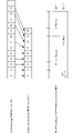
図1は、本開示の様々な実施形態による、CORESET0以外の制御リソースセット(CORESET)の例示的なTCI状態を示す。 FIG. 1 illustrates exemplary TCI states for control resource sets (CORESETs) other than CORESET0, according to various embodiments of the present disclosure.
RRCは、PDSCHのために最大128個のTCI状態を設定することができる。UEは、MAC CEを介して最大8つのアクティブ化されたTCI状態を有することができる。例示的なMAC CEが、図1に示される。 RRC can configure up to 128 TCI states for PDSCH. A UE can have up to 8 TCI states activated via MAC CE. An exemplary MAC CE is shown in FIG.
UEが、PDSCHをスケジューリングするCORESETの「イネーブルにされた」として設定される上位層パラメータTCI-PresentInDCIを用いて構成される場合、TCIフィールドは、DCIフォーマット1_1内に存在する。スケジューリングとPDSCHとの間のスケジューリングオフセットがThreshold-Sched-Offsetよりも大きく、TCIフィールドが存在する場合、PDSCHのTCI状態はDCIを介して示される。TCI-PresentInDCIが構成されていないか、又は、PDSCHがDCIフォーマット1_0を用いてスケジューリングされるか、又はPDCCHとPDSCHとの間のスケジューリングオフセットが、Threshold-Sched-Offsetよりも小さい場合、PDSCHは、PDCCHのTCIに従う。ThresholdSched-Offsetは、TS 38.306.内に定義されたUE能力timeDurationForQCLに基づく。 The TCI field is present in DCI format 1_1 if the UE is configured with the higher layer parameter TCI-PresentInDCI set as 'enabled' in the CORESET scheduling PDSCH. If the scheduling offset between scheduling and PDSCH is greater than Threshold-Sched-Offset and the TCI field is present, the TCI status of PDSCH is indicated via DCI. If TCI-PresentInDCI is not configured, or PDSCH is scheduled using DCI format 1_0, or the scheduling offset between PDCCH and PDSCH is less than Threshold-Sched-Offset, PDSCH: According to TCI of PDCCH. ThresholdSched-Offset is defined in TS 38.306. based on the UE capability timeDurationForQCL defined in
図2は、本開示の様々な実施形態による、PDSCHの例示的なTCI状態を示す。 FIG. 2 shows exemplary TCI states for PDSCH, according to various embodiments of the present disclosure.
TCI状態変更及び対応するビーム切り替えは、MAC CE又はダウンリンク制御情報(DCI)を介して開始することができる。PDSCHのTCIがDCIによって示される場合、TCI状態又はビーム切り替えは、DCIを介して構成することができる。DCIに基づくTCI状態切り替えは、PDSCHに適用可能である。PDSCHがPDCCHのTCI状態に続くとき、ビーム切り替えの場合、PDCCHのTCI状態は、最初にMAC CEを介して開始されなければならない。したがって、PDCCHの場合、MAC CEに基づくTCI状態切り替えが適用可能であり得る。 A TCI state change and corresponding beam switch can be initiated via MAC CE or downlink control information (DCI). If the PDSCH TCI is indicated by the DCI, the TCI state or beam switching can be configured via the DCI. DCI-based TCI state switching is applicable to PDSCH. When the PDSCH follows the TCI state of the PDCCH, the TCI state of the PDCCH must first be initiated via the MAC CE in case of beam switching. Therefore, for PDCCH, MAC CE based TCI state switching may be applicable.
RRCにおいて1つのTCI状態のみが構成される場合、RRCベースのTCI状態切り替えも可能であり得る。TCI状態変更は、ユーザ機器(UE)側での遅延及び中断をもたらし得る。新しいTCI状態に切り替えるために、UEは、時間及び周波数オフセット、並びにFR2の場合のRxビームを取得する必要があり得る。 RRC-based TCI state switching may also be possible if only one TCI state is configured in RRC. A TCI state change can cause delays and disruptions on the user equipment (UE) side. In order to switch to a new TCI state, the UE may need to acquire the time and frequency offsets and Rx beams in case of FR2.
MAC CEに基づくTCI状態切り替え遅延は、以下のようにTS 38.214で定義され、アクティブ化コマンドを搬送するPDSCHに対応するHARQ-ACKがスロットnで送信されるとき、TCI状態とDCIフィールド「送信構成指示」のコードポイントとの間の示されたマッピングは、スロットn+3N slotSubframe、μ+1から開始して適用されるべきである。 The MAC CE based TCI state switch delay is defined in TS 38.214 as follows, when the HARQ-ACK corresponding to the PDSCH carrying the activation command is sent in slot n, the TCI state and the DCI field " The indicated mapping between the codepoints of the 'transmission configuration indication' should be applied starting from slot n+3 N slot Subframe, μ+1.
DCIに基づくTCI状態切り替えについては、timeDurationForQCLによって示されるUE能力は、UEが新しいTCI状態に切り替わるのに必要な時間を定義する。

上記で取得されたMAC CE及びDCIに基づく切り替え遅延は、UEが新しいTCI状態の時間/周波数オフセット及びRxビーム改良を追跡するために追加の時間を必要としないという基準に基づいている。これが当てはまらない場合、UEにおいてTCI状態を切り替えるために追加の時間が必要とされる。UEがTCI状態変更を指示され、新しいTCI状態で受信する準備ができていない場合、UE側でのPDCCH上のスケジューリング許可のミス又はPDSCH送信のミスをもたらす可能性がある。 The MAC CE and DCI based switching delay obtained above is based on the criterion that the UE does not need additional time to track the time/frequency offset and Rx beam refinement of the new TCI state. If this is not the case, additional time is required in the UE to switch TCI states. If the UE is instructed to change TCI state and is not ready to receive in the new TCI state, it may result in missed scheduling grants on the PDCCH or missed PDSCH transmissions on the UE side.
問題#1:ネットワークが新しいTCI状態を適宜使用するために、MAC CE及びDCIに基づくTCI状態変更の遅延の構成要素を取り込む必要がある。 Problem #1: In order for the network to use the new TCI state accordingly, it is necessary to introduce a delay component of TCI state change based on MAC CE and DCI.
DCI及びMAC CEに基づくTCI状態切り替えの場合、UEは、TCI状態切り替え中にいかなる中断も有さない可能性がある。 For DCI and MAC CE based TCI state switching, the UE may not have any interruption during the TCI state switching.
RRCに基づくTCI状態切り替えでは、RRC構成を変更する必要があり、RRC再構成時間に依存する。また、TCI状態切り替えのためのRRC再構成中にダウンリンク送信が中断される。 RRC-based TCI state switching requires a change in RRC configuration and is dependent on the RRC reconfiguration time. Also, downlink transmission is interrupted during RRC reconfiguration for TCI state switch.
とりわけ、本開示の実施形態は、状態変更が示された後にUEが新しいTCI状態で受信する準備ができるときをネットワークに示すために、MAC CE及びDCIに基づくTCI状態切り替え遅延の構成要素を定義する。本開示の実施形態は、TCI状態切り替え遅延を低減するための新しい挙動及びシグナリングを定義してもよい。とりわけ、本開示の実施形態に従ってTCI状態切り替え時間の遅延を定義することにより、UEが新しいTCI状態を受信する準備が整うと、ネットワークが新しいTCI状態で送信することを可能にする。 Among other things, embodiments of the present disclosure define a TCI state switch delay component based on MAC CE and DCI to indicate to the network when the UE is ready to receive in a new TCI state after a state change has been indicated. do. Embodiments of the present disclosure may define new behaviors and signaling to reduce TCI state switch delay. Among other things, defining a TCI state switch time delay according to embodiments of the present disclosure allows the network to transmit in the new TCI state when the UE is ready to receive the new TCI state.
MAC CEに基づくTCI状態切り替えでは、新しいTCI状態に切り替える時間は、MAC CEアクティブ化コマンドを搬送するPDSCHのUL HARQ送信の時間から3msとして取り込まれる。DCIに基づくTCI状態切り替えについては、遅延はUE能力によって定義される。しかし、これらの遅延は、UEが新しいTCI状態の時間/周波数オフセット及びRxビームを既に知っているときにのみ有効である。 For MAC CE based TCI state switching, the time to switch to a new TCI state is taken as 3ms from the time of the UL HARQ transmission of the PDSCH carrying the MAC CE activation command. For DCI based TCI state switching, the delay is defined by the UE capabilities. However, these delays are only effective when the UE already knows the time/frequency offset and Rx beams of the new TCI state.
UEが新しいTCI状態で正常に受信するために、TCI状態切り替えにおいて、追加の遅延を考慮する必要があり得る。 In order for the UE to successfully receive in the new TCI state, additional delay may need to be considered in the TCI state switch.
既存のTCI状態切り替え遅延を維持するために、新しいネットワーク挙動及びUEシグナリングを導入することができる。
1.遅延の構成要素
New network behavior and UE signaling can be introduced to maintain the existing TCI state switch delay.
1. Components of Delay
新しいTCI状態に切り替えるために、UEは、新しいTCI状態の時間/周波数オフセット取得及びRxビーム情報を必要とする。UEは、時間/周波数同期のためのトラッキング基準信号(TRS)又は同期信号/パブリックブロードキャストチャネル(SS/PBCH)と、Rxビーム取得のための反復「オン」が設定されたCSI-RSリソースとを必要とする。TCI状態変更コマンドがMAC CE又はDCIを介して受信される場合、UEは、コマンドを復号するための時間を必要とする。次いで、UEは、新しいTCI状態に切り替えるために、ある程度の準備時間を必要とする。 In order to switch to a new TCI state, the UE needs time/frequency offset acquisition and Rx beam information of the new TCI state. The UE uses a Tracking Reference Signal (TRS) or Synchronization Signal/Public Broadcast Channel (SS/PBCH) for time/frequency synchronization and CSI-RS resources set to repeat "on" for Rx beam acquisition. I need. If a TCI state change command is received via MAC CE or DCI, the UE needs time to decode the command. The UE then needs some preparation time to switch to the new TCI state.
遅延の構成要素は、以下のように分類することができる。
TACQ-TO,FO:時間/周波数オフセット取得又は同期時間。
TACQ-RxBeam:Rxビームを取得する時間。
TDec:TCI状態切り替えコマンドの復号時間。
TUE
Prep:TCI状態変更のためのUE準備時間。
The components of delay can be categorized as follows.
T ACQ-TO,FO : Time/Frequency Offset Acquisition or Synchronization Time.
T ACQ-RxBeam : Time to acquire Rx beam.
T Dec : Decoding time of the TCI state switch command.
T UE Prep : UE preparation time for TCI state change.
UEが、TCI状態切り替えの前に新しいTCI状態のためのTRS又はSS/PBCHなどのリソースで構成され、アクティブTCI状態リストにある場合、UEは、TCI状態切り替えコマンドの後の時間/周波数オフセット推定のための追加の時間を必要としないことがある。 If the UE is configured with resources such as TRS or SS/PBCH for the new TCI state before the TCI state switch and is in the active TCI state list, the UE will perform time/frequency offset estimation after the TCI state switch command. may not require additional time for
伝搬条件及びチャネル条件が与えられて、ある程度の妥当な時間内で、UEがターゲットTCI状態についてのL1-RSRP測定をネットワークに行って報告した場合、UEは、新しいTCI状態についての測定報告に使用されるRxビーム情報を使用することができ、新しいTCI状態についてのRxビーム改良又は取得を実行する必要はない。測定報告の有効時間は、UE電力クラスに依存し得る。電力クラス2/3/4をサポートするUEの場合、報告の有効性は短くてもよい(例えば、数ms)が、固定UE、電力クラス1をサポートするUEの場合、報告の有効性は数100msまでであり得る。また、FR1の場合、UEはRxビーム取得のための更なる時間を必要としない。
Given the propagation and channel conditions, if the UE makes and reports L1-RSRP measurements for the target TCI state to the network within some reasonable amount of time, the UE uses the measurement report for the new TCI state. Rx beam information obtained from the previous TCI state can be used and there is no need to perform Rx beam refinement or acquisition for the new TCI state. Valid time of measurement report may depend on UE power class. For UEs supporting
MAC CEの復号時間は、PDSCH受信と対応するPDSCH(THARQ)のUL HARQ送信との間の時間に吸収され得る。DCIに基づく切り替えについては、DCI復号時間は、他の遅延のうちの1つに吸収されるのに十分小さいと仮定することができる。
MAC CEに基づくTCI状態切り替え
MAC CE decoding time may be absorbed in the time between PDSCH reception and UL HARQ transmission of the corresponding PDSCH (T HARQ ). For DCI-based switching, we can assume that the DCI decoding time is small enough to be absorbed in one of the other delays.
TCI state switching based on MAC CE
PDCCHのためのMAC CEに基づくTCI状態切り替えをRRC構成TCI状態に切り替えるには、以下の場合が可能である。
a.時間/周波数オフセット既知、Rxビーム既知
b.時間/周波数オフセット未知、Rxビーム既知
c.時間/周波数オフセット既知、Rxビーム未知
d.時間/周波数オフセット未知、Rxビーム未知
For MAC CE based TCI state switching for PDCCH to RRC configured TCI state, the following cases are possible.
a. Time/frequency offset known, Rx beam known b. Time/frequency offset unknown, Rx beam known c. Time/frequency offset known, Rx beam unknown d. Time/frequency offset unknown, Rx beam unknown
時間/周波数オフセット及びRxビームが新しいTCI状態に関して既知である最良のケースでは、新しいTCI状態に切り替わる遅延は、次の通りである。
TTCI切り替え、MAC
CE、FO既知、Rxビーム既知=THARQ+TUE
Prep
MAC CEに基づく切り替えのUE準備時間は、
![]()
T TCI switching, MAC CE, FO known, Rx beam known = T HARQ + T UE Prep
The UE preparation time for switching based on MAC CE is
![]()
MAC CEに基づくTCI状態切り替えの一般的な遅延は、以下のように定式化することができる。
TTCI切り替え,MAC
CE=max(A*TACQ-TO,FO+B*TACQ-Rxビーム)+THARQ+TUE
Prep
TO/FOが未知である場合A=1であり、そうでなければ0である。
Rxビームが未知である場合、B=1、そうでなければ0である。
DCIに基づくTCI状態切り替え
A typical delay for TCI state switching based on MAC CE can be formulated as follows.
T TCI switching, MAC CE = max (A * T ACQ-TO, FO + B * T ACQ-Rx beam ) + T HARQ + T UE Prep
A=1 if TO/FO is unknown, 0 otherwise.
B=1 if the Rx beam is unknown, 0 otherwise.
TCI state switching based on DCI
PDCCHのためのMAC CEに基づくTCI状態切り替えをRRC構成TCI状態に切り替えるには、以下の場合が可能である。
a.時間/周波数オフセット既知、Rxビーム既知
b.時間/周波数オフセット未知、Rxビーム既知
c.時間/周波数オフセット既知、Rxビーム未知
d.時間/周波数オフセット未知、Rxビーム未知
For MAC CE based TCI state switching for PDCCH to RRC configured TCI state, the following cases are possible.
a. Time/frequency offset known, Rx beam known b. Time/frequency offset unknown, Rx beam known c. Time/frequency offset known, Rx beam unknown d. Time/frequency offset unknown, Rx beam unknown
時間/周波数オフセット及びRxビームが新しいTCI状態に関して既知である最良のケースでは、新しいTCI状態に切り替わる遅延は、次の通りである。
TTCI切り替え,DCI,TO-FO既知,Rxビーム既知=TUE
Prep
ここで、DCIに基づくTCI状態切り替えのUE準備時間は、UE能力timeDurationForQCLによって示される。
In the best case where the time/frequency offset and Rx beams are known for the new TCI state, the delay to switch to the new TCI state is:
T TCI switching, DCI, TO-FO known, Rx beam known = T UE Prep
Here, the UE preparation time for TCI state switch based on DCI is indicated by UE capability timeDurationForQCL.
DCIに基づくTCI状態切り替えの一般的な遅延は、以下のように定式化することができる。
TTCI切り替え,DCI=max(A*TACQ-、FO、B*TACQ-Rxビーム)+timeDurationForQCL
TO/FOが未知である場合A=1であり、そうでなければ0である。
Rxビームが未知である場合、B=1、そうでなければ0である。
2.ネットワーク挙動
A typical delay for TCI state switching based on DCI can be formulated as follows.
T TCI switching, DCI = max(A * T ACQ-, FO , B * T ACQ-Rx beam ) + timeDurationForQCL
A=1 if TO/FO is unknown, 0 otherwise.
B=1 if the Rx beam is unknown, 0 otherwise.
2. network behavior
新しいTCI状態への最小切り替え遅延を保証するために、gNBは、切り替え後に、UEがRxビーム取得のための追加の時間及び新しいTCI状態のための時間/周波数オフセットトラッキングを必要としないことを保証することができる。 To ensure minimum switch delay to new TCI state, gNB ensures that after switching, UE does not need additional time for Rx beam acquisition and time/frequency offset tracking for new TCI state can do.
Rxビーム掃引による時間遅延を回避するために、ネットワークは、所与のチャネル及び伝搬条件の測定値の妥当性を保証する一定の時間内に、UEによって測定及び報告されたTCI状態に切り替わることができる。 To avoid time delays due to Rx beam sweeping, the network may switch to the TCI state measured and reported by the UE within a fixed amount of time that ensures the validity of the measurements given the channel and propagation conditions. can.
UEが、時間オフセット/周波数オフセット(TO/FO)トラッキングのための追加時間を必要としないため、UEがそれを追跡する機会を有するように、アクティブなTCI状態リストのためのTRS/SSBを構成してもよい。 Configure the TRS/SSB for the active TCI state list so that the UE does not need additional time for Time Offset/Frequency Offset (TO/FO) tracking, so that the UE has the opportunity to track it. You may
或いは、ネットワークは、TCI状態変更後の初期送信に対して低変調符号化方式(MCS)を設定し、データ送信を受信している間に、TCI状態切り替え後のビーム改良及び同期のための機会をUEに与えるために、TO/FOトラッキング及びRxビーム改良のためのリソースを構成してもよい。
3.新しいシグナリング
Alternatively, the network may set a low modulation coding scheme (MCS) for initial transmissions after a TCI state change and, while receiving data transmissions, take the opportunity for beam refinement and synchronization after a TCI state switch. to the UE, resources for TO/FO tracking and Rx beam refinement may be configured.
3. new signaling
ネットワークは、ビーム報告のためのリソースを構成し、報告を使用してTCI状態切り替えの前に報告の経過時間を知ることができるが、ターゲットTCI状態についてのTO/FOを取得している場合、UEによる指示はない。アクティブなTCI状態又はRRC構成TCI状態が追跡されたかどうかを示すためのUE側からのシグナリングは、新しいTCI状態への切り替えの遅延を低減するのに役立つ。
システム及び実装
The network can configure resources for beam reporting and use the report to know the elapsed time of the report before the TCI state switch, but if it has obtained the TO/FO for the target TCI state: No indication by UE. Signaling from the UE side to indicate whether an active TCI state or an RRC configured TCI state has been tracked helps reduce the delay of switching to a new TCI state.
system and implementation
図3は、様々な実施形態による、ネットワークのシステム300の例示的なアーキテクチャを示す。以下の説明は、3GPP技術仕様によって提供される、LTEシステム規格、及び5G又はNRシステム規格と併せて動作する例示的なシステム300に関して提供される。しかしながら、例示的な実施形態は、この点に関して限定されず、説明される実施形態は、将来の3GPPシステム(例えば、第6世代(6G))システム、IEEE802.16プロトコル(例えば、WLAN、WiMAXなど)などの、本明細書に記載の原理から恩恵を受ける他のネットワークに適用することができる。
FIG. 3 shows an exemplary architecture of a system of
図3に示すように、システム300は、UE301a及びUE301b(集合的に「UE301」と呼ばれる)を含む。この例では、UE301は、スマートフォン(例えば、1つ以上のセルラネットワークに接続可能なハンドヘルドタッチスクリーンモバイルコンピューティングデバイス)として図示されているが、家庭用電子機器、セルラ電話、スマートフォン、フィーチャーフォン、タブレットコンピュータ、ウェアラブルコンピュータデバイス、携帯情報端末(PDA)、ページャ、無線ハンドセット、デスクトップコンピュータ、ラップトップコンピュータ、車載インフォテインメント(IVI)、車載エンターテインメント(ICE)デバイス、インストルメントクラスタ(IC)、ヘッドアップディスプレイ(HUD)デバイス、車載診断(OBD)デバイス、ダッシュトップモバイル機器(DME)、モバイルデータ端末(MDT)、電子エンジン管理システム(EEMS)、電子/エンジン制御ユニット(ECU)、電子エンジン/エンジン制御モジュール(ECM)、組み込みシステム、マイクロコントローラ、制御モジュール、エンジン管理システム(EMS)、ネットワーク化又は「スマート」電化製品、MTCデバイス、M2M、IoTデバイス、などの任意のモバイル又は非モバイルコンピューティングデバイスを含んでもよい。
As shown in FIG. 3,
いくつかの実施形態では、UE301のいずれかは、IoT UEであってもよく、それは、短命UE接続を利用する低電力IoTアプリケーション用に設計されたネットワークアクセス層を含み得る。IoT UEは、PLMN、ProSe又はD2D通信、センサネットワーク、又はIoTネットワークを介して、MTCサーバ又はデバイスとデータを交換するためのM2M又はMTCなどの技術を利用することができる。M2Mデータ交換又はMTCデータ交換は、機械起動のデータの交換であってもよい。IoTネットワークは、相互に接続するIoT UEをいい、それは、短命接続による、(インターネットインフラストラクチャ内の)一意に識別可能な埋め込み型コンピューティングデバイスを含み得る。IoT UEは、IoTネットワークの接続を容易にするために、バックグラウンドアプリケーション(例えば、キープアライブメッセージ、ステータス更新など)を実行してもよい。 In some embodiments, any of the UEs 301 may be IoT UEs, which may include a network access layer designed for low-power IoT applications utilizing short-lived UE connections. An IoT UE may utilize technologies such as M2M or MTC to exchange data with MTC servers or devices via PLMN, ProSe or D2D communication, sensor networks, or IoT networks. The M2M data exchange or MTC data exchange may be a machine-initiated exchange of data. An IoT network refers to interconnected IoT UEs, which may include uniquely identifiable embedded computing devices (within the Internet infrastructure) with short-lived connections. An IoT UE may run background applications (eg, keep-alive messages, status updates, etc.) to facilitate IoT network connectivity.
UE301は、例えば、通信可能な結合によってRAN310に接続されるように構成され得る。実施形態では、RAN310は、NG RAN若しくは5G RAN、E-UTRAN、又はUTRAN若しくはGERANなどのレガシーRANであってもよい。本明細書で使用するとき、用語「NG RAN」などは、NR又は5Gシステム300で動作するRAN310を指し、用語「E-UTRAN」などは、LTE又は4Gシステム300で動作するRAN310を指してもよい。UE301は、それぞれ接続(又はチャネル)303及び接続304を利用し、これらは各々、物理通信インタフェース又は層(以下で更に詳細に議論する)を含む。
UE 301 may be configured to be connected to
この実施例では、接続303及び304は、通信可能な結合を可能にするためのエアインタフェースとして示されており、GSMプロトコル、CDMAネットワークプロトコル、PTTプロトコル、POCプロトコル、UMTSプロトコル、3GPP LTEプロトコル、5Gプロトコル、NRプロトコル、及び/又は本明細書で論じる他の通信プロトコルのいずれかなどのセルラ通信プロトコルと一致し得る。実施形態では、UE301は、ProSeインタフェース305を介して通信データを直接交換することができる。ProSeインタフェース305は、代替的にSLインタフェース305と称されてもよく、PSCCH、PSSCH、PSDCH、及びPSBCHを含むがこれらに限定されない1つ以上の論理チャネルを含んでもよい。
In this example,
UE301bは、接続307を介してAP306(「WLANノード306」「WLAN306」「WLAN端末306」、「WT306」などとも呼ばれる)にアクセスするように構成されていることが示されている。接続307は、任意のIEEE802.11プロトコルと合致する接続などのローカルワイヤレス接続を含むことができ、その中でAP306は、WiFi(Wireless Fidelity)(登録商標)ルータを備えるであろう。本例では、AP306は、ワイヤレスシステムのコアネットワークに接続せずにインターネットに接続されることが示されている(以下で更に詳細に説明する)。様々な実施形態では、UE301b、RAN310及びAP306は、LWA動作及び/又はLWIP動作を利用するように構成されていることが可能である。LWA動作は、LTE及びWLANの無線リソースを利用するために、RANノード311a~311bによって構成されているRRC_CONNECTEDにあるUE301bを必要とし得る。LWIP動作は、接続307を介して送信されるパケット(例えば、IPパケット)を認証し暗号化するために、IPsecプロトコルトンネルを介してWLAN無線リソース(例えば、接続307)を使用するUE301bを必要とし得る。IPsecトンネリングは、元のIPパケットの全体をカプセル化し、新しいパケットヘッダを追加することを含んでもよく、それによってIPパケットのオリジナルヘッダを保護する。
RAN310は、接続303及び304を可能にする1つ以上のANノード又はRANノード311a及び311b(集合的に「RANノード311」と呼ぶ)を含むことができる。本明細書で使用するとき、用語「アクセスノード」、「アクセスポイント」などは、ネットワークと1人以上のユーザとの間のデータ及び/又は音声接続のための無線ベースバンド機能を提供する機器について述べてもよい。これらのアクセスノードは、BS、gNB、RANノード、eNB、NodeBs、RSUs、TRxP又はTRPなどと称される場合があり、地理的エリア(例えば、セル)内にカバレッジを提供する地上局(例えば、地上アクセスポイント)又はサテライト局を含むことができる。本明細書で使用するとき、用語「NG RANノード」などは、NR又は5Gシステム300(例えば、gNB)で動作するRANノード311を指してもよく、用語「E-UTRANノード」などは、LTE又は4Gシステム300(例えば、eNB)で動作するRANノード311を指し得る。様々な実装形態によれば、RANノード311は、マクロセルと比較してより小さいカバレッジエリア、より小さいユーザ容量、又はより高い帯域幅を有するフェムトセル、ピコセル、又は他の同様のセルを提供するための、マクロセル基地局、及び/又は低電力(LP)基地局などの専用物理デバイスのうちの1つ以上として実装され得る。
いくつかの実装形態では、RANノード311の全て又は一部は、仮想ネットワークの一部としてサーバコンピュータ上で実行される1つ以上のソフトウェアエンティティとして実装されてもよく、これは、CRAN及び/又は仮想ベースバンドユニットプール(vBBUP)と称され得る。これらの実装形態では、CRAN又はvBBUPは、RRC及びPDCP層がCRAN/vBBUPによって動作され、他のL2プロトコルエンティティは個々のRANノード311によって動作される、PDCP分割などのRAN機能分割、RRC、PDCP、RLC、及びMAC層がCRAN/vBBUPによって動作され、PHY層は個々のRANノード311によって動作される、MAC/PHY分割、又はRRC、PDCP、RLC、MAC層、及びPHY層の上部がCRAN/vBBUPによって動作され、PHY層の下部は個々のRANノード311によって動作される、「下位PHY」分割、を実装し得る。この仮想化されたフレームワークは、RANノード311の解放されたプロセッサコアが、他の仮想化されたアプリケーションを実行することを可能にする。いくつかの実装形態では、個々のRANノード311は、個々のF1インタフェース(図3に示されていない)を介してgNB-CUに接続された個々のgNB-DUを表し得る。これらの実装形態では、gNB-DUは、1つ以上のリモート無線ヘッド又はRFEM(例えば、図6を参照)を含むことができ、gNB-CUは、RAN310(図示せず)に配置されたサーバによって、又はCRAN/vBBUPと同様の方法でサーバプールによって動作することができる。追加的又は代替的に、RANノード311のうちの1つ以上は次世代eNB(ng-eNB)であってもよく、次世代eNBは、UE301に向けてE-UTRAユーザプレーン及び制御プレーンプロトコル端末を提供し、NGインタフェースを介して5GC(例えば、図5のCN520)に接続されるRANノードである。
In some implementations, all or part of RAN nodes 311 may be implemented as one or more software entities running on server computers as part of a virtual network, which may include CRAN and/or It may be referred to as a virtual baseband unit pool (vBBUP). In these implementations, CRAN or vBBUP is a RAN functional split, such as PDCP split, RRC, PDCP, where the RRC and PDCP layers are run by the CRAN/vBBUP and other L2 protocol entities are run by individual RAN nodes 311. , RLC and MAC layers are operated by CRAN/vBBUP and PHY layer is operated by individual RAN nodes 311, MAC/PHY split or RRC, PDCP, RLC, MAC and PHY layers on top of CRAN/vBBUP A “lower PHY” split, operated by vBBUP and the bottom of the PHY layer operated by individual RAN nodes 311, may be implemented. This virtualized framework allows freed processor cores of RAN node 311 to run other virtualized applications. In some implementations, individual RAN nodes 311 may represent individual gNB-DUs connected to gNB-CUs via individual F1 interfaces (not shown in FIG. 3). In these implementations, the gNB-DU can include one or more remote radio heads or RFEMs (see, eg, FIG. 6), and the gNB-CU is a server located in the RAN 310 (not shown). or by a server pool in a manner similar to CRAN/vBBUP. Additionally or alternatively, one or more of RAN nodes 311 may be Next Generation eNBs (ng-eNBs), which provide E-UTRA user plane and control plane protocol terminal , and connected to the 5GC (eg,
V2Xシナリオでは、RANノード311のうちの1つ以上は、RSUとすることができるか、又はその役割を果たし得る。用語「路側機(Road Side Unit)」又は「RSU」は、V2X通信に使用される任意の交通インフラストラクチャエンティティを指し得る。RSUは、適切なRANノード又は静止した(又は比較的静止した)UEにおいて又はそれによって実装されてもよく、UEにおいて又はそれによって実装されるRSUは「UEタイプRSU」と呼ばれてもよく、eNBにおいて又はそれによって実装されるRSUは「eNBタイプRSU」と呼ばれてもよく、gNBにおいて又はそれによって実装されるRSUは「gNBタイプRSU」などと呼ばれてもよい。一例では、RSUは、通過車両UE301(vUE301)に接続性サポートを提供する路側に位置する無線周波数回路に結合されたコンピューティングデバイスである。RSUはまた、交差点マップ形状、交通統計、媒体、並びに持続中の車両及び歩行者の交通を検知及び制御するためのアプリケーション/ソフトウェアを記憶するための内部データ記憶回路を含むことができる。RSUは、5.9GHz Direct Short Range Communication(DSRC)帯域で動作して、衝突回避、トラフィック警告などの高速イベントに必要な非常に低レイテンシである通信を提供することができる。追加的又は代替的に、RSUは、前述の低レイテンシである通信、並びに他のセルラ通信サービスを提供するために、セルラV2X帯域で動作することができる。追加的又は代替的に、RSUは、Wi-Fiホットスポット(2.4GHz帯域)として動作することができ、かつ/又は1つ以上のセルラネットワークへの接続性を提供して、アップリンク及びダウンリンク通信を提供することができる。コンピューティングデバイス及びRSUの無線周波数回路の一部又は全ては、屋外設置に適した耐候性エンクロージャにパッケージ化することができ、交通信号コントローラ及び/又はバックホールネットワークに有線接続(例えば、イーサネット)を提供するためのネットワークインタフェースコントローラを含むことができる。 In a V2X scenario, one or more of the RAN nodes 311 may be or act as RSUs. The term "Road Side Unit" or "RSU" may refer to any transportation infrastructure entity used for V2X communications. RSU may be implemented in or by suitable RAN nodes or stationary (or relatively stationary) UEs, RSUs implemented in or by UEs may be referred to as "UE-type RSU", An RSU implemented at or by an eNB may be referred to as an "eNB-type RSU," an RSU implemented at or by a gNB may be referred to as a "gNB-type RSU," and so on. In one example, an RSU is a computing device coupled to a roadside radio frequency circuit that provides connectivity support for a passing vehicle UE301 (vUE301). The RSU may also include internal data storage circuitry for storing intersection map geometry, traffic statistics, media, and applications/software for sensing and controlling ongoing vehicular and pedestrian traffic. The RSU can operate in the 5.9 GHz Direct Short Range Communication (DSRC) band to provide very low latency communications necessary for high speed events such as collision avoidance, traffic warnings, and the like. Additionally or alternatively, the RSU may operate in the cellular V2X band to provide the aforementioned low latency communications, as well as other cellular communications services. Additionally or alternatively, the RSU can operate as a Wi-Fi hotspot (2.4 GHz band) and/or provide connectivity to one or more cellular networks for uplink and downlink Link communication can be provided. Some or all of the computing device and the radio frequency circuitry of the RSU can be packaged in a weatherproof enclosure suitable for outdoor installation, with a wired connection (e.g., Ethernet) to the traffic light controller and/or backhaul network. A network interface controller can be included for providing.
RANノード311のうちのいずれかは、エアインタフェースプロトコルを終結させることができ、UE301の第1の接触点とすることができる。いくつかの実施形態では、RANノード311のいずれも、RAN310のための様々な論理機能を果たすことができ、その機能は、限定されないが、無線ベアラ管理、アップリンク及びダウンリンク動的無線リソース管理、並びにデータパケットスケジューリング、並びにモビリティ管理などの無線ネットワークコントローラ(RNC)機能を含む。
Any of the RAN nodes 311 may terminate air interface protocols and may be the first point of contact for UE 301 . In some embodiments, any of the RAN nodes 311 can perform various logical functions for the
実施形態では、UE301は、様々な通信技術に従ったマルチキャリア通信チャネルにより、OFDM通信信号を用いて、互いに又はRANノード311のいずれかと通信するように構成することができ、この様々な通信技術は、例えば、(例えば、ダウンリンク通信用の)OFDMA通信技術、又は(例えば、アップリンク及びProSe又はサイドリンク通信用の)SC-FDMA通信技術であるが、これらに限定されず、実施形態の範囲は、この点において限定されない。OFDM信号は、複数の直交サブキャリアを含むことができる。 In embodiments, the UEs 301 may be configured to communicate with each other or with the RAN node 311 using OFDM communication signals over multi-carrier communication channels according to various communication technologies. is, for example, but not limited to, OFDMA communication technology (eg, for downlink communication) or SC-FDMA communication technology (eg, for uplink and ProSe or sidelink communication). The scope is not limited in this respect. An OFDM signal may include multiple orthogonal subcarriers.
いくつかの実施形態では、ダウンリンクリソースグリッドは、RANノード311のいずれかからUE301へのダウンリンク送信のために使用することができ、一方、アップリンク送信は同様の技術を利用することができる。グリッドは、リソースグリッド又は時間周波数リソースグリッドと呼ばれる時間周波数グリッドとすることができ、それは、各スロット内のダウンリンクの物理的リソースである。このような時間周波数平面表現は、OFDMシステムの一般的な方法であり、それにより無線リソースの割り当てが直感的なものとなる。リソースグリッドの各列及び各行は、それぞれ、1つのOFDMシンボル及び1つのOFDMサブキャリアに対応する。時間ドメイン内のリソースグリッドの持続時間は、無線フレーム内の1つのスロットに対応する。リソースグリッドの最小時間周波数単位は、リソースエレメントと表記する。各リソースグリッドは、多数のリソースブロックを含み、それは、リソースエレメントへの特定の物理チャネルのマッピングを表す。各リソースブロックは、リソースエレメントの集合を含み、周波数ドメインにおいて、これは、現在割り当てられ得るリソースの最小量を表すことができる。このようなリソースブロックを用いて伝達されるいくつかの異なる物理ダウンリンクチャネルが存在する。 In some embodiments, the downlink resource grid may be used for downlink transmissions from any of RAN nodes 311 to UE 301, while uplink transmissions may utilize similar techniques. . The grid can be a time-frequency grid, called resource grid or time-frequency resource grid, which is the downlink physical resources in each slot. Such a time-frequency plane representation is a common practice in OFDM systems, which makes allocation of radio resources intuitive. Each column and each row of the resource grid corresponds to one OFDM symbol and one OFDM subcarrier, respectively. The duration of the resource grid in the time domain corresponds to one slot in the radio frame. A minimum time-frequency unit of a resource grid is denoted as a resource element. Each resource grid contains a number of resource blocks, which represent the mapping of specific physical channels to resource elements. Each resource block contains a set of resource elements, which in the frequency domain can represent the minimum amount of resources that can currently be allocated. There are several different physical downlink channels that are conveyed using such resource blocks.
様々な実施形態によれば、UE301及びRANノード311は、認可媒体(「認可スペクトル」及び/又は「認可帯域」とも呼ばれる)及び無認可共有媒体(「無認可スペクトル」及び/又は「無認可帯域」とも呼ばれる)を介してデータ(例えば、送信及び受信)データを通信する。認可スペクトルは、約400MHz~約3.8GHzの周波数範囲で動作するチャネルを含んでもよく、無認可スペクトルは5GHz帯域を含んでもよい。 According to various embodiments, UE 301 and RAN node 311 are connected to a licensed medium (also called “licensed spectrum” and/or “licensed band”) and an unlicensed shared medium (also called “unlicensed spectrum” and/or “unlicensed band”). ) to communicate data (eg, send and receive) data. The licensed spectrum may include channels operating in the frequency range from approximately 400 MHz to approximately 3.8 GHz, and the unlicensed spectrum may include the 5 GHz band.
無認可スペクトルで動作するために、UE301及びRANノード311は、LAA、eLAA、及び/又はfeLAA機構を使用して動作し得る。これらの実装では、UE301及びRANノード311は、無認可スペクトルにおいて送信する前に、無認可スペクトル内の1つ以上のチャネルが利用不可能であるか、又は別の方法で占有されているかを判定するために、1つ以上の既知の媒体検知動作及び/又はキャリア検知動作を実行してもよい。媒体/キャリア検知動作は、listen-before-talk(LBT)プロトコルに従って実行することができる。 To operate in the unlicensed spectrum, UE 301 and RAN node 311 may operate using LAA, eLAA, and/or feLAA mechanisms. In these implementations, UE 301 and RAN node 311, prior to transmitting in the unlicensed spectrum, determine if one or more channels in the unlicensed spectrum are unavailable or otherwise occupied. , one or more known medium sensing and/or carrier sensing operations may be performed. Medium/carrier sensing operations may be performed according to the listen-before-talk (LBT) protocol.
LBTは、機器(例えば、UE301、RANノード311など)が媒体(例えば、チャネル又はキャリア周波数)を検知し、媒体がアイドル状態であることが検知されたとき(又は、媒体内の特定のチャネルが占有されていないと検知されたとき)を送信する機構である。媒体検知動作は、チャネルが占有されているか又は空いているかを判断するために、少なくともEDを利用してチャネル上の他の信号の有無を判断するCCAを含んでもよい。このLBT機構は、無認可スペクトルにおいて、セルラ/LAAネットワークが現在の占有しているシステムと共存し、かつ他のLAAネットワークと共存することを可能にする。EDは、ある期間にわたって意図された送信帯域にわたってRFエネルギーを検知することと、検知されたRFエネルギーを所定の閾値又は設定された閾値と比較することとを含んでもよい。 LBT is when a device (e.g., UE 301, RAN node 311, etc.) senses the medium (e.g., channel or carrier frequency) and the medium is detected to be idle (or when a particular channel within the medium is is detected to be unoccupied). A medium sensing operation may include a CCA that utilizes at least the ED to determine the presence or absence of other signals on the channel to determine if the channel is occupied or free. This LBT mechanism will allow cellular/LAA networks to coexist with current occupied systems and coexist with other LAA networks in the unlicensed spectrum. ED may involve sensing RF energy over the intended transmission band over a period of time and comparing the sensed RF energy to a predetermined or set threshold.
典型的には、5GHz帯域における現在占有しているシステムは、IEEE802.11技術に基づくWLANである。WLANは、CSMA/CAと呼ばれる、コンテンションベースのチャネルアクセス機構を採用する。ここで、WLANノード(例えば、UE301、AP306などの移動局(MS))が送信することを意図する場合、WLANノードは、送信前にCCAを最初に実行してもよい。更に、2つ以上のWLANノードが同時にチャネルをアイドル状態として検知し送信する状況において、衝突を回避するためにバックオフ機構が使用される。バックオフ機構は、CWS内でランダムに抽出されるカウンタであってもよく、これは、衝突の発生時に指数関数的に増加され、送信が成功したときに最小値にリセットされる。LAA用に設計されたLBT機構は、WLANのCSMA/CAと幾分類似している。いくつかの実装形態では、PDSCH又はPUSCH送信をそれぞれ含むDL又はUL送信バーストのためのLBT手順は、X ECCAスロットとY ECCAスロットとの間の長さが可変であるLAA競合ウィンドウを有することができ、X及びYは、LAAのためのCWSの最小値及び最大値である。一例では、LAA送信のための最小CWSは、9マイクロ秒(μs)であってもよいが、CWS及びMCOTのサイズ(例えば、送信バースト)は、政府規制上の要件に基づいてもよい。
Typically, the current dominant systems in the 5 GHz band are WLANs based on IEEE 802.11 technology. WLANs employ a contention-based channel access mechanism called CSMA/CA. Here, if a WLAN node (eg, a mobile station (MS) such as UE 301,
LAA機構は、LTEアドバンストシステムのCA技術に基づいて構築されている。CAでは、各集約されたキャリアはCCと呼ばれる。CCは、1.4、3、5、10、15、又は20MHzの帯域幅を有することができ、最大5つのCCを集約することができ、従って、集約された最大帯域幅は100MHzである。FDDシステムでは、集約されたキャリアの数は、DLとULとで異なることがあり、UL CCの数は、DLコンポーネントキャリアの数以下である。場合によっては、個々のCCは、他のCCとは異なる帯域幅を有することができる。TDDシステムでは、CCの数及び各CCの帯域幅は、通常、DL及びULに対して同じである。 The LAA mechanism is built on the CA technology of the LTE advanced system. In CA, each aggregated carrier is called CC. A CC can have a bandwidth of 1.4, 3, 5, 10, 15, or 20 MHz, and up to 5 CCs can be aggregated, so the maximum aggregated bandwidth is 100 MHz. In FDD systems, the number of aggregated carriers can be different for DL and UL, and the number of UL CCs is less than or equal to the number of DL component carriers. In some cases, individual CCs can have different bandwidths than other CCs. In a TDD system, the number of CCs and the bandwidth of each CC are usually the same for DL and UL.
CAはまた、個々のCCを提供する個々のサービングセルを含む。例えば、異なる周波数帯域におけるCCは、異なる経路喪失を経験するので、サービングセルのカバレッジは異なり得る。プライマリサービスセル又はPCellは、UL及びDLの両方にPCCを提供することができ、RRC及びNAS関連のアクティビティを処理することができる。他のサービングセルはSCellと呼ばれ、各SCellはULとDLの両方に個別のSCCを提供し得る。SCCは、必要に応じて追加及び除去され得る一方、PCCを変更するには、UE301がハンドオーバを受けることを必要とし得る。LAA、eLAA、及びfeLAAでは、SCellの一部又は全部は、無認可スペクトル(「LAA SCell」と呼ばれる)で動作することができ、LAA SCellは、認可スペクトルで動作するPCellによって支援される。UEが2つ以上のLAA SCellで構成される場合、UEは、同じサブフレーム内の異なるPUSCH開始位置を示す、構成されたLAA SCell上でULグラントを受信することができる。 A CA also includes individual serving cells serving individual CCs. For example, CCs in different frequency bands experience different path losses, so the coverage of the serving cell may differ. A primary serving cell or PCell can provide PCC for both UL and DL and can handle RRC and NAS related activities. Other serving cells are called SCells, and each SCell may provide separate SCCs for both the UL and DL. SCCs may be added and removed as needed, while changing the PCC may require the UE 301 to undergo a handover. In LAA, eLAA, and feLAA, some or all of the SCells may operate in the unlicensed spectrum (referred to as "LAA SCells"), and the LAA SCells are backed by PCells operating in the licensed spectrum. If the UE is configured with more than one LAA SCell, the UE may receive UL grants on configured LAA SCells indicating different PUSCH start locations within the same subframe.
PDSCHは、ユーザデータ及び上位層シグナリングをUE301に搬送する。PDCCHは、とりわけ、PDSCHチャネルに関連するトランスポートフォーマット及びリソース割り当てに関する情報を搬送する。また、それは、アップリンク共有チャネルに関する、送信フォーマット、リソース割り当て、及びHARQ情報について、UE301に通知することもできる。典型的には、ダウンリンクスケジューリング(制御及び共有チャネルリソースブロックをセル内のUE301bに割り当てる)は、UE301のいずれかからフィードバックされるチャネル品質情報に基づいて、RANノード311のいずれかで実行されてもよい。ダウンリンクリソース割り当て情報は、UE301の各々に対して使用される(例えば、割り当てられた)PDCCHで送信されてもよい。 PDSCH carries user data and higher layer signaling to UE 301 . The PDCCH carries, among other things, information regarding transport formats and resource allocations associated with the PDSCH channel. It can also inform UE 301 about the transmission format, resource allocation and HARQ information for the uplink shared channel. Typically, downlink scheduling (allocating control and shared channel resource blocks to UEs 301b within a cell) is performed in any of the RAN nodes 311 based on channel quality information fed back from any of the UEs 301. good too. Downlink resource allocation information may be sent on the PDCCH used (eg, assigned) for each of the UEs 301 .
PDCCHは、CCEを使用して制御情報を伝達する。リソースエレメントにマッピングされる前に、PDCCH複素数値シンボルは最初に、4つ組(quadruplets)に編成されてもよく、その後、レートマッチングのためのサブブロックインターリーバを用いて入れ替えられてもよい。各PDCCHを、これらのCCEのうちの1つ以上を用いて送信してもよく、各CCEは、REGとして知られる4つの物理リソースエレメントの9つのセットに対応することができる。4つの四位相偏移変調(QPSK)シンボルを各REGにマッピングしてもよい。PDCCHは、DCIのサイズ及びチャネル状態に応じて、1つ以上のCCEを用いて送信することができる。異なる数のCCE(例えば、アグリゲーションレベル、L=1、2、4、又は8)を有するLTEに定義される4つ以上の異なるPDCCHフォーマットが存在し得る。 The PDCCH uses CCE to convey control information. Before being mapped to resource elements, the PDCCH complex-valued symbols may first be organized into quadruplets and then permuted using a sub-block interleaver for rate matching. Each PDCCH may be transmitted using one or more of these CCEs, and each CCE can correspond to nine sets of four physical resource elements known as REGs. Four quadrature phase shift keying (QPSK) symbols may be mapped to each REG. A PDCCH may be transmitted using one or more CCEs, depending on the DCI size and channel conditions. There may be four or more different PDCCH formats defined for LTE with different numbers of CCEs (eg, aggregation levels, L=1, 2, 4, or 8).
いくつかの実施形態は、上記の概念の拡張である制御チャネル情報のためのリソース割り当てのための概念を使用することができる。例えば、いくつかの実施形態は、制御情報送信のためにPDSCHリソースを使用するEPDCCHを利用することができる。EPDCCHを、1つ以上のECCEを用いて送信してもよい。上記と同様に、各ECCEは、EREGとして知られる4つの物理リソースエレメントからなる9つのセットに対応し得る。ECCEは、一部の状況では、他の数のEREGを有してもよい。 Some embodiments may use concepts for resource allocation for control channel information that are extensions of the above concepts. For example, some embodiments may utilize EPDCCH, which uses PDSCH resources for control information transmission. EPDCCH may be transmitted using one or more ECCEs. Similar to above, each ECCE may correspond to nine sets of four physical resource elements known as EREGs. An ECCE may have other numbers of EREGs in some circumstances.
RANノード311は、インタフェース312を介して互いに通信するように構成され得る。システム300がLTEシステム(例えば、CN320が図4のEPC420である場合)である実施形態では、インタフェース312は、X2インタフェース312であり得る。X2インタフェースは、EPC320に接続する2つ以上のRANノード311(例えば、2つ以上のeNBなど)間、及び/又はEPC320に接続する2つのeNB間に定義されてもよい。いくつかの実装形態では、X2インタフェースは、X2ユーザプレーンインタフェース(X2-U)及びX2制御プレーンインタフェース(X2-C)を含むことができる。X2-Uは、X2インタフェースを介して転送されるユーザデータパケットのためのフロー制御機構を提供し得、eNB間のユーザデータの配信に関する情報を通信するために使用され得る。例えば、X2-Uは、MeNBからSeNBへ転送されるユーザデータのための特定のシーケンス番号情報と、ユーザデータのためのSeNBからUE301へのPDCP PDUのシーケンス配信の成功に関する情報と、UE301に配信されなかったPDCP PDUの情報と、UEユーザデータに送信するためのSeNBにおける現在の最小所望バッファサイズに関する情報などを提供し得る。X2-Cは、ソースeNBからターゲットeNBへのコンテキスト転送、ユーザプレーントランスポート制御等を含む、LTE内アクセスモビリティ機能と、負荷管理機能と、セル間干渉調整機能とを提供し得る。
RAN nodes 311 may be configured to communicate with each other via
システム300が5G又はNRシステム(例えば、CN320が図5の5GC520である場合)である実施形態では、インタフェース312は、Xnインタフェース312であり得る。Xnインタフェースは、5GC320に接続する2つ以上のRANノード311(例えば、2つ以上のgNBなど)間、5GC320に接続するRANノード311(例えば、gNB)とeNBとの間、及び/又は5GC320に接続する2つのeNB間で定義される。いくつかの実装形態では、Xnインタフェースは、Xnユーザプレーン(Xn-U)インタフェース及びXn制御プレーン(Xn-C)インタフェースを含むことができる。Xn-Uは、ユーザプレーンPDUの非保証配信を提供し、データ転送及びフロー制御機能をサポート/提供することができる。Xn-Cは、管理及びエラー処理機能、Xn-Cインタフェースを管理する機能、1つ以上のRANノード311間の接続モードのためのUEモビリティを管理する機能を含む、接続モード(例えば、CM-CONNECTED)のUE301のためのモビリティサポートを提供し得る。モビリティサポートは、古い(ソース)サービングRANノード311から新しい(ターゲット)サービングRANノード311へのコンテキスト転送と、古い(ソース)サービングRANノード311と新しい(ターゲット)サービングRANノード311との間のユーザプレーントンネルの制御とを含み得る。ユーザプレーンPDUを搬送するために、Xn-Uのプロトコルスタックは、インターネットプロトコル(IP)トランスポート層上に構築されたトランスポートネットワーク層と、UDP層及び/又はIP層の上のGTP-U層とを含むことができる。Xn-Cプロトコルスタックは、アプリケーション層シグナリングプロトコル(Xnアプリケーションプロトコル(Xn-AP)と呼ばれる)と、SCTP上に構築されたトランスポートネットワーク層とを含むことができる。SCTPは、IP層の上にあってもよく、アプリケーション層メッセージの保証された配信を提供してもよい。トランスポートIP層では、シグナリングPDUを配信するためにポイントツーポイント送信が使用される。他の実装形態では、Xn-Uプロトコルスタック及び/又はXn-Cプロトコルスタックは、本明細書に示し説明したユーザプレーン及び/又は制御プレーンプロトコルスタックと同じ又は同様であってもよい。
In embodiments where
RAN310は、コアネットワーク、この実施形態ではコアネットワーク(CN)320に通信可能に結合されるように示されている。CN320は、RAN310を介してCN320に接続されている顧客/加入者(例えば、UE301のユーザ)に様々なデータ及び電気通信サービスを提供するように構成された複数のネットワーク要素322を備えることができる。CN320の構成要素は、機械可読媒体又はコンピュータ可読媒体(例えば、非一時的機械可読記憶媒体)から命令を読み取って実行するための構成要素を含む、単一の物理ノード又は別個の物理ノードに実装されてもよい。いくつかの実施形態では、NFVを利用して、1つ以上のコンピュータ可読記憶媒体(以下で更に詳細に説明する)に記憶された実行可能命令を介して、上述のネットワークノード機能のいずれか又は全てを仮想化することができる。CN320の論理インスタンス化は、ネットワークスライスと称されてもよく、CN320の一部の論理インスタンス化は、ネットワークサブスライスと呼ばれることができる。NFVアーキテクチャ及びインフラストラクチャは、業界標準のサーバハードウェア、ストレージハードウェア、又はスイッチの組み合わせを含む物理リソース上で、1つ以上のネットワーク機能を仮想化するために使用されてもよく、或いは専用ハードウェアによって実行されてもよい。言い換えれば、NFVシステムを使用して、1つ以上のEPC構成要素/機能の仮想の又は再構成可能な実装を実行することができる。
一般に、アプリケーションサーバ330は、コアネットワーク(例えば、UMTSPSドメイン、LTEPSデータサービスなど)とのIPベアラリソースを使用するアプリケーションを提供するエレメントであってもよい。アプリケーションサーバ330はまた、EPC320を介してUE301のために1つ以上の通信サービス(例えば、VoIPセッション、PTTセッション、グループ通信セッション、ソーシャルネットワーキングサービスなど)をサポートするように構成することもできる。
In general,
実施形態では、CN320は5GC(「5GC320」などと呼ばれる)であってもよく、RAN310はNGインタフェース313を介してCN320に接続されてもよい。実施形態では、NGインタフェース313は、RANノード311とUPFとの間でトラフィックデータを搬送するNGユーザプレーン(NG-U)インタフェース314と、RANノード311とAMFとの間のシグナリングインタフェースであるS1制御プレーン(NG-C)インタフェース315との2つの部分に分割することができる。CN320が5GC320である実施形態は、図5に関してより詳細に説明される。
In embodiments,
実施形態では、CN320は5G CN(「5GC320」などと呼ばれる)であってもよく、他の実施形態では、CN320はEPCであってもよい。CN320がEPC(「EPC320」などと呼ばれる)である場合、RAN310は、S1インタフェース313を介してCN320と接続され得る。実施形態では、S1インタフェース313は、RANノード311とS-GWとの間でトラフィックデータを搬送するS1ユーザプレーン(S1-U)インタフェース314と、RANノード311とMMEとの間のシグナリングインタフェースであるS1-MMEインタフェース315との2つの部分に分割され得る。
In embodiments, the
図4は、様々な実施形態による、第1のCN420を含むシステム400の例示的なアーキテクチャを示す。この例では、システム400は、CN420が図3のCN320に対応するEPC420であるLTE規格を実装することができる。更に、UE401は、図3のUE301と同じか又は同様であってもよく、E-UTRAN410は、図3のRAN310と同じか又は同様であり、前述したRANノード311を含み得るRANであってもよい。CN420は、MME421、S-GW422、P-GW423、HSS424、及びSGSN425を備えることができる。
FIG. 4 shows an exemplary architecture of a
MME421は、レガシーSGSNの制御プレーンと機能が類似していてもよく、UE401の現在位置を追跡するためにMM機能を実施し得る。MME421は、ゲートウェイ選択及びトラッキングエリアリスト管理などのアクセスのモビリティ態様を管理するために、様々なMM手順を実行し得る。MM(E-UTRANシステムでは「EPSMM」又は「EMM」とも呼ばれる)は、UE401の現在位置に関する知識を維持し、ユーザアイデンティティの機密性を提供し、かつ/又はユーザ/加入者に他の同様のサービスを実行するために使用される全ての適用可能な手順、方法、データストレージなどを指すことができる。各UE401及びMME421は、MM又はEMMサブ層を含んでもよく、アタッチ手順が正常に完了したときに、UE401及びMME421においてMMコンテキストが確立されてもよい。MMコンテキストは、UE401のMM関連情報を記憶するデータ構造又はデータベースオブジェクトであってもよい。MME421は、S6a基準点を介してHSS424と結合されてもよく、S3基準点を介してSGSN425と結合されてもよく、S11基準点を介してS-GW422と結合されてもよい。
The
SGSN425は、個々のUE401の位置を追跡し、セキュリティ機能を実行することによって、UE401にサービス提供するノードであってもよい。更に、SGSN425は、2G/3GとE-UTRAN3GPPアクセスネットワークとの間のモビリティのためのEPC間ノードシグナリング、MME421によって指定されたPDN及びS-GW選択、MME421によって指定されたUE401の時間帯機能の処理、E-UTRAN3GPPアクセスネットワークへのハンドオーバのためのMME選択とを行うことができる。MME421とSGSN425との間のS3基準点は、アイドル状態及び/又はアクティブ状態における3GPP間アクセスネットワークモビリティのためのユーザ及びベアラ情報交換を可能にすることができる。
HSS424は、ネットワークユーザのデータベースを備えることができ、それは、ネットワークエンティティによる通信セッションの取り扱いをサポートするための加入関連情報を含む。EPC420は、モバイル加入者の数、機器の容量、ネットワークの組織などに応じて、1つ以上のHSS424を備えることができる。例えば、HSS424は、ルーティング/ローミング、認証、認可、命名/アドレス指定解決、位置依存関係などのサポートを提供することができる。HSS424とMME421との間のS6a基準点は、HSS424とMME421との間のEPC420へのユーザアクセスを認証/認可するための加入及び認証データの転送を可能にすることができる。
S-GW422は、RAN410に対するS1インタフェース313(図4における「S1-U」)を終了させ、RAN410とEPC420との間でデータパケットをルーティングしてもよい。加えて、S-GW422は、RANノード間ハンドオーバのためのローカルモビリティアンカー点であってもよく、また、3GPP間モビリティのためのアンカーを提供してもよい。他の責任として、合法的傍受、課金、及び一部のポリシー施行を含んでもよい。S-GW422とMME421との間のS11基準点は、MME421とS-GW422との間に制御プレーンを提供することができる。S-GW422は、S5基準点を介してP-GW423と結合され得る。
S-
P-GW423は、PDN430に対するSGiインタフェースを終了することができる。P-GW423は、IPインタフェース325(例えば、図3を参照されたい)を介して、EPC420と、アプリケーションサーバ330を含むネットワーク(代替的に「AF」と称される)などの外部ネットワークとの間でデータパケットをルーティングしてもよい。実施形態では、P-GW423は、IP通信インタフェース325(例えば、図3を参照されたい)を介してアプリケーションサーバ(図3のアプリケーションサーバ330又は図4のPDN430)に通信可能に結合することができる。P-GW423とS-GW422との間のS5基準点は、P-GW423とS-GW422との間のユーザプレーントンネリング及びトンネル管理を提供し得る。S5基準点はまた、UE401のモビリティに起因して、かつS-GW422が必要とするPDN接続性のために、非並置のP-GW423に接続する必要がある場合に、S-GW422の再配置に使用されてもよい。P-GW423は、更に、ポリシー施行及び課金データ収集のためのノード(例えば、PCEF(図示せず))を含んでもよい。加えて、P-GW423とパケットデータネットワーク(PDN)430との間のSGi基準点は、例えば、IMSサービスを提供するための、オペレータ外部公衆、プライベートPDN、又はオペレータ内パケットデータネットワークであってもよい。P-GW423は、Gx基準点を介してPCRF426と結合され得る。
P-
PCRF426は、EPC420のポリシー及び課金制御要素である。非ローミングシナリオでは、UE401のインターネットプロトコル接続性アクセスネットワーク(IP-CAN)セッションに関連付けられたHPLMN(ホーム地上公共移動通信ネットワーク、Home Public Land Mobile Network)内に単一のPCRF426が存在してもよい。トラフィックのローカルブレークアウトを伴うローミングシナリオでは、UE401のIP-CANセッションに関連付けられた2つのPCRF、すなわち、HPLMN内のホームPCRF(H-PCRF)とVPLMN(訪問先地上公共移動通信ネットワーク、Visited Public Land Mobile Network)内のVisited PCRF(V-PCRF)が存在し得る。PCRF426は、P-GW423を介してアプリケーションサーバ430に通信可能に結合されてもよい。アプリケーションサーバ430は、PCRF426に信号を送って、新しいサービスフローを指示し、適切なQoS及び課金パラメータを選択することができる。PCRF426は、この規則を適切なTFT及びQCIによって、PCEF(図示せず)にプロビジョニングすることができ、これによりアプリケーションサーバ430によって指定されたQoS及び課金を開始する。PCRF426とP-GW423との間のGx基準点は、PCRF426からP-GW423のPCEFへのQoSポリシー及び課金ルールの転送を可能にし得る。Rx基準点は、PDN430(又は「AF430」)とPCRF426との間に存在し得る。
図5は、様々な実施形態による第2のCN520を含むシステム500のアーキテクチャを示す。システム500は、前述のUE301及びUE401と同じ又は同様であり得るUE501と、前述したRAN310及びRAN410と同じか又は同様であり得、前述したRANノード311を含み得る(R)AN510と、例えば、オペレータサービス、インターネットアクセス、又はサードパーティサービスであってもよいDN503と、5GC520とを含むように示されている。5GC520は、AUSF522、AMF521、SMF524、NEF523、PCF526、NRF525、UDM527、AF528、UPF502及びNSSF529を含み得る。
FIG. 5 shows architecture of a
UPF502は、RAT内及びRAT間モビリティのためのアンカー点、DN503への相互接続の外部PDUセッション点、及びマルチホーム化PDUセッションをサポートする分岐点として機能し得る。UPF502はまた、パケットルーティング及び転送を実行し、パケット検査を実行し、ポリシールールのユーザプレーン部分を施行し、パケットを合法的に傍受し(UPコレクション)、トラフィック使用レポートを実行し、ユーザプレーンに対するQoS処理を実行し(例えば、パケットフィルタリング、ゲーティング、UL/DLレート施行)、アップリンクトラフィック検証を実行し(例えば、SDFからQoSへのフローマッピング)、アップリンク及びダウンリンクにおけるトランスポートレベルパケットマーキングを実行し、ダウンリンクパケットバッファ及びダウンリンクデータ通知トリガを実行することができる。UPF502は、データネットワークへのルーティングトラフィックフローをサポートするためのアップリンク分類子を含むことができる。DN503は、様々なネットワークオペレータサービス、インターネットアクセス、又はサードパーティサービスを表すことができる。DN503は、先に論じたアプリケーションサーバ330を含んでもよく、又はこれと同様であってもよい。UPF502は、SMF524とUPF502との間のN4基準点を介してSMF524と相互作用することができる。
AUSF522は、UE501の認証のためのデータを記憶し、認証関連機能を処理してもよい。AUSF522は、様々なアクセスタイプのための一般的な認証フレームワークを容易にすることができる。AUSF522は、AMF521とAUSF522との間のN12基準点を介してAMF521と通信することができ、UDM527とAUSF522との間のN13基準点を介してUDM527と通信することができる。加えて、AUSF522は、Nausfサービスベースのインタフェースを示し得る。
AMF521は、登録管理(例えば、UE501を登録するためなど)、接続管理、到達可能性管理、モビリティ管理、及びAMF関連イベントの合法的傍受、並びにアクセス認証及び認可に関与してもよい。AMF521は、AMF521とSMF524との間のN11基準点の終端点であり得る。AMF521は、UE501とSMF524との間のSMメッセージのトランスポートを提供し、SMメッセージをルーティングするための透明的プロキシとして機能することができる。AMF521はまた、UE501とSMSF(図5には示されず)との間のSMSメッセージのためのトランスポートを提供し得る。AMF521は、AUSF522及びUE501との相互作用と、UE501の認証プロセスの結果として確立された中間鍵の受信とを含んでもよい、SEAFとして機能してもよい。USIMベースの認証が使用される場合、AMF521は、AUSF522からセキュリティ材料を取得してもよい。AMF521はまた、アクセスネットワーク固有の鍵を導出するために使用するSEAからの鍵を受信する、SCM機能を含んでもよい。更に、AMF521は、RANCPインタフェースの終端点であってもよく、(R)AN510とAMF521との間のN2基準点を含むか又はそれであってもよく、AMF521は、NAS(N1)シグナリングの終端点であってもよく、NAS暗号化及び完全性保護を行うことができる。
AMF521はまた、N3 IWFインタフェースを介するUE501とのNASシグナリングをサポートすることができる。N3IWFを使用して、信頼できないエンティティへのアクセスを提供することができる。N3IWFは、制御プレーンの(R)AN510とAMF521との間のN2インタフェースの終端点であってもよく、ユーザプレーンの(R)AN510とUPF502との間のN3基準点の終端点であってもよい。従って、AMF521は、PDUセッション及びQoSのためにSMF524及びAMF521からのN2シグナリングを処理し、IPsec及びN3トンネリングのためにパケットをカプセル化/カプセル化解除し、アップリンクでN3ユーザプレーンパケットをマークし、N2を介して受信されたそのようなマーキングに関連するQoS要件を考慮して、N3パケットマーキングに対応するQoSを実施することができる。N3IWFはまた、UE501とAMF521との間のN1基準点を介してUE501とAMF521との間のアップリンク及びダウンリンク制御プレーンNASシグナリングを中継し、UE501とUPF502との間のアップリンク及びダウンリンクユーザプレーンパケットを中継することができる。N3IWFはまた、UE501とのIPsecトンネル確立のための機構を提供する。AMF521は、Namfサービスに基づくインタフェースを示すことができ、2つのAMF521間のN14参照点、及びAMF521と5G-EIR(図5には示されず)との間のN17参照点の終端点とすることができる。
UE501は、ネットワークサービスを受信するためにAMF521に登録する必要があり得る。RMは、UE501をネットワーク(例えば、AMF521)に登録又は登録解除し、ネットワーク(例えば、AMF521)内のUEコンテキストを確立するために使用される。UE501は、RM登録状態又はRM登録解除状態で動作してもよい。RM登録解除状態では、UE501はネットワークに登録されず、AMF521内のUEコンテキストは、UE501がAMF521によって到達可能ではないように、UE501に対する有効なロケーション又はルーティング情報を保持しない。RM登録状態では、UE501はネットワークに登録され、AMF521内のUEコンテキストは、UE501がAMF521によって到達可能であるように、UE501に対する有効な位置又はルーティング情報を保持することができる。RM登録状態では、とりわけ、UE501は、モビリティ登録更新手順を実行し、(例えば、UE501がまだアクティブであることをネットワークに通知するために)周期的更新タイマの満了によってトリガされる周期的登録更新手順を実行し、UE能力情報を更新するか、又はネットワークとプロトコルパラメータを再ネゴシエートするために登録更新手順を実行することができる。
AMF521は、UE501に対する1つ以上のRMコンテキストを記憶することができ、各RMコンテキストは、ネットワークへの特定のアクセスに関連付けられる。RMコンテキストは、とりわけ、アクセスタイプごとの登録状態及び定期更新タイマを示すか又は記憶するデータ構造、データベースオブジェクトなどであってもよい。AMF521はまた、前述した(E)MMコンテキストと同じ又は同様であり得る5GCMMコンテキストを記憶し得る。様々な実施形態では、AMF521は、関連付けられたMMコンテキスト又はRMコンテキストにUE501のCEモードB制限パラメータを記憶することができる。AMF521はまた、UEコンテキスト(及び/又はMM/RMコンテキスト)に既に記憶されているUEの使用設定パラメータから、必要に応じて値を導出してもよい。
CMは、N1インタフェースを介してUE501とAMF521との間のシグナリング接続を確立及び解放するために使用され得る。シグナリング接続は、UE501とCN520との間のNASシグナリング交換を可能にするために使用され、UEとAN(例えば、非3GPPアクセスのためのRRC接続又はUE-N3IWF接続)との間のシグナリング接続と、AN(例えば、RAN510)とAMF521との間のUE501のためのN2接続の両方を含む。UE501は、CM-IDLEモード又はCM-CONNECTEDモードの2つのCM状態のいずれかで動作してもよい。UE501がCM-IDLE状態/モードで動作しているとき、UE501は、N1インタフェースを介してAMF521とのNASシグナリング接続を確立されていなくてもよく、UE501のための(R)AN510シグナリング接続(例えば、N2及び/又はN3接続)があってもよい。UE501がCM-CONNECTED状態/モードで動作しているとき、UE501は、N1インタフェースを介してAMF521との確立されたNASシグナリング接続を有していてもよく、UE501のための(R)AN510シグナリング接続(例えば、N2及び/又はN3接続)があってもよい。(R)AN510とAMF521との間のN2接続の確立は、UE501をCM-IDLEモードからCM-CONNECTEDモードに遷移させることができ、UE501は、(R)AN510とAMF521との間のN2シグナリングが解放されたときにCM-CONNECTEDモードからCM-IDLEモードに遷移することができる。
CM may be used to establish and release signaling connections between
SMF524は、SM(例えば、UPFとANノードとの間のトンネル維持を含む、セッションの確立、変更、及び解放)、UE IPアドレス割り当て及び管理(任意選択的な認可を含む)、UP機能の選択及び制御、適切な宛先にトラフィックをルーティングするために、UPFでトラフィックステアリングを構成すること、ポリシー制御機能に向かうインタフェースの終了、ポリシー施行及びQoSの一部の制御、(SMイベント及びLIシステムへのインタフェースの)合法的傍受、NASメッセージのSM部分の終了、ダウンリンクデータ通知、N2上でAMFを介してANに送信されるAN固有SM情報を開始すること、及びセッションのSSCモードの判定に関与し、実行することができる。SMは、PDUセッションの管理を指すことができ、PDUセッション又は「セッション」は、UE501とデータネットワーク名(DNN)によって識別されるデータネットワーク(DN)503との間のPDUの交換を行う又は可能にするPDU接続性サービスを指すことができる。PDUセッションは、UE501要求時に確立され、UE501及び5GC520要求に応じて変更され、UE501とSMF524との間のN1基準点を介して交換されたNAS SMシグナリングを使用して、UE501及び5GC520要求時に解放され得る。アプリケーションサーバからの要求に応じて、5GC520は、UE501内の特定のアプリケーションをトリガすることができる。トリガメッセージの受信に応じて、UE501は、トリガメッセージ(又はトリガメッセージの関連する部分/情報)を、UE501内の1つ以上の特定されたアプリケーションに渡すことができる。UE501内の特定されたアプリケーション(単数又は複数)は、特定のDNNにPDUセッションを確立することができる。SMF524は、UE501要求がUE501に関連付けられたユーザ加入情報に準拠しているか否かをチェックすることができる。この点に関して、SMF524は、SMF524レベルの加入データに対する更新通知をUDM527から取得すること、及び/又は受信することを要求することができる。
SMF524は、以下のローミング機能を含むことができる:QoS SLA(VPLMN)を適用するためのローカル施行の処理、課金データの収集及び課金インタフェース(VPLMN)、(VPLMN内でのSMイベント及びLIシステムへのインタフェースの)合法的傍受、及び、外部DNによるPDUセッションの認可/認証のためのシグナリングの伝送のための外部DNとの相互作用のためのサポート。2つのSMF524間のN16基準点がシステム500に含まれてもよく、これは、ローミングシナリオにおける訪問先ネットワーク内の別のSMF524とホームネットワーク内のSMF524との間であってもよい。加えて、SMF524は、Nsmfサービスベースのインタフェースを示し得る。
The
NEF523は、サードパーティ、内部開示/再開示、アプリケーション機能(例えば、AF528)、エッジコンピューティング又はフォッグコンピューティングシステムなどのための、3GPPネットワーク機能によって提供されるサービス及び能力を安全に開示させるための手段を提供してもよい。そのような実施形態では、NEF523は、AFを認証、認可、及び/又は減速させることができる。NEF523はまた、AF528と交換された情報、及び内部ネットワーク機能と交換された情報を変換してもよい。例えば、NEF523は、AFサービス識別子と内部5GC情報との間で変換することができる。NEF523はまた、他のネットワーク機能の開示した能力に基づいて、他のネットワーク機能(NF)から情報を受信してもよい。この情報は、構造化されたデータとしてNEF523に、又は標準化されたインタフェースを使用してデータ記憶NFで記憶されてもよい。次いで、記憶された情報は、NEF523によって他のNF及びAFに再開示し、かつ/又は分析などの他の目的に使用することができる。更に、NEF523は、Nnefサービスベースのインタフェースを提示することができる。
NRF525は、サービス発見機能をサポートし、NFインスタンスからNF発見要求を受信し、NFインスタンスに発見されたNFインスタンスの情報を提供することができる。NRF525はまた、利用可能なNFインスタンス及びそれらのサポートされたサービスの情報を維持する。本明細書で使用するとき、用語「インスタンス化する」、「インスタンス化」などは、インスタンスの作成を指すことができ、「インスタンス」は、例えば、プログラムコードの実行中に発生し得るオブジェクトの具体的な発生を指すことができる。加えて、NRF525は、Nnrfサービスベースのインタフェースを示し得る。
The
PCF526は、制御プレーン機能(単数又は複数)にポリシールールを提供して、それらを施行することができ、また、統合ポリシーフレームワークをサポートして、ネットワーク挙動を統制することができる。PCF526はまた、UDM527のUDRにおけるポリシー決定に関連する加入情報にアクセスするためにFEを実装してもよい。PCF526は、PCF526とAMF521との間のN15基準点を介してAMF521と通信することができ、ローミングシナリオの場合、訪問先ネットワーク内のPCF526及びAMF521を含むことができる。PCF526は、PCF526とAF528との間のN5基準点を介してAF528と通信することができ、PCF526とSMF524との間のN7基準点を介してSMF524と通信することができる。システム500及び/又はCN520はまた、(ホームネットワーク内の)PCF526と訪問先ネットワーク内のPCF526との間にN24基準点を含むことができる。更に、PCF526は、Npcfサービスベースのインタフェースを提示することができる。
UDM527は、加入関連情報を処理して、通信セッションのネットワークエンティティによる処理をサポートすることができ、UE501の加入データを記憶することができる。例えば、加入データは、UDM527とAMFの間のN8基準点を介してUDM527とAMF521の間で通信され得る。UDM527は、アプリケーションFE及びUDRの2つの部分を含むことができる(FE及びUDRは図5には示されず)。UDRは、UDM527及びPCF526の加入データ及びポリシーデータ、及び/又はNEF523の開示及びアプリケーションデータ(アプリケーション検出のためのPFD、複数のUE501のためのアプリケーション要求情報を含む)のための構造化データを記憶することができる。Nudrサービスベースのインタフェースは、UDM527、PCF526、及びNEF523が、記憶されたデータの特定のセットにアクセスすること、及びUDRにおける関連するデータ変更通知を読み取り、更新(例えば、追加、修正)し、削除し、かつサブスクライブすることを可能にするために、UDR221によって提示され得る。UDMは、クレデンシャル、位置管理、加入管理などの処理を担当するUDM FEを含んでもよい。いくつかの異なるフロントエンドが、異なるトランザクションにおいて同じユーザにサービスを提供することができる。UDM-FEは、UDRに記憶されたサブスクリプション情報にアクセスし、認証クレデンシャル処理、ユーザ識別処理、アクセス許可、登録/モビリティ管理、及びサブスクリプション管理を実行する。UDRは、UDM527とSMF524との間のN10基準点を介してSMF524と相互作用することができる。UDM527はまた、SMS管理をサポートすることができ、SMS-FEは、前述したものと同様のアプリケーションロジックを実装する。加えて、UDM527は、Nudmサービスベースのインタフェースを示し得る。
AF528は、トラフィックルーティングにアプリケーションの影響を与え、NCEへのアクセスを提供し、ポリシー制御のためにポリシーフレームワークと相互作用することができる。NCEは、エッジコンピューティング実装に使用することができる、NEF523を介して5GC520及びAF528が互いに情報を提供することを可能にする機構であってもよい。そのような実装形態では、ネットワークオペレータ及びサードパーティサービスは、UE501が接続されるアクセスポイントに近接してホスティングされ、トランスポートネットワーク上のエンドツーエンドレイテンシ及び負荷の低減を通じて、効率的なサービス配信を達成することができる。エッジコンピューティング実装では、5GCは、UE501に近接したUPF502を選択し、N6インタフェースを介してUPF502からDN503へのトラフィックステアリングを実行することができる。これは、UE加入データ、UE位置、及びAF528によって提供される情報に基づいてもよい。このようにして、AF528は、UPF(再)選択及びトラフィックルーティングに影響を及ぼすことができる。オペレータのデプロイメントに基づいて、AF528が信頼されたエンティティであると見なされるとき、ネットワークオペレータは、AF528が関連するNFと直接相互作用することを許可することができる。更に、AF528は、Nafサービスベースのインタフェースを提示することができる。
NSSF529は、UE501にサービスを提供するネットワークスライスインスタンスのセットを選択することができる。NSSF529は、必要に応じて、許可されたNSSAI及びサブスクライブされたS-NSSAIへのマッピングを決定することもできる。NSSF529はまた、好適な構成に基づいて、場合によってはNRF525を照会することによって、UE501にサービス提供するために使用されるAMFセット、又は候補AMF(単数又は複数)521のリストを決定することもできる。UE501に対するネットワークスライスインスタンスのセットの選択は、AMF521によってトリガされてもよく、このAMF521には、その変化につながり得るNSSF529と相互作用することによってUE501が登録される。NSS529は、AMF521とNSS529との間のN22参照点を介してAMF521と相互作用することができる。N31基準点(図5には示されていない)を介して訪問先ネットワーク内の別のNSS529と通信することができる。更に、NSSF529は、Nnssfサービスベースのインタフェースを提示することができる。
前述したように、CN520は、SMS加入チェック及び検証に関与して、UE501とSMS-GMSC/IWMSC/SMSルータなどの他のエンティティとの間のSMメッセージを中継することができる、SMSFを含んでもよい。SMSはまた、UE501がSMS転送に利用可能であることを通知する手順のために、AMF521及びUDM527と相互作用する(例えば、UEに到達不可能なフラグを設定し、UE501がSMSのために利用可能である場合にUDM527に通知する)ことができる。
As previously mentioned,
CN120はまた、データストレージシステム/アーキテクチャ、5G-EIR、SEPPなど、図5に示されていない他の要素を含んでもよい。データストレージシステムは、SDSF、UDSFなどを含むことができる。任意のNFは、任意のNFとUDSFとの間のN18参照点(図5には示されていない)を介して、非構造化データをUDSF(例えば、UEコンテキスト)に格納し、UDSFから取り出すことができる。個々のNFは、各非構造化データを記憶するためにUDSFを共有することができ、又は個々のNFがそれぞれ、独自のUDSFを個々のNFにおいて又はその近くに有することができる。更に、UDSFは、Nudsfサービスに基づくインタフェース(図5には示されず)を提示することができる。5G-EIRは、特定の機器/エンティティがネットワークのブラックリストに記載されているかどうかを判定するためにPEIのステータスをチェックするNFであってもよく、SEPPは、PLMN間制御プレーンインタフェース上でトポロジ隠蔽、メッセージフィルタリング、及びポリシングを実行する非透過プロキシであってもよい。 CN 120 may also include other elements not shown in FIG. 5, such as data storage system/architecture, 5G-EIR, SEPP. Data storage systems may include SDSF, UDSF, and the like. Any NF stores and retrieves unstructured data to and from the UDSF (e.g., UE context) via the N18 reference point (not shown in FIG. 5) between any NF and the UDSF be able to. Individual NFs may share a UDSF for storing their unstructured data, or each individual NF may have its own UDSF at or near the individual NF. Additionally, UDSF may expose an interface (not shown in FIG. 5) based on Nudsf services. The 5G-EIR may be the NF that checks the status of the PEI to determine if a particular equipment/entity is blacklisted in the network, and the SEPP is the topology over the inter-PLMN control plane interface. It may be a non-transparent proxy that performs concealment, message filtering and policing.
更に、NF内のNFサービス間には、より多くの基準点及び/又はサービスベースのインタフェースが存在してもよい。しかしながら、これらのインタフェース及び基準点は、明確にするために図5から省略されている。一例では、CN520は、CN520とCN420との間のインターワーキングを可能にするために、MME(例えば、MME421)とAMF521との間のCN間インタフェースである、Nxインタフェースを含むことができる。他の例示的なインタフェース/基準点は、5G-EIRによって提示されるN5g-EIRサービスベースのインタフェースと、訪問先ネットワーク内のNRFとホームネットワーク内のNRFとの間のN27基準点と、訪問先ネットワーク内のNSSFとホームネットワーク内のNSSFとの間のN31基準点とを含むことができる。
Additionally, there may be more reference points and/or service-based interfaces between NF services within an NF. However, these interfaces and reference points have been omitted from FIG. 5 for clarity. In one example,
図6は、様々な実施形態によるインフラストラクチャ機器600の例示の構成要素を示す。インフラストラクチャ機器600(又は「システム600」)は、基地局、無線ヘッド、RANノード、例えばRANノード311、及び/又は既に示して説明したAP306、アプリケーションサーバ(単数又は複数)330、及び/又は本明細書で説明した任意の他のエレメント/デバイスとして実装することができる。他の例では、システム600は、UEにおいて、又はUEによって実装され得る。
FIG. 6 illustrates exemplary components of
システム600は、アプリケーション回路605と、ベースバンド回路610と、1つ以上の無線フロントエンドモジュール(RFEM)615と、メモリ回路620と、電力管理集積回路(PMIC)625と、電力T回路630と、ネットワークコントローラ回路635と、ネットワークインタフェースコネクタ640と、衛星測位回路645と、ユーザインタフェース650とを含む。いくつかの実施形態では、デバイス600は、例えば、メモリ/記憶装置、ディスプレイ、カメラ、センサ、又は入力/出力(I/O)インタフェースなどの追加のエレメントを含んでもよい。他の実施形態では、以下で説明される構成要素は、2つ以上のデバイスに含まれてもよい。例えば、当該回路は、CRAN、vBBU、又は他の同様の実装のために2つ以上のデバイスに別々に含まれてもよい。
アプリケーション回路605は、これらに限られるわけではないが、1つ以上のプロセッサ(又はプロセッサコア)、キャッシュメモリ、並びに低ドロップアウトレギュレータ(LDO)、割り込みコントローラ、SPI、I2C、又はユニバーサルプログラマブルシリアルインタフェースモジュールなどのシリアルインタフェース、リアルタイムクロック(RTC)、インタバル及びウォッチドッグタイマを含むタイマカウンタ、汎用入出力(I/O又はIO)、Secure Digital(SD)マルチメディアカード(MMC)などのメモリカードコントローラ、ユニバーサルシリアルバス(USB)インタフェース、モバイル産業プロセッサインタフェース(MIPI)インタフェース、及びJoint Test Access Group(JTAG)テストアクセスポートなどのうちの1つ以上の回路を含む。アプリケーション回路605のプロセッサ(又はコア)は、メモリ/記憶要素に結合されてもよいし、メモリ/記憶要素を含んでもよく、様々なアプリケーション又はオペレーティングシステムをシステム600上で実行することを可能にするために、メモリ/記憶装置に記憶された命令を実行するように構成されてもよい。いくつかの実装形態では、メモリ/記憶要素はオンチップメモリ回路であってもよく、これは、DRAM、SRAM、EPROM、EEPROM、フラッシュメモリ、ソリッドステートメモリ、及び/又は本明細書で説明されるような任意の他のタイプのメモリデバイス技術などの任意の適切な揮発性及び/又は不揮発性メモリを含んでもよい。
アプリケーション回路605のプロセッサ(単数又は複数)は、例えば、1つ以上のプロセッサコア(CPU)、1つ以上のアプリケーションプロセッサ、1つ以上のグラフィック処理ユニット(GPU)、1つ以上の縮小命令セットコンピューティング(RISC)プロセッサ、1つ以上のAcorn RISCマシン(ARM)プロセッサ、1つ以上の複合命令セットコンピューティング(CISC)プロセッサ、1つ以上のデジタル信号プロセッサ(DSP)、1つ以上のFPGA、1つ以上のPLD、1つ以上のASIC、1つ以上のマイクロプロセッサ若しくはコントローラ、又はこれらの任意の好適な組み合わせを含むことができる。いくつかの実施形態では、アプリケーション回路605は、本明細書の様々な実施形態に従って動作する専用プロセッサ/コントローラを含んでもよく、又は専用プロセッサ/コントローラであってもよい。例として、アプリケーション回路605のプロセッサは、1つ以上のIntel Pentium(登録商標)、Core(登録商標)、又はXeon(登録商標)プロセッサ、Advanced Micro Devices(AMD)Ryzen(登録商標)プロセッサ、Accelerated Processing Unit(APU)、又はEpyc(登録商標)プロセッサ、ARM Cortex-AファミリプロセッサなどのARM Holdings、Ltdによって提供されるARMベースのプロセッサ、及び、Cavium(商標)Inc.によって提供されるThunderX2(登録商標)、MIPS Warrior P-クラスプロセッサなどのMIPS Technologies,Inc.から提供されるMIPSベースの設計のプロセッサなどを含み得る。いくつかの実施形態では、システム600は、アプリケーション回路605を利用しなくてもよく、代わりに、例えば、EPC又は5GCから受信したIPデータを処理するための専用プロセッサ/コントローラを含んでもよい。
The processor(s) of the
いくつかの実装形態では、アプリケーション回路605は、マイクロプロセッサ、プログラマブル処理デバイスなどであり得る、1つ以上のハードウェアアクセラレータを含むことができる。1つ以上のハードウェアアクセラレータは、例えば、コンピュータビジョン(CV)及び/又はディープラーニング(DL)アクセラレータを含むことができる。例として、プログラマブル処理デバイスは、フィールドプログラマブルゲートアレイ(FPGA)などの1つ以上のフィールドプログラマブルデバイス(FPD)、複合PLD(CPLD)、高容量PLD(HCPLD)などのプログラマブルロジックデバイス(PLD)、構造化ASICなどのASIC、プログラマブルSoC(PSoC)、などの回路を含み得る。そのような実装形態では、アプリケーション回路605の回路は、論理ブロック又は論理ファブリック、及び本明細書で説明される様々な実装形態の手順、方法、機能などの様々な機能を実行するようにプログラムされ得る他の相互接続されたリソースを含むことができる。そのような実施形態では、アプリケーション回路605の回路は、ルックアップテーブル(LUT)などに論理ブロック、論理ファブリック、データなどを記憶するために使用されるメモリセル(例えば、消去可能プログラマブル読み出し専用メモリ(EPROM)、電気的消去可能プログラマブル読み出し専用メモリ(EEPROM)、フラッシュメモリ、スタティックメモリ(例えば、スタティックランダムアクセスメモリ(SRAM)、アンチヒューズなど))を含むことができる。
In some implementations,
ベースバンド回路610は、例えば、1つ以上の集積回路を含むはんだ付け基板、主回路基板にはんだ付けされた単一のパッケージ集積回路、又は2つ以上の集積回路を含むマルチチップモジュールとして実装されてもよい。ベースバンド回路610の様々なハードウェア電子要素は、図8に関して以下に説明される。
ユーザインタフェース回路650は、システム600とのユーザ相互作用を可能にするように設計された1つ以上のユーザインタフェース、又はシステム600との周辺構成要素相互作用を可能にするように設計された周辺構成要素インタフェースを含むことができる。ユーザインタフェースは、1つ以上の物理又は仮想ボタン(例えば、リセットボタン)、1つ以上のインジケータ(例えば、発光ダイオード(LED))、物理キーボード又はキーパッド、マウス、タッチパッド、タッチスクリーン、スピーカ又は他のオーディオ放出デバイス、マイクロフォン、プリンタ、スキャナ、ヘッドセット、ディスプレイスクリーン又はディスプレイデバイスなどを含むことができるが、これらに限定されない。周辺構成要素インタフェースは、不揮発性メモリポート、ユニバーサルシリアルバス(USB)ポート、オーディオジャック、電源インタフェースなどを含むことができるが、これらに限定されない。
無線フロントエンドモジュール(RFEM)615は、ミリメートル波(ミリ波)RFEM及び1つ以上のサブミリ波無線周波数集積回路(RFIC)を含んでもよい。いくつかの実装形態では、1つ以上のサブミリ波RFICは、ミリ波RFEMから物理的に分離されてもよい。RFICは、1つ以上のアンテナ又はアンテナアレイ(例えば、以下の図8のアンテナアレイ811を参照)への接続を含むことができ、RFEMは、複数のアンテナに接続されることができる。代替実装形態では、ミリ波及びサブミリ波無線機能の両方は、ミリ波アンテナ及びサブミリ波の両方を組み込んだ同じ物理RFEM615内に実装されてもよい。
The radio front end module (RFEM) 615 may include a millimeter wave (millimeter wave) RFEM and one or more sub-millimeter wave radio frequency integrated circuits (RFICs). In some implementations, one or more sub-millimeter-wave RFICs may be physically separated from the millimeter-wave RFEM. The RFIC can include connections to one or more antennas or antenna arrays (see, eg,
メモリ回路620は、ダイナミックランダムアクセスメモリ(DRAM)及び/又は同期ダイナミックランダムアクセスメモリ(SDRAM)を含む揮発性メモリ、並びに高速電気的消去可能メモリ(一般にフラッシュメモリと呼ばれる)、相変化ランダムアクセスメモリ(PRAM)、磁気抵抗ランダムアクセスメモリ(MRAM)などを含む不揮発性メモリ(NVM)のうちの1つ以上を含むことができ、Intel(登録商標)及びMicron(登録商標)の三次元(3D)クロスポイント(XPOINT)メモリを組み込むことができる。メモリ回路620は、はんだ付けパッケージ集積回路、ソケット式メモリモジュール、及びプラグインメモリカードのうちの1つ以上として実装されてもよい。
PMIC625は、電圧レギュレータ、サージ保護器、電力アラーム検出回路、及びバッテリ又はコンデンサなどの1つ以上の予備電源を含んでもよい。電力アラーム検出回路は、ブラウンアウト(不足電圧)及びサージ(過電圧)状態のうちの1つ以上を検出してもよい。電力T回路630は、単一のケーブルを使用してインフラストラクチャ機器600に電力供給及びデータ接続性の両方を提供するネットワークケーブルから引き出される電力を供給することができる。
The
ネットワークコントローラ回路635は、イーサネット、GREトンネル上のイーサネット、マルチプロトコルラベルスイッチング(MPLS)上のイーサネット、又は何らかの他の適切なプロトコルなどの標準的なネットワークインタフェースプロトコルを使用してネットワークへの接続性を提供することができる。ネットワーク接続は、電気によるものであり得る物理接続(一般に「銅配線」と呼ばれる)、光、又は無線を使用して、ネットワークインタフェースコネクタ640を介してインフラストラクチャ機器600に/から提供され得る。ネットワークコントローラ回路635は、前述のプロトコルのうちの1つ以上を使用して通信するための1つ以上の専用プロセッサ及び/又はFPGAを含むことができる。いくつかの実装形態では、ネットワークコントローラ回路635は、同じ又は異なるプロトコルを使用して他のネットワークへの接続を提供するための複数のコントローラを含むことができる。
測位回路645は、全地球航法衛星システム(GNSS)の測位ネットワークによって送信/ブロードキャストされた信号を受信及び復号するための回路を含む。航法衛星コンスタレーション(又はGNSS)の例には、米国の全地球測位システム(GPS)、ロシアの全地球航法システム(GLONASS)、欧州連合のガリレオシステム、中国の北斗航法衛星システム、地域航法システム又はGNSS補強システム(例えば、Indian Constellation(NAVIC)によるナビゲーション、日本の準天頂衛星システム(QZSS)、フランスのDoppler Orbitography and Radio positioning Integrated by Satellite(DORIS)など)などが含まれる。測位回路645は、航法衛星コンスタレーションノードなどの測位ネットワークの構成要素と通信するための様々なハードウェアエレメント(例えば、OTA通信を容易にするために、スイッチ、フィルタ、増幅器、アンテナ要素などのハードウェアデバイスを含む)を備える。いくつかの実施形態では、測位回路645は、マスタタイミングクロックを使用してGNSS支援なしで位置追跡/推定を実行するためのMicro-Technology for Positioning,Navigation,and Timing(Micro-PNT)ICを含むことができる。測位回路645はまた、測位ネットワークのノード及び構成要素と通信するために、ベースバンド回路610及び/又はRFEM615の一部であってもよく、又はそれらと相互作用してもよい。測位回路645はまた、位置データ及び/又は時間データをアプリケーション回路605に提供することができ、アプリケーション回路は、データを使用して動作を様々なインフラストラクチャ(例えば、RANノード311など)などと同期させることができる。
図6に示す構成要素は、業界標準アーキテクチャ(ISA)、拡張ISA(EISA)、周辺構成要素相互接続(PCI)、拡張周辺構成要素相互接続(PCIx)、PCIエクスプレス(PCIe)、又は任意の数の他の技術などの任意の数のバス及び/又は相互接続(IX)技術を含むことができるインタフェース回路を使用して互いに通信することができる。バス/IXは、例えば、SoCベースのシステムで使用される独自のバスであってもよい。他のバス/IXシステム、とりわけ、I2Cインタフェース、SPIインタフェース、ポイントツーポイントインタフェース、及び電力バスなどが含まれてもよい。 The components shown in FIG. 6 may be represented by Industry Standard Architecture (ISA), Enhanced ISA (EISA), Peripheral Component Interconnect (PCI), Enhanced Peripheral Component Interconnect (PCIx), PCI Express (PCIe), or any number of may communicate with each other using interface circuits, which may include any number of bus and/or interconnect (IX) technologies, such as other technologies of . Bus/IX may be, for example, a proprietary bus used in SoC-based systems. Other bus/IX systems, such as I 2 C interfaces, SPI interfaces, point-to-point interfaces, and power buses, among others, may also be included.
図7は、様々な実施形態によるプラットフォーム700(又は「デバイス700」)の一例を示す。実施形態では、コンピュータプラットフォーム700は、UE301、401、501、アプリケーションサーバ330、及び/又は本明細書で説明される任意の他のエレメント/デバイスとしての使用に適し得る。プラットフォーム700は、実施例に示される構成要素の任意の組み合わせを含んでもよい。プラットフォーム700の構成要素は、コンピュータプラットフォーム700に適合された集積回路(IC)、その一部、個別の電子デバイス、又は他のモジュール、論理、ハードウェア、ソフトウェア、ファームウェア、又はそれらの組み合わせとして、或いはより大きなシステムのシャーシ内にその他の方法で組み込まれる構成要素として実装されてもよい。図7のブロック図は、コンピュータプラットフォーム700の構成要素の高レベル図を示すことを意図している。しかしながら、示されている構成要素のいくつかは省略されてもよく、追加の構成要素が存在してもよく、示されている構成要素の異なる配置が他の実施態様で発生してもよい。
FIG. 7 illustrates an example platform 700 (or “
アプリケーション回路705は、これらに限られるわけではないが、1つ以上のプロセッサ(又はプロセッサコア)、キャッシュメモリ、並びに1つ以上のLDO、割り込みコントローラ、SPI、I2C、又はユニバーサルプログラマブルシリアルインタフェースモジュールなどのシリアルインタフェース、RTC、インタバル及びウォッチドッグタイマを含むタイマカウンタ、汎用I/O、SD MMCなどのメモリカードコントローラ、USBインタフェース、MIPIインタフェース、及びJTAGテストアクセスポートなどの回路を含む。アプリケーション回路705のプロセッサ(又はコア)は、メモリ/記憶要素に結合されてもよいし、メモリ/記憶要素を含んでもよく、様々なアプリケーション又はオペレーティングシステムをシステム700上で実行することを可能にするために、メモリ/記憶装置に記憶された命令を実行するように構成されてもよい。いくつかの実装形態では、メモリ/記憶要素はオンチップメモリ回路であってもよく、これは、DRAM、SRAM、EPROM、EEPROM、フラッシュメモリ、ソリッドステートメモリ、及び/又は本明細書で説明されるような任意の他のタイプのメモリデバイス技術などの任意の適切な揮発性及び/又は不揮発性メモリを含んでもよい。
アプリケーション回路605のプロセッサ(単数又は複数)は、例えば、1つ以上のプロセッサコア、1つ以上のアプリケーションプロセッサ、1つ以上のGPU、1つ以上のRISCプロセッサ、1つ以上のARMプロセッサ、1つ以上のCISCプロセッサ、1つ以上のDSP、1つ以上のFPGA、1つ以上のPLD、1つ以上のASIC、1つ以上のマイクロプロセッサ若しくはコントローラ、マルチスレッドプロセッサ、超低電圧プロセッサ、埋め込みプロセッサ、いくつかの他の既知の処理エレメント、又はこれらの任意の好適な組み合わせを含み得る。いくつかの実施形態では、アプリケーション回路605は、本明細書の様々な実施形態に従って動作する専用プロセッサ/コントローラを含んでもよく、又は専用プロセッサ/コントローラであってもよい。
The processor(s) of
例として、アプリケーション回路705のプロセッサは、Quark(商標)、Atom(商標)、i3、i5、i7、若しくはMCUクラスのプロセッサなどのIntel(登録商標)Architecture Core(商標)に基づくプロセッサ、又はカリフォルニア州サンタクララのIntel(登録商標)Corporationから入手可能な別のそのようなプロセッサを含むことができる。アプリケーション回路705のプロセッサはまた、Advanced Micro Devices(AMD)Ryzen(登録商標)プロセッサ又はAccelerated Processing Units(APU)、Apple(登録商標)Inc.製のA5-A9プロセッサ、Qualcomm(登録商標)Technologies,Inc.のSnapdragon(商標)プロセッサ、Texas Instruments,Inc.(登録商標)Open Multimedia Applications Platform(OMAP)(商標)プロセッサ、MIPS Warrior M-クラス、Warrior I-クラス及びWarrior P-クラスプロセッサなどのMIPS Technologies,Inc.からのMIPSベースの設計のプロセッサ、ARM Cortex-A、Cortex-R及びプロセッサのCortex-MファミリなどのARM Holdings,Ltd.から認可されたARMベースの設計のプロセッサ、などのうちの1つ以上も含むことができる。いくつかの実装形態では、アプリケーション回路705は、アプリケーション回路705及び他の構成要素が単一の集積回路、又はIntel(登録商標)Corporation製のEdison(商標)若しくはGalileo(商標)SoCボードなどの単一のパッケージに形成されるシステムオンチップ(SoC)の一部であってもよい。
By way of example, the processor of the
追加的又は代替的に、アプリケーション回路705は、これらに限定されるものではないが、FPGAなどの1つ以上のフィールドプログラマブルデバイス(FPD)、複合PLD(CPLD)、高容量PLD(HCPLD)などのプログラマブルロジックデバイス(PLD)、構造化ASICなどのASIC、プログラマブルSoC(PSoC)、などの回路を含み得る。そのような実施形態では、アプリケーション回路705の回路は、論理ブロック又は論理ファブリック、及び本明細書で説明される様々な実施形態の手順、方法、機能などの様々な機能を実行するようにプログラムされ得る他の相互接続されたリソースを含むことができる。そのような実施形態では、アプリケーション回路705の回路は、ルックアップテーブル(LUT)などに論理ブロック、論理ファブリック、データなどを記憶するために使用されるメモリセル(例えば、消去可能プログラマブル読み出し専用メモリ(EPROM)、電気的消去可能プログラマブル読み出し専用メモリ(EEPROM)、フラッシュメモリ、スタティックメモリ(例えば、スタティックランダムアクセスメモリ(SRAM)、アンチヒューズなど))を含むことができる。
Additionally or alternatively,
ベースバンド回路710は、例えば、1つ以上の集積回路を含むはんだ付け基板、主回路基板にはんだ付けされた単一のパッケージ集積回路、又は2つ以上の集積回路を含むマルチチップモジュールとして実装されてもよい。ベースバンド回路710の様々なハードウェア電子要素は、図8に関して以下に説明される。
RFEM715は、ミリメートル波(ミリ波)RFEM及び1つ以上のサブミリ波無線周波数集積回路(RFIC)を含んでもよい。いくつかの実装形態では、1つ以上のサブミリ波RFICは、ミリ波RFEMから物理的に分離されてもよい。RFICは、1つ以上のアンテナ又はアンテナアレイ(例えば、以下の図8のアンテナアレイ811を参照)への接続を含むことができ、RFEMは、複数のアンテナに接続されることができる。代替実装形態では、ミリ波及びサブミリ波無線機能の両方は、ミリ波アンテナ及びサブミリ波の両方を組み込んだ同じ物理RFEM715内に実装されてもよい。
メモリ回路720は、所与の量のシステムメモリを提供するために使用される任意の数及び種類のメモリデバイスを含み得る。例として、メモリ回路720は、ランダムアクセスメモリ(RAM)、ダイナミックRAM(DRAM)及び/又は同期ダイナミックRAM(SDRAM)を含む揮発性メモリ、並びに高速電気的消去可能メモリ(一般にフラッシュメモリと呼ばれる)、相変化ランダムアクセスメモリ(PRAM)、磁気抵抗ランダムアクセスメモリ(MRAM)などを含む不揮発性メモリ(NVM)のうちの1つ以上を含むことができる。メモリ回路720は、Joint Electron Devices Engineering Council(JEDEC)の低電力ダブルデータレート(LPDDR)ベースの設計、例えばLPDDR2、LPDDR3、LPDDR4などに従って開発されてもよい。メモリ回路720は、はんだ付きパッケージ集積回路、シングルダイパッケージ(SDP)、デュアルダイパッケージ(DDP)又はクワッドダイパッケージ(Q17P)、ソケット式メモリモジュール、マイクロDIMM又はミニDIMMを含むデュアルインラインメモリモジュール(DIMM)、及び/又はボールグリッドアレイ(BGA)を介してマザーボード上にはんだ付けされたもののうちの1つ以上として実装されてもよい。低電力実装では、メモリ回路720は、アプリケーション回路705に関連付けられたオンダイメモリ又はレジスタであってもよい。データ、アプリケーション、オペレーティングシステムなどの情報の永続的記憶を提供するために、メモリ回路720は、1つ以上の大容量記憶装置を含んでもよく、それには、とりわけ、ソリッドステートディスクドライブ(SSDD)、ハードディスクドライブ(HDD)、マイクロHDD、抵抗変化メモリ、相変化メモリ、ホログラフィックメモリ、又は化学メモリが含まれ得る。例えば、コンピュータプラットフォーム700は、Intel(登録商標)及びMicron(登録商標)からの3次元(3D)クロスポイント(XPOINT)メモリを組み込んでもよい。
取り外し可能なメモリ回路723は、ポータブルデータ記憶装置をプラットフォーム700と結合するために使用されるデバイス、回路、エンクロージャ/筐体、ポート又はレセプタクルなどを含んでもよい。これらのポータブルデータ記憶装置は、大量記憶目的のために使用することができ、例えば、フラッシュメモリカード(例えば、セキュアデジタル(SD)カード、microSDカード、xD画像カードなど)、及びUSBフラッシュドライブ、光ディスク、外部HDDなどを含んでもよい。
プラットフォーム700はまた、外部デバイスをプラットフォーム700と接続するために使用されるインタフェース回路(図示せず)を含んでもよい。インタフェース回路を介してプラットフォーム700に接続された外部デバイスは、センサ回路721及び電気機械構成要素(EMC)722、並びに取り外し可能なメモリ回路723に結合された取り外し可能なメモリデバイスを含む。
センサ回路721は、その目的がその環境内でイベント又は変化を検出し、検出されたイベントに関する情報(センサデータ)を、他のデバイス、モジュール、サブシステムなどに送信することであるデバイス、モジュール、又はサブシステムを含む。このようなセンサの例は、とりわけ加速度計、ジャイロスコープ、及び/又は磁力計を含む慣性測定ユニット(IMU)、3軸加速度計、3軸ジャイロスコープ、及び/又は磁力計を備える微小電気機械システム(MEMS)又はナノ電気機械システム(NEMS)、レベルセンサ、フローセンサ、温度センサ(例えば、サーミスタ)、圧力センサ、気圧センサ、重力計、高度計、画像キャプチャデバイス(例えば、カメラ又はレンズレス開口)、光検出測距(LiDAR)センサ、近接センサ(例えば、赤外線検出器など)、深度センサ、周囲光センサ、超音波トランシーバ、マイクロフォン又は他の同様の音声キャプチャデバイス、などを含む。
The
EMC722は、プラットフォーム700がその状態、位置、及び/又は向きを変更すること、又は機構若しくは(サブ)システムを移動若しくは制御することを可能にすることを目的とするデバイス、モジュール、又はサブシステムを含む。更に、EMC722は、EMC722の現在の状態を示すために、プラットフォーム700の他の構成要素にメッセージ/信号を生成及び送信するように構成されてもよい。EMC722の例には、1つ以上の電源スイッチ、電気機械式リレー(EMR)及び/又はソリッドステートリレー(SSR)を含むリレー、アクチュエータ(例えば、バルブアクチュエータなど)、可聴音発生装置、視覚的警告デバイス、モータ(例えば、DCモータ、ステッパモータなど)、車輪、スラスタ、プロペラ、爪、クランプ、フック、及び/又は他の同様の電気機械部品が含まれる。実施形態では、プラットフォーム700は、1つ以上のキャプチャされたイベント及び/又はサービスプロバイダ及び/又は様々なクライアントから受信した命令又は制御信号に基づいて、1つ以上のEMC722を動作させるように構成される。
いくつかの実装形態では、インタフェース回路は、プラットフォーム700を測位回路745と接続してもよい。測位回路745は、GNSSの測位ネットワークによって送信/ブロードキャストされた信号を受信及び復号するための回路を含む。航法衛星コンスタレーション(又はGNSS)の例には、米国のGPS、ロシアのGLONASS、欧州連合のガリレオシステム、中国の北斗航法衛星システム、地域航法システム又はGNSS補強システム(例えば、NAVIC、日本のQZSS、フランスのDORISなど)などが含まれる。測位回路745は、航法衛星コンスタレーションノードなどの測位ネットワークの構成要素と通信するための様々なハードウェアエレメント(例えば、OTA通信を容易にするために、スイッチ、フィルタ、増幅器、アンテナ要素などのハードウェアデバイスを含む)を備える。いくつかの実施形態では、測位回路745は、マスタタイミングクロックを使用してGNSS支援なしで位置トラッキング/推定を実行するためのMicro-PNT ICを含むことができる。測位回路745はまた、測位ネットワークのノード及び構成要素と通信するために、ベースバンド回路610及び/又はRFEM715の一部であってもよく、又はそれらと相互作用してもよい。測位回路745はまた、位置データ及び/又は時間データをアプリケーション回路705に提供することができ、アプリケーション回路は、データを使用して、ターンバイターンナビゲーションアプリケーションなどのために、様々なインフラストラクチャ(例えば、無線基地局)と動作を同期させることができる。
In some implementations, interface circuitry may connect
いくつかの実装形態では、インタフェース回路は、プラットフォーム700を近距離通信(NFC)回路740と接続してもよい。NFC回路740は、無線周波数識別(RFID)規格に基づいて非接触の短距離通信を提供するように構成されており、磁場誘導は、NFC回路740とプラットフォーム700の外部のNFC対応デバイス(例えば、「NFCタッチポイント」)との間の通信を可能にするために使用される。NFC回路740は、アンテナ要素と結合されたNFCコントローラと、NFCコントローラと結合されたプロセッサとを備える。NFCコントローラは、NFCコントローラのファームウェア及びNFCスタックを実行することにより、NFC回路740にNFC機能を提供するチップ/ICであってもよい。NFCスタックは、NFCコントローラを制御するためにプロセッサによって実行されてもよく、NFCコントローラファームウェアは、近距離RF信号を放射するようにアンテナ要素を制御するためにNFCコントローラによって実行されてもよい。RF信号は、パッシブNFCタグ(例えば、ステッカー又はリストバンドに埋め込まれたマイクロチップ)に電力を供給して、記憶されたデータをNFC回路740に送信するか、又は、プラットフォーム700に近接したNFC回路740と別のアクティブNFCデバイス(例えば、スマートフォン又はNFC対応POS端末)との間のデータ送出を開始することができる。
In some implementations, interface circuitry may connect
ドライバ回路746は、プラットフォーム700に組み込まれた、プラットフォーム700に取り付けられた、又は他の方法でプラットフォーム700と通信可能に結合された特定のデバイスを制御するように動作するソフトウェア及びハードウェア要素を含むことができる。ドライバ回路746は、プラットフォーム700の他の構成要素が、プラットフォーム700内に存在するか、又はそれに接続され得る様々な入力/出力(I/O)装置と相互作用するか、又はそれらを制御することを可能にする個々のドライバを含むことができる。例えば、ドライバ回路746は、ディスプレイデバイスへのアクセスを制御及び許可するためのディスプレイドライバと、プラットフォーム700のタッチスクリーンインタフェースへのアクセスを制御及び許可するためのタッチスクリーンドライバと、センサ回路721のセンサ読み取り値を取得してセンサ回路721へのアクセスを制御及び許可するためのセンサドライバと、EMC722のアクチュエータ位置を取得して及び/又はEMC722へのアクセスを制御及び許可するためのEMCドライバと、埋め込みキャプチャデバイスへのアクセスを制御及び許可するためのカメラドライバと、1つ以上のオーディオ装置へのアクセスを制御及び許可するためのオーディオドライバとを含むことができる。
電力管理集積回路(PMIC)725(「電力管理回路725」とも呼ばれる)は、プラットフォーム700の様々な構成要素に供給される電力を管理することができる。特に、ベースバンド回路710に関して、PMIC725は、電源選択、電圧スケーリング、バッテリ充電、又はDC-DC変換を制御することができる。プラットフォーム700がバッテリ730によって給電可能である場合、例えば、デバイスがUE301、401、501に含まれている場合は、多くの場合、PMIC725が含まれてもよい。
A power management integrated circuit (PMIC) 725 (also referred to as “
いくつかの実施形態では、PMIC725は、プラットフォーム700の様々な省電力機構を制御するか、又は別の方法でその一部であることができる。例えば、プラットフォーム700がRRC_Connected状態にあって、トラフィックを間もなく受信することが予期されるのでRANノードに依然として接続されている場合、ある非アクティブ期間後、プラットフォームは、間欠受信モード(DRX)として知られる状態に入ることができる。この状態の間は、プラットフォーム700は、電力を短い間隔で落とすことができ、それによって節電することができる。長期間データトラフィック活動がない場合、プラットフォーム700は、RRC_Idle状態に遷移することができ、ネットワークから切断し、チャネル品質フィードバック、ハンドオーバなどの動作を実行しない。プラットフォーム700は、非常に低電力の状態になり、そこでページングを実行し、ここで再び周期的に再び目覚めてネットワークをリッスンし、そして再びパワーダウンする。プラットフォーム700は、この状態ではデータを受信し得ず、データを受信するために、RRC_Connected状態に復帰しなければならない。更なる省電力モードでは、デバイスはページング間隔(数秒から数時間に及ぶ)より長期間、ネットワークから利用できなくなることを許容され得る。この間、デバイスは、ネットワークに全く到達できず、完全に電力が落とされ得る。この間に送信された全てのデータに大幅な遅延が生じるが、遅延は許容できるものと見なされる。
In some embodiments,
バッテリ730は、プラットフォーム700に電力を供給することができるが、いくつかの例では、プラットフォーム700は、固定位置にデプロイされて取り付けられてもよく、送電網に結合された電源を有してもよい。バッテリ730は、リチウムイオンバッテリ、空気亜鉛バッテリなどの金属空気バッテリ、アルミニウム空気バッテリ、リチウム空気バッテリなどであってもよい。V2X用途などのいくつかの実装形態では、バッテリ730は、典型的な鉛酸自動車バッテリであってもよい。
A
いくつかの実装形態では、バッテリ730は、バッテリ管理システム(BMS)又はバッテリ監視集積回路を含むか、又はそれに結合された「スマートバッテリ」であってもよい。BMSは、プラットフォーム700に含まれてバッテリ730の充電状態(SoCh)を追跡してもよい。BMSは、バッテリ730の他のパラメータを監視して、バッテリ730の健康状態(SoH)及び機能状態(SoF)などの故障予測を提供するために使用されてもよい。BMSは、バッテリ730の情報を、アプリケーション回路705又はプラットフォーム700の他の構成要素に通信してもよい。BMSはまた、アプリケーション回路705がバッテリ730の電圧、又はバッテリ730からの電流を直接監視することを可能にするアナログ-デジタル(ADC)変換器を含んでもよい。バッテリパラメータは、送信周波数、ネットワーク動作、検知周波数などの、プラットフォーム700が実行し得る動作を決定するために使用されてもよい。
In some implementations,
電力ブロック、又は電気グリッドに結合された他の電源は、バッテリ730を充電するためにBMSと結合されてもよい。いくつかの実施例では、電力ブロック725は、無線電力受信機と置き換えられて、例えば、コンピュータプラットフォーム700内のループアンテナを介して無線で電力を取得することができる。これらの実施例では、無線バッテリ充電回路がBMSに含まれてもよい。選択される特定の充電回路は、バッテリ730のサイズ、従って必要とされる電流に依存し得る。充電は、とりわけ、Airfuel Allianceによって公布されたAirfuel標準、Wireless Power Consortiumによって公布されたQi無線充電標準、又はAlliance for Wireless Powerによって公布されたRezence充電標準を使用して実行することができる。
A power block or other power source coupled to the electrical grid may be coupled with the BMS to charge the
ユーザインタフェース回路750は、プラットフォーム700内に存在するか、又はそれに接続される様々な入出力(I/O)デバイスを含み、プラットフォーム700とのユーザ相互作用を可能にするように設計された1つ以上のユーザインタフェース、及び/又はプラットフォーム700との周辺構成要素相互作用を可能にするように設計された周辺構成要素インタフェースを含む。ユーザインタフェース回路750は、入力デバイス回路及び出力デバイス回路を含む。入力デバイス回路は、とりわけ、1つ以上の物理的又は仮想的ボタン(例えば、リセットボタン)、物理キーボード、キーパッド、マウス、タッチパッド、タッチスクリーン、マイクロフォン、スキャナ、ヘッドセットなどを含む入力を受け付けるための任意の物理的又は仮想的手段を含む。出力デバイス回路は、センサ読み取り値、アクチュエータ位置、又は他の同様の情報などの情報を表示するか、又は他の方法で情報を伝達するための任意の物理的又は仮想的な手段を含む。出力デバイス回路は、任意の数及び/又は組み合わせのオーディオ又は視覚ディスプレイ、とりわけ、1つ以上の単純な視覚出力/インジケータ(例えば2値の状態インジケータ(例えば、発光ダイオード(LED))、及び複数文字の視覚出力又はより複雑な出力、例えば、ディスプレイデバイス若しくはタッチスクリーン(例えば、液晶ディスプレイ(LCD)、LEDディスプレイ、量子ドットディスプレイ、プロジェクタなど)などを含み、プラットフォーム700の動作から生成若しくは作成される、文字、グラフィック、マルチメディアオブジェクトなどを出力することができる。出力デバイス回路はまた、スピーカ又は他のオーディオ放出デバイス、プリンタ、及び/又は同様のものを含んでもよい。いくつかの実施形態では、センサ回路721は、入力デバイス回路(例えば、画像キャプチャデバイス、モーションキャプチャデバイスなど)として使用されてもよく、1つ以上のEMCが、出力デバイス回路(例えば、触覚フィードバックを提供するためのアクチュエータなど)として使用されてもよい。別の実施例では、アンテナ要素及び処理デバイスと結合されたNFCコントローラを備えるNFC回路が、電子タグを読み取り、かつ/又は別のNFC対応デバイスと接続するために含まれてもよい。周辺構成要素インタフェースとしては、不揮発性メモリポート、USBポート、オーディオジャック、電源インタフェースなどが挙げられるが、これらに限定されない。
図示されていないが、プラットフォーム700の構成要素は、適切なバス又は相互接続(IX)技術を使用して互いに通信することができ、これは、ISA、EISA、PCI、PCIx、PCIe、時間トリガプロトコル(TTP)システム、FlexRayシステムを含む任意の数の技術、又は任意の数の他の技術を含むことができる。バス/IXは、例えば、SoCベースのシステムで使用される独自のバス/IXであってもよい。とりわけ、I2Cインタフェース、SPIインタフェース、ポイントツーポイントインタフェース、及び電力バスなどの他のバス/IXシステムが含まれてもよい。
Although not shown, the components of
図8は、様々な実施形態による、ベースバンド回路810及び無線フロントエンドモジュール(RFEM)815の例示的な構成要素を示す。ベースバンド回路810は、図6及び図7のベースバンド回路610及び710にそれぞれ対応する。RFEM815は、図6及び図7のRFEM615及び715にそれぞれ対応する。図示のように、RFEM815は、少なくとも示されるように互いに結合された無線周波数(RF)回路806、フロントエンドモジュール(FEM)回路808、アンテナアレイ811を含んでもよい。
FIG. 8 shows exemplary components of a
ベースバンド回路810は、RF回路806を介して1つ以上の無線ネットワークとの通信を可能にする様々な無線/ネットワークプロトコル及び無線制御機能を実行するように構成された回路及び/又は制御論理を含む。無線制御機能は、信号変調/復調、符号化/復号化、無線周波数シフト等を含み得るが、これらに限定されない。いくつかの実施形態では、ベースバンド回路810の変調/復調回路は、高速フーリエ変換(FFT)、プリコーディング、又はコンスタレーションマッピング/デマッピング機能性を含み得る。いくつかの実施形態では、ベースバンド回路810の符号化/復号回路は、畳込み、テールバイティング畳込み、ターボ、ビタビ、又は低密度パリティチェック(LDPC)エンコーダ/デコーダ機能性を含んでもよい。変調/復調及びエンコーダ/デコーダ機能の実施形態は、これらの実施例に限定されず、他の実施形態では他の好適な機能を含んでもよい。ベースバンド回路810は、RF回路806の受信信号経路から受信したベースバンド信号を処理し、RF回路806の送信信号経路のためのベースバンド信号を生成するように構成される。ベースバンド回路810は、ベースバンド信号の生成及び処理のために、かつRF回路806の動作を制御するために、アプリケーション回路605/705(図6及び図7を参照)とインタフェースをとるように構成される。ベースバンド回路810は、様々な無線制御機能を処理することができる。
ベースバンド回路810の前述の回路及び/又は制御論理は、1つ以上の単一又はマルチコアプロセッサを含んでもよい。例えば、1つ以上のプロセッサは、3Gベースバンドプロセッサ804A、4G/LTEベースバンドプロセッサ804B、5G/NRベースバンドプロセッサ804C、又は他の既存世代、開発中の、若しくは将来開発される世代(例えば、第6世代(6G)など)の他のいくつかのベースバンドプロセッサ804Dを含み得る。他の実施形態では、ベースバンドプロセッサ804A~804Dの機能の一部又は全部は、メモリ804Gに記憶されたモジュールに含まれ、中央処理装置(CPU)804Eを介して実行されてもよい。他の実施形態では、ベースバンドプロセッサ804A~804Dの機能の一部又は全ては、それぞれのメモリセルに記憶された適切なビットストリーム又は論理ブロックを搭載するハードウェアアクセラレータ(例えば、FPGA、ASICなど)として提供されてもよい。様々な実施形態では、メモリ804Gは、CPU804E(又は他のベースバンドプロセッサ)によって実行されると、CPU804E(又は他のベースバンドプロセッサ)に、ベースバンド回路810のリソース管理、タスクのスケジュールなどをさせることになるリアルタイムOS(RTOS)のプログラムコードを記憶することができる。RTOSの例は、Enea(登録商標)によって提供されるOperating System Embedded(OSE)(商標)、Mentor Graphics(登録商標)によって提供されるNucleus RTOS(商標)、Mentor Graphics(登録商標)によって提供されるVersatile Real-Time Executive(VRTX)、Express Logic(登録商標)によって提供されるThreadX(商標)、FreeRTOS、Qualcomm(登録商標)によって提供されるREX OS、Open Kernel(OK)Labs(登録商標)によって提供されるOKL4、又は本明細書で説明されるような他の任意の適切なRTOSを含むことができる。更に、ベースバンド回路810は、1つ以上の音声デジタル信号プロセッサ(単数又は複数)(DSP)804Fを含み得る。音声DSP(単数又は複数)804Fは、圧縮/展開及びエコー除去のための要素を含み、他の実施形態では、他の好適な処理要素を含むことができる。
The aforementioned circuitry and/or control logic of
いくつかの実施形態では、プロセッサ804A~804Eの各々は、メモリ804Gに/メモリ804Gからデータを送受信するためのそれぞれのメモリインタフェースを含む。ベースバンド回路810は、ベースバンド回路810の外部のメモリとの間でデータを送受信するインタフェースなどの他の回路/デバイスに通信可能に結合する1つ以上のインタフェースと、図6~XTのアプリケーション回路605/705との間でデータを送受信するためのアプリケーション回路インタフェースと、図8のRF回路806との間でデータを送受信するRF回路インタフェースと、1つ以上の無線ハードウェア要素(例えば、近距離無線通信(NFC)構成要素、Bluetooth(登録商標)/Bluetooth(登録商標)低エネルギー構成要素、WiFi(登録商標)構成要素など)との間でデータを送受信するための無線ハードウェア接続インタフェースと、PMIC725との間で電力又は制御信号を送受信する電力管理インタフェースと、を更に含み得る。
In some embodiments, each of
代替の実施形態(上述の実施形態と組み合わされてもよい)では、ベースバンド回路810は、相互接続サブシステムを介して互いに、かつCPUサブシステム、オーディオサブシステム、及びインタフェースサブシステムに結合された、1つ以上のデジタルベースバンドシステムを含む。デジタルベースバンドサブシステムはまた、別の相互接続サブシステムを介してデジタルベースバンドインタフェース及び混合信号ベースバンドサブシステムに結合されてもよい。相互接続サブシステムのそれぞれは、バスシステム、ポイントツーポイント接続、ネットワークオンチップ(NOC)構造、及び/又は本明細書で論じられるものなどのいくつかの他の好適なバス若しくは相互接続技術を含んでもよい。オーディオサブシステムは、DSP回路、バッファメモリ、プログラムメモリ、音声処理アクセラレータ回路、アナログ-デジタル及びデジタル-アナログ変換回路などのデータ変換回路、増幅器及びフィルタのうちの1つ以上を含むアナログ回路、及び/又は他の同様の構成要素を含み得る。本開示の一態様では、ベースバンド回路810は、デジタルベースバンド回路及び/又は無線周波数回路(例えば、無線フロントエンドモジュール815)のための制御機能を提供するために、制御回路(図示せず)の1つ以上のインスタンスを有するプロトコル処理回路を含むことができる。
In an alternative embodiment (which may be combined with the embodiments described above),
図8には示されていないが、いくつかの実装形態では、ベースバンド回路810は、1つ以上の無線通信プロトコル(例えば、「マルチプロトコルベースバンドプロセッサ」又は「プロトコル処理回路機構」)を実行するための個々の処理装置(単数又は複数)及びPHY層機能を実装するための個々の処理デバイス(単数又は複数)を含む。これらの実施形態では、PHY層機能は、前述の無線制御機能を含む。これらの実施形態では、プロトコル処理回路は、1つ以上の無線通信プロトコルの様々なプロトコル層/エンティティを動作又は実装させる。第1の実施例では、プロトコル処理回路は、ベースバンド回路810及び/又はRF回路806がミリ波通信回路又はいくつかの他の好適なセルラ通信回路の一部であるときに、LTEプロトコルエンティティ及び/又は5G/NRプロトコルエンティティを動作させることができる。第1の実施例では、プロトコル処理回路は、MAC、RLC、PDCP、SDAP、RRC、及びNAS機能を動作させる。第2の実施例では、プロトコル処理回路は、ベースバンド回路810及び/又はRF回路806がWi-Fi通信システムの一部である場合に、1つ以上のIEEEに基づくプロトコルを動作させてもよい。第2の実施例では、プロトコル処理回路は、WiFi MAC及び論理リンク制御(LLC)機能を動作させる。プロトコル処理回路は、プログラムコード及びプロトコル機能を動作させるためのデータを記憶するための1つ以上のメモリ構造(例えば804G)と、プログラムコードを実行し、データを使用して様々な動作を実行する1つ以上の処理コアを含んでもよい。ベースバンド回路810はまた、2つ以上の無線プロトコルに関する無線通信をサポートすることができる。
Although not shown in FIG. 8, in some implementations,
本明細書で論じるベースバンド回路810の様々なハードウェア要素は、例えば、1つ以上の集積回路(IC)を含むはんだ付け基板、主回路基板にはんだ付けされた単一のパッケージIC、又は2つ以上のICを含むマルチチップモジュールとして実装されてもよい。一実施例では、ベースバンド回路810の構成要素は、単一のチップ、又はチップセット内で好適に組み合わされてもよいし、同じ回路基板上に配置されてもよい。別の実施例では、ベースバンド回路810及びRF回路806を構成する構成要素の一部又は全部は、例えば、システムオンチップSoC又はシステムインパッケージ(SiP)として、一緒に実装されてもよい。別の実施例では、ベースバンド回路810を構成する構成要素の一部又は全ては、RF回路806(又はRF回路806の複数のインスタンス)と通信可能に結合された別個のSoCとして実装されてもよい。更に別の実施例では、ベースバンド回路810及びアプリケーション回路605/705を構成する構成要素の一部又は全部は、同じ回路基板(例えば、「マルチチップパッケージ」)に取り付けられた個々のSoCとして一緒に実装されてもよい。
The various hardware elements of the
いくつかの実施形態では、ベースバンド回路810は、1つ以上の無線技術と互換性のある通信を提供することができる。例えば、いくつかの実施形態では、ベースバンド回路810は、E-UTRAN又は他のWMAN、WLAN、WPANとの通信をサポートすることができる。ベースバンド回路810が2つ以上の無線プロトコルの無線通信をサポートするように構成される実施形態は、マルチモードベースバンド回路と称される場合がある。
In some embodiments,
RF回路806は、非固体媒体を通した変調電磁放射線を用いて無線ネットワークとの通信を可能にすることができる。様々な実施形態では、RF回路806は、無線ネットワークとの通信を容易にするために、スイッチ、フィルタ、増幅器などを含んでもよい。RF回路806は、FEM回路808から受信したRF信号をダウンコンバートし、ベースバンド信号をベースバンド回路810に提供するための回路を含み得る受信信号経路を含み得る。RF回路806はまた、ベースバンド回路810によって提供されるベースバンド信号をアップコンバートし、送信のためにRF出力信号をFEM回路808に提供するための回路を含み得る送信信号経路も含んでもよい。
いくつかの実施形態では、RF回路806の受信信号経路は、ミキサ回路806a、増幅器回路806b及びフィルタ回路806cを含み得る。いくつかの実施形態では、RF回路806の送信信号経路は、フィルタ回路806c及びミキサ回路806aを含み得る。RF回路806はまた、受信信号経路及び送信信号経路のミキサ回路806aによって使用される周波数を合成するための合成器回路806dを含んでもよい。いくつかの実施形態では、受信信号経路のミキサ回路806aは、合成器回路806dによって提供される合成周波数に基づいて、FEM回路808から受信したRF信号をダウンコンバートするように構成されてもよい。増幅器回路806bは、ダウンコンバートされた信号を増幅するように構成されてもよく、フィルタ回路806cは、ダウンコンバートされた信号から不要な信号を除去して出力ベースバンド信号を生成するように構成されたローパスフィルタ(LPF)又はバンドパスフィルタ(BPF)であってもよい。出力ベースバンド信号は、更に処理するためにベースバンド回路810に提供されてもよい。いくつかの実施形態では、出力ベースバンド信号は、ゼロ周波数ベースバンド信号であってもよいが、これは必須ではない。いくつかの実施形態では、受信信号経路のミキサ回路806aは、受動ミキサを含んでもよいが、実施形態の範囲はこの点で限定されない。
In some embodiments, the receive signal path of
いくつかの実施形態では、送信信号経路のミキサ回路806aは、合成器回路806dによって提供される合成周波数に基づいて入力ベースバンド信号をアップコンバートして、FEM回路808のためのRF出力信号を生成するように構成されてもよい。ベースバンド信号は、ベースバンド回路810によって提供されてもよく、フィルタ回路806cによってフィルタリングされてもよい。
In some embodiments, the transmit signal path mixer circuit 806a upconverts the input baseband signal based on the synthesized frequency provided by the combiner circuit 806d to generate the RF output signal for the
いくつかの実施形態では、受信信号経路のミキサ回路806a及び送信信号経路のミキサ回路806aは、2つ以上のミキサを含んでもよく、直交ダウンコンバージョン及びアップコンバージョンのためにそれぞれ配置されてもよい。いくつかの実施形態では、受信信号経路のミキサ回路806a及び送信信号経路のミキサ回路806aは、2つ以上のミキサを含んでもよく、画像除去(例えば、ハートレー(Hartley)画像除去)のために配置されてもよい。いくつかの実施形態では、受信信号経路のミキサ回路806a及び送信信号経路のミキサ回路806aは、それぞれ直接ダウンコンバージョン及び直接アップコンバージョンのために構成されてもよい。いくつかの実施形態では、受信信号経路のミキサ回路806a及び送信信号経路のミキサ回路806aは、スーパーヘテロダイン動作のために構成されてもよい。 In some embodiments, the receive signal path mixer circuit 806a and the transmit signal path mixer circuit 806a may include two or more mixers and may be arranged for quadrature downconversion and upconversion, respectively. In some embodiments, the receive signal path mixer circuit 806a and the transmit signal path mixer circuit 806a may include two or more mixers, arranged for image rejection (e.g., Hartley image rejection). may be In some embodiments, receive signal path mixer circuit 806a and transmit signal path mixer circuit 806a may be configured for direct downconversion and direct upconversion, respectively. In some embodiments, the receive signal path mixer circuit 806a and the transmit signal path mixer circuit 806a may be configured for superheterodyne operation.
いくつかの実施形態では、出力ベースバンド信号及び入力ベースバンド信号は、アナログベースバンド信号であってもよいが、実施形態の範囲はこの点で限定されない。いくつかの代替実施形態では、出力ベースバンド信号及び入力ベースバンド信号は、デジタルベースバンド信号であってもよい。これらの代替実施形態では、RF回路806は、アナログデジタル変換器(ADC)及びデジタルアナログ変換器(DAC)回路を含むことができ、ベースバンド回路810は、RF回路806と通信するためのデジタルベースバンドインタフェースを含んでもよい。
In some embodiments, the output baseband signal and the input baseband signal may be analog baseband signals, although the scope of embodiments is not limited in this respect. In some alternative embodiments, the output baseband signal and the input baseband signal may be digital baseband signals. In these alternative embodiments,
いくつかのデュアルモード実施形態では、各スペクトルの信号を処理するために別個の無線IC回路が提供されてもよいが、実施形態の範囲はこの点で限定されない。 In some dual-mode embodiments, separate radio IC circuitry may be provided to process signals for each spectrum, although the scope of embodiments is not limited in this respect.
いくつかの実施形態では、合成器回路806dは、フラクショナルN合成器であってもよいし、又はフラクショナルN/N+1合成器であってもよいが、他の種類の周波数合成器が好適である場合があるので、本実施形態の範囲はこの点で限定されない。例えば、合成器回路806dは、デルタ-シグマ合成器、周波数乗算器、又は周波数分割器を有する位相ロックループを備える合成器であってもよい。 In some embodiments, synthesizer circuit 806d may be a fractional-N synthesizer or a fractional N/N+1 synthesizer, although other types of frequency synthesizers may be suitable. Therefore, the scope of the present embodiments is not limited in this respect. For example, combiner circuit 806d may be a combiner comprising a phase-locked loop with a delta-sigma combiner, a frequency multiplier, or a frequency divider.
合成器回路806dは、周波数入力及び分割器制御入力に基づいて、RF回路806のミキサ回路806aによって使用される出力周波数を合成するように構成されてもよい。いくつかの実施形態では、合成器回路806dは、フラクショナルN/N+1合成器であってもよい。
Synthesizer circuit 806d may be configured to synthesize the output frequency used by mixer circuit 806a of
いくつかの実施形態では、周波数入力は、電圧制御型発振器(VCO)によって提供されてもよいが、それは必須ではない。分割器制御入力は、所望の出力周波数に応じてベースバンド回路810又はアプリケーション回路605/705のいずれかによって提供されてもよい。いくつかの実施形態では、分割器制御入力(例えば、N)は、アプリケーション回路605/705によって示されるチャネルに基づいてルックアップテーブルから決定されてもよい。
In some embodiments, the frequency input may be provided by a voltage controlled oscillator (VCO), but that is not required. The divider control input may be provided by either
RF回路806の合成器回路806dは、分割器、遅延ロックループ(DLL)、マルチプレクサ、及び位相アキュムレータを含み得る。いくつかの実施形態では、分割器は、デュアルモジュラスディバイダ(dual modulus divider、DMD)であってもよく、位相アキュムレータは、デジタル位相アキュムレータ(digital phase accumulator、DPA)であってもよい。いくつかの実施形態では、DMDは、入力信号を(例えば、実行に基づいて)N又はN+1のいずれかに分割して、フラクショナル分割比を提供するように構成されてもよい。いくつかの例示的実施形態では、DLLは、カスケード式同調可能な遅延素子、位相検出器、チャージポンプ、及びD型フリップフロップのセットを含み得る。これらの実施形態では、遅延素子は、VCO周期を、Ndの等しい位相のパケットに分割するように構成することができ、ここでNdは遅延線内の遅延素子の数である。このようにして、DLLは、遅延線を通した合計遅延が1つのVCOサイクルであることを保証することに寄与すべく、負のフィードバックを提供する。
Combiner circuit 806d of
いくつかの実施形態では、合成器回路806dは、出力周波数としてキャリア周波数を生成するように構成されてもよく、他の実施形態では、出力周波数は、キャリア周波数の倍数(例えば、キャリア周波数の2倍、キャリア周波数の4倍)であってもよく、直交発生器及び分割器回路と併せて使用して、互いに対して複数の異なる位相を有するキャリア周波数で複数の信号を生成することができる。いくつかの実施形態では、出力周波数はLO周波数(fLO)であってもよい。いくつかの実施形態では、RF回路806は、IQ/極性変換器を含んでもよい。
In some embodiments, the synthesizer circuit 806d may be configured to generate the carrier frequency as the output frequency, and in other embodiments the output frequency is a multiple of the carrier frequency (eg, 2 of the carrier frequency). four times the carrier frequency) and can be used in conjunction with a quadrature generator and divider circuit to generate multiple signals at carrier frequencies that have multiple different phases with respect to each other. In some embodiments, the output frequency may be the LO frequency (fLO). In some embodiments,
FEM回路808は、アンテナアレイ811から受信したRF信号上で動作し、受信信号を増幅し、更に処理するために受信信号の増幅バージョンをRF回路806に提供するように構成された回路を含み得る受信信号経路を含んでもよい。FEM回路808はまた、アンテナアレイ811の1つ以上のアンテナ要素により送信されるためにRF回路806によって提供される、送信のための信号を増幅するように構成された回路を含み得る送信信号経路を含んでもよい。様々な実施形態では、送信又は受信信号経路を通じた増幅は、RF回路806のみにおいて、FEM回路808のみにおいて、又はRF回路806及びFEM回路808の両方において行われてもよい。
いくつかの実施形態では、FEM回路808は、送信モードと受信モード動作との間で切り替えるためのTX/RX切り替えを含んでもよい。FEM回路808は、受信信号経路及び送信信号経路を含み得る。FEM回路808の受信信号経路は、受信されたRF信号を増幅し、増幅された受信RF信号を出力として(例えば、RF回路806に)提供するためのLNAを含んでもよい。FEM回路808の送信信号経路は、(例えば、RF回路806によって提供される)入力RF信号を増幅するための電力増幅器(PA)と、アンテナアレイ811のうちの1つ以上のアンテナ要素による後続する送信のためにRF信号を生成するための1つ以上のフィルタとを含むことができる。
In some embodiments,
アンテナアレイ811は、各々が電気信号が空気中を進むように電波に変換し、受信した電波を電気信号に変換するように構成された、1つ以上のアンテナ要素を備える。例えば、ベースバンド回路810によって提供されるデジタルベースバンド信号は、1つ以上のアンテナ要素(図示せず)を含むアンテナアレイ811のアンテナ要素を介して増幅され送信されるアナログRF信号(例えば、変調波形)に変換される。アンテナ要素は、無指向性、指向性、又はこれらの組み合わせであってもよい。アンテナ要素は、既知のようにかつ/又は本明細書で説明されているように、多数の配列で形成されてもよい。アンテナアレイ811は、1つ以上のプリント回路基板の表面上に作製されるマイクロストリップアンテナ又はプリントアンテナを含み得る。アンテナアレイ811は、様々な形状の金属箔(例えば、パッチアンテナ)のパッチとして形成されてもよく、金属送信線などを使用してRF回路806及び/又はFEM回路808と結合されてもよい。
アプリケーション回路605/705のプロセッサ及びベースバンド回路810のプロセッサを使用して、プロトコルスタックの1つ以上のインスタンスの要素を実行することができる。例えば、ベースバンド回路810のプロセッサを単独で又は組み合わせて使用して、層3、層2、又は層1の機能を実行することができる一方で、アプリケーション回路605/705のプロセッサは、これらの層から受信したデータ(例えば、パケットデータ)を利用してもよく、更に層4の機能(例えば、TCP及びUDP層)を実行してもよい。本明細書で言及するように、層3は、以下に更に詳細に記載するRRC層を含んでもよい。本明細書で言及するように、層2は、以下に更に詳細に記載するMAC層、RLC層及びPDCP層を含んでもよい。本明細書で言及するように、層1は、以下に更に詳細に記載する、UE/RANノードのPHY層を含み得る。
The processors of
図9は、様々な実施形態に従って、無線通信デバイスにおいて実施され得る様々なプロトコル機能を例示する。具体的には、図9は、様々なプロトコル層/エンティティ間の相互接続を示す構成900を含む。図9の以下の説明は、5G/NRシステム規格及びLTEシステム規格と連携して動作する様々なプロトコル層/エンティティについて提供されるが、図9の態様の一部又は全ては、他の無線通信ネットワークシステムにも適用可能であり得る。
FIG. 9 illustrates various protocol functions that may be implemented in a wireless communication device, according to various embodiments. Specifically, FIG. 9 includes a
配置900のプロトコル層は、図示されていない他の上位層機能に加えて、PHY910、MAC920、RLC930、PDCP940、SDAP947、RRC955、及びNAS層957のうちの1つ以上を含むことができる。プロトコル層は、2つ以上のプロトコル層の間の通信を提供することができる1つ以上のサービスアクセスポイント(例えば、図9の項目959,956,950,949,945,935,925及び915)を含むことができる。
The protocol layers of
PHY910は、1つ以上の他の通信デバイスとの間で受信又は送信され得る物理層信号905を送受信することができる。物理層信号905は、本明細書で説明したような、1つ以上の物理チャネルを含むことができる。PHY910は、リンク適応又は適応変調及び符号化(adaptive modulation and coding、AMC)、電力制御、(例えば、初期同期及びハンドオーバ目的のための)セル探索、並びに、RRC955などの上位層によって使用される他の測定を更に実行してもよい。PHY910は、また、トランスポートチャネル上のエラー検出、トランスポートチャネルの前方エラー訂正(forward error correction、FEC)符号化/復号、物理チャネルの変調/復調、インターリーブ、レートマッチング、物理チャネルへのマッピング、及びMIMOアンテナ処理を更に実行してもよい。実施形態では、PHY910のインスタンスは、1つ以上のPHY-SAP915を介してMAC920のインスタンスからの要求を処理し、インジケーションを提供することができる。いくつかの実施形態によれば、PHY-SAP915を介して通信される要求及びインジケーションは、1つ以上のトランスポートチャネルを含むことができる。
MAC920のインスタンスは、1つ以上のMAC-SAP925を介してRLC930のインスタンスからの要求を処理し、インスタンスにインジケーションを提供することができる。MAC-SAP925を介して通信されるこれらの要求及びインジケーションは、1つ以上の論理チャネルを含むことができる。MAC920は、論理チャネルとトランスポートチャネルとの間のマッピング、トランスポートチャネルを介してPHY910に配信されるTB上への1つ以上の論理チャネルからのMAC SDUの多重化、トランスポートチャネルを介してPHY910に配信されるTBから1つ以上の論理チャネルへのMAC SDUの逆多重化、TB上へのMAC SDUの多重化、スケジューリング情報報告、HARQによるエラー訂正、及び論理チャネル優先順位付けを実行することができる。
Instances of
RLC930のインスタンスは、1つ以上の無線リンク制御サービスアクセスポイント(RLC-SAP)935を介してPDCP940のインスタンスからの要求を処理し、PDCPのインスタンスにインジケーションを提供することができる。RLC-SAP935を介して通信されるこれらの要求及びインジケーションは、1つ以上のRLCチャネルを含むことができる。RLC930は、透過モード(Transparent Mode、TM)、非確認モード(Unacknowledged Mode、UM)、及び確認モード(Acknowledged Mode、AM)を含む、複数の動作モードで動作することができる。RLC930は、上位層プロトコルデータユニット(PDU)の転送、AMデータ転送のための自動再送要求(automatic repeat request、ARQ)によるエラー訂正、並びに、UM及びAMデータ転送のためのRLC SDUの連結、分割、及び再組み立てを実行することができる。RLC930はまた、AMデータ転送のためのRLCデータPDUの再分割を実行し、UM及びAMデータ転送のためのRLCデータPDUを並べ替え、UM及びAMデータ転送のための複製データを検出し、UM及びAMデータ転送のためのRLC SDUを廃棄し、AMデータ転送のためのプロトコルエラーを検出し、RLC再確立を実行してもよい。
Instances of
PDCP940のインスタンスは、RRC955のインスタンス及び/又はSDAP947のインスタンスへの要求を処理し、インジケーションを、1つ以上のパケットデータ統合プロトコルサービスアクセスポイント(PDCP-SAP)945を介して提供することができる。PDCP-SAP945を介して通信されるこれらの要求及びインジケーションは、1つ以上の無線ベアラを備え得る。PDCP940は、IPデータのヘッダ圧縮及び展開を実行し、PDCPシーケンス番号(SN)を維持し、下位層の再確立における上位層PDUのインシーケンス配信を実行し、RLC AM上にマッピングされた無線ベアラのための下位層の再確立における下位層SDUの複製を除去し、制御プレーンデータを暗号化及び解読し、制御プレーンデータの完全性保護及び完全性検証を実行し、データのタイマベースの廃棄を制御し、セキュリティ動作(例えば、暗号化、解読、完全性保護、完全性検証など)を実行することができる。
An instance of
SDAP947のインスタンスは、1つ以上のSDAP-SAP949を介して、1つ以上の上位層プロトコルエンティティからの要求を処理し、インジケーションを提供することができる。SDAP-SAP949を介して通信されるこれらの要求及びインジケーションは、1つ以上のQoSフローを含むことができる。SDAP947は、QoSフローをDRBにマッピングすることができ、その逆も可能であり、DLパケット及びULパケット内のQFIをマークすることもできる。単一のSDAPエンティティ947は、個々のPDUセッションのために構成されてもよい。UL方向では、NG-RAN310は、反射マッピング、又は明示的マッピングの2つの異なる方法で、QoSフローのDRB(単数又は複数)へのマッピングを制御することができる。反射マッピングのために、UE301のSDAP947は、各DRBに対するDLパケットのQFIを監視してもよく、UL方向に流れるパケットに対して同じマッピングを適用することができる。DRBに関しては、UE301のSDAP947は、QoSフローID(単数又は複数)及びそのDRBに関するDLパケット内で観測されたPDUセッションに対応するQoSフロー(単数又は複数)に属するULパケットをマッピングすることができる。反射マッピングを有効にするために、NG-RAN510は、Uuインタフェース上のDLパケットをQoSフローIDでマークすることができる。明示的なマッピングは、RRC955がSDAP947をDRBマッピングルールに従う明示的なQoSフローで構成することを必要としてもよく、SDAP947はこれを記憶し、従うことができる。実施形態では、SDAP947は、NR実装でのみ使用されてもよく、LTE実装では使用されなくてもよい。
An instance of
RRC955は、1つ以上の管理サービスアクセスポイント(M-SAP)を介して、PHY910、MAC920、RLC930、PDCP940、及びSDAP947の1つ以上のインスタンスを含み得る、1つ以上のプロトコル層の態様を構成し得る。実施形態では、RRC955のインスタンスは、1つ以上のRRC-SAP956を介して、1つ以上のNASエンティティ957からの要求を処理し、インジケーションを提供することができる。RRC955の主なサービス及び機能としては、システム情報(例えば、NASに関連するMIB又はSIBに含まれる)のブロードキャスト、アクセス層(access stratum、AS)に関するシステム情報のブロードキャスト、UE301とRAN310間のRRC接続のページング、確立、維持、及び解放(例えば、RRC接続ページング、RRC接続確立、RRC接続変更、RRC接続解放)、ポイントツーポイント無線ベアラの確立、構成、維持、及び解放、鍵管理を含むセキュリティ機能、無線アクセス技術(RAT)間モビリティ、並びにUE測定報告のための測定構成を挙げることができる。MIB及びSIBは、それぞれ個々のデータフィールド又はデータ構造を含むことができる1つ以上のIEを含んでもよい。
NAS957は、UE301とAMF521との間の制御プレーンの最上位層を形成してもよい。NAS957は、UE301とLTEシステムのP-GWとの間のIP接続性を確立及び維持するために、UE301のモビリティ及びセッション管理手順をサポートしてもよい。
様々な実施形態によれば、配置900の1つ以上のプロトコルエンティティは、上述のデバイス間の制御プレーン又はユーザプレーン通信プロトコルスタックに使用される、UE301、RANノード311、NR実装のAMF521又はLTE実装のMME421、NR実装のUPF502又はLTE実装のS-GW422及びP-GW423などで実装されてもよい。そのような実施形態では、UE301、gNB311、AMF521などのうちの1つ以上に実装され得る1つ以上のプロトコルエンティティは、そのような通信を実行するために、それぞれの下位層プロトコルエンティティのサービスを使用する別のデバイス内又は上に実装され得るそれぞれのピアプロトコルエンティティと通信することができる。いくつかの実施形態では、gNB311のgNB-CUは、1つ以上のgNB-DUの動作を制御するgNBのRRC955、SDAP947、及びPDCP940をホストすることができ、gNB311のgNB-DUは、gNB311のRLC930、MAC920、及びPHY910をそれぞれホストすることができる。
According to various embodiments, one or more protocol entities of
第1の例では、制御プレーンプロトコルスタックは、最上位層から最下位層の順に、NAS957、RRC955、PDCP940、RLC930、MAC920、及びPHY910を備えることができる。この実施例では、上位層960は、IP層961、SCTP962、及びアプリケーション層シグナリングプロトコル(AP)963を含むNAS957の上に構築することができる。
In a first example, the control plane protocol stack may comprise
NR実装においては、AP963は、NG-RANノード311とAMF521との間に定義されるNGインタフェース313に対するNGアプリケーションプロトコル層(NGAP若しくはNG-AP)963であってもよく、又はAP963は、2つ以上のRANノード311の間に定義されるXnインタフェース312に対するXnアプリケーションプロトコル層(XnAP若しくはXn-AP)963であってもよい。
In an NR implementation, the
NG-AP963は、NGインタフェース313の機能をサポートしてもよく、エレメンタリープロシージャ(Elementary Procedures)(EP)を含んでもよい。NG-AP EPは、NG-RANノード311とAMF521との間の相互作用の単位であってよい。NG-AP963サービスは、UEに関連付けられたサービス(例えば、UE301に関連付けられたサービス)及び非UE関連サービス(例えば、NG-RANノード311とAMF521との間のNGインタフェースインスタンス全体に関連するサービス)の2つのグループを含み得る。これらのサービスは、これらに限定されないが、NG-RANノード311に特定のページングエリアに関わるページング要求を送信するためのページング機能、AMF521がAMF521及びNG-RANノード311内にUEコンテキストを確立、修正、及び/又は解放することを可能にするためのUEコンテキスト管理機能、NG-RAN内のモビリティをサポートするシステム内HO及び、EPSシステムとの間のモビリティをサポートするシステム間HOのための、ECM接続モードにあるUE301のためのモビリティ機能、UE301とAMF521との間でNASメッセージを伝送又は再ルーティングするためのNASシグナリング伝送機能、AMF521とUE301との間の関連性を判定するためのNASノード選択機能、NGインタフェースを設定し、NGインタフェースを介してエラーを監視するためのNGインタフェース管理機能(単数又は複数)、NGインタフェースを介して警告メッセージを転送し、又は進行中の警告メッセージのブロードキャストをキャンセルする手段を提供するための警告メッセージ送信機能、RAN構成情報(例えば、SON情報、性能測定(PM)データなど)をCN320を介して2つのRANノード311間で要求し転送する、構成転送機能(Configuration Transfer function)などの機能を含んでもよい。
NG-
XnAP963は、Xnインタフェース312の機能をサポートすることができ、XnAP基本モビリティ手順及びXnAPグローバル手順を含んでもよい。XnAP基本モビリティ手順は、ハンドオーバ準備及びキャンセル手順、SNステータス転送手順、UEコンテキスト検索及びUEコンテキスト解放手順、RANページング手順、デュアルコネクティビティ関連手順など、NG RAN311(又はE-UTRAN410)内でUEモビリティを処理するために使用される手順を含むことができる。XnAPグローバル手順は、Xnインタフェースセットアップ手順及びリセット手順、NG-RAN更新手順、セル活性化手順など、特定のUE301に関連しない手順を含み得る。
LTE実装においては、AP963は、E-UTRANノード311とMMEとの間に定義されるS1インタフェース313に対するS1アプリケーションプロトコル層(S1-AP)963であってもよく、又はAP963は、2つ以上のE-UTRANノード311の間に定義されるX2インタフェース312に対するX2アプリケーションプロトコル層(X2AP又はX2-AP)963であってもよい。
In an LTE implementation, the
S1アプリケーションプロトコル層(S1-AP)963は、S1インタフェースの機能をサポートすることができ、前述のNG-APと同様に、S1-APは、S1-APEPを含むことができる。S1-AP EPは、E-UTRANノード311とLTE CN320内のMME421との間の相互作用の単位とすることができる。S1-AP963サービスは、UEに関連付けられたサービス及び非UE関連サービスの2つのグループを含んでもよい。これらのサービスは、E-UTRAN無線アクセスベアラ(E-UTRAN Radio Access Bearer、E-RAB)管理、UE能力インジケーション、モビリティ、NASシグナリング伝送、RAN情報管理(RAN Information Management、RIM)、及び構成転送を含むが、これらに限定されない機能を実行する。
The S1 Application Protocol Layer (S1-AP) 963 can support the functionality of the S1 interface, and like the NG-APs described above, the S1-AP can include the S1-APEP. S1-AP EP may be the unit of interaction between E-UTRAN node 311 and
X2AP963は、X2インタフェース312の機能をサポートすることができ、X2AP基本モビリティ手順及びX2APグローバル手順を含むことができる。X2AP基本モビリティ手順は、ハンドオーバ準備及びキャンセル手順、SNステータス転送手順、UEコンテキスト検索及びUEコンテキスト解放手順、RANページング手順、デュアルコネクティビティ関連手順など、E-UTRAN320内でUEモビリティを処理するために使用される手順を含み得る。X2APグローバル手順は、X2インタフェースセットアップ及びリセット手順、負荷インジケーション手順、エラーインジケーション手順、セルアクティブ化手順など、特定のUE301に関連しない手順を含み得る。
SCTP層(或いはSCTP/IP層と呼ばれる)962は、アプリケーション層メッセージ(例えば、NR実装におけるNGAP若しくはXnAPメッセージ、又はLTE実装におけるS1-AP若しくはX2APメッセージ)の保証された配信を提供することができる。SCTP962は、IP961によってサポートされるIPプロトコルに部分的に基づいて、RANノード311とAMF521/MME421との間のシグナリングメッセージの信頼できる配信を保証することができる。インターネットプロトコル層(IP)961は、パケットアドレス指定及びルーティング機能を実行するために使用され得る。いくつかの実装形態では、IP層961は、PDUを配信及び伝達するためにポイントツーポイント送信を使用することができる。これに関して、RANノード311は、情報を交換するためにMME/AMFとのL2及びL1層通信リンク(例えば、有線又は無線)を備えてもよい。
The SCTP layer (also called SCTP/IP layer) 962 can provide guaranteed delivery of application layer messages (eg, NGAP or XnAP messages in NR implementations, or S1-AP or X2AP messages in LTE implementations). .
第2の例では、ユーザプレーンプロトコルスタックは、最上位層から最下位層の順に、SDAP947、PDCP940、RLC930、MAC920、及びPHY910を備えることができる。ユーザプレーンプロトコルスタックは、NR実装では、UE301、RANノード311及びUPF502の間の通信のために、又、LTE実装では、S-GW422とP-GW423との間で使用されてもよい。この例では、上位層951は、SDAP947の上に構築されてもよく、ユーザデータグラムプロトコル(UDP)及びIPセキュリティ層(UDP/IP)952、ユーザプレーン層(GTP-U)のための汎用パケット無線サービス(GPRS)トンネリングプロトコル953、及びユーザプレーンPDU層(UP PDU)963を含んでもよい。
In a second example, the user plane protocol stack may comprise
トランスポートネットワーク層954(「トランスポート層」とも呼ばれる)はIPトランスポート上に構築されてもよく、UDP/IP層952(UDP層及びIP層を含む)の上にGTP-U953を使用して、ユーザプレーンPDU(UP-PDU)を搬送してもよい。IP層(「インターネット層」とも呼ばれる)は、パケットアドレス指定及びルーティング機能を実行するために使用されてもよい。IP層は、例えば、IPv4、IPv6、又はPPPフォーマットのうちのいずれかにおいて、IPアドレスをユーザデータパケットに割り当てることができる。
Transport network layer 954 (also called “transport layer”) may be built on top of IP transport, using GTP-
GTP-U953は、GPRSコアネットワーク内及び無線アクセスネットワークとコアネットワークとの間にユーザデータを運ぶために使用され得る。伝送されるユーザデータは、例えば、IPv4、IPv6、又はPPPフォーマットのうちのいずれかのパケットであってもよい。UDP/IP952は、データ完全性のチェックサム、ソース及び宛先で異なる機能に対処するためのポート番号、並びに選択されたデータフロー上の暗号化及び認証を提供することができる。RANノード311及びS-GW422は、L1層(例えば、PHY910)、L2層(例えば、MAC920、RLC930、PDCP940、及び/又はSDAP947)、UDP/IP層952、及びGTP-U953を含むプロトコルスタックを介してユーザプレーンデータを交換するためにS1-Uインタフェースを利用することができる。S-GW422及びP-GW423は、S5/S8aインタフェースを利用して、L1層、L2層、UDP層/IP層952、及びGTP-U953を含むプロトコルスタックを介してユーザプレーンデータを交換することができる。前述したように、NASプロトコルは、UE301とP-GW423との間のIP接続を確立及び維持するために、UE301のモビリティ及びセッション管理手順をサポートすることができる。
GTP-
更に、図9には示されていないが、AP963及び/又はトランスポートネットワーク層954の上にアプリケーション層が存在してもよい。アプリケーション層は、UE301、RANノード311、又は他のネットワーク要素のユーザが、例えば、アプリケーション回路605又はアプリケーション回路705によってそれぞれ実行されるソフトウェアアプリケーションと相互作用する層であってもよい。アプリケーション層はまた、UE301又はベースバンド回路810などのRANノード311の通信システムと相互作用するためのソフトウェアアプリケーションのための1つ以上のインタフェースを提供してもよい。いくつかの実装形態では、IP層及び/又はアプリケーション層は、開放型システム間相互接続(OSI)モデル(例えば、OSI層7-アプリケーション層、OSI層6-プレゼンテーション層、及びOSI層5-セッション層)の層5~7又はその一部と同じ又は類似の機能を提供することができる。
Additionally, although not shown in FIG. 9, there may be application layers above
図10は、様々な実施形態によるコアネットワークの構成要素を示す。CN420の構成要素は、機械可読媒体又はコンピュータ可読媒体(例えば、非一時的機械可読記憶媒体)から命令を読み取って実行するための構成要素を含む、単一の物理ノード又は別個の物理ノードに実装されてもよい。実施形態では、CN520の構成要素は、CN420の構成要素に関して本明細書で説明したのと同じ又は同様の方法で実装されてもよい。いくつかの実施形態では、NFVを利用して、1つ以上のコンピュータ可読記憶媒体(以下で更に詳細に説明する)に格納された実行可能命令を介して、上述のネットワークノード機能のいずれか又は全てを仮想化する。CN420の論理インスタンス化は、ネットワークスライス1001と呼ばれることがあり、CN420の個々の論理インスタンス化は、特定のネットワーク能力及びネットワーク特性を提供することができる。CN420の一部分の論理インスタンス化は、ネットワークサブスライス1002と呼ぶことができる(例えば、ネットワークサブスライス1002は、P-GW423及びPCRF426を含むように示されている)。
FIG. 10 illustrates components of a core network according to various embodiments. Components of
本明細書で使用するとき、用語「インスタンス化する」、「インスタンス化」などは、インスタンスの作成を指すことができ、「インスタンス」は、例えば、プログラムコードの実行中に発生し得るオブジェクトの具体的な発生を指すことができる。ネットワークインスタンスは、異なるIPドメイン又は重複しているIPアドレスの場合にトラフィック検出及びルーティングに使用され得るドメインを識別する情報を指し得る。ネットワークスライスインスタンスは、ネットワーク機能(NF)インスタンス及びネットワークスライスを展開するために必要なリソース(例えば、計算、ストレージ、及びネットワーキングリソース)のセットを指すことができる。 As used herein, the terms "instantiate," "instantiate," and the like can refer to the creation of an instance, where an "instance" is a concrete representation of an object that may occur, for example, during execution of program code. can refer to the occurrence of A network instance may refer to information identifying domains that may be used for traffic detection and routing in the case of different IP domains or overlapping IP addresses. A network slice instance can refer to a network function (NF) instance and a set of resources (eg, compute, storage, and networking resources) required to deploy a network slice.
5Gシステム(例えば、図5を参照されたい)に関して、ネットワークスライスは常にRAN部分とCN部分とを含む。ネットワークスライシングのサポートは、異なるスライスに対するトラフィックが異なるPDUセッションによって扱われるという原理に依存する。ネットワークは、スケジューリングによって、また異なるL1/L2構成を提供することによって、異なるネットワークスライスを実現することができる。UE501は、NASによって提供されている場合に、適切なRRCメッセージにおけるネットワークスライス選択のための支援情報を提供する。ネットワークは、多数のスライスをサポートすることができるが、UEは、8スライスを同時にサポートする必要はない。
For 5G systems (eg, see FIG. 5), a network slice always includes a RAN part and a CN part. Support for network slicing relies on the principle that traffic for different slices is handled by different PDU sessions. A network can achieve different network slices through scheduling and by providing different L1/L2 configurations.
ネットワークスライスは、CN520制御プレーン及びユーザプレーンNF、サービングPLMN内のNG-RAN510、及びサービングPLMN内のN3IWF機能を含み得る。個々のネットワークスライスは、異なるS-NSSAIを有してもよく、及び/又は異なるSSTを有してもよい。NSSAIは、1つ以上のS-NSSAIを含み、各ネットワークスライスは、S-NSSAIによって一意に識別される。ネットワークスライスは、サポートされる機能及びネットワーク機能の最適化について異なり得、及び/又は複数のネットワークスライスインスタンスは、UE501の異なるグループ(例えば、企業ユーザ)について同じサービス/機能を配信し得る。例えば、個々のネットワークスライスは、異なるコミットされたサービスを配信してもよく、及び/又は特定の顧客又は企業専用であってもよい。この実施例では、各ネットワークスライスは、同じSSTを有するが異なるスライス微分子を有した、異なるNSSAIを有し得る。更に、単一のUEは、5G ANを介して同時に1つ以上のネットワークスライスインスタンスでサービスされ、8つの異なるS-NSSAIに関連付けられ得る。更に、個々のUE501にサービス提供するAMF521インスタンスは、そのUEにサービス提供するネットワークスライスインスタンスの各々に属し得る。
A network slice may include the
NG-RAN510におけるネットワークスライシングは、RANスライス認識を含む。RANスライス認識は、事前構成された異なるネットワークスライスに関するトラフィックの微分された処理を含む。NG-RAN510におけるスライス認識は、PDUセッションリソース情報を含む全てのシグナリングにおいて、PDUセッションに対応するS-NSSAIを示すことによって、PDUセッションレベルで導入される。NG-RAN510が、NG-RAN機能(例えば、各スライスを含むネットワーク機能のセット)の観点からスライス有効化をサポートする方法は、実装形態に依存する。NG-RAN510は、UE501又は5GC520によって提供される支援情報を使用してネットワークスライスのRAN部分を選択し、これは、PLMN内の事前構成されたネットワークスライスのうちの1つ以上を曖昧さなく識別する。NG-RAN510はまた、SLAに従ってスライス間のリソース管理及びポリシー施行をサポートする。単一のNG-RANノードは、複数のスライスをサポートすることができ、NG-RAN510はまた、各サポートされたスライスに対して、実施されているSLAの適切なRRMポリシーを適用してもよい。NG-RAN510はまた、スライス内でQoS差別化をサポートすることができる。
Network slicing in NG-
NG-RAN510はまた、利用可能な場合、初期アタッチ中にAMF521を選択するためのUE支援情報を使用してもよい。NG-RAN510は、初期NASをAMF521にルーティングするために支援情報を使用する。NG-RAN510が支援情報を使用してAMF521を選択できない場合、又はUE501がそのような情報を全く提供しない場合、NG-RAN510は、AMF521のプールの中にあり得るデフォルトAMF521にNASシグナリングを送信する。後続のアクセスのために、UE501は、5GC520によってUE501に割り当てられた一時的ID(temp ID)を提供して、一時的IDが有効である限り、NG-RAN510がNASメッセージを適切なAMF521にルーティングすることを可能にする。NG-RAN510は、一時的IDに関連付けられたAMF521を認識し、それに到達することができる。そうでなければ、初期アタッチのための方法が当てはまる。
NG-
NG-RAN510は、スライス間のリソース分離をサポートする。NG-RAN510リソース分離は、RRMポリシー及び保護機構によって達成されてもよく、これは、1つのスライスが別のスライスのためのサービスレベル合意を破る場合に共有リソースの不足を回避する必要がある。いくつかの実装形態では、NG-RAN510リソースを特定のスライスに完全に専用にすることが可能である。NG-RAN510がリソース分離をサポートする方法は、実装形態に依存する。
NG-
いくつかのスライスは、ネットワークの一部でのみ利用可能であってもよい。その隣接セルのセル内でサポートされるスライスのNG-RAN510の認識は、接続モードでの周波数間モビリティに有益であり得る。スライス可用性は、UEの登録エリア内で変化しないようにできる。NG-RAN510及び5GC520は、所与の領域で利用可能であってもなくてもよいスライスのサービス要求を処理する役割を果たす。スライスへのアクセスの承認又は拒否は、スライスのサポート、リソースの可用性、NG-RAN510による要求されたサービスのサポートなどの要因に依存し得る。
Some slices may only be available on part of the network. NG-
UE501は、複数のネットワークスライスと同時に関連付けられてもよい。UE501が複数のスライスに同時に関連付けられている場合、1つのシグナリング接続のみが維持され、周波数内セル再選択のために、UE501は最良のセルにキャンプするように試みる。周波数間セル再選択に対して、UE501がキャンプしている周波数を制御するために、専用の優先度を使用することができる。5GC520は、UE501がネットワークスライスにアクセスする権利を有することを検証することになる。初期コンテキストセットアップ要求メッセージを受信する前に、NG-RAN510は、UE501がアクセスを要求している特定のスライスの認識に基づいて、いくつかの暫定/ローカルポリシーを適用することを許可され得る。初期コンテキスト設定中、NG-RAN510は、リソースが要求されているスライスについて通知される。
A
NFVアーキテクチャ及びインフラストラクチャは、1つ以上のNFを仮想化するために使用されてもよく、代替的に専有ハードウェアによって実行されて、業界標準のサーバハードウェア、記憶ハードウェア、又はスイッチの組み合わせを含む物理リソース上に仮想化されてもよい。言い換えれば、NFVシステムを使用して、1つ以上のEPC構成要素/機能の仮想の又は再構成可能な実装を実行することができる。 The NFV architecture and infrastructure may be used to virtualize one or more NFs, alternatively performed by proprietary hardware, a combination of industry standard server hardware, storage hardware, or switches. may be virtualized on physical resources including In other words, the NFV system can be used to implement virtual or reconfigurable implementations of one or more EPC components/functions.
図11は、NFVをサポートするためのシステム1100のいくつかの例示的実施形態に係る構成要素を示すブロック図である。システム1100は、VIM1102、NFVI1104、VNFM1106、VNF1108、EM1110、NFVO1112、及びNM1114を含むものとして示されている。
FIG. 11 is a block diagram illustrating components according to some exemplary embodiments of a
VIM1102は、NFVI1104のリソースを管理する。NFVI1104は、システム1100を実行するために使用される物理リソース又は仮想リソース及びアプリケーション(ハイパーバイザを含む)を含むことができる。VIM1102は、NFVI1104による仮想リソースのライフサイクル(例えば、1つ以上の物理リソースに関連付けられたVMの生成、維持、及び解体)を管理し、VMインスタンスを追跡し、VMインスタンス及び関連する物理リソースの性能、障害、及びセキュリティを追跡し、VMインスタンス及び関連する物理リソースを他の管理システムに露出することができる。
VNFM1106は、VNF1108を管理することができる。VNF1108を使用して、EPC構成要素/機能を実行することができる。VNFM1106は、VNF1108のライフサイクルを管理し、VNF1108の仮想態様の性能、障害、及びセキュリティを追跡してもよい。EM1110は、VNF1108の機能的態様の性能、障害、及びセキュリティを追跡することができる。VNFM1106及びEM1110からの追跡データは、例えば、VIM1102又はNFVI1104によって使用される性能測定PMデータを含んでもよい。VNFM1106及びEM1110の両方は、システム1100のVNFの量をスケールアップ/ダウンすることができる。
NFVO1112は、要求されたサービスを提供するために(例えば、EPC機能、構成要素、又はスライスを実行するために)、NFVI1104のリソースを調整、認可、解放、及び予約することができる。NM1114は、ネットワークの管理の責任を有するエンドユーザ機能のパッケージを提供することができ、これは、VNF、非仮想化ネットワーク機能、又はその両方を有するネットワーク要素を含んでもよい(VNFの管理は、EM1110を介して行われてもよい)。
図12は、いくつかの例示的実施形態による、機械可読媒体又はコンピュータ可読媒体(例えば、非一時的機械可読記憶媒体)から命令を読み取り、本明細書で論じる方法論のうちのいずれか1つ以上を実行することができる構成要素を示すブロック図である。具体的には、図12は、1つ以上のプロセッサ(又はプロセッサコア)1210、1つ以上のメモリ/記憶装置1220、及び1つ以上の通信リソース1230を含み、各々が、バス1240を介して通信可能に結合され得るハードウェアリソース1200の図式表現を示す。ノード仮想化(例えば、NFV)が利用される実施形態では、ハイパーバイザ1202が、ハードウェアリソース1200を利用するための1つ以上のネットワークスライス/サブスライスの実行環境を提供するために実行されてもよい。
FIG. 12 illustrates reading instructions from a machine-readable medium or computer-readable medium (e.g., non-transitory machine-readable storage medium) and performing any one or more of the methodologies discussed herein, according to some example embodiments. FIG. 2 is a block diagram illustrating components capable of executing Specifically, FIG. 12 includes one or more processors (or processor cores) 1210, one or more memory/
プロセッサ1210は、例えば、プロセッサ1212及びプロセッサ1214を含み得る。プロセッサ1210(単数又は複数)は、例えば、中央処理装置(CPU)、縮小命令セットコンピューティング(RISC)プロセッサ、複合命令セットコンピューティング(CISC)プロセッサ、グラフィック処理ユニット(GPU)、DSP、例えばベースバンドプロセッサ、ASIC、FPGA、高周波集積回路(RFIC)、(本明細書で論じたものを含む)別のプロセッサ、又はこれらの任意の好適な組み合わせであり得る。
メモリ/記憶装置1220は、メインメモリ、ディスクストレージ、又はそれらの任意の好適な組み合わせを含むことができる。メモリ/記憶装置1220としては、ダイナミックランダムアクセスメモリ(DRAM)、スタティックランダムアクセスメモリ(SRAM)、消去可能プログラマブル読み出し専用メモリ(EPROM)、電気的消去可能プログラマブル読み出し専用メモリ(EEPROM)、フラッシュメモリ、ソリッドステートストレージなどの任意の種類の揮発性又は不揮発性メモリを含んでもよいが、これらに限定されない。
Memory/
通信リソース1230は、ネットワーク1208を介して1つ以上の周辺機器1204又は1つ以上のデータベース1206と通信するための、相互接続又はネットワークインタフェースコンポーネント又は他の好適なデバイスを含み得る。例えば、通信リソース1230は、(例えば、USBを介した結合のための)有線通信構成要素、セルラ通信構成要素、NFC構成要素、Bluetooth(登録商標)又は、Bluetooth(登録商標)Low Energy構成要素、WiFi(登録商標)構成要素、及び他の通信構成要素を含み得る。
命令1250は、プロセッサ1210の少なくともいずれかに、本明細書で論じる方法論のうちの任意の1つ以上を実行させるための、ソフトウェア、プログラム、アプリケーション、アプレット、アプリ、又は他の実行可能コードを含んでもよい。命令1250は、完全に又は部分的に、プロセッサ1210(例えば、プロセッサのキャッシュメモリ内に)、メモリ/記憶装置1220、又はそれらの任意の好適な組み合わせのうちの少なくとも1つの中に存在してもよい。更に、命令1250の任意の部分は、周辺機器1204又はデータベース1206の任意の組み合わせからハードウェアリソース1200に転送されてもよい。したがって、プロセッサ1210のメモリ、メモリ/記憶装置1220、周辺機器1204、及びデータベース1206は、コンピュータ可読媒体及び機械可読媒体の例である。
手順例
Example procedure
いくつかの実施形態では、図3~12、又は本明細書の何らかの他の図の電子デバイス、ネットワーク、システム、チップ若しくは構成要素、又はその一部若しくは実装は、本明細書に記載の1つ以上のプロセス、技術、若しくは方法、又はその一部を実行するように構成され得る。そのようなプロセスの一例を、図13に示す。例えば、プロセスは、動作1302において、送信構成指示(TCI)状態変更コマンドを含むメッセージを受信することを含んでもよい。プロセスは、動作1304において、TCI状態変更コマンドに基づいて、新しいTCI状態へのTCI状態変更を実行することを更に含む。
In some embodiments, the electronic device, network, system, chip or component of FIGS. 3-12, or any other figure herein, or a portion or implementation thereof, is one It may be configured to perform any of the above processes, techniques or methods, or portions thereof. An example of such a process is shown in FIG. For example, the process may include, at
いくつかの実施形態では、TCI状態変更コマンドは、媒体アクセス制御(MAC)制御要素(CE)又はダウンリンク制御情報(DCI)に含まれる。 In some embodiments, the TCI state change command is included in a medium access control (MAC) control element (CE) or downlink control information (DCI).
TCI状態変更は、時間オフセット/周波数オフセット(TO/FO)が既知であるか未知であるか、及び受信(Rx)ビームが既知であるか未知であるかに基づいて遅延を有し得る。いくつかの実施形態では、新しいTCI状態に関して時間オフセット/周波数オフセット(TO/FO)が既知であり、受信(Rx)ビームが既知であり、Rxビーム改良及びTO/FO取得は行われない。いくつかの実施形態では、新しいTCI状態についてTO/FOは未知であり、Rxビームは既知であり、TO/FO取得が実行され、Rxビーム改良は実行されない。いくつかの実施形態では、新しいTCI状態についてTO/FOは既知であり、Rxビームは未知であり、TO/FO取得は実行されず、Rxビーム改良は実行される。いくつかの実施形態では、新しいTCI状態についてTO/FOは未知であり、Rxビームは未知であり、TO/FO取得が実行され、Rxビーム改良は実行される。 A TCI state change may have a delay based on whether the time offset/frequency offset (TO/FO) is known or unknown, and whether the receive (Rx) beam is known or unknown. In some embodiments, the time offset/frequency offset (TO/FO) is known for the new TCI state, the receive (Rx) beam is known, and Rx beam refinement and TO/FO acquisition are not performed. In some embodiments, the TO/FO is unknown for the new TCI state, the Rx beam is known, TO/FO acquisition is performed, and no Rx beam refinement is performed. In some embodiments, the TO/FO is known for the new TCI state, the Rx beam is unknown, no TO/FO acquisition is performed, and Rx beam refinement is performed. In some embodiments, TO/FO is unknown and Rx beam is unknown for the new TCI state, TO/FO acquisition is performed, and Rx beam refinement is performed.
1つ以上の実施形態については、前述の図のうちの1つ以上に記載されている構成要素のうちの少なくとも1つは、以下の例示的なセクションに記載されているような1つ以上の動作、技術、プロセス、及び/又は方法を実行するように構成され得る。例えば、前述の図のうちの1つ以上に関連して上述したベースバンド回路は、以下に記載される例のうちの1つ以上に従って動作するように構成されてもよい。別の例として、前述の図のうちの1つ以上に関連して上述したようなUE、基地局、ネットワーク要素などに関連付けられた回路は、例示的なセクションにおいて以下に記載される例のうちの1つ以上に従って動作するように構成され得る。 For one or more embodiments, at least one of the components described in one or more of the foregoing figures may be replaced with one or more components as described in the illustrative section below. It may be configured to perform acts, techniques, processes, and/or methods. For example, the baseband circuitry described above in connection with one or more of the preceding figures may be configured to operate according to one or more of the examples described below. As another example, circuitry associated with UEs, base stations, network elements, etc., such as those described above in connection with one or more of the preceding figures, may be included in the examples described below in the illustrative section. may be configured to operate in accordance with one or more of
図14は、いくつかの例示的な実施形態による、ユーザ機器(UE)によってTCI状態を変更するための別の例示的な方法を示すブロック図である。例えば、方法は、動作1402において、ネットワークからTCI状態変更コマンドを含む第1のメッセージを受信することを含み得る。方法は、動作1404において、第1のメッセージに基づいて、新しいTCI状態の時間オフセット/周波数オフセット(TO/FO)及び受信(Rx)ビームがUEによって知られているかどうかを判定することを更に含む。方法は、動作1406において、判定に基づいて、新しいTCI状態で基準信号を受信するために準備されるUEの時間遅延を計算する(又は決定する)ことを更に含む。方法は、動作1408において、新しいTCI状態に関連付けられた基準信号を受信するように準備されるUEの時間遅延を示す第2のメッセージを生成することと、動作1304において、第2のメッセージをネットワークに送信することとを更に含む。
FIG. 14 is a block diagram illustrating another example method for changing TCI state by user equipment (UE), according to some example embodiments. For example, the method may include, at
図13~図14のステップ及び/又は機能は、アプリケーション回路605又は705、ベースバンド回路610又は710、及び/又はプロセッサ1214によって少なくとも部分的に実行され得る。
The steps and/or functions of FIGS. 13-14 may be performed, at least in part, by
上述したように、本技術の態様は、例えば、機能を改善又は強化するために、様々なソースから入手可能なデータを収集及び使用することを含み得る。本開示は、いくつかの例において、この収集されたデータが、特定の人を一意に特定する個人情報データ、又は特定の人に連絡する若しくはその所在を突き止めるために使用できる個人情報データを含み得ることを考察する。そのような個人情報データは、人口統計データ、位置ベースのデータ、電話番号、電子メールアドレス、ツイッターID、住所、ユーザの健康又はフィットネスレベル(例えば、バイタルサイン測定、服薬情報、運動情報)に関するデータ若しくは記録、誕生日、又は任意の他の識別情報若しくは個人情報を含むことができる。本開示は、本技術におけるそのような個人情報データの使用がユーザの利益になる使用であり得る点を認識するものである。 As noted above, aspects of the technology may include collecting and using data available from various sources, for example, to improve or enhance functionality. This disclosure indicates that, in some instances, this collected data includes personal information data that uniquely identifies a particular person or that can be used to contact or locate a particular person. Consider getting Such Personal Data may include demographic data, location-based data, phone number, email address, Twitter ID, home address, data regarding the user's health or fitness level (e.g., vital sign measurements, medication information, exercise information). or may include records, dates of birth, or any other identifying or personal information. This disclosure recognizes that the use of such personal information data in the present technology may be a use to the benefit of the user.
本開示は、そのような個人情報データの収集、分析、開示、伝送、記憶、又は他の使用に関与するエンティティが、確固たるプライバシーポリシー及び/又はプライバシー慣行を遵守するものとなることを想到する。具体的には、そのようなエンティティは、個人情報データを秘密として厳重に保守するための、業界又は政府の要件を満たしているか又は上回るものとして一般に認識されている、プライバシーのポリシー及び慣行を実施し、一貫して使用するべきである。そのようなポリシーは、ユーザによって容易にアクセス可能とするべきであり、データの収集及び/又は使用が変化するにつれて更新されるべきである。ユーザからの個人情報は、そのエンティティの合法的かつ正当な使用のために収集されるべきであり、それらの合法的使用を除いては、共有又は販売されるべきではない。更には、そのような収集/共有は、ユーザに告知して同意を得た後にのみ実施されるべきである。更には、そのようなエンティティは、そのような個人情報データへのアクセスを保護して安全化し、その個人情報データへのアクセスを有する他者が、それらのプライバシーポリシー及び手順を遵守することを保証するための、あらゆる必要な措置を講じることを考慮するべきである。更には、そのようなエンティティは、広く受け入れられているプライバシーのポリシー及び慣行に対する自身の遵守を証明するために、第三者による評価を自らが受けることができる。更には、ポリシー及び慣行は、収集及び/又はアクセスされる具体的な個人情報データのタイプに適合されるべきであり、また、管轄権固有の考慮事項を含めた、適用可能な法令及び規格に適合されるべきである。例えば、米国では、特定の健康データの収集又はアクセスは、医療保険の相互運用性と説明責任に関する法律(Health Insurance Portability and Accountability Act;HIPAA)などの、連邦法及び/又は州法によって管理することができ、その一方で、他国における健康データは、他の規制及びポリシーの対象となり得るものであり、それに従って対処されるべきである。それゆえ、各国において、異なる個人データのタイプに関して異なるプライバシー慣行が保たれるべきである。 The present disclosure contemplates that entities involved in the collection, analysis, disclosure, transmission, storage, or other use of such personal information data will adhere to robust privacy policies and/or practices. Specifically, such entities implement privacy policies and practices that are generally recognized as meeting or exceeding industry or governmental requirements to keep personal data confidential and strictly maintained. and should be used consistently. Such policies should be readily accessible by users and should be updated as data collection and/or use changes. Personal information from users should be collected for the entity's lawful and legitimate use and should not be shared or sold except for those lawful uses. Moreover, such collection/sharing should only occur after informing and obtaining consent from the user. In addition, such entities protect and secure access to such Personal Data and ensure that others who have access to that Personal Data comply with their privacy policies and procedures. should consider taking all necessary steps to Further, such entities may themselves be evaluated by third parties to certify their adherence to widely accepted privacy policies and practices. In addition, policies and practices should be adapted to the specific types of personal information data collected and/or accessed and comply with applicable laws and standards, including jurisdiction-specific considerations. should be adapted. For example, in the United States, collection or access to certain health data may be governed by federal and/or state laws, such as the Health Insurance Portability and Accountability Act (HIPAA). However, health data in other countries may be subject to other regulations and policies and should be dealt with accordingly. Different countries should therefore have different privacy practices for different types of personal data.
前述のことがらにも関わらず、本開示はまた、個人情報データの使用又は個人情報データへのアクセスを、ユーザが選択的に阻止する実施形態も想到する。すなわち、本開示は、そのような個人情報データへのアクセスを防止又は阻止するように、ハードウェア要素及び/又はソフトウェア要素を提供することができると想到する。例えば、本技術は、ユーザが、例えばサービスの登録中又はその後のいつでも、個人情報データの収集への参加の「オプトイン」又は「オプトアウト」を選択することを可能にするように構成されていることが可能である。「オプトイン」及び「オプトアウト」の選択肢を提供することに加えて、本開示は、個人情報のアクセス又は使用に関する通知を提供することを想到する。例えば、ユーザの個人情報データにアクセスすることとなるアプリのダウンロード時にユーザに通知され、その後、個人情報データがアプリによってアクセスされる直前に再びユーザに注意してもよい。 Notwithstanding the foregoing, the present disclosure also contemplates embodiments in which a user selectively prevents use of or access to personal information data. That is, the present disclosure contemplates that hardware and/or software elements may be provided to prevent or block access to such personal information data. For example, the technology is configured to allow users to choose to "opt-in" or "opt-out" of participation in the collection of personal information data, such as during registration for a service or at any time thereafter. Is possible. In addition to providing "opt-in" and "opt-out" options, this disclosure contemplates providing notice regarding access or use of personal information. For example, the user may be notified upon download of an app that will access the user's personal data, and then reminded again just before the personal data is accessed by the app.
更には、本開示の意図は、個人情報データを、非意図的若しくは無許可アクセス又は使用の危険性を最小限に抑える方法で、管理及び処理するべきであるという点である。データの収集を制限し、データがもはや必要とされなくなった時点で削除することによって、危険性を最小限に抑えることができる。更には、適用可能な場合、特定の健康関連アプリケーションを含めて、ユーザのプライバシーを保護するために、データの非特定化を使用することができる。非特定化は、適切な場合には、特定の識別子(例えば、生年月日など)を除去すること、記憶されたデータの量又は特異性を制御すること(例えば、位置データを住所レベルよりも都市レベルで収集すること)、データがどのように記憶されるかを制御すること(例えば、データをユーザ全体にわたって集約すること)及び/又は他の方法によって、容易にすることができる。 Furthermore, it is the intent of this disclosure that personal information data should be managed and processed in a manner that minimizes the risk of unintentional or unauthorized access or use. Risks can be minimized by limiting data collection and deleting data when it is no longer needed. Additionally, where applicable, data de-identification can be used to protect user privacy, including in certain health-related applications. De-identification includes, where appropriate, removing certain identifiers (e.g. date of birth, etc.), controlling the amount or specificity of data stored (e.g. location data rather than address level). city level), controlling how data is stored (eg, aggregating data across users), and/or in other ways.
それゆえ、本開示は、1つ以上の様々な開示された実施形態を実施するための、個人情報データの使用を広範に網羅し得るものであるが、本開示はまた、様々な実施形態を、そのような個人情報データにアクセスすることを必要とせずに実施することも可能であることを想到する。すなわち、本技術の様々な実施形態は、そのような個人情報データの全て又は一部分が欠如することにより、実施不可能となるものではない。
実施例
Thus, while this disclosure may broadly cover the use of personal information data to implement one or more of the various disclosed embodiments, this disclosure also describes various embodiments. , may be implemented without the need to access such personal data. That is, various embodiments of the present technology are not rendered inoperable by the lack of all or part of such personal information data.
Example
実施例1は、UEからの測定報告の有効時間を決定又は使用することを含む方法を含んでもよく、有効時間は、UEによってサポートされる電力クラスに依存する。 Example 1 may include a method that includes determining or using a valid time for measurement reports from the UE, where the valid time depends on the power class supported by the UE.
実施例2は、MAC CEベースのTCI状態切り替えが既知のRxビーム、既知のTO/FOに対するものである場合、UE挙動:UEは、RXビーム改良を実行せず、時間/周波数オフセット取得を実行しない、ネットワーク挙動:gNBは、THARQ+3ms後に新しいTCI状態を使用して送信することができることを含み得る。 Example 2 shows that if MAC CE-based TCI state switching is for known Rx beam, known TO/FO, UE behavior: UE does not perform RX beam refinement and performs time/frequency offset acquisition No, network behavior: gNB may include that it can transmit using the new TCI state after T HARQ +3 ms.
実施例3は、MAC CEベースのTCI状態切り替えが既知のRxビーム、未知のTO/FOに対するものである場合、UE挙動:UEは、新しいTCI状態に対して時間/周波数オフセット取得を実行し、RXビーム改良を実行しない、ネットワーク挙動:gNBは、THARQ+TACQ-TO,FO+3ms後に新しいTCI状態を使用して送信することができることを含み得る。 Example 3 shows that if MAC CE-based TCI state switching is for known Rx beams, unknown TO/FO, UE behavior: UE performs time/frequency offset acquisition for new TCI state, Network behavior without performing RX beam refinement: The gNB may include being able to transmit using the new TCI state after T HARQ + T ACQ-TO,FO +3 ms.
実施例4は、MAC CEベースのTCI状態切り替えが未知のRxビーム、既知のTO/FOに対するものである場合、UE挙動:UEは、RXビーム改良を実行し、時間/周波数オフセット取得を実行しない、ネットワーク挙動:gNBは、THARQ+TACQ-Rxビーム+3ms後に新しいTCI状態を使用して送信することができることを含み得る。 Example 4 shows that if MAC CE-based TCI state switching is for unknown Rx beam, known TO/FO, UE behavior: UE performs RX beam refinement and does not perform time/frequency offset acquisition , Network Behavior: The gNB can transmit using the new TCI state after T HARQ + T ACQ - Rx beams + 3 ms.
実施例5は、MAC CEベースのTCI状態切り替えが未知のRxビーム、未知のTO/FOに対するものである場合、UE挙動:UEは、RXビーム改良を実行し、時間/周波数オフセット取得を実行し、ネットワーク挙動:gNBは、THARQ+max(TACQ-Rxビーム+TACQ-Rxビーム)+3ms後に新しいTCI状態を使用して送信することができることを含み得る。 Example 5 shows that if MAC CE based TCI state switch is for unknown Rx beam, unknown TO/FO, UE behavior: UE performs RX beam refinement and performs time/frequency offset acquisition , network behavior: the gNB may include that it can transmit using the new TCI state after THARQ + max ( TACQ-Rx beams + TACQ-Rx beams) + 3 ms.
実施例6は、FR1において、MAC CEベースのTCI状態切り替えが、既知のTO/FOに対するものである場合、UE挙動:UEは、時間/周波数オフセット取得を実行しない、ネットワーク挙動:gNBは、THARQ+3ms後に新しいTCI状態を使用して送信することができることを含み得る。 Example 6 is that in FR1, if MAC CE-based TCI state switching is for known TO/FO, UE behavior: UE does not perform time/frequency offset acquisition, network behavior: gNB performs T It may include being able to transmit using the new TCI state after HARQ +3 ms.
実施例7は、FR1において、MAC CEベースのTCI状態切り替えが未知のTO/FOに対するものである場合、UE挙動:UEは、新しいTCI状態に対して時間/周波数オフセット取得を実行し、ネットワーク挙動:gNBは、THARQ+TACQ-TO,FO+3ms後に新しいTCI状態を使用して送信することができることを含み得る。 Example 7 shows that in FR1, if MAC CE-based TCI state switching is for unknown TO/FO, UE behavior: UE performs time/frequency offset acquisition for new TCI state, network behavior : The gNB can transmit using the new TCI state after T HARQ + T ACQ-TO,FO +3 ms.
実施例8は、DCIベースのTCI状態切り替えが既知のRxビーム、既知のTO/FOに対するものである場合、UE挙動:UEは、RXビーム改良を実行せず、時間/周波数オフセット取得を実行しない、ネットワーク挙動:gNBは、timeDurationForQCL後に新しいTCI状態を使用して送信することができることを含み得る。 Example 8 shows that if DCI-based TCI state switching is for known Rx beams, known TO/FO, UE behavior: UE does not perform RX beam refinement and does not perform time/frequency offset acquisition , network behavior: the gNB may transmit using the new TCI state after timeDurationForQCL.
実施例9は、DCIベースのTCI状態切り替えが既知のRxビーム、未知のTO/FOに対するものである場合、UE挙動:UEは、新しいTCI状態に対して時間/周波数オフセット取得を実行し、Rxビーム改良を実行しない、ネットワーク挙動:gNBは、TACQ-TO,FO+timeDurationForQCL後に新しいTCI状態を使用して送信することができることを含み得る。 Example 9 shows that if DCI-based TCI state switching is for known Rx beams, unknown TO/FO, UE behavior: UE performs time/frequency offset acquisition for new TCI state, Rx Network behavior without performing beam refinement: gNB may include being able to transmit using the new TCI state after TACQ-TO,FO +timeDurationForQCL.
実施例10は、DCIベースのTCI状態切り替えが未知のRxビーム、既知のTO/FOに対するものである場合、UE挙動:UEは、RXビーム改良を実行し、時間/周波数オフセット取得を実行しない、ネットワーク挙動:gNBは、TACQ-Rxビーム+timeDurationForQCL後に新しいTCI状態を使用して送信することができることを含み得る。 Example 10 shows that if DCI-based TCI state switching is for unknown Rx beams, known TO/FO, UE behavior: UE performs RX beam refinement and does not perform time/frequency offset acquisition; Network Behavior: The gNB may include that it can transmit using the new TCI state after TACQ-Rx beams +timeDurationForQCL.
実施例11は、DCIベースのTCI状態切り替えが未知のRxビーム、未知のTO/FOに対するものである場合、UE挙動:UEは、RXビーム改良を実行し、時間/周波数オフセット取得を実行し、ネットワーク挙動:gNBは、max(TACQ-TO,FO,TACQ-Rxビーム)+timeDurationForQCL後に新しいTCI状態を使用して送信することができることを含み得る。 Example 11 shows that if DCI-based TCI state switching is for unknown Rx beams, unknown TO/FO, UE behavior: UE performs RX beam refinement, performs time/frequency offset acquisition, Network Behavior: The gNB may include that it can transmit using the new TCI state after max( TACQ-TO,FO , TACQ-Rx beams ) + timeDurationForQCL.
実施例12は、FR1において、DCIベースのTCI状態切り替えが、既知のTO/FOに対するものである場合、UE挙動:UEは、時間/周波数オフセット取得を実行しない、ネットワーク挙動:gNBは、timeDurationForQCL後に新しいTCI状態を使用して送信することができることを含み得る。 Example 12 is in FR1, if DCI-based TCI state switching is for known TO/FO, UE behavior: UE does not perform time/frequency offset acquisition, Network behavior: gNB after timeDurationForQCL It may include being able to transmit using the new TCI state.
実施例13は、DCIベースのTCI状態切り替えが未知のTO/FOに対するものである場合、UE挙動:UEは、新しいTCI状態に対して時間/周波数オフセット取得を実行し、ネットワーク挙動:gNBは、TACQ-TO,FO+timeDurationForQCL後に新しいTCI状態を使用して送信することができることを含み得る。 Example 13 shows that if DCI-based TCI state switching is for unknown TO/FO, UE behavior: UE performs time/frequency offset acquisition for new TCI state, Network behavior: gNB: It may include being able to transmit using the new TCI state after T ACQ-TO,FO +timeDurationForQCL.
実施例14は、UEが新しいTCI状態に切り替わるためにRxビームを取得する必要がないように、測定値の有効性を保証する一定の時間内にUEによって測定及び報告されるTCI状態へのTCI状態変更を、ネットワークがアクティブ化することを含み得る。 Example 14 applies TCI to TCI state measured and reported by the UE within a certain time to ensure the validity of the measurements so that the UE does not need to acquire Rx beams to switch to a new TCI state. State changes may include network activation.
実施例15は、UEが新しいTCI状態のためにTO/FOを取得する必要がないように、UEがTCI状態変更をアクティブ化する前に、ターゲットTCI状態のTO/FOを取得するように、ネットワークがTRS/SSBを構成することを含み得る。 Example 15 provides: The network may include configuring TRS/SSB.
実施例16は、ネットワークが、新しいTCI状態のための低MCSを構成し、新しいTCI状態をアクティブ化した後に、TO/FO取得及びRxビーム改良のためのリソースを構成することを含み得る。 Example 16 may include the network configuring low MCS for the new TCI state and configuring resources for TO/FO acquisition and Rx beam refinement after activating the new TCI state.
実施例17は、アクティブなTCI状態又はRRC構成されたTCI状態がUEによって追跡されているかどうかを示す新しいシグナリングを含んでもよい。 Example 17 may include new signaling to indicate whether active TCI state or RRC-configured TCI state is being tracked by the UE.
実施例18は、
送信構成指示(TCI)状態変更コマンドを含むメッセージを受信することと、
TCI状態変更コマンドに基づいて、新しいTCI状態へのTCI状態変更を実行することと
を含む方法を含む。
Example 18 is
receiving a message including a transmission configuration indication (TCI) state change command;
performing a TCI state change to a new TCI state based on the TCI state change command.
実施例19は、実施例18の方法及び/又は本明細書におけるいくつかの他の実施例を含み、TCI状態変更コマンドは、媒体アクセス制御(MAC)制御要素(CE)又はダウンリンク制御情報(DCI)に含まれる。 Example 19 includes the method of Example 18 and/or some other example herein, wherein the change TCI state command is a medium access control (MAC) control element (CE) or downlink control information ( DCI).
実施例20は、本明細書における実施例18及び/又はいくつかの他の実施例を含み、新しいTCI状態に関して時間オフセット/周波数オフセット(TO/FO)が既知であり、受信(Rx)ビームが既知であり、Rxビーム改良及びTO/FO取得は行われない。 Example 20 includes Example 18 and/or some other example herein, wherein the time offset/frequency offset (TO/FO) is known for the new TCI state and the receive (Rx) beam is Known, no Rx beam refinement and TO/FO acquisition.
実施例21は、実施例18及び/又は本明細書におけるいくつかの他の実施例の方法を含み、新しいTCI状態についてTO/FOは未知であり、Rxビームは既知であり、TO/FO取得が実行され、Rxビーム改良は実行されない。 Example 21 includes the method of Example 18 and/or some other example herein wherein TO/FO is unknown for the new TCI state, Rx beam is known, TO/FO acquisition is performed and no Rx beam refinement is performed.
実施例22は、実施例18及び/又は本明細書におけるいくつかの他の実施例の方法を含み、新しいTCI状態についてTO/FOは既知であり、Rxビームは未知であり、TO/FO取得は実行されず、Rxビーム改良は実行される。 Example 22 includes the method of Example 18 and/or some other example herein wherein TO/FO is known for the new TCI state, Rx beam is unknown, TO/FO acquisition is not performed and Rx beam refinement is performed.
実施例23は、実施例18及び/又は本明細書におけるいくつかの他の実施例の方法を含み、新しいTCI状態についてTO/FOは未知であり、Rxビームは未知であり、TO/FO取得が実行され、Rxビーム改良は実行される。 Example 23 includes the method of Example 18 and/or some other example herein wherein TO/FO is unknown for the new TCI state, Rx beam is unknown, TO/FO acquisition is performed and Rx beam refinement is performed.
実施例24は、実施例17~実施例23のいずれかの方法、及び/又は本明細書における何らかの他の実施例を含むことができ、方法は、ユーザ機器(UE)又はその一部によって実行される。 Example 24 can include the method of any of Examples 17-23 and/or any other example herein, wherein the method is performed by a user equipment (UE) or portion thereof. be done.
実施例Z01は、実施例1~24のいずれかに記載の、若しくはこれらに関連する方法、又は本明細書に記載のいずれかの他の方法若しくはプロセス、の1つ以上の要素を実行する手段を含む装置を含むことができる。 Example Z01 is a means of carrying out one or more elements of the method described in or related to any of Examples 1-24, or any other method or process described herein. can include a device that includes
実施例Z02は、命令を含む1つ以上の非一時的コンピュータ可読媒体であって、電子デバイスの1つ以上のプロセッサによって命令が実行されると、命令は電子デバイスに、実施例1~24のいずれかに記載の、若しくはこれらに関連する方法、又は本明細書に記載のいずれかの他の方法若しくはプロセス、の1つ以上の要素を実行させる、1つ以上の非一時的コンピュータ可読媒体を含むことができる。 Example Z02 is one or more non-transitory computer-readable media containing instructions that, when executed by one or more processors of an electronic device, transfer the instructions to the electronic device as described in Examples 1-24. one or more non-transitory computer-readable media for carrying out one or more elements of any method described or related thereto, or any other method or process described herein; can contain.
実施例Z03は、実施例1~24のいずれかに記載の、若しくはこれらに関連する方法、又は本明細書に記載のいずれかの他の方法若しくはプロセスの1つ以上の要素を実行するためのロジック、モジュール、又は回路を含む装置を含むことができる。 Example Z03 is for carrying out one or more elements of the method of or related to any of Examples 1-24, or any other method or process described herein. It can include devices that include logic, modules, or circuits.
実施例Z04は、実施例1~24のいずれかに記載の、若しくはこれらに関連する方法、技術、又はプロセス、又はこれらの一部若しくは部分を含むことができる。 Example Z04 can include any method, technique, or process described in or related to any of Examples 1-24, or portions or portions thereof.
実施例Z05は、1つ以上のプロセッサと、1つ以上のプロセッサによって実行されると、1つ以上のプロセッサに実施例1~24のいずれかに記載の、若しくはこれらに関連する方法、技術、又はプロセス、又はこれらの部分を実行させる命令を含む1つ以上のコンピュータ可読媒体と、を含む装置を含むことができる。 Example Z05 may include one or more processors and, when executed by the one or more processors, the methods, techniques, or methods described or related to any of Examples 1-24 to the one or more processors. or one or more computer-readable media containing instructions that cause the process, or portions thereof, to be executed.
実施例Z06は、実施例1~24のいずれかに記載又は関連する信号、又はその一部若しくは部分を含み得る。 Example Z06 may include a signal described in or related to any of Examples 1-24, or a portion or portion thereof.
実施例Z07は、実施例1~24、又はその一部若しくは部分、又は本開示に記載された他のもののいずれかに記載された又は関連するデータグラム、パケット、フレーム、セグメント、プロトコルデータユニット(PDU)、又はメッセージを含むことができる。 Example Z07 is a datagram, packet, frame, segment, protocol data unit ( PDU), or messages.
実施例Z08は、実施例1~24、又はその一部若しくは部分、又は本開示に記載された他のもののいずれかに記載された又は関連するデータによって符号化された信号を含むことができる。 Example Z08 can include a signal encoded with data described in or related to any of Examples 1-24, or portions or portions thereof, or others described in this disclosure.
実施例Z09は、実施例1~24、又はその一部若しくは部分、又は本開示に記載された他のもののいずれかに記載された又は関連するデータグラム、パケット、フレーム、セグメント、プロトコルデータユニット(PDU)、又はメッセージによって符号化された信号を含むことができる。 Example Z09 is a datagram, packet, frame, segment, protocol data unit ( PDU), or the signal encoded by the message.
実施例Z10は、1つ以上のプロセッサによるコンピュータ可読命令の実行が、1つ以上のプロセッサに、実施例1~24、又はその一部のいずれかに記載された又は関連する方法、技術、又はプロセスを実行させる、コンピュータ可読命令を運ぶ電磁信号を含むことができる。 Example Z10 demonstrates that execution of computer readable instructions by one or more processors causes one or more processors to perform any of the methods, techniques, or methods described or related to any of Examples 1-24, or portions thereof. It can include electromagnetic signals carrying computer readable instructions that cause processes to be performed.
実施例Z11は、処理要素によるプログラムの実行が、処理要素に、実施例1~24、又はその一部のいずれかに記載された又は関連する方法、技術、又はプロセスを実行させる、命令を備えるコンピュータプログラムを含むことができる。 Example Z11 comprises instructions wherein execution of the program by the processing element causes the processing element to perform a method, technique, or process described in or related to any of Examples 1-24, or portions thereof. It can contain a computer program.
実施例Z12は、本明細書に示されて記載された無線ネットワークにおける信号を含むことができる。 Example Z12 may include signals in a wireless network as shown and described herein.
実施例Z13は、本明細書に示されて記載された無線ネットワークにおいて通信する方法を含むことができる。 Example Z13 may include a method of communicating in a wireless network as shown and described herein.
実施例Z14は、本明細書に示されて記載された無線通信を提供するシステムを含むことができる。 Example Z14 can include a system that provides wireless communication as shown and described herein.
実施例Z15は、本明細書に示されて記載された無線通信を提供するデバイスを含むことができる。 Example Z15 can include a device that provides wireless communication as shown and described herein.
上記の実施例のいずれも、特に明記しない限り、任意の他の実施例(又は実施例の組み合わせ)と組み合わせることができる。1つ以上の実装形態の前述の説明は、例示及び説明を提供するが、網羅的であることを意図するものではなく、又は、実装形態の範囲を開示される正確な形態に限定することを意図するものではない。修正及び変形は、上記の教示を踏まえて可能であり、又は様々な実施形態の実践から習得することができる。
略語
Any of the above examples can be combined with any other example (or combination of examples) unless stated otherwise. The foregoing description of one or more implementations provides illustrations and explanations, but is not intended to be exhaustive or to limit the scope of the implementations to the precise forms disclosed. not intended. Modifications and variations are possible in light of the above teachings, or may be acquired from practice of various embodiments.
Abbreviations
本文書の目的のために、以下の短縮が本明細書で論じる例及び実施形態に適用可能であるが、限定することを意図するものではない。 For the purposes of this document, the following abbreviations are applicable to the examples and embodiments discussed herein, but are not intended to be limiting.
3GPP 第3世代パートナーシッププロジェクト 3GPP 3rd Generation Partnership Project
4G 第4世代 4G 4th generation
5G 第5世代 5G 5th generation
5GC 5Gコアネットワーク 5GC 5G core network
ACK 確認 ACK confirmation
AF アプリケーション機能 AF application function
AM 確認モード AM confirmation mode
AMBR アグリゲート最大ビットレート AMBR aggregate maximum bitrate
AMF アクセス・モビリティ管理機能 AMF Access and Mobility Management Functions
AN アクセスネットワーク AN access network
ANR 自動近隣関係 ANR Automatic Neighbor Relations
AP アプリケーションプロトコル、アンテナポート、アクセスポイント AP application protocol, antenna port, access point
API アプリケーションプログラミングインタフェース API application programming interface
APN アクセスポイント名 APN access point name
ARP 割り当て及び保持優先度 ARP allocation and retention priority
ARQ 自動再送要求 ARQ automatic repeat request
AS アクセス層 AS access layer
ASN.1 抽象構文表記1
ASN. 1
AUSF 認証サーバ機能 AUSF authentication server function
AWGN 付加白色ガウスノイズ AWGN Additive White Gaussian Noise
BCH ブロードキャストチャネル BCH Broadcast channel
BER ビットエラー率 BER bit error rate
BFD ビーム故障検出 BFD beam failure detection
BLER ブロックエラー率 BLER block error rate
BPSK 2値位相シフトキーイング BPSK Binary Phase Shift Keying
BRAS ブロードバンドリモートアクセスサーバ BRAS broadband remote access server
BSS 業務支援システム BSS business support system
BS 基地局 BS base station
BSR バッファ状態レポート BSR buffer status report
BW 帯域幅 BW bandwidth
BWP 帯域幅部分 BWP bandwidth part
C-RNTI セル無線ネットワーク臨時アイデンティティ C-RNTI Cell Radio Network Temporary Identity
CA キャリアアグリゲーション、認証局 CA Carrier Aggregation, Certification Authority
CAPEX 設備構築費 CAPEX equipment construction cost
CBRA 競合ベースのランダムアクセス CBRA Contention-Based Random Access
CC コンポーネントキャリア、国コード、暗号チェックサム CC component carrier, country code, cryptographic checksum
CCA クリアチャネルアセスメント CCA Clear Channel Assessment
CCE 制御チャネル要素 CCE Control Channel Element
CCCH 共通制御チャネル CCCH Common Control Channel
CE カバレッジ拡張 CE coverage extension
CDM コンテンツ配信ネットワーク CDM content delivery network
CDMA 符号分割多元接続 CDMA code division multiple access
CFRA コンテンションフリーランダムアクセス CFRA Contention-Free Random Access
CG セルグループ CG cell group
CI セルアイデンティティ CI cell identity
CID セルID(例えば、測位方法) CID Cell ID (e.g. positioning method)
CIM 共通情報モデル CIM common information model
CIR キャリア対干渉比 CIR carrier-to-interference ratio
CK 暗号鍵 CK encryption key
CM 接続管理、条件付き必須 CM connection management, conditionally required
CMAS 商用モバイル警告サービス CMAS Commercial Mobile Alert Service
CMD コマンド CMD command
CMS クラウド管理システム CMS cloud management system
CO 条件付きオプション CO conditional option
CoMP 協調マルチポイント CoMP Cooperative Multipoint
CORESET 制御リソースセット CORESET control resource set
COTS いつでも買える市販品 COTS Commercial products that can be purchased at any time
CP 制御プレーン、サイクリックプレフィックス、接続ポイント CP Control Plane, Cyclic Prefix, Attachment Points
CPD 接続点記述子 CPD Connection Point Descriptor
CPE 顧客宅内機器 CPE Customer Premises Equipment
CPICH 共通パイロットチャネル CPICH Common Pilot Channel
CQI チャネル品質インジケータ CQI channel quality indicator
CPU CSI処理部、中央処理部 CPU CSI processing unit, central processing unit
C/R コマンド/応答フィールドビット C/R Command/Response Field Bit
CRAN クラウド無線アクセスネットワーク、クラウドRAN CRAN Cloud Radio Access Network, Cloud RAN
CRB 共通リソースブロック CRB Common Resource Block
CRC 巡回冗長検査 CRC cyclic redundancy check
CRI チャネル状態情報リソースインジケータ、CSI-RSリソースインジケータ CRI channel state information resource indicator, CSI-RS resource indicator
C-RNTI セルRNTI C-RNTI Cell RNTI
CS 回路交換の CS circuit exchange
CSAR クラウドサービスアーカイブ CSAR Cloud Service Archive
CSI チャネル状態情報 CSI channel state information
CSI-IM CSI干渉測定値 CSI-IM CSI interference measurement
CSI-RS CSI基準信号 CSI-RS CSI reference signal
CSI-RSRP CSI基準信号受信電力 CSI-RSRP CSI reference signal received power
CSI-RSRQ CSI基準信号受信品質 CSI-RSRQ CSI reference signal reception quality
CSI-SINR CSI信号対干渉及びノイズ比 CSI-SINR CSI signal-to-interference and noise ratio
CSMA キャリア検知多重アクセス CSMA Carrier Sense Multiple Access
CSMA/CA 衝突回避を伴うCSMA CSMA/CA CSMA with Collision Avoidance
CSS 共通探索空間、セル固有探索空間 CSS common search space, cell-specific search space
CTS 送信許可 CTS transmission permission
CW コードワード CW code word
CWS 競合ウィンドウサイズ CWS contention window size
D2D デバイス間 Between D2D devices
DC デュアルコネクティビティ、直流 DC dual connectivity, direct current
DCI ダウンリンク制御情報 DCI downlink control information
DF Deployment Flavour DF Deployment Flavor
DL ダウンリンク DL Downlink
DMTF 分散管理タスクフォース DMTF Distributed Management Task Force
DPDK データプレーン開発キット DPDK Data Plane Development Kit
DM-RS、DMRS 復調基準信号 DM-RS, DMRS demodulation reference signal
DN データネットワーク DN data network
DRB データ無線ベアラ DRB data radio bearer
DRS 発見基準信号 DRS Discovery Reference Signal
DRX 間欠受信 DRX intermittent reception
DSL ドメイン固有言語デジタル加入者回線 DSL Domain Specific Language Digital Subscriber Line
DSLAM DSLアクセスマルチプレクサ DSLAM DSL Access Multiplexer
DwPTS ダウンリンクパイロット時間スロット DwPTS Downlink Pilot Time Slot
E-LAN イーサネットローカルエリアネットワーク E-LAN Ethernet Local Area Network
E2E エンドツーエンド E2E end-to-end
ECCA 拡張クリアチャネルアセスメント、拡張CCA ECCA Enhanced Clear Channel Assessment, Enhanced CCA
ECCE 拡張制御チャネル要素、拡張CCE ECCE Extended Control Channel Element, Extended CCE
ED エネルギー検出 ED energy detection
EDGE GSM進化型高速データレート(GSMエボリューション) EDGE GSM Evolved High Data Rate (GSM Evolution)
EGMF Exposure Governance Management Function EGMF Exposure Governance Management Function
EGPRS 拡張GPRS EGPRS Enhanced GPRS
EIR 機器アイデンティティレジスタ EIR Equipment Identity Register
eLAA enhanced enhanced Licensed Assisted Access、enhanced LAA eLAA enhanced enhanced Licensed Assisted Access, enhanced LAA
EM 要素マネージャ EM element manager
eMBB 拡張モバイルブロードバンド eMBB Enhanced Mobile Broadband
EMS 要素管理システム EMS element management system
eNB 進化型ノードB、E-UTRANノードB eNB Evolved Node B, E-UTRAN Node B
EN-DC E-UTRA-NRデュアルコネクティビティ EN-DC E-UTRA-NR Dual Connectivity
EPC 進化型パケットコア EPC advanced packet core
EPDCCH 拡張PDCCH、拡張物理ダウンリンク制御チャネル EPDCCH Enhanced PDCCH, enhanced physical downlink control channel
EPRE リソース要素ごとのエネルギー EPRE Energy per resource element
EPS 進化型パケットシステム EPS Advanced packet system
EREG 拡張REG、拡張リソース要素グループ EREG Extended REG, extended resource element group
ETSI 欧州電気通信標準化機構 ETSI European Telecommunications Standards Institute
ETWS 地震・津波警報システム ETWS Earthquake/Tsunami Warning System
eUICC 埋め込みUICC、埋め込みユニバーサル集積回路カード eUICC Embedded UICC, Embedded Universal Integrated Circuit Card
E-UTRA 進化型UTRA E-UTRA Evolutionary UTRA
E-UTRAN 進化型UTRAN E-UTRAN Evolutionary UTRAN
EV2X 拡張V2X EV2X Extended V2X
F1AP F1アプリケーションプロトコル F1AP F1 application protocol
F1-C F1制御プレーンインタフェース F1-C F1 control plane interface
F1-U F1ユーザプレーンインタフェース F1-U F1 user plane interface
FACCH 高速付随制御チャネル FACCH Fast Associated Control Channel
FACCH/F 高速付随制御チャネル/フルレート FACCH/F Fast Associated Control Channel/Full Rate
FACCH/H 高速付随制御チャネル/ハーフレート FACCH/H Fast Associated Control Channel/Half Rate
FACH 順方向アクセスチャネル FACH Forward Access Channel
FAUSCH 高速アップリンクシグナリングチャネル FAUSCH Fast Uplink Signaling Channel
FB 機能ブロック FB function block
FBI フィードバック情報 FBI Feedback Information
FCC 連邦通信委員会 FCC Federal Communications Commission
FCCH 周波数補正チャネル FCCH Frequency correction channel
FDD 周波数分割複信 FDD Frequency Division Duplex
FDM 周波数分割多重化 FDM frequency division multiplexing
FDMA 符号分割多元接続 FDMA Code Division Multiple Access
FE フロントエンド FE front end
FEC 順方向エラー訂正 FEC forward error correction
FFS 更なる研究 FFS Further research
FFT 高速フーリエ変換 FFT fast Fourier transform
feLAA further enhancedライセンス支援アクセス、further enhanced LAA feLAA further enhanced License Assisted Access, further enhanced LAA
FN フレーム番号 FN frame number
FPGA フィールドプログラマブルゲートアレイ FPGA field programmable gate array
FR 周波数範囲 FR frequency range
G-RNTI GERAN無線ネットワーク一時アイデンティティ G-RNTI GERAN Radio Network Temporary Identity
GERAN GSM EDGE RAN、GSM EDGE無線アクセスネットワーク GERAN GSM EDGE RAN, GSM EDGE Radio Access Network
GGSN ゲートウェイGPRSサポートノード GGSN Gateway GPRS Support Node
GLONASS GLObal’naya NAvigatsionnaya Sputnikovaya Sistema(英語訳:全地球航法衛星システム) GLONASS GLObal'naya NAvigatsionnaya Sputnikovaya Sistema (English translation: Global Navigation Satellite System)
gNB 次世代ノードB gNB Next Generation Node B
gNB-CU gNB-集中ユニット、次世代NodeB集中ユニット gNB-CU gNB-Centralized Unit, Next Generation NodeB Centralized Unit
gNB-DU gNB-分散ユニット、次世代NodeB分散ユニット gNB-DU gNB-Distributed Unit, Next Generation NodeB Distributed Unit
GNSS 全地球航法衛星システム GNSS Global Navigation Satellite System
GPRS 汎用パケット無線サービス GPRS General Packet Radio Service
GSM Global System for Mobile communications GSM Global System for Mobile communications
GTP GPRSトンネリングプロトコル GTP GPRS tunneling protocol
GTP-U ユーザプレーン用GPRSトンネリングプロトコル GPRS tunneling protocol for GTP-U user plane
GTS スリープ指示信号(WUS関連) GTS sleep instruction signal (related to WUS)
GUMMEI グローバルに一意のMME識別子 GUMMEI Globally Unique MME Identifier
GUTI グローバルに一意の一時UEアイデンティティ GUTI Globally Unique Temporary UE Identity
HARQ ハイブリッドARQ、ハイブリッド自動再送要求 HARQ Hybrid ARQ, Hybrid Automatic Repeat Request
HANDO、HO ハンドオーバ HANDO, HO Handover
HFN ハイパーフレーム番号 HFN Hyperframe number
HHO ハードハンドオーバ HHO hard handover
HLR ホームロケーションレジスタ HLR Home Location Register
HN ホームネットワーク HN home network
HO ハンドオーバ HO Handover
HPLMN ホーム地上公共移動通信ネットワーク HPLMN Home Terrestrial Public Mobile Communication Network
HSDPA 高速ダウンリンクパケットアクセス HSDPA high speed downlink packet access
HSN ホッピングシーケンス番号 HSN Hopping sequence number
HSPA 高速パケットアクセス HSPA high speed packet access
HSS ホーム加入者サーバ HSS Home Subscriber Server
HSUPA 高速アップリンクパケットアクセス HSUPA High Speed Uplink Packet Access
HTTP ハイパーテキスト転送プロトコル HTTP Hypertext Transfer Protocol
HTTPS ハイパーテキスト転送プロトコルセキュア(httpsはSSL上のhttp/1.1、すなわちポート443である) HTTPS Hypertext Transfer Protocol Secure (https is http/1.1 over SSL, ie port 443)
I-Block 情報ブロック I-Block information block
ICCID 集積カード識別 ICCID Accumulated card identification
ICIC セル間干渉調整 ICIC Inter-cell interference coordination
ID アイデンティティ、識別子 ID identity, identifier
IDFT 逆離散フーリエ変換 IDFT Inverse Discrete Fourier Transform
IE 情報要素 IE information element
IBE 帯域内放射 IBE in-band emissions
IEEE 米国電気電子学会 IEEE Institute of Electrical and Electronics Engineers
IEI 情報要素識別子 IEI Information Element Identifier
IEIDL 情報要素識別子データ長 IEIDL Information element identifier data length
IETF インターネット技術タスクフォース IETF Internet Engineering Task Force
IF インフラストラクチャ IF infrastructure
IM 干渉測定、相互変調、IPマルチメディア IM interference measurement, intermodulation, IP multimedia
IMC IMSクレデンシャル IMC IMS Credentials
IMEII 国際モバイル機器アイデンティティ IMEII International Mobile Device Identity
IMGI 国際移動体グループアイデンティティ IMGI International Mobile Group Identity
IMPI IPマルチメディアプライベートアイデンティティ IMPI IP Multimedia Private Identity
IMPU IPマルチメディアパブリックアイデンティティ IMPU IP Multimedia Public Identity
IMS IPマルチメディアサブシステム IMS IP Multimedia Subsystem
IMSI 国際移動電話加入者識別番号 IMSI International Mobile Subscriber Identification Number
IoT インターネット・オブ・シングス IoT Internet of Things
IP インターネットプロトコル IP internet protocol
Ipsec IPセキュリティ、インターネットプロトコルセキュリティ IPsec IP Security, Internet Protocol Security
IP-CAN IP接続アクセスネットワーク IP-CAN IP connection access network
IP-M IPマルチキャスト IP-M IP Multicast
IPv4 インターネットプロトコルバージョン4
IPv4
IPv6 インターネットプロトコルバージョン6
IPv6
IR 赤外線 IR Infrared
IS 同期している IS in sync
IRP 積分基準点 IRP Integration reference point
ISDN 統合サービスデジタルネットワーク ISDN Integrated Service Digital Network
ISIM IMサービスアイデンティティモジュール ISIM IM Service Identity Module
ISO 国際標準化機構 ISO International Organization for Standardization
ISP インターネットサービスプロバイダ ISP internet service provider
IWF 相互接続機能 IWF interconnection function
I-WLAN 相互接続LAN I-WLAN Interconnected LAN
K 畳込符号の制約長、USIM個別キー K Convolutional Code Constraint Length, USIM Individual Key
kB キロバイト(1000バイト) kB Kilobyte (1000 bytes)
kbps キロビット/秒 kbps Kilobits per second
Kc 暗号鍵 Kc encryption key
Ki 個別加入者認証鍵 Ki individual subscriber authentication key
KPI 主要性能インジケータ KPI Key Performance Indicators
KQI 主要品質インジケータ KQI Key Quality Indicator
KSI キーセット識別子 KSI keyset identifier
ksps キロシンボル/秒 ksps Kilosymbols per second
KVM カーネル仮想マシン KVM kernel virtual machine
L1 層1(物理層) L1 layer 1 (physical layer)
L1-RSRP 層1基準信号受信電力
L1-
L2 層2(データリンク層) L2 layer 2 (data link layer)
L3 層3(ネットワーク層) L3 layer 3 (network layer)
LAA 免許支援アクセス LAA License Assistance Access
LAN ローカルエリアネットワーク LAN local area network
LBT リッスンビフォアトーク LBT Listen Before Talk
LCM ライフサイクル管理 LCM life cycle management
LCR 低チップレート LCR low chip rate
LCS 位置特定サービス LCS Locating Service
LCID 論理チャネルID LCID Logical channel ID
LI 層インジケータ LI layer indicator
LLC 論理リンク制御、低層互換性 LLC Logical Link Control, Low Layer Compatibility
LPLMN ローカルPLMN LPLMN Local PLMN
LPP LTE測位プロトコル LPP LTE positioning protocol
LSB 最下位ビット LSB least significant bit
LTE ロングタームエボリューション LTE Long Term Evolution
LWA LTE-WLANアグリゲーション LWA LTE-WLAN aggregation
LWIP IPsecトンネルとのLTE/WLAN無線レベル統合 LTE/WLAN Radio Level Integration with LWIP IPsec Tunnel
LTE ロングタームエボリューション LTE Long Term Evolution
M2M マシンツーマシン M2M machine to machine
MAC メディアアクセス制御(プロトコル層コンテキスト) MAC media access control (protocol layer context)
MAC メッセージ認証コード(セキュリティ/暗号コンテキスト) MAC message authentication code (security/cryptographic context)
MAC-A 認証及び鍵一致に使用されるMAC(TSG T WG3コンテキスト) MAC-A MAC used for authentication and key agreement (TSG T WG3 context)
MAC-I シグナリングメッセージのデータ完全性に使用されるMAC(TSG T WG3コンテキスト) MAC used for data integrity of MAC-I signaling messages (TSG T WG3 context)
MANO 管理及びオーケストレーション MANO management and orchestration
MBMS マルチメディアブロードキャストマルチキャストサービス MBMS Multimedia Broadcast Multicast Service
MBSFN マルチメディアブロードキャストマルチキャストサービスシングル周波数ネットワーク MBSFN Multimedia Broadcast Multicast Service Single Frequency Network
MCC モバイルカントリコード MCC mobile country code
MCG マスタセルグループ MCG master cell group
MCOT 最大チャネル占有時間 MCOT Maximum channel occupation time
MCS 変調及び符号化スキーム MCS modulation and coding scheme
MDAF 管理データ分析機能 MDAF management data analysis function
MDAS 管理データ分析サービス MDAS management data analysis service
MDT 駆動試験の最小化 Minimization of MDT driving test
ME モバイル機器 ME mobile device
MeNB マスタeNB MeNB Master eNB
MER メッセージエラー率 MER message error rate
MGL 測定ギャップ長 MGL Measurement gap length
MGRP 測定ギャップ反復期間 MGRP Measurement Gap Repetition Period
MIB マスタ情報ブロック、管理情報ベース MIB master information block, management information base
MIMO 多重入力多重出力 MIMO multiple input multiple output
MLC モバイルロケーションセンタ MLC Mobile Location Center
MM モビリティ管理 MM Mobility Management
MME モビリティ管理エンティティ MME Mobility Management Entity
MN マスタノード MN master node
MO 測定オブジェクト、モバイル発信の MO measurement object, mobile-originated
MPBCH MTC物理ブロードキャストチャネル MPBCH MTC Physical Broadcast Channel
MPDCCH MTC物理ダウンリンク制御チャネル MPDCCH MTC physical downlink control channel
MPDSCH MTC物理ダウンリンク共有チャネル MPDSCH MTC physical downlink shared channel
MPRACH MTC物理ランダムアクセスチャネル MPRACH MTC physical random access channel
MPDSCH MTC物理アップリンク共有チャネル MPDSCH MTC physical uplink shared channel
MPLS マルチプロトコルラベルスイッチング MPLS Multiprotocol Label Switching
MS 移動局 MS Mobile station
MSB 最上位ビット MSB most significant bit
MSC 移動交換局 MSC mobile switching center
MSI 最小システム情報、MCHスケジューリング情報 MSI minimum system information, MCH scheduling information
MSID 移動局識別子 MSID mobile station identifier
MSIN 移動局識別番号 MSIN mobile station identification number
MSISDN 移動体加入者ISDN番号 MSISDN Mobile subscriber ISDN number
MT モバイル終端、モバイルターミネーション MT mobile termination, mobile termination
MTC マシン型通信 MTC machine type communication
mMTC 大規模MTC、大規模マシン型通信 mMTC Large-scale MTC, large-scale machine type communication
MU-MIMO マルチユーザMIMO MU-MIMO Multi-user MIMO
MWUS MTCウェイクアップ信号、MTC WUS MWUS MTC wakeup signal, MTC WUS
NACK 否定応答 NACK Negative acknowledgment
NAI ネットワークアクセス識別子 NAI Network Access Identifier
NAS 非アクセス層 NAS non-access layer
NCT ネットワーク接続トポロジ NCT network connection topology
NEC ネットワーク能力開示 NEC Network Capability Disclosure
NE-DC NR-E-UTRAデュアルコネクティビティ NE-DC NR-E-UTRA dual connectivity
NEF ネットワーク開示機能 NEF network disclosure function
NF ネットワーク機能 NF network function
NFP ネットワーク転送経路 NFP network forwarding path
NFPD ネットワーク転送経路記述子 NFPD Network Transport Path Descriptor
NFV ネットワーク機能仮想化 NFV network function virtualization
NFVI NFVインフラストラクチャ NFVI NFV Infrastructure
NFVO NFVオーケストレータ NFVO NFV Orchestrator
NG 次世代 NG next generation
NGEN-DC NG-RAN E-UTRA-NRデュアルコネクティビティ NGEN-DC NG-RAN E-UTRA-NR Dual Connectivity
NM ネットワークマネージャ NM network manager
NMS ネットワーク管理システム NMS network management system
N-PoP ネットワークポイントオブプレゼンス N-PoP Network Point of Presence
NMIB、N-MIB 狭帯域MIB NMIB, N-MIB Narrowband MIB
NPBCH 狭帯域物理ブロードキャストチャネル NPBCH Narrowband Physical Broadcast Channel
NPDCCH 狭帯域物理ダウンリンク制御チャネル NPDCCH Narrowband Physical Downlink Control Channel
NPDSCH 狭帯域物理ダウンリンク共有チャネル NPDSCH Narrowband Physical Downlink Shared Channel
NPRACH 狭帯域物理ランダムアクセスチャネル NPRACH Narrowband Physical Random Access Channel
NPUSCH 狭帯域物理アップリンク共有チャネル NPUSCH Narrowband Physical Uplink Shared Channel
NPSS 狭帯域プライマリ同期信号 NPSS Narrowband Primary Synchronization Signal
NSSS 狭帯域セカンダリ同期信号 NSSS Narrowband Secondary Synchronization Signal
NR 新無線、隣接関係 NR new radio, adjacency
NRF NFリポジトリ機能 NRF NF repository function
NRS 狭帯域基準信号 NRS narrow band reference signal
NS ネットワークサービス NS network service
NSA 非スタンドアロン動作モード NSA non-standalone mode of operation
NSD ネットワークサービス記述子 NSD Network Service Descriptor
NSR ネットワークサービス記録 NSR network service record
NSSAI ネットワークスライス選択支援情報 NSSAI network slice selection support information
S-NNSAI シングルNSSAI S-NNSAI Single NSSAI
NSSF ネットワークスライス選択機能 NSSF network slice selection function
NW ネットワーク network
NWUS 狭帯域ウェイクアップ信号、狭帯域WUS NWUS Narrowband wake-up signal, narrowband WUS
NZP 非ゼロ電力 NZP non-zero power
O&M 運用及び保守 O&M operation and maintenance
ODU2 光チャネルデータユニット-タイプ2
ODU2 Optical Channel Data Unit -
OFDM 直交周波数分割多重化 OFDM Orthogonal Frequency Division Multiplexing
OFDMA 直交周波数分割多元接続 OFDMA Orthogonal Frequency Division Multiple Access
OOB 帯域外 OOB out of band
OOS 同期外れ OOS out of sync
OPEX 保守運用費 OPEX maintenance and operation cost
OSI その他システム情報 OSI Other system information
OSS オペレーションサポートシステム OSS Operation Support System
OTA over-the-air OTA over-the-air
PAPR ピーク対平均電力比 PAPR peak-to-average power ratio
PAR ピーク対平均比 PAR peak-to-average ratio
PBCH 物理ブロードキャストチャネル PBCH Physical Broadcast Channel
PC 電力制御、パーソナルコンピュータ PC power control, personal computer
PCC プライマリコンポーネントキャリア、プライマリCC PCC primary component carrier, primary CC
PCell プライマリセル PCell primary cell
PCI 物理セルID、物理セルアイデンティティ PCI Physical Cell ID, Physical Cell Identity
PCEF ポリシー及び課金実施機能 PCEF policy and charging enforcement functions
PCF ポリシー制御機能 PCF policy control function
PCRF ポリシー制御及び課金ルール機能 PCRF policy control and charging rule function
PDCP パケットデータ統合プロトコル、パケットデータ統合プロトコル層 PDCP Packet Data Integration Protocol, Packet Data Integration Protocol Layer
PDCCH 物理ダウンリンク制御チャネル PDCCH Physical Downlink Control Channel
PDCP パケットデータ統合プロトコル PDCP packet data integration protocol
PDN パケットデータネットワーク、パブリックデータネットワーク PDN packet data network, public data network
PDSCH 物理ダウンリンク共有チャネル PDSCH Physical Downlink Shared Channel
PDU プロトコルデータユニット PDU Protocol data unit
PEI 永久機器識別子 PEI Permanent Equipment Identifier
PFD パケットフロー記述 PFD packet flow description
P-GW PDNゲートウェイ P-GW PDN Gateway
PHICH 物理ハイブリッドARQインジケータチャネル PHICH Physical Hybrid ARQ Indicator Channel
PHY 物理層 PHY physical layer
PLMN 地上公共移動通信ネットワーク PLMN Terrestrial public mobile communication network
PIN 個人識別番号 PIN personal identification number
PM 性能測定 PM performance measurement
PMI プリコーディング行列インジケータ PMI precoding matrix indicator
PNF 物理ネットワーク機能 PNF physical network function
PNFD 物理ネットワーク機能記述子 PNFD Physical Network Function Descriptor
PNFR 物理ネットワーク機能記録 PNFR physical network function record
POC PTTオーバセルラ POC PTT over cellular
PP、PTP ポイントツーポイント PP, PTP point-to-point
PPP ポイントツーポイントプロトコル PPP point-to-point protocol
PRACH 物理RACH PRACH Physical RACH
PRB 物理リソースブロック PRB physical resource block
PRG 物理リソースブロックグループ PRG Physical Resource Block Group
ProSe 近接サービス、近接ベースのサービス ProSe Proximity Services, proximity-based services
PRS 測位基準信号 PRS Positioning reference signal
PRR パケット受信無線機 PRR packet receiver radio
PS パケットサービス PS packet service
PSBCH 物理サイドリンクブロードキャストチャネル PSBCH Physical Sidelink Broadcast Channel
PSDCH 物理サイドリンクダウンリンクチャネル PSDCH Physical sidelink downlink channel
PSCCH 物理サイドリンク制御チャネル PSCCH Physical Sidelink Control Channel
PSSCH 物理サイドリンク共有チャネル PSSCH Physical Sidelink Shared Channel
PSCell プライマリSCell PSCell Primary SCell
PSS プライマリ同期信号 PSS Primary sync signal
PSTN 公衆交換電話網 PSTN public switched telephone network
PT-RS 位相推定基準信号 PT-RS Phase estimation reference signal
PTT プッシュツートーク PTT push to talk
PUCCH 物理アップリンク制御チャネル PUCCH Physical Uplink Control Channel
PUSCH 物理アップリンク共有チャネル PUSCH Physical Uplink Shared Channel
QAM 直交振幅変調 QAM Quadrature Amplitude Modulation
QCI 識別子のQoSクラス QoS class of QCI identifier
QCL 準コロケーション QCL Quasi-collocation
QFI QoSフローID、QoSフロー識別子 QFI QoS Flow ID, QoS Flow Identifier
QoS サービス品質 QoS service quality
QPSK 直交(四値)位相シフトキーイング QPSK Quadrature (quaternary) phase shift keying
QZSS 準天頂衛星システム QZSS Quasi-Zenith Satellite System
RA-RNTI ランダムアクセスRNTI RA-RNTI Random Access RNTI
RAB 無線アクセスベアラ、ランダムアクセスバースト RAB Radio Access Bearer, Random Access Burst
RACH ランダムアクセスチャネル RACH Random Access Channel
RADIUS ユーザサービスにおけるリモート認証ダイヤル REMOTE AUTHORIZED DIAL IN RADIUS USER SERVICES
RAN 無線アクセスネットワーク RAN radio access network
RAND 乱数(認証に使用) RAND random number (used for authentication)
RAR ランダムアクセス応答 RAR random access response
RAT 無線アクセス技術 RAT Radio Access Technology
RAU ルーティングエリア更新 RAU routing area update
RB リソースブロック、無線ベアラ RB resource block, radio bearer
RBG リソースブロックグループ RBG resource block group
REG リソース要素グループ REG resource element group
Rel 解放 Release Rel
REQ 要求 REQ request
RF 無線周波数 RF radio frequency
RI ランクインジケータ RI rank indicator
RIV リソースインジケータ値 RIV resource indicator value
RL 無線リンク RL radio link
RLC 無線リンク制御、無線リンク制御層 RLC Radio Link Control, Radio Link Control Layer
RLC AM RLC確認モード RLC AM RLC Acknowledged Mode
RLC UM RLC非確認モード RLC UM RLC unacknowledged mode
RLF 無線リンク障害 RLF radio link failure
RLM 無線リンクモニタリング RLM Radio Link Monitoring
RLM-RS RLMのための基準信号 RLM-RS Reference signal for RLM
RM 登録管理 RM registration management
RMC 基準測定チャネル RMC reference measurement channel
RMSI 残存MSI、残存最小システム情報 RMSI Remaining MSI, Remaining Minimum System Information
RN 中継ノード RN relay node
RNC 無線ネットワークコントローラ RNC Radio network controller
RNL 無線ネットワーク層 RNL Radio Network Layer
RNTI 無線ネットワーク一時識別子 RNTI Radio Network Temporary Identifier
ROHC ロバストヘッダ圧縮 ROHC Robust Header Compression
RRC 無線リソース制御、無線リソース制御層 RRC radio resource control, radio resource control layer
RRM 無線リソース管理 RRM radio resource management
RS 基準信号 RS reference signal
RSRP 基準信号受信電力 RSRP Reference signal received power
RSRQ 基準信号受信品質 RSRQ Reference signal reception quality
RSSI 受信信号強度インジケータ RSSI Received Signal Strength Indicator
RSU 路側機 RSU roadside unit
RSTD 基準信号時間差 RSTD Reference signal time difference
RTP リアルタイムプロトコル RTP real-time protocol
RTS 送信準備完了 RTS ready to send
RTT 往復時間 RTT round-trip time
Rx 受信、受信機 Rx reception, receiver
S1AP S1アプリケーションプロトコル S1AP S1 application protocol
S1-MME 制御プレーン用S1 S1-MME S1 for control plane
S1-U ユーザプレーン用S1 S1-U S1 for user plane
S-GW サービングゲートウェイ S-GW Serving gateway
S-RNTI SRNC無線ネットワーク臨時アイデンティティ S-RNTI SRNC Radio Network Temporary Identity
S-TMSI SAE一時移動局識別子 S-TMSI SAE Temporary Mobile Station Identifier
SA スタンドアロン動作モード SA stand-alone operation mode
SAE システムアーキテクチャ発展 Development of SAE system architecture
SAP サービスアクセスポイント SAP service access point
SAPD サービスアクセスポイント記述子 SAPD Service Access Point Descriptor
SAPI サービスアクセスポイント識別子 SAPI Service Access Point Identifier
SCC セカンダリコンポーネントキャリア、セカンダリCC SCC secondary component carrier, secondary CC
SCell セカンダリセル SCell Secondary cell
SC-FDMA シングルキャリア周波数分割多元接続 SC-FDMA single carrier frequency division multiple access
SCG セカンダリセルグループ SCG Secondary Cell Group
SCM セキュリティコンテキスト管理 SCM security context management
SCS サブキャリア間隔 SCS subcarrier spacing
SCTP ストリーム制御伝送プロトコル SCTP Stream Control Transmission Protocol
SDAP サービスデータ適応プロトコル、サービスデータ適応プロトコル層 SDAP Service Data Adaptation Protocol, Service Data Adaptation Protocol Layer
SDL 補助ダウンリンク SDL auxiliary downlink
SDNF 構造化データストレージネットワーク機能 SDNF Structured Data Storage Network Function
SDP セッション記述プロトコル SDP session description protocol
SDSF 構造化データ記憶機能 SDSF Structured Data Storage Facility
SDU サービスデータユニット SDU Service data unit
SEAF セキュリティアンカー機能 SEAF security anchor function
SeNB セカンダリeNB SeNB Secondary eNB
SEPP セキュリティエッジ保護プロキシ SEPP Security Edge Protection Proxy
SFI スロットフォーマットインジケーション SFI slot format indication
SFTD 空間周波数時間ダイバーシティ、SFN及びフレームタイミング差 SFTD Spatial Frequency Time Diversity, SFN and Frame Timing Difference
SFN システムフレーム番号 SFN system frame number
SgNB セカンダリgNB SgNB Secondary gNB
SGSN サービングGPRSサポートノード SGSN Serving GPRS Support Node
S-GW サービングゲートウェイ S-GW Serving gateway
SI システム情報 SI system information
SI-RNTI システム情報RNTI SI-RNTI System information RNTI
SIB システム情報ブロック SIB System Information Block
SIM 加入者識別モジュール SIM Subscriber Identity Module
SIP セッション開始プロトコル SIP session initiation protocol
SiP システムインパッケージ SiP system in package
SL サイドリンク SL side link
SLA サービスレベル契約 SLA service level agreement
SM セッション管理 SM session management
SMF セッション管理機能 SMF session management function
SMS ショートメッセージサービス SMS short message service
SMSF SMS機能 SMSF SMS function
SMTC SSBベースの測定タイミング構成 SMTC SSB based measurement timing configuration
SN セカンダリノード、シーケンス番号 SN secondary node, sequence number
SoC システムオンチップ SoC system-on-chip
SON 自己組織ネットワーク SON self-organizing network
SpCell スペシャルセル SpCell Special cell
SP-CSI-RNTI 準永続的CSI RNTI SP-CSI-RNTI Semi-persistent CSI RNTI
SPS 準永続的スケジューリング SPS Semi-Persistent Scheduling
SQN シーケンス番号 SQN sequence number
SR スケジューリング要求 SR Scheduling Request
SRB シグナリング無線ベアラ SRB signaling radio bearer
SRS サウンディング基準信号 SRS sounding reference signal
SS 同期信号 SS Synchronization signal
SSB 同期信号ブロック、SS/PBCHブロック SSB sync signal block, SS/PBCH block
SSBRI SS/PBCHブロックリソースインジケータ、同期信号ブロックリソースインジケータ SSBRI SS/PBCH block resource indicator, sync signal block resource indicator
SSC セッション及びサービス連続性 SSC session and service continuity
SS-RSRP 同期信号ベースの基準信号受信電力 SS-RSRP Synchronization signal-based reference signal received power
SS-RSRQ 同期信号ベースの基準信号受信品質 SS-RSRQ Synchronization signal-based reference signal reception quality
SS-SINR 同期信号ベースの信号対ノイズ及び干渉比 SS-SINR sync signal-based signal-to-noise and interference ratio
SSS セカンダリ同期信号 SSS Secondary Synchronization Signal
SSSG 探索空間セットグループ SSSG Search Space Set Group
SSSIF 探索空間セットインジケータ SSSIF Search Space Set Indicator
SST スライス/サービスタイプ SST slice/service type
SU-MIMO シングルユーザMIMO SU-MIMO Single User MIMO
SUL 補助アップリンク SUL Auxiliary Uplink
TA タイミングアドバンス、トラッキングエリア TA timing advance, tracking area
TAC 追跡エリアコード TAC tracking area code
TAG タイミングアドバンスグループ TAG Timing Advance Group
TAU 追跡エリア更新 TAU tracking area update
TB トランスポートブロック TB transport block
TBS トランスポートブロックサイズ TBS transport block size
TBD 未定 TBD TBD
TCI 送信構成インジケータ TCI Transmission Configuration Indicator
TCP 伝送通信プロトコル TCP transmission communication protocol
TDD 時分割複信 TDD Time Division Duplex
TDM 時分割多重 TDM time division multiplexing
TDMA 時分割多元接続 TDMA time division multiple access
TE 端末機器 TE terminal equipment
TEID トンネルエンドポイント識別子 TEID Tunnel endpoint identifier
TFT トラフィックフローテンプレート TFT traffic flow template
TMSI 一時モバイル加入者アイデンティティ TMSI Temporary Mobile Subscriber Identity
TNL トランスポートネットワーク層 TNL transport network layer
TPC 送信電力制御 TPC transmission power control
TPMI 送信プリコーディング行列インジケータ TPMI Transmit Precoding Matrix Indicator
TR 技術報告書 TR Technical Report
TRP、TRxP 送受信点 TRP, TRxP Transceiver point
TRS 追跡基準信号 TRS tracking reference signal
TRx トランシーバ TRx transceiver
TS 技術仕様書、技術規格 TS Technical specifications, technical standards
TTI 送信時間間隔 TTI transmission time interval
Tx 送信、送信機 Tx transmission, transmitter
U-RNTI UTRAN無線ネットワーク臨時アイデンティティ U-RNTI UTRAN Radio Network Temporary Identity
UART ユニバーサル非同期送受信機 UART universal asynchronous transceiver
UCI アップリンク制御情報 UCI uplink control information
UE ユーザ機器 UE User Equipment
UDM 統合データ管理 UDM integrated data management
UDP ユーザデータグラムプロトコル UDP User Datagram Protocol
UDSF 非構造化データストレージネットワーク機能 UDSF Unstructured Data Storage Network Function
UICC ユニバーサル集積回路カード UICC universal integrated circuit card
UL アップリンク UL uplink
UM 非確認モード UM unacknowledged mode
UML 統一モデル言語 UML Unified Modeling Language
UMTS ユニバーサル移動体通信システム UMTS Universal Mobile Telecommunications System
UP ユーザプレーン UP user plane
UPF ユーザプレーン機能 UPF user plane function
URI 統一資源識別子 URI Uniform Resource Identifier
URL ユニフォームリソースロケータ URL uniform resource locator
URLLC 超高信頼・超低遅延 URLLLC Ultra-high reliability, ultra-low latency
USB ユニバーサルシリアルバス USB universal serial bus
USIM 汎用加入者識別モジュール USIM Universal Subscriber Identity Module
USS UE 固有探索空間 USS UE specific search space
UTRA UMTS端末無線アクセス UTRA UMTS terminal radio access
UTRAN ユニバーサル地上無線アクセスネットワーク UTRAN Universal Terrestrial Radio Access Network
UwPTS アップリンクパイロットタイムスロット UwPTS Uplink Pilot Timeslot
V2I ビークルツーインフラストラクチャ V2I vehicle-to-infrastructure
V2P ビークルツー歩行者 V2P vehicle to pedestrian
V2V ビークルツービークル V2V vehicle-to-vehicle
V2X ビークルツーエブリシング V2X Vehicle to Everything
VIM 仮想化インフラストラクチャマネージャ VIM virtualization infrastructure manager
VL 仮想リンク、 VL virtual link,
VLAN 仮想LAN、仮想ローカルエリアネットワーク VLAN virtual LAN, virtual local area network
VM 仮想マシン VM virtual machine
VNF 仮想化ネットワーク機能 VNF virtual network function
VNFFG VNF転送グラフ VNFFG VNF transfer graph
VNFFGD VNF転送グラフ記述子 VNFFGD VNF Transfer Graph Descriptor
VNFM VNFマネージャ VNFM VNF manager
VoIP ボイスオーバーIP、ボイスオーバーインターネットプロトコル VoIP Voice over IP, Voice over Internet Protocol
VPLMN 訪問先地上公共移動通信ネットワーク VPLMN Visited Terrestrial Public Mobile Network
VPN 仮想プライベートネットワーク VPN Virtual Private Network
VRB 仮想リソースブロック VRB Virtual Resource Block
WiMAX ワールドワイド・インターオペラビリティ・フォー・マイクロウェーブ・アクセス WiMAX Worldwide Interoperability for Microwave Access
WLAN 無線ローカルエリアネットワーク WLAN wireless local area network
WMAN 無線メトロポリタンエリアネットワーク WMAN wireless metropolitan area network
WPAN 無線パーソナルエリアネットワーク WPAN Wireless Personal Area Network
X2-C X2-制御プレーン X2-C X2-Control plane
X2-U X2-ユーザプレーン X2-U X2-user plane
XML 拡張可能なマークアップ言語 XML extensible markup language
XRES 予想ユーザ応答 XRES Expected User Response
XOR 排他的論理和 XOR Exclusive OR
ZC Zadoff-Chu ZC Zadoff-Chu
ZP ゼロ電力
専門用語
ZP Zero Power Terminology
本明細書の目的のために、以下の用語及び定義が本明細書で論じる例及び実施形態に適用可能であるが、限定することを意味するものではない。 For the purposes of this specification, the following terms and definitions are applicable to the examples and embodiments discussed herein, but are not meant to be limiting.
本明細書で使用するとき、「回路」という用語は、電子回路、論理回路、プロセッサ(共有、専用、又はグループ)及び/又はメモリ(共有、専用、又はグループ)、特定用途向け集積回路(ASIC)、フィールドプログラマブルデバイス(FPD)(例えば、フィールドプログラマブルゲートアレイ(FPGA)、プログラマブルロジックデバイス(PLD)、複合PLD(CPLD)、大容量PLD(HCPLD)、構造化ASIC、又はプログラマブルSoC)、デジタル信号プロセッサ(DSP)などの、説明した機能を提供するように構成されたハードウェア構成要素を指すか、その一部であるか、又は含む。いくつかの実施形態では、回路は、1つ以上のソフトウェア又はファームウェアプログラムを実行して、記載された機能の少なくとも一部を提供することができる。「回路」という用語はまた、1つ以上のハードウェア要素(又は、電気システム若しくは電子システムにおいて使用される回路の組み合わせ)と、使用されるプログラムコードを組み合わせて、そのプログラムコードの機能を実行することを指すことができる。これらの実施形態では、ハードウェア要素とプログラムコードとの組み合わせは、特定のタイプの回路と称されてもよい。 As used herein, the term "circuit" refers to electronic circuits, logic circuits, processors (shared, dedicated or grouped) and/or memory (shared, dedicated or grouped), application specific integrated circuits (ASICs) ), field programmable device (FPD) (e.g., field programmable gate array (FPGA), programmable logic device (PLD), complex PLD (CPLD), high capacity PLD (HCPLD), structured ASIC, or programmable SoC), digital signals Refers to, is part of, or includes a hardware component configured to provide the described functionality, such as a processor (DSP). In some embodiments, the circuitry may execute one or more software or firmware programs to provide at least some of the functionality described. The term "circuit" also combines one or more hardware elements (or combinations of circuits used in an electrical or electronic system) and program code used to perform the function of that program code. can point to In these embodiments, the combination of hardware elements and program code may be referred to as a specific type of circuitry.
本明細書で使用するとき、「プロセッサ回路」という用語は、一連の算術演算若しくは論理演算、又はデジタルデータの記録、記憶、及び/又は転送を順次自動的に実行することができる回路を指すか、その一部であるか、又は含む。「プロセッサ回路」という用語は、1つ以上のアプリケーションプロセッサ、1つ以上のベースバンドプロセッサ、物理的な中央処理装置(CPU)、シングルコアプロセッサ、デュアルコアプロセッサ、トリプルコアプロセッサ、クアドコアプロセッサ、及び/又はプログラムコード、ソフトウェアモジュール、及び/又は機能プロセスなどのコンピュータ実行可能命令を実行又はその他動作させることができる任意の他のデバイスを指すことができる。「アプリケーション回路」及び/又は「ベースバンド回路」という用語は、「プロセッサ回路」と同義であると考えられ、「プロセッサ回路」と呼ばれることがある。 As used herein, the term "processor circuitry" refers to circuitry capable of sequentially and automatically performing a series of arithmetic or logical operations, or recording, storing, and/or transferring digital data. , being part of or including The term "processor circuit" includes one or more application processors, one or more baseband processors, physical central processing units (CPUs), single-core processors, dual-core processors, triple-core processors, quad-core processors, and /or can refer to any other device capable of executing or otherwise operating computer-executable instructions, such as program code, software modules, and/or functional processes. The terms "application circuitry" and/or "baseband circuitry" are considered synonymous with and are sometimes referred to as "processor circuitry."
本明細書で使用するとき、「インタフェース回路」という用語は、2つ以上の構成要素又はデバイス間の情報の交換を可能にする回路を指すか、その一部であるか、又は含む。用語「インタフェース回路」は、1つ以上のハードウェアインタフェース、例えば、バス、I/Oインタフェース、周辺構成要素インタフェース、ネットワークインタフェースカード、及び/又は同様のものを指すことがある。 As used herein, the term "interface circuitry" refers to, is part of, or includes circuitry that enables the exchange of information between two or more components or devices. The term "interface circuit" may refer to one or more hardware interfaces, such as buses, I/O interfaces, peripheral component interfaces, network interface cards, and/or the like.
本明細書で使用される「ユーザ機器」又は「UE」という用語は、無線通信機能を有するデバイスを指し、通信ネットワーク内のネットワークリソースのリモートユーザを表すことができる。「ユーザ機器」又は「UE」という用語は、クライアント、モバイル、モバイルデバイス、モバイル端末、ユーザ端末、モバイルユニット、モバイルステーション、モバイルユーザ、加入者、ユーザ、リモートステーション、アクセスエージェント、ユーザエージェント、受信機、無線機器、再構成可能無線機器、再構成可能モバイルデバイスなどと同義であると考えられてもよく、それらと呼ばれてもよい。更に、「ユーザ機器」又は「UE」という用語は、任意のタイプの無線/有線デバイス又は無線通信インタフェースを含む任意のコンピューティングデバイスを含んでもよい。 As used herein, the term "user equipment" or "UE" refers to a device with wireless communication capabilities and can represent a remote user of network resources within a communication network. The term "user equipment" or "UE" means a client, mobile, mobile device, mobile terminal, user terminal, mobile unit, mobile station, mobile user, subscriber, user, remote station, access agent, user agent, receiver. , wireless device, reconfigurable wireless device, reconfigurable mobile device, etc. may be considered synonymous and referred to as such. Further, the term "user equipment" or "UE" may include any type of wireless/wired device or any computing device that includes a wireless communication interface.
本明細書で使用される「ネットワーク要素」という用語は、有線又は無線通信ネットワークサービスを提供するために使用される物理的又は仮想化された機器及び/又はインフラストラクチャを指す。「ネットワーク要素」という用語は、ネットワーク化されたコンピュータ、ネットワーク化されたハードウェア、ネットワーク機器、ネットワークノード、ルータ、スイッチ、ハブ、ブリッジ、無線ネットワークコントローラ、RANデバイス、RANノード、ゲートウェイ、サーバ、仮想化されたVNF、NFVIなどと同義であると考えられてもよく、かつ/又はそれらと呼ばれてもよい。 As used herein, the term "network element" refers to physical or virtualized equipment and/or infrastructure used to provide wired or wireless communication network services. The term "network element" includes networked computers, networked hardware, network equipment, network nodes, routers, switches, hubs, bridges, wireless network controllers, RAN devices, RAN nodes, gateways, servers, virtual may be considered synonymous with and/or referred to as modified VNF, NFVI, etc.
本明細書で使用するとき、用語「コンピュータシステム」は、任意のタイプの相互接続された電子デバイス、コンピュータデバイス、又はそれらの構成要素を指す。更に、「コンピュータシステム」及び/又は「システム」という用語は、互いに通信可能に結合されたコンピュータの様々な構成要素を指すことができる。更に、「コンピュータシステム」及び/又は「システム」という用語は、互いに通信可能に結合され、コンピューティングリソース及び/又はネットワーキングリソースを共有するように構成された複数のコンピュータデバイス及び/又は複数のコンピューティングシステムを指すことができる。 As used herein, the term "computer system" refers to any type of interconnected electronic device, computing device, or components thereof. Additionally, the terms "computer system" and/or "system" can refer to various components of a computer that are communicatively coupled to each other. Further, the terms “computer system” and/or “system” may refer to multiple computing devices and/or multiple computing devices communicatively coupled to each other and configured to share computing and/or networking resources. can point to the system.
本明細書で使用するとき、「機器」、「コンピュータ機器」などの用語は、特定のコンピューティングリソースを提供するように特に設計されたプログラムコード(例えば、ソフトウェア又はファームウェア)を有するコンピュータデバイス又はコンピュータシステムを指す。「仮想機器」は、コンピュータ機器を仮想化又はエミュレートする、又は特定のコンピューティングリソースを提供するように専用化された、ハイパーバイザを備えたデバイスによって実装される仮想マシンイメージである。 As used herein, terms such as "appliance", "computing equipment" refer to a computing device or computer having program code (e.g., software or firmware) specifically designed to provide a particular computing resource. point to the system. A "virtual machine" is a virtual machine image implemented by a device with a hypervisor that virtualizes or emulates a computer machine or that is dedicated to providing specific computing resources.
本明細書で使用するとき、「リソース」という用語は、物理的な又は仮想デバイス、コンピューティング環境内の物理的な又は仮想コンポーネント、及び/又は特定のデバイス内の物理的な又は仮想コンポーネント、例えば、コンピュータデバイス、機械的デバイス、メモリ空間、プロセッサ/CPU時間、プロセッサ/CPU使用量、プロセッサ及びアクセラレータ負荷、ハードウェア時間又は使用量、電力、入出力動作、ポート又はネットワークソケット、チャネル/リンク割り当て、スループット、メモリ使用量、ストレージ、ネットワーク、データベース及びアプリケーション、ワークロードユニットなどを指す。「ハードウェアリソース」は、物理的ハードウェア要素によって提供される計算リソース、記憶リソース、及び/又はネットワークリソースを指すことができる。「仮想化リソース」は、仮想化インフラストラクチャによってアプリケーション、デバイス、システムなどに提供される、計算リソース、ストレージリソース、及び/又はネットワークリソースを指すことができる。「ネットワークリソース」又は「通信リソース」という用語は、通信ネットワークを介してコンピュータデバイス/システムによってアクセス可能なリソースを指すことができる。「システムリソース」という用語は、サービスを提供するための任意の種類の共有エンティティを指すことができ、コンピューティングリソース及び/又はネットワークリソースを含むことができる。システムリソースは、そのようなシステムリソースが単一のホスト又は複数のホスト上に存在し、明確に識別可能であるサーバを介してアクセス可能である、コヒーレント機能、ネットワークデータオブジェクト又はサービスのセットと考えることができる。 As used herein, the term "resource" refers to a physical or virtual device, a physical or virtual component within a computing environment, and/or a physical or virtual component within a particular device, such as , computing device, mechanical device, memory space, processor/CPU time, processor/CPU usage, processor and accelerator load, hardware time or usage, power, input/output activity, port or network socket, channel/link allocation, Refers to throughput, memory usage, storage, networks, databases and applications, workload units, etc. "Hardware resources" can refer to computational, storage, and/or network resources provided by physical hardware elements. "Virtualization resources" can refer to computational, storage, and/or network resources provided to applications, devices, systems, etc. by a virtualization infrastructure. The terms "network resource" or "communications resource" can refer to resources accessible by a computing device/system over a communications network. The term "system resource" can refer to any kind of shared entity for providing services, and can include computing resources and/or network resources. A system resource is considered a set of coherent functions, network data objects or services accessible via a server where such system resource resides on a single host or on multiple hosts and is clearly identifiable. be able to.
本明細書で使用するとき、用語「チャネル」は、データ又はデータストリームを通信するために使用される有形又は非有形のいずれかの伝送媒体を指す。「チャネル」という用語は、「通信チャネル」、「データ通信チャネル」、「伝送チャネル」、「データ伝送チャネル」、「アクセスチャネル」、「データアクセスチャネル」、「リンク」、「データリンク」、「キャリア」、「高周波キャリア」、及び/又はデータが通信される経路又は媒体を示す任意の他の同様の用語と同義及び/又は同等であり得る。更に、本明細書で使用するとき、用語「リンク」は、情報を送受信する目的で、RATを介した2つのデバイス間の接続を指す。 As used herein, the term "channel" refers to either tangible or intangible transmission medium used to communicate data or data streams. The term "channel" is used interchangeably with the terms "communication channel", "data communication channel", "transmission channel", "data transmission channel", "access channel", "data access channel", "link", "data link", " may be synonymous and/or equivalent to "carrier", "radio frequency carrier", and/or any other similar term indicating a path or medium over which data is communicated. Additionally, as used herein, the term "link" refers to a connection between two devices via a RAT for the purpose of sending and receiving information.
本明細書で使用するとき、「インスタンス化する」、「インスタンス化」などの用語は、インスタンスの作成を指す。「インスタンス」はまた、例えばプログラムコードの実行中に発生し得るオブジェクトの具体的な発生を指す。 As used herein, the terms “instantiate,” “instantiate,” etc. refer to the creation of an instance. "Instance" also refers to a concrete occurrence of an object, such as may occur during execution of program code.
「結合された(coupled)」、「通信可能に結合された(communicatively coupled)」という用語は、その派生語と共に本明細書で使用される。用語「結合された」は、2つ以上の要素が互いに直接物理的又は電気的に接触していることを意味することができ、2つ以上の要素が互いに間接的に接触し、それでも互いに連携若しくは相互作用することを意味することができ、かつ/又は、互いに結合されていると言われる要素の間に1つ以上の他の要素が結合又は接続されていることを意味することができる。用語「直接結合された」は、2つ以上の要素が互いに直接接触していることを意味し得る。「通信可能に結合された」という用語は、2つ以上の要素が、有線又は他の相互接続を介する手段、無線通信チャネル又はインクを介する手段、などを含む通信手段によって互いに接触することができることを意味することができる。 The terms "coupled" and "communicatively coupled" are used herein along with their derivatives. The term "coupled" can mean that two or more elements are in direct physical or electrical contact with each other, or that two or more elements are in indirect contact with each other and still cooperate with each other. or interact with each other, and/or it can mean that one or more other elements are coupled or connected between elements that are said to be coupled to each other. The term "directly coupled" can mean that two or more elements are in direct contact with each other. The term "communicatively coupled" means that two or more elements are capable of contacting each other by communication means including through a wire or other interconnection, through a wireless communication channel or ink, etc. can mean
「情報要素」という用語は、1つ以上のフィールドを含む構造要素を指す。「フィールド」という用語は、情報要素、又はコンテンツを含むデータ要素の個々のコンテンツを指す。 The term "information element" refers to a structural element that contains one or more fields. The term "field" refers to an information element or individual content of a data element that contains content.
「SMTC」という用語は、SSB-MeasurementTimingConfigurationによって構成されたSSBベースの測定タイミング構成を指す。 The term "SMTC" refers to the SSB-based measurement timing configuration configured by SSB-MeasurementTimingConfiguration.
「SSB」という用語は、SS/PBCHブロックを指す。 The term "SSB" refers to the SS/PBCH block.
「プライマリセル」という用語は、プライマリ周波数で動作するMCGセルを指し、UEは、初期接続確立手順を実行するか、又は接続再確立手順を開始する。 The term "primary cell" refers to the MCG cell operating on the primary frequency on which the UE performs initial connection establishment procedures or initiates connection re-establishment procedures.
「プライマリSCGセル」とは、DC動作用の同期手順を用いて再構成を行う際に、UEがランダムアクセスを行うSCGセルを指す。 "Primary SCG cell" refers to the SCG cell that the UE randomly accesses when reconfiguring using the synchronization procedure for DC operation.
「セカンダリセル」という用語は、CAで構成されたUEのためのスペシャルセルの上に追加の無線リソースを提供するセルを指す。 The term "secondary cell" refers to a cell that provides additional radio resources above a special cell for CA-configured UEs.
「セカンダリセルグループ」という用語は、DCで構成されたUEのためのPSCell及び0個以上のセカンダリセルを含むサービングセルのサブセットを指す。 The term “secondary cell group” refers to a subset of serving cells that includes a PSCell and zero or more secondary cells for a DC-configured UE.
「サービングセル」という用語は、CA/DCで構成されていないRRC_CONNECTEDにおけるUEのためのプライマリセルを指し、プライマリセルから構成されるサービングセルは1つのみである。 The term "serving cell" refers to a primary cell for a UE in RRC_CONNECTED that is not configured with CA/DC, and only one serving cell is configured from the primary cell.
「サービングセル」という用語は、スペシャルセルと、CA/で構成されたRRC_CONNECTEDにおけるUE用の全てのセカンダリセルとを含むセルのセットを指す。 The term "serving cell" refers to the set of cells including the special cell and all secondary cells for a UE in RRC_CONNECTED configured with CA/.
「スペシャルセル」という用語は、DC動作のためのMCGのPCell又はSCGのPSCellを指す。そうでない場合、「スペシャルセル」という用語はPセルを指す。 The term "special cell" refers to an MCG PCell or an SCG PSCell for DC operation. Otherwise, the term "special cell" refers to the PCell.
Claims (20)
前記ネットワークから送信構成指示(TCI)状態変更コマンドを含む第1のメッセージを受信するように構成された無線フロントエンド回路と、
前記無線フロントエンド回路に結合されたプロセッサ回路であって、
前記第1のメッセージに基づいて、新しいTCI状態の時間オフセット/周波数オフセット(TO/FO)及び受信(Rx)ビームがUEによって知られているかどうかを判定し、
前記判定に基づいて、前記新しいTCI状態に関連付けられた基準信号を受信するために、前記UEの時間遅延を計算し、
前記新しいTCI状態に関連付けられた前記基準信号を受信するように準備される前記UEの前記時間遅延を示す第2のメッセージを生成する
ように構成された、プロセッサ回路と
を備え、前記無線フロントエンド回路は、前記第2のメッセージを前記ネットワークに送信するように更に構成されている、ユーザ機器(UE)。 A user equipment (UE) for wireless communication with a network, comprising:
a radio front-end circuit configured to receive a first message comprising a transmission configuration indication (TCI) state change command from the network;
a processor circuit coupled to the radio front end circuit, comprising:
determining whether the time offset/frequency offset (TO/FO) and receive (Rx) beams of the new TCI state are known by the UE based on the first message;
Based on the determination, calculate a time delay for the UE to receive a reference signal associated with the new TCI state;
a processor circuit configured to generate a second message indicating the time delay of the UE prepared to receive the reference signal associated with the new TCI state; A user equipment (UE), wherein circuitry is further configured to transmit the second message to the network.
TO/FO取得を実行し、
Rxビーム改良を実行し、
少なくともTO/FO取得又は同期時間に基づいて、前記時間遅延を計算し、Rxビーム取得時間を計算する
ように更に構成されている、請求項1に記載のUE。 In response to determining that the TO/FO is unknown and the Rx beam is unknown, the processor circuit:
perform a TO/FO acquisition;
perform Rx beam refinement,
2. The UE of claim 1, further configured to: calculate the time delay and calculate Rx beam acquisition time based at least on TO/FO acquisition or synchronization time.
前記TCI状態変更コマンドがメディアアクセス制御(MAC)制御要素(CE)を介して受信された場合、TCI状態変更のためのUE準備時間を3msとして設定し、
少なくとも前記UE準備時間と、前記TO/FO取得又は同期時間と前記Rxビーム取得時間との合計とに基づいて、前記時間遅延を計算する
ように更に構成されている、請求項2に記載のUE。 The processor circuit comprises:
if the TCI state change command is received via a media access control (MAC) control element (CE), set the UE preparation time for TCI state change as 3 ms;
3. The UE of claim 2, further configured to: calculate the time delay based at least on the UE preparation time, the sum of the TO/FO acquisition or synchronization time and the Rx beam acquisition time. .
前記TCI状態変更コマンドがダウンリンク制御情報(DCI)を介して受信された場合、TCI状態変更のためのUE準備時間をUE能力パラメータtimeDurationForQCLとして設定し、
少なくとも前記UE準備時間と、前記TO/FO取得又は同期時間と前記Rxビーム取得時間のより大きい方とに基づいて、前記時間遅延を計算する
ように更に構成されている、請求項2に記載のUE。 The processor circuit comprises:
if the TCI state change command is received via downlink control information (DCI), set the UE preparation time for TCI state change as a UE capability parameter timeDurationForQCL;
3. The method of claim 2, further configured to: calculate the time delay based at least on the UE preparation time, the TO/FO acquisition or synchronization time and the Rx beam acquisition time, whichever is greater. U.E.
TO/FO取得を実行することなく、Rxビーム改良を実行し、
少なくともRxビーム取得時間に基づいて、前記時間遅延を計算する
ように更に構成されている、請求項1に記載のUE。 In response to determining that the TO/FO is known and the Rx beam is unknown, the processor circuit:
performing Rx beam refinement without performing a TO/FO acquisition;
2. The UE of claim 1, further configured to: calculate the time delay based at least on Rx beam acquisition time.
Rxビーム改良を実行することなく、TO/FO取得を実行し、
少なくともTO/FO取得又は同期時間に基づいて、前記時間遅延を計算する
ように更に構成されている、請求項1に記載のUE。 In response to determining that the TO/FO is unknown and the Rx beam is known, the processor circuit:
performing a TO/FO acquisition without performing Rx beam refinement;
2. The UE of claim 1, further configured to: calculate the time delay based at least on TO/FO acquisition or synchronization time.
前記新しいTCI状態が前記UEによって前記ネットワークに追跡されたことを示す信号を送信する
ように更に構成されている、請求項1に記載のUE。 The radio front end circuit comprises:
2. The UE of claim 1, further configured to: transmit a signal indicating that the new TCI state has been tracked by the UE to the network.
ネットワークからTCI状態変更コマンドを含む第1のメッセージを受信することと、
前記第1のメッセージに基づいて、新しいTCI状態の時間オフセット/周波数オフセット(TO/FO)及び受信(Rx)ビームが前記UEによって知られているかどうかを判定することと、
前記判定に基づいて、前記新しいTCI状態に関連付けられた基準信号を受信するために、前記UEの時間遅延を計算することと、
前記新しいTCI状態に関連付けられた前記基準信号を受信するように準備される前記UEの前記時間遅延を示す第2のメッセージを生成することと、前記第2のメッセージを前記ネットワークに送信することと
を含む、方法。 A method for changing a transmission configuration indication (TCI) state by a user equipment (UE), the method comprising:
receiving a first message including a TCI state change command from the network;
determining whether a new TCI state time offset/frequency offset (TO/FO) and receive (Rx) beams are known by the UE based on the first message;
calculating a time delay for the UE to receive a reference signal associated with the new TCI state based on the determination;
generating a second message indicating the time delay of the UE prepared to receive the reference signal associated with the new TCI state; and sending the second message to the network. A method, including
TO/FO取得を実行することと、
Rxビーム改良を実行することと、
少なくともTO/FO取得又は同期時間に基づいて、前記時間遅延を計算し、Rxビーム取得時間を計算することと
を更に含む、請求項8に記載の方法。 In response to determining that the TO/FO is unknown and the Rx beam is unknown,
performing a TO/FO acquisition;
performing Rx beam refinement;
9. The method of claim 8, further comprising: calculating the time delays and calculating Rx beam acquisition times based at least on TO/FO acquisition or synchronization times.
少なくとも前記UE準備時間と、前記TO/FO取得又は同期時間と前記Rxビーム取得時間との合計とに基づいて、前記時間遅延を計算することと
を更に含む、請求項9に記載の方法。 setting the UE preparation time for TCI state change as 3 ms when the TCI state change command is received via a media access control (MAC) control element (CE);
10. The method of claim 9, further comprising: calculating the time delay based at least on the UE preparation time, the sum of the TO/FO acquisition or synchronization time and the Rx beam acquisition time.
少なくとも前記UE準備時間と、前記TO/FO取得又は同期時間と前記Rxビーム取得時間のより大きい方とに基づいて、前記時間遅延を計算することと
を更に含む、請求項9に記載の方法。 setting a UE preparation time for TCI state change as a UE capability parameter timeDurationForQCL when the TCI state change command is received via downlink control information (DCI);
10. The method of claim 9, further comprising: calculating the time delay based at least on the UE preparation time, the TO/FO acquisition or synchronization time and the Rx beam acquisition time, whichever is greater.
TO/FO取得を実行することなく、Rxビーム改良を実行することと、
少なくともRxビーム取得時間に基づいて、前記時間遅延を計算することと
を更に含む、請求項8に記載の方法。 In response to determining that the TO/FO is known and the Rx beam is unknown,
performing Rx beam refinement without performing TO/FO acquisition;
9. The method of claim 8, further comprising: calculating the time delay based at least on Rx beam acquisition time.
Rxビーム改良を実行することなく、TO/FO取得を実行することと、
少なくともTO/FO取得又は同期時間に基づいて、前記時間遅延を計算することと
を更に含む、請求項8に記載の方法。 In response to determining that the TO/FO is known and the Rx beam is unknown,
performing TO/FO acquisition without performing Rx beam refinement;
9. The method of claim 8, further comprising: calculating the time delay based at least on TO/FO acquisition or synchronization time.
を更に含む、請求項8に記載の方法。 9. The method of claim 8, further comprising transmitting a signal indicating that the new TCI state has been tracked by the UE to the network.
ネットワークから送信構成指示(TCI)状態変更コマンドを含む第1のメッセージを受信することと、
前記第1のメッセージに基づいて、新しいTCI状態の時間オフセット/周波数オフセット(TO/FO)及び受信(Rx)ビームが前記UEによって知られているかどうかを判定することと、
前記判定に基づいて、前記新しいTCI状態に関連付けられた前記基準信号を受信するために、前記UEの時間遅延を計算することと、
前記新しいTCI状態に関連付けられた前記基準信号を受信するように準備される前記UEの前記時間遅延を示す第2のメッセージを生成することと、
前記第2のメッセージを前記ネットワークに送信することと
を含む、非一時的コンピュータ可読媒体。 A non-transitory computer-readable medium containing instructions, the instructions, upon execution of the instructions by one or more processors of a user equipment (UE), cause the UE to perform an action, the action comprising:
receiving a first message from the network including a Transmit Configuration Indication (TCI) state change command;
determining whether a new TCI state time offset/frequency offset (TO/FO) and receive (Rx) beams are known by the UE based on the first message;
calculating a time delay for the UE to receive the reference signal associated with the new TCI state based on the determination;
generating a second message indicating the time delay for the UE to be prepared to receive the reference signal associated with the new TCI state;
and transmitting the second message to the network.
TO/FO取得を実行することと、
Rxビーム改良を実行することと、
少なくともTO/FO取得又は同期時間に基づいて、前記時間遅延を計算し、Rxビーム取得時間を計算することと
を更に含む、請求項15に記載の非一時的コンピュータ可読媒体。 In response to determining that the TO/FO is unknown and the Rx beam is unknown, the operation comprises:
performing a TO/FO acquisition;
performing Rx beam refinement;
16. The non-transitory computer-readable medium of claim 15, further comprising: calculating the time delays and calculating Rx beam acquisition times based at least on TO/FO acquisition or synchronization times.
前記TCI状態変更コマンドが、メディアアクセス制御(MAC)制御要素(CE)を介して受信される場合、TCI状態変更のためのUE準備時間を3msとして設定し、少なくとも前記UE準備時間と、前記TO/FO取得又は同期時間と前記Rxビーム取得時間との合計とに基づいて、前記時間遅延を決定することと、
前記TCI状態変更コマンドがダウンリンク制御情報(DCI)を介して受信される場合、TCI状態変更のためのUE準備時間をUE能力パラメータtimeDurationForQCLとして設定し、少なくとも前記UE準備時間と、前記TO/FO取得又は同期時間と前記Rxビーム取得時間のより大きい方とに基づいて、前記時間遅延を判定することと
を更に含む、請求項16に記載の非一時的コンピュータ可読媒体。 The method includes:
If the TCI state change command is received via a media access control (MAC) control element (CE), set the UE preparation time for TCI state change as 3ms, at least the UE preparation time and the TO determining the time delay based on a /FO acquisition or synchronization time and the sum of the Rx beam acquisition time;
If the TCI state change command is received via downlink control information (DCI), set the UE preparation time for TCI state change as a UE capability parameter timeDurationForQCL, at least the UE preparation time and the TO/FO 17. The non-transitory computer-readable medium of claim 16, further comprising: determining the time delay based on an acquisition or synchronization time and the greater of the Rx beam acquisition time.
TO/FO取得を実行することなく、Rxビーム改良を実行することと、
少なくともRxビーム取得時間に基づいて、前記時間遅延を計算することと
を更に含む、請求項15に記載の非一時的コンピュータ可読媒体。 In response to determining that the TO/FO is known and the Rx beam is unknown, the operation comprises:
performing Rx beam refinement without performing TO/FO acquisition;
16. The non-transitory computer-readable medium of claim 15, further comprising: calculating the time delay based at least on Rx beam acquisition time.
Rxビーム改良を実行することなく、TO/FO取得を実行することと、
少なくともTO/FO取得又は同期時間に基づいて、前記時間遅延を計算することと
を更に含む、請求項15に記載の非一時的コンピュータ可読媒体。 In response to determining that the TO/FO is unknown and the Rx beam is known, the method includes:
performing TO/FO acquisition without performing Rx beam refinement;
16. The non-transitory computer-readable medium of claim 15, further comprising: calculating the time delay based at least on TO/FO acquisition or synchronization time.
を更に含む、請求項15に記載の非一時的コンピュータ可読媒体。 16. The non-transitory computer-readable medium of Claim 15, wherein the method further comprises transmitting a signal indicating that the new TCI state has been tracked by the UE to the network.
Applications Claiming Priority (3)
| Application Number | Priority Date | Filing Date | Title |
|---|---|---|---|
| US201962826851P | 2019-03-29 | 2019-03-29 | |
| US62/826,851 | 2019-03-29 | ||
| PCT/US2020/025836 WO2020205802A1 (en) | 2019-03-29 | 2020-03-30 | Transmission configuration indication (tci) state and beam switching |
Publications (2)
| Publication Number | Publication Date |
|---|---|
| JP2022527193A JP2022527193A (en) | 2022-05-31 |
| JP7242896B2 true JP7242896B2 (en) | 2023-03-20 |
Family
ID=70416576
Family Applications (1)
| Application Number | Title | Priority Date | Filing Date |
|---|---|---|---|
| JP2021557954A Active JP7242896B2 (en) | 2019-03-29 | 2020-03-30 | Transmit Configuration Indication (TCI) State and Beam Switching |
Country Status (4)
| Country | Link |
|---|---|
| US (2) | US11894903B2 (en) |
| JP (1) | JP7242896B2 (en) |
| CN (1) | CN113711503A (en) |
| WO (1) | WO2020205802A1 (en) |
Families Citing this family (16)
| Publication number | Priority date | Publication date | Assignee | Title |
|---|---|---|---|---|
| US10601942B2 (en) * | 2018-04-12 | 2020-03-24 | Pearson Management Services Limited | Systems and methods for automated module-based content provisioning |
| KR20210129218A (en) * | 2019-04-05 | 2021-10-27 | 엘지전자 주식회사 | Proposal for transmission timing error for V2X sidelink communication |
| US11601925B2 (en) * | 2020-04-17 | 2023-03-07 | Qualcomm Incorporated | Quasi co-location relationship reporting |
| US11770812B2 (en) * | 2020-07-08 | 2023-09-26 | Samsung Electronics Co. , Ltd. | Methods and apparatuses for physical layer beam indications |
| WO2022087489A1 (en) * | 2020-10-23 | 2022-04-28 | Intel Corporation | Downlink control information (dci) based beam indication for new radio (nr) |
| WO2022126663A1 (en) * | 2020-12-18 | 2022-06-23 | Oppo广东移动通信有限公司 | Tci state list updating method and apparatus, and device and storage medium |
| US11751014B2 (en) * | 2021-03-19 | 2023-09-05 | Nokia Technologies Oy | Long term evolution (LTE) positioning protocol (LPP) enhancements for latency control |
| CN115175333A (en) * | 2021-04-06 | 2022-10-11 | 华为技术有限公司 | Communication parameter indication method and device |
| CN115474207A (en) * | 2021-06-10 | 2022-12-13 | 华为技术有限公司 | Beam time synchronization method, terminal equipment and access network equipment |
| CN115943598A (en) * | 2021-08-06 | 2023-04-07 | 苹果公司 | Reference signal in active TCI switching |
| WO2023031720A1 (en) * | 2021-08-30 | 2023-03-09 | Guangdong Oppo Mobile Telecommunications Corp., Ltd. | Methods and systems of determining time for application of transmission configuration indicator (tci) state |
| US20230119853A1 (en) * | 2021-10-18 | 2023-04-20 | Qualcomm Incorporated | Mac ce format for sidelink tci |
| WO2023151019A1 (en) * | 2022-02-11 | 2023-08-17 | Apple Inc. | Action delay for a common transmission configuration indication (tci) switch |
| CN117318777A (en) * | 2022-06-21 | 2023-12-29 | 北京三星通信技术研究有限公司 | Method performed by base station, and computer-readable storage medium |
| WO2024076812A1 (en) * | 2022-10-07 | 2024-04-11 | Qualcomm Incorporated | User equipment triggered l1 measurement and reporting for l1/l2 inter-cell mobility |
| CN117614519B (en) * | 2024-01-23 | 2024-03-29 | 成都星联芯通科技有限公司 | Satellite link self-healing method and device, master station gateway and storage medium |
Citations (1)
| Publication number | Priority date | Publication date | Assignee | Title |
|---|---|---|---|---|
| JP2017513384A (en) | 2014-04-02 | 2017-05-25 | エルジー エレクトロニクス インコーポレイティド | Method and apparatus for transmitting and receiving signals in a wireless communication system |
Family Cites Families (9)
| Publication number | Priority date | Publication date | Assignee | Title |
|---|---|---|---|---|
| EP3619950A1 (en) * | 2017-05-04 | 2020-03-11 | Ofinno, LLC | Beam-based measurement configuration |
| TW201907680A (en) * | 2017-06-14 | 2019-02-16 | 美商Idac控股公司 | Unified beam management in a wireless network |
| CN111095846B (en) * | 2017-08-08 | 2023-04-28 | 苹果公司 | System and method for multiplexing tracking reference signal and synchronization signal blocks |
| US10701724B2 (en) * | 2018-01-12 | 2020-06-30 | Apple Inc. | Time density and frequency density determination of phase tracking reference signals (PT-RS) in new radio (NR) systems |
| US10993189B2 (en) * | 2018-02-16 | 2021-04-27 | Lenovo (Singapore) Pte. Ltd. | Method and apparatus having power control for grant-free uplink transmission |
| WO2019190236A1 (en) * | 2018-03-29 | 2019-10-03 | 엘지전자 주식회사 | Method for transmitting sounding reference signal (srs) in wireless communication system and apparatus therefor |
| US11324028B2 (en) * | 2018-06-22 | 2022-05-03 | Qualcomm Incorporated | Transmission configuration indicator pattern list for shared channel transmission |
| WO2020141014A1 (en) * | 2018-12-31 | 2020-07-09 | Nokia Technologies Oy | Improving operation of beam-based wireless communication networks |
| CN110197587A (en) * | 2019-05-31 | 2019-09-03 | 京东方科技集团股份有限公司 | A kind of driving processing method and vehicle, server and driving system |
-
2020
- 2020-03-30 US US17/599,930 patent/US11894903B2/en active Active
- 2020-03-30 WO PCT/US2020/025836 patent/WO2020205802A1/en active Application Filing
- 2020-03-30 JP JP2021557954A patent/JP7242896B2/en active Active
- 2020-03-30 CN CN202080025969.8A patent/CN113711503A/en active Pending
-
2023
- 2023-09-27 US US18/475,468 patent/US20240022305A1/en active Pending
Patent Citations (1)
| Publication number | Priority date | Publication date | Assignee | Title |
|---|---|---|---|---|
| JP2017513384A (en) | 2014-04-02 | 2017-05-25 | エルジー エレクトロニクス インコーポレイティド | Method and apparatus for transmitting and receiving signals in a wireless communication system |
Non-Patent Citations (2)
| Title |
|---|
| Intel Corporation,Discussion on TCI State Switching Requirements[online],3GPP TSG RAN WG4 #90Bis R4-1902937,Internet<URL:https://www.3gpp.org/ftp/tsg_ran/WG4_Radio/TSGR4_90Bis/Docs/R4-1902937.zip>,2019年04月01日 |
| Intel Corporation,On TCI State Switch Delay[online],3GPP TSG RAN WG4 #90 R4-1900111,Internet<URL:https://www.3gpp.org/ftp/tsg_ran/WG4_Radio/TSGR4_90/Docs/R4-1900111.zip>,2019年02月15日 |
Also Published As
| Publication number | Publication date |
|---|---|
| US20240022305A1 (en) | 2024-01-18 |
| CN113711503A (en) | 2021-11-26 |
| US20220200675A1 (en) | 2022-06-23 |
| WO2020205802A1 (en) | 2020-10-08 |
| JP2022527193A (en) | 2022-05-31 |
| US11894903B2 (en) | 2024-02-06 |
Similar Documents
| Publication | Publication Date | Title |
|---|---|---|
| JP7242896B2 (en) | Transmit Configuration Indication (TCI) State and Beam Switching | |
| JP7232346B2 (en) | Measurement gap design for NE-DC mode | |
| JP7216834B2 (en) | Cross-link interference (CLI) measurement report | |
| JP7279177B2 (en) | Systems and methods for reducing handover interruptions | |
| JP7245344B2 (en) | Mechanisms for Converging WI FI Access Networks with 5G New Radio (NR) Access Networks in Radio Access Networks | |
| JP7250958B2 (en) | Uplink transmission in new wireless systems operating on unlicensed spectrum | |
| US20220150809A1 (en) | Apparatus and method for support of location management functionality in a radio access network | |
| US20220141738A1 (en) | Self-organizing networks (son) for mobility robustness optimization (mro) and automatic network slice creation | |
| US20220159501A1 (en) | Systems and methods to deploy user plane function (upf) and edge computing virtualized network functions (vnfs) in network functions virtualization (nfv) environment networks | |
| JP7228708B2 (en) | Method and system for information-oriented network name compression and decompression in Packet Data Convergence Protocol (PDCP) | |
| KR20210154251A (en) | Apparatus and method for handling uplink LBT failures for new radio (NR) systems operating on unlicensed spectrum | |
| US20220190902A1 (en) | Emission and Panel Aware Beam Selection | |
| KR20210111308A (en) | Demodulation Reference Signal (DMRS) indication for single downlink control information (DCI) multiple transmit receiving point (TRP) transmissions | |
| JP7206403B2 (en) | CLI-RSSI measurement resource configuration | |
| JP2023081963A (en) | Adaptive system and method of reference signal (RS) monitoring for user equipment (UE) power saving | |
| JP7297921B2 (en) | Two-Step RACH for New Radio (NR) with Unlicensed Operation | |
| US20220167448A1 (en) | Apparatus and method for dual connectivity and carrier aggregation in new radio (nr) | |
| KR20210141700A (en) | Hybrid Automatic Repeat Request (HARQ) Transmissions for New Radio (NR) | |
| JP7304422B2 (en) | Apparatus and method for generating MAC format for messaging in two-step random access procedure | |
| JP7250933B2 (en) | Information exchange for network coordination of cross-link interference measurements between UEs | |
| US20220086607A1 (en) | System information design for new radio (nr) vehicle-to-everything (v2x) sidelink operation | |
| US20220095235A1 (en) | System and method for uplink panel selection with power saving | |
| KR20210114523A (en) | Transmission, retransmission, and hybrid automatic repeat request process using preconfigured uplink resources in idle mode | |
| JP7245345B2 (en) | Synchronization block periodicity for cell reselection | |
| JP7342139B2 (en) | Method and system for secondary cell beam recovery |
Legal Events
| Date | Code | Title | Description |
|---|---|---|---|
| A621 | Written request for application examination |
Free format text: JAPANESE INTERMEDIATE CODE: A621 Effective date: 20210928 |
|
| A131 | Notification of reasons for refusal |
Free format text: JAPANESE INTERMEDIATE CODE: A131 Effective date: 20220822 |
|
| TRDD | Decision of grant or rejection written | ||
| A01 | Written decision to grant a patent or to grant a registration (utility model) |
Free format text: JAPANESE INTERMEDIATE CODE: A01 Effective date: 20230206 |
|
| A61 | First payment of annual fees (during grant procedure) |
Free format text: JAPANESE INTERMEDIATE CODE: A61 Effective date: 20230308 |
|
| R150 | Certificate of patent or registration of utility model |
Ref document number: 7242896 Country of ref document: JP Free format text: JAPANESE INTERMEDIATE CODE: R150 |