JP7242544B2 - Lens driver and camera module - Google Patents
Lens driver and camera module Download PDFInfo
- Publication number
- JP7242544B2 JP7242544B2 JP2019551524A JP2019551524A JP7242544B2 JP 7242544 B2 JP7242544 B2 JP 7242544B2 JP 2019551524 A JP2019551524 A JP 2019551524A JP 2019551524 A JP2019551524 A JP 2019551524A JP 7242544 B2 JP7242544 B2 JP 7242544B2
- Authority
- JP
- Japan
- Prior art keywords
- coil
- magnet
- unit
- housing
- driving device
- Prior art date
- Legal status (The legal status is an assumption and is not a legal conclusion. Google has not performed a legal analysis and makes no representation as to the accuracy of the status listed.)
- Active
Links
Images


Classifications
-
- G—PHYSICS
- G03—PHOTOGRAPHY; CINEMATOGRAPHY; ANALOGOUS TECHNIQUES USING WAVES OTHER THAN OPTICAL WAVES; ELECTROGRAPHY; HOLOGRAPHY
- G03B—APPARATUS OR ARRANGEMENTS FOR TAKING PHOTOGRAPHS OR FOR PROJECTING OR VIEWING THEM; APPARATUS OR ARRANGEMENTS EMPLOYING ANALOGOUS TECHNIQUES USING WAVES OTHER THAN OPTICAL WAVES; ACCESSORIES THEREFOR
- G03B5/00—Adjustment of optical system relative to image or object surface other than for focusing
-
- G—PHYSICS
- G02—OPTICS
- G02B—OPTICAL ELEMENTS, SYSTEMS OR APPARATUS
- G02B7/00—Mountings, adjusting means, or light-tight connections, for optical elements
- G02B7/02—Mountings, adjusting means, or light-tight connections, for optical elements for lenses
- G02B7/04—Mountings, adjusting means, or light-tight connections, for optical elements for lenses with mechanism for focusing or varying magnification
- G02B7/08—Mountings, adjusting means, or light-tight connections, for optical elements for lenses with mechanism for focusing or varying magnification adapted to co-operate with a remote control mechanism
-
- G—PHYSICS
- G02—OPTICS
- G02B—OPTICAL ELEMENTS, SYSTEMS OR APPARATUS
- G02B27/00—Optical systems or apparatus not provided for by any of the groups G02B1/00 - G02B26/00, G02B30/00
- G02B27/64—Imaging systems using optical elements for stabilisation of the lateral and angular position of the image
- G02B27/646—Imaging systems using optical elements for stabilisation of the lateral and angular position of the image compensating for small deviations, e.g. due to vibration or shake
-
- G—PHYSICS
- G03—PHOTOGRAPHY; CINEMATOGRAPHY; ANALOGOUS TECHNIQUES USING WAVES OTHER THAN OPTICAL WAVES; ELECTROGRAPHY; HOLOGRAPHY
- G03B—APPARATUS OR ARRANGEMENTS FOR TAKING PHOTOGRAPHS OR FOR PROJECTING OR VIEWING THEM; APPARATUS OR ARRANGEMENTS EMPLOYING ANALOGOUS TECHNIQUES USING WAVES OTHER THAN OPTICAL WAVES; ACCESSORIES THEREFOR
- G03B17/00—Details of cameras or camera bodies; Accessories therefor
- G03B17/02—Bodies
- G03B17/12—Bodies with means for supporting objectives, supplementary lenses, filters, masks, or turrets
-
- G—PHYSICS
- G03—PHOTOGRAPHY; CINEMATOGRAPHY; ANALOGOUS TECHNIQUES USING WAVES OTHER THAN OPTICAL WAVES; ELECTROGRAPHY; HOLOGRAPHY
- G03B—APPARATUS OR ARRANGEMENTS FOR TAKING PHOTOGRAPHS OR FOR PROJECTING OR VIEWING THEM; APPARATUS OR ARRANGEMENTS EMPLOYING ANALOGOUS TECHNIQUES USING WAVES OTHER THAN OPTICAL WAVES; ACCESSORIES THEREFOR
- G03B19/00—Cameras
- G03B19/18—Motion-picture cameras
- G03B19/22—Double cameras
-
- G—PHYSICS
- G03—PHOTOGRAPHY; CINEMATOGRAPHY; ANALOGOUS TECHNIQUES USING WAVES OTHER THAN OPTICAL WAVES; ELECTROGRAPHY; HOLOGRAPHY
- G03B—APPARATUS OR ARRANGEMENTS FOR TAKING PHOTOGRAPHS OR FOR PROJECTING OR VIEWING THEM; APPARATUS OR ARRANGEMENTS EMPLOYING ANALOGOUS TECHNIQUES USING WAVES OTHER THAN OPTICAL WAVES; ACCESSORIES THEREFOR
- G03B3/00—Focusing arrangements of general interest for cameras, projectors or printers
- G03B3/10—Power-operated focusing
-
- G—PHYSICS
- G03—PHOTOGRAPHY; CINEMATOGRAPHY; ANALOGOUS TECHNIQUES USING WAVES OTHER THAN OPTICAL WAVES; ELECTROGRAPHY; HOLOGRAPHY
- G03B—APPARATUS OR ARRANGEMENTS FOR TAKING PHOTOGRAPHS OR FOR PROJECTING OR VIEWING THEM; APPARATUS OR ARRANGEMENTS EMPLOYING ANALOGOUS TECHNIQUES USING WAVES OTHER THAN OPTICAL WAVES; ACCESSORIES THEREFOR
- G03B30/00—Camera modules comprising integrated lens units and imaging units, specially adapted for being embedded in other devices, e.g. mobile phones or vehicles
-
- G—PHYSICS
- G03—PHOTOGRAPHY; CINEMATOGRAPHY; ANALOGOUS TECHNIQUES USING WAVES OTHER THAN OPTICAL WAVES; ELECTROGRAPHY; HOLOGRAPHY
- G03B—APPARATUS OR ARRANGEMENTS FOR TAKING PHOTOGRAPHS OR FOR PROJECTING OR VIEWING THEM; APPARATUS OR ARRANGEMENTS EMPLOYING ANALOGOUS TECHNIQUES USING WAVES OTHER THAN OPTICAL WAVES; ACCESSORIES THEREFOR
- G03B2205/00—Adjustment of optical system relative to image or object surface other than for focusing
- G03B2205/0053—Driving means for the movement of one or more optical element
- G03B2205/0069—Driving means for the movement of one or more optical element using electromagnetic actuators, e.g. voice coils
-
- H—ELECTRICITY
- H01—ELECTRIC ELEMENTS
- H01F—MAGNETS; INDUCTANCES; TRANSFORMERS; SELECTION OF MATERIALS FOR THEIR MAGNETIC PROPERTIES
- H01F7/00—Magnets
- H01F7/02—Permanent magnets [PM]
- H01F7/0273—Magnetic circuits with PM for magnetic field generation
- H01F7/0289—Transducers, loudspeakers, moving coil arrangements
-
- H—ELECTRICITY
- H01—ELECTRIC ELEMENTS
- H01F—MAGNETS; INDUCTANCES; TRANSFORMERS; SELECTION OF MATERIALS FOR THEIR MAGNETIC PROPERTIES
- H01F7/00—Magnets
- H01F7/06—Electromagnets; Actuators including electromagnets
- H01F7/066—Electromagnets with movable winding
Description
本実施例は、レンズ駆動装置及びカメラモジュールに関するものである。 This embodiment relates to a lens driving device and a camera module.
以下記述される内容は、本実施例に対する背景情報を提供するだけで従来技術を記載したのではない。 The following discussion merely provides background information for the present embodiments and does not describe the prior art.
各種携帯端末の普及が広く一般化され、無線インターネツトサービスが商用化されるに伴って携帯端末関連の消費者のニーズも多様化されて、種々の付加装置が携帯端末に取り付けられている。 With the spread of various mobile terminals and the commercialization of wireless Internet services, consumer needs related to mobile terminals have diversified, and various additional devices are attached to mobile terminals.
そのうち代表的なものとして被写体を写真や動画として撮影するカメラモジュールがある。一方、近年二つのカメラモジュールを並べて配置するデュアルカメラモジュールが研究されている。 Among them, a typical example is a camera module for capturing a subject as a photograph or a moving image. On the other hand, in recent years, a dual camera module in which two camera modules are arranged side by side has been researched.
ところで、従来のデュアルカメラモジュールでは、カメラモジュール間の距離が狭く互いに磁界干渉が発生する問題がある。 By the way, in the conventional dual camera module, there is a problem that the distance between the camera modules is narrow and mutual magnetic field interference occurs.
本実施例は、デュアルOIS用レンズ駆動装置構造においてマグネット間の相互干渉を排除できる構造を提供しようとする。 The present embodiment aims to provide a structure capable of eliminating mutual interference between magnets in a dual OIS lens driving device structure.
さらに、前記構造でAF駆動のためのマグネットの磁気力確保のためにマグネットのz軸の長さを確保する構造を提供しようとする。 Further, it is desirable to provide a structure that secures the length of the z-axis of the magnet in order to secure the magnetic force of the magnet for AF driving.
本実施例に係るレンズ駆動装置は、ハウジング;前記ハウジングの中に配置されるボビン;前記ハウジングに配置されるマグネットとダミー部材;前記ボビンに配置される第1コイル;及び前記マグネットと対向する第2コイルを含む基板を含み、前記ハウジングは、互いに向かい合う第1側部と第2側部と、互いに向かい合う第3側部と第4側部を含み、前記マグネットは、前記第1側部に配置される第1マグネットユニット、前記第3側部に配置される第2マグネットユニット、及び前記第4側部に配置される第3マグネットユニットを含み、前記のダミー部材は、前記第2側部に配置されることができる。 A bobbin arranged in the housing; a magnet and a dummy member arranged in the housing; a first coil arranged in the bobbin; a substrate including two coils, wherein the housing includes first and second sides facing each other and third and fourth sides facing each other; and the magnet is disposed on the first side. a first magnet unit arranged on the third side, a second magnet unit arranged on the third side, and a third magnet unit arranged on the fourth side, wherein the dummy member is arranged on the second side can be placed.
本実施例に係るレンズ駆動装置は、ハウジング;前記ハウジングの中に配置されるボビン;前記ハウジングに配置されるマグネット;前記ボビンに配置される第1コイル;及び前記マグネットと対向する第2コイルを含む基板を含み、前記ハウジングは、互いに向かい合う第1側部と第2側部と、互いに向かい合う第3側部と第4側部を含み、前記マグネットは、前記第1側部に配置される第1マグネットユニット、前記第3側部に配置される第2マグネットユニット、及び前記第4側部に配置される第3マグネットユニットを含み、前記第1マグネットユニットは、2極マグネットで、前記第2マグネットユニットと前記第3マグネットユニットは、4極マグネットであり得る。 A lens driving device according to this embodiment includes a housing; a bobbin arranged in the housing; a magnet arranged in the housing; a first coil arranged in the bobbin; the housing includes a first side and a second side facing each other and a third side and a fourth side facing each other; and the magnet is disposed on the first side. 1 magnet unit, a second magnet unit disposed on the third side, and a third magnet unit disposed on the fourth side, wherein the first magnet unit is a two-pole magnet and the second magnet unit is a two-pole magnet. The magnet unit and the third magnet unit may be quadrupole magnets.
前記第1コイルは、前記第2マグネットユニットと対向する第1コイルユニットと、前記第3マグネットユニットと対向する第2コイルユニットを含むことができる。 The first coil may include a first coil unit facing the second magnet unit and a second coil unit facing the third magnet unit.
前記第1コイルは、前記第1コイルユニットと前記第2コイルユニットを連結する連結部をさらに備え、前記第1コイルの連結部は、前記第1マグネットユニットと前記ボビンとの間に配置されるか前記のダミー部材と前記ボビンとの間に配置されることができる。 The first coil further includes a connection portion connecting the first coil unit and the second coil unit, and the connection portion of the first coil is disposed between the first magnet unit and the bobbin. or between the dummy member and the bobbin.
前記第1コイルは、前記第2マグネットユニットと水平方向に対向する第1コイルユニットと、前記第3マグネットユニットと前記水平方向に対向する第2コイルユニットを含み、前記第2コイルは、前記第1マグネットユニットと垂直方向に対向する第3コイルユニットと、前記第2マグネットユニットと前記垂直方向に対向する第4コイルユニットと、前記第3マグネットユニットと前記垂直方向に対向する第5コイルユニットを含むことができる。 The first coil includes a first coil unit facing the second magnet unit in the horizontal direction and a second coil unit facing the third magnet unit in the horizontal direction. A third coil unit vertically opposed to the first magnet unit, a fourth coil unit vertically opposed to the second magnet unit, and a fifth coil unit vertically opposed to the third magnet unit. can contain.
前記基板は、ホールを含み、前記基板の前記ホールは、前記のダミー部材と隣接した前記基板の一側面により近く形成されることができる。 The substrate may include a hole, and the hole of the substrate may be formed closer to one side of the substrate adjacent to the dummy member.
前記第2マグネットユニットと前記第3マグネットユニットは、前記ボビンを光軸方向に動かして、前記第1マグネットユニット、前記第2マグネットユニット及び前記第3マグネットユニットは、前記ハウジングを光軸方向に垂直な方向に動かすことができる。 The second magnet unit and the third magnet unit move the bobbin in the optical axis direction, and the first magnet unit, the second magnet unit and the third magnet unit move the housing perpendicular to the optical axis direction. can move in any direction.
前記第2マグネットユニットと前記第3マグネットユニットの各々は、前記第1コイルと対向する第1面を含み、前記第1面は、二つの極を持つことができる。 Each of the second magnet unit and the third magnet unit includes a first surface facing the first coil, and the first surface may have two poles.
前記第1乃至第3マグネットユニットの各々は、前記第2コイルと対向する第2面を含み、前記第2面は、二つの極を持つことができる。 Each of the first to third magnet units may include a second surface facing the second coil, and the second surface may have two poles.
本実施例に係るレンズ駆動装置は、ハウジング;前記ハウジングの中に配置されるボビン;前記ボビンに配置される第1コイル;前記ハウジングに配置されるマグネット;及び前記マグネットと対向する第2コイルを含む第1基板を含み、前記ハウジングは、互いに向かい合う第1側部と第2側部と、互いに向かい合う第3側部と第4側部を含み、前記マグネットは、前記ハウジングの第1側部に配置される第1マグネットユニットと、前記ハウジングの第3側部に配置される第2マグネットユニットと、前記ハウジングの第4側部に配置される第3マグネットユニットを含み、前記第1コイルは、複数のコイルユニットを含み、前記複数のコイルユニットは、前記第2マグネットユニットと対向する第1コイルユニットと、前記第3マグネットユニットと対向する第2コイルユニットを含み、前記ボビンと前記第1マグネットユニットとの間には前記コイルユニットが配置されないことがある。 A lens driving device according to this embodiment includes a housing; a bobbin arranged in the housing; a first coil arranged in the bobbin; a magnet arranged in the housing; the housing includes a first side and a second side facing each other and a third side and a fourth side facing each other; and the magnet is mounted on the first side of the housing. a first magnet unit disposed on a third side of the housing; a second magnet unit disposed on a third side of the housing; and a third magnet unit disposed on a fourth side of the housing, the first coil comprising: a plurality of coil units, the plurality of coil units including a first coil unit facing the second magnet unit and a second coil unit facing the third magnet unit, the bobbin and the first magnet The coil unit may not be arranged between the units.
本実施例に係るレンズ駆動装置は、ハウジング;前記ハウジングの中に配置されるボビン;前記ハウジングに配置されるマグネットとダミー部材;前記ボビンに配置される第1コイル;及び前記マグネットと対向する第2コイルを含む基板を含み、前記ハウジングは、互いに向かい合う第1側部と第2側部と、互いに向かい合う第3側部と第4側部を含み、前記マグネットは、前記第1側部に配置される第1マグネットユニット、前記第3側部に配置される第2マグネットユニット、及び前記第4側部に配置される第3マグネットユニットを含み、前記ダミー部材は、前記第2側部に配置されることができる。 A bobbin arranged in the housing; a magnet and a dummy member arranged in the housing; a first coil arranged in the bobbin; a substrate including two coils, wherein the housing includes first and second sides facing each other and third and fourth sides facing each other; and the magnet is disposed on the first side. a first magnet unit arranged on the third side, a second magnet unit arranged on the third side, and a third magnet unit arranged on the fourth side, wherein the dummy member is arranged on the second side can be
本実施例に係るレンズ駆動装置は、ハウジング;前記ハウジングの中に配置されるボビン;前記ハウジングに配置されるマグネット;前記ボビンに配置される第1コイル;及び前記マグネットと対向する第2コイルを含む基板を含み、前記ハウジングは、互いに向かい合う第1側部と第2側部と、互いに向かい合う第3側部と第4側部を含み、前記マグネットは、前記第1側部に配置される第1マグネットユニット、前記第3側部に配置される第2マグネットユニット、及び前記第4側部に配置される第3マグネットユニットを含み、前記第1マグネットユニットは、2極マグネットで、前記第2マグネットユニットと前記第3マグネットユニットは、4極マグネットであり得る。 A lens driving device according to this embodiment includes a housing; a bobbin arranged in the housing; a magnet arranged in the housing; a first coil arranged in the bobbin; the housing includes a first side and a second side facing each other and a third side and a fourth side facing each other; and the magnet is disposed on the first side. 1 magnet unit, a second magnet unit disposed on the third side, and a third magnet unit disposed on the fourth side, wherein the first magnet unit is a two-pole magnet and the second magnet unit is a two-pole magnet. The magnet unit and the third magnet unit may be quadrupole magnets.
前記第1コイルは、複数のコイルユニットを含み、前記複数のコイルユニットは、前記第2マグネットユニットと対向する第1コイルユニットと、前記第3マグネットユニットと対向する第2コイルユニットを含むことができる。 The first coil may include a plurality of coil units, and the plurality of coil units may include a first coil unit facing the second magnet unit and a second coil unit facing the third magnet unit. can.
前記ボビンと前記第1マグネットユニットとの間に前記コイルユニットが配置されないことがある。 The coil unit may not be arranged between the bobbin and the first magnet unit.
前記ボビンと前記のダミー部材との間に前記コイルユニットが配置されないことがある。 The coil unit may not be arranged between the bobbin and the dummy member.
前記第1マグネットユニットは、2極マグネットで、前記第2マグネットユニットと前記第3マグネットユニットは、4極マグネットであり得る。 The first magnet unit may be a 2-pole magnet, and the second magnet unit and the third magnet unit may be 4-pole magnets.
前記ハウジングの前記第2側部に配置されるダミー部材を含むことができる。 A dummy member disposed on the second side of the housing may be included.
前記のダミー部材と前記基板との間には前記第2コイルが配置されないことがある。 The second coil may not be arranged between the dummy member and the substrate.
前記のダミー部材は、非磁性物質を含むことができる。 The dummy member may include non-magnetic material.
前記第1コイルは、前記第1コイルユニットと前記第2コイルユニットを連結する連結部をさらに含み、前記第1コイルの連結部は、前記第1マグネットユニットと前記ボビンとの間に配置されるか前記のダミー部材と前記ボビンとの間に配置されることができる。 The first coil further includes a connection portion connecting the first coil unit and the second coil unit, and the connection portion of the first coil is disposed between the first magnet unit and the bobbin. or between the dummy member and the bobbin.
前記基板は、ホールを含み、前記基板の前記ホールは、前記基板の一側面により近く形成されることができる。 The substrate may include a hole, and the hole of the substrate may be formed closer to one side of the substrate.
前記基板の前記一側面は、前記のダミー部材と隣接することができる。 The one side surface of the substrate may be adjacent to the dummy member.
前記基板の前記一側面の反対側にある他側面から前記ホールまでの最短距離が、前記一側面から前記ホールまでの最短距離より大きいことがある。 A shortest distance from the other side of the substrate opposite to the one side to the hole may be greater than a shortest distance from the one side to the hole.
前記第1コイルは、前記第2マグネットユニットと水平方向に対向する第1コイルユニットと、前記第3マグネットユニットと前記水平方向に対向する第2コイルユニットを含み、前記第2コイルは、前記第1マグネットユニットと垂直方向に対向する第3コイルユニットと、前記第2マグネットユニットと前記垂直方向に対向する第4コイルユニットと、前記第3マグネットユニットと前記垂直方向に対向する第5コイルユニットを含むことができる。 The first coil includes a first coil unit facing the second magnet unit in the horizontal direction and a second coil unit facing the third magnet unit in the horizontal direction. A third coil unit vertically opposed to the first magnet unit, a fourth coil unit vertically opposed to the second magnet unit, and a fifth coil unit vertically opposed to the third magnet unit. can contain.
前記第1コイルユニットと前記第2コイルユニットは、楕円形状、トラック形状、閉曲線形状中少なくともいずれか一つの形状を持つことができる。 The first coil unit and the second coil unit may have at least one shape among an oval shape, a track shape, and a closed curve shape.
前記第2マグネットユニットと前記第3マグネットユニットは、前記ボビンを光軸方向に動かして、前記第1マグネットユニット、前記第2マグネットユニット及び前記第3マグネットユニットは、前記ハウジングを光軸方向に垂直な方向に動かすことができる。 The second magnet unit and the third magnet unit move the bobbin in the optical axis direction, and the first magnet unit, the second magnet unit and the third magnet unit move the housing perpendicular to the optical axis direction. can move in any direction.
前記ボビンは、第1突起と、前記第1突起と反対側に配置される第2突起を含み、前記第1コイルユニットは、前記第1突起を覆うように配置されて、前記第2コイルユニットは、前記第2突起を覆うように配置されることができる。 The bobbin includes a first protrusion and a second protrusion arranged opposite to the first protrusion, and the first coil unit is arranged to cover the first protrusion, and the second coil unit is arranged to cover the first protrusion. may be arranged to cover the second protrusion.
前記レンズ駆動装置は、前記ボビンの上部に配置されて、前記ボビンと前記ハウジングに結合する上部弾性部材;及び前記上部弾性部材と前記基板に結合する支持部材をさらに含み、前記第1コイルユニットと前記第2コイルユニットは、電気的に連結されて、前記上部弾性部材は、互いに離隔する第1上部弾性ユニットと第2上部弾性ユニットを含み、前記第1コイルユニットの一側端部は、前記第1上部弾性ユニットと結合して、前記第2コイルの一側端部は、前記第2上部弾性ユニットと結合することができる。 The lens driving device further includes an upper elastic member disposed above the bobbin and coupled to the bobbin and the housing; and a support member coupled to the upper elastic member and the substrate, and the first coil unit and The second coil unit is electrically connected, the upper elastic member includes a first upper elastic unit and a second upper elastic unit spaced apart from each other, and one end of the first coil unit is connected to the above. Combined with the first upper elastic unit, one side end of the second coil may be combined with the second upper elastic unit.
前記第2マグネットユニットと前記第3マグネットユニットの各々は、前記第1コイルと対向する第1面を含み、前記第1面は、二つの極を持つことができる。 Each of the second magnet unit and the third magnet unit includes a first surface facing the first coil, and the first surface may have two poles.
前記第1乃至第3マグネットユニットの各々は、前記第2コイルと対向する第2面を含み、前記第2面は、二つの極を持つことができる。 Each of the first to third magnet units may include a second surface facing the second coil, and the second surface may have two poles.
本実施例に係るカメラモジュールは、前記第1レンズ駆動装置と、前記第1レンズ駆動装置と隣接した第2レンズ駆動装置を含むことができる。 The camera module according to this embodiment may include the first lens driving device and a second lens driving device adjacent to the first lens driving device.
前記第2レンズ駆動装置は、前記第1レンズ駆動装置のハウジングの第4側部と隣接して配置されて、前記第2レンズ駆動装置は、ハウジング;前記第2レンズ駆動装置のハウジングの中に配置されるボビン;前記第2レンズ駆動装置のボビンの外周面に配置される第3コイル;前記第2レンズ駆動装置のハウジングに配置されて、前記第3コイルと対向するマグネット;及び前記第2レンズ駆動装置のマグネットと対向する第4コイルを含む基板を含み、前記第2レンズ駆動装置のマグネットは、前記第2レンズ駆動装置のハウジングの隅部に配置される四つのマグネットユニットを含むことができる。 said second lens driver disposed adjacent a fourth side of said first lens driver housing, said second lens driver positioned within said housing; said second lens driver housing; a bobbin disposed; a third coil disposed on the outer peripheral surface of the bobbin of the second lens driving device; a magnet disposed in the housing of the second lens driving device and facing the third coil; A substrate including a fourth coil facing the magnet of the lens driving device may be included, and the magnet of the second lens driving device may include four magnet units arranged at the corners of the housing of the second lens driving device. can.
本実施例に係るデュアルカメラモジュールは、第1レンズ駆動装置と、前記第1レンズ駆動装置の第1面と対向する第2面を含む第2レンズ駆動装置を含み、前記第1レンズ駆動装置は、ハウジング;前記ハウジングの中に配置されるボビン;前記ボビンに配置される第1コイル;前記ハウジングに配置されて、前記第1コイルと対向するマグネット;前記ハウジングの下に配置されるベース;前記マグネットと対向する第2コイルを含み前記ベースに配置される基板;前記ボビンの上側に配置されて前記ボビンと前記ハウジングに結合する上部弾性部材;及び前記上部弾性部材と前記基板に結合する支持部材を含み、前記マグネットは、前記ハウジングの側部に配置されて、前記マグネットの上面は、前記上部弾性部材と光軸方向に重なって前記ハウジングと前記光軸方向に重ならない第1部分を含むことができる。 A dual camera module according to this embodiment includes a first lens driving device and a second lens driving device including a second surface facing the first surface of the first lens driving device, wherein the first lens driving device a housing; a bobbin disposed within said housing; a first coil disposed on said bobbin; a magnet disposed on said housing and facing said first coil; a base disposed below said housing; a substrate including a second coil facing a magnet and disposed on the base; an upper elastic member disposed above the bobbin and coupled to the bobbin and the housing; and a support member coupled to the upper elastic member and the substrate. wherein the magnet is disposed on the side of the housing, and the top surface of the magnet includes a first portion that overlaps the upper elastic member in the optical axis direction and does not overlap the housing in the optical axis direction. can be done.
前記マグネットの上面は、前記ハウジングと前記光軸方向に重なって、前記上部弾性部材と光軸方向に重ならない第2部分をさらに含み、前記マグネットの上面の第2部分の上側には前記ハウジングの上板が配置されることができる。 The top surface of the magnet further includes a second portion that overlaps the housing in the optical axis direction and does not overlap the upper elastic member in the optical axis direction. A top plate can be arranged.
前記マグネットの上面の第1部分は、前記上部弾性部材と接触することができる。 A first portion of the upper surface of the magnet may contact the upper elastic member.
前記デュアルカメラモジュールは、前記第1レンズ駆動装置は、前記ベースと結合して前記ハウジングを中に収容するカバーをさらに含み、前記ハウジングの上板には前記カバーの上板に向かって突出するストッパーが配置されることができる。 In the dual camera module, the first lens driving device further includes a cover coupled with the base to accommodate the housing therein, and a stopper on the upper plate of the housing protrudes toward the upper plate of the cover. can be placed.
前記ハウジングは、前記第1レンズ駆動装置の第1面側に配置される第1側部と、前記第1側部の反対側に配置される第2側部と、前記第1側部と前記第2側部との間に配置されて互いに反対側に配置される第3側部と第4側部を含み、前記マグネットは、前記ハウジングの第2側部に配置される第1マグネットと、前記ハウジングの第3側部に配置される第2マグネットと、前記ハウジングの第4側部に配置される第3マグネットを含むことができる。 The housing includes a first side portion arranged on the first surface side of the first lens driving device, a second side portion arranged on the side opposite to the first side portion, the first side portion and the a first magnet disposed on the second side of the housing including a third side and a fourth side disposed opposite to each other between a second side, the magnet being disposed on the second side of the housing; A second magnet disposed on a third side of the housing and a third magnet disposed on a fourth side of the housing may be included.
前記ハウジングの第1側部には前記第1マグネットと対応する質量を持つダミー部材が配置されることができる。 A dummy member having a mass corresponding to the first magnet may be disposed on the first side of the housing.
前記ハウジングの上板は、前記第2側部、前記第3側部及び前記第4側部の各々に配置されて前記第1側部に配置されないことがある。 A top plate of the housing may be disposed on each of the second side, the third side and the fourth side and not on the first side.
本実施例に係るレンズ駆動装置は、ハウジング;前記ハウジングの中に配置されるボビン;前記ボビンに配置される第1コイル;前記ハウジングに配置されて前記第1コイルと対向するマグネット;前記ハウジングの下に配置されるベース;前記マグネットと対向する第2コイルを含み前記ベースに配置される基板;前記ボビンの上側に配置されて前記ボビンと前記ハウジングに結合する上部弾性部材;及び前記上部弾性部材と前記基板に結合する支持部材を含み、前記マグネットは、前記ハウジングの側部に配置されて、前記マグネットの上面は、前記上部弾性部材が結合する前記ハウジングの上面と同じ平面に配置されることができる。 The lens driving device according to the present embodiment includes a housing; a bobbin arranged in the housing; a first coil arranged in the bobbin; a magnet arranged in the housing and facing the first coil; a base disposed below; a substrate including a second coil facing the magnet and disposed on the base; an upper elastic member disposed above the bobbin and coupled to the bobbin and the housing; and the upper elastic member. and a support member coupled to the substrate, wherein the magnet is arranged on the side of the housing, and the upper surface of the magnet is arranged in the same plane as the upper surface of the housing to which the upper elastic member is coupled. can be done.
本実施例に係るデュアルカメラモジュールは、第1レンズ駆動装置と、前記第1レンズ駆動装置の第1面と対向する第2面を含む第2レンズ駆動装置を含み、前記第1レンズ駆動装置は、ハウジング;前記ハウジングの中に配置されるボビン;前記ボビンに配置される第1コイル;前記ハウジングに配置されて前記第1コイルと対向するマグネット;前記ハウジングの下に配置されるベース;及び前記マグネットと対向する第2コイルを含み前記ベースに配置される基板を含み、前記ハウジングは、前記第1レンズ駆動装置の第1面側に配置される第1側部と、前記第1側部の反対側に配置される第2側部と、前記第1側部と前記第2側部との間に配置されて互いに反対側に配置される第3側部と第4側部を含み、前記マグネットは、前記ハウジングの第2側部に配置される第1マグネットと、前記ハウジングの第3側に配置される第2マグネットと、前記ハウジングの第4側部に配置される第3マグネットを含み、前記第2コイルは、前記第1マグネットと対向する第1コイルユニットと、前記第2マグネットと対向する第2コイルユニットと、前記第3マグネットと対向する第3コイルユニットを含み、前記第1コイルユニットでコイルが巻かれた回数は、前記第2コイルユニットでコイルが巻かれた回数より多いことがある。 A dual camera module according to this embodiment includes a first lens driving device and a second lens driving device including a second surface facing the first surface of the first lens driving device, wherein the first lens driving device a housing; a bobbin disposed within said housing; a first coil disposed on said bobbin; a magnet disposed on said housing and facing said first coil; a base disposed below said housing; A substrate including a second coil facing a magnet and disposed on the base, the housing includes a first side portion disposed on the first surface side of the first lens driving device, and a first side portion of the first side portion. a second side disposed on opposite sides; and third and fourth sides disposed between said first side and said second side and disposed opposite to each other; The magnets include a first magnet disposed on the second side of the housing, a second magnet disposed on the third side of the housing, and a third magnet disposed on the fourth side of the housing. , the second coil includes a first coil unit facing the first magnet, a second coil unit facing the second magnet, and a third coil unit facing the third magnet, The number of times the coil is wound in the coil unit may be greater than the number of times the coil is wound in the second coil unit.
前記ハウジングの第1側部には非磁性物質を含むダミー部材が配置されることができる。 A dummy member including a non-magnetic material may be disposed on the first side of the housing.
前記第3コイルユニットでコイルが巻かれた回数は、前記第2コイルユニットでコイルが巻かれた回数と対応することができる。 The number of times the coil is wound in the third coil unit may correspond to the number of times the coil is wound in the second coil unit.
前記ボビンの中心軸は、前記第1レンズ駆動装置の中心軸から前記のダミー部材の方向に偏心されて配置されることができる。 A central axis of the bobbin may be eccentrically arranged in a direction of the dummy member from a central axis of the first lens driving device.
前記基板は、前記ボビンに結合するレンズと対応する貫通ホールを含み、前記貫通ホールは、前記第1レンズ駆動装置の第1面側に偏心されて配置されることができる。 The substrate may include a through-hole corresponding to a lens coupled to the bobbin, and the through-hole may be eccentrically arranged on the first surface side of the first lens driving device.
前記基板は、貫通ホールと、前記貫通ホールによって形成される内周面と、前記ハウジングの第1側部側に配置される第1側面と、前記ハウジングの第2側部側に配置される第2側面を含み、前記基板の内周面と前記基板の第2側面との間には前記第1コイルユニットが配置されて、前記基板の内周面と前記基板の第1側面との間には前記第2コイルが配置されないことがある。 The substrate includes a through hole, an inner peripheral surface formed by the through hole, a first side surface arranged on a first side of the housing, and a second side arranged on a second side of the housing. including two side surfaces, the first coil unit is arranged between the inner peripheral surface of the substrate and the second side surface of the substrate, and the first coil unit is arranged between the inner peripheral surface of the substrate and the first side surface of the substrate. may not have the second coil.
前記基板は、前記第1レンズ駆動装置の第1面側に配置される第1側面と、前記第1側面の反対側に配置される第2側面と、前記第1側面と前記第2側面との間に配置されて互いに反対側に配置される第3側面と第4側面を含み、前記第3側面と前記第4側面との間の距離は、前記第1側面と前記第2側面の間の距離より長いことがある。 The substrate has a first side surface arranged on the first surface side of the first lens driving device, a second side surface arranged opposite to the first side surface, and the first side surface and the second side surface. a third side and a fourth side disposed opposite each other between and disposed between, wherein the distance between the third side and the fourth side is the distance between the first side and the second side may be longer than the distance of
前記第2コイルは、前記第1マグネットと対向する第1コイルユニットと、前記第2マグネットと対向する第2コイルユニットと、前記第3マグネットと対向する第3コイルユニットを含み、前記第1コイルユニットの長手方向の長さは、前記第2コイルユニットと前記第3コイルユニットの各々の長手方向の長さより長いことがある。 The second coil includes a first coil unit facing the first magnet, a second coil unit facing the second magnet, and a third coil unit facing the third magnet, and the first coil A longitudinal length of the unit may be longer than a longitudinal length of each of the second coil unit and the third coil unit.
前記第2レンズ駆動装置は、ハウジング;前記第2レンズ駆動装置のハウジングの中に配置されるボビン;前記第2レンズ駆動装置のボビンに配置される第1コイル;前記第2レンズ駆動装置のハウジングに配置されて前記第2レンズ駆動装置の第1コイルと対向するマグネット;前記第2レンズ駆動装置のハウジングの下に配置されるベース;及び前記第2レンズ駆動装置のマグネットと対向する第2コイルを含み前記第2レンズ駆動装置のベースに配置される基板を含み、前記第2レンズ駆動装置のマグネットは、前記第2レンズ駆動装置のハウジングの四つの側部の間に配置される四つの隅部に配置される四つのコーナーマグネットを含むことができる。 a bobbin disposed in the housing of the second lens driving device; a first coil disposed on the bobbin of the second lens driving device; and a housing of the second lens driving device. a magnet disposed in and facing the first coil of the second lens driving device; a base disposed under the housing of the second lens driving device; and a second coil facing the magnet of the second lens driving device and a substrate disposed on the base of the second lens driving device, the magnets of the second lens driving device having four corners disposed between the four sides of the housing of the second lens driving device. It can include four corner magnets arranged in the section.
本実施例に係るレンズ駆動装置は、ハウジング;前記ハウジングの中に配置されるボビン;前記ボビンに配置される第1コイル;前記ハウジングに配置されて前記第1コイルと対向するマグネットとダミー部材;前記ハウジングの下に配置されるベース;及び前記マグネットと対向する第2コイルを含み前記ベースに配置される基板を含み、前記ハウジングは第1側部と、前記第1側部の反対側に配置される第2側部と、前記第1側部と前記第2側部との間に配置されて互いに反対側に配置される第3側部と第4側部を含み、前記のダミー部材は、前記ハウジングの第1側部に配置されて、前記マグネットは、前記ハウジングの第2側部に配置される第1マグネットと、前記ハウジングの第3側部に配置される第2マグネットと、前記ハウジングの第4側部に配置される第3マグネットを含み、前記ボビンの中心軸は、前記ハウジングの中心軸から前記のダミー部材に偏心されて配置されることができる。 A bobbin arranged in the housing; a first coil arranged in the bobbin; a magnet and a dummy member arranged in the housing and facing the first coil; a base positioned below the housing; and a substrate positioned on the base containing a second coil facing the magnet, the housing positioned on a first side and opposite the first side. and a third side and a fourth side disposed between the first side and the second side and disposed opposite to each other, the dummy member comprising: , disposed on a first side of the housing, the magnets comprising: a first magnet disposed on a second side of the housing; a second magnet disposed on a third side of the housing; A third magnet may be disposed on a fourth side of the housing, and the central axis of the bobbin may be eccentrically disposed on the dummy member from the central axis of the housing.
本実施例によりデュアルOIS用レンズ駆動装置構造でマグネット間の相互干渉が最小化されることができる。 According to this embodiment, mutual interference between magnets can be minimized in the lens driving device structure for dual OIS.
さらに、先述した構造でAF駆動のための磁気力が確保されることができる。 In addition, magnetic force for AF driving can be secured with the structure described above.
以下、説明の便宜のために本発明の一部実施例を例示的な図面により説明する。ただし、本発明の技術思想は説明される一部実施例に限定されない。 Hereinafter, some embodiments of the present invention will be described with reference to exemplary drawings for convenience of explanation. However, the technical idea of the present invention is not limited to some described embodiments.
さらに、本発明の実施例の構成要素を説明するに当たり、第1、第2、A、B、(a)、(b)等の用語を使うことができる。このような用語は、その構成要素を別の構成要素と区別するためのものであり、その用語によって該当構成要素の本質や順番または順序などが限定されない。 Further, terms such as first, second, A, B, (a), (b) may be used in describing the components of embodiments of the present invention. Such terms are used to distinguish the component from other components, and do not limit the nature, order, or order of the component.
ある構成要素が別の構成要素に‘連結’または‘結合’されると記載された場合、その構成要素はその別の構成要素に直接的に連結または結合することができるが、その構成要素とその別の構成要素との間にさらに他の構成要素が‘連結’または‘結合’され得ると理解されなければならない。 When an element is described as being 'linked' or 'coupled' to another element, that element can be directly connected or bonded to that other element, but the It should be understood that further components may be 'linked' or 'coupled' between the other components.
以下で使われる‘光軸方向’とは、レンズ駆動装置に結合したレンズの光軸方向と定義する。一方、‘光軸方向’は‘上下方向’、‘z軸方向’などと対応することができる。 The 'optical axis direction' used below is defined as the optical axis direction of the lens coupled to the lens driving device. Meanwhile, the 'optical axis direction' may correspond to 'vertical direction', 'z-axis direction', and the like.
以下で使われる‘オートフォーカス機能’とは、イメージセンサーに被写体の鮮明な映像が得られるように被写体の距離に応じてレンズを光軸方向に移動させてイメージセンサーとの距離を調節することによって被写体に対する焦点を自動で合わせる機能と定義する。一方、‘オートフォーカス’とは‘AF(Auto Focus)’と混用されることができる。 The 'autofocus function' used below refers to adjusting the distance from the image sensor by moving the lens in the direction of the optical axis according to the distance of the subject so that a clear image of the subject can be obtained on the image sensor. It is defined as a function that automatically adjusts the focus on the subject. Meanwhile, 'autofocus' can be used together with 'AF (Auto Focus)'.
以下で使われる‘手振れ補正機能’とは、外力によってイメージセンサーに発生する振動(動き)を相殺するようにレンズを光軸方向と垂直方向に移動させたりチルトさせる機能と定義する。一方、‘手振れ補正’とは、‘OIS(Optical Image Stabilization)’と混用されることがある。 The 'image stabilization function' used below is defined as a function that moves or tilts the lens in the direction perpendicular to the optical axis so as to offset the vibration (movement) generated in the image sensor by an external force. On the other hand, 'shake correction' is sometimes used together with 'OIS (Optical Image Stabilization)'.
以下では、本実施例に係る光学機器の構成を図面を参照して説明する。 The configuration of the optical device according to this embodiment will be described below with reference to the drawings.
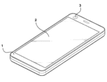
図15は、本実施例に係る光学機器の斜視図である。 FIG. 15 is a perspective view of an optical device according to this embodiment.
光学機器は、携帯電話、スマートフォン(smart phone)、携帯用スマート機器、デジタルカメラ、ノートブックコンピュータ(laptop computer)、デジタル放送用端末、PDA(Personal Digital Assistants)、PMP(Portable MultimediaPlayer)及びナビゲーションのいずれかであり得る。ただし、光学機器の種類がこれに制限されず映像または写真を撮影するための何らかの装置も光学機器で呼称されることができる。 Optical devices include mobile phones, smart phones, portable smart devices, digital cameras, laptop computers, digital broadcasting terminals, PDAs (Personal Digital Assistants), PMPs (Portable Multimedia Players), and navigation. can be However, the type of optical equipment is not limited to this, and any device for taking an image or a photograph can also be called an optical equipment.
光学機器は、本体1を含むことができる。本体1は、光学機器の外観を形成することができる。本体1は、カメラモジュール3を収容することができる。本体1の一面にはディスプレイ部2が配置されることができる。例えば、本体1の一面にディスプレイ部2及びカメラモジュール3が配置されて、本体1の他面(一面の反対側に位置する面)にカメラモジュール3が追加で配置されることができる。
The optical instrument can include a
光学機器は、ディスプレイ部2を含むことができる。ディスプレイ部2は、本体1の一面に配置されることができる。ディスプレイ部2は、カメラモジュール3で撮影された映像を出力することができる。
The optical instrument can include a
光学機器は、カメラモジュール3を含むことができる。カメラモジュール3は、本体1に配置されることができる。カメラモジュール3は、少なくとも一部が本体1の内部に収容されることができる。カメラモジュール3は、複数で備えられることができる。カメラモジュール3は、本体1の一面及び本体1の他面の各々に配置されることができる。カメラモジュール3は、被写体の映像を撮影することができる。本実施例では、光学機器のカメラモジュール3にデュアルカメラモジュールが適用されることができる。
The optics can include a
以下では、本実施例に係るデュアルカメラモジュールの構成を図面を参照して説明する。 The configuration of the dual camera module according to this embodiment will be described below with reference to the drawings.
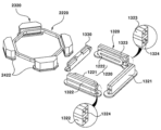
図1は、本実施例に係るデュアルカメラモジュールを図示する斜視図である。 FIG. 1 is a perspective view illustrating a dual camera module according to this embodiment.
デュアルカメラモジュールは、第1カメラモジュール及び第2カメラモジュールを含むことができる。デュアルカメラモジュールは、第1レンズ駆動装置1000及び第2レンズ駆動装置2000を含むことができる。第1カメラモジュールは、第1レンズ駆動装置1000を含むことができる。第2カメラモジュールは、第2レンズ駆動装置2000を含むことができる。本実施例で第1及び第2レンズ駆動装置1000、2000の各々は、オートフォーカス機能及び/または手振れ補正機能を行うことができる。つまり、本実施例で第1及び第2レンズ駆動装置1000、2000は、‘OISモジュール(Optical Image Stabilization Module)’、‘OISアクチュエーター’または‘AFアクチュエーター’であり得る。デュアルカメラモジュールは、第1面を含む第1レンズ駆動装置1000と、第1面と対向する第2面を含む第2レンズ駆動装置2000を含むことができる。第1面は、後述する第1レンズ駆動装置1000のカバー1100の一面であり、第2面は、後述する第2レンズ駆動装置2000のカバー2100の一面であり得る。デュアルカメラモジュールは、プリント回路基板11に並べて配置される第1及び第2レンズ駆動装置1000、2000を含むことができる。他の実施例は、プリント回路基板11が分離して第1プリント回路基板上に第1レンズ駆動装置1000が配置されて第2プリント回路基板上に第2レンズ駆動装置2000が配置されてもよい。
A dual camera module may include a first camera module and a second camera module. A dual camera module may include a first
デュアルカメラモジュールは、レンズモジュールを含むことができる。レンズモジュールは、少なくとも一つのレンズを含むことができる。レンズモジュールは、レンズ及びバレルを含むことができる。レンズモジュールは、第1レンズ駆動装置1000に結合する第1レンズモジュールと、第2レンズ駆動装置2000に結合する第2レンズモジュールを含むことができる。第1レンズモジュールは、第1レンズ駆動装置1000のボビン1210に結合することができる。第1レンズモジュールは、ボビン1210にねじ結合及び/または接着剤によって結合することができる。第1レンズモジュールは、ボビン1210と一体で移動することができる。第2レンズモジュールは、第2レンズ駆動装置2000のボビン2210に結合することができる。第2レンズモジュールは、ボビン2210にねじ結合及び/または接着剤によって結合することができる。第2レンズモジュールは、ボビン1210と一体で移動することができる。
A dual camera module may include a lens module. A lens module can include at least one lens. A lens module can include a lens and a barrel. The lens modules may include a first lens module coupled to the
デュアルカメラモジュールは、フィルターを含むことができる。フィルターは、赤外線フィルターを含むことができる。赤外線フィルターは、イメージセンサーに赤外線領域の光が入射されるのを遮断することができる。赤外線フィルターは、レンズモジュールとイメージセンサーとの間に配置されることができる。赤外線フィルターは、第1レンズ駆動装置1000に結合するレンズの下側に配置される第1赤外線フィルターと、第2レンズ駆動装置2000に結合するレンズの下側に配置される第2赤外線フィルターを含むことができる。例えば、赤外線フィルターは、センサーベース12、13に配置されることができる。他の例として、赤外線フィルターは、ベース1430、2430に配置されることができる。
A dual camera module may include a filter. The filters can include infrared filters. The infrared filter may block light in the infrared region from entering the image sensor. An infrared filter can be placed between the lens module and the image sensor. The infrared filters include a first infrared filter arranged under the lens coupled to the first
デュアルカメラモジュールは、プリント回路基板11を含むことができる。プリント回路基板11には第1レンズ駆動装置1000及び第2レンズ駆動装置2000が配置されることができる。この時、プリント回路基板11と第1レンズ駆動装置1000との間には第1センサーベース12が配置されることができる。また、プリント回路基板11と第2レンズ駆動装置2000との間には第2センサーベース13が配置されることができる。プリント回路基板11は、第1及び第2レンズ駆動装置1000、2000と電気的に連結されることができる。プリント回路基板11にはイメージセンサーが配置されることができる。プリント回路基板11は、イメージセンサーと電気的に連結されることができる。
A dual camera module may include a printed
デュアルカメラモジュールは、イメージセンサーを含むことができる。イメージセンサーは、プリント回路基板11に配置されることができる。イメージセンサーは、プリント回路基板11に電気的に連結されることができる。例えば、イメージセンサーは、プリント回路基板11に表面実装技術(SMT,SurfaceMounting Technology)により結合することができる。他の例として、イメージセンサーは、プリント回路基板11にフリップチップ(flip chip)技術によって結合することができる。イメージセンサーは、第1レンズ駆動装置1000に結合するレンズの下側に配置される第1イメージセンサーと、第2レンズ駆動装置2000に結合するレンズの下側に配置される第2イメージセンサーを含むことができる。イメージセンサーは、レンズと光軸が一致するように配置されることができる。つまり、イメージセンサーの光軸とレンズの光軸は、アラインメント(alignment)できる。イメージセンサーは、イメージセンサーの有効画像領域に照射される光を電気的信号に変換することができる。イメージセンサーは、CCD(charge coupled device、電荷結合素子)、MOS(metal oxide semi-conductor、金属酸化物半導体)、CPD及びCIDのうちのいずれかであり得る。
A dual camera module may include an image sensor. The image sensor can be arranged on the printed
デュアルカメラモジュールは、制御部を含むことができる。制御部は、プリント回路基板11に配置されることができる。制御部は、第1レンズ駆動装置1000の第1コイル1220及び第2コイル1422に供給する電流の方向、強さ及び振幅などを個別的に制御することができる。制御部は、第2レンズ駆動装置2000の第1コイル2220及び第2コイル2422に供給する電流の方向、強さ及び振幅などを個別的に制御することができる。制御部は、第1及び第2レンズ駆動装置1000、2000を制御してオートフォーカス機能及び/または手振れ補正機能を行うことができる。さらに制御部は、第1及び第2レンズ駆動装置1000、2000に対するオートフォーカスフィードバック制御及び/または手振れ補正フィードバック制御を行うことができる。
A dual camera module may include a controller. The controller can be arranged on the printed
以下では、第1レンズ駆動装置の構成を図面を参照して説明する。 The configuration of the first lens driving device will be described below with reference to the drawings.
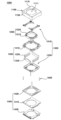
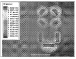
図2は、本実施例に係る第1レンズ駆動装置及び第2レンズ駆動装置の各々のカバーを除去した状態を図示する斜視図で、図3は、本実施例に係る第1レンズ駆動装置及び第2レンズ駆動装置の各々のマグネット、コイル及びのダミー部材の配置構造を図示する斜視図で、図4は、本実施例に係る第1レンズ駆動装置の分解斜視図で、図5は、本実施例に係る第1レンズ駆動装置の第1可動子の分解斜視図で、図6は、本実施例に係る第1レンズ駆動装置の第2可動子の分解斜視図で、図7は、本実施例に係る第1レンズ駆動装置の固定子の分解斜視図で、図8は、本実施例に係る第1レンズ駆動装置の弾性部材の分解斜視図で、図9は、本実施例に係る第1レンズ駆動装置の断面図で、図10は、本実施例に係る第1レンズ駆動装置の一部の断面図で、図11は、本実施例に係る第1レンズ駆動装置の一部の平面図で、図13は、比較例に係るデュアルカメラモジュールのマグネットの磁界分布を図示する図面で、図14は、本実施例に係るデュアルカメラモジュールのマグネットの磁界分布を図示する図である。 FIG. 2 is a perspective view illustrating a state in which the covers of the first lens driving device and the second lens driving device according to this embodiment are removed, and FIG. FIG. 4 is an exploded perspective view of the first lens driving device according to this embodiment, and FIG. FIG. 6 is an exploded perspective view of the second mover of the first lens driving device according to the embodiment, and FIG. 7 is an exploded perspective view of the second mover of the first lens driving device according to the embodiment FIG. 8 is an exploded perspective view of the stator of the first lens driving device according to the embodiment, FIG. 8 is an exploded perspective view of the elastic member of the first lens driving device according to the embodiment, and FIG. 10 is a cross-sectional view of a part of the first lens driving device according to this embodiment, and FIG. 11 is a cross-sectional view of a part of the first lens driving device according to this embodiment. 13 is a plan view showing the magnetic field distribution of the magnet of the dual camera module according to the comparative example, and FIG. 14 is the diagram showing the magnetic field distribution of the magnet of the dual camera module according to the present embodiment.
第1レンズ駆動装置1000は、ボイスコイルモーター(Vcm,Voice Coil Motor)であり得る。さらに、第1レンズ駆動装置1000は、OISであり、Dual OISのためのOISであり得る。
The first
第1レンズ駆動装置1000は、カバー1100を含むことができる。カバー1100は、ベース1430と結合することができる。カバー1100は、ハウジング1310を内側に収容することができる。カバー1100は、第1レンズ駆動装置1000の外観を形成することができる。カバー1100は、下面が開放された六面体形状であり得る。カバー1100は、非磁性体であり得る。カバー1100は、金属材で形成されることができる。カバー1100は、金属の板材で形成されることができる。カバー1100は、プリント回路基板11のグラウンド部と連結されることができる。これにより、カバー1100は、グラウンドされることができる。カバー1100は、電磁波障害(EMI,electro magnetic interference)を遮断することができる。この時、カバー1100は、‘EMIシールドカン’で呼称されることができる。
The first
カバー1100は、上板1110及び側板1120を含むことができる。カバー1100は、上板1110と、上板1110の外周(outer periphery)またはエッジ(edge)から下側に延びる側板1120を含むことができる。カバー1100の側板1120の下端は、ベース1430の段差部1434に配置されることができる。カバー1100の側板1120の内面は、ベース1430と接着剤によって結合することができる。
The
カバー1100の上板1110は、ホール1111を含むことができる。ホール1111は、カバー1100の上板1110に形成されることができる。ホール1111は、レンズを上側に露出させることができる。ホール1111は、レンズと対応する大きさ及び形状で形成されることができる。ホール1111の大きさは、レンズモジュールがホール1111を介して挿入されて組み立てられるようにレンズモジュールの直径より大きく形成されることができる。ホール1111を介して流入した光は、レンズを通過することができる。この時、レンズを通過した光は、イメージセンサーで電気的信号に変換されて映像で得ることができる。
A
第1レンズ駆動装置1000は、第1可動子1200を含むことができる。第1可動子1200は、レンズと結合することができる。第1可動子1200は、弾性部材1500を介して第2可動子1300と結合することができる。第1可動子1200は、第2可動子1300との相互作用により移動することができる。この時、第1可動子1200は、レンズと一体で移動することができる。一方、第1可動子1200は、AF駆動時移動することができる。この時、第1可動子1200は、‘AF可動子’と呼称されることができる。ただし、第1可動子1200は、OIS駆動時にも移動することができる。
The first
第1可動子1200は、ボビン1210を含むことができる。ボビン1210は、ハウジング1310の中にまたは内側に配置されることができる。ボビン1210は、ハウジング1310のホール1311に配置されることができる。ボビン1210は、ハウジング1310に移動可能に結合することができる。ボビン1210は、ハウジング1310に対して光軸方向に移動することができる。ボビン1210にはレンズが結合することができる。ボビン1210とレンズは、ねじ結合及び/または接着剤によって結合することができる。ボビン1210には第1コイル1220が結合することができる。ボビン1210の上部または上面には上部弾性部材1510が結合することができる。ボビン1210の下部または下面には下部弾性部材1520が結合することができる。ボビン1210は、弾性部材1500と熱融着及び/または接着剤によって結合することができる。ボビン1210とレンズ、及びボビン1210と弾性部材1500を結合する接着剤は、紫外線(UV)、熱及びレーザーのうちのいずれか一つ以上によって硬化するエポキシ(epoxy)であり得る。
ボビン1210は、ホール1211を含むことができる。ホール1211は、ボビン1210を光軸方向に貫くことができる。ホール1211にはレンズモジュールが収容されることができる。例えば、ホール1211を形成するボビン1210の内周面には、レンズモジュールの外周面に形成されるねじ山と対応するねじ山が形成されることができる。
ボビン1210は、突起1212を含むことができる。突起1212は、ボビン1210の側面に配置されることができる。突起1212は、ボビン1210の側面から突出して一体で形成されることができる。突起1212には第1コイル1220が巻線されることができる。比較例として、突起1212にすでに巻線された第1コイル1220が結合することができる。突起1212は、第1突起1212及び第2突起を含むことができる。ボビン1210は、ボビン1210の第1側面に配置される第1突起1212と、ボビン1210の第1側面の反対側に配置される第2側面に配置される第2突起を含むことができる。第1突起1212及び第2突起の各々は、二つの突起で分離備えられることができる。比較例として、第1突起1212及び第2突起の各々は、分離せず一体で形成されることができる。第1突起1212には第1コイルユニット1221が巻線されることができる。第2突起には第2コイルユニット1222が巻線されることができる。
第1可動子1200は、第1コイル1220を含むことができる。第1コイル1220は、ボビン1210に配置されることができる。第1コイル1220は、ボビン1210とハウジング1310との間に配置されることができる。第1コイル1220は、ボビン1210の外周面に配置されることができる。第1コイル1220は、ボビン1210に直巻線されることができる。第1コイル1220は、マグネット1320と対向することができる。第1コイル1220は、マグネット1320と電磁気的相互作用することができる。この場合、第1コイル1220に電流が供給されて第1コイル1220の周りに電磁気場が形成されると、第1コイル1220とマグネット1320との間の電磁気的相互作用によって第1コイル1220がマグネット1320に対して移動することができる。第1コイル1220は一体で形成される一つのコイルであり得る。
The
第1コイル1220は、電源供給のための両端部を含むことができる。この時、第1コイル1220の一側端部(引出線)は、第1上部弾性ユニット1510aと結合して第1コイル1220の他方端部(引出線)は、第2上部弾性ユニット1510bと結合することができる。つまり、第1コイル1220は、上部弾性部材1510と電気的に連結されることができる。より詳細に、第1コイル1220は、順次プリント回路基板11、基板1410、支持部材1600及び上部弾性部材1510を通して電源の供給を受けることができる。変形例で、第1コイル1220は、下部弾性部材1520と電気的に連結されることができる。
The
第1コイル1220は、互いに離隔する第1コイルユニット1221及び第2コイルユニット1222を含むことができる。第1コイル1220は、第2マグネットユニット1322と対向する第1コイルユニット1221と、第3マグネットユニット1323と対向する第2コイルユニット1222を含むことができる。第1コイルユニット1221と第2コイルユニット1222は、ボビン1210の外側面の反対側に互いに離隔して配置されることができる。第1コイルユニット1221は、第1突起1212の上面と下面を覆うように第1突起1212に巻かれることができる。第1コイルユニット1221は、第1突起1212に挿入されて配置されることができて、第2コイルユニット1222は、第2突起に挿入されて配置されることができる。第2コイルユニット1222は、第2突起の上面と下面を覆うように第2突起に巻かれることができる。第1コイルユニット1221及び第2コイルユニット1222は、‘メガネコイル’と呼称されることができる。第1コイルユニット1221と第2コイルユニット1222は、楕円形状、トラック形状、閉曲線形状の少なくともいずれか一つの形状を持つことができる。
The
第1コイル1220は、マグネット1320の第1マグネットユニット1321と対向することができないことがある。より詳細に、第1コイル1220は、マグネット1320の第2マグネットユニット1322及び第3マグネットユニット1323とだけ対向するだけで第1マグネットユニット1321とは対向することができないことがある。第2マグネットユニット1322と対向するように第1コイルユニット1221が配置されて、第3マグネットユニット1323と対向するように第2コイルユニット1222が配置されるが、第1マグネットユニット1321には対向する第1コイル1220の区分構成が配置されないことがある。
The
第1コイル1220は、第1コイルユニット1221と第2コイルユニット1222を電気的に連結する連結部(図示せず)を含むことができる。第1コイル1220の連結部は、連結コイル(図示せず)であり得る。第1コイル1220の連結部には第1コイルユニット1221の一終端と第2コイルユニット1222の一終端が互いに連結されることができる。第1コイル1220の連結部は、第1コイルユニット1221と第2コイルユニット1222との間に配置されることができる。第1コイル1220の連結部は、第1マグネットユニット1321と対向することができる。他の実施例で第1コイル1220の連結部は、ダミー部材1330と対向することができる。第1コイル1220の連結部は、第1マグネットユニット1321とボビン1210との間に配置されるかダミー部材1330とボビン1210との間に配置されることができる。
The
本実施例で、第1コイルユニット1221と第2マグネットユニット1322との間の距離及び/または第2コイルユニット1222と第3マグネットユニット1323との間の距離(図11のL1参照)は、60μm乃至150μmであり得る。ボビン1210と第1マグネットユニット1321との間の距離(図11のL2参照)は、60μm乃至200μmであり得る。
In this embodiment, the distance between the
第1レンズ駆動装置1000は、第2可動子1300を含むことができる。第2可動子1300は、固定子1400に支持部材1600を介して移動可能に結合することができる。第2可動子1300は、弾性部材1500を介して第1可動子1200を支持することができる。第2可動子1300は、第1可動子1200を移動させたり第1可動子1200とともに移動することができる。第2可動子1300は、固定子1400との相互作用により移動することができる。第2可動子1300は、OIS駆動時移動することができる。この時、第2可動子1300は、‘OIS可動子’と呼称されることができる。第2可動子1300は、OIS駆動時第1可動子1200と一体で移動することができる。
The first
第2可動子1300は、ハウジング1310を含むことができる。ハウジング1310は、ボビン1210の外側に配置されることができる。ハウジング1310は、中または内側にボビン1210の少なくとも一部を収容することができる。ハウジング1310は、カバー1100の中に(内側に)配置されることができる。ハウジング1310は、カバー1100とボビン1210との間に配置されることができる。ハウジング1310は、カバー1100と異なる材質で形成されることができる。ハウジング1310は、絶縁材質で形成されることができる。ハウジング1310は、射出物で形成されることができる。ハウジング1310の外側の側面は、カバー1100の側板1120の内面と離隔することができる。ハウジング1310とカバー1100との間の離隔空間を通してハウジング1310は、OIS駆動のために移動することができる。ハウジング1310にはマグネット1320が配置されることができる。ハウジング1310とマグネット1320は、接着剤によって結合することができる。ハウジング1310の上部または上面には上部弾性部材1510が結合することができる。ハウジング1310の上部または下面には下部弾性部材1520が結合することができる。ハウジング1310は、弾性部材1500と熱融着及び/または接着剤によって結合することができる。ハウジング1310とマグネット1320、及びハウジング1310と弾性部材1500を結合する接着剤は紫外線(UV)、熱及びレーザーのうちのいずれか一つ以上によって硬化するエポキシ(epoxy)であり得る。
The
ハウジング1310は、四つの側部と、四つの側面の間に配置される四つの隅部を含むことができる。ハウジング1310は、第1レンズ駆動装置1000の第1面側に配置される第1側部と、第1側部の反対側に配置される第2側部と、第1側部と第2側部との間に配置されて互いに反対側に配置される第3側部と第4側部を含むことができる。ハウジング1310の第1側部は、第1レンズ駆動装置1000の第1面側に配置されることができる。ハウジング1310は、四つの側部を含むことができて、四つの側部を互い区分するために任意に‘第1側部’乃至‘第4側部’と呼称されることができる。例えば、前述した説明とは異なり第2側部が第1レンズ駆動装置1000の第1面側に配置されることができる。
The
ハウジング1310は、ホール1311を含むことができる。ホール1311は、ハウジング1310に形成されることができる。ホール1311は、ハウジング1310を光軸方向に貫くように形成されることができる。ホール1311にはボビン1210が配置されることができる。ホール1311は、少なくとも一部でボビン1210と対応する形状で形成されることができる。ホール1311を形成するハウジング1310の内周面は、ボビン1210の外周面と離隔して位置することができる。ただし、ハウジング1310とボビン1210は、少なくとも一部で光軸方向に重なってボビン1210の光軸方向の移動ストローク距離を制限することができる。
ハウジング1310は、マグネット結合部1312を含むことができる。マグネット結合部1312にはマグネット1320が結合することができる。マグネット結合部1312は、ハウジング1310の内周面及び/または下面の一部が陥没して形成される収容溝を含むことができる。マグネット結合部1312は、ハウジング1310の四つの側部の各々に形成されることができる。変形例で、マグネット結合部1312は、ハウジング1310の四つの隅部の各々に形成されることができる。
ハウジング1310は、上板1313を含むことができる。ハウジング1310は、マグネット1320の上面の上側に配置される上板1313を含むことができる。上板1313は、マグネット1320の上面を支持することができる。上板1313とマグネット1320との間には接着剤が配置されることができる。上板1313は、マグネット1320の上面の一部の上側に配置されることができる。上板1313にはカバー1100の上板1110に向かって突出するストッパー1314が配置されることができる。上板1313は、ハウジング1310と一体で形成されることができる。ストッパー1314は、上板1313と一体で形成されることができる。上板1313は、ハウジング1310の第2側部、第3側部及び第4側部に各々配置されることができる。つまり、三つの上板1313がハウジング1310に配置されることができる。上板1313は、ダミー部材1330が配置されるハウジング1310の第1側部には配置されないことがある。ハウジング1310の上板1313は、ハウジング1310の第2側部、第3側部及び第4側部の各々に配置されてハウジング1310の第1側部に配置されないことがある。つまり、ハウジング1310の第1側部に配置されるダミー部材1330の上部には、ハウジング1310の上板1313が配置されないことがある。つまり、ハウジング1310は、ボビン1210に結合するレンズの中心軸を基準に非対称であり得る。
ハウジング1310は、ストッパー1314を含むことができる。ストッパー1314は、上板1313に配置されることができる。ストッパー1314は、上板1313と一体で形成されることができる。ストッパー1314は、上板1313毎に二つずつ備えられることができる。つまり、ハウジング1310には計六つのストッパー1314が配置されることができる。二つのストッパー1314は、上板1313の両側末端に各々配置されることができる。ストッパー1314の上面は、ハウジング1310の上端を形成することができる。ストッパー1314は、カバー1100の上板1110と光軸方向に重なることができる。つまり、ハウジング1310が上側に移動し続けるとストッパー1314の上面がカバー1100の上板1110と接触するようになる。従って、ストッパー1314は、ハウジング1310の上側への移動距離を制限することができる。
第2可動子1300は、マグネット1320を含むことができる。マグネット1320は、ハウジング1310に配置されることができる。マグネット1320は、ハウジング1310に接着剤によって固定されることができる。マグネット1320は、ボビン1210とハウジング1310との間に配置されることができる。マグネット1320は、第1コイル1220と対向することができる。マグネット1320は、第1コイル1220と電磁気的相互作用することができる。マグネット1320は、第2コイル1422と対向することができる。マグネット1320は、第2コイル1422と電磁気的相互作用することができる。マグネット1320は、AF駆動及びOIS駆動に共用に使われることができる。マグネット1320は、ハウジング1310の側部に配置されることができる。この時、マグネット1320は、平板(flat plate)形状を持つ平板マグネットであり得る。変形例で、マグネット1320は、ハウジング1310の隅部に配置されることができる。この時、マグネット1320は、内側の側面が外側の側面より広い六面体形状を持つコーナーマグネットであり得る。
The
本実施例で、マグネット1320の上面は、上部弾性部材1510と光軸方向に重なる第1部分を含むことができる。マグネット1320の上面の第1部分は、ハウジング1310と光軸方向に重ならないことがある。マグネット1320の上面の第1部分は、上部弾性部材1510と対向するようにハウジング1310から露出することができる。マグネット1320の上面の第1部分は、上部弾性部材1510と接触することができる。マグネット1320の上面は、ハウジング1310と光軸方向に重なる第2部分を含むことができる。マグネット1320の上面の第2部分の上側にはハウジング1310の上板1313が配置されることができる。マグネット1320の上面の第2部分は、ハウジング1310の上板1313と結合することができる。マグネット1320の上面の第2部分は、上部弾性部材1510と光軸方向に重ならないことがある。マグネット1320の上面は、ハウジング1310と上部弾性部材1510と光軸方向に重ならない第3部分をさらに含むことができる。つまり、マグネット1320の上面は、光軸方向に上部弾性部材1510と重なる第1部分と、ハウジング1310の上板1313と重なる第2部分と、上部弾性部材1510及びハウジング1310の上板1313の全てと重ならない第3部分を含むことができる。ただし、第3部分は存在しないことがある。
In this embodiment, the top surface of the
本実施例でマグネット1320の上面は、上部弾性部材1510が結合するハウジング1310の上面と同じ平面に配置されることができる。このような構造のために、本実施例ではハウジング1310の一部が省略されるものであり得る。つまり、該当構造は、ハウジング1310の一部が省略されて該当の部分に上部弾性部材1510が配置されたものと説明することできる。マグネット1320の上面の一部は、上部弾性部材1510と接触することができる。さらに、マグネット1320の上面の他の一部は、ハウジング1310の上板1313と接触することができる。
In this embodiment, the top surface of the
マグネット1320は、相互間離隔する複数のマグネットを含むことができる。マグネット1320は、相互間離隔する三つのマグネットを含むことができる。マグネット1320は、第1乃至第3マグネットユニット1321、1322、1323を含むことができる。マグネット1320は、ハウジング1310の第2側部に配置される第1マグネットユニット1321と、ハウジング1310の第3側部に配置される第2マグネットユニット1322と、ハウジング1310の第4側部に配置される第3マグネットユニット1323を含むことができる。第1マグネットユニット1321は、第2コイル1422の第1コイルユニット1422aと対向することができる。第2マグネットユニット1322は、第1コイル1220の第1コイルユニット1221と対向して第2コイル1422の第2コイルユニット1422bと対向することができる。第3マグネットユニット1323は、第1コイル1220の第2コイルユニット1222と対向して第2コイル1422の第3コイルユニット1422cと対向することができる。第2マグネットユニット1322と第3マグネットユニット1323は、ボビン1210を光軸方向に動かすことができる。第1マグネットユニット1321、第2マグネットユニット1322、及び第3マグネットユニット1323は、ハウジング1310を光軸方向に垂直な方向に動かすことができる。
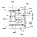
第1マグネットユニット1321は、2極マグネット(2pole magnet)であり得る。本実施例で第2マグネットユニット1322と第3マグネットユニット1323は、4極マグネット(4pole magnet)であり得る。2極マグネットは、2極着磁マグネットであり、4極マグネットは4極着磁マグネットであり得る。本実施例ではこれにより、第1レンズ駆動装置1000のマグネット1320と第2レンズ駆動装置2000のマグネット2320との間の磁界干渉を減少させることができる。比較例は、第2マグネットユニット1322と第3マグネットユニット1323が、2極マグネットで備えられる。比較例の磁界分布を図示した図面が図13である。さらに、本実施例の磁界分布を図示した図面が図14である。図14を図13と比較すると第1レンズ駆動装置1000のマグネット1320と第2レンズ駆動装置2000のマグネット2320との間の磁界干渉が減少または解消されたことを確認することができる。
The
第2マグネットユニット1322と第3マグネットユニット1323の各々は、第1コイル1220と対向する第1面を含むことができる。第1面は、中心部に水平方向に配置される中立部1324を含むことができる。中立部1324は、中立領域であり、極を含まないことがある。第1面は、中立部1324を基準に上部と下部が異なる極を持つことができる。つまり、中立部1324の上側はS極を持って、中立部1324の下側はN極を持つことができる。変形例で、中立部1324の上側はN極を持って、中立部1324の下側はS極を持つことができる。中立部1324の縦の長さ(図10のL参照)は0.1mm乃至0.5mmであり得る。
Each of the
第1乃至第3マグネットユニット1321、1322、1323の各々は、第2コイル1422と対向する第2面と、第2面と反対側に配置される第3面を含むことができる。第2面は、第1レンズ駆動装置1000の中心側である内側であり、第3面は、前記内側の反対側である外側であり得る。第1乃至第3マグネットユニット1321、1322、1323の各々の第2面と第3面は異なる極を持つことができる。つまり、第2面はN極を持って、第3面はS極を持つことができる。変形例で、第2面はS極を持って、第3面はN極を持つことができる。
Each of the first to
第2可動子1300は、ダミー部材1330を含むことができる。ハウジング1310の第1側部にはダミー部材1330が配置されることができる。ダミー部材1330は、非磁性物質を含むことができる。ダミー部材1330は、第1マグネットユニット1321と対応する質量を持つことができる。ダミー部材1330は、重さの均衡のために第1マグネットユニット1321と対応する位置に配置されることができる。または、ダミー部材1330の磁性の強さは、第1マグネットユニット1321の磁性の強さより弱いことがあり得る。ダミー部材1330は、第1マグネットユニット1321の反対側に重心を合わせるために配置されることができる。ダミー部材1330は非磁性体であり得る。ダミー部材1330は95%以上タングステンを材料にすることができる。つまり、ダミー部材1330は、タングステン合金であり得る。例えば、ダミー部材1330の比重は18000以上であり得る。ダミー部材1330は、上面の全体がハウジング1310から露出することができる。つまり、ダミー部材1330の上面は、ハウジング1310と光軸方向に重なるか支持されないことがある。ダミー部材1330の上側にはハウジング1310の上板1313が配置されないことがある。ダミー部材1330と基板1410との間には第2コイル1422が配置されないことがある。
The
ダミー部材1330は、ハウジング1310に組み付けられるための形状を含むことができる。ダミー部材1330は、両側方に突出する突起を含むことができる。ダミー部材1330は、隣接動作部品に対する干渉回避のための形状を含むことができる。ダミー部材1330は、上面と内面が会う部分に形成される溝を含むことができる。ダミー部材1330の外面の水平方向の長さは、第1マグネットユニット1321の対応する方向の長さより短いことがある。ダミー部材1330の厚さは、第1マグネットユニット1321の厚さと対応することができる。または、ダミー部材1330の厚さは、第1マグネットユニット1321の厚さより大きいか小さいことがある。ダミー部材1330の形状は、第1マグネットユニット1321の形状と異なることがある。変形例で、ダミー部材1330の形状は、第1マグネットユニット1321の形状と対応することができる。ダミー部材1330は、第1マグネットユニット1321と同じ高さに配置されることができる。または、ダミー部材1330は、第1マグネットユニット1321より高くまたはより低く配置されることができる。ダミー部材1330の上端は、第1マグネットユニット1321の上端と同じ高さに配置されることができる。または、ダミー部材1330の上端は、第1マグネットユニット1321の上端より高くまたはより低く配置されることができる。ダミー部材1330の下端は、第1マグネットユニット1321の下端と対応する高さに配置されることができる。または、ダミー部材1330の下端は、第1マグネットユニット1321の下端より高くまたはより低く配置されることができる。図3に示したように、ダミー部材1330は、第1レンズ駆動装置1000のマグネット1320と第2レンズ駆動装置2000のマグネット2320との間に配置されることができる。ダミー部材1330の横の長さは、第1マグネットユニット1321の横の長さと同じか、より短かかったりまたはより長いことがある。ダミー部材1330の縦の長さは、第1マグネットユニット1321の横の長さと同じか、より短いかまたはより長いことがある。
第1レンズ駆動装置1000は、固定子1400を含むことができる。固定子1400は、第1及び第2可動子1200、1300の下側に配置されることができる。固定子1400は、第2可動子1300を移動可能に支持することができる。固定子1400は、第2可動子1300を移動させることができる。この時、第1可動子1200も第2可動子1300と共に移動することができる。
The first
固定子1400は、基板1410を含むことができる。基板1410は、マグネット1320と対向する第2コイル1422を含むことができる。または、基板1410は、マグネット1320と対向する第2コイル1422を含む回路部材1420を含むことができる。基板1410は、ベース1430に配置されることができる。基板1410は、ハウジング1310とベース1430との間に配置されることができる。基板1410には支持部材1600が結合することができる。基板1410は、第2コイル1422に電源を供給することができる。基板1410は、回路部材1420と結合することができる。基板1410は、第2コイル1422と結合することができる。基板1410は、ベース1430の下側に配置されるプリント回路基板11と結合することができる。基板1410は、フレキシブルなプリント回路基板(FPCB,Flexible Printed Circuit Board)を含むことができる。基板1410は、一部で折り曲げられることができる。
基板1410は、本体部1411を含むことができる。基板1410は、本体部1411に形成されるホール1411aを含むことができる。基板1410は、ボビン1210に結合するレンズと対応するホール1411aを含むことができる。ホール1411aは、第1レンズ駆動装置1000の第1面側に偏心して配置されることができる。本実施例では、このようなホール1411aの偏心配置構造により第1コイルユニット1422aのターン数を増加させるためのベース1430、基板1410及び回路部材1420のうちのいずれか一つ以上の空間を確保することができる。基板1410のホール1411aは、基板1410の一側面により近く形成されることができる。この時、基板1410の一側面は、ダミー部材1330と隣接することができる。基板1410の一側面の反対側にある他側面からホール1411aまでの最短距離は、一側面からホール1411aまでの最短距離より大きいことがある。
The
基板1410は、ホール1411aと、ホール1411aにより形成される内周面と、ハウジング1310の第1側部側に配置される第1側面と、ハウジング1310の第2側部側に配置される第2側面を含むことができる。基板1410の内周面と基板1410の第2側面との間の距離(図7のW4参照)は、基板1410の内周面と基板1410の第1側面との間の距離(図7のW3参照)より長いことがある。基板1410の内周面と基板1410の第2側面との間には第1コイルユニット1422aが配置されることができる。基板1410の内周面と基板1410の第1側面との間には第2コイル1422が配置されないことがある。
The
基板1410は、第1レンズ駆動装置1000の第1面側に配置される第1側面と、第1側面の反対側に配置される第2側面と、第1側面と第2側面との間に配置されて互いに反対側に配置される第3側面と第4側面を含むことができる。この時、第3側面と第4側面との間の距離(図7のW1参照)は、第1側面と第2側面との間の距離(図7のW2参照)より長いことがある。本実施例では、前記の構造により第1コイルユニット1422aの長手方向の長さ(L1)を第2及び第3コイルユニット1422b、1422cの長手方向の長さ(L2)より長く形成できる空間を確保することができる。
The
基板1410は、端子部1412を含むことができる。端子部1412は、基板1410の本体部1411から延びることができる。端子部1412は、基板1410の一部が下側に折り曲げられて形成されることができる。端子部1412は、少なくとも一部が外側に露出することができる。端子部1412は、ベース1430の下側に配置されるプリント回路基板11とはんだ付け(soldering)により結合することができる。端子部1412は、ベース1430の端子収容部1433に配置されることができる。
The
基板1410は、回路部材1420を含むことができる。固定子1400は、回路部材1420を含むことができる。回路部材1420は、ベース1430に配置されることができる。回路部材1420は、基板1410に配置されることができる。回路部材1420は、マグネット1320とベース1430との間に配置されることができる。ここで、回路部材1420が基板1410と別の構成と説明されているが、回路部材1420は基板1410に含まれる構成と理解されることができる。
回路部材1420は、基板部1421を含むことができる。基板部1421は、回路基板であり得る。基板部1421は、FPCBであり得る。基板部1421には第2コイル1422が微細パターンコイル(FP coil,Fine pattern coil)で一体で形成されることができる。基板部1421には支持部材1600が通過するホールが形成されることができる。基板部1421にはホール1421aが形成されることができる。基板部1421のホール1421aは、基板1410のホール1411aと対応するように形成されることができる。
回路部材1420は、第2コイル1422を含むことができる。第2コイル1422は、マグネット1320と対向することができる。第2コイル1422は、マグネット1320と電磁気的相互作用することができる。この場合、第2コイル1422に電流が供給されて第2コイル1422の周りに磁場が形成されると、第2コイル1422とマグネット1320との間の電磁気的相互作用によってマグネット1320が第2コイル1422に対して移動することができる。第2コイル1422は、マグネット1320との電磁気的相互作用によりハウジング1310及びボビン1210をベース1430に対して光軸と垂直方向に移動させることができる。第2コイル1422は、基板部1421に一体で形成される微細パターンコイル(FP coil,Fine Pattern coil)であり得る。
第2コイル1422は、第1マグネットユニット1321と対向する第1コイルユニット1422aと、第2マグネットユニット1322と対向する第2コイルユニット1422bと、第3マグネットユニット1323と対向する第3コイルユニット1422cを含むことができる。第1コイルユニット1422aでコイルが巻かれた回数が、第2コイルユニット1422bでコイルが巻かれた回数より多いことがある。第3コイルユニット1422cでコイルが巻かれた回数は、第2コイルユニット1422bでコイルが巻かれた回数と対応することができる。本実施例では、OIS駆動時X軸方向移動を第1コイルユニット1422aを介して行って、Y軸方向移動を第2コイルユニット1422bと第3コイルユニット1422cを介して行うことができる。従って、本実施例ではX軸方向の不足した推進力を補充するために第1コイルユニット1422aのターン(turn)数を第2コイルユニット1422bと第3コイルユニット1422cのターン数より高くすることができる。例えば、第1コイルユニット1422aのターン数と第2コイルユニット1422b(または第3コイルユニット1422c)のターン数の比は、1.5:2.0乃至1:1であり得る。これは、第1コイルユニット1422aと対向する位置に第2コイル1422が配置されないため、これを補償するためである。つまり、第1コイルユニット1422aのターン数と第2コイルユニット1422b(または第3コイルユニット1422c)のターン数の比は、空間的制約によって1.5:2.0まで配置されることができる。第1コイルユニット1422aの長手方向の長さ(図7のL1参照)は、第2コイルユニット1422bと第3コイルユニット1422cの各々の長手方向の長さ(図7のL2参照)より長いことがある。第1コイルユニット1422aの幅方向の長さ(図7のL3参照)は、第2コイルユニット1422bと第3コイルユニット1422cの各々の幅方向の長さ(図7のL4参照)より長いことがある。
The
本実施例で、ボビン1210に結合するレンズの中心軸(図9のC1参照)は、第1レンズ駆動装置1000の中心軸(図9のC2参照)からダミー部材1330の方向に偏心して配置されることができる。ボビン1210の中心軸(C1)は、ハウジング1310の中心軸(C2)からダミー部材1330の方向に偏心して配置されることができる。この時、レンズの中心軸(C1)は、ボビン1210の中心軸(C1)またはハウジング1310のホール1311の中心軸と一致することができる。さらに、第1レンズ駆動装置1000の中心軸(C2)とハウジング1310の中心軸(C2)は一致することができる。この時、ハウジング1310の中心軸(C2)は、ハウジング1310のホール1311の中心軸ではないハウジング1310の外郭を基準に見ると中心軸であり得る。さらに、ホール1411aは、第1レンズ駆動装置1000の第1面側に偏心して配置されることができる。本実施例では前記の構造により第1コイルユニット1422aの長手方向の長さ(L1)を第2及び第3コイルユニット1422b、1422cの長手方向の長さ(L2)より長く形成できる空間を確保することができる。
In this embodiment, the central axis of the lens coupled to the bobbin 1210 (see C1 of FIG. 9) is eccentrically arranged in the direction of the
固定子1400は、ベース1430を含むことができる。ベース1430は、ハウジング1310の下側に配置されることができる。ベース1430は基板1410の下側に配置されることができる。ベース1430の上面には基板1410が配置されることができる。ベース1430はカバー1100と結合することができる。ベース1430は、プリント回路基板11の上側に配置されることができる。
ベース1430は、ホール1431を含むことができる。ホール1431は、ベース1430に形成されることができる。ホール1431は、ベース1430を光軸方向に貫くように形成されることができる。ホール1431を通してレンズモジュールを通過した光がイメージセンサーに入射されることができる。つまり、レンズモジュールを通過した光は、回路部材1420のホール1421a、基板1410のホール1411a及びベース1430のホール1431を通過してイメージセンサーに入射されることができる。
ベース1430は、センサー結合部1432を含むことができる。センサー結合部1432には第2センサー(図示せず)が配置されることができる。センサー結合部1432は、第2センサーの少なくとも一部を収容されることができる。センサー結合部1432は、ベース1430の上面が陥没して形成される溝を含むことができる。センサー結合部1432は、二つの溝を含むことができる。この時、二つの溝の各々には第2センサーが配置されてマグネット1320のX軸方向移動及びY軸方向移動を感知することができる。
ベース1430は、端子収容部1433を含むことができる。端子収容部1433には基板1410の端子部1412が配置されることができる。端子収容部1433は、ベース1430の側面の一部が内側に陥没して形成される溝を含むことができる。端子収容部1433の幅は、基板1410の端子部1412の幅と対応するように形成されることができる。端子収容部1433の長さは、基板1410の端子部1412の長さと対応するように形成されることができる。
The
ベース1430は、段差部1434を含むことができる。段差部1434はベース1430の側面に形成されることができる。段差部1434は、ベース1430の外周面を囲むように形成されることができる。段差部1434は、ベース1430の側面の上部が陥没して形成されることができる。または、段差部1434は、ベース1430の側面の下部が突出して形成されることができる。段差部1434にはカバー1100の側板1120の下端が配置されることができる。
The
第1レンズ駆動装置1000は、弾性部材1500を含むことができる。弾性部材1500は、ボビン1210及びハウジング1310に結合することができる。弾性部材1500は、ボビン1210を弾性的に支持することができる。弾性部材1500は、少なくとも一部で弾性を持つことができる。弾性部材1500は、ボビン1210を移動可能に支持することができる。弾性部材1500は、AF駆動時ボビン1210の移動を支持することができる。この時、弾性部材1500は、‘AF支持部材’と呼称されることができる。
The first
弾性部材1500は、上部弾性部材1510を含むことができる。上部弾性部材1510は、ボビン1210の上側に配置されることができる。上部弾性部材1510は、ボビン1210とハウジング1310に結合することができる。上部弾性部材1510は、ボビン1210の上面に結合することができる。上部弾性部材1510は、ハウジング1310の上面に結合することができる。上部弾性部材1510は、支持部材1600と結合することができる。上部弾性部材1510は、板バネで形成されることができる。
The
上部弾性部材1510は、第1コイル1220に電気を供給するための導電ラインで使われることができる。上部弾性部材1510は、互いに離隔する第1上部弾性ユニット1510aと第2上部弾性ユニット1510bを含むことができる。第1上部弾性ユニット1510aは、第1コイル1220の一端と結合して、第2上部弾性ユニット1510bは、第1コイル1220の他端と結合することができる。上部弾性部材1510と第1コイル1220は、はんだ付け(soldering)により結合することができる。
The upper
上部弾性部材1510は、外側部1511を含むことができる。外側部1511は、ハウジング1310に結合することができる。外側部1511は、ハウジング1310の上面に結合することができる。外側部1511は、ハウジング1310の突起に結合するホールまたは溝を含むことができる。外側部1511は接着剤によってハウジング1310に固定されることができる。
The upper
上部弾性部材1510は内側部1512を含むことができる。内側部1512は、ボビン1210に結合することができる。内側部1512は、ボビン1210の上面に結合することができる。内側部1512は、ボビン1210の突起に結合するホールまたは溝を含むことができる。内側部1512は、接着剤によってボビン1210に固定されることができる。
The upper
上部弾性部材1510は、連結部1513を含むことができる。連結部1513は、外側部1511及び内側部1512を連結することができる。連結部1513は、外側部1511及び内側部1512を弾性的に連結することができる。連結部1513は、弾性を持つことができる。この時、連結部1513は‘弾性部’と呼称されることができる。連結部1513は、2回以上折り曲げられて形成されることができる。
The upper
上部弾性部材1510は、結合部1514を含むことができる。結合部1514は、支持部材1600と結合することができる。結合部1514は、支持部材1600とはんだ付けによって結合することができる。結合部1514は、支持部材1600と結合するホールまたは溝を含むことができる。結合部1514は、外側部1511から延びることができる。結合部1514は、折り曲げられて形成される折曲部を含むことができる。
The upper
弾性部材1500は、下部弾性部材1520を含むことができる。下部弾性部材1520は、ボビン1210の下側に配置されることができる。下部弾性部材1520は、ボビン1210とハウジング1310に結合することができる。下部弾性部材1520は、ボビン1210の下面に結合することができる。下部弾性部材1520は、ハウジング1310の下面に結合することができる。下部弾性部材1520は、板バネで形成されることができる。下部弾性部材1520は一体で形成されることができる。
The
下部弾性部材1520は、外側部1521を含むことができる。外側部1521は、ハウジング1310に結合することができる。外側部1521は、ハウジング1310の下面に結合することができる。外側部1521は、ハウジング1310の突起に結合するホールまたは溝を含むことができる。外側部1521は、接着剤によってハウジング1310に固定されることができる。
The lower
下部弾性部材1520は、内側部1522を含むことができる。内側部1522は、ボビン1210に結合することができる。内側部1522は、ボビン1210の下面に結合することができる。内側部1522は、ボビン1210の突起に結合するホールまたは溝を含むことができる。内側部1522は、接着剤によってボビン1210に固定されることができる。
The lower
下部弾性部材1520は、連結部1523を含むことができる。連結部1523は、外側部1521及び内側部1522を連結することができる。連結部1523は、外側部1521及び内側部1522を弾性的に連結することができる。連結部1523は、弾性を持つことができる。この時、連結部1523は‘弾性部’と呼称されることができる。連結部1523は、2回以上折り曲げられて形成されることができる。
The lower
第1レンズ駆動装置1000は、支持部材1600を含むことができる。支持部材1600は、サスペンションワイヤーであり得る。支持部材1600は、ハウジング1310を移動可能に支持することができる。支持部材1600は、ハウジング1310を弾性的に支持することができる。支持部材1600は、少なくとも一部で弾性を持つことができる。支持部材1600は、OIS駆動時ハウジング1310及びボビン1210の移動を支持することができる。この時、支持部材1600は‘OIS支持部材’と呼称されることができる。支持部材1600は、複数のワイヤーを含むことができる。支持部材1600は、相互間離隔する四つのワイヤーを含むことができる。比較例として、支持部材1600は、板バネで形成されることができる。支持部材1600は、上部弾性部材1510と基板1410に結合することができる。支持部材1600は、上部弾性部材1510と基板1410の回路部材1420に結合することができる。支持部材1600は、基板1410のホールを貫いて基板1410の下面とはんだ付けされる。または、支持部材1600は、回路部材1420のホールを貫いて回路部材1420の下面とはんだ付けされる。
The first
第1レンズ駆動装置1000は、ダンパー(図示せず)は、支持部材1600に配置されることができる。ダンパーは、支持部材1600及びハウジング1310に配置されることができる。ダンパーは、弾性部材1500に配置されることができる。ダンパーは、弾性部材1500及び/または支持部材1600に配置されて弾性部材1500及び/または支持部材1600から発生する共振現象を防止することができる。
A damper (not shown) of the first
第1レンズ駆動装置1000は、第1センサー(図示せず)を含むことができる。第1センサーは、AFフィードバック用センサーであり得る。第1センサーは、ボビン1210に配置されることができる。比較例として、第1センサーは、ハウジング1310に配置されることができる。第1センサーは、第1可動子1200の移動を感知することができる。第1センサーは、ホールセンサーを含むことができる。この時、ホールセンサーは、マグネット1320または別に備えられるマグネットの磁気力を感知してボビン1210及びレンズの移動を感知することができる。第1センサーによって感知された感知値は、AFフィードバック制御に使われることができる。
The first
第1レンズ駆動装置1000は、第2センサーを含むことができる。第2センサーは、OISフィードバック用センサーであり得る。第2センサーは、ベース1430と基板1410との間に配置されることができる。第2センサーは、第2可動子1300の移動を感知することができる。第2センサーは、ホールセンサーを含むことができる。この時、ホールセンサーは、マグネット1320の磁気力を感知してハウジング1310及びマグネット1320の移動を感知することができる。第2センサーによって感知された感知値は、OISフィードバック制御に使われることができる。
The first
以下、第2レンズ駆動装置の構成について図面を参照して説明する。 The configuration of the second lens driving device will be described below with reference to the drawings.
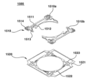
図12は、本実施例に係る第2レンズ駆動装置の分解斜視図である。 FIG. 12 is an exploded perspective view of the second lens driving device according to this embodiment.
第2レンズ駆動装置2000は、ボイスコイルモーター(VCM)であり得る。
The
第2レンズ駆動装置2000は、カバー2100を含むことができる。カバー2100は、ハウジング2310を内側に収容されることができる。カバー2100は、ベース2430に結合することができる。
The second
第2レンズ駆動装置2000は、第1可動子2200を含むことができる。第1可動子2200は、AF駆動時移動することができる。
The second
第1可動子2200は、ボビン2210を含むことができる。ボビン2210は、ハウジング2310の内側に配置されることができる。ボビン2210は、弾性部材1500によりハウジング2310に移動可能に結合することができる。
The
第1可動子2200は、第1コイル2220を含むことができる。第1コイル2220は、ボビン2210に配置されることができる。第1コイル2220は、マグネット2320と対向することができる。第1コイル2220とマグネット2320との間の電磁気的相互作用により第1可動子2200がAF駆動することができる。
The
第2レンズ駆動装置2000は、第2可動子2300を含むことができる。第2可動子2300は、OIS駆動時移動することができる。OIS駆動時第1可動子2200は、第2可動子2300と共に移動することができる。
The second
第2可動子2300は、ハウジング2310を含むことができる。ハウジング2310は、ボビン2210の外側に配置されることができる。ハウジング2310は、内側にボビン2210を収容されることができる。ハウジング2310は、ボビン2210とカバー2100との間に配置されることができる。
The
第2可動子2300は、マグネット2320を含むことができる。マグネット2320は、ハウジング2310に配置されることができる。マグネット2320は、第1コイル2220と対向することができる。マグネット2320は、第2コイル2422と対向することができる。マグネット2320は、ハウジング2310の四つの側部の間に配置される四つの隅部に配置されることができる。マグネット2320は、四つの隅部の各々に配置される四つのコーナーマグネットを含むことができる。
The
第2レンズ駆動装置2000は、固定子2400を含むことができる。固定子2400は、第2可動子2300を移動可能に支持することができる。
The second
固定子2400は、基板2410を含むことができる。基板2410は、ベース1430に配置されることができる。基板2410は、ハウジング1310とベース1430との間に配置されることができる。基板2410は、マグネット2320と対向する第2コイル2422を含む回路部材2420を含むことができる。基板2410は、ベース2430に配置されることができる。
基板2410は、端子部2412を含むことができる。基板2410は、一部が折り曲げられて形成される端子部2412を含むことができる。端子部2412は、プリント回路基板11とはんだ付けによって結合することができる。
基板2410は、回路部材2420を含むことができる。回路部材2420は、基板部と、基板部に微細パターンコイル(FP coil,Fine Pattern coil)で形成される第2コイル2422を含むことができる。回路部材2420は、第2コイル2422を含むことができる。第2コイル2422は、マグネット2320と対向することができる。第2コイル2422とマグネット2320との間の電磁気的相互作用によってOIS駆動が行われることができる。
固定子2400は、ベース2430を含むことができる。ベース2430は、ハウジング2310の下側に配置されることができる。ベース2430は、基板2410を支持することができる。
第2レンズ駆動装置2000は、弾性部材2500を含むことができる。弾性部材2500は、ボビン2210及びハウジング2310に結合することができる。弾性部材2500は、AF駆動時ボビン2210の移動を支持することができる。弾性部材2500は、上部弾性部材2510を含むことができる。上部弾性部材2510は、ボビン2210の上側に配置されてボビン2210及びハウジング2310に結合することができる。弾性部材2500は、下部弾性部材2520を含むことができる。下部弾性部材2520は、ボビン2210の下側に配置されてボビン2210及びハウジング2310に結合することができる。
The second
第2レンズ駆動装置2000は、支持部材2600を含むことができる。支持部材2600は、第2可動子2300を移動可能に支持することができる。支持部材2600は、上部弾性部材2510及び基板2410に結合することができる。
The second
本実施例は、ボイスコイルモーター(VCM)構造においてマグネット間の相互干渉を排除できる構造を提案しようとする。 This embodiment proposes a structure capable of eliminating mutual interference between magnets in a voice coil motor (VCM) structure.
本実施例で、第1レンズ駆動装置1000のマグネット1320は、三つのマグネットで構成され、二つのマグネットは4極マグネットであり、残り一つのマグネットは2極マグネットであり得る。二つの第1コイル1220が、直列で回路連結されて、各々4極マグネットに対向して配置されて、AF動作時必要な推進力を提供して、各々のマグネットの下端には第2コイル1422が配置されて、X、Y方向にのOIS推進力を提供することができる。2極着磁マグネットの反対側には重心を合わせるためにダミー部材(dummy mass)が配置されてOIS動作時重さ偏心による振動(oscillation)を防止することができる。
In this embodiment, the
本実施例の機構構成で、ボビン1210の四つの側面のうち二つの向かい合う側面に第1コイル1220が直巻線され四つのマグネットの代わりに三つのマグネットとダミー部材がハウジングに組み立てられることができる。Y方向は、二つの4極着磁マグネットと1対の第2コイル1422の区分構成で推進力が発生するが、X方向は一つの2極着磁マグネットと一つの第2コイル1422の区分構成だけで推進力が発生するので、X方向の推進力が小さくならざるを得ない。これを解決するために、本実施例では、レンズ中心軸(C1)を製品中心軸(C2)からダミー部材1330方向に偏心させて2極マグネット方向のベース1430側の残る空間を活用して第2コイル1422のターン(turn)数を増加させてX方向の推進力を増加させた。
In the mechanical structure of this embodiment, the
比較例のように2極マグネットだけを使う場合、隣接したマグネットの磁界分布の密度が増加することによって隣接したVCM間に引力あるいは斥力が発生して、OIS制御に困難が生じる可能性がある。比較例に係る磁界分布は、図13に図示される。 When only a two-pole magnet is used as in the comparative example, the density of the magnetic field distribution of the adjacent magnets increases, causing attraction or repulsion between adjacent VCMs, which may cause difficulty in OIS control. A magnetic field distribution according to the comparative example is illustrated in FIG.
本実施例では、4極着磁マグネットを適用することによって二つのレンズ駆動装置のマグネット間の磁界干渉が減少する効果を得ることができる。これは、図14に図示される。一方、本実施例によると、磁界干渉による隣接したVCM間のあるいは斥力を無視するほどの水準で設計する場合、磁界干渉の影響を無視してOIS制御が可能である。 In this embodiment, by applying a four-pole magnetized magnet, it is possible to obtain the effect of reducing the magnetic field interference between the magnets of the two lens driving devices. This is illustrated in FIG. On the other hand, according to the present embodiment, when designing at a level of negligible repulsive force between adjacent VCMs due to magnetic field interference, OIS control is possible ignoring the influence of magnetic field interference.
本実施例では、比較例でマグネット1320の上面(top surface)と当接するハウジング1310の射出最小厚さを構成した部分を削除して、上部弾性部材1510の組み立て面とマグネット1320の上面が一致するように構成することができる。さらに、本実施例では、上部弾性部材1510の組み立て面と同じ平面にあるが、上部弾性部材1510が通り過ぎない空間は、全て射出材質で詰めることによってストッパー1314が位置する外郭の部分でハウジング1310の上板1313を構成することができる。上側から見た時(Top view状態で見た時)、本実施例では図11に示したようにマグネット1320の上面の一部分が露出していながらもカバー1100との間隔を維持するハウジング1310のストッパー1314と連結されたハウジング1310の上板1313によりマグネット1320が機構的に拘束されることができる。つまり、本実施例により、マグネット1320の機構的拘束効果とマグネット1320の上面を上向き組み立てる効果を同時に確保することができる。
In the present embodiment, the portion forming the minimum injection thickness of the
以上、本発明の実施例を構成する全ての構成要素が一つで結合したり結合して動作するものと説明したが、本発明が必ずしも実施例の全ての構成要素を含むものと限定されるのではない。つまり、本発明は実施例の全ての構成要素中一つ以上を含み、これらの構成により動作することもできる。さらに、以上で記載された‘含む’の用語は、特に定めるような記載がない限り該当構成要素が内在する可能性があることを意味するので、他の構成要素を除くのではなく該当構成要素の他にも他の構成要素をさらに包含できると解釈されなければならない。さらに、以上で記載された‘配置される’の用語は、別途の部材で製造されて配置される場合、及び一体で製造されて配置される場合まで含む用語と解釈されなければならない。 As described above, all the constituent elements constituting the embodiments of the present invention are described as being combined or operated in combination, but the present invention is not necessarily limited to include all the constituent elements of the embodiments. not. In other words, the present invention includes one or more of all the constituent elements of the embodiments, and can also operate with these configurations. Furthermore, the term 'including' described above means that the relevant component may be included unless otherwise specified, so the relevant component does not exclude other components. should be construed as being able to further include other components. In addition, the term 'disposed' described above should be interpreted as a term including the case where it is manufactured and disposed as a separate member and the case where it is integrally manufactured and disposed.
以上の説明は、本発明の技術思想を例示的に説明したものに過ぎず、本発明が属する技術分野において通常の知識を有する者は、本発明の本質的な特性から逸脱しない範囲で多様な修正及び変形が可能である。従って、本発明に開示された実施例は、本発明の技術思想を限定するためのものでなく説明するためのものであって、このような実施例によって本発明の技術思想の範囲が限定されるのではない。本発明の保護範囲は、下記の請求範囲によって解釈されるべきで、それと同等な範囲内にあるすべての技術思想は、本発明の権利範囲に含まれると解釈されなければならない。 The above description is merely illustrative of the technical idea of the present invention, and those skilled in the art in the technical field to which the present invention pertains may make various modifications without departing from the essential characteristics of the present invention. Modifications and variations are possible. Therefore, the embodiments disclosed in the present invention are not intended to limit the technical idea of the present invention, but to explain it, and the scope of the technical idea of the present invention is limited by such embodiments. not The protection scope of the present invention should be construed by the following claims, and all technical ideas within the equivalent scope should be construed as included in the scope of rights of the present invention.
Claims (20)
前記ハウジングの中に配置されるボビン;
前記ハウジングに配置されるマグネット;
前記ボビンに配置される第1コイル;及び
前記マグネットと対向する第2コイルを含む基板を含み、
前記ハウジングは、互いに反対側に配置される第1側部と第2側部と、互いに反対側に配置される第3側部と第4側部を含み、
前記マグネットは、前記第1側部に配置される第1マグネットユニット、前記第3側部に配置される第2マグネットユニット、及び前記第4側部に配置される第3マグネットユニットを含み、
前記第1コイルは前記第2マグネットユニットと向かい合う第1コイルユニットと、前記第3マグネットユニットと向かい合う第2コイルユニットを含み、
前記第1コイルは前記ボビンと前記第1マグネットユニットとの間に配置されず、
前記第2コイルは、前記第1マグネットユニットと垂直方向に対向する第3コイルユニットと、前記第2マグネットユニットと前記垂直方向に対向する第4コイルユニットと、前記第3マグネットユニットと前記垂直方向に対向する第5コイルユニットを含み、
前記第3コイルユニットでのコイルが巻かれた回数は前記第4コイルユニットでのコイルが巻かれた回数より多い、レンズ駆動装置。 housing;
a bobbin disposed within said housing;
a magnet disposed in the housing;
a first coil disposed on the bobbin; and a substrate including a second coil facing the magnet,
the housing includes first and second opposite sides and third and fourth opposite sides;
the magnet includes a first magnet unit arranged on the first side, a second magnet unit arranged on the third side, and a third magnet unit arranged on the fourth side;
The first coil includes a first coil unit facing the second magnet unit and a second coil unit facing the third magnet unit,
The first coil is not arranged between the bobbin and the first magnet unit,
The second coil includes a third coil unit vertically opposed to the first magnet unit, a fourth coil unit vertically opposed to the second magnet unit, and a third coil unit vertically opposed to the third magnet unit. including a fifth coil unit facing the
The lens driving device, wherein the number of times the coil is wound in the third coil unit is greater than the number of times the coil is wound in the fourth coil unit.
前記ハウジングの中に配置されるボビン;
前記ハウジングに配置されるマグネットとダミー部材;
前記ボビンに配置される第1コイル;及び
前記マグネットと対向する第2コイルを含む基板を含み、
前記ハウジングは、互いに反対側に配置される第1側部と第2側部と、互いに反対側に配置される第3側部と第4側部を含み、
前記マグネットは、前記第1側部に配置される第1マグネットユニット、前記第3側部に配置される第2マグネットユニット、及び前記第4側部に配置される第3マグネットユニットを含み、
前記ダミー部材は前記第2側部に配置され、
前記ダミー部材は前記第1マグネットユニットと異なる形状で形成され、
前記第2コイルは、前記第1マグネットユニットと垂直方向に対向する第3コイルユニットと、前記第2マグネットユニットと前記垂直方向に対向する第4コイルユニットと、前記第3マグネットユニットと前記垂直方向に対向する第5コイルユニットを含み、
前記第3コイルユニットでのコイルが巻かれた回数は前記第4コイルユニットでのコイルが巻かれた回数より多い、レンズ駆動装置。 housing;
a bobbin disposed within said housing;
a magnet and a dummy member disposed in the housing;
a first coil disposed on the bobbin; and a substrate including a second coil facing the magnet,
the housing includes first and second opposite sides and third and fourth opposite sides;
the magnet includes a first magnet unit arranged on the first side, a second magnet unit arranged on the third side, and a third magnet unit arranged on the fourth side;
the dummy member is disposed on the second side;
The dummy member is formed in a shape different from that of the first magnet unit ,
The second coil includes a third coil unit vertically opposed to the first magnet unit, a fourth coil unit vertically opposed to the second magnet unit, and a third coil unit vertically opposed to the third magnet unit. including a fifth coil unit facing the
The lens driving device , wherein the number of times the coil is wound in the third coil unit is greater than the number of times the coil is wound in the fourth coil unit.
前記ハウジングの中に配置されるボビン;
前記ハウジングに配置されるマグネット;
前記ボビンに配置される第1コイル;及び
前記マグネットと対向する第2コイルを含む基板を含み、
前記ハウジングは、互いに反対側に配置される第1側部と第2側部と、互いに反対側に配置される第3側部と第4側部を含み、
前記マグネットは、前記第1側部に配置される第1マグネットユニット、前記第3側部に配置される第2マグネットユニット、及び前記第4側部に配置される第3マグネットユニットを含み、
前記第1マグネットユニットは、2極マグネットであり、前記第2マグネットユニットと前記第3マグネットユニットは、4極マグネットであり、
前記第2マグネットユニットと前記第3マグネットユニット各々はN極とS極を有する第1マグネット部と、N極とS極を有し前記第1マグネット部上に配置される第2マグネット部と、前記第1マグネット部と前記第2マグネット部との間に配置されて極性を有しない中立部を含み、
前記第1マグネット部と前記第2マグネット部は前記中立部によって光軸方向に離隔される、レンズ駆動装置。 housing;
a bobbin disposed within said housing;
a magnet disposed in the housing;
a first coil disposed on the bobbin; and a substrate including a second coil facing the magnet,
the housing includes first and second opposite sides and third and fourth opposite sides;
the magnet includes a first magnet unit arranged on the first side, a second magnet unit arranged on the third side, and a third magnet unit arranged on the fourth side;
the first magnet unit is a two-pole magnet, the second magnet unit and the third magnet unit are four-pole magnets,
each of the second magnet unit and the third magnet unit includes a first magnet portion having an N pole and an S pole; a second magnet portion having an N pole and an S pole and disposed on the first magnet portion; including a neutral portion having no polarity disposed between the first magnet portion and the second magnet portion;
The lens driving device, wherein the first magnet portion and the second magnet portion are separated in the optical axis direction by the neutral portion.
前記第1コイルは、前記第1コイルユニットと前記第2コイルユニットを連結する連結部を含み、
前記第1コイルの前記連結部は、前記第1マグネットユニットと前記ボビンとの間に配置されるか前記のダミー部材と前記ボビンとの間に配置される、請求項4に記載のレンズ駆動装置。 a dummy member positioned on the second side of the housing;
The first coil includes a connecting portion that connects the first coil unit and the second coil unit,
5. The lens driving device according to claim 4, wherein said connecting portion of said first coil is arranged between said first magnet unit and said bobbin or arranged between said dummy member and said bobbin. .
前記第2コイルは、前記第1マグネットユニットと垂直方向に対向する第3コイルユニットと、前記第2マグネットユニットと前記垂直方向に対向する第4コイルユニットと、前記第3マグネットユニットと前記垂直方向に対向する第5コイルユニットを含む、請求項3に記載のレンズ駆動装置。 The first coil includes a first coil unit horizontally facing the second magnet unit and a second coil unit horizontally facing the third magnet unit,
The second coil includes a third coil unit vertically opposed to the first magnet unit, a fourth coil unit vertically opposed to the second magnet unit, and a third coil unit vertically opposed to the third magnet unit. 4. The lens driving device according to claim 3, comprising a fifth coil unit facing the .
前記第1コイルユニットは前記第1突起を覆うように配置され、
前記第2コイルユニットは前記第2突起を覆うように配置される、請求項11に記載のレンズ駆動装置。 the bobbin includes a first protrusion and a second protrusion disposed opposite the first protrusion;
The first coil unit is arranged to cover the first projection,
12. The lens driving device according to claim 11, wherein said second coil unit is arranged to cover said second protrusion.
前記基板の前記ホールは、前記基板の一側面により近くに形成された、請求項2に記載のレンズ駆動装置。 the substrate includes a hole;
3. The lens driving device of claim 2, wherein the hole of the substrate is formed closer to one side of the substrate.
前記第1マグネットユニット、前記第2マグネットユニット及び前記第3マグネットユニットは、前記ハウジングを前記光軸方向に垂直な方向に動かす、請求項1乃至14のいずれか一項に記載のレンズ駆動装置。 The second magnet unit and the third magnet unit move the bobbin in the optical axis direction,
15. The lens driving device according to claim 1, wherein said first magnet unit, said second magnet unit and said third magnet unit move said housing in a direction perpendicular to said optical axis direction.
前記第1面は、二つの極を持つ、請求項1乃至15のいずれか一項に記載のレンズ駆動装置。 each of the second magnet unit and the third magnet unit includes a first surface facing the first coil;
16. The lens driving device according to any one of claims 1 to 15, wherein said first surface has two poles.
前記第2面は、二つの極を持つ、請求項1~16のいずれか1項に記載のレンズ駆動装置。 each of the first to third magnet units includes a second surface facing the second coil;
The lens driving device according to any one of claims 1 to 16, wherein said second surface has two poles.
前記上部弾性部材と前記基板を連結する支持部材を含み、
前記第1コイルユニットと前記第2コイルユニットは電気的に連結され、
前記上部弾性部材は互いに離隔する第1上部弾性ユニットと第2上部弾性ユニットを含み、
前記第1コイルユニットの一側端部は前記第1上部弾性ユニットと結合され、前記第2コイルユニットの一側端部は前記第2上部弾性ユニットと結合される、請求項1に記載のレンズ駆動装置。 an upper elastic member connecting the bobbin and the housing; and a support member connecting the upper elastic member and the substrate,
The first coil unit and the second coil unit are electrically connected,
the upper elastic member includes a first upper elastic unit and a second upper elastic unit spaced apart from each other;
The lens of claim 1, wherein one side end of the first coil unit is combined with the first upper elastic unit, and one side end of the second coil unit is combined with the second upper elastic unit. drive.
前記レンズ駆動装置と隣接した第2レンズ駆動装置を含み、
前記第2レンズ駆動装置は、前記レンズ駆動装置の前記ハウジングの前記第2側部と隣接して配置されて、
前記第2レンズ駆動装置は、
ハウジング;
前記第2レンズ駆動装置のハウジングの中に配置されるボビン;
前記第2レンズ駆動装置のボビンの外周面に配置される第3コイル;
前記第2レンズ駆動装置のハウジングに配置されて前記第3コイルと対向するマグネット;及び
前記第2レンズ駆動装置のマグネットと対向する第4コイルを含む基板を含み、
前記第2レンズ駆動装置のマグネットは、前記第2レンズ駆動装置のハウジングの隅部に配置される四つのマグネットユニットを含む、カメラモジュール。 A lens driving device according to any one of claims 1 to 19; and a second lens driving device adjacent to the lens driving device,
the second lens driver positioned adjacent the second side of the housing of the lens driver,
The second lens driving device,
housing;
a bobbin disposed within the housing of the second lens driver;
a third coil disposed on the outer peripheral surface of the bobbin of the second lens driving device;
a magnet disposed in the housing of the second lens driving device and facing the third coil; and a substrate including a fourth coil facing the magnet of the second lens driving device,
The camera module, wherein the magnet of the second lens driving device includes four magnet units arranged at the corners of the housing of the second lens driving device.
Priority Applications (1)
| Application Number | Priority Date | Filing Date | Title |
|---|---|---|---|
| JP2022211736A JP2023040131A (en) | 2017-03-30 | 2022-12-28 | Lens drive device and camera module |
Applications Claiming Priority (7)
| Application Number | Priority Date | Filing Date | Title |
|---|---|---|---|
| KR10-2017-0041106 | 2017-03-30 | ||
| KR1020170041106A KR102340951B1 (en) | 2017-03-30 | 2017-03-30 | Lens driving device and dual camera module |
| KR1020170041105A KR102322155B1 (en) | 2017-03-30 | 2017-03-30 | Lens driving device and camera module |
| KR1020170041119A KR102305047B1 (en) | 2017-03-30 | 2017-03-30 | Lens driving device and dual camera module |
| KR10-2017-0041105 | 2017-03-30 | ||
| KR10-2017-0041119 | 2017-03-30 | ||
| PCT/KR2018/002876 WO2018182203A1 (en) | 2017-03-30 | 2018-03-12 | Lens driving device and camera module |
Related Child Applications (1)
| Application Number | Title | Priority Date | Filing Date |
|---|---|---|---|
| JP2022211736A Division JP2023040131A (en) | 2017-03-30 | 2022-12-28 | Lens drive device and camera module |
Publications (3)
| Publication Number | Publication Date |
|---|---|
| JP2020515889A JP2020515889A (en) | 2020-05-28 |
| JP2020515889A5 JP2020515889A5 (en) | 2021-04-22 |
| JP7242544B2 true JP7242544B2 (en) | 2023-03-20 |
Family
ID=63678072
Family Applications (2)
| Application Number | Title | Priority Date | Filing Date |
|---|---|---|---|
| JP2019551524A Active JP7242544B2 (en) | 2017-03-30 | 2018-03-12 | Lens driver and camera module |
| JP2022211736A Pending JP2023040131A (en) | 2017-03-30 | 2022-12-28 | Lens drive device and camera module |
Family Applications After (1)
| Application Number | Title | Priority Date | Filing Date |
|---|---|---|---|
| JP2022211736A Pending JP2023040131A (en) | 2017-03-30 | 2022-12-28 | Lens drive device and camera module |
Country Status (5)
| Country | Link |
|---|---|
| US (2) | US11762168B2 (en) |
| EP (3) | EP3605221B1 (en) |
| JP (2) | JP7242544B2 (en) |
| CN (5) | CN114326264B (en) |
| WO (1) | WO2018182203A1 (en) |
Families Citing this family (12)
| Publication number | Priority date | Publication date | Assignee | Title |
|---|---|---|---|---|
| US11022726B2 (en) * | 2018-01-25 | 2021-06-01 | Tdk Taiwan Corp. | Optical driving mechanism |
| CN112543887B (en) * | 2018-05-23 | 2022-08-19 | Lg伊诺特有限公司 | Lens driving device, camera module and optical apparatus including the same |
| US20220035173A1 (en) * | 2018-10-08 | 2022-02-03 | Lg Innotek Co., Ltd. | Camera module |
| CN111323886A (en) * | 2018-12-17 | 2020-06-23 | 新思考电机有限公司 | Lens driving device, camera device and electronic equipment |
| US11506862B2 (en) * | 2019-02-01 | 2022-11-22 | Tdk Taiwan Corp. | Optical element driving mechanism |
| KR20200114252A (en) * | 2019-03-28 | 2020-10-07 | 엘지이노텍 주식회사 | camera device |
| US20220255414A1 (en) * | 2019-08-06 | 2022-08-11 | Lg Innotek Co., Ltd. | Lens driving device, camera module, and optical apparatus |
| CN114514456B (en) * | 2019-09-26 | 2024-02-06 | Lg伊诺特有限公司 | Camera module |
| WO2021120109A1 (en) * | 2019-12-19 | 2021-06-24 | Guangdong Oppo Mobile Telecommunications Corp., Ltd. | Lens driving device, camera device, and electronic apparatus |
| WO2021120113A1 (en) * | 2019-12-19 | 2021-06-24 | Guangdong Oppo Mobile Telecommunications Corp., Ltd. | Lens driving device, camera device, and electronic apparatus |
| CN116736467A (en) * | 2020-04-10 | 2023-09-12 | 华为技术有限公司 | Optical lens group, camera module and electronic equipment |
| US11808951B2 (en) * | 2020-12-11 | 2023-11-07 | Samsung Electro-Mechanics Co., Ltd. | Actuator for camera, and camera module including the same |
Citations (4)
| Publication number | Priority date | Publication date | Assignee | Title |
|---|---|---|---|---|
| KR101017341B1 (en) | 2009-11-06 | 2011-02-28 | 주식회사 하이소닉 | Compact camera device |
| JP2015099282A (en) | 2013-11-19 | 2015-05-28 | 日本電産コパル株式会社 | Lens driving device |
| JP2015127724A (en) | 2013-12-27 | 2015-07-09 | 日本電産コパル株式会社 | Lens drive unit |
| JP2017227850A (en) | 2016-06-24 | 2017-12-28 | ミツミ電機株式会社 | Lens drive device, camera module, and camera loading device |
Family Cites Families (37)
| Publication number | Priority date | Publication date | Assignee | Title |
|---|---|---|---|---|
| US5229983A (en) * | 1989-12-28 | 1993-07-20 | Matsushita Electric Industrial Co., Ltd. | Bias magnetic field generating apparatus for magneto-optical recording and reproducing system |
| KR100867604B1 (en) * | 2007-02-01 | 2008-11-10 | 동인하이텍주식회사 | Small camera device for communication machine |
| GB0702835D0 (en) * | 2007-02-14 | 2007-03-28 | Johnson Electric Sa | Lens module |
| US8289638B2 (en) * | 2007-03-30 | 2012-10-16 | Nidec Sankyo Corporation | Lens driving device |
| JP2009211076A (en) | 2008-02-29 | 2009-09-17 | Johnson Electric Sa | Lens driving device |
| JP4457320B2 (en) * | 2008-03-05 | 2010-04-28 | ソニー株式会社 | The camera module |
| JP2010015107A (en) * | 2008-07-07 | 2010-01-21 | Olympus Imaging Corp | Imaging apparatus to correct blurring |
| US20130141541A1 (en) * | 2010-06-11 | 2013-06-06 | Hysonic. Co., Ltd. | Compact camera actuator and compact stereo-scopic image photographing device |
| JP5867994B2 (en) * | 2010-11-08 | 2016-02-24 | キヤノン株式会社 | Lens barrel and optical equipment |
| US9035502B2 (en) | 2011-02-07 | 2015-05-19 | Lg Innotek Co., Ltd. | Multifunctional voice coil motor |
| KR101804575B1 (en) * | 2011-02-07 | 2017-12-04 | 엘지이노텍 주식회사 | Multi-function voice coil motor |
| US9300196B2 (en) * | 2011-11-16 | 2016-03-29 | Lg Innotek Co., Ltd. | Voice coil motor |
| KR101931183B1 (en) | 2011-12-23 | 2018-12-21 | 엘지이노텍 주식회사 | Voice coil motor |
| TWI490630B (en) * | 2013-07-22 | 2015-07-01 | Tdk Taiwan Corp | Lens driving device and manufacturing method thereof |
| EP2887514B1 (en) * | 2013-12-23 | 2020-06-24 | LG Innotek Co., Ltd. | Lens moving apparatus |
| KR102319554B1 (en) | 2014-08-20 | 2021-11-01 | 엘지이노텍 주식회사 | Lens moving unit and camera module including the same |
| KR20150113675A (en) * | 2014-03-31 | 2015-10-08 | 자화전자(주) | Dual camera lens module |
| CN105024516B (en) * | 2014-04-30 | 2017-12-01 | 光宝电子(广州)有限公司 | Voice coil motor array module |
| US20150346453A1 (en) * | 2014-06-03 | 2015-12-03 | Samsung Electro-Mechanics Co., Ltd. | Camera module and driving control system for camera module |
| JP6458378B2 (en) * | 2014-07-11 | 2019-01-30 | ミツミ電機株式会社 | Lens driving device, camera module, and mobile terminal with camera |
| KR20160045385A (en) | 2014-10-17 | 2016-04-27 | 엘지이노텍 주식회사 | Lens driving unit and camera module including the same |
| EP3040753B1 (en) * | 2014-12-30 | 2024-02-21 | LG Innotek Co., Ltd. | Lens moving apparatus |
| KR102392579B1 (en) | 2015-01-12 | 2022-05-02 | 엘지이노텍 주식회사 | Lens driving unit and camera module including the same |
| KR20160082035A (en) * | 2014-12-30 | 2016-07-08 | 엘지이노텍 주식회사 | Lens driving unit and camera module including the same |
| CN105807538B (en) | 2015-01-20 | 2020-10-09 | Lg伊诺特有限公司 | Lens driving device, camera module and optical apparatus |
| CN104678531B (en) * | 2015-02-05 | 2017-10-31 | 新思考电机有限公司 | Lens driver, cam device and electronic equipment |
| US9781345B1 (en) | 2015-02-13 | 2017-10-03 | Apple Inc. | Dual camera magnet arrangement |
| JP6476981B2 (en) | 2015-02-20 | 2019-03-06 | ミツミ電機株式会社 | Lens driving device, camera module, and camera mounting device |
| KR102396356B1 (en) | 2015-03-19 | 2022-05-10 | 엘지이노텍 주식회사 | Lens driving device, camera module and optical apparatus |
| WO2016156996A1 (en) | 2015-04-02 | 2016-10-06 | Corephotonics Ltd. | Dual voice coil motor structure in a dual-optical module camera |
| CN117849979A (en) * | 2015-09-08 | 2024-04-09 | Lg伊诺特有限公司 | Dual camera module and optical device |
| CN106856553B (en) * | 2015-12-09 | 2019-12-17 | 台湾东电化股份有限公司 | Optical image shockproof mechanism |
| CN107340668B (en) * | 2016-04-28 | 2019-11-19 | 台湾东电化股份有限公司 | Twin-lens photographic system |
| TWI666506B (en) * | 2016-04-28 | 2019-07-21 | 台灣東電化股份有限公司 | Dual lens camera system |
| CN206039001U (en) * | 2016-08-22 | 2017-03-22 | 河南省皓泽电子有限公司 | Automatic electromagnetic force that focusing mechanism used produces circuit board |
| CN106226887A (en) * | 2016-08-30 | 2016-12-14 | 金龙机电股份有限公司 | A kind of dual camera automatic focusing mechanism |
| CN108476283B (en) * | 2016-12-14 | 2019-11-05 | 华为技术有限公司 | Camera unit, camera module and mobile terminal |
-
2018
- 2018-03-12 EP EP18775256.3A patent/EP3605221B1/en active Active
- 2018-03-12 EP EP24151587.3A patent/EP4336253A3/en active Pending
- 2018-03-12 EP EP22202567.8A patent/EP4141535B1/en active Active
- 2018-03-12 CN CN202111519614.7A patent/CN114326264B/en active Active
- 2018-03-12 US US16/498,358 patent/US11762168B2/en active Active
- 2018-03-12 WO PCT/KR2018/002876 patent/WO2018182203A1/en unknown
- 2018-03-12 CN CN202410058276.9A patent/CN117826509A/en active Pending
- 2018-03-12 CN CN202111519626.XA patent/CN114326265B/en active Active
- 2018-03-12 JP JP2019551524A patent/JP7242544B2/en active Active
- 2018-03-12 CN CN201880022438.6A patent/CN110476119B/en active Active
- 2018-03-12 CN CN202111519549.8A patent/CN114326263B/en active Active
-
2022
- 2022-12-28 JP JP2022211736A patent/JP2023040131A/en active Pending
-
2023
- 2023-07-21 US US18/224,812 patent/US20230358994A1/en active Pending
Patent Citations (4)
| Publication number | Priority date | Publication date | Assignee | Title |
|---|---|---|---|---|
| KR101017341B1 (en) | 2009-11-06 | 2011-02-28 | 주식회사 하이소닉 | Compact camera device |
| JP2015099282A (en) | 2013-11-19 | 2015-05-28 | 日本電産コパル株式会社 | Lens driving device |
| JP2015127724A (en) | 2013-12-27 | 2015-07-09 | 日本電産コパル株式会社 | Lens drive unit |
| JP2017227850A (en) | 2016-06-24 | 2017-12-28 | ミツミ電機株式会社 | Lens drive device, camera module, and camera loading device |
Also Published As
| Publication number | Publication date |
|---|---|
| US20230358994A1 (en) | 2023-11-09 |
| US11762168B2 (en) | 2023-09-19 |
| CN114326265A (en) | 2022-04-12 |
| WO2018182203A1 (en) | 2018-10-04 |
| EP4141535A1 (en) | 2023-03-01 |
| EP4336253A3 (en) | 2024-04-17 |
| CN114326263A (en) | 2022-04-12 |
| CN117826509A (en) | 2024-04-05 |
| EP3605221B1 (en) | 2022-11-30 |
| EP4336253A2 (en) | 2024-03-13 |
| CN114326264B (en) | 2024-02-06 |
| JP2020515889A (en) | 2020-05-28 |
| CN110476119B (en) | 2021-12-31 |
| EP4141535B1 (en) | 2024-02-21 |
| EP3605221A1 (en) | 2020-02-05 |
| US20200033551A1 (en) | 2020-01-30 |
| JP2023040131A (en) | 2023-03-22 |
| CN114326264A (en) | 2022-04-12 |
| CN114326263B (en) | 2024-03-08 |
| EP3605221A4 (en) | 2021-01-06 |
| CN110476119A (en) | 2019-11-19 |
| CN114326265B (en) | 2024-03-08 |
Similar Documents
| Publication | Publication Date | Title |
|---|---|---|
| JP7242544B2 (en) | Lens driver and camera module | |
| US10274746B2 (en) | Optical image stabilization (OIS) unit of a camera module | |
| US20220299729A1 (en) | Camera module | |
| KR102467715B1 (en) | Lens driving device and dual camera module | |
| CN112041741A (en) | Camera device, double-camera device and three-camera device | |
| KR102456661B1 (en) | Lens driving device and camera module | |
| CN111936926B (en) | Lens driving device and camera device comprising same | |
| KR102493514B1 (en) | Lens driving device and dual camera module | |
| KR20180113730A (en) | Lens driving device and camera module | |
| CN116250244A (en) | Camera device | |
| KR20210039841A (en) | camera module | |
| KR20190117216A (en) | Lens driving device and camera apparatus comprising the same |
Legal Events
| Date | Code | Title | Description |
|---|---|---|---|
| A521 | Request for written amendment filed |
Free format text: JAPANESE INTERMEDIATE CODE: A523 Effective date: 20210310 |
|
| A621 | Written request for application examination |
Free format text: JAPANESE INTERMEDIATE CODE: A621 Effective date: 20210310 |
|
| A977 | Report on retrieval |
Free format text: JAPANESE INTERMEDIATE CODE: A971007 Effective date: 20211217 |
|
| A131 | Notification of reasons for refusal |
Free format text: JAPANESE INTERMEDIATE CODE: A131 Effective date: 20220111 |
|
| A521 | Request for written amendment filed |
Free format text: JAPANESE INTERMEDIATE CODE: A523 Effective date: 20220407 |
|
| A02 | Decision of refusal |
Free format text: JAPANESE INTERMEDIATE CODE: A02 Effective date: 20220830 |
|
| A521 | Request for written amendment filed |
Free format text: JAPANESE INTERMEDIATE CODE: A523 Effective date: 20221228 |
|
| C60 | Trial request (containing other claim documents, opposition documents) |
Free format text: JAPANESE INTERMEDIATE CODE: C60 Effective date: 20221228 |
|
| A911 | Transfer to examiner for re-examination before appeal (zenchi) |
Free format text: JAPANESE INTERMEDIATE CODE: A911 Effective date: 20230111 |
|
| C21 | Notice of transfer of a case for reconsideration by examiners before appeal proceedings |
Free format text: JAPANESE INTERMEDIATE CODE: C21 Effective date: 20230117 |
|
| TRDD | Decision of grant or rejection written | ||
| A01 | Written decision to grant a patent or to grant a registration (utility model) |
Free format text: JAPANESE INTERMEDIATE CODE: A01 Effective date: 20230207 |
|
| A61 | First payment of annual fees (during grant procedure) |
Free format text: JAPANESE INTERMEDIATE CODE: A61 Effective date: 20230308 |
|
| R150 | Certificate of patent or registration of utility model |
Ref document number: 7242544 Country of ref document: JP Free format text: JAPANESE INTERMEDIATE CODE: R150 |