JP7238668B2 - game machine - Google Patents
game machine Download PDFInfo
- Publication number
- JP7238668B2 JP7238668B2 JP2019134975A JP2019134975A JP7238668B2 JP 7238668 B2 JP7238668 B2 JP 7238668B2 JP 2019134975 A JP2019134975 A JP 2019134975A JP 2019134975 A JP2019134975 A JP 2019134975A JP 7238668 B2 JP7238668 B2 JP 7238668B2
- Authority
- JP
- Japan
- Prior art keywords
- mpu
- result
- game
- display
- opening
- Prior art date
- Legal status (The legal status is an assumption and is not a legal conclusion. Google has not performed a legal analysis and makes no representation as to the accuracy of the status listed.)
- Active
Links
Images


Classifications
-
- Y—GENERAL TAGGING OF NEW TECHNOLOGICAL DEVELOPMENTS; GENERAL TAGGING OF CROSS-SECTIONAL TECHNOLOGIES SPANNING OVER SEVERAL SECTIONS OF THE IPC; TECHNICAL SUBJECTS COVERED BY FORMER USPC CROSS-REFERENCE ART COLLECTIONS [XRACs] AND DIGESTS
- Y02—TECHNOLOGIES OR APPLICATIONS FOR MITIGATION OR ADAPTATION AGAINST CLIMATE CHANGE
- Y02E—REDUCTION OF GREENHOUSE GAS [GHG] EMISSIONS, RELATED TO ENERGY GENERATION, TRANSMISSION OR DISTRIBUTION
- Y02E60/00—Enabling technologies; Technologies with a potential or indirect contribution to GHG emissions mitigation
- Y02E60/10—Energy storage using batteries
Description
本発明は、パチンコ遊技機等の遊技機に関する。 The present invention relates to a game machine such as a pachinko game machine.
従来、複数の絵柄を変動表示する変動表示手段を備えた遊技機が知られている(例えば、特許文献1参照)。この遊技機は、作動口(始動入球手段)に遊技球が入球することによって、大当たり抽選などの内部抽選を実行するとともに、絵柄の変動表示を開始する。遊技機は、例えば、大当たり抽選に当選した場合には、特定の絵柄の組み合わせ等を変動表示手段に最終的に停止表示させるとともに、遊技者にとって有利な特定制御状態に遊技状態を移行する。この特定制御状態では、遊技機は、例えば、遊技球が入球可能な状態に可変入賞装置を移行させることによって、大量の遊技球を払い出している。
2. Description of the Related Art Conventionally, there is known a gaming machine provided with variable display means for variably displaying a plurality of patterns (see
しかしながら、遊技機は、大当たり抽選に当選した場合には、遊技者にとって有利な特定制御状態に遊技状態を移行し、この特定制御状態では、遊技機は、遊技球が入球可能な状態に可変入賞装置を移行させることによって、大量の遊技球を払い出しているので、遊技者に利益を付与する流れは単調になってしまい、遊技者の遊技への注目度は低下してしまうという問題がある。 However, when the game machine wins the jackpot lottery, the game state shifts to a specific control state that is advantageous to the player, and in this specific control state, the game machine is variable to a state in which game balls can enter. Since a large number of game balls are put out by shifting the prize-winning device, the flow of giving profit to the player becomes monotonous, and the player's attention to the game is lowered. .
本発明の目的は、遊技者の遊技への注目度を向上させることができる遊技機を提供することである。 SUMMARY OF THE INVENTION An object of the present invention is to provide a gaming machine capable of increasing the attention of a player to a game.
本発明の遊技機は、遊技盤に形成された遊技領域に向かって遊技球を発射する発射手段と、遊技領域を流下する遊技球の入球に基づいて抽選を実行する契機となる始動入球手段と、抽選の結果に基づいて、遊技者にとって有利な特定遊技制御状態に遊技状態を移行する遊技状態移行手段と、を備える遊技機であって、本遊技機は、遊技球を検出した場合に遊技者にとって第1次の価値を付与し得る第1次の流下検出可能状態と、遊技球を検出した場合に遊技者にとって第1次の価値よりも小さな第2次の価値を付与し得る第2次の流下検出可能状態と、遊技球を検出した場合に遊技者にとって第2次の価値よりも小さな第3次の価値を付与し得る第3次の流下検出可能状態と、を発生可能であり、第1次の流下検出可能状態において流下した所定の遊技球を検出可能な第1次の検出手段と、第2次の流下検出可能状態において流下した特定の遊技球を検出可能な第2次の検出手段と、第3次の流下検出可能状態において流下した遊技球を検出可能な第3次の検出手段と、第1次の流下検出可能状態および第2次の流下検出可能状態の双方で遊技球が流下可能な期間において、第1次の流下検出可能状態または第2次の流下検出可能状態のいずれか一方の状態において遊技球が流下可能な所定作動状態、および第3次の流下検出可能状態においては遊技球が流下可能な非作動状態に制御される作動部材と、所定の作動条件の成立に基づいて作動部材を非作動状態から所定作動状態に切り替える切替手段と、を備え、特定遊技制御状態の開始後に所定制御状態に移行し、所定制御状態への移行後に特定入球条件が成立した場合に特別遊技制御状態に移行させ得るものであり、第1次の流下検出可能状態および第2次の流下検出可能状態の双方は特定遊技制御状態に移行した後の同一の所定制御状態の開始後に発生可能に構成され、本遊技機は、第1次の流下検出可能状態および第2次の流下検出可能状態と、第3次の流下検出可能状態とは、遊技盤の正面視において異なる面に流路が形成され、第3次の検出手段にて遊技球を検出した場合に1個の遊技球の検出に対して1個以下の遊技球を付与可能に構成されたことを特徴とする。
The gaming machine of the present invention comprises a launching means for shooting a game ball toward a game area formed on a game board, and a starting input as a trigger for executing a lottery based on the entry of a game ball flowing down the game area. A game machine comprising ball means and game state transition means for shifting the game state to a specific game control state advantageous to the player based on the result of a lottery , wherein the game machine detects a game ball. A first-order flow detectable state in which a first-order value can be given to a player when a game ball is detected, and a second-order value smaller than the first-order value is given to a player when a game ball is detected. A secondary flow detectable state that can be imparted , and a tertiary flow detectable state that can impart a tertiary value smaller than the secondary value to the player when the game ball is detected. and a first detection means capable of detecting a predetermined game ball that has flowed down in the first flow detectable state, and a specific game ball that has flowed down in the second flow detectable state. a second detection means capable of detecting the, a third detection means capable of detecting a game ball that has flowed down in the third flow detectable state, a first flow detectable state and a second a predetermined operating state in which the game ball can flow in either the primary flow detectable state or the secondary flow detectable state during the period in which the game ball can flow in both of the flow detectable states ; and an operating member that is controlled to a non-operating state in which a game ball can flow down in the third flow detectable state , and a switch that switches the operating member from the non-operating state to a predetermined operating state based on the establishment of a predetermined operating condition. means, which can shift to a predetermined control state after the start of the specific game control state, and can shift to the special game control state when the specific ball entry condition is satisfied after the transition to the predetermined control state; Both the next flow detectable state and the secondary flow detectable state are configured to be generated after the start of the same predetermined control state after shifting to the specific game control state, and the game machine In the flow detectable state, the secondary flow detectable state, and the tertiary flow detectable state, flow paths are formed on different surfaces in a front view of the game board, and the game is played by the tertiary detection means. It is characterized in that, when a ball is detected, one game ball or less can be given to one game ball detected .
本発明によれば、遊技機は、遊技者の遊技への注目度を向上させることができる。 Advantageous Effects of Invention According to the present invention, a gaming machine can increase the attention of a player to a game.
〔参考形態〕
以下、本発明の参考形態を図面に基づいて説明する。
図1は、本発明の参考形態に係るパチンコ機の正面図である。
パチンコ機1は、遊技機の一種であるパチンコ遊技機である。このパチンコ機1は、図1に示すように、パチンコ機1の外殻を形成する外枠11と、この外枠11に対して前方(正面側)に回動可能に取り付けられた遊技機本体12とを備えている。
[Reference form]
A reference embodiment of the present invention will be described below with reference to the drawings.
FIG. 1 is a front view of a pachinko machine according to a reference embodiment of the present invention.
The pachinko
遊技機本体12は、左右両側部のうち一方を支持側として回動可能となるように外枠11に支持される内枠(図示略)と、内枠の前方に配置されるとともに、左右両側部のうち一方を支持側として前方へ回動可能となるように内枠に支持される前扉枠121と、内枠の後方に配置されるとともに、左右両側部のうち一方を支持側として後方へ回動可能となるように内枠に支持される裏パックユニット(図示略)とを備えている。
The gaming machine
なお、遊技機本体12は、その回動先端部に設けられた施錠装置(図示略)を備えている。この施錠装置は、遊技機本体12を外枠11に対して開放不能な施錠状態とする機能を有しているとともに、前扉枠121を内枠に対して開放不能な施錠状態とする機能を有している。これらの施錠状態は、パチンコ機1の前面に露出させて設けられたシリンダ錠13に対して解錠キーを用いて解錠操作を行うことによって解除される。
The gaming machine
前扉枠121は、内枠の前面側全体を覆うようにして設けられた略楕円形状の窓部122と、窓部122に嵌め込まれた窓パネル123とを有している。なお、本参考形態では、窓パネル123は、ガラスによって無色透明に形成されているが、合成樹脂などによって無色透明に形成されていてもよい。
また、前扉枠121は、窓部122の周囲に設けられた各種ランプ部等にて構成される発光手段の一部として窓部122の上方に設けられた表示ランプ部124と、表示ランプ部124の左右両側に設けられるとともに、遊技状況に応じた効果音などを出力するスピーカ部125と、窓部122の下方に設けられた上側膨出部14および下側膨出部15とを備えている。
The
In addition, the
上側膨出部14および下側膨出部15は、上下に並設されるとともに、共に前方へ膨出するように設けられている。
上側膨出部14は、上方に開口するようにして内側に設けられた上皿141を有している。上皿141は、裏パックユニットに設けられた払出装置48(図4参照)にて払い出された遊技球を一旦貯留し、一列に整列させながら遊技球発射機構49(図4参照)側へ導くための機能を有している。
下側膨出部15は、同じく上方に開口するようにして内側に設けられた下皿151を有している。下皿151は、上皿141内にて余剰となった遊技球を貯留する機能を有している。
The upper bulging
The upper bulging
The lower bulging
さらに、前扉枠121は、下皿151の右方に設けられた発射手段としての発射ハンドル16を備えている。この発射ハンドル16は、パチンコ機1の遊技者に操作されることによって、内枠の下方に設けられた遊技球発射機構49から内枠の上方に設けられた遊技領域に向けて遊技球を発射する。発射ハンドル16は、その回転操作量を変更することによって、遊技領域に向けて発射する遊技球の発射強度、すなわち発射の勢いを変更する。
Furthermore, the
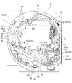
図2は、遊技盤の正面図である。
遊技盤2は、図2に示すように、その表面に取り付けられた内レール部21および外レール部22を有し、内枠に搭載されている。前述した遊技領域は、内レール部21および外レール部22によって区画されるようにして遊技盤2に形成されている。この遊技領域は、窓部122を介して略全域を前方から視認することができる。
内レール部21および外レール部22は、遊技領域への遊技球の誘導レール23を構成し、この誘導レール23は、遊技者が発射ハンドル16を回転操作したことによって遊技球発射機構49から発射された遊技球を遊技領域の上部に案内する。
FIG. 2 is a front view of the game board.
The
The
誘導レール23は、その出口部分が遊技領域の一方の側部に配置されるとともに、遊技領域の上部中央を向くようにして形成されている。このため、遊技領域の上部における遊技球の到達位置は、遊技者による発射ハンドル16の回転操作量が大きくなるにしたがって、誘導レール23の出口部分が形成された側部の側からその反対側の側部の側へとシフトしていく。なお、本参考形態では、誘導レール23の出口部分は、遊技領域の左側部に設けられている。
The
遊技盤2は、ルータ加工が施されることによって前後方向に貫通するように形成された大小複数の開口部を遊技領域に有している。また、遊技盤2は、各開口部に設けられた一般入賞口24、上作動口(第1始動入球部)25、下作動口(第2始動入球部)26、可変入賞装置27、およびアウト口28を有している。また、遊技盤2は、中央部左側および中央部右側のそれぞれに設けられたスルーゲート31と、上部右側に設けられた主表示装置32と、中央部に設けられた可変表示ユニット33等とを有している。さらに、遊技盤2は、遊技球の落下方向を適宜分散させるために、または調整等するために植設された多数の釘NLや、風車等の各種部材(役物)を遊技領域に有している。
The
一般入賞口24、上作動口25、下作動口26、および可変入賞装置27の各種入賞口のそれぞれは、遊技球の入球を検知する検知センサ301~304(図4参照)を備え、これらの検知センサ301~304は、遊技盤2の背面側に配設されている。具体的には、一般入賞口24は、検知センサ301を備え、上作動口25は、検知センサ302を備え、下作動口26は、検知センサ303を備え、可変入賞装置27は、検知センサ304を備えている。パチンコ機1は、検知センサ301~304の検知結果に基づいて、所定数の賞球の払い出しを実行する。なお、検知センサ301~304は、遊技球の入賞を個別に検知できるものであれば、どのようなものであってもよく、例えば、電磁誘導型の近接センサなどを採用することができる。
Each of the general winning
具体的には、パチンコ機1は、一般入賞口24への入球が発生した場合には10個の賞球の払い出しを実行する。パチンコ機1は、上作動口25への入球が発生した場合および下作動口26への入球が発生した場合には3個の賞球の払い出しを実行する。パチンコ機1は、可変入賞装置27への入球が発生した場合には15個の賞球の払い出しを実行する。なお、これら賞球の個数は任意であり、例えば、各作動口25,26の賞球個数を相違させてもよい。
Specifically, the
アウト口28は、遊技盤2の遊技領域の最下部に設けられている。各種入賞口等に入球しなかった遊技球は、このアウト口28を通って遊技領域から排出される。また、アウト口28は、遊技球の入球を検知する検知センサ305(図4参照)を備え、この検知センサ305は、遊技盤2の背面側に配設されている。なお、パチンコ機1は、アウト口28への入球が発生した場合には、各種入賞口への入球が発生した場合と異なり、賞球の払い出しを実行しない。
Out
各スルーゲート31は、遊技球の入球を検知する検知センサ306(図4参照)を備え、この検知センサ306は、遊技盤2の背面側に配設されている。なお、パチンコ機1は、各スルーゲート31への入球が発生した場合には、各種入賞口への入球が発生した場合と異なり、賞球の払い出しを実行しない。
Each through
ここで、入球とは、所定の開口部を遊技球が通過することをいい、開口部を通過した後に遊技領域から排出される態様だけでなく、開口部を通過した後に遊技領域から排出されずに遊技領域の流下を継続する態様も含む。ただし、以下の説明では、アウト口28への遊技球の入球と明確に区別するために、各種入賞口への遊技球の入球を入賞とも表現する。また、スルーゲート31への入球とは、遊技領域に設けられたゲートを通過した後に遊技領域から排出されずに遊技領域の流下を継続することをいう。このスルーゲート31への入球についても各種入賞口への入球と同様に入賞とも表現する。
Here, the entry ball means that a game ball passes through a predetermined opening. It also includes a mode in which the game area continues to flow down. However, in the following description, in order to distinguish clearly from the game ball entering the
上作動口25および下作動口26は、作動口装置としてユニット化されて遊技盤2に設置されている。各作動口25,26は、遊技領域を流下する遊技球を入球可能とすべく共に上向きに開口するとともに、上作動口25を上方に配置し、下作動口26を下方に配置するようにして鉛直方向に並設されている。下作動口26は、左右一対の可動片によって構成されたガイド片(サポート片)としての電動役物261を有している。
The
電動役物261は、遊技盤2の背面側に搭載された電動役物駆動部262に連結されている。この電動役物261は、電動役物駆動部262にて駆動されることによって、閉鎖状態(非サポート状態または非ガイド状態)および開放状態(サポート状態またはガイド状態)のいずれかに設定される。閉鎖状態は、電動役物261の上端を左右方向に近接させることによって、下作動口26を閉鎖した状態である。開放状態は、電動役物261の上端を左右方向に離間させることによって、下作動口26を開放した状態である。
The
ここで、電動役物261を閉鎖状態に設定した場合には、この電動役物261の上端と、上作動口25との間隔は、遊技球1個分よりも狭くなる。また、電動役物261を開放状態に設定した場合には、この電動役物261の上端と、上作動口25との間隔は、遊技球1個分よりも広くなる。したがって、遊技球は、電動役物261を閉鎖状態に設定した場合には、下作動口26に入賞することができず、開放状態に設定した場合には、下作動口26に入賞することができる。
Here, when the
なお、電動役物261は、前述した閉鎖状態および開放状態に代えて、下作動口26に遊技球が入賞しにくい状態(閉鎖状態とは異なり遊技球の入球は可能な状態)と、下作動口26に遊技球が入賞しやすい状態とを切り換える構成としてもよい。また、下作動口26は、このような切り換えを電動役物261の設定によって行うのではなく、下作動口26の変位によって行う構成としてもよく、このように構成した場合には、下作動口26は、電動役物261を備えていなくてもよい。
In addition, instead of the closed state and the open state described above, the
可変入賞装置27は、遊技領域を流下する遊技球を入球可能とすべく上向きに開口する大入賞口271と、大入賞口271を開閉するための開閉扉272と、開閉扉272を駆動する可変入賞駆動部273とを備えている。
なお、遊技者は、発射ハンドル16の回転操作量を最大として右打ちし、遊技領域の上部における遊技球の到達位置を誘導レール23の出口部分が形成された側部の側からその反対側の側部の側へとシフトさせることによって、可変表示ユニット33等を避けて可変入賞装置27に遊技球を導くことができる。
The
The player hits to the right by maximizing the amount of rotational operation of the
ここで、遊技盤2は、可変入賞装置27の前面側を覆うようにして設けられたカバー29を備えている。このカバー29は、可変入賞装置27を前面側から視認可能とすべく透明(または半透明)に形成された透明パネル291と、この透明パネル291の周囲に設けられるとともに、不透明に形成された不透明パネル292とを備えている。
したがって、遊技者は、透明パネル291および窓部122を介して可変入賞装置27を前方から視認することができる。
Here, the
Therefore, the player can see the variable
大入賞口271は、ルータ加工が施されることによって前後方向に貫通するように遊技領域に形成された開口部に設けられている。この大入賞口271は、前述したように、遊技球の入球を検知する検知センサ304を備えている。パチンコ機1は、その検知結果に基づいて、所定数の賞球の払い出しを実行する。
The
開閉扉272は、矩形板状に形成されるとともに、大入賞口271の開口を閉鎖するようにして遊技盤2に設けられている。この開閉扉272は、窓パネル123に向かって前進して遊技盤2から突出することによって、大入賞口271の開口を閉鎖する閉鎖状態と、遊技盤2の内部に向かって後退して遊技盤2に埋没することによって、大入賞口271の開口を開放する開放状態とを有している。
可変入賞駆動部273は、開閉扉272を駆動することによって、開閉扉272を開放状態および閉鎖状態のいずれかに設定する。
The opening/
The variable
具体的には、開閉扉272は、通常は遊技球が入賞できない閉鎖状態に設定されている。そして、内部抽選において開閉実行モードへの移行に当選し、開閉実行モードに移行した場合には、開閉扉272は、遊技球が入賞できる開放状態に設定される。
なお、開閉実行モード(特定制御状態)とは、開閉扉272を開放状態に設定し、大入賞口271に遊技球を入球可能とするモードをいう。また、開閉実行モードにおいて、開閉扉272を開放状態に設定した後、再び閉鎖状態に設定するまでを1回のラウンド遊技という。
Specifically, the opening/
The opening/closing execution mode (specific control state) refers to a mode in which the opening/
主表示装置32は、メイン表示部34と、役物用表示部35とを有し、複数のセグメント発光部を所定の態様で配列したセグメント表示器や、ドット表示器などの複数の表示装置を配置して構成されている。
なお、主表示装置32は、その前面側に設けられた窓パネル123に向かって膨出するようにして遊技盤2に設けられている。すなわち、主表示装置32は、窓パネル123を介してパチンコ機1の前方から視認可能となっている。また、主表示装置32と、窓パネル123との間の距離は、遊技球1個分よりも狭くなっている。これによって、パチンコ機1は、主表示装置32と、窓パネル123との間を遊技球が落下していくのを防止している。換言すれば、パチンコ機1は、主表示装置32の前方を遊技球が落下していくのを防止している。
The main display device 32 has a main display unit 34 and a character
The main display device 32 is provided on the
メイン表示部34は、上作動口25への入賞に基づいて行われた内部抽選の結果を表示するための第1結果表示部341と、下作動口26への入賞に基づいて行われた内部抽選の結果を表示するための第2結果表示部342とを備えている(図4参照)。なお、メイン表示部34は、開閉実行モードとなった場合(または開閉実行モードとなる場合)に、その開閉実行モードにおけるラウンド遊技の回数を明示するためのラウンド表示部を更に備えていてもよい。
The main display section 34 includes a first result display section 341 for displaying the results of the internal lottery performed based on the winning at the upper working
第1結果表示部341は、上作動口25への入賞をトリガとして絵柄の変動表示を実行するとともに、その変動表示の停止結果として、上作動口25への入賞に基づいて行われた内部抽選の結果を表示する。この内部抽選の結果が開閉実行モードへの移行に対応した結果であった場合には、第1結果表示部341は、所定の停止結果を表示する。その後、パチンコ機1は、開閉実行モードへ移行する。
第2結果表示部342は、下作動口26への入賞をトリガとして絵柄の変動表示を実行するとともに、その変動表示の停止結果として、下作動口26への入賞に基づいて行われた内部抽選の結果を表示する。この内部抽選の結果が開閉実行モードへの移行に対応した結果であった場合には、第2結果表示部342は、所定の停止結果を表示する。その後、パチンコ機1は、開閉実行モードへ移行する。
The first result display unit 341 executes the variable display of the pattern with the winning to the upper working
The second result display unit 342 executes the variable display of the pattern with the winning of the lower working
役物用表示部35は、各スルーゲート31への入賞をトリガとして絵柄の変動表示を実行するとともに、その変動表示の停止結果として、各スルーゲート31への入賞に基づいて行われた内部抽選の結果を表示する。役物用表示部35は、内部抽選の結果が電役開放状態への移行に対応した結果であった場合には、所定の停止結果を表示する。その後、パチンコ機1は、電役開放状態へ移行する。この電役開放状態では、下作動口26に設けられた電動役物261は、所定の態様で開放状態となる。
The character
なお、本参考形態では、メイン表示部34および役物用表示部35は、セグメント表示器により構成されているが、これに限定されることはなく、液晶表示装置、有機EL表示装置、CRT、ドットマトリックス等の他のタイプの表示装置によって構成されていてもよい。また、メイン表示部34および役物用表示部35に変動表示させる絵柄としては、複数種の文字を変動表示させる構成、複数種の記号を変動表示させる構成、複数種のキャラクタを変動表示させる構成、または複数種の色を切り換えて表示させる構成などを採用できる。
In the present embodiment, the main display unit 34 and character
可変表示ユニット33は、絵柄の一種である図柄を変動表示(可変表示または切換表示)する図柄表示装置36を備えている。また、可変表示ユニット33は、図柄表示装置36を囲むようにして配設されたセンターフレーム37を備えている。このセンターフレーム37の上部は、その前面側に設けられた窓パネル123に向かって膨出するようにして設けられている。これによって、パチンコ機1は、図柄表示装置36の表示画面Gの前方を遊技球が落下していくのを防止し、遊技球の落下によって表示画面Gの視認性が低下するといった不都合を生じない構成となっている。
The
図柄表示装置36は、液晶ディスプレイを備えた液晶表示装置として構成されている。この図柄表示装置36は、上作動口25または下作動口26への入賞に基づいて図柄の変動表示を開始する。すなわち、図柄表示装置36は、メイン表示部34の第1結果表示部341にて変動表示を実行する場合およびメイン表示部34の第2結果表示部342にて変動表示を実行する場合には、それに合わせて変動表示を実行する。
なお、図柄表示装置36は、液晶表示装置であることに限定されることはなく、プラズマディスプレイ装置、有機EL表示装置、またはCRT等の他の表示装置であってもよい。
The
The
センターフレーム37は、図柄表示装置36の左下側の領域に設けられた第1保留ランプ部371と、図柄表示装置36の右下側の領域に設けられた第2保留ランプ部372と、図柄表示装置36の上側の領域に設けられた第3保留ランプ部373とを備えている。
The
第1保留ランプ部371は、上作動口25に入賞した遊技球の保留個数を表示する部位であり、保留個数に応じて点灯する。この第1保留ランプ部371は、遊技球を最大4個まで保留することができ、第1結果表示部341および図柄表示装置36の変動表示に対応している。
第2保留ランプ部372は、下作動口26に入賞した遊技球の保留個数を表示する部位であり、保留個数に応じて点灯する。この第2保留ランプ部372は、遊技球を最大4個まで保留することができ、第2結果表示部342および図柄表示装置36の変動表示に対応している。
第3保留ランプ部373は、各スルーゲート31に入賞した遊技球の保留個数を表示する部位であり、保留個数に応じて点灯する。この第3保留ランプ部373は、遊技球を最大4個まで保留することができ、役物用表示部35の変動表示に対応している。
なお、各保留ランプ部371~373は、後述する図柄表示装置36の一部に画像として表示される等の他の構成であってもよい。
The first
The second
The third
Note that each of the holding
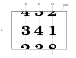
図3は、図柄表示装置の表示画面を示す図である。
図柄表示装置36の表示画面Gは、図3に示すように、3列の表示領域に区画されており、各表示領域には、左から順に左図柄列Z1、中図柄列Z2、および右図柄列Z3が表示される。各図柄列Z1~Z3は、「1」~「8」の数字からなる8種類の図柄を下方から上方に向かって昇順となるとともに、「8」の次は「1」となるように配列して構成されている。なお、図3では、各表示領域の中心線を一点鎖線で示している。
FIG. 3 is a diagram showing a display screen of the pattern display device.
As shown in FIG. 3, the display screen G of the
図柄表示装置36は、上作動口25または下作動口26への入賞に基づいて、各図柄列Z1~Z3の図柄を所定の向き(本参考形態では上向き)に周期的にスクロールさせるようにして図柄の変動表示を開始することによって、表示画面Gにおいて遊技回用の演出を実行する。この遊技回用の演出は、左図柄列Z1→右図柄列Z3→中図柄列Z2の順に変動表示から停止表示に切り換わり、最終的には、有効ラインL上に所定の図柄を停止表示した状態で終了する。
すなわち、遊技回とは、各作動口25,26への入賞に基づいて、メイン表示部34および図柄表示装置36にて変動表示が開始された後、所定の停止結果を表示するまでをいう。
The
In other words, the game cycle means the period from the start of variable display on the main display unit 34 and the
なお、図柄表示装置36における図柄の変動表示の態様は、これに限定されることはなく任意である。例えば、図柄列の列数、各図柄列のスクロールの方向、各図柄列の図柄数などは適宜変更可能である。また、各図柄列の図柄は、数字のみの態様に代えて、絵と数字とを組み合わせた態様としてもよく、絵のみの態様としてもよい。
It should be noted that the
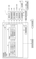
<パチンコ機の電気的構成>
図4は、パチンコ機の電気的構成を示すブロック図である。
パチンコ機1は、図4に示すように、主制御装置4と、音声発光制御装置5と、表示制御装置6とを備え、これらの装置は、内枠の背面側に搭載されている。また、パチンコ機1は、払出制御装置46と、電源・発射制御装置47とを備え、これらの装置は、裏パックユニットに搭載されている。払出制御装置46は、前述した払出装置48に遊技球の払い出しをさせる払出制御を実行する。電源・発射制御装置47は、前述した遊技球発射機構49に遊技球を発射させる発射制御を実行する。
<Electrical Configuration of Pachinko Machine>
FIG. 4 is a block diagram showing the electrical configuration of the pachinko machine.
As shown in FIG. 4, the
主制御装置4は、遊技の主たる制御(主制御)を司る主制御基板41と、電源を監視する停電監視基板45とを備えている。なお、主制御装置4は、主制御基板41などを収容する基板ボックスを備えている。この基板ボックスは、その開放に際して痕跡を残す痕跡手段を備えていてもよく、その開放に際して痕跡を残す痕跡構造を備えていてもよい。具体的には、痕跡手段としては、複数のケース体を結合することによって基板ボックスを構成し、各ケース体の分離に際して所定部位の破壊を要する結合部(カシメ部)を設ける構成や、引き剥がしに際して粘着層が接着対象に残ることで剥がされたことの痕跡を残す封印シールを複数のケース体間の境界を跨ぐようにして貼り付ける構成などを採用することができる。また、痕跡構造としては、これらのケース体間の境界に対して接着剤を塗布する構成などを採用することができる。
The
主制御基板41は、主制御基板41に実装されたMPU42と、このMPU42を構成しているROM43およびRAM44とを備えている。ここで、MPU42は、ROM43およびRAM44の他、CPU、割込回路、タイマ回路、データ入出力回路、および乱数発生器としてのカウンタ回路などを複合的にチップ化した素子である。
なお、本参考形態では、ROM43およびRAM44は、MPU42に対して1チップ化されているが、個別にチップ化された構成としてもよい。これは主制御装置4以外の他の制御装置のMPUについても同様である。
The
In this embodiment, the
ROM43は、各種の制御プログラムや固定値データを記憶するためのメモリであり、記憶している情報の保持に際して外部からの電力供給を必要としない不揮発性記憶手段である。このROM43は、当否テーブル記憶エリア431や、振分テーブル記憶エリア432や、リーチ用テーブル記憶エリア433などの各種エリアを有している。これらのエリアについては後に詳細に説明する。
RAM44は、ROM43に記憶された制御プログラムの実行に際して各種のデータ等を一時的に記憶するためのメモリであり、記憶している情報の保持に際して外部からの電力供給を必要とする揮発性記憶手段である。このRAM44は、各種カウンタエリア441や、保留球格納エリア442や、電役保留エリア443などの各種エリアを有している。これらのエリアについては後に詳細に説明する。
The
The
MPU42は、入力ポートおよび出力ポートを備えている。MPU42の入力ポートは、主制御装置4に設けられた停電監視基板45と、複数の検知センサ301~306とに接続されている。MPU42の出力ポートは、停電監視基板45と、払出制御装置46と、音声発光制御装置5とに接続されている。また、MPU42の出力ポートは、下作動口26の電動役物261を開閉動作させる電動役物駆動部262と、可変入賞装置27の開閉扉272を開閉動作させる可変入賞駆動部273と、メイン表示部34と、役物用表示部35とに接続されている。
The
なお、主制御基板41は、ドライバ回路を有している。MPU42は、このドライバ回路を通じて各種駆動部などの駆動制御を実行する。具体的には、電役開放状態では、MPU42は、電動役物駆動部262の駆動制御を実行して電動役物261を開閉させる。また、開閉実行モードでは、MPU42は、可変入賞駆動部273の駆動制御を実行して大入賞口271を開閉させる。また、各遊技回では、MPU42は、メイン表示部34の表示制御を実行して各作動口25,26への入賞に基づいて行われた内部抽選の結果を表示する。さらに、MPU42は、役物用表示部35の表示制御を実行して各スルーゲート31への入賞に基づいて行われた内部抽選の結果を表示する。
The
停電監視基板45は、主制御基板41と、動作電力を供給する機能を有する電源・発射制御装置47とを中継し、電源・発射制御装置47から出力される直流安定24ボルトの電圧を監視する。したがって、MPU42は、停電監視基板45を介して電力を受給する。
検知センサ301~306は、一般入賞口24、上作動口25、下作動口26、および可変入賞装置27の各種入賞口や、アウト口28や、各スルーゲート31に1対1で対応して設けられている。MPU42は、検知センサ301~306の検知結果に基づいて、各種入賞口や、アウト口28や、各スルーゲート31への入賞判定(入球判定)を行っている。なお、MPU42は、上作動口25または下作動口26への入賞判定に基づいて、内部抽選を実行する。
The power
The
払出制御装置46は、主制御装置4から送信されるコマンド(制御命令)に基づいて、払出装置48に賞球や貸し球(遊技に際して遊技者に貸し出す遊技球)の払い出しをさせる払出制御を実行する。
The
電源・発射制御装置47は、例えば、遊技場等における商用電源(外部電源)に接続されている。そして、電源・発射制御装置47は、その商用電源から供給される外部電力に基づいて主制御基板41や払出制御装置46等に対して各々に必要な動作電力を生成するとともに、その生成した動作電力を供給する。なお、電源・発射制御装置47は、バックアップ用コンデンサなどの電断時用電源部を備えている。この電断時用電源部は、パチンコ機1への電力供給が遮断された電断時においても主制御装置4のRAM44に記憶保持用の電力を供給する。
The power supply/
また、電源・発射制御装置47は、遊技球発射機構49に遊技球を発射させる発射制御を実行する。ここで、遊技球発射機構49は、遊技盤2の誘導レール23に向けて延びる発射レールと、上皿141に貯留されている遊技球を発射レール上に供給する球送り装置と、発射レール上に供給された遊技球を誘導レール23に向けて発射させる電動アクチュエータであるソレノイドとを備えている。電源・発射制御装置47は、所定の発射条件が整っている場合に、このソレノイドに対して駆動信号(発射許可信号)を供給し、遊技球を発射させる。
In addition, the power supply/
<主制御装置のMPUにて内部抽選を実行するための電気的構成>
図5は、内部抽選に用いられる各カウンタの内容を示す図である。
MPU42は、図5に示すように、各カウンタC1~C3,CINI,CS,C4の値(情報)を用いることによって、内部抽選などを実行する。具体的には、MPU42は、大当たり発生の抽選に大当たり乱数カウンタC1を使用し、大当たり発生に際し、その大当たりの種別の抽選に大当たり種別カウンタC2を使用し、リーチ表示を発生させるか否かの抽選にリーチ乱数カウンタC3を使用する。また、MPU42は、大当たり乱数カウンタC1の初期値設定に乱数初期値カウンタCINIを使用し、メイン表示部34および図柄表示装置36における表示継続時間の決定に変動種別カウンタCSを使用する。さらに、MPU42は、下作動口26の電動役物261を電役開放状態とするか否かの抽選に電動役物開放カウンタC4を使用する。なお、各カウンタC1~C3,CINI,CS,C4は、RAM44の各種カウンタエリア441(図4参照)に設けられている。
<Electrical Configuration for Execution of Internal Lottery by MPU of Main Control Unit>
FIG. 5 is a diagram showing the contents of each counter used for the internal lottery.
As shown in FIG. 5, the
各カウンタC1~C3,CINI,CS,C4は、その更新の都度、前回値に1が加算され、最大値に達した後、0に戻るループカウンタとなっている。各カウンタは、定期的に更新され、その更新された値は、RAM44の所定領域に設定された抽選カウンタ用バッファに適宜格納される。抽選カウンタ用バッファに格納された値のうち、大当たり乱数カウンタC1、大当たり種別カウンタC2、およびリーチ乱数カウンタC3の各値は、上作動口25または下作動口26に遊技球が入賞したタイミングでRAM44に取得情報記憶手段として設けられた保留球格納エリア442(図4参照)に格納される。また、抽選カウンタ用バッファに格納された値のうち、電動役物開放カウンタC4の値は、各スルーゲート31に遊技球が入賞したタイミングでRAM44の電役保留エリア443(図4参照)に格納される。
Each of the counters C1 to C3, CINI, CS, and C4 is a loop counter that adds 1 to the previous value each time it is updated and returns to 0 after reaching the maximum value. Each counter is periodically updated, and the updated value is appropriately stored in a lottery counter buffer set in a predetermined area of the
保留球格納エリア442は、第1結果表示部用保留エリアRaと、第2結果表示部用保留エリアRbと、実行エリアAEとを備えている。
The reserved
第1取得情報記憶手段として設けられた第1結果表示部用保留エリアRaは、第1エリアRa1~第4エリアRa4の4つの記憶エリアを備えている。各エリアRa1~Ra4は、大当たり乱数カウンタC1、大当たり種別カウンタC2、およびリーチ乱数カウンタC3の各値の組を格納可能な記憶容量に設定されている。MPU42は、大当たり乱数カウンタC1、大当たり種別カウンタC2、およびリーチ乱数カウンタC3の各値の組を保留情報として上作動口25への遊技球の入賞に合わせて各エリアRa1~Ra4に時系列的に格納していく。具体的には、MPU42は、上作動口25への入賞が複数回連続して発生した場合に、第1エリアRa1→第2エリアRa2→第3エリアRa3→第4エリアRa4の順に保留情報を時系列的に格納していく。
The first result display holding area Ra provided as the first acquired information storage means has four storage areas of a first area Ra1 to a fourth area Ra4. Each of the areas Ra1 to Ra4 is set to have a storage capacity capable of storing a set of values of the jackpot random number counter C1, the jackpot type counter C2, and the reach random number counter C3. The
このように、第1結果表示部用保留エリアRaは、4つの記憶エリアを備えているので、上作動口25への遊技球の入賞は、最大4個まで保留されるようになっている。また、第1結果表示部用保留エリアRaは、各エリアRa1~Ra4に格納されている保留個数を書き込むための記憶エリアを備えている。
なお、上作動口25に係る保留個数は、4個に限定されることはなく任意であり、2個、3個、または5個以上といったように他の複数であってもよく、単数であってもよい。
As described above, the reservation area Ra for the first result display section is provided with four storage areas, so that up to four winnings of game balls into the upper working
In addition, the number of reservations related to the upper working
第2取得情報記憶手段として設けられた第2結果表示部用保留エリアRbは、第1エリアRb1~第4エリアRb4の4つの記憶エリアを備えている。各エリアRb1~Rb4は、大当たり乱数カウンタC1、大当たり種別カウンタC2、およびリーチ乱数カウンタC3の各値の組を格納可能な記憶容量に設定されている。MPU42は、大当たり乱数カウンタC1、大当たり種別カウンタC2、およびリーチ乱数カウンタC3の各値の組を保留情報として下作動口26への遊技球の入賞に合わせて各エリアRb1~Rb4に時系列的に格納していく。具体的には、MPU42は、下作動口26への入賞が複数回連続して発生した場合に、第1エリアRb1→第2エリアRb2→第3エリアRb3→第4エリアRb4の順に保留情報を時系列的に格納していく。
The second result display holding area Rb provided as the second acquired information storage means comprises four storage areas, a first area Rb1 to a fourth area Rb4. Each of the areas Rb1 to Rb4 is set to have a storage capacity capable of storing a set of values of the jackpot random number counter C1, the jackpot type counter C2, and the reach random number counter C3. The
このように、第2結果表示部用保留エリアRbは、4つの記憶エリアを備えているので、下作動口26への遊技球の入賞は、最大4個まで保留されるようになっている。また、第2結果表示部用保留エリアRbは、各エリアRb1~Rb4に格納されている保留個数を書き込むための記憶エリアを備えている。
なお、下作動口26に係る保留個数は、4個に限定されることはなく任意であり、2個、3個、または5個以上といったように他の複数であってもよく、単数であってもよい。
As described above, since the second result display portion reservation area Rb has four storage areas, up to four winnings of game balls into the
In addition, the number of reservations related to the lower working
実行エリアAEは、各結果表示部341,342の変動表示を開始する際に、第1結果表示部用保留エリアRa、または第2結果表示部用保留エリアRbの記憶エリアに格納された保留情報を移動させるためのエリアである。 The execution area AE stores the pending information stored in the storage area of the first result display portion pending area Ra or the second result display portion pending area Rb when starting the variable display of each of the result display portions 341 and 342. This is the area to move the .
電役保留エリア443は、第1結果表示部用保留エリアRaおよび第2結果表示部用保留エリアRbと同様に4つの記憶エリアを備えている。したがって、各スルーゲート31への遊技球の入賞は、最大4個まで保留されるようになっている。
なお、各スルーゲート31に係る保留個数は、4個に限定されることはなく任意であり、2個、3個、または5個以上といったように他の複数であってもよく、単数であってもよい。
The electric
The number of pending
<各カウンタの詳細な説明>
以下、各カウンタの詳細について説明する。
まず、電動役物開放カウンタC4について説明する。電動役物開放カウンタC4は、例えば、その更新の都度、前回値に1が加算され、最大値250に達した後、0に戻ることによって、0~250の範囲内でループするループカウンタとなっている。
電動役物開放カウンタC4は、定期的に更新され、その更新された値は、各スルーゲート31に遊技球が入賞したタイミングで抽選カウンタ用バッファを介してRAM44の電役保留エリア443に格納される。
そして、MPU42は、電役保留エリア443に格納された電動役物開放カウンタC4の値に基づいて、下作動口26の電動役物261を電役開放状態とするか否かの抽選(電動役物開放抽選)を実行する。
<Detailed description of each counter>
The details of each counter will be described below.
First, the electric accessory release counter C4 will be described. For example, the electric accessory release counter C4 is a loop counter that loops within the range of 0 to 250 by adding 1 to the previous value each time it is updated and returning to 0 after reaching the maximum value of 250. ing.
The electric accessory release counter C4 is periodically updated, and the updated value is stored in the electric
Then, based on the value of the electric role product open counter C4 stored in the electric
ここで、パチンコ機1は、電動役物261を開放状態に設定することによって、下作動口26への遊技球の入賞を可能とする頻度が互いに異なる複数のサポートモードを有している。具体的には、パチンコ機1は、電動役物261を開放状態に設定する頻度が相対的に低い低頻度サポートモード(低頻度ガイド状態)と、電動役物261を開放状態に設定する頻度が相対的に高い高頻度サポートモード(高頻度ガイド状態)とを有している。
Here, the
低頻度サポートモードおよび高頻度サポートモードは、電動役物開放抽選において、電役開放状態に当選する確率は同一(例えば、共に4/5)となっている。しかしながら、高頻度サポートモードは、低頻度サポートモードと比較して、電役開放状態に当選した際に、電動役物261を開放状態に設定する回数が多く、電動役物261を開放状態に設定する1回の開放時間も長くなっている。また、高頻度サポートモードでは、1回の電役開放状態における各回の開放の間に、電動役物261を閉鎖状態に設定する閉鎖時間は、1回の開放時間よりも短くなっている。さらに、高頻度サポートモードは、低頻度サポートモードと比較して、電動役物開放抽選を終えてから次回の電動役物開放抽選を行うまでに待機する時間として最低限確保される確保時間(役物用表示部35における1回の変動表示の継続時間)が短くなっている。
The low frequency support mode and the high frequency support mode have the same probability of winning the electric role open state in the electric accessory open lottery (for example, both 4/5). However, in the high-frequency support mode, the number of times the
したがって、高頻度サポートモードでは、低頻度サポートモードと比較して、遊技球は、下作動口26に入賞しやすくなる。換言すれば、低頻度サポートモードでは、遊技者は、発射ハンドル16の回転操作量を中程度として左打ちし、遊技領域の上部における遊技球の到達位置を誘導レール23の出口部分が形成された側部の側から中央部へとシフトさせることによって、下作動口26よりも上作動口25に入賞する確率を高くすることができる。また、高頻度サポートモードでは、遊技者は、発射ハンドル16の回転操作量を最大として右打ちし、遊技領域の上部における遊技球の到達位置を誘導レール23の出口部分が形成された側部の側からその反対側の側部の側へとシフトさせることによって、上作動口25よりも下作動口26に入賞する確率を高くすることができる。
そして、下作動口26への入賞を検知した場合には、所定数の賞球の払い出しが実行されるので、高頻度サポートモードでは、遊技者は、遊技球をあまり減らさないようにしながら遊技を行うことができる。
Therefore, in the high-frequency support mode, game balls are more likely to enter the lower operation opening 26 than in the low-frequency support mode. In other words, in the low-frequency support mode, the player left-handedly hits the firing handle 16 with a medium rotational operation amount, and the exit portion of the
When it is detected that a prize has been entered into the
このように、本参考形態では、パチンコ機1は、上作動口25への遊技球の入球を発生させやすく、下作動口26への遊技球の入球を発生させにくい左打ちルート(第1の経路)と、下作動口26への遊技球の入球を発生させやすく、上作動口25への遊技球の入球を発生させにくい右打ちルート(第2の経路)とを備えている。
As described above, in the present embodiment, the
なお、低頻度サポートモードおよび高頻度サポートモードの構成は、これに限定されることはない。例えば、高頻度サポートモードは、電動役物開放抽選にて電役開放状態に当選する確率を低頻度サポートモードと比較して高くするように構成してもよい。また、例えば、複数種類の確保時間を用意し、高頻度サポートモードは、低頻度サポートモードと比較して、短い確保時間を選択し易いように構成してもよく、選択される確保時間の平均を短くするように構成してもよい。さらに、電動役物261を開放状態に設定する回数、開放時間、および確保時間の各条件を組み合わせることによって、高頻度サポートモードは、電動役物261を開放状態に設定する頻度を低頻度サポートモードと比較して相対的に高くするように構成してもよい。
Note that the configurations of the low-frequency support mode and the high-frequency support mode are not limited to this. For example, the high frequency support mode may be configured to increase the probability of winning the electric role open state in the electric accessory open lottery as compared to the low frequency support mode. Further, for example, a plurality of types of reserved time may be prepared, and the high-frequency support mode may be configured so that it is easier to select a shorter reserved time than the low-frequency support mode, and the average of the selected reserved time may be configured to be shortened. Furthermore, by combining the conditions of the number of times the
次に、大当たり乱数カウンタC1について説明する。大当たり乱数カウンタC1は、例えば、その更新の都度、前回値に1が加算され、最大値599に達した後、0に戻ることによって、0~599の範囲内でループするループカウンタとなっている。また、大当たり乱数カウンタC1は、1周ループするごとに、その時点の乱数初期値カウンタCINIの値を初期値として読み込む。なお、乱数初期値カウンタCINIは、大当たり乱数カウンタC1と同様に0~599の範囲内でループするループカウンタである。 Next, the jackpot random number counter C1 will be described. For example, the jackpot random number counter C1 is a loop counter that loops within the range of 0 to 599 by adding 1 to the previous value each time it is updated and returning to 0 after reaching the maximum value of 599. . Also, the jackpot random number counter C1 reads the value of the random number initial value counter CINI at that time as an initial value each time it loops. The random number initial value counter CINI is a loop counter that loops within the range of 0 to 599, like the jackpot random number counter C1.
大当たり乱数カウンタC1は、定期的に更新され、その更新された値は、上作動口25または下作動口26に遊技球が入賞したタイミングで抽選カウンタ用バッファを介してRAM44の保留球格納エリア442に格納される。具体的には、大当たり乱数カウンタC1の値は、上作動口25に遊技球が入賞したタイミングでRAM44の第1結果表示部用保留エリアRaに格納され、下作動口26に遊技球が入賞したタイミングでRAM44の第2結果表示部用保留エリアRbに格納される。
そして、MPU42は、保留球格納エリア442に格納された大当たり乱数カウンタC1の値に基づいて、大当たり発生の抽選(当否抽選)を実行する。
The jackpot random number counter C1 is periodically updated, and the updated value is transferred to the reserved
Then, the
図6は、大当たり発生に当選する乱数の値を記憶した当否テーブルを示す図である。
大当たり乱数カウンタC1の値のうち、大当たり発生に当選する乱数の値は、図6に示すように、当否情報群記憶手段として設けられたROM43の当否テーブル記憶エリア431(図4参照)に当否テーブル(当否情報群)として記憶されている。
FIG. 6 is a diagram showing a success/failure table that stores values of random numbers for winning a jackpot.
Among the values of the jackpot random number counter C1, the value of the random number that wins the jackpot is stored in the hit/fail table storage area 431 (see FIG. 4) of the
ここで、パチンコ機1は、大当たり発生に当選しにくい低確率モード(低確率状態)と、大当たり発生に当選しやすい高確率モード(高確率状態)との2つの当否抽選モードを有している。また、当否テーブルは、図6(a)に示す低確率モード用の当否テーブル(低確率用当否情報群)と、図6(b)に示す高確率モード用の当否テーブル(高確率用当否情報群)とを備えている。
MPU42は、これらの当否テーブルと、保留球格納エリア442に格納された大当たり乱数カウンタC1の値とを比較することによって、大当たり発生の抽選を実行する。
Here, the
The
これらの当否テーブルは、「大当たり当選」、「特別外れ結果」、および「通常外れ結果」の複数の大当たり発生の抽選の結果(当否結果)を有している。
具体的には、大当たり発生の抽選に際して低確率モード用の当否テーブルを参照することになる遊技状態下では、図6(a)に示すように、「大当たり当選」となる乱数の値は2個である。
これに対して、大当たり発生の抽選に際して高確率モード用の当否テーブルを参照することになる遊技状態下では、図6(b)に示すように、「大当たり当選」となる乱数の値は21個である。ここで、低確率モード用の当否テーブルに記憶された大当たり当選となる乱数の値は、高確率モード用の当否テーブルに記憶された「大当たり当選」となる乱数の値に含まれている。
These hit/fail tables have lottery results (hit/fail results) of occurrence of a plurality of jackpots, such as "jackpot win", "special loss result", and "ordinary loss result".
Specifically, under the gaming state in which the success/failure table for the low-probability mode is referred to for the lottery for the occurrence of the big win, as shown in FIG. is.
On the other hand, under the gaming state in which the win/fail table for the high-probability mode is referred to for the lottery for the occurrence of the big win, as shown in FIG. is. Here, the value of the random number for winning the jackpot stored in the success/failure table for the low-probability mode is included in the value of the random number for "winning the jackpot" stored in the success/failure table for the high-probability mode.
なお、各当否テーブルに記憶される乱数の値や個数は任意であり、高確率モードは、低確率モードと比較して「大当たり当選」となる確率が高くなっていればよい。また、高確率モード用の当否テーブルに記憶された「大当たり当選」となる乱数の値は、低確率モード用の当否テーブルに記憶された「大当たり当選」となる乱数の値を含んでいなくてもよく、低確率モード用の当否テーブルに記憶された「大当たり当選」となる乱数の値の一部を含んでいてもよい。 The value and number of random numbers stored in each success/failure table are arbitrary, and it is sufficient that the high probability mode has a higher probability of winning a "big win" than the low probability mode. Further, the value of the random number for "winning the jackpot" stored in the success/failure table for the high-probability mode must not include the value of the random number for "winning the jackpot" stored in the success/failure table for the low-probability mode. Alternatively, it may include a part of the random number values that are stored in the success/failure table for the low-probability mode and become the "big win".
また、各当否抽選モードにおいて、「大当たり当選」となる乱数の値以外は、大当たり発生に当選せずに外れ結果となる。
ここで、パチンコ機1は、前述したように、「特別外れ結果(小当たり結果)」と、「通常外れ結果」との2種類の外れ結果を有している。これらの外れ結果は、いずれも当否抽選モードや、サポートモードの移行契機とはならない点で共通している。しかしながら、「特別外れ結果」は、開閉実行モードへの移行契機となるのに対して、「通常外れ結果」は、開閉実行モードへの移行契機とはならない点で異なっている。
In addition, in each win/fail lottery mode, random numbers other than "big win win" results in a loss without winning a big win.
Here, as described above, the
次に、大当たり種別カウンタC2について説明する。大当たり種別カウンタC2は、例えば、その更新の都度、前回値に1が加算され、最大値29に達した後、0に戻ることによって、0~29の範囲内でループするループカウンタとなっている。
大当たり種別カウンタC2は、定期的に更新され、その更新された値は、上作動口25または下作動口26に遊技球が入賞したタイミングで抽選カウンタ用バッファを介してRAM44の保留球格納エリア442に格納される。具体的には、大当たり種別カウンタC2の値は、上作動口25に遊技球が入賞したタイミングでRAM44の第1結果表示部用保留エリアRaに格納され、下作動口26に遊技球が入賞したタイミングでRAM44の第2結果表示部用保留エリアRbに格納される。
そして、MPU42は、保留球格納エリア442に格納された大当たり種別カウンタC2の値に基づいて、大当たり発生に際し、その大当たりの種別の抽選(振分抽選)を実行する。
Next, the jackpot type counter C2 will be described. The jackpot type counter C2 is, for example, a loop counter that loops within the range of 0 to 29 by adding 1 to the previous value each time it is updated and returning to 0 after reaching the maximum value of 29. .
The jackpot type counter C2 is periodically updated, and the updated value is stored in the reserved
Then, based on the value of the jackpot type counter C2 stored in the reserved
図7は、大当たりの種別の振分先に係る乱数の値を記憶した振分テーブルを示す図である。
大当たりの種別の振分先に係る乱数の値は、図7に示すように、振分情報群記憶手段として設けられたROM43の振分テーブル記憶エリア432(図4参照)に振分テーブル(振分情報群)として記憶されている。振分テーブルは、図7(a)に示す第1振分テーブル(第1振分情報群)と、図7(b)に示す第2振分テーブル(第2振分情報群)とを備えている。
MPU42は、これらの振分テーブルと、保留球格納エリア442に格納された大当たり種別カウンタC2の値とを比較することによって、大当たりの種別の抽選を実行する。
FIG. 7 is a diagram showing an allocation table storing random number values relating to allocation destinations of types of jackpots.
As shown in FIG. 7, the random number value related to the allocation destination of the jackpot type is stored in the allocation table storage area 432 (see FIG. 4) of the
The
第1振分テーブルは、第1結果表示部用保留エリアRaから実行エリアAEにシフトされた大当たり種別カウンタC2の値、すなわち上作動口25への入賞に基づく大当たり種別カウンタC2の値に対して大当たりの種別の抽選を行う場合に参照されるテーブルである。
第1振分テーブルは、図7(a)に示すように、「低確結果(低確率対応の特別振分結果)」、「非明示少ラウンド高確結果(少ラウンド対応の潜伏高確率結果)」、「明示少ラウンド高確結果(少ラウンド対応の高確率結果)」、および「最有利結果(高確率対応の特別振分結果)」の複数の振分結果を振分先としている。具体的には、第1振分テーブルでは、大当たり種別カウンタC2の値「0~29」のうち、「0~9」を「低確結果」に振り分け、「10~14」を「非明示少ラウンド高確結果」に振り分け、「15~19」を「明示少ラウンド高確結果」に振り分け、「20~29」を「最有利結果」に振り分けている。
In the first distribution table, the value of the jackpot type counter C2 shifted from the first result display portion reservation area Ra to the execution area AE, that is, the value of the jackpot type counter C2 based on the winning to the
As shown in FIG. 7A, the first distribution table includes "low probability result (special distribution result corresponding to low probability)", "non-explicit small round high probability result (latency high probability result corresponding to small round )”, “explicit small-round high-probability result (high-probability result corresponding to few-rounds)”, and “most advantageous result (special distribution result corresponding to high-probability)” are the distribution destinations. Specifically, in the first distribution table, among the values “0 to 29” of the jackpot type counter C2, “0 to 9” are distributed to “low probability results”, and “10 to 14” are distributed to “unspecified low ``15 to 19'' are assigned to ``Highly Probable Round Results'', and ``20 to 29'' are assigned to ``Most Favorable Results''.
第2振分テーブルは、第2結果表示部用保留エリアRbから実行エリアAEにシフトされた大当たり種別カウンタC2の値、すなわち下作動口26への入賞に基づく大当たり種別カウンタC2の値に対して大当たりの種別の抽選を行う場合に参照されるテーブルである。
第2振分テーブルは、図7(b)に示すように、「低確結果」および「最有利結果」の2つの振分結果を振分先としている。具体的には、第2振分テーブルでは、大当たり種別カウンタC2の値「0~29」のうち、「0~9」を「低確結果」に振り分け、「10~29」を「最有利結果」に振り分けている。
In the second distribution table, the value of the jackpot type counter C2 shifted from the second result display portion reservation area Rb to the execution area AE, that is, the value of the jackpot type counter C2 based on the winning to the
The second distribution table, as shown in FIG. 7(b), has two distribution results of "low probability result" and "best result" as distribution destinations. Specifically, in the second distribution table, among the values “0 to 29” of the jackpot type counter C2, “0 to 9” are distributed to “low probability results”, and “10 to 29” are the “best results” ”.
各振分結果は、以下の(1)~(3)の条件の少なくともいずれかに差異を有している。
(1)開閉実行モード終了後の当否抽選モード
(2)開閉実行モード終了後のサポートモード
(3)開閉実行モードにおける可変入賞装置27の開閉制御の態様
Each distribution result has a difference in at least one of the following conditions (1) to (3).
(1) Winner lottery mode after completion of opening/closing execution mode (2) Support mode after completion of opening/closing execution mode (3) Aspect of opening/closing control of variable winning
まず、(1)の当否抽選モードの相違について説明する。
「低確結果」は、開閉実行モード終了前の当否抽選モードに関わらず開閉実行モード終了後に当否抽選モードが低確率モードに設定される振分結果である。この低確率モードは、少なくとも当否抽選において「大当たり当選」となるまで継続する。
「非明示少ラウンド高確結果」、「明示少ラウンド高確結果」、および「最有利結果」は、開閉実行モード終了前の当否抽選モードに関わらず開閉実行モード終了後に当否抽選モードが高確率モードに設定される振分結果である。この高確率モードは、少なくとも当否抽選において「大当たり当選」となるまで継続する。
First, the difference between the win/fail lottery modes (1) will be described.
The "low-probability result" is a distribution result in which the win-or-fail lottery mode is set to the low-probability mode after the opening/closing execution mode ends, regardless of the winning/failure lottery mode before the opening/closing execution mode ends. This low-probability mode continues at least until a "big win" is achieved in the winning lottery.
"Unexplained few rounds high probability result", "Explicit few rounds high probability result", and "Most favorable result" are high probability of winning lottery mode after opening and closing execution mode regardless of the winning lottery mode before closing execution mode. This is the distribution result set in the mode. This high-probability mode continues at least until a "big win" is achieved in the winning lottery.
次に、(2)のサポートモードの相違について説明する。
「低確結果」は、開閉実行モード終了前のサポートモードに関わらず開閉実行モード終了後にサポートモードが高頻度サポートモードに設定される振分結果である。この高頻度サポートモードは、遊技回が終了基準回数(具体的には、100回)に達した場合には低頻度サポートモードに移行する。
Next, the difference in support mode (2) will be described.
The "low probability result" is a distribution result in which the support mode is set to the high frequency support mode after the opening/closing execution mode ends, regardless of the support mode before the opening/closing execution mode ends. This high-frequency support mode shifts to a low-frequency support mode when the game times reach the end reference number of times (specifically, 100 times).
「非明示少ラウンド高確結果」は、開閉実行モード終了前のサポートモードをそのまま維持する振分結果である。ここで、開閉実行モード終了前のサポートモードが高頻度サポートモードであった場合には、高頻度サポートモードは、少なくとも当否抽選において「大当たり当選」となるまで継続する。
「明示少ラウンド高確結果」および「最有利結果」は、開閉実行モード終了前のサポートモードに関わらず開閉実行モード終了後にサポートモードが高頻度サポートモードに設定される振分結果である。この高頻度サポートモードは、少なくとも当否抽選において「大当たり当選」となるまで継続する。
The “non-explicit few rounds high probability result” is a sorting result that maintains the support mode before the end of the open/close execution mode. Here, if the support mode before the end of the opening/closing execution mode is the high-frequency support mode, the high-frequency support mode continues at least until "big win" is won in the lottery.
The "explicit few rounds high probability result" and "most advantageous result" are distribution results in which the support mode is set to the high frequency support mode after the opening/closing execution mode ends, regardless of the support mode before the opening/closing execution mode ends. This high-frequency support mode continues at least until a "big win" is achieved in the winning lottery.
なお、(3)の開閉実行モードにおける可変入賞装置27の開閉制御の態様の相違については後に詳細に説明する。
The difference in the opening/closing control mode of the variable winning
次に、リーチ乱数カウンタC3について説明する。リーチ乱数カウンタC3は、例えば、その更新の都度、前回値に1が加算され、最大値238に達した後、0に戻ることによって、0~238の範囲内でループするループカウンタとなっている。
リーチ乱数カウンタC3は、定期的に更新され、その更新された値は、上作動口25または下作動口26に遊技球が入賞したタイミングで抽選カウンタ用バッファを介してRAM44の保留球格納エリア442に格納される。具体的には、リーチ乱数カウンタC3の値は、上作動口25に遊技球が入賞したタイミングでRAM44の第1結果表示部用保留エリアRaに格納され、下作動口26に遊技球が入賞したタイミングでRAM44の第2結果表示部用保留エリアRbに格納される。
そして、MPU42は、保留球格納エリア442に格納されたリーチ乱数カウンタC3の値に基づいて、リーチ表示を発生させるか否かの抽選(リーチ発生抽選)を実行する。
Next, the reach random number counter C3 will be described. The reach random number counter C3 is, for example, a loop counter that loops within the range of 0 to 238 by adding 1 to the previous value each time it is updated and returning to 0 after reaching the maximum value of 238. .
The reach random number counter C3 is periodically updated, and the updated value is stored in the reserved
And MPU42 performs the lottery (reach generation lottery) of whether to generate a reach display based on the value of the reach random number counter C3 stored in the holding
リーチ表示は、当否抽選において「大当たり当選」となることなく「通常外れ結果」となった場合に発生する期待演出である。
具体的には、MPU42は、当否抽選において「大当たり当選」となることなく「通常外れ結果」となった場合に、リーチ用テーブルと、保留球格納エリア442に格納されたリーチ乱数カウンタC3の値とを比較することによって、リーチ表示を発生させるか否かの抽選を実行し、この抽選においてリーチ表示を発生させるとなった場合にリーチ表示を発生させる。なお、リーチ用テーブルは、リーチ表示の発生に係る乱数の値を記憶したテーブルであり、ROM43のリーチ用テーブル記憶エリア433(図4参照)に記憶されている。
The ready-to-win display is an expectation effect that occurs when the winning lottery does not result in a "big win" but results in a "normal failure".
Specifically, the
ここで、当否抽選において「大当たり当選」となって、振分抽選において「最有利結果」に振り分けられた場合には、図柄表示装置36は、停止結果として、同一の奇数の数字または同一の偶数の数字を有する図柄の組み合わせを有効ラインL上に停止表示する。また、当否抽選において「大当たり当選」となって、振分抽選において「低確結果」に振り分けられた場合には、図柄表示装置36は、停止結果として、同一の偶数の数字を有する図柄の組み合わせを有効ラインL上に停止表示する。さらに、当否抽選において「大当たり当選」となって、振分抽選において「非明示少ラウンド高確結果」または「明示少ラウンド高確結果」に振り分けられた場合や、当否抽選において「大当たり当選」となることなく「特別外れ結果」となった場合には、図柄表示装置36は、停止結果として、同一の数字を有する図柄の組み合わせではなく、当否抽選において「通常外れ結果」となった場合に選択されることのない互いに異なる数字を有する特別な図柄(例えば「3・4・1」)の組み合わせを有効ラインL上に停止表示する。
Here, in the case of "big win winning" in the lottery lottery and "best result" in the distribution lottery, the
リーチ表示は、同一の数字を有する図柄の組み合わせを最終的に停止表示させる場合(当否抽選において「大当たり当選」となって、振分抽選において「最有利結果」または「低確結果」に振り分けられた場合)には、リーチ乱数カウンタC3の値に関わらず発生する。また、リーチ表示は、特別な図柄の組み合わせを最終的に停止表示させる場合(当否抽選において「大当たり当選」となって、振分抽選において「非明示少ラウンド高確結果」または「明示少ラウンド高確結果」に振り分けられた場合や、当否抽選において「大当たり当選」となることなく「特別外れ結果」となった場合)には、リーチ乱数カウンタC3の値に関わらず発生しない。 The reach display is when the combination of symbols with the same number is finally stopped and displayed (it becomes a "big hit" in the winning lottery, and is distributed to the "best result" or "low probability result" in the distribution lottery. ), it occurs regardless of the value of the reach random number counter C3. In addition, the reach display is used when the combination of special symbols is finally stopped and displayed ("jackpot winning" in the winning lottery, "unspecified small round high probability result" or "explicit small round high probability" in the distribution lottery) In the case of being sorted to "probable result" or "special losing result" instead of "big hit winning" in the winning lottery), it does not occur regardless of the value of the reach random number counter C3.
リーチ表示の態様は、図柄表示装置36の表示画面Gに表示される複数の図柄列Z1~Z3のうち、一部の図柄列(例えば、図柄列Z1および図柄列Z3)を有効ラインL上に停止表示させることによって、同一の図柄の組み合わせを表示して停止結果を示唆し、その状態で残りの図柄列(例えば、図柄列Z2)を変動表示する。
したがって、パチンコ機1は、リーチ表示を発生させることによって、図柄表示装置36にて変動表示が開始された後、所定の停止結果を表示する前に、当否抽選において「大当たり当選」となって、振分抽選において「低確結果」または「最有利結果」に振り分けられたのではないかと遊技者に期待させることができる。
In the ready-to-win display mode, some of the plurality of symbol rows Z1 to Z3 displayed on the display screen G of the symbol display device 36 (for example, the symbol row Z1 and the symbol row Z3) are displayed on the activated line L. By stopping and displaying, the same combination of symbols is displayed to indicate the result of stopping, and in that state, the remaining symbol rows (for example, the symbol row Z2) are variably displayed.
Therefore, by generating the ready-to-win display, the
なお、リーチ表示の態様は、これに限定されることはなく、一部の図柄列を停止表示させた上で残りの図柄列を変動表示させるとともに、所定のキャラクタなどを動画として背景に表示してもよく、各図柄列を縮小表示または非表示にした上で所定のキャラクタなどを動画として表示画面Gの略全体に表示してもよい。 Note that the ready-to-win display mode is not limited to this, and a part of the symbol rows are stopped and displayed, and the remaining symbol rows are variably displayed, and a predetermined character or the like is displayed in the background as a moving image. Alternatively, each pattern row may be reduced or hidden, and a predetermined character or the like may be displayed on substantially the entire display screen G as a moving image.
ここで、パチンコ機1は、図柄表示装置36の変動表示の一種として期待演出を有している。期待演出とは、図柄表示装置36にて変動表示が開始された後、所定の停止結果を表示する前に、当否抽選において「大当たり当選」となったのではないかと遊技者に期待させるような演出をいう。具体的には、パチンコ機1は、前述したリーチ表示と、予告表示との2種類の期待演出を有している。
Here, the
予告表示は、当否抽選において「大当たり当選」となった場合や、当否抽選において「大当たり当選」となることなく「特別外れ結果」となった場合に、当否抽選において「大当たり当選」となることなく「通常外れ結果」となった場合よりも演出を発生しやすくする期待演出である。この予告表示は、演出を発生しやすくする代わりに、出現率の低い演出を選択しやすくするようにしてもよく、これらを組み合わせるようにしてもよい。
なお、リーチ表示を発生させるか否かの抽選は、主制御装置4にて実行されていたのに対し、予告表示を発生させるか否かの抽選は、音声発光制御装置5にて実行される。
The notice display will not be "jackpot winning" in the lottery if it becomes "jackpot winning" in the lottery, or if it becomes "special losing result" without becoming "jackpot winning" in the lottery lottery. This is an expected effect that makes the effect more likely to occur than in the case of the "normal deviation result". This advance notice display may make it easier to select an effect with a low appearance rate instead of making the effect more likely to occur, or may be combined.
While the lottery to determine whether to generate the ready-to-win display was performed by the
予告表示の態様は、図柄表示装置36の表示画面Gに表示される複数の図柄列Z1~Z3のうち、全ての図柄列Z1~Z3を変動表示させている、一部の図柄列(例えば、図柄列Z1)を有効ラインL上に停止表示させた上で複数の図柄列(例えば、図柄列Z2,Z3)を変動表示させている、またはリーチ表示を発生させている状況において、所定のキャラクタなどを動画として表示画面Gに表示する。この予告表示は、リーチ表示を発生させる場合およびリーチ表示を発生させない場合のいずれの場合においても発生するが、リーチ表示を発生させない場合よりもリーチ表示を発生させる場合に発生しやすくなるように設定されている。
なお、予告表示は、これに限定されることはなく、例えば、背景を変更して表示してもよく、図柄列Z1~Z3の形態を変更して表示してもよい。
The mode of the advance notice display is a partial symbol row (for example, symbol row Z1) is stopped on the activated line L, and a plurality of symbol rows (for example, symbol rows Z2, Z3) are variably displayed or ready-to-win display is generated, a predetermined character etc. are displayed on the display screen G as moving images. This notice display occurs both when the reach display is generated and when the reach display is not generated, but it is set so that it is more likely to occur when the reach display is generated than when the reach display is not generated. It is
Note that the advance notice display is not limited to this, and for example, the background may be changed, and the pattern rows Z1 to Z3 may be changed and displayed.
最後に、変動種別カウンタCSについて説明する。変動種別カウンタCSは、例えば、その更新の都度、前回値に1が加算され、最大値198に達した後、0に戻ることによって、0~198の範囲内でループするループカウンタとなっている。
変動種別カウンタCSは、後述する通常処理の実行ごとに少なくとも1回更新され、その更新の都度、抽選カウンタ用バッファに格納される。
そして、MPU42は、抽選カウンタ用バッファに格納された変動種別カウンタCSの値に基づいて、メイン表示部34における絵柄の表示継続時間と、図柄表示装置36における図柄の表示継続時間とを決定する。なお、これらの表示継続時間については後に詳細に説明する。
Finally, the fluctuation type counter CS will be explained. For example, the fluctuation type counter CS is a loop counter that loops within the range of 0 to 198 by adding 1 to the previous value each time it is updated and returning to 0 after reaching the maximum value 198. .
The fluctuation type counter CS is updated at least once each time a normal process, which will be described later, is executed, and is stored in the lottery counter buffer each time it is updated.
Then, the
<主制御装置にて実行される各種処理について>
主制御装置4のMPU42は、遊技を進行させるタイマ割込み処理および通常処理や、電源投入に伴って起動するメイン処理を実行する。以下、タイマ割込み処理、通常処理、およびメイン処理について順に説明する。
なお、MPU42は、タイマ割込み処理、通常処理、およびメイン処理の他、NMI端子(ノンマスカブル端子)への停電信号の入力によって起動するNMI割込み処理を実行するが、この処理についての説明は省略する。
<Regarding various processes executed by the main controller>
The
In addition to timer interrupt processing, normal processing, and main processing, the
<タイマ割込み処理>
図8は、タイマ割込み処理のフローチャートを示す図である。
タイマ割込み処理では、MPU42は、図8に示すように、ステップS101~S105を定期的に(例えば、2msec周期で)実行する。
<Timer interrupt processing>
FIG. 8 is a diagram showing a flowchart of timer interrupt processing.
In timer interrupt processing, the
ステップS101では、MPU42は、複数の検知センサ301~306の読み込み処理を実行する。この読み込み処理では、MPU42は、複数の検知センサ301~306の状態を読み込み、その状態を判定して入賞検知情報としてRAM44に保存する。MPU42は、各種入賞口に対応した検知センサ301~304が遊技球の入賞を検知していると判定した場合には、賞球の払い出し指示を行うための賞球コマンドを設定し、この設定したコマンドを払出制御装置46に送信する。例えば、MPU42は、可変入賞装置27に対応した検知センサ304が遊技球の入賞を検知していると判定した場合には、特定単位個数である15個の賞球を指示するための賞球コマンドを払出制御装置46に送信する。
なお、払出制御装置46は、MPU42から送信される賞球コマンドに基づいて、払出装置48に賞球の払い出しを実行させる払出制御を行う。
In step S101, the
The
ステップS102では、MPU42は、乱数初期値カウンタCINIの更新を実行する。具体的には、MPU42は、前述したように、乱数初期値カウンタCINIの前回値に1を加算して更新するとともに、更新後の値をRAM44の所定領域に設定された抽選カウンタ用バッファに格納する。なお、MPU42は、乱数初期値カウンタCINIの前回値に1を加算する際に最大値に達していた場合には、乱数初期値カウンタCINIの値を0に戻してクリアする。
In step S102, the
ステップS103では、MPU42は、大当たり乱数カウンタC1、大当たり種別カウンタC2、リーチ乱数カウンタC3、および電動役物開放カウンタC4の更新を実行する。具体的には、MPU42は、前述したように、大当たり乱数カウンタC1、大当たり種別カウンタC2、リーチ乱数カウンタC3、および電動役物開放カウンタC4の前回値にそれぞれ1を加算して更新するとともに、更新後の値をRAM44の所定領域に設定された抽選カウンタ用バッファに格納する。なお、MPU42は、各カウンタC1~C4の前回値にそれぞれ1を加算する際に最大値に達していた場合には、各カウンタC1~C4の値を0に戻してクリアする。
In step S103, the
ステップS104では、MPU42は、スルー用の入賞処理を実行する。このスルー用の入賞処理では、MPU42は、各スルーゲート31に対応した検知センサ306が遊技球の入賞を検知していると判定した場合には、ステップS103にて更新した電動役物開放カウンタC4の値を電役保留エリア443に格納する。また、MPU42は、第3保留ランプ部373を点灯させるためのコマンドを設定し、この設定したコマンドを音声発光制御装置5に送信する。
なお、音声発光制御装置5は、MPU42から送信されるコマンドに基づいて、第3保留ランプ部373を点灯させる。また、各スルーゲート31に入賞した遊技球の保留個数は、前述したように、最大4個であり、第3保留ランプ部373は、この保留個数と対応する数だけ点灯する。
In step S104, the
In addition, the sound
ステップS105では、MPU42は、作動口用の入賞処理を実行する。
以下、作動口用の入賞処理について詳細に説明する。
In step S105, the
The prize winning process for the operating port will be described in detail below.
<作動口用の入賞処理>
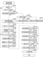
図9は、作動口用の入賞処理のフローチャートを示す図である。
作動口用の入賞処理では、MPU42は、図9に示すように、ステップS201~S208を実行する。
<Winning process for operating port>
FIG. 9 is a diagram showing a flow chart of the winning process for the working opening.
In the winning process for the working opening, the
ステップS201では、MPU42は、上作動口25に対応した検知センサ302が遊技球の入賞を検知したか否かを判定することによって、上作動口25に遊技球が入賞(始動入賞)したか否かを判定する。MPU42は、ステップS201にて上作動口25に遊技球が入賞したと判定した場合には、ステップS202において、第1結果表示部用保留エリアRaに記憶されている保留個数を把握し、その保留個数を第1始動保留記憶数RaNとして第1結果表示部用保留エリアRaにおける所定の記憶エリアにセットする。その後、MPU42は、ステップS205以降の処理を実行する。
In step S201, the
これに対して、MPU42は、ステップS201にて上作動口25に遊技球が入賞していないと判定した場合には、ステップS203において、下作動口26に対応した検知センサ303が遊技球の入賞を検知したか否かを判定することによって、下作動口26に遊技球が入賞(始動入賞)したか否かを判定する。
MPU42は、ステップS203にて下作動口26に遊技球が入賞していないと判定した場合には、作動口用の入賞処理を終了する。また、MPU42は、ステップS203にて下作動口26に遊技球が入賞したと判定した場合には、ステップS204において、第2結果表示部用保留エリアRbに記憶されている保留個数を把握し、その保留個数を第2始動保留記憶数RbNとして第2結果表示部用保留エリアRbにおける所定の記憶エリアにセットする。その後、MPU42は、ステップS205以降の処理を実行する。
On the other hand, when the
When the
ステップS202またはステップS204の処理を実行した後、MPU42は、ステップS205において、ステップS202またはステップS204にてセットした始動保留記憶数N(RaNまたはRbN)が上限値(本参考形態では4)未満であるか否かを判定する。
MPU42は、ステップS205にて始動保留記憶数Nが上限値未満でないと判定した場合には、作動口用の入賞処理を終了する。また、MPU42は、ステップS205にて始動保留記憶数Nが上限値未満であると判定した場合には、ステップS206において、その始動保留記憶数Nの値に1を加算して更新する。
After executing the process of step S202 or step S204, the
When the
ステップS207では、MPU42は、タイマ割込み処理のステップS103にて更新した大当たり乱数カウンタC1、大当たり種別カウンタC2、およびリーチ乱数カウンタC3の各値の組を結果表示部用保留エリアの空き記憶エリアのうち最初の記憶エリア、すなわちステップS206にて更新した始動保留記憶数Nと対応する記憶エリアに保留情報として格納する。
In step S207, the
例えば、MPU42は、ステップS202にて第1始動保留記憶数RaNをセットした場合には、タイマ割込み処理のステップS103にて更新した大当たり乱数カウンタC1、大当たり種別カウンタC2、およびリーチ乱数カウンタC3の各値の組を第1結果表示部用保留エリアRaの空き記憶エリアのうち最初の記憶エリア、すなわちステップS206にて更新した第1始動保留記憶数RaNと対応する記憶エリアに保留情報として格納する。例えば、MPU42は、ステップS202にて第1始動保留記憶数RaNに「3」をセットした場合には、ステップS206にて更新した第1始動保留記憶数RaNの「4」と対応する記憶エリアである第4エリアRa4に保留情報を格納する。
For example, when the
また、例えば、MPU42は、ステップS204にて第2始動保留記憶数RbNをセットした場合には、タイマ割込み処理のステップS103にて更新した大当たり乱数カウンタC1、大当たり種別カウンタC2、およびリーチ乱数カウンタC3の各値の組を第2結果表示部用保留エリアRbの空き記憶エリアのうち最初の記憶エリア、すなわちステップS206にて更新した第2始動保留記憶数RbNと対応する記憶エリアに保留情報として格納する。例えば、MPU42は、ステップS204にて第2始動保留記憶数RbNに「3」をセットした場合には、ステップS206にて更新した第2始動保留記憶数RbNの「4」と対応する記憶エリアである第4エリアRb4に保留情報を格納する。
Further, for example, when the
ステップS208では、MPU42は、ステップS202にて第1始動保留記憶数RaNをセットした場合には、第1結果表示部用保留エリアRaの記憶エリアに保留情報を格納したことを認識させるための第1保留発生コマンドを設定し、この設定した第1保留発生コマンドを音声発光制御装置5に送信する。その後、MPU42は、作動口用の入賞処理を終了する。
この第1保留発生コマンドは、上作動口25への遊技球の入賞に基づいて第1結果表示部用保留エリアRaの記憶エリアに保留情報を格納したことを音声発光制御装置5に認識させるための情報を含んでいる。また、第1保留発生コマンドは、現在のサポートモードに係る情報を含んでいる。
なお、音声発光制御装置5は、MPU42から送信される第1保留発生コマンドに基づいて、第1保留ランプ部371を点灯させる他、所定の処理を実行する。この処理については後に詳細に説明する。また、上作動口25に入賞した遊技球の保留個数は、前述したように、最大4個であり、第1保留ランプ部371は、この保留個数と対応する数だけ点灯する。
In step S208, the
This first pending generation command is for making the sound
In addition, the sound
また、ステップS208では、MPU42は、ステップS204にて第2始動保留記憶数RbNをセットした場合には、第2結果表示部用保留エリアRbの記憶エリアに保留情報を格納したことを認識させるための第2保留発生コマンドを設定し、この設定した第2保留発生コマンドを音声発光制御装置5に送信する。その後、MPU42は、作動口用の入賞処理を終了する。
この第2保留発生コマンドは、下作動口26への遊技球の入賞に基づいて第2結果表示部用保留エリアRbの記憶エリアに保留情報を格納したことを音声発光制御装置5に認識させるための情報を含んでいる。また、第2保留発生コマンドは、現在のサポートモードに係る情報を含んでいる。
なお、音声発光制御装置5は、MPU42から送信される第2保留発生コマンドに基づいて、第2保留ランプ部372を点灯させる他、所定の処理を実行する。この処理については後に詳細に説明する。また、下作動口26に入賞した遊技球の保留個数は、前述したように、最大4個であり、第2保留ランプ部372は、この保留個数と対応する数だけ点灯する。
Further, in step S208, the
This second hold generation command is used to make the sound
In addition, the sound
<通常処理>
図10は、通常処理のフローチャートを示す図である。
MPU42は、電源投入に伴って起動する後述のメイン処理を実行した後、遊技を進行させるための主要な処理である通常処理を実行する。この通常処理では、MPU42は、図10に示すように、ステップS301~S314を実行する。具体的には、MPU42は、ステップS301~S309を4msec周期で定期的に実行し、残余時間が発生した場合にステップS308~S311を繰り返し実行し、ステップS308の判定結果に応じてステップS312以降を実行する。
<Normal processing>
FIG. 10 is a diagram showing a flowchart of normal processing.
The
ステップS301では、MPU42は、タイマ割込み処理、作動口用の入賞処理、または前回の通常処理で設定したコマンドをサブ側の各制御装置に送信するための外部出力処理を実行する。この外部出力処理では、例えば、MPU42は、賞球コマンドが設定されているか否かを判定し、賞球コマンドが設定されていると判定した場合には、その賞球コマンドを払出制御装置46に送信する。また、例えば、MPU42は、遊技回用の演出に対応したコマンドや、開閉実行モード用の演出に対応したコマンドなどの演出用のコマンドが設定されているか否かを判定し、演出用のコマンドが設定されていると判定した場合には、その演出用のコマンドを音声発光制御装置5に送信する。
In step S301, the
ステップS302では、MPU42は、変動種別カウンタCSの更新を実行する。具体的には、MPU42は、前述したように、変動種別カウンタCSの前回値に1を加算して更新するとともに、更新後の値をRAM44の所定領域に設定された抽選カウンタ用バッファに格納する。なお、MPU42は、変動種別カウンタCSの前回値に1を加算する際に最大値に達していた場合には、変動種別カウンタCSの値を0に戻してクリアする。
In step S302, the
ステップS303では、MPU42は、遊技回を進行させるための遊技回制御処理を実行する。遊技回制御処理では、MPU42は、当否抽選および振分抽選を実行するとともに、図柄表示装置36に最終的に停止表示させる絵柄に係る情報の決定およびメイン表示部34に最終的に停止表示させる絵柄に係る情報の決定などを実行する。
ステップS304では、MPU42は、遊技状態を移行させるための遊技状態移行処理を実行する。遊技状態移行処理では、MPU42は、開閉実行モード、高確率モード、および高頻度サポートモードなどの各遊技状態への移行処理を実行する。
なお、ステップS303の遊技回制御処理およびステップS304の遊技状態移行処理については後に詳細に説明する。
In step S303, the
In step S304, the
The game round control process in step S303 and the game state transition process in step S304 will be described later in detail.
ステップS305では、MPU42は、デモ表示実行判定処理を実行する。このデモ表示実行判定処理では、MPU42は、遊技回の終了後に新たな遊技回が開始されることなく予め定められたデモ開始用の開始待ち期間(例えば、30sec)を経過したか否かを判定し、開始待ち期間を経過していると判定した場合には、デモ表示を開始させるためのデモコマンドを設定する。MPU42は、通常処理のステップS301において、ステップS305にて設定したデモコマンドを音声発光制御装置5に送信する。
なお、音声発光制御装置5は、MPU42から送信されるデモコマンドに基づいて、デモ表示実行処理を開始する。
In step S305, the
Note that the sound
ここで、MPU42は、ステップS305の処理の実行回数をカウントすることによって開始待ち期間が経過したか否かを判定する。例えば、開始待ち期間を30secとし、ステップS305の処理を繰り返し実行する間隔が4msecである場合には、MPU42は、ステップS305の処理の実行回数をカウントして7500回に達したときに開始待ち期間を経過したと判定する。なお、開始待ち期間を測定する構成は任意であり、例えば、リアルタイムクロックを用いて開始待ち期間を測定してもよい。また、MPU42は、ステップS305の処理の実行回数をカウントしているときに新たな遊技回を開始した場合には、そのカウントの値をリセットする。
Here, the
ステップS306では、MPU42は、下作動口26に設けられた電動役物261の駆動制御を実行するための電役サポート用処理を実行する。この電役サポート用処理では、MPU42は、RAM44の電役保留エリア443に格納された電動役物開放カウンタC4の値に基づいて、電動役物開放抽選を実行するとともに、電動役物開放抽選に当選した場合には、電動役物261の開閉処理を実行する。また、MPU42は、電動役物開放抽選の結果を表示するように、役物用表示部35の表示制御を実行する。
In step S<b>306 , the
ステップS307では、MPU42は、遊技球発射制御処理を実行する。この遊技球発射制御処理では、MPU42は、遊技者が発射ハンドル16を回転操作したことに基づいて、電源・発射制御装置47に遊技球を発射させる発射制御を実行させる。具体的には、電源・発射制御装置47は、所定の周期(本参考形態では0.6sec)で遊技球発射機構49のソレノイドを励磁することによって、遊技球発射機構49に遊技球を発射させる。なお、ソレノイドは、発射ハンドル16の回転操作量に応じた発射強度で遊技球を発射するように励磁される。また、電源・発射制御装置47は、所定の発射条件が整っている場合に、遊技球発射機構49のソレノイドに対して駆動信号を供給し、遊技球を発射させる。
In step S307, the
ステップS308では、MPU42は、RAM44の停電フラグ格納エリア(図示略)に停電フラグがセットされているか否かを判定する。この停電フラグは、MPU42のNMI端子に対して停電監視基板45から停電信号が入力されることによってRAM44にセットされる。停電監視基板45は、停電の発生を確認した場合に、この停電信号を出力する。なお、この停電フラグは、次回のメイン処理の実行時にクリアされる。
In step S308, the
ここで、パチンコ機1は、RAM44等の所定のエリアに1を代入することによって各種のフラグをセットし、0を代入することによって各種のフラグをクリアする。例えば、パチンコ機1は、RAM44の停電フラグ格納エリアに1を代入することによって停電フラグをセットし、RAM44の停電フラグ格納エリアに0を代入することによって停電フラグをクリアする。
Here, the
MPU42は、ステップS308にて停電フラグがセットされていると判定した場合には、ステップS309以降の処理を実行することなく、ステップS312以降の電断時処理を実行する。具体的には、ステップS312では、MPU42は、タイマ割込み処理の発生を禁止する。ステップS313では、MPU42は、RAM判定値(RAM44のチェックサム)を算出して保存する。ステップS314では、MPU42は、RAM44へのアクセスを禁止する。その後、MPU42は、電源が完全に遮断して処理が実行できなくなるまで無限ループを継続する。
When the
これに対して、MPU42は、ステップS308にて停電フラグがセットされていないと判定した場合には、ステップS309において、次回の通常処理を実行するタイミングに至ったか否か、すなわち現在の通常処理を開始したときから所定時間(本参考形態では4msec)が経過したか否かを判定する。
MPU42は、ステップS309にて次回の通常処理を実行するタイミングに至っていないと判定した場合、すなわち残余時間が発生した場合には、ステップS310において、乱数初期値カウンタCINIの更新を実行し、ステップS311において、変動種別カウンタCSの更新を実行する。なお、MPU42は、ステップS309にて次回の通常処理を実行するタイミングに至ったと判定するまでステップS308~S311を繰り返し実行する。
On the other hand, if the
When the
これに対して、MPU42は、ステップS309にて次回の通常処理を実行するタイミングに至ったと判定した場合、すなわち残余時間が発生していない場合には、ステップS301を再び実行することによって、次回の通常処理を開始する。
On the other hand, when the
<メイン処理>
図11は、メイン処理のフローチャートを示す図である。
メイン処理では、MPU42は、図11に示すように、ステップS401~S412を実行する。
ステップS401では、MPU42は、電源投入に伴って立ち上げ処理を実行する。この立ち上げ処理では、MPU42は、サブ側の制御基板(音声発光制御装置5の制御基板等)が動作可能な状態になるのを待つために、電源投入後、所定の時間(例えば、500msec程度)が経過するまで待機する。
<Main processing>
FIG. 11 is a diagram showing a flowchart of the main processing.
In the main process, the
In step S401, the
ステップS402では、MPU42は、許可禁止用期間である1secが経過したか否かを判定する。MPU42は、ステップS402にて1secが経過していないと判定した場合には、ステップS402の処理を繰り返し実行する。また、MPU42は、ステップS402にて1secが経過したと判定した場合には、ステップS403以降の処理を実行する。
In step S402, the
ここで、MPU42は、ステップS402の処理の実行回数をカウントすることによって1secが経過したか否かを判定する。例えば、ステップS402の処理を繰り返し実行する間隔が0.1msecである場合には、MPU42は、ステップS402の処理の実行回数をカウントして10000回に達したときに1secが経過したと判定する。なお、許可禁止用期間を測定する構成は任意であり、例えば、リアルタイムクロックを用いて許可禁止用期間を測定してもよい。
Here, the
ステップS403では、MPU42は、RAM44へのアクセスを許可する。
ステップS404では、MPU42は、電源・発射制御装置47に設けられたRAM消去スイッチ(図示略)がオンになっているか否かを判定する。
MPU42は、ステップS404にてRAM消去スイッチがオンになっていると判定した場合には、ステップS409以降の処理を実行する。
これに対して、MPU42は、ステップS404にてRAM消去スイッチがオンになっていないと判定した場合には、ステップS405において、RAM44の停電フラグ格納エリアに停電フラグがセットされているか否かを判定する。
In step S403, the
In step S404, the
When the
On the other hand, if the
そして、MPU42は、ステップS405にて停電フラグがセットされていないと判定した場合には、ステップS409以降の処理を実行する。
これに対して、MPU42は、ステップS405にて停電フラグがセットされていると判定した場合には、ステップS406において、RAM判定値を算出する。
ステップS407では、MPU42は、ステップS406にて算出したRAM判定値が正常であるか否かを判定することによって、RAM44に記憶されたデータの有効性を確認する。具体的には、MPU42は、ステップS406にて算出したRAM判定値と、通常処理のステップS313(電断時処理)にて保存されたRAM判定値とを比較し、これらが一致した場合には、RAM判定値は正常であると判定し、一致しない場合には、RAM判定値は異常であると判定する。
When the
On the other hand, when the
At step S407, the
そして、MPU42は、ステップS407にてRAM判定値が正常でないと判定した場合には、ステップS409以降の処理を実行する。
これに対して、MPU42は、ステップS407にてRAM判定値が正常であると判定した場合には、ステップS408において、RAM44の停電フラグ格納エリアに格納されている停電フラグをクリアする。
When the
On the other hand, when the
なお、RAM44に記憶されたデータの有効性は、RAM判定値の整合性を確認する方法とは異なる方法によって判定してもよく、例えば、電断時処理にてRAM44の所定のエリアにキーワードを書き込み、このキーワードが正常に書き込まれているか否かをメイン処理にて判定することによって、RAM44に記憶されたデータの有効性を確認してもよい。
The validity of the data stored in the
前述したように、MPU42は、ステップS404にてRAM消去スイッチがオンになっていると判定した場合、ステップS405にて停電フラグがセットされていないと判定した場合、またはステップS407にてRAM判定値が正常でないと判定した場合には、ステップS409以降の処理を実行する。
具体的には、MPU42は、ステップS409において、RAM44の作業領域をクリアし、ステップS410において、RAM44の初期化を実行する。
As described above, when the
Specifically, the
したがって、例えば、遊技場の管理者は、遊技場の営業開始時にRAM消去スイッチを押下しながらパチンコ機1の電源を投入することによって、RAM44に記憶されたデータを初期化することができる。また、パチンコ機1は、停電監視基板45にて停電の発生を確認していない場合や、RAM判定値が異常であった場合には、RAM44に記憶されたデータを初期化する。
Therefore, for example, the manager of the game hall can initialize the data stored in the
ステップS408またはステップS410の処理を実行した後、MPU42は、ステップS411において、サブ側の制御基板(音声発光制御装置5の制御基板等)に対して初期コマンドを送信し、ステップS412において、タイマ割込み処理の発生を許可し、前述した通常処理に移行する。
なお、サブ側の制御基板は、ステップS411にて送信された初期コマンドを受信することによって、主制御基板41との通信が正常に行われていることを認識するとともに、自己の初期化を実行する。
After executing the process of step S408 or step S410, the
By receiving the initial command transmitted in step S411, the sub-side control board recognizes that communication with the
<遊技回制御処理>
図12は、遊技回制御処理のフローチャートを示す図である。
遊技回制御処理では、MPU42は、図12に示すように、ステップS501~S509を実行する。
ステップS501では、MPU42は、開閉実行モード中であるか否かを判定する。MPU42は、ステップS501にて開閉実行モード中であると判定した場合には、ステップS502以降の処理を実行することなく、遊技回制御処理を終了する。したがって、開閉実行モード中であると判定した場合には、MPU42は、各作動口25,26への遊技球の入賞を検知しているか否かに関わらず遊技回の進行を開始しない。
なお、MPU42は、RAM44に記憶された開閉実行モード中フラグを参照することによって、開閉実行モード中であるか否かを判定している。以下の各処理においても同様である。MPU42は、開閉実行モードへの移行時に開閉実行モード中フラグをセットし、開閉実行モードの終了時に開閉実行モード中フラグをクリアする。
<Game Round Control Processing>
FIG. 12 is a diagram showing a flowchart of the game round control process.
In the game round control process, the
In step S501, the
The
これに対して、MPU42は、ステップS501にて開閉実行モード中でないと判定した場合には、ステップS502において、メイン表示部34が変動表示中であるか否か、すなわち遊技回を進行中であるか否かを判定する。
MPU42は、ステップS502にてメイン表示部34が変動表示中でないと判定した場合には、ステップS503~S505の遊技回開始用処理を実行する。
これに対して、MPU42は、ステップS502にてメイン表示部34が変動表示中であると判定した場合には、ステップS506~S509の遊技回進行用処理を実行する。
On the other hand, if the
When the
On the other hand, when the
まず、ステップS503~S505の遊技回開始用処理について説明する。
ステップS503では、MPU42は、第1結果表示部用保留エリアRaに記憶されている保留個数と、第2結果表示部用保留エリアRbに記憶されている保留個数とを把握し、これらの保留個数の合計数CRNが「0」以下であるか否かを判定する。MPU42は、ステップS503にて合計数CRNが「0」以下であると判定した場合には、遊技回制御処理を終了する。
First, the processing for starting a game cycle in steps S503 to S505 will be described.
In step S503, the
これに対して、MPU42は、ステップS503にて合計数CRNが「0」以下でないと判定した場合には、ステップS504において、第1結果表示部用保留エリアRaまたは第2結果表示部用保留エリアRbに記憶されている保留情報を遊技回の消化用に設定するためのデータ設定処理を実行する。その後、MPU42は、ステップS505において、メイン表示部34および図柄表示装置36に変動表示を開始させて遊技回を消化するための変動開始処理を実行し、遊技回制御処理を終了する。
以下、ステップS504のデータ設定処理およびステップS505の変動開始処理について詳細に説明する。
On the other hand, when the
The data setting process in step S504 and the variation start process in step S505 will be described in detail below.
図13は、データ設定処理のフローチャートを示す図である。
データ設定処理では、MPU42は、図13に示すように、ステップS601~S611を実行する。
ステップS601では、MPU42は、作動口用の入賞処理のステップS204にてセットされた第2結果表示部用保留エリアRbの第2始動保留記憶数RbNが「0」以下であるか否かを判定する。MPU42は、ステップS601にて第2始動保留記憶数RbNが「0」以下であると判定した場合には、ステップS602~S606の第1結果表示部用のデータ設定処理を実行し、ステップS601にて第2始動保留記憶数RbNが「0」以下でないと判定した場合には、ステップS607~S611の第2結果表示部用のデータ設定処理を実行する。
FIG. 13 is a diagram showing a flowchart of data setting processing.
In the data setting process, the
In step S601, the
このように、データ設定処理は、第1結果表示部用保留エリアRaに記憶された保留情報を遊技回の消化用に設定する第1結果表示部用のデータ設定処理と、第2結果表示部用保留エリアRbに記憶された保留情報を遊技回の消化用に設定する第2結果表示部用のデータ設定処理とを有している。
そして、MPU42は、ステップS601にて第2始動保留記憶数RbNが「0」以下でないと判定した場合には、第1結果表示部用のデータ設定処理を実行することなく、第2結果表示部用のデータ設定処理を実行する。換言すれば、MPU42は、下作動口26への遊技球の入賞に基づいて第2結果表示部用保留エリアRbに記憶された保留情報があると判定した場合には、上作動口25への遊技球の入賞に基づいて第1結果表示部用保留エリアRaに記憶された保留情報があるか否かに関わらず第2結果表示部用保留エリアRbに記憶された保留情報を優先的に遊技回の消化用に設定する。
In this way, the data setting process includes the data setting process for the first result display section for setting the reservation information stored in the reservation area Ra for the first result display section for completing the game cycle, and the data setting processing for the second result display section. and a data setting process for the second result display section for setting the reservation information stored in the reservation area Rb for completion of the game cycle.
When the
まず、ステップS602~S606の第1結果表示部用のデータ設定処理について説明する。
ステップS602では、MPU42は、第1結果表示部用保留エリアRaの第1始動保留記憶数RaNの値に1を減算して更新する。
ステップS603では、MPU42は、第1結果表示部用保留エリアRaの第1エリアRa1に格納された保留情報を実行エリアAEに移動する。
ステップS604では、MPU42は、第1結果表示部用保留エリアRaの記憶エリアに格納された保留情報をシフトするデータシフト処理を実行する。このデータシフト処理は、各エリアRa1~Ra4に格納されている保留情報を第1エリアRa1側に順にシフトする処理である。具体的には、MPU42は、第2エリアRa2の保留情報を第1エリアRa1にシフトし、第3エリアRa3の保留情報を第2エリアRa2にシフトし、第4エリアRa4の保留情報を第3エリアRa3にシフトする。
First, data setting processing for the first result display section in steps S602 to S606 will be described.
In step S602, the
In step S603, the
In step S604, the
ステップS605では、MPU42は、RAM44に記憶された第2結果表示部フラグをクリアする。この第2結果表示部フラグは、遊技回の消化に際して第1結果表示部341および第2結果表示部342のうち、どちらのメイン表示部34に変動表示を開始させているかを特定するためのフラグである。このステップS605では、MPU42は、第2結果表示部フラグをクリアしているので、遊技回の消化に際し、上作動口25への遊技球の入賞に基づいて、第1結果表示部341に変動表示を開始させることを示している。
In step S605, the
ステップS606では、MPU42は、保留情報のシフトを実行したことを認識させるための第1シフト時コマンドを設定する。その後、MPU42は、データ設定処理を終了する。MPU42は、通常処理のステップS301において、ステップS606にて設定した第1シフト時コマンドを音声発光制御装置5に送信する。この第1シフト時コマンドは、上作動口25への遊技球の入賞に基づいて第1結果表示部用保留エリアRaに記憶された保留情報を対象として保留情報のシフトを実行したことを音声発光制御装置5に認識させるための情報を含んでいる。
なお、音声発光制御装置5は、MPU42から送信される第1シフト時コマンドに基づいて、第1保留ランプ部371の点灯状態を変更する他、所定の処理を実行する。この処理については後に詳細に説明する。具体的には、音声発光制御装置5は、上作動口25に入賞した遊技球の保留個数の減少に伴って、第1保留ランプ部371の点灯個数を減少させる。
In step S606, the
In addition, the sound
次に、ステップS607~S611の第2結果表示部用のデータ設定処理について説明する。
ステップS607では、MPU42は、第2結果表示部用保留エリアRbの第2始動保留記憶数RbNの値に1を減算して更新する。
ステップS608では、MPU42は、第2結果表示部用保留エリアRbの第2エリアRb1に格納された保留情報を実行エリアAEに移動する。
ステップS609では、MPU42は、第2結果表示部用保留エリアRbの記憶エリアに格納された保留情報をシフトするデータシフト処理を実行する。このデータシフト処理は、各エリアRb1~Rb4に格納されている保留情報を第1エリアRb1側に順にシフトする処理である。具体的には、MPU42は、第2エリアRb2の保留情報を第1エリアRb1にシフトし、第3エリアRb3の保留情報を第2エリアRb2にシフトし、第4エリアRb4の保留情報を第3エリアRb3にシフトする。
Next, data setting processing for the second result display section in steps S607 to S611 will be described.
In step S607, the
In step S608, the
In step S609, the
ステップS610では、MPU42は、RAM44に第2結果表示部フラグをセットする。このステップS610では、MPU42は、第2結果表示部フラグをセットしているので、遊技回の消化に際し、下作動口26への遊技球の入賞に基づいて、第2結果表示部342に変動表示を開始させることを示している。
In step S610, the
ステップS611では、MPU42は、保留情報のシフトを実行したことを認識させるための第2シフト時コマンドを設定する。その後、MPU42は、データ設定処理を終了する。MPU42は、通常処理のステップS301において、ステップS611にて設定した第2シフト時コマンドを音声発光制御装置5に送信する。この第2シフト時コマンドは、下作動口26への遊技球の入賞に基づいて第2結果表示部用保留エリアRbに記憶された保留情報を対象として保留情報のシフトを実行したことを音声発光制御装置5に認識させるための情報を含んでいる。
なお、音声発光制御装置5は、MPU42から送信される第2シフト時コマンドに基づいて、第2保留ランプ部372の点灯状態を変更する他、所定の処理を実行する。この処理については後に詳細に説明する。具体的には、音声発光制御装置5は、下作動口26に入賞した遊技球の保留個数の減少に伴って、第2保留ランプ部372の点灯個数を減少させる。
In step S611, the
In addition, the sound
図14は、変動開始処理のフローチャートを示す図である。
変動開始処理では、MPU42は、図14に示すように、ステップS701~S718を実行する。
ステップS701では、MPU42は、当否抽選モードが高確率モードであるか否かを判定する。
MPU42は、ステップS701にて当否抽選モードが高確率モードでないと判定した場合には、ステップS702において、低確率モード用の当否テーブル(図6(a)参照)をROM43の当否テーブル記憶エリア431から読み出し、ステップS701にて当否抽選モードが高確率モードであると判定した場合には、ステップS703において、高確率モード用の当否テーブル(図6(b)参照)をROM43の当否テーブル記憶エリア431から読み出す。
FIG. 14 is a diagram showing a flowchart of the fluctuation start process.
In the fluctuation start process, the
In step S701, the
When the
ステップS702またはステップS703の処理を実行した後、MPU42は、ステップS704において、当否判定処理を実行する。この当否判定処理では、MPU42は、実行エリアAEに格納された大当たり乱数カウンタC1の値と、ステップS702またはステップS703にて読み出した当否テーブルとを比較することによって、当否抽選の結果(当否結果)を判定する。なお、前述したように、当否結果は、「大当たり当選」、「特別外れ結果」、および「通常外れ結果」のいずれかであり、当否抽選モードが低確率モードであっても高確率モードであっても同様である。
After executing the process of step S702 or step S703, the
ステップS705では、MPU42は、ステップS704にて判定した当否結果が「大当たり当選」であるか否かを判定する。MPU42は、ステップS705にて当否結果が「大当たり当選」であると判定した場合には、ステップS706以降の処理を実行し、ステップS705にて当否結果が「大当たり当選」でないと判定した場合には、ステップS712以降の処理を実行する。
In step S705, the
まず、ステップS705において、MPU42にて当否結果が「大当たり当選」であると判定された場合の処理(ステップS706以降の処理)について説明する。
ステップS706では、MPU42は、RAM44に第2結果表示部フラグがセットされているか否かを判定する。
First, in step S705, the processing (processing after step S706) when the
In step S706, the
MPU42は、ステップS706にてRAM44に第2結果表示部フラグがセットされていないと判定した場合には、上作動口25への遊技球の入賞に基づく第1結果表示部341に変動表示を開始させることを示しているので、ステップS707において、第1振分テーブル(図7(a)参照)をROM43の振分テーブル記憶エリア432から読み出す。
これに対して、MPU42は、ステップS706にてRAM44に第2結果表示部フラグがセットされていると判定した場合には、下作動口26への遊技球の入賞に基づく第2結果表示部342に変動表示を開始させることを示しているので、ステップS708において、第2振分テーブル(図7(b)参照)をROM43の振分テーブル記憶エリア432から読み出す。
When the
On the other hand, when the
ステップS707またはステップS708の処理を実行した後、MPU42は、ステップS709において、振分判定処理を実行する。この振分判定処理では、MPU42は、実行エリアAEに格納された大当たり種別カウンタC2の値と、ステップS707またはステップS708にて読み出した振分テーブルとを比較することによって、振分抽選の結果(振分結果)を判定する。
After performing the process of step S707 or step S708, MPU42 performs a distribution determination process in step S709. In this distribution determination process, the
ステップS710では、MPU42は、大当たり結果用の停止結果設定処理を実行する。この大当たり結果用の停止結果設定処理では、MPU42は、メイン表示部34の第1結果表示部341または第2結果表示部342に最終的に停止表示させる絵柄に係る情報をステップS709にて判定した振分結果に応じて決定し、その決定した情報をRAM44に記憶させる。ここで、MPU42は、ステップS709にて判定した振分結果と、ROM43に予め記憶された大当たり結果用の停止結果テーブルとを比較することによって、メイン表示部34に最終的に停止表示させる絵柄に係る情報を決定する。この大当たり結果用の停止結果テーブルは、メイン表示部34に停止表示させる絵柄の態様を振分結果ごとに相違させて規定している。
In step S710, the
ステップS711では、MPU42は、ステップS709にて判定した振分結果に応じたフラグをRAM44にセットする。具体的には、MPU42は、振分結果が「低確結果」であることを特定した場合には、低確結果フラグをセットし、「非明示少ラウンド高確結果」であることを特定した場合には、非明示少ラウンド高確結果フラグをセットし、「明示少ラウンド高確結果」であることを特定した場合には、明示少ラウンド高確結果フラグをセットし、「最有利結果」であることを特定した場合には、最有利結果フラグをセットする。その後、MPU42は、ステップS716以降の処理を実行する。
なお、以下の各処理において、MPU42は、これらのフラグを参照することによって、振分結果の判定を実行する。
In step S711, the
In addition, in each of the following processes, the
次に、ステップS705において、MPU42にて当否結果が「大当たり当選」でないと判定された場合の処理(ステップS712以降の処理)について説明する。
ステップS712では、MPU42は、ステップS704にて判定した当否結果が「特別外れ結果」であるか否かを判定する。
MPU42は、ステップS712にて当否結果が「特別外れ結果」であると判定した場合には、ステップS713以降の処理を実行し、ステップS712にて当否結果が「特別外れ結果」でないと判定した場合には、ステップS715以降の処理を実行する。
Next, the process (process after step S712) when it is determined by the
In step S712, the
If the
ステップS713では、MPU42は、特別外れ結果用の停止結果設定処理を実行する。この特別外れ結果用の停止結果設定処理では、MPU42は、メイン表示部34の第1結果表示部341または第2結果表示部342に最終的に停止表示させる絵柄に係る情報を決定し、その決定した情報をRAM44に記憶させる。ここで、MPU42は、ROM43に予め記憶された特別外れ結果用の停止結果テーブルを参照することによって、メイン表示部34に最終的に停止表示させる絵柄に係る情報を決定する。この特別外れ結果用の停止結果テーブルに設定された絵柄の態様は、大当たり結果用の停止結果テーブルに設定された絵柄の態様とは異なっている。
ステップS714では、MPU42は、特別外れフラグをRAM44にセットする。
なお、以下の各処理において、MPU42は、この特別外れフラグを参照することによって、当否結果が「特別外れ結果」であるか否かの判定を実行する。
In step S713, the
At step S714, the
Incidentally, in each of the following processes, the
これに対して、ステップS715では、MPU42は、通常外れ結果用の停止結果設定処理を実行する。この通常外れ結果用の停止結果設定処理では、MPU42は、メイン表示部34の第1結果表示部341または第2結果表示部342に最終的に停止表示させる絵柄に係る情報を決定し、その決定した情報をRAM44に記憶させる。ここで、MPU42は、ROM43に予め記憶された通常外れ結果用の停止結果テーブルを参照することによって、メイン表示部34に最終的に停止表示させる絵柄に係る情報を決定する。この通常外れ結果用の停止結果テーブルに設定された絵柄の態様は、大当たり結果用の停止結果テーブルおよび特別外れ結果用の停止結果テーブルに設定された絵柄の態様とは異なっている。
On the other hand, in step S715, the
ステップS711、ステップS714、およびステップS715のいずれかの処理を実行した後、MPU42は、ステップS716において、表示継続時間(表示継続期間)の設定処理を実行する。
表示継続時間の設定処理では、MPU42は、RAM44の抽選カウンタ用バッファにおける変動種別カウンタ用バッファに格納された変動種別カウンタCSの値を取得する。
After executing any of the processes in steps S711, S714, and S715, the
In the display duration setting process, the
また、表示継続時間の設定処理では、MPU42は、図柄表示装置36にてリーチ表示が発生するか否かを判定する。具体的には、MPU42は、ステップS709にて判定した振分結果が「低確結果」または「最有利結果」である場合、並びにステップS704にて判定した当否結果が「通常外れ結果」であるとともに、リーチ発生抽選に当選した場合には、リーチ表示が発生すると判定する。なお、MPU42は、前述したように、ROM43のリーチ用テーブル記憶エリア433に予め記憶されたリーチ用テーブルと、保留球格納エリア442に格納されたリーチ乱数カウンタC3の値とを比較することによって、リーチ発生抽選を実行する。
Further, in the display duration setting process, the
MPU42は、リーチ表示が発生すると判定した場合には、ROM43のリーチ用テーブル記憶エリア433に記憶されたリーチ発生用表示継続時間テーブルを参照することによって、変動種別カウンタ用バッファから取得した変動種別カウンタCSの値に対応した表示継続時間を決定し、その決定した表示継続時間をRAM44の各種カウンタエリア441に設けられた表示継続時間カウンタにセットする。
これに対して、MPU42は、リーチ表示が発生しないと判定した場合には、ROM43のリーチ用テーブル記憶エリア433に記憶されたリーチ非発生用表示継続時間テーブルを参照することによって、変動種別カウンタ用バッファから取得した変動種別カウンタCSの値に対応した表示継続時間を決定し、その決定した表示継続時間をRAM44の各種カウンタエリア441に設けられた表示継続時間カウンタにセットする。
When it is determined that the reach display occurs, the
On the other hand, when it is determined that the reach display does not occur, the
具体的には、リーチ非発生用表示継続時間テーブルは、保留個数が多くなるほど表示継続時間を短くするように設定されている。したがって、上作動口25に係る保留情報を消化する際の表示継続時間は、上作動口25に係る保留個数が多くなるほど短くなるように設定されている。そして、下作動口26に係る保留情報を消化する際の表示継続時間は、下作動口26に係る保留個数が多くなるほど短くなるように設定されている。また、リーチ非発生用表示継続時間テーブルは、サポートモードが高頻度サポートモードである場合には、低頻度サポートモードである場合と比較して、表示継続時間を短くするように設定されている。換言すれば、保留個数が同じであれば、高頻度サポートモードである場合の表示継続時間は、低頻度サポートモードである場合のそれよりも短い。
さらに、リーチ発生用表示継続時間テーブルを参照することによって決定される表示継続時間は、リーチ非発生用表示継続時間テーブルを参照することによって決定される表示継続時間とは異なっている。
Specifically, the reach non-occurrence display duration table is set so that the display duration is shortened as the pending number increases. Therefore, the display continuation time for consuming the pending information related to the upper working
Furthermore, the display duration determined by referring to the reach occurrence display duration table is different from the display duration determined by referring to the reach non-occurrence display duration table.
なお、リーチ非発生用表示継続時間テーブルは、保留個数が多くなるほど表示継続時間を長くなる等のように前述した関係とは逆の関係に設定されていてもよく、保留個数やサポートモードに応じて変動しない構成としてもよい。また、当否結果および振分結果のそれぞれに対して個別に表示継続時間テーブルを設定してもよい。 In addition, the reach non-occurrence display duration table may be set to a relationship opposite to the above-described relationship, such as the display duration becomes longer as the number of holds increases, depending on the number of holds and support mode It may be configured so that it does not fluctuate. Alternatively, the display duration table may be set individually for each of the win/fail result and the sorting result.
ステップS717では、MPU42は、変動用コマンドおよび種別コマンドを設定する。MPU42は、通常処理のステップS301において、ステップS717にて設定した変動用コマンドおよび種別コマンドを音声発光制御装置5に送信する。
なお、音声発光制御装置5は、MPU42から送信される変動用コマンドおよび種別コマンドに基づいて、所定の処理を実行する。この処理については後に詳細に説明する。
At step S717, the
In addition, the sound
変動用コマンドは、表示継続時間に係る情報を含んでいる。また、変動用コマンドは、リーチ表示が発生するか否かの情報を含んでいない。
ここで、前述したように、リーチ発生用表示継続時間テーブルを参照することによって決定される表示継続時間と、リーチ非発生用表示継続時間テーブルを参照することによって決定される表示継続時間とは互いに異なっている。
したがって、リーチ表示が発生するか否かの情報を変動用コマンドに含めなかったとしても、表示継続時間に係る情報に基づいて、サブ側の制御装置である音声発光制御装置5にてリーチ表示が発生するか否かを判定することは可能である。この意味では、変動用コマンドは、リーチ表示が発生するか否かの情報を間接的に含んでいるとも言える。なお、変動用コマンドは、リーチ表示が発生するか否かの情報を直接的に含んでいてもよい。
The variation command includes information related to display duration. Also, the variation command does not include information as to whether or not the ready-to-win display will occur.
Here, as described above, the display duration determined by referring to the reach generation display duration table and the display duration determined by referring to the reach non-occurrence display duration table are mutually different.
Therefore, even if the information on whether or not the ready-to-win display occurs is not included in the variation command, the ready-to-win display is performed by the sound
種別コマンドは、当否結果に係る情報を含んでいる。換言すれば、種別コマンドは、当否結果に係る情報として、「大当たり当選」、「特別外れ結果」、および「通常外れ結果」に係る各情報を含んでいる。また、種別コマンドは、振分結果に係る情報を含んでいる。換言すれば、種別コマンドは、振分結果に係る情報として、「低確結果」、「非明示少ラウンド高確結果」、「明示少ラウンド高確結果」、および「最有利結果」に係る各情報を含んでいる。
なお、以下の説明では、当否結果および振分結果を総称して遊技結果とする。換言すれば、種別コマンドは、遊技結果に係る情報を含んでいる。
The type command includes information regarding the win/fail result. In other words, the type command includes each piece of information related to "big win win", "special loss result", and "normal loss result" as information related to win/fail results. Also, the type command includes information related to the sorting result. In other words, the type command includes, as information related to the sorting result, each of the "low probability result", the "non-explicit few round high probability result", the "explicit few round high probability result", and the "best result". contains information.
In the following description, the win/fail result and the sorting result are collectively referred to as the game result. In other words, the type command includes information regarding the game result.
ステップS718では、MPU42は、RAM44に第2結果表示部フラグがセットされているか否かを判定し、その判定結果に基づいてメイン表示部34に変動表示を開始させる。その後、MPU42は、変動開始処理を終了する。
具体的には、MPU42は、RAM44に第2結果表示部フラグがセットされていないと判定した場合には、遊技回の消化に際し、上作動口25への遊技球の入賞に基づいて、第1結果表示部341に変動表示を開始させることを示しているので、第1結果表示部341に変動表示を開始させる。
これに対して、MPU42は、RAM44に第2結果表示部フラグがセットされていると判定した場合には、遊技回の消化に際し、下作動口26への遊技球の入賞に基づいて、第2結果表示部342に変動表示を開始させることを示しているので、第2結果表示部342に変動表示を開始させる。
In step S718, the
Specifically, when the
On the other hand, when the
遊技回制御処理の説明に戻り、図12を参照してステップS506~S509の遊技回進行用処理について説明する。
MPU42は、ステップS502において、メイン表示部34が変動表示中であるか否かを判定し、メイン表示部34が変動表示中であると判定した場合には、ステップS506~S509の遊技回進行用処理を実行する。
Returning to the description of the game round control process, the game round progressing process of steps S506 to S509 will be described with reference to FIG.
In step S502, the
ステップS506では、MPU42は、変動開始処理のステップS716にてセットした表示継続時間が経過したか否かを判定する。具体的には、MPU42は、RAM44の表示継続時間カウンタにセットされた値が「0」以下になったか否かを判定する。なお、この表示継続時間カウンタの値は、タイマ割込み処理の実行の都度、前回値に1を減算して更新される。
In step S506, the
MPU42は、ステップS506にて表示継続時間が経過していないと判定した場合には、ステップS507において、変動表示用処理を実行する。この変動表示用処理では、MPU42は、変動表示中のメイン表示部34の表示を更新する。その後、MPU42は、遊技回制御処理を終了する。
When the
これに対して、MPU42は、ステップS506にて表示継続時間が経過していると判定した場合には、ステップS508において、変動終了処理を実行する。この変動終了処理では、MPU42は、メイン表示部34に変動表示を開始させる際に実行された変動開始処理のステップS710、ステップS713、およびステップS715のいずれかの処理においてRAM44に記憶した情報(メイン表示部34に最終的に停止表示させる絵柄に係る情報)を特定する。そして、MPU42は、遊技回の終了に際し、この特定した情報に対応した絵柄を変動表示中のメイン表示部34に表示させるようにメイン表示部34の表示制御を実行する。
On the other hand, when the
ここで、メイン表示部34に最終的に停止表示させる絵柄は、遊技結果の種類ごとに異なっている。したがって、遊技場の管理者などは、遊技回の終了に際してメイン表示部34を目視することによって、遊技結果を確認することができる。これによれば、遊技場の管理者などは、例えば、大当たり発生の抽選に当選した場合と同様の挙動をパチンコ機1に行わせようとする不正行為が行われているか否かの確認を簡易的に行うことができる。
また、メイン表示部34は、図柄表示装置36の表示画面Gと比較して表示領域が狭く、メイン表示部34に停止表示させる絵柄は、図柄表示装置36の表示画面Gに停止表示させる図柄列Z1~Z3と比較して遊技者にとって認識しにくいものとなっている。したがって、遊技者は、遊技回の終了に際し、メイン表示部34ではなく図柄表示装置36の表示画面Gを確認することによって、大当たり発生に当選したか否か等を判断することになるので、表示画面Gへの注目度を高めることができる。
Here, the pattern finally stopped and displayed on the main display unit 34 differs for each type of game result. Therefore, the manager of the game hall or the like can confirm the game result by looking at the main display section 34 at the end of the game round. According to this, the manager of the game parlor can easily confirm whether or not the
The display area of the main display unit 34 is narrower than that of the display screen G of the
ステップS509では、MPU42は、変動終了コマンドを設定する。MPU42は、通常処理のステップS301において、ステップS509にて設定した変動終了コマンドを音声発光制御装置5に送信する。その後、MPU42は、遊技回制御処理を終了する。
なお、音声発光制御装置5は、MPU42から送信される変動終了コマンドに基づいて、その遊技回の演出を終了させるための処理を実行する。ここで、音声発光制御装置5は、変動終了コマンドの受信を必要とすることなく、独自に遊技回の演出を終了するように構成されていてもよい。
In step S509, the
In addition, the sound
<遊技状態移行処理>
図15は、遊技状態移行処理のフローチャートを示す図である。
遊技状態移行処理では、MPU42は、図15に示すように、ステップS801~S814を実行する。
ステップS801では、MPU42は、開閉実行モード中であるか否かを判定する。
MPU42は、ステップS801にて開閉実行モード中でないと判定した場合には、ステップS802以降の処理を実行する。
これに対して、MPU42は、ステップS801にて開閉実行モード中であると判定した場合には、ステップS811以降の処理を実行する。
<Game state transition processing>
FIG. 15 is a diagram showing a flowchart of game state transition processing.
In the game state transition process, the
In step S801, the
When the
On the other hand, when the
まず、ステップS801において、MPU42にて開閉実行モード中でないと判定された場合の処理(ステップS802以降の処理)について説明する。
ステップS802では、MPU42は、メイン表示部34の変動表示が終了したか否かを判定する。MPU42は、ステップS802にてメイン表示部34の変動表示が終了していないと判定した場合には、遊技状態移行処理を終了する。
これに対して、MPU42は、ステップS802にてメイン表示部34の変動表示が終了したと判定した場合には、ステップS803において、当否結果が開閉実行モードへの移行に対応したものであるか否かを判定する。具体的には、MPU42は、当否結果が「大当たり当選」または「特別外れ結果」であるか否かを判定する。
First, the processing (processing after step S802) when it is determined that the
In step S802, the
On the other hand, if the
MPU42は、ステップS803にて当否結果が開閉実行モードへの移行に対応したものであると判定した場合には、RAM44に開閉実行モード中フラグをセットした後、ステップS804以降の処理を実行する。
これに対して、MPU42は、ステップS803にて当否結果が開閉実行モードへの移行に対応したものでないと判定した場合(当否結果が「通常外れ結果」であると判定した場合)には、遊技状態移行処理を終了する。
When the
On the other hand, when the
ステップS804では、MPU42は、当否結果が「特別外れ結果」であるか否かを判定する。
MPU42は、ステップS804にて当否結果が「特別外れ結果」であると判定した場合には、ステップS805において、RAM44の各種カウンタエリア441に設けられた開閉カウンタSOCに「2」をセットする。この開閉カウンタSOCは、開閉実行モードへの移行に際して可変入賞装置27の大入賞口271を開閉する総回数をMPU42にて特定するためのカウンタである。
In step S804, the
When the
これに対して、MPU42は、ステップS804にて当否結果が「特別外れ結果」でないと判定した場合、すなわち当否結果が「大当たり当選」であると判定した場合には、ステップS806において、振分結果が少ラウンド高確結果(「非明示少ラウンド高確結果」または「明示少ラウンド高確結果」)であるか否かを判定する。
On the other hand, if the
MPU42は、ステップS806にて振分結果が少ラウンド高確結果であると判定した場合には、ステップS807において、RAM44の各種カウンタエリア441に設けられたラウンドカウンタRCに「2」をセットする。また、MPU42は、ステップS806にて振分結果が少ラウンド高確結果でないと判定した場合、すなわち振分結果が「低確結果」または「最有利結果」であると判定した場合には、ステップS808において、ラウンドカウンタRCに「15」をセットする。このラウンドカウンタRCは、開閉実行モードへの移行に際してラウンド遊技の回数をMPU42にて特定するためのカウンタである。
When the
ここで、パチンコ機1は、終了条件が互いに異なる複数の開閉実行モードを有している。具体的には、パチンコ機1は、開閉実行モードとして、当否結果が「大当たり当選」である場合に移行するラウンド数規定モードと、当否結果が「特別外れ結果」である場合に移行する開閉数規定モードとを有している。
Here, the
ラウンド数規定モードは、予め定められた回数のラウンド遊技を実行したことを条件として終了する。ここで、ラウンド遊技の回数は、ラウンドカウンタRCにセットした値に対応している。
開閉数規定モードは、予め定められた総回数の大入賞口271の開閉を実行したこと、または予め定められた個数の遊技球が大入賞口271に入賞したことを条件として終了する。ここで、大入賞口271の開閉の総回数は、開閉カウンタSOCにセットした値に対応している。この開閉数規定モードは、ラウンド遊技の実行回数を条件として終了することはない。
The round number regulation mode ends on the condition that a predetermined number of round games have been executed. Here, the number of round games corresponds to the value set in the round counter RC.
The opening/closing number regulation mode ends under the condition that the
なお、パチンコ機1は、1回のラウンド遊技につき、1回の大入賞口271の開閉を実行する。また、1回のラウンド遊技は、以下の2つの条件のうち、いずれかの条件を満たすまで継続する。換言すれば、パチンコ機1は、開閉扉272を開放状態に設定した後、以下の2つの条件のうち、いずれかの条件を満たすことによって、開閉扉272を再び閉鎖状態に設定する。
(1)予め定められた上限継続時間(上限継続期間)が経過すること
(2)大入賞口271への遊技球の総入賞個数が予め定められた上限個数に達すること
The
(1) Elapse of a predetermined upper limit duration (upper limit duration) (2) The total winning number of game balls into the big winning
ステップS805、ステップS807、およびステップS808のいずれかの処理を実行した後、MPU42は、ステップS809において、RAM44の各種カウンタエリア441に設けられたタイマカウンタTにオープニング用の待機時間(待機期間)として「1000」をセットする。このタイマカウンタTにセットされた値は、タイマ割込み処理の実行の都度、前回値に1を減算して更新される。したがって、オープニング用の待機時間は2secとなる。なお、オープニング用の待機時間は、これに限定されることはなく任意である。
After executing any of the processes of steps S805, S807, and S808, the
このように、MPU42は、ステップS803において、当否結果が開閉実行モードへの移行に対応したものであると判定した場合には、遊技結果の種類に関わらずタイマカウンタTにオープニング用の待機時間をセットする。換言すれば、オープニング用の待機時間は、遊技結果の種類に関わらず同一である。
なお、オープニング用の待機時間は、これに限定されることはなく、例えば、遊技者には同様と認識される程度に遊技結果の種類に応じて微妙に相違させる構成としてもよい。また、例えば、オープニング用の待機時間は、「低確結果」または「最有利結果」の遊技結果である場合と、これら以外の遊技結果である場合とで大きく相違する等のように、遊技結果の種類に応じて大きく相違させる構成としてもよい。
In this way, when the
The waiting time for the opening is not limited to this, and for example, it may be configured to be subtly different according to the type of game result to such an extent that the player recognizes the same. In addition, for example, the waiting time for the opening is greatly different between the game result of "low probability result" or "best result" and the game result other than these. It is good also as a structure which makes it differ greatly according to the kind.
ステップS810では、MPU42は、オープニングコマンドを設定する。その後、MPU42は、遊技状態移行処理を終了する。このオープニングコマンドは、開閉実行モードへの移行の契機となった遊技結果の情報を含んでいる。MPU42は、通常処理のステップS301において、ステップS810にて設定したオープニングコマンドを音声発光制御装置5に送信する。
なお、音声発光制御装置5は、MPU42から送信されるオープニングコマンドに基づいて、開閉実行モードへの移行を認識し、所定の処理を実行する。この処理については、後に詳細に説明する。
At step S810, the
Note that the sound
次に、ステップS801において、MPU42にて開閉実行モード中であると判定された場合の処理(ステップS811以降の処理)について説明する。
ステップS811では、MPU42は、大入賞口開閉処理を実行する。
Next, the processing (processing after step S811) when it is determined in step S801 that the
In step S811, the
図16は、大入賞口開閉処理のフローチャートを示す図である。
大入賞口開閉処理では、MPU42は、図16に示すように、ステップS901~S924を実行する。
ステップS901では、MPU42は、大入賞口271が開放中であるか否かを判定する。
MPU42は、ステップS901にて大入賞口271が開放中でないと判定した場合には、ステップS902以降の処理を実行する。
これに対して、MPU42は、ステップS901にて大入賞口271が開放中であると判定した場合には、ステップS906以降の処理を実行する。
FIG. 16 is a diagram showing a flowchart of the big winning opening opening/closing process.
In the big winning opening opening/closing process, the
In step S901, the
When the
On the other hand, when the
まず、ステップS901において、MPU42にて大入賞口271が開放中でないと判定された場合の処理(ステップS902以降の処理)について説明する。
ステップS902では、MPU42は、開閉カウンタSOCの値が「0」以下であり、かつラウンドカウンタRCの値が「0」以下であるか否かを判定する。
MPU42は、ステップS902にて開閉カウンタSOCの値およびラウンドカウンタRCの値の双方が「0」以下であると判定した場合には、大入賞口開閉処理を終了する。
First, in step S901, the processing (processing after step S902) when it is determined by the
In step S902, the
When the
これに対して、MPU42は、ステップS902にて開閉カウンタSOCの値およびラウンドカウンタRCの値の少なくともいずれか一方が「0」以下ではないと判定した場合には、ステップS903において、タイマカウンタTの値が「0」以下であるか否かを判定する。
MPU42は、ステップS903にてタイマカウンタTの値が「0」以下ではないと判定した場合には、大入賞口開閉処理を終了する。
On the other hand, if the
When the
これに対して、MPU42は、ステップS903にてタイマカウンタTの値が「0」以下であると判定した場合には、ステップS904において、大入賞口開放処理を実行する。
以下、ステップS904の大入賞口開放処理について詳細に説明する。
On the other hand, when the
In the following, a detailed description will be given of the big winning opening opening process in step S904.
図17は、大入賞口開放処理のフローチャートを示す図である。
大入賞口開放処理では、MPU42は、図17に示すように、ステップS1001~S1007を実行する。
ステップS1001では、MPU42は、当否結果が「特別外れ結果」であるか否かを判定する。
FIG. 17 is a diagram showing a flowchart of the big winning opening opening process.
In the big winning opening opening process, the
In step S1001, the
MPU42は、ステップS1001にて当否結果が「特別外れ結果」であると判定した場合には、ステップS1002において、RAM44の各種カウンタエリア441に設けられた入賞カウンタPCに「8」をセットし、ステップS1003において、タイマカウンタTに「85」をセットする。前述したように、タイマカウンタTは、タイマ割込み処理の実行の都度、前回値に1を減算して更新される。したがって、タイマカウンタTにセットされた時間は0.17secとなる。
When the
これに対して、MPU42は、ステップS1001にて当否結果が「特別外れ結果」でないと判定した場合には、ステップS1004において、入賞カウンタPCに「8」をセットし、ステップS1005において、振分結果が少ラウンド高確結果(「非明示少ラウンド高確結果」または「明示少ラウンド高確結果」)であるか否かを判定する。
On the other hand, if the
MPU42は、ステップS1005にて振分結果が少ラウンド高確結果であると判定した場合には、前述したステップS1003において、タイマカウンタTに「85」をセットする。
これに対して、MPU42は、ステップS1005にて振分結果が少ラウンド高確結果でないと判定した場合には、ステップS1006において、タイマカウンタTに「15000」をセットする。前述したように、タイマカウンタTは、タイマ割込み処理の実行の都度、前回値に1を減算して更新される。したがって、タイマカウンタTにセットされた時間は30secとなる。
When the
On the other hand, when the
ステップS1003またはステップS1006の処理を実行した後、MPU42は、ステップS1007において、大入賞口271の開放実行処理を実行する。この開放実行処理では、MPU42は、可変入賞駆動部273の駆動制御を実行することによって、開閉扉272を開放状態に設定する。その後、MPU42は、大入賞口開放処理を終了する。
After executing the process of step S1003 or step S1006, the
なお、ステップS1002またはステップS1004にて入賞カウンタPCにセットされた値は、大入賞口271への遊技球の総入賞個数の上限を規定している。ここで、本参考形態では、MPU42は、ステップS1001にて当否結果が「特別外れ結果」であると判定した場合、および「特別外れ結果」でないと判定した場合に同一の値(本参考形態では「8」)を入賞カウンタPCにセットしているが、互いに異なる値を入賞カウンタPCにセットしてもよい。
The value set in the winning counter PC in step S1002 or step S1004 defines the upper limit of the total winning number of game balls into the big winning
また、ステップS1003またはステップS1006にてタイマカウンタTにセットされた値は、開閉扉272を開放状態に設定した後、再び閉鎖状態に設定するまでの上限継続時間を規定している。したがって、MPU42は、前述したように、タイマカウンタTに「85」または「15000」をセットすることによって、長さの異なる2種類の上限継続時間を設定している。具体的には、MPU42は、上限継続時間を30secに設定した長時間態様(長期間態様)と、上限継続時間を長時間態様のそれよりも短い0.17secに設定した短時間態様(短期間態様)とを設定している。
Also, the value set in the timer counter T in step S1003 or step S1006 defines the upper limit duration time from when the open/
ここで、パチンコ機1は、前述したように、0.6secの周期で遊技球発射機構49のソレノイドを励磁することによって、遊技球発射機構49に遊技球を発射させる。また、MPU42は、前述したように、入賞カウンタPCに「8」をセットすることによって、大入賞口271への遊技球の総入賞個数の上限を8個に設定している。
したがって、長時間態様の上限継続時間は、大入賞口271への遊技球の総入賞個数の上限と、遊技球の発射周期との積よりも十分に長いので、上限である8個の遊技球を大入賞口271に入賞させることは容易である。
これに対して、短時間態様の上限継続時間は、大入賞口271への遊技球の総入賞個数の上限と、遊技球の発射周期との積よりも短い(更に言及すれば遊技球の発射周期よりも短い)ので、遊技球を大入賞口271に入賞させることは困難である。なお、タイミングによっては1個程度の遊技球を大入賞口271に入賞させることは可能である。
Here, as described above, the
Therefore, the upper limit duration of the long time mode is sufficiently longer than the product of the upper limit of the total winning number of game balls into the big winning
On the other hand, the upper limit duration of the short time mode is shorter than the product of the upper limit of the total winning number of game balls into the big winning
大入賞口開閉処理の説明に戻り、図16を参照してステップS905以降の処理について説明する。
MPU42は、ステップS904の大入賞口開放処理を実行した後、ステップS905において、開放コマンドを設定する。また、MPU42は、通常処理のステップS301において、ステップS905にて設定した開放コマンドを音声発光制御装置5に送信する。その後、MPU42は、大入賞口開閉処理を終了する。
なお、音声発光制御装置5は、MPU42から送信される開放コマンドに基づいて、開閉扉272を開放状態に設定したことを認識し、所定の処理を実行する。
Returning to the explanation of the big winning opening opening/closing process, the processes after step S905 will be explained with reference to FIG.
The
Based on the open command transmitted from the
次に、ステップS901において、MPU42にて大入賞口271が開放中であると判定された場合の処理(ステップS906以降の処理)について説明する。
ステップS906では、MPU42は、タイマカウンタTの値が「0」以下であるか否かを判定する。すなわち、MPU42は、大入賞口開放処理のステップS1003またはステップS1006にてタイマカウンタTにセットされた上限継続時間が経過したか否かを判定する。
Next, the processing (processing after step S906) when it is determined by the
In step S906, the
MPU42は、ステップS906にてタイマカウンタTの値が「0」以下でないと判定した場合には、ステップS907以降の処理を実行する。
これに対して、MPU42は、ステップS906にてタイマカウンタTの値が「0」以下であると判定した場合には、ステップS918以降の処理を実行する。
When the
On the other hand, when the
まず、ステップS906において、MPU42にてタイマカウンタTの値が「0」以下でないと判定された場合の処理(ステップS907以降の処理)について説明する。
ステップS907では、MPU42は、大入賞口271への入賞が発生したか否かを判定する。なお、大入賞口271への入賞が発生したか否かの判定は、大入賞口271に対応した検知センサ304の検知結果に基づいて実行される。
First, the processing (processing after step S907) when the
In step S907, the
MPU42は、ステップS907にて大入賞口271への入賞が発生していないと判定した場合には、大入賞口開閉処理を終了する。
これに対して、MPU42は、ステップS907にて大入賞口271への入賞が発生したと判定した場合には、ステップS908において、入賞カウンタPCの値に1を減算して更新する。
When the
On the other hand, when the
ステップS909では、MPU42は、入賞カウンタPCの値が「0」以下であるか否かを判定する。
MPU42は、ステップS909にて入賞カウンタPCの値が「0」以下でないと判定した場合には、大入賞口開閉処理を終了する。
これに対して、MPU42は、ステップS909にて入賞カウンタPCの値が「0」以下であると判定した場合には、ステップS910において、閉鎖実行処理を実行する。この閉鎖実行処理では、MPU42は、可変入賞駆動部273の駆動制御を実行することによって、開閉扉272を閉鎖状態に設定する。
In step S909, the
When the
On the other hand, when the
ステップS911では、MPU42は、閉鎖コマンドを設定する。MPU42は、通常処理のステップS301において、ステップS911にて設定した閉鎖コマンドを音声発光制御装置5に送信する。
なお、音声発光制御装置5は、MPU42から送信される閉鎖コマンドに基づいて、開閉扉272を閉鎖状態に設定したことを認識し、所定の処理を実行する。
In step S911, the
Based on the closing command transmitted from the
ステップS912では、MPU42は、当否結果が「特別外れ結果」であるか否かを判定する。
MPU42は、ステップS912にて当否結果が「特別外れ結果」であると判定した場合には、後述するステップS923以降の処理を実行する。
In step S912, the
When the
これに対して、MPU42は、ステップS912にて当否結果が「特別外れ結果」でないと判定した場合には、ステップS913以降の処理を実行する。
ステップS913では、MPU42は、ラウンドカウンタRCの値に1を減算して更新する。
On the other hand, when the
In step S913, the
ステップS914では、MPU42は、ラウンドカウンタRCの値が「0」以下であるか否かを判定する。
MPU42は、ステップS914にてラウンドカウンタRCの値が「0」以下でないと判定した場合には、ステップS915において、タイマカウンタTの値に「500」をセットする。その後、MPU42は、大入賞口開閉処理を終了する。
In step S914, the
When the
ここで、ステップS915にてタイマカウンタTにセットされた値は、開閉扉272を開放状態に設定した後、閉鎖状態に設定してから再び開閉扉272を開放状態に設定するまでの開放待機時間を規定している。なお、本参考形態では、開放待機時間は1secである。この開放待機時間は、開閉実行モードの種類や進行状況に関わらず同一である。
Here, the value set in the timer counter T in step S915 is the open standby time from when the open/
これに対して、MPU42は、ステップS914にてラウンドカウンタRCの値が「0」以下であると判定した場合には、ステップS916以降の処理を実行する。
ステップS916では、MPU42は、タイマカウンタTにエンディング用の待機時間(待機期間)として「2000」をセットする。このタイマカウンタTにセットされた値は、前述したように、タイマ割込み処理の実行の都度、前回値に1を減算して更新される。したがって、エンディング用の待機時間は4secとなる。なお、エンディング用の待機時間は、これに限定されることはなく任意である。
On the other hand, when the
In step S916, the
エンディング用の待機時間は、オープニング用の待機時間と同様に、遊技結果の種類に関わらず同一である。すなわち、このエンディング用の待機時間は、開閉実行モードの種類に関わらず同一である。
なお、エンディング用の待機時間は、これに限定されることはなく、例えば、遊技者には同様と認識される程度に遊技結果の種類に応じて微妙に相違させる構成としてもよい。また、例えば、エンディング用の待機時間は、「低確結果」または「最有利結果」の遊技結果である場合と、これら以外の遊技結果である場合とで大きく相違する等のように、遊技結果の種類に応じて大きく相違させる構成としてもよい。
The waiting time for the ending is the same regardless of the type of game result, like the waiting time for the opening. That is, the waiting time for this ending is the same regardless of the type of opening/closing execution mode.
The waiting time for the ending is not limited to this, and for example, it may be configured to be subtly different according to the type of game result to such an extent that the player recognizes the same. In addition, for example, the waiting time for the ending is greatly different between the game result of "low probability result" or "best result" and the game result other than these. It is good also as a structure which makes it differ greatly according to the kind.
ステップS917では、MPU42は、エンディングコマンドを設定する。MPU42は、通常処理のステップS301において、ステップS917にて設定したエンディングコマンドを音声発光制御装置5に送信する。その後、MPU42は、大入賞口開閉処理を終了する。
なお、音声発光制御装置5は、MPU42から送信されるエンディングコマンドに基づいて、開閉実行モードの終了を認識し、所定の処理を実行する。
In step S917, the
Note that the sound
次に、ステップS906おいて、MPU42にてタイマカウンタTの値が「0」以下であると判定された場合の処理(ステップS918以降の処理)について説明する。
ステップS918では、MPU42は、前述したステップS910と同様に閉鎖実行処理を実行する。
ステップS919では、MPU42は、前述したステップS911と同様に閉鎖コマンドを設定する。
Next, the processing (processing after step S918) when the
In step S918, the
In step S919, the
ステップS920では、MPU42は、当否結果が「特別外れ結果」であるか否かを判定する。
MPU42は、ステップS920にて当否結果が「特別外れ結果」でないと判定した場合、すなわち当否結果が「大当たり当選」であると判定した場合には、ステップS921以降の処理を実行する。
これに対して、MPU42は、ステップS920にて当否結果が「特別外れ結果」であると判定した場合には、ステップS923以降の処理を実行する。
In step S920, the
If the
On the other hand, when the
まず、ステップS920において、MPU42にて当否結果が「特別外れ結果」でないと判定された場合の処理(ステップS921以降の処理)について説明する。
ステップS921では、MPU42は、ラウンドカウンタRCの値に1を減算して更新する。
First, the process (process after step S921) when it is determined by the
In step S921, the
ステップS922では、MPU42は、ラウンドカウンタRCの値が「0」以下であるか否かを判定する。
MPU42は、ステップS922にてラウンドカウンタRCの値が「0」以下でないと判定した場合には、前述したステップS915以降の処理を実行する。
これに対して、MPU42は、ステップS922にてラウンドカウンタRCの値が「0」以下であると判定した場合には、前述したS916以降の処理を実行する。
In step S922, the
When the
On the other hand, when the
次に、ステップS912またはステップS920において、MPU42にて当否結果が「特別外れ結果」であると判定された場合の処理(ステップS923以降の処理)について説明する。
ステップS923では、MPU42は、開閉カウンタSOCの値に1を減算して更新する。
Next, the processing (processing after step S923) when the
In step S923, the
ステップS924では、MPU42は、開閉カウンタSOCの値が「0」以下であるか否かを判定する。
MPU42は、ステップS924にて開閉カウンタSOCの値が「0」以下でないと判定した場合には、前述したステップS915以降の処理を実行する。
これに対して、MPU42は、ステップS924にて開閉カウンタSOCの値が「0」以下であると判定した場合には、前述したS916以降の処理を実行する。
In step S924, the
When the
On the other hand, when the
遊技状態移行処理の説明に戻り、図15を参照してステップS812以降の処理について説明する。
MPU42は、ステップS811の大入賞口開閉処理を実行した後、ステップS812において、開閉カウンタSOCの値が「0」以下であり、かつラウンドカウンタRCの値が「0」以下であるか否かを判定する。
Returning to the description of the game state transition processing, the processing after step S812 will be described with reference to FIG.
After executing the big winning opening opening/closing process in step S811, the
MPU42は、ステップS812にて開閉カウンタSOCの値およびラウンドカウンタRCの値の少なくともいずれか一方が「0」以下ではないと判定した場合には、遊技状態移行処理を終了する。
これに対して、MPU42は、ステップS812にて開閉カウンタSOCの値およびラウンドカウンタRCの値の双方が「0」以下であると判定した場合には、ステップS813において、タイマカウンタTの値が「0」以下であるか否かを判定する。
When the
On the other hand, when the
MPU42は、ステップS813にてタイマカウンタTの値が「0」以下でないと判定した場合には、遊技状態移行処理を終了する。
これに対して、MPU42は、ステップS813にてタイマカウンタTの値が「0」以下であると判定した場合には、ステップS814において、RAM44に記憶された開閉実行モード中フラグをクリアした後、開閉実行モード終了時の移行処理を実行する。その後、MPU42は、遊技状態移行処理を終了する。
以下、開閉実行モード終了時の移行処理について詳細に説明する。
When the
On the other hand, when the
The transition processing at the end of the opening/closing execution mode will be described in detail below.
図18は、開閉実行モード終了時の移行処理のフローチャートを示す図である。
開閉実行モード終了時の移行処理では、MPU42は、図18に示すように、ステップS1101~S1112を実行する。
ステップS1101では、MPU42は、振分結果が「最有利結果」または「明示少ラウンド高確結果」であるか否かを判定する。
FIG. 18 is a diagram showing a flowchart of transition processing when the opening/closing execution mode ends.
In the transition process at the end of the opening/closing execution mode, the
In step S1101, the
MPU42は、ステップS1101にて振分結果が「最有利結果」または「明示少ラウンド高確結果」であると判定した場合には、ステップS1102以降の処理を実行する。
これに対して、MPU42は、ステップS1101にて振分結果が「最有利結果」または「明示少ラウンド高確結果」でないと判定した場合には、ステップS1105以降の処理を実行する。
When the
On the other hand, when the
まず、ステップS1101において、MPU42にて振分結果が「最有利結果」または「明示少ラウンド高確結果」であると判定された場合の処理(ステップS1102以降の処理)について説明する。
ステップS1102では、MPU42は、高頻度サポートフラグをRAM44にセットする。MPU42は、RAM44に既に高頻度サポートフラグがセットされている場合には、これを維持する。これによって、MPU42は、サポートモードを高頻度サポートモードに設定する。
First, in step S1101, the processing (processing after step S1102) when the
At step S1102, the
ステップS1103では、MPU42は、RAM44に記憶された回数制限フラグをクリアする。
ここで、高頻度サポートモードは、RAM44に高頻度サポートフラグがセットされているとともに、回数制限フラグがセットされていない場合には、少なくとも当否抽選において「大当たり当選」となるまで継続する。
In step S1103, the
Here, the high-frequency support mode is continued at least until "big hit" is won in the winning lottery when the high-frequency support flag is set in the
ステップS1104では、MPU42は、高確率モードフラグをRAM44にセットする。MPU42は、RAM44に既に高確率モードフラグがセットされている場合には、これを維持する。これによって、MPU42は、当否抽選モードを高確率モードに設定する。この高確率モードは、少なくとも当否抽選において「大当たり当選」となるまで継続する。その後、MPU42は、開閉実行モード終了時の移行処理を終了する。
At step S1104, the
なお、開閉実行モード終了時の移行処理を終了する際には、MPU42は、振分結果に応じてRAM44にセットしたフラグ(低確結果フラグ、非明示少ラウンド高確結果フラグ、明示少ラウンド高確結果フラグ、および最有利結果フラグ)や、特別外れフラグをクリアする。また、前述した変動開始処理のステップS701では、MPU42は、RAM44に高確率モードフラグがセットされているか否かを判定することによって、当否抽選モードが高確率モードであるか否かを判定している。
When ending the transition process at the end of the open/close execution mode, the
次に、ステップS1101において、MPU42にて振分結果が「最有利結果」または「明示少ラウンド高確結果」でないと判定された場合の処理(ステップS1105以降の処理)について説明する。
ステップS1105では、MPU42は、振分結果が「非明示少ラウンド高確結果」であるか否かを判定する。
Next, processing (processing after step S1105) when the
In step S1105, the
MPU42は、ステップS1105にて振分結果が「非明示少ラウンド高確結果」であると判定した場合には、ステップS1106以降の処理を実行する。
これに対して、MPU42は、ステップS1105にて振分結果が「非明示少ラウンド高確結果」でないと判定した場合には、ステップS1108以降の処理を実行する。
When the
On the other hand, when the
まず、ステップS1105において、MPU42にて振分結果が「非明示少ラウンド高確結果」であると判定された場合の処理(ステップS1106以降の処理)について説明する。
ステップS1106では、MPU42は、RAM44に高頻度サポートフラグがセットされているか否かを判定する。
First, the processing (processing after step S1106) when the
In step S1106, the
MPU42は、ステップS1106にてRAM44に高頻度サポートフラグがセットされていると判定した場合には、前述したステップS1103以降の処理を実行する。
これに対して、MPU42は、ステップS1106にてRAM44に高頻度サポートフラグがセットされていないと判定した場合には、ステップS1107において、高確率モードフラグをRAM44にセットする。MPU42は、RAM44に既に高確率モードフラグがセットされている場合には、これを維持する。これによって、MPU42は、当否抽選モードを高確率モードに設定する。この高確率モードは、少なくとも当否抽選において「大当たり当選」となるまで継続する。その後、MPU42は、開閉実行モード終了時の移行処理を終了する。
When the
On the other hand, when the
次に、ステップS1105において、MPU42にて振分結果が「非明示少ラウンド高確結果」でないと判定された場合の処理(ステップS1108以降の処理)について説明する。
ステップS1108では、MPU42は、振分結果が「低確結果」であるか否かを判定する。
Next, the processing (processing after step S1108) when the
In step S1108, the
MPU42は、ステップS1108にて振分結果が「低確結果」でないと判定した場合(当否結果が「特別外れ結果」であると判定した場合)には、開閉実行モード終了時の移行処理を終了する。
これに対して、MPU42は、ステップS1108にて振分結果が「低確結果」であると判定した場合には、ステップS1109以降の処理を実行する。
When the
On the other hand, when the
ステップS1109では、MPU42は、高確率モードフラグをクリアする。これによって、MPU42は、当否抽選モードを低確率モードに設定する。この低確率モードは、少なくとも当否抽選において「大当たり当選」となって、振分結果が「低確結果」以外になるまで継続する。
In step S1109, the
ステップS1110では、MPU42は、高頻度サポートフラグをRAM44にセットする。MPU42は、RAM44に既に高頻度サポートフラグがセットされている場合には、これを維持する。これによって、MPU42は、サポートモードを高頻度サポートモードに設定する。
ステップS1111では、MPU42は、RAM44の各種カウンタエリア441に設けられた遊技回数カウンタの値に「100」をセットする。
ステップS1112では、MPU42は、回数制限フラグをRAM44にセットする。MPU42は、RAM44に既に回数制限フラグがセットされている場合には、これを維持する。その後、MPU42は、開閉実行モード終了時の移行処理を終了する。
In step S1110, the
At step S1111, the
At step S1112, the
ここで、高頻度サポートモードは、RAM44に高頻度サポートフラグがセットされているとともに、回数制限フラグがセットされている場合には、遊技回数カウンタにセットされた終了基準回数である100回の遊技回を消化するまで継続する。MPU42は、100回の遊技回を消化した場合には、高頻度サポートフラグおよび回数制限フラグをクリアする。これによって、MPU42は、サポートモードを低頻度サポートモードに設定する。
なお、MPU42は、これらの処理を通常処理のステップS306において、電役サポート用処理として実行するが、詳細な説明は省略する。
Here, in the high-frequency support mode, when the high-frequency support flag is set in the
Note that the
このように、当否抽選において「大当たり当選」となって、振分抽選において振分結果が「最有利結果」または「明示少ラウンド高確結果」となった場合には、遊技状態は、現在の遊技状態に関わらず開閉実行モード(すなわち、ラウンド数規定モード)の終了後に、高確率モードに移行するとともに、高頻度サポートモードに移行する。高確率モードおよび高頻度サポートモードは、少なくとも当否抽選において「大当たり当選」となるまで継続する。 In this way, if the winning lottery results in a "jackpot winning" and the distribution result in the distribution lottery becomes a "most advantageous result" or a "high probability result", the game state is the current state. Regardless of the game state, after the opening/closing execution mode (that is, the round number regulation mode) ends, the game shifts to the high probability mode and the high frequency support mode. The high-probability mode and the high-frequency support mode are continued at least until "big win" is achieved in the lottery.
また、現在のサポートモードが高頻度サポートモードであるときに当否抽選において「大当たり当選」となって、振分抽選において振分結果が「非明示少ラウンド高確結果」となった場合には、遊技状態は、開閉実行モード(すなわち、ラウンド数規定モード)の終了後に、高確率モードに移行するとともに、高頻度サポートモードに移行する。高確率モードおよび高頻度サポートモードは、少なくとも当否抽選において「大当たり当選」となるまで継続する。 Also, when the current support mode is the high-frequency support mode, if the win-or-loss lottery results in a "jackpot win" and the distribution result in the distribution lottery is "unexplained small round high probability result", After the opening/closing execution mode (that is, round number regulation mode) ends, the game state shifts to the high probability mode and the high frequency support mode. The high-probability mode and the high-frequency support mode are continued at least until "big win" is achieved in the lottery.
これに対して、現在のサポートモードが低頻度サポートモードであるときに当否抽選において「大当たり当選」となって、振分抽選において振分結果が「非明示少ラウンド高確結果」となった場合には、遊技状態は、開閉実行モード(すなわち、ラウンド数規定モード)の終了後に、高確率モードに移行するとともに、低頻度サポートモードに移行する。高確率モードおよび低頻度サポートモードは、少なくとも当否抽選において「大当たり当選」となるまで継続する。 On the other hand, when the current support mode is the low-frequency support mode, the win-or-loss lottery results in a "jackpot win", and the distribution result in the distribution lottery is the "non-explicit small round high probability result". Then, the game state shifts to the high probability mode and the low frequency support mode after the opening/closing execution mode (that is, the round number regulation mode) ends. The high-probability mode and the low-frequency support mode continue at least until "big win" is achieved in the lottery.
また、当否抽選において「大当たり当選」となって、振分抽選において振分結果が「低確結果」となった場合には、遊技状態は、現在の遊技状態に関わらず開閉実行モード(すなわち、ラウンド数規定モード)の終了後に、低確率モードに移行するとともに、高頻度サポートモードに移行する。低確率モードは、少なくとも当否抽選において「大当たり当選」となるまで継続し、高頻度サポートモードは、当否抽選において「大当たり当選」となることなく、100回の遊技回を消化した場合には、低頻度サポートモードに移行する。 In addition, if the winning lottery results in a "big win" and the distribution result in the distribution lottery results in a "low probability result", the game state is the opening and closing execution mode (that is, After the end of the round number regulation mode), it shifts to the low probability mode and the high frequency support mode. The low-probability mode continues at least until a "jackpot win" is achieved in the lottery, and the high-frequency support mode continues until the "jackpot win" is achieved in the lottery. Transition to frequency support mode.
また、当否抽選において「大当たり当選」とならなかった場合、すなわち当否抽選において当否結果が「特別外れ結果」または「通常外れ結果」となった場合には、遊技状態は移行しない。 Further, when the winning lottery does not result in a "big hit", that is, when the winning result in the winning lottery is a "special losing result" or a "normal losing result", the game state does not shift.
<音声発光制御装置の電気的構成>
図19は、音声発光制御装置の電気的構成を示すブロック図である。
音声発光制御装置5は、図19に示すように、音声発光制御基板51と、この音声発光制御基板51に実装されたMPU52と、このMPU52を構成しているROM53およびRAM54とを備えている。ここで、MPU52は、ROM53およびRAM54の他、CPU、割込回路、タイマ回路、およびデータ入出力回路などを複合的にチップ化した素子である。
<Electrical configuration of sound emission control device>
FIG. 19 is a block diagram showing the electrical configuration of the sound emission control device.
As shown in FIG. 19, the sound
ROM53は、各種の制御プログラムや固定値データを記憶するためのメモリであり、記憶している情報の保持に際して外部からの電力供給を必要としない不揮発性記憶手段である。
RAM54は、ROM53に記憶された制御プログラムの実行に際して各種のデータ等を一時的に記憶するためのメモリであり、記憶している情報の保持に際して外部からの電力供給を必要とする揮発性記憶手段である。このRAM54は、コマンドリスト格納エリア541や、各種カウンタエリア542や、サブ側保留情報格納エリア543などの各種エリアを有している。これらのエリアについては後に詳細に説明する。
The
The
MPU52は、入力ポートおよび出力ポートを備えている。MPU52の入力ポートは、前述したように、主制御装置4に接続されている。MPU52の出力ポートは、各種ランプ部124,371~373と、スピーカ部125と、表示制御装置6とに接続されている。
MPU52は、主制御装置4から送信されるコマンドに基づいて、各種ランプ部124,371~373や、スピーカ部125の駆動制御を実行する。
また、MPU52は、これらのコマンドを解析した結果のコマンドを表示制御装置6に送信する。なお、音声発光制御装置5は、信号線の両端にコネクタが設けられたコネクタユニット(接続ユニット)を介して表示制御装置6と電気的に接続されている。
The
The
Also, the
図20は、サブ側保留情報格納エリアの内容を示す図である。
サブ側保留情報格納エリア543は、図20に示すように、第1サブ側保留エリアSRaと、第2サブ側保留エリアSRbと、実行エリアSAEとを備えている。
FIG. 20 is a diagram showing the contents of the sub-side pending information storage area.
The sub-side reservation
第1サブ側取得情報記憶手段として設けられた第1サブ側保留エリアSRaは、第1エリアSRa1~第4エリアSRa4の4つの記憶エリアを備えている。各エリアSRa1~SRa4は、通常保留を発生させるための通常保留情報と、予告保留を発生させるための予告保留情報とを格納可能な記憶容量に設定されている。通常保留を発生させるための通常保留情報および予告保留を発生させるための予告保留情報については後に詳細に説明する。 The first sub-side reservation area SRa provided as the first sub-side acquisition information storage means comprises four storage areas of a first area SRa1 to a fourth area SRa4. Each of the areas SRa1 to SRa4 is set to have a storage capacity capable of storing normal hold information for causing a normal hold and advance notice hold information for causing a notice hold. The normal hold information for generating the normal hold and the notice hold information for causing the notice hold will be described later in detail.
MPU52は、通常保留情報または予告保留情報をサブ側保留情報として第1保留発生コマンドの受信に合わせて各エリアSRa1~SRa4に時系列的に格納していく。具体的には、MPU52は、MPU42から送信された第1保留発生コマンドを受信した場合に、第1エリアSRa1→第2エリアSRa2→第3エリアSRa3→第4エリアSRa4の順にサブ側保留情報を時系列的に格納していく。
The
このように、第1サブ側保留エリアSRaは、4つの記憶エリアを備えているので、第1保留発生コマンドに基づくサブ側保留情報は、最大4個まで保留されるようになっている。また、第1サブ側保留エリアSRaは、各エリアSRa1~SRa4に格納されている保留個数を書き込むための記憶エリアを備えている。 Thus, since the first sub-side reservation area SRa has four storage areas, up to four pieces of sub-side reservation information based on the first reservation generation command are reserved. Also, the first sub-side reservation area SRa has a storage area for writing the number of reservations stored in the areas SRa1 to SRa4.
第2サブ側取得情報記憶手段として設けられた第2サブ側保留エリアSRbは、第1エリアSRb1~第4エリアSRb4の4つの記憶エリアを備えている。各エリアSRb1~SRb4は、通常保留を発生させるための通常保留情報と、予告保留を発生させるための予告保留情報とを格納可能な記憶容量に設定されている。通常保留を発生させるための通常保留情報および予告保留を発生させるための予告保留情報については後に詳細に説明する。 The second sub-side reservation area SRb provided as the second sub-side acquired information storage means comprises four storage areas of a first area SRb1 to a fourth area SRb4. Each of the areas SRb1 to SRb4 is set to have a storage capacity capable of storing normal hold information for generating a normal hold and advance notice hold information for causing a notice hold. The normal hold information for generating the normal hold and the notice hold information for causing the notice hold will be described later in detail.
MPU52は、通常保留情報または予告保留情報をサブ側保留情報として第2保留発生コマンドの受信に合わせて各エリアSRb1~SRb4に時系列的に格納していく。具体的には、MPU52は、MPU42から送信された第2保留発生コマンドを受信した場合に、第1エリアSRb1→第2エリアSRb2→第3エリアSRb3→第4エリアSRb4の順にサブ側保留情報を時系列的に格納していく。
The
このように、第2サブ側保留エリアSRbは、4つの記憶エリアを備えているので、第2保留発生コマンドに基づくサブ側保留情報は、最大4個まで保留されるようになっている。また、第2サブ側保留エリアSRbは、各エリアSRb1~SRb4に格納されている保留個数を書き込むための記憶エリアを備えている。 Thus, the second sub-side reserved area SRb has four storage areas, so that up to four pieces of sub-side reserved information based on the second reservation generation command are reserved. Further, the second sub-side reservation area SRb has a storage area for writing the number of reservations stored in each of the areas SRb1 to SRb4.
実行エリアSAEは、図柄表示装置36の変動表示を開始する際に、第1サブ側保留エリアSRa、または第2サブ側保留エリアSRbの記憶エリアに格納されたサブ側保留情報を移動させるためのエリアである。
The execution area SAE is for moving the sub-side reservation information stored in the storage area of the first sub-side reservation area SRa or the second sub-side reservation area SRb when starting the variable display of the
<表示制御装置の電気的構成>
図21は、表示制御装置の電気的構成を示すブロック図である。
表示制御装置6は、図21に示すように、表示制御基板61と、MPU62と、このMPU62を構成しているプログラムROM63およびワークRAM64と、ビデオディスプレイプロセッサ(VDP)65と、キャラクタROM66と、ビデオRAM67とを備えている。ここで、MPU62は、プログラムROM63およびワークRAM64の他、CPU、割込回路、タイマ回路、およびデータ入出力回路などを複合的にチップ化した素子である。なお、MPU62、VDP65、キャラクタROM66、およびビデオRAM67は、表示制御基板61に実装されている。
<Electrical Configuration of Display Control Device>
FIG. 21 is a block diagram showing the electrical configuration of the display control device.
As shown in FIG. 21, the
MPU62は、音声発光制御装置5から送信されるコマンドを解析するとともに、このコマンドに基づいて所定の演算処理を行ってVDP65の制御を実行する。具体的には、MPU62は、VDP65に対するコマンドを生成することによってVDP65の制御を実行する。
The
プログラムROM63は、各種の制御プログラムや固定値データを記憶するためのメモリであり、記憶している情報の保持に際して外部からの電力供給を必要としない不揮発性記憶手段である。
ワークRAM64は、プログラムROM63に記憶された制御プログラムの実行に際して各種のデータ等を一時的に記憶するためのメモリであり、記憶している情報の保持に際して外部からの電力供給を必要とする揮発性記憶手段である。
The
The
VDP65は、図柄表示装置36に組み込まれた液晶表示部ドライバとしての画像処理デバイスを直接操作する一種の描画回路である。VDP65は、ICチップ化されているため、「描画チップ」とも呼ばれ、その実体は、描画処理専用のファームウェアを内蔵したマイコンチップとでも言うべきものである。このVDP65は、MPU62にて生成されたコマンドの内容に基づいて、キャラクタROM66から画像データを読み出し、この画像データをビデオRAM67に記憶させる。
The
キャラクタROM66は、図柄表示装置36に表示される図柄などのキャラクタデータを記憶するための画像データライブラリとして機能する。このキャラクタROM66は、各種図柄のビットマップ形式画像データや、ビットマップ画像の各ドットでの表現色を決定する際に参照する色パレットテーブル等を保持している。
ビデオRAM67は、図柄表示装置36に表示させる表示データを記憶するためのメモリであり、図柄表示装置36の表示内容は、このビデオRAM67の内容を書き替えることによって変更される。
The
The
このビデオRAM67は、展開用バッファ68と、フレームバッファ69とを備えている。
VDP65は、前述したように、MPU62にて生成されたコマンドの内容に基づいて、キャラクタROM66から画像データを読み出し、この画像データを展開用バッファ68に記憶させる。また、VDP65は、展開用バッファ68に記憶させた画像データを用いて(または加工することによって)、フレームバッファ69に1フレーム分の描画データを作成する。なお、1フレーム分の描画データとは、予め定められた更新タイミングで図柄表示装置36の表示画面Gにおける画像が更新される構成において、1の更新タイミングにおける画像を表示させるために必要なデータのことをいう。
This
As described above, the
ここで、フレームバッファ69は、複数のフレーム領域691,692を備えている。具体的には、フレームバッファ69は、第1フレーム領域691と、第2フレーム領域692とを備えている。
Here, the
各フレーム領域691,692は、1フレーム分の描画データを記憶可能な容量に設定されている。具体的には、各フレーム領域691,692は、表示画面Gのドット(画素)に所定の倍率で対応させた多数の単位エリアを含んでいる。各単位エリアは、いずれの色を表示するかを特定するためのデータを格納可能な記憶容量を有している。より詳細には、各単位エリアは、フルカラー方式を採用しており、R(赤),G(緑),B(青)のそれぞれについて、256色の設定を可能としている。換言すれば、各単位エリアは、RGB各色に1バイト(8ビット)の記憶容量を有し、全体として少なくとも3バイトの記憶容量を有している。
Each of the
VDP65は、一方のフレーム領域(例えば第1フレーム領域691)に作成された描画データを用いて図柄表示装置36への描画が実行されている状況において、他のフレーム領域(例えば第2フレーム領域692)に対して次に用いられる描画データの作成を実行する。つまり、フレームバッファ69は、ダブルバッファ方式を採用している。
The
また、VDP65は、第1フレーム領域691または第2フレーム領域692に作成された描画データに基づいて、表示画面Gの各ドットに対応した画像信号を生成し、その画像信号を図柄表示装置36に出力する。より詳細には、VDP65は、出力対象のフレーム領域691,692に描画データを転送させる。VDP65は、この描画データを図柄表示装置36の解像度に対応したものとすべく、スケーラ(図示略)にて解像度の調整を行って階調データに変換する。そして、VDP65は、この階調データに基づいて、表示画面Gの各ドットに対応した画像信号を生成し、その画像信号を図柄表示装置36に出力する。
The
<音声発光制御装置にて実行されるタイマ割込み処理について>
図22は、音声発光制御装置にて実行されるタイマ割込み処理のフローチャートを示す図である。
音声発光制御装置5のMPU52は、遊技を進行させるタイマ割込み処理を実行する。このタイマ割込み処理では、MPU52は、図22に示すように、ステップS2001~S2006を定期的に(例えば、2msec周期で)実行する。
<Regarding timer interrupt processing executed by the sound emission control device>
FIG. 22 is a diagram showing a flowchart of timer interrupt processing executed by the sound emission control device.
The
ステップS2001では、MPU52は、コマンド格納処理を実行する。このコマンド格納処理では、MPU52は、MPU42からコマンドを受信した場合に、そのコマンドをRAM54に格納する。具体的には、RAM54は、MPU42から送信されたコマンドの格納および読み出しをするためのリングバッファを有し、MPU52は、MPU42から送信された順序にしたがってコマンドをリングバッファに格納していく。なお、MPU52は、リングバッファに格納した順序にしたがってリングバッファからコマンドを読み出す。
In step S2001, the
ステップS2002では、MPU52は、MPU42から送信されたコマンドに基づいて保留決定処理を実行する。保留決定処理では、MPU52は、保留絵柄の発生や、保留絵柄のシフトなどを決定する。この保留決定処理については後に詳細に説明する。
ステップS2003では、MPU52は、MPU42から送信されたコマンドに基づいて演出決定処理を実行する。演出決定処理では、MPU52は、遊技回用の演出や、開閉実行モード用の演出などを決定する。この演出決定処理については後に詳細に説明する。
ステップS2004では、MPU52は、ステップS2002の保留決定処理およびステップS2003の演出決定処理の内容に基づいて、演出実行処理を実行する。具体的には、演出実行処理では、MPU52は、各種ランプ部124,371~373の発光制御を実行し、スピーカ部125の音声制御を実行する。
In step S2002, the
In step S2003, the
In step S2004, the
ステップS2005では、MPU52は、MPU42から送信されたデモコマンドに基づいてデモ表示実行処理を実行する。デモ表示実行処理では、MPU52は、遊技回の終了後に新たな遊技回が開始されることなく予め定められたデモ開始用の開始待ち期間(例えば、30sec)を経過した場合にデモ表示を実行する。具体的には、デモ表示実行処理では、MPU52は、各種ランプ部124の発光制御を実行し、スピーカ部125の音声制御を実行する。
In step S2005, the
ステップS2006では、ステップS2002の保留決定処理およびステップS2003の演出決定処理で設定したコマンドを表示制御装置6に送信するためのコマンド送信処理を実行する。このコマンド送信処理では、MPU52は、RAM54のコマンドリスト格納エリア541にコマンドリストとして格納された各種コマンドを表示制御装置6に送信するタイミングに至ったか否かを判定し、各種コマンドを表示制御装置6に送信するタイミングに至ったと判定した場合には、そのコマンドを表示制御装置6に送信する。その後、MPU52は、タイマ割込み処理を終了する。
In step S2006, command transmission processing for transmitting the commands set in the suspension determination processing in step S2002 and the effect determination processing in step S2003 to the
<音声発光制御装置にて実行される保留決定処理について>
図23は、保留決定処理のフローチャートを示す図である。
音声発光制御装置5のMPU52は、保留絵柄の発生や、保留絵柄のシフトなどを実行するために保留決定処理を実行する。この保留決定処理では、MPU52は、図23に示すように、ステップS2101~S2104を実行する。
<Regarding hold determination processing executed by the sound emission control device>
FIG. 23 is a diagram showing a flowchart of the hold determination process.
The
ステップS2101では、MPU52は、MPU42から送信された保留発生コマンド(第1保留発生コマンドまたは第2保留発生コマンド)を受信しているか否かを判定する。
MPU52は、ステップS2101にて保留発生コマンドを受信していないと判定した場合には、ステップS2103以降の処理を実行する。
これに対して、MPU52は、ステップS2101にて保留発生コマンドを受信していると判定した場合には、ステップS2102において、保留発生処理を実行する。この保留発生処理では、MPU52は、保留発生コマンドの内容に基づいて、サブ側保留情報格納エリア543にサブ側保留情報を格納する。この保留発生処理については後に詳細に説明する。
In step S2101, the
When the
On the other hand, when the
MPU52は、ステップS2102の処理を実行した後、またはステップS2101にて保留発生コマンドを受信していないと判定した場合には、ステップS2103以降の処理を実行する。
ステップS2103では、MPU52は、MPU42から送信された保留シフト時コマンド(第1シフト時コマンドまたは第2シフト時コマンド)を受信しているか否かを判定する。
MPU52は、ステップS2103にて保留シフト時コマンドを受信していないと判定した場合には、保留決定処理を終了する。
これに対して、MPU52は、ステップS2103にて保留シフト時コマンドを受信していると判定した場合には、ステップS2104において、保留シフト処理を実行する。この保留シフト処理では、MPU52は、保留シフト時コマンドの内容に基づいて、サブ側保留情報格納エリア543に格納されたサブ側保留情報のシフトを実行する。この保留シフト処理については後に詳細に説明する。その後、MPU52は、保留発生処理を終了する。
After executing the process of step S2102, or when it is determined in step S2101 that the pending command has not been received, the
In step S2103, the
If the
On the other hand, if the
<保留発生処理>
図24は、保留発生処理のフローチャートを示す図である。
保留発生処理では、MPU52は、図24に示すように、ステップS2201~S2209を実行する。具体的には、MPU52は、保留発生コマンドの内容に基づいて、サブ側保留情報格納エリア543にサブ側保留情報を格納する。
<Holding process>
FIG. 24 is a diagram showing a flowchart of a hold generation process.
In the hold occurrence process, the
ステップS2201では、MPU52は、MPU42から送信された第1保留発生コマンドを受信しているか否かを判定する。
MPU52は、ステップS2201にて第1保留発生コマンドを受信していると判定した場合には、ステップS2202において、第1サブ側保留エリアSRaに記憶されている保留個数を把握し、その保留個数を第1サブ側始動保留記憶数SRaNとして第1サブ側保留エリアSRaにおける所定の記憶エリアにセットする。その後、MPU52は、ステップS2204以降の処理を実行する。
In step S2201, the
When the
これに対して、MPU52は、ステップS2201にて第1保留発生コマンドを受信していないと判定した場合(第2保留発生コマンドを受信していると判定した場合)には、ステップS2203において、第2サブ側保留エリアSRbに記憶されている保留個数を把握し、その保留個数を第2サブ側始動保留記憶数SRbNとして第2サブ側保留エリアSRbにおける所定の記憶エリアにセットする。その後、MPU52は、ステップS2204以降の処理を実行する。
On the other hand, if the
ステップS2202またはステップS2203の処理を実行した後、MPU52は、ステップS2204において、そのサブ側始動保留記憶数SN(SRaNまたはSRbN)の値に1を加算して更新する。
After executing the processing of step S2202 or step S2203, the
ステップS2205では、MPU52は、予告保留の抽選処理を実行する。この予告保留の抽選処理では、MPU52は、予告保留を発生させるか否かの抽選を実行する。
具体的には、MPU52は、予告保留発生カウンタの値を用いることによって、予告保留を発生させるか否かの抽選を実行する。なお、予告保留発生カウンタは、RAM54の各種カウンタエリア542に設けられている。
In step S2205, the
Specifically, the
ここで、予告保留は、その保留の期待度を遊技者に報知すべく保留絵柄の種類などを変更する予告表示や、その保留よりも前に消化される保留に基づく遊技回の演出を利用することによって、その保留の期待度を遊技者に報知する先読み演出を発生させる予告表示などを実行する保留である。 Here, the advance notice suspension utilizes advance notice display for changing the type of pending picture, etc. to inform the player of the degree of expectation of the suspension, and production of a game cycle based on the suspension that is digested before the suspension. By doing so, it is a hold that executes a notice display or the like that generates a look-ahead effect that informs the player of the degree of expectation of the hold.
予告保留発生カウンタは、その更新の都度、前回値に1が加算され、最大値に達した後、0に戻るループカウンタとなっている。予告保留発生カウンタは、定期的に更新され、その更新された値は、RAM54の所定領域に設定された予告保留発生カウンタ用バッファに適宜格納される。
そして、MPU52は、予告保留発生カウンタ用バッファに格納された予告保留発生カウンタの値に基づいて、予告保留を発生させるか否かの抽選(予告保留発生抽選)を実行する。具体的には、MPU52は、予告保留発生カウンタ用バッファに格納された予告保留発生カウンタの値を取得するとともに、この値を予告保留発生用テーブルと比較することによって、予告保留を発生させるか否かの抽選を実行する。なお、予告保留発生用テーブルは、予告保留の発生に係る乱数の値を記憶したテーブルであり、ROM53に記憶されている。
The notice suspension occurrence counter is a loop counter that adds 1 to the previous value each time it is updated and returns to 0 after reaching the maximum value. The notice pending occurrence counter is periodically updated, and the updated value is appropriately stored in a notice pending occurrence counter buffer set in a predetermined area of the
Then, the
ステップS2206では、MPU52は、ステップS2205にて予告保留発生抽選に当選したか否か(予告保留を発生させるか否か)を判定する。
MPU52は、ステップS2206にて予告保留を発生させると判定した場合には、ステップS2207において、予告保留発生処理を実行する。この予告保留発生処理では、MPU52は、予告保留を発生させるための処理を実行する。また、MPU52は、この予告保留発生処理の内容に基づいて、前述したステップS2004の演出実行処理において、表示ランプ部124の発光制御を実行するとともに、スピーカ部125の音声制御を実行する。
In step S2206, the
When the
具体的には、MPU52は、予告保留情報をサブ側保留エリアの空き記憶エリアのうち最初の記憶エリア、すなわちステップS2204にて更新したサブ側始動保留記憶数SNと対応する記憶エリアに格納する。
Specifically, the
例えば、MPU52は、ステップS2202にて第1サブ側始動保留記憶数SRaNをセットした場合には、第1サブ側保留エリアSRaの空き記憶エリアのうち最初の記憶エリア、すなわちステップS2204にて更新した第1サブ側始動保留記憶数SRaNと対応する記憶エリアに予告保留情報を格納する。例えば、MPU52は、ステップS2202にて第1サブ側始動保留記憶数SRaNに「3」をセットした場合には、ステップS2204にて更新した第1サブ側始動保留記憶数SRaNの「4」と対応する記憶エリアである第4エリアSRa4に予告保留情報を格納する。
For example, when the
また、例えば、MPU52は、ステップS2203にて第2サブ側始動保留記憶数SRbNをセットした場合には、第2サブ側保留エリアSRbの空き記憶エリアのうち最初の記憶エリア、すなわちステップS2204にて更新した第2サブ側始動保留記憶数SRbNと対応する記憶エリアに予告保留情報を格納する。例えば、MPU52は、ステップS2203にて第2サブ側始動保留記憶数SRbNに「3」をセットした場合には、ステップS2204にて更新した第2サブ側始動保留記憶数SRbNの「4」と対応する記憶エリアである第4エリアSRb4に予告保留情報を格納する。
Further, for example, when the
これに対して、MPU52は、ステップS2206にて予告保留を発生させないと判定した場合には、ステップS2208において、通常保留発生処理を実行する。この通常保留発生処理では、MPU52は、通常保留を発生させるための処理を実行する。また、MPU52は、この通常保留発生処理の内容に基づいて、前述したステップS2004の演出実行処理において、表示ランプ部124の発光制御を実行するとともに、スピーカ部125の音声制御を実行する。
On the other hand, when the
具体的には、MPU52は、通常保留情報をサブ側保留エリアの空き記憶エリアのうち最初の記憶エリア、すなわちステップS2204にて更新したサブ側始動保留記憶数SNと対応する記憶エリアに格納する。
Specifically, the
例えば、MPU52は、ステップS2202にて第1サブ側始動保留記憶数SRaNをセットした場合には、第1サブ側保留エリアSRaの空き記憶エリアのうち最初の記憶エリア、すなわちステップS2204にて更新した第1サブ側始動保留記憶数SRaNと対応する記憶エリアに通常保留情報を格納する。例えば、MPU52は、ステップS2202にて第1サブ側始動保留記憶数SRaNに「3」をセットした場合には、ステップS2204にて更新した第1サブ側始動保留記憶数SRaNの「4」と対応する記憶エリアである第4エリアSRa4に通常保留情報を格納する。
For example, when the
また、例えば、MPU52は、ステップS2203にて第2サブ側始動保留記憶数SRbNをセットした場合には、第2サブ側保留エリアSRbの空き記憶エリアのうち最初の記憶エリア、すなわちステップS2204にて更新した第2サブ側始動保留記憶数SRbNと対応する記憶エリアに通常保留情報を格納する。例えば、MPU52は、ステップS2203にて第2サブ側始動保留記憶数SRbNに「3」をセットした場合には、ステップS2204にて更新した第2サブ側始動保留記憶数SRbNの「4」と対応する記憶エリアである第4エリアSRb4に通常保留情報を格納する。
Further, for example, when the
ステップS2207の予告保留発生処理、またはステップS2208の通常保留発生処理を実行した後、MPU52は、ステップS2209において、保留表示発生コマンドを設定する。そして、MPU52は、RAM54のコマンドリスト格納エリア541に格納されたコマンドリストに保留表示発生コマンドを記憶する。この保留表示発生コマンドは、前述したステップS2006のコマンド送信処理において、表示制御装置6に送信される。
After executing the advance notice pending generation process in step S2207 or the normal pending pending process in step S2208, the
表示制御装置6のMPU62は、MPU52から送信された保留表示発生コマンドに基づいて、予告保留または通常保留の発生を図柄表示装置36にて実行するためのデータテーブルをプログラムROM63から読み出す。そして、MPU62は、予め定められた画像更新タイミング(例えば、20msec周期)となる度に、このデータテーブルに基づいてVDP65に対してコマンドを出力する。VDP65は、MPU62にて生成されたコマンドの内容に基づいて、キャラクタROM66から画像データを読み出し、この画像データを展開用バッファ68に記憶させる。また、VDP65は、展開用バッファ68に記憶させた画像データを用いて(または加工することによって)、フレームバッファ69に描画データを作成する。これによって、図柄表示装置36は、予告保留絵柄または通常保留絵柄を表示画面Gに表示させて予告保留または通常保留の発生を遊技者に報知する。
The
<保留シフト処理>
図25は、保留シフト処理のフローチャートを示す図である。
音声発光制御装置5のMPU52は、前述したように、保留決定処理のステップS2104において、保留シフト処理を実行する。この保留シフト処理では、MPU52は、図25に示すように、ステップS2301~S2308を実行する。具体的には、MPU52は、保留シフト時コマンドの内容に基づいて、サブ側保留エリアに格納されたサブ側保留情報をシフトする。
<Hold shift processing>
FIG. 25 is a diagram showing a flowchart of hold shift processing.
As described above, the
ステップS2301では、MPU52は、MPU42から送信された第1シフト時コマンドを受信しているか否かを判定する。
MPU52は、ステップS2301にて第1シフト時コマンドを受信していると判定した場合には、ステップS2302~S2304の第1サブ側保留エリアSRaのデータ設定処理を実行し、ステップS2301にて第1シフト時コマンドを受信していないと判定した場合(第2シフト時コマンドを受信していると判定した場合)には、ステップS2305~S2307の第2サブ側保留エリアSRbのデータ設定処理を実行する。
In step S2301, the
When the
まず、ステップS2302~S2304の第1サブ側保留エリアSRaのデータ設定処理について説明する。
ステップS2302では、MPU52は、第1サブ側保留エリアSRaの第1サブ側始動保留記憶数SRaNの値に1を減算して更新する。
ステップS2303では、MPU52は、第1サブ側保留エリアSRaの第1エリアSRa1に格納されたサブ側保留情報を実行エリアSAEに移動する。
ステップS2304では、MPU52は、第1サブ側保留エリアSRaの記憶エリアに格納されたサブ側保留情報をシフトするデータシフト処理を実行する。このデータシフト処理は、各エリアSRa1~SRa4に格納されているサブ側保留情報を第1エリアSRa1側に順にシフトする処理である。具体的には、MPU52は、第2エリアSRa2のサブ側保留情報を第1エリアSRa1にシフトし、第3エリアSRa3のサブ側保留情報を第2エリアSRa2にシフトし、第4エリアSRa4のサブ側保留情報を第3エリアSRa3にシフトする。
First, data setting processing for the first sub-side reservation area SRa in steps S2302 to S2304 will be described.
In step S2302, the
In step S2303, the
In step S2304, the
次に、ステップS2305~S2307の第2サブ側保留エリアSRbのデータ設定処理について説明する。
ステップS2305では、MPU52は、第2サブ側保留エリアSRbの第2サブ側始動保留記憶数SRbNの値に1を減算して更新する。
ステップS2306では、MPU52は、第2サブ側保留エリアSRbの第1エリアSRb1に格納されたサブ側保留情報を実行エリアSAEに移動する。
ステップS2307では、MPU52は、第2サブ側保留エリアSRbの記憶エリアに格納されたサブ側保留情報をシフトするデータシフト処理を実行する。このデータシフト処理は、各エリアSRb1~SRb4に格納されているサブ側保留情報を第1エリアSRb1側に順にシフトする処理である。具体的には、MPU52は、第2エリアSRb2のサブ側保留情報を第1エリアSRb1にシフトし、第3エリアSRb3のサブ側保留情報を第2エリアSRb2にシフトし、第4エリアSRb4のサブ側保留情報を第3エリアSRb3にシフトする。
Next, data setting processing for the second sub-side reservation area SRb in steps S2305 to S2307 will be described.
In step S2305, the
In step S2306, the
In step S2307, the
ステップS2304またはステップS2307の処理を実行した後、MPU52は、ステップS2308において、保留表示シフト時コマンドを設定する。そして、MPU52は、RAM54のコマンドリスト格納エリア541に格納されたコマンドリストに保留表示シフト時コマンドを記憶する。ここで、サブ側保留情報格納エリア543に記憶されたサブ側保留情報は、RAM54のコマンドリスト格納エリア541に記憶される保留表示シフト時コマンドに含まれている。この保留表示シフト時コマンドは、前述したステップS2006のコマンド送信処理において、表示制御装置6に送信される。
After executing the process of step S2304 or step S2307, the
表示制御装置6のMPU62は、MPU52から送信された保留表示シフト時コマンドに基づいて、通常保留および予告保留のシフトを図柄表示装置36にて実行するためのデータテーブルをプログラムROM63から読み出す。そして、MPU62は、予め定められた画像更新タイミング(例えば、20msec周期)となる度に、このデータテーブルに基づいてVDP65に対してコマンドを出力する。VDP65は、MPU62にて生成されたコマンドの内容に基づいて、キャラクタROM66から画像データを読み出し、この画像データを展開用バッファ68に記憶させる。また、VDP65は、展開用バッファ68に記憶させた画像データを用いて(または加工することによって)、フレームバッファ69に描画データを作成する。これによって、図柄表示装置36は、通常保留および予告保留のシフトを表示画面Gに表示させて実行する。
The
図26は、図柄表示装置の表示画面に表示される予告保留絵柄および通常保留絵柄を示す図である。
MPU62は、図26に示すように、第1サブ側保留エリアSRaの第1エリアSRa1~第4エリアSRa4の4つの記憶エリアに対応して設けられた台座B11~B14と、第2サブ側保留エリアSRbの第1エリアSRb1~第4エリアSRb4の4つの記憶エリアに対応して設けられた台座B21~B24と、実行エリアSAEに対応して台座B11,B21の間に設けられた実行用台座ABとを表示画面Gに表示する。
FIG. 26 is a diagram showing the advance notice reserved design and normal reserved design displayed on the display screen of the design display device.
As shown in FIG. 26, the
なお、第1保留ランプ部371は、左側から右側に向かって第1サブ側保留エリアSRaの第1エリアSRa1~第4エリアSRa4の4つの記憶エリアに対応して設けられている。これに対して、台座B11~B14は、右側から左側に向かって第1サブ側保留エリアSRaの第1エリアSRa1~第4エリアSRa4の4つの記憶エリアに対応して設けられている。
また、第2保留ランプ部372は、左側から右側に向かって第2サブ側保留エリアSRbの第1エリアSRb1~第4エリアSRb4の4つの記憶エリアに対応して設けられている。これと同様に、台座B21~B24は、左側から右側に向かって第2サブ側保留エリアSRbの第1エリアSRb1~第4エリアSRb4の4つの記憶エリアに対応して設けられている。
The first
In addition, the second
台座B11~B14、台座B21~B24、および実行用台座ABは、その上に予告保留絵柄または通常保留絵柄を載置することによって、予告保留または通常保留の発生を遊技者に報知する。
具体的には、MPU62は、MPU52から送信された保留表示発生コマンドまたは保留表示シフト時コマンドの内容に基づいて、第1サブ側保留エリアSRaの記憶エリアに通常保留情報が記憶されていると特定した場合には、台座B11~B14の上に通常保留絵柄である白色の球体の絵柄を載置する。
MPU62は、MPU52から送信された保留表示発生コマンドまたは保留表示シフト時コマンドの内容に基づいて、第1サブ側保留エリアSRaの記憶エリアに予告保留情報が記憶されていると特定した場合には、台座B11~B14の上に予告保留絵柄である点滅する白色の球体の絵柄を載置する。
The pedestals B11 to B14, the pedestals B21 to B24, and the execution pedestal AB notify the player of the occurrence of the advance notice suspension or the normal suspension by placing the notice suspension pattern or the normal suspension pattern thereon.
Specifically, the
When the
また、MPU62は、MPU52から送信された保留表示発生コマンドまたは保留表示シフト時コマンドの内容に基づいて、第2サブ側保留エリアSRbの記憶エリアに通常保留情報が記憶されていると特定した場合には、台座B21~B24の上に通常保留絵柄である白色の球体の絵柄を載置する。
MPU62は、MPU52から送信された保留表示発生コマンドまたは保留表示シフト時コマンドの内容に基づいて、第2サブ側保留エリアSRbの記憶エリアに予告保留情報が記憶されていると特定した場合には、台座B21~B24の上に予告保留絵柄である点滅する白色の球体の絵柄を載置する。
Further, when the
When the
さらに、MPU62は、MPU52から送信された保留表示シフト時コマンドの内容に基づいて、実行エリアSAEに通常保留情報が記憶されていると特定した場合には、実行用台座ABの上に通常保留絵柄である白色の球体の絵柄を載置する。
MPU62は、MPU52から送信された保留表示シフト時コマンドの内容に基づいて、実行エリアSAEに予告保留情報が記憶されていると特定した場合には、実行用台座ABの上に予告保留絵柄である点滅する白色の球体の絵柄を載置する。
Further, when the
When the
ここで、図26の例では、MPU62は、台座B11,B12の上に通常保留絵柄を載置し、台座B13の上に予告保留絵柄を載置し、実行用台座ABの上に通常保留絵柄を載置している。また、この例では、MPU62は、台座B21の上に通常保留絵柄を載置している。また、この例では、MPU62は、台座B14,B22~B24の上に絵柄を載置していない。
なお、本参考形態では、通常保留および予告保留の絵柄は、互いに異なっているが、同一としてもよい。また、本参考形態では、MPU62は、台座B11~B14、台座B21~B24、および実行用台座ABを表示画面Gに表示していたが、各台座を表示画面Gに表示しなくてもよい。
Here, in the example of FIG. 26, the
In this reference embodiment, the pictures of normal suspension and advance notice suspension are different from each other, but they may be the same. Further, in the present embodiment, the
<音声発光制御装置にて実行される演出決定処理について>
図27は、演出決定処理のフローチャートを示す図である。
音声発光制御装置5のMPU52は、遊技回用の演出や、開閉実行モード用の演出などを実行するために演出決定処理を実行する。この演出決定処理では、MPU52は、図27に示すように、ステップS2401~S2413を実行する。
<Regarding production determination processing executed by the sound emission control device>
FIG. 27 is a diagram showing a flowchart of effect determination processing.
The
ステップS2401では、MPU52は、MPU42から送信された変動用コマンドおよび種別コマンドを受信しているか否かを判定する。
MPU52は、ステップS2401にて各コマンドを受信していないと判定した場合には、ステップS2409以降の処理を実行する。
これに対して、MPU52は、ステップS2401にて各コマンドを受信していると判定した場合には、ステップS2402において、種別コマンドの内容に基づいて、遊技結果が「最有利結果」または「低確結果」であるか否かを判定する。
In step S2401, the
When the
On the other hand, when the
MPU52は、ステップS2402にて遊技結果が「最有利結果」または「低確結果」であると判定した場合には、ステップS2403において、遊技結果の種類に対応した図柄決定処理を実行する。この図柄決定処理では、MPU52は、遊技結果が「最有利結果」であると判定した場合には、有効ラインL上に最終的に停止表示させる停止結果として同一の奇数の数字または同一の偶数の数字を有する図柄の組み合わせに係る情報を決定し、遊技結果が「低確結果」であると判定した場合には、有効ラインL上に最終的に停止表示させる停止結果として同一の偶数の数字を有する図柄の組み合わせに係る情報を決定する。なお、奇数および偶数の数字は、抽選などによってランダムに決定される。
When the
これに対して、MPU52は、ステップS2402にて遊技結果が「最有利結果」または「低確結果」でないと判定した場合には、ステップS2404において、種別コマンドの内容に基づいて、遊技結果が「通常外れ結果」であるか否かを判定する。
MPU52は、ステップS2404にて遊技結果が「通常外れ結果」でないと判定した場合、すなわち遊技結果が「特別外れ結果」、「非明示少ラウンド高確結果」、および「明示少ラウンド高確結果」のいずれかである場合には、ステップS2405において、共通用の図柄決定処理を実行する。この共通用の図柄決定処理では、MPU52は、有効ラインL上に最終的に停止表示させる停止結果として特別な図柄の組み合わせに係る情報を決定する。具体的には、MPU52は、同一の数字を有する図柄の組み合わせではなく、当否抽選において「通常外れ結果」となった場合に選択されることのない互いに異なる数字を有する特別な図柄の組み合わせ(例えば「3・4・1」)を決定する。なお、この特別な図柄の組み合わせは、遊技結果の種類に関わらず同一である。
On the other hand, when the
When the
これに対して、MPU52は、ステップS2404にて遊技結果が「通常外れ結果」であると判定した場合には、ステップS2406において、通常外れ用の図柄決定処理を実行する。この通常外れ用の図柄決定処理では、MPU52は、変動用コマンドの内容に基づいて、リーチ表示が発生するか否かを判定する。
On the other hand, when the
MPU52は、リーチ表示が発生すると判定した場合には、有効ラインL上に最終的に停止表示させる停止結果としてリーチ表示の図柄の組み合わせに係る情報を決定する。なお、リーチ表示の図柄の組み合わせは、抽選などによってランダムに決定される。
これに対して、MPU52は、リーチ表示が発生しないと判定した場合には、有効ラインL上に最終的に停止表示させる停止結果として前述した各図柄の組み合わせとは異なる図柄の組み合わせに係る情報を決定する。具体的には、MPU52は、同一の数字を有する図柄の組み合わせ、特別な図柄の組み合わせ、およびリーチ表示の図柄の組み合わせのいずれとも異なる組み合わせの図柄を抽選などによってランダムに決定する。
When the
On the other hand, when the
ステップS2403、ステップS2405、およびステップS2406のいずれかの処理を実行した後、MPU52は、ステップS2407において、演出パターンの決定処理を実行する。この演出パターンの決定処理では、MPU52は、ROM53に予め記憶された演出用のテーブルを参照することによって、変動用コマンドおよび種別コマンドに対応する演出パターンを選択する。具体的には、MPU52は、演出パターンとして、演出継続時間(演出継続期間)および演出の内容を選択する。なお、ステップS2407では、MPU52は、予告表示を発生させるか否かの抽選も実行する。
After executing any one of steps S2403, S2405, and S2406, the
また、MPU52は、選択した演出パターンに基づいて、前述したステップS2004の演出実行処理において、表示ランプ部124の発光制御を実行するとともに、スピーカ部125の音声制御を実行する。
Further, based on the selected effect pattern, the
ステップS2408では、MPU52は、変動開始コマンドと、ステップS2403、ステップS2405、およびステップS2406のいずれかの処理にて決定した停止結果に係る情報を含む停止結果コマンドとを設定する。そして、MPU52は、RAM54のコマンドリスト格納エリア541に格納されたコマンドリストに変動開始コマンドおよび停止結果コマンドを記憶する。これらの変動開始コマンドおよび停止結果コマンドは、前述したステップS2006のコマンド送信処理において、表示制御装置6に送信される。
In step S2408, the
表示制御装置6のMPU62は、MPU52から送信された変動開始コマンドおよび停止結果コマンドに基づいて、変動表示の開始および停止結果の表示を図柄表示装置36にて実行するためのデータテーブルをプログラムROM63から読み出す。そして、MPU62は、予め定められた画像更新タイミング(例えば、20msec周期)となる度に、このデータテーブルに基づいてVDP65に対してコマンドを出力する。VDP65は、MPU62にて生成されたコマンドの内容に基づいて、キャラクタROM66から画像データを読み出し、この画像データを展開用バッファ68に記憶させる。また、VDP65は、展開用バッファ68に記憶させた画像データを用いて(または加工することによって)、フレームバッファ69に描画データを作成する。これによって、図柄表示装置36は、変動表示を開始した後、MPU52にて決定された停止結果を有効ラインL上に最終的に停止表示させる。
The
MPU52は、ステップS2408の処理を実行した後、またはステップS2401にて変動用コマンドおよび種別コマンドを受信していないと判定した場合には、ステップS2409以降の処理を実行する。
ステップS2409では、MPU52は、オープニングコマンドを受信しているか否かを判定する。
After executing the process of step S2408, or when determining in step S2401 that the variation command and the type command have not been received, the
In step S2409, the
MPU52は、ステップS2409にてオープニングコマンドを受信していないと判定した場合には、ステップS2413以降の処理を実行する。
これに対して、MPU52は、ステップS2409にてオープニングコマンドを受信していると判定した場合には、ステップS2410において、オープニングコマンドの内容に基づいて、遊技結果の種類を判定する。
When the
On the other hand, when the
ステップS2411では、MPU52は、ステップS2410にて判定した遊技結果の種類に対応する開閉実行モード用の演出の決定処理を実行する。開閉実行モード用の演出の決定処理では、MPU52は、ステップS2410にて遊技結果が「特別外れ結果」または「非明示少ラウンド高確結果」であると判定した場合には、開閉実行モード用の演出として演出Aを選択する。また、MPU52は、遊技結果が「明示少ラウンド高確結果」であると判定した場合には、開閉実行モード用の演出として演出Bを選択する。また、MPU52は、遊技結果が「最有利結果」であると判定した場合には、開閉実行モード用の演出として演出Cまたは演出Dを選択する。また、MPU52は、遊技結果が「低確結果」であると判定した場合には、開閉実行モード用の演出として演出Dを選択する。
なお、演出Aおよび演出Bの継続時間は、開閉実行モードに際して大入賞口271の開閉を短時間態様で2回実行する場合の時間と対応している。また、演出Cおよび演出Dの継続時間は、開閉実行モードに際して大入賞口271の開閉を長時間態様で15回実行する場合の時間と対応している。
In step S2411, the
The duration of the effects A and B corresponds to the time when the opening and closing of the big winning
また、MPU52は、演出A~演出Dの選択結果に基づいて、前述したステップS2004の演出実行処理において、表示ランプ部124の発光制御を実行するとともに、スピーカ部125の音声制御を実行する。
Further, the
ステップS2412では、MPU52は、ステップS2411にて選択した開閉実行モード用の演出に係る情報を含む開閉実行モード用コマンドを設定する。そして、MPU52は、RAM54のコマンドリスト格納エリア541に格納されたコマンドリストに開閉実行モード用コマンドを記憶する。この開閉実行モード用コマンドは、前述したステップS2006のコマンド送信処理において、表示制御装置6に送信される。
In step S2412, the
表示制御装置6のMPU62は、MPU52から送信された開閉実行モード用コマンドに基づいて、開閉実行モード用の演出を図柄表示装置36にて実行するためのデータテーブルをプログラムROM63から読み出す。そして、MPU62は、予め定められた画像更新タイミング(例えば、20msec周期)となる度に、このデータテーブルに基づいてVDP65に対してコマンドを出力する。VDP65は、MPU62にて生成されたコマンドの内容に基づいて、キャラクタROM66から画像データを読み出し、この画像データを展開用バッファ68に記憶させる。また、VDP65は、展開用バッファ68に記憶させた画像データを用いて(または加工することによって)、フレームバッファ69に描画データを作成する。これによって、図柄表示装置36は、音声発光制御装置5のMPU52にて選択された開閉実行モード用の演出を実行する。
The
MPU52は、ステップS2412の処理を実行した後、またはステップS2409にてオープニングコマンドを受信していないと判定した場合には、ステップS2413以降の処理を実行する。
ステップS2413では、MPU52は、その他の処理を実行する。その他の処理では、MPU52は、例えば、MPU42から送信された開放コマンド、閉鎖コマンドおよびエンディングコマンドに基づいて、開閉実行モード用の演出を進行させるための処理を実行する。その後、MPU52は、演出決定処理を終了する。
After executing the processing of step S2412, or when determining that the opening command has not been received in step S2409, the
In step S2413, the
<遊技結果と遊技状態等との関係について>
以下、遊技結果と、各種処理の実行に基づく遊技状態等との関係について説明する。
図28は、遊技結果と、遊技状態等との関係を示す図である。具体的には、図28は、「通常外れ結果」を除く遊技結果と、遊技状態等との関係を示す図であり、遊技結果を列方向に並べ、遊技状態等を行方向に並べている。
パチンコ機1は、図28に示すように、「通常外れ結果」を除く遊技結果として、「大当たり当選」および「特別外れ結果」の当否結果と、「非明示少ラウンド高確結果」、「明示少ラウンド高確結果」、「最有利結果」、および「低確結果」の振分結果とを有している。
<Regarding the relationship between game results and game status>
The relationship between game results and game states based on the execution of various processes will be described below.
FIG. 28 is a diagram showing the relationship between game results and game states. Specifically, FIG. 28 is a diagram showing the relationship between the game results excluding the "normal failure results" and the game states, etc., in which the game results are arranged in the column direction and the game states, etc. are arranged in the row direction.
As shown in FIG. 28, the
ここで、「特別外れ結果」は、図28の表2列目に示すように、当否抽選において「大当たり当選」とならなかった場合(図中記号×)に選択される遊技結果である。また、振分結果は、当否抽選において「大当たり当選」となった場合(図中記号○)に選択される遊技結果である。
以下、「通常外れ結果」を除く遊技結果と、遊技状態等との関係について説明する。なお、本参考形態では、パチンコ機1は、遊技結果と、遊技状態等との関係を以下のように設定しているが、遊技結果と、遊技状態等との組み合わせ、遊技結果の内容、および遊技状態等の内容については任意である。
As shown in the second column of the table in FIG. 28, the "special loss result" is the game result selected when the "big win" is not won in the lottery (symbol x in the figure). Also, the sorting result is the game result selected when "big hit" is won in the winning lottery (symbol ◯ in the figure).
Hereinafter, the relationship between the game results other than the "normal result" and the game state will be described. In this reference embodiment, the
「特別外れ結果」では、開閉実行モードは、ラウンド数規定モードではなく、開閉数規定モードに移行し、大入賞口271の開閉は、短時間態様で2回実行される。また、「特別外れ結果」では、当否抽選モードは移行しない。
「非明示少ラウンド高確結果」では、開閉実行モードは、2回を上限回数としてラウンド遊技が行われるラウンド数規定モードに移行し、大入賞口271の開閉は、短時間態様で2回実行される。また、「非明示少ラウンド高確結果」では、当否抽選モードは、高確率モードに移行する。
このように、「特別外れ結果」および「非明示少ラウンド高確結果」は、開閉実行モードの種類は異なるが、大入賞口271の開閉が短時間態様で2回実行される点においては共通している。
In the "special loss result", the opening/closing execution mode shifts to the opening/closing number regulation mode instead of the round number regulation mode, and the opening/closing of the big winning
In the "unspecified small round high probability result", the opening and closing execution mode shifts to the round number regulation mode in which the round game is performed with two times as the upper limit number, and the opening and closing of the big winning
In this way, the "special loss result" and the "non-explicit small round high probability result" are different in the type of opening and closing execution mode, but are common in that the opening and closing of the big winning
また、「特別外れ結果」および「非明示少ラウンド高確結果」では、停止結果は、特別な図柄の組み合わせとなるとともに、開閉実行モード用の演出は、演出Aとなる。さらに、「特別外れ結果」および「非明示少ラウンド高確結果」では、サポートモードは移行しない。また、開閉実行モード終了後の遊技回では、図柄表示装置36は、高確率モードであることを明示する画像を表示画面Gに表示しない。
In addition, in the "special failure result" and "non-explicit small round high probability result", the stop result is a combination of special symbols, and the effect for the opening/closing execution mode is effect A. In addition, "special outlier results" and "implicit few-round high-probability results" do not transition to support mode. In addition, the
したがって、遊技者は、停止結果や、開閉実行モード用の演出を確認することによって、遊技結果が「特別外れ結果」および「非明示少ラウンド高確結果」のいずれであるかを把握することはできない。換言すれば、振分抽選において「非明示少ラウンド高確結果」となって高確率モードに移行した場合であっても、図柄表示装置36は、開閉実行モード終了後の遊技回では、当否抽選モードは移行していないかのごとく偽装を施す。
このため、遊技者は、当否抽選モードが高確率モードに移行したか否かの予測を楽しみながら遊技を行うことができる。
Therefore, the player cannot grasp whether the game result is the "special failure result" or the "non-explicit small round high probability result" by checking the stop result or the effect for the opening/closing execution mode. Can not. In other words, even if the distribution lottery results in the "non-explicit small round high probability result" and shifts to the high probability mode, the
Therefore, the player can play the game while enjoying the prediction of whether or not the winning lottery mode has shifted to the high-probability mode.
「明示少ラウンド高確結果」では、開閉実行モードは、2回を上限回数としてラウンド遊技が行われるラウンド数規定モードに移行し、大入賞口271の開閉は、短時間態様で2回実行される。また、「明示少ラウンド高確結果」では、当否抽選モードは、高確率モードに移行する。また、「明示少ラウンド高確結果」では、停止結果は、特別な図柄の組み合わせとなるとともに、開閉実行モード用の演出は、演出Bとなる。また、「明示少ラウンド高確結果」では、サポートモードは、高頻度サポートモードに移行する。さらに、開閉実行モード終了後の遊技回では、図柄表示装置36は、高確率モードであることを明示する画像を表示画面Gに表示する。
したがって、遊技者は、停止結果や、開閉実行モード用の演出を確認することによって、遊技結果が「明示少ラウンド高確結果」であることを把握することができる。
In the "explicit small round high probability result", the opening and closing execution mode shifts to the round number regulation mode in which the round game is performed with two times as the upper limit number, and the opening and closing of the big winning
Therefore, the player can understand that the game result is the "explicit small round high probability result" by confirming the stop result and the effect for the opening/closing execution mode.
「最有利結果」および「低確結果」では、開閉実行モードは、15回を上限回数としてラウンド遊技が行われるラウンド数規定モードに移行し、大入賞口271の開閉は、長時間態様で15回実行される。
ここで、「最有利結果」では、停止結果は、同一の奇数の数字または同一の偶数の数字を有する図柄の組み合わせとなるとともに、当否抽選モードは、高確率モードに移行し、開閉実行モード用の演出は、演出Cまたは演出Dとなる。具体的には、停止結果が同一の奇数の数字を有する図柄の組み合わせとなった場合には、開閉実行モード用の演出は、演出Cとなり、停止結果が同一の偶数の数字を有する図柄の組み合わせとなった場合には、開閉実行モード用の演出は、演出Dとなる。
また、「低確結果」では、停止結果は、同一の偶数の数字を有する図柄の組み合わせとなるとともに、当否抽選モードは、低確率モードに移行し、開閉実行モード用の演出は、演出Dとなる。さらに、「最有利結果」および「低確結果」では、サポートモードは、高頻度サポートモードに移行する。
In the "most advantageous result" and "low probability result", the opening/closing execution mode shifts to the round number regulation mode in which the round game is performed with the upper limit of 15 times, and the opening/closing of the big winning
Here, in the "most advantageous result", the stop result is a combination of symbols having the same odd number or the same even number, and the winning lottery mode shifts to the high probability mode, and the open/close execution mode is the effect C or the effect D. Specifically, when the stop result is a combination of symbols having the same odd number, the effect for the opening/closing execution mode is the effect C, and the stop result is a combination of symbols having the same even number. If so, the effect for the opening/closing execution mode is the effect D.
In addition, in the "low-probability result", the stop result is a combination of symbols having the same even number, and the win-or-fail lottery mode shifts to the low-probability mode. Become. Additionally, for "Most Favorable Outcome" and "Less Probable Outcome", the support mode transitions to a high frequency support mode.
したがって、遊技者は、停止結果が同一の奇数の数字を有する図柄の組み合わせとなって、開閉実行モード用の演出が演出Cとなった場合には、遊技結果が「最有利結果」であることを把握することができる。しかしながら、遊技者は、停止結果が同一の偶数の数字を有する図柄の組み合わせとなった場合には、停止結果や、開閉実行モード用の演出を確認することによって、遊技結果が「最有利結果」および「低確結果」のいずれであるかを把握することはできない。 Therefore, when the stop result is a combination of symbols having the same odd number and the effect for the opening/closing execution mode is the effect C, the game result is the "best result". can be grasped. However, when the stop result is a combination of symbols having the same even number, the player confirms the stop result and the effect for the opening/closing execution mode, so that the game result is the "best result". and "low-probability results" cannot be grasped.
そして、開閉実行モード終了後の遊技回では、開閉実行モード用の演出が最終的に演出Dであれば、図柄表示装置36は、高確率モードであることを明示する画像を表示画面Gに表示しない。
Then, in the game cycle after the end of the opening/closing execution mode, if the effect for the opening/closing execution mode is finally the effect D, the
具体的には、図柄表示装置36は、高確率モードであることを明示する画像を表示画面Gに表示することなく、高頻度サポートモードは、遊技回が終了基準回数(具体的には、100回)に達した場合には低頻度サポートモードに移行することを報知する画像を表示画面Gに表示する。換言すれば、振分抽選において「最有利結果」となった場合であっても、図柄表示装置36は、開閉実行モード終了後の遊技回では、開閉実行モード用の演出が最終的に演出Dであれば、遊技結果が「低確結果」であったかのごとく偽装を施す。
Specifically, the
そして、振分結果が「最有利結果」であった場合には、図柄表示装置36は、当否抽選において「大当たり当選」となることなく、100回の遊技回を消化した後に高確率モードであることを明示する画像を表示画面Gに表示する。換言すれば、図柄表示装置36は、遊技結果が「低確結果」であったかのごとく施していた偽装を解除する。
Then, when the sorting result is the "most advantageous result", the
〔参考形態の変形例〕
なお、本発明の参考形態は、前記参考形態に限定されるものではなく、本発明の目的を達成できる範囲の変形、改良等を含むものである。
(1)本参考形態では、パチンコ機1は、1回のラウンド遊技につき、1回の大入賞口271の開閉を実行していた。これに対して、パチンコ機1は、1回のラウンド遊技につき、複数回の大入賞口271の開閉を実行してもよい。
(2)本参考形態では、パチンコ機1は、開閉扉272を開放状態に設定した後、予め定められた上限継続時間(上限継続期間)が経過すること、または大入賞口271への遊技球の総入賞個数が予め定められた上限個数に達することによって、開閉扉272を再び閉鎖状態に設定していた。これに対して、例えば、上限個数は、上限継続時間に応じて変動するようにしてもよく、開閉扉272を再び閉鎖状態に設定するための条件は任意である。
[Modification of reference form]
In addition, the reference form of the present invention is not limited to the reference form described above, and includes modifications, improvements, etc. within a range that can achieve the object of the present invention.
(1) In this reference embodiment, the
(2) In the present embodiment, the
(3)本参考形態では、パチンコ機1は、開閉扉272を開放状態に設定した後、大入賞口271への遊技球の総入賞個数が予め定められた上限個数である8個に達することによって、開閉扉272を再び閉鎖状態に設定していた。これに対して、例えば、パチンコ機1は、上限個数を8個以外の任意の個数に設定してもよい。また、例えば、パチンコ機1は、振分結果に応じて上限個数を相違させて設定してもよい。さらに、例えば、パチンコ機1は、1回の開閉実行モード中におけるラウンドごとに上限個数を相違させて設定してもよい。
(3) In the present embodiment, the
(4)本参考形態では、パチンコ機1は、開閉扉272を開放状態に設定した後、大入賞口271への遊技球の総入賞個数が予め定められた上限個数に達することによって、開閉扉272を再び閉鎖状態に設定していた。これに対して、例えば、パチンコ機1は、遊技球が入球したことを契機として開閉扉272を閉鎖状態に設定する終了契機口を備え、予め定められた時間が経過することによって、この終了契機口への入球を可能とするように構成されていてもよい。
(5)本参考形態では、パチンコ機1は、開閉扉272を開放状態に設定した後、予め定められた上限継続時間(上限継続期間)が経過することによって、開閉扉272を再び閉鎖状態に設定していた。これに対して、例えば、パチンコ機1は、開閉扉272を開放状態に設定した後、大入賞口271への入賞が発生したときから予め定められた時間が経過することによって、開閉扉272を再び閉鎖状態に設定してもよい。
(4) In the present embodiment, the
(5) In the present embodiment, after the
(6)本参考形態では、パチンコ機1は、開閉扉272を開放状態に設定した後、開閉扉272を再び閉鎖状態に設定していた。これに対して、例えば、パチンコ機1は、開閉扉272を開放状態に設定した後、開閉扉272を再び閉鎖状態に設定することなく、次回のラウンド遊技に移行するようにしてもよい。
(7)本参考形態では、短時間態様の上限継続時間は、遊技球の発射周期よりも短く設定されていた。これに対して、例えば、短時間態様の上限継続時間は、遊技球の発射周期以上の時間であって、遊技球の発射周期のn倍(n=1,2,3のいずれか)以下の時間に設定されていてもよい。
(6) In the present embodiment, the
(7) In this reference embodiment, the upper limit duration of the short-time mode is set shorter than the game ball launch cycle. On the other hand, for example, the upper limit duration of the short-time mode is a time equal to or longer than the firing cycle of the game ball and less than or equal to n times (n=1, 2, or 3) the firing cycle of the game ball. It may be set to time.
(8)本参考形態では、パチンコ機1は、2種類の開閉実行モードを有していた。具体的には、パチンコ機1は、短時間態様の上限継続時間でラウンド遊技を2回実行する開閉実行モードと、長時間態様の上限継続時間でラウンド遊技を15回実行する開閉実行モードとを有していた。これに対して、パチンコ機1は、上限継続時間の態様や、ラウンド遊技の実行回数について、これらとは相違する開閉実行モードを有していてもよい。また、パチンコ機1は、上限継続時間の態様を相違させることによって、複数種類の開閉実行モードを設定する構成に代えて、半開や全開といったように開閉扉272の開放の度合いを相違させることによって、複数種類の開閉実行モードを設定する構成としてもよい。さらに、上限継続時間の態様は、遊技者からは同一の態様に見えるものの正確な上限継続時間は相違するように設定してもよい。
(8) In this reference embodiment, the
(9)本参考形態では、遊技結果と、開閉実行モード用の演出とは、1対1で対応するように予め設定されていた。これに対して、例えば、開閉実行モード用の演出は、遊技結果に対応させることなく、複数種類の演出からランダムに選択して設定するようにしてもよく、複数種類の演出から抽選などによって選択して設定し、その選択率を遊技結果に応じて相違させるようにしてもよい。 (9) In the present embodiment, the game result and the effect for the opening/closing execution mode are set in advance so as to correspond one-to-one. On the other hand, for example, the effect for the opening/closing execution mode may be set by randomly selecting from a plurality of types of effects without corresponding to the game result, or may be selected from a plurality of types of effects by lottery or the like. , and the selection rate may be changed according to the game result.
(10)本参考形態では、MPU52は、遊技結果が「特別外れ結果」、「非明示少ラウンド高確結果」、および「明示少ラウンド高確結果」のいずれかである場合には、有効ラインL上に最終的に停止表示させる停止結果として特別な図柄の組み合わせに係る情報を決定し、この特別な図柄の組み合わせは、遊技結果の種類に関わらず同一であった。これに対して、MPU52は、停止結果に係る情報をランダムに決定し、いずれの遊技結果であるかを遊技者に把握しにくいようにしてもよい。
(10) In this embodiment, the
(11)本参考形態では、MPU42は、大当たり発生の抽選に大当たり乱数カウンタC1を使用し、大当たり発生に際し、その大当たりの種別の抽選に大当たり種別カウンタC2を使用していた。これに対して、MPU42は、大当たり発生に際し、その大当たりの種別の抽選に大当たり乱数カウンタC1を使用してもよい。この場合には、大当たり種別カウンタC2は、RAM44の各種カウンタエリア441に設けられていなくてもよい。
(11) In the present embodiment, the
(12)本参考形態では、パチンコ機1は、「特別外れ結果」と、「通常外れ結果」との2種類の外れ結果を有し、MPU42は、大当たり発生に当選する乱数の値を記憶した当否テーブルと、保留球格納エリア442に格納された大当たり乱数カウンタC1の値とを比較することによって、大当たり発生の抽選を実行していた。換言すれば、MPU42は、大当たり乱数カウンタC1の値を使用することによって、「特別外れ結果」に係る抽選を実行していた。これに対して、MPU42は、「特別外れ結果」に係る抽選を実行するためにRAM44の各種カウンタエリア441に設けられた大当たり乱数カウンタC1とは異なる新たなカウンタを使用することによって、「特別外れ結果」に係る抽選を実行してもよい。
(12) In the present embodiment, the
(13)本参考形態では、大当たり発生の抽選に際して低確率モード用の当否テーブルを参照することになる遊技状態下では、「特別外れ結果」となる乱数の値は2個であり、大当たり発生の抽選に際して高確率モード用の当否テーブルを参照することになる遊技状態下では、「特別外れ結果」となる乱数の値は1個であった。換言すれば、「特別外れ結果」となる確率は、低確率モードでは、高確率モードよりも高くなるように設定されていた。これに対して、「特別外れ結果」となる確率は、低確率モードでは、高確率モードよりも低くなるように設定されていてもよく、低確率モードおよび高確率モードで同一となるように設定されていてもよい。また、「特別外れ結果」となる確率は、低確率モードおよび高確率モードの少なくともいずれかで0となるように設定されていてもよい。 (13) In the present embodiment, under the gaming state in which the success/failure table for the low-probability mode is referred to during the lottery for the occurrence of the big win, the number of random numbers that become the "special loss result" is two. Under the game state in which the success/failure table for the high-probability mode is referred to in the lottery, the value of the random number that becomes the "special loss result" is one. In other words, the probability of a "special failure result" is set to be higher in the low-probability mode than in the high-probability mode. On the other hand, the probability of becoming a "special outlier result" may be set lower in the low probability mode than in the high probability mode, and set to be the same in the low probability mode and the high probability mode. may have been Also, the probability of the "special failure result" may be set to 0 in at least one of the low-probability mode and the high-probability mode.
(14)本参考形態では、パチンコ機1は、当否抽選モードおよびサポートモードを設定することによって、遊技者にとって有利な遊技状態と、不利な遊技状態とを作り出していたが、これら以外の遊技状態を設定することによって、遊技者にとって有利な遊技状態と、不利な遊技状態とを作り出してもよい。例えば、パチンコ機1は、開閉実行モードの終了後に高頻度サポートモードを継続させる遊技回の回数を相違させることによって、遊技者にとって有利な遊技状態と、不利な遊技状態とを作り出してもよい。また、例えば、パチンコ機1は、開閉実行モードの終了後に高頻度サポートモードに移行させるか否かによって、遊技者にとって有利な遊技状態と、不利な遊技状態とを作り出してもよい。さらに、例えば、パチンコ機1は、開閉実行モードの終了後に高確率モードを継続させる遊技回の回数を相違させることによって、遊技者にとって有利な遊技状態と、不利な遊技状態とを作り出してもよい。
(14) In the present embodiment, the
(15)本参考形態では、パチンコ機1は、上作動口25に係る保留情報を第1結果表示部用保留エリアRaに格納し、下作動口26に係る保留情報を第2結果表示部用保留エリアRbに格納することによって、上作動口25に係る保留情報と、下作動口26に係る保留情報とを別々に格納していた。これに対して、パチンコ機1は、上作動口25に係る保留情報と、下作動口26に係る保留情報とを一緒に格納してもよい。
(16)本参考形態では、MPU42は、上作動口25に係る保留情報があるか否かに関わらず下作動口26に係る保留情報を優先的に遊技回の消化用に設定していた。これに対して、MPU42は、上作動口25に係る保留情報と、下作動口26に係る保留情報とを、それぞれの保留情報の入賞順に遊技回の消化用に設定してもよい。
(15) In this reference embodiment, the
(16) In the present reference embodiment, the
(17)本参考形態では、主制御装置4は、音声発光制御装置5にコマンドを送信し、音声発光制御装置5は、そのコマンドを解析した結果のコマンドを表示制御装置6に送信することによって、表示制御装置6の制御を実行していた。これに対して、主制御装置4は、表示制御装置6にコマンドを送信し、表示制御装置6は、そのコマンドを解析した結果のコマンドを音声発光制御装置5に送信することによって、音声発光制御装置5の制御を実行してもよい。なお、主制御装置4から音声発光制御装置5に送信されるコマンドや、音声発光制御装置5から表示制御装置6に送信されるコマンドは、本参考形態に記載したコマンドに限らず任意である。
(18)本参考形態では、パチンコ機1は、主制御装置4と、音声発光制御装置5と、表示制御装置6とを別々の制御装置として備えていた。これに対して、例えば、音声発光制御装置5と、表示制御装置6とを同一の制御装置として備えていてもよく、音声発光制御装置5および表示制御装置6の少なくともいずれかの制御装置を主制御装置4と同一の制御装置として備えていてもよい。
(17) In this embodiment, the
(18) In the present embodiment, the
(19)本参考形態では、図柄表示装置36は、上作動口25または下作動口26への入賞に基づいて、各図柄列Z1~Z3の図柄を所定の向きに周期的にスクロールさせるようにして図柄の変動表示を開始することによって、表示画面Gにおいて遊技回用の演出を実行していた。これに対して、遊技回用の演出は、本参考形態に記載した演出に限らず任意である。例えば、パチンコ機1は、遊技盤2に設けられた可動式の装飾部材と、図柄表示装置36とを組み合わせて動作させることによって、遊技回用の演出を実行してもよい。また、例えば、パチンコ機1は、遊技盤2に設けられた発光手段と、図柄表示装置36とを組み合わせて動作させることによって、遊技回用の演出を実行してもよい。さらに、例えば、パチンコ機1は、これらの装飾部材および発光手段と、図柄表示装置36とを組み合わせて動作させることによって、遊技回用の演出を実行してもよい。
(19) In the present embodiment, the
(20)本参考形態では、パチンコ機1は、上作動口25または下作動口26への入賞に基づいて、内部抽選(当否抽選および振分抽選)を実行し、その後、メイン表示部34および図柄表示装置36は、変動表示を実行するとともに、その変動表示の停止結果として、上作動口25または下作動口26への入賞に基づいて行われた内部抽選の結果を表示していた。これに対して、例えば、メイン表示部34および図柄表示装置36は、内部抽選を実行する前に変動表示を開始し、その変動表示の停止結果として、変動表示を開始した後に行われた内部抽選の結果を表示してもよい。この場合には、変動表示を開始した後、その変動表示を停止する前に、内部抽選を実行するとともに、停止結果等の設定を実行すればよい。
(20) In this reference embodiment, the
(21)本参考形態では、パチンコ機1は、メイン表示部34を備え、メイン表示部34は、絵柄の変動表示を実行するとともに、その変動表示の停止結果として、内部抽選の結果を表示していた。これに対して、例えば、メイン表示部34は、その変動表示の停止結果として、内部抽選の結果に関わらず同一の停止結果を表示してもよく、ランダムに停止結果を表示することによって、内部抽選の結果を識別できないようにしてもよい。また、例えば、パチンコ機1は、メイン表示部34を備えていなくてもよい。
(21) In the present embodiment, the
(22)本参考形態では、図柄表示装置36は、上作動口25または下作動口26への入賞に基づいて、各図柄列Z1~Z3の図柄を所定の向きに周期的にスクロールさせるようにして図柄の変動表示を開始することによって、表示画面Gにおいて遊技回用の演出を実行していた。これに対して、図柄表示装置36は、内部抽選の結果を明示する図柄(絵柄)を表示することによって、表示画面Gにおいて遊技回用の演出を実行してもよい。
(22) In this reference embodiment, the
例えば、図柄表示装置36は、各図柄列Z1~Z3の図柄を表示する領域よりも狭い領域および各図柄列Z1~Z3の図柄を表示する領域の周縁の領域の少なくともいずれかに所定の領域を設定し、各図柄列Z1~Z3の図柄の変動表示を停止する際に、この所定の領域に内部抽選の結果を明示する図柄を表示してもよい。この所定の領域に表示する図柄は、各図柄列Z1~Z3の図柄の変動表示中には、変動表示を実行していてもよく、非表示となっていてもよい。
For example, the
ここで、所定の領域に表示する図柄は、遊技者にとって識別しにくい文字や、色や、模様を採用してもよく、これらの組み合わせを採用してもよい。また、遊技者にとって識別しにくい文字や、色や、模様ではなくても、相互に類似する図柄や、その組み合わせを採用することによって、遊技者にとって識別しにくいようにしてもよい。これによれば、遊技場の管理者などは、例えば、遊技回の終了に際してメイン表示部34を目視することなく、図柄表示装置36を目視することによって、大当たり発生の抽選に当選した場合と同様の挙動をパチンコ機1に行わせようとする不正行為が行われているか否かの確認を簡易的に行うことができる。
Here, the pattern displayed in the predetermined area may employ letters, colors, or patterns that are difficult for the player to distinguish, or may employ a combination of these. In addition, even if characters, colors, and patterns that are difficult for the player to identify are not used, mutually similar patterns or combinations thereof may be used to make it difficult for the player to identify. According to this, the manager of the game arcade, for example, looks at the
(23)本参考形態では、パチンコ機1は、単独で動作するように構成されていたが、携帯電話機などの外部機器と連動させることによって、情報を送受信するように構成されていてもよい。例えば、遊技者が遊技機に設けられたボタン等を操作することによって、光学コードを出力することができるように遊技機を構成するとともに、この光学コードの情報を携帯電話等に設けられたカメラにて撮像して読み取り、ウェブサイトにアクセスすることによって、遊技機の情報をウェブサーバーに送信できるように遊技機を構成してもよい。また、遊技者がウェブサイトにアクセスすることによって発行されたパスワードを遊技機に設けられたボタン等を操作して遊技機に入力することによって、ウェブサーバーの情報を受信できるように遊技機を構成してもよい。
(23) In the present embodiment, the
(24)本参考形態では、本発明の遊技機としてパチンコ機1を例示して説明していた。これに対して、本発明の遊技機は、パチンコ機1とは異なる他のタイプのパチンコ機であってもよく、例えば、本発明の遊技機は、特定の領域に遊技球が入球すると、電動役物を所定の回数だけ開放させるパチンコ機や、特定の領域に遊技球が入球すると、大当たりの権利を発生させるパチンコ機などであってもよい。また、本発明の遊技機は、アレンジボール機や、雀球等の他のタイプの遊技機であってもよい。
(24) In this reference form, the
〔参考形態A〕
以下、本発明の参考形態Aを図面に基づいて説明する。
なお、以下の説明では、既に説明した部分については、同一符号を付してその説明を省略する。
[Reference Form A]
Hereinafter, reference form A of the present invention will be described with reference to the drawings.
In the following description, the same reference numerals are given to the parts that have already been described, and the description thereof will be omitted.
<表示制御装置の電気的構成>
図29は、本発明の参考形態Aに係る表示制御装置の電気的構成を示すブロック図である。
表示制御装置6は、図29に示すように、表示制御基板61と、MPU62と、このMPU62を構成しているプログラムROM63およびワークRAM64と、ビデオディスプレイプロセッサ(VDP)65と、キャラクタROM66と、ビデオRAM67とを備えている。ここで、MPU62は、プログラムROM63およびワークRAM64の他、CPU、割込回路、タイマ回路、およびデータ入出力回路などを複合的にチップ化した素子である。なお、MPU62、VDP65、キャラクタROM66、およびビデオRAM67は、表示制御基板61に実装されている。
<Electrical Configuration of Display Control Device>
FIG. 29 is a block diagram showing an electrical configuration of a display control device according to Reference Mode A of the present invention.
As shown in FIG. 29, the
MPU62は、音声発光制御装置5から送信されるコマンドを解析するとともに、このコマンドに基づいて所定の演算処理を行ってVDP65の制御を実行する。具体的には、MPU62は、VDP65に対するコマンドを生成することによってVDP65の制御を実行する。
The
プログラムROM63は、各種の制御プログラムや固定値データを記憶するためのメモリであり、記憶している情報の保持に際して外部からの電力供給を必要としない不揮発性記憶手段である。
ワークRAM64は、プログラムROM63に記憶された制御プログラムの実行に際して各種のデータ等を一時的に記憶するためのメモリであり、記憶している情報の保持に際して外部からの電力供給を必要とする揮発性記憶手段である。
The
The
VDP65は、図柄表示装置36に組み込まれた液晶表示部ドライバとしての画像処理デバイスを直接操作する一種の描画回路である。VDP65は、ICチップ化されているため、「描画チップ」とも呼ばれ、その実体は、描画処理専用のファームウェアを内蔵したマイコンチップとでも言うべきものである。このVDP65は、MPU62にて生成されたコマンドの内容に基づいて、キャラクタROM66から画像データを読み出し、この画像データをビデオRAM67に記憶させる。
The
キャラクタROM66は、図柄表示装置36に表示される図柄などのキャラクタデータを記憶するための画像データライブラリとして機能する。このキャラクタROM66は、各種図柄のビットマップ形式画像データや、ビットマップ画像の各ドットでの表現色を決定する際に参照する色パレットテーブル等を保持している。
ビデオRAM67は、図柄表示装置36に表示させる表示データを記憶するためのメモリであり、図柄表示装置36の表示内容は、このビデオRAM67の内容を書き替えることによって変更される。
The
The
このビデオRAM67は、展開用バッファ68と、フレームバッファ69とを備えている。
VDP65は、前述したように、MPU62にて生成されたコマンドの内容に基づいて、キャラクタROM66から画像データを読み出し、この画像データを展開用バッファ68に記憶させる。また、VDP65は、展開用バッファ68に記憶させた画像データを用いて(または加工することによって)、フレームバッファ69に1フレーム分の描画データを作成する。なお、1フレーム分の描画データとは、予め定められた更新タイミングで図柄表示装置36の表示画面Gにおける画像が更新される構成において、1の更新タイミングにおける画像を表示させるために必要なデータのことをいう。
This
As described above, the
ここで、フレームバッファ69は、複数のフレーム領域691A,692Aを備えている。具体的には、フレームバッファ69は、第1フレーム領域691Aと、第2フレーム領域692Aとを備えている。
Here, the
第1フレーム領域691Aは、第1レイヤ691A1と、この第1レイヤ691A1よりも優先度の低い第2レイヤ691A2と、この第2レイヤ691A2よりも優先度の低い第3レイヤ691A3とを備え、各レイヤ691A1~691A3を優先度の順に重ね合わせることによって、1フレーム分の描画データを記憶している。
第2フレーム領域692は、第1レイヤ692A1と、この第1レイヤ692A1よりも優先度の低い第2レイヤ692A2と、この第2レイヤ692A2よりも優先度の低い第3レイヤ692A3とを備え、各レイヤ692A1~692A3を優先度の順に重ね合わせることによって、1フレーム分の描画データを記憶している。
なお、以下の説明では、第1レイヤ691A1,692A1は、単に第1レイヤL1とも称し、第2レイヤ691A2,692A2は、単に第2レイヤL2とも称し、第3レイヤ691A3,692A3は、単に第3レイヤL3とも称する。
The
The
In the following description, the first layers 691A1 and 692A1 are also simply referred to as the first layer L1, the second layers 691A2 and 692A2 are simply referred to as the second layer L2, and the third layers 691A3 and 692A3 are simply referred to as the third layer L2. Also called layer L3.
したがって、各レイヤL1~L3は、1フレーム分の描画データを記憶可能な容量に設定されている。具体的には、各レイヤL1~L3は、表示画面Gのドット(画素)に所定の倍率で対応させた多数の単位エリアを含んでいる。各単位エリアは、いずれの色を表示するかを特定するためのデータを格納可能な記憶容量を有している。より詳細には、各単位エリアは、フルカラー方式を採用しており、R(赤),G(緑),B(青)のそれぞれについて、256色の設定を可能としている。換言すれば、各単位エリアは、RGB各色に1バイト(8ビット)の記憶容量を有し、全体として少なくとも3バイトの記憶容量を有している。 Therefore, each layer L1 to L3 is set to have a capacity capable of storing drawing data for one frame. Specifically, each layer L1 to L3 includes a large number of unit areas corresponding to dots (pixels) on the display screen G at a predetermined magnification. Each unit area has a storage capacity capable of storing data for specifying which color to display. More specifically, each unit area adopts a full-color system, and 256 colors can be set for each of R (red), G (green), and B (blue). In other words, each unit area has a storage capacity of 1 byte (8 bits) for each color of RGB, and has a total storage capacity of at least 3 bytes.
VDP65は、一方のフレーム領域(例えば第1フレーム領域691)に作成された描画データを用いて図柄表示装置36への描画が実行されている状況において、他のフレーム領域(例えば第2フレーム領域692)に対して次に用いられる描画データの作成を実行する。つまり、フレームバッファ69は、ダブルバッファ方式を採用している。
The
また、VDP65は、第1フレーム領域691または第2フレーム領域692に作成された描画データに基づいて、表示画面Gの各ドットに対応した画像信号を生成し、その画像信号を図柄表示装置36に出力する。より詳細には、VDP65は、出力対象のフレーム領域691,692に描画データを転送させる。VDP65は、この描画データを図柄表示装置36の解像度に対応したものとすべく、スケーラ(図示略)にて解像度の調整を行って階調データに変換する。そして、VDP65は、この階調データに基づいて、表示画面Gの各ドットに対応した画像信号を生成し、その画像信号を図柄表示装置36に出力する。
The
本参考形態では、音声発光制御装置5および表示制御装置6は、前記参考形態とは異なる処理を実行する。具体的には、本参考形態では、保留発生処理および演出パターンの決定処理は、前記参考形態とは異なっている。以下、本参考形態における保留発生処理および演出パターンの決定処理の内容について説明する。
In this reference embodiment, the sound
<保留発生処理>
図30は、保留発生処理のフローチャートを示す図である。
保留発生処理では、MPU52は、前記参考形態と略同様に、ステップS2201~S2209を実行する。具体的には、MPU52は、保留発生コマンドの内容に基づいて、サブ側保留情報格納エリア543にサブ側保留情報を格納する。なお、本参考形態では、MPU52は、図30に示すように、ステップS2204の処理を実行した後、ステップS2210A~S2212Aの処理を実行する点で前記参考形態と異なる。
<Holding process>
FIG. 30 is a diagram showing a flowchart of a hold occurrence process.
In the hold occurrence process, the
ステップS2201では、MPU52は、MPU42から送信された第1保留発生コマンドを受信しているか否かを判定する。
MPU52は、ステップS2201にて第1保留発生コマンドを受信していると判定した場合には、ステップS2202において、第1サブ側保留エリアSRaに記憶されている保留個数を把握し、その保留個数を第1サブ側始動保留記憶数SRaNとして第1サブ側保留エリアSRaにおける所定の記憶エリアにセットする。その後、MPU52は、ステップS2204以降の処理を実行する。
In step S2201, the
When the
これに対して、MPU52は、ステップS2201にて第1保留発生コマンドを受信していないと判定した場合(第2保留発生コマンドを受信していると判定した場合)には、ステップS2203において、第2サブ側保留エリアSRbに記憶されている保留個数を把握し、その保留個数を第2サブ側始動保留記憶数SRbNとして第2サブ側保留エリアSRbにおける所定の記憶エリアにセットする。その後、MPU52は、ステップS2204以降の処理を実行する。
On the other hand, if the
ステップS2202またはステップS2203の処理を実行した後、MPU52は、ステップS2204において、そのサブ側始動保留記憶数SN(SRaNまたはSRbN)の値に1を加算して更新する。
After executing the processing of step S2202 or step S2203, the
ステップS2210Aでは、MPU52は、保留発生コマンドの内容に基づいて、現在のサポートモードが低頻度サポートモードであるか否かを判定する。
MPU52は、ステップS2210Aにて現在のサポートモードが低頻度サポートモードでないと判定した場合(現在のサポートモードが高頻度サポートモードであると判定した場合)には、ステップS2205以降の処理を実行する。
これに対して、MPU52は、ステップS2210Aにて現在のサポートモードが低頻度サポートモードであると判定した場合には、ステップS2211A以降の処理を実行する。
In step S2210A, the
If the
On the other hand, when the
まず、ステップS2210Aにおいて、MPU52にて現在のサポートモードが低頻度サポートモードでないと判定された場合の処理(ステップS2205以降の処理)について説明する。
ステップS2205では、MPU52は、予告保留の抽選処理を実行する。この予告保留の抽選処理では、MPU52は、予告保留を発生させるか否かの抽選を実行する。
具体的には、MPU52は、予告保留発生カウンタの値を用いることによって、予告保留を発生させるか否かの抽選を実行する。なお、予告保留発生カウンタは、RAM54の各種カウンタエリア542に設けられている。
First, the processing (processing after step S2205) when the
In step S2205, the
Specifically, the
ここで、予告保留は、その保留の期待度を遊技者に報知すべく保留絵柄の種類などを変更する予告表示や、その保留よりも前に消化される保留に基づく遊技回の演出を利用することによって、その保留の期待度を遊技者に報知する先読み演出を発生させる予告表示などを実行する保留である。なお、本参考形態では、先読み演出を発生させる予告表示を実行する予告保留について説明し、その他の予告表示を実行する予告保留についての説明は省略する。 Here, the advance notice suspension utilizes advance notice display for changing the type of pending picture, etc. to inform the player of the degree of expectation of the suspension, and production of a game cycle based on the suspension that is digested before the suspension. By doing so, it is a hold that executes a notice display or the like that generates a look-ahead effect that informs the player of the degree of expectation of the hold. Note that, in the present embodiment, the notice suspension for executing the notice display that causes the prefetch effect will be explained, and the explanation for the notice hold for executing the other notice display will be omitted.
予告保留発生カウンタは、その更新の都度、前回値に1が加算され、最大値に達した後、0に戻るループカウンタとなっている。予告保留発生カウンタは、定期的に更新され、その更新された値は、RAM54の所定領域に設定された予告保留発生カウンタ用バッファに適宜格納される。
そして、MPU52は、予告保留発生カウンタ用バッファに格納された予告保留発生カウンタの値に基づいて、予告保留を発生させるか否かの抽選(予告保留発生抽選)を実行する。具体的には、MPU52は、予告保留発生カウンタ用バッファに格納された予告保留発生カウンタの値を取得するとともに、この値を予告保留発生用テーブルと比較することによって、予告保留を発生させるか否かの抽選を実行する。なお、予告保留発生用テーブルは、予告保留の発生に係る乱数の値を記憶したテーブルであり、ROM53に記憶されている。
The notice suspension occurrence counter is a loop counter that adds 1 to the previous value each time it is updated and returns to 0 after reaching the maximum value. The notice pending occurrence counter is periodically updated, and the updated value is appropriately stored in a notice pending occurrence counter buffer set in a predetermined area of the
Then, the
ステップS2206では、MPU52は、ステップS2205にて予告保留発生抽選に当選したか否か(予告保留を発生させるか否か)を判定する。
MPU52は、ステップS2206にて予告保留を発生させると判定した場合には、ステップS2207において、予告保留発生処理を実行する。この予告保留発生処理では、MPU52は、予告保留を発生させるための処理を実行する。また、MPU52は、この予告保留発生処理の内容に基づいて、前述したステップS2004の演出実行処理において、表示ランプ部124の発光制御を実行するとともに、スピーカ部125の音声制御を実行する。
In step S2206, the
When the
具体的には、MPU52は、予告保留情報をサブ側保留エリアの空き記憶エリアのうち最初の記憶エリア、すなわちステップS2204にて更新したサブ側始動保留記憶数SNと対応する記憶エリアに格納する。
Specifically, the
例えば、MPU52は、ステップS2202にて第1サブ側始動保留記憶数SRaNをセットした場合には、第1サブ側保留エリアSRaの空き記憶エリアのうち最初の記憶エリア、すなわちステップS2204にて更新した第1サブ側始動保留記憶数SRaNと対応する記憶エリアに予告保留情報を格納する。例えば、MPU52は、ステップS2202にて第1サブ側始動保留記憶数SRaNに「3」をセットした場合には、ステップS2204にて更新した第1サブ側始動保留記憶数SRaNの「4」と対応する記憶エリアである第4エリアSRa4に予告保留情報を格納する。
For example, when the
また、例えば、MPU52は、ステップS2203にて第2サブ側始動保留記憶数SRbNをセットした場合には、第2サブ側保留エリアSRbの空き記憶エリアのうち最初の記憶エリア、すなわちステップS2204にて更新した第2サブ側始動保留記憶数SRbNと対応する記憶エリアに予告保留情報を格納する。例えば、MPU52は、ステップS2203にて第2サブ側始動保留記憶数SRbNに「3」をセットした場合には、ステップS2204にて更新した第2サブ側始動保留記憶数SRbNの「4」と対応する記憶エリアである第4エリアSRb4に予告保留情報を格納する。
Further, for example, when the
これに対して、MPU52は、ステップS2207にて予告保留を発生させないと判定した場合には、ステップS2209において、通常保留発生処理を実行する。この通常保留発生処理では、MPU52は、通常保留を発生させるための処理を実行する。また、MPU52は、この通常保留発生処理の内容に基づいて、前述したステップS2004の演出実行処理において、表示ランプ部124の発光制御を実行するとともに、スピーカ部125の音声制御を実行する。
On the other hand, when the
具体的には、MPU52は、通常保留情報をサブ側保留エリアの空き記憶エリアのうち最初の記憶エリア、すなわちステップS2204にて更新したサブ側始動保留記憶数SNと対応する記憶エリアに格納する。
Specifically, the
例えば、MPU52は、ステップS2202にて第1サブ側始動保留記憶数SRaNをセットした場合には、第1サブ側保留エリアSRaの空き記憶エリアのうち最初の記憶エリア、すなわちステップS2204にて更新した第1サブ側始動保留記憶数SRaNと対応する記憶エリアに通常保留情報を格納する。例えば、MPU52は、ステップS2202にて第1サブ側始動保留記憶数SRaNに「3」をセットした場合には、ステップS2204にて更新した第1サブ側始動保留記憶数SRaNの「4」と対応する記憶エリアである第4エリアSRa4に通常保留情報を格納する。
For example, when the
また、例えば、MPU52は、ステップS2203にて第2サブ側始動保留記憶数SRbNをセットした場合には、第2サブ側保留エリアSRbの空き記憶エリアのうち最初の記憶エリア、すなわちステップS2204にて更新した第2サブ側始動保留記憶数SRbNと対応する記憶エリアに通常保留情報を格納する。例えば、MPU52は、ステップS2203にて第2サブ側始動保留記憶数SRbNに「3」をセットした場合には、ステップS2204にて更新した第2サブ側始動保留記憶数SRbNの「4」と対応する記憶エリアである第4エリアSRb4に通常保留情報を格納する。
Further, for example, when the
次に、ステップS2210Aにおいて、MPU52にて現在のサポートモードが低頻度サポートモードであると判定された場合の処理(ステップS2211A以降の処理)について説明する。
ステップS2211Aでは、MPU52は、MPU42から送信された第2保留発生コマンドを受信していたか否か(ステップS2203にて第2サブ側始動保留記憶数SRbNをセットしたか否か)を判定する。
Next, the processing (processing after step S2211A) when the
In step S2211A, the
MPU52は、ステップS2211Aにて第2保留発生コマンドを受信していなかったと判定した場合には、前述したステップS2205以降の処理を実行する。
これに対して、MPU52は、ステップS2211Aにて第2保留発生コマンドを受信していたと判定した場合には、ステップS2212Aにおいて、特殊保留発生処理を実行する。この特殊保留発生処理では、MPU52は、特殊保留を発生させるための処理を実行する。また、MPU52は、この特殊保留発生処理の内容に基づいて、前述したステップS2004の演出実行処理において、表示ランプ部124の発光制御を実行するとともに、スピーカ部125の音声制御を実行する。
When the
On the other hand, when the
具体的には、MPU52は、特殊保留情報をサブ側保留エリアの空き記憶エリアのうち最初の記憶エリア、すなわちステップS2204にて更新したサブ側始動保留記憶数SNと対応する記憶エリアに格納する。
Specifically, the
ここで、MPU52は、ステップS2203にて第2サブ側始動保留記憶数SRbNをセットしているので、第2サブ側保留エリアSRbの空き記憶エリアのうち最初の記憶エリア、すなわちステップS2204にて更新した第2サブ側始動保留記憶数SRbNと対応する記憶エリアに特殊保留情報を格納する。例えば、MPU52は、ステップS2203にて第2サブ側始動保留記憶数SRbNに「3」をセットした場合には、ステップS2204にて更新した第2サブ側始動保留記憶数SRbNの「4」と対応する記憶エリアである第4エリアSRb4に特殊保留情報を格納する。
Here, since the
このように、MPU52は、特殊保留情報をサブ側保留情報として第2保留発生コマンドの受信に合わせて各エリアSRb1~SRb4に時系列的に格納していく。なお、各エリアSRb1~SRb4は、特殊保留を発生させるための特殊保留情報を格納可能な記憶容量に設定されている。
In this way, the
ステップS2207の予告保留発生処理、ステップS2208の通常保留発生処理、またはステップS2212Aの特殊保留発生処理を実行した後、MPU52は、ステップS2209において、保留表示発生コマンドを設定する。そして、MPU52は、RAM54のコマンドリスト格納エリア541に格納されたコマンドリストに保留表示発生コマンドを記憶する。この保留表示発生コマンドは、前述したステップS2006のコマンド送信処理において、表示制御装置6に送信される。
After executing the advance notice pending occurrence processing in step S2207, the normal pending pending processing in step S2208, or the special pending pending processing in step S2212A, the
表示制御装置6のMPU62は、MPU52から送信された保留表示発生コマンドに基づいて、予告保留、通常保留、または特殊保留の発生を図柄表示装置36にて実行するためのデータテーブルをプログラムROM63から読み出す。そして、MPU62は、予め定められた画像更新タイミング(例えば、20msec周期)となる度に、このデータテーブルに基づいてVDP65に対してコマンドを出力する。VDP65は、MPU62にて生成されたコマンドの内容に基づいて、キャラクタROM66から画像データを読み出し、この画像データを展開用バッファ68に記憶させる。また、VDP65は、展開用バッファ68に記憶させた画像データを用いて(または加工することによって)、フレームバッファ69の第1レイヤL1に描画データを作成する。これによって、図柄表示装置36は、予告保留絵柄、通常保留絵柄、または特殊保留絵柄を表示画面Gに表示させて予告保留、通常保留、または特殊保留の発生を遊技者に報知する。
The
なお、表示制御装置6のMPU62は、MPU52から送信された保留表示シフト時コマンドに基づいて、通常保留、予告保留、および特殊保留のシフトを図柄表示装置36にて実行するためのデータテーブルをプログラムROM63から読み出す。そして、MPU62は、予め定められた画像更新タイミング(例えば、20msec周期)となる度に、このデータテーブルに基づいてVDP65に対してコマンドを出力する。VDP65は、MPU62にて生成されたコマンドの内容に基づいて、キャラクタROM66から画像データを読み出し、この画像データを展開用バッファ68に記憶させる。また、VDP65は、展開用バッファ68に記憶させた画像データを用いて(または加工することによって)、フレームバッファ69の第1レイヤL1に描画データを作成する。これによって、図柄表示装置36は、通常保留、予告保留、および特殊保留のシフトを表示画面Gに表示させて実行する。
The
図31は、図柄表示装置の表示画面に表示される予告保留絵柄、通常保留絵柄、および特殊保留絵柄を示す図である。
MPU62は、図31に示すように、第1サブ側保留エリアSRaの第1エリアSRa1~第4エリアSRa4の4つの記憶エリアに対応して設けられた台座B11~B14と、第2サブ側保留エリアSRbの第1エリアSRb1~第4エリアSRb4の4つの記憶エリアに対応して設けられた台座B21~B24と、実行エリアSAEに対応して台座B11,B21の間に設けられた実行用台座ABとを表示画面Gに表示する。
FIG. 31 is a diagram showing the notice reserved design, the normal reserved design, and the special reserved design displayed on the display screen of the design display device.
As shown in FIG. 31, the
なお、第1保留ランプ部371は、左側から右側に向かって第1サブ側保留エリアSRaの第1エリアSRa1~第4エリアSRa4の4つの記憶エリアに対応して設けられている。これに対して、台座B11~B14は、右側から左側に向かって第1サブ側保留エリアSRaの第1エリアSRa1~第4エリアSRa4の4つの記憶エリアに対応して設けられている。
また、第2保留ランプ部372は、左側から右側に向かって第2サブ側保留エリアSRbの第1エリアSRb1~第4エリアSRb4の4つの記憶エリアに対応して設けられている。これと同様に、台座B21~B24は、左側から右側に向かって第2サブ側保留エリアSRbの第1エリアSRb1~第4エリアSRb4の4つの記憶エリアに対応して設けられている。
The first
In addition, the second
台座B11~B14、台座B21~B24、および実行用台座ABは、その上に予告保留絵柄、通常保留絵柄、または特殊保留絵柄を載置することによって、予告保留、通常保留、または特殊保留の発生を遊技者に報知する。
具体的には、MPU62は、MPU52から送信された保留表示発生コマンドまたは保留表示シフト時コマンドの内容に基づいて、第1サブ側保留エリアSRaの記憶エリアに通常保留情報が記憶されていると特定した場合には、台座B11~B14の上に通常保留絵柄である白色の球体の絵柄を載置する。
MPU62は、MPU52から送信された保留表示発生コマンドまたは保留表示シフト時コマンドの内容に基づいて、第1サブ側保留エリアSRaの記憶エリアに予告保留情報が記憶されていると特定した場合には、台座B11~B14の上に予告保留絵柄である点滅する白色の球体の絵柄を載置する。
Pedestals B11 to B14, pedestals B21 to B24, and execution pedestal AB generate notice suspension, normal suspension, or special suspension by placing a notice suspension design, normal suspension design, or special suspension design on them. is notified to the player.
Specifically, the
When the
また、MPU62は、MPU52から送信された保留表示発生コマンドまたは保留表示シフト時コマンドの内容に基づいて、第2サブ側保留エリアSRbの記憶エリアに通常保留情報が記憶されていると特定した場合には、台座B21~B24の上に通常保留絵柄である白色の球体の絵柄を載置する。
MPU62は、MPU52から送信された保留表示発生コマンドまたは保留表示シフト時コマンドの内容に基づいて、第2サブ側保留エリアSRbの記憶エリアに予告保留情報が記憶されていると特定した場合には、台座B21~B24の上に予告保留絵柄である点滅する白色の球体の絵柄を載置する。
MPU62は、MPU52から送信された保留表示発生コマンドまたは保留表示シフト時コマンドの内容に基づいて、第2サブ側保留エリアSRbの記憶エリアに特殊保留情報が記憶されていると特定した場合には、台座B21~B24の上に特殊保留絵柄である黒色の球体の絵柄を載置する。
Further, when the
When the
When the
さらに、MPU62は、MPU52から送信された保留表示シフト時コマンドの内容に基づいて、実行エリアSAEに通常保留情報が記憶されていると特定した場合には、実行用台座ABの上に通常保留絵柄である白色の球体の絵柄を載置する。
MPU62は、MPU52から送信された保留表示シフト時コマンドの内容に基づいて、実行エリアSAEに予告保留情報が記憶されていると特定した場合には、実行用台座ABの上に予告保留絵柄である点滅する白色の球体の絵柄を載置する。
MPU62は、MPU52から送信された保留表示シフト時コマンドの内容に基づいて、実行エリアSAEに特殊保留情報が記憶されていると特定した場合には、実行用台座ABの上に特殊保留絵柄である黒色の球体の絵柄を載置する。
Further, when the
When the
When the
ここで、図31の例では、MPU62は、台座B11,B12の上に通常保留絵柄を載置し、台座B13の上に予告保留絵柄を載置し、実行用台座ABの上に通常保留絵柄を載置している。また、この例では、MPU62は、台座B21の上に特殊保留絵柄を載置している。換言すれば、この例では、サポートモードは、低頻度サポートモードとなっている。また、この例では、MPU62は、台座B14,B22~B24の上に絵柄を載置していない。
なお、本参考形態では、通常保留、予告保留、および特殊保留の絵柄は、互いに異なっているが、いずれか2つの絵柄を同一としてもよく、全ての絵柄を同一としてもよい。また、本参考形態では、MPU62は、台座B11~B14、台座B21~B24、および実行用台座ABを表示画面Gに表示していたが、各台座を表示画面Gに表示しなくてもよい。
Here, in the example of FIG. 31, the
In this reference embodiment, the patterns of the normal hold, the advance notice hold, and the special hold are different from each other, but any two patterns may be the same, or all the patterns may be the same. Further, in the present embodiment, the
<音声発光制御装置にて実行される演出決定処理について>
図32は、演出決定処理のフローチャートを示す図である。
音声発光制御装置5のMPU52は、遊技回用の演出や、開閉実行モード用の演出などを実行するために演出決定処理を実行する。この演出決定処理では、MPU52は、前記参考形態と略同様に、ステップS2401~S2413を実行する。なお、本参考形態では、MPU52は、図32に示すように、ステップS2403、ステップS2405、およびステップS2406のいずれかの処理を実行した後、ステップS2407Aの処理を実行する点で前記参考形態と異なる。
<Regarding production determination processing executed by the sound emission control device>
FIG. 32 is a diagram showing a flowchart of effect determination processing.
The
ステップS2407Aでは、MPU52は、演出パターンの決定処理を実行する。この演出パターンの決定処理では、MPU52は、ROM53に予め記憶された演出用のテーブルを参照することによって、変動用コマンドおよび種別コマンドに対応する演出パターンを選択する。具体的には、MPU52は、演出パターンとして、演出継続時間(演出継続期間)および演出の内容を選択する。なお、ステップS2407Aでは、MPU52は、予告表示を発生させるか否かの抽選も実行する。
In step S2407A, the
また、MPU52は、選択した演出パターンに基づいて、前述したステップS2004の演出実行処理において、表示ランプ部124の発光制御を実行するとともに、スピーカ部125の音声制御を実行する。
以下、演出パターンの決定処理について詳細に説明する。
Further, based on the selected effect pattern, the
In the following, the effect pattern determination processing will be described in detail.
図33は、演出パターンの決定処理のフローチャートを示す図である。
音声発光制御装置5のMPU52は、演出パターンとして、演出継続時間(演出継続期間)および演出の内容を選択するために演出パターンの決定処理を実行する。この演出パターンの決定処理では、MPU52は、図33に示すように、ステップS3001~S3011を実行する。
FIG. 33 is a diagram showing a flow chart of the effect pattern determination process.
The
ステップS3001では、保留シフト処理にて実行エリアSAEにシフトしたサブ側保留情報が特殊保留情報であるか否かを判定する。 In step S3001, it is determined whether or not the sub-side hold information shifted to the execution area SAE in the hold shift process is special hold information.
MPU52は、ステップS3001にて特殊保留情報であると判定した場合には、ステップS3002において、特殊保留演出決定処理を実行する。この特殊保留演出決定処理では、MPU52は、特殊保留の消化用の演出を決定する。また、MPU52は、この特殊保留演出決定処理の内容に基づいて、前述したステップS2004の演出実行処理において、表示ランプ部124の発光制御を実行するとともに、スピーカ部125の音声制御を実行する。
When the
ステップS3003では、MPU52は、特殊保留演出コマンドを設定する。そして、MPU52は、RAM54のコマンドリスト格納エリア541に格納されたコマンドリストに特殊保留演出コマンドを記憶する。ここで、サブ側保留情報格納エリア543に記憶されたサブ側保留情報は、RAM54のコマンドリスト格納エリア541に記憶される特殊保留演出コマンドに含まれている。この特殊保留演出コマンドは、前述したステップS2006のコマンド送信処理において、表示制御装置6に送信される。
In step S3003, the
表示制御装置6のMPU62は、MPU52から送信された特殊保留演出コマンドに基づいて、特殊保留の消化用の演出を図柄表示装置36にて実行するためのデータテーブルをプログラムROM63から読み出す。そして、MPU62は、予め定められた画像更新タイミング(例えば、20msec周期)となる度に、このデータテーブルに基づいてVDP65に対してコマンドを出力する。VDP65は、MPU62にて生成されたコマンドの内容に基づいて、キャラクタROM66から画像データを読み出し、この画像データを展開用バッファ68に記憶させる。また、VDP65は、展開用バッファ68に記憶させた画像データを用いて(または加工することによって)、フレームバッファ69の第2レイヤL2に描画データを作成する。これによって、図柄表示装置36は、特殊保留の消化用の演出を表示画面Gに表示させて実行する。
The
これに対して、MPU52は、ステップS3001にて実行エリアSAEにシフトしたサブ側保留情報が特殊保留情報でないと判定した場合には、ステップS3004において、特殊保留演出終了コマンドを設定する。そして、MPU52は、RAM54のコマンドリスト格納エリア541に格納されたコマンドリストに特殊保留演出終了コマンドを記憶する。ここで、サブ側保留情報格納エリア543に記憶されたサブ側保留情報は、RAM54のコマンドリスト格納エリア541に記憶される特殊保留演出終了コマンドに含まれている。この特殊保留演出終了コマンドは、前述したステップS2006のコマンド送信処理において、表示制御装置6に送信される。
On the other hand, when the
表示制御装置6のMPU62は、MPU52から送信された特殊保留演出終了コマンドに基づいて、フレームバッファ69の第2レイヤL2に作成されていた描画データ(特殊保留の消化用の演出に係る描画データ)をクリアする。
なお、本参考形態では、MPU52は、ステップS3001にて実行エリアSAEにシフトしたサブ側保留情報が特殊保留情報でないと判定した場合には、ステップS3004において、常に特殊保留演出終了コマンドを設定し、MPU62は、MPU52から送信された特殊保留演出終了コマンドに基づいて、フレームバッファ69の第2レイヤL2に作成されていた描画データをクリアしていた。これに対して、MPU52は、フレームバッファ69の第2レイヤL2に描画データが作成されていた場合にのみ特殊保留演出終了コマンドを設定するようにしてもよい。
The
In addition, in this reference form, when the
ステップS3005では、MPU52は、保留シフト処理にてサブ側保留エリアの記憶エリアにシフトしたサブ側保留情報が予告保留情報であるか否かを判定する。
MPU52は、ステップS3005にて予告保留情報であると判定した場合には、ステップS3006において、予告保留演出決定処理を実行する。この予告保留演出決定処理では、MPU52は、予告保留の消化用の演出(先読み演出)を決定する。また、MPU52は、この予告保留演出決定処理の内容に基づいて、前述したステップS2004の演出実行処理において、表示ランプ部124の発光制御を実行するとともに、スピーカ部125の音声制御を実行する。
In step S3005, the
When the
ステップS3007では、MPU52は、予告保留演出コマンドを設定する。そして、MPU52は、RAM54のコマンドリスト格納エリア541に格納されたコマンドリストに予告保留演出コマンドを記憶する。ここで、サブ側保留情報格納エリア543に記憶されたサブ側保留情報は、RAM54のコマンドリスト格納エリア541に記憶される予告保留演出コマンドに含まれている。この予告保留演出コマンドは、前述したステップS2006のコマンド送信処理において、表示制御装置6に送信される。
In step S3007, the
表示制御装置6のMPU62は、MPU52から送信された予告保留演出コマンドに基づいて、予告保留の消化用の演出を図柄表示装置36にて実行するためのデータテーブルをプログラムROM63から読み出す。そして、MPU62は、予め定められた画像更新タイミング(例えば、20msec周期)となる度に、このデータテーブルに基づいてVDP65に対してコマンドを出力する。VDP65は、MPU62にて生成されたコマンドの内容に基づいて、キャラクタROM66から画像データを読み出し、この画像データを展開用バッファ68に記憶させる。また、VDP65は、展開用バッファ68に記憶させた画像データを用いて(または加工することによって)、フレームバッファ69の第3レイヤL3に描画データを作成する。これによって、図柄表示装置36は、予告保留の消化用の演出を表示画面Gに表示させて実行する。
The
図34は、先読み演出の流れを示す図である。
具体的には、MPU62は、図34に示すように、「怪」の文字を表示した看板を所持させた天使のキャラクタを表示画面Gの全体にわたって飛び回らせるように図柄表示装置36に表示させることによって、先読み演出を図柄表示装置36の表示画面Gに表示させて実行する。この先読み演出は、その保留よりも前に消化される保留に基づく遊技回の演出を利用することによって、その保留の期待度を遊技者に報知する予告保留の消化用の演出である。ここで、VDP65は、フレームバッファ69の第3レイヤL3に描画データを作成することによって、図柄表示装置36の表示画面Gに先読み演出を表示している。
FIG. 34 is a diagram showing the flow of the look-ahead effect.
Specifically, as shown in FIG. 34, the
先読み演出は、表示画面Gの右上位置を飛行開始位置として中央位置に向かって天使のキャラクタを飛行させた後(図34(A)参照)、その位置から左上位置に向かって天使のキャラクタを飛行させる(図34(B)参照)。その後、先読み演出は、表示画面Gの左上位置(図34(B)の位置)から右上位置に向かって天使のキャラクタを飛行させることによって(図34(C)参照)、天使のキャラクタを飛行開始位置に戻すようになっている。そして、先読み演出は、図34(A)~(C)に示すように、再び天使のキャラクタを飛行させることによって、天使のキャラクタを無限にループさせて飛行させるようになっている。ここで、本参考形態では、先読み演出の1回のループにかかる時間は10secとなっている。 In the look-ahead effect, the flight start position is the upper right position of the display screen G, and after the angel character flies toward the center position (see FIG. 34A), the angel character flies from that position toward the upper left position. (see FIG. 34(B)). After that, in the look-ahead effect, the angel character starts flying from the upper left position (position in FIG. 34(B)) of the display screen G to the upper right position (see FIG. 34(C)). It is designed to return to its position. In the look-ahead effect, as shown in FIGS. 34A to 34C, the angel character is made to fly in an infinite loop by making the angel character fly again. Here, in the present embodiment, the time required for one loop of the look-ahead effect is 10 seconds.
演出パターンの決定処理の説明に戻り、図33を参照してステップS3008以降の処理について説明する。
ステップS3008では、MPU52は、表示継続時間の累積処理を実行する。この表示継続時間の累積処理では、MPU52は、ステップS3006の予告保留演出決定処理を実行する都度、変動用コマンドの内容に基づいて、表示継続時間の累積時間を算出し、その累積時間をRAM54に記憶させる。換言すれば、表示継続時間の累積時間は、先読み演出の開始から終了までにかかった時間を示している。ここで、前述した予告保留演出コマンドは、表示継続時間の累積時間に係る情報を含んでいる。したがって、MPU62は、表示継続時間の累積時間に係る情報をMPU52から受信することによって、天使のキャラクタを飛行させる際の起点と、その後の動きを把握することができるようになっている。なお、表示継続時間の累積時間の初期値は「0」であり、この時の天使のキャラクタの起点は、飛行開始位置となっている。
Returning to the description of the effect pattern determination processing, the processing after step S3008 will be described with reference to FIG.
In step S3008, the
これに対して、MPU52は、ステップS3005にて予告保留情報でないと判定した場合には、ステップS3009において、予告保留演出終了コマンドを設定する。そして、MPU52は、RAM54のコマンドリスト格納エリア541に格納されたコマンドリストに予告保留演出終了コマンドを記憶する。ここで、サブ側保留情報格納エリア543に記憶されたサブ側保留情報は、RAM54のコマンドリスト格納エリア541に記憶される予告保留演出終了コマンドに含まれている。この予告保留演出終了コマンドは、前述したステップS2006のコマンド送信処理において、表示制御装置6に送信される。
On the other hand, when the
表示制御装置6のMPU62は、MPU52から送信された予告保留演出終了コマンドに基づいて、フレームバッファ69の第3レイヤL3に作成されていた描画データ(予告保留の消化用の演出に係る描画データ)をクリアする。
The
ステップS3010では、MPU52は、表示継続時間の累積リセット処理を実行する。この表示継続時間の累積リセット処理では、MPU52は、RAM54に記憶された表示継続時間の累積時間に「0」を代入してリセットする。
In step S3010, the
ステップS3003の処理を実行した後、ステップS3008の処理を実行した後、またはステップS3010の処理を実行した後、MPU52は、ステップS3011において、その他の処理を実行する。その後、MPU52は、演出パターンの決定処理を終了する。その他の処理では、MPU52は、ROM53に予め記憶された演出用のテーブルを参照することによって、変動用コマンドおよび種別コマンドに対応する演出パターンを選択する。具体的には、MPU52は、演出パターンとして、演出継続時間(演出継続期間)および演出の内容を選択する。なお、ステップS3011では、MPU52は、先読み演出以外の予告表示を発生させるか否かの抽選も実行する。
After executing the process of step S3003, after executing the process of step S3008, or after executing the process of step S3010, the
<先読み演出の発生と、その後の流れについて>
図35は、第1サブ側保留エリアの第3エリアに予告保留情報が記憶されていると特定された場合における図柄表示装置の表示画面と、フレームバッファの各レイヤとを示す図である。具体的には、図35(A)は、図柄表示装置36の表示画面Gを示す図である。また、図35(B)は、フレームバッファ69の第1レイヤL1を示す図であり、図35(C)は、フレームバッファ69の第2レイヤL2を示す図であり、図35(D)は、フレームバッファ69の第3レイヤL3を示す図である。
なお、この例では、MPU52は、第1サブ側保留エリアSRaの第1エリアSRa1および第2エリアSRa2に通常保留情報が記憶されていると特定し、実行エリアSAEに通常保留情報が記憶されていると特定している。
<About the occurrence of the look-ahead effect and the subsequent flow>
FIG. 35 is a diagram showing the display screen of the pattern display device and each layer of the frame buffer when it is specified that the notice pending information is stored in the third area of the first sub-side pending area. Specifically, FIG. 35A is a diagram showing a display screen G of the
In this example, the
MPU62は、図35(A)に示すように、MPU52から送信された変動開始コマンドに基づいて、図柄表示装置36の表示画面Gに表示している複数の図柄列Z1~Z3(図3参照)の変動表示を開始することによって、高速変動期間に移行する。この高速変動期間では、MPU62は、各図柄列Z1~Z3の図柄を所定の向き(本参考形態では上向き)に周期的にスクロールさせるようにして図柄の変動表示を開始する。図35の例では、MPU62は、実行エリアSAEに格納された通常保留情報に係る変動開始コマンドに基づいて、変動表示を開始している。
As shown in FIG. 35(A), the
その後、MPU62は、MPU52から送信された停止結果コマンドに基づいて、停止結果として、各種の図柄の組み合わせを有効ラインL上に停止表示することによって、当否抽選の結果を報知する(図示略)。
なお、本参考形態では、VDP65は、図35(B)に示すように、フレームバッファ69の第1レイヤL1に描画データを作成することによって、図柄表示装置36の表示画面Gに複数の図柄列Z1~Z3を表示している。
After that, the
In this reference embodiment, the
また、MPU52は、ステップS2206にて予告保留を発生させると判定した場合には、ステップS2207において、予告保留発生処理を実行し、予告保留情報をサブ側保留エリアの空き記憶エリアのうち最初の記憶エリア、すなわちステップS2204にて更新したサブ側始動保留記憶数SNと対応する記憶エリアに格納する。図35の例では、MPU52は、第1サブ側保留エリアSRaの第3エリアSRa3に予告保留情報を格納している。
MPU62は、MPU52から送信された保留表示発生コマンドに基づいて、予告保留絵柄を図柄表示装置36の表示画面Gに表示させて予告保留の発生を遊技者に報知する。
具体的には、MPU62は、MPU52から送信された保留表示発生コマンドの内容に基づいて、第1サブ側保留エリアSRaの第3エリアSRa3に予告保留情報が記憶されていると特定した場合には、台座B13の上に予告保留絵柄である点滅する白色の球体の絵柄を載置する。ここで、VDP65は、図35(B)に示すように、フレームバッファ69の第1レイヤL1に描画データを作成することによって、図柄表示装置36の表示画面Gに予告保留絵柄を表示している。
Further, when the
The
Specifically, when the
なお、図35の例では、MPU62は、特殊保留の消化用の演出を実行していないので、VDP65は、図35(C)に示すように、フレームバッファ69の第2レイヤL2に描画データを作成していない。また、図35の例では、MPU62は、予告保留の消化用の演出を実行していないので、VDP65は、図35(D)に示すように、フレームバッファ69の第3レイヤL3に描画データを作成していない。
Note that in the example of FIG. 35, the
図36は、第1サブ側保留エリアの第3エリアに予告保留情報が記憶されていると特定された後、1回目の保留シフト処理を実行した場合における図柄表示装置の表示画面と、フレームバッファの各レイヤとを示す図である。具体的には、図36(A)は、図柄表示装置36の表示画面Gを示す図である。また、図36(B)は、フレームバッファ69の第1レイヤL1を示す図であり、図36(C)は、フレームバッファ69の第2レイヤL2を示す図であり、図36(D)は、フレームバッファ69の第3レイヤL3を示す図である。
FIG. 36 shows the display screen of the pattern display device and the frame buffer when the first hold shift process is executed after it is specified that the notice hold information is stored in the third area of the first sub-side hold area. 1 is a diagram showing each layer of . Specifically, FIG. 36A is a diagram showing a display screen G of the
MPU62は、MPU52から送信された保留表示シフト時コマンドに基づいて、通常保留、予告保留、および特殊保留のシフトを図柄表示装置36の表示画面Gに表示させて実行する。
具体的には、MPU62は、図36(A)に示すように、MPU52から送信された保留表示シフト時コマンドに基づいて、台座B11の上に載置されていた通常保留絵柄である白色の球体の絵柄を実行用台座ABの上にシフトして載置し、台座B12の上に載置されていた通常保留絵柄である白色の球体の絵柄を台座B11の上にシフトして載置し、台座B13の上に載置されていた予告保留絵柄である点滅する白色の球体の絵柄を台座B12の上にシフトして載置する。ここで、VDP65は、図36(B)に示すように、フレームバッファ69の第1レイヤL1に描画データを作成することによって、図柄表示装置36の表示画面Gに通常保留絵柄および予告保留絵柄を表示している。
The
Specifically, the
MPU62は、図36(A)に示すように、MPU52から送信された変動開始コマンドに基づいて、図柄表示装置36の表示画面Gに表示している複数の図柄列Z1~Z3(図3参照)の変動表示を開始することによって、高速変動期間に移行する。この高速変動期間では、MPU62は、各図柄列Z1~Z3の図柄を所定の向き(本参考形態では上向き)に周期的にスクロールさせるようにして図柄の変動表示を開始する。図36の例では、MPU62は、保留シフト処理を実行したことによって、新たに実行エリアSAEに格納された通常保留情報に係る変動開始コマンドに基づいて、変動表示を開始している。
As shown in FIG. 36(A), the
その後、MPU62は、MPU52から送信された停止結果コマンドに基づいて、停止結果として、各種の図柄の組み合わせを有効ラインL上に停止表示することによって、当否抽選の結果を報知する(図示略)。
なお、本参考形態では、VDP65は、図36(B)に示すように、フレームバッファ69の第1レイヤL1に描画データを作成することによって、図柄表示装置36の表示画面Gに複数の図柄列Z1~Z3を表示している。
After that, the
In this reference embodiment, the
また、MPU52は、ステップS3005にてサブ側保留エリアの記憶エリアにシフトしたサブ側保留情報が予告保留情報であるか否かを判定し、ステップS3005にて予告保留情報であると判定した場合には、ステップS3006において、予告保留演出決定処理を実行し、ステップS3007において、予告保留演出コマンドを設定する。
そして、MPU62は、MPU52から送信された予告保留演出コマンドに基づいて、予告保留の消化用の演出を図柄表示装置36の表示画面Gに表示させて実行する。
具体的には、MPU62は、図36(A)に示すように、「怪」の文字を表示した看板を所持させた天使のキャラクタを表示画面Gの全体にわたって飛び回らせるように図柄表示装置36に表示させることによって、先読み演出を図柄表示装置36の表示画面Gに表示させて実行する。この先読み演出は、その保留よりも前に消化される保留(図36の例では、実行用台座ABの上、および台座B11の上に載置されている通常保留絵柄に係る保留)に基づく遊技回の演出を利用することによって、その保留(図36の例では、台座B12の上に載置されている予告保留絵柄に係る保留)の期待度を遊技者に報知する予告保留の消化用の演出である。ここで、VDP65は、図36(D)に示すように、フレームバッファ69の第3レイヤL3に描画データを作成することによって、図柄表示装置36の表示画面Gに先読み演出を表示している。
Further, the
Then, the
Specifically, as shown in FIG. 36(A), the
また、図36の例では、MPU62は、第1サブ側保留エリアSRaの第3エリアSRa3に予告保留情報が記憶されていると特定された後、1回目の予告保留演出コマンドを受信しているので、この予告保留演出コマンドに含まれている表示継続時間の累積時間は「0」となっている。したがって、MPU62は、図36(A),(D)に示すように、表示画面Gの右上位置を飛行開始位置として天使のキャラクタを飛行させることになる。
Also, in the example of FIG. 36, the
なお、図36の例では、MPU62は、特殊保留の消化用の演出を実行していないので、VDP65は、図36(C)に示すように、フレームバッファ69の第2レイヤL2に描画データを作成していない。
In the example of FIG. 36, since the
<先読み演出の発生後、通常保留を消化する場合の流れについて>
図37は、第1サブ側保留エリアの第3エリアに予告保留情報が記憶されていると特定された後、2回目の保留シフト処理を実行した場合における図柄表示装置の表示画面と、フレームバッファの各レイヤとを示す図である。具体的には、図37(A)は、図柄表示装置36の表示画面Gを示す図である。また、図37(B)は、フレームバッファ69の第1レイヤL1を示す図であり、図37(C)は、フレームバッファ69の第2レイヤL2を示す図であり、図37(D)は、フレームバッファ69の第3レイヤL3を示す図である。
<Regarding the flow of processing the normal hold after the look-ahead effect occurs>
FIG. 37 shows the display screen of the pattern display device and the frame buffer when the second hold shift process is executed after it is specified that the notice hold information is stored in the third area of the first sub-side hold area. 1 is a diagram showing each layer of . Specifically, FIG. 37A is a diagram showing a display screen G of the
MPU62は、MPU52から送信された保留表示シフト時コマンドに基づいて、通常保留、予告保留、および特殊保留のシフトを図柄表示装置36の表示画面Gに表示させて実行する。
具体的には、MPU62は、図37(A)に示すように、MPU52から送信された保留表示シフト時コマンドに基づいて、台座B11の上に載置されていた通常保留絵柄である白色の球体の絵柄を実行用台座ABの上にシフトして載置し、台座B12の上に載置されていた予告保留絵柄である点滅する白色の球体の絵柄を台座B11の上にシフトして載置する。ここで、VDP65は、図37(B)に示すように、フレームバッファ69の第1レイヤL1に描画データを作成することによって、図柄表示装置36の表示画面Gに通常保留絵柄および予告保留絵柄を表示している。
The
Specifically, the
MPU62は、図37(A)に示すように、MPU52から送信された変動開始コマンドに基づいて、図柄表示装置36の表示画面Gに表示している複数の図柄列Z1~Z3(図3参照)の変動表示を開始することによって、高速変動期間に移行する。この高速変動期間では、MPU62は、各図柄列Z1~Z3の図柄を所定の向き(本参考形態では上向き)に周期的にスクロールさせるようにして図柄の変動表示を開始する。図37の例では、MPU62は、保留シフト処理を実行したことによって、新たに実行エリアSAEに格納された通常保留情報に係る変動開始コマンドに基づいて、変動表示を開始している。
As shown in FIG. 37(A), the
その後、MPU62は、MPU52から送信された停止結果コマンドに基づいて、停止結果として、各種の図柄の組み合わせを有効ラインL上に停止表示することによって、当否抽選の結果を報知する(図示略)。
なお、本参考形態では、VDP65は、図37(B)に示すように、フレームバッファ69の第1レイヤL1に描画データを作成することによって、図柄表示装置36の表示画面Gに複数の図柄列Z1~Z3を表示している。
After that, the
In this reference embodiment, the
また、MPU52は、ステップS3005にてサブ側保留エリアの記憶エリアにシフトしたサブ側保留情報が予告保留情報であるか否かを判定し、ステップS3005にて予告保留情報であると判定した場合には、ステップS3006において、予告保留演出決定処理を実行し、ステップS3007において、予告保留演出コマンドを設定する。
そして、MPU62は、MPU52から送信された予告保留演出コマンドに基づいて、予告保留の消化用の演出を図柄表示装置36の表示画面Gに表示させて実行する。
具体的には、MPU62は、図37(A)に示すように、「怪」の文字を表示した看板を所持させた天使のキャラクタを表示画面Gの全体にわたって飛び回らせるように図柄表示装置36に表示させることによって、先読み演出を図柄表示装置36の表示画面Gに表示させて実行する。この先読み演出は、その保留よりも前に消化される保留(図37の例では、実行用台座ABの上に載置されている通常保留絵柄に係る保留)に基づく遊技回の演出を利用することによって、その保留(図37の例では、台座B11の上に載置されている予告保留絵柄に係る保留)の期待度を遊技者に報知する予告保留の消化用の演出である。ここで、VDP65は、図37(D)に示すように、フレームバッファ69の第3レイヤL3に描画データを作成することによって、図柄表示装置36の表示画面Gに先読み演出を表示している。
Further, the
Then, the
Specifically, as shown in FIG. 37(A), the
また、図37の例では、MPU62は、第1サブ側保留エリアSRaの第3エリアSRa3に予告保留情報が記憶されていると特定された後、2回目の予告保留演出コマンドを受信しているので、この予告保留演出コマンドに含まれている表示継続時間の累積時間は前回の遊技回の表示継続時間と同じ時間となっている。したがって、MPU62は、図37(A),(D)に示すように、前回の先読み演出の終了時における天使の位置を起点として天使のキャラクタを飛行させることになる。
Also, in the example of FIG. 37, the
ここで、表示制御装置6のMPU62は、MPU52から送信された予告保留演出終了コマンドに基づいて、フレームバッファ69の第3レイヤL3に作成されていた描画データ(予告保留の消化用の演出に係る描画データ)をクリアする。換言すれば、図37の例では、MPU62は、次回の遊技回において、MPU52から予告保留演出終了コマンドを受信することになるので、この予告保留演出終了コマンドに基づいて、フレームバッファ69の第3レイヤL3に作成されていた描画データ(予告保留の消化用の演出に係る描画データ)をクリアする。
Here, the
なお、図37の例では、MPU62は、特殊保留の消化用の演出を実行していないので、VDP65は、図37(C)に示すように、フレームバッファ69の第2レイヤL2に描画データを作成していない。
In the example of FIG. 37, the
<先読み演出の発生後、特殊保留を消化する場合の流れについて>
図38は、第1サブ側保留エリアの第3エリアに予告保留情報が記憶されていると特定された後、1回目の保留シフト処理を実行し、その後、第2サブ側保留エリアの第1エリアに特殊保留情報が記憶されていると特定された場合における図柄表示装置の表示画面と、フレームバッファの各レイヤとを示す図である。換言すれば、図38は、図36に示す状態となった後、第2サブ側保留エリアの第1エリアに特殊保留情報が記憶されていると特定された場合における図柄表示装置の表示画面と、フレームバッファの各レイヤとを示す図である。具体的には、図38(A)は、図柄表示装置36の表示画面Gを示す図である。また、図38(B)は、フレームバッファ69の第1レイヤL1を示す図であり、図38(C)は、フレームバッファ69の第2レイヤL2を示す図であり、図38(D)は、フレームバッファ69の第3レイヤL3を示す図である。
<Regarding the flow of processing the special hold after the pre-reading effect occurs>
In FIG. 38, after it is specified that the advance notice pending information is stored in the third area of the first sub-side pending area, the first pending shift process is executed, and then the first sub-side pending area of the second sub-side pending area. FIG. 10 is a diagram showing the display screen of the pattern display device and each layer of the frame buffer when it is specified that special hold information is stored in the area; In other words, FIG. 38 shows the display screen of the symbol display device when it is specified that the special reservation information is stored in the first area of the second sub-side reservation area after the state shown in FIG. , and each layer of a frame buffer. Specifically, FIG. 38A is a diagram showing a display screen G of the
MPU62は、MPU52から送信された保留表示シフト時コマンドに基づいて、通常保留、予告保留、および特殊保留のシフトを図柄表示装置36の表示画面Gに表示させて実行する。
具体的には、MPU62は、図38(A)に示すように、MPU52から送信された保留表示シフト時コマンドに基づいて、台座B11の上に載置されていた通常保留絵柄である白色の球体の絵柄を実行用台座ABの上にシフトして載置し、台座B12の上に載置されていた通常保留絵柄である白色の球体の絵柄を台座B11の上にシフトして載置し、台座B13の上に載置されていた予告保留絵柄である点滅する白色の球体の絵柄を台座B12の上にシフトして載置する。ここで、VDP65は、図38(B)に示すように、フレームバッファ69の第1レイヤL1に描画データを作成することによって、図柄表示装置36の表示画面Gに通常保留絵柄および予告保留絵柄を表示している。
The
Specifically, as shown in FIG. 38(A), the
MPU62は、図38(A)に示すように、MPU52から送信された変動開始コマンドに基づいて、図柄表示装置36の表示画面Gに表示している複数の図柄列Z1~Z3(図3参照)の変動表示を開始することによって、高速変動期間に移行する。この高速変動期間では、MPU62は、各図柄列Z1~Z3の図柄を所定の向き(本参考形態では上向き)に周期的にスクロールさせるようにして図柄の変動表示を開始する。図38の例では、MPU62は、保留シフト処理を実行したことによって、新たに実行エリアSAEに格納された通常保留情報に係る変動開始コマンドに基づいて、変動表示を開始している。
As shown in FIG. 38(A), the
その後、MPU62は、MPU52から送信された停止結果コマンドに基づいて、停止結果として、各種の図柄の組み合わせを有効ラインL上に停止表示することによって、当否抽選の結果を報知する(図示略)。
なお、本参考形態では、VDP65は、図38(B)に示すように、フレームバッファ69の第1レイヤL1に描画データを作成することによって、図柄表示装置36の表示画面Gに複数の図柄列Z1~Z3を表示している。
After that, the
In this reference embodiment, the
また、MPU52は、ステップS3005にてサブ側保留エリアの記憶エリアにシフトしたサブ側保留情報が予告保留情報であるか否かを判定し、ステップS3005にて予告保留情報であると判定した場合には、ステップS3006において、予告保留演出決定処理を実行し、ステップS3007において、予告保留演出コマンドを設定する。
そして、MPU62は、MPU52から送信された予告保留演出コマンドに基づいて、予告保留の消化用の演出を図柄表示装置36の表示画面Gに表示させて実行する。
具体的には、MPU62は、図38(A)に示すように、「怪」の文字を表示した看板を所持させた天使のキャラクタを表示画面Gの全体にわたって飛び回らせるように図柄表示装置36に表示させることによって、先読み演出を図柄表示装置36の表示画面Gに表示させて実行する。この先読み演出は、その保留よりも前に消化される保留(図38の例では、実行用台座ABの上、および台座B11の上に載置されている通常保留絵柄に係る保留)に基づく遊技回の演出を利用することによって、その保留(図38の例では、台座B12の上に載置されている予告保留絵柄に係る保留)の期待度を遊技者に報知する予告保留の消化用の演出である。ここで、VDP65は、図38(D)に示すように、フレームバッファ69の第3レイヤL3に描画データを作成することによって、図柄表示装置36の表示画面Gに先読み演出を表示している。
Further, the
Then, the
Specifically, as shown in FIG. 38(A), the
また、図38の例では、MPU62は、第1サブ側保留エリアSRaの第3エリアSRa3に予告保留情報が記憶されていると特定された後、1回目の予告保留演出コマンドを受信しているので、この予告保留演出コマンドに含まれている表示継続時間の累積時間は「0」となっている。したがって、MPU62は、図38(A),(D)に示すように、表示画面Gの右上位置を飛行開始位置として天使のキャラクタを飛行させることになる。
Further, in the example of FIG. 38, the
また、MPU52は、ステップS2211Aにて第2保留発生コマンドを受信していたと判定した場合には、ステップS2212Aにおいて、特殊保留発生処理を実行し、特殊保留情報をサブ側保留エリアの空き記憶エリアのうち最初の記憶エリア、すなわちステップS2204にて更新したサブ側始動保留記憶数SNと対応する記憶エリアに格納する。図38の例では、MPU52は、第2サブ側保留エリアSRbの第1エリアSRb1に特殊保留情報を格納している。
MPU62は、MPU52から送信された保留表示発生コマンドに基づいて、特殊保留絵柄を図柄表示装置36の表示画面Gに表示させて特殊保留の発生を遊技者に報知する。
具体的には、MPU62は、MPU52から送信された保留表示発生コマンドの内容に基づいて、第2サブ側保留エリアSRbの第1エリアSRb1に特殊保留情報が記憶されていると特定した場合には、台座B21の上に特殊保留絵柄である黒色の球体の絵柄を載置する。ここで、VDP65は、図38(B)に示すように、フレームバッファ69の第1レイヤL1に描画データを作成することによって、図柄表示装置36の表示画面Gに特殊保留絵柄を表示している。
If the
The
Specifically, when the
なお、図38の例では、MPU62は、特殊保留の消化用の演出を実行していないので、VDP65は、図38(C)に示すように、フレームバッファ69の第2レイヤL2に描画データを作成していない。
In the example of FIG. 38, the
図39は、第2サブ側保留エリアの第1エリアに特殊保留情報が記憶されていると特定された後、保留シフト処理を実行した場合における図柄表示装置の表示画面と、フレームバッファの各レイヤとを示す図である。具体的には、図39(A)は、図柄表示装置36の表示画面Gを示す図である。また、図39(B)は、フレームバッファ69の第1レイヤL1を示す図であり、図39(C)は、フレームバッファ69の第2レイヤL2を示す図であり、図39(D)は、フレームバッファ69の第3レイヤL3を示す図である。
FIG. 39 shows the display screen of the pattern display device and each layer of the frame buffer when the hold shift process is executed after it is specified that the special hold information is stored in the first area of the second sub-side hold area. It is a figure which shows . Specifically, FIG. 39A is a diagram showing a display screen G of the
MPU62は、MPU52から送信された保留表示シフト時コマンドに基づいて、通常保留、予告保留、および特殊保留のシフトを図柄表示装置36の表示画面Gに表示させて実行する。
具体的には、MPU62は、図39(A)に示すように、MPU52から送信された保留表示シフト時コマンドに基づいて、台座B21の上に載置されていた特殊保留絵柄である黒色の球体の絵柄を実行用台座ABの上にシフトして載置する。ここで、VDP65は、図39(B)に示すように、フレームバッファ69の第1レイヤL1に描画データを作成することによって、図柄表示装置36の表示画面Gに通常保留絵柄、予告保留絵柄、および特殊保留絵柄を表示している。
The
Specifically, as shown in FIG. 39(A), the
MPU62は、図39(A)に示すように、MPU52から送信された変動開始コマンドに基づいて、図柄表示装置36の表示画面Gに表示している複数の図柄列Z1~Z3(図3参照)の変動表示を開始することによって、高速変動期間に移行する。この高速変動期間では、MPU62は、各図柄列Z1~Z3の図柄を所定の向き(本参考形態では上向き)に周期的にスクロールさせるようにして図柄の変動表示を開始する。図39の例では、MPU62は、保留シフト処理を実行したことによって、新たに実行エリアSAEに格納された特殊保留情報に係る変動開始コマンドに基づいて、変動表示を開始している。
As shown in FIG. 39(A), the
その後、MPU62は、MPU52から送信された停止結果コマンドに基づいて、停止結果として、各種の図柄の組み合わせを有効ラインL上に停止表示することによって、当否抽選の結果を報知する(図示略)。
なお、本参考形態では、VDP65は、図39(B)に示すように、フレームバッファ69の第1レイヤL1に描画データを作成することによって、図柄表示装置36の表示画面Gに複数の図柄列Z1~Z3を表示している。
After that, the
In this reference embodiment, the
また、MPU52は、ステップS3001にて実行エリアSAEにシフトしたサブ側保留情報が特殊保留情報であるか否かを判定し、ステップS3001にて特殊保留情報であると判定した場合には、ステップS3002において、特殊保留演出決定処理を実行し、ステップS3003において、特殊保留演出コマンドを設定する。
そして、MPU62は、MPU52から送信された特殊保留演出コマンドに基づいて、特殊保留の消化用の演出を図柄表示装置36の表示画面Gに表示させて実行する。
具体的には、MPU62は、図39(A)に示すように、図柄表示装置36に「リーチになればチャンス!」の文字を表示画面Gの上部に表示させるとともに、宝箱と、この宝箱を開けようとしている天使のキャラクタを表示画面Gの中央に表示させることによって、特殊保留の消化用の演出を図柄表示装置36の表示画面Gに表示させて実行する。ここで、VDP65は、図39(C)に示すように、フレームバッファ69の第2レイヤL2に描画データを作成することによって、図柄表示装置36の表示画面Gに特殊保留の消化用の演出を表示している。
Further, the
Then, the
Specifically, as shown in FIG. 39(A), the
また、VDP65は、フレームバッファ69の第3レイヤL3に記憶された先読み演出に係るデータを上書きするように特殊保留の消化用の演出に係るデータをフレームバッファ69の第2レイヤL2に記憶させている。具体的には、VDP65は、フレームバッファ69の第2レイヤL2の背景を暗転させることによって、フレームバッファ69の第3レイヤL3に記憶された先読み演出に係るデータを遊技者に視認できなくするように特殊保留の消化用の演出に係るデータをフレームバッファ69の第2レイヤL2に記憶させている。
In addition, the
なお、図39の例では、MPU62は、予告保留の消化用の演出を実行していないので、VDP65は、図39(D)に示すように、フレームバッファ69の第3レイヤL3に描画データを作成していない(天使のキャラクタは飛び回ることなく静止した状態となっている)。換言すれば、天使の位置は、前回の先読み演出の終了時における天使の位置にて静止した状態となっている。
In the example of FIG. 39, the
そして、MPU62は、MPU52から送信された保留表示シフト時コマンドに基づいて、通常保留、予告保留、および特殊保留のシフトを図柄表示装置36の表示画面Gに表示させて実行する。その後の流れは、先読み演出の発生後、通常保留を消化する場合の流れと同様である(図37参照)。
Then, the
ここで、表示制御装置6のMPU62は、MPU52から送信された特殊保留演出終了コマンドに基づいて、フレームバッファ69の第2レイヤL2に作成されていた描画データ(特殊保留の消化用の演出に係る描画データ)をクリアする。結果として、フレームバッファ69の各レイヤL1~L3は、図37と同様の状態となる。
なお、前述したように、天使の位置は、前回の先読み演出の終了時における天使の位置にて静止した状態となっているので、MPU62は、MPU52から送信された特殊保留演出終了コマンドに基づいて、フレームバッファ69の第2レイヤL2に作成されていた描画データ(特殊保留の消化用の演出に係る描画データ)をクリアすることによって、遊技者に違和感を覚えさせることなく先読み演出を再開することができる。
Here, the
As described above, the position of the angel is in a stationary state at the position of the angel at the end of the previous look-ahead effect. By clearing the drawing data created in the second layer L2 of the frame buffer 69 (drawing data relating to the special reservation digesting effect), the read-ahead effect is restarted without making the player feel uncomfortable. can be done.
このように、本参考形態では、図柄表示装置36は、上作動口25または下作動口26への遊技球の入球に基づいて、変動表示を実行する変動表示手段として機能する。また、本参考形態では、音声発光制御装置5および表示制御装置6は、図柄表示装置36に演出を実行させる演出実行手段として機能する。
Thus, in the present embodiment, the
また、本参考形態では、ステップS3006の予告保留演出決定処理は、上作動口25への遊技球の入球(第1の契機の成立)に基づいて、所定期間(表示継続時間の累積時間)にわたって図柄表示装置36に先読み演出(第1の演出)を実行させる第1演出手段として機能する。
また、本参考形態では、ステップS3002の特殊保留演出決定処理は、下作動口26への遊技球の入球(第1の契機とは異なる第2の契機の成立)に基づいて、所定期間中に図柄表示装置36に先読み演出と重複して先読み演出と異なる特殊保留の消化用の演出(第2の演出)を実行させる第2演出手段として機能する。
そして、本参考形態では、予告保留演出決定処理は、特殊保留の消化用の演出の終了後、先読み演出を継続して実行させている。
なお、本参考形態では、第1の演出を継続して実行するとは、第2の演出の終了後、第1の演出を動作させている状態に限らず、図柄表示装置36に表示されていれば、動作させていない状態(静止している状態)を含むものとする。
In addition, in the present reference form, the notice suspension effect determination processing in step S3006 is based on the entry of the game ball into the upper operation port 25 (establishment of the first opportunity) for a predetermined period (cumulative display duration time). It functions as a first effect means for causing the
In addition, in this reference form, the special holding effect determination processing of step S3002 is performed during a predetermined period based on the entry of the game ball into the lower operation opening 26 (establishment of the second opportunity different from the first opportunity). Secondly, it functions as a second performance means for causing the
Then, in the present reference form, the advance notice suspension effect determination processing causes the look-ahead effect to continue to be executed after the end of the effect for digesting the special suspension.
Note that, in the present embodiment, the continuous execution of the first effect is not limited to the state in which the first effect is operated after the end of the second effect. For example, it shall include a non-operating state (stationary state).
これによれば、パチンコ機1は、上作動口25への遊技球の入球に基づいて、所定期間にわたって図柄表示装置36に先読み演出を実行させている状態であっても、特殊保留の消化用の演出を実行させることができ、特殊保留の消化用の演出の終了後、先読み演出を継続して実行させることができる。したがって、パチンコ機1は、遊技者に快適に遊技させることができる。
According to this, the
また、本参考形態では、予告保留演出決定処理は、特殊保留演出決定処理にて図柄表示装置36に特殊保留の消化用の演出を実行させる場合に図柄表示装置36に先読み演出を中断させ(天使のキャラクタは飛び回ることなく静止した状態となっている)、特殊保留演出決定処理にて図柄表示装置36に特殊保留の消化用の演出を終了させる場合に図柄表示装置36に先読み演出を再開させている。
In addition, in the present reference form, the notice pending effect determination processing causes the
これによれば、予告保留演出決定処理は、特殊保留演出決定処理にて図柄表示装置36に特殊保留の消化用の演出を実行させる場合に図柄表示装置36に先読み演出を中断させ、特殊保留演出決定処理にて図柄表示装置36に特殊保留の消化用の演出を終了させる場合に図柄表示装置36に先読み演出を再開させるので、先読み演出を実行させている状態であっても、先読み演出を中断させて特殊保留の消化用の演出を実行させることができ、特殊保留の消化用の演出の終了後、先読み演出を再開させることができる。したがって、パチンコ機1は、遊技者に先読み演出を確実に楽しませることができる。
According to this, the advance notice pending effect determination processing causes the
さらに、本参考形態では、ステップS3002の特殊保留演出決定処理は、先読み演出に係るデータをフレームバッファ69の第3レイヤL3(第1演出用レイヤ)に記憶させることによって、図柄表示装置36に先読み演出(第1の演出)を実行させ、ステップS3002の特殊保留演出決定処理は、特殊保留の消化用の演出に係るデータをフレームバッファ69の第3レイヤL3よりも優先度の高いフレームバッファ69の第2レイヤL2(第2演出用レイヤ)に記憶させることによって、図柄表示装置36に特殊保留の消化用の演出(第2の演出)を実行させる。
また、本参考形態では、フレームバッファ69は、第2レイヤL2および第3レイヤL3を含む複数のレイヤ(各レイヤL1~L3)を優先度の順に重ね合わせることによって、図柄表示装置36に画像を表示させる画像合成手段として機能する。
そして、ステップS3002の特殊保留演出決定処理は、フレームバッファ69の第3レイヤL3に記憶された先読み演出に係るデータを上書きするように特殊保留の消化用の演出に係るデータをフレームバッファ69の第2レイヤL2に記憶させている。
Furthermore, in the present reference embodiment, the special pending effect determination processing in step S3002 stores data relating to the prefetch effect in the third layer L3 (first effect layer) of the
Further, in the present embodiment, the
Then, in the special pending effect determination processing of step S3002, the data related to the special pending effect is transferred to the third layer of the
これによれば、フレームバッファ69は、第2レイヤL2および第3レイヤL3を含む複数のレイヤを優先度の順に重ね合わせることによって、図柄表示装置36に画像を表示させるので、予告保留演出決定処理にて上作動口25への遊技球の入球に基づく先読み演出に係るデータを記憶させた第3レイヤL3の上に、特殊保留演出決定処理にて下作動口26への遊技球の入球に基づく特殊保留の消化用の演出に係るデータを記憶させた第2レイヤL2を重ね合わせることによって、図柄表示装置36に画像を表示させることができる。そして、特殊保留演出決定処理は、第3レイヤL3に記憶された先読み演出に係るデータを上書きするように特殊保留の消化用の演出に係るデータを第2レイヤL2に記憶させるので、上作動口25への遊技球の入球に基づく先読み演出を実行させている状態であっても、下作動口26への遊技球の入球に基づく特殊保留の消化用の演出を上書きして実行させることができ、特殊保留の消化用の演出の終了後、第2レイヤL2に記憶させた特殊保留の消化用の演出に係るデータを消去することによって、ステップS3006の予告保留演出決定処理は、先読み演出を継続して実行させることができる。
According to this, the
また、本参考形態では、サブ側保留情報格納エリア543は、上作動口25または下作動口26への遊技球の入球に基づいて、複数の保留情報(サブ側保留情報)を記憶する情報記憶手段として機能する。
そして、サブ側保留情報格納エリア543は、図柄表示装置36にて変動表示を実行中の保留情報を記憶する実行エリアSAE(実行領域)と、図柄表示装置36にて変動表示を実行する前の保留状態の保留情報を記憶する第1サブ側保留エリアSRaおよび第2サブ側保留エリアSRb(複数の保留領域)とを備えている。
In addition, in this reference form, the sub-side reservation
The sub-side pending
また、ステップS2002の保留決定処理は、上作動口25または下作動口26への遊技球の入球順にサブ側保留情報格納エリア543に保留情報(サブ側保留情報)を記憶させる情報格納手段として機能する。
さらに、ステップS2002の保留決定処理は、上作動口25への遊技球の入球に基づいて、第1サブ側保留エリアSRa(第1の保留領域)に保留情報を記憶させるステップS2202の処理(第1保留格納手段)と、下作動口26への遊技球の入球に基づいて、第1サブ側保留エリアSRaと異なる第2サブ側保留エリアSRb(第2の保留領域)に保留情報を記憶させるステップS2203の処理(第2保留格納手段)と、第1サブ側保留エリアSRaおよび第2サブ側保留エリアSRbに記憶された保留情報を実行エリアSAEに向かってシフトさせるステップS2104の保留シフト処理(保留シフト手段)とを備えている。
そして、ステップS2104の保留シフト処理は、第2サブ側保留エリアSRbに記憶された保留情報を優先的に実行エリアSAEに向かってシフトさせている。
In addition, the hold determination process of step S2002 serves as information storage means for storing hold information (sub-side hold information) in the sub-side hold
Furthermore, the reservation determination process of step S2002 is based on the entry of the game ball into the upper working
The pending shift process in step S2104 preferentially shifts the pending information stored in the second sub-side pending area SRb toward the execution area SAE.
これによれば、保留シフト処理は、第2サブ側保留エリアSRbに記憶された保留情報を優先的に実行エリアSAEに向かってシフトさせるので、上作動口25への遊技球の入球に基づいて、第1サブ側保留エリアSRaに記憶された保留情報に基づく先読み演出を実行させている状態であっても、下作動口26への遊技球の入球に基づいて、第2サブ側保留エリアSRbに記憶された保留情報に基づく特殊保留の消化用の演出を実行させることができる。
According to this, the reservation shift process preferentially shifts the reservation information stored in the second sub-side reservation area SRb toward the execution area SAE. Therefore, even in the state of executing the look-ahead effect based on the reservation information stored in the first sub-side reservation area SRa, the second sub-side reservation is performed based on the entry of the game ball into the
なお、本参考形態では、ステップS2104の保留シフト処理は、第2サブ側保留エリアSRbに記憶された保留情報を優先的に実行エリアSAEに向かってシフトさせているが、第2サブ側保留エリアSRbに記憶された保留情報を優先的に実行エリアSAEに向かってシフトさせなくてもよく、例えば、第1サブ側保留エリアSRaおよび第2サブ側保留エリアSRbに記憶された保留情報を入球順に実行エリアSAEに向かってシフトさせてもよい。 In this embodiment, the pending shift process in step S2104 preferentially shifts the pending information stored in the second sub-side pending area SRb toward the execution area SAE. The holding information stored in SRb may not be preferentially shifted toward the execution area SAE. For example, the holding information stored in the first sub-side holding area SRa and the second sub-side holding area SRb may They may be shifted in order towards the execution area SAE.
また、第1の演出は、先読み演出であるので、上作動口25への遊技球の入球に基づいて、第1サブ側保留エリアSRaに記憶された保留情報に基づく先読み演出を実行させている状態において、下作動口26への遊技球の入球に基づいて、第2サブ側保留エリアSRbに記憶された保留情報に基づく特殊保留の消化用の演出を実行させることになると、先読み演出の連続性を損なってしまうことになる。本参考形態によれば、パチンコ機1は、上作動口25への遊技球の入球に基づいて、所定期間にわたって図柄表示装置36に先読み演出を実行させている状態であっても、特殊保留の消化用の演出を実行させることができ、特殊保留の消化用の演出の終了後、先読み演出を継続して実行させることができるので、先読み演出の連続性を損なうことなく、遊技者に快適に遊技させることができる。
In addition, since the first effect is a look-ahead effect, the look-ahead effect based on the reservation information stored in the first sub-side reservation area SRa is executed based on the entry of the game ball into the upper working
なお、本参考形態では、第1の演出は、先読み演出であったが、例えば、その保留の期待度を遊技者に報知すべく保留絵柄の種類などを変更する予告表示などの他の演出であってもよい。
また、本参考形態では、第2の演出は、特殊保留の消化用の演出であったが、例えば、遊技者に押ボタンの押下を促すような演出であってもよく、図柄表示装置36の表示画面Gに表示した画像を徐々に拡大していくような演出であってもよい。また、第2の演出は、図柄表示装置36に画像を表示する演出に限らず、例えば、役物を駆動させるような演出であってもよい。要するに、第1の演出および第2の演出は、どのような演出であってもよく、第2の演出は、第1の演出と重複して実行される演出であればよい。ここで、本参考形態では、重複とは、第2の演出を実行することによって、第1の演出を視認できなくなる状態をいうものとする。
In the present embodiment, the first effect is a look-ahead effect. There may be.
In addition, in the present embodiment, the second effect is the effect for clearing the special hold. The effect may be such that the image displayed on the display screen G is gradually enlarged. Further, the second effect is not limited to the effect of displaying an image on the
また、本参考形態では、ステップS2102の保留発生処理は、サブ側保留情報格納エリア543に記憶された保留情報(サブ側保留情報)に基づいて、この保留情報に関連付けられた保留絵柄を図柄表示装置36に表示させる情報報知手段として機能する。
そして、ステップS2102の保留発生処理は、保留絵柄に係るデータを第2レイヤL2よりも優先度の高い第1レイヤL1(保留絵柄用レイヤ)に記憶させることによって、図柄表示装置36に保留絵柄を表示させている。
Further, in the present reference embodiment, the pending generation process of step S2102 is based on the pending information (sub-side pending information) stored in the sub-side pending
Then, in the pending pattern generating process of step S2102, the pending pattern is displayed on the
これによれば、保留発生処理は、保留絵柄に係るデータを第2レイヤL2よりも優先度の高い第1レイヤL1に記憶させることによって、図柄表示装置36に保留絵柄を表示させるので、先読み演出および特殊保留の消化用の演出を実行させる場合に、図柄表示装置36に表示された保留絵柄を上書きしてしまうことなく図柄表示装置36に保留絵柄を確実に表示させることができる。
According to this, the pending pattern generation process causes the
なお、本参考形態では、保留発生処理は、保留絵柄に係るデータを第2レイヤL2よりも優先度の高い第1レイヤL1に記憶させることによって、図柄表示装置36に保留絵柄を表示させていた。
これに対して、情報報知手段は、保留絵柄に係るデータを第1演出用レイヤおよび第2演出用レイヤの双方に記憶させることによって、変動表示手段に保留絵柄を表示させてもよい。
これによれば、情報報知手段は、保留絵柄に係るデータを第1演出用レイヤおよび第2演出用レイヤの双方に記憶させることによって、変動表示手段に保留絵柄を表示させるので、第1の演出および第2の演出を実行させる場合に、変動表示手段に表示された保留絵柄を上書きしてしまうことなく変動表示手段に保留絵柄を確実に表示させることができる。また、情報報知手段は、新たなレイヤを利用することなく変動表示手段に保留絵柄を確実に表示させることができる。
In addition, in the present reference form, the pending pattern is displayed on the
On the other hand, the information notifying means may cause the variable display means to display the reserved design by storing data related to the reserved design in both the first effect layer and the second effect layer.
According to this, the information notification means causes the variable display means to display the reserved design by storing the data related to the reserved design in both the first effect layer and the second effect layer, so that the first effect is achieved. And when the second performance is executed, the reserved pattern can be reliably displayed on the variable display means without overwriting the reserved pattern displayed on the variable display means. Further, the information notification means can reliably display the reserved design on the variable display means without using a new layer.
また、本参考形態では、第2演出手段は、ステップS3004にて特殊保留演出終了コマンドを設定することによって、図柄表示装置36に特殊保留の消化用の演出を一括して直ちに終了させている。
これによれば、第2演出手段は、図柄表示装置36に特殊保留の消化用の演出を一括して直ちに終了させるので、迅速に特殊保留の消化用の演出を終了させることができる。
In addition, in the present reference form, the second effect means causes the
According to this, the second effect means causes the
なお、本参考形態では、ステップS3006の予告保留演出決定処理は、上作動口25への遊技球の入球に基づいて、先読み演出(第1の演出)に係るデータをフレームバッファ69の第3レイヤL3(第1演出用レイヤ)に記憶させることによって、図柄表示装置36に先読み演出を実行させる第1演出手段として機能し、ステップS3002の特殊保留演出決定処理は、下作動口26への遊技球の入球に基づいて、先読み演出と異なる特殊保留の消化用の演出(第2の演出)に係るデータをフレームバッファ69の第3レイヤL3よりも優先度の高いフレームバッファ69の第2レイヤL2(第2演出用レイヤ)に記憶させることによって、図柄表示装置36に特殊保留の消化用の演出を実行させる第2演出手段として機能していた。
In addition, in the present reference embodiment, the advance notice pending effect determination processing in step S3006 is based on the entry of the game ball into the
これに対して、ステップS3006の予告保留演出決定処理およびステップS3002の特殊保留演出決定処理は、先読み演出(第1の演出)に係るデータおよび特殊保留の消化用の演出(第2の演出)に係るデータを同一のレイヤに記憶させることによって、図柄表示装置36に先読み演出および特殊保留の消化用の演出を実行させてもよい。
また、ステップS3006の予告保留演出決定処理およびステップS3002の特殊保留演出決定処理は、同一の始動入球手段への遊技球の入球に基づいて、図柄表示装置36に先読み演出および特殊保留の消化用の演出を実行させてもよい。
On the other hand, the advance notice suspension effect determination processing in step S3006 and the special suspension effect determination processing in step S3002 are based on the data related to the look-ahead effect (first effect) and the effect (second effect) for digesting the special suspension. By storing such data in the same layer, the
In addition, the advance notice suspension effect determination processing in step S3006 and the special suspension effect determination processing in step S3002 are based on the entry of the game ball into the same starting ball entry means, and the
このように、第1演出手段および第2演出手段は、特定の契機の成立に基づいて、特定の演出に係るデータを特定演出用レイヤに記憶させることによって、変動表示手段に特定の演出を実行させる特定演出手段として機能していればよい。
そして、本参考形態では、ステップS2102の保留発生処理は、特定の演出とは異なる共通の画像(保留絵柄および各図柄列Z1~Z3)に係るデータを特定演出用レイヤ(第2レイヤL2および第3レイヤL3)よりも優先度の高い共通用レイヤ(第1レイヤL1)に記憶させることによって、図柄表示装置36に共通の画像を表示させている。
In this way, the first effect means and the second effect means execute the specific effect on the variable display means by storing the data relating to the specific effect in the specific effect layer based on the establishment of the specific opportunity. It suffices if it functions as a specific effect means for causing
Then, in the present reference embodiment, the suspension generation process in step S2102 is performed by transferring data related to common images (suspended pattern and each pattern row Z1 to Z3) different from the specific effect to the specific effect layer (the second layer L2 and the second layer L2). A common image is displayed on the
これによれば、ステップS2102の保留発生処理は、先読み演出および特殊保留の消化用の演出とは異なる共通の画像(保留絵柄および各図柄列Z1~Z3)に係るデータを特定演出用レイヤ(第2レイヤL2および第3レイヤL3)よりも優先度の高い共通用レイヤ(第1レイヤL1)に記憶させることによって、図柄表示装置36に共通の画像を表示させるので、先読み演出および特殊保留の消化用の演出を実行させる場合に、図柄表示装置36に表示された共通の画像を上書きしてしまうことなく図柄表示装置36に共通の画像を確実に表示させることができる。
According to this, in the suspension generation process of step S2102, the data related to the common image (suspended pattern and each symbol row Z1 to Z3) different from the look-ahead effect and the effect for digestion of the special suspension is transferred to the specific effect layer (first Since a common image is displayed on the
また、本参考形態では、下作動口26への入賞に基づく大当たり種別カウンタC2の値に対して大当たりの種別の抽選を行う場合に参照される第2振分テーブルは、上作動口25への入賞に基づく大当たり種別カウンタC2の値に対して大当たりの種別の抽選を行う場合に参照される第1振分テーブルと比較して「最有利結果」に振り分けやすくなっている。換言すれば、下作動口26への遊技球の入賞に基づく特殊保留の消化用の演出(第2の演出)は、上作動口25への遊技球の入賞に基づく先読み演出(第1の演出)よりも遊技者にとって有用である。
In addition, in the present embodiment, the second distribution table referred to when performing a lottery for the type of jackpot with respect to the value of the jackpot type counter C2 based on the winning to the lower working
これによれば、特殊保留の消化用の演出は、先読み演出よりも遊技者にとって有用であるので、遊技者は、所定期間中に特殊保留の消化用の演出が実行されるか否かに注目することになる。したがって、パチンコ機1は、遊技者の遊技への注目度を向上させることができる。
According to this, since the effect for consuming the special hold is more useful to the player than the look-ahead effect, the player pays attention to whether the effect for consuming the special hold is executed during the predetermined period. will do. Therefore, the
なお、本参考形態では、「最有利結果」に振り分けやすくなっていることによって、第2の演出は、第1の演出よりも遊技者にとって有用な演出となっていたが、第2の演出は、第1の演出よりも遊技者にとって有用な演出となっていればよく、第1の演出および第2の演出は、どのような演出を採用してもよい。
例えば、第1始動入球部への入球に基づく第1の遊技回と、第2始動入球部への入球に基づく第2の遊技回とを並行して実行するように構成された遊技機において、第2の遊技回に当選した、または当選しそうな場合に、第1の遊技回にて実行中の第1の演出と重複して第2の遊技回にて第2の演出を実行することによって、第2の演出は、第1の演出よりも遊技者にとって有用な演出となっていてもよい。
また、例えば、スルーゲートへの入球に基づく電動役物開放抽選に係る電役遊技回を開閉実行モード中に実行するように構成された遊技機において、電役遊技回に当選した、または当選しそうな場合に、開閉実行モード中の第1の演出と重複して電役遊技回にて第2の演出を実行することによって、第2の演出は、第1の演出よりも遊技者にとって有用な演出となっていてもよい。
In this reference form, the second effect is more useful to the player than the first effect because it is easy to sort into the "most advantageous result", but the second effect is Any effects may be adopted as the first effect and the second effect as long as the effect is more useful for the player than the first effect.
For example, a first game round based on the ball entering the first starting ball entering section and a second game round based on the ball entering the second starting ball entering section are executed in parallel. In a game machine, when a second game round is won or is likely to be won, a second performance is performed in the second game round overlapping the first performance being executed in the first game round. By executing the second effect, the effect may be more useful to the player than the first effect.
Further, for example, in a gaming machine configured to execute an electric role game round related to an electric role item opening lottery based on a ball entering a through gate during the opening/closing execution mode, the electric role game round is won or won. When it is likely to happen, the second effect is more useful to the player than the first effect by executing the second effect in the electric role game cycle overlapping with the first effect in the opening/closing execution mode. It may be a direct performance.
また、本参考形態では、MPU62は、「怪」の文字を表示した看板を所持させた天使のキャラクタを表示画面Gの全体にわたって飛び回らせるように図柄表示装置36に表示させることによって、先読み演出を実行していた。そして、MPU62は、特殊保留の消化用の演出の終了後、先読み演出を継続して実行させる場合に、「怪」の文字を表示した看板を所持させた天使のキャラクタを表示画面Gの全体にわたって飛び回らせるように図柄表示装置36に表示させることによって、先読み演出を実行していた。換言すれば、先読み演出は、1種類の演出となっていた。
Further, in the present embodiment, the
これに対して、第1演出手段は、第1の契機の成立に基づいて、所定期間にわたって変動表示手段に複数の期待度を有する第1の演出を実行させるようにしてもよい。例えば、MPU62は、「怪」の文字を表示した看板を所持させた天使のキャラクタを表示画面Gの全体にわたって飛び回らせるように図柄表示装置36に表示させることによって、低期待度の先読み演出を実行し、「熱」の文字を表示した看板を所持させた天使のキャラクタを表示画面Gの全体にわたって飛び回らせるように図柄表示装置36に表示させることによって、高期待度の先読み演出を実行してもよい。
On the other hand, the first effect means may cause the variable display means to execute the first effect having a plurality of expectations over a predetermined period based on the establishment of the first opportunity. For example, the
そして、所定期間にわたって変動表示手段に複数の期待度を有する第1の演出を実行させるようにした場合には、第1演出手段は、第2演出手段にて第2の演出を実行させている重複期間中に第1の演出の期待度を変更するようにしてもよい。例えば、MPU62は、「怪」の文字を表示した看板を所持させた天使のキャラクタを表示画面Gの全体にわたって飛び回らせるように図柄表示装置36に表示させることによって、先読み演出を実行し、特殊保留の消化用の演出の終了後、先読み演出を継続して実行させる場合に、「熱」の文字を表示した看板を所持させた天使のキャラクタを表示画面Gの全体にわたって飛び回らせるように図柄表示装置36に表示させることによって、先読み演出を実行してもよい。
When the variable display means is caused to execute a first effect having a plurality of expectations over a predetermined period, the first effect means causes the second effect means to execute the second effect. You may make it change the expectation degree of a 1st production|presentation during an overlap period. For example, the
これによれば、パチンコ機1は、上作動口25への遊技球の入球に基づいて、所定期間にわたって図柄表示装置36に先読み演出を実行させている状態であっても、特殊保留の消化用の演出を実行させることができ、特殊保留演出決定処理にて特殊保留の消化用の演出を実行させている重複期間中に先読み演出の期待度を変更することができる。したがって、パチンコ機1は、遊技者の遊技への注目度を向上させることができる。
According to this, the
このような本参考形態によれば、以下の作用・効果を奏することができる。
(1)パチンコ機1は、上作動口25への遊技球の入球に基づいて、所定期間にわたって図柄表示装置36に先読み演出を実行させている状態であっても、特殊保留の消化用の演出を実行させることができ、特殊保留の消化用の演出の終了後、先読み演出を継続して実行させることができる。したがって、パチンコ機1は、遊技者に快適に遊技させることができる。
(2)予告保留演出決定処理は、特殊保留演出決定処理にて図柄表示装置36に特殊保留の消化用の演出を実行させる場合に図柄表示装置36に先読み演出を中断させ、特殊保留演出決定処理にて図柄表示装置36に特殊保留の消化用の演出を終了させる場合に図柄表示装置36に先読み演出を再開させるので、先読み演出を実行させている状態であっても、先読み演出を中断させて特殊保留の消化用の演出を実行させることができ、特殊保留の消化用の演出の終了後、先読み演出を再開させることができる。したがって、パチンコ機1は、遊技者に先読み演出を確実に楽しませることができる。
According to this embodiment, the following functions and effects can be obtained.
(1) The
(2) The advance notice pending effect determination processing causes the
(3)フレームバッファ69は、第2レイヤL2および第3レイヤL3を含む複数のレイヤを優先度の順に重ね合わせることによって、図柄表示装置36に画像を表示させるので、予告保留演出決定処理にて上作動口25への遊技球の入球に基づく先読み演出に係るデータを記憶させた第3レイヤL3の上に、特殊保留演出決定処理にて下作動口26への遊技球の入球に基づく特殊保留の消化用の演出に係るデータを記憶させた第2レイヤL2を重ね合わせることによって、図柄表示装置36に画像を表示させることができる。そして、特殊保留演出決定処理は、第3レイヤL3に記憶された先読み演出に係るデータを上書きするように特殊保留の消化用の演出に係るデータを第2レイヤL2に記憶させるので、上作動口25への遊技球の入球に基づく先読み演出を実行させている状態であっても、下作動口26への遊技球の入球に基づく特殊保留の消化用の演出を上書きして実行させることができ、特殊保留の消化用の演出の終了後、第2レイヤL2に記憶させた特殊保留の消化用の演出に係るデータを消去することによって、ステップS3006の予告保留演出決定処理は、先読み演出を継続して実行させることができる。
(3) The
(4)保留シフト処理は、第2サブ側保留エリアSRbに記憶された保留情報を優先的に実行エリアSAEに向かってシフトさせるので、上作動口25への遊技球の入球に基づいて、第1サブ側保留エリアSRaに記憶された保留情報に基づく先読み演出を実行させている状態であっても、下作動口26への遊技球の入球に基づいて、第2サブ側保留エリアSRbに記憶された保留情報に基づく特殊保留の消化用の演出を実行させることができる。
(5)パチンコ機1は、上作動口25への遊技球の入球に基づいて、所定期間にわたって図柄表示装置36に先読み演出を実行させている状態であっても、特殊保留の消化用の演出を実行させることができ、特殊保留の消化用の演出の終了後、先読み演出を継続して実行させることができるので、先読み演出の連続性を損なうことなく遊技者に快適に遊技させることができる。
(4) The hold shift process preferentially shifts the hold information stored in the second sub-side hold area SRb toward the execution area SAE. Even in the state of executing the look-ahead effect based on the reservation information stored in the first sub-side reservation area SRa, the second sub-side reservation area SRb based on the entry of the game ball into the
(5) The
(6)保留発生処理は、保留絵柄に係るデータを第2レイヤL2よりも優先度の高い第1レイヤL1に記憶させることによって、図柄表示装置36に保留絵柄を表示させるので、先読み演出および特殊保留の消化用の演出を実行させる場合に、図柄表示装置36に表示された保留絵柄を上書きしてしまうことなく図柄表示装置36に保留絵柄を確実に表示させることができる。
(7)第2演出手段は、図柄表示装置36に特殊保留の消化用の演出を一括して直ちに終了させるので、迅速に特殊保留の消化用の演出を終了させることができる。
(6) The pending pattern generation process causes the
(7) The second effect means causes the
〔参考形態B〕
以下、本発明の参考形態Bを図面に基づいて説明する。
なお、以下の説明では、既に説明した部分については、同一符号を付してその説明を省略する。
前記参考形態Aでは、予告保留演出決定処理は、特殊保留演出決定処理にて図柄表示装置36に特殊保留の消化用の演出を実行させる場合に図柄表示装置36に先読み演出を中断させ(天使のキャラクタは飛び回ることなく静止した状態となっている)、特殊保留演出決定処理にて図柄表示装置36に特殊保留の消化用の演出を終了させる場合に図柄表示装置36に先読み演出を再開させていた。
これに対して、本参考形態では、予告保留演出決定処理は、特殊保留演出決定処理にて図柄表示装置36に特殊保留の消化用の演出を実行させている重複期間中に先読み演出を継続して実行させる点で前記参考形態Aと異なる。
[Reference Form B]
Hereinafter, reference form B of the present invention will be described based on the drawings.
In the following description, the same reference numerals are given to the parts that have already been described, and the description thereof will be omitted.
In the reference form A, the notice pending effect determination process causes the
On the other hand, in the present reference form, the advance notice effect determination process continues the look-ahead effect during the overlapping period in which the
本参考形態では、音声発光制御装置5および表示制御装置6は、前記参考形態Aとは異なる処理を実行する。具体的には、本参考形態では、演出パターンの決定処理は、前記参考形態Aとは異なっている。以下、本参考形態における演出パターンの決定処理の内容について説明する。
In the present reference embodiment, the sound
図40は、本発明の参考形態Bに係る演出パターンの決定処理のフローチャートを示す図である。
音声発光制御装置5のMPU52は、演出パターンとして、演出継続時間(演出継続期間)および演出の内容を選択するために演出パターンの決定処理を実行する。この演出パターンの決定処理では、MPU52は、前記参考形態Aと同様に、ステップS3001~S3011を実行する。なお、本参考形態では、MPU52は、図40に示すように、ステップS3003の処理を実行した後、ステップS3012Bの処理を実行する点で前記参考形態Aと異なる。
FIG. 40 is a diagram showing a flowchart of the effect pattern determination process according to the reference form B of the present invention.
The
ステップS3012Bでは、MPU52は、保留シフト処理にてサブ側保留エリアの記憶エリアにシフトしたサブ側保留情報が予告保留情報であるか否かを判定する。
In step S3012B, the
MPU52は、ステップS3012Bにて予告保留情報であると判定した場合には、前述したステップS3006以降の処理を実行する。
これに対して、MPU52は、ステップS3012Bにて予告保留情報でないと判定した場合には、前述したステップS3011以降の処理を実行する。
このように、本参考形態では、サブ側保留エリアの記憶エリアに予告保留情報が記憶されていると特定した場合には、MPU52は、特殊保留演出決定処理にて特殊保留の消化用の演出を実行させるとともに、予告保留演出決定処理にて先読み演出を実行する。
When the
On the other hand, when the
As described above, in the present embodiment, when it is specified that the advance notice suspension information is stored in the storage area of the sub-side suspension area, the
<先読み演出の発生後、特殊保留を消化する場合の流れについて>
図41は、第2サブ側保留エリアの第1エリアに特殊保留情報が記憶されていると特定された後、保留シフト処理を実行した場合における図柄表示装置の表示画面と、フレームバッファの各レイヤとを示す図である。換言すれば、図41は、前記参考形態Aにおける図38の状態となった後、特殊保留の消化用の演出を実行する場合を示す図である。具体的には、図41(A)は、図柄表示装置36の表示画面Gを示す図である。また、図41(B)は、フレームバッファ69の第1レイヤL1を示す図であり、図41(C)は、フレームバッファ69の第2レイヤL2を示す図であり、図41(D)は、フレームバッファ69の第3レイヤL3を示す図である。
<About the flow of digesting the special hold after the occurrence of the look-ahead effect>
FIG. 41 shows the display screen of the pattern display device and each layer of the frame buffer when the hold shift process is executed after it is specified that the special hold information is stored in the first area of the second sub-side hold area. It is a figure which shows . In other words, FIG. 41 is a diagram showing a case where the effect for extinguishing the special hold is executed after the state of FIG. Specifically, FIG. 41(A) is a diagram showing a display screen G of the
MPU62は、MPU52から送信された保留表示シフト時コマンドに基づいて、通常保留、予告保留、および特殊保留のシフトを図柄表示装置36の表示画面Gに表示させて実行する。
具体的には、MPU62は、図41(A)に示すように、MPU52から送信された保留表示シフト時コマンドに基づいて、台座B21の上に載置されていた特殊保留絵柄である黒色の球体の絵柄を実行用台座ABの上にシフトして載置する。ここで、VDP65は、図41(B)に示すように、フレームバッファ69の第1レイヤL1に描画データを作成することによって、図柄表示装置36の表示画面Gに通常保留絵柄、予告保留絵柄、および特殊保留絵柄を表示している。
The
Specifically, as shown in FIG. 41(A), the
MPU62は、図41(A)に示すように、MPU52から送信された変動開始コマンドに基づいて、図柄表示装置36の表示画面Gに表示している複数の図柄列Z1~Z3(図3参照)の変動表示を開始することによって、高速変動期間に移行する。この高速変動期間では、MPU62は、各図柄列Z1~Z3の図柄を所定の向き(本参考形態では上向き)に周期的にスクロールさせるようにして図柄の変動表示を開始する。図41の例では、MPU62は、保留シフト処理を実行したことによって、新たに実行エリアSAEに格納された特殊保留情報に係る変動開始コマンドに基づいて、変動表示を開始している。
As shown in FIG. 41(A), the
その後、MPU62は、MPU52から送信された停止結果コマンドに基づいて、停止結果として、各種の図柄の組み合わせを有効ラインL上に停止表示することによって、当否抽選の結果を報知する(図示略)。
なお、本参考形態では、VDP65は、図41(B)に示すように、フレームバッファ69の第1レイヤL1に描画データを作成することによって、図柄表示装置36の表示画面Gに複数の図柄列Z1~Z3を表示している。
After that, the
In this reference embodiment, the
また、MPU52は、ステップS3001にて実行エリアSAEにシフトしたサブ側保留情報が特殊保留情報であるか否かを判定し、ステップS3001にて特殊保留情報であると判定した場合には、ステップS3002において、特殊保留演出決定処理を実行し、ステップS3003において、特殊保留演出コマンドを設定する。
そして、MPU62は、MPU52から送信された特殊保留演出コマンドに基づいて、特殊保留の消化用の演出を図柄表示装置36の表示画面Gに表示させて実行する。
具体的には、MPU62は、図41(A)に示すように、図柄表示装置36に「リーチになればチャンス!」の文字を表示画面Gの上部に表示させるとともに、宝箱と、この宝箱を開けようとしている天使のキャラクタを表示画面Gの中央に表示させることによって、特殊保留の消化用の演出を図柄表示装置36の表示画面Gに表示させて実行する。ここで、VDP65は、図41(C)に示すように、フレームバッファ69の第2レイヤL2に描画データを作成することによって、図柄表示装置36の表示画面Gに特殊保留の消化用の演出を表示している。
Further, the
Then, the
Specifically, as shown in FIG. 41(A), the
また、VDP65は、フレームバッファ69の第3レイヤL3に記憶された先読み演出に係るデータを上書きするように特殊保留の消化用の演出に係るデータをフレームバッファ69の第2レイヤL2に記憶させている。具体的には、VDP65は、フレームバッファ69の第2レイヤL2の背景を暗転させることによって、フレームバッファ69の第3レイヤL3に記憶された先読み演出に係るデータを遊技者に視認できなくするように特殊保留の消化用の演出に係るデータをフレームバッファ69の第2レイヤL2に記憶させている。
In addition, the
また、MPU52は、ステップS3012Bにてサブ側保留エリアの記憶エリアにシフトしたサブ側保留情報が予告保留情報であるか否かを判定し、ステップS3012Bにて予告保留情報であると判定した場合には、ステップS3006において、予告保留演出決定処理を実行し、ステップS3007において、予告保留演出コマンドを設定する。
そして、MPU62は、MPU52から送信された予告保留演出コマンドに基づいて、予告保留の消化用の演出を図柄表示装置36の表示画面Gに表示させて実行する。
具体的には、MPU62は、図41(D)に示すように、「怪」の文字を表示した看板を所持させた天使のキャラクタを表示画面Gの全体にわたって飛び回らせるように図柄表示装置36に表示させることによって、先読み演出を図柄表示装置36の表示画面Gに表示させて実行する。この先読み演出は、その保留よりも前に消化される保留(図41の例では、実行用台座ABの上、および台座B11の上に載置されている通常保留絵柄に係る保留)に基づく遊技回の演出を利用することによって、その保留(図41の例では、台座B12の上に載置されている予告保留絵柄に係る保留)の期待度を遊技者に報知する予告保留の消化用の演出である。ここで、VDP65は、図41(D)に示すように、フレームバッファ69の第3レイヤL3に描画データを作成することによって、図柄表示装置36の表示画面Gに先読み演出を表示している。
Further, the
Then, the
Specifically, as shown in FIG. 41(D), the
また、図41の例では、MPU62は、第1サブ側保留エリアSRaの第3エリアSRa3に予告保留情報が記憶されていると特定された後、2回目の予告保留演出コマンドを受信しているので、この予告保留演出コマンドに含まれている表示継続時間の累積時間は前回の遊技回の表示継続時間と同じ時間となっている。したがって、MPU62は、図41(D)に示すように、前回の先読み演出の終了時における天使の位置を起点として天使のキャラクタを飛行させることになる。
Further, in the example of FIG. 41, the
図42は、第2サブ側保留エリアの第1エリアに特殊保留情報が記憶されていると特定された後、2回目の保留シフト処理を実行した場合における図柄表示装置の表示画面と、フレームバッファの各レイヤとを示す図である。具体的には、図42(A)は、図柄表示装置36の表示画面Gを示す図である。また、図42(B)は、フレームバッファ69の第1レイヤL1を示す図であり、図42(C)は、フレームバッファ69の第2レイヤL2を示す図であり、図42(D)は、フレームバッファ69の第3レイヤL3を示す図である。
FIG. 42 shows the display screen of the pattern display device and the frame buffer when the second hold shift process is executed after it is specified that the special hold information is stored in the first area of the second sub-side hold area. 1 is a diagram showing each layer of . Specifically, FIG. 42A is a diagram showing a display screen G of the
MPU62は、MPU52から送信された保留表示シフト時コマンドに基づいて、通常保留、予告保留、および特殊保留のシフトを図柄表示装置36の表示画面Gに表示させて実行する。
具体的には、MPU62は、図42(A)に示すように、MPU52から送信された保留表示シフト時コマンドに基づいて、台座B11の上に載置されていた通常保留絵柄である白色の球体の絵柄を実行用台座ABの上にシフトして載置し、台座B12の上に載置されていた予告保留絵柄である点滅する白色の球体の絵柄を台座B11の上にシフトして載置する。ここで、VDP65は、図42(B)に示すように、フレームバッファ69の第1レイヤL1に描画データを作成することによって、図柄表示装置36の表示画面Gに通常保留絵柄および予告保留絵柄を表示している。
The
Specifically, as shown in FIG. 42(A), the
MPU62は、図42(A)に示すように、MPU52から送信された変動開始コマンドに基づいて、図柄表示装置36の表示画面Gに表示している複数の図柄列Z1~Z3(図3参照)の変動表示を開始することによって、高速変動期間に移行する。この高速変動期間では、MPU62は、各図柄列Z1~Z3の図柄を所定の向き(本参考形態では上向き)に周期的にスクロールさせるようにして図柄の変動表示を開始する。図42の例では、MPU62は、保留シフト処理を実行したことによって、新たに実行エリアSAEに格納された通常保留情報に係る変動開始コマンドに基づいて、変動表示を開始している。
As shown in FIG. 42(A), the
その後、MPU62は、MPU52から送信された停止結果コマンドに基づいて、停止結果として、各種の図柄の組み合わせを有効ラインL上に停止表示することによって、当否抽選の結果を報知する(図示略)。
なお、本参考形態では、VDP65は、図42(B)に示すように、フレームバッファ69の第1レイヤL1に描画データを作成することによって、図柄表示装置36の表示画面Gに複数の図柄列Z1~Z3を表示している。
After that, the
In this reference embodiment, the
また、MPU52は、ステップS3005にてサブ側保留エリアの記憶エリアにシフトしたサブ側保留情報が予告保留情報であるか否かを判定し、ステップS3005にて予告保留情報であると判定した場合には、ステップS3006において、予告保留演出決定処理を実行し、ステップS3007において、予告保留演出コマンドを設定する。
そして、MPU62は、MPU52から送信された予告保留演出コマンドに基づいて、予告保留の消化用の演出を図柄表示装置36の表示画面Gに表示させて実行する。
具体的には、MPU62は、図42(A)に示すように、「怪」の文字を表示した看板を所持させた天使のキャラクタを表示画面Gの全体にわたって飛び回らせるように図柄表示装置36に表示させることによって、先読み演出を図柄表示装置36の表示画面Gに表示させて実行する。この先読み演出は、その保留よりも前に消化される保留(図42の例では、実行用台座ABの上に載置されている通常保留絵柄に係る保留)に基づく遊技回の演出を利用することによって、その保留(図42の例では、台座B11の上に載置されている予告保留絵柄に係る保留)の期待度を遊技者に報知する予告保留の消化用の演出である。ここで、VDP65は、図42(D)に示すように、フレームバッファ69の第3レイヤL3に描画データを作成することによって、図柄表示装置36の表示画面Gに先読み演出を表示している。
Further, the
Then, the
Specifically, as shown in FIG. 42(A), the
また、図42の例では、MPU62は、第1サブ側保留エリアSRaの第3エリアSRa3に予告保留情報が記憶されていると特定された後、3回目の予告保留演出コマンドを受信しているので、この予告保留演出コマンドに含まれている表示継続時間の累積時間は前回および前々回の遊技回の表示継続時間の合計と同じ時間となっている。したがって、MPU62は、図42(A),(D)に示すように、前回の先読み演出の終了時における天使の位置を起点として天使のキャラクタを飛行させることになる。
Also, in the example of FIG. 42, the
ここで、表示制御装置6のMPU62は、MPU52から送信された予告保留演出終了コマンドに基づいて、フレームバッファ69の第3レイヤL3に作成されていた描画データ(予告保留の消化用の演出に係る描画データ)をクリアする。換言すれば、図42の例では、MPU62は、次回の遊技回において、MPU52から予告保留演出終了コマンドを受信することになるので、この予告保留演出終了コマンドに基づいて、フレームバッファ69の第3レイヤL3に作成されていた描画データ(予告保留の消化用の演出に係る描画データ)をクリアする。
Here, the
なお、図42の例では、MPU62は、特殊保留の消化用の演出を実行していないので、VDP65は、図42(C)に示すように、フレームバッファ69の第2レイヤL2に描画データを作成していない。
In the example of FIG. 42, since the
このように、本参考形態では、予告保留演出決定処理は、特殊保留演出決定処理にて図柄表示装置36に特殊保留の消化用の演出を実行させている重複期間中に先読み演出を継続して実行させている。
Thus, in the present reference form, the notice pending effect determination process continues the look-ahead effect during the overlapping period in which the
これによれば、予告保留演出決定処理は、特殊保留演出決定処理にて図柄表示装置36に特殊保留の消化用の演出を実行させている重複期間中に先読み演出を継続して実行させるので、特殊保留の消化用の演出に関わらず先読み演出を継続して実行させておくことができる。したがって、パチンコ機1は、遊技者に先読み演出の流れを楽しませることができる。
According to this, the advance notice pending effect determination processing continues to execute the look-ahead effect during the overlapping period in which the
このような本参考形態によれば、前記参考形態Aにおける(1),(3)~(7)と同様の作用・効果を奏することができる他、以下の作用・効果を奏することができる。
(8)予告保留演出決定処理は、特殊保留演出決定処理にて図柄表示装置36に特殊保留の消化用の演出を実行させている重複期間中に先読み演出を継続して実行させるので、特殊保留の消化用の演出に関わらず先読み演出を継続して実行させておくことができる。したがって、パチンコ機1は、遊技者に先読み演出の流れを楽しませることができる。
According to this embodiment, in addition to the same effects and effects as (1), (3) to (7) in the reference mode A, the following effects and effects can be achieved.
(8) In the advance notice pending effect determination process, the
〔参考形態C〕
以下、本発明の参考形態Cを図面に基づいて説明する。
なお、以下の説明では、既に説明した部分については、同一符号を付してその説明を省略する。
[Reference Form C]
Reference form C of the present invention will be described below with reference to the drawings.
In the following description, the same reference numerals are given to the parts that have already been described, and the description thereof will be omitted.
前記参考形態Aでは、MPU52は、ステップS3001にて実行エリアSAEにシフトしたサブ側保留情報が特殊保留情報でないと判定した場合には、ステップS3004において、特殊保留演出終了コマンドを設定し、表示制御装置6のMPU62は、MPU52から送信された特殊保留演出終了コマンドに基づいて、フレームバッファ69の第2レイヤL2に作成されていた描画データ(特殊保留の消化用の演出に係る描画データ)をクリアしていた。
これに対して、本参考形態では、MPU52は、ステップS3001にて実行エリアSAEにシフトしたサブ側保留情報が特殊保留情報でないと判定した場合であっても、サブ側保留エリアの記憶エリアにシフトしたサブ側保留情報が予告保留情報である場合には、表示制御装置6のMPU62は、直ちにフレームバッファ69の第2レイヤL2に作成されていた描画データをクリアしない点で前記参考形態Aと異なる。
In the reference form A, when the
On the other hand, in the present embodiment, even if the
本参考形態では、音声発光制御装置5および表示制御装置6は、前記参考形態Aとは異なる処理を実行する。具体的には、本参考形態では、演出パターンの決定処理は、前記参考形態Aとは異なっている。以下、本参考形態における演出パターンの決定処理の内容について説明する。
In the present reference embodiment, the sound
図43は、本発明の参考形態Cに係る演出パターンの決定処理のフローチャートを示す図である。
音声発光制御装置5のMPU52は、演出パターンとして、演出継続時間(演出継続期間)および演出の内容を選択するために演出パターンの決定処理を実行する。この演出パターンの決定処理では、MPU52は、図43に示すように、ステップS3001~S3011を実行する。
FIG. 43 is a diagram showing a flowchart of the effect pattern determination process according to the reference form C of the present invention.
The
ステップS3001では、保留シフト処理にて実行エリアSAEにシフトしたサブ側保留情報が特殊保留情報であるか否かを判定する。 In step S3001, it is determined whether or not the sub-side hold information shifted to the execution area SAE in the hold shift process is special hold information.
MPU52は、ステップS3001にて特殊保留情報であると判定した場合には、ステップS3002において、特殊保留演出決定処理を実行する。この特殊保留演出決定処理では、MPU52は、特殊保留の消化用の演出を決定する。また、MPU52は、この特殊保留演出決定処理の内容に基づいて、前述したステップS2004の演出実行処理において、表示ランプ部124の発光制御を実行するとともに、スピーカ部125の音声制御を実行する。
When the
ステップS3003では、MPU52は、特殊保留演出コマンドを設定する。そして、MPU52は、RAM54のコマンドリスト格納エリア541に格納されたコマンドリストに特殊保留演出コマンドを記憶する。ここで、サブ側保留情報格納エリア543に記憶されたサブ側保留情報は、RAM54のコマンドリスト格納エリア541に記憶される特殊保留演出コマンドに含まれている。この特殊保留演出コマンドは、前述したステップS2006のコマンド送信処理において、表示制御装置6に送信される。
In step S3003, the
表示制御装置6のMPU62は、MPU52から送信された特殊保留演出コマンドに基づいて、特殊保留の消化用の演出を図柄表示装置36にて実行するためのデータテーブルをプログラムROM63から読み出す。そして、MPU62は、予め定められた画像更新タイミング(例えば、20msec周期)となる度に、このデータテーブルに基づいてVDP65に対してコマンドを出力する。VDP65は、MPU62にて生成されたコマンドの内容に基づいて、キャラクタROM66から画像データを読み出し、この画像データを展開用バッファ68に記憶させる。また、VDP65は、展開用バッファ68に記憶させた画像データを用いて(または加工することによって)、フレームバッファ69の第2レイヤL2に描画データを作成する。これによって、図柄表示装置36は、特殊保留の消化用の演出を表示画面Gに表示させて実行する。
The
これに対して、MPU52は、ステップS3001にて実行エリアSAEにシフトしたサブ側保留情報が特殊保留情報でないと判定した場合には、ステップS3005以降の処理を実行する。
ステップS3005では、MPU52は、保留シフト処理にてサブ側保留エリアの記憶エリアにシフトしたサブ側保留情報が予告保留情報であるか否かを判定する。
On the other hand, when the
In step S3005, the
MPU52は、ステップS3005にて予告保留情報であると判定した場合には、ステップS3006において、予告保留演出決定処理を実行する。この予告保留演出決定処理では、MPU52は、予告保留の消化用の演出(先読み演出)を決定する。また、MPU52は、この予告保留演出決定処理の内容に基づいて、前述したステップS2004の演出実行処理において、表示ランプ部124の発光制御を実行するとともに、スピーカ部125の音声制御を実行する。
When the
ステップS3007では、MPU52は、予告保留演出コマンドを設定する。そして、MPU52は、RAM54のコマンドリスト格納エリア541に格納されたコマンドリストに予告保留演出コマンドを記憶する。ここで、サブ側保留情報格納エリア543に記憶されたサブ側保留情報は、RAM54のコマンドリスト格納エリア541に記憶される予告保留演出コマンドに含まれている。この予告保留演出コマンドは、前述したステップS2006のコマンド送信処理において、表示制御装置6に送信される。
In step S3007, the
表示制御装置6のMPU62は、MPU52から送信された予告保留演出コマンドに基づいて、予告保留の消化用の演出を図柄表示装置36にて実行するためのデータテーブルをプログラムROM63から読み出す。そして、MPU62は、予め定められた画像更新タイミング(例えば、20msec周期)となる度に、このデータテーブルに基づいてVDP65に対してコマンドを出力する。VDP65は、MPU62にて生成されたコマンドの内容に基づいて、キャラクタROM66から画像データを読み出し、この画像データを展開用バッファ68に記憶させる。また、VDP65は、展開用バッファ68に記憶させた画像データを用いて(または加工することによって)、フレームバッファ69の第3レイヤL3に描画データを作成する。これによって、図柄表示装置36は、予告保留の消化用の演出を表示画面Gに表示させて実行する。
The
ステップS3008では、MPU52は、表示継続時間の累積処理を実行する。この表示継続時間の累積処理では、MPU52は、ステップS3006の予告保留演出決定処理を実行する都度、変動用コマンドの内容に基づいて、表示継続時間の累積時間を算出し、その累積時間をRAM54に記憶させる。換言すれば、表示継続時間の累積時間は、先読み演出の開始から終了までにかかった時間を示している。ここで、前述した予告保留演出コマンドは、表示継続時間の累積時間に係る情報を含んでいる。したがって、MPU62は、表示継続時間の累積時間に係る情報をMPU52から受信することによって、天使のキャラクタを飛行させる際の起点と、その後の動きを把握することができるようになっている。なお、表示継続時間の累積時間の初期値は「0」であり、この時の天使のキャラクタの起点は、飛行開始位置となっている。
In step S3008, the
ステップS3013Cでは、MPU52は、特殊保留演出フェードアウトコマンドを設定する。そして、MPU52は、RAM54のコマンドリスト格納エリア541に格納されたコマンドリストに特殊保留演出フェードアウトコマンドを記憶する。ここで、サブ側保留情報格納エリア543に記憶されたサブ側保留情報は、RAM54のコマンドリスト格納エリア541に記憶される特殊保留演出フェードアウトコマンドに含まれている。この特殊保留演出フェードアウトコマンドは、前述したステップS2006のコマンド送信処理において、表示制御装置6に送信される。
At step S3013C, the
表示制御装置6のMPU62は、MPU52から送信された特殊保留演出フェードアウトコマンドに基づいて、フレームバッファ69の第2レイヤL2に作成されていた描画データ(特殊保留の消化用の演出に係る描画データ)を図柄表示装置36の表示画面Gの中央から周縁に向かってフェードアウトするようにクリアする。
The
これに対して、MPU52は、ステップS3005にて予告保留情報でないと判定した場合には、ステップS3009において、予告保留演出終了コマンドを設定する。そして、MPU52は、RAM54のコマンドリスト格納エリア541に格納されたコマンドリストに予告保留演出終了コマンドを記憶する。ここで、サブ側保留情報格納エリア543に記憶されたサブ側保留情報は、RAM54のコマンドリスト格納エリア541に記憶される予告保留演出終了コマンドに含まれている。この予告保留演出終了コマンドは、前述したステップS2006のコマンド送信処理において、表示制御装置6に送信される。
On the other hand, when the
表示制御装置6のMPU62は、MPU52から送信された予告保留演出終了コマンドに基づいて、フレームバッファ69の第3レイヤL3に作成されていた描画データ(予告保留の消化用の演出に係る描画データ)をクリアする。
The
ステップS3010では、MPU52は、表示継続時間の累積リセット処理を実行する。この表示継続時間の累積リセット処理では、MPU52は、RAM54に記憶された表示継続時間の累積時間に「0」を代入してリセットする。
In step S3010, the
ステップS3004Cでは、MPU52は、特殊保留演出終了コマンドを設定する。そして、MPU52は、RAM54のコマンドリスト格納エリア541に格納されたコマンドリストに特殊保留演出終了コマンドを記憶する。ここで、サブ側保留情報格納エリア543に記憶されたサブ側保留情報は、RAM54のコマンドリスト格納エリア541に記憶される特殊保留演出終了コマンドに含まれている。この特殊保留演出終了コマンドは、前述したステップS2006のコマンド送信処理において、表示制御装置6に送信される。
In step S3004C, the
表示制御装置6のMPU62は、MPU52から送信された特殊保留演出終了コマンドに基づいて、フレームバッファ69の第2レイヤL2に作成されていた描画データ(特殊保留の消化用の演出に係る描画データ)をクリアする。
The
ステップS3003の処理を実行した後、ステップS3013Cの処理を実行した後、またはステップS3004Cの処理を実行した後、MPU52は、ステップS3011において、その他の処理を実行する。その後、MPU52は、演出パターンの決定処理を終了する。その他の処理では、MPU52は、ROM53に予め記憶された演出用のテーブルを参照することによって、変動用コマンドおよび種別コマンドに対応する演出パターンを選択する。具体的には、MPU52は、演出パターンとして、演出継続時間(演出継続期間)および演出の内容を選択する。なお、ステップS3011では、MPU52は、先読み演出以外の予告表示を発生させるか否かの抽選も実行する。
After executing the process of step S3003, after executing the process of step S3013C, or after executing the process of step S3004C, the
<先読み演出の発生後、特殊保留を消化する場合の流れについて>
図44は、第2サブ側保留エリアの第1エリアに特殊保留情報が記憶されていると特定された後、特殊保留の消化用の演出を終了し、予告保留の消化用の演出を実行する場合における図柄表示装置の表示画面と、フレームバッファの各レイヤとを示す図である。換言すれば、図44は、前記参考形態Aにおける図39の状態となった後、特殊保留の消化用の演出を終了し、予告保留の消化用の演出を実行する場合を示す図である。具体的には、図44(A)は、図柄表示装置36の表示画面Gを示す図である。また、図44(B)は、フレームバッファ69の第1レイヤL1を示す図であり、図44(C)は、フレームバッファ69の第2レイヤL2を示す図であり、図44(D)は、フレームバッファ69の第3レイヤL3を示す図である。
<About the flow of digesting the special hold after the occurrence of the look-ahead effect>
In FIG. 44, after it is specified that the special hold information is stored in the first area of the second sub-side hold area, the effect for consuming the special hold is terminated, and the effect for consuming the advance notice hold is executed. FIG. 10 is a diagram showing the display screen of the pattern display device and each layer of the frame buffer in this case. In other words, FIG. 44 is a diagram showing a case where after the state of FIG. 39 in reference form A is reached, the effect for consuming the special hold is terminated and the effect for consuming the advance notice hold is executed. Specifically, FIG. 44A is a diagram showing a display screen G of the
MPU62は、MPU52から送信された保留表示シフト時コマンドに基づいて、通常保留、予告保留、および特殊保留のシフトを図柄表示装置36の表示画面Gに表示させて実行する。
具体的には、MPU62は、図44(A)に示すように、MPU52から送信された保留表示シフト時コマンドに基づいて、台座B11の上に載置されていた通常保留絵柄である白色の球体の絵柄を実行用台座ABの上にシフトして載置し、台座B12の上に載置されていた予告保留絵柄である点滅する白色の球体の絵柄を台座B11の上にシフトして載置する。ここで、VDP65は、図44(B)に示すように、フレームバッファ69の第1レイヤL1に描画データを作成することによって、図柄表示装置36の表示画面Gに通常保留絵柄および予告保留絵柄を表示している。
The
Specifically, as shown in FIG. 44(A), the
MPU62は、図44(A)に示すように、MPU52から送信された変動開始コマンドに基づいて、図柄表示装置36の表示画面Gに表示している複数の図柄列Z1~Z3(図3参照)の変動表示を開始することによって、高速変動期間に移行する。この高速変動期間では、MPU62は、各図柄列Z1~Z3の図柄を所定の向き(本参考形態では上向き)に周期的にスクロールさせるようにして図柄の変動表示を開始する。図44の例では、MPU62は、保留シフト処理を実行したことによって、新たに実行エリアSAEに格納された通常保留情報に係る変動開始コマンドに基づいて、変動表示を開始している。
As shown in FIG. 44(A), the
その後、MPU62は、MPU52から送信された停止結果コマンドに基づいて、停止結果として、各種の図柄の組み合わせを有効ラインL上に停止表示することによって、当否抽選の結果を報知する(図示略)。
なお、本参考形態では、VDP65は、図44(B)に示すように、フレームバッファ69の第1レイヤL1に描画データを作成することによって、図柄表示装置36の表示画面Gに複数の図柄列Z1~Z3を表示している。
After that, the
In this reference embodiment, the
また、MPU52は、ステップS3005にてサブ側保留エリアの記憶エリアにシフトしたサブ側保留情報が予告保留情報であるか否かを判定し、ステップS3005にて予告保留情報であると判定した場合には、ステップS3006において、予告保留演出決定処理を実行し、ステップS3007において、予告保留演出コマンドを設定する。
そして、MPU62は、MPU52から送信された予告保留演出コマンドに基づいて、予告保留の消化用の演出を図柄表示装置36の表示画面Gに表示させて実行する。
具体的には、MPU62は、図44(A)に示すように、「怪」の文字を表示した看板を所持させた天使のキャラクタを表示画面Gの全体にわたって飛び回らせるように図柄表示装置36に表示させることによって、先読み演出を図柄表示装置36の表示画面Gに表示させて実行する。この先読み演出は、その保留よりも前に消化される保留(図44の例では、実行用台座ABの上に載置されている通常保留絵柄に係る保留)に基づく遊技回の演出を利用することによって、その保留(図44の例では、台座B11の上に載置されている予告保留絵柄に係る保留)の期待度を遊技者に報知する予告保留の消化用の演出である。ここで、VDP65は、図44(D)に示すように、フレームバッファ69の第3レイヤL3に描画データを作成することによって、図柄表示装置36の表示画面Gに先読み演出を表示している。
Further, the
Then, the
Specifically, as shown in FIG. 44(A), the
その後、MPU52は、ステップS3005にて予告保留情報であると判定した場合には、ステップS3013Cにおいて、特殊保留演出フェードアウトコマンドを設定する。
そして、MPU62は、MPU52から送信された特殊保留演出フェードアウトコマンドに基づいて、図44(C)に示すように、フレームバッファ69の第2レイヤL2に作成されていた描画データ(特殊保留の消化用の演出に係る描画データ)を図柄表示装置36の表示画面Gの中央から周縁に向かってフェードアウトするようにクリアする。
Thereafter, when the
Then, based on the special suspension effect fade-out command transmitted from the
このように、本参考形態では、ステップS3013Cの処理は、図柄表示装置36に特殊保留の消化用の演出をフェードアウトするように終了させる第2演出手段として機能する。
これによれば、ステップS3013Cの処理は、図柄表示装置36に特殊保留の消化用の演出をフェードアウトするように終了させるので、遊技者に違和感を覚えさせることなく特殊保留の消化用の演出を終了させることができる。
Thus, in the present embodiment, the process of step S3013C functions as a second effect means for causing the
According to this, the process of step S3013C terminates the effect for consuming the special hold on the
また、本参考形態では、ステップS3013Cの処理は、予告保留演出決定処理にて図柄表示装置36に先読み演出を実行させた後、図柄表示装置36に特殊保留の消化用の演出を終了させている。
これによれば、ステップS3013Cの処理は、予告保留演出決定処理にて図柄表示装置36に先読み演出を実行させた後、図柄表示装置36に特殊保留の消化用の演出を終了させるので、静止した状態となっている天使のキャラクタを遊技者に視認させることなく、第2レイヤL2および第3レイヤL3の画像を同時に変化させることができ、遊技者に違和感を覚えさせることなく特殊保留の消化用の演出を終了させて先読み演出を実行することができる。
Further, in the present embodiment, the process of step S3013C causes the
According to this, the process of step S3013C causes the
このような本参考形態によれば、前記参考形態Aにおける(1)~(6)と同様の作用・効果を奏することができる他、以下の作用・効果を奏することができる。
(9)ステップS3013Cの処理は、図柄表示装置36に特殊保留の消化用の演出をフェードアウトするように終了させるので、遊技者に違和感を覚えさせることなく特殊保留の消化用の演出を終了させることができる。
(10)ステップS3013Cの処理は、予告保留演出決定処理にて図柄表示装置36に先読み演出を実行させた後、図柄表示装置36に特殊保留の消化用の演出を終了させるので、遊技者に違和感を覚えさせることなく特殊保留の消化用の演出を終了させて先読み演出を実行することができる。
According to this embodiment, in addition to the same functions and effects as (1) to (6) in the reference embodiment A, the following functions and effects can be obtained.
(9) The process of step S3013C causes the
(10) In the process of step S3013C, the
〔参考形態D〕
以下、本発明の参考形態Dを図面に基づいて説明する。
なお、以下の説明では、既に説明した部分については、同一符号を付してその説明を省略する。
[Reference form D]
Reference form D of the present invention will be described below with reference to the drawings.
In the following description, the same reference numerals are given to the parts that have already been described, and the description thereof will be omitted.
図45は、本発明の参考形態Dに係る遊技盤の正面図である。
本参考形態では、センターフレーム37は、図45に示すように、図柄表示装置36の下側の領域に設けられた二段ステージ7を備えている点で前記参考形態と異なる。
二段ステージ7は、鉛直上方側(図柄表示装置36の表示画面G側)に配置された上段ステージ71と、上段ステージ71の鉛直下方側に配置された下段ステージ72と、遊技領域を流下する遊技球を上段ステージ71および下段ステージ72のいずれかに振り分けるステージ振分機構73とを備えている。
FIG. 45 is a front view of a game board according to Reference Mode D of the present invention.
45, the present reference embodiment differs from the reference embodiment in that the
The two-
図46は、二段ステージの近傍を拡大した斜視図である。図47は、二段ステージの近傍を拡大した正面図である。
上段ステージ71は、図46および図47に示すように、遊技領域を流下する遊技球を転動させる転動面74と、転動面74を転動する遊技球を遊技盤2の後方に向かって案内した後、この遊技球を遊技盤2の前方に向かって案内する案内路75とを備えている。
FIG. 46 is an enlarged perspective view of the vicinity of the two-stage stage. FIG. 47 is a front view enlarging the vicinity of the two-stage stage.
As shown in FIGS. 46 and 47 , the
転動面74は、遊技領域と、図柄表示装置36との間に奥行きを有するように設けられている。遊技球は、センターフレーム37の左側の領域に設けられた釘NL1および釘NL2の間を通ってステージ振分機構73に到達し(図45矢印A参照)、ステージ振分機構73にて上段ステージ71に振り分けられることによって、転動面74に到達する。
The rolling
また、転動面74は、上作動口25の鉛直上方位置を最下位置とし、水平左右両側に向かうにしたがって上昇するように緩やかに湾曲して形成されている。この転動面74は、上作動口25の上方に位置し、なだらかに陥没する凹状部741と、凹状部741の左右両側に凹状部741と隣り合うように位置し、なだらかに陥没する2つの凹状部742とを有している。
Further, the rolling
凹状部741は、遊技盤2の後方に向かうにしたがって下降するように傾斜する傾斜面を有している。この傾斜面の下端は、案内路75に接続している。
各凹状部742は、遊技盤2の前方に向かうにしたがって下降するように傾斜する傾斜面を有している。各傾斜面の下端は、遊技領域に接続している。
したがって、遊技球は、水平左右方向に往来することによって、転動面74を転動した後、凹状部741の傾斜面を伝って案内路75に入球するルートと、凹状部742の傾斜面を伝って遊技領域に落下するルートとのいずれかのルートを通って遊技領域に排出されることになる。具体的には、上段ステージ71は、転動面74の傾斜角度や、凹状部741および各凹状部742の傾斜角度などを設定することによって、転動面74に到達した遊技球のうち、約40%の遊技球を案内路75に入球するルートに振り分け、約60%の遊技球を遊技領域に落下するルートに振り分けるように構成されている。
The
Each
Therefore, the game ball travels in the horizontal left-right direction, and after rolling on the rolling
案内路75は、転動面74を転動する遊技球を内部に入球可能な上段導入部751と、上段導入部751から入球した遊技球を遊技領域に排出して落下させる排出部752とを備えている。ここで、上段ステージ71は、案内路75の内部に入球した遊技球を視認可能とすべく透明(または半透明)の合成樹脂にて形成されている。
The
また、案内路75は、上段導入部751に入球した遊技球を遊技盤2の後方に向かって案内した後、水平左方向に向かって案内する左方案内部753と、左方案内部753にて水平左方向に向かって案内された遊技球を遊技盤2の下方に向かって落下させて案内した後、水平右方向に向かって案内する右方案内部754と、右方案内部754にて水平右方向に向かって案内された遊技球を遊技盤2の前方に向かって案内した後、遊技領域に設けられた排出部752から排出して落下させる前方案内部755とを備えている。
ここで、排出部752は、上作動口25の鉛直上方位置に設けられているので、案内路75に入球するルートを通って遊技領域に排出された遊技球は、上作動口25に入賞しやすくなる。
In addition, the
Here, since the discharge part 752 is provided at a position vertically above the
下段ステージ72は、遊技領域を流下する遊技球を転動させる転動面76と、転動面76を転動する遊技球を遊技盤2の後方に向かって案内した後、この遊技球を遊技盤2の前方に向かって案内する案内路77とを備えている。
The
転動面76は、遊技領域と、図柄表示装置36との間に奥行きを有するように設けられている。遊技球は、センターフレーム37の左側の領域に設けられた釘NL1および釘NL2の間を通ってステージ振分機構73に到達し(図45矢印A参照)、ステージ振分機構73にて下段ステージ72に振り分けられることによって、転動面76に到達する。
The rolling
また、転動面76は、上作動口25の上方に位置し、鉛直上方側に突出する山状部と、山状部の左右両側に位置し、鉛直下方側に陥没する2つの谷状部とを有し、上段ステージ71の転動面74と比較して大きく湾曲して形成されている。この転動面76は、上作動口25の上方(山状部の頂部)に位置し、なだらかに陥没する凹状部761と、谷状部の底部に位置し、なだらかに陥没する2つの凹状部762とを有している。
The rolling
凹状部761は、遊技盤2の後方に向かうにしたがって下降するように傾斜する傾斜面を有している。この傾斜面の下端は、案内路77に接続している。
各凹状部762は、遊技盤2の前方に向かうにしたがって下降するように傾斜する傾斜面を有している。各傾斜面の下端は、遊技領域に接続している。
したがって、遊技球は、水平左右方向に往来することによって、転動面76を転動した後、凹状部761の傾斜面を伝って案内路77に入球するルートと、凹状部762の傾斜面を伝って遊技領域に落下するルートとのいずれかのルートを通って遊技領域に排出されることになる。具体的には、下段ステージ72は、転動面76の傾斜角度や、凹状部761および各凹状部762の傾斜角度などを設定することによって、転動面76に到達した遊技球のうち、約10%の遊技球を案内路77に入球するルートに振り分け、約90%の遊技球を遊技領域に落下するルートに振り分けるように構成されている。
The
Each
Therefore, the game ball travels in the horizontal left-right direction, and after rolling on the rolling
案内路77は、転動面76を転動する遊技球を内部に入球可能な下段導入部771と、下段導入部771から入球した遊技球を遊技領域に排出して落下させる排出部772(排出部752)とを備えている。本参考形態では、下段ステージ72の排出部772は、上段ステージ71の排出部752と共用となっている。ここで、下段ステージ72は、案内路77の内部に入球した遊技球を視認可能とすべく透明(または半透明)の合成樹脂にて形成されている。なお、本参考形態では、下段ステージ72の排出部772は、上段ステージ71の排出部752と共用となっているが、共用となっていなくてもよい。
The
また、案内路77は、下段導入部771に入球した遊技球を遊技盤2の後方に向かって案内した後、遊技盤2の下方に向かって落下させて案内する後方案内部773と、後方案内部773にて遊技盤2の下方に向かって落下させて案内された遊技球を遊技盤2の前方に向かって案内した後、遊技領域に設けられた排出部772(排出部752)から排出して落下させる前方案内部774(前方案内部755)とを備えている。本参考形態では、下段ステージ72の前方案内部774は、上段ステージ71の前方案内部755と共用となっている。換言すれば、下段ステージ72の前方案内部774は、上段ステージ71の右方案内部754と連通し、右方案内部754にて水平右方向に向かって案内された遊技球を内部に入球可能となっている。なお、本参考形態では、下段ステージ72の前方案内部774は、上段ステージ71の前方案内部755と共用となっているが、共用となっていなくてもよい。
ここで、排出部772は、上作動口25の鉛直上方位置に設けられているので、案内路77に入球するルートを通って遊技領域に排出された遊技球は、上作動口25に入賞しやすくなる。
In addition, the
Here, since the discharge part 772 is provided at a position vertically above the
ステージ振分機構73は、上段ステージ71の転動面74の左方に設けられた回転部材78と、上段ステージ71の左方案内部753に設けられた扉部材79とを備えている。
The
回転部材78は、水平前後方向を軸方向としてセンターフレーム37に回転自在に取り付けられた回転軸781と、回転軸781の水平前方側(上段ステージ71の転動面74側)に固定された第1プレート782と、第1プレート782と略直交となるようにして回転軸781の水平前方側に固定された第2プレート783と、第1プレート782と略平行となるようにして回転軸781の水平後方側(上段ステージ71の左方案内部753側)に固定された第3プレート784とを備えている。
The rotating
第1プレート782は、矩形板状に形成されるとともに、水平前後方向に沿って回転軸781を貫通させるようにして回転軸781に固定されている。この第1プレート782は、回転軸781から斜め右上に向かって延在する第1板状部785と、回転軸781から斜め左下に向かって延在する第2板状部786とを備えている。この第1板状部785は、板面に対して傾斜した端面を回転軸781と反対側に有している。
第2プレート783は、矩形板状に形成されるとともに、水平方向右側の一端を回転軸781に固定されている。この第2プレート783は、板面に対して傾斜した端面を回転軸781と反対側に有している。
第3プレート784は、矩形板状に形成されるとともに、鉛直下方側の一端を回転軸781に固定されている。この第3プレート784は、水平方向右側の板面に固定された永久磁石787を備えている。
The
The
The
扉部材79は、水平前後方向を軸方向として上段ステージ71の左方案内部753に回転自在に取り付けられた回転軸791と、左方案内部753の内部を閉塞するようにして回転軸791に固定された回転扉792とを備えている。
回転扉792は、矩形板状に形成されるとともに、鉛直上方側の一端を回転軸791に固定されている。この回転扉792は、水平方向左側の板面に固定された永久磁石793を備えている。
The
The
以下、遊技領域を流下する遊技球をステージ振分機構73にて上段ステージ71および下段ステージ72のいずれかに振り分ける流れについて説明する。
図47の状態では、第2プレート783の板面は、略水平状態となっているので、ステージ振分機構73に到達した遊技球BA1を転動させることができる。
遊技球BA1は、センターフレーム37の左側の領域に設けられた釘NL1および釘NL2の間を通ってステージ振分機構73に到達し(図45矢印A参照)、図47に示すように、第2プレート783の板面を水平右方向に向かって転動する。
第2プレート783の板面を水平右方向に向かって転動した遊技球BA1は、第1プレート782の第1板状部785に衝突する。
The flow of distributing game balls flowing down the game area to either the
In the state of FIG. 47, the plate surface of the
The game ball BA1 passes between the nail NL1 and the nail NL2 provided in the left area of the
The game ball BA1 rolling on the plate surface of the
図48は、第1プレートの第1板状部に遊技球が衝突した場合における回転部材の動作状態を示す図である。具体的には、図48(A)は、第1プレート782の第1板状部785に遊技球BA1が衝突する直前の状態であり、図48(B)は、第1プレート782の第1板状部785に遊技球BA1が衝突した直後の状態である。
第1プレート782の第1板状部785に遊技球BA1が衝突すると、第1プレート782は、回転軸781を軸として回転するので、回転部材78は、図48(A)に示すように、回転軸781を軸として回転する(図中右回り方向矢印参照)。また、各プレート783,784は、回転軸781の回転に伴って回転する。
その後、遊技球BA1は、図48(B)に示すように、第1プレート782の第1板状部785の板面を水平右方向に向かって転動することになる。
FIG. 48 is a diagram showing the operating state of the rotating member when the game ball collides with the first plate-shaped portion of the first plate. Specifically, FIG. 48(A) shows the state immediately before the game ball BA1 collides with the first plate-shaped
When the game ball BA1 collides with the first plate-shaped
After that, as shown in FIG. 48(B), the game ball BA1 rolls horizontally rightward on the plate surface of the first plate-
図49は、回転部材の回転後における二段ステージの近傍を拡大した正面図である。
回転部材78は、図49に示すように、第1プレート782の第1板状部785に遊技球BA1が衝突することによって、回転軸781を軸として回転すると、第1プレート782の第1板状部785における回転軸781と反対側の端面と、上段ステージ71の転動面74における回転部材78側の端面とが係合し、その回転を停止する。換言すれば、上段ステージ71の転動面74は、第1プレート782の第1板状部785の端面と対応するとともに、転動面74の板面に対して傾斜した端面を回転部材78側に有している。
したがって、第1プレート782の第1板状部785の板面は、転動面74に接続することになるので、第1プレート782の第1板状部785の板面を水平右方向に向かって転動していた遊技球BA1は、上段ステージ71に振り分けられることになる。
FIG. 49 is an enlarged front view of the vicinity of the two-stage stage after rotation of the rotating member.
As shown in FIG. 49, when the game ball BA1 collides with the first plate-shaped
Therefore, since the plate surface of the first plate-
第1プレート782の第1板状部785の板面が転動面74に接続した状態では、第2プレート783の板面は、起立した状態となっているので、ステージ振分機構73に到達した後続の遊技球BA2を転動させることができなくなる。また、第2プレート783の板面に後続の遊技球BA2が衝突した場合に、回転部材78は、第1板状部785および転動面74の係合によって、回転軸781を軸として回転することはないので、後続の遊技球BA2は、上段ステージ71に振り分けられなくなる。具体的には、後続の遊技球BA2は、下段ステージ72の転動面76と、第1プレート782の第2板状部786との間に形成された隙間を通って下段ステージ72に振り分けられることになる。
また、第3プレート784の板面は、案内路75の左方案内部753に近接し、第3プレート784の永久磁石787は、左方案内部753に形成された開口756を介して左方案内部753の内部に露出することになる。
When the plate surface of the first plate-
Also, the plate surface of the
ここで、上段ステージ71は、前述したように、転動面74に到達した遊技球のうち、約40%の遊技球を案内路75に入球するルートに振り分け、約60%の遊技球を遊技領域に落下するルートに振り分けるように構成されている。
また、下段ステージ72は、前述したように、転動面76に到達した遊技球のうち、約10%の遊技球を案内路77に入球するルートに振り分け、約90%の遊技球を遊技領域に落下するルートに振り分けるように構成されている。
以下、上段ステージ71の各ルートに振り分けられた遊技球の流れについて説明する。なお、下段ステージ72の各ルートに振り分けられた遊技球の流れについての説明は省略する。
Here, as described above, the
In addition, as described above, the
The flow of game balls distributed to each route on the
図50は、案内路に入球するルートに振り分けられた遊技球を示す図である。
案内路75に入球するルートに振り分けられた遊技球BA1は、凹状部741の傾斜面を伝って上段導入部751に入球することになる。上段導入部751に入球した遊技球BA1は、図50に示すように、左方案内部753にて遊技盤2の後方に向かって案内された後、水平左方向に向かって案内されることになる。左方案内部753にて水平左方向に向かって案内された遊技球BA1は、回転扉792に衝突する。
FIG. 50 is a diagram showing game balls distributed to routes that enter the guideway.
The game ball BA1 distributed to the route to enter the
図51は、回転扉に遊技球が衝突した場合における回転部材の動作状態を示す図である。具体的には、図51(A)は、回転扉792に遊技球BA1が衝突する直前の状態であり、図51(B)は、回転扉792に遊技球BA1が衝突した直後の状態である。
回転扉792に遊技球BA1が衝突すると、扉部材79は、図51(A)に示すように、回転軸791を軸として回転する(図中右回り方向矢印参照)。回転扉792に遊技球BA1が衝突することによって、回転軸791を軸として扉部材79が回転すると、回転扉792の永久磁石793は、左方案内部753に形成された開口756を介して第3プレート784の永久磁石787に近接することになる。
ここで、回転扉792の永久磁石793は、扉部材79の回転に伴って第3プレート784の永久磁石787に近接した場合に、互いに反発し合うように回転扉792に取り付けられている。
FIG. 51 is a diagram showing the operating state of the rotating member when the game ball collides with the rotating door. Specifically, FIG. 51(A) shows the state immediately before the game ball BA1 collides with the revolving
When the game ball BA1 collides with the revolving
Here, the
したがって、回転扉792に遊技球BA1が衝突すると、回転扉792の永久磁石793は、左方案内部753に形成された開口756を介して第3プレート784の永久磁石787に近接し、第3プレート784は、永久磁石787の反発力によって、回転軸781を軸として回転するので、回転部材78は、図51(B)に示すように、回転軸781を軸として回転する(図中左回り方向矢印参照)。また、各プレート782,783は、回転軸781の回転に伴って回転する。
回転部材78は、回転扉792に遊技球BA1が衝突することによって、回転軸781を軸として回転すると、第2プレート783における回転軸781と反対側の端面と、下段ステージ72の転動面76とが係合し、その回転を停止する。これによって、回転部材78は、図47の状態に戻ることになる。
Therefore, when the game ball BA1 collides with the revolving
When the game ball BA1 collides with the revolving
図52は、遊技領域に落下するルートに振り分けられた遊技球を示す図である。
遊技領域に落下するルートに振り分けられた遊技球BA1は、図52に示すように、凹状部742の傾斜面を伝って遊技領域に落下することになる。この場合には、遊技球BA1は、回転扉792に衝突することはないので、回転扉792の永久磁石793は、左方案内部753に形成された開口756を介して第3プレート784の永久磁石787に近接することはなく、回転部材78は、回転しないことになる。
FIG. 52 is a diagram showing game balls distributed to routes that fall into the game area.
The game ball BA1 distributed to the route to fall to the game area falls to the game area along the inclined surface of the
ここで、第1プレート782の第1板状部785の板面が転動面74に接続した状態では、第1プレート782の第2板状部786は、水平方向左側に向かって突出した状態となっているので、下段ステージ72の転動面76と、第1プレート782の第2板状部786との間に形成された隙間を通って下段ステージ72に振り分けられる後続の遊技球BA2は、第1プレート782の第2板状部786に衝突する場合がある。なお、第1プレート782の第2板状部786の長さは、下段ステージ72に振り分けられる遊技球のうち、第1プレート782の第2板状部786に衝突する遊技球の割合を約20%とするように設定されているが、これとは異なる割合に設定されていてもよい。
Here, when the plate surface of the first plate-shaped
第1プレート782の第2板状部786に遊技球BA2が衝突すると、第1プレート782は、回転軸781を軸として回転するので、回転部材78は、回転軸781を軸として回転する(図中左回り方向矢印参照)。また、各プレート783,784は、回転軸781の回転に伴って回転する。
回転部材78は、第1プレート782の第2板状部786に遊技球BA2が衝突することによって、回転軸781を軸として回転すると、第2プレート783における回転軸781と反対側の端面と、下段ステージ72の転動面76とが係合し、その回転を停止する。これによって、回転部材78は、図47の状態に戻ることになる。
When the game ball BA2 collides with the second plate-shaped
When the game ball BA2 collides with the second plate-shaped
このように、本参考形態では、二段ステージ7は、上段ステージ71に遊技球を誘導する誘導手段(第1プレート782および第2プレート783)と、誘導手段にて1個の遊技球を上段ステージ71の転動面74に誘導した場合に、誘導手段にて後続の遊技球を上段ステージ71の転動面74に誘導することを阻止する阻止手段(第2プレート783)とを備えている。
これによれば、阻止手段は、誘導手段にて1個の遊技球を上段ステージ71の転動面74に誘導した場合に、誘導手段にて後続の遊技球を上段ステージ71の転動面74に誘導することを阻止するので、誘導手段にて上段ステージ71に誘導された遊技球は、後続の遊技球に阻害されることなく、上段ステージ71の転動面74を転動することができる。したがって、パチンコ機1は、遊技者に快適に遊技をさせることができる。
As described above, in the present embodiment, the two-
According to this, when one game ball is guided to the rolling
なお、本参考形態では、第2プレート783は、誘導手段および阻止手段を兼ねているが、兼ねていなくてもよく、誘導手段および阻止手段は、別体となっていてもよい。
また、本参考形態では、阻止手段は、誘導手段にて1個の遊技球を上段ステージ71の転動面74に誘導した場合に、誘導手段にて後続の遊技球を上段ステージ71の転動面74に誘導することを阻止しているが、2個以上の複数の遊技球を上段ステージ71の転動面74に誘導した場合に、誘導手段にて後続の遊技球を上段ステージ71の転動面74に誘導することを阻止してもよい。
また、本参考形態では、阻止手段は、誘導手段にて1個の遊技球を上段ステージ71の転動面74に誘導した場合に、誘導手段にて後続の遊技球を上段ステージ71の転動面74に誘導することを阻止しているが、例えば、所定の時間を経過したことなどの他の条件に基づいて、誘導手段にて後続の遊技球を上段ステージ71の転動面74に誘導することを阻止してもよい。
In this reference embodiment, the
Further, in the present embodiment, when the guiding means guides one game ball to the rolling
Further, in the present embodiment, when the guiding means guides one game ball to the rolling
また、本参考形態では、二段ステージ7は、上段ステージ71(第1のステージ)と、上段ステージ71と異なる下段ステージ72(第2のステージ)とを備えている。誘導手段は、上段ステージ71の転動面74に遊技球を誘導している。阻止手段は、下段ステージ72の転動面76に遊技球を誘導することによって、誘導手段にて後続の遊技球を上段ステージ71の転動面74に誘導することを阻止している。
これによれば、誘導手段は、上段ステージ71の転動面74に遊技球を誘導し、阻止手段は、下段ステージ72の転動面76に遊技球を誘導することによって、誘導手段にて後続の遊技球を上段ステージ71の転動面74に誘導することを阻止するので、遊技者は、阻止手段にて後続の遊技球を上段ステージ71の転動面74に誘導することを阻止された場合であっても下段ステージ72の転動面76に誘導された後続の遊技球の動きを楽しむことができる。
Further, in this reference embodiment, the two-
According to this, the guiding means guides the game ball to the rolling
なお、本参考形態では、阻止手段は、下段ステージ72の転動面76に遊技球を誘導することによって、誘導手段にて後続の遊技球を上段ステージ71の転動面74に誘導することを阻止しているが、例えば、遊技領域に遊技球を誘導することによって、誘導手段にて後続の遊技球を上段ステージ71の転動面74に誘導することを阻止してもよい。要するに、阻止手段は、誘導手段にて後続の遊技球を上段ステージ71の転動面74に誘導することを阻止することができればよく、ステージは、下段ステージ72を備えていなくてもよい。
In this reference embodiment, the blocking means guides the game ball to the rolling
また、上段ステージ71は、前述したように、転動面74に到達した遊技球のうち、約40%の遊技球を案内路75に入球するルートに振り分け、約60%の遊技球を遊技領域に落下するルートに振り分けるように構成されている。下段ステージ72は、前述したように、転動面76に到達した遊技球のうち、約10%の遊技球を案内路77に入球するルートに振り分け、約90%の遊技球を遊技領域に落下するルートに振り分けるように構成されている。換言すれば、本参考形態では、上段ステージ71は、下段ステージ72と比較して遊技者にとって有利なステージである。
これによれば、誘導手段にて上段ステージ71に誘導された遊技球は、後続の遊技球に阻害されることなく、上段ステージ71の転動面74を転動することができ、上段ステージ71は、下段ステージ72と比較して遊技者にとって有利なステージであるので、遊技者は、上段ステージ71の転動面74に誘導された遊技球の動きを安心して楽しむことができる。
In addition, as described above, the
According to this, the game ball guided to the
なお、本参考形態では、上段ステージ71は、前述したように、転動面74に到達した遊技球のうち、約40%の遊技球を案内路75に入球するルートに振り分け、約60%の遊技球を遊技領域に落下するルートに振り分けるように構成され、下段ステージ72は、前述したように、転動面76に到達した遊技球のうち、約10%の遊技球を案内路77に入球するルートに振り分け、約90%の遊技球を遊技領域に落下するルートに振り分けるように構成されているが、これとは異なる振り分け率に設定されていてもよい。
また、本参考形態では、上段ステージ71は、下段ステージ72と比較して遊技者にとって有利なステージに設定されているが、下段ステージ72と比較して遊技者にとって不利なステージに設定されていてもよく、下段ステージ72と同じ振り分け率に設定されていてもよい。
In this reference embodiment, as described above, the
In addition, in the present embodiment, the
また、本参考形態では、阻止手段は、誘導手段にて後続の遊技球を上段ステージ71の転動面74に誘導することを阻止する阻止状態(第2プレート783の起立した状態)と、誘導手段にて後続の遊技球を上段ステージ71の転動面74に誘導することを阻止しない非阻止状態(第2プレート783の略水平状態)とを有している。そして、二段ステージ7は、阻止手段を阻止状態および非阻止状態のいずれかに切り替えるステージ振分機構73(切替手段)を備えている。このステージ振分機構73は、誘導手段にて1個の遊技球を上段ステージ71の転動面74に誘導した場合に、阻止手段を阻止状態に切り替えている。
これによれば、二段ステージ7は、阻止手段を阻止状態および非阻止状態のいずれかに切り替えるステージ振分機構73を備え、ステージ振分機構73は、誘導手段にて1個の遊技球を上段ステージ71の転動面74に誘導した場合に、阻止手段を阻止状態に切り替えるので、遊技者は、阻止手段の状態に注目することになる。したがって、パチンコ機1は、遊技者の遊技への注目度を向上させることができる。
In addition, in the present embodiment, the blocking means includes a blocking state (a state in which the
According to this, the two-
なお、本参考形態では、ステージ振分機構73は、誘導手段にて1個の遊技球を上段ステージ71の転動面74に誘導した場合に、阻止手段を阻止状態に切り替えているが、2個以上の複数の遊技球を上段ステージ71の転動面74に誘導した場合に、阻止手段を阻止状態に切り替えてもよい。
また、本参考形態では、ステージ振分機構73は、誘導手段にて1個の遊技球を上段ステージ71の転動面74に誘導した場合に、阻止手段を阻止状態に切り替えているが、例えば、所定の時間を経過したことなどの他の条件に基づいて、阻止手段を阻止状態に切り替えてもよい。
In this reference embodiment, the
In addition, in the present embodiment, the
また、本参考形態では、ステージ振分機構73は、誘導手段にて上段ステージ71に誘導された遊技球と協働することによって、阻止手段を非阻止状態に切り替えている。具体的には、ステージ振分機構73は、誘導手段にて上段ステージ71に誘導された遊技球BA1が回転扉792に衝突することによって、阻止手段を非阻止状態に切り替えている。
これによれば、ステージ振分機構73は、誘導手段にて上段ステージ71に誘導された遊技球と協働することによって、阻止手段を非阻止状態に切り替えるので、遊技者は、誘導手段にて上段ステージ71に誘導された遊技球の動きを更に楽しむことができる。
Further, in this reference embodiment, the
According to this, the
なお、本参考形態では、ステージ振分機構73は、誘導手段にて上段ステージ71に誘導された遊技球BA1が回転扉792に衝突することによって、阻止手段を非阻止状態に切り替えているが、例えば、遊技領域に落下するルートに振り分けられた遊技球を利用することによって、阻止手段を非阻止状態に切り替えてもよい。要するに、ステージ振分機構73は、誘導手段にて上段ステージ71に誘導された遊技球と協働することによって、阻止手段を非阻止状態に切り替えればよい。
In this reference embodiment, the
また、本参考形態では、ステージ振分機構73は、誘導手段にて上段ステージ71に誘導された遊技球と異なる後続の遊技球と協働することによって、阻止手段を非阻止状態に切り替えている。具体的には、ステージ振分機構73は、誘導手段にて上段ステージ71に誘導された遊技球と異なる後続の遊技球BA2が第1プレート782の第2板状部786に衝突することによって、阻止手段を非阻止状態に切り替えている。
これによれば、ステージ振分機構73は、誘導手段にて上段ステージ71に誘導された遊技球と異なる後続の遊技球と協働することによって、阻止手段を非阻止状態に切り替えるので、遊技者は、誘導手段にて上段ステージ71に誘導された遊技球と異なる後続の遊技球の動きを更に楽しむことができる。
In addition, in this reference embodiment, the
According to this, the
また、本参考形態では、ステージ振分機構73は、誘導手段にて上段ステージ71に誘導された遊技球と異なる後続の遊技球と接触することによって、阻止手段を非阻止状態に切り替える第1プレート782の第2板状部786(接触手段)を備えている。この接触手段は、誘導手段にて上段ステージ71に誘導された遊技球と異なる後続の遊技球のうち、一部の遊技球と接触する位置に配設されている。具体的には、第1プレート782の第2板状部786の長さは、下段ステージ72に振り分けられる遊技球のうち、第1プレート782の第2板状部786に衝突する遊技球の割合を約20%とするように設定されている。
これによれば、ステージ振分機構73は、誘導手段にて上段ステージ71に誘導された遊技球と異なる後続の遊技球と接触することによって、阻止手段を非阻止状態に切り替える接触手段を備え、接触手段は、誘導手段にて上段ステージ71に誘導された遊技球と異なる後続の遊技球のうち、一部(約20%)の遊技球と接触する位置に配設されているので、遊技者は、誘導手段にて上段ステージ71に誘導された遊技球と異なる後続の遊技球が接触手段に接触するか否かに注目することになる。したがって、パチンコ機1は、遊技者の遊技への注目度を向上させることができる。
In addition, in this reference embodiment, the
According to this, the
また、本参考形態では、ステージ振分機構73は、誘導手段にて上段ステージ71に誘導された遊技球BA1が回転扉792に衝突することによって、回転扉792の永久磁石793を左方案内部753に形成された開口756を介して第3プレート784の永久磁石787に近接させて阻止手段を非阻止状態に切り替えている。
これによれば、ステージ振分機構73は、永久磁石793および永久磁石787の反発力を調整することによって、阻止手段を非阻止状態に確実に切り替えることができるので、遊技者は、安心して遊技することができる。
Further, in the present embodiment, the
According to this, the
また、本参考形態では、第1プレート782および第2プレート783は、上段ステージ71のみに遊技球を誘導する第1の誘導状態(第2プレート783の略水平状態)と、下段ステージ72のみに遊技球を誘導する第2の誘導状態(第2プレート783の起立した状態)とを有し、上段ステージ71および下段ステージ72のいずれかに遊技球を誘導するステージ誘導手段として機能している。このステージ誘導手段は、ステージ誘導手段を第1の誘導状態および第2の誘導状態のいずれかに切り替えるステージ振分機構73(切替手段)を備えている。
これによれば、第1プレート782および第2プレート783は、第1プレート782および第2プレート783を第1の誘導状態および第2の誘導状態のいずれかに切り替えるステージ振分機構73を備え、ステージ振分機構73は、上段ステージ71のみに遊技球を誘導する第1の誘導状態、および下段ステージ72のみに遊技球を誘導する第2の誘導状態のいずれかに切り替えるので、遊技者は、第1プレート782および第2プレート783の状態に注目することになる。また、第1プレート782および第2プレート783は、第2の誘導状態(第1の誘導状態)に切り替えることによって、第1プレート782および第2プレート783にて後続の遊技球を上段ステージ71(下段ステージ72)の転動面に誘導することを阻止するので、第1プレート782および第2プレート783にて上段ステージ71(下段ステージ72)に誘導された遊技球は、後続の遊技球に阻害されることなく、上段ステージ71(下段ステージ72)の転動面を転動することができる。したがって、パチンコ機1は、遊技者の遊技への注目度を向上させることができる。
In addition, in this reference embodiment, the
According to this, the
なお、本参考形態では、遊技領域を流下する遊技球を流入させる流路は、上段ステージ71(第1の流路)と、下段ステージ72(第2の流路)ととを備えた二段ステージ7を例示して説明しているが、これ以外の流路に適用してもよい。例えば、第1の流路および第2の流路は、クルーンなどの役物であってもよく、大入賞口やV入賞口などに至る流路であってもよい。
In addition, in this reference embodiment, the passage into which the game balls flowing down the game area are introduced is a two-stage stage having an upper stage 71 (first passage) and a lower stage 72 (second passage). Although the
このような本参考形態によれば、以下の作用・効果を奏することができる。
(1)阻止手段は、誘導手段にて1個の遊技球を上段ステージ71の転動面74に誘導した場合に、誘導手段にて後続の遊技球を上段ステージ71の転動面74に誘導することを阻止するので、誘導手段にて上段ステージ71に誘導された遊技球は、後続の遊技球に阻害されることなく、上段ステージ71の転動面74を転動することができる。したがって、パチンコ機1は、遊技者に快適に遊技をさせることができる。
(2)誘導手段は、上段ステージ71の転動面74に遊技球を誘導し、阻止手段は、下段ステージ72の転動面76に遊技球を誘導することによって、誘導手段にて後続の遊技球を上段ステージ71の転動面74に誘導することを阻止するので、遊技者は、阻止手段にて後続の遊技球を上段ステージ71の転動面74に誘導することを阻止された場合であっても下段ステージ72の転動面76に誘導された後続の遊技球の動きを楽しむことができる。
According to this embodiment, the following functions and effects can be obtained.
(1) When one game ball is guided to the rolling
(2) The guiding means guides the game ball to the rolling
(3)誘導手段にて上段ステージ71に誘導された遊技球は、後続の遊技球に阻害されることなく、上段ステージ71の転動面74を転動することができ、上段ステージ71は、下段ステージ72と比較して遊技者にとって有利なステージであるので、遊技者は、上段ステージ71の転動面74に誘導された遊技球の動きを安心して楽しむことができる。
(4)二段ステージ7は、阻止手段を阻止状態および非阻止状態のいずれかに切り替えるステージ振分機構73を備え、ステージ振分機構73は、誘導手段にて1個の遊技球を上段ステージ71の転動面74に誘導した場合に、阻止手段を阻止状態に切り替えるので、遊技者は、阻止手段の状態に注目することになる。したがって、パチンコ機1は、遊技者の遊技への注目度を向上させることができる。
(3) The game ball guided to the
(4) The two-
(5)ステージ振分機構73は、誘導手段にて上段ステージ71に誘導された遊技球と協働することによって、阻止手段を非阻止状態に切り替えるので、遊技者は、誘導手段にて上段ステージ71に誘導された遊技球の動きを更に楽しむことができる。
(6)ステージ振分機構73は、誘導手段にて上段ステージ71に誘導された遊技球と異なる後続の遊技球と協働することによって、阻止手段を非阻止状態に切り替えるので、遊技者は、誘導手段にて上段ステージ71に誘導された遊技球と異なる後続の遊技球の動きを更に楽しむことができる。
(5) The
(6) The
(7)ステージ振分機構73は、誘導手段にて上段ステージ71に誘導された遊技球と異なる後続の遊技球と接触することによって、阻止手段を非阻止状態に切り替える接触手段を備え、接触手段は、誘導手段にて上段ステージ71に誘導された遊技球と異なる後続の遊技球のうち、一部(約20%)の遊技球と接触する位置に配設されているので、遊技者は、誘導手段にて上段ステージ71に誘導された遊技球と異なる後続の遊技球が接触手段に接触するか否かに注目することになる。したがって、パチンコ機1は、遊技者の遊技への注目度を向上させることができる。
(8)ステージ振分機構73は、永久磁石793および永久磁石787の反発力を調整することによって、阻止手段を非阻止状態に確実に切り替えることができるので、遊技者は、安心して遊技することができる。
(7) The
(8) The
(9)第1プレート782および第2プレート783は、第1プレート782および第2プレート783を第1の誘導状態および第2の誘導状態のいずれかに切り替えるステージ振分機構73を備え、ステージ振分機構73は、上段ステージ71のみに遊技球を誘導する第1の誘導状態、および下段ステージ72のみに遊技球を誘導する第2の誘導状態のいずれかに切り替えるので、遊技者は、第1プレート782および第2プレート783の状態に注目することになる。また、第1プレート782および第2プレート783は、第2の誘導状態(第1の誘導状態)に切り替えることによって、第1プレート782および第2プレート783にて後続の遊技球を上段ステージ71(下段ステージ72)の転動面に誘導することを阻止するので、第1プレート782および第2プレート783にて上段ステージ71(下段ステージ72)に誘導された遊技球は、後続の遊技球に阻害されることなく、上段ステージ71(下段ステージ72)の転動面を転動することができる。したがって、パチンコ機1は、遊技者の遊技への注目度を向上させることができる。
(9) The
ここで、本参考形態では、上段ステージ71の転動面74に存在する遊技球は、案内路75の上段導入部751に入球可能となっている。上段ステージ71の転動面74に遊技球を流下させ得る状態(第2プレート783の略水平状態)を第1の遊技状態とし、上段ステージ71の転動面74に遊技球が存在している状態を第2の遊技状態とすれば、第2の遊技状態は、遊技領域における特定領域(上段ステージ71)に存在する遊技球のみを第1の入球領域(上段導入部751)に入球可能としている。そして、パチンコ機1は、遊技者に利益を付与する第2の入球領域(上作動口25)に第1の入球領域に入球した遊技球を案内する案内手段(案内路75)を備えている。
したがって、パチンコ機1は、第1の遊技状態と、遊技者に利益を付与し、第1の遊技状態よりも遊技者にとって有利な第2の遊技状態とを切り替えている。
なお、本参考形態では、第2の遊技状態は、遊技者に利益を付与し、第1の遊技状態よりも遊技者にとって有利な遊技状態としているが、遊技者に利益を付与しない遊技状態であってもよく、第1の遊技状態よりも遊技者にとって不利な遊技状態であってもよく、第1の遊技状態と同様の利益を遊技者に付与する遊技状態であってもよい。
Here, in this reference embodiment, a game ball existing on the rolling
Therefore, the
In this reference embodiment, the second game state provides the player with a profit and is more advantageous to the player than the first game state. It may be a game state that is more disadvantageous to the player than the first game state, or it may be a game state that gives the player the same benefits as the first game state.
このような観点にて本参考形態に係る発明を鑑みれば、第1プレート782および第2プレート783は、第1の遊技状態の発生中に発射ハンドル16にて発射された第1の遊技球(遊技球BA1)が遊技領域における所定領域(第1プレート782および第2プレート783の間の領域)を通過することに基づいて、第2の遊技状態を発生させる第2遊技状態発生手段として機能する。
また、第1プレート782の第2板状部786は、第2の遊技状態の発生中に第1の遊技球よりも後に発射ハンドル16にて発射された第2の遊技球(遊技球BA2)が特定の条件を成立させた場合(遊技球BA2が第2板状部786に衝突した場合)に、第1の遊技状態を発生させる第1遊技状態発生手段として機能する。
そして、第2プレート783は、第2の遊技状態の発生中に第2の遊技球(遊技球BA2)が遊技領域における所定領域を通過することに基づいて、第2遊技状態発生手段にて第2の遊技状態を発生させることを制限する制限手段として機能する。
Considering the invention according to the present embodiment from such a point of view, the
In addition, the second plate-shaped
Then, the
これによれば、第2の遊技状態の発生中は、遊技領域における特定領域に存在する遊技球のみを上段導入部751に入球可能とし、案内路75は、遊技者に利益を付与する上作動口25に上段導入部751に入球した遊技球を案内するので、遊技者は、第2の遊技状態の発生に際して利益を享受することができる。また、第2プレート783は、第2の遊技状態の発生中に第2の遊技球が遊技領域における所定領域を通過することに基づいて、第1プレート782および第2プレート783にて第2の遊技状態を発生させることを制限するので、遊技者は、第2の遊技状態を安心して楽しむことができる。
According to this, during the occurrence of the second game state, only the game balls existing in the specific area in the game area can be entered into the
また、本参考形態では、第2プレート783は、第2の遊技状態の発生中に第2の遊技球(遊技球BA2)を遊技領域における所定領域(第1プレート782および第2プレート783の間の領域)と異なる他の領域(下段ステージ72の転動面76と、第1プレート782の第2板状部786との間に形成された隙間の領域)を通過させている。
In addition, in this reference embodiment, the
これによれば、第2プレート783は、第2の遊技状態の発生中に遊技領域における所定領域と異なる他の領域を通過させるので、第1プレート782および第2プレート783にて第2の遊技状態を発生させることを確実に制限することができる。
According to this, the
具体的には、本参考形態では、第2プレート783は、第1プレート782および第2プレート783にて第2の遊技状態を発生させることを制限する制限状態(第2プレート783の起立した状態)と、第1プレート782および第2プレート783にて第2の遊技状態を発生させることを制限しない非制限状態(第2プレート783の略水平状態)とを有している。そして、第1プレート782および第2プレート783にて第2の遊技状態を発生させた場合に制限状態に切り替え、第2板状部786にて第1の遊技状態を発生させた場合に非制限状態に切り替えている。
Specifically, in this reference embodiment, the
これによれば、第2プレート783は、第1プレート782および第2プレート783にて第2の遊技状態を発生させた場合に制限状態に切り替え、第2板状部786にて第1の遊技状態を発生させた場合に非制限状態に切り替えるので、第1の遊技状態の発生中に第1プレート782および第2プレート783にて第2の遊技状態を発生させることを制限することなく、第2の遊技状態の発生中に第1プレート782および第2プレート783にて第2の遊技状態を発生させることを確実に制限することができる。
According to this, the
また、本参考形態では、第2板状部786は、第2の遊技球のうち、所定の条件を満たした一部の遊技球(第2板状部786に衝突した遊技球BA2)のみに基づいて、特定の条件を成立させている。
In addition, in the present reference embodiment, the second plate-shaped
これによれば、第2板状部786は、第2の遊技球のうち、所定の条件を満たした一部の遊技球のみに基づいて、特定の条件を成立させるので、遊技者は、第2の遊技球が所定の条件を満たすか否かに注目することになる。したがって、パチンコ機1は、遊技者の遊技への注目度を向上させることができる。
According to this, the second plate-shaped
また、本参考形態では、第1プレート782および第2プレート783は、遊技球BA1にて第1プレート782および第2プレート783を変位させて第2の遊技状態を発生させている。
Further, in this reference embodiment, the
これによれば、第1プレート782および第2プレート783は、第1の遊技球にて第1プレート782および第2プレート783を変位させて第2の遊技状態を発生させるので、第1プレート782および第2プレート783の構成を簡素にすることができる。
According to this, the
また、本参考形態では、第1プレート782および第2プレート783は、遊技球BA1にて第1プレート782および第2プレート783を変位させて第2の遊技状態を発生させていた。換言すれば、第1プレート782および第2プレート783は、遊技球BA1の推進力にて第1プレート782および第2プレート783を変位させていた。
これに対して、第1プレート782および第2プレート783は、モータなどの駆動力にて変位するようにしてもよい。この場合には、例えば、第1プレート782および第2プレート783の間の領域に遊技球を検知するセンサを取り付け、このセンサにて遊技球を検知したときに、第1プレート782および第2プレート783を変位させて第2の遊技状態を発生させてもよい。また、例えば、第1プレート782および第2プレート783の間の領域に遊技球を検知するセンサを取り付け、このセンサにて遊技球を検知したときに、第2の遊技状態を発生させるか否かの抽選を実行し、この抽選に当選した場合に、第1プレート782および第2プレート783を変位させて第2の遊技状態を発生させてもよい。この際、第2の遊技状態を発生させるか否かの抽選に当選しなかった場合に、第1プレート782および第2プレート783の間の領域に存在している遊技球は、下段ステージ72に誘導するようにしてもよく、遊技領域に排出するようにしてもよい。
Further, in this reference embodiment, the
Alternatively, the
このように、第1プレート782および第2プレート783は、第1の遊技状態の発生中に発射ハンドル16にて発射された遊技球BA1が遊技領域における所定領域(第1プレート782および第2プレート783の間の領域や、センターフレーム37の左側の領域に設けられた釘NL1および釘NL2の間の領域など)を通過することに基づき実行された状態発生抽選に当選した場合に、第2の遊技状態を発生させ、状態発生抽選に当選しなかった場合に、第2の遊技状態を発生させないようにしてもよい。
これによれば、第1プレート782および第2プレート783は、状態発生抽選に当選した場合に、第2の遊技状態を発生させ、状態発生抽選に当選しなかった場合に、第2の遊技状態を発生させないので、遊技者は、状態発生抽選の結果に注目することになる。したがって、パチンコ機1は、遊技者の遊技への注目度を向上させることができる。
In this way, the
According to this, the
また、本参考形態では、第1プレート782の第2板状部786は、遊技球BA2にて第1プレート782および第2プレート783を変位させて第1の遊技状態を発生させている。
Further, in this reference embodiment, the second plate-
これによれば、第2板状部786は、第2の遊技球にて第1プレート782および第2プレート783を変位させて第1の遊技状態を発生させるので、第2板状部786の構成を簡素にすることができる。
According to this, the second plate-
また、本参考形態では、第1プレート782の第2板状部786は、遊技球BA2にて第1プレート782および第2プレート783を変位させて第1の遊技状態を発生させていた。換言すれば、第1プレート782の第2板状部786は、遊技球BA2の推進力にて第1プレート782および第2プレート783を変位させていた。
これに対して、第1プレート782の第2板状部786は、モータなどの駆動力にて変位するようにしてもよい。この場合には、例えば、下段ステージ72の転動面76と、第1プレート782の第2板状部786との間に形成された隙間の領域に遊技球を検知するセンサを取り付け、このセンサにて遊技球を検知したときに、第1プレート782および第2プレート783を変位させて第1の遊技状態を発生させてもよい。また、例えば、下段ステージ72の転動面76と、第1プレート782の第2板状部786との間に形成された隙間の領域に遊技球を検知するセンサを取り付け、このセンサにて遊技球を検知したときに、第1の遊技状態を発生させるか否かの抽選を実行し、この抽選に当選した場合に、第1プレート782および第2プレート783を変位させて第1の遊技状態を発生させてもよい。この際、第1の遊技状態を発生させるか否かの抽選に当選しなかった場合に、下段ステージ72の転動面76と、第1プレート782の第2板状部786との間に形成された隙間の領域に存在している遊技球は、下段ステージ72に誘導するようにしてもよく、遊技領域に排出するようにしてもよい。
Further, in this reference embodiment, the second plate-
On the other hand, the second plate-
このように、第1プレート782の第2板状部786は、第2の遊技状態の発生中に発射ハンドル16にて発射された遊技球BA2が遊技領域における所定領域(下段ステージ72の転動面76と、第1プレート782の第2板状部786との間に形成された隙間の領域や、センターフレーム37の左側の領域に設けられた釘NL1および釘NL2の間の領域など)を通過することに基づき実行された状態発生抽選に当選した場合に、第1の遊技状態を発生させ、状態発生抽選に当選しなかった場合に、第1の遊技状態を発生させないようにしてもよい。
これによれば、第2板状部786は、状態発生抽選に当選した場合に、第1の遊技状態を発生させ、状態発生抽選に当選しなかった場合に、第1の遊技状態を発生させないので、遊技者は、状態発生抽選の結果に注目することになる。したがって、パチンコ機1は、遊技者の遊技への注目度を向上させることができる。
なお、第1遊技状態発生手段は、状態発生抽選に当選した場合を、特定の条件を成立させた場合としてもよく、特定の条件は、どのような条件であってもよい。例えば、特定の条件は、所定の時間を経過した場合に成立するようにしてもよく、大入賞口やV入賞口などに所定数の遊技球が入球した場合に成立するようにしてもよい。
In this way, the second plate-shaped
According to this, the second plate-shaped
In addition, the first game state generation means may set the state generation lottery winning as the establishment of a specific condition, and the specific condition may be any condition. For example, the specific condition may be established when a predetermined period of time has elapsed, or may be established when a predetermined number of game balls enter a big winning opening, V winning opening, or the like. .
また、本参考形態では、上段ステージ71の転動面74に遊技球を流下させ得る状態(第2プレート783の略水平状態)を第1の遊技状態とし、上段ステージ71の転動面74に遊技球が存在している状態、換言すれば、下段ステージ72の転動面76に遊技球を流下させ得る状態を第2の遊技状態としていた。そして、上段ステージ71および下段ステージ72は、上作動口25に至る流路となっていた。
これに対して、第1の遊技状態および第2の遊技状態を切り替える構成は、上段ステージ71および下段ステージ72の各流路を切り替える構成とは異なる構成であってもよい。例えば、大入賞口に至る流路、V入賞口に至る流路、一般入賞口に至る流路、各作動口に至る流路、およびスルーゲートに至る流路などを切り替える構成であってもよく、2種のV入賞口に至る各流路を切り替える構成であってもよく、上作動口に至る流路および下作動口に至る流路を切り替える構成であってもよく、どのような流路を切り替える構成であってもよい。また、これらの流路は、遊技機のどのような部位にあってもよく、例えば、大入賞口の内部や、役物の内部にあってもよい。また、第1の遊技状態および第2の遊技状態は、どのような遊技状態であってもよく、例えば、通常の制御状態(低確率モードおよび高確率モード)を第1の遊技状態とし、特定制御状態(開閉実行モード)を第2の遊技状態としてもよい。
In addition, in this embodiment, the state in which the game ball can flow down onto the rolling
On the other hand, the configuration for switching between the first game state and the second game state may be a configuration different from the configuration for switching each channel of the
また、本参考形態では、第2プレート783は、第2の遊技状態の発生中に第2の遊技球(遊技球BA2)を遊技領域における所定領域(第1プレート782および第2プレート783の間の領域)と異なる他の領域(下段ステージ72の転動面76と、第1プレート782の第2板状部786との間に形成された隙間の領域)に誘導する遊技球誘導手段として機能する。
In addition, in this reference embodiment, the
これによれば、第2プレート783は、第2の遊技状態の発生中に遊技領域における所定領域と異なる他の領域に誘導するので、遊技者は、第2の遊技状態を安心して楽しむことができる。
According to this, the
具体的には、本参考形態では、第2プレート783は、第2の遊技状態の発生中に第2の遊技球を遊技領域における所定領域と異なる他の領域に誘導する遊技球誘導状態(第2プレート783の起立した状態)と、第1の遊技状態の発生中に第1の遊技球を遊技領域における所定領域に誘導する遊技球非誘導状態(第2プレート783の略水平状態)とを有している。そして、第1プレート782および第2プレート783にて第2の遊技状態を発生させた場合に遊技球誘導状態に切り替え、第2板状部786にて第1の遊技状態を発生させた場合に遊技球非誘導状態に切り替えている。
Specifically, in this reference embodiment, the
これによれば、第2プレート783は、第1プレート782および第2プレート783にて第2の遊技状態を発生させた場合に遊技球誘導状態に切り替え、第2板状部786にて第1の遊技状態を発生させた場合に遊技球非誘導状態に切り替えるので、第1の遊技状態の発生中に第1プレート782および第2プレート783にて第2の遊技状態を発生させることを制限することなく、第2の遊技状態の発生中に第1プレート782および第2プレート783にて第2の遊技状態を発生させることを確実に制限することができる。
According to this, the
なお、本参考形態では、遊技球誘導手段は、第2プレート783を採用していたが、第2の遊技状態の発生中に第2の遊技球を遊技領域における所定領域と異なる他の領域に誘導することができれば、どのようなものであってもよい。例えば、遊技球誘導手段は、釘や、風車等の各種部材(役物)や、センターフレームや、遊技球の流路を切り替える弁などを採用してもよい。また、遊技球誘導手段は、遊技機のどのような部位にあってもよく、例えば、大入賞口の内部や、役物の内部にあってもよい。
In this reference embodiment, the
また、本参考形態では、第1プレート782および第2プレート783は、第1の遊技状態の発生中に発射ハンドル16にて発射された第1の遊技球(遊技球BA1)が遊技領域における所定領域(第1プレート782および第2プレート783の間の領域)を通過し、第1の遊技球に当接して変位することに基づいて、第2の遊技状態を発生させる第2遊技状態発生手段として機能している。
また、ステージ振分機構73は、第2の遊技状態の発生中に第1の遊技球よりも後に発射ハンドル16にて発射された第2の遊技球(遊技球BA2)が遊技領域における所定領域(下段ステージ72の転動面76と、第1プレート782の第2板状部786との間に形成された隙間の領域)を通過し、第2の遊技球に当接して変位することに基づいて、第1の遊技状態を発生させる第1遊技状態発生手段として機能している。
そして、第1プレート782および第2プレート783は、第2の遊技状態を発生させた第1の遊技球を遊技者に第1の利益(約40%の遊技球を案内路75に入球するルートに振り分ける)を付与する第1の利益付与領域(上段ステージ71)に誘導し、ステージ振分機構73は、第1の遊技状態を発生させた第2の遊技球を遊技者に第1の利益と異なる第2の利益(約10%の遊技球を案内路77に入球するルートに振り分ける)を付与する第2の利益付与領域(下段ステージ72)に誘導している。
In addition, in the present reference embodiment, the
In addition, the
Then, the
これによれば、第1プレート782および第2プレート783は、第2の遊技状態を発生させた第1の遊技球を遊技者に第1の利益を付与する上段ステージ71に誘導し、ステージ振分機構73は、第1の遊技状態を発生させた第2の遊技球を遊技者に第1の利益と異なる第2の利益を付与する下段ステージ72に誘導するので、遊技者は、遊技球の誘導先に注目することになる。
According to this, the
また、本参考形態では、第1プレート782および第2プレート783にて上段ステージ71に誘導された第1の遊技球は、第1の条件(上段導入部751への入球)を満たした場合に、第1の利益を付与する第1利益入球領域(上段導入部751)に入球し、ステージ振分機構73にて下段ステージ72に誘導された第2の遊技球は、第1の条件とは異なる第2の条件(下段導入部771への入球)を満たした場合に、第2の利益を付与する第2利益入球領域(下段導入部771)に入球している。
Further, in this reference embodiment, when the first game ball guided to the
これによれば、第1プレート782および第2プレート783にて上段ステージ71に誘導された第1の遊技球は、第1の条件を満たした場合に、第1の利益を付与する上段導入部751に入球し、ステージ振分機構73にて下段ステージ72に誘導された第2の遊技球は、第1の条件とは異なる第2の条件を満たした場合に、第2の利益を付与する下段導入部771に入球するので、遊技者は、第1の条件および第2の条件を満たすか否かに注目することになる。
According to this, the first game ball guided to the
また、本参考形態では、第1の条件を満たさなかった第1の遊技球、および第2の条件を満たさなかった第2の遊技球は、上段導入部751および下段導入部771の双方の領域と異なる他の領域(遊技領域)に排出されている。
In addition, in this reference embodiment, the first game ball that did not satisfy the first condition and the second game ball that did not satisfy the second condition are located in the areas of both the
これによれば、第1の条件を満たさなかった第1の遊技球、および第2の条件を満たさなかった第2の遊技球は、上段導入部751および下段導入部771の双方の領域と異なる他の領域に排出されるので、遊技者は、第1の遊技球および第2の遊技球が他の領域に排出されるか否かに注目することになる。
According to this, the first game ball that did not satisfy the first condition and the second game ball that did not satisfy the second condition are different from the areas of both the
また、本参考形態では、上段ステージ71の転動面74に遊技球を流下させ得る状態(第2プレート783の略水平状態)を第1の遊技状態とし、上段ステージ71の転動面74に遊技球が存在している状態、換言すれば、下段ステージ72の転動面76に遊技球を流下させ得る状態を第2の遊技状態としていた。そして、上段ステージ71は、第1の条件(上段導入部751への入球)を満たした場合に、第1プレート782および第2プレート783にて上段ステージ71に誘導された第1の遊技球を第1の利益を付与する第1利益入球領域(上段導入部751)に入球させる第1の利益付与領域として機能し、下段ステージ72は、第2の条件(下段導入部771への入球)を満たした場合に、ステージ振分機構73にて下段ステージ72に誘導された第2の遊技球を第2の利益を付与する第2利益入球領域(下段導入部771)に入球させる第2の利益付与領域として機能していた。
これに対して、第1の利益付与領域および第2の利益付与領域は、上段ステージ71および下段ステージ72とは異なる構成であってもよい。例えば、大入賞口、V入賞口、一般入賞口、各作動口、およびスルーゲートなどであってもよく、遊技者に利益を利益を付与することができれば、どのような領域であってもよい。また、これらの領域は、遊技機のどのような部位にあってもよく、例えば、大入賞口の内部や、役物の内部にあってもよい。また、第1の遊技状態および第2の遊技状態は、どのような遊技状態であってもよく、例えば、通常の制御状態(低確率モードおよび高確率モード)を第1の遊技状態とし、特定制御状態(開閉実行モード)を第2の遊技状態としてもよい。
In addition, in this embodiment, the state in which the game ball can flow down onto the rolling
On the other hand, the first profit giving area and the second profit giving area may have configurations different from those of the
〔参考形態E〕
以下、本発明の参考形態Eを図面に基づいて説明する。
なお、以下の説明では、既に説明した部分については、同一符号を付してその説明を省略する。
[Reference Form E]
Hereinafter, reference form E of the present invention will be described based on the drawings.
In the following description, the same reference numerals are given to the parts that have already been described, and the description thereof will be omitted.
図53は、本発明の参考形態Eに係る遊技盤の正面図である。
前記参考形態Dでは、センターフレーム37は、図柄表示装置36の下側の領域に設けられた二段ステージ7を備えていた。
これに対して、本参考形態では、センターフレーム37は、図53に示すように、図柄表示装置36の下側の領域に設けられた二段ステージ7Eを備えている点で前記参考形態Dと異なる。
FIG. 53 is a front view of a game board according to Reference Mode E of the present invention.
In the reference form D, the
On the other hand, in this reference embodiment, as shown in FIG. 53, the
二段ステージ7Eは、鉛直上方側(図柄表示装置36の表示画面G側)に配置された上段ステージ71Eと、上段ステージ71Eの鉛直下方側に配置された下段ステージ72と、遊技領域を流下する遊技球を上段ステージ71Eおよび下段ステージ72のいずれかに振り分けるステージ振分機構73Eとを備えている。
The two-
図54は、二段ステージの近傍を拡大した斜視図である。図55は、二段ステージの近傍を拡大した正面図である。
上段ステージ71Eは、図54および図55に示すように、遊技領域を流下する遊技球を転動させる転動面74と、転動面74を転動する遊技球を遊技盤2の後方に向かって案内した後、この遊技球を遊技盤2の前方に向かって案内する案内路75Eとを備えている。
FIG. 54 is an enlarged perspective view of the vicinity of the two-stage stage. FIG. 55 is an enlarged front view of the vicinity of the two-stage stage.
As shown in FIGS. 54 and 55, the
転動面74は、遊技領域と、図柄表示装置36との間に奥行きを有するように設けられている。遊技球は、センターフレーム37の左側の領域に設けられた釘NL1および釘NL2の間を通ってステージ振分機構73Eに到達し(図53矢印A参照)、ステージ振分機構73Eにて上段ステージ71Eに振り分けられることによって、転動面74に到達する。
The rolling
また、転動面74は、上作動口25の鉛直上方位置を最下位置とし、水平左右両側に向かうにしたがって上昇するように緩やかに湾曲して形成されている。この転動面74は、上作動口25の上方に位置し、なだらかに陥没する凹状部741と、凹状部741の左右両側に凹状部741と隣り合うように位置し、なだらかに陥没する2つの凹状部742とを有している。
Further, the rolling
凹状部741は、遊技盤2の後方に向かうにしたがって下降するように傾斜する傾斜面を有している。この傾斜面の下端は、案内路75Eに接続している。
各凹状部742は、遊技盤2の前方に向かうにしたがって下降するように傾斜する傾斜面を有している。各傾斜面の下端は、遊技領域に接続している。
したがって、遊技球は、水平左右方向に往来することによって、転動面74を転動した後、凹状部741の傾斜面を伝って案内路75Eに入球するルートと、凹状部742の傾斜面を伝って遊技領域に落下するルートとのいずれかのルートを通って遊技領域に排出されることになる。具体的には、上段ステージ71Eは、転動面74の傾斜角度や、凹状部741および各凹状部742の傾斜角度などを設定することによって、転動面74に到達した遊技球のうち、約40%の遊技球を案内路75Eに入球するルートに振り分け、約60%の遊技球を遊技領域に落下するルートに振り分けるように構成されている。
The
Each
Therefore, the game ball travels in the horizontal left-right direction, and after rolling on the rolling
案内路75Eは、転動面74を転動する遊技球を内部に入球可能な上段導入部751と、上段導入部751から入球した遊技球を遊技領域に排出して落下させる排出部752とを備えている。ここで、上段ステージ71は、案内路75Eの内部に入球した遊技球を視認可能とすべく透明(または半透明)の合成樹脂にて形成されている。
The
また、案内路75Eは、上段導入部751に入球した遊技球を遊技盤2の後方に向かって案内した後、水平左方向に向かって案内する左方案内部753Eと、左方案内部753Eにて水平左方向に向かって案内された遊技球を遊技盤2の下方に向かって落下させて案内した後、水平右方向に向かって案内する右方案内部754と、右方案内部754にて水平右方向に向かって案内された遊技球を遊技盤2の前方に向かって案内した後、遊技領域に設けられた排出部752から排出して落下させる前方案内部755とを備えている。
ここで、排出部752は、上作動口25の鉛直上方位置に設けられているので、案内路75Eに入球するルートを通って遊技領域に排出された遊技球は、上作動口25に入賞しやすくなる。
In addition, the
Here, since the discharge part 752 is provided at a position vertically above the
ステージ振分機構73Eは、上段ステージ71Eの転動面74の左方に設けられた回転部材78Eを備えている。
The
回転部材78Eは、水平前後方向を軸方向としてセンターフレーム37に回転自在に取り付けられた回転軸781と、回転軸781の水平前方側(上段ステージ71Eの転動面74側)に固定された第1プレート782と、第1プレート782と略直交となるようにして回転軸781の水平前方側に固定された第2プレート783と、第1プレート782と略平行となるようにして回転軸781の水平後方側(上段ステージ71Eの左方案内部753E側)に固定された第3プレート784Eとを備えている。
The rotating
第1プレート782は、矩形板状に形成されるとともに、水平前後方向に沿って回転軸781を貫通させるようにして回転軸781に固定されている。この第1プレート782は、回転軸781から斜め右上に向かって延在する第1板状部785と、回転軸781から斜め左下に向かって延在する第2板状部786とを備えている。この第1板状部785は、板面に対して傾斜した端面を回転軸781と反対側に有している。
第2プレート783は、矩形板状に形成されるとともに、水平方向右側の一端を回転軸781に固定されている。この第2プレート783は、板面に対して傾斜した端面を回転軸781と反対側に有している。
第3プレート784Eは、矩形板状に形成されるとともに、鉛直下方側の一端を回転軸781に固定されている。この第3プレート784Eは、水平方向右側の板面に形成された突状部788Eを備えている。この突状部788Eは、第3プレート784Eの板面から離間する方向を長軸方向とする半楕円柱状に形成されている。
The
The
The
以下、遊技領域を流下する遊技球をステージ振分機構73Eにて上段ステージ71Eおよび下段ステージ72のいずれかに振り分ける流れについて説明する。
遊技球BA1は、センターフレーム37の左側の領域に設けられた釘NL1および釘NL2の間を通ってステージ振分機構73Eに到達し(図53矢印A参照)、図55に示すように、第2プレート783の板面を水平右方向に向かって転動する。
第2プレート783の板面を水平右方向に向かって転動した遊技球BA1は、第1プレート782の第1板状部785に衝突する。
The flow of distributing game balls flowing down the game area to either the
The game ball BA1 passes between the nail NL1 and the nail NL2 provided in the left area of the
The game ball BA1 rolling on the plate surface of the
図56は、第1プレートの第1板状部に遊技球が衝突した場合における回転部材の動作状態を示す図である。具体的には、図56(A)は、第1プレート782の第1板状部785に遊技球が衝突する直前の状態であり、図56(B)は、第1プレート782の第1板状部785に遊技球が衝突した直後の状態である。
第1プレート782の第1板状部785に遊技球が衝突すると、第1プレート782は、回転軸781を軸として回転するので、回転部材78Eは、図56(A)に示すように、回転軸781を軸として回転する(図中右回り方向矢印参照)。また、各プレート783,784Eは、回転軸781の回転に伴って回転する。
その後、遊技球は、図56(B)に示すように、第1プレート782の第1板状部785の板面を水平右方向に向かって転動することになる。
FIG. 56 is a diagram showing the operating state of the rotating member when the game ball collides with the first plate-shaped portion of the first plate. Specifically, FIG. 56(A) shows the state immediately before the game ball collides with the first plate-
When the game ball collides with the first plate-
After that, as shown in FIG. 56(B), the game ball rolls horizontally rightward on the surface of the first plate-
図57は、回転部材の回転後における二段ステージの近傍を拡大した正面図である。
回転部材78Eは、図57に示すように、第1プレート782の第1板状部785に遊技球が衝突することによって、回転軸781を軸として回転すると、第1プレート782の第1板状部785における回転軸781と反対側の端面と、上段ステージ71Eの転動面74における回転部材78E側の端面とが係合し、その回転を停止する。換言すれば、上段ステージ71Eの転動面74は、第1プレート782の第1板状部785の端面と対応するとともに、転動面74の板面に対して傾斜した端面を回転部材78E側に有している。
したがって、第1プレート782の第1板状部785の板面は、転動面74に接続することになるので、第1プレート782の第1板状部785の板面を水平右方向に向かって転動していた遊技球BA1は、上段ステージ71Eに振り分けられることになる。
FIG. 57 is an enlarged front view of the vicinity of the two-stage stage after rotation of the rotating member.
As shown in FIG. 57, the rotating
Therefore, since the plate surface of the first plate-
第1プレート782の第1板状部785の板面が転動面74に接続した状態では、第2プレート783の板面は、起立した状態となっているので、ステージ振分機構73Eに到達した後続の遊技球BA2を転動させることができなくなる。また、第2プレート783の板面に後続の遊技球BA2が衝突した場合に、回転部材78Eは、第1板状部785および転動面74の係合によって、回転軸781を軸として回転することはないので、後続の遊技球BA2は、上段ステージ71Eに振り分けられなくなる。具体的には、後続の遊技球BA2は、下段ステージ72の転動面76と、第1プレート782の第2板状部786との間に形成された隙間を通って下段ステージ72に振り分けられることになる。
また、第3プレート784Eの板面は、案内路75Eの左方案内部753Eに近接し、第3プレート784Eの突状部788Eは、左方案内部753Eに形成された開口756E(図54,55参照)を介して左方案内部753Eの内部に露出することになる。
When the plate surface of the first plate-
Further, the plate surface of the
ここで、上段ステージ71Eは、前述したように、転動面74に到達した遊技球のうち、約40%の遊技球を案内路75Eに入球するルートに振り分け、約60%の遊技球を遊技領域に落下するルートに振り分けるように構成されている。
また、下段ステージ72は、前述したように、転動面76に到達した遊技球のうち、約10%の遊技球を案内路77に入球するルートに振り分け、約90%の遊技球を遊技領域に落下するルートに振り分けるように構成されている。
以下、上段ステージ71Eの各ルートに振り分けられた遊技球の流れについて説明する。なお、下段ステージ72の各ルートに振り分けられた遊技球の流れについての説明は省略する。
Here, as described above, the
In addition, as described above, the
The flow of game balls distributed to each route of the
図58は、案内路に入球するルートに振り分けられた遊技球を示す図である。
案内路75Eに入球するルートに振り分けられた遊技球BA1は、凹状部741の傾斜面を伝って上段導入部751に入球することになる。上段導入部751に入球した遊技球は、図58に示すように、左方案内部753Eにて遊技盤2の後方に向かって案内された後、水平左方向に向かって案内されることになる。左方案内部753Eにて水平左方向に向かって案内された遊技球BA1は、突状部788Eに衝突する。
FIG. 58 is a diagram showing game balls distributed to routes that enter the guideway.
The game ball BA1 distributed to the route to enter the
図59は、突状部に遊技球が衝突した場合における回転部材の動作状態を示す図である。具体的には、図59(A)は、突状部788Eに遊技球BA1が衝突する直前の状態であり、図59(B)は、突状部788Eに遊技球BA1が衝突した直後の状態である。
突状部788Eに遊技球BA1が衝突すると、突状部788Eは、第3プレート784Eの板面から離間する方向を長軸方向とする半楕円柱状に形成されているので、第3プレート784Eは、遊技球BA1にて鉛直上方側に跳ね上げられることになる。これによって、第3プレート784Eは、回転軸781を軸として回転するので、回転部材78Eは、図59(A)および図59(B)に示すように、回転軸781を軸として回転する(図59(B)中左回り方向矢印参照)。また、各プレート782,783は、回転軸781の回転に伴って回転する。
回転部材78Eは、突状部788Eに遊技球BA1が衝突することによって、回転軸781を軸として回転すると、第2プレート783における回転軸781と反対側の端面と、下段ステージ72の転動面76とが係合し、その回転を停止する。これによって、回転部材78Eは、図55の状態に戻ることになる。
FIG. 59 is a diagram showing the operating state of the rotating member when the game ball collides with the projecting portion. Specifically, FIG. 59(A) shows the state immediately before the game ball BA1 collides with the projecting
When the game ball BA1 collides with the protruding
When the game ball BA1 collides with the protruding
図60は、遊技領域に落下するルートに振り分けられた遊技球を示す図である。
遊技領域に落下するルートに振り分けられた遊技球BA1は、図60に示すように、凹状部742の傾斜面を伝って遊技領域に落下することになる。この場合には、遊技球BA1は、突状部788Eに衝突することはないので、回転部材78Eは、回転しないことになる。
FIG. 60 is a diagram showing game balls distributed to routes that fall into the game area.
The game ball BA1 distributed to the route to fall to the game area falls to the game area along the inclined surface of the
ここで、第1プレート782の第1板状部785の板面が転動面74に接続した状態では、第1プレート782の第2板状部786は、水平方向左側に向かって突出した状態となっているので、下段ステージ72の転動面76と、第1プレート782の第2板状部786との間に形成された隙間を通って下段ステージ72に振り分けられる遊技球は、第1プレート782の第2板状部786に衝突する場合がある。なお、第1プレート782の第2板状部786の長さは、下段ステージ72に振り分けられる遊技球のうち、第1プレート782の第2板状部786に衝突する遊技球の割合を約20%とするように設定されているが、これとは異なる割合に設定されていてもよい。
Here, when the plate surface of the first plate-
第1プレート782の第2板状部786に遊技球BA2が衝突すると、第1プレート782は、回転軸781を軸として回転するので、回転部材78Eは、回転軸781を軸として回転する(図中左回り方向矢印参照)。また、各プレート783,784Eは、回転軸781の回転に伴って回転する。
回転部材78Eは、第1プレート782の第2板状部786に遊技球BA2が衝突することによって、回転軸781を軸として回転すると、第2プレート783における回転軸781と反対側の端面と、下段ステージ72の転動面76とが係合し、その回転を停止する。これによって、回転部材78Eは、図55の状態に戻ることになる。
When the game ball BA2 collides with the second plate-
When the game ball BA2 collides with the second plate-
このように、本参考形態では、ステージ振分機構73Eは、誘導手段にて上段ステージ71に誘導された遊技球BA1が突状部788Eに衝突することによって、第3プレート784Eを鉛直上方側に跳ね上げて阻止手段を非阻止状態に切り替えている。
これによれば、ステージ振分機構73Eは、突状部788Eの形状や大きさを設定することによって、阻止手段を非阻止状態に切り替える確率を調整することができるので、遊技者は、第3プレート784Eが鉛直上方側に跳ね上げられるか否かに注目することになる。したがって、パチンコ機1は、遊技者の遊技への注目度を向上させることができる。
As described above, in the present embodiment, the
According to this, the
このような本参考形態によれば、前記参考形態Dにおける(1)~(7),(9)と同様の作用・効果を奏することができる他、以下の作用・効果を奏することができる。
(10)ステージ振分機構73Eは、突状部788Eの形状や大きさを設定することによって、阻止手段を非阻止状態に切り替える確率を調整することができるので、遊技者は、第3プレート784Eが鉛直上方側に跳ね上げられるか否かに注目することになる。したがって、パチンコ機1は、遊技者の遊技への注目度を向上させることができる。
According to this embodiment, in addition to the same effects and effects as (1) to (7) and (9) in the reference embodiment D, the following effects and effects can be achieved.
(10) The
ここで、本参考形態では、上段ステージ71Eの転動面74に存在する遊技球は、案内路75Eの上段導入部751に入球可能となっている。上段ステージ71Eの転動面74に遊技球を流下させ得る状態(第2プレート783の略水平状態)を第1の遊技状態とし、上段ステージ71Eの転動面74に遊技球が存在している状態を第2の遊技状態とすれば、第2の遊技状態は、遊技領域における特定領域(上段ステージ71E)に存在する遊技球のみを第1の入球領域(上段導入部751)に入球可能としている。そして、パチンコ機1は、遊技者に利益を付与する第2の入球領域(上作動口25)に第1の入球領域に入球した遊技球を案内する案内手段(案内路75E)を備えている。
したがって、パチンコ機1は、第1の遊技状態と、遊技者に利益を付与し、第1の遊技状態よりも遊技者にとって有利な第2の遊技状態とを切り替えている。
なお、本参考形態では、第2の遊技状態は、遊技者に利益を付与し、第1の遊技状態よりも遊技者にとって有利な遊技状態としているが、遊技者に利益を付与しない遊技状態であってもよく、第1の遊技状態よりも遊技者にとって不利な遊技状態であってもよく、第1の遊技状態と同様の利益を遊技者に付与する遊技状態であってもよい。
Here, in this reference embodiment, a game ball existing on the
Therefore, the
In this reference embodiment, the second game state provides the player with a profit and is more advantageous to the player than the first game state. It may be a game state that is more disadvantageous to the player than the first game state, or it may be a game state that gives the player the same benefits as the first game state.
このような観点にて本参考形態に係る発明を鑑みれば、第1プレート782および第2プレート783は、第1の遊技状態の発生中に発射ハンドル16にて発射された第1の遊技球(遊技球BA1)が遊技領域における所定領域(第1プレート782および第2プレート783の間の領域)を通過することに基づいて、第2の遊技状態を発生させる第2遊技状態発生手段として機能する。
また、第1プレート782の第2板状部786は、第2の遊技状態の発生中に第1の遊技球よりも後に発射ハンドル16にて発射された第2の遊技球(遊技球BA2)が特定の条件を成立させた場合(遊技球BA2が第2板状部786に衝突した場合)に、第1の遊技状態を発生させる第1遊技状態発生手段として機能する。
そして、第2プレート783は、第2の遊技状態の発生中に第2の遊技球(遊技球BA2)が遊技領域における所定領域を通過することに基づいて、第2遊技状態発生手段にて第2の遊技状態を発生させることを制限する制限手段として機能する。
Considering the invention according to the present embodiment from such a point of view, the
In addition, the second plate-
Then, the
これによれば、第2の遊技状態の発生中は、遊技領域における特定領域に存在する遊技球のみを上段導入部751に入球可能とし、案内路75Eは、遊技者に利益を付与する上作動口25に上段導入部751に入球した遊技球を案内するので、遊技者は、第2の遊技状態の発生に際して利益を享受することができる。また、第2プレート783は、第2の遊技状態の発生中に第2の遊技球が遊技領域における所定領域を通過することに基づいて、第1プレート782および第2プレート783にて第2の遊技状態を発生させることを制限するので、遊技者は、第2の遊技状態を安心して楽しむことができる。
According to this, during the occurrence of the second game state, only the game balls existing in the specific area in the game area can be entered into the
また、本参考形態では、第2プレート783は、第2の遊技状態の発生中に第2の遊技球(遊技球BA2)を遊技領域における所定領域(第1プレート782および第2プレート783の間の領域)と異なる他の領域(下段ステージ72の転動面76と、第1プレート782の第2板状部786との間に形成された隙間の領域)を通過させている。
In addition, in this reference embodiment, the
これによれば、第2プレート783は、第2の遊技状態の発生中に遊技領域における所定領域と異なる他の領域を通過させるので、第1プレート782および第2プレート783にて第2の遊技状態を発生させることを確実に制限することができる。
According to this, the
具体的には、本参考形態では、第2プレート783は、第1プレート782および第2プレート783にて第2の遊技状態を発生させることを制限する制限状態(第2プレート783の起立した状態)と、第1プレート782および第2プレート783にて第2の遊技状態を発生させることを制限しない非制限状態(第2プレート783の略水平状態)とを有している。そして、第1プレート782および第2プレート783にて第2の遊技状態を発生させた場合に制限状態に切り替え、第2板状部786にて第1の遊技状態を発生させた場合に非制限状態に切り替えている。
Specifically, in this reference embodiment, the
これによれば、第2プレート783は、第1プレート782および第2プレート783にて第2の遊技状態を発生させた場合に制限状態に切り替え、第2板状部786にて第1の遊技状態を発生させた場合に非制限状態に切り替えるので、第1の遊技状態の発生中に第1プレート782および第2プレート783にて第2の遊技状態を発生させることを制限することなく、第2の遊技状態の発生中に第1プレート782および第2プレート783にて第2の遊技状態を発生させることを確実に制限することができる。
According to this, the
また、本参考形態では、第2板状部786は、第2の遊技球のうち、所定の条件を満たした一部の遊技球(第2板状部786に衝突した遊技球BA2)のみに基づいて、特定の条件を成立させている。
In addition, in the present reference embodiment, the second plate-
これによれば、第2板状部786は、第2の遊技球のうち、所定の条件を満たした一部の遊技球のみに基づいて、特定の条件を成立させるので、遊技者は、第2の遊技球が所定の条件を満たすか否かに注目することになる。したがって、パチンコ機1は、遊技者の遊技への注目度を向上させることができる。
According to this, the second plate-
また、本参考形態では、第1プレート782および第2プレート783は、遊技球BA1にて第1プレート782および第2プレート783を変位させて第2の遊技状態を発生させている。
Further, in this reference embodiment, the
これによれば、第1プレート782および第2プレート783は、第1の遊技球にて第1プレート782および第2プレート783を変位させて第2の遊技状態を発生させるので、第1プレート782および第2プレート783の構成を簡素にすることができる。
According to this, the
また、本参考形態では、第1プレート782および第2プレート783は、遊技球BA1にて第1プレート782および第2プレート783を変位させて第2の遊技状態を発生させていた。換言すれば、第1プレート782および第2プレート783は、遊技球BA1の推進力にて第1プレート782および第2プレート783を変位させていた。
これに対して、第1プレート782および第2プレート783は、モータなどの駆動力にて変位するようにしてもよい。この場合には、例えば、第1プレート782および第2プレート783の間の領域に遊技球を検知するセンサを取り付け、このセンサにて遊技球を検知したときに、第1プレート782および第2プレート783を変位させて第2の遊技状態を発生させてもよい。また、例えば、第1プレート782および第2プレート783の間の領域に遊技球を検知するセンサを取り付け、このセンサにて遊技球を検知したときに、第2の遊技状態を発生させるか否かの抽選を実行し、この抽選に当選した場合に、第1プレート782および第2プレート783を変位させて第2の遊技状態を発生させてもよい。この際、第2の遊技状態を発生させるか否かの抽選に当選しなかった場合に、第1プレート782および第2プレート783の間の領域に存在している遊技球は、下段ステージ72に誘導するようにしてもよく、遊技領域に排出するようにしてもよい。
Further, in this reference embodiment, the
Alternatively, the
このように、第1プレート782および第2プレート783は、第1の遊技状態の発生中に発射ハンドル16にて発射された遊技球BA1が遊技領域における所定領域(第1プレート782および第2プレート783の間の領域や、センターフレーム37の左側の領域に設けられた釘NL1および釘NL2の間の領域など)を通過することに基づき実行された状態発生抽選に当選した場合に、第2の遊技状態を発生させ、状態発生抽選に当選しなかった場合に、第2の遊技状態を発生させないようにしてもよい。
これによれば、第1プレート782および第2プレート783は、状態発生抽選に当選した場合に、第2の遊技状態を発生させ、状態発生抽選に当選しなかった場合に、第2の遊技状態を発生させないので、遊技者は、状態発生抽選の結果に注目することになる。したがって、パチンコ機1は、遊技者の遊技への注目度を向上させることができる。
In this way, the
According to this, the
また、本参考形態では、第1プレート782の第2板状部786は、遊技球BA2にて第1プレート782および第2プレート783を変位させて第1の遊技状態を発生させている。
Further, in this reference embodiment, the second plate-
これによれば、第2板状部786は、第2の遊技球にて第1プレート782および第2プレート783を変位させて第1の遊技状態を発生させるので、第2板状部786の構成を簡素にすることができる。
According to this, the second plate-
また、本参考形態では、第1プレート782の第2板状部786は、遊技球BA2にて第1プレート782および第2プレート783を変位させて第1の遊技状態を発生させていた。換言すれば、第1プレート782の第2板状部786は、遊技球BA2の推進力にて第1プレート782および第2プレート783を変位させていた。
これに対して、第1プレート782の第2板状部786は、モータなどの駆動力にて変位するようにしてもよい。この場合には、例えば、下段ステージ72の転動面76と、第1プレート782の第2板状部786との間に形成された隙間の領域に遊技球を検知するセンサを取り付け、このセンサにて遊技球を検知したときに、第1プレート782および第2プレート783を変位させて第1の遊技状態を発生させてもよい。また、例えば、下段ステージ72の転動面76と、第1プレート782の第2板状部786との間に形成された隙間の領域に遊技球を検知するセンサを取り付け、このセンサにて遊技球を検知したときに、第1の遊技状態を発生させるか否かの抽選を実行し、この抽選に当選した場合に、第1プレート782および第2プレート783を変位させて第1の遊技状態を発生させてもよい。この際、第1の遊技状態を発生させるか否かの抽選に当選しなかった場合に、下段ステージ72の転動面76と、第1プレート782の第2板状部786との間に形成された隙間の領域に存在している遊技球は、下段ステージ72に誘導するようにしてもよく、遊技領域に排出するようにしてもよい。
Further, in this reference embodiment, the second plate-
On the other hand, the second plate-
このように、第1プレート782の第2板状部786は、第2の遊技状態の発生中に発射ハンドル16にて発射された遊技球BA2が遊技領域における所定領域(下段ステージ72の転動面76と、第1プレート782の第2板状部786との間に形成された隙間の領域や、センターフレーム37の左側の領域に設けられた釘NL1および釘NL2の間の領域など)を通過することに基づき実行された状態発生抽選に当選した場合に、第1の遊技状態を発生させ、状態発生抽選に当選しなかった場合に、第1の遊技状態を発生させないようにしてもよい。
これによれば、第2板状部786は、状態発生抽選に当選した場合に、第1の遊技状態を発生させ、状態発生抽選に当選しなかった場合に、第1の遊技状態を発生させないので、遊技者は、状態発生抽選の結果に注目することになる。したがって、パチンコ機1は、遊技者の遊技への注目度を向上させることができる。
なお、第1遊技状態発生手段は、状態発生抽選に当選した場合を、特定の条件を成立させた場合としてもよく、特定の条件は、どのような条件であってもよい。例えば、特定の条件は、所定の時間を経過した場合に成立するようにしてもよく、大入賞口やV入賞口などに所定数の遊技球が入球した場合に成立するようにしてもよい。
In this way, the second plate-shaped
According to this, the second plate-shaped
Incidentally, the first game state generation means may set the state generation lottery winning as the establishment of a specific condition, and the specific condition may be any condition. For example, the specific condition may be established when a predetermined period of time has elapsed, or may be established when a predetermined number of game balls enter a large winning opening, V winning opening, or the like. .
また、本参考形態では、上段ステージ71Eの転動面74に遊技球を流下させ得る状態(第2プレート783の略水平状態)を第1の遊技状態とし、上段ステージ71Eの転動面74に遊技球が存在している状態、換言すれば、下段ステージ72の転動面76に遊技球を流下させ得る状態を第2の遊技状態としていた。そして、上段ステージ71Eおよび下段ステージ72は、上作動口25に至る流路となっていた。
これに対して、第1の遊技状態および第2の遊技状態を切り替える構成は、上段ステージ71Eおよび下段ステージ72の各流路を切り替える構成とは異なる構成であってもよい。例えば、大入賞口に至る流路、V入賞口に至る流路、一般入賞口に至る流路、各作動口に至る流路、およびスルーゲートに至る流路などを切り替える構成であってもよく、2種のV入賞口に至る各流路を切り替える構成であってもよく、上作動口に至る流路および下作動口に至る流路を切り替える構成であってもよく、どのような流路を切り替える構成であってもよい。また、これらの流路は、遊技機のどのような部位にあってもよく、例えば、大入賞口の内部や、役物の内部にあってもよい。また、第1の遊技状態および第2の遊技状態は、どのような遊技状態であってもよく、例えば、通常の制御状態(低確率モードおよび高確率モード)を第1の遊技状態とし、特定制御状態(開閉実行モード)を第2の遊技状態としてもよい。
In addition, in this reference embodiment, the state in which the game ball can flow down onto the rolling
On the other hand, the configuration for switching between the first game state and the second game state may be a configuration different from the configuration for switching each channel of the
また、本参考形態では、第2プレート783は、第2の遊技状態の発生中に第2の遊技球(遊技球BA2)を遊技領域における所定領域(第1プレート782および第2プレート783の間の領域)と異なる他の領域(下段ステージ72の転動面76と、第1プレート782の第2板状部786との間に形成された隙間の領域)に誘導する遊技球誘導手段として機能する。
In addition, in this reference embodiment, the
これによれば、第2プレート783は、第2の遊技状態の発生中に遊技領域における所定領域と異なる他の領域に誘導するので、遊技者は、第2の遊技状態を安心して楽しむことができる。
According to this, the
具体的には、本参考形態では、第2プレート783は、第2の遊技状態の発生中に第2の遊技球を遊技領域における所定領域と異なる他の領域に誘導する遊技球誘導状態(第2プレート783の起立した状態)と、第1の遊技状態の発生中に第1の遊技球を遊技領域における所定領域に誘導する遊技球非誘導状態(第2プレート783の略水平状態)とを有している。そして、第1プレート782および第2プレート783にて第2の遊技状態を発生させた場合に遊技球誘導状態に切り替え、第2板状部786にて第1の遊技状態を発生させた場合に遊技球非誘導状態に切り替えている。
Specifically, in this reference embodiment, the
これによれば、第2プレート783は、第1プレート782および第2プレート783にて第2の遊技状態を発生させた場合に遊技球誘導状態に切り替え、第2板状部786にて第1の遊技状態を発生させた場合に遊技球非誘導状態に切り替えるので、第1の遊技状態の発生中に第1プレート782および第2プレート783にて第2の遊技状態を発生させることを制限することなく、第2の遊技状態の発生中に第1プレート782および第2プレート783にて第2の遊技状態を発生させることを確実に制限することができる。
According to this, the
なお、本参考形態では、遊技球誘導手段は、第2プレート783を採用していたが、第2の遊技状態の発生中に第2の遊技球を遊技領域における所定領域と異なる他の領域に誘導することができれば、どのようなものであってもよい。例えば、遊技球誘導手段は、釘や、風車等の各種部材(役物)や、センターフレームや、遊技球の流路を切り替える弁などを採用してもよい。また、遊技球誘導手段は、遊技機のどのような部位にあってもよく、例えば、大入賞口の内部や、役物の内部にあってもよい。
In this reference embodiment, the
また、本参考形態では、第1プレート782および第2プレート783は、第1の遊技状態の発生中に発射ハンドル16にて発射された第1の遊技球(遊技球BA1)が遊技領域における所定領域(第1プレート782および第2プレート783の間の領域)を通過し、第1の遊技球に当接して変位することに基づいて、第2の遊技状態を発生させる第2遊技状態発生手段として機能している。
また、ステージ振分機構73Eは、第2の遊技状態の発生中に第1の遊技球よりも後に発射ハンドル16にて発射された第2の遊技球(遊技球BA2)が遊技領域における所定領域(下段ステージ72の転動面76と、第1プレート782の第2板状部786との間に形成された隙間の領域)を通過し、第2の遊技球に当接して変位することに基づいて、第1の遊技状態を発生させる第1遊技状態発生手段として機能している。
そして、第1プレート782および第2プレート783は、第2の遊技状態を発生させた第1の遊技球を遊技者に第1の利益(約40%の遊技球を案内路75Eに入球するルートに振り分ける)を付与する第1の利益付与領域(上段ステージ71E)に誘導し、ステージ振分機構73Eは、第1の遊技状態を発生させた第2の遊技球を遊技者に第1の利益と異なる第2の利益(約10%の遊技球を案内路77に入球するルートに振り分ける)を付与する第2の利益付与領域(下段ステージ72)に誘導している。
In addition, in the present reference embodiment, the
In addition, the
Then, the
これによれば、第1プレート782および第2プレート783は、第2の遊技状態を発生させた第1の遊技球を遊技者に第1の利益を付与する上段ステージ71Eに誘導し、ステージ振分機構73Eは、第1の遊技状態を発生させた第2の遊技球を遊技者に第1の利益と異なる第2の利益を付与する下段ステージ72に誘導するので、遊技者は、遊技球の誘導先に注目することになる。
According to this, the
また、本参考形態では、第1プレート782および第2プレート783にて上段ステージ71Eに誘導された第1の遊技球は、第1の条件(上段導入部751への入球)を満たした場合に、第1の利益を付与する第1利益入球領域(上段導入部751)に入球し、ステージ振分機構73Eにて下段ステージ72に誘導された第2の遊技球は、第1の条件とは異なる第2の条件(下段導入部771への入球)を満たした場合に、第2の利益を付与する第2利益入球領域(下段導入部771)に入球している。
Further, in this reference embodiment, when the first game ball guided to the
これによれば、第1プレート782および第2プレート783にて上段ステージ71Eに誘導された第1の遊技球は、第1の条件を満たした場合に、第1の利益を付与する上段導入部751に入球し、ステージ振分機構73Eにて下段ステージ72に誘導された第2の遊技球は、第1の条件とは異なる第2の条件を満たした場合に、第2の利益を付与する下段導入部771に入球するので、遊技者は、第1の条件および第2の条件を満たすか否かに注目することになる。
According to this, the first game ball guided to the
また、本参考形態では、第1の条件を満たさなかった第1の遊技球、および第2の条件を満たさなかった第2の遊技球は、上段導入部751および下段導入部771の双方の領域と異なる他の領域(遊技領域)に排出されている。
In addition, in this reference embodiment, the first game ball that did not satisfy the first condition and the second game ball that did not satisfy the second condition are located in the areas of both the
これによれば、第1の条件を満たさなかった第1の遊技球、および第2の条件を満たさなかった第2の遊技球は、上段導入部751および下段導入部771の双方の領域と異なる他の領域に排出されるので、遊技者は、第1の遊技球および第2の遊技球が他の領域に排出されるか否かに注目することになる。
According to this, the first game ball that did not satisfy the first condition and the second game ball that did not satisfy the second condition are different from the areas of both the
また、本参考形態では、上段ステージ71Eの転動面74に遊技球を流下させ得る状態(第2プレート783の略水平状態)を第1の遊技状態とし、上段ステージ71Eの転動面74に遊技球が存在している状態、換言すれば、下段ステージ72の転動面76に遊技球を流下させ得る状態を第2の遊技状態としていた。そして、上段ステージ71Eは、第1の条件(上段導入部751への入球)を満たした場合に、第1プレート782および第2プレート783にて上段ステージ71Eに誘導された第1の遊技球を第1の利益を付与する第1利益入球領域(上段導入部751)に入球させる第1の利益付与領域として機能し、下段ステージ72は、第2の条件(下段導入部771への入球)を満たした場合に、ステージ振分機構73Eにて下段ステージ72に誘導された第2の遊技球を第2の利益を付与する第2利益入球領域(下段導入部771)に入球させる第2の利益付与領域として機能していた。
これに対して、第1の利益付与領域および第2の利益付与領域は、上段ステージ71Eおよび下段ステージ72とは異なる構成であってもよい。例えば、大入賞口、V入賞口、一般入賞口、各作動口、およびスルーゲートなどであってもよく、遊技者に利益を利益を付与することができれば、どのような領域であってもよい。また、これらの領域は、遊技機のどのような部位にあってもよく、例えば、大入賞口の内部や、役物の内部にあってもよい。また、第1の遊技状態および第2の遊技状態は、どのような遊技状態であってもよく、例えば、通常の制御状態(低確率モードおよび高確率モード)を第1の遊技状態とし、特定制御状態(開閉実行モード)を第2の遊技状態としてもよい。
In addition, in this reference embodiment, the state in which the game ball can flow down onto the rolling
On the other hand, the first profit giving area and the second profit giving area may have configurations different from those of the
〔参考形態F〕
以下、本発明の参考形態Fを図面に基づいて説明する。
なお、以下の説明では、既に説明した部分については、同一符号を付してその説明を省略する。
[Reference form F]
Reference form F of the present invention will be described below with reference to the drawings.
In the following description, the same reference numerals are given to the parts that have already been described, and the description thereof will be omitted.
図61は、本発明の参考形態Fに係る遊技盤の正面図である。
前記参考形態Dでは、センターフレーム37は、図柄表示装置36の下側の領域に設けられた二段ステージ7を備えていた。
これに対して、本参考形態では、センターフレーム37は、図61に示すように、図柄表示装置36の下側の領域に設けられた二段ステージ7Fを備えている点で前記参考形態Dと異なる。
FIG. 61 is a front view of a game board according to Reference Mode F of the present invention.
In the reference form D, the
On the other hand, in this reference embodiment, as shown in FIG. 61, the
二段ステージ7Fは、鉛直上方側(図柄表示装置36の表示画面G側)に配置された上段ステージ71Fと、上段ステージ71Fの鉛直下方側に配置された下段ステージ72と、遊技領域を流下する遊技球を上段ステージ71Fおよび下段ステージ72のいずれかに振り分けるステージ振分機構73Fとを備えている。
The two-
図62は、二段ステージの近傍を拡大した斜視図である。図63は、二段ステージの近傍を拡大した正面図である。
上段ステージ71Fは、図62および図63に示すように、遊技領域を流下する遊技球を転動させる転動面74と、転動面74を転動する遊技球を遊技盤2の後方に向かって案内した後、この遊技球を遊技盤2の前方に向かって案内する案内路75Fとを備えている。
FIG. 62 is an enlarged perspective view of the vicinity of the two-stage stage. FIG. 63 is an enlarged front view of the vicinity of the two-stage stage.
As shown in FIGS. 62 and 63, the
転動面74は、遊技領域と、図柄表示装置36との間に奥行きを有するように設けられている。遊技球は、センターフレーム37の左側の領域に設けられた釘NL1および釘NL2の間を通ってステージ振分機構73Fに到達し(図61矢印A参照)、ステージ振分機構73Fにて上段ステージ71Fに振り分けられることによって、転動面74に到達する。
The rolling
また、転動面74は、上作動口25の鉛直上方位置を最下位置とし、水平左右両側に向かうにしたがって上昇するように緩やかに湾曲して形成されている。この転動面74は、上作動口25の上方に位置し、なだらかに陥没する凹状部741と、凹状部741の左右両側に凹状部741と隣り合うように位置し、なだらかに陥没する2つの凹状部742とを有している。
Further, the rolling
凹状部741は、遊技盤2の後方に向かうにしたがって下降するように傾斜する傾斜面を有している。この傾斜面の下端は、案内路75Fに接続している。
各凹状部742は、遊技盤2の前方に向かうにしたがって下降するように傾斜する傾斜面を有している。各傾斜面の下端は、遊技領域に接続している。
したがって、遊技球は、水平左右方向に往来することによって、転動面74を転動した後、凹状部741の傾斜面を伝って案内路75Fに入球するルートと、凹状部742の傾斜面を伝って遊技領域に落下するルートとのいずれかのルートを通って遊技領域に排出されることになる。具体的には、上段ステージ71Fは、転動面74の傾斜角度や、凹状部741および各凹状部742の傾斜角度などを設定することによって、転動面74に到達した遊技球のうち、約40%の遊技球を案内路75Fに入球するルートに振り分け、約60%の遊技球を遊技領域に落下するルートに振り分けるように構成されている。
The
Each
Therefore, the game ball travels in the horizontal left-right direction, and after rolling on the rolling
案内路75Fは、転動面74を転動する遊技球を内部に入球可能な上段導入部751と、上段導入部751から入球した遊技球を遊技領域に排出して落下させる排出部752とを備えている。ここで、上段ステージ71Fは、案内路75Fの内部に入球した遊技球を視認可能とすべく透明(または半透明)の合成樹脂にて形成されている。
The
また、案内路75Fは、上段導入部751に入球した遊技球を遊技盤2の後方に向かって案内した後、水平左方向に向かって案内する左方案内部753Fと、左方案内部753Fにて水平左方向に向かって案内された遊技球を遊技盤2の下方に向かって落下させて案内した後、水平右方向に向かって案内する右方案内部754と、右方案内部754にて水平右方向に向かって案内された遊技球を遊技盤2の前方に向かって案内した後、遊技領域に設けられた排出部752から排出して落下させる前方案内部755とを備えている。
ここで、排出部752は、上作動口25の鉛直上方位置に設けられているので、案内路75Fに入球するルートを通って遊技領域に排出された遊技球は、上作動口25に入賞しやすくなる。
In addition, the
Here, since the discharge part 752 is provided at a position vertically above the
ステージ振分機構73Fは、上段ステージ71Fの転動面74の左方に設けられた回転部材78Fを備えている。
The
回転部材78Fは、水平前後方向を軸方向としてセンターフレーム37に回転自在に取り付けられた回転軸781Fと、回転軸781Fの水平前方側(上段ステージ71Fの転動面74側)に固定された第1プレート782と、第1プレート782と略直交となるようにして回転軸781Fの水平前方側に固定された第2プレート783とを備えている。
The rotating
第1プレート782は、矩形板状に形成されるとともに、水平前後方向に沿って回転軸781Fを貫通させるようにして回転軸781Fに固定されている。この第1プレート782は、回転軸781Fから斜め右上に向かって延在する第1板状部785と、回転軸781Fから斜め左下に向かって延在する第2板状部786とを備えている。この第1板状部785は、板面に対して傾斜した端面を回転軸781Fと反対側に有している。
第2プレート783は、矩形板状に形成されるとともに、水平方向右側の一端を回転軸781Fに固定されている。この第2プレート783は、板面に対して傾斜した端面を回転軸781Fと反対側に有している。
The
The
以下、遊技領域を流下する遊技球をステージ振分機構73Fにて上段ステージ71Fおよび下段ステージ72のいずれかに振り分ける流れについて説明する。
遊技球BA1は、センターフレーム37の左側の領域に設けられた釘NL1および釘NL2の間を通ってステージ振分機構73Fに到達し(図61矢印A参照)、図63に示すように、第2プレート783の板面を水平右方向に向かって転動する。
第2プレート783の板面を水平右方向に向かって転動した遊技球BA1は、第1プレート782の第1板状部785に衝突する。
The flow of distributing game balls flowing down the game area to either the
The game ball BA1 passes between the nail NL1 and the nail NL2 provided in the left area of the
The game ball BA1 rolling on the plate surface of the
図64は、回転部材の回転後における二段ステージの近傍を拡大した正面図である。
回転部材78Fは、図64に示すように、第1プレート782の第1板状部785に遊技球が衝突することによって、回転軸781Fを軸として回転すると、第1プレート782の第1板状部785における回転軸781Fと反対側の端面と、上段ステージ71Fの転動面74における回転部材78F側の端面とが係合し、その回転を停止する。換言すれば、上段ステージ71Fの転動面74は、第1プレート782の第1板状部785の端面と対応するとともに、転動面74の板面に対して傾斜した端面を回転部材78F側に有している。
したがって、第1プレート782の第1板状部785の板面は、転動面74に接続することになるので、第1プレート782の第1板状部785の板面を水平右方向に向かって転動していた遊技球BA1は、上段ステージ71Fに振り分けられることになる。
FIG. 64 is an enlarged front view of the vicinity of the two-stage stage after rotation of the rotating member.
As shown in FIG. 64, the rotating
Therefore, since the plate surface of the first plate-
第1プレート782の第1板状部785の板面が転動面74に接続した状態では、第2プレート783の板面は、起立した状態となっているので、ステージ振分機構73Fに到達した後続の遊技球BA2を転動させることができなくなる。また、第2プレート783の板面に後続の遊技球BA2が衝突した場合に、回転部材78Fは、第1板状部785および転動面74の係合によって、回転軸781Fを軸として回転することはないので、後続の遊技球BA2は、上段ステージ71Fに振り分けられなくなる。具体的には、後続の遊技球BA2は、下段ステージ72の転動面76と、第1プレート782の第2板状部786との間に形成された隙間を通って下段ステージ72に振り分けられることになる。
When the plate surface of the first plate-
そして、上段ステージ71Fは、前述したように、転動面74に到達した遊技球のうち、約40%の遊技球を案内路75Fに入球するルートに振り分け、約60%の遊技球を遊技領域に落下するルートに振り分けるように構成されている。
なお、下段ステージ72は、前述したように、転動面76に到達した遊技球のうち、約10%の遊技球を案内路77に入球するルートに振り分け、約90%の遊技球を遊技領域に落下するルートに振り分けるように構成されている。
Then, as described above, the
In addition, as described above, the
第1プレート782の第1板状部785の板面が転動面74に接続した状態では、第1プレート782の第2板状部786は、水平方向左側に向かって突出した状態となっているので、下段ステージ72の転動面76と、第1プレート782の第2板状部786との間に形成された隙間を通って下段ステージ72に振り分けられる遊技球は、第1プレート782の第2板状部786に衝突する場合がある。なお、第1プレート782の第2板状部786の長さは、下段ステージ72に振り分けられる遊技球のうち、第1プレート782の第2板状部786に衝突する遊技球の割合を約20%とするように設定されているが、これとは異なる割合に設定されていてもよい。
When the plate surface of the first plate-shaped
第1プレート782の第2板状部786に遊技球が衝突すると、第1プレート782は、回転軸781Fを軸として回転するので、回転部材78Fは、回転軸781Fを軸として回転する(図中左回り方向矢印参照)。また、プレート783は、回転軸781Fの回転に伴って回転する。
回転部材78Fは、第1プレート782の第2板状部786に遊技球が衝突することによって、回転軸781Fを軸として回転すると、第2プレート783における回転軸781Fと反対側の端面と、下段ステージ72の転動面76とが係合し、その回転を停止する。これによって、回転部材78Fは、図63の状態に戻ることになる。
When the game ball collides with the second plate-shaped
When the game ball collides with the second plate-shaped
このような本参考形態によれば、前記参考形態Dにおける(1)~(4),(6),(7),(9)と同様の作用・効果を奏することができる。 According to this embodiment, the same functions and effects as (1) to (4), (6), (7), and (9) in the reference embodiment D can be obtained.
ここで、本参考形態では、上段ステージ71Fの転動面74に存在する遊技球は、案内路75Fの上段導入部751に入球可能となっている。上段ステージ71Fの転動面74に遊技球を流下させ得る状態(第2プレート783の略水平状態)を第1の遊技状態とし、上段ステージ71Fの転動面74に遊技球が存在している状態を第2の遊技状態とすれば、第2の遊技状態は、遊技領域における特定領域(上段ステージ71F)に存在する遊技球のみを第1の入球領域(上段導入部751)に入球可能としている。そして、パチンコ機1は、遊技者に利益を付与する第2の入球領域(上作動口25)に第1の入球領域に入球した遊技球を案内する案内手段(案内路75F)を備えている。
したがって、パチンコ機1は、第1の遊技状態と、遊技者に利益を付与し、第1の遊技状態よりも遊技者にとって有利な第2の遊技状態とを切り替えている。
なお、本参考形態では、第2の遊技状態は、遊技者に利益を付与し、第1の遊技状態よりも遊技者にとって有利な遊技状態としているが、遊技者に利益を付与しない遊技状態であってもよく、第1の遊技状態よりも遊技者にとって不利な遊技状態であってもよく、第1の遊技状態と同様の利益を遊技者に付与する遊技状態であってもよい。
Here, in this reference embodiment, a game ball existing on the rolling
Therefore, the
In this reference embodiment, the second game state provides the player with a profit and is more advantageous to the player than the first game state. It may be a game state that is more disadvantageous to the player than the first game state, or it may be a game state that gives the player the same benefits as the first game state.
このような観点にて本参考形態に係る発明を鑑みれば、第1プレート782および第2プレート783は、第1の遊技状態の発生中に発射ハンドル16にて発射された第1の遊技球(遊技球BA1)が遊技領域における所定領域(第1プレート782および第2プレート783の間の領域)を通過することに基づいて、第2の遊技状態を発生させる第2遊技状態発生手段として機能する。
また、第1プレート782の第2板状部786は、第2の遊技状態の発生中に第1の遊技球よりも後に発射ハンドル16にて発射された第2の遊技球(遊技球BA2)が特定の条件を成立させた場合(遊技球BA2が第2板状部786に衝突した場合)に、第1の遊技状態を発生させる第1遊技状態発生手段として機能する。
そして、第2プレート783は、第2の遊技状態の発生中に第2の遊技球(遊技球BA2)が遊技領域における所定領域を通過することに基づいて、第2遊技状態発生手段にて第2の遊技状態を発生させることを制限する制限手段として機能する。
Considering the invention according to the present embodiment from such a point of view, the
In addition, the second plate-shaped
Then, the
これによれば、第2の遊技状態の発生中は、遊技領域における特定領域に存在する遊技球のみを上段導入部751に入球可能とし、案内路75Fは、遊技者に利益を付与する上作動口25に上段導入部751に入球した遊技球を案内するので、遊技者は、第2の遊技状態の発生に際して利益を享受することができる。また、第2プレート783は、第2の遊技状態の発生中に第2の遊技球が遊技領域における所定領域を通過することに基づいて、第1プレート782および第2プレート783にて第2の遊技状態を発生させることを制限するので、遊技者は、第2の遊技状態を安心して楽しむことができる。
According to this, during the occurrence of the second game state, only the game balls existing in the specific area in the game area can be entered into the
また、本参考形態では、第2プレート783は、第2の遊技状態の発生中に第2の遊技球(遊技球BA2)を遊技領域における所定領域(第1プレート782および第2プレート783の間の領域)と異なる他の領域(下段ステージ72の転動面76と、第1プレート782の第2板状部786との間に形成された隙間の領域)を通過させている。
In addition, in this reference embodiment, the
これによれば、第2プレート783は、第2の遊技状態の発生中に遊技領域における所定領域と異なる他の領域を通過させるので、第1プレート782および第2プレート783にて第2の遊技状態を発生させることを確実に制限することができる。
According to this, the
具体的には、本参考形態では、第2プレート783は、第1プレート782および第2プレート783にて第2の遊技状態を発生させることを制限する制限状態(第2プレート783の起立した状態)と、第1プレート782および第2プレート783にて第2の遊技状態を発生させることを制限しない非制限状態(第2プレート783の略水平状態)とを有している。そして、第1プレート782および第2プレート783にて第2の遊技状態を発生させた場合に制限状態に切り替え、第2板状部786にて第1の遊技状態を発生させた場合に非制限状態に切り替えている。
Specifically, in this reference embodiment, the
これによれば、第2プレート783は、第1プレート782および第2プレート783にて第2の遊技状態を発生させた場合に制限状態に切り替え、第2板状部786にて第1の遊技状態を発生させた場合に非制限状態に切り替えるので、第1の遊技状態の発生中に第1プレート782および第2プレート783にて第2の遊技状態を発生させることを制限することなく、第2の遊技状態の発生中に第1プレート782および第2プレート783にて第2の遊技状態を発生させることを確実に制限することができる。
According to this, the
また、本参考形態では、第2板状部786は、第2の遊技球のうち、所定の条件を満たした一部の遊技球(第2板状部786に衝突した遊技球BA2)のみに基づいて、特定の条件を成立させている。
In addition, in the present reference embodiment, the second plate-shaped
これによれば、第2板状部786は、第2の遊技球のうち、所定の条件を満たした一部の遊技球のみに基づいて、特定の条件を成立させるので、遊技者は、第2の遊技球が所定の条件を満たすか否かに注目することになる。したがって、パチンコ機1は、遊技者の遊技への注目度を向上させることができる。
According to this, the second plate-shaped
また、本参考形態では、第1プレート782および第2プレート783は、遊技球BA1にて第1プレート782および第2プレート783を変位させて第2の遊技状態を発生させている。
Further, in this reference embodiment, the
これによれば、第1プレート782および第2プレート783は、第1の遊技球にて第1プレート782および第2プレート783を変位させて第2の遊技状態を発生させるので、第1プレート782および第2プレート783の構成を簡素にすることができる。
According to this, the
また、本参考形態では、第1プレート782および第2プレート783は、遊技球BA1にて第1プレート782および第2プレート783を変位させて第2の遊技状態を発生させていた。換言すれば、第1プレート782および第2プレート783は、遊技球BA1の推進力にて第1プレート782および第2プレート783を変位させていた。
これに対して、第1プレート782および第2プレート783は、モータなどの駆動力にて変位するようにしてもよい。この場合には、例えば、第1プレート782および第2プレート783の間の領域に遊技球を検知するセンサを取り付け、このセンサにて遊技球を検知したときに、第1プレート782および第2プレート783を変位させて第2の遊技状態を発生させてもよい。また、例えば、第1プレート782および第2プレート783の間の領域に遊技球を検知するセンサを取り付け、このセンサにて遊技球を検知したときに、第2の遊技状態を発生させるか否かの抽選を実行し、この抽選に当選した場合に、第1プレート782および第2プレート783を変位させて第2の遊技状態を発生させてもよい。この際、第2の遊技状態を発生させるか否かの抽選に当選しなかった場合に、第1プレート782および第2プレート783の間の領域に存在している遊技球は、下段ステージ72に誘導するようにしてもよく、遊技領域に排出するようにしてもよい。
Further, in this reference embodiment, the
Alternatively, the
このように、第1プレート782および第2プレート783は、第1の遊技状態の発生中に発射ハンドル16にて発射された遊技球BA1が遊技領域における所定領域(第1プレート782および第2プレート783の間の領域や、センターフレーム37の左側の領域に設けられた釘NL1および釘NL2の間の領域など)を通過することに基づき実行された状態発生抽選に当選した場合に、第2の遊技状態を発生させ、状態発生抽選に当選しなかった場合に、第2の遊技状態を発生させないようにしてもよい。
これによれば、第1プレート782および第2プレート783は、状態発生抽選に当選した場合に、第2の遊技状態を発生させ、状態発生抽選に当選しなかった場合に、第2の遊技状態を発生させないので、遊技者は、状態発生抽選の結果に注目することになる。したがって、パチンコ機1は、遊技者の遊技への注目度を向上させることができる。
In this way, the
According to this, the
また、本参考形態では、第1プレート782の第2板状部786は、遊技球BA2にて第1プレート782および第2プレート783を変位させて第1の遊技状態を発生させている。
Further, in this reference embodiment, the second plate-
これによれば、第2板状部786は、第2の遊技球にて第1プレート782および第2プレート783を変位させて第1の遊技状態を発生させるので、第2板状部786の構成を簡素にすることができる。
According to this, the second plate-
また、本参考形態では、第1プレート782の第2板状部786は、遊技球BA2にて第1プレート782および第2プレート783を変位させて第1の遊技状態を発生させていた。換言すれば、第1プレート782の第2板状部786は、遊技球BA2の推進力にて第1プレート782および第2プレート783を変位させていた。
これに対して、第1プレート782の第2板状部786は、モータなどの駆動力にて変位するようにしてもよい。この場合には、例えば、下段ステージ72の転動面76と、第1プレート782の第2板状部786との間に形成された隙間の領域に遊技球を検知するセンサを取り付け、このセンサにて遊技球を検知したときに、第1プレート782および第2プレート783を変位させて第1の遊技状態を発生させてもよい。また、例えば、下段ステージ72の転動面76と、第1プレート782の第2板状部786との間に形成された隙間の領域に遊技球を検知するセンサを取り付け、このセンサにて遊技球を検知したときに、第1の遊技状態を発生させるか否かの抽選を実行し、この抽選に当選した場合に、第1プレート782および第2プレート783を変位させて第1の遊技状態を発生させてもよい。この際、第1の遊技状態を発生させるか否かの抽選に当選しなかった場合に、下段ステージ72の転動面76と、第1プレート782の第2板状部786との間に形成された隙間の領域に存在している遊技球は、下段ステージ72に誘導するようにしてもよく、遊技領域に排出するようにしてもよい。
Further, in this reference embodiment, the second plate-
On the other hand, the second plate-
このように、第1プレート782の第2板状部786は、第2の遊技状態の発生中に発射ハンドル16にて発射された遊技球BA2が遊技領域における所定領域(下段ステージ72の転動面76と、第1プレート782の第2板状部786との間に形成された隙間の領域や、センターフレーム37の左側の領域に設けられた釘NL1および釘NL2の間の領域など)を通過することに基づき実行された状態発生抽選に当選した場合に、第1の遊技状態を発生させ、状態発生抽選に当選しなかった場合に、第1の遊技状態を発生させないようにしてもよい。
これによれば、第2板状部786は、状態発生抽選に当選した場合に、第1の遊技状態を発生させ、状態発生抽選に当選しなかった場合に、第1の遊技状態を発生させないので、遊技者は、状態発生抽選の結果に注目することになる。したがって、パチンコ機1は、遊技者の遊技への注目度を向上させることができる。
なお、第1遊技状態発生手段は、状態発生抽選に当選した場合を、特定の条件を成立させた場合としてもよく、特定の条件は、どのような条件であってもよい。例えば、特定の条件は、所定の時間を経過した場合に成立するようにしてもよく、大入賞口やV入賞口などに所定数の遊技球が入球した場合に成立するようにしてもよい。
In this way, the second plate-shaped
According to this, the second plate-shaped
In addition, the first game state generation means may set the state generation lottery winning as the establishment of a specific condition, and the specific condition may be any condition. For example, the specific condition may be established when a predetermined period of time has elapsed, or may be established when a predetermined number of game balls enter a big winning opening, V winning opening, or the like. .
また、本参考形態では、上段ステージ71Fの転動面74に遊技球を流下させ得る状態(第2プレート783の略水平状態)を第1の遊技状態とし、上段ステージ71Fの転動面74に遊技球が存在している状態、換言すれば、下段ステージ72の転動面76に遊技球を流下させ得る状態を第2の遊技状態としていた。そして、上段ステージ71Fおよび下段ステージ72は、上作動口25に至る流路となっていた。
これに対して、第1の遊技状態および第2の遊技状態を切り替える構成は、上段ステージ71Fおよび下段ステージ72の各流路を切り替える構成とは異なる構成であってもよい。例えば、大入賞口に至る流路、V入賞口に至る流路、一般入賞口に至る流路、各作動口に至る流路、およびスルーゲートに至る流路などを切り替える構成であってもよく、2種のV入賞口に至る各流路を切り替える構成であってもよく、上作動口に至る流路および下作動口に至る流路を切り替える構成であってもよく、どのような流路を切り替える構成であってもよい。また、これらの流路は、遊技機のどのような部位にあってもよく、例えば、大入賞口の内部や、役物の内部にあってもよい。また、第1の遊技状態および第2の遊技状態は、どのような遊技状態であってもよく、例えば、通常の制御状態(低確率モードおよび高確率モード)を第1の遊技状態とし、特定制御状態(開閉実行モード)を第2の遊技状態としてもよい。
In addition, in this reference embodiment, the state in which the game ball can flow down onto the rolling
On the other hand, the configuration for switching between the first game state and the second game state may be a configuration different from the configuration for switching each channel of the
また、本参考形態では、第2プレート783は、第2の遊技状態の発生中に第2の遊技球(遊技球BA2)を遊技領域における所定領域(第1プレート782および第2プレート783の間の領域)と異なる他の領域(下段ステージ72の転動面76と、第1プレート782の第2板状部786との間に形成された隙間の領域)に誘導する遊技球誘導手段として機能する。
In addition, in this reference embodiment, the
これによれば、第2プレート783は、第2の遊技状態の発生中に遊技領域における所定領域と異なる他の領域に誘導するので、遊技者は、第2の遊技状態を安心して楽しむことができる。
According to this, the
具体的には、本参考形態では、第2プレート783は、第2の遊技状態の発生中に第2の遊技球を遊技領域における所定領域と異なる他の領域に誘導する遊技球誘導状態(第2プレート783の起立した状態)と、第1の遊技状態の発生中に第1の遊技球を遊技領域における所定領域に誘導する遊技球非誘導状態(第2プレート783の略水平状態)とを有している。そして、第1プレート782および第2プレート783にて第2の遊技状態を発生させた場合に遊技球誘導状態に切り替え、第2板状部786にて第1の遊技状態を発生させた場合に遊技球非誘導状態に切り替えている。
Specifically, in this reference embodiment, the
これによれば、第2プレート783は、第1プレート782および第2プレート783にて第2の遊技状態を発生させた場合に遊技球誘導状態に切り替え、第2板状部786にて第1の遊技状態を発生させた場合に遊技球非誘導状態に切り替えるので、第1の遊技状態の発生中に第1プレート782および第2プレート783にて第2の遊技状態を発生させることを制限することなく、第2の遊技状態の発生中に第1プレート782および第2プレート783にて第2の遊技状態を発生させることを確実に制限することができる。
According to this, the
なお、本参考形態では、遊技球誘導手段は、第2プレート783を採用していたが、第2の遊技状態の発生中に第2の遊技球を遊技領域における所定領域と異なる他の領域に誘導することができれば、どのようなものであってもよい。例えば、遊技球誘導手段は、釘や、風車等の各種部材(役物)や、センターフレームや、遊技球の流路を切り替える弁などを採用してもよい。また、遊技球誘導手段は、遊技機のどのような部位にあってもよく、例えば、大入賞口の内部や、役物の内部にあってもよい。
In this reference embodiment, the
また、本参考形態では、第1プレート782および第2プレート783は、第1の遊技状態の発生中に発射ハンドル16にて発射された第1の遊技球(遊技球BA1)が遊技領域における所定領域(第1プレート782および第2プレート783の間の領域)を通過し、第1の遊技球に当接して変位することに基づいて、第2の遊技状態を発生させる第2遊技状態発生手段として機能している。
また、ステージ振分機構73Fは、第2の遊技状態の発生中に第1の遊技球よりも後に発射ハンドル16にて発射された第2の遊技球(遊技球BA2)が遊技領域における所定領域(下段ステージ72の転動面76と、第1プレート782の第2板状部786との間に形成された隙間の領域)を通過し、第2の遊技球に当接して変位することに基づいて、第1の遊技状態を発生させる第1遊技状態発生手段として機能している。
そして、第1プレート782および第2プレート783は、第2の遊技状態を発生させた第1の遊技球を遊技者に第1の利益(約40%の遊技球を案内路75Fに入球するルートに振り分ける)を付与する第1の利益付与領域(上段ステージ71F)に誘導し、ステージ振分機構73Fは、第1の遊技状態を発生させた第2の遊技球を遊技者に第1の利益と異なる第2の利益(約10%の遊技球を案内路77に入球するルートに振り分ける)を付与する第2の利益付与領域(下段ステージ72)に誘導している。
In addition, in the present reference embodiment, the
In addition, the
Then, the
これによれば、第1プレート782および第2プレート783は、第2の遊技状態を発生させた第1の遊技球を遊技者に第1の利益を付与する上段ステージ71Fに誘導し、ステージ振分機構73Fは、第1の遊技状態を発生させた第2の遊技球を遊技者に第1の利益と異なる第2の利益を付与する下段ステージ72に誘導するので、遊技者は、遊技球の誘導先に注目することになる。
According to this, the
また、本参考形態では、第1プレート782および第2プレート783にて上段ステージ71Fに誘導された第1の遊技球は、第1の条件(上段導入部751への入球)を満たした場合に、第1の利益を付与する第1利益入球領域(上段導入部751)に入球し、ステージ振分機構73Fにて下段ステージ72に誘導された第2の遊技球は、第1の条件とは異なる第2の条件(下段導入部771への入球)を満たした場合に、第2の利益を付与する第2利益入球領域(下段導入部771)に入球している。
Further, in this reference embodiment, when the first game ball guided to the
これによれば、第1プレート782および第2プレート783にて上段ステージ71Fに誘導された第1の遊技球は、第1の条件を満たした場合に、第1の利益を付与する上段導入部751に入球し、ステージ振分機構73Fにて下段ステージ72に誘導された第2の遊技球は、第1の条件とは異なる第2の条件を満たした場合に、第2の利益を付与する下段導入部771に入球するので、遊技者は、第1の条件および第2の条件を満たすか否かに注目することになる。
According to this, the first game ball guided to the
また、本参考形態では、第1の条件を満たさなかった第1の遊技球、および第2の条件を満たさなかった第2の遊技球は、上段導入部751および下段導入部771の双方の領域と異なる他の領域(遊技領域)に排出されている。
In addition, in this reference embodiment, the first game ball that did not satisfy the first condition and the second game ball that did not satisfy the second condition are located in the areas of both the
これによれば、第1の条件を満たさなかった第1の遊技球、および第2の条件を満たさなかった第2の遊技球は、上段導入部751および下段導入部771の双方の領域と異なる他の領域に排出されるので、遊技者は、第1の遊技球および第2の遊技球が他の領域に排出されるか否かに注目することになる。
According to this, the first game ball that did not satisfy the first condition and the second game ball that did not satisfy the second condition are different from the areas of both the
また、本参考形態では、上段ステージ71Fの転動面74に遊技球を流下させ得る状態(第2プレート783の略水平状態)を第1の遊技状態とし、上段ステージ71Fの転動面74に遊技球が存在している状態、換言すれば、下段ステージ72の転動面76に遊技球を流下させ得る状態を第2の遊技状態としていた。そして、上段ステージ71Fは、第1の条件(上段導入部751への入球)を満たした場合に、第1プレート782および第2プレート783にて上段ステージ71Fに誘導された第1の遊技球を第1の利益を付与する第1利益入球領域(上段導入部751)に入球させる第1の利益付与領域として機能し、下段ステージ72は、第2の条件(下段導入部771への入球)を満たした場合に、ステージ振分機構73Fにて下段ステージ72に誘導された第2の遊技球を第2の利益を付与する第2利益入球領域(下段導入部771)に入球させる第2の利益付与領域として機能していた。
これに対して、第1の利益付与領域および第2の利益付与領域は、上段ステージ71Fおよび下段ステージ72とは異なる構成であってもよい。例えば、大入賞口、V入賞口、一般入賞口、各作動口、およびスルーゲートなどであってもよく、遊技者に利益を利益を付与することができれば、どのような領域であってもよい。また、これらの領域は、遊技機のどのような部位にあってもよく、例えば、大入賞口の内部や、役物の内部にあってもよい。また、第1の遊技状態および第2の遊技状態は、どのような遊技状態であってもよく、例えば、通常の制御状態(低確率モードおよび高確率モード)を第1の遊技状態とし、特定制御状態(開閉実行モード)を第2の遊技状態としてもよい。
In addition, in this reference embodiment, the state in which the game ball can flow down onto the rolling
On the other hand, the first profit giving area and the second profit giving area may have configurations different from those of the
〔参考形態G〕
以下、本発明の参考形態Gを図面に基づいて説明する。
なお、以下の説明では、既に説明した部分については、同一符号を付してその説明を省略する。
[Reference form G]
Reference form G of the present invention will be described below with reference to the drawings.
In the following description, the same reference numerals are given to the parts that have already been described, and the description thereof will be omitted.
図65は、本発明の参考形態Gに係る遊技盤の正面図である。
前記参考形態Fでは、センターフレーム37は、図柄表示装置36の下側の領域に設けられた二段ステージ7Fを備えていた。
これに対して、本参考形態では、センターフレーム37は、図65に示すように、図柄表示装置36の下側の領域に設けられた二段ステージ7Gを備えている点で前記参考形態Dと異なる。
FIG. 65 is a front view of a game board according to Reference Mode G of the present invention.
In the reference form F, the
On the other hand, in this reference embodiment, as shown in FIG. 65, the
二段ステージ7Gは、鉛直上方側(図柄表示装置36の表示画面G側)に配置された上段ステージ71Fと、上段ステージ71Fの鉛直下方側に配置された下段ステージ72と、遊技領域を流下する遊技球を上段ステージ71Fおよび下段ステージ72のいずれかに振り分けるステージ振分機構73Gとを備えている。
The two-
図66は、二段ステージの近傍を拡大した斜視図である。図67は、二段ステージの近傍を拡大した正面図である。
ステージ振分機構73Gは、図66および図67に示すように、上段ステージ71Fの転動面74の左方に設けられた回転部材78Gを備えている。
FIG. 66 is an enlarged perspective view of the vicinity of the two-stage stage. FIG. 67 is a front view enlarging the vicinity of the two-stage stage.
As shown in FIGS. 66 and 67, the
回転部材78Gは、水平前後方向を軸方向としてセンターフレーム37に回転自在に取り付けられた回転軸781Fと、回転軸781Fの水平前方側(上段ステージ71Fの転動面74側)に固定された第1プレート782Gと、第1プレート782Gと略直交となるようにして回転軸781Fの水平前方側に固定された第2プレート783と、第1プレート782Gと略直交となるようにして回転軸781Fの水平前方側に固定されるとともに、回転軸781Fを挟んで第2プレート783の反対側に固定された第4プレート789Gとを備えている。
The rotating
第1プレート782Gは、矩形板状に形成されるとともに、水平前後方向に沿って回転軸781Fを貫通させるようにして回転軸781Fに固定されている。この第1プレート782Gは、回転軸781Fから斜め右上に向かって延在する第1板状部785を備えている。この第1板状部785は、板面に対して傾斜した端面を回転軸781Fと反対側に有している。
第2プレート783は、矩形板状に形成されるとともに、水平方向右側の一端を回転軸781Fに固定されている。この第2プレート783は、板面に対して傾斜した端面を回転軸781Fと反対側に有している。
第4プレート789Gは、矩形板状に形成されるとともに、水平方向左側の一端を回転軸781Fに固定されている。
The
The
The
以下、遊技領域を流下する遊技球をステージ振分機構73Gにて上段ステージ71Fおよび下段ステージ72のいずれかに振り分ける流れについて説明する。
遊技球BA1は、センターフレーム37の左側の領域に設けられた釘NL1および釘NL2の間を通ってステージ振分機構73Gに到達し(図65矢印A参照)、図67に示すように、第2プレート783の板面を水平右方向に向かって転動する。
第2プレート783の板面を水平右方向に向かって転動した遊技球BA1は、第1プレート782Gの第1板状部785に衝突する。
The flow of distributing game balls flowing down the game area to either the
The game ball BA1 passes between the nail NL1 and the nail NL2 provided in the left area of the
The game ball BA1 rolling on the plate surface of the
図68は、回転部材の回転後における二段ステージの近傍を拡大した正面図である。
回転部材78Gは、図68に示すように、第1プレート782Gの第1板状部785に遊技球が衝突することによって、回転軸781Fを軸として回転すると、第1プレート782Gの第1板状部785における回転軸781Fと反対側の端面と、上段ステージ71Fの転動面74における回転部材78G側の端面とが係合し、その回転を停止する。換言すれば、上段ステージ71Fの転動面74は、第1プレート782Gの第1板状部785の端面と対応するとともに、転動面74の板面に対して傾斜した端面を回転部材78G側に有している。
したがって、第1プレート782Gの第1板状部785の板面は、転動面74に接続することになるので、第1プレート782Gの第1板状部785の板面を水平右方向に向かって転動していた遊技球BA1は、上段ステージ71Fに振り分けられることになる。
FIG. 68 is an enlarged front view of the vicinity of the two-stage stage after rotation of the rotating member.
As shown in FIG. 68, the rotating
Therefore, since the plate surface of the first plate-
第1プレート782Gの第1板状部785の板面が転動面74に接続した状態では、第2プレート783の板面は、起立した状態となっているので、ステージ振分機構73Gに到達した後続の遊技球BA2を転動させることができなくなる。また、第2プレート783の板面に後続の遊技球BA2が衝突した場合に、回転部材78Gは、第1板状部785および転動面74の係合によって、回転軸781Fを軸として回転することはないので、後続の遊技球BA2は、上段ステージ71Fに振り分けられなくなる。具体的には、後続の遊技球BA2は、下段ステージ72の転動面76と、回転軸781Fとの間に形成された隙間を通って下段ステージ72に振り分けられることになる。
When the plate surface of the first plate-
そして、上段ステージ71Fは、前述したように、転動面74に到達した遊技球のうち、約40%の遊技球を案内路75Fに入球するルートに振り分け、約60%の遊技球を遊技領域に落下するルートに振り分けるように構成されている。
なお、下段ステージ72は、前述したように、転動面76に到達した遊技球のうち、約10%の遊技球を案内路77に入球するルートに振り分け、約90%の遊技球を遊技領域に落下するルートに振り分けるように構成されている。
Then, as described above, the
In addition, as described above, the
第1プレート782Gの第1板状部785の板面が転動面74に接続した状態では、第4プレート789Gは、鉛直下方側に向かって突出した状態となっているので、下段ステージ72の転動面76と、回転軸781Fとの間に形成された隙間を通って下段ステージ72に振り分けられる遊技球BA2は、第4プレート789Gに衝突することになる。
When the plate surface of the first plate-
第4プレート789Gに遊技球BA2が衝突すると、第4プレート789Gは、回転軸781Fを軸として回転するので、回転部材78Gは、第1板状部785および転動面74の係合を解除する方向に回転軸781Fを軸として回転する(図中左回り方向矢印参照)。また、プレート783は、回転軸781Fの回転に伴って回転する。
回転部材78Gは、第4プレート789Gに遊技球が衝突することによって、回転軸781Fを軸として回転すると、第2プレート783における回転軸781Fと反対側の端面と、下段ステージ72の転動面76とが係合し、その回転を停止する。これによって、回転部材78Gは、図67の状態に戻ることになる。
When the game ball BA2 collides with the
When the game ball collides with the
このように、本参考形態では、ステージ振分機構73Gは、誘導手段にて上段ステージ71Fに誘導された遊技球と異なる後続の遊技球と接触することによって、阻止手段を非阻止状態に切り替える第4プレート789G(接触手段)を備えている。この接触手段は、誘導手段にて上段ステージ71Fに誘導された遊技球と異なる後続の遊技球のうち、全部の遊技球と接触する位置に配設されている。
これによれば、ステージ振分機構73Gは、誘導手段にて上段ステージ71Fに誘導された遊技球と異なる後続の遊技球と接触することによって、阻止手段を非阻止状態に切り替える接触手段を備え、接触手段は、誘導手段にて上段ステージ71Fに誘導された遊技球と異なる後続の遊技球のうち、全部の遊技球と接触する位置に配設されているので、遊技者は、誘導手段にて上段ステージ71に誘導された遊技球の動きを安心して楽しむことができる。
Thus, in this embodiment, the
According to this, the
このような本参考形態によれば、前記参考形態Dにおける(1)~(4),(6),(9)と同様の作用・効果を奏することができる他、以下の作用・効果を奏することができる。
(11)ステージ振分機構73Gは、誘導手段にて上段ステージ71Fに誘導された遊技球と異なる後続の遊技球と接触することによって、阻止手段を非阻止状態に切り替える接触手段を備え、接触手段は、誘導手段にて上段ステージ71Fに誘導された遊技球と異なる後続の遊技球のうち、全部の遊技球と接触する位置に配設されているので、遊技者は、誘導手段にて上段ステージ71Fに誘導された遊技球の動きを安心して楽しむことができる。
According to this embodiment, in addition to the same actions and effects as (1) to (4), (6), and (9) in the reference embodiment D, the following actions and effects can be obtained. be able to.
(11) The
ここで、本参考形態では、上段ステージ71Fの転動面74に存在する遊技球は、案内路75Fの上段導入部751に入球可能となっている。上段ステージ71Fの転動面74に遊技球を流下させ得る状態(第2プレート783の略水平状態)を第1の遊技状態とし、上段ステージ71Fの転動面74に遊技球が存在している状態を第2の遊技状態とすれば、第2の遊技状態は、遊技領域における特定領域(上段ステージ71F)に存在する遊技球のみを第1の入球領域(上段導入部751)に入球可能としている。そして、パチンコ機1は、遊技者に利益を付与する第2の入球領域(上作動口25)に第1の入球領域に入球した遊技球を案内する案内手段(案内路75F)を備えている。
したがって、パチンコ機1は、第1の遊技状態と、遊技者に利益を付与し、第1の遊技状態よりも遊技者にとって有利な第2の遊技状態とを切り替えている。
なお、本参考形態では、第2の遊技状態は、遊技者に利益を付与し、第1の遊技状態よりも遊技者にとって有利な遊技状態としているが、遊技者に利益を付与しない遊技状態であってもよく、第1の遊技状態よりも遊技者にとって不利な遊技状態であってもよく、第1の遊技状態と同様の利益を遊技者に付与する遊技状態であってもよい。
Here, in this reference embodiment, a game ball existing on the rolling
Therefore, the
In this reference embodiment, the second game state provides the player with a profit and is more advantageous to the player than the first game state. It may be a game state that is more disadvantageous to the player than the first game state, or it may be a game state that gives the player the same benefits as the first game state.
このような観点にて本参考形態に係る発明を鑑みれば、第1プレート782Gおよび第2プレート783は、第1の遊技状態の発生中に発射ハンドル16にて発射された第1の遊技球(遊技球BA1)が遊技領域における所定領域(第1プレート782Gおよび第2プレート783の間の領域)を通過することに基づいて、第2の遊技状態を発生させる第2遊技状態発生手段として機能する。
また、第4プレート789Gは、第2の遊技状態の発生中に第1の遊技球よりも後に発射ハンドル16にて発射された第2の遊技球(遊技球BA2)が特定の条件を成立させた場合(遊技球BA2が第4プレート789Gに衝突した場合)に、第1の遊技状態を発生させる第1遊技状態発生手段として機能する。
そして、第2プレート783は、第2の遊技状態の発生中に第2の遊技球(遊技球BA2)が遊技領域における所定領域を通過することに基づいて、第2遊技状態発生手段にて第2の遊技状態を発生させることを制限する制限手段として機能する。
Considering the invention according to the present embodiment from such a point of view, the
In addition, the
Then, the
これによれば、第2の遊技状態の発生中は、遊技領域における特定領域に存在する遊技球のみを上段導入部751に入球可能とし、案内路75Fは、遊技者に利益を付与する上作動口25に上段導入部751に入球した遊技球を案内するので、遊技者は、第2の遊技状態の発生に際して利益を享受することができる。また、第2プレート783は、第2の遊技状態の発生中に第2の遊技球が遊技領域における所定領域を通過することに基づいて、第1プレート782Gおよび第2プレート783にて第2の遊技状態を発生させることを制限するので、遊技者は、第2の遊技状態を安心して楽しむことができる。
According to this, during the occurrence of the second game state, only the game balls existing in the specific area in the game area can be entered into the
また、本参考形態では、第2プレート783は、第2の遊技状態の発生中に第2の遊技球(遊技球BA2)を遊技領域における所定領域(第1プレート782Gおよび第2プレート783の間の領域)と異なる他の領域(下段ステージ72の転動面76と、回転軸781Fとの間に形成された隙間の領域)を通過させている。
In addition, in this reference embodiment, the
これによれば、第2プレート783は、第2の遊技状態の発生中に遊技領域における所定領域と異なる他の領域を通過させるので、第1プレート782Gおよび第2プレート783にて第2の遊技状態を発生させることを確実に制限することができる。
According to this, the
具体的には、本参考形態では、第2プレート783は、第1プレート782Gおよび第2プレート783にて第2の遊技状態を発生させることを制限する制限状態(第2プレート783の起立した状態)と、第1プレート782Gおよび第2プレート783にて第2の遊技状態を発生させることを制限しない非制限状態(第2プレート783の略水平状態)とを有している。そして、第1プレート782Gおよび第2プレート783にて第2の遊技状態を発生させた場合に制限状態に切り替え、第4プレート789Gにて第1の遊技状態を発生させた場合に非制限状態に切り替えている。
Specifically, in the present embodiment, the
これによれば、第2プレート783は、第1プレート782Gおよび第2プレート783にて第2の遊技状態を発生させた場合に制限状態に切り替え、第4プレート789Gにて第1の遊技状態を発生させた場合に非制限状態に切り替えるので、第1の遊技状態の発生中に第1プレート782Gおよび第2プレート783にて第2の遊技状態を発生させることを制限することなく、第2の遊技状態の発生中に第1プレート782Gおよび第2プレート783にて第2の遊技状態を発生させることを確実に制限することができる。
According to this, the
また、本参考形態では、第1プレート782Gおよび第2プレート783は、遊技球BA1にて第1プレート782Gおよび第2プレート783を変位させて第2の遊技状態を発生させている。
Further, in this reference embodiment, the
これによれば、第1プレート782Gおよび第2プレート783は、第1の遊技球にて第1プレート782Gおよび第2プレート783を変位させて第2の遊技状態を発生させるので、第1プレート782Gおよび第2プレート783の構成を簡素にすることができる。
According to this, the
また、本参考形態では、第1プレート782Gおよび第2プレート783は、遊技球BA1にて第1プレート782Gおよび第2プレート783を変位させて第2の遊技状態を発生させていた。換言すれば、第1プレート782Gおよび第2プレート783は、遊技球BA1の推進力にて第1プレート782Gおよび第2プレート783を変位させていた。
これに対して、第1プレート782Gおよび第2プレート783は、モータなどの駆動力にて変位するようにしてもよい。この場合には、例えば、第1プレート782Gおよび第2プレート783の間の領域に遊技球を検知するセンサを取り付け、このセンサにて遊技球を検知したときに、第1プレート782Gおよび第2プレート783を変位させて第2の遊技状態を発生させてもよい。また、例えば、第1プレート782Gおよび第2プレート783の間の領域に遊技球を検知するセンサを取り付け、このセンサにて遊技球を検知したときに、第2の遊技状態を発生させるか否かの抽選を実行し、この抽選に当選した場合に、第1プレート782Gおよび第2プレート783を変位させて第2の遊技状態を発生させてもよい。この際、第2の遊技状態を発生させるか否かの抽選に当選しなかった場合に、第1プレート782Gおよび第2プレート783の間の領域に存在している遊技球は、下段ステージ72に誘導するようにしてもよく、遊技領域に排出するようにしてもよい。
Further, in this reference embodiment, the
Alternatively, the
このように、第1プレート782Gおよび第2プレート783は、第1の遊技状態の発生中に発射ハンドル16にて発射された遊技球BA1が遊技領域における所定領域(第1プレート782Gおよび第2プレート783の間の領域や、センターフレーム37の左側の領域に設けられた釘NL1および釘NL2の間の領域など)を通過することに基づき実行された状態発生抽選に当選した場合に、第2の遊技状態を発生させ、状態発生抽選に当選しなかった場合に、第2の遊技状態を発生させないようにしてもよい。
これによれば、第1プレート782Gおよび第2プレート783は、状態発生抽選に当選した場合に、第2の遊技状態を発生させ、状態発生抽選に当選しなかった場合に、第2の遊技状態を発生させないので、遊技者は、状態発生抽選の結果に注目することになる。したがって、パチンコ機1は、遊技者の遊技への注目度を向上させることができる。
In this way, the
According to this, the
また、本参考形態では、第4プレート789Gは、遊技球BA2にて第1プレート782Gおよび第2プレート783を変位させて第1の遊技状態を発生させている。
Further, in this reference embodiment, the
これによれば、第4プレート789Gは、第2の遊技球にて第1プレート782Gおよび第2プレート783を変位させて第1の遊技状態を発生させるので、第4プレート789Gの構成を簡素にすることができる。
According to this, the
また、本参考形態では、第4プレート789Gは、遊技球BA2にて第1プレート782Gおよび第2プレート783を変位させて第1の遊技状態を発生させていた。換言すれば、第4プレート789Gは、遊技球BA2の推進力にて第1プレート782Gおよび第2プレート783を変位させていた。
これに対して、第4プレート789Gは、モータなどの駆動力にて変位するようにしてもよい。この場合には、例えば、下段ステージ72の転動面76と、回転軸781Fとの間に形成された隙間の領域に遊技球を検知するセンサを取り付け、このセンサにて遊技球を検知したときに、第1プレート782Gおよび第2プレート783を変位させて第1の遊技状態を発生させてもよい。また、例えば、下段ステージ72の転動面76と、回転軸781Fとの間に形成された隙間の領域に遊技球を検知するセンサを取り付け、このセンサにて遊技球を検知したときに、第1の遊技状態を発生させるか否かの抽選を実行し、この抽選に当選した場合に、第1プレート782Gおよび第2プレート783を変位させて第1の遊技状態を発生させてもよい。この際、第1の遊技状態を発生させるか否かの抽選に当選しなかった場合に、下段ステージ72の転動面76と、回転軸781Fとの間に形成された隙間の領域に存在している遊技球は、下段ステージ72に誘導するようにしてもよく、遊技領域に排出するようにしてもよい。
Further, in this reference embodiment, the
Alternatively, the
このように、第4プレート789Gは、第2の遊技状態の発生中に発射ハンドル16にて発射された遊技球BA2が遊技領域における所定領域(下段ステージ72の転動面76と、回転軸781Fとの間に形成された隙間の領域や、センターフレーム37の左側の領域に設けられた釘NL1および釘NL2の間の領域など)を通過することに基づき実行された状態発生抽選に当選した場合に、第1の遊技状態を発生させ、状態発生抽選に当選しなかった場合に、第1の遊技状態を発生させないようにしてもよい。
これによれば、第4プレート789Gは、状態発生抽選に当選した場合に、第1の遊技状態を発生させ、状態発生抽選に当選しなかった場合に、第1の遊技状態を発生させないので、遊技者は、状態発生抽選の結果に注目することになる。したがって、パチンコ機1は、遊技者の遊技への注目度を向上させることができる。
なお、第1遊技状態発生手段は、状態発生抽選に当選した場合を、特定の条件を成立させた場合としてもよく、特定の条件は、どのような条件であってもよい。例えば、特定の条件は、所定の時間を経過した場合に成立するようにしてもよく、大入賞口やV入賞口などに所定数の遊技球が入球した場合に成立するようにしてもよい。
In this way, the
According to this, the
In addition, the first game state generation means may set the state generation lottery winning as the establishment of a specific condition, and the specific condition may be any condition. For example, the specific condition may be established when a predetermined period of time has elapsed, or may be established when a predetermined number of game balls enter a big winning opening, V winning opening, or the like. .
また、本参考形態では、上段ステージ71Fの転動面74に遊技球を流下させ得る状態(第2プレート783の略水平状態)を第1の遊技状態とし、上段ステージ71Fの転動面74に遊技球が存在している状態、換言すれば、下段ステージ72の転動面76に遊技球を流下させ得る状態を第2の遊技状態としていた。そして、上段ステージ71Fおよび下段ステージ72は、上作動口25に至る流路となっていた。
これに対して、第1の遊技状態および第2の遊技状態を切り替える構成は、上段ステージ71Fおよび下段ステージ72の各流路を切り替える構成とは異なる構成であってもよい。例えば、大入賞口に至る流路、V入賞口に至る流路、一般入賞口に至る流路、各作動口に至る流路、およびスルーゲートに至る流路などを切り替える構成であってもよく、2種のV入賞口に至る各流路を切り替える構成であってもよく、上作動口に至る流路および下作動口に至る流路を切り替える構成であってもよく、どのような流路を切り替える構成であってもよい。また、これらの流路は、遊技機のどのような部位にあってもよく、例えば、大入賞口の内部や、役物の内部にあってもよい。また、第1の遊技状態および第2の遊技状態は、どのような遊技状態であってもよく、例えば、通常の制御状態(低確率モードおよび高確率モード)を第1の遊技状態とし、特定制御状態(開閉実行モード)を第2の遊技状態としてもよい。
In addition, in this reference embodiment, the state in which the game ball can flow down onto the rolling
On the other hand, the configuration for switching between the first game state and the second game state may be a configuration different from the configuration for switching each channel of the
また、本参考形態では、第2プレート783は、第2の遊技状態の発生中に第2の遊技球(遊技球BA2)を遊技領域における所定領域(第1プレート782Gおよび第2プレート783の間の領域)と異なる他の領域(下段ステージ72の転動面76と、回転軸781Fとの間に形成された隙間の領域)に誘導する遊技球誘導手段として機能する。
In addition, in this reference embodiment, the
これによれば、第2プレート783は、第2の遊技状態の発生中に遊技領域における所定領域と異なる他の領域に誘導するので、遊技者は、第2の遊技状態を安心して楽しむことができる。
According to this, the
具体的には、本参考形態では、第2プレート783は、第2の遊技状態の発生中に第2の遊技球を遊技領域における所定領域と異なる他の領域に誘導する遊技球誘導状態(第2プレート783の起立した状態)と、第1の遊技状態の発生中に第1の遊技球を遊技領域における所定領域に誘導する遊技球非誘導状態(第2プレート783の略水平状態)とを有している。そして、第1プレート782Gおよび第2プレート783にて第2の遊技状態を発生させた場合に遊技球誘導状態に切り替え、第4プレート789Gにて第1の遊技状態を発生させた場合に遊技球非誘導状態に切り替えている。
Specifically, in this reference embodiment, the
これによれば、第2プレート783は、第1プレート782Gおよび第2プレート783にて第2の遊技状態を発生させた場合に遊技球誘導状態に切り替え、第4プレート789Gにて第1の遊技状態を発生させた場合に遊技球非誘導状態に切り替えるので、第1の遊技状態の発生中に第1プレート782Gおよび第2プレート783にて第2の遊技状態を発生させることを制限することなく、第2の遊技状態の発生中に第1プレート782Gおよび第2プレート783にて第2の遊技状態を発生させることを確実に制限することができる。
According to this, the
なお、本参考形態では、遊技球誘導手段は、第2プレート783を採用していたが、第2の遊技状態の発生中に第2の遊技球を遊技領域における所定領域と異なる他の領域に誘導することができれば、どのようなものであってもよい。例えば、遊技球誘導手段は、釘や、風車等の各種部材(役物)や、センターフレームや、遊技球の流路を切り替える弁などを採用してもよい。また、遊技球誘導手段は、遊技機のどのような部位にあってもよく、例えば、大入賞口の内部や、役物の内部にあってもよい。
In this reference embodiment, the
また、本参考形態では、第1プレート782Gおよび第2プレート783は、第1の遊技状態の発生中に発射ハンドル16にて発射された第1の遊技球(遊技球BA1)が遊技領域における所定領域(第1プレート782Gおよび第2プレート783の間の領域)を通過し、第1の遊技球に当接して変位することに基づいて、第2の遊技状態を発生させる第2遊技状態発生手段として機能している。
また、ステージ振分機構73Gは、第2の遊技状態の発生中に第1の遊技球よりも後に発射ハンドル16にて発射された第2の遊技球(遊技球BA2)が遊技領域における所定領域(下段ステージ72の転動面76と、回転軸781Fとの間に形成された隙間の領域)を通過し、第2の遊技球に当接して変位することに基づいて、第1の遊技状態を発生させる第1遊技状態発生手段として機能している。
そして、第1プレート782Gおよび第2プレート783は、第2の遊技状態を発生させた第1の遊技球を遊技者に第1の利益(約40%の遊技球を案内路75Fに入球するルートに振り分ける)を付与する第1の利益付与領域(上段ステージ71F)に誘導し、ステージ振分機構73Gは、第1の遊技状態を発生させた第2の遊技球を遊技者に第1の利益と異なる第2の利益(約10%の遊技球を案内路77に入球するルートに振り分ける)を付与する第2の利益付与領域(下段ステージ72)に誘導している。
In addition, in the present reference embodiment, the
In addition, the
Then, the
これによれば、第1プレート782Gおよび第2プレート783は、第2の遊技状態を発生させた第1の遊技球を遊技者に第1の利益を付与する上段ステージ71Fに誘導し、ステージ振分機構73Gは、第1の遊技状態を発生させた第2の遊技球を遊技者に第1の利益と異なる第2の利益を付与する下段ステージ72に誘導するので、遊技者は、遊技球の誘導先に注目することになる。
According to this, the
また、本参考形態では、第1プレート782Gおよび第2プレート783にて上段ステージ71Fに誘導された第1の遊技球は、第1の条件(上段導入部751への入球)を満たした場合に、第1の利益を付与する第1利益入球領域(上段導入部751)に入球し、ステージ振分機構73Gにて下段ステージ72に誘導された第2の遊技球は、第1の条件とは異なる第2の条件(下段導入部771への入球)を満たした場合に、第2の利益を付与する第2利益入球領域(下段導入部771)に入球している。
Further, in this reference embodiment, when the first game ball guided to the
これによれば、第1プレート782Gおよび第2プレート783にて上段ステージ71Fに誘導された第1の遊技球は、第1の条件を満たした場合に、第1の利益を付与する上段導入部751に入球し、ステージ振分機構73Gにて下段ステージ72に誘導された第2の遊技球は、第1の条件とは異なる第2の条件を満たした場合に、第2の利益を付与する下段導入部771に入球するので、遊技者は、第1の条件および第2の条件を満たすか否かに注目することになる。
According to this, the first game ball guided to the
また、本参考形態では、第1の条件を満たさなかった第1の遊技球、および第2の条件を満たさなかった第2の遊技球は、上段導入部751および下段導入部771の双方の領域と異なる他の領域(遊技領域)に排出されている。
In addition, in this reference embodiment, the first game ball that did not satisfy the first condition and the second game ball that did not satisfy the second condition are located in the areas of both the
これによれば、第1の条件を満たさなかった第1の遊技球、および第2の条件を満たさなかった第2の遊技球は、上段導入部751および下段導入部771の双方の領域と異なる他の領域に排出されるので、遊技者は、第1の遊技球および第2の遊技球が他の領域に排出されるか否かに注目することになる。
According to this, the first game ball that did not satisfy the first condition and the second game ball that did not satisfy the second condition are different from the areas of both the
また、本参考形態では、上段ステージ71Fの転動面74に遊技球を流下させ得る状態(第2プレート783の略水平状態)を第1の遊技状態とし、上段ステージ71Fの転動面74に遊技球が存在している状態、換言すれば、下段ステージ72の転動面76に遊技球を流下させ得る状態を第2の遊技状態としていた。そして、上段ステージ71Fは、第1の条件(上段導入部751への入球)を満たした場合に、第1プレート782Gおよび第2プレート783にて上段ステージ71Fに誘導された第1の遊技球を第1の利益を付与する第1利益入球領域(上段導入部751)に入球させる第1の利益付与領域として機能し、下段ステージ72は、第2の条件(下段導入部771への入球)を満たした場合に、ステージ振分機構73Gにて下段ステージ72に誘導された第2の遊技球を第2の利益を付与する第2利益入球領域(下段導入部771)に入球させる第2の利益付与領域として機能していた。
これに対して、第1の利益付与領域および第2の利益付与領域は、上段ステージ71Fおよび下段ステージ72とは異なる構成であってもよい。例えば、大入賞口、V入賞口、一般入賞口、各作動口、およびスルーゲートなどであってもよく、遊技者に利益を利益を付与することができれば、どのような領域であってもよい。また、これらの領域は、遊技機のどのような部位にあってもよく、例えば、大入賞口の内部や、役物の内部にあってもよい。また、第1の遊技状態および第2の遊技状態は、どのような遊技状態であってもよく、例えば、通常の制御状態(低確率モードおよび高確率モード)を第1の遊技状態とし、特定制御状態(開閉実行モード)を第2の遊技状態としてもよい。
In addition, in this reference embodiment, the state in which the game ball can flow down onto the rolling
On the other hand, the first profit giving area and the second profit giving area may have configurations different from those of the
〔参考形態H〕
以下、本発明の参考形態Hを図面に基づいて説明する。
なお、以下の説明では、既に説明した部分については、同一符号を付してその説明を省略する。
[Reference form H]
Reference form H of the present invention will be described below with reference to the drawings.
In the following description, the same reference numerals are given to the parts that have already been described, and the description thereof will be omitted.
図69は、本発明の参考形態Hに係る二段ステージの近傍を拡大した正面図である。
前記参考形態Dでは、ステージ振分機構73は、上段ステージ71の転動面74の左方に設けられた回転部材78と、上段ステージ71の左方案内部753に設けられた扉部材79とを備えていた。
これに対して、本参考形態では、ステージ振分機構73Hは、回転部材78と、扉部材79と、ステージ振分機構73Hに遊技球が到達するのを邪魔する邪魔手段70とを備えている点で前記参考形態Dと異なる。
FIG. 69 is an enlarged front view of the vicinity of the two-stage stage according to the reference form H of the present invention.
In the reference form D, the
On the other hand, in this reference embodiment, the
邪魔手段70は、回転部材78の回転軸781の左上位置に設けられた邪魔板701と、邪魔板701を駆動する邪魔板駆動部702と、回転部材78の回転状態を検出する回転検出センサ703とを備えている。
The baffle means 70 includes a
邪魔板701は、矩形板状に形成されている。この邪魔板701は、窓パネル123に向かって前進して遊技盤2から突出することによって、ステージ振分機構73Hに遊技球が到達するのを邪魔する邪魔状態と、遊技盤2の内部に向かって後退して遊技盤2に埋没することによって、ステージ振分機構73Hに遊技球が到達するのを邪魔しない非邪魔状態を有している。
また、邪魔板701は、遊技盤2の背面側に搭載された邪魔板駆動部702に連結されている。この邪魔板701は、邪魔板駆動部702にて駆動されることによって、邪魔状態および非邪魔状態のいずれかに設定される。
The
Also, the
回転検出センサ703は、回転軸781の水平後方側(上段ステージ71の左方案内部753側)に取り付けられている。この回転検出センサ703は、第2プレート783の起立した状態、および第2プレート783の略水平状態の2つの回転状態を検出する。
The
<音声発光制御装置の電気的構成>
図70は、音声発光制御装置の電気的構成を示すブロック図である。
音声発光制御装置5Hは、図70に示すように、音声発光制御基板51と、この音声発光制御基板51に実装されたMPU52と、このMPU52を構成しているROM53およびRAM54とを備えている。ここで、MPU52は、ROM53およびRAM54の他、CPU、割込回路、タイマ回路、およびデータ入出力回路などを複合的にチップ化した素子である。
<Electrical configuration of sound emission control device>
FIG. 70 is a block diagram showing the electrical configuration of the sound emission control device.
As shown in FIG. 70, the sound
MPU52は、入力ポートおよび出力ポートを備えている。MPU52の入力ポートは、前述したように、主制御装置4に接続されている。また、MPU52の入力ポートは、回転部材78の回転状態を検出する回転検出センサ703に接続されている。MPU52の出力ポートは、各種ランプ部124,371~373と、スピーカ部125と、表示制御装置6とに接続されている。また、MPU52の出力ポートは、邪魔板701を突没動作させる邪魔板駆動部702に接続されている。
なお、音声発光制御基板51は、ドライバ回路を有している。MPU52は、このドライバ回路を通じて各種駆動部などの駆動制御を実行する。具体的には、MPU52は、邪魔板駆動部702の駆動制御を実行して邪魔板701を突没させる。
The
Note that the sound
以下、遊技領域を流下する遊技球をステージ振分機構73Hにて上段ステージ71および下段ステージ72のいずれかに振り分ける流れについて説明する。
MPU52は、定期的に(例えば、2msec周期で)回転検出センサ703にて第2プレート783の起立した状態、および第2プレート783の略水平状態の2つの回転状態の検出を実行する。
The flow of distributing game balls flowing down the game area to either the
The
図69の状態では、第2プレート783の板面は、略水平状態となっているので、ステージ振分機構73Hに到達した遊技球BA1を転動させることができる。
MPU52は、第2プレート783の略水平状態の回転状態を検出した場合には、邪魔板駆動部702の駆動制御を実行して邪魔板701を非邪魔状態に設定する。なお、図69では、邪魔板701を白抜きで図示することによって、非邪魔状態を示している。
邪魔板701は、非邪魔状態に設定されているので、遊技球BA1は、センターフレーム37の左側の領域に設けられた釘NL1および釘NL2の間を通ってステージ振分機構73Hに到達し(図45矢印A参照)、図69に示すように、第2プレート783の板面を水平右方向に向かって転動する。
第2プレート783の板面を水平右方向に向かって転動した遊技球BA1は、第1プレート782の第1板状部785に衝突する。
In the state of FIG. 69, the plate surface of the
When the
Since the
The game ball BA1 rolling on the plate surface of the
図71は、回転部材の回転後における二段ステージの近傍を拡大した正面図である。
回転部材78は、図71に示すように、第1プレート782の第1板状部785に遊技球BA1が衝突することによって、回転軸781を軸として回転すると、第1プレート782の第1板状部785における回転軸781と反対側の端面と、上段ステージ71の転動面74における回転部材78側の端面とが係合し、その回転を停止する。換言すれば、上段ステージ71の転動面74は、第1プレート782の第1板状部785の端面と対応するとともに、転動面74の板面に対して傾斜した端面を回転部材78側に有している。
したがって、第1プレート782の第1板状部785の板面は、転動面74に接続することになるので、第1プレート782の第1板状部785の板面を水平右方向に向かって転動していた遊技球BA1は、上段ステージ71に振り分けられることになる。
FIG. 71 is an enlarged front view of the vicinity of the two-stage stage after rotation of the rotating member.
As shown in FIG. 71, when the game ball BA1 collides with the first plate-shaped
Therefore, since the plate surface of the first plate-
第1プレート782の第1板状部785の板面が転動面74に接続した状態では、第2プレート783の板面は、起立した状態となっている。
また、第3プレート784の板面は、案内路75の左方案内部753に近接し、第3プレート784の永久磁石787は、左方案内部753に形成された開口756を介して左方案内部753の内部に露出することになる。
When the plate surface of the first plate-
Also, the plate surface of the
ここで、上段ステージ71は、前述したように、転動面74に到達した遊技球のうち、約40%の遊技球を案内路75に入球するルートに振り分け、約60%の遊技球を遊技領域に落下するルートに振り分けるように構成されている。
また、下段ステージ72は、前述したように、転動面76に到達した遊技球のうち、約10%の遊技球を案内路77に入球するルートに振り分け、約90%の遊技球を遊技領域に落下するルートに振り分けるように構成されている。
以下、上段ステージ71の遊技領域に落下するルートに振り分けられた遊技球の流れについて説明する。なお、上段ステージ71の案内路75に入球するルートに振り分けられた遊技球の流れ、および下段ステージ72の各ルートに振り分けられた遊技球の流れは前記参考形態Dと同様である。
Here, as described above, the
In addition, as described above, the
Hereinafter, the flow of the game balls assigned to the route to drop in the game area of the
図72は、遊技領域に落下するルートに振り分けられた遊技球を示す図である。
遊技領域に落下するルートに振り分けられた遊技球BA1は、図72に示すように、凹状部742の傾斜面を伝って遊技領域に落下することになる。この場合には、遊技球BA1は、回転扉792に衝突することはないので、回転扉792の永久磁石793は、左方案内部753に形成された開口756を介して第3プレート784の永久磁石787に近接することはなく、回転部材78は、回転しないことになる。
FIG. 72 is a diagram showing game balls distributed to routes that fall into the game area.
The game ball BA1 distributed to the route to drop into the game area falls into the game area along the inclined surface of the
MPU52は、第2プレート783の起立した状態の回転状態を検出した場合には、邪魔板駆動部702の駆動制御を実行して所定の周期にて邪魔板701を非邪魔状態および邪魔状態に繰り返し設定する。なお、図71では、邪魔板701を斜線で図示することによって、邪魔状態を示し、図72では、邪魔板701を白抜きで図示することによって、非邪魔状態を示している。
When the
ここで、MPU52は、邪魔板701を非邪魔状態に設定する期間を短くし(例えば0.3sec)、邪魔状態に設定する期間を長くし(例えば0.7sec)、ステージ振分機構73Hに遊技球が到達するのを邪魔する頻度の高い高頻度邪魔モードと、邪魔板701を非邪魔状態に設定する期間を長くし(例えば0.7sec)、邪魔状態に設定する期間を短くし(例えば0.3sec)、ステージ振分機構73Hに遊技球が到達するのを邪魔する頻度の低い低頻度邪魔モードとを有している。
Here, the
MPU52は、第2プレート783の略水平状態から第2プレート783の起立した状態への回転状態の移行を検出した場合に、高頻度邪魔モードおよび低頻度邪魔モードのいずれかを選択する抽選を実行し、この抽選に当選したモードにて邪魔板駆動部702の駆動制御を実行する。なお、MPU52は、高頻度邪魔モードおよび低頻度邪魔モードを各50%の確率で選択する抽選を実行するが、これとは異なる確率で選択する抽選を実行してもよい。
When the
MPU52にて邪魔板701を邪魔状態に設定した場合には、後続の遊技球BA2は、図71に示すように、邪魔板701に邪魔されてステージ振分機構73Hに到達できなくなる。この場合には、後続の遊技球BA2は、下段ステージ72の転動面76と、第1プレート782の第2板状部786との間に形成された隙間を通って下段ステージ72に振り分けられることになる。
ここで、第1プレート782の第1板状部785の板面が転動面74に接続した状態では、第1プレート782の第2板状部786は、水平方向左側に向かって突出した状態となっている。しかしながら、邪魔板701は、第2板状部786の先端部の鉛直上方位置に設けられているので、邪魔板701に邪魔された遊技球は、第1プレート782の第2板状部786に衝突することはない。
When the
Here, when the plate surface of the first plate-shaped
これに対して、MPU52にて邪魔板701を非邪魔状態に設定した場合には、後続の遊技球BA2は、図72に示すように、邪魔板701に邪魔されることなくステージ振分機構73Hに到達する。しかしながら、第1プレート782の第1板状部785の板面が転動面74に接続した状態では、第2プレート783の板面は、起立した状態となっているので、ステージ振分機構73Hに到達した後続の遊技球BA2を転動させることができなくなる。また、第2プレート783の板面に後続の遊技球BA2が衝突した場合に、回転部材78は、第1板状部785および転動面74の係合によって、回転軸781を軸として回転することはないので、後続の遊技球BA2は、上段ステージ71に振り分けられなくなる。具体的には、後続の遊技球BA2は、下段ステージ72の転動面76と、第1プレート782の第2板状部786との間に形成された隙間を通って下段ステージ72に振り分けられることになる。
ここで、第1プレート782の第1板状部785の板面が転動面74に接続した状態では、第1プレート782の第2板状部786は、水平方向左側に向かって突出した状態となっている。したがって、下段ステージ72の転動面76と、第1プレート782の第2板状部786との間に形成された隙間を通って下段ステージ72に振り分けられる後続の遊技球BA2は、第1プレート782の第2板状部786に衝突する場合がある。なお、第1プレート782の第2板状部786の長さは、MPU52にて邪魔板701を非邪魔状態に設定した場合において、下段ステージ72に振り分けられる遊技球のうち、第1プレート782の第2板状部786に衝突する遊技球の割合を約20%とするように設定されているが、これとは異なる割合に設定されていてもよい。
On the other hand, when the
Here, when the plate surface of the first plate-shaped
第1プレート782の第2板状部786に遊技球BA2が衝突すると、第1プレート782は、回転軸781を軸として回転するので、回転部材78は、回転軸781を軸として回転する(図中左回り方向矢印参照)。また、各プレート783,784は、回転軸781の回転に伴って回転する。
回転部材78は、第1プレート782の第2板状部786に遊技球BA2が衝突することによって、回転軸781を軸として回転すると、第2プレート783における回転軸781と反対側の端面と、下段ステージ72の転動面76とが係合し、その回転を停止する。これによって、回転部材78は、図69の状態に戻ることになる。
なお、MPU52は、第2プレート783の起立した状態の回転状態を検出した後、回転軸781を軸とした回転を検出した場合には、直ちに邪魔板駆動部702の駆動制御を実行して邪魔板701を非邪魔状態に設定するので、回転軸781を軸とした回転は、邪魔板701に阻害されないようになっている。
When the game ball BA2 collides with the second plate-shaped
When the game ball BA2 collides with the second plate-shaped
After detecting the rotating state of the
このように、本参考形態では、第2の遊技状態は、第1の確率に基づいて、第1遊技状態発生手段に第1の遊技状態を発生させる第1確率状態(高頻度邪魔モード)と、第1の確率よりも確率の高い第2の確率に基づいて、第1遊技状態発生手段に第1の遊技状態を発生させる第2確率状態(低頻度邪魔モード)とを有している。 As described above, in the present embodiment, the second game state is the first probability state (high-frequency disturbance mode) in which the first game state generating means generates the first game state based on the first probability. and a second probability state (low-frequency disturbance mode) that causes the first game state generating means to generate the first game state based on a second probability higher than the first probability.
したがって、本参考形態では、第1確率状態は、第2の遊技状態において、第1の確率に基づいて、第1遊技状態発生手段に第1の遊技状態を発生させることによって、第1の遊技状態において、第1の確率に基づいて、第2遊技状態発生手段に第2の遊技状態を発生させることを間接的に規定している。
また、本参考形態では、第2確率状態は、第2の遊技状態において、第1の確率よりも確率の高い第2の確率に基づいて、第1遊技状態発生手段に第1の遊技状態を発生させることによって、第1の遊技状態において、第2の確率に基づいて、第2遊技状態発生手段に第2の遊技状態を発生させることを間接的に規定している。
Therefore, in the present embodiment, the first probability state is generated by causing the first game state generating means to generate the first game state based on the first probability in the second game state. In the state, it is indirectly defined that the second game state generating means is caused to generate the second game state based on the first probability.
Further, in the present embodiment, the second probability state is the first game state generated by the first game state generating means based on a second probability higher than the first probability in the second game state. By generating, in the first game state, it indirectly defines that the second game state is generated by the second game state generating means based on the second probability.
換言すれば、本参考形態では、第1の遊技状態は、第1の確率に基づいて、第2遊技状態発生手段に第2の遊技状態を発生させる第1確率状態(高頻度邪魔モード)と、第1の確率よりも確率の高い第2の確率に基づいて、第2遊技状態発生手段に第2の遊技状態を発生させる第2確率状態(低頻度邪魔モード)とを有している。
なお、本参考形態では、第1確率状態および第2確率状態は、第1の確率および第2の確率に基づいて、第2遊技状態発生手段に第2の遊技状態を発生させることを間接的に規定しているが、直接的に規定してもよい。要するに、第1の遊技状態は、第1の確率に基づいて、第2遊技状態発生手段に第2の遊技状態を発生させる第1確率状態と、第1の確率よりも確率の高い第2の確率に基づいて、第2遊技状態発生手段に第2の遊技状態を発生させる第2確率状態とを有していればよい。
In other words, in the present embodiment, the first game state is a first probability state (high-frequency disturbance mode) in which the second game state generating means generates the second game state based on the first probability. and a second probability state (low-frequency disturbance mode) that causes the second game state generating means to generate a second game state based on a second probability higher than the first probability.
In the present embodiment, the first probability state and the second probability state indirectly indicate that the second game state generation means generates the second game state based on the first probability and the second probability. , but may be specified directly. In short, the first game state consists of a first probability state that causes the second game state generating means to generate the second game state based on the first probability, and a second game state that has a higher probability than the first probability. It is only necessary to have a second probability state for causing the second game state generating means to generate the second game state based on the probability.
これによれば、第1の遊技状態は、第1の確率に基づいて、第2遊技状態発生手段に第2の遊技状態を発生させる第1確率状態と、第1の確率よりも確率の高い第2の確率に基づいて、第2遊技状態発生手段に第2の遊技状態を発生させる第2確率状態とを有するので、遊技者は、第2遊技状態発生手段の確率状態に注目し、第2確率状態となることを期待して遊技することになる。したがって、遊技機は、遊技者の遊技への注目度を向上させることができる。 According to this, the first game state is the first probability state in which the second game state generating means generates the second game state based on the first probability, and the first probability state is higher than the first probability. Based on the second probability, the second game state generating means generates the second game state. The game is played in anticipation of a 2-probability state. Therefore, the gaming machine can increase the attention of the player to the game.
このような本参考形態によれば、前記参考形態Dと同様の作用・効果を奏することができる他、以下の作用・効果を奏することができる。
(12)第1の遊技状態は、第1の確率に基づいて、第2遊技状態発生手段に第2の遊技状態を発生させる第1確率状態と、第1の確率よりも確率の高い第2の確率に基づいて、第2遊技状態発生手段に第2の遊技状態を発生させる第2確率状態とを有するので、遊技者は、第2遊技状態発生手段の確率状態に注目し、第2確率状態となることを期待して遊技することになる。したがって、遊技機は、遊技者の遊技への注目度を向上させることができる。
According to this embodiment, the following functions and effects can be obtained in addition to the same functions and effects as those of the above-described embodiment D.
(12) The first game state includes a first probability state in which the second game state generating means generates the second game state based on the first probability, and a second game state with a higher probability than the first probability. and the second probability state for causing the second game state generating means to generate the second game state based on the probability of The game is played in anticipation of the state. Therefore, the gaming machine can increase the attention of the player to the game.
なお、本参考形態では、第2の遊技状態は、邪魔板701を非邪魔状態および邪魔状態に設定する期間を相違させることによって、第1確率状態および第2確率状態を有していたが、第1遊技状態発生手段に第1の遊技状態を発生させる確率を相違させることができれば、どのような構成を採用してもよい。例えば、第2の遊技状態は、邪魔板701を邪魔状態に設定した状態を第1確率状態とし、邪魔板701を非邪魔状態に設定した状態を第2確率状態としてもよい。
また、本参考形態では、第2の遊技状態は、邪魔板701を非邪魔状態および邪魔状態に設定することによって、第1確率状態および第2確率状態を有していたが、第1遊技状態発生手段に第1の遊技状態を発生させる確率を相違させることができれば、邪魔板701とは異なる構成を採用してもよい。例えば、第2の遊技状態は、邪魔板701に代えて回転軸781にモータを取り付け、回転軸781に大きな負荷をかけて回転しにくい状態を第1確率状態とし、回転軸781に小さな負荷をかけて回転しやすい状態を第2確率状態としてもよい。
In this reference embodiment, the second game state has a first probability state and a second probability state by setting the
In addition, in the present embodiment, the second game state has the first probability state and the second probability state by setting the
〔第1実施形態〕
以下、本発明の第1実施形態を図面に基づいて説明する。
なお、以下の説明では、既に説明した部分については、同一符号を付してその説明を省略する。
[First embodiment]
A first embodiment of the present invention will be described below with reference to the drawings.
In the following description, the same reference numerals are given to the parts that have already been described, and the description thereof will be omitted.
図73は、本発明の第1実施形態に係る遊技盤の正面図である。
前記参考形態では、遊技盤2は、可変入賞装置27と、可変入賞装置27の前面側を覆うようにして設けられたカバー29と、中央部右側に設けられたスルーゲート31とを備えていた。
これに対して、本実施形態では、遊技盤2は、図73に示すように、図柄表示装置36の右下側の領域に設けられた右下遊技手段8を備え、この右下遊技手段8は、可変入賞装置27Iと、カバー29Iと、スルーゲート31Iとを備えている点で前記参考形態と異なる。
なお、遊技者は、発射ハンドル16の回転操作量を最大として右打ちし、遊技領域の上部における遊技球の到達位置を誘導レール23の出口部分が形成された側部の側からその反対側の側部の側へとシフトさせることによって、可変表示ユニット33等を避けて右下遊技手段8に遊技球を導くことができる。
73 is a front view of the game board according to the first embodiment of the present invention; FIG.
In the reference embodiment, the
On the other hand, in this embodiment, as shown in FIG. differs from the reference embodiment in that it includes a
It should be noted that the player hits to the right with the amount of rotational operation of the shooting handle 16 set to the maximum, and moves the reaching position of the game ball in the upper part of the game area from the side where the exit portion of the
遊技盤2は、ルータ加工が施されることによって前後方向に貫通するように形成された大小複数の開口部を遊技領域に有している。また、遊技盤2は、各開口部に設けられた一般入賞口24、上作動口(第1始動入球部)25、下作動口(第2始動入球部)26、可変入賞装置27I、およびアウト口28,281を有している。また、遊技盤2は、中央部左側および中央部右側のそれぞれに設けられたスルーゲート31,31Iと、上部右側に設けられた主表示装置32と、中央部に設けられた可変表示ユニット33等とを有している。さらに、遊技盤2は、遊技球の落下方向を適宜分散させるために、または調整等するために植設された多数の釘NLや、風車等の各種部材(役物)を遊技領域に有している。
The
一般入賞口24、上作動口25、下作動口26、および可変入賞装置27Iの各種入賞口のそれぞれは、遊技球の入球を検知する検知センサ301~304(図78参照)を備え、これらの検知センサ301~304は、遊技盤2の背面側に配設されている。具体的には、一般入賞口24は、検知センサ301を備え、上作動口25は、検知センサ302を備え、下作動口26は、検知センサ303を備え、可変入賞装置27Iは、検知センサ304を備えている。パチンコ機1は、検知センサ301~304の検知結果に基づいて、所定数の賞球の払い出しを実行する。なお、検知センサ301~304は、遊技球の入賞を個別に検知できるものであれば、どのようなものであってもよく、例えば、電磁誘導型の近接センサなどを採用することができる。
Each of the general winning
具体的には、パチンコ機1は、一般入賞口24への入球が発生した場合には10個の賞球の払い出しを実行する。パチンコ機1は、上作動口25への入球が発生した場合および下作動口26への入球が発生した場合には3個の賞球の払い出しを実行する。パチンコ機1は、可変入賞装置27Iへの入球が発生した場合には15個の賞球の払い出しを実行する。なお、これら賞球の個数は任意であり、例えば、各作動口25,26の賞球個数を相違させてもよい。
Specifically, the
図74は、右下遊技手段の近傍を拡大した遊技盤の拡大正面図である。図74では、鉛直上方向をZ軸方向とし、このZ軸に直交する2軸をX,Y軸として説明する。以下の図面においても同様である。
右下遊技手段8は、前述した可変入賞装置27I、カバー29I、およびスルーゲート31Iを備えている他、図74に示すように、図柄表示装置36の下側の領域に設けられたクルーン81と、クルーン81の右側の領域に設けられた回転振分手段82と、回転振分手段82の右下側に設けられた開放始動口83と、開放始動口83の下側の領域であって、可変入賞装置27Iの右側に隣接して設けられた開放入賞装置84と、開放入賞装置84の右側の領域に設けられたアウト口281と、スルーゲート31Iの左側の領域に設けられた可変入賞用スルーゲート85とを備えている。
FIG. 74 is an enlarged front view of the game board in which the vicinity of the lower right game means is enlarged. In FIG. 74, the vertically upward direction is defined as the Z-axis direction, and two axes perpendicular to the Z-axis are defined as the X and Y axes. The same applies to the following drawings.
The lower right gaming means 8 includes the above-described
可変入賞装置27Iは、遊技領域を流下する遊技球を入球可能とすべく上向きに開口する大入賞口271と、大入賞口271を開閉するための開閉扉272と、開閉扉272を駆動する可変入賞駆動部273とを備えている。換言すれば、可変入賞装置27Iは、その位置を除いて前記参考形態における可変入賞装置27と同様の構成を備えている。
なお、遊技者は、発射ハンドル16の回転操作量を最大として右打ちし、遊技領域の上部における遊技球の到達位置を誘導レール23の出口部分が形成された側部の側からその反対側の側部の側へとシフトさせることによって、可変表示ユニット33等を避けて可変入賞装置27Iに遊技球を導くことができる。
The
It should be noted that the player hits to the right with the amount of rotational operation of the shooting handle 16 set to the maximum, and moves the reaching position of the game ball in the upper part of the game area from the side where the exit portion of the
ここで、カバー29Iは、可変入賞装置27Iおよび開放入賞装置84の下側の領域に設けられるとともに、不透明に形成された不透明パネル292を備えている。
したがって、遊技者は、窓部122を介して可変入賞装置27Iおよび開放入賞装置84を前方から視認することができる。
なお、本実施形態では、カバー29Iは、不透明パネル292のみを備えているが、前記参考形態と同様に、可変入賞装置27Iおよび開放入賞装置84を前面側から視認可能とすべく透明(または半透明)に形成された透明パネルを備えていてもよい。
Here, the cover 29I is provided in the area below the
Therefore, the player can visually recognize the
In this embodiment, the cover 29I has only the
大入賞口271は、ルータ加工が施されることによって前後方向に貫通するように遊技領域に形成された開口部に設けられている。この大入賞口271は、前述したように、遊技球の入球を検知する検知センサ304を備えている。パチンコ機1は、その検知結果に基づいて、所定数の賞球の払い出しを実行する。
The
開閉扉272は、矩形板状に形成されるとともに、大入賞口271の開口を閉鎖するようにして遊技盤2に設けられている。この開閉扉272は、窓パネル123に向かって前進して遊技盤2から突出することによって、大入賞口271の開口を閉鎖する閉鎖状態と、遊技盤2の内部に向かって後退して遊技盤2に埋没することによって、大入賞口271の開口を開放する開放状態とを有している。
可変入賞駆動部273は、開閉扉272を駆動することによって、開閉扉272を開放状態および閉鎖状態のいずれかに設定する。
The opening/
The variable
具体的には、開閉扉272は、通常は遊技球が入賞できない閉鎖状態に設定されている。そして、内部抽選において開閉実行モードへの移行に当選し、開閉実行モードに移行した場合には、開閉扉272は、遊技球が入賞できる開放状態に設定される。
なお、開閉実行モード(特定制御状態)とは、開閉扉272を開放状態に設定し、大入賞口271に遊技球を入球可能とするモードをいう。また、開閉実行モードにおいて、開閉扉272を開放状態に設定した後、再び閉鎖状態に設定するまでを1回のラウンド遊技という。
Specifically, the opening/
The opening/closing execution mode (specific control state) refers to a mode in which the opening/
アウト口281は、開放入賞装置84の右側の領域に設けられている。開放入賞装置84の右側に流下した遊技球は、このアウト口281を通って遊技領域から排出される。また、アウト口281の流路は、アウト口28の流路と合流し、アウト口281を通った遊技球は、遊技球の入球を検知する検知センサ305(図78参照)にて検知されるようになっている。なお、パチンコ機1は、アウト口281への入球が発生した場合には、各種入賞口への入球が発生した場合と異なり、賞球の払い出しを実行しない。
Out
スルーゲート31Iは、その位置を除いて前記参考形態におけるスルーゲート31と同様の構成を備えている。具体的には、スルーゲート31Iは、遊技球の入球を検知する検知センサ306(図78参照)を備え、この検知センサ306は、遊技盤2の背面側に配設されている。なお、パチンコ機1は、各スルーゲート31,31Iへの入球が発生した場合には、各種入賞口への入球が発生した場合と異なり、賞球の払い出しを実行しない。
The through
ここで、入球とは、所定の開口部を遊技球が通過することをいい、開口部を通過した後に遊技領域から排出される態様だけでなく、開口部を通過した後に遊技領域から排出されずに遊技領域の流下を継続する態様も含む。ただし、以下の説明では、アウト口28,281への遊技球の入球と明確に区別するために、各種入賞口への遊技球の入球を入賞とも表現する。また、スルーゲート31,31Iや、可変入賞用スルーゲート85への入球とは、遊技領域に設けられたゲートを通過した後に遊技領域から排出されずに遊技領域の流下を継続することをいう。このスルーゲート31,31Iや、可変入賞用スルーゲート85への入球についても各種入賞口への入球と同様に入賞とも表現する。
Here, the entry ball means that a game ball passes through a predetermined opening. It also includes a mode in which the game area continues to flow down. However, in the following description, in order to clearly distinguish the entry of game balls into the
図75は、クルーンを拡大して鉛直上方側から見た平面図である。
クルーン81は、図74および図75に示すように、回転振分手段82の左側に流下した遊技球をクルーン81に誘導するガイドレール811と、ガイドレール811を介してクルーン81に誘導された遊技球を旋回させる円盤状の旋回面812と、旋回面812の周縁に沿って設けられた側壁813とを備えている。
なお、ガイドレール811は、側壁813に沿うようにして遊技球を旋回面812に誘導する。
FIG. 75 is an enlarged plan view of the croon as seen from the vertical upper side.
As shown in FIGS. 74 and 75, the
In addition, the
旋回面812は、その中心から所定の距離を隔てて形成されるとともに、互いに等間隔となるように形成された3つの穴814~816と、その中心に形成されるとともに、各穴814~816側に向かうにしたがって下降するように傾斜する3つの側面を有する突出部817とを備えている。また、旋回面812は、側壁813側から各穴814~816側に向かうにしたがって下降するように傾斜している(図74参照)。
したがって、ガイドレール811を介してクルーン81に誘導された遊技球は、側壁813に沿って旋回面812を旋回した後、各穴814~816のいずれかに入球することになる(図75中矢印A参照)。
The
Therefore, the game ball guided to the
また、クルーン81は、図74に示すように、穴814に入球した遊技球を案内し、遊技領域に形成された穴801を介して可変入賞用スルーゲート85に入球させる案内管818と、穴815,816に入球した遊技球を案内し、遊技領域に形成された穴802を介してスルーゲート31Iに入球させる案内管819とを備えている。
In addition, as shown in FIG. 74, the
回転振分手段82は、全体略V字状に形成された回動体821と、回動体821を回動自在に支持する回動軸822と、回動体821を駆動する回動体駆動部823とを備えている。そして、遊技盤2は、回動体821の上側の領域に形成された穴803を有している。
回動体821は、+Z軸方向側に形成されるとともに、2つの傾斜面を組み合わせてV字状に形成された案内面824と、+X軸方向側に形成された案内面825と、-X軸方向側に形成された案内面826とを有している。
The rotation distribution means 82 includes a
図76は、回動体を回動させたクルーン誘導状態を示す図である。図77は、回動体を回動させた始動口誘導状態を示す図である。
回動体821は、図74、図76、および図77に示すように、通常誘導状態、クルーン誘導状態、および始動口誘導状態の3つの誘導状態を有している。
通常誘導状態では、回動体821は、図74に示すように、回動軸822を中心として回動体821を回動させて案内面824を+Z軸方向側に位置させて静止させることによって、回動体821に向かって流下してきた遊技球を穴803に誘導する(図中矢印B参照)。
FIG. 76 is a diagram showing a croon guidance state in which the rotating body is rotated. FIG. 77 is a diagram showing a start opening induction state in which the rotating body is rotated.
As shown in FIGS. 74, 76, and 77, the
In the normal guiding state, as shown in FIG. 74, the
ここで、案内面824は、-Y軸方向側に向かうにしたがって下降するように傾斜しているので、回動体821に向かって流下してきた遊技球は、この傾斜を利用して穴803に誘導されることになる。
また、回転振分手段82は、穴803に入球した遊技球を案内し、遊技領域に形成された穴802を介してスルーゲート31Iに入球させる案内管827を備えている。
Here, since the
Further, the rotation distribution means 82 is provided with a
クルーン誘導状態では、回動体821は、図76に示すように、回動軸822を中心として回動体821を回動させて案内面825を+Z軸方向側に位置させることによって、回動体821に向かって流下してきた遊技球をクルーン81のガイドレール811に誘導する(図中矢印B参照)。
始動口誘導状態では、回動体821は、図77に示すように、回動軸822を中心として回動体821を回動させて案内面826を+Z軸方向側に位置させることによって、回動体821に向かって流下してきた遊技球を開放始動口83に誘導する(図中矢印B参照)。
76, the
In the starting port guidance state, as shown in FIG. The game ball that has flowed down toward is guided to the opening start port 83 (see arrow B in the figure).
回動体駆動部823は、回動体821を駆動することによって回動体821を通常誘導状態および特定誘導状態のいずれかに設定する。
通常誘導状態では、回動体駆動部823は、回動軸822を中心として回動体821を回動させて案内面824を+Z軸方向側に位置させて静止させる。
特定誘導状態では、回動体駆動部823は、回動軸822を中心として回動体821を回動させて案内面824を-Z軸方向側に位置させた後、回動体821を回動させてクルーン誘導状態(図76参照)および始動口誘導状態(図77参照)の間を往復させるようにして左右に揺動する。
Rotating
In the normal guidance state, the rotating
In the specific guidance state, the rotating
開放始動口83は、ルータ加工が施されることによって前後方向に貫通するように遊技領域に形成された開口部に設けられている。この開放始動口83は、遊技球の入球を検知する検知センサ307I(図78参照)を備え、この検知センサ307Iは、遊技盤2の背面側に配設されている。パチンコ機1は、その検知結果に基づいて、開放入賞装置84の開放を実行する。なお、パチンコ機1は、開放始動口83への入球が発生した場合には、各種入賞口への入球が発生した場合と異なり、賞球の払い出しを実行しない。
The
開放入賞装置84は、遊技領域を流下する遊技球を入球可能とすべく上向きに開口する開放入賞口841と、開放入賞口841を開閉するための開閉扉842と、開閉扉842を駆動する開放入賞駆動部843とを備えている。
なお、遊技者は、発射ハンドル16の回転操作量を最大として右打ちし、遊技領域の上部における遊技球の到達位置を誘導レール23の出口部分が形成された側部の側からその反対側の側部の側へとシフトさせることによって、可変表示ユニット33等を避けて開放入賞装置84に遊技球を導くことができる。
The open
It should be noted that the player hits to the right with the amount of rotational operation of the shooting handle 16 set to the maximum, and moves the reaching position of the game ball in the upper part of the game area from the side where the exit portion of the
開放入賞口841は、ルータ加工が施されることによって前後方向に貫通するように遊技領域に形成された開口部に設けられている。この開放入賞口841は、遊技球の入球を検知する検知センサ308I(図78参照)を備え、この検知センサ308Iは、遊技盤2の背面側に配設されている。パチンコ機1は、その検知結果に基づいて、所定数の賞球の払い出しを実行する。具体的には、パチンコ機1は、開放入賞口841への入球が発生した場合には15個の賞球の払い出しを実行する。
The open winning
開閉扉842は、鉛直上方側の板面を波状に形成された略平板状に形成されるとともに、開放入賞口841の開口を閉鎖するようにして遊技盤2に設けられている。この開閉扉842は、窓パネル123に向かって前進して遊技盤2から突出することによって、開放入賞口841の開口を閉鎖する閉鎖状態と、遊技盤2の内部に向かって後退して遊技盤2に埋没することによって、開放入賞口841の開口を開放する開放状態とを有している。
The opening/
開放入賞駆動部843は、開閉扉842を駆動することによって、開閉扉842を開放状態および閉鎖状態のいずれかに設定する。
具体的には、開閉扉842は、通常は遊技球が入賞できない閉鎖状態に設定されている。そして、開放始動口83に遊技球が入球した場合には、一定の条件の下、開閉扉842は、遊技球が入賞できる開放状態に設定される。
The opening/winning
Specifically, the opening/
ここで、開閉扉842の鉛直上方側の板面は、波状に形成されているので、遊技球は、この板面にて揺られながら時間をかけて左側に移動していくことになり、開閉扉842は、開放始動口83への遊技球の入球に基づいて開放状態に設定されるまでの間に複数の遊技球を保持することができる。
なお、開放入賞装置84の開閉扉842は、可変入賞装置27Iの開閉扉272の右側に隣接して設けられているので、開閉扉842の板面にて揺られながら時間をかけて左側に移動していった遊技球は、その後、開閉扉272の板面を左側に移動していくことになる。
Here, since the plate surface on the vertically upper side of the opening/
Since the opening/
可変入賞用スルーゲート85は、遊技球の入球を検知する検知センサ309I(図78参照)を備え、この検知センサ309Iは、遊技盤2の背面側に配設されている。なお、パチンコ機1は、可変入賞用スルーゲート85への入球が発生した場合には、各種入賞口への入球が発生した場合と異なり、賞球の払い出しを実行しない。
可変入賞用スルーゲート85は、内部抽選において開閉実行モードへの移行に当選し、開閉実行モードに移行した場合に、ラウンド遊技を開始する契機となっている。具体的には、パチンコ機1は、内部抽選において開閉実行モードへの移行に当選し、開閉実行モードに移行した後、可変入賞用スルーゲート85への入球が発生した場合には、開閉扉272を開放状態に設定し、予め定められた回数のラウンド遊技の実行を開始する。
The variable prize-winning thru
The variable prize-winning thru
<パチンコ機の電気的構成>
図78は、パチンコ機の電気的構成を示すブロック図である。
パチンコ機1は、図78に示すように、主制御装置4と、音声発光制御装置5と、表示制御装置6とを備え、これらの装置は、内枠の背面側に搭載されている。また、パチンコ機1は、払出制御装置46と、電源・発射制御装置47とを備え、これらの装置は、裏パックユニットに搭載されている。払出制御装置46は、前述した払出装置48に遊技球の払い出しをさせる払出制御を実行する。電源・発射制御装置47は、前述した遊技球発射機構49に遊技球を発射させる発射制御を実行する。
<Electrical Configuration of Pachinko Machine>
FIG. 78 is a block diagram showing the electrical configuration of the pachinko machine.
As shown in FIG. 78, the
主制御装置4は、遊技の主たる制御(主制御)を司る主制御基板41と、電源を監視する停電監視基板45とを備えている。なお、主制御装置4は、主制御基板41などを収容する基板ボックスを備えている。この基板ボックスは、その開放に際して痕跡を残す痕跡手段を備えていてもよく、その開放に際して痕跡を残す痕跡構造を備えていてもよい。具体的には、痕跡手段としては、複数のケース体を結合することによって基板ボックスを構成し、各ケース体の分離に際して所定部位の破壊を要する結合部(カシメ部)を設ける構成や、引き剥がしに際して粘着層が接着対象に残ることで剥がされたことの痕跡を残す封印シールを複数のケース体間の境界を跨ぐようにして貼り付ける構成などを採用することができる。また、痕跡構造としては、これらのケース体間の境界に対して接着剤を塗布する構成などを採用することができる。
The
主制御基板41は、主制御基板41に実装されたMPU42と、このMPU42を構成しているROM43およびRAM44とを備えている。ここで、MPU42は、ROM43およびRAM44の他、CPU、割込回路、タイマ回路、データ入出力回路、および乱数発生器としてのカウンタ回路などを複合的にチップ化した素子である。
なお、本実施形態では、ROM43およびRAM44は、MPU42に対して1チップ化されているが、個別にチップ化された構成としてもよい。これは主制御装置4以外の他の制御装置のMPUについても同様である。
The
In this embodiment, the
ROM43は、各種の制御プログラムや固定値データを記憶するためのメモリであり、記憶している情報の保持に際して外部からの電力供給を必要としない不揮発性記憶手段である。このROM43は、当否テーブル記憶エリア431や、振分テーブル記憶エリア432や、リーチ用テーブル記憶エリア433などの各種エリアを有している。
RAM44は、ROM43に記憶された制御プログラムの実行に際して各種のデータ等を一時的に記憶するためのメモリであり、記憶している情報の保持に際して外部からの電力供給を必要とする揮発性記憶手段である。このRAM44は、各種カウンタエリア441や、保留球格納エリア442や、電役保留エリア443などの各種エリアを有している。
The
The
MPU42は、入力ポートおよび出力ポートを備えている。MPU42の入力ポートは、主制御装置4に設けられた停電監視基板45と、複数の検知センサ301~306,307I~309Iとに接続されている。MPU42の出力ポートは、停電監視基板45と、払出制御装置46と、音声発光制御装置5とに接続されている。また、MPU42の出力ポートは、下作動口26の電動役物261を開閉動作させる電動役物駆動部262と、可変入賞装置27Iの開閉扉272を開閉動作させる可変入賞駆動部273と、開放入賞装置84の開閉扉842を開閉動作させる開放入賞駆動部843と、メイン表示部34と、役物用表示部35とに接続されている。
The
なお、主制御基板41は、ドライバ回路を有している。MPU42は、このドライバ回路を通じて各種駆動部などの駆動制御を実行する。具体的には、電役開放状態では、MPU42は、電動役物駆動部262の駆動制御を実行して電動役物261を開閉させる。また、開閉実行モードでは、MPU42は、可変入賞駆動部273の駆動制御を実行して大入賞口271を開閉させる。また、MPU42は、開放入賞駆動部843の駆動制御を実行して開放入賞口841を開閉させる。また、各遊技回では、MPU42は、メイン表示部34の表示制御を実行して各作動口25,26への入賞に基づいて行われた内部抽選の結果を表示する。さらに、MPU42は、役物用表示部35の表示制御を実行して各スルーゲート31,31Iへの入賞に基づいて行われた内部抽選の結果を表示する。
The
停電監視基板45は、主制御基板41と、動作電力を供給する機能を有する電源・発射制御装置47とを中継し、電源・発射制御装置47から出力される直流安定24ボルトの電圧を監視する。したがって、MPU42は、停電監視基板45を介して電力を受給する。
検知センサ301~306,307I~309Iは、一般入賞口24、上作動口25、下作動口26、可変入賞装置27I、および開放入賞装置84の各種入賞口や、アウト口28,281や、各スルーゲート31,31Iや、開放始動口83や、可変入賞用スルーゲート85に1対1で対応して設けられている。MPU42は、検知センサ301~306,307I~309Iの検知結果に基づいて、各種入賞口や、アウト口28,281や、各スルーゲート31,31Iや、開放始動口83や、可変入賞用スルーゲート85への入賞判定(入球判定)を行っている。なお、MPU42は、上作動口25または下作動口26への入賞判定に基づいて、内部抽選を実行する。
The power
The
払出制御装置46は、主制御装置4から送信されるコマンド(制御命令)に基づいて、払出装置48に賞球や貸し球(遊技に際して遊技者に貸し出す遊技球)の払い出しをさせる払出制御を実行する。
The
電源・発射制御装置47は、例えば、遊技場等における商用電源(外部電源)に接続されている。そして、電源・発射制御装置47は、その商用電源から供給される外部電力に基づいて主制御基板41や払出制御装置46等に対して各々に必要な動作電力を生成するとともに、その生成した動作電力を供給する。なお、電源・発射制御装置47は、バックアップ用コンデンサなどの電断時用電源部を備えている。この電断時用電源部は、パチンコ機1への電力供給が遮断された電断時においても主制御装置4のRAM44に記憶保持用の電力を供給する。
The power supply/
また、電源・発射制御装置47は、遊技球発射機構49に遊技球を発射させる発射制御を実行する。ここで、遊技球発射機構49は、遊技盤2の誘導レール23に向けて延びる発射レールと、上皿141に貯留されている遊技球を発射レール上に供給する球送り装置と、発射レール上に供給された遊技球を誘導レール23に向けて発射させる電動アクチュエータであるソレノイドとを備えている。電源・発射制御装置47は、所定の発射条件が整っている場合に、このソレノイドに対して駆動信号(発射許可信号)を供給し、遊技球を発射させる。
In addition, the power supply/
図79は、大当たりの種別の振分先に係る乱数の値を記憶した振分テーブルを示す図である。
本実施形態では、第1振分テーブルおよび第2振分テーブルは、前記参考形態と異なっている。
具体的には、大当たりの種別の振分先に係る乱数の値は、図79に示すように、振分情報群記憶手段として設けられたROM43の振分テーブル記憶エリア432(図78参照)に振分テーブル(振分情報群)として記憶されている。振分テーブルは、図79(a)に示す第1振分テーブル(第1振分情報群)と、図79(b)に示す第2振分テーブル(第2振分情報群)とを備えている。
MPU42は、これらの振分テーブルと、保留球格納エリア442に格納された大当たり種別カウンタC2の値とを比較することによって、大当たりの種別の抽選を実行する。
FIG. 79 is a diagram showing a distribution table storing values of random numbers relating to distribution destinations of types of jackpots.
In this embodiment, the first distribution table and the second distribution table are different from the reference embodiment.
Specifically, as shown in FIG. 79, the values of the random numbers related to the allocation destinations of the jackpot types are stored in the allocation table storage area 432 (see FIG. 78) of the
The
第1振分テーブルは、第1結果表示部用保留エリアRaから実行エリアAEにシフトされた大当たり種別カウンタC2の値、すなわち上作動口25への入賞に基づく大当たり種別カウンタC2の値に対して大当たりの種別の抽選を行う場合に参照されるテーブルである。
第1振分テーブルは、図79(a)に示すように、「低確結果(低確率対応の特別振分結果)」、「非明示少ラウンド高確結果(少ラウンド対応の潜伏高確率結果)」、「明示少ラウンド高確結果(少ラウンド対応の高確率結果)」、および「最有利結果(高確率対応の特別振分結果)」の複数の振分結果を振分先としている。具体的には、第1振分テーブルでは、大当たり種別カウンタC2の値「0~29」のうち、「0~9」を「低確結果」に振り分け、「10~14」を「非明示少ラウンド高確結果」に振り分け、「15~19」を「明示少ラウンド高確結果」に振り分け、「20~29」を「最有利結果」に振り分けている。
In the first distribution table, the value of the jackpot type counter C2 shifted from the first result display portion reservation area Ra to the execution area AE, that is, the value of the jackpot type counter C2 based on the winning to the
The first distribution table, as shown in FIG. 79(a), includes "low probability result (special distribution result corresponding to low probability)", "non-explicit small round high probability result (latency high probability result corresponding to small round )”, “explicit small-round high-probability result (high-probability result corresponding to few-rounds)”, and “most advantageous result (special distribution result corresponding to high-probability)” are the distribution destinations. Specifically, in the first distribution table, among the values “0 to 29” of the jackpot type counter C2, “0 to 9” are distributed to “low probability results”, and “10 to 14” are distributed to “unspecified low ``15 to 19'' are assigned to ``Highly Probable Round Results'', and ``20 to 29'' are assigned to ``Most Favorable Results''.
第2振分テーブルは、第2結果表示部用保留エリアRbから実行エリアAEにシフトされた大当たり種別カウンタC2の値、すなわち下作動口26への入賞に基づく大当たり種別カウンタC2の値に対して大当たりの種別の抽選を行う場合に参照されるテーブルである。
第2振分テーブルは、図79(b)に示すように、「低確結果」、「最有利結果」、および「特別遊技付最有利結果」の3つの振分結果を振分先としている。具体的には、第2振分テーブルでは、大当たり種別カウンタC2の値「0~29」のうち、「0~9」を「低確結果」に振り分け、「10~14」を「最有利結果」に振り分け、「15~29」を「特別遊技付最有利結果」に振り分けている。
ここで、「特別遊技付最有利結果」は、右下遊技手段8による特別遊技を付加している点で「最有利結果」と異なっており、パチンコ機1では、「特別遊技付最有利結果」は、この点を除いて「最有利結果」と同様に扱われる。右下遊技手段8による特別遊技については後に詳細に説明する。
In the second distribution table, the value of the jackpot type counter C2 shifted from the second result display portion reservation area Rb to the execution area AE, that is, the value of the jackpot type counter C2 based on the winning to the
The second distribution table, as shown in FIG. 79(b), has three distribution results of "low probability result", "best result", and "best result with special game" as distribution destinations. . Specifically, in the second distribution table, among the values “0 to 29” of the jackpot type counter C2, “0 to 9” are distributed to “low probability results”, and “10 to 14” are the “best results” , and ``15 to 29'' are assigned to ``best result with special game''.
Here, the "best result with special game" is different from the "best result" in that a special game is added by the lower right game means 8. ' is treated the same as 'Best Result' except for this point. The special game by the lower right game means 8 will be explained later in detail.
各振分結果は、以下の(1)~(3)の条件の少なくともいずれかに差異を有している。
(1)開閉実行モード終了後の当否抽選モード
(2)開閉実行モード終了後のサポートモード
(3)開閉実行モードにおける可変入賞装置27Iの開閉制御の態様
Each sorting result has a difference in at least one of the following conditions (1) to (3).
(1) Winner lottery mode after the end of the opening/closing execution mode (2) Support mode after the end of the opening/closing execution mode (3) Mode of opening/closing control of the
まず、(1)の当否抽選モードの相違について説明する。
「低確結果」は、開閉実行モード終了前の当否抽選モードに関わらず開閉実行モード終了後に当否抽選モードが低確率モードに設定される振分結果である。この低確率モードは、少なくとも当否抽選において「大当たり当選」となるまで継続する。
「非明示少ラウンド高確結果」、「明示少ラウンド高確結果」、「最有利結果」、および「特別遊技付最有利結果」は、開閉実行モード終了前の当否抽選モードに関わらず開閉実行モード終了後に当否抽選モードが高確率モードに設定される振分結果である。この高確率モードは、少なくとも当否抽選において「大当たり当選」となるまで継続する。
First, the difference between the win/fail lottery modes (1) will be described.
The "low-probability result" is a distribution result in which the win-or-fail lottery mode is set to the low-probability mode after the opening/closing execution mode ends, regardless of the winning/failure lottery mode before the opening/closing execution mode ends. This low-probability mode continues at least until a "big win" is achieved in the winning lottery.
"Non-explicit small round high probability result", "explicit small round high probability result", "best result", and "best result with special game" are opened and closed regardless of the lottery mode before the end of the opening and closing execution mode. This is the distribution result in which the win/fail lottery mode is set to the high probability mode after the mode ends. This high-probability mode continues at least until a "big win" is achieved in the winning lottery.
次に、(2)のサポートモードの相違について説明する。
「低確結果」は、開閉実行モード終了前のサポートモードに関わらず開閉実行モード終了後にサポートモードが高頻度サポートモードに設定される振分結果である。この高頻度サポートモードは、遊技回が終了基準回数(具体的には、100回)に達した場合には低頻度サポートモードに移行する。
Next, the difference in support mode (2) will be described.
The "low probability result" is a distribution result in which the support mode is set to the high frequency support mode after the opening/closing execution mode ends, regardless of the support mode before the opening/closing execution mode ends. This high-frequency support mode shifts to a low-frequency support mode when the game times reach the end reference number of times (specifically, 100 times).
「非明示少ラウンド高確結果」は、開閉実行モード終了前のサポートモードをそのまま維持する振分結果である。ここで、開閉実行モード終了前のサポートモードが高頻度サポートモードであった場合には、高頻度サポートモードは、少なくとも当否抽選において「大当たり当選」となるまで継続する。
「明示少ラウンド高確結果」、「最有利結果」、および「特別遊技付最有利結果」は、開閉実行モード終了前のサポートモードに関わらず開閉実行モード終了後にサポートモードが高頻度サポートモードに設定される振分結果である。この高頻度サポートモードは、少なくとも当否抽選において「大当たり当選」となるまで継続する。
The “non-explicit few rounds high probability result” is a sorting result that maintains the support mode before the end of the open/close execution mode. Here, if the support mode before the end of the opening/closing execution mode is the high-frequency support mode, the high-frequency support mode continues at least until "big win" is won in the lottery.
Regardless of the support mode before the end of the opening and closing execution mode, the support mode will change to the high frequency support mode after the opening and closing execution mode. This is the sorting result that is set. This high-frequency support mode continues at least until "big win" is achieved in the lottery.
なお、(3)の開閉実行モードにおける可変入賞装置27Iの開閉制御の態様の相違については後に詳細に説明する。
The difference in the opening/closing control mode of the
本実施形態では、主制御装置4は、前記参考形態とは異なる処理を実行する。以下、本実施形態において、前記参考形態とは異なる各種処理の内容について説明する。
In this embodiment, the
<タイマ割込み処理>
図80は、タイマ割込み処理のフローチャートを示す図である。
タイマ割込み処理では、MPU42は、図80に示すように、ステップS101~S107Iを定期的に(例えば、2msec周期で)実行する。
<Timer interrupt processing>
FIG. 80 is a diagram showing a flowchart of timer interrupt processing.
In timer interrupt processing, the
ステップS101では、MPU42は、複数の検知センサ301~306,307I~309Iの読み込み処理を実行する。この読み込み処理では、MPU42は、複数の検知センサ301~306,307I~309Iの状態を読み込み、その状態を判定して入賞検知情報としてRAM44に保存する。MPU42は、各種入賞口に対応した検知センサ301~304,308Iが遊技球の入賞を検知していると判定した場合には、賞球の払い出し指示を行うための賞球コマンドを設定し、この設定したコマンドを払出制御装置46に送信する。例えば、MPU42は、開放入賞装置84に対応した検知センサ308Iが遊技球の入賞を検知していると判定した場合には、特定単位個数である15個の賞球を指示するための賞球コマンドを払出制御装置46に送信する。
なお、払出制御装置46は、MPU42から送信される賞球コマンドに基づいて、払出装置48に賞球の払い出しを実行させる払出制御を行う。
In step S101, the
The
ステップS102では、MPU42は、乱数初期値カウンタCINIの更新を実行する。具体的には、MPU42は、前述したように、乱数初期値カウンタCINIの前回値に1を加算して更新するとともに、更新後の値をRAM44の所定領域に設定された抽選カウンタ用バッファに格納する。なお、MPU42は、乱数初期値カウンタCINIの前回値に1を加算する際に最大値に達していた場合には、乱数初期値カウンタCINIの値を0に戻してクリアする。
In step S102, the
ステップS103では、MPU42は、大当たり乱数カウンタC1、大当たり種別カウンタC2、リーチ乱数カウンタC3、および電動役物開放カウンタC4の更新を実行する。具体的には、MPU42は、前述したように、大当たり乱数カウンタC1、大当たり種別カウンタC2、リーチ乱数カウンタC3、および電動役物開放カウンタC4の前回値にそれぞれ1を加算して更新するとともに、更新後の値をRAM44の所定領域に設定された抽選カウンタ用バッファに格納する。なお、MPU42は、各カウンタC1~C4の前回値にそれぞれ1を加算する際に最大値に達していた場合には、各カウンタC1~C4の値を0に戻してクリアする。
In step S103, the
ステップS104では、MPU42は、スルー用の入賞処理を実行する。このスルー用の入賞処理では、MPU42は、各スルーゲート31,31Iに対応した検知センサ306が遊技球の入賞を検知していると判定した場合には、ステップS103にて更新した電動役物開放カウンタC4の値を電役保留エリア443に格納する。また、MPU42は、第3保留ランプ部373を点灯させるためのコマンドを設定し、この設定したコマンドを音声発光制御装置5に送信する。
なお、音声発光制御装置5は、MPU42から送信されるコマンドに基づいて、第3保留ランプ部373を点灯させる。また、各スルーゲート31,31Iに入賞した遊技球の保留個数は、前述したように、最大4個であり、第3保留ランプ部373は、この保留個数と対応する数だけ点灯する。
In step S104, the
In addition, the sound
ステップS105では、MPU42は、作動口用の入賞処理を実行する。
In step S105, the
ステップS106Iでは、MPU42は、可変入賞用の入賞処理を実行する。この可変入賞用の入賞処理では、MPU42は、可変入賞用スルーゲート85に対応した検知センサ309Iが遊技球の入賞を検知していると判定した場合には、RAM44に可変入賞用フラグをセットする。この可変入賞用フラグは、可変入賞用スルーゲート85への入球が発生したことを特定するためのフラグである。
ここで、パチンコ機1は、RAM44等の所定のエリアに1を代入することによって各種のフラグをセットし、0を代入することによって各種のフラグをクリアする。例えば、パチンコ機1は、RAM44の所定のエリアに1を代入することによって可変入賞用フラグをセットし、RAM44の所定のエリアに0を代入することによって可変入賞用フラグをクリアする。
In step S106I, the
Here, the
ステップS107Iでは、MPU42は、開放入賞用の入賞処理を実行する。
以下、開放入賞用の入賞処理について詳細に説明する。
In step S107I, the
Winning processing for open winning will be described in detail below.
<開放入賞用の入賞処理>
図81は、開放入賞用の入賞処理のフローチャートを示す図である。
開放入賞用の入賞処理では、MPU42は、図81に示すように、ステップS4001~S4004を実行する。
ステップS4001では、MPU42は、開放始動口83に対応した検知センサ307Iが遊技球の入賞を検知したか否かを判定することによって、開放始動口83に遊技球が入賞したか否かを判定する。
<Winning processing for open winning>
FIG. 81 is a diagram showing a flowchart of winning processing for open winning.
In the winning process for open winning, the
In step S4001, the
MPU42は、ステップS4001にて開放始動口83に遊技球が入賞していないと判定した場合には、ステップS4002以降の処理を実行することなく、開放入賞用の入賞処理を終了する。
これに対して、MPU42は、ステップS4001にて開放始動口83に遊技球が入賞したと判定した場合には、ステップS4002において、RAM44に特別遊技中フラグがセットされているか否かを判定する。この特別遊技中フラグは、右下遊技手段8による特別遊技を実行中であることを特定するためのフラグである。
なお、MPU42は、RAM44に記憶された特別遊技中フラグを参照することによって、特別遊技中であるか否かを判定している。MPU42は、特別遊技への移行時に特別遊技中フラグをセットし、特別遊技の終了時に特別遊技中フラグをクリアする。特別遊技への移行時、および特別遊技の終了時については後に詳細に説明する。
When the
On the other hand, when the
Incidentally, the
MPU42は、ステップS4002にて特別遊技中フラグがセットされていないと判定した場合には、ステップS4003以降の処理を実行することなく、開放入賞用の入賞処理を終了する。
これに対して、MPU42は、ステップS4002にて特別遊技中フラグがセットされていると判定した場合には、ステップS4003において、開放入賞口841の開放実行処理を実行する。この開放実行処理では、MPU42は、開放入賞駆動部843の駆動制御を実行することによって、開閉扉842を開放状態に設定する。
なお、本実施形態では、開閉扉842を開放状態に設定した後、再び閉鎖状態に設定するまでの継続時間は、0.17secとなっているが、これとは異なる継続時間となっていてもよく、互いに異なる長さの時間に規定された複数の継続時間を切り替えるようになっていてもよい。
When the
On the other hand, when the
In the present embodiment, the duration from when the opening/
ステップS4004では、MPU42は、開放入賞コマンドを設定する。また、MPU42は、通常処理のステップS301において、ステップS4004にて設定した開放入賞コマンドを音声発光制御装置5に送信する。その後、MPU42は、開放入賞用の入賞処理を終了する。
なお、音声発光制御装置5は、MPU42から送信される開放入賞コマンドに基づいて、開閉扉842を開放状態に設定したことを認識し、所定の処理を実行する。
In step S4004, the
In addition, the sound
図82は、変動開始処理のフローチャートを示す図である。
変動開始処理では、MPU42は、図82に示すように、ステップS701~S718を実行する。なお、本実施形態では、MPU42は、ステップS711に代えてステップS711Iを実行する点で前記参考形態と異なる。
FIG. 82 is a diagram showing a flowchart of fluctuation start processing.
In the fluctuation start process, the
ステップS711Iでは、MPU42は、ステップS709にて判定した振分結果に応じたフラグをRAM44にセットする。具体的には、MPU42は、振分結果が「低確結果」であることを特定した場合には、低確結果フラグをセットし、「非明示少ラウンド高確結果」であることを特定した場合には、非明示少ラウンド高確結果フラグをセットし、「明示少ラウンド高確結果」であることを特定した場合には、明示少ラウンド高確結果フラグをセットし、「最有利結果」であることを特定した場合には、最有利結果フラグをセットし、「特別遊技付最有利結果」であることを特定した場合には、特別遊技付最有利結果フラグをセットする。その後、MPU42は、ステップS716以降の処理を実行する。
なお、以下の各処理において、MPU42は、これらのフラグを参照することによって、振分結果の判定を実行する。
In step S711I, the
In addition, in each of the following processes, the
<遊技状態移行処理>
図83は、遊技状態移行処理のフローチャートを示す図である。
遊技状態移行処理では、MPU42は、図83に示すように、ステップS801~S814を実行する。なお、本実施形態では、MPU42は、ステップS808を実行した後、ステップS815I,816Iを実行し、ステップS811を実行する前にステップS817Iを実行する点で前記参考形態と異なる。
ステップS801では、MPU42は、開閉実行モード中であるか否かを判定する。
MPU42は、ステップS801にて開閉実行モード中でないと判定した場合には、ステップS802以降の処理を実行する。
これに対して、MPU42は、ステップS801にて開閉実行モード中であると判定した場合には、ステップS817I以降の処理を実行する。
<Game state transition processing>
FIG. 83 is a diagram showing a flowchart of game state transition processing.
In the game state transition process, the
In step S801, the
When the
On the other hand, when the
まず、ステップS801において、MPU42にて開閉実行モード中でないと判定された場合の処理(ステップS802以降の処理)について説明する。
ステップS802では、MPU42は、メイン表示部34の変動表示が終了したか否かを判定する。MPU42は、ステップS802にてメイン表示部34の変動表示が終了していないと判定した場合には、遊技状態移行処理を終了する。
これに対して、MPU42は、ステップS802にてメイン表示部34の変動表示が終了したと判定した場合には、ステップS803において、当否結果が開閉実行モードへの移行に対応したものであるか否かを判定する。具体的には、MPU42は、当否結果が「大当たり当選」または「特別外れ結果」であるか否かを判定する。
First, the processing (processing after step S802) when it is determined that the
In step S802, the
On the other hand, if the
MPU42は、ステップS803にて当否結果が開閉実行モードへの移行に対応したものであると判定した場合には、RAM44に開閉実行モード中フラグをセットした後、ステップS804以降の処理を実行する。
これに対して、MPU42は、ステップS803にて当否結果が開閉実行モードへの移行に対応したものでないと判定した場合(当否結果が「通常外れ結果」であると判定した場合)には、遊技状態移行処理を終了する。
When the
On the other hand, when the
ステップS804では、MPU42は、当否結果が「特別外れ結果」であるか否かを判定する。
MPU42は、ステップS804にて当否結果が「特別外れ結果」であると判定した場合には、ステップS805において、RAM44の各種カウンタエリア441に設けられた開閉カウンタSOCに「2」をセットする。この開閉カウンタSOCは、開閉実行モードへの移行に際して可変入賞装置27Iの大入賞口271を開閉する総回数をMPU42にて特定するためのカウンタである。
In step S804, the
When the
これに対して、MPU42は、ステップS804にて当否結果が「特別外れ結果」でないと判定した場合、すなわち当否結果が「大当たり当選」であると判定した場合には、ステップS806において、振分結果が少ラウンド高確結果(「非明示少ラウンド高確結果」または「明示少ラウンド高確結果」)であるか否かを判定する。
On the other hand, if the
MPU42は、ステップS806にて振分結果が少ラウンド高確結果であると判定した場合には、ステップS807において、RAM44の各種カウンタエリア441に設けられたラウンドカウンタRCに「2」をセットする。また、MPU42は、ステップS806にて振分結果が少ラウンド高確結果でないと判定した場合、すなわち振分結果が「低確結果」、「最有利結果」、または「特別遊技付最有利結果」であると判定した場合には、ステップS808において、ラウンドカウンタRCに「15」をセットする。このラウンドカウンタRCは、開閉実行モードへの移行に際してラウンド遊技の回数をMPU42にて特定するためのカウンタである。
When the
ここで、パチンコ機1は、終了条件が互いに異なる複数の開閉実行モードを有している。具体的には、パチンコ機1は、開閉実行モードとして、当否結果が「大当たり当選」である場合に移行するラウンド数規定モードと、当否結果が「特別外れ結果」である場合に移行する開閉数規定モードとを有している。
Here, the
ラウンド数規定モードは、予め定められた回数のラウンド遊技を実行したことを条件として終了する。ここで、ラウンド遊技の回数は、ラウンドカウンタRCにセットした値に対応している。
開閉数規定モードは、予め定められた総回数の大入賞口271の開閉を実行したこと、または予め定められた個数の遊技球が大入賞口271に入賞したことを条件として終了する。ここで、大入賞口271の開閉の総回数は、開閉カウンタSOCにセットした値に対応している。この開閉数規定モードは、ラウンド遊技の実行回数を条件として終了することはない。
The round number regulation mode ends on the condition that a predetermined number of round games have been executed. Here, the number of round games corresponds to the value set in the round counter RC.
The opening/closing number regulation mode ends under the condition that the
なお、パチンコ機1は、1回のラウンド遊技につき、1回の大入賞口271の開閉を実行する。また、1回のラウンド遊技は、以下の2つの条件のうち、いずれかの条件を満たすまで継続する。換言すれば、パチンコ機1は、開閉扉272を開放状態に設定した後、以下の2つの条件のうち、いずれかの条件を満たすことによって、開閉扉272を再び閉鎖状態に設定する。
(1)予め定められた上限継続時間(上限継続期間)が経過すること
(2)大入賞口271への遊技球の総入賞個数が予め定められた上限個数に達すること
The
(1) Elapse of a predetermined upper limit duration (upper limit duration) (2) The total winning number of game balls into the big winning
ステップS808の処理を実行した後、MPU42は、ステップS815Iにおいて、RAM44に格納されている高頻度サポートフラグをクリアする。これによって、MPU42は、サポートモードを低頻度サポートモードに設定する。
ステップS816Iでは、MPU42は、RAM44に特別遊技付最有利結果フラグがセットされているか否かを判定する。
After executing the process of step S808, the
At step S816I, the
MPU42は、ステップS816Iにて特別遊技付最有利結果フラグがセットされていると判定した場合には、遊技状態移行処理を終了する。
When the
ステップS805またはステップS807の処理を実行した後、ならびにステップS816Iにて特別遊技付最有利結果フラグがセットされていないと判定した場合には、MPU42は、ステップS809において、RAM44の各種カウンタエリア441に設けられたタイマカウンタTにオープニング用の待機時間(待機期間)として「1000」をセットする。このタイマカウンタTにセットされた値は、タイマ割込み処理の実行の都度、前回値に1を減算して更新される。したがって、オープニング用の待機時間は2secとなる。なお、オープニング用の待機時間は、これに限定されることはなく任意である。
After executing the process of step S805 or step S807, and when it is determined in step S816I that the special game with most advantageous result flag is not set, the
このように、MPU42は、ステップS803において、当否結果が開閉実行モードへの移行に対応したものであると判定した場合には、ステップS816Iにて特別遊技付最有利結果フラグがセットされていると判定した場合を除き、遊技結果の種類に関わらずタイマカウンタTにオープニング用の待機時間をセットする。換言すれば、オープニング用の待機時間は、遊技結果の種類に関わらず同一である。
なお、オープニング用の待機時間は、これに限定されることはなく、例えば、遊技者には同様と認識される程度に遊技結果の種類に応じて微妙に相違させる構成としてもよい。また、例えば、オープニング用の待機時間は、「低確結果」または「最有利結果」の遊技結果である場合と、これら以外の遊技結果である場合とで大きく相違する等のように、遊技結果の種類に応じて大きく相違させる構成としてもよい。
In this way, when the
The waiting time for the opening is not limited to this, and for example, it may be configured to be subtly different according to the type of game result to such an extent that the player recognizes the same. In addition, for example, the waiting time for the opening is greatly different between the game result of "low probability result" or "best result" and the game result other than these. It is good also as a structure which makes it differ greatly according to the kind.
ステップS810では、MPU42は、オープニングコマンドを設定する。その後、MPU42は、遊技状態移行処理を終了する。このオープニングコマンドは、開閉実行モードへの移行の契機となった遊技結果の情報を含んでいる。MPU42は、通常処理のステップS301において、ステップS810にて設定したオープニングコマンドを音声発光制御装置5に送信する。
なお、音声発光制御装置5は、MPU42から送信されるオープニングコマンドに基づいて、開閉実行モードへの移行を認識し、所定の処理を実行する。この処理については、後に詳細に説明する。
At step S810, the
Note that the sound
次に、ステップS801において、MPU42にて開閉実行モード中であると判定された場合の処理(ステップS817I以降の処理)について説明する。
ステップS817Iでは、MPU42は、特別遊技実行処理を実行する。
Next, the processing (processing after step S817I) when it is determined in step S801 that the
In step S817I, the
図84は、特別遊技実行処理のフローチャートを示す図である。
特別遊技実行処理では、MPU42は、図84に示すように、ステップS4101~S4111を実行する。
ステップS4101では、MPU42は、RAM44に特別遊技付最有利結果フラグがセットされているか否かを判定する。
FIG. 84 is a diagram showing a flowchart of special game execution processing.
In the special game execution process, the
At step S4101, the
MPU42は、ステップS4101にて特別遊技付最有利結果フラグがセットされていないと判定した場合には、ステップS4102以降の処理を実行することなく、特別遊技実行処理を終了する。
これに対して、MPU42は、ステップS4101にて特別遊技付最有利結果フラグがセットされていると判定した場合には、ステップS4102において、RAM44に特別遊技中フラグがセットされているか否かを判定する。
When the
On the other hand, when the
MPU42は、ステップS4102にて特別遊技中フラグがセットされていないと判定した場合には、ステップS4103以降の処理を実行する。
これに対して、MPU42は、ステップS4102にて特別遊技中フラグがセットされていると判定した場合には、ステップS4106以降の処理を実行する。
When the
On the other hand, MPU42 performs the process after step S4106, when it determines with the flag being set in a special game in step S4102.
まず、ステップS4102において、MPU42にて特別遊技中フラグがセットされていないと判定された場合の処理(ステップS4103以降の処理)について説明する。
ステップS4103では、MPU42は、RAM44に格納されている可変入賞用フラグをクリアする。
ステップS4104では、MPU42は、回転振分開始コマンドを設定する。また、MPU42は、通常処理のステップS301において、ステップS4104にて設定した回転振分開始コマンドを音声発光制御装置5に送信する。
なお、音声発光制御装置5は、MPU42から送信される回転振分開始コマンドに基づいて、回転振分手段82を特定誘導状態に設定したことを認識し、所定の処理を実行する。
First, in step S4102, the processing (processing after step S4103) when it is determined by the
At step S4103, the
In step S4104, the
In addition, the sound
ステップS4105では、MPU42は、特別遊技中フラグをRAM44にセットする。その後、MPU42は、特別遊技実行処理を終了する。
In step S4105, the
次に、ステップS4102において、MPU42にて特別遊技中フラグがセットされていると判定された場合の処理(ステップS4106以降の処理)について説明する。
ステップS4106では、MPU42は、RAM44に可変入賞用フラグがセットされているか否かを判定する。換言すれば、MPU42は、特別遊技を実行し、ステップS4103にてRAM44に格納されている可変入賞用フラグをクリアした後、可変入賞用スルーゲート85への入球が発生し、RAM44に可変入賞用フラグがセットされたか否かを判定する。
Next, in step S4102, the process (process after step S4106) when it determines with MPU42 setting the flag during a special game is demonstrated.
In step S4106, the
MPU42は、ステップS4106にて可変入賞用フラグがセットされていないと判定した場合には、ステップS4107以降の処理を実行することなく、特別遊技実行処理を終了する。
これに対して、MPU42は、ステップS4106にて可変入賞用フラグがセットされていると判定した場合には、ステップS4107において、回転振分停止コマンドを設定する。また、MPU42は、通常処理のステップS301において、ステップS4107にて設定した回転振分停止コマンドを音声発光制御装置5に送信する。
なお、音声発光制御装置5は、MPU42から送信される回転振分停止コマンドに基づいて、回転振分手段82を通常誘導状態に設定したことを認識し、所定の処理を実行する。
When the
On the other hand, when the
In addition, the sound
ステップS4108では、MPU42は、RAM44に格納されている特別遊技中フラグをクリアする。
ステップS4109では、MPU42は、RAM44に格納されている特別遊技付最有利結果フラグに代えて最有利結果フラグをRAM44にセットする。
In step S4108, the
In step S4109, the
ステップS4110では、MPU42は、RAM44の各種カウンタエリア441に設けられたタイマカウンタTにオープニング用の待機時間(待機期間)として「1000」をセットする。このタイマカウンタTにセットされた値は、タイマ割込み処理の実行の都度、前回値に1を減算して更新される。したがって、オープニング用の待機時間は2secとなる。なお、オープニング用の待機時間は、これに限定されることはなく任意である。
In step S4110, the
ステップS4111では、MPU42は、オープニングコマンドを設定する。その後、MPU42は、遊技状態移行処理を終了する。このオープニングコマンドは、開閉実行モードへの移行の契機となった遊技結果の情報を含んでいる。MPU42は、通常処理のステップS301において、ステップS4111にて設定したオープニングコマンドを音声発光制御装置5に送信する。
なお、音声発光制御装置5は、MPU42から送信されるオープニングコマンドに基づいて、開閉実行モードへの移行を認識し、所定の処理を実行する。この処理については、後に詳細に説明する。
At step S4111, the
Note that the sound
遊技状態移行処理の説明に戻り、図83を参照してステップS811以降の処理について説明する。
MPU42は、ステップS817Iの特別遊技実行処理を実行した後、ステップS811において、大入賞口開閉処理を実行する。
ステップS812では、MPU42は、開閉カウンタSOCの値が「0」以下であり、かつラウンドカウンタRCの値が「0」以下であるか否かを判定する。
Returning to the description of the game state transition processing, the processing after step S811 will be described with reference to FIG.
After executing the special game execution process of step S817I, the
In step S812, the
MPU42は、ステップS812にて開閉カウンタSOCの値およびラウンドカウンタRCの値の少なくともいずれか一方が「0」以下ではないと判定した場合には、遊技状態移行処理を終了する。
これに対して、MPU42は、ステップS812にて開閉カウンタSOCの値およびラウンドカウンタRCの値の双方が「0」以下であると判定した場合には、ステップS813において、タイマカウンタTの値が「0」以下であるか否かを判定する。
When the
On the other hand, if the
MPU42は、ステップS813にてタイマカウンタTの値が「0」以下でないと判定した場合には、遊技状態移行処理を終了する。
これに対して、MPU42は、ステップS813にてタイマカウンタTの値が「0」以下であると判定した場合には、ステップS814において、RAM44に記憶された開閉実行モード中フラグをクリアした後、開閉実行モード終了時の移行処理を実行する。その後、MPU42は、遊技状態移行処理を終了する。
When the
On the other hand, when the
<音声発光制御装置の電気的構成>
図85は、音声発光制御装置の電気的構成を示すブロック図である。
音声発光制御装置5は、図85に示すように、音声発光制御基板51と、この音声発光制御基板51に実装されたMPU52と、このMPU52を構成しているROM53およびRAM54とを備えている。ここで、MPU52は、ROM53およびRAM54の他、CPU、割込回路、タイマ回路、およびデータ入出力回路などを複合的にチップ化した素子である。
<Electrical configuration of sound emission control device>
FIG. 85 is a block diagram showing the electrical configuration of the sound emission control device.
As shown in FIG. 85, the sound
ROM53は、各種の制御プログラムや固定値データを記憶するためのメモリであり、記憶している情報の保持に際して外部からの電力供給を必要としない不揮発性記憶手段である。
RAM54は、ROM53に記憶された制御プログラムの実行に際して各種のデータ等を一時的に記憶するためのメモリであり、記憶している情報の保持に際して外部からの電力供給を必要とする揮発性記憶手段である。このRAM54は、コマンドリスト格納エリア541や、各種カウンタエリア542や、サブ側保留情報格納エリア543などの各種エリアを有している。
The
The
MPU52は、入力ポートおよび出力ポートを備えている。MPU52の入力ポートは、前述したように、主制御装置4に接続されている。MPU52の出力ポートは、各種ランプ部124,371~373と、スピーカ部125と、回転振分手段82の回動体821を回転動作させる回動体駆動部823と、表示制御装置6とに接続されている。
MPU52は、主制御装置4から送信されるコマンドに基づいて、各種ランプ部124,371~373や、スピーカ部125の駆動制御を実行する。また、MPU52は、主制御装置4から送信されるコマンドに基づいて、回動体駆動部823の駆動制御を実行して回動体821を回転させる。
また、MPU52は、これらのコマンドを解析した結果のコマンドを表示制御装置6に送信する。なお、音声発光制御装置5は、信号線の両端にコネクタが設けられたコネクタユニット(接続ユニット)を介して表示制御装置6と電気的に接続されている。
なお、本実施形態では、回動体駆動部823の駆動制御は、音声発光制御装置5のMPU52にて実行しているが、主制御装置4のMPU42にて実行してもよく、表示制御装置6のMPU62にて実行してもよい。
The
The
Also, the
In this embodiment, the driving control of the rotating
本実施形態では、音声発光制御装置5および表示制御装置6は、前記参考形態とは異なる処理を実行する。以下、本実施形態において、前記参考形態とは異なる各種処理の内容について説明する。
In this embodiment, the audio light
<音声発光制御装置にて実行される演出決定処理について>
図86は、演出決定処理のフローチャートを示す図である。
音声発光制御装置5のMPU52は、遊技回用の演出や、開閉実行モード用の演出などを実行するために演出決定処理を実行する。この演出決定処理では、MPU52は、前記参考形態と略同様に、ステップS2401~S2412の処理を実行した後、ステップS2413の処理を実行する前に、図86に示すように、ステップS2414I~S2419Iの処理を実行する。
<Regarding production determination processing executed by the sound emission control device>
FIG. 86 is a diagram showing a flowchart of effect determination processing.
The
ステップS2401では、MPU52は、MPU42から送信された変動用コマンドおよび種別コマンドを受信しているか否かを判定する。
MPU52は、ステップS2401にて各コマンドを受信していないと判定した場合には、ステップS2409以降の処理を実行する。
これに対して、MPU52は、ステップS2401にて各コマンドを受信していると判定した場合には、ステップS2402において、種別コマンドの内容に基づいて、遊技結果が「最有利結果」(「特別遊技付最有利結果」を含む)または「低確結果」であるか否かを判定する。
In step S2401, the
When the
On the other hand, when the
MPU52は、ステップS2402にて遊技結果が「最有利結果」(「特別遊技付最有利結果」を含む)または「低確結果」であると判定した場合には、ステップS2403において、遊技結果の種類に対応した図柄決定処理を実行する。この図柄決定処理では、MPU52は、遊技結果が「最有利結果」(「特別遊技付最有利結果」を含む)であると判定した場合には、有効ラインL上に最終的に停止表示させる停止結果として同一の奇数の数字または同一の偶数の数字を有する図柄の組み合わせに係る情報を決定し、遊技結果が「低確結果」であると判定した場合には、有効ラインL上に最終的に停止表示させる停止結果として同一の偶数の数字を有する図柄の組み合わせに係る情報を決定する。なお、奇数および偶数の数字は、抽選などによってランダムに決定される。
When the
これに対して、MPU52は、ステップS2402にて遊技結果が「最有利結果」(「特別遊技付最有利結果」を含む)または「低確結果」でないと判定した場合には、ステップS2404において、種別コマンドの内容に基づいて、遊技結果が「通常外れ結果」であるか否かを判定する。
MPU52は、ステップS2404にて遊技結果が「通常外れ結果」でないと判定した場合、すなわち遊技結果が「特別外れ結果」、「非明示少ラウンド高確結果」、および「明示少ラウンド高確結果」のいずれかである場合には、ステップS2405において、共通用の図柄決定処理を実行する。この共通用の図柄決定処理では、MPU52は、有効ラインL上に最終的に停止表示させる停止結果として特別な図柄の組み合わせに係る情報を決定する。具体的には、MPU52は、同一の数字を有する図柄の組み合わせではなく、当否抽選において「通常外れ結果」となった場合に選択されることのない互いに異なる数字を有する特別な図柄の組み合わせ(例えば「3・4・1」)を決定する。なお、この特別な図柄の組み合わせは、遊技結果の種類に関わらず同一である。
On the other hand, when the
When the
これに対して、MPU52は、ステップS2404にて遊技結果が「通常外れ結果」であると判定した場合には、ステップS2406において、通常外れ用の図柄決定処理を実行する。この通常外れ用の図柄決定処理では、MPU52は、変動用コマンドの内容に基づいて、リーチ表示が発生するか否かを判定する。
On the other hand, when the
MPU52は、リーチ表示が発生すると判定した場合には、有効ラインL上に最終的に停止表示させる停止結果としてリーチ表示の図柄の組み合わせに係る情報を決定する。なお、リーチ表示の図柄の組み合わせは、抽選などによってランダムに決定される。
これに対して、MPU52は、リーチ表示が発生しないと判定した場合には、有効ラインL上に最終的に停止表示させる停止結果として前述した各図柄の組み合わせとは異なる図柄の組み合わせに係る情報を決定する。具体的には、MPU52は、同一の数字を有する図柄の組み合わせ、特別な図柄の組み合わせ、およびリーチ表示の図柄の組み合わせのいずれとも異なる組み合わせの図柄を抽選などによってランダムに決定する。
When the
On the other hand, when the
ステップS2403、ステップS2405、およびステップS2406のいずれかの処理を実行した後、MPU52は、ステップS2407において、演出パターンの決定処理を実行する。この演出パターンの決定処理では、MPU52は、ROM53に予め記憶された演出用のテーブルを参照することによって、変動用コマンドおよび種別コマンドに対応する演出パターンを選択する。具体的には、MPU52は、演出パターンとして、演出継続時間(演出継続期間)および演出の内容を選択する。なお、ステップS2407では、MPU52は、予告表示を発生させるか否かの抽選も実行する。
After executing any one of steps S2403, S2405, and S2406, the
また、MPU52は、選択した演出パターンに基づいて、前述したステップS2004の演出実行処理において、表示ランプ部124の発光制御を実行するとともに、スピーカ部125の音声制御を実行する。
Further, based on the selected effect pattern, the
ステップS2408では、MPU52は、変動開始コマンドと、ステップS2403、ステップS2405、およびステップS2406のいずれかの処理にて決定した停止結果に係る情報を含む停止結果コマンドとを設定する。そして、MPU52は、RAM54のコマンドリスト格納エリア541に格納されたコマンドリストに変動開始コマンドおよび停止結果コマンドを記憶する。これらの変動開始コマンドおよび停止結果コマンドは、前述したステップS2006のコマンド送信処理において、表示制御装置6に送信される。
In step S2408, the
表示制御装置6のMPU62は、MPU52から送信された変動開始コマンドおよび停止結果コマンドに基づいて、変動表示の開始および停止結果の表示を図柄表示装置36にて実行するためのデータテーブルをプログラムROM63から読み出す。そして、MPU62は、予め定められた画像更新タイミング(例えば、20msec周期)となる度に、このデータテーブルに基づいてVDP65に対してコマンドを出力する。VDP65は、MPU62にて生成されたコマンドの内容に基づいて、キャラクタROM66から画像データを読み出し、この画像データを展開用バッファ68に記憶させる。また、VDP65は、展開用バッファ68に記憶させた画像データを用いて(または加工することによって)、フレームバッファ69に描画データを作成する。これによって、図柄表示装置36は、変動表示を開始した後、MPU52にて決定された停止結果を有効ラインL上に最終的に停止表示させる。
The
MPU52は、ステップS2408の処理を実行した後、またはステップS2401にて変動用コマンドおよび種別コマンドを受信していないと判定した場合には、ステップS2409以降の処理を実行する。
ステップS2409では、MPU52は、オープニングコマンドを受信しているか否かを判定する。
After executing the process of step S2408, or when determining in step S2401 that the variation command and the type command have not been received, the
In step S2409, the
MPU52は、ステップS2409にてオープニングコマンドを受信していると判定した場合には、前記参考形態と同様に、ステップS2410以降の処理を実行する。
これに対して、MPU52は、ステップS2409にてオープニングコマンドを受信していないと判定した場合には、ステップS2414I以降の処理を実行する。
When the
On the other hand, when the
ステップS2414Iでは、MPU52は、回転振分開始コマンドを受信しているか否かを判定する。
In step S2414I, the
MPU52は、ステップS2414Iにて回転振分開始コマンドを受信していないと判定した場合には、ステップS2416I以降の処理を実行する。
これに対して、MPU52は、ステップS2414Iにて回転振分開始コマンドを受信していると判定した場合には、ステップS2415Iにおいて、回転振分開始用演出の決定処理を実行する。回転振分開始用演出の決定処理では、MPU52は、ROM53に予め記憶された演出用のテーブルを参照することによって、回転振分開始用演出の内容を選択する。この回転振分開始用演出は、回転振分手段82を特定誘導状態に設定したことを遊技者に報知するための演出である。
When the
On the other hand, when the
また、MPU52は、選択した演出の内容に基づいて、前述したステップS2004の演出実行処理において、表示ランプ部124の発光制御を実行するとともに、スピーカ部125の音声制御を実行する。
また、MPU52は、前述したステップS2004の演出実行処理において、回動体駆動部823の駆動制御を実行して回動体821の回転を開始させることによって、回転振分手段82を特定誘導状態に設定する。
Further, the
Further, the
さらに、MPU52は、ステップS2415Iの回転振分開始用演出の決定処理にて決定した回転振分開始用演出に係る回転振分開始用演出コマンドを設定する。そして、MPU52は、RAM54のコマンドリスト格納エリア541に格納されたコマンドリストに回転振分開始用演出コマンドを記憶する。この回転振分開始用演出コマンドは、前述したステップS2006のコマンド送信処理において、表示制御装置6に送信される。
Further, the
表示制御装置6のMPU62は、MPU52から送信された回転振分開始用演出コマンドに基づいて、回転振分開始用演出を図柄表示装置36にて実行するためのデータテーブルをプログラムROM63から読み出す。そして、MPU62は、予め定められた画像更新タイミング(例えば、20msec周期)となる度に、このデータテーブルに基づいてVDP65に対してコマンドを出力する。VDP65は、MPU62にて生成されたコマンドの内容に基づいて、キャラクタROM66から画像データを読み出し、この画像データを展開用バッファ68に記憶させる。また、VDP65は、展開用バッファ68に記憶させた画像データを用いて(または加工することによって)、フレームバッファ69に描画データを作成する。これによって、図柄表示装置36は、音声発光制御装置5のMPU52にて選択された回転振分開始用演出を実行する。
The
ステップS2415Iの処理を実行した後、またはステップS2414Iにて回転振分開始コマンドを受信していないと判定した場合には、MPU52は、ステップS2416Iにおいて、回転振分停止コマンドを受信しているか否かを判定する。
After executing the processing of step S2415I, or when it is determined that the rotation distribution start command has not been received in step S2414I, the
MPU52は、ステップS2416Iにて回転振分停止コマンドを受信していないと判定した場合には、ステップS2418I以降の処理を実行する。
これに対して、MPU52は、ステップS2416Iにて回転振分停止コマンドを受信していると判定した場合には、ステップS2417Iにおいて、回転振分停止用演出の決定処理を実行する。回転振分停止用演出の決定処理では、MPU52は、ROM53に予め記憶された演出用のテーブルを参照することによって、回転振分停止用演出の内容を選択する。この回転振分停止用演出は、回転振分手段82を通常誘導状態に設定したことを遊技者に報知するための演出である。
When the
On the other hand, when the
また、MPU52は、選択した演出の内容に基づいて、前述したステップS2004の演出実行処理において、表示ランプ部124の発光制御を実行するとともに、スピーカ部125の音声制御を実行する。
また、MPU52は、前述したステップS2004の演出実行処理において、回動体駆動部823の駆動制御を実行して回動体821の回転を停止させることによって、回転振分手段82を通常誘導状態に設定する。
Further, the
Further, the
さらに、MPU52は、ステップS2417Iの回転振分停止用演出の決定処理にて決定した回転振分停止用演出に係る回転振分停止用演出コマンドを設定する。そして、MPU52は、RAM54のコマンドリスト格納エリア541に格納されたコマンドリストに回転振分停止用演出コマンドを記憶する。この回転振分停止用演出コマンドは、前述したステップS2006のコマンド送信処理において、表示制御装置6に送信される。
Further, the
表示制御装置6のMPU62は、MPU52から送信された回転振分停止用演出コマンドに基づいて、回転振分停止用演出を図柄表示装置36にて実行するためのデータテーブルをプログラムROM63から読み出す。そして、MPU62は、予め定められた画像更新タイミング(例えば、20msec周期)となる度に、このデータテーブルに基づいてVDP65に対してコマンドを出力する。VDP65は、MPU62にて生成されたコマンドの内容に基づいて、キャラクタROM66から画像データを読み出し、この画像データを展開用バッファ68に記憶させる。また、VDP65は、展開用バッファ68に記憶させた画像データを用いて(または加工することによって)、フレームバッファ69に描画データを作成する。これによって、図柄表示装置36は、音声発光制御装置5のMPU52にて選択された回転振分停止用演出を実行する。
The
ステップS2417Iの処理を実行した後、またはステップS2416Iにて回転振分停止コマンドを受信していないと判定した場合には、MPU52は、ステップS2418Iにおいて、開放入賞コマンドを受信しているか否かを判定する。
After executing the processing of step S2417I, or when it is determined that the rotation distribution stop command has not been received in step S2416I, the
MPU52は、ステップS2418Iにて開放入賞コマンドを受信していないと判定した場合には、ステップS2413以降の処理を実行する。
これに対して、MPU52は、ステップS2418Iにて開放入賞コマンドを受信していると判定した場合には、ステップS2419Iにおいて、開放入賞用演出の決定処理を実行する。開放入賞用演出の決定処理では、MPU52は、ROM53に予め記憶された演出用のテーブルを参照することによって、開放入賞用演出の内容を選択する。この開放入賞用演出は、開放入賞装置84の開閉扉842を開放状態に設定したことを遊技者に報知するための演出である。
When the
On the other hand, when the
また、MPU52は、選択した演出の内容に基づいて、前述したステップS2004の演出実行処理において、表示ランプ部124の発光制御を実行するとともに、スピーカ部125の音声制御を実行する。
Further, the
さらに、MPU52は、ステップS2419Iの開放入賞用演出の決定処理にて決定した開放入賞用演出に係る開放入賞用演出コマンドを設定する。そして、MPU52は、RAM54のコマンドリスト格納エリア541に格納されたコマンドリストに開放入賞用演出コマンドを記憶する。この開放入賞用演出コマンドは、前述したステップS2006のコマンド送信処理において、表示制御装置6に送信される。
Further, the
表示制御装置6のMPU62は、MPU52から送信された開放入賞用演出コマンドに基づいて、開放入賞用演出を図柄表示装置36にて実行するためのデータテーブルをプログラムROM63から読み出す。そして、MPU62は、予め定められた画像更新タイミング(例えば、20msec周期)となる度に、このデータテーブルに基づいてVDP65に対してコマンドを出力する。VDP65は、MPU62にて生成されたコマンドの内容に基づいて、キャラクタROM66から画像データを読み出し、この画像データを展開用バッファ68に記憶させる。また、VDP65は、展開用バッファ68に記憶させた画像データを用いて(または加工することによって)、フレームバッファ69に描画データを作成する。これによって、図柄表示装置36は、音声発光制御装置5のMPU52にて選択された開放入賞用演出を実行する。
The
ステップS2419Iの処理を実行した後、またはステップS2418Iにて開放入賞コマンドを受信していないと判定した場合には、MPU52は、ステップS2413以降の処理を実行する。
After executing the processing of step S2419I, or when it is determined that the open winning command has not been received in step S2418I, the
ステップS2413では、MPU52は、その他の処理を実行する。その他の処理では、MPU52は、例えば、MPU42から送信された開放コマンド、閉鎖コマンドおよびエンディングコマンドに基づいて、開閉実行モード用の演出を進行させるための処理を実行する。その後、MPU52は、演出決定処理を終了する。
In step S2413, the
<特別遊技の流れについて>
図87は、特別遊技を実行する前の図柄表示装置、可変入賞装置、および開放入賞装置を示す図である。図88は、特別遊技を実行している状態の図柄表示装置、可変入賞装置、および開放入賞装置を示す図である。
MPU42は、当否抽選において「大当たり当選」となって、振分抽選において「特別遊技付最有利結果」に振り分けられた場合に特別遊技を実行する。
なお、MPU42は、下作動口26への入賞に基づく大当たり種別カウンタC2の値に対して大当たりの種別の抽選を行う場合にのみ、振分抽選において「特別遊技付最有利結果」に振り分け可能となっている。
<Regarding the flow of special games>
FIG. 87 shows the symbol display device, the variable winning device, and the open winning device before executing the special game. FIG. 88 is a diagram showing the symbol display device, the variable winning device, and the open winning device during execution of the special game.
The
It should be noted that the
まず、MPU62は、MPU52から受信したパターンコマンドに基づいて、図柄表示装置36の表示画面Gに表示している複数の図柄列Z1~Z3(図4参照)の変動表示を開始することによって、高速変動期間に移行する。この高速変動期間では、MPU62は、各図柄列Z1~Z3の図柄を所定の向き(本実施形態では上向き)に周期的にスクロールさせるようにして図柄の変動表示を開始する。
そして、当否抽選において「大当たり当選」となって、振分抽選において「最有利結果」に振り分けられた場合には、MPU62は、高速変動期間の経過後、MPU52から受信した停止結果コマンドに基づいて、停止結果として、同一の数字を有する図柄の組み合わせ(本実施形態では「7・7・7」)を有効ラインL上に停止表示することによって、当否抽選の結果を報知する(図87(A)参照)。その後、パチンコ機1は、開閉実行モードに移行する。
First, based on the pattern command received from the
Then, in the case of "big win" in the lottery lottery and "most advantageous result" in the distribution lottery, the
「最有利結果」では、開閉実行モードは、15回を上限回数としてラウンド遊技が行われるラウンド数規定モードに移行し、大入賞口271の開閉は、長時間態様で15回実行される。
開閉実行モードでは、MPU62は、図87(B)に示すように、遊技者に右打ちを示唆すべく右向き矢印を図柄表示装置36の表示画面Gの右上に表示する。
In the "most advantageous result", the opening/closing execution mode shifts to a round number regulation mode in which the round game is performed with 15 times as the upper limit, and the opening/closing of the big winning
In the open/close execution mode, the
ここで、開閉実行モードでは、回転振分手段82は、通常誘導状態に設定されている。したがって、右打ちルートに向かって発射された遊技球は、回動体821に向かって流下した後、回動体821にて穴803に誘導されたり、開放始動口83や、アウト口281に入球したり、開放入賞装置84に向かって流下したりすることになる(図74参照)。
なお、本実施形態では、右打ちルートに向かって発射された遊技球は、開放始動口83や、アウト口281に入球したり、開放入賞装置84に向かって流下したりすることができるようになっているが、開放始動口83の鉛直上方側に配置された釘NLの配置や間隔を変更し、開放始動口83や、アウト口281に入球したり、開放入賞装置84に向かって流下したりすることができないようになっていてもよい。
Here, in the opening/closing execution mode, the rotation distribution means 82 is set to the normal guidance state. Therefore, the game ball launched toward the right-handed route flows down toward the
In addition, in this embodiment, the game ball launched toward the right-handed route can enter the open starting
そして、穴803に入球した遊技球は、案内管827を介してスルーゲート31Iに入球した後、可変入賞装置27Iに向かって流下することになる。
可変入賞装置27Iや、開放入賞装置84に向かって流下した遊技球は、大入賞口271の開放に際して大入賞口271に入賞することになる。
なお、「最有利結果」では、特別遊技は実行していないので、開閉扉842は、開放始動口83への遊技球の入球に基づいて開放状態に設定されることはない。
The game ball entering the
The
In addition, since the special game is not executed in the "most advantageous result", the opening/
開閉実行モードの終了後、当否抽選モードは、高確率モードに移行し、サポートモードは、高頻度サポートモードに移行する。高頻度サポートモードでは、MPU62は、図87(C)に示すように、遊技者に右打ちを示唆すべく右向き矢印を図柄表示装置36の表示画面Gの右上に表示する。
After the opening/closing execution mode ends, the win/fail lottery mode shifts to the high probability mode, and the support mode shifts to the high frequency support mode. In the high-frequency support mode, the
ここで、高頻度サポートモードでは、遊技者は、発射ハンドル16の回転操作量を最大として右打ちし、遊技領域の上部における遊技球の到達位置を誘導レール23の出口部分が形成された側部の側からその反対側の側部の側へとシフトさせることによって、上作動口25よりも下作動口26に入賞する確率を高くすることができる。
具体的には、高頻度サポートモードでは、回転振分手段82は、通常誘導状態に設定されている。したがって、右打ちルートに向かって発射された遊技球は、回動体821に向かって流下した後、回動体821にて穴803に誘導されることになる(図74矢印B参照)。
Here, in the high-frequency support mode, the player hits to the right with the amount of rotational operation of the shooting handle 16 set to the maximum, and moves the reaching position of the game ball in the upper part of the game area to the side where the exit part of the
Specifically, in the high frequency support mode, the rotation allocating means 82 is set to the normal guidance state. Therefore, the game ball shot toward the right-handed route flows down toward the
そして、穴803に入球した遊技球は、案内管827を介してスルーゲート31Iに入球し、このスルーゲート31Iへの入賞に基づいて行われた内部抽選の結果が電役開放状態への移行に対応した結果であった場合には、下作動口26に設けられた電動役物261
は、所定の態様で開放状態となる。
下作動口26への入賞を検知した場合には、所定数の賞球の払い出しが実行されるので、高頻度サポートモードでは、遊技者は、遊技球をあまり減らさないようにしながら遊技を行うことができる。
したがって、高頻度サポートモードでは、遊技者は、右打ちルートに向かって遊技球を発射することによって、遊技を有利に進めることができる。
Then, the game ball entering the
is opened in a predetermined manner.
When it is detected that a prize has been entered into the
Therefore, in the high-frequency support mode, the player can advance the game advantageously by shooting the game ball toward the right-handed route.
次に、MPU62は、MPU52から受信したパターンコマンドに基づいて、図柄表示装置36の表示画面Gに表示している複数の図柄列Z1~Z3(図4参照)の変動表示を開始することによって、高速変動期間に移行する。この高速変動期間では、MPU62は、各図柄列Z1~Z3の図柄を所定の向き(本実施形態では上向き)に周期的にスクロールさせるようにして図柄の変動表示を開始する。
そして、当否抽選において「大当たり当選」となって、振分抽選において「特別遊技付最有利結果」に振り分けられた場合には、MPU62は、高速変動期間の経過後、MPU52から受信した停止結果コマンドに基づいて、停止結果として、同一の数字を有する図柄の組み合わせ(本実施形態では「7・7・7」)を有効ラインL上に停止表示することによって、当否抽選の結果を報知する(図87(D)参照)。その後、パチンコ機1は、特別遊技を実行する。
なお、本実施形態では、振分抽選において「特別遊技付最有利結果」に振り分けられた場合には、MPU62は、停止結果として、同一の数字を有する図柄の組み合わせ(本実施形態では「7・7・7」)を有効ラインL上に停止表示させているが、振分抽選において「最有利結果」に振り分けられた場合とは異なる図柄の組み合わせ(例えば「V・V・V」)を有効ラインL上に停止表示させてもよい。
Next, based on the pattern command received from the
Then, in the case of "big win winning" in the lottery lottery and "best result with special game" in the allocation lottery, the
In the present embodiment, when the distribution lottery results in the "most advantageous result with special game", the
「特別遊技付最有利結果」では、MPU52は、MPU42から送信される回転振分開始コマンドに基づいて、回転振分手段82を特定誘導状態に設定したことを認識し、所定の処理を実行する。
具体的には、MPU52は、回転振分手段82を特定誘導状態に設定し、MPU62は、当否抽選の結果を報知した後、図88(A)に示すように、音声発光制御装置5のMPU52にて選択された回転振分開始用演出を実行する。
ここで、回転振分開始用演出を実行する際、当否抽選モードは、高確率モードに設定されたままとなっており、サポートモードは、ステップS815Iの処理によって、高頻度サポートモードフラグをクリアしているので、低頻度サポートモードに設定されている。換言すれば、回転振分開始用演出を実行する際、当否抽選において「大当たり当選」となって、振分抽選において「非明示少ラウンド高確結果(少ラウンド対応の潜伏高確率結果)」に振り分けられた場合と同様の状態になっている。
In the "best result with special game", the
Specifically, the
Here, when the rotation distribution start effect is executed, the winning lottery mode remains set to the high probability mode, and the support mode clears the high frequency support mode flag by the processing of step S815I. Therefore, it is set to infrequent support mode. In other words, when executing the rotation distribution start production, it becomes "jackpot winning" in the success or failure lottery, and in the distribution lottery, it becomes "unspecified small round high probability result (latency high probability result corresponding to small round)" It is in the same state as when it is distributed.
回転振分開始用演出では、MPU62は、遊技者に右打ちを示唆すべく右向き矢印を図柄表示装置36の表示画面Gの右上に表示する。また、MPU62は、図柄表示装置36の表示画面Gに天使のキャラクタを表示させるとともに、このキャラクタのセリフ「クルーンを狙って!!」にて遊技者に対して遊技球をクルーンに入球させることを示唆する。
In the rotation distribution start effect, the
回転振分手段82の特定誘導状態では、回動体駆動部823は、回動軸822を中心として回動体821を回動させて案内面824を-Z軸方向側に位置させた後、回動体821を回動させてクルーン誘導状態(図76参照)および始動口誘導状態(図77参照)の間を往復させるようにして左右に揺動する。
In the specific guidance state of the rotation allocating means 82, the rotating
クルーン誘導状態では、回動体821は、図76に示すように、回動軸822を中心として回動体821を回動させて案内面825を+Z軸方向側に位置させることによって、回動体821に向かって流下してきた遊技球をクルーン81のガイドレール811に誘導する(図中矢印B参照)。
76, the
クルーン81に誘導された遊技球は、側壁813に沿って旋回面812を旋回した後、各穴814~816のいずれかに入球することになる(図75中矢印A参照)。
クルーン81の穴814に遊技球が入球した場合には、この遊技球は、遊技領域に形成された穴801に案内管818にて案内された後、この穴801から排出されて可変入賞用スルーゲート85に入球することになる。
The game ball guided to the
When the game ball enters the
可変入賞用スルーゲート85に遊技球が入球した場合には、MPU52は、MPU42から送信される回転振分停止コマンドに基づいて、回転振分手段82を通常誘導状態に設定したことを認識し、所定の処理を実行する。
回転振分停止用演出では、MPU62は、遊技者に右打ちを示唆すべく右向き矢印を図柄表示装置36の表示画面Gの右上に表示する。また、MPU62は、図88(B)に示すように、「V」の文字を図柄表示装置36の表示画面Gの画面全体に表示する。その後、パチンコ機1は、開閉実行モードに移行する。
When the game ball enters the variable winning through
In the rotation distribution stop effect, the
回転振分手段82の通常誘導状態では、回動体821は、図74に示すように、回動軸822を中心として回動体821を回動させて案内面824を+Z軸方向側に位置させて静止させることによって、回動体821に向かって流下してきた遊技球を穴803に誘導する(図中矢印B参照)。
In the normal guiding state of the rotation allocating means 82, as shown in FIG. By making it stand still, the game ball flowing down toward the
開閉実行モードは、15回を上限回数としてラウンド遊技が行われるラウンド数規定モードに移行し、大入賞口271の開閉は、長時間態様で15回実行される。
開閉実行モードでは、MPU62は、図88(C)に示すように、遊技者に右打ちを示唆すべく右向き矢印を図柄表示装置36の表示画面Gの右上に表示する。
The opening/closing execution mode shifts to a round number regulation mode in which a round game is performed with 15 times as the upper limit number of times, and the opening/closing of the big winning
In the open/close execution mode, the
ここで、開閉実行モードでは、回転振分手段82は、通常誘導状態に設定されている。したがって、右打ちルートに向かって発射された遊技球は、回動体821に向かって流下した後、回動体821にて穴803に誘導されたり、開放始動口83や、アウト口281に入球したり、開放入賞装置84に向かって流下したりすることになる(図74参照)。
なお、本実施形態では、右打ちルートに向かって発射された遊技球は、開放始動口83や、アウト口281に入球したり、開放入賞装置84に向かって流下したりすることができるようになっているが、開放始動口83の鉛直上方側に配置された釘NLの配置や間隔を変更し、開放始動口83や、アウト口281に入球したり、開放入賞装置84に向かって流下したりすることができないようになっていてもよい。
Here, in the opening/closing execution mode, the rotation distribution means 82 is set to the normal guidance state. Therefore, the game ball launched toward the right-handed route flows down toward the
In addition, in this embodiment, the game ball launched toward the right-handed route can enter the
そして、穴803に入球した遊技球は、案内管827を介してスルーゲート31Iに入球した後、可変入賞装置27Iに向かって流下することになる。
可変入賞装置27Iや、開放入賞装置84に向かって流下した遊技球は、大入賞口271の開放に際して大入賞口271に入賞することになる。
なお、開閉実行モードでは、特別遊技は実行していないので、開閉扉842は、開放始動口83への遊技球の入球に基づいて開放状態に設定されることはない。
The game ball entering the
The
In addition, since the special game is not executed in the opening/closing execution mode, the opening/
開閉実行モードの終了後、当否抽選モードは、高確率モードに移行し、サポートモードは、高頻度サポートモードに移行する。高頻度サポートモードでは、MPU62は、遊技者に右打ちを示唆すべく右向き矢印を図柄表示装置36の表示画面Gの右上に表示する(図87(C)参照)。
After the opening/closing execution mode ends, the win/fail lottery mode shifts to the high probability mode, and the support mode shifts to the high frequency support mode. In the high-frequency support mode, the
これに対して、クルーン81の穴815,816に遊技球が入球した場合には、この遊技球は、遊技領域に形成された穴802に案内管819にて案内された後、この穴802から排出されてスルーゲート31Iに入球することになる。
なお、この場合には、MPU52は、MPU42から送信される回転振分停止コマンドを受信することはないので、回転振分手段82の特定誘導状態を維持する。
On the other hand, when a game ball enters the
In this case, the
始動口誘導状態では、回動体821は、図77に示すように、回動軸822を中心として回動体821を回動させて案内面826を+Z軸方向側に位置させることによって、回動体821に向かって流下してきた遊技球を開放始動口83に誘導する(図中矢印B参照)。
開放始動口83に誘導された遊技球は、開放始動口83や、アウト口281に入球したり、開放入賞装置84に向かって流下したりすることになる(図77参照)。
なお、本実施形態では、開放始動口83に誘導された遊技球は、開放始動口83や、アウト口281に入球したり、開放入賞装置84に向かって流下したりすることになっているが、開放始動口83のみに入球するようになっていてもよい。
In the starting opening guidance state, as shown in FIG. The game ball that has flowed down toward is guided to the opening start port 83 (see arrow B in the figure).
The game ball guided to the
In addition, in this embodiment, the game ball guided to the
特別遊技の実行中では、開閉扉842は、開放始動口83への遊技球の入球に基づいて開放状態に設定されることになる。
開放始動口83への遊技球の入球に基づいて開閉扉842を開放状態に設定した場合には、MPU52は、MPU42から送信される開放入賞コマンドに基づいて、開閉扉842を開放状態に設定したことを認識し、所定の処理を実行する。
具体的には、MPU62は、図88(D)に示すように、音声発光制御装置5のMPU52にて選択された開放入賞用演出を実行する。
During the execution of the special game, the opening/
When the open/
Specifically, the
開放入賞演出では、MPU62は、遊技者に右打ちを示唆すべく右向き矢印を図柄表示装置36の表示画面Gの右上に表示する。また、MPU62は、図柄表示装置36の表示画面Gに悪魔のキャラクタを表示させるとともに、このキャラクタのセリフ「チャージ中!!」にて遊技者に対して開閉扉842を開放状態に設定したことを示唆する。
なお、特別遊技の実行中では、MPU62は、可変入賞用スルーゲート85に遊技球が入球するまでの間、開放始動口83への遊技球の入球が発生する都度、開放入賞演出を実行することになる。そして、可変入賞用スルーゲート85に遊技球が入球した場合には、MPU62は、前述したように、「V」の文字を図柄表示装置36の表示画面Gの画面全体に表示する(図88(B)参照)。その後、パチンコ機1は、開閉実行モードに移行する。
In the open winning effect, the
During the execution of the special game, the
このように、本実施形態では、可変入賞用スルーゲート85は、遊技領域を流下する遊技球の入球に際して特定制御状態の遊技を開始させる特定入球手段として機能している。
また、本実施形態では、特別遊技実行処理は、主制御装置4にて遊技状態を特定制御状態に移行させた後、可変入賞用スルーゲート85への入球に際して特定制御状態の遊技を開始する特定制御開始手段として機能している。
そして、右下遊技手段8は、主制御装置4にて遊技状態を特定制御状態に移行させた後、特別遊技実行処理にて特定制御状態の遊技を開始する前に、特定制御状態の遊技とは異なる特別遊技を実行する特別遊技実行手段として機能している。
Thus, in this embodiment, the variable winning through
In addition, in the present embodiment, the special game execution process starts the game in the specific control state when the ball enters the variable winning through
After shifting the game state to the specific control state in the
このような構成によれば、パチンコ機1は、主制御装置4にて遊技状態を特定制御状態に移行させた後、特別遊技実行処理にて特定制御状態の遊技を開始する前に、特定制御状態の遊技とは異なる特別遊技を実行する右下遊技手段8を備えているので、遊技者は、特定制御状態の遊技とは異なる特別遊技を楽しむことができる。したがって、パチンコ機1は、遊技者の遊技への注目度を向上させることができる。
According to such a configuration, the
また、本実施形態では、開放始動口83および開放入賞装置84は、遊技領域を流下する遊技球の入球に際して遊技球を払い出す特別遊技払出手段として機能している。
また、本実施形態では、クルーン81は、遊技領域を流下する遊技球を可変入賞用スルーゲート85に案内し、この遊技球を可変入賞用スルーゲート85に入球させるまでの時間を遅延させる入球遅延手段として機能している。
そして、パチンコ機1は、特別遊技払出手段および入球遅延手段の双方に至る特別遊技経路(右打ちルート)を備えている。
Further, in the present embodiment, the
In addition, in this embodiment, the
The
このような構成によれば、右下遊技手段8は、遊技領域を流下する遊技球の入球に際して遊技球を払い出す開放始動口83および開放入賞装置84を備えているので、遊技者は、特別遊技の実行に際して遊技球を増加させることができる。
また、右下遊技手段8は、遊技領域を流下する遊技球を可変入賞用スルーゲート85に案内し、この遊技球を可変入賞用スルーゲート85に入球させるまでの時間を遅延させるクルーン81を備えているので、主制御装置4にて遊技状態を特定制御状態に移行させた後、特別遊技実行処理にて特定制御状態の遊技を開始する前までの時間を遅延させることができる。
したがって、遊技者は、右打ちルートに向かって遊技球を発射することによって、特定制御状態の遊技とは異なる特別遊技を楽しむことができる。
According to such a configuration, the lower right game means 8 is provided with the
In addition, the lower right game means 8 guides the game ball flowing down the game area to the variable winning through
Therefore, the player can enjoy a special game different from the game in the specific control state by shooting the game ball toward the right-handed route.
なお、本実施形態では、入球遅延手段としてクルーン81を採用しているが、遊技領域を流下する遊技球を可変入賞用スルーゲート85に案内し、この遊技球を可変入賞用スルーゲート85に入球させるまでの時間を遅延させることができれば、どのような構成を採用してもよい。例えば、本実施形態では、クルーン81は、3つの穴814~816を備えていたが、遊技領域を流下する遊技球を可変入賞用スルーゲート85に案内し、この遊技球を可変入賞用スルーゲート85に入球させるまでの時間を遅延させることができれば、1つの穴のみを備えていてもよい。また、例えば、回転体や、ゲート機構や、緩斜面などの他の機構を採用することによって、遊技領域を流下する遊技球を可変入賞用スルーゲート85に案内し、この遊技球を可変入賞用スルーゲート85に入球させるまでの時間を遅延させてもよい。
In this embodiment, the
また、本実施形態では、特別遊技払出手段として開放始動口83および開放入賞装置84を採用しているが、遊技領域を流下する遊技球の入球に際して遊技球を払い出すことができれば、どのような構成を採用してもよい。例えば、大入賞口や、V入賞口や、一般入賞口や、各作動口などを採用してもよい。
また、本実施形態では、特別遊技払出手段および入球遅延手段の双方に至る特別遊技経路として右打ちルートを採用しているが、左打ちルートを採用してもよく、大入賞口の内部のルートや、役物の内部のルートなどの他のルートを採用してもよい。
In addition, in this embodiment, the
In addition, in this embodiment, a right-handed route is adopted as a special game path leading to both the special game payout means and the entry delay means, but a left-handed route may be adopted, and the inside of the big winning opening Other routes such as a route or a route inside the character may be adopted.
ここで、本実施形態では、開放始動口83および開放入賞装置84は、クルーン81にて遊技球を可変入賞用スルーゲート85に入球させるまでの時間を遅延させる期間の長さに応じて遊技者に利益を付与している。
したがって、開放始動口83および開放入賞装置84は、主制御装置4にて遊技状態を特定制御状態に移行させた後、特別遊技実行処理にて特定制御状態の遊技を開始する前までの期間の長さに応じて遊技者に利益を付与する期間利益付与手段としても機能している。
Here, in the present embodiment, the
Therefore, the
このような構成によれば、開放始動口83および開放入賞装置84は、主制御装置4にて遊技状態を特定制御状態に移行させた後、特別遊技実行処理にて特定制御状態の遊技を開始する前までの期間の長さに応じて遊技者に利益を付与することができる。したがって、パチンコ機1は、遊技者の遊技への注目度を向上させることができる。
According to such a configuration, the
なお、本実施形態では、期間利益付与手段として開放始動口83および開放入賞装置84を採用し、主制御装置4にて遊技状態を特定制御状態に移行させた後、特別遊技実行処理にて特定制御状態の遊技を開始する前までの期間の長さに応じて開放入賞装置84の開放回数を増加させることによって、遊技球を増加させて遊技者に利益を付与していたが、遊技者に利益を付与することができれば、どのようなものを遊技者に付与してもよい。例えば、遊技者にとって有用な情報を付与してもよく、パチンコ機1の遊技を有利に進められる状況を付与してもよい。
In addition, in this embodiment, the
また、本実施形態では、開放始動口83は、遊技領域を流下する遊技球を入球させる特別遊技入球手段として機能し、開放入賞装置84は、遊技領域を流下する遊技球の入球に際して遊技球を払い出す遊技球払出手段として機能している。そして、開放入賞装置84は、開放始動口83への遊技球の入球に際して遊技領域を流下する遊技球を入球可能に設定されている。
Further, in the present embodiment, the
このような構成によれば、開放入賞装置84は、開放始動口83への遊技球の入球に際して遊技領域を流下する遊技球を入球可能に設定されるので、遊技者は、開放始動口83に遊技球が入球するか否かに注目することになる。したがって、パチンコ機1は、遊技者の遊技への注目度を向上させることができる。
According to such a configuration, the open
また、本実施形態では、開放入賞装置84は、開放始動口83への遊技球の入球に際して遊技領域を流下する遊技球を入球可能に設定することを規制しない非規制状態と、開放始動口83への遊技球の入球に際して前記遊技領域を流下する遊技球を入球不能に設定することを規制する規制状態とを有している。具体的には、開放入賞装置84は、RAM44に特別遊技中フラグがセットされている場合に非規制状態となり、RAM44に特別遊技中フラグがセットされていない場合に規制状態となっている。
そして、開放入賞用の入賞処理は、特別遊技を実行している場合(RAM44に特別遊技中フラグがセットされている場合)に、開放入賞装置84を非規制状態に切り替え、特別遊技を実行していない場合(RAM44に特別遊技中フラグがセットされていない場合)に、開放入賞装置84を規制状態に切り替える規制状態切替手段として機能している。
Further, in the present embodiment, the open
In the winning processing for open winning, when a special game is being executed (when a special game flag is set in the RAM 44), the open winning
このような構成によれば、パチンコ機1は、特別遊技を実行している場合に、開放入賞装置84を非規制状態に切り替え、特別遊技を実行していない場合に、開放入賞装置84を規制状態に切り替える開放入賞用の入賞処理を備えているので、遊技者は、特別遊技を実行している場合に、開放始動口83を狙って遊技球を発射し、特別遊技を実行していない場合に、開放始動口83を狙って遊技球を発射しないようになる。したがって、パチンコ機1は、遊技者の遊技への注目度を向上させることができる。
According to such a configuration, the
なお、本実施形態では、開放入賞装置84は、開放始動口83への遊技球の入球に際して遊技領域を流下する遊技球を入球可能に設定することを規制しない非規制状態と、開放始動口83への遊技球の入球に際して前記遊技領域を流下する遊技球を入球不能に設定することを規制する規制状態とを有し、開放入賞用の入賞処理は、特別遊技を実行している場合に、開放入賞装置84を非規制状態に切り替え、特別遊技を実行していない場合に、開放入賞装置84を規制状態に切り替えていた。
In the present embodiment, the open
これに対して、開放入賞装置84は、開放始動口83に遊技球が入球した後、遊技領域を流下する遊技球を入球可能に設定されるまでの期間を所定の期間とする第1の入球待機期間と、開放始動口83に遊技球が入球した後、遊技領域を流下する遊技球を入球可能に設定されるまでの期間を所定の期間よりも長い期間とする第2の入球待機期間とを有していてもよい。このように構成した場合には、パチンコ機1は、特別遊技を実行している場合に、開放入賞装置84を第1の入球待機期間に切り替え、特別遊技を実行していない場合に、開放入賞装置84を第2の入球待機期間に切り替える入球待機期間切替手段を備えていればよい。
On the other hand, the open
このような構成によれば、パチンコ機1は、特別遊技を実行している場合に、開放入賞装置84を第1の入球待機期間に切り替え、特別遊技を実行していない場合に、開放入賞装置84を第2の入球待機期間に切り替える入球待機期間切替手段を備えているので、遊技者は、特別遊技を実行している場合に、開放始動口83を狙って遊技球を発射し、特別遊技を実行していない場合に、開放始動口83を狙って遊技球を発射しないようになる。したがって、パチンコ機1は、遊技者の遊技への注目度を向上させることができる。
According to such a configuration, the
ここで、本実施形態では、パチンコ機1は、上作動口25および下作動口26に至る左打ちルート(第1の経路)と、開放始動口83および開放入賞装置84に至り、左打ちルートとは異なる右打ちルート(第2の経路)とを備えている。
そして、前述した規制状態切替手段および入球待機期間切替手段は、開放始動口83および開放入賞装置84の状態を切り替えることによって、右打ちルートに向かって遊技球を発射させることを抑制する発射抑制手段として機能している。
Here, in the present embodiment, the
Then, the regulation state switching means and ball entry waiting period switching means described above switch the states of the
このような構成によれば、発射抑制手段は、開放始動口83および開放入賞装置84の状態を切り替えることによって、右打ちルートに向かって遊技球を発射させることを抑制するので、遊技者は、開放始動口83および開放入賞装置84を狙って右打ちルートに向かって遊技球を発射しないようになる。したがって、パチンコ機1は、遊技者に快適に遊技をさせることができる。
According to such a configuration, the launch suppressing means suppresses the shooting of the game ball toward the right-handed route by switching the states of the open starting
なお、本実施形態では、発射抑制手段は、開放入賞装置84を非規制状態または規制状態に切り替えることや、開放入賞装置84を第1の入球待機期間または第2の入球待機期間に切り替えることによって、右打ちルートに向かって遊技球を発射させることを抑制しているが、開放始動口83および開放入賞装置84の状態を切り替えることによって、右打ちルートに向かって遊技球を発射させることを抑制することができれば、開放始動口83および開放入賞装置84のどのような状態を切り替えてもよい。例えば、発射抑制手段は、開放入賞装置84を入球可能に設定する時間の長さを切り替えることによって、右打ちルートに向かって遊技球を発射させることを抑制してもよい。
In this embodiment, the launch suppression means switches the open
また、本実施形態では、クルーン81は、遊技球を旋回させる旋回面812を有している。そして、穴814は、旋回面812を旋回する遊技球を可変入賞用スルーゲート85に案内可能とする案内可能穴として機能し、穴815,816は、旋回面812を旋回する遊技球を可変入賞用スルーゲート85に案内不能とする案内不能穴として機能している。
In addition, in this embodiment, the
このような構成によれば、クルーン81は、旋回面812を旋回する遊技球を可変入賞用スルーゲート85に案内可能とする穴814と、旋回面812を旋回する遊技球を可変入賞用スルーゲート85に案内不能とする穴815,816とを備えているので、主制御装置4にて遊技状態を特定制御状態に移行させた後、特別遊技実行処理にて特定制御状態の遊技を開始する前までの時間を遅延させることができ、クルーン81の構成を簡素にすることができる。
According to such a configuration, the
また、本実施形態では、回転振分手段82は、右打ちルートを流下する遊技球を特別遊技払出手段および入球遅延手段のいずれかに振り分ける特別振分手段として機能している。 Further, in the present embodiment, the rotation distribution means 82 functions as special distribution means for distributing the game balls flowing down the right-handed route to either the special game payout means or the entry delay means.
このような構成によれば、パチンコ機1は、右打ちルートを流下する遊技球を特別遊技払出手段および入球遅延手段のいずれかに振り分ける回転振分手段82を備えているので、遊技者は、回転振分手段82にて遊技球が特別遊技払出手段に振り分けられることを期待して遊技をすることになる。したがって、パチンコ機1は、遊技者の遊技への注目度を向上させることができる。
According to such a configuration, the
なお、本実施形態では、特別振分手段として回転振分手段82を採用しているが、右打ちルートを流下する遊技球を特別遊技払出手段および入球遅延手段のいずれかに振り分けることができれば、どのような構成を採用してもよい。 In this embodiment, the rotation distribution means 82 is employed as the special distribution means. , any configuration may be adopted.
また、本実施形態では、回転振分手段82は、右打ちルートを流下する遊技球を特別遊技払出手段および入球遅延手段のいずれかに振り分ける振分可能状態(特定誘導状態)と、右打ちルートを流下する遊技球を特別遊技払出手段および入球遅延手段のいずれにも振り分けない振分不能状態(通常誘導状態)とを有している。
そして、特別遊技実行処理は、特別遊技を実行している場合(RAM44に特別遊技中フラグがセットされている場合)に、回転振分手段82を特定誘導状態に切り替え、特別遊技を実行していない場合(RAM44に特別遊技中フラグがセットされていない場合)に、回転振分手段82を通常誘導状態に切り替える振分状態切替手段として機能している。
Further, in the present embodiment, the rotation distribution means 82 distributes the game ball flowing down the right-handed route to either the special game payout means or the ball entry delay means (specific guidance state), and the right-handed There is also a distributable state (normal guidance state) in which the game balls flowing down the route are not distributed to either the special game payout means or the ball entry delay means.
In the special game execution process, when the special game is being executed (when the special game flag is set in the RAM 44), the rotation distribution means 82 is switched to the specific induction state, and the special game is being executed. If not (when the special game flag is not set in the RAM 44), it functions as distribution state switching means for switching the rotation distribution means 82 to the normal induction state.
このような構成によれば、パチンコ機1は、特別遊技を実行している場合(RAM44に特別遊技中フラグがセットされている場合)に、回転振分手段82を特定誘導状態に切り替え、特別遊技を実行していない場合(RAM44に特別遊技中フラグがセットされていない場合)に、回転振分手段82を通常誘導状態に切り替える特別遊技実行処理を備えているので、遊技者は、特別遊技実行処理にて回転振分手段82が特定誘導状態に切り替えられることを期待して遊技をすることになる。したがって、パチンコ機1は、遊技者の遊技への注目度を向上させることができる。
According to such a configuration, the
また、本実施形態では、回転振分手段82は、特定誘導状態では、遊技盤2の表面を通すことによって特別遊技払出手段および入球遅延手段のいずれかに遊技球を振り分け、通常誘導状態では、遊技盤2の裏面を通すことによって特別遊技払出手段および入球遅延手段のいずれにも遊技球を振り分けないように、右打ちルートを流下する遊技球を振り分けている。
Further, in this embodiment, the rotation distribution means 82 distributes the game ball to either the special game payout means or the ball entry delay means by passing it through the surface of the
このような構成によれば、回転振分手段82は、特定誘導状態では、遊技盤2の表面を通すことによって特別遊技払出手段および入球遅延手段のいずれかに遊技球を振り分け、通常誘導状態では、遊技盤2の裏面を通すことによって特別遊技払出手段および入球遅延手段のいずれにも遊技球を振り分けないように構成されているので、パチンコ機1は、遊技球の流れを多様化することができる。
According to such a configuration, the rotation distribution means 82, in the specific induction state, distributes the game ball to either the special game payout means or the ball entry delay means by passing it through the surface of the
ここで、本実施形態では、開放始動口83および開放入賞装置84は、回転振分手段82にて遊技領域を流下する遊技球を可変入賞用スルーゲート85に振り分けた後、可変入賞用スルーゲート85に遊技球が入球する前に、回転振分手段82にて開放始動口83および開放入賞装置84に振り分けられた遊技球に基づいて、遊技者に利益を付与する特定利益付与手段としても機能している。
なお、このようにパチンコ機1を構成する場合には、特定入球手段は、遊技領域を流下する遊技球の入球に際して特定制御状態の遊技を開始させる可変入賞用スルーゲート85でなくてもよく、遊技領域を流下する遊技球を入球させることができれば、どのようなものであってもよい。例えば、特定入球手段は、大入賞口や、V入賞口や、一般入賞口や、各作動口などであってもよい。
また、特定利益付与手段は、遊技領域を流下する遊技球の入球に際して遊技球を払い出す開放始動口83および開放入賞装置84でなくてもよく、遊技者に利益を付与することができれば、遊技者にとって有用な情報を付与してもよく、パチンコ機1の遊技を有利に進めることのできる状況を付与してもよく、どのようなものを付与してもよい。
Here, in the present embodiment, the
When the
Further, the specific profit providing means does not have to be the open starting
このような構成によれば、開放始動口83および開放入賞装置84は、回転振分手段82にて遊技領域を流下する遊技球を可変入賞用スルーゲート85に振り分けた後、可変入賞用スルーゲート85に遊技球が入球する前に、回転振分手段82にて開放始動口83および開放入賞装置84に振り分けられた遊技球に基づいて、遊技者に利益を付与するので、遊技者は、開放始動口83および開放入賞装置84にて付与される利益を享受することができる。したがって、パチンコ機1は、遊技者の遊技への注目度を向上させることができる。
According to such a configuration, the
ここで、本実施形態では、回転振分手段82は、特定誘導状態では、遊技盤2の表面を通すことによって特別遊技払出手段および入球遅延手段のいずれかに遊技球を振り分け、通常誘導状態では、遊技盤2の裏面を通すことによって特別遊技払出手段および入球遅延手段のいずれにも遊技球を振り分けないように、右打ちルートを流下する遊技球を振り分けている。
したがって、パチンコ機1は、遊技領域を流下する遊技球を第1の振分流路および第2の振分流路のいずれかに振り分ける回転振分手段82を備えている。そして、回転振分手段82は、遊技盤2の表面を通すことによって第1の振分流路に遊技球を振り分け、遊技盤2の裏面を通すことによって第2の振分流路に遊技球を振り分けている。
Here, in the present embodiment, the rotation distribution means 82 distributes the game ball to either the special game payout means or the ball entry delay means by passing it through the surface of the
Therefore, the
このような構成によれば、回転振分手段82は、遊技盤2の表面を通すことによって第1の振分流路に遊技球を振り分け、遊技盤2の裏面を通すことによって第2の振分流路に遊技球を振り分けるので、パチンコ機1は、遊技球の流れを多様化することができる。
According to such a configuration, the rotation distribution means 82 distributes the game balls to the first distribution flow path by passing them through the surface of the
なお、本実施形態では、第1の振分流路は、特別遊技払出手段および入球遅延手段のいずれかに至る流路を採用し、第2の振分流路は、特別遊技払出手段および入球遅延手段のいずれにも遊技球を振り分けない流路を採用しているが、第1の振分流路および第2の振分流路は、どのような流路を採用してもよい。例えば、第1の振分流路および第2の振分流路は、大入賞口に至る流路、V入賞口に至る流路、一般入賞口に至る流路、各作動口に至る流路、またはスルーゲートに至る流路などであってもよい。また、これらの流路は、遊技機のどのような部位にあってもよく、例えば、大入賞口の内部や、役物の内部にあってもよい。 In this embodiment, the first sorting channel adopts a channel leading to either the special game payout means or the ball entry delaying means, and the second sorting channel is the special game payout means and the ball entering means. Although a flow path that does not distribute game balls is employed in any of the delay means, any flow path may be adopted as the first distribution flow path and the second distribution flow path. For example, the first sorting flow path and the second sorting flow path are the flow path leading to the special winning opening, the flow path leading to the V winning opening, the flow path leading to the general winning opening, the flow path leading to each working opening, or It may be a flow path or the like leading to a through gate. Also, these flow paths may be located in any part of the game machine, for example, inside the big winning slot or inside the accessory.
ここで、本実施形態では、可変入賞用スルーゲート85は、遊技領域を流下する遊技球の入球に際して特定制御状態の遊技を開始させるという第1次の利益を遊技者に付与する第1次の入球領域として機能し、クルーン誘導状態の流路は、この第1次の入球領域に遊技球を入球可能とする第1次の流路として機能している。
また、開放始動口83および開放入賞装置84は、開放入賞口841への入球が発生した場合には15個の賞球の払い出しを実行させるという第2次の利益(第1次の利益よりも小さな利益)を遊技者に付与する第2次の入球領域として機能し、始動口誘導状態の流路は、この第2次の入球領域に遊技球を入球可能とする第2次の流路として機能している。
さらに、下作動口26や、アウト口28は、下作動口26への入球が発生した場合には、3個の賞球の払い出しを実行し、アウト口28への入球が発生した場合には、賞球の払い出しを実行させないという第3次の利益(第2次の利益よりも小さな利益)を遊技者に付与する第3次の入球領域として機能し、通常誘導状態の流路は、この第3次の入球領域に遊技球を入球可能とする第3次の流路として機能している。
そして、回転振分手段82は、第1次の流路および第2次の流路のいずれか一方に遊技球を流下可能とする作動状態(特定誘導状態)、および第3次の流路に遊技球を流下可能とする非作動状態(通常誘導状態)を有し、所定の作動条件の成立(特別遊技の開始)に基づいて、非作動状態から作動状態となる作動部材として機能している。
Here, in the present embodiment, the variable winning through
In addition, the open starting
Furthermore, the lower working
Then, the rotation distribution means 82 is in an operating state (specific induction state) in which the game ball can flow down to either one of the primary flow path and the secondary flow path, and to the tertiary flow path It has a non-operating state (normal induction state) that allows game balls to flow down, and functions as an operating member that changes from the non-operating state to the operating state based on the establishment of a predetermined operating condition (the start of a special game). .
このような構成によれば、パチンコ機1は、クルーン誘導状態の流路および始動口誘導状態の流路のいずれか一方に遊技球を流下可能とする特定誘導状態、および通常誘導状態の流路に遊技球を流下可能とする通常誘導状態を有し、所定の作動条件の成立に基づいて、通常誘導状態から特定誘導状態となる回転振分手段82を備えているので、遊技者は、特別遊技の開始に基づいて、通常誘導状態から特定誘導状態となることを期待して遊技をすることになる。したがって、パチンコ機1は、遊技者の遊技への注目度を向上させることができる。
According to such a configuration, the
ここで、本実施形態では、クルーン誘導状態の流路、および始動口誘導状態の流路と、通常誘導状態の流路とは、遊技盤2の表裏方向における流路を形成する面が互いに異なっている。具体的には、クルーン誘導状態の流路、および始動口誘導状態の流路は、遊技盤2の表面に流路を形成し、通常誘導状態の流路は、遊技盤2の裏面に流路を形成している。
Here, in the present embodiment, the flow path in the crew guidance state, the flow path in the starting port guidance state, and the flow path in the normal guidance state are different in surface forming the flow path in the front and back direction of the
このような構成によれば、クルーン誘導状態の流路、および始動口誘導状態の流路と、通常誘導状態の流路とは、遊技盤2の表裏方向における流路を形成する面が互いに異なるので、パチンコ機1は、遊技球の流れを多様化することができる。また、パチンコ機1は、1つのルートに向かって遊技球を発射した場合の流路に、クルーン誘導状態の流路、始動口誘導状態の流路、および通常誘導状態の流路の3つの流路を形成しなければならない場合であっても遊技盤2の限られたスペースを有効に利用して効率よく流路を形成することができる。
According to such a configuration, the flow path in the crew guidance state, the flow path in the starting port guidance state, and the flow path in the normal guidance state are different from each other in the surface forming the flow path in the front and back direction of the
なお、本実施形態では、クルーン誘導状態の流路、および始動口誘導状態の流路と、通常誘導状態の流路とは、遊技盤2の表裏方向における3つの流路を形成する面が互いに異なっているが、流路の数は、3つでなくてもよく、2つ以上の複数であればよい。
また、本実施形態では、クルーン誘導状態の流路、および始動口誘導状態の流路は、遊技盤2の表面に流路を形成し、通常誘導状態の流路は、遊技盤2の裏面に流路を形成しているが、遊技盤2の表裏方向における流路を形成する面は、これとは逆であってもよい。
In the present embodiment, the flow path in the crew guidance state, the flow path in the starting port guidance state, and the flow path in the normal guidance state are formed by surfaces forming the three flow paths in the front and back directions of the
Further, in the present embodiment, the flow path in the crew guidance state and the flow path in the starting port guidance state form the flow path on the surface of the
ここで、本実施形態では、クルーン誘導状態の流路は、遊技領域を流下する遊技球を可変入賞用スルーゲート85に案内し、この遊技球を可変入賞用スルーゲート85に入球させるまでの時間を遅延させる入球遅延手段としてのクルーン81を備えている。
そして、パチンコ機1は、クルーン81にて可変入賞用スルーゲート85に案内された遊技球が可変入賞用スルーゲート85に入球するまでの間に、始動口誘導状態の流路を流下する他の遊技球が開放始動口83および開放入賞装置84に入球した場合には、即座に15個の賞球の払い出しを実行させて第2次の利益を付与する付与処理を行っている。
Here, in the present embodiment, the channel in the crew guidance state guides the game ball flowing down the game area to the variable winning thru
In the
このような構成によれば、パチンコ機1は、クルーン81にて可変入賞用スルーゲート85に案内された遊技球が可変入賞用スルーゲート85に入球するまでの間に、始動口誘導状態の流路を流下する他の遊技球が開放始動口83および開放入賞装置84に入球した場合には、即座に15個の賞球の払い出しを実行させて第2次の利益を付与する付与処理を行うので、遊技者は、クルーン81にて可変入賞用スルーゲート85に案内された遊技球が可変入賞用スルーゲート85に入球するのを待っている間であっても即座に15個の賞球の払い出しを実行させて第2次の利益を享受することができる。したがって、パチンコ機1は、遊技者に快適に遊技をさせることができる。
According to such a configuration, the
ここで、本実施形態では、回転振分手段82は、特定誘導状態では、クルーン誘導状態の流路および始動口誘導状態の流路のいずれかにのみ遊技球を流下させている。そして、クルーン誘導状態の流路および始動口誘導状態の流路に遊技球を流下させる割合は、同一になっている。
これに対して、クルーン誘導状態の流路および始動口誘導状態の流路に遊技球を流下させる割合は、同一になっていなくてもよく、例えば、始動口誘導状態の流路に遊技球を流下させる割合は、クルーン誘導状態の流路に遊技球を流下させる割合よりも大きくなっていてもよい。
Here, in the present embodiment, the rotation distribution means 82, in the specific guidance state, allows the game ball to flow down only in either the flow path in the crew guidance state or the flow path in the starting opening guidance state. And, the ratio of the game ball flowing down to the flow path of the crew guidance state and the flow path of the start port guidance state is the same.
On the other hand, the ratio of the game ball flowing down the flow path in the crew guidance state and the flow path in the starting port guidance state may not be the same. The ratio of flowing down may be larger than the ratio of flowing down the game ball to the flow channel in the Krun guidance state.
このような構成によれば、回転振分手段82は、特定誘導状態では、クルーン誘導状態の流路および始動口誘導状態の流路のいずれかにのみ遊技球を流下させ、始動口誘導状態の流路に遊技球を流下させる割合は、クルーン誘導状態の流路に遊技球を流下させる割合よりも大きいので、遊技者は、クルーン誘導状態の流路に遊技球が流下するか否かに注目することになる。したがって、パチンコ機1は、遊技者の遊技への注目度を向上させることができる。
According to such a configuration, the rotation distribution means 82, in the specific guidance state, allows the game ball to flow down only in either the flow path of the crew guidance state or the flow path of the starting port guidance state, and the starting port guidance state. Since the rate of game balls flowing down the flow channel is greater than the rate of game balls flowing down the flow channel in the crew guidance state, the player pays attention to whether or not the game ball flows down the flow channel in the crew guidance state. will do. Therefore, the
このような本実施形態によれば、以下の作用・効果を奏することができる。
(1)パチンコ機1は、主制御装置4にて遊技状態を特定制御状態に移行させた後、特別遊技実行処理にて特定制御状態の遊技を開始する前に、特定制御状態の遊技とは異なる特別遊技を実行する右下遊技手段8を備えているので、遊技者は、特定制御状態の遊技とは異なる特別遊技を楽しむことができる。したがって、パチンコ機1は、遊技者の遊技への注目度を向上させることができる。
According to this embodiment, the following functions and effects can be obtained.
(1) The
(2)右下遊技手段8は、遊技領域を流下する遊技球の入球に際して遊技球を払い出す開放始動口83および開放入賞装置84を備えているので、遊技者は、特別遊技の実行に際して遊技球を増加させることができる。
また、右下遊技手段8は、遊技領域を流下する遊技球を可変入賞用スルーゲート85に案内し、この遊技球を可変入賞用スルーゲート85に入球させるまでの時間を遅延させるクルーン81を備えているので、主制御装置4にて遊技状態を特定制御状態に移行させた後、特別遊技実行処理にて特定制御状態の遊技を開始する前までの時間を遅延させることができる。
したがって、遊技者は、右打ちルートに向かって遊技球を発射することによって、特定制御状態の遊技とは異なる特別遊技を楽しむことができる。
(2) Since the lower right game means 8 is provided with an
In addition, the lower right game means 8 guides the game ball flowing down the game area to the variable winning through
Therefore, the player can enjoy a special game different from the game in the specific control state by shooting the game ball toward the right-handed route.
(3)開放入賞装置84は、開放始動口83への遊技球の入球に際して遊技領域を流下する遊技球を入球可能に設定されるので、遊技者は、開放始動口83に遊技球が入球するか否かに注目することになる。したがって、パチンコ機1は、遊技者の遊技への注目度を向上させることができる。
(4)パチンコ機1は、特別遊技を実行している場合に、開放入賞装置84を非規制状態に切り替え、特別遊技を実行していない場合に、開放入賞装置84を規制状態に切り替える開放入賞用の入賞処理を備えているので、遊技者は、特別遊技を実行している場合に、開放始動口83を狙って遊技球を発射し、特別遊技を実行していない場合に、開放始動口83を狙って遊技球を発射しないようになる。したがって、パチンコ機1は、遊技者の遊技への注目度を向上させることができる。
(3) The open
(4) The
(5)クルーン81は、旋回面812を旋回する遊技球を可変入賞用スルーゲート85に案内可能とする穴814と、旋回面812を旋回する遊技球を可変入賞用スルーゲート85に案内不能とする穴815,816とを備えているので、主制御装置4にて遊技状態を特定制御状態に移行させた後、特別遊技実行処理にて特定制御状態の遊技を開始する前までの時間を遅延させることができ、クルーン81の構成を簡素にすることができる。
(6)パチンコ機1は、右打ちルートを流下する遊技球を特別遊技払出手段および入球遅延手段のいずれかに振り分ける回転振分手段82を備えているので、遊技者は、回転振分手段82にて遊技球が特別遊技払出手段に振り分けられることを期待して遊技をすることになる。したがって、パチンコ機1は、遊技者の遊技への注目度を向上させることができる。
(5) The
(6) Since the
(7)パチンコ機1は、特別遊技を実行している場合(RAM44に特別遊技中フラグがセットされている場合)に、回転振分手段82を特定誘導状態に切り替え、特別遊技を実行していない場合(RAM44に特別遊技中フラグがセットされていない場合)に、回転振分手段82を通常誘導状態に切り替える特別遊技実行処理を備えているので、遊技者は、特別遊技実行処理にて回転振分手段82が特定誘導状態に切り替えられることを期待して遊技をすることになる。したがって、パチンコ機1は、遊技者の遊技への注目度を向上させることができる。
(8)回転振分手段82は、特定誘導状態では、遊技盤2の表面を通すことによって特別遊技払出手段および入球遅延手段のいずれかに遊技球を振り分け、通常誘導状態では、遊技盤2の裏面を通すことによって特別遊技払出手段および入球遅延手段のいずれにも遊技球を振り分けないように構成されているので、パチンコ機1は、遊技球の流れを多様化することができる。
(7) When the special game is being executed (when the special game flag is set in the RAM 44), the
(8) The rotation distribution means 82 distributes the game ball to either the special game payout means or the ball entry delay means by passing it through the surface of the
(9)開放始動口83および開放入賞装置84は、主制御装置4にて遊技状態を特定制御状態に移行させた後、特別遊技実行処理にて特定制御状態の遊技を開始する前までの期間の長さに応じて遊技者に利益を付与することができる。したがって、パチンコ機1は、遊技者の遊技への注目度を向上させることができる。
(10)開放始動口83および開放入賞装置84は、回転振分手段82にて遊技領域を流下する遊技球を可変入賞用スルーゲート85に振り分けた後、可変入賞用スルーゲート85に遊技球が入球する前に、回転振分手段82にて開放始動口83および開放入賞装置84に振り分けられた遊技球に基づいて、遊技者に利益を付与するので、遊技者は、開放始動口83および開放入賞装置84にて付与される利益を享受することができる。したがって、パチンコ機1は、遊技者の遊技への注目度を向上させることができる。
(11)回転振分手段82は、遊技盤2の表面を通すことによって第1の振分流路に遊技球を振り分け、遊技盤2の裏面を通すことによって第2の振分流路に遊技球を振り分けるので、パチンコ機1は、遊技球の流れを多様化することができる。
(9) The
(10) The
(11) The rotary distribution means 82 distributes the game balls to the first distribution channel by passing them through the surface of the
(12)パチンコ機1は、クルーン誘導状態の流路および始動口誘導状態の流路のいずれか一方に遊技球を流下可能とする特定誘導状態、および通常誘導状態の流路に遊技球を流下可能とする通常誘導状態を有し、所定の作動条件の成立に基づいて、通常誘導状態から特定誘導状態となる回転振分手段82を備えているので、遊技者は、特別遊技の開始に基づいて、通常誘導状態から特定誘導状態となることを期待して遊技をすることになる。したがって、パチンコ機1は、遊技者の遊技への注目度を向上させることができる。
(13)クルーン誘導状態の流路、および始動口誘導状態の流路と、通常誘導状態の流路とは、遊技盤2の表裏方向における流路を形成する面が互いに異なるので、パチンコ機1は、遊技球の流れを多様化することができる。また、パチンコ機1は、1つのルートに向かって遊技球を発射した場合の流路に、クルーン誘導状態の流路、始動口誘導状態の流路、および通常誘導状態の流路の3つの流路を形成しなければならない場合であっても遊技盤2の限られたスペースを有効に利用して効率よく流路を形成することができる。
(12) The
(13) Since the flow path in the crew guidance state, the flow path in the starting port guidance state, and the flow path in the normal guidance state are different from each other in the surface forming the flow path in the front and back direction of the
(14)パチンコ機1は、クルーン81にて可変入賞用スルーゲート85に案内された遊技球が可変入賞用スルーゲート85に入球するまでの間に、始動口誘導状態の流路を流下する他の遊技球が開放始動口83および開放入賞装置84に入球した場合には、即座に15個の賞球の払い出しを実行させて第2次の利益を付与する付与処理を行うので、遊技者は、クルーン81にて可変入賞用スルーゲート85に案内された遊技球が可変入賞用スルーゲート85に入球するのを待っている間であっても即座に15個の賞球の払い出しを実行させて第2次の利益を享受することができる。したがって、パチンコ機1は、遊技者に快適に遊技をさせることができる。
(14) In the
〔第2実施形態〕
以下、本発明の第2実施形態を図面に基づいて説明する。
なお、以下の説明では、既に説明した部分については、同一符号を付してその説明を省略する。
[Second embodiment]
A second embodiment of the present invention will be described below with reference to the drawings.
In the following description, the same reference numerals are given to the parts that have already been described, and the description thereof will be omitted.
図89は、本発明の第2実施形態に係る右下遊技手段の近傍を拡大した遊技盤の拡大正面図である。図89では、鉛直上方向をZ軸方向とし、このZ軸に直交する2軸をX,Y軸として説明する。以下の図面においても同様である。
前記第1実施形態では、右下遊技手段8は、前述した可変入賞装置27I、カバー29I、およびスルーゲート31Iを備えている他、クルーン81と、回転振分手段82と、開放始動口83と、開放入賞装置84と、アウト口281と、可変入賞用スルーゲート85とを備えていた。
これに対して、本実施形態では、右下遊技手段8は、図89に示すように、回転振分手段82に代えて、移動振分手段86Jを備えている点で前記第1実施形態と異なる。なお、本実施形態では、遊技盤2は、穴803を有していない点でも前記第1実施形態と異なる。
FIG. 89 is an enlarged front view of the game board in which the vicinity of the lower right game means according to the second embodiment of the present invention is enlarged. In FIG. 89, the vertically upward direction is defined as the Z-axis direction, and two axes orthogonal to the Z-axis are defined as the X and Y axes. The same applies to the following drawings.
In the first embodiment, the lower right gaming means 8 includes the
On the other hand, in this embodiment, as shown in FIG. 89, the lower right game means 8 is different from the first embodiment in that it is provided with a movement distribution means 86J instead of the rotation distribution means 82. different. The
移動振分手段86Jは、全体略三角柱状に形成された移動体861と、移動体861を水平方向(X軸方向)に沿って移動自在に支持する移動軸862と、移動体861を駆動する移動体駆動部863とを備えている。そして、遊技盤2は、移動軸862を挿通させるとともに、水平方向を長手方向とするように形成された長穴804を有している。
移動体861は、-X軸方向側に形成された案内面864と、+X軸方向側に形成された案内面865とを有している。
The movement distributing means 86J drives a moving
The moving
図90は、移動体を移動させたクルーン誘導状態を示す図である。図91は、移動体を移動させた始動口誘導状態を示す図である。
移動体861は、図89~91に示すように、通常誘導状態、クルーン誘導状態、および始動口誘導状態の3つの誘導状態を有している。
通常誘導状態では、移動体861は、図89に示すように、移動軸862を+X軸方向側に移動させて案内面864,865を釘NL3J群の下方に静止させることによって、釘NL3J群および釘NL4J群の間を通って流下してきた遊技球を、そのまま流下させてスルーゲート31Iに誘導する(図中矢印B参照)。
FIG. 90 is a diagram showing a crew guidance state in which the moving body is moved. FIG. 91 is a diagram showing a starting port guidance state in which the moving body is moved.
As shown in FIGS. 89 to 91, the moving
In the normal guiding state, as shown in FIG. 89, the
クルーン誘導状態では、移動体861は、図90に示すように、移動軸862を-X軸方向側に移動させて案内面864を釘NL3J群および釘NL4J群の間に位置させることによって、移動体861に向かって流下してきた遊技球をクルーン81のガイドレール811に誘導する(図中矢印B参照)。
始動口誘導状態では、移動体861は、図91に示すように、移動軸862を更に-X軸方向側に移動させて案内面865を釘NL3J群および釘NL4J群の間に位置させることによって、移動体861に向かって流下してきた遊技球を開放始動口83に誘導する(図中矢印B参照)。
90, the moving
91, the moving
移動体駆動部863は、移動体861を駆動することによって移動体861を通常誘導状態および特定誘導状態のいずれかに設定する。
通常誘導状態では、移動体駆動部863は、移動軸862を+X軸方向側に移動させて案内面864,865を釘NL3J群の下方に静止させる。
特定誘導状態では、移動体駆動部863は、移動軸862を-X軸方向側に移動させて案内面864,865を釘NL3J群および釘NL4J群の間に位置させた後、移動体861を移動させてクルーン誘導状態(図90参照)および始動口誘導状態(図91参照)の間を往復させるようにして左右に揺動する。
By driving the moving
In the normal guidance state, the moving
In the specific guidance state, the moving
本実施形態では、主制御装置4は、前記第1実施形態とは異なる処理を実行する。具体的には、本実施形態では、特別遊技実行処理は、前記第1実施形態とは異なっている。以下、本実施形態における特別遊技実行処理の内容について説明する。
In this embodiment, the
図92は、特別遊技実行処理のフローチャートを示す図である。
特別遊技実行処理では、MPU42は、図92に示すように、ステップS4101~S4111を実行する。なお、本実施形態では、MPU42は、ステップS4104の処理に代えて、ステップS4104Jの処理を実行し、ステップS4107の処理に代えて、ステップS4107Jの処理を実行する点で前記第1実施形態と異なる。
FIG. 92 is a diagram showing a flowchart of special game execution processing.
In the special game execution process, the
ステップS4104Jでは、MPU42は、移動振分開始コマンドを設定する。また、MPU42は、通常処理のステップS301において、ステップS4104Jにて設定した移動振分開始コマンドを音声発光制御装置5に送信する。
なお、音声発光制御装置5は、MPU42から送信される移動振分開始コマンドに基づいて、移動振分手段86Jを特定誘導状態に設定したことを認識し、所定の処理を実行する。
In step S4104J, the
In addition, the sound
ステップS4107Jでは、MPU42は、移動振分停止コマンドを設定する。また、MPU42は、通常処理のステップS301において、ステップS4107Jにて設定した移動振分停止コマンドを音声発光制御装置5に送信する。
なお、音声発光制御装置5は、MPU42から送信される移動振分停止コマンドに基づいて、移動振分手段86Jを通常誘導状態に設定したことを認識し、所定の処理を実行する。
In step S4107J, the
In addition, the sound
<音声発光制御装置の電気的構成>
図93は、音声発光制御装置の電気的構成を示すブロック図である。
音声発光制御装置5は、図93に示すように、音声発光制御基板51と、この音声発光制御基板51に実装されたMPU52と、このMPU52を構成しているROM53およびRAM54とを備えている。ここで、MPU52は、ROM53およびRAM54の他、CPU、割込回路、タイマ回路、およびデータ入出力回路などを複合的にチップ化した素子である。
<Electrical configuration of sound emission control device>
FIG. 93 is a block diagram showing the electrical configuration of the sound emission control device.
As shown in FIG. 93, the sound
ROM53は、各種の制御プログラムや固定値データを記憶するためのメモリであり、記憶している情報の保持に際して外部からの電力供給を必要としない不揮発性記憶手段である。
RAM54は、ROM53に記憶された制御プログラムの実行に際して各種のデータ等を一時的に記憶するためのメモリであり、記憶している情報の保持に際して外部からの電力供給を必要とする揮発性記憶手段である。このRAM54は、コマンドリスト格納エリア541や、各種カウンタエリア542や、サブ側保留情報格納エリア543などの各種エリアを有している。
The
The
MPU52は、入力ポートおよび出力ポートを備えている。MPU52の入力ポートは、前述したように、主制御装置4に接続されている。MPU52の出力ポートは、各種ランプ部124,371~373と、スピーカ部125と、移動振分手段86Jの移動体861を移動動作させる移動体駆動部863と、表示制御装置6とに接続されている。
MPU52は、主制御装置4から送信されるコマンドに基づいて、各種ランプ部124,371~373や、スピーカ部125の駆動制御を実行する。また、MPU52は、主制御装置4から送信されるコマンドに基づいて、移動体駆動部863の駆動制御を実行して移動体861を移動させる。
また、MPU52は、これらのコマンドを解析した結果のコマンドを表示制御装置6に送信する。なお、音声発光制御装置5は、信号線の両端にコネクタが設けられたコネクタユニット(接続ユニット)を介して表示制御装置6と電気的に接続されている。
なお、本実施形態では、移動体駆動部863の駆動制御は、音声発光制御装置5のMPU52にて実行しているが、主制御装置4のMPU42にて実行してもよく、表示制御装置6のMPU62にて実行してもよい。
The
The
Also, the
In this embodiment, drive control of the moving
本実施形態では、音声発光制御装置5および表示制御装置6は、前記第1実施形態とは異なる処理を実行する。具体的には、本実施形態では、演出決定処理は、前記第1実施形態とは異なっている。以下、本実施形態における演出決定処理の内容について説明する。
In this embodiment, the audio light
<音声発光制御装置にて実行される演出決定処理について>
図94は、演出決定処理のフローチャートを示す図である。
音声発光制御装置5のMPU52は、遊技回用の演出や、開閉実行モード用の演出などを実行するために演出決定処理を実行する。この演出決定処理では、MPU52は、図94に示すように、ステップS2401~S2413を実行する。なお、本実施形態では、MPU52は、ステップS2414I~S2417Iの処理に代えて、ステップS2414J~S2417Jの処理を実行する点で前記第1実施形態と異なる。
<Regarding production determination processing executed by the sound emission control device>
FIG. 94 is a diagram showing a flowchart of effect determination processing.
The
ステップS2414Jでは、MPU52は、移動振分開始コマンドを受信しているか否かを判定する。
In step S2414J, the
MPU52は、ステップS2414Jにて移動振分開始コマンドを受信していないと判定した場合には、ステップS2416J以降の処理を実行する。
これに対して、MPU52は、ステップS2414Jにて移動振分開始コマンドを受信していると判定した場合には、ステップS2415Jにおいて、移動振分開始用演出の決定処理を実行する。移動振分開始用演出の決定処理では、MPU52は、ROM53に予め記憶された演出用のテーブルを参照することによって、移動振分開始用演出の内容を選択する。この移動振分開始用演出は、移動振分手段86Jを特定誘導状態に設定したことを遊技者に報知するための演出である。なお、本実施形態では、移動振分開始用演出は、前記第1実施形態における回転振分開始用演出と同一の演出となっている。
When the
On the other hand, when the
また、MPU52は、選択した演出の内容に基づいて、前述したステップS2004の演出実行処理において、表示ランプ部124の発光制御を実行するとともに、スピーカ部125の音声制御を実行する。
また、MPU52は、前述したステップS2004の演出実行処理において、移動体駆動部863の駆動制御を実行して移動体861の移動を開始させることによって、移動振分手段86Jを特定誘導状態に設定する。
Further, the
Further, the
さらに、MPU52は、ステップS2415Jの移動振分開始用演出の決定処理にて決定した移動振分開始用演出に係る移動振分開始用演出コマンドを設定する。そして、MPU52は、RAM54のコマンドリスト格納エリア541に格納されたコマンドリストに移動振分開始用演出コマンドを記憶する。この移動振分開始用演出コマンドは、前述したステップS2006のコマンド送信処理において、表示制御装置6に送信される。
Further, the
表示制御装置6のMPU62は、MPU52から送信された移動振分開始用演出コマンドに基づいて、移動振分開始用演出を図柄表示装置36にて実行するためのデータテーブルをプログラムROM63から読み出す。そして、MPU62は、予め定められた画像更新タイミング(例えば、20msec周期)となる度に、このデータテーブルに基づいてVDP65に対してコマンドを出力する。VDP65は、MPU62にて生成されたコマンドの内容に基づいて、キャラクタROM66から画像データを読み出し、この画像データを展開用バッファ68に記憶させる。また、VDP65は、展開用バッファ68に記憶させた画像データを用いて(または加工することによって)、フレームバッファ69に描画データを作成する。これによって、図柄表示装置36は、音声発光制御装置5のMPU52にて選択された移動振分開始用演出を実行する。
The
ステップS2415Jの処理を実行した後、またはステップS2414Jにて移動振分開始コマンドを受信していないと判定した場合には、MPU52は、ステップS2416Jにおいて、移動振分停止コマンドを受信しているか否かを判定する。
After executing the processing of step S2415J, or when it is determined that the movement distribution start command has not been received in step S2414J, the
MPU52は、ステップS2416Jにて移動振分停止コマンドを受信していないと判定した場合には、ステップS2418I以降の処理を実行する。
これに対して、MPU52は、ステップS2416Jにて移動振分停止コマンドを受信していると判定した場合には、ステップS2417Jにおいて、移動振分停止用演出の決定処理を実行する。移動振分停止用演出の決定処理では、MPU52は、ROM53に予め記憶された演出用のテーブルを参照することによって、移動振分停止用演出の内容を選択する。この移動振分停止用演出は、移動振分手段86Jを通常誘導状態に設定したことを遊技者に報知するための演出である。なお、本実施形態では、移動振分停止用演出は、前記第1実施形態における回転振分停止用演出と同一の演出となっている。
When the
On the other hand, when the
また、MPU52は、選択した演出の内容に基づいて、前述したステップS2004の演出実行処理において、表示ランプ部124の発光制御を実行するとともに、スピーカ部125の音声制御を実行する。
また、MPU52は、前述したステップS2004の演出実行処理において、移動体駆動部863の駆動制御を実行して移動体861の移動を停止させることによって、移動振分手段86Jを通常誘導状態に設定する。
Further, the
Further, the
さらに、MPU52は、ステップS2417Jの移動振分停止用演出の決定処理にて決定した移動振分停止用演出に係る移動振分停止用演出コマンドを設定する。そして、MPU52は、RAM54のコマンドリスト格納エリア541に格納されたコマンドリストに移動振分停止用演出コマンドを記憶する。この移動振分停止用演出コマンドは、前述したステップS2006のコマンド送信処理において、表示制御装置6に送信される。
Further, the
表示制御装置6のMPU62は、MPU52から送信された移動振分停止用演出コマンドに基づいて、移動振分停止用演出を図柄表示装置36にて実行するためのデータテーブルをプログラムROM63から読み出す。そして、MPU62は、予め定められた画像更新タイミング(例えば、20msec周期)となる度に、このデータテーブルに基づいてVDP65に対してコマンドを出力する。VDP65は、MPU62にて生成されたコマンドの内容に基づいて、キャラクタROM66から画像データを読み出し、この画像データを展開用バッファ68に記憶させる。また、VDP65は、展開用バッファ68に記憶させた画像データを用いて(または加工することによって)、フレームバッファ69に描画データを作成する。これによって、図柄表示装置36は、音声発光制御装置5のMPU52にて選択された移動振分停止用演出を実行する。
The
ステップS2417Jの処理を実行した後、またはステップS2416Jにて移動振分停止コマンドを受信していないと判定した場合には、MPU52は、前記第1実施形態と同様に、ステップS2418I以降の処理を実行する。
After executing the processing of step S2417J, or when it is determined that the movement distribution stop command has not been received in step S2416J, the
このように、本実施形態では、移動振分手段86Jは、右打ちルートを流下する遊技球を特別遊技払出手段および入球遅延手段のいずれかに振り分ける特別振分手段として機能している。 Thus, in this embodiment, the movement distribution means 86J functions as special distribution means for distributing the game balls flowing down the right-handed route to either the special game payout means or the entry delay means.
このような構成によれば、パチンコ機1は、右打ちルートを流下する遊技球を特別遊技払出手段および入球遅延手段のいずれかに振り分ける移動振分手段86Jを備えているので、遊技者は、移動振分手段86Jにて遊技球が特別遊技払出手段に振り分けられることを期待して遊技をすることになる。したがって、パチンコ機1は、遊技者の遊技への注目度を向上させることができる。
According to such a configuration, the
なお、本実施形態では、特別振分手段として移動振分手段86Jを採用しているが、右打ちルートを流下する遊技球を特別遊技払出手段および入球遅延手段のいずれかに振り分けることができれば、どのような構成を採用してもよい。 In this embodiment, the movement sorting means 86J is adopted as the special sorting means. , any configuration may be adopted.
また、本実施形態では、移動振分手段86Jは、右打ちルートを流下する遊技球を特別遊技払出手段および入球遅延手段のいずれかに振り分ける振分可能状態(特定誘導状態)と、右打ちルートを流下する遊技球を特別遊技払出手段および入球遅延手段のいずれにも振り分けない振分不能状態(通常誘導状態)とを有している。
そして、特別遊技実行処理は、特別遊技を実行している場合(RAM44に特別遊技中フラグがセットされている場合)に、移動振分手段86Jを特定誘導状態に切り替え、特別遊技を実行していない場合(RAM44に特別遊技中フラグがセットされていない場合)に、移動振分手段86Jを通常誘導状態に切り替える振分状態切替手段として機能している。
Further, in this embodiment, the movement distribution means 86J distributes the game ball flowing down the right-handed route to either the special game payout means or the ball entry delay means (specific guidance state), and the right-handed There is also a distributable state (normal guidance state) in which the game balls flowing down the route are not distributed to either the special game payout means or the ball entry delay means.
In the special game execution process, when the special game is being executed (when the special game flag is set in the RAM 44), the movement distribution means 86J is switched to the specific induction state, and the special game is being executed. If not (when the special game flag is not set in the RAM 44), it functions as distribution state switching means for switching the movement distribution means 86J to the normal induction state.
このような構成によれば、パチンコ機1は、特別遊技を実行している場合(RAM44に特別遊技中フラグがセットされている場合)に、移動振分手段86Jを特定誘導状態に切り替え、特別遊技を実行していない場合(RAM44に特別遊技中フラグがセットされていない場合)に、移動振分手段86Jを通常誘導状態に切り替える特別遊技実行処理を備えているので、遊技者は、特別遊技実行処理にて移動振分手段86Jが特定誘導状態に切り替えられることを期待して遊技をすることになる。したがって、パチンコ機1は、遊技者の遊技への注目度を向上させることができる。
According to such a configuration, the
ここで、本実施形態では、開放始動口83および開放入賞装置84は、移動振分手段86Jにて遊技領域を流下する遊技球を可変入賞用スルーゲート85に振り分けた後、可変入賞用スルーゲート85に遊技球が入球する前に、移動振分手段86Jにて開放始動口83および開放入賞装置84に振り分けられた遊技球に基づいて、遊技者に利益を付与する特定利益付与手段としても機能している。
なお、このようにパチンコ機1を構成する場合には、特定入球手段は、遊技領域を流下する遊技球の入球に際して特定制御状態の遊技を開始させる可変入賞用スルーゲート85でなくてもよく、遊技領域を流下する遊技球を入球させることができれば、どのようなものであってもよい。また、特定利益付与手段は、遊技領域を流下する遊技球の入球に際して遊技球を払い出す開放始動口83および開放入賞装置84でなくてもよく、遊技者に利益を付与することができれば、遊技者にとって有用な情報を付与してもよく、パチンコ機1の遊技を有利に進めることのできる状況を付与してもよく、どのようなものを付与してもよい。
Here, in this embodiment, the
When the
このような構成によれば、開放始動口83および開放入賞装置84は、移動振分手段86Jにて遊技領域を流下する遊技球を可変入賞用スルーゲート85に振り分けた後、可変入賞用スルーゲート85に遊技球が入球する前に、移動振分手段86Jにて開放始動口83および開放入賞装置84に振り分けられた遊技球に基づいて、遊技者に利益を付与するので、遊技者は、開放始動口83および開放入賞装置84にて付与される利益を享受することができる。したがって、パチンコ機1は、遊技者の遊技への注目度を向上させることができる。
According to such a configuration, the
ここで、本実施形態では、可変入賞用スルーゲート85は、遊技領域を流下する遊技球の入球に際して特定制御状態の遊技を開始させるという第1次の利益を遊技者に付与する第1次の入球領域として機能し、クルーン誘導状態の流路は、この第1次の入球領域に遊技球を入球可能とする第1次の流路として機能している。
また、開放始動口83および開放入賞装置84は、開放入賞口841への入球が発生した場合には15個の賞球の払い出しを実行させるという第2次の利益(第1次の利益よりも小さな利益)を遊技者に付与する第2次の入球領域として機能し、始動口誘導状態の流路は、この第2次の入球領域に遊技球を入球可能とする第2次の流路として機能している。
さらに、下作動口26や、アウト口28は、下作動口26への入球が発生した場合には、3個の賞球の払い出しを実行し、アウト口28への入球が発生した場合には、賞球の払い出しを実行させないという第3次の利益(第2次の利益よりも小さな利益)を遊技者に付与する第3次の入球領域として機能し、通常誘導状態の流路は、この第3次の入球領域に遊技球を入球可能とする第3次の流路として機能している。
そして、移動振分手段86Jは、第1次の流路および第2次の流路のいずれか一方に遊技球を流下可能とする作動状態(特定誘導状態)、および第3次の流路に遊技球を流下可能とする非作動状態(通常誘導状態)を有し、所定の作動条件の成立(特別遊技の開始)に基づいて、非作動状態から作動状態となる作動部材として機能している。
Here, in the present embodiment, the variable winning through
In addition, the open starting
Furthermore, the lower working
Then, the movement sorting means 86J is in an operating state (specific guidance state) in which the game ball can flow down to either one of the primary flow path and the secondary flow path, and to the tertiary flow path It has a non-operating state (normal induction state) that allows game balls to flow down, and functions as an operating member that changes from the non-operating state to the operating state based on the establishment of a predetermined operating condition (the start of a special game). .
このような構成によれば、パチンコ機1は、クルーン誘導状態の流路および始動口誘導状態の流路のいずれか一方に遊技球を流下可能とする特定誘導状態、および通常誘導状態の流路に遊技球を流下可能とする通常誘導状態を有し、所定の作動条件の成立に基づいて、通常誘導状態から特定誘導状態となる移動振分手段86Jを備えているので、遊技者は、特別遊技の開始に基づいて、通常誘導状態から特定誘導状態となることを期待して遊技をすることになる。したがって、パチンコ機1は、遊技者の遊技への注目度を向上させることができる。
According to such a configuration, the
ここで、本実施形態では、移動振分手段86Jは、特定誘導状態では、クルーン誘導状態の流路および始動口誘導状態の流路のいずれかにのみ遊技球を流下させている。そして、クルーン誘導状態の流路および始動口誘導状態の流路に遊技球を流下させる割合は、同一になっている。
これに対して、クルーン誘導状態の流路および始動口誘導状態の流路に遊技球を流下させる割合は、同一になっていなくてもよく、例えば、始動口誘導状態の流路に遊技球を流下させる割合は、クルーン誘導状態の流路に遊技球を流下させる割合よりも大きくなっていてもよい。
Here, in the present embodiment, the movement distribution means 86J, in the specific guidance state, causes the game ball to flow down only in either the flow path in the crew guidance state or the flow path in the starting port guidance state. And, the ratio of the game ball flowing down to the flow path of the crew guidance state and the flow path of the start port guidance state is the same.
On the other hand, the ratio of the game ball flowing down the flow path in the crew guidance state and the flow path in the starting port guidance state may not be the same. The ratio of flowing down may be greater than the ratio of flowing down the game ball to the flow path in the Krun guidance state.
このような構成によれば、移動振分手段86Jは、特定誘導状態では、クルーン誘導状態の流路および始動口誘導状態の流路のいずれかにのみ遊技球を流下させ、始動口誘導状態の流路に遊技球を流下させる割合は、クルーン誘導状態の流路に遊技球を流下させる割合よりも大きいので、遊技者は、クルーン誘導状態の流路に遊技球が流下するか否かに注目することになる。したがって、パチンコ機1は、遊技者の遊技への注目度を向上させることができる。
According to such a configuration, in the specific guidance state, the movement distribution means 86J causes the game ball to flow down only in either the flow path in the crew guidance state or the flow path in the starting port guidance state, and the flow path in the starting port guidance state Since the rate of game balls flowing down the flow channel is greater than the rate of game balls flowing down the flow channel in the crew guidance state, the player pays attention to whether or not the game ball flows down the flow channel in the crew guidance state. will do. Therefore, the
このような本実施形態によれば、前記第1実施形態における(1)~(5),(9),(14)と同様の作用・効果を奏することができる他、以下の作用・効果を奏することができる。
(15)パチンコ機1は、右打ちルートを流下する遊技球を特別遊技払出手段および入球遅延手段のいずれかに振り分ける移動振分手段86Jを備えているので、遊技者は、移動振分手段86Jにて遊技球が特別遊技払出手段に振り分けられることを期待して遊技をすることになる。したがって、パチンコ機1は、遊技者の遊技への注目度を向上させることができる。
According to this embodiment, in addition to the same effects and effects as (1) to (5), (9), and (14) in the first embodiment, the following effects and effects can be obtained. can play.
(15) Since the
(16)パチンコ機1は、特別遊技を実行している場合(RAM44に特別遊技中フラグがセットされている場合)に、移動振分手段86Jを特定誘導状態に切り替え、特別遊技を実行していない場合(RAM44に特別遊技中フラグがセットされていない場合)に、移動振分手段86Jを通常誘導状態に切り替える特別遊技実行処理を備えているので、遊技者は、特別遊技実行処理にて移動振分手段86Jが特定誘導状態に切り替えられることを期待して遊技をすることになる。したがって、パチンコ機1は、遊技者の遊技への注目度を向上させることができる。
(17)開放始動口83および開放入賞装置84は、移動振分手段86Jにて遊技領域を流下する遊技球を可変入賞用スルーゲート85に振り分けた後、可変入賞用スルーゲート85に遊技球が入球する前に、移動振分手段86Jにて開放始動口83および開放入賞装置84に振り分けられた遊技球に基づいて、遊技者に利益を付与するので、遊技者は、開放始動口83および開放入賞装置84にて付与される利益を享受することができる。したがって、パチンコ機1は、遊技者の遊技への注目度を向上させることができる。
(16) When the special game is being executed (when the special game flag is set in the RAM 44), the
(17) The
(18)パチンコ機1は、クルーン誘導状態の流路および始動口誘導状態の流路のいずれか一方に遊技球を流下可能とする特定誘導状態、および通常誘導状態の流路に遊技球を流下可能とする通常誘導状態を有し、所定の作動条件の成立に基づいて、通常誘導状態から特定誘導状態となる移動振分手段86Jを備えているので、遊技者は、特別遊技の開始に基づいて、通常誘導状態から特定誘導状態となることを期待して遊技をすることになる。したがって、パチンコ機1は、遊技者の遊技への注目度を向上させることができる。
(18) The
〔第3実施形態〕
以下、本発明の第3実施形態を図面に基づいて説明する。
なお、以下の説明では、既に説明した部分については、同一符号を付してその説明を省略する。
[Third embodiment]
A third embodiment of the present invention will be described below with reference to the drawings.
In the following description, the same reference numerals are given to the parts that have already been described, and the description thereof will be omitted.
図95は、本発明の第3実施形態に係る右下遊技手段の近傍を拡大した遊技盤の拡大正面図である。図95では、鉛直上方向をZ軸方向とし、このZ軸に直交する2軸をX,Y軸として説明する。以下の図面においても同様である。
前記第1実施形態では、右下遊技手段8は、前述した可変入賞装置27I、カバー29I、およびスルーゲート31Iを備えている他、クルーン81と、回転振分手段82と、開放始動口83と、開放入賞装置84と、アウト口281と、可変入賞用スルーゲート85とを備えていた。
これに対して、本実施形態では、右下遊技手段8は、図95に示すように、回転振分手段82に代えて、回転振分手段87Kを備えている点で前記第1実施形態と異なる。この回転振分手段87Kは、遊技盤2に取り付けられた風車である。なお、本実施形態では、遊技盤2は、穴803を有していない点でも前記第1実施形態と異なる。
FIG. 95 is an enlarged front view of a game board in which the vicinity of the lower right game means according to the third embodiment of the present invention is enlarged. In FIG. 95, the vertically upward direction is defined as the Z-axis direction, and two axes orthogonal to the Z-axis are defined as the X and Y axes. The same applies to the following drawings.
In the first embodiment, the lower right gaming means 8 includes the
On the other hand, in the present embodiment, as shown in FIG. 95, the lower right game means 8 is different from the first embodiment in that it is equipped with rotation distribution means 87K in place of the rotation distribution means 82. different. This rotation allocating means 87K is a windmill attached to the
図96は、回転振分手段にて遊技球をクルーンに誘導した状態を示す図である。図97は、回転振分手段にて遊技球を開放始動口に誘導した状態を示す図である。
回転振分手段87Kは、図96に示すように、回転振分手段87Kに向かって流下してきた遊技球を受けることによって、図中反時計回りに回転し(図中矢印方向)、回転振分手段87Kに向かって流下してきた遊技球をクルーン81のガイドレール811に誘導する(図中矢印B参照)。
回転振分手段87Kは、図97に示すように、回転振分手段87Kに向かって流下してきた遊技球を受けることによって、図中時計回りに回転し(図中矢印方向)、回転振分手段87Kに向かって流下してきた遊技球を開放始動口83に誘導する(図中矢印B参照)。
FIG. 96 is a diagram showing a state in which the game ball is guided to the croon by the rotation distribution means. FIG. 97 is a diagram showing a state in which the game ball is guided to the open starting port by the rotation distribution means.
As shown in FIG. 96, the rotation distribution means 87K rotates counterclockwise in the figure (in the direction of the arrow) by receiving the game balls flowing down toward the rotation distribution means 87K, and distributes the rotation. The game ball flowing down toward the
As shown in FIG. 97, the rotation distribution means 87K rotates clockwise in the figure (in the direction of the arrow) by receiving the game balls flowing down toward the rotation distribution means 87K. The game ball flowing down toward 87K is guided to the opening start port 83 (see arrow B in the figure).
本実施形態では、主制御装置4は、前記第1実施形態とは異なる処理を実行する。具体的には、本実施形態では、特別遊技実行処理は、前記第1実施形態とは異なっている。以下、本実施形態における特別遊技実行処理の内容について説明する。
In this embodiment, the
図98は、特別遊技実行処理のフローチャートを示す図である。
特別遊技実行処理では、MPU42は、図98に示すように、ステップS4101~S4111を実行する。なお、本実施形態では、MPU42は、ステップS4104の処理に代えて、ステップS4104Kの処理を実行し、ステップS4107の処理に代えて、ステップS4107Kの処理を実行する点で前記第1実施形態と異なる。
FIG. 98 is a diagram showing a flowchart of special game execution processing.
In the special game execution process, the
ステップS4104Kでは、MPU42は、特別遊技開始コマンドを設定する。また、MPU42は、通常処理のステップS301において、ステップS4104Kにて設定した特別遊技開始コマンドを音声発光制御装置5に送信する。
なお、音声発光制御装置5は、MPU42から送信される特別遊技開始コマンドに基づいて、特別遊技を開始したことを認識し、所定の処理を実行する。
At step S4104K, the
In addition, the sound
ステップS4107Kでは、MPU42は、特別遊技停止コマンドを設定する。また、MPU42は、通常処理のステップS301において、ステップS4107Kにて設定した特別遊技停止コマンドを音声発光制御装置5に送信する。
なお、音声発光制御装置5は、MPU42から送信される特別遊技停止コマンドに基づいて、特別遊技を停止したことを認識し、所定の処理を実行する。
At step S4107K, the
In addition, the sound
<音声発光制御装置の電気的構成>
図99は、音声発光制御装置の電気的構成を示すブロック図である。
音声発光制御装置5は、図99に示すように、音声発光制御基板51と、この音声発光制御基板51に実装されたMPU52と、このMPU52を構成しているROM53およびRAM54とを備えている。ここで、MPU52は、ROM53およびRAM54の他、CPU、割込回路、タイマ回路、およびデータ入出力回路などを複合的にチップ化した素子である。
<Electrical configuration of sound emission control device>
FIG. 99 is a block diagram showing the electrical configuration of the sound emission control device.
As shown in FIG. 99, the sound
ROM53は、各種の制御プログラムや固定値データを記憶するためのメモリであり、記憶している情報の保持に際して外部からの電力供給を必要としない不揮発性記憶手段である。
RAM54は、ROM53に記憶された制御プログラムの実行に際して各種のデータ等を一時的に記憶するためのメモリであり、記憶している情報の保持に際して外部からの電力供給を必要とする揮発性記憶手段である。このRAM54は、コマンドリスト格納エリア541や、各種カウンタエリア542や、サブ側保留情報格納エリア543などの各種エリアを有している。
The
The
MPU52は、入力ポートおよび出力ポートを備えている。MPU52の入力ポートは、前述したように、主制御装置4に接続されている。MPU52の出力ポートは、各種ランプ部124,371~373と、スピーカ部125と、表示制御装置6とに接続されている。
MPU52は、主制御装置4から送信されるコマンドに基づいて、各種ランプ部124,371~373や、スピーカ部125の駆動制御を実行する。
また、MPU52は、これらのコマンドを解析した結果のコマンドを表示制御装置6に送信する。なお、音声発光制御装置5は、信号線の両端にコネクタが設けられたコネクタユニット(接続ユニット)を介して表示制御装置6と電気的に接続されている。
The
The
Also, the
本実施形態では、音声発光制御装置5および表示制御装置6は、前記第1実施形態とは異なる処理を実行する。具体的には、本実施形態では、演出決定処理は、前記第1実施形態とは異なっている。以下、本実施形態における演出決定処理の内容について説明する。
In this embodiment, the audio light
<音声発光制御装置にて実行される演出決定処理について>
図100は、演出決定処理のフローチャートを示す図である。
音声発光制御装置5のMPU52は、遊技回用の演出や、開閉実行モード用の演出などを実行するために演出決定処理を実行する。この演出決定処理では、MPU52は、図100に示すように、ステップS2401~S2413を実行する。なお、本実施形態では、MPU52は、ステップS2414I~S2417Iの処理に代えて、ステップS2414K~S2417Kの処理を実行する点で前記第1実施形態と異なる。
<Regarding production determination processing executed by the sound emission control device>
FIG. 100 is a diagram showing a flowchart of effect determination processing.
The
ステップS2414Kでは、MPU52は、特別遊技開始コマンドを受信しているか否かを判定する。
At step S2414K, the
MPU52は、ステップS2414Kにて特別遊技開始コマンドを受信していないと判定した場合には、ステップS2416K以降の処理を実行する。
これに対して、MPU52は、ステップS2414Kにて特別遊技開始コマンドを受信していると判定した場合には、ステップS2415Kにおいて、特別遊技開始用演出の決定処理を実行する。特別遊技開始用演出の決定処理では、MPU52は、ROM53に予め記憶された演出用のテーブルを参照することによって、特別遊技開始用演出の内容を選択する。この特別遊技開始用演出は、特別遊技を開始したことを遊技者に報知するための演出である。なお、本実施形態では、特別遊技開始用演出は、前記第1実施形態における回転振分開始用演出と同一の演出となっている。
When the
On the other hand, when the
また、MPU52は、選択した演出の内容に基づいて、前述したステップS2004の演出実行処理において、表示ランプ部124の発光制御を実行するとともに、スピーカ部125の音声制御を実行する。
Further, the
さらに、MPU52は、ステップS2415Kの特別遊技開始用演出の決定処理にて決定した特別遊技開始用演出に係る特別遊技開始用演出コマンドを設定する。そして、MPU52は、RAM54のコマンドリスト格納エリア541に格納されたコマンドリストに特別遊技開始用演出コマンドを記憶する。この特別遊技開始用演出コマンドは、前述したステップS2006のコマンド送信処理において、表示制御装置6に送信される。
Further, the
表示制御装置6のMPU62は、MPU52から送信された特別遊技開始用演出コマンドに基づいて、特別遊技開始用演出を図柄表示装置36にて実行するためのデータテーブルをプログラムROM63から読み出す。そして、MPU62は、予め定められた画像更新タイミング(例えば、20msec周期)となる度に、このデータテーブルに基づいてVDP65に対してコマンドを出力する。VDP65は、MPU62にて生成されたコマンドの内容に基づいて、キャラクタROM66から画像データを読み出し、この画像データを展開用バッファ68に記憶させる。また、VDP65は、展開用バッファ68に記憶させた画像データを用いて(または加工することによって)、フレームバッファ69に描画データを作成する。これによって、図柄表示装置36は、音声発光制御装置5のMPU52にて選択された特別遊技開始用演出を実行する。
The
ステップS2415Kの処理を実行した後、またはステップS2414Kにて特別遊技開始コマンドを受信していないと判定した場合には、MPU52は、ステップS2416Kにおいて、特別遊技停止コマンドを受信しているか否かを判定する。
After executing the process of step S2415K, or when it is determined that the special game start command is not received at step S2414K, the
MPU52は、ステップS2416Kにて特別遊技停止コマンドを受信していないと判定した場合には、ステップS2418I以降の処理を実行する。
これに対して、MPU52は、ステップS2416Kにて特別遊技停止コマンドを受信していると判定した場合には、ステップS2417Kにおいて、特別遊技停止用演出の決定処理を実行する。特別遊技停止用演出の決定処理では、MPU52は、ROM53に予め記憶された演出用のテーブルを参照することによって、特別遊技停止用演出の内容を選択する。この特別遊技停止用演出は、特別遊技を停止したことを遊技者に報知するための演出である。なお、本実施形態では、特別遊技停止用演出は、前記第1実施形態における回転振分停止用演出と同一の演出となっている。
When the
On the other hand, when the
また、MPU52は、選択した演出の内容に基づいて、前述したステップS2004の演出実行処理において、表示ランプ部124の発光制御を実行するとともに、スピーカ部125の音声制御を実行する。
Further, the
さらに、MPU52は、ステップS2417Kの特別遊技停止用演出の決定処理にて決定した特別遊技停止用演出に係る特別遊技停止用演出コマンドを設定する。そして、MPU52は、RAM54のコマンドリスト格納エリア541に格納されたコマンドリストに特別遊技停止用演出コマンドを記憶する。この特別遊技停止用演出コマンドは、前述したステップS2006のコマンド送信処理において、表示制御装置6に送信される。
Further, the
表示制御装置6のMPU62は、MPU52から送信された特別遊技停止用演出コマンドに基づいて、特別遊技停止用演出を図柄表示装置36にて実行するためのデータテーブルをプログラムROM63から読み出す。そして、MPU62は、予め定められた画像更新タイミング(例えば、20msec周期)となる度に、このデータテーブルに基づいてVDP65に対してコマンドを出力する。VDP65は、MPU62にて生成されたコマンドの内容に基づいて、キャラクタROM66から画像データを読み出し、この画像データを展開用バッファ68に記憶させる。また、VDP65は、展開用バッファ68に記憶させた画像データを用いて(または加工することによって)、フレームバッファ69に描画データを作成する。これによって、図柄表示装置36は、音声発光制御装置5のMPU52にて選択された特別遊技停止用演出を実行する。
The
ステップS2417Kの処理を実行した後、またはステップS2416Kにて特別遊技停止コマンドを受信していないと判定した場合には、MPU52は、前記第1実施形態と同様に、ステップS2418I以降の処理を実行する。
After executing the process of step S2417K, or when it is determined that the special game stop command is not received in step S2416K, the
このように、本実施形態では、回転振分手段87Kは、右打ちルートを流下する遊技球を特別遊技払出手段および入球遅延手段のいずれかに振り分ける特別振分手段として機能している。 Thus, in this embodiment, the rotation distribution means 87K functions as special distribution means for distributing game balls flowing down the right-handed route to either the special game payout means or the entry delay means.
このような構成によれば、パチンコ機1は、右打ちルートを流下する遊技球を特別遊技払出手段および入球遅延手段のいずれかに振り分ける回転振分手段87Kを備えているので、遊技者は、回転振分手段87Kにて遊技球が特別遊技払出手段に振り分けられることを期待して遊技をすることになる。したがって、パチンコ機1は、遊技者の遊技への注目度を向上させることができる。
According to such a configuration, the
なお、本実施形態では、特別振分手段として回転振分手段87Kを採用しているが、右打ちルートを流下する遊技球を特別遊技払出手段および入球遅延手段のいずれかに振り分けることができれば、どのような構成を採用してもよい。 In this embodiment, the rotation distribution means 87K is employed as the special distribution means. , any configuration may be adopted.
ここで、本実施形態では、開放始動口83および開放入賞装置84は、回転振分手段87Kにて遊技領域を流下する遊技球を可変入賞用スルーゲート85に振り分けた後、可変入賞用スルーゲート85に遊技球が入球する前に、回転振分手段87Kにて開放始動口83および開放入賞装置84に振り分けられた遊技球に基づいて、遊技者に利益を付与する特定利益付与手段としても機能している。
なお、このようにパチンコ機1を構成する場合には、特定入球手段は、遊技領域を流下する遊技球の入球に際して特定制御状態の遊技を開始させる可変入賞用スルーゲート85でなくてもよく、遊技領域を流下する遊技球を入球させることができれば、どのようなものであってもよい。また、特定利益付与手段は、遊技領域を流下する遊技球の入球に際して遊技球を払い出す開放始動口83および開放入賞装置84でなくてもよく、遊技者に利益を付与することができれば、遊技者にとって有用な情報を付与してもよく、パチンコ機1の遊技を有利に進めることのできる状況を付与してもよく、どのようなものを付与してもよい。
Here, in the present embodiment, the
When the
このような構成によれば、開放始動口83および開放入賞装置84は、回転振分手段87Kにて遊技領域を流下する遊技球を可変入賞用スルーゲート85に振り分けた後、可変入賞用スルーゲート85に遊技球が入球する前に、回転振分手段87Kにて開放始動口83および開放入賞装置84に振り分けられた遊技球に基づいて、遊技者に利益を付与するので、遊技者は、開放始動口83および開放入賞装置84にて付与される利益を享受することができる。したがって、パチンコ機1は、遊技者の遊技への注目度を向上させることができる。
According to such a configuration, the
このような本実施形態によれば、前記第1実施形態における(1)~(5),(9)と同様の作用・効果を奏することができる他、以下の作用・効果を奏することができる。
(19)パチンコ機1は、右打ちルートを流下する遊技球を特別遊技払出手段および入球遅延手段のいずれかに振り分ける回転振分手段87Kを備えているので、遊技者は、回転振分手段87Kにて遊技球が特別遊技払出手段に振り分けられることを期待して遊技をすることになる。したがって、パチンコ機1は、遊技者の遊技への注目度を向上させることができる。
According to this embodiment, in addition to the same actions and effects as (1) to (5) and (9) in the first embodiment, the following actions and effects can be obtained. .
(19) Since the
(20)開放始動口83および開放入賞装置84は、回転振分手段87Kにて遊技領域を流下する遊技球を可変入賞用スルーゲート85に振り分けた後、可変入賞用スルーゲート85に遊技球が入球する前に、回転振分手段87Kにて開放始動口83および開放入賞装置84に振り分けられた遊技球に基づいて、遊技者に利益を付与するので、遊技者は、開放始動口83および開放入賞装置84にて付与される利益を享受することができる。したがって、パチンコ機1は、遊技者の遊技への注目度を向上させることができる。
(20) The
〔第4実施形態〕
以下、本発明の第4実施形態を図面に基づいて説明する。
なお、以下の説明では、既に説明した部分については、同一符号を付してその説明を省略する。
[Fourth embodiment]
A fourth embodiment of the present invention will be described below with reference to the drawings.
In the following description, the same reference numerals are given to the parts that have already been described, and the description thereof will be omitted.
図101は、本発明の第4実施形態に係る遊技盤の正面図である。
前記第1実施形態では、遊技盤2は、下作動口26と、可変入賞装置27Iと、スルーゲート31Iとを備えていた。
これに対して、本実施形態では、遊技盤2は、図101に示すように、作動入賞装置26Lと、可変入賞装置27Lと、スルーゲート31Lとを備えている点で前記第1実施形態と異なる。また、本実施形態では、遊技盤2は、可変入賞用スルーゲート85の左下位置に設けられた等価入賞口88Lを備えている点でも前記第1実施形態と異なる。
FIG. 101 is a front view of a game board according to the fourth embodiment of the invention.
In the first embodiment, the
On the other hand, in this embodiment, as shown in FIG. 101, the
図102は、右下遊技手段の近傍を拡大した遊技盤の拡大正面図である。図102では、鉛直上方向をZ軸方向とし、このZ軸に直交する2軸をX,Y軸として説明する。以下の図面においても同様である。
作動入賞装置26Lは、可変入賞装置27Lの左側に隣接して設けられている。この作動入賞装置26Lは、遊技領域を流下する遊技球を入球可能とすべく上向きに開口する作動口261Lと、作動口261Lを開閉するための開閉扉262Lと、開閉扉262Lを駆動する作動入賞駆動部263Lとを備えている。
なお、遊技者は、発射ハンドル16の回転操作量を最大として右打ちし、遊技領域の上部における遊技球の到達位置を誘導レール23の出口部分が形成された側部の側からその反対側の側部の側へとシフトさせることによって、可変表示ユニット33等を避けて作動入賞装置26Lに遊技球を導くことができる。
FIG. 102 is an enlarged front view of the game board in which the vicinity of the lower right game means is enlarged. In FIG. 102, the vertically upward direction is defined as the Z-axis direction, and two axes perpendicular to the Z-axis are defined as the X and Y axes. The same applies to the following drawings.
The
The player hits to the right by maximizing the amount of rotational operation of the
ここで、作動入賞装置26Lは、その形態および位置を除いて前記第1実施形態における下作動口26と同様の構成を備え、同様の機能を有している。
具体的には、作動口261Lは、ルータ加工が施されることによって前後方向に貫通するように遊技領域に形成された開口部に設けられている。この作動口261Lは、検知センサ303を備え、前記第1実施形態における下作動口26と同様の機能を有している。パチンコ機1は、作動口261Lへの入球が発生した場合には3個の賞球の払い出しを実行する。なお、これら賞球の個数は任意であり、例えば、上作動口25および作動口261Lの賞球個数を相違させてもよい。
Here, the
Specifically, the
また、開閉扉262Lは、矩形板状に形成されるとともに、作動口261Lの開口を閉鎖するようにして遊技盤2に設けられている。この開閉扉262Lは、前記第1実施形態における電動役物261と同様の機能を有している。
具体的には、開閉扉262Lは、遊技盤2の背面側に搭載された作動入賞駆動部263Lに連結されている。この開閉扉262Lは、作動入賞駆動部263Lにて駆動されることによって、閉鎖状態(非サポート状態または非ガイド状態)および開放状態(サポート状態またはガイド状態)のいずれかに設定される。閉鎖状態は、窓パネル123に向かって前進して遊技盤2から突出することによって、作動口261Lの開口を閉鎖した状態である。開放状態は、遊技盤2の内部に向かって後退して遊技盤2に埋没することによって、作動口261Lの開口を開放した状態である。
The opening/
Specifically, the opening/
したがって、遊技球は、開閉扉262Lを閉鎖状態に設定した場合には、作動口261Lに入賞することができず、開放状態に設定した場合には、作動口261Lに入賞することができる。
Therefore, when the opening/
なお、作動入賞装置26Lは、前述した閉鎖状態および開放状態に代えて、作動口261Lに遊技球が入賞しにくい状態(閉鎖状態とは異なり遊技球の入球は可能な状態)と、作動口261Lに遊技球が入賞しやすい状態とを切り換える構成としてもよい。また、作動入賞装置26Lは、このような切り換えを開閉扉262Lの設定によって行うのではなく、作動口261Lの変位によって行う構成としてもよく、このように構成した場合には、作動入賞装置26Lは、開閉扉262Lを備えていなくてもよい。
In addition, the
ここで、パチンコ機1は、前記第1実施形態と同様に、開閉扉262Lを開放状態に設定することによって、作動口261Lへの遊技球の入賞を可能とする頻度が互いに異なる複数のサポートモードを有している。具体的には、パチンコ機1は、開閉扉262Lを開放状態に設定する頻度が相対的に低い低頻度サポートモード(低頻度ガイド状態)と、開閉扉262Lを開放状態に設定する頻度が相対的に高い高頻度サポートモード(高頻度ガイド状態)とを有している。
Here, as in the first embodiment, the
低頻度サポートモードおよび高頻度サポートモードは、電動役物開放抽選において、電役開放状態に当選する確率は同一(例えば、共に4/5)となっている。しかしながら、高頻度サポートモードは、低頻度サポートモードと比較して、電役開放状態に当選した際に、開閉扉262Lを開放状態に設定する回数が多く、開閉扉262Lを開放状態に設定する1回の開放時間も長くなっている。また、高頻度サポートモードでは、1回の電役開放状態における各回の開放の間に、開閉扉262Lを閉鎖状態に設定する閉鎖時間は、1回の開放時間よりも短くなっている。さらに、高頻度サポートモードは、低頻度サポートモードと比較して、電動役物開放抽選を終えてから次回の電動役物開放抽選を行うまでに待機する時間として最低限確保される確保時間(役物用表示部35における1回の変動表示の継続時間)が短くなっている。
The low frequency support mode and the high frequency support mode have the same probability of winning the electric role open state in the electric accessory open lottery (for example, both 4/5). However, compared with the low-frequency support mode, the high-frequency support mode sets the opening/
したがって、高頻度サポートモードでは、低頻度サポートモードと比較して、遊技球は、作動口261Lに入賞しやすくなる。換言すれば、低頻度サポートモードでは、遊技者は、発射ハンドル16の回転操作量を中程度として左打ちし、遊技領域の上部における遊技球の到達位置を誘導レール23の出口部分が形成された側部の側から中央部へとシフトさせることによって、作動口261Lよりも上作動口25に入賞する確率を高くすることができる。また、高頻度サポートモードでは、遊技者は、発射ハンドル16の回転操作量を最大として右打ちし、遊技領域の上部における遊技球の到達位置を誘導レール23の出口部分が形成された側部の側からその反対側の側部の側へとシフトさせることによって、上作動口25よりも作動口261Lに入賞する確率を高くすることができる。
そして、作動口261Lへの入賞を検知した場合には、所定数の賞球の払い出しが実行されるので、高頻度サポートモードでは、遊技者は、遊技球をあまり減らさないようにしながら遊技を行うことができる。
Therefore, in the high frequency support mode, the game ball is more likely to enter the operation opening 261L as compared with the low frequency support mode. In other words, in the low-frequency support mode, the player left-handedly hits the firing handle 16 with a medium amount of rotational operation, and the exit portion of the
Then, when it is detected that a prize has been entered into the
このように、本実施形態では、パチンコ機1は、上作動口25への遊技球の入球を発生させやすく、作動口261Lへの遊技球の入球を発生させにくい左打ちルート(第1の経路)と、作動口261Lへの遊技球の入球を発生させやすく、上作動口25への遊技球の入球を発生させにくい右打ちルート(第2の経路)とを備えている。
As described above, in the present embodiment, the
なお、低頻度サポートモードおよび高頻度サポートモードの構成は、これに限定されることはない。例えば、高頻度サポートモードは、電動役物開放抽選にて電役開放状態に当選する確率を低頻度サポートモードと比較して高くするように構成してもよい。また、例えば、複数種類の確保時間を用意し、高頻度サポートモードは、低頻度サポートモードと比較して、短い確保時間を選択し易いように構成してもよく、選択される確保時間の平均を短くするように構成してもよい。さらに、開閉扉262Lを開放状態に設定する回数、開放時間、および確保時間の各条件を組み合わせることによって、高頻度サポートモードは、開閉扉262Lを開放状態に設定する頻度を低頻度サポートモードと比較して相対的に高くするように構成してもよい。
Note that the configurations of the low-frequency support mode and the high-frequency support mode are not limited to this. For example, the high frequency support mode may be configured to increase the probability of winning the electric role open state in the electric accessory open lottery as compared to the low frequency support mode. Further, for example, a plurality of types of reserved time may be prepared, and the high-frequency support mode may be configured so that it is easier to select a shorter reserved time than the low-frequency support mode, and the average of the selected reserved time may be configured to be shortened. Furthermore, by combining the conditions of the number of times the opening/
可変入賞装置27Lは、その大きさを除いて前記第1実施形態における可変入賞装置27Iと同様の構成を備えている。具体的には、可変入賞装置27Lは、遊技領域を流下する遊技球を入球可能とすべく上向きに開口する大入賞口271と、大入賞口271を開閉するための開閉扉272と、開閉扉272を駆動する可変入賞駆動部273とを備えている。
なお、遊技者は、発射ハンドル16の回転操作量を最大として右打ちし、遊技領域の上部における遊技球の到達位置を誘導レール23の出口部分が形成された側部の側からその反対側の側部の側へとシフトさせることによって、可変表示ユニット33等を避けて可変入賞装置27Lに遊技球を導くことができる。
The
The player hits to the right by maximizing the amount of rotational operation of the
スルーゲート31Lは、その位置を除いて前記第1実施形態におけるスルーゲート31Iと同様の構成を備えている。具体的には、スルーゲート31Lは、遊技球の入球を検知する検知センサ306(図103参照)を備え、この検知センサ306は、遊技盤2の背面側に配設されている。なお、パチンコ機1は、各スルーゲート31,31Lへの入球が発生した場合には、各種入賞口への入球が発生した場合と異なり、賞球の払い出しを実行しない。
The through
ここで、入球とは、所定の開口部を遊技球が通過することをいい、開口部を通過した後に遊技領域から排出される態様だけでなく、開口部を通過した後に遊技領域から排出されずに遊技領域の流下を継続する態様も含む。ただし、以下の説明では、アウト口28,281への遊技球の入球と明確に区別するために、各種入賞口への遊技球の入球を入賞とも表現する。また、スルーゲート31,31Lや、可変入賞用スルーゲート85への入球とは、遊技領域に設けられたゲートを通過した後に遊技領域から排出されずに遊技領域の流下を継続することをいう。このスルーゲート31,31Lや、可変入賞用スルーゲート85への入球についても各種入賞口への入球と同様に入賞とも表現する。
Here, the entry ball means that a game ball passes through a predetermined opening. It also includes a mode in which the game area continues to flow down. However, in the following description, in order to clearly distinguish the entry of game balls into the
等価入賞口88Lは、可変入賞装置27Lの左側の領域に設けられている。この等価入賞口88Lは、遊技球の入球を検知する検知センサ310L(図103参照)を備え、この検知センサ310Lは、遊技盤2の背面側に配設されている。パチンコ機1は、検知センサ310Lの検知結果に基づいて、所定数の賞球の払い出しを実行する。具体的には、パチンコ機1は、等価入賞口88Lへの入球が発生した場合には1個の賞球の払い出しを実行する。なお、検知センサ310Lは、遊技球の入賞を個別に検知できるものであれば、どのようなものであってもよく、例えば、電磁誘導型の近接センサなどを採用することができる。
The
また、遊技盤2は、等価入賞口88Lの左側に植設された釘NL5L群を有している。この釘NL5L群は、開閉扉272の板面を左側に移動していった遊技球を全て等価入賞口88Lに入球させるように植設されている。
In addition, the
<パチンコ機の電気的構成>
図103は、パチンコ機の電気的構成を示すブロック図である。
パチンコ機1は、図103に示すように、主制御装置4と、音声発光制御装置5と、表示制御装置6とを備え、これらの装置は、内枠の背面側に搭載されている。また、パチンコ機1は、払出制御装置46と、電源・発射制御装置47とを備え、これらの装置は、裏パックユニットに搭載されている。払出制御装置46は、前述した払出装置48に遊技球の払い出しをさせる払出制御を実行する。電源・発射制御装置47は、前述した遊技球発射機構49に遊技球を発射させる発射制御を実行する。
<Electrical Configuration of Pachinko Machine>
FIG. 103 is a block diagram showing the electrical configuration of the pachinko machine.
As shown in FIG. 103, the
主制御装置4は、遊技の主たる制御(主制御)を司る主制御基板41と、電源を監視する停電監視基板45とを備えている。
主制御基板41は、主制御基板41に実装されたMPU42と、このMPU42を構成しているROM43およびRAM44とを備えている。ここで、MPU42は、ROM43およびRAM44の他、CPU、割込回路、タイマ回路、データ入出力回路、および乱数発生器としてのカウンタ回路などを複合的にチップ化した素子である。
なお、本実施形態では、ROM43およびRAM44は、MPU42に対して1チップ化されているが、個別にチップ化された構成としてもよい。これは主制御装置4以外の他の制御装置のMPUについても同様である。
The
The
In this embodiment, the
MPU42は、入力ポートおよび出力ポートを備えている。MPU42の入力ポートは、主制御装置4に設けられた停電監視基板45と、複数の検知センサ301~306,307I~309I,310Lとに接続されている。MPU42の出力ポートは、停電監視基板45と、払出制御装置46と、音声発光制御装置5とに接続されている。また、MPU42の出力ポートは、作動入賞装置26Lの開閉扉262Lを開閉動作させる作動入賞駆動部263Lと、可変入賞装置27Lの開閉扉272を開閉動作させる可変入賞駆動部273と、開放入賞装置84の開閉扉842を開閉動作させる開放入賞駆動部843と、メイン表示部34と、役物用表示部35とに接続されている。
The
なお、主制御基板41は、ドライバ回路を有している。MPU42は、このドライバ回路を通じて各種駆動部などの駆動制御を実行する。具体的には、電役開放状態では、MPU42は、作動入賞駆動部263Lの駆動制御を実行して作動口261Lを開閉させる。また、開閉実行モードでは、MPU42は、可変入賞駆動部273の駆動制御を実行して大入賞口271を開閉させる。また、MPU42は、開放入賞駆動部843の駆動制御を実行して開放入賞口841を開閉させる。また、各遊技回では、MPU42は、メイン表示部34の表示制御を実行して各作動口25,261Lへの入賞に基づいて行われた内部抽選の結果を表示する。さらに、MPU42は、役物用表示部35の表示制御を実行して各スルーゲート31,31Lへの入賞に基づいて行われた内部抽選の結果を表示する。
The
停電監視基板45は、主制御基板41と、動作電力を供給する機能を有する電源・発射制御装置47とを中継し、電源・発射制御装置47から出力される直流安定24ボルトの電圧を監視する。したがって、MPU42は、停電監視基板45を介して電力を受給する。
検知センサ301~306,307I~309I,310Lは、一般入賞口24、上作動口25、作動口261L、可変入賞装置27L、開放入賞装置84、および等価入賞口88Lの各種入賞口や、アウト口28,281や、各スルーゲート31,31Lや、開放始動口83や、可変入賞用スルーゲート85に1対1で対応して設けられている。MPU42は、検知センサ301~306,307I~309I,310Lの検知結果に基づいて、各種入賞口や、アウト口28,281や、各スルーゲート31,31Lや、開放始動口83や、可変入賞用スルーゲート85への入賞判定(入球判定)を行っている。なお、MPU42は、上作動口25または作動口261Lへの入賞判定に基づいて、内部抽選を実行する。
The power
The
本実施形態では、主制御装置4は、前記第1実施形態とは異なる処理を実行する。具体的には、本実施形態では、通常処理は、前記第1実施形態とは異なっている。以下、本実施形態における通常処理の内容について説明する。
In this embodiment, the
図104は、通常処理のフローチャートを示す図である。
通常処理では、MPU42は、図104に示すように、ステップS301~S314を実行する。なお、本実施形態では、MPU42は、ステップS306の処理に代えて、ステップS306Lの処理を実行する点で前記第1実施形態と異なる。
FIG. 104 is a diagram showing a flowchart of normal processing.
In normal processing, the
ステップS306Lでは、MPU42は、作動入賞装置26Lに設けられた開閉扉262Lの駆動制御を実行するための電役サポート用処理を実行する。この電役サポート用処理では、MPU42は、RAM44の電役保留エリア443に格納された電動役物開放カウンタC4の値に基づいて、電動役物開放抽選を実行するとともに、電動役物開放抽選に当選した場合には、開閉扉262Lの開閉処理を実行する。また、MPU42は、電動役物開放抽選の結果を表示するように、役物用表示部35の表示制御を実行する。
In step S306L, the
図105は、作動入賞装置の開閉扉の開放量を示す図である。具体的には、図105は、作動入賞装置26Lの近傍を鉛直上方側から見た拡大図である。図105(A)は、開閉扉262Lを閉鎖状態に設定した状態を示す図であり、図105(B)は、開閉扉262Lを全開の開放状態に設定した状態を示す図であり、図105(C)は、開閉扉262Lを半開の開放状態に設定した状態を示す図である。
FIG. 105 is a diagram showing the opening amount of the opening/closing door of the operation winning device. Specifically, FIG. 105 is an enlarged view of the vicinity of the
作動入賞装置26Lの開閉扉262Lは、電動役物開放抽選に当選しなかった場合には、図105(A)に示すように、作動入賞駆動部263Lにて駆動されることによって、閉鎖状態に設定される。遊技球は、開閉扉262Lを閉鎖状態に設定した場合には、開閉扉262Lの上を通過してしまうので、作動口261Lに入賞することができなくなる。
The open/
ここで、ステップS306Lでは、MPU42は、RAM44に高確率モードフラグがセットされているか否かを判定することによって、当否抽選モードが高確率モードであるか否かを判定する。
Here, in step S306L, the
MPU42は、当否抽選モードが高確率モードであると判定した場合には、開閉扉262Lを開放状態に設定する際の開放量を全開に設定する。作動入賞装置26Lの開閉扉262Lは、電動役物開放抽選に当選した場合には、図105(B)に示すように、作動入賞駆動部263Lにて駆動されることによって、全開の開放状態に設定される。遊技球は、開閉扉262Lを全開の開放状態に設定した場合には、作動口261Lに入賞することができる。
When the
これに対して、MPU42は、当否抽選モードが高確率モードでないと判定した場合(当否抽選モードが低確率モードであると判定した場合)には、開閉扉262Lを開放状態に設定する際の開放量を半開に設定する。作動入賞装置26Lの開閉扉262Lは、電動役物開放抽選に当選した場合には、図105(C)に示すように、作動入賞駆動部263Lにて駆動されることによって、半開の開放状態に設定される。遊技球は、開閉扉262Lを半開の開放状態に設定した場合には、開閉扉262Lの上を通過してしまうので、作動口261Lに入賞することができなくなる。
On the other hand, when the
このように、本実施形態では、可変入賞用スルーゲート85は、遊技領域を流下する遊技球の入球に際して特定制御状態の遊技を開始させるという第1次の利益を遊技者に付与する第1次の入球領域として機能し、クルーン誘導状態の流路は、この第1次の入球領域に遊技球を入球可能とする第1次の流路として機能している。
また、開放始動口83および開放入賞装置84は、開放入賞口841への入球が発生した場合には15個の賞球の払い出しを実行させるという第2次の利益(第1次の利益よりも小さな利益)を遊技者に付与する第2次の入球領域として機能し、始動口誘導状態の流路は、この第2次の入球領域に遊技球を入球可能とする第2次の流路として機能している。
さらに、等価入賞口88Lは、等価入賞口88Lへの入球が発生した場合には、1個の賞球の払い出しを実行するという第3次の利益(第2次の利益よりも小さな利益)を遊技者に付与する第3次の入球領域として機能し、通常誘導状態の流路は、この第3次の入球領域に遊技球を入球可能とする第3次の流路として機能している。
そして、回転振分手段82は、第1次の流路および第2次の流路のいずれか一方に遊技球を流下可能とする作動状態(特定誘導状態)、および第3次の流路に遊技球を流下可能とする非作動状態(通常誘導状態)を有し、所定の作動条件の成立(特別遊技の開始)に基づいて、非作動状態から作動状態となる作動部材として機能している。
Thus, in the present embodiment, the variable winning thru
In addition, the open starting
Furthermore, the
Then, the rotation distribution means 82 is in an operating state (specific induction state) in which the game ball can flow down to either one of the primary flow path and the secondary flow path, and to the tertiary flow path It has a non-operating state (normal induction state) that allows game balls to flow down, and functions as an operating member that changes from the non-operating state to the operating state based on the establishment of a predetermined operating condition (the start of a special game). .
このような構成によれば、パチンコ機1は、クルーン誘導状態の流路および始動口誘導状態の流路のいずれか一方に遊技球を流下可能とする特定誘導状態、および通常誘導状態の流路に遊技球を流下可能とする通常誘導状態を有し、所定の作動条件の成立に基づいて、通常誘導状態から特定誘導状態となる回転振分手段82を備えているので、遊技者は、特別遊技の開始に基づいて、通常誘導状態から特定誘導状態となることを期待して遊技をすることになる。したがって、パチンコ機1は、遊技者の遊技への注目度を向上させることができる。
According to such a configuration, the
ここで、本実施形態では、等価入賞口88Lは、1個の遊技球の入球に際して1個以下の遊技球を付与可能となっている。
Here, in the present embodiment, the
このような構成によれば、等価入賞口88Lは、1個の遊技球の入球に際して1個以下の遊技球を付与可能となっているので、遊技者は、回転振分手段82の特定誘導状態では、回転振分手段82を狙って遊技球を発射し、回転振分手段82の通常誘導状態では、回転振分手段82を狙って遊技球を発射しないようになる。したがって、パチンコ機1は、遊技者の遊技への注目度を向上させることができる。
According to such a configuration, the
なお、本実施形態では、等価入賞口88Lは、等価入賞口88Lへの入球が発生した場合には、1個の賞球の払い出しを実行していた。これに対して、第3次の入球領域は、例えば、遊技球の入球に際して賞球の払い出しを実行するか否かの抽選を実行し、この抽選に当選した場合に1個の賞球の払い出しを実行するようにしてもよい。また、第3次の入球領域は、例えば、1個の賞球の払い出しを実行する入賞口と、賞球の払い出しを実行しないアウト口とを並設し、これらのいずれか一方に遊技球を入球させるように切り替えるスイッチを備えていてもよい。要するに、第3次の入球領域は、1個の遊技球の入球に際して1個以下の遊技球を付与可能となっていればよい。
In the present embodiment, the
ここで、本実施形態では、通常誘導状態の流路は、所定の遊技状態(当否抽選モードが低確率モードであると判定した場合)では、等価入賞口88Lにのみ遊技球を入球可能としている。
Here, in the present embodiment, the flow path in the normal guidance state allows game balls to enter only the
このような構成によれば、通常誘導状態の流路は、所定の遊技状態では、等価入賞口88Lにのみ遊技球を入球可能としているので、遊技者は、所定の遊技状態では、回転振分手段82の通常誘導状態に際して通常誘導状態の流路を狙って遊技球を発射しないようになる。したがって、パチンコ機1は、所定の遊技状態(通常の遊技状態)では、右打ちルートに向かって遊技球を発射した場合であっても遊技者が不正に利益を得ることができないようにすることができる。
According to such a configuration, the channel in the normal guiding state allows the game ball to enter only the
このような本実施形態によれば、前記第1実施形態における(1)~(14)と同様の作用・効果を奏することができる他、以下の作用・効果を奏することができる。
(21)等価入賞口88Lは、1個の遊技球の入球に際して1個以下の遊技球を付与可能となっているので、遊技者は、回転振分手段82の特定誘導状態では、回転振分手段82を狙って遊技球を発射し、回転振分手段82の通常誘導状態では、回転振分手段82を狙って遊技球を発射しないようになる。したがって、パチンコ機1は、遊技者の遊技への注目度を向上させることができる。
(22)通常誘導状態の流路は、所定の遊技状態では、等価入賞口88Lにのみ遊技球を入球可能としているので、遊技者は、所定の遊技状態では、回転振分手段82の通常誘導状態に際して通常誘導状態の流路を狙って遊技球を発射しないようになる。したがって、パチンコ機1は、所定の遊技状態では、右打ちルートに向かって遊技球を発射した場合であっても遊技者が不正に利益を得ることができないようにすることができる。
According to this embodiment, in addition to the same actions and effects as (1) to (14) in the first embodiment, the following actions and effects can be obtained.
(21) Since the
(22) In a predetermined game state, the channel in the normal guidance state allows game balls to enter only the
〔各実施形態および各参考形態から抽出される発明群〕
以下、前記各実施形態および各参考形態から抽出される発明群の特徴を説明する。なお、本発明群の特徴のうち、前記各実施形態および各参考形態において対応する構成を括弧書きで示すが、本発明群の特徴は、前記各実施形態および各参考形態に限定されるものではなく、本発明群の特徴の目的を達成できる範囲での変形、改良等や、各特徴の組み合わせは本発明群の特徴に含まれるものである。
[Group of inventions extracted from each embodiment and each reference form]
The features of the group of inventions extracted from each of the above-described embodiments and reference forms will be described below. Among the features of the present invention group, the corresponding configurations in each of the above-described embodiments and reference forms are shown in parentheses, but the features of the present invention group are not limited to the above-described embodiments and reference forms. Instead, modifications, improvements, etc., and combinations of features within the range that can achieve the purpose of the features of the invention group are included in the features of the invention group.
<特徴A群>
特徴A1.
遊技盤の正面に形成された遊技領域に向かって遊技球を発射する発射手段(発射ハンドル16)と、前記遊技領域を流下する遊技球を入球させるとともに、遊技球の入球に際して内部抽選を実行する始動入球手段(上作動口25および下作動口26)と、前記始動入球手段への遊技球の入球に基づいて、変動表示を実行する変動表示手段(図柄表示装置36)と、前記変動表示手段に演出を実行させる演出実行手段(音声発光制御装置5および表示制御装置6)とを備える遊技機(パチンコ機1)であって、
前記演出実行手段は、
第1の契機の成立に基づいて、所定期間にわたって前記変動表示手段に第1の演出(先読み演出)を実行させる第1演出手段(予告保留演出決定処理)と、
前記第1の契機とは異なる第2の契機の成立に基づいて、前記所定期間中に前記変動表示手段に前記第1の演出と重複して前記第1の演出と異なる第2の演出(特殊保留の消化用の演出)を実行させる第2演出手段(特殊保留演出決定処理)とを備え、
前記第1演出手段は、前記第2の演出の終了後、前記第1の演出を継続して実行させることを特徴とする遊技機。
<Characteristic group A>
Feature A1.
A shooting means (shooting handle 16) for shooting a game ball toward a game area formed in front of the game board, a game ball flowing down the game area is entered, and an internal lottery is performed when the game ball enters. Starting ball entry means (upper operation opening 25 and lower operation opening 26) to be executed, and variation display means (symbol display device 36) for executing a variation display based on the entry of a game ball into the starting ball entry means. , a game machine (pachinko machine 1) comprising effect execution means (audio
The production executing means is
a first effect means (announcement suspension effect determination processing) for causing the variable display means to execute a first effect (prefetch effect) for a predetermined period of time based on establishment of a first opportunity;
Based on the establishment of a second trigger different from the first trigger, a second effect (special A second effect means (special pending effect determination process) for executing a pending effect for digestion),
The gaming machine, wherein the first effect means causes the first effect to continue to be executed after the second effect ends.
本発明群の特徴A1によれば、第2演出手段は、第1の契機とは異なる第2の契機の成立に基づいて、所定期間中に変動表示手段に第1の演出と重複して第1の演出と異なる第2の演出を実行させ、第1演出手段は、第2の演出の終了後、第1の演出を継続して実行させる。これによれば、遊技機は、第1の契機の成立に基づいて、所定期間にわたって変動表示手段に第1の演出を実行させている状態であっても、第2の演出を実行させることができ、第2の演出の終了後、第1の演出を継続して実行させることができる。したがって、遊技機は、遊技者に快適に遊技させることができる。 According to the feature A1 of the present invention group, the second effect means, based on establishment of the second event different from the first event, causes the variable display means to overlap the first effect during a predetermined period of time. A second performance different from the first performance is executed, and the first performance means continues to execute the first performance after the second performance is finished. According to this, the gaming machine can cause the second effect to be executed even in a state where the variable display means is executing the first effect for a predetermined period of time based on the establishment of the first opportunity. It is possible to continue the first performance after the second performance is finished. Therefore, the gaming machine allows the player to play comfortably.
特徴A2.
本発明群の特徴A1に記載された遊技機において、
前記第1演出手段は、前記第2演出手段にて前記変動表示手段に前記第2の演出を実行させる場合に前記変動表示手段に前記第1の演出を中断させ、前記第2演出手段にて前記変動表示手段に前記第2の演出を終了させる場合に前記変動表示手段に前記第1の演出を再開させることを特徴とする遊技機。
Feature A2.
In the gaming machine described in feature A1 of the invention group,
The first effect means causes the variable display means to interrupt the first effect when the second effect means causes the variable display means to execute the second effect, and the second effect means A game machine characterized in that when the variable display means is caused to end the second effect, the variable display means is caused to resume the first effect.
本発明群の特徴A2によれば、第1演出手段は、第2演出手段にて変動表示手段に第2の演出を実行させる場合に変動表示手段に第1の演出を中断させ、第2演出手段にて変動表示手段に第2の演出を終了させる場合に変動表示手段に第1の演出を再開させるので、第1の演出を実行させている状態であっても、第1の演出を中断させて第2の演出を実行させることができ、第2の演出の終了後、第1の演出を再開させることができる。したがって、遊技機は、遊技者に第1の演出を確実に楽しませることができる。 According to feature A2 of the present invention group, when the second effect means causes the variable display means to execute the second effect, the first effect means causes the variable display means to suspend the first effect and the second effect. When the means causes the variable display means to finish the second performance, the variable display means resumes the first performance, so that the first performance is interrupted even when the first performance is being executed. The second effect can be executed by causing the second effect to be executed, and the first effect can be resumed after the second effect is finished. Therefore, the gaming machine can surely entertain the player with the first effect.
特徴A3.
本発明群の特徴A1に記載された遊技機において、
前記第1演出手段は、前記第2演出手段にて前記変動表示手段に前記第2の演出を実行させている重複期間中に前記第1の演出を継続して実行させることを特徴とする遊技機。
Feature A3.
In the gaming machine described in feature A1 of the invention group,
A game characterized in that the first effect means causes the second effect means to continuously execute the first effect during an overlap period in which the second effect is being executed by the variable display means. machine.
本発明群の特徴A3によれば、第1演出手段は、第2演出手段にて変動表示手段に第2の演出を実行させている重複期間中に第1の演出を継続して実行させるので、第2の演出に関わらず第1の演出を継続して実行させておくことができる。したがって、遊技機は、遊技者に第1の演出の流れを楽しませることができる。 According to feature A3 of the present invention group, the first effect means continues the first effect during the overlapping period in which the second effect means causes the variable display means to execute the second effect. , the first performance can be continuously executed regardless of the second performance. Therefore, the gaming machine can entertain the player with the flow of the first effect.
特徴A4.
本発明群の特徴A1から特徴A3のいずれかに記載された遊技機において、
前記始動入球手段は、
第1始動入球部(上作動口25)と、
前記第1始動入球部と異なる第2始動入球部(下作動口26)とを備え、
前記演出実行手段は、
前記第1始動入球部への遊技球の入球を前記第1の契機として、前記第1の演出に係るデータを第1演出用レイヤ(第3レイヤL3)に記憶させることによって、前記変動表示手段に前記第1の演出を実行させる前記第1演出手段と、
前記第2始動入球部への遊技球の入球を前記第2の契機として、前記第2の演出に係るデータを前記第1演出用レイヤよりも優先度の高い第2演出用レイヤ(第2レイヤL2)に記憶させることによって、前記変動表示手段に前記第2の演出を実行させる前記第2演出手段と、
前記第1演出用レイヤおよび前記第2演出用レイヤを含む複数のレイヤを優先度の順に重ね合わせることによって、前記変動表示手段に画像を表示させる画像合成手段(フレームバッファ69)とを備え、
前記第2演出手段は、前記第1演出用レイヤに記憶された前記第1の演出に係るデータを上書きするように前記第2の演出に係るデータを前記第2演出用レイヤに記憶させることを特徴とする遊技機。
Feature A4.
In the gaming machine according to any one of features A1 to A3 of the present invention group,
The starting ball entry means is
a first starting ball entry portion (upper working port 25);
A second start-up ball entry portion (lower operation port 26) different from the first start-up ball entry portion,
The production executing means is
By storing the data related to the first effect in the first effect layer (third layer L3) with the entry of the game ball into the first starting ball entry portion as the first trigger, the change the first effect means for causing the display means to execute the first effect;
With the entry of the game ball into the second starting ball entry portion as the second trigger, the data related to the second production is transferred to the second production layer (second production layer) having a higher priority than the first production layer. the second effect means for causing the variable display means to execute the second effect by storing in the second layer L2);
an image synthesizing means (frame buffer 69) for displaying an image on the variable display means by superimposing a plurality of layers including the first effect layer and the second effect layer in order of priority;
The second effect means stores the data related to the second effect in the second effect layer so as to overwrite the data related to the first effect stored in the first effect layer. Characteristic game machine.
本発明群の特徴A4によれば、画像合成手段は、第1演出用レイヤおよび第2演出用レイヤを含む複数のレイヤを優先度の順に重ね合わせることによって、変動表示手段に画像を表示させるので、第1演出手段にて第1始動入球部への遊技球の入球に基づく第1の演出に係るデータを記憶させた第1演出用レイヤの上に、第2演出手段にて第2始動入球部への遊技球の入球に基づく第2の演出に係るデータを記憶させた第2演出用レイヤを重ね合わせることによって、変動表示手段に画像を表示させることができる。そして、第2演出手段は、第1演出用レイヤに記憶された第1の演出に係るデータを上書きするように第2の演出に係るデータを第2演出用レイヤに記憶させるので、第1始動入球部への遊技球の入球に基づく第1の演出を実行させている状態であっても、第2始動入球部への遊技球の入球に基づく第2の演出を上書きして実行させることができ、第2の演出の終了後、第2演出用レイヤに記憶させた第2の演出に係るデータを消去することによって、第1演出手段は、第1の演出を継続して実行させることができる。 According to feature A4 of the group of inventions, the image composition means causes the variable display means to display an image by superimposing a plurality of layers including the first effect layer and the second effect layer in order of priority. , on the first effect layer storing the data related to the first effect based on the entry of the game ball into the first starting ball entry part by the first effect means, the second effect is generated by the second effect means. An image can be displayed on the variable display means by superimposing the second performance layer storing the data relating to the second performance based on the entry of the game ball into the starting ball entry section. Then, the second effect means stores the data related to the second effect in the second effect layer so as to overwrite the data related to the first effect stored in the first effect layer. Even in a state in which the first performance based on the entry of the game ball into the ball entry part is executed, the second performance based on the entry of the game ball into the second start ball entry part is overwritten. After the second effect is completed, the first effect means continues the first effect by erasing the data related to the second effect stored in the second effect layer. can be executed.
特徴A5.
本発明群の特徴A4に記載された遊技機において、
前記演出実行手段は、
前記始動入球手段への遊技球の入球に基づいて、複数の保留情報(サブ側保留情報)を記憶する情報記憶手段(サブ側保留情報格納エリア543)と、
前記始動入球手段への遊技球の入球順に前記情報記憶手段に保留情報を記憶させる情報格納手段(保留決定処理)とを備え、
前記情報記憶手段は、
前記変動表示手段にて変動表示を実行中の保留情報を記憶する実行領域(実行エリアSAE)と、
前記変動表示手段にて変動表示を実行する前の保留状態の保留情報を記憶する複数の保留領域(第1サブ側保留エリアSRaおよび第2サブ側保留エリアSRb)とを備え、
前記情報格納手段は、
前記第1始動入球部への遊技球の入球に基づいて、第1の保留領域(第1サブ側保留エリアSRa)に保留情報を記憶させる第1保留格納手段(ステップS2202の処理)と、
前記第2始動入球部への遊技球の入球に基づいて、前記第1の保留領域と異なる第2の保留領域(第2サブ側保留エリアSRb)に保留情報を記憶させる第2保留格納手段(ステップS2203の処理)と、
前記第1の保留領域および前記第2の保留領域に記憶された保留情報を前記実行領域に向かってシフトさせる保留シフト手段(保留シフト処理)とを備え、
前記保留シフト手段は、前記第2の保留領域に記憶された保留情報を優先的に前記実行領域に向かってシフトさせることを特徴とする遊技機。
Feature A5.
In the gaming machine described in feature A4 of the invention group,
The production executing means is
Information storage means (sub-side hold information storage area 543) for storing a plurality of pieces of hold information (sub-side hold information) based on the entry of a game ball into the starting ball entry means;
an information storage means (suspension determination process) for storing suspension information in the information storage means in the order in which the game ball enters the starting ball entry means;
The information storage means is
an execution area (execution area SAE) for storing pending information during execution of variable display by the variable display means;
A plurality of reservation areas (first sub-side reservation area SRa and second sub-side reservation area SRb) for storing reservation information in a reservation state before execution of variable display by the variable display means,
The information storage means is
First reservation storage means (processing of step S2202) for storing reservation information in the first reservation area (first sub-side reservation area SRa) based on the entry of the gaming ball into the first start ball entry section; ,
A second holding storage that stores holding information in a second holding area (second sub-side holding area SRb) different from the first holding area based on the entry of the game ball into the second starting ball entry section means (process of step S2203);
a pending shift means (pending shift process) for shifting the pending information stored in the first pending area and the second pending area toward the execution area;
The gaming machine, wherein the hold shift means preferentially shifts the hold information stored in the second hold area toward the execution area.
本発明群の特徴A5によれば、保留シフト手段は、第2の保留領域に記憶された保留情報を優先的に実行領域に向かってシフトさせるので、第1始動入球部への遊技球の入球に基づいて、第1の保留領域に記憶された保留情報に基づく第1の演出を実行させている状態であっても、第2始動入球部への遊技球の入球に基づいて、第2の保留領域に記憶された保留情報に基づく第2の演出を実行させることができる。 According to feature A5 of the present invention group, the holding shift means preferentially shifts the holding information stored in the second holding area toward the execution area, so that the number of game balls entering the first start ball entering section Based on the ball entry, even in a state where the first effect based on the reservation information stored in the first reservation area is executed, based on the game ball entry to the second start ball entry part. , the second effect based on the reservation information stored in the second reservation area can be executed.
特徴A6.
本発明群の特徴A5に記載された遊技機において、
前記第1の演出は、前記第1保留格納手段にて前記第1の保留領域に保留情報を記憶させた場合に、当該保留情報よりも前に消化される前記第1の保留領域に記憶された保留情報に基づく演出を利用することによって、当該保留情報の期待度を遊技者に報知する先読み演出であることを特徴とする遊技機。
Feature A6.
In the gaming machine described in feature A5 of the invention group,
The first effect is stored in the first reservation area digested before the reservation information when the reservation information is stored in the first reservation area by the first reservation storage means. The game machine is characterized by being a look-ahead performance for informing a player of the degree of expectation of the pending information by using the performance based on the pending information.
本発明群の特徴A6によれば、第1の演出は、先読み演出であるので、第1始動入球部への遊技球の入球に基づいて、第1の保留領域に記憶された保留情報に基づく第1の演出を実行させている状態において、第2始動入球部への遊技球の入球に基づいて、第2の保留領域に記憶された保留情報に基づく第2の演出を実行させることになると、第1の演出の連続性を損なってしまうことになる。本発明によれば、遊技機は、第1の契機の成立に基づいて、所定期間にわたって変動表示手段に第1の演出を実行させている状態であっても、第2の演出を実行させることができ、第2の演出の終了後、第1の演出を継続して実行させることができるので、第1の演出の連続性を損なうことなく、遊技者に快適に遊技させることができる。 According to the feature A6 of the present invention group, since the first effect is a look-ahead effect, the reservation information stored in the first reservation area based on the entry of the game ball into the first start ball entry section In the state where the first effect based on is being executed, the second effect based on the reservation information stored in the second reservation area is executed based on the entry of the game ball into the second start ball entry part. If so, the continuity of the first effect will be lost. According to the present invention, the gaming machine causes the variable display means to execute the second effect even in a state where the first effect is being executed for a predetermined period of time based on the establishment of the first opportunity. After the second performance is finished, the first performance can be continuously executed, so that the player can comfortably play the game without impairing the continuity of the first performance.
特徴A7.
本発明群の特徴A5または特徴A6に記載された遊技機において、
前記演出実行手段は、
前記情報記憶手段に記憶された保留情報に基づいて、当該保留情報に関連付けられた保留絵柄を前記変動表示手段に表示させる情報報知手段(保留発生処理)を備え、
前記情報報知手段は、前記保留絵柄に係るデータを前記第2演出用レイヤよりも優先度の高い保留絵柄用レイヤ(第1レイヤL1)に記憶させることによって、前記変動表示手段に前記保留絵柄を表示させることを特徴とする遊技機。
Feature A7.
In the gaming machine described in feature A5 or feature A6 of the present invention group,
The production executing means is
Based on the hold information stored in the information storage means, an information notification means (hold generation process) for displaying the hold pattern associated with the hold information on the variable display means,
The information notification means stores the data related to the reserved design in a reserved design layer (first layer L1) having a higher priority than the second effect layer, thereby displaying the reserved design to the variable display means. A game machine characterized by displaying.
本発明群の特徴A7によれば、情報報知手段は、保留絵柄に係るデータを第2演出用レイヤよりも優先度の高い保留絵柄用レイヤに記憶させることによって、変動表示手段に保留絵柄を表示させるので、第1の演出および第2の演出を実行させる場合に、変動表示手段に表示された保留絵柄を上書きしてしまうことなく変動表示手段に保留絵柄を確実に表示させることができる。 According to feature A7 of the present invention group, the information notifying means displays the reserved design on the variable display means by storing the data related to the reserved design in the reserved design layer having a higher priority than the second effect layer. Therefore, when executing the first performance and the second performance, the reserved pattern displayed on the variable display means can be reliably displayed on the variable display means without overwriting the reserved pattern displayed on the variable display means.
特徴A8.
本発明群の特徴A5または特徴A6に記載された遊技機において、
前記演出実行手段は、
前記情報記憶手段に記憶された保留情報に基づいて、当該保留情報に関連付けられた保留絵柄を前記変動表示手段に表示させる情報報知手段(保留発生処理)を備え、
前記情報報知手段は、前記保留絵柄に係るデータを前記第1演出用レイヤおよび前記第2演出用レイヤの双方に記憶させることによって、前記変動表示手段に前記保留絵柄を表示させることを特徴とする遊技機。
Feature A8.
In the gaming machine described in feature A5 or feature A6 of the present invention group,
The production executing means is
Based on the hold information stored in the information storage means, an information notification means (hold generation process) for displaying the hold pattern associated with the hold information on the variable display means,
The information notifying means causes the variable display means to display the reserved design by storing data related to the reserved design in both the first effect layer and the second effect layer. game machine.
本発明群の特徴A8によれば、情報報知手段は、保留絵柄に係るデータを第1演出用レイヤおよび第2演出用レイヤの双方に記憶させることによって、変動表示手段に保留絵柄を表示させるので、第1の演出および第2の演出を実行させる場合に、変動表示手段に表示された保留絵柄を上書きしてしまうことなく変動表示手段に保留絵柄を確実に表示させることができる。また、情報報知手段は、新たなレイヤを利用することなく変動表示手段に保留絵柄を確実に表示させることができる。 According to feature A8 of the present invention group, the information notifying means causes the variable display means to display the reserved design by storing data relating to the reserved design in both the first effect layer and the second effect layer. When executing the first performance and the second performance, the reserved pattern displayed on the variable display means can be reliably displayed without overwriting the reserved pattern displayed on the variable display means. Further, the information notification means can reliably display the reserved design on the variable display means without using a new layer.
特徴A9.
本発明群の特徴A1から特徴A8のいずれかに記載された遊技機において、
前記第2演出手段は、前記変動表示手段に前記第2の演出をフェードアウトするように終了させることを特徴とする遊技機。
Feature A9.
In the gaming machine according to any one of features A1 to A8 of the present invention group,
The gaming machine, wherein the second effect means causes the variable display means to fade out the second effect.
本発明群の特徴A9によれば、第2演出手段は、変動表示手段に第2の演出をフェードアウトするように終了させるので、遊技者に違和感を覚えさせることなく第2の演出を終了させることができる。 According to feature A9 of the group of the present invention, the second effect means ends the second effect so that the variable display means fades out, so that the second effect is ended without making the player feel uncomfortable. can be done.
特徴A10.
本発明群の特徴A9に記載された遊技機において、
前記第2演出手段は、前記第1演出手段にて前記変動表示手段に前記第1の演出を実行させた後、前記変動表示手段に前記第2の演出を終了させることを特徴とする遊技機。
Feature A10.
In the gaming machine described in feature A9 of the invention group,
The gaming machine characterized in that the second effect means causes the variable display means to end the second effect after the first effect means causes the variable display means to execute the first effect. .
本発明群の特徴A10によれば、第2演出手段は、第1演出手段にて変動表示手段に第1の演出を実行させた後、変動表示手段に第2の演出を終了させるので、遊技者に違和感を覚えさせることなく第2の演出を終了させて第1の演出を実行することができる。 According to the feature A10 of the present invention group, the second effect means causes the variable display means to end the second effect after the first effect means causes the variable display means to execute the first effect. The second performance can be ended and the first performance can be executed without making the person feel uncomfortable.
特徴A11.
本発明群の特徴A1から特徴A8のいずれかに記載された遊技機において、
前記第2演出手段は、前記変動表示手段に前記第2の演出を一括して直ちに終了させることを特徴とする遊技機。
Feature A11.
In the gaming machine according to any one of features A1 to A8 of the invention group,
The gaming machine, wherein the second effect means causes the variable display means to collectively end the second effect immediately.
本発明群の特徴A11によれば、第2演出手段は、変動表示手段に第2の演出を一括して直ちに終了させるので、迅速に第2の演出を終了させることができる。 According to the feature A11 of the present invention group, the second effect means causes the variable display means to collectively end the second effect immediately, so that the second effect can be ended quickly.
このような本発明の特徴A群によれば、遊技者に快適に遊技をさせることができるので、次のような課題を解決することができる。 According to the characteristic group A of the present invention, the following problems can be solved because the player can play the game comfortably.
従来、複数の絵柄を変動表示する変動表示手段を備えた遊技機が知られている。この遊技機は、作動口(始動入球手段)に遊技球が入球することによって、大当たり抽選などの内部抽選を実行するとともに、絵柄の変動表示を開始する。遊技機は、例えば、大当たり抽選に当選した場合には、特定の絵柄の組み合わせ等を変動表示手段に最終的に停止表示させるとともに、遊技者にとって有利な特定制御状態に遊技状態を移行する。この特定制御状態では、遊技機は、例えば、遊技球が入球可能な状態に可変入賞装置を移行させることによって、大量の遊技球を払い出している。
ところで、このような遊技機は、絵柄の変動表示を開始した後、特定制御状態に遊技状態を移行するのではないかと遊技者に期待させるような複数種の演出を実行している。
2. Description of the Related Art Conventionally, a gaming machine is known which has variable display means for variably displaying a plurality of patterns. This game machine executes an internal lottery such as a jackpot lottery when a game ball enters an operation opening (starting ball entry means), and starts variable display of patterns. For example, when a jackpot lottery is won, the game machine finally stop-displays a specific pattern combination or the like on the variable display means, and shifts the game state to a specific control state advantageous to the player. In this specific control state, the gaming machine pays out a large number of game balls, for example, by shifting the variable winning device to a state in which game balls can enter.
By the way, such a gaming machine executes a plurality of types of effects that make the player expect that the game state will shift to a specific control state after starting the variable display of the patterns.
しかしながら、複数種の演出は、遊技機の制御を簡単にすべく無秩序に実行されているので、遊技者に快適に遊技をさせることができない場合があるという問題がある。 However, since the multiple types of effects are executed in a chaotic manner in order to simplify the control of the gaming machine, there is a problem that the player may not be able to comfortably play the game.
<特徴B群>
特徴B1.
遊技盤の正面に形成された遊技領域に向かって遊技球を発射する発射手段(発射ハンドル16)と、前記遊技領域を流下する遊技球を入球させるとともに、遊技球の入球に際して内部抽選を実行する始動入球手段(上作動口25および下作動口26)と、前記始動入球手段への遊技球の入球に基づいて、変動表示を実行する変動表示手段(図柄表示装置36)と、前記変動表示手段に演出を実行させる演出実行手段(音声発光制御装置5および表示制御装置6)とを備える遊技機(パチンコ機1)であって、
前記演出実行手段は、
特定の契機の成立に基づいて、特定の演出(先読み演出および特殊保留の消化用の演出)に係るデータを特定演出用レイヤ(第2レイヤL2および第3レイヤL3)に記憶させることによって、前記変動表示手段に前記特定の演出を実行させる特定演出手段(予告保留演出決定処理および特殊保留演出決定処理)と、
前記特定の演出とは異なる共通の画像に係るデータを前記特定演出用レイヤよりも優先度の高い共通用レイヤ(第1レイヤL1)に記憶させることによって、前記変動表示手段に前記共通の画像を表示させる情報報知手段(保留発生処理)と、
前記特定演出用レイヤを含む複数のレイヤを優先度の順に重ね合わせることによって、前記変動表示手段に画像を表示させる画像合成手段(フレームバッファ69)とを備えることを特徴とする遊技機。
<Characteristic group B>
Feature B1.
A shooting means (shooting handle 16) for shooting a game ball toward a game area formed in front of the game board, a game ball flowing down the game area is entered, and an internal lottery is performed when the game ball enters. Starting ball entry means (upper operation opening 25 and lower operation opening 26) to be executed, and variation display means (symbol display device 36) for executing a variation display based on the entry of a game ball into the starting ball entry means. , a game machine (pachinko machine 1) comprising effect execution means (audio light
The production executing means is
Based on the establishment of a specific opportunity, by storing data related to a specific effect (a look-ahead effect and an effect for digesting a special hold) in a specific effect layer (second layer L2 and third layer L3), Specific effect means (notice pending effect determination process and special pending effect determination process) for causing the variable display means to execute the specified effect;
By storing data related to a common image different from the specific effect in a common layer (first layer L1) having a higher priority than the specific effect layer, the common image can be displayed on the variable display means. Information reporting means to be displayed (holding occurrence process);
A gaming machine comprising: an image synthesizing means (frame buffer 69) for displaying an image on the variable display means by superimposing a plurality of layers including the specific effect layer in order of priority.
本発明群の特徴B1によれば、情報報知手段は、特定の演出とは異なる共通の画像に係るデータを特定演出用レイヤよりも優先度の高い共通用レイヤに記憶させることによって、変動表示手段に共通の画像を表示させるので、特定の演出を実行させる場合に、変動表示手段に表示された共通の画像を上書きしてしまうことなく変動表示手段に共通の画像を確実に表示させることができる。 According to feature B1 of the group of inventions, the information notification means stores data related to a common image different from the specific effect in a common layer having a higher priority than the specific effect layer, thereby providing a variable display means. Since the common image is displayed on the variable display means, the common image can be reliably displayed on the variable display means without overwriting the common image displayed on the variable display means when executing a specific performance. .
特徴B2.
本発明群の特徴B1に記載された遊技機において、
前記演出実行手段は、
前記始動入球手段への遊技球の入球に基づいて、複数の保留情報(サブ側保留情報)を記憶する情報記憶手段(サブ側保留情報格納エリア543)と、
前記始動入球手段への遊技球の入球順に前記情報記憶手段に保留情報を記憶させる情報格納手段(保留決定処理)と、
前記情報記憶手段に記憶された保留情報に基づいて、当該保留情報に関連付けられた保留絵柄を前記共通の画像として前記変動表示手段に表示させる前記情報報知手段とを備えることを特徴とする遊技機。
Feature B2.
In the gaming machine described in feature B1 of the invention group,
The production executing means is
Information storage means (sub-side hold information storage area 543) for storing a plurality of pieces of hold information (sub-side hold information) based on the entry of a game ball into the starting ball entry means;
Information storage means for storing hold information in the information storage means in the order in which game balls enter the starting ball entry means (hold determination process);
and said information reporting means for causing said variable display means to display, as said common image, a pending pattern associated with said pending information based on said pending information stored in said information storage means. .
本発明群の特徴B2によれば、情報報知手段は、保留絵柄に係るデータを特定演出用レイヤよりも優先度の高い共通用レイヤに記憶させることによって、変動表示手段に保留絵柄を表示させるので、特定の演出を実行させる場合に、変動表示手段に表示された保留絵柄を上書きしてしまうことなく変動表示手段に保留絵柄を確実に表示させることができる。 According to feature B2 of the group of the present inventions, the information reporting means causes the variable display means to display the pending design by storing the data related to the pending design in the common layer having a higher priority than the specific rendering layer. To reliably display a reserved pattern on a variable display means without overwriting the reserved pattern displayed on the variable display means when executing a specific performance.
特徴B3.
本発明群の特徴B1または特徴B2に記載された遊技機において、
前記特定演出手段は、
前記特定の契機としての第1の契機の成立に基づいて、所定期間にわたって前記変動表示手段に前記特定の演出としての第1の演出(先読み演出)を実行させる第1演出手段(予告保留演出決定処理)と、
前記第1の契機とは異なる前記特定の契機としての第2の契機の成立に基づいて、前記所定期間中に前記変動表示手段に前記第1の演出と重複して前記第1の演出と異なる前記特定の演出としての第2の演出(特殊保留の消化用の演出)を実行させる第2演出手段(特殊保留演出決定処理)とを備え、
前記第1演出手段は、前記第2の演出の終了後、前記第1の演出を継続して実行させることを特徴とする遊技機。
Feature B3.
In the gaming machine described in Feature B1 or Feature B2 of the present invention group,
The specific production means is
Based on the establishment of the first trigger as the specific trigger, a first effect means (advance pending effect determination) that causes the variable display means to execute a first effect (prefetch effect) as the specific effect for a predetermined period processing) and
Based on establishment of a second trigger as the specific trigger that is different from the first trigger, during the predetermined period, the variable display means overlaps with the first production and is different from the first production. A second effect means (special pending effect determination process) for executing a second effect (special pending effect for digestion) as the specific effect,
The gaming machine, wherein the first effect means causes the first effect to continue to be executed after the second effect ends.
本発明群の特徴B3によれば、第2演出手段は、第1の契機とは異なる第2の契機の成立に基づいて、所定期間中に変動表示手段に第1の演出と重複して第1の演出と異なる第2の演出を実行させ、第1演出手段は、第2の演出の終了後、第1の演出を継続して実行させる。これによれば、遊技機は、第1の契機の成立に基づいて、所定期間にわたって変動表示手段に第1の演出を実行させている状態であっても、第2の演出を実行させることができ、第2の演出の終了後、第1の演出を継続して実行させることができる。したがって、遊技機は、遊技者に快適に遊技させることができる。 According to feature B3 of the present invention group, the second effect means, based on establishment of a second event different from the first event, displays the variable display means during a predetermined period of time so as to duplicate the first effect. A second performance different from the first performance is executed, and the first performance means continues to execute the first performance after the second performance is finished. According to this, the gaming machine can cause the second effect to be executed even in a state where the variable display means is executing the first effect for a predetermined period of time based on the establishment of the first opportunity. It is possible to continue the first performance after the second performance is finished. Therefore, the gaming machine allows the player to play comfortably.
特徴B4.
本発明群の特徴B3に記載された遊技機において、
前記第1演出手段は、前記第2演出手段にて前記変動表示手段に前記第2の演出を実行させる場合に前記変動表示手段に前記第1の演出を中断させ、前記第2演出手段にて前記変動表示手段に前記第2の演出を終了させる場合に前記変動表示手段に前記第1の演出を再開させることを特徴とする遊技機。
Feature B4.
In the gaming machine described in feature B3 of the invention group,
The first effect means causes the variable display means to interrupt the first effect when the second effect means causes the variable display means to execute the second effect, and the second effect means A gaming machine characterized in that when the variable display means is caused to end the second effect, the variable display means is caused to resume the first effect.
本発明群の特徴B4によれば、第1演出手段は、第2演出手段にて変動表示手段に第2の演出を実行させる場合に変動表示手段に第1の演出を中断させ、第2演出手段にて変動表示手段に第2の演出を終了させる場合に変動表示手段に第1の演出を再開させるので、第1の演出を実行させている状態であっても、第1の演出を中断させて第2の演出を実行させることができ、第2の演出の終了後、第1の演出を再開させることができる。したがって、遊技機は、遊技者に第1の演出を確実に楽しませることができる。 According to feature B4 of the present invention group, when the second effect means causes the variable display means to execute the second effect, the first effect means causes the variable display means to suspend the first effect and the second effect. When the means causes the variable display means to finish the second performance, the variable display means resumes the first performance, so that the first performance is interrupted even when the first performance is being executed. The second effect can be executed by causing the second effect to be executed, and the first effect can be resumed after the second effect is finished. Therefore, the gaming machine can surely entertain the player with the first effect.
特徴B5.
本発明群の特徴B3に記載された遊技機において、
前記第1演出手段は、前記第2演出手段にて前記変動表示手段に前記第2の演出を実行させている重複期間中に前記第1の演出を継続して実行させることを特徴とする遊技機。
Feature B5.
In the gaming machine described in feature B3 of the invention group,
A game characterized in that the first effect means causes the second effect means to continuously execute the first effect during an overlap period in which the second effect is being executed by the variable display means. machine.
本発明群の特徴B5によれば、第1演出手段は、第2演出手段にて変動表示手段に第2の演出を実行させている重複期間中に第1の演出を継続して実行させるので、第2の演出に関わらず第1の演出を継続して実行させておくことができる。したがって、遊技機は、遊技者に第1の演出の流れを楽しませることができる。 According to feature B5 of the group of the present invention, the first effect means continuously executes the first effect during the overlapping period in which the second effect means causes the variable display means to execute the second effect. , the first performance can be continuously executed regardless of the second performance. Therefore, the gaming machine can entertain the player with the flow of the first effect.
特徴B6.
本発明群の特徴B3から特徴B5のいずれかに記載された遊技機において、
前記始動入球手段は、
第1始動入球部(上作動口25)と、
前記第1始動入球部と異なる第2始動入球部(下作動口26)とを備え、
前記特定演出手段は、
前記第1始動入球部への遊技球の入球を前記第1の契機として、前記第1の演出に係るデータを前記特定演出用レイヤとしての第1演出用レイヤ(第3レイヤL3)に記憶させることによって、前記変動表示手段に前記第1の演出を実行させる前記第1演出手段と、
前記第2始動入球部への遊技球の入球を前記第2の契機として、前記第2の演出に係るデータを前記第1演出用レイヤよりも優先度の高い前記特定演出用レイヤとしての第2演出用レイヤ(第2レイヤL2)に記憶させることによって、前記変動表示手段に前記第2の演出を実行させる前記第2演出手段とを備え、
前記第2演出手段は、前記第1演出用レイヤに記憶された前記第1の演出に係るデータを上書きするように前記第2の演出に係るデータを前記第2演出用レイヤに記憶させることを特徴とする遊技機。
Feature B6.
In the gaming machine according to any one of feature B3 to feature B5 of the present invention group,
The starting ball entry means is
a first starting ball entry portion (upper working port 25);
A second start-up ball entry portion (lower operation port 26) different from the first start-up ball entry portion,
The specific effect means is
With the entry of the game ball into the first starting ball entry portion as the first trigger, the data related to the first production is transferred to the first production layer (third layer L3) as the specific production layer. the first effect means for causing the variable display means to execute the first effect by storing;
With the entry of the game ball into the second starting ball entry portion as the second trigger, the data related to the second production is used as the specific production layer with a higher priority than the first production layer. a second effect means for causing the variable display means to execute the second effect by storing in a second effect layer (second layer L2);
The second effect means stores the data related to the second effect in the second effect layer so as to overwrite the data related to the first effect stored in the first effect layer. Characteristic game machine.
本発明群の特徴B6によれば、画像合成手段は、第1演出用レイヤおよび第2演出用レイヤを含む複数のレイヤを優先度の順に重ね合わせることによって、変動表示手段に画像を表示させるので、第1演出手段にて第1始動入球部への遊技球の入球に基づく第1の演出に係るデータを記憶させた第1演出用レイヤの上に、第2演出手段にて第2始動入球部への遊技球の入球に基づく第2の演出に係るデータを記憶させた第2演出用レイヤを重ね合わせることによって、変動表示手段に画像を表示させることができる。そして、第2演出手段は、第1演出用レイヤに記憶された第1の演出に係るデータを上書きするように第2の演出に係るデータを第2演出用レイヤに記憶させるので、第1始動入球部への遊技球の入球に基づく第1の演出を実行させている状態であっても、第2始動入球部への遊技球の入球に基づく第2の演出を上書きして実行させることができ、第2の演出の終了後、第2演出用レイヤに記憶させた第2の演出に係るデータを消去することによって、第1演出手段は、第1の演出を継続して実行させることができる。 According to feature B6 of the group of inventions, the image synthesizing means superimposes a plurality of layers including the first effect layer and the second effect layer in order of priority, thereby causing the variable display means to display the image. , on the first effect layer storing the data related to the first effect based on the entry of the game ball into the first starting ball entry part by the first effect means, the second effect is generated by the second effect means. An image can be displayed on the variable display means by superimposing the second performance layer storing the data relating to the second performance based on the entry of the game ball into the starting ball entry section. Then, the second effect means stores the data related to the second effect in the second effect layer so as to overwrite the data related to the first effect stored in the first effect layer. Even in a state in which the first performance based on the entry of the game ball into the ball entry part is executed, the second performance based on the entry of the game ball into the second start ball entry part is overwritten. After the second effect is completed, the first effect means continues the first effect by erasing the data related to the second effect stored in the second effect layer. can be executed.
特徴B7.
本発明群の特徴B6に記載された遊技機において、
前記演出実行手段は、
前記始動入球手段への遊技球の入球に基づいて、複数の保留情報(サブ側保留情報)を記憶する情報記憶手段(サブ側保留情報格納エリア543)と、
前記始動入球手段への遊技球の入球順に前記情報記憶手段に保留情報を記憶させる情報格納手段(保留決定処理)とを備え、
前記情報記憶手段は、
前記変動表示手段にて変動表示を実行中の保留情報を記憶する実行領域(実行エリアSAE)と、
前記変動表示手段にて変動表示を実行する前の保留状態の保留情報を記憶する複数の保留領域(第1サブ側保留エリアSRaおよび第2サブ側保留エリアSRb)とを備え、
前記情報格納手段は、
前記第1始動入球部への遊技球の入球に基づいて、第1の保留領域(第1サブ側保留エリアSRa)に保留情報を記憶させる第1保留格納手段(ステップS2202の処理)と、
前記第2始動入球部への遊技球の入球に基づいて、前記第1の保留領域と異なる第2の保留領域(第2サブ側保留エリアSRb)に保留情報を記憶させる第2保留格納手段(ステップS2203の処理)と、
前記第1の保留領域および前記第2の保留領域に記憶された保留情報を前記実行領域に向かってシフトさせる保留シフト手段(保留シフト処理)とを備え、
前記保留シフト手段は、前記第2の保留領域に記憶された保留情報を優先的に前記実行領域に向かってシフトさせることを特徴とする遊技機。
Feature B7.
In the gaming machine described in feature B6 of the invention group,
The production executing means is
Information storage means (sub-side hold information storage area 543) for storing a plurality of pieces of hold information (sub-side hold information) based on the entry of a game ball into the starting ball entry means;
an information storage means (suspension determination process) for storing suspension information in the information storage means in the order in which the game ball enters the starting ball entry means;
The information storage means is
an execution area (execution area SAE) for storing pending information during execution of variable display by the variable display means;
A plurality of reservation areas (first sub-side reservation area SRa and second sub-side reservation area SRb) for storing reservation information in a reservation state before execution of variable display by the variable display means,
The information storage means is
First reservation storage means (processing of step S2202) for storing reservation information in the first reservation area (first sub-side reservation area SRa) based on the entry of the gaming ball into the first start ball entry section; ,
A second holding storage that stores holding information in a second holding area (second sub-side holding area SRb) different from the first holding area based on the entry of the game ball into the second starting ball entry section means (process of step S2203);
a pending shift means (pending shift process) for shifting the pending information stored in the first pending area and the second pending area toward the execution area;
The gaming machine, wherein the hold shift means preferentially shifts the hold information stored in the second hold area toward the execution area.
本発明群の特徴B7によれば、保留シフト手段は、第2の保留領域に記憶された保留情報を優先的に実行領域に向かってシフトさせるので、第1始動入球部への遊技球の入球に基づいて、第1の保留領域に記憶された保留情報に基づく第1の演出を実行させている状態であっても、第2始動入球部への遊技球の入球に基づいて、第2の保留領域に記憶された保留情報に基づく第2の演出を実行させることができる。 According to feature B7 of the present invention group, the holding shift means preferentially shifts the holding information stored in the second holding area toward the execution area. Based on the ball entry, even in a state where the first effect based on the reservation information stored in the first reservation area is executed, based on the game ball entry to the second start ball entry part. , the second effect based on the reservation information stored in the second reservation area can be executed.
特徴B8.
本発明群の特徴B7に記載された遊技機において、
前記第1の演出は、前記第1保留格納手段にて前記第1の保留領域に保留情報を記憶させた場合に、当該保留情報よりも前に消化される前記第1の保留領域に記憶された保留情報に基づく演出を利用することによって、当該保留情報の期待度を遊技者に報知する先読み演出であることを特徴とする遊技機。
Feature B8.
In the gaming machine described in feature B7 of the invention group,
The first effect is stored in the first reservation area digested before the reservation information when the reservation information is stored in the first reservation area by the first reservation storage means. The game machine is characterized by being a look-ahead performance for informing a player of the degree of expectation of the pending information by using the performance based on the pending information.
本発明群の特徴B8によれば、第1の演出は、先読み演出であるので、第1始動入球部への遊技球の入球に基づいて、第1の保留領域に記憶された保留情報に基づく第1の演出を実行させている状態において、第2始動入球部への遊技球の入球に基づいて、第2の保留領域に記憶された保留情報に基づく第2の演出を実行させることになると、第1の演出の連続性を損なってしまうことになる。本発明によれば、遊技機は、第1の契機の成立に基づいて、所定期間にわたって変動表示手段に第1の演出を実行させている状態であっても、第2の演出を実行させることができ、第2の演出の終了後、第1の演出を継続して実行させることができるので、第1の演出の連続性を損なうことなく、遊技者に快適に遊技させることができる。 According to the feature B8 of the present invention group, the first effect is a look-ahead effect, so the reservation information stored in the first reservation area based on the entry of the game ball into the first start ball entry section In the state where the first effect based on is being executed, the second effect based on the reservation information stored in the second reservation area is executed based on the entry of the game ball into the second start ball entry part. If so, the continuity of the first effect will be lost. According to the present invention, the gaming machine causes the variable display means to execute the second effect even in a state where the first effect is being executed for a predetermined period of time based on the establishment of the first opportunity. After the second performance is finished, the first performance can be continuously executed, so that the player can comfortably play the game without impairing the continuity of the first performance.
特徴B9.
本発明群の特徴B3から特徴B8のいずれかに記載された遊技機において、
前記第2演出手段は、前記変動表示手段に前記第2の演出をフェードアウトするように終了させることを特徴とする遊技機。
Feature B9.
In the gaming machine according to any one of feature B3 to feature B8 of the present invention group,
The gaming machine, wherein the second effect means causes the variable display means to end the second effect by fading out.
本発明群の特徴B9によれば、第2演出手段は、変動表示手段に第2の演出をフェードアウトするように終了させるので、遊技者に違和感を覚えさせることなく第2の演出を終了させることができる。 According to the feature B9 of the group of the present invention, the second effect means ends the second effect by causing the variable display means to fade out the second effect, so that the second effect can be ended without making the player feel uncomfortable. can be done.
特徴B10.
本発明群の特徴B9に記載された遊技機において、
前記第2演出手段は、前記第1演出手段にて前記変動表示手段に前記第1の演出を実行させた後、前記変動表示手段に前記第2の演出を終了させることを特徴とする遊技機。
Feature B10.
In the gaming machine described in feature B9 of the invention group,
The gaming machine characterized in that the second effect means causes the variable display means to end the second effect after the first effect means causes the variable display means to execute the first effect. .
本発明群の特徴B10によれば、第2演出手段は、第1演出手段にて変動表示手段に第1の演出を実行させた後、変動表示手段に第2の演出を終了させるので、遊技者に違和感を覚えさせることなく第2の演出を終了させて第1の演出を実行することができる。 According to feature B10 of the present invention group, the second effect means causes the variable display means to end the second effect after causing the first effect means to cause the variable display means to execute the first effect. The second performance can be ended and the first performance can be executed without making the person feel uncomfortable.
特徴B11.
本発明群の特徴B3から特徴B8のいずれかに記載された遊技機において、
前記第2演出手段は、前記変動表示手段に前記第2の演出を一括して直ちに終了させることを特徴とする遊技機。
Feature B11.
In the gaming machine according to any one of feature B3 to feature B8 of the present invention group,
The gaming machine, wherein the second effect means causes the variable display means to collectively end the second effect immediately.
本発明群の特徴B11によれば、第2演出手段は、変動表示手段に第2の演出を一括して直ちに終了させるので、迅速に第2の演出を終了させることができる。 According to feature B11 of the present invention group, the second effect means causes the variable display means to end the second effect all at once, so that the second effect can be ended quickly.
このような本発明の特徴B群によれば、遊技者に快適に遊技をさせることができるので、次のような課題を解決することができる。 According to the characteristic group B of the present invention, the player can play the game comfortably, so that the following problems can be solved.
従来、複数の絵柄を変動表示する変動表示手段を備えた遊技機が知られている。この遊技機は、作動口(始動入球手段)に遊技球が入球することによって、大当たり抽選などの内部抽選を実行するとともに、絵柄の変動表示を開始する。遊技機は、例えば、大当たり抽選に当選した場合には、特定の絵柄の組み合わせ等を変動表示手段に最終的に停止表示させるとともに、遊技者にとって有利な特定制御状態に遊技状態を移行する。この特定制御状態では、遊技機は、例えば、遊技球が入球可能な状態に可変入賞装置を移行させることによって、大量の遊技球を払い出している。
ところで、このような遊技機は、作動口への遊技球の入球順に情報記憶手段に保留情報を記憶させるとともに、情報記憶手段に記憶された保留情報に基づいて、この保留情報に関連付けられた保留絵柄などの共通の画像を変動表示手段に表示させている。また、遊技機は、絵柄の変動表示を開始した後、特定制御状態に遊技状態を移行するのではないかと遊技者に期待させるような複数種の演出を実行している。
2. Description of the Related Art Conventionally, a gaming machine is known which has variable display means for variably displaying a plurality of patterns. This game machine executes an internal lottery such as a jackpot lottery and starts variable display of patterns when a game ball enters an operation opening (starting ball entry means). For example, when a jackpot lottery is won, the game machine finally stop-displays a specific pattern combination or the like on the variable display means, and shifts the game state to a specific control state advantageous to the player. In this specific control state, the gaming machine pays out a large number of game balls, for example, by shifting the variable winning device to a state in which game balls can enter.
By the way, in such a gaming machine, as well as storing hold information in the information storage means in the order in which game balls are entered into the activation opening, based on the hold information stored in the information storage means, A common image such as a reserved pattern is displayed on the variable display means. In addition, after starting the variable display of patterns, the gaming machine executes multiple types of effects that make the player expect that the game state will shift to a specific control state.
しかしながら、複数種の演出は、遊技機の制御を簡単にすべく無秩序に実行されているので、変動表示手段に表示された共通の画像に影響を与えてしまうことがあり、遊技者に快適に遊技をさせることができない場合があるという問題がある。 However, since the multiple types of effects are executed in a chaotic manner in order to simplify the control of the game machine, they may affect the common image displayed on the variable display means. There is a problem that it may not be possible to play games.
<特徴C群>
特徴C1.
遊技盤の正面に形成された遊技領域に向かって遊技球を発射する発射手段(発射ハンドル16)と、前記遊技領域を流下する遊技球を入球させるとともに、遊技球の入球に際して内部抽選を実行する始動入球手段(上作動口25および下作動口26)と、前記始動入球手段への遊技球の入球に基づいて、変動表示を実行する変動表示手段(図柄表示装置36)と、前記変動表示手段に演出を実行させる演出実行手段(音声発光制御装置5および表示制御装置6)とを備える遊技機(パチンコ機1)であって、
前記演出実行手段は、
第1の契機の成立に基づいて、所定期間にわたって前記変動表示手段に第1の演出(先読み演出)を実行させる第1演出手段(予告保留演出決定処理)と、
前記第1の契機とは異なる第2の契機の成立に基づいて、前記所定期間中に前記変動表示手段に前記第1の演出と重複して前記第1の演出と異なる第2の演出(特殊保留の消化用の演出)を実行させる第2演出手段(特殊保留演出決定処理)とを備え、
前記第2演出手段は、前記変動表示手段に前記第2の演出をフェードアウトするように終了させることを特徴とする遊技機。
<Characteristic group C>
Feature C1.
A shooting means (shooting handle 16) for shooting a game ball toward a game area formed in front of the game board, a game ball flowing down the game area is entered, and an internal lottery is performed when the game ball enters. Starting ball entry means (upper operation opening 25 and lower operation opening 26) to be executed, and variation display means (symbol display device 36) for executing a variation display based on the entry of a game ball into the starting ball entry means. , a game machine (pachinko machine 1) comprising effect execution means (audio light
The production executing means is
a first effect means (announcement pending effect determination processing) for causing the variable display means to execute a first effect (prefetch effect) for a predetermined period of time based on establishment of a first opportunity;
Based on the establishment of a second trigger different from the first trigger, a second effect (special A second effect means (special pending effect determination process) for executing a pending effect for digestion),
The gaming machine, wherein the second effect means causes the variable display means to fade out the second effect.
本発明群の特徴C1によれば、第2演出手段は、第1の契機とは異なる第2の契機の成立に基づいて、所定期間中に変動表示手段に第1の演出と重複して第1の演出と異なる第2の演出を実行させる。そして、第2演出手段は、変動表示手段に第2の演出をフェードアウトするように終了させるので、遊技者に違和感を覚えさせることなく第2の演出を終了させることができる。 According to the feature C1 of the present invention group, the second effect means, based on the establishment of the second event different from the first event, causes the variable display means to overlap the first effect during a predetermined period of time. A second performance different from the first performance is executed. Since the second effect means causes the variable display means to end the second effect by fading out, the second effect can be ended without making the player feel uncomfortable.
特徴C2.
本発明群の特徴C1に記載された遊技機において、
前記第2演出手段は、前記第1演出手段にて前記変動表示手段に前記第1の演出を実行させた後、前記変動表示手段に前記第2の演出を終了させることを特徴とする遊技機。
Feature C2.
In the gaming machine described in feature C1 of the invention group,
The gaming machine characterized in that the second effect means causes the variable display means to end the second effect after the first effect means causes the variable display means to execute the first effect. .
本発明群の特徴C2によれば、第2演出手段は、第1演出手段にて変動表示手段に第1の演出を実行させた後、変動表示手段に第2の演出を終了させるので、遊技者に違和感を覚えさせることなく第2の演出を終了させて第1の演出を実行することができる。 According to the feature C2 of the group of the present invention, the second effect means causes the variable display means to end the second effect after the first effect means causes the variable display means to execute the first effect. The second performance can be ended and the first performance can be executed without making the person feel uncomfortable.
特徴C3.
遊技盤の正面に形成された遊技領域に向かって遊技球を発射する発射手段(発射ハンドル16)と、前記遊技領域を流下する遊技球を入球させるとともに、遊技球の入球に際して内部抽選を実行する始動入球手段(上作動口25および下作動口26)と、前記始動入球手段への遊技球の入球に基づいて、変動表示を実行する変動表示手段(図柄表示装置36)と、前記変動表示手段に演出を実行させる演出実行手段(音声発光制御装置5および表示制御装置6)とを備える遊技機(パチンコ機1)であって、
前記演出実行手段は、
第1の契機の成立に基づいて、所定期間にわたって前記変動表示手段に第1の演出(先読み演出)を実行させる第1演出手段(予告保留演出決定処理)と、
前記第1の契機とは異なる第2の契機の成立に基づいて、前記所定期間中に前記変動表示手段に前記第1の演出と重複して前記第1の演出と異なる第2の演出(特殊保留の消化用の演出)を実行させる第2演出手段(特殊保留演出決定処理)とを備え、
前記第2演出手段は、前記変動表示手段に前記第2の演出を一括して直ちに終了させることを特徴とする遊技機。
Feature C3.
A shooting means (shooting handle 16) for shooting a game ball toward a game area formed in front of the game board, a game ball flowing down the game area is entered, and an internal lottery is performed when the game ball enters. Starting ball entry means (upper operation opening 25 and lower operation opening 26) to be executed, and variation display means (symbol display device 36) for executing a variation display based on the entry of a game ball into the starting ball entry means. , a game machine (pachinko machine 1) comprising effect execution means (audio light
The production executing means is
a first effect means (announcement pending effect determination processing) for causing the variable display means to execute a first effect (prefetch effect) for a predetermined period of time based on establishment of a first opportunity;
Based on the establishment of a second trigger different from the first trigger, a second effect (special A second effect means (special pending effect determination process) for executing a pending effect for digestion),
The gaming machine, wherein the second effect means causes the variable display means to collectively end the second effect immediately.
本発明群の特徴C3によれば、第2演出手段は、第1の契機とは異なる第2の契機の成立に基づいて、所定期間中に変動表示手段に第1の演出と重複して第1の演出と異なる第2の演出を実行させる。そして、第2演出手段は、変動表示手段に第2の演出を一括して直ちに終了させるので、迅速に第2の演出を終了させることができる。 According to the feature C3 of the group of the present invention, the second effect means provides the variable display means with the first effect overlapped with the first effect during the predetermined period based on the establishment of the second event different from the first event. A second performance different from the first performance is executed. Since the second effect means causes the variable display means to end the second effect all at once, it is possible to quickly end the second effect.
特徴C4.
本発明群の特徴C1から特徴C3のいずれかに記載された遊技機において、
前記第1演出手段は、前記第2の演出の終了後、前記第1の演出を継続して実行させることを特徴とする遊技機。
Feature C4.
In the gaming machine according to any one of feature C1 to feature C3 of the present invention group,
The gaming machine, wherein the first effect means causes the first effect to continue to be executed after the second effect ends.
本発明群の特徴C4によれば、第1演出手段は、第2の演出の終了後、第1の演出を継続して実行させる。これによれば、遊技機は、第1の契機の成立に基づいて、所定期間にわたって変動表示手段に第1の演出を実行させている状態であっても、第2の演出を実行させることができ、第2の演出の終了後、第1の演出を継続して実行させることができる。したがって、遊技機は、遊技者に快適に遊技させることができる。 According to the feature C4 of the present invention group, the first effect means continues the first effect after the second effect ends. According to this, the gaming machine can cause the second effect to be executed even in a state where the variable display means is executing the first effect for a predetermined period of time based on the establishment of the first opportunity. It is possible to continue the first performance after the second performance is finished. Therefore, the gaming machine allows the player to play comfortably.
特徴C5.
本発明群の特徴C4に記載された遊技機において、
前記第1演出手段は、前記第2演出手段にて前記変動表示手段に前記第2の演出を実行させる場合に前記変動表示手段に前記第1の演出を中断させ、前記第2演出手段にて前記変動表示手段に前記第2の演出を終了させる場合に前記変動表示手段に前記第1の演出を再開させることを特徴とする遊技機。
Feature C5.
In the gaming machine described in feature C4 of the invention group,
The first effect means causes the variable display means to interrupt the first effect when the second effect means causes the variable display means to execute the second effect, and the second effect means A gaming machine characterized in that when the variable display means is caused to end the second effect, the variable display means is caused to resume the first effect.
本発明群の特徴C5によれば、第1演出手段は、第2演出手段にて変動表示手段に第2の演出を実行させる場合に変動表示手段に第1の演出を中断させ、第2演出手段にて変動表示手段に第2の演出を終了させる場合に変動表示手段に第1の演出を再開させるので、第1の演出を実行させている状態であっても、第1の演出を中断させて第2の演出を実行させることができ、第2の演出の終了後、第1の演出を再開させることができる。したがって、遊技機は、遊技者に第1の演出を確実に楽しませることができる。 According to the feature C5 of the present invention group, the first effect means causes the variable display means to interrupt the first effect and the second effect when the second effect means causes the variable display means to execute the second effect. When the means causes the variable display means to finish the second performance, the variable display means resumes the first performance, so that the first performance is interrupted even when the first performance is being executed. The second effect can be executed by causing the second effect to be executed, and the first effect can be resumed after the second effect is finished. Therefore, the gaming machine can surely entertain the player with the first effect.
特徴C6.
本発明群の特徴C4に記載された遊技機において、
前記第1演出手段は、前記第2演出手段にて前記変動表示手段に前記第2の演出を実行させている重複期間中に前記第1の演出を継続して実行させることを特徴とする遊技機。
Feature C6.
In the gaming machine described in feature C4 of the invention group,
A game characterized in that the first effect means causes the second effect means to continuously execute the first effect during an overlap period in which the second effect is being executed by the variable display means. machine.
本発明群の特徴C6によれば、第1演出手段は、第2演出手段にて変動表示手段に第2の演出を実行させている重複期間中に第1の演出を継続して実行させるので、第2の演出に関わらず第1の演出を継続して実行させておくことができる。したがって、遊技機は、遊技者に第1の演出の流れを楽しませることができる。 According to feature C6 of the group of the present invention, the first effect means continuously executes the first effect during the overlapping period in which the second effect means causes the variable display means to execute the second effect. , the first performance can be continuously executed regardless of the second performance. Therefore, the gaming machine can entertain the player with the flow of the first effect.
特徴C7.
本発明群の特徴C4から特徴C6のいずれかに記載された遊技機において、
前記始動入球手段は、
第1始動入球部(上作動口25)と、
前記第1始動入球部と異なる第2始動入球部(下作動口26)とを備え、
前記演出実行手段は、
前記第1始動入球部への遊技球の入球を前記第1の契機として、前記第1の演出に係るデータを第1演出用レイヤ(第3レイヤL3)に記憶させることによって、前記変動表示手段に前記第1の演出を実行させる前記第1演出手段と、
前記第2始動入球部への遊技球の入球を前記第2の契機として、前記第2の演出に係るデータを前記第1演出用レイヤよりも優先度の高い第2演出用レイヤ(第2レイヤL2)に記憶させることによって、前記変動表示手段に前記第2の演出を実行させる前記第2演出手段と、
前記第1演出用レイヤおよび前記第2演出用レイヤを含む複数のレイヤを優先度の順に重ね合わせることによって、前記変動表示手段に画像を表示させる画像合成手段(フレームバッファ69)とを備え、
前記第2演出手段は、前記第1演出用レイヤに記憶された前記第1の演出に係るデータを上書きするように前記第2の演出に係るデータを前記第2演出用レイヤに記憶させることを特徴とする遊技機。
Feature C7.
In the gaming machine according to any one of feature C4 to feature C6 of the present invention group,
The starting ball entry means is
a first starting ball entry portion (upper working port 25);
A second start-up ball entry portion (lower operation port 26) different from the first start-up ball entry portion,
The production executing means is
By storing the data related to the first effect in the first effect layer (third layer L3) with the entry of the game ball into the first starting ball entry portion as the first trigger, the change the first effect means for causing the display means to execute the first effect;
With the entry of the game ball into the second starting ball entry portion as the second trigger, the data related to the second production is transferred to the second production layer (second production layer) having a higher priority than the first production layer. the second effect means for causing the variable display means to execute the second effect by storing in the second layer L2);
an image synthesizing means (frame buffer 69) for displaying an image on the variable display means by superimposing a plurality of layers including the first effect layer and the second effect layer in order of priority;
The second effect means stores the data related to the second effect in the second effect layer so as to overwrite the data related to the first effect stored in the first effect layer. Characteristic game machine.
本発明群の特徴C7によれば、画像合成手段は、第1演出用レイヤおよび第2演出用レイヤを含む複数のレイヤを優先度の順に重ね合わせることによって、変動表示手段に画像を表示させるので、第1演出手段にて第1始動入球部への遊技球の入球に基づく第1の演出に係るデータを記憶させた第1演出用レイヤの上に、第2演出手段にて第2始動入球部への遊技球の入球に基づく第2の演出に係るデータを記憶させた第2演出用レイヤを重ね合わせることによって、変動表示手段に画像を表示させることができる。そして、第2演出手段は、第1演出用レイヤに記憶された第1の演出に係るデータを上書きするように第2の演出に係るデータを第2演出用レイヤに記憶させるので、第1始動入球部への遊技球の入球に基づく第1の演出を実行させている状態であっても、第2始動入球部への遊技球の入球に基づく第2の演出を上書きして実行させることができ、第2の演出の終了後、第2演出用レイヤに記憶させた第2の演出に係るデータを消去することによって、第1演出手段は、第1の演出を継続して実行させることができる。 According to feature C7 of the group of inventions, the image composition means causes the variable display means to display an image by superimposing a plurality of layers including the first effect layer and the second effect layer in order of priority. , on the first effect layer storing the data related to the first effect based on the entry of the game ball into the first starting ball entry part by the first effect means, the second effect is generated by the second effect means. An image can be displayed on the variable display means by superimposing the second performance layer storing the data relating to the second performance based on the entry of the game ball into the starting ball entry section. Then, the second effect means stores the data related to the second effect in the second effect layer so as to overwrite the data related to the first effect stored in the first effect layer. Even in a state in which the first performance based on the entry of the game ball into the ball entry part is executed, the second performance based on the entry of the game ball into the second start ball entry part is overwritten. After the second effect is completed, the first effect means continues the first effect by erasing the data related to the second effect stored in the second effect layer. can be executed.
特徴C8.
本発明群の特徴C7に記載された遊技機において、
前記演出実行手段は、
前記始動入球手段への遊技球の入球に基づいて、複数の保留情報(サブ側保留情報)を記憶する情報記憶手段(サブ側保留情報格納エリア543)と、
前記始動入球手段への遊技球の入球順に前記情報記憶手段に保留情報を記憶させる情報格納手段(保留決定処理)とを備え、
前記情報記憶手段は、
前記変動表示手段にて変動表示を実行中の保留情報を記憶する実行領域(実行エリアSAE)と、
前記変動表示手段にて変動表示を実行する前の保留状態の保留情報を記憶する複数の保留領域(第1サブ側保留エリアSRaおよび第2サブ側保留エリアSRb)とを備え、
前記情報格納手段は、
前記第1始動入球部への遊技球の入球に基づいて、第1の保留領域(第1サブ側保留エリアSRa)に保留情報を記憶させる第1保留格納手段(ステップS2202の処理)と、
前記第2始動入球部への遊技球の入球に基づいて、前記第1の保留領域と異なる第2の保留領域(第2サブ側保留エリアSRb)に保留情報を記憶させる第2保留格納手段(ステップS2203の処理)と、
前記第1の保留領域および前記第2の保留領域に記憶された保留情報を前記実行領域に向かってシフトさせる保留シフト手段(保留シフト処理)とを備え、
前記保留シフト手段は、前記第2の保留領域に記憶された保留情報を優先的に前記実行領域に向かってシフトさせることを特徴とする遊技機。
Feature C8.
In the gaming machine described in feature C7 of the invention group,
The production executing means is
Information storage means (sub-side hold information storage area 543) for storing a plurality of pieces of hold information (sub-side hold information) based on the entry of a game ball into the starting ball entry means;
an information storage means (suspension determination process) for storing suspension information in the information storage means in the order in which the game ball is entered into the starting ball entry means;
The information storage means is
an execution area (execution area SAE) for storing pending information during execution of variable display by the variable display means;
a plurality of reservation areas (first sub-side reservation area SRa and second sub-side reservation area SRb) for storing reservation information in a reservation state before execution of variable display by the variable display means;
The information storage means is
First reservation storage means (processing of step S2202) for storing reservation information in the first reservation area (first sub-side reservation area SRa) based on the entry of the gaming ball into the first start ball entry section; ,
A second holding storage that stores holding information in a second holding area (second sub-side holding area SRb) different from the first holding area based on the entry of the game ball into the second starting ball entry section means (processing of step S2203);
a pending shift means (pending shift process) for shifting the pending information stored in the first pending area and the second pending area toward the execution area;
The gaming machine, wherein the hold shift means preferentially shifts the hold information stored in the second hold area toward the execution area.
本発明群の特徴C8によれば、保留シフト手段は、第2の保留領域に記憶された保留情報を優先的に実行領域に向かってシフトさせるので、第1始動入球部への遊技球の入球に基づいて、第1の保留領域に記憶された保留情報に基づく第1の演出を実行させている状態であっても、第2始動入球部への遊技球の入球に基づいて、第2の保留領域に記憶された保留情報に基づく第2の演出を実行させることができる。 According to feature C8 of the present invention group, the holding shift means preferentially shifts the holding information stored in the second holding area toward the execution area. Based on the ball entry, even in a state where the first effect based on the reservation information stored in the first reservation area is executed, based on the game ball entry to the second start ball entry part. , the second effect based on the reservation information stored in the second reservation area can be executed.
特徴C9.
本発明群の特徴C8に記載された遊技機において、
前記第1の演出は、前記第1保留格納手段にて前記第1の保留領域に保留情報を記憶させた場合に、当該保留情報よりも前に消化される前記第1の保留領域に記憶された保留情報に基づく演出を利用することによって、当該保留情報の期待度を遊技者に報知する先読み演出であることを特徴とする遊技機。
Feature C9.
In the gaming machine described in feature C8 of the invention group,
The first effect is stored in the first reservation area digested before the reservation information when the reservation information is stored in the first reservation area by the first reservation storage means. The game machine is characterized by being a look-ahead performance for informing a player of the degree of expectation of the pending information by using the performance based on the pending information.
本発明群の特徴C9によれば、第1の演出は、先読み演出であるので、第1始動入球部への遊技球の入球に基づいて、第1の保留領域に記憶された保留情報に基づく第1の演出を実行させている状態において、第2始動入球部への遊技球の入球に基づいて、第2の保留領域に記憶された保留情報に基づく第2の演出を実行させることになると、第1の演出の連続性を損なってしまうことになる。本発明によれば、遊技機は、第1の契機の成立に基づいて、所定期間にわたって変動表示手段に第1の演出を実行させている状態であっても、第2の演出を実行させることができ、第2の演出の終了後、第1の演出を継続して実行させることができるので、第1の演出の連続性を損なうことなく、遊技者に快適に遊技させることができる。 According to the feature C9 of the present invention group, the first effect is a look-ahead effect, so the reservation information stored in the first reservation area based on the entry of the game ball into the first start ball entry section In the state where the first effect based on is being executed, the second effect based on the reservation information stored in the second reservation area is executed based on the entry of the game ball into the second start ball entry part. If so, the continuity of the first effect will be lost. According to the present invention, the gaming machine causes the variable display means to execute the second effect even in a state where the first effect is being executed for a predetermined period of time based on the establishment of the first opportunity. After the second performance is finished, the first performance can be continuously executed, so that the player can comfortably play the game without impairing the continuity of the first performance.
特徴C10.
本発明群の特徴C8または特徴C9に記載された遊技機において、
前記演出実行手段は、
前記情報記憶手段に記憶された保留情報に基づいて、当該保留情報に関連付けられた保留絵柄を前記変動表示手段に表示させる情報報知手段(保留発生処理)を備え、
前記情報報知手段は、前記保留絵柄に係るデータを前記第2演出用レイヤよりも優先度の高い保留絵柄用レイヤ(第1レイヤL1)に記憶させることによって、前記変動表示手段に前記保留絵柄を表示させることを特徴とする遊技機。
Feature C10.
In the gaming machine described in feature C8 or feature C9 of the present invention group,
The production executing means is
Based on the hold information stored in the information storage means, an information notification means (hold generation process) for displaying the hold pattern associated with the hold information on the variable display means,
The information notification means stores the data related to the reserved design in a reserved design layer (first layer L1) having a higher priority than the second effect layer, thereby displaying the reserved design to the variable display means. A game machine characterized by displaying.
本発明群の特徴C10によれば、情報報知手段は、保留絵柄に係るデータを第2演出用レイヤよりも優先度の高い保留絵柄用レイヤに記憶させることによって、変動表示手段に保留絵柄を表示させるので、第1の演出および第2の演出を実行させる場合に、変動表示手段に表示された保留絵柄を上書きしてしまうことなく変動表示手段に保留絵柄を確実に表示させることができる。 According to the feature C10 of the group of inventions, the information reporting means displays the pending design on the variable display means by storing the data related to the pending design in the pending design layer having a higher priority than the second effect layer. Therefore, when executing the first performance and the second performance, the reserved pattern displayed on the variable display means can be reliably displayed on the variable display means without overwriting the reserved pattern displayed on the variable display means.
特徴C11.
本発明群の特徴C8または特徴C9に記載された遊技機において、
前記演出実行手段は、
前記情報記憶手段に記憶された保留情報に基づいて、当該保留情報に関連付けられた保留絵柄を前記変動表示手段に表示させる情報報知手段(保留発生処理)を備え、
前記情報報知手段は、前記保留絵柄に係るデータを前記第1演出用レイヤおよび前記第2演出用レイヤの双方に記憶させることによって、前記変動表示手段に前記保留絵柄を表示させることを特徴とする遊技機。
Feature C11.
In the gaming machine described in feature C8 or feature C9 of the present invention group,
The production executing means is
Based on the hold information stored in the information storage means, an information notification means (hold generation process) for displaying the hold pattern associated with the hold information on the variable display means,
The information notifying means causes the variable display means to display the reserved design by storing data related to the reserved design in both the first effect layer and the second effect layer. game machine.
本発明群の特徴C11によれば、情報報知手段は、保留絵柄に係るデータを第1演出用レイヤおよび第2演出用レイヤの双方に記憶させることによって、変動表示手段に保留絵柄を表示させるので、第1の演出および第2の演出を実行させる場合に、変動表示手段に表示された保留絵柄を上書きしてしまうことなく変動表示手段に保留絵柄を確実に表示させることができる。また、情報報知手段は、新たなレイヤを利用することなく変動表示手段に保留絵柄を確実に表示させることができる。 According to the feature C11 of the present invention group, the information notification means causes the variable display means to display the reserved design by storing the data related to the reserved design in both the first effect layer and the second effect layer. When executing the first performance and the second performance, the reserved pattern displayed on the variable display means can be reliably displayed without overwriting the reserved pattern displayed on the variable display means. Further, the information notification means can reliably display the reserved design on the variable display means without using a new layer.
このような本発明の特徴C群によれば、遊技者に快適に遊技をさせることができるので、次のような課題を解決することができる。 According to the characteristic group C of the present invention, the following problem can be solved because the player can play the game comfortably.
従来、複数の絵柄を変動表示する変動表示手段を備えた遊技機が知られている。この遊技機は、作動口(始動入球手段)に遊技球が入球することによって、大当たり抽選などの内部抽選を実行するとともに、絵柄の変動表示を開始する。遊技機は、例えば、大当たり抽選に当選した場合には、特定の絵柄の組み合わせ等を変動表示手段に最終的に停止表示させるとともに、遊技者にとって有利な特定制御状態に遊技状態を移行する。この特定制御状態では、遊技機は、例えば、遊技球が入球可能な状態に可変入賞装置を移行させることによって、大量の遊技球を払い出している。
ところで、このような遊技機は、絵柄の変動表示を開始した後、特定制御状態に遊技状態を移行するのではないかと遊技者に期待させるような複数種の演出を実行している。
2. Description of the Related Art Conventionally, a gaming machine is known which has variable display means for variably displaying a plurality of patterns. This game machine executes an internal lottery such as a jackpot lottery when a game ball enters an operation opening (starting ball entry means), and starts variable display of patterns. For example, when a jackpot lottery is won, the game machine finally stop-displays a specific pattern combination or the like on the variable display means, and shifts the game state to a specific control state advantageous to the player. In this specific control state, the gaming machine pays out a large number of game balls, for example, by shifting the variable winning device to a state in which game balls can enter.
By the way, such a gaming machine executes a plurality of types of effects that make the player expect that the game state will shift to a specific control state after starting the variable display of the patterns.
しかしながら、複数種の演出は、遊技機の制御を簡単にすべく無秩序に実行されているので、遊技者に快適に遊技をさせることができない場合があるという問題がある。 However, since the multiple types of effects are executed in a chaotic manner in order to simplify the control of the gaming machine, there is a problem that the player may not be able to comfortably play the game.
<特徴D群>
特徴D1.
遊技盤の正面に形成された遊技領域に向かって遊技球を発射する発射手段(発射ハンドル16)と、前記遊技領域を流下する遊技球を入球させるとともに、遊技球の入球に際して内部抽選を実行する始動入球手段(上作動口25および下作動口26)と、前記始動入球手段への遊技球の入球に基づいて、変動表示を実行する変動表示手段(図柄表示装置36)と、前記変動表示手段に演出を実行させる演出実行手段(音声発光制御装置5および表示制御装置6)とを備える遊技機(パチンコ機1)であって、
前記演出実行手段は、
第1の契機の成立に基づいて、所定期間にわたって前記変動表示手段に第1の演出(先読み演出)を実行させる第1演出手段(予告保留演出決定処理)と、
前記第1の契機とは異なる第2の契機の成立に基づいて、前記所定期間中に前記変動表示手段に前記第1の演出と重複して前記第1の演出と異なる第2の演出(特殊保留の消化用の演出)を実行させる第2演出手段(特殊保留演出決定処理)とを備え、
前記第2の演出は、前記第1の演出よりも遊技者にとって有用であることを特徴とする遊技機。
<Characteristic group D>
Feature D1.
A shooting means (shooting handle 16) for shooting a game ball toward a game area formed in front of the game board, a game ball flowing down the game area is entered, and an internal lottery is performed when the game ball enters. Starting ball entry means (upper operation opening 25 and lower operation opening 26) to be executed, and variation display means (symbol display device 36) for executing a variation display based on the entry of a game ball into the starting ball entry means. , a game machine (pachinko machine 1) comprising effect execution means (audio light
The production executing means is
a first effect means (announcement pending effect determination processing) for causing the variable display means to execute a first effect (prefetch effect) for a predetermined period of time based on establishment of a first opportunity;
Based on the establishment of a second trigger different from the first trigger, a second effect (special A second effect means (special pending effect determination process) for executing a pending effect for digestion),
The gaming machine, wherein the second effect is more useful for the player than the first effect.
本発明群の特徴D1によれば、第2演出手段は、第1の契機とは異なる第2の契機の成立に基づいて、所定期間中に変動表示手段に第1の演出と重複して第1の演出と異なる第2の演出を実行させる。そして、第2の演出は、第1の演出よりも遊技者にとって有用であるので、遊技者は、所定期間中に第2の演出が実行されるか否かに注目することになる。したがって、遊技機は、遊技者の遊技への注目度を向上させることができる。 According to the feature D1 of the group of the present invention, the second effect means provides the variable display means with the first effect overlapped with the first effect during the predetermined period based on the establishment of the second event different from the first event. A second performance different from the first performance is executed. Since the second effect is more useful for the player than the first effect, the player pays attention to whether or not the second effect is executed during the predetermined period. Therefore, the gaming machine can increase the attention of the player to the game.
特徴D2.
本発明群の特徴D1に記載された遊技機において、
前記第1演出手段は、前記第2の演出の終了後、前記第1の演出を継続して実行させることを特徴とする遊技機。
Feature D2.
In the gaming machine described in feature D1 of the invention group,
The gaming machine, wherein the first effect means causes the first effect to continue to be executed after the second effect ends.
本発明群の特徴D2によれば、第1演出手段は、第2の演出の終了後、第1の演出を継続して実行させる。これによれば、遊技機は、第1の契機の成立に基づいて、所定期間にわたって変動表示手段に第1の演出を実行させている状態であっても、第2の演出を実行させることができ、第2の演出の終了後、第1の演出を継続して実行させることができる。したがって、遊技機は、遊技者に快適に遊技させることができる。 According to the feature D2 of the present invention group, the first effect means continues the first effect after the second effect ends. According to this, the gaming machine can cause the second effect to be executed even in a state where the variable display means is executing the first effect for a predetermined period of time based on the establishment of the first opportunity. It is possible to continue the first performance after the second performance is finished. Therefore, the gaming machine allows the player to play comfortably.
特徴D3.
本発明群の特徴D2に記載された遊技機において、
前記第1演出手段は、前記第2演出手段にて前記変動表示手段に前記第2の演出を実行させる場合に前記変動表示手段に前記第1の演出を中断させ、前記第2演出手段にて前記変動表示手段に前記第2の演出を終了させる場合に前記変動表示手段に前記第1の演出を再開させることを特徴とする遊技機。
Feature D3.
In the gaming machine described in feature D2 of the invention group,
The first effect means causes the variable display means to interrupt the first effect when the second effect means causes the variable display means to execute the second effect, and the second effect means A game machine characterized in that when the variable display means is caused to end the second effect, the variable display means is caused to resume the first effect.
本発明群の特徴D3によれば、第1演出手段は、第2演出手段にて変動表示手段に第2の演出を実行させる場合に変動表示手段に第1の演出を中断させ、第2演出手段にて変動表示手段に第2の演出を終了させる場合に変動表示手段に第1の演出を再開させるので、第1の演出を実行させている状態であっても、第1の演出を中断させて第2の演出を実行させることができ、第2の演出の終了後、第1の演出を再開させることができる。したがって、遊技機は、遊技者に第1の演出を確実に楽しませることができる。 According to feature D3 of the present invention group, the first effect means causes the variable display means to suspend the first effect and the second effect when the second effect means causes the variable display means to execute the second effect. When the means causes the variable display means to finish the second performance, the variable display means resumes the first performance, so that the first performance is interrupted even when the first performance is being executed. The second effect can be executed by causing the second effect to be executed, and the first effect can be resumed after the second effect is finished. Therefore, the gaming machine can surely entertain the player with the first effect.
特徴D4.
本発明群の特徴D2に記載された遊技機において、
前記第1演出手段は、前記第2演出手段にて前記変動表示手段に前記第2の演出を実行させている重複期間中に前記第1の演出を継続して実行させることを特徴とする遊技機。
Feature D4.
In the gaming machine described in feature D2 of the invention group,
A game characterized in that the first effect means causes the second effect means to continuously execute the first effect during an overlap period in which the second effect is being executed by the variable display means. machine.
本発明群の特徴D4によれば、第1演出手段は、第2演出手段にて変動表示手段に第2の演出を実行させている重複期間中に第1の演出を継続して実行させるので、第2の演出に関わらず第1の演出を継続して実行させておくことができる。したがって、遊技機は、遊技者に第1の演出の流れを楽しませることができる。 According to feature D4 of the group of the present invention, the first effect means continuously executes the first effect during the overlapping period in which the second effect means causes the variable display means to execute the second effect. , the first performance can be continuously executed regardless of the second performance. Therefore, the gaming machine can entertain the player with the flow of the first effect.
特徴D5.
本発明群の特徴D2から特徴D4のいずれかに記載された遊技機において、
前記始動入球手段は、
第1始動入球部(上作動口25)と、
前記第1始動入球部と異なる第2始動入球部(下作動口26)とを備え、
前記演出実行手段は、
前記第1始動入球部への遊技球の入球を前記第1の契機として、前記第1の演出に係るデータを第1演出用レイヤ(第3レイヤL3)に記憶させることによって、前記変動表示手段に前記第1の演出を実行させる前記第1演出手段と、
前記第2始動入球部への遊技球の入球を前記第2の契機として、前記第2の演出に係るデータを前記第1演出用レイヤよりも優先度の高い第2演出用レイヤ(第2レイヤL2)に記憶させることによって、前記変動表示手段に前記第2の演出を実行させる前記第2演出手段と、
前記第1演出用レイヤおよび前記第2演出用レイヤを含む複数のレイヤを優先度の順に重ね合わせることによって、前記変動表示手段に画像を表示させる画像合成手段(フレームバッファ69)とを備え、
前記第2演出手段は、前記第1演出用レイヤに記憶された前記第1の演出に係るデータを上書きするように前記第2の演出に係るデータを前記第2演出用レイヤに記憶させることを特徴とする遊技機。
Feature D5.
In the gaming machine described in any one of features D2 to D4 of the present invention group,
The starting ball entry means is
a first starting ball entry portion (upper working port 25);
A second start-up ball entry portion (lower operation port 26) different from the first start-up ball entry portion,
The production executing means is
By storing the data related to the first effect in the first effect layer (third layer L3) with the entry of the game ball into the first start ball entry portion as the first trigger, the change the first effect means for causing the display means to execute the first effect;
With the entry of the game ball into the second starting ball entry portion as the second trigger, the data related to the second production is transferred to the second production layer (second production layer) having a higher priority than the first production layer. the second effect means for causing the variable display means to execute the second effect by storing in the second layer L2);
an image synthesizing means (frame buffer 69) for displaying an image on the variable display means by superimposing a plurality of layers including the first rendering layer and the second rendering layer in order of priority;
The second effect means stores the data related to the second effect in the second effect layer so as to overwrite the data related to the first effect stored in the first effect layer. Characteristic game machine.
本発明群の特徴D5によれば、画像合成手段は、第1演出用レイヤおよび第2演出用レイヤを含む複数のレイヤを優先度の順に重ね合わせることによって、変動表示手段に画像を表示させるので、第1演出手段にて第1始動入球部への遊技球の入球に基づく第1の演出に係るデータを記憶させた第1演出用レイヤの上に、第2演出手段にて第2始動入球部への遊技球の入球に基づく第2の演出に係るデータを記憶させた第2演出用レイヤを重ね合わせることによって、変動表示手段に画像を表示させることができる。そして、第2演出手段は、第1演出用レイヤに記憶された第1の演出に係るデータを上書きするように第2の演出に係るデータを第2演出用レイヤに記憶させるので、第1始動入球部への遊技球の入球に基づく第1の演出を実行させている状態であっても、第2始動入球部への遊技球の入球に基づく第2の演出を上書きして実行させることができ、第2の演出の終了後、第2演出用レイヤに記憶させた第2の演出に係るデータを消去することによって、第1演出手段は、第1の演出を継続して実行させることができる。 According to feature D5 of the group of inventions, the image composition means causes the variable display means to display an image by superimposing a plurality of layers including the first effect layer and the second effect layer in order of priority. , on the first effect layer storing the data related to the first effect based on the entry of the game ball into the first starting ball entry part by the first effect means, the second effect is generated by the second effect means. An image can be displayed on the variable display means by superimposing the second performance layer storing the data relating to the second performance based on the entry of the game ball into the starting ball entry section. Then, the second effect means stores the data related to the second effect in the second effect layer so as to overwrite the data related to the first effect stored in the first effect layer. Even in a state in which the first performance based on the entry of the game ball into the ball entry part is executed, the second performance based on the entry of the game ball into the second start ball entry part is overwritten. After the second effect is completed, the first effect means continues the first effect by erasing the data related to the second effect stored in the second effect layer. can be executed.
特徴D6.
本発明群の特徴D5に記載された遊技機において、
前記演出実行手段は、
前記始動入球手段への遊技球の入球に基づいて、複数の保留情報(サブ側保留情報)を記憶する情報記憶手段(サブ側保留情報格納エリア543)と、
前記始動入球手段への遊技球の入球順に前記情報記憶手段に保留情報を記憶させる情報格納手段(保留決定処理)とを備え、
前記情報記憶手段は、
前記変動表示手段にて変動表示を実行中の保留情報を記憶する実行領域(実行エリアSAE)と、
前記変動表示手段にて変動表示を実行する前の保留状態の保留情報を記憶する複数の保留領域(第1サブ側保留エリアSRaおよび第2サブ側保留エリアSRb)とを備え、
前記情報格納手段は、
前記第1始動入球部への遊技球の入球に基づいて、第1の保留領域(第1サブ側保留エリアSRa)に保留情報を記憶させる第1保留格納手段(ステップS2202の処理)と、
前記第2始動入球部への遊技球の入球に基づいて、前記第1の保留領域と異なる第2の保留領域(第2サブ側保留エリアSRb)に保留情報を記憶させる第2保留格納手段(ステップS2203の処理)と、
前記第1の保留領域および前記第2の保留領域に記憶された保留情報を前記実行領域に向かってシフトさせる保留シフト手段(保留シフト処理)とを備え、
前記保留シフト手段は、前記第2の保留領域に記憶された保留情報を優先的に前記実行領域に向かってシフトさせることを特徴とする遊技機。
Feature D6.
In the gaming machine described in feature D5 of the invention group,
The production executing means is
Information storage means (sub-side hold information storage area 543) for storing a plurality of pieces of hold information (sub-side hold information) based on the entry of a game ball into the starting ball entry means;
an information storage means (suspension determination process) for storing suspension information in the information storage means in the order in which the game ball is entered into the starting ball entry means;
The information storage means is
an execution area (execution area SAE) for storing pending information during execution of variable display by the variable display means;
a plurality of reservation areas (first sub-side reservation area SRa and second sub-side reservation area SRb) for storing reservation information in a reservation state before execution of variable display by the variable display means;
The information storage means is
First reservation storage means (processing of step S2202) for storing reservation information in the first reservation area (first sub-side reservation area SRa) based on the entry of the gaming ball into the first start ball entry section; ,
A second holding storage that stores holding information in a second holding area (second sub-side holding area SRb) different from the first holding area based on the entry of the game ball into the second starting ball entry section means (process of step S2203);
a pending shift means (pending shift process) for shifting the pending information stored in the first pending area and the second pending area toward the execution area;
The gaming machine, wherein the hold shift means preferentially shifts the hold information stored in the second hold area toward the execution area.
本発明群の特徴D6によれば、保留シフト手段は、第2の保留領域に記憶された保留情報を優先的に実行領域に向かってシフトさせるので、第1始動入球部への遊技球の入球に基づいて、第1の保留領域に記憶された保留情報に基づく第1の演出を実行させている状態であっても、第2始動入球部への遊技球の入球に基づいて、第2の保留領域に記憶された保留情報に基づく第2の演出を実行させることができる。 According to feature D6 of the present invention group, the holding shift means preferentially shifts the holding information stored in the second holding area toward the execution area. Based on the ball entry, even in a state where the first effect based on the reservation information stored in the first reservation area is executed, based on the game ball entry to the second start ball entry part. , the second effect based on the reservation information stored in the second reservation area can be executed.
特徴D7.
本発明群の特徴D6に記載された遊技機において、
前記第1の演出は、前記第1保留格納手段にて前記第1の保留領域に保留情報を記憶させた場合に、当該保留情報よりも前に消化される前記第1の保留領域に記憶された保留情報に基づく演出を利用することによって、当該保留情報の期待度を遊技者に報知する先読み演出であることを特徴とする遊技機。
Feature D7.
In the gaming machine described in feature D6 of the invention group,
The first effect is stored in the first reservation area digested before the reservation information when the reservation information is stored in the first reservation area by the first reservation storage means. The game machine is characterized by being a look-ahead performance for informing a player of the degree of expectation of the pending information by using the performance based on the pending information.
本発明群の特徴D7によれば、第1の演出は、先読み演出であるので、第1始動入球部への遊技球の入球に基づいて、第1の保留領域に記憶された保留情報に基づく第1の演出を実行させている状態において、第2始動入球部への遊技球の入球に基づいて、第2の保留領域に記憶された保留情報に基づく第2の演出を実行させることになると、第1の演出の連続性を損なってしまうことになる。本発明によれば、遊技機は、第1の契機の成立に基づいて、所定期間にわたって変動表示手段に第1の演出を実行させている状態であっても、第2の演出を実行させることができ、第2の演出の終了後、第1の演出を継続して実行させることができるので、第1の演出の連続性を損なうことなく、遊技者に快適に遊技させることができる。 According to the feature D7 of the present invention group, the first effect is a look-ahead effect, so the reservation information stored in the first reservation area based on the entry of the game ball into the first start ball entry section In the state where the first effect based on is being executed, the second effect based on the reservation information stored in the second reservation area is executed based on the entry of the game ball into the second start ball entry part. If so, the continuity of the first effect will be lost. According to the present invention, the gaming machine causes the variable display means to execute the second effect even in a state where the first effect is being executed for a predetermined period of time based on the establishment of the first opportunity. After the second performance is finished, the first performance can be continuously executed, so that the player can comfortably play the game without impairing the continuity of the first performance.
特徴D8.
本発明群の特徴D6または特徴D7に記載された遊技機において、
前記演出実行手段は、
前記情報記憶手段に記憶された保留情報に基づいて、当該保留情報に関連付けられた保留絵柄を前記変動表示手段に表示させる情報報知手段(保留発生処理)を備え、
前記情報報知手段は、前記保留絵柄に係るデータを前記第2演出用レイヤよりも優先度の高い保留絵柄用レイヤ(第1レイヤL1)に記憶させることによって、前記変動表示手段に前記保留絵柄を表示させることを特徴とする遊技機。
Feature D8.
In the gaming machine described in feature D6 or feature D7 of the present invention group,
The production executing means is
Based on the hold information stored in the information storage means, an information notification means (hold generation process) for displaying the hold pattern associated with the hold information on the variable display means,
The information notification means stores the data related to the reserved design in a reserved design layer (first layer L1) having a higher priority than the second effect layer, thereby displaying the reserved design to the variable display means. A game machine characterized by displaying.
本発明群の特徴D8によれば、情報報知手段は、保留絵柄に係るデータを第2演出用レイヤよりも優先度の高い保留絵柄用レイヤに記憶させることによって、変動表示手段に保留絵柄を表示させるので、第1の演出および第2の演出を実行させる場合に、変動表示手段に表示された保留絵柄を上書きしてしまうことなく変動表示手段に保留絵柄を確実に表示させることができる。 According to feature D8 of the group of the present inventions, the information notification means displays the reserved design on the variable display means by storing the data related to the reserved design in the reserved design layer having a higher priority than the second effect layer. Therefore, when executing the first performance and the second performance, the reserved pattern displayed on the variable display means can be reliably displayed on the variable display means without overwriting the reserved pattern displayed on the variable display means.
特徴D9.
本発明群の特徴D6または特徴D7に記載された遊技機において、
前記演出実行手段は、
前記情報記憶手段に記憶された保留情報に基づいて、当該保留情報に関連付けられた保留絵柄を前記変動表示手段に表示させる情報報知手段(保留発生処理)を備え、
前記情報報知手段は、前記保留絵柄に係るデータを前記第1演出用レイヤおよび前記第2演出用レイヤの双方に記憶させることによって、前記変動表示手段に前記保留絵柄を表示させることを特徴とする遊技機。
Feature D9.
In the gaming machine described in feature D6 or feature D7 of the present invention group,
The production executing means is
Based on the hold information stored in the information storage means, an information notification means (hold generation process) for displaying the hold pattern associated with the hold information on the variable display means,
The information notifying means causes the variable display means to display the reserved design by storing data related to the reserved design in both the first effect layer and the second effect layer. game machine.
本発明群の特徴D9によれば、情報報知手段は、保留絵柄に係るデータを第1演出用レイヤおよび第2演出用レイヤの双方に記憶させることによって、変動表示手段に保留絵柄を表示させるので、第1の演出および第2の演出を実行させる場合に、変動表示手段に表示された保留絵柄を上書きしてしまうことなく変動表示手段に保留絵柄を確実に表示させることができる。また、情報報知手段は、新たなレイヤを利用することなく変動表示手段に保留絵柄を確実に表示させることができる。 According to feature D9 of the present invention group, the information reporting means causes the variable display means to display the pending design by storing data relating to the pending design in both the first effect layer and the second effect layer. When executing the first performance and the second performance, the reserved pattern displayed on the variable display means can be reliably displayed without overwriting the reserved pattern displayed on the variable display means. Further, the information notification means can reliably display the reserved design on the variable display means without using a new layer.
特徴D10.
本発明群の特徴D2から特徴D9のいずれかに記載された遊技機において、
前記第2演出手段は、前記変動表示手段に前記第2の演出をフェードアウトするように終了させることを特徴とする遊技機。
Feature D10.
In the gaming machine according to any one of features D2 to D9 of the present invention group,
The gaming machine, wherein the second effect means causes the variable display means to fade out the second effect.
本発明群の特徴D10によれば、第2演出手段は、変動表示手段に第2の演出をフェードアウトするように終了させるので、遊技者に違和感を覚えさせることなく第2の演出を終了させることができる。 According to the feature D10 of the group of the present invention, the second effect means ends the second effect by causing the variable display means to fade out the second effect, so that the second effect can be ended without making the player feel uncomfortable. can be done.
特徴D11.
本発明群の特徴D10に記載された遊技機において、
前記第2演出手段は、前記第1演出手段にて前記変動表示手段に前記第1の演出を実行させた後、前記変動表示手段に前記第2の演出を終了させることを特徴とする遊技機。
Feature D11.
In the gaming machine described in feature D10 of the invention group,
The gaming machine characterized in that the second effect means causes the variable display means to end the second effect after the first effect means causes the variable display means to execute the first effect. .
本発明群の特徴D11によれば、第2演出手段は、第1演出手段にて変動表示手段に第1の演出を実行させた後、変動表示手段に第2の演出を終了させるので、遊技者に違和感を覚えさせることなく第2の演出を終了させて第1の演出を実行することができる。 According to the feature D11 of the group of the present invention, the second effect means causes the variable display means to end the second effect after the first effect means causes the variable display means to execute the first effect. The second performance can be ended and the first performance can be executed without making the person feel uncomfortable.
特徴D12.
本発明群の特徴D2から特徴D9のいずれかに記載された遊技機において、
前記第2演出手段は、前記変動表示手段に前記第2の演出を一括して直ちに終了させることを特徴とする遊技機。
Feature D12.
In the gaming machine according to any one of features D2 to D9 of the present invention group,
The gaming machine, wherein the second effect means causes the variable display means to collectively end the second effect immediately.
本発明群の特徴D12によれば、第2演出手段は、変動表示手段に第2の演出を一括して直ちに終了させるので、迅速に第2の演出を終了させることができる。 According to feature D12 of the group of the present invention, the second effect means causes the variable display means to collectively end the second effect immediately, so that the second effect can be ended quickly.
このような本発明の特徴D群によれば、遊技機は、遊技者の遊技への注目度を向上させることができるので、次のような課題を解決することができる。 According to the characteristic group D of the present invention, the gaming machine can improve the attention of the player to the game, so that the following problems can be solved.
従来、複数の絵柄を変動表示する変動表示手段を備えた遊技機が知られている。この遊技機は、作動口(始動入球手段)に遊技球が入球することによって、大当たり抽選などの内部抽選を実行するとともに、絵柄の変動表示を開始する。遊技機は、例えば、大当たり抽選に当選した場合には、特定の絵柄の組み合わせ等を変動表示手段に最終的に停止表示させるとともに、遊技者にとって有利な特定制御状態に遊技状態を移行する。この特定制御状態では、遊技機は、例えば、遊技球が入球可能な状態に可変入賞装置を移行させることによって、大量の遊技球を払い出している。
ところで、このような遊技機は、絵柄の変動表示を開始した後、特定制御状態に遊技状態を移行するのではないかと遊技者に期待させるような複数種の演出を実行している。
2. Description of the Related Art Conventionally, a gaming machine is known which has variable display means for variably displaying a plurality of patterns. This game machine executes an internal lottery such as a jackpot lottery when a game ball enters an operation opening (starting ball entry means), and starts variable display of patterns. For example, when a jackpot lottery is won, the game machine finally stop-displays a specific pattern combination or the like on the variable display means, and shifts the game state to a specific control state advantageous to the player. In this specific control state, the gaming machine pays out a large number of game balls, for example, by shifting the variable winning device to a state in which game balls can enter.
By the way, such a gaming machine executes a plurality of types of effects that make the player expect that the game state will shift to a specific control state after starting the variable display of the patterns.
しかしながら、複数種の演出は、遊技機の制御を簡単にすべく無秩序に実行されているので、遊技者の遊技への注目度は低下してしまうという問題がある。 However, since the multiple types of effects are executed in a chaotic manner in order to simplify the control of the gaming machine, there is a problem that the player's attention to the game is reduced.
<特徴E群>
特徴E1.
遊技盤の正面に形成された遊技領域に向かって遊技球を発射する発射手段(発射ハンドル16)と、前記遊技領域を流下する遊技球を入球させるとともに、遊技球の入球に際して内部抽選を実行する始動入球手段(上作動口25および下作動口26)と、前記始動入球手段への遊技球の入球に基づいて、変動表示を実行する変動表示手段(図柄表示装置36)と、前記変動表示手段に演出を実行させる演出実行手段(音声発光制御装置5および表示制御装置6)とを備える遊技機(パチンコ機1)であって、
前記演出実行手段は、
第1の契機の成立に基づいて、所定期間にわたって前記変動表示手段に複数の期待度を有する第1の演出(先読み演出)を実行させる第1演出手段(予告保留演出決定処理)を備え、
前記遊技機は、
前記第1の契機とは異なる第2の契機の成立に基づいて、前記所定期間中に前記第1の演出と重複して前記第1の演出と異なる第2の演出(特殊保留の消化用の演出)を実行させる第2演出手段(特殊保留演出決定処理)とを備え、
前記第1演出手段は、前記第2演出手段にて前記第2の演出を実行させている重複期間中に前記第1の演出の期待度を変更することを特徴とする遊技機。
<Characteristic group E>
Features E1.
A shooting means (shooting handle 16) for shooting a game ball toward a game area formed in front of the game board, a game ball flowing down the game area is entered, and an internal lottery is performed when the game ball enters. Starting ball entry means (upper operation opening 25 and lower operation opening 26) to be executed, and variation display means (symbol display device 36) for executing a variation display based on the entry of a game ball into the starting ball entry means. , a game machine (pachinko machine 1) comprising effect execution means (audio light
The production executing means is
a first effect means (announcement pending effect determination processing) for causing the variable display means to execute a first effect (forecast effect) having a plurality of expectations for a predetermined period based on establishment of a first opportunity;
The game machine is
Based on the establishment of a second opportunity different from the first opportunity, a second production overlapping with the first production and different from the first production during the predetermined period (for extinguishing the special hold) a second effect means (special pending effect determination process) for executing the effect),
The gaming machine, wherein the first effect means changes the degree of expectation of the first effect during an overlapping period in which the second effect is executed by the second effect means.
本発明群の特徴E1によれば、第2演出手段は、第1の契機とは異なる第2の契機の成立に基づいて、所定期間中に第1の演出と重複して第1の演出と異なる第2の演出を実行させ、第1演出手段は、第2演出手段にて第2の演出を実行させている重複期間中に第1の演出の期待度を変更する。これによれば、遊技機は、第1の契機の成立に基づいて、所定期間にわたって変動表示手段に第1の演出を実行させている状態であっても、第2の演出を実行させることができ、第2演出手段にて第2の演出を実行させている重複期間中に第1の演出の期待度を変更することができる。したがって、遊技機は、遊技者の遊技への注目度を向上させることができる。 According to feature E1 of the present invention group, the second effect means overlaps with the first effect during a predetermined period based on establishment of a second event different from the first event. A different second performance is executed, and a first performance means changes the degree of expectation of the first performance during an overlapping period during which the second performance is executed by the second performance means. According to this, the gaming machine can cause the second effect to be executed even in a state where the variable display means is executing the first effect for a predetermined period of time based on the establishment of the first opportunity. It is possible to change the degree of expectation of the first performance during the overlapping period in which the second performance is executed by the second performance means. Therefore, the gaming machine can increase the attention of the player to the game.
特徴E2.
本発明群の特徴E1に記載された遊技機において、
前記演出実行手段は、
前記第1の契機とは異なる第2の契機の成立に基づいて、前記所定期間中に前記変動表示手段に前記第1の演出と重複して前記第1の演出と異なる第2の演出(特殊保留の消化用の演出)を実行させる前記第2演出手段(特殊保留演出決定処理)を備え、
前記第1演出手段は、前記第2の演出の終了後、前記第1の演出を継続して実行させることを特徴とする遊技機。
Feature E2.
In the gaming machine described in feature E1 of the invention group,
The production executing means is
Based on the establishment of a second trigger different from the first trigger, a second effect (special The second effect means (special pending effect determination process) for executing the effect for digestion of the pending effect,
The gaming machine, wherein the first effect means causes the first effect to continue to be executed after the second effect ends.
本発明群の特徴E2によれば、第1演出手段は、第2の演出の終了後、第1の演出を継続して実行させる。これによれば、遊技機は、第1の契機の成立に基づいて、所定期間にわたって変動表示手段に第1の演出を実行させている状態であっても、第2の演出を実行させることができ、第2の演出の終了後、第1の演出を継続して実行させることができる。したがって、遊技機は、遊技者に快適に遊技させることができる。 According to the feature E2 of the group of the present invention, the first effect means continues to execute the first effect after the second effect ends. According to this, the gaming machine can cause the second effect to be executed even in a state where the variable display means is executing the first effect for a predetermined period of time based on the establishment of the first opportunity. It is possible to continue the first performance after the second performance is finished. Therefore, the gaming machine allows the player to play comfortably.
特徴E3.
本発明群の特徴E2に記載された遊技機において、
前記第1演出手段は、前記第2演出手段にて前記変動表示手段に前記第2の演出を実行させる場合に前記変動表示手段に前記第1の演出を中断させ、前記第2演出手段にて前記変動表示手段に前記第2の演出を終了させる場合に前記変動表示手段に前記第1の演出を再開させることを特徴とする遊技機。
Feature E3.
In the gaming machine described in feature E2 of the invention group,
The first effect means causes the variable display means to interrupt the first effect when the second effect means causes the variable display means to execute the second effect, and the second effect means A gaming machine characterized in that when the variable display means is caused to end the second effect, the variable display means is caused to resume the first effect.
本発明群の特徴E3によれば、第1演出手段は、第2演出手段にて変動表示手段に第2の演出を実行させる場合に変動表示手段に第1の演出を中断させ、第2演出手段にて変動表示手段に第2の演出を終了させる場合に変動表示手段に第1の演出を再開させるので、第1の演出を実行させている状態であっても、第1の演出を中断させて第2の演出を実行させることができ、第2の演出の終了後、第1の演出を再開させることができる。したがって、遊技機は、遊技者に第1の演出を確実に楽しませることができる。 According to feature E3 of the present invention group, the first effect means causes the variable display means to interrupt the first effect and the second effect when the second effect means causes the variable display means to execute the second effect. When the means causes the variable display means to finish the second performance, the variable display means resumes the first performance, so that the first performance is interrupted even when the first performance is being executed. The second effect can be executed by causing the second effect to be executed, and the first effect can be resumed after the second effect is finished. Therefore, the gaming machine can surely entertain the player with the first effect.
特徴E4.
本発明群の特徴E2に記載された遊技機において、
前記第1演出手段は、前記第2演出手段にて前記変動表示手段に前記第2の演出を実行させている重複期間中に前記第1の演出を継続して実行させることを特徴とする遊技機。
Feature E4.
In the gaming machine described in feature E2 of the invention group,
A game characterized in that the first effect means causes the second effect means to continuously execute the first effect during an overlap period in which the second effect is being executed by the variable display means. machine.
本発明群の特徴E4によれば、第1演出手段は、第2演出手段にて変動表示手段に第2の演出を実行させている重複期間中に第1の演出を継続して実行させるので、第2の演出に関わらず第1の演出を継続して実行させておくことができる。したがって、遊技機は、遊技者に第1の演出の流れを楽しませることができる。 According to feature E4 of the group of the present invention, the first effect means continuously executes the first effect during the overlapping period in which the second effect means causes the variable display means to execute the second effect. , the first performance can be continuously executed regardless of the second performance. Therefore, the gaming machine can entertain the player with the flow of the first effect.
特徴E5.
本発明群の特徴E2から特徴E4のいずれかに記載された遊技機において、
前記始動入球手段は、
第1始動入球部(上作動口25)と、
前記第1始動入球部と異なる第2始動入球部(下作動口26)とを備え、
前記演出実行手段は、
前記第1始動入球部への遊技球の入球を前記第1の契機として、前記第1の演出に係るデータを第1演出用レイヤ(第3レイヤL3)に記憶させることによって、前記変動表示手段に前記第1の演出を実行させる前記第1演出手段と、
前記第2始動入球部への遊技球の入球を前記第2の契機として、前記第2の演出に係るデータを前記第1演出用レイヤよりも優先度の高い第2演出用レイヤ(第2レイヤL2)に記憶させることによって、前記変動表示手段に前記第2の演出を実行させる前記第2演出手段と、
前記第1演出用レイヤおよび前記第2演出用レイヤを含む複数のレイヤを優先度の順に重ね合わせることによって、前記変動表示手段に画像を表示させる画像合成手段(フレームバッファ69)とを備え、
前記第2演出手段は、前記第1演出用レイヤに記憶された前記第1の演出に係るデータを上書きするように前記第2の演出に係るデータを前記第2演出用レイヤに記憶させることを特徴とする遊技機。
Feature E5.
In the gaming machine according to any one of feature E2 to feature E4 of the present invention group,
The starting ball entry means is
a first starting ball entry portion (upper working port 25);
A second start-up ball entry portion (lower operation port 26) different from the first start-up ball entry portion,
The production executing means is
By storing the data related to the first effect in the first effect layer (third layer L3) with the entry of the game ball into the first start ball entry portion as the first trigger, the change the first effect means for causing the display means to execute the first effect;
With the entry of the game ball into the second starting ball entry portion as the second trigger, the data related to the second production is transferred to the second production layer (second production layer) having a higher priority than the first production layer. the second effect means for causing the variable display means to execute the second effect by storing in the second layer L2);
an image synthesizing means (frame buffer 69) for displaying an image on the variable display means by superimposing a plurality of layers including the first rendering layer and the second rendering layer in order of priority;
The second effect means stores the data related to the second effect in the second effect layer so as to overwrite the data related to the first effect stored in the first effect layer. Characteristic game machine.
本発明群の特徴E5によれば、画像合成手段は、第1演出用レイヤおよび第2演出用レイヤを含む複数のレイヤを優先度の順に重ね合わせることによって、変動表示手段に画像を表示させるので、第1演出手段にて第1始動入球部への遊技球の入球に基づく第1の演出に係るデータを記憶させた第1演出用レイヤの上に、第2演出手段にて第2始動入球部への遊技球の入球に基づく第2の演出に係るデータを記憶させた第2演出用レイヤを重ね合わせることによって、変動表示手段に画像を表示させることができる。そして、第2演出手段は、第1演出用レイヤに記憶された第1の演出に係るデータを上書きするように第2の演出に係るデータを第2演出用レイヤに記憶させるので、第1始動入球部への遊技球の入球に基づく第1の演出を実行させている状態であっても、第2始動入球部への遊技球の入球に基づく第2の演出を上書きして実行させることができ、第2の演出の終了後、第2演出用レイヤに記憶させた第2の演出に係るデータを消去することによって、第1演出手段は、第1の演出を継続して実行させることができる。 According to feature E5 of the group of inventions, the image synthesizing means causes the variable display means to display an image by superimposing a plurality of layers including the first effect layer and the second effect layer in order of priority. , on the first effect layer storing the data related to the first effect based on the entry of the game ball into the first starting ball entry part by the first effect means, the second effect is generated by the second effect means. An image can be displayed on the variable display means by superimposing the second performance layer storing the data relating to the second performance based on the entry of the game ball into the starting ball entry section. Then, the second effect means stores the data related to the second effect in the second effect layer so as to overwrite the data related to the first effect stored in the first effect layer. Even in a state in which the first performance based on the entry of the game ball into the ball entry part is executed, the second performance based on the entry of the game ball into the second start ball entry part is overwritten. After the second effect is completed, the first effect means continues the first effect by erasing the data related to the second effect stored in the second effect layer. can be executed.
特徴E6.
本発明群の特徴E5に記載された遊技機において、
前記演出実行手段は、
前記始動入球手段への遊技球の入球に基づいて、複数の保留情報(サブ側保留情報)を記憶する情報記憶手段(サブ側保留情報格納エリア543)と、
前記始動入球手段への遊技球の入球順に前記情報記憶手段に保留情報を記憶させる情報格納手段(保留決定処理)とを備え、
前記情報記憶手段は、
前記変動表示手段にて変動表示を実行中の保留情報を記憶する実行領域(実行エリアSAE)と、
前記変動表示手段にて変動表示を実行する前の保留状態の保留情報を記憶する複数の保留領域(第1サブ側保留エリアSRaおよび第2サブ側保留エリアSRb)とを備え、
前記情報格納手段は、
前記第1始動入球部への遊技球の入球に基づいて、第1の保留領域(第1サブ側保留エリアSRa)に保留情報を記憶させる第1保留格納手段(ステップS2202の処理)と、
前記第2始動入球部への遊技球の入球に基づいて、前記第1の保留領域と異なる第2の保留領域(第2サブ側保留エリアSRb)に保留情報を記憶させる第2保留格納手段(ステップS2203の処理)と、
前記第1の保留領域および前記第2の保留領域に記憶された保留情報を前記実行領域に向かってシフトさせる保留シフト手段(保留シフト処理)とを備え、
前記保留シフト手段は、前記第2の保留領域に記憶された保留情報を優先的に前記実行領域に向かってシフトさせることを特徴とする遊技機。
Feature E6.
In the gaming machine described in feature E5 of the invention group,
The production executing means is
Information storage means (sub-side hold information storage area 543) for storing a plurality of pieces of hold information (sub-side hold information) based on the entry of a game ball into the starting ball entry means;
an information storage means (suspension determination process) for storing suspension information in the information storage means in the order in which the game ball is entered into the starting ball entry means;
The information storage means is
an execution area (execution area SAE) for storing pending information during execution of variable display by the variable display means;
a plurality of reservation areas (first sub-side reservation area SRa and second sub-side reservation area SRb) for storing reservation information in a reservation state before execution of variable display by the variable display means;
The information storage means is
First reservation storage means (processing of step S2202) for storing reservation information in the first reservation area (first sub-side reservation area SRa) based on the entry of the gaming ball into the first start ball entry section; ,
A second holding storage that stores holding information in a second holding area (second sub-side holding area SRb) different from the first holding area based on the entry of the game ball into the second starting ball entry section means (processing of step S2203);
a pending shift means (pending shift process) for shifting the pending information stored in the first pending area and the second pending area toward the execution area;
The gaming machine, wherein the hold shift means preferentially shifts the hold information stored in the second hold area toward the execution area.
本発明群の特徴E6によれば、保留シフト手段は、第2の保留領域に記憶された保留情報を優先的に実行領域に向かってシフトさせるので、第1始動入球部への遊技球の入球に基づいて、第1の保留領域に記憶された保留情報に基づく第1の演出を実行させている状態であっても、第2始動入球部への遊技球の入球に基づいて、第2の保留領域に記憶された保留情報に基づく第2の演出を実行させることができる。 According to feature E6 of the present invention group, the holding shift means preferentially shifts the holding information stored in the second holding area toward the execution area. Based on the ball entry, even in a state where the first effect based on the reservation information stored in the first reservation area is executed, based on the game ball entry to the second start ball entry part. , the second effect based on the reservation information stored in the second reservation area can be executed.
特徴E7.
本発明群の特徴E6に記載された遊技機において、
前記第1の演出は、前記第1保留格納手段にて前記第1の保留領域に保留情報を記憶させた場合に、当該保留情報よりも前に消化される前記第1の保留領域に記憶された保留情報に基づく演出を利用することによって、当該保留情報の期待度を遊技者に報知する先読み演出であることを特徴とする遊技機。
Feature E7.
In the gaming machine described in feature E6 of the invention group,
The first effect is stored in the first reservation area digested before the reservation information when the reservation information is stored in the first reservation area by the first reservation storage means. The game machine is characterized by being a look-ahead performance for informing a player of the degree of expectation of the pending information by using the performance based on the pending information.
本発明群の特徴E7によれば、第1の演出は、先読み演出であるので、第1始動入球部への遊技球の入球に基づいて、第1の保留領域に記憶された保留情報に基づく第1の演出を実行させている状態において、第2始動入球部への遊技球の入球に基づいて、第2の保留領域に記憶された保留情報に基づく第2の演出を実行させることになると、第1の演出の連続性を損なってしまうことになる。本発明によれば、遊技機は、第1の契機の成立に基づいて、所定期間にわたって変動表示手段に第1の演出を実行させている状態であっても、第2の演出を実行させることができ、第2の演出の終了後、第1の演出を継続して実行させることができるので、第1の演出の連続性を損なうことなく、遊技者に快適に遊技させることができる。 According to the feature E7 of the present invention group, the first effect is a look-ahead effect, so the reservation information stored in the first reservation area based on the entry of the game ball into the first start ball entry section In the state where the first effect based on is being executed, the second effect based on the reservation information stored in the second reservation area is executed based on the entry of the game ball into the second start ball entry part. If so, the continuity of the first effect will be lost. According to the present invention, the gaming machine causes the variable display means to execute the second effect even in a state where the first effect is being executed for a predetermined period of time based on the establishment of the first opportunity. After the second performance is finished, the first performance can be continuously executed, so that the player can comfortably play the game without impairing the continuity of the first performance.
特徴E8.
本発明群の特徴E6または特徴E7に記載された遊技機において、
前記演出実行手段は、
前記情報記憶手段に記憶された保留情報に基づいて、当該保留情報に関連付けられた保留絵柄を前記変動表示手段に表示させる情報報知手段(保留発生処理)を備え、
前記情報報知手段は、前記保留絵柄に係るデータを前記第2演出用レイヤよりも優先度の高い保留絵柄用レイヤ(第1レイヤL1)に記憶させることによって、前記変動表示手段に前記保留絵柄を表示させることを特徴とする遊技機。
Feature E8.
In the gaming machine described in feature E6 or feature E7 of the present invention group,
The production executing means is
Based on the hold information stored in the information storage means, an information notification means (hold generation process) for displaying the hold pattern associated with the hold information on the variable display means,
The information notification means stores the data related to the reserved design in a reserved design layer (first layer L1) having a higher priority than the second effect layer, thereby displaying the reserved design to the variable display means. A game machine characterized by displaying.
本発明群の特徴E8によれば、情報報知手段は、保留絵柄に係るデータを第2演出用レイヤよりも優先度の高い保留絵柄用レイヤに記憶させることによって、変動表示手段に保留絵柄を表示させるので、第1の演出および第2の演出を実行させる場合に、変動表示手段に表示された保留絵柄を上書きしてしまうことなく変動表示手段に保留絵柄を確実に表示させることができる。 According to feature E8 of the group of the present inventions, the information notification means displays the reserved design on the variable display means by storing data related to the reserved design in the reserved design layer having a higher priority than the second effect layer. Therefore, when executing the first performance and the second performance, the reserved pattern displayed on the variable display means can be reliably displayed on the variable display means without overwriting the reserved pattern displayed on the variable display means.
特徴E9.
本発明群の特徴E6または特徴E7に記載された遊技機において、
前記演出実行手段は、
前記情報記憶手段に記憶された保留情報に基づいて、当該保留情報に関連付けられた保留絵柄を前記変動表示手段に表示させる情報報知手段(保留発生処理)を備え、
前記情報報知手段は、前記保留絵柄に係るデータを前記第1演出用レイヤおよび前記第2演出用レイヤの双方に記憶させることによって、前記変動表示手段に前記保留絵柄を表示させることを特徴とする遊技機。
Feature E9.
In the gaming machine described in feature E6 or feature E7 of the present invention group,
The production executing means is
Based on the hold information stored in the information storage means, an information notification means (hold generation process) for displaying the hold pattern associated with the hold information on the variable display means,
The information notifying means causes the variable display means to display the reserved design by storing data related to the reserved design in both the first effect layer and the second effect layer. game machine.
本発明群の特徴E9によれば、情報報知手段は、保留絵柄に係るデータを第1演出用レイヤおよび第2演出用レイヤの双方に記憶させることによって、変動表示手段に保留絵柄を表示させるので、第1の演出および第2の演出を実行させる場合に、変動表示手段に表示された保留絵柄を上書きしてしまうことなく変動表示手段に保留絵柄を確実に表示させることができる。また、情報報知手段は、新たなレイヤを利用することなく変動表示手段に保留絵柄を確実に表示させることができる。 According to feature E9 of the present invention group, the information notification means causes the variable display means to display the reserved design by storing data relating to the reserved design in both the first effect layer and the second effect layer. When executing the first performance and the second performance, the reserved pattern displayed on the variable display means can be reliably displayed without overwriting the reserved pattern displayed on the variable display means. Further, the information notification means can reliably display the reserved design on the variable display means without using a new layer.
特徴E10.
本発明群の特徴E2から特徴E9のいずれかに記載された遊技機において、
前記第2演出手段は、前記変動表示手段に前記第2の演出をフェードアウトするように終了させることを特徴とする遊技機。
Feature E10.
In the gaming machine according to any one of feature E2 to feature E9 of the present invention group,
The gaming machine, wherein the second effect means causes the variable display means to end the second effect by fading out.
本発明群の特徴E10によれば、第2演出手段は、変動表示手段に第2の演出をフェードアウトするように終了させるので、遊技者に違和感を覚えさせることなく第2の演出を終了させることができる。 According to the feature E10 of the group of the present invention, the second effect means ends the second effect by causing the variable display means to fade out the second effect, so that the second effect can be ended without making the player feel uncomfortable. can be done.
特徴E11.
本発明群の特徴E10に記載された遊技機において、
前記第2演出手段は、前記第1演出手段にて前記変動表示手段に前記第1の演出を実行させた後、前記変動表示手段に前記第2の演出を終了させることを特徴とする遊技機。
Feature E11.
In the gaming machine described in feature E10 of the invention group,
The gaming machine characterized in that the second effect means causes the variable display means to end the second effect after the first effect means causes the variable display means to execute the first effect. .
本発明群の特徴E11によれば、第2演出手段は、第1演出手段にて変動表示手段に第1の演出を実行させた後、変動表示手段に第2の演出を終了させるので、遊技者に違和感を覚えさせることなく第2の演出を終了させて第1の演出を実行することができる。 According to feature E11 of the present invention group, the second effect means causes the variable display means to end the second effect after the first effect means causes the variable display means to execute the first effect. The second performance can be ended and the first performance can be executed without making the person feel uncomfortable.
特徴E12.
本発明群の特徴E2から特徴E9のいずれかに記載された遊技機において、
前記第2演出手段は、前記変動表示手段に前記第2の演出を一括して直ちに終了させることを特徴とする遊技機。
Feature E12.
In the gaming machine according to any one of feature E2 to feature E9 of the present invention group,
The gaming machine, wherein the second effect means causes the variable display means to collectively end the second effect immediately.
本発明群の特徴E12によれば、第2演出手段は、変動表示手段に第2の演出を一括して直ちに終了させるので、迅速に第2の演出を終了させることができる。 According to feature E12 of the present invention group, the second effect means causes the variable display means to collectively end the second effect immediately, so that the second effect can be ended quickly.
このような本発明の特徴E群によれば、遊技機は、遊技者の遊技への注目度を向上させることができるので、次のような課題を解決することができる。 According to the characteristic group E of the present invention, the gaming machine can improve the degree of attention of the player to the game, so that the following problems can be solved.
従来、複数の絵柄を変動表示する変動表示手段を備えた遊技機が知られている。この遊技機は、作動口(始動入球手段)に遊技球が入球することによって、大当たり抽選などの内部抽選を実行するとともに、絵柄の変動表示を開始する。遊技機は、例えば、大当たり抽選に当選した場合には、特定の絵柄の組み合わせ等を変動表示手段に最終的に停止表示させるとともに、遊技者にとって有利な特定制御状態に遊技状態を移行する。この特定制御状態では、遊技機は、例えば、遊技球が入球可能な状態に可変入賞装置を移行させることによって、大量の遊技球を払い出している。
ところで、このような遊技機は、絵柄の変動表示を開始した後、特定制御状態に遊技状態を移行するのではないかと遊技者に期待させるような複数種の演出を実行している。
2. Description of the Related Art Conventionally, a gaming machine is known which has variable display means for variably displaying a plurality of patterns. This game machine executes an internal lottery such as a jackpot lottery and starts variable display of patterns when a game ball enters an operation opening (starting ball entry means). For example, when a jackpot lottery is won, the game machine finally stop-displays a specific pattern combination or the like on the variable display means, and shifts the game state to a specific control state advantageous to the player. In this specific control state, the gaming machine pays out a large number of game balls, for example, by shifting the variable winning device to a state in which game balls can enter.
By the way, such a gaming machine executes a plurality of types of effects that make the player expect that the game state will shift to a specific control state after starting the variable display of the patterns.
しかしながら、複数種の演出は、遊技機の制御を簡単にすべく無秩序に実行されているので、遊技者に快適に遊技をさせることができない場合があるという問題がある。 However, since the multiple types of effects are executed in a chaotic manner in order to simplify the control of the gaming machine, there is a problem that the player may not be able to comfortably play the game.
<特徴F群>
特徴F1.
遊技盤の正面に形成された遊技領域に向かって遊技球を発射する発射手段(発射ハンドル16)と、前記遊技領域を流下する遊技球を転動させる転動面を有し、前記転動面にて遊技球を一時的に転動させて落下させるステージ(二段ステージ7,7E,7F,7G)と、前記ステージから落下した遊技球を入球可能な入球手段(上作動口25)とを備える遊技機(パチンコ機1)であって、
前記ステージは、
前記ステージ(上段ステージ71,71E,71F)の転動面(転動面74)に遊技球を誘導する誘導手段(第1プレート782および第2プレート783)と、
前記誘導手段にて少なくとも1個の遊技球を前記ステージの転動面に誘導した場合に、前記誘導手段にて後続の遊技球を前記ステージの転動面に誘導することを阻止する阻止手段(第2プレート783)とを備えることを特徴とする遊技機。
<Feature group F>
Feature F1.
It has a shooting means (shooting handle 16) for shooting game balls toward a game area formed in front of the game board, and a rolling surface for rolling the game balls flowing down the game area. A stage (two-
The stage is
Guide means (
When at least one game ball is guided to the rolling surface of the stage by the guiding means, blocking means ( A game machine characterized by comprising a second plate 783).
本発明群の特徴F1によれば、阻止手段は、誘導手段にて少なくとも1個の遊技球をステージの転動面に誘導した場合に、誘導手段にて後続の遊技球をステージの転動面に誘導することを阻止するので、誘導手段にてステージに誘導された遊技球は、後続の遊技球に阻害されることなく、ステージの転動面を転動することができる。したがって、遊技機は、遊技者に快適に遊技をさせることができる。 According to feature F1 of the group of inventions, when the guiding means guides at least one game ball to the rolling surface of the stage, the blocking means causes the following game ball to be guided to the rolling surface of the stage by the guiding means. Therefore, the game ball guided to the stage by the guiding means can roll on the rolling surface of the stage without being hindered by subsequent game balls. Therefore, the gaming machine can allow players to play games comfortably.
特徴F2.
本発明群の特徴F1に記載された遊技機において、
前記ステージは、
第1のステージ(上段ステージ71,71E,71F)と、
前記第1のステージと異なる第2のステージ(下段ステージ72)とを備え、
前記誘導手段は、前記第1のステージの転動面(転動面74)に遊技球を誘導し、
前記阻止手段は、前記第2のステージの転動面(転動面76)に遊技球を誘導することによって、前記誘導手段にて後続の遊技球を前記第1のステージの転動面に誘導することを阻止することを特徴とする遊技機。
Feature F2.
In the gaming machine described in feature F1 of the invention group,
The stage is
a first stage (
A second stage (lower stage 72) different from the first stage,
The guiding means guides the game ball to the rolling surface (rolling surface 74) of the first stage,
By guiding the game ball to the rolling surface (rolling surface 76) of the second stage, the blocking means guides the subsequent game ball to the rolling surface of the first stage by the guiding means. A gaming machine characterized in that it prevents the player from playing the game.
本発明群の特徴F2によれば、誘導手段は、第1のステージの転動面に遊技球を誘導し、阻止手段は、第2のステージの転動面に遊技球を誘導することによって、誘導手段にて後続の遊技球を第1のステージの転動面に誘導することを阻止するので、遊技者は、阻止手段にて後続の遊技球を第1のステージの転動面に誘導することを阻止された場合であっても第2のステージの転動面に誘導された後続の遊技球の動きを楽しむことができる。 According to feature F2 of the present invention group, the guiding means guides the game ball to the rolling surface of the first stage, and the blocking means guides the game ball to the rolling surface of the second stage, Since the guidance means prevents the subsequent game balls from being guided to the rolling surface of the first stage, the player guides the subsequent game balls to the rolling surface of the first stage by the blocking means. Even if this is blocked, the user can enjoy the subsequent movement of the game ball guided to the rolling surface of the second stage.
特徴F3.
本発明群の特徴F2に記載された遊技機において、
前記第1のステージは、前記第2のステージと比較して遊技者にとって有利なステージであることを特徴とする遊技機。
Feature F3.
In the gaming machine described in feature F2 of the invention group,
The gaming machine, wherein the first stage is more advantageous for the player than the second stage.
本発明群の特徴F3によれば、誘導手段にて第1のステージに誘導された遊技球は、後続の遊技球に阻害されることなく、第1のステージの転動面を転動することができ、第1のステージは、第2のステージと比較して遊技者にとって有利なステージであるので、遊技者は、第1のステージの転動面に誘導された遊技球の動きを安心して楽しむことができる。 According to feature F3 of the present invention group, the game ball guided to the first stage by the guiding means rolls on the rolling surface of the first stage without being hindered by subsequent game balls. Since the first stage is more advantageous for the player than the second stage, the player can feel at ease the movement of the game ball guided to the rolling surface of the first stage. can enjoy.
特徴F4.
本発明群の特徴F1から特徴F3のいずれかに記載された遊技機において、
前記阻止手段は、
前記誘導手段にて後続の遊技球を前記ステージの転動面に誘導することを阻止する阻止状態と、
前記誘導手段にて後続の遊技球を前記ステージの転動面に誘導することを阻止しない非阻止状態とを有し、
前記ステージは、
前記阻止手段を阻止状態および非阻止状態のいずれかに切り替える切替手段(ステージ振分機構73,73E,73F,73G,73H)を備え、
前記切替手段は、前記誘導手段にて少なくとも1個の遊技球を前記ステージの転動面に誘導した場合に、前記阻止手段を阻止状態に切り替えることを特徴とする遊技機。
Feature F4.
In the gaming machine according to any one of features F1 to F3 of the present invention group,
The blocking means is
a blocking state in which the guidance means prevents subsequent game balls from being guided to the rolling surface of the stage;
a non-blocking state in which the guidance means does not block the subsequent game ball from being guided to the rolling surface of the stage;
The stage is
switching means (stage
A gaming machine, wherein the switching means switches the blocking means to a blocking state when at least one game ball is guided to the rolling surface of the stage by the guiding means.
本発明群の特徴F4によれば、ステージは、阻止手段を阻止状態および非阻止状態のいずれかに切り替える切替手段を備え、切替手段は、誘導手段にて少なくとも1個の遊技球をステージの転動面に誘導した場合に、阻止手段を阻止状態に切り替えるので、遊技者は、阻止手段の状態に注目することになる。したがって、遊技機は、遊技者の遊技への注目度を向上させることができる。 According to feature F4 of the group of inventions, the stage comprises switching means for switching the blocking means between the blocking state and the non-blocking state, and the switching means causes at least one game ball to move on the stage by the guiding means. Since the blocking means is switched to the blocking state when guided to the moving surface, the player pays attention to the state of the blocking means. Therefore, the gaming machine can increase the attention of the player to the game.
特徴F5.
本発明群の特徴F4に記載された遊技機において、
前記切替手段は、前記誘導手段にて前記ステージに誘導された遊技球と協働することによって、前記阻止手段を非阻止状態に切り替えることを特徴とする遊技機。
Feature F5.
In the game machine described in feature F4 of the invention group,
A gaming machine, wherein the switching means switches the blocking means to the non-blocking state by cooperating with the game ball guided to the stage by the guiding means.
本発明群の特徴F5によれば、切替手段は、誘導手段にてステージに誘導された遊技球と協働することによって、阻止手段を非阻止状態に切り替えるので、遊技者は、誘導手段にてステージに誘導された遊技球の動きを更に楽しむことができる。 According to the feature F5 of the group of the present invention, the switching means switches the blocking means to the non-blocking state by cooperating with the game ball guided to the stage by the guiding means. The movement of the game ball guided to the stage can be further enjoyed.
特徴F6.
本発明群の特徴F4に記載された遊技機において、
前記切替手段は、前記誘導手段にて前記ステージに誘導された遊技球と異なる後続の遊技球と協働することによって、前記阻止手段を非阻止状態に切り替えることを特徴とする遊技機。
Feature F6.
In the gaming machine described in feature F4 of the invention group,
A gaming machine, wherein the switching means switches the blocking means to a non-blocking state by cooperating with a subsequent game ball different from the game ball guided to the stage by the guiding means.
本発明群の特徴F6によれば、切替手段は、誘導手段にてステージに誘導された遊技球と異なる後続の遊技球と協働することによって、阻止手段を非阻止状態に切り替えるので、遊技者は、誘導手段にてステージに誘導された遊技球と異なる後続の遊技球の動きを更に楽しむことができる。 According to the feature F6 of the present invention group, the switching means switches the blocking means to the non-blocking state by cooperating with a subsequent game ball different from the game ball guided to the stage by the guiding means. can further enjoy the movement of the subsequent game ball different from the game ball guided to the stage by the guiding means.
特徴F7.
本発明群の特徴F6に記載された遊技機において、
前記切替手段は、
前記誘導手段にて前記ステージに誘導された遊技球と異なる後続の遊技球と接触することによって、前記阻止手段を非阻止状態に切り替える接触手段(第2板状部786)を備え、
前記接触手段は、前記誘導手段にて前記ステージに誘導された遊技球と異なる後続の遊技球のうち、一部の遊技球と接触する位置に配設されることを特徴とする遊技機。
Feature F7.
In the gaming machine described in feature F6 of the invention group,
The switching means is
A contact means (second plate-shaped portion 786) that switches the blocking means to a non-blocking state by contacting a subsequent game ball different from the game ball guided to the stage by the guiding means,
The gaming machine, wherein the contact means is disposed at a position where it contacts some of the subsequent game balls that are different from the game balls guided to the stage by the guide means.
本発明群の特徴F7によれば、切替手段は、誘導手段にてステージに誘導された遊技球と異なる後続の遊技球と接触することによって、阻止手段を非阻止状態に切り替える接触手段を備え、接触手段は、誘導手段にてステージに誘導された遊技球と異なる後続の遊技球のうち、一部の遊技球と接触する位置に配設されているので、遊技者は、誘導手段にてステージに誘導された遊技球と異なる後続の遊技球が接触手段に接触するか否かに注目することになる。したがって、遊技機は、遊技者の遊技への注目度を向上させることができる。 According to feature F7 of the present invention group, the switching means comprises contact means for switching the blocking means to the non-blocking state by contacting a subsequent game ball different from the game ball guided to the stage by the guiding means, Since the contact means is disposed at a position where it contacts some of the subsequent game balls that are different from the game balls guided to the stage by the guide means, the player can reach the stage by the guide means. Attention is paid to whether or not a subsequent game ball different from the game ball guided to touches the contact means. Therefore, the gaming machine can increase the attention of the player to the game.
特徴F8.
本発明群の特徴F6に記載された遊技機において、
前記切替手段は、
前記誘導手段にて前記ステージに誘導された遊技球と異なる後続の遊技球と接触することによって、前記阻止手段を非阻止状態に切り替える接触手段(第4プレート789G)を備え、
前記接触手段は、前記誘導手段にて前記ステージに誘導された遊技球と異なる後続の遊技球のうち、全部の遊技球と接触する位置に配設されることを特徴とする遊技機。
Feature F8.
In the game machine described in feature F6 of the invention group,
The switching means is
A contact means (
A gaming machine, wherein the contact means is disposed at a position where all of the following game balls, which are different from the game balls guided to the stage by the guide means, come into contact with each other.
本発明群の特徴F8によれば、切替手段は、誘導手段にてステージに誘導された遊技球と異なる後続の遊技球と接触することによって、阻止手段を非阻止状態に切り替える接触手段を備え、接触手段は、誘導手段にてステージに誘導された遊技球と異なる後続の遊技球のうち、全部の遊技球と接触する位置に配設されているので、遊技者は、ステージの転動面に誘導された遊技球の動きを安心して楽しむことができる。 According to feature F8 of the present invention group, the switching means includes contact means for switching the blocking means to the non-blocking state by contacting a subsequent game ball different from the game ball guided to the stage by the guiding means, Since the contact means is disposed at a position where it contacts all the game balls that follow the game balls that are different from the game balls guided to the stage by the guide means, the player can easily touch the rolling surface of the stage. You can enjoy the guided movement of the game ball without worry.
このような本発明の特徴F群によれば、遊技機は、遊技者に快適に遊技をさせることができるので、次のような課題を解決することができる。 According to the characteristic group F of the present invention, the gaming machine can allow the player to play games comfortably, so that the following problems can be solved.
従来、複数の絵柄を変動表示する変動表示手段を備えた遊技機が知られている。この遊技機は、作動口(始動入球手段)に遊技球が入球することによって、大当たり抽選などの内部抽選を実行するとともに、絵柄の変動表示を開始する。遊技機は、例えば、大当たり抽選に当選した場合には、特定の絵柄の組み合わせ等を変動表示手段に最終的に停止表示させるとともに、遊技者にとって有利な特定制御状態に遊技状態を移行する。この特定制御状態では、遊技機は、例えば、遊技球が入球可能な状態に可変入賞装置を移行させることによって、大量の遊技球を払い出している。
また、遊技機は、遊技領域を流下する遊技球を一時的に転動させて落下させるステージを備え、始動入球手段は、このステージから落下した遊技球を入球可能としている。
2. Description of the Related Art Conventionally, a gaming machine is known which has variable display means for variably displaying a plurality of patterns. This game machine executes an internal lottery such as a jackpot lottery and starts variable display of patterns when a game ball enters an operation opening (starting ball entry means). For example, when a jackpot lottery is won, the game machine finally stop-displays a specific pattern combination or the like on the variable display means, and shifts the game state to a specific control state advantageous to the player. In this specific control state, the gaming machine pays out a large number of game balls, for example, by shifting the variable winning device to a state in which game balls can enter.
In addition, the game machine has a stage for temporarily rolling and dropping the game ball flowing down the game area, and the starting ball entry means allows the game ball that has fallen from this stage to enter.
しかしながら、ステージを転動している遊技球に後続の遊技球が接触すると、ステージを転動している遊技球は、遊技者にとって不利な動きをしてしまうことがあるので、遊技機は、遊技者に快適に遊技をさせることができなくなるという問題がある。 However, if a game ball rolling on the stage comes into contact with a subsequent game ball, the game ball rolling on the stage may move unfavorably for the player. There is a problem that the player cannot play the game comfortably.
<特徴G群>
特徴G1.
遊技盤の正面に形成された遊技領域に向かって遊技球を発射する発射手段(発射ハンドル16)と、前記遊技領域を流下する遊技球を転動させる転動面を有し、前記転動面にて遊技球を一時的に転動させて落下させるステージ(二段ステージ7,7E,7F,7G)と、前記ステージから落下した遊技球を入球可能な入球手段(上作動口25)とを備える遊技機(パチンコ機1)であって、
前記ステージは、
第1のステージ(上段ステージ71,71E,71F)と、
前記第1のステージと異なる第2のステージ(下段ステージ72)と、
前記第1のステージのみに遊技球を誘導する第1の誘導状態と、前記第2のステージのみに遊技球を誘導する第2の誘導状態とを有し、前記第1のステージおよび前記第2のステージのいずれかに遊技球を誘導するステージ誘導手段(第1プレート782および第2プレート783)とを備え、
前記ステージ誘導手段は、
前記ステージ誘導手段を第1の誘導状態および第2の誘導状態のいずれかに切り替える切替手段(ステージ振分機構73,73E,73F,73G,73H)を備えることを特徴とする遊技機。
<Characteristic group G>
Feature G1.
It has a shooting means (shooting handle 16) for shooting game balls toward a game area formed in front of the game board, and a rolling surface for rolling the game balls flowing down the game area. A stage (two-
The stage is
a first stage (
a second stage (lower stage 72) different from the first stage;
It has a first guidance state that guides the game ball only to the first stage and a second guidance state that guides the game ball only to the second stage, and the first stage and the second stage. Stage guiding means (
The stage guidance means is
A gaming machine comprising switching means (stage
本発明群の特徴G1によれば、ステージ誘導手段は、ステージ誘導手段を第1の誘導状態および第2の誘導状態のいずれかに切り替える切替手段を備え、切替手段は、第1のステージのみに遊技球を誘導する第1の誘導状態、および第2のステージのみに遊技球を誘導する第2の誘導状態のいずれかに切り替えるので、遊技者は、ステージ誘導手段の状態に注目することになる。また、切替手段は、第2の誘導状態(第1の誘導状態)に切り替えることによって、ステージ誘導手段にて後続の遊技球を第1のステージ(第2のステージ)の転動面に誘導することを阻止するので、ステージ誘導手段にて第1のステージ(第2のステージ)に誘導された遊技球は、後続の遊技球に阻害されることなく、第1のステージ(第2のステージ)の転動面を転動することができる。したがって、遊技機は、遊技者の遊技への注目度を向上させることができる。 According to feature G1 of the group of inventions, the stage guiding means comprises switching means for switching the stage guiding means between the first guiding state and the second guiding state, and the switching means switches only to the first stage. Since switching is made between the first guidance state for guiding the game ball and the second guidance state for guiding the game ball only to the second stage, the player pays attention to the state of the stage guidance means. . Further, the switching means guides the subsequent game ball to the rolling surface of the first stage (second stage) by the stage guiding means by switching to the second guiding state (first guiding state). Therefore, the game ball guided to the first stage (second stage) by the stage guiding means can reach the first stage (second stage) without being hindered by the subsequent game balls. can roll on the rolling surface of Therefore, the gaming machine can increase the attention of the player to the game.
特徴G2.
本発明群の特徴G1に記載された遊技機において、
前記切替手段は、前記ステージ誘導手段にて少なくとも1個の遊技球を前記第1のステージの転動面に誘導した場合に、前記ステージ誘導手段を第2の誘導状態に切り替えることを特徴とする遊技機。
Feature G2.
In the gaming machine described in feature G1 of the invention group,
The switching means switches the stage guiding means to the second guiding state when at least one game ball is guided to the rolling surface of the first stage by the stage guiding means. game machine.
本発明群の特徴G2によれば、切替手段は、ステージ誘導手段にて少なくとも1個の遊技球を第1のステージの転動面に誘導した場合に、ステージ誘導手段を第2の誘導状態に切り替えるので、ステージ誘導手段にて第1のステージに誘導された遊技球は、後続の遊技球に阻害されることなく、第1のステージの転動面を転動することができる。したがって、遊技機は、遊技者に快適に遊技をさせることができる。 According to feature G2 of the present invention group, the switching means changes the stage guiding means to the second guiding state when at least one game ball is guided to the rolling surface of the first stage by the stage guiding means. Because of the switching, the game ball guided to the first stage by the stage guiding means can roll on the rolling surface of the first stage without being hindered by the following game ball. Therefore, the gaming machine can allow players to play games comfortably.
特徴G3.
本発明群の特徴G2に記載された遊技機において、
前記第1のステージは、前記第2のステージと比較して遊技者にとって有利なステージであることを特徴とする遊技機。
Feature G3.
In the gaming machine described in feature G2 of the invention group,
The gaming machine, wherein the first stage is more advantageous for the player than the second stage.
本発明群の特徴G3によれば、ステージ誘導手段にて第1のステージに誘導された遊技球は、後続の遊技球に阻害されることなく、第1のステージの転動面を転動することができ、第1のステージは、第2のステージと比較して遊技者にとって有利なステージであるので、遊技者は、第1のステージの転動面に誘導された遊技球の動きを安心して楽しむことができる。 According to feature G3 of the present invention group, the game ball guided to the first stage by the stage guiding means rolls on the rolling surface of the first stage without being hindered by subsequent game balls. Since the first stage is an advantageous stage for the player compared to the second stage, the player can safely control the movement of the game ball guided to the rolling surface of the first stage. You can enjoy it to your heart's content.
特徴G4.
本発明群の特徴G2または特徴G3に記載された遊技機において、
前記切替手段は、前記ステージ誘導手段にて前記第1のステージに誘導された遊技球と協働することによって、前記ステージ誘導手段を第1の誘導状態に切り替えることを特徴とする遊技機。
Feature G4.
In the gaming machine described in feature G2 or feature G3 of the invention group,
The game machine, wherein the switching means switches the stage guiding means to the first guiding state by cooperating with the game ball guided to the first stage by the stage guiding means.
本発明群の特徴G4によれば、切替手段は、ステージ誘導手段にて第1のステージに誘導された遊技球と協働することによって、ステージ誘導手段を第1の誘導状態に切り替えるので、遊技者は、ステージ誘導手段にて第1のステージに誘導された遊技球の動きを更に楽しむことができる。 According to feature G4 of the present invention group, the switching means switches the stage guiding means to the first guidance state by cooperating with the game ball guided to the first stage by the stage guiding means, so that the game The player can further enjoy the movement of the game ball guided to the first stage by the stage guiding means.
特徴G5.
本発明群の特徴G2または特徴G3に記載された遊技機において、
前記切替手段は、前記ステージ誘導手段にて前記第1のステージに誘導された遊技球と異なる後続の遊技球と協働することによって、前記ステージ誘導手段を第1の誘導状態に切り替えることを特徴とする遊技機。
Feature G5.
In the gaming machine described in feature G2 or feature G3 of the invention group,
The switching means switches the stage guiding means to the first guiding state by cooperating with a subsequent game ball different from the game ball guided to the first stage by the stage guiding means. Amusement machine.
本発明群の特徴G5によれば、切替手段は、ステージ誘導手段にて第1のステージに誘導された遊技球と異なる後続の遊技球と協働することによって、ステージ誘導手段を第1の誘導状態に切り替えるので、遊技者は、ステージ誘導手段にて第1のステージに誘導された遊技球と異なる後続の遊技球の動きを更に楽しむことができる。 According to feature G5 of the group of inventions, the switching means causes the stage guiding means to move to the first stage by cooperating with a subsequent game ball different from the game ball guided to the first stage by the stage guiding means. Since the state is switched, the player can further enjoy the movement of the subsequent game ball different from the game ball guided to the first stage by the stage guiding means.
特徴G6.
本発明群の特徴G5に記載された遊技機において、
前記切替手段は、
前記ステージ誘導手段にて前記第1のステージに誘導された遊技球と異なる後続の遊技球と接触することによって、前記ステージ誘導手段を第1の誘導状態に切り替える接触手段(第2板状部786)を備え、
前記接触手段は、前記ステージ誘導誘導手段にて前記第1のステージに誘導された遊技球と異なる後続の遊技球のうち、一部の遊技球と接触する位置に配設されることを特徴とする遊技機。
Feature G6.
In the gaming machine described in feature G5 of the invention group,
The switching means is
By contacting a subsequent game ball different from the game ball guided to the first stage by the stage guidance means, the contact means (the second plate-shaped portion 786) switches the stage guidance means to the first guidance state. ),
The contact means is arranged at a position where it contacts some of the following game balls that are different from the game balls guided to the first stage by the stage guide means. game machine.
本発明群の特徴G6によれば、切替手段は、ステージ誘導手段にて第1のステージに誘導された遊技球と異なる後続の遊技球と接触することによって、ステージ誘導手段を第1の誘導状態に切り替える接触手段を備え、接触手段は、ステージ誘導手段にて第1のステージに誘導された遊技球と異なる後続の遊技球のうち、一部の遊技球と接触する位置に配設されているので、遊技者は、ステージ誘導手段にて第1のステージに誘導された遊技球と異なる後続の遊技球が接触手段に接触するか否かに注目することになる。したがって、遊技機は、遊技者の遊技への注目度を向上させることができる。 According to feature G6 of the present invention group, the switching means brings the stage guidance means into the first guidance state by contacting a subsequent game ball different from the game ball guided to the first stage by the stage guidance means. The contact means is disposed at a position where it contacts some of the subsequent game balls different from the game balls guided to the first stage by the stage guidance means. Therefore, the player pays attention to whether or not a subsequent game ball different from the game ball guided to the first stage by the stage guiding means contacts the contact means. Therefore, the gaming machine can increase the attention of the player to the game.
特徴G7.
本発明群の特徴G5に記載された遊技機において、
前記切替手段は、
前記ステージ誘導手段にて前記第1のステージに誘導された遊技球と異なる後続の遊技球と接触することによって、前記ステージ誘導手段を第1の誘導状態に切り替える接触手段(第4プレート789G)を備え、
前記接触手段は、前記誘導手段にて前記第1のステージに誘導された遊技球と異なる後続の遊技球のうち、全部の遊技球と接触する位置に配設されることを特徴とする遊技機。
Feature G7.
In the gaming machine described in feature G5 of the invention group,
The switching means is
A contact means (
The gaming machine, wherein the contact means is disposed at a position where all of the following game balls, which are different from the game balls guided to the first stage by the guiding means, come into contact with each other. .
本発明群の特徴G7によれば、切替手段は、ステージ誘導手段にて第1のステージに誘導された遊技球と異なる後続の遊技球と接触することによって、ステージ誘導手段を第1の誘導状態に切り替える接触手段を備え、接触手段は、ステージ誘導手段にて第1のステージに誘導された遊技球と異なる後続の遊技球のうち、全部の遊技球と接触する位置に配設されているので、遊技者は、第1のステージの転動面に誘導された遊技球の動きを安心して楽しむことができる。 According to feature G7 of the present invention group, the switching means brings the stage guidance means into the first guidance state by contacting a subsequent game ball different from the game ball guided to the first stage by the stage guidance means. , and the contact means is disposed at a position where it contacts all of the following game balls that are different from the game balls guided to the first stage by the stage guiding means. , the player can safely enjoy the movement of the game ball guided to the rolling surface of the first stage.
このような本発明の特徴G群によれば、遊技機は、遊技者に快適に遊技をさせることができるので、次のような課題を解決することができる。 According to the characteristic group G of the present invention, the gaming machine can allow the player to play games comfortably, so that the following problems can be solved.
従来、複数の絵柄を変動表示する変動表示手段を備えた遊技機が知られている。この遊技機は、作動口(始動入球手段)に遊技球が入球することによって、大当たり抽選などの内部抽選を実行するとともに、絵柄の変動表示を開始する。遊技機は、例えば、大当たり抽選に当選した場合には、特定の絵柄の組み合わせ等を変動表示手段に最終的に停止表示させるとともに、遊技者にとって有利な特定制御状態に遊技状態を移行する。この特定制御状態では、遊技機は、例えば、遊技球が入球可能な状態に可変入賞装置を移行させることによって、大量の遊技球を払い出している。
また、遊技機は、遊技領域を流下する遊技球を一時的に転動させて落下させるステージを備え、始動入球手段は、このステージから落下した遊技球を入球可能としている。
2. Description of the Related Art Conventionally, a gaming machine is known which has variable display means for variably displaying a plurality of patterns. This game machine executes an internal lottery such as a jackpot lottery when a game ball enters an operation opening (starting ball entry means), and starts variable display of patterns. For example, when a jackpot lottery is won, the game machine finally stop-displays a specific pattern combination or the like on the variable display means, and shifts the game state to a specific control state advantageous to the player. In this specific control state, the gaming machine pays out a large number of game balls, for example, by shifting the variable winning device to a state in which game balls can enter.
In addition, the game machine has a stage for temporarily rolling and dropping the game ball flowing down the game area, and the starting ball entry means enables the game ball that has fallen from this stage to enter.
しかしながら、ステージを転動している遊技球に後続の遊技球が接触すると、ステージを転動している遊技球は、遊技者にとって不利な動きをしてしまうことがあるので、遊技機は、遊技者に快適に遊技をさせることができなくなるという問題がある。 However, if a game ball rolling on the stage comes into contact with a subsequent game ball, the game ball rolling on the stage may move unfavorably for the player. There is a problem that the player cannot play the game comfortably.
<特徴H群>
特徴H1.
遊技盤の正面に形成された遊技領域に向かって遊技球を発射する発射手段(発射ハンドル16)と、前記遊技領域を流下する遊技球を流入させる流路(二段ステージ7,7E)とを備える遊技機(パチンコ機1)であって、
前記流路は、
第1の流路(上段ステージ71,71E)と、
前記第1の流路と異なる第2の流路(下段ステージ72)と、
前記第1の流路のみに遊技球を誘導する第1の誘導状態と、前記第2の流路のみに遊技球を誘導する第2の誘導状態とを有し、前記第1の流路および前記第2の流路のいずれかに遊技球を誘導する流路誘導手段(第1プレート782および第2プレート783)とを備え、
前記流路誘導手段は、
前記流路誘導手段を第1の誘導状態および第2の誘導状態のいずれかに切り替える切替手段(ステージ振分機構73,73E,73H)を備え、
前記切替手段は、前記流路誘導手段にて前記第1の流路に誘導された遊技球と協働することによって、第1の誘導状態に切り替えることを特徴とする遊技機。
<Characteristic group H>
Feature H1.
A shooting means (shooting handle 16) for shooting game balls toward a game area formed in front of the game board, and a channel (two-
The flow path is
a first flow path (
a second flow path (lower stage 72) different from the first flow path;
It has a first guidance state in which a game ball is guided only to the first flow path, and a second guidance state in which a game ball is guided only to the second flow path, wherein the first flow path and A flow path guiding means (
The flow path guiding means is
Switching means (stage
The game machine, wherein the switching means switches to the first guidance state by cooperating with the game ball guided to the first flow path by the flow path guiding means.
本発明群の特徴H1によれば、切替手段は、第1の流路のみに遊技球を誘導する第1の誘導状態、および第2の流路のみに遊技球を誘導する第2の誘導状態のいずれかに流路誘導手段を切り替えるので、遊技者は、流路誘導手段の状態に注目することになる。また、切替手段は、第2の誘導状態に切り替えることによって、流路誘導手段にて後続の遊技球を第1の流路に誘導することを阻止するので、流路誘導手段にて第1の流路に誘導された遊技球は、後続の遊技球に阻害されることなく、第1の流路を流下することができる。さらに、切替手段は、流路誘導手段にて第1の流路に誘導された遊技球と協働することによって、第1の誘導状態に切り替えるので、遊技者は、流路誘導手段にて第1の流路に誘導された遊技球の動きを更に楽しむことができる。したがって、遊技機は、遊技者の遊技への注目度を向上させることができる。 According to feature H1 of the present invention group, the switching means has a first guidance state in which the game ball is guided only to the first flow path, and a second guidance state in which the game ball is guided only to the second flow path. , the player pays attention to the state of the flow path guide means. Further, by switching to the second guiding state, the switching means prevents the flow path guiding means from guiding the subsequent game ball to the first flow path. The game ball guided to the flow path can flow down the first flow path without being hindered by subsequent game balls. Furthermore, the switching means switches to the first guidance state by cooperating with the game ball guided to the first flow path by the flow path guiding means, so that the player can use the flow path guiding means to switch to the first guidance state. The motion of the game ball guided to one flow path can be further enjoyed. Therefore, the gaming machine can increase the attention of the player to the game.
特徴H2.
本発明群の特徴H1に記載された遊技機において、
前記切替手段は、前記流路誘導手段にて少なくとも1個の遊技球を前記第1の流路に誘導した場合に、前記流路誘導手段を前記第2の誘導状態に切り替えることを特徴とする遊技機。
Feature H2.
In the gaming machine described in feature H1 of the invention group,
The switching means switches the flow path guiding means to the second guidance state when at least one game ball is guided to the first flow path by the flow path guiding means. game machine.
本発明群の特徴H2によれば、切替手段は、流路誘導手段にて少なくとも1個の遊技球を第1の流路に誘導した場合に、流路誘導手段を第2の誘導状態に切り替えるので、流路誘導手段にて第1の流路に誘導された遊技球は、後続の遊技球に阻害されることなく、第1の流路を転動することができる。したがって、遊技機は、遊技者に快適に遊技をさせることができる。 According to feature H2 of the present invention group, the switching means switches the flow path guiding means to the second guiding state when at least one game ball is guided to the first flow path by the flow path guiding means. Therefore, the game ball guided to the first flow path by the flow path guide means can roll in the first flow path without being hindered by the subsequent game ball. Therefore, the gaming machine can allow players to play games comfortably.
特徴H3.
本発明群の特徴H2に記載された遊技機において、
前記第1の流路は、前記第2の流路と比較して遊技者にとって有利な流路であることを特徴とする遊技機。
Feature H3.
In the game machine described in feature H2 of the invention group,
A gaming machine, wherein the first flow path is more advantageous for the player than the second flow path.
本発明群の特徴H3によれば、流路誘導手段にて第1の流路に誘導された遊技球は、後続の遊技球に阻害されることなく、第1の流路を流下することができ、第1の流路は、第2の流路と比較して遊技者にとって有利な流路であるので、遊技者は、第1の流路に誘導された遊技球の動きを安心して楽しむことができる。 According to feature H3 of the group of inventions, the game ball guided to the first flow path by the flow path guide means can flow down the first flow path without being hindered by subsequent game balls. Since the first flow path is more advantageous for the player than the second flow path, the player can safely enjoy the movement of the game ball guided to the first flow path. be able to.
このような本発明の特徴H群によれば、遊技機は、遊技者に快適に遊技をさせることができるので、次のような課題を解決することができる。 According to the characteristic group H of the present invention, the gaming machine can allow the player to play games comfortably, so that the following problems can be solved.
従来、複数の絵柄を変動表示する変動表示手段を備えた遊技機が知られている。この遊技機は、作動口(始動入球手段)に遊技球が入球することによって、大当たり抽選などの内部抽選を実行するとともに、絵柄の変動表示を開始する。遊技機は、例えば、大当たり抽選に当選した場合には、特定の絵柄の組み合わせ等を変動表示手段に最終的に停止表示させるとともに、遊技者にとって有利な特定制御状態に遊技状態を移行する。この特定制御状態では、遊技機は、例えば、遊技球が入球可能な状態に可変入賞装置を移行させることによって、大量の遊技球を払い出している。
また、遊技機は、遊技領域を流下する遊技球を一時的に転動させて落下させるステージなどの流路を備え、始動入球手段は、このステージから落下した遊技球を入球可能としている。
2. Description of the Related Art Conventionally, a gaming machine is known which has variable display means for variably displaying a plurality of patterns. This game machine executes an internal lottery such as a jackpot lottery and starts variable display of patterns when a game ball enters an operation opening (starting ball entry means). For example, when a jackpot lottery is won, the game machine finally stop-displays a specific pattern combination or the like on the variable display means, and shifts the game state to a specific control state advantageous to the player. In this specific control state, the gaming machine pays out a large number of game balls, for example, by shifting the variable winning device to a state in which game balls can enter.
In addition, the game machine includes a flow path such as a stage that temporarily rolls and drops the game ball flowing down the game area, and the starting ball entry means allows the game ball that has fallen from this stage to enter. .
しかしながら、ステージなどの流路を転動している遊技球に後続の遊技球が接触すると、ステージを転動している遊技球は、遊技者にとって不利な動きをしてしまうことがあるので、遊技機は、遊技者に快適に遊技をさせることができなくなるという問題がある。 However, if a game ball rolling in a channel such as a stage comes into contact with a subsequent game ball, the game ball rolling in the stage may move disadvantageously for the player. A gaming machine has a problem that it becomes impossible for a player to play a game comfortably.
<特徴I群>
特徴I1.
遊技盤の正面に形成された遊技領域に向かって遊技球を発射する発射手段(発射ハンドル16)と、前記遊技領域を流下する遊技球を流入させる流路(二段ステージ7,7E,7F,7G)とを備える遊技機(パチンコ機1)であって、
前記流路は、
第1の流路(上段ステージ71,71E,71F)と、
前記第1の流路と異なる第2の流路(下段ステージ72)と、
前記第1の流路のみに遊技球を誘導する第1の誘導状態と、前記第2の流路のみに遊技球を誘導する第2の誘導状態とを有し、前記第1の流路および前記第2の流路のいずれかに遊技球を誘導する流路誘導手段(第1プレート782および第2プレート783)とを備え、
前記流路誘導手段は、
前記流路誘導手段を第1の誘導状態および第2の誘導状態のいずれかに切り替える切替手段(ステージ振分機構73,73E,73F,73G,73H)を備え、
前記切替手段は、前記流路誘導手段にて前記第1の流路に誘導された遊技球と異なる後続の遊技球と協働することによって、第1の誘導状態に切り替えることを特徴とする遊技機。
<Characteristic group I>
Features I1.
A shooting means (shooting handle 16) for shooting game balls toward a game area formed in front of the game board, and a channel (two-
The flow path is
a first flow path (
a second flow path (lower stage 72) different from the first flow path;
It has a first guidance state in which a game ball is guided only to the first flow path, and a second guidance state in which a game ball is guided only to the second flow path, wherein the first flow path and A flow path guiding means (
The flow path guidance means is
Switching means (stage
A game characterized in that the switching means switches to the first guiding state by cooperating with a subsequent game ball different from the game ball guided to the first flow path by the flow path guiding means. machine.
本発明群の特徴I1によれば、切替手段は、第1の流路のみに遊技球を誘導する第1の誘導状態、および第2の流路のみに遊技球を誘導する第2の誘導状態のいずれかに流路誘導手段を切り替えるので、遊技者は、流路誘導手段の状態に注目することになる。また、切替手段は、第2の誘導状態に切り替えることによって、流路誘導手段にて後続の遊技球を第1の流路に誘導することを阻止するので、流路誘導手段にて第1の流路に誘導された遊技球は、後続の遊技球に阻害されることなく、第1の流路を流下することができる。さらに、切替手段は、流路誘導手段にて第1の流路に誘導された遊技球と異なる後続の遊技球と協働することによって、第1の誘導状態に切り替えるので、遊技者は、流路誘導手段にて第1の流路に誘導された遊技球と異なる後続の遊技球の動きを更に楽しむことができる。したがって、遊技機は、遊技者の遊技への注目度を向上させることができる。 According to feature I1 of the group of inventions, the switching means has a first guidance state in which the game ball is guided only to the first flow path, and a second guidance state in which the game ball is guided only to the second flow path. , the player pays attention to the state of the flow path guide means. Further, by switching to the second guiding state, the switching means prevents the flow path guiding means from guiding the subsequent game ball to the first flow path. The game ball guided to the flow path can flow down the first flow path without being hindered by subsequent game balls. Furthermore, the switching means switches to the first guided state by cooperating with the subsequent game ball different from the game ball guided to the first flow path by the flow path guiding means, so that the player can It is possible to further enjoy the movement of subsequent game balls that are different from the game balls guided to the first flow path by the path guiding means. Therefore, the gaming machine can increase the attention of the player to the game.
特徴I2.
本発明群の特徴I1に記載された遊技機において、
前記切替手段は、前記流路誘導手段にて少なくとも1個の遊技球を前記第1の流路に誘導した場合に、前記流路誘導手段を前記第2の誘導状態に切り替えることを特徴とする遊技機。
Feature I2.
In the gaming machine described in feature I1 of the invention group,
The switching means switches the flow path guiding means to the second guidance state when at least one game ball is guided to the first flow path by the flow path guiding means. game machine.
本発明群の特徴I2によれば、切替手段は、流路誘導手段にて少なくとも1個の遊技球を第1の流路に誘導した場合に、流路誘導手段を第2の誘導状態に切り替えるので、流路誘導手段にて第1の流路に誘導された遊技球は、後続の遊技球に阻害されることなく、第1の流路を転動することができる。したがって、遊技機は、遊技者に快適に遊技をさせることができる。 According to feature I2 of the present invention group, the switching means switches the flow path guiding means to the second guidance state when at least one game ball is guided to the first flow path by the flow path guiding means. Therefore, the game ball guided to the first flow path by the flow path guide means can roll in the first flow path without being hindered by the subsequent game ball. Therefore, the gaming machine can allow players to play games comfortably.
特徴I3.
本発明群の特徴I2に記載された遊技機において、
前記切替手段は、
前記流路誘導手段にて前記第1の流路に誘導された遊技球と異なる後続の遊技球と接触することによって、前記流路誘導手段を第1の誘導状態に切り替える接触手段(第2板状部786)を備え、
前記接触手段は、前記流路誘導手段にて前記第1の流路に誘導された遊技球と異なる後続の遊技球のうち、一部の遊技球と接触する位置に配設されることを特徴とする遊技機。
Feature I3.
In the gaming machine described in feature I2 of the invention group,
The switching means is
Contact means (second plate shaped portion 786),
The contact means is arranged at a position where it contacts some of the following game balls different from the game balls guided to the first flow path by the flow path guide means. Amusement machine.
本発明群の特徴I3によれば、切替手段は、流路誘導手段にて第1の流路に誘導された遊技球と異なる後続の遊技球と接触することによって、流路誘導手段を第1の誘導状態に切り替える接触手段を備え、接触手段は、流路誘導手段にて第1の流路に誘導された遊技球と異なる後続の遊技球のうち、一部の遊技球と接触する位置に配設されているので、遊技者は、流路誘導手段にて第1の流路に誘導された遊技球と異なる後続の遊技球が接触手段に接触するか否かに注目することになる。したがって、遊技機は、遊技者の遊技への注目度を向上させることができる。 According to feature I3 of the present invention group, the switching means changes the flow path guiding means to the first flow path by contacting a subsequent game ball different from the game ball guided to the first flow path by the flow path guiding means. The contact means is in a position to contact some of the subsequent game balls different from the game balls guided to the first flow path by the flow path guidance means. Since it is arranged, the player pays attention to whether or not a subsequent game ball different from the game ball guided to the first flow path by the flow path guide means contacts the contact means. Therefore, the gaming machine can increase the attention of the player to the game.
特徴I4.
本発明群の特徴I2に記載された遊技機において、
前記切替手段は、
前記流路誘導手段にて前記第1の流路に誘導された遊技球と異なる後続の遊技球と接触することによって、前記流路誘導手段を第1の誘導状態に切り替える接触手段(第4プレート789G)を備え、
前記接触手段は、前記流路誘導手段にて前記第1の流路に誘導された遊技球と異なる後続の遊技球のうち、全部の遊技球と接触する位置に配設されることを特徴とする遊技機。
Feature I4.
In the gaming machine described in feature I2 of the invention group,
The switching means is
Contact means (
The contact means is arranged at a position where it contacts all of the following game balls that are different from the game balls guided to the first flow path by the flow path guide means. game machine.
本発明群の特徴I4によれば、切替手段は、流路誘導手段にて第1の流路に誘導された遊技球と異なる後続の遊技球と接触することによって、流路誘導手段を第1の誘導状態に切り替える接触手段を備え、接触手段は、流路誘導手段にて第1の流路に誘導された遊技球と異なる後続の遊技球のうち、全部の遊技球と接触する位置に配設されているので、遊技者は、第1の流路に誘導された遊技球の動きを安心して楽しむことができる。 According to feature I4 of the present invention group, the switching means switches the flow path guiding means to the first flow path by contacting a subsequent game ball different from the game ball guided to the first flow path by the flow path guiding means. The contact means is arranged at a position where it contacts all of the following game balls different from the game balls guided to the first flow path by the flow path guidance means. Since the first flow path is provided, the player can enjoy the movement of the game ball guided to the first flow path without anxiety.
特徴I5.
本発明群の特徴I2から特徴I4のいずれかに記載された遊技機において、
前記第1の流路は、前記第2の流路と比較して遊技者にとって有利な流路であることを特徴とする遊技機。
Feature I5.
In the gaming machine according to any one of features I2 to I4 of the invention group,
A gaming machine, wherein the first flow path is more advantageous for the player than the second flow path.
本発明群の特徴I5によれば、流路誘導手段にて第1の流路に誘導された遊技球は、後続の遊技球に阻害されることなく、第1の流路を流下することができ、第1の流路は、第2の流路と比較して遊技者にとって有利な流路であるので、遊技者は、第1の流路に誘導された遊技球の動きを安心して楽しむことができる。 According to feature I5 of the present invention group, the game ball guided to the first flow path by the flow path guide means can flow down the first flow path without being hindered by the following game balls. Since the first flow path is more advantageous for the player than the second flow path, the player can safely enjoy the movement of the game ball guided to the first flow path. be able to.
このような本発明の特徴I群によれば、遊技機は、遊技者に快適に遊技をさせることができるので、次のような課題を解決することができる。 According to the characteristic group I of the present invention, the gaming machine can allow the player to play the game comfortably, so that the following problems can be solved.
従来、複数の絵柄を変動表示する変動表示手段を備えた遊技機が知られている。この遊技機は、作動口(始動入球手段)に遊技球が入球することによって、大当たり抽選などの内部抽選を実行するとともに、絵柄の変動表示を開始する。遊技機は、例えば、大当たり抽選に当選した場合には、特定の絵柄の組み合わせ等を変動表示手段に最終的に停止表示させるとともに、遊技者にとって有利な特定制御状態に遊技状態を移行する。この特定制御状態では、遊技機は、例えば、遊技球が入球可能な状態に可変入賞装置を移行させることによって、大量の遊技球を払い出している。
また、遊技機は、遊技領域を流下する遊技球を一時的に転動させて落下させるステージなどの流路を備え、始動入球手段は、このステージから落下した遊技球を入球可能としている。
2. Description of the Related Art Conventionally, a gaming machine is known which has variable display means for variably displaying a plurality of patterns. This game machine executes an internal lottery such as a jackpot lottery and starts variable display of patterns when a game ball enters an operation opening (starting ball entry means). For example, when a jackpot lottery is won, the game machine finally stop-displays a specific pattern combination or the like on the variable display means, and shifts the game state to a specific control state advantageous to the player. In this specific control state, the gaming machine pays out a large number of game balls, for example, by shifting the variable winning device to a state in which game balls can enter.
In addition, the game machine includes a flow path such as a stage that temporarily rolls and drops the game ball flowing down the game area, and the starting ball entry means allows the game ball that has fallen from this stage to enter. .
しかしながら、ステージなどの流路を転動している遊技球に後続の遊技球が接触すると、ステージを転動している遊技球は、遊技者にとって不利な動きをしてしまうことがあるので、遊技機は、遊技者に快適に遊技をさせることができなくなるという問題がある。 However, if a game ball rolling in a channel such as a stage comes into contact with a subsequent game ball, the game ball rolling in the stage may move disadvantageously for the player. A gaming machine has a problem that it becomes impossible for a player to play a game comfortably.
<特徴J群>
特徴J1.
遊技盤の正面に形成された遊技領域に向かって遊技球を発射する発射手段(発射ハンドル16)を備える遊技機(パチンコ機1)であって、
第1の遊技状態と、
前記遊技領域における特定領域(上段ステージ71,71E,71F)に存在する遊技球のみを第1の入球領域(上段導入部751)に入球可能とし、前記第1の遊技状態と異なる第2の遊技状態と、
遊技者に利益を付与する第2の入球領域(上作動口25)に前記第1の入球領域に入球した遊技球を案内する案内手段(案内路75,75E,75F)と、
前記第1の遊技状態の発生中に前記発射手段にて発射された第1の遊技球が前記遊技領域における所定領域を通過することに基づいて、前記第2の遊技状態を発生させる第2遊技状態発生手段(第1プレート782,782Gおよび第2プレート783)と、
前記第2の遊技状態の発生中に前記第1の遊技球よりも後に前記発射手段にて発射された第2の遊技球が特定の条件を成立させた場合に、前記第1の遊技状態を発生させる第1遊技状態発生手段(第2板状部786または第4プレート789G)と、
前記第2の遊技状態の発生中に前記第2の遊技球が前記遊技領域における所定領域を通過することに基づいて、前記第2遊技状態発生手段にて前記第2の遊技状態を発生させることを制限する制限手段(第2プレート783)とを備えることを特徴とする遊技機。
<Characteristic group J>
Feature J1.
A gaming machine (pachinko machine 1) comprising shooting means (shooting handle 16) for shooting game balls toward a game area formed in front of a game board,
a first gaming state;
Only game balls existing in specific areas (
Guiding means (guide
A second game in which the second game state is generated based on the first game ball shot by the shooting means during the generation of the first game state passing through a predetermined area in the game area. state generating means (
When the second game ball fired by the shooting means after the first game ball during the occurrence of the second game state satisfies a specific condition, the first game state is activated. First game state generating means (second plate-shaped
generating the second game state by the second game state generating means based on the passage of the second game ball through a predetermined area in the game area during the occurrence of the second game state; A game machine characterized by comprising a limiting means (second plate 783) for limiting the.
本発明群の特徴J1によれば、第2の遊技状態の発生中は、遊技領域における特定領域に存在する遊技球のみを第1の入球領域に入球可能とし、案内手段は、遊技者に利益を付与する第2の入球領域に第1の入球領域に入球した遊技球を案内するので、遊技者は、第2の遊技状態の発生に際して利益を享受することができる。また、制限手段は、第2の遊技状態の発生中に第2の遊技球が遊技領域における所定領域を通過することに基づいて、第2遊技状態発生手段にて第2の遊技状態を発生させることを制限するので、遊技者は、第2の遊技状態を安心して楽しむことができる。 According to feature J1 of the present invention group, during the occurrence of the second game state, only a game ball existing in a specific area in the game area is allowed to enter the first ball entry area, and the guide means Since the game ball entering the first ball entering area is guided to the second ball entering area, the player can enjoy the profit when the second game state occurs. Further, the limiting means causes the second game state generating means to generate the second game state based on the fact that the second game ball passes through a predetermined area in the game area while the second game state is being generated. Therefore, the player can enjoy the second game state with peace of mind.
特徴J2.
本発明群の特徴J1に記載された遊技機において、
前記制限手段は、前記第2の遊技状態の発生中に前記第2の遊技球を前記遊技領域における所定領域と異なる他の領域を通過させることを特徴とする遊技機。
Feature J2.
In the gaming machine described in feature J1 of the invention group,
The gaming machine, wherein the restricting means allows the second game ball to pass through another area different from the predetermined area in the game area during the occurrence of the second game state.
本発明群の特徴J2によれば、制限手段は、第2の遊技状態の発生中に第2の遊技球を遊技領域における所定領域と異なる他の領域を通過させるので、第2遊技状態発生手段にて第2の遊技状態を発生させることを確実に制限することができる。 According to feature J2 of the present invention group, the limiting means allows the second game ball to pass through another area different from the predetermined area in the game area while the second game state is occurring, so that the second game state generating means , the occurrence of the second game state can be reliably restricted.
特徴J3.
本発明群の特徴J1または特徴J2に記載された遊技機において、
前記第2遊技状態発生手段は、前記第1の遊技状態の発生中に前記発射手段にて発射された第1の遊技球が前記遊技領域における所定領域を通過することに基づき実行された状態発生抽選に当選した場合に、前記第2の遊技状態を発生させ、前記状態発生抽選に当選しなかった場合に、前記第2の遊技状態を発生させないことを特徴とする遊技機。
Feature J3.
In the gaming machine described in feature J1 or feature J2 of the invention group,
The second game state generating means generates a state executed based on the passage of the first game ball shot by the shooting means during the occurrence of the first game state through a predetermined area in the game area. A game machine characterized in that the second game state is generated when a lottery is won, and the second game state is not generated when the state generation lottery is not won.
本発明群の特徴J3によれば、第2遊技状態発生手段は、状態発生抽選に当選した場合に、第2の遊技状態を発生させ、状態発生抽選に当選しなかった場合に、第2の遊技状態を発生させないので、遊技者は、状態発生抽選の結果に注目することになる。したがって、遊技機は、遊技者の遊技への注目度を向上させることができる。 According to feature J3 of the present invention group, the second game state generating means generates the second game state when the state generation lottery is won, and when the state generation lottery is not won, the second game state is generated. Since no game state is generated, the player pays attention to the result of the state generating lottery. Therefore, the gaming machine can increase the attention of the player to the game.
特徴J4.
本発明群の特徴J1から特徴J3のいずれかに記載された遊技機において、
前記制限手段は、
前記第2遊技状態発生手段にて前記第2の遊技状態を発生させることを制限する制限状態と、
前記第2遊技状態発生手段にて前記第2の遊技状態を発生させることを制限しない非制限状態とを有し、
前記第2遊技状態発生手段にて前記第2の遊技状態を発生させた場合に前記制限状態に切り替え、前記第1遊技状態発生手段にて前記第1の遊技状態を発生させた場合に前記非制限状態に切り替えることを特徴とする遊技機。
Feature J4.
In the gaming machine according to any one of features J1 to J3 of the present invention group,
The limiting means are
a restriction state for restricting the generation of the second game state by the second game state generating means;
and an unrestricted state in which the generation of the second game state by the second game state generating means is not restricted,
When the second game state is generated by the second game state generating means, it is switched to the restricted state, and when the first game state is generated by the first game state generating means, the non- A gaming machine characterized by switching to a restricted state.
本発明群の特徴J4によれば、制限手段は、第2遊技状態発生手段にて第2の遊技状態を発生させた場合に制限状態に切り替え、第1遊技状態発生手段にて第1の遊技状態を発生させた場合に非制限状態に切り替えるので、第1の遊技状態の発生中に第2遊技状態発生手段にて第2の遊技状態を発生させることを制限することなく、第2の遊技状態の発生中に第2遊技状態発生手段にて第2の遊技状態を発生させることを確実に制限することができる。 According to the feature J4 of the present invention group, the limiting means switches to the limiting state when the second game state generating means generates the second game state, and the first game state generating means generates the first game state. Since the state is switched to the unrestricted state when the state is generated, the second game can be played without restricting the generation of the second game state by the second game state generating means during the generation of the first game state. It is possible to reliably restrict the generation of the second game state by the second game state generation means while the state is being generated.
特徴J5.
本発明群の特徴J1から特徴J4のいずれかに記載された遊技機において、
前記第1遊技状態発生手段は、前記第2の遊技球のうち、所定の条件を満たした一部の遊技球のみに基づいて、前記特定の条件を成立させることを特徴とする遊技機。
Feature J5.
In the gaming machine according to any one of features J1 to J4 of the present invention group,
The gaming machine, wherein the first game state generating means establishes the specific condition based on only some of the second game balls that satisfy a predetermined condition.
本発明群の特徴J5によれば、第1遊技状態発生手段は、第2の遊技球のうち、所定の条件を満たした一部の遊技球のみに基づいて、特定の条件を成立させるので、遊技者は、第2の遊技球が所定の条件を満たすか否かに注目することになる。したがって、遊技機は、遊技者の遊技への注目度を向上させることができる。 According to feature J5 of the present invention group, the first game state generating means establishes a specific condition based on only some of the second game balls that satisfy a predetermined condition, The player pays attention to whether or not the second game ball satisfies a predetermined condition. Therefore, the gaming machine can increase the attention of the player to the game.
特徴J6.
本発明群の特徴J1から特徴J5のいずれかに記載された遊技機において、
前記第1の遊技状態は、
第1の確率に基づいて、前記第2遊技状態発生手段に前記第2の遊技状態を発生させる第1確率状態(高頻度邪魔モード)と、
前記第1の確率よりも確率の高い第2の確率に基づいて、前記第2遊技状態発生手段に前記第2の遊技状態を発生させる第2確率状態(低頻度邪魔モード)とを有することを特徴とする遊技機。
Feature J6.
In the gaming machine according to any one of features J1 to J5 of the present invention group,
The first gaming state is
a first probability state (high-frequency disturbance mode) that causes the second game state generating means to generate the second game state based on the first probability;
and a second probability state (low frequency disturbance mode) that causes the second game state generating means to generate the second game state based on a second probability higher than the first probability. Characteristic game machine.
本発明群の特徴J6によれば、第1の遊技状態は、第1の確率に基づいて、第2遊技状態発生手段に第2の遊技状態を発生させる第1確率状態と、第1の確率よりも確率の高い第2の確率に基づいて、第2遊技状態発生手段に第2の遊技状態を発生させる第2確率状態とを有するので、遊技者は、第2遊技状態発生手段の確率状態に注目し、第2確率状態となることを期待して遊技することになる。したがって、遊技機は、遊技者の遊技への注目度を向上させることができる。 According to feature J6 of the present invention group, the first game state includes a first probability state that causes the second game state generating means to generate the second game state based on the first probability, and a first probability and a second probability state that causes the second game state generating means to generate the second game state based on a second probability higher than the probability state of the second game state generating means. , and the game is played in anticipation of the second probability state. Therefore, the gaming machine can increase the attention of the player to the game.
特徴J7.
本発明群の特徴J1から特徴J6のいずれかに記載された遊技機において、
前記第2遊技状態発生手段は、前記第1の遊技球にて前記第2遊技状態発生手段を変位させて前記第2の遊技状態を発生させることを特徴とする遊技機。
Feature J7.
In the gaming machine according to any one of features J1 to J6 of the present invention group,
The gaming machine, wherein the second game state generating means generates the second game state by displacing the second game state generating means with the first game ball.
本発明群の特徴J7によれば、第2遊技状態発生手段は、第1の遊技球にて第2遊技状態発生手段を変位させて第2の遊技状態を発生させるので、第2遊技状態発生手段の構成を簡素にすることができる。 According to feature J7 of the present invention group, the second game state generating means generates the second game state by displacing the second game state generating means with the first game ball, so that the second game state is generated. The configuration of the means can be simplified.
特徴J8.
本発明群の特徴J1から特徴J7のいずれかに記載された遊技機において、
前記第1遊技状態発生手段は、前記第2の遊技球にて前記第2遊技状態発生手段を変位させて前記第1の遊技状態を発生させることを特徴とする遊技機。
Feature J8.
In the gaming machine according to any one of features J1 to J7 of the invention group,
The gaming machine, wherein the first game state generating means generates the first game state by displacing the second game state generating means with the second game ball.
本発明群の特徴J8によれば、第1遊技状態発生手段は、第2の遊技球にて第2遊技状態発生手段を変位させて第1の遊技状態を発生させるので、第1遊技状態発生手段の構成を簡素にすることができる。 According to feature J8 of the present invention group, the first game state generating means displaces the second game state generating means with the second game ball to generate the first game state, so that the first game state is generated. The configuration of the means can be simplified.
このような本発明の特徴J群によれば、遊技機は、遊技者に快適に遊技をさせることができるので、次のような課題を解決することができる。 According to the characteristic group J of the present invention, the gaming machine can allow the player to play games comfortably, so that the following problems can be solved.
従来、複数の絵柄を変動表示する変動表示手段を備えた遊技機が知られている。この遊技機は、作動口(始動入球手段)に遊技球が入球することによって、大当たり抽選などの内部抽選を実行するとともに、絵柄の変動表示を開始する。遊技機は、例えば、大当たり抽選に当選した場合には、特定の絵柄の組み合わせ等を変動表示手段に最終的に停止表示させるとともに、遊技者にとって有利な特定制御状態に遊技状態を移行する。この特定制御状態では、遊技機は、例えば、遊技球が入球可能な状態に可変入賞装置を移行させることによって、大量の遊技球を払い出している。
このように、遊技機は、第1の遊技状態と、遊技者に利益を付与し、第1の遊技状態よりも遊技者にとって有利な第2の遊技状態とを切り替えることによって、遊技者の遊技への注目度を向上させている。
2. Description of the Related Art Conventionally, a gaming machine is known which has variable display means for variably displaying a plurality of patterns. This game machine executes an internal lottery such as a jackpot lottery and starts variable display of patterns when a game ball enters an operation opening (starting ball entry means). For example, when a jackpot lottery is won, the game machine finally stop-displays a specific pattern combination or the like on the variable display means, and shifts the game state to a specific control state advantageous to the player. In this specific control state, the gaming machine pays out a large number of game balls, for example, by shifting the variable winning device to a state in which game balls can enter.
In this way, the gaming machine switches between the first gaming state and the second gaming state, which provides the player with a profit and is more advantageous to the player than the first gaming state, thereby allowing the player to play the game. has increased the attention to
しかしながら、第2の遊技状態の発生中に利益を付与されることなく、第1の遊技状態に切り替わってしまうと、遊技機は、遊技者に快適に遊技をさせることができなくなるという問題がある。 However, if the game state is switched to the first game state without receiving any profit while the second game state is being generated, the gaming machine cannot allow the player to comfortably play the game. .
<特徴K群>
特徴K1.
遊技盤の正面に形成された遊技領域に向かって遊技球を発射する発射手段(発射ハンドル16)を備える遊技機(パチンコ機1)であって、
第1の遊技状態と、
前記遊技領域における特定領域(上段ステージ71,71E,71F)に存在する遊技球のみを第1の入球領域(上段導入部751)に入球可能とし、前記第1の遊技状態と異なる第2の遊技状態と、
遊技者に利益を付与する第2の入球領域(上作動口25)に前記第1の入球領域に入球した遊技球を案内する案内手段(案内路75,75E,75F)と、
前記第1の遊技状態の発生中に前記発射手段にて発射された第1の遊技球が前記遊技領域における所定領域を通過することに基づいて、前記第2の遊技状態を発生させる第2遊技状態発生手段(第1プレート782,782Gおよび第2プレート783)と、
前記第2の遊技状態の発生中に前記第1の遊技球よりも後に前記発射手段にて発射された第2の遊技球が特定の条件を成立させた場合に、前記第1の遊技状態を発生させる第1遊技状態発生手段(第2板状部786または第4プレート789G)と、
前記第2の遊技状態の発生中に前記第2の遊技球を前記遊技領域における所定領域と異なる他の領域に誘導する遊技球誘導手段(第2プレート783)とを備えることを特徴とする遊技機。
<Characteristic group K>
Features K1.
A gaming machine (pachinko machine 1) comprising shooting means (shooting handle 16) for shooting game balls toward a game area formed in front of a game board,
a first gaming state;
Only game balls existing in specific areas (
Guiding means (guide
A second game in which the second game state is generated based on the first game ball shot by the shooting means during the generation of the first game state passing through a predetermined area in the game area. state generating means (
When the second game ball fired by the shooting means after the first game ball during the occurrence of the second game state satisfies a specific condition, the first game state is activated. First game state generating means (second plate-shaped
A game characterized by comprising a game ball guiding means (second plate 783) for guiding the second game ball to another area different from the predetermined area in the game area during the occurrence of the second game state. machine.
本発明群の特徴K1によれば、第2の遊技状態の発生中は、遊技領域における特定領域に存在する遊技球のみを第1の入球領域に入球可能とし、案内手段は、遊技者に利益を付与する第2の入球領域に第1の入球領域に入球した遊技球を案内するので、遊技者は、第2の遊技状態の発生に際して利益を享受することができる。また、遊技球誘導手段は、第2の遊技状態の発生中に発射手段にて発射された遊技球を遊技領域における所定領域と異なる他の領域に誘導するので、遊技者は、第2の遊技状態を安心して楽しむことができる。 According to the feature K1 of the present invention group, during the occurrence of the second game state, only game balls existing in the specific area in the game area can enter the first ball entry area, and the guide means Since the game ball entering the first ball entering area is guided to the second ball entering area, the player can enjoy the profit when the second game state occurs. In addition, since the game ball guiding means guides the game ball shot by the shooting means during the occurrence of the second game state to another area different from the predetermined area in the game area, the player can easily perform the second game. You can relax and enjoy the situation.
特徴K2.
本発明群の特徴K1に記載された遊技機において、
前記第1遊技状態発生手段は、前記第2の遊技状態の発生中に前記第2の遊技球が前記遊技領域における所定領域と異なる他の領域を通過することに基づいて、前記第1の遊技状態を発生させることを特徴とする遊技機。
Feature K2.
In the gaming machine described in feature K1 of the invention group,
The first game state generating means generates the first game state based on the passage of the second game ball through another area different from the predetermined area in the game area during the occurrence of the second game state. A gaming machine characterized by generating states.
本発明群の特徴K2によれば、第1遊技状態発生手段は、第2の遊技状態の発生中に第2の遊技球遊技領域における所定領域と異なる他の領域を通過することに基づいて、第1の遊技状態を発生させるので、第2の遊技球を利用して第1の遊技状態を発生させることができる。 According to the characteristic K2 of the present invention group, the first game state generating means passes through another area different from the predetermined area in the second game ball game area during the generation of the second game state, Since the first game state is generated, the second game ball can be used to generate the first game state.
特徴K3.
本発明群の特徴K1または特徴K2に記載された遊技機において、
前記第2遊技状態発生手段は、前記第1の遊技状態の発生中に前記発射手段にて発射された第1の遊技球が前記遊技領域における所定領域を通過することに基づき実行された状態発生抽選に当選した場合に、前記第2の遊技状態を発生させ、前記状態発生抽選に当選しなかった場合に、前記第2の遊技状態を発生させないことを特徴とする遊技機。
Feature K3.
In the gaming machine described in feature K1 or feature K2 of the invention group,
The second game state generating means generates a state executed based on the passage of the first game ball shot by the shooting means during the occurrence of the first game state through a predetermined area in the game area. A game machine characterized in that the second game state is generated when a lottery is won, and the second game state is not generated when the state generation lottery is not won.
本発明群の特徴K3によれば、第2遊技状態発生手段は、状態発生抽選に当選した場合に、第2の遊技状態を発生させ、状態発生抽選に当選しなかった場合に、第2の遊技状態を発生させないので、遊技者は、状態発生抽選の結果に注目することになる。したがって、遊技機は、遊技者の遊技への注目度を向上させることができる。 According to the feature K3 of the present invention group, the second game state generation means generates the second game state when the state generation lottery is won, and when the state generation lottery is not won, the second game state is generated. Since no game state is generated, the player pays attention to the result of the state generating lottery. Therefore, the gaming machine can increase the attention of the player to the game.
特徴K4.
本発明群の特徴K1から特徴K3のいずれかに記載された遊技機において、
前記遊技球誘導手段は、
前記第2の遊技状態の発生中に前記第2の遊技球を前記遊技領域における所定領域と異なる他の領域に誘導する遊技球誘導状態と、
前記第1の遊技状態の発生中に前記第1の遊技球を前記遊技領域における所定領域に誘導する遊技球非誘導状態とを有し、
前記第2遊技状態発生手段にて前記第2の遊技状態を発生させた場合に前記遊技球誘導状態に切り替え、前記第1遊技状態発生手段にて前記第1の遊技状態を発生させた場合に前記遊技球非誘導状態に切り替えることを特徴とする遊技機。
Feature K4.
In the gaming machine according to any one of features K1 to K3 of the invention group,
The game ball guiding means is
a game ball guidance state for guiding the second game ball to another area different from the predetermined area in the game area during the occurrence of the second game state;
a game ball non-guiding state in which the first game ball is guided to a predetermined area in the game area while the first game state is occurring;
When the second game state is generated by the second game state generating means, the state is switched to the game ball guidance state, and when the first game state is generated by the first game state generating means. A game machine characterized by switching to the game ball non-induction state.
本発明群の特徴K4によれば、遊技球誘導手段は、第2遊技状態発生手段にて第2の遊技状態を発生させた場合に遊技球誘導状態に切り替え、第1遊技状態発生手段にて第1の遊技状態を発生させた場合に遊技球非誘導状態に切り替えるので、第1の遊技状態の発生中に第2遊技状態発生手段にて第2の遊技状態を発生させることを制限することなく、第2の遊技状態の発生中に第2遊技状態発生手段にて第2の遊技状態を発生させることを確実に制限することができる。 According to the feature K4 of the present invention group, the game ball guiding means switches to the game ball guiding state when the second game state generating means generates the second game state, and the first game state generating means To restrict generation of a second game state by a second game state generating means during the generation of the first game state, because the state is switched to the game ball non-induction state when the first game state is generated. Therefore, it is possible to reliably restrict the generation of the second game state by the second game state generation means while the second game state is being generated.
特徴K5.
本発明群の特徴K1から特徴K4のいずれかに記載された遊技機において、
前記第1遊技状態発生手段は、前記第2の遊技球のうち、所定の条件を満たした一部の遊技球のみに基づいて、前記特定の条件を成立させることを特徴とする遊技機。
Feature K5.
In the gaming machine according to any one of features K1 to K4 of the invention group,
The gaming machine, wherein the first game state generating means establishes the specific condition based on only some of the second game balls that satisfy a predetermined condition.
本発明群の特徴K5によれば、第1遊技状態発生手段は、第2の遊技球のうち、所定の条件を満たした一部の遊技球のみに基づいて、特定の条件を成立させるので、遊技者は、第2の遊技球が所定の条件を満たすか否かに注目することになる。したがって、遊技機は、遊技者の遊技への注目度を向上させることができる。 According to feature K5 of the present invention group, the first game state generating means establishes a specific condition based on only some of the second game balls that satisfy a predetermined condition, The player pays attention to whether or not the second game ball satisfies a predetermined condition. Therefore, the gaming machine can increase the attention of the player to the game.
特徴K6.
本発明群の特徴K1から特徴K5のいずれかに記載された遊技機において、
前記第1の遊技状態は、
第1の確率に基づいて、前記第2遊技状態発生手段に前記第2の遊技状態を発生させる第1確率状態(高頻度邪魔モード)と、
前記第1の確率よりも確率の高い第2の確率に基づいて、前記第2遊技状態発生手段に前記第2の遊技状態を発生させる第2確率状態(低頻度邪魔モード)とを有することを特徴とする遊技機。
Feature K6.
In the gaming machine according to any one of features K1 to K5 of the invention group,
The first gaming state is
a first probability state (high-frequency disturbance mode) that causes the second game state generating means to generate the second game state based on the first probability;
and a second probability state (low frequency disturbance mode) that causes the second game state generating means to generate the second game state based on a second probability higher than the first probability. Characteristic game machine.
本発明群の特徴K6によれば、第1の遊技状態は、第1の確率に基づいて、第2遊技状態発生手段に第2の遊技状態を発生させる第1確率状態と、第1の確率よりも確率の高い第2の確率に基づいて、第2遊技状態発生手段に第2の遊技状態を発生させる第2確率状態とを有するので、遊技者は、第2遊技状態発生手段の確率状態に注目し、第2確率状態となることを期待して遊技することになる。したがって、遊技機は、遊技者の遊技への注目度を向上させることができる。 According to the feature K6 of the present invention group, the first game state includes a first probability state that causes the second game state generating means to generate the second game state based on the first probability, and a first probability and a second probability state that causes the second game state generating means to generate the second game state based on a second probability higher than the probability state of the second game state generating means. , and the game is played in anticipation of the second probability state. Therefore, the gaming machine can increase the attention of the player to the game.
特徴K7.
本発明群の特徴K1から特徴K6のいずれかに記載された遊技機において、
前記第2遊技状態発生手段は、前記第1の遊技球にて前記第2遊技状態発生手段を変位させて前記第2の遊技状態を発生させることを特徴とする遊技機。
Feature K7.
In the gaming machine according to any one of features K1 to K6 of the invention group,
The gaming machine, wherein the second game state generating means generates the second game state by displacing the second game state generating means with the first game ball.
本発明群の特徴K7によれば、第2遊技状態発生手段は、第1の遊技球にて第2遊技状態発生手段を変位させて第2の遊技状態を発生させるので、第2遊技状態発生手段の構成を簡素にすることができる。 According to the feature K7 of the present invention group, the second game state generating means displaces the second game state generating means with the first game ball to generate the second game state, so that the second game state is generated. The configuration of the means can be simplified.
特徴K8.
本発明群の特徴K1から特徴K7のいずれかに記載された遊技機において、
前記第1遊技状態発生手段は、前記第2の遊技球にて前記第2遊技状態発生手段を変位させて前記第1の遊技状態を発生させることを特徴とする遊技機。
Feature K8.
In the gaming machine according to any one of features K1 to K7 of the invention group,
The gaming machine, wherein the first game state generating means generates the first game state by displacing the second game state generating means with the second game ball.
本発明群の特徴K8によれば、第1遊技状態発生手段は、第2の遊技球にて第2遊技状態発生手段を変位させて第1の遊技状態を発生させるので、第1遊技状態発生手段の構成を簡素にすることができる。 According to the feature K8 of the present invention group, the first game state generating means generates the first game state by displacing the second game state generating means with the second game ball, so the first game state is generated. The configuration of the means can be simplified.
このような本発明の特徴K群によれば、遊技機は、遊技者に快適に遊技をさせることができるので、次のような課題を解決することができる。 According to the characteristic group K of the present invention, the gaming machine allows the player to play the game comfortably, so that the following problems can be solved.
従来、複数の絵柄を変動表示する変動表示手段を備えた遊技機が知られている。この遊技機は、作動口(始動入球手段)に遊技球が入球することによって、大当たり抽選などの内部抽選を実行するとともに、絵柄の変動表示を開始する。遊技機は、例えば、大当たり抽選に当選した場合には、特定の絵柄の組み合わせ等を変動表示手段に最終的に停止表示させるとともに、遊技者にとって有利な特定制御状態に遊技状態を移行する。この特定制御状態では、遊技機は、例えば、遊技球が入球可能な状態に可変入賞装置を移行させることによって、大量の遊技球を払い出している。
このように、遊技機は、第1の遊技状態と、遊技者に利益を付与し、第1の遊技状態よりも遊技者にとって有利な第2の遊技状態とを切り替えることによって、遊技者の遊技への注目度を向上させている。
2. Description of the Related Art Conventionally, a gaming machine is known which has variable display means for variably displaying a plurality of patterns. This game machine executes an internal lottery such as a jackpot lottery when a game ball enters an operation opening (starting ball entry means), and starts variable display of patterns. For example, when a jackpot lottery is won, the game machine finally stop-displays a specific pattern combination or the like on the variable display means, and shifts the game state to a specific control state advantageous to the player. In this specific control state, the gaming machine pays out a large number of game balls, for example, by shifting the variable winning device to a state in which game balls can enter.
In this way, the gaming machine switches between the first gaming state and the second gaming state, which provides the player with a profit and is more advantageous to the player than the first gaming state, thereby allowing the player to play the game. has increased the attention to
しかしながら、第2の遊技状態の発生中に利益を付与されることなく、第1の遊技状態に切り替わってしまうと、遊技機は、遊技者に快適に遊技をさせることができなくなるという問題がある。 However, if the game state is switched to the first game state without receiving any profit while the second game state is being generated, the gaming machine cannot allow the player to comfortably play the game. .
<特徴L群>
特徴L1.
遊技盤の正面に形成された遊技領域に向かって遊技球を発射する発射手段(発射ハンドル16)を備える遊技機(パチンコ機1)であって、
第1の遊技状態と、
前記遊技領域における特定領域(上段ステージ71,71E,71F)に存在する遊技球のみを第1の入球領域(上段導入部751)に入球可能とし、前記第1の遊技状態と異なる第2の遊技状態と、
遊技者に利益を付与する第2の入球領域(上作動口25)に前記第1の入球領域に入球した遊技球を案内する案内手段(案内路75)と、
前記第1の遊技状態の発生中に前記発射手段にて発射された第1の遊技球が前記遊技領域における所定領域を通過することに基づいて、前記第2の遊技状態を発生させる第2遊技状態発生手段(第1プレート782および第2プレート783)と、
前記第2の遊技状態の発生中に前記第1の遊技球よりも後に前記発射手段にて発射された第2の遊技球が特定の条件を成立させた場合に、前記第1の遊技状態を発生させる第1遊技状態発生手段(第2板状部786)とを備え、
前記第1の遊技状態は、
第1の確率に基づいて、前記第2遊技状態発生手段に前記第2の遊技状態を発生させる第1確率状態(高頻度邪魔モード)と、
前記第1の確率よりも確率の高い第2の確率に基づいて、前記第2遊技状態発生手段に前記第2の遊技状態を発生させる第2確率状態(低頻度邪魔モード)とを有することを特徴とする遊技機。
<Characteristic group L>
Feature L1.
A gaming machine (pachinko machine 1) comprising shooting means (shooting handle 16) for shooting game balls toward a game area formed in front of a game board,
a first gaming state;
Only game balls existing in specific areas (
Guiding means (guide path 75) for guiding the game ball that has entered the first ball entry area to the second ball entry area (upper operation port 25) that gives profit to the player;
A second game in which the second game state is generated based on the first game ball shot by the shooting means during the generation of the first game state passing through a predetermined area in the game area. state generating means (
When the second game ball fired by the shooting means after the first game ball during the occurrence of the second game state satisfies a specific condition, the first game state is activated. A first game state generating means (second plate-shaped portion 786) to generate,
The first gaming state is
a first probability state (high-frequency disturbance mode) that causes the second game state generating means to generate the second game state based on the first probability;
and a second probability state (low-frequency disturbance mode) that causes the second game state generating means to generate the second game state based on a second probability higher than the first probability. Characteristic game machine.
本発明群の特徴L1によれば、第2の遊技状態の発生中は、遊技領域における特定領域に存在する遊技球のみを第1の入球領域に入球可能とし、案内手段は、遊技者に利益を付与する第2の入球領域に第1の入球領域に入球した遊技球を案内するので、遊技者は、第2の遊技状態の発生に際して利益を享受することができる。また、第1の遊技状態は、第1の確率に基づいて、第2遊技状態発生手段に第2の遊技状態を発生させる第1確率状態と、第1の確率よりも確率の高い第2の確率に基づいて、第2遊技状態発生手段に第2の遊技状態を発生させる第2確率状態とを有するので、遊技者は、第2遊技状態発生手段の確率状態に注目し、第2確率状態となることを期待して遊技することになる。したがって、遊技機は、遊技者の遊技への注目度を向上させることができる。 According to feature L1 of the present invention group, during the occurrence of the second game state, only a game ball existing in a specific area in the game area is allowed to enter the first ball entry area, and the guide means Since the game ball entering the first ball entering area is guided to the second ball entering area, the player can enjoy the profit when the second game state occurs. Further, the first game state includes a first probability state in which the second game state generating means generates the second game state based on the first probability, and a second game state having a higher probability than the first probability. Based on the probability, the second game state generating means has the second probability state to generate the second game state. You will play with the expectation that it will be. Therefore, the gaming machine can increase the attention of the player to the game.
特徴L2.
本発明群の特徴L1に記載された遊技機において、
前記第2の遊技状態の発生中に前記第2の遊技球が前記遊技領域における所定領域を通過することに基づいて、前記第2遊技状態発生手段にて前記第2の遊技状態を発生させることを制限する制限手段を備えることを特徴とする遊技機。
Feature L2.
In the gaming machine described in feature L1 of the invention group,
generating the second game state by the second game state generating means based on the passage of the second game ball through a predetermined area in the game area during the occurrence of the second game state; A gaming machine characterized by comprising limiting means for limiting the.
本発明群の特徴L2によれば、制限手段は、第2の遊技状態の発生中に第2の遊技球が遊技領域における所定領域を通過することに基づいて、第2遊技状態発生手段にて第2の遊技状態を発生させることを制限するので、遊技者は、第2の遊技状態を安心して楽しむことができる。 According to the feature L2 of the group of the present invention, the limiting means, in the second game state generating means, based on the fact that the second game ball passes through the predetermined area in the game area during the occurrence of the second game state Since the occurrence of the second game state is restricted, the player can enjoy the second game state with peace of mind.
特徴L3.
本発明群の特徴L2に記載された遊技機において、
前記制限手段は、前記第2の遊技状態の発生中に前記第2の遊技球を前記遊技領域における所定領域と異なる他の領域を通過させることを特徴とする遊技機。
Feature L3.
In the gaming machine described in feature L2 of the invention group,
The gaming machine, wherein the restricting means allows the second game ball to pass through another area different from the predetermined area in the game area during the occurrence of the second game state.
本発明群の特徴L3によれば、制限手段は、第2の遊技状態の発生中に第2の遊技球を遊技領域における所定領域と異なる他の領域を通過させるので、第2遊技状態発生手段にて第2の遊技状態を発生させることを確実に制限することができる。 According to the feature L3 of the group of the present invention, the limiting means allows the second game ball to pass through another area different from the predetermined area in the game area while the second game state is occurring, so the second game state generating means , the occurrence of the second game state can be reliably restricted.
特徴L4.
本発明群の特徴L2または特徴L3に記載された遊技機において、
前記制限手段は、
前記第2遊技状態発生手段にて前記第2の遊技状態を発生させることを制限する制限状態と、
前記第2遊技状態発生手段にて前記第2の遊技状態を発生させることを制限しない非制限状態とを有し、
前記第2遊技状態発生手段にて前記第2の遊技状態を発生させた場合に前記制限状態に切り替え、前記第1遊技状態発生手段にて前記第1の遊技状態を発生させた場合に前記非制限状態に切り替えることを特徴とする遊技機。
Feature L4.
In the gaming machine described in feature L2 or feature L3 of the invention group,
The limiting means are
a restriction state for restricting the generation of the second game state by the second game state generating means;
and an unrestricted state in which the generation of the second game state by the second game state generating means is not restricted,
When the second game state generating means generates the second game state, it switches to the restricted state, and when the first game state generating means generates the first game state, the non- A gaming machine characterized by switching to a restricted state.
本発明群の特徴L4によれば、制限手段は、第2遊技状態発生手段にて第2の遊技状態を発生させた場合に制限状態に切り替え、第1遊技状態発生手段にて第1の遊技状態を発生させた場合に非制限状態に切り替えるので、第1の遊技状態の発生中に第2遊技状態発生手段にて第2の遊技状態を発生させることを制限することなく、第2の遊技状態の発生中に第2遊技状態発生手段にて第2の遊技状態を発生させることを確実に制限することができる。 According to the feature L4 of the present invention group, the limiting means switches to the limiting state when the second game state is generated by the second game state generating means, and the first game state is generated by the first game state generating means. Since the state is switched to the unrestricted state when the state is generated, the second game can be played without restricting the generation of the second game state by the second game state generating means during the generation of the first game state. It is possible to reliably restrict the generation of the second game state by the second game state generation means while the state is being generated.
特徴L5.
本発明群の特徴L1から特徴L4のいずれかに記載された遊技機において、
前記第2遊技状態発生手段は、前記第1の遊技状態の発生中に前記発射手段にて発射された第1の遊技球が前記遊技領域における所定領域を通過することに基づき実行された状態発生抽選に当選した場合に、前記第2の遊技状態を発生させ、前記状態発生抽選に当選しなかった場合に、前記第2の遊技状態を発生させないことを特徴とする遊技機。
Feature L5.
In the gaming machine described in any one of features L1 to L4 of the present invention group,
The second game state generating means generates a state executed based on the passage of the first game ball shot by the shooting means during the occurrence of the first game state through a predetermined area in the game area. A game machine characterized in that the second game state is generated when a lottery is won, and the second game state is not generated when the state generation lottery is not won.
本発明群の特徴L5によれば、第2遊技状態発生手段は、状態発生抽選に当選した場合に、第2の遊技状態を発生させ、状態発生抽選に当選しなかった場合に、第2の遊技状態を発生させないので、遊技者は、状態発生抽選の結果に注目することになる。したがって、遊技機は、遊技者の遊技への注目度を向上させることができる。 According to feature L5 of the present invention group, the second game state generating means generates the second game state when the state generation lottery is won, and when the state generation lottery is not won, the second game state is generated. Since no game state is generated, the player pays attention to the result of the state generating lottery. Therefore, the gaming machine can increase the attention of the player to the game.
特徴L6.
本発明群の特徴L1から特徴L5のいずれかに記載された遊技機において、
前記第1遊技状態発生手段は、前記第2の遊技球のうち、所定の条件を満たした一部の遊技球のみに基づいて、前記特定の条件を成立させることを特徴とする遊技機。
Feature L6.
In the gaming machine described in any one of features L1 to L5 of the present invention group,
The gaming machine, wherein the first game state generating means establishes the specific condition based on only some of the second game balls that satisfy a predetermined condition.
本発明群の特徴L6によれば、第1遊技状態発生手段は、第2の遊技球のうち、所定の条件を満たした一部の遊技球のみに基づいて、特定の条件を成立させるので、遊技者は、第2の遊技球が所定の条件を満たすか否かに注目することになる。したがって、遊技機は、遊技者の遊技への注目度を向上させることができる。 According to feature L6 of the present invention group, the first game state generating means establishes a specific condition based on only some of the second game balls that satisfy a predetermined condition, The player pays attention to whether or not the second game ball satisfies a predetermined condition. Therefore, the gaming machine can increase the attention of the player to the game.
特徴L7.
本発明群の特徴L1から特徴L6のいずれかに記載された遊技機において、
前記第2遊技状態発生手段は、前記第1の遊技球にて前記第2遊技状態発生手段を変位させて前記第2の遊技状態を発生させることを特徴とする遊技機。
Feature L7.
In the gaming machine according to any one of features L1 to L6 of the present invention group,
The gaming machine, wherein the second game state generating means generates the second game state by displacing the second game state generating means with the first game ball.
本発明群の特徴L7によれば、第2遊技状態発生手段は、第1の遊技球にて第2遊技状態発生手段を変位させて第2の遊技状態を発生させるので、第2遊技状態発生手段の構成を簡素にすることができる。 According to feature L7 of the present invention group, the second game state generating means generates the second game state by displacing the second game state generating means with the first game ball, so that the second game state is generated. The configuration of the means can be simplified.
特徴L8.
本発明群の特徴L1から特徴L7のいずれかに記載された遊技機において、
前記第1遊技状態発生手段は、前記第2の遊技球にて前記第2遊技状態発生手段を変位させて前記第1の遊技状態を発生させることを特徴とする遊技機。
Feature L8.
In the gaming machine according to any one of features L1 to L7 of the present invention group,
The gaming machine, wherein the first game state generating means generates the first game state by displacing the second game state generating means with the second game ball.
本発明群の特徴L8によれば、第1遊技状態発生手段は、第2の遊技球にて第2遊技状態発生手段を変位させて第1の遊技状態を発生させるので、第1遊技状態発生手段の構成を簡素にすることができる。 According to feature L8 of the present invention group, the first game state generating means generates the first game state by displacing the second game state generating means with the second game ball, so the first game state is generated. The configuration of the means can be simplified.
このような本発明の特徴L群によれば、遊技機は、遊技者に快適に遊技をさせることができるので、次のような課題を解決することができる。 According to the characteristic group L of the present invention, the gaming machine allows the player to play the game comfortably, so that the following problems can be solved.
従来、複数の絵柄を変動表示する変動表示手段を備えた遊技機が知られている。この遊技機は、作動口(始動入球手段)に遊技球が入球することによって、大当たり抽選などの内部抽選を実行するとともに、絵柄の変動表示を開始する。遊技機は、例えば、大当たり抽選に当選した場合には、特定の絵柄の組み合わせ等を変動表示手段に最終的に停止表示させるとともに、遊技者にとって有利な特定制御状態に遊技状態を移行する。この特定制御状態では、遊技機は、例えば、遊技球が入球可能な状態に可変入賞装置を移行させることによって、大量の遊技球を払い出している。
このように、遊技機は、第1の遊技状態と、遊技者に利益を付与し、第1の遊技状態よりも遊技者にとって有利な第2の遊技状態とを切り替えることによって、遊技者の遊技への注目度を向上させている。
2. Description of the Related Art Conventionally, a gaming machine is known which has variable display means for variably displaying a plurality of patterns. This game machine executes an internal lottery such as a jackpot lottery and starts variable display of patterns when a game ball enters an operation opening (starting ball entry means). For example, when a jackpot lottery is won, the game machine finally stop-displays a specific pattern combination or the like on the variable display means, and shifts the game state to a specific control state advantageous to the player. In this specific control state, the gaming machine pays out a large number of game balls, for example, by shifting the variable winning device to a state in which game balls can enter.
In this way, the gaming machine switches between the first gaming state and the second gaming state, which provides the player with a profit and is more advantageous to the player than the first gaming state, thereby allowing the player to play the game. has increased the attention to
しかしながら、第2の遊技状態の発生中に利益を付与されることなく、第1の遊技状態に切り替わってしまうと、遊技機は、遊技者に快適に遊技をさせることができなくなるという問題がある。 However, if the game state is switched to the first game state without receiving any profit while the second game state is being generated, the gaming machine cannot allow the player to comfortably play the game. .
<特徴M群>
特徴M1.
遊技盤の正面に形成された遊技領域に向かって遊技球を発射する発射手段(発射ハンドル16)を備える遊技機(パチンコ機1)であって、
第1の遊技状態と、
前記第1の遊技状態と異なる第2の遊技状態と、
前記第1の遊技状態の発生中に前記発射手段にて発射された第1の遊技球が前記遊技領域における所定領域を通過し、前記第1の遊技球に当接して変位することに基づいて、前記第2の遊技状態を発生させる第2遊技状態発生手段(第1プレート782,782Gおよび第2プレート783)と、
前記第2の遊技状態の発生中に前記第1の遊技球よりも後に前記発射手段にて発射された第2の遊技球が前記遊技領域における所定領域を通過し、前記第2の遊技球に当接して変位することに基づいて、前記第1の遊技状態を発生させる第1遊技状態発生手段(ステージ振分機構73,73E,73F,73G,73H)と、
前記第2の遊技状態の発生中に前記第2の遊技球が前記遊技領域における所定領域を通過することに基づいて、前記第2遊技状態発生手段にて前記第2の遊技状態を発生させることを制限する制限手段(第2プレート783)とを備え、
前記第2遊技状態発生手段は、前記第2の遊技状態を発生させた前記第1の遊技球を遊技者に第1の利益を付与する第1の利益付与領域(上段ステージ71,71E,71F)に誘導し、前記第1遊技状態発生手段は、前記第1の遊技状態を発生させた前記第2の遊技球を遊技者に前記第1の利益と異なる第2の利益を付与する第2の利益付与領域(下段ステージ72)に誘導することを特徴とする遊技機。
<Characteristic group M>
Feature M1.
A gaming machine (pachinko machine 1) comprising shooting means (shooting handle 16) for shooting game balls toward a game area formed in front of a game board,
a first gaming state;
a second game state different from the first game state;
The first game ball shot by the shooting means during the occurrence of the first game state passes through a predetermined area in the game area, contacts the first game ball, and is displaced. , second game state generating means (
A second game ball shot by the shooting means after the first game ball during the occurrence of the second game state passes through a predetermined area in the game area and hits the second game ball. first game state generating means (
generating the second game state by the second game state generating means based on the passage of the second game ball through a predetermined area in the game area during the occurrence of the second game state; and a limiting means (second plate 783) for limiting the
The second game state generating means is a first profit giving area (
本発明群の特徴M1によれば、第2遊技状態発生手段は、第2の遊技状態を発生させた第1の遊技球を遊技者に第1の利益を付与する第1の利益付与領域に誘導し、第1遊技状態発生手段は、第1の遊技状態を発生させた第2の遊技球を遊技者に第1の利益と異なる第2の利益を付与する第2の利益付与領域に誘導するので、遊技者は、遊技球の誘導先に注目することになる。また、制限手段は、第2の遊技状態の発生中に第2の遊技球が遊技領域における所定領域を通過することに基づいて、第2遊技状態発生手段にて第2の遊技状態を発生させることを制限するので、遊技者は、第2の遊技状態を安心して楽しむことができる。 According to the feature M1 of the group of inventions, the second game state generating means places the first game ball that generated the second game state in the first profit giving area for giving the first profit to the player. The first game state generating means guides the second game ball that has generated the first game state to the second profit giving area for giving the player a second profit different from the first profit. Therefore, the player pays attention to the guide destination of the game ball. Further, the limiting means causes the second game state generating means to generate the second game state based on the fact that the second game ball passes through a predetermined area in the game area while the second game state is being generated. Therefore, the player can enjoy the second game state with peace of mind.
特徴M2.
本発明群の特徴M1に記載された遊技機において、
前記第2遊技状態発生手段にて前記第1の利益付与領域に誘導された前記第1の遊技球は、第1の条件を満たした場合に、前記第1の利益を付与する第1利益入球領域(上段導入部751)に入球し、前記第1遊技状態発生手段にて前記第2の利益付与領域に誘導された前記第2の遊技球は、前記第1の条件とは異なる第2の条件を満たした場合に、前記第2の利益を付与する第2利益入球領域(下段導入部771)に入球することを特徴とする遊技機。
Feature M2.
In the gaming machine described in feature M1 of the invention group,
The first game ball guided to the first profit giving area by the second game state generating means is a first profit receiving means for giving the first profit when a first condition is satisfied. The second game ball that enters the ball area (upper introduction part 751) and is guided to the second profit giving area by the first game state generating means is a second game ball different from the first condition. A gaming machine characterized in that, when
本発明群の特徴M2によれば、第2遊技状態発生手段にて第1の利益付与領域に誘導された第1の遊技球は、第1の条件を満たした場合に、第1の利益を付与する第1利益入球領域に入球し、第1遊技状態発生手段にて第2の利益付与領域に誘導された第2の遊技球は、第1の条件とは異なる第2の条件を満たした場合に、第2の利益を付与する第2利益入球領域に入球するので、遊技者は、第1の条件および第2の条件を満たすか否かに注目することになる。 According to the feature M2 of the group of the present invention, the first game ball guided to the first profit giving area by the second game state generating means receives the first profit when the first condition is satisfied. The second game ball that enters the first profit entry area to be awarded and guided to the second profit provision area by the first game state generating means is subjected to a second condition different from the first condition. If the conditions are met, the ball enters the second profit-entering area that gives the second profit, so the player pays attention to whether the first condition and the second condition are met.
特徴M3.
本発明群の特徴M2に記載された遊技機において、
前記第1の条件を満たさなかった前記第1の遊技球、および前記第2の条件を満たさなかった前記第2の遊技球は、前記第1利益入球領域および前記第2利益入球領域の双方の領域と異なる他の領域に排出されることを特徴とする遊技機。
Feature M3.
In the gaming machine described in feature M2 of the invention group,
The first game ball that did not satisfy the first condition and the second game ball that did not satisfy the second condition are the first profit ball entry area and the second profit ball entry area. A gaming machine characterized by being discharged to another area different from both areas.
本発明群の特徴M3によれば、第1の条件を満たさなかった第1の遊技球、および第2の条件を満たさなかった第2の遊技球は、第1利益入球領域および第2利益入球領域の双方の領域と異なる他の領域に排出されるので、遊技者は、第1の遊技球および第2の遊技球が他の領域に排出されるか否かに注目することになる。 According to feature M3 of the present invention group, the first game ball that did not satisfy the first condition and the second game ball that did not satisfy the second condition are located in the first profit ball entry area and the second profit ball entry area. Since the balls are discharged to other areas different from both areas of the entering ball area, the player pays attention to whether the first game ball and the second game ball are discharged to other areas. .
特徴M4.
本発明群の特徴M1から特徴M3に記載された遊技機において、
前記制限手段は、
前記第2遊技状態発生手段にて前記第2の遊技状態を発生させることを制限する制限状態と、
前記第2遊技状態発生手段にて前記第2の遊技状態を発生させることを制限しない非制限状態とを有し、
前記第2遊技状態発生手段にて前記第2の遊技状態を発生させた場合に前記制限状態に切り替え、前記第1遊技状態発生手段にて前記第1の遊技状態を発生させた場合に前記非制限状態に切り替えることを特徴とする遊技機。
Feature M4.
In the game machine described in features M1 to M3 of the present invention group,
The limiting means are
a restriction state for restricting the generation of the second game state by the second game state generating means;
and an unrestricted state in which the generation of the second game state by the second game state generating means is not restricted,
When the second game state generating means generates the second game state, it switches to the restricted state, and when the first game state generating means generates the first game state, the non- A gaming machine characterized by switching to a restricted state.
本発明群の特徴M4によれば、制限手段は、第2遊技状態発生手段にて第2の遊技状態を発生させた場合に制限状態に切り替え、第1遊技状態発生手段にて第1の遊技状態を発生させた場合に非制限状態に切り替えるので、第1の遊技状態の発生中に第2遊技状態発生手段にて第2の遊技状態を発生させることを制限することなく、第2の遊技状態の発生中に第2遊技状態発生手段にて第2の遊技状態を発生させることを確実に制限することができる。 According to the feature M4 of the present invention group, the limiting means switches to the limiting state when the second game state generating means generates the second game state, and the first game state generating means generates the first game state. Since the state is switched to the unrestricted state when the state is generated, the second game can be played without restricting the generation of the second game state by the second game state generating means during the generation of the first game state. It is possible to reliably restrict the generation of the second game state by the second game state generation means while the state is being generated.
特徴M5.
本発明群の特徴M1から特徴M4のいずれかに記載された遊技機において、
前記第1の遊技状態は、
第1の確率に基づいて、前記第2遊技状態発生手段に前記第2の遊技状態を発生させる第1確率状態(高頻度邪魔モード)と、
前記第1の確率よりも確率の高い第2の確率に基づいて、前記第2遊技状態発生手段に前記第2の遊技状態を発生させる第2確率状態(低頻度邪魔モード)とを有することを特徴とする遊技機。
Feature M5.
In the gaming machine described in any one of features M1 to M4 of the present invention group,
The first gaming state is
a first probability state (high-frequency disturbance mode) that causes the second game state generating means to generate the second game state based on the first probability;
and a second probability state (low-frequency disturbance mode) that causes the second game state generating means to generate the second game state based on a second probability higher than the first probability. Characteristic game machine.
本発明群の特徴M5によれば、第1の遊技状態は、第1の確率に基づいて、第2遊技状態発生手段に第2の遊技状態を発生させる第1確率状態と、第1の確率よりも確率の高い第2の確率に基づいて、第2遊技状態発生手段に第2の遊技状態を発生させる第2確率状態とを有するので、遊技者は、第2遊技状態発生手段の確率状態に注目し、第2確率状態となることを期待して遊技することになる。したがって、遊技機は、遊技者の遊技への注目度を向上させることができる。 According to the feature M5 of the present invention group, the first game state includes a first probability state that causes the second game state generating means to generate the second game state based on the first probability, and a first probability and a second probability state that causes the second game state generating means to generate the second game state based on a second probability higher than the probability state of the second game state generating means. , and the game is played in anticipation of the second probability state. Therefore, the gaming machine can increase the attention of the player to the game.
このような本発明の特徴M群によれば、遊技機は、遊技者に快適に遊技をさせることができるので、次のような課題を解決することができる。 According to the characteristic group M of the present invention, the gaming machine can allow the player to play games comfortably, so that the following problems can be solved.
従来、複数の絵柄を変動表示する変動表示手段を備えた遊技機が知られている。この遊技機は、作動口(始動入球手段)に遊技球が入球することによって、大当たり抽選などの内部抽選を実行するとともに、絵柄の変動表示を開始する。遊技機は、例えば、大当たり抽選に当選した場合には、特定の絵柄の組み合わせ等を変動表示手段に最終的に停止表示させるとともに、遊技者にとって有利な特定制御状態に遊技状態を移行する。この特定制御状態では、遊技機は、例えば、遊技球が入球可能な状態に可変入賞装置を移行させることによって、大量の遊技球を払い出している。
このように、遊技機は、第1の遊技状態と、遊技者に利益を付与し、第1の遊技状態よりも遊技者にとって有利な第2の遊技状態とを切り替えることによって、遊技者の遊技への注目度を向上させている。
2. Description of the Related Art Conventionally, a gaming machine is known which has variable display means for variably displaying a plurality of patterns. This game machine executes an internal lottery such as a jackpot lottery and starts variable display of patterns when a game ball enters an operation opening (starting ball entry means). For example, when a jackpot lottery is won, the game machine finally stop-displays a specific pattern combination or the like on the variable display means, and shifts the game state to a specific control state advantageous to the player. In this specific control state, the gaming machine pays out a large number of game balls, for example, by shifting the variable winning device to a state in which game balls can enter.
In this way, the gaming machine switches between the first gaming state and the second gaming state, which provides the player with a profit and is more advantageous to the player than the first gaming state, thereby allowing the player to play the game. has increased the attention to
しかしながら、第2の遊技状態の発生中に利益を付与されることなく、第1の遊技状態に切り替わってしまうと、遊技機は、遊技者に快適に遊技をさせることができなくなるという問題がある。 However, if the game state is switched to the first game state without receiving any profit while the second game state is being generated, the gaming machine cannot allow the player to comfortably play the game. .
<特徴N群>
特徴N1.
遊技盤に形成された遊技領域に向かって遊技球を発射する発射手段(発射ハンドル16)と、前記遊技領域を流下する遊技球の入球に際して内部抽選を実行する始動入球手段(上作動口25および作動口261L)と、前記始動入球手段への遊技球の入球に際して実行された内部抽選の結果に基づいて、遊技者にとって有利な特定制御状態に遊技状態を移行する遊技状態移行手段(主制御装置4)とを備える遊技機(パチンコ機1)であって、
前記遊技盤は、
第1次の利益を遊技者に付与する第1次の入球領域(可変入賞用スルーゲート85)に遊技球を入球可能とする第1次の流路と、
前記第1次の利益よりも小さな第2次の利益を遊技者に付与する第2次の入球領域(開放始動口83および開放入賞装置84)に遊技球を入球可能とする第2次の流路と、
前記第2次の利益よりも小さな第3次の利益を遊技者に付与する第3次の入球領域(等価入賞口88L)に遊技球を入球可能とする第3次の流路と、
前記第1次の流路および前記第2次の流路のいずれか一方に遊技球を流下可能とする作動状態、および前記第3次の流路に遊技球を流下可能とする非作動状態を有し、所定の作動条件の成立に基づいて、前記非作動状態から前記作動状態となる作動部材(回転振分手段82)とを備え、
前記第3次の流路は、所定の遊技状態では、前記第3次の入球領域にのみ遊技球を入球可能とすることを特徴とする遊技機。
<Characteristic N group>
Feature N1.
A shooting means (shooting handle 16) for shooting a game ball toward a game area formed on a game board, and a starting ball entry means (upper operation port) for executing an internal lottery when a game ball flowing down the game area enters 25 and
The game board is
a primary flow path that allows a game ball to enter a primary ball entry area (variable winning through gate 85) that provides the player with a primary profit;
A secondary profit that allows a game ball to enter a secondary ball entry area (an
a tertiary flow path that allows a game ball to enter a tertiary ball entry area (equivalent
An operating state in which game balls can flow down either one of the primary flow path and the secondary flow path, and a non-operating state in which game balls can flow down in the tertiary flow path. and an operating member (rotation distribution means 82) that changes from the non-operating state to the operating state based on the establishment of a predetermined operating condition,
A gaming machine, wherein the tertiary flow path allows a game ball to enter only the tertiary ball entering area in a predetermined game state.
本発明群の特徴N1によれば、遊技機は、第1次の流路および第2次の流路のいずれか一方に遊技球を流下可能とする作動状態、および第3次の流路に遊技球を流下可能とする非作動状態を有し、所定の作動条件の成立に基づいて、非作動状態から作動状態となる作動部材を備えているので、遊技者は、所定の作動条件の成立に基づいて、非作動状態から作動状態となることを期待して遊技をすることになる。したがって、遊技機は、遊技者の遊技への注目度を向上させることができる。
また、第3次の流路は、所定の遊技状態では、第3次の入球領域にのみ遊技球を入球可能としているので、遊技者は、所定の遊技状態では、作動部材の非作動状態に際して第3次の流路を狙って遊技球を発射しないようになる。したがって、遊技機は、所定の遊技状態では、第3次の流路に向かって遊技球を発射した場合であっても遊技者が不正に利益を得ることができないようにすることができる。
According to feature N1 of the present invention group, the game machine has an operating state in which the game ball can flow down either one of the primary flow path and the secondary flow path, and the tertiary flow path. It has a non-operating state in which game balls can flow down, and is provided with an operating member that changes from the non-operating state to the operating state based on the establishment of a predetermined operating condition, so that the player can enjoy the establishment of the predetermined operating condition. Based on this, the game is played with the expectation that the non-operating state will be changed to the operating state. Therefore, the gaming machine can increase the attention of the player to the game.
In addition, since the tertiary flow path allows the game ball to enter only the tertiary ball entry area in a predetermined game state, the player can not operate the operating member in a predetermined game state. In this state, game balls will not be shot aiming at the tertiary flow path. Therefore, the gaming machine can prevent the player from illegally obtaining profit even when the game ball is shot toward the tertiary flow path in a predetermined gaming state.
特徴N2.
本発明群の特徴N1に記載された遊技機において、
前記第1次の流路、および前記第2次の流路と、前記第3次の流路とは、前記遊技盤の表裏方向における流路を形成する面が互いに異なることを特徴とする遊技機。
Feature N2.
In the gaming machine described in feature N1 of the invention group,
A game characterized in that the first flow path, the second flow path, and the tertiary flow path are different from each other in the surface forming the flow path in the front and back direction of the game board. machine.
本発明群の特徴N2によれば、第1次の流路、および第2次の流路と、第3次の流路とは、遊技盤の表裏方向における流路を形成する面が互いに異なるので、遊技機は、遊技球の流れを多様化することができる。また、遊技機は、1つのルートに向かって遊技球を発射した場合の流路に、第1次の流路、第2次の流路、および第3次の流路の3つの流路を形成しなければならない場合であっても遊技盤の限られたスペースを有効に利用して効率よく流路を形成することができる。 According to feature N2 of the present invention group, the first flow path, the second flow path, and the tertiary flow path have different surfaces forming the flow paths in the front and back directions of the game board. Therefore, the gaming machine can diversify the flow of game balls. In addition, the gaming machine has three flow paths, a primary flow path, a secondary flow path, and a tertiary flow path, in the flow path when game balls are shot toward one route. Even if it must be formed, the flow path can be efficiently formed by effectively utilizing the limited space of the game board.
特徴N3.
本発明群の特徴N1または特徴N2に記載された遊技機において、
前記第1次の流路は、
前記遊技領域を流下する遊技球を前記第1次の入球領域に案内し、当該遊技球を前記第1次の入球領域に入球させるまでの時間を遅延させる入球遅延手段(クルーン81)を備え、
前記遊技機は、
前記入球遅延手段にて前記第1次の入球領域に案内された遊技球が前記第1次の入球領域に入球するまでの間に、前記第2次の流路を流下する他の遊技球が前記第2次の入球領域に入球した場合には、即座に前記第2次の利益を付与する付与処理を行うことを特徴とする遊技機。
Feature N3.
In the gaming machine described in feature N1 or feature N2 of the invention group,
The primary flow path is
A ball entry delaying means (crun 81 ),
The game machine is
While the game ball guided to the first ball entry area by the ball entry delay means enters the first ball entry area, it flows down the second flow path. a game ball enters the secondary ball entry area, the game machine immediately performs the provision processing of providing the secondary profit.
本発明群の特徴N3によれば、遊技機は、入球遅延手段にて第1次の入球領域に案内された遊技球が第1次の入球領域に入球するまでの間に、第2次の流路を流下する他の遊技球が第2次の入球領域に入球した場合には、即座に第2次の利益を付与する付与処理を行うので、遊技者は、入球遅延手段にて第1次の入球領域に案内された遊技球が第1次の入球領域に入球するのを待っている間であっても即座に第2次の利益を享受することができる。したがって、遊技機は、遊技者に快適に遊技をさせることができる。 According to the feature N3 of the group of the present invention, the gaming machine, until the game ball guided to the first ball-entering area by the ball-entering delay means enters the first ball-entering area, When another game ball flowing down the secondary flow path enters the secondary ball entering area, the second profit is immediately given, so that the player can enter the game ball. Even while waiting for the game ball guided to the first ball entry area by the ball delay means to enter the first ball entry area, the player immediately enjoys the secondary profit. be able to. Therefore, the gaming machine can allow players to play games comfortably.
特徴N4.
本発明群の特徴N3に記載された遊技機において、
前記遊技領域を流下する遊技球を入球させる特定入球手段としての前記第1次の入球領域と、
遊技者に利益を付与する特定利益付与手段としての前記第2次の入球領域と、
前記遊技領域を流下する遊技球を前記特定入球手段および前記特定利益付与手段のいずれかに振り分ける特別振分手段としての前記作動部材とを備え、
前記特定利益付与手段は、前記特別振分手段にて前記遊技領域を流下する遊技球を前記特定入球手段に振り分けた後、前記特定入球手段に遊技球が入球する前に、前記特別振分手段にて前記特定利益付与手段に振り分けられた遊技球に基づいて、遊技者に利益を付与することを特徴とする遊技機。
Feature N4.
In the gaming machine described in feature N3 of the invention group,
the primary ball entry area as a specific ball entry means for entering a game ball flowing down the game area;
the secondary ball-entering area as a specific profit giving means for giving a profit to the player;
the operating member as a special allocating means for allocating game balls flowing down the game area to either the specific ball entry means or the specific profit giving means;
After allocating the game ball flowing down the game area to the specific ball entering means by the special allocating means, the specific profit giving means, before the game ball enters the specific ball entering means, performs the special A gaming machine characterized in that a profit is given to a player based on game balls distributed to the specific profit giving means by a distribution means.
本発明群の特徴N4によれば、特定利益付与手段は、特別振分手段にて遊技領域を流下する遊技球を特定入球手段に振り分けた後、特定入球手段に遊技球が入球する前に、特別振分手段にて特定利益付与手段に振り分けられた遊技球に基づいて、遊技者に利益を付与するので、遊技者は、特定利益付与手段にて付与される利益を享受することができる。したがって、遊技機は、遊技者の遊技への注目度を向上させることができる。 According to feature N4 of the group of the present invention, the specific profit provision means distributes the game ball flowing down the game area to the specific ball entry means by the special distribution means, and then the game ball enters the specific ball entry means. A profit is given to the player based on the game balls previously distributed to the specific profit giving means by the special distribution means, so that the player can enjoy the profit given by the specific profit giving means. can be done. Therefore, the gaming machine can increase the attention of the player to the game.
特徴N5.
本発明群の特徴N1から特徴N4のいずれかに記載された遊技機において、
前記第3次の入球領域は、1個の遊技球の入球に際して1個以下の遊技球を付与可能となっていることを特徴とする遊技機。
Feature N5.
In the gaming machine according to any one of features N1 to N4 of the present invention group,
A game machine, wherein the tertiary ball entry area is capable of awarding one game ball or less when one game ball is entered.
本発明群の特徴N5によれば、第3次の入球領域は、1個の遊技球の入球に際して1個以下の遊技球を付与可能となっているので、遊技者は、作動部材の作動状態では、作動部材を狙って遊技球を発射し、作動部材の非作動状態では、作動部材を狙って遊技球を発射しないようになる。したがって、遊技機は、遊技者の遊技への注目度を向上させることができる。 According to feature N5 of the present invention group, the tertiary ball entry area can provide one or less game balls upon entry of one game ball, so that the player can use the operating member. In the operating state, the game ball is aimed at the operating member, and in the non-operating state of the operating member, the game ball is not aimed at the operating member. Therefore, the gaming machine can increase the attention of the player to the game.
特徴N6.
本発明群の特徴N1から特徴N5のいずれかに記載された遊技機において、
前記作動部材は、前記作動状態では、前記第1次の流路および前記第2次の流路のいずれかにのみ遊技球を流下させ、前記第2次の流路に遊技球を流下させる割合は、前記第1次の流路に遊技球を流下させる割合よりも大きいことを特徴とする遊技機。
Feature N6.
In the gaming machine according to any one of feature N1 to feature N5 of the present invention group,
The operating member, in the operating state, causes the game ball to flow down only in one of the primary flow path and the secondary flow path, and the ratio of causing the game ball to flow down in the secondary flow path. is larger than the rate at which game balls flow down the primary flow path.
本発明群の特徴N6によれば、作動部材は、作動状態では、第1次の流路および第2次の流路のいずれかにのみ遊技球を流下させ、第2次の流路に遊技球を流下させる割合は、第1次の流路に遊技球を流下させる割合よりも大きいので、遊技者は、第1次の流路に遊技球が流下するか否かに注目することになる。したがって、遊技機は、遊技者の遊技への注目度を向上させることができる。 According to feature N6 of the present invention group, the actuating member, in the actuated state, causes the game ball to flow down only into either the primary flow path or the secondary flow path, and the game ball flows down to the secondary flow path. Since the rate at which the balls flow down is greater than the rate at which the game balls flow down to the primary flow path, the player pays attention to whether or not the game balls flow down to the primary flow path. . Therefore, the gaming machine can increase the attention of the player to the game.
このような本発明の特徴N群によれば、遊技機は、遊技者の遊技への注目度を向上させることができるので、次のような課題を解決することができる。 According to the N group of features of the present invention, the gaming machine can improve the degree of attention of the player to the game, so that the following problems can be solved.
従来、複数の絵柄を変動表示する変動表示手段を備えた遊技機が知られている。この遊技機は、作動口(始動入球手段)に遊技球が入球することによって、大当たり抽選などの内部抽選を実行するとともに、絵柄の変動表示を開始する。遊技機は、例えば、大当たり抽選に当選した場合には、特定の絵柄の組み合わせ等を変動表示手段に最終的に停止表示させるとともに、遊技者にとって有利な特定制御状態に遊技状態を移行する。この特定制御状態では、遊技機は、例えば、遊技球が入球可能な状態に可変入賞装置を移行させることによって、大量の遊技球を払い出している。 2. Description of the Related Art Conventionally, a gaming machine is known which has variable display means for variably displaying a plurality of patterns. This game machine executes an internal lottery such as a jackpot lottery and starts variable display of patterns when a game ball enters an operation opening (starting ball entry means). For example, when a jackpot lottery is won, the game machine finally stop-displays a specific pattern combination or the like on the variable display means, and shifts the game state to a specific control state advantageous to the player. In this specific control state, the gaming machine pays out a large number of game balls, for example, by shifting the variable winning device to a state in which game balls can enter.
しかしながら、遊技機は、大当たり抽選に当選した場合には、遊技者にとって有利な特定制御状態に遊技状態を移行し、この特定制御状態では、遊技機は、遊技球が入球可能な状態に可変入賞装置を移行させることによって、大量の遊技球を払い出しているので、遊技者に利益を付与する流れは単調になってしまい、遊技者の遊技への注目度は低下してしまうという問題がある。 However, when the game machine wins the jackpot lottery, the game state shifts to a specific control state that is advantageous to the player, and in this specific control state, the game machine is variable to a state in which game balls can enter. Since a large number of game balls are put out by shifting the prize-winning device, the flow of giving profit to the player becomes monotonous, and the player's attention to the game is lowered. .
<特徴O群>
特徴O1.
遊技盤に形成された遊技領域に向かって遊技球を発射する発射手段(発射ハンドル16)と、前記遊技領域を流下する遊技球の入球に際して内部抽選を実行する始動入球手段(上作動口25、下作動口26、および作動口261L)と、前記始動入球手段への遊技球の入球に際して実行された内部抽選の結果に基づいて、遊技者にとって有利な特定制御状態に遊技状態を移行する遊技状態移行手段(主制御装置4)とを備える遊技機(パチンコ機1)であって、
前記遊技盤は、
第1次の利益を遊技者に付与する第1次の入球領域(可変入賞用スルーゲート85)に遊技球を入球可能とする第1次の流路と、
前記第1次の利益よりも小さな第3次の利益を遊技者に付与する第3次の入球領域(下作動口26、アウト口28、および等価入賞口88L)に遊技球を入球可能とする第3次の流路と、
前記第1次の流路に遊技球を流下可能とする作動状態、および前記第3次の流路に遊技球を流下可能とする非作動状態を有し、所定の作動条件の成立に基づいて、前記非作動状態から前記作動状態となる作動部材(回転振分手段82または移動振分手段86J)とを備え、
前記第1次の流路と、前記第3次の流路とは、前記遊技盤の表裏方向における流路を形成する面が互いに異なることを特徴とする遊技機。
<Characteristic group O>
Features O1.
A shooting means (shooting handle 16) for shooting a game ball toward a game area formed on a game board, and a starting ball entry means (upper operation port) for executing an internal lottery when a game ball flowing down the game area enters 25,
The game board is
a primary flow path that allows a game ball to enter a primary ball entry area (variable winning through gate 85) that provides the player with a primary profit;
A game ball can be entered into a tertiary ball entry area (
It has an operating state in which game balls can flow down the primary flow path and a non-operating state in which game balls can flow down in the tertiary flow path, and based on the establishment of a predetermined operating condition. , an operating member (rotation distribution means 82 or movement distribution means 86J) that changes from the non-operating state to the operating state,
A gaming machine, wherein the primary flow path and the tertiary flow path are different in surface forming the flow path in the front-rear direction of the game board.
本発明群の特徴O1によれば、遊技機は、第1次の流路に遊技球を流下可能とする作動状態、および第3次の流路に遊技球を流下可能とする非作動状態を有し、所定の作動条件の成立に基づいて、非作動状態から作動状態となる作動部材を備えているので、遊技者は、所定の作動条件の成立に基づいて、非作動状態から作動状態となることを期待して遊技をすることになる。したがって、遊技機は、遊技者の遊技への注目度を向上させることができる。
また、第1次の流路と、第3次の流路とは、遊技盤の表裏方向における流路を形成する面が互いに異なるので、遊技機は、遊技球の流れを多様化することができる。また、遊技機は、1つのルートに向かって遊技球を発射した場合の流路に、第1次の流路、および第3次の流路の2つの流路を形成しなければならない場合であっても遊技盤の限られたスペースを有効に利用して効率よく流路を形成することができる。
According to feature O1 of the group of inventions, the gaming machine has an operating state in which game balls can flow down the primary flow path, and a non-operating state in which game balls can flow down the tertiary flow path. Since it has an operating member that changes from a non-operating state to an operating state based on the establishment of a predetermined operating condition, the player can switch from the non-operating state to the operating state based on the establishment of the predetermined operating condition. You will play the game with the expectation that it will become. Therefore, the gaming machine can increase the attention of the player to the game.
In addition, since the surfaces forming the flow paths in the front and back directions of the game board are different from each other in the primary flow path and the tertiary flow path, the game machine can diversify the flow of game balls. can. In addition, the game machine must form two flow paths, a primary flow path and a tertiary flow path, in the flow path when game balls are shot toward one route. Even if there is, the flow path can be efficiently formed by effectively utilizing the limited space of the game board.
特徴O2.
本発明群の特徴O1に記載された遊技機において、
前記遊技盤は、
前記第1次の利益よりも小さく前記第3次の利益よりも大きな第2次の利益を遊技者に付与する第2次の入球領域(開放始動口83および開放入賞装置84)に遊技球を入球可能とする第2次の流路を備え、
前記作動部材は、前記第1次の流路および前記第2次の流路のいずれか一方に遊技球を流下可能とする作動状態、および前記第3次の流路に遊技球を流下可能とする非作動状態を有し、所定の作動条件の成立に基づいて、前記非作動状態から前記作動状態となり、
前記第1次の流路、および前記第2次の流路と、前記第3次の流路とは、前記遊技盤の表裏方向における流路を形成する面が互いに異なることを特徴とする遊技機。
Feature O2.
In the gaming machine described in feature O1 of the invention group,
The game board is
A game ball is placed in a secondary ball entry area (an
The operating member is in an operating state in which a game ball can flow down either one of the first flow path and the second flow path, and in which a game ball can flow down in the third flow path. having a non-operating state, and transitioning from the non-operating state to the operating state based on the establishment of a predetermined operating condition;
A game characterized in that the first flow path, the second flow path, and the tertiary flow path are different from each other in the surface forming the flow path in the front and back direction of the game board. machine.
本発明群の特徴O2によれば、遊技機は、第1次の流路および第2次の流路のいずれか一方に遊技球を流下可能とする作動状態、および第3次の流路に遊技球を流下可能とする非作動状態を有し、所定の作動条件の成立に基づいて、非作動状態から作動状態となる作動部材を備えているので、遊技者は、所定の作動条件の成立に基づいて、非作動状態から作動状態となることを期待して遊技をすることになる。したがって、遊技機は、遊技者の遊技への注目度を向上させることができる。
また、第1次の流路、および第2次の流路と、第3次の流路とは、遊技盤の表裏方向における流路を形成する面が互いに異なるので、遊技機は、遊技球の流れを多様化することができる。また、遊技機は、1つのルートに向かって遊技球を発射した場合の流路に、第1次の流路、および第3次の流路の3つの流路を形成しなければならない場合であっても遊技盤の限られたスペースを有効に利用して効率よく流路を形成することができる。
According to feature O2 of the group of inventions, the game machine has an operating state in which the game ball can flow down either one of the primary flow path and the secondary flow path, and the tertiary flow path. It has a non-operating state in which game balls can flow down, and is provided with an operating member that changes from the non-operating state to the operating state based on the establishment of a predetermined operating condition, so that the player can enjoy the establishment of the predetermined operating condition. Based on this, the game is played with the expectation that the non-operating state will be changed to the operating state. Therefore, the gaming machine can increase the attention of the player to the game.
In addition, since the first flow path, the second flow path, and the tertiary flow path are different from each other in the surface forming the flow path in the front and back direction of the game board, the game machine is equipped with a game ball. flow can be diversified. In addition, the game machine must form three flow paths, ie, a primary flow path and a tertiary flow path, in the flow path when game balls are shot toward one route. Even if there is, the flow path can be efficiently formed by effectively utilizing the limited space of the game board.
特徴O3.
本発明群の特徴O2に記載された遊技機において、
前記第1次の流路は、
前記遊技領域を流下する遊技球を前記第1次の入球領域に案内し、当該遊技球を前記第1次の入球領域に入球させるまでの時間を遅延させる入球遅延手段(クルーン81)を備え、
前記遊技機は、
前記入球遅延手段にて前記第1次の入球領域に案内された遊技球が前記第1次の入球領域に入球するまでの間に、前記第2次の流路を流下する他の遊技球が前記第2次の入球領域に入球した場合には、即座に前記第2次の利益を付与する付与処理を行うことを特徴とする遊技機。
Feature O3.
In the gaming machine described in feature O2 of the invention group,
The primary flow path is
A ball entry delay means (crun 81 ),
The game machine is
The game ball guided to the first ball entry area by the ball entry delay means flows down the second flow path until it enters the first ball entry area. a game ball enters the secondary ball entry area, the gaming machine immediately performs the provision processing of providing the secondary profit.
本発明群の特徴O3によれば、遊技機は、入球遅延手段にて第1次の入球領域に案内された遊技球が第1次の入球領域に入球するまでの間に、第2次の流路を流下する他の遊技球が第2次の入球領域に入球した場合には、即座に第2次の利益を付与する付与処理を行うので、遊技者は、入球遅延手段にて第1次の入球領域に案内された遊技球が第1次の入球領域に入球するのを待っている間であっても即座に第2次の利益を享受することができる。したがって、遊技機は、遊技者に快適に遊技をさせることができる。 According to the feature O3 of the group of the present invention, the gaming machine, until the game ball guided to the first ball-entering area by the ball-entering delay means enters the first ball-entering area, When another game ball flowing down the secondary flow path enters the secondary ball entering area, the second profit is immediately given, so that the player can enter the game ball. Even while waiting for the game ball guided to the first ball entry area by the ball delay means to enter the first ball entry area, the player immediately enjoys the secondary profit. be able to. Therefore, the gaming machine can allow players to play games comfortably.
特徴O4.
本発明群の特徴O2に記載された遊技機において、
前記作動部材は、前記作動状態では、前記第1次の流路および前記第2次の流路のいずれかにのみ遊技球を流下させ、前記第2次の流路に遊技球を流下させる割合は、前記第1次の流路に遊技球を流下させる割合よりも大きいことを特徴とする遊技機。
Feature O4.
In the gaming machine described in feature O2 of the invention group,
The operating member, in the operating state, causes the game ball to flow down only in one of the primary flow path and the secondary flow path, and the rate at which the game ball flows down in the secondary flow path. is larger than the rate at which game balls flow down the primary flow path.
本発明群の特徴O4によれば、作動部材は、作動状態では、第1次の流路および第2次の流路のいずれかにのみ遊技球を流下させ、第2次の流路に遊技球を流下させる割合は、第1次の流路に遊技球を流下させる割合よりも大きいので、遊技者は、第1次の流路に遊技球が流下するか否かに注目することになる。したがって、遊技機は、遊技者の遊技への注目度を向上させることができる。 According to feature O4 of the group of inventions, the actuating member, in the actuated state, causes the game ball to flow down only to either the primary flow path or the secondary flow path, and the game ball is allowed to flow down to the secondary flow path. Since the rate at which the balls flow down is greater than the rate at which the game balls flow down to the primary flow path, the player pays attention to whether or not the game balls flow down to the primary flow path. . Therefore, the gaming machine can increase the attention of the player to the game.
特徴O5.
本発明群の特徴O2に記載された遊技機において、
前記遊技領域を流下する遊技球を入球させる特定入球手段としての前記第1次の入球領域と、
遊技者に利益を付与する特定利益付与手段としての前記第2次の入球領域と、
前記遊技領域を流下する遊技球を前記特定入球手段および前記特定利益付与手段のいずれかに振り分ける特別振分手段としての前記作動部材とを備え、
前記特定利益付与手段は、前記特別振分手段にて前記遊技領域を流下する遊技球を前記特定入球手段に振り分けた後、前記特定入球手段に遊技球が入球する前に、前記特別振分手段にて前記特定利益付与手段に振り分けられた遊技球に基づいて、遊技者に利益を付与することを特徴とする遊技機。
Feature O5.
In the gaming machine described in feature O2 of the invention group,
the primary ball entry area as a specific ball entry means for entering a game ball flowing down the game area;
the secondary ball-entering area as a specific profit giving means for giving a profit to the player;
the operating member as a special allocating means for allocating game balls flowing down the game area to either the specific ball entry means or the specific profit giving means;
After allocating the game ball flowing down the game area to the specific ball entering means by the special allocating means, the specific profit giving means performs the special profit before the game ball enters the specific ball entering means. A gaming machine characterized in that a profit is given to a player based on game balls distributed to the specific profit giving means by a distribution means.
本発明群の特徴O5によれば、特定利益付与手段は、特別振分手段にて遊技領域を流下する遊技球を特定入球手段に振り分けた後、特定入球手段に遊技球が入球する前に、特別振分手段にて特定利益付与手段に振り分けられた遊技球に基づいて、遊技者に利益を付与するので、遊技者は、特定利益付与手段にて付与される利益を享受することができる。したがって、遊技機は、遊技者の遊技への注目度を向上させることができる。 According to feature O5 of the group of inventions, the specific profit provision means distributes the game ball flowing down the game area to the specific ball entry means by the special distribution means, and then the game ball enters the specific ball entry means. A profit is given to the player based on the game balls previously distributed to the specific profit giving means by the special distribution means, so that the player can enjoy the profit given by the specific profit giving means. can be done. Therefore, the gaming machine can increase the attention of the player to the game.
特徴O6.
本発明群の特徴O1から特徴O5のいずれかに記載された遊技機において、
前記第3次の流路は、所定の遊技状態では、前記第3次の入球領域にのみ遊技球を入球可能とすることを特徴とする遊技機。
Feature O6.
In the gaming machine according to any one of feature O1 to feature O5 of the invention group,
The gaming machine, wherein the tertiary flow path allows a game ball to enter only the tertiary ball entering area in a predetermined game state.
本発明群の特徴O6によれば、第3次の流路は、所定の遊技状態では、第3次の入球領域にのみ遊技球を入球可能としているので、遊技者は、所定の遊技状態では、作動部材の非作動状態に際して第3次の流路を狙って遊技球を発射しないようになる。したがって、遊技機は、所定の遊技状態では、第3次の流路に向かって遊技球を発射した場合であっても遊技者が不正に利益を得ることができないようにすることができる。 According to the feature O6 of the present invention group, the tertiary flow path allows the game ball to enter only the tertiary ball entry area in a predetermined game state, so that the player can play the predetermined game. In the state, when the actuating member is in the non-actuating state, the game ball is not shot toward the tertiary flow path. Therefore, the gaming machine can prevent the player from illegally obtaining profit even when the game ball is shot toward the tertiary flow path in a predetermined gaming state.
特徴O7.
本発明群の特徴O1から特徴O6のいずれかに記載された遊技機において、
前記第3次の入球領域は、1個の遊技球の入球に際して1個以下の遊技球を付与可能となっていることを特徴とする遊技機。
Feature O7.
In the gaming machine according to any one of feature O1 to feature O6 of the present invention group,
A gaming machine, wherein the tertiary ball entry area is capable of awarding one game ball or less when one game ball is entered.
本発明群の特徴O7によれば、第3次の入球領域は、1個の遊技球の入球に際して1個以下の遊技球を付与可能となっているので、遊技者は、作動部材の作動状態では、作動部材を狙って遊技球を発射し、作動部材の非作動状態では、作動部材を狙って遊技球を発射しないようになる。したがって、遊技機は、遊技者の遊技への注目度を向上させることができる。 According to feature O7 of the present invention group, the tertiary ball entry area can provide one or less game balls upon entry of one game ball, so the player can use the operating member. In the operating state, the game ball is aimed at the operating member, and in the non-operating state of the operating member, the game ball is not aimed at the operating member. Therefore, the gaming machine can increase the attention of the player to the game.
このような本発明の特徴O群によれば、遊技機は、遊技者の遊技への注目度を向上させることができるので、次のような課題を解決することができる。 According to the characteristic group O of the present invention, the gaming machine can improve the degree of attention of the player to the game, so that the following problems can be solved.
従来、複数の絵柄を変動表示する変動表示手段を備えた遊技機が知られている。この遊技機は、作動口(始動入球手段)に遊技球が入球することによって、大当たり抽選などの内部抽選を実行するとともに、絵柄の変動表示を開始する。遊技機は、例えば、大当たり抽選に当選した場合には、特定の絵柄の組み合わせ等を変動表示手段に最終的に停止表示させるとともに、遊技者にとって有利な特定制御状態に遊技状態を移行する。この特定制御状態では、遊技機は、例えば、遊技球が入球可能な状態に可変入賞装置を移行させることによって、大量の遊技球を払い出している。 2. Description of the Related Art Conventionally, a gaming machine is known which has variable display means for variably displaying a plurality of patterns. This game machine executes an internal lottery such as a jackpot lottery and starts variable display of patterns when a game ball enters an operation opening (starting ball entry means). For example, when a jackpot lottery is won, the game machine finally stop-displays a specific pattern combination or the like on the variable display means, and shifts the game state to a specific control state advantageous to the player. In this specific control state, the gaming machine pays out a large number of game balls, for example, by shifting the variable winning device to a state in which game balls can enter.
しかしながら、遊技機は、大当たり抽選に当選した場合には、遊技者にとって有利な特定制御状態に遊技状態を移行し、この特定制御状態では、遊技機は、遊技球が入球可能な状態に可変入賞装置を移行させることによって、大量の遊技球を払い出しているので、遊技者に利益を付与する流れは単調になってしまい、遊技者の遊技への注目度は低下してしまうという問題がある。 However, when the game machine wins the jackpot lottery, the game state shifts to a specific control state that is advantageous to the player, and in this specific control state, the game machine is variable to a state in which game balls can enter. Since a large number of game balls are put out by shifting the prize-winning device, the flow of giving profit to the player becomes monotonous, and the player's attention to the game is lowered. .
<特徴P群>
特徴P1.
遊技盤に形成された遊技領域に向かって遊技球を発射する発射手段(発射ハンドル16)と、前記遊技領域を流下する遊技球の入球に際して内部抽選を実行する始動入球手段(上作動口25、下作動口26、および作動口261L)と、前記始動入球手段への遊技球の入球に際して実行された内部抽選の結果に基づいて、遊技者にとって有利な特定制御状態に遊技状態を移行する遊技状態移行手段(主制御装置4)とを備える遊技機(パチンコ機1)であって、
前記遊技盤は、
第1次の利益を遊技者に付与する第1次の入球領域(可変入賞用スルーゲート85)に遊技球を入球可能とする第1次の流路と、
前記第1次の利益よりも小さな第2次の利益を遊技者に付与する第2次の入球領域(開放始動口83および開放入賞装置84)に遊技球を入球可能とする第2次の流路と、
前記第2次の利益よりも小さな第3次の利益を遊技者に付与する第3次の入球領域(下作動口26、アウト口28、および等価入賞口88L)に遊技球を入球可能とする第3次の流路と、
前記第1次の流路および前記第2次の流路のいずれか一方に遊技球を流下可能とする作動状態、および前記第3次の流路に遊技球を流下可能とする非作動状態を有し、所定の作動条件の成立に基づいて、前記非作動状態から前記作動状態となる作動部材(回転振分手段82または移動振分手段86J)とを備え、
前記第1次の流路は、
前記遊技領域を流下する遊技球を前記第1次の入球領域に案内し、当該遊技球を前記第1次の入球領域に入球させるまでの時間を遅延させる入球遅延手段(クルーン81)を備え、
前記遊技機は、
前記入球遅延手段にて前記第1次の入球領域に案内された遊技球が前記第1次の入球領域に入球するまでの間に、前記第2次の流路を流下する他の遊技球が前記第2次の入球領域に入球した場合には、即座に前記第2次の利益を付与する付与処理を行うことを特徴とする遊技機。
<Characteristic P group>
Feature P1.
A shooting means (shooting handle 16) for shooting a game ball toward a game area formed on a game board, and a starting ball entry means (upper operation port) for executing an internal lottery when a game ball flowing down the game area enters 25,
The game board is
a primary flow path that allows a game ball to enter a primary ball entry area (variable winning through gate 85) that provides the player with a primary profit;
A secondary profit that allows a game ball to enter a secondary ball entry area (an
A game ball can be entered into a tertiary ball entry area (
An operating state in which game balls can flow down either one of the primary flow path and the secondary flow path, and a non-operating state in which game balls can flow down in the tertiary flow path. and an operating member (rotation distribution means 82 or movement distribution means 86J) that changes from the non-operating state to the operating state based on the establishment of a predetermined operating condition,
The primary flow path is
A ball entry delay means (crun 81 ),
The game machine is
The game ball guided to the first ball entry area by the ball entry delay means flows down the second flow path until it enters the first ball entry area. a game ball enters the secondary ball entry area, the gaming machine immediately performs the provision processing of providing the secondary profit.
本発明群の特徴P1によれば、遊技機は、第1次の流路および第2次の流路のいずれか一方に遊技球を流下可能とする作動状態、および第3次の流路に遊技球を流下可能とする非作動状態を有し、所定の作動条件の成立に基づいて、非作動状態から作動状態となる作動部材を備えているので、遊技者は、所定の作動条件の成立に基づいて、非作動状態から作動状態となることを期待して遊技をすることになる。したがって、遊技機は、遊技者の遊技への注目度を向上させることができる。
また、遊技機は、入球遅延手段にて第1次の入球領域に案内された遊技球が第1次の入球領域に入球するまでの間に、第2次の流路を流下する他の遊技球が第2次の入球領域に入球した場合には、即座に第2次の利益を付与する付与処理を行うので、遊技者は、入球遅延手段にて第1次の入球領域に案内された遊技球が第1次の入球領域に入球するのを待っている間であっても即座に第2次の利益を享受することができる。したがって、遊技機は、遊技者に快適に遊技をさせることができる。
According to feature P1 of the group of the present invention, the game machine has an operating state in which a game ball can flow down either one of the primary flow path and the secondary flow path, and the tertiary flow path. It has a non-operating state in which game balls can flow down, and is provided with an operating member that changes from the non-operating state to the operating state based on the establishment of a predetermined operating condition, so that the player can enjoy the establishment of the predetermined operating condition. Based on this, the game is played with the expectation that the non-operating state will be changed to the operating state. Therefore, the gaming machine can increase the attention of the player to the game.
Further, in the gaming machine, the game ball guided to the first ball-entering area by the ball-entering delay means flows down the secondary flow path until it enters the first ball-entering area. When another game ball enters the secondary ball entry area, the player immediately performs the provision processing of giving the secondary profit. Even while waiting for the game ball guided to the first ball entry area to enter the first ball entry area, the second profit can be enjoyed immediately. Therefore, the gaming machine can allow players to play games comfortably.
特徴P2.
本発明群の特徴P1に記載された遊技機において、
前記遊技領域を流下する遊技球を入球させる特定入球手段としての前記第1次の入球領域と、
遊技者に利益を付与する特定利益付与手段としての前記第2次の入球領域と、
前記遊技領域を流下する遊技球を前記特定入球手段および前記特定利益付与手段のいずれかに振り分ける特別振分手段としての前記作動部材とを備え、
前記特定利益付与手段は、前記特別振分手段にて前記遊技領域を流下する遊技球を前記特定入球手段に振り分けた後、前記特定入球手段に遊技球が入球する前に、前記特別振分手段にて前記特定利益付与手段に振り分けられた遊技球に基づいて、遊技者に利益を付与することを特徴とする遊技機。
Feature P2.
In the gaming machine described in feature P1 of the invention group,
the primary ball entry area as a specific ball entry means for entering a game ball flowing down the game area;
the secondary ball-entering area as a specific profit giving means for giving a profit to the player;
the operating member as a special allocating means for allocating game balls flowing down the game area to either the specific ball entry means or the specific profit giving means;
After allocating the game ball flowing down the game area to the specific ball entering means by the special allocating means, the specific profit giving means performs the special profit before the game ball enters the specific ball entering means. A gaming machine characterized in that a profit is given to a player based on game balls distributed to the specific profit giving means by a distribution means.
本発明群の特徴P2によれば、特定利益付与手段は、特別振分手段にて遊技領域を流下する遊技球を特定入球手段に振り分けた後、特定入球手段に遊技球が入球する前に、特別振分手段にて特定利益付与手段に振り分けられた遊技球に基づいて、遊技者に利益を付与するので、遊技者は、特定利益付与手段にて付与される利益を享受することができる。したがって、遊技機は、遊技者の遊技への注目度を向上させることができる。 According to the feature P2 of the group of inventions, the specific profit provision means distributes the game ball flowing down the game area to the specific ball entry means by the special distribution means, and then the game ball enters the specific ball entry means. A profit is given to the player based on the game balls previously distributed to the specific profit giving means by the special distribution means, so that the player can enjoy the profit given by the specific profit giving means. can be done. Therefore, the gaming machine can increase the attention of the player to the game.
特徴P3.
本発明群の特徴P1または特徴P2に記載された遊技機において、
前記第3次の流路は、所定の遊技状態では、前記第3次の入球領域にのみ遊技球を入球可能とすることを特徴とする遊技機。
Feature P3.
In the gaming machine described in feature P1 or feature P2 of the invention group,
A gaming machine, wherein the tertiary flow path allows a game ball to enter only the tertiary ball entering area in a predetermined game state.
本発明群の特徴P3によれば、第3次の流路は、所定の遊技状態では、第3次の入球領域にのみ遊技球を入球可能としているので、遊技者は、所定の遊技状態では、作動部材の非作動状態に際して第3次の流路を狙って遊技球を発射しないようになる。したがって、遊技機は、所定の遊技状態では、第3次の流路に向かって遊技球を発射した場合であっても遊技者が不正に利益を得ることができないようにすることができる。 According to the feature P3 of the present invention group, the tertiary flow path allows the game ball to enter only the tertiary ball entry area in a predetermined game state. In the state, when the actuating member is in the non-actuating state, the game ball is not shot toward the tertiary flow path. Therefore, the gaming machine can prevent the player from illegally obtaining profit even when the game ball is shot toward the tertiary flow path in a predetermined gaming state.
特徴P4.
本発明群の特徴P1から特徴P3のいずれかに記載された遊技機において、
前記第1次の流路、および前記第2次の流路と、前記第3次の流路とは、前記遊技盤の表裏方向における流路を形成する面が互いに異なることを特徴とする遊技機。
Feature P4.
In the gaming machine described in any one of features P1 to P3 of the invention group,
A game characterized in that the first flow path, the second flow path, and the tertiary flow path are different from each other in the surface forming the flow path in the front and back direction of the game board. machine.
本発明群の特徴P4によれば、第1次の流路、および第2次の流路と、第3次の流路とは、遊技盤の表裏方向における流路を形成する面が互いに異なるので、遊技機は、遊技球の流れを多様化することができる。また、遊技機は、1つのルートに向かって遊技球を発射した場合の流路に、第1次の流路、第2次の流路、および第3次の流路の3つの流路を形成しなければならない場合であっても遊技盤の限られたスペースを有効に利用して効率よく流路を形成することができる。 According to feature P4 of the present invention group, the first flow path, the second flow path, and the tertiary flow path have different surfaces forming the flow paths in the front and back directions of the game board. Therefore, the gaming machine can diversify the flow of game balls. In addition, the gaming machine has three flow paths, a primary flow path, a secondary flow path, and a tertiary flow path, in the flow path when game balls are shot toward one route. Even if it must be formed, the flow path can be efficiently formed by effectively utilizing the limited space of the game board.
特徴P5.
本発明群の特徴P1から特徴P4のいずれかに記載された遊技機において、
前記第3次の入球領域は、1個の遊技球の入球に際して1個以下の遊技球を付与可能となっていることを特徴とする遊技機。
Feature P5.
In the gaming machine described in any one of features P1 to P4 of the invention group,
A game machine, wherein the tertiary ball entry area is capable of awarding one game ball or less when one game ball is entered.
本発明群の特徴P5によれば、第3次の入球領域は、1個の遊技球の入球に際して1個以下の遊技球を付与可能となっているので、遊技者は、作動部材の作動状態では、作動部材を狙って遊技球を発射し、作動部材の非作動状態では、作動部材を狙って遊技球を発射しないようになる。したがって、遊技機は、遊技者の遊技への注目度を向上させることができる。 According to feature P5 of the present invention group, the tertiary ball entry area can provide one or less game balls upon entry of one game ball, so the player can use the operating member. In the operating state, the game ball is aimed at the operating member, and in the non-operating state of the operating member, the game ball is not aimed at the operating member. Therefore, the gaming machine can increase the attention of the player to the game.
特徴P6.
本発明群の特徴P1から特徴P5のいずれかに記載された遊技機において、
前記作動部材は、前記作動状態では、前記第1次の流路および前記第2次の流路のいずれかにのみ遊技球を流下させ、前記第2次の流路に遊技球を流下させる割合は、前記第1次の流路に遊技球を流下させる割合よりも大きいことを特徴とする遊技機。
Feature P6.
In the gaming machine according to any one of features P1 to P5 of the invention group,
The operating member, in the operating state, causes the game ball to flow down only in one of the primary flow path and the secondary flow path, and the ratio of causing the game ball to flow down in the secondary flow path. is larger than the rate at which game balls flow down the primary flow path.
本発明群の特徴P6によれば、作動部材は、作動状態では、第1次の流路および第2次の流路のいずれかにのみ遊技球を流下させ、第2次の流路に遊技球を流下させる割合は、第1次の流路に遊技球を流下させる割合よりも大きいので、遊技者は、第1次の流路に遊技球が流下するか否かに注目することになる。したがって、遊技機は、遊技者の遊技への注目度を向上させることができる。 According to feature P6 of the group of inventions, the actuating member, in the actuated state, causes the game ball to flow down only to either the primary flow path or the secondary flow path, and the game ball is allowed to flow down to the secondary flow path. Since the rate at which the balls flow down is greater than the rate at which the game balls flow down to the primary flow path, the player pays attention to whether or not the game balls flow down to the primary flow path. . Therefore, the gaming machine can increase the attention of the player to the game.
このような本発明の特徴P群によれば、遊技機は、遊技者の遊技への注目度を向上させることができるので、次のような課題を解決することができる。 According to the feature P group of the present invention, the gaming machine can improve the attention of the player to the game, so that the following problems can be solved.
従来、複数の絵柄を変動表示する変動表示手段を備えた遊技機が知られている。この遊技機は、作動口(始動入球手段)に遊技球が入球することによって、大当たり抽選などの内部抽選を実行するとともに、絵柄の変動表示を開始する。遊技機は、例えば、大当たり抽選に当選した場合には、特定の絵柄の組み合わせ等を変動表示手段に最終的に停止表示させるとともに、遊技者にとって有利な特定制御状態に遊技状態を移行する。この特定制御状態では、遊技機は、例えば、遊技球が入球可能な状態に可変入賞装置を移行させることによって、大量の遊技球を払い出している。 2. Description of the Related Art Conventionally, a gaming machine is known which has variable display means for variably displaying a plurality of patterns. This game machine executes an internal lottery such as a jackpot lottery and starts variable display of patterns when a game ball enters an operation opening (starting ball entry means). For example, when a jackpot lottery is won, the game machine finally stop-displays a specific pattern combination or the like on the variable display means, and shifts the game state to a specific control state advantageous to the player. In this specific control state, the gaming machine pays out a large number of game balls, for example, by shifting the variable winning device to a state in which game balls can enter.
しかしながら、遊技機は、大当たり抽選に当選した場合には、遊技者にとって有利な特定制御状態に遊技状態を移行し、この特定制御状態では、遊技機は、遊技球が入球可能な状態に可変入賞装置を移行させることによって、大量の遊技球を払い出しているので、遊技者に利益を付与する流れは単調になってしまい、遊技者の遊技への注目度は低下してしまうという問題がある。 However, when the game machine wins the jackpot lottery, the game state shifts to a specific control state that is advantageous to the player, and in this specific control state, the game machine is variable to a state in which game balls can enter. Since a large number of game balls are put out by shifting the prize-winning device, the flow of giving profit to the player becomes monotonous, and the player's attention to the game is lowered. .
<特徴Q群>
特徴Q1.
遊技盤に形成された遊技領域に向かって遊技球を発射する発射手段(発射ハンドル16)と、前記遊技領域を流下する遊技球の入球に際して内部抽選を実行する始動入球手段(上作動口25および作動口261L)と、前記始動入球手段への遊技球の入球に際して実行された内部抽選の結果に基づいて、遊技者にとって有利な特定制御状態に遊技状態を移行する遊技状態移行手段(主制御装置4)とを備える遊技機(パチンコ機1)であって、
前記遊技盤は、
第1次の利益を遊技者に付与する第1次の入球領域(可変入賞用スルーゲート85)に遊技球を入球可能とする第1次の流路と、
前記第1次の利益よりも小さな第2次の利益を遊技者に付与する第2次の入球領域(開放始動口83および開放入賞装置84)に遊技球を入球可能とする第2次の流路と、
前記第2次の利益よりも小さな第3次の利益を遊技者に付与する第3次の入球領域(等価入賞口88L)に遊技球を入球可能とする第3次の流路と、
前記第1次の流路および前記第2次の流路のいずれか一方に遊技球を流下可能とする作動状態、および前記第3次の流路に遊技球を流下可能とする非作動状態を有し、所定の作動条件の成立に基づいて、前記非作動状態から前記作動状態となる作動部材(回転振分手段82)とを備え、
前記第3次の入球領域は、1個の遊技球の入球に際して1個以下の遊技球を付与可能となっていることを特徴とする遊技機。
<Characteristic Q group>
Feature Q1.
A shooting means (shooting handle 16) for shooting a game ball toward a game area formed on a game board, and a starting ball entry means (upper operation port) for executing an internal lottery when a game ball flowing down the game area enters 25 and
The game board is
a primary flow path that allows a game ball to enter a primary ball entry area (variable winning through gate 85) that provides the player with a primary profit;
A secondary profit that allows a game ball to enter a secondary ball entry area (an
a tertiary flow path that allows a game ball to enter a tertiary ball entry area (equivalent
An operating state in which game balls can flow down either one of the primary flow path and the secondary flow path, and a non-operating state in which game balls can flow down in the tertiary flow path. and an operating member (rotation distribution means 82) that changes from the non-operating state to the operating state based on the establishment of a predetermined operating condition,
A gaming machine, wherein the tertiary ball entry area is capable of awarding one game ball or less when one game ball is entered.
本発明群の特徴Q1によれば、遊技機は、第1次の流路および第2次の流路のいずれか一方に遊技球を流下可能とする作動状態、および第3次の流路に遊技球を流下可能とする非作動状態を有し、所定の作動条件の成立に基づいて、非作動状態から作動状態となる作動部材を備えているので、遊技者は、所定の作動条件の成立に基づいて、非作動状態から作動状態となることを期待して遊技をすることになる。したがって、遊技機は、遊技者の遊技への注目度を向上させることができる。
また、第3次の入球領域は、1個の遊技球の入球に際して1個以下の遊技球を付与可能となっているので、遊技者は、作動部材の作動状態では、作動部材を狙って遊技球を発射し、作動部材の非作動状態では、作動部材を狙って遊技球を発射しないようになる。したがって、遊技機は、遊技者の遊技への注目度を向上させることができる。
According to feature Q1 of the present invention group, the game machine has an operating state in which the game ball can flow down either one of the primary flow path and the secondary flow path, and the tertiary flow path. It has a non-operating state in which game balls can flow down, and is provided with an operating member that changes from the non-operating state to the operating state based on the establishment of a predetermined operating condition, so that the player can enjoy the establishment of the predetermined operating condition. Based on this, the game is played in anticipation that the non-operating state will be changed to the operating state. Therefore, the gaming machine can increase the attention of the player to the game.
In addition, since the tertiary ball entry area can provide one or less game balls when one game ball is entered, the player can aim at the operation member in the operating state of the operation member. When the operating member is in a non-operating state, the game ball is not shot aiming at the operating member. Therefore, the gaming machine can increase the attention of the player to the game.
特徴Q2.
本発明群の特徴Q1に記載された遊技機において、
前記第3次の流路は、所定の遊技状態では、前記第3次の入球領域にのみ遊技球を入球可能とすることを特徴とする遊技機。
Feature Q2.
In the gaming machine described in feature Q1 of the invention group,
The gaming machine, wherein the tertiary flow path allows a game ball to enter only the tertiary ball entering area in a predetermined game state.
本発明群の特徴Q2によれば、第3次の流路は、所定の遊技状態では、第3次の入球領域にのみ遊技球を入球可能としているので、遊技者は、所定の遊技状態では、作動部材の非作動状態に際して第3次の流路を狙って遊技球を発射しないようになる。したがって、遊技機は、所定の遊技状態では、第3次の流路に向かって遊技球を発射した場合であっても遊技者が不正に利益を得ることができないようにすることができる。 According to the feature Q2 of the present invention group, the tertiary flow path allows the game ball to enter only the tertiary ball entry area in a predetermined game state, so that the player can play the predetermined game. In the state, when the actuating member is in the non-actuating state, the game ball is not shot toward the tertiary flow path. Therefore, the gaming machine can prevent the player from illegally obtaining profit even when the game ball is shot toward the tertiary flow path in a predetermined gaming state.
特徴Q3.
本発明群の特徴Q1または特徴Q2に記載された遊技機において、
前記第1次の流路、および前記第2次の流路と、前記第3次の流路とは、前記遊技盤の表裏方向における流路を形成する面が互いに異なることを特徴とする遊技機。
Feature Q3.
In the gaming machine described in feature Q1 or feature Q2 of the present invention group,
A game characterized in that the first flow path, the second flow path, and the tertiary flow path are different from each other in the surface forming the flow path in the front and back direction of the game board. machine.
本発明群の特徴Q3によれば、第1次の流路、および第2次の流路と、第3次の流路とは、遊技盤の表裏方向における流路を形成する面が互いに異なるので、遊技機は、遊技球の流れを多様化することができる。また、遊技機は、1つのルートに向かって遊技球を発射した場合の流路に、第1次の流路、第2次の流路、および第3次の流路の3つの流路を形成しなければならない場合であっても遊技盤の限られたスペースを有効に利用して効率よく流路を形成することができる。 According to feature Q3 of the group of inventions, the first flow path, the second flow path, and the third flow path are different from each other in the surface forming the flow path in the front and back direction of the game board. Therefore, the gaming machine can diversify the flow of game balls. In addition, the gaming machine has three flow paths, a primary flow path, a secondary flow path, and a tertiary flow path, in the flow path when game balls are shot toward one route. Even if it must be formed, the flow path can be efficiently formed by effectively utilizing the limited space of the game board.
特徴Q4.
本発明群の特徴Q1から特徴Q3のいずれかに記載された遊技機において、
前記第1次の流路は、
前記遊技領域を流下する遊技球を前記第1次の入球領域に案内し、当該遊技球を前記第1次の入球領域に入球させるまでの時間を遅延させる入球遅延手段(クルーン81)を備え、
前記遊技機は、
前記入球遅延手段にて前記第1次の入球領域に案内された遊技球が前記第1次の入球領域に入球するまでの間に、前記第2次の流路を流下する他の遊技球が前記第2次の入球領域に入球した場合には、即座に前記第2次の利益を付与する付与処理を行うことを特徴とする遊技機。
Feature Q4.
In the gaming machine according to any one of features Q1 to Q3 of the present invention group,
The primary flow path is
A ball entry delaying means (crun 81 ),
The game machine is
While the game ball guided to the first ball entry area by the ball entry delay means enters the first ball entry area, it flows down the second flow path. a game ball enters the secondary ball entry area, the game machine immediately performs the provision processing of providing the secondary profit.
本発明群の特徴Q4によれば、遊技機は、入球遅延手段にて第1次の入球領域に案内された遊技球が第1次の入球領域に入球するまでの間に、第2次の流路を流下する他の遊技球が第2次の入球領域に入球した場合には、即座に第2次の利益を付与する付与処理を行うので、遊技者は、入球遅延手段にて第1次の入球領域に案内された遊技球が第1次の入球領域に入球するのを待っている間であっても即座に第2次の利益を享受することができる。したがって、遊技機は、遊技者に快適に遊技をさせることができる。 According to the feature Q4 of the group of the present invention, the gaming machine, until the game ball guided to the first ball-entering area by the ball-entering delay means enters the first ball-entering area, When another game ball flowing down the secondary flow path enters the secondary ball entering area, the second profit is immediately given, so that the player can enter the game ball. Even while waiting for the game ball guided to the first ball entry area by the ball delay means to enter the first ball entry area, the player immediately enjoys the secondary profit. be able to. Therefore, the gaming machine can allow players to play games comfortably.
特徴Q5.
本発明群の特徴Q4に記載された遊技機において、
前記遊技領域を流下する遊技球を入球させる特定入球手段としての前記第1次の入球領域と、
遊技者に利益を付与する特定利益付与手段としての前記第2次の入球領域と、
前記遊技領域を流下する遊技球を前記特定入球手段および前記特定利益付与手段のいずれかに振り分ける特別振分手段としての前記作動部材とを備え、
前記特定利益付与手段は、前記特別振分手段にて前記遊技領域を流下する遊技球を前記特定入球手段に振り分けた後、前記特定入球手段に遊技球が入球する前に、前記特別振分手段にて前記特定利益付与手段に振り分けられた遊技球に基づいて、遊技者に利益を付与することを特徴とする遊技機。
Feature Q5.
In the gaming machine described in feature Q4 of the invention group,
the primary ball entry area as a specific ball entry means for entering a game ball flowing down the game area;
the secondary ball-entering area as a specific profit giving means for giving a profit to the player;
the operating member as a special allocating means for allocating game balls flowing down the game area to either the specific ball entry means or the specific profit giving means;
After allocating the game ball flowing down the game area to the specific ball entering means by the special allocating means, the specific profit giving means, before the game ball enters the specific ball entering means, performs the special A gaming machine characterized in that a profit is given to a player based on game balls distributed to the specific profit giving means by a distribution means.
本発明群の特徴Q5によれば、特定利益付与手段は、特別振分手段にて遊技領域を流下する遊技球を特定入球手段に振り分けた後、特定入球手段に遊技球が入球する前に、特別振分手段にて特定利益付与手段に振り分けられた遊技球に基づいて、遊技者に利益を付与するので、遊技者は、特定利益付与手段にて付与される利益を享受することができる。したがって、遊技機は、遊技者の遊技への注目度を向上させることができる。 According to feature Q5 of the group of inventions, the specific profit giving means distributes the game ball flowing down the game area to the specific ball entry means by the special distribution means, and then the game ball enters the specific ball entry means. A profit is given to the player based on the game balls previously distributed to the specific profit giving means by the special distribution means, so that the player can enjoy the profit given by the specific profit giving means. can be done. Therefore, the gaming machine can increase the attention of the player to the game.
特徴Q6.
本発明群の特徴Q1から特徴Q5のいずれかに記載された遊技機において、
前記作動部材は、前記作動状態では、前記第1次の流路および前記第2次の流路のいずれかにのみ遊技球を流下させ、前記第2次の流路に遊技球を流下させる割合は、前記第1次の流路に遊技球を流下させる割合よりも大きいことを特徴とする遊技機。
Feature Q6.
In the gaming machine according to any one of features Q1 to Q5 of the present invention group,
The operating member, in the operating state, causes the game ball to flow down only in one of the primary flow path and the secondary flow path, and the ratio of causing the game ball to flow down in the secondary flow path. is larger than the rate at which game balls flow down the primary flow path.
本発明群の特徴Q6によれば、作動部材は、作動状態では、第1次の流路および第2次の流路のいずれかにのみ遊技球を流下させ、第2次の流路に遊技球を流下させる割合は、第1次の流路に遊技球を流下させる割合よりも大きいので、遊技者は、第1次の流路に遊技球が流下するか否かに注目することになる。したがって、遊技機は、遊技者の遊技への注目度を向上させることができる。 According to the feature Q6 of the group of inventions, the operating member, in the operating state, causes the game ball to flow down only to either the primary flow path or the secondary flow path, and the game ball flows down to the secondary flow path. Since the rate at which the balls flow down is greater than the rate at which the game balls flow down to the primary flow path, the player pays attention to whether or not the game balls flow down to the primary flow path. . Therefore, the gaming machine can increase the attention of the player to the game.
このような本発明の特徴Q群によれば、遊技機は、遊技者の遊技への注目度を向上させることができるので、次のような課題を解決することができる。 According to the feature Q group of the present invention as described above, the gaming machine can improve the attention of the player to the game, so that the following problems can be solved.
従来、複数の絵柄を変動表示する変動表示手段を備えた遊技機が知られている。この遊技機は、作動口(始動入球手段)に遊技球が入球することによって、大当たり抽選などの内部抽選を実行するとともに、絵柄の変動表示を開始する。遊技機は、例えば、大当たり抽選に当選した場合には、特定の絵柄の組み合わせ等を変動表示手段に最終的に停止表示させるとともに、遊技者にとって有利な特定制御状態に遊技状態を移行する。この特定制御状態では、遊技機は、例えば、遊技球が入球可能な状態に可変入賞装置を移行させることによって、大量の遊技球を払い出している。 2. Description of the Related Art Conventionally, a gaming machine is known which has variable display means for variably displaying a plurality of patterns. This game machine executes an internal lottery such as a jackpot lottery and starts variable display of patterns when a game ball enters an operation opening (starting ball entry means). For example, when a jackpot lottery is won, the game machine finally stop-displays a specific pattern combination or the like on the variable display means, and shifts the game state to a specific control state advantageous to the player. In this specific control state, the gaming machine pays out a large number of game balls, for example, by shifting the variable winning device to a state in which game balls can enter.
しかしながら、遊技機は、大当たり抽選に当選した場合には、遊技者にとって有利な特定制御状態に遊技状態を移行し、この特定制御状態では、遊技機は、遊技球が入球可能な状態に可変入賞装置を移行させることによって、大量の遊技球を払い出しているので、遊技者に利益を付与する流れは単調になってしまい、遊技者の遊技への注目度は低下してしまうという問題がある。 However, when the game machine wins the jackpot lottery, the game state shifts to a specific control state that is advantageous to the player, and in this specific control state, the game machine is variable to a state in which game balls can enter. Since a large number of game balls are put out by shifting the prize-winning device, the flow of giving profit to the player becomes monotonous, and the player's attention to the game is lowered. .
<特徴R群>
特徴R1.
遊技盤に形成された遊技領域に向かって遊技球を発射する発射手段(発射ハンドル16)と、前記遊技領域を流下する遊技球の入球に際して内部抽選を実行する始動入球手段(上作動口25、下作動口26、および作動口261L)と、前記始動入球手段への遊技球の入球に際して実行された内部抽選の結果に基づいて、遊技者にとって有利な特定制御状態に遊技状態を移行する遊技状態移行手段(主制御装置4)とを備える遊技機(パチンコ機1)であって、
前記遊技盤は、
第1次の利益を遊技者に付与する第1次の入球領域(可変入賞用スルーゲート85)に遊技球を入球可能とする第1次の流路と、
前記第1次の利益よりも小さな第2次の利益を遊技者に付与する第2次の入球領域(開放始動口83および開放入賞装置84)に遊技球を入球可能とする第2次の流路と、
前記第2次の利益よりも小さな第3次の利益を遊技者に付与する第3次の入球領域(下作動口26、アウト口28、および等価入賞口88L)に遊技球を入球可能とする第3次の流路と、
前記第1次の流路および前記第2次の流路のいずれか一方に遊技球を流下可能とする作動状態、および前記第3次の流路に遊技球を流下可能とする非作動状態を有し、所定の作動条件の成立に基づいて、前記非作動状態から前記作動状態となる作動部材(回転振分手段82または移動振分手段86J)とを備え、
前記作動部材は、前記作動状態では、前記第1次の流路および前記第2次の流路のいずれかにのみ遊技球を流下させ、前記第2次の流路に遊技球を流下させる割合は、前記第1次の流路に遊技球を流下させる割合よりも大きいことを特徴とする遊技機。
<Characteristic group R>
Feature R1.
A shooting means (shooting handle 16) for shooting a game ball toward a game area formed on a game board, and a starting ball entry means (upper operation port) for executing an internal lottery when a game ball flowing down the game area enters 25,
The game board is
a primary flow path that allows a game ball to enter a primary ball entry area (variable winning through gate 85) that provides the player with a primary profit;
A secondary profit that allows a game ball to enter a secondary ball entry area (an
A game ball can be entered into a tertiary ball entry area (
An operating state in which game balls can flow down either one of the primary flow path and the secondary flow path, and a non-operating state in which game balls can flow down in the tertiary flow path. and an operating member (rotation distribution means 82 or movement distribution means 86J) that changes from the non-operating state to the operating state based on the establishment of a predetermined operating condition,
The operating member, in the operating state, causes the game ball to flow down only in one of the primary flow path and the secondary flow path, and the ratio of causing the game ball to flow down in the secondary flow path. is larger than the rate at which game balls are allowed to flow down the primary flow path.
本発明群の特徴R1によれば、遊技機は、第1次の流路および第2次の流路のいずれか一方に遊技球を流下可能とする作動状態、および第3次の流路に遊技球を流下可能とする非作動状態を有し、所定の作動条件の成立に基づいて、非作動状態から作動状態となる作動部材を備えているので、遊技者は、所定の作動条件の成立に基づいて、非作動状態から作動状態となることを期待して遊技をすることになる。したがって、遊技機は、遊技者の遊技への注目度を向上させることができる。
また、作動部材は、作動状態では、第1次の流路および第2次の流路のいずれかにのみ遊技球を流下させ、第2次の流路に遊技球を流下させる割合は、第1次の流路に遊技球を流下させる割合よりも大きいので、遊技者は、第1次の流路に遊技球が流下するか否かに注目することになる。したがって、遊技機は、遊技者の遊技への注目度を向上させることができる。
According to feature R1 of the present invention group, the game machine has an operating state in which the game ball can flow down either one of the primary flow path and the secondary flow path, and the tertiary flow path. It has a non-operating state in which game balls can flow down, and is provided with an operating member that changes from the non-operating state to the operating state based on the establishment of a predetermined operating condition, so that the player can enjoy the establishment of the predetermined operating condition. Based on this, the game is played with the expectation that the non-operating state will be changed to the operating state. Therefore, the gaming machine can increase the attention of the player to the game.
In addition, in the operating state, the operating member causes the game ball to flow down only to either the primary flow path or the secondary flow path, and the ratio of the game ball flowing down to the secondary flow path is the second flow path. Since it is larger than the ratio of game balls flowing down the primary flow path, the player pays attention to whether or not the game ball flows down the primary flow path. Therefore, the gaming machine can increase the attention of the player to the game.
特徴R2.
本発明群の特徴R1に記載された遊技機において、
前記第3次の流路は、所定の遊技状態では、前記第3次の入球領域にのみ遊技球を入球可能とすることを特徴とする遊技機。
Feature R2.
In the gaming machine described in feature R1 of the invention group,
The gaming machine, wherein the tertiary flow path allows a game ball to enter only the tertiary ball entering area in a predetermined game state.
本発明群の特徴R2によれば、第3次の流路は、所定の遊技状態では、第3次の入球領域にのみ遊技球を入球可能としているので、遊技者は、所定の遊技状態では、作動部材の非作動状態に際して第3次の流路を狙って遊技球を発射しないようになる。したがって、遊技機は、所定の遊技状態では、第3次の流路に向かって遊技球を発射した場合であっても遊技者が不正に利益を得ることができないようにすることができる。 According to feature R2 of the present invention group, the tertiary flow path allows the game ball to be entered only in the tertiary ball entry area in a predetermined game state. In the state, when the actuating member is in the non-actuating state, the game ball is not shot toward the tertiary flow path. Therefore, the gaming machine can prevent the player from illegally obtaining profit even when the game ball is shot toward the tertiary flow path in a predetermined gaming state.
特徴R3.
本発明群の特徴R1または特徴R2に記載された遊技機において、
前記第1次の流路、および前記第2次の流路と、前記第3次の流路とは、前記遊技盤の表裏方向における流路を形成する面が互いに異なることを特徴とする遊技機。
Feature R3.
In the gaming machine described in feature R1 or feature R2 of the invention group,
A game characterized in that the first flow path, the second flow path, and the tertiary flow path are different from each other in the surface forming the flow path in the front and back direction of the game board. machine.
本発明群の特徴R3によれば、第1次の流路、および第2次の流路と、第3次の流路とは、遊技盤の表裏方向における流路を形成する面が互いに異なるので、遊技機は、遊技球の流れを多様化することができる。また、遊技機は、1つのルートに向かって遊技球を発射した場合の流路に、第1次の流路、第2次の流路、および第3次の流路の3つの流路を形成しなければならない場合であっても遊技盤の限られたスペースを有効に利用して効率よく流路を形成することができる。 According to feature R3 of the group of inventions, the first flow path, the second flow path, and the tertiary flow path are different in surface forming the flow path in the front and back direction of the game board. Therefore, the gaming machine can diversify the flow of game balls. In addition, the gaming machine has three flow paths, a primary flow path, a secondary flow path, and a tertiary flow path, in the flow path when game balls are shot toward one route. Even if it must be formed, the flow path can be efficiently formed by effectively utilizing the limited space of the game board.
特徴R4.
本発明群の特徴R1から特徴R3のいずれかに記載された遊技機において、
前記第1次の流路は、
前記遊技領域を流下する遊技球を前記第1次の入球領域に案内し、当該遊技球を前記第1次の入球領域に入球させるまでの時間を遅延させる入球遅延手段(クルーン81)を備え、
前記遊技機は、
前記入球遅延手段にて前記第1次の入球領域に案内された遊技球が前記第1次の入球領域に入球するまでの間に、前記第2次の流路を流下する他の遊技球が前記第2次の入球領域に入球した場合には、即座に前記第2次の利益を付与する付与処理を行うことを特徴とする遊技機。
Feature R4.
In the gaming machine according to any one of feature R1 to feature R3 of the present invention group,
The primary flow path is
A ball entry delay means (crun 81 ),
The game machine is
The game ball guided to the first ball entry area by the ball entry delay means flows down the second flow path until it enters the first ball entry area. a game ball enters the secondary ball entry area, the gaming machine immediately performs the provision processing of providing the secondary profit.
本発明群の特徴R4によれば、遊技機は、入球遅延手段にて第1次の入球領域に案内された遊技球が第1次の入球領域に入球するまでの間に、第2次の流路を流下する他の遊技球が第2次の入球領域に入球した場合には、即座に第2次の利益を付与する付与処理を行うので、遊技者は、入球遅延手段にて第1次の入球領域に案内された遊技球が第1次の入球領域に入球するのを待っている間であっても即座に第2次の利益を享受することができる。したがって、遊技機は、遊技者に快適に遊技をさせることができる。 According to feature R4 of the group of the present invention, the gaming machine, until the game ball guided to the first ball-entering area by the ball-entering delay means enters the first ball-entering area, When another game ball flowing down the secondary flow path enters the secondary ball entering area, the second profit is immediately given, so that the player can enter the game ball. Even while waiting for the game ball guided to the first ball entry area by the ball delay means to enter the first ball entry area, the player immediately enjoys the secondary profit. be able to. Therefore, the gaming machine can allow players to play games comfortably.
特徴R5.
本発明群の特徴R4に記載された遊技機において、
前記遊技領域を流下する遊技球を入球させる特定入球手段としての前記第1次の入球領域と、
遊技者に利益を付与する特定利益付与手段としての前記第2次の入球領域と、
前記遊技領域を流下する遊技球を前記特定入球手段および前記特定利益付与手段のいずれかに振り分ける特別振分手段としての前記作動部材とを備え、
前記特定利益付与手段は、前記特別振分手段にて前記遊技領域を流下する遊技球を前記特定入球手段に振り分けた後、前記特定入球手段に遊技球が入球する前に、前記特別振分手段にて前記特定利益付与手段に振り分けられた遊技球に基づいて、遊技者に利益を付与することを特徴とする遊技機。
Feature R5.
In the gaming machine described in feature R4 of the invention group,
the primary ball entry area as a specific ball entry means for entering a game ball flowing down the game area;
the secondary ball-entering area as a specific profit giving means for giving a profit to the player;
the operating member as a special allocating means for allocating game balls flowing down the game area to either the specific ball entry means or the specific profit giving means;
After allocating the game ball flowing down the game area to the specific ball entering means by the special allocating means, the specific profit giving means performs the special profit before the game ball enters the specific ball entering means. A gaming machine characterized in that a profit is given to a player based on game balls distributed to the specific profit giving means by a distribution means.
本発明群の特徴R5によれば、特定利益付与手段は、特別振分手段にて遊技領域を流下する遊技球を特定入球手段に振り分けた後、特定入球手段に遊技球が入球する前に、特別振分手段にて特定利益付与手段に振り分けられた遊技球に基づいて、遊技者に利益を付与するので、遊技者は、特定利益付与手段にて付与される利益を享受することができる。したがって、遊技機は、遊技者の遊技への注目度を向上させることができる。 According to feature R5 of the group of inventions, the specific profit provision means distributes the game ball flowing down the game area to the specific ball entry means by the special distribution means, and then the game ball enters the specific ball entry means. A profit is given to the player based on the game balls previously distributed to the specific profit giving means by the special distribution means, so that the player can enjoy the profit given by the specific profit giving means. can be done. Therefore, the gaming machine can increase the attention of the player to the game.
特徴R6.
本発明群の特徴R1から特徴R5のいずれかに記載された遊技機において、
前記第3次の入球領域は、1個の遊技球の入球に際して1個以下の遊技球を付与可能となっていることを特徴とする遊技機。
Feature R6.
In the gaming machine according to any one of feature R1 to feature R5 of the invention group,
A gaming machine, wherein the tertiary ball entry area is capable of awarding one game ball or less when one game ball is entered.
本発明群の特徴R6によれば、第3次の入球領域は、1個の遊技球の入球に際して1個以下の遊技球を付与可能となっているので、遊技者は、作動部材の作動状態では、作動部材を狙って遊技球を発射し、作動部材の非作動状態では、作動部材を狙って遊技球を発射しないようになる。したがって、遊技機は、遊技者の遊技への注目度を向上させることができる。 According to feature R6 of the present invention group, the tertiary ball entry area can provide one or less game balls upon entry of one game ball, so the player can use the operating member. In the operating state, the game ball is aimed at the operating member, and in the non-operating state of the operating member, the game ball is not aimed at the operating member. Therefore, the gaming machine can increase the attention of the player to the game.
このような本発明の特徴R群によれば、遊技機は、遊技者の遊技への注目度を向上させることができるので、次のような課題を解決することができる。 According to the characteristic group R of the present invention, the gaming machine can improve the degree of attention of the player to the game, so that the following problems can be solved.
従来、複数の絵柄を変動表示する変動表示手段を備えた遊技機が知られている。この遊技機は、作動口(始動入球手段)に遊技球が入球することによって、大当たり抽選などの内部抽選を実行するとともに、絵柄の変動表示を開始する。遊技機は、例えば、大当たり抽選に当選した場合には、特定の絵柄の組み合わせ等を変動表示手段に最終的に停止表示させるとともに、遊技者にとって有利な特定制御状態に遊技状態を移行する。この特定制御状態では、遊技機は、例えば、遊技球が入球可能な状態に可変入賞装置を移行させることによって、大量の遊技球を払い出している。 2. Description of the Related Art Conventionally, a gaming machine is known which has variable display means for variably displaying a plurality of patterns. This game machine executes an internal lottery such as a jackpot lottery and starts variable display of patterns when a game ball enters an operation opening (starting ball entry means). For example, when a jackpot lottery is won, the game machine finally stop-displays a specific pattern combination or the like on the variable display means, and shifts the game state to a specific control state advantageous to the player. In this specific control state, the gaming machine pays out a large number of game balls, for example, by shifting the variable winning device to a state in which game balls can enter.
しかしながら、遊技機は、大当たり抽選に当選した場合には、遊技者にとって有利な特定制御状態に遊技状態を移行し、この特定制御状態では、遊技機は、遊技球が入球可能な状態に可変入賞装置を移行させることによって、大量の遊技球を払い出しているので、遊技者に利益を付与する流れは単調になってしまい、遊技者の遊技への注目度は低下してしまうという問題がある。 However, when the game machine wins the jackpot lottery, the game state shifts to a specific control state that is advantageous to the player, and in this specific control state, the game machine is variable to a state in which game balls can enter. Since a large number of game balls are put out by shifting the prize-winning device, the flow of giving profit to the player becomes monotonous, and the player's attention to the game is lowered. .
<特徴S群>
特徴S1.
遊技盤に形成された遊技領域に向かって遊技球を発射する発射手段(発射ハンドル16)と、前記遊技領域を流下する遊技球の入球に際して内部抽選を実行する始動入球手段(上作動口25、下作動口26、および作動口261L)と、前記始動入球手段への遊技球の入球に際して実行された内部抽選の結果に基づいて、遊技者にとって有利な特定制御状態に遊技状態を移行する遊技状態移行手段(主制御装置4)とを備える遊技機(パチンコ機1)であって、
前記遊技領域を流下する遊技球の入球に際して前記特定制御状態の遊技を開始させる特定入球手段(可変入賞用スルーゲート85)と、
前記遊技状態移行手段にて遊技状態を前記特定制御状態に移行させた後、前記特定入球手段への入球に際して前記特定制御状態の遊技を開始する特定制御開始手段(特別遊技実行処理)と、
前記遊技状態移行手段にて遊技状態を前記特定制御状態に移行させた後、前記特定制御開始手段にて前記特定制御状態の遊技を開始する前に、前記特定制御状態の遊技とは異なる特別遊技を実行する特別遊技実行手段(右下遊技手段8)とを備えることを特徴とする遊技機。
<Characteristic group S>
Feature S1.
A shooting means (shooting handle 16) for shooting a game ball toward a game area formed on a game board, and a starting ball entry means (upper operation port) for executing an internal lottery when a game ball flowing down the game area enters 25,
specific ball entry means (variable winning through gate 85) for starting the game in the specific control state when the game ball flowing down the game area enters;
specific control start means (special game execution processing) for starting a game in the specific control state when a ball is entered into the specific ball entering means after the game state transition means has shifted the game state to the specific control state; ,
After shifting the game state to the specific control state by the game state transition means, before starting the game in the specific control state by the specific control start means, a special game different from the game in the specific control state A gaming machine characterized by comprising special game execution means (lower right game means 8) for executing
本発明群の特徴S1によれば、遊技機は、遊技状態移行手段にて遊技状態を特定制御状態に移行させた後、特定制御開始手段にて特定制御状態の遊技を開始する前に、特定制御状態の遊技とは異なる特別遊技を実行する特別遊技実行手段を備えているので、遊技者は、特定制御状態の遊技とは異なる特別遊技を楽しむことができる。したがって、遊技機は、遊技者の遊技への注目度を向上させることができる。 According to the feature S1 of the present invention group, the game machine, after shifting the game state to the specific control state by the game state transition means, before starting the game in the specific control state by the specific control start means, performs the specific control state. Since the special game executing means for executing a special game different from the game in the controlled state is provided, the player can enjoy the special game different from the game in the specific controlled state. Therefore, the gaming machine can increase the attention of the player to the game.
特徴S2.
本発明群の特徴S1に記載された遊技機において、
前記特別遊技実行手段は、
前記遊技領域を流下する遊技球の入球に際して遊技球を払い出す特別遊技払出手段(開放始動口83および開放入賞装置84)と、
前記遊技領域を流下する遊技球を前記特定入球手段に案内し、当該遊技球を前記特定入球手段に入球させるまでの時間を遅延させる入球遅延手段(クルーン81)とを備え、
前記遊技機は、前記特別遊技払出手段および前記入球遅延手段の双方に至る特別遊技経路(右打ちルート)を備えることを特徴とする遊技機。
Feature S2.
In the gaming machine described in feature S1 of the invention group,
The special game execution means is
Special game payout means (
A ball entry delay means (clone 81) that guides the game ball flowing down the game area to the specific ball entry means and delays the time until the game ball enters the specific ball entry means,
The gaming machine is characterized by comprising a special game path (right-handed route) leading to both the special game payout means and the ball-entering delay means.
本発明群の特徴S2によれば、特別遊技実行手段は、遊技領域を流下する遊技球の入球に際して遊技球を払い出す特別遊技払出手段を備えているので、遊技者は、特別遊技の実行に際して遊技球を増加させることができる。
また、特別遊技実行手段は、遊技領域を流下する遊技球を特定入球手段に案内し、この遊技球を特定入球手段に入球させるまでの時間を遅延させる入球遅延手段を備えているので、遊技状態移行手段にて遊技状態を特定制御状態に移行させた後、特定制御開始手段にて特定制御状態の遊技を開始する前までの時間を遅延させることができる。
したがって、遊技者は、特別遊技経路に向かって遊技球を発射することによって、特定制御状態の遊技とは異なる特別遊技を楽しむことができる。
According to the characteristic S2 of the present invention group, the special game execution means includes the special game payout means for putting out the game ball when the game ball flowing down the game area enters the game area, so that the player can execute the special game. It is possible to increase the number of game balls at the time.
In addition, the special game execution means is provided with ball entry delay means for guiding the game ball flowing down the game area to the specific ball entry means and for delaying the time until the game ball enters the specific ball entry means. Therefore, it is possible to delay the time from when the game state is shifted to the specific control state by the game state transition means to when the game in the specific control state is started by the specific control start means.
Therefore, the player can enjoy a special game different from the game in the specific control state by shooting the game ball toward the special game path.
特徴S3.
本発明群の特徴S2に記載された遊技機において、
前記特別遊技払出手段は、
前記遊技領域を流下する遊技球を入球させる特別遊技入球手段(開放始動口83)と、
前記遊技領域を流下する遊技球の入球に際して遊技球を払い出す遊技球払出手段(開放入賞装置84)とを備え、
前記遊技球払出手段は、前記特別遊技入球手段への遊技球の入球に際して前記遊技領域を流下する遊技球を入球可能に設定されることを特徴とする遊技機。
Feature S3.
In the gaming machine described in feature S2 of the invention group,
The special game payout means is
Special game ball entry means (open start port 83) for entering the game ball flowing down the game area,
A game ball payout means (open winning device 84) for putting out a game ball when the game ball flowing down the game area enters the game area,
A gaming machine, wherein the game ball payout means is set to allow a game ball flowing down the game area to enter the special game ball entering means when the game ball enters the special game ball entering means.
本発明群の特徴S3によれば、遊技球払出手段は、特別遊技入球手段への遊技球の入球に際して遊技領域を流下する遊技球を入球可能に設定されるので、遊技者は、特別遊技入球手段に遊技球が入球するか否かに注目することになる。したがって、遊技機は、遊技者の遊技への注目度を向上させることができる。 According to the feature S3 of the present invention group, the game ball payout means is set so as to be able to enter the game ball flowing down the game area when the game ball enters the special game ball entering means. Attention is paid to whether or not the game ball enters the special game ball entering means. Therefore, the gaming machine can increase the attention of the player to the game.
特徴S4.
本発明群の特徴S3に記載された遊技機において、
前記遊技球払出手段は、
前記特別遊技入球手段への遊技球の入球に際して前記遊技領域を流下する遊技球を入球可能に設定することを規制しない非規制状態と、
前記特別遊技入球手段への遊技球の入球に際して前記遊技領域を流下する遊技球を入球不能に設定することを規制する規制状態とを有し、
前記遊技機は、前記特別遊技を実行している場合に、前記遊技球払出手段を前記非規制状態に切り替え、前記特別遊技を実行していない場合に、前記遊技球払出手段を前記規制状態に切り替える規制状態切替手段(開放入賞用の入賞処理)を備えることを特徴とする遊技機。
Feature S4.
In the gaming machine described in feature S3 of the invention group,
The game ball payout means is
A non-restricted state in which the game ball flowing down the game area is not restricted to be allowed to enter when the game ball enters the special game ball entry means;
a regulating state for regulating the game ball flowing down the game area when the game ball enters the special game ball entry means so that the game ball cannot be entered;
The game machine switches the game ball payout means to the non-regulated state when the special game is being executed, and switches the game ball payout means to the regulated state when the special game is not being executed. A game machine characterized by comprising a regulation state switching means for switching (winning process for open winning).
本発明群の特徴S4によれば、遊技機は、特別遊技を実行している場合に、遊技球払出手段を非規制状態に切り替え、特別遊技を実行していない場合に、遊技球払出手段を規制状態に切り替える規制状態切替手段を備えているので、遊技者は、特別遊技を実行している場合に、特別遊技入球手段を狙って遊技球を発射し、特別遊技を実行していない場合に、特別遊技入球手段を狙って遊技球を発射しないようになる。したがって、遊技機は、遊技者の遊技への注目度を向上させることができる。 According to the feature S4 of the present invention group, the gaming machine switches the game ball payout means to the non-regulated state when the special game is being executed, and switches the game ball payout means to the non-regulated state when the special game is not being executed. Since the regulation state switching means for switching to the regulation state is provided, the player shoots the game ball aiming at the special game ball entering means when the special game is executed, and when the special game is not executed. In addition, the game ball is not shot aiming at the special game ball entry means. Therefore, the gaming machine can increase the attention of the player to the game.
特徴S5.
本発明群の特徴S3に記載された遊技機において、
前記遊技球払出手段は、
前記特別遊技入球手段に遊技球が入球した後、前記遊技領域を流下する遊技球を入球可能に設定されるまでの期間を所定の期間とする第1の入球待機期間と、
前記特別遊技入球手段に遊技球が入球した後、前記遊技領域を流下する遊技球を入球可能に設定されるまでの期間を前記所定の期間よりも長い期間とする第2の入球待機期間とを有し、
前記遊技機は、前記特別遊技を実行している場合に、前記遊技球払出手段を前記第1の入球待機期間に切り替え、前記特別遊技を実行していない場合に、前記遊技球払出手段を前記第2の入球待機期間に切り替える入球待機期間切替手段を備えることを特徴とする遊技機。
Feature S5.
In the gaming machine described in feature S3 of the invention group,
The game ball payout means is
A first ball entry standby period, which is a predetermined period from when the game ball enters the special game ball entry means until the game ball flowing down the game area is set to be able to enter,
A second ball entry, in which the period from when the game ball enters the special game ball entry means until the game ball flowing down the game area is set to be able to enter is longer than the predetermined period. a waiting period;
The gaming machine switches the game ball payout means to the first ball entry waiting period when the special game is being executed, and switches the game ball payout means to the first ball entry waiting period when the special game is not being executed. A gaming machine comprising: a ball-entering waiting period switching means for switching to the second ball-entering waiting period.
本発明群の特徴S5によれば、遊技機は、特別遊技を実行している場合に、遊技球払出手段を第1の入球待機期間に切り替え、特別遊技を実行していない場合に、遊技球払出手段を第2の入球待機期間に切り替える入球待機期間切替手段を備えているので、遊技者は、特別遊技を実行している場合に、特別遊技入球手段を狙って遊技球を発射し、特別遊技を実行していない場合に、特別遊技入球手段を狙って遊技球を発射しないようになる。したがって、遊技機は、遊技者の遊技への注目度を向上させることができる。 According to the feature S5 of the present invention group, the gaming machine switches the game ball payout means to the first ball entry waiting period when the special game is being executed, and when the special game is not being executed, the game Since the ball entry waiting period switching means for switching the ball payout means to the second ball entry waiting period is provided, the player can target the special game ball entry means and shoot the game ball when the special game is being executed. When the game ball is shot and the special game is not executed, the game ball is not shot aiming at the special game ball entry means. Therefore, the gaming machine can increase the attention of the player to the game.
特徴S6.
本発明群の特徴S2から特徴S5のいずれかに記載された遊技機において、
前記入球遅延手段は、
遊技球を旋回させる旋回面(旋回面812)を有するクルーン(クルーン81)を備え、
前記クルーンは、
前記旋回面を旋回する遊技球を前記特定入球手段に案内可能とする案内可能穴(穴814)と、
前記旋回面を旋回する遊技球を前記特定入球手段に案内不能とする案内不能穴(穴815,816)とを備えることを特徴とする遊技機。
Feature S6.
In the gaming machine described in any one of features S2 to S5 of the present invention group,
The ball entry delay means
Equipped with a croon (croon 81) having a turning surface (turning surface 812) for turning the game ball,
The clone is
a guideable hole (hole 814) that allows the game ball that turns on the turning surface to be guided to the specific ball entry means;
A gaming machine characterized by comprising guide-disabled holes (
本発明群の特徴S6によれば、クルーンは、旋回面を旋回する遊技球を特定入球手段に案内可能とする案内可能穴と、旋回面を旋回する遊技球を特定入球手段に案内不能とする案内不能穴とを備えているので、遊技状態移行手段にて遊技状態を特定制御状態に移行させた後、特定制御開始手段にて特定制御状態の遊技を開始する前までの時間を遅延させることができ、入球遅延手段の構成を簡素にすることができる。 According to the feature S6 of the group of the present invention, the croon includes a guideable hole that can guide a game ball turning on the turning surface to the specific ball entering means, and a game ball turning on the turning surface that cannot be guided to the specific ball entering means. After shifting the game state to the specific control state by the game state transition means, the time before starting the game in the specific control state by the specific control start means is delayed. It is possible to simplify the configuration of the incoming ball delay means.
特徴S7.
本発明群の特徴S2から特徴S6のいずれかに記載された遊技機において、
前記特別遊技経路を流下する遊技球を前記特別遊技払出手段および前記入球遅延手段のいずれかに振り分ける特別振分手段(回転振分手段82、移動振分手段86J、または回転振分手段87K)を備えることを特徴とする遊技機。
Feature S7.
In the gaming machine described in any one of features S2 to S6 of the present invention group,
Special distribution means (rotation distribution means 82, movement distribution means 86J, or rotation distribution means 87K) for distributing game balls flowing down the special game path to either the special game payout means or the ball entry delay means A game machine characterized by comprising:
本発明群の特徴S7によれば、遊技機は、特別遊技経路を流下する遊技球を特別遊技払出手段および入球遅延手段のいずれかに振り分ける特別振分手段を備えているので、遊技者は、特別振分手段にて遊技球が特別遊技払出手段に振り分けられることを期待して遊技をすることになる。したがって、遊技機は、遊技者の遊技への注目度を向上させることができる。 According to the feature S7 of the group of the present invention, the gaming machine is provided with the special allocating means for allocating the game balls flowing down the special game path to either the special game payout means or the ball entry delay means, so that the player can , the player plays the game expecting that the game balls will be distributed to the special game payout means by the special distribution means. Therefore, the gaming machine can increase the attention of the player to the game.
特徴S8.
本発明群の特徴S7に記載された遊技機において、
前記特別振分手段は、
前記特別遊技経路を流下する遊技球を前記特別遊技払出手段および前記入球遅延手段のいずれかに振り分ける振分可能状態(特定誘導状態)と、
前記特別遊技経路を流下する遊技球を前記特別遊技払出手段および前記入球遅延手段のいずれにも振り分けない振分不能状態(通常誘導状態)とを有し、
前記遊技機は、前記特別遊技を実行している場合に、前記特別振分手段を前記振分可能状態に切り替え、前記特別遊技を実行していない場合に、前記特別振分手段を前記振分不能状態に切り替える振分状態切替手段(特別遊技実行処理)を備えることを特徴とする遊技機。
Feature S8.
In the gaming machine described in feature S7 of the invention group,
The special sorting means is
A distributable state (specific induction state) in which game balls flowing down the special game path are distributed to either the special game payout means or the ball entry delay means;
a distributable state (normal induction state) in which the game balls flowing down the special game path are not distributed to either the special game payout means or the ball entry delay means;
The gaming machine switches the special allocating means to the allocable state when the special game is being executed, and switches the special allocating means to the allocating state when the special game is not being executed. A game machine characterized by comprising distribution state switching means (special game execution processing) for switching to a disabled state.
本発明群の特徴S8によれば、遊技機は、特別遊技を実行している場合に、特別振分手段を振分可能状態に切り替え、特別遊技を実行していない場合に、特別振分手段を振分不能状態に切り替える振分状態切替手段を備えているので、遊技者は、振分状態切替手段にて特別振分手段が振分可能状態に切り替えられることを期待して遊技をすることになる。したがって、遊技機は、遊技者の遊技への注目度を向上させることができる。 According to the feature S8 of the present invention group, the gaming machine switches the special allocating means to the allocable state when the special game is being executed, and switches the special allocating means to the allocable state when the special game is not being executed. to the undistributable state, the player plays the game expecting that the special distribution means will be switched to the distributable state by the distribution state switching means. become. Therefore, the gaming machine can increase the attention of the player to the game.
特徴S9.
本発明群の特徴S8に記載された遊技機において、
前記特別振分手段は、前記振分可能状態では、前記遊技盤の表面を通すことによって前記特別遊技払出手段および前記入球遅延手段のいずれかに遊技球を振り分け、前記振分不能状態では、前記遊技盤の裏面を通すことによって前記特別遊技払出手段および前記入球遅延手段のいずれにも遊技球を振り分けないように、前記特別遊技経路を流下する遊技球を振り分けることを特徴とする遊技機。
Feature S9.
In the gaming machine described in feature S8 of the invention group,
The special allocating means, in the allocable state, allots the game ball to either the special game payout means or the ball entry delay means by passing it through the surface of the game board, and in the non-allocable state, A gaming machine characterized by distributing game balls flowing down the special game path so as not to distribute the game balls to either the special game payout means or the ball entry delay means by passing through the back surface of the game board. .
本発明群の特徴S9によれば、特別振分手段は、振分可能状態では、遊技盤の表面を通すことによって特別遊技払出手段および入球遅延手段のいずれかに遊技球を振り分け、振分不能状態では、遊技盤の裏面を通すことによって特別遊技払出手段および入球遅延手段のいずれにも遊技球を振り分けないように構成されているので、遊技機は、遊技球の流れを多様化することができる。 According to the feature S9 of the present invention group, the special allocating means, in the allocable state, distributes the game ball to either the special game payout means or the ball entry delay means by passing it through the surface of the game board, and distributes it. In the disabled state, the game machine diversifies the flow of the game balls because it is configured so that the game balls are not distributed to either the special game payout means or the ball entry delay means by passing through the back surface of the game board. be able to.
このような本発明の特徴S群によれば、遊技機は、遊技者の遊技への注目度を向上させることができるので、次のような課題を解決することができる。 According to the group of characteristics S of the present invention, the gaming machine can improve the degree of attention of the player to the game, so that the following problems can be solved.
従来、複数の絵柄を変動表示する変動表示手段を備えた遊技機が知られている。この遊技機は、作動口(始動入球手段)に遊技球が入球することによって、大当たり抽選などの内部抽選を実行するとともに、絵柄の変動表示を開始する。遊技機は、例えば、大当たり抽選に当選した場合には、特定の絵柄の組み合わせ等を変動表示手段に最終的に停止表示させるとともに、遊技者にとって有利な特定制御状態に遊技状態を移行する。この特定制御状態では、遊技機は、例えば、遊技球が入球可能な状態に可変入賞装置を移行させることによって、大量の遊技球を払い出している。 2. Description of the Related Art Conventionally, a gaming machine is known which has variable display means for variably displaying a plurality of patterns. This game machine executes an internal lottery such as a jackpot lottery and starts variable display of patterns when a game ball enters an operation opening (starting ball entry means). For example, when a jackpot lottery is won, the game machine finally stop-displays a specific pattern combination or the like on the variable display means, and shifts the game state to a specific control state advantageous to the player. In this specific control state, the gaming machine pays out a large number of game balls, for example, by shifting the variable winning device to a state in which game balls can enter.
しかしながら、遊技機は、大当たり抽選に当選した場合には、遊技者にとって有利な特定制御状態に遊技状態を移行するので、その流れは単調になってしまい、遊技者の遊技への注目度は低下してしまうという問題がある。 However, when the game machine wins a jackpot lottery, the game state shifts to a specific control state that is advantageous to the player, so the flow becomes monotonous and the player's attention to the game is reduced. There is a problem that
<特徴T群>
特徴T1.
遊技盤に形成された遊技領域に向かって遊技球を発射する発射手段(発射ハンドル16)と、前記遊技領域を流下する遊技球の入球に際して内部抽選を実行する始動入球手段(上作動口25、下作動口26、および作動口261L)と、前記始動入球手段への遊技球の入球に際して実行された内部抽選の結果に基づいて、遊技者にとって有利な特定制御状態に遊技状態を移行する遊技状態移行手段(主制御装置4)とを備える遊技機(パチンコ機1)であって、
前記遊技領域を流下する遊技球の入球に際して遊技球を払い出す特別遊技払出手段(開放始動口83および開放入賞装置84)と、
前記始動入球手段に至る第1の経路(左打ちルート)と、
前記特別遊技払出手段に至り、前記第1の経路とは異なる第2の経路(右打ちルート)とを備え、
前記特別遊技払出手段は、
前記遊技領域を流下する遊技球を入球させる特別遊技入球手段(開放始動口83)と、
前記遊技領域を流下する遊技球の入球に際して遊技球を払い出す遊技球払出手段(開放入賞装置84)と、
前記特別遊技払出手段の状態を切り替えることによって、前記第2の経路に向かって遊技球を発射させることを抑制する発射抑制手段とを備え、
前記遊技球払出手段は、前記特別遊技入球手段への遊技球の入球に際して前記遊技領域を流下する遊技球を入球可能に設定されることを特徴とする遊技機。
<Characteristic T group>
Feature T1.
A shooting means (shooting handle 16) for shooting a game ball toward a game area formed on a game board, and a starting ball entry means (upper operation port) for executing an internal lottery when a game ball flowing down the game area enters 25,
Special game payout means (
A first route (left-handed route) leading to the starting ball entry means;
Leading to the special game payout means, comprising a second route (right-handed route) different from the first route,
The special game payout means is
Special game ball entry means (open start port 83) for entering the game ball flowing down the game area,
A game ball payout means (open winning device 84) for putting out a game ball when the game ball flowing down the game area enters the game area;
a launch suppressing means for suppressing the launching of the game ball toward the second path by switching the state of the special game payout means;
The gaming machine, wherein the game ball payout means is set to allow a game ball flowing down the game area to enter the special game ball entering means when the game ball enters the special game ball entering means.
本発明群の特徴T1によれば、発射抑制手段は、特別遊技払出手段の状態を切り替えることによって、第2の経路に向かって遊技球を発射させることを抑制するので、遊技者は、特別遊技入球手段を狙って第2の経路に向かって遊技球を発射しないようになる。したがって、遊技機は、遊技者に快適に遊技をさせることができる。 According to the feature T1 of the present invention group, the launch suppressing means suppresses the shooting of the game ball toward the second path by switching the state of the special game payout means. A game ball is not shot toward the second path aiming at the ball entry means. Therefore, the gaming machine can allow players to play games comfortably.
特徴T2.
本発明群の特徴T1に記載された遊技機において、
前記遊技球払出手段は、
前記特別遊技入球手段への遊技球の入球に際して前記遊技領域を流下する遊技球を入球可能に設定することを規制しない非規制状態と、
前記特別遊技入球手段への遊技球の入球に際して前記遊技領域を流下する遊技球を入球不能に設定することを規制する規制状態とを有し、
前記発射抑制手段は、前記遊技球払出手段を前記非規制状態および前記規制状態のいずれかに切り替える規制状態切替手段(開放入賞用の入賞処理)を備えることを特徴とする遊技機。
Feature T2.
In the gaming machine described in feature T1 of the invention group,
The game ball payout means is
A non-restricted state in which the game ball flowing down the game area is not restricted to be allowed to enter when the game ball enters the special game ball entry means;
a regulating state for regulating the game ball flowing down the game area when the game ball enters the special game ball entry means so that the game ball cannot be entered;
A gaming machine, wherein the launch restraint means comprises regulation state switching means (winning process for open winning) for switching the game ball payout means to either the non-regulated state or the regulated state.
本発明群の特徴T2によれば、発射抑制手段は、遊技球払出手段を非規制状態および規制状態のいずれかに切り替える規制状態切替手段を備えているので、遊技者は、規制状態切替手段にて遊技球払出手段を規制状態に切り替えた場合に、特別遊技入球手段を狙って第2の経路に向かって遊技球を発射しないようになる。したがって、遊技機は、遊技者の遊技への注目度を向上させることができる。 According to the feature T2 of the present invention group, the launch restraining means has the regulated state switching means for switching the game ball payout means between the non-regulated state and the regulated state. When the game ball putting-out means is switched to the regulated state, the game balls are not shot toward the second path aiming at the special game ball-entering means. Therefore, the gaming machine can increase the attention of the player to the game.
特徴T3.
本発明群の特徴T1に記載された遊技機において、
前記遊技球払出手段は、
前記特別遊技入球手段に遊技球が入球した後、前記遊技領域を流下する遊技球を入球可能に設定されるまでの期間を所定の期間とする第1の入球待機期間と、
前記特別遊技入球手段に遊技球が入球した後、前記遊技領域を流下する遊技球を入球可能に設定されるまでの期間を前記所定の期間よりも長い期間とする第2の入球待機期間とを有し、
前記発射抑制手段は、前記遊技球払出手段を前記第1の入球待機期間および前記第2の入球待機期間のいずれかに切り替える入球待機期間切替手段を備えることを特徴とする遊技機。
Feature T3.
In the gaming machine described in feature T1 of the invention group,
The game ball payout means is
A first ball entry standby period, which is a predetermined period from when the game ball enters the special game ball entry means until the game ball flowing down the game area is set to be able to enter,
A second ball entry, in which the period from when the game ball enters the special game ball entry means until the game ball flowing down the game area is set to be able to enter is longer than the predetermined period. a waiting period;
The gaming machine, wherein the launch suppression means comprises ball entry waiting period switching means for switching the game ball payout means to either the first ball entry waiting period or the second ball entry waiting period.
本発明群の特徴T3によれば、発射抑制手段は、遊技球払出手段を第1の入球待機期間および第2の入球待機期間のいずれかに切り替える入球待機期間切替手段を備えているので、遊技者は、入球待機期間切替手段にて第2の入球待機期間に切り替えた場合に、特別遊技入球手段を狙って第2の経路に向かって遊技球を発射しないようになる。したがって、遊技機は、遊技者の遊技への注目度を向上させることができる。 According to feature T3 of the present invention group, the launch suppression means includes ball entry waiting period switching means for switching the game ball payout means to either the first ball entry waiting period or the second ball entry waiting period. Therefore, when the player switches to the second ball-entering waiting period by the ball-entering waiting period switching means, the player does not shoot the game ball toward the second path aiming at the special game ball-entering means. . Therefore, the gaming machine can increase the attention of the player to the game.
特徴T4.
本発明群の特徴T1から特徴T3のいずれかに記載された遊技機において、
前記遊技領域を流下する遊技球の入球に際して前記特定制御状態の遊技を開始させる特定入球手段(可変入賞用スルーゲート85)と、
前記遊技状態移行手段にて遊技状態を前記特定制御状態に移行させた後、前記特定入球手段への入球に際して前記特定制御状態の遊技を開始する特定制御開始手段(特別遊技実行処理)と、
前記遊技状態移行手段にて遊技状態を前記特定制御状態に移行させた後、前記特定制御開始手段にて前記特定制御状態の遊技を開始する前に、前記特定制御状態の遊技とは異なる特別遊技を実行する特別遊技実行手段(右下遊技手段8)とを備え、
前記特別遊技実行手段は、前記特別遊技払出手段を備えることを特徴とする遊技機。
Feature T4.
In the gaming machine described in any one of features T1 to T3 of the present invention group,
specific ball entry means (variable winning through gate 85) for starting the game in the specific control state when the game ball flowing down the game area enters;
specific control start means (special game execution processing) for starting a game in the specific control state when a ball is entered into the specific ball entering means after the game state transition means has shifted the game state to the specific control state; ,
After shifting the game state to the specific control state by the game state transition means, before starting the game in the specific control state by the specific control start means, a special game different from the game in the specific control state Special game execution means (lower right game means 8) for executing
A gaming machine, wherein the special game execution means comprises the special game payout means.
本発明群の特徴T4によれば、遊技機は、遊技状態移行手段にて遊技状態を特定制御状態に移行させた後、特定制御開始手段にて特定制御状態の遊技を開始する前に、特定制御状態の遊技とは異なる特別遊技を実行する特別遊技実行手段を備えているので、遊技者は、特定制御状態の遊技とは異なる特別遊技を楽しむことができる。したがって、遊技機は、遊技者の遊技への注目度を向上させることができる。 According to feature T4 of the present invention group, the gaming machine, after shifting the game state to the specific control state by the game state transition means, before starting the game in the specific control state by the specific control start means, performs the specific Since the special game executing means for executing a special game different from the game in the controlled state is provided, the player can enjoy the special game different from the game in the specific controlled state. Therefore, the gaming machine can increase the attention of the player to the game.
特徴T5.
本発明群の特徴T4に記載された遊技機において、
前記特別遊技実行手段は、
前記遊技領域を流下する遊技球を前記特定入球手段に案内し、当該遊技球を前記特定入球手段に入球させるまでの時間を遅延させる入球遅延手段(クルーン81)を備え、
前記遊技機は、前記特別遊技払出手段および前記入球遅延手段の双方に至る前記第2の経路(右打ちルート)を備えることを特徴とする遊技機。
Feature T5.
In the gaming machine described in feature T4 of the invention group,
The special game execution means is
A ball entry delay means (clone 81) for guiding the game ball flowing down the game area to the specific ball entry means and delaying the time until the game ball enters the specific ball entry means,
The gaming machine is characterized by comprising the second route (right-handed route) leading to both the special game payout means and the ball-entering delay means.
本発明群の特徴T5によれば、特別遊技実行手段は、遊技領域を流下する遊技球の入球に際して遊技球を払い出す特別遊技払出手段を備えているので、遊技者は、特別遊技の実行に際して遊技球を増加させることができる。
また、特別遊技実行手段は、遊技領域を流下する遊技球を特定入球手段に案内し、この遊技球を特定入球手段に入球させるまでの時間を遅延させる入球遅延手段を備えているので、遊技状態移行手段にて遊技状態を特定制御状態に移行させた後、特定制御開始手段にて特定制御状態の遊技を開始する前までの時間を遅延させることができ、遊技者は、特定制御状態の遊技とは異なる特別遊技を楽しむことができる。
したがって、遊技者は、第2の経路に向かって遊技球を発射することによって、特定制御状態の遊技とは異なる特別遊技を楽しむことができる。
According to feature T5 of the present invention group, the special game execution means includes special game payout means for putting out game balls when the game balls flowing down the game area enter the game area, so that the player can execute the special game. It is possible to increase the number of game balls at the time.
In addition, the special game execution means is provided with ball entry delay means for guiding the game ball flowing down the game area to the specific ball entry means and for delaying the time until the game ball enters the specific ball entry means. Therefore, after shifting the game state to the specific control state by the game state transition means, it is possible to delay the time before starting the game in the specific control state by the specific control start means. A special game different from the game in the controlled state can be enjoyed.
Therefore, the player can enjoy a special game different from the game in the specific control state by shooting the game ball toward the second path.
特徴T6.
本発明群の特徴T5に記載された遊技機において、
前記入球遅延手段は、
遊技球を旋回させる旋回面(旋回面812)を有するクルーン(クルーン81)を備え、
前記クルーンは、
前記旋回面を旋回する遊技球を前記特定入球手段に案内可能とする案内可能穴(穴814)と、
前記旋回面を旋回する遊技球を前記特定入球手段に案内不能とする案内不能穴(穴815,816)とを備えることを特徴とする遊技機。
Feature T6.
In the gaming machine described in feature T5 of the invention group,
The ball entry delay means
Equipped with a croon (croon 81) having a turning surface (turning surface 812) for turning the game ball,
The clone is
a guideable hole (hole 814) that allows the game ball that turns on the turning surface to be guided to the specific ball entry means;
A gaming machine characterized by comprising guide-disabled holes (
本発明群の特徴T6によれば、クルーンは、旋回面を旋回する遊技球を特定入球手段に案内可能とする案内可能穴と、旋回面を旋回する遊技球を特定入球手段に案内不能とする案内不能穴とを備えているので、遊技状態移行手段にて遊技状態を特定制御状態に移行させた後、特定制御開始手段にて特定制御状態の遊技を開始する前までの時間を遅延させることができ、入球遅延手段の構成を簡素にすることができる。 According to feature T6 of the present invention group, the croon has a guideable hole that can guide a game ball turning on the turning surface to the specific ball entering means, and a game ball turning on the turning surface that cannot be guided to the specific ball entering means. After shifting the game state to the specific control state by the game state transition means, the time before starting the game in the specific control state by the specific control start means is delayed. It is possible to simplify the configuration of the incoming ball delay means.
特徴T7.
本発明群の特徴T5または特徴T6に記載された遊技機において、
前記第2の経路を流下する遊技球を前記特別遊技払出手段および前記入球遅延手段のいずれかに振り分ける特別振分手段(回転振分手段82、移動振分手段86J、または回転振分手段87K)を備えることを特徴とする遊技機。
Feature T7.
In the gaming machine described in feature T5 or feature T6 of the invention group,
Special distribution means (rotation distribution means 82, movement distribution means 86J, or rotation distribution means 87K) for distributing game balls flowing down the second path to either the special game payout means or the ball entry delay means ) is provided.
本発明群の特徴T7によれば、遊技機は、第2の経路を流下する遊技球を特別遊技払出手段および入球遅延手段のいずれかに振り分ける特別振分手段を備えているので、遊技者は、特別振分手段にて遊技球が特別遊技払出手段に振り分けられることを期待して遊技をすることになる。したがって、遊技機は、遊技者の遊技への注目度を向上させることができる。 According to feature T7 of the group of inventions, the gaming machine is equipped with a special allocating means for allocating game balls flowing down the second path to either the special game payout means or the ball entry delaying means. Players play the game expecting that the game balls will be distributed to the special game payout means by the special distribution means. Therefore, the gaming machine can increase the attention of the player to the game.
特徴T8.
本発明群の特徴T7に記載された遊技機において、
前記特別振分手段は、
前記第2の経路を流下する遊技球を前記特別遊技払出手段および前記入球遅延手段のいずれかに振り分ける振分可能状態(特定誘導状態)と、
前記第2の経路を流下する遊技球を前記特別遊技払出手段および前記入球遅延手段のいずれにも振り分けない振分不能状態(通常誘導状態)とを有し、
前記遊技機は、前記特別遊技を実行している場合に、前記特別振分手段を前記振分可能状態に切り替え、前記特別遊技を実行していない場合に、前記特別振分手段を前記振分不能状態に切り替える振分状態切替手段(特別遊技実行処理)を備えることを特徴とする遊技機。
Feature T8.
In the gaming machine described in feature T7 of the invention group,
The special sorting means is
A distributable state (specific induction state) in which game balls flowing down the second path are distributed to either the special game payout means or the ball entry delay means;
a distributable state (normal guidance state) in which the game balls flowing down the second path are not distributed to either the special game payout means or the ball entry delay means;
The gaming machine switches the special allocating means to the allocable state when the special game is being executed, and switches the special allocating means to the allocating state when the special game is not being executed. A game machine characterized by comprising distribution state switching means (special game execution processing) for switching to a disabled state.
本発明群の特徴T8によれば、遊技機は、特別遊技を実行している場合に、特別振分手段を振分可能状態に切り替え、特別遊技を実行していない場合に、特別振分手段を振分不能状態に切り替える振分状態切替手段を備えているので、遊技者は、振分状態切替手段にて特別振分手段が振分可能状態に切り替えられることを期待して遊技をすることになる。したがって、遊技機は、遊技者の遊技への注目度を向上させることができる。 According to feature T8 of the present invention group, the gaming machine switches the special allocating means to the allocable state when the special game is being executed, and switches the special allocating means to the allocable state when the special game is not being executed. to the undistributable state, the player plays the game expecting that the special distribution means will be switched to the distributable state by the distribution state switching means. become. Therefore, the gaming machine can increase the attention of the player to the game.
特徴T9.
本発明群の特徴T8に記載された遊技機において、
前記特別振分手段は、前記振分可能状態では、前記遊技盤の表面を通すことによって前記特別遊技払出手段および前記入球遅延手段のいずれかに遊技球を振り分け、前記振分不能状態では、前記遊技盤の裏面を通すことによって前記特別遊技払出手段および前記入球遅延手段のいずれにも遊技球を振り分けないように、前記第2の経路を流下する遊技球を振り分けることを特徴とする遊技機。
Feature T9.
In the gaming machine described in feature T8 of the invention group,
The special allocating means, in the allocable state, allots the game ball to either the special game payout means or the ball entry delay means by passing it through the surface of the game board, and in the non-allocable state, A game characterized by distributing the game balls flowing down the second path so as not to distribute the game balls to either the special game payout means or the ball entry delay means by passing through the back surface of the game board. machine.
本発明群の特徴T9によれば、特別振分手段は、振分可能状態では、遊技盤の表面を通すことによって特別遊技払出手段および入球遅延手段のいずれかに遊技球を振り分け、振分不能状態では、遊技盤の裏面を通すことによって特別遊技払出手段および入球遅延手段のいずれにも遊技球を振り分けないように構成されているので、遊技機は、遊技球の流れを多様化することができる。 According to feature T9 of the present invention group, the special allocating means, in the allocable state, distributes and distributes the game balls to either the special game payout means or the ball entry delay means by passing them through the surface of the game board. In the disabled state, the game machine diversifies the flow of the game balls because it is configured so that the game balls are not distributed to either the special game payout means or the ball entry delay means by passing through the back surface of the game board. be able to.
このような本発明の特徴T群によれば、遊技機は、遊技者に快適に遊技をさせることができるので、次のような課題を解決することができる。 According to the group of features T of the present invention, the gaming machine can allow players to play games comfortably, so that the following problems can be solved.
従来、複数の絵柄を変動表示する変動表示手段を備えた遊技機が知られている。この遊技機は、作動口(始動入球手段)に遊技球が入球することによって、大当たり抽選などの内部抽選を実行するとともに、絵柄の変動表示を開始する。遊技機は、例えば、大当たり抽選に当選した場合には、特定の絵柄の組み合わせ等を変動表示手段に最終的に停止表示させるとともに、遊技者にとって有利な特定制御状態に遊技状態を移行する。この特定制御状態では、遊技機は、例えば、遊技球が入球可能な状態に可変入賞装置を移行させることによって、大量の遊技球を払い出している。
このような遊技機は、第1の経路(左打ちルート)と、第1の経路とは異なる第2の経路(右打ちルート)とを備え、遊技者は、第1の経路および第2の経路のいずれかに向かって遊技球を発射している。
2. Description of the Related Art Conventionally, a gaming machine is known which has variable display means for variably displaying a plurality of patterns. This game machine executes an internal lottery such as a jackpot lottery when a game ball enters an operation opening (starting ball entry means), and starts variable display of patterns. For example, when a jackpot lottery is won, the game machine finally stop-displays a specific pattern combination or the like on the variable display means, and shifts the game state to a specific control state advantageous to the player. In this specific control state, the gaming machine pays out a large number of game balls, for example, by shifting the variable winning device to a state in which game balls can enter.
Such a gaming machine comprises a first route (left-handed route) and a second route (right-handed route) different from the first route, and a player can choose between the first route and the second route. A game ball is shot toward one of the paths.
しかしながら、第1の経路および第2の経路のいずれか一方を遊技者にとって有利な経路とした場合には、遊技者は、遊技機の遊技状態に関わらず、遊技者にとって有利な経路に向かって遊技球を発射させてしまい、遊技者に快適に遊技をさせることができなくなるという問題がある。 However, if either one of the first route and the second route is a route advantageous to the player, the player can proceed toward the route advantageous to the player regardless of the gaming state of the gaming machine. There is a problem that a game ball is shot and the player cannot play comfortably.
<特徴U群>
特徴U1.
遊技盤に形成された遊技領域に向かって遊技球を発射する発射手段(発射ハンドル16)と、前記遊技領域を流下する遊技球の入球に際して内部抽選を実行する始動入球手段(上作動口25、下作動口26、および作動口261L)と、前記始動入球手段への遊技球の入球に際して実行された内部抽選の結果に基づいて、遊技者にとって有利な特定制御状態に遊技状態を移行する遊技状態移行手段(主制御装置4)とを備える遊技機(パチンコ機1)であって、
前記遊技領域を流下する遊技球の入球に際して前記特定制御状態の遊技を開始させる特定入球手段(可変入賞用スルーゲート85)と、
前記遊技状態移行手段にて遊技状態を前記特定制御状態に移行させた後、前記特定入球手段への入球に際して前記特定制御状態の遊技を開始する特定制御開始手段(特別遊技実行処理)と、
前記遊技領域を流下する遊技球を前記特定入球手段に案内し、当該遊技球を前記特定入球手段に入球させるまでの時間を遅延させる入球遅延手段(クルーン81)と、
前記遊技状態移行手段にて遊技状態を前記特定制御状態に移行させた後、前記特定制御開始手段にて前記特定制御状態の遊技を開始する前までの期間の長さに応じて遊技者に利益を付与する期間利益付与手段(開放始動口83および開放入賞装置84)とを備え、
前記遊技機は、前記期間利益付与手段および前記入球遅延手段の双方に至る特別遊技経路(右打ちルート)を備えることを特徴とする遊技機。
<Characteristic group U>
Features U1.
A shooting means (shooting handle 16) for shooting a game ball toward a game area formed on a game board, and a starting ball entry means (upper operation port) for executing an internal lottery when a game ball flowing down the game area enters 25,
specific ball entry means (variable winning through gate 85) for starting the game in the specific control state when the game ball flowing down the game area enters;
specific control start means (special game execution processing) for starting a game in the specific control state when a ball is entered into the specific ball entering means after the game state transition means has shifted the game state to the specific control state; ,
A ball entry delay means (clone 81) that guides the game ball flowing down the game area to the specific ball entry means and delays the time until the game ball enters the specific ball entry means;
After shifting the game state to the specific control state by the game state transition means, a profit is given to the player according to the length of the period before starting the game in the specific control state by the specific control start means. and a period profit granting means (
The gaming machine is characterized by comprising a special gaming path (right-handed route) leading to both the period profit imparting means and the entering ball delaying means.
本発明群の特徴U1によれば、遊技機は、遊技領域を流下する遊技球を特定入球手段に案内し、この遊技球を特定入球手段に入球させるまでの時間を遅延させる入球遅延手段を備えているので、遊技状態移行手段にて遊技状態を特定制御状態に移行させた後、特定制御開始手段にて特定制御状態の遊技を開始する前までの時間を遅延させることができる。
そして、期間利益付与手段は、遊技状態移行手段にて遊技状態を特定制御状態に移行させた後、特定制御開始手段にて特定制御状態の遊技を開始する前までの期間の長さに応じて遊技者に利益を付与することができる。したがって、遊技機は、遊技者の遊技への注目度を向上させることができる。
According to feature U1 of the present invention group, the gaming machine guides a game ball flowing down the game area to the specific ball entering means, and delays the time until the game ball enters the specific ball entering means. Since the delay means is provided, it is possible to delay the time from when the game state transition means shifts the game state to the specific control state to when the specific control start means starts the game in the specific control state. .
After the game state transition means shifts the game state to the specific control state, the period profit provision means determines the length of the period until the specific control start means starts the game in the specific control state. A profit can be awarded to the player. Therefore, the gaming machine can increase the attention of the player to the game.
特徴U2.
本発明群の特徴U1に記載された遊技機において、
前記入球遅延手段は、
遊技球を旋回させる旋回面(旋回面812)を有するクルーン(クルーン81)を備え、
前記クルーンは、
前記旋回面を旋回する遊技球を前記特定入球手段に案内可能とする案内可能穴(穴814)と、
前記旋回面を旋回する遊技球を前記特定入球手段に案内不能とする案内不能穴(穴815,816)とを備えることを特徴とする遊技機。
Feature U2.
In the gaming machine described in feature U1 of the invention group,
The ball entry delay means
Equipped with a croon (croon 81) having a turning surface (turning surface 812) for turning the game ball,
The clone is
a guideable hole (hole 814) that allows the game ball that turns on the turning surface to be guided to the specific ball entry means;
A gaming machine characterized by comprising guide-disabled holes (
本発明群の特徴U2によれば、クルーンは、旋回面を旋回する遊技球を特定入球手段に案内可能とする案内可能穴と、旋回面を旋回する遊技球を特定入球手段に案内不能とする案内不能穴とを備えているので、遊技状態移行手段にて遊技状態を特定制御状態に移行させた後、特定制御開始手段にて特定制御状態の遊技を開始する前までの時間を遅延させることができ、入球遅延手段の構成を簡素にすることができる。 According to the feature U2 of the group of the present invention, the croon has a guideable hole that can guide a game ball turning on the turning surface to the specific ball entering means, and a game ball turning on the turning surface that cannot be guided to the specific ball entering means. After shifting the game state to the specific control state by the game state transition means, the time before starting the game in the specific control state by the specific control start means is delayed. It is possible to simplify the configuration of the incoming ball delay means.
特徴U3.
本発明群の特徴U1または特徴U2に記載された遊技機において、
前記遊技状態移行手段にて遊技状態を前記特定制御状態に移行させた後、前記特定制御開始手段にて前記特定制御状態の遊技を開始する前に、前記特定制御状態の遊技とは異なる特別遊技を実行する特別遊技実行手段(右下遊技手段8)を備え、
前記特別遊技実行手段は、
前記遊技領域を流下する遊技球の入球に際して遊技球を払い出す前記期間利益付与手段としての特別遊技払出手段(開放始動口83および開放入賞装置84)と、
前記入球遅延手段とを備えることを特徴とする遊技機。
Feature U3.
In the gaming machine described in feature U1 or feature U2 of the invention group,
After shifting the game state to the specific control state by the game state transition means, before starting the game in the specific control state by the specific control start means, a special game different from the game in the specific control state Special game execution means (lower right game means 8) for executing
The special game execution means is
Special game payout means (
A gaming machine comprising the ball-entering delay means.
本発明群の特徴U3によれば、特別遊技実行手段は、遊技領域を流下する遊技球の入球に際して遊技球を払い出す特別遊技払出手段を備えているので、遊技者は、特別遊技の実行に際して遊技球を増加させることができる。
また、特別遊技実行手段は、遊技領域を流下する遊技球を特定入球手段に案内し、この遊技球を特定入球手段に入球させるまでの時間を遅延させる入球遅延手段を備えているので、遊技状態移行手段にて遊技状態を特定制御状態に移行させた後、特定制御開始手段にて特定制御状態の遊技を開始する前までの時間を遅延させることができる。
したがって、遊技者は、特別遊技経路に向かって遊技球を発射することによって、特定制御状態の遊技とは異なる特別遊技を楽しむことができる。
According to the feature U3 of the present invention group, the special game execution means includes the special game payout means for putting out game balls when the game balls flowing down the game area enter the game area, so that the player can execute the special game. It is possible to increase the number of game balls at the time.
In addition, the special game execution means is provided with ball entry delay means for guiding the game ball flowing down the game area to the specific ball entry means and for delaying the time until the game ball enters the specific ball entry means. Therefore, it is possible to delay the time from when the game state is shifted to the specific control state by the game state transition means to when the game in the specific control state is started by the specific control start means.
Therefore, the player can enjoy a special game different from the game in the specific control state by shooting the game ball toward the special game path.
特徴U4.
本発明群の特徴U3に記載された遊技機において、
前記特別遊技払出手段は、
前記遊技領域を流下する遊技球を入球させる特別遊技入球手段(開放始動口83)と、
前記遊技領域を流下する遊技球の入球に際して遊技球を払い出す遊技球払出手段(開放入賞装置84)とを備え、
前記遊技球払出手段は、前記特別遊技入球手段への遊技球の入球に際して前記遊技領域を流下する遊技球を入球可能に設定されることを特徴とする遊技機。
Feature U4.
In the gaming machine described in feature U3 of the invention group,
The special game payout means is
Special game ball entry means (open start port 83) for entering the game ball flowing down the game area,
A game ball payout means (open winning device 84) for putting out a game ball when the game ball flowing down the game area enters the game area,
A gaming machine, wherein the game ball payout means is set to allow a game ball flowing down the game area to enter the special game ball entering means when the game ball enters the special game ball entering means.
本発明群の特徴U4によれば、遊技球払出手段は、特別遊技入球手段への遊技球の入球に際して遊技領域を流下する遊技球を入球可能に設定されるので、遊技者は、特別遊技入球手段に遊技球が入球するか否かに注目することになる。したがって、遊技機は、遊技者の遊技への注目度を向上させることができる。 According to feature U4 of the present invention group, the game ball payout means is set to allow the game ball flowing down the game area to be entered when the game ball enters the special game ball entry means. Attention is paid to whether or not the game ball enters the special game ball entering means. Therefore, the gaming machine can increase the attention of the player to the game.
特徴U5.
本発明群の特徴U4に記載された遊技機において、
前記遊技球払出手段は、
前記特別遊技入球手段への遊技球の入球に際して前記遊技領域を流下する遊技球を入球可能に設定することを規制しない非規制状態と、
前記特別遊技入球手段への遊技球の入球に際して前記遊技領域を流下する遊技球を入球不能に設定することを規制する規制状態とを有し、
前記遊技機は、前記特別遊技を実行している場合に、前記遊技球払出手段を前記非規制状態に切り替え、前記特別遊技を実行していない場合に、前記遊技球払出手段を前記規制状態に切り替える規制状態切替手段(開放入賞用の入賞処理)を備えることを特徴とする遊技機。
Feature U5.
In the gaming machine described in feature U4 of the invention group,
The game ball payout means is
A non-restricted state in which the game ball flowing down the game area is not restricted to be allowed to enter when the game ball enters the special game ball entry means;
a regulating state for regulating the game ball flowing down the game area when the game ball enters the special game ball entry means so that the game ball cannot be entered;
The gaming machine switches the game ball payout means to the non-regulated state when the special game is being executed, and switches the game ball payout means to the regulated state when the special game is not being executed. A game machine characterized by comprising a regulation state switching means for switching (winning process for open winning).
本発明群の特徴U5によれば、遊技機は、特別遊技を実行している場合に、遊技球払出手段を非規制状態に切り替え、特別遊技を実行していない場合に、遊技球払出手段を規制状態に切り替える規制状態切替手段を備えているので、遊技者は、特別遊技を実行している場合に、特別遊技入球手段を狙って遊技球を発射し、特別遊技を実行していない場合に、特別遊技入球手段を狙って遊技球を発射しないようになる。したがって、遊技機は、遊技者の遊技への注目度を向上させることができる。 According to feature U5 of the present invention group, the gaming machine switches the game ball payout means to the non-regulation state when the special game is being executed, and switches the game ball payout means to the non-regulated state when the special game is not being executed. Since the regulation state switching means for switching to the regulation state is provided, the player shoots the game ball aiming at the special game ball entering means when the special game is executed, and when the special game is not executed. In addition, the game ball is not shot aiming at the special game ball entry means. Therefore, the gaming machine can increase the attention of the player to the game.
特徴U6.
本発明群の特徴U4に記載された遊技機において、
前記遊技球払出手段は、
前記特別遊技入球手段に遊技球が入球した後、前記遊技領域を流下する遊技球を入球可能に設定されるまでの期間を所定の期間とする第1の入球待機期間と、
前記特別遊技入球手段に遊技球が入球した後、前記遊技領域を流下する遊技球を入球可能に設定されるまでの期間を前記所定の期間よりも長い期間とする第2の入球待機期間とを有し、
前記遊技機は、前記特別遊技を実行している場合に、前記遊技球払出手段を前記第1の入球待機期間に切り替え、前記特別遊技を実行していない場合に、前記遊技球払出手段を前記第2の入球待機期間に切り替える入球待機期間切替手段を備えることを特徴とする遊技機。
Feature U6.
In the gaming machine described in feature U4 of the invention group,
The game ball payout means is
A first ball entry standby period, which is a predetermined period from when the game ball enters the special game ball entry means until the game ball flowing down the game area is set to be able to enter,
A second ball entry, in which the period from when the game ball enters the special game ball entry means until the game ball flowing down the game area is set to be able to enter is longer than the predetermined period. a waiting period;
The gaming machine switches the game ball payout means to the first ball entry waiting period when the special game is being executed, and switches the game ball payout means to the first ball entry waiting period when the special game is not being executed. A gaming machine comprising: a ball-entering waiting period switching means for switching to the second ball-entering waiting period.
本発明群の特徴U6によれば、遊技機は、特別遊技を実行している場合に、遊技球払出手段を第1の入球待機期間に切り替え、特別遊技を実行していない場合に、遊技球払出手段を第2の入球待機期間に切り替える入球待機期間切替手段を備えているので、遊技者は、特別遊技を実行している場合に、特別遊技入球手段を狙って遊技球を発射し、特別遊技を実行していない場合に、特別遊技入球手段を狙って遊技球を発射しないようになる。したがって、遊技機は、遊技者の遊技への注目度を向上させることができる。 According to feature U6 of the present invention group, the gaming machine switches the game ball payout means to the first ball entry waiting period when the special game is being executed, and when the special game is not being executed, the game Since the ball entry waiting period switching means for switching the ball payout means to the second ball entry waiting period is provided, the player can target the special game ball entry means and shoot the game ball when the special game is being executed. When the game ball is shot and the special game is not executed, the game ball is not shot aiming at the special game ball entry means. Therefore, the gaming machine can increase the attention of the player to the game.
特徴U7.
本発明群の特徴U3から特徴U6のいずれかに記載された遊技機において、
前記特別遊技経路を流下する遊技球を前記特別遊技払出手段および前記入球遅延手段のいずれかに振り分ける特別振分手段(回転振分手段82、移動振分手段86J、または回転振分手段87K)を備えることを特徴とする遊技機。
Feature U7.
In the gaming machine according to any one of feature U3 to feature U6 of the present invention group,
Special distribution means (rotation distribution means 82, movement distribution means 86J, or rotation distribution means 87K) for distributing game balls flowing down the special game path to either the special game payout means or the ball entry delay means A game machine characterized by comprising:
本発明群の特徴U7によれば、遊技機は、特別遊技経路を流下する遊技球を特別遊技払出手段および入球遅延手段のいずれかに振り分ける特別振分手段を備えているので、遊技者は、特別振分手段にて遊技球が特別遊技払出手段に振り分けられることを期待して遊技をすることになる。したがって、遊技機は、遊技者の遊技への注目度を向上させることができる。 According to feature U7 of the group of the present invention, the gaming machine is equipped with a special allocating means for allocating game balls flowing down the special game path to either the special game payout means or the ball entry delay means, so that the player can , the player plays the game expecting that the game balls will be distributed to the special game payout means by the special distribution means. Therefore, the gaming machine can increase the attention of the player to the game.
特徴U8.
本発明群の特徴U7に記載された遊技機において、
前記特別振分手段は、
前記特別遊技経路を流下する遊技球を前記特別遊技払出手段および前記入球遅延手段のいずれかに振り分ける振分可能状態(特定誘導状態)と、
前記特別遊技経路を流下する遊技球を前記特別遊技払出手段および前記入球遅延手段のいずれにも振り分けない振分不能状態(通常誘導状態)とを有し、
前記遊技機は、前記特別遊技を実行している場合に、前記特別振分手段を前記振分可能状態に切り替え、前記特別遊技を実行していない場合に、前記特別振分手段を前記振分不能状態に切り替える振分状態切替手段(特別遊技実行処理)を備えることを特徴とする遊技機。
Feature U8.
In the gaming machine described in feature U7 of the invention group,
The special sorting means is
A distributable state (specific induction state) in which game balls flowing down the special game path are distributed to either the special game payout means or the ball entry delay means;
a distributable state (normal induction state) in which the game balls flowing down the special game path are not distributed to either the special game payout means or the ball entry delay means;
The gaming machine switches the special allocating means to the allocable state when the special game is being executed, and switches the special allocating means to the allocating state when the special game is not being executed. A game machine characterized by comprising distribution state switching means (special game execution processing) for switching to a disabled state.
本発明群の特徴U8によれば、遊技機は、特別遊技を実行している場合に、特別振分手段を振分可能状態に切り替え、特別遊技を実行していない場合に、特別振分手段を振分不能状態に切り替える振分状態切替手段を備えているので、遊技者は、振分状態切替手段にて特別振分手段が振分可能状態に切り替えられることを期待して遊技をすることになる。したがって、遊技機は、遊技者の遊技への注目度を向上させることができる。 According to feature U8 of the present invention group, the gaming machine switches the special allocating means to the allocable state when the special game is being executed, and switches the special allocating means to the allocable state when the special game is not being executed. to the undistributable state, the player plays the game expecting that the special distribution means will be switched to the distributable state by the distribution state switching means. become. Therefore, the gaming machine can increase the attention of the player to the game.
特徴U9.
本発明群の特徴U8に記載された遊技機において、
前記特別振分手段は、前記振分可能状態では、前記遊技盤の表面を通すことによって前記特別遊技払出手段および前記入球遅延手段のいずれかに遊技球を振り分け、前記振分不能状態では、前記遊技盤の裏面を通すことによって前記特別遊技払出手段および前記入球遅延手段のいずれにも遊技球を振り分けないように、前記特別遊技経路を流下する遊技球を振り分けることを特徴とする遊技機。
Feature U9.
In the gaming machine described in feature U8 of the invention group,
The special allocating means, in the allocable state, allots the game ball to either the special game payout means or the ball entry delay means by passing it through the surface of the game board, and in the non-allocable state, A gaming machine characterized by distributing game balls flowing down the special game path so as not to distribute the game balls to either the special game payout means or the ball entry delay means by passing through the back surface of the game board. .
本発明群の特徴U9によれば、特別振分手段は、振分可能状態では、遊技盤の表面を通すことによって特別遊技払出手段および入球遅延手段のいずれかに遊技球を振り分け、振分不能状態では、遊技盤の裏面を通すことによって特別遊技払出手段および入球遅延手段のいずれにも遊技球を振り分けないように構成されているので、遊技機は、遊技球の流れを多様化することができる。 According to feature U9 of the present invention group, the special allocating means, in the allocable state, distributes the game ball to either the special game payout means or the entry delay means by passing it through the surface of the game board. In the disabled state, the game machine diversifies the flow of the game balls because it is configured so that the game balls are not distributed to either the special game payout means or the ball entry delay means by passing through the back surface of the game board. be able to.
このような本発明の特徴U群によれば、遊技機は、遊技者の遊技への注目度を向上させることができるので、次のような課題を解決することができる。 According to the characteristic U group of the present invention, the gaming machine can improve the attention of the player to the game, so that the following problems can be solved.
従来、複数の絵柄を変動表示する変動表示手段を備えた遊技機が知られている。この遊技機は、作動口(始動入球手段)に遊技球が入球することによって、大当たり抽選などの内部抽選を実行するとともに、絵柄の変動表示を開始する。遊技機は、例えば、大当たり抽選に当選した場合には、特定の絵柄の組み合わせ等を変動表示手段に最終的に停止表示させるとともに、遊技者にとって有利な特定制御状態に遊技状態を移行する。この特定制御状態では、遊技機は、例えば、遊技球が入球可能な状態に可変入賞装置を移行させることによって、大量の遊技球を払い出している。 2. Description of the Related Art Conventionally, a gaming machine is known which has variable display means for variably displaying a plurality of patterns. This game machine executes an internal lottery such as a jackpot lottery and starts variable display of patterns when a game ball enters an operation opening (starting ball entry means). For example, when a jackpot lottery is won, the game machine finally stop-displays a specific pattern combination or the like on the variable display means, and shifts the game state to a specific control state advantageous to the player. In this specific control state, the gaming machine pays out a large number of game balls, for example, by shifting the variable winning device to a state in which game balls can enter.
しかしながら、遊技機は、大当たり抽選に当選した場合には、遊技者にとって有利な特定制御状態に遊技状態を移行するので、その流れは単調になってしまい、遊技者の遊技への注目度は低下してしまうという問題がある。 However, when the game machine wins a jackpot lottery, the game state shifts to a specific control state that is advantageous to the player, so the flow becomes monotonous and the player's attention to the game is reduced. There is a problem that
<特徴V群>
特徴V1.
遊技盤に形成された遊技領域に向かって遊技球を発射する発射手段(発射ハンドル16)と、前記遊技領域を流下する遊技球の入球に際して内部抽選を実行する始動入球手段(上作動口25、下作動口26、および作動口261L)と、前記始動入球手段への遊技球の入球に際して実行された内部抽選の結果に基づいて、遊技者にとって有利な特定制御状態に遊技状態を移行する遊技状態移行手段(主制御装置4)とを備える遊技機(パチンコ機1)であって、
前記遊技領域を流下する遊技球を入球させる特定入球手段(可変入賞用スルーゲート85)と、
遊技者に利益を付与する特定利益付与手段(開放始動口83および開放入賞装置84)と、
前記遊技領域を流下する遊技球を前記特定入球手段および前記特定利益付与手段のいずれかに振り分ける特別振分手段(回転振分手段82、移動振分手段86J、または回転振分手段87K)を備え、
前記特定利益付与手段は、前記特別振分手段にて前記遊技領域を流下する遊技球を前記特定入球手段に振り分けた後、前記特定入球手段に遊技球が入球する前に、前記特別振分手段にて前記特定利益付与手段に振り分けられた遊技球に基づいて、遊技者に利益を付与することを特徴とする遊技機。
<Characteristic group V>
Feature V1.
A shooting means (shooting handle 16) for shooting a game ball toward a game area formed on a game board, and a starting ball entry means (upper operation port) for executing an internal lottery when a game ball flowing down the game area enters 25,
Specific ball entry means (variable winning through gate 85) for entering game balls flowing down the game area;
Specific profit giving means (
Special distribution means (rotation distribution means 82, movement distribution means 86J, or rotation distribution means 87K) for distributing game balls flowing down the game area to either the specific ball entry means or the specific profit provision means prepared,
After allocating the game ball flowing down the game area to the specific ball entering means by the special allocating means, the specific profit giving means performs the special profit before the game ball enters the specific ball entering means. A gaming machine characterized in that a profit is given to a player based on game balls distributed to the specific profit giving means by a distribution means.
本発明群の特徴V1によれば、特定利益付与手段は、特別振分手段にて遊技領域を流下する遊技球を特定入球手段に振り分けた後、特定入球手段に遊技球が入球する前に、特別振分手段にて特定利益付与手段に振り分けられた遊技球に基づいて、遊技者に利益を付与するので、遊技者は、特定利益付与手段にて付与される利益を享受することができる。したがって、遊技機は、遊技者の遊技への注目度を向上させることができる。 According to feature V1 of the present invention group, the specific profit giving means distributes the game ball flowing down the game area by the special distribution means to the specific ball entering means, and then the game ball enters the specific ball entering means. A profit is given to the player based on the game balls previously distributed to the specific profit giving means by the special distribution means, so that the player can enjoy the profit given by the specific profit giving means. can be done. Therefore, the gaming machine can increase the attention of the player to the game.
特徴V2.
本発明群の特徴V1に記載された遊技機において、
前記遊技領域を流下する遊技球の入球に際して前記特定制御状態の遊技を開始させる前記特定入球手段(可変入賞用スルーゲート85)と、
前記遊技状態移行手段にて遊技状態を前記特定制御状態に移行させた後、前記特定入球手段への入球に際して前記特定制御状態の遊技を開始する特定制御開始手段(特別遊技実行処理)と、
前記遊技状態移行手段にて遊技状態を前記特定制御状態に移行させた後、前記特定制御開始手段にて前記特定制御状態の遊技を開始する前に、前記特定制御状態の遊技とは異なる特別遊技を実行する特別遊技実行手段(右下遊技手段8)とを備え、
前記特別遊技実行手段は、
前記遊技領域を流下する遊技球の入球に際して遊技球を払い出す前記特定利益付与手段としての特別遊技払出手段(開放始動口83および開放入賞装置84)と、
前記遊技領域を流下する遊技球を前記特定入球手段に案内し、当該遊技球を前記特定入球手段に入球させるまでの時間を遅延させる入球遅延手段(クルーン81)とを備え、
前記遊技機は、前記特別遊技払出手段および前記入球遅延手段の双方に至る特別遊技経路(右打ちルート)を備えることを特徴とする遊技機。
Feature V2.
In the gaming machine described in feature V1 of the invention group,
the specific ball entry means (variable winning through gate 85) for starting the game in the specific control state when the game ball flowing down the game area enters;
specific control start means (special game execution processing) for starting a game in the specific control state when a ball is entered into the specific ball entering means after the game state transition means has shifted the game state to the specific control state; ,
After shifting the game state to the specific control state by the game state transition means, before starting the game in the specific control state by the specific control start means, a special game different from the game in the specific control state Special game execution means (lower right game means 8) for executing
The special game execution means is
Special game payout means (
A ball entry delay means (clone 81) that guides the game ball flowing down the game area to the specific ball entry means and delays the time until the game ball enters the specific ball entry means,
The gaming machine is characterized by comprising a special game path (right-handed route) leading to both the special game payout means and the ball-entering delay means.
本発明群の特徴V2によれば、特別遊技実行手段は、遊技領域を流下する遊技球の入球に際して遊技球を払い出す特別遊技払出手段を備えているので、遊技者は、特別遊技の実行に際して遊技球を増加させることができる。
また、特別遊技実行手段は、遊技領域を流下する遊技球を特定入球手段に案内し、この遊技球を特定入球手段に入球させるまでの時間を遅延させる入球遅延手段を備えているので、遊技状態移行手段にて遊技状態を特定制御状態に移行させた後、特定制御開始手段にて特定制御状態の遊技を開始する前までの時間を遅延させることができる。
したがって、遊技者は、特別遊技経路に向かって遊技球を発射することによって、特定制御状態の遊技とは異なる特別遊技を楽しむことができる。
According to feature V2 of the present invention group, the special game execution means includes special game payout means for paying out game balls when the game balls flowing down the game area enter the game area, so that the player can execute the special game. It is possible to increase the number of game balls at the time.
In addition, the special game execution means is provided with ball entry delay means for guiding the game ball flowing down the game area to the specific ball entry means and for delaying the time until the game ball enters the specific ball entry means. Therefore, it is possible to delay the time from when the game state is shifted to the specific control state by the game state transition means to when the game in the specific control state is started by the specific control start means.
Therefore, the player can enjoy a special game different from the game in the specific control state by shooting the game ball toward the special game path.
特徴V3.
本発明群の特徴V2に記載された遊技機において、
前記特別遊技払出手段は、
前記遊技領域を流下する遊技球を入球させる特別遊技入球手段(開放始動口83)と、
前記遊技領域を流下する遊技球の入球に際して遊技球を払い出す遊技球払出手段(開放入賞装置84)とを備え、
前記遊技球払出手段は、前記特別遊技入球手段への遊技球の入球に際して前記遊技領域を流下する遊技球を入球可能に設定されることを特徴とする遊技機。
Feature V3.
In the gaming machine described in feature V2 of the invention group,
The special game payout means is
Special game ball entry means (open start port 83) for entering the game ball flowing down the game area,
A game ball payout means (open winning device 84) for putting out a game ball when the game ball flowing down the game area enters the game area,
A gaming machine, wherein the game ball payout means is set to allow a game ball flowing down the game area to enter the special game ball entering means when the game ball enters the special game ball entering means.
本発明群の特徴V3によれば、遊技球払出手段は、特別遊技入球手段への遊技球の入球に際して遊技領域を流下する遊技球を入球可能に設定されるので、遊技者は、特別遊技入球手段に遊技球が入球するか否かに注目することになる。したがって、遊技機は、遊技者の遊技への注目度を向上させることができる。 According to feature V3 of the present invention group, the game ball payout means is set so as to be able to enter the game ball flowing down the game area when the game ball enters the special game ball entering means. Attention is paid to whether or not the game ball enters the special game ball entering means. Therefore, the gaming machine can increase the attention of the player to the game.
特徴V4.
本発明群の特徴V3に記載された遊技機において、
前記遊技球払出手段は、
前記特別遊技入球手段への遊技球の入球に際して前記遊技領域を流下する遊技球を入球可能に設定することを規制しない非規制状態と、
前記特別遊技入球手段への遊技球の入球に際して前記遊技領域を流下する遊技球を入球不能に設定することを規制する規制状態とを有し、
前記遊技機は、前記特別遊技を実行している場合に、前記遊技球払出手段を前記非規制状態に切り替え、前記特別遊技を実行していない場合に、前記遊技球払出手段を前記規制状態に切り替える規制状態切替手段(開放入賞用の入賞処理)を備えることを特徴とする遊技機。
Feature V4.
In the gaming machine described in feature V3 of the invention group,
The game ball payout means is
A non-restricted state in which the game ball flowing down the game area is not restricted to be allowed to enter when the game ball enters the special game ball entry means;
a regulating state for regulating the game ball flowing down the game area when the game ball enters the special game ball entry means so that the game ball cannot be entered;
The gaming machine switches the game ball payout means to the non-regulated state when the special game is being executed, and switches the game ball payout means to the regulated state when the special game is not being executed. A game machine characterized by comprising a regulation state switching means for switching (winning process for open winning).
本発明群の特徴V4によれば、遊技機は、特別遊技を実行している場合に、遊技球払出手段を非規制状態に切り替え、特別遊技を実行していない場合に、遊技球払出手段を規制状態に切り替える規制状態切替手段を備えているので、遊技者は、特別遊技を実行している場合に、特別遊技入球手段を狙って遊技球を発射し、特別遊技を実行していない場合に、特別遊技入球手段を狙って遊技球を発射しないようになる。したがって、遊技機は、遊技者の遊技への注目度を向上させることができる。 According to feature V4 of the present invention group, the gaming machine switches the game ball payout means to the non-regulated state when the special game is being executed, and switches the game ball payout means to the non-regulated state when the special game is not being executed. Since the regulation state switching means for switching to the regulation state is provided, the player shoots the game ball aiming at the special game ball entering means when the special game is executed, and when the special game is not executed. In addition, the game ball is not shot aiming at the special game ball entry means. Therefore, the gaming machine can increase the attention of the player to the game.
特徴V5.
本発明群の特徴V3に記載された遊技機において、
前記遊技球払出手段は、
前記特別遊技入球手段に遊技球が入球した後、前記遊技領域を流下する遊技球を入球可能に設定されるまでの期間を所定の期間とする第1の入球待機期間と、
前記特別遊技入球手段に遊技球が入球した後、前記遊技領域を流下する遊技球を入球可能に設定されるまでの期間を前記所定の期間よりも長い期間とする第2の入球待機期間とを有し、
前記遊技機は、前記特別遊技を実行している場合に、前記遊技球払出手段を前記第1の入球待機期間に切り替え、前記特別遊技を実行していない場合に、前記遊技球払出手段を前記第2の入球待機期間に切り替える入球待機期間切替手段を備えることを特徴とする遊技機。
Feature V5.
In the gaming machine described in feature V3 of the invention group,
The game ball payout means is
A first ball entry standby period, which is a predetermined period from when the game ball enters the special game ball entry means until the game ball flowing down the game area is set to be able to enter,
A second ball entry, in which the period from when the game ball enters the special game ball entry means until the game ball flowing down the game area is set to be able to enter is longer than the predetermined period. a waiting period;
The gaming machine switches the game ball payout means to the first ball entry waiting period when the special game is being executed, and switches the game ball payout means to the first ball entry waiting period when the special game is not being executed. A gaming machine comprising: a ball-entering waiting period switching means for switching to the second ball-entering waiting period.
本発明群の特徴V5によれば、遊技機は、特別遊技を実行している場合に、遊技球払出手段を第1の入球待機期間に切り替え、特別遊技を実行していない場合に、遊技球払出手段を第2の入球待機期間に切り替える入球待機期間切替手段を備えているので、遊技者は、特別遊技を実行している場合に、特別遊技入球手段を狙って遊技球を発射し、特別遊技を実行していない場合に、特別遊技入球手段を狙って遊技球を発射しないようになる。したがって、遊技機は、遊技者の遊技への注目度を向上させることができる。 According to feature V5 of the present invention group, the gaming machine switches the game ball payout means to the first ball entry waiting period when the special game is being executed, and when the special game is not being executed, the game Since the ball entry waiting period switching means for switching the ball payout means to the second ball entry waiting period is provided, the player can target the special game ball entry means and shoot the game ball when the special game is being executed. When the game ball is shot and the special game is not executed, the game ball is not shot aiming at the special game ball entry means. Therefore, the gaming machine can increase the attention of the player to the game.
特徴V6.
本発明群の特徴V2から特徴V5のいずれかに記載された遊技機において、
前記入球遅延手段は、
遊技球を旋回させる旋回面(旋回面812)を有するクルーン(クルーン81)を備え、
前記クルーンは、
前記旋回面を旋回する遊技球を前記特定入球手段に案内可能とする案内可能穴(穴814)と、
前記旋回面を旋回する遊技球を前記特定入球手段に案内不能とする案内不能穴(穴815,816)とを備えることを特徴とする遊技機。
Feature V6.
In the gaming machine according to any one of features V2 to V5 of the invention group,
The ball entry delay means
Equipped with a croon (croon 81) having a turning surface (turning surface 812) for turning the game ball,
The clone is
a guideable hole (hole 814) that allows the game ball that turns on the turning surface to be guided to the specific ball entry means;
A gaming machine characterized by comprising guide-disabled holes (
本発明群の特徴V6によれば、クルーンは、旋回面を旋回する遊技球を特定入球手段に案内可能とする案内可能穴と、旋回面を旋回する遊技球を特定入球手段に案内不能とする案内不能穴とを備えているので、遊技状態移行手段にて遊技状態を特定制御状態に移行させた後、特定制御開始手段にて特定制御状態の遊技を開始する前までの時間を遅延させることができ、入球遅延手段の構成を簡素にすることができる。 According to feature V6 of the present invention group, the croon has a guideable hole that can guide a game ball turning on the turning surface to the specific ball entering means, and a game ball turning on the turning surface that cannot be guided to the specific ball entering means. After shifting the game state to the specific control state by the game state transition means, the time before starting the game in the specific control state by the specific control start means is delayed. It is possible to simplify the configuration of the incoming ball delay means.
特徴V7.
本発明群の特徴V2から特徴V6のいずれかに記載された遊技機において、
前記特別振分手段は、
前記特別遊技経路を流下する遊技球を前記特別遊技払出手段および前記入球遅延手段のいずれかに振り分ける振分可能状態(特定誘導状態)と、
前記特別遊技経路を流下する遊技球を前記特別遊技払出手段および前記入球遅延手段のいずれにも振り分けない振分不能状態(通常誘導状態)とを有し、
前記遊技機は、前記特別遊技を実行している場合に、前記特別振分手段を前記振分可能状態に切り替え、前記特別遊技を実行していない場合に、前記特別振分手段を前記振分不能状態に切り替える振分状態切替手段(特別遊技実行処理)を備えることを特徴とする遊技機。
Feature V7.
In the gaming machine according to any one of features V2 to V6 of the present invention group,
The special sorting means is
A distributable state (specific induction state) in which game balls flowing down the special game path are distributed to either the special game payout means or the ball entry delay means;
a distributable state (normal induction state) in which the game balls flowing down the special game path are not distributed to either the special game payout means or the ball entry delay means;
The gaming machine switches the special allocating means to the allocable state when the special game is being executed, and switches the special allocating means to the allocating state when the special game is not being executed. A game machine characterized by comprising distribution state switching means (special game execution processing) for switching to a disabled state.
本発明群の特徴V7によれば、遊技機は、特別遊技を実行している場合に、特別振分手段を振分可能状態に切り替え、特別遊技を実行していない場合に、特別振分手段を振分不能状態に切り替える振分状態切替手段を備えているので、遊技者は、振分状態切替手段にて特別振分手段が振分可能状態に切り替えられることを期待して遊技をすることになる。したがって、遊技機は、遊技者の遊技への注目度を向上させることができる。 According to feature V7 of the present invention group, the gaming machine switches the special allocating means to the allocable state when the special game is being executed, and switches the special allocating means to the allocable state when the special game is not being executed. to the undistributable state, the player plays the game expecting that the special distribution means will be switched to the distributable state by the distribution state switching means. become. Therefore, the gaming machine can increase the attention of the player to the game.
特徴V8.
本発明群の特徴V7に記載された遊技機において、
前記特別振分手段は、前記振分可能状態では、前記遊技盤の表面を通すことによって前記特別遊技払出手段および前記入球遅延手段のいずれかに遊技球を振り分け、前記振分不能状態では、前記遊技盤の裏面を通すことによって前記特別遊技払出手段および前記入球遅延手段のいずれにも遊技球を振り分けないように、前記特別遊技経路を流下する遊技球を振り分けることを特徴とする遊技機。
Feature V8.
In the gaming machine described in feature V7 of the invention group,
The special allocating means, in the allocable state, allots the game ball to either the special game payout means or the ball entry delay means by passing it through the surface of the game board, and in the non-allocable state, A gaming machine characterized by distributing game balls flowing down the special game path so as not to distribute the game balls to either the special game payout means or the ball entry delay means by passing through the back surface of the game board. .
本発明群の特徴V8によれば、特別振分手段は、振分可能状態では、遊技盤の表面を通すことによって特別遊技払出手段および入球遅延手段のいずれかに遊技球を振り分け、振分不能状態では、遊技盤の裏面を通すことによって特別遊技払出手段および入球遅延手段のいずれにも遊技球を振り分けないように構成されているので、遊技機は、遊技球の流れを多様化することができる。 According to feature V8 of the present invention group, the special allocating means, in the allocable state, distributes and distributes the game balls to either the special game payout means or the ball entry delay means by passing them through the surface of the game board. In the disabled state, the game machine diversifies the flow of the game balls because it is configured so that the game balls are not distributed to either the special game payout means or the ball entry delay means by passing through the back surface of the game board. be able to.
このような本発明の特徴V群によれば、遊技機は、遊技者の遊技への注目度を向上させることができるので、次のような課題を解決することができる。 According to the characteristic group V of the present invention, the gaming machine can improve the degree of attention of the player to the game, so that the following problems can be solved.
従来、複数の絵柄を変動表示する変動表示手段を備えた遊技機が知られている。この遊技機は、作動口(始動入球手段)に遊技球が入球することによって、大当たり抽選などの内部抽選を実行するとともに、絵柄の変動表示を開始する。遊技機は、例えば、大当たり抽選に当選した場合には、特定の絵柄の組み合わせ等を変動表示手段に最終的に停止表示させるとともに、遊技者にとって有利な特定制御状態に遊技状態を移行する。この特定制御状態では、遊技機は、例えば、遊技球が入球可能な状態に可変入賞装置を移行させることによって、大量の遊技球を払い出している。 2. Description of the Related Art Conventionally, a gaming machine is known which has variable display means for variably displaying a plurality of patterns. This game machine executes an internal lottery such as a jackpot lottery and starts variable display of patterns when a game ball enters an operation opening (starting ball entry means). For example, when a jackpot lottery is won, the game machine finally stop-displays a specific pattern combination or the like on the variable display means, and shifts the game state to a specific control state advantageous to the player. In this specific control state, the gaming machine pays out a large number of game balls, for example, by shifting the variable winning device to a state in which game balls can enter.
しかしながら、遊技機は、大当たり抽選に当選した場合には、遊技者にとって有利な特定制御状態に遊技状態を移行し、この特定制御状態では、遊技機は、遊技球が入球可能な状態に可変入賞装置を移行させることによって、大量の遊技球を払い出しているので、遊技者に利益を付与する流れは単調になってしまい、遊技者の遊技への注目度は低下してしまうという問題がある。 However, when the game machine wins the jackpot lottery, the game state shifts to a specific control state that is advantageous to the player, and in this specific control state, the game machine is variable to a state in which game balls can enter. Since a large number of game balls are put out by shifting the prize-winning device, the flow of giving profit to the player becomes monotonous, and the player's attention to the game is lowered. .
<特徴W群>
特徴W1.
遊技盤に形成された遊技領域に向かって遊技球を発射する発射手段(発射ハンドル16)と、前記遊技領域を流下する遊技球の入球に際して内部抽選を実行する始動入球手段(上作動口25、下作動口26、および作動口261L)と、前記始動入球手段への遊技球の入球に際して実行された内部抽選の結果に基づいて、遊技者にとって有利な特定制御状態に遊技状態を移行する遊技状態移行手段(主制御装置4)とを備える遊技機(パチンコ機1)であって、
前記遊技領域を流下する遊技球を第1の振分流路および第2の振分流路のいずれかに振り分ける特別振分手段(回転振分手段82)を備え、
前記特別振分手段は、前記遊技盤の表面を通すことによって前記第1の振分流路に遊技球を振り分け、前記遊技盤の裏面を通すことによって前記第2の振分流路に遊技球を振り分けることを特徴とする遊技機。
<Characteristic group W>
Feature W1.
A shooting means (shooting handle 16) for shooting a game ball toward a game area formed on a game board, and a starting ball entry means (upper operation port) for executing an internal lottery when a game ball flowing down the game area enters 25,
Special distribution means (rotary distribution means 82) for distributing game balls flowing down the game area to either the first distribution flow path or the second distribution flow path,
The special distribution means distributes game balls to the first distribution channel by passing them through the surface of the game board, and distributes game balls to the second distribution channel by passing them through the back surface of the game board. A gaming machine characterized by:
本発明群の特徴W1によれば、特別振分手段は、遊技盤の表面を通すことによって第1の振分流路に遊技球を振り分け、遊技盤の裏面を通すことによって第2の振分流路に遊技球を振り分けるので、遊技機は、遊技球の流れを多様化することができる。 According to the feature W1 of the present invention group, the special distribution means distributes the game balls to the first distribution channel by passing them through the surface of the game board, and distributes the game balls to the second distribution channel by passing them through the back surface of the game board. Since the game balls are distributed to the game balls, the game machine can diversify the flow of the game balls.
特徴W2.
本発明群の特徴W1に記載された遊技機において、
前記遊技領域を流下する遊技球の入球に際して前記特定制御状態の遊技を開始させる特定入球手段(可変入賞用スルーゲート85)と、
前記遊技状態移行手段にて遊技状態を前記特定制御状態に移行させた後、前記特定入球手段への入球に際して前記特定制御状態の遊技を開始する特定制御開始手段(特別遊技実行処理)と、
前記遊技状態移行手段にて遊技状態を前記特定制御状態に移行させた後、前記特定制御開始手段にて前記特定制御状態の遊技を開始する前に、前記特定制御状態の遊技とは異なる特別遊技を実行する特別遊技実行手段(右下遊技手段8)とを備え、
前記特別遊技実行手段は、
前記遊技領域を流下する遊技球の入球に際して遊技球を払い出す特別遊技払出手段(開放始動口83および開放入賞装置84)と、
前記遊技領域を流下する遊技球を前記特定入球手段に案内し、当該遊技球を前記特定入球手段に入球させるまでの時間を遅延させる入球遅延手段(クルーン81)とを備え、
前記遊技機は、前記特別遊技払出手段および前記入球遅延手段の双方に至る特別遊技経路(右打ちルート)を備え、
前記特別振分手段は、前記特別遊技経路を流下する遊技球を前記第1の振分流路を介して前記特別遊技払出手段および前記入球遅延手段のいずれかに振り分けることを特徴とする遊技機。
Feature W2.
In the gaming machine described in feature W1 of the invention group,
specific ball entry means (variable winning through gate 85) for starting the game in the specific control state when the game ball flowing down the game area enters;
specific control start means (special game execution processing) for starting a game in the specific control state when a ball is entered into the specific ball entering means after the game state transition means has shifted the game state to the specific control state; ,
After shifting the game state to the specific control state by the game state transition means, before starting the game in the specific control state by the specific control start means, a special game different from the game in the specific control state Special game execution means (lower right game means 8) for executing
The special game execution means is
Special game payout means (
A ball entry delay means (clone 81) that guides the game ball flowing down the game area to the specific ball entry means and delays the time until the game ball enters the specific ball entry means,
The gaming machine includes a special game path (right-handed route) leading to both the special game payout means and the ball entry delay means,
Said special distribution means distributes game balls flowing down said special game path to either said special game payout means or said ball entry delay means via said first distribution path. .
本発明群の特徴W2によれば、遊技機は、遊技状態移行手段にて遊技状態を特定制御状態に移行させた後、特定制御開始手段にて特定制御状態の遊技を開始する前に、特定制御状態の遊技とは異なる特別遊技を実行する特別遊技実行手段を備えているので、遊技者は、特定制御状態の遊技とは異なる特別遊技を楽しむことができる。したがって、遊技機は、遊技者の遊技への注目度を向上させることができる。
また、特別遊技実行手段は、遊技領域を流下する遊技球の入球に際して遊技球を払い出す特別遊技払出手段を備えているので、遊技者は、特別遊技の実行に際して遊技球を増加させることができる。
そして、特別遊技実行手段は、遊技領域を流下する遊技球を特定入球手段に案内し、この遊技球を特定入球手段に入球させるまでの時間を遅延させる入球遅延手段を備えているので、遊技状態移行手段にて遊技状態を特定制御状態に移行させた後、特定制御開始手段にて特定制御状態の遊技を開始する前までの時間を遅延させることができる。
したがって、遊技者は、特別遊技経路に向かって遊技球を発射することによって、特定制御状態の遊技とは異なる特別遊技を楽しむことができる。
According to the feature W2 of the present invention group, the gaming machine, after shifting the game state to the specific control state by the game state transition means, before starting the game in the specific control state by the specific control start means, performs the specific Since the special game executing means for executing a special game different from the game in the controlled state is provided, the player can enjoy the special game different from the game in the specific controlled state. Therefore, the gaming machine can increase the attention of the player to the game.
In addition, since the special game execution means has a special game payout means for putting out game balls when the game balls flowing down the game area enter the game area, the player can increase the number of game balls when executing the special game. can.
The special game execution means includes ball entry delay means for guiding the game ball flowing down the game area to the specific ball entry means and for delaying the time until the game ball enters the specific ball entry means. Therefore, it is possible to delay the time from when the game state is shifted to the specific control state by the game state transition means to when the game in the specific control state is started by the specific control start means.
Therefore, the player can enjoy a special game different from the game in the specific control state by shooting the game ball toward the special game path.
特徴W3.
本発明群の特徴W2に記載された遊技機において、
前記特別遊技払出手段は、
前記遊技領域を流下する遊技球を入球させる特別遊技入球手段(開放始動口83)と、
前記遊技領域を流下する遊技球の入球に際して遊技球を払い出す遊技球払出手段(開放入賞装置84)とを備え、
前記遊技球払出手段は、前記特別遊技入球手段への遊技球の入球に際して前記遊技領域を流下する遊技球を入球可能に設定されることを特徴とする遊技機。
Feature W3.
In the gaming machine described in feature W2 of the invention group,
The special game payout means is
Special game ball entry means (open start port 83) for entering the game ball flowing down the game area,
A game ball payout means (open winning device 84) for putting out a game ball when the game ball flowing down the game area enters the game area,
A gaming machine, wherein the game ball payout means is set to allow a game ball flowing down the game area to enter the special game ball entering means when the game ball enters the special game ball entering means.
本発明群の特徴W3によれば、遊技球払出手段は、特別遊技入球手段への遊技球の入球に際して遊技領域を流下する遊技球を入球可能に設定されるので、遊技者は、特別遊技入球手段に遊技球が入球するか否かに注目することになる。したがって、遊技機は、遊技者の遊技への注目度を向上させることができる。 According to the feature W3 of the present invention group, the game ball payout means is set so as to be able to enter the game ball flowing down the game area when the game ball enters the special game ball entering means. Attention is paid to whether or not the game ball enters the special game ball entering means. Therefore, the gaming machine can increase the attention of the player to the game.
特徴W4.
本発明群の特徴W3に記載された遊技機において、
前記遊技球払出手段は、
前記特別遊技入球手段への遊技球の入球に際して前記遊技領域を流下する遊技球を入球可能に設定することを規制しない非規制状態と、
前記特別遊技入球手段への遊技球の入球に際して前記遊技領域を流下する遊技球を入球不能に設定することを規制する規制状態とを有し、
前記遊技機は、前記特別遊技を実行している場合に、前記遊技球払出手段を前記非規制状態に切り替え、前記特別遊技を実行していない場合に、前記遊技球払出手段を前記規制状態に切り替える規制状態切替手段(開放入賞用の入賞処理)を備えることを特徴とする遊技機。
Feature W4.
In the gaming machine described in feature W3 of the invention group,
The game ball payout means is
A non-restricted state in which the game ball flowing down the game area is not restricted to be allowed to enter when the game ball enters the special game ball entry means;
a regulating state for regulating the game ball flowing down the game area when the game ball enters the special game ball entry means so that the game ball cannot be entered;
The game machine switches the game ball payout means to the non-regulated state when the special game is being executed, and switches the game ball payout means to the regulated state when the special game is not being executed. A gaming machine characterized by comprising switching regulation state switching means (winning process for open winning).
本発明群の特徴W4によれば、遊技機は、特別遊技を実行している場合に、遊技球払出手段を非規制状態に切り替え、特別遊技を実行していない場合に、遊技球払出手段を規制状態に切り替える規制状態切替手段を備えているので、遊技者は、特別遊技を実行している場合に、特別遊技入球手段を狙って遊技球を発射し、特別遊技を実行していない場合に、特別遊技入球手段を狙って遊技球を発射しないようになる。したがって、遊技機は、遊技者の遊技への注目度を向上させることができる。 According to feature W4 of the present invention group, the gaming machine switches the game ball payout means to the non-regulated state when the special game is being executed, and switches the game ball payout means to the non-regulated state when the special game is not being executed. Since the regulation state switching means for switching to the regulation state is provided, the player shoots the game ball aiming at the special game ball entering means when the special game is executed, and when the special game is not executed. In addition, the game ball is not shot aiming at the special game ball entry means. Therefore, the gaming machine can increase the attention of the player to the game.
特徴W5.
本発明群の特徴W3に記載された遊技機において、
前記遊技球払出手段は、
前記特別遊技入球手段に遊技球が入球した後、前記遊技領域を流下する遊技球を入球可能に設定されるまでの期間を所定の期間とする第1の入球待機期間と、
前記特別遊技入球手段に遊技球が入球した後、前記遊技領域を流下する遊技球を入球可能に設定されるまでの期間を前記所定の期間よりも長い期間とする第2の入球待機期間とを有し、
前記遊技機は、前記特別遊技を実行している場合に、前記遊技球払出手段を前記第1の入球待機期間に切り替え、前記特別遊技を実行していない場合に、前記遊技球払出手段を前記第2の入球待機期間に切り替える入球待機期間切替手段を備えることを特徴とする遊技機。
Feature W5.
In the gaming machine described in feature W3 of the invention group,
The game ball payout means is
A first ball entry standby period, which is a predetermined period of time from when the game ball enters the special game ball entry means until the game ball flowing down the game area is set to be allowed to enter;
A second ball entry in which a period from when the game ball enters the special game ball entry means until the game ball flowing down the game area is set to be able to enter is longer than the predetermined period. a waiting period;
The gaming machine switches the game ball payout means to the first ball entry waiting period when the special game is being executed, and switches the game ball payout means when the special game is not being executed. A gaming machine comprising: a ball-entering waiting period switching means for switching to the second ball-entering waiting period.
本発明群の特徴W5によれば、遊技機は、特別遊技を実行している場合に、遊技球払出手段を第1の入球待機期間に切り替え、特別遊技を実行していない場合に、遊技球払出手段を第2の入球待機期間に切り替える入球待機期間切替手段を備えているので、遊技者は、特別遊技を実行している場合に、特別遊技入球手段を狙って遊技球を発射し、特別遊技を実行していない場合に、特別遊技入球手段を狙って遊技球を発射しないようになる。したがって、遊技機は、遊技者の遊技への注目度を向上させることができる。 According to the feature W5 of the present invention group, the gaming machine switches the game ball payout means to the first ball entry waiting period when the special game is being executed, and when the special game is not being executed, the game Since the ball entry waiting period switching means for switching the ball payout means to the second ball entry waiting period is provided, the player can target the special game ball entry means and shoot the game ball when the special game is being executed. When the game ball is shot and the special game is not executed, the game ball is not shot aiming at the special game ball entry means. Therefore, the gaming machine can increase the attention of the player to the game.
特徴W6.
本発明群の特徴W2から特徴W5のいずれかに記載された遊技機において、
前記入球遅延手段は、
遊技球を旋回させる旋回面(旋回面812)を有するクルーン(クルーン81)を備え、
前記クルーンは、
前記旋回面を旋回する遊技球を前記特定入球手段に案内可能とする案内可能穴(穴814)と、
前記旋回面を旋回する遊技球を前記特定入球手段に案内不能とする案内不能穴(穴815,816)とを備えることを特徴とする遊技機。
Feature W6.
In the gaming machine according to any one of features W2 to W5 of the invention group,
The ball entry delay means
Equipped with a croon (croon 81) having a turning surface (turning surface 812) for turning the game ball,
The clone is
a guideable hole (hole 814) that allows the game ball that turns on the turning surface to be guided to the specific ball entry means;
A gaming machine characterized by comprising guide-disabled holes (
本発明群の特徴W6によれば、クルーンは、旋回面を旋回する遊技球を特定入球手段に案内可能とする案内可能穴と、旋回面を旋回する遊技球を特定入球手段に案内不能とする案内不能穴とを備えているので、遊技状態移行手段にて遊技状態を特定制御状態に移行させた後、特定制御開始手段にて特定制御状態の遊技を開始する前までの時間を遅延させることができ、入球遅延手段の構成を簡素にすることができる。 According to the feature W6 of the group of the present invention, the croon has a guideable hole that can guide a game ball turning on the turning surface to the specific ball entering means, and a game ball turning on the turning surface that cannot be guided to the specific ball entering means. After shifting the game state to the specific control state by the game state transition means, the time before starting the game in the specific control state by the specific control start means is delayed. It is possible to simplify the configuration of the incoming ball delay means.
特徴W7.
本発明群の特徴W2から特徴W6のいずれかに記載された遊技機において、
前記特別振分手段は、
前記特別遊技経路を流下する遊技球を前記特別遊技払出手段および前記入球遅延手段のいずれかに振り分ける振分可能状態(特定誘導状態)と、
前記特別遊技経路を流下する遊技球を前記特別遊技払出手段および前記入球遅延手段のいずれにも振り分けない振分不能状態(通常誘導状態)とを有し、
前記遊技機は、前記特別遊技を実行している場合に、前記特別振分手段を前記振分可能状態に切り替え、前記特別遊技を実行していない場合に、前記特別振分手段を前記振分不能状態に切り替える振分状態切替手段(特別遊技実行処理)を備えることを特徴とする遊技機。
Feature W7.
In the gaming machine described in any one of features W2 to W6 of the present invention group,
The special sorting means is
A distributable state (specific induction state) in which game balls flowing down the special game path are distributed to either the special game payout means or the ball entry delay means;
a distributable state (normal induction state) in which the game balls flowing down the special game path are not distributed to either the special game payout means or the ball entry delay means;
The gaming machine switches the special allocating means to the allocable state when the special game is being executed, and switches the special allocating means to the allocating state when the special game is not being executed. A game machine characterized by comprising distribution state switching means (special game execution processing) for switching to a disabled state.
本発明群の特徴W7によれば、遊技機は、特別遊技を実行している場合に、特別振分手段を振分可能状態に切り替え、特別遊技を実行していない場合に、特別振分手段を振分不能状態に切り替える振分状態切替手段を備えているので、遊技者は、振分状態切替手段にて特別振分手段が振分可能状態に切り替えられることを期待して遊技をすることになる。したがって、遊技機は、遊技者の遊技への注目度を向上させることができる。 According to feature W7 of the present invention group, the gaming machine switches the special allocating means to the allocable state when the special game is being executed, and switches the special allocating means to the allocable state when the special game is not being executed. to the undistributable state, the player plays the game expecting that the special distribution means will be switched to the distributable state by the distribution state switching means. become. Therefore, the gaming machine can increase the attention of the player to the game.
このような本発明の特徴W群によれば、遊技機は、遊技者の遊技への注目度を向上させることができるので、次のような課題を解決することができる。 According to the feature W group of the present invention, the gaming machine can improve the degree of attention of the player to the game, so that the following problems can be solved.
従来、複数の絵柄を変動表示する変動表示手段を備えた遊技機が知られている。この遊技機は、作動口(始動入球手段)に遊技球が入球することによって、大当たり抽選などの内部抽選を実行するとともに、絵柄の変動表示を開始する。遊技機は、例えば、大当たり抽選に当選した場合には、特定の絵柄の組み合わせ等を変動表示手段に最終的に停止表示させるとともに、遊技者にとって有利な特定制御状態に遊技状態を移行する。この特定制御状態では、遊技機は、例えば、遊技球が入球可能な状態に可変入賞装置を移行させることによって、大量の遊技球を払い出している。
ところで、このような遊技機は、遊技球の落下方向を適宜分散させるために植設された多数の釘や、風車等の各種部材(役物)を遊技領域に有している。
2. Description of the Related Art Conventionally, a gaming machine is known which has variable display means for variably displaying a plurality of patterns. This game machine executes an internal lottery such as a jackpot lottery and starts variable display of patterns when a game ball enters an operation opening (starting ball entry means). For example, when a jackpot lottery is won, the game machine finally stop-displays a specific pattern combination or the like on the variable display means, and shifts the game state to a specific control state advantageous to the player. In this specific control state, the gaming machine pays out a large number of game balls, for example, by shifting the variable winning device to a state in which game balls can enter.
By the way, such a game machine has various members (accessories) such as a large number of nails planted in order to appropriately distribute the falling directions of the game balls, windmills, and the like in the game area.
しかしながら、遊技機は、遊技盤の表面を通すことによって遊技球を振り分けているので、その流れは単調になってしまい、遊技者の遊技への注目度は低下してしまうという問題がある。 However, since the game machine distributes the game balls by passing them through the surface of the game board, the flow becomes monotonous, and there is a problem that the player's attention to the game is lowered.
<特徴X群>
特徴X1.
遊技盤に形成された遊技領域に向かって遊技球を発射する発射手段(発射ハンドル16)と、前記遊技領域を流下する遊技球の入球に際して内部抽選を実行する始動入球手段(上作動口25、下作動口26、および作動口261L)と、前記始動入球手段への遊技球の入球に際して実行された内部抽選の結果に基づいて、遊技者にとって有利な特定制御状態に遊技状態を移行する遊技状態移行手段(主制御装置4)とを備える遊技機(パチンコ機1)であって、
前記遊技領域を流下する遊技球を第1の振分流路および第2の振分流路のいずれかに振り分ける特別振分手段(回転振分手段82または移動振分手段86J)を備え、
前記特別振分手段は、
前記遊技領域を流下する遊技球を前記第1の振分流路および前記第2の振分流路のいずれかに振り分ける振分可能状態(特定誘導状態)と、
前記遊技領域を流下する遊技球を前記第1の振分流路および前記第2の振分流路のいずれにも振り分けない振分不能状態(通常誘導状態)とを有し、
前記遊技機は、前記特別振分手段を前記振分可能状態および前記振分不能状態のいずれかに切り替える振分状態切替手段(特別遊技実行処理)を備えることを特徴とする遊技機。
<Characteristic group X>
Feature X1.
A shooting means (shooting handle 16) for shooting a game ball toward a game area formed on a game board, and a starting ball entry means (upper operation port) for executing an internal lottery when a game ball flowing down the game area enters 25,
Special distribution means (rotation distribution means 82 or movement distribution means 86J) for distributing game balls flowing down the game area to either the first distribution flow path or the second distribution flow path,
The special sorting means is
A distributable state (specific guidance state) in which game balls flowing down the game area are distributed to either the first distribution channel or the second distribution channel;
a distributable state (normal induction state) in which game balls flowing down the game area are not distributed to either the first distribution channel or the second distribution channel;
The gaming machine is characterized by comprising allocation state switching means (special game execution processing) for switching the special allocation means between the allocating possible state and the allocating impossible state.
本発明群の特徴X1によれば、遊技機は、特別振分手段を振分可能状態および振分不能状態のいずれかに切り替える振分状態切替手段を備えているので、遊技者は、振分状態切替手段にて特別振分手段が振分可能状態に切り替えられることを期待して遊技をすることになる。したがって、遊技機は、遊技者の遊技への注目度を向上させることができる。 According to the feature X1 of the group of the present invention, the game machine includes the allocation state switching means for switching the special allocation means between the allocation possible state and the allocation impossible state. The game is played in anticipation that the state switching means will switch the special allocating means to the allocable state. Therefore, the gaming machine can increase the attention of the player to the game.
特徴X2.
本発明群の特徴X1に記載された遊技機において、
前記特別振分手段は、前記遊技盤の表面を通すことによって前記第1の振分流路および前記第2の振分流路のいずれかに遊技球を振り分け、前記遊技盤の裏面を通すことによって前記第1の振分流路および前記第2の振分流路とは異なる他の流路に遊技球を振り分けることを特徴とする遊技機。
Feature X2.
In the gaming machine described in feature X1 of the invention group,
The special distribution means distributes the game balls to either the first distribution channel or the second distribution channel by passing them through the surface of the game board, and the game balls by passing them through the back surface of the game board. A gaming machine characterized by distributing game balls to a flow path different from the first distribution flow path and the second distribution flow path.
本発明群の特徴X2によれば、遊技盤の表面を通すことによって第1の振分流路および第2の振分流路のいずれかに遊技球を振り分け、遊技盤の裏面を通すことによって第1の振分流路および第2の振分流路とは異なる他の流路に遊技球を振り分けるので、遊技機は、遊技球の流れを多様化することができる。 According to the feature X2 of the present invention group, the game balls are distributed to either the first distributing channel or the second distributing channel by passing through the surface of the game board, and the first distribution channel is distributed by passing through the back surface of the game board. Since game balls are distributed to channels different from the second distribution channel and the second distribution channel, the game machine can diversify the flow of game balls.
特徴X3.
本発明群の特徴X1または特徴X2に記載された遊技機において、
前記遊技領域を流下する遊技球の入球に際して前記特定制御状態の遊技を開始させる特定入球手段(可変入賞用スルーゲート85)と、
前記遊技状態移行手段にて遊技状態を前記特定制御状態に移行させた後、前記特定入球手段への入球に際して前記特定制御状態の遊技を開始する特定制御開始手段(特別遊技実行処理)と、
前記遊技状態移行手段にて遊技状態を前記特定制御状態に移行させた後、前記特定制御開始手段にて前記特定制御状態の遊技を開始する前に、前記特定制御状態の遊技とは異なる特別遊技を実行する特別遊技実行手段(右下遊技手段8)とを備え、
前記特別遊技実行手段は、
前記遊技領域を流下する遊技球の入球に際して遊技球を払い出す特別遊技払出手段(開放始動口83および開放入賞装置84)と、
前記遊技領域を流下する遊技球を前記特定入球手段に案内し、当該遊技球を前記特定入球手段に入球させるまでの時間を遅延させる入球遅延手段(クルーン81)とを備え、
前記遊技機は、前記特別遊技払出手段および前記入球遅延手段の双方に至る特別遊技経路(右打ちルート)を備え、
前記特別振分手段は、前記特別遊技経路を流下する遊技球を前記第1の振分流路を介して前記特別遊技払出手段に振り分け、前記第2の振分流路を介して前記入球遅延手段に振り分けることを特徴とする遊技機。
Feature X3.
In the gaming machine described in feature X1 or feature X2 of the invention group,
specific ball entry means (variable winning through gate 85) for starting the game in the specific control state when the game ball flowing down the game area enters;
specific control start means (special game execution processing) for starting a game in the specific control state when a ball is entered into the specific ball entering means after the game state transition means has shifted the game state to the specific control state; ,
After shifting the game state to the specific control state by the game state transition means, before starting the game in the specific control state by the specific control start means, a special game different from the game in the specific control state Special game execution means (lower right game means 8) for executing
The special game execution means is
Special game payout means (
A ball entry delay means (clone 81) that guides the game ball flowing down the game area to the specific ball entry means and delays the time until the game ball enters the specific ball entry means,
The gaming machine includes a special game path (right-handed route) leading to both the special game payout means and the ball entry delay means,
The special distribution means distributes game balls flowing down the special game path to the special game payout means via the first distribution flow path, and the ball entry delay means via the second distribution flow path. A game machine characterized by allocating to.
本発明群の特徴X3によれば、遊技機は、遊技状態移行手段にて遊技状態を特定制御状態に移行させた後、特定制御開始手段にて特定制御状態の遊技を開始する前に、特定制御状態の遊技とは異なる特別遊技を実行する特別遊技実行手段を備えているので、遊技者は、特定制御状態の遊技とは異なる特別遊技を楽しむことができる。したがって、遊技機は、遊技者の遊技への注目度を向上させることができる。
また、特別遊技実行手段は、遊技領域を流下する遊技球の入球に際して遊技球を払い出す特別遊技払出手段を備えているので、遊技者は、特別遊技の実行に際して遊技球を増加させることができる。
そして、特別遊技実行手段は、遊技領域を流下する遊技球を特定入球手段に案内し、この遊技球を特定入球手段に入球させるまでの時間を遅延させる入球遅延手段を備えているので、遊技状態移行手段にて遊技状態を特定制御状態に移行させた後、特定制御開始手段にて特定制御状態の遊技を開始する前までの時間を遅延させることができる。
したがって、遊技者は、特別遊技経路に向かって遊技球を発射することによって、特定制御状態の遊技とは異なる特別遊技を楽しむことができる。
According to the feature X3 of the present invention group, the game machine, after shifting the game state to the specific control state by the game state transition means, before starting the game in the specific control state by the specific control start means, performs the specific control state. Since the special game executing means for executing a special game different from the game in the controlled state is provided, the player can enjoy the special game different from the game in the specific controlled state. Therefore, the gaming machine can increase the attention of the player to the game.
In addition, since the special game execution means has a special game payout means for putting out game balls when the game balls flowing down the game area enter the game area, the player can increase the number of game balls when executing the special game. can.
The special game executing means includes ball entry delay means for guiding the game ball flowing down the game area to the specific ball entry means and for delaying the time until the game ball enters the specific ball entry means. Therefore, it is possible to delay the time from when the game state is shifted to the specific control state by the game state transition means to when the game in the specific control state is started by the specific control start means.
Therefore, the player can enjoy a special game different from the game in the specific control state by shooting the game ball toward the special game path.
特徴X4.
本発明群の特徴X3に記載された遊技機において、
前記特別遊技払出手段は、
前記遊技領域を流下する遊技球を入球させる特別遊技入球手段(開放始動口83)と、
前記遊技領域を流下する遊技球の入球に際して遊技球を払い出す遊技球払出手段(開放入賞装置84)とを備え、
前記遊技球払出手段は、前記特別遊技入球手段への遊技球の入球に際して前記遊技領域を流下する遊技球を入球可能に設定されることを特徴とする遊技機。
Feature X4.
In the gaming machine described in feature X3 of the invention group,
The special game payout means is
Special game ball entry means (open start port 83) for entering the game ball flowing down the game area,
A game ball payout means (open prize winning device 84) for putting out a game ball when the game ball flowing down the game area enters the game area,
The gaming machine, wherein the game ball payout means is set to allow a game ball flowing down the game area to enter the special game ball entering means when the game ball enters the special game ball entering means.
本発明群の特徴X4によれば、遊技球払出手段は、特別遊技入球手段への遊技球の入球に際して遊技領域を流下する遊技球を入球可能に設定されるので、遊技者は、特別遊技入球手段に遊技球が入球するか否かに注目することになる。したがって、遊技機は、遊技者の遊技への注目度を向上させることができる。 According to the feature X4 of the present invention group, the game ball payout means is set so as to be able to enter the game ball flowing down the game area when the game ball enters the special game ball entering means. Attention is paid to whether or not the game ball enters the special game ball entering means. Therefore, the gaming machine can increase the attention of the player to the game.
特徴X5.
本発明群の特徴X4に記載された遊技機において、
前記遊技球払出手段は、
前記特別遊技入球手段への遊技球の入球に際して前記遊技領域を流下する遊技球を入球可能に設定することを規制しない非規制状態と、
前記特別遊技入球手段への遊技球の入球に際して前記遊技領域を流下する遊技球を入球不能に設定することを規制する規制状態とを有し、
前記遊技機は、前記特別遊技を実行している場合に、前記遊技球払出手段を前記非規制状態に切り替え、前記特別遊技を実行していない場合に、前記遊技球払出手段を前記規制状態に切り替える規制状態切替手段(開放入賞用の入賞処理)を備えることを特徴とする遊技機。
Feature X5.
In the gaming machine described in feature X4 of the invention group,
The game ball payout means is
A non-restricted state in which the game ball flowing down the game area is not restricted to be allowed to enter when the game ball enters the special game ball entry means;
a regulating state for regulating the game ball flowing down the game area when the game ball enters the special game ball entry means so that the game ball cannot be entered;
The gaming machine switches the game ball payout means to the non-regulated state when the special game is being executed, and switches the game ball payout means to the regulated state when the special game is not being executed. A game machine characterized by comprising a regulation state switching means for switching (winning process for open winning).
本発明群の特徴X5によれば、遊技機は、特別遊技を実行している場合に、遊技球払出手段を非規制状態に切り替え、特別遊技を実行していない場合に、遊技球払出手段を規制状態に切り替える規制状態切替手段を備えているので、遊技者は、特別遊技を実行している場合に、特別遊技入球手段を狙って遊技球を発射し、特別遊技を実行していない場合に、特別遊技入球手段を狙って遊技球を発射しないようになる。したがって、遊技機は、遊技者の遊技への注目度を向上させることができる。 According to feature X5 of the present invention group, the gaming machine switches the game ball payout means to the non-regulated state when the special game is being executed, and switches the game ball payout means to the non-regulated state when the special game is not being executed. Since the regulation state switching means for switching to the regulation state is provided, the player shoots the game ball aiming at the special game ball entering means when the special game is executed, and when the special game is not executed. In addition, the game ball is not shot aiming at the special game ball entry means. Therefore, the gaming machine can increase the attention of the player to the game.
特徴X6.
本発明群の特徴X4に記載された遊技機において、
前記遊技球払出手段は、
前記特別遊技入球手段に遊技球が入球した後、前記遊技領域を流下する遊技球を入球可能に設定されるまでの期間を所定の期間とする第1の入球待機期間と、
前記特別遊技入球手段に遊技球が入球した後、前記遊技領域を流下する遊技球を入球可能に設定されるまでの期間を前記所定の期間よりも長い期間とする第2の入球待機期間とを有し、
前記遊技機は、前記特別遊技を実行している場合に、前記遊技球払出手段を前記第1の入球待機期間に切り替え、前記特別遊技を実行していない場合に、前記遊技球払出手段を前記第2の入球待機期間に切り替える入球待機期間切替手段を備えることを特徴とする遊技機。
Feature X6.
In the gaming machine described in feature X4 of the invention group,
The game ball payout means is
A first ball entry standby period, which is a predetermined period from when the game ball enters the special game ball entry means until the game ball flowing down the game area is set to be able to enter,
A second ball entry, in which the period from when the game ball enters the special game ball entry means until the game ball flowing down the game area is set to be able to enter is longer than the predetermined period. a waiting period;
The gaming machine switches the game ball payout means to the first ball entry waiting period when the special game is being executed, and switches the game ball payout means to the first ball entry waiting period when the special game is not being executed. A gaming machine comprising: a ball-entering waiting period switching means for switching to the second ball-entering waiting period.
本発明群の特徴X6によれば、遊技機は、特別遊技を実行している場合に、遊技球払出手段を第1の入球待機期間に切り替え、特別遊技を実行していない場合に、遊技球払出手段を第2の入球待機期間に切り替える入球待機期間切替手段を備えているので、遊技者は、特別遊技を実行している場合に、特別遊技入球手段を狙って遊技球を発射し、特別遊技を実行していない場合に、特別遊技入球手段を狙って遊技球を発射しないようになる。したがって、遊技機は、遊技者の遊技への注目度を向上させることができる。 According to the feature X6 of the present invention group, the gaming machine switches the game ball payout means to the first ball entry waiting period when the special game is being executed, and when the special game is not being executed, the game Since the ball payout means is provided with the ball entry waiting period switching means for switching the ball entry waiting period to the second ball entry waiting period, the player can aim the game ball at the special game ball entry means when the special game is being executed. When the game ball is shot and the special game is not executed, the game ball is not shot aiming at the special game ball entry means. Therefore, the gaming machine can increase the attention of the player to the game.
特徴X7.
本発明群の特徴X3から特徴X6のいずれかに記載された遊技機において、
前記入球遅延手段は、
遊技球を旋回させる旋回面(旋回面812)を有するクルーン(クルーン81)を備え、
前記クルーンは、
前記旋回面を旋回する遊技球を前記特定入球手段に案内可能とする案内可能穴(穴814)と、
前記旋回面を旋回する遊技球を前記特定入球手段に案内不能とする案内不能穴(穴815,816)とを備えることを特徴とする遊技機。
Feature X7.
In the gaming machine according to any one of feature X3 to feature X6 of the present invention group,
The ball entry delay means
Equipped with a croon (croon 81) having a turning surface (turning surface 812) for turning the game ball,
The clone is
a guideable hole (hole 814) that allows the game ball that turns on the turning surface to be guided to the specific ball entry means;
A gaming machine characterized by comprising guide-disabled holes (
本発明群の特徴X7によれば、クルーンは、旋回面を旋回する遊技球を特定入球手段に案内可能とする案内可能穴と、旋回面を旋回する遊技球を特定入球手段に案内不能とする案内不能穴とを備えているので、遊技状態移行手段にて遊技状態を特定制御状態に移行させた後、特定制御開始手段にて特定制御状態の遊技を開始する前までの時間を遅延させることができ、入球遅延手段の構成を簡素にすることができる。 According to the characteristic X7 of the present invention group, the croon has a guideable hole that can guide a game ball that turns on the turning surface to the specific ball entering means, and a game ball that turns on the turning surface that cannot be guided to the specific ball entering means. After shifting the game state to the specific control state by the game state transition means, the time before starting the game in the specific control state by the specific control start means is delayed. It is possible to simplify the configuration of the incoming ball delay means.
このような本発明の特徴X群によれば、遊技機は、遊技者の遊技への注目度を向上させることができるので、次のような課題を解決することができる。 According to the characteristic X group of the present invention, the gaming machine can improve the attention of the player to the game, so that the following problems can be solved.
従来、複数の絵柄を変動表示する変動表示手段を備えた遊技機が知られている。この遊技機は、作動口(始動入球手段)に遊技球が入球することによって、大当たり抽選などの内部抽選を実行するとともに、絵柄の変動表示を開始する。遊技機は、例えば、大当たり抽選に当選した場合には、特定の絵柄の組み合わせ等を変動表示手段に最終的に停止表示させるとともに、遊技者にとって有利な特定制御状態に遊技状態を移行する。この特定制御状態では、遊技機は、例えば、遊技球が入球可能な状態に可変入賞装置を移行させることによって、大量の遊技球を払い出している。
ところで、このような遊技機は、遊技球の落下方向を適宜分散させるために植設された多数の釘や、風車等の各種部材(役物)を遊技領域に有している。
2. Description of the Related Art Conventionally, a gaming machine is known which has variable display means for variably displaying a plurality of patterns. This game machine executes an internal lottery such as a jackpot lottery and starts variable display of patterns when a game ball enters an operation opening (starting ball entry means). For example, when a jackpot lottery is won, the game machine finally stop-displays a specific pattern combination or the like on the variable display means, and shifts the game state to a specific control state advantageous to the player. In this specific control state, the gaming machine pays out a large number of game balls, for example, by shifting the variable winning device to a state in which game balls can enter.
By the way, such a game machine has various members (accessories) such as a large number of nails planted in order to appropriately distribute the falling directions of the game balls, windmills, and the like in the game area.
しかしながら、遊技機は、釘や、風車等の各種部材にて遊技球を常に振り分けているので、その流れは単調になってしまい、遊技者の遊技への注目度は低下してしまうという問題がある。 However, since game balls are always sorted by various members such as nails and windmills in the game machine, the flow becomes monotonous and the player's attention to the game is lowered. be.
以上のように、本発明は、パチンコ遊技機等の遊技機に好適に利用できる。 INDUSTRIAL APPLICABILITY As described above, the present invention can be suitably used for game machines such as pachinko game machines.
1…パチンコ機、24…一般入賞口、25…上作動口、26…下作動口、27…可変入賞装置、271…大入賞口、272…開閉扉、273…可変入賞駆動部、28…アウト口、35…図柄表示装置、4…主制御装置、42…MPU、5…音声発光制御装置、52…MPU、6…表示制御装置、62…MPU。
1
Claims (1)
前記遊技領域を流下する遊技球の入球に基づいて抽選を実行する契機となる始動入球手段と、
前記抽選の結果に基づいて、遊技者にとって有利な特定遊技制御状態に遊技状態を移行する遊技状態移行手段と、を備える遊技機であって、
本遊技機は、
遊技球を検出した場合に遊技者にとって第1次の価値を付与し得る第1次の流下検出可能状態と、
遊技球を検出した場合に遊技者にとって前記第1次の価値よりも小さな第2次の価値を付与し得る第2次の流下検出可能状態と、
遊技球を検出した場合に遊技者にとって前記第2次の価値よりも小さな第3次の価値を付与し得る第3次の流下検出可能状態と、を発生可能であり、
前記第1次の流下検出可能状態において流下した所定の遊技球を検出可能な第1次の検出手段と、
前記第2次の流下検出可能状態において流下した特定の遊技球を検出可能な第2次の検出手段と、
前記第3次の流下検出可能状態において流下した遊技球を検出可能な第3次の検出手段と、
前記第1次の流下検出可能状態および前記第2次の流下検出可能状態の双方で遊技球が流下可能な期間において、前記第1次の流下検出可能状態または前記第2次の流下検出可能状態のいずれか一方の状態において遊技球が流下可能な所定作動状態、および前記第3次の流下検出可能状態においては遊技球が流下可能な非作動状態に制御される作動部材と、
所定の作動条件の成立に基づいて前記作動部材を前記非作動状態から前記所定作動状態に切り替える切替手段と、を備え、
前記特定遊技制御状態の開始後に所定制御状態に移行し、前記所定制御状態への移行後に特定入球条件が成立した場合に特別遊技制御状態に移行させ得るものであり、
前記第1次の流下検出可能状態および前記第2次の流下検出可能状態の双方は前記特定遊技制御状態に移行した後の同一の所定制御状態の開始後に発生可能に構成され、
本遊技機は、
前記第1次の流下検出可能状態および前記第2次の流下検出可能状態と、前記第3次の流下検出可能状態とは、前記遊技盤の正面視において異なる面に流路が形成され、
前記第3次の検出手段にて遊技球を検出した場合に1個の遊技球の検出に対して1個以下の遊技球を付与可能に構成されたことを特徴とする遊技機。 a shooting means for shooting game balls toward a game area formed on the game board;
Starting ball entry means that serves as a trigger for executing a lottery based on the entry of a game ball flowing down the game area;
A gaming machine comprising game state transition means for shifting the game state to a specific game control state advantageous to the player based on the result of the lottery ,
This game machine is
a primary flow detectable state in which a primary value can be imparted to a player when a game ball is detected ;
a secondary flow detectable state in which a secondary value smaller than the primary value can be given to the player when the game ball is detected ;
a tertiary flow detectable state that can give a tertiary value smaller than the secondary value to the player when the game ball is detected ,
primary detection means capable of detecting a predetermined game ball that has flowed down in the primary flow detectable state;
a secondary detection means capable of detecting a specific game ball that has flowed down in the secondary flow detectable state;
a tertiary detection means capable of detecting a game ball that has flowed down in the tertiary flow detectable state;
In a period in which the game ball can flow in both the primary flow detectable state and the secondary flow detectable state , the primary flow detectable state or the secondary flow detectable state an actuating member controlled to a predetermined operating state in which game balls can flow down in any one of the above states , and a non-operating state in which game balls can flow down in the third flow detectable state ;
switching means for switching the operating member from the non-operating state to the predetermined operating state based on the establishment of a predetermined operating condition;
After the start of the specific game control state, it shifts to a predetermined control state, and when the specific ball entry condition is established after the transition to the predetermined control state, it is possible to shift to a special game control state,
Both the first flow detectable state and the second flow detectable state are configured to be generated after the start of the same predetermined control state after shifting to the specific game control state,
This game machine is
The first flow detectable state, the second flow detectable state, and the third flow detectable state have channels formed on different surfaces when viewed from the front of the game board,
A gaming machine characterized in that, when a game ball is detected by the tertiary detection means, one game ball or less can be provided for one game ball detected.
Priority Applications (4)
| Application Number | Priority Date | Filing Date | Title |
|---|---|---|---|
| JP2019134975A JP7238668B2 (en) | 2019-07-23 | 2019-07-23 | game machine |
| JP2022041999A JP7405171B2 (en) | 2019-07-23 | 2022-03-17 | gaming machine |
| JP2023019662A JP2023053236A (en) | 2019-07-23 | 2023-02-13 | game machine |
| JP2023021246A JP2023053326A (en) | 2019-07-23 | 2023-02-15 | game machine |
Applications Claiming Priority (1)
| Application Number | Priority Date | Filing Date | Title |
|---|---|---|---|
| JP2019134975A JP7238668B2 (en) | 2019-07-23 | 2019-07-23 | game machine |
Related Child Applications (2)
| Application Number | Title | Priority Date | Filing Date |
|---|---|---|---|
| JP2022041999A Division JP7405171B2 (en) | 2019-07-23 | 2022-03-17 | gaming machine |
| JP2023021246A Division JP2023053326A (en) | 2019-07-23 | 2023-02-15 | game machine |
Publications (3)
| Publication Number | Publication Date |
|---|---|
| JP2021016655A JP2021016655A (en) | 2021-02-15 |
| JP2021016655A5 JP2021016655A5 (en) | 2021-12-09 |
| JP7238668B2 true JP7238668B2 (en) | 2023-03-14 |
Family
ID=74562938
Family Applications (4)
| Application Number | Title | Priority Date | Filing Date |
|---|---|---|---|
| JP2019134975A Active JP7238668B2 (en) | 2019-07-23 | 2019-07-23 | game machine |
| JP2022041999A Active JP7405171B2 (en) | 2019-07-23 | 2022-03-17 | gaming machine |
| JP2023019662A Pending JP2023053236A (en) | 2019-07-23 | 2023-02-13 | game machine |
| JP2023021246A Pending JP2023053326A (en) | 2019-07-23 | 2023-02-15 | game machine |
Family Applications After (3)
| Application Number | Title | Priority Date | Filing Date |
|---|---|---|---|
| JP2022041999A Active JP7405171B2 (en) | 2019-07-23 | 2022-03-17 | gaming machine |
| JP2023019662A Pending JP2023053236A (en) | 2019-07-23 | 2023-02-13 | game machine |
| JP2023021246A Pending JP2023053326A (en) | 2019-07-23 | 2023-02-15 | game machine |
Country Status (1)
| Country | Link |
|---|---|
| JP (4) | JP7238668B2 (en) |
Families Citing this family (11)
| Publication number | Priority date | Publication date | Assignee | Title |
|---|---|---|---|---|
| JP7238663B2 (en) * | 2019-07-23 | 2023-03-14 | 株式会社三洋物産 | game machine |
| JP7238666B2 (en) * | 2019-07-23 | 2023-03-14 | 株式会社三洋物産 | game machine |
| JP7238662B2 (en) * | 2019-07-23 | 2023-03-14 | 株式会社三洋物産 | game machine |
| JP7238661B2 (en) * | 2019-07-23 | 2023-03-14 | 株式会社三洋物産 | game machine |
| JP7238664B2 (en) * | 2019-07-23 | 2023-03-14 | 株式会社三洋物産 | game machine |
| JP7238665B2 (en) * | 2019-07-23 | 2023-03-14 | 株式会社三洋物産 | game machine |
| JP7238667B2 (en) * | 2019-07-23 | 2023-03-14 | 株式会社三洋物産 | game machine |
| JP2023053235A (en) * | 2022-03-17 | 2023-04-12 | 株式会社三洋物産 | game machine |
| JP2023053232A (en) * | 2022-03-17 | 2023-04-12 | 株式会社三洋物産 | game machine |
| JP2023053234A (en) * | 2022-03-17 | 2023-04-12 | 株式会社三洋物産 | game machine |
| JP2023053233A (en) * | 2022-03-17 | 2023-04-12 | 株式会社三洋物産 | game machine |
Family Cites Families (49)
| Publication number | Priority date | Publication date | Assignee | Title |
|---|---|---|---|---|
| JP2002058822A (en) * | 2000-08-17 | 2002-02-26 | Sophia Co Ltd | Game machine |
| JP4606794B2 (en) * | 2004-07-02 | 2011-01-05 | 株式会社ニューギン | Game machine |
| JP5320582B2 (en) * | 2008-11-28 | 2013-10-23 | 株式会社ソフイア | Game machine |
| JP2010233669A (en) * | 2009-03-30 | 2010-10-21 | Heiwa Corp | Game machine |
| JP5573244B2 (en) * | 2009-12-04 | 2014-08-20 | 株式会社三洋物産 | Game machine |
| JP2014030562A (en) * | 2012-08-03 | 2014-02-20 | Daiichi Shokai Co Ltd | Game machine |
| US10028880B2 (en) * | 2013-03-08 | 2018-07-24 | Kyushu University, National University Corporation | Hand exoskeleton device |
| CN105392432B (en) * | 2013-03-15 | 2019-04-30 | 火山公司 | Distal embolic protection system and method with pressure and ultrasonic wave characteristic |
| JP5775901B2 (en) * | 2013-04-30 | 2015-09-09 | 株式会社大都技研 | Amusement stand |
| JP5965367B2 (en) | 2013-08-29 | 2016-08-03 | 株式会社ソフイア | Game machine |
| JP2015092891A (en) * | 2013-11-08 | 2015-05-18 | 株式会社大都技研 | Game machine |
| PL2907463T3 (en) * | 2014-02-12 | 2016-08-31 | Erbe Elektromedizin | Surgical instrument with electrode holder |
| US9861491B2 (en) * | 2014-04-30 | 2018-01-09 | Depuy Ireland Unlimited Company | Tibial trial system for a knee prosthesis |
| US10105609B2 (en) * | 2015-03-31 | 2018-10-23 | Universal City Studios Llc | System and method for positioning vehicles of an amusement park attraction |
| JP6033928B1 (en) | 2015-06-26 | 2016-11-30 | 株式会社藤商事 | Game machine |
| JP6901519B2 (en) * | 2016-03-23 | 2021-07-14 | グリー株式会社 | Computer, its control method and control program |
| JP2020039612A (en) * | 2018-09-11 | 2020-03-19 | 株式会社三洋物産 | Game machine |
| JP2020039613A (en) * | 2018-09-11 | 2020-03-19 | 株式会社三洋物産 | Game machine |
| JP7259237B2 (en) * | 2018-09-11 | 2023-04-18 | 株式会社三洋物産 | game machine |
| JP2020039611A (en) * | 2018-09-11 | 2020-03-19 | 株式会社三洋物産 | Game machine |
| JP2020039614A (en) * | 2018-09-11 | 2020-03-19 | 株式会社三洋物産 | Game machine |
| JP2020039615A (en) * | 2018-09-11 | 2020-03-19 | 株式会社三洋物産 | Game machine |
| JP2020039581A (en) * | 2018-09-11 | 2020-03-19 | 株式会社三洋物産 | Game machine |
| JP6984638B2 (en) * | 2019-07-18 | 2021-12-22 | 株式会社三洋物産 | Pachinko machine |
| JP2021016456A (en) * | 2019-07-18 | 2021-02-15 | 株式会社三洋物産 | Game machine |
| JP7243504B2 (en) * | 2019-07-18 | 2023-03-22 | 株式会社三洋物産 | game machine |
| JP2021016458A (en) * | 2019-07-18 | 2021-02-15 | 株式会社三洋物産 | Game machine |
| JP2021016459A (en) * | 2019-07-18 | 2021-02-15 | 株式会社三洋物産 | Game machine |
| JP7238663B2 (en) * | 2019-07-23 | 2023-03-14 | 株式会社三洋物産 | game machine |
| JP7238661B2 (en) * | 2019-07-23 | 2023-03-14 | 株式会社三洋物産 | game machine |
| JP7238662B2 (en) * | 2019-07-23 | 2023-03-14 | 株式会社三洋物産 | game machine |
| JP7238665B2 (en) * | 2019-07-23 | 2023-03-14 | 株式会社三洋物産 | game machine |
| JP7238664B2 (en) * | 2019-07-23 | 2023-03-14 | 株式会社三洋物産 | game machine |
| JP7238666B2 (en) * | 2019-07-23 | 2023-03-14 | 株式会社三洋物産 | game machine |
| JP7238667B2 (en) * | 2019-07-23 | 2023-03-14 | 株式会社三洋物産 | game machine |
| JP2022041998A (en) * | 2020-08-31 | 2022-03-11 | 株式会社トラスト化学 | Antiviral article and method for producing the same |
| US20220070563A1 (en) * | 2020-08-31 | 2022-03-03 | Lg Display Co., Ltd. | Vibration apparatus and apparatus including the same |
| US20230317245A1 (en) * | 2020-09-01 | 2023-10-05 | Waseda University | Medical treatment system and method for implementing same |
| GB2604414A (en) * | 2020-09-01 | 2022-09-07 | Nextremity Solutions Inc | Bone displacement system and method |
| JP2023053226A (en) * | 2022-03-17 | 2023-04-12 | 株式会社三洋物産 | game machine |
| JP2023053234A (en) * | 2022-03-17 | 2023-04-12 | 株式会社三洋物産 | game machine |
| JP2023056536A (en) * | 2022-03-17 | 2023-04-19 | 株式会社三洋物産 | game machine |
| JP2023056535A (en) * | 2022-03-17 | 2023-04-19 | 株式会社三洋物産 | game machine |
| JP7456528B2 (en) * | 2022-03-17 | 2024-03-27 | 株式会社三洋物産 | gaming machine |
| JP2023053232A (en) * | 2022-03-17 | 2023-04-12 | 株式会社三洋物産 | game machine |
| JP2023056534A (en) * | 2022-03-17 | 2023-04-19 | 株式会社三洋物産 | game machine |
| JP2023056532A (en) * | 2022-03-17 | 2023-04-19 | 株式会社三洋物産 | game machine |
| JP2023053235A (en) * | 2022-03-17 | 2023-04-12 | 株式会社三洋物産 | game machine |
| JP2023053233A (en) * | 2022-03-17 | 2023-04-12 | 株式会社三洋物産 | game machine |
-
2019
- 2019-07-23 JP JP2019134975A patent/JP7238668B2/en active Active
-
2022
- 2022-03-17 JP JP2022041999A patent/JP7405171B2/en active Active
-
2023
- 2023-02-13 JP JP2023019662A patent/JP2023053236A/en active Pending
- 2023-02-15 JP JP2023021246A patent/JP2023053326A/en active Pending
Also Published As
| Publication number | Publication date |
|---|---|
| JP2023053326A (en) | 2023-04-12 |
| JP7405171B2 (en) | 2023-12-26 |
| JP2023053236A (en) | 2023-04-12 |
| JP2021016655A (en) | 2021-02-15 |
| JP2022069634A (en) | 2022-05-11 |
Similar Documents
| Publication | Publication Date | Title |
|---|---|---|
| JP7238663B2 (en) | game machine | |
| JP7211462B2 (en) | game machine | |
| JP7238668B2 (en) | game machine | |
| JP7238664B2 (en) | game machine | |
| JP7238665B2 (en) | game machine | |
| JP7238667B2 (en) | game machine | |
| JP7238666B2 (en) | game machine | |
| JP7238661B2 (en) | game machine | |
| JP7238662B2 (en) | game machine | |
| JP7243504B2 (en) | game machine | |
| JP7302692B2 (en) | game machine | |
| JP2023056535A (en) | game machine | |
| JP2023056536A (en) | game machine | |
| JP7302690B2 (en) | game machine | |
| JP7302689B2 (en) | game machine | |
| JP7311812B2 (en) | game machine | |
| JP2023056538A (en) | game machine | |
| JP2023053226A (en) | game machine | |
| JP2023056532A (en) | game machine | |
| JP2023053225A (en) | game machine | |
| JP2023056537A (en) | game machine | |
| JP2023056539A (en) | game machine | |
| JP2023053234A (en) | game machine | |
| JP2023053233A (en) | game machine | |
| JP2023053235A (en) | game machine |
Legal Events
| Date | Code | Title | Description |
|---|---|---|---|
| A521 | Request for written amendment filed |
Free format text: JAPANESE INTERMEDIATE CODE: A523 Effective date: 20211026 |
|
| A621 | Written request for application examination |
Free format text: JAPANESE INTERMEDIATE CODE: A621 Effective date: 20211026 |
|
| A131 | Notification of reasons for refusal |
Free format text: JAPANESE INTERMEDIATE CODE: A131 Effective date: 20220816 |
|
| A521 | Request for written amendment filed |
Free format text: JAPANESE INTERMEDIATE CODE: A523 Effective date: 20221011 |
|
| TRDD | Decision of grant or rejection written | ||
| A01 | Written decision to grant a patent or to grant a registration (utility model) |
Free format text: JAPANESE INTERMEDIATE CODE: A01 Effective date: 20230131 |
|
| A61 | First payment of annual fees (during grant procedure) |
Free format text: JAPANESE INTERMEDIATE CODE: A61 Effective date: 20230213 |
|
| R150 | Certificate of patent or registration of utility model |
Ref document number: 7238668 Country of ref document: JP Free format text: JAPANESE INTERMEDIATE CODE: R150 |