JP7236147B2 - game machine - Google Patents
game machine Download PDFInfo
- Publication number
- JP7236147B2 JP7236147B2 JP2019119484A JP2019119484A JP7236147B2 JP 7236147 B2 JP7236147 B2 JP 7236147B2 JP 2019119484 A JP2019119484 A JP 2019119484A JP 2019119484 A JP2019119484 A JP 2019119484A JP 7236147 B2 JP7236147 B2 JP 7236147B2
- Authority
- JP
- Japan
- Prior art keywords
- effect
- pattern
- variable
- reach
- cut
- Prior art date
- Legal status (The legal status is an assumption and is not a legal conclusion. Google has not performed a legal analysis and makes no representation as to the accuracy of the status listed.)
- Active
Links
Images


Description
本発明は、遊技媒体を用いた遊技機に関するものである。 The present invention relates to a game machine using game media.
パチンコ機などの遊技機では、液晶画面を備える画像表示装置や、音声出力装置(スピーカー)、電動役物などを用いた各種の演出が行われ、遊技者の興趣を高める工夫がなされている。
例えば、始動口への遊技球の入球を契機として行われた図柄の抽選結果に基づいて演出パターンが決定され、この演出パターンに応じて画像表示装置に演出画像が表示される(例えば、特許文献1参照)。
Amusement machines such as pachinko machines are designed to enhance the interest of players by providing various effects using an image display device having a liquid crystal screen, a sound output device (speaker), and electric accessories.
For example, an effect pattern is determined based on the lottery result of the pattern that is triggered by the entry of the game ball into the starting hole, and the effect image is displayed on the image display device according to this effect pattern (for example, patent Reference 1).
本発明は、新たな態様の演出によって遊技の興趣を高め得る遊技機を提案することを目的とする。 SUMMARY OF THE INVENTION An object of the present invention is to propose a gaming machine capable of enhancing the interest of a game by means of a new mode of presentation.
本発明は、上述の課題を解決するためになされたものであり、以下の形態により実現することが可能である。
本発明に係る第1の形態は、所定の特別遊技を実行するか否かを判定する判定手段と、該判定手段の判定結果に基づいて、図柄を変動表示させてから当該判定の判定結果を示す態様で図柄を停止表示させる図柄表示制御手段と、画像表示装置に演出画像を表示する制御と、音声出力装置から演出音を出力させる制御と、を行い、演出を制御する演出制御手段と、を備え、前記演出は、第1演出と、該第1演出を実行したあとに実行される第2演出と、を含み、前記第1演出の実行中には第1演出画像に対応する第1楽曲を出力し、前記第2演出の実行中には第2演出画像に対応する第2楽曲を出力し、前記第1楽曲を出力している前記第1演出の実行中において、所定条件を満たしたときに前記第1楽曲に替えて特定楽曲の出力を開始することにより高期待度演出となる第2演出の実行を確定し、前記第1楽曲の出力を行わないまま前記第2演出まで前記特定楽曲を継続して出力し、前記第2演出の実行中において前記第2楽曲を出力することなく、前記特定楽曲を前記第2演出中の所定タイミングまで継続して出力し、前記第1楽曲を出力している前記第1演出中は、前記第1演出画像に関連する効果音を、前記第1楽曲とともに出力し、前記第2楽曲を出力している前記第2演出中は、前記第2演出画像に関連する効果音を、前記第2楽曲とともに出力し、前記特定楽曲を出力している前記第1演出中は、前記第1演出画像に関連する効果音を、前記特定楽曲とともに出力可能であり、前記特定楽曲を出力している前記第2演出中は、前記第2演出画像に関連する効果音を、前記特定楽曲とともに出力可能である、遊技機を特徴とする。
The present invention has been made to solve the above-described problems, and can be implemented by the following modes.
A first form according to the present invention includes determining means for determining whether or not a predetermined special game is to be executed; A pattern display control means for stopping and displaying the patterns in the manner shown, a control for displaying a production image on the image display device, and a control for outputting a production sound from the audio output device, and a production control means for controlling the production, wherein the effect includes a first effect and a second effect that is executed after the first effect is executed, and a first effect corresponding to the first effect image is displayed during execution of the first effect Outputting music, outputting a second music corresponding to a second effect image during execution of the second effect, and satisfying a predetermined condition during the execution of the first effect outputting the first music By starting to output a specific music piece in place of the first music piece, execution of a second effect that is a high-expectation effect is confirmed, and the second effect is performed without outputting the first music piece. The specific music is continuously output, the specific music is continuously output until a predetermined timing during the second performance without outputting the second music during execution of the second performance, and the first music is output. is outputted together with the first music, and during the second production that the second music is output, the second A sound effect related to the second effect image is output together with the second music, and during the first effect in which the specific music is output, a sound effect related to the first effect image is output together with the specific music. The game machine is characterized by being capable of outputting sound effects related to the second effect image together with the specific music during the second effect in which the specific music is being output.
上記のように構成したので、本発明によれば、遊技の興趣を高め得る遊技機を実現することが出来る。 Since it is constructed as described above, according to the present invention, it is possible to realize a gaming machine capable of enhancing the interest of the game.
以下、本発明を図面に示した実施の形態により詳細に説明する。
<遊技機の構成>
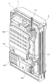
図1は、本実施形態に係る遊技機の一例を示した正面図、図2は、本実施形態に係る遊技機の裏面側の一例を示した斜視図、図3は、本実施形態に係る遊技機に備えられている遊技制御装置の構成を示したブロック図である。
BEST MODE FOR CARRYING OUT THE INVENTION The present invention will now be described in detail with reference to embodiments shown in the drawings.
<Composition of gaming machines>
1 is a front view showing an example of a gaming machine according to the present embodiment, FIG. 2 is a perspective view showing an example of the back side of the gaming machine according to the present embodiment, and FIG. 3 is the present embodiment. It is a block diagram showing the configuration of a game control device provided in the game machine.
この図1に示す遊技機1には、遊技ホールの島構造体に取付けられる外枠2に内枠(開閉枠)3が開閉可能に装着され、この内枠3にガラス枠4が開閉可能に装着されている。
ガラス枠4には窓4aが形成され、その窓4aに透明板4bが装着されている。内枠3には遊技球が打出される盤面を有する遊技盤10が装着され、この遊技盤10の盤面とその前側の透明板4bとの間に遊技球が転動、流下可能な遊技領域10aが形成されている。透明板4bは、例えばガラス板であり、ガラス枠4に対して着脱可能に固定されている。
In the
A window 4a is formed in the
またガラス枠4は、左右方向の一端側(例えば遊技機に正対して左側)においてヒンジ機構部5を介して外枠2に連結されており、ヒンジ機構部5を支点として左右方向の他端側(例えば遊技機に正対して右側)を外枠2から開放させる方向に回動可能とされている。ガラス枠4は、ガラス板4bとともに遊技盤10を覆い、ヒンジ機構部5を支点として扉のように回動することによって、遊技盤10を含む外枠2の内側部分を開放することができる。ガラス枠4の他端側には、ガラス枠4の他端側を外枠2に固定するロック機構が設けられている。ロック機構による固定は、専用の鍵によって解除することが可能とされている。また、ガラス枠4には、ガラス枠4が外枠2から開放されているか否かを検出する扉開放スイッチ136(図3参照)が設けられている。
The
ガラス枠4の下部(窓4aの下側部分)には、遊技球を貯留する貯留皿6(上皿6aと下皿6b)を有する皿ユニット7が設けられ、その皿ユニット7に、遊技者が押下操作可能な演出ボタン8と、遊技者が種々の選択操作を実行可能な十字キー40と、下皿6bに貯留された遊技球を遊技機外部へ排出する排出ボタン9とが装備されている。
演出ボタン8は、例えば、後述する画像表示装置31に当該演出ボタン8を操作するようなメッセージが表示されたときのみ有効となる。演出ボタン8には、演出ボタン検出スイッチ8a(図4参照)が設けられており、この演出ボタン検出スイッチ8aが遊技者の操作を検出すると、この操作に応じてさらなる演出が実行される。
また、十字キー40には、十字キー検出スイッチ40(上キー検出スイッチ40a、下キー検出スイッチ40b、左キー検出スイッチ40c、右キー検出スイッチ40d)(図3参照)が設けられている。
A
The
The cross key 40 is provided with cross key detection switches 40 (up
ガラス枠4の右下側には、操作ハンドル11が設けられている。操作ハンドル11は、遊技者が操作ハンドル11に触れると、操作ハンドル11内にあるタッチセンサ11a(図4参照)が、操作ハンドル11に遊技者が触れたことを検知し、後述する発射制御基板160にタッチ信号を送信する。発射制御基板160は、タッチセンサ11a(図4参照)からタッチ信号を受信すると、発射用ソレノイド12aの通電を許可する。そして、操作ハンドル11の回転角度を変化させると、操作ハンドル11に直結しているギアが回転し、ギアに連結した発射ボリューム11b(図4参照)のつまみが回転する。この発射ボリューム11bの検出角度に応じた電圧が、遊技球発射機構に設けられた発射用ソレノイド12aに印加される。そして、発射用ソレノイド12a(図3参照)に電圧が印加されると、発射用ソレノイド12aが印加電圧に応じて作動するとともに、操作ハンドル11の回動角度に応じた強さで遊技球が遊技盤10の遊技領域10aへ発射される。
An operation handle 11 is provided on the lower right side of the
遊技盤10における遊技領域10aの周囲には、外レールR1及び内レールR2が設けられている。これら外レールR1及び内レールR2は、操作ハンドル11を操作したときに遊技球発射機構から発射された遊技球を遊技領域10aの上部に案内する。遊技領域10aの上部に案内された遊技球は、遊技領域10a内を落下する。このとき、遊技領域10aに設けられた複数の釘や風車によって、遊技球は予測不能に落下することとなる。
Around the
遊技盤10の略中央には、センター部材12が配置されている。センター部材12には、液晶表示装置等からなる画像表示装置31と、「刀」を模した演出用役物装置32が設けられている。
また、センター部材12の中央下側の遊技領域10aには、遊技球が入球可能な第1始動口13が設けられている。そして、この第1始動口13の下方に第2始動口14が設けられている。第2始動口14は、開閉扉14bを有しており、開閉扉14bが閉状態に維持される第1の態様と、開閉扉14bが開状態となる第2の態様とに可動制御される。従って、第2始動口14は、第1の態様にあるときには遊技球の入賞機会がなく、第2の態様にあるときには遊技球の入賞機会が増すこととなる。
なお、本実施形態では、第2始動口14が第1の態様に制御されているときは、当該第2始動口14に遊技球が入球することがないようにしている。しかしながら、第2の態様に制御されているときよりも第1の態様に制御されているときの方が遊技球の入球機会が少なければ、第1の態様に制御されているときに第2始動口14に遊技球が入球しても構わない。つまり、第1の態様には、第2始動口14への遊技球の入球が不可能または困難な状態が含まれる。
また、遊技領域10aの適所には、様々に発光色を変更して様々な演出を行うことができる後述する盤ランプ60が備えられている。
第1始動口13の近傍には、第1始動口ランプ62が設けられている。
第1始動口ランプ62は、第1始動口13への遊技球の入賞があったときに発光し、その発光色によってその入賞にかかる大当たり期待度を遊技者に対して示唆するためのランプである。
A
In addition, in the
In addition, in this embodiment, when the
In addition,
A first
The first
上記第1始動口13および第2始動口14には、遊技球の入球を検出する第1始動口検出スイッチ13a(図4参照)および第2始動口検出スイッチ14aがそれぞれ設けられており、これら検出スイッチが遊技球の入球を検出すると、後述する大当たり遊技を実行する権利獲得の抽選(以下、「大当たりの抽選」という)が行われる。また、第1始動口検出スイッチ13aおよび第2始動口検出スイッチ14aが遊技球の入球を検出した場合にも、所定の賞球(例えば3個の遊技球)が払い出される。
なお、本実施形態の遊技機1では、第1始動口13および第2始動口14に遊技球が入球した場合、例えば3個の遊技球の払い出しを行うようにしているが、遊技球の入球に伴う払い出しは必ずしも行う必要は無い。また、例えば第1始動口13の払い出し個数を3個、第2始動口14の払い出し個数を1個といったように始動口ごとに払い出し個数を異なるように構成してもよい。
The
In the
センター部材12の両側の遊技領域10aには、遊技球が通過可能なゲート15が設けられている。ゲート15には、遊技球の通過を検出するゲート検出スイッチ15a(図4参照)が設けられており、このゲート検出スイッチ15aが遊技球の通過を検出すると、後述する普通図柄の抽選が行われる。
さらにセンター部材12の右側の遊技領域10aには、遊技球が入球可能な第1大入賞口16および第2大入賞口17が設けられている。このため、操作ハンドル11を大きく回動させ、強い力で打ち出された遊技球でないと、第1大入賞口16および第2大入賞口17には遊技球が入賞しないように構成されている。
The
Further, in the
第1大入賞口16は、通常は開閉扉16bによって閉状態に維持されており、遊技球の入球を不可能としている。これに対して、後述する大当たり遊技が開始されると、開閉扉16bが開放されるとともに、この開閉扉16bが遊技球を第1大入賞口16内に導く受け皿として機能し、遊技球が第1大入賞口16に入球可能となる。第1大入賞口16には第1大入賞口スイッチ16aが設けられており、この第1大入賞口スイッチ16aが遊技球の入球を検出すると、予め設定された賞球(例えば15個の遊技球)が払い出される。
The first big
第2大入賞口17は、通常は可動片17bによって閉状態に維持されており、遊技球の入球を不可能としている。これに対して、後述する大当たり遊技が開始されると、可動片17bが作動して開放されるとともに、この可動片17bが遊技球を第2大入賞口17内に導く誘導路として機能し、遊技球が第2大入賞口17に入球可能となる。第2大入賞口17には第2大入賞口スイッチ17aが設けられており、この第2大入賞口スイッチ17aが遊技球の入球を検出すると、予め設定された賞球(例えば15個の遊技球)が払い出される。
さらに、遊技領域10aには、複数の一般入賞口18が設けられている。これら各一般入賞口18に遊技球が入賞すると、所定の賞球(例えば10個の遊技球)が払い出される。
遊技領域10aの最下部には、一般入賞口18、第1始動口13、第2始動口14、第1大入賞口16および第2大入賞口17のいずれにも入球しなかった遊技球を排出するためのアウト口19が設けられている。
The second big winning
Furthermore, a plurality of general winning
At the bottom of the
上記画像表示装置31は、遊技が行われていない待機中に画像を表示したり、遊技の進行に応じた画像を表示したりする。なかでも、第1始動口13または第2始動口14に遊技球が入球したときには、抽選結果を遊技者に報知する演出図柄35が変動表示される。
演出図柄35というのは、例えば第1図柄(左図柄)、第2図柄(右図柄)、第3図柄(中図柄)という3つの図柄(数字)をそれぞれスクロール表示するとともに、所定時間経過後に当該スクロールを停止させて、特定の図柄(数字)を配列表示するものである。
これにより、図柄のスクロール中には、あたかも現在抽選が行われているような印象を遊技者に与えるとともに、スクロールの停止時に表示される図柄によって、抽選結果が遊技者に報知される。この演出図柄35の変動表示中に、さまざまな画像や自キャラクタCH1等を表示することによって、大当たりに当選するかもしれないという高い期待感を遊技者に与えるようにしている。
The
The
Thus, during the scrolling of the patterns, the player is given an impression as if a lottery is currently being performed, and the player is notified of the lottery result by the patterns displayed when the scrolling is stopped. By displaying various images, own character CH1, etc. during the variable display of the
また、図示しないが、画像表示装置31には、上記演出図柄35とは別に第4図柄が表示されている。第4図柄は、大当たり抽選処理による抽選結果の報知に用いる演出図柄35の変動状態を示している図柄である。
なお、第4図柄は、必ずしも画像表示装置31に表示する必要は無く、別途、第4図柄表示ランプを設けて表示するようにしてもよい。
ガラス枠4の上部には、左右1対の演出用照明装置33が装備されている。演出用照明装置33は、それぞれ複数のライトを備えており、各ライトの光の照射方向や発光色を変更しながら、さまざまな演出を行うようにしている。
In addition, although not shown, the
The fourth pattern does not necessarily have to be displayed on the
A pair of left and
また、演出用照明装置33は、それぞれ複数のライトを備えており、各ライトの光の照射方向や発光色を変更しながら、さまざまな演出を行うようにしている。
また、ガラス枠4の両側には、様々に発光色を変更して様々な演出を行うことができる枠ランプ61が備えられている。
さらに、図1には示していないが、遊技機1にはスピーカーからなる音声出力装置34(図4参照)が設けられており、上記の各演出装置に加えて、BGM(バックグランドミュージック)、SE(サウンドエフェクト)等を出力し、サウンドによる演出も行うようにしている。
In addition, each of the
In addition, on both sides of the
Furthermore, although not shown in FIG. 1, the
遊技領域10aの左側下方には、後述する第1特別図柄表示装置20、第2特別図柄表示装置21、普通図柄表示装置22、第1特別図柄保留表示器23、第2特別図柄保留表示器24、普通図柄保留表示器25、ラウンド回数表示器26等の表示領域27が設けられている。
上記第1特別図柄表示装置20は、第1始動口13に遊技球が入球したことを契機として行われた大当たりの抽選結果を報知するものであり、複数のLEDで構成されている。つまり、大当たりの抽選結果に対応する特別図柄が複数設けられており、この第1特別図柄表示装置20に大当たりの抽選結果に対応する特別図柄(点灯態様)を表示することによって、抽選結果を遊技者に報知するようにしている。このようにして表示される特別図柄はすぐに表示されるわけではなく、所定時間変動表示(点滅)された後に、停止表示されるようにしている。
On the lower left side of the
The first special
より詳細には、第1始動口13に遊技球が入球すると、大当たりの抽選が行われることとなるが、この大当たりの抽選結果は即座に遊技者に報知されるわけではなく、所定時間を経過したところで遊技者に報知される。そして、所定時間が経過したところで、大当たりの抽選結果に対応する特別図柄が停止表示して、遊技者に抽選結果が報知されるようにしている。
第2特別図柄表示装置21は、第2始動口14に遊技球が入球したことを契機として行われた大当たりの抽選結果を報知するためのもので、その表示態様は、上記第1特別図柄表示装置20における特別図柄の表示態様と同一である。
普通図柄表示装置22は、ゲート15を遊技球が通過したことを契機として行われる普通図柄の抽選結果を報知するためのものである。詳しくは後述するが、この普通図柄の抽選によって所定の当たりに当選すると普通図柄表示装置22が点灯し、その後、上記第2始動口14が所定時間、第2の態様に制御される。なお、この普通図柄についても、ゲート15を遊技球が通過して即座に抽選結果が報知されるわけではなく、所定時間が経過するまで、普通図柄表示装置22を点滅させる等、普通図柄が変動表示するようにしている。
More specifically, when a game ball enters the
The second special
The normal
さらに、特別図柄の変動表示中や後述する特別遊技中等、第1始動口13または第2始動口14に遊技球が入球して、即座に大当たりの抽選が行えない場合には、一定の条件のもとで大当たりの抽選の権利が留保される。より詳細には、第1始動口13に遊技球が入球して留保される大当たりの抽選の権利は第1保留として留保され、第2始動口14に遊技球が入球して留保される大当たりの抽選の権利は第2保留として留保される。
これら両保留は、それぞれ上限留保個数を4個に設定し、その留保個数は、それぞれ第1特別図柄保留表示器23と第2特別図柄保留表示器24とに表示される。
そして、普通図柄の上限留保個数も4個に設定されており、その留保個数が、上記第1特別図柄保留表示器23および第2特別図柄保留表示器24と同様の態様によって、普通図柄保留表示器25において表示される。
ラウンド回数表示器26は、後述する特別遊技中に行われるラウンド遊技のラウンド回数を報知するためのものである。
Furthermore, when the game ball enters the
Both of these reservations set the upper limit reserved number to 4 respectively, and the reserved numbers are displayed on the first special
And, the upper limit reserved number of normal symbols is also set to 4, and the reserved number is normally displayed in the same manner as the first special
The number-of-
図2に示すように、遊技機1の裏面には、主制御基板110、演出制御基板120、払出制御基板130、電源基板170、遊技情報出力端子板27などが設けられている。また、電源基板170に遊技機に電力を給電するための電源プラグ171や、図示しない電源スイッチが設けられている。
As shown in FIG. 2, a
次に、演出ボタン8について説明する。
演出ボタン8は、皿ユニット7の中央部分に組込まれている。
演出ボタン8は、図示しない通常操作位置と、通常操作位置よりも下方へ退入した押下位置と、通常操作位置よりも上方へ突出した突出操作位置とに亙って進退可能に構成されている。また、演出ボタン8は通常操作位置及び突出操作位置を含む任意の位置から押下位置へ押下操作可能に構成されている。
なお、本明細書では演出ボタン8の詳細な構造については、例えば特開2013-116168公報等に開示されているので説明を省略する。
Next, the
A
The
In this specification, the detailed structure of the
<遊技制御装置の構成>
次に、図3を用いて、本実施形態の遊技機1において遊技の進行を制御する遊技制御装置について説明する。
この図3において、主制御基板110は遊技の基本動作を制御する。この主制御基板110は、メインCPU111、メインROM112、メインRAM113から構成されるワンチップマイコン114と、主制御用の入力ポートと出力ポート(図示せず)とを少なくとも備えている。
メインCPU111は、各検出スイッチからの入力信号に基づいて、メインROM112に格納されたプログラムを読み出して演算処理を行うとともに、各装置や表示器を直接制御したり、あるいは演算処理の結果に応じて他の基板にコマンドを送信したりする。メインRAM113は、メインCPU111の演算処理時におけるデータのワークエリアとして機能する。
<Configuration of game control device>
Next, a game control device for controlling the progress of a game in the
In FIG. 3, the
The main CPU 111 reads the program stored in the main ROM 112 based on the input signal from each detection switch and performs arithmetic processing, and directly controls each device and display, or according to the result of the arithmetic processing. Send commands to other boards. The main RAM 113 functions as a data work area during arithmetic processing of the main CPU 111 .
上記主制御基板110の入力側には、第1始動口検出スイッチ13a、第2始動口検出スイッチ14a、ゲート検出スイッチ15a、第1大入賞口検出スイッチ16a、第2大入賞口検出スイッチ17a、一般入賞口検出スイッチ18aが接続されており、遊技球の検出信号を主制御基板110に入力するようにしている。
また、主制御基板110の出力側には、第2始動口14の開閉扉14bを開閉動作させる始動口開閉ソレノイド14c、第1大入賞口16の開閉扉16bを開閉動作させる第1大入賞口開閉ソレノイド16c、第2大入賞口17の可動片17bを開閉動作させる第2大入賞口開閉ソレノイド17cが接続されている。
さらに、主制御基板110の出力側には、第1特別図柄表示装置20、第2特別図柄表示装置21、普通図柄表示装置22、第1特別図柄保留表示器23、第2特別図柄保留表示器24、普通図柄保留表示器25、およびラウンド回数表示器26が接続されており、出力ポートを介して各種信号を出力するようにしている。
また、主制御基板110は、遊技店のホールコンピュータ等において遊技機の管理をするために必要となる外部情報信号を遊技情報出力端子板27に出力する。
On the input side of the
In addition, on the output side of the
Furthermore, on the output side of the
In addition, the
主制御基板110のメインROM112には、後述する遊技制御用のプログラムや各種の遊技に必要なデータ、テーブルが記憶されている。
また、主制御基板110のメインRAM113は、複数の記憶領域を有している。
例えば、メインRAM113には、普通図柄保留数(G)記憶領域、普通図柄保留記憶領域、第1特別図柄保留数(U1)記憶領域、第2特別図柄保留数(U2)記憶領域、判定記憶領域、第1特別図柄記憶領域、第2特別図柄記憶領域、高確率遊技回数(X)記憶領域、時短遊技回数(J)記憶領域、ラウンド遊技回数(R)記憶領域、開放回数(K)記憶領域、第1大入賞口入れ球数(C1)記憶領域、第2大入賞口入球数(C2)記憶領域、遊技状態記憶領域、遊技状態バッファ、停止図柄データ記憶領域、演出用伝送データ格納領域等が設けられている。そして、遊技状態記憶領域は、時短遊技フラグ記憶領域、高確率遊技フラグ記憶領域、特図特電処理データ記憶領域、普図普電処理データ記憶領域を備えている。なお、上述した記憶領域は一例に過ぎず、この他にも多数の記憶領域が設けられている。
The main ROM 112 of the
Also, the main RAM 113 of the
For example, the main RAM 113 has a normal symbol reserved number (G) storage area, a normal symbol reserved storage area, a first special symbol reserved number (U1) storage area, a second special symbol reserved number (U2) storage area, and a determination storage area. , 1st special symbol storage area, 2nd special symbol storage area, high probability game number (X) storage area, time saving game number (J) storage area, round game number (R) storage area, open number (K) storage area , 1st big winning hole number of balls (C1) storage area, 2nd big winning hole number of balls (C2) storage area, game state storage area, game state buffer, stop pattern data storage area, performance transmission data storage area etc. are provided. The game state storage area includes a time saving game flag storage area, a high probability game flag storage area, a special figure special electric processing data storage area, and a normal figure normal electric processing data storage area. Note that the storage areas described above are merely examples, and many other storage areas are provided.
遊技情報出力端子板27は、主制御基板110において生成された外部情報信号を遊技店のホールコンピュータ等に出力するための基板である。遊技情報出力端子板27は、主制御基板110と配線接続されるとともに、遊技店のホールコンピュータ等に接続をするためのコネクタが設けられている。
電源基板170は、電源プラグ171から供給される電源電圧を所定電圧に変換して各制御基板に供給する。また、電源基板170はコンデンサからなるバックアップ電源を備えており、遊技機に供給する電源電圧を監視し、電源電圧が所定値以下となったときに、電断検知信号を主制御基板110に出力する。より具体的には、電断検知信号がハイレベルになるとメインCPU111は動作可能状態になり、電断検知信号がローレベルになるとメインCPU111は動作停止状態になる。バックアップ電源はコンデンサに限らず、例えば、電池でもよく、コンデンサと電池とを併用して用いてもよい。
また、主制御基板110には、不正電波を検知するための磁気センサ50が接続されている。
The game information
The
A
演出制御基板120は、主に遊技中や待機中等の各演出を制御する。この演出制御基板120は、サブCPU121、サブROM122、サブRAM123を備えており、主制御基板110に対して、当該主制御基板110から演出制御基板120への一方向に通信可能に接続されている。
サブCPU121は、主制御基板110から送信されたコマンド、または、ランプ制御基板140を介して入力される演出ボタン検出スイッチ8aからの入力信号に基づいて、サブROM122に格納されたプログラムを読み出して演算処理を行うとともに、当該処理に基づいて、対応するデータをランプ制御基板140または画像制御基板150に送信する。サブRAM123は、サブCPU121の演算処理時におけるデータのワークエリアとして機能する。
The
The
演出制御基板120のサブROM122には、演出制御用のプログラムや各種の遊技に必要なデータ、テーブルが記憶されている。
例えば、主制御基板110から受信した変動パターン指定コマンドに基づいて演出パターンを決定するための変動演出パターン決定テーブル(図示省略)、停止表示する演出図柄35の組み合わせを決定するための演出図柄パターン決定テーブル(図示省略)等がサブROM122に記憶されている。なお、上述したテーブルは、本実施形態におけるテーブルのうち、特徴的なテーブルを一例として列挙しているに過ぎず、遊技の進行にあたっては、この他にも不図示のテーブルやプログラムが多数設けられている。
The
For example, a variable performance pattern determination table (not shown) for determining a performance pattern based on a variation pattern designation command received from the
演出制御基板120のサブRAM123は、複数の記憶領域を有している。
サブRAM123には、コマンド受信バッファ、遊技状態記憶領域、演出モード記憶領域、演出パターン記憶領域、演出図柄記憶領域、判定記憶領域(第0記憶領域)、第1保留記憶領域、第2保留記憶領域等が設けられている。なお、上述した記憶領域も一例に過ぎず、この他にも多数の記憶領域が設けられている。
また、演出制御基板120には、現在時刻を出力するRTC(リアルタイムクロック)124が搭載されている。サブCPU121は、RTC124から現在の日付を示す日付信号や現在の時刻を示す時刻信号を入力し、現在の日時に基づいて各種処理を実行する。
RTC124は、通常、遊技機に電源が供給されているときには遊技機からの電源によって動作し、遊技機の電源が切られているときには、電源基板170に搭載されたバックアップ電源から供給される電源によって動作する。したがって、RTC124は、遊技機の電源が切られている場合であっても現在の日時を計時することができる。なお、RTC124は、演出制御基板120上に電池を設けて、かかる電池によって動作するようにしてもよい。
The sub-RAM 123 of the
The sub RAM 123 includes a command reception buffer, a game state storage area, an effect mode storage area, an effect pattern storage area, an effect pattern storage area, a judgment storage area (0th storage area), a first reserved storage area, a second reserved storage area. etc. are provided. Note that the above-described storage area is only an example, and many other storage areas are provided.
Also, the
The
払出制御基板130は、遊技球の発射制御と賞球の払い出し制御を行う。この払出制御基板130は、払出CPU131、払出ROM132、払出RAM133を備えており、主制御基板110に対して、双方向に通信可能に接続されている。払出CPU131は、遊技球が払い出されたか否かを検知する払出球計数スイッチ135、扉開放スイッチ136からの入力信号に基づいて、払出ROM132に格納されたプログラムを読み出して演算処理を行うとともに、当該処理に基づいて、対応するデータを主制御基板110に送信する。
The
また、払出制御基板130の出力側には、遊技球の貯留部から所定数の賞球を遊技者に払い出すための賞球払出装置の払出モータ134が接続されている。払出CPU131は、主制御基板110から送信された払出個数指定コマンドに基づいて、払出ROM132から所定のプログラムを読み出して演算処理を行うとともに、賞球払出装置の払出モータ134を制御して所定の賞球を遊技者に払い出す。このとき、払出RAM133は、払出CPU131の演算処理時におけるデータのワークエリアとして機能する。
また、図示しない遊技球貸出装置(カードユニット)が払出制御基板130に接続されているか確認し、遊技球貸出装置(カードユニット)が接続されていれば、発射制御基板160に遊技球を発射させることを許可する発射制御データを送信する。
また、払出制御基板130には、皿満タン検知スイッチ51や、球詰まり検知スイッチ52が接続されている。
The output side of the
It also checks whether a game ball lending device (card unit) (not shown) is connected to the
Further, the
皿満タン検知スイッチ51は、遊技球の貯留皿(下皿)が満タンになったことを検知するためのスイッチである。
また、球詰まり検知スイッチ52は、例えば、遊技球の貯留部から遊技球を払い出す通路における遊技球の詰まりを検知するためのスイッチである。
発射制御基板160は、払出制御基板130から発射制御データを受信すると発射の許可を行う。そして、タッチセンサ11aからのタッチ信号および発射ボリューム11bからの入力信号を読み出し、発射用ソレノイド12aおよび球送りソレノイド12bを通電制御し、遊技球を発射させる。
The plate
Also, the ball clogging
The firing
発射用ソレノイド12aは、ロータリーソレノイドにより構成されている。発射用ソレノイド12aには、図示しない打出部材が直結されており、発射用ソレノイド12aが回転することで打出部材を回転させる。
ここで、発射用ソレノイド12aの回転速度は、発射制御基板160に設けられた水晶発振器の出力周期に基づく周波数から、約99.9(回/分)に設定されている。これにより、1分間における発射遊技球数は、発射ソレノイドが1回転する毎に1個発射されるため、約99.9(個/分)となる。すなわち、遊技球は約0.6秒毎に発射されることになる。
球送りソレノイド12bは、直進ソレノイドにより構成され、上皿6a(図1参照)にある遊技球を発射用ソレノイド12aに直結された打出部材に向けて1個ずつ送り出す。
The firing
Here, the rotation speed of the firing
The
ランプ制御基板140は、上記演出制御基板120に双方向通信可能に接続されており、その入力側には演出ボタン8に設けられている演出ボタン検出スイッチ8aが接続されており、演出ボタン検出スイッチ8aから検出信号が入力された場合は、演出制御基板120に出力するようにしている。
また、ランプ制御基板140には、遊技盤10に設けられた演出用役物装置32や演出用照明装置33が接続されており、ランプ制御基板140は、演出制御基板120から送信されたデータに基づいて、演出用照明装置33を点灯制御したり、光の照射方向を変更するためのモータに対する駆動制御をしたりする。また、演出用役物装置32を動作させるソレノイドやモータ等の駆動源を通電制御する。なお、本実施形態では、演出ボタン8が突出するように構成されているので演出役物装置32は演出ボタン8を含む。
また、ランプ制御基板140には、上記した盤ランプ60、枠ランプ61、第1始動口ランプ62が接続されている。
画像制御基板150は、上記演出制御基板120に双方向通信可能に接続されており、その出力側に上記画像表示装置31および音声出力装置34を接続している。
The
In addition, the
Further, the
The
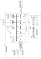
<画像制御基板の構成>
ここで、図4を用いて画像制御基板150の構成について説明する。
図4は、画像制御基板の構成を示したブロック図である。
画像制御基板150は、画像表示装置31の画像表示制御を行うためホストCPU151、ホストRAM152、ホストROM153、CGROM154、水晶発振器155、VRAM156、VDP(Video Display Processor)200と、を備えている。
また、VDP200は、遊技機における音声出力を制御するための音声制御回路300を含んでいる。
<Configuration of image control board>
Here, the configuration of the
FIG. 4 is a block diagram showing the configuration of the image control board.
The
The
ホストCPU151は、演出制御基板120から受信した後述する演出パターン指定コマンドに基づいて、VDP200にCGROM154に記憶されている画像データを画像表示装置31に表示させる指示を行う。かかる指示は、VDP200の制御レジスタ201におけるデータの設定、描画制御コマンド群から構成されるディスプレイリストの出力によって行われる。
また、ホストCPU151は、VDP200からVブランク割込信号や描画終了信号を受信すると、適宜割り込み処理を行う。
The
Also, when the
さらに、ホストCPU151は、VDP200に含まれる音声制御回路300にも、演出制御基板120から受信した演出パターン指定コマンドに基づいて、所定の音声データを音声出力装置34に出力させる指示を行う。
ホストRAM152は、ホストCPU151に内蔵されており、ホストCPU151の演算処理時におけるデータのワークエリアとして機能し、ホストROM153から読み出されたデータを一時的に記憶するものである。
Furthermore, the
The
また、ホストROM153は、マスクROMで構成されており、ホストCPU151の制御処理のプログラム、演出図柄の図柄番号と演出図柄35の種類とを対応付けた図柄配列情報、ディスプレイリストを生成するためのディスプレイリスト生成プログラム、演出パターンのアニメーションを表示するためのアニメパターン、アニメシーン情報等が記憶されている。
このアニメパターンは、演出パターンのアニメーションを表示するにあたり参照され、その演出パターンに含まれるアニメシーン情報の組み合わせや各アニメシーン情報の表示順序等を記憶している。また、アニメシーン情報には、ウェイトフレーム(表示時間)、対象データ(スプライトの識別番号、転送元アドレス等)、パラメータ(スプライトの表示位置、転送先アドレス等)、描画方法等などの情報を記憶している。
The
The animation pattern is referred to when the animation of the production pattern is displayed, and stores the combination of animation scene information included in the production pattern, the display order of each animation scene information, and the like. In addition, animation scene information stores information such as wait frames (display time), target data (sprite identification number, transfer source address, etc.), parameters (sprite display position, transfer destination address, etc.), drawing method, etc. are doing.
CGROM154は、フラッシュメモリ、EEPROM、EPROM、マスクROM等から構成され、所定範囲の画素(例えば、32×32ピクセル)における画素情報の集まりからなる画像データ(スプライト、ムービー)等を圧縮して記憶している。なお、前記画素情報は、それぞれの画素毎に色番号を指定する色番号情報と画像の透明度を示すα値とから構成されている。
さらに、CGROM154には、色番号を指定する色番号情報と実際に色を表示するための表示色情報とが対応づけられたパレットデータを圧縮せずに記憶している。
なお、CGROM154は、全ての画像データを圧縮せずとも、一部のみ圧縮している構成でもよい。また、ムービーの圧縮方式としては、MPEG4等の公知の種々の圧縮方式を用いることができる。
また、CGROM154には、音声データも多数格納されている。
The
Further, the
It should be noted that the
The
水晶発振器155は、パルス信号をVDP200のクロック生成回路205に出力し、このパルス信号を分周することで、クロック生成回路205にてVDP200が制御を行うためのシステムクロック、画像表示装置31と同期を図るための同期信号等が生成される。
The
VRAM156は、画像データの書込みまたは読み出しが高速なSRAMで構成されている。
また、VRAM156は、ホストCPU151から出力されたディスプレイリストを一時的に記憶するディスプレイリスト記憶領域156aと、伸長回路206により伸長された画像データを記憶する展開記憶領域156bと、画像を描画または表示するための第1フレームバッファ156c、第2フレームバッファ156dと、を有している。また、VRAM156には、パレットデータも記憶される。
なお、2つのフレームバッファ156c、156dは、描画の開始毎に、「描画用フレームバッファ」と「表示用フレームバッファ」とに交互に切り替わるものである。
The
The
Note that the two
VDP200は、いわゆる画像プロセッサであり、ホストCPU151からの指示に基づいて、いずれかのフレームバッファ(表示用フレームバッファ)から画像データを読み出し、読み出した画像データに基づいて、映像信号(RGB信号等)を生成して、画像表示装置に出力するものである。
ただし、本実施形態の遊技機において、VDP200は単に画像プロセッサであるに留まらず、音声出力機能を有している。
またVDP200は、制御レジスタ201と、CGバスI/F202と、CPUI/F203と、クロック生成回路205と、伸長回路206と、描画回路207と、表示回路208と、メモリコントローラ209と、音声制御回路300と、を備えている。
The
However, in the gaming machine of this embodiment, the
The
制御レジスタ201は、VDP200が描画や表示の制御を行うためレジスタであり、制御レジスタ201に対するデータの書き込みと読み出しで、描画の制御や表示の制御が行われる。ホストCPU151は、CPUI/F203を介して、制御レジスタ201に対するデータの書き込みと読み出しを行うことができる。
この制御レジスタ201は、VDP200が動作するために必要な基本的な設定を行うシステム制御レジスタと、データの転送に必要な設定をするデータ転送レジスタと、描画の制御をするための設定をする描画レジスタと、バスのアクセスに必要な設定をするバスインターフェースレジスタと、圧縮された画像の伸長に必要な設定をする伸長レジスタと、表示の制御をするための設定をする表示レジスタと、6種類のレジスタを備えている。
The
The
CGバスI/F202は、CGROM154との通信用のインターフェース回路であり、CGバスI/F202を介して、CGROM154からの画像データがVDP200に入力される。
また、CPUI/F203は、ホストCPU151との通信用のインターフェース回路であり、CPUI/F203を介して、ホストCPU151がVDP200にディスプレイリストを出力したり、制御レジスタにアクセスしたり、VDP200からの各種の割込信号をホストCPU151が入力したりする。
データ転送回路204は、各種デバイス間のデータ転送を行う。
具体的には、ホストCPU151とVRAM156とのデータ転送、CGROM154とVRAM156とのデータ転送、VRAM156の各種記憶領域(フレームバッファも含む)の相互間のデータ転送を行う。
クロック生成回路205は、水晶発振器155よりパルス信号を入力し、VDP200の演算処理速度を決定するシステムクロックを生成する。また、同期信号生成用クロックを生成し、表示回路を介して同期信号を画像表示装置に出力する。
A CG bus I/
Also, the CPU I/
A
Specifically, data transfer between the
A
伸長回路206は、CGROM154に圧縮された画像データを伸長するための回路であり、伸長した画像データを展開記憶領域153bに記憶させる。
描画回路207は、描画制御コマンド群から構成されるディスプレイリストによるシーケンス制御を行う回路である。
表示回路208は、VRAM156にある「表示用フレームバッファ」に記憶された画像データ(デジタル信号)から、映像信号として画像の色データを示すRGB信号(アナログ信号)を生成し、生成した映像信号(RGB信号)を画像表示装置31に出力する回路である。さらに、表示回路208は、画像表示装置31と同期を図るための同期信号(垂直同期信号、水平同期信号等)も画像表示装置31に出力する。
なお、本実施形態では、映像信号として、デジタル信号をアナログ信号に変換したRGB信号を画像表示装置31に出力するように構成したが、デジタル信号のまま映像信号を出力してもよい。
The
The
The
Note that in the present embodiment, as video signals, RGB signals obtained by converting digital signals into analog signals are output to the
メモリコントローラ209は、ホストCPU151からフレームバッファ切換えの指示があると、「描画用フレームバッファ」と「表示用フレームバッファ」とを切り替える制御を行うものである。
音声制御回路300は、演出制御基板120から送信されたコマンドに基づいて所定のプログラムを読み出すとともに、音声出力装置34における音声出力制御をする。
音声制御回路300は、CGROM154に格納されたに格納された音声データを用いて音声を出力する。この場合、CGROM154は、音声データを格納するための音声ROMを含むものとする。
The
The
The
なお、音声データは、CGROM154に格納するのではなく、音源ROMを、VDP154に別途設けてもよい。
この場合、容量が固定化されたCGROM154に音声データを格納せず、より多くの画像データを格納することが出来るため、映像を用いた演出をより多彩且つ印象深いものとすることが出来る。
また、音声制御回路300は、VDP200に含まれず、画像制御基板150内で、独立して設けられていてもよい。その場合、音源ROMは、音声制御回路300に含まれていてもよい。
It should be noted that the sound data may be separately provided in the
In this case, since more image data can be stored without storing audio data in the
Also, the
次に、図5乃至図10を参照して、メインROM112に記憶されている各種テーブルの詳細について説明する。
<大当たり判定テーブル>
図5(a)(b)は、特別図柄変動の停止結果を大当たりとするか否かを判定する際に参照される大当たり判定テーブルの一例を示した図であり、図5(a)は、第1特別図柄表示装置において参照される大当たり判定テーブル、図5(b)は、第2特別図柄表示装置において参照される大当たり判定テーブルである。
Next, details of various tables stored in the main ROM 112 will be described with reference to FIGS. 5 to 10. FIG.
<Jackpot determination table>
FIGS. 5(a) and 5(b) are diagrams showing an example of a jackpot determination table to be referred to when determining whether or not the stop result of the special symbol variation is a jackpot. FIG. 5(a) A jackpot determination table referred to in the first special symbol display device, and FIG. 5(b) is a jackpot determination table referred to in the second special symbol display device.
図5(a)(b)に示す大当たり判定テーブルは、低確率時乱数判定テーブルと高確率時乱数判定テーブルとにより構成され、遊技状態を参照し、低確率時乱数判定テーブル又は高確率時乱数判定テーブルを選択し、選択したテーブルと抽出された特別図柄判定用乱数値とに基づいて、「大当たり」、「ハズレ」の何れかを判定するものである。
例えば、図5(a)に示す第1特別図柄表示装置の低確率時乱数判定テーブルによれば、2個の特別図柄判定用乱数値が「大当たり」と判定される。一方、高確率時乱数判定テーブルによれば、20個の特別図柄判定用乱数値が「大当たり」と判定される。
The jackpot determination table shown in FIGS. 5(a) and 5(b) is composed of a low-probability random number determination table and a high-probability random number determination table. A determination table is selected, and based on the selected table and the extracted special symbol determination random number value, either "big win" or "losing" is determined.
For example, according to the low-probability random number determination table of the first special symbol display device shown in FIG. On the other hand, according to the high-probability random number determination table, 20 special symbol determination random numbers are determined to be "big win".
図5(a)に示す第1特別図柄表示装置の大当たり判定テーブルでは、上記以外の乱数値であった場合、「ハズレ」と判定される。
特別図柄判定用乱数値の乱数範囲は、0~598であるから、第1特別図柄表示装置の大当たり判定テーブルにおいて、低確率時に大当たりと判定される確率は1/299.5であり、高確率時に大当たりと判定される確率は10倍となって1/29.95である。
In the jackpot determination table of the first special symbol display device shown in FIG. 5(a), if the random number is other than the above, it is determined as "losing".
Since the random number range of the special symbol determination random number is 0 to 598, the probability of being determined as a big hit at a low probability in the jackpot determination table of the first special symbol display device is 1/299.5, which is a high probability. The probability of being judged as a big hit is 1/29.95, which is 10 times.
一方、図5(b)に示す第2特別図柄表示装置の大当たり判定テーブルでは、低確率時及び高確率時に大当たりと判定される特別図柄判定用乱数値が上記第1特別図柄表示装置と同一である。
従って、第2特別図柄表示装置における低確率時乱数判定テーブルでは、第1特別図柄表示装置における低確率時乱数判定テーブルと同様、低確率時に大当たりと判定される確率は1/299.5であり、高確率時に大当たりと判定される確率は10倍となって1/29.95である。
On the other hand, in the jackpot determination table of the second special symbol display device shown in FIG. 5(b), the special symbol determination random number determined to be a jackpot at the time of low probability and at the time of high probability is the same as that of the first special symbol display device. be.
Therefore, in the low-probability random number determination table in the second special symbol display device, the probability of being determined as a jackpot at the low probability is 1/299.5, as in the low-probability random number determination table in the first special symbol display device. , the probability of being determined to be a big hit at a high probability is 1/29.95, which is 10 times.
<当たり判定テーブル>
図5(c)は、普通図柄変動の停止結果を当たりとするか否かを判定する際に参照される当たり判定テーブルを示した図である。
図5(c)に示す当たり判定テーブルは、非時短遊技状態時乱数判定テーブルと時短遊技状態時乱数判定テーブルとから構成され、遊技状態を参照し、非時短遊技状態時乱数判定テーブル又は時短遊技状態時乱数判定テーブルが選択され、選択されたテーブルと抽出された当たり判定用乱数値に基づいて、「当たり」か「ハズレ」かを判定する。
図5(c)に示す当たり判定テーブルでは、非時短遊技状態時に普通図柄が当たりと判定される確率は1/20であり、時短遊技状態時に普通図柄が当たりと判定される確率は19/20である。
<Hit Judgment Table>
FIG. 5(c) is a diagram showing a hit determination table that is referred to when determining whether or not the stop result of normal symbol variation is a win.
The hit determination table shown in FIG. 5 (c) is composed of a non-time-saving game state random number determination table and a time-saving game state random number determination table. A state-time random number determination table is selected, and based on the selected table and the extracted random value for determination of hit, it is determined whether it is a "hit" or a "lose".
In the hit determination table shown in FIG. 5(c), the probability that the normal symbol is determined to be a hit during the non-time-saving game state is 1/20, and the probability that the normal symbol is determined to be a hit during the time-saving game state is 19/20. is.
<図柄決定テーブル>
図6は、特別図柄の停止図柄を決定する図柄決定テーブルを示した図である。
図6(a)は、大当たり時に停止図柄を決定するための大当たり図柄決定テーブルであり、図6(b)は、ハズレ時に停止図柄を決定するためのハズレ図柄決定テーブルである。また、より詳細には各図柄決定テーブルは特別図柄表示装置ごとに構成され、第1特別図柄表示装置用の図柄決定テーブルと第2特別図柄表示装置用の図柄決定テーブルとから構成されている。
<Design decision table>
FIG. 6 is a diagram showing a symbol determination table for determining stop symbols of special symbols.
FIG. 6(a) is a big win symbol determination table for determining a stop symbol at the time of a big win, and FIG. 6(b) is a losing symbol determination table for determining a stop symbol at the time of a loss. In more detail, each symbol determination table is configured for each special symbol display device, and is composed of a symbol determination table for the first special symbol display device and a symbol determination table for the second special symbol display device.
図6(a)に示す大当たり図柄決定テーブルでは、大当たり図柄用乱数値を参照する。そして、第1特別図柄表示装置20において大当たりと判定された時に、大当たり図柄用乱数値が「0」~「39」であれば、停止図柄データとして「01」(第1特別図柄1)を決定する。さらに、特別図柄の変動開始時には、決定した特別図柄の種類(停止図柄データ)に基づいて、特別図柄の情報としての演出図柄指定コマンド「E0H」「01H」を生成する。
In the jackpot symbol determination table shown in FIG. 6(a), the jackpot symbol random number is referred to. Then, when the first special
また、第1特別図柄表示装置20において大当たりと判定された時に、大当たり図柄用乱数値が「40」~「49」であれば、停止図柄データとして「02」(第1特別図柄2)を決定して、演出図柄指定コマンド「E0H」「02H」を生成し、大当たり図柄用乱数値が「50」~「99」であれば、停止図柄データとして「03」(第1特別図柄3)を決定して、演出図柄指定コマンド「E0H」「03H」を生成する。
また、第2特別図柄表示装置21において大当たりと判定された時に、大当たり図柄用乱数値が「0」~「59」であれば、停止図柄データとして「04」(第2特別図柄1)を決定して、演出図柄指定コマンド「E1H」「01H」を生成し、大当たり図柄用乱数値が「60」~「79」であれば、停止図柄データとして「05」(第2特別図柄2)を決定して、演出図柄指定コマンド「E1H」「02H」を生成し、大当たり図柄用乱数値が「80」~「99」であれば、停止図柄データとして「05」(第2特別図柄3)を決定する。
第1特別図柄1、2、3および第2特別図柄1、2、3は、内部的にはすべて確変10ラウンドあたりである。
第1特別図柄1は、全ラウンドで出玉が得られる開放パターンで大入賞口が開放される。1ラウンド目にVラウンドがあって、このVラウンドでは内部的にVアタッカーに入賞可能な開放パターンで大入賞口が開放される。Vラウンド中にVアタッカーに遊技球が入球した場合には、大当たり終了後、確変遊技状態として制御される。
第1特別図柄2は、2ラウンド目までは、出玉が得られる開放パターンで大入賞口が開放される。1ラウンド目にVラウンドがあって、Vラウンドでは内部的にVアタッカーに入賞可能な開放パターンで、大入賞口が開放される。3ラウンド目~10ラウンド目では、遊技球が入賞できない高速態様で大入賞口が開放される(実質2ラウンド)。
第1特別図柄3は、全ラウンドで出玉が得られる開放パターンで大入賞口が開放される。1ラウンド目にVラウンドがあるが、Vラウンドでは内部的にVアタッカーに入賞不可能な開放パターンで、大入賞口が開放される。Vラウンド中にVアタッカーに遊技球が入球しないので、10ラウンド分の出玉が得られるものの大当たり終了後、時短遊技状態として制御される。
第2特別図柄1は、全ラウンドで出玉が得られる開放パターンで大入賞口が開放される。1ラウンド目にVラウンドがあって、Vラウンドでは内部的にVアタッカーに入賞可能な開放パターンで、大入賞口が開放される。Vラウンド中にVアタッカーに遊技球が入球した場合には、大当たり終了後、確変遊技状態として制御される。
第2特別図柄2は、2ラウンド目までは、出玉が得られる開放パターンで大入賞口が開放される。1ラウンド目にVラウンドがあって、Vラウンドでは内部的にVアタッカーに入賞可能な開放パターンで、大入賞口が開放される。3ラウンド目~10ラウンド目では、遊技球が入賞できない高速態様で大入賞口が開放される(実質2ラウンド)。
第2特別図柄3は、全ラウンドで出玉が得られる開放パターンで大入賞口が開放される。1ラウンド目にVラウンドがあるが、Vラウンドでは内部的にVアタッカーに入賞不可能な開放パターンで、大入賞口が開放される。Vラウンド中にVアタッカーに遊技球が入球しないので、10ラウンド分の出玉が得られるものの大当たり終了後、時短遊技状態として制御される。
In addition, when the first special
In addition, when the second special
The first
The first
As for the first
The first
The second
As for the second
The second
次に、図6(b)に示すハズレ図柄決定テーブルでは、第1特別図柄表示装置20においてハズレと判定された場合、停止図柄データとして「00」(特別図柄0(ハズレ)を決定し、特別図柄の変動開始時には、演出図柄指定コマンド「E0H」「00H」を生成する。また、第2特別図柄表示装置21においてハズレと判定された場合は、停止図柄データとして「00」(特別図柄0(ハズレ)を決定し、特別図柄の変動開始時には、演出図柄指定コマンド「E1H」「00H」を生成する。
なお、特別図柄の種類(停止図柄データ)によって、大当たり終了後の遊技状態、大当たり態様が決定されることから、特別図柄の種類が大当たり遊技終了後の遊技状態と大当たり態様を決定するものといえる。
Next, in the losing symbol determination table shown in FIG. 6B, when it is determined that the first special
Since the game state and the jackpot mode after the jackpot game ends are determined by the special symbol type (stopped pattern data), it can be said that the special symbol type determines the game state and the jackpot mode after the jackpot game ends. .
図7は、普通図柄変動の停止結果に基づいて普通図柄を決定する際に参照される当たり普通図柄決定テーブルを示した図であり、図7(a)は、当たり判定用乱数値の判定により当たりと判定された場合に参照される普通図柄決定テーブル、図7(b)は、当たり判定用乱数値の判定によりハズレと判定された場合に参照される普通図柄決定テーブルである。 FIG. 7 is a diagram showing a winning normal design determination table that is referred to when determining a normal design based on the result of stopping normal design variation. FIG. A normal symbol determination table that is referred to when a win is determined, and FIG. 7(b) is a normal symbol determination table that is referred to when a loss is determined based on the determination of the random number value for hit determination.
図7(a)(b)に示す普通図柄決定テーブルでは、普通図柄用乱数値(0~10)を参照する。
そして、普通図柄表示装置22の普通図柄用乱数値が当たり判定テーブルにおいて当たりと判定された場合は、図7(a)に示すように、普通図柄用乱数値が「0」及び「1」であれば、長開放図柄を決定し、普通図柄乱数値が「2」~「10」であれば、短開放図柄を決定する。
長開放図柄の場合は、停止図柄データとして「01」を決定し、普通図柄の変動開始時には、普通図柄指定コマンド「E8H」「01H」を生成する。また、短開放図柄と決定した場合は、停止図柄データとして「02」を決定し、普通図柄の変動開始時には、普通図柄指定コマンド「E8H」「02H」を生成する。
In the normal symbol determination table shown in FIGS. 7(a) and (b), normal symbol random numbers (0 to 10) are referred to.
Then, when the normal symbol random number value of the normal
In the case of the long open symbol, "01" is determined as the stop symbol data, and when the variation of the normal symbol is started, the normal symbol specifying commands "E8H" and "01H" are generated. Further, when the short open pattern is determined, "02" is determined as the stop design data, and at the start of fluctuation of the normal design, the normal design designation commands "E8H" and "02H" are generated.
一方、普通図柄表示装置22の普通図柄用乱数値が当たり判定テーブルにおいてハズレと判定された場合は、図7(b)に示すように、普通図柄用乱数値が「0」~「10」の何れの値であってもハズレ図柄を決定する。
ハズレ図柄の場合は、停止図柄データとして「00」を決定し、普通図柄の変動開始時には、普通図柄指定コマンド「E8H」「00H」を生成する。
On the other hand, when the normal symbol random number value of the normal
In the case of a losing design, "00" is determined as the stop design data, and at the start of fluctuation of the normal design, normal design designation commands "E8H" and "00H" are generated.
<変動パターン決定テーブル>
図8、図9は、特別図柄の変動パターンを決定するための変動パターン決定テーブルを示す図であり、図8は、非時短遊技状態(低確率非時短遊技状態用)に参照される変動パターン決定テーブルの一例であり、図9は、時短遊技状態時(低確率時短遊技状態、高確率時短遊技状態)に参照される変動パターン決定テーブルの一例である。
具体的には、変動パターン決定テーブルによって、特別図柄表示装置の種別、特別図柄判定用乱数値(大当たりの当選または落選)、大当たり図柄用乱数値(大当たり図柄)、時短遊技状態の有無、特別図柄保留数、リーチ判定用乱数値および変動パターン用乱数値(特図変動用乱数値)に基づき、変動パターンが決定される。
変動パターンは、特別図柄の変動開始時に決定され、決定された変動パターンに基づいて変動パターン指定コマンドが生成される。この変動パターン指定コマンドは、出力制御処理において主制御基板110から演出制御基板120へと送信される。
<Variation pattern determination table>
Figure 8, Figure 9 is a diagram showing a variation pattern determination table for determining the variation pattern of the special symbol, FIG. It is an example of a determination table, and FIG. 9 is an example of a variation pattern determination table referred to during the time-saving gaming state (low-probability time-saving gaming state, high-probability time-saving gaming state).
Specifically, according to the variation pattern determination table, the type of special symbol display device, the random number for special symbol determination (won or lose the jackpot), the random number for the jackpot symbol (jackpot symbol), the presence or absence of the time-saving gaming state, the special symbol The variation pattern is determined based on the number of reservations, the random number for reach determination and the random number for variation pattern (random number for special figure variation).
A variation pattern is determined at the start of variation of the special symbol, and a variation pattern designation command is generated based on the determined variation pattern. This variation pattern specification command is transmitted from the
なお、本実施形態の遊技機1では、大当たりのときには必ずリーチを行うように構成しているため、大当たりのときにはリーチ判定用乱数値を参照しないように構成されている。
本実施形態でいう「リーチ」とは、特別遊技に移行することを報知する演出図柄35の組合せの一部が停止表示された後に、残りの一部の演出図柄35が変動表示を継続するものをいう。例えば、大当たり遊技に移行することを報知する演出図柄35の組合せとして「777」の3桁の演出図柄35の組み合わせが設定されている場合に、2つの演出図柄35が「7」で停止表示され、残りの演出図柄35が変動表示を行っている状態をいう。
The
In the present embodiment, "ready-to-win" means that after a part of the combination of the
また、変動パターン指定コマンドは、MODEとして「E6H」であるときには、第1始動口13に遊技球が入球して、第1特別図柄表示装置20の特別図柄の変動開始時に決定された変動パターンに対応する変動パターン指定コマンドであることを示し、MODEとして「E7H」であるときには、第2始動口14に遊技球が入球して、第2特別図柄表示装置21の特別図柄の変動開始時に決定された変動パターンに対応する変動パターン指定コマンドであることを示す。そして、変動パターン指定コマンドのDATAは、具体的な変動パターン番号を示すものである。すなわち、変動パターン指定コマンドも変動パターンを示す情報ということになる。
In addition, when the MODE is "E6H", the variation pattern specification command is a variation pattern determined when the game ball enters the
<非時短遊技状態用の変動パターン決定テーブル>
図8に示す非時短遊技状態用の変動パターン決定テーブルの構成について説明する。
図8に示す変動パターン決定テーブルでは、第1特別図柄表示装置20、第2特別図柄表示装置21の特別図柄の変動パターンとして、変動パターン1、2、3A、3B、4、5、6、7、8A、8B、9、10、11、12、13、15が設定されている。
特別図柄表示装置の種別、特別図柄判定用乱数値(大当たりの当選または落選)、大当たり図柄用乱数値(大当たり図柄)、特別図柄保留数、リーチ判定用乱数値および変動パターン用乱数値に基づき、これらの変動パターンのなかから一の変動パターンが図8に示される割り振りで選択される。
<Variation pattern determination table for non-time-saving gaming state>
The configuration of the variation pattern determination table for the non-time-saving gaming state shown in FIG. 8 will be described.
In the variation pattern determination table shown in FIG. 8,
Based on the type of special design display device, random number for special design judgment (win or lose the jackpot), random number for big hit design (jackpot design), number of reserved special designs, random number for reach judgment and random number for fluctuation pattern, One variation pattern is selected from among these variation patterns with the allocation shown in FIG.
なお、下記の説明において、「ノーマルリーチ(演出)」は、画像表示装置31の表示部における左側領域と右側領域に2つの演出図柄35(左図柄、右図柄)が仮停止し、中央領域で残り1つの演出図柄35が変動する大当たり当選の期待度が低いリーチ演出である。
「SPリーチ演出」は、上記「ノーマルリーチ(演出)」よりも大当たり当選の(特別遊技が実行される)期待度が高いスーパーリーチである。
さらに、「SPSPリーチ(演出)」は、「SPリーチ(演出)」よりも大当たり当選の(特別遊技が実行される)期待度がさらに高いリーチである。「SPリーチ(演出)」から発展したり、「ノーマルリーチ(演出)」から直接発展したりする。「SPリーチ(演出)」とはさらに異なる演出画面やムービー等が表示される等する。
In the following description, "normal reach (effect)" means that two effect patterns 35 (left pattern, right pattern) are temporarily stopped in the left and right regions of the display section of the
The “SP ready-to-win effect” is a super ready-to-win with a higher expectation of winning a big win (executing a special game) than the “normal ready-to-win (effect)”.
Furthermore, "SPSP reach (effect)" is a reach with a higher degree of expectation for winning a jackpot (execution of a special game) than "SP reach (effect)". It develops from "SP reach (directing)" or directly from "normal reach (directing)". An effect screen, movie, or the like that is further different from "SP reach (effect)" is displayed.
例えば、変動パターン1は、この変動パターンが選択された場合、演出制御基板120により40,000msの変動時間を用いて行われる演出において、ノーマルリーチ演出を実行した後、確変大当たり(大当たり後に確変遊技状態になる大当たり)となる演出に対応する。
For example, the
また、変動パターン2は、この変動パターンが選択された場合、演出制御基板120により60,000msの変動時間を用いて行われる演出において、ノーマルリーチ演出を実行した後、SPリーチを実行し、確変大当たりとなる演出に対応する。
また、変動パターン3Aは、この変動パターンが選択される場合、演出制御基板120により70,000msの変動時間を用いて行われる演出において、ノーマルリーチ演出を実行した後、SPリーチ演出を経由あるいは直接に、SPSPリーチ演出を実行し、復活演出を行うことなく確変大当たりとなる演出に対応する。
なお、復活演出は、例えば、SPSPリーチ中に、一度ハズレ態様で演出図柄35を仮停止させ、ハズレを示唆する演出(自キャラクタCH1が敗北するなど)を行った後で、演出図柄を再変動させて大当たり態様で停止させる演出である。
In addition, when this variation pattern is selected, the
In addition, when this variation pattern is selected, the variation pattern 3A is performed by the
In the resurrection effect, for example, during the SPSP ready-to-win, the
また、変動パターン3Bは、この変動パターンが選択される場合、演出制御基板120により70,000msの変動時間を用いて行われる演出において、ノーマルリーチ演出を実行した後、SPリーチ演出を経由あるいは直接に、SPSPリーチ演出を実行し、上記復活演出を行って確変大当たりとなる演出に対応する。
また、変動パターン5は、この変動パターンが選択される場合、演出制御基板120により20,000msの変動時間を用いて行われる短当たり演出に対応する。
In addition, when this variation pattern is selected, the variation pattern 3B is an effect performed using a variation time of 70,000 ms by the
In addition, the
例えば、変動パターン6は、この変動パターンが選択された場合、演出制御基板120により40,000msの変動時間を用いて行われる演出において、ノーマルリーチ演出を実行した後、通常大当たり(大当たり後に通常遊技状態になる大当たり)となる演出に対応する。
また、変動パターン7は、この変動パターンが選択された場合、演出制御基板120により60,000msの変動時間を用いて行われる演出において、ノーマルリーチ演出を実行した後、SPリーチを実行し、通常大当たりとなる演出に対応する。
For example, the
Further, the
また、変動パターン8Aは、この変動パターンが選択される場合、演出制御基板120により70,000msの変動時間を用いて行われる演出において、ノーマルリーチ演出を実行した後、SPリーチ演出を経由あるいは直接に、SPSPリーチ演出を実行し、上記復活演出を行うことなく通常大当たりとなる演出に対応する。
また、変動パターン8Bは、この変動パターンが選択される場合、演出制御基板120により70,000msの変動時間を用いて行われる演出において、ノーマルリーチ演出を実行した後、SPリーチ演出を経由あるいは直接に、SPSPリーチ演出を実行し、上記復活演出を行って通常大当たりとなる演出に対応する。
In addition, when this variation pattern is selected, the variation pattern 8A is an effect that is performed using a variation time of 70,000 ms by the
In addition, when this variation pattern is selected, the variation pattern 8B is performed by the
例えば、変動パターン10は、この変動パターンが選択された場合、演出制御基板120により3,000msの変動時間を用いて行われる演出において、リーチ演出を行うことなくハズレとなる演出に対応する。
例えば、変動パターン11は、この変動パターンが選択された場合、演出制御基板120により40,000msの変動時間を用いて行われる演出において、ノーマルリーチ演出を実行した後、ハズレとなる演出に対応する。
For example, the
For example, the
また、変動パターン12は、この変動パターンが選択された場合、演出制御基板120により60,000msの変動時間を用いて行われる演出において、ノーマルリーチ演出を実行した後、SPリーチを実行し、ハズレとなる演出に対応する。
また、変動パターン13は、この変動パターンが選択される場合、演出制御基板120により70,000msの変動時間を用いて行われる演出において、ノーマルリーチ演出を実行した後、SPリーチ演出を経由あるいは直接に、SPSPリーチ演出を実行し、ハズレとなる演出に対応する。
また、変動パターン15は、この変動パターンが選択された場合、演出制御基板120により極めて短時間の2,000msの変動時間を用いて行われる演出において、リーチ演出を行うことなくハズレとなる演出に対応する。
In addition, when this variation pattern is selected, the
In addition, when this variation pattern is selected, the
In addition, when this variation pattern is selected, the
<時短遊技状態用の変動パターン決定テーブル>
図9に示す時短遊技状態用の変動パターン決定テーブルの構成について説明する。
図9に示す変動パターン決定テーブルでは、第1特別図柄表示装置20、第2特別図柄表示装置21の特別図柄の変動パターンとして、変動パターン21、22、23A、23B、24、25、26、27、28A、28B、29、30、31、32、33が設定されている。
特別図柄表示装置の種別、特別図柄判定用乱数値(大当たりの当選または落選)、大当たり図柄用乱数値(大当たり図柄)、特別図柄保留数、リーチ判定用乱数値および変動パターン用乱数値に基づき、これらの変動パターンのなかから一の変動パターンが図9に示される割り振りで選択される。
図9に示す変動パターンも、演出制御基板120による(演出図柄35の)変動演出の際に行われる演出内容が関連づけられたものである。
<Variation pattern determination table for time saving gaming state>
The configuration of the variation pattern determination table for the time saving gaming state shown in FIG. 9 will be described.
In the variation pattern determination table shown in FIG. 9,
Based on the type of special design display device, random number for special design judgment (win or lose the jackpot), random number for big hit design (jackpot design), number of reserved special designs, random number for reach judgment and random number for fluctuation pattern, One variation pattern is selected from among these variation patterns with the allocation shown in FIG.
The variation pattern shown in FIG. 9 is also associated with the contents of the effect performed when the
例えば、変動パターン21は、この変動パターンが選択された場合、演出制御基板120により40,000msの変動時間を用いて行われる演出において、ノーマルリーチ演出を実行した後、確変大当たり(大当たり後に確変遊技状態になる大当たり)となる演出に対応する。
また、変動パターン22は、この変動パターンが選択された場合、演出制御基板120により60,000msの変動時間を用いて行われる演出において、ノーマルリーチ演出を実行した後、SPリーチを実行し、確変大当たりとなる演出に対応する。
For example, the
In addition, when this variation pattern is selected, the
また、変動パターン23Aは、この変動パターンが選択される場合、演出制御基板120により70,000msの変動時間を用いて行われる演出において、ノーマルリーチ演出を実行した後、SPリーチ演出を経由あるいは直接に、SPSPリーチ演出を実行し、上記復活演出を行うことなく確変大当たりとなる演出に対応する。
また、変動パターン23Bは、この変動パターンが選択される場合、演出制御基板120により70,000msの変動時間を用いて行われる演出において、ノーマルリーチ演出を実行した後、SPリーチ演出を経由あるいは直接に、SPSPリーチ演出を実行し、上記復活演出を行って確変大当たりとなる演出に対応する。
In addition, when this variation pattern is selected, the variation pattern 23A is an effect performed using a variation time of 70,000 ms by the
In addition, when this variation pattern is selected, the variation pattern 23B, in the effect performed using the variation time of 70,000 ms by the
また、変動パターン25は、この変動パターンが選択される場合、演出制御基板120により20,000msの変動時間を用いて行われる短当たり演出に対応する。
In addition, the
例えば、変動パターン26は、この変動パターンが選択された場合、演出制御基板120により40,000msの変動時間を用いて行われる演出において、ノーマルリーチ演出を実行した後、通常大当たり(大当たり後に通常遊技状態になる大当たり)となる演出に対応する。
また、変動パターン27は、この変動パターンが選択された場合、演出制御基板120により60,000msの変動時間を用いて行われる演出において、ノーマルリーチ演出を実行した後、SPリーチを実行し、通常大当たりとなる演出に対応する。
For example, the
In addition, when this variation pattern is selected, the
また、変動パターン28Aは、この変動パターンが選択される場合、演出制御基板120により70,000msの変動時間を用いて行われる演出において、ノーマルリーチ演出を実行した後、SPリーチ演出を経由あるいは直接に、SPSPリーチ演出を実行し、上記復活演出を行うことなく通常大当たりとなる演出に対応する。
また、変動パターン28Bは、この変動パターンが選択される場合、演出制御基板120により70,000msの変動時間を用いて行われる演出において、ノーマルリーチ演出を実行した後、SPリーチ演出を経由あるいは直接に、SPSPリーチ演出を実行し、上記復活演出を行って通常大当たりとなる演出に対応する。
In addition, when this variation pattern is selected, the variation pattern 28A is an effect performed using a variation time of 70,000 ms by the
In addition, when this variation pattern is selected, the variation pattern 28B is an effect performed using a variation time of 70,000 ms by the
例えば、変動パターン30は、この変動パターンが選択された場合、演出制御基板120により極めて短時間の2,000msの変動時間を用いて行われる演出において、リーチ演出を行うことなくハズレとなる演出に対応する。
例えば、変動パターン31は、この変動パターンが選択された場合、演出制御基板120により40,000msの変動時間を用いて行われる演出において、ノーマルリーチ演出を実行した後、ハズレとなる演出に対応する。
For example, the
For example, when the
また、変動パターン32は、この変動パターンが選択された場合、演出制御基板120により60,000msの変動時間を用いて行われる演出において、ノーマルリーチ演出を実行した後、SPリーチを実行し、ハズレとなる演出に対応する。
また、変動パターン33は、この変動パターンが選択される場合、演出制御基板120により70,000msの変動時間を用いて行われる演出において、ノーマルリーチ演出を実行した後、SPリーチ演出を経由あるいは直接に、SPSPリーチ演出を実行し、ハズレとなる演出に対応する。
In addition, when this variation pattern is selected, the
In addition, when this variation pattern is selected, the
<特別図柄の事前判定テーブル>
図10は、大当たり抽選の結果を事前に判定するための事前判定テーブルを示す図である。
図10に示す事前判定テーブルでは、特別図柄表示装置の種類(遊技球が始動口に入賞したことを検出した始動口検出スイッチの種類)と、特別図柄判定用乱数値と、大当たり図柄用乱数値と、リーチ判定用乱数値と、変動パターン用乱数値と、これらに基づいて決定される変動パターンと、に基づいて、大当たり抽選の結果を事前に判定するための入賞情報が生成される。そして、生成された入賞情報に基づいて、大当たり抽選の結果を事前に判定するための始動入賞指定コマンドが生成される。
<Preliminary judgment table for special symbols>
FIG. 10 is a diagram showing a pre-determination table for pre-determining the result of the jackpot lottery.
In the preliminary determination table shown in FIG. 10, the type of the special symbol display device (the type of the start opening detection switch that detects that the game ball has entered the start opening), the random number for special symbol determination, and the random number for the jackpot symbol. Winning information for judging the result of the jackpot lottery in advance is generated based on the reach judgment random number, the fluctuation pattern random number, and the fluctuation pattern determined based thereon. Then, based on the generated winning information, a starting winning designation command for determining the result of the big winning lottery in advance is generated.
図10に示す事前判定テーブルでは、第1特別図柄表示装置20についての入賞情報として、入賞情報1、2、3A、3B、5、7、8、9、10が設定されている。
また、第2特別図柄表示装置21についての入賞情報として、入賞情報11、12、13A、13B、15、16、17、18、19、20が設定されている。
特別図柄表示装置の種別、特別図柄判定用乱数値(大当たりの当選または落選)、大当たり図柄用乱数値(大当たり図柄)、リーチ判定用乱数値および変動パターン用乱数値に基づき、これらの入賞情報のなかから一の入賞情報が図10に示される割り振りで選択される。
Winning
Winning
Winning information based on the type of special symbol display device, random number for special symbol determination (win or lose the jackpot), random number for jackpot symbol (jackpot symbol), random number for reach determination, and random number for fluctuation pattern One piece of winning information is selected from among them by the allocation shown in FIG.
例えば、入賞情報1、11は、この入賞情報が選択された場合、演出制御基板120により40,000msの変動時間を用いて行われる演出において、ノーマルリーチ演出を実行した後、長当たりとなる演出に対応する。
また、入賞情報2、12は、この入賞情報が選択された場合、演出制御基板120により60,000msの変動時間を用いて行われる演出において、ノーマルリーチ演出を実行した後、SPリーチを実行し、長当たりとなる演出に対応する。
For example, when the winning
In addition, when the winning
また、入賞情報3A、3B、13A、13Bは、この入賞情報が選択される場合、演出制御基板120により70,000msの変動時間を用いて行われる演出において、ノーマルリーチ演出を実行した後、SPリーチ演出を経由あるいは直接に、SPSPリーチ演出を実行し、長当たりとなる演出に対応する。
また、入賞情報4、14は、この入賞情報が選択される場合、演出制御基板120により70,000msの変動時間を用いて行われる演出において、ノーマルリーチ演出を実行した後、SPリーチ演出を経由あるいは直接に、SPSPリーチ演出を実行し、長当たりとなる演出に対応する。
In addition, when the winning information 3A, 3B, 13A, 13B is selected, the
In addition, when the winning
また、入賞情報5、15は、この入賞情報が選択される場合、演出制御基板120により20,000msの変動時間を用いて行われる短当たり演出に対応する。
入賞情報7~10、17~21は、ハズレの場合に該当している。
また、時短遊技中は、第1特別図柄表示装置20における特別図柄判定用乱数値が大当たり、ハズレの場合に関わらず、遊技状態が時短遊技状態のときは、第1始動口13に遊技球が入賞したことに対応する入賞情報の設定および始動入賞指定コマンドの生成は行わないようにしている。
Winning
Winning
Also, during the time-saving game, regardless of whether the random number value for special symbol determination in the first special
本実施形態の遊技機1は、第2特別図柄表示装置21に対応する図柄変動を優先するタイプの遊技機とされる。このタイプの遊技機では、時短遊技中に図柄変動が非優先である第1特別図柄表示装置20における特別図柄判定用乱数値が大当たりに当選しているか否かの事前判定の結果、その対象が大当たりであり、大当たりであることを事前判定演出により遊技者に報知した場合、図柄変動が非優先とされる第1特別図柄表示装置20に大当たりが存在することが遊技者に報知されたうえで、図柄変動が優先して行われる第2始動口に遊技球を入賞させることで、第1特別図柄表示装置20の大当たりを保留し続けた状態で、第2特別図柄表示装置21における大当たり抽選を受けることができる。この場合、遊技機の射幸性が著しく高くなってしまい適切でない。
そこで、本実施形態の遊技機1では、上記したように時短遊技中は非優先側である第1始動口13に遊技球が入賞したことに対応する入賞情報の設定および始動入賞指定コマンドの生成は行わないようにしている。
The
Therefore, in the
上述した通り、特別図柄の事前判定テーブルでは、特別図柄判定用乱数値によって「大当り」「ハズレ」かが判定され、大当たり図柄用乱数値によって「長当たり」、「短当たり」かの特別遊技の種類が判定される。
さらに、リーチ判定用乱数値によって「リーチの発生の有無」等が判定される。
特別図柄表示装置の種別、特別図柄判定用乱数値(大当たりの当選または落選)、大当たり図柄用乱数値(大当たり図柄)、リーチ判定用乱数値および変動パターン用乱数値に基づき、変動パターンが判定される。
従って、始動入賞指定コマンドのDATAデータによって、大当たりの種別、変動パターン、リーチの発生の有無を特別図柄の変動開始前に判別できることとなる。なお、大当たりの場合には必ず「リーチ」を伴うことから、大当たりということでリーチが発生することも判別できる。
As described above, in the special symbol pre-determination table, it is determined whether it is a "big hit" or "losing" by the special symbol determination random number, and the special game of "long hit" or "short hit" is determined by the big hit symbol random number. type is determined.
Furthermore, "whether or not a reach occurs" and the like are determined by the reach determination random number value.
The variation pattern is determined based on the type of special symbol display device, random number for special symbol determination (win or lose the jackpot), random number for jackpot symbol (jackpot symbol), random number for reach determination, and random number for variation pattern. be.
Therefore, according to the DATA data of the starting winning designation command, it is possible to determine the type of big hit, the variation pattern, and the presence or absence of reach before the start of variation of the special symbol. It should be noted that since a big win always accompanies a "reach", it can also be determined that a big win will result in a reach.
<遊技状態の説明>
次に、遊技が進行する際の遊技状態について説明する。
本実施形態においては、「低確率遊技状態」「高確率遊技状態」「時短遊技状態」「非時短遊技状態」のいずれかの遊技状態にて遊技が進行する。
ただし、遊技の進行中において、遊技状態が「低確率遊技状態」又は「高確率遊技状態」である場合には、必ず「時短遊技状態」又は「非時短遊技状態」となっている。つまり、「低確率遊技状態」であって「時短遊技状態」である場合と、「低確率遊技状態」であって「非時短遊技状態」である場合と、「高確率遊技状態」であって「時短遊技状態」である場合とが存在することとなる。
<Description of game state>
Next, the game state when the game progresses will be described.
In this embodiment, the game progresses in one of the "low-probability game state", "high-probability game state", "time-saving game state", and "non-time-saving game state".
However, when the game state is "low probability game state" or "high probability game state" during the progress of the game, it is always "time saving game state" or "non-time saving game state". In other words, if it is a "low probability gaming state" and is a "shortening gaming state", if it is a "low probability gaming state" and is a "non-shortening gaming state", and if it is a "high probability gaming state" There is a case where it is "time saving game state".
本実施形態において「低確率遊技状態」というのは、第1始動口13又は第2始動口14に遊技球が入球したことを条件として行われる大当たりの抽選において、大当たりの当選確率が1/299.5に設定された遊技状態をいう。ここでいう大当たりの当選とは、後述する「長当たり遊技」又は「短当たり遊技」を実行する権利を獲得することである。
これに対して「高確率遊技状態」というのは、上記大当たりの当選確率が1/299.5に設定された遊技状態をいう。従って、「高確率遊技状態」では、「低確率遊技状態」よりも、「長当たり遊技」又は「短当たり遊技」を実行する権利の獲得が容易となる。
In the present embodiment, the "low-probability gaming state" means that in the jackpot lottery performed on the condition that the game ball enters the
On the other hand, the "high-probability gaming state" refers to a gaming state in which the probability of winning the jackpot is set to 1/299.5. Therefore, in the "high probability game state", acquisition of the right to execute the "long winning game" or "short winning game" is easier than in the "low probability game state".
本実施形態において「非時短遊技状態」というのは、ゲート15を遊技球が通過したことを条件として行われる普通図柄の抽選において、その抽選に要する時間が10秒に設定され、且つ、長開放図柄が決定された際の第2始動口14の総開放時間が4.2秒、短開放図柄が決定された際の第2始動口14の総開放時間が0.2秒に設定された遊技状態をいう。
これに対して「時短遊技状態」というのは、ゲート15を遊技球が通過したことを条件として行われる普通図柄の抽選において、その抽選に要する時間が1秒に設定され、且つ、長開放図柄が決定された際の第2始動口14の総開放時間が5秒、短開放図柄が決定された際の第2始動口14の総開放時間が3秒に設定された遊技状態をいう。
In this embodiment, the "non-time-saving gaming state" means that the time required for the lottery is set to 10 seconds in the normal symbol lottery performed on the condition that the game ball has passed through the
On the other hand, the "time-saving game state" means that the time required for the lottery is set to 1 second and the long open pattern is set to 1 second in the normal pattern lottery performed on the condition that the game ball has passed through the
また、「時短遊技状態」においては、「非時短遊技状態」よりも普通図柄の抽選で当たりに当選する確率が高くなる。従って、「時短遊技状態」においては、「非時短遊技状態」よりも、ゲート15を遊技球が通過する限りにおいて、第2始動口14が第2の態様に制御され易くなる。これにより、「時短遊技状態」では、遊技者が遊技球を消費せずに遊技を進行することが可能となり、非時短遊技状態のときと比べて遊技効率を大幅に高めることができる。
In addition, in the "time-saving gaming state", the probability of winning a winning lottery for normal symbols is higher than in the "non-time-saving gaming state". Therefore, in the "time-saving gaming state", as long as the game ball passes through the
また、「時短遊技状態」においては、単位時間内における特別図柄の抽選回数が非時短遊技状態のときよりも早くなるように変動パターン(変動時間)が組まれている。つまり、「時短遊技状態」のときは、「非時短遊技状態」のときより特別図柄の抽選を効率よく行うようにしている。
例えば、「非時短遊技状態」のときは、第2始動口14に遊技球が入賞し難いため、第1始動口13への遊技球の入賞に伴う第1特別図柄の変動がメインとなる。そこで、「非時短遊技状態」のときは、第1特別図柄の(通常)ハズレ時の変動パターンを「3秒」に設定するようにしている。
In addition, in the "time-saving game state", a variation pattern (variation time) is set so that the number of special symbol lotteries within a unit time is faster than in the non-time-saving game state. That is, in the "time-saving gaming state", the lottery for the special symbols is performed more efficiently than in the "non-time-saving gaming state".
For example, in the "non-time-saving gaming state", since it is difficult for the game ball to enter the
一方、「時短遊技状態」のときは、第2始動口14に遊技球が入賞し易いため、第2始動口14への遊技球の入賞に伴う第2特別図柄の変動がメインになる。
そこで、「時短遊技状態」のときは、第2特別図柄の(通常)ハズレ時の変動パターンを「2秒」に設定するようにしている。
このように構成すると、「時短遊技状態」のときは、第2特別図柄の1回の変動に要する時間の多くが「2秒」で済むのに対して、「非時短遊技状態」のときは、第1特別図柄の1回の変動に要する時間が「3秒」と「時短遊技状態」のときより長くなる。
よって、「時短遊技状態」のときのほうが「非時短遊技状態」のときより特別図柄抽選をスピーディに行うことができる。
On the other hand, in the "time-saving gaming state", since the game ball is likely to enter the
Therefore, in the "time-saving gaming state", the variation pattern when the second special symbol (usually) loses is set to "2 seconds".
When configured in this way, most of the time required for one variation of the second special symbol is "2 seconds" in the "time-saving gaming state", whereas in the "non-time-saving gaming state" , the time required for one variation of the first special symbol is longer than in the case of "3 seconds" and the "time-saving game state".
Therefore, the special symbol lottery can be performed more speedily in the "time-saving game state" than in the "non-time-saving game state".
さらに本実施形態の遊技機1は、第2始動口14に遊技球が入球したときのほうが、第1始動口13に遊技球が入球したときより遊技者に有利な大当たりに当選する割合が高くなっていることから時短遊技中は通常遊技中より遊技者に有利な大当たりに当選し易い構成になっている。
なお、普通図柄の抽選において当たりに当選する確率を「非時短遊技状態」及び「時短遊技状態」のいずれの遊技状態であっても変わらないように設定してもよい。
Furthermore, in the
It should be noted that the probability of winning the lottery of normal symbols may be set to be the same in any game state of the "non-time-saving game state" and the "time-saving game state".
次に、本実施形態の遊技機1における遊技の進行について説明する。
<主制御基板のメイン処理>
図11は、主制御基板によるメイン処理を説明するフローチャートである。
電源基板170により電源が供給されると、メインCPU111にシステムリセットが発生し、メインCPU111は、以下のメイン処理を行う。
まず、ステップS10において、メインCPU111は初期化処理を行う。この処理において、メインCPU111は、メインROM112から起動プログラムを読み込むと共に、メインRAM113に記憶されるフラグなどを初期化する処理を行う。
Next, the progress of the game in the
<Main processing of the main control board>
FIG. 11 is a flowchart for explaining main processing by the main control board.
When power is supplied from the
First, in step S10, the main CPU 111 performs initialization processing. In this process, the main CPU 111 reads a startup program from the main ROM 112 and performs a process of initializing flags and the like stored in the main RAM 113 .
ステップS20において、メインCPU111は、変動パターン用乱数値、リーチ判定用乱数値の更新を行う遊技用乱数値更新処理を行う。
ステップS30において、メインCPU111は、特別図柄判定用初期乱数値、大当たり図柄用初期乱数値の更新を行う。
それ以降は、所定の割込み処理が行われるまで、メインCPU111はステップS20とステップS30の処理を繰り返し行う。
In step S20, the main CPU 111 performs game random number update processing for updating the random number for variation pattern and the random number for reach determination.
In step S30, the main CPU 111 updates the initial random number value for special symbol determination and the initial random number value for big win symbol.
Thereafter, the main CPU 111 repeats the processing of steps S20 and S30 until predetermined interrupt processing is performed.
<主制御基板のタイマー割込処理>
図12は、主制御基板によるタイマー割込処理を説明するフローチャートである。
主制御基板110に設けられたリセット用クロックパルス発生回路によって、所定の周期(4ミリ秒、以下「4ms」という)毎にクロックパルスが発生されることで、以下に説明するタイマー割込処理が実行される。
まず、ステップS101において、メインCPU111は、そのレジスタに格納されている情報をスタック領域に退避させる。
次にステップS102において、メインCPU111は、特別図柄時間カウンタの更新処理、特別電動役物の開放時間などの特別遊技タイマカウンタの更新処理、普通図柄時間カウンタの更新処理、普電開放時間カウンタの更新処理等の各種タイマカウンタを更新する時間制御処理を行う。
具体的には、メインCPU111は、特別図柄時間カウンタ、特別遊技タイマカウンタ、普通図柄時間カウンタ、普電開放時間カウンタから1を減算する処理を行う。
<Timer interrupt processing of the main control board>
FIG. 12 is a flowchart for explaining timer interrupt processing by the main control board.
A reset clock pulse generation circuit provided on the
First, in step S101, the main CPU 111 saves information stored in the register to the stack area.
Next, in step S102, the main CPU 111 updates the special symbol time counter, updates the special game timer counter such as the opening time of the special electric accessory, updates the normal symbol time counter, and updates the general electric opening time counter. It performs time control processing for updating various timer counters such as processing.
Specifically, the main CPU 111 performs a process of subtracting 1 from the special symbol time counter, the special game timer counter, the normal symbol time counter, and the general electric open time counter.
ステップS103において、メインCPU111は、特別図柄判定用乱数値、大当たり図柄用乱数値、当たり判定用乱数値の乱数更新処理を行う。
具体的には、それぞれの乱数カウンタに1を加算して、乱数カウンタを更新する。なお、加算した結果が乱数範囲の最大値を超えた場合には、乱数カウンタを0に戻し、乱数カウンタが1周した場合には、その時の初期乱数の値から乱数を更新する。
ステップS104において、メインCPU111は、特別図柄判定用初期乱数値カウンタ、大当たり図柄用初期乱数値カウンタを1加算して乱数カウンタを更新する初期乱数値カウンタ更新処理を行う。
In step S103, the main CPU 111 performs a random number update process for the special symbol determination random number value, the jackpot symbol random number value, and the hit determination random number value.
Specifically, 1 is added to each random number counter to update the random number counter. When the result of the addition exceeds the maximum value of the random number range, the random number counter is reset to 0, and when the random number counter completes one cycle, the random number is updated from the initial random number value at that time.
In step S104, the main CPU 111 performs an initial random number counter update process of adding 1 to the special symbol determination initial random number counter and the jackpot symbol initial random number counter to update the random number counters.
ステップS105において、メインCPU111は、入力制御処理を行う。
この入力制御処理において、メインCPU111は、第1始動口検出スイッチ13a、第2始動口検出スイッチ14a、ゲート検出スイッチ15a、大入賞口検出スイッチ16a、一般入賞口検出スイッチ18aの各スイッチに入力があったか否か判定する。詳しくは、図13乃至図15を用いて後述する。
ステップS106において、メインCPU111は、特別図柄、特別電動役物の制御を行うための特図特電制御処理を行う。詳しくは、図16乃至図17を用いて後述する。
ステップS107において、メインCPU111は、普通図柄、普通電動役物の制御を行うための普図普電制御処理を行う。
In step S105, the main CPU 111 performs input control processing.
In this input control process, the main CPU 111 detects inputs to the switches of the first start
In step S106, the main CPU 111 performs special symbol special electric control processing for controlling special symbols and special electric accessories. Details will be described later with reference to FIGS. 16 and 17. FIG.
In step S107, the main CPU 111 performs a normal pattern normal electric control process for controlling normal symbols and normal electric accessories.
ステップS108において、メインCPU111は、払出制御処理を行う。
この払出制御処理において、メインCPU111は、大入賞口16、第1始動口13、第2始動口14、一般入賞口18に遊技球が入賞したか否かのチェックを行い、入賞があった場合は、それぞれに対応する払出個数指定コマンドを払出制御基板130に送信する。
より具体的には、一般入賞口賞球カウンタ、大入賞口賞球カウンタ、始動口賞球カウンタをチェックし、それぞれの入賞口に対応する払出個数指定コマンドを払出制御基板130に送信する。その後、送信した払出個数指定コマンドに対応する賞球カウンタから所定のデータを減算して更新する。
ステップS109において、メインCPU111は、外部情報データ、始動口開閉ソレノイドデータ、大入賞口開閉ソレノイドデータ、特別図柄表示装置データ、普通図柄表示装置データ、記憶数指定コマンドのデータ作成処理を行う。
ステップS110において、メインCPU111は、出力制御処理を行う。
この出力制御処理において、メインCPU111は、上記ステップS109で作成した外部情報データ、始動口開閉ソレノイドデータ、大入賞口開閉ソレノイドデータの信号を出力させるポート出力処理を行う。
In step S108, the main CPU 111 performs payout control processing.
In this payout control process, the main CPU 111 checks whether or not a game ball has entered the special winning
More specifically, the general winning opening prize ball counter, the big winning opening prize ball counter, and the starting opening prize ball counter are checked, and a payout number specifying command corresponding to each winning opening is transmitted to the
In step S109, the main CPU 111 performs data creation processing for external information data, starting opening/closing solenoid data, big winning opening/closing solenoid data, special symbol display device data, normal symbol display device data, and memory number designation command.
In step S110, the main CPU 111 performs output control processing.
In this output control process, the main CPU 111 performs a port output process for outputting signals of the external information data, the starting opening opening/closing solenoid data, and the winning opening opening/closing solenoid data created in step S109.
また、メインCPU111は、第1特別図柄表示装置20、第2特別図柄表示装置21及び普通図柄表示装置22の各LEDを点灯させるために、上記ステップS109で作成した特別図柄表示装置データと普通図柄表示装置データとを出力する表示装置出力処理を行う。さらに、メインCPU111は、メインRAM113の演出用伝送データ格納領域にセットされているコマンドを送信するコマンド送信処理も行う。
ステップS111において、メインCPU111は、ステップS101で退避した情報をメインCPU111のレジスタに復帰させる。
In addition, the main CPU 111, in order to light the respective LEDs of the first special
In step S<b>111 , the main CPU 111 restores the information saved in step S<b>101 to the register of the main CPU 111 .
<入力制御処理>
図13は、主制御基板による入力制御処理を説明するフローチャートである。
まず、ステップS121において、メインCPU111は、一般入賞口検出スイッチ18aから検出信号を入力したか、すなわち、遊技球が一般入賞口18に入球したか否かを判定する。メインCPU111は、一般入賞口検出スイッチ18aから検出信号を入力した場合には、賞球のために用いる一般入賞口賞球カウンタに所定のデータを加算して更新する。
ステップS122において、メインCPU111は、大入賞口検出スイッチ16からの検出信号を入力したか、すなわち、遊技球が大入賞口16に入球したか否かを判定する。
メインCPU111は、大入賞口検出スイッチ16aから検出信号を入力した場合には、賞球のために用いる大入賞口賞球カウンタに所定のデータを加算して更新するとともに、大入賞口16に入賞した遊技球を計数するための大入賞口入球カウンタ(C1)記憶領域のカウンタを加算して更新する。
<Input control processing>
FIG. 13 is a flowchart for explaining input control processing by the main control board.
First, in step S121, the main CPU 111 determines whether or not a detection signal has been input from the general winning
In step S<b>122 , the main CPU 111 determines whether or not a detection signal from the large winning
When the detection signal is input from the big winning
ステップS123において、メインCPU111は、第1始動口検出スイッチ13aからの検出信号を入力したか、すなわち、遊技球が第1始動口13に入球したか否かを判定して、大当たりの判定を行うための所定のデータをセットする。詳しくは、図14を用いて後述する。
ステップS124において、メインCPU111は、第2始動口検出スイッチ14aからの検出信号を入力したか、すなわち、遊技球が第2始動口14に入球したか否かを判定する。
メインCPU111は、第2始動口検出スイッチ14aから検出信号を入力した場合には、上記ステップS123と同様の処理を行う。
ただし、この第2始動口検出スイッチ入力処理においては、第2特別図柄保留数(U2)記憶領域に「1」を加算し、抽出した特別図柄判定用乱数値、大当たり図柄用乱数値、リーチ判定用乱数値を第2特別図柄記憶領域に記憶する。つまり、第1始動口検出スイッチ入力処理と第2始動口検出スイッチ入力処理とでは、各種のデータを記憶する記憶領域のみ異なり、その他は全て同じ処理を行うこととなる。
ステップS125において、メインCPU111は、ゲート検出スイッチ15aが信号を入力したか、すなわち、遊技球が普通図柄ゲート15を通過したか否かを判定する。
In step S123, the main CPU 111 determines whether or not the detection signal from the first start
In step S124, the main CPU 111 determines whether or not a detection signal from the second start
When the detection signal is input from the second start opening
However, in this second starting opening detection switch input process, "1" is added to the second special symbol reservation number (U2) storage area, and the extracted random number for special symbol determination, random number for jackpot symbol, reach determination The random number value is stored in the second special symbol storage area. In other words, the first starting opening detection switch input process and the second starting opening detection switch input process differ only in the storage areas for storing various data, and all other processes are the same.
In step S125, the main CPU 111 determines whether the
<第1始動口検出スイッチ入力処理>
図14は、主制御基板による第1始動口検出スイッチ入力処理を説明するフローチャートである。
まず、ステップS131において、メインCPU111は、第1始動口検出スイッチ13aからの検出信号を入力したか否かを判定する。
第1始動口検出スイッチ13aからの検出信号を入力した場合には(ステップS131でYes)、ステップS132に処理を移し、第1始動口検出スイッチ13aからの検出信号を入力しなかった場合には(ステップS131でNo)、第1始動口検出スイッチ入力処理を終了する。
ステップS132において、メインCPU111は、賞球のために用いる始動口賞球カウンタに所定のデータを加算して更新する処理を行う。
次に、ステップS133において、メインCPU111は、第1特別図柄保留数(U1)記憶領域にセットされている保留個数が4未満であるか否かを判定する。第1特別図柄保留数(U1)記憶領域にセットされている保留個数が4未満であった場合には、ステップS134に処理を移し、第1特別図柄保留数(U1)記憶領域にセットされている保留個数が4未満でない場合には第1始動口検出スイッチ入力処理を終了する。
<First start port detection switch input processing>
FIG. 14 is a flow chart for explaining the first starting port detection switch input process by the main control board.
First, in step S131, the main CPU 111 determines whether or not a detection signal is input from the first starting
When the detection signal from the first starting
In step S132, the main CPU 111 performs a process of adding predetermined data to and updating the starter prize ball counter used for the prize balls.
Next, in step S133, the main CPU 111 determines whether or not the reserved number set in the first special symbol reserved number (U1) storage area is less than four. When the number of reservations set in the first special design reservation number (U1) storage area is less than 4, the process is moved to step S134, and the first special design reservation number (U1) is set in the storage area. If the number of pending positions is not less than 4, the first starting port detection switch input processing is terminated.
ステップS134において、メインCPU111は、特別図柄判定用乱数値を取得して、第1特別図柄記憶領域にある第1記憶部から順に空いている記憶部を検索していき、空いている記憶部に取得した特別図柄判定用乱数値を記憶する。
ステップS135において、メインCPU111は、大当たり図柄用乱数値を取得して、第1特別図柄記憶領域にある第1記憶部から順に空いている記憶部を検索していき、空いている記憶部に取得した大当たり図柄用乱数値を記憶する。
In step S134, the main CPU 111 obtains a random number value for special symbol determination, sequentially searches for empty storage units from the first storage unit in the first special symbol storage area, The obtained random number for special symbol determination is stored.
In step S135, the main CPU 111 acquires a random number value for a jackpot symbol, sequentially searches for an empty storage unit from the first storage unit in the first special symbol storage area, and acquires it in an empty storage unit. The random number for the jackpot symbol is stored.
ステップS136において、メインCPU111は、遊技用乱数値(変動パターン用乱数値およびリーチ判定用乱数値)を取得して、第1特別図柄記憶領域にある第1記憶部から順に空いている記憶部を検索していき、空いている記憶部に取得した遊技用乱数値(変動パターン用乱数値およびリーチ判定用乱数値)を記憶する。
ステップS137において、メインCPU111は、第1特別図柄保留数(U1)記憶領域に「1」を加算して記憶する。
ステップS138において、メインCPU111は、上記ステップS134乃至ステップS136で取得した各乱数値を、それぞれ現在の遊技状態に対応する事前判定テーブルに基づいて判定する事前判定処理(図15)を行う。
In step S136, the main CPU 111 acquires the game random number value (fluctuation pattern random number value and reach determination random number value), and stores the empty storage units in order from the first storage unit in the first special symbol storage area. The game random numbers (random number for fluctuation pattern and random number for reach determination) are stored in the vacant storage unit after searching.
In step S137, the main CPU 111 adds and stores "1" in the first special symbol reservation number (U1) storage area.
At step S138, the main CPU 111 performs a preliminary determination process (FIG. 15) for determining each of the random numbers obtained at steps S134 to S136 based on the preliminary determination table corresponding to the current gaming state.
<事前判定処理>
図15は、主制御基板による事前判定処理を説明するフローチャートである。
まず、ステップS151において、メインCPU111は、特別図柄保留記憶領域に新たに書き込まれた特別図柄判定用乱数値を、図10に示した事前判定テーブルに基づいて判定する。
次に、ステップS152において、メインCPU111は、上記ステップS151における大当たり判定の結果、大当たりと仮判定されたか否かを判定する。
大当たりと仮判定された場合(ステップS152でYes)、メインCPU111はステップS153に処理を移し、大当たりと仮判定されなかった場合(ステップS152でNo)にはステップS156に処理を移す。
上記ステップS152において大当たりと仮判定された場合、メインCPU111は、ステップS153において、新たに書き込まれた大当たり図柄用乱数値を判定して、特別図柄の種類(停止図柄データ)を仮判定する。
<Pre-judgment processing>
FIG. 15 is a flowchart for explaining pre-determination processing by the main control board.
First, in step S151, the main CPU 111 determines the special symbol determination random number newly written in the special symbol reservation storage area based on the preliminary determination table shown in FIG.
Next, in step S152, the main CPU 111 determines whether or not it is tentatively determined as a big win as a result of the big win determination in step S151.
If it is tentatively determined to be a big hit (Yes in step S152), the main CPU 111 shifts the process to step S153, and if it is not tentatively determined to be a big hit (No in step S152), it moves the process to step S156.
When it is tentatively determined in step S152 that a big win has been made, the main CPU 111 determines the newly written random number for the big win symbol in step S153, and tentatively determines the type of special symbol (stopped symbol data).
次に、メインCPU111は、ステップS154において、新たに書き込まれた特図変動用乱数値を判定して、特別図柄の変動パターンを仮判定する。
次にメインCPU111は、ステップS155において、仮判定された特別図柄の種類、仮判定された変動パターンに対応する始動入賞指定コマンドを生成して、演出用伝送データ格納領域にセットして事前判定処理を終了する。
なお、始動入賞指定コマンドは、図8乃至図9に示す変動パターン指定コマンドと同様に識別可能に設けられており、大当たり、ハズレの各情報が対応付けられている。
ステップS152において、大当たりと仮判定されなかった場合には(ステップS152でNo)、メインCPU111は、ステップS156において、特図変動用乱数値を判定して、特別図柄の変動パターンを仮判定する。そして、メインCPU111は、ステップS157において、ハズレであることを示す始動入賞指定コマンド(仮判定された変動パターンを含む)を演出用伝送データ格納領域にセットして事前判定処理を終了する。
なお、ステップS124(図13)に示す第2始動口検出スイッチ入力処理においても、メインCPU111は事前判定テーブルを参照して入賞情報が生成し、この入賞情報に基づいた始動入賞指定コマンドを演出制御基板120に送信する事前判定処理を行う。
Next, in step S154, the main CPU 111 determines the newly written special symbol variation random number value to provisionally determine the special symbol variation pattern.
Next, in step S155, the main CPU 111 generates a start winning designation command corresponding to the temporarily determined special symbol type and the temporarily determined variation pattern, sets it in the performance transmission data storage area, and performs preliminary determination processing. exit.
Note that the starting winning designation command is provided to be identifiable in the same manner as the variation pattern designation command shown in FIGS.
In step S152, if it is not tentatively determined to be a big hit (No in step S152), the main CPU 111 determines the special symbol variation random number and tentatively determines the special symbol variation pattern in step S156. Then, in step S157, the main CPU 111 sets a start winning designation command (including the provisionally determined variation pattern) indicating a loss in the performance transmission data storage area, and terminates the preliminary determination process.
Also in the second start opening detection switch input process shown in step S124 (FIG. 13), the main CPU 111 refers to the preliminary determination table to generate winning information, and controls the starting winning designation command based on this winning information. Pre-determination processing for transmission to the
以上の事前判定処理により、遊技球が第1始動口13または第2始動口14に入球した時点で、入賞情報を始動入賞指定コマンドとして演出制御基板120へ送信することができる。
従って、始動入賞指定コマンドを受信した演出制御基板120のサブCPU121は、始動入賞コマンドを解析して、今回の第1始動口への遊技球の入賞を契機とした特別図柄の変動が開始される前から、事前に所定の演出を実行することが出来る。
ただし、この事前判定処理は、あくまでも遊技球が各始動口13、14に入球した時点の遊技状態に応じて判定されるものである。そのため、当該入球によって留保された第1保留または第2保留を処理する前に遊技状態が変更した場合には、後述する大当たり判定処理の結果と、当該事前判定処理の結果とが異なる可能性がある。
By the above preliminary determination processing, when the game ball enters the
Therefore, the
However, this pre-determining process is only determined according to the game state at the time when the game ball enters the starting holes 13 and 14 . Therefore, if the gaming state changes before processing the first suspension or second suspension reserved by the ball entry, the result of the jackpot determination process described later may differ from the result of the prior determination process. There is
<特図特電制御処理>
図16は、主制御基板による特図特電制御処理を説明するフローチャートである。
まず、メインCPU111は、ステップS181において特図特電処理データの値をロードし、ステップS182においてロードした特図特電処理データから分岐アドレスを参照する。
ステップS183において特図特電処理データ=0であれば(ステップS183でYes)、メインCPU111は特別図柄記憶判定処理(ステップS184)に処理を移す。
ステップS183において特図特電処理データ=0で無い場合(ステップS183でNo)、メインCPU111はステップS185において特図特電処理データ=1であるかを判断する。
ステップS185において特図特電処理データ=1であれば(ステップS185でYes)、メインCPU111は特別図柄変動処理(ステップS186)に処理を移す。
<Special special train control processing>
FIG. 16 is a flowchart for explaining the special figure special electric control processing by the main control board.
First, the main CPU 111 loads the value of the special figure special electric processing data in step S181, and refers to the branch address from the loaded special figure special electric processing data in step S182.
If the special figure special electric processing data=0 in step S183 (Yes in step S183), the main CPU 111 shifts the process to the special symbol storage determination process (step S184).
If the special figure special electric processing data is not 0 in step S183 (No in step S183), the main CPU 111 determines whether the special figure special electric processing data=1 in step S185.
If the special figure special electric processing data=1 in step S185 (Yes in step S185), the main CPU 111 shifts the processing to special symbol variation processing (step S186).
ステップS186の特別図柄変動処理では、特別図柄記憶判定処理においてセットされた特別図柄の変動時間が経過した場合、特別図柄記憶判定処理においてセットされた特別図柄を特別図柄表示装置20、21に所定の図柄停止時間(例えば0.5秒)停止表示させる。
ステップS185において特図特電処理データ=1で無い場合(ステップS185でNo)、メインCPU111は、ステップS187において特図特電処理データ=2であるかを判断する。
In the special symbol variation process of step S186, when the variation time of the special symbol set in the special symbol storage determination process has passed, the special symbol set in the special symbol storage determination process is displayed on the special
If the special figure special electric processing data is not 1 in step S185 (No in step S185), the main CPU 111 determines whether special figure special electric processing data=2 in step S187.
ステップS187において特図特電処理データ=2であれば(ステップS187でYes)、メインCPU111は特別図柄停止処理(ステップS188)に処理を移す。
ステップS188の特別図柄停止処理では、特別図柄変動処理においてセットされた所定の図柄停止時間が経過した場合、停止表示された特別図柄が大当たり図柄であれば特図特電処理データに「3」をセットした後、大当たり用のオープニングコマンドとオープニング時間をセットする。
If the special figure special electric processing data=2 in step S187 (Yes in step S187), the main CPU 111 shifts the processing to special symbol stop processing (step S188).
In the special design stop processing of step S188, when the predetermined design stop time set in the special design variation processing has passed, if the special design stopped and displayed is a jackpot design, "3" is set in the special design special electric processing data. After that, set the opening command and opening time for the jackpot.
ステップS187において特図特電処理データ=2で無い場合(ステップS187でNo)、メインCPU111は、ステップS189において特図特電処理データ=3であるかを判断する。
ステップS189において特図特電処理データ=3であれば(ステップS189でYes)、メインCPU111は大当たり遊技処理(ステップS190)に処理を移す。
ステップS190の大当たり遊技処理では、大当たりのオープニングが終了したら大当たり用の開放態様決定テーブル(図示しない)に応じて、大入賞口16を所定期間開放する。大入賞口16の開放終了後、所定期間エンディングを行い、エンディング終了後、特図特電処理データに「5」をセットする。
If the special figure special electric processing data is not 2 in step S187 (No in step S187), the main CPU 111 determines whether the special figure special electric processing data=3 in step S189.
If the special figure special electric processing data=3 in step S189 (Yes in step S189), the main CPU 111 shifts the process to the jackpot game process (step S190).
In the jackpot game process of step S190, after the opening of the jackpot ends, the
ステップS189において特図特電処理データ=3で無い場合(ステップS189でNo)、メインCPU111は、特別遊技終了処理(ステップS191)に処理を移す。
ステップS191の特別遊技終了処理では、大当たり終了時に大当たり遊技後の遊技状態を確変遊技状態又は時短遊技状態に設定した後、特図特電処理データに「0」をセットする。
If the special figure special electric processing data is not 3 in step S189 (No in step S189), the main CPU 111 shifts the process to special game end processing (step S191).
In the special game end processing of step S191, after setting the game state after the jackpot game to the probability variable game state or the time-saving game state at the end of the jackpot, "0" is set to the special figure special electric processing data.
<特別図柄記憶判定処理>
図17は、主制御基板による特別図柄記憶判定処理を説明するフローチャートである。
ステップS201において、メインCPU111は、特別図柄の変動表示中であるか否かを判定する。ここで、特別図柄の変動表示中、すなわち特別図柄時間カウンタ≠0であれば(ステップS201でYes)、特別図柄記憶判定処理を終了する。
また、特別図柄の変動表示中でなければ、すなわち特別図柄時間カウンタ=0であれば(ステップS201でNo)、メインCPU111は、ステップS202に処理を移し第2特別図柄保留数(U2)記憶領域が1以上であるかを判定する。
第2特別図柄保留数(U2)記憶領域が1以上でない場合には(ステップS202でNo)、CPU111は、ステップS204に処理を移し、第2特別図柄保留数(U2)記憶領域が「1」以上であると判定した場合にはステップS203に処理を移す。
これにより、第1特別図柄記憶領域よりも第2特別図柄記憶領域が優先して処理されていく。
ステップS203において、メインCPU111は、第2特別図柄保留数(U2)記憶領域に記憶されている値から「1」を減算して記憶する。
<Special symbol memory determination process>
FIG. 17 is a flow chart for explaining special symbol storage determination processing by the main control board.
In step S201, the main CPU 111 determines whether or not the special symbols are being variably displayed. Here, when the special symbol is displayed in a variable manner, that is, when the special symbol time counter is not equal to 0 (Yes in step S201), the special symbol storage determination process is terminated.
In addition, if the special symbol is not displayed in a variable display, that is, if the special symbol time counter is 0 (No in step S201), the main CPU 111 shifts the process to step S202 and stores the second special symbol reserved number (U2) storage area. is 1 or more.
When the second special symbol reserved number (U2) storage area is not 1 or more (No in step S202), the CPU 111 shifts the process to step S204, and the second special symbol reserved number (U2) storage area is "1". If it is determined that the above is the case, the process proceeds to step S203.
As a result, the second special symbol storage area is preferentially processed over the first special symbol storage area.
In step S203, the main CPU 111 subtracts "1" from the value stored in the second special symbol reservation number (U2) storage area and stores the result.
ステップS204において、メインCPU111は、第1特別図柄保留数(U1)記憶領域が1以上であるかを判定する。第1特別図柄保留数(U1)記憶領域が1以上でない場合には(ステップS204でNo)、ステップS215に処理を移し、第1特別図柄保留数(U1)記憶領域が「1」以上であると判定した場合には(ステップS204でYes)ステップS205に処理を移す。 In step S204, the main CPU 111 determines whether or not the first special symbol reserved number (U1) storage area is 1 or more. When the first special symbol reserved number (U1) storage area is not 1 or more (No in step S204), the process is moved to step S215, and the first special symbol reserved number (U1) storage area is "1" or more. If so (Yes in step S204), the process proceeds to step S205.
ステップS205において、メインCPU111は、第1特別図柄保留数(U1)記憶領域に記憶されている値から「1」を減算して記憶する。
ステップS206において、メインCPU111は、上記ステップS202~S205において減算された特別図柄保留数(U)記憶領域に対応する特別図柄保留記憶領域に記憶された所定の乱数値(特別図柄判定用乱数値、大当たり図柄用乱数値、リーチ判定用乱数値、変動パターン用乱数値)と始動入賞指定コマンドのシフト処理を行う。具体的には、第1特別図柄記憶領域または第2特別図柄記憶領域にある第1記憶部~第4記憶部に記憶された所定の乱数値と始動入賞指定コマンドとを1つ前の記憶部にシフトさせる。
In step S205, the main CPU 111 subtracts "1" from the value stored in the first special symbol reservation number (U1) storage area and stores the result.
In step S206, the main CPU 111 stores a predetermined random number (random number for special symbol determination, Random number for jackpot pattern, random number for reach determination, random number for variation pattern) and shift processing of start winning designation command. Specifically, the predetermined random value stored in the first to fourth storage units in the first special symbol storage area or the second special symbol storage area and the start winning designation command are stored in the previous storage unit shift to
ここで、第1記憶部に記憶されている所定の乱数値と始動入賞指定コマンドとは、判定記憶領域(第0記憶部)にシフトさせる。このとき、第1記憶部に記憶されている所定の乱数値と始動入賞指定コマンドとは、判定記憶領域(第0記憶部)に書き込まれるとともに、既に判定記憶領域(第0記憶部)に書き込まれていたデータは特別図柄保留記憶領域からは消去されることとなる。これにより、前回の遊技で用いた所定の乱数値と始動入賞指定コマンドとが消去される。また、シフト後には、始動入賞指定コマンドのMODEを、シフト後の記憶領域に対応するように加工処理する。 Here, the predetermined random number value and the start winning designation command stored in the first storage section are shifted to the judgment storage area (0th storage section). At this time, the predetermined random number value and the starting winning designation command stored in the first storage section are written in the determination storage area (0th storage section) and have already been written in the determination storage area (0th storage section). The stored data will be erased from the special symbol reserve storage area. As a result, the predetermined random number used in the previous game and the start winning designation command are erased. Further, after the shift, the MODE of the start winning designation command is processed so as to correspond to the storage area after the shift.
ステップS207において、メインCPU111は、上記ステップS206において特別図柄保留記憶領域の判定記憶領域(第0記憶部)に書き込まれたデータ(特別図柄判定用乱数値、大当たり図柄用乱数値)に基づいて、大当たり判定処理を実行する。
ステップS207の大当たり判定処理では、大当たりに当選していると判定した場合、特別図柄表示装置20、21に停止表示させる大当たり用の特別図柄を決定する。なお、ハズレの場合はハズレ用の特別図柄を決定する。
In step S207, the main CPU 111, based on the data (random number for special symbol determination, random number for jackpot symbol) written in the determination storage area (0th storage unit) of the special symbol reservation storage area in step S206, Execute the jackpot determination process.
In the jackpot determination process of step S207, when it is determined that the jackpot has been won, the special symbols for the jackpot to be stopped and displayed on the special
ステップS208において、メインCPU111は、変動パターン決定処理を行う。
変動パターン決定処理は、まずメインRAM113の遊技状態記憶領域を参照して、現在の遊技状態に基づく変動パターン決定テーブルを決定する。具体的には、時短遊技状態である場合には図9に示す時短遊技状態用の変動パターン決定テーブルを決定し、非時短遊技状態である場合には、図8に示す非時短遊技状態の変動パターン決定テーブルを決定する。
その後、特別図柄判定用乱数値、大当たり図柄用乱数値、リーチ判定用乱数値および変動パターン用乱数値を参照し、決定した変動パターン決定テーブルに基づいて、変動パターンを決定する。
In step S208, the main CPU 111 performs variation pattern determination processing.
In the variation pattern determination process, first, the game state storage area of the main RAM 113 is referenced to determine a variation pattern determination table based on the current game state. Specifically, when the time-saving gaming state is determined, the variation pattern determination table for the time-saving gaming state shown in FIG. Determine the pattern determination table.
Thereafter, the random number for special symbol determination, the random number for big win symbol, the random number for reach determination, and the random number for variation pattern are referred to, and the variation pattern is determined based on the determined variation pattern determination table.
ステップS209において、メインCPU111は、決定した変動パターンに対応する変動パターン指定コマンドを演出用伝送データ格納領域にセットする。
ステップS210において、メインCPU111は、変動開始時の遊技状態を確認し、現在の遊技状態に対応する遊技状態指定コマンドを演出用伝送データ格納領域にセットする。
In step S209, the main CPU 111 sets a variation pattern designation command corresponding to the determined variation pattern in the performance transmission data storage area.
In step S210, the main CPU 111 confirms the game state at the start of the variation, and sets a game state designation command corresponding to the current game state in the effect transmission data storage area.
ステップS211において、メインCPU111は、特別図柄表示装置20、21において特別図柄の変動表示を開始する。つまり、特別図柄の変動表示データを処理領域にセットする。これにより、処理領域に書き込まれた情報が、第1保留(U1)に係る場合には第1特別図柄表示装置20を点滅させ、第2保留(U2)に係る場合には第2特別図柄表示装置21を点滅させることとなる。
ステップS212において、メインCPU111は、上記のようにして特別図柄の変動表示を開始したら、特別図柄時間カウンタに上記ステップS208において決定した変動パターンに基づいた変動時間(カウンタ値)を特別図柄時間カウンタにセットする。なお、特別図柄時間カウンタは上記S110において4ms毎に減算処理されていく。
In step S<b>211 , the main CPU 111 starts variable display of special symbols on the special
In step S212, after starting the variable display of the special symbols as described above, the main CPU 111 sets the special symbol time counter to the variable time (counter value) based on the variation pattern determined in step S208. set. The special symbol time counter is subtracted every 4 ms at S110.
ステップS213において、メインCPU111は、客待ち判定フラグに00Hをセットする。すなわち、客待ち判定フラグをクリアする。なお、客待ち判定フラグ=「00H」というのは、現在、特別図柄の変動表示中であったり、特別遊技中であったりすることを示す。一方、特別図柄の変動表示中でもなく、特別遊技中でもない場合には客待ち判定フラグ「01H」が記憶される。客待ち判定フラグ=「01H」が記憶されている場合には、後述するステップS217において客待ちコマンドがセットされ、演出制御基板120に特別図柄の変動表示中でも特別遊技中でもないことが伝達される。
In step S213, the main CPU 111 sets the customer waiting determination flag to 00H. That is, the customer waiting determination flag is cleared. It should be noted that the customer waiting determination flag=“00H” indicates that a special symbol is currently displayed in a variable manner or that a special game is being played. On the other hand, when the special symbols are not displayed in a variable manner and the special game is not being played, the customer waiting determination flag "01H" is stored. When the customer waiting determination flag=“01H” is stored, a customer waiting command is set in step S217, which will be described later, and the
ステップS214において、メインCPU111は、特図特電処理データ=1をセットし、特別図柄記憶判定処理を終了する。
上記ステップS204において、第1保留(U1)が「0」であると判定した場合、すなわち、第1保留(U1)および第2保留(U2)のいずれも留保されていない場合には、メインCPU111は、ステップS215において客待ち判定フラグに01Hがセットされているか否かを判定する。
客待ち判定フラグに01Hがセットされている場合には(ステップS215でYes)、特別図柄記憶判定処理を終了し、客待ち判定フラグに01Hがセットされていない場合には(ステップS215でNo)、ステップS216に処理を移す。
ステップS216において、メインCPU111は、後述するステップS217で客待ちコマンドを何度もセットすることがないように、客待ち判定フラグに01Hをセットする。
ステップS217において、メインCPU111は、客待ちコマンドを演出用伝送データ格納領域にセットし、特別図柄記憶判定処理を終了する。
In step S214, the main CPU 111 sets the special symbol special electric processing data=1, and ends the special symbol storage determination process.
In step S204, if it is determined that the first suspension (U1) is "0", that is, if neither the first suspension (U1) nor the second suspension (U2) is suspended, the main CPU 111 determines whether 01H is set in the customer waiting determination flag in step S215.
When 01H is set in the customer waiting determination flag (Yes in step S215), the special symbol storage determination process is terminated, and when 01H is not set in the customer waiting determination flag (No in step S215). , the process proceeds to step S216.
In step S216, the main CPU 111 sets the customer waiting determination flag to 01H so as not to set the customer waiting command repeatedly in step S217, which will be described later.
In step S217, the main CPU 111 sets a customer waiting command in the effect transmission data storage area, and ends the special symbol storage determination process.
次に、演出制御基板120のサブCPU121により実行される処理について説明する。
演出制御基板120では、前述したように、主制御基板110から変動パターン指定コマンドを受信すると、受信した変動パターン指定コマンドに対応した演出を抽選により決定して実行する。
Next, processing executed by the
As described above, when the
<演出制御基板のメイン処理>
図18は、演出制御基板によるメイン処理を説明するフローチャートである。
ステップS510において、サブCPU121は、初期化処理を行う。この処理において、サブCPU121は、電源投入に応じて、サブROM122からメイン処理プログラムを読み込むと共に、サブRAM123に記憶されるフラグなどを初期化し、設定する処理を行う。この処理が終了した場合には、ステップS520に処理を移す。
ステップS520において、サブCPU121は、演出用乱数値更新処理を行う。この処理において、サブCPU121は、サブRAM123に記憶される種々の乱数値を更新する処理を行う。以降は、所定の割込み処理が行われるまで、上記ステップS510の処理を繰り返し行う。
<Main processing of production control board>
FIG. 18 is a flowchart for explaining main processing by the effect control board.
In step S510, the
In step S520, the
<演出制御基板のタイマー割込処理>
図19は、演出制御基板によるタイマー割込処理を説明するフローチャートである。
図示はしないが、演出制御基板120に設けられたリセット用クロックパルス発生回路によって、所定の周期(2ミリ秒)毎にクロックパルスが発生され、タイマー割込処理プログラムを読み込み、演出制御基板120のタイマー割込処理が実行される。
まず、ステップS601において、サブCPU121は、自身のレジスタに格納されている情報をスタック領域に退避させる。
<Timer interrupt processing of production control board>
FIG. 19 is a flow chart for explaining timer interrupt processing by the effect control board.
Although not shown, a reset clock pulse generation circuit provided in the
First, in step S601, the
ステップS602において、サブCPU121は、演出制御基板120で用いられる各種タイマカウンタの更新処理を行う。
ステップS603において、サブCPU121は、コマンド解析処理を行う。この処理において、サブCPU121は、サブRAM123の受信バッファに格納されているコマンドを解析する処理を行う。コマンド解析処理の具体的な説明は、図20及び図21を用いて後述する。
なお、演出制御基板120は、主制御基板110から送信されたコマンドを受信すると、図示しない演出制御基板120のコマンド受信割込処理が発生し、受信したコマンドを受信バッファに格納する。その後、ステップS603において受信したコマンドの解析処理が行われる。
In step S<b>602 , the
In step S603, the
In addition, when the command transmitted from the
ステップS604において、サブCPU121は、ランプ制御基板140を介して入力される演出ボタン検出スイッチ8aの信号のチェックを行い、演出ボタン8に関する演出入力制御処理を行う。なお、演出入力制御処理の具体的な説明は、図22を用いて後述する。
ステップS605において、サブCPU121は、サブRAM123の送信バッファにセットされている各種データを画像制御基板150やランプ制御基板140へ送信する。
ステップS606において、サブCPU121は、ステップS601で退避した情報をサブCPU121のレジスタに復帰させる。
In step S604, the
In step S<b>605 , the
In step S<b>606 , the
<コマンド解析処理>
図20、図21は、演出制御基板によるコマンド解析処理を説明するフローチャートである。なお、図21に示すコマンド解析処理2は、図20に示すコマンド解析処理1に引き続いて行われるものである。
ステップS611において、サブCPU121は、受信バッファにコマンドが有るか否かを確認して、コマンドを受信したかを確認する。
サブCPU121は、受信バッファにコマンドがなければ(ステップS611でNo)、コマンド解析処理を終了し、受信バッファにコマンドがあれば(ステップS611でYes)、ステップS621に処理を移す。
<Command analysis processing>
20 and 21 are flowcharts for explaining command analysis processing by the effect control board. Note that the
In step S611, the
If there is no command in the reception buffer (No in step S611), the
ステップS621において、サブCPU121は、受信バッファに格納されているコマンドが、客待ちコマンドであるか否かを確認する。
サブCPU121は、受信バッファに格納されているコマンドが客待ちコマンドであれば(ステップS621でYes)、ステップS622に処理を移し、客待ちコマンドでなければ(ステップS621でNo)、ステップS631に処理を移す。
ステップS622において、サブCPU121は、客待ち演出パターンを決定する客待ち演出パターン決定処理を行う。具体的には、客待ち演出パターンを決定し、決定した客待ち演出パターンを演出パターン記憶領域にセットするとともに、決定した客待ち演出パターンの情報を画像演制御基板150とランプ制御基板140に送信するため、決定した客待ち演出パターンに基づくデータをサブRAM123の送信バッファにセットする。
In step S621, the
If the command stored in the reception buffer is a customer waiting command (Yes in step S621), the
In step S622, the
ステップS631において、サブCPU121は、受信バッファに格納されているコマンドが、始動入賞指定コマンドであるか否かを確認する。
サブCPU121は、受信バッファに格納されているコマンドが始動入賞指定コマンドであれば(ステップS631でYes)、ステップS632に処理を移し、始動入賞指定コマンドでなければ(ステップS631でNo)、ステップS641に処理を移す。
ステップS632において、サブCPU121は、受信した始動入賞指定コマンドを解析すると共に、当該始動入賞指定コマンドに対応するデータ更新処理を実行する。始動入賞指定コマンドには、事前判定処理によって仮判定された大当たり、ハズレに係る情報が対応付けられている。従って、ここでは新たに留保された第1保留(U1)又は第2保留(U2)についての情報が、サブRAM123の所定の記憶領域に記憶されることとなる。
In step S631, the
If the command stored in the reception buffer is the start winning designation command (Yes in step S631), the
In step S632, the
ステップS633において、サブCPU121は、始動入賞指定コマンドを解析し、保留表示を所定の態様で行うべく保留表示コマンドを画像制御基板150とランプ制御基板140に送信する保留表示態様決定処理を行う。これにより、画像表示装置31には、第1保留(U1)及び第2保留(U2)の現在の留保個数が表示されることとなる。
In step S633, the
ステップS641において、サブCPU121は、受信バッファに格納されているコマンドが、変動パターン指定コマンドであるか否かを確認する。
サブCPU121は、受信バッファに格納されているコマンドが変動パターン指定コマンドであれば(ステップS641でYes)、ステップS642に処理を移し、変動パターン指定コマンドでなければ(ステップS641でNo)、ステップS651に処理を移す。
ステップS642において、サブCPU121は、受信した変動パターン指定コマンドに基づいて、後述する図25乃至図27に基づいて、複数の変動演出パターンの中から1つの変動演出パターンを決定する変動演出パターン決定処理を行う。
また、後述するように、図28乃至図30に基づいて、付随する予告演出などについて実行を制御するための演出制御情報を決定する。
In step S641, the
If the command stored in the reception buffer is a variation pattern designation command (Yes in step S641), the
In step S642, the
Also, as will be described later, based on FIGS. 28 to 30, effect control information for controlling the execution of accompanying advance notice effects and the like is determined.
ステップS643において、サブCPU121は、第1保留記憶領域及び第2保留記憶領域に記憶されている保留表示データと始動入賞指定コマンドに対応するデータとをシフトさせ、シフトした後の保留表示データの情報を画像制御基板150とランプ制御基板140に送信する保留表示態様更新処理を行う。
In step S643, the
ステップS651において、サブCPU121は、受信バッファに格納されているコマンドが、演出図柄指定コマンドであるか否かを確認する。
サブCPU121は、受信バッファに格納されているコマンドが演出図柄指定コマンドであれば(ステップS651でYes)、ステップS652に処理を移し、演出図柄指定コマンドでなければ(ステップS651でNo)、ステップS661に処理を移す。
ステップS652において、サブCPU121は、受信した演出図柄指定コマンドの内容に基づいて、画像表示装置31に停止表示させる演出図柄35を決定する演出図柄決定処理を行う。具体的には、演出図柄指定コマンドを解析して、大当たりの有無、大当たりの種別に応じて演出図柄35の組み合わせを構成する演出図柄データを決定し、決定された演出図柄データに基づく図柄コマンドを演出図柄記憶領域にセットする。
In step S651, the
If the command stored in the reception buffer is a production design designation command (Yes in step S651), the
In step S652, the
ステップS661において、サブCPU121は、受信バッファに格納されているコマンドが、図柄確定コマンドであるか否かを確認する。
サブCPU121は、受信バッファに格納されているコマンドが図柄確定コマンドであれば(ステップS661でYes)、ステップS662に処理を移し、図柄確定コマンドでなければ(ステップS661でNo)、ステップS671に処理を移す。
ステップS662において、サブCPU121は、演出図柄を停止表示させるための図柄停止コマンドをサブRAM123の送信バッファにセットする演出図柄停止処理を行う。
In step S661, the
If the command stored in the reception buffer is a pattern confirmation command (Yes at step S661), the
In step S<b>662 , the
ステップS671において、サブCPU121は、受信バッファに格納されているコマンドが、普図変動パターン指定コマンドであるか否かを確認する。
サブCPU121は、受信バッファに格納されているコマンドが普図変動パターン指定コマンドであれば(ステップS671でYes)、ステップS672に処理を移し、普図変動パターン指定コマンドでなければ(ステップS671でNo)、ステップS681に処理を移す。
ステップS672において、サブCPU121は、受信した普図変動パターン指定コマンドに基づいて、複数の普図変動演出パターンの中から1つの普図変動演出パターンを決定する普図変動演出パターン決定処理を行う。
In step S671, the
If the command stored in the reception buffer is a general pattern fluctuation pattern designation command (Yes in step S671), the
In step S672, the
ステップS681において、サブCPU121は、受信バッファに格納されているコマンドが、長開放開始コマンドであるか否かを確認する。
サブCPU121は、受信バッファに格納されているコマンドが長開放開始コマンドであれば(ステップS681でYes)、ステップS682に処理を移し、長開放開始コマンドでなければ(ステップS681でNo)、ステップS700に処理を移す。
ステップS682において、サブCPU121は、長開放中演出処理を行う。ここでは、非時短遊技状態において第2始動口14が長時間(4.2秒)開放されることを遊技者に報知すべく、報知演出が実行される。
In step S681, the
If the command stored in the reception buffer is the long open start command (Yes in step S681), the
In step S682, the
ステップS691において、サブCPU121は、受信バッファに格納されているコマンドが、普通図柄確定コマンドであるか否かを確認する。
サブCPU121は、受信バッファに格納されているコマンドが普通図柄確定コマンドであれば(ステップS691でYes)、ステップS692に処理を移し、普通図柄確定コマンドでなければ(ステップS691でNo)、ステップS700に処理を移す。
ステップS692において、サブCPU121は、普図演出図柄を停止表示させるために、受信した普通図柄確定コマンドに対応する演出図柄データと、普図演出図柄を停止表示させるための図柄停止コマンドをサブRAM123の送信バッファにセットする普通図柄変動停止処理を行う。
In step S691, the
If the command stored in the reception buffer is a normal design determination command (Yes at step S691), the
In step S692, the
ステップS700において、サブCPU121は、受信バッファに格納されているコマンドが、遊技状態指定コマンドであるか否かを判定する。
サブCPU121は、受信バッファに格納されているコマンドが遊技状態指定コマンドであれば(ステップS700でYes)、ステップS701に処理を移し、遊技状態指定コマンドでなければ(ステップS700でNo)、ステップS711に処理を移す。
ステップS701において、サブCPU121は、受信した遊技状態指定コマンドに基づいた遊技状態をサブRAM123にある遊技状態記憶領域にセットする。
ステップS711において、サブCPU121は、受信バッファに格納されているコマンドが、オープニングコマンドであるか否かを確認する。
サブCPU121は、受信バッファに格納されているコマンドがオープニングコマンドであれば(ステップS711でYes)、ステップS712に処理を移し、オープニングコマンドでなければ(ステップS711でNo)、ステップS721に処理を移す。
At step S700, the
If the command stored in the reception buffer is the game state designation command (Yes in step S700), the
In step S<b>701 , the
In step S711, the
If the command stored in the reception buffer is an opening command (Yes at step S711), the
ステップS712において、サブCPU121は、当たり開始演出パターンを決定する当たり開始演出パターン決定処理を行う。具体的には、オープニングコマンドに基づいて当たり開始演出パターンを決定し、決定した当たり開始演出パターンを演出パターン記憶領域にセットすると共に、決定した当たり開始演出パターンの情報を画像制御基板150とランプ制御基板140に送信するため、決定した当たり開始演出パターンに基づくデータをサブRAM123の送信バッファにセットする。
ステップS721において、サブCPU121は、受信バッファに格納されているコマンドが、大当たりのラウンド遊技開始を示す大入賞口開放指定コマンドであるか否かを確認する。
サブCPU121は、受信バッファに格納されているコマンドが大入賞口開放指定コマンドであれば(ステップS721でYes)、ステップS722に処理を移し、大入賞口開放指定コマンドでなければ(ステップS721でNo)、ステップS731に処理を移す。
In step S712, the
In step S721, the
If the command stored in the reception buffer is a command for opening a large winning opening (Yes in step S721), the
ステップS722において、サブCPU121は、大当たり演出パターンを決定するラウンド中演出パターン決定処理を行う。具体的には、何回目のラウンド遊技が開始するかについての情報を有する大入賞口開放指定コマンドに基づいて、開始するラウンドごとにラウンド中演出パターンを決定する。そして、決定したラウンド中演出パターンを演出パターン記憶領域にセットすると共に、当該演出パターンの情報を画像制御基板150とランプ制御基板140に送信するため、対応するデータをサブRAM123の送信バッファにセットする。
ステップS731において、サブCPU121は、受信バッファに格納されているコマンドが、ラウンド終了指定コマンドであるか否かを確認する。
サブCPU121は、受信バッファに格納されているコマンドがラウンド終了指定コマンドであれば(ステップS731でYes)、ステップS732に処理を移し、ラウンド終了指定コマンドでなければ(ステップS731でNo)、ステップS741に処理を移す。
ステップS732において、サブCPU121は、各ラウンド間の演出パターンを決定する休止中演出パターン決定処理を行う。
In step S722, the
In step S731, the
If the command stored in the reception buffer is a round end designation command (Yes in step S731), the
In step S732, the
ステップS741において、サブCPU121は、受信バッファに格納されているコマンドが、エンディングコマンドであるか否かを確認する。
サブCPU121は、受信バッファに格納されているコマンドがエンディングコマンドであれば(ステップS741でYes)、ステップS742に処理を移し、エンディングコマンドでなければ(ステップS741でNo)、ステップS751に処理を移す。
ステップS742において、サブCPU121は、当たり終了演出パターンを決定する当たり終了演出パターン決定処理を行う。具体的には、エンディングコマンドに基づいて当たり終了演出パターンを決定し、決定した当たり終了演出パターンを演出パターン記憶領域にセットすると共に、決定した当たり終了演出パターンの情報を画像制御基板150とランプ制御基板140に送信するため、決定した当たり終了演出パターンに基づくデータをサブRAM123の送信バッファにセットする。
In step S741, the
If the command stored in the reception buffer is an ending command (Yes at step S741), the
In step S742, the
ステップS751において、サブCPU121は、受信バッファに格納されているコマンドが、大入賞口入球コマンドであるか否かを確認する。
サブCPU121は、受信バッファに格納されているコマンドが大入賞口入球コマンドであれば(ステップS751でYes)、ステップS752に処理を移し、大入賞口入球コマンドでなければ(ステップS751でNo)、コマンド解析処理を終了する。
ステップS752において、サブCPU121は、大入賞口入球コマンドを画像制御基板150とランプ制御基板140に送信するため、サブRAM123の送信バッファにセットする。
In step S751, the
If the command stored in the reception buffer is the command for entering a large winning slot (Yes in step S751), the
In
<演出入力制御処理>
図22は、演出制御基板による演出入力制御処理を説明するフローチャートである。
まず、ステップS831において、サブCPU121は、ランプ制御基板140からの演出ボタン検出コマンドに基づいて、演出ボタン検出スイッチ8aからの有効な演出ボタン検出信号があったか否かを判定する。ここで、サブCPU121は、演出ボタン検出信号がないと判定すれば(ステップS831でNo)、当該処理を終了し、演出ボタン検出信号があると判定すれば(ステップS831でYes)、ステップS832の処理に移行する。
<Production input control processing>
FIG. 22 is a flow chart for explaining effect input control processing by the effect control board.
First, in step S831, the
ステップS832において、サブCPU121は、サブRAM123の記憶領域にボタン操作演出実行可能フラグ=01がセットされているか否かを判定する。ここで、サブCPU121は、ボタン操作演出実行可能フラグ=01がセットされていなければ(ステップS832でNo)、当該処理を終了し、ボタン操作演出実行可能フラグ=01がセットされていれば(ステップS832でYes)、ステップS833の処理に移行する。
In step S<b>832 , the
なお、ボタン操作演出実行可能フラグとは、ボタン操作が行われたことに基づいて、当該操作に対応した演出を実行させることができる状態であるか否かを判断するものであり、フラグ「01」ならば当該操作に対応した演出を実行させることが可能であり、フラグ「00」ならば当該操作に対応した演出を実行させることが不可能であることを示し、演出ボタン8の操作有効期間の開始に合わせてフラグ「01」がセットされ、演出ボタン8が操作されるか、又は演出ボタン8が操作されずに操作有効期間が終了したらフラグ「00」がセットされる。
It should be noted that the button operation effect executable flag is for determining whether or not the state is such that the effect corresponding to the button operation can be executed based on the fact that the button operation has been performed. , the effect corresponding to the operation can be executed, and if the flag is "00", it indicates that the effect corresponding to the operation cannot be executed. A flag "01" is set in accordance with the start of , and a flag "00" is set when the
ステップS833において、サブCPU121は、ボタン操作演出実行コマンドを送信バッファにセットする。このコマンドは、画像制御基板150に演出ボタン8の操作に対応した演出を実行させるためのコマンドである。
ここで、サブCPU121は、演出入力制御処理の後のステップS605(図19参照)において送信バッファにセットされたコマンドを画像制御基板150及びランプ制御基板140に送信する。画像制御基板150は受信したコマンドに基づいて、画像表示装置31及び音声出力装置34を作動させ、ランプ制御基板140は受信したコマンドに基づいて演出用役物装置32及び演出用照明装置33を作動させる。
In step S833, the
Here, the
次に、画像制御基板150について説明する。
画像制御基板150では、演出制御基板120から演出用のコマンドを受信すると、受信した演出用のコマンドに基づいて、ホストCPU151がホストROM153から音声出力装置制御プログラムを読み出して、音声出力装置342における音声を出力制御すると共に、ホストCPU151がホストROM153からアニメーション制御プログラムを読み出して、画像表示装置31における画像表示を制御する。
Next, the
In the
ここで、画像制御基板150におけるホストCPU151により実行される処理について説明する。
Here, processing executed by the
<ホストCPUメイン処理>
図23は、画像制御基板によるメイン処理を説明するフローチャートである。
電源基板170により電源が供給されると、ホストCPU151にシステムリセットが発生し、ホストCPU151は、以下のメイン処理を行う。
先ず、ステップS901において、ホストCPU151は、初期化処理を行う。この処理において、ホストCPU151は、電源投入に応じて、ホストROM153からメイン処理プログラムを読み込むと共に、ホストCPU151の各種モジュールやVDP200の初期設定を指示する。
<Host CPU main processing>
FIG. 23 is a flowchart for explaining main processing by the image control board.
When power is supplied from the
First, in step S901, the
ステップS902において、ホストCPU151は、演出制御基板120から送信された演出パターン指定コマンド(ホストRAM152の受信バッファに格納されているコマンド)を解析する演出パターン指定コマンド解析処理を行う。
なお、画像制御基板150は、演出制御基板120から送信されたコマンドを受信すると、図示しない画像制御基板150のコマンド受信割込処理が発生し、受信したコマンドを受信バッファに格納する。その後、ステップS902において受信したコマンドの解析処理が行われる。
In step S902, the
In addition, when the
演出パターン指定コマンド解析処理は、受信バッファに演出パターン指定コマンド(+演出制御コマンド)が記憶されているか否かを確認する。受信バッファに演出パターン指定コマンドが記憶されていなければ、そのままステップS903に処理を移す。
受信バッファに演出パターン指定コマンド(+演出制御コマンド)が記憶されていれば、新たな演出パターン指定コマンドを読み込み、読み込んだ演出パターン指定コマンドに基づいて、実行する1つ又は複数のアニメグループを決定すると共に、それぞれのアニメグループからアニメパターンを決定する。そして、アニメパターンを決定すると、読み込んだ演出パターン指定コマンドを送信バッファから消去する。
The effect pattern specification command analysis process confirms whether or not the effect pattern specification command (+effect control command) is stored in the reception buffer. If the effect pattern designation command is not stored in the reception buffer, the process proceeds directly to step S903.
If an effect pattern designation command (+ effect control command) is stored in the reception buffer, a new effect pattern designation command is read, and one or more animation groups to be executed are determined based on the read effect pattern designation command. At the same time, an animation pattern is determined from each animation group. Then, when the animation pattern is determined, the read effect pattern designation command is erased from the transmission buffer.
ステップS903において、ホストCPU151は、アニメーション制御処理を行う。この処理において、後述するステップS921において更新される「シーン切換えカウンタ」、「ウェイトフレーム」、「フレームカウンタ」と、上記ステップS902で決定されたアニメパターンとに基づいて、各種アニメシーンのアドレスを更新する。
ステップS904において、ホストCPU151は、アニメシーンが属するアニメグループの優先順位(描画順序)に従って、更新したアドレスにあるアニメシーンの1フレームの表示情報(スプライトの識別番号、表示位置等)から、ディスプレイリストを生成していく。そして、ディスプレイリストの生成が完了すると、ホストCPU151はディスプレイリストをVDP200に出力する。なお、ここで出力されたディスプレイリストは、VDP200におけるCPUI/F203を介して、VRAM156のディスプレイリスト記憶領域156aに記憶される。
In step S903, the
In step S904, the
ステップS905において、ホストCPU151は、FB切換えフラグ=01であるか否かを判定する。
ここで、FB切換えフラグは、図24(b)で後述するように、1/60秒(約16.6ms)毎のVブランク割込みにおいて、前回のディスプレイリストの描画が完了していれば、FB切換えフラグ=01になる。即ち、ステップS905では、前回の描画が完了したか否かを判定することになる。
ホストCPU151は、FB切換えフラグ=01であれば(ステップS905でYes)、ステップS906に処理を移し、FB切換えフラグ=00であれば(ステップS905でNo)、FB切換えフラグ=01になるまで待機をする。
In step S905, the
Here, as will be described later with reference to FIG. 24B, the FB switching flag is set to FB if the previous display list drawing is completed at V blank interrupts every 1/60 second (approximately 16.6 ms). Switching flag=01. That is, in step S905, it is determined whether or not the previous rendering has been completed.
If the FB switching flag=01 (Yes in step S905), the
ステップS906において、ホストCPU151は、FB切換えフラグ=00をセットして(FB切換えフラグをオフにして)、ステップS906に処理を移す。
ステップS907において、ホストCPU151は、描画実行開始処理を行う。
この処理において、既に出力したディスプレイリストに対する描画の実行をVDP200に指示するため、描画レジスタに描画実行開始データをセットする。即ち、上記ステップS904で出力されたディスプレイリストに対する描画の実行が指示されることになる。
以降は、図24に示す所定の割り込みが発生するまで、ステップS902~ステップS907の処理を繰り返し行う。
In step S906, the
In step S907, the
In this process, the drawing execution start data is set in the drawing register in order to instruct the
After that, the processing of steps S902 to S907 is repeated until a predetermined interrupt shown in FIG. 24 occurs.
<画像制御基板の割込処理>
図24を用いて画像制御基板150の割込処理を説明する。
画像制御基板150の割込処理には、描画終了割込信号を入力したことで行う描画終了割込処理と、Vブランク割込信号を入力したことで行うVブランク割込処理とを少なくとも備えている。
<Interrupt processing of the image control board>
Interrupt processing of the
The interrupt processing of the
<ホストCPU描画終了割込処理>
図24(a)は、画像制御基板による描画終了割込処理を説明するフローチャートである。
VDP200は、所定単位のフレーム(1フレーム)の描画が終了すると、CPUI/F203を介して、ホストCPU151に描画終了割込信号を出力する。
ホストCPU151は、VDP200から描画終了割込信号を入力すると、描画終了割込処理を実行する。
描画終了割込処理においては、ステップS911において、ホストCPU151は、描画終了フラグ=01をセット(描画終了フラグをオン)して、今回の描画終了割込処理を終了する。即ち、描画の終了毎に描画終了フラグがオンになる。
<Host CPU rendering end interrupt processing>
FIG. 24(a) is a flowchart for explaining drawing end interrupt processing by the image control board.
The
When the drawing end interrupt signal is input from the
In the drawing end interrupt process, in step S911, the
<ホストCPU Vブランク割込処理>
図24(b)は、画像制御基板によるVブランク割込処理を説明するフローチャートである。
VDP200は1/60秒(約16.6ms)毎に、CPUI/F203を介して、ホストCPU151にVブランク割込信号(垂直同期信号)を出力する。
ホストCPU151は、VDP200からVブランク割込信号を入力すると、Vブランク割込処理を実行する。
<Host CPU V blank interrupt processing>
FIG. 24(b) is a flowchart for explaining V-blank interrupt processing by the image control board.
The
When the
ステップS921において、ホストCPU151は、「シーン切換えカウンタ」、「ウェイトフレーム」、「フレームカウンタ」の各種カウンタを更新する処理を行う。
ステップS922において、ホストCPU151は、描画終了フラグ=01であるか否かを判定する。即ち、所定単位のフレームの描画が終了しているか否かを判定する。
ホストCPU151は、描画終了フラグ=01であれば(ステップS922でYes)、ステップS923に処理を移し、描画終了フラグ=01でなければ(ステップS922でNo)、今回のVブランク割込処理を終了する。即ち、Vブランク割込信号を入力しても、描画が終了していなければ、ステップS923以降の処理が行われない。
ステップS923において、ホストCPU151は、描画終了フラグ=00をセットする(描画終了フラグをオフにする)。
ステップS924において、ホストCPU151は、VDP200のメモリコントローラ209に「表示用フレームバッファ」と「描画用フレームバッファ」とを切り替える指示を与える。
ステップS925において、ホストCPU151は、FB切換えフラグ=01をセットし(FB切換えフラグをオンにし)、上記ステップS905(図23参照)における待機状態を解除して、今回のVブランク割込処理を終了する。
In step S921, the
In step S922, the
If the drawing end flag = 01 (Yes in step S922), the
In step S923, the
In step S924, the
In step S925, the
次に、ランプ制御基板140の概略を簡単に説明する。
ランプ制御基板140においては、演出制御基板120から演出用のコマンドを受信すると、受信した演出用のコマンドに基づいて演出用役物装置作動プログラムを読み出して、演出用役物装置32を作動制御すると共に、受信した演出用のコマンドに基づいて演出用照明装置制御プログラムを読み出して、演出用照明装置33、枠ランプ60、盤ランプ61、第1始動口ランプ62を制御する。
またランプ制御基板140においては、演出制御基板120を介して画像制御基板150から演出ボタン用のコマンドを受信すると、受信した演出ボタン用のコマンドに基づいて演出ボタン用作動プログラムを読み出して、演出ボタン8を制御する。
Next, the outline of the
When the command for performance is received from the
Further, when the
以下に、本実施形態の遊技機において行われる演出と、それを実現するために用いられ各種のコマンドの取り扱いについて説明する。
まず、本実施異形態の遊技機において行われる演出を決定するための変動演出パターン決定テーブルについて説明する。
Below, description will be given of effects performed in the gaming machine of the present embodiment and handling of various commands used for realizing the effects.
First, the variable effect pattern determination table for determining the effect to be performed in the gaming machine according to this embodiment will be described.
<変動演出パターン決定テーブル>
図25乃至図27は、第1特別図柄表示装置20における特別図柄の変動パターン、第2特別図柄表示装置21における特別図柄の変動パターンに基づく、変動演出パターン決定テーブルの一例を示した図である。
「変動演出パターン決定テーブル」は、現在の遊技状態と演出モードにしたがって、例えば複数の変動演出パターン決定テーブルの中から一つの変動演出パターン決定テーブルが参照されるものであり、ここでは変動演出パターン決定テーブルの一つを例示して説明する。
なお、演出モードとは、例えば背景やBGM、変動演出の選択肢などが異なるものであり、遊技中の遊技の単調さを解消するために適宜移行可能なモードである。
<Variation production pattern decision table>
25 to 27 are diagrams showing an example of a variation performance pattern determination table based on the special symbol variation pattern in the first special
The ``fluctuation effect pattern determination table'' refers to, for example, one variable effect pattern determination table out of a plurality of variable effect pattern determination tables according to the current game state and effect mode. An example of the decision table will be explained.
Note that the production mode is, for example, a different background, BGM, variable production options, and the like, and is a mode that can be switched as appropriate in order to eliminate the monotony of the game during the game.
なお、「変動演出パターン」とは、特別図柄の変動中に行われる演出手段(画像表示装置31、演出用役物装置32、演出用照明装置33、音声出力装置34、盤ランプ60、枠ランプ61)における具体的な演出態様をいう。例えば、画像表示装置31においては、変動演出パターンによって演出図柄35の変動態様が決定される。
また、盤ランプ60、枠ランプ61の発光態様(発光色)も、変動演出パターンによって規定される。本実施形態において、「変動演出対応発光」とは変動演出パターンに基づく盤ランプ60、枠ランプ61の発光を意味し、「変動演出対応色」とは、変動演出パターンに基づく盤ランプ60、枠ランプ61の発光色を意味する。
In addition, the "fluctuation production pattern" means production means (
In addition, the luminescence mode (luminescence color) of the
すなわち「変動演出対応発光」は、「変動演出パターン」に指定されている変動演出(ノーマルリーチや、SPリーチ、SPSPリーチなど)における演出画像や楽曲に合わせた枠ランプ60、盤ランプ61の発光態様であり、変動演出パターンに基づいて一義的に決定されるものである。
例えば、SPリーチ中には、SPリーチに対応した演出画像が画像表示装置31に表示されるとともに、SPリーチに対応した楽曲等の音声が音声出力装置31から出力される。そして、これらの演出画像や音声に応じて、枠ランプ60、盤ランプ61が発光する。あるいは、SPSPリーチ中には、SPSPリーチに対応した演出画像が画像表示装置31に表示されるとともに、SPSPリーチに対応した楽曲等の音声が音声出力装置31から出力される。そして、これらの演出画像や音声に応じて、枠ランプ60、盤ランプ61が発光する。
That is, the "light emission for variable effect" is the light emission mode of the
For example, during the SP reach, the effect image corresponding to the SP reach is displayed on the
なお、本実施形態において、盤ランプ60、枠ランプ61の発光態様には変動演出パターンに基づく上記「変動演出対応発光」の他に「通常発光」と称する態様がある。
「通常発光」は、「変動終了後(図柄の確定停止後)」における盤ランプ60、枠ランプ61の発光態様である。あるいは「通常発光」は「客待ち中(デモ中)」における発光態様であり、客待ちコマンドを受けて行われ、客待ち用の発光態様で盤ランプ60、枠ランプ61が発光制御される。
客待ち中に変動パターン指定コマンドが受信されることで、盤ランプ60、枠ランプ61は変動演出パターンに基づく発光色で発光することになる。
特別図柄の保留が存在する場合には、変動終了時に、盤ランプ60、枠ランプ61は変動演出対応発光から「通常発光」となり、次の変動開始時(変動パターン指定コマンドの受信時)に、盤ランプ60、枠ランプ61は再び「変動演出対応発光」となる。
In this embodiment, the
"Normal light emission" is the light emission mode of the
The
If there is a hold of the special pattern, at the end of the variation, the
さらに、本実施形態の遊技機においては、変動演出中に様々な予告演出(カットイン演出、ボタン演出など)が行われる。それらの演出は画像表示装置31への表示に加えて、演出内容に則った盤ランプ60、枠ランプ61の発光を伴う場合がある。
例えば予告演出としてのカットイン演出(下記に詳述する)は、SPリーチ中やSPSPリーチ中に、大当たり期待度に応じたカットイン画像を画像表示装置31に表示させる演出である。
Furthermore, in the gaming machine of the present embodiment, various advance notice effects (cut-in effects, button effects, etc.) are performed during the variable effects. In addition to the display on the
For example, a cut-in effect (to be described in detail below) as an advance notice effect is an effect that causes the
後述するが、カットイン画像には期待度が高い順に、プレミアカットイン画像、強カットイン画像、中カットイン画像、弱カットイン画像がある。
プレミアカットイン画像は大当たり確定を示す虹色の画像、強カットイン画像は、高期待度を示す赤色の画像、中カットイン画像は、中期待度度を示す緑色の画像、弱カットイン画像は低期待度を示す青色の画像である。カットイン画像の色によって、大当たり期待度を明確に遊技者に提示出来る。
そして、カットイン演出として、上記カットイン画像が夫々表示されるプレミアカットイン演出、強カットイン演出、中カットイン演出、弱カットイン演出が行われる。
As will be described later, the cut-in images are classified into a premium cut-in image, a strong cut-in image, a medium cut-in image, and a weak cut-in image in descending order of expectations.
The premium cut-in image is a rainbow-colored image that indicates a confirmed jackpot, the strong cut-in image is a red image that indicates high expectations, the medium cut-in image is a green image that indicates medium expectations, and the weak cut-in image is It is a blue image showing low expectations. The degree of expectation for a big win can be clearly presented to the player by the color of the cut-in image.
As the cut-in effects, a premium cut-in effect, a strong cut-in effect, a medium cut-in effect, and a weak cut-in effect are performed in which the cut-in images are respectively displayed.
演出パターン決定テーブルに基づいてカットイン演出を行う変動演出パターンが選択された場合において、カットイン演出の種類は、例えば、下記に説明する図29、図30の演出テーブルを用いて決定する。
盤ランプ60、枠ランプ61は、夫々のカットイン演出のカットイン画像に対応した色で発光する。
盤ランプ60、枠ランプ61は、弱カットイン演出では、青色のカットイン画像の表示に応じて青色で発光し、中カットイン演出では、緑色のカットイン画像の表示に応じて緑色で発光し、強カットイン演出では、赤色の強カットイン画像の表示に応じて赤色で発光し、プレミアムカットイン演出では、虹色のプレミアカットイン画像の表示に応じて虹色で発光する、という具合である。
When a variable effect pattern for performing a cut-in effect is selected based on the effect pattern determination table, the type of cut-in effect is determined using, for example, effect tables shown in FIGS. 29 and 30 described below.
A
The
なお、図29、図30で説明するように、本実施形態の遊技機では、カットイン演出の種類は変動演出パターンに基づいて決定される。従って、カットイン演出中に行われる盤ランプ60、枠ランプ61の発光は、広義では期待度を表す「変動演出対応発光」である。
ただし、カットイン演出は実質的に予告演出であり、カットイン演出中に行われる演出内容(カットイン画像)に応じた盤ランプ60、枠ランプ61の発光及びその発光色は、「カットイン演出対応発光」、「カットイン演出対応発光色」として、変動演出パターンに基づいて決定される枠ランプ60、盤ランプ61の上記「変動演出対応発光」とは区別して説明される。
ただし、カットイン演出の中でもプレミアカットイン演出は、カットイン演出の一種であるとともに大当たり確定演出であり、それに伴う盤ランプ60、枠ランプ61の虹発光は「カットイン演出対応発光」であるとともに「確定演出対応発光」であるとも言える。
As will be described with reference to FIGS. 29 and 30, in the gaming machine of this embodiment, the type of cut-in effect is determined based on the variable effect pattern. Therefore, the light emission of the
However, the cut-in effect is substantially an advance notice effect, and the light emission of the
However, among the cut-in effects, the premier cut-in effect is a type of cut-in effect and is a jackpot fixed effect, and the accompanying rainbow light emission of the
また、変動演出、特にSPSPリーチ演出の一部であるボタン演出(下記に詳述する)は、遊技者による演出ボタン8の操作に伴って、大当たり判定結果が大当たりの場合は大当たり確定ギミックを作動させ、ハズレの場合、あるいは大当たりであっても復活演出を行う場合には確定ギミックを作動させない、という演出である。
さらに、本実施形態のボタン演出は、演出ボタン8が備えた光源の発光色等に表される期待度が異なるプレミアボタン演出、強ボタン演出、弱ボタン演出を含む。
プレミアボタン演出では、演出ボタンを虹色に発光させるなどして大当たり確定を報知し、強ボタン演出では、演出ボタンを赤色に発光させるなどして高期待度を示唆し、弱ボタン演出では、演出ボタンを白色に発光させるなどして低期待度を示唆する。
カットイン演出の種類は、例えば、下記に説明する図33の演出テーブルを用いて決定する。
In addition, the variable effect, especially the button effect (described in detail below), which is part of the SPSP ready-to-win effect, activates the big win confirmation gimmick when the big win determination result is a big win in accordance with the operation of the
Furthermore, the button effects of the present embodiment include a premium button effect, a strong button effect, and a weak button effect in which the degree of expectation expressed by the color of the light emitted from the light source of the
In the premium button effect, the effect button lights up in rainbow colors to notify the confirmation of the big hit, in the strong button effect, the effect button lights up in red to suggest high expectations, Suggest low expectations by making the button emit white light.
The type of cut-in effect is determined using, for example, the effect table of FIG. 33 described below.
本実施形態においてボタン演出を実行する際には、それが弱ボタン演出であっても、強ボタン演出であっても、さらには大当たりとハズレの場合に関係なく、基本的には、ボタン演出に対する興味を高めるために盤ランプ60、枠ランプ61の輝度を落とした発光パターン(虹色以外)や、発光頻度を低く(あるいは非発光とする)した発光パターンによる発光が行われる。
プレミアボタン演出を実行する場合には、特別な発光態様として、盤ランプ60、枠ランプ61は虹発光される。
When executing a button effect in this embodiment, basically, regardless of whether it is a weak button effect, a strong button effect, or a big hit or a loss, In order to increase interest, light emission is performed by a light emission pattern (other than rainbow colors) in which the brightness of the
When the premium button effect is executed, the
このようなボタン演出中に行われる演出内容に応じた盤ランプ60、枠ランプ61の発光及びその発光色も、「ボタン演出対応発光」、「カットイン演出対応発光色」とし、変動演出パターンに基づく枠ランプ60、盤ランプ61の他の「変動演出対応発光」とは区別して説明される。
ただし、プレミアボタン演出は、ボタン演出の一種であるとともに大当たり確定演出であり、それに伴う盤ランプ60、枠ランプ61の虹発光は、「ボタン演出対応発光」であるとともに「確定演出対応発光」であるとも言える。
The light emission of the
However, the premier button effect is a type of button effect and is a big hit confirmation effect, and the accompanying rainbow light emission of the
また、「擬似連演出」も、特別図柄の一変動表示中に、演出図柄35を一旦仮停止させた後で再変動させる演出を1回又は複数回行うことで、複数回の変動表示を擬似的に行う予告演出である。再変動の回数が多いほど、大当たりとなる期待度が高いとされる。
また、「擬似連演出」において、上記した「擬似連演出対応発光色」で枠ランプ60、盤ランプ61を発光させる。
「擬似連演出」は、ノーマルリーチ前(リーチ成立前)やノーマルリーチ中に実行し得るが、後述するように、本実施形態の遊技機では、「擬似連演出」を行う場合には、リーチ成立前に「擬似連演出」を行うようにしている。
演出パターン決定テーブルに基づいて擬似連演出を行う変動演出パターンが選択された場合において、擬似連演出の再変動の回数(ステップ数)は、例えば、下記に説明する図28の演出テーブルを用いて決定する。
「擬似連演出」に関して、変動演出パターンで一義的に決められた変動演出対応発光よりも優先される「擬似連演出対応発光」が行われる。
「擬似連演出対応発光」は、演出図柄が再変動して演出が発展する毎に、異なる枠ランプ60、盤ランプ61の発光色が変化する発光パターンとすることが出来る。
Also, in the "pseudo-continuous effect", during the one-variation display of the special symbol, the effect of temporarily stopping the
In addition, in the "pseudo-continuous effect", the
The "pseudo continuous effect" can be executed before normal reach (before establishment of ready reach) or during normal reach. ``Pseudo-continuous performance'' is performed.
In the case where a variable effect pattern for performing a pseudo-continuous effect is selected based on the effect pattern determination table, the number of times (number of steps) of re-fluctuation of the pseudo-continuous effect can be determined, for example, using the effect table of FIG. 28 described below. decide.
Regarding the "pseudo-continuous effect", the "pseudo-continuous effect corresponding light emission" having priority over the variable effect corresponding light emission uniquely determined by the fluctuation effect pattern is performed.
The "pseudo continuous effect light emission" can be a light emission pattern in which the emission colors of
また、本実施形態では記載されていない「ステップアップ予告」などの演出に関しても、変動演出パターンで一義的に決められた変動演出対応発光よりも優先される「ステップアップ予告対応発光」が行われる。
ステップアップ予告演出は、予め設定されたステップ数(例えば「4」)を上限として発展演出を行い、最終的に発展するステップ数によって大当たりに対する信頼度を示唆する予告演出である。例えば、ステップアップ予告の一種であるウィンドウステップアップ予告演出では、ステップの発展毎に画面内にウィンドウが一枚ずつ表示されていき、最終的に発展したステップにおいてウィンドウが強調表示された時のステップ数で大当たり期待度が示唆される。
「ステップアップ予告対応発光」は、ステップアップ予告のステップが発展する毎に、枠ランプ60、盤ランプ61の発光色が変化する発光パターンとすることが出来る。
In addition, regarding effects such as "step-up notice" that are not described in the present embodiment, "step-up notice corresponding light emission" that takes priority over the variable effect corresponding light emission that is uniquely determined by the variable effect pattern is performed. .
The step-up notice effect is a notice effect that develops with a preset number of steps (for example, "4") as the upper limit, and indicates the reliability of the big win by the number of steps that finally develops. For example, in the window step-up notice effect, which is a type of step-up notice, windows are displayed one by one on the screen as the step progresses, and the step when the window is highlighted in the final step The number indicates the expected jackpot.
The “light emission corresponding to step-up notice” can be a light emission pattern in which the emission colors of the
また、演出図柄が大当たり態様で仮停止表示したときにも、盤ランプ60、枠ランプ61は、それまでの変動演出パターンで決められた変動演出対応色(虹色以外)から虹色での発光となる。確定演出として行われる大当たり態様での仮停止に対応する盤ランプ60、枠ランプ61の虹発光は、変動演出の流れの中で行われるものであるが、それまでの変動演出対応発光とは一線を画すものである。
さらに、大当たり確定ギミックの動作時にも、盤ランプ60、枠ランプ61は、それまでの変動演出パターンで決められた変動演出対応色(虹色以外)から虹色での発光となる。
これらの虹発光も、「確定演出対応発光」、「確定演出対応発光色」とし、変動演出パターンで決められた枠ランプ60、盤ランプ61の他の「変動演出対応発光」とは区別して説明される。
In addition, even when the performance pattern is temporarily stopped and displayed in a jackpot mode, the
Furthermore, even when the big win confirmation gimmick is operated, the
These rainbow luminescence are also referred to as ``light emission corresponding to fixed effect'' and ``luminous color corresponding to fixed effect'', and are explained separately from other ``light emission corresponding to variable effect'' of the
なお、本実施形態において、盤ランプ60、枠ランプ61の虹色での発光は、大当たり確定を示し、プレミアボタン演出やプレミアカットイン演出、確定演出(演出図柄が大当たり態様で仮停止表示、大当たり確定ギミックの動作)に伴って行われる特別な発光である。従って、単に「変動演出対応発光」、「変動演出対応色」と記載した場合、これは虹色以外の発光及びその発光色を意味する。
In the present embodiment, the
なお、以上説明したような予告演出等、すなわちボタン演出やカットイン演出、ギミック動作等における盤ランプ60、枠ランプ61の赤色や青色、緑色、虹色での発光は、その前後に行われる変動演出パターンに基づく「変動演出対応発光」に対して「上乗せ(上書き)」して行われるものである。
It should be noted that the lighting of the
画像表示装置31での表示では、異なる変動演出や予告演出を重畳して行うことが出来るが、ランプの場合、一度に発光可能な色は一色であるため、当然、異なる演出に由来する発光を同時に(レイヤー的に)行うことが出来ない。
よって、変動演出や予告演出同士で優先順位を予め設定し、最も優先順位の高い演出(発光)を優先して盤ランプ60、枠ランプ61の発光を行う。
一般的に、予告演出は変動演出よりも優先順位が高いものとされる場合が多いが、演出内容によっては、変動演出が予告演出よりも優先され、変動演出由来の発光が予告演出由来の発光よりも優先される場合もある。
In the display on the
Therefore, the order of priority is set in advance between the variable effects and the notice effects, and the
In general, the notice effect is often given a higher priority than the variable effect, but depending on the content of the effect, the variable effect is prioritized over the notice effect, and the light emission derived from the variable effect is the light emission derived from the notice effect. may take precedence over
以下に説明する、本実施形態の遊技機における演出において、盤ランプ60、枠ランプ61の発光色は、様々な変動演出や予告演出(実質的に予告演出と見なしうる変動演出を含む)が同時に発生する中で、常に優先順位が最も高い(演出の)発光色が選ばれた結果、実現されているものである。
例えば、「カットイン演出対応発光」、「ボタン演出対応発光」、「確定演出対応発光」が、変動演出パターンに基づく枠ランプ60、盤ランプ61の発光よりも高い優先順位で行われることで、「カットイン演出対応発光色」、「ボタン演出対応発光色」、「確定演出対応発光色」で枠ランプ60、盤ランプ61が発光する。
また、後述する「ノーマルリーチ中強予告」においても、変動演出パターンで一義的に決められた変動演出対応発光よりも優先される「ノーマルリーチ中強予告対応発光色」で、枠ランプ60、盤ランプ61が発光する。
In the effects in the gaming machine according to the present embodiment, which will be described below, the emission colors of the
For example, "light emission corresponding to cut-in effect", "light emission corresponding to button effect", and "light emission corresponding to final effect" are performed with a higher priority than the light emission of the
In addition, in the "normal reach medium-strong notice" to be described later, the
ところで、本実施形態でいう「リーチ」とは、特別遊技に移行することを報知する演出図柄35の組合せの一部が停止表示され、他の演出図柄35が変動表示を行っている状態をいう。例えば、大当たり遊技に移行することを報知する演出図柄35の組合せとして「777」の3桁の演出図柄35の組み合わせが設定されている場合に、2つの演出図柄35が「7」で停止表示され、残りの演出図柄35が変動表示を行っている状態をいう。
By the way, the term "ready-to-win" in the present embodiment refers to a state in which a part of the combination of the
図8、図9の変動パターン決定テーブルについて説明したように、「リーチ」は、その態様として「ノーマルリーチ」、「SPリーチ」、「SPSPリーチ」を含む。
「ノーマルリーチ」は、画像表示装置31の表示部における左側領域と右側領域に2つの演出図柄35(左図柄、右図柄)が仮停止し、中央領域で残り1つの演出図柄35が変動する大当たり当選の期待度が低いリーチである。後述するように、「ノーマルリーチ」中は、演出図柄35は、数字図柄に装飾を加えた図柄となっている。
「SPリーチ」は、上記「ノーマルリーチ」よりも大当たり当選の(特別遊技が実行される)期待度が高いスーパーリーチであり、主に「ノーマルリーチ」から発展する。
演出画面が特別なものに変更され、演出図柄35の表示態様も変化する。例えば、装飾図柄35は装飾がなくなり、数字図柄のみとなる。
さらに、「SPSPリーチ」は、「SPリーチ」よりも大当たり当選の(特別遊技が実行される)期待度がさらに高いリーチである。「SPリーチ」から発展したり、「ノーマルリーチ」から直接発展したりする。「SPリーチ」とはさらに異なる演出画面やムービー等が表示される等する。
As described for the fluctuation pattern determination table in FIGS. 8 and 9, "reach" includes "normal reach", "SP reach", and "SPSP reach" as its aspects.
"Normal Reach" is a jackpot winning in which two production patterns 35 (left pattern, right pattern) temporarily stop in the left and right regions of the display section of the
"SP reach" is a super reach with a higher expectation of winning a jackpot (execution of a special game) than the above "normal reach", and is mainly developed from "normal reach".
The effect screen is changed to a special one, and the display mode of the
Furthermore, "SPSP reach" is a reach with a higher expectation of winning a big win (execution of a special game) than "SP reach". It develops from "SP Reach" or directly from "Normal Reach". A production screen, a movie, and the like, which are further different from "SP reach", are displayed.
図25乃至図27に示す変動演出パターン決定テーブルは、主制御基板110から受信した変動パターン指定コマンドと演出用乱数値1と変動演出パターンとが対応付けて構成されている。
サブCPU121は、演出用乱数値1を取得し、図25乃至図27に示した変動演出パターン決定テーブルを参照し、主制御基板110から受信した変動パターン指定コマンドと取得した演出用乱数値1に基づいて、変動演出パターンを決定する。そして、決定した変動演出パターンに対応する演出パターン指定コマンドを画像制御基板150のホストCPU151に送信するようにしている。
The variable effect pattern determination table shown in FIGS. 25 to 27 is configured by associating the variable pattern designation command received from the
The
なお、図25の変動演出パターンテーブルには、ノーマルリーチ、SPリーチ、SPSPリーチにまで発展して確変大当たりとなる変動演出パターンと、それに付随する予告演出が主に定義されている。
図26の変動演出パターンテーブルには、ノーマルリーチ、SPリーチ、SPSPリーチにまで発展して通常大当たりとなる変動演出パターンと、それに付随する予告演出が主に定義されている。
図27の変動演出パターンテーブルには、ノーマルリーチ、SPリーチ、SPSPリーチにまで発展してハズレとなる変動演出パターンと、それに付随する予告演出が主に定義されている。
In addition, in the variable performance pattern table of FIG. 25, variable performance patterns that develop into normal reach, SP reach, and SPSP reach and become a probability variable jackpot, and associated advance notice performance are mainly defined.
In the variable performance pattern table shown in FIG. 26, variable performance patterns that develop into normal reach, SP reach, and SPSP reach and usually become a jackpot, and advance notice performance associated therewith are mainly defined.
In the variable performance pattern table shown in FIG. 27, the variable performance pattern that develops to normal reach, SP reach, and SPSP reach and becomes a loss, and accompanying advance notice performance are mainly defined.
図25乃至図27の演出パターン決定テーブルに示される変動演出パターンには、予告演出として、上記擬似連演出、上記カットイン演出の何れかあるいは両方を行うもの、あるいは何れの予告演出も行わないものがある。 The variable effect patterns shown in the effect pattern determination tables of FIGS. 25 to 27 include those in which either or both of the pseudo-continuous effect and the cut-in effect are performed as the advance notice effect, or none of the advance notice effects are performed. There is
図25乃至図27に示す変動演出パターン決定テーブルで指定される変動演出パターンと、その演出内容について説明する。
まず、図25に示す、主制御基板110から受信した変動パターン指定コマンドが、変動パターン1、21を示す場合を説明する。
演出用乱数値1が「0」~「49」であれば、変動演出パターン1を選択する。例えば、変動演出パターン1は、ノーマルリーチを実行後、確変大当たりとなる演出内容である。また、擬似連演出を行い、カットイン演出は行わない。
演出用乱数値1が「50」~「99」であれば、変動演出パターン2を選択する。例えば、変動演出パターン2は、ノーマルリーチを実行後、確変大当たりとなる演出内容である。また、擬似連演出、カットイン演出の何れも行わない。
The variable effect pattern specified in the variable effect pattern determination table shown in FIGS. 25 to 27 and the content of the effect will be described.
First, the case where the variation pattern designation command received from the
If the
If the
図25に示す、主制御基板110から受信した変動パターン指定コマンドが、変動パターン2、22を示す場合を説明する。
演出用乱数値1が「0」~「24」であれば、変動演出パターン11を選択する。例えば、変動演出パターン11は、ノーマルリーチを実行後、SPリーチに発展し、確変大当たりとなる演出内容である。また、擬似連演出、カットイン演出を行う。
演出用乱数値1が「25」~「49」であれば、変動演出パターン12を選択する。
例えば、変動演出パターン12は、ノーマルリーチを実行後、SPリーチに発展し、確変大当たりとなる演出内容である。また、擬似連演出を行い、カットイン演出は行わない。
演出用乱数値1が「50」~「74」であれば、変動演出パターン13を選択する。例えば、変動演出パターン13は、ノーマルリーチを実行後、SPリーチに発展し、確変大当たりとなる演出内容である。また、擬似連演出は行わず、カットイン演出を行う。
演出用乱数値1が「75」~「99」であれば、変動演出パターン14を選択する。例えば、変動演出パターン14は、ノーマルリーチを実行後、SPリーチに発展し、確変大当たりとなる演出内容である。また、擬似連演出、カットイン演出の何れも行わない。
A case where the variation pattern designation command received from the
If the
If the
For example, the
If the
If the
図25に示す、主制御基板110から受信した変動パターン指定コマンドが、変動パターン3A、23Aを示す場合を説明する。
演出用乱数値1が「0」~「11」であれば、変動演出パターン21を選択する。例えば、変動演出パターン21は、ノーマルリーチを実行後、SPリーチを経てSPSPリーチに発展し、確変大当たりとなる演出内容である。SPSPリーチにおいては、ハズレ示唆演出からの復活を行わず、直接大当たりとなる演出が行われる。また、擬似連演出、カットイン演出を行う。
A case where the variation pattern designation command received from the
If the
演出用乱数値1が「12」~「23」であれば、変動演出パターン22を選択する。例えば、変動演出パターン22は、ノーマルリーチを実行後、SPリーチを経てSPSPリーチに発展し、確変大当たりとなる演出内容である。SPSPリーチにおいては、ハズレ示唆演出からの復活を行わず、直接大当たりとなる演出が行われる。また、擬似連演出を行い、カットイン演出は行わない。
演出用乱数値1が「24」~「35」であれば、変動演出パターン23を選択する。例えば、変動演出パターン23は、ノーマルリーチを実行後、SPリーチを経てSPSPリーチに発展し、確変大当たりとなる演出内容である。SPSPリーチにおいては、ハズレ示唆演出からの復活を行わず、直接大当たりとなる演出が行われる。また、擬似連演出を行わず、カットイン演出を行う。
If the
If the
演出用乱数値1が「36」~「47」であれば、変動演出パターン24を選択する。例えば、変動演出パターン24は、ノーマルリーチを実行後、SPリーチを経てSPSPリーチに発展し、確変大当たりとなる演出内容である。
SPSPリーチにおいては、ハズレ示唆演出からの復活を行わず、直接大当たりとなる演出が行われる。擬似連演出、カットイン演出のいずれも行わない。
If the
In the SPSP reach, a direct jackpot effect is performed without resurrection from the loss suggestive effect. Neither the pseudo continuous effect nor the cut-in effect is performed.
演出用乱数値1が「48」~「59」であれば、変動演出パターン25を選択する。例えば、変動演出パターン25は、ノーマルリーチを実行後、SPリーチを経由せずにSPSPリーチに発展し、確変大当たりとなる演出内容である。SPSPリーチにおいては、ハズレ示唆演出からの復活を行わず、直接大当たりとなる演出が行われる。また、擬似連演出、カットイン演出を行う。
演出用乱数値1が「60」~「71」であれば、変動演出パターン26を選択する。例えば、変動演出パターン26は、ノーマルリーチを実行後、SPリーチを経由せずにSPSPリーチに発展し、確変大当たりとなる演出内容である。SPSPリーチにおいては、ハズレ示唆演出からの復活を行わず、直接大当たりとなる演出が行われる。また、擬似連演出を行い、カットイン演出は行わない。
If the
If the
演出用乱数値1が「72」~「83」であれば、変動演出パターン27を選択する。例えば、変動演出パターン27は、ノーマルリーチを実行後、SPリーチを経由せずにSPSPリーチに発展し、確変大当たりとなる演出内容である。SPSPリーチにおいては、ハズレ示唆演出からの復活を行わず、直接大当たりとなる演出が行われる。また、擬似連演出を行わず、カットイン演出を行う。
If the
演出用乱数値1が「84」~「99」であれば、変動演出パターン28を選択する。例えば、変動演出パターン28は、ノーマルリーチを実行後、SPリーチを経由せずにSPSPリーチに発展し、確変大当たりとなる演出内容である。SPSPリーチにおいては、ハズレ示唆演出からの復活を行わず、直接大当たりとなる演出が行われる。また、擬似連演出、カットイン演出の何れも行わない。
If the
図25に示す、主制御基板110から受信した変動パターン指定コマンドが、変動パターン3B、23Bを示す場合を説明する。
演出用乱数値1が「0」~「11」であれば、変動演出パターン31を選択する。例えば、変動演出パターン31は、ノーマルリーチを実行後、SPリーチを経てSPSPリーチに発展し、確変大当たりとなる演出内容である。SPSPリーチにおいては、ハズレ示唆演出からの復活を経て大当たりとなる演出が行われる。また、擬似連演出、カットイン演出を行う。
A case where the variation pattern designation command received from the
If the
演出用乱数値1が「12」~「23」であれば、変動演出パターン32を選択する。例えば、変動演出パターン32は、ノーマルリーチを実行後、SPリーチを経てSPSPリーチに発展し、確変大当たりとなる演出内容である。SPSPリーチにおいては、ハズレ示唆演出からの復活を経て大当たりとなる演出が行われる。また、擬似連演出を行い、カットイン演出は行わない。
演出用乱数値1が「24」~「35」であれば、変動演出パターン33を選択する。例えば、変動演出パターン33は、ノーマルリーチを実行後、SPリーチを経てSPSPリーチに発展し、確変大当たりとなる演出内容である。SPSPリーチにおいては、ハズレ示唆演出からの復活を経て大当たりとなる演出が行われる。また、擬似連演出を行わず、カットイン演出を行う。
If the effect
If the
演出用乱数値1が「36」~「47」であれば、変動演出パターン34を選択する。例えば、変動演出パターン34は、ノーマルリーチを実行後、SPリーチを経てSPSPリーチに発展し、確変大当たりとなる演出内容である。
SPSPリーチにおいては、ハズレ示唆演出からの復活を経て大当たりとなる演出が行われる。擬似連演出、カットイン演出のいずれも行わない。
If the
In the SPSP Reach, a performance that becomes a big hit is performed through a resurrection from the performance suggesting loss. Neither the pseudo continuous effect nor the cut-in effect is performed.
演出用乱数値1が「48」~「59」であれば、変動演出パターン35を選択する。例えば、変動演出パターン35は、ノーマルリーチを実行後、SPリーチを経由せずにSPSPリーチに発展し、確変大当たりとなる演出内容である。SPSPリーチにおいては、ハズレ示唆演出からの復活を経て大当たりとなる演出が行われる。また、擬似連演出、カットイン演出を行う。
If the
演出用乱数値1が「60」~「71」であれば、変動演出パターン36を選択する。例えば、変動演出パターン36は、ノーマルリーチを実行後、SPリーチを経由せずにSPSPリーチに発展し、確変大当たりとなる演出内容である。SPSPリーチにおいては、ハズレ示唆演出からの復活を経て大当たりとなる演出が行われる。また、擬似連演出を行い、カットイン演出は行わない。
演出用乱数値1が「72」~「83」であれば、変動演出パターン37を選択する。例えば、変動演出パターン37は、ノーマルリーチを実行後、SPリーチを経由せずにSPSPリーチに発展し、確変大当たりとなる演出内容である。SPSPリーチにおいては、ハズレ示唆演出からの復活を経て大当たりとなる演出が行われる。また、擬似連演出を行わず、カットイン演出を行う。
If the
If the
演出用乱数値1が「84」~「99」であれば、変動演出パターン38を選択する。例えば、変動演出パターン38は、ノーマルリーチを実行後、SPリーチを経由せずにSPSPリーチに発展し、確変大当たりとなる演出内容である。SPSPリーチにおいては、ハズレ示唆演出からの復活を経て大当たりとなる演出が行われる。また、擬似連演出、カットイン演出の何れも行わない。
If the
図25に示すように、主制御基板110から受信した変動パターン指定コマンドが、変動パターン5、25を示す場合は、演出用乱数値1の値「0」~「99」に関係なく、変動演出パターン41を選択する。変動演出パターン7は、例えば短当たりを示す演出内容である。
As shown in FIG. 25, when the variation pattern designation command received from the
図26に示すように、主制御基板110から受信した変動パターン指定コマンドが、変動パターン6、26を示す場合は、変動演出パターン51、52を選択する。
これらの変動演出パターン51、52は、夫々、変動演出パターン1、2と同様のリーチ演出、予告演出を行った後、通常大当たりとなる演出内容である。
また、主制御基板110から受信した変動パターン指定コマンドが、変動パターン7、27を示す場合は、変動演出パターン61、62、63、64を選択する。
この変動演出パターン61~64は、夫々、変動演出パターン11~14と同様のリーチ演出、予告演出を行った後、通常大当たりとなる演出内容である。
As shown in FIG. 26, when the variation pattern designation command received from the
These
Also, when the variation pattern designation command received from the
These
図26に示すように、主制御基板110から受信した変動パターン指定コマンドが、変動パターン8A、28Aを示す場合は、変動演出パターン71、72、73、74、75、76、77、78を選択する。
これらの変動演出パターン71~78は、夫々、変動演出パターン21~28と同様のリーチ演出、予告演出を行った後、通常大当たりとなる演出内容である。
As shown in FIG. 26, when the variation pattern designation command received from the
These
図26に示すように、主制御基板110から受信した変動パターン指定コマンドが、変動パターン8B、28Bを示す場合は、変動演出パターン81、82、83、84、85、86、87、88を選択する。
これらの変動演出パターン81~88は、夫々、変動演出パターン31~38と同様のリーチ演出、予告演出を行った後、通常大当たりとなる演出内容である。
As shown in FIG. 26, when the variation pattern designation command received from the
These
図27に示すように、主制御基板110から受信した変動パターン指定コマンドが、変動パターン10を示す場合には、変動演出パターン91を選択する。変動演出パターン91の演出内容は、例えば通常変動演出(通常ハズレ)である。
図27に示すように、主制御基板110から受信した変動パターン指定コマンドが、変動パターン15、30を示す場合には、変動演出パターン92を選択する。変動演出パターン92の演出内容は、例えば短縮変動演出(短縮ハズレ)である。
また、主制御基板110から受信した変動パターン指定コマンドが、変動パターン11、31を示す場合、変動演出パターン101、102を選択する。
これらの変動演出パターン101、102は、変動演出パターン1、2、51、52と同様のリーチ演出、予告演出を行った後、ハズレとなる演出内容である。
As shown in FIG. 27, when the variation pattern designation command received from the
As shown in FIG. 27, when the variation pattern designation command received from the
Further, when the variation pattern designation command received from the
These variable performance patterns 101 and 102 are performance contents that result in a failure after the reach performance and advance notice performance similar to the
図27に示すように、主制御基板110から受信した変動パターン指定コマンドが、変動パターン12、32を示す場合は、変動演出パターン103、104、105、106を選択する。
これらの変動演出パターン103~106は、変動演出パターン11~14、61~64と同様のリーチ演出、予告演出を行った後、ハズレとなる演出内容である。
図27に示す、主制御基板110から受信した変動パターン指定コマンドが、変動パターン13、33を示す場合を説明する。
As shown in FIG. 27, when the variation pattern designation command received from the
These variable performance patterns 103 to 106 are performance contents that result in a failure after the ready-to-win performance and advance notice performance similar to the
A case where the variation pattern designation command received from the
演出用乱数値1が「0」~「11」であれば、変動演出パターン111を選択する。例えば、変動演出パターン111は、ノーマルリーチを実行後、SPリーチを経てSPSPリーチに発展し、ハズレとなる演出内容である。擬似連演出、カットイン演出を行う。
演出用乱数値1が「12」~「23」であれば、変動演出パターン112を選択する。例えば、変動演出パターン112は、ノーマルリーチを実行後、SPリーチを経てSPSPリーチに発展し、ハズレとなる演出内容である。擬似連演出を行い、カットイン演出は行わない。
If the effect
If the effect
演出用乱数値1が「24」~「35」であれば、変動演出パターン113を選択する。例えば、変動演出パターン113は、ノーマルリーチを実行後、SPリーチを経てSPSPリーチに発展し、ハズレとなる演出内容である。擬似連演出を行わず、カットイン演出を行う。
演出用乱数値1が「36」~「47」であれば、変動演出パターン114を選択する。例えば、変動演出パターン114は、ノーマルリーチを実行後、SPリーチを経てSPSPリーチに発展し、ハズレとなる演出内容である。擬似連演出、カットイン演出の何れも行われない。
If the
If the
演出用乱数値1が「48」~「59」であれば、変動演出パターン115を選択する。例えば、変動演出パターン115は、ノーマルリーチを実行後、SPリーチを経由せずにSPSPリーチに発展し、ハズレとなる演出内容である。擬似連演出、カットイン予行を行う。
演出用乱数値1が「60」~「71」であれば、変動演出パターン116を選択する。例えば、変動演出パターン116は、ノーマルリーチを実行後、SPリーチを経由せずにSPSPリーチに発展し、ハズレとなる演出内容である。擬似連演出を行い、カットイン演出は行わない。
If the
If the
演出用乱数値1が「72」~「83」であれば、変動演出パターン117を選択する。例えば、変動演出パターン117は、ノーマルリーチを実行後、SPリーチを経由せずにSPSPリーチに発展し、ハズレとなる演出内容である。擬似連演出は行わず、カットイン演出を行う。
演出用乱数値1が「84」~「99」であれば、変動演出パターン118を選択する。例えば、変動演出パターン118は、ノーマルリーチを実行後、SPリーチを経由せずSPSPリーチに発展し、ハズレとなる演出内容である。擬似連演出、カットイン演出の何れも行わない。
なお、演出パターン指定コマンドは、変動演出パターンに対応するもの以外にも、「客待ち演出パターンに対応する演出パターン指定コマンド」、「当たり開始演出パターンに対応する演出パターン指定コマンド」、「大当り演出パターンに対応する演出パターン指定コマンド」、「当たり終了演出パターンに対応する演出パターン指定コマンド」等の各種の演出パターン指定コマンドを画像制御基板150に送信する。
If the
If the
In addition to those corresponding to the variable production pattern, the production pattern specification commands include "production pattern specification command corresponding to the customer waiting production pattern", "production pattern specification command corresponding to the win start production pattern", "jackpot production". Various effect pattern designation commands such as "effect pattern designation command corresponding to the pattern" and "effect pattern designation command corresponding to the winning end effect pattern" are transmitted to the image control board 150.例文帳に追加
次に、本実施形態の遊技機において予告演出の実行を制御するための演出テーブルについて説明する。 Next, an effect table for controlling the execution of the advance notice effect in the gaming machine of this embodiment will be described.
図28は、擬似連演出の実行態様を決定するための演出テーブルを示す図である。
図25乃至図27の演出パターン決定テーブルを用いた変動演出パターンの決定において、「擬似連演出」を行う演出パターンが選択された場合、図28の演出テーブルを用いて何回の再変動を行う「擬似連演出」を行うかを決定する。
本実施形態の遊技機では、「擬似連演出」を行う場合、ノーマルリーチまで発展する変動演出においては、再変動を1回行う擬似連演出を行い、SPリーチ、SPSPリーチまで発展する変動演出では、1回又は2回の再変動を行う擬似連演出を行う。
なお、「擬似連演出」のステップ数などは、演出テーブルを用いて別途決定するのではなく変動演出パターンに定義されていてよい。
図25、図26の変動演出パターンテーブルにおいて、ノーマルリーチから大当たりとなる変動演出パターン(変動演出パターン1、2、51、52)のうち、擬似連演出を行うことが定められた変動演出パターン(変動演出パターン1、51)が選択された場合は、演出用乱数値2の値「0」~「99」に関係なく、ノーマルリーチ中に再変動を1回行う擬似連演出が行われる。
また、図27の変動演出パターンテーブルにおいて、ノーマルリーチからハズレとなる変動演出パターン(変動演出パターン101、102)のうち、擬似連演出を行うことが定められた変動演出パターン(変動演出パターン101)が選択された場合にも、演出用乱数値2の値「0」~「99」に関係なく、ノーマルリーチ中に再変動を1回行う擬似連演出が行われる。
FIG. 28 is a diagram showing an effect table for determining the mode of execution of the pseudo-continuous effect.
25 to 27, in the determination of the variable effect pattern, when the effect pattern for performing the "pseudo-continuous effect" is selected, how many times of re-variation is performed using the effect table of FIG. Determines whether or not to perform a "pseudo continuous effect".
In the gaming machine of the present embodiment, when performing the "pseudo-continuous effect", in the variable effect that develops to the normal reach, the pseudo-continuous effect in which the change is repeated once is performed, and in the variable effect that develops to the SP reach and SPSP reach, Pseudo-continuous performance is performed in which one or two re-fluctuations are performed.
It should be noted that the number of steps of the "pseudo continuous effect" and the like may be defined in the variable effect pattern instead of being determined separately using the effect table.
In the variable effect pattern table of FIGS. 25 and 26, among the variable effect patterns (
Further, in the variable effect pattern table of FIG. 27, among the variable effect patterns (variable effect patterns 101 and 102) that result in a loss from the normal reach, there is a variable effect pattern (variable effect pattern 101) determined to perform a pseudo-continuous effect. Even if it is selected, regardless of the value "0" to "99" of the
図25、図26の変動演出パターンテーブルにおいて、SPリーチあるいはSPSPリーチから大当たりとなる変動演出パターン(変動演出パターン11~14、21~28、31~38、61~64、71~78、81~88)のうち、擬似連演出を行うことが定められた変動演出パターン(変動演出パターン11、12、21、22、25、
26、31、32、35、36、61、62、71、72、75、76、81、82、85、86)が選択された場合であって、演出用乱数値2として、「0」~「39」が選択された場合、再変動を2回行う擬似連演出が行われ、「40」~「99」が選択された場合、2回の再変動を行う擬似連演出が行われる。
25 and 26, the fluctuation production patterns (variation production patterns 11-14, 21-28, 31-38, 61-64, 71-78, 81- 88), the variation production patterns (
26, 31, 32, 35, 36, 61, 62, 71, 72, 75, 76, 81, 82, 85, 86) is selected, and the effect
図27の変動演出パターンテーブルにおいて、SPリーチあるいはSPSPリーチからハズレとなる変動演出パターン(変動演出パターン103~106、111~118)のうち、擬似連演出を行うことが定められた変動演出パターン(変動演出パターン103、104、111、112、115、116)が選択された場合であって、演出用乱数値2として、「0」~「59」が選択された場合、再変動を1回行う擬似連演出が行われ、「60」~「99」が選択された場合、2回の再変動を行う擬似連演出が行われる。
In the variable effect pattern table of FIG. 27, among the variable effect patterns (variable effect patterns 103 to 106, 111 to 118) that are lost from the SP reach or SPSP reach, the variable effect pattern ( When the variable performance pattern 103, 104, 111, 112, 115, 116) is selected and "0" to "59" is selected as the
図29、図30は、カットイン演出の実行態様を決定するための演出テーブルを示す図である。
図25乃至図27の演出パターン決定テーブルを用いた変動演出パターンの決定において、「カットイン演出」を行う演出パターンが選択された場合、図29、図30の演出テーブルを用いて、プレミアカットイン画像、強カットイン画像、中カットイン画像、弱カットイン画像のうち何れのカットイン画像を表示するか(何れのカットイン演出を実行するか)を決定する。
なお、「カットイン演出」の種類などは、演出テーブルを用いて別途決定するのではなく変動演出パターンに定義されていてよい。
29 and 30 are diagrams showing effect tables for determining the mode of execution of the cut-in effect.
25 to 27, in the determination of the variable effect pattern using the effect pattern determination table, when the effect pattern for performing the "cut-in effect" is selected, the premium cut-in effect is performed using the effect tables of FIGS. It determines which cut-in image is to be displayed (which cut-in effect is to be executed) among an image, a strong cut-in image, a medium cut-in image, and a weak cut-in image.
The type of "cut-in effect" and the like may be defined in the variable effect pattern instead of being separately determined using the effect table.
図29は、SPリーチにまで発展する変動演出において実行されるカットイン演出の実行態様を決定するための演出テーブルを示す図である。
本実施形態の遊技機において、カットイン演出は、SPリーチあるいはSPSPリーチ中に行い得るものとする。
さらに、本実施形態において、カットイン演出のうちプレミアムカットイン演出は、SPSPリーチに発展する変動演出中にのみ行われるものであり、図29のテーブルではプレミアム(虹)カットインは選択され得ない。
また、上記したように、カットイン演出に伴う盤ランプ60、枠ランプ61の発光色は変動演出パターンに基づく変動演出対応色とは区別されるカットイン演出対応発光色である。
FIG. 29 is a diagram showing an effect table for determining the execution mode of the cut-in effect executed in the variable effect that develops to SP reach.
In the gaming machine of this embodiment, the cut-in effect can be performed during SP reach or SPSP reach.
Furthermore, in this embodiment, the premium cut-in effect among the cut-in effects is performed only during the variable effect that develops into the SPSP reach, and the premium (rainbow) cut-in cannot be selected in the table of FIG. .
Further, as described above, the luminous colors of the
変動演出パターンに基づいて様々な演出や予告が同時に発生する中で、優先順位が最も高い演出の発光として、「カットイン演出対応発光」が選ばれた結果、実現されているものである。
盤ランプ60、枠ランプ61は、SPSPリーチ中には、実行されているSPSPリーチに伴う(変動演出パターンで決定される)「変動演出対応発光」を行い、カットイン演出の実行時には、表示するカットイン画像の色に対応した発光である「カットイン演出対応発光」を行い、カットイン演出の終了後は、再度、SPSPリーチに伴う「変動演出対応発光」を行う。
This is realized as a result of selecting "light emission corresponding to cut-in effect" as the light emission of the effect with the highest priority while various effects and notices occur simultaneously based on the variable effect pattern.
A
図25、図26の変動演出パターンテーブルにおいて、SPリーチから大当たりとなる変動演出パターン(変動演出パターン11~14、61~64)のうち、カットイン演出を行うと定められた変動演出パターン(変動演出パターン11、13、61、63)が選択された場合であって、演出用乱数値3として「0」~「69」が選択された場合、SPリーチ中に、高期待度の赤(強)カットイン画面が表示される。その際、盤ランプ60、枠ランプ61がカットイン演出対応発光色としての赤色に発光する。
また、演出用乱数値3として「70」~「89」が選択された場合、中期待度の緑(中)カットイン画面が表示される。その際、盤ランプ60、枠ランプ61がカットイン演出対応発光色としての緑色に発光する。
さらに、演出用乱数値3として「90」~「99」が選択された場合、低期待度の青(弱)カットイン画面が表示される。その際、盤ランプ60、枠ランプ61がカットイン演出対応発光色としての青色に発光する。
25 and 26, among the fluctuation production patterns (
Also, when "70" to "89" are selected as the
Furthermore, when "90" to "99" are selected as the random number value for
また、図27の変動演出パターンテーブルにおいて、SPリーチからハズレとなる変動演出パターン(変動演出パターン103~106)のうち、カットイン演出を行うと定められた変動演出パターン(変動演出パターン103、105)が選択された場合であって、演出用乱数値5として「0」~「9」が選択された場合、高期待度の赤(強)カットイン画面が表示され、演出用乱数値3として「10」~「29」が選択された場合、中期待度の青(中)カットイン画面が表示され、演出用乱数値3として「30」~「99」が選択された場合には、低期待度(青)カットイン画面が表示される。
上記と同様に、赤カットイン画面が表示されるときには、盤ランプ60、枠ランプ61がカットイン演出対応発光色しての赤色に発光し、緑カットイン画面が表示されるときには、盤ランプ60、枠ランプ61がカットイン演出対応発光色としての緑色に発光し、青カットイン画面が表示されるときには、盤ランプ60、枠ランプ61がカットイン演出対応発光色としての青色に発光する。
Also, in the variable effect pattern table of FIG. 27, among the variable effect patterns (variable effect patterns 103 to 106) that are lost from the SP reach, the variable effect patterns (variable effect patterns 103, 105) that are determined to perform a cut-in effect ) is selected and ``0'' to ``9'' are selected as
Similarly to the above, when the red cut-in screen is displayed, the
図30は、SPSPリーチにまで発展する変動演出において実行されるカットイン演出の実行態様を決定するための演出テーブルを示す図である。
図25、図26の変動演出パターンテーブルにおいて、ノーマルリーチから直接SPSPリーチとなり、ハズレ示唆演出からの復活なしで大当たりとなる変動演出パターン(変動演出パターン25~28、75~78)のうち、カットイン演出を行うと定められた変動演出パターン(変動演出パターン25、27、75、77)が選択された場合であって、演出用乱数値4として「0」~「4」が選択された場合、SPSPリーチ中に、プレミア演出である大当たり確定を示すプレミアカットイン画像が表示される。
その際、盤ランプ60、枠ランプ61がカットイン演出対応発光色としての虹色に発光する。
FIG. 30 is a diagram showing an effect table for determining the execution mode of the cut-in effect executed in the variable effect that develops to the SPSP reach.
In the variable performance pattern table of FIGS. 25 and 26, the variation performance pattern (
At that time, the
また、演出用乱数値4として「5」~「69」が選択された場合、SPSPリーチ中に、高期待度の赤(強)カットイン画面が表示される。その際、盤ランプ60、枠ランプ61が赤色に発光する。
また、演出用乱数値4として「70」~「89」が選択された場合、中期待度の緑(中)カットイン画面が表示される。その際、盤ランプ60、枠ランプ61がカットイン演出対応発光色としての緑色に発光する。
さらに、演出用乱数値4として「90」~「99」が選択された場合、低期待度の青(弱)カットイン画面が表示される。その際、盤ランプ60、枠ランプ61がカットイン演出対応発光色としての青色に発光する。
Also, when "5" to "69" are selected as the
Also, when "70" to "89" are selected as the
Furthermore, when "90" to "99" are selected as the random number value for
図25、図26の変動演出パターンテーブルにおいて、ノーマルリーチから直接SPSPリーチとなり、ハズレ示唆演出からの復活後に大当たりとなる変動演出パターン(変動演出パターン35~38、85~88)のうち、カットイン演出を行うと定められた変動演出パターン(変動演出パターン35、37、85、87)が選択された場合であって、演出用乱数値4として「0」~「1」が選択された場合、SPSPリーチ中に、プレミア演出である大当たり確定を示すプレミアカットイン画像が表示される。その際、盤ランプ60、枠ランプ61がカットイン演出対応発光色としての虹色に発光する。
また、演出用乱数値4として「2」~「69」が選択された場合、SPSPリーチ中に、高期待度の赤(強)カットイン画面が表示される。その際、盤ランプ60、枠ランプ61がカットイン演出対応発光色としての赤色に発光する。
また、演出用乱数値4として「70」~「89」が選択された場合、中期待度の緑(中)カットイン画面が表示される。その際、盤ランプ60、枠ランプ61がカットイン演出対応発光色としての緑色に発光する。
さらに、演出用乱数値4として「90」~「99」が選択された場合、低期待度の青(弱)カットイン画面が表示される。その際、盤ランプ60、枠ランプ61がカットイン演出対応発光色としての青色に発光する。
In the variable performance pattern table of FIGS. 25 and 26, cut-in performance among variable performance patterns (
Further, when "2" to "69" are selected as the
Also, when "70" to "89" are selected as the
Furthermore, when "90" to "99" are selected as the random number value for
図27の変動演出パターンテーブルにおいて、ノーマルリーチから直接SPSPリーチとなってハズレとなる変動演出パターン(変動演出パターン115~118)のうち、カットイン演出を行うと定められた変動演出パターン(変動演出パターン115、117)が選択された場合であって、演出用乱数値4として「0」~「9」が選択された場合、高期待度の赤(強)カットイン画面が表示され、演出用乱数値4として「10」~「29」が選択された場合、中期待度の緑(中)カットイン画面が表示される、演出用乱数値4として「30」~「99」が選択された場合、低期待度の青(弱)カットイン画面が表示される。
上記と同様に、赤カットイン画面が表示されるときには、盤ランプ60、枠ランプ61がカットイン演出対応発光色としての赤色に発光し、緑カットイン画面が表示されるときには、盤ランプ60、枠ランプ61がカットイン演出対応発光色としての緑色に発光し、青カットイン画面が表示されるときには、盤ランプ60、枠ランプ61がカットイン演出対応発光色としての青色に発光する。
In the variable effect pattern table of FIG. 27, among the variable effect patterns (variable effect patterns 115 to 118) that directly become SPSP reach from normal reach and lose, the variable effect pattern (variable effect pattern) determined to perform cut-in effect 115, 117) is selected, and when "0" to "9" are selected as the
Similarly to the above, when the red cut-in screen is displayed, the
図25、図26の変動演出パターンテーブルにおいて、ノーマルリーチからSPリーチを経由してSPSPリーチとなり、ハズレ示唆演出からの復活なしで大当たりとなる変動演出パターン(変動演出パターン21~24、71~74)のうち、カットイン演出を行うと定められた変動演出パターン(変動演出パターン21、23、71、73)
が選択された場合であって、演出用乱数値4として「0」~「4」が選択された場合、プレミア演出である大当たり確定を示すプレミアカットイン画像が表示される。その際、盤ランプ60、枠ランプ61がカットイン演出対応発光色としての虹色に発光する。
In the variable performance pattern table of FIGS. 25 and 26, the variable performance pattern (
is selected and ``0'' to ``4'' are selected as the
また、演出用乱数値4として「5」~「69」が選択された場合、SPSPリーチ中に、高期待度の赤(強)カットイン画面が表示される。その際、盤ランプ60、枠ランプ61がカットイン演出対応発光色としての赤色に発光する。
また、演出用乱数値4として「70」~「89」が選択された場合、中期待度の緑(中)カットイン画面が表示される。その際、盤ランプ60、枠ランプ61がカットイン演出対応発光色としての緑色に発光する。
Also, when "5" to "69" are selected as the
Also, when "70" to "89" are selected as the
さらに、演出用乱数値4として「90」~「99」が選択された場合、低期待度の青(弱)カットイン画面が表示される。その際、盤ランプ60、枠ランプ61がカットイン演出対応発光色としての青色に発光する。
なお、何れの場合も、演出用乱数値5として「0」~「49」が選択された場合には、カットイン演出をSPリーチ中に実行し、演出用乱数値5として「50」~「99」が選択された場合には、カットイン演出をSPSPリーチ中に実行する。
Furthermore, when "90" to "99" are selected as the random number value for
In any case, when "0" to "49" are selected as the random number value for
図25、図26の変動演出パターンテーブルにおいて、ノーマルリーチからSPリーチを経由してSPSPリーチとなり、ハズレ示唆演出からの復活後に大当たりとなる変動演出パターン(変動演出パターン31~34、81~84)のうち、カットイン演出を行うと定められた変動演出パターン(変動演出パターン31、33、81、83)が選択された場合であって、演出用乱数値4として「0」~「1」が選択された場合、SPSPリーチ中に、プレミア演出である大当たり確定を示すプレミアカットイン画像が表示される。その際、盤ランプ60、枠ランプ61がカットイン演出対応発光色としての虹色に発光する。
In the variable performance pattern table of FIGS. 25 and 26, the variable performance patterns (
また、演出用乱数値4として「2」~「69」が選択された場合、SPSPリーチ中に、高期待度の赤(強)カットイン画面が表示される。その際、盤ランプ60、枠ランプ61がカットイン演出対応発光色としての赤色に発光する。
また、演出用乱数値4として「70」~「89」が選択された場合、中期待度の緑(中)カットイン画面が表示される。その際、盤ランプ60、枠ランプ61がカットイン演出対応発光色としての緑色に発光する。
Further, when "2" to "69" are selected as the
Also, when "70" to "89" are selected as the
さらに、演出用乱数値4として「90」~「99」が選択された場合、低期待度の青(弱)カットイン画面が表示される。その際、盤ランプ60、枠ランプ61がカットイン演出対応発光色としての青色に発光する。
なお、何れの場合も、演出用乱数値5として「0」~「49」が選択された場合には、カットイン演出をSPリーチ中に実行し、演出用乱数値5として「50」~「99」が選択された場合には、カットイン演出をSPSPリーチ中に実行する。
Furthermore, when "90" to "99" are selected as the random number value for
In any case, when "0" to "49" are selected as the random number value for
図27の変動演出パターンテーブルにおいて、ノーマルリーチからSPリーチを経由してSPSPリーチとなってハズレとなる変動演出パターン(変動演出パターン111~114)のうち、カットイン演出を行うと定められた変動演出パターン(変動演出パターン111、113)が選択された場合であって、演出用乱数値4として「0」~「9」が選択された場合、高期待度の赤(強)カットイン画面が表示され、演出用乱数値4として「10」~「29」が選択された場合、中期待度の緑(中)カットイン画面が表示される、演出用乱数値4として「30」~「99」が選択された場合、低期待度の青(弱)カットイン画面が表示される。
上記と同様に、赤カットイン画面が表示されるときには、盤ランプ60、枠ランプ61がカットイン演出対応発光色としての赤色に発光し、緑カットイン画面が表示されるときには、盤ランプ60、枠ランプ61がカットイン演出対応発光色としての緑色に発光し、青カットイン画面が表示されるときには、盤ランプ60、枠ランプ61がカットイン演出対応発光色としての青色に発光する。
また、何れの場合も、演出用乱数値5として「0」~「49」が選択された場合には、カットイン演出をSPリーチ中に実行し、演出用乱数値5として「50」~「99」が選択された場合には、カットイン演出をSPSPリーチ中に実行する。
In the fluctuation production pattern table of FIG. 27, the fluctuation production patterns (variation production patterns 111 to 114) that result in a loss from normal reach via SP reach to SPSP reach, which are determined to perform cut-in production. When patterns (fluctuation effect patterns 111 and 113) are selected, and when "0" to "9" are selected as the
Similarly to the above, when the red cut-in screen is displayed, the
Also, in any case, when "0" to "49" are selected as the random number value for
図31は、本実施形態の遊技機におけるカットイン演出を概説する図(その1)である。
図31(a)は、青(弱)カットイン演出を示している。弱カットイン演出では、画像表示装置31に、青背景に青文字でセリフが表示されるカットインセリフ画像(弱カットイン画像)71が表示され、それとともに、セリフ画像と同様の内容を有する弱カットイン音が音声出力装置34から出力される。
例えば、カットインセリフ画像71には「やってみろ」というセリフが表示され、弱カットイン音として、セリフと同じ内容の「やってみろ」という音が出力される。
また、上記したように、盤ランプ60、枠ランプ61がカットイン演出対応発光色としての青色に発光する。
盤ランプ60、枠ランプ61は、カットイン演出の前後で、変動演出対応色で発光しているが、カットイン演出の実行中は、そのような変動演出対応色に優先した変動演出対応色としてカットイン演出対応発光色としての青色に発光する。
FIG. 31 is a diagram (Part 1) outlining the cut-in effect in the gaming machine of the present embodiment.
FIG. 31(a) shows a blue (weak) cut-in effect. In the weak cut-in effect, a cut-in dialogue image (weak cut-in image) 71 in which dialogue is displayed in blue characters on a blue background is displayed on the
For example, the cut-in
Further, as described above, the
The
図31(b)は、緑(中)カットイン演出を示している。中カットイン演出においても、画像表示装置31に緑背景に緑文字で表示されるカットインセリフ画像(中カットイン画像)72が表示され、それとともに、セリフ画像と同様の内容を有する中カットイン音が音声出力装置34から出力される。
例えば、カットインセリフ画像72には「まいるぞ」というセリフが表示され、中カットイン音として、セリフと同じ内容の「まいるぞ」という音が出力される。
また、上記したように、盤ランプ60、枠ランプ61がカットイン演出対応発光色としての緑色に発光する。
盤ランプ60、枠ランプ61は、カットイン演出の前後で、変動演出対応色で発光しているが、カットイン演出の実行中は、そのような変動演出対応色に優先したカットイン演出対応発光色として緑色に発光する。
FIG. 31(b) shows a green (middle) cut-in effect. Also in the medium cut-in effect, a cut-in dialogue image (middle cut-in image) 72 displayed in green characters on a green background is displayed on the
For example, the cut-in
Further, as described above, the
The
図31(c)は、強(赤)カットイン演出を示している。強カットイン演出では、画像表示装置31にゼブラ柄の背景に赤文字で表示されるカットインセリフ画像(強カットイン画像)73が表示され、それとともに、セリフ画像と同様の内容を有する強カットイン音が音声出力装置34から出力される。
例えば、カットインセリフ画像73には「げきあつ」というセリフが表示され、強カットイン音として、セリフと同じ内容の「げきあつ」という音が出力される。
また、上記したように、盤ランプ60、枠ランプ61がカットイン演出対応発光色として赤色に発光する。
盤ランプ60、枠ランプ61は、カットイン演出の前後で、変動演出対応色で発光しているが、カットイン演出の実行中は、そのような変動演出対応色に優先して、カットイン演出対応発光色としての赤色に発光する。
FIG. 31(c) shows a strong (red) cut-in effect. In the strong cut-in effect, a cut-in dialogue image (strong cut-in image) 73 displayed in red characters on a zebra-patterned background is displayed on the
For example, the cut-in
Further, as described above, the
The
さらに、図31(d)は、プレミア(虹色)カットイン演出を示している。プレミアカットイン演出では、画像表示装置31に虹色の背景に虹文字で表示されるカットインセリフ画像(プレミアカットイン画像)74が表示され、それとともに、大当たり確定を報知する確定音(プレミアカットイン音)が音声出力装置34から出力される。
例えば、カットインセリフ画像74には「やったー」というセリフが表示され、確定音として、例えば「キュイーン」などの音が出力される。
また、上記したように、盤ランプ60、枠ランプ61がカットイン演出対応発光色として虹色に発光する。
盤ランプ60、枠ランプ61は、カットイン演出の前後で、変動演出対応色で発光しているが、カットイン演出の実行中は、そのような変動演出対応色に優先して、カットイン演出対応発光色としての虹色に発光する。
Further, FIG. 31(d) shows a premium (rainbow) cut-in effect. In the premium cut-in effect, a cut-in dialogue image (premium cut-in image) 74 displayed in rainbow characters on a rainbow-colored background is displayed on the
For example, the cut-in
Further, as described above, the
The
なお、図31に示すように、例えば弱カットイン演出では、カットイン画像の表示、カットイン音の出力、盤ランプ60、枠ランプ61のカットイン演出対応発光色での発光時間が夫々1秒に設定される。
また、中カットイン演出では、カットイン画像の表示、カットイン音の出力、盤ランプ60、枠ランプ61のカットイン演出対応発光色での発光時間が夫々1.5秒に設定される。
さらに、強カットイン演出は、カットイン画像の表示、カットイン音の出力、盤ランプ60、枠ランプ61のカットイン演出対応発光色での発光時間が夫々1.8秒に設定されており、カットイン演出の強度(確度)が上がる毎に演出時間が長くなっている。
なお、以上に説明したプレミアカットイン演出以外の弱、中、強のカットイン演出において、カットイン画像の表示、カットイン音の出力、さらには盤ランプ60、枠ランプ61のカットイン演出対応発光が同一の時間尺で実行されている。ただし、それに限らず、例えばカットイン音の出力が、カットイン画像の表示や盤ランプ60、枠ランプ61のカットイン演出対応発光よりも先に終了するように構成してもよい。
さらに、プレミアカットイン演出については、プレミアカットイン画像74を短時間(0.8秒)行い、プレミアカットイン音の出力を強カットイン音と同じ時間(1.8秒)行い、盤ランプ60、枠ランプ61の虹色でのカットイン演出対応発光を長時間(2.0秒)行う。
As shown in FIG. 31, for example, in the weak cut-in effect, the display of the cut-in image, the output of the cut-in sound, and the emission time of the
In the medium cut-in effect, the display of the cut-in image, the output of the cut-in sound, and the emission time of the
Furthermore, for the strong cut-in effect, the display of the cut-in image, the output of the cut-in sound, and the emission time of the
In the weak, medium, and strong cut-in effects other than the premier cut-in effects described above, the cut-in image is displayed, the cut-in sound is output, and the
Further, as for the premium cut-in effect, the premium cut-in
図32は、本実施形態の遊技機におけるカットイン演出を概説する図(その2)である。
図32に示すように、プレミアカットイン演出を行う場合、図31(c)に示すような強カットイン画像を表示(図32(a))したうえで、その強カットイン画像73に重畳してプレミアカットイン画像を表示(図32(b))するようにしてもよい。
FIG. 32 is a diagram (part 2) outlining the cut-in effect in the gaming machine of the present embodiment.
As shown in FIG. 32, when performing a premium cut-in effect, after displaying a strong cut-in image as shown in FIG. The premier cut-in image may be displayed (FIG. 32B).
より詳しく説明すると、図32(a)において、図31(c)と同様な画像表示装置31にゼブラ柄の背景に赤文字で表示されるカットインセリフ画像(強カットイン画像)73が表示され、それとともに、セリフ画像と同様の内容を有する強カットイン音が音声出力装置34から出力される。
例えば、カットインセリフ画像73には「げきあつ」というセリフが表示され、強カットイン音として、セリフと同じ内容の「げきあつ」という音が出力される。
また、上記したように、盤ランプ60、枠ランプ61がカットイン演出対応発光色として赤色に発光する。
盤ランプ60、枠ランプ61は、カットイン演出の前後で、「変動演出対応色」で発光しているが、カットイン演出の実行中は、そのような変動演出対応色に優先して、カットイン演出対応発光色としての赤色に発光する。
More specifically, in FIG. 32(a), a cut-in serif image (strong cut-in image) 73 displayed in red characters on a zebra pattern background is displayed on the
For example, the cut-in
Further, as described above, the
The
次いで、図32(b)において、画像表示装置31に虹色の背景に虹文字で表示されるカットインセリフ画像(プレミアカットイン画像)74が、カットインセリフ画像(強カットイン画像)73に重畳して表示され、それとともに、大当たり確定を報知する確定音(プレミアカットイン音)が音声出力装置34から出力される。
例えば、カットインセリフ画像74には「やったー」というセリフが表示され、確定音として、例えば「キュイーン」などの音が出力される。
また、上記したように、盤ランプ60、枠ランプ61がカットイン演出対応発光色として虹色に発光する。
盤ランプ60、枠ランプ61は、カットイン演出の前後で、変動演出対応色で発光しているが、カットイン演出の実行中は、そのような変動演出対応色に優先して、カットイン演出対応発光色としての虹色に発光する。
ただし、図32で説明するプレミアカットイン演出全体の演出実行時間は、図31(d)で説明したプレミアカットイン演出の演出実行時間と同一である。
Next, in FIG. 32B, a cut-in dialogue image (premier cut-in image) 74 displayed on the
For example, the cut-in
Further, as described above, the
The
However, the effect execution time of the entire premier cut-in effect explained in FIG. 32 is the same as the effect execution time of the premier cut-in effect explained in FIG. 31(d).
図32の態様のプレミアカットイン演出では、例えば、図32(a)に示す「げきあつ」という強カットイン音がすべて出力された後で、図32(b)に示す「キュイーン」という確定音が出力される。
盤ランプ60、枠ランプ61の発光についても、図32(a)に示す強カットイン演出対応の発光パターンでの発光を全て行った後で、図32(b)に示すプレミアカットイン演出対応の発光パターンでの発光を行う。
In the premier cut-in effect of the mode of FIG. 32, for example, after all the strong cut-in sounds of "excited" shown in FIG. is output.
Regarding the light emission of the
あるいは、図32(a)に示す「げきあつ」という強カットイン音の出力中に、図32(b)に示す「キュイーン」という確定音が重なる(かぶさる)ように出力されてもよい。
盤ランプ60、枠ランプ61の発光についても、図32(a)に示す強カットイン演出対応の発光パターンでの発光中に(それを中断して)、図32(b)に示すプレミアカットイン演出対応の発光パターンでの発光を行ってもよい。
盤ランプ60、枠ランプ61によっては、複数の発光パターンを同時に行うことが出来ないため、次の発光パターンを行う場合には、前の発光パターンが中断される。
Alternatively, during the output of the strong cut-in sound "Gekiatsu" shown in FIG. 32(a), the definite sound "Queen" shown in FIG. 32(b) may be output so as to overlap.
As for the light emission of the
Depending on the
なお、図32の態様のプレミアカットイン演出では、図31(d)の場合と同様に、図32(a)における強カットイン画像73の表示開始から1.8秒後に強カットイン画像73が非表示となる。
なお、プレミアカットイン画像74のみが表示されて不自然な演出とならないように、強カットイン画像の表示を、図32(b)のプレミアカットイン画像74を非表示とするタイミングまで維持し、プレミアムカットイン画像74を非表示とするタイミングにあわせて強カットイン画像を非表示とするようにしてもよい。
Note that, in the premium cut-in effect of the aspect of FIG. 32, as in the case of FIG. 31(d), the strong cut-in
In addition, in order to prevent an unnatural effect by displaying only the premium cut-in
図33は、SPSPリーチ演出において実行されるボタン演出の実行態様を決定するための演出テーブルを示す図である。
また、上記したように、ボタン演出に伴う盤ランプ60、枠ランプ61の発光色は変動演出パターンに基づくものの、ボタン演出対応色として区別される発光色である。
変動演出パターンに基づいて様々な変動演出や予告演出が同時に発生する中で、優先順位が最も高い演出の発光としてボタン演出の発光が選ばれた結果、実現されているものである。
FIG. 33 is a diagram showing an effect table for determining the execution mode of the button effect executed in the SPSP ready-to-win effect.
Further, as described above, the luminescent colors of the
This is realized as a result of selecting the light emission of the button effect as the light emission of the effect with the highest priority while various variable effects and advance notice effects occur simultaneously based on the variable effect pattern.
図25、図26の変動演出パターンテーブルにおいて、SPSPリーチとなって大当たりとなる変動演出パターンのうち、ハズレ示唆演出からの復活を行うことなく直接大当たりとなる変動演出パターンが選択された場合であって、演出用乱数値6として「0」~「1」が選択された場合、大当たり確定を示すプレミアボタン演出が行われる。
プレミアボタン演出行われるとき、盤ランプ60、枠ランプ61がボタン演出対応色(確定演出対応色)として虹色に発光する。
また、演出ボタン8は突出状態(突出操作位置)となるとともに、内部に配置された光源(ランプ)が虹色に発光することで演出ボタン8が虹色に発光する。
In the variable performance pattern table of FIGS. 25 and 26, it is the case that the variable performance pattern that directly becomes a big hit without restoring from the loss suggestive performance is selected from among the variable performance patterns that result in a SPSP reach and a big win. Then, when "0" to "1" are selected as the
When a premium button effect is performed, a
In addition, the
また、演出用乱数値6として「2」~「60」が選択された場合、高期待度の強ボタン演出が行われる。
強ボタン演出が行われるとき、盤ランプ60、枠ランプ61は虹色以外のボタン演出対応色で発光する。
また、演出ボタン8は突出状態(突出操作位置)となるとともに、内部に配置された光源(ランプ)が赤色に発光することで演出ボタン8が赤色に発光する。
Further, when "2" to "60" are selected as the
When a strong button effect is performed, a
In addition, the
また、演出用乱数値6として「61」~「99」が選択された場合、低期待度の弱ボタン演出が行われる。
弱ボタン演出が行われるとき、盤ランプ60、枠ランプ61は、虹色以外のボタン演出対応色で発光する。また、演出ボタン8は非突出状態(通常操作位置)となるとともに、内部に配置された光源(ランプ)が白色に発光することで演出ボタン8が白色に発光する。
Further, when "61" to "99" are selected as the
When the weak button effect is performed, the
図25、図26の変動演出パターンテーブルにおいて、SPSPリーチとなって大当たりとなる変動演出パターンのうち、ハズレ示唆演出からの復活を経て大当たりとなる変動演出パターンが選択された場合であって、演出用乱数値6として「0」~「39」が選択された場合、高期待度の強ボタン演出が行われる。
強ボタン演出が行われるとき、盤ランプ60、枠ランプ61は、虹色以外のボタン演出対応色で発光する。また、演出ボタン8は突出状態(突出操作位置)となるとともに、内部に配置された光源(ランプ)が赤色に発光することで演出ボタン8が赤色に発光する。
また、演出用乱数値6として「40」~「99」が選択された場合、低期待度の弱ボタン演出が行われる。
弱ボタン演出が行われるとき、盤ランプ60、枠ランプ61は、虹色以外のボタン演出対応色で発光する。また、演出ボタン8は非突出状態(通常操作位置)となるとともに、内部に配置された光源(ランプ)が白色に発光することで演出ボタン8が白色に発光する。
In the variable performance pattern table of FIGS. 25 and 26, a variable performance pattern that becomes a big hit after being revived from a loss-suggesting performance is selected from among the variable performance patterns that result in a SPSP reach and a big win. When "0" to "39" are selected as the
When a strong button effect is performed, a
Further, when "40" to "99" are selected as the
When the weak button effect is performed, the
図27の変動演出パターンテーブルにおいて、SPSPリーチとなってハズレとなる変動演出パターンが選択された場合であって、演出用乱数値6として「0」~「9」が選択された場合、高期待度の強ボタン演出が行われる。
強ボタン演出が行われるとき、盤ランプ60、枠ランプ61は、虹色以外のボタン演出対応色で発光する。また、演出ボタン8は突出状態(突出操作位置)となるとともに、内部に配置された光源(ランプ)が赤色に発光することで演出ボタン8が赤色に発光する。
また、演出用乱数値6として「10」~「99」が選択された場合、低期待度の弱ボタン演出が行われる。
弱ボタン演出が行われるとき、盤ランプ60、枠ランプ61は、虹色以外のボタン演出対応色で発光する。また、演出ボタン8は非突出状態(通常操作位置)となるとともに、内部に配置された光源(ランプ)が白色に発光することで演出ボタン8が白色に発光する。
In the variable performance pattern table of FIG. 27, when a variable performance pattern that becomes SPSP reach and lose is selected and "0" to "9" are selected as the
When the strong button effect is performed, the
Further, when "10" to "99" are selected as the
When the weak button effect is performed, the
図34は、本実施形態の遊技機におけるボタン演出を概説する図である。
本実施形態の遊技機においては、ボタン演出はSPSPリーチに組み込まれており、特別図柄の変動開始から(あるいはSPSPリーチ移行後から)所定時間が経過して演出ボタン8の操作を促す操作促進演出を開始するタイミングになると、上記したボタン操作演出実行可能フラグがオンになる。
ボタン演出においては、画像表示装置31に、演出ボタン8の操作を遊技者に促す「押せ!」の文言、同じく遊技者に演出ボタン8の押下を促す「操作促進画像」としての演出ボタン画像80、有効期間ゲージ画像81を表示する。
これらの操作促進画像は、アニメパターンの一つとしてホストROM153に格納されている。
FIG. 34 is a diagram outlining the button effects in the gaming machine of this embodiment.
In the gaming machine of the present embodiment, the button effect is incorporated in the SPSP ready-to-win, and an operation promoting effect to prompt the operation of the
In the button effect, the
These operation promoting images are stored in the
有効期間ゲージ画像81は、操作ボタン8の操作有効期間の開始から終了までの間に最大位置から最小位置まで短縮表示されることで、演出ボタン8の操作有効期間を遊技者に示すゲージである。
操作有効期間の経過と共に有効期間ゲージ画像81が短縮していく。
そして有効期間ゲージ画像81が最小位置まで短縮しきらないタイミングで(演出ボタン8の操作有効期間中に)演出ボタン8がオン操作された時、または、操作有効期間が終了して有効期間ゲージ画像81が下限に達した時に、大当たり判定結果に応じた画面表示等が行われる。
なお、有効期間ゲージ画像81は、弱ボタン演出、強ボタン演出、プレミアボタン演出で共通している。
The effective
The valid
Then, when the
Note that the validity
図34(a)は、弱ボタン演出を示している。弱カットイン演出では、上記した「押せ!」の文言や操作促進画像(弱演出ボタン画像80A、有効期間ゲージ画像81)が表示されるとともに、盤ランプ60、枠ランプ61は、虹色以外のボタン演出対応色で発光し、演出ボタン8が通常操作位置(非突出状態)のまま白発光する。
なお、弱演出ボタン画像80Aは、実際の演出ボタンの状態(非突出状態、白発光)を模した画像とすることが出来る。
また、画像表示装置31に表示した文言と同じ「押せ!」の音声(操作指示音)が音声出力装置34から出力される。
FIG. 34(a) shows a weak button effect. In the weak cut-in effect, the wording “press!” and the operation prompting image (weak
The weak
In addition, the
図34(b)は、強ボタン演出を示している。弱カットイン演出では、上記した「押せ!」の文言や操作促進画像(強演出ボタン画像80B、有効期間ゲージ画像81)が表示されるとともに、盤ランプ60、枠ランプ61は虹色以外のボタン演出対応色で発光し、演出ボタン8が突出操作位置(突出状態)で赤発光する。
なお、強演出ボタン画像80Bは、実際の演出ボタン8の状態(突出状態、赤発光)を模した画像とすることが出来る。
また、画像表示装置31に表示した文言と同じ「押せ!」の音声(操作指示音)が音声出力装置34から出力される。
ここで出力される操作指示音は、弱ボタン演出の操作指示音と同じ音声となっている。
ただし、強ボタン演出における操作指示音は、弱ボタン演出の操作指示音と異なる音声であってもよいし、同じ(同様の)音声であっても音量を変えて、弱ボタン演出の操作指示音に対して強弱をつけても良い。
FIG. 34(b) shows a strong button effect. In the weak cut-in effect, the wording "Press!" and the operation promotion image (strong
The strong
In addition, the
The operation instruction sound output here is the same sound as the operation instruction sound for the weak button effect.
However, the operation instruction sound for the strong button effect may be different from the operation instruction sound for the weak button effect, or even if it is the same (similar) sound, the volume may be changed to produce the operation instruction sound for the weak button effect. You can also add strengths and weaknesses to .
図34(c)は、プレミアボタン演出を示している。プレミアボタン演出では、上記した「押せ!」に替えて虹色の装飾が施された「押して!」などの他の文言や操作促進画像(プレミア演出ボタン画像80C、有効期間ゲージ画像81)が表示されるとともに、盤ランプ60、枠ランプ61が、ボタン演出対応色である虹色で発光し、演出ボタン8が突出操作位置(突出状態)で虹発光する。
なお、プレミア演出ボタン画像80Cは、実際の演出ボタン8の状態(突出状態、虹発光)を模した画像とすることが出来る。
また、大当たり確定を示唆する確定音が音声出力装置34から出力される。
FIG. 34(c) shows a premium button effect. In the premium button effect, instead of the above-described "Press!" At the same time, the
Note that the premium effect button image 80C can be an image simulating the actual state of the effect button 8 (protruding state, rainbow emission).
In addition, the
なお、図34に示すように、例えば弱ボタン演出、強ボタン演出、プレミアボタン演出は、演出の継続時間(ボタンの操作有効期間、演出ボタン画像80、有効期間ゲージ画像81の表示期間、盤ランプ60、枠ランプ61のボタン演出対応発光期間、演出ボタン8の発光期間)が何れも3秒に設定されている。
ただし、弱ボタン演出・強ボタン演出の操作指示音の出力が1秒継続されるのに対し、プレミアボタン演出における大当たり確定音は、0.5秒間のみ出力される。
図34では、プレミアボタン演出における大当たり確定音の出力時間が、弱ボタン演出・強ボタン演出の操作指示音の出力時間よりも短い例を示したが、それとは逆に、プレミアボタン演出における大当たり確定音の出力時間を、弱ボタン演出・強ボタン演出の操作指示音の出力時間よりも長く構成してもよい。
Note that, as shown in FIG. 34, for example, the weak button effect, the strong button effect, and the premium button effect are the duration of the effect (the effective period of the button operation, the display period of the
However, while the output of the operation instruction sound for the weak button effect and the strong button effect continues for 1 second, the big win determination sound for the premium button effect is output for only 0.5 seconds.
FIG. 34 shows an example in which the output time of the jackpot confirmation sound in the premium button effect is shorter than the output time of the operation instruction sound in the weak button effect and the strong button effect. The output time of the sound may be configured to be longer than the output time of the operation instruction sound for the weak button effect/strong button effect.
以下に、本実施形態の遊技機において行われる演出の一例を詳細に説明する。
本実施形態では、変動演出中に、当該変動アイコン36を表示態様(表示色)変化させて大当たり期待度を示唆する保留変化演出が行われることを、当該変動アイコン36の近傍又は当該変動アイコン36に合体させて表示するアイコン(剣アイコン、銃アイコン、手アイコン)によって示唆する。
以下の記載では、当該変動アイコン36を表示態様が変化する、あるいは当該変動アイコン36を表示態様させることを、保留変化する、あるいは保留変化させるなどと記載する場合がある。
下記に説明する、剣アイコン、銃アイコン、手アイコンの表示は、当該変動アイコン36の表示変化(保留変化)を示唆する保留変化示唆演出である。
なかでも、剣アイコン、銃アイコンの表示は、それらの表示によって当該変動アイコン36の保留変化が起きる場合と起きない場合があり、保留変化が行われる可能性があることを示唆する演出である。それに対して、手アイコンの表示は、その表示によって必ず当該変動アイコン36の保留変化が起きることを示唆する演出である。
本実施形態の保留変化示唆演出は、武器アイコンが出現すると保留変化が実行され、あるいはされない(ガセ)演出と、武器アイコンが出現することで保留変化が約束される(保留変化が確定する)演出と、を含む。
An example of the effects performed in the gaming machine of this embodiment will be described in detail below.
In the present embodiment, during the variable effect, the display mode (display color) of the
In the following description, changing the display mode of the
The display of the sword icon, the gun icon, and the hand icon, which will be described below, is a suspended change suggesting effect that suggests a display change (suspended change) of the
Above all, the display of the sword icon and the gun icon may or may not cause the pending change of the
The pending change suggesting effect of the present embodiment is an effect that the pending change is executed or not performed (fake) when the weapon icon appears, and an effect that the pending change is promised by the appearance of the weapon icon (the pending change is confirmed). and including.
図35は、本実施形態の遊技機のノーマルリーチに発展する前の演出の流れを説明する図である。
図35(a)において、演出図柄35は停止状態にある。この状態で、例えば第1始動口13に遊技球が入賞すると、図35(b)に示すように、画像表示装置31の下方中央に当該変動アイコン36が表示され、図35(c)に示すように、演出図柄35が高速変動を開始する。
演出図柄35の変動開始に伴って、リーチ前BGMが音声出力装置34から出力開始される。このリーチ前BGMの出力は、リーチ発展前あるいは、この変動がリーチとなることなくハズレとなるまで継続される。
また、演出図柄35の変動開始に伴って、その旨を遊技者に知らせる変動開始音が音声出力装置34から出力される。
その後、図35(d-1)において、当該変動アイコン36の近傍に、剣を象った剣アイコン37が表示される。このとき、剣アイコン37の登場を遊技者に知らせる登場音が音声出力装置34から出力される。
または、図35(d-2)において、当該変動アイコン36の近傍に、銃を象った銃アイコン38が表示される。このとき、銃アイコン38の登場を遊技者に知らせる登場音が音声出力装置34から出力される。
あるいは図35(d-3)において、当該変動アイコン36の近傍に、手を象った手アイコン39が表示される。このとき、手アイコン39の登場を遊技者に知らせる登場音が音声出力装置34から出力される。
なお、手アイコン39は、当該変動アイコン36の近傍ではなく、当該変動アイコン36と一体化して表示することが出来る。
後述のように手アイコン39を表示する場合には当該変動アイコン36の保留変化演出をストック(保留)して後で実行するので、そのことを遊技者に示唆する「STNAD-BY」などの文字が当該変動アイコン36に付随して表示される。
FIG. 35 is a diagram for explaining the flow of effects before developing into normal reach in the gaming machine of this embodiment.
In FIG. 35(a), the
Along with the start of the variation of the
In addition, along with the start of the variation of the
After that, in FIG. 35(d-1), a
Alternatively, in FIG. 35(d-2), a
Alternatively, in FIG. 35(d-3), a
Note that the
When the
図35(d-1)において剣アイコン37が表示された場合、図35(e-1)において、すぐに剣アイコン37が当該変動アイコン36を攻撃するか、図35(e-3)において剣アイコン37が非表示となる。
図35(e-1)において剣アイコン37が当該変動アイコン36を攻撃した場合、図35(f)に示すように当該変動アイコン36の表示色が変化する保留変化演出が行われる。
なお、図35(e-1)で剣アイコン37が当該変動アイコン36を攻撃したときには「バキッ」などの攻撃音が音声出力装置34から出力され、図35(f)で当該変動アイコン36の表示色が変化すると、その変化を遊技者に知らせる変化音が音声出力装置34から出力される。
図35(e-3)において剣アイコン37が非表示となった場合、図35(g)に示すように、当該変動アイコン36について保留変化演出は行われない。図35(e-3)で剣アイコン37が非表示となったときには、その旨を遊技者に知らせる「シューン」などという消失音が音声出力装置34から出力される。
When the
When the
When the
When the
図35(d-2)において銃アイコン38が表示された場合、図35(e-2)において、すぐに銃アイコン38が当該変動アイコン36を攻撃するか、図35(e-3)において剣アイコン38が非表示となる。
図35(e-2)において銃アイコン38が当該変動アイコン36を攻撃した場合、図35(f)に示すように当該変動アイコン36の表示色が変化する保留変化演出が行われる。
なお、図35(e-2)で銃アイコン38が当該変動アイコン36を攻撃したときには「バーン」などの攻撃音が音声出力装置34から出力され、図35(f)で当該変動アイコン36の表示色が変化すると、その変化を遊技者に知らせる変化音が音声出力装置34から出力される。
図35(e-3)において銃アイコン38が非表示となった場合、図35(g)に示すように、当該変動アイコン36について保留変化演出は行われない。図35(e-3)で銃アイコン38が非表示となったときには、その旨を遊技者に知らせる「シューン」などという消失音を出力する。
When the
When the
When the
When the
剣アイコン37、銃アイコン38が当該変動アイコン36の近傍に表示された場合、その直後に保留変化演出が行われるか、剣アイコン37、銃アイコン38が非表示となって保留変化演出が行われないガセ演出となるとなるか、の何れかである。
それに対して、図35(d-3)で手アイコン39が表示された場合、その時点では、当該変動アイコン36について保留変化演出は行われず、保留変化演出がストックされる。
なお、手アイコン39の表示ととともに、保留変化演出がストックされていることを示すストック音が定期的に(3秒間に1回)、かつ継続的に音声出力装置34から出力される。それは、実際に手アイコン39の表示を契機とした保留変化演出が実行されるまで継続される。
後述するように手アイコン39の表示を契機とした保留変化演出は、特定タイミングまでの間に必ず実行され、剣アイコン37、銃アイコン38の場合のように、保留変化演出が行われないガセ演出は存在しない。
When the
On the other hand, when the
Along with the display of the
As will be described later, the pending change effect triggered by the display of the
当該変動アイコン36の近傍に出現した武器アイコンが剣アイコン37、銃アイコン38の場合、そのまま保留変化(当該変動アイコン36の表示変化)が起こることなく武器が消えるか(ガセ)、直ちに剣アイコン37、銃アイコン38が当該保留アイコン36を攻撃して表示態様(表示色)を変化させる。
それに対して、当該変動アイコン36の近傍に出現した武器アイコンが手アイコン39の場合、「スタンバイ(STAND-BY)」と表示されて手アイコン39が当該変動アイコン36付近(その中)で表示されて保留変化が待機される。
手アイコン39は、保留変化をストックしており、当該変動のどこかで必ず保留変化が起きる状態を示す。その後、手アイコン39が当該変動アイコン36を握りつぶすことで保留変化させる。
遊技者は、剣アイコン37、銃アイコン38が出現したときには、すぐに保留変化が起きるか、あるいは起きないかをスリルをもって見守ることができ、手アイコン39が表示された場合には、必ず発生する保留変化が、いつ発生するのかを楽しみをもって見守ることができる。同じ保留変化演出でも異なる楽しみかたをすることができる。
If the weapon icon that appears in the vicinity of the
On the other hand, when the weapon icon that appears near the
The
When the
なお、SPSPリーチに演出が発展すると、当該変動アイコン36が非表示となるため、保留変化演出を実行することが出来ない。
従って、手アイコン39の表示、及びそれに基づく保留変化演出は、SPSPリーチ演出発展前に実行しておかなければならない。剣アイコン37、銃アイコン38についても同様であり、これらのアイコン表示及び保留変化演出は、SPSPリーチ発展前に実行することが出来る。
SPSPリーチ中に当該変動アイコン36を非表示とするのは以下の理由による。
そもそも、SPリーチ中にまでは発展すると、保留アイコンを非表示として当該変動アイコン36だけを表示するのであるが、SPSPリーチにまで発展すると、当該変動アイコン36も非表示とする。SPSPリーチ中に、当該変動アイコン36が青色のままであった場合には、遊技者はどうせハズレであろうと考え、その変動に期待をしなくなる。これは遊技の興趣を損なう。
そこで、SPSPリーチにまで発展した場合には、当該変動アイコ36を非表示とし、その先に行われるカットイン演出やその他予告演出でだけで遊技者の期待感を煽るようにしている。
It should be noted that when the effect develops to SPSP ready-to-win, the
Therefore, the display of the
The reason why the
In the first place, when the game progresses to SP reach, the reserved icon is hidden and only the
Therefore, when it develops to SPSP reach, the
図36は、本実施形態の遊技機のノーマルリーチ中における演出の流れを説明する図である。
図36(a)において、演出図柄35は左図柄と右図柄が同じ出目で仮停止したリーチ状態となり、当該変動アイコン36が表示されている。それとともに、ノーマルリーチ中BGMが音声出力装置34から出力開始される。このノーマルリーチ中BGMの出力は、SPリーチ発展まで、あるいは、この変動がSPリーチとなることなく大当たり又はハズレとなるまで継続される。
その後、図36(b-1)において、当該変動アイコン36の近傍に、剣を象った剣アイコン37が表示される。このとき、剣アイコン37の登場を遊技者に知らせる登場音が音声出力装置34から出力される。
または、図36(b-2)において、当該変動アイコン36の近傍に、銃を象った銃アイコン38が表示される。このとき、銃アイコン38の登場を遊技者に知らせる登場音が音声出力装置34から出力される。
あるいは図36(b-3)において、当該変動アイコン36の近傍に、手を象った手アイコン39が表示される。このとき、手アイコン39の登場を遊技者に知らせる登場音が音声出力装置34から出力される。
手アイコン39は、当該変動アイコン36の近傍ではなく、当該変動アイコン36と一体化して表示することが出来る。
後述のように手アイコン39を表示する場合には当該変動アイコン36の保留変化演出をストック(保留)して後で実行するので、そのことを遊技者に示唆する「STNAD-BY」などの文字が当該変動アイコン36に付随して表示される。
FIG. 36 is a diagram for explaining the flow of effects during normal reach in the gaming machine of this embodiment.
In FIG. 36(a), the
After that, in FIG. 36(b-1), a
Alternatively, in FIG. 36(b-2), a
Alternatively, in FIG. 36(b-3), a
The
When the
図36(b-1)において剣アイコン37が表示された場合、図36(c-1)においてすぐに剣アイコン37が当該変動アイコン36を攻撃するか、図36(c-3)において剣アイコン37が非表示となる。
図36(c-1)において剣アイコン37が当該変動アイコン36を攻撃した場合、図36(d)に示すように当該変動アイコン36の表示色が変化する保留変化演出が行われる。
図36(c-1)で剣アイコン37が当該変動アイコン36を攻撃したときには「バキッ」などの攻撃音が音声出力装置34から出力され、図36(d)で当該変動アイコン36の表示色が変化すると、その変化を遊技者に知らせる変化音が音声出力装置34から出力される。
図36(c-3)において剣アイコン37が非表示となった場合、図36(e)に示すように、当該変動アイコン36について保留変化演出は行われない。
図36(c-3)で剣アイコン37が非表示となったときには、その旨を遊技者に知らせる「シューン」などという消失音を出力する。
When the
When the
When the
When the
When the
図36(b-2)において銃アイコン38が表示された場合、図36(c-2)において、すぐに銃アイコン38が当該変動アイコン36を攻撃するか、図36(c-3)において銃アイコン38が非表示となる。
図36(c-2)において銃アイコン38が当該変動アイコン36を攻撃した場合、図36(d)に示すように当該変動アイコン36の表示色が変化する保留変化演出が行われる。
図36(c-2)で銃アイコン38が当該変動アイコン36を攻撃したときには「バーン」などの攻撃音が音声出力装置34から出力され、図36(d)で当該変動アイコン36の表示色が変化すると、その変化を遊技者に知らせる変化音が音声出力装置34から出力される。
図36(c-3)において銃アイコン38が非表示となった場合、図36(e)に示すように、当該変動アイコン36について保留変化演出は行われない。図36(c-3)で銃アイコン38が非表示となったとき、その旨を遊技者に知らせる「シューン」などという消失音を出力する。
When the
When the
When the
When the
上記と同様に、剣アイコン37、銃アイコン38が当該変動アイコン36の近傍に表示された場合、その直後に保留変化演出が行われるか、剣アイコン37、銃アイコン38が非表示となって保留変化演出が行われないガセ演出となるとなるか、の何れかである。
それに対して、図36(b-3)で手アイコン39が表示された場合、その時点では、当該変動アイコン36について保留変化演出は行われず、保留変化演出がストックされる。
In the same manner as described above, when the
On the other hand, when the
後述するように手アイコン39の表示を契機とした保留変化演出は、特定タイミングまでの間に必ず実行され、剣アイコン37、銃アイコン38の場合のように、保留変化演出が行われないガセ演出は存在しない。
手アイコン39の表示ととともに、保留変化演出がストックされていることを示すストック音が定期的に(3秒間に1回)、かつ継続的に音声出力装置34から出力される。それは、実際に手アイコン39の表示を契機とした保留変化演出が実行されるまで継続される。
上記のようにSPSPリーチに演出が発展すると、当該変動アイコン36が非表示となるため、保留変化演出を実行することが出来ない。
従って、手アイコン39の表示、及びそれに基づく保留変化演出は、SPSPリーチ演出発展前に実行しておかなければならない。剣アイコン37、銃アイコン38についても同様であり、これらのアイコンの表示及び保留変化演出は、SPSPリーチ発展前に実行することが出来る。
As will be described later, the pending change effect triggered by the display of the
Along with the display of the
When the effect develops to SPSP ready-to-win as described above, the
Therefore, the display of the
図37は、本実施形態の遊技機のSPリーチ中における演出の流れを説明する図である。
図37(a)において、演出図柄35(右図柄、左図柄)は、装飾を伴わない態様となって画像表示装置31の上端の左右側に移動し(移行演出)、SPリーチ演出が開始される。当該変動アイコン36が表示されている。それとともに、SPリーチ中BGMが音声出力装置34から出力開始される。このSPリーチ中BGMの出力は、SPSPリーチ発展まで、あるいは、この変動がSPSPリーチとなることなく大当たり又はハズレとなるまで継続される。
また、SPリーチへの発展に伴って、画像表示装置31内に表示される自キャラクタCH1による「いくぞ!」のなどのセリフ(キャラ音声)が音声出力装置34から出力される。
その後、図37(b-1)において、当該変動アイコン36の近傍に、剣を象った剣アイコン37が表示される。このとき、剣アイコン37の登場を遊技者に知らせる登場音が音声出力装置34から出力される。このとき、上記登場音とは無関係に、SPリーチ演出の内容自体に関連する自キャラクタCH1のセリフ(キャラ音声)として「うりゃあ」などのかけ声が音声出力装置34から出力されてもよい。
または、図37(b-2)において、当該変動アイコン36の近傍に、銃を象った銃アイコン38が表示される。このとき、剣アイコン37の登場を遊技者に知らせる登場音が音声出力装置34から出力される。このとき、上記登場音とは無関係に、SPリーチ演出の内容そのものに関連する自キャラクタCH1のセリフ(キャラ音声)として、「うりゃあ」などのかけ声が音声出力装置34から出力されてもよい。
あるいは図37(b-3)において、当該変動アイコン36の近傍に、手を象った手アイコン39が表示される。このとき、手アイコン39の登場を遊技者に知らせる登場音が音声出力装置34から出力される。このとき、上記登場音とは無関係に、SPリーチ演出の内容そのものに関連する自キャラクタCH1のセリフ(キャラ音声)として、「うりゃあ」などのかけ声が音声出力装置34から出力されてもよい。
なお、手アイコン39は、当該変動アイコン36の近傍ではなく、当該変動アイコン36と一体化して表示することが出来る。
手アイコン39の表示ととともに、保留変化演出がストックされていることを示すストック音が定期的に(3秒間に1回)、継続的に音声出力装置34から出力される。それは、実際に手アイコン39の表示を契機とした保留変化演出が実行されるまで継続される。
後述のように手アイコン39を表示する場合には当該変動アイコン36の保留変化演出をストック(保留)して後で実行するので、そのことを遊技者に示唆する「STNAD-BY」の文字が当該変動アイコン36に付随して表示される。
FIG. 37 is a diagram for explaining the flow of effects during the SP reach of the gaming machine of this embodiment.
In FIG. 37(a), the effect pattern 35 (right pattern, left pattern) moves to the left and right sides of the upper end of the
In addition, with the development of the SP reach, the
After that, in FIG. 37(b-1), a
Alternatively, in FIG. 37(b-2), a
Alternatively, in FIG. 37(b-3), a
Note that the
Along with the display of the
As will be described later, when the
図37(b-1)において剣アイコン37が表示された場合、図37(c-1)においてすぐに剣アイコン37が当該変動アイコン36を攻撃するか、図1(c-3)において剣アイコン37が非表示となる。
図37(c-1)において剣アイコン37が当該変動アイコン36を攻撃した場合、図37(d)に示すように当該変動アイコン36の表示色が変化する保留変化演出が行われる。
図37(c-1)で剣アイコン37が当該変動アイコン36を攻撃したときには「バキッ」などの攻撃音が音声出力装置34から出力され、図37(d)で当該変動アイコン36の表示色が変化すると、その変化を遊技者に知らせる変化音が音声出力装置34から出力される。
図37(c-3)において剣アイコン37が非表示となった場合、図37(e)に示すように、当該変動アイコン36について保留変化演出は行われない。図37(c-3)で剣アイコン37が非表示となったときには、その旨を遊技者に知らせる「シューン」などという消失音を出力する。
When the
When the
When the
When the
図37(b-2)において銃アイコン38が表示された場合、図37(c-2)において、すぐに銃アイコン38が当該変動アイコン36を攻撃するか、図37(c-3)において銃アイコン38が非表示となる。
図37(c-2)において銃アイコン38が当該変動アイコン36を攻撃した場合、図37(d)に示すように当該変動アイコン36の表示色が変化する保留変化演出が行われる。
図37(c-2)で銃アイコン37が当該変動アイコン36を攻撃したときには「バキッ」などの攻撃音が音声出力装置34から出力され、図37(d)で当該変動アイコン36の表示色が変化すると、その変化を遊技者に知らせる変化音が音声出力装置34から出力される。
図37(c-3)において銃アイコン38が非表示となった場合、図37(e)に示すように、当該変動アイコン36について保留変化演出は行われない。図37(c-3)で銃アイコン38が非表示となったとき、その旨を遊技者に知らせる「シューン」などという消失音を出力する。
When the
When the
When the
When the
上記と同様に、剣アイコン37、銃アイコン38が当該変動アイコン36の近傍に表示された場合、その直後に保留変化演出が行われるか、剣アイコン37、銃アイコン38が非表示となって保留変化演出が行われないガセ演出となるとなるか、の何れかである。
In the same way as described above, when the
それに対して、図37(d-3)で手アイコン39が表示された場合、その時点では、当該変動アイコン36について保留変化演出は行われず、保留変化演出がストックされる。
後述するように手アイコン39の表示を契機とした保留変化演出は、特定タイミングまでの間に必ず実行され、剣アイコン37、銃アイコン38の場合のように、保留変化演出が行われないガセ演出は存在しない。
なお、手アイコン39の表示ととともに、保留変化演出がストックされていることを示すストック音が定期的に(3秒間に1回)、継続的に音声出力装置34から出力される。それは、実際に手アイコン39の表示を契機とした保留変化演出が実行されるまで継続される。
上記のようにSPSPリーチに演出が発展すると、当該変動アイコン36が非表示となるため、保留変化演出を実行することが出来ない。
従って、手アイコン39の表示、それに基づく保留変化演出は、SPSPリーチ演出発展前に実行しておかなければならない。剣アイコン37、銃アイコン38についても同様であり、これらのアイコン表示及び保留変化演出は、SPSPリーチ発展前に実行することが出来る。
On the other hand, when the
As will be described later, the pending change effect triggered by the display of the
Along with the display of the
When the effect develops to SPSP ready-to-win as described above, the
Therefore, the display of the
図38は、手アイコンが表示されることでストックされていた保留変化演出が実行される場合の演出の流れを示す図である。
手アイコンが表示されることでストックされた保留変化演出は、ノーマルリーチ前、ノーマルリーチ中、SPリーチ中に行うことが出来る。SPSPリーチ中は上記したように当該変動アイコン36自体が非表示となるため不可である。
図38は、ストックされていた保留演出がノーマルリーチ中に行われる場合を示している。
図38(a)において、演出図柄35は左図柄と右図柄が同じ出目で仮停止したリーチ状態であり、当該変動アイコン36が表示されている。そして、当該変動アイコン36の近傍に、あるいは当該変動アイコン36と一体化して、手アイコン39が表示されている。
図38(a)の時点において、BGM(リーチ前BGM、ノーマルリーチ中BGM、SPリーチ中BGMのいずれか)が継続して音声出力装置34から出力されているとともに、上記に説明したストック音が断続的に音声出力装置34から出力されている。
FIG. 38 is a diagram showing the flow of effects when the reserved change effect is executed by displaying the hand icon.
The pending change effect stocked by displaying the hand icon can be performed before normal reach, during normal reach, and during SP reach. During the SPSP reach, the
FIG. 38 shows a case where the stocked pending effect is performed during normal reach.
In FIG. 38(a), the
At the time of FIG. 38(a), BGM (either BGM before reach, BGM during normal reach, or BGM during SP reach) is continuously output from the
この状態でも、剣アイコン37、銃アイコン38を表示することによる当該変動アイコン36の保留変化演出を実行可能である。図35等で説明したガセ演出も行われ得る。
図38(b-1)において、当該変動アイコン36の近傍に、剣を象った剣アイコン37が表示され、剣アイコン37の登場を遊技者に知らせる登場音が音声出力装置34から出力される。
または、図38(b-2)において、当該変動アイコン36の近傍に、銃を象った銃アイコン38が表示され、銃アイコン38の登場を遊技者に知らせる登場音が音声出力装置34から出力される。手アイコン39も引き続き表示されている。
図38(b-1)において剣アイコン37が表示された場合、すぐに剣アイコン37が当該変動アイコン36を攻撃するか、剣アイコン37が非表示となる。
剣アイコン37が当該変動アイコン36を攻撃した場合、図38(d)に示すように当該変動アイコン36の表示色が変化する保留変化演出が行われる。
図38(c-1)で剣アイコン37が当該変動アイコン36を攻撃したとき、「バキッ」などの攻撃音が音声出力装置34から出力され、図38(d)で当該変動アイコン36の表示色が変化すると、その変化を遊技者に知らせる変化音が音声出力装置34から出力される。
剣アイコン37が非表示となった場合、図38(h)に示すように、当該変動アイコン36について保留変化演出は行われないガセ演出となる。
図38(c-3)で剣アイコン37が非表示となったとき、その旨を遊技者に知らせる「シューン」などという消失音を出力する。
Even in this state, by displaying the
In FIG. 38(b-1), a
Alternatively, in FIG. 38(b-2), a
When the
When the
When the
When the
When the
図38(b-2)において銃アイコン38が表示された場合、すぐに銃アイコン38が当該変動アイコン36を攻撃するか、銃アイコン38が非表示となる。
アイコン38が当該変動アイコン36を攻撃した場合、図38(d)に示すように当該変動アイコン36の表示色が変化する保留変化演出が行われる。手アイコン39も引き続き表示されている。
図36(c-2)で銃アイコン38が当該変動アイコン36を攻撃したとき、「バーン」などの攻撃音が音声出力装置34から出力され、図36(d)で当該変動アイコン36の表示色が変化すると、その変化を遊技者に知らせる変化音が音声出力装置34から出力される。
銃アイコン38が非表示となった場合、図38(h)に示すように、当該変動アイコン36について保留変化演出は行われない。図38(c-3)で銃アイコン38が非表示となったとき、その旨を遊技者に知らせる「シューン」などという消失音を出力する。
図38(d)で、保留変化演出を行ったあと、図38(e)で手アイコン39の表示に基づく保留変化演出を予告するカウントダウン表示が行われる。
カウントダウン表示が終了すると、図38(f)において、手アイコン39と共通のモチーフを有する手40が現れて当該変動アイコン36をつかむ。
手40がなくなると、図38(g)に示すように、当該変動アイコン36の表示変化が行われている。
When the
When the
When the
When the
After the holding change effect is performed in FIG. 38(d), a countdown display for notifying the holding change effect based on the display of the
When the countdown display ends, in FIG. 38( f ), a
When the
あるいは、図38(h)でガセ演出となったあと、図38(i)で手アイコン39の表示に基づく保留変化演出を予告するカウントダウン表示が行われる。
カウントダウン表示が終了すると、図38(j)において、手アイコン39と共通のモチーフを有する手40が現れて当該変動アイコン36をつかむ。
手40がなくなると、図38(k)に示すように、当該変動アイコン36の表示変化が行われている。
Alternatively, after the false effect in FIG. 38(h), a countdown display for announcing a pending change effect based on the display of the
When the countdown display ends, a
When the
図39は、SPSPリーチ中の演出の流れを説明する図である。
図39(a-1)は、SPリーチ中に当該変動アイコン36の保留変化演出が行われなかった場合、図39(a-2)は、SPリーチ中に当該変動アイコン36の保留変化演出が行われた場合を示している。
いずれの場合であっても、図39(b)においてSPSPリーチに発展した時点で、当該変動アイコン36は非表示とされる。
SPSPリーチに発展するとともに、SPSPリーチ中BGMが音声出力装置34から出力開始される。このSPSPリーチ中BGMの出力はボタン演出の直前まで継続される。
FIG. 39 is a diagram for explaining the flow of effects during SPSP reach.
FIG. 39(a-1) shows that the pending change effect of the
In either case, the
As the SPSP reach progresses, the BGM during the SPSP reach starts to be output from the
図39(b)のSPSPリーチ演出において、自キャラクタCH1と敵キャラクタCH2とが戦って鍔迫り合いを繰り広げる「チャリン、チャリン」などの戦闘音が音声出力装置34から出力される。
図39(b)に示すように、SPSPリーチに発展すると、当該変動アイコン36が非表示となっている。この理由は、上記に説明したとおりである。
このあとのSPSPリーチ演出において、図39(c)では、当該変動の大当たり期待度を遊技者に示唆するカットイン演出が行われ、図39(d)では、当落分岐演出であるボタン演出が行われる。
なお、図39(c)でカットイン演出が行われるのは、図30のテーブルにおいて、SPSPリーチ中にカットイン演出を実行すると決定された場合である。
In the SPSP reach performance of FIG. 39(b), the
As shown in FIG. 39(b), when it develops into SPSP reach, the
In the SPSP ready-to-win production after this, in FIG. 39(c), a cut-in production is performed to suggest the degree of expectation for the big hit to the player, and in FIG. will be
Note that the cut-in effect is performed in FIG. 39(c) when it is determined in the table of FIG. 30 that the cut-in effect is to be performed during the SPSP reach.
当該変動が大当たりであり復活演出を行わない場合、図39(d)で演出ボタン8を操作した結果、図39(e)において大当たり確定を報知する役物(確定ギミック)が作動し、図39(f)において、演出図柄35が大当たり態様で仮停止表示され、図39(g)において演出図柄35が大当たり態様で確定停止される。
あるいは、当該変動が大当たりであり復活演出を行う場合、図39(d)で演出ボタン8を操作した結果、図39(h)において大当たり確定を報知する役物(確定ギミック)が作動せず、図39(i)において演出図柄35がハズレ態様で仮停止表示される。その後、図39(e)において確定ギミック)が作動し、図39(f)において、演出図柄35が大当たり態様で仮停止表示され、図39(g)において演出図柄35が大当たり態様で確定停止される。
図39(f)では、自キャラクタCH1が敵キャラクタCH2を倒したことを示す「バキッ」などの戦闘音が音声出力装置34から出力される。
If the change is a big win and no resurrection effect is performed, as a result of operating the
Alternatively, if the change is a big win and a resurrection effect is performed, as a result of operating the
In FIG. 39(f), the
当該変動がハズレである場合には、図39(d)で演出ボタン8を操作した結果、図39(h)において大当たり報知する役物は作動せず、図39(i)において演出図柄35がハズレ態様で仮停止表示され、図39(j)において演出図柄35がハズレ態様で確定停止される。
図39(i)では、自キャラクタCH1が敵キャラクタCH2に敗北したことを示す「ドカッ」などの戦闘音が音声出力装置34から出力される。
SPSPリーチ中は、当該変動アイコン36の保留変化演出による期待度示唆を行うことは出来ないが、その代わりにカットイン演出や、ボタン演出によって期待度示唆を行うことが出来る。
If the variation is a loss, as a result of operating the
In FIG. 39(i), the
During the SPSP reach, it is not possible to suggest the degree of expectation by the pending change effect of the
図39(c)においては、図30のテーブルに基づいて、図31で説明した、弱カットイン演出、緑カットイン演出、赤カットイン演出、プレミアムカットイン演出の何れかが行われる。カットイン演出は、カットイン画像の色や内容、カットイン音、ランプの発光色によって大当たり期待度を遊技者に示唆するものであり、当該変動アイコン36が非表示となった状態でも期待度示唆を行うことが出来る。
図39(d)においては、図33のテーブルに基づいて、図34で説明した、弱ボタン演出、強ボタン演出、プレミアムボタン演出の何れかが行われる。
ボタン演出は、ランプの発光色や演出ボタンの発光色、ボタン画像、ゲージ画像の色や内容で大当たり期待度を示唆するものであり、該変動アイコン36が非表示となった状態でも期待度示唆を行うことが出来る。
In FIG. 39(c), any one of the weak cut-in effect, the green cut-in effect, the red cut-in effect, and the premium cut-in effect described with reference to FIG. 31 is performed based on the table of FIG. The cut-in effect suggests the degree of expectation for the big win to the player by the color and content of the cut-in image, the cut-in sound, and the light emission color of the lamp. can be done.
In FIG. 39(d), any one of the weak button effect, strong button effect, and premium button effect described in FIG. 34 is performed based on the table of FIG.
The button effect suggests the degree of expectation for a big win by the light emission color of the lamp, the light emission color of the effect button, the color and content of the button image and the gauge image, and the degree of expectation is suggested even when the
図40は、本実施形態の保留変化演出に関する各演出の可能期間を説明する図である。
上記したように、本実施形態において、剣アイコン37、銃アイコン38、手アイコン39が表示されてから、実際に当該変動アイコン36の表示変化(保留変化)が起きるまでの演出は、当該変動アイコン36が非表示となるSPSPリーチ発展までに行わなければならない。
図40では、当該変動アイコン36の表示可能期間と、当該変動アイコン36の保留変化が可能な期間と、保留変化を示唆する保留変化示唆演出としての剣アイコン37、銃アイコン38、手アイコン39の表示可能期間を説明している。
図40(a)に示すように、変動開始後、ノーマルリーチ、SPリーチを経てSPSPリーチの開始までが、当該変動アイコン36の表示可能期間である。変動がSPSPリーチに発展すると、当該変動アイコン36は非表示とされる。
それに対して、図40(b)に示すように、当該変動アイコン36の保留変化演出の実行可能期間は、変動開始後、ノーマルリーチを経たSPリーチ中におけるSPSPリーチ発展前までである。当該変動アイコン36の表示可能期間が終了するよりも前に、保留変化演出の実行可能期間は終了する。
当該変動アイコン36の表示可能期間が終了するタイミングで保留変化演出が行われても意味がない。保留変化演出の結果を遊技者にしっかり視認させるために、当該変動アイコン36の表示可能期間が終了する前までに保留変化演出を実行する。
FIG. 40 is a diagram explaining possible periods of each effect related to the pending change effect of the present embodiment.
As described above, in the present embodiment, the effect from when the
In FIG. 40, the period during which the
As shown in FIG. 40(a), the displayable period of the
On the other hand, as shown in FIG. 40(b), the executable period of the pending change effect of the
It is meaningless to perform the pending change effect at the timing when the displayable period of the
さらに、図40(c)に示すように、保留変化示唆演出の実行可能期間は、変動開始後、ノーマルリーチを経たSPリーチ中における、保留変化演出の実行可能期間よりも早いタイミングで終了する。
保留変化演出の実行を示唆する保留変化示唆演出(保留変化を示唆する剣アイコン37、銃アイコン38、手アイコン39の表示)は、保留変化演出の実行が不可能なった後に行っても意味がない。
従って、保留変化示唆演出は保留変化演出の実行可能期間の終了まで完了させておく必要があり、剣アイコン37、銃アイコン38を表示する場合でも保留変化が起きるまである程度のタイムラグはあるため、保留変化示唆演出の実行可能期間は、保留変化演出の実行可能期間よりも早く終了するようにしている。
手アイコン39の場合はすぐに保留変化が起きるのではないため、ストック期間を考慮して保留変化示唆演出の実行可能期間内でもかなり早い段階で手アイコン39を表示させる必要がある。
Further, as shown in FIG. 40(c), the execution possible period of the pending change suggesting effect ends at a timing earlier than the executable period of the pending change effect during the SP reach through the normal reach after the fluctuation starts.
The pending change suggesting effect suggesting the execution of the pending change effect (the display of the
Therefore, it is necessary to complete the pending change suggestion effect until the end of the pending change effect executable period. The executable period of the change-suggesting effect is terminated earlier than the executable period of the pending change effect.
In the case of the
図41は、本実施形態の遊技機における保留変化シナリオテーブルを示す図である。図41に示される何れの場合においても、保留変化の開始色はデフォルの白色である。
まず、大当たりとなる場合の保留変化態様を説明する。ノーマルリーチから当たりとなる場合、15%の確率で、変化シナリオ1が選択され、35%の確率で変化シナリオ2が選択され、50%の確率で変化シナリオ3が選択される。
FIG. 41 is a diagram showing a pending change scenario table in the gaming machine of this embodiment. In both cases shown in FIG. 41, the starting color of the pending change is the default white.
First, a description will be given of a holding change mode in the case of a big hit. In the case of winning from normal reach, change
SPリーチから当たりとなる場合、3%の確率で、変化シナリオ3が選択され、7%の確率で変化シナリオ4が選択され、10%の確率で変化シナリオ5が選択され、10%の確率で変化シナリオ6が選択され、15%の確率で変化シナリオ7が選択され、18%の確率で変化シナリオ8が選択され、22%の確率で変化シナリオ9が選択され、25%の確率で変化シナリオ10が選択される。
When winning from SP reach, change
SPSPリーチから当たりとなる場合、1%の確率で変化シナリオ11が選択され、2%の確率で変化シナリオ12が選択され、2%の確率で変化シナリオ13が選択され、2%の確率で変化シナリオ14が選択され、3%の確率で変化シナリオ15が選択され、8%の確率で変化シナリオ16が選択され、8%の確率で変化シナリオ17が選択され、8%の確率で変化シナリオ18が選択され、8%の確率で変化シナリオ19が選択され、8の確率で変化シナリオ20が選択され、12%の確率で変化シナリオ21が選択され、12%の確率で変化シナリオ22が選択され、13%の確率で変化シナリオ23が選択され、13%の確率で変化シナリオ24が選択される。
If you win from the SPSP reach, change
変化シナリオ1では、当該変アイコン36が、リーチ前、ノーマルリーチ中にデフォルトの白色に維持される。
変化シナリオ2では、当該変アイコン36が、リーチ前にはデフォルトの白色に維持され、ノーマルリーチ中に青色に変化される。
変化シナリオ3では、当該変アイコン36が、リーチ前にデフォルトの白色から青色に変化され、ノーマルリーチ中には青色に維持される。
変化シナリオ5では、当該変動アイコン36が、リーチ前、ノーマルリーチ中にはデフォルトの白色に維持され、SPリーチ中に青色に変化される。
変化シナリオ6では、当該変動アイコン36が、リーチ前にデフォルトの白色から青色に変化され、ノーマルリーチ中には青色に維持され、SPリーチ中にも青色に維持される。
変化シナリオ7では、当該変動アイコン36が、リーチ前にはデフォルトの白色に維持され、ノーマルリーチ中に青色に変化され、SPリーチ中には青色に維持される。
In
In
In
In
In
In
変化シナリオ8では、当該変動アイコン36が、リーチ前にはデフォルトの白色に維持され、ノーマルリーチ中に青色に変化され、SPリーチ中に緑色に変化される。
変化シナリオ9では、当該変動アイコン36が、リーチ前にデフォルトの白色から青色に変化され、ノーマルリーチ中に緑色に変化され、SPリーチ中には緑色に維持される。
変化シナリオ10では、当該変動アイコン36が、リーチ前にデフォルトの白色から青色に変化され、ノーマルリーチ中には青色に維持され、SPリーチ中に緑色に変化される。
変化シナリオ11では、当該変アイコン36が、リーチ前、ノーマルリーチ中、SPリーチ前半中、SPリーチ後半中に、デフォルトの白色に維持される。
変化シナリオ12では、当該変アイコン36が、リーチ前、ノーマルリーチ中、SPリーチ前半にはデフォルトの白色に維持され、SPリーチ後半中に青色に変化する。
In
In
In
In the
In the
変化シナリオ13では、当該変アイコン37が、リーチ前、ノーマルリーチ中にデフォルトの白色に維持され、SPリーチ前半中にデフォルトの青色に変化され、SPリーチ後半中に青色に維持される。
変化シナリオ14では、当該変アイコン37が、リーチ前にデフォルトの白色に維持され、ノーマルリーチ中に青色に変化され、SPリーチ前半中、SPリーチ後半中に青色に維持される。
変化シナリオ15では、当該変アイコン37が、リーチ前にデフォルトの白色から青色に変化され、ノーマルリーチ中、SPリーチ前半中、SPリーチ後半中に青色に維持される。
変化シナリオ16では、当該変アイコン37が、リーチ前に、ノーマルリーチ中にデフォルトの白色に維持され、SPリーチ前半中に青色に変化され、SPリーチ後半中に緑色に維持される。
In the
In the
In
In
変化シナリオ17では、当該変アイコン37が、リーチ前にデフォルトの白色に維持され、ノーマルリーチ中に青色に変化され、SPリーチ前半中に維持され、SPリーチ後半中に緑色に変化される。
変化シナリオ18では、当該変アイコン37が、リーチ前にデフォルトの白色に維持され、ノーマルリーチ中に青色に変化され、SPリーチ前半中に緑色に変化され、SPリーチ後半中に緑色に維持される。
変化シナリオ19では、当該変アイコン37が、リーチ前にデフォルトの白色から青色に変化され、ノーマルリーチ中に青色に維持され、SPリーチ前半中に緑色に変化され、SPリーチ後半中に緑色に維持される。
変化シナリオ20では、当該変アイコン37が、リーチ前にデフォルトの白色から青色に変化され、ノーマルリーチ中、SPリーチ前半中に青色に維持され、SPリーチ後半中に緑色に変化される。
In
In the
In the
In the
変化シナリオ21では、当該変アイコン37が、リーチ前にデフォルトの白色に維持され、ノーマルリーチ中に青色に変化され、SPリーチ前半中に緑色に変化され、SPリーチ後半中に赤色に変化する。
変化シナリオ22では、当該変アイコン37が、リーチ前にデフォルトの白色から青色に変化され、ノーマルリーチ中に青色に維持され、SPリーチ前半中に緑色に変化され、SPリーチ後半中に赤色に変化する。
変化シナリオ23では、当該変アイコン37が、リーチ前にデフォルトの白色から青色に変化され、ノーマルリーチ中に緑色に変化され、SPリーチ前半中に緑色に維持され、SPリーチ後半中に赤色に変化する。
変化シナリオ24では、当該変アイコン37が、リーチ前にデフォルトの白色から青色に変化され、ノーマルリーチ中に緑色に変化され、SPリーチ前半中に赤色に変化あれて、SPリーチ後半中に赤色に維持される。
In the
In the
In the
In the
ハズレとなる場合の保留変化態様を説明する。
通常変動では、シナリオ0として、当該変アイコン37がリーチ前にデフォルトの白色に維持される。
ノーマルリーチからハズレとなる場合、50%の確率で、変化シナリオ1が選択され、35%の確率で変化シナリオ2が選択され、15%の確率で変化シナリオ3が選択される。
A description will be given of a holding change mode in the case of losing.
In normal variation, as
In the case of losing from normal reach, change
SPリーチからハズレとなる場合、25%の確率で、変化シナリオ3が選択され、22%の確率で変化シナリオ4が選択され、18%の確率で変化シナリオ5が選択され、15%の確率で変化シナリオ6が選択され、10%の確率で変化シナリオ7が選択され、18%の確率で変化シナリオ8が選択され、7%の確率で変化シナリオ9が選択され、25%の確率で変化シナリオ3が選択される。
If you lose from SP reach, change
SPSPリーチからハズレとなる場合、13%の確率で変化シナリオ11が選択され、13%の確率で変化シナリオ12が選択され、12%の確率で変化シナリオ13が選択され、12%の確率で変化シナリオ14が選択され、8%の確率で変化シナリオ15が選択され、8%の確率で変化シナリオ16が選択され、8%の確率で変化シナリオ17が選択され、8%の確率で変化シナリオ18が選択され、8%の確率で変化シナリオ19が選択され、3%の確率で変化シナリオ20が選択され、2%の確率で変化シナリオ21が選択され、2%の確率で変化シナリオ22が選択され、2%の確率で変化シナリオ23が選択され、1%の確率で変化シナリオ24が選択される。
If you lose from SPSP reach, change
図42は、図41に示した保留変化シナリオに対して実行可能な保留変化示唆演出のシナリオを示す図である。なお、図42に示すのはあくまで一例であり、保留変化演出の様々な組み合わせが可能である。
図42に例示される変化シナリオからいずれかが選択されることで、図35から図38で説明した本実施形態の保留変化示唆演出及びその後の保留変化演出(ガセ演出含む)が実現される。
図42では、剣アイコン37が出現して保留変化することを「剣発動」と記載し、銃アイコン38が出現して保留変化を行うことを「銃発動」と記載し、手アイコン39が出現して保留変化をストックすることを「手」と記載し、手アイコン39による保留変化を行うことを「手発動」と記載する。
剣アイコン37が出現しても保留変化しないことを「剣ガセ」と記載し、銃アイコン38が出現しても保留変化しないことを「銃ガセ」と記載する。
FIG. 42 is a diagram showing a scenario of a pending change suggestion effect that can be executed for the pending change scenario shown in FIG. Note that FIG. 42 is only an example, and various combinations of pending change effects are possible.
By selecting one of the change scenarios exemplified in FIG. 42, the pending change suggesting effect and the subsequent pending change effect (including fake effect) of the present embodiment described with reference to FIGS. 35 to 38 are realized.
In FIG. 42, the appearance of the
The fact that the
図41の変化シナリオ0において、リーチ前に剣アイコン37が出現するが保留変化はしないガセ演出を行うシナリオを実行可能である。
図41の変化シナリオ1において、リーチ前に剣アイコン37が出現するが保留変化はしないガセ演出を行い、ノーマルリーチ中に銃アイコン38が出現するが保留変化は行われないガセ演出を実行するシナリオを実行可能である。
図41の変化シナリオ2において、リーチ前に剣アイコン37が出現するが保留変化はしないガセ演出を行い、ノーマルリーチ中に銃アイコン38が出現して保留変化を行うシナリオを実行可能である。
また、リーチ前に手アイコン39が出現して保留変化をストックし、ノーマルリーチ中に手アイコン39による保留変化を行うシナリオを実行可能である。
In the
In the
In the
In addition, it is possible to execute a scenario in which the
図41の変化シナリオ3において、リーチ前に剣アイコン37が出現して保留変化し、ノーマルリーチ中に銃アイコン38が出現するが保留変化はしないガセ演出を行うシナリオを実行可能である。
図41の変化シナリオ4において、リーチ前に剣アイコン37が出現するが保留変化はしないガセ演出を行い、ノーマルリーチ中に銃アイコン38が出現するが保留変化はしないガセ演出を行い、SPリーチ前半に剣アイコン37が出現するが保留変化はしないガセ演出を行うシナリオを実行可能である。
図41の変化シナリオ5において、リーチ前に剣アイコン37が出現するが保留変化はしないガセ演出を行い、ノーマルリーチ中に銃アイコン38が出現するが保留変化は行われないガセ演出を実行し、SPリーチ前半中に剣アイコン37が出現して保留変化を行うシナリオを実行可能である。
In the
In the
In
図41の変化シナリオ6において、リーチ前に剣アイコン37が出現して保留変化を行い、ノーマルリーチ中に銃アイコン38が出現するが保留変化は行われないガセ演出を実行し、SPリーチ前半中に剣アイコン37が出現するが保留変化はしないガセ演出を行うシナリオを実行可能である。
図41の変化シナリオ7において、リーチ前に剣アイコン37が出現するが保留変化はしないガセ演出を行い、ノーマルリーチ中に銃アイコン38が出現して保留変化を行い、SPリーチ前半中に剣アイコン37が出現するが保留変化はしないガセ演出を行うシナリオを実行可能である。
図41の変化シナリオ8において、リーチ前に剣アイコン37が出現するが保留変化はしないガセ演出を行い、ノーマルリーチ中に銃アイコン38が出現して保留変化を行い、SPリーチ前半中に剣アイコン37が出現して保留変化を行うシナリオを実行可能である。
また、リーチ前に手アイコン39が出現して保留変化をストックし、ノーマルリーチ中に銃アイコン38が出現して保留変化を行い、SPリーチ前半中に手アイコン39による保留変化を行うシナリオを実行可能である
In the
In the
In the
In addition, it is possible to execute a scenario in which a
図41の変化シナリオ9において、リーチ前に剣アイコン37が出現して保留変化を行い、ノーマルリーチ中に銃アイコン38が出現して保留変化を行い、SPリーチ前半中に剣アイコン37が出現するが保留変化はしないガセ演出を行うシナリオを実行可能である。
図41の変化シナリオ10において、リーチ前に剣アイコン37が出現して保留変化を行い、ノーマルリーチ中に銃アイコン38が出現するが保留変化はしないガセ演出を行い、SPリーチ前半中に剣アイコン37が出現して保留変化を行うシナリオを実行可能である。
また、リーチ前に剣アイコン37が出現して保留変化を行い、ノーマルリーチ中に手アイコン39が出現して保留変化をストックし、SPリーチ前半中に手アイコン39による保留変化を行うシナリオを実行可能である
In the
In the
In addition, it is possible to execute a scenario in which a
図41の変化シナリオ11において、リーチ前に剣アイコン37が出現するが保留変化はしないガセ演出を行い、ノーマルリーチ中に銃アイコン38が出現するが保留変化はしないガセ演出を行い、SPリーチ前半中に剣アイコン37が出現するが保留変化はしないガセ演出を実行し、SPリーチ後半中に銃アイコン38が出現するが保留変化はしないガセ演出を実行するシナリオを実行可能である。
図41の変化シナリオ12において、リーチ前に剣アイコン37が出現するが保留変化はしないガセ演出を行い、ノーマルリーチ中に銃アイコン38が出現するが保留変化はしないガセ演出を行い、SPリーチ前半中に剣アイコン37が出現するが保留変化はしないガセ演出を実行し、SPリーチ後半中に銃アイコン38が出現して保留変化を行う実行するシナリオを実行可能である。
また、リーチ前に手アイコン39が出現して保留変化をストックし、ノーマルリーチ中に剣アイコン37が出現するが保留変化はしないガセ演出を行い、SPリーチ前半中に銃アイコン38が出現するが保留変化はしないガセ演出を実行し、SPリーチ後半中に手アイコン39による保留変化を行うシナリオを実行可能である。
In the
In the
In addition, the
図41の変化シナリオ13において、リーチ前に剣アイコン37が出現するが保留変化はしないガセ演出を行い、ノーマルリーチ中に銃アイコン38が出現するが保留変化はしないガセ演出を行い、SPリーチ前半中に剣アイコン37が出現して保留変化を行い、SPリーチ後半中に銃アイコン38が出現するが保留変化はしないシナリオを実行可能である。
また、リーチ前に手アイコン39が出現して保留変化をストックし、ノーマルリーチ中に剣アイコン37が出現するが保留変化はしないガセ演出を行い、SPリーチ前半中に手アイコン39による保留変化を行い、SPリーチ後半中に銃アイコン38が出現するが保留変化はしないシナリオを実行可能である。
In the
In addition, the
図41の変化シナリオ14において、リーチ前に剣アイコン37が出現するが保留変化はしないガセ演出を行い、ノーマルリーチ中に銃アイコン38が出現して保留変化を行い、SPリーチ前半中に剣アイコン37が出現するが保留変化はしないガセ演出を行い、SPリーチ後半中に銃アイコン38が出現するが保留変化はしないガセ演出を行うシナリオを実行可能である。
また、リーチ前に手アイコン39が出現して保留変化をストックし、ノーマルリーチ中に手アイコン39による保留変化を行い、SPリーチ前半中にリーチ前に剣アイコン37が出現するが保留変化はしないガセ演出を行い、SPリーチ後半中にリーチ前に銃アイコン38が出現するが保留変化はしないガセ演出を行うシナリオを実行可能である。
In the
In addition, a
図41の変化シナリオ15において、リーチ前に剣アイコン37が出現して保留変化を行い、ノーマルリーチ中に銃アイコン38が出現するが保留変化はしないガセ演出を行い、SPリーチ前半中に剣アイコン37が出現するが保留変化はしないガセ演出を行い、SPリーチ後半中に銃アイコン38が出現するが保留変化はしないガセ演出を行うシナリオを実行可能である。
図41の変化シナリオ16において、リーチ前に剣アイコン37が出現するが保留変化はしないガセ演出を行い、ノーマルリーチ中に銃アイコン38が出現するが保留変化はしないガセ演出を行い、SPリーチ前半中に剣アイコン37が出現して保留変化を行い、SPリーチ後半中に銃アイコン38が出現して保留変化を行うシナリオを実行可能である。
また、リーチ前に手アイコン39が出現して保留変化をストックし、ノーマルリーチ中に剣アイコン37が出現するが保留変化はしないガセ演出を行い、SPリーチ前半中にリーチ前に手アイコン39による保留変化を行い、SPリーチ後半中に銃アイコン38が出現して保留変化を行うシナリオを実行可能である。
In the
In the
In addition, a
図41の変化シナリオ17において、リーチ前に剣アイコン37が出現するが保留変化はしないガセ演出を実行し、ノーマルリーチ中に銃アイコン38が出現して保留変化を行い、SPリーチ前半中に剣アイコン37が出現するが保留変化はしないガセ演出を行い、SPリーチ後半中に銃アイコン38が出現して保留変化を行うシナリオを実行可能である。
また、リーチ前に手アイコン39が出現して保留変化をストックし、ノーマルリーチ中に手アイコン39による保留変化を行い、SPリーチ前半中に剣アイコン37が出現するが保留変化はしないガセ演出を行い、SPリーチ後半中に銃アイコン38が出現して保留変化を行うシナリオを実行可能である。
図41の変化シナリオ18において、リーチ前に剣アイコン37が出現するが保留変化はしないガセ演出を行い、ノーマルリーチ中に銃アイコン38が出現して保留変化を行い、SPリーチ前半中に剣アイコン37が出現して保留変化を行い、SPリーチ後半中に銃アイコン38が出現するが保留変化はしないガセ演出を行うシナリオを実行可能である。
また、リーチ前に手アイコン39が出現して保留変化をストックし、ノーマルリーチ中に銃アイコン38が出現して保留変化を行い、SPリーチ前半中に手アイコン39による保留変化を行い、SPリーチ後半中に剣アイコン37が出現するが保留変化はしないガセ演出を行うシナリオを実行可能である。
In the
In addition, the
In the
In addition, the
図41の変化シナリオ19において、リーチ前に剣アイコン37が出現して保留変化を行い、ノーマルリーチ中に銃アイコン38が出現するが保留変化はしないガセ演出を行い、SPリーチ前半中に剣アイコン37が出現して保留変化を行い、SPリーチ後半中に銃アイコン38が出現するが保留変化はしないガセ演出を行うシナリオを実行可能である。
また、リーチ前に剣アイコン37が出現して保留変化を行い、ノーマルリーチ中に手アイコン39が出現して保留変化をストックし、SPリーチ前半中に手アイコン39による保留変化を行い、SPリーチ後半中に銃アイコン38が出現するが保留変化はしないガセ演出を行うシナリオを実行可能である。
In the
In addition, a
図41の変化シナリオ20において、リーチ前に剣アイコン37が出現して保留変化を行い、ノーマルリーチ中に銃アイコン38が出現するが保留変化はしないガセ演出を行い、SPリーチ前半中に剣アイコン37が出現するが保留変化はしないガセ演出を行い、SPリーチ後半中に銃アイコン38が出現して保留変化を行うガセ演出を行うシナリオを実行可能である。
また、リーチ前に剣アイコン37が出現して保留変化を行い、ノーマルリーチ中に手アイコン39が出現して保留変化をストックし、SPリーチ前半中に銃アイコン38が出現するが保留変化はしないガセ演出を行い、SPリーチ後半中に手アイコン39による保留変化を行うシナリオを実行可能である。
In the
In addition, a
図41の変化シナリオ21において、リーチ前に剣アイコン37が出現するが保留変化を行わないガセ演出を行い、ノーマルリーチ中に銃アイコン38が出現して保留変化を行い、SPリーチ前半中に剣アイコン37が出現して保留変化を行い、SPリーチ後半中に銃アイコン38が出現して保留変化を行うシナリオを実行可能である。
また、リーチ前に手アイコン39が出現して保留変化をストックし、ノーマルリーチ中に剣アイコン37が出現して保留変化を行い、SPリーチ前半中に手アイコン39による保留変化を行い、SPリーチ後半中に銃アイコン38が出現して保留変化を行うシナリオを実行可能である。
図41の変化シナリオ22において、リーチ前に剣アイコン37が出現して保留変化を行い、ノーマルリーチ中に手アイコン39が出現して保留変化をストックし、SPリーチ前半中に手アイコン39による保留変化を行い、SPリーチ後半中に銃アイコン38が出現して保留変化を行うシナリオを実行可能である。
In the
In addition, the
In the
図41の変化シナリオ23において、リーチ前に剣アイコン37が出現して保留変化を行い、ノーマルリーチ中に銃アイコン38が出現して保留変化を行い、SPリーチ前半中に剣アイコン37が出現するが保留変化はしないガセ演出を行い、SPリーチ後半中に銃アイコン38が出現して保留変化を行うシナリオを実行可能である。
また、リーチ前に剣アイコン37が出現して保留変化を行い、ノーマルリーチ中に銃アイコン38が出現して保留変化を行い、SPリーチ前半中に手アイコン39が出現するが保留変化をストックし、SPリーチ後半中に手アイコン39による保留変化を行うシナリオを実行可能である。
図41の変化シナリオ24において、リーチ前に剣アイコン37が出現して保留変化を行い、ノーマルリーチ中に銃アイコン38が出現して保留変化を行い、SPリーチ前半中に剣アイコン37が出現して保留変化を行い、SPリーチ後半中に銃アイコン38が出現するが保留変化はしないガセ演出を行うシナリオを実行可能である。
In the
In addition, a
In the
図43は、本実施形態の遊技機において、SPリーチ中に実行可能な特定演出を説明する図である。
この特定演出は、図37のSPリーチ演出に差し込まれるかたちで行われる特殊な演出であり、同時に行われている図37のSPリーチの内容が非表示となるとともに、当該保留アイコン36を含むすべての保留アイコンが非表示となる。また、SPリーチ中BGMはもはや音声出力装置34から出力されず、特定演出の専用音声に置き換えられる。
また、図35乃至図39で説明した、登場音、攻撃音、消失音、変化音、戦闘音、といった効果音も出力されず、手アイコン39の出現によって保留変化がストックされていることを示すストック音も出力されない。
FIG. 43 is a diagram for explaining a specific effect that can be executed during SP reach in the gaming machine of this embodiment.
This specific effect is a special effect that is performed in the form of being inserted into the SP reach effect of FIG. 's pending icon is hidden. Also, the BGM during SP reach is no longer output from the
Also, sound effects such as appearing sound, attack sound, disappearing sound, changing sound, and battle sound explained with reference to FIGS. No stock sound is output.
図43(a)において、特定演出が開始されると、専用音声の出力が開始されるとともに、この演出専用のカットイン表示が行われる。ここでは、この特定演出を「クラッシュ演出」と称し、専用音声はクラッシュ演出用音声である。
続いて、図43(b)において、「クラッシュ」役物が画像表示装置31の下方から上昇してくる。
ついで、図43(c)において、画像表示装置31の下方に向けて役物が下降し、役物を模した画像を、画面いっぱいに表示された手が握りつぶして発生した爆発(クラッシュ)を模した画像が画像表示装置31に表示される。
図43(d)で、爆発を模した画像は徐々に消えていき、「クラッシュ演出」は終了する。図43(d)で、爆発を模した画像が消え始めた時点から、クラッシュ演出用音声や、SPリーチ中BGMとは異なる専用BGMが出力を開始され、これはSPSPリーチ演出にまで継続する。
図43(d)の間は、クラッシュ演出用音声の出力も継続しており、図43(d)に対応する2秒間にわたって、クラッシュ演出用音声、専用BGMは同時に出力される。両音声は「クロスフェード」のような関係にあり、音声が唐突に切り替わることによる遊技者の違和感を低減している。
In FIG. 43(a), when the specific effect is started, the output of the dedicated sound is started and the cut-in display dedicated to this effect is performed. Here, this specific effect is called "crash effect", and the dedicated sound is a crash effect sound.
Subsequently, in FIG. 43( b ), the “crash” accessory rises from below the
Next, in FIG. 43(c), the character object descends toward the bottom of the
In FIG. 43(d), the image simulating the explosion gradually disappears, and the "crash effect" ends. In FIG. 43(d), when the image simulating the explosion begins to disappear, the output of crash effect sound and dedicated BGM different from the SP reach BGM is started, and this continues until the SP SP reach effect.
During FIG. 43(d), the output of the crash effect sound is also continued, and the crash effect sound and the dedicated BGM are simultaneously output for two seconds corresponding to FIG. 43(d). The two sounds have a "cross-fade" relationship, which reduces the player's sense of discomfort due to the abrupt switching of the sounds.
図44は、本実施形態の遊技機において、SPリーチ中に特定演出を実行可能なタイミングを説明する図である。
上記のように、図44の表示は図37に基づいている。特定演出は、本実施形態の図35から図39に示す演出中に実行可能な演出である。
図43の特定演出は、図44(a)におけるノーマルリーチからの移行演出直前(SPリーチ移行直後)のタイミング(1)で行われてもよいし、SPリーチ移行後の任意のタイミングで行われてもよい。例えば、図44(a)のあと、剣アイコン37や、銃アイコン38、手アイコン39が表示される前のタイミング(2)で行われてもよいし、剣アイコン37や銃アイコン38の表示後、保留変化が行われるまでのタイミング(3)で行われてもよい。
本実施形態の遊技機は、上記したように特定演出がSPリーチ中に実行される(図43(d))ことによってBGMが専用BGMに切り替わる。
以下に、本実施形態の遊技機に特徴的なBGMの切り替え態様を説明する。
FIG. 44 is a diagram for explaining the timing at which the specific effect can be executed during SP reach in the gaming machine of this embodiment.
As noted above, the display of FIG. 44 is based on FIG. A specific effect is an effect that can be executed during the effects shown in FIGS. 35 to 39 of this embodiment.
The specific effect of FIG. 43 may be performed at timing (1) immediately before the transition effect from normal reach (immediately after transition to SP reach) in FIG. good too. For example, after FIG. 44(a), it may be performed at timing (2) before the
In the gaming machine of this embodiment, as described above, the BGM is switched to the dedicated BGM by executing the specific effect during the SP reach (FIG. 43(d)).
The BGM switching mode that is characteristic of the gaming machine of this embodiment will be described below.
図45は、本実施形態の遊技機におけるBGMの遷移を説明する図である。
SPリーチ、SPSPリーチには、夫々演出音としてBGMや効果音が設定され、演出の実行中にはそれらのBGM、効果音が出力される。
図45(a)に示す<パターン1>は、SPリーチを経てSPSPリーチに発展する演出における演出音の基本的な態様である。
図43、図44で説明した「クラッシュ演出」が行われることなく、SPリーチ中にはSPリーチ中BGMが出力され、SPSPリーチ中には通常のSPSPリーチ中が出力される。
そして、SPリーチリーチ、SPSPリーチにわたって効果音が出力される。ここで効果音は、図35乃至図39で説明した登場音、攻撃音、消失音、変化音、ストック音などや、図31で説明したカットイン音、図34で説明した指定音などである。
なお、SPSPリーチ最終盤における決め演出(ボタン演出)中にはSPSPリーチ中BGMは出力されないものとする。
FIG. 45 is a diagram for explaining the transition of BGM in the gaming machine of this embodiment.
BGM and sound effects are set for SP reach and SP reach, respectively, and these BGM and sound effects are output during execution of the effects.
<
BGM during SP reach is output during SP reach, and normal during SPSP reach is output during SP reach, without the "crash effect" described in FIGS.
Then, sound effects are output over SP reach reach and SP reach reach. Here, the sound effects are the appearing sound, attack sound, disappearing sound, changing sound, stock sound, etc. described in FIGS. 35 to 39, the cut-in sound described in FIG. 31, the specified sound described in FIG. .
It should be noted that BGM during SPSP reach is not output during the decision effect (button effect) in the final stage of SPSP reach.
図45(b)に示す<パターン2>は、上記<パターン1>を踏まえた特徴的な演出音の態様である。
<パターン2-1>において、SPリーチが開始された時点(図44のタイミング(1))で、図43で説明した特定演出(クラッシュ演出)が行われ、特定演出が終了した後に(特定演出中に)、<パターン1>のSPリーチ中BGMではなく、専用BGMの出力が開始される。
この専用BGMは、SPリーチ中に一度出力開始されると、図39に示すSPSPリーチにまで継続してシームレスに出力される。すなわち、専用BGMが出力される場合、図39に示すSPSPリーチ中において、<パターン1>で出力していたSPSPリーチ中BGMは出力されない。
図44のタイミング(1))で、図43で説明した特定演出(クラッシュ演出)が行われたことを契機に(特定演出実行中に)、本来であればSPSPリーチ中に流れない専用BGM音が、その前のSPリーチ中から流れ始めることでSPSPリーチ確定が示され、それがSPSPリーチ中に継続して流れることで遊技者は変動の最後まで気分良く遊技を楽しむことが出来る。
SPリーチ時点で専用BGMが出力された時点でSPSPリーチに発展することが確定し、その後に特別なことが控えている(高期待度演出としてのSPSPリーチが実行される)ことが示唆される。
<パターン1>で出力していた効果音に関しては、専用BGMを出力する場合も変わらず出力する。効果音は、図35乃至図39で説明した登場音、攻撃音、消失音、変化音、ストック音などや、図31で説明したカットイン音、図34で説明した指定音などである。
図44に示すように、SPリーチ中の演出(画面)自体は図37のSPリーチ演出から変更されず、SPSPリーチ中の演出(画面)も図39に示すものから変更されない。
従って、SPリーチ中、SPSPリーチ中のBGMだけが変更されることで遊技者に違和感を与えるが、SPリーチ、SPリーチの演出内容に合致した効果音(登場音、攻撃音、消失音、変化音、ストック音などや、図31で説明したカットイン音、図34で説明した指定音)は同様に出力すること演出の矛盾を防ぐことが出来る。
なお、SPSPリーチ最終盤における決め演出(ボタン演出)中には専用BGMも出力されないものとする。
<
In <Pattern 2-1>, when the SP reach starts (timing (1) in FIG. 44), the specific effect (crash effect) described in FIG. 43 is performed, and after the specific effect ends (specific effect during), the output of dedicated BGM is started instead of the BGM during SP reach of <
Once the output of this dedicated BGM is started during the SP reach, it is continuously output seamlessly until the SPSP reach shown in FIG. That is, when the dedicated BGM is output, the BGM during SPSP reach, which was output in <
At timing (1) in FIG. 44, when the specific effect (crash effect) described in FIG. However, the SPSP reach determination is indicated by starting to flow from the SP reach before that, and the player can enjoy the game comfortably until the end of the fluctuation by continuing to flow during the SPSP reach.
It is suggested that it will develop into SPSP Reach at the time when the dedicated BGM is output at the time of SP Reach, and that there will be something special after that (SPSP Reach will be executed as a high-expectation production). .
The sound effect output in <
As shown in FIG. 44, the effect (screen) itself during SP reach is not changed from the SP reach effect shown in FIG. 37, and the effect (screen) during SP SP reach is also not changed from that shown in FIG.
Therefore, while only the BGM during SP reach and SP reach is changed, it gives the player a sense of incongruity. Sounds, stock sounds, cut-in sounds described in FIG. 31, designated sounds described in FIG.
In addition, it is assumed that the dedicated BGM is not output during the decision effect (button effect) in the final stage of the SPSP reach.
<パターン2-2>においては、図43で説明した特定演出(クラッシュ演出)が、SPリーチが開始された後の時点(図44のタイミング(2)、(3))で行われ、それを契機に専用BGMの出力が開始される。
この場合、SPリーチの開始から、特定演出(クラッシュ演出)が行われるまでは、<パターン1>と同様のSPリーチ中BGMが出力される。
特定演出(クラッシュ演出)の実行後は、<パターン2-1>と同じである。
専用BGMは、SPリーチ中の特定演出実行中に一度出力開始されると、図39に示すSPSPリーチにまで継続してシームレスに出力される。すなわち、専用BGMが出力される場合、図39に示すSPSPリーチ中において、<パターン1>で出力していたSPSPリーチ中BGMは出力されない。
図44のタイミング(2)、(3)で、図43で説明した特定演出(クラッシュ演出)が行われたことを契機に、本来であればSPSPリーチ中に流れない専用BGM音が、その前のSPリーチ中から流れ始めることでSPSPリーチ確定が示され、それがSPSPリーチ中に継続して流れることで遊技者は変動の最後まで気分良く遊技を楽しむことが出来る。
SPリーチ時点で専用BGMが出力された時点でSPSPリーチに発展することが確定し、その後に特別なことが控えている(高期待度演出としてのSPSPリーチが実行される)ことが示唆される。
<パターン1>で出力していた効果音に関しては、専用BGMを出力する場合も変わらず出力する。効果音は、図35乃至図39で説明した登場音、攻撃音、消失音、変化音、ストック音などや、図31で説明したカットイン音、図34で説明した指定音などである。
図44に示すように、SPリーチ中の演出(画面)自体は図37のSPリーチ演出から変更されず、SPSPリーチ中の演出(画面)も図39に示すものから変更されない。
従って、SPリーチ中、SPSPリーチ中のBGMだけが変更されることで遊技者に違和感を与えるが、SPリーチ、SPリーチの演出内容に合致した効果音(登場音、攻撃音、消失音、変化音、ストック音などや、図31で説明したカットイン音、図34で説明した指定音)は同様に出力すること演出の矛盾を防ぐことが出来る。
なお、SPSPリーチ最終盤における決め演出(ボタン演出)中には専用BGMも出力されない。
In <Pattern 2-2>, the specific effect (crash effect) described with reference to FIG. Triggered by this, the output of the dedicated BGM is started.
In this case, BGM during SP reach similar to <
After execution of the specific effect (crash effect), it is the same as <Pattern 2-1>.
Once output of the dedicated BGM is started during execution of a specific effect during SP reach, it is continuously output seamlessly until SPSP reach shown in FIG. That is, when the dedicated BGM is output, the BGM during SPSP reach, which was output in <
At timings (2) and (3) in FIG. 44, when the specific effect (crash effect) described in FIG. SPSP reach confirmation is shown by starting to flow from SP reach, and the player can enjoy the game comfortably until the end of the fluctuation by continuing to flow during SPSP reach.
It is suggested that it will develop into SPSP Reach at the time when the dedicated BGM is output at the time of SP Reach, and that there will be something special after that (SPSP Reach will be executed as a high-expectation production). .
The sound effect output in <
As shown in FIG. 44, the effect (screen) itself during SP reach is not changed from the SP reach effect shown in FIG. 37, and the effect (screen) during SP SP reach is also not changed from that shown in FIG.
Therefore, while only the BGM during SP reach and SP reach is changed, it gives the player a sense of incongruity. Sounds, stock sounds, cut-in sounds described in FIG. 31, designated sounds described in FIG.
It should be noted that dedicated BGM is not output during the decision effect (button effect) in the SPSP reach final stage.
本実施形態の遊技機は、特定のV領域を通過することで確変となるような所謂V確変機である。この種の遊技機においては、大当たりとなり大入賞口内に設けられたV入賞領域に遊技球が入賞することにより大当たり後の遊技状態が確変遊技状態となる。ここで、大当たりとなると大入賞口が開放され、V入賞領域への打ち出しを遊技者に報知するために「Vを狙え」といった表示、「Vを狙え」といった音声を繰り返し出力する。この状態でV領域に遊技球が入球すると、ラウンド中の音声、表示の出力に切り替わる。
また、本実施形態の遊技機は、大当たり遊技中のBGMを遊技者が変更(カスタマイズ)することができるが、そのような大当たり中BGMの変更(カスタマイズ)が可能な大当たりと、不可能な大当たりがある。
The gaming machine of the present embodiment is a so-called V definite variable machine that becomes definite variable by passing through a specific V area. In this type of gaming machine, the game state after the big win becomes the probability variable game state by winning the big win and the game ball winning in the V winning area provided in the big winning opening. Here, when a big win is achieved, the big prize opening is opened, and a display such as "Aim for V" and a voice such as "Aim for V" are repeatedly output in order to notify the player of the launch to the V winning area. When a game ball enters the V area in this state, the output is switched to the sound and display during the round.
In addition, in the gaming machine of the present embodiment, the player can change (customize) the BGM during the jackpot game. There is
BGMの変更が不可能な大当たりは3ラウンド大当たりであり、BGMの変更が可能な大当たりは、10ラウンド大当たりである。
10ラウンド大当たりでは、画像表示装置31にBGMを選択変更するための選択表示が表示され、スティック(十字キー)操作によって遊技者が任意のBGMを選択することができる。
BGM変更が可能な大当たりであっても特定のラウンド(特定の期間)ではできない。
ラウンド中のV入賞で確変となるV確変機では、大当たり中の特定ラウンド、例えば1ラウンド目であいて「Vを狙え」といった音声の出力や表示によって遊技者に遊技者に発射すべき方向を報知する。この特定ラウンド(Vラウンド)中はBGMの変更を不可とする。
A jackpot in which the BGM cannot be changed is a 3-round jackpot, and a jackpot in which the BGM can be changed is a 10-round jackpot.
In the 10-round jackpot, a selection display for selecting and changing the BGM is displayed on the
Even if the BGM can be changed, it cannot be won in a specific round (specific period).
In the V variable machine, which becomes variable by winning V during the round, the player is notified of the direction in which the player should shoot by outputting or displaying a voice such as "Aim for V" in a specific round during the big win, for example, in the first round. do. BGM cannot be changed during this specific round (V round).
Vラウンドでは上記のように右を狙え、Vを狙え、など、遊技上重要な情報を遊技者に提示しなければならず、そのための音声を優先させるためにBGMを変更させない。上記サブ液晶におけるBGMの選択表示も非表示とる。
そもそも、Vラウンド中はV入賞を遊技者に促す専用BGM(音声)が流れており、通常の大当たり中BGMは流れていない。
なお、大当たり遊技中にはBGMの音量や役物の光量を遊技者のスティック(十字キー)操作に応じて変更することが出来るが、これら音量光量に関しては、特定ラウンドにおいても引き続き変更可能としてもよい。
以下詳細に説明する。
In the V round, as described above, the player must be presented with information important to the game, such as aiming to the right and aiming for the V, and the BGM is not changed in order to give priority to the sound for that purpose. The selective display of BGM on the sub liquid crystal is also hidden.
In the first place, during the V round, a dedicated BGM (sound) is played to prompt the player to win the V prize, and the BGM during the normal jackpot is not played.
During the jackpot game, the volume of the BGM and the light intensity of the character can be changed according to the player's stick (cross key) operation. good.
A detailed description will be given below.
図46は、本実施形態の遊技機における大当たり遊技中に大当たり中BGMの実行可能な期間を説明する図である。
本実施形態の遊技機では、第1第2を問わず、通常長当たりでは大当たり中BGMの変更を行わせず、第1確変長当たり、第1確変短当たりでも大当たり中BGMの変更を行わせない。
それ以外においても、図46(A)に示す第2確変短当たり(実質3ラウンド)では、オープニング期間後、1ラウンド目のVラウンドでは大当たり中BGMの変更を行わせず、2ラウンド目、続く3ラウンド目(大入賞口の高速開放)でも、大当たり中BGMの変更を行わせない。エンディング期間も、大当たり中BGMの変更を行わせない。
残る第2確変長当たりには、昇格演出を伴うものと、昇格演出を伴わないものがある。
昇格演出は、短当たり(3ラウンド当たり)として開始された大当たりが、長当たり(10ラウンド当たり)に昇格することを表す動画像を所定の固定期間にわたって表示する演出である。
図46(B)に示す、昇格演出を伴わない第2確変長当たりでは、オープニング期間後、1ラウンド目のVラウンドでは大当たり中BGMの変更を行わせないが、2ラウンド目以降10ラウンド目まで大当たり中BGMの変更を可能とする。
1ラウンド目と2ラウンド目の間のインターバル期間が始まった時点で大当たり中BGMの変更を可能としてもよい。エンディング期間は、大当たり中BGMの変更を行わせない。エンディング期間では、大当たり中BGMの変更は不可能である。
図46(C)に示す昇格演出を伴う第2確変長当たりでは、オープニング期間後、第2確変短当たりと同様に、1ラウンド目のVラウンドでは大当たり中BGMの変更を行わせず、2ラウンド目でも大当たり中BGMの変更を行わせない。
3ラウンド目において、10ラウンド目まで大当たりが行われることを示す昇格演出が行われ、昇格演出が終了したあと、10ラウンド目まで大当たり中BGMの変更を可能とする。エンディング期間は、大当たり中BGMの変更を行わせない。
上記のように、昇格演出は、短当たり(3ラウンド当たり)として開始された大当たりが、長当たり(10ラウンド当たり)に昇格することを表す動画像を所定の固定期間(例えば、8秒間)にわたって表示する演出である。この固定期間は8秒間に限らず他の秒数であってもよい。
一つの場合において昇格演出は、2ラウンド目と3ラウンド目の間のインターバル期間(例えば2秒間)の開始時点で開始され、上記の固定期間行われ、3ラウンド目の終了前に終了する。この昇格演出が終了すると、3ラウンド目内で大当たり中BGMの変更が可能となる。
なお、昇格演出は3ラウンド目の開始時点から開始されてもよく、その場合も、昇格演出は上記の固定期間にわたって行われ、3ラウンド目の終了前に終了する。この昇格演出が終了すると、3ラウンド目内で大当たり中BGMの変更が可能となる。
ただし、いずれの場合であっても、エンディング期間では大当たり中BGMの変更は不可能となっている。
以下に、個別の場合を詳しく説明する。
FIG. 46 is a diagram for explaining a period during which the BGM during the jackpot can be executed during the jackpot game in the gaming machine of the present embodiment.
In the gaming machine of the present embodiment, the BGM during the jackpot is not changed for the normal long win regardless of the first or second, and the BGM during the jackpot is changed for the first variable length win and the first variable short win. do not have.
Other than that, in the second fixed variable short hit (substantially 3 rounds) shown in FIG. Even in the 3rd round (high-speed opening of the big prize opening), the BGM during the big win is not changed. Also during the ending period, the BGM is not changed during the jackpot.
The remaining 2nd probability variable length hit includes those with promotion production and those without promotion production.
The promotion effect is a effect in which a moving image is displayed for a predetermined fixed period, showing that a big win started as a short win (per 3 rounds) is promoted to a long win (per 10 rounds).
As shown in FIG. 46(B), in the second fixed variable length without promotion effect, after the opening period, in the V round of the 1st round, the BGM during the jackpot is not changed, but from the 2nd round to the 10th round. It is possible to change the BGM during the jackpot.
It may be possible to change the BGM during the jackpot when the interval period between the first round and the second round begins. During the ending period, the BGM is not changed during the jackpot. During the ending period, it is impossible to change the BGM during the jackpot.
In the second definite variable length per with the promotion effect shown in FIG. 46 (C), after the opening period, in the same way as the second definite variable short per, in the V round of the 1st round, the BGM during the jackpot is not changed, 2 rounds Even the eyes do not change the BGM during the jackpot.
In the 3rd round, a promotion performance is performed to indicate that the jackpot will be held until the 10th round, and after the promotion performance is completed, the BGM during the big win can be changed until the 10th round. During the ending period, the BGM is not changed during the jackpot.
As described above, in the promotion effect, a moving image representing that a jackpot that started as a short win (per 3 rounds) is promoted to a long win (per 10 rounds) is displayed for a predetermined fixed period (for example, 8 seconds). This is the presentation to display. This fixed period is not limited to 8 seconds and may be any number of seconds.
In one case, the promotion effect starts at the start of the interval period (for example, 2 seconds) between the second and third rounds, is performed for the above-mentioned fixed period, and ends before the end of the third round. When this promotion effect ends, the BGM during the big win can be changed within the third round.
Note that the promotion effect may be started at the start of the third round, and in that case as well, the promotion effect is performed over the above-mentioned fixed period and ends before the end of the third round. When this promotion effect ends, the BGM during the big win can be changed within the third round.
However, in any case, it is impossible to change the BGM during the jackpot during the ending period.
Individual cases are described in detail below.
図47は、第2特別図柄2(第2確変短当たり)に当選した場合における、大当たり遊技中の画像表示装置の表示例を示す図である。
(a)は大当たり図柄が停止した状態を示す。ここでは「右を狙え」などの右打ち指示は行われていない。
(b)は大当たりが開始されてオープニング演出が実行されている状態を示す。ここでも「右を狙え」などの右打ち指示は行われていない。
オープニング演出として、実行される大当たりを示すために大当たり種別を示すように「仕置ボーナス」といった短当たりを示す表示が背景画面において行われている。ここで出力されている演出音は、「仕置ボーナス」を実行することを示す演出音である。大当たり中BGMの曲名及び選択ボタンは非表示でありBGMの変更は不可能である。
FIG. 47 is a diagram showing a display example of the image display device during the jackpot game when the second special symbol 2 (second probability variable short win) is won.
(a) shows a state in which the jackpot symbols are stopped. Here, there is no right-handed instruction such as "Aim for the right".
(b) shows a state in which a big win is started and an opening effect is being executed. Even here, there is no right-handed instruction such as "Aim for the right".
As an opening effect, a display indicating a short win such as a "punishment bonus" is performed on the background screen so as to indicate the type of the jackpot to be executed. The effect sound output here is a effect sound indicating that the "punishment bonus" is to be executed. The song title and selection button of the BGM during the jackpot are not displayed, and the BGM cannot be changed.
(b)のオープニング期間が経過すると、1ラウンド目(Vラウンド)が開始され、Vアタッカーが有効になる。
(c)はVラウンドが開始された状態を示す。大当たり中BGMの曲名及び選択ボタンは未だ非表示でありBGMの変更は不可能である。背景画面にVを狙え!と大きく表示され、それに重畳して「右打ち」を促すアニメーションが表示される。
(d)において、V入賞が果たされることが大きな効果表示で示されると、(c)において、画面一杯にVと表示され、右打ちを促す表示が小さく行われる。(c)から(e)のVラウンドにおいて常に大当たり中BGMの曲名及び選択ボタンは非表示でありBGMの変更は不可能である。
(f)において、2ラウンド目が開始され、背景画面は仕置ボーナスの背景画面となる。上記のように、第2特別図柄2(第2確変短当たり)では、2ラウンド目において、遊技球が入賞不可能に、大入賞口が開放される。この間、大当たり中BGMの曲名及び選択ボタンは未だ非表示でありBGMの変更は不可能である。
(g)に示すエンディングにおいても、大当たり中BGMの曲名と選択ボタンが非表示される、十字キーなどを用いたBGM変更は不可能である。
After the opening period (b) has passed, the first round (V round) starts and the V attacker becomes effective.
(c) shows the state in which the V round has started. The song title and selection button for the BGM during the jackpot are still hidden, and the BGM cannot be changed. Aim for V on the background screen! is displayed in a large size, and an animation is superimposed on it and prompts you to hit right.
In (d), when a V prize is achieved is indicated by a large effect display, in (c), a V is displayed on the full screen, and a small display prompting right-handed hitting is performed. In the V rounds (c) to (e), the song title and selection button of the BGM that is always in the jackpot are hidden, and the BGM cannot be changed.
In (f), the second round is started, and the background screen becomes the background screen of the punishment bonus. As described above, in the second special symbol 2 (second probability variable short hit), the big winning opening is opened so that the game ball cannot win in the second round. During this time, the song title and selection button of the BGM during the jackpot are still hidden, and the BGM cannot be changed.
Also in the ending shown in (g), the title of the BGM and the selection button are hidden during the big win, and it is impossible to change the BGM using the cross key or the like.
図48は、第2特別図柄1(第2確変長当たり)に当選した場合における、大当たり遊技中の画像表示装置の表示例を示す図(その1)である。図48の場合、上記の昇格演出を行わない。
(a)は大当たり図柄が停止した状態を示す。ここでは「右を狙え」などの右打ち指示は行われていない。
(b)は大当たりが開始されてオープニング演出が実行されている状態を示す。ここでも「右を狙え」などの右打ち指示は行われていない。
オープニング演出として、実行される大当たりを示すために、大当たり種別を示すように「ハイパー仕置ボーナス」といった長当たりを示す表示が背景画面で行われている。ここで出力されている演出音は、「ハイパー仕置ボーナス」を実行することを示す演出音である。大当たり中BGMの曲名及び選択ボタンは非表示であり、BGMの変更は不可能である。
FIG. 48 is a diagram (part 1) showing a display example of the image display device during the jackpot game when the second special symbol 1 (second probability variable length win) is won. In the case of FIG. 48, the promotion effect is not performed.
(a) shows a state in which the jackpot symbols are stopped. Here, there is no right-handed instruction such as "Aim for the right".
(b) shows a state in which a big win is started and an opening effect is being executed. Even here, there is no right-handed instruction such as "Aim for the right".
As an opening effect, in order to show the jackpot to be executed, a display indicating a long win such as "hyper penalty bonus" is displayed on the background screen so as to indicate the type of the jackpot. The effect sound output here is a effect sound indicating that the "hyper punishment bonus" is to be executed. The song title and selection button of the BGM during the jackpot are not displayed, and the BGM cannot be changed.
(b)のオープニング期間が経過すると、1ラウンド目(Vラウンド)が開始され、Vアタッカーが有効になる。
(c)はVラウンドが開始された状態を示す。大当たり中BGMの曲名及び選択ボタンは未だ非表示でありBGMの変更は不可能である。背景画面にVを狙え!と大きく表示され、それに重畳して「右打ち」を促すアニメーションが表示される。
(d)において、V入賞が果たされることが大きな効果表示で示されると、(e)において、画面一杯にVと表示され、右打ちを促す表示が小さく行われる。(c)から(e)のVラウンドにおいて常に大当たり中BGMの曲名及び選択ボタンは非表示でありBGMの変更は不可能である。
(f)から(h)にかけてラウンド演出が行われ、この間画面内には大当たり中BGMの曲名と選択ボタンが表示され十字キーなどを用いてBGM変更が可能となる。
(i)において、エンディングを迎えると、大当たり中BGMの曲名と選択ボタンが非表示とされ、十字キーなどを用いたBGM変更が不可能となる。
After the opening period (b) has passed, the first round (V round) starts and the V attacker becomes effective.
(c) shows the state in which the V round has started. The song title and selection button for the BGM during the jackpot are still hidden, and the BGM cannot be changed. Aim for V on the background screen! is displayed in a large size, and an animation is superimposed on it and prompts you to hit right.
In (d), when a V prize is achieved is indicated by a large effect display, in (e), a V is displayed on the full screen, and a small display prompting right-handed hitting is performed. In the V rounds (c) to (e), the song title and selection button of the BGM that is always in the jackpot are hidden, and the BGM cannot be changed.
A round effect is performed from (f) to (h), during which the title of the BGM during the jackpot and selection buttons are displayed on the screen, and the BGM can be changed using the cross key or the like.
In (i), when the ending is reached, the title of the BGM during the big win and the selection button are hidden, and it becomes impossible to change the BGM using the cross key or the like.
図49は、第2特別図柄1(第2確変長当たり)に当選した場合における、大当たり遊技中の画像表示装置の表示例を示す図(その2)である。図49の場合、上記の昇格演出を行う。
(a)は大当たり図柄が停止した状態を示す。ここでは「右を狙え」などの右打ち指示は行われていない。
(b)は大当たりが開始されてオープニング演出が実行されている状態を示す。ここでも「右を狙え」などの右打ち指示は行われていない。
オープニング演出として、実行される大当たりを示すために大当たり種別を示すように「仕置ボーナス」といった短当たりを示す表示が背景画面において行われている。ここで出力されている演出音は、「仕置ボーナス」を実行することを示す演出音である。大当たり中BGMの曲名及び選択ボタンは非表示でありBGMの変更は不可能である。
FIG. 49 is a diagram (part 2) showing a display example of the image display device during the jackpot game when the second special symbol 1 (second probability variable length win) is won. In the case of FIG. 49, the above promotion effect is performed.
(a) shows a state in which the jackpot symbols are stopped. Here, there is no right-handed instruction such as "Aim for the right".
(b) shows a state in which a big win is started and an opening effect is being executed. Even here, there is no right-handed instruction such as "Aim for the right".
As an opening effect, a display indicating a short win such as a "punishment bonus" is performed on the background screen so as to indicate the type of the jackpot to be executed. The effect sound output here is a effect sound indicating that the "punishment bonus" is to be executed. The song title and selection button of the BGM during the jackpot are not displayed, and the BGM cannot be changed.
(b)のオープニング期間が経過すると、1ラウンド目(Vラウンド)が開始され、Vアタッカーが有効になる。
(c)は、Vラウンドが開始された状態を示す。未だ大当たり中BGMの曲名及び選択ボタンは非表示でありBGMの変更は不可能である。背景画面にVを狙え!と大きく表示され、それに重畳して「右打ち」を促すアニメーションが表示される。
(d)において、V入賞が果たされることが大きな効果表示で示されると、(e)において、画面一杯にVと表示され、右打ちを促す表示が小さく行われる。未だ大当たり中BGMの曲名及び選択ボタンは非表示であり、BGMの変更は不可能である。
(f)において大当たりラウンド名が表示されるが、ここでもなお未だ大当たり中BGMの曲名及び選択ボタンは非表示であり、BGMの変更は不可能である。
(f)に示す2ラウンド目では、背景画面は「仕置ボーナス」といった短当たりを示す表示であるが、(g)に示す3ラウンド目において10ラウンド目まで大当たりが行われることを示す昇格演出が行われ、背景画面は「ハイパー仕置ボーナス」といった長当たりを示す表示となる。昇格演出が終了すると、曲名と選択ボタンが表示されて大当たり中BGMの変更が可能となる。
上記のように、昇格演出は、短当たり(3ラウンド当たり)として開始された大当たりが、長当たり(10ラウンド当たり)に昇格することを表す動画像を所定の固定期間(例えば、8秒間)にわたって表示する演出である。この固定期間は8秒間に限らず他の秒数であってもよい。
一つの場合において昇格演出は、2ラウンド目と3ラウンド目の間のインターバル期間(例えば2秒間)の開始時点で開始され、上記の固定期間にわたって行われ、3ラウンド目の終了前に終了する。この昇格演出が終了すると、3ラウンド目内で大当たり中BGMの変更が可能となる。
なお、昇格演出は3ラウンド目の開始時点から開始されてもよく、その場合も、上記の固定期間にわたって行われ、3ラウンド目の終了前に終了する。この昇格演出が終了すると、3ラウンド目内で大当たり中BGMの変更が可能となる。
ただし、いずれの場合であっても、エンディング期間では大当たり中BGMの変更は不可能となっている。
(g)~(j)に示す3ラウンド目~10ラウンド目までは曲名と選択ボタンが表示されて大当たり中BGMの変更が可能である。
(i)において、エンディングを迎えると、大当たり中BGMの曲名と選択ボタンが非表示とされて十字キーなどを用いたBGM変更が不可能となる。
After the opening period (b) has passed, the first round (V round) starts and the V attacker becomes effective.
(c) shows the state where the V round has started. The song title and selection button of the BGM during the jackpot are still hidden, and the BGM cannot be changed. Aim for V on the background screen! is displayed in a large size, and an animation is superimposed on it and prompts you to hit right.
In (d), when a V prize is achieved is indicated by a large effect display, in (e), a V is displayed on the full screen, and a small display prompting right-handed hitting is performed. The song title and selection button of the BGM during the jackpot are still hidden, and the BGM cannot be changed.
In (f), the name of the big winning round is displayed, but even here, the title of the BGM during the big winning and the selection button are not displayed, and the BGM cannot be changed.
In the second round shown in (f), the background screen is a display indicating a short hit such as "punishment bonus", but in the third round shown in (g), a promotion effect indicating that the jackpot will be performed up to the tenth round. It will be done, and the background screen will display a long hit such as "Hyper Punishment Bonus". When the promotion effect is finished, the song title and selection button are displayed, and the BGM during the big win can be changed.
As described above, in the promotion effect, a moving image representing that a jackpot that started as a short win (per 3 rounds) is promoted to a long win (per 10 rounds) is displayed for a predetermined fixed period (for example, 8 seconds). This is the presentation to display. This fixed period is not limited to 8 seconds and may be any number of seconds.
In one case, the promotion effect starts at the beginning of the interval period (for example, 2 seconds) between the second and third rounds, continues for the above-mentioned fixed period, and ends before the end of the third round. When this promotion effect ends, the BGM during the big win can be changed within the third round.
Note that the promotion effect may be started at the start of the third round, and in that case also, it is performed over the above-mentioned fixed period and ends before the end of the third round. When this promotion effect ends, the BGM during the big win can be changed within the third round.
However, in any case, it is impossible to change the BGM during the jackpot during the ending period.
In the 3rd to 10th rounds shown in (g) to (j), song titles and selection buttons are displayed, and the BGM can be changed during the big win.
In (i), when the ending is reached, the title of the BGM during the big win and the selection button are hidden, and it becomes impossible to change the BGM using the cross key or the like.
本実施形態で説明した、BGMの曲名及び選択ボタンを表示するBGM変更可能期間とBGMの曲名及び選択ボタンを表示しない不可能期間の構成は、大当たり中BGMのみならず、変動中のBGMについても適用することが出来る。
変動表示中でも、BGMの変更を許可する期間は、BGMの曲名及び選択ボタンを表示してBGM変更を可能とし、BGMの変更を許可しない期間は、BGMの曲名及び選択ボタンを不表示としてBGM変更を不可能とする。
例えば、上記に説明したクラッシュ演出後の専用BGMを出力中には、BGMの曲名及び選択ボタンを不表示としてSPリーチ中、SPSPリーチ中のBGM変更を不可能とし、そうではなく通常のBGMを出力している場合には、BGMの曲名及び選択ボタンを表示してBGM変更を可能とするなどすることが出来る。
特別な演出を行っている(特別な意味をもつBGMを出力している)場合には、BGMの変更を不可とするが、通常のBGMを出力しているときにはBGMの変更を許可して遊技者に楽しみを与え、遊技の興趣を高めることが出来る。
The configuration of the BGM changeable period in which the BGM song title and selection button are displayed and the impossible period in which the BGM song title and selection button are not displayed, as described in the present embodiment, applies not only to the BGM during the jackpot, but also to the BGM that is fluctuating. can be applied.
Even during the variable display, the BGM song title and selection button are displayed to enable the BGM change during the period when the BGM change is permitted, and the BGM song title and selection button are not displayed and the BGM is changed during the period when the BGM change is not permitted. impossible.
For example, while outputting the dedicated BGM after the crash effect described above, the BGM song title and selection button are not displayed to make it impossible to change the BGM during SP reach and SP reach, instead normal BGM is played. When the BGM is being output, it is possible to display the name of the BGM and a selection button so that the BGM can be changed.
When a special effect is being performed (BGM with a special meaning is being output), the BGM cannot be changed, but when normal BGM is being output, the game is played with the BGM being allowed to be changed. It is possible to give enjoyment to the player and increase the interest of the game.
なお、遊技機1の画像表示装置としては、液晶表示装置、リアプロジェクタ、その他、任意の表示装置を採用することができる。
また、本発明の画像表示装置の表示態様は、パチンコ機のみならず、スロットマシン、その他、表示装置を有した遊技機、ゲーム機一般に適用することができる。
As the image display device of the
In addition, the display mode of the image display device of the present invention can be applied not only to pachinko machines, but also to slot machines, other game machines having display devices, and game machines in general.
1 遊技機、10 遊技盤、13 第1始動口、14 第2始動口、31 画像表示装置、35 演出図柄、110 主制御基板、111 メインCPU、112 メインROM、113 メインRAM、120 演出制御基板、121 サブCPU、122 サブROM、123 サブRAM、140 ランプ制御基板、150 画像制御基板、151 ホストCPU、152 ホストRAM152 ホストROM
1 game machine, 10 game board, 13 first start port, 14 second start port, 31 image display device, 35 effect pattern, 110 main control board, 111 main CPU, 112 main ROM, 113 main RAM, 120 effect control board , 121 sub-CPU, 122 sub-ROM, 123 sub-RAM, 140 lamp control board, 150 image control board, 151 host CPU, 152
Claims (1)
該判定手段の判定結果に基づいて、図柄を変動表示させてから当該判定の判定結果を示す態様で図柄を停止表示させる図柄表示制御手段と、
画像表示装置に演出画像を表示する制御と、音声出力装置から演出音を出力させる制御と、を行い、演出を制御する演出制御手段と、を備え、
前記演出は、第1演出と、該第1演出を実行したあとに実行される第2演出と、を含み、
前記第1演出の実行中には第1演出画像に対応する第1楽曲を出力し、
前記第2演出の実行中には第2演出画像に対応する第2楽曲を出力し、
前記第1楽曲を出力している前記第1演出の実行中において、所定条件を満たしたときに前記第1楽曲に替えて特定楽曲の出力を開始することにより高期待度演出となる第2演出の実行を確定し、前記第1楽曲の出力を行わないまま前記第2演出まで前記特定楽曲を継続して出力し、
前記第2演出の実行中において前記第2楽曲を出力することなく、前記特定楽曲を前記第2演出中の所定タイミングまで継続して出力し、
前記第1楽曲を出力している前記第1演出中は、前記第1演出画像に関連する効果音を、前記第1楽曲とともに出力し、
前記第2楽曲を出力している前記第2演出中は、前記第2演出画像に関連する効果音を、前記第2楽曲とともに出力し、
前記特定楽曲を出力している前記第1演出中は、前記第1演出画像に関連する効果音を、前記特定楽曲とともに出力可能であり、
前記特定楽曲を出力している前記第2演出中は、前記第2演出画像に関連する効果音を、前記特定楽曲とともに出力可能である、
ことを特徴とする遊技機。 Determination means for determining whether or not to execute a predetermined special game;
a pattern display control means for variably displaying a pattern based on the determination result of the determination means and then stopping and displaying the pattern in a manner indicating the determination result of the determination;
an effect control means for controlling the effect by performing control to display the effect image on the image display device and control to output the effect sound from the audio output device;
The effect includes a first effect and a second effect executed after executing the first effect,
outputting a first music piece corresponding to the first effect image during execution of the first effect;
outputting a second music corresponding to the second effect image during execution of the second effect;
During execution of the first performance outputting the first music, when a predetermined condition is satisfied, the output of the specific music is started in place of the first music, resulting in a second performance with a high degree of expectation. confirming the execution of, continuously outputting the specific music until the second effect without outputting the first music,
continuously outputting the specific music until a predetermined timing during the second production without outputting the second music during execution of the second production;
During the first effect in which the first music is being output, a sound effect related to the first effect image is output together with the first music,
During the second effect in which the second music is being output, a sound effect related to the second effect image is output together with the second music,
During the first effect in which the specific music is being output, a sound effect related to the first effect image can be output together with the specific music,
During the second effect in which the specific music is being output, a sound effect related to the second effect image can be output together with the specific music.
A gaming machine characterized by:
Priority Applications (1)
| Application Number | Priority Date | Filing Date | Title |
|---|---|---|---|
| JP2019119484A JP7236147B2 (en) | 2019-06-27 | 2019-06-27 | game machine |
Applications Claiming Priority (1)
| Application Number | Priority Date | Filing Date | Title |
|---|---|---|---|
| JP2019119484A JP7236147B2 (en) | 2019-06-27 | 2019-06-27 | game machine |
Publications (3)
| Publication Number | Publication Date |
|---|---|
| JP2021003439A JP2021003439A (en) | 2021-01-14 |
| JP2021003439A5 JP2021003439A5 (en) | 2022-03-31 |
| JP7236147B2 true JP7236147B2 (en) | 2023-03-09 |
Family
ID=74098006
Family Applications (1)
| Application Number | Title | Priority Date | Filing Date |
|---|---|---|---|
| JP2019119484A Active JP7236147B2 (en) | 2019-06-27 | 2019-06-27 | game machine |
Country Status (1)
| Country | Link |
|---|---|
| JP (1) | JP7236147B2 (en) |
Citations (6)
| Publication number | Priority date | Publication date | Assignee | Title |
|---|---|---|---|---|
| JP2014124410A (en) | 2012-12-27 | 2014-07-07 | Daito Giken:Kk | Game board |
| JP2016140628A (en) | 2015-02-03 | 2016-08-08 | サミー株式会社 | Pinball game machine |
| JP2017196493A (en) | 2017-07-10 | 2017-11-02 | サミー株式会社 | Game machine |
| JP2018075246A (en) | 2016-11-10 | 2018-05-17 | 京楽産業.株式会社 | Game machine |
| JP2018102448A (en) | 2016-12-24 | 2018-07-05 | 株式会社藤商事 | Pinball game machine |
| JP2019005139A (en) | 2017-06-23 | 2019-01-17 | 京楽産業.株式会社 | Game machine |
-
2019
- 2019-06-27 JP JP2019119484A patent/JP7236147B2/en active Active
Patent Citations (6)
| Publication number | Priority date | Publication date | Assignee | Title |
|---|---|---|---|---|
| JP2014124410A (en) | 2012-12-27 | 2014-07-07 | Daito Giken:Kk | Game board |
| JP2016140628A (en) | 2015-02-03 | 2016-08-08 | サミー株式会社 | Pinball game machine |
| JP2018075246A (en) | 2016-11-10 | 2018-05-17 | 京楽産業.株式会社 | Game machine |
| JP2018102448A (en) | 2016-12-24 | 2018-07-05 | 株式会社藤商事 | Pinball game machine |
| JP2019005139A (en) | 2017-06-23 | 2019-01-17 | 京楽産業.株式会社 | Game machine |
| JP2017196493A (en) | 2017-07-10 | 2017-11-02 | サミー株式会社 | Game machine |
Also Published As
| Publication number | Publication date |
|---|---|
| JP2021003439A (en) | 2021-01-14 |
Similar Documents
| Publication | Publication Date | Title |
|---|---|---|
| JP7002132B2 (en) | Pachinko machine | |
| JP7002133B2 (en) | Pachinko machine | |
| JP6970970B2 (en) | Pachinko machine | |
| JP2021003446A (en) | Game machine | |
| JP7388681B2 (en) | gaming machine | |
| JP7236147B2 (en) | game machine | |
| JP7236146B2 (en) | game machine | |
| JP7236145B2 (en) | game machine | |
| JP7334934B2 (en) | game machine | |
| JP7334935B2 (en) | game machine | |
| JP6978781B2 (en) | Pachinko machine | |
| JP6888829B2 (en) | Pachinko machine | |
| JP2021003392A (en) | Game machine | |
| JP6856270B2 (en) | Game machine | |
| JP6856269B2 (en) | Game machine | |
| JP7002136B2 (en) | Pachinko machine | |
| JP7398773B2 (en) | gaming machine | |
| JP7398772B2 (en) | gaming machine | |
| JP7388680B2 (en) | gaming machine | |
| JP2021003202A (en) | Game machine | |
| JP2021003208A (en) | Game machine | |
| JP7286149B2 (en) | game machine | |
| JP7286147B2 (en) | game machine | |
| JP7276835B2 (en) | game machine | |
| JP7286148B2 (en) | game machine |
Legal Events
| Date | Code | Title | Description |
|---|---|---|---|
| A521 | Request for written amendment filed |
Free format text: JAPANESE INTERMEDIATE CODE: A523 Effective date: 20220323 |
|
| A621 | Written request for application examination |
Free format text: JAPANESE INTERMEDIATE CODE: A621 Effective date: 20220323 |
|
| TRDD | Decision of grant or rejection written | ||
| A977 | Report on retrieval |
Free format text: JAPANESE INTERMEDIATE CODE: A971007 Effective date: 20230127 |
|
| A01 | Written decision to grant a patent or to grant a registration (utility model) |
Free format text: JAPANESE INTERMEDIATE CODE: A01 Effective date: 20230131 |
|
| A61 | First payment of annual fees (during grant procedure) |
Free format text: JAPANESE INTERMEDIATE CODE: A61 Effective date: 20230217 |
|
| R150 | Certificate of patent or registration of utility model |
Ref document number: 7236147 Country of ref document: JP Free format text: JAPANESE INTERMEDIATE CODE: R150 |