JP7233290B2 - Sockets for electrical components - Google Patents
Sockets for electrical components Download PDFInfo
- Publication number
- JP7233290B2 JP7233290B2 JP2019076386A JP2019076386A JP7233290B2 JP 7233290 B2 JP7233290 B2 JP 7233290B2 JP 2019076386 A JP2019076386 A JP 2019076386A JP 2019076386 A JP2019076386 A JP 2019076386A JP 7233290 B2 JP7233290 B2 JP 7233290B2
- Authority
- JP
- Japan
- Prior art keywords
- opening
- closing
- socket
- link mechanism
- pressing
- Prior art date
- Legal status (The legal status is an assumption and is not a legal conclusion. Google has not performed a legal analysis and makes no representation as to the accuracy of the status listed.)
- Active
Links
- 230000007246 mechanism Effects 0.000 claims description 107
- 230000000630 rising effect Effects 0.000 claims description 6
- 238000012360 testing method Methods 0.000 description 5
- 230000006835 compression Effects 0.000 description 4
- 238000007906 compression Methods 0.000 description 4
- 238000010586 diagram Methods 0.000 description 3
- 230000002093 peripheral effect Effects 0.000 description 3
- 239000002184 metal Substances 0.000 description 1
- 239000004065 semiconductor Substances 0.000 description 1
- 238000000926 separation method Methods 0.000 description 1
Images


Classifications
-
- G—PHYSICS
- G01—MEASURING; TESTING
- G01R—MEASURING ELECTRIC VARIABLES; MEASURING MAGNETIC VARIABLES
- G01R1/00—Details of instruments or arrangements of the types included in groups G01R5/00 - G01R13/00 and G01R31/00
- G01R1/02—General constructional details
- G01R1/04—Housings; Supporting members; Arrangements of terminals
- G01R1/0408—Test fixtures or contact fields; Connectors or connecting adaptors; Test clips; Test sockets
- G01R1/0433—Sockets for IC's or transistors
- G01R1/0441—Details
- G01R1/0466—Details concerning contact pieces or mechanical details, e.g. hinges or cams; Shielding
-
- G—PHYSICS
- G01—MEASURING; TESTING
- G01R—MEASURING ELECTRIC VARIABLES; MEASURING MAGNETIC VARIABLES
- G01R31/00—Arrangements for testing electric properties; Arrangements for locating electric faults; Arrangements for electrical testing characterised by what is being tested not provided for elsewhere
- G01R31/28—Testing of electronic circuits, e.g. by signal tracer
- G01R31/2851—Testing of integrated circuits [IC]
- G01R31/2896—Testing of IC packages; Test features related to IC packages
-
- H—ELECTRICITY
- H01—ELECTRIC ELEMENTS
- H01R—ELECTRICALLY-CONDUCTIVE CONNECTIONS; STRUCTURAL ASSOCIATIONS OF A PLURALITY OF MUTUALLY-INSULATED ELECTRICAL CONNECTING ELEMENTS; COUPLING DEVICES; CURRENT COLLECTORS
- H01R33/00—Coupling devices specially adapted for supporting apparatus and having one part acting as a holder providing support and electrical connection via a counterpart which is structurally associated with the apparatus, e.g. lamp holders; Separate parts thereof
- H01R33/74—Devices having four or more poles, e.g. holders for compact fluorescent lamps
- H01R33/76—Holders with sockets, clips, or analogous contacts adapted for axially-sliding engagement with parallely-arranged pins, blades, or analogous contacts on counterpart, e.g. electronic tube socket
-
- G—PHYSICS
- G01—MEASURING; TESTING
- G01R—MEASURING ELECTRIC VARIABLES; MEASURING MAGNETIC VARIABLES
- G01R31/00—Arrangements for testing electric properties; Arrangements for locating electric faults; Arrangements for electrical testing characterised by what is being tested not provided for elsewhere
- G01R31/28—Testing of electronic circuits, e.g. by signal tracer
- G01R31/2851—Testing of integrated circuits [IC]
- G01R31/2855—Environmental, reliability or burn-in testing
- G01R31/286—External aspects, e.g. related to chambers, contacting devices or handlers
- G01R31/2863—Contacting devices, e.g. sockets, burn-in boards or mounting fixtures
-
- H—ELECTRICITY
- H01—ELECTRIC ELEMENTS
- H01R—ELECTRICALLY-CONDUCTIVE CONNECTIONS; STRUCTURAL ASSOCIATIONS OF A PLURALITY OF MUTUALLY-INSULATED ELECTRICAL CONNECTING ELEMENTS; COUPLING DEVICES; CURRENT COLLECTORS
- H01R33/00—Coupling devices specially adapted for supporting apparatus and having one part acting as a holder providing support and electrical connection via a counterpart which is structurally associated with the apparatus, e.g. lamp holders; Separate parts thereof
- H01R33/97—Holders with separate means to prevent loosening of the coupling or unauthorised removal of apparatus held
Description
この発明は、半導体装置(以下「ICパッケージ」という)等の電気部品と電気的に接続される電気部品用ソケットに関するものである。 The present invention relates to an electrical component socket electrically connected to an electrical component such as a semiconductor device (hereinafter referred to as an "IC package").
従来、電気部品用ソケットとして、コンタクトピンが配置されたICソケット等が知られている。ICソケットは、配線基板上に配置されて検査対象であるICパッケージを収容し、ICパッケージの端子と配線基板の電極とをコンタクトピンを介して電気的に接続して、導通試験等の試験を行うように構成されている。 2. Description of the Related Art Conventionally, IC sockets in which contact pins are arranged are known as electrical component sockets. An IC socket is arranged on a wiring board to accommodate an IC package to be tested, and electrically connects terminals of the IC package and electrodes of the wiring board through contact pins to perform tests such as continuity tests. configured to do so.
このようなICソケットとして、ソケット本体の上方が開放され、上方からICパッケージを出し入れする所謂オープントップタイプのものが知られている。このタイプのICソケットでは、ソケット本体上に配置されるICパッケージを、コンタクトピンの弾性力に抗して押圧し、ICパッケージの端子とコンタクトピンとを弾性的に接触させている。 As such an IC socket, a so-called open-top type is known, in which the upper part of the socket body is opened and the IC package is inserted and removed from above. In this type of IC socket, the IC package arranged on the socket body is pressed against the elastic force of the contact pins to elastically bring the terminals of the IC package into contact with the contact pins.
このようなICソケットでは、ソケット本体上に配置されたICパッケージを押圧するための開閉体がソケット本体に開閉可能に設けられており、ソケット本体に装着された操作部材を上下動させることで、リンク機構を介して開閉体を回動させてICパッケージを押圧するように構成されている。 In such an IC socket, an opening/closing member for pressing the IC package arranged on the socket body is provided on the socket body so as to be able to open and close. The opening/closing body is rotated via a link mechanism to press the IC package.
例えば、下記特許文献1ではラッチ及びレバーによりリンク機構が構成されており、操作部材であるカバーが上昇すると、ラッチ及びレバーが回動してラッチプレートを下降させ、ICパッケージを押圧している。 For example, in Japanese Unexamined Patent Application Publication No. 2002-200002, a link mechanism is formed by a latch and a lever. When a cover, which is an operating member, is lifted, the latch and lever rotate to lower the latch plate and press the IC package.
しかしながら従来の電気部品用ソケットでは、リンク機構の両端側の基端部がソケット本体と操作部材とに連結されていて、両基端部よりも側方位置で開閉体を押圧するように配設されている。そのためICパッケージを多数のコンタクトピンに圧接させるなど開閉体に大きな反力が作用する場合には、リンク機構の先端部側に撓みや変位が生じてリンク機構の動作が不完全になり易かった。 However, in the conventional electrical component socket, the base end portions on both end sides of the link mechanism are connected to the socket body and the operation member, and are arranged to press the opening/closing body at positions lateral to the base end portions. It is Therefore, when a large reaction force acts on the opening/closing member, such as when the IC package is pressed against a large number of contact pins, the tip of the link mechanism tends to flex or displace, resulting in imperfect operation of the link mechanism.
その結果、開閉体に大きな反力が作用する場合には、電気部品を押圧する押圧力が偏ったり不足したりして十分な押圧力で均一に押圧することができなかった。 As a result, when a large reaction force acts on the opening/closing member, the pressing force for pressing the electrical component is biased or insufficient, and it is not possible to press the electrical component uniformly with a sufficient pressing force.
そこで本発明では、開閉体により電気部品全体を十分な押圧力でより均一に押圧できる電気部品用ソケットを提供することを課題とする。 SUMMARY OF THE INVENTION Accordingly, it is an object of the present invention to provide an electrical component socket that can uniformly press the entire electrical component with a sufficient pressing force by means of an opening/closing body.
上記課題を解決する本発明の電気部品用ソケットは、コンタクトピンを有するソケット本体と、前記ソケット本体に上下動可能に設けられて上向きに付勢された操作部材と、前記ソケット本体に開閉可能に設けられ、閉じることで前記ソケット本体上に配置された電気部品を押圧して前記コンタクトピンに圧接させる開閉体と、前記ソケット本体及び前記操作部材に基端部が連結し、前記操作部材が上昇することで前記開閉体を閉じるように前記開閉体に連結した開閉リンク機構と、前記開閉体が閉じるときに前記開閉リンク機構の先端部を押下げる押下機構と、を備えていることを特徴としている。 The electrical component socket of the present invention, which solves the above-described problems, comprises a socket body having a contact pin, an operating member provided on the socket body so as to be movable up and down and biased upward, and a socket body capable of being opened and closed. An opening/closing body is provided which, when closed, presses an electrical component arranged on the socket main body to bring it into pressure contact with the contact pin; an opening/closing link mechanism connected to the opening/closing body so as to close the opening/closing body; and a push-down mechanism that pushes down the tip of the opening/closing link mechanism when the opening/closing body is closed. there is
本発明の電気部品用ソケットの前記押下機構は、前記開閉体が開くときに前記開閉リンク機構を開放し、前記開閉体が閉じるときに前記開閉リンク機構の前記先端部を係止して押し下げる押下部材を有していていもよい。 The pressing mechanism of the electrical component socket of the present invention opens the opening/closing link mechanism when the opening/closing body is opened, and locks and pushes down the distal end portion of the opening/closing link mechanism when the opening/closing body is closed. It may have a member.
本発明の電気部品用ソケットの前記押下機構は、前記押下機構が前記ソケット本体に揺動可能に支持され、基端部で前記操作部材に連結されるとともに先端部で前記押下部材に係止された揺動レバーを有し、前記操作部材が上昇することで前記揺動レバーの前記先端部が前記押下部材を押下げるように構成されていてもよい。 The push-down mechanism of the electrical component socket of the present invention is swingably supported by the socket body, connected to the operation member at the base end, and locked to the push-down member at the tip end. A rocking lever may be provided, and the distal end portion of the rocking lever may push down the pressing member when the operating member is lifted.
本発明の電気部品用ソケットによれば、上向きに付勢された操作部材とソケット本体とに基端部が連結された開閉リンク機構に、操作部材が上昇することで閉じるように開閉体が連結されていて、開閉体が閉じるときに押下機構により開閉リンク機構の先端部を押下げるように構成されている。 According to the electrical component socket of the present invention, the opening/closing body is connected to the opening/closing link mechanism in which the proximal end portion is connected to the upwardly biased operating member and the socket body so that the opening/closing body is closed by raising the operating member. When the opening/closing body is closed, the pushing mechanism pushes down the tip of the opening/closing link mechanism.
そのため開閉体を閉じるときに、開閉リンク機構の基端部及び先端部が支持された状態で動作させることができ、基端部よりも側方位置で開閉体を押圧することで大きな反力が作用しても、開閉リンク機構の先端側に撓みや変位が生じることを防止できる。 Therefore, when the opening/closing body is closed, the opening/closing link mechanism can be operated in a state in which the proximal end and the distal end are supported, and by pressing the opening/closing body at a position lateral to the base end, a large reaction force can be generated. Even if it acts, it is possible to prevent the front end side of the opening/closing link mechanism from being bent or displaced.
その結果、開閉リンク機構により開閉体の所定動作を確実に実現することができ、開閉体により電気部品全体を十分な押圧力でより均一に押圧できる電気部品用ソケットを提供することができる。 As a result, it is possible to provide an electrical component socket in which the opening/closing link mechanism can reliably realize a predetermined operation of the opening/closing member, and the opening/closing member can uniformly press the entire electrical component with a sufficient pressing force.
本発明の電気部品用ソケットによれば、例えば、開閉体が開くときに開閉リンク機構を開放し、開閉体が閉じるときに開閉リンク機構の先端部を係止して押し下げる押下部材を有していれば、開閉体からの大きな反力が開閉リンク機構に作用する範囲にのみ押下部材を動作可能に配置することができ、開閉リンク機構の動作範囲に比べて押下機構の動作範囲を小さくして構造を簡素化することができる。 According to the electrical component socket of the present invention, for example, it has a pressing member that opens the opening/closing link mechanism when the opening/closing body is opened, and locks and pushes down the tip of the opening/closing link mechanism when the opening/closing body is closed. With this arrangement, the push-down member can be operably arranged only in a range where a large reaction force from the opening/closing body acts on the opening/closing link mechanism. The structure can be simplified.
本発明の電気部品用ソケットによれば、例えば、ソケット本体に揺動可能に支持されて基端部で操作部材に連結されるとともに先端部で押下部材に係止された揺動レバーを有し、操作部材が上昇することで揺動レバーの先端部が押下部材を押下げるように構成されていれば、操作部材が上昇するときに確実に押下部材を押下げることができ、確実な動作を簡素な構造で実現することができる。 According to the electrical component socket of the present invention, for example, it has a rocking lever that is rockably supported by the socket body, connected to the operation member at the base end, and locked to the pressing member at the tip end. If the tip of the rocking lever pushes down the push-down member when the operation member rises, the push-down member can be pushed down reliably when the operation member rises, ensuring reliable operation. It can be realized with a simple structure.
以下、本発明の実施形態について図を用いて詳細に説明する。 Hereinafter, embodiments of the present invention will be described in detail with reference to the drawings.
この実施の形態の「電気部品用ソケット」としてのICソケット10は、配線基板上に配置されて、例えばICパッケージに対するバーンイン試験等の導通試験の試験装置などに用いられるものである。
An
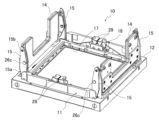
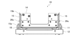
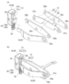
ICソケット10は、図1~図5に示すように、「電気部品」としてのICパッケージを配置可能なソケット本体11と、ソケット本体11に上下動可能に設けられた操作部材12と、操作部材12を上向きに付勢する付勢手段13と、ソケット本体11に開閉可能に設けられた開閉体14と、ソケット本体11と操作部材12とに両側の基端部15aが連結して開閉体14に連結した開閉リンク機構15と、開閉リンク機構15の先端部15bを押下げる押下機構16と、を備えている。
As shown in FIGS. 1 to 5, the
ソケット本体11は、金属製のベース部17と、ベース部17の外周側に立設された複数の立上り片18と、を有している。ソケット本体11には、ICパッケージを上面側に配置可能なコンタクトピンユニットがベース部17に囲まれて設けられ、ICパッケージの端子に対応する位置に配線基板と接続した多数のコンタクトピンが配設されているが、詳細な図示は省略されている。
The
操作部材12は、ソケット本体11の外周囲を囲む枠状に形成されており、複数の立上り片18に沿って上下動可能に配設されている。
The
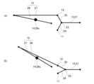
付勢手段13は、図2に示すように、ソケット本体11の側縁に沿って配置された圧縮バネ21及びバネ保持部22と、バネ保持部22の両端に設けられて圧縮バネ21により互いに離間する方向に付勢された一対の端部ブロック23と、一端部がソケット本体11のベース部17に回動自在に枢支されるとともに他端部が端部ブロック23に回動自在に枢支された第1付勢レバー24と、一端部が操作部材12に回動自在に枢支されるともに他端部が端部ブロック23に回動自在に枢支された第2付勢レバー25と、を備えている。
As shown in FIG. 2, the biasing means 13 includes a
付勢手段13では、圧縮バネ21により両端の端部ブロック23間が離間する方向に付勢されることで、第1付勢レバー24の一端部と第2付勢レバー25の一端部とが離間する方向に付勢され、これによりソケット本体11に対して操作部材12が上向きに付勢されている。操作部材12が下向きに押圧されて下降すると、付勢力に抗して第1付勢レバー24の一端部と第2付勢レバー25の一端部との間が近接する方向に変位する。
In the biasing means 13 , the
開閉体14は、平面視略コ字状の形状を有する片からなり、ベース部17の複数の立上り片18に回動して開閉自在に枢支されている。この実施形態では、ソケット本体11の上面側における互いに対向する側縁側に、観音開き方向に開閉するように一対装着されている。
The opening/
一対の開閉体14は、閉じることでソケット本体11上に配置された図示しないICパッケージの外周部を下向きに押圧可能に形成されている。ICパッケージを下向きに押圧することで、ICパッケージの端子をソケット本体11に設けられた多数の図示しないコンタクトピンと圧接する。ICパッケージの多数の端子が多数のコンタクトピンの弾性力に抗して圧接するため、開閉体14を閉じたときにはICパッケージから開閉体14に大きな反力が作用する。
The pair of opening/closing
開閉リンク機構15は、図6(a)乃至(d)及び図7(a)(b)に示すように、基端部26aがソケット本体11のベース部17に枢支された第1開閉レバー26と、基端部27aが操作部材12に回動自在に枢支された第2開閉レバー27と、を備え、第1開閉レバー26の先端部26bと第2開閉レバー27の先端部27bとが互いに相対回動自在に連結されて構成されている。
As shown in FIGS. 6A to 6D and 7A and 7B, the opening/
この開閉リンク機構15では、第1及び第2開閉レバー26,27の基端部26a,27aがソケット本体11と操作部材12とにそれぞれ連結されることで、関節リンク機構15の両端の基端部15aが構成され、第1開閉レバー26と第2開閉レバー27とが連結された関節部及びその近傍により先端部15bが構成されている。
In this opening/
開閉リンク機構15の第1開閉レバー26の長手方向中間部位には、開閉体連結部26cが設けられており、第1開閉レバー26及び開閉リンク機構15と開閉体14とが相対回動自在に連結されている。開閉体連結部26cは、開閉体14のソケット本体11に対する枢支部位から離間しており、かつ開閉体14を閉じた状態で開閉リンク機構15の両側の基端部15aよりも側方の位置に設けられている。
An opening/closing
そのため操作部材12の昇降により開閉リンク機構15の先端部15b側が基端部15a側に対して回動することで開閉体14が開閉でき、操作部材12の昇降により各開閉体14が開閉する。
Therefore, the opening/
この開閉リンク機構15では、ソケット本体11に連結された第1開閉レバー26の基端部26aと、操作部材12に連結された第2開閉レバー27の基端部27aと、が何れも第1開閉レバー26と第2開閉レバー27との連結部位よりも低い位置に設けられるとともに、基端部26aよりも基端部27aが上方に設けられている。また基端部27aは第1開閉レバー26と第2開閉レバー27との連結部位からの距離が基端部26aよりも長く設けられている。
In this opening/
これにより、まず図1、図6(a)(b)、7(a)のように、操作部材12が最も上昇した状態では、開閉リンク機構15では先端部15b及び開閉体連結部26cが最も低い位置に配置され、開閉体14がソケット本体11に対して完全に閉じた状態で配置される。
1, 6(a), 6(b), and 7(a), when the
図6(c)(d)、7(b)のように、付勢手段13の付勢力に抗して操作部材12を下降させると、開閉リンク機構15では先端部15b及び開閉体連結部26cが上昇し、開閉体14が開き始める。
As shown in FIGS. 6(c), 6(d) and 7(b), when the
そして、操作部材12が最も下降した状態になると、図4及び図5のように、開閉リンク機構15では、先端部15b及び開閉体連結部26cが最も上昇した位置に配置され、開閉体14がソケット本体11に対して完全に開いた状態で配置される。
Then, when the operating
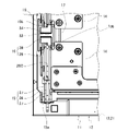
押下機構16は、図1、図8(a)(b)、図9(a)乃至(d)、図10(a)(b)に示すように、開閉体14が閉じるときに開閉リンク機構15の先端部15bを押下げるように構成されている。本実施形態の押下機構16は、開閉体14が開くときには開閉リンク機構15を開放するとともに開閉体14が閉じるときには開閉リンク機構15の先端部15bと係止する押下部材28と、ソケット本体11に揺動可能に支持され、基端部29aで操作部材12に連結されるとともに先端部29bで押下部材28に係止された揺動レバー29と、を有している。
As shown in FIGS. 1, 8(a)(b), 9(a) to (d), and 10(a)(b), the
押下部材28は、ソケット本体11における開閉リンク機構15が配置された側縁に、各開閉リンク機構15の先端部15bに対応する位置にそれぞれ配置されており、ソケット本体11の立上り片18に上下動自在に支持されている。
The
各押下部材28は、開閉リンク機構15と対向する一方の側面側に、開閉リンク機構15の第1開閉レバー26の先端部26bを係脱可能な開閉リンク係止部31と、開閉リンク係止部31に沿って形成され、揺動レバー29の先端部29bを常時収容する揺動レバー係止部32と、を備え、それぞれソケット本体11との間に介在された押上バネ35により上方に付勢されている。
Each pressing
開閉リンク係止部31は、回動する開閉リンク機構15の先端部15bが挿入及び離脱するための係止開口31aと、開閉リンク機構15の先端部15bに上方から係止するように深く設けられた係止段差31bと、を有している。
The opening/closing
揺動レバー係止部32は、揺動レバー29の先端部29bが遊嵌する収容部32aと、揺動レバー29の先端部29bにより下方へ押下げ可能な押下段差32bと、を備えている。
The rocking
押下部材28の他方の側面側には、押下部材28が上下動する際に、ソケット本体11の立上り片18の側面に固設された案内突起33と摺接する案内カム34が設けられている。
A
揺動レバー29は、開閉リンク機構15の第1開閉レバー26及び第2開閉レバー27と平行に並べて配置され、長手方向の中間位置でソケット本体11に揺動自在に支持されている。揺動レバー29の基端部29aは操作部材12に回動自在に連結されており、先端部29bが押下部材28の揺動レバー係止部32に収容されている。
The rocking
本実施形態の開閉リンク機構16では、開閉体14が開くときには、押上バネ35に付勢された押下部材28が開閉リンク機構15の先端部15bとともに押し上げられる。その際、開閉リンク機構15の先端部15b及び押上バネ35により押圧部材28を押し上げつつ後方側、即ち開閉リンク機構15から離間する側へ押圧することで、案内カムを案内突起33に摺接させる。
In the opening/
これにより、例えば後述する図11(d)(c)(b)に示すように、押下部材28の上部側を後方へ傾斜させて、係止開口31aをより後方側へ広く上向きに開口させることができる。
As a result, as shown in FIGS. 11(d), 11(c) and 11(b), for example, the upper portion of the pressing
一方、開閉体14を閉じるときには、開閉リンク機構15の先端部15bが係止開口31aから開閉リンク係止部31に収容された後、揺動レバー係止部32に収容されている揺動レバー29の先端部29bにより、押下段差32bが下方へ押圧されることで、押下部材28が押し下げられる。
On the other hand, when the opening/
その際、開閉リンク機構15の先端部15bにより、開閉リンク係止部31における係止開口31aから係止段差31bまでの間の底部等に接して押し下げつつ後方側(開閉リンク機構15から離間する側)へ押圧することで、案内カム34を案内突起33に摺動させる。
At this time, the
これにより、後述する図11(b)(c)(d)に示すように、押下部材28の上部側の傾斜を戻して上部側を開閉リンク機構15側へ変位させ、開閉リンク係止部31における係止段差31bに開閉リンク機構15の先端部15bを係止させる。さらに揺動レバー29の先端部29bにより押下段差32bを下方へ押圧することで、押下部材28により開閉リンク機構15の先端部15bを押し下げることができる。
As a result, as shown in FIGS. 11B, 11C, and 11D to be described later, the inclination of the upper portion of the pressing
このような押下機構16では、まず図1、図9(a)(b)、図10(a)のように、操作部材12が最も上昇した状態では、開閉リンク機構15により開閉体14がソケット本体11に対して完全に閉じた状態で配置されている。また押下機構16では、押下部材28の開閉リンク係止部31における係止段差31bに開閉リンク機構15の先端部15bが係止された状態で、揺動レバー29の先端部29bが揺動レバー係止部32の押下段差32bを押下げた状態となっている。この状態では押下部材28及び押下部材28に係止された開閉リンク機構15の先端部15bが最も押下げられている。
1, 9(a), 9(b), and 10(a), when the
図9(c)(d)、図10(b)のように、付勢手段13の付勢力に抗して操作部材12を下降させると、開閉リンク機構15により開閉体14が開き始め、押下機構16では、揺動レバー係止部32の押下段差32bを押下げている揺動レバー29の先端部29bが上昇するとともに、開閉リンク機構15の先端部15bが押下部材28の係止段差31bに係止された状態で上昇する。これにより押下部材28が案内カム34を案内突起33に摺動させつつ上昇する。
As shown in FIGS. 9(c), 9(d) and 10(b), when the
押下部材28が上昇すると、開閉リンク機構15の先端部15bが押下部材28の係止段差31bから離脱するとともに、揺動レバー29の先端部29bが収容部32a内で遊嵌された状態で配置される。
When the pressing
そして操作部材12を最も下降させた状態では、図4のように、開閉リンク機構15により開閉体14がソケット本体11に対して完全に開いた状態で配置される。また押下機構16では、開閉リンク機構15の先端部15bが離脱するとともに揺動レバー29の先端部29bが収容部32a内で遊嵌した状態で、押下部材28が最も上昇した位置に配置され、押下部材28の上部側が後方側へ傾斜して係止開口31aが上方側により大きく開口した状態でソケット本体11に支持される。
When the
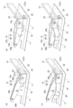
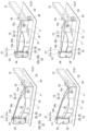
次に、このような本実施形態のICソケット10にICパッケージを収容する動作について図11(a)~(d)を用いて説明する。
Next, the operation of housing an IC package in the
まず図11(a)に示すように、操作部材12を最も下降させることで、一対の開閉体14を観音開き方向に全開する。このとき押下機構16では、互いに背面側を対向させた押下部材28の上部同士が互いに近接するように後方側へ傾斜させた状態で、押下部材28がそれぞれ最も上昇した位置に配置される。
First, as shown in FIG. 11(a), the
この状態で、ソケット本体11における図示しないコンタクトピンユニット上にICパッケージを載置した後、操作部材12を上昇させる。すると図11(b)に示すように、開閉リンク機構15の先端部15bが押下部材28の開閉リンク係止部31内に係止開口31aから挿入されて係止段差31b内に収容される。
In this state, after the IC package is placed on the contact pin unit (not shown) of the
次いで、図11(c)に示すように、開閉リンク機構15の先端部15bが押下部材28の開閉リンク係止部31の係止段差31b付近に達するとともに、揺動レバー29の先端部29bにより揺動レバー29の先端部29bが押下部材28の押下段差32bを押下げることで押下部材28を下方へ移動させる。
Next, as shown in FIG. 11(c), the
そして図11(d)に示すように、揺動レバー29の先端部29bにより押下部材28を押下げることで、開閉リンク係止部31の係止段差31bに係止された開閉リンク機構15の先端部15bが押下部材28により強く押下げられる。これによりICパッケージの周縁側を開閉体14により強く押圧して、多数のコンタクトピンの弾性力に抗してICパッケージの多数の端子を各コンタクトピンと接続することができる。
Then, as shown in FIG. 11(d), by pushing down the pressing
以上のような本実施形態のICソケット10によれば、上向きに付勢された操作部材12とソケット本体11とに基端部15bが連結された開閉リンク機構15に、操作部材12が上昇することで閉じるように開閉体14が連結されていて、開閉体14が閉じるときに押下機構28により開閉リンク機構15の先端部15bを押下げるように構成されている。
According to the
そのため開閉体14を閉じるときに、開閉リンク機構15の両側の基端部15a及び先端部15bが安定して支持される。即ち、第1開閉レバー26の基端部26bはソケット本体11に回動自在に連結されることで安定して支持され、第2開閉レバー27の基端部27aは操作部材12に回動自在に連結されることで安定して支持される。また第1開閉レバー26と第2開閉レバー27とが互いに相対回動自在に連結している先端部15aは押下機構16に押下可能に係止されることで安定して支持される。
Therefore, when the opening/
これにより開閉リンク機構15の基端部15a及び先端部15bが安定して支持された状態で開閉リンク機構15を動作させることができ、基端部15aよりも側方位置で開閉体14を押圧することで大きな反力が作用しても、開閉リンク機構15の先端部15bに撓みや変位が生じることを防止できる。
As a result, the opening/
その結果、開閉リンク機構15により開閉体14の所定動作を確実に実現することができ、開閉体14によりICパッケージの外周全体を十分な押圧力でより均一に押圧することが可能である。
As a result, the opening/
また本実施形態のICソケット10によれば、開閉体14が開くときに開閉リンク機構15を開放し、開閉体14が閉じるときに開閉リンク機構15の先端部15bと係止する押下部材28を押下機構16に有している。そのため開閉体14からの大きな反力が開閉リンク機構15に作用する範囲にのみ押下部材28を動作可能に配置することができ、開閉リンク機構15の動作範囲に比べて押下機構16の動作範囲を小さくして構造を簡素化することができる。
Further, according to the
しかも本実施形態のICソケット10では、開閉リンク機構15により観音開き方向に開閉する一対の開閉体14を備え、各開閉体14の開閉リンク機構15毎に押下機構16が設けられていて、押下機構16の押下部材28が上昇したときに開閉リンク係止部31の係止開口31aが上向きに傾斜することが可能である。そのため例えば図12に示すように、操作部材12が片当たりなどにより斜めに押圧され、一対の開閉体14のうちの一方が閉じて、他方が開放した状態となっても、その後に傾斜した操作部材12のより押下げられた側を上昇させた際、開閉リンク機構15の先端部15bが押下部材の外形部分に当接することなく、円滑に開閉リンク係止部31内に挿入することができる。
Moreover, the
さらに本実施形態のICソケット10によれば、押下機構16が、ソケット本体11に揺動可能に支持されて基端部29aで操作部材12に連結されるとともに先端部29bで押下部材28に係止された揺動レバー29を有し、操作部材12が上昇することで揺動レバー29の先端部29bが押下部材28を押下げるように構成されている。そのため操作部材12を下降させたときに揺動レバー29の先端部29bを上昇させ、操作部材12が上昇するときに揺動レバー29の先端部29bを下降することができ、操作部材12の上昇するときに確実に押下部材28を押下げることが可能で、確実な動作を簡素な構造で実現することができる。
Further, according to the
なお上記実施形態は本発明の範囲内において適宜変更可能である。 It should be noted that the above embodiment can be appropriately modified within the scope of the present invention.
例えば上記実施形態では、開閉体14がICパッケージの周囲を直接する押圧する例について説明したが、特に限定されるものではなく、例えば開閉体14にヒートシンクや他の押圧部材等を装着し、これらを介して間接にICパッケージを押圧するように構成してもよい。
For example, in the above embodiment, an example in which the opening/
また上記実施形態では、開閉体14を一対設けて互いに反対方向に開閉する観音開き形式にした例について説明したが、単数又は複数の開閉体14を一方側のみに開閉するように構成しても本発明を適用することは可能である。
In the above-described embodiment, a pair of opening/
さらに上記実施形態における開閉リンク機構15及び押下機構16の構造は一例であって、何ら限定されるものではなく、他の構成にすることは可能である。
Furthermore, the structures of the opening/
10 ICソケット
11 ソケット本体
12 操作部材
13 付勢手段
14 開閉体
15 開閉リンク機構
15a 基端部
15b 先端部
16 押下機構
17 ベース部
18 立上り片
21 圧縮バネ
22 バネ保持部
23 端部ブロック
24 第1付勢レバー
25 第2付勢レバー
26 第1開閉レバー
26a 基端部
26b 先端部
26c 開閉体連結部
27 第2開閉レバー
27a 基端部
27b 先端部
28 押下部材
29 揺動レバー
29a 基端部
29b 先端部
31 開閉リンク係止部
31a 係止開口
31b係止段差
32 揺動レバー係止部
32a 収容部
32b 押下段差
33 案内突起
34 案内カム
35 押上バネ
10
Claims (3)
前記ソケット本体に上下動可能に設けられて上向きに付勢された操作部材と、
前記ソケット本体に開閉可能に設けられ、閉じることで前記ソケット本体上に配置された電気部品を押圧して前記コンタクトピンに圧接させる開閉体と、
前記ソケット本体及び前記操作部材に基端部が連結し、前記操作部材が上昇することで前記開閉体を閉じるように前記開閉体に連結した開閉リンク機構と、
前記開閉体が閉じるときに前記開閉リンク機構の先端部を押下げる押下機構と、
を備えていることを特徴とする電気部品用ソケット。 a socket body having contact pins;
an operating member provided in the socket body so as to be vertically movable and biased upward;
an openable/closable body that is provided on the socket body so as to be openable and closable, and that, when closed, presses an electrical component arranged on the socket body to be brought into pressure contact with the contact pin;
an opening/closing link mechanism having a base end connected to the socket body and the operation member, and connected to the opening/closing body so as to close the opening/closing body when the operation member rises;
a pressing mechanism that presses down the distal end portion of the opening/closing link mechanism when the opening/closing body is closed;
A socket for electrical components, characterized by comprising:
Priority Applications (3)
| Application Number | Priority Date | Filing Date | Title |
|---|---|---|---|
| JP2019076386A JP7233290B2 (en) | 2019-04-12 | 2019-04-12 | Sockets for electrical components |
| PCT/JP2020/015236 WO2020209182A1 (en) | 2019-04-12 | 2020-04-02 | Socket for electrical component |
| US17/603,198 US20220187359A1 (en) | 2019-04-12 | 2020-04-02 | Socket for electrical component |
Applications Claiming Priority (1)
| Application Number | Priority Date | Filing Date | Title |
|---|---|---|---|
| JP2019076386A JP7233290B2 (en) | 2019-04-12 | 2019-04-12 | Sockets for electrical components |
Publications (2)
| Publication Number | Publication Date |
|---|---|
| JP2020174016A JP2020174016A (en) | 2020-10-22 |
| JP7233290B2 true JP7233290B2 (en) | 2023-03-06 |
Family
ID=72751606
Family Applications (1)
| Application Number | Title | Priority Date | Filing Date |
|---|---|---|---|
| JP2019076386A Active JP7233290B2 (en) | 2019-04-12 | 2019-04-12 | Sockets for electrical components |
Country Status (3)
| Country | Link |
|---|---|
| US (1) | US20220187359A1 (en) |
| JP (1) | JP7233290B2 (en) |
| WO (1) | WO2020209182A1 (en) |
Families Citing this family (1)
| Publication number | Priority date | Publication date | Assignee | Title |
|---|---|---|---|---|
| JP2022071373A (en) * | 2020-10-28 | 2022-05-16 | 山一電機株式会社 | Heat sink unit, ic socket, method for manufacturing semiconductor package, and semiconductor package |
Citations (2)
| Publication number | Priority date | Publication date | Assignee | Title |
|---|---|---|---|---|
| JP2005327628A (en) | 2004-05-14 | 2005-11-24 | Three M Innovative Properties Co | Ic socket |
| US20170176493A1 (en) | 2015-12-18 | 2017-06-22 | Samsung Electronics Co., Ltd. | Test socket and method for testing a semiconductor package |
Family Cites Families (7)
| Publication number | Priority date | Publication date | Assignee | Title |
|---|---|---|---|---|
| JP3755701B2 (en) * | 1997-11-28 | 2006-03-15 | 株式会社エンプラス | Socket for electrical parts |
| JPH11329643A (en) * | 1998-05-14 | 1999-11-30 | Wells Cti Kk | Ic socket |
| JP2004014873A (en) * | 2002-06-07 | 2004-01-15 | Yamaichi Electronics Co Ltd | Socket for electronic component |
| JP4495200B2 (en) * | 2007-09-28 | 2010-06-30 | 山一電機株式会社 | Socket for semiconductor device |
| JP2010118275A (en) * | 2008-11-13 | 2010-05-27 | Yamaichi Electronics Co Ltd | Socket for semiconductor device |
| JP6373130B2 (en) * | 2014-09-01 | 2018-08-15 | 株式会社エンプラス | Socket for electrical parts |
| JP2019032930A (en) * | 2017-08-04 | 2019-02-28 | 株式会社エンプラス | Socket for electrical component |
-
2019
- 2019-04-12 JP JP2019076386A patent/JP7233290B2/en active Active
-
2020
- 2020-04-02 US US17/603,198 patent/US20220187359A1/en active Pending
- 2020-04-02 WO PCT/JP2020/015236 patent/WO2020209182A1/en active Application Filing
Patent Citations (2)
| Publication number | Priority date | Publication date | Assignee | Title |
|---|---|---|---|---|
| JP2005327628A (en) | 2004-05-14 | 2005-11-24 | Three M Innovative Properties Co | Ic socket |
| US20170176493A1 (en) | 2015-12-18 | 2017-06-22 | Samsung Electronics Co., Ltd. | Test socket and method for testing a semiconductor package |
Also Published As
| Publication number | Publication date |
|---|---|
| US20220187359A1 (en) | 2022-06-16 |
| JP2020174016A (en) | 2020-10-22 |
| WO2020209182A1 (en) | 2020-10-15 |
Similar Documents
| Publication | Publication Date | Title |
|---|---|---|
| TWI780278B (en) | Sockets for electrical parts | |
| TWI791703B (en) | Sockets for electrical parts | |
| US7393232B2 (en) | Socket for electrical parts | |
| US7097488B2 (en) | Socket for electrical parts | |
| JP7233290B2 (en) | Sockets for electrical components | |
| JP5836112B2 (en) | Socket for electrical parts | |
| US7575460B2 (en) | IC socket | |
| JP2012229923A (en) | Electrical connection device | |
| KR101628302B1 (en) | Socket For Testing Electronics | |
| JP6095982B2 (en) | Socket for electrical parts | |
| JP7170393B2 (en) | Opening and closing mechanism of opening and closing body | |
| US6428337B2 (en) | Socket for electrical parts | |
| TWI777006B (en) | Opening and closing mechanism of the opening and closing body | |
| JP4786409B2 (en) | Socket for electrical parts | |
| JP2004228042A (en) | Socket for electric component | |
| JP6660683B2 (en) | Socket for electrical components | |
| JP5202288B2 (en) | Socket for electrical parts | |
| JP2022057444A (en) | Socket and socket for inspection |
Legal Events
| Date | Code | Title | Description |
|---|---|---|---|
| A621 | Written request for application examination |
Free format text: JAPANESE INTERMEDIATE CODE: A621 Effective date: 20220307 |
|
| TRDD | Decision of grant or rejection written | ||
| A01 | Written decision to grant a patent or to grant a registration (utility model) |
Free format text: JAPANESE INTERMEDIATE CODE: A01 Effective date: 20230110 |
|
| A601 | Written request for extension of time |
Free format text: JAPANESE INTERMEDIATE CODE: A601 Effective date: 20230201 |
|
| A61 | First payment of annual fees (during grant procedure) |
Free format text: JAPANESE INTERMEDIATE CODE: A61 Effective date: 20230221 |
|
| R150 | Certificate of patent or registration of utility model |
Ref document number: 7233290 Country of ref document: JP Free format text: JAPANESE INTERMEDIATE CODE: R150 |