JP7218552B2 - Information processing device, remote device management system, communication method and program - Google Patents

Information processing device, remote device management system, communication method and program Download PDF

Info

Publication number
JP7218552B2
JP7218552B2 JP2018222966A JP2018222966A JP7218552B2 JP 7218552 B2 JP7218552 B2 JP 7218552B2 JP 2018222966 A JP2018222966 A JP 2018222966A JP 2018222966 A JP2018222966 A JP 2018222966A JP 7218552 B2 JP7218552 B2 JP 7218552B2
Authority
JP
Japan
Prior art keywords
file
management system
communication
data
information
Prior art date
Legal status (The legal status is an assumption and is not a legal conclusion. Google has not performed a legal analysis and makes no representation as to the accuracy of the status listed.)
Active
Application number
JP2018222966A
Other languages
Japanese (ja)
Other versions
JP2020087147A (en
Inventor
祥平 宇都宮
Current Assignee (The listed assignees may be inaccurate. Google has not performed a legal analysis and makes no representation or warranty as to the accuracy of the list.)
Ricoh Co Ltd
Original Assignee
Ricoh Co Ltd
Priority date (The priority date is an assumption and is not a legal conclusion. Google has not performed a legal analysis and makes no representation as to the accuracy of the date listed.)
Filing date
Publication date
Application filed by Ricoh Co Ltd filed Critical Ricoh Co Ltd
Priority to JP2018222966A priority Critical patent/JP7218552B2/en
Publication of JP2020087147A publication Critical patent/JP2020087147A/en
Application granted granted Critical
Publication of JP7218552B2 publication Critical patent/JP7218552B2/en
Active legal-status Critical Current
Anticipated expiration legal-status Critical

Links

Images

Landscapes

  • Debugging And Monitoring (AREA)

Description

本発明は、情報処理装置、遠隔機器管理システム、通信方法およびプログラムに関する。 The present invention relates to an information processing device, a remote device management system, a communication method and a program.

LAN(Local Area Network)等のローカルネットワーク内に存在する機器をローカルネットワーク外から遠隔管理する遠隔機器管理システムが知られている。遠隔機器管理システムは、例えば、機器から機器情報を取得可能な仲介装置をローカルネットワーク内に設けている。そして、ローカルネットワーク外に位置する管理サーバは、仲介装置との間でファイアウォールを介して通信を行うことで、機器の遠隔管理を実現している。 2. Description of the Related Art A remote device management system is known that remotely manages devices existing in a local network such as a LAN (Local Area Network) from outside the local network. A remote device management system includes, for example, an intermediary device in a local network that can acquire device information from devices. A management server located outside the local network realizes remote management of the device by communicating with the intermediary device through the firewall.

また、このような遠隔機器管理システムにおいて、管理対象の機器の種別に依らずに、管理サーバ側での機器管理を実現することにより、システムの利便性が高まる。例えば、特許文献1には、少なくとも1つの機器に接続される機器情報管理装置であって、機器の機種を判定し、判定した機種に対応する動作定義ファイルを選択し、選択した動作定義ファイルの動作に従って、機器が実装する通信プロトコルのドライバを用いて、機器から機器情報を取得する内容が開示されている。 Further, in such a remote device management system, the convenience of the system is enhanced by realizing device management on the management server side regardless of the type of device to be managed. For example, Patent Document 1 discloses a device information management device connected to at least one device, which determines the model of the device, selects an operation definition file corresponding to the determined model, and stores the selected operation definition file. According to the operation, using a communication protocol driver implemented by the device to obtain device information from the device is disclosed.

しかし、従来の方法では、機器情報管理装置としての機器管理システムが対応していない通信プロトコルを用いて機器と通信を行うためには、遠隔地に設置された仲介装置のファームウエアをそれぞれ更新しなければならなかった。そのため、システム自体の変更を行わなわなければ、機器管理システムが対応していない通信プロトコルを用いて通信を行う機器と機器管理システムとの通信を行うことができないという課題があった。 However, in the conventional method, in order to communicate with devices using a communication protocol that is not supported by the device management system as the device information management device, the firmware of each intermediary device installed at a remote location must be updated. had to. Therefore, unless the system itself is changed, there is a problem that the device management system cannot communicate with a device that communicates using a communication protocol that the device management system does not support.

請求項1に係る情報処理装置は、ローカルネットワーク内に存在する機器と、前記機器とファイアウォールを介した通信を行う機器管理システムとの通信を仲介する情報処理装置であって、前記機器管理システムとの通信に用いる通信プロトコルとは異なる特定の通信プロトコルを示す第1のファイルと、前記機器管理システムと前記特定の機器との間で通信されるデータのデータ形式の変換に用いる第2のファイルを、前記機器管理システムから受信する受信手段と、前記第1のファイルと前記第2のファイルとに基づいて、前記機器管理システムと前記特定の機器との間で通信されるデータのデータ形式を変換する変換手段と、を備え、前記機器管理システムと前記特定の機器との間で、前記変換されたデータの通信を仲介する。 An information processing apparatus according to claim 1 is an information processing apparatus that mediates communication between a device existing in a local network and a device management system that communicates with the device via a firewall, wherein the device management system communicates with the device through a firewall. a first file indicating a specific communication protocol different from the communication protocol used for the communication of the device management system and a second file used for converting the data format of data communicated between the device management system and the specific device and converting a data format of data communicated between the device management system and the specific device based on the first file and the second file. and a conversion means for mediating communication of the converted data between the device management system and the specific device.

本発明によれば、遠隔機器管理システムにおいて、システム自体の変更を行わなくても、機器管理システムが対応していない通信プロトコルを用いて通信を行う機器と機器管理システムとの通信を行うことができる。 According to the present invention, in a remote device management system, it is possible to communicate with a device that communicates using a communication protocol not supported by the device management system without changing the system itself. can.

第1の実施形態に係る遠隔機器管理システムのシステム構成の一例を示す図である。1 is a diagram showing an example of a system configuration of a remote device management system according to a first embodiment; FIG. 第1の実施形態に係る遠隔機器管理システムの概略の一例を示す図である。BRIEF DESCRIPTION OF THE DRAWINGS It is a figure which shows an example of the outline of the remote equipment management system which concerns on 1st Embodiment. 第1の実施形態に係るコンピュータのハードウエア構成の一例を示す図である。It is a figure showing an example of hardware constitutions of a computer concerning a 1st embodiment. 第1の実施形態に係る管理システムの機能構成の一例を示す図である。It is a figure showing an example of functional composition of a management system concerning a 1st embodiment. 第1の実施形態に係る仲介装置および機器の機能構成の一例を示す図である。3 is a diagram illustrating an example of functional configurations of an intermediary device and equipment according to the first embodiment; FIG. 第1の実施形態に係る機器との通信に用いる通信定義の概略モデルの一例を示す図である。FIG. 3 is a diagram showing an example of a schematic model of communication definitions used for communication with devices according to the first embodiment; 第1の実施形態に係る仲介装置管理テーブルの一例を示す図である。4 is a diagram illustrating an example of an intermediary device management table according to the first embodiment; FIG. 第1の実施形態に係るファイル管理テーブルの一例を示す図である。4 is a diagram showing an example of a file management table according to the first embodiment; FIG. 第1の実施形態に係る機器管理テーブルの一例を示す図である。It is a figure which shows an example of the equipment management table which concerns on 1st Embodiment. 第1の実施形態に係るプロトコル変換情報の一例を示す図である。4 is a diagram showing an example of protocol conversion information according to the first embodiment; FIG. 第1の実施形態に係る設定ファイルの一例を示す図である。It is a figure which shows an example of the setting file which concerns on 1st Embodiment. 第1の実施形態に係る遠隔機器管理システムにおけるファイル登録処理の一例を示すシーケンスである。4 is a sequence showing an example of file registration processing in the remote device management system according to the first embodiment; 第1の実施形態に係る遠隔機器管理システムおける、仲介装置に対するプロトコル変換ルールの設定処理の一例を示すシーケンス図である。FIG. 7 is a sequence diagram showing an example of setting processing of protocol conversion rules for mediation devices in the remote device management system according to the first embodiment; 第1の実施形態に係る遠隔機器管理システムにおける機器情報取得処理の一例を示すシーケンス図である。4 is a sequence diagram showing an example of device information acquisition processing in the remote device management system according to the first embodiment; FIG. 第1の実施形態に係る仲介装置におけるプロトコル変換処理の一例を示すフローチャートである。6 is a flow chart showing an example of protocol conversion processing in the intermediary device according to the first embodiment; 第1の実施形態に係る仲介装置におけるプロトコル変換処理の一例を示すフローチャートである。6 is a flow chart showing an example of protocol conversion processing in the intermediary device according to the first embodiment; 第1の実施形態に係る遠隔機器管理システムにおける機器から遠隔機器管理システムへの機器情報の通知処理の一例を示すシーケンス図である。FIG. 7 is a sequence diagram showing an example of a process of notifying device information from a device to the remote device management system in the remote device management system according to the first embodiment; 第1の実施形態に係る仲介装置におけるプロトコル変換処理の一例を示すフローチャートである。6 is a flow chart showing an example of protocol conversion processing in the intermediary device according to the first embodiment; 第1の実施形態に係る遠隔機器管理システムおける、プロトコル変換装置10に設定されたプロトコル変換情報の取得処理の一例を示すシーケンス図である。4 is a sequence diagram showing an example of processing for acquiring protocol conversion information set in the protocol conversion device 10 in the remote device management system according to the first embodiment; FIG. 第2の実施形態に係る遠隔機器管理システムの概略の一例を示す図である。FIG. 10 is a diagram showing an example of a schematic of a remote device management system according to a second embodiment; FIG. 第2の実施形態に係る仲介装置および機器の機能構成の一例を示す図である。FIG. 10 is a diagram illustrating an example of functional configurations of an intermediary device and equipment according to the second embodiment; その他の実施形態に係る遠隔機器管理システムのシステム構成の一例を示す図である。FIG. 11 is a diagram showing an example of a system configuration of a remote device management system according to another embodiment;

以下、図面を参照しながら、発明を実施するための形態を説明する。なお、図面の説明において同一要素には同一符号を付し、重複する説明は省略する。 BEST MODE FOR CARRYING OUT THE INVENTION Hereinafter, embodiments for carrying out the invention will be described with reference to the drawings. In the description of the drawings, the same elements are denoted by the same reference numerals, and redundant description is omitted.

●第1の実施形態●
●システム構成
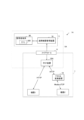
図1は、第1の実施形態に係る遠隔機器管理システムのシステム構成の一例を示す図である。遠隔機器管理システム1は、管理システム3、ローカルネットワーク7およびファイアウォール9を含む。ローカルネットワーク7は、インターネットを介して管理システム3と接続されている。ローカルネットワーク7と管理システム3は、ファイアウォール9をインターフェースとして接続されている。
●First Embodiment●
●System Configuration FIG. 1 is a diagram showing an example of the system configuration of the remote device management system according to the first embodiment. Remote equipment management system 1 includes management system 3 , local network 7 and firewall 9 . A local network 7 is connected to the management system 3 via the Internet. The local network 7 and the management system 3 are connected with a firewall 9 as an interface.

ローカルネットワーク7は、オフィス、会議室、倉庫、工場または特定の生産ライン等のネットワーク環境において形成される通信ネットワークである。ローカルネットワーク7は、例えば、インターネットを経由しない社内LAN(Local Area Network)である。ローカルネットワーク7は、仲介装置30、MFP(Multi-Function Peripheral:複合機)500a、PJ(Projector:プロジェクタ)500b、IWB(Interactive White Board:相互通信が可能な電子式の黒板機能を有する白板)500c、PC(Personal Computer:パソコン)500d、センサデバイス500e(例:外部と通信可能な、電子天秤・気圧計・加速度計・電流計・温度計・光度計・人感センサ・カメラ・照度計)を含む。MFP500a、PJ500b、IWB500c、PC500d、センサデバイス500eは、管理システム3における遠隔管理の対象となる管理対象機器である。なお、以下の説明で使用する機器500は、これらの管理対象機器の総称である。 The local network 7 is a communication network formed in network environments such as offices, conference rooms, warehouses, factories, or specific production lines. The local network 7 is, for example, an in-house LAN (Local Area Network) that does not go through the Internet. The local network 7 includes an intermediary device 30, an MFP (Multi-Function Peripheral) 500a, a PJ (Projector) 500b, an IWB (Interactive White Board: a white board having an electronic blackboard function capable of mutual communication) 500c. , a PC (Personal Computer) 500d, and a sensor device 500e (e.g., an electronic balance, barometer, accelerometer, ammeter, thermometer, photometer, motion sensor, camera, and illuminance meter that can communicate with the outside). include. The MFP 500 a , PJ 500 b , IWB 500 c , PC 500 d and sensor device 500 e are devices to be managed remotely by the management system 3 . Note that the device 500 used in the following description is a general term for these managed devices.

ファイアウォール9は、管理システム3(インターネット)からの特定のパケットのみをローカルネットワーク7内に通過させる機能を有する。これにより、ファイアウォール9は、ローカルネットワーク7への意図しないまたは不正なアクセスをブロックすることが可能となる。また、ファイアウォール9は、仲介装置30からのパケットを管理システム3に転送する機能を有する。 The firewall 9 has a function of allowing only specific packets from the management system 3 (Internet) to pass through the local network 7 . This allows firewall 9 to block unintended or unauthorized access to local network 7 . The firewall 9 also has a function of transferring packets from the intermediary device 30 to the management system 3 .

管理システム3は、ローカルネットワーク7内に存在する仲介装置30および機器500を管理するためのシステムである。管理システム3は、遠隔機器管理装置70および複数の管理者端末90(90a、90b、90c、以下区別する必要のないときは管理者端末90と称する。)を含む。 The management system 3 is a system for managing the intermediary device 30 and the device 500 existing within the local network 7 . The management system 3 includes a remote device management device 70 and a plurality of administrator terminals 90 (90a, 90b, 90c, hereinafter referred to as administrator terminals 90 when there is no need to distinguish between them).

遠隔機器管理装置70は、複数のローカルネットワーク7に存在する仲介装置30および機器500の情報を管理するためのサーバコンピュータである。遠隔機器管理装置70は、ファイアウォ-ル9を介して仲介装置30と接続され、ローカルネットワーク7内の機器500を、仲介装置30を介して遠隔管理する。管理の一例として、遠隔機器管理装置70は、MFP500aから、トナー残量・印刷枚数等の状態に関する情報を取得することが可能である。また、遠隔機器管理装置70は、MFP500aに蓄積されたドキュメントデータの印刷を実行させるための指示が可能である。また、遠隔機器管理装置70は、PJ500b、IWB500c、およびPC500dに対して、電源のONまたはOFFを制御することが可能である。さらに、遠隔機器管理装置70は、センサデバイス500eに対して、当該センサデバイス500eによって取得された情報を取得することが可能である。なお、遠隔機器管理装置70は、一台のサーバコンピュータによって構成されてもよく、複数のサーバコンピュータによって構成されてもよい。 The remote device management device 70 is a server computer for managing information on mediation devices 30 and devices 500 existing in a plurality of local networks 7 . The remote equipment management device 70 is connected to the mediation device 30 via the firewall 9 and remotely manages the equipment 500 within the local network 7 via the mediation device 30 . As an example of management, the remote device management apparatus 70 can acquire information on the state of the remaining amount of toner, the number of printed sheets, and the like from the MFP 500a. Further, the remote device management apparatus 70 can issue an instruction to print the document data accumulated in the MFP 500a. In addition, the remote device management device 70 can control power ON/OFF for the PJ 500b, IWB 500c, and PC 500d. Furthermore, the remote device management apparatus 70 can obtain information obtained by the sensor device 500e from the sensor device 500e. The remote device management apparatus 70 may be composed of one server computer, or may be composed of a plurality of server computers.

管理者端末90は、仲介装置30の設置担当者または機器500の保守担当者等の遠隔機器管理システム1の管理者が使用するノートPC等の端末である。管理者端末90は、遠隔機器管理装置70によって管理される機器500の機器情報を表示させることで、遠隔機器管理システム1の管理者に機器500の情報を提供する。また、複数の管理者端末90は、異なる拠点からそれぞれ遠隔機器管理装置70へアクセスすることができる。管理者端末90aではアプリ900a、管理者端末90bではアプリ900b、管理者端末90cではアプリ900c(以下、アプリ900a~cのそれぞれを区別しない場合、アプリ900という。)が動作している。遠隔機器管理装置70は、例えば、ローカルネットワーク7の使用環境や機器500の種別に応じて、提供するアプリケーションの内容を設定することができ、管理者端末90ごとに提供するアプリケーションを管理している。なお、管理者端末90は、例えば、タブレット端末、携帯電話、スマートフォン、ウェアラブル端末またはディスクトップPC等のWebブラウザを搭載した端末であってもよい。また、管理者端末90は、ローカルネットワーク7内において、仲介装置30と直接通信可能な構成であってもよい。例えば、仲介装置30の設置担当者が現場で仲介装置30の設置作業を行う場合、設置担当者が使用する管理者端末90は、仲介装置30とローカルネットワーク7内で直接通信を行うことで、仲介装置30の設置作業を円滑に行うことができる。 The administrator terminal 90 is a terminal such as a notebook PC used by an administrator of the remote device management system 1 , such as a person in charge of installation of the intermediary device 30 or a person in charge of maintenance of the device 500 . The administrator terminal 90 provides information on the equipment 500 to the administrator of the remote equipment management system 1 by displaying the equipment information of the equipment 500 managed by the remote equipment management apparatus 70 . Also, a plurality of administrator terminals 90 can access the remote device management apparatus 70 from different bases. An application 900a is running on the administrator terminal 90a, an application 900b is running on the administrator terminal 90b, and an application 900c is running on the administrator terminal 90c (hereinafter referred to as the application 900 when the applications 900a to 900c are not distinguished from each other). The remote device management device 70 can set the content of the application to be provided according to, for example, the usage environment of the local network 7 and the type of the device 500, and manages the application to be provided for each administrator terminal 90. . Note that the administrator terminal 90 may be, for example, a terminal equipped with a web browser, such as a tablet terminal, a mobile phone, a smart phone, a wearable terminal, or a desktop PC. Also, the administrator terminal 90 may be configured to be able to directly communicate with the intermediary device 30 within the local network 7 . For example, when a person in charge of installation of the mediation device 30 performs installation work of the mediation device 30 on site, the administrator terminal 90 used by the person in charge of installation performs direct communication with the mediation device 30 within the local network 7, Installation work of the intermediary device 30 can be performed smoothly.

仲介装置30は、遠隔機器管理装置70と、ローカルネットワーク7における機器500との間の通信を仲介する装置である。仲介装置30は、遠隔機器管理装置70からファイアウォール9を超えて、ローカルネットワーク7内にメッセージを送信するために常時セッションを維持するための責務を持ち、ローカルネットワーク7内のセキュリティを担保しつつ遠隔機器管理装置70と監視対象の機器500との双方向の通信を実現する。仲介装置30は、機器500およびファイアウォール9と、有線または無線LAN等を介して通信可能である。仲介装置30は、遠隔機器管理装置70からの指示を受けて機器500にアクセスしたり、機器500からのアラート通知を遠隔機器管理装置70に送信したり、予め設定されたスケジュールに基づき機器500の情報取得通知や死活監視(例えば、機器500が通信可能であるかどうか等)を行う。仲介装置30は、単体として機能するボックス型(箱型)の通信装置であってもよく、MFP500a等の機器に内蔵されていてもよい。 The intermediary device 30 is a device that mediates communication between the remote device management device 70 and the device 500 on the local network 7 . The intermediary device 30 is responsible for always maintaining a session for transmitting a message from the remote device management device 70 to the local network 7 over the firewall 9 , ensuring security within the local network 7 and remotely Two-way communication between the device management apparatus 70 and the device 500 to be monitored is realized. Intermediary device 30 can communicate with device 500 and firewall 9 via a wired or wireless LAN or the like. Intermediary device 30 accesses device 500 in response to an instruction from remote device management device 70, transmits alert notification from device 500 to remote device management device 70, and controls device 500 based on a preset schedule. Information acquisition notification and life-and-death monitoring (for example, whether the device 500 is communicable or not) are performed. Intermediary device 30 may be a box-type (box-shaped) communication device that functions as a single unit, or may be built in a device such as MFP 500a.

また、仲介装置30は、インターネット上にある遠隔機器管理装置70と、ファイアウォール9を経由して通信可能である。すなわち、仲介装置30は、ファイアウォール(をインターフェースとするローカルネットワーク7)内に位置し、管理システム3を構成する遠隔機器管理装置70は、ファイアウォール(をインターフェースとするローカルネットワーク7)外に位置するといえる。 Also, the intermediary device 30 can communicate with the remote device management device 70 on the Internet via the firewall 9 . In other words, it can be said that the intermediary device 30 is located within (the local network 7 that interfaces with) the firewall, and the remote device management device 70 that constitutes the management system 3 is located outside the firewall (the local network 7 that interfaces with) the firewall. .

機器500(MFP500a、PJ500b、IWB500c、PC500dおよびセンサデバイス500e)は、ローカルネットワーク7内に位置し、かつファイアウォール(をインターフェースとするローカルネットワーク7)内に位置する。機器500は、管理システム3によるメンテナンスやカウンタ検針等が行われる管理対象の機器である。また、機器500は、人感センサ等のネットワーク機能を備えていない端末に、ネットワーク機能を備えた機器を取り付けてもよい。 The devices 500 (MFP 500a, PJ 500b, IWB 500c, PC 500d and sensor device 500e) are located within the local network 7 and within (the local network 7 with the firewall as an interface). The device 500 is a device to be managed by the management system 3 for maintenance, counter meter reading, and the like. Also, the device 500 may be a device having a network function attached to a terminal such as a human sensor that does not have a network function.

なお、管理システム3は、遠隔機器管理装置70と管理者端末90の機能を一台の装置によって実行される構成であってもよい。また、図1は、管理システム3が、一つのローカルネットワーク7内に位置する複数の機器500を遠隔管理する例を示すが、管理システム3が、複数のローカルネットワーク7内のそれぞれに位置する機器500を遠隔管理する構成にしてもよい。また、図1は、一台の仲介装置30が一つのローカルネットワーク7内に位置する例を示すが、一つのローカルネットワーク内に二台以上の仲介装置30が位置する構成にしてもよい。この場合、仲介装置30ごとに担う機能を分担してもよい。 Note that the management system 3 may be configured such that the functions of the remote device management device 70 and the administrator terminal 90 are executed by a single device. Also, FIG. 1 shows an example in which the management system 3 remotely manages a plurality of devices 500 located within one local network 7. 500 may be configured to be remotely managed. Moreover, although FIG. 1 shows an example in which one intermediary device 30 is located within one local network 7, a configuration in which two or more intermediary devices 30 are located within one local network may be employed. In this case, each intermediary device 30 may share the function.

●概略
ここで、第1の実施形態に係る遠隔機器管理システムの構成の概略に説明する。なお、図2は、第1の実施形態に係る遠隔機器管理システムの概略を簡略的に説明したものであり、遠隔機器管理システム1Aが実現する機能等の詳細は、後述する図面等を用いて説明する。
●Outline Here, an outline of the configuration of the remote device management system according to the first embodiment will be described. It should be noted that FIG. 2 simply illustrates the outline of the remote device management system according to the first embodiment, and details such as the functions realized by the remote device management system 1A will be described with reference to the drawings to be described later. explain.

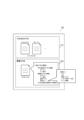
図2は、第1の実施形態に係る遠隔機器管理システムの概略の一例を示す図である。図2に示す遠隔機器管理システム1Aは、機器との通信に用いる通信プロトコルを柔軟に追加・変更することができるシステムである。また、遠隔機器管理システム1Aは、システム自体の変更を行わなくても、機器管理システム5Aが対応していない通信プロトコルを用いて通信を行う機器500と機器管理システム5Aとの通信を行うことができる。図2に示す遠隔機器管理システム1Aは、管理システム3および仲介装置30Aによって構成される機器管理システム5A、プロトコル変換装置10、並びに機器1および機器2(機器500)が含まれる。機器1は、HTTP(HyperText Transfer Protocol)の通信プロトコルに対応しており、仲介装置30Aと通信を行うことができる。一方、仲介装置30Aは、通常同一のネットワークに存在する機器500に対しては、同列に管理対象として通信することができるが、TCP/IPネットワークではない場合やHTTP/SNMP等の標準プロトコルをサポートしていない機器とは通信できないケースがある。機器2は、仲介装置30Aにインストールされている既存のファームウエアに組み込まれていない通信プロトコルが用いられるため、機器管理システム5Aとの通信を行うことができない。機器2は、例えば、ModbusTCPのプロトコルに対応している。 FIG. 2 is a schematic diagram illustrating an example of a remote device management system according to the first embodiment. The remote device management system 1A shown in FIG. 2 is a system that can flexibly add or change the communication protocol used for communication with devices. In addition, the remote device management system 1A can communicate with the device 500 that communicates using a communication protocol not supported by the device management system 5A without changing the system itself. can. A remote device management system 1A shown in FIG. 2 includes a device management system 5A configured by a management system 3 and an intermediary device 30A, a protocol conversion device 10, and devices 1 and 2 (devices 500). The device 1 is compatible with the HTTP (HyperText Transfer Protocol) communication protocol, and can communicate with the intermediary device 30A. On the other hand, the intermediary device 30A can communicate with devices 500 that normally exist on the same network as objects to be managed in the same manner, but supports standard protocols such as HTTP/SNMP when the network is not a TCP/IP network. It may not be possible to communicate with devices that do not The device 2 cannot communicate with the device management system 5A because it uses a communication protocol that is not incorporated in the existing firmware installed in the intermediary device 30A. The device 2 is compatible with the Modbus TCP protocol, for example.

そこで、図2に示すように、遠隔機器管理システム1Aは、機器管理システム5Aと機器2との間に、通信プロトコルを変換するプロトコル変換装置10を設けている。プロトコル変換装置10は、機器管理システム5Aが対応していない通信プロトコルを扱う機器500と、仲介装置Aとの通信を仲介する装置である。プロトコル変換装置10は、機器500と仲介装置30Aのそれぞれから受信したデータを、送信先が対応しているプロトコルに適したデータ形式に変換して送信する。図2の例において、プロトコル変換装置10は、例えば、仲介装置30Aとの間のHTTP通信によって受信したデータを、ModbusTCPに適したデータ形式に変換して、機器2へ送信する。プロトコル変換装置10は、ノートPC等の情報処理装置に機能を実装させることによって実現可能である。 Therefore, as shown in FIG. 2, the remote device management system 1A has a protocol conversion device 10 between the device management system 5A and the device 2 to convert the communication protocol. The protocol conversion device 10 is a device that mediates communication between the mediation device A and the device 500 that handles a communication protocol that is not supported by the device management system 5A. The protocol conversion device 10 converts the data received from each of the device 500 and the intermediary device 30A into a data format suitable for the protocol supported by the destination and transmits the data. In the example of FIG. 2, the protocol conversion device 10 converts data received through HTTP communication with the mediation device 30A into a data format suitable for ModbusTCP, and transmits the data to the device 2 . The protocol conversion device 10 can be realized by having an information processing device such as a notebook PC implement functions.

ここで、プロトコル変換装置10には、機器管理システム5Aと機器500との間で送受信されるデータのデータ形式を変換するためのプロトコル変換情報200が設定されている。プロトコル変換情報200は、プロトコルライブラリ210および設定ファイル250を含む。また、機器管理システム5Aは、プロトコル変換装置10に対して、設定ファイル250を遠隔で読み込ませる。プロトコル変換装置10は、読み込ませた設定ファイル250に基づいて、送受信するデータを、機器500の種別に応じた通信プロトコルに変換する。プロトコル変換装置10は、情報処理装置の一例である。 Protocol conversion information 200 for converting the data format of data transmitted and received between the device management system 5A and the device 500 is set in the protocol conversion device 10 . Protocol conversion information 200 includes protocol library 210 and configuration file 250 . Also, the device management system 5A causes the protocol conversion device 10 to read the setting file 250 remotely. The protocol conversion device 10 converts the data to be transmitted and received into a communication protocol according to the type of the device 500 based on the read setting file 250 . The protocol conversion device 10 is an example of an information processing device.

これにより、遠隔機器管理システム1Aは、機器管理システム5A自体のファームウエアの更新等の設定変更を行うことなく、プロトコル変換装置10にプロトコルライブラリ210および設定ファイル250を遠隔で読み込ませることで、通信プロトコルと動作定義を容易に追加変更することができる。また、遠隔機器管理システム1Aは、仲介装置30Aとプロトコル変換装置10がHTTP通信を行うため、機器500が位置する環境に合わせて、プロトコル変換装置10を任意の位置に設置することができる。さらに、遠隔機器管理システム1Aは、ノートPC等のローカルネットワーク7内に存在する汎用的な情報処理装置にプロトコル変換装置10の機能を実装させることができるので、既に機器管理システム5Aを運用している場合においても運用を停止させずに、本発明に係る機能を導入することができる。 As a result, the remote device management system 1A allows the protocol conversion device 10 to remotely read the protocol library 210 and the setting file 250 without changing the settings such as updating the firmware of the device management system 5A itself. Protocols and action definitions can be easily added and changed. Further, in the remote device management system 1A, since the mediating device 30A and the protocol conversion device 10 perform HTTP communication, the protocol conversion device 10 can be installed at an arbitrary position according to the environment in which the device 500 is located. Furthermore, since the remote device management system 1A can implement the function of the protocol conversion device 10 in a general-purpose information processing device such as a notebook PC existing in the local network 7, the device management system 5A is already in operation. It is possible to introduce the function according to the present invention without stopping the operation even when there is

●ハードウエア構成
続いて、第1の実施形態に係る各装置のハードウエア構成について説明する。遠隔機器管理システム1を構成する各装置は、一般的なコンピュータの構成を有する。ここでは、一般的なコンピュータのハードウエア構成例について説明する。
●Hardware Configuration Next, the hardware configuration of each device according to the first embodiment will be described. Each device constituting the remote device management system 1 has a general computer configuration. Here, an example of hardware configuration of a general computer will be described.

図3は、第1の実施形態に係るコンピュータのハードウエア構成の一例を示す図である。なお、図3に示すコンピュータ1000のハードウエア構成は、各実施形態において同様の構成を有していてもよく、必要に応じて構成要素が追加または削除されてもよい。コンピュータ1000は、CPU(Central Processing Unit)1001、ROM(Read Only Memory)1002、RAM(Random Access Memory)1003、ストレージ1004、キーボード1005、ディスプレイインターフェース(I/F)1006、メディアインターフェース(I/F)1007、ネットワークインターフェース(I/F)1008およびバス1009等を有する。 FIG. 3 is a diagram illustrating an example of a hardware configuration of a computer according to the first embodiment; Note that the hardware configuration of the computer 1000 shown in FIG. 3 may have the same configuration in each embodiment, and components may be added or deleted as necessary. Computer 1000 includes CPU (Central Processing Unit) 1001, ROM (Read Only Memory) 1002, RAM (Random Access Memory) 1003, storage 1004, keyboard 1005, display interface (I/F) 1006, media interface (I/F) 1007, a network interface (I/F) 1008, a bus 1009, and the like.

CPU1001は、ROM1002やストレージ1004等に格納されたプログラムやデータをRAM1003上に読み出し、処理を実行することで、コンピュータ1000の各機能を実現する演算装置である。例えば、プロトコル変換装置10は、本発明に係るプログラムをCPU1001で実行することで、本発明に係る通信方法を実現する。 The CPU 1001 is an arithmetic unit that implements each function of the computer 1000 by reading programs and data stored in the ROM 1002, storage 1004, etc. onto the RAM 1003 and executing processing. For example, the protocol conversion device 10 implements the communication method according to the present invention by executing the program according to the present invention on the CPU 1001 .

ROM1002は、電源を切ってもプログラムやデータを保持することができる不揮発性のメモリである。ROM1002は、例えば、フラッシュROM等により構成される。ROM1002は、多種の用途に対応したSDK(Software Development Kit)がインストールされており、SDKのアプリケーションを用いて、コンピュータ1000の機能やネットワーク接続等を実現することが可能である。 A ROM 1002 is a non-volatile memory that can retain programs and data even when the power is turned off. The ROM 1002 is composed of, for example, a flash ROM or the like. The ROM 1002 is installed with an SDK (Software Development Kit) corresponding to a variety of uses, and can realize the functions of the computer 1000, network connection, and the like using SDK applications.

RAM1003は、CPU1001のワークエリア等として用いられる揮発性のメモリである。ストレージ1004は、例えば、HDD(Hard Disk Drive)、SSD(Solid State Drive)等のストレージデバイスである。ストレージ1004は、例えば、OS(Operation System)、アプリケーションプログラムおよび各種データ等を記憶する。 A RAM 1003 is a volatile memory used as a work area or the like for the CPU 1001 . The storage 1004 is, for example, a storage device such as an HDD (Hard Disk Drive) or an SSD (Solid State Drive). The storage 1004 stores, for example, an OS (Operation System), application programs, various data, and the like.

キーボード1005は、文字、数値、各種指示等の入力のための複数のキーを備えた入力手段の一種である。入力手段は、キーボード1005のみならず、例えば、マウス、タッチパネルまたは音声入力装置等であってもよい。ディスプレイI/F1006は、LCD(Liquid Crystal Display)等のディスプレイ1006aに対するカーソル、メニュー、ウィンドウ、文字または画像等の各種情報の表示を制御する。ディスプレイ1006aは、入力手段を備えたタッチパネルディスプレイであってもよい。 A keyboard 1005 is a type of input means having a plurality of keys for inputting characters, numerical values, various instructions, and the like. Input means may be not only the keyboard 1005 but also a mouse, a touch panel, a voice input device, or the like. A display I/F 1006 controls display of various information such as cursors, menus, windows, characters, and images on a display 1006a such as an LCD (Liquid Crystal Display). The display 1006a may be a touch panel display with input means.

メディアI/F1007は、USB(Universal Serial Bus)メモリ、メモリカード、光学ディスクまたはフラッシュメモリ等の記録メディア1007aに対するデータの読み出しまたは書き込み(記憶)を制御する。 A media I/F 1007 controls reading or writing (storage) of data to a recording medium 1007a such as a USB (Universal Serial Bus) memory, memory card, optical disk, or flash memory.

ネットワークI/F1008は、コンピュータ1000をネットワークに接続し、他のコンピュータや、電子機器等とデータの送受信を行うためのインターフェースである。ネットワークI/F1008は、例えば、有線または無線LAN(Local Area Network)等の通信インターフェースである。また、ネットワークI/F1008は、3G(3rd Generation)、LTE(Long Term Evolution)、4G(4th Generation)、5G(5th Generation)、Zigbee(登録商標)、EnOcean、BLE(Bluetooth(登録商標)Low Energy)、NFC(Near Field Communication)、ミリ波無線通信、赤外線通信、QRコード(登録商標)、可視光、環境音または超音波等の通信インターフェースを備えてもよい。 A network I/F 1008 is an interface for connecting the computer 1000 to a network and transmitting/receiving data to/from other computers, electronic devices, and the like. A network I/F 1008 is, for example, a communication interface such as a wired or wireless LAN (Local Area Network). Network I/F 1008 supports 3G (3rd Generation), LTE (Long Term Evolution), 4G (4th Generation), 5G (5th Generation), Zigbee (registered trademark), EnOcean, BLE (Bluetooth (registered trademark) Low Energy ), NFC (Near Field Communication), millimeter wave wireless communication, infrared communication, QR code (registered trademark), visible light, environmental sound, ultrasonic waves, or other communication interfaces.

バスライン1009は、上記の各構成要素に共通に接続され、アドレス信号、データ信号、および各種制御信号等を伝送する。CPU1001、ROM1002、RAM1003、ストレージ1004、キーボード1005、ディスプレイI/F1006、メディアI/F1007およびネットワークI/F1008は、バスライン1009を介して相互に接続されている。 A bus line 1009 is commonly connected to each of the components described above, and transmits address signals, data signals, various control signals, and the like. CPU 1001 , ROM 1002 , RAM 1003 , storage 1004 , keyboard 1005 , display I/F 1006 , media I/F 1007 and network I/F 1008 are interconnected via bus line 1009 .

なお、第1の実施形態に係る各装置のハードウエア構成は、必要に応じて構成要素が追加または削除されてもよい。例えば、遠隔機器管理装置70は、キーボード1005等の入力手段およびディスプレイ1006aを備えていない構成であってもよい。また、機器500は、各機器の種別に応じた機能やサービスを提供するためのモジュール等を備える構成であってもよい。 Note that components may be added or deleted from the hardware configuration of each device according to the first embodiment as necessary. For example, the remote device management apparatus 70 may be configured without input means such as the keyboard 1005 and the display 1006a. Further, the device 500 may be configured to include a module or the like for providing functions and services according to the type of each device.

●機能構成
続いて、第1の実施形態に係る遠隔機器管理システムの機能構成について説明する。まず、図4を用いて、管理システム3を構成する遠隔機器管理装置70および管理者端末90の機能構成を説明する。図4は、第1の実施形態に係る管理システムの機能構成の一例を示す図である。図4に示す遠隔機器管理装置70により実現される機能は、仲介装置通信部71、コマンド管理部72、判断部73、ファイル管理部74、通信管理部75、Webサーバ部76、記憶・読出部77および記憶部800を含む。
●Functional Configuration Next, the functional configuration of the remote device management system according to the first embodiment will be described. First, with reference to FIG. 4, the functional configurations of the remote device management device 70 and the administrator terminal 90 that constitute the management system 3 will be described. FIG. 4 is a diagram illustrating an example of a functional configuration of a management system according to the first embodiment; Functions realized by the remote device management device 70 shown in FIG. 77 and storage unit 800 .

仲介装置通信部71は、仲介装置30Aとの間で各種データ(情報)をやり取りする機能である。仲介装置通信部71は、ローカルネットワーク7の内部に位置する仲介装置30Aとの間のファイアウォ-ル9を経由した通信を制御する。仲介装置通信部11は、仲介装置30Aから送信された遠隔機器管理装置70へのポーリングを受信し、当該ポーリングに対する応答を仲介装置30Aへ送信する。または、仲介装置通信部11は、仲介装置30Aから遠隔機器管理装置70に対して常時通信可能なように通信セッション(WebSocket等)を維持しておき、仲介装置30Aとの間で、各種データ(情報)を送受信する。本実施形態では、どちらの方法をとってもよい。 The intermediary device communication unit 71 is a function that exchanges various data (information) with the intermediary device 30A. The mediation device communication unit 71 controls communication via the firewall 9 with the mediation device 30A located inside the local network 7 . Intermediation device communication unit 11 receives polling for remote device management device 70 transmitted from intermediary device 30A, and transmits a response to the polling to intermediary device 30A. Alternatively, the mediation device communication unit 11 maintains a communication session (WebSocket, etc.) so that the mediation device 30A can always communicate with the remote device management device 70, and exchanges various data (such as WebSocket) with the mediation device 30A. information). Either method may be used in this embodiment.

仲介装置通信部71は、例えば、Webサーバ部76によって発行されたコマンドを、仲介装置30Aへ送信する。仲介装置通信部71から送信されるコマンドは、例えば、機器500に対する所定の要求を示す要求情報の一例である。仲介装置30Aから遠隔機器管理装置70に対して常時通信可能な通信セッション(WebSocket等)でない場合、遠隔機器管理装置70は、Webサーバ部76によって発行されたコマンドを、未送信または送信完了といったステータスでコマンドの送信状態を管理する。また、仲介装置通信部71は、仲介装置30Aへ送信したコマンドに対する応答、または機器500から自発的に送信された機器500のステータスを示す状態情報等の機器情報を、仲介装置30Aから受信する。受信された情報は、Webサーバ部76に送信され、Webクライアントを用いて管理者端末90に表示される。仲介装置通信部71は、例えば、図3に示したネットワークI/F1008およびCPU1001で実行されるプログラム等により実現される。仲介装置通信部71は、ファイル送信手段の一例である。また、仲介装置通信部71は、ファイル受信手段の一例である。 The mediation device communication unit 71, for example, transmits a command issued by the web server unit 76 to the mediation device 30A. The command transmitted from the intermediary device communication unit 71 is an example of request information indicating a predetermined request to the device 500, for example. If the communication session (WebSocket, etc.) that allows constant communication from the intermediation device 30A to the remote device management device 70 is not established, the remote device management device 70 returns the command issued by the Web server unit 76 to a status such as not yet transmitted or transmission completed. to manage the command transmission status. Intermediary device communication unit 71 also receives, from intermediary device 30A, response to a command transmitted to intermediation device 30A, or device information such as state information indicating the status of device 500 spontaneously transmitted from device 500. FIG. The received information is transmitted to the web server section 76 and displayed on the administrator terminal 90 using the web client. Intermediary device communication unit 71 is implemented by, for example, a program or the like executed by network I/F 1008 and CPU 1001 shown in FIG. The intermediary device communication unit 71 is an example of file transmission means. Also, the intermediary device communication unit 71 is an example of a file receiving unit.

コマンド管理部72は、仲介装置30Aまたは機器500に対する所定の要求であるコマンドを管理する機能である。コマンド管理部72は、Webサーバ部76によって生成されたコマンド、および仲介装置30または機器500によるコマンドの実行結果を管理する。コマンド管理部72は、例えば、図3に示したCPU1001で実行されるプログラム等により実現される。 The command management unit 72 has a function of managing commands, which are predetermined requests to the intermediary device 30A or the device 500 . The command management unit 72 manages commands generated by the web server unit 76 and command execution results by the intermediary device 30 or the device 500 . The command management unit 72 is implemented by, for example, a program or the like executed by the CPU 1001 shown in FIG.

判断部73は、管理(監視)対象の機器500から送信される機器情報に基づいて、機器500の状態を判断する機能である。判断部73は、例えば、図3に示したCPU1001で実行されるプログラム等により実現される。 The determination unit 73 has a function of determining the state of the device 500 based on the device information transmitted from the device 500 to be managed (monitored). The determination unit 73 is implemented by, for example, a program or the like executed by the CPU 1001 shown in FIG.

ファイル管理部74は、遠隔機器管理装置70にアップロードされたファイルを管理する機能である。ファイル管理部74は、例えば、後述するファイル管理テーブル830に、アップロードされた設定用ファイルとファイルIDとを関連づけて記憶・管理する。ファイル管理部74は、例えば、図3に示したCPU1001で実行されるプログラム等により実現される。ファイル管理部74は、ファイル管理手段の一例である。 The file management unit 74 has a function of managing files uploaded to the remote device management device 70 . The file management unit 74 stores and manages the uploaded setting file and the file ID in association with each other, for example, in a file management table 830, which will be described later. The file management unit 74 is implemented by, for example, a program or the like executed by the CPU 1001 shown in FIG. The file management unit 74 is an example of file management means.

通信管理部75は、ローカルネットワーク7に存在する仲介装置30および機器500との通信を管理する機能である。通信管理部75は、例えば、図3に示したCPU1001で実行されるプログラム等により実現される。 The communication management unit 75 has a function of managing communication with the intermediary device 30 and the device 500 existing in the local network 7 . The communication management unit 75 is implemented by, for example, a program or the like executed by the CPU 1001 shown in FIG.

Webサーバ部76は、Webアプリケーションのサーバ部としての機能を担う機能である。Webサーバ部76は、Webクライアント部91からの要求をHTTPS(HyperText Transfer Protocol Secure)等の通信プロトコルを利用してWebAPI(Web Application Programming Interface)で受け付け、要求に従った処理を行ってWebクライアント部91へ応答する。利用される通信プロトコルは、これに限られず、FTP(File Transfer Protocol)、HTTPまたはSNMP(Simple Network Management Protocol)等のプロトコルを用いてもよい。また、Webサーバ部76は、遠隔機器管理装置70から仲介装置30Aや機器500との通信が必要な場合に、仲介装置30Aまたは機器500に送信するコマンドを発行(生成)する。発行されるコマンドは、機器500のステータスを示す状態情報の取得または電源のON/OFF等の制御命令である。これらのコマンドは、機器500に対する所定の要求を示す要求情報の一例である。Webサーバ部76は、仲介装置通信部71によって受信されたコマンド結果を、Webクライアント部91の画面上にリアルタイムに通知するためにWebSocket等の機能を有していてもよい。Webサーバ部76は、例えば、図3に示したCPU1001で実行されるプログラム等により実現される。 The web server unit 76 is a function that functions as a server unit for web applications. The web server unit 76 accepts a request from the web client unit 91 through a Web API (Web Application Programming Interface) using a communication protocol such as HTTPS (HyperText Transfer Protocol Secure), performs processing according to the request, and sends the request to the web client unit. 91. The communication protocol used is not limited to this, and a protocol such as FTP (File Transfer Protocol), HTTP or SNMP (Simple Network Management Protocol) may be used. Further, the Web server unit 76 issues (generates) a command to be transmitted to the mediation device 30A or the device 500 when the remote device management device 70 needs to communicate with the mediation device 30A or the device 500 . The command to be issued is a control instruction such as acquisition of state information indicating the status of the device 500 or power ON/OFF. These commands are examples of request information indicating predetermined requests to the device 500 . The Web server unit 76 may have a function such as WebSocket for notifying the screen of the Web client unit 91 in real time of the command result received by the intermediary device communication unit 71 . The web server unit 76 is implemented by, for example, a program or the like executed by the CPU 1001 shown in FIG.

記憶・読出部77は、記憶部800に各種データを記憶し、記憶部800から各種データを読み出す機能である。記憶・読出部77および記憶部800は、例えば、図3に示したCPU1001で実行されるプログラム等により実現される。また、記憶部800は、図3に示したROM1002またはストレージ1004によって実現される。さらに、記憶部800は、仲介装置30Aに関する各種情報を記憶・管理する仲介装置管理テーブル810、および遠隔機器管理装置70にアップロードされたファイルを記憶・管理するファイル管理テーブル830を記憶している。 The storage/readout unit 77 has a function of storing various data in the storage unit 800 and reading out various data from the storage unit 800 . The storage/readout unit 77 and the storage unit 800 are realized by, for example, a program or the like executed by the CPU 1001 shown in FIG. Storage unit 800 is realized by ROM 1002 or storage 1004 shown in FIG. Further, the storage unit 800 stores an intermediate device management table 810 that stores and manages various types of information about the intermediate device 30A, and a file management table 830 that stores and manages files uploaded to the remote device management device .

続いて、管理者端末90の機能構成について説明する。図4に示す管理者端末90により実現される機能は、Webクライアント部91および受付部92を含む。 Next, the functional configuration of the administrator terminal 90 will be described. Functions implemented by the administrator terminal 90 shown in FIG. 4 include a web client section 91 and a reception section 92 .

Webクライアント部91は、Webアプリケーションのクライアント部としての役割を担う機能である。Webクライアント部91は、Webブラウザで動作するHTML(Hyper Text Markup Language)、またはJavaScript(登録商標)、CSS(Cascading Style Sheets)といった言語で記述されたプログラムが実行されることによって実現される。Webクライアント部91は、例えば、機器500の機器情報の閲覧画面、仲介装置30Aおよびプロトコル変換装置10の設定を変更する設定変更画面等を、管理者端末90のディスプレイ1006aに表示させる。Webクライアント部91は、例えば、図3に示したネットワークI/F1008およびCPU1001で実行されるプログラム等により実現される。 The web client unit 91 is a function that plays a role as a web application client unit. The Web client unit 91 is implemented by executing a program written in a language such as HTML (Hyper Text Markup Language), JavaScript (registered trademark), or CSS (Cascading Style Sheets) that operates on a Web browser. The Web client unit 91 causes the display 1006a of the administrator terminal 90 to display, for example, a device information browsing screen of the device 500, a setting change screen for changing settings of the intermediary device 30A and the protocol conversion device 10, and the like. The Web client unit 91 is realized by, for example, a program or the like executed by the network I/F 1008 and the CPU 1001 shown in FIG.

受付部92は、図3に示したキーボード1005等の入力手段に対するユーザ入力を受け付ける機能である。受付部92は、例えば、Webクライアント部91によってディスプレイ1006aに表示された表示画面に示される各種項目に対する選択を受け付ける。受付部92は、例えば、図3に示したキーボード1005およびCPU1001で実行されるプログラム等によって実現される。 The receiving unit 92 has a function of receiving user input to input means such as the keyboard 1005 shown in FIG. The accepting unit 92 accepts selections of various items displayed on the display screen displayed on the display 1006a by the Web client unit 91, for example. The reception unit 92 is implemented by, for example, a program or the like executed by the keyboard 1005 and the CPU 1001 shown in FIG.

続いて、図5を用いて、ローカルネットワーク7に属する各装置の機能構成を説明する。図5は、第1の実施形態に係る仲介装置および機器の機能構成の一例を示す図である。図5に示す仲介装置30Aにより実現される機能は、管理装置通信部31、機器通信部32、受付部33、表示制御部34、機器情報管理部35、通信管理部36、コマンド実行部37、記憶・読出部38および記憶部300を含む。 Next, the functional configuration of each device belonging to the local network 7 will be described with reference to FIG. FIG. 5 is a diagram illustrating an example of a functional configuration of an intermediary device and equipment according to the first embodiment; Functions realized by the intermediary device 30A shown in FIG. A storage/readout unit 38 and a storage unit 300 are included.

管理装置通信部31は、遠隔機器管理装置70との間で各種データ(情報)をやり取りする機能である。管理装置通信部31は、例えば、遠隔機器管理装置70から送信された機器500に対して所定の処理の実行を要求するコマンドを受信する。また、管理装置通信部31は、例えば、遠隔機器管理装置70から送信されたコマンドに対する応答(処理の実行結果)を、遠隔機器管理装置70へ送信する。さらに、管理装置通信部31は、仲介装置30または機器500の状態を示す状態情報等の装置情報または機器情報を、遠隔機器管理装置70へ送信する。管理装置通信部31は、例えば、図3に示すネットワークI/F1008およびCPU1001で実行されるプログラム等により実現される。 The management device communication unit 31 is a function that exchanges various data (information) with the remote device management device 70 . The management device communication unit 31 receives, for example, a command from the remote device management device 70 requesting the device 500 to execute a predetermined process. The management device communication unit 31 also transmits, for example, a response (process execution result) to a command transmitted from the remote device management device 70 to the remote device management device 70 . Furthermore, the management device communication unit 31 transmits device information or device information such as state information indicating the state of the intermediary device 30 or the device 500 to the remote device management device 70 . The management device communication unit 31 is implemented by, for example, a program executed by the network I/F 1008 and the CPU 1001 shown in FIG.

機器通信部32は、機器500との間で各種データ(情報)をやり取りする機能である。機器通信部32は、通信管理部36によって管理される動作種別、通信プロトコルおよびパラメータを用いて、機器500と通信を行う。機器通信部32は、例えば、管理装置通信部31によって受信されたコマンドを、機器500へ送信する。また、機器通信部32は、例えば、機器500から送信された、コマンドに対する応答を受信する。 The device communication unit 32 has a function of exchanging various data (information) with the device 500 . The device communication unit 32 communicates with the device 500 using the operation type, communication protocol and parameters managed by the communication management unit 36 . The device communication unit 32 , for example, transmits commands received by the management device communication unit 31 to the device 500 . Also, the device communication unit 32 receives, for example, a response to a command transmitted from the device 500 .

さらに、機器通信部32は、ローカルネットワーク7内に存在するプロトコル変換装置10と通信を行う。機器通信部32は、例えば、図3に示すネットワークI/F1008およびCPU1001で実行されるプログラム等により実現される。 Furthermore, the device communication unit 32 communicates with the protocol conversion device 10 existing within the local network 7 . The device communication unit 32 is realized by, for example, a program executed by the network I/F 1008 and the CPU 1001 shown in FIG.

受付部33は、図3に示したキーボード1005等の入力手段に対するユーザ入力を受け付ける機能である。受付部33は、例えば、図3に示したキーボード1005およびCPU1001で実行されるプログラム等によって実現される。表示制御部34は、図3に示したディスプレイ1006aに各種画面情報を表示させる機能である。表示制御部34は、例えば、ユーザによる入力操作を受け付ける操作画面等を、ディスプレイ1006aに表示させる。表示制御部34によって表示される表示画面は、例えば、仲介装置30Aをローカルネットワーク7に設置するために必要な設定を行うためのUI(user interface)である。仲介装置30Aは、表示制御部34によって表示されるUIを用いて、ネットワーク通信するためのIPアドレス、サブネットマスクもしくはデフォルトゲートウェイ等のパラメータ、および遠隔機器管理装置70のURLもしくはプロキシサーバ(認証サーバ)等の設定を行う。また、仲介装置30Aは、表示制御部34によって表示されるUIを用いて、遠隔機器管理装置70との疎通確認、および通信を開始するための手続きを実行する。表示制御部34は、例えば、図3に示すCPU1001で実行されるプログラム等により実現される。 The receiving unit 33 has a function of receiving user input to input means such as the keyboard 1005 shown in FIG. The reception unit 33 is implemented by, for example, a program or the like executed by the keyboard 1005 and the CPU 1001 shown in FIG. The display control unit 34 has a function of displaying various screen information on the display 1006a shown in FIG. The display control unit 34 causes the display 1006a to display, for example, an operation screen for receiving an input operation by the user. The display screen displayed by the display control unit 34 is, for example, a UI (user interface) for making settings necessary for installing the intermediary device 30A in the local network 7 . The intermediary device 30A uses the UI displayed by the display control unit 34 to display parameters such as an IP address, subnet mask or default gateway for network communication, and the URL or proxy server (authentication server) of the remote device management device 70. etc. In addition, the intermediary device 30A uses the UI displayed by the display control unit 34 to confirm communication with the remote device management device 70 and execute procedures for starting communication. The display control unit 34 is implemented by, for example, a program or the like executed by the CPU 1001 shown in FIG.

機器情報管理部35は、仲介装置30Aと通信可能な機器500に関する機器情報を管理する機能である。機器情報管理部35は、例えば、機器500へ機器情報の取得要求を送信するタスクスケジュールを管理する。また、機器情報管理部35は、例えば、機器500から送信された機器500の状態を示す状態情報に基づいて、機器500の状態を管理する。 The device information management unit 35 is a function that manages device information regarding the device 500 that can communicate with the intermediary device 30A. The device information management unit 35 manages, for example, a task schedule for transmitting a device information acquisition request to the device 500 . The device information management unit 35 also manages the state of the device 500 based on, for example, state information indicating the state of the device 500 transmitted from the device 500 .

さらに、機器情報管理部35は、仲介装置30Aのリソース状態を管理する。機器情報管理部35は、例えば、仲介装置30Aのメモリ不足、ストレージ不足、または書き込みエラー等の障害(異常)の兆候を検知する。また、機器情報管理部35は、例えば、予め設定されたスケジュールに基づいて、定期的にリソース状態の監視結果を含む仲介装置30Aの状態情報を生成する。機器情報管理部35は、例えば、図3に示したCPU1001により実行されるプログラム等によって実現される。 Furthermore, the device information management unit 35 manages the resource status of the mediation device 30A. The device information management unit 35 detects signs of failure (abnormality) such as memory shortage, storage shortage, or write error of the intermediary device 30A, for example. In addition, the device information management unit 35 periodically generates state information of the intermediary device 30A including resource state monitoring results, for example, based on a preset schedule. The device information management unit 35 is implemented by, for example, a program or the like executed by the CPU 1001 shown in FIG.

通信管理部36は、ローカルネットワーク7に属する機器500と通信するための通信定義を管理する機能である。通信管理部36は、例えば、機器500との通信に用いる動作種別、通信プロトコルおよびパラメータを管理する。例えば、動作種別は、機器500の識別子(シリアル番号)の取得、機器500の状態情報の取得、遠隔機器管理装置70との疎通確認、管理対象(監視対象)の機器500の追加または削除等である。通信プロトコルは、HTTP、SNMPまたはICMP(Ping)等の標準プロトコルのみならず、ModBusまたは独自プロトコル等の既存のファームウエアに組み込まれている通信プロトコル以外の通信プロトコルも含む。パラメータは、各通信プロトコルに共通なものとしてタイムアウト時間またはリトライ回数があり、HTTP特有なパラメータとしてメソッド、リソースURI(Uniform Resource Identifier)、ヘッダまたはボディ、SNMP特有なパラメータとしてOID(オブジェクト識別子)、バージョン、コマンド種別、またはコミュニティ名等である。通信管理部36は、例えば、図3に示したCPU1001により実行されるプログラム等によって実現される。 The communication management unit 36 has a function of managing communication definitions for communicating with the devices 500 belonging to the local network 7 . The communication management unit 36 manages, for example, operation types, communication protocols, and parameters used for communication with the device 500 . For example, the type of operation is acquisition of the identifier (serial number) of the device 500, acquisition of status information of the device 500, confirmation of communication with the remote device management device 70, addition or deletion of the device 500 to be managed (monitored), and the like. be. Communication protocols include not only standard protocols such as HTTP, SNMP or ICMP (Ping), but also communication protocols other than those built into existing firmware, such as ModBus or proprietary protocols. The parameters include timeout time or retry count as common to each communication protocol, method, resource URI (Uniform Resource Identifier), header or body as parameters specific to HTTP, and OID (object identifier) and version as parameters specific to SNMP. , command type, or community name. The communication manager 36 is implemented by, for example, a program executed by the CPU 1001 shown in FIG.

コマンド実行部37は、遠隔機器管理装置70によって発行された仲介装置30Aへの所定の処理の命令であるコマンドを実行する機能である。コマンドは、例えば、仲介装置30Aのステータスを示す状態情報等の機器情報の取得または電源のON/OFF等の制御命令である。コマンド実行部37は、例えば、図3に示すCPU1001で実行されるプログラム等により実現される。 The command execution unit 37 has a function of executing a command issued by the remote device management device 70 to the intermediary device 30A for a predetermined process. The command is, for example, a control instruction such as acquisition of device information such as state information indicating the status of the intermediary device 30A or power ON/OFF. The command execution unit 37 is implemented by, for example, a program or the like executed by the CPU 1001 shown in FIG.

記憶・読出部38は、記憶部300に各種データを記憶し、記憶部300から各種データを読み出す機能である。記憶・読出部38および記憶部300は、例えば、図3に示すROM1002、ストレージ1004およびCPU1001で実行されるプログラム等により実現される。記憶部300は、機器管理テーブル310を記憶している。機器管理テーブル310の詳細は、後述する。また、記憶部300は、プロトコル変換装置10を識別するための変換装置識別情報330を記憶している。変換装置識別情報330は、例えば、プロトコル変換装置10のIPアドレスである。 The storage/readout unit 38 has a function of storing various data in the storage unit 300 and reading out various data from the storage unit 300 . The storage/readout unit 38 and the storage unit 300 are realized by, for example, programs executed by the ROM 1002, the storage 1004, and the CPU 1001 shown in FIG. The storage unit 300 stores a device management table 310. FIG. Details of the device management table 310 will be described later. The storage unit 300 also stores conversion device identification information 330 for identifying the protocol conversion device 10 . The conversion device identification information 330 is, for example, the IP address of the protocol conversion device 10 .

続いて、プロトコル変換装置10の機能構成について説明する。図5に示すプロトコル変換装置10により実現される機能は、仲介装置通信部11、機器通信部12、プロトコル変換部13、設定部14、記憶・読出部15および記憶部100を含む。 Next, the functional configuration of the protocol conversion device 10 will be described. Functions implemented by the protocol conversion device 10 shown in FIG.

仲介装置通信部11は、仲介装置30Aとの間で各種データ(情報)をやり取りする機能である。仲介装置通信部11は、例えば、後述するプロトコル変換情報200に含まれる設定ファイル250に記述された仲介装置30Aのアクセス情報を用いて、仲介装置30Aと通信を行う。仲介装置通信部11は、HTTPまたはSNMP等の通信プロトコルを用いて、仲介装置30Aと通信を行う。仲介装置通信部11は、例えば、図3に示すネットワークI/F1008およびCPU1001で実行されるプログラム等により実現される。仲介装置通信部11は、受信手段の一例である。仲介装置通信部11は、送信手段の一例である。 The mediation device communication unit 11 is a function that exchanges various data (information) with the mediation device 30A. The mediation device communication unit 11 communicates with the mediation device 30A using, for example, the access information of the mediation device 30A described in the setting file 250 included in the protocol conversion information 200 described later. The mediation device communication unit 11 communicates with the mediation device 30A using a communication protocol such as HTTP or SNMP. Intermediary device communication unit 11 is realized by, for example, a program executed by network I/F 1008 and CPU 1001 shown in FIG. Intermediary device communication unit 11 is an example of receiving means. Intermediary device communication unit 11 is an example of a transmission unit.

機器通信部12は、例えば、後述するプロトコル変換情報200に含まれる設定ファイル250に記述されたアクセス情報、およびプロトコル変換情報200に含まれるプロトコルライブラリ210に基づいて、機器500との通信を行う。機器通信部12は、例えば、図3に示したネットワークI/F1008およびCPU1001で実行されるプログラム等により実現される。機器通信部12は、機器通信手段の一例である。 The device communication unit 12 communicates with the device 500 based on, for example, the access information described in the setting file 250 included in the protocol conversion information 200 described below and the protocol library 210 included in the protocol conversion information 200 . The device communication unit 12 is realized by, for example, a program executed by the network I/F 1008 and the CPU 1001 shown in FIG. The device communication unit 12 is an example of device communication means.

プロトコル変換部13は、仲介装置30Aと機器500との間で送受信されるデータのプロトコル変換を行う機能である。プロトコル変換部13は、例えば、設定部14によって設定されたプロトコル変換情報200に含まれる設定ファイル250に記述された動作定義に応じて、仲介装置30Aと機器500との間で通信されるデータのデータ形式を変換する。プロトコル変換部13は、例えば、設定ファイル250に記述された動作定義に応じて、データの送信先が対応している通信プロトコルのデータ形式に、送受信されるデータのプロトコル変換を行う。プロトコル変換部13は、例えば、図3に示したCPU1001で実行されるプログラム等により実現される。プロトコル変換部13は、変換手段の一例である。 The protocol conversion unit 13 has a function of converting the protocol of data transmitted and received between the intermediary device 30A and the device 500 . The protocol conversion unit 13 converts data communicated between the intermediary device 30A and the device 500 according to, for example, the operation definition described in the setting file 250 included in the protocol conversion information 200 set by the setting unit 14. Convert data format. The protocol conversion unit 13 converts the protocol of the data to be transmitted/received into the data format of the communication protocol supported by the data transmission destination, for example, according to the operation definition described in the setting file 250 . The protocol converter 13 is implemented by, for example, a program or the like executed by the CPU 1001 shown in FIG. The protocol converter 13 is an example of conversion means.

設定部14は、送受信されるデータのプロトコル変換を行うためのプロトコル変換情報200を設定する機能である。設定部14は、例えば、図3に示したCPU1001で実行されるプログラム等により実現される。設定部14は、記憶制御手段の一例である。 The setting unit 14 has a function of setting protocol conversion information 200 for protocol conversion of data to be transmitted and received. The setting unit 14 is implemented, for example, by a program or the like executed by the CPU 1001 shown in FIG. The setting unit 14 is an example of storage control means.

記憶・読出部15は、記憶部100に各種データを記憶し、記憶部100から各種データを読み出す機能である。記憶・読出部15および記憶部100は、例えば、図3に示すROM1002、ストレージ1004およびCPU1001で実行されるプログラム等により実現される。記憶部100は、プロトコル変換情報200を記憶している。プロトコル変換情報200の詳細は、後述する。 The storage/readout unit 15 has a function of storing various data in the storage unit 100 and reading out various data from the storage unit 100 . The storage/readout unit 15 and the storage unit 100 are realized by, for example, programs executed by the ROM 1002, the storage 1004, and the CPU 1001 shown in FIG. The storage unit 100 stores protocol conversion information 200 . Details of the protocol conversion information 200 will be described later.

続いて、機器500の機能構成について説明する。図5に示す機器500により実現される機能は、通信部501、機器情報生成部502、コマンド実行部503、記憶・読出部504および記憶部600を含む。 Next, the functional configuration of device 500 will be described. Functions implemented by the device 500 shown in FIG.

通信部501は、仲介装置30Aとの間でデータをやり取りする機能である。通信部501は、HTTPまたはSNMP等の通信プロトコルを用いて、仲介装置30Aと通信を行う。通信部501による通信方式は、特に限定されず、例えば、TCP/IP通信であってもよいし、機器500の種別に応じた独自のプロトコルを用いた通信方式であってもよい。通信部501は、例えば、図3に示すネットワークI/F1008およびCPU1001で実行されるプログラム等により実現される。 The communication unit 501 is a function that exchanges data with the mediation device 30A. The communication unit 501 communicates with the mediation device 30A using a communication protocol such as HTTP or SNMP. A communication method by the communication unit 501 is not particularly limited, and may be, for example, TCP/IP communication or a communication method using a unique protocol according to the type of the device 500 . The communication unit 501 is realized by, for example, a program executed by the network I/F 1008 and the CPU 1001 shown in FIG.

機器情報生成部502は、機器500のステータスを示す状態情報等の機器情報を生成する機能である。機器情報生成部502は、例えば、仲介装置30Aからの要求に応じて、仲介装置30Aへ送信するための状態情報を生成する。状態情報は、機器500のリソース状態を示す情報や稼働状態に関する情報を含むログ情報等の機器情報である。機器情報生成部502は、例えば、図3に示すCPU1001で実行されるプログラム等により実現される。 The device information generation unit 502 is a function that generates device information such as state information indicating the status of the device 500 . The device information generation unit 502 generates status information to be transmitted to the mediation device 30A, for example, in response to a request from the mediation device 30A. The state information is device information such as information indicating the resource state of the device 500 and log information including information about the operating state. The device information generation unit 502 is implemented by, for example, a program or the like executed by the CPU 1001 shown in FIG.

コマンド実行部503は、遠隔機器管理装置70によって発行された機器500への所定の処理の命令であるコマンドを実行する機能である。コマンドは、例えば、機器500のステータスを示す状態情報等の機器情報の取得または電源のON/OFF等の制御命令である。コマンド実行部503は、例えば、図3に示すCPU1001で実行されるプログラム等により実現される。 The command execution unit 503 has a function of executing a command issued by the remote device management apparatus 70 to the device 500 for a predetermined process. The command is, for example, a control instruction such as acquisition of device information such as state information indicating the status of the device 500 or power ON/OFF. The command execution unit 503 is implemented by, for example, a program or the like executed by the CPU 1001 shown in FIG.

記憶・読出部504は、記憶部600に各種データを記憶し、記憶部600から各種データを読み出す機能である。記憶・読出部504および記憶部600は、例えば、図3に示すROM1002、ストレージ1004およびCPU1001で実行されるプログラム等により実現される。記憶部600は、プロトコル変換装置10を識別するための変換装置識別情報610を記憶している。変換装置識別情報610は、例えば、プロトコル変換装置10のIPアドレスである。 The storage/readout unit 504 has a function of storing various data in the storage unit 600 and reading out various data from the storage unit 600 . The storage/readout unit 504 and the storage unit 600 are implemented by, for example, programs executed by the ROM 1002, the storage 1004, and the CPU 1001 shown in FIG. The storage unit 600 stores conversion device identification information 610 for identifying the protocol conversion device 10 . The conversion device identification information 610 is, for example, the IP address of the protocol conversion device 10 .

○通信定義○
ここで、図6を用いて、機器500からの通信に用いる通信定義について説明する。図6は、第1の実施形態に係る機器との通信に用いる通信定義の概略モデルの一例を示す図である。遠隔機器管理装置70の監視対象(管理対象)である機器500(管理対象機器)は、機器500の種別を示すモデル名、機器500の機器識別子であるシリアルNo、機器500を識別するための機器ID、機器500のステータスを示す状態情報、および遠隔機器管理装置70が機器500を管理対象とするかを示す管理対象情報を送信する。遠隔機器管理装置70は、機器500から送信されるモデル名およびシリアルNoを用いて、機器500を特定することができる。また、機器IDは、モデル名とシリアルNoを含む。なお、機器IDは、モデル名とシリアルNoとは異なる情報であり、機器IDを用いて機器500が特定される構成であってもよい。
○Communication definition○
Here, a communication definition used for communication from the device 500 will be described with reference to FIG. FIG. 6 is a diagram showing an example of a schematic model of communication definitions used for communication with devices according to the first embodiment. A device 500 (managed device) to be monitored (managed) by the remote device management apparatus 70 has a model name indicating the type of the device 500, a serial number as a device identifier of the device 500, and a device for identifying the device 500. ID, status information indicating the status of the device 500, and management target information indicating whether the remote device management apparatus 70 treats the device 500 as a management target are transmitted. The remote device management apparatus 70 can identify the device 500 using the model name and serial number transmitted from the device 500 . Also, the device ID includes the model name and serial number. Note that the device ID is information different from the model name and the serial number, and the device 500 may be specified using the device ID.

また、機器500(管理対象機器)は、動作定義として、機器種別ごとに複数の動作種別を有している。動作種別とは、例えば、機器500の機器識別子(シリアルNo)の取得、状態情報の取得、仲介装置30との疎通確認、管理対象の機器500の追加または削除等である。 In addition, the device 500 (managed device) has a plurality of operation types for each device type as operation definitions. The operation type is, for example, acquisition of the device identifier (serial number) of the device 500, acquisition of status information, confirmation of communication with the intermediary device 30, addition or deletion of the device 500 to be managed, and the like.

さらに、各動作種別は、複数の通信プロトコルから構成される。機器500において使用できる通信プロトコルは、ICMP(Ping)、SNMPまたはHTTP(ボディ部はJSON(Java(登録商標)Script Object Notation))等の標準プロトコルであり、各通信プロトコルは、一つにつき一回の通信を意味する。つまり、機器500は、一つの動作種別に対して複数回の通信を行う構成とすることができる。パラメータは、例えば、共通なものとしてタイムアウト時間やリトライ回数を含み、HTTP特有なパラメータとして、メソッド、リソースURI、ヘッダ、ボディ等を含む。また、SNMP特有なパラメータは、例えば、OID(オブジェクト識別子)、バージョン、コマンド種別(Get/GetBulk)、コミュニティ名等を含む。 Furthermore, each operation type is composed of a plurality of communication protocols. The communication protocol that can be used in the device 500 is a standard protocol such as ICMP (Ping), SNMP or HTTP (the body part is JSON (Java (registered trademark) Script Object Notation)). means the communication of That is, the device 500 can be configured to perform communication multiple times for one operation type. The parameters include, for example, timeout time and retry count as common parameters, and methods, resource URIs, headers, bodies, etc. as HTTP-specific parameters. SNMP-specific parameters include, for example, OID (object identifier), version, command type (Get/GetBulk), community name, and the like.

このように、機器500は、図6に示す通信定義を用いて、仲介装置30Aおよび遠隔機器管理装置70との通信を行う。これによって、遠隔機器管理システム1Aは、ローカルネットワーク7に属する機器500を、遠隔機器管理装置70側で識別することができる。 In this way, the device 500 communicates with the intermediary device 30A and the remote device management device 70 using the communication definition shown in FIG. As a result, the remote device management system 1A can identify the device 500 belonging to the local network 7 on the remote device management device 70 side.

○仲介装置管理テーブル○
図7は、第1の実施形態に係る仲介装置管理テーブルの一例を示す図である。仲介装置管理テーブル810は、遠隔機器管理装置70の記憶部800に記憶・管理されている。仲介装置管理テーブル810は、遠隔機器管理装置70とファイアウォール9を介して通信可能な仲介装置30Aに関する各種情報を記憶している。
○ Intermediary device management table ○
FIG. 7 is a diagram illustrating an example of an intermediary device management table according to the first embodiment; The intermediary device management table 810 is stored and managed in the storage unit 800 of the remote device management device 70 . The intermediary device management table 810 stores various information regarding the intermediary device 30A that can communicate with the remote device management device 70 via the firewall 9 .

仲介装置管理テーブル810は、仲介装置名、登録番号、仲介装置30Aが設置されたローカルネットワーク7を識別するためのネットワーク識別情報の一例であるネットワーク名、仲介装置30Aの宛先を示す宛先情報の一例であるIPアドレス、および仲介装置30Aと通信可能な機器500を識別するための機器IDを関連づけて記憶している。仲介装置管理テーブル810において関連づけられている仲介装置名、登録番号、ネットワーク名、IPアドレスおよび機器IDは、仲介装置設定情報を構成する。遠隔機器管理装置70は、仲介装置管理テーブル810を用いて、仲介装置30Aの宛先情報(IPアドレス)と、仲介装置30Aと通信可能な機器500を特定することができる。なお、仲介装置名および登録番号は、仲介装置識別情報の一例である。 The intermediation device management table 810 includes an intermediation device name, a registration number, a network name that is an example of network identification information for identifying the local network 7 in which the intermediation device 30A is installed, and an example of destination information that indicates the destination of the intermediation device 30A. and the device ID for identifying the device 500 that can communicate with the intermediary device 30A are stored in association with each other. The intermediation device name, registration number, network name, IP address and device ID associated in the intermediation device management table 810 constitute the intermediation device setting information. The remote device management device 70 can use the mediation device management table 810 to identify the destination information (IP address) of the mediation device 30A and the devices 500 that can communicate with the mediation device 30A. Note that the intermediation device name and registration number are examples of intermediation device identification information.

○ファイル管理テーブル○
図8は、第1の実施形態に係るファイル管理テーブルの一例を示す図である。ファイル管理テーブル830は、遠隔機器管理装置70の記憶部800に記憶・管理されている。ファイル管理テーブル830は、遠隔機器管理装置70にアップロードされた、プロトコル変換装置10への設定用ファイルを管理するものである。ファイル管理テーブル830は、ファイルを識別するためのファイルIDに、ファイルデータ(ファイル実体)を示す設定用ファイルを関連づけて記憶している。
○ File management table ○
FIG. 8 is a diagram showing an example of a file management table according to the first embodiment. A file management table 830 is stored and managed in the storage unit 800 of the remote device management device 70 . The file management table 830 manages setting files for the protocol conversion device 10 that have been uploaded to the remote device management device 70 . The file management table 830 stores a file ID for identifying a file in association with a setting file indicating file data (file substance).

○機器管理テーブル○
図9は、第1の実施形態に係る機器管理テーブルの一例を示す図である。機器管理テーブル310は、仲介装置30Aの記憶部300に記憶・管理されている。機器管理テーブル310は、仲介装置30Aと通信可能に接続され、遠隔機器管理装置70による管理対象(監視対象)となる機器500に関する各種情報を記憶している。
○Device management table○
FIG. 9 is a diagram illustrating an example of a device management table according to the first embodiment; The device management table 310 is stored and managed in the storage unit 300 of the mediation device 30A. The device management table 310 stores various information about the device 500 that is communicably connected to the mediation device 30A and that is to be managed (monitored) by the remote device management device 70 .

機器管理テーブル310は、機器500のモデル名、シリアルNo、機器500を識別するための機器ID、状態情報およびプラグインIDを関連づけて記憶している。仲介装置30は、機器管理テーブル310に含まれるモデル名およびシリアルNoを用いて、機器500を特定することができる。機器IDは、モデル名とシリアルNoを含む。なお、機器IDは、モデル名とシリアルNoとは別のものであり、仲介装置30は、機器IDを用いて機器500を特定する構成であってもよい。モデル名およびシリアルNo、または機器IDは、機器特定情報の一例である。なお、機器500を特定するための機器特定情報は、これに限られず、例えば、機器500のMAC(Media Access Control)アドレスまたは機器名等であってもよい。 The device management table 310 stores the model name of the device 500, the serial number, the device ID for identifying the device 500, the state information, and the plug-in ID in association with each other. The intermediary device 30 can identify the device 500 using the model name and serial number included in the device management table 310 . A device ID includes a model name and a serial number. Note that the device ID may be different from the model name and the serial number, and the intermediary device 30 may be configured to identify the device 500 using the device ID. The model name and serial number or device ID are examples of device identification information. Note that the device identification information for identifying the device 500 is not limited to this, and may be, for example, the MAC (Media Access Control) address or device name of the device 500 .

○プロトコル変換情報○
図10は、第1の実施形態に係るプロトコル変換情報の一例を示す図である。プロトコル変換情報200は、プロトコル変換装置10の記憶部100に記憶・管理されている。プロトコル変換情報200は、遠隔機器管理装置70から遠隔で読み込まれたファイルデータを含み、設定部14によって設定された情報である。図10に示すように、プロトコル変換情報200は、プロトコルライブラリ210と設定ファイル250を含む。プロトコルライブラリ210は、機器通信部12における機器500との通信手段となり、OSS(Open Source Software)等を用いて作成されるバイナリファイルを含む。プロトコルライブラリ210は、仲介装置30Aとの通信に用いる通信プロトコルとは異なる特定の通信プロトコルを示す。プロトコルライブラリ210は、第1のファイルの一例である。機器通信部12は、設定ファイル250に記述された機器500のアクセス情報および変換ルールを用いて、機器500との間でプロトコルライブラリ210を介した通信を行う。
○ Protocol conversion information ○
FIG. 10 is a diagram showing an example of protocol conversion information according to the first embodiment. The protocol conversion information 200 is stored and managed in the storage section 100 of the protocol conversion device 10 . The protocol conversion information 200 is information set by the setting unit 14 including file data remotely read from the remote device management device 70 . As shown in FIG. 10, protocol conversion information 200 includes protocol library 210 and configuration file 250 . The protocol library 210 serves as means for communicating with the device 500 in the device communication unit 12, and includes binary files created using OSS (Open Source Software) or the like. Protocol library 210 indicates a specific communication protocol different from the communication protocol used for communication with intermediary device 30A. Protocol library 210 is an example of a first file. The device communication unit 12 communicates with the device 500 via the protocol library 210 using the device 500 access information and conversion rule described in the setting file 250 .

設定ファイル250は、仲介装置30Aと特定の機器500との間で通信されるデータのデータ形式の変換に用いられるファイルである。設定ファイル250は、仲介装置30Aのアクセス情報と機器500のアクセス情報が記述されたテキストファイルを含む。設定ファイル250は、第2のファイルの一例である。設定ファイル250に設定できる情報は、仲介装置30Aのアクセス情報、機器500のアクセス情報、およびその他の通信を補間する情報である。 The setting file 250 is a file used for converting the data format of data communicated between the intermediation device 30A and the specific device 500. FIG. The setting file 250 includes a text file in which access information of the intermediary device 30A and access information of the device 500 are described. The setting file 250 is an example of a second file. Information that can be set in the setting file 250 is access information for the intermediary device 30A, access information for the device 500, and other information that interpolates communication.

仲介装置30Aのアクセス情報には、仲介装置30Aの宛先を示すIPアドレス、ポート番号等が含まれる。機器500のアクセス情報には、機器500の宛先を示すIPアドレス、ポート番号、機器500との通信に用いる通信プロトコル、プロトコル変換ルール等が含まれる。プロトコル変換ルールには、HTTP通信で仲介装置30Aから送信されるリクエスト(メソッド、URL等)を設定することで、リクエストに応じた変換パラメータ、およびレスポンス時のデータ型等を設定することができる。図11は、第1の実施形態に係る設定ファイルの一例を示す図である。図11に示す設定ファイル250は、機器500との通信に用いる通信プロトコルが、MudbusTCPである場合の例である。また、その他通信を補間するための補間情報には、追加する通信プロトコルによって、アクセス情報以外に必要な情報があれば設定する。プロトコル変換装置10は、プロトコル変換情報200に補間情報を含むことで、特定の通信プロトコルにおいて不足する情報がある場合には情報を補間することができ、ユーザI/Fでの管理を容易にすることができる。 The access information of the mediation device 30A includes an IP address, a port number, etc. indicating the destination of the mediation device 30A. The access information of the device 500 includes an IP address indicating the destination of the device 500, a port number, a communication protocol used for communication with the device 500, a protocol conversion rule, and the like. By setting a request (method, URL, etc.) transmitted from the intermediary device 30A via HTTP communication, the protocol conversion rule can set a conversion parameter corresponding to the request, a data type at the time of response, and the like. FIG. 11 is a diagram illustrating an example of a setting file according to the first embodiment; The configuration file 250 shown in FIG. 11 is an example in which the communication protocol used for communication with the device 500 is MudbusTCP. In addition, the interpolation information for interpolating other communication is set if there is necessary information other than the access information depending on the communication protocol to be added. By including interpolation information in the protocol conversion information 200, the protocol conversion device 10 can interpolate information when there is insufficient information in a specific communication protocol, and facilitate management on the user I/F. be able to.

●第1の実施形態の処理および動作
○ファイル登録処理○
続いて、第1の実施形態に係る遠隔機器管理システム1Aの処理または動作について説明する。なお、以下の説明において、機器管理システム5Aと機器500とがローカルネットワーク7内に設置されたプロトコル変換装置10を介して通信を行う場合について説明する。まず、図12および図13を用いて、プロトコル変換装置10にプロトコル変換情報200を設定する処理について説明する。図12は、第1の実施形態に係る遠隔機器管理システムにおけるファイル登録処理の一例を示すシーケンスである。図12は、プロトコル変換装置10に読み込ませるファイルを、遠隔機器管理装置70に登録する処理を示す。
● Processing and operation of the first embodiment ○ File registration processing ○
Next, processing or operation of the remote device management system 1A according to the first embodiment will be described. In the following description, the case where the device management system 5A and the device 500 communicate via the protocol conversion device 10 installed in the local network 7 will be described. First, the process of setting the protocol conversion information 200 in the protocol conversion device 10 will be described with reference to FIGS. 12 and 13. FIG. FIG. 12 is a sequence showing an example of file registration processing in the remote device management system according to the first embodiment. FIG. 12 shows the process of registering a file to be read by the protocol conversion device 10 in the remote device management device 70 .

まず、ステップS11において、管理者端末90のWebクライアント部91は、ファイル登録要求を、遠隔機器管理装置70へ送信する。具体的には、管理者端末90の受付部92は、Webクライアント部91によって管理者端末90のディスプレイ1006aに表示された所定の設定画面に対するユーザの入力操作によって、遠隔機器管理装置70にアップロードする設定用ファイルの入力(指定)を受け付ける。そして、Webクライアント部91は、受付部92によって受け付けられた設定用ファイルの登録を要求するためのファイル登録要求を、遠隔機器管理装置70へ送信する。ここで、ファイル登録要求には、受付部92によって受け付けられた設定用ファイルが含まれる。これにより、遠隔機器管理装置70のWebサーバ部76は、ファイル登録要求を受信する。 First, in step S<b>11 , the web client section 91 of the administrator terminal 90 transmits a file registration request to the remote device management apparatus 70 . Specifically, the reception unit 92 of the administrator terminal 90 uploads the data to the remote device management apparatus 70 by the user's input operation on a predetermined setting screen displayed on the display 1006a of the administrator terminal 90 by the Web client unit 91. Accepts the input (designation) of the setting file. The Web client unit 91 then transmits a file registration request for requesting registration of the setting file accepted by the accepting unit 92 to the remote device management apparatus 70 . Here, the file registration request includes the setting file accepted by the accepting unit 92 . As a result, the Web server section 76 of the remote device management apparatus 70 receives the file registration request.

ステップS12において、遠隔機器管理装置70のファイル管理部74は、Webサーバ部76によってファイル登録要求を受信された場合、登録する設定用ファイルを識別するためのファイルIDを発行する。ステップS13において、遠隔機器管理装置70のファイル管理部74は、発行したファイルIDと、Webサーバ部76によって受信された設定用ファイル(ファイル実体)を関連づけて、ファイル管理テーブル830に登録する。設定用ファイルは、プロトコル変換装置10に設定されるプロトコルライブラリ210および設定ファイル250に相当するファイルデータが含まれる。 In step S12, when the file registration request is received by the Web server section 76, the file management section 74 of the remote device management apparatus 70 issues a file ID for identifying the setting file to be registered. In step S<b>13 , the file management unit 74 of the remote device management device 70 associates the issued file ID with the setting file (entity of the file) received by the web server unit 76 and registers them in the file management table 830 . The setting file contains file data corresponding to the protocol library 210 and the setting file 250 set in the protocol conversion device 10 .

ステップS14において、遠隔機器管理装置70のWebサーバ部76は、ファイル管理部74によって設定用ファイルが登録された場合、登録された設定用ファイルのファイルIDの通知を、管理者端末90へ送信する。これにより、管理者端末90のWebクライアント部91は、遠隔機器管理装置70から送信されたファイルIDの通知を受信する。管理者端末90のWebクライアント部91は、受信した通知に示されるファイルIDを管理者端末90のディスプレイ1006aに表示させる等の方法によって、管理者端末90を使用する管理者に登録された設定用ファイルのファイルIDを提示する。 In step S14, when the file management unit 74 registers the setting file, the Web server unit 76 of the remote device management device 70 transmits notification of the file ID of the registered setting file to the administrator terminal 90. . As a result, the Web client unit 91 of the administrator terminal 90 receives the notification of the file ID sent from the remote device management device 70 . The Web client unit 91 of the administrator terminal 90 displays the file ID indicated in the received notification on the display 1006 a of the administrator terminal 90 . Provide the file ID of the file.

続いて、図13を用いて、遠隔機器管理装置70にアップロードされた設定用ファイルを、プロトコル変換装置10に読み込ませて、プロトコル変換情報200を設定する処理について説明する。図13は、第1の実施形態に係る遠隔機器管理システムおける、仲介装置に対するプロトコル変換ルールの設定処理の一例を示すシーケンス図である。 Next, referring to FIG. 13, the process of reading the setting file uploaded to the remote device management apparatus 70 into the protocol conversion apparatus 10 and setting the protocol conversion information 200 will be described. FIG. 13 is a sequence diagram illustrating an example of processing for setting protocol conversion rules for mediation devices in the remote device management system according to the first embodiment.

ステップS31において、管理者端末90のWebクライアント部91は、プロトコル変換装置10に対してファイルの設定を要求するファイル設定要求を、遠隔機器管理装置70へ送信する。具体的には、管理者端末90の受付部92は、Webクライアント部91によって管理者端末90のディスプレイ1006aに表示された所定の入力画面に対する入力操作によって、プロトコル変換装置10に設定を要求するファイルを識別するためのファイルIDの入力(指定)を受け付ける。そして、Webクライアント部91は、受付部92によって受け付けられたファイルIDによって識別されるファイルの設定を要求するためのファイル登録要求を、遠隔機器管理装置70へ送信する。ここで、ファイル設定要求には、受付部92によって受け付けられたファイルIDが含まれる。これにより、遠隔機器管理装置70のWebサーバ部76は、管理者端末90から送信されたファイル設定要求を受信する。 In step S<b>31 , the web client unit 91 of the administrator terminal 90 transmits to the remote device management apparatus 70 a file setting request for requesting the protocol conversion apparatus 10 to set a file. Specifically, the reception unit 92 of the administrator terminal 90 requests the protocol conversion device 10 to set a file by performing an input operation on a predetermined input screen displayed on the display 1006 a of the administrator terminal 90 by the Web client unit 91 . The input (designation) of the file ID for identifying the is accepted. The Web client unit 91 then transmits a file registration request for requesting setting of the file identified by the file ID accepted by the accepting unit 92 to the remote device management apparatus 70 . Here, the file setting request includes the file ID received by the receiving unit 92 . As a result, the web server section 76 of the remote device management apparatus 70 receives the file setting request transmitted from the administrator terminal 90 .

ステップS32において、遠隔機器管理装置70の仲介装置通信部71は、Webサーバ部76によって受信されたファイル設定要求を、仲介装置30Aへ送信する。具体的には、遠隔機器管理装置70のコマンド管理部72は、Webサーバ部76によってファイル設定要求が受信された場合、コマンドIDを発行する。そして、仲介装置通信部71は、ファイルIDおよびコマンド管理部72によって発行されたコマンドIDを含むファイル設定要求を、仲介装置30Aへ送信する。これにより、仲介装置30Aの管理装置通信部31は、遠隔機器管理装置70から送信されたファイル設定要求を受信する。 In step S32, the mediation device communication unit 71 of the remote device management device 70 transmits the file setting request received by the web server unit 76 to the mediation device 30A. Specifically, the command management unit 72 of the remote device management device 70 issues a command ID when the file setting request is received by the web server unit 76 . Intermediation device communication unit 71 then transmits a file setting request including the file ID and the command ID issued by command management unit 72 to intermediary device 30A. As a result, the management device communication unit 31 of the intermediary device 30A receives the file setting request transmitted from the remote device management device 70 .

ステップS33において、遠隔機器管理装置70のWebサーバ部76は、仲介装置通信部71によって受信されたファイル設定要求に含まれるコマンドIDの通知を、管理者端末90へ送信する。これにより、管理者端末90のWebクライアント部91は、遠隔機器管理装置70から送信されたコマンドIDの通知を受信する。なお、ステップS32の処理とステップS33の処理の順序は、前後してもよく、または並行して行われてもよい。 In step S<b>33 , the web server section 76 of the remote device management device 70 transmits to the administrator terminal 90 notification of the command ID included in the file setting request received by the intermediary device communication section 71 . As a result, the Web client unit 91 of the administrator terminal 90 receives the notification of the command ID sent from the remote device management device 70 . The order of the processing of step S32 and the processing of step S33 may be reversed or may be performed in parallel.

ステップS34において、仲介装置30Aの管理装置通信部31は、ファイル設定要求に含まれるファイルIDによって識別されるファイルの転送を要求するファイル転送要求を、遠隔機器管理装置70へ送信する。ここで、ファイル転送要求には、ファイル設定要求に含まれるファイルIDが含まれる。これにより、遠隔機器管理装置70の仲介装置通信部71は、仲介装置30Aから送信されたファイル転送要求を受信する。 In step S34, the management device communication unit 31 of the mediation device 30A transmits to the remote device management device 70 a file transfer request requesting transfer of the file identified by the file ID included in the file setting request. Here, the file transfer request includes the file ID included in the file setting request. As a result, the mediation device communication unit 71 of the remote device management device 70 receives the file transfer request transmitted from the mediation device 30A.

ステップS35において、遠隔機器管理装置70のファイル管理部74は、ファイル転送要求に含まれるファイルIDを検索キーとして、ファイル管理テーブル830を検索することにより、対応するファイルIDに関連づけられた設定用ファイルを取得する。 In step S35, the file management unit 74 of the remote device management device 70 retrieves the setting file associated with the corresponding file ID by searching the file management table 830 using the file ID included in the file transfer request as a search key. to get

ステップS36において、遠隔機器管理装置70の仲介装置通信部71は、ファイル管理部74によって取得された設定用ファイルを、仲介装置30Aへ送信する。これにより、仲介装置30Aの管理装置通信部31は、遠隔機器管理装置70から送信された設定用ファイルを受信する。 In step S36, the mediation device communication unit 71 of the remote device management device 70 transmits the setting file acquired by the file management unit 74 to the mediation device 30A. As a result, the management device communication unit 31 of the mediation device 30A receives the setting file transmitted from the remote device management device 70 .

ステップS37において、仲介装置30Aの記憶・読出部38は、記憶部300に記憶された変換装置識別情報330を読み出す。ステップS38において、仲介装置30Aの機器通信部32は、記憶・読出部38によって読み出された変換装置識別情報330によって識別されるプロトコル変換装置10へ、管理装置通信部31によって受信された設定用ファイルを送信する。これにより、プロトコル変換装置10の仲介装置通信部11は、仲介装置30Aから送信された設定用ファイルを受信する。 In step S<b>37 , the storage/reading unit 38 of the mediation device 30</b>A reads the conversion device identification information 330 stored in the storage unit 300 . In step S<b>38 , the device communication unit 32 of the intermediary device 30</b>A sends the setting information received by the management device communication unit 31 to the protocol conversion device 10 identified by the conversion device identification information 330 read by the storage/readout unit 38 . Send files. As a result, the mediation device communication unit 11 of the protocol conversion device 10 receives the setting file transmitted from the mediation device 30A.

ステップS39において、プロトコル変換装置10の設定部14は、仲介装置通信部11によって受信された設定用ファイルを用いて、記憶部100にプロトコル変換情報200を設定する。具体的には、設定部14は、図10に示すように、プロトコル変換情報200の特定の記憶領域に、設定用ファイルに含まれるプロトコルライブラリ210および設定ファイル250を記憶させることにより、プロトコル変換情報200を設定する。 In step S<b>39 , the setting unit 14 of the protocol conversion device 10 sets the protocol conversion information 200 in the storage unit 100 using the setting file received by the intermediary device communication unit 11 . Specifically, as shown in FIG. 10, the setting unit 14 stores the protocol library 210 and the setting file 250 included in the setting file in a specific storage area of the protocol conversion information 200, thereby generating the protocol conversion information. Set to 200.

ステップS40において、プロトコル変換装置10の仲介装置通信部11は、設定部14によってプロトコル変換情報200が設定された場合、設定結果の通知を仲介装置30Aへ送信する。これにより、仲介装置30Aの機器通信部32は、プロトコル変換装置10から送信された設定結果の通知を受信する。 In step S40, when the protocol conversion information 200 is set by the setting unit 14, the mediation device communication unit 11 of the protocol conversion device 10 transmits a setting result notification to the mediation device 30A. As a result, the device communication unit 32 of the intermediary device 30A receives the setting result notification transmitted from the protocol conversion device 10 .

ステップS41において、仲介装置30Aの管理装置通信部31は、機器通信部32によって受信された設定結果の通知を、遠隔機器管理装置70へ送信する。ここで、仲介装置30Aから遠隔機器管理装置70へ送信される設定結果の通知には、プロトコル変換装置10による設定結果の内容と、ステップS32によって受信されたコマンドIDが含まれる。これにより、遠隔機器管理装置70の仲介装置通信部71は、仲介装置30Aから送信された設定結果の通知を受信する。 In step S<b>41 , the management device communication section 31 of the intermediary device 30</b>A transmits the setting result notification received by the device communication section 32 to the remote device management device 70 . Here, the notification of the setting result transmitted from the intermediation apparatus 30A to the remote device management apparatus 70 includes the content of the setting result by the protocol conversion apparatus 10 and the command ID received in step S32. As a result, the mediation device communication unit 71 of the remote device management device 70 receives the setting result notification transmitted from the mediation device 30A.

ステップS42において、遠隔機器管理装置70のWebサーバ部76は、仲介装置通信部71によって受信された設定結果の通知を、管理者端末90へ送信する。これにより、管理者端末90のWebクライアント部91は、遠隔機器管理装置70から送信された設定結果の通知を受信する。管理者端末90のWebクライアント部91は、受信した通知に含まれるコマンドIDを管理者端末90のディスプレイ1006aに表示させる等の方法によって、管理者端末90を使用する管理者に設定結果に対応するコマンドIDを提示する。これにより、管理者端末90を使用する管理者は、設定結果の通知に含まれるコマンドIDと、ステップS33によって通知されたコマンドIDとを照合することにより、ファイルの転送に時間を要した場合においても、要求した設定用ファイルの設定が完了したか否かを確認することができる。 In step S<b>42 , the web server section 76 of the remote device management device 70 transmits the notification of the setting result received by the intermediary device communication section 71 to the administrator terminal 90 . As a result, the Web client unit 91 of the administrator terminal 90 receives the setting result notification sent from the remote device management apparatus 70 . The Web client unit 91 of the administrator terminal 90 responds to the setting result to the administrator using the administrator terminal 90 by displaying the command ID included in the received notification on the display 1006a of the administrator terminal 90. Present the command ID. As a result, the administrator using the administrator terminal 90 can compare the command ID included in the notification of the setting result with the command ID notified in step S33, so that when the file transfer takes time, Also, it is possible to confirm whether or not the setting of the requested setting file has been completed.

○機器情報の取得処理○
次に、図14乃至図16を用いて、仲介装置30Aからの要求によって機器500の機器情報を取得する処理について説明する。図14は、第1の実施形態に係る遠隔機器管理システムにおける機器情報取得処理の一例を示すシーケンス図である。図14は、予め指定した時刻または一定間隔で、仲介装置30Aが機器500の機器情報を定期的に取得して遠隔機器管理装置70に通知する場合の処理を説明する。
○ Acquisition processing of device information ○
Next, processing for acquiring the device information of the device 500 in response to a request from the intermediary device 30A will be described with reference to FIGS. 14 to 16. FIG. FIG. 14 is a sequence diagram showing an example of device information acquisition processing in the remote device management system according to the first embodiment. FIG. 14 illustrates a process in which the intermediary device 30A periodically acquires the device information of the device 500 and notifies the remote device management device 70 at a predetermined time or at regular intervals.

ステップS51において、仲介装置30Aの記憶・読出部38は、記憶部300に記憶された変換装置識別情報330を読み出す。ステップS52において、仲介装置30Aの機器通信部32は、記憶・読出部38によって読み出された変換装置識別情報330によって識別されるプロトコル変換装置10へ、機器情報取得要求を送信する。仲介装置30Aは、アプリの通信定義で設定された所定のインターバルで定期的に機器情報の取得要求を送信する。これにより、プロトコル変換装置10の仲介装置通信部11は、仲介装置30Aから送信された機器情報取得要求を受信する。ここで、仲介装置30Aから送信された機器情報取得要求は、第1のデータの一例である。 In step S<b>51 , the storage/reading unit 38 of the mediation device 30</b>A reads the conversion device identification information 330 stored in the storage unit 300 . In step S<b>52 , the device communication unit 32 of the mediation device 30</b>A transmits a device information acquisition request to the protocol conversion device 10 identified by the conversion device identification information 330 read by the storage/readout unit 38 . The intermediary device 30A periodically transmits a device information acquisition request at a predetermined interval set in the communication definition of the application. As a result, the mediation device communication unit 11 of the protocol conversion device 10 receives the device information acquisition request transmitted from the mediation device 30A. Here, the device information acquisition request transmitted from the intermediary device 30A is an example of the first data.

ステップS53において、プロトコル変換装置10のプロトコル変換部13は、仲介装置通信部11によって機器情報取得要求が受信された場合、プロトコル変換処理を実行する。ここで、図15を用いて、ステップS53によって実行される具体的な処理について説明する。図15は、第1の実施形態に係るプロトコル変換装置10におけるプロトコル変換処理の一例を示すフローチャートである。なお、図15は、仲介装置30AからHTTP通信によって受信されたデータを、MudbusTCPのデータ形式にプロトコル変換を行う例を説明する。 In step S<b>53 , the protocol conversion unit 13 of the protocol conversion device 10 executes protocol conversion processing when the device information acquisition request is received by the intermediary device communication unit 11 . Here, specific processing executed in step S53 will be described with reference to FIG. FIG. 15 is a flowchart showing an example of protocol conversion processing in the protocol conversion device 10 according to the first embodiment. Note that FIG. 15 illustrates an example of protocol conversion of data received from the intermediary device 30A through HTTP communication into the data format of MudbusTCP.

ステップS531において、プロトコル変換装置10の仲介装置通信部11は、仲介装置30Aから送信された機器情報取得要求を示すリクエスト(GET/state)を受信する。ステップS532において、プロトコル変換装置10の記憶・読出部15は、記憶部100に記憶されたプロトコル変換情報200を読み出す。 In step S531, the mediation device communication unit 11 of the protocol conversion device 10 receives a request (GET/state) indicating a device information acquisition request transmitted from the mediation device 30A. In step S<b>532 , the storage/readout unit 15 of the protocol conversion device 10 reads out the protocol conversion information 200 stored in the storage unit 100 .

ステップS533において、プロトコル変換装置10のプロトコル変換部13は、読み出されたプロトコル変換情報200に基づいて、受信されたリクエストのプロトコル変換を行う。具体的には、プロトコル変換部13は、プロトコル変換情報200に含まれる設定ファイル250に、リクエスト(GET/state)に対応した変換ルール(convertRules)が存在するため、変換ルールに記述された変換パラメータ(func,addr,size)を特定する。ここで、仲介装置30Aから送信されたリクエストのデータ形式を変換するための変換ルールは、第1の変換ルールィ一例である。また、プロトコル変換部13は、設定ファイル250に含まれる、リクエストの送信先となる機器500へアクセスするためのアクセス情報を特定する。ここで、設定ファイル250に含まれる機器500のアクセス情報は、特定の機器500の宛先を示す第1の宛先情報の一例である。 In step S<b>533 , the protocol conversion unit 13 of the protocol conversion device 10 performs protocol conversion of the received request based on the read protocol conversion information 200 . Specifically, since the setting file 250 included in the protocol conversion information 200 contains conversion rules (convertRules) corresponding to the request (GET/state), the protocol conversion unit 13 converts the conversion parameters described in the conversion rules. Identify (func, addr, size). Here, the conversion rule for converting the data format of the request transmitted from the intermediation device 30A is an example of the first conversion rule. The protocol conversion unit 13 also identifies access information for accessing the device 500 to which the request is sent, included in the setting file 250 . Here, the access information of the device 500 included in the setting file 250 is an example of first destination information indicating the destination of a specific device 500 .

ステップS544において、プロトコル変換装置10の機器通信部12は、特定された変換パラメータに応じたリクエストであるレジスタ読込要求を、特定されたアクセス情報によって示される機器500へ送信する。この場合、機器通信部12は、ステップS532によって読み出されたプロトコル変換情報200に含まれるプロトコルライブラリ210に示される通信プロトコルを用いて、レジスタ読込要求を機器500へ送信する。ここで、特定された変換パラメータに応じたリクエストであるレジスタ読込要求は、第2のデータの一例である。これにより、プロトコル変換装置10は、仲介装置30Aから送信された機器情報取得要求を、送信先となる機器500が対応する通信プロトコルによって受信可能なデータ形式に変換することで、仲介装置30Aから送信されたデータを機器500へ送信することができる。 In step S544, the device communication unit 12 of the protocol conversion device 10 transmits a register read request, which is a request corresponding to the identified conversion parameter, to the device 500 indicated by the identified access information. In this case, device communication section 12 transmits a register read request to device 500 using the communication protocol indicated in protocol library 210 included in protocol conversion information 200 read in step S532. Here, the register read request, which is a request according to the specified conversion parameter, is an example of the second data. As a result, the protocol conversion device 10 converts the device information acquisition request transmitted from the intermediary device 30A into a data format that can be received by the communication protocol supported by the device 500 serving as the transmission destination, thereby transmitting the device information acquisition request from the intermediation device 30A. The received data can be transmitted to the device 500 .

図14に戻り、遠隔機器管理装置70からの機器情報取得処理の説明を続ける。ステップS54において、プロトコル変換装置10の機器通信部12は、プロトコル変換部13によって変換された機器情報取得要求を、機器500へ送信する。これにより、機器500の通信部501は、プロトコル変換装置10から送信された機器情報取得要求を受信する。 Returning to FIG. 14, the description of the device information acquisition process from the remote device management apparatus 70 will be continued. In step S<b>54 , the device communication unit 12 of the protocol conversion device 10 transmits the device information acquisition request converted by the protocol conversion unit 13 to the device 500 . Accordingly, the communication unit 501 of the device 500 receives the device information acquisition request transmitted from the protocol conversion device 10 .

ステップS55において、機器500の機器情報生成部502は、機器500のステータスを示す状態情報等の機器情報を生成する。状態情報は、機器500のリソース状態を示す情報や稼働状態に関する情報を含むログ情報等の機器情報である。 In step S<b>55 , the device information generation unit 502 of the device 500 generates device information such as state information indicating the status of the device 500 . The state information is device information such as information indicating the resource state of the device 500 and log information including information about the operating state.

ステップS56において、機器500の通信部501は、機器情報生成部502によって生成された機器情報を、プロトコル変換装置10へ送信する。この場合、通信部501は、プロトコル変換装置10から送信されたレジスタ読込要求に応じたレジスタ情報を、レジスタ読込要求に対するレスポンスとしてプロトコル変換装置10へ送信する。これにより、プロトコル変換装置10の機器通信部12は、機器500から送信されたレジスタ情報としての機器情報を受信する。ここで、機器500から送信された機器情報は、第3のデータの一例である。 In step S<b>56 , the communication unit 501 of the device 500 transmits the device information generated by the device information generation unit 502 to the protocol conversion device 10 . In this case, the communication unit 501 transmits register information corresponding to the register read request transmitted from the protocol conversion device 10 to the protocol conversion device 10 as a response to the register read request. As a result, the device communication unit 12 of the protocol conversion device 10 receives device information as register information transmitted from the device 500 . Here, the device information transmitted from the device 500 is an example of the third data.

ステップS57において、プロトコル変換装置10のプロトコル変換部13は、機器通信部12によって機器情報が受信された場合、プロトコル変換処理を実行する。ここで、図16を用いて、ステップS57によって実行される具体的な処理について説明する。図16は、第1の実施形態に係る仲介装置におけるプロトコル変換処理の一例を示すフローチャートである。なお、図16は、機器500からModbusTCPのプロトコルによって受信されたデータを、HTTPのデータ形式にプロトコル変換する例を説明する。 In step S57, when the device information is received by the device communication unit 12, the protocol conversion unit 13 of the protocol conversion device 10 executes protocol conversion processing. Here, with reference to FIG. 16, specific processing executed in step S57 will be described. 16 is a flowchart illustrating an example of protocol conversion processing in the intermediary device according to the first embodiment; FIG. Note that FIG. 16 illustrates an example of protocol conversion of data received from the device 500 using the ModbusTCP protocol to the HTTP data format.

ステップS571において、プロトコル変換装置10の機器通信部12は、機器500から送信されたレジスタ情報を受信する。ステップS572において、プロトコル変換装置10の記憶・読出部15は、記憶部100に記憶されたプロトコル変換情報200を読み出す。 In step S<b>571 , the device communication unit 12 of the protocol conversion device 10 receives the register information transmitted from the device 500 . In step S<b>572 , the storage/readout unit 15 of the protocol conversion device 10 reads out the protocol conversion information 200 stored in the storage unit 100 .

ステップS573において、プロトコル変換装置10のプロトコル変換部13は、読み出されたプロトコル変換情報200に基づいて、受信されたレジスタ情報のプロトコル変換を行う。具体的には、プロトコル変換部13は、プロトコル変換情報200に含まれる設定ファイル250に記述された、レスポンス時のデータ型(data type)と、機器500との通信時のリクエスト情報(keys)に合わせて、機器情報(makerNote内のresults)を生成する。ここで、レスポンス時のデータ型(data type)および機器500との通信時のリクエスト情報(keys)は、機器500から送信されたレジスタ情報のデータ形式を変換するための第2の変換ルールの一例である。また、プロトコル変換部13は、設定ファイル250に含まれる仲介装置30Aへアクセスするためのアクセス情報を特定する。ここで、設定ファイル250に含まれる仲介装置30Aのアクセス情報は、機器管理システム5Aの宛先を示す第2の宛先情報の一例である。 In step S<b>573 , the protocol conversion unit 13 of the protocol conversion device 10 performs protocol conversion of the received register information based on the read protocol conversion information 200 . Specifically, the protocol conversion unit 13 converts the data type at the time of response (data type) described in the setting file 250 included in the protocol conversion information 200 and the request information (keys) at the time of communication with the device 500 into At the same time, generate device information (results in makerNote). Here, the data type at the time of response and the request information (keys) at the time of communication with the device 500 are an example of a second conversion rule for converting the data format of the register information transmitted from the device 500. is. Also, the protocol conversion unit 13 identifies access information for accessing the intermediary device 30</b>A included in the setting file 250 . Here, the access information of the intermediary device 30A included in the setting file 250 is an example of second destination information indicating the destination of the device management system 5A.

ステップS574において、プロトコル変換装置10の仲介装置通信部11は、プロトコル変換部13によって変換された機器情報を、特定されたアクセス情報によって示される仲介装置30Aへ送信する。ここで、プロトコル変換部13によって変換された機器情報は、第4のデータの一例である。これにより、プロトコル変換装置10は、機器500から送信されたレジスタ情報を、仲介装置30Aが通信に用いるHTTP等の標準プロトコルのデータ形式に変換することで、機器500から送信されたデータを仲介装置30Aへ送信することができる。 In step S574, the intermediation device communication unit 11 of the protocol conversion device 10 transmits the device information converted by the protocol conversion unit 13 to the intermediation device 30A indicated by the specified access information. Here, the device information converted by the protocol converter 13 is an example of the fourth data. As a result, the protocol conversion device 10 converts the register information transmitted from the device 500 into the data format of the standard protocol such as HTTP used for communication by the mediation device 30A. 30A.

図14に戻り、遠隔機器管理装置70からの機器情報取得処理の説明を続ける。ステップS58において、プロトコル変換装置10の仲介装置通信部11は、プロトコル変換部13によって変換された機器情報を、仲介装置30Aへ送信する。これにより、仲介装置30Aの機器通信部32は、プロトコル変換装置10から送信された機器情報を受信する。 Returning to FIG. 14, the description of the device information acquisition process from the remote device management apparatus 70 will be continued. In step S58, the intermediation device communication unit 11 of the protocol conversion device 10 transmits the device information converted by the protocol conversion unit 13 to the intermediation device 30A. As a result, the device communication unit 32 of the intermediation device 30A receives the device information transmitted from the protocol conversion device 10 .

ステップS59において、仲介装置30Aの管理装置通信部31は、機器通信部32によって受信された機器情報を、遠隔機器管理装置70へ送信する。これにより、遠隔機器管理装置70の仲介装置通信部71は、仲介装置30Aから送信された機器情報を受信する。 In step S<b>59 , the management device communication section 31 of the intermediary device 30</b>A transmits the device information received by the device communication section 32 to the remote device management device 70 . As a result, the mediation device communication unit 71 of the remote device management device 70 receives the device information transmitted from the mediation device 30A.

ステップS60において、遠隔機器管理装置70のWebサーバ部76は、仲介装置通信部71によって受信された機器情報を、管理者端末90へ送信する。これにより、管理者端末90のWebクライアント部91は、遠隔機器管理装置70から送信された機器情報を受信する。そして、管理者端末90のWebクライアント部91は、受信した機器情報を、管理者端末90のディスプレイ1006aに表示させる等の方法によって、管理者端末90を使用する管理者に機器情報を提示する。 In step S<b>60 , the web server section 76 of the remote device management device 70 transmits the device information received by the intermediary device communication section 71 to the administrator terminal 90 . As a result, the web client unit 91 of the administrator terminal 90 receives the device information transmitted from the remote device management device 70 . Then, the Web client unit 91 of the administrator terminal 90 presents the received device information to the administrator who uses the administrator terminal 90 by displaying the received device information on the display 1006a of the administrator terminal 90 or the like.

これにより、遠隔機器管理システム1Aは、遠隔機器管理装置70から送信されたプロトコルライブラリ210および設定ファイル250を含むプロトコル変換情報200を、プロトコル変換装置10へ設定することで、設定されたプロトコル変換情報200を用いて変換されたデータを、対応する通信プロトコルの異なる仲介装置30Aと機器500との間で送受信することができる。 As a result, the remote device management system 1A sets the protocol conversion information 200 including the protocol library 210 and the setting file 250 transmitted from the remote device management device 70 to the protocol conversion device 10. 200 can be transmitted and received between the intermediary device 30A and the equipment 500 with different corresponding communication protocols.

○機器情報の通知処理○
次に、図17および図18を用いて、機器500から自発的に機器情報を通知する場合の処理について説明する。機器500は、故障等の異常を検知した場合、異常状態を管理者へ知らせるための所定のイベント通知を送信する。図17は、第1の実施形態に係る遠隔機器管理システムにおける機器から遠隔機器管理システムへの機器情報の通知処理の一例を示すシーケンス図である。
○ Device information notification process ○
Next, processing when the device 500 spontaneously notifies the device information will be described with reference to FIGS. 17 and 18. FIG. When detecting an abnormality such as a failure, the device 500 transmits a predetermined event notification to inform the administrator of the abnormal state. FIG. 17 is a sequence diagram showing an example of processing for notifying device information from a device to the remote device management system in the remote device management system according to the first embodiment.

ステップ71において、機器500の記憶・読出部504は、記憶部600に記憶された変換装置識別情報610を読み出す。ステップS72において、機器500の通信部501は、記憶・読出部504によって読み出された変換装置識別情報610によって識別されるプロトコル変換装置10へ、イベント通知を送信する。このイベント通知には、機器500の機器情報生成部502によって生成された、機器500の状態を示す状態情報等の機器情報が含まれる。これにより、プロトコル変換装置10の機器通信部12は、機器500から送信されたイベント通知を受信する。ここで、機器500から送信されたイベント通知は、第3のデータの一例である。 At step 71 , the storage/reading unit 504 of the device 500 reads the conversion device identification information 610 stored in the storage unit 600 . In step S<b>72 , the communication unit 501 of the device 500 transmits an event notification to the protocol conversion device 10 identified by the conversion device identification information 610 read by the storage/readout unit 504 . This event notification includes device information such as state information indicating the state of the device 500 generated by the device information generation unit 502 of the device 500 . Thereby, the device communication unit 12 of the protocol conversion device 10 receives the event notification transmitted from the device 500 . Here, the event notification transmitted from the device 500 is an example of the third data.

ステップS73において、プロトコル変換装置10のプロトコル変換部13は、機器通信部12によってイベント通知が受信された場合、プロトコル変換処理を実行する。ここで、図18を用いて、ステップS73によって実行される具体的な処理について説明する。図18は、第1の実施形態に係る仲介装置におけるプロトコル変換処理の一例を示すフローチャートである。なお、図18は、機器500からModbusTCPのプロトコルによって受信されたデータを、HTTPのデータ形式にプロトコル変換する例を説明する。 In step S73, the protocol conversion unit 13 of the protocol conversion device 10 executes protocol conversion processing when the device communication unit 12 receives the event notification. Here, using FIG. 18, specific processing executed in step S73 will be described. 18 is a flowchart illustrating an example of protocol conversion processing in the intermediary device according to the first embodiment; FIG. FIG. 18 illustrates an example of protocol conversion of data received from the device 500 using the ModbusTCP protocol to HTTP data format.

ステップS731において、プロトコル変換装置10の機器通信部12は、機器500から送信されたレジスタ情報(イベント通知)を受信する。ステップS732において、プロトコル変換装置10の記憶・読出部15は、記憶部100に記憶されたプロトコル変換情報200を読み出す。 In step S<b>731 , the device communication unit 12 of the protocol conversion device 10 receives the register information (event notification) transmitted from the device 500 . In step S<b>732 , the storage/readout unit 15 of the protocol conversion device 10 reads out the protocol conversion information 200 stored in the storage unit 100 .

ステップS733において、プロトコル変換装置10のプロトコル変換部13は、読み出されたプロトコル変換情報200に基づいて、受信されたレジスタ情報(イベント通知)のプロトコル変換を行う。具体的には、プロトコル変換部13は、プロトコル変換情報200に含まれる設定ファイル250に記述された、レジスタ情報(イベント通知)に対応した変換ルールによって、レジスタ情報(イベント通知)をHTTP通信に適したデータ形式(機器情報)に変換する。ここで、レジスタ情報(イベント通知)に対応した変換ルールは、第2の変換ルールの一例である。プロトコル変換部13は、例えば、レジスタ情報に含まれるアドレス(adr);「D2000」を、通知種別;「故障」に変換する。また、プロトコル変換部13は、例えば、レジスタ情報に含まれるレジスタ値;「0001」を、アラームコード;「1」に変換する。また、プロトコル変換部13は、設定ファイル250に含まれる仲介装置30Aへアクセスするためのアクセス情報を特定する。ここで設定ファイル250に含まれる仲介装置30Aのアクセス情報は、機器管理システム5Aの宛先を示す第2の宛先情報の一例である。 In step S733, the protocol conversion unit 13 of the protocol conversion device 10 performs protocol conversion of the received register information (event notification) based on the read protocol conversion information 200. FIG. Specifically, the protocol conversion unit 13 converts the register information (event notification) to HTTP communication according to the conversion rule corresponding to the register information (event notification) described in the setting file 250 included in the protocol conversion information 200. data format (equipment information). Here, the conversion rule corresponding to the register information (event notification) is an example of the second conversion rule. The protocol conversion unit 13 converts, for example, the address (adr) included in the register information; "D2000" into the notification type; "failure". Also, the protocol conversion unit 13 converts, for example, the register value "0001" included in the register information into the alarm code "1". Also, the protocol conversion unit 13 identifies access information for accessing the intermediary device 30</b>A included in the setting file 250 . Here, the access information of the intermediary device 30A included in the setting file 250 is an example of second destination information indicating the destination of the device management system 5A.

ステップS734において、プロトコル変換装置10の仲介装置通信部11は、プロトコル変換部13によって変換された機器情報を、特定されたアクセス情報に示される仲介装置30Aへ送信する。ここで、プロトコル変換部13によって変換された機器情報は、第4のデータの一例である。 In step S734, the intermediation device communication unit 11 of the protocol conversion device 10 transmits the device information converted by the protocol conversion unit 13 to the intermediation device 30A indicated by the identified access information. Here, the device information converted by the protocol converter 13 is an example of the fourth data.

図17に戻り、機器500からの機器情報の通知処理の説明を続ける。ステップS74において、プロトコル変換装置10の仲介装置通信部11は、プロトコル変換部13によって変換されたイベント通知(機器情報)を、仲介装置30Aへ送信する。これにより、仲介装置30Aの機器通信部32は、プロトコル変換装置10から送信されたイベント通知を受信する。 Returning to FIG. 17, the description of the device information notification process from the device 500 will be continued. In step S74, the intermediation device communication unit 11 of the protocol conversion device 10 transmits the event notification (equipment information) converted by the protocol conversion unit 13 to the intermediation device 30A. As a result, the device communication unit 32 of the intermediation device 30A receives the event notification transmitted from the protocol conversion device 10. FIG.

ステップS75において、仲介装置30Aの管理装置通信部31は、機器通信部32によって受信されたイベント通知を、遠隔機器管理装置70へ送信する。これにより、遠隔機器管理装置70の仲介装置通信部71は、仲介装置30Aから送信されたイベント通知を受信する。 In step S<b>75 , the management device communication section 31 of the intermediary device 30</b>A transmits the event notification received by the device communication section 32 to the remote device management device 70 . As a result, the mediation device communication unit 71 of the remote device management device 70 receives the event notification transmitted from the mediation device 30A.

ステップS76において、遠隔機器管理装置70のWebサーバ部76は、仲介装置通信部71によって受信されたイベント通知を、管理者端末90へ送信する。これにより、管理者端末90のWebクライアント部91は、遠隔機器管理装置70から送信されたイベント通知を受信する。そして、管理者端末90のWebクライアント部91は、受信したイベント通知を、管理者端末90のディスプレイ1006aに表示させる等の方法によって、管理者端末90を使用する管理者にイベント通知を提示する。 In step S<b>76 , the web server section 76 of the remote device management device 70 transmits the event notification received by the intermediary device communication section 71 to the administrator terminal 90 . As a result, the web client unit 91 of the administrator terminal 90 receives the event notification sent from the remote device management device 70 . Then, the Web client unit 91 of the administrator terminal 90 presents the event notification to the administrator using the administrator terminal 90 by, for example, displaying the received event notification on the display 1006a of the administrator terminal 90. FIG.

これにより、遠隔機器管理システム1Aは、仲介装置30Aからの定期的な機器情報の取得だけでなく、管理対象(監視対象)の機器500から自発的に機器情報を通知することができるので、遠隔機器管理装置70へリアルタイム性の高い機器情報を取得することができる。 As a result, the remote device management system 1A can voluntarily notify the device information from the managed (monitored) device 500 in addition to periodically acquiring the device information from the intermediary device 30A. The device information can be acquired in real time to the device management device 70 .

○ファイルの取得処理○
続いて、図19を用いて、プロトコル変換装置10に設定されたファイルをクラウドから取得する処理について説明する。図19は、第2の実施形態に係る遠隔機器管理システムおける、プロトコル変換装置10に設定されたプロトコル変換情報の取得処理の一例を示すシーケンス図である。図19は、プロトコル変換装置10が機器管理者の手元にない場合を想定し、管理者端末90で動作するアプリ900を用いた遠隔でのファイルの取得方法について説明する。
○ Acquisition processing of files ○
Next, with reference to FIG. 19, the process of acquiring the file set in the protocol conversion device 10 from the cloud will be described. FIG. 19 is a sequence diagram showing an example of processing for acquiring protocol conversion information set in the protocol conversion device 10 in the remote device management system according to the second embodiment. FIG. 19 describes a remote file acquisition method using an application 900 operating on the administrator's terminal 90, assuming that the protocol conversion device 10 is not at hand of the administrator.

ステップS101において、管理者端末90のWebクライアント部91は、プロトコル変換装置10に設定されたプロトコル変換情報200に含まれるプロトコルライブラリ210および設定ファイル250の取得を要求するファイル取得要求を、遠隔機器管理装置70へ送信する。具体的には、管理者端末90の受付部92は、Webクライアント部91によって管理者端末90のディスプレイ1006aに表示された所定の入力画面に対する入力操作によって、プロトコル変換装置10へ要求するプロトコルライブラリ210および設定ファイル250を特定するためのファイル情報の入力(指定)を受け付ける。ファイル情報は、プロトコルライブラリ210および設定ファイル250のファイル名等である。そして、Webクライアント部91は、受付部92によって受け付けられたファイル情報によって特定されるプロトコルライブラリ210および設定ファイル250を要求するためのファイル取得要求を、遠隔機器管理装置70へ送信する。ここで、ファイル取得要求には、受付部92によって受け付けられたファイル情報が含まれる。これにより、遠隔機器管理装置70のWebサーバ部76は、管理者端末90から送信されたファイル取得要求を受信する。 In step S101, the web client unit 91 of the administrator terminal 90 sends a file acquisition request to request acquisition of the protocol library 210 and the setting file 250 included in the protocol conversion information 200 set in the protocol conversion device 10, to the remote device management device. Send to device 70 . Specifically, the reception unit 92 of the administrator terminal 90 requests the protocol library 210 from the protocol conversion device 10 by performing an input operation on a predetermined input screen displayed on the display 1006 a of the administrator terminal 90 by the Web client unit 91 . and input (designation) of file information for specifying the setting file 250 . The file information is the file names of the protocol library 210 and the setting file 250, and the like. The Web client unit 91 then transmits a file acquisition request for requesting the protocol library 210 and the setting file 250 specified by the file information accepted by the accepting unit 92 to the remote device management apparatus 70 . Here, the file acquisition request includes the file information received by the receiving unit 92 . As a result, the web server section 76 of the remote device management apparatus 70 receives the file acquisition request transmitted from the administrator terminal 90 .

ステップS102において、遠隔機器管理装置70の仲介装置通信部71は、Webサーバ部76によって受信されたファイル取得要求を、仲介装置30Aへ送信する。具体的には、遠隔機器管理装置70のコマンド管理部72は、Webサーバ部76によってファイル取得要求が受信された場合、コマンドIDを発行する。そして、仲介装置通信部71は、ファイル情報およびコマンド管理部72によって発行されたコマンドIDを含むファイル取得要求を、仲介装置30Aへ送信する。これにより、仲介装置30Aの管理装置通信部31は、遠隔機器管理装置70から送信されたファイル取得要求を受信する。 In step S102, the mediation device communication unit 71 of the remote device management device 70 transmits the file acquisition request received by the web server unit 76 to the mediation device 30A. Specifically, the command management unit 72 of the remote device management device 70 issues a command ID when the Web server unit 76 receives a file acquisition request. Intermediation device communication unit 71 then transmits a file acquisition request including the file information and the command ID issued by command management unit 72 to intermediary device 30A. As a result, the management device communication unit 31 of the intermediation device 30A receives the file acquisition request transmitted from the remote device management device 70 .

ステップS103において、遠隔機器管理装置70のWebサーバ部76は、仲介装置通信部71によって受信されたファイル取得要求に含まれるコマンドIDの通知を、管理者端末90へ送信する。これにより、管理者端末90のWebクライアント部91は、遠隔機器管理装置70から送信されたコマンドIDの通知を受信する。なお、ステップS102の処理とステップS103の処理の順序は、前後してもよく、または並行して行われてもよい。 In step S<b>103 , the web server section 76 of the remote device management apparatus 70 transmits to the administrator terminal 90 a notification of the command ID included in the file acquisition request received by the intermediary apparatus communication section 71 . As a result, the Web client unit 91 of the administrator terminal 90 receives the notification of the command ID sent from the remote device management device 70 . The order of the processing in step S102 and the processing in step S103 may be reversed or may be performed in parallel.

ステップS104において、仲介装置30Aの機器通信部32は、管理装置通信部31によって受信されたファイル取得要求を、プロトコル変換装置10へ送信する。これにより、プロトコル変換装置10の仲介装置通信部11は、仲介装置30Aから送信されたファイル取得要求を受信する。 In step S<b>104 , the device communication unit 32 of the intermediary device 30</b>A transmits the file acquisition request received by the management device communication unit 31 to the protocol conversion device 10 . As a result, the mediation device communication unit 11 of the protocol conversion device 10 receives the file acquisition request transmitted from the mediation device 30A.

ステップS105において、プロトコル変換装置10の記憶・読出部15は、記憶部100に記憶されたプロトコル変換情報200のうち、仲介装置通信部11によって受信されたファイル取得要求に含まれるファイル情報によって特定されるプロトコルライブラリ210および設定ファイル250を読み出す。 In step S<b>105 , the storage/readout unit 15 of the protocol conversion device 10 retrieves the file specified by the file information included in the file acquisition request received by the intermediary device communication unit 11 from the protocol conversion information 200 stored in the storage unit 100 . protocol library 210 and configuration file 250.

ステップS106において、プロトコル変換装置10の仲介装置通信部11は、記憶・読出部15によって読み出されたプロトコルライブラリ210および設定ファイル250(ファイル実体)を、仲介装置30Aへ送信する。これにより、仲介装置30Aの機器通信部32は、プロトコル変換装置10から送信されたプロトコルライブラリ210および設定ファイル250を受信する。 In step S106, the intermediation device communication unit 11 of the protocol conversion device 10 transmits the protocol library 210 and the setting file 250 (file entities) read by the storage/readout unit 15 to the intermediation device 30A. As a result, device communication unit 32 of mediation device 30A receives protocol library 210 and setting file 250 transmitted from protocol conversion device 10 .

ステップS107において、仲介装置30Aの管理装置通信部31は、機器通信部32によって受信されたプロトコルライブラリ210および設定ファイル250の登録(アップロード)を要求するファイル登録要求を、遠隔機器管理装置70へ送信する。ここで、ファイル登録要求には、プロトコル変換装置10からダウンロードされたプロトコルライブラリ210および設定ファイル250が含まれる。これにより、遠隔機器管理装置70の仲介装置通信部71は、仲介装置30Aから送信されたファイル登録要求を受信する。 In step S107, the management device communication unit 31 of the mediation device 30A transmits to the remote device management device 70 a file registration request requesting registration (upload) of the protocol library 210 and the setting file 250 received by the device communication unit 32. do. Here, the file registration request includes the protocol library 210 and setting file 250 downloaded from the protocol conversion device 10 . As a result, the mediation device communication unit 71 of the remote device management device 70 receives the file registration request transmitted from the mediation device 30A.

ステップS108において、遠隔機器管理装置70のファイル管理部74は、仲介装置通信部71によって受信されたファイル登録要求に含まれるプロトコルライブラリ210および設定ファイル250を、ファイル管理テーブル830に登録する。このとき、ファイル管理部74は、ファイルIDを発行し、発行したファイルIDと、プロトコルライブラリ210および設定ファイル250(ファイル実体)とを関連づけて、設定用ファイルとして登録する。 In step S<b>108 , the file management unit 74 of the remote device management device 70 registers the protocol library 210 and setting file 250 included in the file registration request received by the intermediary device communication unit 71 in the file management table 830 . At this time, the file management unit 74 issues a file ID, associates the issued file ID with the protocol library 210 and the setting file 250 (file entity), and registers them as a setting file.

ステップS109において、遠隔機器管理装置70の仲介装置通信部71は、ファイル管理部74によるファイル登録が完了したことを示す登録完了通知を、仲介装置30Aへ送信する。ここで、登録完了通知には、登録されたプロトコルライブラリ210および設定ファイル250に関連づけられたファイルIDが含まれる。これにより、仲介装置30Aの管理装置通信部31は、遠隔機器管理装置70から送信された登録完了通知を受信する。 In step S109, the intermediation apparatus communication section 71 of the remote device management apparatus 70 transmits a registration completion notification indicating that the file registration by the file management section 74 has been completed to the intermediation apparatus 30A. Here, the registration completion notification includes the file ID associated with the registered protocol library 210 and setting file 250 . As a result, the management device communication unit 31 of the intermediation device 30A receives the registration completion notification transmitted from the remote device management device 70. FIG.

ステップS110において、仲介装置30Aの管理装置通信部31は、受信した登録完了通知に含まれるファイルIDの通知を、遠隔機器管理装置70へ送信する。ここでファイルIDの通知には、登録完了通知に含まれるファイルID、およびステップS102によって受信されたファイル取得要求に含まれるコマンドIDが含まれる。これにより、遠隔機器管理装置70の仲介装置通信部71は、仲介装置30Aから送信されたファイルIDの通知を受信する。 In step S<b>110 , the management device communication unit 31 of the mediation device 30</b>A transmits to the remote device management device 70 the notification of the file ID included in the received registration completion notification. The file ID notification includes the file ID included in the registration completion notification and the command ID included in the file acquisition request received in step S102. As a result, the intermediary device communication unit 71 of the remote device management device 70 receives the notification of the file ID transmitted from the intermediary device 30A.

ステップS111において、遠隔機器管理装置70のWebサーバ部76は、仲介装置通信部71によって受信されたファイルIDの通知を、管理者端末90へ送信する。これにより、管理者端末90のWebクライアント部91は、遠隔機器管理装置70から送信されたファイルIDの通知を受信する。ここで、管理者端末90を使用する管理者は、受信した通知に含まれるコマンドIDと、ステップS103によって受信されたコマンドIDとを照合することにより、ファイルの取得に時間を要した場合においても、要求したファイルがダウンロードできるか否かを把握することができる。 In step S<b>111 , the Web server section 76 of the remote device management device 70 transmits notification of the file ID received by the intermediary device communication section 71 to the administrator terminal 90 . As a result, the Web client unit 91 of the administrator terminal 90 receives the notification of the file ID sent from the remote device management device 70 . Here, the administrator using the administrator terminal 90 compares the command ID included in the received notification with the command ID received in step S103, so that even if it takes time to acquire the file, , it is possible to grasp whether the requested file can be downloaded.

ステップS112において、管理者端末90のWebクライアント部91は、受信された通知に含まれるファイルIDによって識別される設定用ファイルをダウンロードするためのファイル転送要求を、遠隔機器管理装置70へ送信する。ここで、ファイル転送要求には、ダウンロードする設定用ファイルを識別するためのファイルIDが含まれる。これにより、遠隔機器管理装置70のWebサーバ部76は、管理者端末90から送信されたファイル転送要求を受信する。 In step S112, the web client unit 91 of the administrator terminal 90 transmits to the remote device management apparatus 70 a file transfer request for downloading the setting file identified by the file ID included in the received notification. Here, the file transfer request includes a file ID for identifying the setting file to be downloaded. As a result, the web server section 76 of the remote device management device 70 receives the file transfer request transmitted from the administrator terminal 90 .

ステップS113において、遠隔機器管理装置70のファイル管理部74は、Webサーバ部76によって受信されたファイル転送要求に含まれるファイルIDを検索キーとして、ファイル管理テーブル830を検索することにより、対応するファイルIDに関連づけられた設定用ファイルを取得する。 In step S113, the file management unit 74 of the remote device management apparatus 70 searches the file management table 830 using the file ID included in the file transfer request received by the web server unit 76 as a search key, thereby finding the corresponding file. Acquire the setting file associated with the ID.

ステップS114において、遠隔機器管理装置70のWebサーバ部76は、ファイル管理部74によって取得された設定用ファイルを、管理者端末90へ送信する、これにより、管理者端末90のWebクライアント部91は、遠隔機器管理装置70から送信された設定用ファイルを受信する。これにより、遠隔機器管理システム1Aは、管理者端末90を使用する管理者の手元に設定用ファイルがない場合においても、プロトコル変換装置10からプロトコルライブラリ210および設定ファイル250を取得することができ、設定内容の確認や設定変更を行うことができる。 In step S114, the web server section 76 of the remote device management apparatus 70 transmits the setting file acquired by the file management section 74 to the administrator terminal 90. As a result, the web client section 91 of the administrator terminal 90 , the setting file transmitted from the remote device management apparatus 70 is received. As a result, the remote device management system 1A can acquire the protocol library 210 and the setting file 250 from the protocol conversion device 10 even when the administrator using the administrator terminal 90 does not have the setting file. You can check the settings and change the settings.

●第1の実施形態の効果
以上説明したように、第1の実施形態に係る遠隔機器管理システムは、遠隔機器管理装置70からプロトコル変換装置10へ、仲介装置30の通信に用いる通信プロトコルとは異なる通信プロトコルを用いて設定するための設定用ファイルを送信する。プロトコル変換装置10は、受信した設定用ファイルに含まれるプロトコルライブラリ210および設定ファイル250を用いて、仲介装置30Aおよび機器500との間で送受信されるデータのデータ形式を変換する。そして、プロトコル変換装置10は、変換したデータを用いて、仲介装置30Aと機器500との間の通信を仲介する。これにより、遠隔機器管理システム1Aは、機器管理システム5A自体の変更を行わずに、機器管理システム5Aが対応していない通信プロトコルを用いて通信を行う機器500と機器管理システム5Aとの間で通信を行うことができる。
Effect of the First Embodiment As described above, the remote device management system according to the first embodiment transmits from the remote device management device 70 to the protocol conversion device 10 what is the communication protocol used for communication with the intermediary device 30? Send configuration files for configuration using different communication protocols. Protocol conversion device 10 converts the data format of data transmitted and received between intermediary device 30A and device 500 using protocol library 210 and configuration file 250 included in the received configuration file. Then, the protocol conversion device 10 mediates communication between the mediation device 30A and the device 500 using the converted data. As a result, the remote device management system 1A can communicate between the device 500 and the device management system 5A using a communication protocol not supported by the device management system 5A without changing the device management system 5A itself. can communicate.

●第2の実施形態●
次に、第2の実施形態に係る遠隔機器管理システムについて説明する。第1の実施形態と同一構成および同一機能は、同一の符号を付して、その説明を省略する。第2の実施形態に係る遠隔機器管理システムは、プロトコル変換装置10によって実現される機能を、仲介装置30に実装させたシステムである。
●Second Embodiment●
Next, a remote device management system according to the second embodiment will be described. The same configurations and functions as those of the first embodiment are denoted by the same reference numerals, and descriptions thereof are omitted. The remote device management system according to the second embodiment is a system in which the function realized by the protocol conversion device 10 is implemented in the intermediary device 30 .

●概要
図20は、第2の実施形態に係る遠隔機器管理システムの概略の一例を示す図である。図20に示すように、遠隔機器管理システム1Bは、仲介装置30Aの内部に、仲介装置としての機能を担う仲介装置機能部400と、プロトコル変換を行う機能を担うプロトコル変換機能部450を有する。
●Outline FIG. 20 is a diagram showing an example of an outline of a remote device management system according to the second embodiment. As shown in FIG. 20, the remote device management system 1B has, inside the mediation device 30A, a mediation device function unit 400 that functions as a mediation device and a protocol conversion function unit 450 that performs a protocol conversion function.

これにより、遠隔機器管理システム1Bは、仲介装置30Bの内部にプロトコル変換を行う機能を実装させることで、ローカルネットワーク7内に設置する装置を削減することができるとともに、仲介装置30Bの稼働と併せて、プロトコル変換機能の稼働をON/OFF制御することができる。 As a result, the remote device management system 1B can reduce the number of devices installed in the local network 7 by implementing the protocol conversion function inside the intermediary device 30B. can be used to ON/OFF control the operation of the protocol conversion function.

また、図2および図20に示したように、プロトコル変換装置10と仲介装置30Aとの間、またはプロトコル変換機能部450と仲介装置機能部400との間でHTTP通信を行われるので、機器500の設置環境に合わせてプロトコル変換機能を有する装置を任意の場所に設置させることができる。 2 and 20, HTTP communication is performed between the protocol conversion device 10 and the mediation device 30A or between the protocol conversion function unit 450 and the mediation device function unit 400. Therefore, the device 500 A device having a protocol conversion function can be installed at any place according to the installation environment.

●機能構成
続いて、図21を用いて、第2の実施形態に係る遠隔機器管理システムの機能構成について説明する。なお、第2の実施形態に係る遠隔機器管理装置70、管理者端末90および機器500によって実現される機能は、図4および図5で示した第1の実施形態における構成と同様であるため、説明を省略する。
●Functional Configuration Next, with reference to FIG. 21, the functional configuration of the remote device management system according to the second embodiment will be described. Note that the functions realized by the remote device management apparatus 70, the administrator terminal 90, and the device 500 according to the second embodiment are the same as those in the first embodiment shown in FIGS. Description is omitted.

図21は、第2の実施形態に係る仲介装置および機器の機能構成の一例を示す図である。第2の実施形態に係る仲介装置30Bによって実現される機能は、仲介装置機能部400、プロトコル変換機能部450、記憶・読出部38および記憶部300を含む。 FIG. 21 is a diagram illustrating an example of a functional configuration of an intermediary device and equipment according to the second embodiment; The functions realized by the mediation device 30B according to the second embodiment include a mediation device function unit 400, a protocol conversion function unit 450, a storage/readout unit 38 and a storage unit 300. FIG.

仲介装置機能部400は、機器管理システム5Bと機器500との間の通信を仲介するための役割を担う。仲介装置機能部400は、管理装置通信部31、機器通信部32、受付部33、表示制御部34、機器情報管理部35、通信管理部36およびコマンド実行部37を含む。なお、仲介装置機能部400に含まれる各機能構成は、図5に示した仲介装置30Aに含まれるそれぞれに対応する構成と同様であるため、説明を省略する。 The mediation device function unit 400 plays a role of mediating communication between the device management system 5B and the device 500 . Intermediary device function unit 400 includes management device communication unit 31 , device communication unit 32 , reception unit 33 , display control unit 34 , device information management unit 35 , communication management unit 36 and command execution unit 37 . Note that each functional configuration included in the intermediation device function unit 400 is the same as the configuration corresponding to each included in the intermediary device 30A shown in FIG.

プロトコル変換機能部450は、機器管理システム5Bと機器500との間で通信されるデータのデータ形式を変換するための機能を担う。プロトコル変換部41および設定部42を含む。プロトコル変換部41および設定部42は、図5に示したプロトコル変換装置10に含まれるそれぞれに対応する構成と同様であるため、説明を省略する。 The protocol conversion function unit 450 has a function of converting the data format of data communicated between the device management system 5B and the device 500 . A protocol conversion unit 41 and a setting unit 42 are included. Since the protocol conversion unit 41 and the setting unit 42 are the same as those corresponding to the respective components included in the protocol conversion device 10 shown in FIG. 5, description thereof is omitted.

記憶・読出部38は、記憶部300に各種データを記憶し、記憶部300から各種データを読み出す機能である。記憶・読出部38および記憶部300は、例えば、図3に示すROM1002、ストレージ1004およびCPU1001で実行されるプログラム等により実現される。記憶部300は、機器管理テーブル310およびプロトコル変換情報200を記憶している。機器管理テーブル310およびプロトコル変換情報200は、図9および図10に示した内容と同様であるため説明を省略する。 The storage/readout unit 38 has a function of storing various data in the storage unit 300 and reading out various data from the storage unit 300 . The storage/readout unit 38 and the storage unit 300 are realized by, for example, programs executed by the ROM 1002, the storage 1004, and the CPU 1001 shown in FIG. Storage unit 300 stores device management table 310 and protocol conversion information 200 . The device management table 310 and the protocol conversion information 200 are the same as the contents shown in FIGS. 9 and 10, so description thereof will be omitted.

●第2の実施形態の効果
以上説明したように、第2の実施形態に係る遠隔機器管理システムは、仲介装置30Bの内部にプロトコル変換を行う機能(プロトコル変換機能部450)を実装させることで、ローカルネットワーク7内に設置する装置を削減することができる。また、遠隔機器管理システム1Bは、仲介装置30Bの稼働と併せて、プロトコル変換機能の稼働をON/OFF制御することができる。
Effects of the Second Embodiment As described above, the remote device management system according to the second embodiment implements a protocol conversion function (protocol conversion function unit 450) inside the intermediary device 30B. , the number of devices installed in the local network 7 can be reduced. In addition, the remote device management system 1B can ON/OFF-control the operation of the protocol conversion function together with the operation of the intermediary device 30B.

●その他の実施形態●
図22は、その他の実施形態に係る遠隔機器管理システムのシステム構成の一例を示す図である。図22に示す遠隔機器管理システム2において、上記で説明した遠隔機器管理システム1と異なる点は、仲介装置30と通信を行う機器500の種類が異なること、すなわち管理対象の機器500の使用環境が異なることである。機器700は、産業機械700a、撮像装置700b、集音装置700c、医療機器700d、立体物造形装置700e等を含む。
●Other Embodiments●
FIG. 22 is a diagram showing an example of the system configuration of a remote device management system according to another embodiment. The remote device management system 2 shown in FIG. 22 differs from the remote device management system 1 described above in that the types of devices 500 that communicate with the intermediary device 30 are different. It is different. The device 700 includes an industrial machine 700a, an imaging device 700b, a sound collector 700c, a medical device 700d, a three-dimensional object shaping device 700e, and the like.

産業機械700aは、加工装置、検査装置、搬送装置、ピッキング装置等である。産業機械700aは、機器の識別情報や、稼働状況、異常動作の有無、消耗品の交換時期に関する情報、機器による検査結果等の機器情報を、管理システム3(遠隔機器管理装置70)へ送信する。産業機械700aは、データ形式または画像形式等の種々の情報伝達手段を用いて、機器情報を管理システム3(遠隔機器管理装置70)へ送信する。 The industrial machine 700a is a processing device, an inspection device, a transfer device, a picking device, and the like. The industrial machine 700a transmits to the management system 3 (remote device management device 70) device information such as identification information of the device, operation status, presence or absence of abnormal operation, information on replacement timing of consumables, inspection results by the device, and the like. . The industrial machine 700a transmits device information to the management system 3 (remote device management device 70) using various information transmission means such as data format or image format.

撮像装置700bと集音装置700cは、例えば、産業機械700aの周辺に設置され、産業機械700aの状態を把握するための装置である。医療機器700dは、眼底検査装置、X線検査装置、血圧計、体脂肪計、視力計、ペースメーカ等である。医療機器700dは、機器の識別情報や、機器の稼働状況、異常動作の有無、機器による測定結果等の機器情報を、管理システム3(遠隔機器管理装置70)へ送信する。医療機器700dは、データ形式または画像形式等の種々の情報伝達手段を用いて、機器情報を管理システム3(遠隔機器管理装置70)へ送信する。 The imaging device 700b and the sound collecting device 700c are devices installed, for example, in the vicinity of the industrial machine 700a to grasp the state of the industrial machine 700a. The medical device 700d is a fundus examination device, an X-ray examination device, a sphygmomanometer, a body fat meter, an optometer, a pacemaker, or the like. The medical device 700d transmits to the management system 3 (remote device management device 70) device information such as device identification information, device operation status, presence or absence of abnormal operation, and device measurement results. The medical device 700d transmits device information to the management system 3 (remote device management device 70) using various information transmission means such as data format or image format.

立体物造形装置700eは、CAD(Computer Aided Design)データ等の立体物の形状を示す3Dデータを受信し、そのデータに基づいて成形材の層を堆積させることにより立体物を造形する3Dプリンタ等によって構成される。立体物造形装置700eは、造形方式として、材料押出堆積法(FDM(Fused Deposition Modeling))、マテリアルジェッティング、バインダジェッティング、粉末焼結積層造形(SLS(Selective Laser Sintering))、光造形法(SLA(Stereolithography))等を採用する。立体物造形装置700eは、当該機器の識別情報、当該機器の稼働状況、異常動作の有無または当該機器に装着された消耗品の状態等を、数値データ、テキストデータまたは画像データ等の種々のデータ形式を用いて仲介装置30を経由して管理システム3(遠隔機器管理装置70)へ送信する。 The three-dimensional object shaping apparatus 700e is a 3D printer or the like that receives 3D data indicating the shape of a three-dimensional object such as CAD (Computer Aided Design) data and builds a three-dimensional object by depositing layers of molding material based on the data. Consists of The three-dimensional object shaping apparatus 700e uses a material extrusion deposition method (FDM (Fused Deposition Modeling)), material jetting, binder jetting, powder sintering layered manufacturing (SLS (Selective Laser Sintering)), stereolithography ( SLA (Stereolithography), etc. are adopted. The three-dimensional object modeling apparatus 700e stores identification information of the device, the operating status of the device, the presence or absence of abnormal operation, the state of consumables attached to the device, etc. as various data such as numerical data, text data, and image data. It transmits to the management system 3 (remote device management device 70) via the intermediary device 30 using the format.

図22に示す遠隔機器管理システム2において、仲介装置30は、遠隔機器管理装置70とファイアウォール9を介して接続されている。仲介装置30は、機器700内に設けてあるファームウエアを、インターネット接続を利用して更新するファームウエア更新機能を備えていてもよい。 In the remote device management system 2 shown in FIG. 22 , the intermediary device 30 is connected to the remote device management device 70 via the firewall 9 . The intermediary device 30 may have a firmware update function that updates the firmware provided in the device 700 using Internet connection.

図22の例において、遠隔機器管理システム2は、複数の機器700と一台の仲介装置30を含む構成を示しているが、更に他の機器を含んで構成してもよい。例えば、一台の仲介装置30では処理負荷が大きくなる場合、機器700のファームウエア更新のための機能と機器700の遠隔管理を集中的に行う機能を複数の仲介装置に分けて割り当てる構成にしてもよい。 In the example of FIG. 22, the remote device management system 2 has a configuration including a plurality of devices 700 and one intermediary device 30, but may also include other devices. For example, when the processing load on a single intermediary device 30 is large, the function for updating the firmware of the device 700 and the function for centrally performing remote management of the device 700 are divided and assigned to a plurality of intermediary devices. good too.

なお、遠隔機器管理システム2における管理対象の機器700は、これに限られない。機器700は、例えば、家庭用電化製品(家電)、自動販売機、電源装置、空調システムまたはガス・水道・電気等の計量システム等に通信機能を持たせた機器であってもよい。 Note that the device 700 to be managed in the remote device management system 2 is not limited to this. The device 700 may be, for example, a home appliance (household appliance), a vending machine, a power supply, an air conditioning system, or a metering system for gas, water, electricity, or the like with a communication function.

●まとめ●
以上説明したように、本発明の一実施形態に係るプロトコル変換装置10または仲介装置30B(情報処理装置の一例)は、ローカルネットワーク7内に存在する機器500と、機器500とファイアウォール9を介した通信を行う機器管理システム5A,5Bとの通信を仲介する情報処理装置であって、機器管理システム5A,5Bとの通信に用いる通信プロトコルとは異なる特定の通信プロトコルを示すプロトコルライブラリ210(第1のファイルの一例)と、機器管理システム5A,5Bと特定の機器500との間で通信されるデータのデータ形式の変換に用いる設定ファイル250(第2のファイルの一例)を、機器管理システム5A,5Bから受信する。そして、情報処理装置は、プロトコルライブラリ210と設定ファイル250とに基づいて、機器管理システム5A,5Bと特定の機器500との間で通信されるデータのデータ形式を変換し、機器管理システム5A,5Bと特定の機器500との間で、変換したデータの通信を仲介する。これにより、情報処理装置は、システム自体の変更を行わなくても、機器管理システム5Aが対応していない通信プロトコルを用いて通信を行う機器500と機器管理システム5Aとの通信を仲介することができる。
●Summary●
As described above, the protocol conversion device 10 or mediation device 30B (an example of an information processing device) according to an embodiment of the present invention includes the device 500 existing in the local network 7 and the device 500 and the firewall 9. A protocol library 210 (first ), and a setting file 250 (an example of a second file) used for converting the data format of data communicated between the device management systems 5A and 5B and a specific device 500, the device management system 5A , 5B. Then, based on the protocol library 210 and the setting file 250, the information processing device converts the data format of the data communicated between the device management systems 5A, 5B and the specific device 500, It mediates communication of converted data between 5B and a specific device 500 . As a result, the information processing apparatus can mediate communication between the device 500 and the device management system 5A, which communicate using a communication protocol not supported by the device management system 5A, without changing the system itself. can.

また、本発明の一実施形態に係るプロトコル変換装置10または仲介装置30B(情報処理装置の一例)は、機器管理システム5A,5Bから送信された機器情報取得要求(第1のデータの一例)を受信し、プロトコルライブラリ210(第1のファイルの一例)および設定ファイル250(第2のファイルの一例)に基づいて、受信された機器情報取得要求を、特定の機器500へ機器情報取得要求を送信するためのデータ形式で示されるレジスタ取得要求(第2のデータの一例)へ変換する。そして、情報処理装置は、設定ファイル250に含まれる特定の機器500のアクセス情報(第1の宛先情報の一例)によって示される特定の機器500へ、レジスタ取得要求を送信する。これにより、情報処理装置は、遠隔機器管理装置70から送信されたプロトコルライブラリ210および設定ファイル250を含むプロトコル変換情報200を、プロトコル変換装置10へ設定することで、設定されたプロトコル変換情報200を用いて変換されたデータを、対応する通信プロトコルの異なる機器管理システム5Aと機器500との間で送受信することができる。 Further, the protocol conversion device 10 or mediating device 30B (an example of an information processing device) according to an embodiment of the present invention receives a device information acquisition request (an example of first data) transmitted from the device management systems 5A and 5B. Receive and transmit the received device information acquisition request to the specific device 500 based on the protocol library 210 (an example of the first file) and the setting file 250 (an example of the second file). is converted into a register acquisition request (an example of second data) shown in a data format for The information processing apparatus then transmits a register acquisition request to the specific device 500 indicated by the access information (an example of the first destination information) of the specific device 500 included in the setting file 250 . As a result, the information processing device sets the protocol conversion information 200 including the protocol library 210 and the setting file 250 transmitted from the remote device management device 70 to the protocol conversion device 10, thereby converting the set protocol conversion information 200 into The data converted using this can be transmitted and received between the device management system 5A and the device 500 with different corresponding communication protocols.

さらに、本発明の一実施形態に係るプロトコル変換装置10または仲介装置30B(情報処理装置の一例)は、特定の機器500から送信されたイベント情報(第3のデータの一例)を受信し、プロトコルライブラリ210(第1のファイルの一例)および設定ファイル250(第2のファイルの一例)に基づいて、受信されたレジスタ情報を、機器管理システム5A,5Bへレジスタ情報を送信するためのデータ形式で示される機器情報(第4のデータの一例)へ変換する。そして、情報処理装置は、設定ファイル250に含まれる機器管理システム5A,5Bのアクセス情報(第2の宛先情報の一例)によって示される機器管理システム5A,5Bへ、機器情報を送信する。これにより、情報処理装置は、仲介装置30Aからの定期的な機器情報の取得だけでなく、管理対象(監視対象)の機器500から自発的にデータが送信された場合においても、遠隔機器管理装置70から送信されたプロトコルライブラリ210および設定ファイル250を含むプロトコル変換情報200を用いてデータ形式を変換することができるので、遠隔機器管理装置70へリアルタイム性の高い機器情報を取得することができる。 Furthermore, the protocol conversion device 10 or mediation device 30B (an example of an information processing device) according to an embodiment of the present invention receives event information (an example of third data) transmitted from a specific device 500, Based on the library 210 (an example of the first file) and the setting file 250 (an example of the second file), the received register information is stored in a data format for transmitting the register information to the device management systems 5A and 5B. Convert to the indicated device information (an example of the fourth data). The information processing apparatus then transmits the device information to the device management systems 5A and 5B indicated by the access information (an example of the second destination information) of the device management systems 5A and 5B included in the setting file 250 . As a result, the information processing apparatus not only periodically acquires device information from the intermediary device 30A, but also receives data voluntarily from the device 500 to be managed (monitoring target). Since the data format can be converted using the protocol conversion information 200 including the protocol library 210 and the setting file 250 sent from 70 , highly real-time device information can be acquired by the remote device management device 70 .

また、本発明の一実施形態に係るプロトコル変換装置10または仲介装置30B(情報処理装置の一例)において、設定ファイル250(第2のファイルの一例)は、特定の機器500との通信に用いる特定の通信プロトコルに関する補間情報を含む。そのため、情報処理装置は、プロトコル変換情報200に補間情報を含むことで、特定の通信プロトコルにおいて不足する情報がある場合には情報を補間することができ、ユーザI/Fでの管理を容易にすることができる。 Further, in the protocol conversion device 10 or the intermediary device 30B (an example of the information processing device) according to an embodiment of the present invention, the setting file 250 (an example of the second file) is a specific file used for communication with the specific device 500. contains interpolated information about the communication protocol of Therefore, by including the interpolation information in the protocol conversion information 200, the information processing apparatus can interpolate the information when there is insufficient information in a specific communication protocol, and facilitate management on the user I/F. can do.

さらに、本発明の一実施形態に係る遠隔機器管理システムにおいて、機器管理システム5A,5Bは、プロトコルライブラリ210(第1のファイルの一例)および設定ファイル250(第2のファイルの一例)を管理し、管理されたプロトコルライブラリ210および設定ファイル250を、情報処理装置へ送信する。そのため、遠隔機器管理システム1A,1B,2は、機器管理システム5A,5Bに管理されたプロトコルライブラリ210および設定ファイル250を情報処理装置へ送信することで、機器管理システム5A,5Bとの通信に用いる通信プロトコルとは異なる特定の通信プロトコルを柔軟に追加・変更することができる。 Furthermore, in the remote device management system according to one embodiment of the present invention, the device management systems 5A and 5B manage the protocol library 210 (an example of the first file) and the setting file 250 (an example of the second file). , the managed protocol library 210 and configuration file 250 are sent to the information processing device. Therefore, the remote device management systems 1A, 1B, 2 transmit the protocol library 210 and the setting file 250 managed by the device management systems 5A, 5B to the information processing device, thereby enabling communication with the device management systems 5A, 5B. A specific communication protocol different from the communication protocol used can be flexibly added or changed.

また、本発明の一実施形態に係る遠隔機器管理システムにおいて、機器管理システム5A,5Bは、プロトコル変換装置10または仲介装置30B(情報処理装置の一例)に記憶されたプロトコルライブラリ210(第1のファイルの一例)および設定ファイル250(第2のファイルの一例)を、情報処理装置から受信し、受信されたプロトコルライブラリ210および設定ファイル250を管理する。そのため、遠隔機器管理システム1A,1B,2は、管理者端末90を使用する管理者の手元に設定用ファイルがない場合においても、プロトコル変換装置10からプロトコルライブラリ210および設定ファイル250を取得することができ、設定内容の確認や設定変更を行うことができる。 Further, in the remote device management system according to one embodiment of the present invention, the device management systems 5A and 5B include a protocol library 210 (first An example of a file) and a setting file 250 (an example of a second file) are received from the information processing apparatus, and the received protocol library 210 and setting file 250 are managed. Therefore, the remote device management systems 1A, 1B, 2 can acquire the protocol library 210 and the setting file 250 from the protocol converter 10 even if the administrator using the administrator terminal 90 does not have the setting file. You can check the settings and change the settings.

さらに、本発明の一実施形態に係る通信方法は、ローカルネットワーク7内に存在する機器500と、機器500とファイアウォール9を介した通信を行う機器管理システム5A,5Bとの通信を仲介するプロトコル変換装置10または仲介装置30B(情報処理装置の一例)が実行する通信方法であって、機器管理システム5A,5Bとの通信に用いる通信プロトコルとは異なる特定の通信プロトコルを示すプロトコルライブラリ210(第1のファイルの一例)と、機器管理システム5A,5Bと特定の機器500との間で通信されるデータのデータ形式の変換に用いる設定ファイル250(第2のファイルの一例9を、機器管理システム5A,5Bから受信する受信ステップと、プロトコルライブラリ210と設定ファイル250とに基づいて、機器管理システム5A,5Bと特定の機器500との間で通信されるデータのデータ形式を変換する変換ステップと、機器管理システム5A,5Bと特定の機器500との間で、変換されたデータの通信を仲介する通信ステップと、を実行する。これにより、本発明の一実施形態に係る通信方法は、システム自体の変更を行わなくても、機器管理システム5Aが対応していない通信プロトコルを用いて通信を行う機器500と機器管理システム5Aとの通信を仲介することができる。 Furthermore, the communication method according to one embodiment of the present invention includes protocol conversion mediating communication between the device 500 existing in the local network 7 and the device management systems 5A and 5B that communicate with the device 500 via the firewall 9. Protocol library 210 (first ), and a setting file 250 used for converting the data format of data communicated between the device management systems 5A, 5B and the specific device 500 (an example of the second file 9 is the device management system 5A , 5B; a conversion step of converting the data format of data communicated between the device management systems 5A, 5B and the specific device 500 based on the protocol library 210 and the setting file 250; and a communication step of mediating the communication of the converted data between the device management systems 5A, 5B and the specific device 500. Thereby, the communication method according to one embodiment of the present invention enables the system itself to Communication between the device 500 and the device management system 5A that communicate using a communication protocol that is not supported by the device management system 5A can be mediated without changing .

●補足●
なお、各実施形態の機能は、アセンブラ、C、C++、C#、Java(登録商標)等のレガシープログラミング言語やオブジェクト指向プログラミング言語等で記述されたコンピュータ実行可能なプログラムにより実現でき、各実施形態の機能を実行するためのプログラムは、電気通信回線を通じて頒布することができる。
● Supplement ●
The functions of each embodiment can be realized by a computer-executable program written in a legacy programming language such as assembler, C, C++, C#, Java (registered trademark), an object-oriented programming language, or the like. Programs to perform the functions of may be distributed over telecommunications lines.

また、各実施形態の機能を実行するためのプログラムは、ROM、EEPROM(Electrically Erasable Programmable Read-Only Memory)、EPROM(Erasable Programmable Read-Only Memory)、フラッシュメモリ、フレキシブルディスク、CD(Compact Disc)-ROM、CD-RW(Re-Writable)、DVD-ROM、DVD-RAM、DVD-RW、ブルーレイディスク、SDカード、MO(Magneto-Optical disc)等の装置可読な記録媒体に格納して頒布することもできる。 Programs for executing the functions of each embodiment include ROM, EEPROM (Electrically Erasable Programmable Read-Only Memory), EPROM (Erasable Programmable Read-Only Memory), flash memory, flexible disk, CD (Compact Disc)- Storing and distributing in device-readable recording media such as ROM, CD-RW (Re-Writable), DVD-ROM, DVD-RAM, DVD-RW, Blu-ray disc, SD card, MO (Magneto-Optical disc), etc. can also

さらに、各実施形態の機能の一部または全部は、例えばFPGA(Field Programmable Gate Array)等のプログラマブル・デバイス(PD)上に実装することができ、またはASICとして実装することができ、各実施形態の機能をPD上に実現するためにPDにダウンロードする回路構成データ(ビットストリームデータ)、回路構成データを生成するためのHDL(Hardware Description Language)、VHDL(Very High Speed Integrated Circuits Hardware Description Language)、Verilog-HDL等により記述されたデータとして記録媒体により配布することができる。 Furthermore, part or all of the functionality of each embodiment can be implemented on a programmable device (PD), such as an FPGA (Field Programmable Gate Array), or can be implemented as an ASIC, and each embodiment Circuit configuration data (bit stream data) downloaded to the PD to realize the function of PD, HDL (Hardware Description Language) for generating circuit configuration data, VHDL (Very High Speed Integrated Circuits Hardware Description Language), It can be distributed on a recording medium as data described in Verilog-HDL or the like.

これまで本発明の一実施形態に係る情報処理装置、遠隔機器管理システム、通信方法およびプログラムについて説明してきたが、本発明は、上述した実施形態に限定されるものではなく、他の実施形態の追加、変更または削除等、当業者が想到することができる範囲内で変更することができ、いずれの態様においても本発明の作用・効果を奏する限り、本発明の範囲に含まれるものである。 An information processing apparatus, a remote device management system, a communication method, and a program according to one embodiment of the present invention have been described so far. Additions, changes, deletions, etc., can be made within the range that a person skilled in the art can conceive, and as long as the action and effect of the present invention are exhibited in any aspect, it is included in the scope of the present invention.

1,1A,1B,2 遠隔機器管理システム
3 管理システム
5A,5B 機器管理システム
7 ローカルネットワーク
10 プロトコル変換装置(情報処理装置の一例)
11 仲介装置通信部(受信手段の一例、送信手段の一例)
12 機器通信部(機器通信手段の一例)
13 プロトコル変換部(変換手段の一例)
14 設定部(記憶制御手段の一例)
15 記憶・読出部
30,30A,30B 仲介装置(情報処理装置の一例)
31 管理装置通信部(受信手段の一例、送信手段の一例)
32 機器通信部(機器通信手段の一例)
33 受付部
34 表示制御部
41 プロトコル変換部(変換手段の一例)
42 設定部(記憶制御手段の一例)
70 遠隔機器管理装置
71 仲介装置通信部(ファイル送信手段の一例、ファイル受信手段の一例)
74 ファイル管理部(ファイル管理手段の一例)
90 管理者端末
210 プロトコルライブラリ(第1のファイルの一例)
250 設定ファイル(第2のファイルの一例)
500 機器
1, 1A, 1B, 2 remote device management system 3 management system 5A, 5B device management system 7 local network 10 protocol converter (an example of information processing device)
11 intermediary device communication unit (an example of receiving means, an example of transmitting means)
12 device communication unit (an example of device communication means)
13 Protocol converter (an example of conversion means)
14 setting unit (an example of storage control means)
15 storage/reading units 30, 30A, 30B intermediation device (an example of an information processing device)
31 Management device communication unit (an example of receiving means, an example of transmitting means)
32 device communication unit (an example of device communication means)
33 reception unit 34 display control unit 41 protocol conversion unit (an example of conversion means)
42 setting unit (an example of storage control means)
70 Remote device management device 71 Intermediary device communication unit (an example of file transmission means, an example of file reception means)
74 file management unit (an example of file management means)
90 administrator terminal 210 protocol library (an example of the first file)
250 configuration file (an example of the second file)
500 equipment

特開2015-26154号公報JP 2015-26154 A

Claims (13)

ローカルネットワーク内に存在する機器と、前記機器とファイアウォールを介した通信を行う機器管理システムとの通信を仲介する情報処理装置であって、
前記機器管理システムとの通信に用いる通信プロトコルとは異なる特定の通信プロトコルを示す第1のファイルと、前記機器管理システムと特定の機器との間で通信されるデータのデータ形式の変換に用いる第2のファイルを、前記機器管理システムから受信する受信手段と、
前記第1のファイルと前記第2のファイルとに基づいて、前記機器管理システムと前記特定の機器との間で通信されるデータのデータ形式を変換する変換手段と、を備え、
前記機器管理システムと前記特定の機器との間で、前記変換されたデータの通信を仲介する情報処理装置。
An information processing device that mediates communication between a device existing in a local network and a device management system that communicates with the device via a firewall,
A first file indicating a specific communication protocol different from the communication protocol used for communication with the equipment management system, and a first file used for converting the data format of data communicated between the equipment management system and the specific equipment. a receiving means for receiving the file of 2 from the device management system;
conversion means for converting a data format of data communicated between the device management system and the specific device based on the first file and the second file;
An information processing device that mediates communication of the converted data between the device management system and the specific device.
請求項1に記載の情報処理装置であって、
前記受信手段は、前記機器管理システムから送信された第1のデータを受信し、
前記変換手段は、前記第1のファイルおよび前記第2のファイルに基づいて、前記受信された第1のデータを、前記特定の機器へ前記第1のデータを送信するためのデータ形式で示される第2のデータへ変換し、更に、
前記第2のデータを、前記特定の機器へ送信する機器通信手段を備える情報処理装置。
The information processing device according to claim 1,
The receiving means receives the first data transmitted from the equipment management system,
The conversion means converts the received first data into a data format for transmitting the first data to the specific device based on the first file and the second file. Convert to second data, and
An information processing apparatus comprising device communication means for transmitting the second data to the specific device.
前記第2のファイルは、前記特定の機器の宛先を示す第1の宛先情報、および第1のデータのデータ形式を変換するための第1の変換ルールを含み、
前記変換手段は、前記第1の変換ルールを用いて、前記第1のデータを前記第2のデータへ変換し、
前記機器通信手段は、前記第2のデータを、前記第1の宛先情報によって示される前記特定の機器へ送信する請求項2に記載の情報処理装置。
The second file includes first destination information indicating the destination of the specific device and a first conversion rule for converting the data format of the first data,
The conversion means converts the first data into the second data using the first conversion rule,
3. The information processing apparatus according to claim 2, wherein said device communication means transmits said second data to said specific device indicated by said first destination information.
請求項2または3に記載の情報処理装置であって、
前記機器通信手段は、前記特定の機器から送信された第3のデータを受信し、
前記変換手段は、前記第1のファイルおよび前記第2のファイルに基づいて、前記受信された第3のデータを、前記機器管理システムへ前記第3のデータを送信するためのデータ形式で示される第4のデータへ変換し、更に、
前記第4のデータを、前記機器管理システムへ送信する送信手段を備える情報処理装置。
The information processing device according to claim 2 or 3,
The device communication means receives third data transmitted from the specific device,
The converting means converts the received third data into a data format for transmitting the third data to the equipment management system based on the first file and the second file. Convert to fourth data, and
An information processing apparatus comprising transmission means for transmitting the fourth data to the device management system.
前記第2のファイルは、前記機器管理システムの宛先を示す第2の宛先情報、および第3のデータのデータ形式を変換するための第2の変換ルールを含み、
前記変換手段は、前記第2の変換ルールを用いて、前記第3のデータを前記第4のデータへ変換し、
前記送信手段は、前記第4のデータを、前記第2の宛先情報によって示される前記機器管理システムへ送信する請求項4に記載の情報処理装置。
the second file includes second destination information indicating the destination of the device management system and a second conversion rule for converting the data format of the third data;
The conversion means converts the third data into the fourth data using the second conversion rule,
5. The information processing apparatus according to claim 4, wherein said transmitting means transmits said fourth data to said device management system indicated by said second destination information.
前記送信手段は、前記第1のファイルおよび前記第2のファイルの転送要求を、前記機器管理システムへ送信し、
前記受信手段は、前記転送要求に対する応答として、前記第1のファイルおよび前記第2のファイルを、前記機器管理システムから受信する請求項4または5に記載の情報処理装置。
the transmission means transmits a transfer request for the first file and the second file to the device management system;
6. The information processing apparatus according to claim 4, wherein said receiving means receives said first file and said second file from said equipment management system as a response to said transfer request.
前記第2のファイルは、前記特定の機器との通信に用いる前記特定の通信プロトコルに関する補間情報を含む、請求項1乃至6のいずれか一項に記載の情報処理装置。 7. The information processing apparatus according to any one of claims 1 to 6, wherein said second file includes interpolation information regarding said specific communication protocol used for communication with said specific device. 請求項1乃至7のいずれか一項に記載の情報処理装置であって、更に、
前記受信された第1のファイルおよび第2のファイルを特定の記憶領域に記憶させる記憶制御手段と、を備え、
前記変換手段は、前記記憶された前記第1のファイルおよび前記第2のファイルに基づいて、前記機器管理システムと前記特定の機器との間で通信されるデータのデータ形式を変換する情報処理装置。
The information processing device according to any one of claims 1 to 7, further comprising:
storage control means for storing the received first file and second file in a specific storage area;
The conversion means is an information processing device that converts a data format of data communicated between the device management system and the specific device based on the stored first file and second file. .
請求項1乃至8のいずれか一項に記載の情報処理装置と、前記機器管理システムとを備える遠隔機器管理システムであって、
前記機器管理システムは、
前記機器と、前記ローカルネットワークと前記ファイアウォールを介して接続された管理システムとの通信を仲介する仲介装置を有し、
前記仲介装置は、
前記情報処理装置との間で通信を行うことを特徴とする遠隔機器管理システム。
A remote device management system comprising the information processing apparatus according to any one of claims 1 to 8 and the device management system,
The equipment management system includes:
a mediation device that mediates communication between the device and a management system connected to the local network and the firewall;
The intermediary device is
A remote device management system, characterized in that communication is performed with the information processing device.
請求項9に記載の遠隔機器管理システムであって、
前記機器管理システムは、更に、
前記第1のファイルおよび前記第2のファイルを管理するファイル管理手段と、
前記管理された前記第1のファイルおよび前記第2のファイルを、前記情報処理装置へ送信するファイル送信手段と、
を備える遠隔機器管理システム。
A remote equipment management system according to claim 9,
The equipment management system further includes:
file management means for managing the first file and the second file;
file transmission means for transmitting the managed first file and second file to the information processing device;
remote equipment management system.
前記機器管理システムは、
前記情報処理装置に記憶された第1のファイルおよび第2のファイルを、前記情報処理装置から受信するファイル受信手段を備え、
前記ファイル管理手段は、前記受信された前記第1のファイルおよび前記第2のファイルを管理する請求項10に記載の遠隔機器管理システム。
The equipment management system includes:
File receiving means for receiving, from the information processing device, a first file and a second file stored in the information processing device;
11. The remote equipment management system according to claim 10, wherein said file management means manages said received first file and said second file.
ローカルネットワーク内に存在する機器と、前記機器とファイアウォールを介した通信を行う機器管理システムとの通信を仲介する情報処理装置が実行する通信方法であって、
前記機器管理システムとの通信に用いる通信プロトコルとは異なる特定の通信プロトコルを示す第1のファイルと、前記機器管理システムと特定の機器との間で通信されるデータのデータ形式の変換に用いる第2のファイルを、前記機器管理システムから受信する受信ステップと、
前記第1のファイルと前記第2のファイルとに基づいて、前記機器管理システムと前記特定の機器との間で通信されるデータのデータ形式を変換する変換ステップと、
前記機器管理システムと前記特定の機器との間で、前記変換されたデータの通信を仲介する通信ステップと、
を実行する通信方法。

A communication method executed by an information processing device that mediates communication between a device existing in a local network and a device management system that communicates with the device via a firewall,
A first file indicating a specific communication protocol different from the communication protocol used for communication with the equipment management system, and a first file used for converting the data format of data communicated between the equipment management system and the specific equipment. a receiving step of receiving the file of 2 from the device management system;
a conversion step of converting a data format of data communicated between the device management system and the specific device based on the first file and the second file;
a communication step of mediating communication of the converted data between the device management system and the specific device;
communication method to perform.

コンピュータに、請求項12に記載の通信方法を実行させるプログラム。 A program that causes a computer to execute the communication method according to claim 12.
JP2018222966A 2018-11-29 2018-11-29 Information processing device, remote device management system, communication method and program Active JP7218552B2 (en)

Priority Applications (1)

Application Number Priority Date Filing Date Title
JP2018222966A JP7218552B2 (en) 2018-11-29 2018-11-29 Information processing device, remote device management system, communication method and program

Applications Claiming Priority (1)

Application Number Priority Date Filing Date Title
JP2018222966A JP7218552B2 (en) 2018-11-29 2018-11-29 Information processing device, remote device management system, communication method and program

Publications (2)

Publication Number Publication Date
JP2020087147A JP2020087147A (en) 2020-06-04
JP7218552B2 true JP7218552B2 (en) 2023-02-07

Family

ID=70908416

Family Applications (1)

Application Number Title Priority Date Filing Date
JP2018222966A Active JP7218552B2 (en) 2018-11-29 2018-11-29 Information processing device, remote device management system, communication method and program

Country Status (1)

Country Link
JP (1) JP7218552B2 (en)

Families Citing this family (4)

* Cited by examiner, † Cited by third party
Publication number Priority date Publication date Assignee Title
CN111984465A (en) * 2020-07-28 2020-11-24 北京人大金仓信息技术股份有限公司 Database remote backup method, device, medium and electronic equipment
JP7676984B2 (en) * 2021-06-18 2025-05-15 富士電機株式会社 Communication terminal unit and vending machine system
CN113938382B (en) * 2021-10-15 2024-01-23 湖南麒麟信安科技股份有限公司 Parcemaker-based cluster management method, system and storage medium
CN114124646B (en) * 2022-01-26 2022-06-24 天津七一二移动通信有限公司 Websocket mode integrated network management system and method

Citations (2)

* Cited by examiner, † Cited by third party
Publication number Priority date Publication date Assignee Title
JP2000183875A (en) 1998-12-11 2000-06-30 Nec Corp Network management system and dynamic adding method for function
WO2006126355A1 (en) 2005-05-24 2006-11-30 Matsushita Electric Industrial Co., Ltd. Gateway device and control device

Patent Citations (2)

* Cited by examiner, † Cited by third party
Publication number Priority date Publication date Assignee Title
JP2000183875A (en) 1998-12-11 2000-06-30 Nec Corp Network management system and dynamic adding method for function
WO2006126355A1 (en) 2005-05-24 2006-11-30 Matsushita Electric Industrial Co., Ltd. Gateway device and control device

Also Published As

Publication number Publication date
JP2020087147A (en) 2020-06-04

Similar Documents

Publication Publication Date Title
JP7215083B2 (en) REMOTE DEVICE MANAGEMENT SYSTEM, COMMUNICATION METHOD AND PROGRAM
JP7218552B2 (en) Information processing device, remote device management system, communication method and program
JP7196567B2 (en) Management system, remote device management system, display control method and program
US10432801B2 (en) Device management system, device management method, and recording medium
KR102042664B1 (en) Data collection device, data collection method and recording medium
JP4337591B2 (en) Information processing apparatus, network system, and network system control method
US11082524B2 (en) Information processing apparatus, device management system, and device management method
JP2022027302A (en) Apparatus management device, remote management system, apparatus control method, and program
JP2008130082A (en) Method for controlling a device connected to a UPnP home network through the Internet, and system and apparatus therefor
CN102103626A (en) Information processing apparatus, method for controlling information processing apparatus
CN101185307A (en) Gateway device and control device
US11463298B2 (en) Mediating apparatus, device management system, communication control method, and non-transitory recording medium
JP7279344B2 (en) Intermediary device, remote device management system, communication method and program
JP6816589B2 (en) Remote management systems, intermediaries, remote management methods, and remote management programs
CN110573974A (en) Device, fieldbus access unit and method for monitoring automation technology systems
JP2016140044A (en) Fill out form provision device, image formation device and program
JP6879014B2 (en) Monitoring system, program and monitoring method
JP7069902B2 (en) Remote management system and remote management method
JP5932355B2 (en) Content management apparatus, control method, and program
JP7167762B2 (en) Information processing system, information processing method, and information processing device
JP2005123766A (en) Communication control device
JP2012095171A (en) Information processing system, information processing device, and image forming device
JP2020119569A (en) Equipment management system and program
JP2022000718A (en) Apparatus management device, remote management system, apparatus management method and program
JP2021019293A (en) Communication system, electronic device, communication management method, and program

Legal Events

Date Code Title Description
A621 Written request for application examination

Free format text: JAPANESE INTERMEDIATE CODE: A621

Effective date: 20210819

A977 Report on retrieval

Free format text: JAPANESE INTERMEDIATE CODE: A971007

Effective date: 20220615

A131 Notification of reasons for refusal

Free format text: JAPANESE INTERMEDIATE CODE: A131

Effective date: 20220628

A521 Request for written amendment filed

Free format text: JAPANESE INTERMEDIATE CODE: A523

Effective date: 20220829

TRDD Decision of grant or rejection written
A01 Written decision to grant a patent or to grant a registration (utility model)

Free format text: JAPANESE INTERMEDIATE CODE: A01

Effective date: 20221227

A61 First payment of annual fees (during grant procedure)

Free format text: JAPANESE INTERMEDIATE CODE: A61

Effective date: 20230109

R151 Written notification of patent or utility model registration

Ref document number: 7218552

Country of ref document: JP

Free format text: JAPANESE INTERMEDIATE CODE: R151