JP2005123766A - Communication control device - Google Patents
Communication control device Download PDFInfo
- Publication number
- JP2005123766A JP2005123766A JP2003354667A JP2003354667A JP2005123766A JP 2005123766 A JP2005123766 A JP 2005123766A JP 2003354667 A JP2003354667 A JP 2003354667A JP 2003354667 A JP2003354667 A JP 2003354667A JP 2005123766 A JP2005123766 A JP 2005123766A
- Authority
- JP
- Japan
- Prior art keywords
- communication
- plc
- data
- control network
- various
- Prior art date
- Legal status (The legal status is an assumption and is not a legal conclusion. Google has not performed a legal analysis and makes no representation as to the accuracy of the status listed.)
- Pending
Links
- 238000004891 communication Methods 0.000 title claims abstract description 168
- 238000012544 monitoring process Methods 0.000 claims abstract description 16
- 238000013480 data collection Methods 0.000 claims abstract description 8
- 238000000034 method Methods 0.000 description 9
- 230000004044 response Effects 0.000 description 9
- 238000012545 processing Methods 0.000 description 6
- 230000005856 abnormality Effects 0.000 description 4
- 238000010586 diagram Methods 0.000 description 4
- 238000005259 measurement Methods 0.000 description 4
- 230000008859 change Effects 0.000 description 3
- 238000006243 chemical reaction Methods 0.000 description 3
- 238000012423 maintenance Methods 0.000 description 3
- 230000008901 benefit Effects 0.000 description 2
- 230000008569 process Effects 0.000 description 2
- 230000002159 abnormal effect Effects 0.000 description 1
- 238000009825 accumulation Methods 0.000 description 1
- 230000005540 biological transmission Effects 0.000 description 1
- 238000012937 correction Methods 0.000 description 1
- 230000000694 effects Effects 0.000 description 1
- 230000006872 improvement Effects 0.000 description 1
- 238000004886 process control Methods 0.000 description 1
- 238000012795 verification Methods 0.000 description 1
Images


Landscapes
- Testing And Monitoring For Control Systems (AREA)
- Programmable Controllers (AREA)
- Small-Scale Networks (AREA)
Abstract
【課題】 同一の制御ネットワーク上に異なるPLCが接続されていてもその監視及び/又は操作を可能にする。
【解決手段】 各制御ネットワーク20に接続された各種デバイス31の監視及び/又は操作を行うアプリケーションソフトウェア100と、各PLC30の固有の物理的なネットワーク情報を設定するとともに通信プロトコル定義がなされた接続設定テーブル112とデータ収集を行うタイミング毎に各種デバイス31をグループ分けするとともこれらグループと上記各PLC30とを関連づけたグループ設定テーブル113とグループ単位で収集するデバイス31を設定したデバイス設定テーブル114とを有する通信設定部110と、各PLC30内の各種データを収集するとともに各種デバイス31の情報が格納されたデータ部120と、各制御ネットワーク20との通信を制御する通信ドライバソフトウェア101と、上記通信設定部110の各種設定に基づいて通信ドライバソフトウェア101を選択するとともに、各制御ネットワーク20に接続する通信管理ソフトウェア102と、を備える。
【選択図】 図1
PROBLEM TO BE SOLVED: To enable monitoring and / or operation even when different PLCs are connected on the same control network.
Application software 100 for monitoring and / or operating various devices 31 connected to each control network 20 and connection settings in which a specific physical network information of each PLC 30 is set and a communication protocol is defined. The table 112 and various devices 31 are grouped for each timing of data collection, and a group setting table 113 that associates these groups with the PLCs 30 and a device setting table 114 that sets the devices 31 to be collected in groups are provided. A communication setting unit 110, a data unit 120 that collects various data in each PLC 30, and stores information of various devices 31, communication driver software 101 that controls communication with each control network 20, and the communication setting The communication driver software 101 is selected based on various settings of the unit 110, and the communication management software 102 connected to each control network 20 is provided.
[Selection] Figure 1
Description
本発明は、FA(Factory Automation)機器を制御するプログラマブルロジックコントローラ(以下「PLC」という。)を監視及び/又は操作する通信制御装置に関し、同一の制御ネットワーク上に異なるPLCが接続されていてもその監視及び/又は操作を可能にする通信制御装置に関する。 The present invention relates to a communication control apparatus for monitoring and / or operating a programmable logic controller (hereinafter referred to as “PLC”) that controls FA (Factory Automation) equipment, even if different PLCs are connected on the same control network. The present invention relates to a communication control device that enables monitoring and / or operation thereof.
通信制御装置とプログラマブルロジックコントローラ(PLC)とを制御ネットワークにより接続し、PLCが行う各種のプロセス制御を通信制御装置を用いて監視及び操作を行う計測制御システムがある。 There is a measurement control system in which a communication control device and a programmable logic controller (PLC) are connected by a control network, and various process controls performed by the PLC are monitored and operated using the communication control device.
しかしながら従来の計測制御システムでは、PLCの通信プロトコルが異なっているため、PLCの種類毎に各PLCに対応するハードウェア及びソフトウェアが必要であるため、種類が異なるPLCを用いるには、それぞれの計測制御システムを構築する必要があった。 However, in the conventional measurement control system, because the PLC communication protocol is different, hardware and software corresponding to each PLC are required for each PLC type. It was necessary to build a control system.
その改善策として、以下の公報がある。
この公報には、1台の通信制御装置で通信規約(通信プロトコル)が異なる複数の制御ネットワークに接続し、各制御ネットワークに複数のPLCを接続してその監視及び操作することができるようにしたものが記載されている。 In this publication, a single communication control device is connected to a plurality of control networks having different communication protocols (communication protocols), and a plurality of PLCs are connected to each control network so that they can be monitored and operated. Things are listed.
ところで、この特開2000−341357号公報に記載された通信制御装置にあっては、同一の制御ネットワークに異なる通信プロトコル(以下、「PLC通信プロトコル」という。)のPLCを接続することはできず、異種のPLCの監視及び操作を行おうとすると、これを接続するための別の制御ネットワークを構築する必要がある。また、新たな制御ネットワークを構築したときは、変換テーブルの修正の他、それぞれ対応する新たな通信管理ソフトウェア及び通信プロトコルソフトウェア等が必要になり、これらソフトウェアを新たに開発しなければならないという問題があった。 By the way, in the communication control apparatus described in JP 2000-341357 A, it is not possible to connect PLCs of different communication protocols (hereinafter referred to as “PLC communication protocols”) to the same control network. In order to monitor and operate different kinds of PLCs, it is necessary to construct another control network for connecting the PLCs. In addition, when a new control network is constructed, in addition to correction of the conversion table, corresponding new communication management software and communication protocol software are required, and there is a problem that these software must be newly developed. there were.
解決しようとする問題点は、同一の制御ネットワークに異なるPLC通信プロトコルのPLCを接続することができないこと及び異種のPLCを接続しようとした場合、新たな制御ネットワークを構築してこれらと通信するための通信管理ソフトウェアの開発しなければならないこと、また、変換テーブルの修正のみで対応することができないことである。 Problems to be solved are that PLCs of different PLC communication protocols cannot be connected to the same control network, and when a different type of PLC is to be connected, a new control network is constructed and communicated with them. It is necessary to develop the communication management software, and it is impossible to cope with it only by correcting the conversion table.
そこで、本発明の通信制御装置(1)は、各制御ネットワーク(20)を介して装置制御用プログラマブルコントローラ(PLC)(30)内の各種データを監視及び/又は操作する通信制御装置(1)であって、各制御ネットワーク(20)に接続された各種デバイス(31)の監視及び/又は操作を行うアプリケーションソフトウェア(100)と、各PLC(30)の固有の物理的なネットワーク情報を設定するとともに通信プロトコル定義がなされた接続設定テーブル(112)とデータ収集を行うタイミング毎に各種デバイス(31)をグループ分けするとともこれらグループと上記各PLC(30)とを関連づけたグループ設定テーブル(113)とグループ単位で収集するデバイス(31)を設定したデバイス設定テーブル(114)とを有する通信設定部(110)と、各PLC(30)内の各種データを収集するとともに各種デバイス(31)の情報が格納されたデータ部(120)と、各制御ネットワーク(20)との通信を制御する通信ドライバソフトウェア(101)と、上記通信設定部(110)の各種設定に基づいて通信ドライバソフトウェア(101)を選択するとともに、各制御ネットワーク(20)に接続する通信管理ソフトウェア(102)と、を備えたことを特徴とする。 Therefore, the communication control device (1) of the present invention monitors and / or manipulates various data in the device control programmable controller (PLC) (30) via each control network (20). In this case, application software (100) for monitoring and / or operating various devices (31) connected to each control network (20) and unique physical network information of each PLC (30) are set. In addition, a connection setting table (112) in which a communication protocol is defined and a group setting table (113) in which various devices (31) are grouped for each timing of data collection, and these groups are associated with each PLC (30). And device setting table (31) that sets devices (31) to be collected in groups 14), a data setting unit (120) that collects various data in each PLC (30) and stores information on various devices (31), and each control network (20). Communication software (101) that controls communication with the communication setting software (101) and communication management software (101) that selects communication driver software (101) based on various settings of the communication setting unit (110) and that connects to each control network (20) (102).
本発明の通信制御装置(1)は、以上の設定から、グループ毎に処理を行い、接続先PLC(30)のネットワーク情報・通信プロトコルタイプを決め、グループ毎で設定しているデバイス情報を収集するので、同一ネットワーク(20)上にPLC通信プロトコルの異なるPLC(30)が存在してもグループ単位でPLC通信プロトコルを選択し、通信を行うことができ、よって、異なったPLC通信プロトコルのPLC(30)を同一制御ネットワーク(12)内での通信が可能となるという利点がある。 The communication control apparatus (1) of the present invention performs processing for each group from the above settings, determines the network information / communication protocol type of the connection destination PLC (30), and collects device information set for each group. Therefore, even if PLCs (30) having different PLC communication protocols exist on the same network (20), the PLC communication protocol can be selected and communicated in units of groups. Therefore, PLCs having different PLC communication protocols can be used. (30) has the advantage that communication within the same control network (12) becomes possible.
また、これまでとは異なった異種のPLC通信プロトコルのPLC(30)を接続しようとしたときでも、そのPLC(30)が接続することができる制御ネットワーク(20)に接続して、接続設定テーブル(112)に、その異種のPLC通信プロトコルに関する情報を追加するだけで良いため、容易に異種のPLC通信プロトコルのPLC(30)との通信を可能にするという利点がある。 In addition, even when trying to connect a PLC (30) of a different PLC communication protocol different from the conventional one, the connection setting table is connected to the control network (20) to which the PLC (30) can be connected. Since it is only necessary to add information on the different PLC communication protocol to (112), there is an advantage that communication with the PLC (30) of the different PLC communication protocol can be easily performed.
PLC(30)の各デバイスデータを収集単位で集め、グループ別に上記データ部(120)に保存すると、グループ毎のデバイスデータを表示することができる。 When each device data of the PLC (30) is collected in a collection unit and stored in the data section (120) for each group, the device data for each group can be displayed.
PLC(30)の各デバイスデータを時系列で上記データ部(120)に保存すると、時系列でデバイスデータをロギングデータとして表示することができ、ロギングデータを基にトレンドを表示することができる。 When each device data of the PLC (30) is stored in the data section (120) in time series, the device data can be displayed as logging data in time series, and a trend can be displayed based on the logging data.
PLC(30)の各デバイスデータを所定の設定条件で監視し、設定条件を逸脱して時に警報を発するようにすると、自動的に警報を発報することができ、当該デバイス(31)の異常を知らせることができる。 If each device data of the PLC (30) is monitored under a predetermined setting condition and an alarm is issued when the set condition is deviated, an alarm can be automatically issued, and an abnormality of the device (31) is detected. Can be informed.
発報された警報の履歴を上記データ部(120)に保存すると、発生した警報履歴を表示することができる。 If the history of the issued alarm is stored in the data part (120), the alarm history that has occurred can be displayed.
発報された警報を電子メールにて送信すると、警報発生時に即座に所定の者への通報が容易にできる。 If the issued alarm is transmitted by e-mail, it is easy to immediately notify a predetermined person when the alarm occurs.
インターネット(130)又はイントラネット(140)を通じて遠隔に置かれた各種端末機器(151、152)と接続し、該各種端末機器(151、152)により各デバイス(31)の監視及び/又は操作を行うようにすると、インターネット(130)又はイントラネット(140)を通じて遠隔での各デバイス(31)を監視及び/又は操作が可能となる。 It connects with various terminal devices (151, 152) placed remotely through the Internet (130) or intranet (140), and monitors and / or operates each device (31) with the various terminal devices (151, 152). By doing so, it is possible to monitor and / or operate each device (31) remotely through the Internet (130) or the intranet (140).
Webサーバ機能(103)を備え、各種端末機器(151、152)から各デバイスデータを閲覧可能にすることにより、各デバイス(31)の状態をクライアント側の端末機器(151、152)で簡単に確認することができる。 By providing a Web server function (103) and making it possible to view each device data from various terminal devices (151, 152), the state of each device (31) can be easily changed by the terminal device (151, 152) on the client side. Can be confirmed.
1台の通信制御装置で複数の異種の制御ネットワーク及び同一の制御ネットワーク上にPLC通信プロトコルの異なる複数のプログラマブルロジックコントローラ(PLC)を接続し、その監視及び/又は操作を実現した。 A plurality of different control networks and a plurality of programmable logic controllers (PLCs) having different PLC communication protocols are connected to one communication control apparatus on the same control network, and monitoring and / or operation thereof are realized.
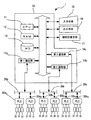
図1は本発明の実施の形態における計測制御システム及び通信制御装置1の構成を示すブロック図である。
FIG. 1 is a block diagram showing a configuration of a measurement control system and a
本発明の通信制御装置1は、各制御ネットワーク20を介して装置制御用プログラマブルコントローラ(PLC)30、30、…内の各種データを監視及び/又は操作する通信制御装置1であって、各制御ネットワーク20に接続された各種デバイス31、31、…の監視及び/又は操作を行うアプリケーションソフトウェア100と、各PLC30、30、…の固有の物理的なネットワーク情報を設定するとともに通信プロトコル定義がなされた接続設定テーブル112とデータ収集を行うタイミング毎に各種デバイス31をグループ分けするとともこれらグループと上記各PLC30、30、…とを関連づけたグループ設定テーブル113とグループ単位で収集するデバイス31を設定したデバイス設定テーブル114とを有する通信設定部110と、各PLC30内の各種データを収集するとともに各種デバイス31の情報が格納されたデータ部120と、各制御ネットワーク20との通信を制御する通信ドライバソフトウェア101と、上記通信設定部110の各種設定に基づいて通信ドライバソフトウェア101を選択するとともに、各制御ネットワーク20に接続する通信管理ソフトウェア102とを備える。
The
図中10は本発明の通信制御装置1として用いるサーバコンピュータであり、サーバコンピュータ10は、各種の処理を行うCPU(Central Processing Unit)11と、CPU11により実行される各種のプログラム及びデータを記憶するRAM(Random Access Memory)12と、各種の情報が記録され、計測制御システムにおける通信に必要なデータの変換処理に用いるテーブル等が記録されたハードディスク(HD:hard disk)13と、を有する(図1参照)。
In the figure,
また、サーバコンピュータ10は、制御ネットワーク20に物理的に接続する接続用コネクタ及び通信制御回路等の通信部14を備えるとともに、マウス及びキーボード等の入力手段15、モニタ及びプリンタ等の出力手段16、CD−ROM、FD等の記録媒体から情報を読み取る補助記憶手段17が接続されている(図1参照)。
In addition, the
ここで、この実施の形態においては、サーバコンピュータ10は3つの制御ネットワーク20a、20b、20cに各別の通信部14a、14b、14cを介して接続され、また、各制御ネットワーク20a、20b、20cにはそれぞれPLC通信プロトコルの異なった複数のPLC301、PLC302、…が各別接続されている(図1参照)。
Here, in this embodiment, the
例えば、第1の制御ネットワーク20aにはPLC通信プロトコルの異なった複数のPLC30A1、PLC30A2、…が、第2の制御ネットワーク20bにはPLC通信プロトコルの異なった複数のPLC30B1、PLC30B2、…が、第3の制御ネットワーク20cにはPLC通信プロトコルの異なった複数のPLC30C1、PLC30C2、…が接続されている(図1、図2参照)。
For example, the
また、各PLC30には、制御対象としての各種デバイス31、31、…が接続されている。
Further,
RAM12上でCPU11により実行されるプログラムには、PLC30内の各種データを監視及び/又は操作するアプリケーションソフトウェア100と、各制御ネットワーク20との通信を行うため各通信部14を制御する各別の通信ドライバソフトウェア101と、制御ネットワーク20上での通信プロトコルに基づきデータの通信形態を制御する通信管理ソフトウェア102と、www(World Wide Web)による情報送信機能を持ったソフトウェア(Webサーバ機能)103等がある(図2参照)。
The program executed by the
ハードディスク13には、各デバイス31との通信に関する各種情報等がテーブルとして格納された通信設定部110と、各種デバイス31に関する情報(デバイス情報)が記録されたデータ部120とが格納されている。
The
通信設定部110には、通信プロトコル定義がなされたPLCプロトコル定義テーブル111と各PLC30の固有の物理的なネットワーク情報を設定した接続設定テーブル112とデータ収集を行うタイミング毎に各種デバイス31をグループ分けするとともこれらグループと上記各PLC30とを関連づけたグループ設定テーブル113とグループ単位で収集するデバイス31のデータタイプと上記グループとを設定したデバイス設定テーブル114とを有する。
In the
データ部120には、ログ作成に関するロギング情報121、警報に関する情報122、各PLC30内の各種データを収集するとともに各種デバイス31の情報123(デバイス情報)が格納されている。
The
次に通信設定部110の各テーブル111、112、113、114について説明する(図3、図4、図5、図6参照)。
Next, each table 111, 112, 113, 114 of the
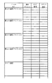
PLCプロトコル定義テーブル111は、PLC通信プロトコルのタイプと通信デバイス、コマンド設定、レスポンス設定が定義づけられている(図3参照)。 The PLC protocol definition table 111 defines the PLC communication protocol type, communication device, command setting, and response setting (see FIG. 3).
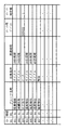
接続設定テーブル112は、接続No.、装置名称、接続方式、IPアドレス、PLC機種名称、PLC通信プロトコルタイプなどが関連づけられている(図4参照)。 The connection setting table 112 includes a connection No. , Device name, connection method, IP address, PLC model name, PLC communication protocol type, and the like are associated (see FIG. 4).
グループ設定テーブル113は、グループNo.、接続No.、グループ名称、収集条件、タイミングなどが関連づけられている(図5参照)。 The group setting table 113 includes a group number. , Connection No. , Group names, collection conditions, timings, and the like are associated (see FIG. 5).
デバイス設定テーブル114は、グループNo.、デバイス31、各デバイス31に関するデータ形式などが関連づけられている(図6参照)。
The device setting table 114 includes a group number. ,
ところで、各PLCにはデバイス番号が割り当てられており、このデバイス番号は同一PLC内では重複することはないが、たとえば、同一制御ネットワーク内に複数の同一のPLCが接続された場合に、そのままだとデバイス番号が重複してしまうことになる。これを回避するために、上述のように、デバイス設定テーブル114によりグループNo.とデバイス31とを関連づけておくことにより、各デバイス31を、グループNo.とデバイスNo.とで特定することでユニークな番号にすることができる。これは、制御対象装置全体でユニークな論理アドレスを定義し、実際のデバイス31に変換する方式よりも、直接的にデバイス31を表現することができ、使い勝手を良好にする。
By the way, a device number is assigned to each PLC, and this device number does not overlap in the same PLC. For example, when a plurality of identical PLCs are connected in the same control network, the device numbers remain as they are. Device number will be duplicated. In order to avoid this, as described above, the device setting table 114 sets the group number. By associating the
このように、各テーブル111、112、113、114は各グループを中心として関連付けられており、これにより次のような効果を有する。 As described above, the tables 111, 112, 113, and 114 are associated with each group as a center, and thus have the following effects.
1.データ収集のタイミングを変更する場合、グループの設定のみ変更すれば足りる。 1. If you want to change the timing of data collection, you only need to change the group settings.
すなわち、上記グループ設定テーブル113のうち、「収集タイミング(収集周期)」を変更するだけで、このグループに属するすべてのデバイスに関するデータを変更された収集タイミングで収集することができる。 That is, by changing only the “collection timing (collection period)” in the group setting table 113, data regarding all devices belonging to this group can be collected at the changed collection timing.
2.データ収集の効率化を図ることができる。 2. Data collection efficiency can be improved.
すなわち、例えば、データの内容によって、例えば1分毎、10分毎、1時間毎等のように必要とする収集周期が異なるが、収集周期単位でデバイス31をグループ化することにより、不必要なデバイス31のデータを収集することなく、必要とするデバイス31のデータのみを収集することができデータの収集効率を上げることができる。
That is, for example, depending on the content of the data, the required collection cycle is different, for example, every minute, every 10 minutes, every hour, etc., but it is unnecessary by grouping the
3.新たなPLC通信プロトコルの追加が容易になる。 3. It becomes easy to add a new PLC communication protocol.
すなわち、新たなPLC通信プロトコルを追加する場合、その新たな通信プロトコル定義をPLCプロトコル定義テーブル111に追加し、接続する制御ネットワーク情報、PLC30の機種等を、上記PLC通信プロトコルとの関係を接続設定テーブル112に設定するだけで済む。 That is, when a new PLC communication protocol is added, the new communication protocol definition is added to the PLC protocol definition table 111, and the control network information to be connected, the model of the PLC 30, etc. are set to be connected to the PLC communication protocol. It only needs to be set in the table 112.
このように、テーブルを細分化して機能別に分けることで変更のしやすさ、汎用性を高めることができる。 Thus, by subdividing the table and dividing it by function, the ease of change and versatility can be improved.
上記CPU11は通信ドライバソフトウェア101及び通信管理ソフトウェア102を実行し、通信部14を介して制御ネットワーク20に接続することで、制御ネットワーク20に接続されているPLC30、30、…と制御信号及び計測データ等の各種データを送受信して、上記アプリケーションソフトウェア100が行う監視及び/又は操作、例えば、監視(モニタリング)、ロギング、トレンド、警報などを行う(図2参照)。
The
また、CPU11はWebサーバ機能103を実行し、後述するクライアント側端末機器151、152からの要求に応じて、ハードディスク13に蓄積された各デバイスデータを インターネット130又はイントラネット140などのネットワークを通じて送信するようになっている(図2参照)。
Further, the
そして、プログラム及びデータ等の情報をハードディスク13から読み取り、情報を記憶するRAM12に記憶させて、CPU11により実行することで、サーバコンピュータ10は通信制御装置1として動作する。
The
また、このようなサーバコンピュータ10は、インターネット130等の公衆回線又はイントラネット140等のLAN(Local Area Network)に接続され、インターネット130又はイントラネット140に接続されたクライアント側の端末機器151、携帯電話機152、監視用カメラ153等との間で通信が可能になっている(図2参照)。
The
次に本発明の実施の形態における通信制御装置1のCPU11の処理を図7に示すフローチャートを用いて説明する。
Next, the processing of the
先ず、アプリケーションソフトウェア100の実行により、所定のPLC30にグループNo.とデバイスNo.を引数として設定された通信要求が発生する(S01)。
First, when the
次に、通信管理ソフトウェア102は、発生した通信要求を受け付けて(S02)、グループNo.とデバイスNo.を基に接続設定テーブル112から、PLC30の種類・通信プロトコル・制御ネットワーク20を識別する(S03)。
Next, the
また、通信管理ソフトウェア102は、識別した制御ネットワーク20・PLC30の種類に対する通信プロトコル定義情報を基に通信データを生成(S04)し、生成した通信データを通信ドライバソフトウェア101へ渡す(S05)。
Further, the
通信ドライバソフトウェア101では、通信データを受け付け(S06)、通信部14を制御して制御ネットワーク20上の所定のPLC30へ通信データを送信する(S07)。
The
また、PLC30から送信される返答の受信は、上記の処理を逆にすれば良く、PLC30から通信データへの返答として入力された値を通信部14で受信し、通信ドライバソフトウェア101、通信プロトコル、及び通信管理ソフトウェア102の順で処理を行い、その結果をアプリケーションソフトウェア100に渡すことによりなされる。
The response transmitted from the PLC 30 may be received by reversing the above processing. The communication unit 14 receives a value input as a response to the communication data from the PLC 30, and the
なお、この実施例ではハードディスク13に接続設定テーブル112、グループ設定テーブル113及びデバイス設定テーブル114を有する通信設定部110を記録するようにしたが、本発明はこれに限らず、ネットワークを介して接続される外部のデータベース、上記RAM12或いは補助記憶手段17などであっても良いのは勿論である。
In this embodiment, the
このように、アプリケーションソフトウェア100の通信要求に対しては、接続設定テーブル112、グループ設定テーブル113、デバイス設定テーブル114を参照するようにしているため、同一の制御ネットワーク20上の異なるPLC通信プロトコルのPLC30とも通信が可能となる。
Thus, since the connection setting table 112, the group setting table 113, and the device setting table 114 are referred to for the communication request of the
次に新たなPLC30を追加する場合について説明する。なお、新たなPLC30を追加するには2つの場合があり、1つ目は既に登録されたPLC通信プロトコルのPLCを制御ネットワーク20に追加する場合(図8参照)と、2つ目は全く新たなPLC通信プロトコルのPLC30を追加する場合(図9参照)とである。 Next, a case where a new PLC 30 is added will be described. There are two cases in which a new PLC 30 is added. The first is when adding a PLC of the already registered PLC communication protocol to the control network 20 (see FIG. 8), and the second is completely new. This is a case where a PLC 30 of a new PLC communication protocol is added (see FIG. 9).
前者の場合(図8参照)には、先ず、接続する制御ネットワーク情報、PLC30の機種、そのPLC通信プロトコルを、PLCプロトコル定義テーブル111、接続設定テーブル112に設定する(S11)。次に、通信する方式及び収集条件(収集タイミングなど)をグループ設定テーブル113に設定する(S12)。最後に、各PLC30の固有のデバイス31をデバイス設定テーブル114に設定する(S13)ことにより、既に登録されたPLC通信プロトコルのPLC30を制御ネットワーク20に追加することができる。
In the former case (see FIG. 8), first, the control network information to be connected, the PLC 30 model, and its PLC communication protocol are set in the PLC protocol definition table 111 and the connection setting table 112 (S11). Next, a communication method and collection conditions (collection timing, etc.) are set in the group setting table 113 (S12). Finally, by setting the
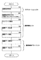
後者の場合(図9参照)には、先ず、コマンド設定、レスポンス設定により、プロトコル定義ファイルをPLCプロトコル定義テーブル111に設定する(S21)。次に、接続する制御ネットワーク20、PLC30、通信プロトコルを接続設定テーブル112に設定する(S22)。続いて、通信する方式、収集条件(収集タイミングなど)をグループ設定テーブル113に設定する(S23)。最後に、各PLC固有のデバイス31を設定する(S24)ことにより、新たなPLC通信プロトコルのPLC30を制御ネットワーク20に追加することができる。 In the latter case (see FIG. 9), first, a protocol definition file is set in the PLC protocol definition table 111 by command setting and response setting (S21). Next, the control network 20, PLC 30, and communication protocol to be connected are set in the connection setting table 112 (S22). Subsequently, the communication method and collection conditions (collection timing, etc.) are set in the group setting table 113 (S23). Finally, by setting each PLC-specific device 31 (S24), a new PLC communication protocol PLC 30 can be added to the control network 20.
このようにして、この実施例にかかる通信制御装置1にあっては、既存の制御ネットワーク20にPLC30を接続する場合であっても、新たなPLC通信プロトコルのPLC30を制御ネットワーク20に追加する場合であっても、通信管理ソフトウェア102に修正を加えることなく、各テーブル111、112、113、114に所定事項を追加するだけで、対応することができる。
As described above, in the
次に新たな制御ネットワークを追加する場合について説明する(図10参照)。この場合には、先ず、新たな制御ネットワーク20に対応する通信ドライバソフトウェア101をインストールし(S31)、通信管理ソフトウェア102のドライバ参照部を修正する(S32)。次に、接続設定テーブル112に新たな制御ネットワーク20を追加する(S33)。これ以降は、上記同一制御ネットワーク20に新たなPLC30を追加する手順を同じ手順を行う。すなわち、コマンド設定、レスポンス設定により、プロトコル定義ファイルをPLCプロトコル定義テーブル111に設定する(S34)。次に、接続する制御ネットワーク20、PLC30、通信プロトコルを接続設定テーブル112に設定する(S35)。続いて、通信する方式、収集条件(収集タイミングなど)をグループ設定テーブル113に設定する(S36)。最後に、各PLC固有のデバイス31を設定する(S37)ことにより、新たな制御ネットワーク20を追加することができる。
Next, a case where a new control network is added will be described (see FIG. 10). In this case, first, the
このように、上記実施例にかかる通信制御装置1にあっては、同一制御ネットワーク20上でPLC通信プロトコルの異なるPLC30、30、…と通信することができるのは、グループ単位でPLC通信プロトコルを判断し、そのPLC通信プロトコルに対応したコマンド、レスポンスで通信データを生成するためである。
As described above, in the
例えば、あるグループのPLC通信プロトコルが第1のPLC通信プロトコルであれば、この第1のPLC通信プロトコルに対応するコマンド、対応レスポンスで通信データを生成して通信を行う。この動作はアプリケーションソフトウェア100からの要求単位がグループ単位でなされて処理されるためである。
For example, if the PLC communication protocol of a certain group is the first PLC communication protocol, communication is performed by generating communication data with a command and a corresponding response corresponding to the first PLC communication protocol. This is because the request unit from the
そして、アプリケーションソフトウェア100が第1のPLC通信プロトコルに対応するコマンド、レスポンスの通信データを発行しているときは、同一制御ネットワーク20内の他のPLC30(第2のPLC、第3のPLC等)は上記通信データは届かず、第1のPLCのみに上記通信データが届く。これは、接続設定テーブル112に同一制御ネットワーク20内において各PLC30、30、…にはそれぞれ固有のIPアドレスが設定されているためである。
When the
したがって、各制御ネットワーク20との通信を行うため各通信部14を制御する各別の通信ドライバソフトウェア101と、制御ネットワーク20上での通信プロトコルに基づきデータの通信形態を制御する通信管理ソフトウェア102があれば、同一制御ネットワーク20に接続された異種のPLC通信プロトコルのPLC30との通信が可能になる。
Accordingly, there are
また、本実施例にかかるサーバコンピュータ10は、インターネット130等の公衆回線又はイントラネット140等のLAN(Local Area Network)に接続され、クライアント側の端末機器151、携帯電話機、モバイル機器などの携帯端末機器152、監視用カメラ153等との間で通信が可能になっているため、次のようなことが可能である。
The
・端末機器からの各デバイス31の状態の閲覧
サーバコンピュータ10にWebサーバ機能103が有するため、サーバコンピュータ10をインターネット130又はイントラネット140に接続しておけば、これらネットワークに接続されたクライアント側端末機器151、152等から各デバイス31の状態を閲覧することができる。しかも、クライアント側は特別なソフトウェアを要せずに、既存のWebブラウザで閲覧することができ、さらに、HTMLファイルを作成しておけば、ユーザー独自のWeb画面を作成することができる。
Viewing the status of each
・デバイス31の異常時にメール通報
デバイス31に関する情報のうち、そのデータがあらかじめ設定した閾値を逸脱したときに、サーバコンピュータ10が警報を発し、これをクライアント側の端末機器151に通報することができる。
-E-mail notification when
そして、デバイス31の異常の通報を受けたクライアント側端末機器151の操作者(メンテナンス者)は、上述のようにサーバコンピュータ10のWebサーバ機能103により異常が発生したデバイス31の状態を容易に閲覧し確認することができる。
Then, the operator (maintenance person) of the client-
また、クライアント側の端末機器151の代わりに、メンテナンス者の携帯電話機152に電子メールによる通報を行うようにしてもよい。このようにすると、通報を受ける者(メンテナンス者)は携帯電話機152さえ所持していれば、デバイス31の異常をどこにいても知ることができる。この場合、上記Webサーバ機能103に携帯電話機152用のWebページ(例えば、「http://○○○/i/」というように)を用意しておけば容易に実現することができる。
Further, instead of the
・データロギング機能によるデータの蓄積
あらかじめ設定されたデバイス(装置名・デバイス名)31に関し、収集タイミングにより、サーバコンピュータ10内のデータベース(DB)に上記デバイス31に関するデータをロギングすることができる。そして、ロギングされたデバイス31に関するデータはハードディスク13内のデータベース(DB)として保存され、クライアントはそのこのデータベース(DB)をWebブラウザを介して閲覧できる。また、かかるデータをXML、CSVなど形式にしてクライアント側の端末機器151にダウンロードしてデータとして利用することもできる。
-Accumulation of data by data logging function With respect to a preset device (device name / device name) 31, data related to the
・トレンド機能によるトレンドグラフの作成
あらかじめ設定されたデバイス(装置名・デバイス名)31に関し、収集タイミングにより、サーバコンピュータ10内のデータベース(DB)に上記デバイス31に関するデータをロギングするとともに、かかるデータをトレンドグラフとして表示させることができる。
-Creation of a trend graph by the trend function With respect to a preset device (device name / device name) 31, data related to the
・画像による監視
インターネット130等の公衆回線又はイントラネット140等のLAN(Local Area Network)に監視用カメラ153を接続しているため遠隔地から各装置の状態を画像にて監視することができる。
-Image monitoring Since the
・PLCに関するプログラムのアップ/ダウンロード
プログラムのアップ/ダウンロードは、機能的に各PLC30のツール機能であり、本機能はツール機能から行うこととし、回線接続部での接続確立検証を行うことで、ツール接続可能な検証を行うことができる。
Program up / download of PLC Program up / download is functionally a tool function of each PLC 30. This function is performed from the tool function, and the tool is established by verifying connection establishment at the line connection unit. A connectable verification can be performed.
1 通信制御装置
10 サーバコンピュータ
11 CPU
12 RAM
13 HD
14 通信部
15 入力手段
16 出力手段
17 補助記憶手段
20a 第1の制御ネットワーク
20b 第2の制御ネットワーク
20c 第3の制御ネットワーク
30A1 PLC
30A2 PLC
30B1 PLC
30B2 PLC
30C1 PLC
30C2 PLC
31 デバイス
100 アプリケーションソフトウェア
101 通信ドライバソフトウェア
102 通信管理ソフトウェア
110 通信設定部
111 PLCプロトコル定義テーブル
112 接続設定テーブル
113 グループ設定テーブル
114 デバイス設定テーブル
120 データ部
130 インターネット
140 イントラネット
151 クライアント側端末機器
152 携帯電話機
153 監視用カメラ
1
12 RAM
13 HD
DESCRIPTION OF SYMBOLS 14
30A 2 PLC
30B 1 PLC
30B 2 PLC
30C 1 PLC
30C 2 PLC
31
Claims (8)
各制御ネットワーク(20)に接続された各種デバイス(31)の監視及び/又は操作を行うアプリケーションソフトウェア(100)と、
各PLC(30)の固有の物理的なネットワーク情報を設定するとともに通信プロトコル定義がなされた接続設定テーブル(112)とデータ収集を行うタイミング毎に各種デバイス(31)をグループ分けするとともこれらグループと上記各PLC(30)とを関連づけたグループ設定テーブル(113)とグループ単位で収集するデバイス(31)を設定したデバイス設定テーブル(114)とを有する通信設定部(110)と、
各PLC(30)内の各種データを収集するとともに各種デバイス(31)の情報が格納されたデータ部(120)と、
各制御ネットワーク(20)との通信を制御する通信ドライバソフトウェア(101)と、
上記通信設定部(110)の各種設定に基づいて通信ドライバソフトウェア(101)を選択するとともに、各制御ネットワーク(20)に接続する通信管理ソフトウェア(102)と、を備えた
ことを特徴とする通信制御装置。 A communication control device (1) for monitoring and / or manipulating various data in a programmable controller for device control (hereinafter referred to as “PLC”) (30) via each control network (20),
Application software (100) for monitoring and / or operating various devices (31) connected to each control network (20);
The unique physical network information of each PLC (30) is set, the connection setting table (112) in which the communication protocol is defined, and various devices (31) are grouped for each data collection timing. A communication setting unit (110) having a group setting table (113) associated with each PLC (30) and a device setting table (114) in which devices (31) to be collected in groups are set;
A data section (120) that collects various data in each PLC (30) and stores information on various devices (31);
Communication driver software (101) for controlling communication with each control network (20);
Communication management software (102) for selecting communication driver software (101) based on various settings of the communication setting unit (110) and connecting to each control network (20) Control device.
ことを特徴とする請求項1に記載した通信制御装置。 The communication control device according to claim 1, wherein each device data of the PLC (30) is collected in a collection unit and stored in the data section (120) for each group.
ことを特徴とする請求項2に記載した通信制御装置。 The communication control apparatus according to claim 2, wherein each device data of the PLC (30) is stored in the data section (120) in time series.
ことを特徴とする請求項1、請求項2又は請求項3に記載した通信制御装置。 Each device data of the PLC (30) is monitored under a predetermined setting condition, and an alarm is issued when the setting condition is deviated. The claim 1, 2 or 3, Communication control device.
ことを特徴とする請求項4に記載した通信制御装置。 The communication control device according to claim 4, wherein a history of issued alarms is stored in the data unit.
ことを特徴とする請求項4又は請求項5に記載した通信制御装置。 The communication control device according to claim 4 or 5, wherein the issued alarm is transmitted by electronic mail.
ことを特徴とする請求項1、請求項2、請求項3、請求項4、請求項5又は請求項6に記載した通信制御装置。 It is connected to various terminal devices (151, 152) placed remotely through the Internet (130) or intranet (140), and the devices 31 are monitored and / or operated by the various terminal devices (151, 152). The communication control device according to claim 1, claim 2, claim 3, claim 4, claim 5, or claim 6.
ことを特徴とする請求項7に記載した通信制御装置。
The communication control apparatus according to claim 7, comprising a Web server function (103), wherein each device data can be browsed from various terminal devices (151, 152).
Priority Applications (1)
| Application Number | Priority Date | Filing Date | Title |
|---|---|---|---|
| JP2003354667A JP2005123766A (en) | 2003-10-15 | 2003-10-15 | Communication control device |
Applications Claiming Priority (1)
| Application Number | Priority Date | Filing Date | Title |
|---|---|---|---|
| JP2003354667A JP2005123766A (en) | 2003-10-15 | 2003-10-15 | Communication control device |
Publications (1)
| Publication Number | Publication Date |
|---|---|
| JP2005123766A true JP2005123766A (en) | 2005-05-12 |
Family
ID=34612506
Family Applications (1)
| Application Number | Title | Priority Date | Filing Date |
|---|---|---|---|
| JP2003354667A Pending JP2005123766A (en) | 2003-10-15 | 2003-10-15 | Communication control device |
Country Status (1)
| Country | Link |
|---|---|
| JP (1) | JP2005123766A (en) |
Cited By (7)
| Publication number | Priority date | Publication date | Assignee | Title |
|---|---|---|---|---|
| JP2007286992A (en) * | 2006-04-19 | 2007-11-01 | Yokogawa Electric Corp | Data collection method and apparatus |
| JP2007293683A (en) * | 2006-04-26 | 2007-11-08 | Tokyo Electron Ltd | Group management system, process information management device, and program |
| JP2008172403A (en) * | 2007-01-10 | 2008-07-24 | Fuji Electric Fa Components & Systems Co Ltd | Remote monitoring device |
| US8155843B2 (en) | 2007-12-21 | 2012-04-10 | Denso Corporation | Vehicle control apparatus and vehicle control system using the same |
| US8155829B2 (en) | 2007-11-21 | 2012-04-10 | Denso Corporation | Common control apparatus and vehicle control system |
| JP2022020837A (en) * | 2018-02-26 | 2022-02-01 | オムロン株式会社 | Controllers, control methods and programs |
| KR102789911B1 (en) * | 2024-10-14 | 2025-03-31 | 정창영 | Build communication drivers and interfaces for mechanical equipment automated solution delivery methods, devices, and systems |
-
2003
- 2003-10-15 JP JP2003354667A patent/JP2005123766A/en active Pending
Cited By (8)
| Publication number | Priority date | Publication date | Assignee | Title |
|---|---|---|---|---|
| JP2007286992A (en) * | 2006-04-19 | 2007-11-01 | Yokogawa Electric Corp | Data collection method and apparatus |
| JP2007293683A (en) * | 2006-04-26 | 2007-11-08 | Tokyo Electron Ltd | Group management system, process information management device, and program |
| JP2008172403A (en) * | 2007-01-10 | 2008-07-24 | Fuji Electric Fa Components & Systems Co Ltd | Remote monitoring device |
| US8155829B2 (en) | 2007-11-21 | 2012-04-10 | Denso Corporation | Common control apparatus and vehicle control system |
| US8155843B2 (en) | 2007-12-21 | 2012-04-10 | Denso Corporation | Vehicle control apparatus and vehicle control system using the same |
| JP2022020837A (en) * | 2018-02-26 | 2022-02-01 | オムロン株式会社 | Controllers, control methods and programs |
| JP7294391B2 (en) | 2018-02-26 | 2023-06-20 | オムロン株式会社 | Controller, control method and program |
| KR102789911B1 (en) * | 2024-10-14 | 2025-03-31 | 정창영 | Build communication drivers and interfaces for mechanical equipment automated solution delivery methods, devices, and systems |
Similar Documents
| Publication | Publication Date | Title |
|---|---|---|
| KR101369373B1 (en) | Method, system and apparatus for providing automation management services | |
| CN103201689B (en) | There is field panel and the access method thereof of embedded web server | |
| JP6651510B2 (en) | Equipment hierarchy for remote terminals | |
| CN104025070A (en) | System and method for managing industrial processes | |
| JP4337591B2 (en) | Information processing apparatus, network system, and network system control method | |
| KR102204906B1 (en) | System for Remote Controlling Machine Tools by Using OPC UA | |
| KR20050000345A (en) | Method and apparatus for self-configuring supervisory control and data acquisition(scada) system for distributed control | |
| KR20190072630A (en) | DATA COLLECTING DEVICE, METHOD OF COLLECTING DATA | |
| CN1313966A (en) | Function block apparatus for viewing data in a process control system | |
| JP2019204224A (en) | Sensor data analysis system and sensor data analysis method | |
| KR102686512B1 (en) | Data collection edge device and data collection gateway having AI module | |
| CN101741637A (en) | Method and device for diagnosing networks, in particular fieldbus systems | |
| CN110460476A (en) | A kind of network O&M management method | |
| JP2005123766A (en) | Communication control device | |
| JP7218552B2 (en) | Information processing device, remote device management system, communication method and program | |
| CN109392192B (en) | Method and system for device connection of SCADA system for fast communication | |
| JP2000075907A (en) | Production system | |
| JP6575311B2 (en) | Network system and control device | |
| JP2000330622A (en) | Remotely operable arithmetic type system | |
| JP2014060636A (en) | Communication interface conversion device | |
| JP6879014B2 (en) | Monitoring system, program and monitoring method | |
| KR20190016370A (en) | Method for fast communication between scada system and device and system thereof | |
| JP6978447B2 (en) | Display data providing device | |
| JP2012216890A (en) | Engineering device | |
| CN106464722A (en) | Apparatus and method for seamless data transfer to a cloud network |
Legal Events
| Date | Code | Title | Description |
|---|---|---|---|
| A621 | Written request for application examination |
Free format text: JAPANESE INTERMEDIATE CODE: A621 Effective date: 20050726 |
|
| A977 | Report on retrieval |
Free format text: JAPANESE INTERMEDIATE CODE: A971007 Effective date: 20070731 |
|
| A131 | Notification of reasons for refusal |
Free format text: JAPANESE INTERMEDIATE CODE: A131 Effective date: 20070814 |
|
| A02 | Decision of refusal |
Free format text: JAPANESE INTERMEDIATE CODE: A02 Effective date: 20080311 |