JP7216072B2 - Filter Cartridge, Air Purifier Assembly, Housing, Features, Components, and Methods - Google Patents
Filter Cartridge, Air Purifier Assembly, Housing, Features, Components, and Methods Download PDFInfo
- Publication number
- JP7216072B2 JP7216072B2 JP2020505870A JP2020505870A JP7216072B2 JP 7216072 B2 JP7216072 B2 JP 7216072B2 JP 2020505870 A JP2020505870 A JP 2020505870A JP 2020505870 A JP2020505870 A JP 2020505870A JP 7216072 B2 JP7216072 B2 JP 7216072B2
- Authority
- JP
- Japan
- Prior art keywords
- seal
- sealing
- convex
- sealing surface
- filter media
- Prior art date
- Legal status (The legal status is an assumption and is not a legal conclusion. Google has not performed a legal analysis and makes no representation as to the accuracy of the status listed.)
- Active
Links
- 238000000034 method Methods 0.000 title description 42
- 238000007789 sealing Methods 0.000 claims description 674
- 238000004140 cleaning Methods 0.000 claims description 36
- 239000000463 material Substances 0.000 claims description 34
- 239000003566 sealing material Substances 0.000 claims description 11
- 239000002386 air freshener Substances 0.000 description 42
- 239000011324 bead Substances 0.000 description 35
- 238000010586 diagram Methods 0.000 description 21
- 238000009434 installation Methods 0.000 description 20
- 230000002093 peripheral effect Effects 0.000 description 14
- 239000000565 sealant Substances 0.000 description 13
- 238000001914 filtration Methods 0.000 description 12
- 238000011068 loading method Methods 0.000 description 12
- 238000010276 construction Methods 0.000 description 11
- 230000008569 process Effects 0.000 description 11
- 239000000853 adhesive Substances 0.000 description 10
- 230000001070 adhesive effect Effects 0.000 description 10
- 230000008901 benefit Effects 0.000 description 10
- 238000004519 manufacturing process Methods 0.000 description 10
- 230000007704 transition Effects 0.000 description 10
- 239000000835 fiber Substances 0.000 description 7
- 239000012530 fluid Substances 0.000 description 7
- 238000012512 characterization method Methods 0.000 description 6
- 238000002485 combustion reaction Methods 0.000 description 6
- 239000000356 contaminant Substances 0.000 description 6
- 239000007787 solid Substances 0.000 description 6
- 229920002994 synthetic fiber Polymers 0.000 description 6
- 230000006835 compression Effects 0.000 description 5
- 238000007906 compression Methods 0.000 description 5
- 239000000428 dust Substances 0.000 description 5
- 238000005516 engineering process Methods 0.000 description 5
- -1 polyethylene terephthalate Polymers 0.000 description 5
- 238000011144 upstream manufacturing Methods 0.000 description 5
- 230000009286 beneficial effect Effects 0.000 description 4
- 239000002657 fibrous material Substances 0.000 description 4
- 239000007789 gas Substances 0.000 description 4
- 238000003475 lamination Methods 0.000 description 4
- 230000013011 mating Effects 0.000 description 4
- 230000004048 modification Effects 0.000 description 4
- 238000012986 modification Methods 0.000 description 4
- 239000011347 resin Substances 0.000 description 4
- 229920005989 resin Polymers 0.000 description 4
- 238000005096 rolling process Methods 0.000 description 4
- 229920001169 thermoplastic Polymers 0.000 description 4
- 230000008859 change Effects 0.000 description 3
- 230000000694 effects Effects 0.000 description 3
- 239000012209 synthetic fiber Substances 0.000 description 3
- 238000004804 winding Methods 0.000 description 3
- 239000004698 Polyethylene Substances 0.000 description 2
- 239000004743 Polypropylene Substances 0.000 description 2
- 230000000712 assembly Effects 0.000 description 2
- 238000000429 assembly Methods 0.000 description 2
- 238000005452 bending Methods 0.000 description 2
- 230000000903 blocking effect Effects 0.000 description 2
- 230000006870 function Effects 0.000 description 2
- 239000012943 hotmelt Substances 0.000 description 2
- 238000003780 insertion Methods 0.000 description 2
- 230000037431 insertion Effects 0.000 description 2
- 230000003993 interaction Effects 0.000 description 2
- 229920000728 polyester Polymers 0.000 description 2
- 229920000573 polyethylene Polymers 0.000 description 2
- 229920001155 polypropylene Polymers 0.000 description 2
- 229920002635 polyurethane Polymers 0.000 description 2
- 239000004814 polyurethane Substances 0.000 description 2
- 239000011253 protective coating Substances 0.000 description 2
- 239000012812 sealant material Substances 0.000 description 2
- 125000006850 spacer group Chemical group 0.000 description 2
- XLYOFNOQVPJJNP-UHFFFAOYSA-N water Substances O XLYOFNOQVPJJNP-UHFFFAOYSA-N 0.000 description 2
- 241000473391 Archosargus rhomboidalis Species 0.000 description 1
- 229920003043 Cellulose fiber Polymers 0.000 description 1
- 206010011878 Deafness Diseases 0.000 description 1
- 239000004677 Nylon Substances 0.000 description 1
- 241001306288 Ophrys fuciflora Species 0.000 description 1
- 239000004952 Polyamide Substances 0.000 description 1
- 239000004372 Polyvinyl alcohol Substances 0.000 description 1
- 229920000297 Rayon Polymers 0.000 description 1
- 230000009471 action Effects 0.000 description 1
- 239000008186 active pharmaceutical agent Substances 0.000 description 1
- 230000004075 alteration Effects 0.000 description 1
- 229920002678 cellulose Polymers 0.000 description 1
- 239000001913 cellulose Substances 0.000 description 1
- 239000003795 chemical substances by application Substances 0.000 description 1
- 150000001875 compounds Chemical class 0.000 description 1
- 239000013256 coordination polymer Substances 0.000 description 1
- 238000005520 cutting process Methods 0.000 description 1
- 230000009477 glass transition Effects 0.000 description 1
- 238000010438 heat treatment Methods 0.000 description 1
- 230000007062 hydrolysis Effects 0.000 description 1
- 238000006460 hydrolysis reaction Methods 0.000 description 1
- 230000006872 improvement Effects 0.000 description 1
- 238000007689 inspection Methods 0.000 description 1
- 239000007788 liquid Substances 0.000 description 1
- 239000012092 media component Substances 0.000 description 1
- 239000000203 mixture Substances 0.000 description 1
- 239000002991 molded plastic Substances 0.000 description 1
- 238000000465 moulding Methods 0.000 description 1
- 229920001778 nylon Polymers 0.000 description 1
- 239000002245 particle Substances 0.000 description 1
- 239000013618 particulate matter Substances 0.000 description 1
- 229920003023 plastic Polymers 0.000 description 1
- 239000004033 plastic Substances 0.000 description 1
- 229920002647 polyamide Polymers 0.000 description 1
- 229920000139 polyethylene terephthalate Polymers 0.000 description 1
- 239000005020 polyethylene terephthalate Substances 0.000 description 1
- 229920005594 polymer fiber Polymers 0.000 description 1
- 239000002861 polymer material Substances 0.000 description 1
- 229920000098 polyolefin Polymers 0.000 description 1
- 229920002689 polyvinyl acetate Polymers 0.000 description 1
- 239000011118 polyvinyl acetate Substances 0.000 description 1
- 229920002451 polyvinyl alcohol Polymers 0.000 description 1
- 229920000915 polyvinyl chloride Polymers 0.000 description 1
- 239000004800 polyvinyl chloride Substances 0.000 description 1
- 239000002964 rayon Substances 0.000 description 1
- 239000007779 soft material Substances 0.000 description 1
- 238000000527 sonication Methods 0.000 description 1
- 230000000087 stabilizing effect Effects 0.000 description 1
- 239000000126 substance Substances 0.000 description 1
- 239000004416 thermosoftening plastic Substances 0.000 description 1
- 238000009423 ventilation Methods 0.000 description 1
- 238000003466 welding Methods 0.000 description 1
Images


Classifications
-
- B—PERFORMING OPERATIONS; TRANSPORTING
- B01—PHYSICAL OR CHEMICAL PROCESSES OR APPARATUS IN GENERAL
- B01D—SEPARATION
- B01D46/00—Filters or filtering processes specially modified for separating dispersed particles from gases or vapours
- B01D46/24—Particle separators, e.g. dust precipitators, using rigid hollow filter bodies
-
- B—PERFORMING OPERATIONS; TRANSPORTING
- B01—PHYSICAL OR CHEMICAL PROCESSES OR APPARATUS IN GENERAL
- B01D—SEPARATION
- B01D46/00—Filters or filtering processes specially modified for separating dispersed particles from gases or vapours
- B01D46/52—Particle separators, e.g. dust precipitators, using filters embodying folded corrugated or wound sheet material
- B01D46/521—Particle separators, e.g. dust precipitators, using filters embodying folded corrugated or wound sheet material using folded, pleated material
- B01D46/525—Particle separators, e.g. dust precipitators, using filters embodying folded corrugated or wound sheet material using folded, pleated material which comprises flutes
- B01D46/526—Particle separators, e.g. dust precipitators, using filters embodying folded corrugated or wound sheet material using folded, pleated material which comprises flutes in stacked arrangement
-
- B—PERFORMING OPERATIONS; TRANSPORTING
- B01—PHYSICAL OR CHEMICAL PROCESSES OR APPARATUS IN GENERAL
- B01D—SEPARATION
- B01D46/00—Filters or filtering processes specially modified for separating dispersed particles from gases or vapours
- B01D46/52—Particle separators, e.g. dust precipitators, using filters embodying folded corrugated or wound sheet material
- B01D46/521—Particle separators, e.g. dust precipitators, using filters embodying folded corrugated or wound sheet material using folded, pleated material
- B01D46/525—Particle separators, e.g. dust precipitators, using filters embodying folded corrugated or wound sheet material using folded, pleated material which comprises flutes
- B01D46/527—Particle separators, e.g. dust precipitators, using filters embodying folded corrugated or wound sheet material using folded, pleated material which comprises flutes in wound arrangement
-
- B—PERFORMING OPERATIONS; TRANSPORTING
- B01—PHYSICAL OR CHEMICAL PROCESSES OR APPARATUS IN GENERAL
- B01D—SEPARATION
- B01D46/00—Filters or filtering processes specially modified for separating dispersed particles from gases or vapours
- B01D46/0002—Casings; Housings; Frame constructions
- B01D46/0005—Mounting of filtering elements within casings, housings or frames
-
- B—PERFORMING OPERATIONS; TRANSPORTING
- B01—PHYSICAL OR CHEMICAL PROCESSES OR APPARATUS IN GENERAL
- B01D—SEPARATION
- B01D46/00—Filters or filtering processes specially modified for separating dispersed particles from gases or vapours
- B01D46/0084—Filters or filtering processes specially modified for separating dispersed particles from gases or vapours provided with safety means
- B01D46/009—Identification of filter type or position thereof, e.g. by transponders or bar codes
-
- B—PERFORMING OPERATIONS; TRANSPORTING
- B01—PHYSICAL OR CHEMICAL PROCESSES OR APPARATUS IN GENERAL
- B01D—SEPARATION
- B01D46/00—Filters or filtering processes specially modified for separating dispersed particles from gases or vapours
- B01D46/24—Particle separators, e.g. dust precipitators, using rigid hollow filter bodies
- B01D46/2403—Particle separators, e.g. dust precipitators, using rigid hollow filter bodies characterised by the physical shape or structure of the filtering element
- B01D46/2411—Filter cartridges
-
- B—PERFORMING OPERATIONS; TRANSPORTING
- B01—PHYSICAL OR CHEMICAL PROCESSES OR APPARATUS IN GENERAL
- B01D—SEPARATION
- B01D46/00—Filters or filtering processes specially modified for separating dispersed particles from gases or vapours
- B01D46/42—Auxiliary equipment or operation thereof
- B01D46/4227—Manipulating filters or filter elements, e.g. handles or extracting tools
-
- B—PERFORMING OPERATIONS; TRANSPORTING
- B01—PHYSICAL OR CHEMICAL PROCESSES OR APPARATUS IN GENERAL
- B01D—SEPARATION
- B01D46/00—Filters or filtering processes specially modified for separating dispersed particles from gases or vapours
- B01D46/52—Particle separators, e.g. dust precipitators, using filters embodying folded corrugated or wound sheet material
- B01D46/521—Particle separators, e.g. dust precipitators, using filters embodying folded corrugated or wound sheet material using folded, pleated material
- B01D46/525—Particle separators, e.g. dust precipitators, using filters embodying folded corrugated or wound sheet material using folded, pleated material which comprises flutes
-
- F—MECHANICAL ENGINEERING; LIGHTING; HEATING; WEAPONS; BLASTING
- F02—COMBUSTION ENGINES; HOT-GAS OR COMBUSTION-PRODUCT ENGINE PLANTS
- F02M—SUPPLYING COMBUSTION ENGINES IN GENERAL WITH COMBUSTIBLE MIXTURES OR CONSTITUENTS THEREOF
- F02M35/00—Combustion-air cleaners, air intakes, intake silencers, or induction systems specially adapted for, or arranged on, internal-combustion engines
- F02M35/02—Air cleaners
- F02M35/0201—Housings; Casings; Frame constructions; Lids; Manufacturing or assembling thereof
-
- F—MECHANICAL ENGINEERING; LIGHTING; HEATING; WEAPONS; BLASTING
- F02—COMBUSTION ENGINES; HOT-GAS OR COMBUSTION-PRODUCT ENGINE PLANTS
- F02M—SUPPLYING COMBUSTION ENGINES IN GENERAL WITH COMBUSTIBLE MIXTURES OR CONSTITUENTS THEREOF
- F02M35/00—Combustion-air cleaners, air intakes, intake silencers, or induction systems specially adapted for, or arranged on, internal-combustion engines
- F02M35/02—Air cleaners
- F02M35/024—Air cleaners using filters, e.g. moistened
- F02M35/02408—Manufacturing filter elements
-
- F—MECHANICAL ENGINEERING; LIGHTING; HEATING; WEAPONS; BLASTING
- F02—COMBUSTION ENGINES; HOT-GAS OR COMBUSTION-PRODUCT ENGINE PLANTS
- F02M—SUPPLYING COMBUSTION ENGINES IN GENERAL WITH COMBUSTIBLE MIXTURES OR CONSTITUENTS THEREOF
- F02M35/00—Combustion-air cleaners, air intakes, intake silencers, or induction systems specially adapted for, or arranged on, internal-combustion engines
- F02M35/02—Air cleaners
- F02M35/024—Air cleaners using filters, e.g. moistened
- F02M35/02416—Fixing, mounting, supporting or arranging filter elements; Filter element cartridges
-
- F—MECHANICAL ENGINEERING; LIGHTING; HEATING; WEAPONS; BLASTING
- F02—COMBUSTION ENGINES; HOT-GAS OR COMBUSTION-PRODUCT ENGINE PLANTS
- F02M—SUPPLYING COMBUSTION ENGINES IN GENERAL WITH COMBUSTIBLE MIXTURES OR CONSTITUENTS THEREOF
- F02M35/00—Combustion-air cleaners, air intakes, intake silencers, or induction systems specially adapted for, or arranged on, internal-combustion engines
- F02M35/02—Air cleaners
- F02M35/024—Air cleaners using filters, e.g. moistened
- F02M35/02475—Air cleaners using filters, e.g. moistened characterised by the shape of the filter element
- F02M35/02483—Cylindrical, conical, oval, spherical or the like filter elements; wounded filter elements
-
- B—PERFORMING OPERATIONS; TRANSPORTING
- B01—PHYSICAL OR CHEMICAL PROCESSES OR APPARATUS IN GENERAL
- B01D—SEPARATION
- B01D2265/00—Casings, housings or mounting for filters specially adapted for separating dispersed particles from gases or vapours
- B01D2265/02—Non-permanent measures for connecting different parts of the filter
- B01D2265/024—Mounting aids
- B01D2265/026—Mounting aids with means for avoiding false mounting
-
- B—PERFORMING OPERATIONS; TRANSPORTING
- B01—PHYSICAL OR CHEMICAL PROCESSES OR APPARATUS IN GENERAL
- B01D—SEPARATION
- B01D2271/00—Sealings for filters specially adapted for separating dispersed particles from gases or vapours
- B01D2271/02—Gaskets, sealings
- B01D2271/022—Axial sealings
-
- B—PERFORMING OPERATIONS; TRANSPORTING
- B01—PHYSICAL OR CHEMICAL PROCESSES OR APPARATUS IN GENERAL
- B01D—SEPARATION
- B01D2271/00—Sealings for filters specially adapted for separating dispersed particles from gases or vapours
- B01D2271/02—Gaskets, sealings
- B01D2271/027—Radial sealings
-
- B—PERFORMING OPERATIONS; TRANSPORTING
- B01—PHYSICAL OR CHEMICAL PROCESSES OR APPARATUS IN GENERAL
- B01D—SEPARATION
- B01D2275/00—Filter media structures for filters specially adapted for separating dispersed particles from gases or vapours
- B01D2275/20—Shape of filtering material
- B01D2275/208—Oval shape
-
- B—PERFORMING OPERATIONS; TRANSPORTING
- B01—PHYSICAL OR CHEMICAL PROCESSES OR APPARATUS IN GENERAL
- B01D—SEPARATION
- B01D2279/00—Filters adapted for separating dispersed particles from gases or vapours specially modified for specific uses
- B01D2279/60—Filters adapted for separating dispersed particles from gases or vapours specially modified for specific uses for the intake of internal combustion engines or turbines
-
- F—MECHANICAL ENGINEERING; LIGHTING; HEATING; WEAPONS; BLASTING
- F02—COMBUSTION ENGINES; HOT-GAS OR COMBUSTION-PRODUCT ENGINE PLANTS
- F02M—SUPPLYING COMBUSTION ENGINES IN GENERAL WITH COMBUSTIBLE MIXTURES OR CONSTITUENTS THEREOF
- F02M35/00—Combustion-air cleaners, air intakes, intake silencers, or induction systems specially adapted for, or arranged on, internal-combustion engines
- F02M35/02—Air cleaners
- F02M35/024—Air cleaners using filters, e.g. moistened
- F02M35/02441—Materials or structure of filter elements, e.g. foams
- F02M35/0245—Pleated, folded, corrugated filter elements, e.g. made of paper
Description
関連出願の相互参照
本願は、2018年8月8日にPCT国際特許出願として出願される。本開示は、2017年8月9日に出願された米国仮特許出願第62/543,090号の開示を、校正を加えた上で含む。米国仮特許出願第62/543,090号の優先権を適切な範囲で主張するものであり、米国仮特許出願第62/543,090号の開示全体を参照によって本願に援用する。
CROSS-REFERENCE TO RELATED APPLICATIONS This application is filed as a PCT International Patent Application on August 8, 2018. This disclosure includes the disclosures of US Provisional Patent Application No. 62/543,090, filed Aug. 9, 2017, with proof. Priority to US Provisional Patent Application No. 62/543,090 is claimed to the extent appropriate, and the entire disclosure of US Provisional Patent Application No. 62/543,090 is incorporated herein by reference.
本開示は、典型的に例えば内燃機関用吸気等の空気を濾過するためのフィルタ装置に関する。幾つかの選択された例においては、本開示は特に、相互に反対側にある吸排気端を有する実用可能なカートリッジを使用するフィルタ装置に関するが、他の用途も記載されている。空気清浄装置、特徴、組立及び製造方法も記載されている。 FIELD OF THE DISCLOSURE The present disclosure typically relates to filter devices for filtering air, such as intake air for internal combustion engines. In some selected examples, the present disclosure is particularly directed to filter devices that employ practicable cartridges having opposed inlet and outlet ends, although other applications are also described. An air cleaning device, features, assembly and method of manufacture are also described.
空気の流れは、その中で粉塵や液体粒子等の汚染物質を運んでいる可能性がある。多くの例において、汚染物質の一部又は全部を空気の流れからフィルタで除去することが望ましい。例えば、自動車用又は発電装置用のエンジンへの空気の流れ(例えば、燃焼空気の流れ)、ガスタービンシステムへのガスの流れ、及び各種の燃焼炉への空気の流れは、その中でフィルタにかけるべき粒子状汚染物質を運んでいる。そのようなシステムについては、選択された汚染物質を空気から除去する(又は空気中のレベルを低下させる)ことが望ましい。汚染物質除去のために様々なエアフィルタ装置が開発されている。改良が求められている。 Air currents can carry contaminants within them, such as dust and liquid particles. In many instances, it is desirable to filter some or all of the contaminants from the airflow. For example, air flows to engines (e.g., combustion air flows) for automotive or power plant applications, gas flows to gas turbine systems, and air flows to various combustion furnaces may be filtered therein. Carrying particulate contaminants to be sprayed. For such systems, it is desirable to remove selected contaminants from the air (or reduce their levels in the air). Various air filter devices have been developed for contaminant removal. Improvement is required.
本開示によれば、空気清浄装置アセンブリ及び、それに関する筐体、修理交換可能なフィルタカートリッジ及び特徴、コンポーネント、及び方法が開示される。一般に、特徴は、修理点検中に、不適当なカートリッジが空気清浄装置筐体の中に取り付けられないようにするのを助けるように構成されるシステムに関する。本明細書には様々な方式が記載されており、これらは所望の結果を得るために個別にも又は一緒にも使用できる。 SUMMARY In accordance with the present disclosure, air cleaner assemblies and associated housings, serviceable and replaceable filter cartridges and features, components, and methods are disclosed. In general, features relate to systems configured to help prevent improper cartridges from being installed in air freshener housings during servicing. Various modalities are described herein, which can be used individually or together to achieve desired results.
I.例示的濾材構成全般
本開示による原理は、後述のような特定の選択された所望の結果を実現するために有利な方法によるフィルタカートリッジと空気清浄装置システムとの間の相互作用に関する。フィルタカートリッジは一般に、その中に濾材を含み、そこを濾過動作中に空気及びその他の気体が通過する。濾材は、様々な種類と構成とすることができ、様々な材料を使って製作できる。例えば、本開示の原理によるカートリッジには、後述のように、プリーツ付き濾材装置を使用できる。
I. Exemplary Filter Media Configurations General The principles according to the present disclosure relate to the interaction between the filter cartridge and the air freshener system in advantageous ways to achieve certain selected desired results as described below. Filter cartridges generally contain filter media therein through which air and other gases pass during filtering operations. Filter media can be of various types and configurations and can be made from a variety of materials. For example, cartridges according to the principles of the present disclosure may use pleated media devices, as described below.
この原理は、カートリッジの入口側及び出口側端間の範囲で濾材がかなり深い状況での使用に特によく適応されているが、他の選択肢もありうる。また、この原理は断面寸法が比較的大きいカートリッジにおいてよく使用される。このような装置では、プリーツ付き濾材に代わる種類の濾材が望ましいことが多い。 This principle is particularly well adapted for use in situations where the filter media is fairly deep in the area between the inlet and outlet ends of the cartridge, although other options are possible. Also, this principle is often used in cartridges with relatively large cross-sectional dimensions. Alternative types of filter media to pleated filter media are often desirable in such devices.
この項では、本明細書に記載されている技術に使用可能ないくつかの濾材装置の例を挙げる。しかしながら、様々な代替的種類の濾材が使用可能であることがわかるであろう。濾材の種類の選択は一般に、入手可能性、ある使用状況での機能、製造しやすさ等の選好のうちの1つであり、選択は必ずしも本明細書で特徴付けられるフィルタカートリッジと空気清浄装置との相互作用の様々な特徴の中から選択されたものの全体的機能に関しているとはかぎらない。 This section provides examples of some filter media devices that can be used with the techniques described herein. However, it will be appreciated that various alternative types of filter media can be used. The selection of the type of filter media is generally one of preferences such as availability, function in a given use situation, ease of manufacture, etc., and the selection is not necessarily the filter cartridges and air cleaning devices featured herein. It does not necessarily relate to the overall functioning of a selection of the various features of interaction with.
A.ライナ濾材に固定された、濾材畝部(フルート)を有する濾材を使用した濾材パック装置
フルート付濾材(濾材畝部を有する濾材)は、各種の方法で流体フィルタ構造物を提供するために使用できる。1つのよく知られている方法は、本明細書において、Z型フィルタ構造物として特徴付けられる。「Z型フィルタ構造物」という用語は、本明細書で使用されるかぎり、積層された、折り畳まれた、又はその他の方法で形成されたフィルタのフルートのひとつひとつが、長さ方向の、典型的に平行な、濾材を通る流体流のための吸入及び排出フィルタフルートの集合(典型的にはライナ濾材と組み合わされる)を定義するために使用される種類のフィルタ構造物を含むものとする(ただし、これに限定されない)。Z型濾材のいくつかの例が、米国特許第5,820,646号明細書、同第5,772,883号明細書、同第5,902,364号明細書、同第5,792,247号明細書、同第5,895,574号明細書、同第6,210,469号明細書、同第6,190,432号明細書、同第6,350,291号明細書、同第6,179,890号明細書、同第6,235,195号明細書、米国意匠特許第399,944号明細書、米国意匠特許第428,128号明細書、米国意匠特許第396,098号明細書、米国意匠特許第398,046号明細書、及び米国意匠特許第437,401号明細書において提供されており、これらの引用文献の各々を参照によって本願に援用する。
A. Filter Media Pack Apparatus Using Filter Media Having Filter Media Ridges (Flutes) Secured To Liner Media Fluted media (filter media having media ridges) can be used to provide fluid filter constructions in a variety of ways. . One well-known method is characterized herein as a Z-filter structure. As used herein, the term "Z-filter construction" means that each flute of a stacked, folded, or otherwise formed filter has a longitudinal, typically The type of filter construction used to define a set of inlet and outlet filter flutes (typically combined with liner filter media) for fluid flow through the filter media parallel to the is not limited to). Some examples of Z-filter media are described in U.S. Pat. Nos. 5,820,646; 5,772,883; 5,902,364; 247, 5,895,574, 6,210,469, 6,190,432, 6,350,291, 6,179,890, 6,235,195, U.S. Design Patent 399,944, U.S. Design Patent 428,128, U.S. Design Patent 396,098 US Design Patent No. 398,046 and US Design Patent No. 437,401, each of which is incorporated herein by reference.
1つの種類のZ型濾材は、相互に結合されて濾材構造物を形成する2つの特定の濾材コンポーネントを利用する。2つのコンポーネントとは、(1)フルート付き(典型的に波形の)濾材シート又はシート切片と、(2)ライナ濾材シート又はシート切片である。ライン濾材シートは典型的には波形でないが、例えばフルートの方向に垂直な波形とすることもでき、これは2004年2月11日に出願され、2005年8月25日にPCT国際公開第05/077487号パンフレットとして公開されている米国仮特許出願第60/543,804号明細書に記載されており、これを参照によって本願に援用する。 One type of Z-filter media utilizes two specific filter media components that are bonded together to form a filter media structure. The two components are (1) a fluted (typically corrugated) filter media sheet or sheet segment and (2) a liner filter media sheet or sheet segment. Line media sheets are typically not corrugated, but can also be corrugated, e.g. US Provisional Patent Application No. 60/543,804, published as No./077487, which is incorporated herein by reference.
フルート付き濾材切片とライナ濾材切片は、相互間に別の材料を含むことができる。しかしながら、これらはまた、1枚の濾材シートを折り畳んで、ライナ濾材の材料が濾材のうちのフルート付き濾材部分と適切に隣り合わせとなるようにしたものの切片とすることができる。 The fluted media segments and the liner media segments may include another material between them. However, they can also be segments of a single filter media sheet folded such that the liner media material is properly adjacent to the fluted media portion of the media.
フルート付き(典型的に波形の)濾材シートとライナ濾材シート又は合体シート切片は、平行なフルートを有する濾材を画定するために典型的に使用される。いくつかの例において、フルート付きシートとライナシートは別々であり、その後、相互に固定され、その後、濾材条片として巻き取られ、Z型濾材構造物が形成される。このような装置は、例えば米国特許第6,235,195号明細書及び第6,179,890号明細書に記載されており、その各々を参照によって本願に援用する。特定のその他の装置では、ライナ濾材に固定されたフルート付き(典型的に波形の)濾材のうち、巻き取られていない切片又は条片のいくつかを相互に積み重ねてフィルタ構造物が構築される。この例は米国特許第5,820,646号明細書の図11に示されており、これを参照によって本願に援用する。 Fluted (typically corrugated) media sheets and liner media sheets or coalescing sheet segments are typically used to define media having parallel flutes. In some examples, the fluted sheet and the liner sheet are separate and then secured together and then rolled up as a filter media strip to form the Z-filter media construction. Such devices are described, for example, in US Pat. Nos. 6,235,195 and 6,179,890, each of which is incorporated herein by reference. In certain other devices, the filter structure is constructed by stacking several unwound pieces or strips of fluted (typically corrugated) media affixed to a liner media on top of each other. . An example of this is shown in FIG. 11 of US Pat. No. 5,820,646, which is incorporated herein by reference.
ここで、波形シートに固定されたフルート付きシート(畝部を有する濾材シート)を含む材料の条片はその後、積層体として組み立てられて濾材パックを形成し、これは「シングルフェーサ条片」、「シングルフェース条片」、又は「シングルフェーサ」若しくは「シングルフェース」濾材と呼ばれることがある。これらの用語とその変化形は、各条片において、フルート付き(典型的には波形の)シートの片面、すなわちシングルフェースにライナシートが張られていることを意味する。 Here, strips of material comprising fluted sheets (ridged media sheets) secured to corrugated sheets are then assembled in a laminate to form a media pack, which is a "single facer strip". , a "single face strip", or a "single facer" or "single face" filter media. These terms and their variations mean that in each strip one side, or single face, of the fluted (typically corrugated) sheet is lined with a liner sheet.
典型的に、フルート付きシートとライナシートの(すなわちシングルフェーサの)組合せの条片を巻き取ってロール型濾材パックを構築することは、ライナシートが外側になるようにして行われる。巻き上げのためのいくつかの方法が、2003年5月2日に出願された米国仮特許出願第60/467,521号明細書及び2004年3月17日に出願され、現在は国際公開第04/082795号パンフレットとして公開されているPCT出願第04/07927号明細書に記載されており、その各々を参照によって本願に援用する。その結果として得られるロール型の装置は一般に、その結果、濾材パックの外面としてライナシートの一部を有する。 Typically, the winding of the combined fluted sheet and liner sheet (ie, single facer) strip to construct a rolled filter media pack is done with the liner sheet on the outside. Several methods for hoisting are described in US Provisional Patent Application No. 60/467,521 filed May 2, 2003 and March 17, 2004, now WO04. No. 04/07927, published as PCT/082795, each of which is incorporated herein by reference. The resulting roll-type device then generally has a portion of the liner sheet as the outer surface of the media pack.
「波形の」という用語は、本明細書において濾材内の構造を指すために使用されるかぎり、各々が最終的な濾材に波形を付けるのに適した表面特徴物を有する2つの波形ローラ間、すなわち2つのローラのニップ又は咥えの中に濾材を通すことから得られる波形構造を指す。しかしながら、「波形」という用語は、これらが波形ローラ間の咥えの中に媒体を通すことを含む方式によるフルートによるものと明記されていないかぎり、このようなフルートに限定されない。「波形の」という用語は、濾材が波形にされた後に、例えば参照によって本願に援用される2004年1月22日に公開されたPCT国際公開第04/007054号パンフレットに記載されている折畳み方式によってさらに変更又は変形された場合にも当てはまるものとする。 As the term "corrugated" is used herein to refer to structures within a filter medium, between two corrugating rollers each having surface features suitable for corrugating the final filter medium; That is, it refers to the corrugated structure resulting from passing the filter media through the nip or jaw of two rollers. However, the term "corrugation" is not limited to such flutes unless it is specified that they are by means of fluting in a manner that involves passing the media through the jaws between corrugating rollers. The term "corrugated" refers to the folding method described, for example, in PCT Publication No. WO 04/007054, published Jan. 22, 2004, which is incorporated herein by reference, after the filter medium has been corrugated. shall apply even if further modified or modified by
波形濾材は、フルート付き濾材の特定の形態である。フルート付き濾材は、それを横切る(例えば波形加工又は折畳み加工によって形成された)個々のフルート又は畝部を有する濾材である。 Corrugated filter media is a particular form of fluted filter media. A fluted filter medium is a filter medium that has individual flutes or ridges (eg, formed by corrugating or folding) across it.
Z型濾材を利用する修理交換可能なフィルタエレメント又はフィルタカートリッジ構成は、「直線的流動構成」として、又はその変化形で呼ばれることがある。一般に、これに関しては、修理交換可能なフィルタエレメント又はカートリッジが一般に、吸気端(又は面)及びそれと反対の排気端(又は面)を有し、フィルタカートリッジへの流入とそこからの流出が概して同じ直線的方向であることを意味する。これに関して、「修理交換可能」という用語は、対応する流体(例えば空気)清浄装置から定期的に取り外され、交換されるフィルタカートリッジを含む濾材を指すものとする。いくつかの例において、吸気端(又は面)と排気端(又は面)の各々は概して平ら又は平坦であり、両者は相互に平行である。しかしながら、その変形型、例えば平坦でない面も可能である。 Repairable filter element or filter cartridge configurations that utilize Z-filter media are sometimes referred to as "straight flow configurations" or variations thereof. Generally, in this regard, serviceable filter elements or cartridges generally have an inlet end (or face) and an opposite outlet end (or face) such that the flow into and out of the filter cartridge is generally the same. Means to be in a straight direction. In this regard, the term "serviceable" shall refer to filter media that include filter cartridges that are periodically removed and replaced from the corresponding fluid (eg, air) cleaning device. In some examples, each of the intake end (or face) and the exhaust end (or face) is generally flat or planar and both are parallel to each other. However, variations thereof, such as non-flat surfaces, are also possible.
直線的流動構成(特に、ロール型又は積層型濾材パックについて)は例えば、参照によって本願に援用される米国特許第6,039.778号明細書に示されている種類の円筒形プリーツ付きフィルタカートリッジ等、流れが一般に、濾材に入る時とそこから出る時に実質的に方向転換する修理点検可能フィルタカートリッジとは対照的である。すなわち、米国特許第6,039,778号明細書のフィルタの場合、流れは円筒形フィルタカートリッジの中に円筒側面から入り、その後、方向転換して、濾材の開放端から出る(順流システム)。典型的な逆流システムでは、流れは修理交換可能な円筒形カートリッジに濾材の開放端から入り、その後、方向転換して、円筒形濾材の側面から出る。このような逆流システムの一例が、米国特許第5,613,992号明細書に示されており、これを参照によって本願に援用する。 Linear flow configurations (particularly for rolled or stacked filter media packs) include, for example, cylindrical pleated filter cartridges of the type shown in U.S. Pat. No. 6,039,778, incorporated herein by reference. , etc., in contrast to serviceable filter cartridges in which the flow generally substantially changes direction as it enters and exits the filter media. That is, in the filter of US Pat. No. 6,039,778, flow enters the cylindrical filter cartridge from the cylindrical side and then turns to exit the open end of the filter media (forward flow system). In a typical reverse flow system, flow enters a serviceable cylindrical cartridge through the open end of the filter media and then turns to exit the sides of the cylindrical filter media. An example of such a reverse flow system is shown in US Pat. No. 5,613,992, which is incorporated herein by reference.
「Z型濾材構成」という用語とその変化形は、本明細書中で使用されるかぎり、それ以上のものがなければ、波形又はその他の方法でフルートの付いた濾材(濾材畝部を有する濾材)が(ライナ)濾材に固定され、シートが別々であるか1枚のウェブの一部であるかを問わず、適当なシーリング(閉鎖部)を有して吸気及び排気フルートを画定できるようなウェブ、及び/又はこのような濾材から吸気及び排気フルートの立体網状構造に構成又は形成された濾材パック、及び/又はこのような濾材パックを含むフィルタカートリッジ又は構造体の何れか又は全部を含むものするが、必ずしもこれらに限定されない。 As used herein, the term "Z-filter media configuration" and variations thereof, if nothing more, refers to corrugated or otherwise fluted media ) is affixed to the (liner) filter media such that the sheets, whether separate or part of a single web, have suitable sealing (closures) to define intake and exhaust flutes. including any or all of a web and/or a filter media pack constructed or formed into a three-dimensional network of intake and exhaust flutes from such filter media, and/or a filter cartridge or structure containing such a filter media pack but not necessarily limited to these.
図1において、Z型濾材構造体で使用可能な濾材1の例が示されている。濾材1は、フルート付きの、この場合は波形のシート3とライナシート4から形成される。濾材1のような構造体を本明細書においてはシングルフェーサ又はシングルフェース条片と呼ぶ。
In FIG. 1 there is shown an example of a
時々、図1の波形フルート付き又は畝付きシート3は、本明細書において、フルート、畝部、又は波形7の規則的な湾曲波パターンを有すると概して特徴付けられる種類のものである。これに関する「波パターン」という用語は、交互に並ぶ谷7bと畝7aのフルート、畝、又は波形パターンを指すものとする。これに関して、「規則的」という用語は谷と畝のペア(7b、7a)が交互に並び、概して同じ繰返しの波形(フルート又は畝)の形状と大きさであることを指すものとする。(また、規則的構成においては典型的に、各谷7bは各畝7aについて実質的に反転した畝である。)「規則的」という用語はそれゆえ、波形(又はフルート)パターンが谷(反転された畝)と畝を含み、各ペア(隣接する谷と畝を含む)が、フルートの長さの少なくとも70%にわたり、波型の大きさと形状が実質的に変化せずに繰り返されることを示すものとする。これに関して「実質的に」という用語は、波型又はフルート付きシートを製作するために使用されるプロセス又は形状の変更から生じる変化を指し、これは濾材シート3が柔軟であるということによるわずかな変化とは異なる。繰返しパターンの特徴に関して、何れのフィルタ構成においても、必ずしも畝と溝の数が等しいとはかぎらない。濾材1の終端は、例えば畝と谷を含むペアの間、又は畝と谷を含むペアに部分的に沿っていてもよい。(例えば、図1において、部分的に示されている濾材1には8つの完全な畝7aと7つの完全な谷7bがある。)また、フルートの反対の端部(谷と畝の端)は相互に異なっていてもよい。端部におけるこのようなばらつきは、特にことわりがないかぎり、これらの定義において無視される。すなわち、フルートの端の違いは、上記の定義によりカバーされるものとする。
Sometimes the corrugated fluted or
波型の「湾曲」波パターンの特徴に関して、特定の例では、波形パターンは濾材に付けられた折畳み、又は折り目形状の結果ではなく、各畝の頂点7aと各谷の底部7bがアールの付いた曲線に沿って形成される。このようなZ型濾材の典型的な半径は、少なくとも0.25mmであり、典型的に3mm以下である。
Regarding the characteristics of the corrugated "curved" wave pattern, in certain instances the corrugation pattern is not the result of folds or folds applied to the filter medium, but rather the peaks 7a of each ridge and the
波型シート3に関して、図1に示される特定の規則的な湾曲波パターンの別の特徴は、フルート7の長さの大部分に沿って、各谷と隣接する各畝との間の略中間点30に、曲率が逆転する移行領域があることである。例えば、図1の裏側又は面3aを見た場合、谷7bは凹んだ領域であり、畝aは突出した領域である。もちろん、表側又は面3bを見ると、側3aの谷7bは畝を形成し、面3aの畝7aは谷を形成する。(いくつかの例において、領域30は、点ではなく直線的セグメントとすることができ、その曲率はセグメント30の端で逆転する。)
With respect to the
図1に示されている特定の規則的な波パターンのフルート付き(この場合、波形の)シート3の特徴は、個々の波形、畝、又はフルートが概してまっすぐであることであるが、他の選択肢もありうる。これに関して「まっすぐの」とは、長さの少なくとも70%、典型的に少なくとも80%にわたり、畝7aと谷(又は反転した畝)7bが実質的に断面形状において変化しないことを意味する。図1に示される波形パターンに関する「まっすぐの」という用語は、一部に、そのパターンを、参照によって本願に援用される国際公開第97/40918号パンフレットの図1と2003年6月12日に公開されたPCT出願国際公開第03/47722号パンフレットに示されている波形濾材のテーパ付フルートから区別する。例えば、国際公開第97/40918号パンフレットのテーパ付フルートは、湾曲波パターンであって、本明細書で使用される用語としての「規則的」パターン、又はまっすぐなフルートのパターンではない。
A characteristic of the particular regular wave pattern fluted (in this case corrugated)
本願の図1を参照すると、前述のように、濾材1は第一及び第二の相互に反対の縁8及び9を有する。濾材1が濾材パックに形成されると、一般に、縁9はこの濾材パックのための入口端又は面を形成し、縁8は出口端又は面を形成するが、反対の向きも可能である。
Referring to FIG. 1 of the present application,
図の例において、各種のフルート7が相互に反対の縁8、9間の全体にわたって延びているが、他の選択肢もありうる。例えば、これらは縁の近辺又は付近の位置まで延び、それらの間の全体にわたって延びていないようにすることができる。また、これらは例えば、参照によって本願に援用される米国特許出願公開第2014/0208705 A1号明細書の濾材のように、濾材を通じて途中で終わり、また始まるようにすることもできる。
In the example shown,
濾材が図1に示されているようなものである場合、縁8の近辺にシーラントビード10を提供し、波形シート3とライナシート4を相互に密着させることができる。ビード10は、時として「シングルフェーサ」又は「シングルフェース」ビード、又はその変化形で呼ばれるが、これは、そのビードが波形シート3とライナシート4の間にあり、シングルフェーサ(シングルフェース)濾材条片1を形成するからである。シーラントビード10は、縁8の近辺の個々のフルート11を、そこから出る(又は反対方向の流れではそこに入る)空気の通過に対して閉鎖する。
If the filter media is such as shown in FIG. 1, a
図1に示される濾材において、縁9の近辺にシールビード14が提供される。シールビード14は一般に、縁9の近辺で、濾過されていない流体がそこから通る(又は反対の流れにおいてはその中に流れる)ことに対してフルート15を閉じる。ビード14は、典型的には、濾材1が濾材パックに構成される際に塗布されるであろう。濾材パックが条片1の積層体から製作される場合、ビード14はライナシート4の裏面17と隣接する次の波形シート3の側面18との間のシールを形成する。濾材1が切断されて条片にされ、巻き上げられるのではなく積層される場合、ビード14は「積層ビード」と呼ばれる。(ビード14が濾材1の長い条片から形成されるロール型の構成で使用される場合、これは「巻き上げビード」と呼ばれる。)
In the filter medium shown in FIG. 1, a sealing
別の種類の通過流濾材では、シール材料を他の位置にすることができ、それ以上のシーラント又は接着剤は使用しないようにすることさえできる。例えば、いくつかの例において、濾材を折り畳んで端又は縁シームを形成でき、又は濾材を超音波照射等の別の技術によって密閉することもできる。さらに、シーラント材料が使用される場合でも、それは両端の付近である必要はない。 In other types of through-flow filter media, the sealing material can be in other locations, and even no further sealants or adhesives can be used. For example, in some instances, the filter media can be folded to form an edge or edge seam, or the filter media can be sealed by another technique such as sonication. Moreover, even if a sealant material is used, it need not be near the ends.
図1を参照すると、例えば積層又は巻き上げによって濾材1が濾材パックに組み込まれると、これは次のように動作できる。まず、矢印12の方向の空気が端9の付近の開放したフルート11の中に入る。端8はビード10によって閉じられているため、空気は矢印13で示されるように濾材1を通過する。すると、濾材パックの端8の付近のフルート15の開放端15aを通過することによって、濾材又は濾材パックから出ることができる。もちろん、動作は、反対方向の空気の流れでも実行できる。
Referring to FIG. 1, once the
ここで図1に示される特定の構成について、平行な波形7a、7bは概して縁8から縁9まで、濾材全体を通じてまっすぐである。まっすぐなフルート、畝、又は波形は、選択された位置、特に端において変形させ、又は折り畳むことができる。閉じるためにフルートの端に加えられる変更は一般に、「規則的」、「湾曲した」、及び「波パターン」の前述の定義においては考慮されない。
For the particular configuration shown here in FIG. 1, the
まっすぐの規則的な湾曲した波パターンの波形形状を利用しないZ型フィルタも知られている。例えば、山田らの米国特許第5,562,825号明細書では、狭いV字形(湾曲した側面を有する)の出口フルートの付近の(断面が)略半円形の入口フルートを利用する波形パターンが示されている(第5,562,825号の図1及び3参照)。松本らの米国特許第5,049,326号明細書では、半管を有する1枚のシートが半管を有する別のシートに取り付けられたものによって画定され、その結果として得られる平行のまっすぐなフルート間に平らな領域がある(断面が)円形又は管状のフルートが示されており、松本の‘326号特許の図2を参照されたい。石井らの米国特許第4,925,561号明細書(図1)においては、断面が長方形になるように折り畳まれたフルートが示されており、この中で、フルートにはその長さに沿ってテーパが付けられる。国際公開第97/40918号パンフレット(図1)においては、湾曲した波パターン(離接する湾曲した凸状部と凹状部の谷による)を有するが、その長さに沿ってテーパが付けられた(それゆえ、まっすぐではない)フルート又は平行な波形が示されている。また、国際公開第97/40918号パンフレットでは、湾曲波バターンを有するが、畝と谷の大きさが異なるフルートが示されている。また、様々な畝を含む形状の異なるフルートも知られている。 Z-filters are also known that do not utilize straight regular curved wave pattern wave shapes. For example, in Yamada et al., U.S. Pat. No. 5,562,825, a corrugation pattern utilizing a substantially semi-circular (in cross section) inlet flute near a narrow V-shaped (with curved sides) outlet flute. (See FIGS. 1 and 3 of US Pat. No. 5,562,825). In U.S. Pat. No. 5,049,326 to Matsumoto et al., one sheet having half tubes is defined by another sheet having half tubes, and the resulting parallel straight lines are formed. Circular or tubular flutes (in cross section) with flattened areas between the flutes are shown, see FIG. 2 of the Matsumoto '326 patent. U.S. Pat. No. 4,925,561 to Ishii et al. (FIG. 1) shows a flute folded into a rectangular cross-section in which the flute has a tapered. In WO 97/40918 (Fig. 1) it has a curved wave pattern (due to contiguous curved convex and concave troughs), but is tapered along its length ( Therefore, flutes (not straight) or parallel corrugations are shown. Also, WO 97/40918 shows a flute with a curved wave pattern, but with different ridge and valley sizes. Also known are flutes with different shapes that include various ridges.
一般に、濾材は比較的柔軟な材料、典型的には(セルロース繊維、合成繊維、またこれら両方の)不織布繊維材料であり、その中に樹脂を含んでいることが多く、追加の材料で処理されていることもある。それゆえ、これは、濾材に容認不能な損傷を与えずに、それを様々な波形パターンに合わせ、その中に組み込むことができる。また、使用するために巻き上げ、又はその他の方法で構成することも容易であり、その際もまた、容認不能な濾材の損傷は生じない。もちろん、これは、使用中には必要な波形状態が保たれるような性質のものでなければならない。 In general, filter media are relatively soft materials, typically non-woven fibrous materials (of cellulosic fibers, synthetic fibers, or both), often containing resins therein, and treated with additional materials. sometimes Therefore, it can be adapted to and incorporated into various corrugation patterns without unacceptably damaging the filter media. It is also easy to roll up or otherwise configure for use, again without unacceptable damage to the filter media. Of course, this must be of a nature such that the required corrugation is maintained during use.
典型的に、波形にするプロセスでは非弾性変形が媒体に加えられる。これによって、濾材はその当初の形に復元できない。しかしながら、張力が解除されると、フルート又は波形は跳ね戻る傾向があり、それまでに生じていた延びと曲げの一部のみ復元する。波形シートのこのような跳ね戻りを防止するために、ライナ濾材シートがフルート付濾材シートに連結されることがある。このような連結は20に示されている。 Typically, the corrugating process imparts an inelastic deformation to the media. This prevents the filter medium from recovering to its original shape. However, when the tension is released, the flutes or corrugations tend to spring back, restoring only part of the elongation and bending that had previously occurred. To prevent such springback of the corrugated sheet, the liner media sheet is sometimes connected to the fluted media sheet. Such connections are shown at 20 .
また、典型的に濾材は樹脂を含む。波形にするプロセス中に、濾材をその樹脂のガラス転移温度より高い温度まで加熱できる。その後、樹脂が冷却され、これはフルーと形状を保つのに役立つ。 The filter medium also typically contains a resin. During the corrugating process, the filter media can be heated to a temperature above the glass transition temperature of the resin. The resin is then allowed to cool, which helps to keep it fluid and in shape.
波形(フルート付き)シート3、ライナシート4、又はそれらの両方の濾材では、例えば参照によって本願に援用される米国特許第6,673,136号明細書により、その片面又は両面に微細繊維材料を提供できる。いくつかの例において、このような微細繊維材料が使用される場合、微細繊維を材料の上流側とフルートの中に提供することが望ましいかもしれない。この場合、濾過中の空気流は典型的に、積層ビードを含む縁の中に入る。
The filter media, either the corrugated (fluted)
Z型フィルタ構造体に関する問題は、個々のフルートの端の閉鎖に関係する。他の選択肢もありうるが、典型的には、この閉鎖を実現するためにシーラント又は接着剤が提供される。上述の開示から明らかであるように、典型的なZ型濾材、特にテーパ付フルートではなくまっすぐのフルートとフルートを密閉のためのシーラントを使用するものにおいて、上流端と下流端の両方に大きなシーラント表面積(及び体積)が必要となる。これらの位置における高品質のシールは、結果として得られる濾材構造の適正な動作にとって重要である。大きいシーラント体積と面積は、これに関する問題の原因となる。 A problem with Z-filter structures concerns the closure of the ends of the individual flutes. A sealant or adhesive is typically provided to achieve this closure, although other options are possible. As is evident from the above disclosure, in typical Z-filter media, particularly those that use straight flutes rather than tapered flutes and sealants for sealing the flutes, large sealants are present at both the upstream and downstream ends. Surface area (and volume) is required. A high quality seal at these locations is critical to proper operation of the resulting filter media structure. Large sealant volumes and areas cause problems with this.
次に、図2に注目すると、規則的な湾曲した波パターンの波形シート43と波形加工されていない平坦シート44を利用する、すなわちシングルフェーサ条片であるZ型濾材、すなわちZ型濾材構造体40が概略的に示されている。点50及び51間の距離D1は、ある波形フルート53の下の領域52の中の平坦濾材44の範囲を画定する。同じ距離D1にわたる波形フルート53のための弓型濾材の長さD2は当然のことながら、波形フルート53の形状によってD1より大きい。フルート付フィルタの用途に要される典型的な規則的形状の濾材に場合、点50及び51間の濾材53の直線長さD2は、D1の少なくとも1.2倍であることが多い。典型的に、D2はD1の1.2~2.0倍(両端値を含む)であろう。エアフィルタのための1つの特に従来型の装置、D2がD1の約1.25~1.35倍である構成を有する。このような濾材は、例えば、Donaldson Powercore(商標)Z型フィルタ装置中で商業的に使用されている。他の好都合と思われる大きさは、D2がD1の約1.4~1.6倍のものである。ここで、D2/D1の比は時として、波形濾材のためのフルート部/平坦部の比、すなわち濾材の絞りとして特徴付けられる。
Turning now to FIG. 2, Z-filter media, i.e., Z-filter media construction, utilizing
段ボール業界では、様々なフルートが定義されている。例えば、規格フルートE、規格XフルートX、規格フルートB、規格フルートC、及び規格フルートAである。添付の図3は、以下の表Aと共に、これらのフルートの定義を提供する。 Various flutes are defined in the corrugated industry. For example, standard flute E, standard X flute X, standard flute B, standard flute C, and standard flute A. Accompanying FIG. 3, together with Table A below, provides definitions of these flutes.
本願の譲受人であるDonaldson Company,Inc.(以下、DCI)は、各種のZ型フィルタ装置の中で、様々な規格フルートA及び規格フルートBを使用している。これらのフルートもまた、表Aと図3において定義されている。 Donaldson Company, Inc., the assignee of the present application. (DCI) uses various standard flute A and standard flute B in various Z-filter arrangements. These flutes are also defined in Table A and FIG.

もちろん、段ボール箱業界からのその他の規格、フルート定義も知られている。 Of course, other standards from the corrugated box industry, the flute definition, are also known.
一般に、段ボール箱業界からの規格フルート構成は、波形濾材のための波形径所又は略波形形状の定義に使用できる。DCI Aフルート及びDCI Bフルートと、段ボール業界の規格フルートA及び規格フルートBの上記の比較は、いくつかの好都合の変形型を示す。 In general, standard flute configurations from the corrugated box industry can be used to define the corrugation radius or approximate corrugation shape for corrugated filter media. The above comparison of the DCI A and DCI B flutes to the corrugated industry standard A and B flutes shows some advantageous variations.
留意すべき点として、2008年6月26日に出願され、米国特許出願公開第2009/0127211号明細書として公開されている米国特許出願第12/215,718号明細書、2008年2月4日に出願され、米国特許出願公開第2008/0282890として公開されている米国特許出願第12/012,785号明細書、及び/又は米国特許出願公開第2010/0032365号明細書として公開されている米国特許出願第12/537,069号明細書において特徴付けられているもの等、代替的なフルート定義を、以下で特徴付けられる空気清浄装置の特徴と共に使用できる。米国特許出願第2009/0127211号明細書、米国特許出願第2008/0282890号明細書、及び米国特許出願第2010/0032365号明細書の各々の開示全体を参照によって本願に援用する。 Note that U.S. patent application Ser. U.S. Patent Application No. 12/012,785, filed on June 1, 2008 and published as U.S. Patent Application Publication No. 2008/0282890, and/or published as U.S. Patent Application Publication No. 2010/0032365 Alternative flute definitions, such as those characterized in US patent application Ser. No. 12/537,069, can be used with the air cleaning device features characterized below. The entire disclosures of each of US Patent Application No. 2009/0127211, US Patent Application No. 2008/0282890, and US Patent Application No. 2010/0032365 are incorporated herein by reference.
フルート付き濾材とそこに固定されたライナ濾材を含む別の変形濾材を本開示による装置において、積層型又はロール型の何れでも使用でき、これはBaldwin Filters,Inc.が所有する2014年7月31日に公開された米国特許出願公開第2014/0208705 A1号明細書に記載されており、これを参照によって本願に援用する。 Another modified filter medium comprising a fluted filter medium and a liner filter medium secured thereto, either stacked or rolled, can be used in a device according to the present disclosure, available from Baldwin Filters, Inc.; US Patent Application Publication No. 2014/0208705 A1, published Jul. 31, 2014, owned by Co., Ltd., which is incorporated herein by reference.
B.図1~3の濾材を含む濾材パック構成の製造 図4~7参照
図4において、図1の条片1に対応する濾材条片(シングルフェーサ)を製作するための製造プロセスの一例が示されている。一般に、ライナシート64とフルート68を有するフルート付き(波形)シート66が、それらの間の70に位置付けられた接着剤ビードで一体化されて、濾材ウェブ69が形成される。接着剤ビード70は、図1のシングルフェーサビード10を形成する。任意選択による折込プロセスがステーション71で実行されて、ウェブ中央にある中心折込部72が形成される。Z型濾材又はZ型濾材条片74は、ビード70に沿って75で切断され、又は切り込まれて、Z型濾材74の2枚の小片又は条片76、77が作られ、その各々の縁には線状のシーラント(シングルフェーサビード)が波形及びライナシート間に延びる。もちろん、任意選択の折込プロセスが使用される場合、洗浄のシーラント(シングルフェーサビード)を有する縁もまた、この位置で折込の付けられたフルートの集合を有する。
B. Manufacture of a filter media pack configuration containing the filter media of FIGS. 1-3. See FIGS. 4-7. In FIG. 4, one example of a manufacturing process for making a filter media strip (single facer) corresponding to strip 1 of FIG. 1 is shown. It is In general, a
図4に関して特徴付けられるプロセスを実行するための方法は、2004年1月22日に公開されたPCT国際公開第04/007054号パンフレットに記載されており、これを参照によって本願に援用する。 A method for performing the process characterized with respect to FIG. 4 is described in PCT Publication No. WO 04/007054, published Jan. 22, 2004, which is incorporated herein by reference.
さらに図4を参照すると、Z型濾材74は、折込ステーション71を通過し、最終的に75で切り込まれる前に形成されなければならない。図4に示される概略図において、これは、フィルタ濾材92のシートを波形加工ローラ94、95のペアの間に通すことによって行われる。図4に示される略図において、濾材92のシートがロール96から巻き出され、テンションローラ98の周囲に巻き取られ、その後、波形加工ローラ94、95間のニップ又は咥え102を通過する。波形加工ローラ94、95は歯104を有し、これが、平坦シート92がニップ102を通過した後に概して所望の波形形状を付与する。ニップ102を通過した後、シート92は機械の方向にわたり波形が付けられ、66で波形シートと呼ばれる。波形シート66は次にライナシート64に固定される。(波形加工プロセスには、場合により、濾材を加熱するステップを含んでいてもよい。)
Still referring to FIG. 4, the Z-shaped
さらに図4を参照すると、プロセスはまた、ライナシート64が折込プロセスステーション71へと送られる。ライナシート64は、ロール106に保管され、その後、波形シート66に向かって案内されて、Z型濾材74を形成する。波形シート66とライナシート64は典型的に、接着剤又はその他の手段により(例えば音波溶接により)相互に固定されるであろう。
Still referring to FIG. 4, the process also passes the
図4を参照すると、波形シート66とライナシート64を相互に固定するためにシーラントビードとして使用される接着剤ライン70が示されている。或いは、ライナビードを形成するためのシーラントビードを70aとして示されるように塗布することができる。シーランドが70aに塗布されると、波形加工ローラ95に、及びおそらくは波形加工ローラ94、95の両方に、ビード70aを受けるためのギャップを設けることが望ましいかもれない。
Referring to FIG. 4, there is shown an
もちろん、図4の装置は、希望に応じて、図1のタックビード20を使用するように改造できる。
Of course, the apparatus of FIG. 4 can be modified to use the
波形濾材に提供される波形の種類は選択可能であり、波形加工ローラ94、95の波形加工又は波形加工用の歯によって決まる。有益な波形パターンの1つは、上で定義された、まっすぐなフルート又は畝を有する規則的湾曲波パターンの波形であろう。使用される典型的な基礎側的湾曲波パターンは、波形パターン内の上で定義された距離D2が上で定義された距離D1の少なくとも1.2倍である。ある例示的用途において、典型的にはD2=1.25~1.35×D1であるが、他の選択肢もありうる。いくつかの例において、この技術は、例えばまっすぐなフルートを使用しないものを含めた「規則的」でない湾曲波パターンにも応用されてよい。また、図の湾曲波パターンを変形させることも可能である。
The type of corrugation provided in the corrugated filter media is selectable and depends on the corrugation or corrugation teeth of the
前述のように、図4に示されるプロセスは、中央折込部72を作るために使用できる。図5は、折込加工と切込み加工の後のフルート68の1つの断面を示している。
As previously mentioned, the process illustrated in FIG. 4 can be used to make
折畳み構成118は、4つの折り目121a、121b、121c、121dを有する折込付フルート120を形成することがわかる。折畳み構成118は、平坦な第一の層又は部分122を含み、これがライナシート64に固定される。第二の層又は部分124は、第一の層又は部分122に押し付けられているように示されている。第二の層又は部分124は好ましくは、第一の層又は部分122の反対の外側端126、127を折り畳むことによって形成される。
It can be seen that the
さらに図5を参照すると、折山又は折り目のうちの2つ121a、121bは、本明細書では概して「上側の内向の」折山又は折り目と呼ばれる。これに関する「上側の」という用語は、折畳み体120を図5の向きに見た時に、折り目が折畳み体120全体の上部にあることを意味する。「内向の」という用語は、各折り目121a、121bの折り線又は折り目の線が相互に向かって方向付けられることを指す。
Still referring to FIG. 5, two of the folds or folds 121a, 121b are generally referred to herein as "upper inward" folds or folds. The term "upper" in this context means that the fold is at the top of the
図5において、折り目121c、121dは、本明細書では概して「下側の外向の」折り目と呼ばれる。これに関する「下側の」という用語は、折り目121c、121dが、図5の向きにおいて、折り目121a、121bのように上に位置付けられていないことを指す。「外向の」という用語は、折り目121c、121dの折り線が相互に反対に向くことを指すものとする。
In FIG. 5, fold
「上側」及び「下側」という用語は、これに関して使用されるかぎり、特に図5の方向に見た時の折山120を指すものとする。すなわち、これらはそれ以外に、折山120が使用時の実際の製品において向けられている方向を示すものではない。
The terms "upper" and "lower" as used in this regard shall refer specifically to fold 120 when viewed in the direction of FIG. That is, they do not otherwise indicate the direction in which the
これらの特徴付けと図5の参照に基づき、本開示における図5による規則的な折畳み構成118は、少なくとも2つの「上側の内向の折り目」を含むものである。これらの内向の折り目は固有であり、折り畳みによって隣接するフルートを大きく浸食することにならない。
Based on these characterizations and reference to FIG. 5, the
第三の層又は部分128もまた、第二の層又は部分124に押し付けられていることがわかる。第三の層又は部分128は、第三の層128の両側の内端130、131から折り畳むことによって形成される。
It can be seen that a third layer or
折畳み構成118の別の見方は、波形シート66の交互の畝と谷の形状に関するものである。第一の層又は部分122は、反転された畝から形成される。第二の層又は部分124は、反転された畝に向かって折り畳まれた、好ましい構成ではそれと接するように折り畳まれた2つの頂点(畝を反転させた後)に対応する。
Another view of the
図5に関して説明した任意選択の折込を好ましい方法で提供する技術は、PCT国際公開第04/007054号パンフレットに記載されており、これを参照によって本願に援用する。巻き上げビードを塗布して濾材を巻き上げるための方法は、2004年3月17日に出願され、国際公開第04/082795号パンフレットとして公開されているPCT出願第04/07927号明細書に記載されており、これを参照によって本願に援用する。 Techniques for providing the optional folding described with respect to FIG. 5 in a preferred manner are described in PCT Publication No. WO 04/007054, which is incorporated herein by reference. A method for applying a winding bead to wind up the filter media is described in PCT Application No. 04/07927 filed March 17, 2004 and published as WO 04/082795. , which is incorporated herein by reference.
フルート付きの端を折込加工によって閉じるための別の方法も可能である。このような方法には、例えば、各フルートの中心以外での折込加工と、様々なフルートに対するロール、プレス、又は折畳みの実行を含むことができる。一般に、折込加工には、フルート付きの端の付近の濾材を折り畳むか、それ以外の方法で操作して、圧縮して閉じた状態にすることが含まれる。 Alternative methods for closing the fluted ends by folding are also possible. Such methods can include, for example, folding off the center of each flute and performing rolls, presses, or folds on the various flutes. In general, folding involves folding or otherwise manipulating the filter media near the fluted ends into a compressed closed condition.
本明細書に記載の技術は、波形シートとライナシートの組合せを含む1枚のシート、すなわち「シングルフェーサ」条片を巻き上げるステップから得られる濾材パックでの使用に特によく適している。しかしながら、これらは、積層構成にすることもできる。 The techniques described herein are particularly well suited for use with filter media packs resulting from rolling up a single sheet or "single facer" strip comprising a combination of corrugated and liner sheets. However, they can also be of laminated construction.
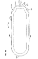
ロール型濾材又は濾材パック構成には、様々な外周の定義を提供できる。これに関して、「外周の定義」という用語又はその変形は、濾材又は濾材パックの入口端又は出口端の何れかにおいて見たときの、定義された外周形状を指すものとする。典型的な形状は、PCT国際公開第04/007054号パンフレットに記載されているように円形である。その他の使用可能な形状は長丸であり、長丸のいくつかの例は楕円形である。一般に、楕円形は1対の対向する辺でつなげられた対向する湾曲端を有する。いくつかの楕円形において、対向する面もまた湾曲している。トラック形とも呼ばれる他の楕円形では、対向する辺は概してまっすぐである。トラック形は、例えばPCT国際公開第04/007054号パンフレット及び、国際公開第04/082795号パンフレットとして公開されているPCT出願第04/07927号明細書に記載されており、その各々を参照によって本願に援用する。 Various perimeter definitions can be provided for roll media or media pack configurations. In this regard, the term "defined perimeter" or variations thereof shall refer to a defined perimeter shape when viewed at either the inlet or outlet end of a filter media or filter media pack. A typical shape is circular as described in PCT Publication No. WO 04/007054. Other usable shapes are oblongs, and some examples of oblongs are ovals. Generally, an ellipse has opposite curved ends joined by a pair of opposite sides. In some ellipses, the opposing faces are also curved. In other ellipses, also called track shapes, the opposite sides are generally straight. Track configurations are described, for example, in PCT Publication No. WO 04/007054 and PCT Application No. 04/07927, published as PCT Publication No. WO 04/082795, each of which is incorporated herein by reference. to refer to.
周辺又は外周形状を説明する別の方法は、濾材パックをロールの巻き上げ口に垂直な方向に切断することから得られる外周を定義することによる。 Another way to describe the perimeter or perimeter shape is by defining the perimeter that results from cutting the filter media pack in a direction perpendicular to the winding mouth of the roll.
濾材又は濾材パックの相互に反対の吸排気端又は吸排気面には、様々な異なる定義を提供できる。多くの構成において、端又は端面は概して平ら(平坦)であり、相互に垂直である。他の構成において、端面の一方又は両方が、テーパの付いた、例えば階段状の部分を含み、これは濾材パックの側壁の軸方向の端から軸方向に外側に突出するか、又は濾材パックの側壁の端から軸方向に内側に突出するかの何れかとして定義できる。 A variety of different definitions can be provided for the mutually opposed inlet and outlet ends or surfaces of a filter media or filter media pack. In many configurations, the ends or end faces are generally flat (flat) and perpendicular to each other. In other configurations, one or both of the end faces include a tapered, e.g. It can be defined as either projecting axially inwardly from the edge of the side wall.
フルートシール(例えば、シングルフェーサビード、巻き上げビード、又は積層ビードから)は、様々な材料で形成できる。引用され、援用される各種の文献において、ホットメルト又はポリウレタンシールが様々な用途に使用可能であると記載されている。 Flute seals (eg, from single facer beads, wound-up beads, or laminated beads) can be formed from a variety of materials. Various documents cited and incorporated describe that hot melt or polyurethane seals can be used in a variety of applications.
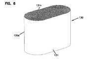
図6では、シングルフェース濾材の1つの条片を巻き上げることにより構成されるロール型濾材パック(又はロール型濾材)130が概して描かれている。図のような特定のロール型濾材パックは、楕円濾材パック130a、特にトラック形濾材パック131である。濾材の後端は、濾材パック130の外側にあり、131xで示されている。便宜と密閉のために、終端を濾材パック130のまっすぐな部分に沿って終了させることが典型的である。典型的に、ホットメルトシールビート又はシールビードは、シーリングを確実に行うために、この終端に沿って位置付けられる。濾材パック130において、相互に反対の吸排気(端)面は132、133に示されている。一方は入口側吸気面、他方は出口側排気面である。
FIG. 6 generally depicts a rolled filter media pack (or rolled filter media) 130 constructed by rolling up one strip of single-faced filter media. The particular roll media pack as shown is an
図7において、Z型フィルタ濾材の条片から積層Z型フィルタ濾材(又は濾材パック)を形成するステップが(概略的に)示されており、各条片はライナシートに固定されたフルート付シートである。図6を参照すると、シングルフェーサ条片200は、条片200と同様の条片202の積層体201に加えられているように示されている。条片200は、図4の条片76、77の何れかから切断できる。図6の205で、積層ビード206の塗布が、シングルフェーサビード又はシールから反対の端において条片200、202に対応する各々の層間に示されている。(積層はまた、各層を積層体の上ではなく下に追加して行うこともできる。)
In FIG. 7, the step of forming a laminated Z-filter media (or media pack) from strips of Z-filter media is shown (schematically), each strip being a fluted sheet secured to a liner sheet. is. Referring to FIG. 6, a
図7を参照すると、各条片200、202は前縁と後縁207、208及び対向する側縁209a、209bを有する。各条片200、202を含む波形シートとライナシートの組合せの入口及び出口フルートは概して、前及び後縁207、208との間に、側縁209a、209bに平行に延びる。
Referring to FIG. 7, each
さらに図7を参照すると、形成されている濾材又は濾材パック201において、相互に反対側の吸排気面が210、211で示されている。濾過中にどちらの面210、211を入口端面とし、どちらを出口端面とするかは、選択できる。いくつかの例において、積層ビード206は、上流、すなわち入口面211の付近に位置付けられ、他の例では、逆もまた真なりである。吸排気面210、211は、相互に反対側の面220、221間に延びる。
Still referring to FIG. 7, opposite intake and exhaust surfaces are shown at 210 and 211 in the filter media or
図7において形成されているように示されている積層された濾材構成又はパック201は、「ブロック型」積層濾材パックと呼ばれることがある。これに関する「ブロック型」という用語は、構成が、すべての面がすべての隣接する壁面に関して90°である長方形のブロックとして形成されることを示す。例えば、いくつかの例において、積層体は、各条片200が隣接する条片との整列からわずかにずらされて、入口面と出口面は相互に平行であるが、上下の面に対しては垂直でない平行四辺形又は傾斜ブロック形状を作ることによって形成できる。
The stacked media configuration or pack 201 shown as formed in FIG. 7 is sometimes referred to as a "block-type" stacked media pack. The term "block-shaped" in this context indicates that the configuration is formed as a rectangular block with all faces at 90° with respect to all adjacent walls. For example, in some instances, the laminations are arranged such that each
いくつかの例において、濾材又は濾材パックは何れの断面においても平行四辺形を有すると述べられ、これは、何れの対向する2面も相互に概して平行に延びることを意味する。 In some instances, a filter media or filter media pack is said to have a parallelogram in any cross-section, meaning that any two opposing faces extend generally parallel to each other.
留意される点として、図7に対応するブロック型の積層構成は、米国特許第5,820,646号明細書の先行文献に記載されており、これを参照によって本願に援用する。また、留意される点として、積層構成は米国特許第5,772,883号明細書、同第5,792,247号明細書、2003年3月25日に出願された米国仮特許出願第60/457,255号明細書、及び2003年12月8日に出願され、米国特許出願公開第2004/0187689号明細書として公開された米国特許出願第10/731,564号明細書に記載されている。これらの後者の参考文献の各々を参照によって本願に援用する。留意される点として、米国特許出願公開第2005/0130508号明細書として公開された米国特許出願第10/731,504号明細書に記載されている積層構成は傾斜した積層構成である。 It is noted that a block-type stacking configuration corresponding to FIG. 7 is described in the prior document US Pat. No. 5,820,646, which is incorporated herein by reference. It is also noted that the laminate construction is described in U.S. Pat. Nos. 5,772,883; /457,255, and in U.S. Patent Application No. 10/731,564, filed Dec. 8, 2003 and published as U.S. Patent Application Publication No. 2004/0187689. there is Each of these latter references is incorporated herein by reference. It is noted that the laminate configuration described in US Patent Application No. 10/731,504, published as US Patent Application Publication No. 2005/0130508, is a tilted laminate configuration.
同じく留意される点として、いくつかの例において、複数の積層体を1つの濾材パックに組み込むことができる。また、いくつかの例において、積層体はその中に凹部を有する1つ又は複数の吸排気面を有するように生成でき、これは例えば米国特許第7,625,419号明細書に示されており、これを参照によって本願に援用する。 Also noted, in some instances, multiple laminations may be incorporated into a single media pack. Also, in some examples, the laminate can be produced with one or more ventilation surfaces having recesses therein, such as shown in U.S. Pat. No. 7,625,419. , which is incorporated herein by reference.
C.フルート付き濾材の複数の離間されたロールを含む、選択された濾材又は濾材パック構成 図8~8B
両端間に延びるフルートを含む別の種類の濾材構成又はパックが、本開示による選択された原理と共に使用できる。このような代替的濾材構成又はパックの一例が図8~8Bに示されている。図8~8Bの媒体は、独国特許第20 2008 017 059 U1号明細書に描かれ、記載されているものと同様であり、Mann & Hummelから「IQORON」の商標で入手可能な構成の中に見られることがある。
C. Selected filter media or filter media pack configurations comprising multiple spaced apart rolls of fluted filter media FIGS. 8-8B
Other types of filter media configurations or packs that include flutes extending across them can be used with selected principles according to the present disclosure. An example of such an alternative filter media configuration or pack is shown in FIGS. 8-8B. The media of FIGS. 8-8B are similar to those depicted and described in
図8を参照すると、濾材又は濾材パックが概して250で示されている。濾材又は濾材パック250は、第一の外側プリーツ付(畝付)濾材ループ251と、第二の内側プリーツ付(畝付)濾材ループ252と、を含み、各々のプリーツ先端(又は畝)は相互に反対側の吸排気端間に延びる。図8の図は、濾材パックの(吸排気)端255に向かっている。図の端255は、選択された流れの方向に応じて、入口(吸気)端とも出口(排気)端ともなりうる。特徴付けられた原理を用いた多くの構成に関して、濾材パック250は、フィルタカートリッジの中で、端255が入口吸気端であるように構成されるであろう。
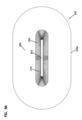
Referring to FIG. 8, a filter media or filter media pack is indicated generally at 250 . The filter media or
さらに図8を参照すると、外側プリーツ付(畝付)濾材ループ251は、楕円形に構成されているが、他の選択肢もありうる。260において、例えばモールド・イン・プレース加工によるプリーツ端閉鎖手段が、濾材パック端部255でプリーツ又は畝251の端を閉じているように示されている。
Still referring to FIG. 8, the outer pleated (ridged)
プリーツ又は畝252(及びそれに関連するプリーツ先端)は、ループ251によって取り囲まれ、そこから離間されるように位置付けられ、それゆえ、プリーツ付濾材ループ252もまた略楕円形に示されている。この例において、ループ252内の個々のプリーツ又は畝252pの端252eが密閉されている。また、ループ252は、典型的にモールド・イン・プレース加工による材料の中央条片253によって閉鎖された中央252cを取り囲む。
Pleats or ridges 252 (and their associated pleat tips) are surrounded by
濾過中に、端255が入口吸気端である場合、空気は2つの濾材ループ251、252間のギャップ265に入る。次に空気は、濾材パック250の中を移動しながらループ251又はループ252の何れかを通って流れ、濾過される。
During filtration, air enters the
図の例において、ループ251は、端255から離れた領域で、ループ252に向かって内側に傾斜するように構成される。また、構造健全性のために、ループ252の端を取り囲むセンタリングリング267を支持するスペーサ266も示されている。
In the illustrated example,
図8Aでは、カートリッジ250の、端255と反対の端256が見えている。ここで、ループ252の内部が開放したガス流領域270を取り囲んでいることがわかる。空気がカートリッジ250を通って端256に向かい、端255から離れる全体的方向に案内されると、空気のうち、ループ252を通過する部分が中央領域270に入り、そこから端256を通って出る。もちろん、濾過中に図8のループ251に入った空気は概して、端256の外周256pの周囲を(それを覆うように)流れる。
In FIG. 8A, end 256 of
図8Bにおいて、カートリッジ250の概略断面図が提供される。特定され、説明された特徴のうち選択されたものは同様の参照番号で示されている。
In FIG. 8B, a schematic cross-sectional view of
図8~8Bの上記の説明からわかるように、記載されているカートリッジ250は概して両方の吸排気端255、256間に長手方向に延びる濾材先端を有するカートリッジである。
As can be seen from the above description of FIGS. 8-8B, the
図8~8Bの構成において、濾材パック250は楕円形、特にトラック形外周を有するように描かれている。このようにして示されているのは、後述の多くの例におけるエアフィルタカートリッジも楕円形又はトラック形構成であるからである。しかしながら、この原理は様々な代替的な外周形状で具現化することができる。
In the configuration of Figures 8-8B, the
D.濾材の他の変形型 図9~12
ここで、図9~12において、本明細書中で特徴付けられる原理の選択された応用の中で使用可能な種類の濾材のさらにまた別の代替的変形型の断面図が提供されている。特定の例は、2014年11月10に出願された、本開示の譲受人であるDonaldson Company,Inc.が所有する米国特許出願第62/077,749号明細書に記載されている。一般に、図9~12の構成の各々は、相互に反対の入口及び出口吸排気端(又は面)を有し、まっすぐの通過流を有する構成に積層又はロール状に巻き上げることのできる濾材の種類を示している。
D. Other variations of filter media Figures 9-12
9-12, cross-sectional views of yet another alternative variation of the type of filter media that can be used in selected applications of the principles featured herein are provided. A specific example is Donaldson Company, Inc., the assignee of the present disclosure, filed November 10, 2014; US patent application Ser. No. 62/077,749, owned by In general, each of the configurations of FIGS. 9-12 has mutually opposite inlet and outlet inlet and outlet ends (or faces) and is a type of filter media that can be stacked or rolled into a configuration with straight through flow. is shown.
図9において、米国特許出願第62/077,749(2658)号明細書からの例示的濾材構成301が示されており、その中ではエンボスシート302がエンボスのないシート303に固定され、その後、積層し、又は巻き上げて濾材パックが形成され、本願の図1に関してすでに説明した種類の対向する辺に沿ってシールされる。
9, an exemplary
図10において、米国特許出願第62/077,749号明細書からの別の例示的濾材パック310が示されており、その中では第一のエンボスシート311が第二のエンボスシート312に固定され、その後、積層型又はロール型濾材パック構成に形成され、概して本願の図1により縁部がシールされる。
10, another exemplary
図11において、米国特許出願第62/077,749号明細書からの第三の例示的濾材構成320が示されており、その中では、両面がエンボス加工されたシート321が同様であるが逆にされた濾材の他の層322に固定され、積層され、又は巻き上げられて濾材パック320が構成され、図1と概して同様に縁部がシールされる。 A third exemplary filter media configuration 320 from US Patent Application No. 62/077,749 is shown in FIG. 11 in which a double-sided embossed sheet 321 is similar but reversed. Another layer 322 of flattened filter media is secured, laminated, or rolled up to form a filter media pack 320 and edge sealed generally as in FIG.
縁部シールは、上流端又は下流端の何れかで、又はいくつかの例においてはその両方で実行できる。特に濾材がフィタリング中に化学物質と遭遇する可能性がある場合、典型的な接着剤又はシーラントを避けることが望ましいかもしれない。 Edge sealing can be performed at either the upstream end or the downstream end, or in some instances both. It may be desirable to avoid typical adhesives or sealants, especially if the filter media may encounter chemicals during filtering.
図11Aにおいて、フルート付きシートXがその上に、ライナシートYと係合するための各種のエンボス加工部を有する断面が示されている。再び、これらは別々とすることも、又は同じ濾材シートの切片とすることもできる。 In FIG. 11A, the fluted sheet X is shown in cross-section with various embossments thereon for engaging the liner sheet Y. In FIG. Again, these can be separate or segments of the same filter media sheet.
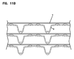
図11Bにおいて、フルート付きシートXとライナシートYとの間のこのような構成の概略図も示されている。 A schematic of such a configuration between fluted sheet X and liner sheet Y is also shown in FIG. 11B.
図11Cにおいて、このような原理のまた別の変形型がフルート付きシートXとライナシートYとの間に示されている。これらは、様々な方式がどのように可能であるかを理解しやすくするためのものである。 Another variation of this principle is shown between the fluted sheet X and the liner sheet Y in FIG. 11C. They are meant to make it easier to understand how different schemes are possible.
図12において、フルート付きシートXとライナシートYにおけるさらに別の可能な変形型が示されている。 In FIG. 12, yet another possible variation in fluted sheet X and liner sheet Y is shown.
図12A及び12Bにおいて、例示的な濾材構成6401が示されており、その中で、フルート付きシート6402がライナシート6403に固定されている。ライナシート6403は平坦シートであってもよい。その後、濾材構成6401を積層され、又は巻き上げることによって濾材パックとすることができ、本願の図1に関して前述した種類の対向する縁に沿ったシールが設けられる。図の実施形態において、フルートシート6402のフルート6404は、一連の頂点6405と支持部6406を含む波状にうねる稜線を有する。隣接するフルート6404の頂点6405は、図12A及び12Bに示されていように整列させることも、又はずらすこともできる。さらに、頂点の高さ及び/又は密度をフルート6404の長さに沿って増大させることも、減少させることも、又は一定とすることもできる。頂点におけるフルート高さと支持部におけるフルートの高さの比は、約1.5、典型的には1.1~約1の範囲とすることができる。
12A and 12B, an exemplary
留意される点として、フルート付きシート切片とライナシート切片に同じ濾材を使用するという要求事項は特にない。各々において、異なる効果を得るために、異なる濾材が望ましいい可能性もある。例えば、一方はセルロース濾材であってもよく、他方は何れかのセルロース以外の繊維を含む濾材である。これらには、所望の結果を得るために、異なる気孔率又は異なる構造的特徴が付与されていてもよい。 It should be noted that there is no specific requirement to use the same filter media for the fluted sheet segment and the liner sheet segment. Different filter media may be desirable in each to achieve different effects. For example, one may be a cellulosic filter medium and the other is any filter medium containing non-cellulose fibers. They may be endowed with different porosities or different structural characteristics to achieve desired results.
様々な材料を使用できる。例えば、フルート付きシート切片又はライナシート切片は、セルロース材料、合成材料、又はその混合物を含むことができる。いくつかの実施形態において、フルート付きシート切片とライナシート切片のうちの一方は、セルロース材料を含み、フルート付きシート切片とライナシート切片の他方は合成材料を含む。 Various materials can be used. For example, fluted sheet segments or liner sheet segments can comprise cellulosic materials, synthetic materials, or mixtures thereof. In some embodiments, one of the fluted sheet segment and the liner sheet segment comprises a cellulosic material and the other of the fluted sheet segment and the liner sheet segment comprises a synthetic material.
合成材料としては、ポリマ繊維、例えばポリオレフィン、ポリアミド、ポリエステル、ポリ塩化ビニル、(加水分解度の異なる)ポリビニルアルコール、及びポリビニルアセテート繊維を含むことができる。適当な合成繊維としては、例えばポリエチレンテレフタレート、ポリエチレン、ポリプロピレン、ナイロン、及びレーヨン繊維が含まれる。その他の適当な合成繊維としては、熱可塑性ポリマ、熱可塑性ポリマでコーティングされたセルロース及びその他の繊維、及び成分の少なくとも1つが熱可塑性ポリマを含む多成分繊維が含まれる。単成分及び多成分繊維は、ポリエステル、ポリエチレン、ポリプロピレン、及びその他の従来の熱可塑性繊維材料から製造できる。 Synthetic materials can include polymer fibers such as polyolefins, polyamides, polyesters, polyvinyl chloride, polyvinyl alcohol (with different degrees of hydrolysis), and polyvinyl acetate fibers. Suitable synthetic fibers include, for example, polyethylene terephthalate, polyethylene, polypropylene, nylon, and rayon fibers. Other suitable synthetic fibers include thermoplastic polymers, cellulose and other fibers coated with thermoplastic polymers, and multicomponent fibers in which at least one of the components comprises a thermoplastic polymer. Monocomponent and multicomponent fibers can be made from polyester, polyethylene, polypropylene, and other conventional thermoplastic fiber materials.
図9~12Bの例は、概して、本願の原理により様々な代替的濾材パックを使用できることを示すものである。また、いくつかの代替的な濾材の種類の構成と応用の全体的原理に関して、米国特許出願第62/077,749号明細書にも注目し、これを参照によって本願に援用する。 The examples of Figures 9-12B generally demonstrate that various alternative media packs can be used in accordance with the principles of the present application. Attention is also directed to US patent application Ser. No. 62/077,749 for general principles of construction and application of several alternative filter media types, which is incorporated herein by reference.
E.また別の種類の濾材
本願で特徴付けられている技術の多くは、好ましくは、カートリッジの相互に反対側の吸排気端間で濾過する向きの濾材が、これら両端間のある方向に延びるフルート又はプリーツ先端を有する濾材である場合に適用される。しかしながら、他の選択肢もありうる。シール構成の定義に関して本願で特徴付けられる技術は、相互に反対の吸排気端を有し、濾材がこれらの端間の流体の流れを濾過するように位置付けられたフィルタカートリッジにおいて、濾材がこれらの端の間のある方向に延びるフルート又はプリーツ先端を含まない場合であっても応用可能である。濾材は例えば、デプスタイプ濾材とすることができ、交互方向にプリーツを付けることができ、又はプリーツを持たない材料とすることもできる。
E. Yet Another Type of Filter Media Many of the techniques featured in this application preferably include filter media oriented to filter between opposite inlet and outlet ends of the cartridge, with flutes or filters extending in a direction between these ends. Applies to filter media with pleated tips. However, other options are possible. The technique featured in this application with respect to the definition of the seal arrangement is a filter cartridge having mutually opposed intake and exhaust ends, the filter media positioned to filter fluid flow between those ends, and the filter media It is applicable even if it does not include flutes or pleat tips extending in one direction between the ends. The filter media can be, for example, depth-type filter media, can be pleated in alternating directions, or can be an unpleated material.
しかしながら、実際に、本願で特徴付けられる技術は、吸排気端間の範囲が比較的深く、通常、少なくとも100mm、典型的に少なくとも150mm、多くの場合に少なくも200mm、時には少なくとも250mm、及びいくつかの例においては300mm又はそれ以上であり、使用中に大きな負荷体積を処理するように構成されたカートリッジでの使用に特に有利である。これらのタイプのシステムは典型的に、プリーツ先端又はフルートが相互に反対側の吸排気端間である方向に延びるような濾材が構成されるものである。 In practice, however, the technology featured in this application has a relatively deep end-to-end range, usually at least 100 mm, typically at least 150 mm, often at least 200 mm, sometimes at least 250 mm, and some 300 mm or more in the example, which is particularly advantageous for use with cartridges configured to handle large load volumes during use. These types of systems typically comprise a filter media having pleat tips or flutes extending in one direction between opposite intake and exhaust ends.
同じく留意される点として、本明細書に記載の技術は典型的に、直線的流動構成の濾材パックを含む有利な用途及び装置のために開発されたものであるが、この技術は他のシステムに利するためにも応用できる。例えば、この技術は、カートリッジが中央内部を取り囲む濾材を含む場合に応用でき、この場合、カートリッジは開放端を有する。このような装置には濾過すべき空気が濾材を通過することによって中央の開放型の内部に入り、開放端を通って出る「順流」が関わることができ、又は、濾過すべき空気が開放端に入り、その後、方向転換して濾材を通過する逆流が用いられる。様々なこのような装置が可能であり、これにはプリーツ付濾材及びその他の種類の濾材が含まれる。使用可能な構成には、とりわけ円筒形及び円錐形が含まれるであろう。 It is also noted that although the technology described herein has typically been developed for advantageous applications and devices involving filter media packs in linear flow configurations, the technology may be used in other systems. It can also be applied to benefit For example, this technique is applicable where the cartridge includes a filter media surrounding a central interior, in which case the cartridge has an open end. Such devices can involve a "forward flow" in which the air to be filtered enters the interior of a central open mold by passing through the filter media and exits through the open ends, or the air to be filtered is passed through the open ends. A reverse flow is used that enters and then turns to pass through the filter media. A variety of such devices are possible, including pleated filter media and other types of filter media. Useable configurations would include cylindrical and conical, among others.
II.空気清浄装置の設計及び修理点検に関する幾つかの一般的な問題
A.空気清浄装置アセンブリを用いる機器システム全般、図13
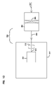
図13において、エンジン機器装置360の略図が示されている。機器システム360は、この例では、燃焼空気入口363を備える内燃機関装置362を有する車両又はその他の機器361を含む。機器装置360は空気清浄装置システム365を含み、これはその中にフィルタ装置366を有し、これは典型的に修理点検可能な(すなわち、取外し可能且つ交換可能な)フィルタカートリッジを含む。システムへの吸気は367において、空気清浄器アセンブリ365の中へと向かうように示されており、その後、濾過前の空気がフィルタカートリッジ装置366の濾材を通じて濾過される。368で、濾過された空気は機器の空気入口363へと向かうように示されている。370には、ターボシステム等の任意選択による機器が示されている。
II. Some common problems with air cleaning device design and servicing A. Equipment system in general using the air freshener assembly, FIG. 13
In FIG. 13, a schematic representation of the
もちろん、代替的な機器システムを図13のそれらと同様の装置により表すこともできる。機器システムは例えば、工業用エアフィルタ、タービンに関連して使用される空気清浄装置構成等とすることができる。内燃機関に関連する使用は典型的であるが、本明細書において特徴付けられる原理の多くにとって特に必要とされるものではない。 Of course, alternative equipment systems could be represented by devices similar to those of FIG. Equipment systems can be, for example, industrial air filters, air cleaner arrangements used in conjunction with turbines, and the like. Use in connection with internal combustion engines is typical, but not specifically required, for many of the principles featured herein.
B.空気清浄機に取付け可能なカートリッジがその空気清浄装置にとって確実に適当であるようにすること
一般に、フィルタ機器の吸気に使用されるような空気清浄装置は、その中に少なくとも1つのメインフィルタカートリッジが設置される筐体と、時々、安全装置とを含む。メインフィルタカートリッジは一般に、機器のための吸気ストリームの中に流入する微粒子汚染物質を回収するように構成される。これは機器が損傷を受けるのを防止する。このようなフィルタカートリッジは一般に、取り外されて交換されるように構成され、すなわち、これらは修理用部品である。様々な所定の修理点検間隔で、及び/又は(粉塵負荷からの)制約の増大が問題となったときに、カートリッジは空気清浄装置から取り外され、手入れがされるか又は交換される。
B. Ensuring that the Cartridge Attachable to the Air Purifier is Appropriate for the Air Purifying Device Generally, air purifying devices, such as those used for the air intake of filtering devices, include at least one main filter cartridge therein. Includes an installed enclosure and sometimes a safety device. The main filter cartridge is generally configured to collect particulate contaminants entering the intake stream for the instrument. This prevents the equipment from being damaged. Such filter cartridges are generally configured to be removed and replaced, ie they are service parts. At various predetermined service intervals and/or when increased constraints (from dust loads) become a problem, the cartridge is removed from the air cleaning device and serviced or replaced.
多くの場合、カートリッジは特に機器の製造業者の動作に対する要求事項にマッチするように設計される。現場で交換されるカートリッジが関係する機器にとって正しいものであり、それゆえ適正にフィットし、シールされることを確実にすることが重要である。 In many cases, cartridges are designed specifically to match the operating requirements of the equipment manufacturer. It is important to ensure that the cartridge being replaced in the field is the correct one for the equipment involved and is therefore properly fitted and sealed.
一般に、フィルタカートリッジと空気清浄装置との間の主な接合面は筐体シールに沿っている。この接合面は時々、フィットするカートリッジが関心対象システムにとっても適正なものであることを確実にするのを助けるために使用されている。例は米国特許第8,864,866号明細書により挙げられており、その開示を参照によって本願に援用する。この具体的な参考文献では、凸部及び/又は凹部を通じたシール面の変化が一般的な用語で説明されている。これらの一般的原理は本願にも適用され、特定の用途については改良と変更を伴う。 Generally, the primary interface between the filter cartridge and the air cleaning device is along the housing seal. This mating surface is sometimes used to help ensure that the cartridge that fits is also the correct one for the system of interest. Examples are given by US Pat. No. 8,864,866, the disclosure of which is incorporated herein by reference. In this specific reference, changes in the sealing surface through protrusions and/or recesses are described in general terms. These general principles apply to this application as well, with modifications and variations for specific applications.
本明細書において、説明されている原理は、特にフィルタカートリッジ上に位置付けられた筐体シールが「半径方向」又は「半径方向に向かう」シールである装置において実装されることを特徴とする。これによって意味しようとするのは、使用中のシールのために、概して筐体の周辺部分に向かって方向付けられる圧縮シール力を加えるために使用されるか、又は、代替的に、筐体のうちシールにより取り囲まれる部分に向かって方向付けられるシール力を利用するシールである。本明細書において特徴付けられる種類のフィルタカートリッジでは、半径方向のシールは一般に、流路を取り囲むシールとなり、主な圧縮方向(取付け時)は流路に向かうか、又はその反対に向かう。外側に、又は半径方向に外側に向けられるシールは、(カートリッジの)シール装置に、使用中に周囲の構造とシール状態で係合するシール面を有するものとなる。半径方向に内側に向けられるシールは、カートリッジのシール面が、使用中にそれがシールされる構造を取り囲むシール装置である。 The principles described herein are characterized in that they are particularly implemented in devices in which the housing seal located on the filter cartridge is a "radial" or "radially directed" seal. By this is meant to be used to apply a compressive sealing force generally directed toward the peripheral portion of the housing for the seal in use, or alternatively, the A seal that utilizes a sealing force directed toward a portion of it that is surrounded by the seal. In filter cartridges of the type featured herein, the radial seal will generally be a seal surrounding the flow path, with the primary direction of compression (when installed) either toward or away from the flow path. An outwardly or radially outwardly oriented seal will have a sealing surface which, in use, sealingly engages the surrounding structure in the sealing device (of the cartridge). A radially inward directed seal is a sealing device in which the sealing surface of the cartridge surrounds structure against which it is sealed during use.
C.関心対象の筐体の半径方向のシールが筐体内の最も奥に位置付けられるシステムへのカートリッジの取付け、及び/又は側面装填が関わる場合の問題に関する所見
多くの場合、カートリッジ上のシールと係合することになるシール面は筐体内の最も奥に位置付けられてサービス業者から見えない。それに加えて、筐体の大きさとカートリッジの遮蔽効果とにより、カートリッジの取付け中にシール面を手で触ることが、不可能でなくても困難であり得る。単に単純又は均一な幾何学的形状、例えば円形又は楕円形ではないシールを有するカートリッジを使用することに伴う問題は、設計に応じて、取付け中にシーリングが適切に行われるようにするためにカートリッジを適当に向き付けることが難しい可能性がある。本明細書において特徴付けられる技術の何れかは、応用時にこれを容易にするために有益であり、これは以下のさらに詳しい説明からわかるであろう。
C. Observations regarding problems when mounting and/or side-loading cartridges into systems where the radial seal of the housing of interest is positioned furthest within the housing often engages seals on the cartridge. The corresponding sealing surface is located at the innermost part of the housing and is not visible to the service provider. In addition, due to the size of the housing and the shielding effect of the cartridge, it can be difficult, if not impossible, to touch the sealing surface during cartridge installation. A problem with using cartridges that simply have seals that are not simple or uniform geometries, e.g., circular or elliptical, is that, depending on the design, the cartridges must be designed to ensure proper sealing during installation. can be difficult to properly orient. Any of the techniques featured herein are useful to facilitate this in application, as will be seen from the more detailed description below.
問題は、カートリッジが側面装填用に構成される場合、より悪化することがあり得る。側面装填とは、筐体のうちカートリッジが使用中に取り付けられる部分を意味する。特に、いくつかの例において、直線的流動カートリッジは筐体の側面から装填され、その後、シーリングが位置付けられるように横方向に押し込まれる。良好なシーリングを得るために、カートリッジを適正に操作し、移動させる(leverage)することは困難であり得る。装填を容易にするのに有益な特徴を備える有利な側面装填構成の例は、例えば米国特許第7,396,375号明細書、米国特許第7,655,074号明細書、米国特許第7,905,936号明細書、米国特許第7,713,321号明細書、及び米国特許第7,972,404号明細書に記載されており、これらを参照によって本願に援用する。 The problem can be exacerbated if the cartridge is configured for side loading. Side-loading refers to the portion of the housing where the cartridge is mounted during use. Specifically, in some instances, the linear flow cartridge is loaded from the side of the housing and then pushed laterally so that the seal is positioned. Properly manipulating and leveraging the cartridge to obtain a good seal can be difficult. Examples of advantageous side-loading configurations with features beneficial for facilitating loading are e.g. , 905,936, U.S. Pat. No. 7,713,321, and U.S. Pat. No. 7,972,404, which are incorporated herein by reference.
前段落で挙げた参照文献の構成は一般に、楕円形のシール、典型的にはレーストラック形の楕円形(シール面内で直線の側辺が半円形の端で分離された形状)を用いている。シール面に変化をもたらしたい場合、どのように実装されるかに応じて、側面装填にとって良好で好都合な取付けを可能にすることは時として難しい可能性がある。本明細書に記載の幾つかの原理は、装填を容易にするために、このような状況において特に有益であることを特徴とする。 The configurations of the references listed in the preceding paragraph generally employ an elliptical seal, typically a racetrack ellipse (a shape with straight sides separated by semi-circular ends in the plane of the seal). there is Depending on how it is implemented, it can sometimes be difficult to allow good and convenient mounting for side loading if one wants to effect a variation in the sealing surface. Some of the principles described herein are characterized as being particularly useful in such situations for ease of loading.
III.第一の例示的アセンブリ、図14~22
A.アセンブリの一般的特徴、図14~15A
本開示による原理のうちの選択されたものは、図14~22を参照すると理解できる。図の例は、以下からわかるように、その中にメインフィルタカートリッジが取外し可能に取り付けられた空気清浄装置アセンブリである。さらに、アセンブリは、「端面装填」型として構成されており、筐体のアクセスカバーがカートリッジの空気流出口とは反対の端にあることを意味する。原理は別の筐体構成においても応用できる。
III. First Exemplary Assembly, FIGS. 14-22
A. General Features of Assembly, Figures 14-15A
Selected ones of the principles according to the present disclosure can be understood with reference to FIGS. 14-22. The illustrated example is an air freshener assembly with a main filter cartridge removably mounted therein, as will be seen below. Additionally, the assembly is configured as an "end-loading" type, meaning that the housing access cover is at the opposite end of the cartridge from the air outlet. The principle can also be applied in other housing configurations.
ここで図14を参照すると、参照番号400は本開示による原理のうちの選択されたものによる空気清浄装置アセンブリを概して示す。空気清浄装置アセンブリ400は筐体401を含む。筐体401は一般に、本体403と、この場合はラッチ405により所定の位置に固定されるアクセスカバー404を含む。図の例において、アクセスカバー404は筐体本体403から完全に取外し可能であるが、原理は他の構成にも応用できる。
Referring now to FIG. 14,
筐体401は一般に、空気流入口装置407と空気流出口装置408を画定する。濾過すべき空気は入口407から筐体401に入り、内部に位置付けられたフィルタ装置を通過し、濾過された空気は出口装置408を通って出る。図の例において、使用中、入口装置407を通る入口流は筐体内に取り付けられたカートリッジを通る空気流に対して概して垂直であり、出口装置408を通る空気流は取り付けられたフィルタカートリッジを通る空気流の方向と概して一致するが、原理は他の構成でも実行できる。
図14において、使用のための機器内での向きは特に示そうとしていない。アセンブリ400は使用のために、側面の1つ、例えば図14において見ている人に面する側面を上向きに、下向きに、又は横向きにして、方向付けることができる。本明細書に記載の原理は、様々なこのような装置に応用でき、特定の向きが要求されることはない。実際に、これは、本開示による装置の利点となり得る。
In FIG. 14, no particular orientation within the instrument for use is intended to be shown.
図14Aにおいて、アセンブリ400の選択された斜視図が示されている。すでに明示されたものと同様の特徴は、同様の参照番号で示されている。図の筐体401は任意選択により、それによって機器を固定できる各種の取付けパッド409を含む。
14A, a selected perspective view of
図15において、空気清浄装置アセンブリ400の分解立面図が示されている。ここでは、内部の特徴に到達するためにアクセスカバー404が本体403から取り外されているように示されている。任意選択によるウェザガスケット411が示されている。これは、希望に応じて、本体403内のアクセスカバー404のうちの一方又は他方に固定できるか、又は、これは別の部品とすることができる。ウェザガスケット411は、取付け時にアクセスカバー404と本体403との間にウェザシールを提供して、例えば水(例えば雨水)の移動が筐体401の内部に進入するのを阻止するのを助ける。
15, an exploded elevational view of
図15の例では、入口装置407と出口装置405の両方が本体403上に描かれて示されているが、代替案も可能である。また、前述のように、入口及び出口装置407/408は代替的な位置又は向きとすることもできる。
Although both the
さらに図15を参照すると、空気清浄装置アセンブリ400は、内側に受けられた、取外し可能且つ交換可能(すなわち、修理点検可能)なメインフィルタカートリッジ415を含む。アセンブリ400はまた、任意選択による安全フィルタカートリッジ416を有するように描かれている。この例示的なアセンブリにおいて、安全フィルタカートリッジ416は使用時にメインフィルタカートリッジ415の下流に位置付けられる。
Still referring to FIG. 15, the
メインフィルタカートリッジ415は、使用中、空気流ストリームから分離された微粒子物質の大部分を捕集する役割を果たす。安全フィルタカートリッジ416は様々な機能を提供する。これは、メインフィルタカートリッジ415が取り外されて修理点検されているときにその場に残すことができ、それゆえ、清浄な空気のための出口を、筐体及び格子の内部からその上に落ちる粉塵から保護する。フィルタカートリッジ安全装置416はまた、メインフィルタカートリッジ415の濾材又はシールに不良があった場合の幾分かの粉塵を捕集することもできる。これらは、安全フィルタカートリッジのよく知られた用途である。図の特定の安全フィルタカートリッジ416は一般に既知の種類のものであり、例えば米国特許第7,905,936号明細書を参照されたく、それを参照によって本願に援用する。
The
図15Aにおいて、アセンブリ400の分解斜視図が示されており、これによって前述の一般的コンポーネントをさらによく見ることができる。安全フィルタカートリッジ416、特に取付け用突起417及びハンドル又はハンドル装置418に注目されたい。このような特徴は、例えば前述の米国特許第7,905,936号明細書に記載されており、それを参照によって本願に援用する。安全フィルタカートリッジ416の取付け中、典型的にサービス業者は安全フィルタカートリッジ416を筐体本体403に押し込み、突起417を本体403に適切に位置付けられた受容部と係合させる。このようにして、ユーザは安全フィルタカートリッジ416を、ハンドル418を使って所定の位置へと移動できる(leverage)。図の特定の安全フィルタカートリッジ416は、周辺シール419を使用しており、これは安全装置416が適正に取り付けられると、筐体の周辺部分と(半径方向のシールとして)係合する。それゆえ、安全装置416は、本明細書中、先に特徴付けられた用語で外側に向かう半径方向のシールを使用する。
In FIG. 15A, an exploded perspective view of
図15及び15Aをよく見ると、図のアセンブリ400は、上記のこのような用語の特徴にしたがい、メインフィルタカートリッジ415が端面装填を通じて取り付けられるものであることがわかる。この例では、メインカートリッジ415は取付け中に筐体本体403の中に押し込まれ、排気端又は出口装置408に向けられる。図15及び15Aを参照すると、メインフィルタカートリッジ415がカートリッジ415の、取付け中に筐体本体403の中の最も奥に位置付けられる端にあるシール装置420を含むことがわかる。図の例において、これはカートリッジ415の下流の排気端である。
15 and 15A, it can be seen that the illustrated
B.メインフィルタカートリッジ415の一般的特徴、図16~19
メインフィルタカートリッジ415の選択された特徴は、図16~19をよく見ると理解できる。
B. General Features of
Selected features of the
まず図16を参照すると、メインフィルタカートリッジ415は一般に、相互に反対側にある吸排気端424、425を有する、まっすぐの通過流のために構成された濾材パックを含む。本明細書において、「吸排気端」という用語は、濾材パック427又はフィルタカートリッジ415について使用された場合、使用中に空気がその中に(又はそこから)流れる端面又は領域を意味する。典型的に、吸排気端は平坦であるが、代替案も可能である。一般に、端の一方は吸気端であり、反対の端は排気端となる。図の特定のフィルタカートリッジ415の場合、吸排気端424は吸気端であり、吸排気端425は排気端である。濾材パック427は一般に空気用濾材を含み、これは閉じられて、入口端424からカートリッジに入る吸気の通過が、濾過のために濾材を通過せずに排気端425から出るのを阻止する。
Referring first to FIG. 16, the
フィルタカートリッジ415は一般に、濾材パック427を含む。濾材パックは、行われようとする濾過動作にとって適当な濾材を含み、一般に空気は両側の端を通って流れる。図1~12Bに関して上で特徴付けた濾材を使用できる。図の特定の例示的な濾材パック429は一般に楕円形であり、相互に反対側にある湾曲端427a、427bは典型的に、ほぼ半円形であり、それらの間に比較的まっすぐの(相互に反対側にある)第一及び第二の側面部分427c、427dが延びる。このような濾材パックは、前述の説明によるライナ濾材に固定された波形濾材のロール型条片から製作できるが、代替案も可能である。
図の特定の濾材パック427は典型的に、例えば米国特許第8,226,786号明細書の技術により、中心コアを設けずに構成されるが、中心コアが提供される代替案も可能である。濾材パック427は、それを取り囲む外側シース、シールド、又は保護コーティングを含んでいてよい。しかしながら、多くの用途では、濾材パック427の、濾材パックの露出部の長さの大部分に沿った外面427sは、おそらくラベル以外の外側保護コーティングを持たないライナ濾材を含む。
The particular
図16~19の例を含む多くの例において、本開示によるメインフィルタカートリッジは、その上に1つ又は複数の任意選択により「プリフォーム」を含む。これに関する「プリフォーム」という用語及びその変化形は、典型的には事前に作られ、例えばプラスチックから成形され、その後フィルタカートリッジの濾材に、接着剤若しくはシーラント材料又は硬化若しくは凝固するその他の材料を使って固定される構造的部品を意味する。プリフォームは一般によく知られており、例えば米国特許第7,905,936号明細書、米国特許第7,713,321号明細書、及び米国特許第7,972,404号明細書を参照されたい。 In many examples, including the examples of FIGS. 16-19, the main filter cartridge according to the present disclosure includes one or more optionally "preforms" thereon. The term "preform" and variations thereof in this context are typically preformed, e.g., molded from plastic, and then applied to the filter media of the filter cartridge with an adhesive or sealant material or other material that hardens or solidifies. means a structural part that is secured using Preforms are generally well known, see for example US Pat. Nos. 7,905,936, 7,713,321, and 7,972,404. sea bream.
図16~19の特定のカートリッジ415は、2つのこのような任意選択によるプリフォームを含み、概して430、431で示される。プリフォーム430は、端424の付近に位置付けられる。これは、この例において吸排気端424と軸方向に重複する取付け用ハンドル装置434と、濾材パック427を取り囲む周囲装置435とを含む。プリフォーム430は、所定の場所に位置付け、希望に応じて接着剤により、又はシール材料で固定できる。しかしながら、プリフォーム430は筐体シール装置420の上流に位置付けられるため、プリフォーム430と濾材427との間のシールは重要ではない。図16を参照すると、プリフォーム430はまた、濾材の端424と軸方向に整列する任意選択による端部格子装置435も含む。端部格子435は、プリフォーム430と濾材パック427の濾材との両方に強度、構造、及び完全性を提供できる。
The
図17を参照すると、プリフォーム431は吸排気端425の付近に位置付けられる。プリフォーム431は、シール支持プリフォームであり、その上に濾材の端425を歪みに対して安定化させるための任意選択による格子440を含む。シール支持プリフォーム431として、プリフォーム431はその上に、後述の、使用中にシール装置420のシール材料445に対するシーリング圧を支持するように位置付けられたシール支持部分441を含む。
Referring to FIG. 17,
様々なシール装置420を使用できる。図の特定の装置は、シール材料がモールド・イン・プレース加工されてプリフォーム431の所定の位置に固定され、また、シール材料445のシール面445aも形成するシール装置を使用している。米国特許第7,396,376号明細書及び米国特許第8,409,316号明細書に記載されているもののような技術を使用できるが、代替案も可能である。
図18、すなわちフィルタカートリッジ415の分解斜視図に注目する。前述の各種の特徴が容易に見える。プリフォーム431に関して、シール支持フランジ447に注目され、これは、理解されるように、シーリング中にシール材料445を支持するために、シール装置420の適当な部分に向かって突出している。
Attention is directed to FIG. 18, an exploded perspective view of
図19には代替的な分解斜視図が示されており、これは概してカートリッジ415の吸排気端424に向かって見たものである。
An alternative exploded perspective view is shown in FIG. 19 looking generally toward the intake and
さらに図16~19を参照すると、特定のシール装置420が、シール面445aが外側に向かう半径方向のシールを形成するように構成された状態で描かれていることがわかるであろう。すなわち、これはカートリッジ415の中で、取付け中に空気清浄装置(典型的に、内部筐体部分)の周辺部分(筐体構造)とのシールを形成する位置に位置付けられている。代替案では、シール面445aは、取付け中に空気清浄装置の一部(典型的に、内部筐体部分)を取り囲み、それゆえ半径方向に内側に向かうシールを形成するように構成できる。
16-19, it will be appreciated that the
それに加えて、図の半径方向のシールは、プリフォーム431の支持フランジ447が取付け中にシール材料445を支持するように位置付けられているという点で「支持されたシール」であり、それによって材料445は、少なくとも部分的に、使用中に支持フランジ431と筐体面との間で圧縮される。このような一般的な方法で動作するシール支持部分はよく知られている。
In addition, the illustrated radial seal is a "supported seal" in that the
図の例示的な装置415の特定のシール面445は、任意選択による変形型の楕円形を用いている。特に、これは、まっすぐな、又は反対向きの弧状のシール部分が両方の湾曲(例えば、半円形の)端間に位置付けられている、米国特許第7,905,936号明細書等の装置の楕円形のレーストラック形シールの場合のような単純な楕円形ではない。これはむしろ、利益を得るために、その面に位置付けられた変形部分の特定の配置を利用している。このような変形部分は、米国特許第8,864,866号明細書に概して記載されているものに関する種類とすることができ、これを参照により本願に援用する。しかしながら、特定の選択された構成と変形部分も、有利な点として、本明細書で論じられている特徴を含むことができる。
The
一般に、図17に関して、シール面の有利なまっすぐでない部分は概して448で、凸部448pと凹部448rを交互に含むように示されており、これについてはさらに後述する。図18及び19を参照すると、留意される点として、支持フランジ447は449において、関係するシール部分内でシール装置を支持するために提供された同様の凸部/凹部を含む。
Generally, with respect to FIG. 17, the advantageous non-straight portion of the sealing surface is shown generally at 448 to include alternating
C.安全フィルタ、図20
図20において、任意選択による安全フィルタ416が示されている。安全フィルタ416は、その中に位置付けられた濾材、典型的にはプリーツ付濾材451を有するプリフォーム450を含む。プリフォーム450は、前述の突出部417を含む外周リム452を有する。プリーツスペーサは、プリフォームの中の453に示されている。安全装置を扱うためのハンドル装置418が示されている。プリフォーム450の上に、濾材451を取り囲むようにシール部材419が位置付けられ、これは典型的に接着剤によって所定の位置に固定される。代替案も可能である。
C. Safety filter, Fig. 20
In FIG. 20 an
D.筐体との例示的なメインフィルタカートリッジシールの係合、図21~22
前述のように、メインフィルタカートリッジ415のシール構成は、希望に応じて、代替的な構成の取付けを防止するために、関係するシステムに固有とすることのできる構成を有するように、また安全且つ確実に確立し、釈放できるような種類となるように選択される。図の特定の装置は、シール装置の、まっすぐでない相互に反対側にある部分に係合する2つの反対に湾曲した(半円形の)端を持つ概して楕円形の周囲を有する。本明細書において、まっすぐでない部分について示されている特定の構成は、以下により詳しく説明する「波形部分」と呼ばれることがあるかもしれない。これは一般に、後述のような凸/凹の外形を有する部分である。シーリングのためのこのような装置の係合は、図21、21A、及び22を参照することにより理解できる。
D. Engaging Exemplary Main Filter Cartridge Seal with Housing, FIGS. 21-22
As previously mentioned, the seal configuration of the
図21は、入口407に向かって見た筐体401の平面図が示されている。この図では、カートリッジは筐体に入っていない。図21は、図21Aのための向きを提供していることがわかる。
FIG. 21 shows a plan view of
図21Aは、概して図21の線21A-21Aに沿った断面図である。留意される点として、筐体内に位置付けられた筐体シール面(又は構造)460があり、これはこの例において、取り付けられたときにカートリッジシール装置420を取り囲み、取付け時に、それに対してシール装置420及びしたがってカートリッジ415がシールされる。図のシール面460と装置は、外側に向かう半径方向のシールを使用しており、使用中にシール装置420を取り囲み、使用中はそれに対してシール面445aが押し付けられるシール面である。図のシール面460は、平滑な(波形でない)部分461と波形又は凸/凹部分462を含む。波形又は凸/凹部分462は、面460の部分であり、カートリッジ415の、図18のその相手となる波形面448の1つ又は複数とシール係合するための交互の凸/凹構成を含む。図21Aに示される特定の断面図は、面460の全体のほぼ半分を示しており、面460の残りの半分は典型的にその鏡像である。その結果、2つの波形(又は凸/凹)部分462があり、この例では各々が3つの内側に向かう凸部465とそれらの間の2つの外側に突出する部分466を含むことが理解できるであろう。これらの部分は、希望に応じて、部分465については「内向きの凸部」、及び部分466については「内向きの凹部」として特徴付けることができる。代替案も可能である。
FIG. 21A is a cross-sectional view taken generally along
図21及び21Aをよく見ると、本明細書に記載の原理を含む装置において一般に使用可能な(及び、特に例示的カートリッジ415と共に使用される)種類の筐体シール面460は、希望に応じて、成形筐体の一部として成形される特徴とすることができることが理解できる。 Looking closely at FIGS. 21 and 21A, housing sealing surfaces 460 of the type commonly available in devices including the principles described herein (and particularly used with exemplary cartridge 415) can be optionally , can be features that are molded as part of a molded housing.
図22において、カートリッジ405がその中に位置付けられた筐体401の略図が提供されている。
In FIG. 22, a schematic illustration of
E.幾つかの選択された変形型
図14~22は、本開示による選択された原理を用いる例示的装置を示そうとするものである。特徴は、筐体の特徴、カートリッジの特徴に関する、及び実際に、具体的なシール構成に関する多様な変形型で実装できる。シール構成に関して、本明細書において、一般的な原理は、その他の実施形態と例が示された後で提供される。
E. Some Selected Variants FIGS. 14-22 are intended to illustrate exemplary devices employing selected principles according to this disclosure. Features can be implemented in a wide variety of variations with respect to housing features, cartridge features, and indeed specific seal configurations. With respect to seal configurations, general principles are provided herein after other embodiments and examples are presented.
理解すべき点として、原理は図16~19のカートリッジ415に示された具体的な例とは異なるシール面のまっすぐでない「交互の」凸/凹バージョンを用いて応用できる。例えば、領域のうちの何れの1つにおける交互の凸部と凹部の数は変更できる。また、このような交互の凸/凹領域を含む領域の総数のほか、シール面内のその位置も変更できる。また、形状、大きさ、位置、及び間隔の変更も可能である。これらに関する幾つかの原理を以下にさらに説明する。
It should be understood that the principles can be applied using a non-straight, "alternating" convex/concave version of the sealing surface, which differs from the specific example shown in
さらに図14~22を参照すると、留意される点として、図のカートリッジ(図16)が前述のような取付け用ハンドル434を含む。様々な図面を参照すると、ハンドル434が濾材パックの吸気端と重複するように位置付けられていることがわかり、修理点検中、カートリッジを所定の位置に押し込むか、又はカートリッジをシーリング部から引き出すために使用できる。この種のハンドル434は取付け及び取外しの軸方向について特徴付けられる「取付け用ハンドル」と呼ばれることがある。
14-22, it is noted that the illustrated cartridge (FIG. 16) includes a mounting
IV.その他の実施形態と変形型
図23~34において、カートリッジ415の第一の例示的な変形型が示されている。図の特定のカートリッジ並びにカートリッジコンポーネント及びこれらの特徴は、カートリッジ415から主に次の2つの点で異なる:カートリッジのシール装置と反対の端にプリフォームがないこと、及びカートリッジのシール端のプリフォーム装置の変更。しかしながら、図19のプリフォーム430等のプリフォームは、希望に応じて図23~34による装置でも使用できる。
IV. OTHER EMBODIMENTS AND VARIATIONS In FIGS. 23-34, a first exemplary variation of
図23を参照すると、カートリッジ480は一般に、濾材パック481とシール装置482を含む。濾材パック481は、概して前述の原理にしたがって構成されてよく、実際に、概して図16~19の濾材パック427に準じていてもよい。
Referring to FIG. 23,
カートリッジ480は、相互に反対側にある吸排気端484、485を含む。シール装置482は、吸排気端485に位置付けられる。代替案も可能であるが、典型的な用途においては、濾材パック481について、484は吸気端となり、485は排気端となることが予想される。
留意される点として、端484にプリフォーム又はハンドル装置がないが、シール装置482が描かれているのと同じ端である端485にハンドル装置488がある。ハンドル装置488は、後述のように、シール装置482で使用されるものと同じプリフォームの一部として構成されてよいが、代替案も可能である。
It is noted that there is no preform or handle device at
吸排気端484の付近にハンドル装置がないことは、カートリッジ480がその端を持って押し込まれない(及び取り外されない)ことを示そうとするものではない。むしろ、幾つかの例において、カートリッジ480及びアセンブリは、カートリッジを持ってシーリング方向に出し入れするように操作でき、筐体シール装置とは反対の端にハンドル装置が不要であるように構成できることを示そうとしている。
The absence of a handle device near the intake and
留意される点として、図23を参照すると、シール装置482は一般に、モールド・イン・プレース加工されたシール部材489を含む。シール部材489は、シール面489sを含む。図のシール面489sは、前述の原理により外向きの半径方向のシールを形成するように構成された外向き面である。代替案も可能である。
It is noted that referring to FIG. 23, the
留意される点として、シール面489sは、全体的な特徴において、図16及び17の面448sと同様の形状を有する。
It is noted that sealing
図23の装置で使用される構成は、図16の装置にも応用でき、図16の装置で使用される構成は、図23の特徴にしたがって使用できる。 The configuration used in the device of FIG. 23 can also be applied to the device of FIG. 16, and the configuration used in the device of FIG. 16 can be used according to the features of FIG.
図24には、カートリッジ480の平面図が示されており、面485及びシール装置482に向かって見ている。断面図は概して図25及び26に示されている。図27において、図25の一部の拡大断面図が示されている。
A plan view of
これらの図をよく見ると、図のシール装置482がモールド・イン・プレース加工されたシール部分489とシール支持プリフォーム490を含むことが理解できる。図のプリフォーム490は、シール支持フランジ491をその上に含む。
Upon inspection of these figures, it can be seen that the illustrated
図27を参照すると、シール面490sを通る断面図が示されている。シール面490sは一般に、最大径部分489xから挿入先端490tに向かってテーパの付いた形状を有することが見られる。図の特定のテーパは、階段状の構成である。しかしながら、直線的に面取りされた構成も可能である。これは取付けを容易にし、様々な種類の半径方向のシールについてよく知られており、例えば米国特許第7,396,376号明細書及び米国特許第8,409,316号明細書を参照されたい。
Referring to FIG. 27, a cross-sectional view through sealing surface 490s is shown. The sealing surface 490s is generally seen to have a tapered shape from the
図28~29Cにおいて、成形シール部分489はカートリッジ及びプリフォームとは別に示されている。図28は、図24と同様の向きで見た平面図である。図29は斜視図であり、図29A、29B、及び29Cは断面図である。
In Figures 28-29C, the molded
図30~34において、シール支持プリフォーム490が示されている。図30において、ハンドル488に向かって見た斜視図が示されている。図31には、ハンドル488に向かって見た平面図が示されている。図32、33、及び34では、断面図が示されている。
30-34, a
図23~34の装置において、幾つかの例示的な寸法が提供されている。これらは、本開示の原理を使った使用可能な装置を示そうとするものである。寸法は変更できる。例示的な寸法は次のとおり:AX=半径16mm、AY=半径19mm、AZ=半径99mm、図25では、BA=200mm、BB=182mm、BC=198mm、BD=205mm、図26では、BE=349mm、BF=344mm、BG=200mm、BH=231mm、BI=342mm、図27では、BJ=9mm、BK=3mm、図28では、AA=349mm、AB=半径16mm、AC=半径19mm、AD=44.5mm、AE=44.5mm、AF=半径34.4mm、AG=半径5mm、AH=205mm、図29Aでは、AN=313.9mm、AO=224.6mm、AP=336mm、AQ=342mm、図29Bでは、AI=41.9mm、AJ=171.4mm、AK=145.2mm、AL=182mm、AM=198mm、図29Cでは、AR=31.1mm、AS=3mm、AT=1.5mm、AU=2mm、AV=4.1mm、AW=14.3mm。 Some exemplary dimensions are provided in the device of Figures 23-34. They are intended to be illustrative of possible apparatus employing the principles of the present disclosure. Dimensions can be changed. Exemplary dimensions are: AX = 16 mm radius, AY = 19 mm radius, AZ = 99 mm radius, in Fig. 25 BA = 200 mm, BB = 182 mm, BC = 198 mm, BD = 205 mm, in Fig. 26 BE = 349 mm, BF = 344 mm, BG = 200 mm, BH = 231 mm, BI = 342 mm, in Fig. 27 BJ = 9 mm, BK = 3 mm, in Fig. 28 AA = 349 mm, AB = radius 16 mm, AC = radius 19 mm, AD = 44.5 mm, AE=44.5 mm, AF=radius 34.4 mm, AG=radius 5 mm, AH=205 mm, in FIG. In FIG. 29B, AI=41.9 mm, AJ=171.4 mm, AK=145.2 mm, AL=182 mm, AM=198 mm; in FIG. 29C, AR=31.1 mm, AS=3 mm, AT=1.5 mm; AU=2 mm, AV=4.1 mm, AW=14.3 mm.
図31では、BL=203.4mm、BM=半径33mm、BN=44.5mm、BO=44.5mm、BP=半径5mm、BQ=60°、BR=半径85.4mm、BS=193.9mm、BT=336.9mm、図32では、BU=170mm、BV=17mm、図33では、BW=314mm、図34では、BX=27mm、BY=10mm、BZ=0.3mm、CA=127.9°、CB=1°、CC=2.4mmである。 In FIG. 31 , BL=203.4 mm, BM=33 mm radius, BN=44.5 mm, BO=44.5 mm, BP=5 mm radius, BQ=60°, BR=85.4 mm radius, BS=193.9 mm, BT=336.9 mm, BU=170 mm, BV=17 mm in FIG. 32, BW=314 mm in FIG. 33, BX=27 mm, BY=10 mm, BZ=0.3 mm, CA=127.9° in FIG. , CB=1° and CC=2.4 mm.
典型的に、シール支持部分と整列するモールド・イン・プレース加工されたシール部分の最大厚さ(シール面と支持部分との間)は少なくとも10mmであり、通常、20mmを超えない(12~16mmであることが多い)が、代替案も可能である。 Typically, the maximum thickness of the molded-in-place seal portion that aligns with the seal support portion (between the sealing surface and the support portion) is at least 10 mm and usually does not exceed 20 mm (12-16 mm). ), but alternatives are possible.
幾つかの同様の寸法は、希望に応じて、同様の特徴及び図16~19の前述の実施形態についても使用できる。 Some similar dimensions can be used for similar features and the previous embodiments of FIGS. 16-19, if desired.
シール端の付近にハンドルを位置付けることにより、幾つかの利点が得られる。例えば、このようなカートリッジが扱われる時、典型的にサービス業者はカートリッジをハンドル端から扱い、カートリッジを上向きにしてそれをセットする。これは、取り扱い中にシール材料489が作動面等と接触しないように保つのに役立つ。
Positioning the handle near the seal edge provides several advantages. For example, when such cartridges are handled, service providers typically handle the cartridge from the handle end and set it with the cartridge facing up. This helps keep the sealing
何れかの形態のハンドル装置を有することもまた望ましいかもしれないが、そのように構成されると、カートリッジは図23の反対の吸排気端488においてその装置の上で立たせることができない。望ましい場合、ハンドル装置を追加できる。しかしながら、カートリッジが、プリフォームのないその端の付近で濾材パックを持って扱うことができるような大きさと用途であれば、ハンドル装置は望ましくないかもしれない。
It may also be desirable to have some form of handle device, but so configured the cartridge cannot stand on it at the opposite intake and
V.波形シール部分が変形楕円形の端の付近に配置された例示的装置、図35~56
A.総論
図16~19及び23~34の例示的な装置において、シール面は2つの半円形の湾曲端を有し、それらの間に延びる反対側にある部分があり、概して楕円形を画定し、本来であれば(それぞれの)楕円形のまっすぐの部分である箇所に1つ又は複数の波形又は凸/凹部分を含むように変更された状態で構成されていた。本開示の原理は、本来は楕円形の端部曲線の中の少なくとも1つの波形又は凸/凹部分を、前述の特徴の代わりに、又はそれに加えて含めた代替的構成の中に実装することが可能である。本項及び上述の図面に幾つかの例を説明する。
V. Exemplary Apparatus with Corrugated Seal Portion Located Near End of Modified Ellipse, FIGS. 35-56
A. General In the exemplary devices of FIGS. 16-19 and 23-34, the sealing face has two semi-circular curved ends with opposing portions extending therebetween to define a generally elliptical shape, It has been modified to include one or more corrugations or convex/concave sections where what would otherwise be the straight sections of the (respective) ellipse. The principles of the present disclosure may be implemented in alternative configurations that include at least one corrugation or convex/concave portion in the otherwise elliptical end curve instead of or in addition to the aforementioned features. is possible. Some examples are illustrated in this section and in the drawings described above.
B.第一の例、図35~38
図35~38において、したがって、第一の例示的なフィルタカートリッジと特徴が概略的に示され、これは、本明細書に記載の原理によるシール装置の弧状の「端」に波形(又は凸/凹)部分を有する。図35において、このようなカートリッジの概略斜視図が500で示されている。カートリッジ500は、反対側にある吸排気端502、503を有する濾材パック501(破線で示される)を含む。留意される点として、濾材パック501は破線で示されているが、本明細書で前述した濾材パックの構成と同様であってよく、前述の説明による濾材を使用する。
B. First example, Figures 35-38
In FIGS. 35-38, therefore, a first exemplary filter cartridge and features are schematically shown, which corrugate (or convex/ concave). A schematic perspective view of such a cartridge is shown at 500 in FIG.
図の特定の例において、吸排気端502にプリフォームは示されていない。しかしながら、希望に応じてそれをこの位置に位置付けることができる。 In the particular example of the figures, no preforms are shown at the intake and exhaust ends 502 . However, it can be positioned at this location if desired.
端503で、シール装置505が示されている。シール装置505は、シール面506sを有するように構成されたシール部材506を含む。代替案も可能であるが、図の特定のシール部材506は、前述のようなモールド・イン・プレース加工された材料を使って構成され、表面506sが外向きの半径方向のシールとして構成され、すなわち使用中に筐体の周辺部分に対してシールされるように位置付けられ、代替案も可能である。
At end 503 a
図36において、シール装置505に向かって見たカートリッジ500の平面図が示されている。シール面506sを含むシールリング506が示され、これはその周囲形状を示している。図36を参照すると、面506sが、第一の端部分508、相互に反対側にある側辺部分509、510、及び部分508と反対の端部分510xを有することがわかる。周囲形状は一般に楕円形であるが、後述のように端510が変形されている。それゆえ、図の例において、端508は周囲形状の中で弧状(この例では概して半円形)であり、反対側にある部分509、510は概してまっすぐで相互に平行である。代替案も可能である。
In FIG. 36, a plan view of
さらに図36を参照すると、端510xは180°の弧にわたって延びるが、波形又は凸/凹形状を有し、交互の凹部分511と凸部分512を含むように構成された表面領域を有することがわかる。図の例において、3つの凹部分511と2つの凸部分512があるが、代替案も可能である。
Still referring to FIG. 36,
図37において、図36の線37-37に沿った、シール装置505のモールド・イン・プレース加工されたシール材料505の断面図が示されている。領域513は、モールド・イン・プレース加工された部分がプリフォーム上の支持用突起を受ける位置を示している。領域514は、シール、シール材料(及びプリフォーム)を濾材パックに固定するオーバモールド部分を示す。
37, a cross-sectional view of the molded-in-
図38には、概して図37の線38-38に沿った断面図が示されている。 FIG. 38 shows a cross-sectional view taken generally along line 38-38 of FIG.
図35~38の例において、使用可能な寸法が以下のように示されている:図37では、CD=41.9mm、CE=10.5mm、CF=7.5mm、CG=118.4mm、CH=113.6mm、CI=92.5mmCJ=4.5m、CK=113mm、CL=122mm、CJ=118.4mm、CM=16.7mm、CN=20.1mm。図38において、CO=21.2°、CP=321.7mm、CQ=317.6mm、CR=295.7mm、CS=32.4°、CT=322.9mm、CU=332mm、CW=24.2°、CV=4.5°である。 In the example of FIGS. 35-38 the dimensions available are shown as follows: in FIG. 37 CD=41.9 mm, CE=10.5 mm, CF=7.5 mm, CG=118.4 mm; CH=113.6mm, CI=92.5mm, CJ=4.5m, CK=113mm, CL=122mm, CJ=118.4mm, CM=16.7mm, CN=20.1mm. In FIG. 38, CO=21.2°, CP=321.7 mm, CQ=317.6 mm, CR=295.7 mm, CS=32.4°, CT=322.9 mm, CU=332 mm, CW=24. 2°, CV=4.5°.
もちろん、本開示による原理を用いた代替案も可能である。利用可能な幾つかの一般的な変形型を本明細書において後述する。 Of course, alternatives are possible using principles according to the present disclosure. Some common variations available are described later in this specification.
C.第二の変形型、図39~45
図35~38の実施形態に関連して特徴付けられた原理は、シール支持用プリフォーム装置がその上に、カートリッジのシール装置と同じ端においてハンドルを含む装置に応用できる。一例が以下のように図39~46において提供される。
C. Second variant, FIGS. 39-45
The principles characterized in connection with the embodiment of Figures 35-38 can be applied to devices on which the seal-supporting preform device includes a handle at the same end as the sealing device of the cartridge. An example is provided in FIGS. 39-46 as follows.
図39において、例示的なカートリッジ550が示されており、これは濾材パック551とシール装置552を含む。これらは概して、図35~38の装置によるものであってよいが、濾材551の端555と重複するハンドル装置553がある点が例外である。
In FIG. 39, an
図35~38の装置と同様に、シール装置551は、シール面556sを有する領域556を含む材料のモールド・イン・プレース加工された領域555を含む。
35-38, the
濾材パック550は一般に、前述のように、相互に反対側にある吸排気端558、559を有していてよい。
The
図40において、吸排気端559に向かって見た平面図が示されている。図41には、図40の線41-41に沿った断面図が示されている。図42には、図40の線42-42に沿った断面図が示されている。これらの図中、プリフォーム560はシール支持部分561と共に見える。
In FIG. 40, a plan view looking toward the intake and
図43において、プリフォーム560が斜視図で示されている。図44には、フランジ561と反対の端に向かって見た平面図が示されている。図45には、フランジ461に向かう反対の平面図が示されている。図46には、図45の線46-46に沿った断面図が示されている。
In FIG. 43,
図43~46の例の図中、幾つかの寸法が示される。これらは、例とされるものであり、以下に対応するであろう。図40では、CX=半径23.6mm、CY=半径26.4mm、CZ=30°、CRC=半径50mm、図41では、DA=332mm、DB=321.7mm、DC=250mm、DD=281.1mm、DE=327mm、図42では、DH=118.4mm、DF=2.4mm、DG=122mm、DI=117mm、図44では、DJ=2.4mmDK=105mm、DL=210mm、図45では、DO=112.9mm、DP=30°、DQ=30°、DR=半径11.1mm、DS=半径38.9mm、DT=322.9mm、図46では、DM=28.3mm、DU=34.8mmである。 Some dimensions are shown in the example illustrations of FIGS. These are given as examples and will correspond to the following. In FIG. 40 CX=23.6 mm radius, CY=26.4 mm radius, CZ=30°, CRC=50 mm radius, and in FIG. 41 DA=332 mm, DB=321.7 mm, DC=250 mm, DD=281. 1 mm, DE = 327 mm, in Figure 42, DH = 118.4 mm, DF = 2.4 mm, DG = 122 mm, DI = 117 mm, in Figure 44, DJ = 2.4 mm, DK = 105 mm, DL = 210 mm, in Figure 45, DO=112.9 mm, DP=30°, DQ=30°, DR=radius 11.1 mm, DS=radius 38.9 mm, DT=322.9 mm, in FIG. 46 DM=28.3 mm, DU=34. 8 mm.
もちろん、説明されている技術による原理を用いて、代替案も可能である。 Of course, alternatives are possible using the principles according to the described technology.
D.例示的な空気清浄装置アセンブリ、図47~56
図47~56において、図35~38及び/又は図39~45の実施形態において前述したものと同様のシール特性を有するメインフィルタカートリッジと共に使用できる例示的な空気清浄装置アセンブリが示されている。
D. Exemplary Air Freshener Assembly, FIGS. 47-56
47-56, there is shown an exemplary air freshener assembly that can be used with a main filter cartridge having sealing characteristics similar to those described above in the embodiments of FIGS. 35-38 and/or 39-45.
図47を参照すると、本開示のこの部分による空気清浄装置アセンブリが概して600で示されている。空気清浄装置アセンブリ600は筐体601を含み、これは筐体本体602と修理点検用アクセスカバー603を含む。
Referring to FIG. 47, an air freshener assembly according to this portion of the disclosure is shown generally at 600 .
図の空気清浄装置アセンブリ600の例では、後述の説明から理解されるように、前述の筐体401(図14)からの変形型が示され、アクセスカバー603は、アクセスカバー603を開けるときに筐体本体602から取り外されない。むしろ、これは筐体本体に固定されたままである。代替案も可能であり、この変形型は図14のアセンブリ400にも使用できる。
In the illustrated
さらに図47を参照すると、見ることのできる他の特徴には、濾過された空気流出口装置604が含まれ、それによって濾過された空気が筐体から出て、下流の機器へと向けられる。濾過すべき空気は一般に、端605の入口から筐体に入る。606で、使用中に機器への取付を容易にするための任意選択による取付けパッドが示されている。パッド606は、固定しやすくするために様々な位置に位置付けることができる。
Still referring to FIG. 47, other features that may be seen include a filtered
図47に示される向きから、使用中に筐体全体601及び全体的なアセンブリ600がどのような向きにされるかについて、いかなる具体的な特徴も意図されない。アセンブリ600は、図47の図と対向する側面を上向き又は下向きにして位置付けることができる。しかしながら、これは、出口604が上向き又は下向きとなるような向きにすることもできる。
From the orientation shown in FIG. 47, no specific features are intended as to how the
図48において、空気清浄装置アセンブリ600の分解図が、アクセスカバー603が旋回して開かれた状態で示されている。内側に受けられるカートリッジ620は、本体602の内部602iから分解されて示されている。図48をよく見ると、図の例示的な空気清浄装置アセンブリ600が、本明細書において使用される用語である「側面装填」型アセンブリであることが理解できる。すなわち、カートリッジ620が筐体本体602に挿入され、又はそこから取り出されるのは、入口605と出口604との間のその側面から行われる。これは一般に、取付け中にカートリッジ620に2種類の移動が必要であることを意味する。カートリッジ620を通る空気流に概して垂直な、矢印609を参照されたい第一の方向に、カートリッジ620は筐体本体602に挿入される。第二の方向に(矢印610を参照されたい)カートリッジは、筐体とのシーリング方向に、そこを通る流れの方向へと押し込まれる。この種の側面装填は、米国特許第7,396,375号明細書、米国特許第7,655,074号明細書、米国特許第7,905,936号明細書、米国特許第7,713,321号明細書、米国特許第7,972,404号明細書に関する原理の中に記載されており、これらを参照によって本願に援用する。
48, an exploded view of
図49及び50において、カートリッジ620の斜視図が示されている。カートリッジ620は、反対側にある吸排気端622、623を有する濾材パック621を含むことがわかる。
49 and 50, a perspective view of
吸排気端623にシール装置625が示されている。シール装置625は概して、図39~40のシール装置552によるものとすることができるが、変形型も使用できる。それゆえ、これは外向きの半径方向のシールを形成するように構成されたシール面626sを形成するシール部材626を含み、シール面626sは、弧状の半円形の湾曲端627、相互に反対側にあるまっすぐの側辺部分628、629、及び630における、端627の反対の湾曲端を有する周囲形状を持つ。端630は、3つの凹部分631と2つの凸部分632を有する波形又は凸/凹構成を含む。端623で、ハンドル部分636とシールを支持するための支持領域637(図53)を含むシール支持プリフォーム635が示されている。
A
シール装置625は、前述のものと同様の種類の、図49の638のオーバモールドによって所定の場所に固定できる。
The
図49及び50を参照すると、吸排気端622に、第二のプリフォーム640が示されており、これは、濾材620を取り囲む帯状部分641、端622の一部にわたって延びる端リム部分642と、取付け用ハンドル装置645を有する。特定のハンドル装置625は、楕円形の濾材パック621の湾曲端621と重複するように位置付けられる。
49 and 50, a
留意される点として、図の特定の例示的装置において、ハンドル装置645は、前述のシール面626sの波形(凸/凹)端部分630がそうであるように、濾材パック621の同じ湾曲端621aと整列する。これによる利点を以下に説明するが、代替案も可能である。
It is noted that in the particular exemplary device of the figures, the
図51において、上述の特徴が設けられたフィルタカートリッジ620の側面図が示されている。図52には、端623に向かって見た端面図が、上述の特徴と共に示されている。
In FIG. 51 there is shown a side view of a
図53において、分解図が上述の特徴と共に示されている。図54には、図53と同様の代替的な概略分解斜視図が示されている。 In FIG. 53 an exploded view is shown with the features described above. An alternative schematic exploded perspective view similar to FIG. 53 is shown in FIG.
図48をよく見ると、波形部分630がそうであるように、濾材パック621の同じ湾曲端621aの付近で向き付けられたときに据付を容易にするためのハンドル装置645が位置付けられている。これは、側面取付け中に、シール装置の、弧状の波形(凸/凹)部分630と反対の端の弧状部分627を最初に挿入するか、又は部分的に挿入でき、その後、ユーザはハンドル645を操作して、シールを完全に係合させ、取付けを完了する。この種の作業で、シールの、波形部分630と反対の非波形の弧状部分627により取付けが容易となる。
Looking closely at FIG. 48, a
留意される点として、ハンドル装置645はまた、アクセスカバー603と係合してカートリッジをその場に固定する突起装置の一部としても使用できる。この例は図55~56に示されている。アクセスカバー603はそれゆえ、取付け中に望ましくない移動に対してカートリッジ620を支持するのに役立つ様々な特徴を有することができる。
It is noted that the
E.幾つかの有益な変形型と代替案、図57~59
本明細書において前述の図面の各種の実施形態に関連して説明した原理は、そのほかにも応用できる。例えば、前述のように、図示された外向きの半径方向のシールを使用できる。代替的に、前述のように、内向きの半径方向のシールを使用できる。実際に、幾つかの例では両方の種類のシールも使用できる。
E. Some Beneficial Variants and Alternatives, Figures 57-59
The principles described herein in connection with the various embodiments of the aforementioned figures have other applications. For example, as previously described, the illustrated outward radial seal can be used. Alternatively, an inward radial seal can be used, as previously described. In fact, both types of seals can be used in some instances.
図の例において、示されているシール装置は筐体構造の周辺部分と係合するタイプである。シールは、使用中、筐体内の溝又はその他の受容装置の中に取り付けることを通じて形成できる。 In the illustrated example, the sealing device shown is of the type that engages a peripheral portion of the housing structure. The seal can be formed through fitting into a groove or other receiving device in the housing during use.
上述の原理は、例えば図57の断面略図から理解できる。筐体構造配置700が示され、これは使用中のシール装置のための受容溝701を含む。図57において、シール装置720は、溝701に挿入可能であるように示されている。シール装置720は、溝701上の外側フランジ701oと係合するための、図のように半径方向に外側に向かうシール部材又は面721を含む。代替的に、又は追加的に、シール装置720は、使用中に溝701の内面又はフランジ701iと係合するような向き及び構成の、半径方向に内側に向かうシール面722を含むことができる。
The principle described above can be understood, for example, from the schematic cross-sectional view of FIG. A housing
それゆえ、図57をよく見ると、外向きの半径方向のシール又は内向きの半径方向のシールの何れか又は両方を溝701と共に使用できることが理解できる。留意される点として、一方のみが使用される場合、シール装置の反対側は依然として、安定性を提供するために溝701の関連する面と係合するような構成にすることができるが、必ずしもシールでなくてもよい。
57, it can be seen that either or both outwardly directed radial seals or inwardly directed radial seals can be used with
図58において、730に内向きの半径方向のシールを有するシール装置が示されている。 In FIG. 58, a seal arrangement having an inward radial seal at 730 is shown.
図59において、外向きのシール装置731及び内向きのシール装置732の両方を有するシール装置が示されている。
In FIG. 59, a sealing device having both an outward facing sealing
この項で説明した変形型は、各種の具体的な特徴の何れとも、また先に特徴付けた実施形態の何れにおいても実装できる。 The variations described in this section can be implemented with any of the various specific features and in any of the embodiments characterized above.
VI.図14~61に関する幾つかの一般的原理、所見、及び考察
A.全体:図60及び61
図41~59に関連して上で特徴付けた例は、本明細書において特徴付けられた一般的原理が様々な形態のフィルタカートリッジ及び空気清浄装置の筐体に応用できることを示している。本項では、典型的な好ましい装置の全体的考察を特徴付ける。
VI. Some General Principles, Remarks, and Discussions Regarding FIGS. 14-61A. Overall: Figures 60 and 61
The examples characterized above in connection with FIGS. 41-59 show that the general principles characterized herein can be applied to various forms of filter cartridges and air cleaning device housings. This section features a general discussion of exemplary preferred devices.
図60は、本開示による選択された装置において使用可能な(非弧状)であるが波形(凸/凹)シール面部分の略図である。図60は、図24の例の波形シール面部分の周囲部分の略図として見ることができる。 FIG. 60 is a schematic illustration of a (non-arcuate) but wavy (convex/concave) seal face portion usable in selected devices according to the present disclosure. FIG. 60 can be viewed as a schematic representation of the perimeter portion of the corrugated seal face portion of the example of FIG.
図61は、本開示による選択された装置の中で使用可能な弧状の波形(凸/凹)面部分のものである。図61は概して図60と同じであり、これは図40の例の波形シール面部分の周囲部分を示すものとして見ることができる。 FIG. 61 is of an arcuate corrugated (convex/concave) surface portion that can be used in selected devices according to the present disclosure. FIG. 61 is generally the same as FIG. 60, which can be viewed as showing the perimeter of the corrugated seal face portion of the example of FIG.
B.ここまでに説明された、及び/又は参照によって本願に援用される米国仮特許出願第62/543,090号明細書に示される例示的実施形態の選択された一般的特徴
直線的流動構成の、特徴付けられた技術の典型的な応用では、濾材を含み、第一及び第二の、相互に反対側にある吸排気端を有する濾材パックを含むエアフィルタカートリッジを提供できる。第一及び第二の相互に反対側にある吸排気端の第一のものは排気端を含み、反対の端は吸気端とすることができる。濾材パックは、濾材が吸気端から流入する空気を濾過した後に、その空気が反対の排気端から出るような向きとなるように構成される。様々な種類の濾材が特徴付けられ、各種の形状及び構成が使用できる。このようなカートリッジ(例えば)は、図15、16、23、39、及び48のカートリッジの図に含まれる。
B. Selected general features of the exemplary embodiments described above and/or shown in U.S. Provisional Patent Application No. 62/543,090, which is incorporated herein by reference: In a typical application of the featured technology, an air filter cartridge can be provided that includes a filter media pack containing filter media and having first and second mutually opposed inlet and outlet ends. A first of the first and second mutually opposite intake and exhaust ends may comprise an exhaust end and the opposite end may be an intake end. The filter media pack is configured such that the filter media filters air entering through an intake end and then oriented such that the air exits through the opposite exhaust end. Various types of filter media are characterized and various shapes and configurations are available. Such cartridges (for example) are included in the cartridge illustrations of FIGS.
筐体シール装置は、濾材パック上に位置付けられる。筐体シール装置は典型的に、2つの吸排気端の一方の上に(又はその付近に)位置付けられる。多くの例において、それは排気端の付近であるが、代替案も可能である。吸排気端上にシール装置を有するカートリッジの例は、図15、16、23、39、及び48の図に含まれる。 A housing sealing device is positioned on the filter media pack. A housing seal device is typically positioned on (or near) one of the two intake and exhaust ends. In many instances it is near the exhaust end, but alternatives are possible. Examples of cartridges having sealing devices on the intake and exhaust ends are included in the illustrations of FIGS.
筐体シール装置は一般に、使用中に空気清浄装置の構造と釈放可能、シール可能に係合するような向きの半径方向のシール面を画定する半径方向に向かうシール部材を含む。筐体シール装置は典型的に、濾材流動パックと重複する空気流路を画定するように構成され、半径方向のシール面は空気流路の周囲に延びる。このようなカートリッジの例は、図15、16、23、39、及び48の図に含まれる。 The enclosure sealing device generally includes a radially directed sealing member defining a radial sealing surface oriented for releasable, sealable engagement with structure of the air cleaning device during use. The housing seal arrangement is typically configured to define an air flow path that overlaps the media fluid pack, with a radial sealing surface extending around the air flow path. Examples of such cartridges are included in the illustrations of FIGS.
半径方向のシール面は、本明細書で使用される用語において、シールが内向きの半径方向のシールであれば、流路に面していてよく、又はシールが半径方向に外向きのシールである場合、空気流路と反対に面していてよい。両面シール(半径方向に外側及び半径方向に内側の両方)を備える装置も前述のように可能である。 The radial seal face, as the term is used herein, may face the flow path if the seal is an inward radial seal or if the seal is a radially outward seal. In some cases, it may face away from the air flow path. Devices with double-sided seals (both radially outer and radially inner) are also possible as previously described.
半径方向のシール面は一般に、流路の周囲に延びる周囲方向を画定するものと特徴付けられる。「周囲方向」という用語は、(その面が内向きか、又は外向きかに応じて)シール面材料及び空気流路の内周又は外周に沿って周囲方向にわたるシール面の範囲を指す。 A radial sealing surface is generally characterized as defining a circumferential direction that extends around the flow path. The term "circumferential" refers to the extent of the seal face that extends circumferentially along the inner or outer perimeter of the seal face material and air flow path (depending on whether the face faces inward or outward).
多くの応用において、典型的なシール面は、好ましくは「非波形の(凸/凹のない)空気清浄装置構造と半径方向にシール状態で係合する」ように構成された少なくとも第一の弧状のシール部分を含むが、代替案も可能である。この、及び同様の用語により、シール面が、この領域において、空気清浄装置内に取り付けられたときにそれが対応する筐体領域(構造)の非波形の(すなわち凸/凹のない)面とシールされるように構成されることを意味する。これは必ずしも、(カートリッジ上の)第一の弧状シール面における(カートリッジ上の)シール面に、その中の局所化された何れか1つ又は全部の凸部又は凹部が完全にないことを意味しているのではない。むしろ、それがカートリッジのシール面上において何れかのこのような特徴を持つ場合、これらは、シール対象の筐体の構造的領域シール自体が、対応する領域において波形部分(凸及び/又は凹)を持たないときに、シーリングを妨害しないように十分に小さいことが好ましいことを意味する。このような第一の弧状部分を有する例示的カートリッジは図24(部分801参照)と図40(部分901参照)に示されている。 In many applications, the typical sealing surface preferably has at least a first arcuate surface configured to radially sealingly engage a non-corrugated (non-concave/concave) air freshener structure. , but alternatives are possible. By this and similar terms, the sealing surface is defined in this region as the non-corrugated (i.e., non-concave) surface of the housing region (structure) to which it corresponds when mounted in an air cleaning device. Means configured to be sealed. This does not necessarily mean that the sealing surface (on the cartridge) at the first arcuate sealing surface (on the cartridge) is completely free of any one or all localized protrusions or recesses therein. I'm not. Rather, when it has any such features on the sealing surface of the cartridge, these are the structural areas of the housing to be sealed where the seal itself has undulations (convex and/or concave) in the corresponding areas. This means that it is preferably small enough so as not to interfere with the sealing when it does not. Exemplary cartridges having such first arcuate portions are shown in FIGS. 24 (see section 801) and 40 (see section 901).
代替案は可能であるが、特定の例において、第一の弧状シール面部分は、少なくとも130°、通常270°以下の内側弧(弧の両端間)にわたり、典型的には、150°~210°(両端の値を含む)の範囲内、しばしば160°~200°(両端の値を含む)の範囲内、及び典型的に170°~190°(両端の値を含む)の弧にわたる。多くの場合、第一の弧状シール面は、180°の弧(弧の両端間)にわたる。 Although alternatives are possible, in certain examples the first arcuate sealing face portion spans an inner arc (between the ends of the arc) of at least 130° and usually no more than 270°, typically between 150° and 210°. ° (inclusive), often in the range 160° to 200° (inclusive), and typically over an arc of 170° to 190° (inclusive). In many cases, the first arcuate sealing surface spans an arc of 180 degrees (between the ends of the arc).
しかしながら、留意される点として、弧の中の非波形(凸/凹のない)部分は、比較的短い弧、例えば少なくとも20°、典型的に少なくとも30°、しばしば少なくとも40°、及びしばしば110°以下、幾つかの場合では180°以下の範囲の弧にわたるようにすることができる。これらの例は、以降の図面に関して後述する説明文の中で提案されている。 It should be noted, however, that the non-wavy (no convex/concave) portions of the arc are relatively short arcs, such as at least 20°, typically at least 30°, often at least 40°, and often 110°. The following may span an arc ranging up to 180° in some cases. Examples of these are suggested in the description below with respect to the subsequent figures.
図24の例において、第一の弧状部分801の弧状の端は802、803に示され、第一の弧状部分801は180°の弧にわたる。図40の例では、第一の弧状の端901は、端902、903間の弧にわたり、180°の弧として特徴付けることができる。留意される点として、ここまで使用されている用語によれば、図40の弧状部分901は端点904、905間の弧にわたるとは考えられず、弧は依然として180°であるが、その中にまっすぐの部分を有するとして特徴付けられる。これは、第一の弧状部分がその中にまっすぐの部分を含むことができるものの、幾つかの場合では、弧の端は典型的に、弧の全体的長さ範囲の中で(第一の弧状部分の中の)様々な湾曲部分が終了する最終端点であると考えられるからである。それゆえこれは、その中の1つ又は複数の湾曲部分により画定される第一の弧状部分の両端にある端点902、903である。
In the example of FIG. 24, the arcuate ends of the first
図24のカートリッジにおいて、第一の波形(凸/凹)シール部分は、端点803、807間の部分806により、又は端点802、809間の波形シール(凸/凹)部分808(示されているもう一方の波形シール部分は第二の波形(凸/凹)シール部分である)として特定されることが理解できる。図40の例において、第一の波形(凸/凹)シール部分は、端点904、905間に延びる部分906を含むことができる。図60において、図24の部分806に対応する略図が示され、図61には、図40の部分906による波形(凸/凹)部分の略図が示されている。
In the cartridge of FIG. 24, the first corrugated (convex/concave) seal portion is shown by
「第一の弧状シール面」という用語は、これに関して使用された場合、例えば「円形」又はある量の半径を有するとして特徴付けることによって特に別段の明記がなされていないかぎり、弧状のシール面が円弧を画定することを黙示又は示唆しようとしていない(それでも、特にことわりがないかぎり、円形からのごくわずかなずれもこの用語に含まれるものとする)。 The term "first arcuate sealing surface" when used in this context, unless otherwise specified, e.g., by characterizing it as "circular" or having a certain amount of radius, the arcuate sealing surface (nevertheless, very slight deviations from circularity are to be included in the term unless otherwise stated).
典型的に、ここまでに記載した構成において、シール面には、交互の半径方向の凸/凹構成を含む半径方向に向かう部分、すなわちその中に交互の半径方向の凸部と半径方向の凹部を有する構成を含む少なくとも1つの波形(凸/凹)シール面が含まれている。典型的に、変形型も可能であり、そのうちの幾つかを以下に特徴付ける。 Typically, in the configurations described so far, the sealing surface has a radially facing portion comprising an alternating radial convex/concave configuration, i.e., alternating radial convexes and radial concaves therein. includes at least one corrugated (convex/concave) sealing surface including a configuration having a Typically, variations are also possible, some of which are characterized below.
本明細書において、「半径方向の凸/凹構成」という用語及びその変形は、ある領域内の交互の凹部と凸部の「波形」構成を概して特徴付けるものである。この用語は、(その部分の端からの範囲において)凸部又は凹部のどちらが先に来るかを示そうとしていない。それゆえ、「凸/凹」構成という用語は、本明細書において、「凹/凸」構成と同じ意味を有する。これに関する「波形」という用語は、交互の凸部と凹部を示すものであり、これらの凹部と凸部の形状の性質について特に追加の特徴は示さず、また、別段の明記がなされていないかぎり、すべての凹部が同じ形状(又は大きさ)であるか、及びすべての凸部が同じ形状(又は大きさ)であるかを示そうとしていない。図40の例において、第一の弧状部分901の半径は、概して寸法915により示されている。波形部分906の様々な交互の凹凸部分の半径は、916、917、918、919、及び920で示されている。
As used herein, the term "radial convex/concave configuration" and variations thereof generally characterize a "wavy" configuration of alternating concaves and convexes within a region. This term is not intended to indicate whether the protrusion or recess comes first (in the range from the edge of the part). Therefore, the term "convex/concave" configuration has the same meaning herein as the "concave/convex" configuration. The term "corrugated" in this context indicates alternating ridges and depressions, does not denote any additional features as to the nature of the shape of these depressions and ridges, and unless otherwise specified. , do not attempt to indicate whether all recesses are of the same shape (or size) and whether all protrusions are of the same shape (or size). In the example of FIG. 40, the radius of first
第一の弧状シール面は、本開示による多くの構成において、典型的に、対応する内側弧の周囲の周囲方向の範囲全体において非波形(凸/凹のない)構成を有する弧状シール面部分であり、例えば図24及び40を参照されたい。幾つかの例において、何れかの小さい凸部又は凹部がその中にある場合、典型的に、及び好ましくは、これらの凹部又は凸部は、その変形型の反対側に関して、弧の曲線のばらつきが約2mm超、典型的には約1mm以下とならない。これによって、シール面の非波形(凸/凹がない)部分であっても、非波形(凸/凹のない)筐体部分との半径方向のシーリングを妨害しないように十分に小さいものであるかぎり、それに対する小さい凸部、凹部、又は凸/凹構成を有することが可能であると理解すべきであるものとする。 The first arcuate seal surface, in many configurations according to the present disclosure, is typically an arcuate seal surface portion having a non-corrugated (no convex/concave) configuration throughout the circumferential extent around the corresponding inner arc. Yes, see FIGS. 24 and 40 for example. In some instances, if there are any small ridges or depressions in it, typically and preferably these ridges or ridges will have variations in the curve of the arc with respect to opposite sides of the variant. is no more than about 2 mm, typically no more than about 1 mm. This ensures that even the non-corrugated (non-convex/non-concave) portion of the seal face is small enough so as not to interfere with the radial sealing with the non-corrugated (non-convex/non-concave) housing portion. To the extent it should be understood that it is possible to have small protrusions, recesses, or a protrusion/depression configuration for it.
本明細書において、「周囲方向のシール面長さ」という用語は、半径方向のシール面の、又は半径方向のシール面の特定されたある部分の、周囲方向の長さ寸法を指すものとする。すなわち、この文言は、シール部材により取り囲まれる空気流路の周囲のシール面の範囲の方向を指す。 As used herein, the term "circumferential seal face length" shall refer to the circumferential length dimension of the radial seal face or of a specified portion of the radial seal face. . That is, the term refers to the direction of the extent of the sealing surface around the air flow path enclosed by the sealing member.
代替案も可能であるが、図示された前述の装置に関して、典型的に、第一の弧状シール面部分の第一の周囲シール方向面長さの全長は、半径方向のシール面全体の周囲方向のシール面長さの全長の少なくとも5%であり、多くの場合、これはその距離の少なくとも10%、通常はその距離の少なくとも15%であり、例えば図24を参照されたい。また、典型的に、及び好ましくは、第一の弧状シール面の第一の周囲方向シール面長さの全長は、周囲方向のシール面長さの全長の90%以下であり、多くの場合その長さの80%以下である。この例は、少なくとも図24及び40のカートリッジにより提供されている。 Although alternatives are possible, for the illustrated and previously described arrangement, typically the total first circumferential seal direction face length of the first arcuate seal face portion extends circumferentially across the entire radial seal face. is at least 5% of the total length of the seal face length, often this is at least 10% of that distance, usually at least 15% of that distance, see for example FIG. Also, typically and preferably, the total first circumferential seal face length of the first arcuate seal face is 90% or less of the total circumferential seal face length, and often 80% or less of the length. An example of this is provided by at least the cartridges of FIGS.
代替案も可能であるが、典型的に、第一の波形(凸/凹)シール部分の第一の周囲方向のシール面長さの全長は、半径方向のシール面の周囲方向のシール面長さの全長の少なくとも5%、典型的には少なくとも10%、多くの場合、少なくとも15%であり、典型的にその90%以下、多くの場合、その80%以下であり、図24の例及び図40の変形型を参照されたい。 Typically, the total length of the first circumferential seal face length of the first corrugated (convex/concave) seal portion is equal to the circumferential seal face length of the radial seal face, although alternatives are possible. at least 5%, typically at least 10%, often at least 15%, and typically no more than 90%, often no more than 80% of the total length of the length, the examples and See variant in FIG.
典型的に、第一の弧状シール面部分は、第一のオープンな周囲方向の面長さX1を有すると特徴付けることができる。これは、シール面の、第一の弧状シール面部分の端点間の周囲方向への範囲の距離を指すものとする。第一の波形シール部分は、第一の周囲方向のシール面長さの全長X2を有すると特徴付けることができる。本開示による多くの応用において、X1対X2の比は少なくとも0.8、多くの場合、少なくとも1.0、及び通常、少なくとも1.50である。多くの例においてX1対X2の比は6.0以下、多くの場合、4.0以下、及び多くの例において1.0~3.0の範囲内であるが、代替案も可能である。図24の例示的なカートリッジにおいて、第一の弧状部分の周囲方向の長さX1は、第一のシール面部分801の端点802、803間のシール面長さである。図24の同じ例において、X2は第一の対応する波形シール部分806、808にわたる、端点803、807間の距離となる。図40の例において、X1は第一の弧状シール面部分901にわたる、端点902、903間の距離に対応し、X2は第一の波形シール部分906の端点905、906間の長さに対応する。本明細書において、「距離」、「長さ」という用語及びそれらの変形は、これに関して、輪郭を含むシール面の距離を指すものとする(すなわち、必ずしも直接的、最短、直線距離ではない)。
Typically, the first arcuate sealing face portion can be characterized as having a first open circumferential face length X1. It shall refer to the circumferential extent distance of the sealing face between the endpoints of the first arcuate sealing face portion. The first corrugated seal portion may be characterized as having a total first circumferential seal face length X2. For many applications according to the present disclosure, the ratio of X1 to X2 is at least 0.8, often at least 1.0, and usually at least 1.50. Although in many instances the ratio of X1 to X2 is 6.0 or less, often 4.0 or less, and in many instances within the range of 1.0 to 3.0, alternatives are possible. In the exemplary cartridge of FIG. 24, the circumferential length X1 of the first arcuate portion is the seal face length between the
本明細書において、特にそのように明記されていないかぎり、必ずしも凸/凹構成内の凸部又は凹部が湾曲しているとはかぎらない。また、これらは、そのように明記されているか、又は曲率半径の定義により暗示されていないかぎり、円形の輪郭になるように湾曲していることは意図されない。それゆえ、「曲率半径」という用語が使用される場合、形状が実質的に円形であることを意味し、それゆえ、数学的に円形でも、そこからわずかにずれていてもよい。 Herein, the protrusions or recesses in a convex/concave configuration are not necessarily curved, unless specifically stated as such. Nor are they intended to be curved to a circular profile unless so stated or implied by the definition of radius of curvature. Therefore, when the term "radius of curvature" is used, it is meant that the shape is substantially circular, and thus may be mathematically circular or slightly deviated therefrom.
典型的に、前述したもののような構成において、波形(凸/凹)部分の中の凸部分及び凹部分の少なくとも1つは曲率半径R2を有し、第一の弧状シール面部分は曲率半径R1を有する。典型的に、R1/R2の比は少なくとも1.5、通常、少なくとも2.0、多くの場合、少なくとも4.0である。変形型も可能である。この特徴は、例えば図24の例を参照することにより、或いは図40の例を参照することにより理解できる。まず図24を参照すると、第一の弧状シール面部分の曲率半径R1は概して815に示され、第一の波形シール部分806(又は808)の各種の凸部分及び凹部分の個々の半径R2は、様々な寸法816、817、818、819、820(又は821、822、823、824、825)で示されている。この段落での特徴付けが意味するのは、少なくとも凸部分及び凹部分のうちの選択された1つに関するR1とR2の関係である。これは、すべての凹部分と凸部分がそれ以外と同じ半径を有すること等を示そうとしていない。図24の例において、R1は第一の弧状シール部分801の半径815に対応し、R2は、第一の波形シール面部分(それぞれ806又は808の何れか)の様々な凸凹部分(816~820、又は821~825)のうちの選択された1つの半径に対応する。
Typically, in configurations such as those described above, at least one of the convex and concave portions of the corrugated (convex/concave) portion has a radius of curvature R2 and the first arcuate seal face portion has a radius of curvature R1 have Typically, the R1/R2 ratio is at least 1.5, usually at least 2.0, and often at least 4.0. Variants are also possible. This feature can be understood, for example, by referring to the example of FIG. 24, or by referring to the example of FIG. Referring first to FIG. 24, the radius of curvature R1 of the first arcuate seal face portion is shown generally at 815, and the individual radii R2 of the various convex and concave portions of the first corrugated seal portion 806 (or 808) are , with
典型的に、第一の波形(凸/凹)シール面部分の湾曲した凸/湾曲した凹の構成の中の各凸部及び各凹部は、各々のR1/R2の比が少なくとも1.5、通常、少なくとも2.0、多くの場合に、少なくとも4.0となる曲率半径R2を有する。これによって、各凹部及び各凸部の曲率半径が必ず同じでなければならないことは意味されていない。それゆえ、R2は、明示された比が上記のとおりであるかぎり、凸部及び凹部のひとつひとつについて異なっていてもよい。 Typically, each protrusion and each recess in the curved convex/curved concave configuration of the first corrugated (convex/concave) seal face portion has a respective R1/R2 ratio of at least 1.5, It typically has a radius of curvature R2 that is at least 2.0 and often at least 4.0. By this is not meant that the radius of curvature of each recess and each protrusion must necessarily be the same. Therefore, R2 may be different for each convex and concave portion as long as the specified ratios are as above.
前段落の考察にかかわらず、幾つかの典型的な例において、第一の波形(凸/凹)シール面部分の各湾曲凹部は、円の曲率に合わせて湾曲されている場合、同じ波形(凸/凹)シール面部分の中の他の各凹部と同じ曲率半径を有し、第一の波形(凸/凹)シール面部分の各湾曲凸部分は、円の曲率に合わせて湾曲されている場合、同じ波形シール面部分の中の他の各湾曲凸部と同じ曲率半径を有すると予想され、図24及び40を参照されたい。しかしながら、代替案が後述の特定の図面の中に示されている。 Notwithstanding the discussion in the previous paragraph, in some typical examples, each curved recess of the first corrugated (convex/concave) seal face portion has the same corrugation ( Each curved convex portion of the first corrugated (convex/concave) seal face portion has the same radius of curvature as each of the other recesses in the convex/concave) seal face portion and is curved to match the curvature of a circle. If so, it is expected to have the same radius of curvature as each other curved projection in the same corrugated seal face portion, see FIGS. However, alternatives are shown in the specific drawings described below.
代替案も可能であるが、幾つかの例において、本明細書ですでに提供された例示的な寸法により特徴付けられているように、ある波形面部分の中の各凸部分は、同じ波形シール面部分の中の各凹部分より大きい曲率半径を有し、図24及び40を参照されたい。 Although alternatives are possible, in some instances each convex portion within a corrugated surface portion has the same corrugated surface, as characterized by the exemplary dimensions provided earlier herein. It has a larger radius of curvature than each recessed portion in the seal face portion, see FIGS.
幾つかの例において、各凸部分は同じ波形(凸/凹)シール面部分の中の各凹部分より12mm以下だけ大きい、多くの場合、6mm以下だけ大きい、多くの例において、4mm以下だけ大きい曲率半径を有する。 In some examples, each convex portion is 12 mm or less larger than each concave portion in the same corrugated (convex/concave) seal face portion, often 6 mm or less, and in many instances 4 mm or less. has a radius of curvature.
通常、各凸部分は各凹部分より少なくとも0.4mm大きい、通常、少なくとも0.5mm、多くの例では少なくとも2mm大きい曲率半径を有する。 Typically, each convex portion has a radius of curvature that is at least 0.4 mm larger than each concave portion, typically at least 0.5 mm, and in many instances at least 2 mm.
図60及び61を参照すると、波形(凸/凹)シール面部分は、「凸/凹深さ」を有するように特徴付けることができる。一般に、「凸/凹深さ寸法」という用語及びその変形は、最大凹部と最大凸部との間の半径距離を指すものとする。図60の略図中、この凸/凹深さは寸法D1で表されている。図61の例では、これはD2で表される。 With reference to Figures 60 and 61, corrugated (convex/concave) seal face portions can be characterized as having a "convex/concave depth". In general, the term "convex/concave depth dimension" and variations thereof shall refer to the radial distance between the maximum concavity and the maximum convexity. In the diagram of FIG. 60, this convex/concave depth is represented by dimension D1. In the example of FIG. 61 this is represented by D2.
典型的に、凸/凹深さD1(又はD2)は、第一の波形シール(凸/凹)面部分の中の最大凸/凹深さは70mm以下、多くの場合、50mm以下、通常、30mm以下である。しかしながら、典型的に、最大凸凹深さD1(又はD2)は少なくとも5mm、通常、少なくとも10mm、多くの場合、少なくとも15mmである。代替案も可能である。 Typically, the convex/concave depth D1 (or D2) is such that the maximum convex/concave depth in the first corrugated seal (convex/concave) surface portion is 70 mm or less, often 50 mm or less, usually 30 mm or less. However, typically the maximum roughness depth D1 (or D2) is at least 5 mm, usually at least 10 mm and often at least 15 mm. Alternatives are also possible.
前述のように、第一の弧状シール面部分自体が非波形の(凸/凹がない)部分である必要はない。しかしながら、その中に何れかの凸部又は凹部が含まれる場合、典型的に、非波形の(凸/凹のない筐体面)にシーリングされる場合、各々のその表面の隣接部分からの最大起伏は好ましくは2mm以下(通常、最大起伏は1mm以下)である。図示し、ここまでに説明した幾つかの例において、第一の弧状シール部分は、図24及び40の例に示されているように非波形部分である。 As previously mentioned, the first arcuate sealing face portion need not itself be a non-corrugated (no convex/concave) portion. However, if any protrusions or recesses are included therein, typically when sealed to a non-corrugated (non-convex/concave housing surface), the maximum undulation from each adjacent portion of that surface is preferably 2 mm or less (usually the maximum undulation is 1 mm or less). In some examples shown and described so far, the first arcuate seal portion is a non-corrugated portion, as shown in the examples of FIGS.
図24及び40のそれらを含む幾つかの例と好ましい構成において、第一の波形(凸/凹)シール部分の中で、各凹部及び各凸部は、(周囲寸法に沿って、各凹部が各凸部と融合する移行部(又は変化部)を除き、ある半径の円弧となるように構成される。これにより、各々の円形の輪郭(もしある場合)が必ずしも同じではないことを意味する。ある波形部分の中で、各凸部分と各凹部分が概して円弧である場合、好ましくは、その弧状範囲は半円(180°)以下であり、典型的にはそれ未満で、通常、170°以下、好ましくは150°以下である。しかしながら、典型的に、及び好ましくは、各々は少なくとも45°、多くの場合、少なくとも60°、多くの例において、少なくとも90°の弧にわたって延びる。図60を参照すると、例えば凹部分816の半径方向の弧は、おおまかな端点816aと816bとの間に示されている。凸部分817の例示的な弧は、端点816bと816cとの間に示されている。
In some examples and preferred configurations, including those of FIGS. 24 and 40, in the first corrugated (convex/concave) seal portion, each recess and each protrusion (along the perimeter dimension, each recess is Except for transitions (or transitions) that merge with each protrusion, they are configured to be circular arcs of a certain radius, which means that each circular profile (if any) is not necessarily the same If each convex portion and each concave portion of a corrugated portion are generally arcuate, then preferably the arcuate extent is less than or equal to a half circle (180°), typically less, usually less than 170°. ° or less, preferably 150° or less, but typically and preferably each extends over an arc of at least 45°, often at least 60°, and in many instances at least 90°. , for example, the radial arc of
このことから、凹部分又は凸部分の端点は概して、凹部から凸部(凹状から凸状)への湾曲した移行が発生する点であることがわかるであろう。弧とは、再び、凸部分のある凹部分が概して、選好が明示された上で、半円ほど大きい弧にわたらないことを意味する。これは一般に、個々の波(ある波形部分の中の隣接する凹部と凸部により表される)が典型的に(多くの応用において)、全体の形状として比較的広くて浅いことを意味する。これに関して、半径方向の弧の量は単に、円の周囲のうち、凸部分と凹部分の弧が延びる半径により画定される部分を指すものとする。 From this it will be seen that the endpoints of a concave or convex portion are generally the points at which the curved transition from concave to convex (concave to convex) occurs. Arc means, again, that a concave portion with a convex portion generally does not span an arc as large as a semicircle, with an explicit preference. This generally means that the individual waves (represented by adjacent depressions and ridges within a corrugated portion) are typically (in many applications) relatively broad and shallow in overall shape. In this regard, the amount of radial arc shall simply refer to the portion of the circumference of the circle defined by the radius over which the convex and concave arcs extend.
上で特徴付けたように、第一の波形(凸/凹)シール面部分は、第一及び第二の、相互に反対側にある末端部分を有すると特徴付けることができる。図60を参照すると、波形(凸/凹)シール面部分の末端部分は803及び807で示され、図61の例では、これらは904及び905で示されている。典型的に、波形(凸/凹)シール部分は、特に外向きの半径方向のシールが関係するときに、図60及び61に示されるように、末端部分が凹部(すなわち、凹状形状)を含むように構成される。しかしながら、代替的な応用では、波形シール面部分は、第一及び第二の、相互に反対側にある末端部分が凸(凸状)部分を含むか、又は各々が1つの末端にあるように構成できる。 As characterized above, the first corrugated (convex/concave) sealing face portion can be characterized as having first and second mutually opposed end portions. 60, the end portions of the corrugated (convex/concave) sealing face portions are indicated at 803 and 807 and in the example of FIG. 61 these are indicated at 904 and 905. FIG. Typically, corrugated (convex/concave) seal portions, particularly when outwardly directed radial seals are concerned, include recesses (i.e., concave shapes) at the end portions, as shown in FIGS. configured as However, in alternative applications, the corrugated sealing face portion includes first and second mutually opposite end portions including convex (convex) portions, or such that each is at one end. Configurable.
本明細書において、波形(凸/凹)シール部分は「弧状」、又は代替的に「非弧状」として特徴付けられることがあるかもしれない。これに関して、この用語は、言及されている波形(凸/凹)シール部分の端点間の範囲を指すものとする。例えば、図60の略図において、波形(凸/凹)シール部分は端点803、807間で非弧状ではない、すなわち弧状である。他方で、図61の略図において、波形(凸/凹)シール部分は端点804、805間の範囲において弧状である(この例では、180°の半円弧にわたる)。これに関するこの用語は、個々の波又は凸/凹の輪郭を指すものではなく、単に半径方向のシールの周囲に沿った、2つの端点間の直接の周囲方向の経路(直線又は弧状)を指す。 As used herein, corrugated (convex/concave) seal portions may be characterized as "arc-shaped" or alternatively as "non-arc-shaped". In this regard, the term shall refer to the range between the endpoints of the corrugated (convex/concave) seal portion referred to. For example, in the diagram of FIG. 60, the corrugated (convex/concave) seal portion is non-arcuate, ie arcuate, between end points 803,807. 61, on the other hand, the corrugated (convex/concave) seal portion is arcuate in the range between endpoints 804, 805 (in this example, over a 180° half arc). This term in this regard does not refer to individual waves or convex/concave profiles, but simply to the direct circumferential path (either straight or arcuate) between two endpoints along the radial circumference of the seal. .
図24の例に関連して前述したように、第一の波形(凸/凹)シール面部分は、非弧状の波形(凸/凹)シール面部分、すなわちシール範囲の、そうでなければまっすぐの部分の中に位置付けることができる。しかしながら、これは例えば、図40の例に示されるように、その部分の2つの両端間の弧にわたる弧状の波形(凸/凹)シール面部分とすることができる。 24, the first corrugated (convex/concave) seal face portion is a non-arcuate corrugated (convex/concave) seal face portion, i. can be located in the part of However, this may be an arcuate corrugated (convex/concave) seal face portion spanning an arc between the two ends of the portion, as shown in the example of FIG. 40, for example.
シール面部分の「うねり」の量は、幾つかの例において、波形(凸/凹)シール面部分の端点間の輪郭にわたる周囲方向への長さを、波形(凸/凹)シール面部分の末端間の直接的長さと比較することにより理解できる。凹凸部分にわたる長さは、本明細書において、第一の波形(凸/凹)シール面部分の「凹凸のある第一の周囲方向長さL1」として特徴付けられることがある。第一の波形(凸/凹)シール面部分の末端間の長さは、「凹凸のない第一の周囲方向の長さL2」と呼ぶことがある。図60の例示的略図において、凹凸のある第一の周囲方向の長さL1は、端点803、807間の波形部分の輪郭に追従する長さであり、長さL2は端点803及び807間の直線的長さの寸法であり、線L2の長さで表される。
The amount of "waviness" of the seal face portion is, in some instances, the circumferential length across the contour between the endpoints of the wavy (convex/concave) seal face portion. It can be understood by comparing the direct length between the ends. The length across the rugged portion is sometimes characterized herein as the "rugged first circumferential length L1" of the first corrugated (convex/concave) sealing face portion. The end-to-end length of the first corrugated (convex/concave) sealing face portion is sometimes referred to as the "first plain circumferential length L2". In the exemplary diagram of FIG. 60, the first circumferential length L1 of the undulation is the length that follows the contour of the corrugated portion between
図61において、弧状波形(凸/凹)面部分が示されており、それゆえ、L1は端点904、905間の、波形(凸/凹)部分の輪郭に追従する長さであり、L2は、同じ2つの端点間に延びる線L2により示される弧(非波形又は凸/凹がない)の長さである。
In FIG. 61, an arcuate corrugated (convex/concave) surface portion is shown, so L1 is the length between
留意される点として、幾つかの応用において、波形(凸/凹)シール部分がまっすぐ又は非弧状シール部分である場合(図60)、典型的に、凹凸のある長さL1から凹凸のない長さL2の長さまではかなり大きい。しかしながら、図61に示される弧状波形(凸/凹)シール部分では、凹凸のある弧状長さは対応する凹凸のない弧状長さに比較的近いかもしれず、L1/L2の比はこれを反映する。 It is noted that in some applications, where the corrugated (convex/concave) seal portion is a straight or non-arcuate seal portion (Fig. 60), typically the length Ll It is quite large up to the length L2. However, in the arcuate corrugated (convex/concave) seal portion shown in FIG. 61, the arcuate length with ruggedness may be relatively close to the corresponding arcuate length without ruggedness, and the ratio of L1/L2 reflects this. .
多くの場合、波形(凸/凹)部分の中で、L1対L2の比は2.5以下、通常、2以下、多くの場合、1.6以下である。しかしながら、L1対L2の比は1.0以上、通常、1.01以上、例えば1.03以上、時々、1.1以上である。代替案も可能である。 Often, within the corrugated (convex/concave) portion, the ratio of L1 to L2 is 2.5 or less, usually 2 or less, and often 1.6 or less. However, the ratio of L1 to L2 is greater than or equal to 1.0, usually greater than or equal to 1.01, such as greater than or equal to 1.03, and sometimes greater than or equal to 1.1. Alternatives are also possible.
末端間の範囲において、典型的に且つ好ましくは、波形(凸/凹)シール部分は、実質的長さのまっすぐな、すなわち湾曲していない範囲を有していない。実際に、多くの例において、凹部分は凸部分に移行し、移行点の各接合部で湾曲部分を有するが、有意にまっすぐな(湾曲していない)部分を持たない。しかしながら、幾つかの例においては、まっすぐな部分を含めることができる。典型的に、末端間の第一の波形(凸/凹)シール面部分は、周囲方向の長さで10mmを超える、好ましくは周囲方向の長さで5mm以下、通常、長さ3mm以下のその中の非湾曲小部分(すなわち、その中のまっすぐの部分)を持たないか、多くの場合、非湾曲面の周囲方向の小部分をまったく持たない。 In the end-to-end extent, the corrugated (convex/concave) seal portion typically and preferably does not have a straight or uncurved extent of substantial length. Indeed, in many instances the concave portion transitions to the convex portion, having curved portions at each junction of the transition points, but no significantly straight (uncurved) portions. However, in some examples, straight portions can be included. Typically, the first corrugated (convex/concave) sealing surface portion between the ends is greater than 10 mm in circumferential length, preferably 5 mm or less in circumferential length, and usually 3 mm or less in length. It has no inner uncurved minor portion (ie, straight portion therein) or, in many cases, no circumferential minor portion of the uncurved surface.
代替案も可能であるが、多くの応用において、第一の波形(凸/凹)シール面部分は、その中に少なくとも3つの凹部、通常、その中に8以下(多くの場合、5以下)の凹部を含む。また、多くの例において、第一の波形(凸/凹)シール面部分は、その中に少なくとも2つの凸部、多くの場合、その中に7以下の凸部(典型的に、5以下)を含む。代替案も可能であるが、図60及び61の波形(凸/凹)シール部分には3つの凹部と2つの凸部の例が示されている。 Although alternatives are possible, in many applications the first corrugated (convex/concave) sealing face portion has at least three recesses therein, usually no more than eight (often no more than five) therein. including recesses of Also, in many instances, the first corrugated (convex/concave) sealing face portion has at least two projections therein, and often no more than seven projections therein (typically no more than five). including. An example of three recesses and two protrusions is shown in the corrugated (convex/concave) seal portion of FIGS. 60 and 61, although alternatives are possible.
本明細書において特徴付けられる技術の多くは、比較的大きいシール周囲大きさを有するカートリッジに使用するように特に適合される。多くの場合、第一の弧状シール面部分の周囲方向のシール面長さは、少なくとも150mm、通常、少なくとも200mm、多くの場合、少なくとも250mmである。留意される点として、第一の弧状シール部分面は、幾つかの例において、シール面内の弧の端点間の「単独の凸部分」として特徴付けることができ、図21の861及び図40の901(上で特徴付けた例示的寸法と共に)例を参照されたい。 Many of the techniques featured herein are particularly adapted for use with cartridges having relatively large seal perimeter dimensions. Frequently, the circumferential seal face length of the first arcuate seal face portion is at least 150 mm, usually at least 200 mm, and often at least 250 mm. It is noted that the first arcuate seal portion surface can in some instances be characterized as a "single convex portion" between the endpoints of the arcs in the seal surface, 861 in FIG. 21 and 861 in FIG. See example 901 (with exemplary dimensions characterized above).
比較的大きいカートリッジでの典型的且つ好ましい応用と同様に、第一の波形(凸/凹)シール面部分は典型的に比較的大きい周囲方向のシール面長さ、典型的に少なくとも50mm、多くの場合、少なくとも80mm、多くの例において少なくとも100mmを有すると特徴付けることができる。例は図24及び40の構成に(上で特徴付けた例示的寸法と共に)示されている。 As with typical and preferred applications in relatively large cartridges, the first corrugated (convex/concave) sealing face portion typically has a relatively large circumferential sealing face length, typically at least 50 mm, and many Cases can be characterized as having at least 80 mm, and in many instances at least 100 mm. An example is shown in the configurations of FIGS. 24 and 40 (with exemplary dimensions characterized above).
前述のように、半径方向のシール面は半径方向に外向きのシール面、半径方向に内向きのシール面とすることができ、又はシール装置は半径方向に内向きの半径方向のシール面と半径方向に外向きの半径方向のシール面の両方を有すると特徴付けることができる。 As previously mentioned, the radial seal face can be a radially outwardly facing sealing face, a radially inwardly facing sealing face, or the seal arrangement can be a radially inwardly facing radial sealing face. It can be characterized as having both radially outward facing radial sealing surfaces.
本明細書に記載の技術の多くの応用において、半径方向の面の全体は、変更された楕円の周囲形状又は変更された楕円形状を有すると特徴付けることができる。これに関して、「楕円形状」とは概して、その中に波形(凸/凹)部分がなく、2つの相互に反対側にある湾曲端と、それらの間に延びる側辺部分を有する形状を含む。2つの湾曲部分が半円形であり、2つの弧状湾曲端間に延びる領域がまっすぐである場合、この楕円のシール面は「レーストラック」又は楕円形のレーストラックバージョンとして特徴付けることができる。本明細書において、「変更された」という用語は、本来は楕円の(又はレーストラック型の)シール面の少なくとも1部分が本明細書における特徴付けによる波形(凸/凹)シール面の輪郭を有することを指すものとする。図24及び40の例は、「変形された楕円形状」のシールとして特徴付けることができ、それぞれの場合において、変更は変更されたレーストラック型楕円形である。 In many applications of the techniques described herein, the overall radial surface can be characterized as having a modified elliptical perimeter shape or a modified elliptical shape. In this regard, "elliptical shape" generally includes shapes that have two mutually opposite curved ends and side portions extending therebetween, without corrugations (convex/concave) portions therein. If the two curved portions are semi-circular and the area extending between the two arcuately curved ends is straight, this elliptical sealing surface can be characterized as a "racetrack" or racetrack version of the ellipse. As used herein, the term "modified" means that at least a portion of the originally elliptical (or racetrack-shaped) seal face has a wavy (convex/concave) seal face profile according to the characterization herein. It shall refer to having The examples of Figures 24 and 40 can be characterized as "modified oval" seals, where in each case the modification is a modified racetrack oval.
図60及び61を参照すると、図の例において、各凸部分は、「楕円の周囲形状」の変更されていない、まっすぐの、又は変更されていない湾曲部分と接する点まで延びる。これは多くの応用において典型的であるが、必要ではない。代替案について後述する。 60 and 61, in the example shown, each convex portion extends to a point where it meets an unaltered, straight, or unaltered curved portion of the "elliptical perimeter shape". While this is typical in many applications, it is not necessary. Alternatives are discussed below.
変更された楕円周囲形状を有する例示的構成において、シール面の周囲方向の形状は、半円の弧に沿って延びる第一の弧状シール面部分、第一の弧状シール面部分の反対側の第二の弧状シール面部分、第一及び第二の弧状シール部分間に延びる第一の側方シール面部分であって、第一の波形(凸/凹)シール面部分を含む第一の側方シール面及び、第一の弧状シール面部分と第二の弧状シール面部分との間に延びる第二の側方シール面部分であって、第一の側方シール面部分の反対側の第二の側方シール面部分を有する。図24の例はこれに対応しており、第二の弧状シール面部分は非波形(凸/凹のない)部分であり、また、第二の側方シール部分は波形(凸/凹)シール面部分である。 In an exemplary configuration having a modified elliptical perimeter shape, the circumferential shape of the seal face includes a first arcuate seal face portion extending along an arc of a semicircle, a second arcuate seal face portion opposite the first arcuate seal face portion, and a a first side including two arcuate seal face portions, a first lateral seal face portion extending between the first and second arcuate seal face portions, the first lateral seal face portion including a first corrugated (convex/concave) seal face portion; A sealing face and a second lateral sealing face portion extending between the first arcuate sealing face portion and the second arcuate sealing face portion, opposite the first lateral sealing face portion. side sealing surface portions. The example of FIG. 24 corresponds to this, where the second arcuate seal face portion is a non-corrugated (no convex/concave) portion and the second side seal portion is a corrugated (convex/concave) seal. It is the face part.
例24の種類の多くの例において、第二の側方シール面部分は第一の側方シール面部分の鏡像となる。 In many examples of the type of Example 24, the second side sealing face portion will be a mirror image of the first side sealing face portion.
例24の種類の構成では、典型的に半径方向のシール面はその中に15mmより大きい、通常、10mm以下、多くの場合、5mm以下のまっすぐの周囲方向部分を持たない。実際に、多くの応用において、これらはその中にまっすぐの周囲方向のシール面部分をまったく持たない。 In configurations of the type of Example 24, the radial seal face typically has no straight circumferential portion therein greater than 15 mm, usually less than 10 mm and often less than 5 mm. In fact, in many applications they do not have any straight circumferential sealing face portions therein.
しかしながら、図40の構成のような幾つかの応用では、シール面にはその中にまっすぐの周囲方向のシール面部分がある。実際、図40の構成は、変更された楕円周囲形状を有するものと特徴付けることができ、半円弧に沿った第一の弧状シール面部分、第一の弧状シール面部分の反対側にあり、第一の波形(凸/凹)シール面部分を含む第二の弧状シール面部分、第一及び第二の弧状シール面部分間に延びる第一の側方シール面部分、及びその部分上の第一の弧状シール面と第二の面部分との間に延びる第二の側方シール面部分であって、第一の側方シール面部分の反対側にある第二の側方面部分を有する。図40の例において、第一の側方シール面部分は第一の非波形(凸/凹のない)側方シール面部分であり、第二の側方シール面部分は第一の側方シール面部分の鏡像であり、第一及び第二のシール面部分は各々まっすぐであり、周囲方向において相互に平行である。代替案も可能である。 However, in some applications, such as the configuration of FIG. 40, the seal face has a straight circumferential seal face portion therein. Indeed, the configuration of FIG. 40 can be characterized as having a modified elliptical perimeter shape, with a first arcuate seal face portion along a semicircular arc, opposite the first arcuate seal face portion, and a second arcuate seal face portion. a second arcuate seal face portion comprising a corrugated (convex/concave) seal face portion; a first side seal face portion extending between the first and second arcuate seal face portions; A second side seal face portion extending between the arcuate seal face and the second face portion, having a second side face portion opposite the first side seal face portion. In the example of FIG. 40, the first side sealing face portion is the first non-corrugated (no convex/concave) side sealing face portion and the second side sealing face portion is the first side sealing face portion. Mirror images of the face portions, the first and second sealing face portions are each straight and parallel to each other in the circumferential direction. Alternatives are also possible.
本明細書において特徴付けられる幾つかの例では、カートリッジは、シール支持用フランジが半径方向のシール面を画定するシール材料に埋め込まれた(又はそれ以外に係合した)状態で位置付けられたシール支持用プリフォームを含むことができる。シール支持用プリフォームは、濾材パック上の所定の場所に、例えば同じくそれと一体のシール材料自体の領域を含むモールド・イン・プレース加工された材料により固定できる。シール支持部は連続的で全範囲にわたり中実とすることができ、又はその中にスロット、スリット、若しくは穴を設けることもできる。ここまでに説明した例において、支持用フランジは、係合する濾材パックの端と重複するのに十分に小さいサイズを画定する。 In some examples featured herein, the cartridge is a seal positioned with a seal-supporting flange embedded in (or otherwise engaged in) a seal material defining a radial seal surface. A supporting preform can be included. The seal-supporting preform can be secured in place on the media pack, for example, by a molded-in-place material that also includes a region of the seal material itself integral therewith. The seal support may be continuous and solid over its entire extent, or it may have slots, slits or holes therein. In the examples described so far, the supporting flange defines a size small enough to overlap the end of the media pack it engages.
典型的に、シール支持用フランジは周囲方向に、半径方向のシールと整列する半径方向の形状の周囲を有する。それゆえ、シール支持用フランジは、シール面の非波形(凸/凹のない)部分と重複する(整列する)非波形(凸/凹のない)部分を有し、シール支持部は、シール面の波形部分と半径方向に重複又は整列する波形(凸/凹)部分を有する。これは、シール支持部が、制御された方法で所望のレベルの圧縮を周囲範囲全体にわたってシールに提供するのに役立つ。 Typically, the seal-supporting flange has a radially shaped perimeter circumferentially aligned with the radial seal. Therefore, the seal support flange has a non-corrugated (non-convex/non-concave) portion that overlaps (aligns with) a non-convex (non-convex/concave) portion of the seal face, and the seal support has a has corrugated (convex/concave) portions that radially overlap or align with the corrugated portions of the . This helps the seal support provide the desired level of compression to the seal over its entire perimeter in a controlled manner.
留意される点として、シール支持用プリフォームは、その周囲に半径方向のシールが延びる空気流路を画定し、又はそれを取り囲むものと特徴付けることができる。 It is noted that the seal-supporting preform can be characterized as defining or surrounding an air flow path around which the radial seal extends.
多くの場合、シール支持用プリフォームは、それを横切って延びる任意選択による濾材パックグリッド装置を含む。これは、シール支持部に硬直性を提供するほか、濾材パックを歪みに対して支持することができる。 In many cases, the seal support preform includes an optional filter media pack grid arrangement extending across it. This can provide rigidity to the seal support as well as support the media pack against distortion.
シール支持用プリフォームには、その上のハンドルブリッジを、例えば濾材パックの端と重複するように設けることができる。例は図23及び39に関連して示される。 The seal-supporting preform may have a handle bridge thereon, for example overlapping the edge of the media pack. Examples are shown in connection with FIGS.
シール支持用プリフォームは典型的に、濾材パックの排気端に位置付けられるが、代替案も可能である。その理由は、多くの場合、設計パラメータから可能であれば、濾材パックの出口端に近い位置で清浄な空気の塊を汚れた空気の塊から分離することが望ましいからである。 The seal support preform is typically positioned at the exhaust end of the media pack, although alternatives are possible. This is because it is often desirable to separate clean air masses from dirty air masses at a location closer to the outlet end of the media pack if design parameters permit.
典型的に、筐体シール装置は、前述のように、シール支持用プリフォームを濾材パックに固定し、濾材パックを取り囲むモールド・イン・プレース加工部分を含む。典型的に、このモールド・イン・プレース加工部分も、それと一体の半径方向のシールを含む。典型的且つ好ましくは、モールド・イン・プレース加工材料の「成形密度(molded density)」は0.45kg/cu.cm以下、典型的には0.295kg/cu.cm以下である。典型的に、これは「成形時の」ショアA硬さが30以下、典型的に24以下、多くの場合、20以下、多くの場合、少なくとも10となるように成形される。多くの場合、発泡ポリマ材料が望ましい。このような状況に使用可能なよく知られた材料は、使用中に体積が増大する発泡ポリウレタンであり、例えば米国特許第9,457,310号明細書の文献等に記載されており、これを参照によって援用する。 Typically, the housing sealing device includes a molded-in-place portion that secures the seal-supporting preform to the filter media pack and surrounds the filter media pack, as previously described. Typically, this mold-in-place part also includes a radial seal integral therewith. Typically and preferably, the "molded density" of the mold-in-place processed material is 0.45 kg/cu. cm or less, typically 0.295 kg/cu. cm or less. Typically, it is molded to an "as molded" Shore A hardness of 30 or less, typically 24 or less, often 20 or less, often at least 10. Foamed polymer materials are often desirable. A well-known material that can be used in such situations is foamed polyurethane, which expands in volume during use, as described, for example, in US Pat. No. 9,457,310, which describes Incorporated by reference.
カートリッジは、シール支持用プリフォームから離間され、そこから分離された端部プリフォームを含んでいてよい。例は、図16の430、図49の610に示されている。この端部プリフォームは、濾材パックを取り囲む部分、すなわちリムと、希望に応じて取付け用ハンドル部材を含むことができる。取付け用ハンドル部材は、カートリッジの筐体への取付け又は取外しを助けるために把持される向きのハンドル部材である。シール支持装置が取付け中にカートリッジの最も奥の端に位置付けられる場合、取付け用ハンドル部材を有するプリフォームは典型的に、濾材パックの、シール支持プリフォームとは反対の端に、又はその付近に位置付けられることがわかるであろう。取付け用ハンドル部材は、濾材パックの吸排気端と軸方向に重複するように位置付けることができ(図16参照)、又はそれは濾材パックの側面と重複させることもでき、これについては図49を参照されたい。「取付け用ハンドル」部材という用語及びその変形は、カートリッジの取付け又は取外しの何れかを助けるために把持され、使用できるハンドル部材を指すものとする。 The cartridge may include an end preform spaced apart from and separated from the seal-supporting preform. Examples are shown at 430 in FIG. 16 and 610 in FIG. The end preform may include a portion or rim surrounding the media pack and, if desired, an attachment handle member. The mounting handle member is a handle member oriented to be grasped to assist in mounting or removing the cartridge from the housing. If the seal support device is positioned at the innermost end of the cartridge during installation, the preform with the installation handle member is typically located at or near the end of the media pack opposite the seal support preform. You will find it positioned. The mounting handle member can be positioned so that it axially overlaps the inlet and outlet ends of the media pack (see FIG. 16), or it can overlap the sides of the media pack, see FIG. want to be The term "installation handle" member and variations thereof shall refer to a handle member that can be grasped and used to assist in either installing or removing the cartridge.
本明細書において特徴付けられた特徴と技術は特に、それ自体が楕円の周囲形状を有する濾材パック用として考案されたが、この技術はその他の応用にも適用できる。典型的に、濾材パックが楕円周囲形状である場合、それはレーストラック又はほぼレーストラック形状の周囲を有し、相互に反対側にある湾曲端とそれらの間に延びるまっすぐの側辺を有する。 Although the features and techniques featured herein were specifically devised for filter media packs that themselves have an elliptical perimeter, the techniques are applicable to other applications as well. Typically, when the filter media pack is of elliptical perimeter shape, it has a racetrack or near-racetrack-shaped perimeter with mutually opposite curved ends and straight sides extending therebetween.
このような濾材パックの場合、典型的に、濾材パックの湾曲端と整列するハンドル部材を有するプリフォームが提供されるとすると、それは濾材パックの選択された湾曲端と整列するハンドル装置であり、これはまた、それと整列して、濾材パックの反対側の端に弧状の波形シール面部分も有する。 For such media packs, typically provided is a preform having a handle member aligned with a curved end of the media pack, a handle device aligned with a selected curved end of the media pack, and It also has an arcuate corrugated sealing face portion at the opposite end of the media pack aligned therewith.
留意される点として、本開示による何れかの利点を得るために、エアフィルタカートリッジ、コンポーネント、又は空気清浄装置アセンブリが本明細書中で特徴付けられた特徴のすべてを含むことは特に要求されていない。さらに、例えば、各実施形態に関して特徴付けられた特徴について、特徴は、希望に応じて特定の例に代わるカートリッジの中で実施されてよく、必ずしも他の特徴のすべてを必要としない。 It is noted that it is not specifically required that an air filter cartridge, component, or air freshener assembly include all of the features characterized herein in order to obtain any of the benefits of this disclosure. do not have. Further, for example, for features featured with respect to each embodiment, the features may be embodied in cartridges that alternate particular examples, if desired, and not necessarily all of the other features.
留意される点として、この例では、図の濾材パックは概して例えば楕円形であり、これは濾材の定義について上で特徴付けた各種の技術の結果であるかもしれない。典型的に、このような構成はロール型濾材を含むであろうが、代替案も可能である。技術は、図7に示されるような積層型濾材の場合に関しても使用可能である。このような例において典型的であるのは、濾材パックと適正に係合し、その後、所望の、特徴付けられた種類のシール構成を支援するようなプリフォームの使用である。 It is noted that in this example the illustrated filter media pack is generally oval, for example, which may be the result of the various techniques characterized above for the definition of filter media. Typically such a configuration would include a roll of filter media, although alternatives are possible. The technique can also be used with respect to the case of layered filter media as shown in FIG. Typical in such instances is the use of preforms to properly engage the filter media pack and subsequently assist in the desired and characterized type of sealing configuration.
留意される点として、ここまでに説明した図の中には幾つかの具体的な図の例が示されている。しかしながら、図の一般的な特徴は、審美的(デザインの外観)理由から選択し、使用時に特定の特徴について本明細書で特徴付けられた可変的要素と一致させることができる。すなわち、図の具体的なデザインはまた、本明細書の説明により実現可能な変形型と共に審美的特性も反映するものである。 It is noted that some specific diagram examples are shown in the diagrams described so far. However, the general features of the figures may be chosen for aesthetic (design appearance) reasons and matched with the variables featured herein for specific features in use. That is, the specific design of the figures also reflects the aesthetic characteristics as well as the variations that are possible with the description herein.
C.参照により本願に援用される米国仮特許出願第62/543,090号明細書の開示からの例示的特徴
1.エアフィルタカートリッジにおいて、(a)濾材を含み、第一及び第二の、相互に反対側にある吸排気端を有する濾材パックであって、(i)相互に反対側にある吸排気端の第一のものは吸気端を含み、(ii)相互に反対側にある吸排気端の第二のものは排気端を含み、(iii)濾材パックは吸気端に流入する空気を、空気が排気端から出る前に濾過するように構成されている濾材パックと、(b)濾材パック上に位置付けられた筐体シール装置であって、(i)筐体シール装置は空気流路を画定し、(ii)筐体シール装置は、使用時に空気清浄装置と釈放可能、シール状態で係合する向きの半径方向のシール面を画定する半径方向に向かうシール部材を含み、(iii)半径方向のシール面は、流路周辺の範囲に周囲方向を画定し、(iv)シール面は、(A)非波形空気清浄装置構造の一部分と完全に、半径方向に、シール状態で係合し、弧の端間が少なくとも130°の内側の弧にわたって延びる少なくとも第一の弧状シール面部分と、(B)交互の半径方向の凸/凹構成を含む半径方向に向かう部分を含む少なくとも第一の波形シール面部分を含むような筐体シール装置と、を含む。
2.特徴1によるエアフィルタカートリッジにおいて、(a)第一の弧状シール面部分は、270°以下の内側の弧にわたって延びる。
3.特徴1及び2の何れか一方によるエアフィルタカートリッジにおいて、(a)第一の弧状シール面部分は、150°~210°(両端の値を含む)の範囲内の内側の弧にわたって延びる。
4.特徴1及び2の何れか一方によるエアフィルタカートリッジにおいて、(a)第一の弧状シール面部分は、160°~200°(両端の値を含む)の範囲内の内側の弧にわたって延びる。
5.特徴1~4の何れか1つによるエアフィルタカートリッジにおいて、(a)第一の弧状シール面部分は、130°以下の内側の弧にわたって延びる。
6.特徴1~5の何れか1つによるエアフィルタカートリッジにおいて、(a)第一の弧状シール面部分は、180°の内側の弧にわたって延びる。
7.特徴1~6の何れか1つによるエアフィルタカートリッジにおいて、(a)第一の弧状シール面部分は、対応する内側の弧の周囲の周囲方向範囲全体において非波形構成を有する。
8.特徴1~7の何れか1つによるエアフィルタカートリッジにおいて、(a)第一の弧状シール面部分の第一の周囲方向のシール面長さの全長は、半径方向のシール面の周囲方向のシール面長さの全長の少なくとも5%である。
9.特徴1~8の何れか1つによるエアフィルタカートリッジにおいて、(a)第一の弧状シール面部分の第一の周囲方向のシール面長さの全長は、半径方向のシール面の周囲方向のシール面長さの全長の少なくとも10%である。
10.特徴1~8の何れか1つによるエアフィルタカートリッジにおいて、(a)第一の弧状シール面部分の第一の周囲方向のシール面長さの全長は、半径方向のシール面の周囲方向のシール面長さの全長の少なくとも15%である。
11.特徴1~10の何れか1つによるエアフィルタカートリッジにおいて、(a)第一の弧状シール面部分の第一の周囲方向のシール面長さの全長は、半径方向のシール面の周囲方向のシール面長さの全長の90%以下である。
12.特徴1~11の何れか1つによるエアフィルタカートリッジにおいて、(a)第一の弧状シール面部分の第一の周囲方向のシール面長さの全長は、半径方向のシール面の周囲方向のシール面長さの全長の80%以下である。
13.特徴1~12の何れか1つによるエアフィルタカートリッジにおいて、(a)第一の波形シール面部分の第一の周囲方向のシール面長さの全長は、半径方向のシール面の周囲方向のシール面長さの全長の少なくとも5%である。
14.特徴1~13の何れか1つによるエアフィルタカートリッジにおいて、(a)第一の波形シール面部分の第一の周囲方向のシール面長さの全長は、半径方向のシール面の周囲方向のシール面長さの全長の少なくとも10%である。
15.特徴1~14の何れか1つによるエアフィルタカートリッジにおいて、(a)第一の波形シール面部分の第一の周囲方向のシール面長さの全長は、半径方向のシール面の周囲方向のシール面長さの全長の少なくとも15%である。
16.特徴1~15の何れか1つによるエアフィルタカートリッジにおいて、(a)第一の波形シール面部分の第一の周囲方向のシール面長さの全長は、半径方向のシール面の周囲方向のシール面長さの全長の90%以下である。
17.特徴1~16の何れか1つによるエアフィルタカートリッジにおいて、(a)第一の波形シール面部分の第一の周囲方向のシール面長さの全長は、半径方向のシール面の周囲方向のシール面長さの全長の80%以下である。
18.特徴1~17の何れか1つによるエアフィルタカートリッジにおいて、(a)第一の弧状シール面部分は、X1の第一の周囲方向のシール面長さの全長を有し、(b)第一の波形シール部分は、X2の第一の周囲方向のシール面長さの全長を有し、(i)X1対X2の比は少なくとも0.8である。
19.特徴18によるエアフィルタカートリッジにおいて、(a)X1対X2の比は少なくとも1.0である。
20.特徴18及び19の何れか一方によるエアフィルタカートリッジにおいて、(a)X1対X2の比は少なくとも1.5である。
21.特徴18~20の何れか1つによるエアフィルタカートリッジにおいて、(a)X1対X2の比は6以下である。
22.特徴18~21の何れか1つによるエアフィルタカートリッジにおいて、(a)X1対X2の比は4.0以下である。
23.特徴18~22の何れか1つによるエアフィルタカートリッジにおいて、(a)X1対X2の比は1.0~3.0の範囲内である。
24.特徴1~23の何れか1つによるエアフィルタカートリッジにおいて、(a)第一の弧状シール面部分は、160°~200°(両端の値を含む)の弧にわたって延び、曲率半径R1を有し、(b)第一の波形部分は、少なくとも複数の凹部分を有する湾曲した凸部分/湾曲した凹部分の構成を含み、(i)湾曲した凸部分/湾曲した凹部分構成の中の凸部分及び凹部分の少なくとも選択された1つは、R1/R2の比が少なくとも1.5となるような曲率半径R2を有する。
25.特徴24によるエアフィルタカートリッジにおいて、(a)R1/R2の比は少なくとも2.0である。
26.特徴24及び25の何れか一方によるエアフィルタカートリッジにおいて、(a)R1/R2の比は少なくとも4.0である。
27.特徴1~26の何れか1つによるエアフィルタカートリッジにおいて、(a)第一の弧状シール面部分はR1の曲率半径を有し、(b)第一の波形部分は、少なくとも複数の凹部分と複数の凸部分を有する湾曲した凸/湾曲した凹構成を含み、(i)第一の波形シール面部分の湾曲した凸部分/湾曲した凹部分構成の中の各凸部分と各凹部分は、各々に関するR1/R2の比が少なくとも1.5になるような曲率半径R2を有する。
28.特徴1~27の何れか1つによるエアフィルタカートリッジにおいて、(a)第一の波形部分は、少なくとも複数の凹部分と複数の凸部分を有する湾曲した凸/湾曲した凹構成を含み、(i)第一の波形シール面部分の湾曲した凸部分/湾曲した凹部分構成の中の各凸部分と各凹部分は、各々に関するR1/R2の比が少なくとも2.0になるような曲率半径R2を有する。
29.特徴1~28の何れか1つによるエアフィルタカートリッジにおいて、(a)第一の波形部分は、少なくとも複数の凹部分と複数の凸部分を有する湾曲した凸/湾曲した凹構成を含み、(i)第一の波形部分の湾曲した凸部分/湾曲した凹部分構成の中の各凸部分と各凹部分は、各々に関するR1/R2の比が少なくとも4.0になるような曲率半径R2を有する。
30.特徴26~28の何れか1つによるエアフィルタカートリッジにおいて、(a)第一の波形シール面部分の湾曲した凸部分の各々は第一の波形シール面部分の湾曲した凸部分の他の各々と同じ曲率半径を有し、(b)第一の波形シール面部分の湾曲した凹部分の各々は第一の波形シール面部分の湾曲した凹部分の他の各々と同じ曲率半径を有する。
31.特徴1~30の何れか1つによるエアフィルタカートリッジにおいて、(a)第一の波形シール面部分の各凸部分は、第一の波形シール面部分の各凹部分より大きい曲率半径を有する。
32.特徴30によるエアフィルタカートリッジにおいて、(a)第一の波形シール面部分の各凸部分の曲率半径は、第一の波形シール面部分の各凹部分より12mm以下だけ大きい。
33.特徴31及び32の何れか一方によるエアフィルタカートリッジにおいて、(a)第一の波形シール面部分の各凸部分の曲率半径は、同じ第一の波形シール面部分の各凹部分より6mm以下だけ大きい。
34.特徴31~33の何れか1つによるエアフィルタカートリッジにおいて、(a)第一の波形シール面部分の各凸部分の曲率半径は、同じ第一の波形シール面部分の各凹部分より4mm以下だけ大きい。
35.特徴30~34の何れか1つによるエアフィルタカートリッジにおいて、(a)第一の波形シール面部分の各凸部分の曲率半径は、同じ第一の波形シール面部分の各凹部分より少なくとも0.4mm大きい。
36.特徴30~35の何れか1つによるエアフィルタカートリッジにおいて、(a)第一の波形シール面部分の各凸部分の曲率半径は、同じ第一の波形シール面部分の各凹部分より少なくとも0.5mm大きい。
37.特徴30~36の何れか1つによるエアフィルタカートリッジにおいて、(a)第一の波形シール面部分の各凸部分の曲率半径は、同じ第一の波形シール面部分の各凹部分より少なくとも2.0mm大きい。
38.特徴1~37の何れか1つによるエアフィルタカートリッジにおいて、(a)第一の波形シール面部分の最大凸/凹深さ寸法は70mm以下である。
39.特徴1~38の何れか1つによるエアフィルタカートリッジにおいて、(a)第一の波形シール面部分の最大凸/凹深さ寸法は50mm以下である。
40.特徴1~39の何れか1つによるエアフィルタカートリッジにおいて、(a)第一の波形シール面部分の最大凸/凹深さ寸法は30mm以下である。
41.特徴1~40の何れか1つによるエアフィルタカートリッジにおいて、(a)第一の波形シール面部分の最大凸/凹深さ寸法は少なくとも5mmである。
42.特徴1~41の何れか1つによるエアフィルタカートリッジにおいて、(a)第一の波形シール面部分の最大凸/凹深さ寸法は少なくとも10mmである。
43.特徴1~42の何れか1つによるエアフィルタカートリッジにおいて、(a)第一の波形シール面部分の最大凸/凹深さ寸法は少なくとも15mmである。
44.特徴1~43の何れか1つによるエアフィルタカートリッジにおいて、(a)第一の弧状シール面部分は、最大起伏が2mmより大きい二次的な凸部をその中に持たない。
45.特徴1~44の何れか1つによるエアフィルタカートリッジにおいて、(a)第一の弧状シール面部分は、最大起伏が2mmより大きい二次的な凹部をその中に持たない。
46.特徴1~45の何れか1つによるエアフィルタカートリッジにおいて、(a)第一の弧状シール面部分は非波形部分である。
47.特徴1~46の何れか1つによるエアフィルタカートリッジにおいて、(a)第一の波形シール面部分の中の各凹部分は180°以下の半径方向の弧にわたって延びる。
48.特徴1~47の何れか1つによるエアフィルタカートリッジにおいて、(a)第一の波形シール面部分の中の各凹部分は170°以下の半径方向の弧にわたって延びる。
49.特徴1~48の何れか1つによるエアフィルタカートリッジにおいて、(a)第一の波形シール面部分の中の各凹部分は150°以下の半径方向の弧にわたって延びる。
50.特徴1~49の何れか1つによるエアフィルタカートリッジにおいて、(a)第一の波形シール面部分の中の各凹部分は、少なくとも60°の半径方向の弧にわたって延びる。
51.特徴1~50の何れか1つによるエアフィルタカートリッジにおいて、(a)第一の波形シール面部分の中の各凹部分は、少なくとも90°の半径方向の弧にわたって延びる。
52.特徴1~51の何れか1つによるエアフィルタカートリッジにおいて、(a)第一の波形シール面部分の中の各凹部分は、少なくとも110°の半径方向の弧にわたって延びる。
53.特徴1~52の何れか1つによるエアフィルタカートリッジにおいて、(a)第一の波形シール面部分の中の各凸部分は、180°以下の半径方向の弧にわたって延びる。
54.特徴1~53の何れか1つによるエアフィルタカートリッジにおいて、(a)第一の波形シール面部分の中の各凸部分は、170°以下の半径方向の弧にわたって延びる。
55.特徴1~54の何れか1つによるエアフィルタカートリッジにおいて、(a)第一の波形シール面部分の中の各凸部分は、150°以下の半径方向の弧にわたって延びる。
56.特徴1~55の何れか1つによるエアフィルタカートリッジにおいて、(a)第一の波形シール面部分の中の各凸部分は、少なくとも60°の半径方向の弧にわたって延びる。
57.特徴1~56の何れか1つによるエアフィルタカートリッジにおいて、(a)第一の波形シール面部分の中の各凸部分は、少なくとも90°の半径方向の弧にわたって延びる。
58.特徴1~57の何れか1つによるエアフィルタカートリッジにおいて、(a)第一の波形シール面部分の中の各凸部分は、少なくとも110°の半径方向の弧にわたって延びる。
59.特徴1~58の何れか1つによるエアフィルタカートリッジにおいて、(a)第一の波形シール面部分は第一及び第二の、相互に反対側にある末端凹部分を含む。
60.特徴1~58の何れか1つによるエアフィルタカートリッジにおいて、(a)第一の波形シール面部分は第一及び第二の、相互に反対側にある末端凸部分を含む。
61.特徴1~60の何れか1つによるエアフィルタカートリッジにおいて、(a)第一の波形シール面部分は非弧状の波形シール面部分である。
62.特徴1~60の何れか1つによるエアフィルタカートリッジにおいて、(a)第一の波形シール面部分は弧状の波形シール面部分である。
63.特徴1~62の何れか1つによるエアフィルタカートリッジにおいて、(a)第一の波形シール面部分は凹凸のある第一の周囲方向長さL1を有し、(b)第一の波形シール面部分は凹凸のない第一の周囲方向長さ寸法L2を有し、(i)L1対L2の比は2.5以下である。
64.特徴63によるエアフィルタカートリッジにおいて、(a)L1対L2の比は2.0以下である。
65.特徴63及び64の何れか一方によるエアフィルタカートリッジにおいて、(a)L1対L2の比は1.6以下である。
66.特徴63~65の何れか1つによるエアフィルタカートリッジにおいて、(a)L1対L2の比は1.01以上である。
67.特徴63~66の何れか1つによるエアフィルタカートリッジにおいて、(a)L1対L2の比は1.03以上である。
68.特徴63~67の何れか1つによるエアフィルタカートリッジにおいて、(a)L1対L2の比は1.1以上である。
69.特徴1~68の何れか1つによるエアフィルタカートリッジにおいて、(a)第一の波形シール面部分は、周囲方向長さが5mmより大きい非湾曲面小部分をその中に持たない。
70.特徴1~69の何れか1つによるエアフィルタカートリッジにおいて、(a)第一の波形シール面部分は、周囲方向長さが3mmより大きい非湾曲面小部分をその中に持たない。
71.特徴1~70の何れか1つによるエアフィルタカートリッジにおいて、(a)第一の波形シール面部分は、非湾曲面周囲方向小部分をその中に持たない。
72.特徴1~70の何れか1つによるエアフィルタカートリッジにおいて、(a)第一の波形シール面部分は、少なくとも3つの凹部をその中に含む。
73.特徴1~72の何れか1つによるエアフィルタカートリッジにおいて、(a)第一の波形シール面部分は、8以下の凹部をその中に含む。
74.特徴1~73の何れか1つによるエアフィルタカートリッジにおいて、(a)第一の波形シール面部分は、少なくとも2つの凸部をその中に含む。
75.特徴1~74の何れか1つによるエアフィルタカートリッジにおいて、(a)第一の波形シール面部分は、7以下の凸部をその中に含む。
76.特徴1~75の何れか1つによるエアフィルタカートリッジにおいて、(a)第一の弧状シール面部分の突出方向シール面長さは、少なくとも150mmである。
77.特徴1~76の何れか1つによるエアフィルタカートリッジにおいて、(a)第一の弧状シール面部分の突出方向シール面長さは、少なくとも200mmである。
78.特徴1~77の何れか1つによるエアフィルタカートリッジにおいて、(a)第一の弧状シール面部分の突出方向シール面長さは、少なくとも250mmである。
79.特徴1~78の何れか1つによるエアフィルタカートリッジにおいて、(a)第一の波形シール面部分の周囲方向シール面長さは少なくとも50mmである。
80.特徴1~79の何れか1つによるエアフィルタカートリッジにおいて、(a)第一の波形シール面部分の周囲方向シール面長さは少なくとも80mmである。
81.特徴1~80の何れか1つによるエアフィルタカートリッジにおいて、(a)第一の波形シール面部分の周囲方向シール面長さは少なくとも100mmである。
82.特徴1~80の何れか1つによるエアフィルタカートリッジにおいて、(a)半径方向のシール面は半径方向に外向きの半径方向のシール面である。
83.特徴1~81の何れか1つによるエアフィルタカートリッジにおいて、(a)半径方向のシール面は半径方向に内向きの半径方向のシール面である。
84.特徴1~83の何れか1つによるエアフィルタカートリッジにおいて、(a)半径方向のシール面は変更された楕円形を有する。
85.特徴84によるエアフィルタカートリッジにおいて、(a)第一の波形シール面部分の中の各凸部分は、第一及び第二の、相互に反対側にある半円形の端を含み、それらの間に第一及び第二の、相互に反対側にあるまっすぐの側辺を有する楕円形と接する位置まで延びる。
86.特徴1~85の何れか1つによるエアフィルタカートリッジにおいて、(a)シール面は変更された楕円周囲形状を有し、これは(i)半円弧にわたって延びる第一の弧状シール面部分、(ii)第一の弧状シール面部分の反対側にある第二の弧状シール面部分、(iii)第一及び第二の弧状シール面部分間に延びる第一の側方シール面部分であって、第一の波形シール面部分を含む第一の側方シール面部分及び、(iv)第一の弧状シール面部分と第二の弧状シール面部分との間に延びる第二の側方面部分であって、第一の側方シール面部分の反対側にある第二の側方シール面部分を有する。
87.特徴86によるエアフィルタカートリッジにおいて、(a)第二の側方面部分は第二の波形シール面部分である。
88.特徴86及び87の何れか一方によるエアフィルタカートリッジにおいて、(a)第二の側方面部分は第一の側方シール面部分の鏡像である。
89.特徴86~88の何れか1つによるエアフィルタカートリッジにおいて、(a)半径方向のシール面は15mmより大きいまっすぐな周囲方向シール面部分をその中に持たない。
90.特徴85~89の何れか1つによるエアフィルタカートリッジにおいて、(a)シール面は10mmより大きいまっすぐな周囲方向シール面部分を持たない。
91.特徴85~90の何れか1つによるエアフィルタカートリッジにおいて、(a)シール面は5mmより大きいまっすぐな周囲方向部分を持たない。
92.特徴1~85の何れか1つによるエアフィルタカートリッジにおいて、(a)シール面は変更された楕円周囲形状を有し、これは(i)半円弧にわたって延びる第一の弧状シール面部分、(ii)第一の弧状シール面部分の反対側にあり、第一の波形シール面部分を含む第二の弧状シール面部分、(iii)第一及び第二の弧状シール面部分間に延びる第一の側方シール面部分及び、(iv)第一の弧状シール面部分と第二の弧状シール面部分との間に延びる第二の側方シール面部分であって、第一の側方シール面部分の反対側にある第二の側方シール面部分を有する。
93.特徴92によるエアフィルタカートリッジにおいて、(a)第一の側方シール面部分は第一の非波形側方シール面部分である。
94.特徴92及び93の何れか一方によるエアフィルタカートリッジにおいて、(a)第二の側方シール面部分は第一の側方シール面部分の鏡像である。
95.特徴92~94の何れか1つによるエアフィルタカートリッジにおいて、(a)第一及び第二の側方シール面部分は各々、周囲方向にまっすぐであり、相互に平行である。
96.特徴1~95の何れか1つによるエアフィルタカートリッジにおいて、(a)シーリング中にシール部材を支持するために位置付けられたその上のシール支持用プリフォームを含む。
97.特徴96によるエアフィルタカートリッジにおいて、(a)シール部材は、半径方向に向かうシール部材を画定するモールド・イン・プレース加工部分を含み、(b)シール支持用プリフォームは、半径方向に向かうシール部材を画定するモールド・イン・プレース加工部分に埋め込まれたシール支持形状を含む。
98.特徴96及び97の何れか一方によるエアフィルタカートリッジにおいて、(a)シール支持用フランジの周囲形状は、半径方向のシールと半径方向の形状で整列する周囲方向形状を有する。
99.特徴96~98の何れか1つによるエアフィルタカートリッジにおいて、(a)シール支持用プリフォームは、それを横切って延びる濾材パック格子構成を有する空気流路を画定する。
100.特徴96~99の何れか1つによるエアフィルタカートリッジにおいて、(a)シール支持用プリフォームはその上にハンドルブリッジを含む。
101.特徴96~101の何れか1つによるエアフィルタカートリッジにおいて、(a)シール支持用プリフォームは、濾材パックの排気端に位置付けられる。
102.特徴96~101の何れか1つによるエアフィルタカートリッジにおいて、(a)筐体シール装置はシール支持用プリフォームを濾材パックに固定し、濾材パックを取り囲むモールド・イン・プレース加工部分を含む。
103.特徴96~102の何れか1つによるエアフィルタカートリッジにおいて、(a)シール支持用プリフォームから離間され、そこから分離された端部プリフォームを含み、(i)第二のプリフォームは濾材パックを取り囲む部分を含む。
104.特徴103によるエアフィルタカートリッジにおいて、(a)第二のプリフォームは、濾材パックの吸排気端と軸方向に整列するハンドル部材を含む。
105.特徴1~104の何れか1つによるエアフィルタカートリッジにおいて、(a)濾材パックは、第一及び第二の、相互に反対側にある湾曲端と、それらの間に延びる第一及び第二の側辺部分を持つ楕円形状を有し、(i)第一及び第二の側辺部分は相互に鏡像である周囲方向形状を有する。
106.特徴105によるエアフィルタカートリッジにおいて、(a)濾材パックの第一及び第二の湾曲端は半円形であり、(b)濾材パックの第一及び第二の側辺部分はまっすぐである。
107.特徴105及び106の何れか一方によるエアフィルタカートリッジにおいて、(a)半径方向のシール面の第一の弧状シール面部分は、濾材パックの第一の湾曲端と周囲が整列した状態で位置付けられる。
108.特徴107によるエアフィルタカートリッジにおいて、(a)第一の波形シール面部分は、濾材パックの第一及び第二の側辺部分の一方と周囲が整列した状態で位置付けられる。
109.特徴108によるエアフィルタカートリッジにおいて、(a)第一の波形シール面部分は、濾材パックの第二の湾曲端と周囲が整列した状態で位置付けられる。
110.特徴109によるエアフィルタカートリッジにおいて、(a)筐体シール装置から離間されて位置付けられ、濾材パックの第二の湾曲端と周囲が整列するハンドル突出部を含む取付け用ハンドル部材を含む。
111.特徴1~110の何れか1つによるエアフィルタカートリッジにおいて、(a)シール部材は、ショアA硬さが24以下であるモールド・イン・プレース加工部材を含む。
112.特徴1~111の何れか1つによるエアフィルタカートリッジにおいて、(a)シール部材は、ショアA硬さが20以下であるモールド・イン・プレース加工部材を含む。
113.特徴1~112の何れか1つによるエアフィルタカートリッジにおいて、(a)シール部材は、成形密度が0.45g/cu.cm以下であるモールド・イン・プレース加工部材を含む。
114.特徴1~113の何れか1つによるエアフィルタカートリッジにおいて、(a)シール部材は、成形密度が0.291g/cu.cm以下であるモールド・イン・プレース加工部材を含む。
115.エアフィルタカートリッジは、(a)濾材を含み、第一及び第二の、相互に反対側にある吸排気端を有する濾材パックであって、(i)相互に反対側にある吸排気端の第一のものは吸気端を含み、(ii)相互に反対側にある吸排気端の第二のものは排気端を含み、(iii)濾材パックは吸気端に流入する空気を、空気が排気端から出る前に濾過するように構成され、(iv)濾材パックは、第一及び第二の、相互に反対側にある湾曲端と、それらの間に延びる第一及び第二の側辺部分を持つ楕円形状を有し、(A)第一及び第二の側辺部分は相互に同一の周囲方向形状を有するような濾材パックと、(b)濾材パック上に位置付けられた筐体シール装置であって、(i)筐体シール装置は空気流路を画定し、(ii)筐体シール装置は、使用時に空気清浄装置と釈放可能、シール状態で係合する向きの半径方向のシール面を画定する半径方向に向かうシール部材を含み、(iii)半径方向のシール面は、流路周辺の範囲に周囲方向を画定し、(iv)第一及び第二の非波形弧状シール面部分は半円弧にわたって延び、(v)第一及び第二の、相互に反対側にある側方シール面部分は第一及び第二の弧状シール面部分間に延びる筐体シール装置と、を含み、(A)少なくとも第一の側方シール面部分は交互の半径方向の凸/凹構成を含む波形シール面部分である。
116.特徴115によるエアフィルタカートリッジにおいて、(a)第二の側方シール面部分は第一の側方シール面部分の鏡像である。
117.エアフィルタカートリッジは、(a)濾材を含み、第一及び第二の、相互に反対側にある吸排気端を有する濾材パックであって、(i)相互に反対側にある吸排気端の第一のものは吸気端を含み、(ii)相互に反対側にある吸排気端の第二のものは排気端を含み、(iii)濾材パックは吸気端に流入する空気を、空気が排気端から出る前に濾過するように構成され、(iv)濾材パックは、第一及び第二の、相互に反対側にある湾曲端と、それらの間に延びる第一及び第二の側辺部分を持つ楕円形状を有し、(A)第一及び第二の側辺部分は相互に同一の周囲方向形状を有するような濾材パックと、(b)濾材パック上に位置付けられた筐体シール装置であって、(i)筐体シール装置は空気流路を画定し、(ii)筐体シール装置は、使用時に空気清浄装置と釈放可能、シール状態で係合する向きの半径方向のシール面を画定する半径方向に向かうシール部材を含み、(iii)半径方向のシール面は、流路周辺の範囲に周囲方向を画定し、(iv)第一の非波形半円弧状シール面部分と、(v)第一の非波形半円シール面部分と反対の第二の波形弧状シール部分を含み、(vi)第一及び第二の、相互に反対側にある側方シール面部分は第一及び第二の弧状シール面部分間に延びるような筐体シール装置と、を含む。
118.特徴117によるエアフィルタカートリッジにおいて、(a)第一の側方シール部分はまっすぐである。
119.特徴118によるエアフィルタカートリッジにおいて、(a)第二の側方シール面部分は第一の側方シール面部分の鏡像である。
120.エアフィルタカートリッジには、(a)濾材を含み、第一及び第二の、反対側による吸排気端を有する濾材パックであって、(i)相互に反対側にある吸排気端の第一のものは吸気端を含み、(ii)相互に反対側にある吸排気端の第二のものは排気端を含み、(iii)濾材パックは吸気端に流入する空気を、空気が排気端から出る前に濾過するように構成される濾材パックと、(b)濾材パック上に位置付けられた筐体シール装置であって、(i)筐体シール装置は空気流路を画定し、(ii)筐体シール装置は、使用時に空気清浄装置と釈放可能、シール状態で係合する向きの半径方向のシール面を画定する半径方向に向かうシール部材を含み、(iii)半径方向のシール面は、流路周辺の範囲に周囲方向を画定するような筐体シール装置と、を含み、(A)半径方向のシール面は、少なくとも60°の弧状範囲にわたって延びる第一の非波形弧状シール面部分を有し、(B)第一の弧状波形シール面部分は、交互の半径方向の凸/凹構成と、半径方向のシール面の周囲方向のシール面長さの全長の80%以下の内側弧の範囲を含み、(C)第一の弧状シール面部分は曲率半径R1を有し、(D)第一の波形部分は、少なくとも3つの凹部分と複数の凸部分を有する湾曲した凸/湾曲した凹の構成を含み、(1)第一の波形シール面部分の湾曲した凸部分/湾曲した凹部分構成の中の各凸部分と各凹部分は、各々に関するR1/R2の比が少なくとも1.5となるような曲率半径R2を有する。
121.空気清浄装置アセンブリは、(a)本体とアクセスカバーを含む筐体であって、(i)そこでカートリッジシールに対してシールするための波形部分を含む構造的シール面を含むような筐体と、(b)筐体内に位置付けられ、筐体の構造的シール面に釈放可能にシールされる請求項1~120の何れか1つによるエアフィルタカートリッジと、を含む。
122.特徴121による空気清浄装置アセンブリにおいて、(a)アクセスカバーは筐体本体上に取外し可能に位置付けられる。
123.特徴121による空気清浄装置アセンブリにおいて、(a)アクセスカバーは筐体本体上に取外し不能に位置付けられる。
C. Exemplary features from the disclosure of US Provisional Patent Application No. 62/543,090, incorporated herein by reference:1. In an air filter cartridge, (a) a filter media pack containing filter media and having first and second opposite inlet and outlet ends; One includes an intake end, (ii) a second of the mutually opposite intake and exhaust ends includes an exhaust end, and (iii) the filter media pack directs air entering the intake end and the air to the exhaust end. and (b) a housing seal device positioned on the filter media pack, wherein (i) the housing seal device defines an air flow path, and ( ii) the housing sealing device includes a radially directed sealing member defining a radial sealing surface oriented in releasable, sealing engagement with the air cleaning device in use; and (iii) a radial sealing surface. defines a circumferential direction about the perimeter of the flow path, and (iv) the sealing surface fully, radially, and sealingly engages (A) a portion of the non-corrugated air cleaning device structure and ends of the arc; (B) at least a first corrugated seal face portion including a radially directed portion including an alternating radial convex/concave configuration; and a housing sealing device comprising:
2. The air filter cartridge according to
3. The air filter cartridge according to any one of
4. The air filter cartridge according to any one of
5. The air filter cartridge according to any one of features 1-4, wherein: (a) the first arcuate sealing surface portion extends over an inner arc of 130° or less;
6. The air filter cartridge according to any one of features 1-5, wherein: (a) the first arcuate sealing surface portion extends over an inner arc of 180°;
7. The air filter cartridge according to any one of features 1-6, wherein: (a) the first arcuate sealing surface portion has a non-corrugated configuration over a circumferential extent around the corresponding inner arc;
8. The air filter cartridge according to any one of features 1-7, wherein: (a) the total length of the first circumferential seal face length of the first arcuate seal face portion is equal to the circumferential seal length of the radial seal face; At least 5% of the total face length.
9. The air filter cartridge according to any one of features 1-8, wherein: (a) the total length of the first circumferential seal face length of the first arcuate seal face portion is equal to the circumferential seal length of the radial seal face; At least 10% of the total face length.
10. The air filter cartridge according to any one of features 1-8, wherein: (a) the total length of the first circumferential seal face length of the first arcuate seal face portion is equal to the circumferential seal length of the radial seal face; At least 15% of the total face length.
11. The air filter cartridge according to any one of features 1-10, wherein: (a) the total length of the first circumferential seal face length of the first arcuate seal face portion is equal to the circumferential seal length of the radial seal face; The face length is 90% or less of the total length.
12. 12. The air filter cartridge according to any one of features 1-11, wherein: (a) the total length of the first circumferential seal face length of the first arcuate seal face portion is equal to the circumferential seal length of the radial seal face; The face length is 80% or less of the total length.
13. 13. The air filter cartridge according to any one of features 1-12, wherein: (a) the total length of the first circumferential seal face length of the first corrugated seal face portion is equal to the circumferential seal length of the radial seal face; At least 5% of the total face length.
14. 14. The air filter cartridge according to any one of features 1-13, wherein: (a) the total length of the first circumferential seal face length of the first corrugated seal face portion is equal to the circumferential seal length of the radial seal face; At least 10% of the total face length.
15. 15. The air filter cartridge according to any one of features 1-14, wherein: (a) the entire first circumferential seal face length of the first corrugated seal face portion is equal to the circumferential seal length of the radial seal face; At least 15% of the total face length.
16. 16. The air filter cartridge according to any one of features 1-15, wherein: (a) the total length of the first circumferential seal face length of the first corrugated seal face portion is equal to the circumferential seal length of the radial seal face; The face length is 90% or less of the total length.
17. The air filter cartridge according to any one of features 1-16, wherein: (a) the entire first circumferential seal face length of the first corrugated seal face portion is equal to the circumferential seal length of the radial seal face; The face length is 80% or less of the total length.
18. 18. The air filter cartridge according to any one of features 1-17, wherein: (a) the first arcuate sealing face portion has an overall first circumferential sealing face length of X1; has an overall first circumferential seal face length of X2, wherein (i) the ratio of X1 to X2 is at least 0.8;
19. 18. The air filter cartridge according to
20. 19. The air filter cartridge according to any one of
21. 21. The air filter cartridge according to any one of features 18-20, wherein: (a) the ratio of X1 to X2 is 6 or less;
22. 22. The air filter cartridge according to any one of features 18-21, wherein: (a) the ratio of X1 to X2 is 4.0 or less;
23. 23. The air filter cartridge according to any one of features 18-22, wherein: (a) the ratio of X1 to X2 is in the range of 1.0-3.0;
24. The air filter cartridge according to any one of features 1-23, wherein: (a) the first arcuate sealing surface portion extends over an arc of 160° to 200° (inclusive) and has a radius of curvature R1; , (b) the first corrugated portion comprises a convex curved/concave curved portion arrangement having at least a plurality of concave portions, and (i) a convex portion in the convex curved/concave curved portion arrangement; and at least selected one of the concave portions has a radius of curvature R2 such that the ratio of R1/R2 is at least 1.5.
25. 24. The air filter cartridge according to feature 24, wherein: (a) the ratio of R1/R2 is at least 2.0;
26. 26. The air filter cartridge according to any one of
27. 27. The air filter cartridge according to any one of features 1-26, wherein: (a) the first arcuate sealing surface portion has a radius of curvature R1; and (b) the first corrugated portion comprises at least a plurality of recessed portions and comprising a curved convex/curved concave configuration having a plurality of convex portions, wherein (i) each convex portion and each concave portion in the curved convex/curved concave portion configuration of the first corrugated sealing face portion comprises: It has a radius of curvature R2 such that the ratio of R1/R2 for each is at least 1.5.
28. 28. The air filter cartridge according to any one of features 1-27, wherein: (a) the first corrugated portion comprises a curved convex/curved concave configuration having at least a plurality of concave portions and a plurality of convex portions; ) each convex portion and each concave portion in the curved convex/curved concave portion configuration of the first corrugated sealing face portion has a radius of curvature R2 such that the ratio of R1/R2 for each is at least 2.0; have
29. The air filter cartridge according to any one of features 1-28, wherein: (a) the first corrugated portion comprises a curved convex/curved concave configuration having at least a plurality of concave portions and a plurality of convex portions; ) each convex portion and each concave portion in the curved convex/curved concave portion configuration of the first corrugated portion has a radius of curvature R2 such that the ratio of R1/R2 for each is at least 4.0; .
30. 29. The air filter cartridge according to any one of features 26-28, wherein: (a) each curved convex portion of the first corrugated sealing face portion is aligned with each other curved convex portion of the first corrugated sealing face portion; (b) each curved recessed portion of the first corrugated sealing face portion has the same radius of curvature as each other curved recessed portion of the first corrugated sealing face portion;
31. 31. The air filter cartridge according to any one of features 1-30, wherein: (a) each convex portion of the first corrugated sealing face portion has a radius of curvature greater than each concave portion of the first corrugating sealing face portion;
32. 31. The air filter cartridge according to
33. 32. The air filter cartridge according to any one of
34. 34. The air filter cartridge according to any one of features 31-33, wherein: (a) the radius of curvature of each convex portion of the first corrugated sealing face portion is no greater than 4 mm than each concave portion of the same first corrugating sealing face portion; big.
35. 35. The air filter cartridge according to any one of features 30-34, wherein: (a) the radius of curvature of each convex portion of the first corrugated sealing face portion is at least 0.000 cm greater than each concave portion of the same first corrugating sealing face portion; 4 mm larger.
36. 36. The air filter cartridge according to any one of features 30-35, wherein: (a) the radius of curvature of each convex portion of the first corrugated sealing face portion is at least 0.000 cm greater than each concave portion of the same first corrugating sealing face portion; 5 mm larger.
37. 37. The air filter cartridge according to any one of features 30-36, wherein: (a) the radius of curvature of each convex portion of the first corrugated sealing face portion is at least 2.0% greater than that of each concave portion of the same first corrugating sealing face portion; 0 mm larger.
38. 38. The air filter cartridge according to any one of features 1-37, wherein: (a) the maximum convex/concave depth dimension of the first corrugated sealing surface portion is 70 mm or less;
39. 39. The air filter cartridge according to any one of features 1-38, wherein: (a) the maximum convex/concave depth dimension of the first corrugated sealing surface portion is 50 mm or less;
40. 40. The air filter cartridge according to any one of features 1-39, wherein: (a) the maximum convex/concave depth dimension of the first corrugated sealing surface portion is 30 mm or less;
41. 41. The air filter cartridge according to any one of features 1-40, wherein: (a) the maximum convex/concave depth dimension of the first corrugated sealing surface portion is at least 5 mm;
42. 42. The air filter cartridge according to any one of features 1-41, wherein: (a) the maximum convex/concave depth dimension of the first corrugated sealing surface portion is at least 10 mm;
43. 43. The air filter cartridge according to any one of features 1-42, wherein: (a) the maximum convex/concave depth dimension of the first corrugated sealing surface portion is at least 15 mm;
44. 44. The air filter cartridge according to any one of features 1-43, wherein: (a) the first arcuate sealing surface portion does not have secondary projections therein with a maximum undulation greater than 2 mm;
45. 45. The air filter cartridge according to any one of features 1-44, wherein: (a) the first arcuate sealing surface portion does not have a secondary recess therein with a maximum undulation greater than 2 mm;
46. 46. The air filter cartridge according to any one of features 1-45, wherein: (a) the first arcuate sealing surface portion is a non-corrugated portion;
47. 47. The air filter cartridge according to any one of features 1-46, wherein: (a) each recessed portion in the first corrugated sealing surface portion extends over a radial arc of 180° or less;
48. 48. The air filter cartridge according to any one of features 1-47, wherein: (a) each recessed portion in the first corrugated sealing surface portion extends over a radial arc of 170° or less;
49. 49. The air filter cartridge according to any one of features 1-48, wherein: (a) each recessed portion in the first corrugated sealing surface portion extends over a radial arc of 150° or less;
50. 49. The air filter cartridge according to any one of features 1-49, wherein: (a) each recessed portion in the first corrugated sealing surface portion extends over a radial arc of at least 60°;
51. 51. The air filter cartridge according to any one of features 1-50, wherein: (a) each recessed portion in the first corrugated sealing surface portion extends over a radial arc of at least 90°;
52. 52. The air filter cartridge according to any one of features 1-51, wherein: (a) each recessed portion in the first corrugated sealing surface portion extends over a radial arc of at least 110°;
53. 53. The air filter cartridge according to any one of features 1-52, wherein: (a) each convex portion in the first corrugated sealing surface portion extends over a radial arc of 180° or less;
54. 54. The air filter cartridge according to any one of features 1-53, wherein: (a) each convex portion in the first corrugated sealing face portion extends over a radial arc of 170° or less;
55. 55. The air filter cartridge according to any one of features 1-54, wherein: (a) each convex portion in the first corrugated sealing face portion extends over a radial arc of 150° or less;
56. 56. The air filter cartridge according to any one of features 1-55, wherein: (a) each convex portion in the first corrugated sealing surface portion extends over a radial arc of at least 60°;
57. 57. The air filter cartridge according to any one of features 1-56, wherein: (a) each convex portion in the first corrugated sealing surface portion extends over a radial arc of at least 90°;
58. 58. The air filter cartridge according to any one of features 1-57, wherein: (a) each convex portion in the first corrugated sealing face portion extends over a radial arc of at least 110°;
59. 59. The air filter cartridge according to any one of features 1-58, wherein: (a) the first corrugated sealing face portion includes first and second mutually opposed terminal recessed portions;
60. 59. The air filter cartridge according to any one of features 1-58, wherein: (a) the first corrugated sealing surface portion includes first and second mutually opposed terminal convex portions;
61. 61. The air filter cartridge according to any one of features 1-60, wherein: (a) the first corrugated sealing surface portion is a non-arcuate corrugated sealing surface portion;
62. 61. The air filter cartridge according to any one of features 1-60, wherein: (a) the first corrugated sealing surface portion is an arcuate corrugated sealing surface portion;
63. 63. The air filter cartridge according to any one of features 1-62, wherein: (a) the first corrugated sealing surface portion has an uneven first circumferential length L1; and (b) the first corrugated sealing surface. The portion has a first circumferential length dimension L2 without irregularities, and (i) the ratio of L1 to L2 is less than or equal to 2.5.
64. 63. The air filter cartridge according to feature 63, wherein: (a) the ratio of L1 to L2 is less than or equal to 2.0;
65. The air filter cartridge according to any one of
66. 66. The air filter cartridge according to any one of features 63-65, wherein: (a) the ratio of L1 to L2 is 1.01 or greater;
67. 66. The air filter cartridge according to any one of features 63-66, wherein: (a) the ratio of L1 to L2 is 1.03 or greater;
68. 68. The air filter cartridge according to any one of features 63-67, wherein: (a) the ratio of L1 to L2 is greater than or equal to 1.1;
69. 69. The air filter cartridge according to any one of features 1-68, wherein: (a) the first corrugated sealing surface portion has no non-curved surface sub-portions therein having a circumferential length greater than 5 mm;
70. The air filter cartridge according to any one of features 1-69, wherein: (a) the first corrugated sealing surface portion has no non-curved surface sub-portions therein having a circumferential length greater than 3 mm;
71. 71. The air filter cartridge according to any one of features 1-70, wherein: (a) the first corrugated sealing surface portion does not have a non-curved surface circumferential minor portion therein;
72. 71. The air filter cartridge according to any one of features 1-70, wherein: (a) the first corrugated sealing surface portion includes at least three recesses therein;
73. 73. The air filter cartridge according to any one of features 1-72, wherein: (a) the first corrugated sealing surface portion includes no more than eight recesses therein;
74. 74. The air filter cartridge according to any one of features 1-73, wherein: (a) the first corrugated sealing surface portion includes therein at least two protrusions;
75. 75. The air filter cartridge according to any one of features 1-74, wherein: (a) the first corrugated sealing surface portion includes no more than seven ridges therein;
76. 76. The air filter cartridge according to any one of features 1-75, wherein: (a) the protruding direction seal face length of the first arcuate seal face portion is at least 150 mm;
77. 77. The air filter cartridge according to any one of features 1-76, wherein: (a) the protruding direction seal face length of the first arcuate seal face portion is at least 200 mm;
78. 78. The air filter cartridge according to any one of features 1-77, wherein: (a) the protruding direction seal face length of the first arcuate seal face portion is at least 250 mm;
79. 79. The air filter cartridge according to any one of features 1-78, wherein: (a) the circumferential sealing face length of the first corrugated sealing face portion is at least 50 mm;
80. 79. The air filter cartridge according to any one of features 1-79, wherein: (a) the circumferential sealing face length of the first corrugated sealing face portion is at least 80 mm;
81. 81. The air filter cartridge according to any one of features 1-80, wherein: (a) the circumferential sealing face length of the first corrugated sealing face portion is at least 100 mm;
82. 81. The air filter cartridge according to any one of features 1-80, wherein: (a) the radial sealing surface is a radially outward facing radial sealing surface;
83. 82. The air filter cartridge according to any one of features 1-81, wherein: (a) the radial sealing surface is a radially inward facing radial sealing surface;
84. 84. The air filter cartridge according to any one of features 1-83, wherein: (a) the radial sealing surface has a modified elliptical shape;
85. 84. The air filter cartridge according to feature 84, wherein: (a) each convex portion within the first corrugated sealing face portion includes first and second mutually opposed semi-circular ends and between them: It extends to a point tangent to first and second mutually opposite straight-sided ellipses.
86. 86. The air filter cartridge according to any one of features 1-85, wherein (a) the sealing face has a modified elliptical perimeter shape, which comprises (i) a first arcuate sealing face portion extending over a semicircular arc; ) a second arcuate seal face portion opposite the first arcuate seal face portion; and (iii) a first lateral seal face portion extending between the first and second arcuate seal face portions, the first and (iv) a second lateral seal face portion extending between the first arcuate seal face portion and the second arcuate seal face portion, wherein It has a second side sealing face portion opposite the first side sealing face portion.
87. 86. The air filter cartridge according to feature 86, wherein: (a) the second side surface portion is the second corrugated sealing surface portion;
88. The air filter cartridge according to any one of features 86 and 87, wherein: (a) the second side surface portion is a mirror image of the first side sealing surface portion;
89. The air filter cartridge according to any one of features 86-88, wherein: (a) the radial sealing surface has no straight circumferential sealing surface portion therein greater than 15 mm;
90. The air filter cartridge according to any one of features 85-89, wherein: (a) the sealing surface has no straight circumferential sealing surface portion greater than 10 mm;
91. The air filter cartridge according to any one of features 85-90, wherein: (a) the sealing surface has no straight circumferential portion greater than 5 mm;
92. 86. The air filter cartridge according to any one of features 1-85, wherein (a) the sealing face has a modified elliptical perimeter shape, which comprises (i) a first arcuate sealing face portion extending over a semicircular arc; ) a second arcuate seal face portion opposite the first arcuate seal face portion and including the first corrugated seal face portion; (iii) a first side extending between the first and second arcuate seal face portions; and (iv) a second side seal face portion extending between the first arcuate seal face portion and the second arcuate seal face portion, the first side seal face portion It has a second side sealing face portion on the opposite side.
93. 92. The air filter cartridge according to
94. The air filter cartridge according to any one of
95. The air filter cartridge according to any one of features 92-94, wherein: (a) the first and second side sealing surface portions are each circumferentially straight and parallel to each other;
96. 96. The air filter cartridge according to any one of features 1-95, comprising: (a) a seal support preform thereon positioned to support the seal member during sealing;
97. 96. The air filter cartridge according to
98. The air filter cartridge according to any one of
99. 99. The air filter cartridge according to any one of features 96-98, wherein: (a) the seal-supporting preform defines an air flow path having a filter media pack grid configuration extending across it;
100. 99. The air filter cartridge according to any one of features 96-99, wherein: (a) the seal-supporting preform includes a handle bridge thereon;
101. 102. The air filter cartridge according to any one of features 96-101, wherein: (a) the seal-supporting preform is positioned at the exhaust end of the media pack;
102. 102. The air filter cartridge according to any one of features 96-101, wherein: (a) the housing seal arrangement includes a molded-in-place portion securing the seal-supporting preform to the filter media pack and surrounding the filter media pack;
103. 103. The air filter cartridge according to any one of features 96-102, wherein: (a) the seal-supporting preform includes an end preform spaced apart from and separated therefrom, and (i) the second preform comprises a filter media pack. including the part surrounding
104. 103, wherein: (a) the second preform includes a handle member axially aligned with the inlet and outlet ends of the media pack;
105. 105. The air filter cartridge according to any one of features 1-104, wherein: (a) the filter media pack comprises first and second mutually opposed curved ends and first and second ends extending therebetween; It has an oval shape with side portions, and (i) the first and second side portions have circumferential shapes that are mirror images of each other.
106. 105, wherein (a) the first and second curved ends of the filter media pack are semi-circular and (b) the first and second side portions of the filter media pack are straight.
107. The air filter cartridge according to any one of
108. 107. The air filter cartridge according to feature 107, wherein: (a) the first corrugated sealing face portion is positioned in circumferential alignment with one of the first and second side portions of the media pack;
109. 108, wherein: (a) the first corrugated sealing surface portion is positioned in circumferential alignment with the second curved end of the media pack;
110. 109. The air filter cartridge according to feature 109, including: (a) a mounting handle member positioned spaced from the housing sealing device and including a handle projection circumferentially aligned with the second curved end of the media pack;
111. 111. The air filter cartridge according to any one of features 1-110, wherein (a) the sealing member comprises a molded-in-place member having a Shore A hardness of 24 or less.
112. 112. The air filter cartridge according to any one of features 1-111, wherein (a) the sealing member comprises a molded-in-place member having a Shore A hardness of 20 or less.
113. 112. The air filter cartridge according to any one of features 1-112, wherein: (a) the seal member has a molded density of 0.45 g/cu. cm or less, including mold-in-place work pieces.
114. 113. The air filter cartridge according to any one of features 1-113, wherein: (a) the seal member has a molded density of 0.291 g/cu. cm or less, including mold-in-place work pieces.
115. The air filter cartridge comprises: (a) a filter media pack containing filter media and having first and second opposite inlet and outlet ends; One includes an intake end, (ii) a second of the mutually opposite intake and exhaust ends includes an exhaust end, and (iii) the filter media pack directs air entering the intake end and the air to the exhaust end. (iv) the filter media pack has first and second mutually opposed curved ends and first and second side portions extending therebetween; (A) a filter media pack having an elliptical shape with first and second side portions having mutually identical circumferential shapes; and (b) a housing sealing device positioned on the filter media pack. (i) the housing sealing device defines an air flow path; and (ii) the housing sealing device has a radial sealing surface oriented in releasable, sealing engagement with the air cleaning device in use. (iii) the radial seal surface defines a circumferential extent about the flow path; (iv) the first and second non-corrugated arcuate seal surface portions are half (v) the first and second mutually opposed side seal face portions extend between the first and second arcuate seal face portions; (A) At least the first lateral sealing face portion is a corrugated sealing face portion including an alternating radial convex/concave configuration.
116. 115. The air filter cartridge according to feature 115, wherein: (a) the second side sealing face portion is a mirror image of the first side sealing face portion;
117. The air filter cartridge comprises: (a) a filter media pack containing filter media and having first and second opposite inlet and outlet ends; One includes an intake end, (ii) a second of the mutually opposite intake and exhaust ends includes an exhaust end, and (iii) the filter media pack directs air entering the intake end and the air to the exhaust end. (iv) the filter media pack has first and second mutually opposed curved ends and first and second side portions extending therebetween; (A) a filter media pack having an elliptical shape with first and second side portions having mutually identical circumferential shapes; and (b) a housing sealing device positioned on the filter media pack. (i) the housing sealing device defines an air flow path; and (ii) the housing sealing device has a radial sealing surface oriented in releasable, sealing engagement with the air cleaning device in use. a radially directed seal member defining; (iii) a radial seal surface defining a circumferential extent about the flow path; (iv) a first non-corrugated semi-arcuate seal surface portion; v) a first non-wavy semi-circular sealing face portion and a second wavy arcuate sealing face portion opposite the first non-wavy semi-circular sealing face portion; a housing seal arrangement extending between the second arcuate seal face portions.
118. 117. The air filter cartridge according to feature 117, wherein: (a) the first side seal portion is straight;
119. 118. The air filter cartridge according to feature 118, wherein: (a) the second side sealing face portion is a mirror image of the first side sealing face portion;
120. The air filter cartridge comprises: (a) a filter media pack containing filter media and having first and second opposite inlet and outlet ends; (ii) a second of the mutually opposite intake and exhaust ends includes an exhaust end; and (iii) the filter media pack channels air entering the intake end and air exiting the exhaust end and (b) a housing sealing device positioned on the media pack, wherein (i) the housing sealing device defines an air flow path; The body sealing device includes a radially directed sealing member defining a radial sealing surface oriented in releasable, sealing engagement with the air freshening device in use; (A) the radial seal face having a first non-wavy arcuate seal face portion extending over an arcuate extent of at least 60°; and (B) the first arcuate corrugated seal face portion has an alternating radial convex/concave configuration and an inner arc extent of no more than 80% of the total circumferential seal face length of the radial seal face; (C) the first arcuate seal face portion has a radius of curvature R1; (1) each convex portion and each concave portion in the curved convex portion/curved concave portion configuration of the first corrugated sealing face portion has a ratio of R1/R2 for each of at least 1.5; It has a radius of curvature R2 such that
121. An air freshener assembly includes (a) a housing including a body and an access cover, and (i) a housing including a structural sealing surface including a corrugated portion for sealing against a cartridge seal therein; (b) an air filter cartridge according to any one of claims 1-120 positioned within the housing and releasably sealed to a structural sealing surface of the housing.
122. 121. The air freshener assembly according to feature 121, wherein: (a) the access cover is removably positioned on the housing body;
123. 121. The air freshener assembly according to feature 121, wherein: (a) the access cover is permanently positioned on the housing body;
VII.特定のシール輪郭の問題
A.前述のシールの変形型を有する特定のシールについてあり得る問題--不適当な筐体内で取付け及びシーリングが適正に行われたかのように見えること、図62~66
前述の例と説明による、「波形シール」又は「凸/凹」部分又はパターンを有する特定の半径方向のシール装置についてあり得る問題は、この使用により、特定の状況下では、カートリッジが筐体内で取り付けられたかのように見えながら、適正なシーリングがなされていないという結果となることである。この問題は、以下の説明の例と図62~66を参照することにより理解できる。
VII. Problems with specific seal contoursA. Potential problems with certain seals having variations of the seals previously described--appearing properly installed and sealed in an unsuitable housing, Figures 62-66.
A potential problem with certain radial seal arrangements having "corrugated seals" or "convex/concave" portions or patterns, according to the foregoing examples and descriptions, is that this use may, under certain circumstances, cause the cartridge to become dislodged within the housing. The result is that it appears to be installed but not properly sealed. This problem can be understood by referring to the example of the discussion below and FIGS. 62-66.
まず、図62に注目する。図62は、図36のシール装置506を概略的に描いた図であり、問題を理解しやすくするために特定の情報が図面に加えられている。図62を参照すると、シール装置506は、前述のように、半径方向に向かうシール面を含むシール面506sを含む。この例において、半径方向に向かうシール面506sは、本明細書に記載されている用語における、半径方向に外向きの半径方向のシールを示すように構成される。(この問題は、当然のことながら、内向きのシールに関しても生じ得る。)
First, attention is paid to FIG. FIG. 62 is a schematic drawing of the
特に、図62を参照すると、図の例示的なシール装置506は、前述のように、楕円形(特に、レーストラック型)であり、第一及び第二のまっすぐで平行な相互に反対側にある部分509、510と、第一及び第二の(弧状)端部分508、510xを含み、これは前述のとおりである。この例において、端部分508は半円であり、端部分510xはそうではない。むしろ、部分510xは、本明細書で使用される用語において、「凸/凹」又は「波形」形状を有する。
With particular reference to FIG. 62, the illustrated
一般的な用語で言えば、相互に反対側にあるまっすぐの側辺部分509、510は、仮定上の、標準的なシール面係合周囲と接していると説明することができる。この例では、仮定上の標準的なシール面係合周囲は楕円であり、仮定上の楕円シール面係合の輪郭は、相互に反対側にあるまっすぐの側辺509、510と同じ範囲の(共線である)側辺と、相互に反対側にある2つの半円の端を含む。この例では、1つのこのような半円の端は、508においてシール面506と同じ範囲となるように(共線となるように)画定され、反対の半円の端は仮定上のものであり、側辺509、510と共線の(同じ範囲の)弧として延びる破線510zにより示されている。本明細書において、仮定上の標準的形状に関する楕円形状は「レーストラック」と呼ばれることがあり、これは、それが相互に反対側にある2つの平行な辺と2つの半円の端を有するからである。
In general terms, mutually opposite
理解すべき点として、仮定上の楕円のシール面係合の輪郭は、シーリングの対象となる筐体コンポーネントの特定の大きさを示そうとしていない。実際には、典型的に、筐体シール装置506内のシール材料は、取り付けられて周囲のシール面とシールされる際に圧縮される。(すなわち、周囲の筐体シール面となり得るものは、標準的な楕円(レーストラック型)シールについて、典型的に同じ形状を有するが、周囲の大きさにおいてはわずかに小さい)。
It should be understood that the hypothetical elliptical seal face engagement profile is not intended to indicate a particular size of the housing component to be sealed. In practice, typically the sealing material within
図62を参照すると、図のシールを有するカートリッジは、例えば相互に反対側にある側辺509、510、端508、及び仮定上の端510zに対応するレーストラック形状(仮定上の楕円形状)を有する、正しい大きさの楕円(レーストラック型)のシール形状を有するカートリッジを取り付けるように構成された筐体シール面(非波形な、又は凸/凹がない)を有する筐体の中であれば取り付けられることがわかる。これは、一部に、面510xの凸部512の終端が仮定上の標準的形状のシールライン部分510zに接することにより容易に起こりやすくなる。
Referring to FIG. 62, a cartridge with seals as shown has a racetrack shape (hypothetical elliptical shape) corresponding to, for example, mutually
それゆえ、空気清浄装置に、シール内に楕円(レーストラック形状)により完全に係合するように構成された、正しい大きさの、凸/凹のない、又は非波形筐体シール面があるとすると、図62のシールを有するカートリッジは適切にフィットして、凹部511によって正しくシールされていないかもしれないにもかかわらず、適正に取り付けられたかのように見えるであろう。
Therefore, it is assumed that the air cleaning device has a correctly sized, flat or non-corrugated housing sealing surface that is configured to fully engage an ellipse (racetrack shape) within the seal. A cartridge with the seal of FIG. 62 will then fit properly and appear to be properly installed even though it may not be properly sealed by
本明細書において、カートリッジがシールされる空気清浄装置の筐体又は構造の筐体シール面又は筐体シール面の一部が「非波形」又は「凸/凹のない形状」を有する、と言う場合、これは、その部分が例えば、少なくとも50mm、典型的に少なくとも100mmの範囲の長さにわたる凹部又は凸部がその中にないことを意味する。多くの場合、シーリングが行われる構造又は筐体面には、その範囲の長さ全体にわたって凸部又は凹部がない。これに関して、例えば楕円の輪郭の端であるかもしれない筐体内の構造の弧状部分は、「凹部」又は「凸部」自体と解釈すべきではない。すなわち、何を意味しようとしているかと言えば、例えば両端間の長さが約40mm以下、通常はそれらのはるかに小さい、局所的な凸部又は凹部である。 In this specification, it is said that the housing sealing surface or part of the housing sealing surface of the housing or structure of the air cleaning device to which the cartridge is sealed has "non-corrugated" or "non-convex/concave shape". In the case, this means that the part has no recesses or protrusions therein, for example over a length in the range of at least 50 mm, typically at least 100 mm. In many cases, the structure or housing surface to which the sealing takes place is devoid of protrusions or recesses over the length of the area. In this regard, arcuate portions of structures within the housing, which may be, for example, the ends of an elliptical profile, should not be interpreted as "recesses" or "convexities" per se. That is, what is meant is localized protrusions or depressions, for example of about 40 mm or less in length between the ends, usually much smaller.
もちろん、見かけのシーリングというこの点は、図62の種類のシールの場合、そのような筐体が存在していなければ問題とならない。これは基本的に、カートリッジが、そうでなければ、同じ仮定上の標準的形状に対応するシール周囲を有するが筐体とシール状態で係合するように構成された適正なシール形状を持たないカートリッジに適合するような大きさである場合の問題であろう。 Of course, this aspect of apparent sealing is not an issue for seals of the type in FIG. 62 if such a housing is not present. This basically means that the cartridge otherwise has a seal perimeter corresponding to the same hypothetical standard shape but does not have the proper seal shape configured to sealingly engage the housing. It would be a problem if it were sized to fit in the cartridge.
図63において、同様の潜在的問題の例が、図24に関連して前述した種類のシール装置482に関して示されている。特に、シール装置482はシール周囲489sを画定し、これはこの場合、外向きの半径方向のシールであり、相互に反対側にある2つの半円端部分1001、1002と、各々がその中に波形又は凸/凹シール部分(1003w、1004w)を有する2つの相互に反対側にある側辺1003、1004を有する。ここで、仮定上の標準的形状(楕円、レーストラック型)のシール面係合の輪郭は、相互に反対側にある湾曲端1002、1001と、相互に反対側にあるまっすぐの部分1006、1007を有するレーストラック型楕円形を含み、この例のまっすぐの部分1006、1007は湾曲端1002、1001と接する。再び、結果として得られたカートリッジが、シール面部分1003、1004を持たず、仮定上の標準的幾何学形状(楕円)のシール面係合周囲にしたがって画定されたシール面周囲を有する(及びこのようなカートリッジ用に設計された筐体にフィットするように構成された)カートリッジとたまたま同じ大きさであれば、図63によるシールを有するカートリッジは、凹部1010rによって実際にはそうでないのにシールされているように見える可能性がある。これは一部に、外側への凸部1010pが、仮定上の標準的形状(楕円)のシール面係合周囲の相互に反対側にあるまっすぐの側辺1006、1007に接するように延びているからである。
In FIG. 63, an example of a similar potential problem is shown with a
再び、見かけのシーリングは基本的に、そのようなレーストラック形状の楕円の半径方向のシール面を有するが波形又は凸/凹部分を持たないカートリッジを、シール状態で適正に受けるように構成されたシール面を有する筐体がたまたま存在した場合の問題である。 Again, the apparent sealing was essentially configured to properly receive, in a sealed condition, a cartridge having such a racetrack-shaped elliptical radial sealing surface, but without corrugations or convex/concave portions. This is a problem when there happens to be a housing with a sealing surface.
これまで、本項で言及した例示的な仮定上の標準的形状のシール周囲は楕円、この場合はレーストラック形状であり、図62及び63を参照されたい。代替案も可能である。例えば、同様の問題は、その仮定上の標準的な周囲形状が、小さい幅に湾曲された両端の第一のペアと、それらの間に延びる相互に反対側にある外側に湾曲する側辺を有する楕円形状である場合に発生し、このような形状の一例は長円である。もちろん、さらに別の仮定上の標準的な周囲形状も可能であり、他の例は円形である。 Thus far, the exemplary hypothetical standard shape seal perimeter referred to in this section is an ellipse, in this case a racetrack shape, see FIGS. Alternatives are also possible. For example, a similar problem is that the hypothetical standard perimeter shape consists of a first pair of small width curved ends and mutually opposite outwardly curving sides extending therebetween. An elliptical shape with an elliptical shape is an example of such a shape. Of course, still other hypothetical standard perimeter shapes are possible, another example being circular.
図64において、概して多角形、例えば長方形(隅、すなわち頂点には丸みがつけられている)の周囲形状を有する仮定上の標準的な幾何学形状のシール周囲が示されている。例示的なシール面1020は、半径方向に外向きのシール面であるが、内向きのシール面についても同様の原理を適用できる。シール面1020は、半径方向に外向きのシール面部分1022、1023と、相互に反対側にある仮定上の側辺セグメント1024、1025により画定される仮定上の長方形のシール面係合を画定していると言うことができる。再び、本項に記載の問題は、凹部1029が存在して、仮定上の側辺部分1024、1025と凸部1028とが接線方向に整列すると悪化する。
In FIG. 64 there is shown a hypothetical standard geometric seal perimeter having a generally polygonal, e.g. rectangular perimeter shape (with rounded corners or vertices). The
再び、問題は、図のような仮定上の長方形のシール面輪郭を有するシールが半径方向に係合するように設計された筐体が存在すると発生し得る。そのような筐体がなければ、シーリングされていない、見かけの取付けが発生する可能性はより低い。 Again, problems can arise in the presence of a housing designed to radially engage a seal having a hypothetical rectangular seal face profile as shown. Without such an enclosure, an unsealed, apparent mounting is less likely to occur.
図65において、外向きの半径方向のシールのためのシール面を有する筐体シール部(構造)の一部1039を描いた概略断面図が示されている。筐体シール面は1040に示されている。シール面1040は、カートリッジ筐体シール面と適正に半径方向に係合するための起伏又は波形部分(凸/凹部分)を含まないと理解すべきである。むしろ、これは、それと係合することになるカートリッジの半径方向のシールの標準的な非波形(又は凸/凹のない)シール面の形態をとるほぼ標準的形状の面を指す。この特定の例において、シール面1040は、カートリッジのシール面を取り囲むように設計され、それゆえ、カートリッジシールは半径方向に外向きのシールとなる。
In FIG. 65 there is shown a schematic cross-sectional view depicting a
図66において、同じ筐体シール面部分1040が、シール面1045を有するカートリッジのシール1041部分がそこに係合した状態で(概略的に)示されており、波形又は凸/凹シール部分1045は、係合が行われていることが示される部分に示されている。図からわかるように、カートリッジは取り付けられたように見え、しかも、実際のシーリングが行われなくなるような凹部がシール面内にあり得ることが理解される。
In FIG. 66, the same housing
さらに図66を参照して、領域1046に注目されたい。この領域は、(例えば事前に成形されたプラスチック支持部の)シール支持部がカートリッジ上にあり、シールを半径方向に支持する箇所を示す。図66において、シール装置は概略的に示され、モールド・イン・プレースシール部分だけが示されている。
Still referring to FIG. 66,
同じく留意される点として、図62~66に示される例では、関係するシールは半径方向に外向きであった。同様の原理/問題は、半径方向に内向きのシールについても、また、シールの半径方向に内側の、又は内向きの表面に沿って画定される(例えば、波形又は凸/凹部分と接する)仮定上の標準的形状のシール周囲についても適用できる。 Also note that in the examples shown in FIGS. 62-66, the seals involved were facing radially outward. Similar principles/problems apply to radially inward seals, also defined along the radially inner or inward facing surface of the seal (e.g., contacting corrugations or convex/concave portions). A hypothetical standard shape seal perimeter is also applicable.
留意される点として、本項で特徴付ける問題は、カートリッジとのシール係合がなされる筐体の構造面が筐体の中の奥に位置付けられて、カートリッジの取付け時にサービス業者から見えない場合に悪化する。しかしながら、これは、多くの空気清浄装置アセンブリに当てはまる。 It is noted that the problem characterized in this section is that if the structural surface of the housing where sealing engagement with the cartridge is made is positioned deep within the housing and is not visible to the service provider when the cartridge is installed. Getting worse. However, this is true of many air freshener assemblies.
B.さらに「仮定上の標準的形状のシール周囲」の概念に関して
「仮定上の標準的形状のシール周囲」という用語及びその変形は、本明細書で使用されるかぎり、その中に凸部、凹部、又は起伏を持たず、むしろ、対応するシール面の起伏がなく(非波形又は凸/凹がない)、いくつかの例においてそれらの間にまっすぐの、又は弧状の線が延びる部分により概して画定される周囲形状に対応する仮定上の形状を意味し、「波形の」、「起伏のある」、又は凸/凹周囲シール部分は実際のシール面上に見られる。前述のように、このような「仮定上の標準的形状のシール周囲」は、多くの場合、楕円であり、いくつかの例においてはレーストラック型、多角形(例えば長方形)、又は円形である。しかしながら、代替案も可能である。
B. Further with respect to the concept of a "hypothetical standard-shaped seal perimeter", the term "hypothetical standard-shaped seal perimeter" and variations thereof, as used herein, includes projections, recesses, or without undulations, but rather without corresponding undulations of the sealing surface (non-corrugated or convex/concave) and in some instances generally defined by portions having straight or arcuate lines extending therebetween. means a hypothetical shape corresponding to the perimeter shape of a "wavy,""undulating," or convex/concave perimeter seal portion found on the actual seal surface. As noted above, such "hypothetical standard-shaped seal perimeters" are often elliptical, and in some instances racetrack-shaped, polygonal (e.g., rectangular), or circular. . However, alternatives are possible.
仮定上の線区間がカートリッジ内の凸/凹部分の凸部と接することは特に要求されない。しかしながら、外向きの半径方向のシールにおいてこのような接線関係が見られる例は、図62~64において、標準的なシールを受けるように設計された筐体内にフィットしているように見えるという潜在的問題を理解するために提供した。 It is not specifically required that the hypothetical line section contact the convex portion of the convex/concave portion in the cartridge. However, examples where such a tangential relationship is found in outward radial seals are potentially visible in FIGS. provided to understand the subject matter.
留意される点として、仮定上の標準的形状のシール周囲は典型的に、共線的又は同じ範囲に広がる線により画定され、シール形状の、凸/凹部分ではない部分を有し、また、シ-ルの、それに対応する(使用中にシーリング面と係合する方向に)最も遠い凸部分を有する。すなわち、仮定上の周囲は典型的に、シール面の、シーリング中に最も圧縮される、凸/凹のない部分に対応するシール形状によって画定される。 It is noted that the seal perimeter of a hypothetical standard shape is typically defined by collinear or coextensive lines, having portions of the seal shape that are not convex/concave portions, and It has a corresponding furthest convex portion (in the direction of engagement with the sealing surface during use) of the seal. That is, the hypothetical perimeter is typically defined by the seal geometry corresponding to the non-concave/concave portion of the seal face that is most compressed during sealing.
仮定上の標準的なシール周囲を画定する実際のシール周囲の凸/凹のない部分がその範囲全体にわたって連続的であることは特に要求されない。例えば、図63に示される構成では、そのような2つの部分(半円の端)があり、これらは凸/凹部分により相互から分離されている。また、仮定上の標準的形状のシール部分が、特定の量の同一範囲により画定されることも特に要求されない。しかしながら、典型的に、仮定上の形状は、1つの連続的な部分か、ひとつにまとめられた幾つかの部分かを問わず、シール面の範囲の少なくとも20%、多くの場合、少なくとも30%、通常、少なくとも40%にわたって共線的(同じ範囲)となる。 It is not specifically required that the solid portion of the actual seal perimeter that defines the hypothetical standard seal perimeter be continuous throughout its extent. For example, in the configuration shown in Figure 63, there are two such portions (half-circle ends), which are separated from each other by convex/concave portions. Nor is it specifically required that the hypothetical standard shaped seal portions be defined by the same range of specific amounts. Typically, however, the hypothetical shape, whether in one continuous section or several sections joined together, will typically cover at least 20%, and often at least 30%, of the extent of the sealing surface. , typically collinear (same range) over at least 40%.
C.見かけのシーリングの問題に対する第一の解決策:可能であれば、みかけのシーリングが発生するのに適した大きさの空気清浄装置筐体を提供しない
もちろん、前述のように、上述の種類の問題の第一の解決策は、適当な大きさで(しかし、適切な波形又は凸/凹筐体シール部分持たない)、したがって概して前項で挙げた問題、すなわち実際にはシーリングされていない状態での見かけの取付けの問題によるカートリッジを受けることができない、そうでなければ対応する既存の筐体又はその他の構造を持たないようにすることである。
C. First Solution to the Apparent Sealing Problem: If Possible, Do Not Provide an Air Purifier Enclosure Large enough for Apparent Sealing to Occur The first solution of is of moderate size (but without a suitable corrugated or convex/concave housing seal portion) and thus generally avoids the problems listed in the previous section, i.e. To avoid receiving cartridges due to apparent mounting problems or otherwise having corresponding existing housings or other structures.
この解決策は、半径方向のシールが半径方向に内向きか外向きかを問わず有効であり得、前述の例は、原理を外向きのシールに関して示したが、前述のように内向きのシールにも適用できる。 This solution can be effective whether the radial seal is radially inward or outward, and although the previous examples have shown the principle in terms of outward facing seals, can also be applied to
しかしながら、いくつかの例において、問題に対してこの方法を用いることが現実的ではないかもしれない。例えば、OEMメーカ、事前に特定の筐体の大きさ、形状、及び場所を決定しているかもしれず、これを新規の筐体製品において再現する必要がある。また、それらの(又は筐体の)一部を、既存のカートリッジ又は筐体製造にわずかな変更のみを加えて製造できるような新規のカートリッジを提供することが望ましいかもしれない。 However, in some instances it may not be practical to use this method for the problem. For example, an OEM manufacturer may have previously determined a particular enclosure size, shape, and location, which needs to be reproduced in new enclosure products. It may also be desirable to provide new cartridges such that portions of them (or housings) can be manufactured with only minor modifications to existing cartridge or housing manufacturing.
D.見かけのシーリングの問題に対する第二の解決策:凸/凹(波形)カートリッジ筐体シール面部分と適切に軸方向に重複し、及びそれに隣接する第二の凸/凹筐体半径方向のシール部分を有し、第二のシール部分が、対応する筐体の凸/凹のない(非波形)筐体シール面部分にシールされる大きさと位置にあるカートリッジを提供する
そのような状況で、第二の方法は、特に特定の先行技術による空気清浄装置筐体シーリング面の輪郭を有する場合、図67~70Aを考えることにより理解できる。
D. A second solution to the apparent sealing problem: a second convex/concave housing radial seal portion that appropriately axially overlaps and abuts the convex/concave (corrugated) cartridge housing seal face portion. and wherein the second sealing portion is sized and positioned to seal to a corresponding solid (non-corrugated) housing sealing surface portion of the housing. The second method can be understood by considering FIGS. 67-70A, especially with certain prior art air freshener enclosure sealing surface profiles.
図67を参照すると、濾材パック1050mの上に位置付けられたシール装置1051を有するフィルタカートリッジ1050が示されている。図のシール装置1051は、半径方向に外向きのシール装置を含む。例示的なシール装置1051は、楕円、この特定の例ではレーストラック型の形状を有する仮定上の標準的形状のシール周囲を画定しているように示されているが、代替案も可能である。実際のシール面1051は、相互に反対側にあるまっすぐの側辺1052、1053を、相互に反対側にある湾曲端1054、1055と共に有し、端1054、1055の各々は弧状であり、凸部1056及び凹部1057の、起伏のある、波形、又は凸/凹構成を有する。この例では、まっすぐの部分1051、1052と凸/凹(波形)部分1054、1055により画定されるシール面は、主要な、又は第一の外向きの半径方向のシール(又はシール部分)を含み、これは適当な形状の(それを取り囲む)筐体面と係合する。すると、問題は、筐体の筐体シール面が起伏を持たない、又は波形でなく、むしろ仮定上の標準的形状のシール周囲の標準的シールと適正にシールするように構成されている場合であっても、適正にシールできるシール装置を有するカートリッジを提供することである。この解決策は、起伏部分1054、1055と軸方向に整列する1つ又は複数の第二の(又は二次的な)半径方向のシール面部又は部分を提供することによって含められる。この例は、図67の凸/凹のない二次的シール部1060、1060aにより理解できる。
Referring to FIG. 67, there is shown
二次的なシール部分1060は、図67Aの概略図において拡大して見ることができる。
図の例の二次的シール面部分1060は凸/凹(波形)ではなく、シーリングを容易にするために、より標準的形状を有する。移行(半径方向のシール)部分において側辺部分1052、1051と係合するのは延長部であり、例えば図67Aの移行部分1065を参照されたい。
The secondary
以下から明らかとなるように、図67Aの例により、第二のシール部分1060の形状が必ずしも凸/凹ではないことを意味しているとはかぎらない。実際に、これはその中に比較的小さい凸及び/又は凹を有する可能性がある。また、これは必ずしも、それが適合する仮定上の標準的形状のシールが様々な凸部1056と接することを意味しているとはかぎらない。実際に、図の例では、二次的な、又は第二のシール部分1060は特に接しておらず、凸部1056から内側に引っ込んでいる。しかしながら、この例では、部分1060は凹部1057ほど引っ込んでいない。重要なのは、それ(表面部分1060)が、1054の部分の凹部にかかわらず、例えば筐体の標準的な(非波形)シール面構造と半径方向に係合することができ、漏れが問題とならないことである。
As will become apparent below, the example of FIG. 67A does not necessarily imply that the shape of the
図67Bにおいて、図67Aの線67B-67Bに沿った、凸部1056のうちの2つの間の概略部分断面図が示されている。シールのための支持部1070が示され、支持部1070はプリフォームの一部を含む。第二の面部分1060の一部が見えている。
In Figure 67B, a schematic partial cross-sectional view between two of the
図68において、概略的な一部断面図が示されており、シール装置の一部が、標準的形状のシールがそこに係合することになるシール面を有する「標準的な」筐体に取り付けられた、概して図67のシール装置1050による形状を有するシール装置、例えば起伏面を持たないシール装置の一部を示している。
In FIG. 68, a schematic partial cross-sectional view is shown showing a portion of the seal arrangement in a "standard" housing having a seal surface on which a standard shaped seal will engage. 68 shows a portion of a seal device having a shape generally according to
図68を参照すると、概して図66による筐体シール面が1040に示されている。シールの凸部1056は重複して示され、圧縮が生じる場所を示している。二次的なシール凸部は1060に示されている。カートリッジシールの周囲全体に適切なシールが生じることがわかり、これは、面1060が、それが二次的なシール部分として、面1040の一部にシーリングを提供できる位置に位置付けられているからである。
Referring to FIG. 68, a housing sealing surface generally according to FIG. 66 is shown at 1040. FIG.
理解すべき点として、図68は二次的なシール面部分1060の使用に関わる原理を概略的に示す。これは、図の部品が、一緒に使用される予定である場合に、それらの大きさのとおりに構成されることを示唆しているのではない。
It should be appreciated that FIG. 68 schematically illustrates the principles involved in using the secondary
前述のように、二次的なシール面は、必ずしも完全に平滑で起伏のない(凸/凹のない、又は非波形の)状態で提供されなければならないとはかぎらない。これは、筐体シール部分の所望の(非波形の、又は凸/凹のない)面とのシーリングの障害とならないように十分に小さい凸部及び/又は凹部をその中に含むことができる。この例は、図69A、69Bから理解できる。 As previously mentioned, the secondary sealing surface does not necessarily have to be provided completely smooth and even (non-concave/concave or non-wavy). It may include protrusions and/or recesses therein that are small enough so as not to interfere with sealing with the desired (non-corrugated or non-ridged/non-ridged) surface of the housing seal portion. An example of this can be seen from Figures 69A and 69B.
図69Aを参照すると、カートリッジ1080の部分図が示され、これは、その上にシール装置1082を有する濾材パック1081を含む。図の部分は概して図67Aに示す部分と同様であり、凸/凹型の外形は、シール装置1082の湾曲端1085上に(その周囲に)位置付けられた凸部1083及び凹部1084により提供される。1087に、二次的なシール部分が示されている。この二次的なシール部分は凸部1083及び凹部1084に関して軸方向に位置付けられ、すなわち、同じ湾曲端1085の周囲に延び、その中にわずかに外側に突出する部分1087aを有する。それ以外は、部分1087の形状は標準的な、凸/凹を持たない形状に対応する。意図されているのは、部分1087aの突出が十分に浅く、それによってこれらは依然として、適切な形状と大きさであるが凸/凹のない(非波形の)面の輪郭を有する筐体の筐体シール面を適切に圧縮し、それにシールされることである。それゆえ、面部分1087は、シール面1082の起伏部分に関して軸方向に位置付けられた部分を含み、それによってカートリッジ1080が誤った筐体に取り付けられたときに所望のシーリングを提供する。
Referring to FIG. 69A, a partial view of
図69Bにおいて、理解しやすくするために、図69Aの線69B-69Bに沿った断面図が示されている。シール支持部1088に留意されたい。
In FIG. 69B, a cross-sectional view along
図69C及び69Dにおいて、標準的形状のシールのために構成された筐体シール面にシールされるための二次的なシール面部分を有する装置の別の例が示されている。 69C and 69D show another example of a device having a secondary sealing face portion for sealing to a housing sealing face configured for standard form seals.
図69Cを参照すると、カートリッジ1090が概略部分図で示され、濾材1091を含み、その上に筐体シール装置1092を有する。この例における筐体シール装置1092は、概して標準的なレーストラック形状の楕円形の輪郭による構成を有す半径方向に外向きのシールを概して含み、例外として一方又は両方の湾曲端に凸/凹の外形を有する。図の例において、このような外形は1093に示されており、凸部1094及び凹部1095を含む。
Referring to FIG. 69C,
ここで、二次的なシール面部分は1097に示され、この例では概してその中に何れの凸部/凹部又は起伏した輪郭も持たない。これは、例えば領域1098を参照されたいが、シール面1092の標準的形状の部分と軸方向に(適切に)重複するように画定され、これはカートリッジ1090が誤った筐体に取り付けられたときに確実にシーリングが行われるのを助ける。
Here, the secondary sealing face portion is shown at 1097 and in this example generally does not have any protrusions/depressions or undulating contours therein. It is defined to axially (appropriately) overlap a portion of the standard shape of the
図69Dにおいて、概して図69の線69D-69Dに沿った概略断面図が示されている。シール支持部1099に注目されたい。
In FIG. 69D, a schematic cross-sectional view taken generally along
以上のことから、様々な二次的シール部分を提供できることが理解できる。主な問題は、このような部分が、カートリッジが偶発的にこのような面を有する筐体に取り付けられた場合に、標準的な筐体シール面と係合できるような位置において、凸/凹シール部分と軸方向に重複するように提供されるようにすることである。 From the foregoing, it can be appreciated that a variety of secondary seal portions can be provided. The main problem is that such portions are not convex/concave in locations such that they can engage standard housing sealing surfaces if the cartridge is accidentally mounted in a housing having such surfaces. It should be provided so as to axially overlap the seal portion.
より一般的な用語で言えば、すると、主要なシール面内の波形の、起伏のある、又は凸/凹シール部分のあるカートリッジが、波形の、起伏のある、又は凸/凹シール面を持たない筐体シール面(構造)に適正に取り付けられ、シールされたように見えるという問題に対する方法は、シールの部分の波形の、又は起伏のある(凸/凹)部分と軸方向に重複する二次的なシール面又は面部分を有するカートリッジを提供することであることが理解できる。「軸方向に重複する」とは、これに関して、必ずしもそれがその範囲全体にわたって波形の、又は起伏のある(凸/凹)部分と軸方向にのみ整列することを意味するとはかぎらない。これは、カートリッジの周囲全体にわたることができる。しかしながら、カートリッジが非波形シール部分を含む場合、これは図示し、説明したように、単にこれらに移行し(又はこれらと整列する)ことができる。 In more general terms, then, a cartridge with a wavy, undulating, or convex/concave sealing portion in the primary sealing surface can have a wavy, undulating, or convex/concave sealing surface. A solution to the problem of properly attached and appearing to be sealed to a non-existent housing sealing surface (structure) is to use two axially overlapping corrugated or undulating (convex/concave) portions of the seal. It can be appreciated to provide the cartridge with a secondary sealing surface or surface portion. "Axially overlapping" in this context does not necessarily mean that it is only axially aligned with the wavy or undulating (convex/concave) portion over its entire extent. It can span the entire perimeter of the cartridge. However, if the cartridge includes non-corrugated seal portions, it can simply transition to (or align with) them as shown and described.
「軸方向に重複」又は「軸方向に整列」という用語は、これに関して、シールとカートリッジの、シールの周囲方向にほぼ垂直な方向への長さ寸法に沿った位置を意味するものとする。濾材パックが相互に反対側にある吸排気端又は濾材端を有する構成を含む図に示したような典型的な構成において、二次的なシール面部分は典型的に、起伏のある波形位置における第一のシール面部分(又は主要なシール面部分)と濾材若しくは濾材パックとの間に位置し、又は少なくとも濾材若しくは濾材パックの反対の(離れた)端に向かう方向にある。 The terms "axially overlapping" or "axially aligned" in this context shall mean the position of the seal and cartridge along the longitudinal dimension in a direction substantially perpendicular to the circumferential direction of the seal. In typical configurations such as those shown in the Figures, including configurations in which the media pack has opposing inlet and outlet ends or filter media ends, the secondary sealing surface portions are typically in undulating corrugations. Located between the first sealing surface portion (or main sealing surface portion) and the filter media or filter media pack, or at least towards the opposite (far) end of the filter media or filter media pack.
図67~69Bに関して説明した例は、第一のシール部分(この例では、「波形」部分をその中に含む主要なシール部分)が、第二のシール面部分(すなわち、非波形部分)により画定されることになるシール周囲の最大断面寸法より大きいそこまでの「最大断面寸法」を有するような特異な半径方向のシール構成を作ると特徴付けることができる。典型的に、これらに関する最大断面寸法の差は、少なくとも1mm、通常、少なくとも2mm、多くの場合、少なくとも3mm、及びいくつかの例において4mm又はそれ以上であろう。 The example described with respect to Figures 67-69B shows that the first sealing portion (in this example the primary sealing portion including the "corrugated" portion therein) is separated by the second sealing face portion (i.e., the non-corrugated portion). It can be characterized as creating a unique radial seal configuration that has a "maximum cross-sectional dimension" to it that is greater than the maximum cross-sectional dimension around the seal to be defined. Typically, the maximum cross-sectional dimension difference for these will be at least 1 mm, usually at least 2 mm, often at least 3 mm, and in some instances 4 mm or more.
すると、第一のシール部分は、シーリング方向に、第二の半径方向のシール部分の軸方向に隣接する部分よりも、シーリング方向に少なくとも1mm遠くまで、通常、少なくとも2mm遠くまで、多くの場合、3mm又はそれ以上遠くまで、延びる少なくとも1つの部分を含むことが典型的である。 The first sealing portion is then at least 1 mm, typically at least 2 mm, further in the sealing direction than the axially adjacent portion of the second radial sealing portion, often It typically includes at least one portion that extends as far as 3 mm or more.
留意される点として、第一のシール部分が波形部分か否かにかかわらず、これは一般的ではない構成である。典型的には、半径方向のシールは、大きさにおいてシール先端から離れる方向に、濾材に向かって(又は、濾材若しくは濾材パックの遠い方の端に向かって)下方にテーパ状であるのではなく、大きさにおいて濾材から離れた先端に向かって下方にテーパ状である。 Note that whether the first sealing portion is a corrugated portion or not, this is an uncommon configuration. Typically, the radial seal tapers in magnitude away from the seal tip, rather than downwardly towards the filter media (or towards the far end of the filter media or filter media pack). , tapering downward in size to a tip remote from the filter media.
本明細書において、これに関して、「第一」及び「第二」のシール部分又は部と言う場合、第一及び第二のシール全体がその全範囲に向かって相互から分離していることを示唆しようとしていない。例に示されているように、第二のシールの一部は、例えば非波形又は凸/凹のない部分において、第一のシールの一部と同じ範囲にわたって延びることができる。離間された軸方向の整列は特に、第二のシール部分のうち、第一のシールの波形又は凸/凹部に関連付けられる、又はそれに隣接する部分を指すものとする。 In this specification, when referring to "first" and "second" seal portions or portions, it is implied that the first and second seals are generally separated from each other over their entire extent. not trying As shown in the example, a portion of the second seal may extend over the same extent as a portion of the first seal, eg, in a non-corrugated or non-concave/concave portion. Spaced-apart axial alignment is intended specifically to refer to portions of the second seal portion associated with or adjacent to corrugations or protrusions/depressions of the first seal.
E.標準的シール又は標準的シール部分のシーリングを不可能にする凸/凹型外形シールのための特別な筐体の構成、図70及び70A
いくつかの例において、標準的なカートリッジを容易には受け入れられないように構成されたシーリング面を筐体又はその他の構造に設けることが望ましいかもしれない。これに関する原理は、上記の説明及び図70及び70Aから理解できる。
E. Special housing configurations for convex/concave profile seals that make sealing of standard seals or standard seal portions impossible, FIGS. 70 and 70A.
In some instances, it may be desirable to provide the housing or other structure with a sealing surface configured to not readily accept a standard cartridge. The principle behind this can be understood from the above discussion and FIGS. 70 and 70A.
図70を参照すると、筐体部分1100を示す概略図が提供されている。この図には詳しく示されていないが、筐体シーリング面部分となる面部分1101は、図67~67Bに関して上述したもののような適当な(波形)又は凸/凹カートリッジシール面と係合するための(波形)又は凸/凹シール部分を有するように構成される。図68の構成と異なり、図70に示される特定の筐体部分1101は、1105において外側の凹部を含み、これは、図67の凸部1060と同様の、又は標準的形状のシールに見られるような何れの二次的なシール凸部ともシール状態で係合しない。
Referring to FIG. 70, a schematic diagram showing
図70Aを参照すると、このことが、図68と同様に筐体部分1100に取り付けられた筐体シール装置1051により例示されている。ここで、凸部1060は凹部1105の中に示されているが、シールされていない。シール凸部構成1056は筐体部分1100の、それに関連する起伏のある(波形の、又は凸/凹部分と係合するものと仮定される。
Referring to FIG. 70A, this is illustrated by
F.第三の解決策-妨害用凸部構成を有するシール面を提供する
仮定上の標準的な幾何学的形状のシール周囲に対応するカートリッジを受け入れることのできる筐体内にカートリッジが適正に取り付けられたように見えることを防止するための他の方法は、シール内又はシール上に確実に妨害用凸部構成があるようにすることである。「妨害用凸部構成」という用語は、シール面における、正しくない筐体に取り付けようとするのを妨害するのに十分なだけ延びた1つ又は複数の凸部の領域を指すものとする。これは例えば、凸/凹シール部分の中の1つ又は複数の誇張された凸部とすることができるが、シール面のその他の場所に提供される1つ又は複数の凸部とすることもできる。これは、シール面の支持部分、又は希望に応じて、妨害用凸部構成のために特に支持されていない部分の中に提供することができる。
F. Third solution--Providing a seal face with an obstructing lobed configuration The cartridge was properly mounted in a housing capable of receiving a cartridge corresponding to a hypothetical standard geometric seal perimeter. Another way to prevent the appearance of tampering is to ensure that there is an obstructing ridge configuration in or on the seal. The term "blocking ridge configuration" shall refer to a region of one or more ridges on the sealing surface that extends sufficiently to block attempts to install in an incorrect housing. This can be, for example, one or more exaggerated projections in the convex/concave seal portion, but also one or more projections provided elsewhere on the sealing face. can. This can be provided in the supported portion of the seal face or, if desired, in the specifically unsupported portion for the obstruction projection arrangement.
妨害を提供するのに十分な、何れかの基準となる幾何学形状のシール周囲からの突出量(半径方向に向けられたシールが関わる場合は外側への、半径方向に内向きのシールが関わる場合は内側への)は、シール装置の材料やカートリッジの大きさ等を含む様々な要素によって異なるかもしれない。一般に、必要なことは、取付けを試みる人物が、そのカートリッジは、そのカートリッジを取り付けようとの努力がなされている筐体にとって正しいものでないことに確実に気付くのに十分な突出であることである。いくつかの例において、わずか1ミリメートルの突出量で十分かもしれない。典型的な例では、少なくとも2mm、多くの場合、少なくとも4mmの妨害のための突出量を提供することが望ましいかもしれない。 The amount of protrusion from the seal perimeter of any reference geometry sufficient to provide an obstruction (outward if radially oriented seals are involved, radially inward if radially oriented seals are involved) to the inside, if any, may vary depending on various factors, including the material of the sealing device, the size of the cartridge, and the like. Generally, all that is required is that the person attempting the installation be protruding sufficiently to be certain that the cartridge is not the correct one for the housing in which the effort is being made to install it. . In some instances, as little as 1 millimeter of protrusion may be sufficient. In a typical example, it may be desirable to provide an amount of protrusion for obstruction of at least 2 mm, and often at least 4 mm.
このような構成の例について以下に説明する。 Examples of such configurations are described below.
もちろん、カートリッジが取り付けられようとする筐体内の相手となるシール面は好ましくは、カートリッジとその表面とのシーリングを妨害しないような方法で、妨害用凸部構成のための適切な受容凹部構成を有する。 Of course, the mating sealing surface in the housing to which the cartridge is to be mounted preferably has a suitable receiving recess configuration for the interference protrusion configuration in a manner that does not interfere with the sealing of the cartridge to its surface. have.
本明細書において、すでに、凸部構成がシール面の特に局所的に支持された部分の中にあり得ることを示した。これによって、シール材料内に位置付けられたシール支持部が、希望に応じて、妨害用凸部構成と特に整列し、それに対応する凸部をその上に含むことができることを意味する。他方で、シール面内の凸部構成は、シール材料の下のシール支持部が、シール装置をそれ以外に支持するためにその構成から変更されないような部分に位置付けることができる。この後者は、「妨害用凸部」構成「のために特に局所的に支持されていない」と言われることがあるが、もちろん、これは、必ずしもこの位置においてシールのための何れかの支持があるとはかぎらないことがそれによって示唆されることを意味していない。 It has already been shown herein that the convex arrangement can be in a particularly locally supported portion of the sealing surface. By this is meant that the seal support positioned within the seal material can include a corresponding protrusion thereon which is specifically aligned with the obstructing protrusion arrangement, if desired. On the other hand, the convex configuration in the seal face can be positioned in such a portion that the seal support below the sealing material is otherwise unchanged from its configuration to support the sealing device. This latter is sometimes said to be "particularly locally unsupported" due to the "blocking lobes" configuration, but of course this does not necessarily imply that there is any support for the seal at this location. It is not meant to be implied by it.
VIII.幾つかの選択されたシールの変形型及びそれに関連する原理、図71~83
A.第一の例示的タイプ、図71~73
本明細書で一般的に示されているように、空気清浄装置の筐体のためのカートリッジは、それを意図された正しい筐体の中に容易且つ適正に取り付け、シールできるような構成であることが重要である。また、可能であれば、空気清浄装置システムが、不適切な非正規のカートリッジを容易に取り付けることができず、シールされたかのように見えないように構成されることが特に重要である。一般に、本明細書で凸/凹外形部分をその中に有する構成に関して前述した原理は、これらの点を満たすカートリッジの設計を容易にするために使用できる。幾つかの追加的な変形型と原理は、図71~73の例から理解できる。
VIII. Some Selected Seal Variants and Their Associated Principles, Figures 71-83
A. First exemplary type, Figures 71-73
As generally indicated herein, a cartridge for an air cleaning device housing is constructed so that it can be easily and properly installed and sealed in the correct housing for which it is intended. This is very important. Also, if possible, it is particularly important that the air freshener system be configured so that inappropriate and unauthorized cartridges cannot be easily installed and do not appear to be sealed. In general, the principles described herein with respect to configurations having convex/concave profiles therein can be used to facilitate the design of cartridges that meet these points. Some additional variations and principles can be understood from the examples of FIGS. 71-73.
図71において、凸/凹外形を含むカートリッジ筐体シール装置の一部の略図が示されている。 In FIG. 71 there is shown a schematic representation of a portion of a cartridge housing sealing device that includes a convex/concave profile.
図71のスケッチは概略的であり、半径方向に外向きのシール面を有するカートリッジの湾曲(弧状)端上の凸/凹(波形)シール部分を示そうとしている。カートリッジはそれ以外に、標準的なレーストラック型の仮定上のシール面を有することができるが、代替案も可能である。 The sketch of Figure 71 is schematic and is intended to show a convex/concave (wavy) seal portion on the curved (arcuate) end of the cartridge with radially outward facing sealing surfaces. The cartridge may otherwise have standard racetrack-type hypothetical sealing surfaces, although alternatives are possible.
図71に関連して説明する原理は、代替的な形状のシール及び代替的な向きのシール面にも適用できる。これは、以下のことから理解されるであろう。 The principles described in connection with FIG. 71 are applicable to alternatively shaped seals and alternatively oriented seal faces. This will be understood from the following.
図71を参照すると、図の構成は、凸/凹又は波形の外形を含み、それが例えば、凸部1201、凸部1201間の比較的深い凹部1202、及び3つの凸部1201のうちの端の凸部1201oと、対応するシール周囲の、隣接する非波形の、又は凸/凹のある部分1205との間の比較的浅い(任意選択による)凸部1204を含むことがわかるであろう。
Referring to FIG. 71 , the illustrated configuration includes a convex/concave or wavy profile, such as
本明細書において使用される一般的な用語では、線1210は仮定上の楕円(レーストラック)形状のシール周囲を含み、起伏のある波形の、又は凸/凹部1215は湾曲した(弧状の)周囲部分に沿って延びる。部分1215は凸部1201を含み、これは周囲1210と接する位置まで延びるのではなく、その周囲1210をシール方向に半径方向に(外側に)横切って延びる。さらに、様々な凹部1202、1204はその仮定上の周囲1210から半径方向の内側に延びる。それゆえ、シール1210の、凸/凹又は波形部分を含む部分1215は、仮定上の標準的形状(レーストラック型)のシール周囲線1210を横切って(すなわち、その両側の位置まで)延びる1つ又は複数の部分を含む。
In general terms used herein,
典型的に、及び好ましくは、係合対象となる筐体シール面に向かって(シーリング方向に)延びる方向において、シールのうちの少なくとも選択された部分は、仮定上の標準的な幾何学形状のシール周囲線1210から少なくとも1mm、典型的に少なくとも2mm、多くの場合、少なくとも2.5mm、及びいくつかの例において、少なくとも3mm(遠くに)延びる。
Typically and preferably, at least selected portions of the seal are of a hypothetical standard geometry in a direction extending toward the housing seal surface to be engaged (in the sealing direction). Extends (far) from
図71のシールは半径方向に外向きのシールとして構成されているため、これは凸部1201の先端を含み、これは線1120を越えて(通過して)延びるように示されている。この延長に対応する寸法は、図の例に関して、寸法EEである。
Since the seal of FIG. 71 is configured as a radially outward seal, it includes the tip of
典型的に、線1210を越えて凸部1201シーリング面のそれと反対方向に延びる少なくとも選択された部分は、(シーリング方向とは反対に)線1210から少なくとも1mm、多くの場合、少なくとも2mm、及び典型的には3~8mmの位置まで延びる。ある例が凹部1202に関する寸法EDにより示されている。
Typically, at least a selected portion extending beyond
この例において、比較的浅い端の凹部又は凹部分1204は依然として、典型的に、少なくとも0.5mm、通常は少なくとも1mmの距離だけ仮定上の線1210の内側に(又はそれを横切って)延びる。
In this example, the relatively shallow end recess or recessed
幾つかの例示的な有益な寸法は以下から理解できる:EA=直径107.4mm、EB=直径118.2mm、EC=少なくとも5mm、例えば5~15mm、例えば9.3mm、ED=少なくとも2、例えば2~8mm、例えば5.4mm、EE=3.9mm、EF=半径4mm、EG=半径11mm、EH=半径6mm、EI=半径10mm、EJ=42°。もちろん、これらは例に過ぎず、代替案も可能である。
Some exemplary useful dimensions can be seen from the following: EA = 107.4 mm diameter, EB = 118.2 mm diameter, EC = at least 5 mm, such as 5-15 mm, such as 9.3 mm, ED = at least 2, such as 2-8 mm, eg 5.4 mm, EE=3.9 mm, EF=radius 4 mm, EG=
留意される点として、比較的浅い端の凹部1204により、カートリッジを所期の筐体の中にフィットさせやすくなる。
It is noted that the relatively
もちろん、シールが半径方向に内向きに構成された場合、シール凸部1201はシーリング方向に半径方向に内側に向けられ、シール凹部1202、1204は(反対に)半径方向に外側に向けられるであろう。
Of course, if the seal were configured radially inward, the
このような構成により提供される利点は、筐体がそのようなシール面のために同様に構成されていれば、筐体内に、その筐体にとって適当なものではないカートリッジを位置付けるのがより難しくなることである。さらに、凸部1201の範囲はシーリング方向に仮定上の標準的幾何学形状のシール周囲1210を十分に越えているため、凸部1201はそのようなシールの相手となるように構成された筐体部分に取り付けられるのを妨害しやすい。すなわち凸部1201は、前述の種類の妨害用凸部構成を含む。
The advantage provided by such a configuration is that if the housing were similarly configured for such sealing surfaces, it would be more difficult to position a cartridge that is not suitable for that housing within the housing. It is to become. Furthermore, since the extent of
図71に関して説明して原理は、様々な代替的シール装置においても適用できる。図72において、凸部/凹部が曲線に沿って延びず、すなわち弧状ではく、例えば図64の部分1024と同様の、シールの湾曲ではないまっすぐな部分である。ここで、仮定上の標準的形状の周囲線は、1230で示されているようにまっすぐであり、凸部1231は半径方向に外側に、すなわちその線1230を越えるシーリング方向へと延び、凹部1232はその線から半径方向に内側に(すなわち、シーリングと反対方向に)延びることがわかる。留意される点として、凹部1232の端は、希望に応じて図71の構成と比較して幾分浅くすることができる。
The principles described with respect to FIG. 71 can also be applied in various alternative sealing arrangements. In FIG. 72, the ridges/depressions do not follow a curve, ie are not arcuate, but are straight, not curved portions of the seal, eg, similar to
図71に関して上述したものと同様の寸法を使用できる。図72に示される例では、幾つかの例が以下のように提供される:EO=9.3mm、EN=6.4mm、EM=少なくとも2mm、例えば2~7mm。 Dimensions similar to those described above with respect to FIG. 71 can be used. In the example shown in FIG. 72 some examples are provided as follows: EO=9.3 mm, EN=6.4 mm, EM=at least 2 mm, eg 2-7 mm.
図73において、図72と同様のものが示されているが、例外として、半径方向のシールは半径方向に内側に向けられており、仮定上の直線セグメントが1240に示され、凸部1241はその線を横切って半径方向に内側に、シーリング方向に延び、凹部1242はその線から離れるように半径方向に外側に延びる。それゆえ、図73の構成は、外向きのシールではなく内向きのシールに反転されていること以外、図72と同じである。図72の例において提供される幾つかの例示的寸法は以下のとおりである:ET=3mm、ES=6.4mm、ER=少なくとも2mm、例えば2~7mm。
In FIG. 73, similar to FIG. 72 is shown, with the exception that the radial seals are directed radially inward, hypothetical straight segments are shown at 1240 and
一般的な用語では、図71~73による構成は、いくつかの例において、標準的な仮定上のシール輪郭を越えて(すなわち、その両側の位置まで)延びる凸/凹面を、片側の凸部又は反対側の凹部まで、提供することが望ましいかもしれないという一般的原則を提供していると理解できる。典型的に、このような構成が使用される場合、凸部の少なくとも1つ(及び典型的に選択された複数)は少なくとも1mm、通常少なくとも2mmだけ仮定上のシール輪郭から延びる。多くの場合、選択された凸部は仮定上のシール輪郭線を越えて少なくとも3mm、時々、少なくとも4mm(例えば、3~9mm)延びる。凹部の少なくとも1つ(例えば、端の凹部)は多くの場合、少なくとも0.5mm延びる。多くの場合、少なくとも1つの凹部はその線を少なくとも1mm、典型的には3~8mm越えて終了し、少なくとも最も深い凹部が使用される。 In general terms, configurations according to FIGS. 71-73 can, in some instances, replace convex/concave surfaces that extend beyond (i.e., to locations on either side of) a standard hypothetical seal profile, with one-sided convex Or it can be understood to provide the general principle that it may be desirable to provide up to the recess on the opposite side. Typically, when such a configuration is used, at least one (and typically selected plurality) of the protrusions will extend from the hypothetical seal contour by at least 1 mm, usually at least 2 mm. In many cases, the selected protrusion extends beyond the hypothetical seal contour by at least 3 mm, and sometimes at least 4 mm (eg, 3-9 mm). At least one of the recesses (eg the edge recesses) often extends at least 0.5 mm. Often at least one recess ends at least 1 mm beyond the line, typically 3-8 mm, and at least the deepest recess is used.
また、このような例において、希望に応じて、及び関係する例において、その少なくとも片側(関係する側)の最も深い凹部に関して、延びている範囲の全体が少なくとも4mm、多くの場合、少なくとも5mm、典型的に少なくとも6mm、時々、少なくとも8mmの最大の凸部の「先端」振幅があることも理解できる。このような最小振幅は希望に応じて凸部の両側に提供できるが、両側間の延びている範囲の量又は振幅は、図71の構成の端の凸部により示されているように不均等とすることもできる。 Also in such instances, if desired, and in relevant instances, for the deepest recess on at least one side thereof (the side concerned), the total extent of extension is at least 4 mm, often at least 5 mm, It can also be seen that there is typically a maximum protrusion "tip" amplitude of at least 6 mm, and sometimes at least 8 mm. Such a minimum amplitude can be provided on both sides of the protrusion if desired, but the amount or amplitude of the extent extending between the sides is unequal, as shown by the end protrusions of the configuration of FIG. can also be
B.「カスタム」シール輪郭、図74~76
一般的に説明したように、好ましくは、関係する空気清浄装置アセンブリと機器のための正規の、又は承認された適正なカートリッジしか受けられないように設計された空気清浄装置の構成を提供することが望ましい。いくつかの例において、OEMの車両又は機器メーカは、それ以外はごく標準的な空気清浄装置パッケージのために、好ましい「カスタム」又は「正規」カートリッジを有することを望む。「カスタム」とは、これに関して、空気清浄装置が使用される車両又はその他の機器のメーカが、取り付けられた空気清浄装置の筐体にのみ適正にシールできるカートリッジを好むかもしれないことを意味する。例えば、空気清浄装置が使用される車両又はその他の機器のメーカは、特定の最低濾過性能特性(例えば、効率、圧力損、含塵濃度、又はフィルタ寿命等)を満たす正規のカートリッジのみを好むかもしれない。
B. "Custom" Seal Profile, Figures 74-76
As generally described, preferably provide an air cleaning device configuration designed to accept only the correct or approved cartridges for the air cleaning device assembly and equipment involved. is desirable. In some instances, an OEM vehicle or equipment manufacturer desires to have a preferred "custom" or "official" cartridge for an otherwise standard air freshener package. "Custom" in this context means that the manufacturer of the vehicle or other equipment in which the air cleaning device is used may prefer a cartridge that can be properly sealed only to the housing of the air cleaning device in which it is installed. . For example, manufacturers of vehicles or other equipment in which air cleaning devices are used may prefer only genuine cartridges that meet certain minimum filtration performance characteristics (e.g., efficiency, pressure drop, dust content, or filter life, etc.). unknown.
本明細書に記載の技術は、このようなカスタム用途にごく単純な方法で適用できる。例は、図74~77の以下の説明から理解できる。 The techniques described herein can be applied to such custom applications in a very straightforward manner. Examples can be understood from the following discussion of Figures 74-77.
まず図74を参照すると、カートリッジシール周囲が1260に概略的に示されている。シール周囲1260は、変更されたレーストラック型の楕円であり、相互に反対側にあるまっすぐの側辺又は側辺部分1261、1262と、相互に反対側にある湾曲(弧状)端(又は端部分)1263、1264がある。端1263は、図の例において、図71において概略的に示されたものと概して同様の凸/凹又は波形外形を有して構成されるように示されている。
Referring first to FIG. 74, the cartridge seal perimeter is shown schematically at 1260 . The
他方で、端1264は、本来はより広く使用されている標準的構成であったかもしれないものにカスタム部分を提供するように構成される。ここでの検討を目的として、より広く使用される構成は、半円形で凸又は凹輪郭をその中に持たない端1264を有するものと仮定する。図74に示されるカスタム構成は、1264において、この端からの変更を含み、特に凸部1168を含む。凸部は、提供された「標準的な」輪郭のために構成された筐体の中にそのカートリッジを取り付けることができなくなるようにするのに十分に大きく、それゆえ、妨害用凸部構成とすることができる。顧客には、1268の輪郭を有するシール1260を適正に受ける凹部を有するように構成された筐体を提供でき、それゆえカートリッジはその筐体のみに適正にシールされる。
凸部1268は、局所化された、それに対応するシール支持用突起をその中に含んでいてもよく、又は、凸部1268のための特別な支持部を設けずに、概して端1264に対応する曲線を有するシール支持部と重複するように成形されてもよい。何れの方式も使用できる。
これらの原理を使って様々な代替案を実施できる。一例が図75の1270に示されている。再び、この例はレーストラック型構成であり、相互に反対側にあるまっすぐの側辺1271、1272、第一の凸/凹端1273、及びその反対側の、この例では3つの凸部1278を含む湾曲端1275の外形を有する。カートリッジがそれ以外は図74のカートリッジ1260と同じであっても、筐体が凸部1278と係合するような形状であり、凸部1278の何れも図74の凸部1268と整列しないかぎり、筐体は、図74の構成1260と比べても、カスタム構成を提供する。
Various alternatives can be implemented using these principles. An example is shown at 1270 in FIG. Again, this example is a racetrack configuration, with mutually opposite
さらに図75のシール周囲1270を参照すると、留意される点として、1275のシール周囲の端は、凸部1278とそれらの間の選択された凹部1279を含む凸/凹輪郭を有する湾曲端に対応している。凹部1279は内側に湾曲せず、この例ではわずかに外側に(シール方向に)弓なりの形状を有し、弓なりの部分は仮定上のシール周囲と整列することに留意される。
With additional reference to seal
同じく留意される点として、図75において、端1273における凸/凹輪郭は図71に関して前述したものと概して同様であるが、代替案も可能である。
Also noted is that in FIG. 75, the convex/concave contour at
図76において、これらの原理の変形型がシール面1280に示されている。ここでも再び、図は相互に反対側にあるまっすぐの側辺1281、1282、及び相互に反対側にある湾曲端1283、1284を有するレーストラック型シールに関連している。ここで、相互に反対側にある端1183、1184は相互に鏡像であり、各々がこの例では概して図76による凸/凹(又は波形)外形を含む。図76の構成は、シール面のカスタム設計を提供できるまた別の方法をさらに示している。
A variation of these principles is shown in FIG. Again, the figure relates to a racetrack seal having
図74~76に関連して述べた例と原理はレーストラック形のシールに関して示されているが、これらは例えば多角形(例えば長方形)のシール、代替的な楕円形シール、円形シール、又は凸/凹外形が湾曲部分ではなく本来はまっすぐの部分にあるシールを含む他の様々な内容でも使用できる。また、凸/凹外形は、同じシールの両方の弧状部分及び、そうでなければまっすぐの部分にも提供できる。この原理はもちろん、半径方向の内向きのシールのほか、半径方向に外向きのシールにおいて適用できる。 The examples and principles discussed in connection with FIGS. 74-76 are shown in terms of racetrack-shaped seals, such as polygonal (eg, rectangular) seals, alternative elliptical seals, circular seals, or convex seals. / Can also be used in a variety of other contexts, including seals where the concave profile is in an essentially straight portion rather than a curved portion. Convex/concave profiles can also be provided on both arcuate and otherwise straight portions of the same seal. This principle can of course be applied to radially outward seals as well as radially inward seals.
C.凸及び/又は凹形状の変形型、図77~83A
本明細書においてここまでに図示した例において、様々なシール輪郭の「凸」及び/又は「凹」部分の多くは概して平滑な弧状の湾曲形状であり、それらの間に1つの変化点、すなわち1つの弧の凹部が隣接する凸部の弧に切り替わる点がある。しかしながら、カートリッジシール面に関する「凸/凹」、「波形」、又は「起伏」という用語及びその変化形は、本明細書で使用されるかぎり、言及された形状が必ずしもシール部分の輪郭全体にわたり平滑な曲線であることを示唆しようとしているわけではない。実際、これらの用語は、平滑な曲線からの様々な変形型及びその他の変形型を含むものである。幾つかの例は、図77~83Aに関する本項の説明から理解できる。
C. Convex and/or concave variants, FIGS. 77-83A
In the examples illustrated so far in this specification, many of the "convex" and/or "concave" portions of the various seal profiles are generally smooth arcuate curved shapes with one transition point between them, i.e. There is a point where the recess of one arc switches to the arc of the adjacent protrusion. However, the terms "convex/concave", "wavy", or "undulating" and variations thereof, as used herein, with respect to the cartridge sealing surface, do not necessarily imply that the shape referred to is smooth throughout the contour of the sealing portion. I am not trying to suggest that the curve is a straight line. In fact, these terms encompass various variations from smooth curves and others. Some examples can be understood from the discussion in this section regarding FIGS. 77-83A.
まず図77を参照すると、平滑な湾曲領域に画定されていないシール凸部を概略的に示そうとしている。図77を参照すると、シール面の一部が1500で概略的に示され、シール力が筐体シールを取り囲む、両矢印1501の方向である外向きのシール面の一部を示そうとしている。それゆえ、図のシール面部分1500の中には、両側が隣接する凹部1506により区切られる凸部が1505にある。
Referring first to FIG. 77, which is intended to schematically illustrate a seal protrusion that is not defined by a smooth curved area. Referring to FIG. 77, a portion of the sealing face is shown schematically at 1500 to indicate a portion of the outward facing sealing face in the direction of
凸部1505は、本明細書において「セグメント式」凸部と特徴付けられる形状である。すなわち、突出形状は複数のセグメント1505sを含む。この例において、セグメント1505sは各々まっすぐ又はほぼまっすぐであるが、代替案も可能である。セグメントは、例えばわずかに外側に弓なり、又はわずかに内側に弓なりとすることができ(又は、相互に異なっていてよく)、端の凸部1505は依然として、対応する平滑な曲線の凸部を受けるように設計されたものさえも含む、適切な輪郭の筐体シール面と係合するシール面内の凸部として適切に動作するような形状にすることができる。すなわち、周囲の筐体の筐体シール面部分は、必ずしもセグメント式シール係合面を有している必要はないが、ただし、セグメント1505sはより平滑な曲線の輪郭の筐体シール面に適合するような大きさと位置であり、シール材料がそのように十分に圧縮可能であることが条件である。
The
図77の例において、凹部1506はセグメント式でないように示されている。しかしながら、これらは概して上述の原理にしたがってセグメント式とすることができる。また、この原理は、平滑な弧状曲線の凸部で、凹部だけがセグメント式の場合にも適用できる。
In the example of FIG. 77,
また、留意される点として、図77の例では、凹部1506は対称に、すなわち同じ大きさと形状を有するように示されている。図71~73に関連して前述したタイプのものを含め、代替案も可能である。
Also note that in the example of FIG. 77, the
さらに、凸及び/又は凹がセグメント式形状を有する場合、同じシール面内のすべての凸/凹がセグメント式の輪郭を有していなければならないこと、又はセグメント式の凸及び/又は凹以上のものが提供されていても、セグメント式の輪郭は同じになるという特別な要求事項はない。一般に、必要なのは、使用される凸/凹の形状が、そのシールの対象となる筐体シール面の中に適正に係合するのに十分であることだけである。 Further, if the convex and/or concave have a segmented shape, all the convex/concave in the same sealing surface must have a segmented profile, or more than the segmented convex and/or concave There is no special requirement that the segmented profile be the same, even if one is provided. Generally, all that is required is that the convex/concave shape used is sufficient to properly engage in the housing sealing surface against which the seal is to be made.
説明のこの部分に関する意図は、筐体シール面が平滑な曲線で構成されている場合であっても、そのシール面部分に係合するように構成されるカートリッジシール面は、セグメント式か、又は平滑な曲線とは別の代替案で画定されてよく、ただし、この変形型が良好なシーリングに必要な適合性を生じさせるような圧縮を可能にするのに十分に小さいことが条件であることである。それゆえ、本項は、「凸」、「凹」、「波形」という用語及びそれらの変形は、本明細書で使用されるかぎり、平滑な湾曲面だけを示唆しているのではなく、それから異なる形状の輪郭を有していてもよいことを示そうとしている。 The intent for this portion of the description is that even if the housing seal surface were configured with a smooth curve, the cartridge seal surface configured to engage that portion of the seal surface would be segmented or Alternatively, a smooth curve may be defined, provided that this deformation is small enough to allow compression to produce the necessary conformance for good sealing. is. Therefore, this section assumes that the terms "convex", "concave", "wavy" and variations thereof, as used herein, do not imply only smooth curved surfaces, but rather It is intended to show that it may have contours of different shapes.
依然として図79を参照すると、留意される点として、図の特定の切頭型部分1525sは、対応する凸部1525に対して対称の辺を作る。代替案も可能である。
Still referring to FIG. 79, it is noted that the particular
図78において、図77と同様のものが示されており、意図するのは、半径方向に内向きのシールに関して同様の理解を示すことである。一部に、シール面1510は矢印1511の方向に、筐体のうちのシール面1510が取り囲む部分にシールすることが意図され、すなわち、面1510は半径方向に内向きのシーリング用として方向付けられている。ここで、半径方向に内向きの凸部1515が示され、これは凹部1516間に図77の輪郭1505によるセグメント式輪郭を有する。図77に関連して上述したセグメントの同じ種類の変形型、セグメントの形状、セグメント式の凸又は凹の数等を図78の構成に関しても適用できる。
In FIG. 78, similar to FIG. 77 is shown and the intention is to show a similar understanding with respect to radially inward seals. In part, sealing
凸又は凹形状の他の変形型は、複数のセグメントを持つことに対しての「1つの」切頭型輪郭であり得る。例が図79に示されている。 Other variations of convex or concave shapes can be "single" truncated contours for having multiple segments. An example is shown in FIG.
図79を参照すると、シール面は1520に示されている。この例において、これは弧にわたって延びる面の一部、例えば本来はレーストラック型シールの端である。これは、筐体の周囲部分とシールするように構成される外向きのシール面1520である。凸部1525のほか、凹部1526が示されている。ここで、凸部1525はこの例においてまっすぐのセグメントにより先端が切り取られている。すなわち、凸部1525の各々への平滑な弧状の曲線は、セグメント1525により切り詰められ、又は先端が切り取られている。この例では、セグメント1525はまっすぐであるが、これらには、わずかに外側に弓なり又はわずかに内側に弓なり等、代替的な輪郭を提供できる。一般に、必要なのは、切頭部1525は、これらがそれ以外の完全に弧状の凸部用として構成された筐体面にもシールされるような大きさと位置であることである。
Referring to FIG. 79, the sealing surface is shown at 1520. FIG. In this example, this is a portion of a surface extending over an arc, eg, originally the edge of a racetrack seal. This is an outward
さらに図79を参照すると、留意される点として、切頭部分は一般に、これらが位置付けられる凸部の2つの側辺間で対称となるように選択される。代替案も可能であり、本明細書中で使用される「切頭型」及びその変化形の意味に含められるものとする。 Still referring to FIG. 79, it is noted that the truncated portions are generally chosen to be symmetrical between the two sides of the protrusion on which they are positioned. Alternatives are possible and shall be included within the meaning of "truncated" and variations thereof as used herein.
もちろん、同様の原理は、追加的又は代替的に凹部526にも適用できる。 Of course, similar principles can additionally or alternatively apply to recess 526 as well.
様々な凹部形状がそうであるように、同じシール面の中に様々な特定の凸部形状を使用できる。 Different specific convex shapes can be used in the same sealing surface, as can different concave shapes.
図79に関して説明した原理はまた、半径方向に内向きのシーリング用になされた構成でも使用できる。このような構成の例は図80のシール面1530に示され、これはシール中に筐体の一部を取り囲むように構成されたカートリッジのシール面を概略的に示そうとしたものである。内向きの凸部1535は切頭型として示されており、それらの間に切頭型ではない凹部1536がある。再び、面1520に関連して上述した原理の変形を適用できる。
The principles described with respect to FIG. 79 can also be used in configurations made for radially inward sealing. An example of such a configuration is shown at
また、留意される点として、切頭部は、凸部1535ではなく凹部1536に、又はそれらの両方に設けることができる。
It should also be noted that the truncated portion can be provided in the
図81には変形型が示されており、これは切頭型の凸部1545と凹部分1546を有する外向きのシール面1540であり、凹部分1546自体はわずかに外側に弓なりの形状を有する。再び、このような構成は、それらの間に内側に湾曲する凹部を有する規則的な外側に湾曲する凸部となるように構成された筐体面にシールでき、ただし、切頭部1545と凹部1546が適切な大きさと形状であり、シールの材料が十分に圧縮可能且つ変形可能であることが条件となる。
A variant is shown in FIG. 81, which is an outwardly facing
図82には、内向きのシールのための同様の変形型が1550によって示され、内側への凸部1555及び凹部1556において内側に弓なりの形状を有する。 A similar variation for an inward seal is shown by 1550 in FIG.
図83及び83Aにおいて、凸/凹又は波形シール外形のまた別のあり得る変形型が示されている。図83にはシール面1570が示されている。シール面は、矢印1571の方向に、すなわち半径方向に外側に面し、離間された凸部1575と凹部1576を含むカートリッジシール面であると理解されるものとする。ここで、凸部1575は、概して1580で示される側方くりぬき部又は陥没部を有する形状である。この例において、各凸部1575は1対の相互に反対側にあるくりぬき部1580を有するが、代替案も可能である。面1570等の面は、同様の形状を持たず、くりぬき部のない凸部用に構成された筐体シール面とシール状態で係合するように押し込むことができるが、材料が十分に圧縮可能であり、くりぬき部が適切な大きさであることが条件である。他方で、凸部1575等の凸部は、相手となるくりぬき部を有する筐体面に押し込み、凸部1575がその筐体面の一部のあたりにパチンとはまるように構成できる。
In Figures 83 and 83A, yet another possible variation of the convex/concave or corrugated seal profile is shown.
図83Aに変形型が示されており、この場合、特定の凸部1590の各々は片側1591にくりぬき部又は凹みがなく、片側1592にはある。図83Aの例は、それ以外は図83の構成と同様とすることができる。
A variation is shown in FIG. 83A, where each
本項で上述したシールの変形型は、様々な一般的原理を示そうとしたものである。主要な原理は、「凸/凹」という用語、その変化形、及び/又は「波形」及び「起伏のある」等の用語は、別段のことわりがないかぎり、必ずしも全体を通じて平滑な曲線を有するシール面を画定するとはかぎらないことを意味する。面は、セグメント、弓なり部分、くりぬき部等を含むことができ、さらに本明細書の原理を利用する適当な筐体にフィットするような大きさ及び形状とすることができる。実際に、多くの場合において、材料が十分に圧縮可能であるかぎり、また平滑な湾曲からの逸脱が比較的小さく保たれるかぎり、平滑な湾曲部分を持たないシール面は、平滑に湾曲する、波形の(又は凸/凹)部分を持つ筐体又は構造的シール面とさえ係合し、シールできる。 The variations of seals described above in this section are intended to illustrate various general principles. The main principle is that the terms "convex/concave", variations thereof, and/or terms such as "wavy" and "undulating" do not necessarily refer to seals having smooth curves throughout, unless otherwise indicated. It means that it does not necessarily define a plane. The faces can include segments, bows, cutouts, etc., and can be sized and shaped to fit in a suitable housing utilizing the principles herein. Indeed, in many cases, sealing surfaces without smooth curvature will curve smoothly as long as the material is sufficiently compressible and deviations from smooth curvature are kept relatively small. It can even engage and seal housings or structural sealing surfaces with corrugated (or convex/concave) portions.
IX.空気清浄装置アセンブリの構成とその製造に関する例示的な原理
図84~86において、本明細書に記載の原理を用いた典型的な空気清浄機の製造及びカートリッジの製造の理解を助けるための概略図が提供される。
IX. Exemplary Principles of Air Purifier Assembly Construction and Manufacture Thereof In FIGS. 84-86, schematic diagrams to aid understanding of typical air purifier manufacturing and cartridge manufacturing using the principles described herein is provided.
まず図84を参照すると、空気清浄装置アセンブリの一部が1600に示されている。部分1600は、空気清浄装置アセンブリの、カートリッジ上のシール面が係合するための筐体シール面1601を含む部分であるものとし、カートリッジシール面は本明細書で選択された一般的な輪郭による。図の例は、筐体部分1600が出口部分1600xであるものであり、濾過された空気流は出口1605から出る。
Referring first to FIG. 84, a portion of the air freshener assembly is shown at 1600. As shown in FIG.
図のシール面1601は、カートリッジの外向きの半径方向のシールをシール状態で受けるように成形され、概して構成されており、それ以外は、レーストラック型の仮定上のシール面を持ち、相互に反対側にあるまっすぐの側辺部分1610、1611と両側にある湾曲端部分1612、1613を有する。部分1612、1613の各々は、凸/凹、波形、又は起伏のある外形部分を含み、内側に突出する部分1616により分離される3つの外側への凸部1615を含む。もちろん、代替的な形状も使用できる。
The illustrated
留意される点として、この例では、部分1615は凸部において平滑で外側に弧状であるが、これらは依然として、必ずしもそれとマッチする平滑な弧状の形状を持つとはかぎらず、前述のように、セグメント式の少なくとも1つの凸又は凹部を含むか、弓状部、切頭部等を含むシール面によってシールできるが、ただし、これらがシール材料において十分に圧縮可能であり、シール状態で係合するように圧縮又は変形するのに適切に面部分1615と係合するように構成されることを条件とする。
Note that although in this example the
一般に、筐体シール装置が「支持された」シールを含むことが当てはまる場合が多い(典型的に好ましい)。これによって、シール面は支持構造を押し返すことを意味する。典型的に、支持構造は、特定の前述の例において示されるように、カートリッジのプリフォーム部分により提供される。図85において、プリフォーム筐体シール支持構成の断片化された図が1620に(概略的に)示されている。プリフォームのうち、シールを裏から支える部分が概して1621に示されている。湾曲部分1622及び凸部1623は、面1621内に示されている。適切な形状を有するカートリッジの中に含められたときに、凸部1623はシール面の中の凸部へと延び(これを支え)、凹部1622はシール面の凹部を受ける。これは、図86を参照することにより理解でき、図は、説明し、図示した種類のプリフォーム1620を有するように構成されたカートリッジを示しており、これはオーバモールドされ、成形材料1655によって所定の場所に固定され、図84のシール面1601とシール状態で係合するような大きさの外向きのシール面1656を提供する。もちろん、シール面1656には前述の変形型も提供できる。
In general, it is often the case (and typically preferred) that the housing seal arrangement includes a "supported" seal. By this it is meant that the sealing surface pushes back against the support structure. Typically, the support structure is provided by a preform portion of the cartridge, as shown in the specific preceding examples. In FIG. 85 a fragmented view of the preform housing seal support arrangement is shown (schematically) at 1620 . The portion of the preform that supports the seal from the back is shown generally at 1621 .
支持部1620の特定の形状を変化させずに、シール面1656の様々な凸部の幾つかの変形型を提供できることがわかるであろう。例えば、切頭型面又はセグメント面等を同じプリフォーム1620に使用できる。これは製造上の利点であり得、なぜなら、必ずしも新しい形状のプリフォーム1620が考え得るあらゆるシール形状に製作されることが必要とはかぎらないからである。
It will be appreciated that several variations of the various projections of sealing
図85を参照すると、留意される点として、先端に隣接して凸部1623は先端付近の、それを横切る最大寸法、すなわち幅Dxを有すると特徴付けることができ、各種の凹部1622は、それを横切る最大寸法Dyを有すると特徴付けることができ、Dy/Dxは少なくとも2、(すなわち、Dyは少なくとも2×Dxと等しい)典型的に少なくとも3、多くの場合、5又はそれ以上である。すなわち、凸部1623は比較的狭く、凹部1612は比較的広い。これにかかわらず、結果として得られる図86のシール面では、凸部が比較的広く、凹部が比較的狭い。これもまた、支持用凸部1623が結果として得られるシールの凸部の形状と必ずしも同じであるとはかぎらないことを示しており、これは金型によって決まるであろう。むしろ、凸部1623は、凸領域内のシール面の圧縮に所望の量だけ適切に対抗するように位置付ける必要がある。
Referring to FIG. 85, it is noted that adjacent the tip,
図86の例示的カートリッジにおいて、濾材パック1650mが概略的に示されており、途中で切れている。濾材パックは、直線的流動用に構成され、例えば、前述のように、ライナ材料に固定されたフルート付材料のロール状構成を含んでいてよい。もちろん、代替案も可能である。
In the exemplary cartridge of FIG. 86,
X.非直線的流動構成に関する原理の応用
本明細書においてこれまでに図示した例において、濾材パックは概して直線的流動用に構成されており、その相互に反対側にある吸気及び排気面がシール面により取り囲まれる領域を通る空気流の方向と整列する(シーリングが半径方向に内側か外側かを問わない)。しかしながら、説明した原理は、開放した内部を取り囲む濾材を有する濾材パックにも応用できる。この例は、図87を参照することによって理解できる。
X. Application of Principles Regarding Non-Linear Flow Configurations In the examples illustrated so far in this specification, the media pack is generally configured for linear flow, with its mutually opposite intake and exhaust surfaces being sealed by sealing surfaces. Align with the direction of airflow through the area to be enclosed (whether the sealing is radially inward or outward). However, the principles described are also applicable to filter media packs having an open interior enclosing filter media. An example of this can be understood by referring to FIG.
図87において、カートリッジ内部1702を取り囲む濾材1701を含むカートリッジ1700が示されている。濾材は例えば、プリーツ付とすることができるが、これは特に要求されていない。濾材1701は第一及び第二のエンドキャップ1705、1706間に延びる。エンドキャップ1706は、それを通る穴1707を持つ開放端キャップである。
In FIG. 87,
カートリッジ1700はシール面1710を含み、これは、図の例において、半径方向に外向きの3つの凸部1715を含む凸/凹部分を含む。
典型的な構成において、エンドピース1705は閉じられる。
In a typical configuration,
留意される点として、シール面1710は、凸/凹部分が示されている場所を除き、その形状が概して円形である。すなわち、面1710は仮定上の円形シール面を画定する。代替案も可能である。
It is noted that sealing
留意される点として、濾材パック1708はエンドキャップ1705及びエンドキャップ1706から延びる断面が増大する幾分円錐形に示されている。代替案も可能であり、これには円筒形の構成又は代替的なテーパを有する構成が含まれる。
It is noted that media pack 1708 is shown somewhat conical in shape with increasing cross-section extending from
より一般的な用語では、各端に隣接する濾材は、円形か、楕円か、又はそれ以外の形状かを問わず、「最大断面寸法」を有すると特徴付けることができる。この最大断面寸法は、両端で同じとすることも、一方の端で他方の端より大きくする(例えば、開放端において、閉鎖端より大きい、又は閉鎖端において、開放端より大きい)こともできる。 In more general terms, the filter media adjacent each end can be characterized as having a "maximum cross-sectional dimension," whether circular, elliptical, or otherwise. This maximum cross-sectional dimension can be the same at both ends, or larger at one end than the other (eg, larger at the open end than the closed end, or larger at the closed end than the open end).
もちろん、図87に関連して説明するものと同じ原理は、希望に応じて、半径方向に内向きのシールを有する構成に応用できる。さらに、留意される点として、図のシール面1710は、シールの外周を取り囲む位置、すなわち濾材1708の隣接端から半径方向に外側に突出する位置に示されている。この変形型は、前述のその他の構成にも使用できる。
Of course, the same principles described in connection with FIG. 87 can be applied to configurations with radially inward facing seals, if desired. Additionally, it should be noted that the illustrated
面1710は代替的に、希望に応じて、濾材1701の隣接端から軸方向に延びるシール支持部により裏から支えられるエンドピース1706の突出部分上に位置付けることもできる。
一般に、図87は、本明細書で前述した原理を様々な形状と濾材の種類の構成にも応用できることを示そうとしている。すると、説明されている各種の変形型及び例は、図87に関して図示され、説明されたもののような構成にも応用できる。 In general, FIG. 87 is intended to illustrate the applicability of the principles previously described herein to configurations of various geometries and filter media types. The various variations and examples described are then applicable to configurations such as those illustrated and described with respect to FIG.
XI.幾つかの最後の所見と考察
本明細書において、空気清浄装置の設計及びフィルタカートリッジの設計における様々な有益且つ有利な特徴が説明され、図示されている。これらの特徴は、用途に応じて、一緒にも別々にも使用でき、いずれにしても本開示による幾つかの利点を実現できる。空気清浄装置アセンブリ、フィルタカートリッジ、又はこれらのうちの1つのコンポーネントが本明細書中で特徴付けられた特徴の全部を含むことは特に要求されない。
XI. Some Final Remarks and Considerations Various beneficial and advantageous features in air cleaning device design and filter cartridge design are described and illustrated herein. These features can be used together or separately, depending on the application, and either way some advantages of the present disclosure can be realized. It is not specifically required that the air freshener assembly, the filter cartridge, or any one component thereof include all of the features characterized herein.
また、留意される点として、図1~61及びそれらに関する特徴付けは、2017年8月9日に出願された本願の先出願である米国仮特許出願第62/543,090号明細書に含まれており、その開示は参照によって本願に援用されている。その仮特許出願の特徴の多くは、後段で説明される図62~87にも様々な形態で含められている。 It is also noted that FIGS. 1-61 and characterizations relating thereto are contained in US Provisional Patent Application Serial No. 62/543,090, filed Aug. 9, 2017, which precedes this application. , the disclosure of which is incorporated herein by reference. Many of the features of that provisional patent application are also included in various forms in FIGS. 62-87, discussed below.
本項では、幾つかの包括的な全体的考察を行う。以下の項目Aでは、幾つかの選択された全体的な一般的用語及び/又は問題について述べる。以下の項目Bでは、本開示による構成の選択された例示的な特徴付けを行う。 This section provides some comprehensive general considerations. Section A below describes some selected general general terms and/or issues. Section B below provides selected exemplary characterizations of configurations according to this disclosure.
A.特定の用語、特徴付け、及び典型的特徴の選択された概要
本明細書において特徴付けられる特徴の多くは、特定の有利なエアフィルタカートリッジに関する。エアフィルタカートリッジは、様々な用途のための様々な種類のものとすることができる。多くの場合に、これらは車両又はその他の機器のためのエンジンの吸気をろ過するための空気清浄装置構成等の空気清浄装置システムの中の取外し可能及び交換可能なコンポーネントを含む種類のものである。このようなカートリッジは一般に、筐体内に容易に取り付けられるような大きさ及び構成である。
A. SELECTED SUMMARY OF SPECIFIC TERMINOLOGY, CHARACTERIZATION, AND EXEMPLARY FEATURES Many of the features characterized herein relate to particular advantageous air filter cartridges. Air filter cartridges can be of different types for different applications. Often these are of the type that include removable and replaceable components in air cleaner systems, such as air cleaner arrangements for filtering engine intake air for vehicles or other equipment. . Such cartridges are generally sized and configured to be easily installed within a housing.
本明細書において、特に関係するカートリッジは、「半径方向に向けられた」シール部材を含む筐体シール装置を有するとして、又は同様の用語により特徴付けられる。半径方向のシール部材は一般に、使用時の空気清浄装置構成の周囲構造又は、使用時に空気清浄装置構成の構造を取り囲むものの何れかにシールされるシール部材であり、そこにシールされる。これは、前述のように、半径方向の構成を軸方向のシール構成又はピンチシール構成から区別しようとするものである。「構造」との言及は典型的に、空気清浄装置筐体の一部であるが、代替案も可能である。カートリッジ上の半径方向に外向きのシールでは、シーリングは周囲構造に対してなされる。半径方向に内向きのシールでは、シーリングはシールにより取り囲まれる構造に対してなされる。 Cartridges of particular interest are characterized herein as having a housing seal arrangement that includes a "radially oriented" seal member, or by similar terms. A radial seal member is generally a seal member that is sealed to either the surrounding structure of the air freshener arrangement in use or that surrounds the structure of the air freshener arrangement in use and is sealed thereto. This is intended to distinguish radial configurations from axial or pinch seal configurations, as previously described. References to "structure" are typically part of the air cleaner housing, but alternatives are possible. With radially outward seals on the cartridge, sealing is to the surrounding structure. With a radially inward facing seal, the sealing is to the structure surrounded by the seal.
多くの例において、半径方向のシールは、「周囲方向の」という用語で、又は各種の関連する用語により特徴付けられる。「周囲方向」及びその変化形は、これに関して、軸方向に対向するシール面の周囲の方向を指し、これはシール面の先端とそこからの方向との間の方向に対応する。 In many instances, radial seals are characterized by the term "circumferential" or by various related terms. "Circumferential" and variations thereof, in this context, refer to directions around axially opposed seal faces, which correspond to directions between the tips of the seal faces and directions therefrom.
本明細書において、「波形の」という用語又はその変化形は、多くの例において、シール面の周囲方向への1つ又は複数の部分を特徴付けるために使用される。このような用語は、本明細書において特徴付けられ、「半径方向への凸/凹構成」という用語及びその変化形と互換可能であるものとする。 As used herein, the term "wavy" or variations thereof is used in many instances to characterize one or more circumferential portions of the sealing surface. Such terms are characterized herein and are intended to be interchangeable with the term "radially convex/concave configuration" and variations thereof.
何れかの凸/凹又は波形部分が平滑な曲線を含むことは特に要求されない。これらに対する様々な代替案が特徴付けられる。 It is not specifically required that any convex/concave or corrugated portions comprise smooth curves. Various alternatives to these are characterized.
留意される点として、いくつかの例において、関連付けられた第一の特徴と第二の特徴に言及される。「関連付けられた」とは、これに関して、特徴付けられた状況により示される意味を有し、一般に、次の2つの条件の一方を指すものとする:第二の特徴が第一の特徴の次に隣接する特徴である、又は、関連する第二の特徴に使用中に第一の特徴が係合することがある。 It is noted that in some examples reference is made to associated first and second features. "Associated" in this regard has the meaning implied by the circumstances characterized and shall generally refer to one of the following two conditions: the second feature follows the first; A first feature may in use engage a second feature that is adjacent to or associated with the .
本明細書において、「非波形の」及び「凸/凹のない」という用語は、シール面の、又はその他の構造のうち、その中に凹部又は凸部を含まない部分を示すために使用されることがある。この言及は、局所化された特徴を指す。例えば、例えば図62の仮定上の形状に対応することのできる先行技術の「レーストラック型半径方向のシール」は、非波形である、又は凸/凹構成がないとして特徴付けることができるが、2つの半円形の端自体を凸部として見ることができる。 As used herein, the terms "non-corrugated" and "non-concave/concave" are used to denote portions of a sealing surface or other structure that do not contain concavities or protrusions therein. There is something. This reference refers to localized features. For example, prior art "racetrack radial seals", which may correspond, for example, to the hypothetical shape of FIG. The two semi-circular ends themselves can be seen as protrusions.
本明細書において、シール面の波形又は凸/凹部分は、時として1つ又は複数の「端凹部」を有すると特徴付けることができる。これに関して、端凹部とは、選択された波形部分のうち、その波形凹部が延びる方向へのその両端のうち一方にある凹部を指す。中間凹部は、これらの端から少なくとも1つの凸部によって離間された凹部である。 As used herein, the corrugated or convex/concave portion of the sealing surface can sometimes be characterized as having one or more "edge recesses." In this context, end recesses refer to recesses of a selected corrugation portion at one of its opposite ends in the direction in which the corrugation recesses extend. Intermediate recesses are recesses spaced from these ends by at least one protrusion.
本明細書において、凸部に関して、「先端振幅」に言及されることがある。これは、次に隣接する、又は関連付けられる凹部の最も深い部分と凸部の先端との間の延びている範囲又は突出の推定寸法を指すものとする。 In this specification, reference is sometimes made to "tip amplitude" with respect to protrusions. It shall refer to the estimated dimension of the extension or projection between the deepest portion of the next adjacent or associated recess and the tip of the protrusion.
本明細書において、「シーリング方向」に言及されることがある。この用語は、シール面とそれがシールされる構造との間の係合の方向を指すものとする。それゆえ、カートリッジ及びシール面に関する半径方向のシールでは、外向きのシールは外側のシール方向を有し、内向きのシールは内側のシール方向を有する。 In this specification, reference is sometimes made to the "sealing direction." This term shall refer to the direction of engagement between the sealing surface and the structure to which it is sealed. Therefore, with radial seals relative to the cartridge and seal faces, outward seals have an outward seal direction and inward seals have an inward seal direction.
本明細書において、「第一及び第二のシール」又は「シール部分」が軸方向に整列することに言及されることがある。これは、これらの第一と第二のシール(軸方向に整列する)が、周囲全体の範囲の少なくとも幾つかの部分において、共通の範囲の一部を共有しないことが示されることを意味していない。これは、図67~67Bの例を参照することにより理解できる。 It is sometimes referred to herein that the "first and second seals" or "seal portions" are axially aligned. This means that these first and second seals (axially aligned) are shown not to share a portion of their common extent over at least some portion of their overall peripheral extent. not This can be understood by referring to the examples of Figures 67-67B.
留意される点として、説明による凸/凹又は波形構成を有する典型的な第一のシール面は、少なくともその位置において、濾材周囲の次の隣接する部分の周囲形状に対応しない、又はそれと同じではない。「対応」しない、又は「同じ」ではないとは、これに関して、軸方向に整列する領域における濾材の周囲輪郭及びシールの軸周囲輪郭がシール面に関して同じ全体的形状ではなことを示そうとしているに過ぎず、その意図は外形の輪郭を示すことである。濾材の周囲輪郭に関しては、その上にシールを有するエンドピースに隣接する全体的な周囲形状を指すものとする。この全体的な濾材の輪郭は、プリーツ付濾材の場合、プリーツの先端により作られる輪郭を指すものとする。濾材がその周囲の付近でプリーツ付でない場合、全体的な形状が意味される。図で示した例の各々において、これらの種類の特徴を適用できる。 It is noted that a typical first sealing surface having a convex/concave or corrugated configuration according to the description does not correspond to, or be the same as, the peripheral shape of the next adjacent portion of the filter media perimeter, at least in that location. do not have. Not "corresponding" or "same", in this regard, is intended to indicate that the perimeter profile of the filter media and the perimeter profile of the seal in axially aligned regions are not the same overall shape with respect to the seal face. and its intention is to outline the outline. Reference to the perimeter profile of the filter media shall refer to the overall perimeter adjacent to the end piece having the seal thereon. This overall filter media profile is intended to refer to the profile created by the tips of the pleats in the case of pleated filter media. Overall shape is meant when the filter media is not pleated about its perimeter. These types of features can be applied in each of the illustrated examples.
B.本明細書で説明されている原理の幾つかの例示的な有益な応用の特徴
1.エアフィルタカートリッジにおいて、(a)濾材を含み、第一及び第二の、相互に反対側にある吸排気端を有する濾材パックであって、(i)第一の吸排気端は吸気端を含み、(ii)第二の吸排気端は排気端を含み、(iii)濾材パックは吸気端に流入する空気を、空気が排気端から出る前に濾過するように構成されている濾材パックと、(b)濾材パック上に位置付けられた筐体シール装置であって、(i)筐体シール装置は空気流路を画定し、(ii)筐体シール装置は、使用時に周囲構造と釈放可能にシール状態で係合する向きの第一の半径方向のシール面を画定する第一の半径方向に外向きのシール部材を含み、(iii)第一の半径方向のシール面は、流路周辺の範囲に周囲方向を画定し、(iv)第一の半径方向のシール面は、(A)周囲方向の一部に沿った範囲内に少なくとも2つの凸部と3つの凹部を含む交互の半径方向の凸/凹構成を含む半径方向に向かう部分を含む少なくとも第一のシール面部分と、(B)交互の凸/凹構成を含まず、その中に凹部を持たない、周囲方向に半径方向のシール面の範囲の少なくとも30%と、を含むような筐体シール装置と、を含む。
2.エアフィルタカートリッジにおいて、(a)濾材を含む濾材パックと、(b)濾材パック上に位置付けられた筐体シール装置であって、(i)筐体シール装置は空気流路を画定し、(ii)筐体シール装置は、使用時に空気清浄装置と釈放可能に、シール状態で係合する向きの第一の半径方向のシール面を画定する第一の半径方向に向かうシール部材を含み、(iii)第一の半径方向のシール面は、流路の周囲の範囲内に周囲方向を画定し、(iv)第一の半径方向のシール面は、(A)半径方向のシール面の周囲方向の一部に沿った範囲内に少なくとも2つの凸部と3つの凹部を含む交互の凸/凹構成を含む半径方向に向かう部分を含む第一のシール面部分と、(B)周囲構造の関連する部分に完全に、半径方向に、シール状態で係合するように構成された第二のシール面部分であって、周囲構造の関連する部分は、少なくとも100mmの連続的な周囲方向の長さにわたり、凸部又は凹部をその中に持たない第二のシール面部分と、を含むような筐体シール装置と、を含む。
3.特徴2によるエアフィルタカートリッジにおいて、(a)濾材パックは第一及び第二の、相互に反対側にある吸排気端を画定する濾材を含む。
4.特徴3によるエアフィルタカートリッジにおいて、(a)第一の半径方向のシール面部分は、第一及び第二の、相互に反対側にある弧状のシール面部分間に延びる第一及び第二の、相互に反対側にある側方シール面部分を含む。
5.エアフィルタカートリッジにおいて、(a)濾材を含み、第一及び第二の、相互に反対側にある吸排気端を有する濾材パックであって、(i)相互に反対側にある吸排気端の第一のものは吸気端を含み、(ii)相互に反対側にある吸排気端の第二のものは排気端を含み、(iii)濾材パックは吸気端に流入する空気を、空気が排気端から出る前に濾過するように構成されているような濾材パックと、(b)濾材パック上に位置付けられた筐体シール装置であって、(i)筐体シール装置は空気流路を画定し、(ii)筐体シール装置は、使用時に空気清浄装置と釈放可能に、シール状態で係合する向きの第一の半径方向のシール面を画定する第一の半径方向に向かうシール部材を含み、(iii)第一の半径方向のシール面は、流路周辺の範囲に周囲方向を画定し、(A)第一の半径方向のシール面は弧状の範囲にわたって延びる第一の非波形の弧状シール面部分を有し、(B)第一の弧状の波形シール面部分は、交互の半径方向の凸/凹構成を含み、半径方向のシール面の周囲方向のシール面長さの全長の80%以下の内側の弧にわたって延び、(C)第一の弧状の波形シール面部分は、R1の曲率半径を有し、(D)第一の弧状の波形シール面部分は、少なくとも3つの凹部分と複数の凸部分を有する湾曲凸/湾曲凹部構成を含み、(1)第一の波形シール面部分の湾曲凸部分/湾曲凹部分構成の各凸部分と各凹部分は、各々についてのR1/R2の比が少なくとも1.5となるような曲率半径R2を有するような濾材パックと、
を含む。
6.特徴5によるエアフィルタカートリッジにおいて、(a)第一の非波形弧状シール面は、少なくとも60°の弧状範囲にわたって延びる。
7.特徴6によるエアフィルタカートリッジにおいて、(a)第一の非波形弧状シール面は、少なくとも60°の連続的な弧状範囲にわたって延びる。
8.特徴6によるエアフィルタカートリッジにおいて、(a)第一の非波形弧状シール面は、合計で少なくとも60°の弧状範囲となる複数の離間された弧状部分をその中に含む。
9.特徴5によるエアフィルタカートリッジにおいて、(a)第一の非波形弧状シール面は、少なくとも20°の弧状範囲にわたって延びる。
10.特徴5によるエアフィルタカートリッジにおいて、(a)第一の非波形弧状シール面は、少なくとも30°の弧状範囲にわたって延びる。
11.特徴5によるエアフィルタカートリッジにおいて、(a)第一の非波形弧状シール面は、少なくとも40°の弧状範囲にわたって延びる。
12.特徴10及び11の何れか一方によるエアフィルタカートリッジにおいて、(a)半径方向のシール面の第一の弧状シール面部分は、少なくとも130°の内側の弧にわたって延びるように構成される。
13.特徴10~12の何れか1つによるエアフィルタカートリッジにおいて、(a)半径方向のシール面の第一の弧状シール面部分は、半円形の内側の弧にわたって延びるように構成される。
14.特徴2~13の何れか1つによるエアフィルタカートリッジにおいて、(a)筐体シール装置は第一の半径方向に外向きの半径方向のシール面を含む。
15.特徴2~13の何れか1つによるエアフィルタカートリッジにおいて、(a)筐体シール装置は第一の半径方向に内向きの半径方向のシール面を含む。
16.特徴1~15の何れか1つによるエアフィルタカートリッジにおいて、(a)第一の半径方向のシール面は周囲方向の範囲に少なくとも第一のシール面部分と第二のシール面部分を含み、各々が、交互の凸/凹部構成を含む半径方向に向かう部分を含む。
17.特徴16によるエアフィルタカートリッジにおいて、(a)第二のシール面部分は、周囲方向の範囲内にそれらの間に凹部を有する少なくとも3つの凸部を含む。
18.特徴1~17の何れか1つによるエアフィルタカートリッジにおいて、(a)第一の半径方向のシール面の周囲方向への範囲の少なくとも40%は、交互の凸/凹構成を含まず、その中に凹部を持たない。
19.特徴1~18の何れか1つによるエアフィルタカートリッジにおいて、(a)第一の半径方向のシール面の周囲方向への範囲の少なくとも50%は、交互の凸/凹構成を含まず、その中に凹部を持たない。
20.特徴1~19の何れか1つによるエアフィルタカートリッジにおいて、(a)第一の半径方向のシール面の周囲方向への範囲の少なくとも50%は、交互の凸/凹構成を含まず、その中に凹部を持たない連続的範囲である。
21.特徴1~20の何れか1つによるエアフィルタカートリッジにおいて、(a)第一の半径方向のシール面は、周囲方向に、合計で第一のシール面の範囲の少なくとも30%となり、交互の凸/凹構成を含まず、その中に凹部を持たない少なくとも2つの離間された部分を含む。
22.特徴1~21の何れか1つによるエアフィルタカートリッジにおいて、(a)第一の半径方向のシール面は、周囲方向に、各々が半径方向のシール面の周囲方向の範囲の少なくとも15%を含み、各々が交互の凸/凹構成を含まず、その中に凹部を持たない少なくとも2つの部分を含む、複数の離間された部分を含む。
23.特徴1~22の何れか1つによるエアフィルタカートリッジにおいて、(a)濾材は、その端に隣接する楕円の外周を有する。
24.特徴1~23の何れか1つによるエアフィルタカートリッジにおいて、(a)濾材は、2つの相互に反対側にあるまっすぐの側辺部分と、その端に隣接する2つの相互に反対側にある半円の端部分とを含むレーストラックの外周を有する。
25.特徴1~24の何れか1つによるエアフィルタカートリッジにおいて、(a)第一の半径方向のシール面は、2つの相互に反対側にあるまっすぐのシール面部分と2つの相互に反対側にある弧状シール面部分を有する周囲方向の形状を含み、(i)まっすぐのシール面部分は弧状シール面部分間に延びる。
26.特徴25によるエアフィルタカートリッジにおいて、(a)2つの相互に反対側にある弧状シール部分の各々は、周囲方向の部分に沿った範囲内に少なくとも2つの凸部と3つの凹部を有する交互の凸/凹構成を有する。
27.特徴26によるエアフィルタカートリッジにおいて、(a)2つの相互に反対側にある弧状シール部分の各々は第一及び第二の端凸部と第一及び第二の端凹部を含み、(i)各端凸部は2つの相互に反対側にあるまっすぐの部分の、隣接する一方から端凹部の少なくとも隣接する1つにより離間される。
28.特徴27によるエアフィルタカートリッジにおいて、(a)2つの相互に反対側にある弧状シール部分の各々は、各端凸部に、端凹部の隣接する1つのその反対側において隣接する、関連する中間凹部を含み、(i)各関連する中間凹部の、凸部の最も外側の部分から反対方向に延びる範囲の深さは、各々の次の隣接する端凹部より深い。
29.特徴28によるエアフィルタカートリッジにおいて、(a)各端凸部は、端凹部の隣接する1つに関する第二の凹/凸先端振幅より少なくとも3mm大きい、隣接する中間凹部に関する第一の凹/凸先端振幅を有する。
30.特徴1~30の何れか1つによるエアフィルタカートリッジにおいて、(a)第一の半径方向のシール面は、(i)第一の半径方向のシール面の凸/凹のない少なくとも1つのシール部分と共線的な仮定上の標準的形状のシール面係合周囲を画定する部分と、(ii)仮定上の標準的形状のシール面係合周囲からシーリング方向に延びる取付け妨害用凸部構成を有する第一の面輪郭を含む半径方向に向かう部分を含む、少なくとも1つの凸/凹シール面部分と、を含む。
31.特徴30によるエアフィルタカートリッジにおいて、(a)取付け妨害用凸部構造は、仮定上の標準的形状のシール面係合周囲から少なくとも1mmだけシーリング方向に延びる少なくとも1つの凸部を含む。
32.特徴30及び31の何れか一方によるエアフィルタカートリッジにおいて、(a)取付け妨害用凸部構造は、仮定上の標準的形状のシール面係合周囲から少なくとも2mmだけシーリング方向に延びる少なくとも1つの凸部を含む。
33.特徴30~32の何れか1つによるエアフィルタカートリッジにおいて、(a)取付け妨害用凸部構造は、仮定上の標準的形状のシール面係合周囲からシーリング方向に延びる複数の凸部を含む。
34.特徴1~33の何れか1つによるエアフィルタカートリッジにおいて、(a)第一の半径方向のシール面は、第一の半径方向のシール面の凸/凹のない少なくとも1つのシール部分と共線的な仮定上の標準的形状のシール面係合周囲を画定する部分を有し、(b)第一の半径方向のシール面は、仮定上の標準的形状のシール面係合周囲を横切る方向に延びる少なくとも第一のシール面部分を有する第一の面輪郭を含む半径方向に向かう部分を含む、少なくとも1つの第一の凸/凹シール面部分を含む。
35.特徴34によるエアフィルタカートリッジにおいて、(a)第一の半径方向のシール面は、仮定上の標準的形状のシール面係合周囲を横切る範囲の各方向に少なくとも1mmだけ延びる部分を含む。
36.特徴34及び35の何れか一方によるエアフィルタカートリッジにおいて、(a)第一の半径方向のシール面輪郭は、仮定上の標準的形状のシール面係合周囲を横切る範囲の各方向に少なくとも2mmだけ延びる部分を含む。
37.特徴34~36の何れか1つによるエアフィルタカートリッジにおいて、(a)第一の半径方向のシール面輪郭は、仮定上の標準的形状のシール面係合周囲から選択された方向に少なくとも3mmだけ延びる少なくとも1つの凸部を含む。
38.特徴34~37の何れか1つによるエアフィルタカートリッジにおいて、(a)仮定上の標準的形状のシール面係合周囲は楕円である。
39.特徴34~38の何れか1つによるエアフィルタカートリッジにおいて、(a)仮定上の標準的形状のシール面係合周囲はレーストラック型である。
40.エアフィルタカートリッジにおいて、(a)濾材パックと、(b)筐体シール装置であって、(i)筐体シール装置は空気流路を画定し、(ii)筐体シール装置は、使用時に空気清浄装置と釈放可能にシール状態で係合する向きの第一の半径方向のシール面を有する第一の半径方向のシール部材を含み、(iii)第一の半径方向のシール面は、流路の周囲の範囲に周囲方向を画定し、(iv)第一のシール面は、第一の半径方向のシール面の凸/凹のない少なくとも1つのシール部分と共線的な仮定上の標準的形状のシール面係合周囲を画定する部分を有し、(v)第一の半径方向のシール面は、仮定上の標準的形状のシール面係合周囲からシーリング方向に延びる取付け妨害用凸部構成を持つ第一の面輪郭を含む半径方向に向かう部分を含む少なくとも第一の凸/凹シール面部分を含むような筐体シール装置と、を含む。
41.特徴40によるエアフィルタカートリッジにおいて、(a)妨害用凸部構成は、仮定上の標準的形状のシール面係合周囲からシーリング方向に少なくとも1mmだけ延びる少なくとも1つの凸部を含む。
42.特徴40及び41の何れか一方によるエアフィルタカートリッジにおいて、(a)妨害用凸部構成は、仮定上の標準的形状のシール面係合周囲からシーリング方向に少なくとも2mmだけ延びる少なくとも1つの凸部を含む。
43.特徴40~42の何れか1つによるエアフィルタカートリッジにおいて、(a)妨害用凸部構成は、仮定上の標準的形状のシール面係合周囲からシーリング方向に延びる複数の凸部を含む。
44.エアフィルタカートリッジにおいて、(a)濾材パックと、(b)筐体シール装置であって、(i)筐体シール装置は空気流路を画定し、(ii)筐体シール装置は、使用時に空気清浄装置と釈放可能にシール状態で係合する向きの第一の半径方向のシール面を有する第一の半径方向のシール部材を含み、(iii)第一の半径方向のシール面は、流路の周囲の範囲に周囲方向を画定し、(iv)第一のシール面は、第一の半径方向のシール面の凸/凹のない少なくとも1つのシール部分と共線的な仮定上の標準的形状のシール面係合周囲を画定する部分を有し、(v)第一のシール面は、仮定上の標準的形状のシール面係合周囲を横切る方向に延びる少なくとも第一のシール面部分を持つ第一の面輪郭を含む半径方向に向かう部分を含む、少なくとも第一の凸/凹シール面部分を含むような筐体シール装置と、を含む。
45.特徴44によるエアフィルタカートリッジにおいて、(a)第一の面輪郭は、仮定上の標準的形状のシール面係合周囲を横切る各延長方向に少なくとも1mmだけ延びる少なくとも第一のシール面部分を含む。
46.特徴44及び45の何れか一方によるエアフィルタカートリッジにおいて、(a)第一の面輪郭は、仮定上の標準的形状のシール面係合周囲を横切る各延長方向に少なくとも2mmだけ延びる少なくとも第一のシール面部分を含む。
47.特徴6の何れか1つによるエアフィルタカートリッジにおいて、(a)面輪郭は、仮定上の標準的形状のシール面係合周囲から選択された方向に少なくとも3mmだけ延びる少なくとも1つの凸部を含む。
48.特徴43~47の何れか1つによるエアフィルタカートリッジにおいて、(a)仮定上の標準的形状のシール面係合周囲は、実際のシール周囲の少なくとも20%と共線的である。
49.特徴43~48の何れか1つによるエアフィルタカートリッジにおいて、(a)仮定上の標準的形状のシール面係合周囲は、実際のシール周囲の少なくとも30%と共線的である。
50.特徴43~49の何れか1つによるエアフィルタカートリッジにおいて、(a)仮定上の標準的形状のシール面係合周囲は、実際のシール周囲の少なくとも40%と共線的である。
51.特徴51~50の何れか1つによるエアフィルタカートリッジにおいて、(a)仮定上の標準的形状のシール面係合周囲のうち実際のシール周囲と共線的である部分は、仮定上の標準的形状のシール面係合周囲の1つの連続的部分を含む。
52.特徴51によるエアフィルタカートリッジにおいて、(a)仮定上の標準的形状のシール面係合周囲は楕円である。
53.特徴52によるエアフィルタカートリッジにおいて、(a)仮定上の標準的形状のシール面係合周囲はレーストラック型である。
54.特徴51~53の何れか1つによるエアフィルタカートリッジにおいて、(a)仮定上の標準的形状のシール面係合周囲のうち実際のシール周囲と共線的である部分は、仮定上の標準的形状のシール面係合周囲の離間された部分を含む。
55.特徴40~52の何れか1つによるエアフィルタカートリッジにおいて、(a)仮定上の標準的形状のシール面係合周囲は、多角形及び円形から選択される。
56.特徴55によるエアフィルタカートリッジにおいて、(a)仮定上の標準的形状のシール面係合周囲は長方形である。
57.特徴55によるエアフィルタカートリッジにおいて、(a)仮定上の標準的形状のシール面係合周囲は円形である。
58.エアフィルタカートリッジにおいて、(a)濾材パックと、(b)筐体シール装置であって、(i)筐体シール装置は空気流路を画定し、(ii)筐体シール装置は、使用時に空気清浄装置と釈放可能にシール状態で係合する向きの第一の半径方向のシール面を有する第一の半径方向のシール部材を含み、(iii)第一の半径方向のシール面は、流路の周囲の範囲に周囲方向を画定し、(iv)第一のシール面は、少なくともその片側において少なくとも5mmの少なくとも1つの凸/凹振幅を有する第一の凸/凹シール面部分を含み、(v)第一のシール面は、流路の周囲の範囲における周囲方向の少なくとも30%の、凸/凹を持たないシール面輪郭を含むような筐体シール装置と、を含む。
59.特徴58によるエアフィルタカートリッジにおいて、(a)第一のシール面は、流路の周囲の範囲における周囲方向の少なくとも30%に沿って連続的に延びる、凸/凹を持たない面輪郭の部分を含む。
60.特徴1~59の何れか1つによるエアフィルタカートリッジにおいて、(a)筐体シール装置は、使用時に空気清浄装置と釈放可能にシール状態で係合するような向きの第二の半径方向のシール面部分を含み、(i)第二の半径方向のシール面部分は、第一の半径方向に向かう部分と軸方向に整列し、(ii)第二の半径方向のシール面部分は、筐体の凸/凹のないシール面とシール状態で係合するように構成される。
61.特徴60によるエアフィルタカートリッジにおいて、(a)第二のシール面部分は凸/凹のないシール面部分である。
62.エアフィルタカートリッジにおいて、(a)濾材パックと、(b)筐体シール装置であって、(i)筐体シール装置は空気流路を画定し、(ii)筐体シール装置は、使用時に空気清浄装置と釈放可能にシール状態で係合する向きの第一の半径方向のシール面を有する第一の半径方向のシール部材を含み、(iii)第一の半径方向のシール面は、流路の周囲の範囲に周囲方向を画定し、(iv)第一の半径方向のシール面は、半径方向の凸/凹構成を含む第一の半径方向に向かう部分を含み、(v)筐体シール装置は、使用時に空気清浄装置と釈放可能にシール状態で係合する向きの第二の半径方向のシール面部分を有する第二の半径方向のシール部材を含み、(A)第二の半径方向のシール面部分は第一の半径方向のシール面部分と軸方向に整列し、(B)第二のシール面部分は、筐体の凸/凹のないシール面とシール状態で係合するように構成されるような筐体シール装置と、を含む。
63.特徴1~62の何れか1つによるエアフィルタカートリッジにおいて、(a)濾材パックは、第一及び第二の、相互に反対側にある吸気端と排気端との間の範囲において楕円の断面形状を有し、(i)楕円の断面形状は、それらの間に延びる側辺を有する第一及び第二の湾曲端を画定し、(b)筐体シール装置は排気端に位置付けられ、(c)ハンドル装置は、吸気端に隣接するプリフォーム上に位置付けられ、第一及び第二の湾曲端の一方と重複するハンドル部材を有する。
64.特徴63によるエアフィルタカートリッジにおいて、(a)半径方向のシール面部材は、濾材パックの第一の湾曲端と軸方向に整列する第一の凸/凹外形部分を画定し、(b)ハンドル装置は、濾材パックの第二の湾曲端と軸方向に重複するように位置付けられる。
65.エアフィルタカートリッジにおいて、(a)第一及び第二の、相互に反対側にある端を有する濾材パックと、(b)濾材パックの第一の端に隣接して位置付けられた筐体シール装置であって、(i)筐体シール装置は空気流路を画定し、(ii)筐体シール装置は、使用時に空気清浄装置と釈放可能にシール状態で係合する向きの第一の半径方向のシール面を含み、(iii)第一の半径方向のシール面は、流路の周囲の範囲に周囲方向を画定し、(iv)第一の半径方向のシール面は、第一の最大の断面寸法を有する第一の半径方向に向かうシール部分を含み、(v)筐体シール装置は、使用時に空気清浄装置に釈放可能にシール状態で係合するような向きの第二の半径方向のシール面部分を含み、(A)第二の半径方向のシール面部分は、第一の半径方向に向かうシール部分と軸方向に整列し、第一の半径方向のシール部分から濾材パックの第二の端の方向に離間され、(B)第二のシール面部分は、第一の最大の断面寸法より小さい第二の最大の断面寸法を有するような筐体シール装置と、を含む。
66.特徴65によるエアフィルタカートリッジにおいて、(a)第二の半径方向のシール面部分の第一の半径方向のシール面部分は各々、外向きの半径方向のシール部分である。
67.特徴65及び66の何れか一方によるエアフィルタカートリッジにおいて、(a)第二の最大の断面寸法は、第一の最大の断面寸法より少なくとも2mm小さい。
68.特徴65~67の何れか1つによるエアフィルタカートリッジにおいて、(a)第二の最大の断面寸法は、第一の最大の断面寸法より少なくとも4mm小さい。
69.特徴1~68の何れか1つによるエアフィルタカートリッジにおいて、(a)濾材パックはライナ濾材に固定されたフルート付濾材を含む。
70.特徴69によるエアフィルタカートリッジにおいて、(a)濾材パックはロール型濾材構成を含む。
71.特徴1~70の何れか1つによるエアフィルタカートリッジにおいて、(a)濾材パックは、開放したフィルタ内部の周囲の範囲にプリーツ付媒体を含む。
72.特徴2、40~62、及び65~69の何れか1つによるエアフィルタカートリッジにおいて、(a)濾材は第一及び第二の、相互に反対側にあるエンドピース間に延び、(i)第一のエンドピースは開放端ピースであり、その上に筐体シール装置を有し、(ii)第二のエンドピースは閉鎖され、(iii)濾材は開放したフィルタ内部の周囲に延びる。
73.特徴72によるエアフィルタカートリッジにおいて、(a)濾材はプリーツ付である。
74.特徴72及び73の何れか一方によるエアフィルタカートリッジにおいて、(a)濾材は円筒形の外周を画定する。
75.特徴72及び73の何れか一方によるエアフィルタカートリッジにおいて、(a)濾材は円錐形の外周を画定する。
76.特徴72及び73の何れか一方によるエアフィルタカートリッジにおいて、(a)濾材は、第一のエンドピースに隣接して、第二のエンドピースに隣接する箇所より大きい外側断面寸法を画定する。
77.特徴72及び73の何れか一方によるエアフィルタカートリッジにおいて、(a)濾材は、第一のエンドピースに隣接して、第二のエンドピースに隣接する箇所より小さい外側断面寸法を画定する。
78.特徴1~77の何れか1つによるエアフィルタカートリッジにおいて、(a)カートリッジは、筐体シール装置のシール材料の中に埋め込まれたシール支持部をその中に含む。
79.特徴78によるエアフィルタカートリッジにおいて、(a)シール支持部は、狭い凸部先端のそれぞれの側に少なくとも1つの広い凹部を含む。
80.特徴79によるエアフィルタカートリッジにおいて、(a)狭い凸部先端は最大断面寸法Dxを有し、(b)広い凹部は最大断面寸法Dyを有し、(i)Dyは少なくとも2×X2である。
81.特徴80によるエアフィルタカートリッジにおいて、(a)狭い凸部先端は最大断面寸法Dxを有し、(b)広い凹部は最大断面寸法Dyを有し、(i)Dyは少なくとも4×Dxである。
82.特徴9によるエアフィルタカートリッジにおいて、(a)狭い凸部先端は最大断面寸法Dxを有し、(b)広い凹部は最大断面寸法Dyを有し、(i)Dyは少なくとも5×Dxである。
83.特徴1~15の何れか1つによるエアフィルタカートリッジにおいて、(a)第一の半径方向のシール面の中の少なくとも1つの凸部はセグメント式の凸部である。
84.特徴1~82の何れか1つによるエアフィルタカートリッジにおいて、(a)第一の半径方向のシール面の中の少なくとも1つの凹部はセグメント式の凹部である。
85.特徴1~84の何れか1つによるエアフィルタカートリッジにおいて、(a)第一の半径方向のシール面の中の少なくとも1つの凸部は切頭型の凸部である。
86.特徴1~85の何れか1つによるエアフィルタカートリッジにおいて、(a)第一の半径方向のシール面の中の少なくとも1つの凸部は、少なくとも1つのくりぬかれた側方部分を含む。
87.特徴1~86の何れか1つによるエアフィルタカートリッジにおいて、(a)第一の半径方向のシール面の中の少なくとも1つの凸部は、少なくとも2つの、相互に反対側にあるくりぬかれた側方部分を含む。
88.特徴1~87の何れか1つによるエアフィルタカートリッジにおいて、(a)第一の半径方向のシール面の中の少なくとも1つの凹部は、凸部の方向に弓なりの部分を含む。
89.特徴1~88の何れか1つによるエアフィルタカートリッジにおいて、(a)第一の半径方向のシール面の中の少なくとも1つの凸部は、凹部の方向に弓なりの部分を含む。
90.特徴1~89の何れか1つによるエアフィルタカートリッジにおいて、(a)第一の半径方向のシール面は、周囲方向に、交互の凸/凹構成を含まず、その中に凹部を持たず、円弧の輪郭に対応する周囲方向の形状を有する少なくとも30%の範囲を含む。
91.特徴1~89の1つによるエアフィルタカートリッジにおいて、(a)筐体シール装置は、(i)凹凸のある第一の周囲方向長さL1と、(ii)それに対応する、凹凸のない第一の周囲方向長さL2を持ち、(A)L1/L2の比は少なくとも1.01である交互の凸/凹構成を含む波形形状の部分を有する第一のシール面部分を含む。
92.特徴91によるエアフィルタカートリッジにおいて、(A)L1/L2は少なくとも1.03である。
93.特徴91及び92の何れか一方によるエアフィルタカートリッジにおいて、(a)L1/L2は少なくとも1.1である。
94.特徴1~93の何れか1つによるエアフィルタカートリッジにおいて、(a)L1/L2は2.5以下である。
95.特徴94によるエアフィルタカートリッジにおいて、(a)L1/L2は2.0以下である。
96.特徴95によるエアフィルタカートリッジにおいて、(a)L1/L2は1.6以下である。
97.特徴91~96の何れか1つによるエアフィルタカートリッジにおいて、(a)第一のシール面は複数の離間された波形部分を含み、(b)シール面内の各波形部分は独立して(i)凹凸のある第一の周囲方向長さL1、(ii)それに対応する、凹凸のない第一の周囲方向長さL2を有し、(A)L1/L2の比は少なくとも1.01である。
98.特徴97によるエアフィルタカートリッジにおいて、(a)L1/L2は少なくとも1.03である。
99.特徴97及び98の何れか一方によるエアフィルタカートリッジにおいて、(a)L1/L2は少なくとも1.1である。
100.特徴97~99の何れか1つによるエアフィルタカートリッジにおいて、(a)L1/L2は2.5以下である。
101.特徴100によるエアフィルタカートリッジにおいて、(a)L1/L2は2.0以下である。
102.特徴101によるエアフィルタカートリッジにおいて、(a)L1/L2は1.6以下である。
103.特徴1~102の何れか1つによるエアフィルタカートリッジにおいて、(a)第一のシール面は、次に隣接する濾材周囲の周囲形状に対応しない凸/凹輪郭を有する少なくとも1つの周囲方向部分を含む。
104.空気清浄装置アセンブリにおいて、(a)本体とアクセスカバーを含む筐体であって、(i)筐体はそこでカートリッジシールとシールされるための波形部分を含む構造的シール面を含むような筐体と、(b)筐体内に位置付けられ、筐体の構造的シール面に釈放可能にシールされる、特徴1~103の少なくとも1つによるエアフィルタカートリッジと、を含む。
105.特徴104による空気清浄装置アセンブリにおいて、(a)筐体は入口端と出口端を含み、(b)筐体の入口及び出口端間のある位置においてエアフィルタカートリッジを側面装填するように構成され、例えば図47を参照されたい。
106.特徴105による空気清浄装置アセンブリにおいて、(a)カートリッジはまた、特徴63及び64の何れか一方による。
107.特徴106による空気清浄装置アセンブリにおいて、(a)カートリッジは特徴64による。
108.特徴104~107の何れか1つによる空気清浄装置アセンブリにおいて、(a)筐体は、凸部も凹部もその中に持たない、少なくとも100mmの少なくとも1つの非波形部分を有する構造的シール面を含む。
B. Features of some exemplary beneficial applications of the principles described herein: 1. In an air filter cartridge, (a) a filter media pack containing filter media and having first and second opposite inlet and outlet ends, (i) the first inlet and outlet ends including the inlet end; , (ii) the second intake and exhaust end includes an exhaust end, and (iii) the filter media pack is configured to filter air entering the intake end before the air exits the exhaust end; (b) a housing sealing device positioned on the filter media pack, wherein (i) the housing sealing device defines an air flow path; and (ii) the housing sealing device is releasable with the surrounding structure in use. a first radially outward sealing member defining a first radial sealing surface oriented in sealing engagement; (iii) the first radial sealing surface extends around the flow path; defining a circumferential extent, and (iv) the first radial sealing surface is (A) alternating radial directions including at least two protrusions and three recesses within the extent along a portion of the circumferential direction; and (B) a circumferentially radial portion that does not include an alternating convex/concave configuration and has no recesses therein. and at least 30% of the extent of the sealing surface.
2. In an air filter cartridge, (a) a filter media pack containing filter media; and (b) a housing seal device positioned on the filter media pack, wherein (i) the housing seal device defines an air flow path; ) the housing sealing device includes a first radially directed sealing member defining a first radial sealing surface oriented for releasable, in use, sealing engagement with the air cleaning device; (iv) the first radial seal surface defines (A) a circumferential direction of the radial seal surface; (B) a first sealing face portion including a radially directed portion including an alternating convex/concave configuration including at least two protrusions and three recesses within a range along the portion; a second sealing face portion configured for full, radial, sealing engagement with the portion, the associated portion of the surrounding structure over a continuous circumferential length of at least 100 mm; and a second sealing surface portion having no protrusions or recesses therein.
3. The air filter cartridge according to feature 2, wherein: (a) the filter media pack includes filter media defining first and second mutually opposite inlet and outlet ends;
4. 3. The air filter cartridge according to
5. In an air filter cartridge, (a) a filter media pack containing filter media and having first and second opposite inlet and outlet ends; One includes an intake end, (ii) a second of the mutually opposite intake and exhaust ends includes an exhaust end, and (iii) the filter media pack directs air entering the intake end and the air to the exhaust end. and (b) a housing seal device positioned on the filter media pack, wherein (i) the housing seal device defines an air flow path. (ii) the housing sealing device includes a first radially directed sealing member defining a first radial sealing surface oriented in releasable sealing engagement with the air cleaning device in use; , (iii) the first radial sealing surface defines a circumferential direction in an area around the flow path; (A) the first radial sealing surface has a first non-wavy arcuate shape extending over the arcuate area (B) the first arcuate corrugated seal face portion comprises an alternating radial convex/concave configuration and is 80% of the total circumferential seal face length of the radial seal face; (C) the first arcuate corrugated sealing surface portion has a radius of curvature of R1; (D) the first arcuate corrugated sealing surface portion comprises at least three recessed portions; and a plurality of convex portions, wherein: (1) each convex portion and each concave portion of the convex/concave curved portion configuration of the first corrugated seal face portion is defined by R1/ a filter media pack having a radius of curvature R2 such that the ratio of R2 is at least 1.5;
including.
6. The air filter cartridge according to feature 5, wherein: (a) the first non-corrugated arcuate sealing surface extends over an arcuate range of at least 60°;
7. The air filter cartridge according to feature 6, wherein: (a) the first non-corrugated arcuate sealing surface extends over a continuous arcuate range of at least 60°;
8. The air filter cartridge according to feature 6, wherein: (a) the first non-corrugated arcuate sealing surface includes therein a plurality of spaced apart arcuate portions totaling an arcuate extent of at least 60°;
9. The air filter cartridge according to feature 5, wherein: (a) the first non-corrugated arcuate sealing surface extends over an arcuate range of at least 20°;
10. The air filter cartridge according to feature 5, wherein: (a) the first non-wavy arcuate sealing surface extends over an arcuate range of at least 30°;
11. The air filter cartridge according to feature 5, wherein: (a) the first non-corrugated arcuate sealing surface extends over an arcuate range of at least 40°;
12. The air filter cartridge according to any one of
13. 13. The air filter cartridge according to any one of features 10-12, wherein: (a) the first arcuate sealing surface portion of the radial sealing surface is configured to extend over the inner arc of the semi-circle;
14. 14. The air filter cartridge according to any one of features 2-13, wherein: (a) the housing seal arrangement includes a first radially outwardly facing radial sealing surface;
15. 14. The air filter cartridge according to any one of features 2-13, wherein: (a) the housing seal arrangement includes a first radially inward facing radial sealing surface;
16. 16. The air filter cartridge according to any one of features 1-15, wherein: (a) the first radial sealing surface includes in circumferential extent at least a first sealing surface portion and a second sealing surface portion; includes radially directed portions comprising alternating convex/concave configurations.
17. 17. The air filter cartridge according to feature 16, wherein: (a) the second sealing surface portion includes at least three protrusions having recesses therebetween within circumferential extent;
18. 18. The air filter cartridge according to any one of features 1-17, wherein: (a) at least 40% of the circumferential extent of the first radial sealing surface is free of alternating convex/concave configurations; do not have recesses in the
19. The air filter cartridge according to any one of features 1-18, wherein: (a) at least 50% of the circumferential extent of the first radial sealing surface does not include an alternating convex/concave configuration; do not have recesses in the
20. 20. The air filter cartridge according to any one of features 1-19, wherein: (a) at least 50% of the circumferential extent of the first radial sealing surface is free of alternating convex/concave configurations; is a continuous range with no recesses in the
21. 21. The air filter cartridge according to any one of features 1-20, wherein: (a) the first radial sealing surfaces are alternately convex circumferentially totaling at least 30% of the extent of the first sealing surfaces; / Does not include a recessed configuration and includes at least two spaced apart portions that do not have recesses therein.
22. 22. The air filter cartridge according to any one of features 1-21, wherein: (a) the first radial sealing surfaces circumferentially each comprise at least 15% of the circumferential extent of the radial sealing surfaces; , each comprising a plurality of spaced apart portions, each free of alternating convex/concave configurations and including at least two portions having no recesses therein.
23. 23. The air filter cartridge according to any one of features 1-22, wherein: (a) the filter medium has an elliptical perimeter adjacent an end thereof;
24. The air filter cartridge according to any one of features 1-23, wherein: (a) the filter media comprises two opposite straight side portions and two opposite halves adjacent the ends thereof; It has a racetrack perimeter including an end portion of a circle.
25. The air filter cartridge according to any one of features 1-24, wherein: (a) the first radial sealing surface is two mutually opposed straight sealing surface portions and two mutually opposed straight sealing surface portions; including a circumferential configuration having arcuate seal face portions, (i) straight seal face portions extending between the arcuate seal face portions;
26. 26. The air filter cartridge according to
27. 27. The air filter cartridge according to
28. The air filter cartridge according to feature 27, wherein: (a) each of the two mutually opposite arcuate seal portions has an associated intermediate recess adjacent to each end protrusion on its opposite side of an adjacent one of the end recesses; and (i) each associated intermediate recess has a depth in the range extending in the opposite direction from the outermost portion of the projection that is deeper than each next adjacent end recess.
29. 29. The air filter cartridge according to feature 28, wherein: (a) each end protrusion has a first concave/convex tip for an adjacent intermediate recess that is at least 3 mm greater than a second concave/convex tip amplitude for an adjacent one of the end recesses; have an amplitude.
30. 31. The air filter cartridge according to any one of features 1-30, wherein: (a) the first radial sealing surface comprises: (i) at least one sealing portion free of first radial sealing surface asperities/notches and (ii) a mounting obstruction projection configuration extending in the sealing direction from the hypothetical normal-shaped seal face-engaging perimeter colinear with at least one convex/concave sealing face portion including a radially facing portion including a first face contour having a convex/concave sealing face portion;
31. 30. The air filter cartridge according to
32. 32. The air filter cartridge according to any one of
33. 33. The air filter cartridge according to any one of features 30-32, wherein: (a) the mounting obstruction projection structure includes a plurality of projections extending in the sealing direction from a hypothetical standard shape seal face engaging perimeter.
34. 34. The air filter cartridge according to any one of features 1-33, wherein: (a) the first radial sealing surface is collinear with at least one non-concave sealing portion of the first radial sealing surface; (b) a first radial seal surface oriented transversely to the hypothetical standard-shaped seal face engagement perimeter; at least one first convex/concave sealing face portion including a radially facing portion including a first face contour having at least the first sealing face portion extending to the radially extending portion;
35. 34. The air filter cartridge according to feature 34, wherein: (a) the first radial sealing surface includes a portion extending at least 1 mm in each direction of extent across a hypothetical standard-shaped sealing surface engagement perimeter;
36. The air filter cartridge according to any one of features 34 and 35, wherein: (a) the first radial seal face contour extends by at least 2 mm in each direction of extent across the seal face engagement perimeter of the hypothetical standard shape; Including the extended part.
37. The air filter cartridge according to any one of features 34-36, wherein: (a) the first radial seal face contour extends at least 3 mm in a selected direction from a hypothetical standard shape seal face engagement perimeter; including at least one protrusion extending therefrom;
38. 38. The air filter cartridge according to any one of features 34-37, wherein: (a) the hypothetical standard shape seal face engagement perimeter is elliptical;
39. 39. The air filter cartridge according to any one of features 34-38, wherein: (a) the hypothetical standard shape seal face engagement perimeter is racetrack-shaped;
40. In an air filter cartridge, (a) a filter media pack; and (b) a housing sealing device, (i) the housing sealing device defines an air flow path; a first radial seal member having a first radial seal surface oriented for releasable sealing engagement with the cleaning device; and (iv) the first sealing surface is a hypothetical standard collinear with at least one non-concave sealing portion of the first radial sealing surface (v) a first radial seal surface having a portion defining a shaped seal face engagement perimeter, and (v) a first radial seal face having a mounting obstruction projection extending in a sealing direction from the hypothetical standard shaped seal face engagement perimeter; a housing sealing device including at least a first convex/concave sealing face portion including a radially directed portion including a first face contour having a configuration.
41. 40. The air filter cartridge according to
42. The air filter cartridge according to any one of
43. 43. The air filter cartridge according to any one of features 40-42, wherein: (a) the obstructing lobes arrangement includes a plurality of lobes extending in the sealing direction from a hypothetical standard shape seal face engaging perimeter;
44. In an air filter cartridge, (a) a filter media pack; and (b) a housing sealing device, (i) the housing sealing device defines an air flow path; a first radial seal member having a first radial seal surface oriented for releasable sealing engagement with the cleaning device; and (iv) the first sealing surface is a hypothetical standard collinear with at least one non-concave sealing portion of the first radial sealing surface (v) the first seal face includes at least a first seal face portion extending transversely to the hypothetical standard-shaped seal face engagement perimeter; a housing sealing device including at least a first convex/concave sealing surface portion including a radially directed portion including a first surface contour having a first surface contour;
45. 44. The air filter cartridge according to
46. The air filter cartridge according to any one of
47. 7. The air filter cartridge according to any one of feature 6, wherein: (a) the surface profile includes at least one projection extending at least 3 mm in a selected direction from a hypothetical standard shape sealing surface engaging perimeter;
48. The air filter cartridge according to any one of features 43-47, wherein: (a) the hypothetical standard shape seal face engagement perimeter is collinear with at least 20% of the actual seal perimeter;
49. The air filter cartridge according to any one of features 43-48, wherein: (a) the hypothetical standard shape seal face engagement perimeter is collinear with at least 30% of the actual seal perimeter;
50. 49. The air filter cartridge according to any one of features 43-49, wherein: (a) the hypothetical standard shape seal face engagement perimeter is collinear with at least 40% of the actual seal perimeter;
51. The air filter cartridge according to any one of features 51-50, wherein: (a) a portion of the hypothetical standard-shaped seal face-engaging perimeter that is collinear with the actual seal perimeter is defined by the hypothetical standard shape; Includes one continuous portion around the seal face engaging perimeter of the shape.
52. An air filter cartridge according to
53. In an air filter cartridge according to
54. The air filter cartridge according to any one of features 51-53, wherein: (a) a portion of the hypothetical standard-shaped seal face engaging perimeter that is collinear with the actual seal perimeter is defined by the hypothetical standard Including spaced apart portions around the seal face engaging perimeter of the shape.
55. 52. The air filter cartridge according to any one of features 40-52, wherein: (a) the hypothetical standard shape seal face engaging perimeter is selected from polygonal and circular;
56. An air filter cartridge according to
57. An air filter cartridge according to
58. In an air filter cartridge, (a) a filter media pack; and (b) a housing sealing device, (i) the housing sealing device defines an air flow path; a first radial seal member having a first radial seal surface oriented for releasable sealing engagement with the cleaning device; (iv) the first sealing face comprises a first convex/concave sealing face portion having at least one convex/concave amplitude of at least 5 mm on at least one side thereof; v) a housing sealing device, wherein the first sealing surface comprises a non-concave sealing surface contour of at least 30% circumferentially in extent around the flow path;
59. 58. The air filter cartridge according to feature 58, wherein: (a) the first sealing surface comprises a portion of a non-concave surface contour extending continuously along at least 30% of the circumferential extent of the flow passage; include.
60. 60. The air filter cartridge according to any one of features 1-59, wherein: (a) the housing sealing device has a second radial seal oriented to releasably sealingly engage the air cleaning device in use; (i) the second radial sealing face portion axially aligned with the first radially facing portion; and (ii) the second radial sealing face portion extending from the housing. is configured to sealingly engage a non-convex sealing surface of the .
61. 60. The air filter cartridge according to feature 60, wherein: (a) the second sealing surface portion is a non-concave/convex sealing surface portion;
62. In an air filter cartridge, (a) a filter media pack; and (b) a housing sealing device, (i) the housing sealing device defines an air flow path; a first radial seal member having a first radial seal surface oriented for releasable sealing engagement with the cleaning device; (iv) the first radial seal surface includes a first radially directed portion including a radial convex/concave configuration; (v) the housing seal The device includes a second radial seal member having a second radial seal surface portion oriented in use for releasable sealing engagement with the air freshening device, (A) the second radial is axially aligned with the first radial seal face portion, and (B) the second seal face portion is adapted to sealingly engage the solid seal surface of the housing; a housing sealing device such as configured in:
63. 63. The air filter cartridge according to any one of features 1-62, wherein: (a) the filter media pack has an elliptical cross-sectional shape in the area between first and second mutually opposite intake and exhaust ends; (i) the elliptical cross-sectional shape defines first and second curved ends having sides extending therebetween; (b) the housing seal arrangement is positioned at the exhaust end; ) A handle device has a handle member positioned on the preform adjacent the intake end and overlapping one of the first and second curved ends.
64. 64. The air filter cartridge according to feature 63, wherein: (a) the radial sealing face member defines a first convex/concave profile portion axially aligned with the first curved end of the media pack; and (b) a handle device. is positioned to axially overlap the second curved end of the media pack.
65. In an air filter cartridge, with (a) a media pack having first and second opposite ends and (b) a housing seal device positioned adjacent the first end of the media pack. (i) the housing sealing device defines an air flow path; a sealing surface, (iii) the first radial sealing surface defining a circumferential extent about the flow path; (iv) the first radial sealing surface having a first largest cross-section; (v) the housing sealing device includes a first radial seal portion having dimensions; and (v) a second radial seal oriented to releasably sealingly engage the air cleaning device in use. (A) the second radial seal face portion is axially aligned with the first radial seal portion and extends from the first radial seal portion to the second filter media pack; (B) the second sealing face portion has a second largest cross-sectional dimension less than the first largest cross-sectional dimension.
66. The air filter cartridge according to feature 65, wherein: (a) each of the first radial seal face portions of the second radial seal face portions is an outwardly facing radial seal face portion;
67. The air filter cartridge according to any one of
68. The air filter cartridge according to any one of features 65-67, wherein: (a) the second largest cross-sectional dimension is at least 4 mm smaller than the first largest cross-sectional dimension;
69. 69. The air filter cartridge according to any one of features 1-68, wherein: (a) the filter media pack includes fluted media secured to the liner media;
70. 69. The air filter cartridge according to
71. 71. The air filter cartridge according to any one of features 1-70, wherein: (a) the filter media pack includes pleated media in a circumferential area within the open filter interior;
72. The air filter cartridge according to any one of features 2, 40-62, and 65-69, wherein: (a) the filter media extends between first and second mutually opposed end pieces; One end piece is an open end piece having a housing sealing device thereon, (ii) the second end piece is closed, and (iii) the filter media extends around the open filter interior.
73. 72. The air filter cartridge according to
74. In the air filter cartridge according to any one of
75. In the air filter cartridge according to any one of
76. In the air filter cartridge according to any one of
77. The air filter cartridge according to any one of
78. 78. The air filter cartridge according to any one of features 1-77, wherein: (a) the cartridge includes therein a seal support embedded in the sealing material of the housing sealing device;
79. 78. The air filter cartridge according to feature 78, wherein: (a) the seal support includes at least one wide recess on each side of the narrow projection tip;
80. 79. The air filter cartridge according to feature 79, wherein (a) the narrow projection tip has a maximum cross-sectional dimension Dx, (b) the wide recess has a maximum cross-sectional dimension Dy, and (i) Dy is at least 2*X2.
81. In the air filter cartridge according to feature 80, (a) the narrow projection tip has a maximum cross-sectional dimension Dx, (b) the wide recess has a maximum cross-sectional dimension Dy, and (i) Dy is at least 4*Dx.
82. 9. The air filter cartridge according to feature 9, wherein (a) the narrow projection tip has a maximum cross-sectional dimension Dx, (b) the wide recess has a maximum cross-sectional dimension Dy, and (i) Dy is at least 5*Dx.
83. 16. The air filter cartridge according to any one of features 1-15, wherein: (a) at least one projection in the first radial sealing surface is a segmented projection;
84. 83. The air filter cartridge according to any one of features 1-82, wherein: (a) at least one recess in the first radial sealing surface is a segmented recess;
85. 85. The air filter cartridge according to any one of features 1-84, wherein: (a) at least one projection in the first radial sealing surface is a truncated projection;
86. 86. The air filter cartridge according to any one of features 1-85, wherein: (a) at least one projection in the first radial sealing surface includes at least one hollowed out side portion;
87. 87. The air filter cartridge according to any one of features 1-86, wherein: (a) the at least one projection in the first radial sealing surface comprises at least two mutually opposite hollowed sides; Including square part.
88. 88. The air filter cartridge according to any one of features 1-87, wherein: (a) at least one recess in the first radial sealing surface includes a bowed portion in the direction of the protrusion;
89. 89. The air filter cartridge according to any one of features 1-88, wherein: (a) at least one convex portion in the first radial sealing surface includes a portion that bows in the direction of the concave portion;
90. The air filter cartridge according to any one of features 1-89, wherein: (a) the first radial sealing surface does not include an alternating convex/concave configuration in the circumferential direction and has no recesses therein; Include at least 30% of the extent having a circumferential shape corresponding to the contour of an arc.
91. 89. The air filter cartridge according to one of features 1-89, wherein (a) the housing sealing device has (i) a first contoured circumferential length L1 and (ii) a corresponding first non-concave length L1. and (A) a first sealing face portion having corrugated portions comprising alternating convex/concave configurations in which the ratio of L1/L2 is at least 1.01.
92. In the air filter cartridge according to feature 91, (A) L1/L2 is at least 1.03.
93. An air filter cartridge according to any one of
94. 93. The air filter cartridge according to any one of features 1-93, wherein: (a) L1/L2 is less than or equal to 2.5;
95. 94. The air filter cartridge according to
96. 95. The air filter cartridge according to
97. 97. The air filter cartridge according to any one of features 91-96, wherein: (a) the first sealing surface includes a plurality of spaced apart undulations; and (b) each undulation within the sealing surface independently (i ) a first circumferential length L1 with ruggedness, (ii) a corresponding first circumferential length without ruggedness L2, and (A) a ratio of L1/L2 is at least 1.01; .
98. 97. The air filter cartridge according to feature 97, wherein: (a) L1/L2 is at least 1.03;
99. An air filter cartridge according to any one of
100. The air filter cartridge according to any one of features 97-99, wherein: (a) L1/L2 is less than or equal to 2.5;
101. The air filter cartridge according to feature 100, wherein: (a) L1/L2 is less than or equal to 2.0;
102. In the air filter cartridge according to feature 101, (a) L1/L2 is less than or equal to 1.6.
103. 103. The air filter cartridge according to any one of features 1-102, wherein: (a) the first sealing surface defines at least one circumferential portion having a convex/concave contour that does not correspond to the circumferential shape around the next adjacent filter media; include.
104. In an air freshener assembly, (a) a housing including a body and an access cover, wherein (i) the housing includes a structural sealing surface including corrugations for being sealed therewith with a cartridge seal. and (b) an air filter cartridge according to at least one of features 1-103 positioned within the housing and releasably sealed to a structural sealing surface of the housing.
105. 104, wherein (a) the housing includes an inlet end and an outlet end, and (b) is configured for side loading an air filter cartridge at a location between the inlet and outlet ends of the housing; See FIG. 47 for example.
106. In the air freshener assembly according to feature 105, (a) the cartridge is also according to any one of
107. The air freshener assembly according to feature 106, wherein: (a) the cartridge is according to feature 64;
108. 108. The air freshener assembly according to any one of features 104-107, wherein: (a) the housing has a structural sealing surface having at least one non-corrugated portion of at least 100 mm having no protrusions or recesses therein; include.
Claims (13)
(a)濾材を含み、第一及び第二の、相互に反対側にある吸排気端を有する濾材パックであって、
(i)前記第一の吸排気端は吸気端を含み、
(ii)前記第二の吸排気端は排気端を含み、
(iii)前記濾材パックは前記吸気端に流入する空気を、前記空気が前記排気端から出る前に濾過するように構成されている
ような濾材パックと、
(b)前記濾材パック上に位置付けられた筐体シール装置であって、
(i)前記筐体シール装置は空気流路を画定し、
(ii)前記筐体シール装置は、使用時に周囲構造と釈放可能にシール状態で係合する向きの第一の半径方向のシール面を画定する第一の半径方向に外向きのシール部材を含み、
(iii)前記第一の半径方向のシール面は、前記流路周辺の範囲に周囲方向を画定し、
(iv)前記第一の半径方向のシール面は、
(A)前記周囲方向の一部に沿った範囲内に少なくとも2つの凸部と3つの凹部を含む交互の半径方向の凸/凹構成を含む半径方向に向かう部分を含む少なくとも第一のシール面部分と、
(B)交互の凸/凹構成を含まず、その中に凹部を持たない、前記周囲方向に前記半径方向のシール面の範囲の少なくとも30%と、
を含む、
ような筐体シール装置と、
(c)前記筐体シール装置を支持するシール支持プリフォームであって、
(i)前記シール支持プリフォームが前記筐体シール装置のシール材料を支持する支持フランジを含み、
(ii)前記支持フランジは、前記交互の半径方向の凸/凹構成に対応する凸/凹部を含む、
ようなシール支持プリフォームと、
を含むエアフィルタカートリッジ。 In the air filter cartridge,
(a) a filter media pack containing filter media and having first and second opposite inlet and outlet ends, comprising:
(i) the first intake/exhaust end includes an intake end;
(ii) the second intake and exhaust end includes an exhaust end;
(iii) a filter media pack, wherein said filter media pack is configured to filter air entering said intake end before said air exits said exhaust end;
(b) a housing sealing device positioned on the filter media pack, comprising:
(i) the housing sealing device defines an air flow path;
(ii) the housing sealing device includes a first radially outward sealing member defining a first radial sealing surface oriented in use for releasable sealing engagement with a surrounding structure; ,
(iii) the first radial sealing surface defines a circumferential direction about the flow path;
(iv) said first radial sealing surface comprising:
(A) at least a first sealing surface comprising a radially directed portion comprising an alternating radial convex/concave configuration comprising at least two projections and three recesses within a range along said circumferential portion; part and
(B) at least 30% of the extent of said radial sealing surface in said circumferential direction, which does not include an alternating convex/concave configuration and has no recesses therein;
including,
a housing sealing device such as
(c) a seal support preform for supporting the housing sealing device,
(i) the seal support preform includes a support flange that supports the seal material of the enclosure sealing device;
(ii) said support flange includes a convex/concave corresponding to said alternating radial convex/concave configuration;
a seal support preform such as
Includes air filter cartridge.
(b)前記第一の半径方向のシール面の範囲の少なくとも40%は、周囲方向において、交互の凸/凹構成を含まず、その中に凹部を持たない、
請求項1に記載のエアフィルタカートリッジ。 (a) said first radial sealing surface comprises at least a first sealing surface portion and a second sealing surface portion, each radially comprising, in said circumferential extent, each comprising an alternating convex/concave configuration; including the part that goes to
(b) at least 40% of the extent of said first radial sealing surface is circumferentially free of alternating convex/concave configurations and has no recesses therein;
The air filter cartridge of Claim 1.
(i)前記まっすぐのシール面部分は前記弧状シール面部分の間に延びる、
請求項1~2の何れか1項に記載のエアフィルタカートリッジ。 (a) said first radial seal face comprises a circumferential shape having two mutually opposed straight seal face portions and two mutually opposed arcuate seal face portions;
(i) said straight sealing face portions extend between said arcuate sealing face portions;
The air filter cartridge according to any one of claims 1 and 2.
請求項3に記載のエアフィルタカートリッジ。 (a) each of said two mutually opposed arcuate seal portions has an alternating convex/concave configuration having at least two convexities and three concaves within range along said circumferential portion;
4. The air filter cartridge of Claim 3.
(i)各端凸部は、前記2つの相互に反対側にあるまっすぐの部分の隣接する1つから、前記端凹部の少なくとも隣接する1つにより離間される、
請求項4に記載のエアフィルタカートリッジ。 (a) each of said two mutually opposite arcuate seal portions including first and second end projections and first and second end recesses;
(i) each end protrusion is spaced from an adjacent one of said two mutually opposed straight portions by at least an adjacent one of said end recesses;
5. The air filter cartridge of claim 4.
(a)濾材を含み、第一及び第二の、相互に反対側にある吸排気端を有する濾材パックであって、
(i)前記第一の吸排気端は吸気端を含み、
(ii)前記第二の吸排気端は排気端を含み、
(iii)前記濾材パックは前記吸気端に流入する空気を、前記空気が前記排気端から出る前に濾過するように構成されている
ような濾材パックと、
(b)前記濾材パック上に位置付けられた筐体シール装置であって、
(i)前記筐体シール装置は空気流路を画定し、
(ii)前記筐体シール装置は、使用時に周囲構造と釈放可能にシール状態で係合する向きの第一の半径方向のシール面を画定する第一の半径方向に外向きのシール部材を含み、
(iii)前記第一の半径方向のシール面は、前記流路周辺の範囲に周囲方向を画定し、
(iv)前記第一の半径方向のシール面は、
(A)前記周囲方向の一部に沿った範囲内に少なくとも2つの凸部と3つの凹部を含む交互の半径方向の凸/凹構成を含む半径方向に向かう部分を含む少なくとも第一のシール面部分と、
(B)交互の凸/凹構成を含まず、その中に凹部を持たない、前記周囲方向に前記半径方向のシール面の範囲の少なくとも30%と、
を含む、
ような筐体シール装置と、
を含み、
(c)前記第一の半径方向のシール面は、2つの相互に反対側にあるまっすぐのシール面部分と2つの相互に反対側にある弧状シール面部分を有する周囲方向の形状を含み、
(i)前記まっすぐのシール面部分は前記弧状シール面部分の間に延び、
(d)前記2つの相互に反対側にある弧状シール部分の各々は、前記周囲方向の部分に沿った範囲内に少なくとも2つの凸部と3つの凹部を有する交互の凸/凹構成を有し、
(e)前記2つの相互に反対側にある弧状シール部分の各々は第一及び第二の端凸部と第一及び第二の端凹部を含み、
(i)各端凸部は、前記2つの相互に反対側にあるまっすぐの部分の隣接する1つから、前記端凹部の少なくとも隣接する1つにより離間され、
(f)前記2つの相互に反対側にある弧状シール部分の各々は、前記端凹部の隣接する1つから、その反対側において各端凸部に隣接する関連する中間凹部を含み、
(i)各関連する中間凹部の、前記凸部の最も外側の部分から離れる方向における範囲の深さは、各々の次の隣接する端凹部よりも深い、
エアフィルタカートリッジ。 In the air filter cartridge,
(a) a filter media pack containing filter media and having first and second opposite inlet and outlet ends, comprising:
(i) the first intake/exhaust end includes an intake end;
(ii) the second intake and exhaust end includes an exhaust end;
(iii) the filter media pack is configured to filter air entering the intake end before the air exits the exhaust end;
a filter media pack such as
(b) a housing sealing device positioned on the filter media pack, comprising:
(i) the housing sealing device defines an air flow path;
(ii) the housing sealing device includes a first radially outward sealing member defining a first radial sealing surface oriented in use for releasable sealing engagement with a surrounding structure; ,
(iii) the first radial sealing surface defines a circumferential direction about the flow path;
(iv) said first radial sealing surface comprising:
(A) at least a first sealing surface comprising a radially directed portion comprising an alternating radial convex/concave configuration comprising at least two projections and three recesses within a range along said circumferential portion; part and
(B) at least 30% of the extent of said radial sealing surface in said circumferential direction, which does not include an alternating convex/concave configuration and has no recesses therein;
including,
a housing sealing device such as
including
(c) said first radial seal face comprises a circumferential shape having two mutually opposed straight seal face portions and two mutually opposed arcuate seal face portions;
(i) said straight sealing face portions extend between said arcuate sealing face portions;
(d) each of said two mutually opposed arcuate seal portions having an alternating convex/concave configuration having at least two convexities and three concaves within range along said circumferential portion; ,
(e) each of said two mutually opposed arcuate seal portions including first and second end protrusions and first and second end recesses;
(i) each end projection is separated from an adjacent one of said two mutually opposed straight portions by at least an adjacent one of said end recesses;
( f ) each of said two mutually opposite arcuate seal portions includes an associated intermediate recess adjacent to each end protrusion on its opposite side from an adjacent one of said end recesses;
(i) the depth of extent of each associated intermediate recess in a direction away from the outermost portion of said protrusion is greater than each next adjacent end recess;
air filter cartridge.
(i)前記第一の半径方向のシール面の少なくとも1つの非凸/凹シール部分と共線的な仮定上の標準的形状のシール面係合周囲を画定する部分と、
(ii)前記仮定上の標準的形状のシール面係合周囲からシール方向に延びる取付け妨害用凸部構成を有する第一の面輪郭を含む半径方向に向かう部分を含む、少なくとも1つの第一の凸/凹シール面部分と、
を含む、
請求項1~6の何れか1項に記載のエアフィルタカートリッジ。 (a) said first radial sealing surface comprises:
(i) a portion defining a hypothetical standard-shaped seal face engagement perimeter collinear with at least one non-convex/concave seal portion of said first radial seal face;
(ii) at least one first radially directed portion including a first surface contour having a mounting obstruction projection configuration extending in the sealing direction from said hypothetical standard-shaped seal face engaging perimeter; a convex/concave seal surface portion;
including,
The air filter cartridge according to any one of claims 1-6.
(b)前記第一の半径方向のシール面は、前記仮定上の標準的形状のシール面係合周囲を横切る方向に延びる少なくとも第一のシール面部分を有する第一の面輪郭を含む半径方向に向かう部分を含む、少なくとも1つの第一の凸/凹シール面部分を含む、
請求項1~7の何れか1項に記載のエアフィルタカートリッジ。 (a) said first radial seal face has a hypothetical standard shaped seal face engagement perimeter collinear with at least one non-convex/concave seal portion of said first radial seal face; having a portion defining
(b) said first radial seal face radially includes a first face contour having at least a first seal face portion extending in a direction transverse to said hypothetical standard-shaped seal face engagement perimeter; including at least one first convex/concave sealing surface portion including a portion directed toward
The air filter cartridge according to any one of claims 1-7.
(a)濾材を含み、第一及び第二の、相互に反対側にある吸排気端を有する濾材パックであって、
(i)前記第一の吸排気端は吸気端を含み、
(ii)前記第二の吸排気端は排気端を含み、
(iii)前記濾材パックは前記吸気端に流入する空気を、前記空気が前記排気端から出る前に濾過するように構成されている
ような濾材パックと、
(b)前記濾材パック上に位置付けられた筐体シール装置であって、
(i)前記筐体シール装置は空気流路を画定し、
(ii)前記筐体シール装置は、使用時に周囲構造と釈放可能にシール状態で係合する向きの第一の半径方向のシール面を画定する第一の半径方向に外向きのシール部材を含み、
(iii)前記第一の半径方向のシール面は、前記流路周辺の範囲に周囲方向を画定し、
(iv)前記第一の半径方向のシール面は、
(A)前記周囲方向の一部に沿った範囲内に少なくとも2つの凸部と3つの凹部を含む交互の半径方向の凸/凹構成を含む半径方向に向かう部分を含む少なくとも第一のシール面部分と、
(B)交互の凸/凹構成を含まず、その中に凹部を持たない、前記周囲方向に前記半径方向のシール面の範囲の少なくとも30%と、
を含む、
ような筐体シール装置と、
を含み、
(c)前記筐体シール装置は、使用時に空気清浄装置と釈放可能にシール状態で係合するような向きの第二の半径方向のシール面部分を含み、
(i)前記第二の半径方向のシール面部分は、前記第一の半径方向に向かう部分と軸方向に整列し、
(ii)前記第二の半径方向のシール面部分は、筐体の非凸/凹シール面とシール状態で係合するように構成される、
エアフィルタカートリッジ。 In the air filter cartridge,
(a) a filter media pack containing filter media and having first and second opposite inlet and outlet ends, comprising:
(i) the first intake/exhaust end includes an intake end;
(ii) the second intake and exhaust end includes an exhaust end;
(iii) the filter media pack is configured to filter air entering the intake end before the air exits the exhaust end;
a filter media pack such as
(b) a housing sealing device positioned on the filter media pack, comprising:
(i) the housing sealing device defines an air flow path;
(ii) the housing sealing device includes a first radially outward sealing member defining a first radial sealing surface oriented in use for releasable sealing engagement with a surrounding structure; ,
(iii) the first radial sealing surface defines a circumferential direction about the flow path;
(iv) said first radial sealing surface comprising:
(A) at least a first sealing surface comprising a radially directed portion comprising an alternating radial convex/concave configuration comprising at least two projections and three recesses within a range along said circumferential portion; part and
(B) at least 30% of the extent of said radial sealing surface in said circumferential direction, which does not include an alternating convex/concave configuration and has no recesses therein;
including,
a housing sealing device such as
including
( c ) the housing sealing device includes a second radial sealing surface portion oriented to releasably sealingly engage the air cleaning device in use;
(i) said second radial seal face portion is axially aligned with said first radially directed portion;
(ii) the second radial sealing surface portion is configured to sealingly engage a non-convex/concave sealing surface of the housing;
air filter cartridge.
(i)前記楕円の断面形状は、それらの間に延びる側辺を有する第一及び第二の湾曲端を画定し、
(b)前記筐体シール装置は前記排気端に位置付けられ、
(c)ハンドル装置は、前記吸気端に隣接するプリフォーム上に位置付けられ、前記第一及び第二の湾曲端の1つと重複するハンドル部材を有する、
請求項1~9の何れか1項に記載のエアフィルタカートリッジ。 (a) the filter media pack has an elliptical cross-sectional shape in the area between the first and second opposite intake and exhaust ends;
(i) the elliptical cross-sectional shape defines first and second curved ends having sides extending therebetween;
(b) said housing sealing device is positioned at said exhaust end;
(c ) a handle device having a handle member positioned on the preform adjacent said intake end and overlapping one of said first and second curved ends;
The air filter cartridge according to any one of claims 1-9.
(b)好ましくは、前記シール支持部は、狭い凸部先端のそれぞれの側に少なくとも1つの広い凹部を含み、
(c)好ましくは、前記第一の半径方向のシール面の中の少なくとも1つの凹部はセグメント式の凹部であり、
(d)好ましくは、前記第一の半径方向のシール面の中の少なくとも1つの凸部は切頭型の凸部であり、
(e)好ましくは、前記第一の半径方向のシール面の中の少なくとも1つの凹部は、凸部の方向に弓なりの部分を含む、
請求項1~10の何れか1項に記載のエアフィルタカートリッジ。 (a) the cartridge includes therein a seal support embedded in the sealing material of the enclosure sealing device;
(b) preferably said seal support includes at least one wide recess on each side of a narrow projection tip;
(c) preferably at least one recess in said first radial sealing surface is a segmented recess;
(d) preferably at least one projection in said first radial sealing surface is a truncated projection;
(e) preferably at least one recess in said first radial sealing surface includes a bowed portion in the direction of the protrusion;
The air filter cartridge according to any one of claims 1-10.
請求項1に記載のエアフィルタカートリッジ。 (a) at least one projection in the first radial sealing surface is a segmented projection;
The air filter cartridge of Claim 1.
請求項1~12の何れか1項に記載のエアフィルタカートリッジ。 (a) said first radial sealing surface does not comprise an alternating convex/concave configuration, has no recesses therein, and has a circumferential shape corresponding to the contour of an arc; including a range of at least 30%;
The air filter cartridge according to any one of claims 1-12.
Priority Applications (1)
| Application Number | Priority Date | Filing Date | Title |
|---|---|---|---|
| JP2023006679A JP2023061940A (en) | 2017-08-09 | 2023-01-19 | Filter cartridges, air cleaner assemblies, housings, features, components, and methods |
Applications Claiming Priority (3)
| Application Number | Priority Date | Filing Date | Title |
|---|---|---|---|
| US201762543090P | 2017-08-09 | 2017-08-09 | |
| US62/543,090 | 2017-08-09 | ||
| PCT/US2018/045819 WO2019032707A1 (en) | 2017-08-09 | 2018-08-08 | Filter cartridges; air cleaner assemblies; housings; features; components; and, methods |
Related Child Applications (1)
| Application Number | Title | Priority Date | Filing Date |
|---|---|---|---|
| JP2023006679A Division JP2023061940A (en) | 2017-08-09 | 2023-01-19 | Filter cartridges, air cleaner assemblies, housings, features, components, and methods |
Publications (3)
| Publication Number | Publication Date |
|---|---|
| JP2020530382A JP2020530382A (en) | 2020-10-22 |
| JP2020530382A5 JP2020530382A5 (en) | 2021-09-24 |
| JP7216072B2 true JP7216072B2 (en) | 2023-01-31 |
Family
ID=63371787
Family Applications (2)
| Application Number | Title | Priority Date | Filing Date |
|---|---|---|---|
| JP2020505870A Active JP7216072B2 (en) | 2017-08-09 | 2018-08-08 | Filter Cartridge, Air Purifier Assembly, Housing, Features, Components, and Methods |
| JP2023006679A Pending JP2023061940A (en) | 2017-08-09 | 2023-01-19 | Filter cartridges, air cleaner assemblies, housings, features, components, and methods |
Family Applications After (1)
| Application Number | Title | Priority Date | Filing Date |
|---|---|---|---|
| JP2023006679A Pending JP2023061940A (en) | 2017-08-09 | 2023-01-19 | Filter cartridges, air cleaner assemblies, housings, features, components, and methods |
Country Status (12)
| Country | Link |
|---|---|
| US (3) | US10758859B2 (en) |
| EP (2) | EP3664915B1 (en) |
| JP (2) | JP7216072B2 (en) |
| KR (2) | KR102585171B1 (en) |
| CN (2) | CN111511454B (en) |
| AU (2) | AU2018313187B2 (en) |
| BR (1) | BR112020002658A2 (en) |
| MX (1) | MX2020001477A (en) |
| PL (1) | PL3664915T3 (en) |
| RU (1) | RU2769798C2 (en) |
| WO (1) | WO2019032707A1 (en) |
| ZA (1) | ZA202001378B (en) |
Families Citing this family (22)
| Publication number | Priority date | Publication date | Assignee | Title |
|---|---|---|---|---|
| US6966940B2 (en) * | 2002-04-04 | 2005-11-22 | Donaldson Company, Inc. | Air filter cartridge |
| EP1965888B1 (en) | 2005-11-09 | 2011-08-03 | Donaldson Company, Inc. | Seal arrangement for filter cartridge |
| US9387425B2 (en) | 2011-10-26 | 2016-07-12 | Donaldson Company, Inc. | Filter assemblies; components and features thereof; and, methods of use and assembly |
| MX345350B (en) | 2011-10-26 | 2017-01-26 | Donaldson Co Inc | Filter assemblies; components and features thereof: and, methods of use and assembly. |
| DE102016003457A1 (en) * | 2015-04-10 | 2016-10-13 | Mann + Hummel Gmbh | Filter element and filter assembly |
| DE112017000784T5 (en) | 2016-02-12 | 2018-10-25 | Donaldson Company, Inc. | Filter elements, air cleaner assemblies and methods of use and assembly |
| BR112018068219B1 (en) * | 2016-03-08 | 2023-11-07 | K&N Engineering, Inc | Air filter configured to be mounted in an air intake of an internal combustion engine |
| US11318405B2 (en) * | 2016-06-17 | 2022-05-03 | Donaldson Company, Inc. | Air cleaner assemblies and methods of use |
| EP3529111B1 (en) | 2016-10-20 | 2023-01-11 | Cummins Filtration IP, Inc. | Interrupted, directional emboss of flat sheet |
| MX2019006192A (en) | 2016-12-01 | 2019-08-12 | Donaldson Co Inc | Filter elements, air cleaner assemblies, and methods of use and assembly. |
| WO2018111822A1 (en) | 2016-12-15 | 2018-06-21 | Cummins Filtration Ip, Inc. | Tetrahedral filter media |
| KR102585171B1 (en) | 2017-08-09 | 2023-10-05 | 도날드슨 컴파니, 인코포레이티드 | Filter cartridges, air cleaner assemblies, housings, features, components, and methods |
| US11498022B2 (en) | 2017-12-08 | 2022-11-15 | Cummins Filtration Ip, Inc. | Oval seal with stabilization contour |
| EP3790645A4 (en) * | 2018-05-07 | 2022-01-05 | Cummins Filtration IP, Inc. | High performance density element with angle between inlet flow and outlet flow |
| USD884866S1 (en) | 2018-05-08 | 2020-05-19 | Cummins Filtration Ip, Inc. | Filter element |
| US10918978B2 (en) | 2018-05-08 | 2021-02-16 | Cummins Filtration Ip, Inc. | Oval filter with exterior elliptical radial seal and internal support structure |
| US20200072169A1 (en) * | 2018-08-28 | 2020-03-05 | Parker-Hannifin Corporation | Non-cylindrical filter element and side entry air cleaner incorporating the same |
| USD1002792S1 (en) | 2019-02-05 | 2023-10-24 | Donaldson Company, Inc. | Filter cartridge |
| USD915564S1 (en) | 2019-02-08 | 2021-04-06 | Donaldson Company, Inc. | End cap seal |
| USD969289S1 (en) | 2020-03-05 | 2022-11-08 | Cummins Filtration Inc. | Filter element |
| US11666844B2 (en) * | 2020-09-30 | 2023-06-06 | Caterpillar Inc. | Filtration device having a latch mechanism adapter |
| WO2023141473A1 (en) * | 2022-01-18 | 2023-07-27 | Donaldson Company, Inc. | Filter cartridges; air cleaner assemblies; housing; features; components; and methods |
Citations (5)
| Publication number | Priority date | Publication date | Assignee | Title |
|---|---|---|---|---|
| JP2007515291A (en) | 2003-12-22 | 2007-06-14 | ドナルドソン カンパニー,インコーポレイティド | FILTER ELEMENT HAVING SEAL STRUCTURE AND METHOD FOR MANUFACTURING SAME |
| JP2014532554A (en) | 2011-10-26 | 2014-12-08 | ドナルドソン カンパニー,インコーポレイティド | Filter assembly, its components and features, method of use and method of assembly |
| JP2015503446A (en) | 2012-01-13 | 2015-02-02 | マン ウント フンメル ゲゼルシャフト ミット ベシュレンクテル ハフツング | Air filter element having a retaining shape |
| JP2015509044A (en) | 2012-01-13 | 2015-03-26 | マン ウント フンメル ゲゼルシャフト ミット ベシュレンクテル ハフツング | Air filter element having a retaining shape |
| JP2016523705A (en) | 2013-06-28 | 2016-08-12 | ドナルドソン カンパニー,インコーポレイティド | Air cleaner assembly filter cartridge |
Family Cites Families (192)
| Publication number | Priority date | Publication date | Assignee | Title |
|---|---|---|---|---|
| US1278508A (en) | 1917-07-14 | 1918-09-10 | Oscar C Roos | Radiotelegraph transmitting system. |
| FR2214505A1 (en) | 1973-01-24 | 1974-08-19 | Cfea | Filter element for air, oil or petrol - is mfd. from folded paper, felt or porous plastics, in cylindrical shape |
| US4410427A (en) | 1981-11-02 | 1983-10-18 | Donaldson Company, Inc. | Fluid filtering device |
| US4720292B1 (en) | 1986-07-14 | 1991-09-10 | Cylindrical air filter with lightweight housing and radially directed seal | |
| US4925561A (en) | 1988-03-31 | 1990-05-15 | Tsuchiya Mfg. Co., Ltd. | Composite planar and triangularly pleated filter element |
| JP2830080B2 (en) | 1988-07-08 | 1998-12-02 | 株式会社デンソー | Filter element and manufacturing method thereof |
| USD326706S (en) | 1989-12-06 | 1992-06-02 | Ab Ph. Nederman & Co. | Air filter housing for use in a factory, laboratory or the like |
| US5102435A (en) * | 1991-03-11 | 1992-04-07 | Hako Minuteman, Inc. | Vacuum suction machine with high efficiency filter and operating interlock |
| DE4241586C1 (en) | 1992-12-10 | 1994-01-27 | Mann & Hummel Filter | Air filter |
| JP3362453B2 (en) | 1993-05-21 | 2003-01-07 | 株式会社デンソー | Filtration element |
| US5487767A (en) | 1993-09-30 | 1996-01-30 | Dana Corporation | Radially sealed air filters |
| JP2858223B2 (en) * | 1994-11-21 | 1999-02-17 | 株式会社いすゞセラミックス研究所 | Fiber material of diesel particulate filter and method for producing the same |
| US5613992A (en) | 1994-11-23 | 1997-03-25 | Donaldson Company, Inc. | Reverse flow air filter arrangement and method |
| DE19519438A1 (en) | 1995-05-26 | 1996-11-28 | Mann & Hummel Filter | Air filters, in particular for cleaning combustion air for internal combustion engines |
| USD425189S (en) | 1996-04-26 | 2000-05-16 | Donaldson Company, Inc. | Combined filter element and frame therefor |
| BR9709744A (en) | 1996-04-26 | 1999-08-10 | Donaldson Co Inc | Striated filter medium |
| US5772883A (en) | 1996-04-26 | 1998-06-30 | Donaldson Company, Inc. | Slanted inline filter |
| US5895574A (en) | 1996-04-26 | 1999-04-20 | Donaldson Company, Inc. | Rolled liquid filter using fluted media |
| USD398046S (en) | 1996-04-26 | 1998-09-08 | Donaldson Company, Inc. | Combined filter element and frame therefor |
| USD417268S (en) | 1996-04-26 | 1999-11-30 | Donaldson Company, Inc. | Oval filter |
| US5792247A (en) | 1996-04-26 | 1998-08-11 | Donaldson Company, Inc. | Integrated resonator and filter apparatus |
| US5902364A (en) | 1996-04-26 | 1999-05-11 | Donaldson Company, Inc. | Conical filter |
| USD399944S (en) | 1996-04-26 | 1998-10-20 | Donaldson Company, Inc. | Conical filter |
| US5820646A (en) | 1996-04-26 | 1998-10-13 | Donaldson Company, Inc. | Inline filter apparatus |
| DE69724639T2 (en) | 1996-12-01 | 2004-07-01 | Warner, Clifford Roy, Bucklands Beach | MAGNETIC DECONTAMINATION DEVICE |
| US6051042A (en) | 1997-09-12 | 2000-04-18 | Donaldson Company, Inc. | Air cleaner assembly |
| US6235195B1 (en) | 1999-02-26 | 2001-05-22 | Donaldson Company, Inc. | Filter element incorporating a handle member |
| USD447549S1 (en) | 1999-02-26 | 2001-09-04 | Donaldson Company, Inc. | Filter frame holding flexible, irregular media |
| USD450827S1 (en) | 1999-02-26 | 2001-11-20 | Donaldson Company, Inc. | Filter element having sealing system |
| US6190432B1 (en) | 1999-02-26 | 2001-02-20 | Donaldson Company, Inc. | Filter arrangement; sealing system; and methods |
| US6210469B1 (en) | 1999-02-26 | 2001-04-03 | Donaldson Company, Inc. | Air filter arrangement having first and second filter media dividing a housing and methods |
| US6221122B1 (en) | 1999-02-26 | 2001-04-24 | Donaldson Company, Inc. | Filter element and methods |
| US6179890B1 (en) | 1999-02-26 | 2001-01-30 | Donaldson Company, Inc. | Air cleaner having sealing arrangement between media arrangement and housing |
| USD461003S1 (en) | 1999-02-26 | 2002-07-30 | Donaldson Company, Inc. | Filter element having sealing system |
| USD437401S1 (en) | 1999-02-26 | 2001-02-06 | Donaldson Company, Inc. | In-line air cleaner |
| DE19930614A1 (en) | 1999-07-02 | 2001-01-04 | Mann & Hummel Filter | Filter insert |
| DE19935297A1 (en) | 1999-07-27 | 2001-02-01 | Mahle Filtersysteme Gmbh | Filter body of a fluid filter, especially an air filter |
| USD444219S1 (en) | 1999-11-05 | 2001-06-26 | Donaldson Company, Inc. | Centerpiece for filter element |
| USD437402S1 (en) | 1999-11-05 | 2001-02-06 | Donaldson Company, Inc. | Filter element with centerpiece |
| US6348084B1 (en) | 1999-11-05 | 2002-02-19 | Donaldson Company, Inc. | Filter element, air cleaner, and methods |
| US6572667B1 (en) | 1999-11-09 | 2003-06-03 | Filterwerk Mann & Hummel Gmbh | Filter system |
| US6348085B1 (en) | 1999-11-10 | 2002-02-19 | Donaldson Company, Inc. | Filter arrangement and methods |
| US6416605B1 (en) | 1999-11-24 | 2002-07-09 | Donaldson Company, Inc. | Method for manufacturing fluted media |
| IT1309947B1 (en) | 1999-12-10 | 2002-02-05 | Virgis Filter Snc | AIR FILTER WITH SEALING COLLAR IN TWO COMPONENTS |
| USD450828S1 (en) | 2000-06-13 | 2001-11-20 | Donaldson Company, Inc. | Fluted filter element having a handle |
| US6368374B1 (en) | 2000-06-13 | 2002-04-09 | Donaldson Company, Inc. | Filter arrangement and methods |
| US6482247B2 (en) | 2000-06-23 | 2002-11-19 | Nelson Industries, Inc. | Multi-panel fluid filter with equalized contaminant passages |
| US6474290B1 (en) * | 2000-06-29 | 2002-11-05 | Kohler Co. | Engine cover |
| US6387162B1 (en) | 2000-06-30 | 2002-05-14 | Donaldson Company Inc. | Air filter assembly having non-cylindrical filter elements, for filtering air with particulate matter |
| US6800117B2 (en) * | 2000-09-05 | 2004-10-05 | Donaldson Company, Inc. | Filtration arrangement utilizing pleated construction and method |
| US6673136B2 (en) | 2000-09-05 | 2004-01-06 | Donaldson Company, Inc. | Air filtration arrangements having fluted media constructions and methods |
| DE10052524A1 (en) | 2000-10-23 | 2002-04-25 | Beko Technologies Gmbh | Filter used for removing pollutants from a gas stream has an inlet elbow partially formed in the housing head and in the element head |
| US6652614B2 (en) | 2000-12-04 | 2003-11-25 | Donaldson Company, Inc. | Filter system; element configuration; and methods |
| USD477659S1 (en) | 2000-12-04 | 2003-07-22 | Donaldson Company, Inc. | Air filter element for engine air cleaner |
| USD471623S1 (en) | 2000-12-04 | 2003-03-11 | Donaldson Company, Inc. | Safety filter element for engine air cleaner |
| US6743317B2 (en) | 2000-12-19 | 2004-06-01 | Robert M. Wydeven | Method of sealing, housing and constructing honeycomb filters |
| US6852141B2 (en) | 2001-06-06 | 2005-02-08 | Donaldson Company, Inc. | Filter element having center piece and methods |
| USD460169S1 (en) | 2001-06-06 | 2002-07-09 | Donaldson Company Inc. | Filter element having an inlet grid |
| US6517598B2 (en) | 2001-06-06 | 2003-02-11 | Donaldson Company, Inc. | Filter element having flange and methods |
| US6610126B2 (en) | 2001-06-06 | 2003-08-26 | Donaldson Company, Inc. | Filter element having sealing members and methods |
| DE10152552A1 (en) | 2001-10-24 | 2003-05-08 | Mann & Hummel Filter | Filter element, in particular for the filtration of liquids |
| US6638332B1 (en) | 2001-10-31 | 2003-10-28 | Fleetguard, Inc. | Filter with multi-purpose end cap |
| DE60236887D1 (en) | 2001-12-03 | 2010-08-12 | Donaldson Co Inc | FILTER ELEMENTS WITH FOLDED FILTER MEDIA |
| USD473637S1 (en) | 2001-12-03 | 2003-04-22 | Donaldson Company, Inc. | Fluted filter element |
| USD464129S1 (en) | 2001-12-20 | 2002-10-08 | Donaldson Company, Inc. | Filter element with pinched seal |
| USD483459S1 (en) | 2002-01-23 | 2003-12-09 | Donaldson Company, Inc. | Air filter element for engine |
| US6966940B2 (en) | 2002-04-04 | 2005-11-22 | Donaldson Company, Inc. | Air filter cartridge |
| DE20320728U1 (en) * | 2002-05-09 | 2005-04-07 | Donaldson Co Inc | Air filter with corrugated filter medium |
| DE10220724A1 (en) | 2002-05-10 | 2003-11-20 | Mann & Hummel Filter | Filter element for cleaning a fluid flow |
| DE10222800B4 (en) | 2002-05-23 | 2013-06-27 | Mann + Hummel Gmbh | Filter in a filter housing |
| EP1521627B1 (en) | 2002-07-10 | 2011-02-16 | Donaldson Company, Inc. | Fluted filter medium and process for its manufacture |
| JP4141226B2 (en) | 2002-10-17 | 2008-08-27 | 和興フィルタテクノロジー株式会社 | Filter device |
| US7070642B2 (en) | 2002-10-28 | 2006-07-04 | Donaldson Company, Inc. | Air cleaner; replaceable filter cartridges; and, methods |
| US7537631B2 (en) | 2002-10-28 | 2009-05-26 | Donaldson Company, Inc. | Filter cartridges; air cleaners; and methods |
| USD481101S1 (en) | 2002-11-07 | 2003-10-21 | Donaldson Company, Inc. | Filter element |
| USD497202S1 (en) | 2002-11-22 | 2004-10-12 | Donaldson Company, Inc. | Filter for engine |
| AU2003296350A1 (en) | 2002-12-11 | 2004-06-30 | Donaldson Company, Inc. | Z-filter media with reverse-flow cleaning systems and methods |
| USD484584S1 (en) | 2003-01-22 | 2003-12-30 | Donaldson Company, Inc. | Filter element for engine |
| KR20050098922A (en) | 2003-02-11 | 2005-10-12 | 도널드선 컴파니 인코포레이티드 | Air cleaner arrangements; serviceable filter elements;and,method |
| DE10354400A1 (en) | 2003-03-14 | 2004-09-23 | Mann + Hummel Gmbh | Air filter for IC engine comprises cylindrical filter insert, filter medium being held at one end by plate with axial gripping components and at opposite end by hollow cylindrical collar with concentric sealing ring |
| US8226786B2 (en) | 2003-03-18 | 2012-07-24 | Donaldson Company, Inc. | Process and materials for coiling z-filter media, and/or closing flutes of filter media; and, products |
| US6902598B2 (en) | 2003-05-02 | 2005-06-07 | Fleetguard, Inc. | Filter with efficiently sealed end |
| US20070137152A1 (en) | 2003-10-17 | 2007-06-21 | Jian Xu | Precleaner arrangement for use in air filtration, method of operation of precleaner and air cleaner comprising the precleaner arrangement |
| WO2005042961A1 (en) | 2003-10-24 | 2005-05-12 | Briggs & Stratton Corporation | Air cleaner assembly |
| JP4528305B2 (en) | 2003-11-12 | 2010-08-18 | ドナルドソン カンパニー,インコーポレイティド | Air filter with slide mount for filter element |
| US8182569B2 (en) | 2003-11-17 | 2012-05-22 | Donaldson Company, Inc. | Separator arrangement for gas/liquid separation; apparatus; and, methods |
| US20050130508A1 (en) | 2003-12-10 | 2005-06-16 | Sheng-Hsing Yeh | Structure of connector |
| WO2005077487A1 (en) | 2004-02-10 | 2005-08-25 | Donaldson Company, Inc. | Media arrangement; filter constructions; and, methods |
| US7682416B2 (en) | 2004-02-17 | 2010-03-23 | Donaldson Company, Inc. | Air cleaner arrangements; serviceable filter elements; and, methods |
| US7311748B2 (en) | 2004-03-02 | 2007-12-25 | Parker-Hannifin Corporation | Air filter assembly system and method |
| PL3470130T3 (en) | 2004-03-24 | 2022-01-17 | Donaldson Company, Inc. | Air filter cartridge and air cleaner arrangement |
| USD506539S1 (en) | 2004-03-24 | 2005-06-21 | Donaldson Company, Inc. | Filter cartridge |
| US8167142B2 (en) | 2004-04-13 | 2012-05-01 | Donaldson Company, Inc. | Filter cartridge for liquid filtration; assembly; and, methods |
| US7905936B2 (en) | 2004-04-30 | 2011-03-15 | Donaldson Company, Inc. | Filter arrangements; housing; assemblies; and, methods |
| WO2005107924A2 (en) * | 2004-04-30 | 2005-11-17 | Donaldson Company, Inc. | Filter arrangements; housings; assemblies; and, methods |
| US7494017B2 (en) | 2004-05-17 | 2009-02-24 | Parker-Hannifin Corporation | Filter element with off-axis end cap |
| ES2355832T3 (en) | 2004-06-08 | 2011-03-31 | Donaldson Company, Inc. | FILTER MEDIA PACKAGING PROVISION Z. |
| ATE487529T1 (en) | 2004-06-14 | 2010-11-15 | Donaldson Co Inc | AIR FILTER ARRANGEMENT AND METHOD |
| US8048188B2 (en) | 2004-06-18 | 2011-11-01 | Donaldson Company, Inc. | Air cleaner arrangements; serviceable filter cartridge; and, methods |
| CN101022877A (en) * | 2004-07-20 | 2007-08-22 | 唐纳森公司 | Z-filter media pack arrangement, filter cartridge, air cleaner arrangement and methods |
| MX2007001427A (en) | 2004-08-06 | 2007-04-02 | Donaldson Co Inc | Air filter arrangement; assembly; and, methods. |
| EP1789159B1 (en) | 2004-08-25 | 2010-12-22 | Donaldson Company, Inc. | Air cleaner and replaceable filter cartridges |
| US7247183B2 (en) | 2004-09-29 | 2007-07-24 | Fleetguard, Inc. | Panel filter with gasket seal |
| US7569090B2 (en) | 2004-11-12 | 2009-08-04 | Donaldson Company, Inc. | Method of forming filter arrangements; and, apparatus |
| DE102004059279B4 (en) | 2004-12-09 | 2018-05-03 | Mann + Hummel Gmbh | air filter |
| USD520619S1 (en) | 2004-12-15 | 2006-05-09 | Donaldson Company, Inc. | Air cleaner for engine |
| BRPI0606625B1 (en) | 2005-01-13 | 2018-06-19 | Donaldson Company, Inc. | AIR FILTER CARTRIDGE AND AIR FILTER ASSEMBLY |
| ATE548102T1 (en) | 2005-01-13 | 2012-03-15 | Donaldson Co Inc | AIR FILTER ARRANGEMENT |
| EP1874432A2 (en) | 2005-01-19 | 2008-01-09 | Donaldson Company, Inc. | Inlet baffle arrangement with perforated vortex finder for gas/liquid separation |
| CN101111297A (en) * | 2005-02-04 | 2008-01-23 | 唐纳森公司 | Non-cylindrical filter elements |
| US7520913B2 (en) | 2005-02-04 | 2009-04-21 | Donaldson Company, Inc. | Non-cylindrical filter elements, and methods |
| EP1858619A2 (en) | 2005-02-28 | 2007-11-28 | Donaldson Company, Inc. | Filter arrangement and methods |
| US7524349B2 (en) | 2005-05-03 | 2009-04-28 | Donaldson Company, Inc. | Air cleaner; air filter cartridge and method of manufacturing |
| WO2007009039A1 (en) | 2005-07-13 | 2007-01-18 | Donaldson Company, Inc. | Air filter cartridge and air filter |
| US20100147381A1 (en) | 2005-07-13 | 2010-06-17 | Haney Michael W | Ultra and very high efficiency solar cells |
| US7537649B2 (en) * | 2005-07-14 | 2009-05-26 | Access Business Group International Llc | Air treatment system |
| EP1754525B1 (en) | 2005-08-16 | 2011-01-19 | Donaldson Company, Inc. | Air cleaner having anti-rotational arrangement and method |
| KR101646891B1 (en) | 2005-10-11 | 2016-08-08 | 도날드슨 컴파니, 인코포레이티드 | Air filter arrangement, assembly, and methods |
| CN101351626B (en) | 2005-10-28 | 2012-05-23 | 唐纳森公司 | Aerosol separator and use method thereof |
| EP1965888B1 (en) | 2005-11-09 | 2011-08-03 | Donaldson Company, Inc. | Seal arrangement for filter cartridge |
| US7708797B2 (en) | 2006-01-20 | 2010-05-04 | Donaldson Company, Inc. | Air cleaner configured for receipt of various sized filter cartridges; components thereof; and, methods |
| US7753982B2 (en) | 2006-02-17 | 2010-07-13 | Baldwin Filters, Inc. | Filter with drained jacket, seal indicator/lock means, and seal baffle |
| JP2007275786A (en) | 2006-04-07 | 2007-10-25 | Aisan Ind Co Ltd | Fuel filter |
| US7625419B2 (en) | 2006-05-10 | 2009-12-01 | Donaldson Company, Inc. | Air filter arrangement; assembly; and, methods |
| USD600790S1 (en) | 2006-05-10 | 2009-09-22 | Donaldson Company, Inc. | Filter cartridge |
| DE102006028161A1 (en) | 2006-06-16 | 2007-12-27 | Mann + Hummel Gmbh | Compact filter element with knock-out protection |
| EP2444139B1 (en) * | 2006-06-22 | 2019-04-10 | Donaldson Company, Inc. | Air cleaner assembly |
| US7713321B2 (en) | 2006-06-22 | 2010-05-11 | Donaldson Company, Inc. | Air cleaner arrangements; components thereof; and, methods |
| US20080041026A1 (en) | 2006-08-18 | 2008-02-21 | Engel Donald F | Air cleaner assembly; components; and, methods |
| EP2664372A1 (en) | 2006-10-06 | 2013-11-20 | Donaldson Company, Inc. | Air cleaner, replaceable filter cartridges, and methods |
| CA2676825C (en) | 2007-02-02 | 2015-04-21 | Donaldson Company, Inc. | Air filtration media pack, filter element, air filtration media, and methods |
| WO2008106375A2 (en) | 2007-02-26 | 2008-09-04 | Donaldson Company, Inc. | Air filter arrangement; air cleaner assembly; and, methods |
| CN105920930B (en) | 2007-03-20 | 2018-04-17 | 唐纳森公司 | Aerosol separator component;Component and method |
| WO2008124437A2 (en) | 2007-04-03 | 2008-10-16 | Donaldson Company, Inc. | Air cleaner; air filter cartridge and method of manufacturing |
| ES2379302T3 (en) | 2007-04-27 | 2012-04-24 | Donaldson Company, Inc. | Liquid filter set, system and methods |
| JP2008292691A (en) | 2007-05-23 | 2008-12-04 | Sony Corp | Display device |
| US8404029B2 (en) | 2007-06-14 | 2013-03-26 | Donaldson Company, Inc. | Crankcase ventilation filter arrangments; components; and, methods |
| WO2009003119A1 (en) | 2007-06-26 | 2008-12-31 | Donaldson Company, Inc. | Filtration media pack, filter elements, and methods |
| US8292984B2 (en) | 2007-07-20 | 2012-10-23 | Donaldson Company, Inc. | Air cleaner arrangments with end support for cartridge; components; and, methods |
| US8066791B2 (en) | 2007-07-20 | 2011-11-29 | Donaldson Company, Inc. | Air cleaner arrangements with internal and external support for cartridge; components; and, methods |
| WO2009018454A2 (en) | 2007-08-02 | 2009-02-05 | Donaldson Company, Inc. | Crankcase ventilation filter assembly; components; and, methods |
| WO2009033040A1 (en) | 2007-09-07 | 2009-03-12 | Donaldson Company, Inc. | Air filter assembly; components thereof; and, methods |
| DE202007014821U1 (en) | 2007-10-02 | 2009-02-26 | Mann+Hummel Gmbh | Filter element V-seal |
| DE202007014822U1 (en) | 2007-10-02 | 2009-02-19 | Mann+Hummel Gmbh | Filter element Zackendichtung |
| DE202007013822U1 (en) | 2007-10-02 | 2009-02-19 | Mann+Hummel Gmbh | Filter element and filter system |
| CN103721481B (en) | 2007-11-15 | 2016-01-06 | 唐纳森公司 | Air filter arrangement, assembly and method |
| DE202007018076U1 (en) | 2007-12-21 | 2009-05-07 | Mann+Hummel Gmbh | Filter device, in particular liquid filter |
| USD635233S1 (en) | 2008-06-02 | 2011-03-29 | Donaldson Company, Inc. | Filter cartridge |
| US8361181B2 (en) | 2008-06-06 | 2013-01-29 | Donaldson Company, Inc. | Air cleaner assemblies; filter cartridges therefor; features; and, methods |
| US7959703B2 (en) | 2008-06-30 | 2011-06-14 | Baldwin Filters, Inc. | Fluted filter with integrated frame |
| US8741017B2 (en) * | 2008-07-22 | 2014-06-03 | Donaldson Company, Inc. | Air cleaner assembly; components therefor; and, methods |
| JP5607624B2 (en) | 2008-08-06 | 2014-10-15 | ドナルドソン カンパニー,インコーポレイティド | One-side laminate in which filter media sheets with flutes are laminated on one side of a face-to-face filter media sheet, method for forming the same, and filter element |
| US8097061B2 (en) | 2008-09-18 | 2012-01-17 | Cummins Filtration Ip, Inc. | Elliptical seal interface for filter assembly |
| DE202008015440U1 (en) | 2008-11-20 | 2010-04-08 | Mann+Hummel Gmbh | Intake air filter for internal combustion engines |
| DE202008017059U1 (en) | 2008-12-23 | 2010-05-12 | Mann + Hummel Gmbh | Filter device for internal combustion engines |
| DE102009008450B4 (en) | 2009-02-11 | 2011-07-21 | Mann + Hummel GmbH, 71638 | Filter element and filter system |
| US8506668B2 (en) | 2009-03-30 | 2013-08-13 | Baldwin Filters, Inc. | Fluted filter with axial seal |
| WO2010114911A1 (en) | 2009-03-31 | 2010-10-07 | Donaldson Company, Inc. | Air cleaner, components thereof, and methods |
| US8192623B2 (en) | 2009-04-01 | 2012-06-05 | Wix Filtration Corp Llc | Filter structure |
| US8061530B2 (en) | 2009-04-09 | 2011-11-22 | Cummins Filtration Ip, Inc. | Filtration sealing system |
| DE102009050587A1 (en) * | 2009-10-24 | 2011-04-28 | Hydac Filtertechnik Gmbh | Filter device and filter element for use in such a filter device |
| WO2011146474A1 (en) * | 2010-05-18 | 2011-11-24 | Donaldson Company, Inc. | Air cleaner assemblies with filter element and method for installing the filter element |
| USD706831S1 (en) | 2011-02-11 | 2014-06-10 | Briggs & Stratton Corporation | Air filter |
| DE102011106502A1 (en) | 2011-06-15 | 2012-12-20 | Mann + Hummel Gmbh | Filter element and housing for a filter element |
| DE102011078057A1 (en) * | 2011-06-24 | 2013-01-10 | Mahle International Gmbh | Plate filter element |
| US9504949B2 (en) | 2011-06-30 | 2016-11-29 | Donaldson Company, Inc. | Air/oil separator assemblies; components; and methods |
| CN106014538B (en) | 2011-06-30 | 2019-03-29 | 唐纳森公司 | Crankcase ventilation filter filter core and component |
| US8973761B2 (en) * | 2011-10-14 | 2015-03-10 | Bha Altair, Llc | Method and mold for making a pleated filter cartridge |
| US9387425B2 (en) | 2011-10-26 | 2016-07-12 | Donaldson Company, Inc. | Filter assemblies; components and features thereof; and, methods of use and assembly |
| BR112014017127B1 (en) * | 2012-01-13 | 2021-03-16 | Mann+Hummel Gmbh | air filter element and air filter |
| USD709919S1 (en) | 2012-11-07 | 2014-07-29 | Donald L. Fairchild | Manifold catalyst |
| USD690407S1 (en) | 2012-12-10 | 2013-09-24 | K&N Engineering, Inc. | Air filter |
| EP2742986B1 (en) | 2012-12-17 | 2018-04-18 | Mann + Hummel Gmbh | Air filter system, air filter element and method for exchanging an air filter element |
| US20140208705A1 (en) | 2013-01-25 | 2014-07-31 | Baldwin Filters, Inc. | Mutli-Pass Fluted Filter |
| CN105492103B (en) | 2013-05-31 | 2018-01-19 | 唐纳森公司 | Filter cartridge arrangement and component;Preferred feature;The method for assembling and using |
| DE102013011609B4 (en) * | 2013-07-12 | 2017-08-17 | Mann + Hummel Gmbh | Air filter element and this containing air filter |
| DE102014017483A1 (en) | 2013-12-12 | 2015-06-18 | Mann + Hummel Gmbh | Filter housing and filter assembly |
| EP3237089B1 (en) | 2014-12-27 | 2020-05-20 | Donaldson Company, Inc. | Air cleaner assembly and filter cartridge |
| WO2017050370A1 (en) * | 2015-09-23 | 2017-03-30 | Volvo Truck Corporation | A filter insert and a filter arrangement |
| USD786935S1 (en) | 2015-11-20 | 2017-05-16 | Baldwin Filters, Inc. | Filter element |
| USD798907S1 (en) | 2015-11-20 | 2017-10-03 | Baldwin Filters, Inc. | Filter element |
| JP6625410B2 (en) | 2015-11-26 | 2019-12-25 | 川崎重工業株式会社 | Transition structure |
| DE112017000784T5 (en) | 2016-02-12 | 2018-10-25 | Donaldson Company, Inc. | Filter elements, air cleaner assemblies and methods of use and assembly |
| DE112017002216A5 (en) * | 2016-04-27 | 2019-01-10 | Mann+Hummel Gmbh | Flat air filter element and air filter |
| BR112019019781B1 (en) | 2017-03-24 | 2023-12-19 | Donaldson Company, Inc | AIR FILTER SYSTEM, AIR FILTER ELEMENT FOR USE IN THE SAME AND METHOD FOR CARRYING OUT MAINTENANCE THEREOF |
| USD885545S1 (en) | 2017-08-09 | 2020-05-26 | Donaldson Company, Inc. | Filter cartridge |
| KR102585171B1 (en) | 2017-08-09 | 2023-10-05 | 도날드슨 컴파니, 인코포레이티드 | Filter cartridges, air cleaner assemblies, housings, features, components, and methods |
| USD885546S1 (en) | 2017-08-09 | 2020-05-26 | Donaldson Company, Inc. | Filter cartridge |
| MX2020002137A (en) | 2017-08-31 | 2020-07-20 | Donaldson Co Inc | Filter cartridges; air cleaner assemblies; housings; features; components; and, methods. |
| USD875630S1 (en) | 2018-07-03 | 2020-02-18 | Stephen A. Kana | Exhaust muffler for automobile |
| USD915564S1 (en) | 2019-02-08 | 2021-04-06 | Donaldson Company, Inc. | End cap seal |
| USD946733S1 (en) | 2020-07-05 | 2022-03-22 | Champion Laboratories, Inc. | Filter frame |
-
2018
- 2018-08-08 KR KR1020207006556A patent/KR102585171B1/en active IP Right Grant
- 2018-08-08 AU AU2018313187A patent/AU2018313187B2/en active Active
- 2018-08-08 EP EP18759800.8A patent/EP3664915B1/en active Active
- 2018-08-08 CN CN201880064815.2A patent/CN111511454B/en active Active
- 2018-08-08 KR KR1020237033162A patent/KR20230146099A/en not_active Application Discontinuation
- 2018-08-08 JP JP2020505870A patent/JP7216072B2/en active Active
- 2018-08-08 WO PCT/US2018/045819 patent/WO2019032707A1/en active Application Filing
- 2018-08-08 PL PL18759800.8T patent/PL3664915T3/en unknown
- 2018-08-08 MX MX2020001477A patent/MX2020001477A/en unknown
- 2018-08-08 EP EP22214208.5A patent/EP4183468A1/en active Pending
- 2018-08-08 CN CN202210011551.2A patent/CN114471010B/en active Active
- 2018-08-08 RU RU2020109428A patent/RU2769798C2/en active
- 2018-08-08 US US16/058,472 patent/US10758859B2/en active Active
- 2018-08-08 BR BR112020002658-1A patent/BR112020002658A2/en unknown
-
2020
- 2020-03-04 ZA ZA2020/01378A patent/ZA202001378B/en unknown
- 2020-07-29 US US16/942,327 patent/US11420147B2/en active Active
-
2022
- 2022-07-13 US US17/863,883 patent/US11857907B2/en active Active
-
2023
- 2023-01-19 JP JP2023006679A patent/JP2023061940A/en active Pending
-
2024
- 2024-02-09 AU AU2024200821A patent/AU2024200821A1/en active Pending
Patent Citations (5)
| Publication number | Priority date | Publication date | Assignee | Title |
|---|---|---|---|---|
| JP2007515291A (en) | 2003-12-22 | 2007-06-14 | ドナルドソン カンパニー,インコーポレイティド | FILTER ELEMENT HAVING SEAL STRUCTURE AND METHOD FOR MANUFACTURING SAME |
| JP2014532554A (en) | 2011-10-26 | 2014-12-08 | ドナルドソン カンパニー,インコーポレイティド | Filter assembly, its components and features, method of use and method of assembly |
| JP2015503446A (en) | 2012-01-13 | 2015-02-02 | マン ウント フンメル ゲゼルシャフト ミット ベシュレンクテル ハフツング | Air filter element having a retaining shape |
| JP2015509044A (en) | 2012-01-13 | 2015-03-26 | マン ウント フンメル ゲゼルシャフト ミット ベシュレンクテル ハフツング | Air filter element having a retaining shape |
| JP2016523705A (en) | 2013-06-28 | 2016-08-12 | ドナルドソン カンパニー,インコーポレイティド | Air cleaner assembly filter cartridge |
Also Published As
| Publication number | Publication date |
|---|---|
| ZA202001378B (en) | 2021-04-28 |
| AU2018313187A1 (en) | 2020-02-06 |
| WO2019032707A1 (en) | 2019-02-14 |
| KR20200039722A (en) | 2020-04-16 |
| RU2769798C2 (en) | 2022-04-06 |
| KR102585171B1 (en) | 2023-10-05 |
| EP3664915B1 (en) | 2023-01-25 |
| JP2020530382A (en) | 2020-10-22 |
| US20190046915A1 (en) | 2019-02-14 |
| US11420147B2 (en) | 2022-08-23 |
| BR112020002658A2 (en) | 2020-08-18 |
| RU2020109428A3 (en) | 2021-10-13 |
| AU2024200821A1 (en) | 2024-02-29 |
| JP2023061940A (en) | 2023-05-02 |
| US20220347618A1 (en) | 2022-11-03 |
| CN111511454B (en) | 2022-02-01 |
| US11857907B2 (en) | 2024-01-02 |
| US20210046416A1 (en) | 2021-02-18 |
| MX2020001477A (en) | 2020-03-20 |
| EP3664915A1 (en) | 2020-06-17 |
| EP4183468A1 (en) | 2023-05-24 |
| CN114471010B (en) | 2023-12-29 |
| CN111511454A (en) | 2020-08-07 |
| CN114471010A (en) | 2022-05-13 |
| RU2020109428A (en) | 2021-09-14 |
| PL3664915T3 (en) | 2023-05-29 |
| AU2018313187B2 (en) | 2023-11-09 |
| KR20230146099A (en) | 2023-10-18 |
| US10758859B2 (en) | 2020-09-01 |
Similar Documents
| Publication | Publication Date | Title |
|---|---|---|
| JP7216072B2 (en) | Filter Cartridge, Air Purifier Assembly, Housing, Features, Components, and Methods | |
| JP7326420B2 (en) | Air Filter Cartridge, Air Purifier Assembly, Enclosure, Features, Components, and Methods | |
| JP7277515B2 (en) | Filter cartridge and air purifier assembly | |
| JP7029485B2 (en) | Filter cartridge for air cleaner assembly | |
| US7997425B2 (en) | Fluted filter medium and process for its manufacture | |
| JP7241062B2 (en) | Filter cartridge, air cleaner assembly, housing, features, components and methods | |
| CN113727771B (en) | Filter element, air cleaner assembly and method |
Legal Events
| Date | Code | Title | Description |
|---|---|---|---|
| RD02 | Notification of acceptance of power of attorney |
Free format text: JAPANESE INTERMEDIATE CODE: A7422 Effective date: 20210421 |
|
| A521 | Request for written amendment filed |
Free format text: JAPANESE INTERMEDIATE CODE: A523 Effective date: 20210810 |
|
| A621 | Written request for application examination |
Free format text: JAPANESE INTERMEDIATE CODE: A621 Effective date: 20210810 |
|
| A977 | Report on retrieval |
Free format text: JAPANESE INTERMEDIATE CODE: A971007 Effective date: 20220615 |
|
| A131 | Notification of reasons for refusal |
Free format text: JAPANESE INTERMEDIATE CODE: A131 Effective date: 20220620 |
|
| A521 | Request for written amendment filed |
Free format text: JAPANESE INTERMEDIATE CODE: A523 Effective date: 20220913 |
|
| TRDD | Decision of grant or rejection written | ||
| A01 | Written decision to grant a patent or to grant a registration (utility model) |
Free format text: JAPANESE INTERMEDIATE CODE: A01 Effective date: 20221223 |
|
| A61 | First payment of annual fees (during grant procedure) |
Free format text: JAPANESE INTERMEDIATE CODE: A61 Effective date: 20230119 |
|
| R150 | Certificate of patent or registration of utility model |
Ref document number: 7216072 Country of ref document: JP Free format text: JAPANESE INTERMEDIATE CODE: R150 |