EP3529111B1 - Interrupted, directional emboss of flat sheet - Google Patents
Interrupted, directional emboss of flat sheet Download PDFInfo
- Publication number
- EP3529111B1 EP3529111B1 EP17862733.7A EP17862733A EP3529111B1 EP 3529111 B1 EP3529111 B1 EP 3529111B1 EP 17862733 A EP17862733 A EP 17862733A EP 3529111 B1 EP3529111 B1 EP 3529111B1
- Authority
- EP
- European Patent Office
- Prior art keywords
- filter media
- embossments
- channels
- sheet
- filter
- Prior art date
- Legal status (The legal status is an assumption and is not a legal conclusion. Google has not performed a legal analysis and makes no representation as to the accuracy of the status listed.)
- Active
Links
- 238000011144 upstream manufacturing Methods 0.000 claims description 59
- 238000001914 filtration Methods 0.000 claims description 15
- 238000000926 separation method Methods 0.000 claims description 13
- 239000012530 fluid Substances 0.000 description 30
- 239000000853 adhesive Substances 0.000 description 14
- 230000001070 adhesive effect Effects 0.000 description 14
- 238000004049 embossing Methods 0.000 description 12
- 239000000428 dust Substances 0.000 description 11
- 230000003247 decreasing effect Effects 0.000 description 8
- 239000000463 material Substances 0.000 description 5
- 238000002485 combustion reaction Methods 0.000 description 4
- 238000007789 sealing Methods 0.000 description 4
- 239000011800 void material Substances 0.000 description 4
- 239000004033 plastic Substances 0.000 description 3
- 229920003023 plastic Polymers 0.000 description 3
- WYTGDNHDOZPMIW-RCBQFDQVSA-N alstonine Natural products C1=CC2=C3C=CC=CC3=NC2=C2N1C[C@H]1[C@H](C)OC=C(C(=O)OC)[C@H]1C2 WYTGDNHDOZPMIW-RCBQFDQVSA-N 0.000 description 2
- 230000004323 axial length Effects 0.000 description 2
- 239000000356 contaminant Substances 0.000 description 2
- -1 diesel Substances 0.000 description 2
- 238000007599 discharging Methods 0.000 description 2
- 239000007789 gas Substances 0.000 description 2
- 238000009434 installation Methods 0.000 description 2
- 239000007788 liquid Substances 0.000 description 2
- 230000013011 mating Effects 0.000 description 2
- VNWKTOKETHGBQD-UHFFFAOYSA-N methane Chemical compound C VNWKTOKETHGBQD-UHFFFAOYSA-N 0.000 description 2
- 229920000642 polymer Polymers 0.000 description 2
- 229920002635 polyurethane Polymers 0.000 description 2
- 239000004814 polyurethane Substances 0.000 description 2
- 230000004075 alteration Effects 0.000 description 1
- 230000006835 compression Effects 0.000 description 1
- 238000007906 compression Methods 0.000 description 1
- 238000010276 construction Methods 0.000 description 1
- 230000001419 dependent effect Effects 0.000 description 1
- 239000006260 foam Substances 0.000 description 1
- 239000000446 fuel Substances 0.000 description 1
- 239000000203 mixture Substances 0.000 description 1
- 238000012986 modification Methods 0.000 description 1
- 230000004048 modification Effects 0.000 description 1
- 239000003345 natural gas Substances 0.000 description 1
- 230000008520 organization Effects 0.000 description 1
- 239000002699 waste material Substances 0.000 description 1
- XLYOFNOQVPJJNP-UHFFFAOYSA-N water Substances O XLYOFNOQVPJJNP-UHFFFAOYSA-N 0.000 description 1
Images


Classifications
-
- B—PERFORMING OPERATIONS; TRANSPORTING
- B01—PHYSICAL OR CHEMICAL PROCESSES OR APPARATUS IN GENERAL
- B01D—SEPARATION
- B01D46/00—Filters or filtering processes specially modified for separating dispersed particles from gases or vapours
- B01D46/0002—Casings; Housings; Frame constructions
- B01D46/001—Means for connecting filter housings to supports
-
- B—PERFORMING OPERATIONS; TRANSPORTING
- B01—PHYSICAL OR CHEMICAL PROCESSES OR APPARATUS IN GENERAL
- B01D—SEPARATION
- B01D46/00—Filters or filtering processes specially modified for separating dispersed particles from gases or vapours
- B01D46/52—Particle separators, e.g. dust precipitators, using filters embodying folded corrugated or wound sheet material
- B01D46/521—Particle separators, e.g. dust precipitators, using filters embodying folded corrugated or wound sheet material using folded, pleated material
- B01D46/522—Particle separators, e.g. dust precipitators, using filters embodying folded corrugated or wound sheet material using folded, pleated material with specific folds, e.g. having different lengths
-
- B—PERFORMING OPERATIONS; TRANSPORTING
- B01—PHYSICAL OR CHEMICAL PROCESSES OR APPARATUS IN GENERAL
- B01D—SEPARATION
- B01D46/00—Filters or filtering processes specially modified for separating dispersed particles from gases or vapours
- B01D46/0002—Casings; Housings; Frame constructions
- B01D46/0005—Mounting of filtering elements within casings, housings or frames
-
- B—PERFORMING OPERATIONS; TRANSPORTING
- B01—PHYSICAL OR CHEMICAL PROCESSES OR APPARATUS IN GENERAL
- B01D—SEPARATION
- B01D46/00—Filters or filtering processes specially modified for separating dispersed particles from gases or vapours
- B01D46/10—Particle separators, e.g. dust precipitators, using filter plates, sheets or pads having plane surfaces
-
- B—PERFORMING OPERATIONS; TRANSPORTING
- B01—PHYSICAL OR CHEMICAL PROCESSES OR APPARATUS IN GENERAL
- B01D—SEPARATION
- B01D46/00—Filters or filtering processes specially modified for separating dispersed particles from gases or vapours
- B01D46/52—Particle separators, e.g. dust precipitators, using filters embodying folded corrugated or wound sheet material
- B01D46/521—Particle separators, e.g. dust precipitators, using filters embodying folded corrugated or wound sheet material using folded, pleated material
- B01D46/523—Particle separators, e.g. dust precipitators, using filters embodying folded corrugated or wound sheet material using folded, pleated material with means for maintaining spacing between the pleats or folds
-
- B—PERFORMING OPERATIONS; TRANSPORTING
- B01—PHYSICAL OR CHEMICAL PROCESSES OR APPARATUS IN GENERAL
- B01D—SEPARATION
- B01D46/00—Filters or filtering processes specially modified for separating dispersed particles from gases or vapours
- B01D46/52—Particle separators, e.g. dust precipitators, using filters embodying folded corrugated or wound sheet material
- B01D46/521—Particle separators, e.g. dust precipitators, using filters embodying folded corrugated or wound sheet material using folded, pleated material
- B01D46/525—Particle separators, e.g. dust precipitators, using filters embodying folded corrugated or wound sheet material using folded, pleated material which comprises flutes
-
- B—PERFORMING OPERATIONS; TRANSPORTING
- B01—PHYSICAL OR CHEMICAL PROCESSES OR APPARATUS IN GENERAL
- B01D—SEPARATION
- B01D46/00—Filters or filtering processes specially modified for separating dispersed particles from gases or vapours
- B01D46/56—Filters or filtering processes specially modified for separating dispersed particles from gases or vapours with multiple filtering elements, characterised by their mutual disposition
- B01D46/58—Filters or filtering processes specially modified for separating dispersed particles from gases or vapours with multiple filtering elements, characterised by their mutual disposition connected in parallel
-
- B—PERFORMING OPERATIONS; TRANSPORTING
- B32—LAYERED PRODUCTS
- B32B—LAYERED PRODUCTS, i.e. PRODUCTS BUILT-UP OF STRATA OF FLAT OR NON-FLAT, e.g. CELLULAR OR HONEYCOMB, FORM
- B32B3/00—Layered products comprising a layer with external or internal discontinuities or unevennesses, or a layer of non-planar form; Layered products having particular features of form
- B32B3/26—Layered products comprising a layer with external or internal discontinuities or unevennesses, or a layer of non-planar form; Layered products having particular features of form characterised by a particular shape of the outline of the cross-section of a continuous layer; characterised by a layer with cavities or internal voids ; characterised by an apertured layer
- B32B3/28—Layered products comprising a layer with external or internal discontinuities or unevennesses, or a layer of non-planar form; Layered products having particular features of form characterised by a particular shape of the outline of the cross-section of a continuous layer; characterised by a layer with cavities or internal voids ; characterised by an apertured layer characterised by a layer comprising a deformed thin sheet, i.e. the layer having its entire thickness deformed out of the plane, e.g. corrugated, crumpled
-
- B—PERFORMING OPERATIONS; TRANSPORTING
- B01—PHYSICAL OR CHEMICAL PROCESSES OR APPARATUS IN GENERAL
- B01D—SEPARATION
- B01D2275/00—Filter media structures for filters specially adapted for separating dispersed particles from gases or vapours
- B01D2275/10—Multiple layers
-
- B—PERFORMING OPERATIONS; TRANSPORTING
- B01—PHYSICAL OR CHEMICAL PROCESSES OR APPARATUS IN GENERAL
- B01D—SEPARATION
- B01D2279/00—Filters adapted for separating dispersed particles from gases or vapours specially modified for specific uses
- B01D2279/60—Filters adapted for separating dispersed particles from gases or vapours specially modified for specific uses for the intake of internal combustion engines or turbines
-
- B—PERFORMING OPERATIONS; TRANSPORTING
- B32—LAYERED PRODUCTS
- B32B—LAYERED PRODUCTS, i.e. PRODUCTS BUILT-UP OF STRATA OF FLAT OR NON-FLAT, e.g. CELLULAR OR HONEYCOMB, FORM
- B32B2250/00—Layers arrangement
- B32B2250/02—2 layers
-
- B—PERFORMING OPERATIONS; TRANSPORTING
- B32—LAYERED PRODUCTS
- B32B—LAYERED PRODUCTS, i.e. PRODUCTS BUILT-UP OF STRATA OF FLAT OR NON-FLAT, e.g. CELLULAR OR HONEYCOMB, FORM
- B32B2307/00—Properties of the layers or laminate
- B32B2307/70—Other properties
- B32B2307/724—Permeability to gases, adsorption
Definitions
- the flow channels 36 have a height 38 along a transverse direction 40, which transverse direction 40 is perpendicular to axial direction 28 (e.g., as shown in FIG. 2 ).
- the flow channels 36 have a lateral width 42 along a lateral direction 44.
- the lateral direction is perpendicular to axial direction 28 and is perpendicular to transverse direction 40.
- at least some of the noted bend lines taper in the noted transverse direction as they extend axially in the noted axial direction.
- the second subset of bend lines 64 taper to respective termination points 72 (e.g., as shown in FIGS. 3 through 6 ), providing at such termination points the minimum transverse channel height 38 of the second set of tetrahedron channels 52.
- the fourth subset of bend lines 68 taper to respective termination points 74, providing at such termination points the minimum transverse channel height 38 of the fourth set of tetrahedron channels 60.
- Termination points 72 of second subset of bend lines 64 are axially downstream of termination points 74 of fourth subset of bend lines 68. This provides the noted axially overlapping sections 70.
- Termination points 72 of second subset of bend lines 64 are at downstream outlet 24 in one embodiment, and in other embodiments are axially upstream of downstream outlet 24.
- Termination points 74 of fourth subset of bend lines 68 are at upstream inlet 22 in one embodiment, and in other embodiments are axially downstream of upstream inlet 22.
- the peaks of the flow channels 36 rest against the raised surface of the embossments 502 thereby creating a separation distance between the flat sheet 84 and the folded filter media sheet 102, which is maintained during use.
- the separation distance increases the dust holding capacity of the filter media 100 and reduces the restriction of the filter media 100, which results in a lower pressure drop and increased capacity compared to similar filter media without the embossments.
- the embossments 502 may be formed in the flat sheet 84 through an embossment roller.
- FIG. 6 shows another arrangement of embossments 502 on the flat sheet 84 in which the embossments 502 are arranged in a less dense angled pattern than the embossments of FIG. 5 .
- FIGS. 7A through 7C close-up perspective views of an embossment 502 arranged at different angles ⁇ on the flat sheet 84 are shown.
- the angle ⁇ is measured with respect to an X-Y axis that define the plane of the flat sheet 84.
- the X axis is aligned with the lateral direction 44 of FIGS. 2-4
- the Y axis is aligned with the axial direction 28 of FIGS. 2-4 .
- the angle ⁇ of the embossment 502 is selected to optimize the air flow through the filter media 100. As described above, the embossments 502 maintain separation between the layers of the filter media 100.
- the filter media 900 is similar to the filter media 800.
- the filter media 900 includes a flat sheet 902 that is alternately folded along pleat fold lines 904 to form the filter media 900.
- the flat sheet 902 is held in the folded or pleated position to form a pleat block (e.g., as shown in FIG. 17 ) with adhesive 906.
- the adhesive 906 may be placed on alternate sides of adjacent pleats.
- the pleat block includes a clean side (i.e., a filtered fluid outlet side) and a dirty side (i.e., an inlet side that receives fluid to be filtered).
- the filtration system 1100 includes a housing 1102 having an inlet (marked by inlet flow arrow 1104) and an outlet 1106.
- the filtration system 1100 includes two V-shaped filter elements 1108.
- Each of the V-shaped filter elements 1108 includes two pleat blocks 1110 that are arranged in a V-shape.
- the pleat blocks 1110 may be formed from the filter media 800 or the filter media 900.
- fluid e.g., air
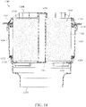
- FIG. 18 a cross-sectional view of an air filtration system 1200 is shown according to an example embodiment.
- the system 1200 filters air and provides clean air to a device, such as an internal combustion engine.
- the system 1200 is shown with an upper member 1202 secured to a housing 1204.
- the upper member 1202 is removably secured to the housing 1204 through a plurality of connections formed between the upper member 1202 and the housing 1204.
- the connections are formed by any suitable mechanical connection, such as snap-fit connections (e.g., formed by mating detents on the housing 1204 and the upper member 1202), screws, bolts, or the like.
- the upper member 1202 is an inlet grate.
- Coupled and the like as used herein mean the joining of two members directly or indirectly to one another. Such joining may be stationary (e.g., permanent) or moveable (e.g., removable or releasable). Such joining may be achieved with the two members or the two members and any additional intermediate members being integrally formed as a single unitary body with one another or with the two members or the two members and any additional intermediate members being attached to one another.
Description
- The present application relates to filter media.
- Internal combustion engines generally combust a mixture of fuel (e.g., gasoline, diesel, natural gas, etc.) and air. Many or all of the fluids passing through the internal combustion engine are filtered to remove particulate and contaminants from the fluids prior to entering the internal combustion engine. For example, prior to entering the engine, intake air is typically passed through a filter element to remove contaminants (e.g., particulates, dust, water, etc.) from the intake air prior to delivery to the engine. The filter media of the filter element captures and removes particulate from the intake air passing through the filter media. As the filter media captures and removes particulate, the restriction of the filter media increases. The filter media has a dust holding capacity that defines the amount of particulate that the filter media can capture without the need for replacement. After the dust holding capacity of the filter media is reached, the filter element may require replacement.
- According to its abstract,
US 2008/120952 A1 describes a filter media including a first sheet having an inner surface and an outer surface, a second sheet having an inner surface and an outer surface, wherein the inner surface of the first sheet and the inner surface of the second sheet at least in part define at least two fluid channels between the first sheet and the second sheet to define a filter media having a first axial end and a second axial end, wherein the at least two fluid channels extend between the first axial end and the second axial end, and wherein, interior to said axial ends, the first and second sheets define at least one opening between a first one of said at least two fluid channels and a second one of said at least two fluid channels such that fluid can uninterruptedly flow between the first one of said at least two fluid channels and the second one of the at least two fluid channels, and further wherein the at least two fluid channels and the at least one opening are at least defined in part by a surface characteristic of the first sheet and a surface characteristic of the second sheet. - Aspects of the present invention are defined by the appended independent claims. Preferred embodiments are defined by the appended dependent claims. Various example embodiments relate to filter media, filter elements containing the filter media, and filtration systems having the filter elements. One example embodiment relates to filter media. The filter media includes a first sheet of filter media having a first side and a second side and pleated along a plurality of bend lines to form a plurality of wall segments. The plurality of wall segments comprises a first set of wall segments alternately sealed to each other at the first side to define a first set of tetrahedron channels having open first ends, and a second set of tetrahedron channels interdigitated with the first set of tetrahedron channels and having closed first ends. The plurality of wall segments comprises a second set of wall segments alternately sealed to each other at the second side to define a third set of tetrahedron channels having closed second ends, and a fourth set of tetrahedron channels interdigitated with the third set of tetrahedron channels and having open second ends. The filter media further includes a second sheet of filter media extending across the first sheet of filter media. The second sheet of filter media comprises an embossment that forms a raised surface configured to maintain a gap between the second sheet of filter media and an adjacent sheet of filter media.
- Another example embodiment relates to filter media. The filter media includes a flat sheet of filter media that is alternately folded along a plurality of pleat fold lines, thereby defining a pleat block. The flat sheet of filter media comprises a plurality of embossments. Each of the plurality of embossments forms a raised surface that maintains a separation distance between adjacent pleats of the pleat block.
- A further example embodiment relates to a filtration system. The filtration system includes a housing body. The housing body includes a housing outlet, a housing inlet, and a central compartment. A filter element is installed in the central compartment. The filter element includes filter media. The filter media includes a first sheet of filter media having an upstream inlet adjacent the housing inlet, a downstream outlet adjacent the housing outlet, and is pleated along a plurality of bend lines to form a plurality of wall segments. The plurality of wall segments comprises a first set of wall segments alternately sealed to each other at the upstream inlet to define a first set of tetrahedron channels having open upstream ends, and a second set of tetrahedron channels interdigitated with the first set of tetrahedron channels and having closed upstream ends. The plurality of wall segments comprises a second set of wall segments alternately sealed to each other at the downstream outlet to define a third set of tetrahedron channels having open downstream ends, and a fourth set of tetrahedron channels interdigitated with the third set of tetrahedron channels and having closed downstream ends. The filter media further includes a second sheet of filter media extending across the first sheet of filter media. The second sheet of filter media comprises an embossment that forms a raised surface configured to maintain a gap between the second sheet of filter media and an adjacent sheet of filter media.
- These and other features, together with the organization and manner of operation thereof, will become apparent from the following detailed description when taken in conjunction with the accompanying drawings, wherein like elements have like numerals throughout the several drawings described below.
-
-
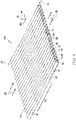
FIG. 1 shows a perspective view of a folded filter media sheet of filter media according to an example embodiment. -
FIG. 2 ,FIG. 3 , andFIG. 4 each show a different perspective view of the filter media ofFIG. 1 . -
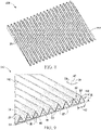
FIG. 5 shows a perspective view of the filter media ofFIG. 1 having an embossment arrangement according to an example embodiment. -
FIG. 6 shows a perspective view of the filter media ofFIG. 1 having a first embossment arrangement according to an example embodiment. -
FIG. 7A, 7B, and 7C each show a close-up perspective view of an embossment of the filter media ofFIG. 1 orFIG. 8 oriented at a different angle. -
FIG. 8 shows a perspective view of a folded filter media sheet of filter media according to another example embodiment. -
FIG. 9 ,FIG. 10 , andFIG. 11 each show a different perspective view of the filter media ofFIG. 8 . -
FIG. 12 shows a perspective view of the filter media ofFIG. 8 having an embossment arrangement according to an example embodiment. -
FIG. 13 shows a perspective view of the filter media ofFIG. 8 having a first embossment arrangement according to an example embodiment. -
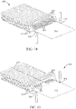
FIG. 14 shows a perspective view of filter media according to an example embodiment. -
FIG. 15 shows a perspective view of filter media according to another example embodiment. -
FIG. 16 is a perspective view of an embossing system according to an example embodiment. -
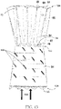
FIG. 17 shows a cross-sectional view of a filtration system according to an example embodiment. -
FIG. 18 shows a cross-sectional view of an air filtration system according to another example embodiment - Referring to the figures generally, filter media having a design embossed into the media are described. In some arrangements, the filter media is pleated filter media. In other arrangements, the filter media includes a plurality of channels, such as tetrahedron channels. The filter media includes a pattern of interrupted straight or angled embossments that help maintain separation between adjacent layers of the filter media. The embossments allow for two adjacent media layers (e.g., mating surfaces of the filter media) to remain separated, thereby increasing dust holding capacity and lowering pressure drop over similarly configured filter media not having the embossments.
- Referring to
FIGS. 1-7C ,filter media 100 is shown according to an example embodiment.FIG. 1 shows a perspective view of a folded (i.e., pleated)filter media sheet 102 of thefilter media 100.FIGS. 2 ,3 , and4 each show a different perspective view of thefilter media 100. As described below, thefilter media 100 includes a plurality offlow channels 36 having a tetrahedral shape. Additional details of thefilter media 100 are described inU.S. Patent No. 8,397,920 . Thefilter media 100 has anupstream inlet 22 receiving incoming dirty fluid as shown atarrows 23, and adownstream outlet 24 discharging clean filtered fluid as shown atarrows 25. Thefilter media 100 is composed of a foldedfilter media sheet 102 that is pleated along a plurality of bend lines 26. The bend lines extend axially along an axial direction 28 (e.g., as shown best inFIGS. 2-4 ), and include a first set ofbend lines 30 extending fromupstream inlet 22 towardsdownstream outlet 24, and a second set ofbend lines 32 extending fromdownstream outlet 24 axially towardsupstream inlet 22. Thefilter media 100 comprises a plurality of filtermedia wall segments 34 extending in serpentine manner between the bend lines. Thewall segments 34 extend axially and defineaxial flow channels 36 therebetween. Theflow channels 36 have aheight 38 along atransverse direction 40, whichtransverse direction 40 is perpendicular to axial direction 28 (e.g., as shown inFIG. 2 ). Theflow channels 36 have alateral width 42 along alateral direction 44. The lateral direction is perpendicular toaxial direction 28 and is perpendicular totransverse direction 40. As described below, at least some of the noted bend lines taper in the noted transverse direction as they extend axially in the noted axial direction. - The
wall segments 34 include a first set of wall segments 46 (e.g., as shown inFIGS. 2 and3 ) that are alternately sealed to each other at upstream inlet 22 (e.g., by adhesive 48 or the like) to define a first set ofchannels 50 having open upstream ends, and a second set oftetrahedron channels 52 interdigitated with the first set oftetrahedron channels 50 and having closed upstream ends. Thewall segments 34 include a second set of wall segments 54 (e.g., as shown inFIGS. 3 and4 ) that are alternately sealed to each other at downstream outlet 24 (e.g., by adhesive 56 or the like) to define a third set oftetrahedron channels 58 having closed downstream ends, and a fourth set of tetrahedron channels 60 (e.g., as shown inFIG. 4 ) having open downstream ends. The first set ofbend lines 30 comprises a first subset ofbend lines 62 defining the first set oftetrahedron channels 50, and a second subset ofbend lines 64 defining the second set oftetrahedron channels 52. The second subset ofbend lines 64 taper intransverse direction 40 as they extend fromupstream inlet 22 axially towards downstream outlet 24 (e.g., as shown inFIGS. 3 through 6 ). The second set ofbend lines 32 comprises a third subset ofbend lines 66 defining the third set oftetrahedron channels 58, and a fourth subset ofbend lines 68 defining the fourth set oftetrahedron channels 60. The fourth subset ofbend lines 68 taper in thetransverse direction 40 as they extend fromdownstream outlet 24 axially towards upstream inlet 22 (e.g., as shown inFIGS. 3 through 6 ). The second set oftetrahedron channels 52 have a decreasingtransverse channel height 38 alongtransverse direction 40 as the second set oftetrahedron channels 52 extend axially alongaxial direction 28 towardsdownstream outlet 24. The tapering of the second subset ofbend lines 64 in thetransverse direction 40 provides the decreasingtransverse channel height 38 of the second set oftetrahedron channels 52. The fourth set oftetrahedron channels 60 have a decreasing transverse channel height alongtransverse direction 40 as the fourth set oftetrahedron channels 60 extend axially alongaxial direction 28 towardsupstream inlet 22. The tapering of the fourth subset ofbend lines 68 in thetransverse direction 40 provides the decreasingtransverse channel height 38 of the fourth set oftetrahedron channels 60. - Still referring to
FIGS. 1-4 , incomingdirty fluid 23 to be filtered flows alongaxial direction 28 intoopen tetrahedron channels 50 atupstream inlet 22 and passes laterally and/or transversely through the filter media wall segments of the pleated filter element and then flows axially alongaxial direction 28 as clean filtered fluid throughopen tetrahedron channels 60 atdownstream outlet 24. A second subset ofbend lines 64 provides lateral cross-flow thereacross alonglateral direction 44 between respective channels downstream ofupstream inlet 22. A fourth subset ofbend lines 68 provides lateral cross-flow thereacross alonglateral direction 44 between respective channels upstream ofdownstream outlet 24. The second and fourth subsets ofbend lines sections 70, and the noted lateral cross-flow is provided at least at axially overlappingsections 70. - The second subset of
bend lines 64 taper to respective termination points 72 (e.g., as shown inFIGS. 3 through 6 ), providing at such termination points the minimumtransverse channel height 38 of the second set oftetrahedron channels 52. The fourth subset ofbend lines 68 taper to respective termination points 74, providing at such termination points the minimumtransverse channel height 38 of the fourth set oftetrahedron channels 60. Termination points 72 of second subset ofbend lines 64 are axially downstream of termination points 74 of fourth subset of bend lines 68. This provides the noted axially overlappingsections 70. Termination points 72 of second subset ofbend lines 64 are atdownstream outlet 24 in one embodiment, and in other embodiments are axially upstream ofdownstream outlet 24. Termination points 74 of fourth subset ofbend lines 68 are atupstream inlet 22 in one embodiment, and in other embodiments are axially downstream ofupstream inlet 22. - A first set of
wall segments 46 alternately sealed to each other at adhesive 48 atupstream inlet 22 define a first set oftetrahedron channels 50 having open upstream ends, and a second set oftetrahedron channels 52 interdigitated with the first set oftetrahedron channels 50 and having closed upstream ends. A second set ofwall segments 54 alternately sealed to each other at adhesive 56 atdownstream outlet 24 define a third set oftetrahedron channels 58 having closed downstream ends, and a fourth set oftetrahedron channels 60 interdigitated with the third set oftetrahedron channels 58 and having open downstream ends. The first set ofbend lines 30 includes the first subset ofbend lines 62 defining the first set oftetrahedron channels 50, and the second subset ofbend lines 64 defining the second set oftetrahedron channels 52. The second subset ofbend lines 64 taper in thetransverse direction 40 as they extend fromupstream inlet 22 axially towardsdownstream outlet 24. The second set ofbend lines 32 includes the third subset ofbend lines 66 defining the third set oftetrahedron channels 58, and the fourth subset ofbend lines 68 defining the fourth set oftetrahedron channels 60. The fourth subset ofbend lines 68 taper in thetransverse direction 40 as they extend fromdownstream outlet 24 axially towardsupstream inlet 22. - First and second sets of
tetrahedron channels tetrahedron channels tetrahedron channels axial direction 28. Each of the first, second, third and fourth sets oftetrahedron channels lateral directions tetrahedron channels tetrahedron channels axial direction 28 fromupstream inlet 22 towarddownstream outlet 24. The cross-sectional areas of third and fourth sets oftetrahedron channels tetrahedron channels axial direction 28 fromdownstream outlet 24 towardupstream inlet 22. In some arrangements, the bend lines 26 are bent at a sharp pointed angle (e.g., as shown at 80 inFIG. 2 ). In other arrangements, the bend lines 26 are rounded along a given radius (e.g., as shown in dashed line at 82 inFIG. 2 ). - The
elongated tetrahedron channels - The filter element is further provided with a substantially
flat sheet 84 extending laterally across the bend lines. In one embodiment, theflat sheet 84 is formed of filter media material, which may be the same filter media material as the foldedfilter media sheet 102. Theflat sheet 84 extends axially along the full axial length alongaxial direction 28 betweenupstream inlet 22 anddownstream outlet 24, and extends laterally along the full lateral width alonglateral direction 44 across and sealing the channels to prevent bypass of dirty upstream air to clean downstream air without passing through and being filtered by awall segment 34. In some arrangements, theflat sheet 84 is generally rectiplanar along a plane defined byaxial direction 28 andlateral direction 44. - As shown in
FIG. 5 , theflat sheet 84 includes a plurality ofembossments 502. Theembossments 502 form a raised surface (with respect to the generally rectiplanar surface of the flat sheet 84) on a first side of theflat sheet 84 and a corresponding lowered surface (with respect to the generally rectiplanar surface of the flat sheet 84). Although shown as being oval in shape, theembossments 502 can have any shape (e.g., circular, triangular, square, rectangular, etc.). Theembossments 502 are arranged in an interrupted straight line pattern. In some arrangements, theembossments 502 are arranged such that theembossments 502 align with the peaks of theflow channels 36. Accordingly, when thefilter media 100 is folded, layered, or coiled to form a pleat block, the peaks of theflow channels 36 rest against the raised surface of theembossments 502 thereby creating a separation distance between theflat sheet 84 and the foldedfilter media sheet 102, which is maintained during use. The separation distance increases the dust holding capacity of thefilter media 100 and reduces the restriction of thefilter media 100, which results in a lower pressure drop and increased capacity compared to similar filter media without the embossments. Theembossments 502 may be formed in theflat sheet 84 through an embossment roller.FIG. 6 shows another arrangement ofembossments 502 on theflat sheet 84 in which theembossments 502 are arranged in a less dense angled pattern than the embossments ofFIG. 5 . - Referring to
FIGS. 7A through 7C , close-up perspective views of anembossment 502 arranged at different angles φ on theflat sheet 84 are shown. In each ofFIGS. 7A through 7C , the angle φ is measured with respect to an X-Y axis that define the plane of theflat sheet 84. The X axis is aligned with thelateral direction 44 ofFIGS. 2-4 , and the Y axis is aligned with theaxial direction 28 ofFIGS. 2-4 . The angle φ of theembossment 502 is selected to optimize the air flow through thefilter media 100. As described above, theembossments 502 maintain separation between the layers of thefilter media 100. Accordingly, the angle φ is selected to be aligned with the flow direction of the air through thefilter media 100 to minimize added restriction or the introduction of turbulence into the air flow. According to the invention, the angle φ is between zero and sixty degrees. In other arrangements, the angle φ is between thirty-five degrees and fifty five degrees. In further arrangements, the angle φ is approximately forty-five degrees. - Referring to
FIGS. 8-13 ,filter media 200 is shown according to another example embodiment. Thefilter media 200 is similar to thefilter media 100 ofFIGS. 1-6 . Differences between this embodiment and the embodiment ofFIGS. 1-6 involve thefilter media 200 having the opposite fluid flow path of thefilter media 100 and the fluid path in thefilter media 200 being the opposite of thefilter media 100. Accordingly, like numbering is used to designate like parts between thefilter media 200 and thefilter media 100. As will be appreciated, due to the orientation and fluid flow path, thefilter media 200 provides improvements in capacity over alternative arrangements. -
FIG. 8 shows a perspective view of a folded (i.e., pleated)filter media sheet 102 of thefilter media 200.FIGS. 9 ,10 , and11 each show a different perspective view of thefilter media 200. As described below, thefilter media 200 includes a plurality offlow channels 36 having a tetrahedral shape. Additional details of thefilter media 200 are generally described inU.S. Patent No. 8,397,920 , which is herein incorporated by reference in its entirety and for all purposes. Thefilter media 200 has anupstream inlet 124 receiving incoming dirty fluid as shown atarrows 125, and adownstream outlet 122 discharging clean filtered fluid as shown atarrows 123. Thefilter media 200 is composed of a foldedfilter media sheet 102 that is pleated along a plurality of bend lines 26. The bend lines extend axially along an axial direction 28 (e.g., as shown best inFIGS. 9-11 ), and include a first set ofbend lines 32 extending fromupstream inlet 124 axially towardsdownstream outlet 122 and a second set ofbend lines 30 extending fromdownstream outlet 122 towardsupstream inlet 124. Thefilter media 200 comprises a plurality of filtermedia wall segments 34 extending in serpentine manner between the bend lines. Thewall segments 34 extend axially and defineaxial flow channels 36 therebetween. Theflow channels 36 have aheight 38 along atransverse direction 40, whichtransverse direction 40 is perpendicular to axial direction 28 (e.g., as shown inFIG. 9 ). Theflow channels 36 have alateral width 42 along alateral direction 44. The lateral direction is perpendicular toaxial direction 28 and is perpendicular totransverse direction 40. As described below, at least some of the noted bend lines taper in the noted transverse direction as they extend axially in the noted axial direction. - The
wall segments 34 include a first set of wall segments 54 (e.g., as shown inFIGS. 9 and10 ) that are alternately sealed to each other at upstream inlet 124 (e.g., by adhesive 48 or the like) to define a first set ofchannels 60 having open upstream ends, and a second set oftetrahedron channels 58 interdigitated with the first set oftetrahedron channels 60 and having closed upstream ends. Thewall segments 34 include a second set of wall segments 46 (e.g., as shown inFIGS. 10 and11 ) that are alternately sealed to each other at downstream outlet 122 (e.g., by adhesive 56 or the like) to define a fourthset of tetrahedron channels 50 (e.g., as shown inFIG. 11 ) having open downstream ends, and a third set oftetrahedron channels 52 having closed downstream ends. The first set ofbend lines 32 comprises a first subset ofbend lines 68 defining the first set oftetrahedron channels 60 and a second subset ofbend lines 66 defining the second set oftetrahedron channels 58. The first subset ofbend lines 68 taper in thetransverse direction 40 as they extend fromupstream inlet 124 axially towards downstream outlet 122 (e.g., as shown inFIGS. 10 through 13 ). The second set ofbend lines 30 comprises a fourth subset ofbend lines 62 defining the fourth set oftetrahedron channels 50, and a third subset ofbend lines 64 defining the third set oftetrahedron channels 52. The third subset ofbend lines 64 taper intransverse direction 40 as they extend fromdownstream outlet 122 axially towards upstream inlet 124 (e.g., as shown inFIGS. 10 through 13 ). The third set oftetrahedron channels 52 have a decreasingtransverse channel height 38 alongtransverse direction 40 as the third set oftetrahedron channels 52 extend axially alongaxial direction 28 towardsupstream inlet 124. The tapering of the third subset ofbend lines 64 in thetransverse direction 40 provides the decreasingtransverse channel height 38 of the third set oftetrahedron channels 52. The first set oftetrahedron channels 60 have a decreasing transverse channel height alongtransverse direction 40 as the first set oftetrahedron channels 60 extend axially alongaxial direction 28 towardsdownstream outlet 122. The tapering of the first subset ofbend lines 68 in thetransverse direction 40 provides the decreasingtransverse channel height 38 of the first set oftetrahedron channels 60. - Still referring to
FIGS. 8-11 , incomingdirty fluid 125 to be filtered flows alongaxial direction 28 intoopen tetrahedron channels 60 atupstream inlet 124 and passes laterally and/or transversely through the filter media wall segments of the pleated filter element and then flows axially alongaxial direction 28 as clean filtered fluid throughopen tetrahedron channels 50 atdownstream outlet 122. A third subset ofbend lines 64 provides lateral cross-flow thereacross alonglateral direction 44 between respective channels downstream ofupstream inlet 124. A first subset ofbend lines 68 provides lateral cross-flow thereacross alonglateral direction 44 between respective channels upstream ofdownstream outlet 122. The first and third subsets ofbend lines sections 70, and the noted lateral cross-flow is provided at least at axially overlappingsections 70. - The third subset of
bend lines 64 taper to respective termination points 72 (e.g., as shown inFIGS. 10 through 13 ), providing at such termination points the minimumtransverse channel height 38 of the third set oftetrahedron channels 52. The first subset ofbend lines 68 taper to respective termination points 74, providing at such termination points the minimumtransverse channel height 38 of the first set oftetrahedron channels 60. Termination points 72 of third subset ofbend lines 64 are axially upstream of termination points 74 of first subset of bend lines 68. This provides the noted axially overlappingsections 70. Termination points 72 of third subset ofbend lines 64 are atupstream inlet 124 in one embodiment, and in other embodiments are axially downstream ofupstream inlet 124. Termination points 74 of first subset ofbend lines 68 are atdownstream outlet 122 in one embodiment, and in other embodiments are axially upstream ofdownstream outlet 122. - A second set of
wall segments 46 alternately sealed to each other at adhesive 48 atdownstream outlet 122 define a fourth set oftetrahedron channels 50 having open downstream ends, and a third set oftetrahedron channels 52 interdigitated with the fourth set oftetrahedron channels 50 and having closed downstream ends. A first set ofwall segments 54 alternately sealed to each other at adhesive 56 atupstream inlet 124 define a second set oftetrahedron channels 58 having closed upstream ends, and a first set oftetrahedron channels 60 interdigitated with the second set oftetrahedron channels 58 and having open upstream ends. The second set ofbend lines 30 includes the fourth subset ofbend lines 62 defining the fourth set oftetrahedron channels 50, and the third subset ofbend lines 64 defining the third set oftetrahedron channels 52. The third subset ofbend lines 64 taper in thetransverse direction 40 as they extend fromdownstream outlet 122 axially towardsupstream inlet 124. The first set ofbend lines 32 includes the second subset ofbend lines 66 defining the second set oftetrahedron channels 58, and the first subset ofbend lines 68 defining the first set oftetrahedron channels 60. The first subset ofbend lines 68 taper in thetransverse direction 40 as they extend fromupstream inlet 124 axially towardsdownstream outlet 122. - First and second sets of
tetrahedron channels tetrahedron channels tetrahedron channels axial direction 28. Each of the first, second, third and fourth sets oftetrahedron channels lateral directions tetrahedron channels tetrahedron channels axial direction 28 fromupstream inlet 124 towarddownstream outlet 122. The cross-sectional areas of the third and fourth sets oftetrahedron channels tetrahedron channels axial direction 28 fromdownstream outlet 122 towardupstream inlet 124. In some arrangements, the bend lines 26 are bent at a sharp pointed angle (e.g., as shown at 80 inFIG. 9 ). In other arrangements, the bend lines 26 are rounded along a given radius (e.g., as shown in dashed line at 82 inFIG. 9 ). - The
elongated tetrahedron channels - The filter element is further provided with a substantially
flat sheet 84 extending laterally across the bend lines. In one embodiment, theflat sheet 84 is formed of filter media material, which may be the same filter media material as the foldedfilter media sheet 102. Theflat sheet 84 extends axially along the full axial length alongaxial direction 28 betweendownstream outlet 122 andupstream inlet 124, and extends laterally along the full lateral width alonglateral direction 44 across and sealing the channels to prevent bypass of dirty upstream air to clean downstream air without passing through and being filtered by awall segment 34. In some arrangements, theflat sheet 84 is generally rectiplanar along a plane defined byaxial direction 28 andlateral direction 44. - As shown in
FIG. 12 , theflat sheet 84 includes a plurality ofembossments 502. Theembossments 502 form a raised surface (with respect to the generally rectiplanar surface of the flat sheet 84) on a first side of theflat sheet 84 and a corresponding lowered surface (with respect to the generally rectiplanar surface of the flat sheet 84). Although shown as being oval in shape, theembossments 502 can have any shape (e.g., circular, triangular, square, rectangular, etc.). Theembossments 502 are arranged in an interrupted straight line pattern. In some arrangements, theembossments 502 are arranged such that theembossments 502 align with the peaks of theflow channels 36. Accordingly, when thefilter media 200 is folded, layered, or coiled to form a pleat block, the peaks of theflow channels 36 rest against the raised surface of theembossments 502 thereby creating a separation distance between theflat sheet 84 and the foldedfilter media sheet 102, which is maintained during use. The separation distance increases the dust holding capacity of thefilter media 200 and reduces the restriction of thefilter media 200, which results in a lower pressure drop and increased capacity compared to similar filter media without the embossments. Theembossments 502 may be formed in theflat sheet 84 through an embossment roller.FIG. 13 shows another arrangement ofembossments 502 on theflat sheet 84 in which theembossments 502 are arranged in a less dense angled pattern than the embossments ofFIG. 12 . - Referring back to
FIGS. 7A through 7C , the close-up perspective views of anembossment 502 arranged at different angles φ on theflat sheet 84 can be applied to thefilter media 200. In each ofFIGS. 7A through 7C , the angle φ is measured with respect to an X-Y axis that define the plane of theflat sheet 84. Accordingly, the X axis is aligned with thelateral direction 44 ofFIGS. 9-11 and the Y axis is aligned with theaxial direction 28 ofFIGS. 9-11 . The angle φ of theembossment 502 is selected to optimize the air flow through thefilter media 200. As described above, theembossments 502 maintain separation between the layers of thefilter media 200. Accordingly, the angle φ is selected to be aligned with the flow direction of the air through thefilter media 200 to minimize added restriction or the introduction of turbulence into the air flow. According to the invention, the angle φ is between zero and sixty degrees. In other arrangements, the angle φ is between thirty-five degrees and fifty five degrees. In further arrangements, the angle φ is approximately forty-five degrees. - Referring to
FIG. 14 , a perspective view offilter media 800 is shown according to an example embodiment. Thefilter media 800 is a pleated filter media. Thefilter media 800 includes aflat sheet 802 that is alternately folded alongpleat fold lines 804 to form thefilter media 800. In some arrangements, theflat sheet 802 is held in the folded or pleated position to form a pleat block (e.g., as shown inFIG. 17 ) withadhesive 806. In such arrangements, the adhesive 806 may be placed on alternate sides of adjacent pleats. The pleat block includes a clean side (i.e., a filtered fluid outlet side) and a dirty side (i.e., an inlet side that receives fluid to be filtered). Theflat sheet 802 is embossed to createembossments 808. Theflat sheet 802 may be embossed by a pair of embossing rollers (e.g.,embossing rollers FIG. 16 ) to createembossments 808. Each of theembossments 808 forms a raised surface. In some arrangements, theembossments 808 are created prior to theflat sheet 802 being pleated. In some arrangements, theembossments 808 are linear in shape. Theembossments 808 extend in a direction that is perpendicular to the pleat fold lines 804. As in thefilter media 100, theembossments 808 maintain a separation distance between adjacent pleats during use of thefilter media 800. The separation distance increases the dust holding capacity of thefilter media 800 and reduces the restriction of thefilter media 800, which results in a lower pressure drop and increased capacity compared to similar filter media without theembossments 808. - Referring to
FIG. 15 , a perspective view offilter media 900 is shown according to an example embodiment. Thefilter media 900 is similar to thefilter media 800. Thefilter media 900 includes aflat sheet 902 that is alternately folded alongpleat fold lines 904 to form thefilter media 900. In some arrangements, theflat sheet 902 is held in the folded or pleated position to form a pleat block (e.g., as shown inFIG. 17 ) withadhesive 906. In such arrangements, the adhesive 906 may be placed on alternate sides of adjacent pleats. The pleat block includes a clean side (i.e., a filtered fluid outlet side) and a dirty side (i.e., an inlet side that receives fluid to be filtered). Theflat sheet 902 is embossed to createembossments 908. Theflat sheet 902 may be embossed by a pair of embossing rollers (e.g.,embossing rollers FIG. 16 ) to createembossments 908. Each of theembossments 908 forms a raised surface. In some arrangements, theembossments 908 are created prior to theflat sheet 902 being pleated. The difference between thefilter media 900 and thefilter media 800 is the orientation and arrangement of theembossments 908. In some arrangements, theembossments 908 are linear in shape. Theembossments 908 are oriented at anangle 910 with respect to the pleat fold lines 904. Theangle 910 of theembossments 904 may be any of the angles described above with respect to the angle φ of theembossment 502 of thefilter media 100. Theangle 910 is less than 90 degrees. In some arrangements, the orientation of theembossments 908 is flipped about acenter line 912 of thefilter media 900. As in thefilter media 100, theembossments 908 maintain a separation distance between adjacent pleats during use of thefilter media 900. The separation distance increases the dust holding capacity of thefilter media 900 and reduces the restriction of thefilter media 900, which results in a lower pressure drop and increased capacity compared to similar filter media without theembossments 908. - Referring to
FIG. 16 , a perspective view of anembossing system 1000 is shown according to an example embodiment. Theembossing system 1000 includes afirst embossing roller 1002 and asecond embossing roller 1004. Theembossing rollers flat sheet 84, theflat sheet 802, theflat sheet 902, etc.) can be fed between therollers embossing roller projections 1006 that are arranged to provide embossments (e.g.,embossments 502,embossments 808,embossments 908, etc.) to a flat sheet that passes between therollers roller linear depressions 1008 extending across a length of the roller that provide creases where the flat sheet will be folded if the flat sheet is to be folded into pleated filter media. Thelinear depressions 1008 are perpendicular to thecenterline 1010 of the rollers (which corresponds to the centerline of the flat sheet that is fed through the embossing system 1000). - Referring to
FIG. 17 , a cross-sectional view of afiltration system 1100 is shown according to an example embodiment. Thefiltration system 1100 includes ahousing 1102 having an inlet (marked by inlet flow arrow 1104) and anoutlet 1106. Thefiltration system 1100 includes two V-shaped filter elements 1108. Each of the V-shaped filter elements 1108 includes twopleat blocks 1110 that are arranged in a V-shape. The pleat blocks 1110 may be formed from thefilter media 800 or thefilter media 900. As fluid (e.g., air) passes from the inlet through theoutlet 1106 of thehousing 1102, the fluid passes through one of the pleat blocks 1110 where the fluid is filtered. - Referring to
FIG. 18 , a cross-sectional view of anair filtration system 1200 is shown according to an example embodiment. Thesystem 1200 filters air and provides clean air to a device, such as an internal combustion engine. Thesystem 1200 is shown with anupper member 1202 secured to ahousing 1204. Theupper member 1202 is removably secured to thehousing 1204 through a plurality of connections formed between theupper member 1202 and thehousing 1204. The connections are formed by any suitable mechanical connection, such as snap-fit connections (e.g., formed by mating detents on thehousing 1204 and the upper member 1202), screws, bolts, or the like. In some arrangements, theupper member 1202 is an inlet grate. Theupper member 1202 includes aninlet opening 1208, and thehousing 1204 includes anoutlet opening 1210. Theinlet opening 1208 and theoutlet 1210 are substantially aligned such that a common axis passes through the centers of theinlet opening 1208 and theoutlet opening 1210. Air to be filtered by thesystem 1200 enters thehousing 1204 through theinlet opening 1208, passes through thehousing 1204, and exits thehousing 1204 through theoutlet opening 1210. As described in further detail below, thehousing 1204 includes afilter element 1304 positioned between theinlet opening 1208 and theoutlet opening 1210 such that the air passing through thehousing 1204 is filtered through thefilter element 1304. Although theupper member 1202 may contact certain portions of thefilter element 1304, theupper member 1202 is not fixed to thefilter element 1304 such that theupper member 1202 can be removed from thefilter element 1304 used with replacement filter elements. Since theupper member 1202 is reusable with replacement filter elements, replacement filter elements can be produced at a lesser cost than replacement filter elements that have an integral cover portion. The reusableupper member 1202 also reduces waste with each filter element replacement service in comparison to replacement filter elements that have an integral cover portion. - The
housing 1204 includes acentral compartment 1302 positioned between theinlet opening 1208 and theoutlet opening 1210. As shown inFIG. 18 , thefilter element 1304 is positioned in thecentral compartment 1302 of thehousing 1204. Thefilter element 1304 is in an installed position (i.e., thefilter element 1304 is received in thecompartment 1302 and theupper member 1202 is secured to the housing 1204). Thefilter element 1304 is an axial flow filter element. Thefilter element 1304 includes acentral tube 1306 and filtermedia 1308 surrounding thecentral tube 1306. In some arrangements, thecentral tube 1306 is comprised of cardboard, which may be less expensive and more environmentally friendly than plastic. In one embodiment, thecentral tube 1306 is not perforated or porous, although other embodiments may include perforations and/or a certain level of porosity. A portion of thecentral tube 1306 extends into an opening in theupper member 1202 when thefilter element 1304 is received in thehousing 1204 in the installed position. In an alternative arrangement, thecentral tube 1306 does not extend into theupper member 1202 and includes a cap to seal the top portion of thecentral tube 1306. Thefilter media 1308 includes aninlet face 1310 that is substantially adjacent to theinlet opening 1208 of theupper member 1202. Thefilter media 1308 includes anoutlet face 1312 that is substantially adjacent to theoutlet opening 1210. Theinlet face 1310 is spaced apart from theoutlet face 1312. Theinlet face 1310 is substantially parallel to theoutlet face 1312. In an alternative arrangement, thefilter element 1304 does not include a central tube. In such an arrangement, thefilter media 1308 may be wound around a removable core. - The
filter media 1308 may include pleated media (e.g., as described above with respect to filtermedia 800 or filter media 900), corrugated media, tetrahedral media (e.g., as described above with respect to filter media 100), or variations thereof. Thefilter media 1308 may be wound around thecentral tube 1306. Thecentral tube 1306 is closed on both ends. A top end of thecentral tube 1306 is closed by theupper member 1202. In some arrangements, a bottom end of thecentral tube 1306 is closed by acap 1314. However, it is possible for such acap 1314 to be used to close the top end of thecentral tube 1306, either in place of or in addition to the use of acap 1314 on the bottom end of thecentral tube 1306. - The
filter element 1304 includes anupper support ring 1316. Theupper support ring 1316 circumscribes thefilter media 1308 adjacent theinlet face 1310. Theupper support ring 1316 may be plastic, a polymer, or the like. In some arrangements, theupper support ring 1316 is secured to thefilter media 1308 with an adhesive. In other arrangements, theupper support ring 1316 is secured to thefilter media 1308 with a friction fit. Theupper support ring 1316 includes anupper seal 1318. Theupper seal 1318 may be a flat gasket. Theupper seal 1318 may be an elastomeric seal. In some arrangements, theupper seal 1318 is a molded polyurethane seal. When thefilter element 1304 is received within thehousing 1204, theupper seal 1318 rests against an upper portion of thehousing 1204. Theupper member 1202 compresses theupper seal 1318 against thehousing 1204 forming an axial seal between theupper support ring 1316 and thehousing 1204. Accordingly, when thefilter element 1304 is received in an installed position within thehousing 1204, air passing through the system 1200 (i.e., from theinlet opening 1208 to the outlet opening 1210) is forced to pass through thefilter media 1308. Additionally, theupper seal 1318 also prevents dust buildup on the inside walls of thehousing 1204 during operation. - The
upper seal 1318 is compressed by an axial sealing force. The force of theupper member 1202 pressing down on thefilter element 1304 when thefilter element 1304 is received within thehousing 1204 assists in creating the upper seal. In some arrangements, the compression distance for theupper seal 1318 caused by theupper member 1202 is limited to approximately fifteen to forty percent of theupper seal 1318. However, because the upper seal is created with an axial sealing force, the pressure differential caused by the filter element between theinlet face 1310 and theoutlet face 1312 also assists in pressing theupper seal 1318 against thehousing 1204. Accordingly, if a technician does not fully tighten theupper member 1202 onto thehousing 1204, normal operational forces caused by the air pressure differential across thefilter element 1204 are sufficient to create the upper seal. - In some arrangements, the
filter element 1304 includes alower support ring 1320. Thelower support ring 1320 circumscribes thefilter media 1308 adjacent theoutlet face 1312. Thelower support ring 1320 may be plastic, a polymer, or the like. In some arrangements, thelower support ring 1320 is secured to thefilter media 1308 with an adhesive. In other arrangements, thelower support ring 1320 is secured to thefilter media 1308 with a friction fit. The lower support ring includes alower support element 1322. Thelower support element 1322 may be an annular support element comprised of a porous and deformable material. In some arrangements, the lower support element is a permeable media gasket. In some arrangements, thelower support element 1322 is comprised of an open foam, a lofty meltblown permeable media, or felt. When thefilter element 1304 is received within thehousing 1204 in an installed position, thelower support element 1322 rests against anangled surface 1324 of thehousing 1204. In some arrangements, attachment of theupper member 1202 to thehousing 1204 compresses thelower support element 1322 against the angled surface 224 when thefilter element 1304 is received within thehousing 1204 in an installed position. Thelower support element 1322 helps position and secure thefilter element 1304 during installation of thefilter element 1304 into thehousing 1204. After installation into the installed position, thelower support element 1322 helps to retain thefilter element 1304 in the installed position and helps to reduce vibration of thefilter element 1304 during use. Further, thelower support element 1322 reduces the risk of thefilter element 1304 vibrating against thehousing 1204, referred to as "chatter," during use of thefilter element 1304. Additionally, thelower support element 1322 significantly reduces the surface friction between thefilter element 1304 and thehousing 1204 over a polyurethane seal. In some arrangements, thelower support ring 1320 does not include alower support element 1322. In such arrangements, theupper seal 1318 is the primary support surface between thehousing 1204 and thefilter element 1304 when thefilter element 1304 is received in thehousing 1204. In other arrangements, the filter element does not include alower support ring 1320. - It should be noted that any use of the term "example" herein to describe various embodiments is intended to indicate that such embodiments are possible examples, representations, and/or illustrations of possible embodiments (and such term is not intended to connote that such embodiments are necessarily extraordinary or superlative examples).
- As utilized herein, the term "substantially" and similar terms are intended to have a broad meaning in harmony with the common and accepted usage by those of ordinary skill in the art to which the subject matter of this disclosure pertains. It should be understood by those of skill in the art who review this disclosure that these terms are intended to allow a description of certain features described and claimed without restricting the scope of these features to the precise numerical ranges provided. Accordingly, these terms should be interpreted as indicating that insubstantial or inconsequential modifications or alterations of the subject matter described and claimed (e.g., within plus or minus five percent of a given angle or other value) are considered to be within the scope of the invention as recited in the appended claims. The term "approximately" when used with respect to values means plus or minus five percent of the associated value.
- References herein to the positions of elements (e.g., "top," "bottom," "above," "below," etc.) are merely used to describe the orientation of various elements in the FIGURES. It should be noted that the orientation of various elements may differ according to other example embodiments, and that such variations are intended to be encompassed by the present disclosure.
- The terms "coupled" and the like as used herein mean the joining of two members directly or indirectly to one another. Such joining may be stationary (e.g., permanent) or moveable (e.g., removable or releasable). Such joining may be achieved with the two members or the two members and any additional intermediate members being integrally formed as a single unitary body with one another or with the two members or the two members and any additional intermediate members being attached to one another.
- It is important to note that the construction and arrangement of the various example embodiments are illustrative only.
Claims (15)
- Filter media (100, 200, 1308) comprising:a first sheet (102) of filter media having a first side and a second side and pleated along a plurality of bend lines (26) to form a plurality of wall segments;the plurality of wall segments (34) comprising a first set of wall segments (46) alternately sealed to each other at the first side to define:a first set of tetrahedron channels (50) having open first ends at an upstream air inlet (22) of the filter media, such that, in use, air to be filtered flows into the filter media through the open first ends, anda second set of tetrahedron channels (52) interdigitated with the first set of tetrahedron channels and having closed first ends at the upstream air inlet (22);the plurality of wall segments comprising a second set of wall segments (54) alternately sealed to each other at the second side to define:a third set of tetrahedron channels (58) having closed second ends at a downstream air outlet (24) of the filter media, anda fourth set of tetrahedron channels (60) interdigitated with the third set of tetrahedron channels and having open second ends at the downstream air outlet, such that, in use, filtered air flows out of the filter media through the open second ends,the plurality of wall segments thereby defining air flow channels, and, in use, an air flow direction, through the filter media between the upstream air inlet and the downstream air outlet; anda second sheet (84) of filter media extending across the first sheet of filter media, characterized in that the second sheet of filter media comprises a plurality of embossments (502) arranged in an interrupted straight line pattern, each of the plurality of embossments form a raised surface configured to maintain a separation distance between the second sheet of filter media and an adjacent sheet of filter media, the plurality of embossments arranged at an angle Φ with respect to an X-Y axis that defines a plane of the second sheet of filter media, wherein the tetrahedron channels (50, 52, 58, 60) extend along an axial direction (28), wherein the Y axis is aligned with the axial direction (28) and the X axis is aligned with a lateral direction (44) which is perpendicular to the axial direction (28), wherein the angle Φ is between 0 and 60 degrees relative to the lateral direction.
- The filter media (100, 200, 1308) of claim 1, wherein the plurality of embossments (502) are positioned such that the embossments align with peaks of the tetrahedron channels.
- The filter media (100, 200, 1308) of claim 1 or claim 2, wherein each embossment (502) is arranged to interact with a peak of a tetrahedron flow channel of the adjacent sheet of filter media.
- The filter media (100, 200, 1308) of any preceding claim, wherein the plurality of embossments (502) are linear in shape.
- The filter media (100, 200, 1308) of any preceding claim, wherein the first side comprises a substantially v-shaped inlet, a v-shaped inlet height being the distance from a lower end of the v-shaped inlet to an upper end of the v-shaped inlet, along an axis that is substantially perpendicular to a longitudinal length of the filter media.
- The filter media (100, 200, 1308) of any preceding claim, wherein the second sheet (84) of filter media extends laterally across the plurality of bend lines (26) from the first side to the second side.
- The filter media (100, 200, 1308) of any preceding claim, wherein each of the plurality of embossments (502) form a lowered surface corresponding to a respective raised surface, the lowered surface configured to maintain a gap between the second sheet of filter media and an adjacent sheet of filter media.
- The filter media (100, 200, 1308) of claim 1, wherein the angle Φ is between thirty-five degrees and fifty five degrees.
- The filter media (100, 200, 1308) of claim 1, wherein the angle Φ is forty-five degrees.
- A filter element (1304) comprising the filter media (100, 200, 1308) of any preceding claim.
- A filtration system (1200) comprising:
a housing body (1202, 1204), the housing body comprising:a housing outlet (1210), a housing inlet (1208), and a central compartment (1302); anda filter element (1304) installed in the central compartment, the filter element comprising the filter media (100, 200, 1308) of claim 1. - The filtration system of claim 11, wherein the plurality of embossments are arranged such that the embossments align with peaks of the tetrahedron channels.
- The filtration system of claim 11 or claim 12, further comprising:
an upper member removably secured to the housing body, the upper member comprising an inlet opening aligned with the housing inlet, wherein a portion of the filter element contacts the upper member. - The filtration system of any of claims 11 to 13, wherein the filtration system further comprises an upper support ring coupled to the first side of the filter media, the upper support ring circumscribing the filter media adjacent the first side.
- The filtration system of any of claims 11 to 14, wherein the filter element further comprises a filter element sidewall formed by the filter media, the filter element sidewall being tapered with respect to the first side.
Applications Claiming Priority (2)
| Application Number | Priority Date | Filing Date | Title |
|---|---|---|---|
| US201662410529P | 2016-10-20 | 2016-10-20 | |
| PCT/US2017/056744 WO2018075385A1 (en) | 2016-10-20 | 2017-10-16 | Interrupted, directional emboss of flat sheet |
Publications (3)
| Publication Number | Publication Date |
|---|---|
| EP3529111A1 EP3529111A1 (en) | 2019-08-28 |
| EP3529111A4 EP3529111A4 (en) | 2020-08-19 |
| EP3529111B1 true EP3529111B1 (en) | 2023-01-11 |
Family
ID=62018778
Family Applications (1)
| Application Number | Title | Priority Date | Filing Date |
|---|---|---|---|
| EP17862733.7A Active EP3529111B1 (en) | 2016-10-20 | 2017-10-16 | Interrupted, directional emboss of flat sheet |
Country Status (4)
| Country | Link |
|---|---|
| US (2) | US11439943B2 (en) |
| EP (1) | EP3529111B1 (en) |
| CN (1) | CN109890666B (en) |
| WO (1) | WO2018075385A1 (en) |
Families Citing this family (7)
| Publication number | Priority date | Publication date | Assignee | Title |
|---|---|---|---|---|
| CA3028983C (en) * | 2016-06-24 | 2023-11-14 | K&N Engineering, Inc. | Compound air filter |
| US11439943B2 (en) | 2016-10-20 | 2022-09-13 | Cummins Filtration Ip, Inc. | Interrupted, directional emboss of flat sheet |
| US11376541B2 (en) | 2016-12-15 | 2022-07-05 | Cummins Filtration Ip, Inc. | Tetrahedral filter media |
| CN108993055B (en) * | 2018-09-29 | 2023-09-15 | 马勒汽车技术(中国)有限公司 | Filter element assembly |
| US20200398202A1 (en) * | 2019-06-18 | 2020-12-24 | MANN+HUMMEL Filtration Technology US LLC | Filter Media Having Angled Embossments |
| US20220355235A1 (en) * | 2019-08-23 | 2022-11-10 | Cummins Filtration Ip, Inc. | Filter assemblies and elements utilizing multilayered and wrapped filter media |
| WO2021041229A1 (en) | 2019-08-26 | 2021-03-04 | Parker-Hannifin Corporation | Enhanced fuel water separation using structural embossing |
Family Cites Families (190)
| Publication number | Priority date | Publication date | Assignee | Title |
|---|---|---|---|---|
| US1729135A (en) | 1925-12-23 | 1929-09-24 | Harold W Slauson | Air and oil filter |
| US2599604A (en) | 1949-07-13 | 1952-06-10 | Jordan V Bauer | Filter element |
| GB753510A (en) | 1953-10-12 | 1956-07-25 | Gen Motors Ltd | Improvements in fluid filters |
| US3020977A (en) | 1959-08-19 | 1962-02-13 | Simpson Herbert Corp | Filter device |
| US3173867A (en) | 1962-09-28 | 1965-03-16 | Amicon Corp | Membrane separation device |
| US3293833A (en) | 1963-02-28 | 1966-12-27 | Cambridge Filter Corp | Pleated filter |
| US3410062A (en) | 1966-09-12 | 1968-11-12 | Cambridge Filter Corp | Filter |
| US3521429A (en) | 1968-10-04 | 1970-07-21 | Frank B Leffler | Muffler |
| US3722696A (en) | 1971-04-22 | 1973-03-27 | Millipore Corp | Spiral wound filter |
| US3853529A (en) | 1971-06-09 | 1974-12-10 | Farr Co | Pleated air filter cartridge |
| US4498915A (en) | 1974-03-29 | 1985-02-12 | Witchell Stanley P | Air filters |
| US3921432A (en) | 1975-03-24 | 1975-11-25 | American Air Filter Co | Method of forming a tapered pleated filter pleat fold separator and a separator formed thereby |
| US4177050A (en) | 1976-08-23 | 1979-12-04 | Farr Company | Air filter assembly |
| US4144043A (en) | 1977-06-13 | 1979-03-13 | Donaldson Company, Inc. | Three-stage dust collector |
| GB1604979A (en) | 1978-05-31 | 1981-12-16 | Engineering Components Ltd | Air filters |
| US4235611A (en) | 1979-04-23 | 1980-11-25 | Fram Corporation | Air filter |
| JPS57113822A (en) | 1980-12-30 | 1982-07-15 | Nippon Soken Inc | Fine particle collecting filter |
| DE3110733A1 (en) | 1981-03-16 | 1982-11-25 | Delbag-Luftfilter Gmbh, 1000 Berlin | COMPACT UNIVERSAL LARGE AREA FILTER SYSTEM ACCORDING TO THE MODULAR PRINCIPLE FOR AIR PURIFICATION |
| US4410427A (en) | 1981-11-02 | 1983-10-18 | Donaldson Company, Inc. | Fluid filtering device |
| GB2131717A (en) | 1982-11-15 | 1984-06-27 | Atomic Energy Authority Uk | Air filter |
| DE8323892U1 (en) | 1983-08-19 | 1985-10-31 | INTERATOM GmbH, 5060 Bergisch Gladbach | Wire mesh diesel exhaust filter |
| US4839037A (en) | 1987-03-09 | 1989-06-13 | Osmonics, Inc. | Tapered, spirally wound filter cartridge and method of making same |
| US4925561A (en) | 1988-03-31 | 1990-05-15 | Tsuchiya Mfg. Co., Ltd. | Composite planar and triangularly pleated filter element |
| US4938869A (en) | 1988-10-19 | 1990-07-03 | Bay-San Co., Inc. | Spiral wound filter element |
| DE3901609A1 (en) | 1989-01-20 | 1990-07-26 | Schwaebische Huettenwerke Gmbh | EXHAUST FILTER |
| DE4002078C1 (en) | 1990-01-25 | 1991-05-02 | Fa. Carl Freudenberg, 6940 Weinheim, De | |
| US5316677A (en) | 1990-06-25 | 1994-05-31 | Harmsco, Inc. | Pleated filtering sleeve for rotational flow filter systems |
| US5114582A (en) | 1991-04-12 | 1992-05-19 | W. R. Grace & Co.-Conn. | Filter element and spiral-wound membrane cartridge containing same |
| JP2572124Y2 (en) | 1991-06-07 | 1998-05-20 | 株式会社ロキテクノ | Multi-layer filtration tube |
| CN2126622Y (en) | 1992-06-27 | 1993-01-27 | 刘先哲 | Point-rest type filter without division plate |
| US5320657A (en) | 1993-04-30 | 1994-06-14 | Dana Corporation | Staggered short pleat air filter |
| US5397632A (en) | 1993-05-14 | 1995-03-14 | Reemay, Inc. | Nonwoven laminated composite article capable or readily undergoing pleating to form a stable pleated depth gaseous filtration medium |
| EP0648524A1 (en) | 1993-10-19 | 1995-04-19 | Millipore Corporation | Filter cartridge construction |
| DE69512713T2 (en) | 1994-07-12 | 2000-03-09 | Nittetsu Mining Co Ltd | Reinforced filter element |
| US5679251A (en) | 1995-07-24 | 1997-10-21 | The Oilguard Company, Llc | Wound oil filter |
| US5557808A (en) | 1995-09-13 | 1996-09-24 | Akashi Hifuku Kogyo Co., Ltd. | Skirt with variable sized pleats |
| JP3024212U (en) | 1995-10-30 | 1996-05-17 | 有限会社ゴーイング東京 | Filter element for engine air cleaner |
| CA2187963C (en) | 1995-11-03 | 2001-04-10 | Stephen Proulx | Filter cartridge construction and process for filtering particle-containing paint compositions |
| US5895574A (en) | 1996-04-26 | 1999-04-20 | Donaldson Company, Inc. | Rolled liquid filter using fluted media |
| US5820646A (en) | 1996-04-26 | 1998-10-13 | Donaldson Company, Inc. | Inline filter apparatus |
| BR9709744A (en) | 1996-04-26 | 1999-08-10 | Donaldson Co Inc | Striated filter medium |
| US5772883A (en) | 1996-04-26 | 1998-06-30 | Donaldson Company, Inc. | Slanted inline filter |
| JPH10137511A (en) | 1996-11-14 | 1998-05-26 | Toripuru R Kogyo Kk | Filter element of filter |
| US6153098A (en) | 1997-09-03 | 2000-11-28 | Filtration Systems, Inc. | Spiral wound filter with central barrier |
| US6932850B1 (en) | 1998-06-29 | 2005-08-23 | Pall Corporation | Pleated filter and a method for making the same |
| US6000685A (en) | 1998-06-29 | 1999-12-14 | Catalytic Distillation Technologies | Gas/liquid contact structure |
| US20030006186A1 (en) | 1998-10-05 | 2003-01-09 | Pulek John L. | Spiral wound depth filter |
| JP4466895B2 (en) | 1998-10-05 | 2010-05-26 | スリーエム イノベーティブ プロパティーズ カンパニー | Filter and fluid filtration method |
| US6391076B1 (en) | 1999-01-29 | 2002-05-21 | Nelson Industries, Inc. | Full flow filter |
| US6068771A (en) | 1999-02-11 | 2000-05-30 | Koch Membrane Systems, Inc. | Method for sealing spiral wound filtration modules |
| US6165242A (en) | 1999-03-27 | 2000-12-26 | Aaf International, Inc | Pleated filter media with crest spacers and method of making |
| US6273938B1 (en) | 1999-08-13 | 2001-08-14 | 3M Innovative Properties Company | Channel flow filter |
| US6238561B1 (en) | 1999-09-24 | 2001-05-29 | Nelson Industries, Inc. | Corrugated axial filter with simple fold pattern and method of making it |
| US7163625B1 (en) | 1999-12-16 | 2007-01-16 | Kimberly-Clark Worldwide, Inc. | Filtration device |
| US6422395B1 (en) | 2000-01-10 | 2002-07-23 | Nelson Industries Inc. | Filter with preferential fluid affinity |
| KR100510644B1 (en) | 2000-02-17 | 2005-08-31 | 엘지전자 주식회사 | cyclone dust collector |
| US6582490B2 (en) | 2000-05-18 | 2003-06-24 | Fleetguard, Inc. | Pre-form for exhaust aftertreatment control filter |
| US6598749B2 (en) | 2000-09-15 | 2003-07-29 | Cuno Incorporated | Spiral pleated filter cartridges |
| US6673242B1 (en) | 2000-10-15 | 2004-01-06 | Osmotek, Inc. | Open-channeled spiral-wound membrane module |
| DE10063789A1 (en) | 2000-12-21 | 2002-06-27 | Mann & Hummel Filter | Filter element for face flow |
| EP1247558A1 (en) | 2001-04-07 | 2002-10-09 | 3M Innovative Properties Company | A combination filter for filtering fluids |
| US6824581B1 (en) * | 2001-05-01 | 2004-11-30 | Dana Corporation | Pleated filter media with embossed spacers and cross flow |
| EP1254689B1 (en) | 2001-05-01 | 2010-09-01 | Wix Filtration Corp LLC | Pleated filter media with embossed spacers and cross flow |
| US6544310B2 (en) | 2001-05-24 | 2003-04-08 | Fleetguard, Inc. | Exhaust aftertreatment filter with particulate distribution pattern |
| JP4388375B2 (en) | 2001-12-03 | 2009-12-24 | ドナルドソン カンパニー,インコーポレイティド | Filter elements using corrugated media sheets |
| US7371321B1 (en) | 2002-01-08 | 2008-05-13 | Nesland Sr Nickolas Bernheart | Fluid filtration system |
| US6656243B2 (en) | 2002-02-06 | 2003-12-02 | Joseph Hodge | Filtered air vent |
| US6887343B2 (en) | 2002-12-20 | 2005-05-03 | Fleetguard, Inc. | Filter coating, winding, finishing and manufacturing system |
| DE10309661A1 (en) | 2003-03-06 | 2004-09-16 | Tepcon Engineering Gesellschaft Mbh | Line filter separating solids from airflow, comprises wound filter channel construction with complementary, tapered inlet- and outlet channel flow cross sections |
| DE20306405U1 (en) | 2003-04-24 | 2003-08-28 | Bsh Bosch Siemens Hausgeraete | Removable dust collector |
| US7552506B2 (en) | 2003-07-09 | 2009-06-30 | Lg Electronics Inc. | Filter assembly for vacuum cleaner |
| WO2005037408A1 (en) | 2003-10-14 | 2005-04-28 | Donaldson Company, Inc. | Filter assembly with pleated media v-packs, and methods |
| US7797790B2 (en) | 2003-12-27 | 2010-09-21 | Lg Electronics Inc. | Dust collector of vacuum cleaner |
| US7779507B2 (en) | 2004-03-11 | 2010-08-24 | Lg Electronics Inc. | Vacuum cleaner |
| EP2243536B1 (en) | 2004-06-14 | 2013-11-20 | Donaldson Company, Inc. | Air filter arrangement and cartridge |
| US7425227B1 (en) | 2004-06-17 | 2008-09-16 | Wix Filtration Corp Llc | Pleated filter element with offset emboss pattern |
| US7323105B1 (en) | 2004-08-11 | 2008-01-29 | Fleetguard, Inc. | High capacity direct flow filter with maintained channel width |
| US20070186528A1 (en) | 2006-02-15 | 2007-08-16 | Baldwin Filters, Inc. | Fluted filter apparatus |
| US20060091084A1 (en) | 2004-11-02 | 2006-05-04 | Baldwin Filters, Inc. | Fluted filter media with intermediate flow restriction and method of making same |
| US20110197556A1 (en) * | 2004-11-02 | 2011-08-18 | Baldwin Filters, Inc. | Filter element |
| EP1661661B1 (en) | 2004-11-19 | 2008-01-30 | BLACK & DECKER INC. | Dust extraction for power tools |
| US20060108277A1 (en) | 2004-11-19 | 2006-05-25 | Fall Brian L | Circumferentially pleated filter assembly and method of forming the same |
| DE102004057107B8 (en) | 2004-11-26 | 2016-07-28 | A3 Water Solutions Gmbh | Frameless, plate-shaped filtration body and filtration module |
| DE102004059279B4 (en) | 2004-12-09 | 2018-05-03 | Mann + Hummel Gmbh | air filter |
| KR100645376B1 (en) | 2005-03-29 | 2006-11-14 | 삼성광주전자 주식회사 | Multi-cyclone dust collecting apparatus |
| US8276605B2 (en) | 2005-05-03 | 2012-10-02 | Pool Systems Pty Ltd. | Device for cleaning a filter element |
| JP2007521939A (en) | 2005-05-27 | 2007-08-09 | ワン イーダン | Dust cup of head type cyclone vacuum cleaner |
| US20060272305A1 (en) | 2005-06-06 | 2006-12-07 | Morgan Jeffrey S | Channel filter |
| US7625418B1 (en) | 2005-06-08 | 2009-12-01 | Aaf-Mcquay, Inc. | Spacer arrangement for pleated filter |
| EP1743562B1 (en) | 2005-07-13 | 2011-09-28 | Toshiba TEC Kabushiki Kaisha | Electric vacuum cleaner |
| US7323106B2 (en) | 2005-09-01 | 2008-01-29 | Fleetguard, Inc. | Multi-element filter with multiple pleat channel height |
| US7314558B1 (en) | 2005-09-01 | 2008-01-01 | Fleetguard, Inc. | Pleated panel fluid filter |
| US20080011673A1 (en) | 2005-09-01 | 2008-01-17 | Janikowski Eric A | Modified Direct Flow Filter |
| US20070056691A1 (en) | 2005-09-12 | 2007-03-15 | Ya-Yin Lin | Pleated blind having positioning function |
| US8545658B2 (en) | 2005-11-09 | 2013-10-01 | 3M Innovative Properties Company | Apparatus and methods for forming filter sleeves having circumferential pleats for use in a bag-type filter assembly |
| US7648546B2 (en) | 2006-01-06 | 2010-01-19 | Cummins Filtration Ip Inc. | Filter with variable pleat depth |
| CA2636131C (en) | 2006-01-12 | 2013-06-11 | Camfil Ab | Cleanable dust filter comprising a zigzag pleated filter pack |
| US7931723B2 (en) | 2006-03-09 | 2011-04-26 | Donaldson Company, Inc. | Filter assembly with pleated media pockets, and methods |
| JP4041150B2 (en) | 2006-03-31 | 2008-01-30 | 株式会社東芝 | Electric vacuum cleaner |
| KR101250077B1 (en) | 2006-04-04 | 2013-04-02 | 엘지전자 주식회사 | Dust collecting unit of vacuum cleaner |
| KR100761445B1 (en) | 2006-04-26 | 2007-10-04 | 한국에너지기술연구원 | A modularized hybrid dust collector |
| BRPI0711183A2 (en) | 2006-05-03 | 2011-08-23 | Sabertec L L C | device and method for reducing emissions |
| US8615844B2 (en) | 2006-06-02 | 2013-12-31 | Koninklijke Philips N.V. | Dust filter and vacuum cleaner comprising such a filter |
| KR20080000188A (en) | 2006-06-27 | 2008-01-02 | 엘지전자 주식회사 | Dust collecting unit for vaccum cleaner |
| US7588619B2 (en) * | 2006-11-28 | 2009-09-15 | Wix Filtration Corp. | Cross-flow filter media and filter assembly |
| CN101626820B (en) | 2007-02-02 | 2012-07-18 | 唐纳森公司 | Air filtration media pack, filter element, air filtration media, and methods |
| AU2008227382B2 (en) | 2007-03-16 | 2010-11-18 | Lg Electronics Inc. | Vacuum cleaner and dust separating apparatus thereof |
| EP1990510B1 (en) | 2007-05-02 | 2010-04-07 | ACR Co., Ltd. | Carrier for exhaust-gas purification |
| KR100833361B1 (en) | 2007-05-07 | 2008-05-28 | 엘지전자 주식회사 | Dust separating apparatus of vacuunm cleaner |
| EP2829310A1 (en) | 2007-06-26 | 2015-01-28 | Donaldson Company, Inc. | Filtration media pack |
| US20090032469A1 (en) | 2007-07-31 | 2009-02-05 | Sorin Biomedica Cardio S.R.L. | Filter for body fluids |
| US8608819B2 (en) | 2007-12-07 | 2013-12-17 | Mann+Hummel Gmbh | Filter device for filtering gaseous fluids |
| JP5551609B2 (en) | 2007-12-21 | 2014-07-16 | スリーエム イノベイティブ プロパティズ カンパニー | Connected filter media pleats |
| US8673148B2 (en) | 2008-02-08 | 2014-03-18 | Emd Millipore Corporation | Multifiltration cartridge filtration apparatus |
| DE102008020478B4 (en) | 2008-04-23 | 2011-07-21 | Sartorius Stedim Biotech GmbH, 37079 | Filter module and filter unit |
| DE102008036098B4 (en) | 2008-08-04 | 2016-04-28 | Mn-Beteiligungs-Gmbh | Filter module with spirally wound flat filters, process for its production and filtration system constructed thereof |
| US8152913B2 (en) | 2009-02-16 | 2012-04-10 | Samsung Gwangju Electronics Co., Ltd. | Dust collecting apparatus for compressing dust |
| KR101566206B1 (en) | 2009-05-11 | 2015-11-05 | 삼성전자 주식회사 | A dust collecting apparatus having a packing member |
| DE102014009886A1 (en) | 2014-07-04 | 2016-01-07 | Mann + Hummel Gmbh | Filter element for filtering media |
| US9314717B2 (en) * | 2009-10-19 | 2016-04-19 | Lpd Technologies | Embossed fluid filter element |
| EP2332454A1 (en) | 2009-12-10 | 2011-06-15 | Koninklijke Philips Electronics N.V. | Vacuum cleaner |
| CA2787822A1 (en) | 2010-01-25 | 2011-07-28 | Donaldson Company, Inc. | Pleated filtration media having tapered flutes |
| US20110252759A1 (en) | 2010-04-15 | 2011-10-20 | General Electric Company | Filter |
| US8888885B2 (en) | 2010-09-07 | 2014-11-18 | Cummins Filtration Ip Inc. | Filter and filter media having reduced restriction |
| US8852310B2 (en) | 2010-09-07 | 2014-10-07 | Cummins Filtration Ip Inc. | Filter and filter media having reduced restriction |
| CN102762270B (en) * | 2010-11-16 | 2015-01-14 | 康明斯过滤Ip公司 | Pleated filter element with tapering bend lines |
| US9061234B2 (en) | 2011-01-14 | 2015-06-23 | Pall Corporation | Gas filter assemblies and methods for filtering gases |
| US20120211408A1 (en) | 2011-02-21 | 2012-08-23 | Purolator Facet, Inc. | Extended Area Filter With Internal Support Structures |
| US20120211411A1 (en) | 2011-02-21 | 2012-08-23 | Purolator Facet, Inc. | Extended Area Filter |
| US20120261333A1 (en) | 2011-04-13 | 2012-10-18 | Shane James Moran | Filter element for fluid filtration system |
| JP5333550B2 (en) * | 2011-08-31 | 2013-11-06 | ダイキン工業株式会社 | Air filter media and air filter unit |
| DE102011113649A1 (en) * | 2011-09-19 | 2013-03-21 | Mann + Hummel Gmbh | Filter element, device for folding a web-shaped filter medium and method for producing a zigzag folded filter element |
| US9371777B2 (en) | 2012-01-23 | 2016-06-21 | Bha Altair, Llc | Filter assembly including pleat tip shapes |
| WO2013110335A1 (en) | 2012-01-26 | 2013-08-01 | Mann+Hummel Gmbh | Filter element and method for producing a filter element |
| WO2013133865A1 (en) | 2012-03-05 | 2013-09-12 | Cummins Filtration Ip Inc. | Filter and filter media having reduced restriction |
| KR20130110690A (en) | 2012-03-30 | 2013-10-10 | 손동원 | Axial flow type cyclone dust collector |
| US20130306547A1 (en) | 2012-05-16 | 2013-11-21 | Lydall, Inc | Pleated filter media with continually varying intermediate pleat heights |
| US20140014597A1 (en) | 2012-07-13 | 2014-01-16 | Cummins Filtration Ip, Inc. | Dual Flow Filter Element |
| US10112130B2 (en) | 2012-10-09 | 2018-10-30 | Donaldson Company, Inc. | Self-supporting folded sheet material, filter elements, and methods |
| EP2916705B1 (en) | 2012-11-09 | 2020-06-03 | Aktiebolaget Electrolux | Cyclone dust separator arrangement, cyclone dust separator and cyclone vacuum cleaner |
| US9504947B2 (en) | 2012-11-13 | 2016-11-29 | Cummins Filtration Ip, Inc. | Air filter assemblies and carrier frames having vortex-generating flow guide |
| CN104780990A (en) | 2012-11-14 | 2015-07-15 | Rt-过滤器技术有限公司 | Filter element and hydraulic circuit with such a filter element |
| US8852308B2 (en) | 2012-11-19 | 2014-10-07 | Bha Altair, Llc | Reverse V-cell or minipleat filter with pleat pack mechanically sealed |
| US20140165839A1 (en) | 2012-12-13 | 2014-06-19 | Clarcor Air Filtration Products, Inc. | Extended Life Panel Filter |
| US10130903B2 (en) | 2013-01-31 | 2018-11-20 | Filtran Llc | Filter with dual pleat pack |
| US20140209529A1 (en) | 2013-01-31 | 2014-07-31 | Filtran Llc | Filter with dual pleat pack |
| MX356112B (en) | 2013-02-15 | 2018-05-15 | 3M Innovative Properties Co | System and method for making pleated filter media. |
| JP5998993B2 (en) | 2013-03-13 | 2016-09-28 | トヨタ紡織株式会社 | Air cleaner |
| US9370742B2 (en) | 2013-03-15 | 2016-06-21 | Bha Altair, Llc | Radial pleat design and collapsible filter element |
| WO2015031429A1 (en) | 2013-09-02 | 2015-03-05 | 3M Innovative Properties Company | A portable system for collecting a dust from a dust producing machine |
| US9457307B2 (en) | 2013-09-02 | 2016-10-04 | Mann+Hummel Gmbh | Filter system with filter element |
| JP5559919B1 (en) | 2013-09-11 | 2014-07-23 | 浩平 中村 | Curved pleated product and method for producing curved pleated product |
| US9168476B2 (en) | 2013-10-11 | 2015-10-27 | 3M Innovative Properties Company | Air filter comprising a microperforated film, and method of using |
| CN105658296B (en) | 2013-10-21 | 2019-05-03 | 康明斯过滤Ip公司 | Filter with two-way pleated media |
| WO2015060364A1 (en) * | 2013-10-23 | 2015-04-30 | ダイキン工業株式会社 | Embossed filter medium for air filter, filter pack, air filter unit, and production method for embossed filter medium for air filter |
| CA2929885C (en) | 2013-11-07 | 2018-08-14 | Lin, Jing-Jyr | Filtering device |
| US20150165348A1 (en) | 2013-12-13 | 2015-06-18 | Bha Altair, Llc | Manufacturing molded pleated filter cartridge with no horizontal extending ledges |
| US20150165362A1 (en) | 2013-12-17 | 2015-06-18 | General Electric Company | Pleated filter with pleatpack tapered at bottom to minimize dust buildup |
| WO2015105887A1 (en) | 2014-01-07 | 2015-07-16 | Donaldson Company, Inc. | Filtration media pack with fluted and facing sheet having protrusions |
| WO2015157408A2 (en) | 2014-04-09 | 2015-10-15 | Donaldson Company, Inc. | Self-supporting folded sheet material, filter elements, and methods |
| US20150315544A1 (en) | 2014-05-05 | 2015-11-05 | Biomet Manufacturing, Llc | Blood separation filter |
| DE102014007373B4 (en) | 2014-05-21 | 2018-01-18 | Mann + Hummel Gmbh | Folded filter element |
| WO2015177282A1 (en) | 2014-05-21 | 2015-11-26 | Mann+Hummel Gmbh | Filter insert piece comprising a pleated filter element |
| EP3741443B1 (en) | 2014-06-18 | 2023-10-04 | MANN+HUMMEL GmbH | Filter insert |
| US9630132B2 (en) | 2014-07-01 | 2017-04-25 | Caterpillar Inc. | Fluid filtering system |
| CN110559748A (en) | 2014-07-25 | 2019-12-13 | 康明斯过滤Ip公司 | Filter element with varying filter media pack characteristics |
| US10226737B2 (en) | 2014-07-29 | 2019-03-12 | Cormetech, Inc. | Catalyst modules and applications thereof |
| CN106687194B (en) | 2014-08-01 | 2019-12-10 | 唐纳森公司 | Filter media, pleated media pack, filter cartridge, and method of manufacture |
| CA2960497C (en) | 2014-09-08 | 2023-10-10 | Clarcor Air Filtration Products, Inc. | Filter with high dust capacity |
| DE112015004116B4 (en) | 2014-09-09 | 2024-02-01 | Cummins Filtration Ip, Inc. | Axial flow air filter element, filter system and filter system maintenance procedures |
| CN106999812A (en) | 2014-10-10 | 2017-08-01 | 恩特格里斯公司 | Point of use or distribution coordinate filter with multiple pleat bags |
| WO2016057815A1 (en) | 2014-10-10 | 2016-04-14 | Baldwin Filters, Inc. | Filter media and filter element with adhesive reinforcing |
| US10661209B2 (en) | 2014-11-10 | 2020-05-26 | Donaldson Company, Inc. | Filtration media packs comprising plurality of bosses between filter media, filter elements, and methods for manufacturing |
| EP3328524B8 (en) | 2015-07-29 | 2020-03-04 | DDP Specialty Electronic Materials US, Inc. | Filter assembly including spiral wound membrane module and brine seal |
| CN108136300B (en) | 2015-08-17 | 2021-09-21 | 帕克-汉尼芬公司 | Filter medium bag, manufacturing method and filter medium press |
| US10737282B2 (en) | 2015-10-12 | 2020-08-11 | Cummins Filtration Ip, Inc. | Tangential air cleaner with coiled filter cartridge |
| US20170203247A1 (en) | 2016-01-14 | 2017-07-20 | Tung-Tsai Lee | Axial flow filter |
| KR102412064B1 (en) | 2016-02-12 | 2022-06-22 | 도날드슨 컴파니, 인코포레이티드 | Filter elements, air purifier assemblies, and methods of use and assembly |
| WO2018038976A1 (en) | 2016-08-26 | 2018-03-01 | 3M Innovative Properties Company | Pleated filter element comprising pleated filter media with edge dams, and method of making and using |
| US11229883B2 (en) | 2016-10-19 | 2022-01-25 | Ppg Industries Ohio, Inc. | Filtration system |
| US11439943B2 (en) | 2016-10-20 | 2022-09-13 | Cummins Filtration Ip, Inc. | Interrupted, directional emboss of flat sheet |
| US11376541B2 (en) | 2016-12-15 | 2022-07-05 | Cummins Filtration Ip, Inc. | Tetrahedral filter media |
| DE112018001969T5 (en) | 2017-04-11 | 2020-01-02 | Cummins Filtration Ip, Inc. | Plate filter element |
| US11305224B2 (en) | 2017-04-18 | 2022-04-19 | 3M Innovative Properties Company | Air filter media with post-pleat-deposited sorbent particles |
| CN114471010B (en) | 2017-08-09 | 2023-12-29 | 唐纳森公司 | A filter cartridge; an air cleaner assembly; a housing; component and method |
| US20210354059A1 (en) | 2017-08-10 | 2021-11-18 | Donaldson Company, Inc. | Fluid filtration apparatuses, systems, and methods |
| BR112020003534A2 (en) | 2017-08-22 | 2020-09-01 | Donaldson Company, Inc. | pleated filter media, filter media packs and filter elements |
| CN115400518B (en) | 2017-09-25 | 2024-03-26 | 唐纳森公司 | Filter assembly |
| GB2583692A (en) | 2019-02-28 | 2020-11-11 | Psi Global Ltd | Filter cartridge and casing |
| WO2020263275A1 (en) | 2019-06-28 | 2020-12-30 | Cummins Filtration Ip, Inc. | Filter assemblies utilizing full cross-section |
-
2017
- 2017-10-16 US US16/343,076 patent/US11439943B2/en active Active
- 2017-10-16 WO PCT/US2017/056744 patent/WO2018075385A1/en unknown
- 2017-10-16 CN CN201780064747.5A patent/CN109890666B/en active Active
- 2017-10-16 EP EP17862733.7A patent/EP3529111B1/en active Active
-
2022
- 2022-07-11 US US17/862,050 patent/US11865488B2/en active Active
Also Published As
| Publication number | Publication date |
|---|---|
| EP3529111A4 (en) | 2020-08-19 |
| US11439943B2 (en) | 2022-09-13 |
| US20220339574A1 (en) | 2022-10-27 |
| CN109890666A (en) | 2019-06-14 |
| US11865488B2 (en) | 2024-01-09 |
| US20190329170A1 (en) | 2019-10-31 |
| CN109890666B (en) | 2022-03-11 |
| WO2018075385A1 (en) | 2018-04-26 |
| EP3529111A1 (en) | 2019-08-28 |
Similar Documents
| Publication | Publication Date | Title |
|---|---|---|
| EP3529111B1 (en) | Interrupted, directional emboss of flat sheet | |
| EP3218080B1 (en) | Filtration media packs comprising plurality of bosses between filter media, filter elements, and methods for manufacturing | |
| CN107281793B (en) | Filter assembly | |
| US10525396B2 (en) | Filter element and filter assembly | |
| US20060090431A1 (en) | Filter assembly with combination filter element | |
| JP2018507095A (en) | Air filter cartridge and air purifier assembly | |
| CN114797328A (en) | A filter cartridge; an air cleaner assembly; a housing; characteristic; a component; and method | |
| US11458426B2 (en) | Integrated module with stage one and stage two filters combined in single housing | |
| US11376541B2 (en) | Tetrahedral filter media | |
| US11020698B2 (en) | Filter with variable cross-section axial seal | |
| US10486096B2 (en) | Axial flow air filter element | |
| WO2017146935A1 (en) | Folded filter media pack with varying channels and deep corrugations | |
| US20220118386A1 (en) | Filter assemblies utilizing full cross-section | |
| CN111867702A (en) | Filter element and housing having non-circular cross-section | |
| US20230264130A1 (en) | Filter assembly with reuleaux sealing interface | |
| US20220314144A1 (en) | Filter element with flow directing permeability layers | |
| US20230390687A1 (en) | Arched air filter | |
| US20240082775A1 (en) | High density filter element |
Legal Events
| Date | Code | Title | Description |
|---|---|---|---|
| STAA | Information on the status of an ep patent application or granted ep patent |
Free format text: STATUS: THE INTERNATIONAL PUBLICATION HAS BEEN MADE |
|
| PUAI | Public reference made under article 153(3) epc to a published international application that has entered the european phase |
Free format text: ORIGINAL CODE: 0009012 |
|
| STAA | Information on the status of an ep patent application or granted ep patent |
Free format text: STATUS: REQUEST FOR EXAMINATION WAS MADE |
|
| 17P | Request for examination filed |
Effective date: 20190412 |
|
| AK | Designated contracting states |
Kind code of ref document: A1 Designated state(s): AL AT BE BG CH CY CZ DE DK EE ES FI FR GB GR HR HU IE IS IT LI LT LU LV MC MK MT NL NO PL PT RO RS SE SI SK SM TR |
|
| AX | Request for extension of the european patent |
Extension state: BA ME |
|
| DAV | Request for validation of the european patent (deleted) | ||
| DAX | Request for extension of the european patent (deleted) | ||
| RIC1 | Information provided on ipc code assigned before grant |
Ipc: B01D 46/24 20060101ALI20200408BHEP Ipc: B60R 21/26 20110101AFI20200408BHEP Ipc: B01D 46/00 20060101ALI20200408BHEP |
|
| A4 | Supplementary search report drawn up and despatched |
Effective date: 20200721 |
|
| RIC1 | Information provided on ipc code assigned before grant |
Ipc: B01D 46/24 20060101ALI20200715BHEP Ipc: B60R 21/26 20110101AFI20200715BHEP Ipc: B01D 46/00 20060101ALI20200715BHEP |
|
| STAA | Information on the status of an ep patent application or granted ep patent |
Free format text: STATUS: EXAMINATION IS IN PROGRESS |
|
| 17Q | First examination report despatched |
Effective date: 20210624 |
|
| STAA | Information on the status of an ep patent application or granted ep patent |
Free format text: STATUS: EXAMINATION IS IN PROGRESS |
|
| GRAP | Despatch of communication of intention to grant a patent |
Free format text: ORIGINAL CODE: EPIDOSNIGR1 |
|
| STAA | Information on the status of an ep patent application or granted ep patent |
Free format text: STATUS: GRANT OF PATENT IS INTENDED |
|
| INTG | Intention to grant announced |
Effective date: 20220826 |
|
| GRAS | Grant fee paid |
Free format text: ORIGINAL CODE: EPIDOSNIGR3 |
|
| GRAA | (expected) grant |
Free format text: ORIGINAL CODE: 0009210 |
|
| STAA | Information on the status of an ep patent application or granted ep patent |
Free format text: STATUS: THE PATENT HAS BEEN GRANTED |
|
| AK | Designated contracting states |
Kind code of ref document: B1 Designated state(s): AL AT BE BG CH CY CZ DE DK EE ES FI FR GB GR HR HU IE IS IT LI LT LU LV MC MK MT NL NO PL PT RO RS SE SI SK SM TR |
|
| REG | Reference to a national code |
Ref country code: GB Ref legal event code: FG4D |
|
| REG | Reference to a national code |
Ref country code: CH Ref legal event code: EP |
|
| REG | Reference to a national code |
Ref country code: DE Ref legal event code: R096 Ref document number: 602017065477 Country of ref document: DE |
|
| REG | Reference to a national code |
Ref country code: IE Ref legal event code: FG4D |
|
| REG | Reference to a national code |
Ref country code: AT Ref legal event code: REF Ref document number: 1543242 Country of ref document: AT Kind code of ref document: T Effective date: 20230215 |
|
| REG | Reference to a national code |
Ref country code: LT Ref legal event code: MG9D |
|
| REG | Reference to a national code |
Ref country code: NL Ref legal event code: MP Effective date: 20230111 |
|
| REG | Reference to a national code |
Ref country code: AT Ref legal event code: MK05 Ref document number: 1543242 Country of ref document: AT Kind code of ref document: T Effective date: 20230111 |
|
| PG25 | Lapsed in a contracting state [announced via postgrant information from national office to epo] |
Ref country code: NL Free format text: LAPSE BECAUSE OF FAILURE TO SUBMIT A TRANSLATION OF THE DESCRIPTION OR TO PAY THE FEE WITHIN THE PRESCRIBED TIME-LIMIT Effective date: 20230111 |
|
| PG25 | Lapsed in a contracting state [announced via postgrant information from national office to epo] |
Ref country code: RS Free format text: LAPSE BECAUSE OF FAILURE TO SUBMIT A TRANSLATION OF THE DESCRIPTION OR TO PAY THE FEE WITHIN THE PRESCRIBED TIME-LIMIT Effective date: 20230111 Ref country code: PT Free format text: LAPSE BECAUSE OF FAILURE TO SUBMIT A TRANSLATION OF THE DESCRIPTION OR TO PAY THE FEE WITHIN THE PRESCRIBED TIME-LIMIT Effective date: 20230511 Ref country code: NO Free format text: LAPSE BECAUSE OF FAILURE TO SUBMIT A TRANSLATION OF THE DESCRIPTION OR TO PAY THE FEE WITHIN THE PRESCRIBED TIME-LIMIT Effective date: 20230411 Ref country code: LV Free format text: LAPSE BECAUSE OF FAILURE TO SUBMIT A TRANSLATION OF THE DESCRIPTION OR TO PAY THE FEE WITHIN THE PRESCRIBED TIME-LIMIT Effective date: 20230111 Ref country code: LT Free format text: LAPSE BECAUSE OF FAILURE TO SUBMIT A TRANSLATION OF THE DESCRIPTION OR TO PAY THE FEE WITHIN THE PRESCRIBED TIME-LIMIT Effective date: 20230111 Ref country code: HR Free format text: LAPSE BECAUSE OF FAILURE TO SUBMIT A TRANSLATION OF THE DESCRIPTION OR TO PAY THE FEE WITHIN THE PRESCRIBED TIME-LIMIT Effective date: 20230111 Ref country code: ES Free format text: LAPSE BECAUSE OF FAILURE TO SUBMIT A TRANSLATION OF THE DESCRIPTION OR TO PAY THE FEE WITHIN THE PRESCRIBED TIME-LIMIT Effective date: 20230111 Ref country code: AT Free format text: LAPSE BECAUSE OF FAILURE TO SUBMIT A TRANSLATION OF THE DESCRIPTION OR TO PAY THE FEE WITHIN THE PRESCRIBED TIME-LIMIT Effective date: 20230111 |
|
| PG25 | Lapsed in a contracting state [announced via postgrant information from national office to epo] |
Ref country code: SE Free format text: LAPSE BECAUSE OF FAILURE TO SUBMIT A TRANSLATION OF THE DESCRIPTION OR TO PAY THE FEE WITHIN THE PRESCRIBED TIME-LIMIT Effective date: 20230111 Ref country code: PL Free format text: LAPSE BECAUSE OF FAILURE TO SUBMIT A TRANSLATION OF THE DESCRIPTION OR TO PAY THE FEE WITHIN THE PRESCRIBED TIME-LIMIT Effective date: 20230111 Ref country code: IS Free format text: LAPSE BECAUSE OF FAILURE TO SUBMIT A TRANSLATION OF THE DESCRIPTION OR TO PAY THE FEE WITHIN THE PRESCRIBED TIME-LIMIT Effective date: 20230511 Ref country code: GR Free format text: LAPSE BECAUSE OF FAILURE TO SUBMIT A TRANSLATION OF THE DESCRIPTION OR TO PAY THE FEE WITHIN THE PRESCRIBED TIME-LIMIT Effective date: 20230412 Ref country code: FI Free format text: LAPSE BECAUSE OF FAILURE TO SUBMIT A TRANSLATION OF THE DESCRIPTION OR TO PAY THE FEE WITHIN THE PRESCRIBED TIME-LIMIT Effective date: 20230111 |
|
| REG | Reference to a national code |
Ref country code: DE Ref legal event code: R097 Ref document number: 602017065477 Country of ref document: DE |
|
| PG25 | Lapsed in a contracting state [announced via postgrant information from national office to epo] |
Ref country code: SM Free format text: LAPSE BECAUSE OF FAILURE TO SUBMIT A TRANSLATION OF THE DESCRIPTION OR TO PAY THE FEE WITHIN THE PRESCRIBED TIME-LIMIT Effective date: 20230111 Ref country code: RO Free format text: LAPSE BECAUSE OF FAILURE TO SUBMIT A TRANSLATION OF THE DESCRIPTION OR TO PAY THE FEE WITHIN THE PRESCRIBED TIME-LIMIT Effective date: 20230111 Ref country code: EE Free format text: LAPSE BECAUSE OF FAILURE TO SUBMIT A TRANSLATION OF THE DESCRIPTION OR TO PAY THE FEE WITHIN THE PRESCRIBED TIME-LIMIT Effective date: 20230111 Ref country code: DK Free format text: LAPSE BECAUSE OF FAILURE TO SUBMIT A TRANSLATION OF THE DESCRIPTION OR TO PAY THE FEE WITHIN THE PRESCRIBED TIME-LIMIT Effective date: 20230111 Ref country code: CZ Free format text: LAPSE BECAUSE OF FAILURE TO SUBMIT A TRANSLATION OF THE DESCRIPTION OR TO PAY THE FEE WITHIN THE PRESCRIBED TIME-LIMIT Effective date: 20230111 |
|
| PLBE | No opposition filed within time limit |
Free format text: ORIGINAL CODE: 0009261 |
|
| STAA | Information on the status of an ep patent application or granted ep patent |
Free format text: STATUS: NO OPPOSITION FILED WITHIN TIME LIMIT |
|
| PG25 | Lapsed in a contracting state [announced via postgrant information from national office to epo] |
Ref country code: SK Free format text: LAPSE BECAUSE OF FAILURE TO SUBMIT A TRANSLATION OF THE DESCRIPTION OR TO PAY THE FEE WITHIN THE PRESCRIBED TIME-LIMIT Effective date: 20230111 |
|
| 26N | No opposition filed |
Effective date: 20231012 |
|
| PG25 | Lapsed in a contracting state [announced via postgrant information from national office to epo] |
Ref country code: SI Free format text: LAPSE BECAUSE OF FAILURE TO SUBMIT A TRANSLATION OF THE DESCRIPTION OR TO PAY THE FEE WITHIN THE PRESCRIBED TIME-LIMIT Effective date: 20230111 |
|
| PGFP | Annual fee paid to national office [announced via postgrant information from national office to epo] |
Ref country code: FR Payment date: 20231025 Year of fee payment: 7 Ref country code: DE Payment date: 20231027 Year of fee payment: 7 |