JP7212175B2 - Imaging support device, imaging support system, imaging system, imaging support method, and program - Google Patents
Imaging support device, imaging support system, imaging system, imaging support method, and program Download PDFInfo
- Publication number
- JP7212175B2 JP7212175B2 JP2021553466A JP2021553466A JP7212175B2 JP 7212175 B2 JP7212175 B2 JP 7212175B2 JP 2021553466 A JP2021553466 A JP 2021553466A JP 2021553466 A JP2021553466 A JP 2021553466A JP 7212175 B2 JP7212175 B2 JP 7212175B2
- Authority
- JP
- Japan
- Prior art keywords
- imaging
- image
- subject image
- turning
- amount
- Prior art date
- Legal status (The legal status is an assumption and is not a legal conclusion. Google has not performed a legal analysis and makes no representation as to the accuracy of the status listed.)
- Active
Links
Images


Classifications
-
- H—ELECTRICITY
- H04—ELECTRIC COMMUNICATION TECHNIQUE
- H04N—PICTORIAL COMMUNICATION, e.g. TELEVISION
- H04N23/00—Cameras or camera modules comprising electronic image sensors; Control thereof
- H04N23/60—Control of cameras or camera modules
- H04N23/68—Control of cameras or camera modules for stable pick-up of the scene, e.g. compensating for camera body vibrations
- H04N23/682—Vibration or motion blur correction
- H04N23/685—Vibration or motion blur correction performed by mechanical compensation
-
- G—PHYSICS
- G02—OPTICS
- G02B—OPTICAL ELEMENTS, SYSTEMS OR APPARATUS
- G02B27/00—Optical systems or apparatus not provided for by any of the groups G02B1/00 - G02B26/00, G02B30/00
- G02B27/64—Imaging systems using optical elements for stabilisation of the lateral and angular position of the image
- G02B27/646—Imaging systems using optical elements for stabilisation of the lateral and angular position of the image compensating for small deviations, e.g. due to vibration or shake
-
- F—MECHANICAL ENGINEERING; LIGHTING; HEATING; WEAPONS; BLASTING
- F16—ENGINEERING ELEMENTS AND UNITS; GENERAL MEASURES FOR PRODUCING AND MAINTAINING EFFECTIVE FUNCTIONING OF MACHINES OR INSTALLATIONS; THERMAL INSULATION IN GENERAL
- F16M—FRAMES, CASINGS OR BEDS OF ENGINES, MACHINES OR APPARATUS, NOT SPECIFIC TO ENGINES, MACHINES OR APPARATUS PROVIDED FOR ELSEWHERE; STANDS; SUPPORTS
- F16M11/00—Stands or trestles as supports for apparatus or articles placed thereon Stands for scientific apparatus such as gravitational force meters
- F16M11/02—Heads
- F16M11/04—Means for attachment of apparatus; Means allowing adjustment of the apparatus relatively to the stand
- F16M11/06—Means for attachment of apparatus; Means allowing adjustment of the apparatus relatively to the stand allowing pivoting
- F16M11/10—Means for attachment of apparatus; Means allowing adjustment of the apparatus relatively to the stand allowing pivoting around a horizontal axis
-
- F—MECHANICAL ENGINEERING; LIGHTING; HEATING; WEAPONS; BLASTING
- F16—ENGINEERING ELEMENTS AND UNITS; GENERAL MEASURES FOR PRODUCING AND MAINTAINING EFFECTIVE FUNCTIONING OF MACHINES OR INSTALLATIONS; THERMAL INSULATION IN GENERAL
- F16M—FRAMES, CASINGS OR BEDS OF ENGINES, MACHINES OR APPARATUS, NOT SPECIFIC TO ENGINES, MACHINES OR APPARATUS PROVIDED FOR ELSEWHERE; STANDS; SUPPORTS
- F16M11/00—Stands or trestles as supports for apparatus or articles placed thereon Stands for scientific apparatus such as gravitational force meters
- F16M11/02—Heads
- F16M11/18—Heads with mechanism for moving the apparatus relatively to the stand
-
- F—MECHANICAL ENGINEERING; LIGHTING; HEATING; WEAPONS; BLASTING
- F16—ENGINEERING ELEMENTS AND UNITS; GENERAL MEASURES FOR PRODUCING AND MAINTAINING EFFECTIVE FUNCTIONING OF MACHINES OR INSTALLATIONS; THERMAL INSULATION IN GENERAL
- F16M—FRAMES, CASINGS OR BEDS OF ENGINES, MACHINES OR APPARATUS, NOT SPECIFIC TO ENGINES, MACHINES OR APPARATUS PROVIDED FOR ELSEWHERE; STANDS; SUPPORTS
- F16M11/00—Stands or trestles as supports for apparatus or articles placed thereon Stands for scientific apparatus such as gravitational force meters
- F16M11/20—Undercarriages with or without wheels
- F16M11/2007—Undercarriages with or without wheels comprising means allowing pivoting adjustment
- F16M11/2014—Undercarriages with or without wheels comprising means allowing pivoting adjustment around a vertical axis
-
- G—PHYSICS
- G03—PHOTOGRAPHY; CINEMATOGRAPHY; ANALOGOUS TECHNIQUES USING WAVES OTHER THAN OPTICAL WAVES; ELECTROGRAPHY; HOLOGRAPHY
- G03B—APPARATUS OR ARRANGEMENTS FOR TAKING PHOTOGRAPHS OR FOR PROJECTING OR VIEWING THEM; APPARATUS OR ARRANGEMENTS EMPLOYING ANALOGOUS TECHNIQUES USING WAVES OTHER THAN OPTICAL WAVES; ACCESSORIES THEREFOR
- G03B15/00—Special procedures for taking photographs; Apparatus therefor
-
- G—PHYSICS
- G03—PHOTOGRAPHY; CINEMATOGRAPHY; ANALOGOUS TECHNIQUES USING WAVES OTHER THAN OPTICAL WAVES; ELECTROGRAPHY; HOLOGRAPHY
- G03B—APPARATUS OR ARRANGEMENTS FOR TAKING PHOTOGRAPHS OR FOR PROJECTING OR VIEWING THEM; APPARATUS OR ARRANGEMENTS EMPLOYING ANALOGOUS TECHNIQUES USING WAVES OTHER THAN OPTICAL WAVES; ACCESSORIES THEREFOR
- G03B17/00—Details of cameras or camera bodies; Accessories therefor
- G03B17/56—Accessories
-
- G—PHYSICS
- G03—PHOTOGRAPHY; CINEMATOGRAPHY; ANALOGOUS TECHNIQUES USING WAVES OTHER THAN OPTICAL WAVES; ELECTROGRAPHY; HOLOGRAPHY
- G03B—APPARATUS OR ARRANGEMENTS FOR TAKING PHOTOGRAPHS OR FOR PROJECTING OR VIEWING THEM; APPARATUS OR ARRANGEMENTS EMPLOYING ANALOGOUS TECHNIQUES USING WAVES OTHER THAN OPTICAL WAVES; ACCESSORIES THEREFOR
- G03B5/00—Adjustment of optical system relative to image or object surface other than for focusing
-
- H—ELECTRICITY
- H04—ELECTRIC COMMUNICATION TECHNIQUE
- H04N—PICTORIAL COMMUNICATION, e.g. TELEVISION
- H04N23/00—Cameras or camera modules comprising electronic image sensors; Control thereof
- H04N23/60—Control of cameras or camera modules
- H04N23/63—Control of cameras or camera modules by using electronic viewfinders
- H04N23/631—Graphical user interfaces [GUI] specially adapted for controlling image capture or setting capture parameters
- H04N23/632—Graphical user interfaces [GUI] specially adapted for controlling image capture or setting capture parameters for displaying or modifying preview images prior to image capturing, e.g. variety of image resolutions or capturing parameters
-
- H—ELECTRICITY
- H04—ELECTRIC COMMUNICATION TECHNIQUE
- H04N—PICTORIAL COMMUNICATION, e.g. TELEVISION
- H04N23/00—Cameras or camera modules comprising electronic image sensors; Control thereof
- H04N23/60—Control of cameras or camera modules
- H04N23/68—Control of cameras or camera modules for stable pick-up of the scene, e.g. compensating for camera body vibrations
- H04N23/681—Motion detection
- H04N23/6812—Motion detection based on additional sensors, e.g. acceleration sensors
-
- H—ELECTRICITY
- H04—ELECTRIC COMMUNICATION TECHNIQUE
- H04N—PICTORIAL COMMUNICATION, e.g. TELEVISION
- H04N23/00—Cameras or camera modules comprising electronic image sensors; Control thereof
- H04N23/60—Control of cameras or camera modules
- H04N23/68—Control of cameras or camera modules for stable pick-up of the scene, e.g. compensating for camera body vibrations
- H04N23/682—Vibration or motion blur correction
- H04N23/685—Vibration or motion blur correction performed by mechanical compensation
- H04N23/687—Vibration or motion blur correction performed by mechanical compensation by shifting the lens or sensor position
-
- H—ELECTRICITY
- H04—ELECTRIC COMMUNICATION TECHNIQUE
- H04N—PICTORIAL COMMUNICATION, e.g. TELEVISION
- H04N23/00—Cameras or camera modules comprising electronic image sensors; Control thereof
- H04N23/60—Control of cameras or camera modules
- H04N23/69—Control of means for changing angle of the field of view, e.g. optical zoom objectives or electronic zooming
-
- H—ELECTRICITY
- H04—ELECTRIC COMMUNICATION TECHNIQUE
- H04N—PICTORIAL COMMUNICATION, e.g. TELEVISION
- H04N23/00—Cameras or camera modules comprising electronic image sensors; Control thereof
- H04N23/60—Control of cameras or camera modules
- H04N23/695—Control of camera direction for changing a field of view, e.g. pan, tilt or based on tracking of objects
Description
本開示の技術は、撮像支援装置、撮像支援システム、撮像システム、撮像支援方法、及びプログラムに関する。 The technology of the present disclosure relates to an imaging support device, an imaging support system, an imaging system, an imaging support method, and a program.
特開2019-102833号公報には、第1の駆動手段、第2の駆動手段動手段及び制御手段を備えた撮像装置が開示されている。第1の駆動手段は、撮像手段の撮像方向を第1の方向に回転させる。第2の駆動手段は、撮像手段の撮像方向を第1の方向と直交する第2の方向に回転させる。制御手段は、第1の駆動手段または第2の駆動手段を制御して、撮像手段に加わる振れにより生じる像振れを補正する振れ補正制御を実行する。制御手段は、第2の駆動手段による回転角度に応じて、第1の駆動手段または第2の駆動手段を用いた振れ補正制御を切り替える。 Japanese Unexamined Patent Application Publication No. 2019-102833 discloses an imaging device that includes first drive means, second drive means, and control means. The first driving means rotates the imaging direction of the imaging means in the first direction. The second driving means rotates the imaging direction of the imaging means in a second direction orthogonal to the first direction. The control means controls the first drive means or the second drive means to perform shake correction control for correcting image blur caused by shake applied to the imaging means. The control means switches shake correction control using the first driving means or the second driving means according to the rotation angle by the second driving means.
特開2015-130612号公報には、撮像手段、補正部材、予測手段、及び制御手段を備えた撮像装置が開示されている。撮像手段は、被写体を撮影して映像信号を出力する。補正部材は、手振れにより映像信号に係る映像に生じる像振れを補正する第1の補正を実行する。予測手段は、被写体の移動方向を予測する。制御手段は、補正部材を駆動して第1の補正を実行する機能を備えるとともに、予測された被写体の移動方向に応じて、補正部材を駆動させることで、撮影画角の被写体が移動する方向の空間を空ける第2の補正を実行する。 Japanese Unexamined Patent Application Publication No. 2015-130612 discloses an imaging device that includes imaging means, a correction member, a prediction means, and a control means. The imaging means photographs a subject and outputs a video signal. The correcting member performs a first correction for correcting image blurring that occurs in a video associated with the video signal due to camera shake. The prediction means predicts the moving direction of the subject. The control means has a function of driving the correction member to perform the first correction, and by driving the correction member according to the predicted moving direction of the subject, the direction in which the subject at the shooting angle of view moves. Perform a second correction that spaces out the .
特開2015-037248号公報には、振れ補正手段、被写体検出手段、及び制御手段を有する撮像装置が開示されている。被写体検出手段は、画像から被写体を検出する。制御手段は、振れ補正手段の駆動を制御するとともに、ズーム位置を制御する。制御手段は、被写体検出手段により検出された被写体の位置に応じて振れ補正手段の駆動を制御し、被写体が第1の画角外に含まれたら、ズーム位置を広角側に移動するよう制御する。 Japanese Unexamined Patent Application Publication No. 2015-037248 discloses an image pickup apparatus having shake correction means, subject detection means, and control means. The subject detection means detects a subject from the image. The control means controls the drive of the shake correction means and also controls the zoom position. The control means controls driving of the shake correction means according to the position of the subject detected by the subject detection means, and controls the zoom position to move to the wide angle side when the subject is included outside the first angle of view. .
本開示の技術に係る一つの実施形態は、変倍機構を有する撮像装置において望遠側に変倍することで撮像画像に対して被写体画像位置にずれが生じた場合でも、被写体画像位置を撮像画像内の特定位置に合わせることができる撮像支援装置、撮像支援システム、撮像システム、撮像支援方法、及びプログラムを提供する。 One embodiment according to the technology of the present disclosure is to adjust the subject image position to the captured image even when the subject image position shifts with respect to the captured image due to zooming to the telephoto side in an imaging apparatus having a variable magnification mechanism. Provided are an imaging support device, an imaging support system, an imaging system, an imaging support method, and a program that can be adjusted to a specific position in the interior.
本開示の技術に係る第1の態様は、変倍機構を有する撮像装置を旋回させる旋回機構の作動により、撮像装置によって対象被写体を含む撮像領域が撮像されることで得られる撮像画像内の対象被写体を示す対象被写体画像の被写体画像位置を検出する検出部と、変倍機構による望遠側への変倍に伴って撮像装置によって撮像されることで得られた撮像画像について、検出部によって検出された被写体画像位置を撮像画像内の特定位置に合わせる位置合わせ制御を行う制御部と、を含む撮像支援装置である。 In a first aspect of the technology of the present disclosure, an object in a captured image obtained by imaging an imaging area including a target subject with an imaging device by operating a turning mechanism that turns an imaging device having a variable magnification mechanism. A detection unit for detecting a subject image position of a target subject image showing a subject, and a detection unit for detecting a captured image obtained by capturing an image by an imaging device as the magnification is changed to the telephoto side by a variable magnification mechanism. and a control unit that performs alignment control for aligning the subject image position with a specific position in the captured image.
本開示の技術に係る第2の態様は、撮像装置は、撮像装置に与えられた振動に起因して生じる振れを補正する振れ補正部を有し、位置合わせ制御は、検出部によって検出された被写体画像位置を、振れ補正部を作動させることで特定位置に合わせる制御を含む制御である第1の態様に係る撮像支援装置である。 According to a second aspect of the technology of the present disclosure, the imaging device includes a shake correction unit that corrects shake caused by vibration applied to the imaging device, and alignment control is performed based on the vibration detected by the detection unit. The imaging support apparatus according to the first aspect, which is control including control for aligning a subject image position to a specific position by operating a shake correction unit.
本開示の技術に係る第3の態様は、位置合わせ制御は、検出部によって検出された被写体画像位置を、旋回機構を作動させることで特定位置に合わせる制御を含む制御である第1の態様又は第2の態様に係る撮像支援装置である。 A third aspect according to the technology of the present disclosure is the first aspect or the position alignment control includes control for aligning the subject image position detected by the detection unit to a specific position by operating the turning mechanism. It is an imaging assistance apparatus concerning a 2nd aspect.
本開示の技術に係る第4の態様は、撮像装置は、撮像装置に与えられた振動に起因して生じる振れを補正する振れ補正部を有し、制御部は、検出部によって検出された被写体画像位置の特定位置に対するオフセット量に応じて、振れ補正部及び旋回機構のうちの少なくとも一方を作動させることで位置合わせ制御を行うことを含む第1の態様に係る撮像支援装置である。 According to a fourth aspect of the technology of the present disclosure, an imaging device includes a shake correction unit that corrects shake caused by vibration applied to the imaging device, and a control unit controls an image of a subject detected by the detection unit. The imaging support apparatus according to the first aspect, including performing alignment control by operating at least one of a shake correcting unit and a turning mechanism according to an offset amount of an image position with respect to a specific position.
本開示の技術に係る第5の態様は、変倍機構、及び、与えられた振動に起因して生じる振れを補正する振れ補正部を有する撮像装置を旋回させる旋回機構の作動により、撮像装置によって対象被写体を含む撮像領域が撮像されることで得られる撮像画像内の対象被写体を示す対象被写体画像の被写体画像位置を検出する検出部と、変倍機構による望遠側への変倍に伴って撮像装置によって撮像されることで得られた撮像画像について、検出部によって検出された被写体画像位置を、検出部によって検出された被写体画像位置の特定位置に対するオフセット量に応じて、振れ補正部及び旋回機構のうちの少なくとも一方を作動させることで撮像画像内の特定位置に合わせる位置合わせ制御を行う制御部と、を含む撮像支援装置である。 According to a fifth aspect of the technology of the present disclosure, the image pickup apparatus operates to rotate the image pickup apparatus having a variable power mechanism and a shake correction unit that corrects shake caused by applied vibration. A detection unit that detects the subject image position of a target subject image showing the target subject in the captured image obtained by capturing an imaging area that includes the target subject, and an image capturing as the magnification is changed to the telephoto side by a variable magnification mechanism. A shake correcting unit and a turning mechanism adjust the object image position detected by the detecting unit in the captured image obtained by the device according to the amount of offset of the object image position detected by the detecting unit from the specific position. and a control unit that controls alignment to a specific position in the captured image by activating at least one of them.
本開示の技術に係る第6の態様は、位置合わせ制御は、旋回機構を作動させることで被写体画像位置を特定位置に向けて移動させる第1位置合わせ制御と、第1位置合わせ制御よりも高い位置合わせ精度であり、かつ、振れ補正部を作動させることで被写体画像位置を特定位置に向けて移動させる第2位置合わせ制御と、を含み、制御部は、第1位置合わせ制御を行ってから、第2位置合わせ制御を行う第4の態様又は第5の態様に係る撮像支援装置である。 According to a sixth aspect of the technology of the present disclosure, the alignment control includes a first alignment control that moves the subject image position toward a specific position by operating a turning mechanism, and a position that is higher than the first alignment control. a second alignment control for moving the object image position toward a specific position by operating the shake correction unit, wherein the control unit performs the first alignment control and then performs the second alignment control. , and an imaging support apparatus according to a fourth aspect or a fifth aspect for performing second alignment control.
本開示の技術に係る第7の態様は、制御部は、望遠側へ変倍が行われることで被写体画像位置が撮像画像から外れた場合に、旋回機構の作動により被写体画像位置を特定位置に向けて移動させ、振れ補正部の作動により被写体画像位置を特定位置に向けて移動させる第4の態様から第6の態様の何れか1つの態様に係る撮像支援装置である。 According to a seventh aspect of the technology of the present disclosure, when the subject image position deviates from the captured image due to zooming to the telephoto side, the control unit moves the subject image position to a specific position by operating the turning mechanism. The imaging support device according to any one of fourth to sixth modes, in which the object image position is moved toward the specific position by the operation of the shake correction section.
本開示の技術に係る第8の態様は、制御部は、対象被写体画像が撮像画像に表示されている状態で望遠側へ変倍が行われることにより対象被写体画像の少なくとも一部が撮像画像から外れた場合に位置合わせ制御を行い、特定位置は、対象被写体画像が撮像画像内に収まる位置として定められた位置である第1の態様から第7の態様に何れか1つの態様に係る撮像支援装置である。 According to an eighth aspect of the technology of the present disclosure, the control unit performs zooming to the telephoto side while the target subject image is displayed in the captured image so that at least part of the target subject image is removed from the captured image. Imaging support according to any one of the first aspect to the seventh aspect, wherein alignment control is performed when the target subject image is out of alignment, and the specific position is a position determined as a position where the target subject image fits within the captured image. It is a device.
本開示の技術に係る第9の態様は、旋回機構による旋回角度の撮像範囲に対する位置合わせ精度が変倍機構による望遠側への変倍に伴って相対的に低下することに起因して、撮像画像内での被写体画像位置の特定位置からのオフセット量が増加する第1の態様から第8の態様の何れか1つの態様に係る撮像支援装置である。 According to a ninth aspect of the technology of the present disclosure, the positioning accuracy of the turning angle of the turning mechanism relative to the imaging range is relatively decreased as the magnification of the variable magnification mechanism is changed to the telephoto side. The imaging support device according to any one of the first to eighth aspects in which the amount of offset from the specific position of the subject image position in the image is increased.
本開示の技術に係る第10の態様は、制御部は、特定位置を撮像画像内の中央位置として位置合わせ制御を行う第1の態様から第9の態様の何れか1つの態様に係る撮像支援装置である。 A tenth aspect of the technology of the present disclosure is the imaging support according to any one aspect of the first aspect to the ninth aspect, in which the control unit performs alignment control with the specific position as the central position in the captured image. It is a device.
本開示の技術に係る第11の態様は、撮像装置に対して行われる旋回機構による旋回が停止した場合の停止位置での旋回機構の旋回角のばらつきは、望遠側における撮像範囲の画角の半分未満である第10の態様に係る撮像支援装置である。 According to an eleventh aspect of the technology of the present disclosure, the variation in the turning angle of the turning mechanism at the stop position when the turning by the turning mechanism performed on the imaging device is stopped is the angle of view of the imaging range on the telephoto side. It is an imaging assistance device according to a tenth aspect that is less than half.
本開示の技術に係る第12の態様は、ばらつきは、画角の半分未満であり、かつ、オフセット量未満である第11の態様に係る撮像支援装置である。 A twelfth aspect of the technology of the present disclosure is the imaging support device according to the eleventh aspect, wherein the variation is less than half the angle of view and less than the offset amount.
本開示の技術に係る第13の態様は、第1に態様から第12の態様の何れか1つの態様に係る撮像支援装置と、旋回機構と、を含み、撮像支援装置は、旋回機構が撮像装置を旋回させる場合に撮像装置による撮像を支援する撮像支援システムである。 A thirteenth aspect of the technology of the present disclosure includes an imaging support device according to any one of the first to twelfth aspects, and a turning mechanism, wherein the imaging support device is configured such that the turning mechanism captures an image An imaging support system that supports imaging by an imaging device when the device is rotated.
本開示の技術に係る第14の態様は、第1に態様から第13の態様の何れか1つの態様に係る撮像支援装置と、撮像装置と、を含み、撮像装置は、撮像支援装置によって撮像の支援が行われる撮像システムである。 A fourteenth aspect of the technology of the present disclosure includes an imaging support device according to any one of the first to thirteenth aspects, and an imaging device, wherein the imaging device captures an image using the imaging support device. is an imaging system in which the support of
本開示の技術に係る第15の態様は、旋回機構を更に含み、旋回機構は、撮像装置を旋回させる第14の態様に係る撮像システムである。 A fifteenth aspect of the technology of the present disclosure is the imaging system according to the fourteenth aspect, further including a turning mechanism, wherein the turning mechanism turns the imaging device.
本開示の技術に係る第16の態様は、変倍機構を有する撮像装置を旋回させる旋回機構の作動により、撮像装置によって対象被写体を含む撮像領域が撮像されることで得られる撮像画像内の対象被写体を示す対象被写体画像の被写体画像位置を検出すること、及び、変倍機構による望遠側への変倍に伴って撮像装置によって撮像されることで得られた撮像画像について、検出された被写体画像位置を撮像画像内の特定位置に合わせる位置合わせ制御を行うことを含む撮像支援方法である。 A sixteenth aspect of the technology of the present disclosure is an object in a captured image obtained by capturing an image of an imaging area including the target subject by the imaging device by operating a turning mechanism that turns the imaging device having a variable magnification mechanism. Detecting the subject image position of the target subject image showing the subject, and the detected subject image with respect to the captured image obtained by capturing the image with the image capturing device along with the zooming to the telephoto side by the zoom mechanism It is an imaging support method including performing alignment control for aligning a position with a specific position within a captured image.
本開示の技術に係る第17の態様は、コンピュータに、変倍機構を有する撮像装置を旋回させる旋回機構の作動により、撮像装置によって対象被写体を含む撮像領域が撮像されることで得られる撮像画像内の対象被写体を示す対象被写体画像の被写体画像位置を検出すること、及び、変倍機構による望遠側への変倍に伴って撮像装置によって撮像されることで得られた撮像画像について、検出された被写体画像位置を撮像画像内の特定位置に合わせる位置合わせ制御を行うことを含む処理を実行させるためのプログラムである。 A seventeenth aspect of the technology of the present disclosure is a captured image obtained by imaging an imaging region including a target subject by an imaging device by operating a rotation mechanism that rotates an imaging device having a variable magnification mechanism in a computer. Detecting the subject image position of the target subject image showing the target subject within, and the captured image obtained by capturing the image by the imaging device along with the zooming to the telephoto side by the zooming mechanism. This is a program for executing processing including alignment control for aligning the subject image position to a specific position in the captured image.
添付図面に従って本開示の技術に係る実施形態の一例について説明する。 An example of an embodiment according to the technology of the present disclosure will be described with reference to the accompanying drawings.
先ず、以下の説明で使用される文言について説明する。 First, the terminology used in the following description will be explained.
CPUは、“Central Processing Unit”の略称である。RAMは、“Random Access Memory”の略称である。ROMは、“Read Only Memory”の略称である。ASICは、“Application Specific Integrated Circuit”の略称である。PLDは、“Programmable Logic Device”の略称である。FPGAは、“Field-Programmable Gate Array”の略称である。AFEは、“Analog Front End”の略称である。DSPは、“Digital Signal Processor”の略称である。ISPは、“Image Signal Processor”の略称である。SoCは、“System-on-a-chip”の略称である。CMOSは、“Complementary Metal Oxide Semiconductor”の略称である。CCDは、“Charge Coupled Device”の略称である。SWIRは、“Short-wavelength infrared”の略称である。 CPU is an abbreviation for "Central Processing Unit". RAM is an abbreviation for "Random Access Memory". ROM is an abbreviation for "Read Only Memory". ASIC is an abbreviation for "Application Specific Integrated Circuit". PLD is an abbreviation for "Programmable Logic Device". FPGA is an abbreviation for "Field-Programmable Gate Array". AFE is an abbreviation for "Analog Front End". DSP is an abbreviation for "Digital Signal Processor". ISP is an abbreviation for "Image Signal Processor". SoC is an abbreviation for "System-on-a-chip." CMOS is an abbreviation for "Complementary Metal Oxide Semiconductor". CCD is an abbreviation for "Charge Coupled Device". SWIR is an abbreviation for "Short-wavelength infrared".
SSDは、“Solid State Drive”の略称である。USBは、“Universal Serial Bus”の略称である。HDDは、“Hard Disk Drive”の略称である。EEPROMは、“Electrically Erasable and Programmable Read Only Memory”の略称である。ELは、“Electro-Luminescence”の略称である。A/Dは、“Analog/Digital”の略称である。I/Fは、“Interface”の略称である。UIは、“User Interface”の略称である。WANは、“Wide Area Network”の略称である。CRTは、“Cathode Ray Tube”の略称である。OISは、“Optical Image Stabilizer”の略称である。BISは、”Body Image Stabilizer”の略称である。 SSD is an abbreviation for "Solid State Drive". USB is an abbreviation for "Universal Serial Bus". HDD is an abbreviation for "Hard Disk Drive". EEPROM is an abbreviation for "Electrically Erasable and Programmable Read Only Memory". EL is an abbreviation for "Electro-Luminescence". A/D is an abbreviation for "Analog/Digital". I/F is an abbreviation for "Interface". UI is an abbreviation for "User Interface". WAN is an abbreviation for "Wide Area Network". CRT is an abbreviation for "Cathode Ray Tube". OIS is an abbreviation for "Optical Image Stabilizer". BIS is an abbreviation for "Body Image Stabilizer".
本明細書の説明において、「水平」とは、完全な水平の他に、本開示の技術が属する技術分野で一般的に許容される誤差を含めた意味合いでの水平を指す。本明細書の説明において、「平行」とは、完全な平行の他に、本開示の技術が属する技術分野で一般的に許容される誤差を含めた意味合いでの平行を指す。本明細書の説明において、「垂直」とは、完全な垂直の他に、本開示の技術が属する技術分野で一般的に許容される誤差を含めた意味合いでの垂直を指す。本明細書の説明において、「同一」とは、完全な同一の他に、本開示の技術が属する技術分野で一般的に許容される誤差を含めた意味合いでの同一を指す。 In the description of this specification, the term “horizontal” refers to horizontal in the sense of being completely horizontal and including an error that is generally allowed in the technical field to which the technology of the present disclosure belongs. In the description of the present specification, "parallel" refers to parallelism in the sense of being perfectly parallel and including an error that is generally allowed in the technical field to which the technology of the present disclosure belongs. In the description of this specification, "perpendicular" means not only perfectly perpendicular but also perpendicular in the sense of including an error generally allowed in the technical field to which the technology of the present disclosure belongs. In the description of the present specification, the term “identical” refers to identical in the sense of not only exact identical but also an error generally allowed in the technical field to which the technology of the present disclosure belongs.
[第一実施形態]
一例として図1に示すように、監視システム2は、監視カメラ10、管理装置11及び旋回機構16を備えている。監視システム2は、本開示の技術に係る「撮像システム」又は「撮像支援システム」の一例であり、監視カメラ10は、本開示の技術に係る「撮像装置」の一例である。[First embodiment]
As an example, the
監視カメラ10は、屋内外の柱、壁又は建物の一部(例えば屋上)等に、後述する旋回機構16を介して設置され、被写体である監視対象を撮像し、撮像することで動画像を生成する。動画像には、撮像することで得られた複数フレームの画像が含まれている。監視カメラ10は、撮像することで得た動画像を、通信ライン12を介して管理装置11に送信する。
The monitoring
管理装置11は、ディスプレイ13及び二次記憶装置14を備えている。ディスプレイ13としては、例えば、液晶ディスプレイ、プラズマディスプレイ、有機ELディスプレイ、及びCRTディスプレイ等が挙げられる。
The
二次記憶装置14の一例としては、HDDが挙げられる。二次記憶装置14は、HDDではなく、フラッシュメモリ、SSD、又はEEPROMなどの不揮発性のメモリであればよい。
An example of the
管理装置11では、監視カメラ10によって送信された動画像が受信され、受信された動画像がディスプレイ13に表示されたり、二次記憶装置14に記憶されたりする。
The
旋回機構16には、監視カメラ10が取り付けられる。旋回機構16は、監視カメラ10を旋回可能とする。具体的には、一例として図2に示すように、旋回機構16は、ヨー方向と交差しピッチ軸PAを中心軸とした旋回方向(以下、「ピッチ方向」という)と、一例として図3に示すように、ヨー軸YAを中心軸とした旋回方向(以下、「ヨー方向」という)と、に監視カメラ10を旋回可能な2軸旋回機構である。旋回機構16は、本開示の技術に係る「旋回機構」の一例である。なお、本実施形態に係る旋回機構16では、2軸旋回機構である例を示したが、本開示の技術はこれに限定されず、3軸旋回機構であってもよい。
The
一例として図4に示すように、監視カメラ10は、光学系15及び撮像素子25を備えている。撮像素子25は、光学系15の後段に位置している。光学系15は、対物レンズ15A及びレンズ群15Bを備えている。対物レンズ15A及びレンズ群15Bは、対象被写体側(物体側)から撮像素子25の受光面25A側(像側)にかけて、光学系15の光軸OAに沿って、対物レンズ15A及びレンズ群15Bの順に配置されている。レンズ群15Bには、防振レンズ15B1及びフォーカスレンズ(不図示)及びズームレンズ15B2等が含まれている。ズームレンズ15B2は後述するレンズアクチュエータ21によって、光軸OAに沿って移動可能に支持されている。防振レンズ15B1は、後述するレンズアクチュエータ17によって、光軸OAと直交する方向に移動可能に支持されている。
As shown in FIG. 4 as an example, the
このように、監視カメラ10は、ズームレンズ15B2を備えており、焦点距離が可変な変倍機構を有する撮像装置の一例である。焦点距離を長くすることで、監視カメラ10は望遠側となるので、画角は小さくなる(撮像範囲は狭くなる)。焦点距離を短くすることで広角側となるので、画角は大きくなる(撮像範囲は広くなる)。なお、本開示の技術において図示した変倍機構の図はあくまで概念図であり、変倍機構は種々の構成を採り得る。
As described above, the monitoring
なお、光学系15としては、対物レンズ15A及びレンズ群15B以外にも不図示の各種レンズを備えていてもよい。さらに、光学系15は、絞りを備えていてもよい。光学系15に含まれるレンズ、レンズ群及び絞りの位置は限定されず、例えば、図4に示す位置と異なる位置であっても、本開示の技術は成立する。
The
防振レンズ15B1は、光軸OAに対して垂直な方向に移動可能であり、ズームレンズ15B2は、光軸OAに沿って移動可能である。 Antivibration lens 15B1 is movable in a direction perpendicular to optical axis OA, and zoom lens 15B2 is movable along optical axis OA.
光学系15は、レンズアクチュエータ17及び21を備えている。レンズアクチュエータ17は、防振レンズ15B1に対し、防振レンズ15B1の光軸に対して垂直方向に変動する力を作用させる。レンズアクチュエータ17は、OISドライバ23により制御される。レンズアクチュエータ17がOISドライバ23の制御下で駆動することで、防振レンズ15B1の位置が光軸OAに対して垂直な方向に変動する。
The
アクチュエータ21は、ズームレンズ15B2に、光学系15の光軸OAに沿って移動するための力を作用させる。アクチュエータ21は、レンズドライバ28により制御される。アクチュエータ21がレンズドライバ28の制御下で駆動することで、ズームレンズ15B2の位置が光軸OAに沿って移動する。ズームレンズ15B2の位置が光軸OAに沿って移動することで監視カメラ10の焦点距離が変化する。
The actuator 21 applies a force to the zoom lens 15B2 to move it along the optical axis OA of the
なお、撮像画像の輪郭が、例えばピッチ軸PA方向に短辺を有し、かつ、ヨー軸YA方向に長辺を有する長方形の場合は、ピッチ軸PA方向での画角が、ヨー軸YA方向での画角よりも狭く、かつ、対角線の画角よりも狭い。 If the contour of the captured image is, for example, a rectangle having short sides in the pitch axis PA direction and long sides in the yaw axis YA direction, the angle of view in the pitch axis PA direction is The angle of view is narrower than the angle of view at the , and narrower than the angle of view at the diagonal.
旋回機構16による旋回量、すなわち旋回角(以下、「旋回量」とも称する)には、旋回機構16の各部品の公差等に起因して、旋回を繰り返し行うことによるばらつきが生じることがある。すなわち、一定の旋回量、例えば度数法における1度(60分)に設定して旋回機構16を作動させようとしても、ある場合は57分の旋回角となってしまうことがあり、また他の場合は63分の旋回角となってしまう場合等があり得る。ここで、本実施形態では、旋回機構16による旋回角のばらつきは、監視カメラ10の望遠側における画角の半分未満になるように調整されている。具体的には、旋回機構16による旋回が停止した場合の停止位置での旋回角のばらつきが、望遠側での画角の半分未満となるように調整されている。例えば上記したように、撮像画像の輪郭が、ピッチ軸PA方向に短辺を有し、かつ、ヨー軸YA方向に長辺を有する長方形の場合は、旋回機構16による旋回が停止した場合の停止位置での旋回角のばらつきが、ピッチ軸PA方向(短辺方向)での画角の半分未満となるように調整されている。さらに、旋回機構16による旋回角のばらつきは、後述するオフセット量未満となるように調整されている。
The amount of turning by the
このように、旋回機構16による旋回が停止した場合の停止位置での旋回角のばらつきは、望遠側での画角の半分未満となるように調整され、かつ、旋回機構16による旋回角のばらつきがオフセット量未満となるように調整されている。これにより、後述する位置合わせ制御処理において、撮像画像内の対象被写体画像の位置(以下、「被写体画像位置」とも称する)を撮像画像内の中央領域に合わせることが可能となる。なお、ここで、撮像画像とは、撮像領域が監視カメラ10によって撮像されることで得られる画像を指す。また、対象被写体画像とは、対象被写体を含む撮像領域が監視カメラ10によって撮像されることで得られる撮像画像内の対象被写体を示す画像を指す。中央領域は、本開示の技術における「中央位置」の一例である。
In this way, when the rotation by the
このように構成された光学系15によって、撮像領域を示す光は、撮像素子25の受光面25Aに結像され、撮像素子25によって撮像領域が撮像される。
By the
ところで、監視カメラ10に与えられる振動には、屋外であれば、自動車の通行による振動、風による振動、及び道路工事による振動等があり、屋内であれば、エアコンディショナーの動作による振動、及び人の出入りによる振動等がある。そのため、監視カメラ10では、監視カメラ10に与えられた振動(以下、単に「振動」とも称する)に起因して振れが生じる。
By the way, the vibration given to the
なお、本実施形態において、「振れ」とは、監視カメラ10において、撮像素子25の受光面25Aでの対象被写体画像が、光軸OAと受光面25Aとの位置関係が変化することで変動する現象を指す。換言すると、「振れ」とは、監視カメラ10に与えられた振動に起因して光軸OAが傾くことによって、受光面25Aに結像されることで得られた光学像が変動する現象とも言える。光軸OAの変動とは、例えば、基準軸(例えば、振れが発生する前の光軸OA)に対して光軸OAが傾くことを意味する。以下では、振動に起因して生じる振れを、単に「振れ」とも称する。
In this embodiment, "shake" means that the target subject image on the
振れは、撮像画像にノイズ成分として含まれ、撮像画像の画質に影響を与える。そこで、振れに起因して撮像画像内に含まれるノイズ成分を除去するために、監視カメラ10は、レンズ側振れ補正機構29、撮像素子側振れ補正機構45及び電子式振れ補正部33を備えており、振れの補正に供される。なお、レンズ側振れ補正機構29、撮像素子側振れ補正機構45及び電子式振れ補正部33の各々は、本開示の技術における「振れ補正部(振れ補正コンポーネント)」の一例である。レンズ側振れ補正機構29及び撮像素子側振れ補正機構45は、機械式振れ補正機構である。機械式振れ補正機構は、モータ(例えば、ボイスコイルモータ)等の駆動源によって生成された動力を振れ補正素子(例えば、防振レンズ及び/又は撮像素子)に付与することで振れ補正素子を撮像光学系の光軸に対して垂直な方向に移動させ、これによって振れを補正する機構である。具体的には、レンズ側振れ補正機構29は、モータ(例えば、ボイスコイルモータ)等の駆動源によって生成された動力を防振レンズに付与することで防振レンズを撮像光学系の光軸に対して垂直な方向に移動させ、これによって振れを補正する機構である。撮像素子側振れ補正機構45は、モータ(例えば、ボイスコイルモータ)等の駆動源によって生成された動力を撮像素子に付与することで撮像素子を撮像光学系の光軸に対して垂直な方向に移動させ、これによって振れを補正する機構である。電子式振れ補正部33は、振れ量に基づいて撮像画像に対して画像処理を施すことで振れを補正する。つまり、振れ補正部(振れ補正コンポーネント)は、ハードウェア構成及び/又はソフトウェア構成で機械的又は電子的に振れの補正を行う。ここで、機械的な振れの補正とは、モータ(例えば、ボイスコイルモータ)等の駆動源によって生成された動力を用いて防振レンズ及び/又は撮像素子等の振れ補正素子を機械的に動かすことにより実現される振れの補正を指し、電子的な振れの補正とは、例えば、プロセッサによって画像処理が行われることで実現される振れの補正を指す。また、本実施形態において、「振れの補正」には、振れを無くすという意味の他に、振れを低減するという意味も含まれる。
The shake is included in the captured image as a noise component and affects the image quality of the captured image. Therefore, in order to remove noise components contained in the captured image due to shake, the
一例として図4に示すように、レンズ側振れ補正機構29は、防振レンズ15B1、レンズアクチュエータ17、OISドライバ23、及び位置検出センサ39を備えている。
As shown in FIG. 4 as an example, the lens-side
レンズ側振れ補正機構29による振れの補正方法としては、周知の種々の方法を採用することができる。本実施形態では、振れの補正方法として、振れ量検出センサ40(後述)によって検出された振れ量に基づいて防振レンズ15B1を移動させることで振れを補正する方法が採用されている。具体的には、振れを打ち消す方向に、振れを打ち消す量だけ防振レンズ15B1を移動させることで振れの補正が行われるようにしている。
Various well-known methods can be adopted as a method for correcting shake by the lens-side
防振レンズ15B1にはレンズアクチュエータ17が取り付けられている。レンズアクチュエータ17は、ボイスコイルモータが搭載されたシフト機構であり、ボイスコイルモータを駆動させることで防振レンズ15B1を、防振レンズ15B1の光軸に対して垂直な方向に変動させる。なお、ここでは、レンズアクチュエータ17としては、ボイスコイルモータが搭載されたシフト機構が採用されているが、本開示の技術はこれに限定されず、ボイスコイルモータに代えて、ステッピングモータ又はピエゾ素子等の他の動力源を適用してもよい。 A lens actuator 17 is attached to the anti-vibration lens 15B1. The lens actuator 17 is a shift mechanism equipped with a voice coil motor, and drives the voice coil motor to move the anti-vibration lens 15B1 in a direction perpendicular to the optical axis of the anti-vibration lens 15B1. Here, as the lens actuator 17, a shift mechanism equipped with a voice coil motor is adopted, but the technology of the present disclosure is not limited to this, and instead of the voice coil motor, a stepping motor or a piezo element Other power sources, such as, may be applied.
レンズアクチュエータ17は、OISドライバ23により制御される。レンズアクチュエータ17がOISドライバ23の制御下で駆動することで、防振レンズ15B1の位置が光軸OAに対して垂直な二次元平面内で機械的に変動する。
Lens actuator 17 is controlled by
位置検出センサ39は、防振レンズ15B1の現在位置を検出し、検出した現在位置を示す位置信号を出力する。ここでは、位置検出センサ39の一例として、ホール素子を含むデバイスが採用されている。ここで、防振レンズ15B1の現在位置とは、防振レンズ二次元平面内の現在位置を指す。防振レンズ二次元平面とは、防振レンズ15B1の光軸に対して垂直な二次元平面を指す。なお、本実施形態では、位置検出センサ39の一例として、ホール素子を含むデバイスが採用されているが、本開示の技術はこれに限定されず、ホール素子に代えて、磁気センサ又はフォトセンサなどを採用してもよい。
The
レンズ側振れ補正機構29は、実際に撮像される範囲を、ピッチ軸PA方向及びヨー軸YA方向のうちの少なくとも一方に沿って防振レンズ15B1を移動させることで振れを補正する。つまり、レンズ側振れ補正機構29は、防振レンズ二次元平面内において防振レンズ15B1を振れ量に応じた移動量で移動させることで振れを補正する。
The lens-side
また、本実施形態では、後述する位置合わせ制御処理が実行されることによって、レンズ側振れ補正機構29が被写体画像位置を撮像画像内の中央領域に移動させる。なお、「中央領域」は、撮像画像の中心を含む領域であり、かつ、中央領域の4辺が撮像画像の輪郭の4辺から離間している領域である。中央領域に対象被写体画像が存在している状態は、中央領域以外に対象被写体画像が存在している状態と比較して、ユーザ等にとって対象被写体画像を視認しやすい場合が多い。
Further, in the present embodiment, the lens-side
撮像素子側振れ補正機構45は、撮像素子25、BISドライバ22、撮像素子アクチュエータ27、及び位置検出センサ47を備えている。
The image sensor side
レンズ側振れ補正機構29による振れの補正方法と同様に、撮像素子側振れ補正機構45による振れの補正方法も、周知の種々の方法を採用することができる。本実施形態では、振れの補正方法として、振れ量検出センサ40によって検出された振れ量に基づいて撮像素子25を移動させることで振れを補正する方法が採用されている。具体的には、振れを打ち消す方向に、振れを打ち消す量だけ撮像素子25を移動させることで振れの補正が行われるようにしている。
As with the method of correcting shake by the lens-side
撮像素子25には撮像素子アクチュエータ27が取り付けられている。撮像素子アクチュエータ27は、ボイスコイルモータが搭載されたシフト機構であり、ボイスコイルモータを駆動させることで撮像素子25を、防振レンズ15B1の光軸に対して垂直方向に変動させる。なお、ここでは、撮像素子アクチュエータ27としては、ボイスコイルモータが搭載されたシフト機構が採用されているが、本開示の技術はこれに限定されず、ボイスコイルモータに代えて、ステッピングモータ又はピエゾ素子等の他の動力源を適用してもよい。
An
撮像素子アクチュエータ27は、BISドライバ22により制御される。撮像素子アクチュエータ27がBISドライバ22の制御下で駆動することで、撮像素子25の位置が光軸OAに対して垂直な方向に機械的に変動する。
The
位置検出センサ47は、撮像素子25の現在位置を検出し、検出した現在位置を示す位置信号を出力する。ここでは、位置検出センサ47の一例として、ホール素子を含むデバイスが採用されている。ここで、撮像素子25の現在位置とは、撮像素子二次元平面内の現在位置を指す。撮像素子二次元平面とは、防振レンズ15B1の光軸に対して垂直な二次元平面を指す。なお、本実施形態では、位置検出センサ47の一例として、ホール素子を含むデバイスが採用されているが、本開示の技術はこれに限定されず、ホール素子に代えて、磁気センサ又はフォトセンサなどを採用してもよい。
The
監視カメラ10は、コンピュータ19、DSP31、画像メモリ32、電子式振れ補正部33、通信I/F34、振れ量検出センサ40、及びUI系デバイス43を備えている。コンピュータ19は、メモリ35、ストレージ36、及びCPU37を備えている。コンピュータ19は、本開示の技術に係る「コンピュータ」の一例である。また、電子式振れ補正部33及び後述の制御部37H(図6参照)は、本開示の技術に係る「電子式振れ補正部」の一例である。本実施形態では、CPU37は制御部37Hとして動作する。
The monitoring
撮像素子25、DSP31、画像メモリ32、電子式振れ補正部33、通信I/F34、メモリ35、ストレージ36、CPU37、振れ量検出センサ40、及びUI系デバイス43は、バス38に接続されている。また、OISドライバ23もバス38に接続されている。なお、図4に示す例では、図示の都合上、バス38として1本のバスが図示されているが、複数本のバスであってもよい。バス38は、シリアルバスであってもよいし、データバス、アドレスバス、及びコントロールバス等を含むパラレルバスであってもよい。
The
メモリ35は、各種情報を一時的に記憶し、ワークメモリとして用いられる。メモリ35の一例としては、RAMが挙げられるが、これに限らず、他の種類の記憶装置であってもよい。ストレージ36には、監視カメラ10用の各種プログラムが記憶されている。CPU37は、ストレージ36から各種プログラムを読み出し、読み出した各種プログラムをメモリ35上で実行することで、監視カメラ10の全体を制御する。ストレージ36としては、例えば、フラッシュメモリ、SSD、EEPROM、又はHDD等が挙げられる。また、例えば、フラッシュメモリに代えて、あるいはフラッシュメモリと併用して、磁気抵抗メモリ、強誘電体メモリ等の各種の不揮発性メモリを用いてもよい。
The
撮像素子25は、CMOSイメージセンサである。撮像素子25は、CPU37の指示の下、既定のフレームレートで対象被写体を撮像する。ここで言う「既定のフレームレート」とは、例えば、数十フレーム/秒から数百フレーム/秒を指す。なお、撮像素子25そのものにも制御装置(撮像素子制御装置)が内蔵されていても良く、その場合はCPU37が出力する撮像指示に応じて撮像素子25内部の詳細な制御を撮像素子制御装置が行う。また、撮像素子25が、DSP31の指示の下に既定のフレームレートで対象被写体を撮像しても良く、この場合は、DSP31が出力する撮像指示に応じて撮像素子25内部の詳細な制御を撮像素子制御装置が行う。なお、DSP31はISPと呼ばれることもある。
The
撮像素子25の受光面25Aは、マトリクス状に配置された複数の感光画素(図示省略)によって形成されている。撮像素子25では、各感光画素が露光され、感光画素毎に光電変換が行われる。感光画素毎に光電変換が行われることで得られた電荷は、対象被写体を示すアナログの撮像信号である。ここでは、複数の感光画素として、可視光に感度を有する複数の光電変換素子(一例として、カラーフィルタが配置された光電変換素子)が採用されている。撮像素子25において、複数の光電変換素子としては、R(赤)の光に感度を有する光電変換素子(例えば、Rに対応するRフィルタが配置された光電変換素子)、G(緑)の光に感度を有する光電変換素子(例えば、Gに対応するGフィルタが配置された光電変換素子)、及びB(青)の光に感度を有する光電変換素子(例えば、Bに対応するBフィルタが配置された光電変換素子)が採用されている。監視カメラ10では、これらの感光画素を用いることによって、可視光(例えば、約700ナノメートル以下の短波長側の光)に基づく撮像が行われている。但し、本実施形態はこれに限定されず、赤外光(例えば、約700ナノメートルよりも長波長側の光)に基づく撮像が行われるようにしてもよい。この場合、複数の感光画素として、赤外光に感度を有する複数の光電変換素子を用いればよい。特に、SWIRについての撮像に対しては、例えば、InGaAsセンサ及び/又はタイプ2型量子井戸(T2SL;Simulation of Type-II Quantum Well)センサ等を用いればよい。
A
撮像素子25は、アナログの撮像信号に対してA/D変換等の信号処理を行い、デジタルの撮像信号であるデジタル画像を生成する。撮像素子25は、バス38を介してDSP31に接続されており、生成したデジタル画像を、バス38を介してフレーム単位でDSP31に出力する。ここで、デジタル画像は、本開示の技術に係る「撮像画像」の一例である。
The
なお、ここでは、撮像素子25の一例としてCMOSイメージセンサを挙げて説明しているが、本開示の技術はこれに限定されず、撮像素子25としてCCDイメージセンサを適用してもよい。この場合、撮像素子25はCCDドライバ内蔵のAFE(図示省略)を介してバス38に接続され、AFEは、撮像素子25によって得られたアナログの撮像信号に対してA/D変換等の信号処理を施すことでデジタル画像を生成し、生成したデジタル画像をDSP31に出力する。CCDイメージセンサはAFEに内蔵されたCCDドライバによって駆動される。もちろんCCDドライバは単独に設けられても良い。
Although a CMOS image sensor is described as an example of the
DSP31は、デジタル画像に対して、各種デジタル信号処理を施す。各種デジタル信号処理とは、例えば、デモザイク処理、ノイズ除去処理、階調補正処理、及び色補正処理等を指す。
The
DSP31は、1フレーム毎に、デジタル信号処理後のデジタル画像を画像メモリ32に出力する。画像メモリ32は、DSP31からのデジタル画像を記憶する。なお、以下では、説明の便宜上、画像メモリ32に記憶されたデジタル画像を「撮像画像」とも称する。
The
振れ量検出センサ40は、例えば、ジャイロセンサを含むデバイスであり、監視カメラ10の振れ量を検出する。換言すると、振れ量検出センサ40は、一対の軸方向の各々について振れ量を検出する。ジャイロセンサは、ピッチ軸PA、ヨー軸YA、及びロール軸RA(光軸OAに平行な軸)の各軸(図1参照)周りの回転振れの量を検出する。振れ量検出センサ40は、ジャイロセンサによって検出されたピッチ軸PA周りの回転振れの量及びヨー軸YA周りの回転振れの量をピッチ軸PA及びヨー軸YAに平行な2次元状の面内での振れ量に変換することで、監視カメラ10の振れ量を検出する。
The shake
ここでは、振れ量検出センサ40の一例としてジャイロセンサを挙げているが、これはあくまでも一例であり、振れ量検出センサ40は、加速度センサであってもよい。加速度センサは、ピッチ軸PAとヨー軸YAに平行な2次元状の面内での振れ量を検出する。振れ量検出センサ40は、検出した振れ量をCPU37に出力する。
Here, a gyro sensor is used as an example of the shake
また、ここでは、振れ量検出センサ40という物理的なセンサによって振れ量が検出される形態例を挙げているが、本開示の技術はこれに限定されない。例えば、画像メモリ32に記憶された時系列的に前後する撮像画像を比較することで得た動きベクトルを振れ量として用いてもよい。また、物理的なセンサによって検出された振れ量と、画像処理によって得られた動きベクトルとに基づいて最終的に使用される振れ量が導出されるようにしてもよい。
Further, here, an example of a form in which the shake amount is detected by a physical sensor called the shake
CPU37は、振れ量検出センサ40によって検出された振れ量を取得し、取得した振れ量に基づいてレンズ側振れ補正機構29、撮像素子側振れ補正機構45及び電子式振れ補正部33を制御する。振れ量検出センサ40によって検出された振れ量は、レンズ側振れ補正機構29及び電子式振れ補正部33の各々による振れの補正に用いられる。
The
電子式振れ補正部33は、ASICを含むデバイスである。電子式振れ補正部33は、振れ量検出センサ40によって検出された振れ量に基づいて、画像メモリ32内の撮像画像に対して画像処理を施すことで振れを補正する。
The electronic
なお、ここでは、電子式振れ補正部33として、ASICを含むデバイスを例示しているが、本開示の技術はこれに限定されるものではなく、例えば、FPGA又はPLDを含むデバイスであってもよい。また、例えば、電子式振れ補正部33は、ASIC、FPGA、及びPLDのうちの複数を含むデバイスであってもよい。また、電子式振れ補正部33として、CPU、ストレージ、及びメモリを含むコンピュータが採用されてもよい。CPUは、単数であってもよいし、複数であってもよい。また、電子式振れ補正部33は、ハードウェア構成及びソフトウェア構成の組み合わせによって実現されてもよい。
Note that although a device including an ASIC is exemplified here as the electronic
通信I/F34は、例えば、ネットワークインターフェースであり、ネットワークを介して、管理装置11との間で各種情報の伝送制御を行う。ネットワークの一例としては、インターネット又は公衆通信網等のWANが挙げられる。監視カメラ10と管理装置11との間の通信を司る。
The communication I/
UI系デバイス43は、受付デバイス43A及びディスプレイ43Bを備えている。受付デバイス43Aは、例えば、ハードキー及びタッチパネル等であり、ユーザからの各種指示を受け付ける。CPU37は、受付デバイス43Aによって受け付けられた各種指示を取得し、取得した指示に従って動作する。
The
ディスプレイ43Bは、CPU37の制御下で、各種情報を表示する。ディスプレイ43Bに表示される各種情報としては、例えば、受付デバイス43Aによって受け付けられた各種指示の内容、及び撮像画像等が挙げられる。
The
一例として図5に示すように、旋回機構16は、ヨー軸旋回機構71、ピッチ軸旋回機構72、モータ73、モータ74、ドライバ75、及びドライバ76を備えている。ヨー軸旋回機構71は、監視カメラ10をヨー方向に旋回させる。モータ73は、ドライバ75の制御下で駆動することで動力を生成する。ヨー軸旋回機構71は、モータ73によって生成された動力を受けることで監視カメラ10をヨー方向に旋回させる。ピッチ軸旋回機構72は、監視カメラ10をピッチ方向に旋回させる。モータ74は、ドライバ76の制御下で駆動することで動力を生成する。ピッチ軸旋回機構72は、モータ74によって生成された動力を受けることで監視カメラ10をピッチ方向に旋回させる。
As an example shown in FIG. 5, the
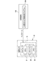
一例として図5に示すように、管理装置11は、ディスプレイ13、制御装置60、受付デバイス62、及び通信I/F66を備えている。制御装置60は、CPU60A、ストレージ60B、及びメモリ60Cを備えている。受付デバイス62、ディスプレイ13、二次記憶装置14、CPU60A、ストレージ60B、メモリ60C、及び通信I/F66の各々は、バス70に接続されている。なお、図5に示す例では、図示の都合上、バス70として1本のバスが図示されているが、複数本のバスであってもよい。バス70は、シリアルバスであってもよいし、データバス、アドレスバス、及びコントロールバス等を含むパラレルバスであってもよい。
As an example, as shown in FIG. 5, the
メモリ60Cは、各種情報を一時的に記憶し、ワークメモリとして用いられる。メモリ60Cの一例としては、RAMが挙げられるが、これに限らず、他の種類の記憶装置であってもよい。ストレージ60Bには、管理装置11用の各種プログラム(以下、単に「管理装置用プログラム」と称する)が記憶されている。CPU60Aは、ストレージ60Bから管理装置用プログラムを読み出し、読み出した管理装置用プログラムをメモリ60C上で実行することで、管理装置11の全体を制御する。
The
通信I/F66は、例えば、ネットワークインターフェースである。通信I/F66は、ネットワークを介して、監視カメラ10の通信I/F34に対して通信可能に接続されており、監視カメラ10との間で各種情報の伝送制御を行う。例えば、通信I/F66は、監視カメラ10に対して撮像画像の送信を要求し、撮像画像の送信の要求に応じて監視カメラ10の通信I/F34から送信された撮像画像を受信する。
Communication I/
通信I/F67及び68は、例えば、ネットワークインターフェースである。通信I/F67は、ネットワークを介して、旋回機構16のドライバ75に対して通信可能に接続されている。CPU60Aは、通信I/F67及びドライバ75を介して、モータ73を制御することで、ヨー軸旋回機構71の旋回動作を制御する。通信I/F68は、ネットワークを介して、旋回機構16のドライバ76に対して通信可能に接続されている。CPU60Aは、通信I/F68及びドライバ76を介して、モータ74を制御することで、ピッチ軸旋回機構72の旋回動作を制御する。
Communication I/
受付デバイス62は、例えば、キーボード、マウス、及びタッチパネル等であり、ユーザからの各種指示を受け付ける。CPU60Aは、受付デバイス62によって受け付けられた各種指示を取得し、取得した指示に従って動作する。例えば、監視カメラ10及び/又は旋回機構16に対する処理内容を受付デバイス62で受け付けた場合、CPU60Aは、受付デバイス62で受け付けた指示内容に従って、監視カメラ10及び/又は旋回機構16を作動させる。
The receiving
ディスプレイ13は、CPU60Aの制御下で、各種情報を表示する。ディスプレイ13に表示される各種情報としては、例えば、受付デバイス62によって受け付けられた各種指示の内容、及び通信I/F66によって受信された撮像画像等が挙げられる。
The
管理装置11は、二次記憶装置14を備えている。二次記憶装置14は、例えば不揮発性のメモリであり、CPU60Aの制御下で、各種情報を記憶する。二次記憶装置14に記憶される各種情報としては、例えば、通信I/F66によって受信された撮像画像等が挙げられる。
The
このように、制御装置60は、通信I/F66によって受信された撮像画像をディスプレイ13に対して表示させる制御、及び通信I/F66によって受信された撮像画像を二次記憶装置14に対して記憶させる制御を行う。
In this way, the
なお、ここでは、制御装置60が撮像画像をディスプレイ13に対して表示させ、かつ、通信I/F66によって受信された撮像画像を二次記憶装置14に対して記憶させるようにしているが、本開示の技術はこれに限定されない。例えば、撮像画像のディスプレイ13に対する表示と撮像画像の二次記憶装置14に対する記憶との何れかが行われるようにしてもよい。
Here, the
一例として図6に示すように、ストレージ36には、位置合わせ制御処理プログラム36Aが記憶されている。CPU37は、ストレージ36から位置合わせ制御処理プログラム36Aを読み出す。CPU37は、ストレージ36から読み出した位置合わせ制御処理プログラム36Aをメモリ35上で実行することで、監視カメラ10による撮像を支援する撮像支援装置として機能する。具体的には、CPU37は、被写体画像検出部37A、画像位置判定部37B、ズーム判定部37C、第1ずれ量算出部37D、第2ずれ量算出部37E、旋回量導出部37F、旋回完了判定部37G及び制御部37Hとして動作する。被写体画像検出部37A及び画像位置判定部37Bは、本開示の技術における「検出部」の一例である。制御部37Hは、本開示の技術における「制御部」の一例である。CPU37は、本開示の技術に係る「プロセッサ」の一例であり、メモリ35は、本開示の技術に係る「メモリ」の一例である。
As an example, as shown in FIG. 6, the
被写体画像検出部37Aは、画像メモリ32から、1フレーム分の撮像画像を取得する。そして、被写体画像検出部37Aは、画像メモリ32から取得した撮像画像内で対象被写体画像を検出する。また、被写体画像検出部37Aは、対象被写体画像を検出した場合に、被写体画像位置を検出する。被写体画像検出部37Aによる被写体画像位置の検出は、後述するように、旋回機構16が作動した場合においても行われる。
The subject
画像位置判定部37Bは、被写体画像検出部37Aによって検出された被写体画像位置が、撮像画像内において、中央領域内にあるか否かを判定する。一例として図7A及び図7Bに示すように、対象被写体が撮像領域に含まれている場合、被写体画像位置は撮像画像において中央領域内であるが、一例として図8A及び図8Bに示すように、旋回機構16によって監視カメラ10が旋回されたり、対象被写体自体が移動したりすることで、対象被写体が撮像領域から外れた場合、被写体画像位置は中央領域にない。
The image
対象被写体画像が中央領域に存在していれば、画像位置判定部37Bでの判定は肯定される。ここで、「存在」とは、対象被写体画像の少なくとも一部が中央領域に被っている態様を意味する。すなわち、対象被写体画像の少なくとも一部が中央領域に被っていれば、画像位置判定部37Bによって「存在」していると判定される。対象被写体画像の少なくとも一部としては、例えば、被写体画像内に含まれる特定部位を示す画像(例えば、対象被写体が人物である場合は、人物の顔)が挙げられる。いわゆる顔認識機能等の画像認識機能が監視カメラ10に搭載されており、特定部位を示す画像が画像認識機能によって検出された場合に、画像位置判定部37Bによって、対象被写体画像が中央領域に存在していると判定されてもよい。なお、中央領域は、本開示の技術に係る「特定位置」の一例である。
If the target subject image exists in the central area, the determination by the image
ズーム判定部37Cは、画像位置判定部37Bにおいて被写体画像位置が中央領域内にあると判定された場合に、監視カメラ10の焦点距離を検出する。そして、ズーム判定部37Cは、焦点距離の変化(例えば、数フレーム前の焦点距離から現時点での焦点距離の変化)から、焦点距離が長くなったか否かを判定する。焦点距離が長くなった場合には、長くなる前と比較して、監視カメラ10による画角が狭くなる。
The
ここで、対象被写体が光軸OAからずれた位置にある状態で焦点距離が長くなった場合、撮像画像全体が光軸OAの位置を中心として拡大され、これに伴って、一例として図9に示すように、対象被写体画像が中心領域からずれてしまう。なお、図9に示す例では、対象被写体画像が撮像画像から外れた態様が示されている。 Here, when the focal length is increased while the target subject is at a position deviated from the optical axis OA, the entire captured image is enlarged centering on the position of the optical axis OA. As shown, the target subject image is shifted from the center area. Note that the example shown in FIG. 9 shows a mode in which the target subject image is out of the captured image.
第1ずれ量算出部37Dは、ズーム判定部37Cにおいて焦点距離が長くなったと判定された場合に、第1ずれ量を算出する。第1ずれ量とは、撮像画像内において、中央領域に対する被写体画像位置のずれ(相対位置の差)を示す量であり、ピッチ軸PA方向及びヨー軸YA方向の2つの値を持つベクトルである。第1ずれ量としては、例えば、対象被写体画像の中心と、中央領域の中心とのずれ量が挙げられる。例えば、対象被写体画像の中心は、対象被写体画像のピッチ軸PA方向での中心座標及びヨー軸YA方向での中心座量の2つの値として求めることができる。第1ずれ量は、本開示の技術に係る「オフセット量」の一例である。
The first
ストレージ36には、旋回量テーブル42Aが記憶されている。一例として図9に示すように、被写体画像検出部37Aによって検出された被写体画像位置は、撮像画像内において中央領域からずれている場合がある。この場合に、旋回機構16によって監視カメラ10を旋回させることで、撮像画像内で被写体画像位置を移動させて、中央領域に近づけることができる。一例として図6に示すように、旋回量テーブル42Aは、被写体画像位置と中央領域とのずれ量と、旋回機構16による監視カメラ10の旋回量とが対応付けられた情報であり、撮像画像内において被写体画像位置を中央領域に近づける場合に用いられる。旋回量は、ピッチ軸PA方向及びヨー軸YA方向の各々に応じて定められている。旋回量テーブル42Aで規定されている旋回量としては、例えば、実機を用いた官能試験及び/又はコンピュータ・シミュレーション等によって、ずれ量を解消するために最適な旋回量として予め導出された旋回量が挙げられる。なお、ここでは、旋回量テーブル42Aを例示しているが、本開示の技術はこれに限定されず、旋回量テーブル42Aと併用して、又は、旋回量テーブル42Aに代えて、ずれ量を独立変数とし、旋回量を従属変数とした旋回量導出用演算式を適用してもよい。
The
旋回量導出部37Fは、ストレージ36から旋回量テーブル42Aを取得する。また、旋回量導出部37Fは、第1ずれ量算出部37Dから、第1ずれ量を取得する。そして、旋回量導出部37Fは、第1ずれ量に対応する旋回量を、旋回量テーブル42Aから導出する。旋回量も、ピッチ方向及びヨー方向の2つの値を持つベクトルである。旋回量導出部37Fは、導出した旋回量を制御部37Hに出力する。
The turning
制御部37Hは、旋回量導出部37Fによって導出された旋回量に基づいて、旋回機構16を作動させる。旋回機構16では、旋回量導出部37Fによって導出された旋回量のうちのピッチ方向及びヨー方向の各々についての比率に応じて定められた旋回量に基づいて旋回機構16が作動され、旋回機構16によって監視カメラ10を旋回させる。監視カメラ10を旋回させることで、撮像画像内において、被写体画像位置が、中央領域に近づくように、撮像範囲が変更される。
The
旋回機構16による監視カメラ10の旋回が完了すると、制御部37Hは、旋回完了判定部37Gに対して、旋回機構16による監視カメラ10の旋回が完了したことを示す完了信号を出力する。
When the turning of the
旋回完了判定部37Gは、旋回機構16による監視カメラ10の旋回が完了したか否かを判定する。旋回完了判定部37Gは、制御部37Hから完了信号が入力されると、旋回機構16による監視カメラ10の旋回が完了したと判定する。旋回完了判定部37Gにおいて、旋回が完了したと判定された場合、画像位置判定部37Bは、被写体画像位置が中央領域内であるか否かを判定する。
The turning
第2ずれ量算出部37Eは、画像位置判定部37Bにおいて被写体画像位置が中央領域内にないと判定された場合に、第2ずれ量を算出する。第2ずれ量は、中央領域に対する被写体画像位置のずれ(相対位置の差)を示す量であり、ピッチ軸PA方向及びヨー軸YA方向の2つの値を持つベクトルである。第2ずれ量としては、例えば、対象被写体画像の中心と、中央領域の中心とのずれ量が挙げられる。対象被写体画像の中心は、一例として、対象被写体画像のピッチ軸PA方向での中心座標及びヨー軸YA方向での中心座量の2つの値として求めることができる。第2ずれ量は、本開示の技術に係る「オフセット量」の一例である。なお、以下では、説明の便宜上、第1ずれ量と第2ずれ量とを区別して説明する必要がない場合、「オフセット量」とも称する。
The second shift
ここで、旋回機構16によって監視カメラ10を旋回させることにより、撮像画像内で被写体画像位置が中央領域からずれることがある。そして、旋回機構16によって監視カメラ10を旋回させることにより、撮像画像に対し撮像画像位置の位置合わせを行うことができる。しかし、この位置合わせの精度は、焦点距離を望遠側に変倍することに伴って低下する。このように、焦点距離の望遠側への変倍に起因して、撮像画像内でのオフセット量は増加する。
Here, when the
制御部37は、オフセット量に従って、レンズ側振れ補正機構29を作動させることで、防振レンズ15B1を防振レンズ二次元平面内で移動させる。このように、制御部37の制御下で防振レンズ15B1を防振レンズ二次元平面内で移動させることにより、一例として図11に示すように、被写体画像位置は、中央領域に近づけられる。
The
管理装置11の制御装置60には、監視カメラ10から送信された撮像画像が順次に入力される。そして、ディスプレイ13は、制御装置60の制御下で、制御装置60に順次に入力された撮像画像を例えばライブビュー画像として表示する。
Captured images transmitted from the monitoring
次に、監視システム2の本開示の技術に係る部分の作用について、図12A及び図12Bを参照しながら説明する。なお、図12A及び図12Bには、CPU37によって実行される位置合わせ制御処理の流れの一例が示されている。位置合わせ制御は、被写体画像検出部37Aによって検出された被写体画像位置を、レンズ側振れ補正機構29を作動させることで中央領域に合わせる制御を含む制御である。図12A及び図12Bに示す位置合わせ制御処理の流れは、本開示の技術に係る「撮像支援方法」の一例である。
Next, the operation of the portion of the
図12A及び図12Bに示す位置合わせ制御処理では、先ず、ステップST10で、被写体画像検出部37Aは、新たな撮像画像が画像メモリ32に記憶されたか否かを判定する。ステップST10において、新たな撮像画像が画像メモリ32に記憶されていない場合は、判定が否定されて、位置合わせ制御処理は、図12Bに示すステップST36へ移行する。ステップST10において、新たな撮像画像が画像メモリ32に記憶された場合は、判定が肯定されて、位置合わせ制御処理はステップST12へ移行する。
In the alignment control process shown in FIGS. 12A and 12B, first, in step ST10, the subject
ステップST12で、被写体画像検出部37Aは、撮像画像を取得する。そして、位置合わせ制御処理はステップST14へ移行する。
In step ST12, the subject
ステップST14で、被写体画像検出部37Aは、被写体画像検出処理を実行する。被写体画像検出処理とは、撮像画像内から対象被写体画像を検出する処理を指す。
In step ST14, the subject
次のステップST16で、被写体画像検出部37Aは、被写体画像検出処理が実行されることによって撮像画像内から対象被写体画像が検出されたか否かを判定する。ステップST16において、撮像画像内に被写体画像が検出されていない場合は、判定が否定されて、位置合わせ制御処理は、図13Bに示すステップST36へ移行する。ステップST16において、被写体画像検出処理が実行されることによって撮像画像内から対象被写体画像が検出された場合は、判定が肯定されて、位置合わせ制御処理はステップST18へ移行する。
In the next step ST16, the subject
ステップST18で、被写体画像検出部37Aは、撮像画像内から被写体画像位置を検出する。例えば、被写体画像検出部37Aは、対象被写体画像が立位であり、かつ、正面視の人物画像である場合、人物画像の頭頂部を対象被写体画像の上端部とし、人物画像の足先部を対象被写体画像の下端部として、被写体画像位置を検出する。また、被写体画像検出部37Aは、人物画像の右肩部又は右腕部を対象被写体画像の右端部とし、人物画像の左肩部又は左腕部を対象被写体画像の左端部として検出する。
In step ST18, the subject
次のステップST20で、画像位置判定部37Bは、被写体画像位置が中央領域内にあるか否かを判定する。ステップST20において、被写体画像位置が中央領域内にある場合は、判定が肯定されて、位置合わせ制御処理はステップST22へ移行する。ステップST20において、被写体画像位置が中央領域内にない場合は、判定が否定されて、位置合わせ制御処理は、図13Bに示すステップST32へ移行する。
In the next step ST20, the image
図13Bに示すステップST32で、第2ずれ量算出部37Eは、第2ずれ量を算出する。
In step ST32 shown in FIG. 13B, the second
次のステップST34で、制御部37Hは、ステップST32で算出された第2ずれ量に従って、レンズ側振れ補正機構29を作動させることで第2位置合わせ制御を行う。レンズ側振れ補正機構29を作動させることにより、一例として図13に示すように、レンズ側振れ補正機構29を作動させる前は、図13中央領域の外部にあった被写体画像位置が、レンズ側振れ補正機構29を作動させた後は、中央領域に収められる。
In the next step ST34, the
一方、図12Aに示すステップST22で、ズーム判定部37Cは、監視カメラ10の焦点距離が長くなったか否かを判定する。ステップST22において、焦点距離が長くなっていない場合は、判定が否定されて、位置合わせ制御処理は、図12Bに示すステップST36へ移行する。ステップST22において、焦点距離が長くなった場合は、判定が肯定されて、位置合わせ制御処理はステップST24へ移行する。
On the other hand, in step ST22 shown in FIG. 12A, the
一例として図9に示すように、焦点距離が長くなった場合には、被写体画像位置が中央領域からずれてしまうばかりか、撮像画像から外れてしまうことがある。そこで、ステップST24で、第1ずれ量算出部37Dは、第1ずれ量を算出する。そして、位置合わせ制御処理はステップST26へ移行する。
As an example, as shown in FIG. 9, when the focal length is long, the subject image position may not only deviate from the central region, but may also deviate from the captured image. Therefore, in step ST24, the first
ステップST26で、旋回量導出部37Fは、旋回量テーブル42Aから、ステップST24で導出された第1ずれ量に対応する旋回量を導出する。そして、位置合わせ制御処理はステップST28へ移行する。
In step ST26, the turning
ステップST28で、制御部37Hは、ステップST26で導出された旋回量に基づいて旋回機構16を作動させることで第1位置合わせ制御を行う。制御部37Hは、旋回機構16を作動させることで、被写体画像位置を中央領域に向けて移動させる。
At step ST28, the
ステップST30で、旋回完了判定部37Gは、旋回が完了したか否かを判定する。ステップST30において、旋回が完了していない場合は、判定が否定されて、位置合わせ制御処理はステップST30の判定が再び行われる。ステップST30において、旋回が完了した場合は、判定が肯定されて、位置合わせ制御処理はステップST20へ移行する。
In step ST30, the turn
図12Bに示すステップST36で、制御部37Hは、位置合わせ制御処理を終了する条件(以下、「終了条件」と称する)を満足したか否かを判定する。終了条件としては、例えば、位置合わせ制御処理を終了させる指示が受付デバイス62によって受け付けられたとの条件が挙げられる。ステップST36において、終了条件を満足していない場合は、判定が否定されて、位置合わせ制御処理は図12Aに示すステップST10へ移行する。ステップST36において、終了条件を満足した場合は、判定が肯定されて、位置合わせ制御処理が終了する。
At step ST36 shown in FIG. 12B, the
ところで、監視カメラ10の旋回による位置合わせの精度は、レンズ側振れ補正機構29の作動による位置合わせの精度よりも低いことが多い。例えば、図10に示すように、旋回機構16を作動させた場合に、中央領域よりも撮像画像の左側にあった被写体画像位置(二点鎖線で示す位置)が、撮像画像の右側に移動してしまい(実線で示す位置)、中央領域には位置しないことがある。
By the way, the accuracy of positioning by turning the
しかも、旋回機構16の作動による旋回角には、例えば度数法で1度(60分)に設定して旋回機構16を作動させようとしても、57分の旋回角となってしまったり、63分の旋回角となってしまったりする等のバラつきがある。したがって、旋回機構16の作動によって、被写体画像位置を中央領域に移動させる際の精度には限界がある。
Moreover, even if the turning angle due to the operation of the
これに対し、レンズ側振れ補正機構29の作動によって被写体画像位置を撮像画像内で移動させる場合は、旋回機構16の作動による場合と比較して、高精度での位置合わせが可能である。すなわち、レンズ側振れ補正機構29を作動させて第2位置合わせ制御が行われることにより、被写体画像位置を撮像画像内で中央領域に合わせることができる。
On the other hand, when the object image position is moved within the captured image by the operation of the lens-side
特に、本実施形態では、旋回角のバラつきは、変倍機構の望遠側における画角の半分未満になるように調整されている。しかも、旋回角のバラつきは、オフセット量未満となるように調整されている。したがって、変倍機構が望遠側にある状態で、旋回機構16による監視カメラ10の旋回の停止位置にばらつきがあっても、レンズ側振れ補正機構29の作動によって被写体画像位置を撮像画像内で中央領域に合わせることができる。
In particular, in this embodiment, the variation in turning angle is adjusted to be less than half of the angle of view on the telephoto side of the variable magnification mechanism. Moreover, the variation in turning angle is adjusted to be less than the offset amount. Therefore, even if there are variations in the rotation stop position of the
例えば、監視カメラ10の旋回によって、被写体画像位置が中央領域内に存在しなくなっている場合がある。このように被写体画像位置が中央領域内に存在しなくなった場合には、位置合わせ制御処理により、第2ずれ量に従って、レンズ側振れ補正機構29を作動させる。したがって、旋回機構16の作動によって被写体画像位置を中央領域内に移動させようとしたにも拘わらず中央領域内に位置しない事態が生じても、その後のレンズ側振れ補正機構29の作動により、図11に示すように、被写体画像位置を中央領域内とすることが可能である。
For example, due to the rotation of the
以上説明したように、監視カメラ10は、撮像支援装置44を備えている。撮像支援装置44では、監視カメラ10の焦点距離が長くなった場合、すなわち望遠側への変倍された場合に、変倍に伴って被写体画像位置が中央領域からずれた場合でも、制御部37Hが、被写体画像位置を中央領域に合わせる位置合わせ制御を行う。このように、望遠側への変倍によって、撮像画像に対し被写体画像位置にずれが生じても、被写体画像位置を撮像画像内の中央領域(本開示の技術に係る「特定位置」の一例)に合わせることができる。
As described above, the
監視カメラ10は、レンズ側振れ補正機構29を有している。レンズ側振れ補正機構29は、監視カメラ10に与えられた振動に起因して生じる振れを補正する機構である。そして、位置合わせ制御は、被写体画像検出部37Aによって検出された被写体画像位置を、レンズ側振れ補正機構29を作動させることで、中央領域に合わせる制御を含んでいる。このように、監視カメラ10に与えられた振動に起因して生じる振れを補正する機構であるレンズ側振れ補正機構29を用いて位置合わせ制御を行っている。したがって、位置合わせ制御のためにのみ用いる機構を監視カメラ10に搭載する場合と比較して、位置合わせ制御に要する部品点数の増加を抑制することができる。
The
撮像支援装置44による位置合わせ制御は、旋回機構16を作動させることで被写体画像位置を中央領域に合わせる制御を含んでいる。旋回機構16に代えて、位置合わせ制御のためにのみ用いる機構を新設する場合と比較して、既存の旋回機構16を用いるので、位置合わせ制御に要する部品点数の増加を抑制することができる。
Alignment control by the imaging support device 44 includes control for aligning the subject image position with the central region by operating the
本実施形態に係る「オフセット量」としては、第1ずれ量と第2ずれ量の2つがある。位置合わせ制御を行うに際し、制御部37Hは、これらのオフセット量に応じて、レンズ側振れ補正機構29及び旋回機構16の少なくとも一方を作動させている。換言すれば、位置合わせ制御を、レンズ側振れ補正機構29及び旋回機構16の両方を作動させて行うことができる。したがって、位置合わせ制御のために、レンズ側振れ補正機構29又は旋回機構16のみを作動させる場合と比較して、被写体画像位置の中央領域への高精度な位置合わせを実現することができる。
As the "offset amount" according to the present embodiment, there are two amounts, a first deviation amount and a second deviation amount. When performing alignment control, the
位置合わせ制御は、旋回機構16を作動させて行う第1位置合わせ制御と、レンズ側振れ補正機構29を作動させて行う第2位置合わせ制御を含んでいる。そして、第2位置合わせ制御の位置合わせ精度は、第1位置合わせ制御の位置合わせ精度よりも高い。制御部37Hは、第1位置合わせ制御を行ってから、第2位置合わせ制御を行うことで、位置合わせ制御を、先ず、相対的に低い精度で行い、次いで、相対的に高い精度で行う。このため、例えば、旋回機構16のみを用いて位置合わせ制御を行う場合と比較して、被写体画像位置の中央領域への位置合わせの高精度化を実現することができる。
The alignment control includes first alignment control performed by operating the
特に、旋回機構16を用いた位置合わせ制御において、旋回機構16の作動による旋回角にバラつきがある場合には、旋回機構16による位置合わせ制御では、被写体画像位置を中央領域に位置させることが難しい。本実施形態では、位置合わせ制御において、旋回機構16の作動によって、被写体画像位置に対する粗調整を行い、その後に、レンズ側振れ補正機構29の作動によって、被写体画像位置に対する微調整を行うので、位置合わせ制高精度化を実現することができる。
In particular, in alignment control using the
本実施形態では、監視カメラ10が焦点距離を変倍させる機能(光学式ズーム機能)を有している。一例として図9にも示したように、変倍前には中央領域にあった被写体画像位置が、変倍後に中央領域から外れることがあり、さらには、撮像画像から外れることもある。被写体画像位置が撮像画像から外れた場合には、旋回機構16を作動させることにより、被写体画像位置を相対的に撮像画像内に向けて移動させることができる。そして、被写体画像位置が撮像画像内にある状態において、レンズ側振れ補正機構29の作動により、被写体画像位置を中央領域に精度良く収めることができる。なお、被写体画像位置が撮像画像から外れた場合には、監視カメラ10の焦点距離を一旦広角側へ変倍させて画角を広げることで、撮像画像内に被写体画像位置が存在する状況を得るようにしてもよい。そして、監視カメラ10の焦点距離を広角側にした状態で、被写体画像位置が中央領域に向けて移動するように、旋回機構16を作動させた後、監視カメラ10の焦点距離を、あらためて望遠側へ変倍(例えば広角側への変倍前の値まで変更)すればよい。
In this embodiment, the
本実施形態において、旋回機構16による監視カメラ10の旋回により、撮像画像内で被写体画像位置が中央領域からずれることがある。そして、被写体画像位置のオフセット量は、焦点距離を長くする(望遠側へ変倍する)ことで相対的に増加する。本実施形態の位置合わせ制御では、レンズ側振れ補正機構29によって被写体画像位置を中央領域に合わせるので、被写体画像位置が撮像画像内にあれば、オフセット量に関わらず位置合わせが可能である。しかも、被写体画像位置を中央領域に合わせる際の精度(位置合わせ精度)は、焦点距離を長くする(望遠側へ変倍する)ことで低下する。換言すれば、一定の旋回角度で監視カメラ10を旋回させた場合であっても、焦点距離が広角側にある状態よりも相対的に望遠側にある状態の方が、監視カメラ10の旋回によって被写体画像位置が大きく変化するので、旋回による位置合わせ精度は相対的に低くなる。このように、変倍機構による望遠側への変倍に伴って、旋回による位置合わせの精度は相対的に低下していても、監視カメラ10の旋回後に、被写体画像位置が撮像画像内にあれば、オフセット量に関わらず、レンズ側振れ補正機構29、撮像素子振れ補正機構45及び電子式振れ補正部33のうちの少なくとも1つの作動により、位置合わせが可能である。
In this embodiment, the rotation of the
中央領域は、本開示の技術における「特定位置」の一例である。特定位置を、撮像画像内の中央領域とすることで、被写体画像位置を撮像画像内の中央に合わせることが可能である。なお、「特定位置」は、撮像画像における中央領域に限定されず、撮像画像の中央からピッチ軸PA方向及びヨー軸YA方向にずれた位置であってもよい。 The central region is an example of a "specific position" in the technology of the present disclosure. By setting the specific position to be the central region within the captured image, it is possible to align the subject image position with the center within the captured image. Note that the "specific position" is not limited to the central region of the captured image, and may be a position shifted in the pitch axis PA direction and the yaw axis YA direction from the center of the captured image.
また、監視カメラ10では、防振レンズ15B1を移動させることで振れが補正される。従って、防振レンズ15B1の可動域の範囲内で振れを補正すること、及び被写体画像位置を中央領域に合わせることができる。
Further, in the
[第二実施形態]
次に、第二実施形態について説明する。第二実施形態において、第一実施形態と同様の要素、及び部材等については第一実施形態と同一の符号を付して、詳細な説明を省略する。また第二実施形態の撮像装置の一例である撮像カメラの全体的構成も、第一実施形態の監視カメラ10と同様であるので、図示を省略する。[Second embodiment]
Next, a second embodiment will be described. In the second embodiment, elements and members that are the same as in the first embodiment are assigned the same reference numerals as in the first embodiment, and detailed descriptions thereof are omitted. The overall configuration of an imaging camera, which is an example of the imaging apparatus of the second embodiment, is also the same as that of the
第二実施形態では、一例として図14に示すように、制御部37Hが位置合わせ制御を行う場合に作動させる振れ補正機構が撮像素子側振れ補正機構45である。換言すれば、第一実施形態の位置合わせ制御処理のフローにおいて、位置合わせ制御処理がステップST34にある状態で作動される振れ補正機構が、第二実施形態では撮像素子側振れ補正機構45である。
In the second embodiment, as shown in FIG. 14 as an example, the
第二実施形態では、位置合わせ制御に撮像素子側振れ補正機構45を用いており、レンズ側振れ補正機構29は用いていない。したがって、位置合わせ制御中において、監視カメラ10の振れの補正に、レンズ側振れ補正機構29を用いることが可能である。
In the second embodiment, the image sensor side
なお、第一実施形態では、位置合わせ制御にレンズ側振れ補正機構29を用いており、撮像素子側振れ補正機構45及び電子式振れ補正部33は用いていない。したがって、位置合わせ制御中において、監視カメラ10の振れの補正に、撮像素子側振れ補正機構45及び電子式振れ補正部33のうちの少なくとも一方を用いることが可能である。
Note that in the first embodiment, the lens-side
[第三実施形態]
次に、第三実施形態について説明する。第三実施形態において、第一実施形態と同様の要素、及び部材等については第一実施形態と同一の符号を付して、詳細な説明を省略する。また第三実施形態の撮像装置の一例である撮像カメラの全体的構成も、第一実施形態の監視カメラ10と同様であるので、図示を省略する。[Third embodiment]
Next, a third embodiment will be described. In the third embodiment, elements and members that are the same as those in the first embodiment are denoted by the same reference numerals as those in the first embodiment, and detailed description thereof will be omitted. The overall configuration of an imaging camera, which is an example of the imaging apparatus of the third embodiment, is also the same as that of the
第三実施形態では、一例として図15に示すように、制御部37Hが位置合わせ制御を行う場合に電子式振れ補正部33を作動させる。換言すれば、第一実施形態の位置合わせ制御処理のフローにおいて、位置合わせ制御処理がステップST34にある状態で、電子式振れ補正部33に作動により、位置合わせ制御処理が実行される。
In the third embodiment, as an example, as shown in FIG. 15, the electronic
第三実施形態では、位置合わせ制御に電子式振れ補正部33を用いており、レンズ側振れ補正機構29及び撮像素子側振れ補正機構45は用いていない。したがって、位置合わせ制御中において、監視カメラ10の振れの補正に、レンズ側振れ補正機構29及び撮像素子側振れ補正機構45のうちの少なくとも一方を用いることが可能である。
In the third embodiment, the electronic
なお、第一実施形態では、位置合わせ制御にレンズ側振れ補正機構29を用いており、撮像素子側振れ補正機構45は用いていない。したがって、位置合わせ制御中において、監視カメラ10の振れの補正に、撮像素子側振れ補正機構45を用いることが可能である。
Note that in the first embodiment, the lens-side
第一実施形態、第二実施形態及び第三実施形態のいずれにおいても、レンズ側振れ補正機構29、撮像素子側振れ補正機構45及び電子機器振れ補正部33を有している。したがって、位置合わせ制御処理を行う場合に、これらのうちの少なくとも1つを作動させることにより、位置合せ制御処理において、被写体画像位置を中央領域に合わせることが可能である。
Each of the first, second, and third embodiments includes the lens-side
例えば、レンズ側振れ補正機構29及び撮像素子側振れ補正機構45の双方を作動させることで、位置合わせ及び振れ補正が実行されるようにしてもよい。この場合、防振レンズ15B1及び撮像素子25の各々の可動域の範囲内で位置合わせ及び振れ補正をすることができる。また、この場合、防振レンズ15B1の可動域によって防振レンズ15B1の移動が制限されることで補正し切れなかった振れを、他の振れ補正機構或いは振れ補正部、例えば撮像素子25を移動させることで補正することが可能となる。
For example, alignment and shake correction may be performed by operating both the lens-side
更に、監視カメラ10では、ピッチ軸PA方向及びヨー軸YAの各々について振れ量が検出される。従って、1つの軸方向についての振れ量のみを用いて振れが補正される場合に比べ、振れを高精度に補正することができる。
Furthermore, in the
上記各実施形態では、監視カメラ10のストレージ36に位置合わせ制御処理プログラム36Aが記憶され、監視カメラのCPU37がメモリ35で位置合わせ制御処理プログラム36Aを実行する形態例を挙げて説明したが、本開示の技術はこれに限定されない。例えば、管理装置11のストレージ60Bに位置合わせ制御処理プログラム36Aが記憶され、管理装置11のCPU60Aがメモリ60Cで位置合わせ制御処理プログラム36Aを実行する例でもよい。さらには、一例として図16に示すように、位置合わせ制御処理プログラム36Aを、非一時的記憶媒体である記憶媒体100に記憶させておいてもよい。図16に示す例の場合、記憶媒体100に記憶されている位置合わせ制御処理プログラム36Aは、コンピュータ19にインストールされ、CPU37は、位置合わせ制御処理プログラム36Aに従って、上述した位置合わせ制御処理を実行する。
In each of the above embodiments, the
図16に示す例では、CPU37は、単数のCPUであるが、本開示の技術はこれに限定されず、複数のCPUを採用してもよい。なお、記憶媒体100の一例としては、SSD又はUSBメモリなどの任意の可搬型の記憶媒体が挙げられる。
In the example shown in FIG. 16, the
また、通信網(図示省略)を介してコンピュータ19に接続される他のコンピュータ又はサーバ装置等の記憶部に位置合わせ制御処理プログラム36Aを記憶させておき、上述の監視カメラ10の要求に応じて位置合わせ制御処理プログラム36Aがコンピュータ19にダウンロードされるようにしてもよい。この場合、ダウンロードされた位置合わせ制御処理プログラム36Aがコンピュータ19のCPU37によって実行される。
In addition, the alignment
また、図16に示す例では、監視カメラ10のコンピュータ19に位置合わせ制御処理プログラム36Aがインストールされる態様が示されているが、本開示の技術はこれに限定されず、管理装置11の制御装置60に位置合わせ制御処理プログラム36Aがインストールされるようにしてもよい。この場合、CPU60Aは、位置合わせ制御処理プログラム36Aに従って、上述した位置合わせ制御処理を実行する。また、位置合わせ制御処理は、監視カメラ10と管理装置11とで分散して行われるようにしてもよい。例えば、第1位置合わせ制御(図12Aに示すステップST28参照)が管理装置11のCPU60Aによって実行され、第2位置合わせ制御(図12Bに示すステップST34参照)が監視カメラ10のCPU37によって実行されるようにしてもよい。
Further, although the example shown in FIG. 16 shows a mode in which the alignment
また、上記各実施形態では、被写体画像検出部37A、画像位置判定部37B、ズーム判定部37C、第1ずれ量算出部37D、第2ずれ量算出部37E、旋回量導出部37F、旋回完了判定部37G、及び制御部37Hが、コンピュータ19によるソフトウェア構成により実現される形態例を挙げて説明したが、本開示の技術はこれに限定されない。例えば、被写体画像検出部37A、画像位置判定部37B、ズーム判定部37C、第1ずれ量算出部37D、第2ずれ量算出部37E、旋回量導出部37F、旋回完了判定部37G、及び制御部37Hは、例えば、ASIC、FPGA、及び/又はPLDを含むデバイスによって実現されるようにしてもよい。また、被写体画像検出部37A、画像位置判定部37B、ズーム判定部37C、第1ずれ量算出部37D、第2ずれ量算出部37E、旋回量導出部37F、旋回完了判定部37G、及び制御部37Hは、ハードウェア構成及びソフトウェア構成の組み合わせによって実現されてもよい。
Further, in each of the above embodiments, the subject
上記の位置合わせ制御処理を実行するハードウェア資源としては、次に示す各種のプロセッサを用いることができる。プロセッサとしては、例えば、上述したように、ソフトウェア、すなわち、プログラムを実行することで、位置合わせ制御処理を実行するハードウェア資源として機能する汎用的なプロセッサであるCPUが挙げられる。また、プロセッサとしては、例えば、FPGA、PLD、又はASICなどの特定の処理を実行させるために専用に設計された回路構成を有するプロセッサである専用電気回路が挙げられる。何れのプロセッサにもメモリが内蔵又は接続されており、何れのプロセッサもメモリを使用することで位置合わせ制御処理を実行する。 As hardware resources for executing the alignment control process, the following various processors can be used. As a processor, for example, as described above, a CPU, which is a general-purpose processor that functions as a hardware resource that executes alignment control processing by executing software, that is, a program, can be used. Also, processors include, for example, FPGAs, PLDs, ASICs, and other dedicated electric circuits that are processors having circuit configurations specially designed to execute specific processing. A memory is built in or connected to each processor, and each processor uses the memory to execute alignment control processing.
位置合わせ制御処理を実行するハードウェア資源は、これらの各種のプロセッサのうちの1つで構成されてもよいし、同種または異種の2つ以上のプロセッサの組み合わせ(例えば、複数のFPGAの組み合わせ、又はCPUとFPGAとの組み合わせ)で構成されてもよい。また、位置合わせ制御処理を実行するハードウェア資源は1つのプロセッサであってもよい。 The hardware resource that executes the alignment control process may be configured with one of these various processors, or a combination of two or more processors of the same or different type (for example, a combination of multiple FPGAs, or a combination of a CPU and an FPGA). Also, the hardware resource that executes the alignment control process may be a single processor.
1つのプロセッサで構成する例としては、第1に、1つ以上のCPUとソフトウェアの組み合わせで1つのプロセッサを構成し、このプロセッサが、制御部37、被写体画像検出部37A、及びズーム判定部37Cの各々の処理を実行するハードウェア資源として機能する形態がある。第2に、SoCなどに代表されるように、位置合わせ制御処理を実行する複数のハードウェア資源を含むシステム全体の機能を1つのICチップで実現するプロセッサを使用する形態がある。このように、制御部37、被写体画像検出部37A、及びズーム判定部37Cの各々の処理は、ハードウェア資源として、上記各種のプロセッサの1つ以上を用いて実現される。
As an example of configuration with one processor, first, one processor is configured by combining one or more CPUs and software, and this processor includes the
さらに、これらの各種のプロセッサのハードウェア的な構造としては、より具体的には、半導体素子などの回路素子を組み合わせた電気回路を用いることができる。 Furthermore, as the hardware structure of these various processors, more specifically, an electric circuit in which circuit elements such as semiconductor elements are combined can be used.
また、上記の位置合わせ制御処理はあくまでも一例である。従って、主旨を逸脱しない範囲内において不要なステップを削除したり、新たなステップを追加したり、処理順序を入れ替えたりしてもよいことは言うまでもない。 Also, the above alignment control process is merely an example. Therefore, it goes without saying that unnecessary steps may be deleted, new steps added, and the order of processing may be changed without departing from the scope of the invention.
また、上記実施形態では、本開示の技術に係る撮像装置の一例として監視カメラ10を挙げたが、本開示の技術はこれに限定されない。例えば、監視カメラ10に代えて、携帯型のレンズ交換式カメラ、携帯型のレンズ固定式カメラ、パーソナル・コンピュータ、スマートデバイス、又はウェアラブル端末装置等の各種の電子機器に対しても本開示の技術は適用可能である。これらの電子機器であっても、上記各実施形態で説明した監視カメラ10と同様の作用及び効果が得られる。
Further, in the above-described embodiment, the
以上に示した記載内容及び図示内容は、本開示の技術に係る部分についての詳細な説明であり、本開示の技術の一例に過ぎない。例えば、上記の構成、機能、作用、及び効果に関する説明は、本開示の技術に係る部分の構成、機能、作用、及び効果の一例に関する説明である。よって、本開示の技術の主旨を逸脱しない範囲内において、以上に示した記載内容及び図示内容に対して、不要な部分を削除したり、新たな要素を追加したり、置き換えたりしてもよいことは言うまでもない。また、錯綜を回避し、本開示の技術に係る部分の理解を容易にするために、以上に示した記載内容及び図示内容では、本開示の技術の実施を可能にする上で特に説明を要しない技術常識等に関する説明は省略されている。 The description and illustration shown above are detailed descriptions of the parts related to the technology of the present disclosure, and are merely examples of the technology of the present disclosure. For example, the above descriptions of configurations, functions, actions, and effects are descriptions of examples of configurations, functions, actions, and effects of portions related to the technology of the present disclosure. Therefore, unnecessary parts may be deleted, new elements added, or replaced with respect to the above-described description and illustration without departing from the gist of the technology of the present disclosure. Needless to say. In addition, in order to avoid complication and facilitate understanding of the portion related to the technology of the present disclosure, the descriptions and illustrations shown above require particular explanation in order to enable implementation of the technology of the present disclosure. Descriptions of common technical knowledge, etc., that are not used are omitted.
本明細書において、「A及び/又はB」は、「A及びBのうちの少なくとも1つ」と同義である。つまり、「A及び/又はB」は、Aだけであってもよいし、Bだけであってもよいし、A及びBの組み合わせであってもよい、という意味である。また、本明細書において、3つ以上の事柄を「及び/又は」で結び付けて表現する場合も、「A及び/又はB」と同様の考え方が適用される。 As used herein, "A and/or B" is synonymous with "at least one of A and B." That is, "A and/or B" means that only A, only B, or a combination of A and B may be used. Also, in this specification, when three or more matters are expressed by connecting with "and/or", the same idea as "A and/or B" is applied.
本明細書に記載された全ての文献、特許出願及び技術規格は、個々の文献、特許出願及び技術規格が参照により取り込まれることが具体的かつ個々に記された場合と同程度に、本明細書中に参照により取り込まれる。 All publications, patent applications and technical standards mentioned herein are expressly incorporated herein by reference to the same extent as if each individual publication, patent application and technical standard were specifically and individually noted to be incorporated by reference. incorporated by reference into the book.
以上の実施形態に関し、更に以下の付記を開示する。 The following additional remarks are disclosed regarding the above embodiments.
(付記)
プロセッサと、
上記プロセッサに内蔵又は接続されたメモリと、を含み、
上記プロセッサは、
変倍機構を有する撮像装置を旋回させる旋回機構の作動により、撮像装置によって対象被写体を含む撮像領域が撮像されることで得られる撮像画像内の対象被写体を示す対象被写体画像の被写体画像位置を検出し、
変倍機構による望遠側への変倍に伴って撮像装置によって撮像されることで得られた撮像画像について、検出された被写体画像位置を撮像画像内の特定位置に合わせる位置合わせ制御を行う
情報処理装置。(Appendix)
a processor;
a memory embedded in or connected to the processor;
The above processor
Detecting the subject image position of the target subject image showing the target subject in the captured image obtained by imaging the imaging region including the target subject with the imaging device by operating the rotation mechanism that rotates the imaging device having the variable magnification mechanism. death,
Positioning control is performed to align the detected subject image position with a specific position in the captured image, which is obtained by capturing an image by the imaging device as the magnification is changed to the telephoto side by the variable magnification mechanism. Device.
Claims (17)
前記プロセッサに内蔵又は接続されたメモリと、を含み、
前記プロセッサは、
変倍機構を有する撮像装置を旋回させる旋回機構の作動により、前記撮像装置によって対象被写体を含む撮像領域が撮像されることで得られる撮像画像内の前記対象被写体を示す対象被写体画像の被写体画像位置を検出し、
前記変倍機構による望遠側への変倍に伴って前記撮像装置によって撮像されることで得られた前記撮像画像について、検出した前記被写体画像位置を前記撮像画像内の特定位置に合わせる位置合わせ制御を行い、
前記メモリに、前記変倍機構による望遠側への変倍に伴って算出される前記被写体画像位置の前記特定位置に対するオフセット量と、前記オフセット量を解消するための旋回機構の旋回量とが対応付けられた情報が予め記憶される
撮像支援装置。a processor;
a memory embedded in or connected to the processor;
The processor
A subject image position of a target subject image showing the target subject in a captured image obtained by imaging an imaging region including the target subject with the imaging device by operating a turning mechanism for turning the imaging device having a variable magnification mechanism. to detect
Alignment control for aligning the detected subject image position with a specific position in the captured image, which is obtained by capturing an image by the imaging device as the magnification is changed to the telephoto side by the variable power mechanism. and
Correspondence between the amount of offset of the position of the subject image from the specific position and the amount of turning of the turning mechanism for canceling the amount of offset in the memory. An imaging support device in which attached information is stored in advance.
前記位置合わせ制御は、前記プロセッサによって検出された前記被写体画像位置を、前記振れ補正コンポーネントを作動させることで前記特定位置に合わせる制御を含む制御である請求項1に記載の撮像支援装置。The imaging device has a shake correction component that corrects shake caused by vibrations applied to the imaging device,
2. The imaging support apparatus according to claim 1, wherein the alignment control includes control for aligning the object image position detected by the processor with the specific position by operating the shake correction component.
前記プロセッサは、検出した前記被写体画像位置の前記特定位置に対するオフセット量に応じて、前記振れ補正コンポーネント及び前記旋回機構のうちの少なくとも一方を作動させることで前記位置合わせ制御を行うことを含む請求項1に記載の撮像支援装置。The imaging device has a shake correction component that corrects shake caused by vibrations applied to the imaging device,
3. The processor, according to the detected offset amount of the subject image position with respect to the specific position, performing the alignment control by operating at least one of the shake correction component and the turning mechanism. 1. The imaging support device according to 1.
前記プロセッサに内蔵又は接続されたメモリと、を含み、
前記プロセッサは、
変倍機構、及び、与えられた振動に起因して生じる振れを補正する振れ補正コンポーネントを有する撮像装置を旋回させる旋回機構の作動により、前記撮像装置によって対象被写体を含む撮像領域が撮像されることで得られる撮像画像内の前記対象被写体を示す対象被写体画像の被写体画像位置を検出し、
前記変倍機構による望遠側への変倍に伴って前記撮像装置によって撮像されることで得られた前記撮像画像について、検出した前記被写体画像位置を、検出した前記被写体画像位置の特定位置に対するオフセット量に応じて、前記振れ補正コンポーネント及び前記旋回機構のうちの少なくとも一方を作動させることで前記撮像画像内の前記特定位置に合わせる位置合わせ制御を行い、
前記メモリに、前記変倍機構による望遠側への変倍に伴って算出される前記被写体画像位置の前記特定位置に対するオフセット量と、前記オフセット量を解消するための旋回機構の旋回量とが対応付けられた情報が予め記憶される、
撮像支援装置。a processor;
a memory embedded in or connected to the processor;
The processor
An image pickup area including a target subject is imaged by the image pickup device through the operation of a rotation mechanism that rotates an image pickup device having a variable magnification mechanism and a shake correction component that corrects shake caused by given vibration. Detecting the subject image position of the target subject image showing the target subject in the captured image obtained in
offsetting the detected object image position with respect to a specific position of the detected object image position with respect to the captured image obtained by imaging by the imaging device along with the zooming to the telephoto side by the zoom mechanism; performing alignment control to align with the specific position in the captured image by operating at least one of the shake correction component and the turning mechanism according to the amount;
Correspondence between the amount of offset of the position of the subject image from the specific position and the amount of turning of the turning mechanism for canceling the amount of offset in the memory. The attached information is pre-stored,
Imaging support device.
前記プロセッサは、前記第1位置合わせ制御を行ってから、前記第2位置合わせ制御を行う請求項4又は請求項5に記載の撮像支援装置。The alignment control includes first alignment control for moving the subject image position toward the specific position by operating the turning mechanism, and alignment accuracy higher than that of the first alignment control, and , a second alignment control that moves the subject image position toward the specific position by actuating the shake correction component;
6. The imaging support apparatus according to claim 4, wherein said processor performs said second alignment control after performing said first alignment control.
前記特定位置は、前記対象被写体画像が前記撮像画像内に収まる位置として定められた位置である請求項1から請求項7のいずれか一項に記載の撮像支援装置。When at least part of the target subject image deviates from the captured image due to the zooming to the telephoto side while the target subject image is displayed in the captured image, the processor determines the position of the target subject image. perform matching control,
8. The imaging support apparatus according to any one of claims 1 to 7, wherein the specific position is a position defined as a position where the target subject image fits within the captured image.
前記旋回機構と、を含み、
前記撮像支援装置は、
前記旋回機構が前記撮像装置を旋回させる場合に前記撮像装置による撮像を支援する
撮像支援システム。The imaging support device according to any one of claims 1 to 12;
and the turning mechanism;
The imaging support device is
An imaging support system that supports imaging by the imaging device when the turning mechanism rotates the imaging device.
前記撮像装置と、を含み、
前記撮像装置は、前記撮像支援装置によって撮像の支援が行われる撮像システム。The imaging support device according to any one of claims 1 to 12;
and the imaging device,
The imaging device is an imaging system in which imaging assistance is performed by the imaging support device.
前記旋回機構は、前記撮像装置を旋回させる請求項14に記載の撮像システム。further comprising the turning mechanism;
15. The imaging system according to claim 14, wherein said pivoting mechanism pivots said imaging device.
前記変倍機構による望遠側への変倍に伴って前記撮像装置によって撮像されることで得られた前記撮像画像について、検出された前記被写体画像位置を前記撮像画像内の特定位置に合わせる位置合わせ制御を行うこと
を含み、
前記変倍機構による望遠側への変倍に伴って算出される前記被写体画像位置の前記特定位置に対するオフセット量と、前記オフセット量を解消するための旋回機構の旋回量とが対応付けられた情報が予め記憶される
撮像支援方法。A subject image position of a target subject image showing the target subject in a captured image obtained by imaging an imaging region including the target subject with the imaging device by operating a turning mechanism for turning the imaging device having a variable magnification mechanism. and
Alignment by aligning the detected subject image position with a specific position in the captured image, with respect to the captured image obtained by imaging by the imaging device as the magnification is changed to the telephoto side by the variable magnification mechanism. including controlling
Information in which an offset amount of the subject image position with respect to the specific position calculated in association with zooming to the telephoto side by the zooming mechanism and a pivoting amount of a pivoting mechanism for canceling the offset amount are associated with each other. is stored in advance.
変倍機構を有する撮像装置を旋回させる旋回機構の作動により、前記撮像装置によって対象被写体を含む撮像領域が撮像されることで得られる撮像画像内の前記対象被写体を示す対象被写体画像の被写体画像位置を検出すること、及び、
前記変倍機構による望遠側への変倍に伴って前記撮像装置によって撮像されることで得られた前記撮像画像について、検出された前記被写体画像位置を前記撮像画像内の特定位置に合わせる位置合わせ制御を行うこと、
を含み、
前記変倍機構による望遠側への変倍に伴って算出される前記被写体画像位置の前記特定位置に対するオフセット量と、前記オフセット量を解消するための旋回機構の旋回量とが対応付けられた情報が予め記憶される
処理を実行させるためのプログラム。to the computer,
A subject image position of a target subject image showing the target subject in a captured image obtained by imaging an imaging region including the target subject with the imaging device by operating a turning mechanism for turning the imaging device having a variable magnification mechanism. and
Alignment by aligning the detected subject image position with a specific position in the captured image, with respect to the captured image obtained by imaging by the imaging device as the magnification is changed to the telephoto side by the variable magnification mechanism. to exercise control;
including
Information in which an offset amount of the subject image position with respect to the specific position calculated in association with zooming to the telephoto side by the zooming mechanism and a pivoting amount of a pivoting mechanism for canceling the offset amount are associated with each other. is stored in advance A program for executing processing.
Priority Applications (1)
| Application Number | Priority Date | Filing Date | Title |
|---|---|---|---|
| JP2023003268A JP2023052365A (en) | 2019-10-29 | 2023-01-12 | Imaging support device, imaging support system, imaging system, imaging support method, and program |
Applications Claiming Priority (3)
| Application Number | Priority Date | Filing Date | Title |
|---|---|---|---|
| JP2019196680 | 2019-10-29 | ||
| JP2019196680 | 2019-10-29 | ||
| PCT/JP2020/039424 WO2021085246A1 (en) | 2019-10-29 | 2020-10-20 | Imaging support device, imaging support system, imaging system, imaging support method, and program |
Related Child Applications (1)
| Application Number | Title | Priority Date | Filing Date |
|---|---|---|---|
| JP2023003268A Division JP2023052365A (en) | 2019-10-29 | 2023-01-12 | Imaging support device, imaging support system, imaging system, imaging support method, and program |
Publications (3)
| Publication Number | Publication Date |
|---|---|
| JPWO2021085246A1 JPWO2021085246A1 (en) | 2021-05-06 |
| JPWO2021085246A5 JPWO2021085246A5 (en) | 2022-08-02 |
| JP7212175B2 true JP7212175B2 (en) | 2023-01-24 |
Family
ID=75714491
Family Applications (2)
| Application Number | Title | Priority Date | Filing Date |
|---|---|---|---|
| JP2021553466A Active JP7212175B2 (en) | 2019-10-29 | 2020-10-20 | Imaging support device, imaging support system, imaging system, imaging support method, and program |
| JP2023003268A Pending JP2023052365A (en) | 2019-10-29 | 2023-01-12 | Imaging support device, imaging support system, imaging system, imaging support method, and program |
Family Applications After (1)
| Application Number | Title | Priority Date | Filing Date |
|---|---|---|---|
| JP2023003268A Pending JP2023052365A (en) | 2019-10-29 | 2023-01-12 | Imaging support device, imaging support system, imaging system, imaging support method, and program |
Country Status (4)
| Country | Link |
|---|---|
| US (2) | US11678055B2 (en) |
| JP (2) | JP7212175B2 (en) |
| CN (1) | CN114641985A (en) |
| WO (1) | WO2021085246A1 (en) |
Families Citing this family (2)
| Publication number | Priority date | Publication date | Assignee | Title |
|---|---|---|---|---|
| JP2022012896A (en) * | 2020-07-02 | 2022-01-17 | キヤノン株式会社 | Imaging apparatus, method, program, and storage medium |
| JP2022155134A (en) * | 2021-03-30 | 2022-10-13 | キヤノン株式会社 | Imaging apparatus |
Citations (1)
| Publication number | Priority date | Publication date | Assignee | Title |
|---|---|---|---|---|
| JP6217187B2 (en) | 2013-07-03 | 2017-10-25 | ソニー株式会社 | Light emitting device and display device |
Family Cites Families (10)
| Publication number | Priority date | Publication date | Assignee | Title |
|---|---|---|---|---|
| JP3168492B2 (en) * | 1992-10-14 | 2001-05-21 | 三菱電機株式会社 | Imaging device |
| US5835641A (en) * | 1992-10-14 | 1998-11-10 | Mitsubishi Denki Kabushiki Kaisha | Image pick-up apparatus for detecting and enlarging registered objects |
| JP2015037248A (en) * | 2013-08-13 | 2015-02-23 | キヤノン株式会社 | Imaging device, control method for imaging device, program, and storage medium |
| JP6395381B2 (en) * | 2014-01-08 | 2018-09-26 | キヤノン株式会社 | Imaging apparatus and control method thereof |
| JP2016027704A (en) * | 2014-07-04 | 2016-02-18 | パナソニックIpマネジメント株式会社 | Imaging device |
| JP2016035543A (en) * | 2014-08-04 | 2016-03-17 | オリンパス株式会社 | Imaging device and method for correcting image blur using the device |
| EP3214832B1 (en) * | 2014-10-31 | 2019-11-27 | Fujifilm Corporation | Imaging device and method for recognizing target object |
| JP7020651B2 (en) * | 2017-10-03 | 2022-02-16 | 株式会社Mirai Eye | Adjustable intraocular lens |
| JP7076988B2 (en) * | 2017-11-28 | 2022-05-30 | キヤノン株式会社 | Imaging device and control method |
| JP7393245B2 (en) * | 2020-02-26 | 2023-12-06 | キヤノン株式会社 | Imaging device, its control method, program, storage medium |
-
2020
- 2020-10-20 JP JP2021553466A patent/JP7212175B2/en active Active
- 2020-10-20 WO PCT/JP2020/039424 patent/WO2021085246A1/en active Application Filing
- 2020-10-20 CN CN202080075109.5A patent/CN114641985A/en active Pending
-
2022
- 2022-04-13 US US17/659,170 patent/US11678055B2/en active Active
-
2023
- 2023-01-12 JP JP2023003268A patent/JP2023052365A/en active Pending
- 2023-05-01 US US18/310,496 patent/US20230276128A1/en active Pending
Patent Citations (1)
| Publication number | Priority date | Publication date | Assignee | Title |
|---|---|---|---|---|
| JP6217187B2 (en) | 2013-07-03 | 2017-10-25 | ソニー株式会社 | Light emitting device and display device |
Also Published As
| Publication number | Publication date |
|---|---|
| US20220239818A1 (en) | 2022-07-28 |
| US20230276128A1 (en) | 2023-08-31 |
| JP2023052365A (en) | 2023-04-11 |
| WO2021085246A1 (en) | 2021-05-06 |
| US11678055B2 (en) | 2023-06-13 |
| JPWO2021085246A1 (en) | 2021-05-06 |
| CN114641985A (en) | 2022-06-17 |
Similar Documents
| Publication | Publication Date | Title |
|---|---|---|
| JP7456043B2 (en) | Imaging support device, imaging support system, imaging system, imaging support method, and program | |
| JP2023052365A (en) | Imaging support device, imaging support system, imaging system, imaging support method, and program | |
| US20080037970A1 (en) | Camera body and camera system including the same | |
| JP2023052772A (en) | Imaging support device, imaging apparatus, imaging system, imaging support system, imaging support method, and program | |
| JP7451795B2 (en) | Shake detection device, imaging device, lens device, and imaging device main body | |
| JP7234412B2 (en) | Imaging support device, imaging device, imaging system, imaging support method, and program | |
| JP5393877B2 (en) | Imaging device and integrated circuit | |
| JP2019092036A (en) | Imaging apparatus and control method | |
| JP7209107B2 (en) | Imaging support device, imaging device, imaging system, imaging support system, imaging support method, and program | |
| JP7289929B2 (en) | Imaging support device, imaging system, imaging support method, and program | |
| US11968448B2 (en) | Imaging support device, imaging apparatus, imaging system, imaging support system, imaging support method, and program | |
| JP6257288B2 (en) | Imaging apparatus and control method thereof | |
| WO2024057788A1 (en) | Control device, imaging system, control method, and control program | |
| JP6188369B2 (en) | Imaging device | |
| JP2009300784A (en) | Camera shake correction device and camera shake correction method, and imaging device | |
| KR20150127391A (en) | Apparatus and its method for stabilizing the image of the high-resolution optical structure |
Legal Events
| Date | Code | Title | Description |
|---|---|---|---|
| A529 | Written submission of copy of amendment under article 34 pct |
Free format text: JAPANESE INTERMEDIATE CODE: A5211 Effective date: 20220418 |
|
| A621 | Written request for application examination |
Free format text: JAPANESE INTERMEDIATE CODE: A621 Effective date: 20220418 |
|
| TRDD | Decision of grant or rejection written | ||
| A01 | Written decision to grant a patent or to grant a registration (utility model) |
Free format text: JAPANESE INTERMEDIATE CODE: A01 Effective date: 20221213 |
|
| A61 | First payment of annual fees (during grant procedure) |
Free format text: JAPANESE INTERMEDIATE CODE: A61 Effective date: 20230112 |
|
| R150 | Certificate of patent or registration of utility model |
Ref document number: 7212175 Country of ref document: JP Free format text: JAPANESE INTERMEDIATE CODE: R150 |