JP7289929B2 - Imaging support device, imaging system, imaging support method, and program - Google Patents

Imaging support device, imaging system, imaging support method, and program Download PDF

Info

Publication number
JP7289929B2
JP7289929B2 JP2021561225A JP2021561225A JP7289929B2 JP 7289929 B2 JP7289929 B2 JP 7289929B2 JP 2021561225 A JP2021561225 A JP 2021561225A JP 2021561225 A JP2021561225 A JP 2021561225A JP 7289929 B2 JP7289929 B2 JP 7289929B2
Authority
JP
Japan
Prior art keywords
shake correction
imaging
irradiation
focal length
irradiation range
Prior art date
Legal status (The legal status is an assumption and is not a legal conclusion. Google has not performed a legal analysis and makes no representation as to the accuracy of the status listed.)
Active
Application number
JP2021561225A
Other languages
Japanese (ja)
Other versions
JPWO2021106447A5 (en
JPWO2021106447A1 (en
Inventor
哲也 藤川
伸一郎 藤木
淳一 田中
睦 川中子
Current Assignee (The listed assignees may be inaccurate. Google has not performed a legal analysis and makes no representation or warranty as to the accuracy of the list.)
Fujifilm Corp
Original Assignee
Fujifilm Corp
Priority date (The priority date is an assumption and is not a legal conclusion. Google has not performed a legal analysis and makes no representation as to the accuracy of the date listed.)
Filing date
Publication date
Application filed by Fujifilm Corp filed Critical Fujifilm Corp
Publication of JPWO2021106447A1 publication Critical patent/JPWO2021106447A1/ja
Publication of JPWO2021106447A5 publication Critical patent/JPWO2021106447A5/ja
Application granted granted Critical
Publication of JP7289929B2 publication Critical patent/JP7289929B2/en
Active legal-status Critical Current
Anticipated expiration legal-status Critical

Links

Images

Classifications

    • HELECTRICITY
    • H04ELECTRIC COMMUNICATION TECHNIQUE
    • H04NPICTORIAL COMMUNICATION, e.g. TELEVISION
    • H04N23/00Cameras or camera modules comprising electronic image sensors; Control thereof
    • H04N23/70Circuitry for compensating brightness variation in the scene
    • H04N23/74Circuitry for compensating brightness variation in the scene by influencing the scene brightness using illuminating means
    • GPHYSICS
    • G03PHOTOGRAPHY; CINEMATOGRAPHY; ANALOGOUS TECHNIQUES USING WAVES OTHER THAN OPTICAL WAVES; ELECTROGRAPHY; HOLOGRAPHY
    • G03BAPPARATUS OR ARRANGEMENTS FOR TAKING PHOTOGRAPHS OR FOR PROJECTING OR VIEWING THEM; APPARATUS OR ARRANGEMENTS EMPLOYING ANALOGOUS TECHNIQUES USING WAVES OTHER THAN OPTICAL WAVES; ACCESSORIES THEREFOR
    • G03B15/00Special procedures for taking photographs; Apparatus therefor
    • G03B15/02Illuminating scene
    • G03B15/03Combinations of cameras with lighting apparatus; Flash units
    • G03B15/05Combinations of cameras with electronic flash apparatus; Electronic flash units
    • GPHYSICS
    • G03PHOTOGRAPHY; CINEMATOGRAPHY; ANALOGOUS TECHNIQUES USING WAVES OTHER THAN OPTICAL WAVES; ELECTROGRAPHY; HOLOGRAPHY
    • G03BAPPARATUS OR ARRANGEMENTS FOR TAKING PHOTOGRAPHS OR FOR PROJECTING OR VIEWING THEM; APPARATUS OR ARRANGEMENTS EMPLOYING ANALOGOUS TECHNIQUES USING WAVES OTHER THAN OPTICAL WAVES; ACCESSORIES THEREFOR
    • G03B5/00Adjustment of optical system relative to image or object surface other than for focusing
    • G03B5/04Vertical adjustment of lens; Rising fronts
    • HELECTRICITY
    • H04ELECTRIC COMMUNICATION TECHNIQUE
    • H04NPICTORIAL COMMUNICATION, e.g. TELEVISION
    • H04N23/00Cameras or camera modules comprising electronic image sensors; Control thereof
    • H04N23/56Cameras or camera modules comprising electronic image sensors; Control thereof provided with illuminating means
    • HELECTRICITY
    • H04ELECTRIC COMMUNICATION TECHNIQUE
    • H04NPICTORIAL COMMUNICATION, e.g. TELEVISION
    • H04N23/00Cameras or camera modules comprising electronic image sensors; Control thereof
    • H04N23/60Control of cameras or camera modules
    • H04N23/68Control of cameras or camera modules for stable pick-up of the scene, e.g. compensating for camera body vibrations
    • H04N23/681Motion detection
    • GPHYSICS
    • G03PHOTOGRAPHY; CINEMATOGRAPHY; ANALOGOUS TECHNIQUES USING WAVES OTHER THAN OPTICAL WAVES; ELECTROGRAPHY; HOLOGRAPHY
    • G03BAPPARATUS OR ARRANGEMENTS FOR TAKING PHOTOGRAPHS OR FOR PROJECTING OR VIEWING THEM; APPARATUS OR ARRANGEMENTS EMPLOYING ANALOGOUS TECHNIQUES USING WAVES OTHER THAN OPTICAL WAVES; ACCESSORIES THEREFOR
    • G03B2205/00Adjustment of optical system relative to image or object surface other than for focusing
    • G03B2205/0007Movement of one or more optical elements for control of motion blur
    • G03B2205/0015Movement of one or more optical elements for control of motion blur by displacing one or more optical elements normal to the optical axis
    • GPHYSICS
    • G03PHOTOGRAPHY; CINEMATOGRAPHY; ANALOGOUS TECHNIQUES USING WAVES OTHER THAN OPTICAL WAVES; ELECTROGRAPHY; HOLOGRAPHY
    • G03BAPPARATUS OR ARRANGEMENTS FOR TAKING PHOTOGRAPHS OR FOR PROJECTING OR VIEWING THEM; APPARATUS OR ARRANGEMENTS EMPLOYING ANALOGOUS TECHNIQUES USING WAVES OTHER THAN OPTICAL WAVES; ACCESSORIES THEREFOR
    • G03B2217/00Details of cameras or camera bodies; Accessories therefor
    • G03B2217/005Blur detection
    • HELECTRICITY
    • H04ELECTRIC COMMUNICATION TECHNIQUE
    • H04NPICTORIAL COMMUNICATION, e.g. TELEVISION
    • H04N23/00Cameras or camera modules comprising electronic image sensors; Control thereof
    • H04N23/60Control of cameras or camera modules
    • H04N23/695Control of camera direction for changing a field of view, e.g. pan, tilt or based on tracking of objects

Description

本開示の技術は、撮像支援装置、撮像システム、撮像支援方法、及びプログラムに関する。 The technology of the present disclosure relates to an imaging support device, an imaging system, an imaging support method, and a program.

特開平10-322590号公報には、撮像手段の振れを検出し振れ信号を出力する検出手段と、補助光の発光手段の不使用が選択されたときの振れ振動を処理して振れ補正信号を生成する処理手段と、振れ補正信号に基づいて振れを光学的に補正する振れ補正手段と、発光手段の不使用が選択されているときの撮像時に処理手段を所定の状態に制御する制御手段と、を備えた撮像装置が開示されている。 Japanese Patent Application Laid-Open No. 10-322590 discloses a detection means for detecting vibration of an imaging means and outputting a vibration signal, and a vibration correction signal by processing vibration when non-use of an auxiliary light emitting means is selected. processing means for generating, shake correction means for optically correcting shake based on the shake correction signal, and control means for controlling the processing means to a predetermined state during imaging when non-use of the light emitting means is selected. is disclosed.

特開2004-128584号公報には、撮像手段の露光時間を複数の時間に分割する分割手段と、撮影の際に2つの期間のそれぞれにおいて受光部に蓄積される電荷信号を第1及び第2の画像データとして読み出す読み出し手段と、第1及び第2の画像データを比較する比較手段と、比較手段による比較結果に基づいて被写体と撮像装置との相対的なぶれ量を検出する検出手段と、を備える撮像装置が開示されている。 Japanese Patent Application Laid-Open No. 2004-128584 discloses a dividing means for dividing an exposure time of an imaging means into a plurality of times, and a first and a second time period for dividing charge signals accumulated in a light-receiving portion in each of two periods during photographing. reading means for reading out as image data of; comparison means for comparing the first and second image data; detection means for detecting the relative amount of blurring between the subject and the imaging device based on the comparison result of the comparison means; is disclosed.

本開示の技術に係る一つの実施形態は、振れ補正機構の作動状態に応じて、対象被写体に対する照射装置からの光の照射範囲を調整することができる撮像支援装置、撮像システム、撮像支援方法、及びプログラムを提供する。 One embodiment according to the technology of the present disclosure provides an imaging support device, an imaging system, an imaging support method, and an imaging support device that can adjust the irradiation range of light from an irradiation device to a target subject according to the operating state of a shake correction mechanism. and provide programs.

本開示の技術に係る第1の態様は、プロセッサと、プロセッサに接続又は内蔵されたメモリと、を含み、プロセッサは、撮像装置の振れ補正機構が作動している状態で振れ補正機構による振れ補正量に関するデータ及び撮像装置の焦点距離に関するデータを取得し、取得した振れ補正量及び焦点距離に関するデータに基づいて対象被写体に対する照射装置からの光の照射範囲を調整する、撮像支援装置である。 A first aspect of the technology of the present disclosure includes a processor and a memory connected to or built into the processor, and the processor performs shake correction by the shake correction mechanism while the shake correction mechanism of the imaging device is operating. An imaging support device that acquires data on the amount and data on the focal length of an imaging device, and adjusts the irradiation range of the light from the irradiation device to the target subject based on the acquired data on the amount of shake correction and the focal length.

本開示の技術に係る第2の態様は、プロセッサは、撮像装置から対象被写体までの被写体距離に関するデータを取得し、振れ補正量に関するデータ、及び焦点距離に関するデータに加えて、被写体距離に関するデータに基づいて照射範囲を調整する第1の態様に係る撮像支援装置である。 In a second aspect of the technology of the present disclosure, the processor obtains data regarding the subject distance from the imaging device to the target subject, and obtains the data regarding the subject distance in addition to the data regarding the shake correction amount and the data regarding the focal length. 1 is an imaging support device according to a first aspect that adjusts an irradiation range based on a

本開示の技術に係る第3の態様は、照射装置は、光の強度を変更可能であり、プロセッサはさらに、被写体距離に基づいて光の強度を調整する第2の態様に係る撮像支援装置である。 A third aspect of the technology of the present disclosure is the imaging support device according to the second aspect, wherein the illumination device can change the intensity of light, and the processor further adjusts the intensity of light based on the subject distance. be.

本開示の技術に係る第4の態様は、プロセッサは、照射装置のレンズの光軸と撮像装置のレンズの光軸との間隔に関するデータ、振れ補正量に関するデータ、及び焦点距離に関するデータに基づいて照射範囲を調整する第1の態様に係る撮像支援装置である。 In a fourth aspect of the technology of the present disclosure, the processor, based on data on the distance between the optical axis of the lens of the irradiation device and the optical axis of the lens of the imaging device, the data on the amount of shake correction, and the data on the focal length 1 is an imaging support device according to a first aspect that adjusts an irradiation range;

本開示の技術に係る第5の態様は、プロセッサは、照射装置のレンズの光軸と撮像装置のレンズの光軸との間隔に関するデータ、振れ補正量に関するデータ、被写体距離に関するデータ及び焦点距離に関するデータに基づいて照射範囲を調整する第2の態様又は第3の態様に係る撮像支援装置である。 In a fifth aspect of the technology of the present disclosure, the processor provides data on the distance between the optical axis of the lens of the illumination device and the optical axis of the lens of the imaging device, data on the amount of shake correction, data on the subject distance, and data on the focal length. It is an imaging support device according to a second aspect or a third aspect for adjusting an irradiation range based on data.

本開示の技術に係る第6の態様は、プロセッサは、振れ補正機構を作動させることにより撮像画像を変位させる位置合わせ制御を行っている場合に、照射範囲を調整する第1の態様から第5の態様の何れか1つの態様に係る撮像支援装置である。 According to a sixth aspect of the technology of the present disclosure, the processor adjusts the irradiation range in the first to fifth aspects when the alignment control for displacing the captured image is performed by operating the shake correction mechanism. 2. An imaging support device according to any one aspect of the above aspects.

本開示の技術に係る第7の態様は、プロセッサは、既定の時間内での位置合わせ制御において、撮像画像内の対象被写体画像の変位量の最大値に従って制限された範囲内で照射範囲を調整する第6の態様に係る撮像支援装置である。 In a seventh aspect of the technology of the present disclosure, the processor adjusts the irradiation range within a range limited according to the maximum value of the displacement amount of the target subject image within the captured image in the alignment control within the predetermined time. It is an imaging support device according to a sixth aspect.

本開示の技術に係る第8の態様は、プロセッサは、撮像装置に対して外部から与えられた振動に起因する像振れを振れ補正機構の作動によって補正する振れ補正制御を行っている場合に、照射範囲を調整する第1の態様から第7の態様の何れか1つの態様に係る撮像支援装置である。 According to an eighth aspect of the technology of the present disclosure, when the processor performs shake correction control for correcting image shake caused by vibration externally applied to the imaging device by operating the shake correction mechanism, 10 is an imaging support device according to any one of first to seventh modes for adjusting an irradiation range;

本開示の技術に係る第9の態様は、プロセッサは、既定の時間内での振れ補正制御において、像振れの最大補正量に従って制限された範囲内で照射範囲を調整する第8の態様に係る撮像支援装置である。 A ninth aspect of the technology of the present disclosure relates to the eighth aspect, wherein the processor adjusts the irradiation range within a range limited according to the maximum image blur correction amount in the shake correction control within the predetermined time. It is an imaging support device.

本開示の技術に係る第10の態様は、照射装置は、光を対象被写体に対して面照射し、プロセッサは、照射装置から面照射される光のうちの中央領域を対象被写体に照射させる制御を照射装置に対して行う第1の態様から第9の態様の何れか1つの態様に係る撮像支援装置である。 In a tenth aspect of the technology of the present disclosure, the irradiation device planarly irradiates the target subject with light, and the processor performs control to irradiate the target subject with a central region of the light that is planarly irradiated from the irradiation device. to the irradiation device according to any one of the first to ninth aspects.

本開示の技術に係る第11の態様は、撮像装置は、光軸に沿って移動可能なレンズを有し、プロセッサは、レンズの光軸上での変位量に関するデータ、振れ補正量に関するデータ、及び焦点距離に関するデータに基づいて照射範囲を調整する第1の態様から第10の態様の何れか1つの態様に係る撮像支援装置である。 According to an eleventh aspect of the technology of the present disclosure, an imaging device has a lens movable along an optical axis, and a processor stores data on a displacement amount of the lens on the optical axis, data on a shake correction amount, and the imaging support device according to any one of the first to tenth aspects, in which the irradiation range is adjusted based on the data on the focal length.

本開示の技術に係る第12の態様は、第1の態様から第11の態様の何れか1つの態様に係る撮像支援装置と、照射装置と、撮像装置と、を含み、照射装置は、撮像支援装置により調整された照射範囲に光を照射し、撮像装置は、照射範囲に光が照射された状態の対象被写体を撮像する撮像システムである。 A twelfth aspect of the technology of the present disclosure includes an imaging support device, an irradiation device, and an imaging device according to any one of the first to eleventh aspects, wherein the irradiation device includes an imaging An imaging system is an imaging system that irradiates an irradiation range adjusted by a support device with light, and an imaging device that images a target subject in a state where the irradiation range is irradiated with light.

本開示の技術に係る第13の態様は、照射装置及び撮像装置が取り付けられる取付部材、を有する第12の態様に係る撮像システムである。 A thirteenth aspect of the technology of the present disclosure is the imaging system according to the twelfth aspect, including an attachment member to which the irradiation device and the imaging device are attached.

本開示の技術に係る第14の態様は、プロセッサは、取付部材に対する照射装置の取付位置と、取付部材に対する撮像装置の取付位置との取付位置差に基づいて、対象被写体に対する光の照射範囲を調整する第13の態様に係る撮像システムである。 According to a fourteenth aspect of the technology of the present disclosure, the processor determines a light irradiation range for the target subject based on a mounting position difference between the mounting position of the irradiation device with respect to the mounting member and the mounting position of the imaging device with respect to the mounting member. 13 is an imaging system according to a thirteenth aspect of adjusting;

本開示の技術に係る第15の態様は、取付部材は、照射装置及び撮像装置を旋回可能である第13の態様又は第14の態様に係る撮像システムである。 A fifteenth aspect of the technology of the present disclosure is the imaging system according to the thirteenth aspect or the fourteenth aspect, in which the mounting member can pivot the irradiation device and the imaging device.

本開示の技術に係る第16の態様は、振れ補正機構を有する撮像装置において振れ補正機構が作動している状態で、振れ補正機構による振れ補正量及び撮像装置の焦点距離を取得すること、及び、取得した振れ補正量及び焦点距離に基づいて、撮像の対象である対象被写体に対する照射装置からの光の照射範囲を調整すること、を含む撮像支援方法である。 A sixteenth aspect according to the technology of the present disclosure acquires the amount of shake correction by the shake correction mechanism and the focal length of the image pickup apparatus while the shake correction mechanism is operating in the image pickup apparatus having the shake correction mechanism; and adjusting the illumination range of light from an illumination device with respect to a target subject, which is an imaging target, based on the acquired shake correction amount and focal length.

本開示の技術に係る第17の態様は、コンピュータに、振れ補正機構を有する撮像装置において振れ補正機構が作動している状態で、振れ補正機構による振れ補正量及び撮像装置の焦点距離を取得すること、及び、取得した振れ補正量及び焦点距離に基づいて、撮像の対象である対象被写体に対する照射装置からの光の照射範囲を調整すること、を含む処理を実行させるためのプログラムである。 According to a seventeenth aspect of the technology of the present disclosure, a computer acquires the amount of shake correction by the shake correction mechanism and the focal length of the image pickup apparatus while the shake correction mechanism is operating in the image pickup apparatus having the shake correction mechanism. and adjusting the irradiation range of the light from the irradiation device to the target subject to be imaged, based on the acquired shake correction amount and focal length.

第一実施形態に係る監視システムの構成の一例を示す概略構成図である。BRIEF DESCRIPTION OF THE DRAWINGS It is a schematic block diagram which shows an example of a structure of the monitoring system which concerns on 1st embodiment. 第一実施形態に係る監視カメラの光学系及び電気系の構成の一例を示すブロック図である。3 is a block diagram showing an example of the configuration of an optical system and an electrical system of the surveillance camera according to the first embodiment; FIG. 第一実施形態に係る照射装置の光学系及び電気系の構成の一例を示すブロック図である。It is a block diagram showing an example of composition of an optical system of an irradiation device concerning a first embodiment, and an electric system. 照射装置から照射される光の照射範囲及び強度分布を示す図である。It is a figure which shows the irradiation range and intensity distribution of the light irradiated from an irradiation device. 第一実施形態に係る管理装置及び旋回機構の電気系の構成の一例を示すブロック図である。It is a block diagram which shows an example of a structure of the electrical system of the management apparatus which concerns on 1st embodiment, and a turning mechanism. 第一実施形態に係る管理装置に含まれるCPUの機能の一例を示す機能ブロック図である。3 is a functional block diagram showing an example of functions of a CPU included in the management device according to the first embodiment; FIG. 監視カメラの振れの補正量の時間変化の一例を示すグラフである。7 is a graph showing an example of temporal change in the amount of correction of shake of a surveillance camera; 第一実施形態に係る監視カメラの正面に対象被写体が位置している状態の一例を示す概念図である。FIG. 4 is a conceptual diagram showing an example of a state in which a target subject is positioned in front of the surveillance camera according to the first embodiment; 図8Aに示す状態において監視カメラによって撮像されることで得られた撮像画像及び光の照射範囲の一例を示す概略図である。FIG. 8B is a schematic diagram showing an example of a captured image obtained by capturing an image by a monitoring camera in the state shown in FIG. 8A and an irradiation range of light; 第一実施形態に係る監視カメラにおいて振れ補正制御を行っている状態の一例を示す概念図である。FIG. 4 is a conceptual diagram showing an example of a state in which shake correction control is being performed in the monitoring camera according to the first embodiment; 図9Aに示す状態において監視カメラによって撮像されることで得られた撮像画像及び光の照射範囲の一例を示す概略図である。9B is a schematic diagram showing an example of a captured image obtained by capturing an image by a monitoring camera in the state shown in FIG. 9A and an irradiation range of light; FIG. 第一実施形態に係る監視カメラにおいて振れ補正制御を行っている状態の一例を示す概念図である。FIG. 4 is a conceptual diagram showing an example of a state in which shake correction control is being performed in the monitoring camera according to the first embodiment; 図10Aに示す状態において監視カメラによって撮像されることで得られた撮像画像及び光の照射範囲の一例を示す概略図である。10B is a schematic diagram showing an example of a captured image obtained by capturing an image by a monitoring camera in the state shown in FIG. 10A and an irradiation range of light; FIG. 第一実施形態に係る監視カメラの正面に対象被写体が位置している状態の一例を示す概念図である。FIG. 4 is a conceptual diagram showing an example of a state in which a target subject is positioned in front of the surveillance camera according to the first embodiment; 第一実施形態に係る監視カメラの正面に対象被写体が位置している状態の一例を示す概念図である。FIG. 4 is a conceptual diagram showing an example of a state in which a target subject is positioned in front of the surveillance camera according to the first embodiment; 第一実施形態に係る照射範囲調整処理の流れの一例を示すフローチャートである。6 is a flowchart showing an example of the flow of irradiation range adjustment processing according to the first embodiment; 第二実施形態に係る管理装置に含まれるCPUの機能の一例を示す機能ブロック図である。It is a functional block diagram which shows an example of the function of CPU contained in the management apparatus which concerns on 2nd embodiment. 振れ補正量の時間変化の一例を示すグラフである。7 is a graph showing an example of temporal change in shake correction amount; 第二実施形態に係る監視カメラにおいて位置合わせ制御を行っている状態の一例を示す概念図である。FIG. 10 is a conceptual diagram showing an example of a state in which alignment control is being performed in the surveillance camera according to the second embodiment; 図16Aに示す状態において監視カメラによって撮像されることで得られた撮像画像及び光の照射範囲の一例を示す概略図である。16B is a schematic diagram showing an example of a captured image obtained by capturing an image by a monitoring camera in the state shown in FIG. 16A and an irradiation range of light; FIG. 第二実施形態に係る照射範囲調整処理の流れの一例を示すフローチャートである。9 is a flowchart showing an example of the flow of irradiation range adjustment processing according to the second embodiment; 第一変形例に係る監視システムの構成の一例を示す概略構成図である。It is a schematic block diagram which shows an example of a structure of the monitoring system which concerns on a 1st modification. 第一変形例に係る管理装置及び旋回機構の電気系の構成の一例を示すブロック図である。It is a block diagram which shows an example of a structure of the electrical system of the management apparatus and turning mechanism which concern on a 1st modification. 第一変形例に係る照射装置が回転した状態を示す概略平面図である。It is a schematic plan view which shows the state which the irradiation apparatus which concerns on a 1st modification rotated. 第一変形例に係る照射装置が回転した状態を示す概略側面図である。It is a schematic side view which shows the state which the irradiation apparatus which concerns on a 1st modification rotated. 第一変形例に係る監視カメラにおいて振れ補正制御を行っている状態の一例を示す概念図である。FIG. 11 is a conceptual diagram showing an example of a state in which shake correction control is being performed in the monitoring camera according to the first modified example; 図22Aに示す状態において監視カメラによって撮像されることで得られた撮像画像及び光の照射範囲の一例を示す概略図である。FIG. 22B is a schematic diagram showing an example of a captured image obtained by capturing an image by a monitoring camera in the state shown in FIG. 22A and an irradiation range of light; 第二変形例に係る照射装置の光学系及び電気系の構成の一例を示すブロック図である。It is a block diagram which shows an example of a structure of the optical system of the irradiation apparatus which concerns on a 2nd modification, and an electrical system. 第二変形例に係る監視カメラにおいて振れ補正制御を行っている状態の一例を示す概念図である。FIG. 11 is a conceptual diagram showing an example of a state in which shake correction control is being performed in a surveillance camera according to a second modified example; 図24Aに示す状態において監視カメラによって撮像されることで得られた撮像画像及び光の照射範囲の一例を示す概略図である。FIG. 24B is a schematic diagram showing an example of a captured image obtained by capturing an image by a monitoring camera in the state shown in FIG. 24A and an irradiation range of light; 第三変形例に係る監視システムの構成の一例を示す概略構成図である。FIG. 11 is a schematic configuration diagram showing an example of configuration of a monitoring system according to a third modified example; 第三変形例に係る管理装置に含まれるCPUの機能の一例を示す機能ブロック図である。FIG. 11 is a functional block diagram showing an example of functions of a CPU included in a management device according to a third modified example; 第三変形例に係る光軸間隔と照射範囲導出テーブルの組み合わせの一例を示す図である。It is a figure which shows an example of the combination of an optical-axis space|interval and an irradiation range derivation table which concerns on a 3rd modification. 第三変形例に係る光軸間隔と照射範囲導出テーブルの組み合わせの図27Aとは異なる一例を示す図である。FIG. 27B is a diagram showing an example different from FIG. 27A of the combination of the optical axis interval and the irradiation range derivation table according to the third modified example; 第三変形例に係る光軸間隔と照射範囲導出テーブルの組み合わせの図27A及び図27Bとは異なる一例を示す図である。FIG. 27B is a diagram showing an example different from FIGS. 27A and 27B of a combination of the optical axis interval and the irradiation range derivation table according to the third modification; 第三変形例において監視カメラの光軸と照射装置の光軸の間隔を連続的に可変とする例を示す平面図である。FIG. 11 is a plan view showing an example in which the interval between the optical axis of the surveillance camera and the optical axis of the irradiation device is continuously variable in the third modified example; 焦点距離が短い状態から長い状態へと変化させた状態での撮像画像及び光の照射範囲の一例を示す概略図である。FIG. 4 is a schematic diagram showing an example of a captured image and a light irradiation range when the focal length is changed from a short state to a long state. 光軸ズレがある場合において焦点距離が短い状態から長い状態へと変化させた状態での撮像画像及び光の照射範囲の一例を示す概略図である。FIG. 5 is a schematic diagram showing an example of a captured image and a light irradiation range when the focal length is changed from a short state to a long state when there is optical axis misalignment. 光軸ズレを考慮して照射範囲を調整した場合において焦点距離が短い状態から長い状態へと変化させた状態での撮像画像及び光の照射範囲の一例を示す概略図である。FIG. 5 is a schematic diagram showing an example of a captured image and a light irradiation range when the focal length is changed from a short state to a long state when the irradiation range is adjusted in consideration of the optical axis shift. 実施形態に係る表示制御処理プログラム及び照射範囲調整処理プログラムが記憶された記憶媒体から、表示制御処理プログラム及び照射範囲調整処理プログラムが管理装置内のコンピュータにインストールされる態様の一例を示す概念図である。FIG. 4 is a conceptual diagram showing an example of a mode in which a display control processing program and an irradiation range adjustment processing program according to the embodiment are installed in a computer in a management device from a storage medium storing the display control processing program and the irradiation range adjustment processing program; be.

添付図面に従って本開示の技術に係る実施形態の一例について説明する。 An example of an embodiment according to the technology of the present disclosure will be described with reference to the accompanying drawings.

先ず、以下の説明で使用される文言について説明する。 First, the terminology used in the following description will be explained.

CPUは、“Central Processing Unit”の略称である。RAMは、“Random Access Memory”の略称である。ROMは、“Read Only Memory”の略称である。ASICは、“Application Specific Integrated Circuit”の略称である。PLDは、“Programmable Logic Device”の略称である。FPGAは、“Field-Programmable Gate Array”の略称である。AFEは、“Analog Front End”の略称である。DSPは、“Digital Signal Processor”の略称である。ISPは、“Image Signal Processor”の略称である。SoCは、“System-on-a-chip”の略称である。CMOSは、“Complementary Metal Oxide Semiconductor”の略称である。CCDは、“Charge Coupled Device”の略称である。SWIRは、“Short-Wavelength InfraRed”の略称である。 CPU is an abbreviation for "Central Processing Unit". RAM is an abbreviation for "Random Access Memory". ROM is an abbreviation for "Read Only Memory". ASIC is an abbreviation for "Application Specific Integrated Circuit". PLD is an abbreviation for "Programmable Logic Device". FPGA is an abbreviation for "Field-Programmable Gate Array". AFE is an abbreviation for "Analog Front End". DSP is an abbreviation for "Digital Signal Processor". ISP is an abbreviation for "Image Signal Processor". SoC is an abbreviation for "System-on-a-chip." CMOS is an abbreviation for "Complementary Metal Oxide Semiconductor". CCD is an abbreviation for "Charge Coupled Device". SWIR is an abbreviation for "Short-Wavelength InfraRed".

SSDは、“Solid State Drive”の略称である。 USBは、“Universal Serial Bus”の略称である。HDDは、“Hard Disk Drive”の略称である。EEPROMは、“Electrically Erasable and Programmable Read Only Memory”の略称である。 ELは、“Electro-Luminescence”の略称である。A/Dは、“Analog/Digital”の略称である。I/Fは、“Interface”の略称である。UIは、“User Interface”の略称である。WANは、“Wide Area Network”の略称である。CRTは、”Cathode Ray Tube”の略称である。OISは、”Optical Image Stabilizer”の略称である。BISは、”Body Image Stabilizer”の略称である。 SSD is an abbreviation for "Solid State Drive". USB is an abbreviation for "Universal Serial Bus". HDD is an abbreviation for "Hard Disk Drive". EEPROM is an abbreviation for "Electrically Erasable and Programmable Read Only Memory". EL is an abbreviation for "Electro-Luminescence". A/D is an abbreviation for "Analog/Digital". I/F is an abbreviation for "Interface". UI is an abbreviation for "User Interface". WAN is an abbreviation for "Wide Area Network". CRT is an abbreviation for "Cathode Ray Tube". OIS is an abbreviation for "Optical Image Stabilizer". BIS is an abbreviation for "Body Image Stabilizer".

本明細書の説明において、「平行」とは、完全な平行の他に、本開示の技術が属する技術分野で一般的に許容される誤差を含めた意味合いでの平行を指す。本明細書の説明において、「垂直」とは、完全な垂直の他に、本開示の技術が属する技術分野で一般的に許容される誤差を含めた意味合いでの垂直を指す。 In the description of the present specification, "parallel" refers to parallelism in the sense of being perfectly parallel and including an error generally allowed in the technical field to which the technology of the present disclosure belongs. In the description of this specification, "perpendicular" means not only perfectly perpendicular but also perpendicular in the sense of including an error generally allowed in the technical field to which the technology of the present disclosure belongs.

[第一実施形態]
一例として図1に示すように、監視システム2は、監視カメラ10、照射装置112、取付部材114、及び管理装置11を備えている。監視システム2は、本開示の技術に係る「撮像システム」の一例であり、監視カメラ10は、本開示の技術に係る「撮像装置」の一例であり、管理装置11は、本開示の技術に係る「撮像支援装置」の一例である。本実施形態の取付部材114は、後述するように、旋回機構16を兼ねている。
[First embodiment]
As an example, the monitoring system 2 includes a monitoring camera 10, an irradiation device 112, a mounting member 114, and a management device 11, as shown in FIG. The monitoring system 2 is an example of an “imaging system” according to the technology of the present disclosure, the surveillance camera 10 is an example of an “imaging device” according to the technology of the present disclosure, and the management device 11 is an example of an “imaging device” according to the technology of the present disclosure. It is an example of such an “imaging support device”. The mounting member 114 of this embodiment also serves as the turning mechanism 16 as will be described later.

監視カメラ10は、屋内外の路面、柱、壁、床又は建物の一部(例えば屋上)等に、取付部材114を介して設置され、被写体である監視対象(以下、「撮像領域」とも称する)を撮像し、撮像することで動画像を生成する。動画像には、撮像することで得られた複数フレームの画像が含まれている。監視カメラ10は、撮像することで得た動画像を、通信ライン12を介して管理装置11に送信する。 The monitoring camera 10 is installed on an indoor or outdoor road surface, pillar, wall, floor, or part of a building (for example, a rooftop) via a mounting member 114, and monitors a subject (hereinafter also referred to as an “imaging area”). ) to generate a moving image. A moving image includes images of a plurality of frames obtained by imaging. The monitoring camera 10 transmits moving images obtained by imaging to the management device 11 via the communication line 12 .

管理装置11は、ディスプレイ13を備えている。ディスプレイ13としては、例えば、液晶ディスプレイ、プラズマディスプレイ、有機ELディスプレイ、及びCRTディスプレイ等が挙げられる。 The management device 11 has a display 13 . Examples of the display 13 include a liquid crystal display, plasma display, organic EL display, and CRT display.

管理装置11では、監視カメラ10によって送信された動画像が受信され、受信された動画像がディスプレイ13に表示される。 The management device 11 receives the moving image transmitted by the surveillance camera 10 and displays the received moving image on the display 13 .

取付部材114は、本実施形態では、支柱116と、この支柱116の上部に取り付けられた支持台118と、を有している。支持台118には、監視カメラ10及び照射装置112が取り付けられる。なお、第一実施形態では、支持台118に対し監視カメラ10及び照射装置112は固定されている。 The mounting member 114 has a support 116 and a support base 118 attached to the top of the support 116 in this embodiment. The monitor camera 10 and the irradiation device 112 are attached to the support base 118 . Note that the monitoring camera 10 and the irradiation device 112 are fixed to the support base 118 in the first embodiment.

支持台118は、支柱116に対して旋回可能であり、この旋回により、監視カメラ10及び照射装置112も支持台118と共に旋回することが可能である。具体的には、旋回機構16は、ピッチ軸PAを中心軸とした旋回方向(以下、「ピッチ方向」という)に回転可能で、かつ、ヨー軸YAを中心軸とした旋回方向(以下、「ヨー方向」という)に回転可能な、2軸旋回機構である。このように、本実施形態では、取付部材114が旋回機構16を兼ねている。旋回機構16として、2軸旋回機構である例を示したが、本開示の技術はこれに限定されず、3軸旋回機構であってもよい。 The support base 118 is pivotable with respect to the column 116 , and by this pivoting, the surveillance camera 10 and the illumination device 112 can also be pivoted together with the support base 118 . Specifically, the turning mechanism 16 is rotatable in a turning direction centered on the pitch axis PA (hereinafter referred to as "pitch direction"), and is capable of turning in a turning direction centered on the yaw axis YA (hereinafter referred to as "pitch direction"). It is a two-axis turning mechanism that can rotate in the yaw direction. Thus, in this embodiment, the mounting member 114 also serves as the turning mechanism 16 . Although an example of a two-axis turning mechanism is shown as the turning mechanism 16, the technology of the present disclosure is not limited to this, and a three-axis turning mechanism may be used.

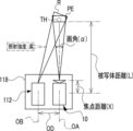
一例として図2に示すように、監視カメラ10は、光学系15及び撮像素子25を備えている。撮像素子25は、光学系15の後段に位置している。撮像素子25は、受光面25Aを備えている。撮像領域の光は、光学系15によって受光面25Aに結像され、撮像素子25によって撮像領域が撮像される。 As shown in FIG. 2 as an example, the surveillance camera 10 includes an optical system 15 and an imaging device 25 . The imaging element 25 is positioned behind the optical system 15 . The imaging device 25 has a light receiving surface 25A. The light of the imaging area is imaged on the light receiving surface 25A by the optical system 15, and the imaging area is imaged by the imaging element 25. FIG.

監視カメラ10は、コンピュータ19、変位用ドライバ22、変位用ドライバ23、ズーム用ドライバ28、DSP31、画像メモリ32、電子式振れ補正部33、通信I/F34、位置センサ39及び47、振れ量センサ40、並びにUI系デバイス43を備えている。コンピュータ19は、メモリ35、ストレージ36、及びCPU37を備えている。 The surveillance camera 10 includes a computer 19, a displacement driver 22, a displacement driver 23, a zoom driver 28, a DSP 31, an image memory 32, an electronic shake corrector 33, a communication I/F 34, position sensors 39 and 47, and a shake amount sensor. 40 and a UI device 43 . Computer 19 comprises memory 35 , storage 36 and CPU 37 .

変位用ドライバ22、変位用ドライバ23、撮像素子25、ズーム用ドライバ28、DSP31、画像メモリ32、電子式振れ補正部33、通信I/F34、メモリ35、ストレージ36、CPU37、位置センサ39及び47、振れ量センサ40、並びにUI系デバイス43は、バス38に接続されている。なお、図2に示す例では、図示の都合上、バス38として1本のバスが図示されているが、複数本のバスであってもよい。バス38は、シリアルバスであってもよいし、データバス、アドレスバス、及びコントロールバス等を含むパラレルバスであってもよい。 Displacement driver 22, displacement driver 23, imaging element 25, zoom driver 28, DSP 31, image memory 32, electronic shake corrector 33, communication I/F 34, memory 35, storage 36, CPU 37, position sensors 39 and 47 , the shake amount sensor 40 and the UI device 43 are connected to the bus 38 . In the example shown in FIG. 2, one bus is shown as the bus 38 for convenience of illustration, but a plurality of buses may be used. Bus 38 may be a serial bus or a parallel bus including a data bus, an address bus, a control bus, and the like.

メモリ35は、各種情報を一時的に記憶し、ワークメモリとして用いられる。メモリ35の一例としては、RAMが挙げられるが、これに限らず、他の種類の記憶装置であってもよい。 The memory 35 temporarily stores various information and is used as a work memory. An example of the memory 35 is a RAM, but the memory is not limited to this and may be another type of storage device.

ストレージ36には、監視カメラ10用の各種プログラムが記憶されている。CPU37は、ストレージ36から各種プログラムを読み出し、読み出した各種プログラムをメモリ35上で実行することで、監視カメラ10の全体を制御する。ストレージ36としては、例えば、フラッシュメモリ、SSD、EEPROM、又はHDD等が挙げられる。また、例えば、フラッシュメモリに代えて、あるいはフラッシュメモリと併用して、磁気抵抗メモリ、強誘電体メモリ等の各種の不揮発性メモリを用いてもよい。 Various programs for the surveillance camera 10 are stored in the storage 36 . The CPU 37 reads various programs from the storage 36 and executes the read various programs on the memory 35 to control the surveillance camera 10 as a whole. Examples of the storage 36 include flash memory, SSD, EEPROM, HDD, and the like. Further, for example, instead of flash memory or in combination with flash memory, various nonvolatile memories such as magnetoresistive memory and ferroelectric memory may be used.

撮像素子25は、本実施形態ではCMOSイメージセンサである。撮像素子25は、CPU37の指示の下、既定のフレームレートで対象被写体を撮像する。ここで言う「既定のフレームレート」とは、例えば、数十フレーム/秒から数百フレーム/秒を指す。なお、撮像素子25そのものにも制御装置(撮像素子制御装置)が内蔵されていてもよく、その場合はCPU37が出力する撮像指示に応じて撮像素子25内部の詳細な制御を撮像素子制御装置が行う。また、撮像素子25が、DSP31の指示の下に既定のフレームレートで対象被写体を撮像してもよく、この場合は、DSP31が出力する撮像指示に応じて撮像素子25内部の詳細な制御を撮像素子制御装置が行う。なお、DSP31はISPと呼ばれることもある。 The imaging device 25 is a CMOS image sensor in this embodiment. The imaging device 25 images the target subject at a predetermined frame rate under the instruction of the CPU 37 . The "predetermined frame rate" referred to here indicates, for example, several tens of frames/second to several hundreds of frames/second. Note that the image pickup device 25 itself may also have a built-in control device (image pickup device control device). conduct. In addition, the image pickup device 25 may image the target subject at a predetermined frame rate under the instruction of the DSP 31. In this case, the detailed control inside the image pickup device 25 is imaged according to the image pickup instruction output by the DSP 31. This is done by the device controller. Note that the DSP 31 is sometimes called an ISP.

撮像素子25の受光面25Aは、マトリクス状に配置された複数の感光画素(図示省略)によって形成されている。撮像素子25では、各感光画素が露光され、感光画素毎に光電変換が行われる。 A light receiving surface 25A of the imaging device 25 is formed by a plurality of photosensitive pixels (not shown) arranged in a matrix. In the imaging device 25, each photosensitive pixel is exposed, and photoelectric conversion is performed for each photosensitive pixel.

感光画素毎に光電変換が行われることで得られた電荷は、対象被写体を示すアナログの撮像信号である。ここでは、複数の感光画素として、赤外光に感度を有する複数の光電変換素子(一例として、赤外光透過フィルタが配置された光電変換素子)が採用されている。 The charge obtained by performing photoelectric conversion for each photosensitive pixel is an analog imaging signal representing the target subject. Here, a plurality of photoelectric conversion elements sensitive to infrared light (for example, a photoelectric conversion element in which an infrared light transmission filter is arranged) are employed as the plurality of photosensitive pixels.

監視カメラ10では、こうした赤外光に感度を有する光電変換素子を用いることによって、赤外光(例えば、約700ナノメートルよりも長波長側の光)に基づく撮像が行われる。特に、SWIRについての撮像に対しては、例えば、撮像素子25として、CMOSイメージセンサに代えて、InGaAsセンサ及び/又はタイプ2型量子井戸(T2SL;Simulation of Type-II Quantum Well)センサ等を用いればよい。但し、本実施形態はこれに限定されず、可視光に感度を有する光電変換素子を用いて、可視光(例えば、約700ナノメートル以下の短波長側の光)に基づく撮像が行われるようにしてもよく、可視光と赤外光の両方に感度を有する光電変換素子を用いたり、光学系15を透過した入射光をフィルタ又はダイクロイックプリズム等で可視光と赤外光に分離し、それぞれの光に感度を持つ光電変換素子を用いたりしてもよい。 In the monitoring camera 10, imaging based on infrared light (for example, light with a wavelength longer than about 700 nanometers) is performed by using a photoelectric conversion element sensitive to such infrared light. In particular, for SWIR imaging, for example, instead of the CMOS image sensor, an InGaAs sensor and/or a type 2 quantum well (TSL; Simulation of Type-II Quantum Well) sensor or the like is used as the imaging element 25. Just do it. However, the present embodiment is not limited to this, and imaging is performed based on visible light (for example, light on the short wavelength side of about 700 nm or less) using a photoelectric conversion element having sensitivity to visible light. Alternatively, a photoelectric conversion element sensitive to both visible light and infrared light may be used, or the incident light transmitted through the optical system 15 may be separated into visible light and infrared light by a filter or dichroic prism or the like. A photoelectric conversion element sensitive to light may be used.

撮像素子25は、アナログの撮像信号に対してA/D変換等の信号処理を施すことでデジタル画像を生成する。撮像素子25は、バス38を介してDSP31に接続されており、生成したデジタル画像を、バス38を介してフレーム単位でDSP31に出力する。ここで、デジタル画像は、本開示の技術に係る「撮像画像」の一例である。 The imaging device 25 generates a digital image by performing signal processing such as A/D conversion on the analog imaging signal. The imaging device 25 is connected to the DSP 31 via the bus 38 and outputs the generated digital image to the DSP 31 via the bus 38 in units of frames. Here, the digital image is an example of the "captured image" according to the technology of the present disclosure.

なお、ここでは、撮像素子25の一例としてCMOSイメージセンサを挙げて説明しているが、本開示の技術はこれに限定されず、撮像素子25としてCCDイメージセンサを適用してもよい。この場合、撮像素子25はCCDドライバ内蔵のAFE(図示省略)を介してバス38に接続される。AFEは、撮像素子25によって得られたアナログの撮像信号に対してA/D変換等の信号処理を施すことでデジタル画像を生成し、生成したデジタル画像をDSP31に出力する。CCDイメージセンサはAFEに内蔵されたCCDドライバによって駆動される。もちろんCCDドライバは単独で設けられてもよい。 Although a CMOS image sensor is described as an example of the imaging device 25 here, the technology of the present disclosure is not limited to this, and a CCD image sensor may be applied as the imaging device 25 . In this case, the imaging device 25 is connected to the bus 38 via an AFE (not shown) with a built-in CCD driver. The AFE generates a digital image by performing signal processing such as A/D conversion on the analog imaging signal obtained by the imaging device 25 and outputs the generated digital image to the DSP 31 . The CCD image sensor is driven by a CCD driver built into the AFE. Of course, the CCD driver may be provided independently.

DSP31は、デジタル画像に対して、各種デジタル信号処理を施す。各種デジタル信号処理とは、例えば、デモザイク処理、ノイズ除去処理、階調補正処理、及び色補正処理等を指す。 The DSP 31 performs various digital signal processing on the digital image. Various types of digital signal processing refer to, for example, demosaic processing, noise removal processing, gradation correction processing, color correction processing, and the like.

DSP31は、1フレーム毎に、デジタル信号処理後のデジタル画像を画像メモリ32に出力する。画像メモリ32は、DSP31からのデジタル画像を記憶する。なお、以下では、説明の便宜上、画像メモリ32に記憶されたデジタル画像を「撮像画像」とも称する。 The DSP 31 outputs the digital image after digital signal processing to the image memory 32 for each frame. Image memory 32 stores digital images from DSP 31 . For convenience of explanation, the digital image stored in the image memory 32 is hereinafter also referred to as a “captured image”.

振れ量センサ40は、例えば、ジャイロセンサを含むデバイスであり、監視カメラ10の振れ量を検出する。ジャイロセンサは、ピッチ軸PA、ヨー軸YA、及びロール軸RA(光軸OAに平行な軸)の各軸周りの回転振れの量を検出する。振れ量センサ40は、ジャイロセンサによって検出されたピッチ軸PA周りの回転振れの量及びヨー軸YA周りの回転振れの量を、ピッチ軸PA及びヨー軸YAに平行な二次元状の面内での振れ量に変換することで、監視カメラ10の振れ量を検出する。振れ量センサ40は、検出した振れ量をCPU37に出力する。 The shake amount sensor 40 is, for example, a device including a gyro sensor, and detects the amount of shake of the surveillance camera 10 . The gyro sensor detects the amount of rotational shake around each of the pitch axis PA, yaw axis YA, and roll axis RA (an axis parallel to the optical axis OA). The shake amount sensor 40 detects the amount of rotational shake about the pitch axis PA and the amount of rotational shake about the yaw axis YA detected by the gyro sensor within a two-dimensional plane parallel to the pitch axis PA and the yaw axis YA. , the amount of shake of the surveillance camera 10 is detected. The shake amount sensor 40 outputs the detected shake amount to the CPU 37 .

ここでは、振れ量センサ40の一例としてジャイロセンサを挙げているが、これはあくまでも一例であり、振れ量センサ40は、加速度センサであってもよい。加速度センサは、ピッチ軸PAとヨー軸YAに平行な二次元状の面内での振れ量を検出する。 Here, a gyro sensor is given as an example of the shake amount sensor 40, but this is only an example, and the shake amount sensor 40 may be an acceleration sensor. The acceleration sensor detects the shake amount within a two-dimensional plane parallel to the pitch axis PA and the yaw axis YA.

また、ここでは、振れ量センサ40という物理的なセンサによって振れ量が検出される形態例を挙げているが、本開示の技術はこれに限定されない。例えば、画像メモリ32に記憶された時系列的に前後する撮像画像を比較することで得た動きベクトルを、振れ量として用いてもよい。また、物理的なセンサによって検出された振れ量と、画像処理によって得られた動きベクトルとに基づいて、最終的に使用される振れ量を導出してもよい。 Also, here, an example of a form in which the shake amount is detected by a physical sensor called the shake amount sensor 40 is given, but the technology of the present disclosure is not limited to this. For example, a motion vector obtained by comparing chronologically successive captured images stored in the image memory 32 may be used as the shake amount. Alternatively, the shake amount to be finally used may be derived based on the shake amount detected by the physical sensor and the motion vector obtained by image processing.

CPU37は、振れ量センサ40によって検出された振れ量を取得し、取得した振れ量に基づいて、レンズ側振れ補正機構29、撮像素子側振れ補正機構45、及び電子式振れ補正部33を制御する。振れ量センサ40によって検出された振れ量は、レンズ側振れ補正機構29、撮像素子側振れ補正機構45、及び電子式振れ補正部33の各々による振れの補正に用いられる。 The CPU 37 acquires the shake amount detected by the shake amount sensor 40, and controls the lens-side shake correction mechanism 29, the image sensor-side shake correction mechanism 45, and the electronic shake correction unit 33 based on the acquired shake amount. . The shake amount detected by the shake amount sensor 40 is used for shake correction by each of the lens side shake correction mechanism 29 , the image sensor side shake correction mechanism 45 , and the electronic shake correction section 33 .

本開示の技術に係る振れ補正部24は、レンズ側振れ補正機構29、撮像素子側振れ補正機構45及び電子式振れ補正部33を含む。すなわち、振れ補正部24は、レンズ側振れ補正機構29、撮像素子側振れ補正機構45及び電子式振れ補正部33のいずれか1つもしくは複数を用い、後述するように、撮像画像を変位させる補正を行って、振れ補正制御及び位置合わせ制御を行う。特に、第一実施形態では、撮像画像の振れ補正制御を行う。 The shake correction unit 24 according to the technology of the present disclosure includes a lens side shake correction mechanism 29 , an image sensor side shake correction mechanism 45 and an electronic shake correction unit 33 . That is, the shake correction unit 24 uses one or a plurality of the lens-side shake correction mechanism 29, the image sensor-side shake correction mechanism 45, and the electronic shake correction unit 33, and as described later, performs correction by displacing the captured image. to perform shake correction control and alignment control. In particular, in the first embodiment, shake correction control of the captured image is performed.

電子式振れ補正部33は、ASICを含むデバイスである。電子式振れ補正部33は、振れ量センサ40によって検出された振れ量に基づいて、撮像素子25によって撮像されることで得られる画像メモリ32内の撮像画像に対して画像処理を施すことで振れを補正する。 The electronic shake correction section 33 is a device including an ASIC. The electronic shake correction unit 33 performs image processing on the captured image in the image memory 32 obtained by imaging the image sensor 25 based on the shake amount detected by the shake amount sensor 40, thereby correcting the shake. is corrected.

また、ここでは、電子式振れ補正部33として、ASICを含むデバイスを例示しているが、本開示の技術はこれに限定されるものではなく、例えば、FPGA又はPLDを含むデバイスであってもよい。また、例えば、電子式振れ補正部33は、ASIC、FPGA、及びPLDのうちの複数を含むデバイスであってもよい。また、電子式振れ補正部33として、CPU、ストレージ、及びメモリを含むコンピュータが採用されてもよい。CPUは、単数であってもよいし、複数であってもよい。また、電子式振れ補正部33は、ハードウェア構成及びソフトウェア構成の組み合わせによって実現されてもよい。 Further, here, a device including an ASIC is exemplified as the electronic shake correction unit 33, but the technology of the present disclosure is not limited to this. good. Also, for example, the electronic shake correction unit 33 may be a device including a plurality of ASICs, FPGAs, and PLDs. Also, a computer including a CPU, a storage, and a memory may be employed as the electronic shake correction section 33 . The number of CPUs may be singular or plural. Also, the electronic shake correction unit 33 may be implemented by a combination of hardware and software configurations.

通信I/F34は、例えば、ネットワークインターフェースであり、ネットワークを介して、管理装置11との間で各種情報の伝送制御を行う。ネットワークの一例としては、インターネット又は公衆通信網等のWANが挙げられる。監視カメラ10と管理装置11との間の通信を司る。 The communication I/F 34 is, for example, a network interface, and controls transmission of various information to and from the management device 11 via the network. Examples of networks include WANs such as the Internet or public networks. It manages communication between the monitoring camera 10 and the management device 11 .

UI系デバイス43は、受付デバイス43A及びディスプレイ43Bを備えている。受付デバイス43Aは、例えば、ハードキー及びタッチパネル等であり、ユーザからの各種指示を受け付ける。CPU37は、受付デバイス43Aによって受け付けられた各種指示を取得し、取得した指示に従って動作する。 The UI device 43 includes a reception device 43A and a display 43B. The receiving device 43A is, for example, a hard key, a touch panel, or the like, and receives various instructions from the user. The CPU 37 acquires various instructions accepted by the accepting device 43A and operates according to the acquired instructions.

ディスプレイ43Bは、CPU37の制御下で、各種情報を表示する。ディスプレイ43Bに表示される各種情報としては、例えば、受付デバイス43Aによって受け付けられた各種指示の内容、及び撮像画像等が挙げられる。 The display 43B displays various information under the control of the CPU 37. FIG. The various information displayed on the display 43B includes, for example, the contents of various instructions received by the reception device 43A, captured images, and the like.

光学系15は、対物レンズ15A及びレンズ群15Bを備えている。対物レンズ15A及びレンズ群15Bは、対象被写体側から撮像素子25の受光面25A側にかけて、光学系15の光軸OAに沿って、対物レンズ15A及びレンズ群15Bの順に配置されている。レンズ群15Bには、防振レンズ15B1、フォーカスレンズ(図示省略)、及びズームレンズ15B2等が含まれている。なお、光学系15としては、対物レンズ15A及びレンズ群15B以外にも各種レンズ(図示省略)を備えていてもよい。更に、光学系15は、絞りを備えていてもよい。光学系15に含まれるレンズ、レンズ群、及び絞りの位置は限定されず、例えば、図2に示す位置と異なる位置であっても、本開示の技術は成立する。 The optical system 15 has an objective lens 15A and a lens group 15B. The objective lens 15A and the lens group 15B are arranged along the optical axis OA of the optical system 15 from the target object side to the light receiving surface 25A side of the imaging device 25 in this order. The lens group 15B includes a vibration reduction lens 15B1, a focus lens (not shown), a zoom lens 15B2, and the like. The optical system 15 may include various lenses (not shown) in addition to the objective lens 15A and the lens group 15B. Furthermore, the optical system 15 may have an aperture. The positions of the lens, the lens group, and the diaphragm included in the optical system 15 are not limited.

監視カメラ10は、アクチュエータ17、アクチュエータ21、及びアクチュエータ27を備えている。防振レンズ15B1は、アクチュエータ17によって、光軸OAと垂直な方向に移動可能に支持されている。ズームレンズ15B2は、アクチュエータ21によって、光軸OAに沿って移動可能に支持されている。撮像素子25は、アクチュエータ27によって、光軸OAと垂直な方向に移動可能に支持されている。 The surveillance camera 10 has an actuator 17 , an actuator 21 and an actuator 27 . The anti-vibration lens 15B1 is supported by an actuator 17 so as to be movable in a direction perpendicular to the optical axis OA. The zoom lens 15B2 is supported by an actuator 21 so as to be movable along the optical axis OA. The imaging element 25 is supported by an actuator 27 so as to be movable in a direction perpendicular to the optical axis OA.

アクチュエータ17は、防振レンズ15B1に対して、光軸OAに垂直な方向に変動させる動力を付与する。アクチュエータ17は、CPU37によって変位用ドライバ23を介して制御される。変位用ドライバ23は、CPU37からの指示に従ってアクチュエータ17を作動させることで、防振レンズ15B1の位置を光軸OAに対して垂直な方向に変動させる。 The actuator 17 applies power to the anti-vibration lens 15B1 to move it in a direction perpendicular to the optical axis OA. The actuator 17 is controlled by the CPU 37 via the displacement driver 23 . The displacement driver 23 operates the actuator 17 according to the instruction from the CPU 37 to change the position of the anti-vibration lens 15B1 in the direction perpendicular to the optical axis OA.

アクチュエータ21は、ズームレンズ15B2に対して、光軸OAに沿って移動させる動力を付与する。アクチュエータ21は、CPU37によってズーム用ドライバ28を介して制御される。ズーム用ドライバ28は、CPU37からの指示に従ってアクチュエータ21を作動させることで、ズームレンズ15B2の位置を光軸OAに沿って移動させる。 The actuator 21 applies power to move the zoom lens 15B2 along the optical axis OA. The actuator 21 is controlled by the CPU 37 via a zoom driver 28 . The zoom driver 28 operates the actuator 21 according to instructions from the CPU 37 to move the position of the zoom lens 15B2 along the optical axis OA.

監視カメラ10は、このようにズームレンズ15B2を移動させることで、焦点距離X(図8A等参照)を連続的に変更可能であり、複数の焦点距離Xの値を採り得る。なお、複数の焦点距離Xを採り得る構成は、ズームレンズ15B2を有する構成に限定されず、例えば、レンズ交換式のカメラであってもよく、この場合には、交換レンズのそれぞれに設定された焦点距離の値を採る。 By moving the zoom lens 15B2 in this manner, the monitoring camera 10 can continuously change the focal length X (see FIG. 8A, etc.), and can take a plurality of focal length X values. Note that the configuration that can adopt a plurality of focal lengths X is not limited to the configuration having the zoom lens 15B2, and may be, for example, a camera with interchangeable lenses. Take the focal length value.

アクチュエータ27は、撮像素子25に対して、光軸OAに垂直な方向に変動させる動力を付与する。アクチュエータ27は、CPU37によって変位用ドライバ22を介して制御される。変位用ドライバ22は、CPU37からの指示に従ってアクチュエータ27を作動させることで、撮像素子25の位置を光軸OAに対して垂直な方向に移動させる。 The actuator 27 applies power to the imaging element 25 to move it in a direction perpendicular to the optical axis OA. The actuator 27 is controlled by the CPU 37 via the displacement driver 22 . The displacement driver 22 operates the actuator 27 according to an instruction from the CPU 37 to move the position of the imaging element 25 in a direction perpendicular to the optical axis OA.

監視カメラ10は、変倍機構18を有する。変倍機構18は、ズームレンズ15B2、アクチュエータ21、及びズーム用ドライバ28により構成され、監視カメラ10の焦点距離Xを変更可能とする機構である。CPU37は、ズーム用ドライバ28を介してアクチュエータ21を作動させることにより焦点距離Xを変更する。なお、本開示の技術において図示した変倍機構18の図はあくまで概念図に過ぎず、変倍機構18は種々の構成を採り得る。 The surveillance camera 10 has a variable power mechanism 18 . The variable power mechanism 18 is configured by a zoom lens 15B2, an actuator 21, and a zoom driver 28, and is a mechanism capable of changing the focal length X of the surveillance camera 10. FIG. The CPU 37 changes the focal length X by operating the actuator 21 via the zoom driver 28 . It should be noted that the drawings of the variable magnification mechanism 18 illustrated in the technique of the present disclosure are merely conceptual diagrams, and the variable magnification mechanism 18 can adopt various configurations.

ところで、監視カメラ10に与えられる振動には、屋外であれば、自動車の通行による振動、風による振動、及び道路工事による振動等があり、屋内であれば、エアコンディショナーの動作による振動、及び人の出入りによる振動等がある。そのため、監視カメラ10では、監視カメラ10に与えられた振動(以下、単に「振動」とも称する)に起因して振れが生じる。本明細書では、振動に起因して生じる振れを、単に「振れ」とも称する。 By the way, the vibration given to the surveillance camera 10 includes the vibration caused by the traffic of automobiles, the vibration caused by the wind, the vibration caused by the road construction, etc. when outdoors, and the vibration caused by the operation of the air conditioner and the vibration caused by the human body when indoors. Vibration, etc. due to entry and exit of Therefore, the monitoring camera 10 shakes due to the vibration applied to the monitoring camera 10 (hereinafter also simply referred to as “vibration”). In this specification, shake caused by vibration is also simply referred to as "shake".

本開示の技術では、監視カメラ10及び照射装置112は、取付部材114に取り付けられている。したがって、取付部材114が振動すると、この振動は、監視カメラ10及び照射装置112の両方に伝わる。 In the technology of the present disclosure, the surveillance camera 10 and the irradiation device 112 are attached to the attachment member 114 . Therefore, when the mounting member 114 vibrates, this vibration is transmitted to both the surveillance camera 10 and the irradiation device 112 .

なお、本実施形態において、「振れ」とは、監視カメラ10において、光軸OAと受光面25Aとの位置関係が変化することで、撮像素子25の受光面25Aでの被写体像が変動する現象を指す。換言すると、「振れ」とは、監視カメラ10に与えられた振動に起因して光軸OAが傾くことによって、受光面25Aに結像されることで得られた光学像が変動する現象とも言える。光軸OAの変動とは、例えば、基準軸(例えば、振れが発生する前の光軸OA)に対して光軸OAが傾くことを意味する。 In the present embodiment, "shake" refers to a phenomenon in which the subject image on the light receiving surface 25A of the imaging device 25 fluctuates due to changes in the positional relationship between the optical axis OA and the light receiving surface 25A of the monitoring camera 10. point to In other words, the “shake” can be said to be a phenomenon in which an optical image formed on the light receiving surface 25A fluctuates due to the tilt of the optical axis OA caused by the vibration applied to the surveillance camera 10. . Fluctuation of the optical axis OA means, for example, inclination of the optical axis OA with respect to a reference axis (for example, the optical axis OA before vibration occurs).

振れは、撮像画像にノイズ成分として含まれ、撮像画像の画質に影響を与える。そこで、振れに起因して撮像画像内に含まれるノイズ成分を除去するために、監視カメラ10は、振れ補正部24を備えている。 The shake is included in the captured image as a noise component and affects the image quality of the captured image. Therefore, the monitoring camera 10 is provided with a shake correction section 24 in order to remove noise components contained in the captured image due to shake.

本開示の技術では、振れ補正部24は、レンズ側振れ補正機構29、撮像素子側振れ補正機構45、及び電子機器振れ補正部33を有する。レンズ側振れ補正機構29は、モータ(例えば、ボイスコイルモータ)等の駆動源によって生成された動力を防振レンズに付与することで防振レンズを撮像光学系の光軸に対して垂直な方向に移動させ、これによって振れを補正する機構である。撮像素子側振れ補正機構45は、モータ(例えば、ボイスコイルモータ)等の駆動源によって生成された動力を撮像素子に付与することで撮像素子を撮像光学系の光軸に対して垂直な方向に移動させ、これによって振れを補正する機構である。電子式振れ補正部33は、振れ量に基づいて撮像画像に対して画像処理を施すことで振れを補正する。つまり、振れ補正部24は、ハードウェア構成及び/又はソフトウェア構成で機械的又は電子的に振れの補正を行う。ここで、機械的な振れの補正とは、モータ(例えば、ボイスコイルモータ)等の駆動源によって生成された動力を用いて防振レンズ及び/又は撮像素子等の振れ補正素子を機械的に動かすことにより実現される振れの補正を指し、電子的な振れの補正とは、例えば、プロセッサによって画像処理が行われることで実現される振れの補正を指す。レンズ側振れ補正機構29、撮像素子側振れ補正機構45、及び電子式振れ補正部33はいずれも、振れの補正に供される。また、本実施形態において、「振れの補正」には、振れを無くすという意味の他に、振れを低減するという意味も含まれる。 In the technology of the present disclosure, the shake correction unit 24 includes a lens-side shake correction mechanism 29 , an image sensor-side shake correction mechanism 45 , and an electronic device shake correction unit 33 . The lens-side shake correction mechanism 29 applies power generated by a drive source such as a motor (for example, a voice coil motor) to the anti-vibration lens to move the anti-vibration lens in a direction perpendicular to the optical axis of the imaging optical system. This is a mechanism for correcting shake by moving the The image pickup element side shake correction mechanism 45 applies power generated by a drive source such as a motor (for example, a voice coil motor) to the image pickup element to move the image pickup element in a direction perpendicular to the optical axis of the imaging optical system. It is a mechanism that moves the lens and thereby corrects the shake. The electronic shake correction unit 33 corrects shake by performing image processing on the captured image based on the amount of shake. In other words, the shake correction unit 24 performs shake correction mechanically or electronically with a hardware configuration and/or a software configuration. Here, the mechanical shake correction refers to mechanically moving a shake correction element such as an anti-vibration lens and/or an imaging element using power generated by a driving source such as a motor (for example, a voice coil motor). Electronic shake correction refers to shake correction achieved by, for example, image processing performed by a processor. The lens-side shake correction mechanism 29, the image sensor-side shake correction mechanism 45, and the electronic shake correction unit 33 are all used for shake correction. Further, in the present embodiment, "shake correction" includes not only the meaning of eliminating shake but also the meaning of reducing shake.

レンズ側振れ補正機構29は、光軸OAと垂直な方向に防振レンズ15B1を移動させる機構である。撮像素子側振れ補正機構45は、光軸OAと垂直な方向に撮像素子25を移動させて、撮像素子25における撮像画像の領域を光軸OAと垂直な方向に移動させる機構である。電子式振れ補正部33は、防振レンズ15B1及び撮像素子25は移動させないが、撮像素子25から撮像範囲PEとして取り出す画素の範囲を移動させることで、撮像素子25における撮像範囲PEの領域を光軸OAと垂直な方向に移動させる機構である。 The lens-side vibration correction mechanism 29 is a mechanism that moves the anti-vibration lens 15B1 in a direction perpendicular to the optical axis OA. The image pickup device side shake correction mechanism 45 is a mechanism that moves the image pickup device 25 in a direction perpendicular to the optical axis OA to move the area of the captured image on the image pickup device 25 in a direction perpendicular to the optical axis OA. The electronic shake correction unit 33 does not move the anti-vibration lens 15B1 and the imaging element 25, but moves the range of pixels extracted as the imaging range PE from the imaging element 25, so that the area of the imaging range PE in the imaging element 25 is illuminated. It is a mechanism for moving in a direction perpendicular to the axis OA.

レンズ側振れ補正機構29は、防振レンズ15B1、アクチュエータ17、変位用ドライバ23、及び位置センサ39により構成される。 The lens-side vibration correction mechanism 29 is composed of the anti-vibration lens 15 B 1 , the actuator 17 , the displacement driver 23 and the position sensor 39 .

レンズ側振れ補正機構29による振れの補正方法としては、周知の種々の方法を採用することができる。本実施形態では、振れの補正方法として、振れ量センサ40によって検出された振れ量に基づいて、防振レンズ15B1を移動させる方法が採用されている。具体的には、振れを打ち消す方向に、振れを打ち消す量だけ防振レンズ15B1を移動させることで、振れの補正が行われるようにしている。 Various well-known methods can be adopted as a method for correcting shake by the lens-side shake correcting mechanism 29 . In this embodiment, a method of moving the anti-vibration lens 15B1 based on the amount of shake detected by the shake amount sensor 40 is employed as a method of correcting shake. Specifically, the vibration is corrected by moving the anti-vibration lens 15B1 in the direction of canceling the vibration by the amount that cancels the vibration.

防振レンズ15B1にはアクチュエータ17が取り付けられている。アクチュエータ17は、ボイスコイルモータが搭載されたシフト機構であり、ボイスコイルモータを駆動させることで、防振レンズ15B1を光軸OAに対して垂直な方向に変動させる。なお、ここでは、アクチュエータ17として、ボイスコイルモータが搭載されたシフト機構が採用されているが、本開示の技術はこれに限定されず、ボイスコイルモータに代えて、ステッピングモータ又はピエゾ素子等の他の動力源を適用してもよい。 An actuator 17 is attached to the anti-vibration lens 15B1. The actuator 17 is a shift mechanism equipped with a voice coil motor, and drives the voice coil motor to move the anti-vibration lens 15B1 in a direction perpendicular to the optical axis OA. Here, a shift mechanism equipped with a voice coil motor is adopted as the actuator 17, but the technology of the present disclosure is not limited to this, and instead of the voice coil motor, a stepping motor, a piezo element, or the like is used. Other power sources may be applied.

アクチュエータ17は、変位用ドライバ23により駆動が制御される。アクチュエータ17が変位用ドライバ23の制御下で駆動することで、防振レンズ15B1の位置が光軸OAに対して垂直な二次元平面内で機械的に変動する。 Driving of the actuator 17 is controlled by a displacement driver 23 . By driving the actuator 17 under the control of the displacement driver 23, the position of the anti-vibration lens 15B1 is mechanically changed within a two-dimensional plane perpendicular to the optical axis OA.

位置センサ39は、防振レンズ15B1の現在位置を検出し、検出した現在位置を示す位置信号を出力する。ここでは、位置センサ39の一例として、ホール素子を含むデバイスが採用されている。ここで、防振レンズ15B1の現在位置とは、防振レンズ15B1の二次元平面(以下、防振レンズ二次元平面という)内の現在位置を指す。防振レンズ二次元平面とは、光軸OAに対して垂直な二次元平面を指す。なお、本実施形態では、位置センサ39の一例として、ホール素子を含むデバイスが採用されているが、本開示の技術はこれに限定されず、ホール素子に代えて、磁気センサ又はフォトセンサなどを採用してもよい。 The position sensor 39 detects the current position of the anti-vibration lens 15B1 and outputs a position signal indicating the detected current position. Here, a device including a Hall element is adopted as an example of the position sensor 39 . Here, the current position of the anti-vibration lens 15B1 refers to the current position within the two-dimensional plane of the anti-vibration lens 15B1 (hereinafter referred to as the two-dimensional plane of the anti-vibration lens). A two-dimensional plane of the anti-vibration lens refers to a two-dimensional plane perpendicular to the optical axis OA. Note that in the present embodiment, a device including a Hall element is adopted as an example of the position sensor 39, but the technology of the present disclosure is not limited to this, and instead of the Hall element, a magnetic sensor, a photosensor, or the like is used. may be adopted.

レンズ側振れ補正機構29は、ピッチ軸PA及びヨー軸YAのうちの少なくとも一方に沿って防振レンズ15B1を移動させることで、振れを補正する。つまり、レンズ側振れ補正機構29は、防振レンズ二次元平面内において、振れ量センサ40によって検出された振れ量に応じた移動量で防振レンズ15B1を移動させることで、振れを補正する。 The lens-side shake correction mechanism 29 corrects shake by moving the anti-vibration lens 15B1 along at least one of the pitch axis PA and the yaw axis YA. That is, the lens-side shake correction mechanism 29 corrects shake by moving the anti-vibration lens 15B1 in the anti-vibration lens two-dimensional plane by a movement amount corresponding to the amount of shake detected by the anti-shake sensor 40.

撮像素子側振れ補正機構45は、撮像素子25、変位用ドライバ22、アクチュエータ27、及び位置センサ47により構成される。 The imaging element side shake correction mechanism 45 is composed of the imaging element 25 , the displacement driver 22 , the actuator 27 and the position sensor 47 .

レンズ側振れ補正機構29による振れの補正方法と同様に、撮像素子側振れ補正機構45による振れの補正方法も、周知の種々の方法を採用することができる。本実施形態では、振れの補正方法として、振れ量センサ40によって検出された振れ量に基づいて、CPU37からの指示に従って変位用ドライバ22がアクチュエータ27を介して撮像素子25を移動させる方法が採用されている。具体的には、振れを打ち消す方向に、振れを打ち消す量だけ撮像素子25を移動させることで、振れの補正が行われるようにしている。 As with the method of correcting shake by the lens-side shake correcting mechanism 29, various well-known methods can be employed for the method of correcting shake by the image sensor-side shake correcting mechanism 45 as well. In this embodiment, as a shake correction method, a method is adopted in which the displacement driver 22 moves the imaging element 25 via the actuator 27 according to the instruction from the CPU 37 based on the shake amount detected by the shake amount sensor 40. ing. Specifically, the shake is corrected by moving the imaging element 25 in the direction of canceling the shake by the amount that cancels the shake.

アクチュエータ27は、ボイスコイルモータが搭載されたシフト機構であり、ボイスコイルモータを駆動させることで、撮像素子25を光軸OAに対して垂直な方向に変動させる。なお、ここでは、アクチュエータ27として、ボイスコイルモータが搭載されたシフト機構が採用されているが、本開示の技術はこれに限定されず、ボイスコイルモータに代えて、ステッピングモータ又はピエゾ素子等の他の動力源を適用してもよい。 The actuator 27 is a shift mechanism equipped with a voice coil motor, and drives the voice coil motor to move the imaging device 25 in a direction perpendicular to the optical axis OA. Here, a shift mechanism equipped with a voice coil motor is adopted as the actuator 27, but the technology of the present disclosure is not limited to this, and instead of the voice coil motor, a stepping motor, a piezo element, or the like is used. Other power sources may be applied.

位置センサ47は、撮像素子25の現在位置を検出し、検出した現在位置を示す位置信号を出力する。ここでは、位置センサ47の一例として、ホール素子を含むデバイスが採用されている。ここで、撮像素子25の現在位置とは、撮像素子25の二次元平面(以下、撮像素子二次元平面という)内の現在位置を指す。撮像素子二次元平面とは、光軸OAに対して垂直な二次元平面を指す。なお、本実施形態では、位置センサ47の一例として、ホール素子を含むデバイスが採用されているが、本開示の技術はこれに限定されず、ホール素子に代えて、磁気センサ又はフォトセンサなどを採用してもよい。 The position sensor 47 detects the current position of the imaging device 25 and outputs a position signal indicating the detected current position. Here, a device including a Hall element is adopted as an example of the position sensor 47 . Here, the current position of the imaging device 25 refers to the current position within the two-dimensional plane of the imaging device 25 (hereinafter referred to as the two-dimensional plane of the imaging device). A two-dimensional plane of the imaging device refers to a two-dimensional plane perpendicular to the optical axis OA. Note that in the present embodiment, a device including a Hall element is adopted as an example of the position sensor 47, but the technology of the present disclosure is not limited to this, and a magnetic sensor, a photosensor, or the like is used instead of the Hall element. may be adopted.

撮像素子側振れ補正機構45は、ピッチ軸PA及びヨー軸YAのうちの少なくとも一方に沿って撮像素子25を移動させることで、振れを補正する。つまり、撮像素子側振れ補正機構45は、撮像素子二次元平面内において、振れ量センサ40によって検出された振れ量に応じた移動量で撮像素子25を移動させることで、振れを補正する。 The image sensor side shake correction mechanism 45 corrects shake by moving the image sensor 25 along at least one of the pitch axis PA and the yaw axis YA. In other words, the image sensor side shake correction mechanism 45 corrects shake by moving the image sensor 25 by a movement amount corresponding to the shake amount detected by the shake amount sensor 40 within the image sensor two-dimensional plane.

一例として図3に示すように、照射装置112は、光学系120及び発光部122を備えている。発光部122は、光を発する光源124と、光源124の駆動を制御する光源ドライバ126とを有している。光源124から射出された光は、光学系120を透過し、照射装置112の外部に照射される。光源124は、射出する光の強度を変更可能である。 As shown in FIG. 3 as an example, the irradiation device 112 includes an optical system 120 and a light emitter 122 . The light emitting section 122 has a light source 124 that emits light and a light source driver 126 that controls driving of the light source 124 . Light emitted from the light source 124 passes through the optical system 120 and is irradiated to the outside of the irradiation device 112 . The light source 124 can change the intensity of emitted light.

さらに、照射装置112は、ズーム用ドライバ128、及び通信I/F130を備えている。 Furthermore, the irradiation device 112 includes a zoom driver 128 and a communication I/F 130 .

光源ドライバ126、ズーム用ドライバ128、及び通信I/F130は、バス132に接続されている。なお、図3に示す例では、図示の都合上、バス132として1本のバスが図示されているが、複数本のバスであってもよい。バス132は、シリアルバスであってもよいし、データバス、アドレスバス、及びコントロールバス等を含むパラレルバスであってもよい。 The light source driver 126 , zoom driver 128 and communication I/F 130 are connected to the bus 132 . In the example shown in FIG. 3, one bus is illustrated as the bus 132 for convenience of illustration, but a plurality of buses may be used. Bus 132 may be a serial bus or a parallel bus including a data bus, an address bus, a control bus, and the like.

光源124は、たとえば発光ダイオードである。本実施形態の監視カメラ10では、前述のように赤外光に基づく撮像が行われるため、光源124は赤外光を発する。この場合光源124として赤外線LEDや赤外線レーザを用いることができる。なお、可視光に基づく撮像を行う場合は、光源124は可視光を射出するものであってもよい。 Light source 124 is, for example, a light emitting diode. In the surveillance camera 10 of the present embodiment, the light source 124 emits infrared light because imaging is performed using infrared light as described above. In this case, an infrared LED or infrared laser can be used as the light source 124 . In addition, when imaging based on visible light, the light source 124 may emit visible light.

光学系120は、対物レンズ134A及びレンズ群134Bを備えている。対物レンズ134A及びレンズ群134Bは、対象被写体側、すなわち照射対象側から光源124側にかけて、光学系120の光軸OBに沿って、対物レンズ134A及びレンズ群134Bの順に配置されている。レンズ群134Bには、ズームレンズ134B2、及び、各種のレンズ(図示省略)等が含まれている。なお、光学系120としても、対物レンズ134A及びレンズ群134B以外に、さらに各種のレンズ(図示省略)を備えていてもよい。更に、光学系120は、絞りを備えていてもよい。光学系120に含まれるレンズ、レンズ群、及び絞りの位置は限定されず、例えば、図3に示す位置と異なる位置であっても、本開示の技術は成立する。 The optical system 120 includes an objective lens 134A and a lens group 134B. The objective lens 134A and the lens group 134B are arranged in order of the objective lens 134A and the lens group 134B along the optical axis OB of the optical system 120 from the target object side, that is, the irradiation target side to the light source 124 side. The lens group 134B includes a zoom lens 134B2 and various lenses (not shown). The optical system 120 may also include various lenses (not shown) in addition to the objective lens 134A and the lens group 134B. Additionally, optical system 120 may include an aperture. The positions of the lens, the lens group, and the diaphragm included in the optical system 120 are not limited.

照射装置112は、アクチュエータ136を備えている。ズームレンズ134B2は、アクチュエータ136によって、光軸OBに沿って移動可能に支持されている。 The illumination device 112 has an actuator 136 . The zoom lens 134B2 is supported by an actuator 136 so as to be movable along the optical axis OB.

アクチュエータ136は、ズームレンズ134B2に対して、光学系120の光軸OBに沿って移動させる動力を付与する。アクチュエータ136は、管理装置11のCPU60Aによってズーム用ドライバ128を介して制御される。ズーム用ドライバ128は、CPU60Aからの指示に従ってアクチュエータ136を作動させることで、ズームレンズ134B2の位置を光軸OBに沿って移動させる。ズームレンズ134B2がこのように光軸OBに沿って移動されることで、照射装置112からの光の照射範囲、すなわち光の広がり角度が調整される。 Actuator 136 provides power to move zoom lens 134 B 2 along optical axis OB of optical system 120 . The actuator 136 is controlled by the CPU 60A of the management device 11 via the zoom driver 128 . The zoom driver 128 moves the position of the zoom lens 134B2 along the optical axis OB by operating the actuator 136 according to the instruction from the CPU 60A. By moving the zoom lens 134B2 along the optical axis OB in this manner, the irradiation range of the light from the irradiation device 112, that is, the spread angle of the light is adjusted.

光源ドライバ126は、光源124に対し、決められた光量の光を射出するよう指示する。すなわち、本実施形態では、照射装置112から照射される光の強度を調整することができる。光源124は、管理装置11のCPU60Aによって光源ドライバ126を介して制御される。 A light source driver 126 instructs the light source 124 to emit a predetermined amount of light. That is, in this embodiment, the intensity of the light emitted from the irradiation device 112 can be adjusted. The light source 124 is controlled by the CPU 60A of the management device 11 via a light source driver 126 .

なお、本開示の技術において、照射装置112における光の照射範囲を調整する機構として図示した、ズームレンズ134B2、アクチュエータ136、及びズーム用ドライバ128を有する機構はあくまで概念図に過ぎず、光の照射範囲を調整する機構は種々の構成を採り得る。 In the technique of the present disclosure, the mechanism having the zoom lens 134B2, the actuator 136, and the zoom driver 128, which is illustrated as a mechanism for adjusting the irradiation range of light in the irradiation device 112, is merely a conceptual diagram. The mechanism for adjusting the range can take various configurations.

通信I/F130は、管理装置11からの制御信号を受信する。照射装置112は、この管理装置11からの制御信号に基づいて駆動される。より詳しくは、通信I/F130は、例えば、ネットワークインターフェースである。通信I/F130は、ネットワークを介して、管理装置11の通信I/F80(図5参照)に対して通信可能に接続されており、管理装置11との間で各種情報の伝送制御を行う。例えば、通信I/F130は、管理装置11に対して光の照射範囲に関する情報の送信を要求する。管理装置11では、照射装置112の要求に応じて、通信I/F80から情報を送信する。 Communication I/F 130 receives a control signal from management device 11 . The irradiation device 112 is driven based on the control signal from this management device 11 . More specifically, the communication I/F 130 is, for example, a network interface. The communication I/F 130 is communicably connected to the communication I/F 80 (see FIG. 5) of the management device 11 via a network, and controls transmission of various information to and from the management device 11 . For example, the communication I/F 130 requests the management device 11 to transmit information about the light irradiation range. The management device 11 transmits information from the communication I/F 80 in response to a request from the irradiation device 112 .

本開示の技術において、照射装置112から射出される光は、対象被写体TH(図8A等参照)に対し面照射される。たとえば、対象被写体THへ照射された光の強度分布としては、図4に示すように、照射光の中央領域において高強度であり、周辺領域に向かうにしたがって徐々に低強度となる光である。なお、この「光の強度分布」は、たとえば、光軸OBに対し垂直な二次元平面における強度分布である。 In the technique of the present disclosure, the light emitted from the irradiation device 112 is planarly irradiated onto the target subject TH (see FIG. 8A, etc.). For example, as shown in FIG. 4, the intensity distribution of the light irradiated to the target subject TH is light that has high intensity in the central area of the irradiation light and gradually decreases in intensity toward the peripheral area. Note that this "light intensity distribution" is, for example, an intensity distribution on a two-dimensional plane perpendicular to the optical axis OB.

一例として図5に示すように、管理装置11は、ディスプレイ13、コンピュータ60、受付デバイス62、通信I/F66、通信I/F67、通信I/F68、及び通信I/F80を備えている。また、旋回機構16は、ヨー軸旋回機構71、ピッチ軸旋回機構72、モータ73、モータ74、ドライバ75、及びドライバ76を備えている。コンピュータ60は、本開示の技術に係る「コンピュータ」の一例である。 As an example shown in FIG. 5, the management device 11 includes a display 13, a computer 60, a reception device 62, a communication I/F 66, a communication I/F 67, a communication I/F 68, and a communication I/F 80. The turning mechanism 16 also includes a yaw axis turning mechanism 71 , a pitch axis turning mechanism 72 , a motor 73 , a motor 74 , a driver 75 and a driver 76 . The computer 60 is an example of a "computer" according to the technology of the present disclosure.

コンピュータ60は、CPU60A、ストレージ60B、及びメモリ60Cを備えている。CPU60Aは、本開示の技術における「プロセッサ」の一例である。ディスプレイ13、受付デバイス62、CPU60A、ストレージ60B、メモリ60C、及び通信I/F66~68、80の各々は、バス70に接続されている。なお、図5に示す例では、図示の都合上、バス70として1本のバスが図示されているが、複数本のバスであってもよい。バス70は、シリアルバスであってもよいし、データバス、アドレスバス、及びコントロールバス等を含むパラレルバスであってもよい。 The computer 60 has a CPU 60A, a storage 60B, and a memory 60C. The CPU 60A is an example of a "processor" in the technology of the present disclosure. Display 13 , receiving device 62 , CPU 60 A, storage 60 B, memory 60 C, and communication I/Fs 66 - 68 , 80 are each connected to bus 70 . In the example shown in FIG. 5, one bus is shown as the bus 70 for convenience of illustration, but a plurality of buses may be used. Bus 70 may be a serial bus or a parallel bus including a data bus, an address bus, a control bus, and the like.

メモリ60Cは、各種情報を一時的に記憶し、ワークメモリとして用いられる。メモリ60Cの一例としては、RAMが挙げられるが、これに限らず、他の種類の記憶装置であってもよい。ストレージ60Bには、管理装置11用の各種プログラム(以下、単に「管理装置用プログラム」と称する)が記憶されている。CPU60Aは、ストレージ60Bから管理装置用プログラムを読み出し、読み出した管理装置用プログラムをメモリ60C上で実行することで、管理装置11の全体を制御する。 The memory 60C temporarily stores various information and is used as a work memory. An example of the memory 60C is a RAM, but it is not limited to this and may be another type of storage device. The storage 60B stores various programs for the management device 11 (hereinafter simply referred to as "management device programs"). The CPU 60A reads the management device program from the storage 60B and executes the read management device program on the memory 60C, thereby controlling the management device 11 as a whole.

通信I/F66は、例えば、ネットワークインターフェースである。通信I/F66は、ネットワークを介して、監視カメラ10の通信I/F34に対して通信可能に接続されており、監視カメラ10との間で各種情報の伝送制御を行う。例えば、通信I/F66は、監視カメラ10に対して撮像画像の送信を要求し、撮像画像の送信の要求に応じて監視カメラ10の通信I/F34から送信された撮像画像を受信する。 Communication I/F 66 is, for example, a network interface. The communication I/F 66 is communicably connected to the communication I/F 34 of the monitoring camera 10 via a network, and controls transmission of various information to and from the monitoring camera 10 . For example, the communication I/F 66 requests the monitoring camera 10 to transmit a captured image, and receives the captured image transmitted from the communication I/F 34 of the monitoring camera 10 in response to the captured image transmission request.

通信I/F67及び通信I/F68は、例えば、ネットワークインターフェースである。通信I/F67は、ネットワークを介して、旋回機構16のドライバ75に対して通信可能に接続されている。CPU60Aは、通信I/F67及びドライバ75を介して、モータ73を制御することで、ヨー軸旋回機構71の旋回動作を制御する。通信I/F68は、ネットワークを介して、旋回機構16のドライバ76に対して通信可能に接続されている。CPU60Aは、通信I/F68及びドライバ76を介して、モータ74を制御することで、ピッチ軸旋回機構72の旋回動作を制御する。 Communication I/F 67 and communication I/F 68 are, for example, network interfaces. The communication I/F 67 is communicably connected to the driver 75 of the turning mechanism 16 via a network. The CPU 60A controls the turning motion of the yaw axis turning mechanism 71 by controlling the motor 73 via the communication I/F 67 and the driver 75 . The communication I/F 68 is communicably connected to the driver 76 of the turning mechanism 16 via a network. The CPU 60A controls the turning motion of the pitch axis turning mechanism 72 by controlling the motor 74 via the communication I/F 68 and the driver 76 .

通信I/F80は、例えば、ネットワークインターフェースである。通信I/F80は、ネットワークを介して、照射装置112の通信I/F130に対して通信可能に接続されており、照射装置112との間で各種情報の伝送制御を行う。例えば、通信I/F80は、照射装置112に対して、光の照射範囲に関する情報を送信して、照射装置112における光の照射を制御する。 Communication I/F 80 is, for example, a network interface. The communication I/F 80 is communicably connected to the communication I/F 130 of the irradiation device 112 via a network, and controls transmission of various information with the irradiation device 112 . For example, the communication I/F 80 transmits information about the light irradiation range to the irradiation device 112 and controls light irradiation in the irradiation device 112 .

受付デバイス62は、例えば、キーボード、マウス、及びタッチパネル等であり、ユーザからの各種指示を受け付ける。CPU60Aは、受付デバイス62によって受け付けられた各種指示を取得し、取得した指示に従って動作する。例えば、監視カメラ10及び/又は旋回機構16に対する処理内容を受付デバイス62で受け付けた場合は、CPU60Aは、受付デバイス62で受け付けた指示内容に従って、監視カメラ10及び/又は旋回機構16を作動させる。 The receiving device 62 is, for example, a keyboard, mouse, touch panel, etc., and receives various instructions from the user. The CPU 60A acquires various instructions accepted by the accepting device 62 and operates according to the acquired instructions. For example, when the reception device 62 receives the processing details for the monitoring camera 10 and/or the turning mechanism 16 , the CPU 60A operates the monitoring camera 10 and/or the turning mechanism 16 according to the instruction received by the reception device 62 .

ディスプレイ13は、CPU60Aの制御下で、各種情報を表示する。ディスプレイ13に表示される各種情報としては、例えば、受付デバイス62によって受け付けられた各種指示の内容、及び通信I/F66によって受信された撮像画像等が挙げられる。このように、コンピュータ60は、通信I/F66によって受信された撮像画像をディスプレイ13に対して表示させる制御を行う。このように、コンピュータ60は、通信I/F66によって受信された撮像画像をディスプレイ13に対して表示させる制御を行う。 The display 13 displays various information under the control of the CPU 60A. The various information displayed on the display 13 includes, for example, the contents of various instructions received by the reception device 62, captured images received by the communication I/F 66, and the like. Thus, the computer 60 controls the display 13 to display the captured image received by the communication I/F 66 . Thus, the computer 60 controls the display 13 to display the captured image received by the communication I/F 66 .

旋回機構16において、モータ73は、ドライバ75の制御下で駆動することで動力を生成する。ヨー軸旋回機構71は、モータ73によって生成された動力を受けることで、監視カメラ10をヨー方向に旋回させる。モータ74は、ドライバ76の制御下で駆動することで動力を生成する。ピッチ軸旋回機構72は、モータ74によって生成された動力を受けることで監視カメラ10をピッチ方向に旋回させる。 In the turning mechanism 16 , the motor 73 is driven under the control of the driver 75 to generate power. The yaw axis turning mechanism 71 receives power generated by the motor 73 to turn the surveillance camera 10 in the yaw direction. Motor 74 generates power by being driven under the control of driver 76 . The pitch axis turning mechanism 72 turns the monitoring camera 10 in the pitch direction by receiving power generated by the motor 74 .

一例として図6に示すように、第一実施形態における管理装置11のストレージ60Bには、表示制御処理プログラム60P及び照射範囲調整処理プログラム60Qが記憶されている。 As an example, as shown in FIG. 6, the storage 60B of the management device 11 in the first embodiment stores a display control processing program 60P and an irradiation range adjustment processing program 60Q.

監視カメラ10のメモリ35は、焦点距離記憶領域35Aを有する。焦点距離記憶領域35Aには、ズームレンズ15B2が移動されて焦点距離Xが変更される毎に、最新の焦点距離Xが上書き保存される。 The memory 35 of the surveillance camera 10 has a focal length storage area 35A. Every time the zoom lens 15B2 is moved and the focal length X is changed, the latest focal length X is overwritten in the focal length storage area 35A.

監視カメラ10は、被写体距離取得部41を有する。被写体距離取得部41は、監視カメラ10から対象被写体THまでの距離としての被写体距離L(図8A等参照)を取得する。この被写体距離Lは、例えば、監視カメラ10に設定されている基準点、一例として、レンズ群15Bの中のあらかじめ決められたレンズの中心点から、対象被写体THまでの距離である。 The surveillance camera 10 has a subject distance acquisition section 41 . The subject distance acquisition unit 41 acquires the subject distance L (see FIG. 8A, etc.) as the distance from the monitoring camera 10 to the target subject TH. This subject distance L is, for example, the distance from a reference point set in the monitoring camera 10, such as the center point of a predetermined lens in the lens group 15B, to the target subject TH.

被写体距離Lを取得する構成は限定されず、たとえば、対象被写体THに対しレーザ光を照射し、レーザ光の往復に要する時間から、被写体距離Lを算出する構成を採ることが可能である。対象被写体THに光を照射し、三角法によって被写体距離Lを算出する構成も採り得る。なお、被写体距離取得部41は、監視カメラ10の内部に設けられていてもよいが、監視カメラ10の外部に設けられて、監視カメラ10とは別に被写体距離Lを取得し、取得した被写体距離Lを監視カメラ10に送信する構成でもよい。 The configuration for obtaining the subject distance L is not limited. For example, it is possible to employ a configuration in which the target subject TH is irradiated with laser light and the subject distance L is calculated from the time required for the laser light to travel back and forth. It is also possible to employ a configuration in which the target subject TH is irradiated with light and the subject distance L is calculated by trigonometry. Note that the subject distance acquisition unit 41 may be provided inside the surveillance camera 10, but is provided outside the surveillance camera 10 to acquire the subject distance L separately from the surveillance camera 10, and A configuration in which L is transmitted to the monitoring camera 10 may also be used.

CPU60Aは、ストレージ60Bから表示制御処理プログラム60Pを読み出し、読み出した表示制御処理プログラム60Pをメモリ60C(図5参照)上で実行する。CPU60Aの制御部60Hは、ディスプレイ13における表示を制御する表示制御部として動作する。 The CPU 60A reads the display control processing program 60P from the storage 60B and executes the read display control processing program 60P on the memory 60C (see FIG. 5). The control unit 60H of the CPU 60A operates as a display control unit that controls display on the display 13. FIG.

制御部60Hは、監視カメラ10の画像メモリ32に記憶された撮像画像を受信し、受信した撮像画像を、ディスプレイ13に対してライブビュー画像として表示させる。なお、ここでは、ディスプレイ13に表示される画像としてライブビュー画像を例示しているが、本開示の技術はこれに限らず、ディスプレイ13に表示される画像は、ストレージ60Bに記録された動画像又は静止画像であってもよい。 The control unit 60H receives the captured image stored in the image memory 32 of the surveillance camera 10 and causes the display 13 to display the received captured image as a live view image. Here, a live view image is exemplified as an image displayed on the display 13, but the technology of the present disclosure is not limited to this, and the image displayed on the display 13 is a moving image recorded in the storage 60B. Or it may be a still image.

制御部60Hは、監視カメラ10の焦点距離記憶領域35Aから、焦点距離Xを取得する。制御部60Hでは、取得した焦点距離Xが変化したか否かを判定する。具体的には、管理装置11内のCPU60Aの内部メモリ(図示省略)に、前回取得された焦点距離(以下、「前回焦点距離」ともいう)を記憶しておく。 The control unit 60H acquires the focal length X from the focal length storage area 35A of the monitoring camera 10. FIG. The control unit 60H determines whether or not the acquired focal length X has changed. Specifically, an internal memory (not shown) of the CPU 60A in the management device 11 stores the previously obtained focal length (hereinafter, also referred to as "previous focal length").

なお、制御部60Hにおいて、内部メモリに記憶された前回焦点距離と、今回取得された最新の焦点距離(以下、「最新焦点距離」という)とを比較し、前回焦点距離と最新焦点距離とが相違していれば、焦点距離Xが変化したと判定し、相違していなければ、焦点距離Xは変化していないと判定するようにしてもよい。最新焦点距離が前回焦点距離と等しければ、焦点距離は変化していないと判定できる。 Note that the control unit 60H compares the previous focal length stored in the internal memory with the latest focal length acquired this time (hereinafter referred to as "the latest focal length"), and the previous focal length and the latest focal length are compared. If there is a difference, it may be determined that the focal length X has changed, and if there is no difference, it may be determined that the focal length X has not changed. If the latest focal length is equal to the previous focal length, it can be determined that the focal length has not changed.

さらに、制御部60Hは、ストレージ60Bから、照射装置112の光の照射範囲Rを導出する。本実施形態では、一例として、ストレージ60Bに、照射範囲導出テーブル60Tが記憶されている。照射範囲導出テーブル60Tには、振れ補正量D、焦点距離X、及び被写体距離Lに応じた照射範囲Rが登録されている。照射範囲導出テーブル60Tに登録された照射範囲Rは、当該振れ補正量D、焦点距離X、及び被写体距離Lの場合に、撮像範囲PEをカバーする範囲である。制御部60Hは、監視カメラ10から取得した振れ補正量D、焦点距離X、及び被写体距離Lに対応する照射範囲Rを、照射範囲導出テーブル60Tから導出する。 Furthermore, the control unit 60H derives the light irradiation range R of the irradiation device 112 from the storage 60B. In this embodiment, as an example, an irradiation range derivation table 60T is stored in the storage 60B. The irradiation range R according to the shake correction amount D, the focal length X, and the subject distance L is registered in the irradiation range derivation table 60T. The irradiation range R registered in the irradiation range derivation table 60T is a range that covers the imaging range PE in the case of the shake correction amount D, the focal length X, and the subject distance L. The control unit 60H derives the irradiation range R corresponding to the shake correction amount D, the focal length X, and the subject distance L obtained from the monitoring camera 10 from the irradiation range derivation table 60T.

図7には、撮像画像の振れ補正制御における撮像画像の補正量の時間変化の一例が示されている。制御部60Hは、振れ補正制御の既定の時間内における振れ補正量の最大値、すなわち最大補正量を、照射範囲Rの導出に用いる振れ補正量Dとして取得する。最大補正量は、たとえば、既定の時間内の一定周期で振れ補正量を取得し、前回取得した振れ補正量よりも、今回取得した振れ補正量の方が大きい場合は、今回取得した振れ補正量を最大補正量に順次更新する処理を行うことで得られる。 FIG. 7 shows an example of temporal changes in the amount of correction of a captured image in shake correction control of a captured image. The control unit 60H acquires the maximum value of the shake correction amount within a predetermined time period of the shake correction control, that is, the maximum correction amount, as the shake correction amount D used for deriving the irradiation range R. For the maximum correction amount, for example, the shake correction amount is obtained at a constant cycle within a predetermined time, and if the shake correction amount obtained this time is larger than the previously obtained shake correction amount, to the maximum correction amount.

ここで、図8A~図10Bには、第一実施形態における、監視カメラ10による撮像範囲PEと、照射装置112による照射範囲Rの関係が示されている。 Here, FIGS. 8A to 10B show the relationship between the imaging range PE by the monitoring camera 10 and the irradiation range R by the irradiation device 112 in the first embodiment.

図8Aには、監視カメラ10の焦点距離Xと画角αが示されている。実際の焦点距離Xの変化は監視カメラ10の内部で生じるが、監視カメラ10の外部では、画角αの変化として現れる。すなわち、ズームレンズ15B2が現時点よりも望遠側に移動すると、焦点距離Xは長くなるので、画角αは狭くなる。画角αが狭くなるということは、撮像範囲PEが狭くなるということを意味する。また、ズームレンズ15B2が現時点よりも広角側に移動すると、焦点距離Xは短くなるので、画角αは広くなる。画角αが広くなるということは、撮像範囲PEが広くなるということを意味する。このため、照射装置112による光の照射範囲Rも、焦点距離Xに応じて変更される(図11及び図12参照)。 FIG. 8A shows the focal length X and the angle of view α of the surveillance camera 10 . A change in the actual focal length X occurs inside the surveillance camera 10 , but appears as a change in the angle of view α outside the surveillance camera 10 . That is, when the zoom lens 15B2 moves to the telephoto side from the current point, the focal length X becomes longer, so the angle of view α becomes narrower. A narrower angle of view α means a narrower imaging range PE. Further, when the zoom lens 15B2 moves to the wide-angle side from the current point, the focal length X becomes shorter, so the angle of view α becomes wider. Widening the angle of view α means widening the imaging range PE. Therefore, the irradiation range R of light by the irradiation device 112 is also changed according to the focal length X (see FIGS. 11 and 12).

図8Aは、対象被写体THが監視カメラ10の正面に位置しており、振れ補正部24が作動していない状態である。この場合、図8Bに示すように、照射装置112からの光の照射範囲Rは、監視カメラ10の撮像範囲PEをカバーしている。 FIG. 8A shows a state in which the target subject TH is positioned in front of the surveillance camera 10 and the shake correction section 24 is not operating. In this case, as shown in FIG. 8B, the irradiation range R of the light from the irradiation device 112 covers the imaging range PE of the surveillance camera 10 .

図9Aは、取付部材114が振動し、取付部材114が図8Aの状態から反時計回り方向に回転した状態である。この場合、監視カメラ10の振れ補正部24によって振れ補正制御が実行されることで、図9Bに示すように、対象被写体THの画像は、撮像範囲PE内に収まる。しかし、照射装置112において、光の照射範囲Rの調整を行わない場合は、図9A及び図9Bに二点鎖線で示すように、照射範囲Rが、撮像範囲PEから左側に外れてしまい、照射範囲Rが撮像範囲PEをカバーすることができなくなる。そこで、制御部60Hは、振れ補正量D、焦点距離X、及び被写体距離Lに応じた照射範囲Rを照射範囲導出テーブル00から導出し、導出した照射範囲Rの情報を照射装置112に送信する。照射装置112では、送信された情報に応じて、照射範囲Rを図9A及び図9Bに実線で示すように広くする。これにより、照射範囲Rが撮像範囲PEをカバーする状態が実現される。なお、図9A及び図9Bでは、振れ補正量D、焦点距離X、及び被写体距離Lに応じた照射範囲Rに調整した場合を例示している。FIG. 9A shows a state in which the mounting member 114 vibrates and rotates counterclockwise from the state in FIG. 8A. In this case, the shake correction control is executed by the shake correction unit 24 of the monitoring camera 10, so that the image of the target subject TH falls within the imaging range PE as shown in FIG. 9B. However, if the irradiation range R of the light is not adjusted in the irradiation device 112, the irradiation range R deviates to the left from the imaging range PE as indicated by the two-dot chain lines in FIGS. 9A and 9B. The range R cannot cover the imaging range PE. Therefore, the control unit 60H derives the irradiation range R according to the shake correction amount D, the focal length X, and the subject distance L from the irradiation range derivation table 00, and transmits information on the derived irradiation range R to the irradiation device 112. . The irradiation device 112 widens the irradiation range R as indicated by solid lines in FIGS. 9A and 9B according to the transmitted information. This realizes a state in which the irradiation range R covers the imaging range PE. Note that FIGS. 9A and 9B illustrate the case where the illumination range R 1 is adjusted according to the shake correction amount D 1 , the focal length X 1 , and the subject distance L 1 .

また、図10Aは、取付部材114が振動し、取付部材114が図8Aの状態から時計回り方向に回転した状態である。この場合においても、監視カメラ10の振れ補正部24によって振れ補正制御が実行されることで、図10Bに示すように、対象被写体THの画像は、撮像範囲PE内に収まる。しかし、照射装置112において、光の照射範囲Rの調整を行わない場合は、図10A及び図10Bに二点鎖線で示すように、照射範囲Rが、撮像範囲PEから右側に外れてしまい、図9A及び図9Bの場合と同じく、照射範囲Rが撮像範囲PEをカバーすることができなくなる。この場合も、制御部60Hは、振れ補正量D、焦点距離X、及び被写体距離Lに応じた照射範囲Rを照射範囲導出テーブル00から導出し、導出した照射範囲Rの情報を照射装置112に送信する。照射装置112では、送信された情報に応じて、照射範囲Rを図10A及び図10Bに実線で示すように広くする。これにより、照射範囲Rが撮像範囲PEをカバーする状態が実現される。なお、図10A及び図10Bでは、振れ補正量D、焦点距離X、及び被写体距離Lに応じた照射範囲Rに調整した場合を例示している。10A shows a state in which the mounting member 114 vibrates and rotates clockwise from the state in FIG. 8A. In this case as well, the shake correction control is executed by the shake correction unit 24 of the monitoring camera 10, so that the image of the target subject TH falls within the imaging range PE as shown in FIG. 10B. However, if the irradiation range R of the light is not adjusted in the irradiation device 112, the irradiation range R deviates to the right from the imaging range PE as indicated by the two-dot chain lines in FIGS. 10A and 10B. As in the cases of 9A and 9B, the irradiation range R cannot cover the imaging range PE. Also in this case, the control unit 60H derives the irradiation range R according to the shake correction amount D, the focal length X, and the subject distance L from the irradiation range derivation table 00, and sends the information of the derived irradiation range R to the irradiation device 112. Send. The irradiation device 112 widens the irradiation range R as indicated by solid lines in FIGS. 10A and 10B according to the transmitted information. This realizes a state in which the irradiation range R covers the imaging range PE. Note that FIGS. 10A and 10B illustrate a case where the irradiation range R2 is adjusted according to the shake correction amount D2 , the focal length X2 , and the subject distance L2 .

図11は、図8Aに示す場合と比較して、監視カメラ10の焦点距離Xが長い場合である。図11においては、画角αが図8Aに示す場合よりも狭くなっている。画角αが狭いために、対象被写体THが監視カメラ10の正面にある場合に、照射装置112からの光の照射範囲Rが狭く設定されている。そして、この場合において、取付部材114が振動した場合には、照射装置112からの光の照射範囲Rは、焦点距離Xが長いこと、すなわち画角αが狭いことを考慮して調整される。 FIG. 11 shows the case where the focal length X of the monitoring camera 10 is longer than the case shown in FIG. 8A. In FIG. 11, the angle of view α is narrower than in the case shown in FIG. 8A. Since the angle of view α is narrow, when the target subject TH is in front of the surveillance camera 10, the irradiation range R of the light from the irradiation device 112 is set narrow. In this case, when the mounting member 114 vibrates, the irradiation range R of the light from the irradiation device 112 is adjusted in consideration of the long focal length X, that is, the narrow angle of view α.

図12は、図8Aに示す場合と比較して、被写体距離Lが短い場合である。図12においては、画角αが図8Aに示す場合よりも広くなっている。画角αが広いために、対象被写体THが監視カメラ10の正面にある場合に、照射装置112からの光の照射範囲Rが広く設定されている。そして、この場合において、取付部材114が振動した場合には、照射装置112からの光の照射範囲Rは、被写体距離Lが短いことを考慮して、照射範囲Rが調整される。 FIG. 12 shows a case where the object distance L is shorter than the case shown in FIG. 8A. In FIG. 12, the angle of view α is wider than in the case shown in FIG. 8A. Since the angle of view α is wide, when the target subject TH is in front of the surveillance camera 10, the irradiation range R of the light from the irradiation device 112 is set wide. In this case, when the mounting member 114 vibrates, the irradiation range R of the light from the irradiation device 112 is adjusted considering that the object distance L is short.

このように、本実施形態では、監視カメラ10及び照射装置112に振動が生じた場合に、照射装置112から照射される光の照射範囲Rが撮像範囲PEをカバーするように調整される。 As described above, in this embodiment, when the monitoring camera 10 and the irradiation device 112 are vibrated, the irradiation range R of the light emitted from the irradiation device 112 is adjusted to cover the imaging range PE.

図8Aに示す場合と比較して、図11に示す場合では、画角αが狭くなっている。そして、照射装置112から照射する光の広がり角度も狭くなっている。この場合、光の強度を変化させない状態では、対象被写体THに照射される単位面積あたりの光量が多くなる。CPU60Aは、光源ドライバ126を介して光源124を制御し、光の強度を低くすることで、対象被写体THに照射される単位面積あたりの光量が多くなることを抑制できる。 The angle of view α is narrower in the case shown in FIG. 11 than in the case shown in FIG. 8A. The spread angle of the light emitted from the irradiation device 112 is also narrowed. In this case, if the intensity of light is not changed, the amount of light per unit area with which the target subject TH is irradiated increases. The CPU 60A controls the light source 124 via the light source driver 126 to reduce the light intensity, thereby suppressing an increase in the amount of light per unit area irradiated to the target subject TH.

図8Aに示す場合と比較して、図12に示す場合では、画角αが広く狭くなっている。そして、照射装置112から照射する光の広がり角度も広くなっている。この場合、光の強度を変化させない状態では、対象被写体THに照射される単位面積あたりの光量が少なくなる。CPU60Aは、光源ドライバ126を介して光源124を制御し、光の強度を高くすることで、対象被写体THに照射される単位面積あたりの光量が少なくなることを抑制できる。 The angle of view α is wider and narrower in the case shown in FIG. 12 than in the case shown in FIG. 8A. The spread angle of the light emitted from the irradiation device 112 is also widened. In this case, if the intensity of light is not changed, the amount of light per unit area with which the target subject TH is irradiated decreases. The CPU 60A controls the light source 124 via the light source driver 126 to increase the intensity of light, thereby suppressing a decrease in the amount of light per unit area with which the target subject TH is irradiated.

このように、本実施形態では、監視カメラ10の焦点距離X及び被写体距離Lに応じて、照射装置112から照射される光の強度を、対象被写体THに対する単位面積あたりの光量が均一に近づくように、光の強度が調整される。 As described above, in this embodiment, the intensity of the light emitted from the irradiation device 112 is adjusted according to the focal length X and the subject distance L of the monitoring camera 10 so that the amount of light per unit area of the target subject TH approaches uniformity. , the intensity of the light is adjusted.

次に、第一実施形態において、本開示の技術に係る部分の作用について、図13を参照しながら説明する。図13には、管理装置11のCPU60Aによって、照射範囲調整処理プログラム60Qに従って実行される照射範囲調整処理の流れの一例が示されている。図13に示す照射範囲調整処理の流れは、本開示の技術における「照射範囲調整方法」の一例である。 Next, in the first embodiment, the operation of the part related to the technology of the present disclosure will be described with reference to FIG. 13 . FIG. 13 shows an example of the flow of irradiation range adjustment processing executed by the CPU 60A of the management device 11 according to the irradiation range adjustment processing program 60Q. The flow of irradiation range adjustment processing shown in FIG. 13 is an example of the “irradiation range adjustment method” in the technology of the present disclosure.

図13に示す照射範囲調整処理では、先ず、ステップST32で、制御部60Hは、振れ補正部24による撮像画像の振れ補正制御が作動中であるか否かを判定する。ステップST32において、振れ補正制御が作動中でない場合は判定が否定され、照射範囲調整処理はステップST42に移行する。 In the irradiation range adjustment process shown in FIG. 13, first, in step ST32, the control unit 60H determines whether or not the shake correction control of the captured image by the shake correction unit 24 is in operation. In step ST32, if shake correction control is not in operation, the determination is negative, and the irradiation range adjustment process proceeds to step ST42.

ステップST32において、振れ補正制御が作動中である場合は判定が肯定され、照射範囲調整処理はステップST34に移行する。 In step ST32, the determination is affirmative when shake correction control is in operation, and the irradiation range adjustment process proceeds to step ST34.

ステップST34で、制御部60Hは、監視カメラ10から振れ補正量Dを取得する。そして、照射範囲調整処理は、ステップST36に移行する。なお、本実施形態では、図6で示したように、制御部60Hは、振れ補正制御の既定の時間内における振れ補正量の最大値、すなわち最大補正量を取得している。ステップST34で取得する振れ補正量Dは、最大補正量である。 In step ST34, the control unit 60H acquires the shake correction amount D from the monitoring camera 10. FIG. Then, the irradiation range adjustment process proceeds to step ST36. In this embodiment, as shown in FIG. 6, the control unit 60H acquires the maximum value of the amount of shake correction within a predetermined time period of the shake correction control, that is, the maximum amount of correction. The shake correction amount D obtained in step ST34 is the maximum correction amount.

ステップST36で、制御部60Hは、監視カメラ10から焦点距離Xを取得する。そして、照射範囲調整処理は、ステップST38に移行する。 In step ST36, the control section 60H acquires the focal length X from the monitoring camera 10. FIG. Then, the irradiation range adjustment process proceeds to step ST38.

ステップST38で、制御部60Hは、監視カメラ10から被写体距離Lを取得する。そして、照射範囲調整処理は、ステップST40に移行する。 In step ST38, the control unit 60H acquires the subject distance L from the monitoring camera 10. FIG. Then, the irradiation range adjustment process proceeds to step ST40.

ステップST40で、制御部60Hは、取得済の振れ補正量D、焦点距離X、及び被写体距離Lに基づいて、照射範囲導出テーブル60Tから、照射範囲Rを導出する。そして、照射範囲調整処理は、ステップST42に移行する。 In step ST40, the control unit 60H derives the irradiation range R from the irradiation range derivation table 60T based on the shake correction amount D, the focal length X, and the subject distance L which have already been acquired. Then, the irradiation range adjustment process proceeds to step ST42.

なお、第一実施形態では、制御部60Hは、ステップST38において、被写体距離Lを取得している。したがって、ステップST40では、被写体距離Lに基づいて、光源124から射出される光の強度を調整することが可能である。 Note that in the first embodiment, the control unit 60H acquires the subject distance L in step ST38. Therefore, it is possible to adjust the intensity of the light emitted from the light source 124 based on the object distance L in step ST40.

ステップST42で、制御部60Hは照射装置112に対し、照射範囲Rの変更を指示する。これにより、図9A~図10Bで示したように、照射装置112において照射範囲Rが変更され、照射範囲Rが撮像範囲PEをカバーするようになる。照射範囲調整処理は、ステップST44に移行する。 In step ST42, the controller 60H instructs the irradiation device 112 to change the irradiation range R. FIG. Accordingly, as shown in FIGS. 9A to 10B, the irradiation range R is changed in the irradiation device 112 so that the irradiation range R covers the imaging range PE. The irradiation range adjustment process proceeds to step ST44.

ステップST44で、制御部60Hは、照射範囲調整処理を終了する条件(以下、「終了条件」と称する)を満足したか否かを判定する。終了条件としては、例えば、照射範囲調整処理を終了させる指示が受付デバイス62によって受け付けられたとの条件が挙げられる。ステップST44において、終了条件を満足していない場合は、判定が否定されて、照射範囲調整処理はステップST32へ移行する。ステップST44において、終了条件を満足した場合は、判定が肯定されて、照射範囲調整処理が終了する。 In step ST44, the control unit 60H determines whether or not a condition for ending the irradiation range adjustment process (hereinafter referred to as "end condition") is satisfied. An example of the termination condition is that the reception device 62 has received an instruction to terminate the irradiation range adjustment process. In step ST44, if the termination condition is not satisfied, the determination is negative, and the irradiation range adjustment process proceeds to step ST32. In step ST44, if the end condition is satisfied, the determination is affirmative, and the irradiation range adjustment process ends.

第一実施形態では、監視カメラ10の振れ補正制御を行っている状態で、振れ補正量D、焦点距離X、及び被写体距離Lに基づいて、対象被写体THに対する照射装置112からの光の照射範囲Rを調整する。したがって、監視カメラ10に生じた振れが振れ補正部24の作動により補正された場合に、照射装置112からの光の照射範囲Rを調整することができる。 In the first embodiment, the irradiation range of the light from the illumination device 112 to the target subject TH is determined based on the shake correction amount D, the focal length X, and the subject distance L while the shake correction control of the surveillance camera 10 is being performed. Adjust R. Therefore, when the shake occurring in the monitoring camera 10 is corrected by the operation of the shake correction unit 24, the irradiation range R of the light from the irradiation device 112 can be adjusted.

第一実施形態では、CPU60Aは、振れ補正制御の既定の時間内における振れ補正量の最大値、すなわち最大補正量を取得する。上記したステップST34では、既定の時間内での最大補正量を取得しており、ステップST40における照射範囲Rの導出では、最大補正量に従って制限された範囲内で照射範囲Rを導出している。このような最大補正量に従った制限を設けることなく照射範囲Rを調整する構成では、振れの変化に伴う照射範囲Rの調整が頻繁になりすぎることがある。最大補正量に従って制限された範囲内で照射範囲Rを調整することで、照射範囲Rの調整が過度に頻繁になることを抑制することができる。 In the first embodiment, the CPU 60A acquires the maximum value of the shake correction amount within a predetermined time period for shake correction control, ie, the maximum correction amount. In step ST34 described above, the maximum correction amount within a predetermined period of time is acquired, and in deriving the irradiation range R in step ST40, the irradiation range R is derived within a range limited according to the maximum correction amount. In such a configuration in which the irradiation range R is adjusted without setting a limit according to the maximum correction amount, the irradiation range R may be adjusted too frequently due to changes in shake. By adjusting the irradiation range R within the range limited according to the maximum correction amount, it is possible to prevent the adjustment of the irradiation range R from becoming excessively frequent.

なお、第一実施形態において、照射範囲導出テーブル60Tに代えて、振れ補正量D、焦点距離X、及び被写体距離Lを独立変数とし、照射範囲Rを従属変数とする照射範囲関数をストレージ60Bに記憶しておき、この照射範囲関数を用いて照射範囲Rを算出するようにしてもよい。 In the first embodiment, instead of the irradiation range derivation table 60T, an irradiation range function having the shake correction amount D, the focal length X, and the subject distance L as independent variables and the irradiation range R as the dependent variable is stored in the storage 60B. The irradiation range R may be calculated using this irradiation range function.

[第二実施形態]
次に、第二実施形態について説明する。第二実施形態において、第一実施形態と同様の要素、部材等については第一実施形態と同一の符号を付して、詳細な説明を省略する。また第二実施形態の撮像装置の一例である監視カメラ及び照射装置の全体的構成も、第一実施形態の監視カメラ10及び照射装置112と同様であるので、図示を省略する。
[Second embodiment]
Next, a second embodiment will be described. In the second embodiment, elements, members, etc. that are the same as in the first embodiment are denoted by the same reference numerals as in the first embodiment, and detailed descriptions thereof are omitted. Also, the overall configuration of the monitoring camera and the irradiation device, which are examples of the imaging device of the second embodiment, is the same as that of the monitoring camera 10 and the irradiation device 112 of the first embodiment, so illustration thereof is omitted.

一例として図14に示すように、第二実施形態では、振れ補正部24を作動させることにより撮像画像を変位させる位置合わせ制御を行う。 As an example, as shown in FIG. 14, in the second embodiment, alignment control for displacing the captured image is performed by operating the shake correction unit 24 .

撮像画像を変位させる方法としては、旋回機構16を用いて、監視カメラ10をピッチ方向及び/又はヨー方向に移動させる方法が考えられる。ただし、旋回機構16による方法では、監視カメラ10の移動量が大きくなりすぎ、対象被写体THが撮像範囲PEから大きく外れてしまう場合がある。そこで第二実施形態では、旋回機構16の代わりに振れ補正部24を用いて撮像画像を変位させる。 As a method of displacing the captured image, a method of moving the monitoring camera 10 in the pitch direction and/or the yaw direction using the turning mechanism 16 is conceivable. However, in the method using the turning mechanism 16, the amount of movement of the monitoring camera 10 becomes too large, and the target subject TH may be greatly deviated from the imaging range PE. Therefore, in the second embodiment, the shake correcting unit 24 is used instead of the turning mechanism 16 to displace the captured image.

第二実施形態では、CPU60Aは、被写体画像検出部60K及び画像位置判定部60Lを備えている。被写体画像検出部60Kは、監視カメラ10の画像メモリ32から、撮像画像を取得する。そして、被写体画像検出部60Kは、画像メモリ32から取得した撮像画像の撮像範囲PE内で対象被写体THの画像(以下、被写体画像という)を検出する。また、被写体画像検出部60Kは、被写体画像を検出した場合に、撮像範囲PE内での被写体画像の位置(被写体画像位置)を検出する。 In the second embodiment, the CPU 60A includes a subject image detection section 60K and an image position determination section 60L. The subject image detection unit 60K acquires a captured image from the image memory 32 of the surveillance camera 10. FIG. Then, the subject image detection unit 60K detects an image of the target subject TH (hereinafter referred to as subject image) within the imaging range PE of the captured image acquired from the image memory 32 . Further, when the subject image is detected, the subject image detection section 60K detects the position of the subject image (subject image position) within the imaging range PE.

画像位置判定部60Lは、被写体画像検出部60Kによって検出された被写体画像位置が、撮像画像内において、予め定められた中央領域内にあるか否かを判定する。一例として、対象被写体TH自体が移動することによって撮像範囲PEから外れた場合、被写体画像位置は中央領域にない状態となる。 The image position determination section 60L determines whether or not the subject image position detected by the subject image detection section 60K is within a predetermined central area in the captured image. As an example, when the target subject TH itself moves out of the imaging range PE, the subject image position is not in the central area.

ずれ補正量算出部60Mは、画像位置判定部60Lにおいて被写体画像位置が中央領域内にないと判定された場合に、ずれ補正量Zを算出する。ずれ補正量Zは、中央領域に対する被写体画像位置のずれ(相対位置の差)を解消して、被写体画像が中央領域に位置するように撮像範囲PEを調整する量であり、ピッチ軸PA及びヨー軸YAの2つの軸の値を持つベクトルである。ずれ補正量Zとしては、例えば、被写体画像の中心と、中央領域の中心とのずれ量が挙げられる。被写体画像の中心は、一例として、被写体画像のピッチ軸PAに沿う方向の座標及びヨー軸YAに沿う方向の座標の2つの値の組み合わせとして求めることができる。 The shift correction amount calculation unit 60M calculates the shift correction amount Z when the image position determination unit 60L determines that the subject image position is not within the central region. The displacement correction amount Z is an amount for adjusting the imaging range PE so that the subject image is positioned in the central region by eliminating the displacement of the subject image position with respect to the central region (difference in relative position). Axis YA is a vector with two axis values. As the deviation correction amount Z, for example, there is a deviation amount between the center of the subject image and the center of the central region. The center of the subject image can be obtained, for example, as a combination of two values, the coordinate along the pitch axis PA of the subject image and the coordinate along the yaw axis YA of the subject image.

ここで、図15には、上記した撮像画像の位置合わせ制御におけるずれ補正量Zの時間変化の一例が示されている。本実施形態では、CPU60Aは、位置合わせ制御の既定の時間内において、ずれ補正量Zの最大値を、照射範囲Rの導出に用いるずれ補正量Zとして取得する。このずれ補正量Zの最大値は、たとえば、既定の時間内の一定周期でずれ補正量Zを取得し、前回取得したずれ補正量Zよりも、今回取得したずれ補正量Zの方が大きい場合は、今回取得したずれ補正量Zを「ずれ補正量Zの最大値」に順次更新する処理を行うことで得られる。 Here, FIG. 15 shows an example of temporal change of the deviation correction amount Z in the above-described position alignment control of the captured images. In this embodiment, the CPU 60A acquires the maximum value of the displacement correction amount Z as the displacement correction amount Z used for deriving the irradiation range R within a predetermined time for alignment control. The maximum value of the deviation correction amount Z is obtained, for example, when the deviation correction amount Z is acquired at a constant cycle within a predetermined period of time, and the deviation correction amount Z acquired this time is larger than the deviation correction amount Z acquired last time. is obtained by performing a process of sequentially updating the deviation correction amount Z acquired this time to the "maximum value of the deviation correction amount Z".

制御部60Hは、ずれ補正量Zに従って、振れ補正部24を作動させる。たとえば、レンズ側振れ補正機構29を作動させることで、防振レンズ15B1を防振レンズ二次元平面内で移動させる。このように、制御部60Hの制御下で振れ補正部24を作動させることにより、被写体画像位置は、中央領域内に収まる。なお、ずれ補正量Zは、本開示の技術に係る「振れ補正量」の一例である。 The control unit 60H operates the shake correction unit 24 according to the displacement correction amount Z. FIG. For example, by operating the lens-side shake correction mechanism 29, the anti-vibration lens 15B1 is moved within the two-dimensional plane of the anti-vibration lens. In this way, by operating the shake correction section 24 under the control of the control section 60H, the subject image position is kept within the central area. Note that the deviation correction amount Z is an example of the "shake correction amount" according to the technique of the present disclosure.

第二実施形態において、ストレージ60Bに記憶されている照射範囲導出テーブル60Tには、ずれ補正量Z、焦点距離X、及び被写体距離Lに応じた照射範囲Rが登録されている。照射範囲導出テーブル60Tに登録された照射範囲Rは、当該ずれ補正量Z、焦点距離X、及び被写体距離Lの場合に、撮像範囲PEをカバーする範囲である。制御部60Hは、ずれ補正算出部60Mで算出したずれ補正量Zと、監視カメラ10から取得した焦点距離X及び被写体距離Lとに対応する照射範囲Rを、照射範囲導出テーブル00から導出する。 In the second embodiment, the irradiation range R according to the deviation correction amount Z, the focal length X, and the subject distance L is registered in the irradiation range derivation table 60T stored in the storage 60B. The irradiation range R registered in the irradiation range derivation table 60T is a range that covers the imaging range PE in the case of the deviation correction amount Z, the focal length X, and the subject distance L. The control unit 60H derives the irradiation range R corresponding to the shift correction amount Z calculated by the shift correction calculation unit 60M and the focal length X and the subject distance L obtained from the monitoring camera 10 from the irradiation range derivation table 00.

図16A及び図16Bには、第二実施形態における、監視カメラ10による撮像範囲PEと、照射装置112による光の照射範囲Rの関係が示されている。なお、第二実施形態においても、対象被写体THが監視カメラ10の正面に位置している状態では、照射装置112からの光の照射範囲Rは、監視カメラ10の撮像範囲PEをカバーしている(図8A及び図8B参照)。 16A and 16B show the relationship between the imaging range PE of the monitoring camera 10 and the light irradiation range R of the irradiation device 112 in the second embodiment. Also in the second embodiment, when the target subject TH is positioned in front of the monitoring camera 10, the irradiation range R of the light from the irradiation device 112 covers the imaging range PE of the monitoring camera 10. (See Figures 8A and 8B).

図16Bに示すように、対象被写体THが移動(図16Bの例では右に移動)すると、第二実施形態では、図16Aに示すように、支持台118、監視カメラ10、及び照射装置112の向きは変化していない状態が維持されつつ、監視カメラ10において振れ補正部24が作動される。これにより、撮像範囲PE内で、対象被写体THの相対的な画像位置が中央領域内に収まるように、撮像範囲PEが移動される。しかし、撮像範囲PEが移動したことで、光の照射範囲Rが撮像範囲PEをカバーすることができなくなる。そこで、第二実施形態の制御部60Hは、ずれ補正量Z、焦点距離X、及び被写体距離Lに応じた照射範囲Rを照射範囲導出テーブル00から導出し、導出した照射範囲Rの情報を照射装置112に送信する。照射装置112では、送信された情報に応じて、照射範囲Rを図17A及び図17Bに実線で示すように広くする。これにより、照射範囲Rが撮像範囲PEをカバーする状態が実現される。 As shown in FIG. 16B, when the target subject TH moves (moves to the right in the example of FIG. 16B), in the second embodiment, as shown in FIG. The shake correcting unit 24 is operated in the monitoring camera 10 while the state in which the orientation is not changed is maintained. As a result, the imaging range PE is moved so that the relative image position of the target subject TH falls within the central area within the imaging range PE. However, due to the movement of the imaging range PE, the light irradiation range R cannot cover the imaging range PE. Therefore, the control unit 60H of the second embodiment derives the irradiation range R according to the deviation correction amount Z, the focal length X, and the subject distance L from the irradiation range derivation table 00, and irradiates information on the derived irradiation range R. Send to device 112 . The irradiation device 112 widens the irradiation range R as indicated by solid lines in FIGS. 17A and 17B according to the transmitted information. This realizes a state in which the irradiation range R covers the imaging range PE.

図17には、第二実施形態において、管理装置11のCPU60Aによって、照射範囲調整処理プログラム60Qに従って実行される照射範囲調整処理の流れの一例が示されている。図17に示す照射範囲調整処理の流れは、本開示の技術における「照射範囲調整方法」の一例である。 FIG. 17 shows an example of the flow of irradiation range adjustment processing executed by the CPU 60A of the management device 11 according to the irradiation range adjustment processing program 60Q in the second embodiment. The flow of irradiation range adjustment processing shown in FIG. 17 is an example of the “irradiation range adjustment method” in the technology of the present disclosure.

図17に示す照射範囲調整処理では、ステップST24で、被写体画像検出部60Kは、監視カメラ10から取得した撮像画像について、撮像画像内から被写体画像が検出されたか否かを判定する。ステップST24において、撮像画像内に被写体画像が検出されていない場合は、判定が否定されて、照射範囲調整処理は、ステップST44へ移行する。 In the irradiation range adjustment process shown in FIG. 17, in step ST24, the subject image detection unit 60K determines whether or not the subject image is detected in the captured image acquired from the monitoring camera 10. FIG. In step ST24, if the subject image is not detected in the captured image, the determination is negative, and the irradiation range adjustment process proceeds to step ST44.

ステップST24において、被写体画像検出部60Kによって撮像画像内から被写体画像が検出された場合は、判定が肯定されて、照射範囲調整処理はステップST26へ移行する。 In step ST24, if the subject image detection unit 60K detects the subject image from within the captured image, the determination is affirmative, and the irradiation range adjustment process proceeds to step ST26.

ステップST26で、被写体画像検出部60Kは、撮像画像内から被写体画像位置を検出する。例えば、被写体画像検出部60Kは、被写体画像が立位であり、かつ、正面視の人物画像である場合、人物画像の頭頂部を被写体画像の上端部とし、人物画像の足先部を被写体画像の下端部として、被写体画像位置を検出する。また、被写体画像検出部60Kは、人物画像の右肩部又は右腕部を対象被写体画像の右端部とし、人物画像の左肩部又は左腕部を対象被写体画像の左端部として検出する。 At step ST26, the subject image detection unit 60K detects the subject image position from within the captured image. For example, when the subject image is in a standing position and is an image of a person viewed from the front, the subject image detection unit 60K sets the top of the head of the person image as the upper end of the subject image, and the toes of the person image as the subject image. The object image position is detected as the lower end of the . Further, the subject image detection unit 60K detects the right shoulder or right arm of the human image as the right edge of the target subject image, and detects the left shoulder or left arm of the human image as the left edge of the target subject image.

次のステップST28で、画像位置判定部60Lは、被写体画像位置が中央領域内にあるか否かを判定する。ステップST28において、被写体画像位置が中央領域内であった場合は、判定が否定されて、照射範囲調整処理はステップST44へ移行する。ステップST28において、被写体画像位置が中央領域内にない場合は、判定が肯定されて、照射範囲調整処理は、ステップST30へ移行する。 In the next step ST28, the image position determining section 60L determines whether or not the subject image position is within the central area. In step ST28, if the subject image position is within the central area, the determination is negative, and the irradiation range adjustment process proceeds to step ST44. In step ST28, if the subject image position is not within the central area, the determination is affirmative, and the irradiation range adjustment process proceeds to step ST30.

ステップST30で、ずれ補正量算出部60Mは、ずれ補正量Zを算出する。第二実施形態では、図16で示したように、制御部60Hは、位置合わせ制御の既定の時間内におけるずれ補正量Zの最大値を取得している。ずれ補正量Zの最大値は、撮像画像内の対象被写画像の変位量の最大値でもある。 In step ST30, the deviation correction amount calculator 60M calculates the deviation correction amount Z. FIG. In the second embodiment, as shown in FIG. 16, the control unit 60H acquires the maximum value of the displacement correction amount Z within a predetermined time period for alignment control. The maximum value of the displacement correction amount Z is also the maximum value of the displacement amount of the target photographed image within the captured image.

次のステップST32で、制御部60Hは、ステップST30で取得されたずれ補正量Zに従って、振れ補正部24を作動させることで、対象被写体の位置合わせ制御を行う。位置合わせ制御により、図17Bで示したように、中央領域の外部にあった被写体画像位置が、中央領域に収められる。 In the next step ST32, the control unit 60H performs alignment control of the target subject by operating the shake correction unit 24 according to the displacement correction amount Z acquired in step ST30. As a result of the alignment control, the subject image position that was outside the central area is accommodated in the central area, as shown in FIG. 17B.

以降は、図13で示した第一実施形態の照射範囲調整処理と同様に、ステップST36で、制御部60Hは、監視カメラ10から焦点距離Xを取得する。照射範囲調整処理は、ステップST38に移行し、ステップST38で、制御部60Hは、監視カメラ10から被写体距離Lを取得する。照射範囲調整処理は、ステップST40に移行し、制御部60Hは、取得済のずれ補正量Z、焦点距離X、及び被写体距離Lに基づいて、照射範囲導出テーブル60Tから、照射範囲Rを導出する。そして、照射範囲調整処理は、ステップST42に移行し、制御部60Hは照射装置112に対し、照射範囲Rの変更を指示する。これにより、図16A及び図16Bで示したように、照射装置112において照射範囲Rが変更され、照射範囲Rが撮像範囲PEをカバーするようになる。そして、照射範囲調整処理は、ステップST44に移行し、ステップST44で、制御部60Hは、終了条件を満足したか否かを判定する。 Thereafter, similarly to the irradiation range adjustment processing of the first embodiment shown in FIG. 13, the control unit 60H acquires the focal length X from the surveillance camera 10 in step ST36. The irradiation range adjustment process proceeds to step ST38, and the control unit 60H acquires the subject distance L from the monitoring camera 10 in step ST38. The irradiation range adjustment process proceeds to step ST40, and the control unit 60H derives the irradiation range R from the irradiation range derivation table 60T based on the already acquired deviation correction amount Z, focal length X, and subject distance L. . Then, the irradiation range adjustment process proceeds to step ST42, and the controller 60H instructs the irradiation device 112 to change the irradiation range R. FIG. Accordingly, as shown in FIGS. 16A and 16B, the irradiation range R is changed in the irradiation device 112 so that the irradiation range R covers the imaging range PE. Then, the irradiation range adjustment process proceeds to step ST44, and in step ST44, the control section 60H determines whether or not the termination condition is satisfied.

第二実施形態では、振れ補正部24を作動させることで、撮像画像の中央領域に対象被写体を収める処理である位置合わせ制御処理を行っている。そして、この位置合わせ制御処理を行う監視カメラ10において、照射装置112からの光の照射範囲Rを調整することができる。 In the second embodiment, by operating the shake correction unit 24, alignment control processing, which is processing for fitting the target subject in the central region of the captured image, is performed. Then, in the monitoring camera 10 that performs this alignment control process, the irradiation range R of the light from the irradiation device 112 can be adjusted.

第二実施形態では、CPU60Aは、位置合わせ制御の既定の時間内におけるずれ補正量Zの最大値を取得する。上記したステップST30では、既定の時間内でのずれ補正量Zの最大値を取得しており、ステップST40における照射範囲Rの導出では、ずれ補正量Zの最大値に従って制限された範囲内で照射範囲Rを導出している。このようなずれ補正量Zの最大値に従った制限を設けることなく照射範囲Rを調整する構成では、対象被写体THの移動に伴う照射範囲Rの調整が頻繁になりすぎることがある。ずれ補正量Zの最大値に従って制限された範囲内で照射範囲Rを調整することで、照射範囲Rの調整が過度に頻繁になることを抑制することができる。 In the second embodiment, the CPU 60A obtains the maximum value of the displacement correction amount Z within a predetermined time period for alignment control. In step ST30 described above, the maximum value of the displacement correction amount Z within a predetermined period of time is acquired, and in deriving the irradiation range R in step ST40, irradiation is performed within a range limited according to the maximum value of the displacement correction amount Z. A range R is derived. In such a configuration in which the irradiation range R is adjusted without setting a limit according to the maximum value of the shift correction amount Z, the irradiation range R may be adjusted too frequently as the target subject TH moves. By adjusting the irradiation range R within a range limited according to the maximum value of the deviation correction amount Z, it is possible to prevent the adjustment of the irradiation range R from becoming excessively frequent.

なお、照射範囲Rを広げた場合には、対象被写体THに対する単位面積当たりの光量が低くなるので、光源124の出力を、照射範囲Rを広げる前よりも高め、対象被写体THの単位面積あたりの光量を近づけてもよい。また、照射範囲Rの上限を設けない場合は、対象被写体THの単位面積当たりの光量を確保するために、照射範囲Rの広がりに応じて光源124の出力を高める必要が生じる。したがって、照射範囲Rに上限を設定することで、光源124の出力を過度に高める必要がない構成となる。 When the irradiation range R is widened, the amount of light per unit area of the target subject TH is reduced. The amount of light may be brought closer. Further, if the upper limit of the irradiation range R is not set, it is necessary to increase the output of the light source 124 in accordance with the expansion of the irradiation range R in order to ensure the amount of light per unit area of the target subject TH. Therefore, by setting the upper limit of the irradiation range R, it becomes possible to eliminate the need to excessively increase the output of the light source 124 .

[第一変形例]
次に、第一変形例について説明する。第一変形例は、一例として、第一実施形態における構成において、以下に示す構成を変形した例である。第一変形例において、第一実施形態と同様の要素、部材等については、第一実施形態と同一の符号を付して詳細な説明を省略する。また第一変形例の撮像装置の一例である監視カメラ及び照射装置の全体的構成も、第一実施形態の監視カメラ10及び照射装置112と同様であるので、図示を省略する。
[First modification]
Next, a first modified example will be described. The first modified example is, as an example, an example obtained by modifying the configuration shown below in the configuration of the first embodiment. In the first modified example, elements, members, etc. that are the same as in the first embodiment are assigned the same reference numerals as in the first embodiment, and detailed description thereof is omitted. Also, since the overall configuration of the monitoring camera and the irradiation device, which are examples of the imaging device of the first modified example, is the same as the monitoring camera 10 and the irradiation device 112 of the first embodiment, illustration thereof is omitted.

一例として図18に示すように、第一変形例では、支持台118に、回転台142を介して照射装置112が取り付けられている。 As an example, as shown in FIG. 18 , in the first modified example, the irradiation device 112 is attached to the support base 118 via the turntable 142 .

図19に示すように、取付部材114は、上記第一実施形態の構成に加えて、回転台旋回機構148、モータ144、及びドライバ146を備えている。 As shown in FIG. 19, the mounting member 114 includes a turntable turning mechanism 148, a motor 144, and a driver 146 in addition to the configuration of the first embodiment.

回転台旋回機構148は、回転台142及び照射装置112を、図20に示すように、支持台118に対してヨー方向に旋回させることが可能である。また、回転台旋回機構148は、回転台142及び照射装置112を、図21に示すように、支持台118に対してピッチ方向に旋回させることが可能である。図20及び図21における旋回方向は、照射装置112における光射出側の端部がいずれの方向に旋回したか、ということを表している。例えば、図20における「左旋回」とは、照射装置112における光射出側の端部が左方向に移動する向きに旋回している。図21における「上旋回」とは、照射装置112における光射出側の端部が上方向に移動する向きに旋回している。 The turntable turning mechanism 148 can turn the turntable 142 and the irradiation device 112 in the yaw direction with respect to the support base 118, as shown in FIG. In addition, the turntable turning mechanism 148 can turn the turntable 142 and the irradiation device 112 in the pitch direction with respect to the support base 118, as shown in FIG. The turning direction in FIGS. 20 and 21 indicates in which direction the end of the irradiation device 112 on the light exit side turns. For example, "left turn" in FIG. 20 means turning in a direction in which the end of the irradiation device 112 on the light exit side moves leftward. “Upward turning” in FIG. 21 means turning in a direction in which the end of the irradiation device 112 on the light exit side moves upward.

モータ144は、ドライバ146の制御下で駆動することで動力を生成する。回転台旋回機構142は、モータ144によって生成された動力を受けることで、回転台142をヨー方向及びピッチ方向に旋回させる。照射装置112は回転台142に固定されているので、回転台142がピッチ方向及びヨー方向に旋回すると、照射装置112も回転台142と一体でピッチ方向及びヨー方向に旋回する。 Motor 144 generates power by being driven under the control of driver 146 . The turntable turning mechanism 142 turns the turntable 142 in the yaw direction and the pitch direction by receiving power generated by the motor 144 . Since the irradiation device 112 is fixed to the turntable 142, when the turntable 142 turns in the pitch direction and the yaw direction, the irradiation device 112 turns together with the turntable 142 in the pitch direction and the yaw direction.

第一変形例では、管理装置11は、通信I/F82を備えている。通信I/F82は、バス70に接続されている。通信I/F82は、例えば、ネットワークインターフェースである。通信I/F82は、ネットワークを介して、ドライバ146に対して通信可能に接続されている。CPU60Aは、通信I/F82及びドライバ146を介して、モータ144を制御することで、回転台旋回機構142の旋回動作を制御する。 In the first modified example, the management device 11 has a communication I/F 82 . Communication I/F 82 is connected to bus 70 . Communication I/F 82 is, for example, a network interface. Communication I/F 82 is communicably connected to driver 146 via a network. The CPU 60A controls the turning operation of the turntable turning mechanism 142 by controlling the motor 144 via the communication I/F 82 and the driver 146 .

図22Aには、第一変形例において、一例として、支持台118が振動し、支持台118が時計回り方向に回転した状態が示されている。この場合、第一実施形態と同様に、監視カメラ10の振れ補正部24によって振れ補正制御が実行されることで、図22Bに示すように、対象被写体THの画像は、撮像範囲PE内に収まる。 FIG. 22A shows, as an example, a state in which the support base 118 vibrates and the support base 118 rotates clockwise in the first modified example. In this case, as in the first embodiment, shake correction control is executed by the shake correction unit 24 of the monitoring camera 10, so that the image of the target subject TH is within the imaging range PE as shown in FIG. 22B. .

そして、第一変形例では、照射範囲調整処理において、図22Aに示すように、回転台142を支持台118に対し相対的に反時計回り方向に旋回、すなわち左旋回させる。これにより照射装置112が左旋回し、図22A及び図22Bに実線で示すように、照射範囲Rが相対的に左側に移動され、照射範囲Rが撮像範囲PEをカバーする状態が実現される。 Then, in the first modified example, in the irradiation range adjustment process, as shown in FIG. 22A, the turntable 142 is turned counterclockwise relative to the support base 118, that is, turned left. As a result, the irradiation device 112 is turned left, and the irradiation range R is relatively moved to the left as indicated by the solid lines in FIGS. 22A and 22B, so that the irradiation range R covers the imaging range PE.

なお、支持台118が図22Aとは逆に反時計回り方向に回転した場合には、照射範囲調整処理において、回転台142を支持台118に対し相対的に時計回り方向に旋回、すなわち右旋回させる。これにより照射装置112が右旋回し、照射範囲Rが相対的に右側に移動され、照射範囲Rが撮像範囲PEをカバーする状態が実現される。 If the support table 118 rotates in the counterclockwise direction, contrary to FIG. 22A, the rotation table 142 rotates clockwise relative to the support table 118 in the irradiation range adjustment process, that is, rotates to the right. let it turn As a result, the irradiation device 112 rotates to the right, the irradiation range R is relatively moved to the right, and a state in which the irradiation range R covers the imaging range PE is realized.

すなわち、第一変形例では、支持台118が振動によりヨー方向に回転した場合に、回転台142が、ヨー方向、ただし支持台118の回転方向の反対方向に旋回される。これにより、照射範囲Rがヨー方向、すなわち左右方向に移動され、照射範囲Rが撮像範囲PEをカバーする状態を維持することができる。 That is, in the first modification, when the support base 118 rotates in the yaw direction due to vibration, the turntable 142 turns in the yaw direction, but in the direction opposite to the rotation direction of the support base 118 . As a result, the irradiation range R is moved in the yaw direction, that is, in the left-right direction, and the state in which the irradiation range R covers the imaging range PE can be maintained.

なお、図22A及び図22Bでは、回転台142が支持台118に対し相対的にヨー方向に回転する場合を例示しているが、第一変形例では、図21で示したように、回転台142は支持台118に対し相対的にピッチ方向にも旋回可能である。したがって、支持台118が振動によりピッチ方向に回転した場合であっても、回転台142及び照射装置112がピッチ方向に旋回されることで、照射範囲Rがピッチ方向、すなわち上下方向に移動される、このように、照射範囲Rが上下方向に移動されることで、照射範囲Rが撮像範囲PEをカバーする状態を維持することができる。 22A and 22B exemplify the case where the turntable 142 rotates in the yaw direction relative to the support base 118, but in the first modified example, as shown in FIG. 142 is also rotatable in the pitch direction relative to support base 118 . Therefore, even if the support base 118 rotates in the pitch direction due to vibration, the turntable 142 and the irradiation device 112 are rotated in the pitch direction, so that the irradiation range R is moved in the pitch direction, that is, in the vertical direction. By moving the irradiation range R in the vertical direction in this manner, the state in which the irradiation range R covers the imaging range PE can be maintained.

[第二変形例]
次に、第二変形例について説明する。第二変形例は、第一実施形態における構成において、以下に示す構成を変形した例である。第二変形例において、第一実施形態と同様の要素、部材等については、第一実施形態と同一の符号を付して詳細な説明を省略する。また第二変形例の撮像装置の一例である監視カメラ及び照射装置の全体的構成も、第一実施形態又は第一変形例の監視カメラ10及び照射装置112と同様であるので、図示を省略する。
[Second modification]
Next, a second modified example will be described. The second modification is an example obtained by modifying the configuration shown below in the configuration of the first embodiment. In the second modification, elements, members, etc. that are the same as in the first embodiment are given the same reference numerals as in the first embodiment, and detailed descriptions thereof are omitted. Also, the general configuration of the monitoring camera and the irradiation device, which are examples of the imaging device of the second modified example, is the same as the monitoring camera 10 and the irradiation device 112 of the first embodiment or the first modified example, so illustration is omitted. .

図23に示すように、第二変形例の照射装置112では、光学系120のレンズ群134Bが、ズームレンズ134B2を備え、さらに、屈折レンズ134B1を備えている。さらに、第二変形例の照射装置112は、アクチュエータ152を備えている。屈折レンズ134B1は、アクチュエータ152によって、光軸OBと垂直な方向に移動可能に支持されている。 As shown in FIG. 23, in the irradiation device 112 of the second modified example, the lens group 134B of the optical system 120 includes a zoom lens 134B2 and a refractive lens 134B1. Furthermore, the irradiation device 112 of the second modification includes an actuator 152 . The refracting lens 134B1 is supported by an actuator 152 so as to be movable in a direction perpendicular to the optical axis OB.

アクチュエータ152は、屈折レンズ134B1に対し、光軸OBに垂直な方向に変動させる動力を付与する。アクチュエータ152は、管理装置11のCPU60Aによって変位用ドライバ154を介して制御される。変位用ドライバ154は、管理装置のCPU60Aからの指示に従ってアクチュエータ152を作動させることで、屈折レンズ134B1の位置を光軸OBに対して垂直な方向に変動させる。屈折レンズ134B1がこのように光軸OBに対して垂直な方向に変動されることで、照射装置112からの光の照射方向が、光軸OBに対しヨー方向及びピッチ方向に調整される。 The actuator 152 applies power to the refraction lens 134B1 to move it in a direction perpendicular to the optical axis OB. The actuator 152 is controlled by the CPU 60A of the management device 11 via the displacement driver 154 . The displacement driver 154 moves the position of the refractive lens 134B1 in a direction perpendicular to the optical axis OB by operating the actuator 152 according to instructions from the CPU 60A of the management device. By moving the refracting lens 134B1 in the direction perpendicular to the optical axis OB, the irradiation direction of the light from the irradiation device 112 is adjusted in the yaw direction and the pitch direction with respect to the optical axis OB.

図24A及び図24Bには、第二変形例において、一例として、支持台118が振動し、支持台118が時計回り方向に回転した状態が示されている。この場合、第一変形例と同様に、監視カメラ10の振れ補正部24によって振れ補正制御が実行されることで、図24Bに示すように、対象被写体THの画像は、撮像範囲PE内に収まる。 24A and 24B show, as an example, a state in which the support base 118 vibrates and rotates clockwise in the second modification. In this case, as in the first modified example, the shake correction control is executed by the shake correction unit 24 of the monitoring camera 10, so that the image of the target subject TH falls within the imaging range PE as shown in FIG. 24B. .

そして、第二変形例では、照射範囲調整処理において、管理装置11のCPU60Aによって変位用ドライバ154を介してアクチュエータ152が制御され、屈折レンズ134B1の位置が光軸OBに対して垂直な方向に変動される。これにより、たとえば図24A及び図24Bに実線で示すように、照射範囲Rが左側に移動される。また、屈折レンズ134B1の移動方向によっては、照射範囲Rが右側、上側及び下側に移動される。このように照射範囲Rが移動されることにより、照射範囲Rが撮像範囲PEをカバーする状態を維持することができる。 In the second modification, in the irradiation range adjustment process, the CPU 60A of the management device 11 controls the actuator 152 via the displacement driver 154, and the position of the refracting lens 134B1 changes in the direction perpendicular to the optical axis OB. be done. As a result, the irradiation range R is moved leftward, for example, as indicated by solid lines in FIGS. 24A and 24B. Also, depending on the movement direction of the refractive lens 134B1, the irradiation range R is moved to the right, upper side, and lower side. By moving the irradiation range R in this way, it is possible to maintain a state in which the irradiation range R covers the imaging range PE.

なお、第二変形例において、支持台118が反時計回り方向に回転した場合には、照射範囲調整処理において、照射範囲Rが右側に移動される。また、第二変形例では、屈折レンズ134B1の変動方向を調整することによって、照射範囲Rが上下方向にも移動される。 In addition, in the second modification, when the support base 118 rotates counterclockwise, the irradiation range R is moved to the right in the irradiation range adjustment process. In addition, in the second modification, the irradiation range R is also moved in the vertical direction by adjusting the changing direction of the refractive lens 134B1.

なお、第二変形例において、さらに第一変形例の回転台142を備える構成を採ることが可能である。すなわち、第一変形例の回転台142を備え、さらに、第二変形例の照射装置112における屈折レンズ134B1及びアクチュエータ152を備える構成を採り得る。この場合、たとえば、回転台142の回転によって、照射方向の粗調整を行い、次に、屈折レンズ134B1の変動によって、照射方向の微調整を行う照射範囲調整処理を実行できる。照射範囲Rの微調整は、照射範囲の粗調整に対し、調整の分解能が相対的に高い調整である。たとえば、ヨー方向での照射角度として、粗調整の調整精度の角度バラつきが弧度法で1度程度であるのに対し、微調整の調整角度の角度バラつきは10分程度である。 In addition, in the second modified example, it is possible to employ a configuration further including the turntable 142 of the first modified example. That is, it is possible to employ a configuration that includes the turntable 142 of the first modified example, and further includes the refractive lens 134B1 and the actuator 152 in the irradiation device 112 of the second modified example. In this case, for example, irradiation range adjustment processing can be performed in which the irradiation direction is coarsely adjusted by rotating the turntable 142, and then the irradiation direction is finely adjusted by moving the refractive lens 134B1. The fine adjustment of the irradiation range R is an adjustment with a relatively high resolution compared to the rough adjustment of the irradiation range. For example, as for the irradiation angle in the yaw direction, the angular variation in the adjustment accuracy of the coarse adjustment is about 1 degree in the radian method, while the angle variation in the adjustment angle of the fine adjustment is about 10 minutes.

[第三変形例]
次に、第三変形例について説明する。第三変形例では、第一実施形態における構成において、以下に示す構成を変形した例である。第三変形例において、第一実施形態と同様の要素、部材等については、第一実施形態と同一の符号を付して詳細な説明を省略する。また第三変形例の撮像装置の一例である監視カメラ及び照射装置の全体的構成も、第一実施形態の監視カメラ10及び照射装置112と同様であるので、図示を省略する。
[Third modification]
Next, a third modified example will be described. The third modification is an example obtained by modifying the configuration shown below in the configuration of the first embodiment. In the third modified example, the same elements, members, etc. as in the first embodiment are given the same reference numerals as in the first embodiment, and detailed description thereof is omitted. Also, since the overall configuration of the monitoring camera and the irradiation device, which are examples of the imaging device of the third modified example, is the same as the monitoring camera 10 and the irradiation device 112 of the first embodiment, illustration thereof is omitted.

一例として図25に示すように、第三変形例では、監視カメラ10に対する照射装置112の相対的な取付位置として、ピッチ軸PAに沿った複数個所(図25に示す例では、実線で示す中央位置CP、一点鎖線で示す右位置RP、及び二点鎖線で示す左位置LPの3ヵ所)が支持台118に設定されている。これらの複数個所の取付位置は、たとえば、照射装置112の種類(サイズや射出光の強度)に応じて設定されていてもよいし、1種類の照射装置112において、取付位置を変更可能なように構成されていてもよい。 As an example, as shown in FIG. 25, in the third modification, the relative mounting position of the irradiation device 112 with respect to the monitoring camera 10 is set at a plurality of positions along the pitch axis PA (in the example shown in FIG. A position CP, a right position RP indicated by a one-dot chain line, and a left position LP indicated by a two-dot chain line) are set on the support base 118 . The mounting positions of these multiple locations may be set according to, for example, the type (size and intensity of emitted light) of the irradiation device 112, or in one type of irradiation device 112, the mounting positions can be changed. may be configured to

図26に示すように、第三実施形態では、ストレージ60Bに、照射装置112の取付位置に一対一で対応する3種の照射範囲導出テーブル60Tが記憶されている。ずなわち、一例として図27A~図27Cに示すように、中央位置CPに対して照射範囲導出テーブル60TAが対応し、右位置RPに対して照射範囲導出テーブル60TBが対応し、左位置LPに対して照射範囲導出テーブル60TCが対応している。3種の照射範囲導出テーブル60Tのそれぞれに登録された照射範囲RCP、RRP、RLPは、照射装置112の取付位置を加味した値が設定されている。As shown in FIG. 26, in the third embodiment, the storage 60B stores three types of irradiation range derivation tables 60T corresponding to the mounting positions of the irradiation devices 112 on a one-to-one basis. That is, as an example, as shown in FIGS. 27A to 27C, the center position CP corresponds to the irradiation range derivation table 60TA, the right position RP corresponds to the irradiation range derivation table 60TB, and the left position LP corresponds to the irradiation range derivation table 60TA. The irradiation range derivation table 60TC corresponds to this. The irradiation ranges R CP , R RP , and R LP registered in each of the three types of irradiation range derivation tables 60T are set to values that take into consideration the mounting position of the irradiation device 112 .

第三変形例では、照射装置112の取付位置に応じて、光軸間隔ODが異なる。この「光軸間隔OD」とは、監視カメラ10の光軸OAと、照射装置112の光軸OBの間隔、すなわち光軸間距離であり、取付位置差でもある。照射装置112の取付位置は、受付デバイス62を介してユーザにより入力され、制御部60Hに送信される。照射装置112の取付位置は、照射装置112の取付位置は、ストレージデバイス60Bに記憶される。支持台118に設けた位置センサによって照射装置112の位置を検出することで得てもよい。 In the third modified example, the optical axis interval OD differs depending on the mounting position of the irradiation device 112 . This "optical axis distance OD" is the distance between the optical axis OA of the monitoring camera 10 and the optical axis OB of the irradiation device 112, that is, the distance between the optical axes, and is also the mounting position difference. The mounting position of the irradiation device 112 is input by the user via the reception device 62 and transmitted to the control unit 60H. The mounting position of the irradiation device 112 is stored in the storage device 60B. It may be obtained by detecting the position of the irradiation device 112 with a position sensor provided on the support base 118 .

第三実施形態では、照射範囲調整処理を行う場合には、まず、ストレージ60Bから、照射装置112の取付位置が制御部60Hに読み込まれる。そして、制御部60Hは、読み出した照射装置112の取付位置に対応する照射範囲導出テーブル60Tを用いて、照射範囲Rを導出する。 In the third embodiment, when performing the irradiation range adjustment process, first, the attachment position of the irradiation device 112 is read from the storage 60B into the control unit 60H. Then, the control unit 60H derives the irradiation range R using the irradiation range derivation table 60T corresponding to the read mounting position of the irradiation device 112 .

以降は、例えば、図13で示した第一実施形態と同様のフローに従って、照射範囲調整処理が実行される。照射装置112の取付位置が異なっていると、照射装置112からの光の照射範囲Rも異なるが、3種の照射範囲導出テーブル60Tのそれぞれには、照射装置112の取付位置を加味した照射範囲Rが設定されている。したがって、照射装置112の取付位置が異なることに起因して、光の照射範囲Rにズレが生じても、このズレを解消して、あるいはズレによる影響を少なくして、照射範囲Rが撮像範囲PEをカバーする状態を維持することができる。 Thereafter, irradiation range adjustment processing is executed, for example, according to the same flow as in the first embodiment shown in FIG. If the mounting position of the irradiation device 112 is different, the irradiation range R of the light from the irradiation device 112 is also different. R is set. Therefore, even if there is a deviation in the light irradiation range R due to the difference in the mounting position of the irradiation device 112, the deviation can be eliminated or the influence of the deviation can be reduced so that the irradiation range R becomes the imaging range. A state of covering the PE can be maintained.

なお、第三変形例において、上記では、照射装置112の取付位置として複数個所が設定されている例を挙げたが、照射装置112の取付位置が連続的に可変である構造でもよい。一例として図28に示すように、支持台118に、ピッチ軸PAと平行な支持レール156を設けておき、この支持レール156上を照射装置112がスライド可能に移動する構造を採り得る。この構成では、たとえば、照射装置112の位置を検出する位置センサを支持台118に設け、位置センサの検出データから、照射装置112の位置の情報を得る。また、このように照射装置112の取付位置が連続的に可変である構造において、ストレージ60Bに記憶される照射範囲導出テーブル60Tが複数、すなわち有限個である場合、有限個の照射範囲導出テーブル60Tから、照射装置112の取付位置に対応する照射範囲導出テーブルを近似的に選択して照射範囲Rを導出する構成とすることが可能である。照射範囲導出テーブル60Tに代えて、振れ補正量D、焦点距離X、被写体距離L、及び光軸間隔ODを独立変数とし、照射範囲Rを従属変数とする照射範囲関数をストレージ60Bに記憶しておき、この照射範囲関数を用いて照射範囲Rを算出するようにしてもよい。 In addition, in the third modified example, an example in which a plurality of positions are set as the mounting position of the irradiation device 112 is given above, but a structure in which the mounting position of the irradiation device 112 is continuously variable may be employed. As an example, as shown in FIG. 28, a structure in which a support rail 156 parallel to the pitch axis PA is provided on the support base 118 and the irradiation device 112 is slidably moved on the support rail 156 can be adopted. In this configuration, for example, a position sensor for detecting the position of the irradiation device 112 is provided on the support base 118, and information on the position of the irradiation device 112 is obtained from detection data of the position sensor. Further, in such a structure in which the mounting position of the irradiation device 112 is continuously variable, if there are a plurality of irradiation range derivation tables 60T stored in the storage 60B, that is, a finite number of irradiation range derivation tables 60T, the finite number of irradiation range derivation tables 60T Therefore, it is possible to adopt a configuration in which the irradiation range R is derived by approximately selecting an irradiation range derivation table corresponding to the mounting position of the irradiation device 112 . Instead of the irradiation range derivation table 60T, an irradiation range function having the shake correction amount D, the focal length X, the subject distance L, and the optical axis interval OD as independent variables and the irradiation range R as the dependent variable is stored in the storage 60B. Then, the irradiation range R may be calculated using this irradiation range function.

また、光軸間隔ODが複数設定される構造、及び、光軸間隔ODが可変である構造は、上記した構造に限定されない。たとえば、照射装置112に加えて、あるいは代えて、監視カメラ10の取付位置が複数設定されている構造、及び、監視カメラ10の取付位置が可変である構造でもよい。 Moreover, the structure in which a plurality of optical axis intervals OD are set and the structure in which the optical axis interval OD is variable are not limited to the above-described structures. For example, in addition to or instead of the irradiation device 112, a structure in which a plurality of mounting positions of the monitoring camera 10 are set and a structure in which the mounting position of the monitoring camera 10 is variable may be employed.

このように、第三変形例では、CPU60Aが、光軸間隔OD、振れ補正量D、及び焦点距離Xに基づいて、照射範囲Rを調整する。光軸間隔ODが考慮されずに照射範囲Rが調整される構成と比較して、照射装置112からの光を撮像範囲PEに精度よく照射することが可能である。 Thus, in the third modification, the CPU 60A adjusts the irradiation range R based on the optical axis distance OD, the shake correction amount D, and the focal length X. Compared to the configuration in which the irradiation range R is adjusted without considering the optical axis interval OD, it is possible to irradiate the imaging range PE with the light from the irradiation device 112 with high accuracy.

特に、本開示の技術では、CPU60Aは、被写体距離Lも取得する。すなわち、CPU60Aが、光軸間隔OD、振れ補正量D、及び焦点距離Xに加えて、被写体距離Lにも基づいて照射範囲Rを調整する。被写体距離Lも考慮して照射範囲Rが調整されるので、照射装置112からの光を撮像範囲PEにさらに精度よく照射することが可能である。というのは、図12で示した被写体距離Lが相対的に短い場合には、図11で示した被写体距離Lが相対的に長い場合と比較して、対象被写体THに対し横方向から光を照射することになる。この場合、光軸間隔ODが長いと、光軸間隔ODが短い場合と比較して、対象被写体THに対しさらに横方向から光を照射することになる。このような場合に、被写体距離Lも考慮して照射範囲Rを調整することで、照射装置112からの光を撮像範囲PEにさらに精度よく照射することができる。 In particular, in the technology of the present disclosure, the CPU 60A also acquires the subject distance L. That is, the CPU 60A adjusts the irradiation range R based on the object distance L in addition to the optical axis distance OD, the shake correction amount D, and the focal length X. Since the irradiation range R is adjusted in consideration of the object distance L, it is possible to irradiate the imaging range PE with the light from the irradiation device 112 with higher accuracy. This is because when the subject distance L shown in FIG. 12 is relatively short, light is emitted from the lateral direction to the target subject TH compared to the case where the subject distance L is relatively long shown in FIG. will be irradiated. In this case, when the optical axis interval OD is long, the target subject TH is irradiated with light from the lateral direction more than when the optical axis interval OD is short. In such a case, by adjusting the irradiation range R in consideration of the object distance L, it is possible to irradiate the imaging range PE with the light from the irradiation device 112 with higher accuracy.

第三変形例において、光軸間隔ODは、取付部材114、具体的には支持台118に対する監視カメラ10の取付位置と照射装置112の取付位置との取付位置差に基づいて生じていると言える。第三変形例は、このような取付位置差に基づいて、対象被写体THに対する光の照射範囲Rを調整することができる構成である。 In the third modification, it can be said that the optical axis interval OD is generated based on the mounting position difference between the mounting position of the monitoring camera 10 and the mounting position of the irradiation device 112 with respect to the mounting member 114, specifically the support base 118. . The third modification is a configuration capable of adjusting the irradiation range R of light for the target subject TH based on such a difference in mounting position.

なお、上記した第一変形例、第二変形例、及び第三変形例では、振れ補正部42の作動によって振れ補正制御を行う第一実施形態の構成に適用された例を挙げた。これに対し、第一変形例、第二変形例、及び第三変形例を、振れ補正部24の作動によって位置合わせ制御を行う第二実施形態の構成に適用することも可能である。 It should be noted that the first, second, and third modifications described above are applied to the configuration of the first embodiment in which shake correction control is performed by the operation of the shake correction section 42 . On the other hand, it is also possible to apply the first modified example, the second modified example, and the third modified example to the configuration of the second embodiment in which the alignment control is performed by the operation of the shake correction section 24 .

本開示の技術において、監視カメラ10がズームレンズ15B2を有する構成では、焦点距離Xを連続的に変更可能である。図29~図31には、監視カメラ10の焦点距離Xを、相対的に短い状態から長くした場合の、撮像範囲PEと照射範囲Rとの関係が示されている。 In the technique of the present disclosure, the focal length X can be changed continuously in a configuration in which the monitoring camera 10 has the zoom lens 15B2. 29 to 31 show the relationship between the imaging range PE and the irradiation range R when the focal length X of the monitoring camera 10 is increased from a relatively short state.

図29において、二点鎖線で示す状態が、焦点距離Xが短い状態であり、実線で示す状態が、焦点距離Xを長くした後の状態である。焦点距離Xを長くした場合には画角αが狭くなり、撮像範囲PEも狭くなるので、これに合わせて照射範囲Rも狭くする。これにより、撮像範囲PEの大きさに適合した光の照射範囲Rを設定して光を照射することができる。 In FIG. 29, the state indicated by the two-dot chain line is the state where the focal length X is short, and the state indicated by the solid line is the state after the focal length X is increased. When the focal length X is lengthened, the angle of view α is narrowed and the imaging range PE is also narrowed. Accordingly, the irradiation range R is also narrowed. Accordingly, it is possible to set the irradiation range R of light suitable for the size of the imaging range PE and irradiate the light.

なお、このように監視カメラ10の焦点距離Xを長くしたことに伴い、光学系15を構成するレンズの一部が、光軸OA上で変位することがある。そして、一例として図30に示すように、監視カメラ10のレンズの一部がズレることで、撮像範囲PEが、光軸OAのズレがない場合と比較して変位し、いわゆる光軸ズレKZが生じることがある。この光軸ズレKZにより、焦点距離Xを長くした状態の撮像範囲PEに、照射装置112からの光が照射されない部分、すなわちケラレVGが生じることがある。 As the focal length X of the surveillance camera 10 is lengthened in this way, a part of the lenses forming the optical system 15 may be displaced on the optical axis OA. As an example, as shown in FIG. 30, a part of the lens of the monitoring camera 10 is displaced, so that the imaging range PE is displaced compared to the case where the optical axis OA is not displaced. can occur. Due to this optical axis deviation KZ, there may occur a portion where the light from the irradiation device 112 is not irradiated, that is, vignetting VG, in the imaging range PE with the focal length X lengthened.

このような光軸ズレKZによるケラレVGが生じる場合を考慮し、たとえば、上記したレンズの光軸OA上での変位量、振れ補正量D及び焦点距離Xに基づき、図31に示すように、焦点距離Xを変化させた後の撮像範囲PEをカバーするように、照射範囲Rをあらかじめ広く設定しておく。これにより、光軸ズレKZによるケラレVGの発生を防ぐことが可能である。 Considering the occurrence of vignetting VG due to such optical axis shift KZ, for example, based on the displacement amount of the lens on the optical axis OA, the shake correction amount D, and the focal length X, as shown in FIG. The irradiation range R is set wide in advance so as to cover the imaging range PE after the focal length X is changed. Thereby, it is possible to prevent the vignetting VG from occurring due to the optical axis deviation KZ.

本開示の技術において、監視カメラ10及び照射装置112は取付部材114に取り付けられている。そして、取付部材114が振動した場合に、照射装置112からの光を調整している。したがって、取付部材114が振動した場合でも、照射装置112の光を撮像範囲PEに照射することが可能である。 In the technology of the present disclosure, the surveillance camera 10 and the irradiation device 112 are attached to the attachment member 114 . The light from the irradiation device 112 is adjusted when the mounting member 114 vibrates. Therefore, even when the mounting member 114 vibrates, it is possible to irradiate the imaging range PE with the light from the irradiation device 112 .

特に、取付部材114の支持台118は、ヨー方向及びピッチ方向に旋回可能である。このため、たとえば、対象被写体THの位置が変化した場合に、まず、支持台118をヨー方向及びピッチ方向に旋回させることで、監視カメラ10も旋回させ、対象被写体THを撮像範囲PE内に収めるように制御することが可能である。この場合、照射装置112は、監視カメラ10と共に旋回し、撮像範囲PEを照射することが可能である。そして、例えば、対象被写体THが移動した場合に、監視カメラ10において対象被写体THが撮像範囲PEの中央領域に位置する位置合わせ制御を行うと共に、照射装置112からの光が撮像範囲PEに精度よく照射される構成を実現可能である。さらに、支持台118の振動が監視カメラ10及び照射装置112に作用した場合でも、監視カメラ10において対象被写体の振れを抑制する振れ補正制御を行うと共に、照射装置112からの光が撮像範囲PEに精度よく照射される構成を実現可能である。 In particular, the support base 118 of the mounting member 114 is pivotable in the yaw and pitch directions. For this reason, for example, when the position of the target subject TH changes, first, by rotating the support base 118 in the yaw direction and the pitch direction, the monitoring camera 10 is also rotated to keep the target subject TH within the imaging range PE. It is possible to control In this case, the illumination device 112 can rotate together with the monitoring camera 10 to illuminate the imaging range PE. Then, for example, when the target subject TH moves, the monitoring camera 10 performs positioning control so that the target subject TH is positioned in the central region of the imaging range PE, and the light from the irradiation device 112 is accurately positioned within the imaging range PE. Illuminated configurations are feasible. Furthermore, even if the vibration of the support table 118 acts on the monitoring camera 10 and the irradiation device 112, the monitoring camera 10 performs shake correction control to suppress the vibration of the target subject, and the light from the irradiation device 112 is reflected in the imaging range PE. It is possible to achieve a configuration in which irradiation is performed with high accuracy.

以上説明したように、上記各実施形態では、プロセッサの一例であるCPU60Aは、振れ補正量D及び焦点距離Xを取得し、取得した振れ補正量D及び焦点距離Xに基づいて、光の照射範囲Rを調整する。したがって、第一実施形態のように、振れ補正部24の作動により、撮像画像の位置が調整される場合、及び、第二実施形態のように、振れ補正部24の作動により、対象被写体THの移動に追従して撮像画像が変位される場合のいずれであっても、照射装置112から照射される光を、対象被写体THに照射することができる。 As described above, in each of the above-described embodiments, the CPU 60A, which is an example of a processor, acquires the shake correction amount D and the focal length X, and based on the acquired shake correction amount D and the focal length X, determines the irradiation range of light. Adjust R. Therefore, when the position of the captured image is adjusted by the operation of the shake correction unit 24 as in the first embodiment, and when the operation of the shake correction unit 24 is performed as in the second embodiment, the target subject TH The target subject TH can be irradiated with the light emitted from the irradiation device 112 in any case where the captured image is displaced following the movement.

上記各実施形態において、プロセッサの一例であるCPU60Aは、監視カメラ10の被写体距離Lを取得する。そして、CPU60Aは、振れ補正量D及び焦点距離Xに加えて、被写体距離Lに基づいて、照射装置112から照射される光の照射範囲Rを調整する。被写体距離Lを考慮せずに照射範囲Rを調整する構成とすることも可能であるが、被写体距離Lを考慮せずに照射範囲Rを調整する構成と比較し、照射装置112からの光を、対象被写体THにさらに精度よく照射することができる。 In each of the above embodiments, the CPU 60A, which is an example of a processor, acquires the subject distance L of the surveillance camera 10. FIG. Then, the CPU 60A adjusts the irradiation range R of the light emitted from the irradiation device 112 based on the subject distance L in addition to the shake correction amount D and the focal length X. Although it is possible to adopt a configuration in which the irradiation range R is adjusted without considering the subject distance L, compared with the configuration in which the irradiation range R is adjusted without considering the subject distance L, the light from the irradiation device 112 is reduced. , the target object TH can be irradiated more accurately.

そして、上記各実施形態では、被写体距離Lに基づいて、照射装置112から照射される光の強度を調整することが可能である。たとえば、被写体距離Lが短い場合は、光の強度を相対的に低くし、被写体距離Lが長い場合は、光の強度を相対的に高くする。このように、被写体距離Lに基づいて光の強度を調整するので、被写体距離Lを考慮せずに光の強度が変更される場合、および光の強度が一定である場合に比べ、対象被写体THに対して光の強度が不足したり、逆に過大な強度の光が対象被写体THに照射されることを抑制したりできる。 In each of the embodiments described above, the intensity of the light emitted from the irradiation device 112 can be adjusted based on the subject distance L. FIG. For example, if the subject distance L is short, the light intensity is relatively low, and if the subject distance L is long, the light intensity is relatively high. In this way, since the light intensity is adjusted based on the subject distance L, the target subject TH It is possible to prevent the intensity of light from becoming insufficient, or conversely, to prevent the target subject TH from being irradiated with light having an excessive intensity.

上記各実施形態では、照射装置112は、対象被写体THに対し光を面照射する。この面照射される光のうちの中央領域(図7参照)を対象被写体THに対し照射させる制御を行っている。周辺領域よりも光の強度が高い中央領域の光を対象被写体THに照射することが可能である。特に、対象被写体THが撮像範囲PEの中央領域に位置するように位置合わせ制御を行う第二実施形態の場合は、撮像範囲PEの中央領域に位置している対象被写体THに、中央領域の光を照射することができる。 In each of the embodiments described above, the irradiation device 112 irradiates the target subject TH with light. Control is performed to irradiate the target subject TH with the central region (see FIG. 7) of the surface-irradiated light. It is possible to irradiate the target subject TH with the light in the central region, which has a higher light intensity than in the peripheral region. In particular, in the case of the second embodiment in which the alignment control is performed so that the target subject TH is positioned in the central region of the imaging range PE, the target subject TH positioned in the central region of the imaging range PE receives light from the central region. can be irradiated.

本開示の技術において、CPU60Aは、振れ補正量D、焦点距離X、被写体距離L、及び光軸間隔ODの値を受信するようになっていてもよいし、これらそのものの値ではなく、これらに関するデータから、演算や導出によって値を導くようになっていてもよい。 In the technology of the present disclosure, the CPU 60A may receive the values of the shake correction amount D, the focal length X, the subject distance L, and the optical axis spacing OD, or may receive values related to these rather than the values themselves. A value may be derived from the data by calculation or derivation.

上記各実施形態では、管理装置11のストレージ60Bに、表示制御処理プログラム60P、照射範囲調整処理プログラム60Qが記憶されている。そして、管理装置11のメモリ60Cでこれらのプログラムを実行する形態例を挙げた。本開示の技術はこれに限定されない。例えば、監視カメラ10のストレージ36にこれらのプログラムが記憶され、監視カメラ10のCPU37がメモリ35でこれらのプログラムを実行する例でもよい。更には、一例として図32に示すように、表示制御処理プログラム60P、照射範囲調整処理プログラム60Qを、非一時的記憶媒体である記憶媒体100に記憶させておいてもよい。図32に示す例の場合、記憶媒体100に記憶されている表示制御処理プログラム60P、照射範囲調整処理プログラム60Qは、コンピュータ60にインストールされる。そして、CPU60Aは、表示制御処理プログラム60P、照射範囲調整処理プログラム60Qに従って、上述した各処理を実行する。 In each of the above embodiments, the storage 60B of the management device 11 stores the display control processing program 60P and the irradiation range adjustment processing program 60Q. An example of the form in which these programs are executed in the memory 60C of the management device 11 is given. The technology of the present disclosure is not limited to this. For example, these programs may be stored in the storage 36 of the surveillance camera 10 and the CPU 37 of the surveillance camera 10 may execute these programs in the memory 35 . Furthermore, as an example, as shown in FIG. 32, the display control processing program 60P and the irradiation range adjustment processing program 60Q may be stored in the storage medium 100, which is a non-temporary storage medium. In the example shown in FIG. 32, the display control processing program 60P and the irradiation range adjustment processing program 60Q stored in the storage medium 100 are installed in the computer 60. FIG. Then, the CPU 60A executes each of the processes described above according to the display control processing program 60P and the irradiation range adjustment processing program 60Q.

上記した各実施形態及び変形例では、CPU60Aは、単数のCPUであるが、本開示の技術はこれに限定されず、複数のCPUを採用してもよい。なお、記憶媒体100の一例としては、SSD又はUSBメモリなどの任意の可搬型の記憶媒体が挙げられる。 In each of the embodiments and modifications described above, the CPU 60A is a single CPU, but the technology of the present disclosure is not limited to this, and a plurality of CPUs may be employed. An example of the storage medium 100 is any portable storage medium such as an SSD or USB memory.

また、通信網(図示省略)を介してコンピュータ60に接続される他のコンピュータ又はサーバ装置等の記憶部に表示制御処理プログラム60P、照射範囲調整処理プログラム60Qを記憶させておき、上述の管理装置11の要求に応じて表示制御処理プログラム60P、照射範囲調整処理プログラム60Qがコンピュータ60にダウンロードされるようにしてもよい。この場合、ダウンロードされた表示制御処理プログラム60Pがコンピュータ60のCPU60Aによって実行される。 In addition, the display control processing program 60P and the irradiation range adjustment processing program 60Q are stored in a storage unit such as another computer or server device connected to the computer 60 via a communication network (not shown), and the management device described above is stored. 11, the display control processing program 60P and the irradiation range adjustment processing program 60Q may be downloaded to the computer 60. FIG. In this case, the downloaded display control processing program 60P is executed by the CPU 60A of the computer 60. FIG.

また、上記各実施形態では、振れ補正量算出部60J、被写体画像検出部60K、画像位置判定部60L、ずれ補正量算出部60M、及び制御部60Hとして、コンピュータ60によるハードウェア構成により実現される形態例を挙げて説明したが、本開示の技術はこれに限定されない。例えば、振れ補正量算出部60J、被写体画像検出部60K、画像位置判定部60L、画像位置判定部60L、及び制御部60Hは、ASIC、FPGA、及び/又はPLDを含むデバイスによって実現されるようにしてもよい。また、振れ補正算出部60J、被写体画像検出部60K、画像位置判定部60L、ずれ補正量算出部60M、及び制御部60Hは、ハードウェア構成及びソフトウェア構成の組み合わせによって実現されてもよい。 Further, in each of the above-described embodiments, the computer 60 implements the hardware configuration of the shake correction amount calculation unit 60J, the subject image detection unit 60K, the image position determination unit 60L, the deviation correction amount calculation unit 60M, and the control unit 60H. Although the embodiment has been described with an example, the technology of the present disclosure is not limited to this. For example, the shake correction amount calculation unit 60J, the subject image detection unit 60K, the image position determination unit 60L, the image position determination unit 60L, and the control unit 60H are realized by devices including ASIC, FPGA, and/or PLD. may Further, the shake correction calculation section 60J, the subject image detection section 60K, the image position determination section 60L, the deviation correction amount calculation section 60M, and the control section 60H may be implemented by a combination of hardware configuration and software configuration.

上記の位置合わせ制御処理、及び照射範囲調整処理(以下、これらの処理を「制御処理」と総称する)を実行するハードウェア資源としては、次に示す各種のプロセッサを用いることができる。プロセッサとしては、例えば、上述したように、ソフトウェア、すなわち、プログラムを実行することで、制御処理を実行するハードウェア資源として機能する汎用的なプロセッサであるCPUが挙げられる。また、プロセッサとしては、例えば、FPGA、PLD、又はASICなどの特定の処理を実行させるために専用に設計された回路構成を有するプロセッサである専用電気回路が挙げられる。何れのプロセッサにもメモリが内蔵又は接続されており、何れのプロセッサもメモリを使用することで制御処理を実行する。 As hardware resources for executing the alignment control process and the irradiation range adjustment process (these processes are hereinafter collectively referred to as "control process"), the following various processors can be used. As a processor, for example, as described above, there is a CPU, which is a general-purpose processor that functions as a hardware resource that executes control processing by executing software, that is, a program. Also, processors include, for example, FPGAs, PLDs, ASICs, and other dedicated electric circuits that are processors having circuit configurations specially designed to execute specific processing. Each processor has a built-in or connected memory, and each processor uses the memory to execute control processing.

制御処理を実行するハードウェア資源は、これらの各種のプロセッサのうちの1つで構成されてもよいし、同種または異種の2つ以上のプロセッサの組み合わせ(例えば、複数のFPGAの組み合わせ、又はCPUとFPGAとの組み合わせ)で構成されてもよい。また、制御処理を実行するハードウェア資源は1つのプロセッサであってもよい。 A hardware resource that executes control processing may be configured with one of these various processors, or a combination of two or more processors of the same or different type (for example, a combination of multiple FPGAs or a CPU and FPGA). Also, the hardware resource that executes the control process may be one processor.

1つのプロセッサで構成する例としては、第1に、1つ以上のCPUとソフトウェアの組み合わせで1つのプロセッサを構成し、このプロセッサが、振れ補正算出部60J、被写体画像検出部60K、画像位置判定部60L、ずれ補正量算出部60M、及び制御部60Hの各々の処理を実行するハードウェア資源として機能する形態がある。第2に、SoCなどに代表されるように、制御処理を実行する複数のハードウェア資源を含むシステム全体の機能を1つのICチップで実現するプロセッサを使用する形態がある。このように、振れ補正算出部60J、被写体画像検出部60K、画像位置判定部60L、ずれ補正量算出部60M、及び制御部60Hの各々の処理は、ハードウェア資源として、上記各種のプロセッサの1つ以上を用いて実現される。 As an example of configuration with one processor, first, one processor is configured by combining one or more CPUs and software, and this processor includes a shake correction calculation unit 60J, a subject image detection unit 60K, and an image position determination unit. There is a form that functions as a hardware resource that executes each process of the unit 60L, the deviation correction amount calculation unit 60M, and the control unit 60H. Secondly, as typified by SoC, etc., there is a form of using a processor that implements the function of the entire system including a plurality of hardware resources for executing control processing with a single IC chip. In this way, the processing of each of the shake correction calculation unit 60J, the subject image detection unit 60K, the image position determination unit 60L, the deviation correction amount calculation unit 60M, and the control unit 60H is performed using one of the various processors as hardware resources. implemented using one or more

更に、これらの各種のプロセッサのハードウェア的な構造としては、より具体的には、半導体素子などの回路素子を組み合わせた電気回路を用いることができる。 Furthermore, as the hardware structure of these various processors, more specifically, an electric circuit in which circuit elements such as semiconductor elements are combined can be used.

また、上記の制御処理はあくまでも一例である。従って、主旨を逸脱しない範囲内において不要なステップを削除したり、新たなステップを追加したり、処理順序を入れ替えたりしてもよいことは言うまでもない。 Also, the control process described above is merely an example. Therefore, it goes without saying that unnecessary steps may be deleted, new steps added, and the order of processing may be changed without departing from the scope of the invention.

また、上記実施形態では、本開示の技術に係る撮像装置の一例として監視カメラ10を挙げたが、本開示の技術はこれに限定されない。例えば、監視カメラ10に代えて、携帯型のレンズ交換式カメラ、携帯型のレンズ固定式カメラ、パーソナル・コンピュータ、スマートデバイス、又はウェアラブル端末装置等の各種の電子機器に対しても本開示の技術は適用可能である。これらの電子機器であっても、上記各実施形態で説明した監視カメラ10と同様の作用及び効果が得られる。 Further, in the above-described embodiment, the surveillance camera 10 is given as an example of the imaging device according to the technology of the present disclosure, but the technology of the present disclosure is not limited to this. For example, in place of the surveillance camera 10, the technology of the present disclosure can be applied to various electronic devices such as a portable interchangeable lens camera, a portable fixed lens camera, a personal computer, a smart device, or a wearable terminal device. is applicable. Even with these electronic devices, the same actions and effects as those of the monitoring camera 10 described in each of the above embodiments can be obtained.

以上に示した記載内容及び図示内容は、本開示の技術に係る部分についての詳細な説明であり、本開示の技術の一例に過ぎない。例えば、上記の構成、機能、作用、及び効果に関する説明は、本開示の技術に係る部分の構成、機能、作用、及び効果の一例に関する説明である。よって、本開示の技術の主旨を逸脱しない範囲内において、以上に示した記載内容及び図示内容に対して、不要な部分を削除したり、新たな要素を追加したり、置き換えたりしてもよいことは言うまでもない。また、錯綜を回避し、本開示の技術に係る部分の理解を容易にするために、以上に示した記載内容及び図示内容では、本開示の技術の実施を可能にする上で特に説明を要しない技術常識等に関する説明は省略されている。 The description and illustration shown above are detailed descriptions of the parts related to the technology of the present disclosure, and are merely examples of the technology of the present disclosure. For example, the above descriptions of configurations, functions, actions, and effects are descriptions of examples of configurations, functions, actions, and effects of portions related to the technology of the present disclosure. Therefore, unnecessary parts may be deleted, new elements added, or replaced with respect to the above-described description and illustration without departing from the gist of the technology of the present disclosure. Needless to say. In addition, in order to avoid complication and facilitate understanding of the portion related to the technology of the present disclosure, the descriptions and illustrations shown above require particular explanation in order to enable implementation of the technology of the present disclosure. Descriptions of common technical knowledge, etc., that are not used are omitted.

本明細書において、「A及び/又はB」は、「A及びBのうちの少なくとも1つ」と同義である。つまり、「A及び/又はB」は、Aだけであってもよいし、Bだけであってもよいし、A及びBの組み合わせであってもよい、という意味である。また、本明細書において、3つ以上の事柄を「及び/又は」で結び付けて表現する場合も、「A及び/又はB」と同様の考え方が適用される。 As used herein, "A and/or B" is synonymous with "at least one of A and B." That is, "A and/or B" means that only A, only B, or a combination of A and B may be used. Also, in this specification, when three or more matters are expressed by connecting with "and/or", the same idea as "A and/or B" is applied.

本明細書に記載された全ての文献、特許出願及び技術規格は、個々の文献、特許出願及び技術規格が参照により取り込まれることが具体的かつ個々に記された場合と同程度に、本明細書中に参照により取り込まれる。 All publications, patent applications and technical standards mentioned herein are expressly incorporated herein by reference to the same extent as if each individual publication, patent application and technical standard were specifically and individually noted to be incorporated by reference. incorporated by reference into the book.

Claims (19)

プロセッサと、
前記プロセッサに接続又は内蔵され、振れ補正量、焦点距離、被写体距離に応じた照射範囲の情報が記憶されているメモリと、を含み、
前記プロセッサは、撮像装置の振れ補正機構が作動している状態で前記振れ補正機構による振れ補正量に関するデータ及び前記撮像装置の焦点距離に関するデータを取得し、
前記プロセッサは、前記撮像装置から対象被写体までの被写体距離に関するデータを取得し、
前記照射範囲の情報を用いて、取得した前記振れ補正量に関するデータ、取得した前記焦点距離に関するデータ、及び取得した前記被写体距離に関するデータに基づいて前記対象被写体に対する照射装置からの光の照射範囲を調整する、
撮像支援装置。
a processor;
a memory that is connected to or built into the processor and stores information on the irradiation range according to the shake correction amount, the focal length, and the subject distance ;
The processor obtains data regarding the amount of shake correction by the shake correction mechanism and data regarding the focal length of the image pickup device while the shake correction mechanism of the image pickup device is operating;
The processor acquires data regarding a subject distance from the imaging device to a target subject,
Using the irradiation range information, the irradiation range of the light from the irradiation device to the target subject is determined based on the acquired data regarding the shake correction amount, the acquired data regarding the focal length, and the acquired data regarding the subject distance. adjust,
Imaging support device.
前記照射装置は、前記光の強度を変更可能であり、
前記プロセッサはさらに、前記被写体距離に基づいて前記光の強度を調整する請求項1に記載の撮像支援装置。
The irradiation device is capable of changing the intensity of the light,
2. The imaging assistance device of claim 1, wherein the processor further adjusts the intensity of the light based on the subject distance.
前記プロセッサは、前記照射装置のレンズの光軸と前記撮像装置のレンズの光軸との間隔に関するデータ、前記振れ補正量に関するデータ、及び前記焦点距離に関するデータに基づいて前記照射範囲を調整する請求項1に記載の撮像支援装置。 wherein the processor adjusts the irradiation range based on data relating to the distance between the optical axis of the lens of the illumination device and the optical axis of the lens of the imaging device, data relating to the shake correction amount, and data relating to the focal length. Item 1. The imaging support device according to Item 1. 前記プロセッサは、前記照射装置のレンズの光軸と前記撮像装置のレンズの光軸との間隔に関するデータ、前記振れ補正量に関するデータ、前記被写体距離に関するデータ及び前記焦点距離に関するデータに基づいて前記照射範囲を調整する請求項1又は請求項2に記載の撮像支援装置。 The processor performs the irradiation based on data regarding the distance between the optical axis of the lens of the irradiation device and the optical axis of the lens of the imaging device, the data regarding the shake correction amount, the data regarding the subject distance, and the data regarding the focal length. 3. The imaging support device according to claim 1, wherein the range is adjusted. 前記プロセッサは、前記振れ補正機構を作動させることにより撮像画像を変位させる位置合わせ制御を行っている場合に、前記照射範囲を調整する請求項1~4の何れか一項に記載の撮像支援装置。 The imaging support device according to any one of claims 1 to 4, wherein the processor adjusts the irradiation range when performing alignment control for displacing the captured image by operating the shake correction mechanism. . 前記プロセッサは、既定の時間内での前記位置合わせ制御において、前記撮像画像内の対象被写体画像の変位量の最大値に従って制限された範囲内で前記照射範囲を調整する請求項5に記載の撮像支援装置。 6. The imaging according to claim 5, wherein in the alignment control within a predetermined time, the processor adjusts the illumination range within a range limited according to a maximum displacement amount of the target subject image within the captured image. support equipment. 前記プロセッサは、前記撮像装置に対して外部から与えられた振動に起因する像振れを前記振れ補正機構の作動によって補正する振れ補正制御を行っている場合に、前記照射範囲を調整する請求項1~6の何れか一項に記載の撮像支援装置。 2. The processor adjusts the irradiation range when performing blur correction control for correcting image blur caused by vibration externally applied to the imaging device by operating the blur correction mechanism. 7. The imaging support device according to any one of 1 to 6. 前記プロセッサは、既定の時間内での前記振れ補正制御において、前記像振れの最大補正量に従って制限された範囲内で前記照射範囲を調整する請求項7に記載の撮像支援装置。 8. The imaging support device according to claim 7, wherein in the shake correction control within a predetermined time, the processor adjusts the irradiation range within a range limited according to the maximum correction amount of the image shake. 前記照射装置は、前記光を前記対象被写体に対して面照射し、
前記プロセッサは、前記照射装置から面照射される前記光のうちの中央領域を前記対象被写体に照射させる制御を前記照射装置に対して行う請求項1~8の何れか一項に記載の撮像支援装置。
The irradiation device irradiates the target subject with the light,
9. The imaging support according to any one of claims 1 to 8, wherein the processor controls the irradiation device to irradiate the target subject with a central region of the light emitted from the irradiation device. Device.
前記撮像装置は、光軸に沿って移動可能なレンズを有し、
前記プロセッサは、前記レンズの光軸上での変位量に関するデータ、前記振れ補正量に関するデータ、及び前記焦点距離に関するデータに基づいて前記照射範囲を調整する請求項1~9の何れか一項に記載の撮像支援装置。
The imaging device has a lens movable along an optical axis,
10. The processor according to any one of claims 1 to 9, wherein the processor adjusts the irradiation range based on data regarding the amount of displacement of the lens on the optical axis, data regarding the amount of shake correction, and data regarding the focal length. The imaging support device described.
請求項1~10の何れか一項に記載の撮像支援装置と、
前記照射装置と、
前記撮像装置と、を含み、
前記照射装置は、前記撮像支援装置により調整された前記照射範囲に前記光を照射し、
前記撮像装置は、前記照射範囲に前記光が照射された状態の前記対象被写体を撮像する撮像システム。
The imaging support device according to any one of claims 1 to 10,
the irradiation device;
and the imaging device,
The irradiation device irradiates the light to the irradiation range adjusted by the imaging support device,
The image pickup device is an image pickup system that picks up an image of the target subject in a state where the irradiation range is irradiated with the light.
前記照射装置及び前記撮像装置が取り付けられる取付部材、を有する請求項11に記載の撮像システム。 12. The imaging system according to claim 11, further comprising an attachment member to which the irradiation device and the imaging device are attached. 前記プロセッサは、前記取付部材に対する前記照射装置の取付位置と、前記取付部材に対する前記撮像装置の取付位置との取付位置差に基づいて、前記対象被写体に対する光の照射範囲を調整する請求項12に記載の撮像システム。 13. The processor according to claim 12, wherein the processor adjusts a light irradiation range for the target subject based on a mounting position difference between a mounting position of the irradiation device with respect to the mounting member and a mounting position of the imaging device with respect to the mounting member. The imaging system described. 前記取付部材は、前記照射装置及び前記撮像装置を旋回可能である請求項12又は請求項13に記載の撮像システム。 14. The imaging system according to claim 12 or 13, wherein the mounting member can turn the irradiation device and the imaging device. 振れ補正量、焦点距離、被写体距離に応じた照射範囲の情報が記憶されることと、
振れ補正機構を有する撮像装置において前記振れ補正機構が作動している状態で、前記振れ補正機構による振れ補正量及び撮像装置の焦点距離を取得することと、
前記撮像装置から対象被写体までの被写体距離を取得することと、
前記照射範囲の情報を用いて、取得した前記振れ補正量、取得した前記焦点距離、及び取得した前記被写体距離に基づいて、前記対象被写体に対する照射装置からの光の照射範囲を調整することと、を含む、
撮像支援方法。
storing information on the irradiation range according to the shake correction amount, the focal length, and the subject distance;
Acquiring the amount of shake correction by the shake correction mechanism and the focal length of the image pickup apparatus in a state where the shake correction mechanism is operating in an image pickup apparatus having the shake correction mechanism;
obtaining a subject distance from the imaging device to a target subject;
adjusting an illumination range of light from an illumination device for the target subject based on the acquired shake correction amount, the acquired focal length, and the acquired subject distance, using the information on the illumination range; including,
Imaging support method.
コンピュータに、
振れ補正量、焦点距離、被写体距離に応じた照射範囲の情報が記憶されることと、
振れ補正機構を有する撮像装置において前記振れ補正機構が作動している状態で、前記振れ補正機構による振れ補正量及び撮像装置の焦点距離を取得することと、
前記撮像装置から対象被写体までの被写体距離を取得することと、
前記照射範囲の情報を用いて、取得した前記振れ補正量、取得した前記焦点距離、及び取得した前記被写体距離に基づいて、前記対象被写体に対する照射装置からの光の照射範囲を調整することと、を含む、
処理を実行させるためのプログラム。
to the computer,
storing information on the irradiation range according to the shake correction amount, the focal length, and the subject distance;
Acquiring the amount of shake correction by the shake correction mechanism and the focal length of the image pickup apparatus in a state where the shake correction mechanism is operating in an image pickup apparatus having the shake correction mechanism;
obtaining a subject distance from the imaging device to a target subject;
adjusting an illumination range of light from an illumination device for the target subject based on the acquired shake correction amount, the acquired focal length, and the acquired subject distance, using the information on the illumination range; including,
A program for executing a process.
プロセッサと、
前記プロセッサに接続又は内蔵され、振れ補正量、焦点距離、被写体距離に応じた照射範囲の情報が記憶されているメモリと、を含み、
前記プロセッサは、撮像装置の振れ補正機構が作動している状態で前記振れ補正機構による振れ補正量に関するデータ及び前記撮像装置の焦点距離に関するデータを取得し、
前記プロセッサは、前記撮像装置から対象被写体までの被写体距離に関するデータを取得し、
取得した前記振れ補正量に関するデータ、取得した前記焦点距離に関するデータ、及び取得した前記被写体距離に関するデータをメモリに記憶し、
前記照射範囲の情報を用いて、前記メモリから導出した前記振れ補正量、前記焦点距離、及び前記被写体距離に基づいて前記対象被写体に対する照射装置からの光の照射範囲を調整する、
撮像支援装置。
a processor;
a memory that is connected to or built into the processor and stores information on the irradiation range according to the shake correction amount, the focal length, and the subject distance ;
The processor obtains data regarding the amount of shake correction by the shake correction mechanism and data regarding the focal length of the image pickup device while the shake correction mechanism of the image pickup device is operating;
The processor acquires data regarding a subject distance from the imaging device to a target subject,
storing in a memory the acquired data on the shake correction amount, the acquired data on the focal length, and the acquired data on the subject distance;
adjusting the illumination range of light from an illumination device for the target subject based on the shake correction amount, the focal length, and the subject distance derived from the memory , using the illumination range information ;
Imaging support device.
振れ補正量、焦点距離、被写体距離に応じた照射範囲の情報が記憶されることと、
振れ補正機構を有する撮像装置において前記振れ補正機構が作動している状態で、前記振れ補正機構による振れ補正量及び撮像装置の焦点距離を取得することと、
前記撮像装置から対象被写体までの被写体距離を取得することと、
取得した前記振れ補正量、取得した前記焦点距離、及び取得した前記被写体距離をデータとしてメモリに記憶することと、
前記照射範囲の情報を用いて、前記メモリから導出した前記振れ補正量、前記焦点距離、及び前記被写体距離に基づいて、前記対象被写体に対する照射装置からの光の照射範囲を調整することと、を含む、
撮像支援方法。
storing information on the irradiation range according to the shake correction amount, the focal length, and the subject distance;
Acquiring the amount of shake correction by the shake correction mechanism and the focal length of the image pickup apparatus in a state where the shake correction mechanism is operating in an image pickup apparatus having the shake correction mechanism;
obtaining a subject distance from the imaging device to a target subject;
storing the acquired shake correction amount, the acquired focal length, and the acquired object distance as data in a memory;
adjusting the illumination range of light from an illumination device for the target subject based on the shake correction amount, the focal length, and the subject distance derived from the memory , using the illumination range information ; include,
Imaging support method.
コンピュータに、
振れ補正量、焦点距離、被写体距離に応じた照射範囲の情報が記憶されることと、
振れ補正機構を有する撮像装置において前記振れ補正機構が作動している状態で、前記振れ補正機構による振れ補正量及び撮像装置の焦点距離を取得することと、
前記撮像装置から対象被写体までの被写体距離を取得することと、
取得した前記振れ補正量、取得した前記焦点距離、及び取得した前記被写体距離をデータとしてメモリに記憶することと、
前記照射範囲の情報を用いて、前記メモリから導出した前記振れ補正量、前記焦点距離、及び前記被写体距離に基づいて、前記対象被写体に対する照射装置からの光の照射範囲を調整することと、を含む、
処理を実行させるためのプログラム。
to the computer,
storing information on the irradiation range according to the shake correction amount, the focal length, and the subject distance;
Acquiring the amount of shake correction by the shake correction mechanism and the focal length of the image pickup apparatus in a state where the shake correction mechanism is operating in an image pickup apparatus having the shake correction mechanism;
obtaining a subject distance from the imaging device to a target subject;
storing the acquired shake correction amount, the acquired focal length, and the acquired object distance as data in a memory;
adjusting the illumination range of light from an illumination device for the target subject based on the shake correction amount, the focal length, and the subject distance derived from the memory , using the illumination range information ; include,
A program for executing a process.
JP2021561225A 2019-11-29 2020-10-22 Imaging support device, imaging system, imaging support method, and program Active JP7289929B2 (en)

Applications Claiming Priority (3)

Application Number Priority Date Filing Date Title
JP2019217418 2019-11-29
PCT/JP2020/039714 WO2021106447A1 (en) 2019-11-29 2020-10-22 Imaging support device, imaging system, imaging support method, and program

Publications (3)

Publication Number Publication Date
JPWO2021106447A1 JPWO2021106447A1 (en) 2021-06-03
JPWO2021106447A5 JPWO2021106447A5 (en) 2022-09-01
JP7289929B2 true JP7289929B2 (en) 2023-06-12

Family

ID=76129501

Family Applications (1)

Application Number Title Priority Date Filing Date
JP2021561225A Active JP7289929B2 (en) 2019-11-29 2020-10-22 Imaging support device, imaging system, imaging support method, and program

Country Status (4)

Country Link
US (1) US11930280B2 (en)
JP (1) JP7289929B2 (en)
CN (1) CN114761871A (en)
WO (1) WO2021106447A1 (en)

Citations (2)

* Cited by examiner, † Cited by third party
Publication number Priority date Publication date Assignee Title
JP2009080244A (en) 2007-09-26 2009-04-16 Fujifilm Corp Imaging apparatus and method for correcting irradiation area in imaging apparatus
JP2017143427A (en) 2016-02-10 2017-08-17 パナソニックIpマネジメント株式会社 Monitor camera

Family Cites Families (17)

* Cited by examiner, † Cited by third party
Publication number Priority date Publication date Assignee Title
JP3170522B2 (en) * 1992-06-30 2001-05-28 キヤノン株式会社 Image stabilizer
JPH0667255A (en) * 1992-08-24 1994-03-11 Canon Inc Vibration-proof camera
JP3088052B2 (en) * 1993-05-31 2000-09-18 キヤノン株式会社 Device for controlling lighting equipment
JPH0713231A (en) * 1993-06-18 1995-01-17 Canon Inc Stroboscopic system for camera
JPH086126A (en) * 1994-06-15 1996-01-12 Canon Inc Photographing device
JPH10322590A (en) 1997-05-20 1998-12-04 Canon Inc Image pickup device and computer readable recording medium
JP2004128584A (en) 2002-09-30 2004-04-22 Minolta Co Ltd Photographing apparatus
TWI274952B (en) * 2005-01-26 2007-03-01 Asia Optical Co Inc Method and system for automatically adjusting the flash intensity of camera
JP2007033543A (en) * 2005-07-22 2007-02-08 Fujifilm Holdings Corp Imaging apparatus
EP2034355B1 (en) * 2006-05-26 2011-03-16 Victor Company of Japan Ltd. Image blurring correction device
CN102131054A (en) * 2011-03-24 2011-07-20 深圳市保千里电子有限公司 Supplementary lighting method and device for implementing synchronous zooming and focusing during image pickup
US10057547B2 (en) * 2013-05-20 2018-08-21 Acp Japan Co., Ltd. Medical image recording device
CN105637413B (en) * 2013-08-21 2018-07-06 奥林巴斯株式会社 Photographic device and image capture method
JP6438671B2 (en) * 2014-04-10 2018-12-19 オリンパス株式会社 Focus adjustment apparatus, camera system, and focus adjustment method of imaging apparatus
JP6281796B2 (en) * 2014-08-27 2018-02-21 株式会社ニコンビジョン Vibration correction device and rangefinder
JP6719947B2 (en) 2016-04-04 2020-07-08 キヤノン株式会社 Imaging system, light emitting device, light emission control method, and program
CN105842958A (en) * 2016-06-15 2016-08-10 维沃移动通信有限公司 Control method of flashlight module and mobile terminal

Patent Citations (2)

* Cited by examiner, † Cited by third party
Publication number Priority date Publication date Assignee Title
JP2009080244A (en) 2007-09-26 2009-04-16 Fujifilm Corp Imaging apparatus and method for correcting irradiation area in imaging apparatus
JP2017143427A (en) 2016-02-10 2017-08-17 パナソニックIpマネジメント株式会社 Monitor camera

Also Published As

Publication number Publication date
US20220294967A1 (en) 2022-09-15
CN114761871A (en) 2022-07-15
WO2021106447A1 (en) 2021-06-03
JPWO2021106447A1 (en) 2021-06-03
US11930280B2 (en) 2024-03-12

Similar Documents

Publication Publication Date Title
CN111147741B (en) Focusing processing-based anti-shake method and device, electronic equipment and storage medium
US9759801B2 (en) Method of automatically tracking and photographing celestial objects and photographic apparatus employing this method
JP7456043B2 (en) Imaging support device, imaging support system, imaging system, imaging support method, and program
US9667853B2 (en) Image-capturing apparatus
US20230276128A1 (en) Imaging support device, imaging support system, imaging system, imaging support method, and program
JPWO2014171304A1 (en) IMAGING DEVICE, IMAGING DEVICE DRIVE METHOD, IMAGING DEVICE CONTROL PROGRAM
JP2023052772A (en) Imaging support device, imaging apparatus, imaging system, imaging support system, imaging support method, and program
JP6917536B2 (en) Imaging device
JP7451795B2 (en) Shake detection device, imaging device, lens device, and imaging device main body
JP7289929B2 (en) Imaging support device, imaging system, imaging support method, and program
US20220174217A1 (en) Image processing method and device, electronic device, and computer-readable storage medium
JP5393877B2 (en) Imaging device and integrated circuit
JP6687210B1 (en) Imaging device
JP2020036091A (en) Imaging device and control method therefor, program, and storage medium
US11968448B2 (en) Imaging support device, imaging apparatus, imaging system, imaging support system, imaging support method, and program
WO2023008102A1 (en) Imaging control device, imaging system, imaging control method, and imaging control program
CN116648663A (en) Lens device, image pickup device, method for operating lens device, method for operating image pickup device, and program
JP2015141284A (en) Imaging apparatus including blurring correction function, control method of the same and program thereof

Legal Events

Date Code Title Description
A529 Written submission of copy of amendment under article 34 pct

Free format text: JAPANESE INTERMEDIATE CODE: A5211

Effective date: 20220525

A621 Written request for application examination

Free format text: JAPANESE INTERMEDIATE CODE: A621

Effective date: 20220525

A131 Notification of reasons for refusal

Free format text: JAPANESE INTERMEDIATE CODE: A131

Effective date: 20221220

A521 Request for written amendment filed

Free format text: JAPANESE INTERMEDIATE CODE: A523

Effective date: 20230130

A131 Notification of reasons for refusal

Free format text: JAPANESE INTERMEDIATE CODE: A131

Effective date: 20230307

A521 Request for written amendment filed

Free format text: JAPANESE INTERMEDIATE CODE: A523

Effective date: 20230428

TRDD Decision of grant or rejection written
A01 Written decision to grant a patent or to grant a registration (utility model)

Free format text: JAPANESE INTERMEDIATE CODE: A01

Effective date: 20230509

A61 First payment of annual fees (during grant procedure)

Free format text: JAPANESE INTERMEDIATE CODE: A61

Effective date: 20230531

R150 Certificate of patent or registration of utility model

Ref document number: 7289929

Country of ref document: JP

Free format text: JAPANESE INTERMEDIATE CODE: R150