JP6917536B2 - Imaging device - Google Patents
Imaging device Download PDFInfo
- Publication number
- JP6917536B2 JP6917536B2 JP2016254947A JP2016254947A JP6917536B2 JP 6917536 B2 JP6917536 B2 JP 6917536B2 JP 2016254947 A JP2016254947 A JP 2016254947A JP 2016254947 A JP2016254947 A JP 2016254947A JP 6917536 B2 JP6917536 B2 JP 6917536B2
- Authority
- JP
- Japan
- Prior art keywords
- peripheral illumination
- correction
- image
- blur
- peripheral
- Prior art date
- Legal status (The legal status is an assumption and is not a legal conclusion. Google has not performed a legal analysis and makes no representation as to the accuracy of the status listed.)
- Active
Links
Images


Landscapes
- Adjustment Of Camera Lenses (AREA)
- Studio Devices (AREA)
Description
本開示は、レンズおよびカメラ本体のどちらか一方あるいは双方においてぶれ補正機能を備えた撮像装置に関する。 The present disclosure relates to an image pickup apparatus having a blur correction function in either one or both of a lens and a camera body.
従来から、自装置のぶれを検出する検出手段(ジャイロセンサ等)を搭載した撮像装置が存在する。レンズ交換式のカメラの場合、撮像装置のぶれを検出する検出手段は、交換レンズおよびカメラ本体の少なくとも一方に設けられる(例えば、特許文献を1参照)。検出手段が交換レンズに設けられている場合、その検出手段の検出結果に基づき、交換レンズ内に備えられたぶれ補正用のレンズの位置がシフトされる。一方、検出手段がカメラ本体に設けられている場合、その検出手段の検出結果に基づき、カメラ本体内に備えられた撮像素子(画像センサ)の位置がシフトされる。 Conventionally, there has been an imaging device equipped with a detecting means (gyro sensor or the like) for detecting blurring of the own device. In the case of an interchangeable lens type camera, a detection means for detecting blurring of the image pickup apparatus is provided on at least one of the interchangeable lens and the camera body (see, for example, Patent Document 1). When the detecting means is provided on the interchangeable lens, the position of the blur correction lens provided in the interchangeable lens is shifted based on the detection result of the detecting means. On the other hand, when the detection means is provided in the camera body, the position of the image sensor (image sensor) provided in the camera body is shifted based on the detection result of the detection means.
このような撮像装置においては、撮影者の手ぶれに起因する1〜10Hz程度の周波数帯域の振動を検出手段で検出する。この検出結果に基づいて交換レンズ内のレンズおよびカメラ本体内の撮像センサのいずれか、または両方を駆動することで撮影画像中のぶれの影響を低減する。 In such an imaging device, vibration in a frequency band of about 1 to 10 Hz due to camera shake of the photographer is detected by the detecting means. Based on this detection result, the influence of blurring in the captured image is reduced by driving either or both of the lens in the interchangeable lens and the image sensor in the camera body.
撮像装置において、レンズを通して撮像素子に投影される被写体像は、撮像素子の周辺ほど光量が低減する、という特性がある。撮像装置のぶれに応じて、補正用レンズまたは撮像素子をシフトして、撮影画像中のぶれの影響を低減する場合には、補正用レンズによるシフトまたは撮像素子のシフトによって、撮像素子に投影される被写体像は、撮像素子の周辺ほど光量がさらに低減するなどする。これにより、撮影された画像の品位が低下するといった問題がある。本開示は、補正用レンズまたは撮像素子をシフトすることによって、撮影中のぶれの影響を低減する撮像装置において、撮像素子に投影される光量が撮像素子の周辺で低下することによる撮影画像の品位低下を防ぎ、良好な撮影画像を提供することを目的とする。 In an image pickup device, a subject image projected onto an image pickup device through a lens has a characteristic that the amount of light decreases toward the periphery of the image pickup device. When the correction lens or the image sensor is shifted according to the blur of the image pickup device to reduce the influence of the blur in the captured image, the image is projected onto the image sensor by the shift by the correction lens or the shift of the image sensor. The amount of light in the subject image is further reduced toward the periphery of the image sensor. As a result, there is a problem that the quality of the captured image is deteriorated. The present disclosure discloses the quality of a photographed image due to a decrease in the amount of light projected on the image sensor in the vicinity of the image sensor in an image pickup device that reduces the influence of blurring during photographing by shifting the correction lens or the image sensor. The purpose is to prevent deterioration and provide a good photographed image.
本開示は特に、撮像素子に投影される光量が撮像素子の周辺で低下することによる撮影画像の品位低下について、動画撮影時における撮影画像の品位低下を防ぎ、良好な動画撮影画像を提供することを目的とする。 In particular, the present disclosure is to prevent deterioration of the quality of a captured image at the time of moving image shooting and provide a good moving image with respect to deterioration of the quality of the captured image due to a decrease in the amount of light projected on the image sensor in the vicinity of the image sensor. With the goal.
本開示の撮像装置は、複数のレンズを含む光学系と、光学系により形成された被写体像を撮像する撮像素子と、撮像素子で撮像された画像の周辺光量を補正する周辺光量補正部と、を有する。また、撮像装置のぶれを検出するぶれ検出部と、ぶれ検出部の出力信号に基づいて、レンズまたは撮像素子の少なくとも一方を光軸に垂直な面で移動させて、ぶれを補正する駆動制御部と、を有する。周辺光量補正部は、ぶれの所定の周波成分を抽出して、ぶれの所定の周波成分に応じて周辺光量の補正量を変化させる。そして、レンズを光軸に垂直な面で移動させる場合と、撮像素子を光軸に垂直な面で移動させる場合とで、周辺光量の補正量を変える。 The image pickup apparatus of the present disclosure includes an optical system including a plurality of lenses, an image pickup element that captures a subject image formed by the optical system, and a peripheral illumination correction unit that corrects the peripheral illumination amount of the image captured by the image pickup device. Has. In addition, a blur detection unit that detects blurring of the image pickup device and a drive control unit that corrects blurring by moving at least one of the lens or the image sensor on a plane perpendicular to the optical axis based on the output signal of the blur detection unit. And have. The peripheral illumination correction unit extracts a predetermined frequency component of the blur and changes the correction amount of the peripheral light amount according to the predetermined frequency component of the blur. Then, the correction amount of the peripheral illumination is changed depending on whether the lens is moved on the plane perpendicular to the optical axis or the image sensor is moved on the plane perpendicular to the optical axis.
あるいは、本開示の撮像装置は、複数のレンズを含む光学系と、光学系により形成された被写体像を撮像する撮像素子と、撮像素子で撮像された画像の周辺光量を補正する周辺光量補正部と、撮像装置のぶれを検出するぶれ検出部と、ぶれ検出部の出力信号に基づいて、レンズまたは撮像素子の少なくとも一方を光軸に垂直な面で移動させて、ぶれを補正する駆動制御部と、を有する。周辺光量補正部は、ぶれの所定の周波数成分を抽出して、ぶれの所定の周波数成分に応じて、撮像素子から出力された画像データを、像高及び補正ゲインに応じてゲインアップを行うことによって、周辺光量を補正する。そして、レンズを光軸に垂直な面で移動させる場合と、撮像素子を光軸に垂直な面で移動させる場合とで、周辺光量の補正量を変える。Alternatively, the image pickup device of the present disclosure includes an optical system including a plurality of lenses, an image pickup element that captures a subject image formed by the optical system, and a peripheral illumination correction unit that corrects the peripheral illumination amount of the image captured by the image pickup device. A blur detection unit that detects blurring of the image sensor, and a drive control unit that corrects blurring by moving at least one of the lens or the image sensor on a plane perpendicular to the optical axis based on the output signal of the blur detection unit. And have. The peripheral illumination correction unit extracts a predetermined frequency component of the blur, and gains the image data output from the image sensor according to the predetermined frequency component of the blur according to the image height and the correction gain. Corrects the amount of ambient light. Then, the correction amount of the peripheral illumination is changed depending on whether the lens is moved on the plane perpendicular to the optical axis or the image sensor is moved on the plane perpendicular to the optical axis.
あるいは、本開示の撮像装置は、複数のレンズを含む光学系と、光学系により形成された被写体像を撮像する撮像素子と、撮像素子で撮像された画像の周辺光量を補正する周辺光量補正部と、撮像装置のぶれを検出するぶれ検出部と、ぶれ検出部の出力信号に基づいて、レンズまたは撮像素子の少なくとも一方を光軸に垂直な面で移動させて、ぶれを補正する駆動制御部と、を有する。周辺光量補正部は、複数のフレームにまたがる期間のぶれから所定の周波成分を抽出して、所定の周波成分に応じて周辺光量の補正量を変化させる。Alternatively, the image pickup device of the present disclosure includes an optical system including a plurality of lenses, an image pickup element that captures a subject image formed by the optical system, and a peripheral illumination correction unit that corrects the peripheral illumination amount of the image captured by the image pickup device. A blur detection unit that detects blurring of the image sensor, and a drive control unit that corrects blurring by moving at least one of the lens or the image sensor on a plane perpendicular to the optical axis based on the output signal of the blur detection unit. And have. The peripheral illumination correction unit extracts a predetermined frequency component from the fluctuation of the period spanning a plurality of frames, and changes the correction amount of the peripheral illumination amount according to the predetermined frequency component.
本開示によれば、撮像装置において撮像素子に投影される光量が撮像素子の周辺で低下することによる撮影画像の品位低下を防ぎ、良好な撮影画像を提供することができる。本開示は特に、動画撮影時における撮影画像の品位低下を防ぎ、良好な動画撮影画像を提供することができる。 According to the present disclosure, it is possible to prevent deterioration of the quality of a photographed image due to a decrease in the amount of light projected on the image sensor in the image pickup device in the vicinity of the image sensor, and to provide a good photographed image. In particular, the present disclosure can prevent deterioration of the quality of the captured image at the time of photographing a moving image and provide a good moving image.
以下、適宜図面を参照しながら、実施の形態を詳細に説明する。但し、必要以上に詳細な説明は省略する場合がある。例えば、既によく知られた事項の詳細説明や実質的に同一の構成に対する重複説明を省略する場合がある。これは、以下の説明が不必要に冗長になるのを避け、当業者の理解を容易にするためである。 Hereinafter, embodiments will be described in detail with reference to the drawings as appropriate. However, more detailed explanation than necessary may be omitted. For example, detailed explanations of already well-known matters and duplicate explanations for substantially the same configuration may be omitted. This is to avoid unnecessary redundancy of the following description and to facilitate the understanding of those skilled in the art.
なお、添付図面および以下の説明は、当業者が本開示を十分に理解するために、提供されるのであって、これらにより特許請求の範囲に記載の主題を限定することは意図されていない。以下では、撮像装置の一例としてデジタルカメラを例として用いて説明する。 It should be noted that the accompanying drawings and the following description are provided for those skilled in the art to fully understand the present disclosure, and are not intended to limit the subject matter described in the claims. In the following, a digital camera will be described as an example of the image pickup apparatus.
(実施の形態1)
本実施の形態のデジタルカメラは、交換レンズおよびカメラ本体のそれぞれにおいて、撮像画像へのカメラのぶれの影響を低減するぶれ補正機能(像ぶれ補正を行う機能)を備える。以下、本実施の形態のカメラの構成および動作を詳述する。
(Embodiment 1)
The digital camera of the present embodiment has a blur correction function (a function of performing image blur correction) for reducing the influence of the camera shake on the captured image in each of the interchangeable lens and the camera body. Hereinafter, the configuration and operation of the camera of the present embodiment will be described in detail.
なお、以下の説明では、交換レンズ内の補正用レンズをシフトしてぶれを補正する機能を「OIS(Optical Image Stabilizer)機能」という。また、カメラ本体内の撮像素子をシフトしてぶれを補正する機能を「BIS(Body Image Stabilizer)機能」という。 In the following description, the function of shifting the correction lens in the interchangeable lens to correct the blur is referred to as an "OIS (Optical Image Stabilizer) function". Further, the function of shifting the image sensor in the camera body to correct the blur is called "BIS (Body Image Stabilizer) function".
1.構成
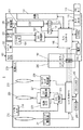
図1は、実施の形態1に係るデジタルカメラ1の構成を示すブロック図である。デジタルカメラ1は、カメラ本体100とそれに着脱可能な交換レンズ200とから構成される。
1. 1. Configuration FIG. 1 is a block diagram showing the configuration of the
1−1.カメラ本体
カメラ本体100は、CCD(Charge Coupled Device)110と液晶モニタ120とカメラコントローラ140とボディマウント150と電源160とカードスロット170とを備える。
1-1. Camera body The
カメラコントローラ140は、レリーズ釦130からの指示に応じて、CCD110等の構成要素を制御することで、デジタルカメラ1全体の動作を制御する。カメラコントローラ140は、垂直同期信号をタイミング発生器(Timing Generator(TG))112に送信する。これと並行して、カメラコントローラ140は、露光同期信号を生成する。カメラコントローラ140は、生成した露光同期信号を、ボディマウント150およびレンズマウント250を介して、レンズコントローラ240に周期的に送信する。カメラコントローラ140は、制御動作または画像処理動作の際に、DRAM(Dynamic Random Access Memory)141をワークメモリとして使用する。
The
CCD110は、交換レンズ200を介して入射される被写体像を撮像して画像データを生成する。生成された画像データは、ADコンバータ(Analog−to−digital Converter(ADC))111でデジタル化される。デジタル化された画像データは、カメラコントローラ140により所定の画像処理が施される。所定の画像処理とは、例えば、ガンマ補正処理、ホワイトバランス補正処理、キズ補正処理、YC変換処理、電子ズーム処理、またはJPEG(Joint Photographic Experts Group)圧縮処理である。
The
CCD110は、タイミング発生器112により制御されるタイミングで動作する。CCD110の動作としては、静止画像の撮像動作、およびスルー画像の撮像動作等が挙げられる。スルー画像は、主に動画像であり、ユーザが静止画像の撮像のための構図を決めるために、液晶モニタ120に表示される。
The
液晶モニタ120は、カメラコントローラ140で画像処理された表示用画像データが示す画像を表示する。液晶モニタ120は、動画像も静止画像も選択的に表示可能である。
The liquid crystal monitor 120 displays the image indicated by the display image data image-processed by the
カードスロット170は、メモリカード171を装着可能であり、カメラコントローラ140からの制御に基づいてメモリカード171を制御する。デジタルカメラ1は、メモリカード171に対して画像データを格納したり、メモリカード171から画像データを読み出したりすることができる。
The
電源160は、デジタルカメラ1内の各要素に電力を供給する。
The
ボディマウント150は、交換レンズ200のレンズマウント250と機械的および電気的に接続可能である。カメラ本体100と交換レンズ200は、ボディマウント150とレンズマウント250に設置されたコネクタを介して、データを送受信可能である。ボディマウント150は、カメラコントローラ140から受信した露光同期信号を、レンズマウント250を介してレンズコントローラ240に送信する。ボディマウント150は、カメラコントローラ140から受信したその他の制御信号を、レンズマウント250を介してレンズコントローラ240に送信する。ボディマウント150は、レンズマウント250を介して、レンズコントローラ240から受信した信号をカメラコントローラ140に送信する。ボディマウント150は、電源160からの電力を、レンズマウント250を介して交換レンズ200全体に供給する。
The
カメラ本体100は、CCD110のシフトにより手ぶれを補正するBIS機能を実現する構成として、カメラ本体100のぶれを検出するジャイロセンサ184と、ジャイロセンサ184の検出結果に基づき、ぶれ補正処理を制御するBIS処理部183とを備える。カメラ本体100は、CCD110を移動させるCCD駆動部181と、CCD110の位置を検出する位置センサ182とをさらに備える。CCD駆動部181は、例えば、マグネットと平板コイルとで実現可能である。位置センサ182は、光学系の光軸に垂直な面内におけるCCD110の位置を検出するセンサである。位置センサ182は、例えば、マグネットとホール素子によって実現可能である。BIS処理部183は、ジャイロセンサ184からの信号および位置センサ182からの信号に基づき、CCD駆動部181を制御して、カメラ本体100のぶれを相殺するように、CCD110を光軸に垂直な面内でシフトさせる。ここで、カメラ本体100に備えられる撮像センサはCCDとしたが、CMOS(Complementary Metal Oxide Semiconductor)センサ等、別の撮像センサを用いてもよい。また、CCD駆動部181はステッピングモータ、または超音波モータ等そのほかのアクチュエータを用いても構わない。尚、アクチュエータにステッピングモータを用いた場合、オープン制御が可能となり、それに伴って、位置センサを不要とすることも可能である。
The
1−2.交換レンズ
交換レンズ200は、光学系とレンズコントローラ240とレンズマウント250とを備える。光学系はズームレンズ210、OISレンズ220、フォーカスレンズ230を含む。
1-2. Interchangeable Lens The
ズームレンズ210は、光学系で形成される被写体像の倍率を変化させるためのレンズである。ズームレンズ210は、1枚または複数枚のレンズで構成される。ズームレンズ駆動部211は、使用者が操作可能なズームリング等を含み、使用者による操作をズームレンズ210に伝え、ズームレンズ210を光学系の光軸方向に沿って移動させる。
The
フォーカスレンズ230は、光学系において、CCD110上に形成される被写体像のフォーカス状態を変化させるためのレンズである。フォーカスレンズ230は、1枚または複数枚のレンズで構成される。
The
フォーカスレンズ駆動部233は、モータを含む。フォーカスレンズ駆動部233は、レンズコントローラ240の制御に基づいて、フォーカスレンズ230を光学系の光軸に沿って移動させる。フォーカスレンズ駆動部233は、DCモータ、ステッピングモータ、サーボモータ、または超音波モータなどで実現できる。
The focus
OISレンズ220は、OISレンズ220のシフトにより手ぶれを補正するOIS機能において、交換レンズ200の光学系で形成される被写体像のぶれを補正するためのレンズである。OISレンズ220は、デジタルカメラ1のぶれを相殺する方向に移動することにより、CCD110上の被写体像のぶれを小さくする。OISレンズ220は、1枚または複数枚のレンズで構成される。OIS駆動部221は、OIS処理部223からの制御を受けて、光学系の光軸に垂直な面内でOISレンズ220をシフトする。
The
OIS駆動部221は、例えば、マグネットと平板コイルとで実現可能である。位置センサ222は、光学系の光軸に垂直な面内におけるOISレンズ220の位置を検出するセンサである。位置センサ222は、例えば、マグネットとホール素子で実現可能である。OIS処理部223は、位置センサ222の出力およびジャイロセンサ224(ぶれ検出器)の出力に基づいて、OIS駆動部221を制御する。ここで、OIS駆動部221として、超音波モータ等そのほかのアクチュエータを用いても構わない。
The
ジャイロセンサ184またはジャイロセンサ224は、デジタルカメラ1の単位時間あたりの角度変化すなわち角速度に基づいて、ヨーイング方向およびピッチング方向のぶれ(振動)を検出する。ジャイロセンサ184またはジャイロセンサ224は、検出したぶれの量(角速度)を示す角速度信号をOIS処理部223またはBIS処理部183に出力する。ジャイロセンサ184またはジャイロセンサ224によって出力された角速度信号は、手ぶれまたはメカノイズ等に起因した幅広い周波数成分を含み得る。本実施の形態では、角速度検出手段としてジャイロセンサを使用するが、ジャイロセンサに代えて、デジタルカメラ1のぶれを検出できるものであれば、他のセンサを使用することもできる。
The
カメラコントローラ140およびレンズコントローラ240は、ハードワイヤードな電子回路で構成してもよいし、プログラムを用いたマイクロコンピュータなどで構成してもよい。
The
デジタルカメラ1は、フラッシュメモリ242に対して画像データを格納したり、フラッシュメモリ242から画像データを読み出したりすることができる。
The
レンズコントローラ240は、制御動作または画像処理動作の際に、DRAM241をワークメモリとして使用する。
The
1−3.OIS処理部
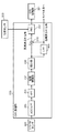
図2は、実施の形態1のデジタルカメラにおけるOIS処理部223の構成を示すブロック図である。図2を用いて、交換レンズ200におけるOIS処理部223の構成を説明する。OIS処理部223は、ADC(アナログ/デジタル変換)/LPF(ロー・パス・フィルタ、Low Pass Filter)305と、HPF(ハイ・パス・フィルタ、High Pass Filter)306と、位相補償部307と、積分器308と、LPF309と、加算器310と、PID制御部(Proportional−Integral−Differential Controller)311とを含む。
1-3. OIS processing unit FIG. 2 is a block diagram showing a configuration of
ADC/LPF305は、ジャイロセンサ224からの角速度信号を、アナログ形式からデジタル形式へ変換する。さらに、ADC/LPF305は、ノイズを排除してデジタルカメラ1のぶれのみを抽出するために、デジタル形式に変換された角速度信号の高周波成分を遮断する。撮影者の手ぶれの周波数が0Hzより大きく10Hz以下程度の低周波である。この点を考慮してLPFのカットオフ周波数が設定される。ノイズが問題とならない場合は、LPFの機能を省略することができる。
The ADC / LPF305 converts the angular velocity signal from the
HPF306は、ドリフト成分を遮断するため、ADC/LPF305から受信した信号に含まれる所定の低周波成分を遮断する。位相補償部307は、HPF306から受信した信号に対して、OIS駆動部221またはレンズ−ボディ間通信(後述)などに起因する位相遅れを補正する。
The
積分器308は、位相補償部307から入力したぶれ(振動)の角速度を示す信号を積分して、ぶれ(振動)の角度を示す信号を生成する。以下、積分器308によって生成された信号を「ぶれ検出信号」という。
The
積分器308からのぶれ検出信号は、LPF309および加算器310に入力される。LPF309は、ぶれ検出信号の高域成分をカットして、低域成分(以下「第1のぶれ信号」という)を通過させる。第1のぶれ信号は、低周波領域のぶれに関するぶれ補正量を示す信号である。ここで、LPF309のカットオフ周波数は、手ぶれの周波数(0Hzより大きく10Hz以下)を考慮して、例えば1Hzに設定される。ここで、低周波成分ぶれ信号生成にLPFを用いたが、別のフィルタ、例えばLSF(ローシェルフフィルタ、Low−shelf Filter)等の高周波成分をカットするフィルタであれば、どのようなフィルタを用いてもよい。フィルタ構成はこの構成に限らず、例えば、HPF306と積分器308の順序を入れ替える等の別構成としても構わない。
The blur detection signal from the
加算器310は、積分器308から入力されたぶれ検出信号から、LPF309で抽出されたぶれ検出信号の低域成分を減算することで、ぶれ検出信号の高周波成分(以下「第2のぶれ信号」という)を抽出する。第2のぶれ信号は、高周波領域(1Hz以上10Hz以下)のぶれに関するぶれ補正量を示す信号である。第2のぶれ信号は、PID制御部311に入力される。一方、第1のぶれ信号は、カメラ本体100に送信される。
The
PID制御部311は、入力された第2のぶれ信号と、位置センサ222から受信したOISレンズ220の現在の位置情報との差分に基づき、PID制御を行なう。PID制御部311は、OIS駆動部221に対する駆動信号を生成し、OIS駆動部221に送る。OIS駆動部221は、駆動信号に基づいてOISレンズ220を駆動する。
The
1−4.BIS処理部
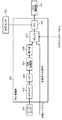
図3は、実施の形態1のデジタルカメラ1におけるBIS処理部183の構成を示すブロック図である。図3を用いて、カメラ本体100におけるBIS処理部183の構成を説明する。BIS処理部183は、ADC/LPF405と、HPF406と、位相補償部407と、積分器408と、セレクタ412と、PID制御部410とを含む。
1-4. BIS processing unit FIG. 3 is a block diagram showing a configuration of
ADC/LPF405、HPF406、位相補償部407、積分器408およびPID制御部410の基本的な機能は、OIS処理部223における対応する要素の機能と同じである。
The basic functions of the ADC / LPF405, HPF406,
BIS処理部183は、特に、カメラ本体100内に設けられたジャイロセンサ184の出力(積分器408の出力)と、交換レンズ200から受信した第1のぶれ信号とのうちのいずれか一方に基づき、ぶれ補正処理を行うように構成されている。このため、BIS処理部183は、カメラ本体100内に設けられたジャイロセンサ184の出力(積分器408の出力)と、交換レンズ200から受信した第1のぶれ信号とのうちのいずれか一方を選択して、PID制御部410に出力するセレクタ412を備えている。交換レンズ200がぶれ補正機能を備えていない場合等、カメラ本体100側でぶれ補正機能を実現する際には、セレクタ412はジャイロセンサ184の出力(積分器408の出力)を選択する。セレクタ412は、カメラコントローラ140により制御される。
The
PID制御部410は、位置センサ182からの出力と、積分器408からの出力または交換レンズ200からの第1のぶれ信号とに基づいて、CCD110をシフトさせるための駆動信号を生成して、CCD駆動部181へ出力する。CCD駆動部181は、駆動信号に基づいてCCD110を駆動する。
The
2.動作
2−1.ぶれ補正処理
以上のように構成されるデジタルカメラ1におけるぶれ補正処理について、説明する。なお、以下の説明では、2つあるジャイロセンサ224、184のうち、レンズ側に設けられたジャイロセンサ224からの信号に基づいて、OISレンズ220およびCCD110を駆動する例を説明する。すなわち、デジタルカメラ1は、レンズ側に設けられたジャイロセンサ224を使用する。このとき、BIS処理部183内のセレクタ412は、第1のぶれ信号を選択し、PID制御部410に出力するように制御されている。このとき、デジタルカメラ1は、使用するジャイロセンサ224を有している交換レンズ200をマスタとし、他方のカメラ本体100をスレーブとして作動する。
2. Operation 2-1. Blur correction processing The blur correction processing in the
OIS処理部223は、ジャイロセンサ224から検出信号を受信し、受信した検出信号からぶれ検出信号を生成する。OIS処理部223は、ぶれ検出信号を、第2の信号と、第1のぶれ信号とに分離する。OIS処理部223は、第2のぶれ信号と位置センサ222からの位置情報とに基づき、OISレンズ220をシフトさせるための駆動信号を生成し、OIS駆動部221に出力する。OIS駆動部221は、OIS処理部223からの駆動信号にしたがい、ジャイロセンサ224で検出された高周波のぶれ(1Hz以上10Hz以下)をキャンセルするように、OISレンズ220を光軸に垂直な面上でシフトさせる。
The
OIS処理部223において生成された第1のぶれ信号は、レンズマウント250およびボディマウント150を介した交換レンズ―カメラ本体間の通信を用いて、カメラ本体100に送信される。このとき、カメラ本体100のBIS処理部183において、セレクタ412は、交換レンズ200からの第1のぶれ信号を選択するように制御されている。BIS処理部183は、交換レンズ200からの第1のぶれ信号と位置センサ182からの位置情報に基づき、CCD110を駆動するための駆動信号を生成し、CCD駆動部181へ送信する。CCD駆動部181は、BIS処理部183からの駆動信号にしたがい、ジャイロセンサ224で検出された低周波のぶれ(1Hz未満)をキャンセルするようにCCD110を光軸に垂直な面上でシフトさせる。ここで、交換レンズ−カメラ本体間の通信は、レンズマウント250およびボディマウント150を介して行っているが、光通信や無線を用いた通信で行っても構わない。
The first blur signal generated by the
以上のように、本実施の形態のデジタルカメラ1は、検出されたぶれ信号における高周波成分(1Hz以上10Hz以下)に基づいて、交換レンズ200側のぶれ補正機能を作動させる。デジタルカメラ1は、検出されたぶれ信号における低周波成分(1Hz未満)に基づいて、カメラ本体100側のぶれ補正機能を作動させる。このように、本実施の形態では、ぶれ補正機能をカメラ本体100と交換レンズ200とで分担させることで、交換レンズ200側においては、ぶれ信号の高周波成分のみを補正すればよくなる。このため、交換レンズ200側において、OISレンズ220の補正範囲を有効活用することが可能になる。
As described above, the
2−2.周辺光量補正の基本原理
上述のように、本実施の形態のデジタルカメラ1は、交換レンズ200とカメラ本体100を備え、交換レンズ200側のOIS機能と、カメラ本体100のBIS機能とを連携動作することにより、像ぶれを補正する。デジタルカメラ1における周辺光量補正の基本原理について、以下に説明する。
2-2. Basic Principle of Peripheral Illumination Correction As described above, the
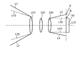
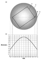
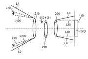
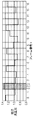
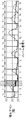
図4は、実施の形態1のデジタルカメラ1における周辺光量落ちの原理説明図である。光学系はズームレンズ210、OISレンズ220、フォーカスレンズ230を含む。撮像素子はCCD110で構成される。OISレンズ220は、光軸に対して垂直方向にシフトさせることによって、手ぶれを補正する機能を有するが、ここではOISレンズ220がセンターに保持されている例を示す。L1およびL2は被写体像を捉えることができる光線範囲の境界を示す。L1およびL2で示す被写体像を捉える光線範囲は、CCD110側のL3およびL4で示す光線範囲に対応する。一方、CCD110側のL30およびL40は、CCD110に撮像される光線範囲の境界を示し、被写体側(ズームレンズ210の左側)のL10およびL20で示す光線範囲に対応する。図4中のAはCCD110の表面の延長線と光線範囲L3との交点を示す。図4中のBはCCD110の端点と光線範囲L30との交点を示す。これらの交点AおよびBに関する詳細は、図5を用いて説明する。
FIG. 4 is an explanatory diagram of the principle of peripheral illumination reduction in the
一般的な光学系では、撮像素子の周辺ほど撮像される光量が低下する。具体的には図4において、CCD110に沿って一点鎖線で示す光軸中心から上側垂直方向にL30からL3に掛けて、徐々に光量が低下する。CCD110に沿って一点鎖線で示す光軸中心から下側垂直方向にL40からL4に掛けて、徐々に光量が低下する。
In a general optical system, the amount of light imaged decreases toward the periphery of the image sensor. Specifically, in FIG. 4, the amount of light gradually decreases from L30 to L3 in the upper vertical direction from the center of the optical axis indicated by the alternate long and short dash line along the
図5は、実施の形態1のデジタルカメラ1における周辺光量落ち原理図である。図5の(b)は周辺光量落ちの特性グラフを示す。図5の(a)において、Cはズームレンズ210とOISレンズ220、フォーカスレンズ230を通したCCD110側の被写体像の光量分布を示し、DはCCD110の外形を示す。なお、CCD110側の被写体像の光量分布Cを有効像円と呼称し、この有効像円より外側では適正な光量が得られない、いわゆるケラレを生じる。一点鎖線と光量分布Cの外形とが交差する点Aは、先に説明した図4の交点Aに対応する。一点鎖線とCCD110の外形Dとが交差する点Bは、先に説明した図4の交点Bに対応する。
FIG. 5 is a peripheral light falloff principle diagram in the
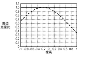
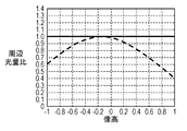
図5の(b)において、横軸は像高を示し、図5の(a)の一点鎖線に沿った座標に対応する。縦軸は周辺光量比を示す。図5の(a)の光量分布Cの中心を像高0として周辺光量比を1.0とし、図5の(a)の一点鎖線に沿う像高が大きくなるほど周辺光量が低下する特性を示す。ここでは、像高が1.0を、図5の(a)の一点鎖線とCCD110の外形Dとが交差する点Bとする。なお、交点Aより外側(像高が1.2を超える領域)は、ケラレが発生して正常な光量が得られない領域を示し、図5の(b)の特性グラフでは省略している。図5の(b)の周辺光量落ちの特性グラフでは、具体例として、像高が1.0のときの周辺光量比を0.5とし、像高が1.2のときの周辺光量比を0.35としている。像高が0を中心として、周辺光量落ちの特性グラフは、左右対称の形状となる。像高が0から左側の座標はマイナスとして−1.2から0の像高までの特性グラフを示す。
In FIG. 5B, the horizontal axis indicates the image height and corresponds to the coordinates along the alternate long and short dash line in FIG. 5A. The vertical axis shows the peripheral illumination ratio. The center of the light amount distribution C in FIG. 5 (a) is set to an image height of 0, the peripheral light amount ratio is set to 1.0, and the characteristic that the peripheral light amount decreases as the image height along the alternate long and short dash line in FIG. 5 (a) increases is shown. .. Here, the image height of 1.0 is defined as the point B where the alternate long and short dash line (a) in FIG. 5 and the outer shape D of the
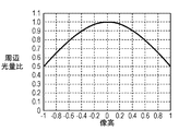
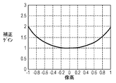
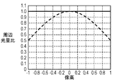
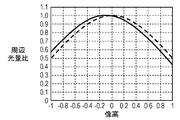
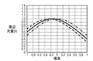
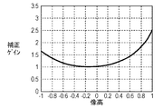
次に、図6A、図6B、図6Cを用いて周辺光量補正を行う具体例を示す。図6Aは、実施の形態1のデジタルカメラ1における周辺光量落ちの特性グラフである。図6Bは、実施の形態1のデジタルカメラ1における周辺光量補正ゲインの特性グラフである。図6Cは、実施の形態1のデジタルカメラ1における周辺光量補正後の特性グラフである。図6Aは、先に説明した図5の(b)の周辺光量落ちの特性グラフと同じだが、CCD110に投影される光量に限定してグラフ化しているために、横軸の像高が−1.0〜1.0に制限されている。図6Bは、図6Aの周辺光量落ちの特性に応じて、周辺光量補正を行う場合の、周辺光量補正ゲインの特性グラフを示す。図1におけるカメラコントローラ140内において、CCD110、ADC111を通じてカメラコントローラ140に入力された画像データを、像高および補正ゲインに応じてゲインアップを行うことによって、周辺光量を補正する。図6Cは、図6Aの周辺光量落ちの特性と図6Bの周辺光量補正ゲインの特性とを像高ごとに掛け合わせることによって、像高に係わらず周辺光量比を1.0に補正することが可能となる例を示す。図6Cにおいて、破線の周辺光量落ちの特性グラフ(図6Aの特性グラフと同じ)が、補正により実線の周辺光量補正後の特性グラフとなる。
Next, a specific example of performing peripheral illumination correction using FIGS. 6A, 6B, and 6C will be shown. FIG. 6A is a characteristic graph of peripheral light falloff in the
2−3.手ぶれ補正システムにおける周辺光量補正の原理
ここでは、補正用レンズ(以下では、OISレンズと称す)によるシフト、または撮像素子(以下では、CCDと称す)によるシフトによって、CCD110に投影される被写体像は、CCD110の周辺ほど光量がさらに低減するなどして、撮影された画像の品位が低下する、という課題を解決するための具体的な実施の形態について、説明する。
2-3. Principle of peripheral illumination correction in the image stabilization system Here, the subject image projected on the
2−3−1.OISレンズシフトによる周辺光量特性の原理
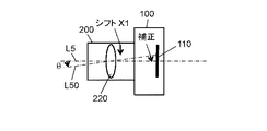
図7Aは、実施の形態1のデジタルカメラ1におけるOISレンズ220シフト時の周辺光量特性の原理説明図である。図7Bは、OISレンズ220シフトによる手ぶれ補正原理図である。図7Bにおいては、カメラ本体100にはCCD110、交換レンズ200にはOISレンズ220で構成されるデジタルカメラ1として、説明のポイントとなる要件のみを記載している。光軸L5に対して、デジタルカメラ1が、手ぶれによって、OISレンズ220を中心にθ分回転したと仮定すると、光軸L5がL50のように、OISレンズ220を中心にθ分回転する。この場合には、OISレンズ220を、手ぶれによるデジタルカメラ1の回転分θに応じて、X1だけシフトさせることによって、回転した光軸L50を、OISレンズ220の右側において、光軸L5に一致させるように補正を行う。これにより、デジタルカメラ1が手ぶれによって回転した場合でも、被写体像をぶれることなく、CCD110に結像させることができる。一例として、交換レンズ200の焦点距離fを150mm、デジタルカメラ1の手ぶれによる回転分θを0.3度とすると、CCD110上では、光軸L5がL50に回転することによって、約0.78mmだけ結像位置がずれることになる。そこで、OISレンズ220をシフトさせることによって、この結像位置のずれを補正することができる。この場合のOISレンズ220のシフト量については光学設計に依存するが、例えばシフト量X1を0.3mmとしたときに結像位置が0.78mmだけずれた分戻るようにすることで、手ぶれ補正機能を実現することができる。
2-3-1. Principle of Peripheral Illumination Characteristic by OIS Lens Shift FIG. 7A is an explanatory diagram of the principle of peripheral illumination characteristic when the
図7Aにおいて、OISレンズ220は、光軸に対して垂直方向にシフトさせることによって、手ぶれを補正する機能を有する。OISレンズ220がセンターに保持されている場合において、L1およびL2は被写体像を捉えることができる光線範囲の境界を示す。L1およびL2で示す被写体像を捉える光線範囲は、CCD110側のL3およびL4で示す光線範囲に対応する。一方、CCD110側のL30およびL40は、CCD110に撮像される光線範囲の境界を示し、被写体側(ズームレンズ210の左側)のL10およびL20で示す光線範囲に対応する。ここで、図7Bを用いて説明したように、デジタルカメラ1が手ぶれによって、OISレンズ220を中心にθ分だけ回転した場合には、OISレンズ220を光軸に対して、垂直方向にX1だけシフトすることによって、手ぶれによる被写体像のCCD110への結像位置のずれを補正することができる。このときには、CCD110に投影される光線範囲である、L30およびL40に対応する被写体側(ズームレンズ210の左側)の光線範囲L10およびL20は、各々L100およびL200で示すように移動する。このように、OISレンズ220のシフトによる手ぶれ補正によって、被写体側の光線範囲が移動することによって、L20は、L200に移動して被写体を捉えることのできる光線範囲の境界L2に近づくことで、CCD110側に対応する光線L30の光量がやや低下する。一方、L10は、L100に移動して被写体を捉えることのできる光線範囲の境界L1から遠のくことで、CCD110側に対応する光線L40の光量がやや増加することになる。
In FIG. 7A, the
2−3−2.CCDシフトによる周辺光量特性の原理
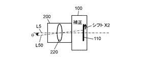
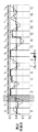
図8Aは、実施の形態1のデジタルカメラ1におけるCCDシフト時の周辺光量特性の原理説明図である。図8Bは、実施の形態1のデジタルカメラ1におけるCCDシフトによる手ぶれ補正原理図である。図8Bにおいては、カメラ本体100にはCCD110、交換レンズ200にはOISレンズ220で構成されるデジタルカメラ1として、説明のポイントとなる要件のみを記載している。光軸L5に対して、デジタルカメラ1が、手ぶれによって、OISレンズ220を中心にθ分回転したと仮定すると、光軸L5がL50のように、OISレンズ220を中心にθ分回転する。この場合には、CCD110を、手ぶれによるデジタルカメラ1の回転分θに応じて、X2だけシフトさせることによって、光軸L5によるCCD110上の交点座標を、光軸L50によるCCD110上の交点座標と一致させるように補正を行う。これにより、デジタルカメラ1が手ぶれによって回転した場合でも、被写体像をぶれることなく、CCD110に結像させることができる。一例として、交換レンズ200の焦点距離fを150mm、デジタルカメラ1の手ぶれによる回転分θを0.3度とすると、CCD110上では、光軸L5がL50に回転することによって、約0.78mmだけ結像位置がずれることになる。そこで、CCD110を約0.78mmシフトさせることによって、この結像位置のずれを補正することができる。
2-3-2. Principle of Peripheral Illumination Characteristic by CCD Shift FIG. 8A is an explanatory diagram of the principle of peripheral illumination characteristic at the time of CCD shift in the
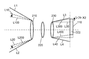
図8Aにおいて、CCD110は、光軸に対して垂直方向にシフトさせることによって、手ぶれを補正する機能を有する。しかし、ここではCCD110がセンターに保持されている場合において、L1およびL2は被写体像を捉えることができる光線範囲の境界を示し、L1およびL2で示す被写体像を捉える光線範囲は、CCD110側のL3およびL4で示す光線範囲に対応する。一方、CCD110側のL30およびL40は、CCD110に撮像される光線範囲の境界を示し、被写体側(ズームレンズ210の左側)のL10およびL20で示す光線範囲に対応する。ここで、図8Bを用いて説明したように、デジタルカメラ1が手ぶれによって、OISレンズ220を中心にθ分だけ回転した場合には、CCD110を光軸に対して垂直方向にX2だけシフトすることによって、手ぶれによる被写体像のCCD110への結像位置のずれを補正することができる。CCD110シフト前においては、CCD110に投影される光線範囲である、L30およびL40は、被写体側(ズームレンズ210の左側)の光線範囲L10およびL20に対応する。CCD110のX2分シフト後においては、CCD110に投影される光線範囲である、L300およびL400は、被写体側(ズームレンズ210の左側)の光線範囲L100およびL200に対応する。光線範囲L100およびL200は、先に説明したOISレンズ220のシフトによる手ぶれ補正時と同様の範囲となる。すなわち、デジタルカメラ1の手ぶれによる回転分をθとした場合に、被写体側の捉えるべき画角は互いに同じである。ここでも、被写体側(ズームレンズ210の左側)の光線範囲のうちL10は、L100に移動することで被写体を捉えることのできる、光線範囲の境界であるL1から遠のくために、L100の光線がCCD110側に投影される光量はやや増加する。一方、被写体側(ズームレンズ210の左側)の光線範囲のうちL20は、L200に移動することで被写体を捉えることのできる、光線範囲の境界であるL2に近づく。このため、L200の光線がCCD110側に投影される光量は、やや低下する。CCD110のX2分シフト後において、CCD110に投影される光線範囲の境界であるL300は、有効像円の外形に対応する光線L3に近づくために、CCD110に投影されるL300の光線による光量は、さらに低下する。すなわち、光線L200による交換レンズ200に入射する光量の低下に加えて、光線L200に対応する光線L300も光量の低下によって、さらに光量が低下することになる。一方、CCD110のX2分シフト後において、CCD110に投影される光線範囲の境界であるL400は、有効像円の外形に対応する光線L4から遠のく。このため、CCD110に投影されるL400の光線による光量はさらに増加する。すなわち、光線L100による交換レンズ200に入射する光量の増加に加えて、光線L100に対応する光線L400も光量の増加によって、さらに光量が増加することになる。
In FIG. 8A, the
したがって、手ぶれ補正によるOISレンズまたはCCDのシフトによって、周辺光量が落ちる領域においては、OISレンズシフト時に比べて、CCDシフト時の方が、周辺光量がより大きく落ちることになる。一方、手ぶれ補正によるOISレンズまたはCCDのシフトによって、周辺光量が上がる領域においては、OISレンズシフト時に比べてCCDシフト時の方が、周辺光量がより大きく上がることになる。 Therefore, in the region where the peripheral light amount is reduced due to the shift of the OIS lens or the CCD by the image stabilization, the peripheral light amount is further reduced at the time of the CCD shift than at the time of the OIS lens shift. On the other hand, in the region where the peripheral illumination increases due to the shift of the OIS lens or the CCD by the image stabilization, the peripheral illumination increases more significantly at the time of the CCD shift than at the time of the OIS lens shift.
2−3−3.OISレンズシフトによる周辺光量特性の補正方法
図9A、図9B、図9Cを用いて、OISレンズシフトによって生じた周辺光量特性の変化を補正する具体例を説明する。図9Aは、実施の形態1のデジタルカメラ1におけるOISレンズシフト後の周辺光量特性グラフである。図9Bは、実施の形態1のデジタルカメラ1におけるOISレンズシフト後の周辺光量補正ゲインの特性グラフである。図9Cは、実施の形態1のデジタルカメラ1におけるOISレンズシフト後の周辺光量補正後の特性グラフである。
2-3-3. Method for Correcting Peripheral Illumination Characteristics by OIS Lens Shift A specific example of correcting changes in peripheral illumination characteristics caused by OIS lens shift will be described with reference to FIGS. 9A, 9B, and 9C. FIG. 9A is a peripheral illumination characteristic graph of the
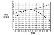
図9Aにおいて、横軸は、CCD110上の中心の像高を0として、CCD110上の角の像高を−1.0から1.0で示す。縦軸は、像高に対応する周辺光量比を表している。破線のグラフは、OISレンズシフト前の周辺光量の特性を表したグラフである。実線のグラフは、OISレンズシフト後、すなわち光軸に対して垂直方向にX1だけシフトした状態における周辺光量の特性を表したグラフである。このグラフでは、先に説明したように、OISレンズシフトによって、像高が1.0ではOISレンズシフト前の周辺光量よりやや低下する様子を示しており、像高が−1.0ではOISレンズシフト前の周辺光量よりやや増加する様子を示している。
In FIG. 9A, the horizontal axis represents the image height of the center on the
図9Bは、図9Aの周辺光量落ちの特性に応じて、周辺光量補正を行う場合の周辺光量補正ゲインの特性グラフを示す。ここでは、OISレンズシフト後の周辺光量補正を行う例を示しているので、図9Aの実線で示すグラフに対応している。カメラコントローラ140内において、CCD110、ADC111を通じてカメラコントローラ140に入力された画像データを、像高および補正ゲインに応じてゲインアップを行うことによって、周辺光量を補正する。図9Cは、図9Aの実線で示す周辺光量落ちの特性と図9Bの周辺光量補正ゲインの特性とを像高ごとに掛け合わせることによって、像高に係わらず周辺光量比を1.0に補正する周辺光量比を示す。図9Cにおいて、破線の周辺光量落ちの特性グラフ(図9Aの実線で示す特性グラフと同じ)が、補正により実線の周辺光量補正後の特性グラフとなる。
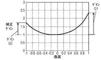
FIG. 9B shows a characteristic graph of the peripheral light amount correction gain when the peripheral light amount correction is performed according to the characteristic of the peripheral light amount drop of FIG. 9A. Here, since an example of performing peripheral illumination correction after the OIS lens shift is shown, it corresponds to the graph shown by the solid line in FIG. 9A. In the
図9Bにおいて、像高が1.0でのゲインをG1として、像高が−1.0でのゲインをG2として定義する。後述するCCDシフトによる周辺光量特性の補正方法における説明の中で、ゲインG1およびゲインG2を用いる。 In FIG. 9B, the gain at an image height of 1.0 is defined as G1, and the gain at an image height of −1.0 is defined as G2. Gain G1 and gain G2 are used in the description of the method for correcting the peripheral illumination characteristic by CCD shift, which will be described later.
2−3−4.CCDシフトによる周辺光量特性の補正方法
図10A、図10B、図10Cを用いてCCDシフトによって生じる周辺光量特性の変化を補正する具体例を説明する。図10Aは、実施の形態1のデジタルカメラ1におけるCCDシフト後の周辺光量特性グラフである。図10Bは、実施の形態1のデジタルカメラ1におけるCCDシフト後の周辺光量補正ゲインの特性グラフである。図10Cは、実施の形態1のデジタルカメラ1におけるCCDシフト後の周辺光量補正後の特性グラフである。
2-3-4. Method for Correcting Peripheral Illumination Characteristics by CCD Shift A specific example of correcting changes in peripheral illumination characteristics caused by a CCD shift will be described with reference to FIGS. 10A, 10B, and 10C. FIG. 10A is a peripheral illumination characteristic graph of the
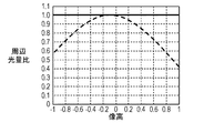
図10Aにおいて、横軸は、CCD110上の中心の像高を0として、CCD110上の角の像高を−1.0から1.0で示す。縦軸は、像高に対応する周辺光量比を表している。破線のグラフは、CCDシフト前の周辺光量の特性を表したグラフである。実線のグラフは、CCDシフト後、すなわち光軸に対して垂直方向にX2だけシフトした状態における周辺光量の特性を表したグラフである。このグラフでは、先に説明したように、CCDシフトによって、像高が1.0ではCCDシフト前の周辺光量より低下する様子を示しており、像高が−1.0ではCCDシフト前の周辺光量よりやや増加する様子を示している。特に、図10Aと図9Aとを比較すると、像高が1.0では、CCDシフト前あるいはOISレンズシフト前の周辺光量に対して、CCDシフト後の方がOISレンズシフト後より大きく周辺光量が低下している様子を示している。図10Aと図9Aとを比較すると、像高が−1.0では、CCDシフト前あるいはOISレンズシフト前の周辺光量に対して、CCDシフト後の方がOISレンズシフト後より大きく周辺光量が増加している様子を示している。
In FIG. 10A, the horizontal axis represents the image height of the center on the
図10Bは、図10Aの周辺光量落ちの特性に応じて、周辺光量補正を行う場合の周辺光量補正ゲインの特性グラフを示す。図10Bは、CCDシフト後の周辺光量補正を行う例を示しているので、図10Aの実線で示すグラフに対応している。カメラコントローラ140内において、CCD110、ADC111を通じてカメラコントローラ140に入力された画像データを、像高および補正ゲインに応じてゲインアップを行うことによって、周辺光量を補正する。図10Cにおいては、図10Aの実線で示す周辺光量落ちの特性と図10Bの周辺光量補正ゲインの特性とを像高ごとに掛け合わせることによって、像高に係わらず周辺光量比を1.0に補正する周辺光量比を示す。図10Cにおいて、破線の周辺光量落ちの特性グラフ(図10Aの実線で示す特性グラフと同じ)が、補正により実線の周辺光量補正後の特性グラフとなる。
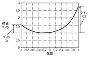
FIG. 10B shows a characteristic graph of the peripheral light amount correction gain when the peripheral light amount correction is performed according to the characteristic of the peripheral light amount drop of FIG. 10A. Since FIG. 10B shows an example of performing peripheral illumination correction after the CCD shift, it corresponds to the graph shown by the solid line in FIG. 10A. In the
図10Bにおいて、像高が1.0でのゲインをG3として、像高が−1.0でのゲインをG4として定義する。図9Bにおいて定義したゲインG1およびG2と、図10Bにおいて定義したゲインG3およびG4との大小関係を比較する。像高が1.0においては、G3>G1の関係になっている。像高が−1.0においては、G4<G2の関係になっている。すなわち、デジタルカメラ1の同じ手ぶれ回転分θに対して、像高が1.0では、OISレンズシフト後に比べて、CCDシフト後の方がより周辺光量の落ちが大きい。このために結果として、周辺光量補正ゲインを、OISレンズシフト時よりCCDシフト時の方が大きくなるように設定する。一方、デジタルカメラ1の同じ手ぶれ回転分θに対して、像高が−1.0では、OISレンズシフト後に比べて、CCDシフト後の方がより周辺光量の落ちが小さい。このために結果として、周辺光量補正ゲインを、OISレンズシフト時よりCCDシフト時の方が小さくなるように設定する。
In FIG. 10B, the gain at an image height of 1.0 is defined as G3, and the gain at an image height of −1.0 is defined as G4. The magnitude relationship between the gains G1 and G2 defined in FIG. 9B and the gains G3 and G4 defined in FIG. 10B is compared. When the image height is 1.0, the relationship is G3> G1. When the image height is −1.0, the relationship is G4 <G2. That is, when the image height is 1.0 with respect to the same camera shake rotation amount θ of the
3.まとめ
本実施の形態においては、CCDの一方の角の周辺光量の低下と、CCDの他方の角の周辺光量の低下を適正に補正して、撮影画像の品位の低下を防ぎ、良好な撮影画像を提供することができる具体例を示す。
3. 3. Summary In the present embodiment, the decrease in the peripheral illumination of one corner of the CCD and the decrease in the peripheral illumination of the other corner of the CCD are appropriately corrected to prevent the deterioration of the quality of the captured image, and a good captured image. A specific example that can be provided is shown.
手ぶれによる撮影中の撮影画像へのぶれの影響を低減するために、OISレンズ220およびCCD110をシフトすることによって、手ぶれ補正を行うデジタルカメラ1について述べた。ある手ぶれ量に対して、OISレンズ220をシフトすることによって、CCD110上の周辺光量が、手ぶれ補正を行わない場合と比較して、落ちる。しかし、同じ手ぶれ量に対して、CCD110をシフトすることによる方が、CCD110上の周辺光量が、より大きく落ちる。そこで、この場合には、CCDシフトすることによって生じる周辺光量補正を、OISレンズシフトすることによって生じる周辺光量補正より大きくすることで、撮影画像中の手ぶれおよび周辺光量落ちによる画像の品位低下を解消することができる。
The
一方、ある手ぶれ量に対してOISレンズ220をシフトすることによって、CCD110上の周辺光量が手ぶれ補正を行わない場合と比較して、上がる場合がある。しかし、同じ手ぶれ量に対して、CCD110をシフトすることによる方が、CCD110上の周辺光量がより大きく上がる。そこで、この場合には、CCDシフトすることによって生じる周辺光量補正を、OISレンズシフトすることによって生じる周辺光量補正より小さくすることで、撮影画像中の手ぶれおよび周辺光量落ちによる画像の品位低下を解消することができる。
On the other hand, by shifting the
特に、これらを双方組合せることによって、撮影画像中の周辺光量落ちの左右の落差を低減することができ、より品位の高い画像を提供することができる。 In particular, by combining both of these, it is possible to reduce the difference between the left and right sides of the peripheral light falloff in the captured image, and it is possible to provide a higher quality image.
すなわち、デジタルカメラ1は、ある手ぶれ量に対して、OISレンズシフトによる補正から、CCDシフトによる補正に切り替える場合、または、CCDシフトによる補正から、OISレンズシフトによる補正に切り替える場合に、周辺光量の補正量を変更することにより、撮影画像中の手ぶれおよび周辺光量落ちによる画像の品位低下を解消することができる。
That is, when the
以上のように、本実施の形態のデジタルカメラ1に相当する撮像装置は、複数のレンズ210、220、230を含む光学系と、光学系により形成された被写体像を撮像するCCD110に相当する撮像素子と、撮像素子で撮像された画像の周辺光量を補正する周辺光量補正部と、を有する。また、撮像装置のぶれを検出するジャイロセンサ184、224に相当するぶれ検出部と、ぶれ検出部の出力信号に基づいて、レンズ210、220、230または撮像素子の少なくとも一方を光軸に垂直な面で移動させて、ぶれを補正するCCD110またはOISレンズ220に相当する駆動制御部とを有する。また、周辺光量補正部は、ぶれの所定の周波成分を抽出して、ぶれの所定の周波成分に応じて周辺光量の補正量を変化させる。
As described above, the image pickup device corresponding to the
これにより、撮像装置において撮像素子に投影される光量が撮像素子の周辺で低下することによる撮影画像の品位低下を防ぎ、良好な撮影画像を提供することができる。特に、動画撮影時における撮影画像の品位低下を防ぎ、良好な動画撮影画像を提供することができる。 As a result, it is possible to prevent deterioration of the quality of the photographed image due to the decrease in the amount of light projected on the image sensor in the image pickup device around the image sensor, and to provide a good photographed image. In particular, it is possible to prevent deterioration of the quality of the captured image during moving image shooting and provide a good moving image shot image.
また、周辺光量補正部は、ぶれ検出部の出力信号からぶれの所定の周波成分を抽出して、ぶれの所定の周波成分に応じて周辺光量の補正量を変化させてもよい。これにより、撮像装置において撮像素子に投影される光量が撮像素子の周辺で低下することによる撮影画像の品位低下を防ぎ、良好な撮影画像を提供することができる。 Further, the peripheral illumination correction unit may extract a predetermined frequency component of the blur from the output signal of the blur detection unit and change the correction amount of the peripheral light amount according to the predetermined frequency component of the blur. As a result, it is possible to prevent deterioration of the quality of the photographed image due to the decrease in the amount of light projected on the image sensor in the image pickup device around the image sensor, and to provide a good photographed image.
また、周辺光量補正部は、駆動制御部においてレンズまたは撮像素子の少なくとも一方を移動させる駆動制御信号からぶれの所定の周波成分を抽出して、ぶれの所定の周波成分に応じて周辺光量の補正量を変化させてもよい。これにより、撮像装置において撮像素子に投影される光量が撮像素子の周辺で低下することによる撮影画像の品位低下を防ぎ、良好な撮影画像を提供することができる。 Further, the peripheral illumination correction unit extracts a predetermined frequency component of the blur from the drive control signal that moves at least one of the lens or the image sensor in the drive control unit, and corrects the peripheral light amount according to the predetermined frequency component of the blur. The amount may be varied. As a result, it is possible to prevent deterioration of the quality of the photographed image due to the decrease in the amount of light projected on the image sensor in the image pickup device around the image sensor, and to provide a good photographed image.
また、撮像装置は、光学系を含む交換レンズ200と、撮像素子と周辺光量補正部とを含むカメラ本体100と、を有してもよい。また、交換レンズ200とカメラ本体100とは着脱可能であってもよい。
Further, the image pickup apparatus may include an
また、光学系はぶれを補正するためのOISレンズ220に相当する補正レンズを含んでもよい。
Further, the optical system may include a correction lens corresponding to the
(実施の形態2)
1.構成
ぶれ補正を実現するデジタルカメラの別の例を説明する。本実施の形態のデジタルカメラの構成および基本動作は、実施の形態1と同じである。本実施の形態のデジタルカメラでは、新たに、動画撮影時における周辺光量の補正性能を向上させるための各種動作を、カメラコントローラ140とレンズコントローラ240に追加している。
(Embodiment 2)
1. 1. Configuration Another example of a digital camera that realizes blur correction will be described. The configuration and basic operation of the digital camera of the present embodiment are the same as those of the first embodiment. In the digital camera of the present embodiment, various operations for improving the correction performance of the peripheral light amount at the time of moving image shooting are newly added to the
2.動作
2−1.ぶれ補正処理
本実施の形態においては、実施の形態1で説明したぶれ補正処理の基本原理は同じであるので、原理の詳細な説明は省略する。本実施の形態においては、説明を分かりやすくするために、CCD110をシフトさせてぶれ補正を行う処理に加えて、周辺光量の補正を行う処理の詳細な動作の説明を行う。一方、OISレンズ220をシフトさせてぶれ補正を行う処理に加えて、周辺光量の補正を行う処理においても、CCD110をシフトさせてぶれ補正を行う処理に加えて周辺光量の補正を行う処理と、同様の効果がある。また、CCD110をシフトさせてぶれ補正を行う処理とOISレンズ220をシフトさせてぶれ補正を行う処理の双方を動作させて、周辺光量の補正を行う処理においても、同様に効果がある。
2. Operation 2-1. Blur correction processing In this embodiment, the basic principle of the blur correction processing described in the first embodiment is the same, and therefore detailed description of the principle will be omitted. In the present embodiment, in order to make the explanation easier to understand, a detailed operation of the process of correcting the peripheral illumination amount will be described in addition to the process of shifting the
本実施の形態においては、カメラコントローラ140とレンズコントローラ240に、周辺光量の補正性能を向上させるための新たな処理を追加している。2−3節以降にて新たな処理の詳細な説明を行う。
In the present embodiment, new processing for improving the peripheral illumination correction performance is added to the
2−2.手ぶれ補正動作中の周辺光量特性の補正方法(参考例)
参考例における手ぶれ補正動作中の周辺光量特性の補正方法について図11A、図11B、図12A、図12B、図12C、図13A、図13B、図13Cを用いて説明する。
2-2. Correction method for peripheral illumination characteristics during camera shake correction operation (reference example)
The method of correcting the peripheral illumination characteristic during the camera shake correction operation in the reference example will be described with reference to FIGS. 11A, 11B, 12A, 12B, 12C, 13A, 13B, and 13C.
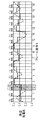
図11Aは、実施の形態2のぶれ補正処理における、ぶれ検出信号および手ぶれ制御信号の波形図である。横軸はフレーム番号k(ただし、k=0,1,2,3・・・)を示し、縦軸は手ぶれ角度と補正角度を示す。フレーム番号kは例えば1/30[秒]毎にインクリメントされるものとする。手ぶれ角度はカメラ本体100内に設けられたジャイロセンサ184の出力(積分器408の出力)に基づいて演算される。補正角度はカメラ本体100内に設けられた位置センサ182の出力に基づいて演算される。図11Aでは、フレーム番号kが0から16(約567ms)までの手ぶれ角度と補正角度の例を表している。なお、厳密には、手ぶれ角度と補正角度とは、残留誤差や応答遅れなどにより、互いに特性が異なり、誤差が存在するが、その誤差は小さいため、ほぼ同じ特性であるものとして重ねてグラフ化されている。
FIG. 11A is a waveform diagram of a blur detection signal and a camera shake control signal in the blur correction process of the second embodiment. The horizontal axis indicates the frame number k (however, k = 0, 1, 2, 3 ...), And the vertical axis indicates the camera shake angle and the correction angle. It is assumed that the frame number k is incremented every 1/30 [second], for example. The camera shake angle is calculated based on the output of the gyro sensor 184 (the output of the integrator 408) provided in the
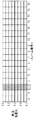
図12Aは、参考例のぶれ補正処理における、露光期間Tk毎に更新される周辺光量補正前の周辺光量比の時間的変化を表す波形図である。横軸はフレーム番号k(ただし、k=0,1,2,3・・・)を示し、縦軸は周辺光量比を示す。フレーム番号kは例えば1/30[秒]毎にインクリメントされるものとする。図12Aの破線で示すグラフは、手ぶれ補正動作中における周辺光量補正前の周辺光量比のリアルタイムの推移を表し、実線で示す階段状のグラフは、手ぶれ補正動作中における周辺光量補正前の周辺光量比の推移を表す。なお、図12Aにおける周辺光量比は、CCD110上の像高1.0に対応する周辺光量比を表している。
FIG. 12A is a waveform diagram showing a temporal change in the peripheral illumination ratio before the peripheral illumination correction, which is updated every exposure period Tk in the blur correction processing of the reference example. The horizontal axis indicates the frame number k (however, k = 0, 1, 2, 3 ...), And the vertical axis indicates the peripheral illumination ratio. It is assumed that the frame number k is incremented every 1/30 [second], for example. The graph shown by the broken line in FIG. 12A shows the real-time transition of the peripheral illumination ratio before the peripheral illumination correction during the camera shake correction operation, and the stepped graph shown by the solid line shows the peripheral illumination amount before the peripheral illumination correction during the image stabilization operation. Shows the transition of the ratio. The peripheral illumination ratio in FIG. 12A represents the peripheral illumination ratio corresponding to the image height of 1.0 on the
図13Aは、CCD110上の中心の像高を0として、CCD110上の角の像高を−1.0および1.0とし、像高に対応する周辺光量補正前の周辺光量比を表している。先に説明した図11Aと図12Aは、網掛けしている領域のフレーム番号k=2における露光期間T2の周辺光量補正前の周辺光量比を表している。図13Aにおいて、破線のグラフは、図11Aにおける時間t2時点の周辺光量補正前の周辺光量の特性を表したグラフである。図13Aにおいて、一点鎖線のグラフは図11Aにおける時間t3時点の周辺光量補正前の周辺光量の特性を表したグラフである。図13Aにおいて、実線のグラフは、図11Aにおける周辺光量補正前の周辺光量の特性を表したグラフである。
FIG. 13A sets the image height of the center on the
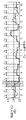
図11Bは、実施の形態2のぶれ補正処理における、周辺光量補正前の周辺光量比の時間的変化を表す波形図である。図11Bは、手ぶれ補正動作中における、CCD110上の像高1.0に対応する、周辺光量補正前の周辺光量比のリアルタイムの推移を表している。
FIG. 11B is a waveform diagram showing a temporal change in the peripheral illumination ratio before the peripheral illumination correction in the blur correction processing of the second embodiment. FIG. 11B shows the real-time transition of the peripheral illumination ratio before the peripheral illumination correction, which corresponds to the image height 1.0 on the
図12Bは、参考例のぶれ補正処理における、露光期間Tk毎に更新される周辺光量補正ゲインの時間的変化を表す波形図である。横軸はフレーム番号k(ただし、k=0,1,2,3・・・)を示し、縦軸は周辺光量補正ゲインを示す。図12Bの破線で示すグラフは手ぶれ補正動作中における周辺光量補正ゲインのリアルタイムの推移を表し、実線で示す階段状のグラフは、手ぶれ補正動作中における、露光開始タイミングtk時点の周辺光量補正ゲインの推移を表す。なお、図12Bにおける周辺光量補正ゲインは、CCD110上の像高1.0に対応する、周辺光量補正ゲインを表している。また、図12Bの破線で示すリアルタイムの周辺光量補正ゲインは、もとの周辺光量比を1.0にするために、必要な補正ゲインを表している。
FIG. 12B is a waveform diagram showing a temporal change in the peripheral illumination correction gain updated for each exposure period Tk in the blur correction process of the reference example. The horizontal axis indicates the frame number k (however, k = 0, 1, 2, 3 ...), And the vertical axis indicates the peripheral illumination correction gain. The graph shown by the broken line in FIG. 12B shows the real-time transition of the peripheral illumination correction gain during the camera shake correction operation, and the stepped graph shown by the solid line shows the peripheral light amount correction gain at the exposure start timing tk during the camera shake correction operation. Shows the transition. The peripheral illumination correction gain in FIG. 12B represents the peripheral illumination correction gain corresponding to the image height 1.0 on the
図13Bは、CCD110上の中心の像高を0として、CCD110上の角の像高を−1.0および1.0で示し、像高に対応する周辺光量補正ゲインを表している。像高1.0のときの周辺光量比の補正だけに着目して説明すると、図12Bにおいて、網掛けしている領域のフレーム番号k=2における、露光期間T2の開始タイミングt2時点の周辺光量補正ゲイン(約3.3倍)は、図13Bにおける像高1.0のときの周辺光量補正ゲインに対応している。
In FIG. 13B, the image height of the center on the
図12Cは、参考例のぶれ補正処理における、露光期間Tk毎に更新される周辺光量補正後の周辺光量比の時間的変化を表す波形図である。横軸はフレーム番号k(ただし、k=0,1,2,3・・・)を示し、縦軸は周辺光量補正後の周辺光量比を示す。図12Cの実線で示す階段状のグラフは、手ぶれ補正動作中における、露光開始タイミングtk時点の周辺光量補正ゲインの推移を表す。なお、図12Cにおける周辺光量補正後の周辺光量比は、CCD110上の像高1.0に対応する周辺光量比を表している。参考例においては、露光期間と関連しない所定のタイミングだけで検知した手ぶれ角度または手ぶれ補正角度を用いて、周辺光量補正を行っていたため、周辺光量比の本来の狙い(周辺光量比=1.0)からの誤差が大きくなっている。
FIG. 12C is a waveform diagram showing a temporal change in the peripheral illumination ratio after the peripheral illumination correction, which is updated every exposure period Tk in the blur correction processing of the reference example. The horizontal axis shows the frame number k (however, k = 0, 1, 2, 3 ...), And the vertical axis shows the peripheral illumination ratio after the peripheral illumination correction. The stepped graph shown by the solid line in FIG. 12C shows the transition of the peripheral illumination correction gain at the time of the exposure start timing tk during the camera shake correction operation. The peripheral illumination ratio after the peripheral illumination correction in FIG. 12C represents the peripheral illumination ratio corresponding to the image height of 1.0 on the
図13Cは、参考例のデジタルカメラにおける、露光期間T2の周辺光量補正後の周辺光量比の特性グラフである。図13Cは、CCD110上の中心の像高を0として、CCD110上の角の像高を−1.0および1.0で示し、像高に対応する、周辺光量補正後の周辺光量の特性を表したグラフである。図13Cの破線で示すグラフは周辺光量補正前の周辺光量補正を表し、図13Aの実線で示すグラフに対応する。図13Cの点線で示すグラフは周辺光量補正後の周辺光量の特性を表したグラフである。図13Cの点線で示すグラフは、図13Cの破線で示すグラフ(図13Aの実線で示すグラフと同じ)と図13Bの破線で示すグラフの像高毎の縦軸の数値を互いに掛け合わせたグラフとなる。参考例においては、露光期間と関連しない所定のタイミングだけで検知した、手ぶれ角度または手ぶれ補正角度を用いて、周辺光量補正を行っているため、周辺光量補正後の周辺光量比の各フレーム間の相対誤差も大きくなっている。
FIG. 13C is a characteristic graph of the peripheral illumination ratio after the peripheral illumination correction for the exposure period T2 in the digital camera of the reference example. In FIG. 13C, the image height of the center on the
この結果から、所定のタイミング(ここの例ではt2時点)で検知した、手ぶれ角度または手ぶれ補正角度を用いて、周辺光量補正を行った場合には、図13Cに示すように周辺光量補正後の周辺光量比が本来の狙い(周辺光量比=1.0)からの誤差が大きくなってしまうことがわかる。また、図12Cに示すように、像高1.0での周辺光量補正後の周辺光量比の時間的な変化に着目すると、露光期間Tk(ただし、k=0,1,2,3・・・)毎に周辺光量補正後の周辺光量比の時間的な変化も大きくなってしまうことがわかる。 From this result, when the peripheral illumination correction is performed using the camera shake angle or the camera shake correction angle detected at a predetermined timing (at the time of t2 in this example), the peripheral illumination is corrected as shown in FIG. 13C. It can be seen that the peripheral illumination ratio has a large error from the original aim (peripheral illumination ratio = 1.0). Further, as shown in FIG. 12C, focusing on the temporal change of the peripheral illumination ratio after the peripheral illumination correction at the image height of 1.0, the exposure period Tk (however, k = 0,1,2,3 ... -) It can be seen that the temporal change in the peripheral illumination ratio after the peripheral illumination correction also increases every time.
したがって、参考例におけるぶれ補正処理の周辺光量補正では、露光期間と関連しない所定のタイミングだけで検知した、手ぶれ角度または手ぶれ補正角度を用いて、周辺光量補正を行った場合に、周辺光量補正後の周辺光量比が本来の狙い(周辺光量比=1.0)からの誤差が大きくなってしまう。さらに、動画撮影時においては、露光期間毎に周辺光量補正後の周辺光量比が本来の狙い(周辺光量比=1.0)からの誤差が大きくなってしまうことで、各フレーム間においても、周辺光量補正後の周辺光量比の誤差が大きくなってしまう。このため、動画像の周辺がちらつきとなって現れることになり、顕著な動画像の品位低下となってしまう。 Therefore, in the peripheral illumination correction of the blur correction processing in the reference example, when the peripheral illumination correction is performed using the camera shake angle or the camera shake correction angle detected only at a predetermined timing unrelated to the exposure period, after the peripheral illumination correction The error from the original aim (peripheral illumination ratio = 1.0) becomes large. Further, when shooting a moving image, the error of the peripheral illumination ratio after the peripheral illumination correction from the original aim (peripheral illumination ratio = 1.0) becomes large for each exposure period, so that even between each frame, The error of the peripheral illumination ratio after the peripheral illumination correction becomes large. For this reason, the periphery of the moving image will appear as flickering, and the quality of the moving image will be significantly deteriorated.
2−3.周辺光量特性の補正原理説明(本実施の形態:CCDシフトの例1)
本実施の形態における、手ぶれ補正動作中の周辺光量特性の補正方法について、図11A、図11B、図14A、図14B、図14C、図15A、図15B、図15Cを用いて説明する。なお、本実施の形態においては、実施の形態1で説明した周辺光量特性および周辺光量補正における原理は同じであるので、本実施の形態では原理の詳細な説明を省略する。
2-3. Description of the correction principle of peripheral illumination characteristics (this embodiment: example of CCD shift 1)
The method of correcting the peripheral illumination characteristic during the camera shake correction operation in the present embodiment will be described with reference to FIGS. 11A, 11B, 14A, 14B, 14C, 15A, 15B, and 15C. In the present embodiment, since the peripheral illumination characteristics and the principle of the peripheral illumination correction described in the first embodiment are the same, the detailed description of the principle will be omitted in the present embodiment.
図11Aは、ぶれ検出信号および手ぶれ制御信号の波形図である。横軸はフレーム番号k(ただし、k=0,1,2,3・・・)を示し、縦軸は手ぶれ角度と補正角度を示す。フレーム番号kは例えば1/30[秒]毎にインクリメントされるものとする。手ぶれ角度はカメラ本体100内に設けられたジャイロセンサ184の出力(積分器408の出力)に基づいて演算される。補正角度はカメラ本体100内に設けられた位置センサ182の出力に基づいて演算される。図11Aでは、フレーム番号kが0から16(約567ms)までの手ぶれ角度と補正角度の例を表している。なお、厳密には、手ぶれ角度と補正角度とは、残留誤差や応答遅れなどにより、互いに特性が異なり、誤差が存在するが、その誤差は小さいため、ほぼ同じ特性であるものとして、重ねてグラフ化されている。
FIG. 11A is a waveform diagram of a blur detection signal and a camera shake control signal. The horizontal axis indicates the frame number k (however, k = 0, 1, 2, 3 ...), And the vertical axis indicates the camera shake angle and the correction angle. It is assumed that the frame number k is incremented every 1/30 [second], for example. The camera shake angle is calculated based on the output of the gyro sensor 184 (the output of the integrator 408) provided in the
図14Aは、実施の形態2のぶれ補正処理における、露光期間Tk毎に更新される周辺光量補正前の周辺光量比の時間的変化を表す波形図である。横軸はフレーム番号k(ただし、k=0,1,2,3・・・)を示し、縦軸は周辺光量比を示す。フレーム番号kは例えば1/30[秒]毎にインクリメントされるものとする。図14Aの破線で示すグラフは、手ぶれ補正動作中における周辺光量補正前の周辺光量比のリアルタイムの推移を表し、実線で示す階段状のグラフは手ぶれ補正動作中における露光期間Tkの間で平均化された周辺光量補正前の周辺光量比の推移を表す。なお、図14Aにおける周辺光量比は、CCD110上の像高1.0に対応する周辺光量比を表している。
FIG. 14A is a waveform diagram showing a temporal change in the peripheral illumination ratio before the peripheral illumination correction, which is updated every exposure period Tk in the blur correction processing of the second embodiment. The horizontal axis indicates the frame number k (however, k = 0, 1, 2, 3 ...), And the vertical axis indicates the peripheral illumination ratio. It is assumed that the frame number k is incremented every 1/30 [second], for example. The graph shown by the broken line in FIG. 14A shows the real-time transition of the peripheral illumination ratio before the peripheral illumination correction during the image stabilization operation, and the stepped graph shown by the solid line averages the exposure period Tk during the image stabilization operation. It shows the transition of the peripheral illumination ratio before the peripheral illumination correction. The peripheral illumination ratio in FIG. 14A represents the peripheral illumination ratio corresponding to the image height of 1.0 on the
図15Aは、実施の形態2のデジタルカメラにおける、露光期間T2のCCDシフト中の周辺光量比の特性グラフである。図15Aは、CCD110上の中心の像高を0として、CCD110上の角の像高を−1.0および1.0とし、像高に対応する周辺光量補正前の周辺光量比を表している。先に説明した図11Aと図14Aは、網掛けしている領域のフレーム番号k=2における、露光期間T2の周辺光量補正前の周辺光量比を表している。図15Aにおいて、破線のグラフは、図11Aにおける、時間t2時点の周辺光量補正前の周辺光量の特性を表したグラフである。図15Aにおいて、一点鎖線のグラフは、図11Aにおける、時間t3時点の周辺光量補正前の周辺光量の特性を表したグラフである。図15Aにおいて、実線のグラフは、図11Aにおける、露光期間T2で周辺光量を平均化したときの、周辺光量補正前の周辺光量の特性を表したグラフである。
FIG. 15A is a characteristic graph of the peripheral illumination ratio during the CCD shift of the exposure period T2 in the digital camera of the second embodiment. In FIG. 15A, the image height of the center on the
図11Bは、周辺光量補正前の周辺光量比の時間的変化を表す波形図であり、手ぶれ補正動作中における、CCD110上の像高1.0に対応する、周辺光量補正前の周辺光量比のリアルタイムの推移を表している。
FIG. 11B is a waveform diagram showing the temporal change of the peripheral illumination ratio before the peripheral illumination correction, and shows the peripheral illumination ratio before the peripheral illumination correction corresponding to the image height 1.0 on the
図14Bは、実施の形態2のぶれ補正処理における、露光期間Tk毎に更新される周辺光量補正ゲインの時間的変化を表す波形図である。横軸はフレーム番号k(ただし、k=0,1,2,3・・・)を示し、縦軸は周辺光量補正ゲインを示す。図14Bの破線で示すグラフは、手ぶれ補正動作中における、周辺光量補正ゲインのリアルタイムの推移を表す。また、実線で示す階段状のグラフは、手ぶれ補正動作中において、露光期間Tk内に検知した手ぶれ角度または手ぶれ補正角度の平均値を用いて求めた、周辺光量補正ゲインの推移を表す。ここで、露光された画像は露光期間Tkの間で平均化されることに着目して、周辺光量補正ゲインも同じく、露光期間Tkの間で検知した、手ぶれ角度または手ぶれ補正角度を平均化することが、ポイントである。すなわち、検知した手ぶれ角度または手ぶれ補正角度の情報に含まれる、低周波成分を抽出することになる。平均化を行う前の手ぶれ角度は、一般に0Hzより大きく30Hz以下の周波数成分を含む。検知した手ぶれ角度を平均化することによって、0Hzより大きく15Hz以下の周波数成分(ぶれの低周波成分)を抽出し、この成分を用いて、周辺光量補正ゲインが求められる。 FIG. 14B is a waveform diagram showing a temporal change in the peripheral illumination correction gain updated for each exposure period Tk in the blur correction process of the second embodiment. The horizontal axis indicates the frame number k (however, k = 0, 1, 2, 3 ...), And the vertical axis indicates the peripheral illumination correction gain. The graph shown by the broken line in FIG. 14B shows the real-time transition of the peripheral illumination correction gain during the image stabilization operation. Further, the stepped graph shown by the solid line shows the transition of the peripheral illumination correction gain obtained by using the average value of the camera shake angle or the camera shake correction angle detected within the exposure period Tk during the camera shake correction operation. Here, paying attention to the fact that the exposed image is averaged during the exposure period Tk, the peripheral illumination correction gain also averages the camera shake angle or the camera shake correction angle detected during the exposure period Tk. That is the point. That is, the low frequency component included in the detected camera shake angle or camera shake correction angle information is extracted. The camera shake angle before averaging generally includes frequency components greater than 0 Hz and less than 30 Hz. By averaging the detected camera shake angles, a frequency component (low frequency component of blur) larger than 0 Hz and 15 Hz or less is extracted, and the peripheral illumination correction gain is obtained using this component.
なお、図14Bにおける周辺光量補正ゲインは、CCD110上の像高1.0に対応する周辺光量補正ゲインを表している。また、図14Bの破線で示すリアルタイムの周辺光量補正ゲインは、もとの周辺光量比を1.0にするために必要な補正ゲインを表している。
The peripheral illumination correction gain in FIG. 14B represents the peripheral illumination correction gain corresponding to the image height 1.0 on the
図15Bは、実施の形態2のデジタルカメラにおける、露光期間T2の周辺光量補正ゲインの特性グラフである。図15Bは、CCD110上の中心の像高を0として、CCD110上の角の像高を−1.0および1.0で示し、像高に対応する周辺光量補正ゲインを表している。像高1.0のときの周辺光量比の補正だけに着目して説明すると、図14Bにおいて網掛けしている領域のフレーム番号k=2における露光期間T2内に検知した手ぶれ角度または手ぶれ補正角度の平均値を用いて求めた周辺光量補正ゲイン(約2.5倍)は、図15Bにおける像高1.0のときの周辺光量補正ゲインに対応している。
FIG. 15B is a characteristic graph of the peripheral illumination correction gain of the exposure period T2 in the digital camera of the second embodiment. In FIG. 15B, the image height of the center on the
図14Cは、実施の形態2のぶれ補正処理における、露光期間Tk毎に更新される周辺光量補正後の周辺光量比の時間的変化を表す波形図である。横軸はフレーム番号k(ただし、k=0,1,2,3・・・)を示し、縦軸は周辺光量補正後の周辺光量比を示す。図14Cの実線で示すグラフは、手ぶれ補正動作中における露光期間Tk内に検知した、手ぶれ角度または手ぶれ補正角度の平均値を用いて求めた周辺光量補正ゲインの推移を表す。なお、図14Cにおける周辺光量補正後の周辺光量比は、CCD110上の像高1.0に対応する周辺光量比を表している。本実施の形態においては、検知した手ぶれ角度または手ぶれ補正角度について、露光期間内で平均した値を用いて、周辺光量補正ゲインを求めることによって、周辺光量補正を行うようにしているため、周辺光量比の本来の狙い(周辺光量比=1.0)通りの特性になっている。
FIG. 14C is a waveform diagram showing a temporal change in the peripheral illumination ratio after the peripheral illumination correction, which is updated every exposure period Tk in the blur correction processing of the second embodiment. The horizontal axis shows the frame number k (however, k = 0, 1, 2, 3 ...), And the vertical axis shows the peripheral illumination ratio after the peripheral illumination correction. The graph shown by the solid line in FIG. 14C shows the transition of the peripheral illumination correction gain obtained by using the average value of the camera shake angle or the camera shake correction angle detected within the exposure period Tk during the camera shake correction operation. The peripheral illumination ratio after the peripheral illumination correction in FIG. 14C represents the peripheral illumination ratio corresponding to the image height of 1.0 on the
図15Cは、実施の形態2のデジタルカメラにおける、露光期間T2の周辺光量補正後の周辺光量比の特性グラフである。図15Cは、CCD110上の中心の像高を0として、CCD110上の角の像高を−1.0および1.0で示し、像高に対応する周辺光量補正後の周辺光量の特性を表したグラフである。図15Cの破線で示すグラフは周辺光量補正前の周辺光量補正を表し、図15Aの実線で示すグラフに対応する。図15Cの実線で示すグラフは周辺光量補正後の周辺光量の特性を表したグラフである。図15Cの実線で示すグラフは、図15Cの破線で示すグラフ(図15Aの実線で示すグラフと同じ)と図15Bの実線で示すグラフの像高毎の縦軸の数値を、互いに掛け合わせたグラフとなる。本実施の形態においては、検知した手ぶれ角度または手ぶれ補正角度を用いて周辺光量補正ゲインを求める場合に、検知した手ぶれ角度または手ぶれ補正角度について露光期間内で平均した値を用いて、周辺光量補正ゲインを求めることによって、周辺光量補正を行うようにしている。このため、露光期間に撮像される画像に対して正確な周辺光量補正を行うことができるので、周辺光量比が本来の狙い(周辺光量比=1.0)通りの特性になる。 FIG. 15C is a characteristic graph of the peripheral illumination ratio after the peripheral illumination correction for the exposure period T2 in the digital camera of the second embodiment. FIG. 15C shows the image heights of the corners on the CCD110 as −1.0 and 1.0, where the image height of the center on the CCD110 is 0, and shows the characteristics of the peripheral illumination amount after the peripheral illumination amount correction corresponding to the image height. It is a graph. The graph shown by the broken line in FIG. 15C represents the peripheral illumination correction before the peripheral illumination correction, and corresponds to the graph shown by the solid line in FIG. 15A. The graph shown by the solid line in FIG. 15C is a graph showing the characteristics of the peripheral illumination amount after the peripheral illumination amount correction. The graph shown by the solid line in FIG. 15C is obtained by multiplying the graph shown by the broken line in FIG. 15C (same as the graph shown by the solid line in FIG. 15A) and the numerical value on the vertical axis for each image height of the graph shown by the solid line in FIG. 15B. It becomes a graph. In the present embodiment, when the peripheral light amount correction gain is obtained using the detected camera shake angle or camera shake correction angle, the peripheral light amount correction is performed by using the value obtained by averaging the detected camera shake angle or camera shake correction angle within the exposure period. Peripheral illumination correction is performed by obtaining the gain. Therefore, since it is possible to accurately correct the peripheral illumination of the image captured during the exposure period, the peripheral illumination ratio becomes the characteristic as originally aimed (peripheral illumination ratio = 1.0).
この結果から、検知した手ぶれ角度または手ぶれ補正角度について、露光期間内で平均した値を用いて、周辺光量補正ゲインを求めることによって、周辺光量補正を行うようにしている本実施の形態においては、図15Cに示すように、周辺光量補正後の周辺光量比が本来の狙い(周辺光量比=1.0)通りの特性を得られることがわかる。また、図14Cに示すように、像高1.0での周辺光量補正後の周辺光量比の時間的な変化に着目すると、露光期間Tk(ただし、k=0,1,2,3・・・)毎に周辺光量補正後の周辺光量比の時間的な変化もないことがわかる。 From this result, in the present embodiment in which the peripheral light amount correction is performed by obtaining the peripheral light amount correction gain using the values averaged within the exposure period for the detected camera shake angle or camera shake correction angle. As shown in FIG. 15C, it can be seen that the peripheral illumination ratio after the peripheral illumination correction can obtain the characteristics as originally intended (peripheral illumination ratio = 1.0). Further, as shown in FIG. 14C, focusing on the temporal change of the peripheral illumination ratio after the peripheral illumination correction at the image height of 1.0, the exposure period Tk (however, k = 0,1,2,3 ... -) It can be seen that there is no temporal change in the peripheral illumination ratio after the peripheral illumination correction for each).
したがって、本実施の形態における撮像装置においては、露光期間に撮像される画像に対して正確な周辺光量補正を行うことができるので、周辺光量比が狙い通りの特性をもった画像を提供することができる。さらに、動画撮影時においては、個々の露光期間毎に正確な周辺光量補正を行うことができるので、各フレーム間においても周辺光量補正後の周辺光量比の誤差が小さい。このため、参考例における問題であった動画像の周辺がちらつきとなって現れることはなく、画像の品位を向上させることができる。 Therefore, in the image pickup apparatus of the present embodiment, since it is possible to accurately correct the peripheral illumination amount for the image captured during the exposure period, it is possible to provide an image having the characteristic that the peripheral illumination amount ratio is as intended. Can be done. Further, when shooting a moving image, accurate peripheral illumination correction can be performed for each exposure period, so that the error of the peripheral illumination ratio after the peripheral illumination correction is small even between each frame. Therefore, the periphery of the moving image, which is a problem in the reference example, does not appear as flicker, and the quality of the image can be improved.
2−4.周辺光量特性の補正動作フロー説明(本実施の形態:CCDシフトの例1)
次に、図面を用いて、本実施の形態のデジタルカメラ1における、ぶれ補正動作中の周辺光量補正の動作フローを説明する。デジタルカメラは、一般的に、静止画を撮影する機能に加えて、動画を撮影する機能を備えている。ここでは、本実施の形態の特長である、動画撮影時におけるぶれ補正動作中の周辺光量補正の動作フローを説明する。なお、デジタルカメラにおいて動画撮影を開始するには、種々の方法が採用されているが、本実施の形態においては、レリーズ釦を押す(ONする)ことで動画撮影が開始される。静止画撮影モードと動画撮影モードとは、モードダイヤル(図示せず)またはメニュー(図示せず)などを操作することによって、切り換えることができる。
2-4. Description of correction operation flow of peripheral illumination characteristics (this embodiment: example of CCD shift 1)
Next, the operation flow of the peripheral illumination correction during the blur correction operation in the
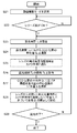
図16は、本実施の形態のデジタルカメラ1における、ぶれ補正処理における、周辺光量補正処理を示すフローチャート(CCDシフト処理の場合)である。実線枠内の処理は、カメラコントローラ140の処理を表す。破線枠内の処理は、レンズコントローラ240の処理を表す。動画撮影モードが選択されると、フレームレートを設定するなどの動画撮影処理の待機状態になる(ステップS21)。ステップS22で、レリーズ釦がONされたと判定された場合に、次の処理に進み、動画撮影処理が開始される。レリーズ釦が押されない状態では、ステップS22の処理を繰り返し、動画撮影処理の待機状態を繰り返す。動画撮影処理が開始されると、露光期間Tkを設定する(ステップS23)。例えば、フレームレートを30[fps]、かつ露光期間を1/30[秒]と設定する場合には、Tk=1/30[秒]に設定される。この設定条件をもとにして、CCD110への露光が開始される。露光期間Tkにおけるぶれ補正動作中のCCD110の位置を検知して、その平均値Qkを演算する(ステップS24)。周辺光量補正を行うために、CCD110上の像高に対応した周辺光量比に関する情報を、レンズコントローラ240からカメラコントローラ140に通知する(ステップS25)。設計中心では、周辺光量比は、CCD110上の中心から同心円状に徐々に低下する数値、となるのが一般的である。この通知された周辺光量比の逆数が周辺光量補正ゲインとなる。この周辺光量補正ゲインは、CCD110面上の水平および垂直座標毎に数値が定義されたテーブルとなる。カメラコントローラ140では露光期間Tkの画像Dkを取得して(ステップS26)、先に演算したCCD110の位置の平均値Qkに基づいて、周辺光量補正ゲインのテーブル中心位置のシフト量Ikを演算する(ステップS27)。カメラコントローラ140では、レンズコントローラ240から通知された周辺光量特性を用いて、演算した周辺光量補正ゲインのテーブルと、ぶれ補正動作に伴って移動したCCD110のシフト量Ikとに基づいて、画像Dkを補正して記録する(ステップS28)。レリーズ釦がOFFされるなどして、露光を終了させるかどうかを判定する(ステップS29)。露光を終了させなければステップS23の処理に戻り、次のフレームの動画撮影における露光が継続される。一方、ステップS29の処理において、レリーズ釦がOFFされ露光を終了させた場合には、動画撮影を終了させる。ここでも、露光された画像は露光期間Tkの間で平均化されることに着目して、周辺光量補正ゲインも同じく、露光期間Tkの間で検知した手ぶれ角度または手ぶれ補正角度を平均化することがポイントである。すなわち、検知した手ぶれ角度または手ぶれ補正角度の情報に含まれる、低周波成分を抽出することになる。平均化を行う前の手ぶれ角度は、一般に0Hzより大きく30Hz以下の周波数成分を含む。検知した手ぶれ角度を平均化することによって、0Hzより大きく15Hz以下の周波数成分(ぶれの低周波成分)を抽出し、この成分を用いて、周辺光量補正ゲインが求められる。
FIG. 16 is a flowchart (in the case of the CCD shift process) showing the peripheral illumination correction process in the blur correction process in the
以上で説明したように、本実施の形態における撮像装置においては、露光期間に撮像される画像に対して、正確な周辺光量補正を行うことができる。したがって、周辺光量比が狙い通りの特性をもった画像を提供することができる。さらに、動画撮影時においては、個々の露光期間毎に正確な周辺光量補正を行うことができる。したがって、各フレーム間においても周辺光量補正後の周辺光量比の誤差が小さい。このため、参考例における問題であった、動画像の周辺がちらつきとなって現れることはなく、画像の品位を向上させることができる。 As described above, in the image pickup apparatus according to the present embodiment, accurate peripheral illumination correction can be performed on the image captured during the exposure period. Therefore, it is possible to provide an image having a characteristic that the peripheral illumination ratio is as intended. Further, when shooting a moving image, accurate peripheral illumination correction can be performed for each individual exposure period. Therefore, the error of the peripheral illumination ratio after the peripheral illumination correction is small even between the frames. Therefore, the periphery of the moving image does not appear as flicker, which is a problem in the reference example, and the quality of the image can be improved.
2−5.周辺光量特性の補正原理の説明(本実施の形態:CCDシフトの例2)
本実施の形態における手ぶれ補正動作中の周辺光量特性の補正方法において、フレーム周期に比べて露光期間Tkが短い場合について、図17A、図17B、図17Cを用いて説明する。ここでは、フレーム周期1/30[秒](すなわちフレームレート30[fps])、露光期間1/60[秒]とした例で説明する。
2-5. Description of the Correction Principle of Peripheral Illumination Characteristics (Implementation: Example 2 of CCD Shift)
In the method of correcting the peripheral illumination characteristic during the camera shake correction operation in the present embodiment, the case where the exposure period Tk is shorter than the frame period will be described with reference to FIGS. 17A, 17B, and 17C. Here, an example will be described in which the frame period is 1/30 [seconds] (that is, the frame rate is 30 [fps]) and the exposure period is 1/60 [seconds].
図17Aは、実施の形態2のぶれ補正処理における、フレーム番号k毎に更新される周辺光量補正前の周辺光量比の時間的変化を表す波形図である。横軸はフレーム番号k(ただし、k=0,1,2,3・・・)を示し、縦軸は周辺光量比を示す。フレーム番号kは、例えば1/30[秒]毎にインクリメントされるものとする。図17Aの破線で示すグラフは、手ぶれ補正動作中における周辺光量補正前の周辺光量比のリアルタイムの推移を表す。図17Aの実線で示す階段状のグラフは、手ぶれ補正動作中における、露光期間Tkの間で平均化された、周辺光量補正前の周辺光量比の推移を表す。図14Aでは露光期間Tkとフレーム周期は等しいものとして説明した。しかし、図17Aでは、フレーム周期(ここでは1/30[秒])に比べて露光期間Tk(ここでは1/60[秒])が短いという点が、図14Aと異なる。なお、図17Aにおける周辺光量比は、CCD110上の像高1.0に対応する周辺光量比を表している。
FIG. 17A is a waveform diagram showing a temporal change in the peripheral illumination ratio before the peripheral illumination correction, which is updated every frame number k in the blur correction processing of the second embodiment. The horizontal axis indicates the frame number k (however, k = 0, 1, 2, 3 ...), And the vertical axis indicates the peripheral illumination ratio. It is assumed that the frame number k is incremented every 1/30 [second], for example. The graph shown by the broken line in FIG. 17A shows the real-time transition of the peripheral illumination ratio before the peripheral illumination correction during the camera shake correction operation. The stepped graph shown by the solid line in FIG. 17A shows the transition of the peripheral illumination ratio before the peripheral illumination correction, which is averaged during the exposure period Tk during the camera shake correction operation. In FIG. 14A, the exposure period Tk and the frame period are assumed to be equal. However, FIG. 17A differs from FIG. 14A in that the exposure period Tk (here, 1/60 [seconds]) is shorter than the frame period (here, 1/30 [seconds]). The peripheral illumination ratio in FIG. 17A represents the peripheral illumination ratio corresponding to the image height of 1.0 on the
図17Bは、実施の形態2のぶれ補正処理における、フレーム番号k毎に更新される周辺光量補正ゲインの時間的変化を表す波形図である。横軸はフレーム番号k(ただし、k=0,1,2,3・・・)を示し、縦軸は周辺光量補正ゲインを示す。図17Bの破線で示すグラフは、手ぶれ補正動作中における、周辺光量補正ゲインのリアルタイムの推移を表す。図17Bの実線で示す階段状のグラフは、手ぶれ補正動作中において、露光期間Tk内に検知した手ぶれ角度または手ぶれ補正角度の平均値を用いて求めた、周辺光量補正ゲインの推移を表す。図14Bでは、露光期間Tkとフレーム周期は等しいものとして説明した。しかし、図17Bでは、フレーム周期(ここでは1/30[秒])に比べて、露光期間Tk(ここでは1/60[秒])が短いという点が、図14Bと異なる。ここでも、露光された画像は露光期間Tkの間で平均化されることに着目して、周辺光量補正ゲインも同じく、露光期間Tkの間で検知した手ぶれ角度または手ぶれ補正角度を平均化することが、ポイントである。すなわち、検知した手ぶれ角度または手ぶれ補正角度の情報に含まれる低周波成分を抽出することになる。平均化を行う前の手ぶれ角度は、一般に0Hzより大きく30Hz以下の周波数成分を含む。検知した手ぶれ角度を平均化することによって、0Hzより大きく15Hz以下の周波数成分(ぶれの低周波成分)を抽出し、この成分を用いて、周辺光量補正ゲインが求められる。 FIG. 17B is a waveform diagram showing a temporal change in the peripheral illumination correction gain updated for each frame number k in the blur correction process of the second embodiment. The horizontal axis indicates the frame number k (however, k = 0, 1, 2, 3 ...), And the vertical axis indicates the peripheral illumination correction gain. The graph shown by the broken line in FIG. 17B shows the real-time transition of the peripheral illumination correction gain during the image stabilization operation. The stepped graph shown by the solid line in FIG. 17B shows the transition of the peripheral illumination correction gain obtained by using the average value of the camera shake angle or the camera shake correction angle detected within the exposure period Tk during the camera shake correction operation. In FIG. 14B, the exposure period Tk and the frame period are assumed to be equal. However, FIG. 17B differs from FIG. 14B in that the exposure period Tk (here, 1/60 [seconds]) is shorter than the frame period (here, 1/30 [seconds]). Again, paying attention to the fact that the exposed image is averaged during the exposure period Tk, the peripheral illumination correction gain is also averaged from the camera shake angle or the camera shake correction angle detected during the exposure period Tk. But the point is. That is, the low frequency component included in the detected camera shake angle or camera shake correction angle information is extracted. The camera shake angle before averaging generally includes frequency components greater than 0 Hz and less than 30 Hz. By averaging the detected camera shake angles, a frequency component (low frequency component of blur) larger than 0 Hz and 15 Hz or less is extracted, and the peripheral illumination correction gain is obtained using this component.
図17Bにおける周辺光量補正ゲインは、CCD110上の像高1.0に対応する周辺光量補正ゲインを表している。図17Bの破線で示すリアルタイムの周辺光量補正ゲインは、もとの周辺光量比を1.0にするために必要な補正ゲインを表している。
The peripheral illumination correction gain in FIG. 17B represents the peripheral illumination correction gain corresponding to the image height 1.0 on the
図17Cは、実施の形態2のぶれ補正処理における、フレーム番号k毎に更新される周辺光量補正後の周辺光量比の時間的変化を表す波形図である。横軸はフレーム番号k(ただし、k=0,1,2,3・・・)を示し、縦軸は周辺光量補正後の周辺光量比を示す。図17Cの実線で示すグラフは、手ぶれ補正動作中における、露光期間Tk内に検知した、手ぶれ角度または手ぶれ補正角度の平均値を用いて求めた、周辺光量補正ゲインの推移を表す。図14Cでは、露光期間Tkとフレーム周期は等しいものとして説明した。しかし、図17Cでは、フレーム周期(ここでは1/30[秒])に比べて露光期間Tk(ここでは1/60[秒])が短いという点が、図14Cと異なる。なお、図17Cにおける周辺光量補正後の周辺光量比は、CCD110上の像高1.0に対応する周辺光量比を表している。本実施の形態においては、検知した手ぶれ角度または手ぶれ補正角度について、露光期間内で平均した値を用いて、周辺光量補正ゲインを求めることによって、周辺光量補正を行うようにしているため、周辺光量比の本来の狙い(周辺光量比=1.0)通りの特性になっている。
FIG. 17C is a waveform diagram showing a temporal change in the peripheral illumination ratio after the peripheral illumination correction, which is updated every frame number k in the blur correction processing of the second embodiment. The horizontal axis shows the frame number k (however, k = 0, 1, 2, 3 ...), And the vertical axis shows the peripheral illumination ratio after the peripheral illumination correction. The graph shown by the solid line in FIG. 17C shows the transition of the peripheral illumination correction gain obtained by using the average value of the camera shake angle or the camera shake correction angle detected within the exposure period Tk during the camera shake correction operation. In FIG. 14C, the exposure period Tk and the frame period have been described as being equal. However, FIG. 17C differs from FIG. 14C in that the exposure period Tk (here, 1/60 [seconds]) is shorter than the frame period (here, 1/30 [seconds]). The peripheral illumination ratio after the peripheral illumination correction in FIG. 17C represents the peripheral illumination ratio corresponding to the image height 1.0 on the
この結果から、本実施の形態においては、周辺光量補正後の周辺光量比が、本来の狙い(周辺光量比=1.0)通りの特性を得られることがわかる。図17Cに示すように、像高1.0での周辺光量補正後の、周辺光量比の時間的な変化に着目すると、フレーム番号k(ただし、k=0,1,2,3・・・)毎に、周辺光量補正後の周辺光量比の時間的な変化もないことがわかる。 From this result, it can be seen that in the present embodiment, the peripheral illumination ratio after the peripheral illumination correction can be obtained as the original target (peripheral illumination ratio = 1.0). As shown in FIG. 17C, focusing on the temporal change of the peripheral illumination ratio after the peripheral illumination correction at the image height of 1.0, the frame number k (however, k = 0, 1, 2, 3 ... ), It can be seen that there is no temporal change in the peripheral illumination ratio after the peripheral illumination correction.
したがって、本実施の形態における撮像装置においては、露光期間に撮像される画像に対して、正確な周辺光量補正を行うことができる。したがって、周辺光量比が、狙い通りの特性をもった画像を提供することができる。さらに、動画撮影時においては、個々の露光期間毎に正確な周辺光量補正を行うことができる。したがって、各フレーム間においても周辺光量補正後の周辺光量比の誤差が小さい。このため、参考例における問題であった動画像の周辺がちらつきとなって現れることはなく、画像の品位を向上させることができる。 Therefore, in the image pickup apparatus of the present embodiment, accurate peripheral illumination correction can be performed on the image captured during the exposure period. Therefore, it is possible to provide an image having a characteristic with a peripheral illumination ratio as intended. Further, when shooting a moving image, accurate peripheral illumination correction can be performed for each individual exposure period. Therefore, the error of the peripheral illumination ratio after the peripheral illumination correction is small even between the frames. Therefore, the periphery of the moving image, which is a problem in the reference example, does not appear as flicker, and the quality of the image can be improved.
2−6.周辺光量特性の補正の動作フローの説明(本実施の形態:OISレンズシフトの例)
図面を用いて、本実施の形態のデジタルカメラ1における、OISレンズシフトによるぶれ補正動作中の、周辺光量補正の動作フローを説明する。デジタルカメラは一般的に、静止画を撮影する機能に加えて、動画を撮影する機能を備えている。ここでは、本実施の形態の特長である、動画撮影時における、ぶれ補正動作中の周辺光量補正の、動作フローを説明する。なお、デジタルカメラにおいて、動画撮影を開始する方法には、種々の方法が採用されているが、本実施の形態においては、レリーズ釦を押す(ONする)ことで、動画撮影が開始されるものとする。また、静止画撮影モードと動画撮影モードとを、モードダイヤル(図示せず)又はメニュー(図示せず)などを操作することによって、切り換えることができる。
2-6. Description of operation flow for correction of peripheral illumination characteristics (this embodiment: example of OIS lens shift)
The operation flow of the peripheral illumination correction during the blur correction operation by the OIS lens shift in the
図18は、実施の形態2のデジタルカメラ1のぶれ補正処理における、OISレンズシフトによる周辺光量補正処理を示すフローチャートである。実線枠内の処理は、カメラコントローラ140の処理を表す。破線枠内の処理は、レンズコントローラ240の処理を表す。動画撮影モードが選択されると、フレームレートを設定するなどの動画撮影処理の待機状態になる(ステップS31)。ステップS32で、レリーズ釦がONされたと判定された場合に、次の処理に進み、動画撮影処理が開始される。レリーズ釦が押されない状態では、ステップS32の処理を繰り返し、動画撮影処理の待機状態を繰り返す。動画撮影処理が開始されると、露光期間Tkを設定する(ステップS33)。例えば、フレームレートを30[fps]、かつ露光期間を1/30[秒]と設定する場合には、Tk=1/30[秒]に設定される。この設定条件をもとにして、CCD110への露光が開始される。露光期間Tkにおけるぶれ補正動作中のOISレンズ220の位置を検知して、その平均値Pkを演算する(ステップS34)。OISレンズ220の位置の平均値Pkと周辺光量補正を行うために、CCD110上の像高に対応した周辺光量比に関する情報を、レンズコントローラ240からカメラコントローラ140に通知する(ステップS35)。設計中心では、周辺光量比は、CCD110上の中心から、同心円状に徐々に低下する数値となるのが一般的である。この通知された周辺光量比の逆数が周辺光量補正ゲインとなる。この周辺光量補正ゲインは、CCD110面上の水平および垂直座標毎に、数値が定義されたテーブルとなる。カメラコントローラ140では、露光期間Tkの画像Dkを取得して(ステップS36)、先に通知されたOISレンズ220の位置の平均値Pkに基づいて、周辺光量補正ゲインのテーブル中心位置のシフト量Hkを演算する(ステップS37)。カメラコントローラ140では、レンズコントローラ240から通知された周辺光量特性を用いて演算した周辺光量補正ゲインのテーブルと、ぶれ補正動作に伴って移動したOISレンズ220のシフト量Hkとに基づいて画像Dkを補正して記録する(ステップS38)。ステップS39の処理において、レリーズ釦がOFFされるなどして露光を終了させるかどうかを判定する。露光を終了させなければステップS33の処理に戻り、次のフレームの動画撮影における露光が継続される。一方、ステップS39の処理において、レリーズ釦がOFFされ、露光を終了させた場合には、動画撮影を終了させる。ここでも、露光された画像は露光期間Tkの間で平均化されることに着目して、周辺光量補正ゲインも同じく、露光期間Tkの間で検知した手ぶれ角度または手ぶれ補正角度を平均化することがポイントである。すなわち、検知した手ぶれ角度または手ぶれ補正角度の情報に含まれる、低周波成分を抽出することになる。平均化を行う前の手ぶれ角度は、一般に0Hzより大きく30Hz以下の周波数成分を含む。検知した手ぶれ角度を平均化することによって、0Hzより大きく15Hz以下の周波数成分(ぶれの低周波成分)を抽出し、この成分を用いて、周辺光量補正ゲインが求められる。
FIG. 18 is a flowchart showing a peripheral illumination correction process by OIS lens shift in the image stabilization process of the
ここでは、レンズコントローラ240からカメラコントローラ140に、OISレンズ220の位置の平均値Pkを通知する例を示した。しかし、OISレンズ220の位置の情報については、カメラコントローラ140において、平均値Pkを算出するようにしてもよい。また、平均値Pkについては、OISレンズ220の位置に限定される訳ではなく、OISレンズ220の制御に用いるぶれ検知情報、あるいはそれに基づく情報であってもよい。
Here, an example is shown in which the
以上で説明したように、本実施の形態における撮像装置においては、露光期間に撮像される画像に対して、正確な周辺光量補正を行うことができる。したがって、周辺光量比が狙い通りの特性をもった画像を提供することができる。さらに、動画撮影時においては、個々の露光期間毎に正確な周辺光量補正を行うことができる。したがって、各フレーム間においても、周辺光量補正後の周辺光量比の誤差が小さい。このため、参考例における問題であった、動画像の周辺がちらつきとなって現れることはなく、画像の品位を向上させることができる。 As described above, in the image pickup apparatus according to the present embodiment, accurate peripheral illumination correction can be performed on the image captured during the exposure period. Therefore, it is possible to provide an image having a characteristic that the peripheral illumination ratio is as intended. Further, when shooting a moving image, accurate peripheral illumination correction can be performed for each individual exposure period. Therefore, even between the frames, the error of the peripheral illumination ratio after the peripheral illumination correction is small. Therefore, the periphery of the moving image does not appear as flicker, which is a problem in the reference example, and the quality of the image can be improved.
なお、本実施の形態においては、CCDシフトの例と、OISレンズシフトの例を個別に説明した。実施の形態1において説明したCCDシフトとOISレンズシフトを同時に動作させた状態においても、実施の形態2において説明した周辺光量補正についてCCDシフトの例とOISレンズシフトの例とを組み合わせることによっても、露光期間に撮像される画像に対して正確な周辺光量補正を行うことができる。また、動画撮影時においては、実施の形態1において説明したCCDシフトとOISレンズシフトを同時に動作させた状態においても、実施の形態2において説明した周辺光量補正についてCCDシフトの例とOISレンズシフトの例とを組み合わせることによっても、個々の露光期間毎に正確な周辺光量補正を行うことができる。 In the present embodiment, an example of the CCD shift and an example of the OIS lens shift have been described separately. Even in the state where the CCD shift and the OIS lens shift described in the first embodiment are operated at the same time, the peripheral illumination correction described in the second embodiment can be performed by combining the example of the CCD shift and the example of the OIS lens shift. Accurate peripheral illumination correction can be performed on the image captured during the exposure period. Further, at the time of moving image shooting, even when the CCD shift and the OIS lens shift described in the first embodiment are operated at the same time, the example of the CCD shift and the OIS lens shift regarding the peripheral illumination correction described in the second embodiment are performed. By combining the examples, it is possible to perform accurate peripheral illumination correction for each individual exposure period.
したがって、本実施の形態においては、CCDシフトとOISレンズシフトを同時に動作させた状態においても、周辺光量比が狙い通りの特性をもった画像を提供することができる。さらに、動画撮影時においても、参考例における問題であった、動画像の周辺がちらつきとなって現れることはなく、画像の品位を向上させることができる。 Therefore, in the present embodiment, it is possible to provide an image having a characteristic that the peripheral illumination ratio is as intended even when the CCD shift and the OIS lens shift are operated at the same time. Further, even when shooting a moving image, the periphery of the moving image does not appear as flicker, which is a problem in the reference example, and the quality of the image can be improved.
3.まとめ
以上で説明したように、本実施の形態におけるデジタルカメラ1は、補正用レンズまたは撮像素子をシフトすることによって、撮影中のぶれの影響を低減する撮像装置において、撮像素子に投影される光量が撮像素子の周辺で低下することによる撮影画像の品位低下を防ぎ、良好な撮影画像を提供することができる。特に、本実施の形態におけるデジタルカメラ1は、撮像素子に投影される光量が撮像素子の周辺で低下することによる撮影画像の品位低下について、動画撮影時における撮影画像の品位低下も防ぐことができ、良好な動画撮影画像を提供することも可能である。
3. 3. Summary As described above, in the
本実施の形態においては、周辺光量補正ゲインを求めるために、検知された手ぶれ角度または手ぶれ補正角度の情報を平均化する例を示した。しかし、これに限らず、周辺光量補正ゲインを平均化するなどして、結果として周辺光量補正に係わる信号のいずれかで平均化すればよい。また、平均化という処理に限定されることなく、周辺光量補正に係わる信号を平滑化すればよい。 In the present embodiment, an example of averaging the detected camera shake angle or camera shake correction angle information in order to obtain the peripheral illumination correction gain is shown. However, the present invention is not limited to this, and the peripheral illumination correction gain may be averaged, and as a result, it may be averaged by any of the signals related to the peripheral illumination correction. Further, the signal related to the peripheral illumination correction may be smoothed without being limited to the process of averaging.
また、本実施の形態のデジタルカメラ1に相当する撮像装置において、周辺光量補正部は、CCD110に相当する撮像素子上の像高に応じた複数の補正データを持ってもよい。
Further, in the image pickup apparatus corresponding to the
(実施の形態3)
図19Aは、実施の形態3のぶれ補正処理における、6フレームの露光期間毎に更新される周辺光量補正前の周辺光量比の時間的変化を表す波形図である。横軸はフレーム番号k(ただし、k=0,1,2,3・・・)を示し、縦軸は周辺光量比を示す。フレーム番号kは例えば1/30[秒]毎にインクリメントされるものとする。図19Aの破線で示すグラフは、手ぶれ補正動作中における、周辺光量補正前の周辺光量比のリアルタイムの推移を表し、実線で示す階段状のグラフは、手ぶれ補正動作中における、6フレームの露光期間の間で平均化された、周辺光量補正前の周辺光量比の推移を表す。なお、図19Aにおける周辺光量比は、CCD110上の像高1.0に対応する周辺光量比を表している。
(Embodiment 3)
FIG. 19A is a waveform diagram showing a temporal change in the peripheral illumination ratio before the peripheral illumination correction, which is updated every 6 frames of the exposure period in the blur correction processing of the third embodiment. The horizontal axis indicates the frame number k (however, k = 0, 1, 2, 3 ...), And the vertical axis indicates the peripheral illumination ratio. It is assumed that the frame number k is incremented every 1/30 [second], for example. The graph shown by the broken line in FIG. 19A shows the real-time transition of the peripheral illumination ratio before the peripheral illumination correction operation during the image stabilization operation, and the stepped graph shown by the solid line shows the exposure period of 6 frames during the image stabilization operation. It shows the transition of the peripheral illumination ratio before the peripheral illumination correction, which is averaged between the two. The peripheral illumination ratio in FIG. 19A represents the peripheral illumination ratio corresponding to the image height of 1.0 on the
図19Bは、実施の形態3のぶれ補正処理における、6フレームの露光期間毎に更新される周辺光量補正ゲインの時間的変化を表す波形図である。横軸はフレーム番号k(ただし、k=0,1,2,3・・・)を示し、縦軸は周辺光量補正ゲインを示す。図19Bの破線で示すグラフは、手ぶれ補正動作中における、周辺光量補正ゲインのリアルタイムの推移を表す。また、実線で示す階段状のグラフは、手ぶれ補正動作中において、6フレームの露光期間内に検知した、手ぶれ角度または手ぶれ補正角度の平均値を用いて求めた、周辺光量補正ゲインの推移を表す。ここで、露光された画像は6フレームの露光期間で平均化されることに着目して、周辺光量補正ゲインも同じく、6フレームの露光期間で検知した、手ぶれ角度または手ぶれ補正角度を平均化する、ことがポイントである。すなわち、検知した手ぶれ角度または手ぶれ補正角度の情報に含まれる低周波成分を抽出することになる。平均化を行う前の手ぶれ角度は、この場合、5Hzの周波数成分を含む。検知した手ぶれ角度を平均化することによって、5Hzの周波数成分(ぶれの低周波成分)を抽出し、この成分を用いて、周辺光量補正ゲインが求められる。 FIG. 19B is a waveform diagram showing a temporal change in the peripheral illumination correction gain updated every 6 frames of the exposure period in the blur correction process of the third embodiment. The horizontal axis indicates the frame number k (however, k = 0, 1, 2, 3 ...), And the vertical axis indicates the peripheral illumination correction gain. The graph shown by the broken line in FIG. 19B shows the real-time transition of the peripheral illumination correction gain during the image stabilization operation. In addition, the stepped graph shown by the solid line shows the transition of the peripheral illumination correction gain obtained by using the average value of the camera shake angle or the camera shake correction angle detected within the exposure period of 6 frames during the camera shake correction operation. .. Here, paying attention to the fact that the exposed image is averaged in the exposure period of 6 frames, the peripheral illumination correction gain also averages the camera shake angle or the camera shake correction angle detected in the exposure period of 6 frames. , Is the point. That is, the low frequency component included in the detected camera shake angle or camera shake correction angle information is extracted. The camera shake angle before averaging in this case includes a frequency component of 5 Hz. By averaging the detected camera shake angles, a frequency component of 5 Hz (low frequency component of blur) is extracted, and the peripheral light amount correction gain is obtained using this component.
なお、図19Bにおける周辺光量補正ゲインは、CCD110上の像高1.0に対応する周辺光量補正ゲインを表している。また、図19Bの破線で示すリアルタイムの周辺光量補正ゲインは、もとの周辺光量比を1.0にするために必要な補正ゲインを表している。
The peripheral illumination correction gain in FIG. 19B represents the peripheral illumination correction gain corresponding to the image height 1.0 on the
以上のように、本実施の形態によれば、複数の露光期間Tkにまたがる平均処理を実施してもよい。 As described above, according to the present embodiment, the averaging process over a plurality of exposure periods Tk may be performed.
(他の実施の形態)
上記実施の形態の思想は、以上で説明された実施の形態に限定されない。種々の実施の形態が考えられてもよい。以下、上記実施の形態の思想を適用できる他の実施の形態について説明する。
(Other embodiments)
The idea of the above-described embodiment is not limited to the embodiment described above. Various embodiments may be considered. Hereinafter, other embodiments to which the idea of the above embodiment can be applied will be described.
実施の形態1乃至3において、交換レンズとカメラ本体とを用いた例で説明したが、レンズ一体型のカメラであってもよい。 In the first to third embodiments, the example in which the interchangeable lens and the camera body are used has been described, but the camera may be a lens-integrated camera.
以上、本開示における技術の例示として、実施の形態を説明した。そのために、詳細な説明および添付の図面を開示した。よって、詳細な説明および添付の図面に記載された構成要素の中には、課題解決のために必須でない構成要素が含まれることがある。したがって、それらの必須でない構成要素が、詳細な説明および添付の図面に記載されているからといって、それらの必須でない構成要素が必須であると直ちに認定されるべきではない。 As an example of the technique in the present disclosure, embodiments have been described. To that end, detailed description and accompanying drawings have been disclosed. Therefore, some of the components described in the detailed description and the attached drawings may include components that are not essential for solving the problem. Therefore, just because those non-essential components are described in the detailed description and accompanying drawings should not be immediately determined to be essential.
上記実施の形態は、本開示における技術を例示するためのものである。よって、上記実施の形態は、特許請求の範囲またはその均等の範囲において、種々の変更、置換、付加および/または省略等が行なわれてもよい。 The above embodiments are for exemplifying the techniques in the present disclosure. Therefore, in the above-described embodiment, various changes, substitutions, additions and / or omissions may be made within the scope of claims or the equivalent thereof.
本開示の思想は、手ぶれ補正機能を備えた電子装置(デジタルカメラまたはカムコーダ等の撮像装置、携帯電話、スマートフォン等)に適用することができる。 The idea of the present disclosure can be applied to an electronic device having a camera shake correction function (an imaging device such as a digital camera or a camcorder, a mobile phone, a smartphone, etc.).
1 デジタルカメラ
100 カメラ本体
110 CCD
111 ADコンバータ
112 タイミング発生器
120 液晶モニタ
130 レリーズ釦
140 カメラコントローラ
141 DRAM
150 ボディマウント
160 電源
170 カードスロット
171 メモリカード
181 CCD駆動部
182 位置センサ
183 BIS処理部
184 ジャイロセンサ
200 交換レンズ
210 ズームレンズ
211 ズームレンズ駆動部
220 OISレンズ
221 OIS駆動部
222 位置センサ
223 OIS処理部
224 ジャイロセンサ
230 フォーカスレンズ
233 フォーカスレンズ駆動部
240 レンズコントローラ
241 DRAM
242 フラッシュメモリ
250 レンズマウント
305 ADC/LPF
306 HPF
307 位相補償部
308 積分器
309 LPF
310 加算器
311 PID制御部
405 ADC/LPF
406 HPF
407 位相補償部
408 積分器
410 PID制御部
412 セレクタ
1
111
150
242
306 HPF
307
310
406 HPF
407
Claims (9)
前記光学系により形成された被写体像を撮像する撮像素子と、
前記撮像素子で撮像された画像の周辺光量を補正する周辺光量補正部と、
撮像装置のぶれを検出するぶれ検出部と、
前記ぶれ検出部の出力信号に基づいて、前記レンズまたは前記撮像素子の少なくとも一方を光軸に垂直な面で移動させて、前記ぶれを補正する駆動制御部と、を有し、
前記周辺光量補正部は、前記ぶれの所定の周波成分を抽出して、前記ぶれの前記所定の周波成分に応じて前記周辺光量の補正量を変化させ、前記レンズを光軸に垂直な面で移動させる場合と、前記撮像素子を光軸に垂直な面で移動させる場合とで、前記周辺光量の補正量を変える、
撮像装置。 An optical system that includes multiple lenses,
An image sensor that captures a subject image formed by the optical system,
Peripheral light amount correction unit that corrects the peripheral light amount of the image captured by the image sensor, and
A blur detection unit that detects blur in the image pickup device,
It has a drive control unit that corrects the blur by moving at least one of the lens or the image sensor on a plane perpendicular to the optical axis based on the output signal of the blur detection unit.
The peripheral illumination correction unit extracts a predetermined frequency component of the blur, changes the correction amount of the peripheral illumination amount according to the predetermined frequency component of the blur, and makes the lens a plane perpendicular to the optical axis. The amount of correction for the peripheral illumination is changed depending on whether the image sensor is moved by the above or on a plane perpendicular to the optical axis.
Imaging device.
前記光学系により形成された被写体像を撮像する撮像素子と、
前記撮像素子で撮像された画像の周辺光量を補正する周辺光量補正部と、
撮像装置のぶれを検出するぶれ検出部と、
前記ぶれ検出部の出力信号に基づいて、前記レンズまたは前記撮像素子の少なくとも一方を光軸に垂直な面で移動させて、前記ぶれを補正する駆動制御部と、を有し、
前記周辺光量補正部は、前記ぶれの所定の周波数成分を抽出して、前記ぶれの所定の周波数成分に応じて、前記撮像素子から出力された画像データを、像高及び補正ゲインに応じてゲインアップを行うことによって、前記周辺光量を補正し、前記レンズを光軸に垂直な面で移動させる場合と、前記撮像素子を光軸に垂直な面で移動させる場合とで、前記周辺光量の補正量を変える、
撮像装置。 An optical system that includes multiple lenses,
An image sensor that captures a subject image formed by the optical system,
Peripheral light amount correction unit that corrects the peripheral light amount of the image captured by the image sensor, and
A blur detection unit that detects blur in the image pickup device,
It has a drive control unit that corrects the blur by moving at least one of the lens or the image sensor on a plane perpendicular to the optical axis based on the output signal of the blur detection unit.
The peripheral illumination correction unit extracts a predetermined frequency component of the blur and gains image data output from the image sensor according to the predetermined frequency component of the blur according to the image height and the correction gain. The peripheral illumination is corrected by raising the image, and the peripheral illumination is corrected depending on whether the lens is moved on a plane perpendicular to the optical axis or the image sensor is moved on a plane perpendicular to the optical axis. Change the amount,
Imaging device.
前記光学系により形成された被写体像を撮像する撮像素子と、An image sensor that captures a subject image formed by the optical system,
前記撮像素子で撮像された画像の周辺光量を補正する周辺光量補正部と、Peripheral light amount correction unit that corrects the peripheral light amount of the image captured by the image sensor, and
撮像装置のぶれを検出するぶれ検出部と、A blur detection unit that detects blur in the image pickup device,
前記ぶれ検出部の出力信号に基づいて、前記レンズまたは前記撮像素子の少なくとも一方を光軸に垂直な面で移動させて、前記ぶれを補正する駆動制御部と、を有し、It has a drive control unit that corrects the blur by moving at least one of the lens or the image sensor on a plane perpendicular to the optical axis based on the output signal of the blur detection unit.
前記周辺光量補正部は、複数のフレームにまたがる期間の前記ぶれから所定の周波成分を抽出して、前記所定の周波成分に応じて前記周辺光量の補正量を変化させる、The peripheral illumination correction unit extracts a predetermined frequency component from the blurring during a period spanning a plurality of frames, and changes the correction amount of the peripheral illumination amount according to the predetermined frequency component.
撮像装置。Imaging device.
前記周辺光量補正部は、前記レンズを光軸に垂直な面で移動させることによる前記周辺光量の補正量と、前記撮像素子を光軸に垂直な面で移動させることによる前記周辺光量の補正量と、を変える、The peripheral illumination correction unit corrects the peripheral illumination by moving the lens on a plane perpendicular to the optical axis and the peripheral illumination correction by moving the image sensor on a plane perpendicular to the optical axis. And change
請求項1から3のいずれかに記載の撮像装置。The imaging device according to any one of claims 1 to 3.
請求項1から4のいずれかに記載の撮像装置。 The peripheral illumination correction unit extracts a predetermined frequency component of the blur from the output signal of the blur detection unit, and changes the correction amount of the peripheral light amount according to the predetermined frequency component of the blur. 4. The imaging device according to any one of 4.
請求項1から5のいずれかに記載の撮像装置。 The peripheral illumination correction unit extracts a predetermined frequency component of the blur from the blur detection unit, and changes the correction amount of the peripheral light amount according to the predetermined frequency component of the blur according to claims 1 to 5 . The imaging apparatus according to any one.
請求項1から6のいずれかに記載の撮像装置。 The imaging device according to any one of claims 1 to 6 , wherein the peripheral illumination correction unit has a plurality of correction data according to the image height on the image sensor.
前記撮像素子と前記周辺光量補正部とを含むカメラ本体と、を有し、
前記交換レンズと前記カメラ本体とは着脱可能である
請求項1から7のいずれか1項に記載の撮像装置。 An interchangeable lens including the optical system and
It has a camera body including the image pickup element and the peripheral illumination correction unit.
The imaging device according to any one of claims 1 to 7 , wherein the interchangeable lens and the camera body are detachable.
請求項8に記載の撮像装置。
The optical system includes a correction lens for correcting the blur.
The imaging device according to claim 8.
Priority Applications (1)
| Application Number | Priority Date | Filing Date | Title |
|---|---|---|---|
| US15/443,492 US10171739B2 (en) | 2016-03-02 | 2017-02-27 | Image pickup device |
Applications Claiming Priority (2)
| Application Number | Priority Date | Filing Date | Title |
|---|---|---|---|
| JP2016039679 | 2016-03-02 | ||
| JP2016039679 | 2016-03-02 |
Publications (3)
| Publication Number | Publication Date |
|---|---|
| JP2017161891A JP2017161891A (en) | 2017-09-14 |
| JP2017161891A5 JP2017161891A5 (en) | 2019-10-31 |
| JP6917536B2 true JP6917536B2 (en) | 2021-08-11 |
Family
ID=59854026
Family Applications (1)
| Application Number | Title | Priority Date | Filing Date |
|---|---|---|---|
| JP2016254947A Active JP6917536B2 (en) | 2016-03-02 | 2016-12-28 | Imaging device |
Country Status (1)
| Country | Link |
|---|---|
| JP (1) | JP6917536B2 (en) |
Families Citing this family (3)
| Publication number | Priority date | Publication date | Assignee | Title |
|---|---|---|---|---|
| JP7236268B2 (en) * | 2018-01-15 | 2023-03-09 | キヤノン株式会社 | Image blur correction device, interchangeable lens, camera body, image blur correction method, and program |
| JP7080118B2 (en) * | 2018-07-09 | 2022-06-03 | キヤノン株式会社 | Image pickup device and its control method, shooting lens, program, storage medium |
| WO2020044803A1 (en) | 2018-08-30 | 2020-03-05 | 富士フイルム株式会社 | Imaging device, imaging method, and program |
Family Cites Families (5)
| Publication number | Priority date | Publication date | Assignee | Title |
|---|---|---|---|---|
| JP2005189654A (en) * | 2003-12-26 | 2005-07-14 | Konica Minolta Photo Imaging Inc | Camera equipped with camera-shake correction mechanism |
| JP2005269130A (en) * | 2004-03-18 | 2005-09-29 | Konica Minolta Photo Imaging Inc | Image pickup apparatus having a camera shake correction function |
| KR101537949B1 (en) * | 2008-12-24 | 2015-07-20 | 삼성전자주식회사 | Photographing apparatus |
| JP6861355B2 (en) * | 2014-03-28 | 2021-04-21 | パナソニックIpマネジメント株式会社 | Imaging device |
| JP6500238B2 (en) * | 2015-03-06 | 2019-04-17 | パナソニックIpマネジメント株式会社 | Imaging device, imaging method and imaging program |
-
2016
- 2016-12-28 JP JP2016254947A patent/JP6917536B2/en active Active
Also Published As
| Publication number | Publication date |
|---|---|
| JP2017161891A (en) | 2017-09-14 |
Similar Documents
| Publication | Publication Date | Title |
|---|---|---|
| US10171739B2 (en) | Image pickup device | |
| US9602727B2 (en) | Imaging apparatus and imaging method | |
| JP6861355B2 (en) | Imaging device | |
| US9531938B2 (en) | Image-capturing apparatus | |
| US9832362B2 (en) | Image-capturing apparatus | |
| JP6685843B2 (en) | Imaging device | |
| US10038849B2 (en) | Imaging device with controlled timing of images to be synthesized based on shake residual | |
| JP6028928B2 (en) | Imaging apparatus and imaging method | |
| JP6500238B2 (en) | Imaging device, imaging method and imaging program | |
| CN103533230A (en) | Imaging apparatus, optical apparatus, imaging system, and control method | |
| JP2016090973A (en) | Imaging device | |
| JP2019128362A (en) | Imaging apparatus | |
| JP2017067954A (en) | Imaging apparatus, and image shake correction method of the same | |
| JP6932531B2 (en) | Image blur correction device, image pickup device, control method of image pickup device | |
| JP2019164338A (en) | Camera, lens device, control method, and computer program | |
| JP2018146663A (en) | Image tremor correction device, control method of the same, imaging device, and lens device | |
| US9507170B2 (en) | Optical apparatus, interchangeable lens, and method for correcting image blurring | |
| JP6529879B2 (en) | Image pickup apparatus and control method of image pickup apparatus | |
| JP6917536B2 (en) | Imaging device | |
| JP2012078495A (en) | Imaging device, shake correction device, and shake correction method | |
| JP2006220870A (en) | Imaging device | |
| JP7080118B2 (en) | Image pickup device and its control method, shooting lens, program, storage medium | |
| JP2017161891A5 (en) | ||
| US20220303465A1 (en) | Imaging apparatus | |
| JP7383413B2 (en) | Lens device, imaging device, imaging system, and control method |
Legal Events
| Date | Code | Title | Description |
|---|---|---|---|
| RD01 | Notification of change of attorney |
Free format text: JAPANESE INTERMEDIATE CODE: A7421 Effective date: 20190118 |
|
| A521 | Request for written amendment filed |
Free format text: JAPANESE INTERMEDIATE CODE: A523 Effective date: 20190917 |
|
| A621 | Written request for application examination |
Free format text: JAPANESE INTERMEDIATE CODE: A621 Effective date: 20190917 |
|
| A977 | Report on retrieval |
Free format text: JAPANESE INTERMEDIATE CODE: A971007 Effective date: 20200715 |
|
| A131 | Notification of reasons for refusal |
Free format text: JAPANESE INTERMEDIATE CODE: A131 Effective date: 20200825 |
|
| A601 | Written request for extension of time |
Free format text: JAPANESE INTERMEDIATE CODE: A601 Effective date: 20201026 |
|
| A521 | Request for written amendment filed |
Free format text: JAPANESE INTERMEDIATE CODE: A523 Effective date: 20201224 |
|
| TRDD | Decision of grant or rejection written | ||
| A01 | Written decision to grant a patent or to grant a registration (utility model) |
Free format text: JAPANESE INTERMEDIATE CODE: A01 Effective date: 20210601 |
|
| A61 | First payment of annual fees (during grant procedure) |
Free format text: JAPANESE INTERMEDIATE CODE: A61 Effective date: 20210614 |
|
| R151 | Written notification of patent or utility model registration |
Ref document number: 6917536 Country of ref document: JP Free format text: JAPANESE INTERMEDIATE CODE: R151 |