JP7210484B2 - Providing protection for information distributed in demodulation reference signals (DMRS) - Google Patents
Providing protection for information distributed in demodulation reference signals (DMRS) Download PDFInfo
- Publication number
- JP7210484B2 JP7210484B2 JP2019571654A JP2019571654A JP7210484B2 JP 7210484 B2 JP7210484 B2 JP 7210484B2 JP 2019571654 A JP2019571654 A JP 2019571654A JP 2019571654 A JP2019571654 A JP 2019571654A JP 7210484 B2 JP7210484 B2 JP 7210484B2
- Authority
- JP
- Japan
- Prior art keywords
- bits
- dmrs
- data
- crc
- reference signal
- Prior art date
- Legal status (The legal status is an assumption and is not a legal conclusion. Google has not performed a legal analysis and makes no representation as to the accuracy of the status listed.)
- Active
Links
Images


Classifications
-
- H—ELECTRICITY
- H04—ELECTRIC COMMUNICATION TECHNIQUE
- H04L—TRANSMISSION OF DIGITAL INFORMATION, e.g. TELEGRAPHIC COMMUNICATION
- H04L5/00—Arrangements affording multiple use of the transmission path
- H04L5/003—Arrangements for allocating sub-channels of the transmission path
- H04L5/0048—Allocation of pilot signals, i.e. of signals known to the receiver
- H04L5/0051—Allocation of pilot signals, i.e. of signals known to the receiver of dedicated pilots, i.e. pilots destined for a single user or terminal
-
- H—ELECTRICITY
- H03—ELECTRONIC CIRCUITRY
- H03M—CODING; DECODING; CODE CONVERSION IN GENERAL
- H03M13/00—Coding, decoding or code conversion, for error detection or error correction; Coding theory basic assumptions; Coding bounds; Error probability evaluation methods; Channel models; Simulation or testing of codes
- H03M13/03—Error detection or forward error correction by redundancy in data representation, i.e. code words containing more digits than the source words
- H03M13/05—Error detection or forward error correction by redundancy in data representation, i.e. code words containing more digits than the source words using block codes, i.e. a predetermined number of check bits joined to a predetermined number of information bits
- H03M13/09—Error detection only, e.g. using cyclic redundancy check [CRC] codes or single parity bit
-
- H—ELECTRICITY
- H04—ELECTRIC COMMUNICATION TECHNIQUE
- H04L—TRANSMISSION OF DIGITAL INFORMATION, e.g. TELEGRAPHIC COMMUNICATION
- H04L1/00—Arrangements for detecting or preventing errors in the information received
- H04L1/004—Arrangements for detecting or preventing errors in the information received by using forward error control
- H04L1/0056—Systems characterized by the type of code used
- H04L1/0061—Error detection codes
-
- H—ELECTRICITY
- H04—ELECTRIC COMMUNICATION TECHNIQUE
- H04W—WIRELESS COMMUNICATION NETWORKS
- H04W72/00—Local resource management
- H04W72/04—Wireless resource allocation
- H04W72/044—Wireless resource allocation based on the type of the allocated resource
- H04W72/0466—Wireless resource allocation based on the type of the allocated resource the resource being a scrambling code
-
- H—ELECTRICITY
- H04—ELECTRIC COMMUNICATION TECHNIQUE
- H04W—WIRELESS COMMUNICATION NETWORKS
- H04W72/00—Local resource management
- H04W72/20—Control channels or signalling for resource management
- H04W72/23—Control channels or signalling for resource management in the downlink direction of a wireless link, i.e. towards a terminal
Description
相互参照
本特許出願は、各々が本出願の譲受人に譲渡された、2018年5月16日に出願された「Providing Protection for Information Delivered in Demodulation Reference Signals (DMRS)」と題する、Lyらによる米国特許出願第15/981,442号、および2017年6月29日に出願された「Providing Protection for Information Delivered in DMRS」と題する、Lyらによる米国仮特許出願第62/527,011号の優先権を主張する。
CROSS-REFERENCE This patent application is filed May 16, 2018, entitled "Providing Protection for Information Delivered in Demodulation Reference Signals (DMRS)," by Ly et al. No. 15/981,442 and U.S. Provisional Patent Application No. 62/527,011 by Ly et al.
以下は、一般にワイヤレス通信に関し、より詳細には、復調基準信号(DMRS)において配信される情報のための保護の提供に関する。 The following relates generally to wireless communications, and more particularly to providing protection for information distributed in demodulation reference signals (DMRS).
ワイヤレス通信システムは、音声、ビデオ、パケットデータ、メッセージング、ブロードキャストなど、様々なタイプの通信コンテンツを提供するために広く展開されている。これらのシステムは、利用可能なシステムリソース(たとえば、時間、周波数、および電力)を共有することによって複数のユーザとの通信をサポートすることが可能であり得る。そのような多元接続システムの例には、符号分割多元接続(CDMA)システム、時分割多元接続(TDMA)システム、周波数分割多元接続(FDMA)システム、および直交周波数分割多元接続(OFDMA)システム、(たとえば、ロングタームエボリューション(LTE)システム、またはニューラジオ(NR)システム)がある。ワイヤレス多元接続通信システムは、場合によってはユーザ機器(UE)として知られることがある複数の通信デバイスのための通信を各々が同時にサポートする、いくつかの基地局またはアクセスネットワークノードを含み得る。 Wireless communication systems are widely deployed to provide various types of communication content such as voice, video, packet data, messaging, broadcast, and so on. These systems may be able to support communication with multiple users by sharing available system resources (eg, time, frequency, and power). Examples of such multiple-access systems include code division multiple access (CDMA) systems, time division multiple access (TDMA) systems, frequency division multiple access (FDMA) systems, and orthogonal frequency division multiple access (OFDMA) systems, ( For example, the Long Term Evolution (LTE) system, or the New Radio (NR) system). A wireless multiple-access communication system may include a number of base stations or access network nodes that each simultaneously support communication for multiple communication devices, sometimes known as user equipments (UEs).
いくつかのワイヤレス通信システムでは、基地局またはUEなどのデバイスは、シグナリング情報、チャネル推定情報、または両方のタイプの情報を含む、DMRSを送信し得る。ただし、DMRSによって搬送されるシグナリング情報は、受信デバイスにおける検出エラーを受けやすいことがある。受信デバイスが、DMRSにおける情報を不正確に検出する場合、受信デバイスは、処理レイテンシ(たとえば、システム捕捉レイテンシ、ハンドオーバレイテンシ、ハイブリッド自動再送要求(HARQ)再送信遅延など)を経験することがある。 In some wireless communication systems, a device such as a base station or UE may transmit DMRS containing signaling information, channel estimation information, or both types of information. However, the signaling information carried by DMRS can be subject to detection errors at receiving devices. If a receiving device incorrectly detects information in the DMRS, the receiving device may experience processing latency (eg, system acquisition latency, handover latency, hybrid automatic repeat request (HARQ) retransmission delay, etc.).
説明する技法は、DMRSにおいて配信される情報のための保護の提供をサポートする、改善された方法、システム、デバイス、または装置に関する。説明する技法は、DMRSに関連付けられた基準信号ビットのセットと、データ送信信号に関連付けられたデータビットのセットとを識別することを提供する。技法は、基準信号ビットとデータビットの両方の関数として、巡回冗長検査(CRC)ビットのセットを計算することを提供し得る。場合によっては、技法は、基準信号ビットに基づいて、スクランブリングコードを識別することと、スクランブリングコードに基づいて、データビットをスクランブルすることとを提供し得る。さらに説明する技法は、DMRS送信信号とデータ送信信号とを送信することを提供する。 The described techniques relate to improved methods, systems, devices, or apparatus that help provide protection for information distributed in DMRS. The described techniques provide for identifying a set of reference signal bits associated with DMRS and a set of data bits associated with data transmission signals. Techniques may provide for calculating a set of cyclic redundancy check (CRC) bits as a function of both reference signal bits and data bits. In some cases, techniques may provide identifying a scrambling code based on the reference signal bits and scrambling the data bits based on the scrambling code. Further described techniques provide for transmitting DMRS transmissions and data transmissions.
ワイヤレス通信の方法について説明する。方法は、DMRS送信信号に関連付けられた基準信号ビットのセットと、データ送信信号に関連付けられたデータビットのセットとを識別するステップを含み得る。方法は、基準信号ビットのセットとデータビットのセットの両方に少なくとも部分的に基づいて、CRCビットのセットを計算するステップと、CRCビットのセットとともに、DMRS送信信号とデータ送信信号とを送信するステップとをさらに含み得る。 A method of wireless communication is described. The method may include identifying a set of reference signal bits associated with DMRS transmissions and a set of data bits associated with data transmissions. The method includes calculating a set of CRC bits based at least in part on both the set of reference signal bits and the set of data bits; and transmitting a DMRS transmission signal and a data transmission signal with the set of CRC bits. and a step.
ワイヤレス通信のための装置について説明する。装置は、DMRS送信信号に関連付けられた基準信号ビットのセットと、データ送信信号に関連付けられたデータビットのセットとを識別するための手段を含み得る。装置は、基準信号ビットのセットとデータビットのセットの両方に少なくとも部分的に基づいて、CRCビットのセットを計算するための手段と、CRCビットのセットとともに、DMRS送信信号とデータ送信信号とを送信するための手段とをさらに含み得る。 An apparatus for wireless communication is described. The apparatus may include means for identifying a set of reference signal bits associated with the DMRS transmission signal and a set of data bits associated with the data transmission signal. The apparatus comprises means for calculating a set of CRC bits based at least in part on both the set of reference signal bits and the set of data bits; and means for transmitting.
ワイヤレス通信のための別の装置について説明する。装置は、プロセッサと、プロセッサと電子通信しているメモリと、メモリ内に記憶された命令とを含み得る。命令は、DMRS送信信号に関連付けられた基準信号ビットのセットと、データ送信信号に関連付けられたデータビットのセットとを識別することを、プロセッサに行わせるように動作可能であり得る。命令は、基準信号ビットのセットとデータビットのセットの両方に少なくとも部分的に基づいて、CRCビットのセットを計算することと、CRCビットのセットとともに、DMRS送信信号とデータ送信信号とを送信することとを、プロセッサに行わせるようにさらに動作可能であり得る。 Another apparatus for wireless communication is described. The apparatus may include a processor, memory in electronic communication with the processor, and instructions stored in the memory. The instructions may be operable to cause the processor to identify a set of reference signal bits associated with DMRS transmission signals and a set of data bits associated with data transmission signals. The instructions are for calculating a set of CRC bits based at least in part on both the set of reference signal bits and the set of data bits, and transmitting a DMRS transmission signal and a data transmission signal with the set of CRC bits. may be further operable to cause the processor to perform
ワイヤレス通信のための非一時的コンピュータ可読媒体について説明する。非一時的コンピュータ可読媒体は、DMRS送信信号に関連付けられた基準信号ビットのセットと、データ送信信号に関連付けられたデータビットのセットとを識別することを、プロセッサに行わせるように動作可能な命令を含み得る。命令は、基準信号ビットのセットとデータビットのセットの両方に少なくとも部分的に基づいて、CRCビットのセットを計算することと、CRCビットのセットとともに、DMRS送信信号とデータ送信信号とを送信することとを、プロセッサに行わせるようにさらに動作可能であり得る。 A non-transitory computer-readable medium for wireless communication is described. A non-transitory computer-readable medium is operable to cause a processor to identify a set of reference signal bits associated with a DMRS transmission signal and a set of data bits associated with a data transmission signal. can include The instructions are for calculating a set of CRC bits based at least in part on both the set of reference signal bits and the set of data bits, and transmitting a DMRS transmission signal and a data transmission signal with the set of CRC bits. may be further operable to cause the processor to perform
上記で説明した方法、装置、および非一時的コンピュータ可読媒体のいくつかの例では、基準信号ビットのセットが、DMRS送信信号とともに搬送され得る第1の基準信号ビットのサブセットと、データ送信信号とともに搬送され得る第2の基準信号ビットのサブセットとを備える。 In some examples of the methods, apparatus, and non-transitory computer-readable media described above, a set of reference signal bits may be carried with a DMRS transmission signal and a first subset of reference signal bits may be carried with a data transmission signal. and a subset of second reference signal bits that may be conveyed.
上記で説明した方法、装置、および非一時的コンピュータ可読媒体のいくつかの例では、CRCビットのセットが、第1の基準信号ビットのサブセットと、第2の基準信号ビットのサブセットと、データビットのセットとに少なくとも部分的に基づいて計算され得る。 In some examples of the methods, apparatus, and non-transitory computer-readable media described above, the set of CRC bits is a subset of the first reference signal bits, a subset of the second reference signal bits, and data bits. may be calculated based at least in part on the set of .
上記で説明した方法、装置、および非一時的コンピュータ可読媒体のいくつかの例は、第2の基準信号ビットのサブセットとデータビットのセットとに少なくとも部分的に基づいて、CRCビットのセットのサブセットを計算するためのプロセス、特徴、手段、または命令をさらに含み得る。上記で説明した方法、装置、および非一時的コンピュータ可読媒体のいくつかの例は、第1の基準信号ビットのサブセットによって、CRCビットのセットのサブセットをマスキングするためのプロセス、特徴、手段、または命令をさらに含み得る。 Some examples of the methods, apparatus, and non-transitory computer-readable media described above provide a subset of a set of CRC bits based at least in part on a subset of second reference signal bits and a set of data bits. may further include a process, feature, means, or instructions for calculating the . Some examples of the methods, apparatus, and non-transitory computer-readable media described above include processes, features, means, or It may further include instructions.
上記で説明した方法、装置、および非一時的コンピュータ可読媒体のいくつかの例は、第1の基準信号ビットのサブセットに少なくとも部分的に基づいて、ビット列を取り出すためのプロセス、特徴、手段、または命令をさらに含み得る。上記で説明した方法、装置、および非一時的コンピュータ可読媒体のいくつかの例は、排他的論理和(XOR)関数を使用して、CRCビットのセットのサブセットをビット列と結合するためのプロセス、特徴、手段、または命令をさらに含み得る。 Some examples of the methods, apparatus and non-transitory computer readable media described above include processes, features, means, or It may further include instructions. Some examples of the methods, apparatus, and non-transitory computer-readable media described above are a process for combining a subset of a set of CRC bits with a bit string using an exclusive OR (XOR) function; It may further include features, means or instructions.
上記で説明した方法、装置、および非一時的コンピュータ可読媒体のいくつかの例は、DMRS送信信号において第1の基準信号ビットのサブセット、およびデータ送信信号において第2の基準信号ビットのサブセットを送信するためのプロセス、特徴、手段、または命令をさらに含み得る。 Some examples of the methods, apparatus, and non-transitory computer-readable media described above transmit a first subset of reference signal bits in a DMRS transmission signal and a second subset of reference signal bits in a data transmission signal. may further include processes, features, means, or instructions for
上記で説明した方法、装置、または非一時的コンピュータ可読媒体のいくつかの例は、データビットのセットにCRCビットのセットを付加するためのプロセス、特徴、手段、または命令をさらに含み得る。 Some examples of the methods, apparatus, or non-transitory computer-readable media described above may further include a process, feature, means, or instructions for appending a set of CRC bits to a set of data bits.
上記で説明した方法、装置、または非一時的コンピュータ可読媒体のいくつかの例は、CRCビットのセットを計算するためのCRC構成を示す、構成シグナリングを受信するためのプロセス、特徴、手段、または命令をさらに含み得る。 Some examples of the method, apparatus or non-transitory computer readable medium described above are processes, features, means or means for receiving configuration signaling indicating a CRC configuration for calculating a set of CRC bits. It may further include instructions.
上記で説明した方法、装置、または非一時的コンピュータ可読媒体のいくつかの例は、CRCビットのセットを計算するための第1のCRC構成から、CRCビットのセットを計算するための第2のCRC構成に切り替えるためのプロセス、特徴、手段、または命令をさらに含み得る。 Some examples of the method, apparatus, or non-transitory computer-readable medium described above are from a first CRC configuration for calculating a set of CRC bits to a second configuration for calculating a set of CRC bits. It may further include a process, feature, means or instructions for switching to a CRC configuration.
上記で説明した方法、装置、または非一時的コンピュータ可読媒体のいくつかの例は、基準信号ビットのセットのサイズ、データビットのセットのサイズ、CRCビットのセットのサイズ、またはそれらの組合せに少なくとも部分的に基づいて、第1のCRC構成から第2のCRC構成に切り替えるためのプロセス、特徴、手段、または命令をさらに含み得る。 Some examples of the method, apparatus, or non-transitory computer-readable medium described above are at least as large as the size of the set of reference signal bits, the size of the set of data bits, the size of the set of CRC bits, or combinations thereof. Based in part, it may further include a process, feature, means, or instructions for switching from a first CRC configuration to a second CRC configuration.
上記で説明した方法、装置、および非一時的コンピュータ可読媒体のいくつかの例は、基準信号ビットのセットに少なくとも部分的に基づいて、スクランブリングコードを識別するためのプロセス、特徴、手段、または命令をさらに含み得る。上記で説明した方法、装置、および非一時的コンピュータ可読媒体のいくつかの例は、識別されたスクランブリングコードに少なくとも部分的に基づいて、データビットのセットをスクランブルするためのプロセス、特徴、手段、または命令をさらに含み得る。 Some examples of the methods, apparatus, and non-transitory computer-readable media described above include processes, features, means, or methods for identifying a scrambling code based at least in part on a set of reference signal bits. It may further include instructions. Some examples of the methods, apparatus, and non-transitory computer-readable media described above describe processes, features, and means for scrambling a set of data bits based at least in part on an identified scrambling code. , or may further include instructions.
上記で説明した方法、装置、および非一時的コンピュータ可読媒体のいくつかの例では、データ送信信号が、物理データチャネルを使用して送信され得る。上記で説明した方法、装置、および非一時的コンピュータ可読媒体のいくつかの例では、DMRS送信信号が、DMRS送信信号のために予約されたリソースを使用して送信され得る。 In some examples of the methods, apparatus, and non-transitory computer-readable media described above, data transmission signals may be transmitted using physical data channels. In some examples of the methods, apparatus, and non-transitory computer-readable media described above, DMRS transmissions may be transmitted using resources reserved for DMRS transmissions.
上記で説明した方法、装置、および非一時的コンピュータ可読媒体のいくつかの例では、DMRS送信信号が、物理データチャネルに関連付けられた位相基準情報を搬送し得る。 In some examples of the methods, apparatus, and non-transitory computer-readable media described above, DMRS transmission signals may carry phase reference information associated with physical data channels.
ワイヤレス通信のさらなる方法について説明する。方法は、DMRS送信信号に関連付けられた基準信号ビットのセットを検出するステップと、データ送信信号に関連付けられたデータビットのセットを復号するステップと、データビットのセットとともに、CRCビットのセットを受信するステップと、CRCビットのセットに少なくとも部分的に基づいて、CRC検証プロセスを実行するステップであって、CRCビットのセットが、基準信号ビットのセットとデータビットのセットの両方に少なくとも部分的に基づいて計算される、ステップとを含み得る。 Further methods of wireless communication are described. The method includes detecting a set of reference signal bits associated with a DMRS transmission signal, decoding a set of data bits associated with a data transmission signal, and receiving a set of CRC bits along with the set of data bits. and performing a CRC verification process based at least in part on the set of CRC bits, the set of CRC bits at least in part on both the set of reference signal bits and the set of data bits. calculated based on the step.
ワイヤレス通信のための装置について説明する。装置は、DMRS送信信号に関連付けられた基準信号ビットのセットを検出するための手段と、データ送信信号に関連付けられたデータビットのセットを復号するための手段と、データビットのセットとともに、CRCビットのセットを受信するための手段と、CRCビットのセットに少なくとも部分的に基づいて、CRC検証プロセスを実行するための手段であって、CRCビットのセットが、基準信号ビットのセットとデータビットのセットの両方に少なくとも部分的に基づいて計算される、手段とを含み得る。 An apparatus for wireless communication is described. The apparatus comprises means for detecting a set of reference signal bits associated with a DMRS transmission signal, means for decoding a set of data bits associated with a data transmission signal, and, together with the set of data bits, CRC bits. and means for performing a CRC verification process based at least in part on the set of CRC bits, the set of CRC bits being the set of reference signal bits and the set of data bits. calculated based at least in part on both sets.
ワイヤレス通信のための別の装置について説明する。装置は、プロセッサと、プロセッサと電子通信しているメモリと、メモリ内に記憶された命令とを含み得る。命令は、DMRS送信信号に関連付けられた基準信号ビットのセットを検出することと、データ送信信号に関連付けられたデータビットのセットを復号することと、データビットのセットとともに、CRCビットのセットを受信することと、CRCビットのセットに少なくとも部分的に基づいて、CRC検証プロセスを実行することであって、CRCビットのセットが、基準信号ビットのセットとデータビットのセットの両方に少なくとも部分的に基づいて計算される、実行することとを、プロセッサに行わせるように動作可能であり得る。 Another apparatus for wireless communication is described. The apparatus may include a processor, memory in electronic communication with the processor, and instructions stored in the memory. The instructions are for detecting a set of reference signal bits associated with a DMRS transmission signal, decoding a set of data bits associated with a data transmission signal, and receiving a set of CRC bits along with the set of data bits. and performing a CRC verification process based at least in part on the set of CRC bits, the set of CRC bits at least in part on both the set of reference signal bits and the set of data bits. may be operable to cause a processor to perform a calculation based on;
ワイヤレス通信のための非一時的コンピュータ可読媒体について説明する。非一時的コンピュータ可読媒体は、DMRS送信信号に関連付けられた基準信号ビットのセットを検出することと、データ送信信号に関連付けられたデータビットのセットを復号することと、データビットのセットとともに、CRCビットのセットを受信することと、CRCビットのセットに少なくとも部分的に基づいて、CRC検証プロセスを実行することであって、CRCビットのセットが、基準信号ビットのセットとデータビットのセットの両方に少なくとも部分的に基づいて計算される、実行することとを、プロセッサに行わせるように動作可能な命令を含み得る。 A non-transitory computer-readable medium for wireless communication is described. A non-transitory computer readable medium detects a set of reference signal bits associated with a DMRS transmission signal; decodes a set of data bits associated with a data transmission signal; receiving a set of bits and performing a CRC verification process based at least in part on the set of CRC bits, the set of CRC bits being both the set of reference signal bits and the set of data bits; may include instructions operable to cause a processor to perform, calculated based at least in part on the .
上記で説明した方法、装置、および非一時的コンピュータ可読媒体のいくつかの例は、CRC検証プロセスが成功するか否かを決定するためのプロセス、特徴、手段、または命令をさらに含み得る。 Some examples of the methods, apparatus, and non-transitory computer-readable media described above may further include processes, features, means, or instructions for determining whether the CRC verification process is successful.
ワイヤレス通信のさらなる方法について説明する。方法は、DMRS送信信号に関連付けられた基準信号ビットのセットと、データ送信信号に関連付けられたデータビットのセットとを識別するステップを含み得る。方法は、基準信号ビットのセットに少なくとも部分的に基づいて、スクランブリングコードを識別するステップと、識別されたスクランブリングコードに少なくとも部分的に基づいて、データビットのセットをスクランブルするステップと、DMRS送信信号とデータ送信信号とを送信するステップとをさらに含み得る。 Further methods of wireless communication are described. The method may include identifying a set of reference signal bits associated with DMRS transmissions and a set of data bits associated with data transmissions. The method includes identifying a scrambling code based at least in part on a set of reference signal bits; scrambling a set of data bits based at least in part on the identified scrambling code; transmitting a transmission signal and a data transmission signal.
ワイヤレス通信のための装置について説明する。装置は、DMRS送信信号に関連付けられた基準信号ビットのセットと、データ送信信号に関連付けられたデータビットのセットとを識別するための手段を含み得る。装置は、基準信号ビットのセットに少なくとも部分的に基づいて、スクランブリングコードを識別するための手段と、識別されたスクランブリングコードに少なくとも部分的に基づいて、データビットのセットをスクランブルするための手段と、DMRS送信信号とデータ送信信号とを送信するための手段とをさらに含み得る。 An apparatus for wireless communication is described. The apparatus may include means for identifying a set of reference signal bits associated with the DMRS transmission signal and a set of data bits associated with the data transmission signal. The apparatus comprises means for identifying a scrambling code based at least in part on the set of reference signal bits and for scrambling the set of data bits based at least in part on the identified scrambling code. Means and means for transmitting a DMRS transmission signal and a data transmission signal.
ワイヤレス通信のための別の装置について説明する。装置は、プロセッサと、プロセッサと電子通信しているメモリと、メモリ内に記憶された命令とを含み得る。命令は、DMRS送信信号に関連付けられた基準信号ビットのセットと、データ送信信号に関連付けられたデータビットのセットとを識別することを、プロセッサに行わせるように動作可能であり得る。命令は、基準信号ビットのセットに少なくとも部分的に基づいて、スクランブリングコードを識別することと、識別されたスクランブリングコードに少なくとも部分的に基づいて、データビットのセットをスクランブルすることと、DMRS送信信号とデータ送信信号とを送信することとを、プロセッサに行わせるようにさらに動作可能であり得る。 Another apparatus for wireless communication is described. The apparatus may include a processor, memory in electronic communication with the processor, and instructions stored in the memory. The instructions may be operable to cause the processor to identify a set of reference signal bits associated with DMRS transmission signals and a set of data bits associated with data transmission signals. The instructions are for: identifying a scrambling code based at least in part on a set of reference signal bits; scrambling a set of data bits based at least in part on the identified scrambling code; It may be further operable to cause the processor to transmit the transmission signal and the data transmission signal.
ワイヤレス通信のための非一時的コンピュータ可読媒体について説明する。非一時的コンピュータ可読媒体は、DMRS送信信号に関連付けられた基準信号ビットのセットと、データ送信信号に関連付けられたデータビットのセットとを識別することを、プロセッサに行わせるように動作可能な命令を含み得る。命令は、基準信号ビットのセットに少なくとも部分的に基づいて、スクランブリングコードを識別することと、識別されたスクランブリングコードに少なくとも部分的に基づいて、データビットのセットをスクランブルすることと、DMRS送信信号とデータ送信信号とを送信することとを、プロセッサに行わせるようにさらに動作可能であり得る。 A non-transitory computer-readable medium for wireless communication is described. A non-transitory computer-readable medium is operable to cause a processor to identify a set of reference signal bits associated with a DMRS transmission signal and a set of data bits associated with a data transmission signal. can include The instructions are for: identifying a scrambling code based at least in part on a set of reference signal bits; scrambling a set of data bits based at least in part on the identified scrambling code; It may be further operable to cause the processor to transmit the transmission signal and the data transmission signal.
上記で説明した方法、装置、および非一時的コンピュータ可読媒体のいくつかの例は、基準信号ビットのセットとデータビットのセットの両方に少なくとも部分的に基づいて、CRCビットのセットを計算するためのプロセス、特徴、手段、または命令をさらに含み得る。 Some examples of the methods, apparatus, and non-transitory computer-readable media described above are for calculating a set of CRC bits based at least in part on both a set of reference signal bits and a set of data bits. may further include the processes, features, means, or instructions of
上記で説明した方法、装置、および非一時的コンピュータ可読媒体のいくつかの例では、データ送信信号が、物理データチャネルを使用して送信され得る。上記で説明した方法、装置、および非一時的コンピュータ可読媒体のいくつかの例では、DMRS送信信号が、DMRS送信信号のために予約されたリソースを使用して送信され得る。 In some examples of the methods, apparatus, and non-transitory computer-readable media described above, data transmission signals may be transmitted using physical data channels. In some examples of the methods, apparatus, and non-transitory computer-readable media described above, DMRS transmissions may be transmitted using resources reserved for DMRS transmissions.
上記で説明した方法、装置、および非一時的コンピュータ可読媒体のいくつかの例では、DMRS送信信号が、物理データチャネルに関連付けられた位相基準情報を搬送し得る。 In some examples of the methods, apparatus, and non-transitory computer-readable media described above, DMRS transmission signals may carry phase reference information associated with physical data channels.
ワイヤレス通信のさらなる方法について説明する。方法は、DMRS送信信号に関連付けられた基準信号ビットのセットと、データ送信信号に関連付けられたデータビットのセットとを検出するステップと、基準信号ビットのセットに基づいて、スクランブリングコードを識別するステップと、識別されたスクランブリングコードに基づいて、データビットのセットをスクランブルするステップとを含み得る。 Further methods of wireless communication are described. The method includes detecting a set of reference signal bits associated with a DMRS transmission signal and a set of data bits associated with a data transmission signal; and identifying a scrambling code based on the set of reference signal bits. and scrambling the set of data bits based on the identified scrambling code.
ワイヤレス通信のための装置について説明する。装置は、プロセッサと、プロセッサと電子通信しているメモリと、メモリ内に記憶された命令とを含み得る。命令は、DMRS送信信号に関連付けられた基準信号ビットのセットと、データ送信信号に関連付けられたデータビットのセットとを検出することと、基準信号ビットのセットに基づいて、スクランブリングコードを識別することと、識別されたスクランブリングコードに基づいて、データビットのセットをデスクランブルすることとを、装置に行わせるように、プロセッサによって実行可能であり得る。 An apparatus for wireless communication is described. The apparatus may include a processor, memory in electronic communication with the processor, and instructions stored in the memory. The instructions detect a set of reference signal bits associated with a DMRS transmission signal and a set of data bits associated with a data transmission signal, and identify a scrambling code based on the set of reference signal bits. and descrambling the set of data bits based on the identified scrambling code.
ワイヤレス通信のための別の装置について説明する。装置は、DMRS送信信号に関連付けられた基準信号ビットのセットと、データ送信信号に関連付けられたデータビットのセットとを検出することと、基準信号ビットのセットに基づいて、スクランブリングコードを識別することと、識別されたスクランブリングコードに基づいて、データビットのセットをスクランブルすることとを行うための手段を含み得る。 Another apparatus for wireless communication is described. An apparatus detects a set of reference signal bits associated with a DMRS transmission signal and a set of data bits associated with a data transmission signal, and identifies a scrambling code based on the set of reference signal bits. and scrambling the set of data bits based on the identified scrambling code.
ワイヤレス通信のためのコードを記憶する非一時的コンピュータ可読媒体について説明する。コードは、DMRS送信信号に関連付けられた基準信号ビットのセットと、データ送信信号に関連付けられたデータビットのセットとを検出することと、基準信号ビットのセットに基づいて、スクランブリングコードを識別することと、識別されたスクランブリングコードに基づいて、データビットのセットをデスクランブルすることとを行うように、プロセッサによって実行可能な命令を含み得る。 A non-transitory computer-readable medium storing code for wireless communication is described. The code identifies a scrambling code based on detecting a set of reference signal bits associated with the DMRS transmission signal and a set of data bits associated with the data transmission signal and based on the set of reference signal bits. and descrambling the set of data bits based on the identified scrambling code.
本明細書で説明する方法、装置、および非一時的コンピュータ可読媒体のいくつかの例では、データ送信信号が、物理データチャネルを使用して送信され得る。 In some examples of the methods, apparatus, and non-transitory computer-readable media described herein, data transmission signals may be transmitted using physical data channels.
本明細書で説明する方法、装置、および非一時的コンピュータ可読媒体のいくつかの例は、CRCビットのセットに基づいて、CRC検証プロセスを実行することであって、CRCビットのセットが、基準信号ビットのセットとデータビットのセットの両方に基づいて計算され得る、実行することを行うための動作、特徴、手段、または命令をさらに含み得る。 Some examples of the methods, apparatus, and non-transitory computer-readable media described herein perform a CRC verification process based on a set of CRC bits, where the set of CRC bits is a reference It can further include acts, features, means, or instructions for performing things that can be calculated based on both the set of signal bits and the set of data bits.
本明細書で説明する方法、装置、および非一時的コンピュータ可読媒体のいくつかの例では、データ送信信号が、物理データチャネルを使用して送信され得、DMRS送信信号が、DMRS送信信号のために予約されたリソースを使用して送信され得る。 In some examples of the methods, apparatus, and non-transitory computer-readable media described herein, data transmission signals may be transmitted using physical data channels, and DMRS transmission signals may be for DMRS transmission signals. may be transmitted using resources reserved for
本明細書で説明する方法、装置、および非一時的コンピュータ可読媒体のいくつかの例では、DMRS送信信号が、物理データチャネルに関連付けられた位相基準情報を搬送する。 In some examples of the methods, apparatus, and non-transitory computer-readable media described herein, DMRS transmission signals carry phase reference information associated with physical data channels.
いくつかのワイヤレス通信システム(たとえば、ニューラジオ(NR)ワイヤレスシステム)では、基地局またはユーザ機器(UE)などのデバイスは、物理データチャネルに関連付けられたDMRSを送信し得、同じ物理データチャネル上でデータペイロードを送信し得る。DMRSシグナリングの機能を拡張するために、DMRSは、チャネル推定情報に加えて、シグナリング情報を含み得る。たとえば、シグナリング情報は、擬似雑音(PN)シーケンスを使用して、DMRSにおいて搬送され得る。PNシーケンス間の相互相関は低くなり得るが、DMRSを受信するデバイスは、PNシーケンスを不正確に検出することがあり、それによって、シグナリング情報の不正確な受信を引き起こすことがある。受信側のワイヤレスデバイスにおけるDMRSシグナリング情報の受信を改善するために、送信デバイスは、シグナリング情報に対してデータ保護技法を採用し、シグナリング情報に対応する情報をもつデータペイロードを修正し得る。 In some wireless communication systems (e.g., New Radio (NR) wireless systems), a device such as a base station or user equipment (UE) may transmit DMRS associated with a physical data channel and over the same physical data channel. can send the data payload. To extend the functionality of DMRS signaling, DMRS may include signaling information in addition to channel estimation information. For example, signaling information may be carried in DMRS using pseudo-noise (PN) sequences. Although cross-correlation between PN sequences may be low, devices receiving DMRS may detect PN sequences incorrectly, thereby causing incorrect reception of signaling information. To improve reception of DMRS signaling information at a receiving wireless device, the transmitting device may employ data protection techniques on the signaling information and modify the data payload with information corresponding to the signaling information.
一態様では、送信デバイスは、シグナリング情報のための検証を含むために、CRC技法を採用し得る。たとえば、デバイスは、ペイロードにおける情報に加えて、DMRSにおけるシグナリング情報に基づいて、CRCビットを計算し得る。別の例では、デバイスは、ペイロードにおける情報に基づいて、予備のCRCビットのセットを計算し得る。次いで、デバイスは、DMRSシグナリング情報に基づいて生成されたビットアレイを使用して、予備のCRCビットのセットをマスキングし得る。両方の例において、得られたCRCビットのセットは、正確なDMRSシグナリング情報の指示を含み得る。デバイスは、静的にまたは動的に、CRC構成を選択するか、またはCRC構成を用いて構成され得る(たとえば、DMRSシグナリング情報に基づいてCRCを計算するか、またはDMRSシグナリング情報に基づいてCRCをマスキングする)。場合によっては、選択は、DMRSシグナリング情報ビット、データペイロード情報ビット、CRCビットの数、またはこれらのビットの数の何らかの組合せに基づき得る。デバイスは、受信デバイスに、データペイロードにおいてCRCビットを送信し得、受信デバイスは、データペイロードとDMRSの両方において受信された情報の復号を検証するために、CRCビットを使用し得る。 In one aspect, a transmitting device may employ CRC techniques to include verification for signaling information. For example, the device may calculate CRC bits based on information in the payload as well as signaling information in the DMRS. In another example, the device may calculate a set of preliminary CRC bits based on information in the payload. The device may then mask the set of spare CRC bits using a bit array generated based on the DMRS signaling information. In both examples, the set of CRC bits obtained may contain an indication of the correct DMRS signaling information. A device may statically or dynamically select a CRC configuration or be configured with a CRC configuration (e.g., calculate a CRC based on DMRS signaling information or calculate a CRC based on DMRS signaling information). ). In some cases, the selection may be based on the number of DMRS signaling information bits, data payload information bits, CRC bits, or some combination of these number of bits. A device may transmit CRC bits in the data payload to a receiving device, and the receiving device may use the CRC bits to verify decoding of information received in both the data payload and the DMRS.
別の態様では、送信デバイスは、DMRSシグナリング情報に基づいて、スクランブリングコードを決定し得る。デバイスは、決定されたスクランブリングコードに基づいて、データペイロードビットをスクランブルし得る。したがって、受信デバイスは、DMRSシグナリング情報を検出し得、検出されたDMRSシグナリング情報に基づいて、データペイロードの復号を開始し得る。受信デバイスが、DMRSシグナリング情報を不正確に検出した場合、データペイロードの復号は、スクランブルされたペイロードビットのために、プロセスにおいて早期に失敗し得る。 In another aspect, the transmitting device may determine the scrambling code based on DMRS signaling information. The device may scramble the data payload bits based on the determined scrambling code. Accordingly, a receiving device may detect the DMRS signaling information and begin decoding the data payload based on the detected DMRS signaling information. If the receiving device incorrectly detects the DMRS signaling information, decoding of the data payload may fail early in the process due to scrambled payload bits.
本開示の態様について、最初にワイヤレス通信システムの文脈で説明する。本開示のさらなる態様について、リソース要素(RE)マッピングフォーマット、DMRSシグナリング情報を用いたCRCプロセス、CRCマスク関数、およびプロセスフロー図を参照しながら説明する。本開示の態様について、DMRSにおいて配信される情報のための保護の提供に関する装置図、システム図、およびフローチャートによってさらに示し、それらを参照しながら説明する。 Aspects of the present disclosure are first described in the context of wireless communication systems. Further aspects of the present disclosure are described with reference to resource element (RE) mapping formats, CRC processes using DMRS signaling information, CRC mask functions, and process flow diagrams. Aspects of the present disclosure are further illustrated by, and described with reference to, apparatus diagrams, system diagrams, and flowcharts relating to providing protection for information distributed in DMRS.
図1は、本開示の様々な態様によるワイヤレス通信システム100の一例を示す。ワイヤレス通信システム100は、基地局105と、UE115と、コアネットワーク130とを含む。いくつかの例では、ワイヤレス通信システム100は、第5世代(5G)/ニューラジオ(NR)、またはロングタームエボリューション(LTE)(もしくはLTEアドバンスト(LTE-A))ネットワークであり得る。一態様では、ワイヤレス通信システム100は、拡張ブロードバンド通信、超高信頼(すなわち、ミッションクリティカル)通信、低レイテンシ通信、および低コストで低複雑度のデバイスとの通信をサポートし得る。ワイヤレス通信システム100は、チャネル推定情報に加えて、DMRS送信信号におけるシグナリング情報の搬送をサポートし得る。デバイスは、(たとえば、CRCまたはスクランブリング技法を使用して)DMRS内のシグナリング情報を保護し得、保護を含むようにデータ送信信号を修正し得、それによって、検出の信頼性が向上し、DMRSにおけるシグナリング情報の搬送に関連するレイテンシが減少し得る。
FIG. 1 illustrates an example
基地局105は、1つまたは複数の基地局アンテナを介してUE115とワイヤレスに通信することがある。各基地局105は、それぞれの地理的カバレージエリア110のための通信カバレージを提供し得る。ワイヤレス通信システム100の中に示された通信リンク125は、UE115から基地局105へのアップリンク送信、または基地局105からUE115へのダウンリンク送信を含み得る。制御情報およびデータは、様々な技法に従って、アップリンクチャネルまたはダウンリンク上で多重化され得る。制御情報およびデータは、たとえば、時分割多重(TDM)技法、周波数分割多重(FDM)技法、またはハイブリッドTDM-FDM技法を使用して、ダウンリンクチャネル上で多重化され得る。いくつかの例では、ダウンリンクチャネルの送信時間間隔(TTI)の間に送信される制御情報は、異なる制御領域の間で(たとえば、共通制御領域と1つまたは複数のUE固有制御領域との間で)カスケード方式で分散され得る。
UE115は、ワイヤレス通信システム100の全体にわたって分散されることがあり、各UE115は、固定またはモバイルであり得る。UE115は、移動局、加入者局、モバイルユニット、加入者ユニット、ワイヤレスユニット、リモートユニット、モバイルデバイス、ワイヤレスデバイス、ワイヤレス通信デバイス、リモートデバイス、モバイル加入者局、アクセス端末、モバイル端末、ワイヤレス端末、リモート端末、ハンドセット、ユーザエージェント、モバイルクライアント、クライアント、または何らかの他の好適な用語で呼ばれることもある。UE115はまた、セルラーフォン、携帯情報端末(PDA)、ワイヤレスモデム、ワイヤレス通信デバイス、ハンドヘルドデバイス、タブレットコンピュータ、ラップトップコンピュータ、コードレスフォン、パーソナル電子デバイス、ハンドヘルドデバイス、パーソナルコンピュータ、ワイヤレスローカルループ(WLL)局、モノのインターネット(IoT)デバイス、インターネットオブエブリシング(IoE)デバイス、マシンタイプ通信(MTC)デバイス、機器、自動車などであり得る。
いくつかの例では、UE115はまた、(たとえば、ピアツーピア(P2P)またはデバイスツーデバイス(D2D)プロトコルを使用して)他のUEと直接通信することが可能であり得る。D2D通信を利用するUE115のグループのうちの1つまたは複数は、セルのカバレージエリア110内にあり得る。そのようなグループの中の他のUE115は、セルのカバレージエリア110の外にあり、またはさもなければ基地局105から送信を受信することが不可能であり得る。いくつかの例では、D2D通信を介して通信するUE115のグループは、各UE115がグループの中のすべての他のUE115へ送信する1対多(1:M)システムを利用し得る。一態様では、基地局105は、D2D通信のためのリソースのスケジューリングを容易にする。別の態様では、D2D通信は、基地局105とは無関係に実行される。
In some examples,
MTCデバイスまたはIoTデバイスなど、いくつかのUE115は、低コストまたは低複雑度のデバイスであり得、マシンの間の自動化された通信、すなわち、マシンツーマシン(M2M)通信を提供し得る。M2MまたはMTCは、人が介在することなく、デバイスが互いとまたは基地局と通信することを可能にするデータ通信技術を指すことがある。たとえば、M2MまたはMTCは、センサーまたはメーターを組み込んで情報を測定または捕捉し、その情報を利用できる中央サーバまたはアプリケーションプログラムにその情報を中継するか、あるいはプログラムまたはアプリケーションと対話する人間にその情報を提示する、デバイスからの通信を指すことがある。いくつかのUE115は、情報を収集するように、またはマシンの自動化された挙動を可能にするように設計され得る。MTCデバイスの用途の例には、スマートメータリング、在庫モニタリング、水位モニタリング、機器モニタリング、医療モニタリング、野生生物モニタリング、天候および地質学的事象モニタリング、船団管理および追跡、リモートセキュリティ検知、物理的アクセス制御、ならびに取引ベースのビジネス課金がある。
Some
一態様では、MTCデバイスは、低減されたピークレートで半二重(一方向)通信を使用して動作し得る。MTCデバイスはまた、アクティブ通信に関与していないとき、電力節約「ディープスリープ」モードに入るように構成され得る。いくつかの例では、MTCデバイスまたはIoTデバイスは、ミッションクリティカル機能をサポートするように設計されてよく、ワイヤレス通信システムは、これらの機能のために超高信頼通信を提供するように構成され得る。 In one aspect, MTC devices may operate using half-duplex (one-way) communication at reduced peak rates. MTC devices may also be configured to enter a power saving "deep sleep" mode when not engaged in active communication. In some examples, MTC or IoT devices may be designed to support mission-critical functions, and wireless communication systems may be configured to provide ultra-reliable communication for these functions.
基地局105は、コアネットワーク130と通信し、互いと通信し得る。たとえば、基地局105は、バックホールリンク132(たとえば、S1など)を通じてコアネットワーク130とインターフェースし得る。基地局105は、バックホールリンク134(たとえば、X2など)上で、直接または間接的に(たとえば、コアネットワーク130を通じて)のいずれかで互いと通信し得る。基地局105は、UE115との通信のための無線構成およびスケジューリングを実行し得、または基地局コントローラ(図示せず)の制御下で動作し得る。いくつかの例では、基地局105は、マクロセル、スモールセル、ホットスポットなどであり得る。基地局105は、発展型ノードB(eNB)105と呼ばれることもある。
基地局105は、S1インターフェースによってコアネットワーク130に接続され得る。コアネットワークは、発展型パケットコア(EPC)であってもよく、発展型パケットコア(EPC)は、少なくとも1つのモビリティ管理エンティティ(MME)と、少なくとも1つのサービングゲートウェイ(S-GW)と、少なくとも1つのパケットデータネットワーク(PDN)ゲートウェイ(P-GW)とを含み得る。MMEは、UE115とEPCとの間のシグナリングを処理する制御ノードであり得る。すべてのユーザインターネットプロトコル(IP)パケットは、それ自体がP-GWに接続され得るS-GWを通じて転送され得る。P-GWは、IPアドレス割振りならびに他の機能を提供し得る。P-GWは、ネットワーク事業者のIPサービスに接続され得る。事業者のIPサービスは、インターネット、イントラネット、IPマルチメディアサブシステム(IMS)、およびパケット交換(PS)ストリーミングサービスを含み得る。
コアネットワーク130は、ユーザ認証、アクセス許可、追跡、インターネットプロトコル(IP)接続性、および他のアクセス機能、ルーティング機能、またはモビリティ機能を提供し得る。ネットワークデバイスのうちの少なくともいくつかは、アクセスネットワークエンティティなどの下位構成要素を含むことがあり、アクセスネットワークエンティティは、アクセスノードコントローラ(ANC)の一例であり得る。各アクセスネットワークエンティティは、その各々がスマートラジオヘッド、または送受信ポイント(TRP)の一例であり得る、いくつかの他のアクセスネットワーク送信エンティティを通して、いくつかのUE115と通信し得る。いくつかの構成では、各アクセスネットワークエンティティまたは基地局105の様々な機能が、様々なネットワークデバイス(たとえば、ラジオヘッドおよびアクセスネットワークコントローラ)にわたって分散されること、または単一のネットワークデバイス(たとえば、基地局105)に統合されることがある。
ワイヤレス通信システム100は、700MHzから2600MHz(2.6GHz)の周波数帯域を使用する超高周波(UHF:ultra-high frequency)周波数領域において動作し得るが、いくつかのネットワーク(たとえば、ワイヤレスローカルエリアネットワーク(WLAN))は、4GHzもの高い周波数を使用し得る。この領域は、波長が約1デシメートルから1メートルの長さに及ぶので、デシメートル帯域として知られていることもある。UHF波は、主に見通し線によって伝搬することがあり、建物および環境的な地物によって遮蔽されることがある。しかしながら、この波は、屋内に位置するUE115にサービスを提供するのに十分な程度に壁を貫通し得る。UHF波の送信は、スペクトルの高周波(HF)または超高周波(VHF:very high frequency)部分のより低い周波数(および、より長い波)を使用する送信と比較して、より小型のアンテナおよびより短い距離(たとえば、100km未満)によって特徴付けられる。いくつかの例では、ワイヤレス通信システム100は、スペクトルの極高周波(EHF:extremely high frequency)部分(たとえば、30GHzから300GHzまで)も利用し得る。この領域は、波長が約1ミリメートルから1センチメートルの長さに及ぶので、ミリメートル帯域として知られていることもある。したがって、EHFアンテナは、UHFアンテナよりもさらに小型であり、より間隔が密であり得る。いくつかの例では、このことは、UE115内の(たとえば、指向性ビームフォーミングのための)アンテナアレイの使用を容易にし得る。しかしながら、EHF送信は、UHF送信よりもさらに大きい大気減衰およびより短い距離を受けることがある。
Although the
したがって、ワイヤレス通信システム100は、UE115と基地局105との間のミリ波(mmW)通信をサポートし得る。mmW帯域またはEHF帯域において動作するデバイスは、ビームフォーミングを可能にするために複数のアンテナを有し得る。すなわち、基地局105は、UE115との指向性通信のためのビームフォーミング動作を行うために、複数のアンテナまたはアンテナアレイを使用し得る。ビームフォーミング(空間フィルタリングまたは指向性送信と呼ばれることもある)とは、ターゲット受信機(たとえば、UE115)の方向にアンテナビーム全体を整形および/またはステアリングするために、送信機(たとえば、基地局105)において使用され得る信号処理技法である。これは、特定の角度における送信信号が、強め合う干渉を受ける一方、他の角度における送信信号が、弱め合う干渉を受けるような方法で、アンテナアレイにおける要素を組み合わせることによって達成され得る。
Accordingly,
多入力多出力(MIMO)ワイヤレスシステムは、送信機と受信機の両方が複数のアンテナを装備する送信方式を、送信機(たとえば、基地局105)と受信機(たとえば、UE115)との間で使用する。ワイヤレス通信システム100のいくつかの部分は、ビームフォーミングを使用し得る。たとえば、基地局105は、基地局105がUE115との通信においてビームフォーミングのために使用し得るアンテナポートのいくつかの行および列を有するアンテナアレイを有し得る。信号は、異なる方向において複数回送信され得る(たとえば、各送信は、異なるようにビームフォーミングされ得る)。mmW受信機(たとえば、UE115)は、同期信号を受信しながら複数のビーム(たとえば、アンテナサブアレイ)を試行し得る。
A multiple-input multiple-output (MIMO) wireless system is a transmission scheme in which both the transmitter and receiver are equipped with multiple antennas between a transmitter (eg, base station 105) and a receiver (eg, UE 115). use. Some portions of
一態様では、基地局105またはUE115のアンテナは、ビームフォーミングまたはMIMO動作をサポートし得る1つまたは複数のアンテナアレイ内に位置し得る。1つまたは複数の基地局アンテナまたはアンテナアレイは、アンテナタワーなどのアンテナアセンブリにおいて併置されてよい。いくつかの例では、基地局105に関連付けられたアンテナまたはアンテナアレイは、多様な地理的ロケーションに位置し得る。基地局105は、UE115との指向性の通信のためのビームフォーミング動作を行うために、複数のアンテナまたはアンテナアレイを使用し得る。
In one aspect, the antennas of
いくつかの例では、ワイヤレス通信システム100は、階層化プロトコルスタックに従って動作するパケットベースのネットワークであり得る。ユーザプレーンでは、ベアラまたはパケットデータコンバージェンスプロトコル(PDCP)レイヤにおける通信は、IPベースであり得る。無線リンク制御(RLC)レイヤは、論理チャネルを介して通信するためにパケットセグメンテーションおよびリアセンブリを実行し得る。媒体アクセス制御(MAC)レイヤは、優先処理、およびトランスポートチャネルへの論理チャネルの多重化を実行し得る。MACレイヤはまた、MACレイヤにおける再送信を行ってリンク効率を改善するために、ハイブリッドARQ(HARQ)を使用し得る。制御プレーンでは、無線リソース制御(RRC)プロトコルレイヤは、ユーザプレーンデータのための無線ベアラをサポートする、UE115とネットワークデバイス105-c、ネットワークデバイス105-b、またはコアネットワーク130との間のRRC接続の確立、構成、および保守を行い得る。物理(PHY)レイヤにおいて、トランスポートチャネルが物理チャネルにマッピングされ得る。
In some examples,
リソース要素は、1つのシンボル期間および1つのサブキャリア(たとえば、15kHz周波数範囲)からなり得る。リソースブロックは、周波数領域における12個の連続するサブキャリア、および各OFDMシンボルの中のノーマルサイクリックプレフィックスの場合、時間領域(1スロット)における7個の連続するOFDMシンボル、すなわち84個のリソース要素を含み得る。各リソース要素によって搬送されるビット数は、変調方式(各シンボル期間の間に選択され得るシンボルの構成)に依存し得る。したがって、UEが受信するリソースブロックが多ければ多いほど、また変調方式が高ければ高いほど、データレートは高くなり得る。 A resource element may consist of one symbol period and one subcarrier (eg, 15 kHz frequency range). A resource block consists of 12 consecutive subcarriers in the frequency domain and 7 consecutive OFDM symbols in the time domain (1 slot), i.e. 84 resource elements, in the case of a normal cyclic prefix in each OFDM symbol. can include The number of bits carried by each resource element may depend on the modulation scheme (the composition of symbols that may be selected during each symbol period). Therefore, the more resource blocks the UE receives and the higher the modulation scheme, the higher the data rate may be.
ワイヤレス通信システム100は、複数のセルまたはキャリア上での動作、すなわち、キャリアアグリゲーション(CA)またはマルチキャリア動作と呼ばれることがある機能をサポートし得る。キャリアはまた、コンポーネントキャリア(CC)、レイヤ、チャネルなどと呼ばれる場合もある。「キャリア」、「コンポーネントキャリア」、「セル」、および「チャネル」という用語は、本明細書で互換的に使用されることがある。UE115は、キャリアアグリゲーションのために、複数のダウンリンクCCと1つまたは複数のアップリンクCCとで構成され得る。キャリアアグリゲーションは、周波数分割複信(FDD)コンポーネントキャリアと時分割複信(TDD)コンポーネントキャリアの両方とともに使用され得る。
A
一態様では、ワイヤレスシステム100は、認可無線周波数スペクトル帯域と無認可無線周波数スペクトル帯域の両方を利用し得る。たとえば、ワイヤレスシステム100は、5GHz産業科学医療用(ISM)帯域などの無認可帯域において、LTE License Assisted Access(LTE-LAA)もしくはLTE Unlicensed(LTE U)無線アクセス技術またはNR技術を採用し得る。無認可無線周波数スペクトル帯域において動作するとき、基地局105およびUE115などのワイヤレスデバイスは、データを送信する前にチャネルがクリアであることを保証するために、リッスンビフォアトーク(LBT:listen-before-talk)手順を採用し得る。無認可帯域における動作は、認可帯域において動作するCCと連携したCA構成に基づき得る。無認可スペクトル内の動作は、ダウンリンク送信、アップリンク送信、または両方を含んでもよい。無認可スペクトルにおける複信は、FDD、TDD、またはその両方の組合せに基づき得る。
In one aspect, the
いくつかのシステムでは、基地局105またはUE115は、受信デバイスが物理データチャネル上でチャネル推定を実行するために、受信デバイスにDMRSを送信し得る。一態様では、チャネル推定情報とともに、DMRSは、追加のシグナリング情報(たとえば、タイミング情報またはアップリンク制御情報)を含み得る。DMRS送信信号においてそのようなシグナリング情報を搬送する信頼性を高めるために、送信デバイスは、DMRSに関連付けられた物理データチャネル上で送信されるデータペイロードにおいて、誤り検出検査ビットを含め得る。たとえば、送信デバイスは、DMRS中に含まれたシグナリング情報に基づいて、データペイロードのためのCRCビットを計算し得る。いくつかの態様では、送信デバイスは、DMRSにおけるシグナリング情報に基づいて、スクランブリングコードを決定し得、スクランブリングコードに基づいて、データペイロードのビットをスクランブルし得る。受信デバイスは、検出されたDMRSシグナリング情報を検証するために、データペイロード中に含まれた誤り検出検査またはスクランブリングコードを使用し得る。
In some systems,
図2は、本開示の様々な態様による、DMRSにおいて配信される情報のための保護の提供をサポートする、ワイヤレス通信システム200の一例を示す。ワイヤレス通信システム200は、図1を参照しながら説明した対応するデバイスおよび特徴の例であり得る、基地局105-aと、地理的カバレージエリア110-aと、UE115-aとを含み得る。基地局105-aおよびUE115-aは、通信リンク205を介してアップリンク上、ダウンリンク上、または両方で通信し得る。基地局105-aとUE115-aの両方は、データペイロード215とともに、通信リンク205を介して、DMRS210を送信し得る。DMRS210のための保護およびより高信頼の検出を提供するために、送信デバイスは、ペイロード215を修正し得る。たとえば、送信デバイスは、DMRS210において送信される情報(たとえば、シグナリング情報)の指示をCRCビット230内に含め得るか、または送信デバイスは、DMRS210における情報に基づいてスクランブリングコードを決定し得、スクランブリングコードに基づいて、ペイロード215内のビットをスクランブルし得る。
FIG. 2 illustrates an example
ワイヤレス送信機(たとえば、基地局105-aまたはUE115-a)は、受信デバイスがチャネル推定を実行するために、受信デバイスにDMRS210などの基準信号を送信し得る。たとえば、アップリンクでは、UE115-aは、基地局105-aにDMRS210を送信し得、基地局105-aは、受信されたDMRS210に基づいて、ワイヤレスチャネルに関連付けられたチャネル品質または位相シフトを推定し得る。ダウンリンクでは、基地局105-aは、(たとえば、セル固有の基準信号を送信することに加えて、またはその代わりに)チャネル推定のために、UE115-aにDMRS210を送信し得る。DMRS210は、物理ブロードキャストチャネル(PBCH)、物理アップリンク共有チャネル(PUSCH)、物理アップリンク制御チャネル(PUCCH)、物理ダウンリンク共有チャネル(PDSCH)、またはデータペイロード215を搬送する任意の他のチャネルなど、物理データチャネルに関連付けられ得る。デバイスは、関連付けられた物理データチャネル上で、またはDMRS送信信号のために割り振られたリソースにおいて、DMRS210を送信し得る。
A wireless transmitter (eg, base station 105-a or UE 115-a) may transmit a reference signal, such as
次世代またはNRワイヤレスシステムなど、いくつかのワイヤレスシステムでは、デバイスは、チャネル推定を超えて、DMRS210の機能を拡張し得る。たとえば、基地局105-aおよび/またはUE115-aは、DMRS210においてシグナリング情報220-aを含め得る。このシグナリング情報220-aは、タイミング指示、ペイロード識別子、または他のシグナリング情報を含み得る。たとえば、タイミング指示は、物理データチャネルに関連付けられたシステムフレーム番号(SFN)、同期信号ブロック時間インデックス、または任意の他のタイミング情報を含み得る。ペイロード識別子は、物理データチャネルにおける1つまたは複数の多重化ペイロード215(たとえば、PUSCHでは、アップリンク制御情報(UCI)多重化ペイロード)を識別し得る。デバイスは、異なるDMRSシーケンスを使用して、DMRS210を構築し得、その場合、異なるDMRSシーケンスは、DMRS210内で送信するためのシグナリング情報に対応し得る。DMRSシーケンスは、異なるDMRSシーケンス間のビットの相互相関を低減させ得る、擬似ランダム雑音(PN)シーケンスに基づいて構築され得る。一例では、デバイスがDMRS210において4ビットのシグナリング情報220-aを送信する場合、デバイスは、情報を示すために、16個のDMRSシーケンスのうちの1つを利用し得る。DMRS210を受信するデバイスは、シグナリングされたDMRSシーケンスを決定するために、相関および/または検出を実行し得る。たとえば、デバイスの受信機において、デバイスは、受信された信号をDMRSシーケンス仮説と相関させ得、仮説および受信されたDMRS信号に基づいて、受信されたDMRSシーケンスを選択し得る。DMRSシーケンスを構築するために使用されたPNシーケンスは、フォールスアラームレートを制限することがあり、すなわち、受信機は、不正確なDMRSシーケンスを選択し、今度は、DMRSシーケンスの不正確な検出に基づいて、不正確な情報ビットを復号することがある。
In some wireless systems, such as next generation or NR wireless systems, devices may extend the functionality of
いくつかの例では、デバイス(たとえば、基地局105-aおよび/またはUE115-a)は、DMRS210においてあるシグナリング情報220-aを送信し得、物理データチャネル上で、データペイロード215内で他のシグナリング情報220-bを送信し得る。デバイスは、ビットの有意性、DMRS210におけるシグナリング情報のために利用可能なビット数、または他のシグナリング情報分割基準に基づいて、DMRS210において送信するためのシグナリング情報220-aのビット数と、データペイロード215において送信するためのシグナリング情報220-bのビット数とを決定し得る。シグナリング情報ビット220の完全なセットは、Nビットと呼ばれることがある。シグナリング情報ビットがDMRS210とデータペイロード215との間で分割される例では、DMRS210において送信されるシグナリング情報ビット220-aは、N1ビットと呼ばれることがあり、ペイロード215において送信されるシグナリング情報ビット220-bは、N2ビットと呼ばれることがある。シグナリング情報ビット220は、SFNまたは同期信号ブロックを示すビットを含み得る。たとえば、SFNの場合、デバイスは、DMRS210における2ビット(たとえば、N1ビット)と、データペイロード215における8ビット(たとえば、N2ビット)とを含む、合計10個のシグナリング情報ビット220を送信し得る。別の例では、デバイスは、DMRS210においてSFNシグナリング情報ビット220のすべてを送信し得、その場合、データペイロード215は、いかなるN2ビットも含まないことがある。
In some examples, a device (eg, base station 105-a and/or UE 115-a) may transmit certain signaling information 220-a in
デバイスは、DMRS210を受信し得、いくつかの例では、デバイスは、(たとえば、チャネル雑音、不正確なDMRS仮説などに基づいて)DMRS210に関連付けられた不正確なDMRSシーケンスを検出し得る。この不正確なDMRS検出は、デバイスにおいて処理レイテンシまたは遅延を生じ得る。たとえば、デバイスは、不正確なDMRSシーケンスを使用して、物理データチャネル(たとえば、PBCH)上で受信されたデータペイロード215の復号を開始し得、それによって、復号失敗が生じ得る。デバイスは、データペイロード215に関連付けられたチャネルコーディングまたはCRCビット230に基づいて、復号失敗を決定し得る。一態様では、デバイスは、復号失敗が不正確なDMRSシーケンスに基づくことを識別し得、デバイスは、物理データチャネル復号からそのDMRSシーケンスを除去し得る。
A device may receive
しかしながら、別の態様では、デバイスは、復号失敗が、選択されたDMRSシーケンスに基づくか、データペイロード215に対応する受信信号に基づくかを決定しないことがある。そのような態様では、デバイスは、データチャネル復号からそのDMRSシーケンスを除去しないことがある。いくつかの手順では、デバイスは、不正確なDMRSシーケンスを使用するにもかかわらず、データペイロード215を復号し得る。ただし、ペイロード215のさらなる処理(たとえば、残りの最小システム情報(RMSI:remaining minimum system information)捕捉)は、復号のために使用された不正確なDMRSシーケンスに基づいて、最終的に失敗し得る。一態様では(たとえば、PUSCH DMRS210を受信するとき)、不正確なDMRSシーケンス検出が、遅延されたHARQ送信を生じ得る。上記の態様のいずれにおいても、デバイスは、不正確なDMRSシーケンスに基づいて、データペイロード215に対して不必要または不成功の復号動作を実行し得、復号動作またはさらなる手順を正確に実行するために、追加の時間を使用し得る。したがって、DMRSシーケンス検出の信頼性の向上は、デバイスにおける、プロセスの中でも、システム捕捉レイテンシ、ハンドオーバレイテンシ、またはHARQ再送信遅延などの処理レイテンシを改善し得る。 However, in another aspect, the device may not determine whether the decoding failure is based on the selected DMRS sequence or the received signal corresponding to data payload 215 . In such aspects, the device may not remove that DMRS sequence from data channel decoding. In some procedures, a device may decode data payload 215 despite using an incorrect DMRS sequence. However, further processing of payload 215 (eg, remaining minimum system information (RMSI) capture) may ultimately fail based on the incorrect DMRS sequence used for decoding. In one aspect (eg, when receiving PUSCH DMRS 210), incorrect DMRS sequence detection may result in delayed HARQ transmissions. In any of the above aspects, the device may perform unnecessary or unsuccessful decoding operations on the data payload 215 based on the inaccurate DMRS sequence to perform decoding operations or further procedures correctly. additional time may be used. Therefore, improving the reliability of DMRS sequence detection may improve processing latency, such as system acquisition latency, handover latency, or HARQ retransmission delay, among other processes, at the device.
デバイスは、データペイロード215を正確に復号する信頼性を向上させるために、データペイロード215内に保護を含め得る。たとえば、データペイロード215は、CRCビット230などの誤り訂正符号ビットを含み得る。デバイスは、情報を含むデータペイロード215におけるビットに対して、CRC計算を実行することによって、K個のCRCビット230を決定し得る。たとえば、データペイロード215は、N2個のシグナリング情報ビット220-b、ならびにM個の他の情報ビット225を含み得る。K個のCRCビット230は、これらの情報ビットのセット(たとえば、N2ビットおよびMビット)の両方に基づき得る。ただし、DMRS210は、N1個のシグナリング情報ビット220-aを決定する信頼性を向上させるために、同様のCRCビットを含まないことがある。代わりに、デバイスは、対応するDMRS210についての情報をさらに含めるために、データペイロード215内のCRCビット230を修正し得る。たとえば、デバイスは、関連付けられたDMRS210において送信されたN1個のシグナリング情報ビット220-aにさらに基づいて、ペイロード215のためのCRC計算または得られたCRCビットシーケンスを変更し得る。このようにして、受信機は、対応するDMRSシーケンスの検出をさらに向上させるために、データペイロード215におけるCRCビット230を使用し得る。
Devices may include protections within data payload 215 to improve confidence in correctly decoding data payload 215 . For example, data payload 215 may include error correction code bits such as
デバイスは、静的または動的なCRC構成設計を実装し得る。静的なCRC構成設計では、デバイスは、すべてのシナリオに対して、同じCRC決定プロセスを実施し得る。一実装形態では、デバイスは、N1個のシグナリング情報ビット220-a、N2個のシグナリング情報ビット220-b、およびM個の他の情報ビット225に対して、CRC計算を実行し得る。第2の実装形態では、デバイスは、予備のCRCビットのセットを取得するために、N2個のシグナリング情報ビット220-b、およびM個の他の情報ビット225に対して、CRC計算を実行し得、N1個のシグナリング情報ビット220-aに基づいて、予備のCRCビットに対して、マスク関数を実行し得る。静的な設計では、デバイスは、1つのそのような実装形態を実装し得る。しかしながら、動的なCRC構成設計では、デバイスは、CRCビット230を決定するための実装形態の間で半静的に切り替え得る。たとえば、デバイスは、送信するためのN1ビット、N2ビット、Mビット、Kビット、またはこれらのビットの何らかの組合せの数に基づいて、実装形態の間で切り替え得る。具体例では、デバイスは、K個のCRCビット230に対する、N1個のシグナリング情報ビット220-aのしきい値数を決定し得、これらのしきい値数に基づいて切り替え得る。N1ビットのあるしきい値より下で、デバイスは、CRC計算設計を実装し得、しきい値より上で、デバイスはCRCマスキング設計を実装し得る。たとえば、N1ビットの数がKビットの数の半分よりも大きいが、Kビットの総数未満である場合、デバイスは、マスキング実装形態を選択し得る。他の場合、デバイスは、計算実装形態を選択し得る。
A device may implement a static or dynamic CRC configuration design. In static CRC configuration design, the device may perform the same CRC determination process for all scenarios. In one implementation, the device may perform CRC calculations on N1 signaling information bits 220-a, N2 signaling information bits 220-b, and M other information bits 225. In a second implementation, the device performs CRC calculations on the N signaling information bits 220-b and the M other information bits 225 to obtain a set of spare CRC bits. Then, a mask function may be performed on the spare CRC bits based on the N1 signaling information bits 220-a. In static design, a device may implement one such implementation. However, in a dynamic CRC configuration design, the device may semi-statically switch between implementations for determining
デバイスは、DMRSシグナリング情報ビット220-aのための保護を改善するために、スクランブリングを実行し得る。たとえば、デバイスは、DMRS210におけるN1個のシグナリング情報ビット220-aに基づいて、スクランブリングコードを決定し得る。デバイスは、このスクランブリングコードに基づいて、データペイロード215におけるビットの一部または全部をスクランブルし得る。たとえば、デバイスは、N2個のシグナリング情報ビット220-b、M個の他の情報ビット225、K個のCRCビット230、データペイロード215における任意の他のビット(たとえば、他の冗長ビット)、またはこれらのビットのセットの何らかの組合せをスクランブルし得る。デバイスは、DMRS210とスクランブルされたデータペイロード215とを受信し得る。受信デバイスが、DMRSシーケンスを不正確に決定する場合、データペイロード215の復号は、スクランブリングシーケンスに基づいて失敗し得る。このようにして、データペイロード215をスクランブルすることで、処理レイテンシを改善することができ、その理由は、データペイロード215の復号が、不正確なDMRSシーケンスに基づいて、復号における早期に自動的に失敗し得るからである。
A device may perform scrambling to improve protection for DMRS signaling information bits 220-a. For example, the device may determine the scrambling code based on N1 signaling information bits 220-a in
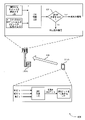
図3は、本開示の様々な態様による、DMRSにおいて配信される情報のための保護の提供をサポートする、リソース要素(RE)マッピング300の一例を示す。REマッピング300は、DMRS送信信号305、PBCH送信310、1次同期信号(PSS)送信315、2次同期信号(SSS)送信320、またはこれらの送信の何らかの組合せのために割り振られたREを含み得る。多数の他のREマッピングフォーマットが、DMRS305の送信のために使用され得る。
FIG. 3 illustrates an example resource element (RE) mapping 300 that supports providing protection for information distributed in DMRS, in accordance with various aspects of the present disclosure.
UE115が、アップリンク上でDMRS305を送信し得るか、または基地局105が、ダウンリンク上でDMRS305を送信し得る。DMRS305に加えて、UE115または基地局105は、1次同期信号(PSS)315、2次同期信号(SSS)320、または両方をさらに送信し得る。PSS315、SSS320、または両方は、PBCH310のために割り振られた帯域幅とは異なる帯域幅上で送信され得る。たとえば、PBCH310は、第1の帯域幅325に及び得るが、PSS315およびSSS320は、より小さい帯域幅であり得る、第2の帯域幅330に及び得る。1つの具体例では、第1の帯域幅325は、288個のリソース要素(RE)に及び得るが、第2の帯域幅330は、127個のREに及び得る。一態様では、UEまたは基地局は、信号が送信されない第2の帯域幅330の両端において、バッファを残し得る。
UE115または基地局105は、PBCH310の帯域幅325の全体にわたって、DMRS305をインターリーブし得る。このようにして、DMRS305およびPBCH310は、同じ時間に、または同じTTI(たとえば、同じシンボルまたはスロットまたはサブフレーム)の間に送信され得る。UE115または基地局105は、(たとえば、計算プロセスまたはマスキングプロセスを使用して)PBCH310において送信されるCRC内に、DMRS305の指示を含め得る。PBCH310は、PBCH310と同じTTIにおいて送信されるDMRS305のための保護を含み得る。この保護は、PBCH310において送信されるデータペイロード内の、CRC保護またはスクランブリング保護を含み得る。
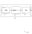
図4は、本開示の様々な態様による、DMRSにおいて配信される情報のための保護の提供をサポートする、DMRSシグナリング情報を用いたCRC計算プロセス400の一例を示す。DMRSシグナリング情報を用いたCRC計算プロセス400は、DMRSシグナリング情報の信頼性を向上させるための1つの可能な設計を示し得る。プロセスは、UE115-bなどのUEが、DMRSおよびデータペイロードを生成し、基地局105-bに、アップリンク通信リンク405上で、DMRSおよびデータペイロードを送信することを示し得る。ただし、DMRSシグナリング情報を用いたCRC計算プロセス400は、ダウンリンクにおいても同様に適用され得る。たとえば、基地局105-bは、送信機側のプロセスを実行し得るが、UE115-bは、受信機側のプロセスを実行し得る。
FIG. 4 illustrates an example
図示のように、UE115-bは、DMRSシグナリング情報を保護するための送信機側のプロセスのセットを実行し得る。DMRSシグナリング情報は、DMRS内のN1ビット中に含まれ得る。さらなるシグナリング情報は、データペイロード中に含まれたN2ビット中に含まれ得る。ただし、いくつかの例では、データペイロードは、いかなるさらなるシグナリング情報ビットをも含まないことがある(たとえば、0個のN2ビットがあり得る)。追加として、データペイロードは、M個の他の情報ビットを含み得る。UE115-bは、410で、N1ビット、N2ビット、およびMビットに対して、CRC計算を実行し得る。CRC計算は、系統的巡回符号、多項式除算アルゴリズム、シフトレジスタベースの除算アルゴリズム、または、入力ビットのセット(たとえば、この態様では、N1ビット、N2ビット、およびMビット)に基づいて、CRCビットのセットを決定するための任意の同様の関数の一例であり得る。410におけるCRC計算は、K個のCRCビットを生じることがあり、K個のCRCビットを、UE115-bが、415で、データペイロードに付加し得るまたは付け加え得る。データペイロード中に含まれたCRCビットを用いて、UE115-bは、物理データチャネルの一例であり得る、アップリンク通信リンク405上で、(たとえば、図3を参照しながら説明したものなどのフォーマットを使用して)基地局105-bにDMRSおよびペイロードを送信し得る。
As shown, UE 115-b may perform a set of transmitter-side processes for protecting DMRS signaling information. DMRS signaling information may be included in the N1 bits in DMRS. Additional signaling information may be included in the N2 bits included in the data payload. However, in some examples, the data payload may not contain any further signaling information bits (eg, there may be 0 N2 bits). Additionally, the data payload may contain M other information bits. UE 115-b may perform CRC calculations at 410 on the N1, N2, and M bits. The CRC calculation may be a systematic cyclic code, a polynomial division algorithm, a shift register-based division algorithm, or a set of input bits (eg, N1 bits, N2 bits, and M bits in this embodiment). It can be an example of any similar function for determining the set. The CRC calculation at 410 may result in K CRC bits, which UE 115-b may or may add to the data payload at 415. With the CRC bits included in the data payload, UE 115-b transmits data on
基地局105-bは、DMRSおよびデータペイロードを受信し得、DMRSおよびデータペイロードにおいて搬送された情報を決定するために、受信機側の機能のセットを実行し得る。基地局105-bは、420で、DMRSに基づいて、N1個のシグナリング情報ビットを検出し得る。追加として、基地局105-bは、425で、物理データチャネル上で受信されたデータペイロードに基づいて、N2個の追加のシグナリング情報ビット、ならびにM個の他の情報ビットを復号し得る。430で、基地局105-bは、検出および復号されたビットに対して、CRC検証を実行し得る。たとえば、基地局105-bは、データペイロードに付加されたCRCビットのセットのための期待値を決定するために、N1ビット、N2ビット、およびMビットに対して、CRC関数を実行し得る。435で、基地局105-bは、期待されるCRCビットのセットを、実際に受信されたCRCビットのセットと比較し得る。期待されるCRCビットのセット、および受信されたCRCビットのセットが一致する場合、CRCが合格し得、基地局105-bは、DMRSにおけるシグナリング情報、ならびに、データペイロードにおけるシグナリングおよび他の情報が、正確に検出および復号されたと決定し得る。期待されるCRCビットのセットが、受信されたCRCビットのセットとは異なる場合、CRCが失敗し得、基地局105-bは、DMRSにおけるシグナリング情報、データペイロードにおけるシグナリングおよび他の情報、またはそれらの2つの組合せが、不正確に検出または復号されたと決定し得る。このようにして、データペイロード中に含まれたCRCビットは、データペイロード中に含まれた情報の精度のみでなく、DMRS送信信号において検出された情報の精度をも検査し得る。 Base station 105-b may receive the DMRS and data payloads and may perform a set of receiver-side functions to determine the information conveyed in the DMRS and data payloads. Base station 105-b may detect 420 the N1 signaling information bits based on the DMRS. Additionally, base station 105-b may decode 425 the N2 additional signaling information bits as well as the M other information bits based on the data payload received on the physical data channel. At 430, base station 105-b may perform CRC verification on the detected and decoded bits. For example, base station 105-b may perform a CRC function on N1, N2, and M bits to determine the expected value for the set of CRC bits appended to the data payload. At 435, the base station 105-b may compare the expected set of CRC bits with the actually received set of CRC bits. If the expected set of CRC bits and the received set of CRC bits match, the CRC may pass and base station 105-b recognizes the signaling information in the DMRS and the signaling and other information in the data payload. , has been correctly detected and decoded. If the expected set of CRC bits is different from the received set of CRC bits, the CRC may fail and base station 105-b receives the signaling information in the DMRS, the signaling and other information in the data payload, or both. may be determined to be incorrectly detected or decoded. In this way, the CRC bits contained in the data payload can check not only the accuracy of the information contained in the data payload, but also the accuracy of the information detected in the DMRS transmission signal.
図5は、本開示の様々な態様による、DMRSにおいて配信される情報のための保護の提供をサポートする、DMRSシグナリング情報を用いたCRCマスキングプロセス500の一例を示す。DMRSシグナリング情報を用いたCRCマスキングプロセス500は、DMRSシグナリング情報の信頼性を向上させるための1つの可能な設計を示し得る。プロセスは、UE115-cなどのUEが、DMRSおよびデータペイロードを生成し、基地局105-cに、アップリンク通信リンク505上で、DMRSおよびデータペイロードを送信することを示し得る。ただし、DMRSシグナリング情報を用いたCRCマスキングプロセス500は、ダウンリンクにおいても同様に適用され得る。たとえば、基地局105-cは、送信機側のプロセスを実行し得るが、UE115-cは、受信機側のプロセスを実行し得る。
FIG. 5 illustrates an example
UE115-cは、DMRSシグナリング情報を保護するための送信機側のプロセスのセットを実行し得る。DMRSシグナリング情報は、DMRS内のN1ビット中に含まれ得る。さらなるシグナリング情報は、データペイロード中に含まれたN2ビット中に含まれ得る。ただし、いくつかの例では、データペイロードは、いかなるさらなるシグナリング情報ビットをも含まないことがある。追加として、データペイロードは、M個の他の情報ビットを含み得る。UE115-cは、510で、N2ビットおよびMビットに対して、CRC計算を実行し得る。510におけるCRC計算は、K個のCRCビットを生じることがあり、K個のCRCビットは、予備のCRCビットと呼ばれることがある。得られたCRCビットをデータペイロードに付加するのではなく、UE115-cは、515で、予備のCRCビットに対してマスキングプロセスを実行し得る。マスキングプロセスは、DMRSにおいて送信されたN1個のシグナリング情報ビットに基づき得る。このようにして、得られたマスキングされたCRCビットは、DMRSからのN1個のシグナリング情報ビットと、データペイロードからのN2およびM個の情報ビットの両方に基づく。UE115-cは、520で、データペイロードに、マスキングされたCRCビットを付加し得る。データペイロード中に含まれた、マスキングされたCRCビットを用いて、UE115-cは、物理データチャネルの一例であり得る、アップリンク通信リンク505上で、基地局105-cにDMRSおよびペイロードを送信し得る。
UE 115-c may perform a set of transmitter-side processes to protect DMRS signaling information. DMRS signaling information may be included in the N1 bits in DMRS. Additional signaling information may be included in the N2 bits included in the data payload. However, in some examples, the data payload may not contain any further signaling information bits. Additionally, the data payload may contain M other information bits. UE 115-c may perform CRC calculations at 510 on the N2 bits and the M bits. The CRC calculation at 510 may yield K CRC bits, which may be referred to as spare CRC bits. Rather than appending the obtained CRC bits to the data payload, UE 115-c may perform 515 a masking process on the spare CRC bits. The masking process may be based on the N1 signaling information bits sent in DMRS. Thus, the resulting masked CRC bits are based on both the N1 signaling information bits from the DMRS and the N2 and M information bits from the data payload. UE 115-c may append 520 masked CRC bits to the data payload. With masked CRC bits included in the data payload, UE 115-c transmits DMRS and payload to base station 105-c over
基地局105-cは、DMRSおよびデータペイロードを受信し得、DMRSおよびデータペイロードにおいて搬送された情報を決定するために、受信機側の機能のセットを実行し得る。基地局105-cは、525で、DMRSに基づいて、N1個のシグナリング情報ビットを検出し得る。追加として、基地局105-cは、530で、物理データチャネル上で受信されたデータペイロードに基づいて、N2個の追加のシグナリング情報ビット、ならびにM個の他の情報ビットを復号し得る。535で、基地局105-cは、検出および復号されたビットに対して、CRC検証を実行し得る。たとえば、基地局105-cは、最初に、DMRSにおいて検出されたN1個のシグナリング情報ビットに基づいて、受信されたマスキングされたCRCビットに対して、関数(たとえば、逆マスク関数)を実行し得る。基地局105-cは、データペイロードにおける、復号されたN2個の追加のシグナリング情報ビット、およびM個の他の情報ビットに対して、CRC関数をさらに実行して、期待されるマスキングされていないCRCビットのセットを取得し得る。540で、基地局105-cは、期待されるマスキングされていないCRCビットのセットを、関数(たとえば、逆マスク関数)の出力と比較し得る。期待されるマスキングされていないCRCビットが、関数の出力に一致する場合、CRCが合格し得、基地局105-cは、DMRSにおけるシグナリング情報、ならびに、データペイロードにおけるシグナリングおよび他の情報が、正確に検出および復号されたと決定し得る。期待されるマスキングされていないCRCビットが、関数の出力とは異なる場合、CRCが失敗し得、基地局105-cは、DMRSにおけるシグナリング情報、データペイロードにおけるシグナリングおよび他の情報、またはそれらの2つの組合せが、不正確に検出または復号されたと決定し得る。このようにして、データペイロード中に含まれたマスキングされたCRCビットは、データペイロード中に含まれた情報の精度のみでなく、DMRS送信信号において検出された情報の精度をも検査し得る。 Base station 105-c may receive the DMRS and data payloads and may perform a set of receiver-side functions to determine the information conveyed in the DMRS and data payloads. Base station 105-c may detect 525 the N1 signaling information bits based on the DMRS. Additionally, base station 105-c may decode 530 the N2 additional signaling information bits as well as the M other information bits based on the data payload received on the physical data channel. At 535, base station 105-c may perform CRC verification on the detected and decoded bits. For example, base station 105-c first performs a function (eg, an inverse mask function) on the received masked CRC bits based on the N1 signaling information bits detected in the DMRS. obtain. Base station 105-c further performs a CRC function on the decoded N2 additional signaling information bits and M other information bits in the data payload to obtain the expected unmasked A set of CRC bits can be obtained. At 540, base station 105-c may compare the expected set of unmasked CRC bits with the output of the function (eg, the inverse mask function). If the expected unmasked CRC bits match the output of the function, the CRC may pass, and base station 105-c determines that the signaling information in the DMRS and the signaling and other information in the data payload are correct. can be determined to have been detected and decoded at If the expected unmasked CRC bits are different from the output of the function, the CRC may fail and base station 105-c receives the signaling information in the DMRS, the signaling and other information in the data payload, or two of them. It may be determined that one combination was detected or decoded incorrectly. In this way, the masked CRC bits contained in the data payload can check not only the accuracy of the information contained in the data payload, but also the accuracy of the information detected in the DMRS transmission signal.
図6は、本開示の様々な態様による、DMRSにおいて配信される情報のための保護の提供をサポートする、ポテンシャルCRCマスク関数600の一例を示す。ポテンシャルCRCマスク関数600は、図5を参照しながら説明したように、基地局またはUEなどの送信デバイスによって、515で実行され得る。図6は、ポテンシャルCRCマスク関数600を示すが、送信デバイスは、DMRSにおける情報のためのデータペイロード内の保護を提供するために、他のCRCマスク関数を実装し得る。
FIG. 6 illustrates an example potential
デバイスは、605で、データペイロードからのN2個のシグナリング情報ビットおよびM個の他の情報ビットを入力として使用して、CRC計算を実行し得る。CRC計算は、Pアレイ610と呼ばれることがある、予備のCRCビットのセットを出力し得る。Pアレイ610は、合計Kビットを含み得、Kビットは、デバイスがデータペイロードにおいてCRCビットのために割り振ったビット数と同じであり得る。
At 605, the device may perform a CRC calculation using the N2 signaling information bits and the M other information bits from the data payload as inputs. The CRC calculation may output a set of preliminary CRC bits, sometimes referred to as the P-
615で、デバイスは、DMRSからのN1個のシグナリング情報ビット625に基づいて、予備のCRCビットのセットをマスキングし得る。一態様では、デバイスは、ルックアップテーブル620を利用し得る。ルックアップテーブルは、N1個のシグナリング情報ビット625のためのすべての可能な値と、対応するXアレイ630とを含み得る。Xアレイ630は、同じく長さがKの異なるビットのセットの例であり得る。別の態様では、ルックアップテーブル620を使用するのではなく、デバイスは、N1個のシグナリング情報ビット625の各値をKビットのアレイ上に射影するために、射影関数を実装し得る。このようにして、デバイスは、DMRS中に含まれたシグナリング情報を、予備のCRCビットのセット(たとえば、Pアレイ610)と等しいサイズのビットのセット(たとえば、マスキングビットと呼ばれることがある、Xアレイ630)に変換し得る。
At 615, the device may mask the set of spare CRC bits based on the N1 signaling
デバイスは、マスキングされたCRCビットのYアレイ635を計算するために、Pアレイ610およびXアレイ630に基づいて、演算を実行し得る。たとえば、デバイスは、Pアレイ610およびXアレイ630に対して、要素ごとの排他的論理和(XOR)関数を実行し得る。たとえば、デバイスは、Pアレイ610およびXアレイ630のp0インデックスおよびx0インデックスに対して、それぞれXOR関数を実行し得、関数の結果を、Yアレイ635のy0インデックスに割り当て得る。デバイスは、この同じプロセスを、Pアレイ610およびXアレイ630の他のインデックスに適用して、得られたYアレイ635の残りのインデックスを計算し得る。640で、デバイスは、送信のために、データペイロードに、Yアレイ635の計算されたマスキングされたCRCビットを付加し得る。
The device may perform operations based on the
データペイロードと対応するDMRSとを受信するデバイスは、DMRS内のN1個のシグナリング情報ビット625を検出し得、データペイロードのN2およびMビットを同様に復号し得る。次いで、受信デバイスは、検出されたN1個のシグナリング情報ビット625に基づいて、期待されるXアレイ630を選択し、復号されたN2およびMビットに基づいて、期待されるPアレイ610を選択し得、それらの期待されるアレイに対して、要素ごとのXOR関数を実行して、期待されるYアレイ635を決定し得る。受信デバイスは、検出および復号された情報を検証するために、期待されるYアレイ635を、データペイロードにおいて受信されたマスキングされたCRCビットと比較し得る。
A device that receives the data payload and corresponding DMRS may detect the N1 signaling
図7は、本開示の様々な態様による、DMRSにおいて配信される情報のための保護の提供をサポートするプロセスフロー700の一例を示す。プロセスフロー700は、図1および図2を参照しながら説明した対応するデバイスの例であり得る、基地局105-dとUE115-dとを含み得る。プロセスフロー700は、ダウンリンク上のDMRS送信信号を示し得るが、同じプロセスが、アップリンクDMRS送信信号に同様に適用され得る。
FIG. 7 illustrates an
705で、送信デバイス(たとえば、この例では、基地局105-d)は、DMRS送信信号に関連付けられた基準信号ビットのセットを識別し得る。一態様では、基準信号ビットのセットは、DMRS送信信号とともに搬送されることになる第1の基準信号ビットのサブセットと、データ送信信号とともに搬送されることになる第2の基準信号ビットのサブセットとを含み得る。 At 705, the transmitting device (eg, base station 105-d in this example) may identify a set of reference signal bits associated with the DMRS transmission. In one aspect, the set of reference signal bits comprises a first subset of reference signal bits to be carried with the DMRS transmission signal and a second subset of reference signal bits to be carried with the data transmission signal. can include
710で、基地局105-dは、データ送信信号に関連付けられたデータビットのセットを識別し得る。基地局105-dは、基準信号ビットのセットの前、またはそれと同時に、データビットのセットを識別し得る。追加として、基地局105-dは、基準信号ビットに基づいて、スクランブリングコードを識別し得、スクランブリングコードに基づいて、データビットをスクランブルし得る。 At 710, base station 105-d may identify a set of data bits associated with the data transmission signal. Base station 105-d may identify the set of data bits prior to or concurrently with the set of reference signal bits. Additionally, base station 105-d may identify a scrambling code based on the reference signal bits and scramble the data bits based on the scrambling code.
715で、基地局105-dは、基準信号ビットのセットとデータビットのセットとに基づいて、CRCビットのセットを計算し得る。一態様では、基地局105-dは、第1の基準信号ビットのサブセットと、第2の基準信号ビットのサブセットと、データビットのセットとに基づいて、CRCビットのセットを計算し得る。別の態様では、基地局105-dは、第2の基準信号ビットのサブセットとデータビットのセットとに基づいて、CRCビットのセットのサブセットを計算し得、第1の基準信号ビットのサブセットを使用して、CRCビットのセットのサブセットをマスキングし得る。たとえば、基地局105-dは、第1の基準信号ビットのサブセットに基づいて、ビット列を取り出し得、XOR関数を使用して、CRCビットのセットのサブセットをビット列と結合し得る。基地局105-dは、データビットにCRCビットのセットを付加し得る。 At 715, base station 105-d may calculate a set of CRC bits based on the set of reference signal bits and the set of data bits. In one aspect, base station 105-d may calculate a set of CRC bits based on the first subset of reference signal bits, the second subset of reference signal bits, and the set of data bits. In another aspect, base station 105-d may calculate a subset of the set of CRC bits based on the subset of the second reference signal bits and the set of data bits, and calculate the subset of the first reference signal bits as may be used to mask a subset of the set of CRC bits. For example, base station 105-d may retrieve a bit string based on a subset of the first reference signal bits and use an XOR function to combine the subset of the set of CRC bits with the bit string. Base station 105-d may append a set of CRC bits to the data bits.
CRCビットのセットを計算することは、基地局105-dが、CRCビットのセットを計算するためのCRC構成を示す、構成シグナリングを受信することをさらに含み得る。追加として、基地局105-dは、CRCビットのセットを計算するための第1のCRC構成から、CRCビットのセットを計算するための第2のCRC構成に切り替え得る。一態様では、この切替えは、基準信号ビットのセットのサイズ、データビットのセットのサイズ、CRCビットのセットのサイズ、またはこれらのサイズの何らかの組合せに基づき得る。 Calculating the set of CRC bits may further include base station 105-d receiving configuration signaling indicating a CRC configuration for calculating the set of CRC bits. Additionally, base station 105-d may switch from a first CRC configuration for calculating a set of CRC bits to a second CRC configuration for calculating a set of CRC bits. In one aspect, this switching may be based on the size of the set of reference signal bits, the size of the set of data bits, the size of the set of CRC bits, or some combination of these sizes.
720で、基地局105-dは、UE115-dに、CRCビットのセットとともに、DMRS送信信号とデータ送信信号とを送信し得る。一態様では、基地局105-dは、DMRS送信信号において第1の基準信号ビットのサブセット、およびデータ送信信号において第2の基準信号ビットのサブセットを送信し得る。基地局105-dは、物理データチャネルを使用して、データ送信信号を送信し得、DMRS送信信号のために予約されたリソースを使用して、DMRS送信信号を送信し得る。DMRS送信信号は、物理データチャネルに関連付けられた位相基準情報を搬送し得る。 At 720, base station 105-d may transmit DMRS transmissions and data transmissions along with a set of CRC bits to UE 115-d. In one aspect, base station 105-d may transmit a first subset of reference signal bits in a DMRS transmission and a second subset of reference signal bits in a data transmission. Base station 105-d may transmit data transmissions using physical data channels, and may transmit DMRS transmissions using resources reserved for DMRS transmissions. A DMRS transmission signal may carry phase reference information associated with a physical data channel.
725で、UE115-dは、DMRS送信信号に関連付けられた基準ビットのセットを検出し得る。730で、UE115-dは、データ送信信号に関連付けられたデータビットのセットを復号し得る。追加として、UE115-dは、データ送信信号とともにCRCビットのセットを受信し得る。 At 725, UE 115-d may detect a set of reference bits associated with the DMRS transmission. At 730, UE 115-d may decode the set of data bits associated with the data transmission. Additionally, UE 115-d may receive a set of CRC bits along with the data transmission.
735で、UE115-dは、CRCビットのセットに基づいて、CRC検証プロセスを実行し得る。UE115-dは、検出された基準信号ビットのセットと、復号されたデータビットのセットとに基づいて、CRC検証が成功するか否かを決定し得る。 At 735, UE 115-d may perform a CRC verification process based on the set of CRC bits. UE 115-d may determine whether the CRC verification is successful based on the detected set of reference signal bits and the decoded set of data bits.
図8は、本開示の様々な態様による、DMRSにおいて配信される情報のための保護の提供をサポートするプロセスフロー800の一例を示す。プロセスフロー800は、図1および図2を参照しながら説明した対応するデバイスの例であり得る、基地局105-eとUE115-eとを含み得る。プロセスフロー800は、ダウンリンク上のDMRS送信信号を示し得るが、同じプロセスが、アップリンクDMRS送信信号に同様に適用され得る。
FIG. 8 illustrates an
805で、送信デバイス(たとえば、この例では、基地局105-e)は、DMRS送信信号に関連付けられた基準信号ビットのセットを識別し得る。810で、基地局105-eは、データ送信信号に関連付けられたデータビットのセットを識別し得る。一態様では、基地局105-eは、基準信号ビットのセットの前、またはそれと同時に、データビットのセットを識別し得る。 At 805, the transmitting device (eg, base station 105-e in this example) may identify a set of reference signal bits associated with the DMRS transmission. At 810, base station 105-e may identify a set of data bits associated with the data transmission signal. In one aspect, the base station 105-e may identify the set of data bits prior to or concurrently with the set of reference signal bits.
815で、基地局105-eは、基準信号ビットに基づいて、スクランブリングコードを識別し得る。820で、基地局105-eは、識別されたスクランブリングコードに基づいて、データビットをスクランブルし得る。いくつかの例では、基地局105-eは、基準信号ビットおよびデータビットに基づいて、CRCビットのセットをさらに計算し得る。 At 815, base station 105-e may identify a scrambling code based on the reference signal bits. At 820, base station 105-e may scramble the data bits based on the identified scrambling code. In some examples, base station 105-e may further calculate a set of CRC bits based on the reference signal bits and the data bits.
825で、基地局105-eは、UE115-eに、DMRS送信信号とデータ送信信号とを送信し得る。たとえば、基地局105-eは、物理データチャネルを使用して、データ送信信号を送信し得、DMRS送信信号のために予約されたリソースを使用して、DMRS送信信号を送信し得る。DMRS送信信号は、物理データチャネルに関連付けられた位相基準の指示を含み得る。 At 825, base station 105-e may transmit DMRS transmissions and data transmissions to UE 115-e. For example, base station 105-e may transmit data transmissions using physical data channels and may transmit DMRS transmissions using resources reserved for DMRS transmissions. A DMRS transmission signal may include an indication of a phase reference associated with the physical data channel.
830で、UE115-eは、DMRS送信信号に関連付けられた基準ビットのセットを検出し得る。835で、UE115-eは、データビットのセットを復号し得る。UE115-eは、検出された基準ビットのセットに基づいて、スクランブリングコードを決定し得、決定されたスクランブリングコードを使用するビットのアンスクランブルに基づいて、データビットのセットを復号し得る。 At 830, UE 115-e may detect a set of reference bits associated with the DMRS transmission. At 835, UE 115-e may decode the set of data bits. UE 115-e may determine a scrambling code based on the detected set of reference bits and may decode the set of data bits based on unscrambling the bits using the determined scrambling code.
図9は、本開示の態様による、DMRSにおいて配信される情報のための保護の提供をサポートする、ワイヤレスデバイス905のブロック図900を示す。ワイヤレスデバイス905は、本明細書で説明するUE115または基地局105の態様の一例であり得る。ワイヤレスデバイス905は、受信機910と、DMRS保護モジュール915と、送信機920とを含み得る。ワイヤレスデバイス905はまた、プロセッサを含み得る。これらの構成要素の各々は、(たとえば、1つまたは複数のバスを介して)互いに通信中であり得る。
FIG. 9 shows a block diagram 900 of a
受信機910は、パケット、ユーザデータ、または様々な情報チャネルに関連付けられた制御情報(たとえば、制御チャネル、データチャネル、および、DMRSにおいて配信される情報のための保護の提供に関する情報など)などの情報を受信し得る。情報はデバイスの他の構成要素に渡され得る。受信機910は、図12を参照しながら説明するトランシーバ1235の態様の一例であり得る。受信機910は、単一のアンテナまたはアンテナのセットを利用し得る。DMRS保護モジュール915は、図12および図13を参照しながら説明するような、DMRS保護モジュール1215または1315の態様の一例であり得る。
DMRS保護モジュール915および/またはその様々な下位構成要素のうちの少なくともいくつかは、ハードウェア、プロセッサによって実行されるソフトウェア、ファームウェア、またはそれらの任意の組合せで実装され得る。プロセッサによって実行されるソフトウェアで実装される場合、DMRS保護モジュール915および/またはその様々な下位構成要素のうちの少なくともいくつかの機能は、汎用プロセッサ、デジタル信号プロセッサ(DSP)、特定用途向け集積回路(ASIC)、フィールドプログラマブルゲートアレイ(FPGA)もしくは他のプログラマブル論理デバイス、個別ゲートもしくはトランジスタ論理、個別ハードウェア構成要素、または本開示で説明する機能を実行するように設計されたそれらの任意の組合せによって実行され得る。DMRS保護モジュール915および/またはその様々な下位構成要素のうちの少なくともいくつかは、機能の部分が1つまたは複数の物理デバイスによって異なる物理的ロケーションにおいて実装されるように分散されることを含めて、様々な位置に物理的に配置され得る。いくつかの例では、DMRS保護モジュール915および/またはその様々な下位構成要素のうちの少なくともいくつかは、本開示の様々な態様による別個のおよび異なる構成要素であり得る。他の例では、DMRS保護モジュール915および/またはその様々な下位構成要素のうちの少なくともいくつかは、限定はしないが、I/O構成要素、トランシーバ、ネットワークサーバ、別のコンピューティングデバイス、本開示で説明する1つもしくは複数の他の構成要素、または本開示の様々な態様によるそれらの組合せを含む、1つまたは複数の他のハードウェア構成要素と組み合わせられ得る。
At least some of the
DMRS保護モジュール915は、DMRS送信信号に関連付けられた基準信号ビットのセットと、データ送信信号に関連付けられたデータビットのセットとを識別することと、基準信号ビットのセットとデータビットのセットの両方に基づいて、CRCビットのセットを計算することとを行い得る。DMRS保護モジュール915はまた、DMRS送信信号に関連付けられた基準信号ビットのセットを検出することと、データ送信信号に関連付けられたデータビットのセットを復号することと、データビットのセットとともに、CRCビットのセットを受信することと、CRCビットのセットに基づいて、CRC検証プロセスを実行することであって、CRCビットのセットが、基準信号ビットのセットとデータビットのセットの両方に基づいて計算される、実行することとを行い得る。DMRS保護モジュール915は、DMRS送信信号に関連付けられた基準信号ビットのセットと、データ送信信号に関連付けられたデータビットのセットとを識別することと、基準信号ビットのセットに基づいて、スクランブリングコードを識別することと、識別されたスクランブリングコードに基づいて、データビットのセットをスクランブルすることとをさらに行い得る。
送信機920は、デバイスの他の構成要素によって生成される信号を送信し得る。送信機920は、CRCビットのセットとともに、DMRS送信信号とデータ送信信号とを送信し得る。いくつかの例では、送信機920は、トランシーバモジュールにおいて受信機910と併置されてよい。たとえば、送信機920は、図12を参照しながら説明するトランシーバ1235の態様の一例であり得る。送信機920は、単一のアンテナまたはアンテナのセットを利用し得る。
図10は、本開示の態様による、DMRSにおいて配信される情報のための保護の提供をサポートする、ワイヤレスデバイス1005のブロック図1000を示す。ワイヤレスデバイス1005は、図9を参照しながら説明したような、ワイヤレスデバイス905、またはUE115、または基地局105の態様の一例であり得る。ワイヤレスデバイス1005は、受信機1010と、DMRS保護モジュール1015と、送信機1020とを含み得る。ワイヤレスデバイス1005はまた、プロセッサを含み得る。これらの構成要素の各々は、(たとえば、1つまたは複数のバスを介して)互いに通信中であり得る。
FIG. 10 shows a block diagram 1000 of a
受信機1010は、パケット、ユーザデータ、または様々な情報チャネルに関連付けられた制御情報(たとえば、制御チャネル、データチャネル、および、DMRSにおいて配信される情報のための保護の提供に関する情報など)などの情報を受信し得る。情報はデバイスの他の構成要素に渡され得る。受信機1010は、図12を参照しながら説明するトランシーバ1235の態様の一例であり得る。受信機1010は、単一のアンテナまたはアンテナのセットを利用し得る。
The
DMRS保護モジュール1015は、図12および図13を参照しながら説明するDMRS保護モジュール1215または1315の態様の一例であり得る。DMRS保護モジュール1015はまた、識別構成要素1025と、CRC構成要素1030と、検出構成要素1035と、デコーダ1040と、CRC検証構成要素1045と、スクランブリング構成要素1050とを含み得る。
識別構成要素1025は、DMRS送信信号に関連付けられた基準信号ビットのセットと、データ送信信号に関連付けられたデータビットのセットとを識別し得る。一態様では、基準信号ビットのセットは、DMRS送信信号とともに搬送される第1の基準信号ビットのサブセットと、データ送信信号とともに搬送される第2の基準信号ビットのサブセットとを含む。
CRC構成要素1030は、基準信号ビットのセットとデータビットのセットの両方に基づいて、CRCビットのセットを計算し得る。一態様では、CRC構成要素1030は、第2の基準信号ビットのサブセットとデータビットのセットとに基づいて、CRCビットのセットのサブセットを計算し得る。いくつかの例では、CRCビットのセットは、第1の基準信号ビットのサブセットと、第2の基準信号ビットのサブセットと、データビットのセットとに基づいて計算される。
検出構成要素1035は、DMRS送信信号に関連付けられた基準信号ビットのセットを検出し得る。デコーダ1040は、データ送信信号に関連付けられたデータビットのセットを復号し得る。
A
CRC検証構成要素1045は、データビットのセットとともに、CRCビットのセットを受信することと、CRCビットのセットに基づいて、CRC検証プロセスを実行することであって、CRCビットのセットが、基準信号ビットのセットとデータビットのセットの両方に基づいて計算される、実行することとを行い得る。CRC検証構成要素1045は、CRC検証プロセスが成功するか否かをさらに決定し得る。
スクランブリング構成要素1050は、基準信号ビットのセットに基づいて、スクランブリングコードを識別することと、識別されたスクランブリングコードに基づいて、データビットのセットをスクランブルすることとを行い得る。
送信機1020は、デバイスの他の構成要素によって生成される信号を送信し得る。送信機1020は、CRCビットのセットとともに、DMRS送信信号とデータ送信信号とを送信し得る。送信機1020は、DMRS送信信号において第1の基準信号ビットのサブセット、およびデータ送信信号において第2の基準信号ビットのサブセットを送信し得る。いくつかの例では、送信機1020は、物理データチャネルにおいてデータ送信信号を送信し得、DMRS送信信号のために予約されたリソースを使用して、DMRS送信信号を送信し得る。DMRS送信信号は、物理データチャネルに関連付けられた位相基準情報を搬送し得る。いくつかの例では、送信機1020は、トランシーバモジュールにおいて受信機1010と併置され得る。たとえば、送信機1020は、図12を参照しながら説明するトランシーバ1235の態様の一例であり得る。送信機1020は、単一のアンテナまたはアンテナのセットを利用し得る。
図11は、本開示の態様による、DMRSにおいて配信される情報のための保護の提供をサポートする、DMRS保護モジュール1115のブロック図1100を示す。DMRS保護モジュール1115は、図9、図10、図12、および図13を参照しながら説明する、DMRS保護モジュール915、DMRS保護モジュール1015、DMRS保護モジュール1215、またはDMRS保護モジュール1315の態様の一例であり得る。DMRS保護モジュール1115は、識別構成要素1120と、CRC構成要素1125と、検出構成要素1130と、デコーダ1135と、CRC検証構成要素1140と、スクランブリング構成要素1145と、マスキング構成要素1150と、ビットセット結合構成要素1155と、CRC構成構成要素1160と、CRC切替え構成要素1165とを含み得る。これらのモジュールの各々は、(たとえば、1つまたは複数のバスを介して)互いと直接的または間接的に通信し得る。
FIG. 11 shows a block diagram 1100 of a
識別構成要素1120は、DMRS送信信号に関連付けられた基準信号ビットのセットと、データ送信信号に関連付けられたデータビットのセットとを識別し得る。一態様では、基準信号ビットのセットは、DMRS送信信号とともに搬送される第1の基準信号ビットのサブセットと、データ送信信号とともに搬送される第2の基準信号ビットのサブセットとを含む。
CRC構成要素1125は、基準信号ビットのセットとデータビットのセットの両方に基づいて、CRCビットのセットを計算することと、第2の基準信号ビットのサブセットとデータビットのセットとに基づいて、CRCビットのセットのサブセットを計算することとを行い得る。いくつかの例では、CRCビットのセットは、第1の基準信号ビットのサブセットと、第2の基準信号ビットのサブセットと、データビットのセットとに基づいて計算される。
検出構成要素1130は、DMRS送信信号に関連付けられた基準信号ビットのセットを検出し得る。場合によっては、検出構成要素1130は、DMRS送信信号に関連付けられた基準信号ビットのセットと、データ送信信号に関連付けられたデータビットのセットとを検出し得る。デコーダ1135は、データ送信信号に関連付けられたデータビットのセットを復号し得る。
A
CRC検証構成要素1140は、データビットのセットとともに、CRCビットのセットを受信し得、CRCビットのセットに基づいて、CRC検証プロセスを実行することであって、CRCビットのセットが、基準信号ビットのセットとデータビットのセットの両方に基づいて計算される、実行することを行い得る。追加として、CRC検証構成要素1140は、CRC検証プロセスが成功するか否かを決定し得る。
The
スクランブリング構成要素1145は、基準信号ビットのセットに基づいて、スクランブリングコードを識別することと、識別されたスクランブリングコードに基づいて、データビットのセットをスクランブルすることとを行い得る。追加として、スクランブリング構成要素1145は、基準信号ビットのセットに基づいて、スクランブリングコードを識別することと、識別されたスクランブリングコードに基づいて、データビットのセットをデスクランブルすることとを行い得る。
マスキング構成要素1150は、第1の基準信号ビットのサブセットによって、CRCビットのセットのサブセットをマスキングし得る。マスキング構成要素1150は、第1の基準信号ビットのサブセットに基づいて、ビット列を取り出すことと、XOR関数を使用して、CRCビットのセットのサブセットをビット列と結合することとを行い得る。
ビットセット結合構成要素1155は、データビットのセットにCRCビットのセットを付加し得る。CRC構成構成要素1160は、CRCビットのセットを計算するためのCRC構成を示す、構成シグナリングを受信し得る。CRC切替え構成要素1165は、CRCビットのセットを計算するための第1のCRC構成から、CRCビットのセットを計算するための第2のCRC構成に切り替えることと、基準信号ビットのセットのサイズ、データビットのセットのサイズ、CRCビットのセットのサイズ、またはそれらの組合せに基づいて、第1のCRC構成から第2のCRC構成に切り替えることを行い得る。
A
図12は、本開示の態様による、DMRSにおいて配信される情報のための保護の提供をサポートする、デバイス1205を含むシステム1200の図を示す。デバイス1205は、たとえば、図1、図2、図4、図5、図9、および図10を参照しながら上記で説明したようなワイヤレスデバイス905、ワイヤレスデバイス1005、またはUE115の構成要素の一例であり得るか、またはそれらの構成要素を含み得る。デバイス1205は、UE DMRS保護モジュール1215と、プロセッサ1220と、メモリ1225と、ソフトウェア1230と、トランシーバ1235と、アンテナ1240と、I/Oコントローラ1245とを含む、通信を送信および受信するための構成要素を含む、双方向の音声およびデータ通信のための構成要素を含み得る。これらの構成要素は、1つまたは複数のバス(たとえば、バス1210)を介して電子通信中であり得る。デバイス1205は、1つまたは複数の基地局105とワイヤレスに通信し得る。
FIG. 12 shows a diagram of a
プロセッサ1220は、インテリジェントハードウェアデバイス(たとえば、汎用プロセッサ、DSP、中央処理装置(CPU)、マイクロコントローラ、ASIC、FPGA、プログラマブル論理デバイス、個別ゲートもしくはトランジスタ論理構成要素、個別ハードウェア構成要素、またはそれらの任意の組合せ)を含み得る。一態様では、プロセッサ1220は、メモリコントローラを使用して、メモリアレイを動作させるように構成され得る。別の態様では、メモリコントローラは、プロセッサ1220へと統合され得る。プロセッサ1220は、様々な機能(たとえば、DMRSにおいて配信される情報のための保護の提供をサポートする機能またはタスク)を実行するために、メモリ内に記憶されたコンピュータ可読命令を実行するように構成され得る。
メモリ1225は、ランダムアクセスメモリ(RAM)および読取り専用メモリ(ROM)を含み得る。メモリ1225は、実行されると、プロセッサに、本明細書で説明する様々な機能を実行させる命令を含む、コンピュータ可読、コンピュータ実行可能ソフトウェア1230を記憶してもよい。いくつかの例では、メモリ1225は、特に、周辺構成要素またはデバイスとの相互作用などの基本的なハードウェアまたはソフトウェア動作を制御し得る、基本入出力システム(BIOS)を含み得る。
ソフトウェア1230は、DMRSにおいて配信される情報のための保護の提供をサポートするためのコードを含む、本開示の態様を実装するためのコードを含み得る。ソフトウェア1230は、システムメモリまたは他のメモリなど、非一時的コンピュータ可読媒体内に記憶され得る。一態様では、ソフトウェア1230は、プロセッサによって直接実行可能でないことがあるが、(たとえば、コンパイルおよび実行されると)本明細書で説明する機能をコンピュータに実行させ得る。
トランシーバ1235は、上記で説明したように、1つまたは複数のアンテナ、ワイヤードリンク、またはワイヤレスリンクを介して双方向に通信し得る。たとえば、トランシーバ1235は、ワイヤレストランシーバを表すことがあり、別のワイヤレストランシーバと双方向に通信し得る。トランシーバ1235はまた、送信のためにパケットを変調するとともに変調されたパケットをアンテナに提供するための、かつアンテナから受信されたパケットを復調するための、モデムを含み得る。
一態様では、ワイヤレスデバイスは、単一のアンテナ1240を含み得る。ただし、別の態様では、デバイスは、複数のアンテナ1240を有することがあり、複数のアンテナ1240は、複数のワイヤレス送信を並行して送信または受信することが可能であり得る。
In one aspect, a wireless device may include a
I/Oコントローラ1245は、デバイス1205のための入力信号および出力信号を管理し得る。I/Oコントローラ1245はまた、デバイス1205内に統合されない周辺機器を管理し得る。いくつかの例では、I/Oコントローラ1245は、外部周辺装置への物理的接続またはポートを表し得る。いくつかの例では、I/Oコントローラ1245は、iOS(登録商標)、ANDROID(登録商標)、MS-DOS(登録商標)、MS-WINDOWS(登録商標)、OS/2(登録商標)、UNIX(登録商標)、LINUX(登録商標)、または別の既知のオペレーティングシステムなどの、オペレーティングシステムを利用し得る。I/Oコントローラ1245は、モデム、キーボード、マウス、タッチスクリーン、または同様のデバイスを表すか、またはそれと対話し得る。一態様では、I/Oコントローラ1245は、プロセッサの一部として実装され得る。いくつかの例では、ユーザは、I/Oコントローラ1245を介して、またはI/Oコントローラ1245によって制御されるハードウェア構成要素を介して、デバイス1205と対話し得る。
I/
図13は、本開示の態様による、DMRSにおいて配信される情報のための保護の提供をサポートする、デバイス1305を含むシステム1300の図を示す。デバイス1305は、たとえば、図1、図2、図4、図5、図9、および図10を参照しながら上記で説明したようなワイヤレスデバイス905、ワイヤレスデバイス1005、または基地局105の構成要素の一例であり得るか、またはそれらの構成要素を含み得る。デバイス1305は、基地局DMRS保護モジュール1315と、プロセッサ1320と、メモリ1325と、ソフトウェア1330と、トランシーバ1335と、アンテナ1340と、ネットワーク通信マネージャ1345と、局間通信マネージャ1350とを含む、通信を送信および受信するための構成要素を含む、双方向の音声およびデータ通信のための構成要素を含み得る。これらの構成要素は、1つまたは複数のバス(たとえば、バス1310)を介して電子通信中であり得る。デバイス1305は、1つまたは複数のUE115とワイヤレスに通信し得る。
FIG. 13 shows a diagram of a
プロセッサ1320は、インテリジェントハードウェアデバイス(たとえば、汎用プロセッサ、DSP、CPU、マイクロコントローラ、ASIC、FPGA、プログラマブル論理デバイス、個別ゲートもしくはトランジスタ論理構成要素、個別ハードウェア構成要素、またはそれらの任意の組合せ)を含み得る。一態様では、プロセッサ1320は、メモリコントローラを使用して、メモリアレイを動作させるように構成され得る。別の態様では、メモリコントローラは、プロセッサ1320へと統合され得る。プロセッサ1320は、様々な機能(たとえば、DMRSにおいて配信される情報のための保護の提供をサポートする機能またはタスク)を実行するために、メモリ内に記憶されたコンピュータ可読命令を実行するように構成され得る。
メモリ1325は、RAMとROMとを含み得る。メモリ1325は、実行されると、プロセッサに、本明細書で説明する様々な機能を実行させる命令を含む、コンピュータ可読、コンピュータ実行可能ソフトウェア1330を記憶してもよい。いくつかの例では、メモリ1325は、特に、周辺構成要素またはデバイスとの相互作用などの基本的なハードウェアまたはソフトウェア動作を制御し得る、BIOSを含み得る。
ソフトウェア1330は、DMRSにおいて配信される情報のための保護の提供をサポートするためのコードを含む、本開示の態様を実装するためのコードを含み得る。ソフトウェア1330は、システムメモリまたは他のメモリなど、非一時的コンピュータ可読媒体内に記憶され得る。一態様では、ソフトウェア1330は、プロセッサによって直接実行可能でないことがあるが、(たとえば、コンパイルおよび実行されると)本明細書で説明する機能をコンピュータに実行させ得る。
トランシーバ1335は、上記で説明したように、1つまたは複数のアンテナ、ワイヤードリンク、またはワイヤレスリンクを介して双方向に通信し得る。たとえば、トランシーバ1335は、ワイヤレストランシーバを表すことがあり、別のワイヤレストランシーバと双方向に通信し得る。トランシーバ1335はまた、送信のためにパケットを変調するとともに変調されたパケットをアンテナに提供するための、かつアンテナから受信されたパケットを復調するための、モデムを含み得る。
一態様では、ワイヤレスデバイスは、単一のアンテナ1340を含み得る。ただし、別の態様では、デバイスは、複数のアンテナ1340を有することがあり、複数のアンテナ1340は、複数のワイヤレス送信を並行して送信または受信することが可能であり得る。
In one aspect, a wireless device may include a
ネットワーク通信マネージャ1345は、(たとえば、1つまたは複数のワイヤードバックホールリンクを介した)コアネットワークとの通信を管理し得る。たとえば、ネットワーク通信マネージャ1345は、1つまたは複数のUE115などのクライアントデバイス用のデータ通信の転送を管理し得る。
A
局間通信マネージャ1350は、他の基地局105との通信を管理し得、他の基地局105と協調してUE115との通信を制御するためのコントローラまたはスケジューラを含み得る。たとえば、局間通信マネージャ1350は、ビームフォーミングまたはジョイント送信などの様々な干渉軽減技法のために、UE115への送信のためのスケジューリングを協調させ得る。いくつかの例では、局間通信マネージャ1350は、基地局105間の通信を行うために、ロングタームエボリューション(LTE)/LTE-Aワイヤレス通信ネットワーク技術内のX2インターフェースを提供し得る。
図14は、本開示の態様による、DMRSにおいて配信される情報のための保護を提供するための方法1400を示すフローチャートを示す。方法1400の動作は、本明細書で説明するようなUE115または基地局105またはその構成要素によって実施され得る。たとえば、方法1400の動作は、図9~図12を参照しながら説明したように、DMRS保護モジュールによって実行され得る。いくつかの例では、UE115または基地局105は、以下で説明する機能を実行するようにデバイスの機能要素を制御するためのコードのセットを実行し得る。追加または代替として、UE115または基地局105は、以下で説明する機能の態様を、専用ハードウェアを使用して実行し得る。
FIG. 14 shows a flowchart illustrating a
ブロック1405で、UE115または基地局105は、DMRS送信信号に関連付けられた基準信号ビットのセットと、データ送信信号に関連付けられたデータビットのセットとを識別し得る。ブロック1405の動作は、本明細書で説明する方法に従って実行され得る。いくつかの例では、ブロック1405の動作の態様は、図9~図12を参照しながら説明したように、識別構成要素によって実行され得る。
At
ブロック1410で、UE115または基地局105は、基準信号ビットのセットとデータビットのセットの両方に少なくとも部分的に基づいて、CRCビットのセットを計算し得る。ブロック1410の動作は、本明細書で説明する方法に従って実行され得る。いくつかの例では、ブロック1410の動作の態様は、図9~図12を参照しながら説明したように、CRC構成要素によって実行され得る。
At
ブロック1415で、UE115または基地局105は、CRCビットのセットとともに、DMRS送信信号とデータ送信信号とを送信し得る。ブロック1415の動作は、本明細書で説明する方法に従って実行され得る。いくつかの例では、ブロック1415の動作の態様は、図9~図12を参照しながら説明したように、送信機によって実行され得る。
At
図15は、本開示の態様による、DMRSにおいて配信される情報のための保護を提供するための方法1500を示すフローチャートを示す。方法1500の動作は、本明細書で説明するようなUE115または基地局105またはその構成要素によって実施され得る。たとえば、方法1500の動作は、図9~図12を参照しながら説明したように、DMRS保護モジュールによって実行され得る。いくつかの例では、UE115または基地局105は、以下で説明する機能を実行するようにデバイスの機能要素を制御するためのコードのセットを実行し得る。追加または代替として、UE115または基地局105は、以下で説明する機能の態様を、専用ハードウェアを使用して実行し得る。
FIG. 15 shows a flowchart illustrating a
ブロック1505で、UE115または基地局105は、DMRS送信信号に関連付けられた基準信号ビットのセットと、データ送信信号に関連付けられたデータビットのセットとを識別し得る。いくつかの例では、基準信号ビットのセットは、DMRS送信信号とともに搬送される第1の基準信号ビットのサブセットと、データ送信信号とともに搬送される第2の基準信号ビットのサブセットとを備える。ブロック1505の動作は、本明細書で説明する方法に従って実行され得る。いくつかの例では、ブロック1505の動作の態様は、図9~図12を参照しながら説明したように、識別構成要素によって実行され得る。
At
ブロック1510で、UE115または基地局105は、基準信号ビットのセットとデータビットのセットの両方に少なくとも部分的に基づいて、CRCビットのセットを計算し得る。ブロック1510の動作は、本明細書で説明する方法に従って実行され得る。いくつかの例では、ブロック1510の動作の態様は、図9~図12を参照しながら説明したように、CRC構成要素によって実行され得る。
At
ブロック1515で、UE115または基地局105は、第2の基準信号ビットのサブセットとデータビットのセットとに少なくとも部分的に基づいて、CRCビットのセットのサブセットを計算し得る。ブロック1515の動作は、本明細書で説明する方法に従って実行され得る。いくつかの例では、ブロック1515の動作の態様は、図9~図12を参照しながら説明したように、CRC構成要素によって実行され得る。
At
ブロック1520で、UE115または基地局105は、第1の基準信号ビットのサブセットによって、CRCビットのセットのサブセットをマスキングし得る。ブロック1520の動作は、本明細書で説明する方法に従って実行され得る。いくつかの例では、ブロック1520の動作の態様は、図9~図12を参照しながら説明したように、マスキング構成要素によって実行され得る。
At
ブロック1525で、UE115または基地局105は、CRCビットのセットとともに、DMRS送信信号とデータ送信信号とを送信し得る。ブロック1525の動作は、本明細書で説明する方法に従って実行され得る。いくつかの例では、ブロック1525の動作の態様は、図9~図12を参照しながら説明したように、送信機によって実行され得る。
At
図16は、本開示の態様による、DMRSにおいて配信される情報のための保護を提供するための方法1600を示すフローチャートを示す。方法1600の動作は、本明細書で説明するようなUE115または基地局105またはその構成要素によって実施され得る。たとえば、方法1600の動作は、図9~図12を参照しながら説明したように、DMRS保護モジュールによって実行され得る。いくつかの例では、UE115または基地局105は、以下で説明する機能を実行するようにデバイスの機能要素を制御するためのコードのセットを実行し得る。追加または代替として、UE115または基地局105は、以下で説明する機能の態様を、専用ハードウェアを使用して実行し得る。
FIG. 16 shows a flowchart illustrating a
ブロック1605で、UE115または基地局105は、DMRS送信信号に関連付けられた基準信号ビットのセットと、データ送信信号に関連付けられたデータビットのセットとを識別し得る。いくつかの例では、基準信号ビットのセットは、DMRS送信信号とともに搬送される第1の基準信号ビットのサブセットと、データ送信信号とともに搬送される第2の基準信号ビットのサブセットとを備える。ブロック1605の動作は、本明細書で説明する方法に従って実行され得る。いくつかの例では、ブロック1605の動作の態様は、図9~図12を参照しながら説明したように、識別構成要素によって実行され得る。
At
ブロック1610で、UE115または基地局105は、第1の基準信号ビットのサブセットと、第2の基準信号ビットのサブセットと、データビットのセットとに少なくとも部分的に基づいて、CRCビットのセットを計算し得る。ブロック1610の動作は、本明細書で説明する方法に従って実行され得る。いくつかの例では、ブロック1610の動作の態様は、図9~図12を参照しながら説明したように、CRC構成要素によって実行され得る。
At
ブロック1615で、UE115または基地局105は、CRCビットのセットとともに、DMRS送信信号とデータ送信信号とを送信し得る。ブロック1615の動作は、本明細書で説明する方法に従って実行され得る。いくつかの例では、ブロック1615の動作の態様は、図9~図12を参照しながら説明したように、送信機によって実行され得る。
At
図17は、本開示の態様による、DMRSにおいて配信される情報のための保護を提供するための方法1700を示すフローチャートを示す。方法1700の動作は、本明細書で説明するようなUE115または基地局105またはその構成要素によって実施され得る。たとえば、方法1700の動作は、図9~図12を参照しながら説明したように、DMRS保護モジュールによって実行され得る。いくつかの例では、UE115または基地局105は、以下で説明する機能を実行するようにデバイスの機能要素を制御するためのコードのセットを実行し得る。追加または代替として、UE115または基地局105は、以下で説明する機能の態様を、専用ハードウェアを使用して実行し得る。
FIG. 17 shows a flowchart illustrating a
ブロック1705で、UE115または基地局105は、DMRS送信信号に関連付けられた基準信号ビットのセットを検出し得る。ブロック1705の動作は、本明細書で説明する方法に従って実行され得る。いくつかの例では、ブロック1705の動作の態様は、図9~図12を参照しながら説明したように、検出構成要素によって実行され得る。
At
ブロック1710で、UE115または基地局105は、データ送信信号に関連付けられたデータビットのセットを復号し得る。ブロック1710の動作は、本明細書で説明する方法に従って実行され得る。いくつかの例では、ブロック1710の動作の態様は、図9~図12を参照しながら説明したように、デコーダによって実行され得る。
At
ブロック1715で、UE115または基地局105は、データビットのセットとともに、CRCビットのセットを受信し得る。ブロック1715の動作は、本明細書で説明する方法に従って実行され得る。いくつかの例では、ブロック1715の動作の態様は、図9~図12を参照しながら説明したように、CRC検証構成要素によって実行され得る。
At
ブロック1720で、UE115または基地局105は、CRCビットのセットに少なくとも部分的に基づいて、CRC検証プロセスを実行することであって、CRCビットのセットが、基準信号ビットのセットとデータビットのセットの両方に少なくとも部分的に基づいて計算される、実行することを行い得る。ブロック1720の動作は、本明細書で説明する方法に従って実行され得る。いくつかの例では、ブロック1720の動作の態様は、図9~図12を参照しながら説明したように、CRC検証構成要素によって実行され得る。
At
図18は、本開示の態様による、DMRSにおいて配信される情報のための保護を提供するための方法1800を示すフローチャートを示す。方法1800の動作は、本明細書で説明するようなUE115または基地局105またはその構成要素によって実施され得る。たとえば、方法1800の動作は、図9~図12を参照しながら説明したように、DMRS保護モジュールによって実行され得る。いくつかの例では、UE115または基地局105は、以下で説明する機能を実行するようにデバイスの機能要素を制御するためのコードのセットを実行し得る。追加または代替として、UE115または基地局105は、以下で説明する機能の態様を、専用ハードウェアを使用して実行し得る。
FIG. 18 shows a flowchart illustrating a
ブロック1805で、UE115または基地局105は、DMRS送信信号に関連付けられた基準信号ビットのセットと、データ送信信号に関連付けられたデータビットのセットとを識別し得る。ブロック1805の動作は、本明細書で説明する方法に従って実行され得る。いくつかの例では、ブロック1805の動作の態様は、図9~図12を参照しながら説明したように、識別構成要素によって実行され得る。
At
ブロック1810で、UE115または基地局105は、基準信号ビットのセットに少なくとも部分的に基づいて、スクランブリングコードを識別し得る。ブロック1810の動作は、本明細書で説明する方法に従って実行され得る。いくつかの例では、ブロック1810の動作の態様は、図9~図12を参照しながら説明したように、スクランブリング構成要素によって実行され得る。
At
ブロック1815で、UE115または基地局105は、識別されたスクランブリングコードに少なくとも部分的に基づいて、データビットのセットをスクランブルし得る。ブロック1815の動作は、本明細書で説明する方法に従って実行され得る。いくつかの例では、ブロック1815の動作の態様は、図9~図12を参照しながら説明したように、スクランブリング構成要素によって実行され得る。
At
ブロック1820で、UE115または基地局105は、DMRS送信信号とデータ送信信号とを送信し得る。ブロック1820の動作は、本明細書で説明する方法に従って実行され得る。いくつかの例では、ブロック1820の動作の態様は、図9~図12を参照しながら説明したように、送信機によって実行され得る。
At
図19は、本開示の態様による、DMRSにおいて配信される情報のための保護を提供するための方法1900を示すフローチャートを示す。方法1900の動作は、本明細書で説明するように、デフォルトまたはその構成要素によって実施され得る。たとえば、方法1900の動作は、図9~図12を参照しながら説明したように、DMRS保護モジュールによって実行され得る。いくつかの例では、UE115または基地局105は、以下で説明する機能を実行するようにデバイスの機能要素を制御するためのコードのセットを実行し得る。追加または代替として、UE115または基地局105は、以下で説明する機能の態様を、専用ハードウェアを使用して実行し得る。
FIG. 19 shows a flowchart illustrating a
1905で、UE115または基地局105は、DMRS送信信号に関連付けられた基準信号ビットのセットと、データ送信信号に関連付けられたデータビットのセットとを検出し得る。1905の動作は、本明細書で説明する方法に従って実行され得る。いくつかの例では、1905の動作の態様は、図9~図12を参照しながら説明したように、検出構成要素によって実行され得る。
At 1905,
1910で、UE115または基地局105は、基準信号ビットのセットに基づいて、スクランブリングコードを識別し得る。1910の動作は、本明細書で説明する方法に従って実行され得る。いくつかの例では、1910の動作の態様は、図9~図12を参照しながら説明したように、スクランブリング構成要素によって実行され得る。
At 1910,
1915で、UE115または基地局105は、識別されたスクランブリングコードに基づいて、データビットのセットをデスクランブルし得る。1915の動作は、本明細書で説明する方法に従って実行され得る。いくつかの例では、1915の動作の態様は、図9~図12を参照しながら説明したように、スクランブリング構成要素によって実行され得る。場合によっては、UE115または基地局105は、識別されたスクランブリングコードが不正確であるときに、データビットのセットをスクランブルするとき、失敗し得る。たとえば、UE115がDMRSを不正確に復号するとき、データチャネルの復号が自動的に失敗することになる。
At 1915,
上記で説明した方法が可能な実装形態について説明していること、動作およびステップが再構成されてよく、または他の方法で修正されてよいこと、ならびに他の実装形態が可能であることに留意されたい。さらに、方法のうちの2つ以上からの態様が組み合わせられてよい。 Note that the methods described above describe possible implementations, that the acts and steps may be rearranged or otherwise modified, and that other implementations are possible. want to be Additionally, aspects from two or more of the methods may be combined.
本明細書で説明する技法は、符号分割多元接続(CDMA)、時分割多元接続(TDMA)、周波数分割多元接続(FDMA)、直交周波数分割多元接続(OFDMA)、シングルキャリア周波数分割多元接続(SC-FDMA)、および他のシステムなど、様々なワイヤレス通信システムのために使用され得る。「システム」および「ネットワーク」という用語は、しばしば、互換的に使用される。符号分割多元接続(CDMA)システムは、CDMA2000、ユニバーサル地上波無線アクセス(UTRA)などの無線技術を実装することがある。CDMA2000は、IS-2000規格、IS-95規格、およびIS-856規格をカバーする。IS-2000リリースは、通常、CDMA2000 1X、1Xなどと呼ばれることがある。IS-856(TIA-856)は、一般に、CDMA2000 1xEV-DO、高速パケットデータ(HRPD)などと呼ばれる。UTRAは、広帯域CDMA(WCDMA(登録商標))、およびCDMAの他の変形態を含む。TDMAシステムは、モバイル通信用グローバルシステム(GSM(登録商標))などの無線技術を実装し得る。 The techniques described herein include code division multiple access (CDMA), time division multiple access (TDMA), frequency division multiple access (FDMA), orthogonal frequency division multiple access (OFDMA), single carrier frequency division multiple access (SC -FDMA), and other systems. The terms "system" and "network" are often used interchangeably. A code division multiple access (CDMA) system may implement a radio technology such as CDMA2000, Universal Terrestrial Radio Access (UTRA), and so on. CDMA2000 covers IS-2000, IS-95 and IS-856 standards. IS-2000 releases are commonly referred to as CDMA2000 1X, 1X, etc. IS-856 (TIA-856) is commonly called CDMA2000 1xEV-DO, high speed packet data (HRPD), and so on. UTRA includes Wideband CDMA (WCDMA®) and other variants of CDMA. A TDMA system may implement a radio technology such as Global System for Mobile Communications (GSM).
OFDMAシステムは、ウルトラモバイルブロードバンド(UMB)、発展型UTRA(E-UTRA)、米国電気電子技術者協会(IEEE)802.11(Wi-Fi)、IEEE802.16(WiMAX)、IEEE802.20、Flash-OFDMなどの無線技術を実装し得る。UTRAおよびE-UTRAは、ユニバーサルモバイルテレコミュニケーションズシステム(UMTS)の一部である。LTEおよびLTE-Aは、E-UTRAを使用するUMTSのリリースである。UTRA、E-UTRA、UMTS、LTE、LTE-A、NR、およびGSM(登録商標)は、「第3世代パートナーシッププロジェクト」(3GPP)と称する団体からの文書に記載されている。CDMA2000およびUMBは、「第3世代パートナーシッププロジェクト2」(3GPP2)と称する団体からの文書に記載されている。本明細書で説明する技法は、上述のシステムおよび無線技術ならびに他のシステムおよび無線技術のために使用され得る。LTEまたはNRシステムの態様について例として説明することがあり、説明の大部分においてLTEまたはNR用語が使用されることがあるが、本明細書で説明する技法はLTEまたはNR適用例以外に適用可能である。 OFDMA systems include Ultra Mobile Broadband (UMB), Evolved UTRA (E-UTRA), Institute of Electrical and Electronics Engineers (IEEE) 802.11 (Wi-Fi), IEEE 802.16 (WiMAX), IEEE 802.20, Flash-OFDM wireless technology such as UTRA and E-UTRA are part of the Universal Mobile Telecommunications System (UMTS). LTE and LTE-A are releases of UMTS that use E-UTRA. UTRA, E-UTRA, UMTS, LTE, LTE-A, NR, and GSM are described in documents from an organization named "3rd Generation Partnership Project" (3GPP). CDMA2000 and UMB are described in documents from an organization named "3rd Generation Partnership Project 2" (3GPP2). The techniques described herein may be used for the systems and radio technologies mentioned above as well as other systems and radio technologies. Although aspects of LTE or NR systems may be described as examples, and LTE or NR terminology may be used in much of the description, the techniques described herein are applicable to non-LTE or NR applications. is.
本明細書で説明するそのようなネットワークを含むLTE/LTE-Aネットワークでは、発展型ノードB(eNB)という用語は、概して、基地局を表すために使用され得る。本明細書で説明する1つまたは複数のワイヤレス通信システムは、異なるタイプのeNBが様々な地理的領域にカバレージを提供する異種LTE/LTE-AまたはNRネットワークを含み得る。たとえば、各eNB、次世代ノードB(gNB)、または基地局は、マクロセル、スモールセル、または他のタイプのセルに通信カバレージを提供し得る。「セル」という用語は、文脈に応じて、基地局、基地局に関連付けられるキャリアもしくはコンポーネントキャリア、またはキャリアもしくは基地局のカバレージエリア(たとえば、セクタなど)を表すために使用され得る。 In LTE/LTE-A networks, including such networks described herein, the term evolved Node B (eNB) may be used generally to refer to a base station. One or more wireless communication systems described herein may include heterogeneous LTE/LTE-A or NR networks in which different types of eNBs provide coverage for various geographic areas. For example, each eNB, next generation Node B (gNB), or base station may provide communication coverage for macro cells, small cells, or other types of cells. The term "cell" may be used to represent a base station, a carrier or component carrier associated with a base station, or a coverage area (eg, sector, etc.) of a carrier or base station, depending on the context.
基地局は、基地トランシーバ局、無線基地局、アクセスポイント、無線トランシーバ、ノードB、eノードB(eNB)、gNB、ホームノードB、ホームeノードB、または何らかの他の好適な用語を含むことがあるか、またはそのように当業者によって呼ばれることがある。基地局のための地理的カバレージエリアは、カバレージエリアの一部分のみを構成するセクタに分割され得る。本明細書で説明する1つまたは複数のワイヤレス通信システムは、異なるタイプの基地局(たとえば、マクロ基地局またはスモールセル基地局)を含むことがある。本明細書で説明するUEは、マクロeNB、スモールセルeNB、gNB、リレー基地局などを含む、様々なタイプの基地局およびネットワーク機器と通信することが可能である場合がある。異なる技術向けの地理的カバレージエリアが重複する場合がある。 A base station may include a base transceiver station, radio base station, access point, radio transceiver, Node B, eNodeB (eNB), gNB, Home NodeB, Home eNodeB, or any other suitable term. exists, or may be referred to as such by those skilled in the art. A geographic coverage area for a base station may be divided into sectors that constitute only portions of the coverage area. One or more wireless communication systems described herein may include different types of base stations (eg, macro base stations or small cell base stations). The UEs described herein may be capable of communicating with various types of base stations and network equipment, including macro eNBs, small cell eNBs, gNBs, relay base stations, and so on. Geographic coverage areas for different technologies may overlap.
マクロセルは、一般に、比較的大きい地理的エリア(たとえば、半径数キロメートル)をカバーし、ネットワークプロバイダのサービスに加入しているUEによる無制限アクセスを可能にし得る。スモールセルは、マクロセルと比較して、マクロセルと同じかまたは異なる(たとえば、認可、無認可などの)周波数帯域内で動作することができる低電力基地局である。スモールセルは、様々な例によれば、ピコセル、フェムトセル、およびマイクロセルを含み得る。ピコセルは、たとえば、小さい地理的エリアをカバーすることができ、ネットワークプロバイダのサービスに加入しているUEによる無制限アクセスを可能にし得る。フェムトセルも、小さい地理的エリア(たとえば、自宅)をカバーし得、フェムトセルとの関連付けを有するUE(たとえば、限定加入者グループ(CSG)の中のUE、自宅の中のユーザ用のUEなど)による制限付きアクセスを提供し得る。マクロセルのためのeNBは、マクロeNBと呼ばれ得る。スモールセルのためのeNBは、スモールセルeNB、ピコeNB、フェムトeNB、またはホームeNBと呼ばれ得る。eNBは、1つまたは複数の(たとえば、2つ、3つ、4つなどの)セル(たとえば、コンポーネントキャリア)をサポートし得る。 A macrocell typically covers a relatively large geographic area (eg, several kilometers in radius) and may allow unrestricted access by UEs that subscribe to the network provider's service. A small cell is a low-power base station that can operate in the same or a different (eg, licensed, unlicensed, etc.) frequency band as the macrocell as compared to the macrocell. Small cells may include picocells, femtocells, and microcells, according to various examples. A picocell, for example, may cover a small geographical area and may allow unrestricted access by UEs subscribing to the network provider's service. A femtocell may also cover a small geographical area (eg, a home) and UEs that have an association with the femtocell (eg, UEs in a closed subscriber group (CSG), UEs for users within a home, etc.). ) may provide restricted access by An eNB for a macro cell may be referred to as a macro eNB. An eNB for a small cell may be called a small cell eNB, a pico eNB, a femto eNB, or a home eNB. An eNB may support one or more (eg, 2, 3, 4, etc.) cells (eg, component carriers).
本明細書で説明する1つまたは複数のワイヤレス通信システムは、同期または非同期動作をサポートし得る。同期動作の場合、基地局は、類似のフレームタイミングを有することがあり、異なる基地局からの送信は、時間的にほぼ整合されることがある。非同期動作の場合、基地局は、異なるフレームタイミングを有する場合があり、異なる基地局からの送信は、時間的に整合されないことがある。本明細書で説明する技法は、同期動作または非同期動作のいずれに使用されてもよい。 One or more wireless communication systems described herein may support synchronous or asynchronous operation. For synchronous operation, base stations may have similar frame timing, and transmissions from different base stations may be nearly aligned in time. For asynchronous operation, base stations may have different frame timings and transmissions from different base stations may not be aligned in time. The techniques described herein may be used for either synchronous or asynchronous operation.
本明細書で説明するダウンリンク送信は順方向リンク送信と呼ばれることもあり、アップリンク送信は逆方向リンク送信と呼ばれることもある。たとえば、図1および図2のワイヤレス通信システム100および200を含む、本明細書で説明する各通信リンクは、1つまたは複数のキャリアを含み得、各キャリアは、複数のサブキャリア(たとえば、異なる周波数の波形信号)から構成される信号であり得る。
Downlink transmissions described herein are sometimes referred to as forward link transmissions, and uplink transmissions are sometimes referred to as reverse link transmissions. For example, each communication link described herein, including the
添付の図面に関して本明細書に記載した説明は、例示的な構成について説明しており、実装され得るまたは特許請求の範囲内に入るすべての例を表すとは限らない。本明細書で使用する「例示的」という用語は、「例、事例、または例示として役立つ」ことを意味し、「好ましい」または「他の例よりも有利な」を意味するものではない。詳細な説明は、説明する技法の理解を与えるための具体的な詳細を含む。しかしながら、これらの技法は、これらの具体的な詳細を伴うことなく実践され得る。いくつかの事例では、説明した例の概念を不明瞭にすることを回避するために、よく知られている構造およびデバイスがブロック図の形態で示される。 The description set forth herein with respect to the accompanying drawings describes example configurations and does not represent all examples that may be implemented or that fall within the scope of the claims. As used herein, the term "exemplary" means "serving as an example, instance, or illustration" and does not mean "preferred" or "advantaged over other examples." The detailed description includes specific details to provide an understanding of the described techniques. However, these techniques may be practiced without these specific details. In some instances, well-known structures and devices are shown in block diagram form in order to avoid obscuring the concepts of the described examples.
添付の図面において、類似の構成要素または特徴は、同じ参照ラベルを有し得る。さらに、同じタイプの様々な構成要素は、参照ラベルの後に、ダッシュおよび類似の構成要素を区別する第2のラベルを続けることによって区別され得る。第1の参照ラベルのみが本明細書で使用される場合、説明は、第2の参照ラベルにかかわらず、同じ第1の参照ラベルを有する類似の構成要素のいずれにも適用可能である。 In the accompanying drawings, similar components or features may have the same reference label. Additionally, various components of the same type may be distinguished by following the reference label with a dash and a second label that distinguishes similar components. Where only the first reference label is used herein, the description is applicable to any similar component having the same first reference label regardless of the second reference label.
本明細書で説明する情報および信号は、多種多様な技術および技法のいずれかを使用して表されてもよい。たとえば、上記の説明全体にわたって言及され得るデータ、命令、コマンド、情報、信号、ビット、シンボルおよびチップは、電圧、電流、電磁波、磁場もしくは磁性粒子、光場もしくは光学粒子、またはそれらの任意の組合せによって表され得る。 Information and signals described herein may be represented using any of a variety of different technologies and techniques. For example, the data, instructions, commands, information, signals, bits, symbols and chips that may be referred to throughout the above description may refer to voltages, currents, electromagnetic waves, magnetic fields or magnetic particles, light fields or optical particles, or any combination thereof. can be represented by
本明細書の本開示に関して説明する様々な例示的なブロックおよびモジュールは、汎用プロセッサ、DSP、ASIC、FPGAもしくは他のプログラマブル論理デバイス、個別ゲートもしくはトランジスタ論理、個別ハードウェア構成要素、または本明細書で説明する機能を実行するように設計されたそれらの任意の組合せを用いて実装または実行され得る。汎用プロセッサはマイクロプロセッサであってもよいが、代替として、プロセッサは、任意の従来のプロセッサ、コントローラ、マイクロコントローラ、または状態機械であってもよい。プロセッサはまた、コンピューティングデバイスの組合せ(たとえば、DSPとマイクロプロセッサの組合せ、複数のマイクロプロセッサ、DSPコアと連携する1つもしくは複数のマイクロプロセッサ、または任意の他のそのような構成)として実装され得る。 Various exemplary blocks and modules described in connection with the present disclosure may be general purpose processors, DSPs, ASICs, FPGAs or other programmable logic devices, discrete gate or transistor logic, discrete hardware components, or may be implemented or performed using any combination thereof designed to perform the functions described in . A general-purpose processor may be a microprocessor, but, in the alternative, the processor may be any conventional processor, controller, microcontroller, or state machine. A processor may also be implemented as a combination of computing devices (eg, a combination DSP and microprocessor, multiple microprocessors, one or more microprocessors in conjunction with a DSP core, or any other such configuration). obtain.
本明細書で説明する機能は、ハードウェア、プロセッサによって実行されるソフトウェア、ファームウェア、またはそれらの任意の組合せにおいて実装され得る。プロセッサによって実行されるソフトウェアにおいて実装される場合、機能は、1つまたは複数の命令またはコードとして、コンピュータ可読媒体上に記憶され、またはコンピュータ可読媒体を介して送信され得る。他の例および実装形態は、本開示および添付の特許請求の範囲の範囲内に入る。たとえば、ソフトウェアの性質に起因して、上記で説明した機能は、プロセッサ、ハードウェア、ファームウェア、ハードワイヤリング、またはこれらのうちのいずれかの組合せによって実行されるソフトウェアを使用して実装され得る。機能を実装する特徴はまた、機能の部分が異なる物理的ロケーションにおいて実装されるように分散されることを含めて、様々な位置に物理的に配置され得る。また、特許請求の範囲内を含めて本明細書で使用する、項目のリスト(たとえば、「のうちの少なくとも1つ」または「のうちの1つまたは複数」などの句が後置される項目のリスト)において使用される「または」は、たとえば、A、B、またはCのうちの少なくとも1つのリストが、AまたはBまたはCまたはABまたはACまたはBCまたはABC(すなわち、AおよびBおよびC)を意味するような包括的リストを示す。また、本明細書で使用する「に基づいて」という句は、条件の閉集合を指すものと解釈されるべきではない。たとえば、「条件Aに基づいて」として説明した例示的なステップは、本開示の範囲から逸脱することなく、条件Aと条件Bの両方に基づいてもよい。言い換えれば、本明細書で使用する「に基づいて」という句は、「に少なくとも部分的に基づいて」という句と同様に解釈されるべきである。 The functions described herein may be implemented in hardware, software executed by a processor, firmware, or any combination thereof. If implemented in software executed by a processor, the functions may be stored on or transmitted over as one or more instructions or code on a computer-readable medium. Other examples and implementations are within the scope of the disclosure and appended claims. For example, due to the nature of software, functions described above can be implemented using software executed by a processor, hardware, firmware, hardwiring, or combinations of any of these. Features implementing functions may also be physically located at various locations, including being distributed such that portions of functions are implemented at different physical locations. Also, as used herein, including in the claims, a list of items (e.g., an item followed by a phrase such as "at least one of" or "one or more of") "or" as used in a list of, for example, at least one of A, B, or C is A or B or C or AB or AC or BC or ABC (i.e., A and B and C ) is meant to be a comprehensive list. Also, the phrase "based on" as used herein should not be construed as referring to a closed set of conditions. For example, an exemplary step described as "based on condition A" may be based on both condition A and condition B without departing from the scope of this disclosure. In other words, the phrase "based on" as used herein is to be interpreted similarly to the phrase "based at least in part on."
コンピュータ可読媒体は、ある場所から別の場所へのコンピュータプログラムの転送を容易にする任意の媒体を含む、非一時的コンピュータ記憶媒体と通信媒体の両方を含む。非一時的記憶媒体は、汎用コンピュータまたは専用コンピュータによってアクセスされ得る任意の利用可能な媒体であり得る。限定ではなく例として、非一時的コンピュータ可読媒体は、RAM、ROM、電気的消去可能プログラマブル読取り専用メモリ(EEPROM)、コンパクトディスク(CD)ROMまたは他の光ディスクストレージ、磁気ディスクストレージまたは他の磁気ストレージデバイス、あるいは、命令またはデータ構造の形態の所望のプログラムコード手段を担持または記憶するために使用され得、汎用コンピュータもしくは専用コンピュータまたは汎用プロセッサもしくは専用プロセッサによってアクセスされ得る任意の他の非一時的媒体を備え得る。また、任意の接続が、適正にコンピュータ可読媒体と呼ばれる。たとえば、ソフトウェアが、同軸ケーブル、光ファイバーケーブル、ツイストペア、デジタル加入者線(DSL)、または赤外線、無線、およびマイクロ波などのワイヤレス技術を使用してウェブサイト、サーバ、または他のリモートソースから送信される場合、同軸ケーブル、光ファイバーケーブル、ツイストペア、DSL、または赤外線、無線、およびマイクロ波などのワイヤレス技術は、媒体の定義に含まれる。本明細書で使用するディスク(disk)およびディスク(disc)は、CD、レーザーディスク(登録商標)(disc)、光ディスク(disc)、デジタル多用途ディスク(disc)(DVD)、フロッピーディスク(disk)およびBlu-ray(登録商標)ディスク(disc)を含み、ディスク(disk)は通常、データを磁気的に再生し、ディスク(disc)は、レーザーを用いてデータを光学的に再生する。上記の組合せも、コンピュータ可読媒体の範囲内に含まれる。 Computer-readable media includes both non-transitory computer storage media and communication media including any medium that facilitates transfer of a computer program from one place to another. Non-transitory storage media may be any available media that can be accessed by a general purpose or special purpose computer. By way of example, and not limitation, non-transitory computer readable media may include RAM, ROM, electrically erasable programmable read-only memory (EEPROM), compact disc (CD) ROM or other optical disc storage, magnetic disc storage or other magnetic storage. A device or any other non-transitory medium that can be used to carry or store desired program code means in the form of instructions or data structures and that can be accessed by a general or special purpose computer or processor. can be provided. Also, any connection is properly termed a computer-readable medium. For example, Software transmitted from a website, server, or other remote source using coaxial cable, fiber optic cable, twisted pair, Digital Subscriber Line (DSL), or wireless technologies such as infrared, radio, and microwave. coaxial cable, fiber optic cable, twisted pair, DSL, or wireless technologies such as infrared, radio, and microwave are included in the definition of medium. As used herein, disk and disc refer to CD, Laserdisc, optical disc, digital versatile disc (DVD), floppy disk and Blu-ray® discs, where discs typically reproduce data magnetically, while discs use lasers to reproduce data optically. Combinations of the above are also included within the scope of computer-readable media.
本明細書の説明は、当業者が本開示を作成または使用することを可能にするために提供される。本開示に対する様々な修正は、当業者に容易に明らかになり、本明細書で定義された一般原理は、本開示の範囲から逸脱することなく他の変形形態に適用され得る。したがって、本開示は、本明細書で説明する例および設計に限定されず、本明細書で開示された原理および新規の特徴と一致する最も広い範囲を与えられるべきである。 The description herein is provided to enable any person skilled in the art to make or use the disclosure. Various modifications to this disclosure will be readily apparent to those skilled in the art, and the general principles defined herein may be applied to other variations without departing from the scope of this disclosure. Accordingly, this disclosure is not to be limited to the examples and designs described herein, but is to be accorded the broadest scope consistent with the principles and novel features disclosed herein.
100 ワイヤレス通信システム、ワイヤレスシステム
105 基地局、発展型ノードB(eNB)
105-a、105-d、105-e 基地局
105-b、105-c ネットワークデバイス、基地局
110 地理的カバレージエリア、カバレージエリア
110-a 地理的カバレージエリア
115、115-a、115-b、115-c、115-d、115-e UE
125、205 通信リンク
130 コアネットワーク
132、134 バックホールリンク
200 ワイヤレス通信システム
210 DMRS、PUSCH DMRS
215 データペイロード、ペイロード、多重化ペイロード
220 シグナリング情報ビット、SFNシグナリング情報ビット
220-a シグナリング情報、あるシグナリング情報、シグナリング情報ビット、N1個のシグナリング情報ビット、DMRSシグナリング情報ビット
220-b 他のシグナリング情報、シグナリング情報、シグナリング情報ビット、N2個のシグナリング情報ビット
225 M個の他の情報ビット
230 CRCビット、K個のCRCビット
300 リソース要素(RE)マッピング、REマッピング
305 DMRS送信信号、DMRS
310 PBCH送信、PBCH
315 1次同期信号(PSS)送信、1次同期信号(PSS)、PSS
320 2次同期信号(SSS)送信、2次同期信号(SSS)、SSS
325 第1の帯域幅、帯域幅
330 第2の帯域幅
400 DMRSシグナリング情報を用いたCRC計算プロセス
405、505 アップリンク通信リンク
500 DMRSシグナリング情報を用いたCRCマスキングプロセス
600 ポテンシャルCRCマスク関数
610 Pアレイ、期待されるPアレイ
620 ルックアップテーブル
625 N1個のシグナリング情報ビット
630 対応するXアレイ、Xアレイ、期待されるXアレイ
635 Yアレイ、期待されるYアレイ
905、1005 ワイヤレスデバイス
910、1010 受信機
915、1015、1115、1315 DMRS保護モジュール
920、1020 送信機
1025、1120 識別構成要素
1030、1125 CRC構成要素
1035、1130 検出構成要素
1040、1135 デコーダ
1045、1140 CRC検証構成要素
1050、1145 スクランブリング構成要素
1150 マスキング構成要素
1155 ビットセット結合構成要素
1160 CRC構成構成要素
1165 CRC切替え構成要素
1200、1300 システム
1205、1305 デバイス
1210、1310 バス
1215 DMRS保護モジュール、UE DMRS保護モジュール
1220、1320 プロセッサ
1225、1325 メモリ
1230、1330 ソフトウェア、コンピュータ可読、コンピュータ実行可能ソフトウェア
1235、1335 トランシーバ
1240、1340 アンテナ
1245 I/Oコントローラ
1315 DMRS保護モジュール、基地局DMRS保護モジュール
1345 ネットワーク通信マネージャ
1350 局間通信マネージャ
100 wireless communication system, wireless system
105 Base Station, Evolved Node B (eNB)
105-a, 105-d, 105-e base stations
105-b, 105-c network devices, base stations
110 geographic coverage area, coverage area
110-a Geographic coverage area
115, 115-a, 115-b, 115-c, 115-d, 115-e UEs
125, 205 communication links
130 core network
132, 134 backhaul link
200 wireless communication system
210 DMRS, PUSCH DMRS
215 data payload, payload, multiplexed payload
220 signaling information bits, SFN signaling information bits
220-a signaling information, some signaling information, signaling information bits, N1 signaling information bits, DMRS signaling information bits
220-b other signaling information, signaling information, signaling information bits, N2 signaling information bits
225 M other information bits
230 CRC bits, K CRC bits
300 Resource Element (RE) Mapping, RE Mapping
305 DMRS transmit signal, DMRS
310 PBCH transmit, PBCH
315 Primary Synchronization Signal (PSS) Transmission, Primary Synchronization Signal (PSS), PSS
320 Secondary Synchronization Signal (SSS) Transmission, Secondary Synchronization Signal (SSS), SSS
325 first bandwidth, bandwidth
330 second bandwidth
CRC calculation process using 400 DMRS signaling information
405, 505 uplink communication link
CRC masking process using 500 DMRS signaling information
600 potential CRC mask function
610 P array, expected P array
620 lookup table
625 N1 signaling information bits
630 corresponding X array, X array, expected X array
635 Y array, expected Y array
905, 1005 wireless devices
910, 1010 receiver
915, 1015, 1115, 1315 DMRS protection modules
920, 1020 transmitter
1025, 1120 identification component
1030, 1125 CRC components
1035, 1130 Sensing Components
1040, 1135 decoders
1045, 1140 CRC verification component
1050, 1145 scrambling components
1150 masking components
1155 bitset binding component
1160 CRC component
1165 CRC switching component
1200, 1300 system
1205, 1305 devices
1210, 1310 bus
1215 DMRS Protection Module, UE DMRS Protection Module
1220, 1320 processor
1225, 1325 memory
1230, 1330 software, computer readable, computer executable software
1235, 1335 transceivers
1240, 1340 antenna
1245 I/O Controller
1315 DMRS Protection Module, Base Station DMRS Protection Module
1345 network communication manager
1350 station-to-station manager
Claims (10)
復調基準信号(DMRS)送信信号に関連付けられた基準信号ビットのセットと、データ送信信号に関連付けられたデータビットのセットとを検出するステップと、
前記基準信号ビットのセットに少なくとも部分的に基づいて、スクランブリングコードを識別するステップと、
前記識別されたスクランブリングコードに少なくとも部分的に基づいて、前記データビットのセットをデスクランブルするステップと、
巡回冗長検査(CRC)ビットのセットに少なくとも部分的に基づいて、CRC検証プロセスを実行するステップであって、前記CRCビットのセットが、前記基準信号ビットのセットと前記データビットのセットの両方に少なくとも部分的に基づいて計算される、ステップと
を含み、
前記DMRSは、物理データチャネルに関連付けられたタイミング情報を含む、
方法。 A method for wireless communication, comprising:
detecting a set of reference signal bits associated with a demodulation reference signal (DMRS) transmission and a set of data bits associated with a data transmission;
identifying a scrambling code based at least in part on the set of reference signal bits;
descrambling the set of data bits based at least in part on the identified scrambling code ;
performing a CRC verification process based at least in part on a set of cyclic redundancy check (CRC) bits, wherein the set of CRC bits applies to both the set of reference signal bits and the set of data bits; a step, calculated at least in part based on
including
the DMRS includes timing information associated with a physical data channel;
Method.
復調基準信号(DMRS)送信信号に関連付けられた基準信号ビットのセットと、データ送信信号に関連付けられたデータビットのセットとを識別するステップと、
前記基準信号ビットのセットに少なくとも部分的に基づいて、スクランブリングコードを識別するステップと、
前記識別されたスクランブリングコードに少なくとも部分的に基づいて、前記データビットのセットをスクランブルするステップと、
前記DMRS送信信号と前記データ送信信号とを送信するステップと、
前記基準信号ビットのセットと前記データビットのセットの両方に少なくとも部分的に基づいて、巡回冗長検査(CRC)ビットのセットを計算するステップと
を含み、
前記DMRSは、物理データチャネルに関連付けられたタイミング情報を含む、
方法。 A method for wireless communication, comprising:
identifying a set of reference signal bits associated with a demodulation reference signal (DMRS) transmission and a set of data bits associated with a data transmission;
identifying a scrambling code based at least in part on the set of reference signal bits;
scrambling the set of data bits based at least in part on the identified scrambling code;
transmitting the DMRS transmission signal and the data transmission signal ;
calculating a set of cyclic redundancy check (CRC) bits based at least in part on both the set of reference signal bits and the set of data bits;
including
the DMRS includes timing information associated with a physical data channel;
Method.
前記DMRS送信信号が、DMRS送信信号のために予約されたリソースを使用して送信される、
請求項3に記載の方法。 the data transmission signal is transmitted using a physical data channel;
the DMRS transmissions are transmitted using resources reserved for DMRS transmissions;
4. The method of claim 3 .
復調基準信号(DMRS)送信信号に関連付けられた基準信号ビットのセットと、データ送信信号に関連付けられたデータビットのセットとを識別するための手段と、
前記基準信号ビットのセットに少なくとも部分的に基づいて、スクランブリングコードを識別するための手段と、
前記識別されたスクランブリングコードに少なくとも部分的に基づいて、前記データビットのセットをスクランブルするための手段と、
前記DMRS送信信号と前記データ送信信号とを送信するための手段と、
巡回冗長検査(CRC)ビットのセットに少なくとも部分的に基づいて、CRC検証プロセスを実行するための手段であって、前記CRCビットのセットが、前記基準信号ビットのセットと前記データビットのセットの両方に少なくとも部分的に基づいて計算される手段と
を備え、
前記DMRSは、物理データチャネルに関連付けられたタイミング情報を含む、
装置。 An apparatus for wireless communication, comprising:
means for identifying a set of reference signal bits associated with a demodulation reference signal (DMRS) transmission and a set of data bits associated with a data transmission;
means for identifying a scrambling code based at least in part on the set of reference signal bits;
means for scrambling the set of data bits based at least in part on the identified scrambling code;
means for transmitting the DMRS transmission signal and the data transmission signal ;
means for performing a CRC verification process based at least in part on a set of cyclic redundancy check (CRC) bits, said set of CRC bits being equal to said set of reference signal bits and said set of data bits; means calculated based at least in part on both and
with
the DMRS includes timing information associated with a physical data channel;
Device.
復調基準信号(DMRS)送信信号に関連付けられた基準信号ビットのセットと、データ送信信号に関連付けられたデータビットのセットとを検出するための手段と、
前記基準信号ビットのセットに少なくとも部分的に基づいて、スクランブリングコードを識別するための手段と、
前記識別されたスクランブリングコードに少なくとも部分的に基づいて、前記データビットのセットをデスクランブルするための手段と、
前記基準信号ビットのセットと前記データビットのセットの両方に少なくとも部分的に基づいて、巡回冗長検査(CRC)ビットのセットを計算するための手段と、
を備え、
前記DMRSは、物理データチャネルに関連付けられたタイミング情報を含む、
装置。 An apparatus for wireless communication, comprising:
means for detecting a set of reference signal bits associated with a demodulation reference signal (DMRS) transmission and a set of data bits associated with a data transmission;
means for identifying a scrambling code based at least in part on the set of reference signal bits;
means for descrambling the set of data bits based at least in part on the identified scrambling code;
means for calculating a set of cyclic redundancy check (CRC) bits based at least in part on both the set of reference signal bits and the set of data bits;
with
the DMRS includes timing information associated with a physical data channel;
Device.
前記DMRS送信信号が、DMRS送信信号のために予約されたリソースを使用して送信される、
請求項6に記載の装置。 the data transmission signal is transmitted using a physical data channel;
the DMRS transmissions are transmitted using resources reserved for DMRS transmissions;
7. Apparatus according to claim 6 .
Applications Claiming Priority (5)
| Application Number | Priority Date | Filing Date | Title |
|---|---|---|---|
| US201762527011P | 2017-06-29 | 2017-06-29 | |
| US62/527,011 | 2017-06-29 | ||
| US15/981,442 | 2018-05-16 | ||
| US15/981,442 US10880062B2 (en) | 2017-06-29 | 2018-05-16 | Providing protection for information delivered in demodulation reference signals (DMRS) |
| PCT/US2018/033248 WO2019005311A1 (en) | 2017-06-29 | 2018-05-17 | Providing protection for information delivered in demodulation reference signals (dmrs) |
Publications (3)
| Publication Number | Publication Date |
|---|---|
| JP2020526100A JP2020526100A (en) | 2020-08-27 |
| JP2020526100A5 JP2020526100A5 (en) | 2021-06-10 |
| JP7210484B2 true JP7210484B2 (en) | 2023-01-23 |
Family
ID=64738340
Family Applications (1)
| Application Number | Title | Priority Date | Filing Date |
|---|---|---|---|
| JP2019571654A Active JP7210484B2 (en) | 2017-06-29 | 2018-05-17 | Providing protection for information distributed in demodulation reference signals (DMRS) |
Country Status (9)
| Country | Link |
|---|---|
| US (2) | US10880062B2 (en) |
| EP (1) | EP3646495A1 (en) |
| JP (1) | JP7210484B2 (en) |
| KR (1) | KR102660541B1 (en) |
| CN (1) | CN110800226B (en) |
| BR (1) | BR112019027054A2 (en) |
| SG (1) | SG11201910708YA (en) |
| TW (1) | TWI756427B (en) |
| WO (1) | WO2019005311A1 (en) |
Families Citing this family (6)
| Publication number | Priority date | Publication date | Assignee | Title |
|---|---|---|---|---|
| US10880062B2 (en) | 2017-06-29 | 2020-12-29 | Qualcomm Incorporated | Providing protection for information delivered in demodulation reference signals (DMRS) |
| US20200266961A1 (en) * | 2019-02-14 | 2020-08-20 | Mediatek Inc. | Dynamic bwp switching under multi-trp transmissions |
| WO2021040350A1 (en) * | 2019-08-23 | 2021-03-04 | 엘지전자 주식회사 | Method and apparatus for transmitting and receiving wireless signal in wireless communication system |
| CN110933003B (en) * | 2019-11-30 | 2021-09-14 | 上海大学 | DMRS signal generation method based on FPGA |
| US20210264255A1 (en) * | 2020-02-24 | 2021-08-26 | Qualcomm Incorporated | Gradient feedback framework for joint transceiver neural network training |
| WO2022180084A1 (en) | 2021-02-26 | 2022-09-01 | Anaconda Biomed, Sl | An expandable clot mobilizer device for extraction of an occlusion from a blood vessel |
Citations (3)
| Publication number | Priority date | Publication date | Assignee | Title |
|---|---|---|---|---|
| JP2008283528A (en) | 2007-05-11 | 2008-11-20 | Sharp Corp | Mobile communication system, radio controller and communication terminal device |
| JP2015528652A (en) | 2012-08-10 | 2015-09-28 | 華為技術有限公司Huawei Technologies Co.,Ltd. | Method and node in a wireless communication system |
| WO2017019120A1 (en) | 2015-07-30 | 2017-02-02 | Intel IP Corporation | Physical broadcast channel design |
Family Cites Families (58)
| Publication number | Priority date | Publication date | Assignee | Title |
|---|---|---|---|---|
| JP2544385B2 (en) * | 1987-05-27 | 1996-10-16 | 株式会社日立製作所 | Communication control device |
| JP4071879B2 (en) * | 1998-12-09 | 2008-04-02 | 富士通株式会社 | Error detector, communication system including the error detector, and error detection method |
| JP4218134B2 (en) * | 1999-06-17 | 2009-02-04 | ソニー株式会社 | Decoding apparatus and method, and program providing medium |
| US6958987B1 (en) * | 2000-01-05 | 2005-10-25 | Advanced Micro Devices, Inc. | DECT-like system and method of transceiving information over the industrial-scientific-medical spectrum |
| JP2001251231A (en) * | 2001-01-29 | 2001-09-14 | Nec Corp | Method and device for receiving wireless signal |
| US6954891B1 (en) * | 2001-10-29 | 2005-10-11 | Cypress Semiconductor Corp. | Technique for payload-independent frame delineation engine for optical data transport |
| JP3852401B2 (en) * | 2002-12-18 | 2006-11-29 | ソニー・エリクソン・モバイルコミュニケーションズ株式会社 | Signal processing apparatus and method |
| JP2004222196A (en) * | 2003-01-17 | 2004-08-05 | Sony Ericsson Mobilecommunications Japan Inc | Device and method for signal processing |
| JP4188769B2 (en) * | 2003-07-23 | 2008-11-26 | 京セラ株式会社 | Transmission method and apparatus, reception method and apparatus, and communication system using them |
| US8417569B2 (en) | 2005-11-30 | 2013-04-09 | John Nicholas and Kristin Gross Trust | System and method of evaluating content based advertising |
| CN100591163C (en) * | 2006-10-09 | 2010-02-17 | 北京信威通信技术股份有限公司 | Method of implementing SCDMA system terminal-to-terminal direct communication and uses thereof |
| CN100517214C (en) * | 2007-05-30 | 2009-07-22 | 北京天碁科技有限公司 | Hardware configuration method implementing binary system polynomial arithmetic and hardware system |
| US20090196366A1 (en) * | 2008-02-04 | 2009-08-06 | Zukang Shen | Transmission of Uplink Control Information with Data in Wireless Networks |
| US8665804B2 (en) * | 2008-03-19 | 2014-03-04 | Qualcomm Incorporated | Filtering semi-persistent scheduling false alarms |
| WO2010137872A2 (en) | 2009-05-27 | 2010-12-02 | Lg Electronics Inc. | Method of indicating number of antennas in network broadcast system |
| US8340134B1 (en) * | 2009-11-04 | 2012-12-25 | Pmc-Sierra, Inc. | Method and system for controlling count information in generic mapping procedure |
| KR101733489B1 (en) * | 2010-01-17 | 2017-05-24 | 엘지전자 주식회사 | Apparatus and method of transmitting control information in wireless communication system |
| EP2579489B1 (en) * | 2010-05-26 | 2019-03-27 | LG Electronics Inc. | Method and apparatus for transceiving control information for uplink multi-antenna transmission |
| JP4928621B2 (en) * | 2010-05-27 | 2012-05-09 | シャープ株式会社 | Wireless communication system, base station apparatus, mobile station apparatus, wireless communication method, and integrated circuit |
| US8660063B2 (en) * | 2010-07-23 | 2014-02-25 | Intel Corporation | Method and apparatus for cell detection in a wireless communication system |
| CN102457854B (en) * | 2010-10-14 | 2015-06-03 | 华为技术有限公司 | Method, device and system for solving channel conflict |
| US20120282936A1 (en) * | 2011-05-02 | 2012-11-08 | Research In Motion Limited | Methods of PDCCH Capacity Enhancement in LTE Systems |
| WO2013010305A1 (en) | 2011-07-15 | 2013-01-24 | Panasonic Corporation | Method of scrambling signals, transmission point device and user equipment using the method |
| CN102325119B (en) * | 2011-09-19 | 2014-03-19 | 武汉邮电科学研究院 | Joint estimation method of time deviation and frequency deviation |
| US9826514B2 (en) * | 2011-11-16 | 2017-11-21 | Qualcomm Incorporated | Downlink control information (DCI) design for low cost devices |
| US9516632B2 (en) * | 2012-01-11 | 2016-12-06 | Samsung Electronics Co., Ltd. | Apparatus and method for transmitting/receiving downlink data channel signal transmission information in cellular radio communication system using cooperative multi-point scheme |
| CN107547187B (en) * | 2012-02-11 | 2020-11-03 | Lg电子株式会社 | Method and apparatus for receiving and transmitting downlink data channel |
| CN104662815B (en) | 2012-09-18 | 2017-12-19 | Lg电子株式会社 | The method and apparatus of reception system information in a wireless communication system |
| CN103686772A (en) * | 2012-09-20 | 2014-03-26 | 中兴通讯股份有限公司 | Enhancement downlink control channel configuration and detection methods and device, base station and terminal |
| CN103716274B (en) * | 2012-09-29 | 2018-08-07 | 中兴通讯股份有限公司 | The transmission method and device of Downlink Control Information |
| KR20140079644A (en) * | 2012-12-18 | 2014-06-27 | 주식회사 팬택 | User Equipment, Information Receiving Method Thereof, Base Station, and Information Transmitting Method Thereof |
| US10432370B2 (en) * | 2013-01-14 | 2019-10-01 | Qualcomm Incorporated | Transmission and processing of higher order modulation |
| US9479298B2 (en) | 2013-07-08 | 2016-10-25 | Intel IP Corporation | Demodulation reference signals (DMRS)for side information for interference cancellation |
| US9516541B2 (en) * | 2013-09-17 | 2016-12-06 | Intel IP Corporation | Congestion measurement and reporting for real-time delay-sensitive applications |
| CN104812057A (en) * | 2014-01-29 | 2015-07-29 | 北京三星通信技术研究有限公司 | Data transmission method and device of D2D system |
| RU2638020C1 (en) * | 2014-01-31 | 2017-12-11 | Телефонактиеболагет Лм Эрикссон (Пабл) | Network with assistance to suppression of interference |
| US10680771B2 (en) * | 2014-08-28 | 2020-06-09 | Qualcomm Incorporated | Reference signal transmission and averaging for wireless communications |
| US10050818B2 (en) * | 2015-01-12 | 2018-08-14 | Lg Electronics Inc. | Method for transmitting DMRS for narrow band transmission, and MTC device |
| EP3282607B1 (en) * | 2015-04-09 | 2020-04-01 | LG Electronics Inc. | Method for transmitting interference downlink control information in a wireless communication system and apparatus therefor |
| CN106209331A (en) * | 2015-05-08 | 2016-12-07 | 中兴通讯股份有限公司 | Method for message transmission, demodulation method, transmitting device and demodulating equipment |
| US10326493B2 (en) * | 2015-05-13 | 2019-06-18 | Samsung Electronics Co., Ltd. | Control channel transmission and frequency error correction |
| WO2016182601A1 (en) * | 2015-05-14 | 2016-11-17 | Intel Corporation | Reduction of concurrent signaling in a relay user equipment (ue) |
| CN105162470B (en) * | 2015-07-29 | 2018-08-03 | 中工科安科技有限公司 | A kind of code device signal digital safety transmitting device |
| JP6643457B2 (en) * | 2015-07-31 | 2020-02-12 | 華為技術有限公司Huawei Technologies Co.,Ltd. | Physical downlink control channel transmission method and apparatus |
| EP3331292B1 (en) * | 2015-08-27 | 2021-12-29 | Huawei Technologies Co., Ltd. | Method and device for indicating synchronous signal period |
| US10630410B2 (en) * | 2016-05-13 | 2020-04-21 | Telefonaktiebolaget Lm Ericsson (Publ) | Network architecture, methods, and devices for a wireless communications network |
| US10313057B2 (en) | 2016-06-01 | 2019-06-04 | Qualcomm Incorporated | Error detection in wireless communications using sectional redundancy check information |
| US10389502B2 (en) * | 2016-08-24 | 2019-08-20 | Qualcomm Incorporated | Demodulation reference signal sequence selection in device-to-device communication |
| US10470191B2 (en) * | 2016-12-09 | 2019-11-05 | Samsung Electronics Co., Ltd. | Method and apparatus of broadcast signals and channels for system information transmission |
| US10225046B2 (en) * | 2017-01-09 | 2019-03-05 | At&T Intellectual Property I, L.P. | Adaptive cyclic redundancy check for uplink control information encoding |
| CN116723542A (en) * | 2017-02-12 | 2023-09-08 | 上海朗帛通信技术有限公司 | Method and device for channel coding in base station and user equipment |
| US10568102B2 (en) | 2017-02-23 | 2020-02-18 | Qualcomm Incorporated | Usage of synchronization signal block index in new radio |
| US10523354B2 (en) | 2017-02-24 | 2019-12-31 | Samsung Electronics Co., Ltd. | Method and apparatus for design of NR-SS burst set |
| CN112566238B (en) * | 2017-05-05 | 2022-03-01 | 中兴通讯股份有限公司 | Techniques for communicating synchronization signal timing information |
| CN108988978B (en) | 2017-06-01 | 2021-01-15 | 华为技术有限公司 | Scrambling code sequence generation method and device |
| US10880062B2 (en) | 2017-06-29 | 2020-12-29 | Qualcomm Incorporated | Providing protection for information delivered in demodulation reference signals (DMRS) |
| US20190013917A1 (en) * | 2017-07-10 | 2019-01-10 | Qualcomm Incorporated | Demodulation reference signal (dmrs) sequence generation and resource mapping for physical broadcast channel (pbch) transmissions |
| CN110034879B (en) * | 2018-01-12 | 2020-07-28 | 维沃移动通信有限公司 | Method for determining number of transmission resources of channel state information and terminal equipment |
-
2018
- 2018-05-16 US US15/981,442 patent/US10880062B2/en active Active
- 2018-05-17 BR BR112019027054-0A patent/BR112019027054A2/en unknown
- 2018-05-17 JP JP2019571654A patent/JP7210484B2/en active Active
- 2018-05-17 EP EP18731582.5A patent/EP3646495A1/en active Pending
- 2018-05-17 SG SG11201910708YA patent/SG11201910708YA/en unknown
- 2018-05-17 CN CN201880042649.6A patent/CN110800226B/en active Active
- 2018-05-17 KR KR1020197038471A patent/KR102660541B1/en active IP Right Grant
- 2018-05-17 WO PCT/US2018/033248 patent/WO2019005311A1/en unknown
- 2018-05-18 TW TW107116983A patent/TWI756427B/en active
-
2020
- 2020-12-16 US US17/124,014 patent/US11671222B2/en active Active
Patent Citations (3)
| Publication number | Priority date | Publication date | Assignee | Title |
|---|---|---|---|---|
| JP2008283528A (en) | 2007-05-11 | 2008-11-20 | Sharp Corp | Mobile communication system, radio controller and communication terminal device |
| JP2015528652A (en) | 2012-08-10 | 2015-09-28 | 華為技術有限公司Huawei Technologies Co.,Ltd. | Method and node in a wireless communication system |
| WO2017019120A1 (en) | 2015-07-30 | 2017-02-02 | Intel IP Corporation | Physical broadcast channel design |
Non-Patent Citations (3)
| Title |
|---|
| Huawei, HiSilicon,Soft-combining for PBCH[online],3GPP TSG RAN WG1 #89 R1-1708158,Internet<URL:http://www.3gpp.org/ftp/tsg_ran/WG1_RL1/TSGR1_89/Docs/R1-1708158.zip>,2017年05月 |
| ITL,NR-PBCH design aspects[online],3GPP TSG RAN WG1 #89 R1-1708328,Internet<URL:http://www.3gpp.org/ftp/tsg_ran/WG1_RL1/TSGR1_89/Docs/R1-1708328.zip>,2017年05月 |
| Qualcomm Incorporated,PBCH channel coding[online],3GPP TSG RAN WG1 adhoc_NR_AH_1706 R1-1711223,Internet<URL:http://www.3gpp.org/ftp/tsg_ran/WG1_RL1/TSGR1_AH/NR_AH_1706/Docs/R1-1711223.zip>,2017年06月20日 |
Also Published As
| Publication number | Publication date |
|---|---|
| BR112019027054A2 (en) | 2020-06-30 |
| JP2020526100A (en) | 2020-08-27 |
| KR20200016894A (en) | 2020-02-17 |
| WO2019005311A1 (en) | 2019-01-03 |
| TWI756427B (en) | 2022-03-01 |
| KR102660541B1 (en) | 2024-04-24 |
| TW201906357A (en) | 2019-02-01 |
| US11671222B2 (en) | 2023-06-06 |
| EP3646495A1 (en) | 2020-05-06 |
| SG11201910708YA (en) | 2020-01-30 |
| US20210105124A1 (en) | 2021-04-08 |
| CN110800226B (en) | 2022-08-02 |
| US10880062B2 (en) | 2020-12-29 |
| CN110800226A (en) | 2020-02-14 |
| US20190007179A1 (en) | 2019-01-03 |
Similar Documents
| Publication | Publication Date | Title |
|---|---|---|
| CN112703797B (en) | Association of transmission configuration indicator status with physical cell identity | |
| JP7313340B2 (en) | Listen-before-talk and channel reservation for mmWave systems | |
| TWI801573B (en) | Rate-matching across downlink transmission repetitions in wireless communications | |
| JP7128192B2 (en) | Broadcast channel encoding and decoding | |
| US20180234960A1 (en) | Uplink resources for beam recovery | |
| JP7277472B2 (en) | Collision Avoidance for Scheduling Requests and Uplink Control Information | |
| JP7210484B2 (en) | Providing protection for information distributed in demodulation reference signals (DMRS) | |
| JP7177093B2 (en) | Polar Code Construction for Low Latency Decoding and False Alarm Rate Reduction Using Multiple Formats | |
| WO2020192584A1 (en) | Waveform configuration and indication for uplink transmission | |
| WO2019024130A1 (en) | Configurations for transmitting random access preamble messages | |
| WO2019005509A1 (en) | Neighbor cell synchronization signal block index determination | |
| JP7164614B2 (en) | Beam recovery in multi-bandwidth sub-environments | |
| WO2020069415A1 (en) | Association of transmission configuration indicator states to physical cell identities | |
| JP7323646B2 (en) | Adaptive retransmission for random access procedures | |
| CN114270772B (en) | Full duplex technology in wireless communication | |
| US11523343B2 (en) | Monitoring wake-up signal using common identifier | |
| EP3718229A1 (en) | User equipment shift randomization for uplink control channel transmission | |
| WO2020024871A1 (en) | Signature sequence design for non-orthogonal multiple access system |
Legal Events
| Date | Code | Title | Description |
|---|---|---|---|
| A521 | Request for written amendment filed |
Free format text: JAPANESE INTERMEDIATE CODE: A523 Effective date: 20210419 |
|
| A621 | Written request for application examination |
Free format text: JAPANESE INTERMEDIATE CODE: A621 Effective date: 20210419 |
|
| A977 | Report on retrieval |
Free format text: JAPANESE INTERMEDIATE CODE: A971007 Effective date: 20220419 |
|
| A131 | Notification of reasons for refusal |
Free format text: JAPANESE INTERMEDIATE CODE: A131 Effective date: 20220516 |
|
| A521 | Request for written amendment filed |
Free format text: JAPANESE INTERMEDIATE CODE: A523 Effective date: 20220815 |
|
| TRDD | Decision of grant or rejection written | ||
| A01 | Written decision to grant a patent or to grant a registration (utility model) |
Free format text: JAPANESE INTERMEDIATE CODE: A01 Effective date: 20221212 |
|
| A61 | First payment of annual fees (during grant procedure) |
Free format text: JAPANESE INTERMEDIATE CODE: A61 Effective date: 20230111 |
|
| R150 | Certificate of patent or registration of utility model |
Ref document number: 7210484 Country of ref document: JP Free format text: JAPANESE INTERMEDIATE CODE: R150 |