JP7207635B2 - Rolling over support device - Google Patents
Rolling over support device Download PDFInfo
- Publication number
- JP7207635B2 JP7207635B2 JP2021047209A JP2021047209A JP7207635B2 JP 7207635 B2 JP7207635 B2 JP 7207635B2 JP 2021047209 A JP2021047209 A JP 2021047209A JP 2021047209 A JP2021047209 A JP 2021047209A JP 7207635 B2 JP7207635 B2 JP 7207635B2
- Authority
- JP
- Japan
- Prior art keywords
- bed
- flexible carrier
- rollers
- swing arm
- roller
- Prior art date
- Legal status (The legal status is an assumption and is not a legal conclusion. Google has not performed a legal analysis and makes no representation as to the accuracy of the status listed.)
- Active
Links
Images


Classifications
-
- A—HUMAN NECESSITIES
- A61—MEDICAL OR VETERINARY SCIENCE; HYGIENE
- A61G—TRANSPORT, PERSONAL CONVEYANCES, OR ACCOMMODATION SPECIALLY ADAPTED FOR PATIENTS OR DISABLED PERSONS; OPERATING TABLES OR CHAIRS; CHAIRS FOR DENTISTRY; FUNERAL DEVICES
- A61G7/00—Beds specially adapted for nursing; Devices for lifting patients or disabled persons
- A61G7/002—Beds specially adapted for nursing; Devices for lifting patients or disabled persons having adjustable mattress frame
- A61G7/008—Beds specially adapted for nursing; Devices for lifting patients or disabled persons having adjustable mattress frame tiltable around longitudinal axis, e.g. for rolling
-
- A—HUMAN NECESSITIES
- A61—MEDICAL OR VETERINARY SCIENCE; HYGIENE
- A61G—TRANSPORT, PERSONAL CONVEYANCES, OR ACCOMMODATION SPECIALLY ADAPTED FOR PATIENTS OR DISABLED PERSONS; OPERATING TABLES OR CHAIRS; CHAIRS FOR DENTISTRY; FUNERAL DEVICES
- A61G7/00—Beds specially adapted for nursing; Devices for lifting patients or disabled persons
- A61G7/001—Beds specially adapted for nursing; Devices for lifting patients or disabled persons with means for turning-over the patient
-
- A—HUMAN NECESSITIES
- A61—MEDICAL OR VETERINARY SCIENCE; HYGIENE
- A61G—TRANSPORT, PERSONAL CONVEYANCES, OR ACCOMMODATION SPECIALLY ADAPTED FOR PATIENTS OR DISABLED PERSONS; OPERATING TABLES OR CHAIRS; CHAIRS FOR DENTISTRY; FUNERAL DEVICES
- A61G7/00—Beds specially adapted for nursing; Devices for lifting patients or disabled persons
- A61G7/05—Parts, details or accessories of beds
- A61G7/057—Arrangements for preventing bed-sores or for supporting patients with burns, e.g. mattresses specially adapted therefor
- A61G7/0573—Arrangements for preventing bed-sores or for supporting patients with burns, e.g. mattresses specially adapted therefor with mattress frames having alternately movable parts
-
- A—HUMAN NECESSITIES
- A61—MEDICAL OR VETERINARY SCIENCE; HYGIENE
- A61G—TRANSPORT, PERSONAL CONVEYANCES, OR ACCOMMODATION SPECIALLY ADAPTED FOR PATIENTS OR DISABLED PERSONS; OPERATING TABLES OR CHAIRS; CHAIRS FOR DENTISTRY; FUNERAL DEVICES
- A61G7/00—Beds specially adapted for nursing; Devices for lifting patients or disabled persons
- A61G7/10—Devices for lifting patients or disabled persons, e.g. special adaptations of hoists thereto
- A61G7/1013—Lifting of patients by
-
- A—HUMAN NECESSITIES
- A61—MEDICAL OR VETERINARY SCIENCE; HYGIENE
- A61G—TRANSPORT, PERSONAL CONVEYANCES, OR ACCOMMODATION SPECIALLY ADAPTED FOR PATIENTS OR DISABLED PERSONS; OPERATING TABLES OR CHAIRS; CHAIRS FOR DENTISTRY; FUNERAL DEVICES
- A61G7/00—Beds specially adapted for nursing; Devices for lifting patients or disabled persons
- A61G7/10—Devices for lifting patients or disabled persons, e.g. special adaptations of hoists thereto
- A61G7/104—Devices carried or supported by
- A61G7/1044—Stationary fixed means, e.g. fixed to a surface or bed
-
- A—HUMAN NECESSITIES
- A61—MEDICAL OR VETERINARY SCIENCE; HYGIENE
- A61G—TRANSPORT, PERSONAL CONVEYANCES, OR ACCOMMODATION SPECIALLY ADAPTED FOR PATIENTS OR DISABLED PERSONS; OPERATING TABLES OR CHAIRS; CHAIRS FOR DENTISTRY; FUNERAL DEVICES
- A61G7/00—Beds specially adapted for nursing; Devices for lifting patients or disabled persons
- A61G7/10—Devices for lifting patients or disabled persons, e.g. special adaptations of hoists thereto
- A61G7/1049—Attachment, suspending or supporting means for patients
- A61G7/1051—Flexible harnesses or slings
-
- A—HUMAN NECESSITIES
- A61—MEDICAL OR VETERINARY SCIENCE; HYGIENE
- A61G—TRANSPORT, PERSONAL CONVEYANCES, OR ACCOMMODATION SPECIALLY ADAPTED FOR PATIENTS OR DISABLED PERSONS; OPERATING TABLES OR CHAIRS; CHAIRS FOR DENTISTRY; FUNERAL DEVICES
- A61G7/00—Beds specially adapted for nursing; Devices for lifting patients or disabled persons
- A61G7/10—Devices for lifting patients or disabled persons, e.g. special adaptations of hoists thereto
- A61G7/1073—Parts, details or accessories
- A61G7/1076—Means for rotating around a vertical axis
-
- A—HUMAN NECESSITIES
- A61—MEDICAL OR VETERINARY SCIENCE; HYGIENE
- A61G—TRANSPORT, PERSONAL CONVEYANCES, OR ACCOMMODATION SPECIALLY ADAPTED FOR PATIENTS OR DISABLED PERSONS; OPERATING TABLES OR CHAIRS; CHAIRS FOR DENTISTRY; FUNERAL DEVICES
- A61G2200/00—Information related to the kind of patient or his position
- A61G2200/30—Specific positions of the patient
- A61G2200/32—Specific positions of the patient lying
-
- A—HUMAN NECESSITIES
- A61—MEDICAL OR VETERINARY SCIENCE; HYGIENE
- A61G—TRANSPORT, PERSONAL CONVEYANCES, OR ACCOMMODATION SPECIALLY ADAPTED FOR PATIENTS OR DISABLED PERSONS; OPERATING TABLES OR CHAIRS; CHAIRS FOR DENTISTRY; FUNERAL DEVICES
- A61G2203/00—General characteristics of devices
- A61G2203/70—General characteristics of devices with special adaptations, e.g. for safety or comfort
-
- A—HUMAN NECESSITIES
- A61—MEDICAL OR VETERINARY SCIENCE; HYGIENE
- A61G—TRANSPORT, PERSONAL CONVEYANCES, OR ACCOMMODATION SPECIALLY ADAPTED FOR PATIENTS OR DISABLED PERSONS; OPERATING TABLES OR CHAIRS; CHAIRS FOR DENTISTRY; FUNERAL DEVICES
- A61G7/00—Beds specially adapted for nursing; Devices for lifting patients or disabled persons
- A61G7/10—Devices for lifting patients or disabled persons, e.g. special adaptations of hoists thereto
- A61G7/1049—Attachment, suspending or supporting means for patients
- A61G7/1055—Suspended platforms, frames or sheets for patient in lying position
-
- A—HUMAN NECESSITIES
- A61—MEDICAL OR VETERINARY SCIENCE; HYGIENE
- A61G—TRANSPORT, PERSONAL CONVEYANCES, OR ACCOMMODATION SPECIALLY ADAPTED FOR PATIENTS OR DISABLED PERSONS; OPERATING TABLES OR CHAIRS; CHAIRS FOR DENTISTRY; FUNERAL DEVICES
- A61G7/00—Beds specially adapted for nursing; Devices for lifting patients or disabled persons
- A61G7/10—Devices for lifting patients or disabled persons, e.g. special adaptations of hoists thereto
- A61G7/1049—Attachment, suspending or supporting means for patients
- A61G7/1057—Supported platforms, frames or sheets for patient in lying position
Landscapes
- Health & Medical Sciences (AREA)
- Nursing (AREA)
- Life Sciences & Earth Sciences (AREA)
- Animal Behavior & Ethology (AREA)
- General Health & Medical Sciences (AREA)
- Public Health (AREA)
- Veterinary Medicine (AREA)
- Invalid Beds And Related Equipment (AREA)
Description
本発明は、医療機器の技術分野に関し、特に寝返り支援装置に関する。 TECHNICAL FIELD The present invention relates to the technical field of medical equipment, and more particularly to a turning assist device.
長い間病床に寝転がっている患者は、圧痛や床ずれが発生しやすく、これらの病症は、患者の持病を悪化させ、医療資源の消費量を増やすだけでなく、高齢者の死亡率を4倍以上に増加させている。多くの研究により、患者の寝返りを支援することは、圧痛や床ずれを予防および治療するための重要な手段であり、患者や医療処置のニーズであることが証明されており、寝たきりの患者の寝返りは非常に重要な介護操作となっている。 Patients who have been in bed for a long time are more likely to develop tenderness and bedsores, and these diseases not only exacerbate the patient's chronic diseases and increase the consumption of medical resources, but also increase the mortality rate of the elderly by more than four times. is increasing to Numerous studies have proven that helping patients turn over is an important means of preventing and treating tenderness and bedsores, a need for patients and medical procedures, and has been shown to help turn over in bedridden patients. has become a very important nursing care operation.
しかし、既存の医療用ベッドや介護用ベッドなどは、ベッドに横たわっている患者が座れるようにベッドを制御するしかない。手術を受けたばかりの患者や重症の患者の体を拭く必要があるときに、患者の横向きや寝返りを助けるという効果を達成できない。患者の横向きや寝返りの介助は、いまだに介護職員が手作業で行う場合が多く、操作に手間がかかり、効率も低く、患者の怪我につながる可能性が非常に高い。また、寝たきりの患者を支援するために使用される装置もある。 However, existing medical beds, care beds, and the like have no choice but to control the bed so that the patient lying on the bed can sit down. When it is necessary to wipe the body of a recently operated patient or a critically ill patient, the effect of helping the patient to turn over or turn over cannot be achieved. Assisting patients in turning and turning over is still often done manually by caregivers, which is cumbersome to operate, inefficient, and highly likely to lead to patient injury. There are also devices used to assist bedridden patients.
この装置の多くは、掘削機のグラブバケットに似た構造であり、広いスペースを占有する。そして、病棟では、患者の他のケアと治療に影響を与え、使用の過程では動作が荒く、材料は硬く、患者に物理的および心理的な不快感を引き起こしやすく、通常、高価で使用コストも高く、一般的な病棟では使用できない。 Many of these devices are similar in construction to the grab buckets of excavators and occupy a large amount of space. And in the ward, it affects the patient's other care and treatment, the movement is rough in the process of use, the material is hard, it is easy to cause physical and psychological discomfort to the patient, and it is usually expensive and costly to use. It is expensive and cannot be used in general hospital wards.
また、横向きに巻くことができるベッド板の構造を備えた病床もあるが、これも高価で使用コストが高く、通常の病棟では通常使用できず、使用中にベッドが乱雑になりやすく、介護業務や治療業務に支障をきたしやすいという問題がある。また、寝たきりの患者は、ベッドへの乗り降りが困難な場合が多く、現状では基本的に介護者が患者をベッドまで運んだり、ベッドに持ち上げたり、ベッドから降ろしている。このようにして、人手がかかり、体力的にも肉体的にも負担が大きく労力がかかる上に、患者に対するバンプ傷害をもたらしやすく、これも早急に解決しなければならない介護の問題である。 In addition, there are hospital beds with a bed board structure that can be rolled up sideways, but this is also expensive and costly to use, and cannot usually be used in ordinary hospital wards. There is a problem that it is easy to interfere with treatment and treatment work. In addition, bedridden patients often find it difficult to get on and off the bed, and at present, caregivers basically carry the patient to the bed, lift the patient onto the bed, and remove the patient from the bed. In this way, it is labor-intensive, physically and physically taxing, and labor-intensive, and it is likely to cause bump injury to the patient, which is also a nursing care problem that must be solved as soon as possible.
本発明が解決しようとする技術的課題は、上記のような先行技術の問題点を克服し、先行技術において寝たきりの患者の寝返りやベッドへの移動時に、人手による支援に労力がかかり、装置による支援では使用コストが高いという問題点を解決するための寝返り支援装置を提供することである。
上記目的を達成するために、本発明の技術的解決手段は、以下の構成を有する寝返り支援装置を提供する。
即ち、寝返り支援装置であって、
それぞれがベッドの両側に設けられ、互いに平行に配置された2つの支持フレームと、
それぞれが前記2つの支持フレームに回転可能に接続された2つのローラと、
それぞれが前記2つのローラを駆動するように接続されて、且つ前記2つのローラを、その軸を中心に同期して回転するように駆動するための駆動機構と、
The technical problem to be solved by the present invention is to overcome the problems of the prior art as described above. To provide a rolling-over assisting device for solving the problem that the use cost is high for assisting.
To achieve the above objects, the technical solution of the present invention provides a turning assist device having the following configurations.
That is, it is a turning assist device,
two support frames, one on each side of the bed and arranged parallel to each other;
two rollers each rotatably connected to the two support frames;
a drive mechanism each connected to drive the two rollers and for driving the two rollers to rotate synchronously about their axes;
前記2つのローラの間に設けられたフレキシブルキャリアであって、その両端は前記2つのローラにそれぞれ巻かれ、前記2つのローラが前記駆動機構の駆動によって同一方向に回転するとき、前記フレキシブルキャリアが移動するとともにその移動方向に沿って一方のローラから解放され同時に他方のローラに巻かれるフレキシブルキャリアと、を具備する。 A flexible carrier provided between the two rollers, both ends of which are wound around the two rollers respectively, and when the two rollers are driven by the driving mechanism to rotate in the same direction, the flexible carrier is a flexible carrier that moves and is released from one roller along its direction of movement and simultaneously wound around the other roller.
上記の構造を採用することにより、従来技術と比較して、本発明の寝返り支援装置は以下の利点を有する。即ち、当該寝返り支援装置を使用する場合、2つの支持フレームが病院のベッドの両側に別々に配置され、フレキシブルキャリアは、病院のベッドのマットレスの上にベッドを跨いで敷設され、患者はフレキシブルキャリアの上に横たわる。フレキシブルキャリアは、寝返り用の動力源として機能し、フレキシブルキャリアが寝返り実行構造と患者の支持構造として機能し、ローラはフレキシブルキャリアの取付コネクタとして機能する。 By adopting the above structure, the turning assist device of the present invention has the following advantages compared with the prior art. That is, when using the turning assist device, two support frames are separately arranged on both sides of the hospital bed, the flexible carrier is laid on the mattress of the hospital bed across the bed, and the patient is placed on the flexible carrier. lying on the The flexible carrier functions as the power source for turning, the flexible carrier functions as the turn effecting structure and patient support structure, and the rollers function as mounting connectors for the flexible carrier.
患者が寝返りを打つ必要があるとき、駆動機構は、2つのローラを同一方向に軸を中心に同期して回転するように駆動し、フレキシブルキャリアが移動する。フレキシブルキャリア上に横たわる患者は、重力の作用下でフレキシブルキャリアの移動に伴って寝返りを打つか、またはフレキシブルキャリア上に横たわる患者は、フレキシブルキャリアと患者との間の摩擦力の作用下でフレキシブルキャリアの並進に伴って寝返りを打つことができる。 When the patient needs to roll over, the drive mechanism drives the two rollers to rotate synchronously about their axes in the same direction, and the flexible carrier moves. A patient lying on a flexible carrier rolls over with the movement of the flexible carrier under the action of gravity, or a patient lying on a flexible carrier rolls over on the flexible carrier under the action of frictional forces between the flexible carrier and the patient. It is possible to roll over with the translation of .
本解決手段の支持フレームは、病院のベッドに接して配置することができる。フレキシブルキャリアを病院のベッドの上に敷設することにより、占有スペースは小さく、介護や治療に影響を与えない。フレキシブルキャリアは柔らかい質感を有し、全体の構造がシンプルで製造が容易であり、病院のベッドとは独立して使用することができ、使用コストが低く、一般病棟でも広く使用することができる。フレキシブルキャリアは病院のベッド上に敷設され、患者は装置の動作中にフレキシブルキャリアによってのみ寝返りを打つ。そのため、病院のベッド上に敷設されたマットレスに影響を与えることがなく、マットレスが整然とした状態を保つことができ、介護業務の発展を促進し、寝たきりの患者に二次的な怪我を負わせることがない。 The support frame of the solution can be placed against a hospital bed. By laying the flexible carrier on the hospital bed, the occupied space is small and does not affect care and treatment. The flexible carrier has a soft texture, the overall structure is simple and easy to manufacture, it can be used independently of hospital beds, the cost of use is low, and it can be widely used in general hospital wards. The flexible carrier is laid on a hospital bed and the patient rolls over only on the flexible carrier during operation of the device. Therefore, it does not affect the mattress laid on the hospital bed, and the mattress can be kept in order, promoting the development of nursing care work and preventing secondary injuries to bedridden patients. never
前記支持フレームはアームレストフレームであり、前記支持フレームの端部がスイングアームに接続され、前記スイングアームの端部がベースに回転可能に接続され、前記スイングアームの中間部が昇降機構に回転可能に接続され、前記昇降機構が前記ベースに回転可能に接続され、前記ベースがベッドの頭部または尾部に固定して接続されることが好ましい。 The support frame is an armrest frame, the end of the support frame is connected to the swing arm, the end of the swing arm is rotatably connected to the base, and the middle part of the swing arm is rotatably connected to the lifting mechanism. preferably connected, said lifting mechanism being rotatably connected to said base and said base being fixedly connected to the head or tail of the bed.
実際のアプリケーションでは、ベッドの頭部及び尾部に2つのベースが固定され、支持フレームがベッドの側端部に配置され、ローラに巻かれた可撓性キャリアが引き出されてベッド上に敷設される。ベースが全体的な支持構造となり昇降機構及びスイングアームの端部を支持し、スイングアームが支持フレームを支持し、支持フレームがローラを支持し、昇降機構はスイングアームの動力源としてスイングアームがベースとの接続点の周りに回転するように駆動することにより、前記スイングアームの他端側の支持フレームを前記ベッドの側端部にスイングして昇降するように駆動し、さらに前記支持フレーム上のローラをスイングするように駆動する。ローラは、前記フレキシブルキャリアの端部が昇降するようにスイングして駆動し、駆動機構は前記ローラがフレキシブルキャリアを巻き戻す動力源として、前記ローラの昇降及び回転により前記フレキシブルキャリアを一方の側に巻き取るか持ち上げるように駆動することにより、寝たきりの患者の横向き寝返りを支援するので、介護者が手で寝返りの支援をする必要がなく、構造が簡単で実用的であり、使用コストも従来技術に比べて低く抑えられる。 In practical application, the two bases are fixed on the head and tail of the bed, the supporting frame is placed on the side edge of the bed, and the flexible carrier wound on the roller is pulled out and laid on the bed. . The base serves as the overall support structure and supports the lift mechanism and the end of the swing arm, the swing arm supports the support frame, the support frame supports the rollers, and the lift mechanism is based on the swing arm as the power source of the swing arm. by driving the support frame on the other end side of the swing arm to swing up and down to the side end of the bed, and further on the support frame Drive the rollers to swing. A roller is driven by swinging so that the end portion of the flexible carrier moves up and down, and a driving mechanism serves as a power source for the roller to rewind the flexible carrier, and moves the flexible carrier to one side by raising and lowering and rotating the roller. It is driven to roll up or lift to support the sideways rollover of a bedridden patient, eliminating the need for a caregiver to assist the rollover by hand, the structure is simple and practical, and the cost of use is lower than that of the conventional technology. can be kept low compared to
また、更に好ましくは、昇降機構や駆動機構をブルートゥース等の無線制御モジュールを組み合わせて使用することもできる。この構成では、寝たきりの患者は、携帯電話のソフト等を介して昇降機構や駆動機構の動作を遠隔操作することができ、さらに、寝たきりの患者が自ら寝返りを支援することができ、より便利となる。寝たきりの患者がベッドに乗り降りするときに、フレキシブルキャリアの巻き取り動作によって寝たきりの患者のベッドへの乗り降りを便利にかつ楽に助けることができ、寝たきりの患者に二次的な怪我をさせることがない。 More preferably, the elevating mechanism and the driving mechanism can be used in combination with a wireless control module such as Bluetooth. With this configuration, the bedridden patient can remotely control the operation of the lifting mechanism and the driving mechanism via the software of the mobile phone or the like. Become. When the bedridden patient gets on and off the bed, the winding operation of the flexible carrier can help the bedridden patient to get on and off the bed conveniently and easily, and the bedridden patient will not cause secondary injury. .
前記アームレストフレームにはブラケットが設けられ、前記駆動機構はブラケットに取り付けられたローラーモーターであり、ローラーの端部はローラーモーターに接続されていることが好ましい。このように、ローラーモーターを使用することで、スペースの占有をさらに削減し、支持フレームとローラーの全体的な構造をシンプルにすることができ、寝たきりの患者の動きやマットレスの敷設に影響を与えないため、使い勝手が良くなる。 Preferably, the armrest frame is provided with a bracket, the drive mechanism is a roller motor mounted on the bracket, and the end of the roller is connected to the roller motor. In this way, the use of roller motors can further reduce space occupation and simplify the overall structure of the support frame and rollers, which can affect bedridden patient movement and mattress laying. Because there is not, usability improves.
前記スイングアームは円弧状で、前記スイングアームには、複数の重量軽減孔が設けられていることが好ましい。円弧状のスイングアームを使用することで、アームレストフレームの揺動角度とローラの揺動角度が広くなり、寝たきりの患者の寝返り動作を支援することに役立ち、重量軽減孔の設計により、スイングアームの重量を減少させ、昇降機構の負荷を下げることができ、昇降機構がスイングアームを安定して長時間駆動することができる。 Preferably, the swing arm is arcuate, and the swing arm is provided with a plurality of weight reduction holes. By using an arc-shaped swing arm, the swing angle of the armrest frame and the swing angle of the rollers are widened, which helps bedridden patients to turn over. The weight can be reduced, the load on the lifting mechanism can be reduced, and the lifting mechanism can drive the swing arm stably for a long time.
前記ベースの上部に連結座が設けられ、前記連結座は縦方向の連結レバーを具備し、前記スイングアームと前記接続レバーとの間にピン軸で接続されていることが好ましい。連結座がスイングアームの連結支持体として機能し、連結シートによってスイングアームの取り付け位置を容易に調整することができる。 A connection seat is provided on the upper part of the base, and the connection seat is provided with a vertical connection lever, and is preferably connected between the swing arm and the connection lever by a pin shaft. The connecting seat functions as a connecting support for the swing arm, and the connecting seat allows easy adjustment of the mounting position of the swing arm.
前記連結レバーには、縦(垂直)方向に沿って複数の連結孔が設けられていることが好ましい。これにより、複数の連結孔によりスイングアームの取付位置を容易に調整することができ、スイングアームの可動範囲を大きくして使い勝手を良くすることができる。 It is preferable that the connecting lever is provided with a plurality of connecting holes along the longitudinal (perpendicular) direction. As a result, the mounting position of the swing arm can be easily adjusted by the plurality of connecting holes, and the swing arm can be moved in a wider range to improve usability.
前記昇降機構は油圧ロッドであり、前記スイングアームの中間部とベースに支持座が固定され、前記支持座には2つのイヤープレートが設けられ、前記2つのイヤープレートのそれぞれにピン孔が設けられ、前記油圧ロッドの両端が前記ピンシャフトにより前記支持座に接続されていることが好ましい。この構成では、油圧ロッドの昇降がより安定して信頼性が高く、騒音も少なく、支持座により油圧ロッドに接続されているので、分解・組立がより柔軟で操作しやすくなる。 The elevating mechanism is a hydraulic rod, a support seat is fixed to the intermediate part and the base of the swing arm, the support seat is provided with two ear plates, and each of the two ear plates is provided with a pin hole. , preferably, both ends of the hydraulic rod are connected to the support seat by the pin shaft. With this configuration, the lifting and lowering of the hydraulic rod is more stable and reliable, the noise is less, and the hydraulic rod is connected to the hydraulic rod by the support seat, so that the disassembly and assembly is more flexible and easier to operate.
前記ローラは前記支持フレームの上方に配置されることが好ましい。この構成では、フレキシブルキャリアは、使用時には常にアームレストフレームのベッド本体に近い側に配置され、フレキシブルキャリアがアームレストフレームに擦れることによる損傷を効果的に回避することができ、フレキシブルキャリアをベッド上に効果的に敷設することができる。 Preferably, the rollers are arranged above the support frame. With this configuration, the flexible carrier is always placed on the side of the armrest frame closer to the bed body when in use, effectively avoiding damage caused by the flexible carrier rubbing against the armrest frame, and effectively placing the flexible carrier on the bed. can be laid
前記油圧ロッドは、0°~75°の角度でベッド表面上を上向きにスイングするように前記スイングアームを駆動することが好ましい。これにより、スイングアームを上方にスイングさせてフレキシブルキャリアを寝返りの要求を満たす高さまで効果的に引っ張ることができ、寝返り操作の支援により有効である。 Preferably, the hydraulic rod drives the swing arm to swing upward over the bed surface at an angle between 0° and 75°. As a result, the swing arm can be swung upward to effectively pull the flexible carrier to a height that satisfies the need to turn over, which is more effective in assisting the turnover operation.
前記油圧ロッドは、0°~16°の角度でベッド表面上を下向きにスイングするように前記スイングアームを駆動することが好ましい。これにより、スイングアームを下降させた後にアームレストフレームとローラーをベッドの下面に近づけることができ、ベッド側空間が過度に占有されたり、介護者の移動や操作の妨げになったりすることを防止することができる。 Preferably, the hydraulic rod drives the swing arm to swing downward over the bed surface at an angle between 0° and 16°. This allows the armrest frame and rollers to be brought closer to the underside of the bed after lowering the swing arm, preventing excessive occupation of the bed-side space and hindering the caregiver's movement and operation. be able to.
前記支持フレームは台座とラックを具備し、前記台座にはトップバーが設けられ、前記ローラは前記ラックの上部に位置し、前記ラックは前記トップバーによって前記台座の上方に接続され、前記駆動機構は前記ラックに取り付けられていることが好ましい。この構成では、ベースは地面に接触して支持し、フレームはトップロッドの支持によってローラーを支持するので、全体的な構造はシンプルで平坦化され、占有面積が小さく、使い勝手が良い。 The support frame comprises a pedestal and a rack, the pedestal is provided with a top bar, the roller is positioned on the top of the rack, the rack is connected above the pedestal by the top bar, and the driving mechanism is preferably attached to said rack. In this configuration, the base contacts and supports the ground, and the frame supports the rollers by supporting the top rod, so the overall structure is simple and flat, occupies a small area, and is convenient to use.
前記駆動機構はラックに横向きに取り付けられたモータを具備し、前記モータの出力軸が能動ギアに接続され、前記ローラの端部がアクティブギアに噛み合う従動ギアに接続することが好ましい。この構成では、モータを介して動力を出力し、ギアセットを介して動力を伝達することにより、ローラの駆動をより自動化、省力化することができ、人工的に寝返りを打つ必要がなく、労力が低く、安定して駆動できる。 Preferably, said drive mechanism comprises a motor transversely mounted on a rack, the output shaft of said motor being connected to an active gear and the end of said roller being connected to a driven gear meshing with the active gear. In this configuration, by outputting power through the motor and transmitting the power through the gear set, the driving of the rollers can be automated and labor-saving. is low and can be driven stably.
前記ラックの下端にはU字型の溝が設けられ、前記U字型溝の側壁の間にはピンバーが設けられ、前記トップバーの上端部には横方向のピン孔が設けられ、前記トップバーの上端部が前記U字型溝に挿入され、前記ピン孔には前記ピンバーが貫通する。この構成では、トップバーをフレームに安定して確実に接続することができ、U字型溝がトップバーを効果的に制限およびガイドすることができる。 A U-shaped groove is provided at the lower end of the rack, a pin bar is provided between the side walls of the U-shaped groove, a horizontal pin hole is provided at the upper end of the top bar, and the top The upper end of the bar is inserted into the U-shaped groove, and the pin hole penetrates the pin bar. With this configuration, the top bar can be stably and reliably connected to the frame, and the U-shaped groove can effectively limit and guide the top bar.
前記ベースにはジャッキ部材が設けられ、前記トップバーが前記ジャッキ部材の出力端に接続されることが好ましい。この構成では、ジャッキ部材は、ジャッキバーを縦方向に昇降するように駆動することができ、それに伴ってローラを昇降するように駆動することができる。そのため、一方では、フレキシブルキャリアを寝返りを打つ前に上方に持ち上げることができ、マットレスとの間の摩擦を減らして寝返りを打ちやすくすることができ、もう一方では一方の側に持ち上げることができるので、フレキシブルキャリアを傾けることができ、患者の寝返りをさらに支援することができる。 Preferably, the base is provided with a jack member, and the top bar is connected to the output end of the jack member. In this configuration, the jacking member can drive the jack bar vertically up and down, which in turn drives the rollers up and down. So, on the one hand, the flexible carrier can be lifted upwards before tossing and turning, reducing friction between it and the mattress to facilitate rolling, and on the other hand, it can be lifted to one side. , the flexible carrier can be tilted to further assist the patient in rolling over.
各支持フレームは、並列した2つのベースと、2つのベースに対応するラックを具備し、前記ラックは、ベアリングが埋め込まれ、前記ローラと前記ベアリングは締り嵌めされることが好ましい。この構成では、ベースとラックは、ベッドの側面に接して使用することができる平らな支持フレームを形成し、ベアリングは、ローラを効果的に取り付けて回転させることを可能にする。 Preferably, each support frame comprises two bases in parallel and racks corresponding to the two bases, said racks having embedded bearings, said rollers and said bearings being interference fit. In this configuration, the base and rack form a flat support frame that can be used against the sides of the bed, and the bearings effectively mount and allow the rollers to rotate.
前記モータは、同一の支持フレームの2つのラックの間に配置されることが好ましい。このように、モータを支持フレームの内側に配置することで、支持フレームの平坦構造を維持し、形状に突出部がないため、介護・治療の動作への影響が少なく、収納が容易になる。 Said motors are preferably arranged between two racks of the same support frame. By arranging the motor inside the support frame in this way, the flat structure of the support frame is maintained, and since there is no projection in the shape, there is little effect on care and treatment operations, and storage is facilitated.
同一支持フレームの2つのラック間に支持管が接続され、前記支持管はモータの下方に位置し、前記支持管にはモータに接続されたワイヤが貫通することが好ましい。この構成では、支持管は、一方では支持フレームの上部の構造の安定性を向上させ、他方ではモータ線の保持構造として機能し、介護や治療に悪影響を与えないシンプルな形状の隠線を形成することができる。 Preferably, a support tube is connected between the two racks of the same support frame, the support tube is positioned below the motor, and a wire connected to the motor passes through the support tube. In this configuration, the support tube, on the one hand, improves the structural stability of the upper part of the support frame, and on the other hand, functions as a holding structure for the motor line, forming a hidden line with a simple shape that does not adversely affect care and treatment. can do.
前記能動ギアの、前記モータから離れた側端部は、ハンドルと同軸に接続されることが好ましい。この構成では、モータの電源が切断されたときに、手動操作ハンドルでローラを回転させることにより、患者の寝返り操作を行うことができる。 The side end of the active gear remote from the motor is preferably coaxially connected to the handle. With this configuration, the patient can be turned over by rotating the rollers with the manual operation handle when the motor is powered off.
前記ベースには、縦方向のシュートが設けられ、前記シュートの外側のベースにジャッキ部材が設けられ、前記駆動機構は、フレームの上面に取り付けられ、且つローラと同軸に配置されたボールベアリングモータであり、前記ラックの前記側端部は、前記シュートに摺動可能に接続され、且つ前記ジャッキ部材のジャッキ端部に接続されることが好ましい。この構成では、ジャッキ部材により、ラックをスライドに沿って縦方向に移動するように駆動することによって、ローラーの高さを容易に調整でき、転がり軸受モータは、ローラーと同軸に設定することができ、スペース占有面積を減少させ、全体をより軽量化し、且つラックの端部は別々に独立して昇降することができ、更に寝返りの支援に役立つ。 The base is provided with a longitudinal chute, a jacking member is provided on the outer base of the chute, and the drive mechanism is a ball bearing motor mounted on the upper surface of the frame and arranged coaxially with the roller. Preferably, said side ends of said rack are slidably connected to said chute and connected to jacking ends of said jacking members. In this configuration, the jacking members allow the rollers to be easily adjusted in height by driving the racks to move longitudinally along the slides, and the rolling bearing motors can be set coaxially with the rollers. , the space occupied area is reduced, the overall weight is lighter, and the ends of the rack can be lifted and lowered separately, further assisting in tossing and turning.
前記フレキシブルキャリアは、綿、不織布、ナイロン布などのうちの一種である。この構成では、ローラーへのフレキシブルキャリアの接続がより安定し、使用中は、患者を安定して効果的に運んで寝返りを支援することができる。また、不織布を使用すると、使用コストが低く、通気性に優れ、質感が柔らかく、使用効果も優れるため好ましい。 The flexible carrier is one of cotton, non-woven fabric, nylon fabric, and the like. This configuration provides a more stable connection of the flexible carrier to the rollers and, in use, provides stable and effective transport of the patient to aid in turning over. In addition, the use of non-woven fabric is preferable because it is inexpensive to use, has excellent air permeability, has a soft texture, and is excellent in usage effects.
なお、本明細書の添付図面の標記は、以下の標記を含む。即ち、ベッド本体1、ベース2、連結座3、スイングアーム4、支持フレーム5、ローラ6、ローラモータ7、重量軽減孔8、支持座9、連結孔10、連結ロッド11、油圧ロッド12、フレキシブルキャリア13、台座14、フレーム15、油圧シリンダ16、トップロッド17、能動ギア18、従動ギア19、モータ20、ストップロッド21、支持管22、医療用ベッド23、ベッドフレーム231、シェルプレート24、ハンドル25、スライド26、油圧ロッド27、ボールベアリング28、フェルール29、プッシュブロック30、プーリー31、細長状の貫通孔32。
Note that the symbols in the attached drawings of this specification include the following symbols. That is,
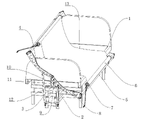
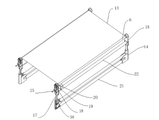
本発明の寝返り支援装置の基本構成を図1に示す。本発明の寝返り支援装置は、それぞれがベッドの両側に設けられている、互いに平行に配置された2つの支持フレーム5と、それぞれが2つの支持フレーム5に回転可能に接続され、且つ軸が平行に配置されている2つのローラ6と、それぞれが2つのローラ6を駆動するように接続され、且つ2つのローラを、その軸を中心に同期して回転するように駆動するための駆動機構と、2つのローラ6の間に設けられたフレキシブルキャリア13であって、その両端が2つのローラ6にそれぞれ巻かれ、前記2つのローラ6が前記駆動機構の駆動によって同一方向に回転するときに、前記フレキシブルキャリア13が移動するとともにその移動方向に沿って一方のローラ6から解放され同時に他方のローラ6に巻かれるフレキシブルキャリア13と、を具備する。本発明の寝返り支援装置は、さらにベッドの頭部と尾部に溶接されたベース2を具備し、ローラ6の端部に駆動機構が取り付けられる。具体的には、支持フレーム5に2個のブラケットがスレーブされてボルト止めされ、駆動機構はブラケットに取り付けられたローラモータ7であり、ローラモータ7のローラ6にローラ6の端部がキーで固定されるように構成されている。支持フレーム5の上方にはローラ6が配置され、このローラ6にフレキシブルキャリア13が巻かれており、このフレキシブルキャリア13は、端部がローラ6に接着固定された不織布であることが好ましく、また、綿、プラスチック布、ナイロン布等の材質であってもよい。
FIG. 1 shows the basic configuration of the turning-over assisting device of the present invention. The turning assist device of the present invention consists of two supporting
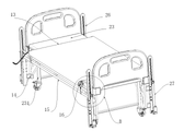
前記支持フレーム5はアームレストフレームであり、支持フレーム5の端部にスイングアーム4がボルト止めされる。スイングアーム4は円弧状であり、スイングアーム4には、複数の重量軽減孔8が設けられている。スイングアーム4の支持フレーム5から離れた端部は、ベース2に回転可能に連結されている。具体的には、ベース2の上部が連結ベース3にボルト止めされており、連結ベース3は、縦方向に沿って4個の連結孔10が形成された垂直な連結ロッド11を具備し、スイングアーム4と連結ロッド11の上部の連結孔10がピンで接続されている。スイングアーム4の中間部には昇降機構が回転可能に接続されており、昇降機構はベース2に回転可能に接続されている。昇降機構は油圧ロッド12であり、スイングアーム4の中間部とベース2には支持体9がボルトで固定されており、支持体9には2つのイヤープレートが一体的に形成されており、イヤープレートにはいずれもピン孔が設けられており、油圧ロッド12の両端部がピンで支持体9に接続されている。油圧ロッド12は、0°~75°の角度でベッド表面が上向きにスイングするようにスイングアーム4を駆動し、油圧ロッド12は、0°~16°の角度でベッド表面が下向きにスイングするようにスイングアーム4を駆動するように構成されている。
The
具体的な実施形態は、以下のように示される。即ち、実際には、ベッドの頭部及び尾部のベッドフレームの両方にベース2を溶接し、ベッド1の両側に支持フレーム5を設置し、支持フレーム5の端部に設けたスイングアーム4を、ベース2の上端に設けた連結座3にピンで接続する。連結ロッド11の上端に設けた連結孔10に連結し、両側のスイングアーム4をそれぞれ連結ロッド11の前側及び後側に当接させることが好ましい。 また、2つの支持フレーム5のローラ6の間には同一のフレキシブルキャリア13が挟まれて巻かれており、ローラモータ7と油圧レバー12は共にワイヤでコントローラに接続されている。通常の使用時には、図3に示すように、油圧ロッド12が収縮状態に保持されているので、スイングアーム4がベッド本体1の両側の下に位置する。スイングアーム4は最大角度16°で下方にスイングすることで、ベッド本体1の下に有効に収納でき、ベッド本体1の両側のローラ6がフレキシブルキャリア13をベッド上面に敷設することができる。
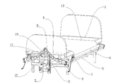
また、麻痺や下肢の不便を抱える患者は、ベッドに入る過程で、通常は介護者がベッドに運んだり、ベッドに乗せたりする必要があり、操作が不便で、労働負担が大きく、予期せぬ傷害をもたらしやすいという問題がある。この問題点について、本願の装置を使用して解決する。まず、患者がベッドの端部に座る/横たわることを支援し、次いでローラモータを起動してフレキシブルキャリア13を一方側に巻き取るようにし、これにより患者をベッドの中央部に移動させるように駆動することができる。 また、途中でスイングアームによってフレキシブルキャリア13を持ち上げることができ、その結果、フレキシブルキャリア13が患者をベッドから持ち上げるようにして、ベッドマットレスを乱すことなく、移動をスムーズに行うことができる。また、フレキシブルキャリア13に乗った患者を、スイングアームの昇降によりベッドの中央部に向かってスライドさせるようにしてもよい。このように、寝たきりの患者の寝返りを支援する機能に加えて、運動障害の人がベッドに入るのを支援する機能も具備する。寝たきりの患者がフレキシブルキャリア13上に横たわった後、寝たきりの患者や介護者の活動に影響を与えることなくベッド本体1の下に支持フレーム5が収納される。不織布材のフレキシブルキャリア13が寝たきりの患者の活動に影響を与えることなくベッド面に敷設され、マットレスの保護層として機能するようになっている。図2に示すように、寝たきりの患者が寝返りを打つ必要がある場合には、コントローラにより連結ロッド11との連結点を中心にスイングアーム4を上方にスイングするように、油圧ロッド12の伸長を制御し、支持フレーム5とローラ6を上方に揺動させると同時に、ローラモータ7によりローラ6を回転するように駆動してフレキシブルキャリア13の一部を解放する。これにより、支持フレーム5とローラ6をベッド表面上にスムーズに持ち上げることができ、ベッド面に敷設されたフレキシブルキャリア13が傾いた状態になり、寝たきりの患者が片側へ寝返りすることを支援する力が作用し、実際のニーズに応じて両側のローラ6が上下に揺動したり回転したりするように制御される。フレキシブルキャリア13をベッド表面上に敷き詰めた状態にする。
傾いた状態では、リカンベントに片側に旋回するための補助力がかかるように、実際のニーズに応じて両側のローラ6のスイング、昇降及び回転を制御する。また、スイングアーム4の上方への最大スイング角度は75°であるので、ローラ6を持ち上げた後、フレキシブルキャリア13の片側を、所定の高さに持ち上げることにより、寝たきりの患者の寝返りの支援を行うことができ、寝たきりの患者の寝返りを容易にすることができる。全体の構造がシンプルで実用的であり、寝たきりの患者への支援は、フレキシブルキャリア13で柔軟な密着力を付与することであり、寝返りの支援過程では、より優しく、ベッドマットレスに影響を与えず、一般病棟でも広く使用できる。
A specific embodiment is presented as follows. That is, in practice, the
In addition, patients with paralysis and lower extremity inconvenience, in the process of getting into bed, usually need to be carried or put on the bed by caregivers, which is inconvenient to operate, heavy labor burden, and unexpected. There is a problem that it is easy to cause injury. This problem is solved using the device of the present application. First, the patient is assisted to sit/lie on the edge of the bed, and then the roller motor is driven to wind the
In the tilted state, the swing, elevation and rotation of the
本発明の一実施形態である実施例1について、以下に説明する。ローラモータ7と油圧ロッド12はワイヤを介して制御端子に接続されている。制御端末はコンピュータであることが好ましく、本実施形態では、制御端末はベッド本体1と共に病室内に配置され、制御端末はワイヤを介してベッドキャリーコントローラに接続されている。本実施形態の使用状態では、寝たきりの患者がベッドキャリーコントローラを介して自分で便利に寝返りを打つことができ、介護者もベッドキャリーコントローラを介して介護時に寝たきりの患者が寝返りを打つのを容易に支援することができ、より便利に使用することができる。
Example 1, which is one embodiment of the present invention, will be described below. The
本発明の一実施形態では、制御端末は制御室に個別に配置され、制御室は複数の病棟に配置された寝返り支援装置の集中管理を行う。この構成では、非接触での集中管理が便利であり、老人ホームやナーシングホームなどの寝返り支援に対するニーズが集中している場所に適している。 In one embodiment of the present invention, the control terminals are individually located in a control room, and the control room centrally manages the turn assist devices located in multiple hospital wards. This configuration is convenient for non-contact centralized management, and is suitable for places where needs for turning over support are concentrated, such as nursing homes and nursing homes.
本発明の一実施形態では、ベッドヘッドまたはスイングアーム4に監視カメラを設け、監視カメラをワイヤで制御端末に接続し、制御端末により、寝返り支援装置を視覚化して遠隔操作できるので、寝たきりの患者の寝返り支援操作を遠隔で行うのに便利である。
In one embodiment of the present invention, a surveillance camera is provided on the bed head or
本発明の一実施形態では、携帯電話ソフトウェアとQRコード認識技術を併用する。各大スイング寝返り支援装置には、独立した識別用QRコードが設置され、携帯電話ソフトウェアはQRコードを認識することで対応する大スイング寝返り支援装置の制御権限を取得する。さらに、寝たきりの患者や介護スタッフは携帯電話を介していつでもどこでも大スイング寝返り支援装置を制御できるので使い勝手が良い。 One embodiment of the present invention combines mobile phone software with QR code recognition technology. Each large-swing tossing-and-turning assist device is provided with an independent identification QR code, and the mobile phone software recognizes the QR code to acquire control authority for the corresponding large-swing tossing-and-turning assist device. In addition, bedridden patients and care staff can control the large-swing tossing-and-turning support device anytime, anywhere via a mobile phone, which is convenient.
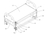
図4及び図6に示すように、本発明の寝返り支援装置は、基本的には、平行に設置された2つの支持フレーム5を含み、各支持フレーム5は、並列した2つの台座14と、2つの台座14に対応する2つのラック15を具備する。各台座14は、2枚のシェルプレート24をスナップ結合して構成される。2枚のシェルプレート24をネジ止めで接続してもよく、各台座14の内部には、油圧シリンダ16が配置される取付キャビティが設けられており、油圧シリンダ16の出力軸が上方に向けて縦方向に設置されている。油圧シリンダ16の出力軸の上部にはトップロッド17が溶接されており、トップロッド17の上部には横方向のピン孔が設けられている。 各フレーム15の下端部にはU字型溝が設けられており、U字型溝の側壁には貫通孔が設けられ、U字型溝の両側壁に形成された貫通孔の間にはピンバーが通され、U字型溝にはトップバー17の上端部が挿入され、ピンバーがトップバー17のピン孔に挿入されている。同一の支持フレームの2つのラック15の上端部の間にはローラ6が回転自在に接続されている。具体的には、ラック15の上端部には軸受が埋め込まれており、ローラ6と軸受は、締り嵌めになっている。ローラ6の一端は軸受を越えて延び、従動ギア19にキー結合し、従動ギア19の下方にあるラック15にモータ20がねじ止めされ、モータ20はローラ6の下方に横向きに取り付けられ、モータ20の本体構造は2つのラック15の間に配置されている。モータ20が搭載されるラック15には、モータ20の出力軸に対応する貫通孔が設けられ、モータ20の出力軸は、ラック15を介して能動ギア18に横方向にキー結合されており、能動ギア18は従動ギア19に噛み合っている。2つの支持フレーム2上にあるローラ6の間にはフレキシブルキャリアが着脱可能に接続されており、ローラ6には軸方向に沿って複数のネジ孔が設けられ、ネジ孔内にはネジが連結され、フレキシブルキャリア13は、ネジによってローラ6に押し付けられている。
As shown in FIGS. 4 and 6, the turning assist device of the present invention basically includes two supporting
同一の支持フレーム2の2つのラック15の間には、支持管22が溶接され、支持管22はモータ20の下方に位置し、支持管22内にはモータ20に接続されたワイヤが挿入されている。同一の支持フレーム2の2つの台座14の間には、縦方向に並列した2本のストップロッド21が溶接されており、このストップロッド21は支持フレームの構造を補強するものである。
また、2つの支持フレームに搭載されたモータ20は同期的に回転し、モータ20の制御回路構成は、順方向および逆方向のスイッチング回路を含む。
A
Also, the
具体的な実施過程は、以下のように示される。図2に示すように、使用時、医療用ベッド23の両側に2つの支持フレームを縦方向に配置することにより、医療用ベッド23のベッドマットレスを挟んでフレキシブルキャリア13が敷設され、医療用ベッド23の使用時にはフレキシブルキャリア13の上に患者が横たわる。 また、患者が介護や治療中に寝返りを打つ必要がある場合には、4つの油圧シリンダ16を同期して上方にジャッキアップするように制御し、トップロッド17によってフレーム15を上方にジャッキアップする。これに伴って2つのローラ6を同期して上方にジャッキアップするので、フレキシブルキャリア13とベッドマットレスとの間の摩擦力が相対的に低減され、フレキシブルキャリア13がベッドマットレスを巻き付けるように動作するのを防止することも可能となる。さらに、支持フレームに設けられたモータ20が動作するように制御され、2つのモータ20が同期して動作することにより、能動ギア18が従動ギア19を駆動し、従動ギア19がローラ6を回転させ、医療用ベッド23の両側のローラ6が同一方向に同期して回転することにより、フレキシブルキャリア13が医療用ベッド23の一方の側に移動し、移動過程で患者の寝返り動作が実現される。また、使用過程では一方の側のローラ6を他方の側のローラ6よりも高くジャッキアップして、フレキシブルキャリア13を傾斜させて患者の寝返りを打ちやすくすることができる。使用後、フレキシブルキャリア13が破損したり汚れたりした場合には、ローラ6のネジを緩めてフレキシブルキャリア13をローラ6から取り外して交換することができるので、使用状況に応じて容易に交換やメンテナンスを行うことができる。
A specific implementation process is shown as follows. As shown in FIG. 2, when in use, two support frames are arranged longitudinally on both sides of the
本実施例では、使用過程において、支持フレームが平坦なプロファイル構造を有し、医療用ベッド23に接して使用することができる。フレキシブルキャリア13は、ベッドマットレスの上に敷設され、使用しない時には、2つの支持フレームをくっつけて置くため、占有スペースは小さい。一方では、フレキシブルキャリア13がベッドマットレスの上に敷設されているので、通気性を向上させることができ、患者の褥瘡を防止することができ、もう一方では患者が寝返りを打つ過程でベッドマットレスが横転することを回避することができる。このため、介護作業により役立ち、さらに、患者に寝返りを打たせる操作は柔軟であり、患者に怪我をさせることがない。本発明の操作は、油圧シリンダ16とモータ20によって駆動され、動作が高度に自動化され、患者の寝返りを支援するための医療従事者の労働負担が低く、操作が便利である。本発明は、全体の構成が簡単であり、材料の入手が容易であり、フレキシブルキャリア13は交換して使用でき、既存の装置と比較して製造コストや使用コストが低く、医療上及び健康上の条件により適合する。
In this embodiment, in the process of use, the support frame has a flat profile structure and can be used against the
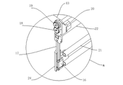
本発明の一実施例を、図8及び図9に示す。ここでは、医療用ベッド23のベッドフレーム231に台座14がボルトで固定され、台座14には縦方向のスライド26がボルトで固定される。スライド26は中央部に縦(垂直)方向に沿って細長い貫通孔32が設けられた板状部材であり、スライド26は医療用ベッド23の四隅の外側に配設され、スライド26の外側にある台座14に油圧ロッド27がボルトで固定されている。駆動機構は、フレーム15の上部に取り付けられ、且つローラ6と同軸に配置されているボールベアリング28のモータである。具体的にはフレーム15の上部に、並列して2つのフェルール29が溶接され、ボールベアリング28のモータは、それぞれ締り嵌めによってローラ6の両端に接続されている。ローラ6は導電性金属で構成され、ローラ6の表面は絶縁材料の層(絶縁材層)で覆われている。本実施例における絶縁材層はゴム層であり、ローラ6の両端はフレーム15のフェルール29にクランプされている。フレーム15のベッドの頭部及び尾部の端部には、縦方向に並設された2つのプーリー31がボルトで固定されている。2つプーリー31はスライド26の細長い貫通孔32内を摺動し、2つのプーリー31の間にはフレーム15のフェルール29に接続されたプッシュブロック30が設けられ、プッシュブロック30は細長い貫通孔32を通って設置される。細長いプッシュブロック30の端部は、貫通孔32を通って油圧ロッド27の上端にヒンジで固定されている。
An embodiment of the present invention is shown in FIGS. 8 and 9. FIG. Here, the
本実施例では、支持フレームが台座14によって医療用ベッド23のベッドフレーム231の両側に接続して設けられる。フレキシブルキャリア13が医療用ベッド23のマットレスの上にまたがっており、患者が寝返りを打つことが必要であるときには、医療用ベッド23の四隅に設けられた油圧ロッド27を同期してまたは個別に昇降して、可撓性キャリア13を平行に持ち上げてベッドマットレスとの間の摩擦力を減らすようにしてもよいし、片側または単一の角度で持ち上げることにより患者の体を横向きにしてもよい。このようにして、フラットなデザインを維持することで占有するスペースが少なくなると同時に、患者の寝返りを支援する効果がより向上し、より多くのシナリオを適用できる。
In this embodiment, a support frame is provided connected to both sides of the
本発明の一実施例では、図7に示すように、能動ギア18のモータ20から離れた側端にハンドル25が同軸的に接続されている。このように、モータ20で作業するのに支障があるとき、例えば電源がないときには、ハンドル25を手動でクランクさせて、ローラ6を回転するように駆動することで患者の寝返りを達成できる。
In one embodiment of the invention, a
本発明の一実施例では、モータ20には、携帯電話APPと相互接続することができるブルートゥース制御モジュールまたは無線制御モジュールが統合されている。このように、本技術手段では、手動モードとインテリジェントモードの両方を有し、医療従事者の不在時には、患者自身は、携帯電話のAPPによってインテリジェントに制御することができ、外力を必要とせずに患者が容易に寝返りを達成することができ、実用性がより高い。
In one embodiment of the present invention, the
以上の記載は、本発明の一実施形態に過ぎず、技術手段において周知の特定の構造および/または特性などの公知常識は、本明細書に過度に記載されていない。当業者にとっては、本発明の構造から逸脱することなく、いくつかの変形および改良が可能であり、これらも本発明の保護範囲とみなすべきであり、いずれも本発明の実施の効果および特許の実用性に影響を与えるものではないことに留意すべきである。 本願で主張される保護範囲は、その特許請求の範囲の記載に従うものとし、明細書中の特定の実施形態および他の記載は、特許請求の範囲の内容を解釈するために使用することができる。 The above description is only one embodiment of the present invention, and common knowledge such as specific structures and/or characteristics that are well known in technical means are not excessively described in this specification. For those skilled in the art, several variations and improvements are possible without departing from the structure of the present invention, which should also be regarded as the protection scope of the present invention, and both the effect of the implementation of the present invention and the patent. It should be noted that this does not affect practicality. The scope of protection claimed in this application shall be subject to the description of the claims, and specific embodiments and other statements in the specification may be used to interpret the content of the claims. .
Claims (2)
それぞれがベッドの両側に設けられ、互いに平行に配置された2つの支持フレームと、
それぞれが前記2つの支持フレームに回転可能に接続された2つのローラと、
それぞれが前記2つのローラを駆動するように接続され、且つ前記2つのローラを、その軸を中心に同期して回転するように駆動するための駆動機構と、
前記2つのローラの間に設けられたフレキシブルキャリアであって、その両端が前記2つのローラにそれぞれ巻かれ、前記2つのローラが前記駆動機構の駆動によって同一方向に回転するとき、前記フレキシブルキャリアが移動するとともにその移動方向に沿って一方のローラから解放され、同時に他方のローラに巻かれるフレキシブルキャリアと、
を具備し、
前記支持フレームはアームレストフレームであり、前記支持フレームの端部がスイングアームに接続され、前記スイングアームの端部がベースに回転可能に接続され、前記スイングアームの中間部が昇降機構に回転可能に接続され、前記昇降機構が前記ベースに回転可能に接続され、前記ベースがベッドの頭部または尾部に固定して接続され、
前記スイングアームは円弧状であり、前記スイングアームには、複数の重量軽減孔が設けられ、
前記ベースの上部には連結座が設けられ、前記連結座は縦方向の連結レバーを具備し、前記スイングアームと前記連結レバーとの間にピン軸で接続され、
前記連結レバーには、縦方向に沿って複数の連結孔が設けられ、
前記昇降機構は油圧ロッドであり、前記スイングアームの中間部とベースに支持座が固定され、前記支持座には2つのイヤープレートが設けられ、前記2つのイヤープレートのそれぞれにピン孔が設けられ、前記油圧ロッドの両端がピンシャフトにより前記支持座に接続され、
前記ローラは前記支持フレームの上方に配置されることを特徴とする寝返り支援装置。 A turnover assist device,
two support frames, one on each side of the bed and arranged parallel to each other;
two rollers each rotatably connected to the two support frames;
a drive mechanism, each connected to drive the two rollers, for driving the two rollers to rotate synchronously about their axes;
A flexible carrier provided between the two rollers, wherein both ends of the flexible carrier are wound around the two rollers, and when the two rollers are rotated in the same direction by driving the drive mechanism, the flexible carrier is a flexible carrier that moves and is released from one roller along its direction of movement and simultaneously wound around the other roller;
and
The support frame is an armrest frame, the end of the support frame is connected to the swing arm, the end of the swing arm is rotatably connected to the base, and the middle part of the swing arm is rotatably connected to the lifting mechanism. wherein the lifting mechanism is rotatably connected to the base, the base is fixedly connected to the head or tail of the bed;
The swing arm has an arc shape, and the swing arm is provided with a plurality of weight reduction holes,
A connection seat is provided on the upper part of the base, the connection seat is provided with a vertical connection lever, and is connected between the swing arm and the connection lever by a pin shaft;
The connecting lever is provided with a plurality of connecting holes along the vertical direction,
The elevating mechanism is a hydraulic rod, a support seat is fixed to the intermediate part and the base of the swing arm, the support seat is provided with two ear plates, and each of the two ear plates is provided with a pin hole. , both ends of the hydraulic rod are connected to the support seat by pin shafts;
A turning assist device, wherein the roller is arranged above the support frame.
Applications Claiming Priority (4)
| Application Number | Priority Date | Filing Date | Title |
|---|---|---|---|
| CN202010864728.4 | 2020-08-25 | ||
| CN202010864728.4A CN111839947A (en) | 2020-08-25 | 2020-08-25 | Active turnover device |
| CN202023019814.XU CN213964037U (en) | 2020-12-15 | 2020-12-15 | Large-swing auxiliary turnover device |
| CN202023019814.X | 2020-12-15 |
Publications (2)
| Publication Number | Publication Date |
|---|---|
| JP2022037868A JP2022037868A (en) | 2022-03-09 |
| JP7207635B2 true JP7207635B2 (en) | 2023-01-18 |
Family
ID=80355828
Family Applications (1)
| Application Number | Title | Priority Date | Filing Date |
|---|---|---|---|
| JP2021047209A Active JP7207635B2 (en) | 2020-08-25 | 2021-03-22 | Rolling over support device |
Country Status (3)
| Country | Link |
|---|---|
| US (1) | US20220062079A1 (en) |
| JP (1) | JP7207635B2 (en) |
| KR (1) | KR102604492B1 (en) |
Families Citing this family (16)
| Publication number | Priority date | Publication date | Assignee | Title |
|---|---|---|---|---|
| CN114587818B (en) * | 2022-03-30 | 2023-11-10 | 贵州省建筑医院 | Nursing bed capable of automatically assisting turning over |
| CN114788765B (en) * | 2022-04-19 | 2024-05-14 | 商丘市第一人民医院 | A therapeutic assisting device for use in a pediatric intensive care unit |
| CN114668604B (en) * | 2022-05-26 | 2022-09-09 | 首都医科大学宣武医院 | A device for assisting patients to transfer and turn over before and after surgery |
| CN115068234B (en) * | 2022-06-01 | 2024-09-20 | 金陵药业股份有限公司 | Nursing bed with automatic turn-over function |
| CN115351763B (en) * | 2022-08-09 | 2025-11-28 | 广东恒鑫智能装备股份有限公司 | Turnover mechanism |
| CN115487010B (en) * | 2022-08-29 | 2023-08-22 | 中国人民解放军空军军医大学 | An auxiliary lifting nursing bed for orthopedic patients |
| CN115645175A (en) * | 2022-11-10 | 2023-01-31 | 段文娜 | Old patient nurses auxiliary device |
| CN115708746A (en) * | 2022-11-16 | 2023-02-24 | 复旦大学 | Rigid-flexible auxiliary turning-over device, using method and nursing bed |
| CN115778705A (en) * | 2022-11-16 | 2023-03-14 | 浙江佑欣智能医疗科技有限公司 | Flexible turning nursing bed and control method thereof |
| US12137803B2 (en) * | 2022-11-17 | 2024-11-12 | Daniel Wampler | Force transfer apparatus for massage and therapeutic bodywork table |
| CN115778575B (en) * | 2023-02-13 | 2023-04-07 | 潍坊医学院附属医院 | Head positioning bracket |
| CN116035817A (en) * | 2023-03-08 | 2023-05-02 | 潍坊医学院附属医院 | Nursing bed for assisting turning over |
| CN116370217B (en) * | 2023-04-20 | 2023-11-03 | 南京林业大学 | Auxiliary device for elderly people to lie down |
| CN118370661B (en) * | 2024-06-20 | 2024-10-25 | 中国人民解放军海军第九七一医院 | Nursing transfer device |
| CN119819518B (en) * | 2025-03-14 | 2025-10-10 | 嘉善思捷机械有限公司 | Automobile paint spraying roll-over stand with automatic locking mechanism and use method thereof |
| CN120305065B (en) * | 2025-06-13 | 2025-08-12 | 普康健康产业(重庆)有限公司 | A multifunctional side-turnable electric hospital bed |
Citations (2)
| Publication number | Priority date | Publication date | Assignee | Title |
|---|---|---|---|---|
| JP2002136553A (en) | 2000-11-01 | 2002-05-14 | Katsuji Nakanishi | Simplified device for preventing bed sore |
| DE102016220175A1 (en) | 2015-10-16 | 2017-04-20 | Peter Leibl | Relocation device and nursing bed arrangement with such |
Family Cites Families (12)
| Publication number | Priority date | Publication date | Assignee | Title |
|---|---|---|---|---|
| GB1447163A (en) * | 1974-03-13 | 1976-08-25 | Gibbs J R | Beds |
| NO160563C (en) * | 1981-07-27 | 1989-05-03 | Vasterviks Pulverlackering Ab | SIDE TURNOVER OF SLEEPING PERSONS. |
| IT1225494B (en) * | 1988-12-23 | 1990-11-20 | Italpres Snc Di Fregni & C | APPARATUS TO PREVENT TRAINING AND TAKE CARE OF PADS IN LONG PATIENTS |
| JP2510841B2 (en) * | 1994-02-24 | 1996-06-26 | パラマウントベッド株式会社 | Bed with rolling mechanism |
| US5640729A (en) * | 1994-03-03 | 1997-06-24 | Marino; Mario Hector Silvio | Ergonomic mechanism for use in hospitals |
| US5659905A (en) * | 1994-07-26 | 1997-08-26 | Palmer, Jr.; John M. | Patient transfer/turning bed |
| JP3310835B2 (en) * | 1995-08-29 | 2002-08-05 | 悦蔵 福田 | A bed device for assisting postural change |
| NL1013069C2 (en) * | 1999-09-16 | 2001-03-19 | Gerrit Johannes Termaten | Bed comprises frame and support surface for recumbent person, support surface having longitudinal sheet-shaped component |
| US20090013469A1 (en) * | 2007-07-14 | 2009-01-15 | Johnson Annamae A | Bed attachment for preventing and treating decubitus ulcers |
| US7895688B1 (en) * | 2007-10-10 | 2011-03-01 | Jay Ronald Rowes | Decubiti ulcer system |
| EP3703535B1 (en) * | 2017-10-30 | 2022-02-09 | Vendlet ApS | Guard rail for a bed, guide rack for a guard rail and a bed with such guard rail |
| US20210077326A1 (en) * | 2019-09-12 | 2021-03-18 | BeacoHealth Pty Ltd | Automated turning system for an immobile person |
-
2021
- 2021-03-22 JP JP2021047209A patent/JP7207635B2/en active Active
- 2021-03-26 KR KR1020210039917A patent/KR102604492B1/en active Active
- 2021-04-16 US US17/233,322 patent/US20220062079A1/en active Pending
Patent Citations (2)
| Publication number | Priority date | Publication date | Assignee | Title |
|---|---|---|---|---|
| JP2002136553A (en) | 2000-11-01 | 2002-05-14 | Katsuji Nakanishi | Simplified device for preventing bed sore |
| DE102016220175A1 (en) | 2015-10-16 | 2017-04-20 | Peter Leibl | Relocation device and nursing bed arrangement with such |
Also Published As
| Publication number | Publication date |
|---|---|
| US20220062079A1 (en) | 2022-03-03 |
| KR20220026464A (en) | 2022-03-04 |
| KR102604492B1 (en) | 2023-11-22 |
| JP2022037868A (en) | 2022-03-09 |
Similar Documents
| Publication | Publication Date | Title |
|---|---|---|
| JP7207635B2 (en) | Rolling over support device | |
| US7434278B2 (en) | Apparatus for patient mobility | |
| US6668396B2 (en) | Turning mechanism for a patient confined to a bed | |
| US5539941A (en) | Bed patient health care system | |
| ES2779772T3 (en) | Stretcher for people with reduced mobility | |
| US8261380B2 (en) | Stretcher accessory for turning a patient | |
| CN102871815A (en) | Medical surgical transfer bed | |
| CN215779231U (en) | Patient shifts mechanism | |
| CN111449872A (en) | Nursing bed for severe patients and paralytic patients | |
| CN111467142A (en) | A bed chair changing roller transfer wheelchair | |
| CN111249084A (en) | Multifunctional electric sickbed | |
| CN211131745U (en) | Bed is transported to bed patient | |
| CN111839947A (en) | Active turnover device | |
| CN203060210U (en) | Medical operation transferring bed | |
| CN112515876A (en) | Hidden supplementary turning-over device and turn-over bed | |
| AU2007219308B2 (en) | Patient Turning Apparatus | |
| CN222218095U (en) | A nursing bed lifting mechanism | |
| CN210301609U (en) | Novel applicable diagnosis and treatment bed | |
| CN113274221B (en) | ICU nursing device for transferring patient | |
| CN110151438B (en) | Medical bed and method for transferring patient by means of medical bed | |
| CN115501054A (en) | An intelligent bed rest device | |
| CN111216140B (en) | Hold in palm formula multi-arm cooperation and transport nursing robot | |
| JPH06209970A (en) | Care lift | |
| CN218391506U (en) | Full-automatic turnover bed | |
| JP4320739B2 (en) | Assistance device |
Legal Events
| Date | Code | Title | Description |
|---|---|---|---|
| A521 | Request for written amendment filed |
Free format text: JAPANESE INTERMEDIATE CODE: A523 Effective date: 20210322 |
|
| A621 | Written request for application examination |
Free format text: JAPANESE INTERMEDIATE CODE: A621 Effective date: 20210322 |
|
| A131 | Notification of reasons for refusal |
Free format text: JAPANESE INTERMEDIATE CODE: A131 Effective date: 20220517 |
|
| A521 | Request for written amendment filed |
Free format text: JAPANESE INTERMEDIATE CODE: A523 Effective date: 20220816 |
|
| A131 | Notification of reasons for refusal |
Free format text: JAPANESE INTERMEDIATE CODE: A131 Effective date: 20220830 |
|
| A521 | Request for written amendment filed |
Free format text: JAPANESE INTERMEDIATE CODE: A523 Effective date: 20221115 |
|
| TRDD | Decision of grant or rejection written | ||
| A01 | Written decision to grant a patent or to grant a registration (utility model) |
Free format text: JAPANESE INTERMEDIATE CODE: A01 Effective date: 20221129 |
|
| A61 | First payment of annual fees (during grant procedure) |
Free format text: JAPANESE INTERMEDIATE CODE: A61 Effective date: 20221221 |
|
| R150 | Certificate of patent or registration of utility model |
Ref document number: 7207635 Country of ref document: JP Free format text: JAPANESE INTERMEDIATE CODE: R150 |
|
| R250 | Receipt of annual fees |
Free format text: JAPANESE INTERMEDIATE CODE: R250 |