JP7204455B2 - Vibration actuators, pan heads, and electronics - Google Patents
Vibration actuators, pan heads, and electronics Download PDFInfo
- Publication number
- JP7204455B2 JP7204455B2 JP2018225869A JP2018225869A JP7204455B2 JP 7204455 B2 JP7204455 B2 JP 7204455B2 JP 2018225869 A JP2018225869 A JP 2018225869A JP 2018225869 A JP2018225869 A JP 2018225869A JP 7204455 B2 JP7204455 B2 JP 7204455B2
- Authority
- JP
- Japan
- Prior art keywords
- vibration
- type actuator
- vibrating body
- vibration type
- circuit board
- Prior art date
- Legal status (The legal status is an assumption and is not a legal conclusion. Google has not performed a legal analysis and makes no representation as to the accuracy of the status listed.)
- Active
Links
- 238000001514 detection method Methods 0.000 claims description 15
- 238000006243 chemical reaction Methods 0.000 claims description 13
- 238000010586 diagram Methods 0.000 description 12
- 238000003384 imaging method Methods 0.000 description 10
- 239000000463 material Substances 0.000 description 9
- 238000005452 bending Methods 0.000 description 7
- 238000000034 method Methods 0.000 description 6
- 238000006073 displacement reaction Methods 0.000 description 5
- 230000007246 mechanism Effects 0.000 description 5
- 230000002159 abnormal effect Effects 0.000 description 4
- 230000008859 change Effects 0.000 description 3
- 230000004048 modification Effects 0.000 description 3
- 238000012986 modification Methods 0.000 description 3
- 239000011347 resin Substances 0.000 description 3
- 229920005989 resin Polymers 0.000 description 3
- XEEYBQQBJWHFJM-UHFFFAOYSA-N Iron Chemical compound [Fe] XEEYBQQBJWHFJM-UHFFFAOYSA-N 0.000 description 2
- 238000005336 cracking Methods 0.000 description 2
- 238000013016 damping Methods 0.000 description 2
- 230000005764 inhibitory process Effects 0.000 description 2
- 238000004519 manufacturing process Methods 0.000 description 2
- 230000002093 peripheral effect Effects 0.000 description 2
- 229910000679 solder Inorganic materials 0.000 description 2
- 229910001220 stainless steel Inorganic materials 0.000 description 2
- 239000010935 stainless steel Substances 0.000 description 2
- CWYNVVGOOAEACU-UHFFFAOYSA-N Fe2+ Chemical compound [Fe+2] CWYNVVGOOAEACU-UHFFFAOYSA-N 0.000 description 1
- 239000000853 adhesive Substances 0.000 description 1
- 230000001070 adhesive effect Effects 0.000 description 1
- 238000009529 body temperature measurement Methods 0.000 description 1
- 230000007423 decrease Effects 0.000 description 1
- 230000006866 deterioration Effects 0.000 description 1
- 230000000694 effects Effects 0.000 description 1
- 239000002783 friction material Substances 0.000 description 1
- 230000005484 gravity Effects 0.000 description 1
- 230000012447 hatching Effects 0.000 description 1
- 229910052742 iron Inorganic materials 0.000 description 1
- 238000005304 joining Methods 0.000 description 1
- 238000012544 monitoring process Methods 0.000 description 1
- 238000005121 nitriding Methods 0.000 description 1
- 238000007747 plating Methods 0.000 description 1
- 230000008569 process Effects 0.000 description 1
- 230000011514 reflex Effects 0.000 description 1
- 230000004044 response Effects 0.000 description 1
- 230000002194 synthesizing effect Effects 0.000 description 1
Images


Classifications
-
- G—PHYSICS
- G03—PHOTOGRAPHY; CINEMATOGRAPHY; ANALOGOUS TECHNIQUES USING WAVES OTHER THAN OPTICAL WAVES; ELECTROGRAPHY; HOLOGRAPHY
- G03B—APPARATUS OR ARRANGEMENTS FOR TAKING PHOTOGRAPHS OR FOR PROJECTING OR VIEWING THEM; APPARATUS OR ARRANGEMENTS EMPLOYING ANALOGOUS TECHNIQUES USING WAVES OTHER THAN OPTICAL WAVES; ACCESSORIES THEREFOR
- G03B17/00—Details of cameras or camera bodies; Accessories therefor
- G03B17/56—Accessories
- G03B17/561—Support related camera accessories
-
- G—PHYSICS
- G03—PHOTOGRAPHY; CINEMATOGRAPHY; ANALOGOUS TECHNIQUES USING WAVES OTHER THAN OPTICAL WAVES; ELECTROGRAPHY; HOLOGRAPHY
- G03B—APPARATUS OR ARRANGEMENTS FOR TAKING PHOTOGRAPHS OR FOR PROJECTING OR VIEWING THEM; APPARATUS OR ARRANGEMENTS EMPLOYING ANALOGOUS TECHNIQUES USING WAVES OTHER THAN OPTICAL WAVES; ACCESSORIES THEREFOR
- G03B3/00—Focusing arrangements of general interest for cameras, projectors or printers
- G03B3/10—Power-operated focusing
-
- G—PHYSICS
- G01—MEASURING; TESTING
- G01K—MEASURING TEMPERATURE; MEASURING QUANTITY OF HEAT; THERMALLY-SENSITIVE ELEMENTS NOT OTHERWISE PROVIDED FOR
- G01K7/00—Measuring temperature based on the use of electric or magnetic elements directly sensitive to heat ; Power supply therefor, e.g. using thermoelectric elements
- G01K7/02—Measuring temperature based on the use of electric or magnetic elements directly sensitive to heat ; Power supply therefor, e.g. using thermoelectric elements using thermoelectric elements, e.g. thermocouples
-
- G—PHYSICS
- G01—MEASURING; TESTING
- G01K—MEASURING TEMPERATURE; MEASURING QUANTITY OF HEAT; THERMALLY-SENSITIVE ELEMENTS NOT OTHERWISE PROVIDED FOR
- G01K7/00—Measuring temperature based on the use of electric or magnetic elements directly sensitive to heat ; Power supply therefor, e.g. using thermoelectric elements
- G01K7/16—Measuring temperature based on the use of electric or magnetic elements directly sensitive to heat ; Power supply therefor, e.g. using thermoelectric elements using resistive elements
- G01K7/22—Measuring temperature based on the use of electric or magnetic elements directly sensitive to heat ; Power supply therefor, e.g. using thermoelectric elements using resistive elements the element being a non-linear resistance, e.g. thermistor
- G01K7/223—Measuring temperature based on the use of electric or magnetic elements directly sensitive to heat ; Power supply therefor, e.g. using thermoelectric elements using resistive elements the element being a non-linear resistance, e.g. thermistor characterised by the shape of the resistive element
-
- H—ELECTRICITY
- H01—ELECTRIC ELEMENTS
- H01C—RESISTORS
- H01C7/00—Non-adjustable resistors formed as one or more layers or coatings; Non-adjustable resistors made from powdered conducting material or powdered semi-conducting material with or without insulating material
- H01C7/008—Thermistors
-
- H—ELECTRICITY
- H02—GENERATION; CONVERSION OR DISTRIBUTION OF ELECTRIC POWER
- H02N—ELECTRIC MACHINES NOT OTHERWISE PROVIDED FOR
- H02N2/00—Electric machines in general using piezoelectric effect, electrostriction or magnetostriction
- H02N2/0005—Electric machines in general using piezoelectric effect, electrostriction or magnetostriction producing non-specific motion; Details common to machines covered by H02N2/02 - H02N2/16
- H02N2/005—Mechanical details, e.g. housings
- H02N2/0055—Supports for driving or driven bodies; Means for pressing driving body against driven body
- H02N2/006—Elastic elements, e.g. springs
-
- H—ELECTRICITY
- H02—GENERATION; CONVERSION OR DISTRIBUTION OF ELECTRIC POWER
- H02N—ELECTRIC MACHINES NOT OTHERWISE PROVIDED FOR
- H02N2/00—Electric machines in general using piezoelectric effect, electrostriction or magnetostriction
- H02N2/0005—Electric machines in general using piezoelectric effect, electrostriction or magnetostriction producing non-specific motion; Details common to machines covered by H02N2/02 - H02N2/16
- H02N2/0075—Electrical details, e.g. drive or control circuits or methods
- H02N2/0085—Leads; Wiring arrangements
-
- H—ELECTRICITY
- H02—GENERATION; CONVERSION OR DISTRIBUTION OF ELECTRIC POWER
- H02N—ELECTRIC MACHINES NOT OTHERWISE PROVIDED FOR
- H02N2/00—Electric machines in general using piezoelectric effect, electrostriction or magnetostriction
- H02N2/0005—Electric machines in general using piezoelectric effect, electrostriction or magnetostriction producing non-specific motion; Details common to machines covered by H02N2/02 - H02N2/16
- H02N2/009—Thermal details, e.g. cooling means
-
- H—ELECTRICITY
- H02—GENERATION; CONVERSION OR DISTRIBUTION OF ELECTRIC POWER
- H02N—ELECTRIC MACHINES NOT OTHERWISE PROVIDED FOR
- H02N2/00—Electric machines in general using piezoelectric effect, electrostriction or magnetostriction
- H02N2/10—Electric machines in general using piezoelectric effect, electrostriction or magnetostriction producing rotary motion, e.g. rotary motors
- H02N2/103—Electric machines in general using piezoelectric effect, electrostriction or magnetostriction producing rotary motion, e.g. rotary motors by pressing one or more vibrators against the rotor
-
- H—ELECTRICITY
- H02—GENERATION; CONVERSION OR DISTRIBUTION OF ELECTRIC POWER
- H02N—ELECTRIC MACHINES NOT OTHERWISE PROVIDED FOR
- H02N2/00—Electric machines in general using piezoelectric effect, electrostriction or magnetostriction
- H02N2/10—Electric machines in general using piezoelectric effect, electrostriction or magnetostriction producing rotary motion, e.g. rotary motors
- H02N2/16—Electric machines in general using piezoelectric effect, electrostriction or magnetostriction producing rotary motion, e.g. rotary motors using travelling waves, i.e. Rayleigh surface waves
- H02N2/163—Motors with ring stator
-
- G—PHYSICS
- G03—PHOTOGRAPHY; CINEMATOGRAPHY; ANALOGOUS TECHNIQUES USING WAVES OTHER THAN OPTICAL WAVES; ELECTROGRAPHY; HOLOGRAPHY
- G03B—APPARATUS OR ARRANGEMENTS FOR TAKING PHOTOGRAPHS OR FOR PROJECTING OR VIEWING THEM; APPARATUS OR ARRANGEMENTS EMPLOYING ANALOGOUS TECHNIQUES USING WAVES OTHER THAN OPTICAL WAVES; ACCESSORIES THEREFOR
- G03B2205/00—Adjustment of optical system relative to image or object surface other than for focusing
- G03B2205/0053—Driving means for the movement of one or more optical element
- G03B2205/0061—Driving means for the movement of one or more optical element using piezoelectric actuators
Description
本発明は、接触体と振動体を備えた、振動型アクチュエータに関するものである。 TECHNICAL FIELD The present invention relates to a vibration type actuator having a contact body and a vibrating body.
振動型アクチュエータは低速・大トルクなどの特徴から、例えば一眼レフカメラの撮影レンズにおけるオートフォーカスの駆動用モータとして実用化されており、近年はカメラ以外のさまざまな電子機器への適用も期待されている。例えば、ロボットアームの関節駆動やロボットハンドの回転駆動、監視カメラ等の撮像装置の雲台の回転駆動、画像形成装置の感光体ドラムの回転駆動への振動型アクチュエータの適用が期待されている。 Vibration-type actuators have been put to practical use, for example, as autofocus drive motors in the shooting lenses of single-lens reflex cameras, due to their low speed and high torque. there is For example, vibration actuators are expected to be applied to the joint drive of a robot arm, the rotation drive of a robot hand, the rotation drive of a camera platform of an imaging device such as a surveillance camera, and the rotation drive of a photosensitive drum of an image forming device.
このような他用途への適用に向けて、振動型アクチュエータの高出力化と高温環境におけるより安定的な動作が求められている。しかしながら、振動型アクチュエータは温度上昇によって振動体と接触体の摩擦効率の低下や、振動体を構成する弾性体と圧電素子の接着部の剥がれなどが発生し、振動型アクチュエータの性能に影響が生じるおそれがある。そのため、振動型アクチュエータの温度を検知し、検知された温度に基づいて振動型アクチュエータを制御し、動作させることが必要となっている。振動型アクチュエータの主な発熱源は、振動体と接触体が接する摩擦部と、振動体に設けられた振動源である圧電素子である。したがって摩擦部あるいは圧電素子の近傍が最も高い高温部となる。また、振動型アクチュエータの温度上昇による性能劣化も高温部で発生する。したがって、この高温部を振動体の温度の代表点として測定することが必要となっている。そこで、振動型アクチュエータの振動体に温度センサを取り付け、温度を検知する技術が提案されている(特許文献1、特許文献2参照)。 For applications to such other uses, there is a demand for higher output and more stable operation in high-temperature environments for vibration-type actuators. However, with vibration actuators, the frictional efficiency of the vibrating body and the contacting body decreases due to temperature rise, and the adhesive part between the elastic body and the piezoelectric element that make up the vibrating body peels off, etc., affecting the performance of the vibration type actuator. There is a risk. Therefore, it is necessary to detect the temperature of the vibration type actuator and control and operate the vibration type actuator based on the detected temperature. The main heat sources of the vibration-type actuator are the friction portion where the vibrating body and the contact body come into contact with each other, and the piezoelectric element, which is the vibration source provided on the vibrating body. Therefore, the friction part or the vicinity of the piezoelectric element becomes the hottest part. Also, the performance deterioration due to the temperature rise of the vibration type actuator also occurs in the high temperature section. Therefore, it is necessary to measure this high temperature portion as a representative point of the temperature of the vibrating body. Therefore, a technique has been proposed in which a temperature sensor is attached to the vibrating body of the vibration type actuator to detect the temperature (see Patent Documents 1 and 2).
しかしながら、特許文献1に記載された技術では、円盤状のステータにおける圧電素子が設けられた外周部側および摩擦部から遠い、内周部側に温度センサが設けられている。そのため、温度測定点の温度が熱の発生源よりも低く、振動体の高温部の温度を正確には測定できないという課題があった。 However, in the technique described in Patent Literature 1, temperature sensors are provided on the outer peripheral side of the disk-shaped stator where the piezoelectric element is provided and on the inner peripheral side far from the friction portion. Therefore, there is a problem that the temperature of the temperature measurement point is lower than the heat source, and the temperature of the high temperature portion of the vibrating body cannot be measured accurately.
また、特許文献2に記載された技術では、振動体の駆動振動の振幅が大きい部分に温度センサの配線があるため、配線が振動し、振動型アクチュエータに異音(鳴き)が発生するという課題があった。 Further, in the technique described in Patent Document 2, since the wiring of the temperature sensor is located in a portion where the driving vibration of the vibrating body has a large amplitude, the wiring vibrates, which causes an abnormal noise (squeal) to occur in the vibration type actuator. was there.
また、上記特許文献1と上記特許文献2に記載された技術では、振動型アクチュエータの組立時に温度センサを取り付ける工程が必要となり、組立が複雑になるという共通の課題があった。 Moreover, the techniques described in Patent Document 1 and Patent Document 2 above have a common problem in that a step of attaching the temperature sensor is required when assembling the vibration type actuator, which complicates the assembly.
そこで、本発明は、異音の発生を抑えつつ、効果的な振動型アクチュエータの温度測定が可能な振動型アクチュエータを提供する。 Accordingly, the present invention provides a vibrating actuator capable of effectively measuring the temperature of the vibrating actuator while suppressing the generation of abnormal noise.
上記課題を解決するため、
弾性体および電気-機械エネルギー変換素子を有する振動体と、
前記振動体と接する接触体と、
前記電気-機械エネルギー変換素子に給電するフレキシブルプリント基板と、
前記フレキシブルプリント基板と前記電気-機械エネルギー変換素子が重なる領域に設けられた直方体形状の温度検出手段と、
を備え、
前記振動体に第1の振動と第2の振動とを合わせた振動が励起することで前記振動体と前記接触体との相対移動が生じるよう構成され、
前記相対移動の方向と垂直な方向と、前記温度検出手段の長手方向が沿うように構成されている振動型アクチュエータを提供する。
In order to solve the above problems,
a vibrating body having an elastic body and an electro-mechanical energy conversion element;
a contact body in contact with the vibrating body;
a flexible printed circuit board that supplies power to the electro-mechanical energy conversion element;
rectangular parallelepiped temperature detection means provided in a region where the flexible printed circuit board and the electro-mechanical energy conversion element overlap;
with
The vibrating body is configured to generate a relative movement between the vibrating body and the contact body by exciting the combined vibration of the first vibration and the second vibration in the vibrating body,
A vibration type actuator is provided in which the direction perpendicular to the direction of the relative movement and the longitudinal direction of the temperature detection means are aligned .
上記発明により、異音の発生を抑え、効果的な振動型アクチュエータの温度測定が可能な振動型アクチュエータを提供することができる。 According to the above invention, it is possible to provide a vibrating actuator capable of suppressing the generation of abnormal noise and effectively measuring the temperature of the vibrating actuator.
〔実施例1〕
以下、本発明の実施形態について、添付図面を参照して詳細に説明する。
[Example 1]
BEST MODE FOR CARRYING OUT THE INVENTION Hereinafter, embodiments of the present invention will be described in detail with reference to the accompanying drawings.
<第1実施形態>
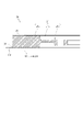
図1は、本発明の第1実施形態に係る振動型アクチュエータ10の構成を概略的に示す断面図である。振動型アクチュエータ10における振動体20および接触体30(被駆動体)および加圧機構40等の機械的構成は、例えば特開2017-108615号公報に記載の振動型アクチュエータと機能的には同等である。
<First embodiment>
FIG. 1 is a cross-sectional view schematically showing the configuration of a
本実施形態の振動型アクチュエータは、弾性体および電気-機械エネルギー変換素子を有する振動体と、振動体と接する接触体を備えている。加えて、電気-機械エネルギー変換素子に給電するフレキシブルプリント基板と、フレキシブルプリント基板と前記電気-機械エネルギー変換素子が重なる領域に設けられた温度検出手段、を備えている。 The vibration-type actuator of this embodiment includes a vibrating body having an elastic body and an electro-mechanical energy conversion element, and a contact body in contact with the vibrating body. In addition, it comprises a flexible printed circuit board for supplying power to the electro-mechanical energy conversion element, and temperature detection means provided in an area where the flexible printed circuit board and the electro-mechanical energy conversion element overlap.
図1において、振動型アクチュエータ10は、円環状に形成された振動体20、円環状に形成された接触体30、および加圧機構40を備える。また、振動型アクチュエータ10は、シャフト、ハウジング、ベアリングを備える。
In FIG. 1, the
「接触体」とは、振動体と接触し、振動体に発生した振動によって、振動体に対して相対移動する部材のことをいう。接触体と振動体の接触は、接触体と振動体の間に他の部材が介在しない直接接触に限られない。接触体と振動体の接触は、振動体に発生した振動によって、接触体が振動体に対して相対移動するならば、接触体と振動体の間に他の部材が介在する間接接触であってもよい。「他の部材」は、接触体及び振動体とは独立した部材(例えば焼結体よりなる高摩擦材)に限られない。「他の部材」は、接触体又は振動体に、メッキや窒化処理などによって形成された表面処理部分であってもよい。 A “contact member” is a member that contacts the vibrating body and moves relative to the vibrating body due to vibration generated in the vibrating body. The contact between the contact body and the vibrating body is not limited to direct contact with no other member interposed between the contact body and the vibrating body. The contact between the contact body and the vibrating body is an indirect contact in which another member is interposed between the contact body and the vibrating body if the vibration generated in the vibrating body causes the contact body to move relative to the vibrating body. good too. "Another member" is not limited to a member independent of the contact member and the vibrating member (for example, a high-friction material made of a sintered body). The "other member" may be a surface-treated portion formed on the contact body or vibrating body by plating, nitriding, or the like.
振動体20は、弾性体21と、弾性体21に接合された電気-機械エネルギー変換素子である圧電素子22と、圧電素子22に接合されて圧電素子22に交流電圧である駆動電圧を印加するための給電部材100を有する。この給電部材100に温度検出手段であるサーミスタ120が設けられている。
The vibrating
接触体30は、本体30aおよび接触ばね30bを有する。接触体30の材料としては、ステンレス鋼等の鉄系材料を用いることができるが、接触体30の材料はこれに限らない。
The
加圧機構40は制振ゴム41、加圧ばね受け部材42、加圧ばね受けゴム43、加圧ばね44及び加圧ばね固定部材45を有する。振動体20及び接触体30はシャフトを中心軸として同心円状に配置され、シャフトに固定された加圧機構40によってシャフトのスラスト方向に関して互いに加圧接触(摩擦接触)する。具体的には、シャフトに固定された加圧ばね固定部材45によって移動を規制された加圧ばね44が、制振ゴム41、加圧ばね受け部材42及び加圧ばね受けゴム43を介して接触体30をスラスト方向に押圧する。このように構成されることにより、接触体30と振動体20は安定的に接触する。
The
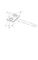
図2は、振動体20の構成を概略的に示す斜視図である。
FIG. 2 is a perspective view schematically showing the configuration of the vibrating
給電部材100は、円環状の圧電素子22に接合されたフレキシブルプリント基板110と、フレキシブルプリント基板に接続された駆動用コネクタ190を有する。
The
図3は、振動体20の構成を概略的に示す断面図である。図3はサーミスタ120を含む断面であり、図1と同じ断面を示している。該断面における弾性体21、圧電素子22およびフレキシブルプリント基板110の肉部はハッチングで描かれているとともに、紙面に向かって奥行方向に在る弾性体21、圧電素子22およびフレキシブルプリント基板110は線図で示されている。
FIG. 3 is a cross-sectional view schematically showing the structure of the vibrating
図3において、弾性体21は円環状の部材からなり、弾性体21は基底部21aと、基底部21aの内径側には基底部21aを支持するための接続部21bが一体的に形成されている。さらに内径側には弾性体21をハウジングに固定するための取付部21cが一体的に形成されている。弾性体21の材料は適宜選択できるが、本実施の形態では、窒化処理されたステンレス鋼等の鉄系材料を用いる。
In FIG. 3, the
弾性体21の基底部21aの一方の面は接触体30と加圧接触する接触部25であり、基底部21aの他方の面には圧電素子22が接合される。圧電素子22にはフレキシブルプリント基板110が接合される。フレキシブルプリント基板110には振動体20の温度検出手段であるサーミスタ120が実装される。
One surface of the
弾性体21は、取付部21cに設けられた穴とハウジングの穴を螺合されることにより、ハウジングへ固定される。ハウジングはベアリングを備えており、そのベアリングはシャフトを軸支する。
The
振動型アクチュエータ10では、給電部材100に備えられた駆動用コネクタ190とフレキシブルプリント基板110を通して圧電素子22へ交流電圧である駆動電圧を印加することにより、振動体20に駆動振動を励起させる。駆動振動の態様は圧電素子22が有する複数の電極の数や配置形態に依存するが、励起される駆動振動が振動体10の周方向に進むn次(本実施形態ではn=9)の進行波となるように、圧電素子22が設計される。なお、n次の駆動振動とは基底部21aの周方向における波数がn個となる曲げ振動である。圧電素子22に発生した駆動振動は振動体20の基底部21aへ伝達され、接触部25に生じた進行波によって、接触体30をシャフト回りの周方向へ駆動する。すなわち、接触体30は振動体20と同心を保ったまま、相対的に回転運動する。接触体30に発生した回転力は加圧機構40とシャフトを通して外部へ出力される。
In the vibration-
図1に描かれている本実施形態の振動型アクチュエータ10は、例えばハウジングを所望の部材に固定し、シャフトの下方に末広がりに構成されているフランジ面にカメラ等の可動対象を固定することで、可動対象を自由に回転駆動させることができる。他方で、シャフトを固定してハウジングを回転駆動させることも可能である。
The
図4は、振動体20に励起される駆動振動の変形の様態を説明するための図である。なお、図4では、振動体20において励起される駆動振動の変位に対する理解を容易にするために、変位を実際よりも誇張している。給電部材500は不図示である。
4A and 4B are diagrams for explaining a deformation mode of driving vibration excited in the vibrating
図5は、フレキシブルプリント基板110の構成を概略的に示す図である。
FIG. 5 is a diagram schematically showing the configuration of the flexible printed
本実施形態の振動型アクチュエータにおいては、フレキシブルプリント基板は、電気-機械エネルギー変換素子と連結する第1の端子部および第1の配線部を有している。加えて、第一の端子部および第一の配線部とは別に設けられ、温度検出手段と連結する第2の端子部および第2の配線部を有している。 In the vibration type actuator of this embodiment, the flexible printed circuit board has a first terminal portion and a first wiring portion that are connected to the electro-mechanical energy conversion element. In addition, it has a second terminal portion and a second wiring portion which are provided separately from the first terminal portion and the first wiring portion and are connected to the temperature detection means.
フレキシブルプリント基板110は、柔軟な樹脂で形成された平面的な基材に設けられた配線と端子を備えている。フレキシブルプリント基板の樹脂部分における、圧電素子が接合する接合面と、接合面と対向する反対側の面と、その両面の間の部位を含む樹脂部分を接合部と以下では呼称する。
The flexible printed
フレキシブルプリント基板110と圧電素子が重なる領域では、両者が隣接しているため、その温度はほぼ圧電素子と同等であることが本願発明者の検討の末に分かった。加えて、フレキシブルプリント基板110と接着された振動体20の基底部21aの温度は熱源となる接触部25の温度ともほぼ同等であることも分かった。
The inventors of the present application found that the area where the flexible printed
以上のことを踏まえ、フレキシブルプリント基板110は本実施形態においては以下のように構成される。
Based on the above, the flexible printed
フレキシブルプリント基板110は、圧電素子22と接着により接合される接合部110aと、駆動用コネクタ190を取り付ける第1の端子部110cを備える。加えて、接合部110aと第1の端子部110cの間に位置する中継部110bと、第1の端子部110cの一部から張り出した第2の端子部110dを備える。
The flexible printed
フレキシブルプリント基板110の接合部110aにはサーミスタ120が実装される。図中の破線は圧電素子22に設けられた電極パターンと、圧電素子22の外形を表す。圧電素子22の電極は、周方向に駆動振動の次数nの4倍の数(本実施形態では9×4=36個)に分割され、1つの電極の周方向の大きさは駆動振動の周方向波長のおよそ4分の1となっている。
A
図6は、図5におけるフレキシブルプリント基板110の一部を拡大した図である。第1の端子部110cは、駆動用コネクタ190を電気的に接続する駆動用端子130を備える。駆動用端子130は、駆動振動を励起するための駆動電圧を印加する4つの電圧印加端子130aと3つのGND端子130bを備える。GND端子130bは、ハウジングを経由し、弾性体21に接続される。
FIG. 6 is an enlarged view of a portion of the flexible printed
4つの電圧印加端子130aは、接合部110aと中継部110bと第1の端子部110cに形成された駆動用配線131と、接合部110aに設けられた駆動用電極132を通して、円周状に配置された複数の圧電素子の電極22aに接続される。
The four voltage-applying
サーミスタ120は、フレキシブルプリント基板110と圧電素子が重なる領域である接合部110aに設けられている。サーミスタ120は、サーミスタ用配線134と、第2の端子部110dの先端に設けられたサーミスタ用端子133を経由し、不図示の温度検出回路に接続される。
The
サーミスタ用端子133はフレキシブルフラットケーブル(FFC)で構成されている。なお、サーミスタ120とサーミスタ用配線134は、駆動用配線131と駆動用電極132等の振動体20の駆動振動を励起するための配線とは絶縁されている。
The
本実施形態の振動型アクチュエータは接触体、弾性体、圧電素子、およびフレキシブルプリント基板の順に配されている。 In the vibration type actuator of this embodiment, the contact body, the elastic body, the piezoelectric element, and the flexible printed circuit board are arranged in this order.
振動型アクチュエータ10の振動体20の駆動時の発熱源は、弾性体21の基底部21aと圧電素子22の振動による損失と、弾性体21と接触体30の摩擦接触による摩擦による損失である。駆動時には振動体20の基底部21a近傍の温度が最も上昇する。過度な昇温は、圧電素子22の性能、振動体20の振動特性、振動体20と接触体30との摩擦特性に変化を生じさせるおそれがある。加えて、弾性体21と圧電素子22の接着剥がれ、圧電素子22とフレキシブルプリント基板110の接着剥がれを引き起こすおそれがある。
The sources of heat generated when the vibrating
上述したように、圧電素子22とフレキシブルプリント基板110の接合部110aの温度は基底部21aとほぼ同じ温度である。そのため、フレキシブルプリント基板110の接合部110aにサーミスタ120を設けて温度測定することで振動体20の高温部の温度測定が可能となる。
As described above, the temperature of the
本実施形態では、フレキシブルプリント基板110の駆動用配線131が設けられた中継部110bにサーミスタ用配線134を通している。そのため、サーミスタ用配線をフレキシブルプリント基板とは別に設ける従来の方式と異なり、サーミスタ用配線に関わる部品数を低減することができる。したがって、振動型アクチュエータ10の駆動時の配線に起因する異音(鳴き)の発生を低減することが可能となる。
In this embodiment, the
本実施形態では、振動型アクチュエータ10の圧電素子22に接着されたフレキシブルプリント基板110にサーミスタ120を実装している。そのため、振動体20の製造工程でサーミスタ120を個別に振動体20に取り付ける工程がなくなり、組立工程を簡略化することが可能となる。
In this embodiment, the
本実施形態では、駆動用端子131に求められる耐電圧と比較し、サーミスタ用端子133に求められる耐電圧が小さいため、駆動用端子131とサーミスタ用端子133を別体としている。これにより耐電圧の低いサーミスタ用端子133の小型化が可能となる。
In this embodiment, the
サーミスタ120による振動体20の駆動振動の阻害、サーミスタ120のクラックが発生、サーミスタ120の実装部の接続不良は、可能な限り低減されることが望ましい。したがって、サーミスタ120は駆動振動による振動体20の曲げ変形によって曲げ方向の大きな荷重がかからないことが好ましい。
It is desirable to reduce as much as possible the inhibition of the drive vibration of the
そのため、温度検出手段の長手方向が円環状の弾性体の径方向に沿っているように構成するとよい。 Therefore, it is preferable that the longitudinal direction of the temperature detection means is along the radial direction of the annular elastic member.
具体的にはサーミスタ120の本体部の短手方向(2つの実装はんだが並ぶ方向に垂直な方向)を、振動体20の駆動振動の波長の短い方向とすることが好ましい。
Specifically, it is preferable that the short-side direction of the main body of the thermistor 120 (the direction perpendicular to the direction in which the two mounting solders are arranged) is the direction in which the wavelength of the drive vibration of the
本実施形態の振動型アクチュエータでは、振動体20の内周と外周の幅と比較して周方向に生じる進行波の波長が短い。
In the vibration type actuator of this embodiment, the wavelength of the traveling wave generated in the circumferential direction is shorter than the width of the inner circumference and the outer circumference of the vibrating
そのため、サーミスタ120の長手方向を振動体20の径方向に沿っているように構成する。より好ましくはサーミスタ120の長手方向を振動体20の径方向に一致させるとよい。このように構成することで進行波の波頭に沿ってサーミスタの長手方向が配置されるため、進行波の発生に伴うサーミスタの本体部への加重をより少なくすることができる。
Therefore, the longitudinal direction of the
サーミスタ120のクラックの発生や実装部の接続不良を防止するため、サーミスタ120の寸法は、振動体20の駆動振動の波長よりも十分に小さい事が好ましく、目安として駆動振動の波長の4分の1以下であることが好ましい。
In order to prevent cracking of the
より好ましくは、サーミスタ120の本体部が直方体形状である場合、縦、横、および高さのうち、その最大寸法が駆動振動の波長の4分の1以下であることが好ましい。
More preferably, when the main body of the
本実施形態では、温度検出部としてサーミスタ120を用いたが、これに限定されない。温度測定が可能なセンサであれば良く、熱電対、測温抵抗体、IC温度センサ等が挙げられる。
In this embodiment, the
図7は、振動体の第1の変形例のフレキシブルプリント基板210の一部を示す図である。フレキシブルプリント基板210は、圧電素子22と接着により接合される接合部210aと、先端にフレキシブルフラットケーブル(FFC)を形成した端子部210cと、接合部210aと端子部210cの間に位置する中継部210bを備える。フレキシブルプリント基板210の接合部210aにはサーミスタ220が実装される。
FIG. 7 is a diagram showing part of a flexible printed
本変形例では、駆動用コネクタを用いず、フレキシブルプリント基板210の端子部210cの先端をフレキシブルフラットケーブル(FFC)としている。サーミスタ用配線234はフレキシブルプリント基板210の中継部210bを通り、サーミスタ用端子233に接続される。サーミスタ用端子233と駆動用端子230(4つの印加電圧端子230aと1つのGND端子230bから成る)は1つのフレキシブルフラットケーブル(FFC)を形成している。GND端子230bは、ハウジングを経由し、弾性体21に接続される。
In this modification, a flexible flat cable (FFC) is used at the tip of the
本実施形態では、圧電素子22に印加する駆動電圧のGND端子230bを、ハウジングを介して弾性体21に接続したが、この方法に限定されない。ハウジングを介せず、弾性体21がGND端子230bに接続され、電気的に接地されていればよい。
In this embodiment, the GND terminal 230b of the drive voltage applied to the
<第2実施形態>
図8は、本発明の第2実施形態に係る振動型アクチュエータを構成する振動体50の構成を概略的に示す斜視図である。振動体50の構成は、例えば特許第4261964号公報に開示されている振動型駆動装置を構成する振動体と同等である。
<Second embodiment>
FIG. 8 is a perspective view schematically showing the configuration of a vibrating
振動体50は、平板状の弾性体51と、弾性体51に接合された圧電素子52と、圧電素子52に接着により接合されたフレキシブルプリント基板である給電部材500を備える。
The vibrating
弾性体51は、圧電素子52が接合された面の反対側の面に所定の間隔で設けられた2つの突起部54を有する。不図示の接触体は、突起部54の先端面である接触部55と、突起部54の突出方向において加圧接触している。
The
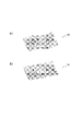
圧電素子52への駆動信号の印加によって、振動体50に予め設定された第1の振動と第2の振動が合成された駆動振動が振動体50に励起される。図9(a)は、振動体50に励起される第1の振動モードの振動での振動体50の変形を説明する図であり、図9(b)は、振動体50に励起される第2の振動モードの振動での振動体50の変形を説明する図である。なお、図9(a)(b)では、振動体50に生じる振動変位に対する理解を容易にするために、変形(変位)を実際よりも拡大して示している。給電部材500は不図示である。
By applying a drive signal to the
図9(a)に示す第1の振動モードは、2つの突起部を結ぶ方向(弾性体51の長手方向)において弾性体51に2個の振動の腹が生じる曲げ振動である。図9(b)に示す第2の振動モードは、第1の振動モードの腹線と垂直な方向(弾性体51の短手方向)に1個の腹が生じる曲げ振動である。弾性体51に接合された圧電素子52への駆動信号の印加によって、振動体51に予め設定された第1の振動モードの振動と、第2の振動モードの振動とが合成された振動の定在波を駆動振動として励起させる。この駆動振動により、接触部55には、2つの突起部54を結ぶ方向と突起部54の突出方向とを含む面内で楕円運動が生じる。不図示の接触体は、振動体50の接触部55に加圧接触しているため、接触部55によって摩擦駆動されて、2つの突起部54を結ぶ方向に直線的に駆動される。
The first vibration mode shown in FIG. 9A is bending vibration in which two antinodes occur in the
なお、1つの振動体50における突起部54を結ぶ線が同一円周の接線となるように、複数の振動体50を円環状の基材に配置してもよい。そして、円環状(又は円板状)の接触体を基材と同心となるように接触部55に加圧接触させた構成とすることにより、接触体と基材とをその円周方向に相対的に回転移動させることができる。
It should be noted that a plurality of vibrating
図10は、図8における給電部材であるフレキシブルプリント基板510の構成を概略的に示す図である。フレキシブルプリント基板510は、圧電素子52と接着により接合される接合部510aと、先端をフレキシブルフラットケーブル(FFC)とした端子部510cと、接合部510aと端子部510cの間に位置する中継部510bを備える。フレキシブルプリント基板110と圧電素子が重なる領域であるフレキシブルプリント基板510の接合部510aにはサーミスタ520が実装される。図中の破線はフレキシブルプリント基板510と接着された圧電素子52の外形および電極形状を表す。端子部510cは、駆動用端子530とサーミスタ用端子533を備える。
FIG. 10 is a diagram schematically showing the configuration of flexible printed circuit board 510, which is the power supply member in FIG. The flexible printed circuit board 510 includes a
駆動用端子530は、駆動振動を励起するための駆動電圧を印加する2つの電圧印加端子530aと、1つのGND端子530bを備える。GND端子530bは、弾性体51に接続される。
The
接合部510aに実装されたサーミスタ520は、接合部510aと中継部510bと端子部510cに形成されたサーミスタ用配線534と、サーミスタ用端子533を経由し、不図示の温度検出回路に接続される。なお、サーミスタ520とサーミスタ用配線534は、駆動用配線531と駆動用電極532等の振動体50の駆動振動を励起するための配線とは絶縁されている。
The thermistor 520 mounted on the
振動型アクチュエータの振動体50の駆動時の発熱源は、弾性体51と圧電素子52の振動による損失と、弾性体51と接触体の摩擦接触による摩擦による損失である。駆動時には弾性体51の温度が最も上昇して高温部となり、圧電素子の性能、振動体50の振動特性、接触体との摩擦接触部の性能が変化するおそれがある。加えて、弾性体51と圧電素子52の接着剥がれ、圧電素子52とフレキシブルプリント基板510の接着剥がれを引き起こす恐れもある。第1実施形態で詳述したように、圧電素子52とフレキシブルプリント基板510の接合部510aの温度は弾性体51とほぼ同じ温度である。そのため、フレキシブルプリント基板510の接合部510aにサーミスタ520を設けて温度測定することで振動体52の高温部の温度測定が可能となる。
The sources of heat generated when the vibrating
本実施形態においても、第1実施形態と同等の効果を得ることができる。具体的には、振動体50の高温部の測定が可能で、サーミスタ配線に関わる部品数の低減により鳴きの発生を抑制し、振動体の製造工程においてサーミスタの組立を簡素化される。
Also in this embodiment, the same effects as in the first embodiment can be obtained. Specifically, it is possible to measure the high-temperature portion of the vibrating
サーミスタ520による振動体50の駆動振動の阻害、サーミスタ520のクラックが発生、サーミスタ520の実装部の接続不良は可能な限り低減されることが望ましい。したがって、サーミスタ520は駆動振動による振動体50の曲げ変形によって曲げ方向の大きな荷重がかからないことが好ましい。
It is desirable to reduce as much as possible the inhibition of the drive vibration of the
したがって弾性体が矩形であるとともに、温度検出手段の長手方向が、矩形である弾性体の短手方向に沿っているように構成することが好ましい。 Therefore, it is preferable that the elastic body is rectangular and the longitudinal direction of the temperature detection means is along the lateral direction of the rectangular elastic body.
そのため、サーミスタ520の短手方向(2つの実装はんだが並ぶ方向に垂直な方向)を、振動体20の駆動振動の波長の短い方向とすることが好ましい。本実施形態の振動体50の駆動振動では、振動体50を構成する弾性体51の短手方向と比較して弾性体51の長手方向に発生する振動の波長が短いため、サーミスタ520の短手方向を振動体50の長手方向と一致させている。
Therefore, it is preferable that the short-side direction of the thermistor 520 (the direction perpendicular to the direction in which the two mounting solders are arranged) is the direction in which the wavelength of the drive vibration of the
つまり図9(a)に図示される振動波の波頭に沿うようにサーミスタの長手方向が配されているため、サーミスタに加わる荷重をより小さくすることができる。 That is, since the longitudinal direction of the thermistor is arranged along the crest of the vibration wave shown in FIG. 9A, the load applied to the thermistor can be further reduced.
サーミスタ520のクラックの発生や実装部の接続不良を防止するため、サーミスタ520の寸法は、振動体50の駆動振動の波長よりも十分に小さい事が好ましく、目安として駆動振動の波長の4分の1以下であることが好ましい。
In order to prevent cracking of the thermistor 520 and connection failure of the mounting portion, the dimensions of the thermistor 520 are preferably sufficiently smaller than the wavelength of the driving vibration of the vibrating
本実施形態では、温度検出部としてサーミスタ520を用いたが、これに限定されない。温度測定が可能なセンサであれば良く、熱電対、測温抵抗体、IC温度センサ等が挙げられる。 In this embodiment, the thermistor 520 is used as the temperature detection unit, but the temperature detection unit is not limited to this. Any sensor capable of measuring temperature may be used, and examples thereof include thermocouples, resistance temperature detectors, and IC temperature sensors.
<第3実施形態>
第3実施形態では、第1実施形態で説明した振動型アクチュエータ10を備える装置の一例としての監視カメラ等の撮像装置の雲台の構成について説明する。
<Third Embodiment>
In the third embodiment, the configuration of a pan head of an imaging device such as a monitoring camera will be described as an example of a device including the
本実施形態では、回転台と、回転台に設けられた振動型アクチュエータを備える雲台を以下説明する。 In this embodiment, a rotary table and a camera platform including a vibration actuator provided on the rotary table will be described below.
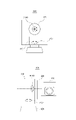
図10は、雲台800と、雲台800に搭載された撮像装置840の構成を概略的に示す図である。雲台800は、ベース820と、2つの振動型アクチュエータ870、880を備えるヘッド810と、撮像装置840を固定するためのLアングル830を備える。パン軸に設けられた振動型アクチュエータ880は、ヘッド810とLアングル830と撮像装置840を、ベース820に対してパン軸まわりに回転させるためのアクチュエータである。また、チルト軸に設けられた振動型アクチュエータ870は、Lアングル830と撮像装置840を、ヘッド810に対してチルト軸まわりに回転させるためのアクチュエータである。
FIG. 10 is a diagram schematically showing the configuration of a
雲台800に2つの振動型アクチュエータ870、880を用いることにより、撮像装置840の向きを高速、高応答、静粛、高精度に変える事が可能となる。また、振動型アクチュエータは無通電時でも高い保持トルクを持つため、撮像装置840のチルト軸まわりの重心ずれがあっても振動型アクチュエータの電力を消費することなく撮像装置40の向きを維持することができる。
By using two
その他、本発明の利用者が所望する部材と、その部材に設けられた振動型アクチュエータを備える電子機器を提供することができる。 In addition, it is possible to provide an electronic device comprising a member desired by a user of the present invention and a vibration type actuator provided on the member.
10 振動型アクチュエータ
20,50 振動体
21,51 弾性体
22,52 圧電素子
100,500 給電部材
110,210,510 フレキシブルプリント基板
100a,110a,210a,510a 接合部
110b,210b,510b 中継部
110c 第1の端子部
110d 第2の端子部
210c 端子部
120,220,520 サーミスタ
130,230,530 駆動用端子
131,231,531 駆動用配線
132,232,532 駆動用電極
133,233,533 サーミスタ用端子
134,234,534 サーミスタ用配線
10
Claims (11)
前記振動体と接する接触体と、
前記電気-機械エネルギー変換素子に給電するフレキシブルプリント基板と、
前記フレキシブルプリント基板と前記電気-機械エネルギー変換素子が重なる領域に設けられた直方体形状の温度検出手段と、
を備え、
前記振動体に第1の振動と第2の振動とを合わせた振動が励起することで前記振動体と前記接触体との相対移動が生じるよう構成され、
前記相対移動の方向と垂直な方向と、前記温度検出手段の長手方向が沿うように構成されている振動型アクチュエータ。 a vibrating body having an elastic body and an electro-mechanical energy conversion element;
a contact body in contact with the vibrating body;
a flexible printed circuit board that supplies power to the electro-mechanical energy conversion element;
rectangular parallelepiped temperature detection means provided in a region where the flexible printed circuit board and the electro-mechanical energy conversion element overlap;
with
The vibrating body is configured to generate a relative movement between the vibrating body and the contact body by exciting the combined vibration of the first vibration and the second vibration in the vibrating body,
A vibration type actuator configured such that the direction perpendicular to the direction of the relative movement and the longitudinal direction of the temperature detecting means are aligned .
前記電気-機械エネルギー変換素子と連結する第1の端子部および第1の配線部と、
前記第一の端子部および前記第一の配線部とは別に設けられ、前記温度検出手段と連結する第2の端子部および第2の配線部と、
を備える請求項1に記載の振動型アクチュエータ。 The flexible printed circuit board is
a first terminal portion and a first wiring portion connected to the electro-mechanical energy conversion element;
a second terminal portion and a second wiring portion provided separately from the first terminal portion and the first wiring portion and connected to the temperature detection means;
The vibration type actuator according to claim 1, comprising:
Priority Applications (2)
| Application Number | Priority Date | Filing Date | Title |
|---|---|---|---|
| JP2018225869A JP7204455B2 (en) | 2018-11-30 | 2018-11-30 | Vibration actuators, pan heads, and electronics |
| US16/697,663 US11454869B2 (en) | 2018-11-30 | 2019-11-27 | Vibration actuator, camera platform, and electronic apparatus |
Applications Claiming Priority (1)
| Application Number | Priority Date | Filing Date | Title |
|---|---|---|---|
| JP2018225869A JP7204455B2 (en) | 2018-11-30 | 2018-11-30 | Vibration actuators, pan heads, and electronics |
Publications (2)
| Publication Number | Publication Date |
|---|---|
| JP2020089237A JP2020089237A (en) | 2020-06-04 |
| JP7204455B2 true JP7204455B2 (en) | 2023-01-16 |
Family
ID=70850832
Family Applications (1)
| Application Number | Title | Priority Date | Filing Date |
|---|---|---|---|
| JP2018225869A Active JP7204455B2 (en) | 2018-11-30 | 2018-11-30 | Vibration actuators, pan heads, and electronics |
Country Status (2)
| Country | Link |
|---|---|
| US (1) | US11454869B2 (en) |
| JP (1) | JP7204455B2 (en) |
Cited By (1)
| Publication number | Priority date | Publication date | Assignee | Title |
|---|---|---|---|---|
| JP2021072759A (en) * | 2019-11-01 | 2021-05-06 | キヤノン株式会社 | Vibration type actuator, camera platform, and electronic device |
Families Citing this family (1)
| Publication number | Priority date | Publication date | Assignee | Title |
|---|---|---|---|---|
| US11644736B2 (en) * | 2020-08-05 | 2023-05-09 | Canon Kabushiki Kaisha | Vibration type actuator, camera platform, and electronic device |
Citations (6)
| Publication number | Priority date | Publication date | Assignee | Title |
|---|---|---|---|---|
| JP2000101346A (en) | 1998-09-25 | 2000-04-07 | Toyo Commun Equip Co Ltd | Structure for highly stable piezoelectric oscillator |
| JP2004320846A (en) | 2003-04-11 | 2004-11-11 | Canon Inc | Vibration-type drive unit |
| JP2007281356A (en) | 2006-04-11 | 2007-10-25 | Fujifilm Holdings Corp | Piezoelectric ceramic transformer apparatus and light source apparatus employing the same |
| JP2008080622A (en) | 2006-09-27 | 2008-04-10 | Kyocera Corp | Liquid discharge head and liquid discharge device |
| JP2008125146A (en) | 2006-11-08 | 2008-05-29 | Canon Inc | Driving apparatus, control method thereof, program and storage medium |
| JP2010114986A (en) | 2008-11-05 | 2010-05-20 | Nikon Corp | Vibrating actuator, lens barrel, and optical apparatus |
Family Cites Families (11)
| Publication number | Priority date | Publication date | Assignee | Title |
|---|---|---|---|---|
| JPH06284753A (en) | 1994-02-21 | 1994-10-07 | Olympus Optical Co Ltd | Driver circuit for vibration wave motor |
| JPH0998589A (en) | 1995-09-29 | 1997-04-08 | Fukoku Co Ltd | Ultrasonic motor, using method and preserving method therefor |
| CA2283963C (en) * | 1998-01-20 | 2005-06-07 | Toyo Communication Equipment Co., Ltd. | Piezo-oscillator |
| JP2003309432A (en) * | 2002-04-17 | 2003-10-31 | Toyo Commun Equip Co Ltd | Highly stable piezoelectric oscillator |
| US7187104B2 (en) | 2003-03-28 | 2007-03-06 | Canon Kabushiki Kaisha | Vibration-type driving device, control apparatus for controlling the driving of the vibration-type driving device, and electronic equipment having the vibration-type driving device and the control apparatus |
| JP4345549B2 (en) * | 2003-07-28 | 2009-10-14 | エプソントヨコム株式会社 | Thin high stability piezoelectric oscillator and surface mount thin high stability piezoelectric oscillator |
| JP5433991B2 (en) * | 2008-06-24 | 2014-03-05 | 株式会社ニコン | Vibration actuator, lens barrel and camera |
| US10038394B2 (en) * | 2013-06-28 | 2018-07-31 | Canon Kabushiki Kaisha | Vibration wave drive device, stator for a vibration wave motor, vibration wave motor, driving control system, optical apparatus, and manufacturing method of a vibration wave driving device |
| JP6622480B2 (en) * | 2014-04-07 | 2019-12-18 | キヤノン株式会社 | Vibration wave driving device and optical apparatus |
| JP6866128B2 (en) | 2015-12-04 | 2021-04-28 | キヤノン株式会社 | Vibration type actuator drive method, vibration type drive device and mechanical device |
| US11258376B2 (en) * | 2017-11-06 | 2022-02-22 | Canon Kabushiki Kaisha | Vibration wave motor, drive control system, optical apparatus, and electronic apparatus |
-
2018
- 2018-11-30 JP JP2018225869A patent/JP7204455B2/en active Active
-
2019
- 2019-11-27 US US16/697,663 patent/US11454869B2/en active Active
Patent Citations (6)
| Publication number | Priority date | Publication date | Assignee | Title |
|---|---|---|---|---|
| JP2000101346A (en) | 1998-09-25 | 2000-04-07 | Toyo Commun Equip Co Ltd | Structure for highly stable piezoelectric oscillator |
| JP2004320846A (en) | 2003-04-11 | 2004-11-11 | Canon Inc | Vibration-type drive unit |
| JP2007281356A (en) | 2006-04-11 | 2007-10-25 | Fujifilm Holdings Corp | Piezoelectric ceramic transformer apparatus and light source apparatus employing the same |
| JP2008080622A (en) | 2006-09-27 | 2008-04-10 | Kyocera Corp | Liquid discharge head and liquid discharge device |
| JP2008125146A (en) | 2006-11-08 | 2008-05-29 | Canon Inc | Driving apparatus, control method thereof, program and storage medium |
| JP2010114986A (en) | 2008-11-05 | 2010-05-20 | Nikon Corp | Vibrating actuator, lens barrel, and optical apparatus |
Cited By (2)
| Publication number | Priority date | Publication date | Assignee | Title |
|---|---|---|---|---|
| JP2021072759A (en) * | 2019-11-01 | 2021-05-06 | キヤノン株式会社 | Vibration type actuator, camera platform, and electronic device |
| JP7395320B2 (en) | 2019-11-01 | 2023-12-11 | キヤノン株式会社 | Vibratory actuators, heads, and electronics |
Also Published As
| Publication number | Publication date |
|---|---|
| US20200174347A1 (en) | 2020-06-04 |
| US11454869B2 (en) | 2022-09-27 |
| JP2020089237A (en) | 2020-06-04 |
Similar Documents
| Publication | Publication Date | Title |
|---|---|---|
| JP5936374B2 (en) | Piezoelectric vibration type force sensor, robot hand and robot arm | |
| JP7204455B2 (en) | Vibration actuators, pan heads, and electronics | |
| JP2007049897A (en) | Stator and ceramics tube ultrasonic motor using same | |
| JP4296041B2 (en) | Piezoelectric motor and electronic device with piezoelectric motor | |
| US8297149B2 (en) | Friction drive actuator | |
| EP0553829A1 (en) | A vibration driven actuator | |
| JPH08317671A (en) | Ultrasonic motor | |
| JP4878378B2 (en) | Piezoelectric motor and electronic device with piezoelectric motor | |
| JPH11235062A (en) | Vibration actuator driver and lens barrel | |
| JP6541448B2 (en) | Vibration type drive | |
| JP6961383B2 (en) | Vibration type actuator | |
| JP7395320B2 (en) | Vibratory actuators, heads, and electronics | |
| JP3016577B2 (en) | Vibration wave device | |
| WO2016002917A1 (en) | Vibration-type actuator, lens barrel, image-capturing device, and automatic stage | |
| JP3059040B2 (en) | Ultrasonic vibrator, ultrasonic motor and device equipped with ultrasonic motor | |
| KR20110107414A (en) | Piezoelectric ultrasonic motor | |
| JP4924205B2 (en) | Vibration actuator | |
| CN114731120A (en) | Ultrasonic motor | |
| JP3059043B2 (en) | Ultrasonic vibrator, ultrasonic motor and device equipped with ultrasonic motor | |
| JP5153185B2 (en) | Vibration wave driving device and vibrator | |
| JP2023068228A (en) | Driving device and robot | |
| JP2023042041A (en) | piezoelectric motor | |
| JP4745754B2 (en) | Piezoelectric vibrator, ultrasonic motor using the same, and electronic equipment | |
| JP2004007925A (en) | Ultrasonic motor | |
| JPH11235058A (en) | Vibrator and vibraton wave actuator |
Legal Events
| Date | Code | Title | Description |
|---|---|---|---|
| A621 | Written request for application examination |
Free format text: JAPANESE INTERMEDIATE CODE: A621 Effective date: 20210816 |
|
| A977 | Report on retrieval |
Free format text: JAPANESE INTERMEDIATE CODE: A971007 Effective date: 20220609 |
|
| A131 | Notification of reasons for refusal |
Free format text: JAPANESE INTERMEDIATE CODE: A131 Effective date: 20220614 |
|
| A521 | Request for written amendment filed |
Free format text: JAPANESE INTERMEDIATE CODE: A523 Effective date: 20220726 |
|
| TRDD | Decision of grant or rejection written | ||
| A01 | Written decision to grant a patent or to grant a registration (utility model) |
Free format text: JAPANESE INTERMEDIATE CODE: A01 Effective date: 20221129 |
|
| A61 | First payment of annual fees (during grant procedure) |
Free format text: JAPANESE INTERMEDIATE CODE: A61 Effective date: 20221228 |
|
| R151 | Written notification of patent or utility model registration |
Ref document number: 7204455 Country of ref document: JP Free format text: JAPANESE INTERMEDIATE CODE: R151 |