JP7204405B2 - LIQUID EJECTING APPARATUS AND LIQUID EJECTING METHOD - Google Patents
LIQUID EJECTING APPARATUS AND LIQUID EJECTING METHOD Download PDFInfo
- Publication number
- JP7204405B2 JP7204405B2 JP2018187444A JP2018187444A JP7204405B2 JP 7204405 B2 JP7204405 B2 JP 7204405B2 JP 2018187444 A JP2018187444 A JP 2018187444A JP 2018187444 A JP2018187444 A JP 2018187444A JP 7204405 B2 JP7204405 B2 JP 7204405B2
- Authority
- JP
- Japan
- Prior art keywords
- liquid
- ejection
- nozzle
- influence
- nozzles
- Prior art date
- Legal status (The legal status is an assumption and is not a legal conclusion. Google has not performed a legal analysis and makes no representation as to the accuracy of the status listed.)
- Active
Links
Images


Classifications
-
- B—PERFORMING OPERATIONS; TRANSPORTING
- B41—PRINTING; LINING MACHINES; TYPEWRITERS; STAMPS
- B41J—TYPEWRITERS; SELECTIVE PRINTING MECHANISMS, i.e. MECHANISMS PRINTING OTHERWISE THAN FROM A FORME; CORRECTION OF TYPOGRAPHICAL ERRORS
- B41J2/00—Typewriters or selective printing mechanisms characterised by the printing or marking process for which they are designed
- B41J2/005—Typewriters or selective printing mechanisms characterised by the printing or marking process for which they are designed characterised by bringing liquid or particles selectively into contact with a printing material
- B41J2/01—Ink jet
- B41J2/015—Ink jet characterised by the jet generation process
- B41J2/04—Ink jet characterised by the jet generation process generating single droplets or particles on demand
- B41J2/045—Ink jet characterised by the jet generation process generating single droplets or particles on demand by pressure, e.g. electromechanical transducers
- B41J2/04501—Control methods or devices therefor, e.g. driver circuits, control circuits
- B41J2/0451—Control methods or devices therefor, e.g. driver circuits, control circuits for detecting failure, e.g. clogging, malfunctioning actuator
-
- B—PERFORMING OPERATIONS; TRANSPORTING
- B41—PRINTING; LINING MACHINES; TYPEWRITERS; STAMPS
- B41J—TYPEWRITERS; SELECTIVE PRINTING MECHANISMS, i.e. MECHANISMS PRINTING OTHERWISE THAN FROM A FORME; CORRECTION OF TYPOGRAPHICAL ERRORS
- B41J2/00—Typewriters or selective printing mechanisms characterised by the printing or marking process for which they are designed
- B41J2/005—Typewriters or selective printing mechanisms characterised by the printing or marking process for which they are designed characterised by bringing liquid or particles selectively into contact with a printing material
- B41J2/01—Ink jet
- B41J2/21—Ink jet for multi-colour printing
- B41J2/2132—Print quality control characterised by dot disposition, e.g. for reducing white stripes or banding
- B41J2/2139—Compensation for malfunctioning nozzles creating dot place or dot size errors
-
- B—PERFORMING OPERATIONS; TRANSPORTING
- B41—PRINTING; LINING MACHINES; TYPEWRITERS; STAMPS
- B41J—TYPEWRITERS; SELECTIVE PRINTING MECHANISMS, i.e. MECHANISMS PRINTING OTHERWISE THAN FROM A FORME; CORRECTION OF TYPOGRAPHICAL ERRORS
- B41J2/00—Typewriters or selective printing mechanisms characterised by the printing or marking process for which they are designed
- B41J2/005—Typewriters or selective printing mechanisms characterised by the printing or marking process for which they are designed characterised by bringing liquid or particles selectively into contact with a printing material
- B41J2/01—Ink jet
- B41J2/015—Ink jet characterised by the jet generation process
- B41J2/04—Ink jet characterised by the jet generation process generating single droplets or particles on demand
- B41J2/045—Ink jet characterised by the jet generation process generating single droplets or particles on demand by pressure, e.g. electromechanical transducers
- B41J2/04501—Control methods or devices therefor, e.g. driver circuits, control circuits
- B41J2/04586—Control methods or devices therefor, e.g. driver circuits, control circuits controlling heads of a type not covered by groups B41J2/04575 - B41J2/04585, or of an undefined type
-
- B—PERFORMING OPERATIONS; TRANSPORTING
- B41—PRINTING; LINING MACHINES; TYPEWRITERS; STAMPS
- B41J—TYPEWRITERS; SELECTIVE PRINTING MECHANISMS, i.e. MECHANISMS PRINTING OTHERWISE THAN FROM A FORME; CORRECTION OF TYPOGRAPHICAL ERRORS
- B41J2/00—Typewriters or selective printing mechanisms characterised by the printing or marking process for which they are designed
- B41J2/005—Typewriters or selective printing mechanisms characterised by the printing or marking process for which they are designed characterised by bringing liquid or particles selectively into contact with a printing material
- B41J2/01—Ink jet
- B41J2/21—Ink jet for multi-colour printing
- B41J2/2103—Features not dealing with the colouring process per se, e.g. construction of printers or heads, driving circuit adaptations
-
- B—PERFORMING OPERATIONS; TRANSPORTING
- B41—PRINTING; LINING MACHINES; TYPEWRITERS; STAMPS
- B41J—TYPEWRITERS; SELECTIVE PRINTING MECHANISMS, i.e. MECHANISMS PRINTING OTHERWISE THAN FROM A FORME; CORRECTION OF TYPOGRAPHICAL ERRORS
- B41J2/00—Typewriters or selective printing mechanisms characterised by the printing or marking process for which they are designed
- B41J2/005—Typewriters or selective printing mechanisms characterised by the printing or marking process for which they are designed characterised by bringing liquid or particles selectively into contact with a printing material
- B41J2/01—Ink jet
- B41J2/21—Ink jet for multi-colour printing
- B41J2/2121—Ink jet for multi-colour printing characterised by dot size, e.g. combinations of printed dots of different diameter
- B41J2/2128—Ink jet for multi-colour printing characterised by dot size, e.g. combinations of printed dots of different diameter by means of energy modulation
-
- H—ELECTRICITY
- H04—ELECTRIC COMMUNICATION TECHNIQUE
- H04N—PICTORIAL COMMUNICATION, e.g. TELEVISION
- H04N1/00—Scanning, transmission or reproduction of documents or the like, e.g. facsimile transmission; Details thereof
- H04N1/40—Picture signal circuits
- H04N1/401—Compensating positionally unequal response of the pick-up or reproducing head
- H04N1/4015—Compensating positionally unequal response of the pick-up or reproducing head of the reproducing head
-
- H—ELECTRICITY
- H04—ELECTRIC COMMUNICATION TECHNIQUE
- H04N—PICTORIAL COMMUNICATION, e.g. TELEVISION
- H04N1/00—Scanning, transmission or reproduction of documents or the like, e.g. facsimile transmission; Details thereof
- H04N1/40—Picture signal circuits
- H04N1/405—Halftoning, i.e. converting the picture signal of a continuous-tone original into a corresponding signal showing only two levels
- H04N1/4055—Halftoning, i.e. converting the picture signal of a continuous-tone original into a corresponding signal showing only two levels producing a clustered dots or a size modulated halftone pattern
- H04N1/4057—Halftoning, i.e. converting the picture signal of a continuous-tone original into a corresponding signal showing only two levels producing a clustered dots or a size modulated halftone pattern the pattern being a mixture of differently sized sub-patterns, e.g. spots having only a few different diameters
Description
本発明は、液体吐出装置及び液体吐出方法に関する。 The present invention relates to a liquid ejecting apparatus and a liquid ejecting method.
従来、インクジェット記録装置に関し、ノズルからのインクの吐出不良に起因する画質低下の抑制する様々な方法が提案されている。例えば、特許文献1には、異常ノズル(不良ノズル)が吐出しないインク量を補うように近傍ノズルにより補完吐出を行わせる補完制御の方法が開示されている。 Conventionally, various methods have been proposed for suppressing deterioration in image quality caused by defective ejection of ink from nozzles for inkjet recording apparatuses. For example, Japanese Patent Application Laid-Open No. 2002-200000 discloses a method of complementary control in which adjacent nozzles perform complementary ejection so as to compensate for the amount of ink that is not ejected by an abnormal nozzle (defective nozzle).
特許文献1の構成に開示されている補完制御において、一の記録動作において非吐出となるインク量と近傍ノズルによる吐出インク量の変化量との間にずれ量がある場合には、次に行われる記録動作に係る補完制御において、非吐出となるインク量にずれ量を加算して、補完吐出における吐出インク量の変化量を定めている。しかし、この場合、単にインクの量のずれ量等を考慮するのみでは、異常ノズルが存在することの影響を十分に抑えることが難しい場合もある。そのため、従来、異常ノズルが存在する場合において、異常ノズルが存在することの影響をより適切に抑えることが望まれていた。そこで、本発明は、上記の課題を解決できる液体吐出装置及び液体吐出方法を提供することを目的とする。 In the complementary control disclosed in the configuration of Japanese Patent Application Laid-Open No. 2002-200310, if there is a deviation between the amount of ink that is not ejected in one printing operation and the amount of change in the amount of ink ejected by neighboring nozzles, the next step is performed. In complementary control related to the printing operation, the deviation amount is added to the non-ejection ink amount to determine the change amount of the ejected ink amount in the complementary ejection. However, in this case, it may be difficult to sufficiently suppress the influence of the presence of abnormal nozzles simply by considering the amount of ink amount deviation or the like. Therefore, conventionally, when an abnormal nozzle exists, it has been desired to more appropriately suppress the influence of the existence of the abnormal nozzle. SUMMARY OF THE INVENTION Accordingly, it is an object of the present invention to provide a liquid ejection apparatus and a liquid ejection method that can solve the above problems.
異常ノズルが存在する場合において、近隣のノズルを用いてインクの量を補う場合、通常、近隣のノズルとして、異常ノズルでの本来の吐出位置とは異なる吐出位置へインクを吐出するノズルを用いることになる。そして、この場合、例えば単位面積に対して吐出されるインクの量の合計量が正常時と同程度になるように、近隣のノズルでの吐出量を調整することが考えられる。しかし、この場合、異常ノズルでの本来の吐出位置とは異なる吐出位置へのインクの量を調整することになるため、単にインクの量の合計量を合わせても、異常ノズルの影響を十分に低減できない場合もある。これに対し、本願の発明者は、単にインクの量の合計量を合わせるのではなく、吐出位置間での影響度を考慮して、異常ノズルの近隣のノズルでの吐出量を調整することを考えた。このように構成すれば、例えば、単にインクの量の合計量を合わせる場合と比べ、異常ノズルの影響をより適切に低減することができる。 When an abnormal nozzle exists and the amount of ink is supplemented by using neighboring nozzles, usually, as the neighboring nozzles, a nozzle that ejects ink to a different ejection position from the original ejection position of the abnormal nozzle is used. become. In this case, for example, it is conceivable to adjust the ejection amount of neighboring nozzles so that the total amount of ink ejected per unit area is approximately the same as in the normal state. However, in this case, since the amount of ink to the ejection position different from the original ejection position of the abnormal nozzle is adjusted, even if the total amount of ink is simply combined, the influence of the abnormal nozzle can be sufficiently reduced. In some cases, it cannot be reduced. On the other hand, the inventor of the present application proposes to adjust the ejection amount of the nozzles adjacent to the abnormal nozzle in consideration of the degree of influence between the ejection positions, instead of simply adjusting the total amount of ink. Thought. With this configuration, the influence of the abnormal nozzle can be reduced more appropriately than in the case of simply adjusting the total amount of ink, for example.
また、本願の発明者は、更なる鋭意研究により、このような効果を得るために必要な特徴を見出し、本発明に至った。上記の課題を解決するために、本発明は、インクジェット方式で液体を吐出する液体吐出装置であって、所定のノズル列方向における位置を互いにずらして並ぶ複数のノズルを有するインクジェットヘッドと、前記液体の吐出対象に対して相対的に前記ノズル列方向と交差する主走査方向へ移動しつつ前記液体を吐出する主走査動作を前記インクジェットヘッドに行わせる走査駆動部と、1回の前記主走査動作において前記液体が吐出される複数の吐出位置の間で生じる影響度を示す影響度情報を記憶する影響度記憶部と、前記インクジェットヘッド及び前記走査駆動部の動作を制御する制御部とを備え、前記影響度記憶部は、前記影響度情報として、一つの吐出位置の周辺における複数の吐出位置のそれぞれに前記液体のドットが形成されることで前記一つの吐出位置に生じる影響の大きさを前記周辺における複数の吐出位置のそれぞれと対応付けて示す情報を記憶し、吐出特性が異常な前記ノズルである異常ノズルが存在する場合、前記制御部は、前記主走査動作時に前記異常ノズルの近傍にある他の前記ノズルにより前記液体を吐出可能な吐出位置の少なくとも一部に対し、前記他のノズルに、前記異常ノズルが存在しない場合である正常時よりも多くの量の前記液体を吐出させ、かつ、前記正常時よりも多くの量の前記液体を前記他のノズルに吐出させる吐出位置について、前記影響度記憶部に記憶されている前記影響度情報に基づいて選択する。 Further, the inventors of the present application have conducted further intensive research and found the characteristics necessary to obtain such effects, and have completed the present invention. In order to solve the above-described problems, the present invention provides a liquid ejecting apparatus that ejects liquid by an inkjet method, comprising: an inkjet head having a plurality of nozzles arranged in a predetermined nozzle array direction with their positions shifted from each other; a scanning driving unit for causing the inkjet head to perform a main scanning operation of ejecting the liquid while moving in a main scanning direction intersecting the nozzle row direction relative to an ejection target, and performing the main scanning operation once. an influence degree storage unit for storing influence degree information indicating the degree of influence occurring between a plurality of ejection positions where the liquid is ejected in; and a control unit for controlling operations of the inkjet head and the scanning drive unit, The influence level storage unit stores, as the influence level information, the magnitude of the influence caused on the one ejection position by forming the dots of the liquid at each of a plurality of ejection positions around the one ejection position. Information associated with each of a plurality of ejection positions in the vicinity is stored, and if there is an abnormal nozzle that is the nozzle with an abnormal ejection characteristic, the control unit causes the nozzle to move to the vicinity of the abnormal nozzle during the main scanning operation. causing the other nozzle to eject a larger amount of the liquid than in a normal state, which is a case where the abnormal nozzle does not exist, to at least part of the ejection positions from which the liquid can be ejected by the other nozzle; Further, an ejection position at which the other nozzle is caused to eject a larger amount of the liquid than in the normal state is selected based on the influence degree information stored in the influence degree storage unit.
このように構成した場合、例えば、他のノズルにより多くの液体を吐出させる吐出位置について、異常ノズルでの本来の吐出位置への影響度を考慮して適切に選択することができる。この場合、異常ノズルでの本来の吐出位置とは、異常ノズルが正常なノズルであった場合に液体を吐出するはずであった吐出位置のことである。また、異常ノズルでの本来の吐出位置については、例えば、異常ノズルに対応する吐出位置である異常ノズル対応位置等と定義することもできる。このように構成すれば、例えば単にインクの量の合計量を合わせる場合と比べ、異常ノズルの影響をより適切に低減することができる。 With this configuration, for example, it is possible to appropriately select ejection positions from which other nozzles eject more liquid, taking into consideration the degree of influence of the abnormal nozzles on the original ejection positions. In this case, the original ejection position of the abnormal nozzle is the ejection position where the liquid should be ejected if the abnormal nozzle were a normal nozzle. Further, the original ejection position of an abnormal nozzle can be defined as, for example, an ejection position corresponding to an abnormal nozzle, such as an abnormal nozzle corresponding position. With this configuration, the influence of the abnormal nozzle can be reduced more appropriately than in the case of simply adjusting the total amount of ink, for example.
また、この構成において、走査駆動部は、例えば、液体の吐出対象の各位置に対して1回の主走査動作を行うように、インクジェットヘッドに主走査動作を行わせる。このような場合も、他のノズルから吐出する液体の量を上記のように変更することで、異常ノズルの影響を適切に低減することができる。また、インクジェットヘッドから吐出する液体は、例えば、印刷に使用するインクである。この場合、液体吐出装置について、例えば、媒体に対してインクを吐出することで印刷を行う印刷装置等と考えることができる。 Further, in this configuration, the scan driving section causes the inkjet head to perform a main scanning operation, for example, so as to perform one main scanning operation for each position of the liquid ejection target. Even in such a case, the influence of the abnormal nozzle can be appropriately reduced by changing the amount of liquid ejected from the other nozzles as described above. Further, the liquid ejected from the inkjet head is, for example, ink used for printing. In this case, the liquid ejection device can be considered, for example, as a printing device that performs printing by ejecting ink onto a medium.
また、この構成において、異常ノズルの近傍にある他のノズルとしては、少なくとも、異常ノズルと隣接するノズルを用いることが考えられる。また、この場合、他のノズルとして、異常ノズルと隣接するノズルを含む複数のノズルを用いることが好ましい。より具体的に、他のノズルとしては、例えば、異常ノズルに対してノズル列方向における一方側にある2個以上のノズルと、他方側にある2個以上のノズルを用いることが好ましい。また、他のノズルについては、例えば、異常ノズルでの本来の吐出位置に対して影響が生じる吐出位置へ液体を吐出可能なノズルを用いると考えることもできる。 In this configuration, it is conceivable to use at least nozzles adjacent to the abnormal nozzle as the other nozzles near the abnormal nozzle. Also, in this case, it is preferable to use a plurality of nozzles including nozzles adjacent to the abnormal nozzle as other nozzles. More specifically, as other nozzles, it is preferable to use, for example, two or more nozzles on one side of the abnormal nozzle in the nozzle row direction and two or more nozzles on the other side. As for the other nozzles, for example, it is possible to use nozzles capable of ejecting liquid to ejection positions that affect the original ejection positions of the abnormal nozzles.
また、この構成において、インクジェットヘッドとしては、ノズルから吐出する液体(液滴)の容量を複数段階で変更可能なインクジェットを用いることが考えられる。そして、この場合、制御部は、例えば、液体の吐出量を多くする吐出位置に他のノズルに吐出させる液体の容量に対応する段階をより大きな容量に対応する段階に変化させることにより、他のノズルに、正常時よりも多くの量の液体を吐出させる。このように構成すれば、例えば、他のノズルに吐出させる液体の量を適切に調整することができる。 Further, in this configuration, as the inkjet head, it is possible to use an inkjet that can change the volume of liquid (droplet) ejected from the nozzle in a plurality of stages. In this case, for example, the control unit changes the stage corresponding to the volume of the liquid to be ejected from the other nozzle to the ejection position where the ejection amount of the liquid is increased to the stage corresponding to the larger volume. To cause the nozzle to eject a larger amount of liquid than it normally does. With this configuration, for example, it is possible to appropriately adjust the amount of liquid to be ejected from another nozzle.
また、この構成において、制御部は、例えば、液体の吐出位置を示すラスタ画像に基づき、インクジェットヘッドのそれぞれのノズルに液体を吐出させる。そして、異常ノズルが存在する場合、制御部は、例えば、影響度情報に基づいてラスタ画像を補正し、補正後のラスタ画像に基づいてそれぞれのノズルに液体を吐出させることにより、主走査動作において他のノズルにより液体を吐出可能な吐出位置の一部に対し、他のノズルに、正常時よりも多くの量の液体を吐出させる。 Further, in this configuration, the control unit causes each nozzle of the inkjet head to eject the liquid based on, for example, a raster image indicating the ejection positions of the liquid. Then, if there is an abnormal nozzle, the control unit corrects the raster image based on the influence information, for example, and causes each nozzle to eject liquid based on the raster image after correction. The other nozzles are caused to eject a larger amount of liquid than in a normal state to some of the ejection positions from which liquid can be ejected by the other nozzles.
また、この構成において、他のノズルに吐出させる液体の量については、例えば、異常ノズルでの本来の吐出位置を含む所定の範囲内での液体の吐出量の合計に関し、調整後の合計の吐出量を正常時の合計の吐出量に近づけるように調整することが考えられる。また、異常ノズルが存在する場合、主走査動作において、制御部は、例えば、異常ノズルに液体を吐出させずに、他のノズルにより液体を吐出可能な吐出位置の一部に対し、他のノズルに正常時よりも多くの量の液体を吐出させる。このように構成すれば、例えば、異常ノズルの影響を適切に低減することができる。 Further, in this configuration, regarding the amount of liquid to be ejected by other nozzles, for example, regarding the total amount of liquid ejected within a predetermined range including the original ejection position of the abnormal nozzle, the total ejection amount after adjustment It is conceivable to adjust the amount so as to approach the total ejection amount during normal operation. Further, when there is an abnormal nozzle, in the main scanning operation, for example, the control unit does not cause the abnormal nozzle to discharge the liquid, and for a part of the ejection positions where the liquid can be ejected by the other nozzle, the other nozzle to eject a larger amount of liquid than normal. By configuring in this way, for example, the influence of an abnormal nozzle can be appropriately reduced.
また、この場合、異常ノズルでの本来の吐出位置(異常ノズル対応位置)の周辺の吐出位置に対して他のノズルにより正常時よりも多く吐出させる液体の量を決定する処理については、例えば、異常ノズルの影響を低減するためのリカバリ処理と考えることができる。また、この場合、他のノズルによる液体の吐出量を調整する範囲について、リカバリ範囲と考えることができる。そして、この場合、液体の吐出量の合計を算出する上記の所定をカバレッジ計算範囲と定義すると、カバレッジ計算範囲について、リカバリ範囲よりも大きくすることが好ましい。このように構成すれば、例えば、リカバリ処理後の液体の合計量が過剰になること等を適切に防ぐことができる。 Further, in this case, the process of determining the amount of liquid to be ejected from the other nozzles to the ejection positions around the original ejection position (abnormal nozzle corresponding position) of the abnormal nozzle in a larger amount than that in the normal state is, for example, It can be considered as recovery processing for reducing the influence of an abnormal nozzle. Also, in this case, the range in which the amount of liquid ejected by the other nozzles is adjusted can be considered as the recovery range. In this case, if the predetermined range for calculating the total discharge amount of liquid is defined as the coverage calculation range, it is preferable that the coverage calculation range be larger than the recovery range. With this configuration, for example, it is possible to appropriately prevent the total amount of liquid after recovery processing from becoming excessive.
また、より具体的に、この場合、異常ノズルの近傍にある他のノズルとしては、例えば、複数のノズルが並ぶノズル列において異常ノズルを含んで連続して並ぶN個(Nは、2以上の整数)のノズルの中の異常ノズル以外のノズルを用いることが考えられる。また、この場合、リカバリ範囲については、異常ノズルの本来の吐出位置の周辺においてこのような他のノズルにより液体が吐出される範囲等と考えることができる。また、この場合において、例えば、ノズル列において異常ノズルを含んで連続して並ぶM個(Mは、2以上の整数)のノズルにより主走査方向における所定の範囲内に吐出されるインクの量の合計を範囲内合計吐出量と定義すると、カバレッジ計算範囲については、範囲内合計吐出量が算出される範囲と考えることができる。また、この場合において、例えば、MをNよりも大きな整数とすることで、カバレッジ計算範囲をリカバリ範囲よりも大きくすることができる。 More specifically, in this case, the other nozzles in the vicinity of the abnormal nozzle include, for example, N (N is 2 or more) that are consecutively arranged including the abnormal nozzle in a nozzle row in which a plurality of nozzles are arranged. It is conceivable to use nozzles other than the abnormal nozzles among the nozzles of (integer). Further, in this case, the recovery range can be considered as a range in which the liquid is ejected by other nozzles around the original ejection position of the abnormal nozzle. In this case, for example, the amount of ink ejected within a predetermined range in the main scanning direction by M (M is an integer equal to or greater than 2) nozzles that are consecutively arranged in the nozzle row including the abnormal nozzle If the total is defined as the in-range total discharge amount, the coverage calculation range can be considered as the range in which the in-range total discharge amount is calculated. Also, in this case, for example, by setting M to an integer larger than N, the coverage calculation range can be made larger than the recovery range.
また、この場合、範囲内合計吐出量については、例えば、カバレッジ計算範囲に対して算出されたカバレッジ等と考えることができる。また、この場合、カバレッジ計算範囲とリカバリ範囲とが対応付けられていることを考えると、範囲内合計吐出量について、リカバリ範囲に対応付けられるカバレッジ等と考えることもできる。また、この構成において、例えば、正常時の範囲内合計吐出量を正常時吐出量と定義し、異常ノズルが存在する場合において他のノズルに吐出させる液体の量を調整した状態での範囲内合計吐出量を調整後吐出量と定義すると、制御部は、例えば、調整後吐出量を正常時吐出量に近づけるように、他のノズルに吐出させる液体の量を調整する。このように構成すれば、例えば、リカバリ処理を適切に行うことができる。 Further, in this case, the total discharge amount within the range can be considered, for example, as the coverage calculated for the coverage calculation range. Further, in this case, considering that the coverage calculation range and the recovery range are associated with each other, the total discharge amount within the range can be considered as the coverage or the like associated with the recovery range. In this configuration, for example, the total discharge amount within the normal range is defined as the normal discharge amount, and when there is an abnormal nozzle, the total within the range is adjusted by adjusting the amount of liquid to be discharged to other nozzles. If the ejection amount is defined as the adjusted ejection amount, the control unit adjusts the amount of liquid to be ejected by other nozzles so that the adjusted ejection amount approaches the normal ejection amount, for example. With this configuration, for example, recovery processing can be performed appropriately.
また、この構成において、影響度情報としては、影響度を示すマトリクス状のデータである影響度マトリクスを用いることが考えられる。また、影響度マトリクスとしては、例えば、異常ノズルでの本来の吐出位置を中心とする複数の吐出位置に対して異常ノズルでの本来の吐出位置への影響度を示す数値が定義されたマトリクス等を用いることが考えられる。 In this configuration, it is conceivable to use an influence matrix, which is matrix-shaped data indicating influence, as the influence information. Further, as the influence degree matrix, for example, a matrix in which numerical values indicating the degree of influence on the original ejection position of the abnormal nozzle are defined for a plurality of ejection positions centering on the original ejection position of the abnormal nozzle. is considered to be used.
また、より具体的に、影響度情報としては、例えば、一つの吐出位置に生じる影響の大きさについて、一つの吐出位置の周辺における複数の吐出位置のそれぞれに対し、影響の大きさが互いに異なる複数種類の影響度の中からいずれかの影響度を対応付ける情報を用いることが考えられる。そして、異常ノズルが存在する場合、制御部は、例えば、影響度情報に基づき、当該異常ノズルでの本来の吐出位置の周辺における複数の吐出位置のうち、より大きな影響を示す影響度に対応付けられている吐出位置をより優先して選択する。また、選択した吐出位置に対し、他のノズルに、正常時よりも多くの量の液体を吐出させる。このように構成すれば、例えば、異常ノズルでの本来の吐出位置への影響がより大きな吐出位置に対して、優先的かつ適切に、他のノズルで吐出する液体の量を増加させることができる。また、これにより、例えば、異常ノズルの影響をより適切に低減することができる。 Further, more specifically, as the influence degree information, for example, regarding the magnitude of the influence that occurs at one ejection position, the magnitude of the influence is different for each of the plurality of ejection positions around the one ejection position. It is conceivable to use information that associates one of a plurality of types of influences. Then, if there is an abnormal nozzle, the control unit associates, for example, based on the influence degree information, the influence degree indicating the greater influence among the plurality of ejection positions in the vicinity of the original ejection position of the abnormal nozzle. priority is given to the selected ejection position. In addition, other nozzles are caused to eject a larger amount of liquid than in the normal state for the selected ejection position. With this configuration, it is possible to preferentially and appropriately increase the amount of liquid ejected by other nozzles, for example, for ejection positions where the influence of the abnormal nozzle on the original ejection position is greater. . Moreover, thereby, the influence of an abnormal nozzle can be reduced more appropriately, for example.
また、この場合、影響度情報において、影響度情報においていずれかの影響度とそれぞれが対応付けられる複数の吐出位置としては、例えば、複数種類の影響度の中で最も大きな影響を示す影響度である第1の影響度と対応付けられる複数の吐出位置と、第1の影響度よりも小さな影響を示す第2の影響度と対応付けられる吐出位置とを含むことが考えられる。そして、異常ノズルが存在する場合、制御部は、例えば、影響度情報に基づき、当該異常ノズルにより液体が吐出される吐出位置の周辺における複数の吐出位置のうち、第1の影響度と対応付けられている吐出位置を優先して選択し、第1の影響度と対応付けられている吐出位置の少なくとも一部へ吐出する液体の容量を示す段階について、正常時よりも大きな段階に変更する。そして、第2の影響度と対応付けられている吐出位置については、例えば、第1の影響度と対応付けられている吐出位置へ吐出する液体の容量が最大の段階へ変更された後のみに、液体の容量を大きく変更する。これにより、制御部は、例えば、第1の影響度と対応付けられている全ての吐出位置へ吐出する液体の容量が最大の段階へ変更され、かつ、更に他の吐出位置へ吐出する液体の容量を多くする場合に、第2の影響度と対応付けられている吐出位置の少なくとも一部へ吐出する液体の容量を示す段階について、正常時よりも大きな段階に変更する。このように構成すれば、例えば、影響度の大きな吐出位置に対し、優先的かつより適切に液体の量を増加させることができる。 Further, in this case, in the influence level information, as the plurality of ejection positions each associated with one of the influence levels in the influence level information, for example, the influence level indicating the greatest influence among the plurality of types of influence levels It is conceivable to include a plurality of ejection positions associated with a certain first degree of influence and ejection positions associated with a second degree of influence indicating an influence smaller than the first degree of influence. Then, if there is an abnormal nozzle, for example, based on the influence degree information, the control unit associates the ejection position with the first influence degree among the ejection positions around the ejection position where the liquid is ejected by the abnormal nozzle. priority is given to the selected ejection position, and the stage indicating the volume of the liquid ejected to at least a part of the ejection positions associated with the first degree of influence is changed to a stage larger than that in the normal state. Then, for the ejection position associated with the second degree of influence, for example, only after the volume of the liquid to be ejected to the ejection position associated with the first degree of influence is changed to the maximum level. , greatly changing the volume of the liquid. As a result, the control unit, for example, changes the volume of the liquid to be ejected to all the ejection positions associated with the first degree of influence to the maximum level, and further changes the volume of the liquid to be ejected to another ejection position. When increasing the volume, the stage indicating the volume of the liquid to be ejected to at least part of the ejection positions associated with the second degree of influence is changed to a stage larger than that in the normal state. By configuring in this way, for example, the amount of liquid can be preferentially and more appropriately increased for ejection positions having a large degree of influence.
また、この構成においては、例えば、複数の吐出位置に対し、同じ影響度が対応付けられること等も考えられる。そのため、影響度記憶部は、同じ影響度と対応付けられている複数の吐出位置に対して選択の優先度を示す優先度情報を更に記憶することが好ましい。この場合において、異常ノズルが存在する場合、制御部は、例えば、優先度情報に更に基づき、正常時よりも多くの量の液体を他のノズルに吐出させる吐出位置を選択する。このように構成すれば、例えば、複数の吐出位置に対し同じ影響度が対応付けられる場合等にも、液体の量を増加させる吐出位置をより適切に選択することができる。また、この場合、優先度情報としては、例えば、優先度として優先順位を示すマトリクス状のデータである優先順位マトリクスを用いることが考えられる。また、優先順位マトリクスとしては、例えば、異常ノズルでの本来の吐出位置を中心とする複数の吐出位置に対して優先順位(例えば、選択の順番等)を示す数値が定義されたマトリクス等を用いることが考えられる。 Further, in this configuration, for example, it is conceivable that the same degree of influence is associated with a plurality of ejection positions. Therefore, it is preferable that the influence degree storage section further stores priority information indicating a selection priority for a plurality of ejection positions associated with the same influence degree. In this case, if there is an abnormal nozzle, for example, the control unit further based on the priority information, selects an ejection position that causes other nozzles to eject a larger amount of liquid than in the normal state. With this configuration, for example, even when the same degree of influence is associated with a plurality of ejection positions, it is possible to more appropriately select the ejection position for increasing the amount of liquid. In this case, as the priority information, for example, a priority matrix, which is matrix-shaped data indicating the priority as the priority, may be used. As the priority order matrix, for example, a matrix in which numerical values indicating the order of priority (for example, the order of selection) are defined for a plurality of ejection positions centering on the original ejection position of the abnormal nozzle is used. can be considered.
また、この構成において、異常ノズルが存在する場合、制御部は、例えば、異常ノズルでの本来の吐出位置のそれぞれ(複数の異常ノズル対応位置のそれぞれ)に対し、リカバリ処理を行う。そして、この場合において、例えば優先度情報に基づいて行う吐出位置の選択の仕方が一律であると、液体の吐出後の状態(例えば、印刷結果等)において、吐出位置の選択の仕方の影響が生じること等も考えられる。そのため、優先度情報に基づいて行う吐出位置の選択の仕方については、例えば、予め設定された数の異常ノズル対応位置に対応するリカバリ処理を行う毎(予め設定された回数のリカバリ処理を行う毎)に変化させることが好ましい。このように構成すれば、例えば、優先度情報に基づいて行う吐出位置の選択をより適切に行うことができる。また、この場合、優先度情報に基づいて行う吐出位置の選択の仕方の変更については、例えば、優先順位マトリクスの上下(又は左右)を反転させることが考えられる。また、この場合、1回のリカバリ処理を行う毎に吐出位置の選択の仕方を変更させることが好ましい。 Further, in this configuration, if there is an abnormal nozzle, the control unit performs recovery processing on each of the original ejection positions of the abnormal nozzle (each of the positions corresponding to the plurality of abnormal nozzles), for example. In this case, for example, if the method of selecting the ejection positions based on the priority information is uniform, the effect of the method of selecting the ejection positions will be affected in the state after the liquid is ejected (for example, the print result). It is also conceivable that Therefore, regarding the method of selecting the ejection position based on the priority information, for example, every time recovery processing corresponding to a preset number of abnormal nozzle positions is performed (every time a preset number of times of recovery processing is performed). ) is preferably changed to With this configuration, for example, the ejection position can be selected more appropriately based on the priority information. Further, in this case, for changing the method of selecting the ejection positions based on the priority information, for example, it is conceivable to reverse the priority order matrix vertically (or horizontally). Also, in this case, it is preferable to change the method of selecting the ejection position each time the recovery process is performed.
また、本発明の構成として、上記と同様の特徴を有する液体吐出方法等を用いることも考えられる。この場合も、例えば、上記と同様の効果を得ることができる。 Further, as a configuration of the present invention, it is conceivable to use a liquid ejection method or the like having the same characteristics as described above. Also in this case, for example, the same effect as described above can be obtained.
本発明によれば、例えば、異常ノズルの影響をより適切に低減することができる。 According to the present invention, for example, the influence of abnormal nozzles can be reduced more appropriately.
以下、本発明に係る実施形態を、図面を参照しながら説明する。図1は、本発明の一実施形態に係る印刷装置10について説明をする図である。図1(a)は、印刷装置10の要部の構成の一例を示す。図1(b)は、印刷装置10におけるヘッド部12の構成の一例を示す。尚、以下において説明をする点を除き、印刷装置10は、公知のインクジェットプリンタと同一又は同様の特徴を有してよい。例えば、印刷装置10は、以下において説明をする構成に加え、公知のインクジェットプリンタと同一又は同様の構成を更に有してよい。
BEST MODE FOR CARRYING OUT THE INVENTION Hereinafter, embodiments according to the present invention will be described with reference to the drawings. FIG. 1 is a diagram illustrating a
印刷装置10は、インクジェット方式で液体を吐出する液体吐出装置の一例であり、印刷対象の媒体(メディア)50に対してインクジェット方式で印刷を行う。この場合、媒体50は、インクの吐出対象の一例である。また、インクとは、インクジェットヘッドから吐出する液体のことである。インクジェットヘッドとは、例えば、インクジェット方式で液体を吐出する吐出ヘッドのことである。インクについては、例えば、液体吐出装置で吐出する機能性の液体等と考えることもできる。
The
また、より具体的に、本例において、印刷装置10は、ヘッド部12、プラテン14、ガイドレール16、走査駆動部18、ヒータ20、記憶部22、及び制御部30を備える。ヘッド部12は、媒体50へインクを吐出する部分であり、例えば図1(b)に示すように、複数のインクジェットヘッド102を有する。この場合、それぞれのインクジェットヘッド102は、印刷に使用する各色のインクを吐出するインクジェットヘッドである。複数のインクジェットヘッド102のそれぞれは、媒体50へインクを吐出するノズルが複数個並ぶノズル列を有し、互いに異なる色のインクを吐出する。また、それぞれのインクジェットヘッド102における複数のノズルは、所定のノズル列方向における位置を互いにずらして並ぶ。ノズル列方向における位置を互いにずらして並ぶとは、例えば、ノズル列方向と直交する方向における位置を無視して、ノズル列方向における位置のみに着目した場合に、位置が互いにずれていることである。また、より具体的に、本例において、ノズル列方向は、印刷装置10において予め設定された副走査方向(図中のX方向)と平行な方向である。また、それぞれのインクジェットヘッド102において、複数のノズルは、副走査方向における間隔が一定になるように並ぶことで、ノズル列を構成する。
More specifically, in this example, the
また、本例において、ヘッド部12は、イエロー(Y)色、マゼンタ(M)色、シアン(C)色、及びブラック(K)色のそれぞれの色のインクをそれぞれが吐出する複数のインクジェットヘッド102を有する。これらの複数のインクジェットヘッド102は、図中に示すように、副走査方向における位置を揃えて、副走査方向と直交する主走査方向(図中のY方向)へ並べて配設されている。この場合、主走査方向は、ノズル列と交差する方向の一例である。また、ヘッド部12においては、例えば図示を省略したキャリッジにより、複数のインクジェットヘッド102を保持する。また、各色用のインクジェットヘッド102としては、ノズルから吐出するインクの容量を複数段階で変更可能なインクジェットヘッドを用いる。インクの容量を変更可能な特徴については、後に更に詳しく説明をする。また、本例において、各色のインクとしては、溶媒を蒸発させることで媒体50に定着するインクである蒸発乾燥型のインクを用いる。印刷装置10の構成の変形例においては、例えば、紫外線の照射により硬化する紫外線硬化型インク等を用いてもよい。
In this example, the
プラテン14は、ヘッド部12と対向する位置において媒体50を支持する台状部材である。ガイドレール16は、主走査方向へ延伸するレール状部材であり、主走査方向へのヘッド部12の移動をガイドする。
The
走査駆動部18は、媒体50に対して相対的に移動する走査動作をヘッド部12に行わせる駆動部である。この場合、ヘッド部12に走査動作を行わせるとは、例えば、ヘッド部12におけるそれぞれのインクジェットヘッド102に走査動作を行わせることである。また、本例において、走査駆動部18は、走査動作として、主走査動作及び副走査動作をヘッド部12に行わせる。主走査動作とは、例えば、主走査方向へ移動しつつインクを吐出する動作(スキャン動作)のことである。主走査動作時において、走査駆動部18は、ガイドレール16に沿って、ヘッド部12を移動させる。また、主走査動作に関し、主走査方向へのヘッド部12の移動とは、媒体50に対する相対的な移動のことである。そのため、印刷装置10の構成の変形例においては、ヘッド部12の位置を固定して、例えばプラテン14を移動させることで、媒体50の側を移動させてもよい。
The
また、副走査動作とは、例えば、副走査方向へ媒体50に対して相対的に移動する動作のことである。本例において、走査駆動部18は、例えば図示を省略したローラ等を用いて、副走査方向と平行な搬送方向へ媒体50を搬送することで、ヘッド部12に副走査動作を行わせる。また、この場合において、各回の主走査動作の合間に予め設定された送り量だけ、媒体50を搬送する。また、本例においては、ヘッド部12に主走査動作及び副走査動作を行わせることで、印刷装置10は、シリアル方式での印刷の動作を実行する。また、この場合において、パス数を1にする1パスの動作により、印刷の動作を実行する。パス数とは、例えば、媒体50における同じ位置に対して行わせる主走査動作の回数のことである。また、1パスの動作については、例えば、媒体50の各位置に対して1回の主走査動作のみを行う動作等と考えることもできる。
Further, the sub-scanning operation is, for example, an operation of moving relative to the medium 50 in the sub-scanning direction. In this example, the
ヒータ20は、インク中の溶媒を蒸発させるための加熱手段である。本例において、ヒータ20は、プラテン14内において媒体50を挟んでヘッド部12と対向する位置に配設され、媒体50を加熱することにより、インク中の溶媒を揮発除去する。また、本例において、ヒータ20は、インクの定着手段の一例である。例えば印刷装置10の構成の変形例等において、蒸発乾燥型以外のインクを用いる場合、定着手段としては、インクの特性に応じた手段を用いることが考えられる。より具体的に、例えば、紫外線硬化型インクを用いる場合には、定着手段として、UVLED等の紫外線光源を用いることが考えられる。この場合、紫外線光源については、例えば、ヘッド部12においてインクジェットヘッド102に隣接する位置に配設すること等が考えられる。
The
記憶部22は、印刷の動作を指定する各種のパラメータ等を記憶する記憶手段である。また、本例において、記憶部22は、影響度記憶部の一例であり、少なくとも、リカバリ処理において用いるパラメータを記憶する。この場合、リカバリ処理とは、例えば、異常ノズルが存在する場合に異常ノズルが存在することの影響を抑えるための処理のことである。また、異常ノズルとは、吐出特性が異常なノズルのことである。また、異常ノズルについては、例えば、吐出特性が予め設定された正常範囲から外れたノズル等と考えることもできる。また、より具体的に、本例において、記憶部22は、リカバリ処理において用いるパラメータとして、影響度マトリクス及び優先順位マトリクスを記憶する。影響度マトリクス及び優先順位マトリクスの詳細や、これらを用いて行うリカバリ処理については、後に更に詳しく説明をする。
The
制御部30は、例えば印刷装置10のCPUであり、印刷装置10の各部の動作を制御する。また、より具体的に、制御部30は、例えば、ヘッド部12による主走査動作の制御時に、印刷すべき画像に応じて、ヘッド部12におけるそれぞれのノズルにインクを吐出させる。また、後に更に詳しく説明をするように、本例において、制御部30は、影響度マトリクス及び優先順位マトリクスを用いて行うリカバリ処理の制御等を更に行う。本例によれば、例えば、印刷装置10により様々な画像を適切に印刷することができる。
The
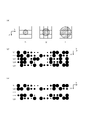
続いて、本例において行うリカバリ処理について、説明をする。説明の便宜上、先ず、各色用のインクジェットヘッド102におけるノズルから吐出可能なインクの容量や、異常ノズルが存在する場合の影響(異常ノズルの影響)等について、説明をする。図2は、インクの容量及び異常ノズルの影響について説明をする図である。図2(a)は、各色用のインクジェットヘッド102におけるノズルから吐出可能なインクの容量の一例を示す。上記においても説明をしたように、本例において、各色用のインクジェットヘッド102としては、ノズルから吐出するインクの容量を複数段階で変更可能なインクジェットヘッドを用いる。より具体的に、本例において、インクジェットヘッド102は、それぞれのノズルから、図中に示すように、S(小)、M(中)、L(大)の3種類の容量で、インクを吐出可能である。この場合、ノズルからインクを吐出しない状態を含めることで、一つのノズルにより、4種類の値(4値)を表現可能になっているといえる。また、このようなインクジェットヘッド102としては、インクの容量を複数段階で可変な公知のインクジェットヘッド(多値ヘッド)を好適に用いることができる。
Next, recovery processing performed in this example will be described. For convenience of explanation, first, the volume of ink that can be ejected from the nozzles in the
また、図2(a)においては、インクの容量に関し、S、M、Lの各容量で形成されるインクのドットの大きさを、印刷の解像度に対応するマス目と重ねて図示している。S、M、Lの各容量で形成されるインクのドットの大きさとは、S、M、Lの3種類のそれぞれの容量で形成されるインクのドットのサイズ(S、M、Lの3種類のサイズ)のことである。また、図中において、それぞれのマス目は、一つの吐出位置に対応している。また、それぞれのマス目については、例えば、印刷の解像度に応じて設定される画素の範囲等と考えることもできる。また、図中に示す印刷の解像度に対応するマス目(9マスのマス目)については、印刷の解像度に応じて設定される吐出位置の例と考えることができる。また、これらマス目のうち、中央のマス目は、それぞれのドットの形成時にインクを吐出する吐出位置を示している。また、中央のマス目以外のマス目は、中央のマス目に対応する吐出位置の周辺の吐出位置を示している。また、本例においては、図中に示したドットのサイズからわかるように、各サイズのインクのドットとして、隣接する吐出位置に形成されるインクのドットと接触するサイズのドットを形成する。この場合、隣接する吐出位置とは、例えば、主走査方向及び副走査方向のそれぞれにおいて隣接する吐出位置のことである。また、印刷装置10の構成の変形例においては、例えば、一部のサイズのドットのみについて、隣接する吐出位置に形成されるインクのドットと接触するサイズにしてもよい。また、この場合、少なくとも一部のサイズのドットについて、少なくとも副走査方向において隣接する吐出位置に形成されるインクのドットと接触するサイズにすることが好ましい。
In addition, in FIG. 2(a), with respect to the ink capacity, the sizes of ink dots formed with the respective capacities of S, M, and L are shown superimposed on the squares corresponding to the printing resolution. . The sizes of the ink dots formed with the respective capacities of S, M, and L refer to the sizes of the ink dots formed with the respective capacities of the three types of S, M, and L (three types of S, M, and L). size). Also, in the drawing, each square corresponds to one ejection position. Also, each square can be considered as a range of pixels set according to the printing resolution, for example. Also, the squares (9 squares) corresponding to the printing resolution shown in the figure can be considered as an example of the ejection positions set according to the printing resolution. Among these squares, the square in the center indicates the ejection position at which ink is ejected when each dot is formed. In addition, squares other than the central square indicate ejection positions around the ejection position corresponding to the central square. Also, in this example, as can be seen from the dot sizes shown in the drawing, as ink dots of each size, dots of a size that come in contact with ink dots formed at adjacent ejection positions are formed. In this case, the adjacent ejection positions are, for example, adjacent ejection positions in the main scanning direction and the sub-scanning direction. Further, in a modified example of the configuration of the
また、本例においては、上記のようにインクの容量を変更可能な特徴を利用して、リカバリ処理を行う。より具体的に、いずれかのインクジェットヘッド102におけるいずれかのノズルが異常ノズルである場合、印刷装置10の制御部30(図1参照)は、異常ノズルを使用しないで主走査動作が行われるように走査駆動部18(図1参照)の動作を制御する。そして、この場合において、異常ノズル以外の他のいずれかのノズルに、その異常ノズルが存在しない場合である正常時よりも多くのインクの量を吐出させることで、異常ノズルにインクを吐出させないことで生じる影響を抑える。このように構成すれば、例えば、異常ノズル以外の他のノズルでの吐出量を多くすることで、異常ノズルの代わりに他のノズルでインクを吐出することができる。また、これにより、異常ノズルが存在する場合において、リカバリ処理を適切に行うことができる。また、本例において行うリカバリ処理については、後に更に詳しく説明をする。また、リカバリ処理の動作について詳しく説明をする前に、以下において、図2(b)、(c)を用いて、異常ノズルの影響の例を説明する。
Also, in this example, recovery processing is performed using the feature that the ink volume can be changed as described above. More specifically, when one of the nozzles in one of the inkjet heads 102 is an abnormal nozzle, the controller 30 (see FIG. 1) of the
図2(b)は、異常ノズルが存在しない正常時に1回の主走査動作で形成されるインクのドットの並びの一例を示す。図2(c)は、異常ノズルが存在する場合においてリカバリ処理を行わなかった場合に1回の主走査動作で形成されるインクのドットの並びの一例を示す。尚、図2(b)、(c)においては、インクのドットの重なりを小さくして、個々のインクのドットを識別しやすくするために、インクのドットについて、少し小さめに図示をしている。実際の印刷時には、各サイズのインクのドットとして、図2(a)に示すようなサイズのインクのドットを形成する。 FIG. 2(b) shows an example of an array of ink dots formed by one main scanning operation in a normal state in which no abnormal nozzle exists. FIG. 2C shows an example of an array of ink dots formed in one main scanning operation when there is an abnormal nozzle and recovery processing is not performed. In addition, in FIGS. 2B and 2C, the ink dots are shown slightly smaller in order to reduce the overlapping of the ink dots and make it easier to identify the individual ink dots. . During actual printing, ink dots of sizes as shown in FIG. 2A are formed as ink dots of each size.
図中において、主走査方向(Y方向)へ並ぶインクのドットは、一つのインクジェットヘッド102における一つのノズルにより形成されるドットである。また、この場合、主走査方向へ並ぶインクのドットの並びについては、一つのノズルにより1回の主走査動作で形成されるドット等と考えることもできる。各回の主走査動作において、それぞれのインクジェットヘッド102におけるそれぞれのノズルは、印刷する画像に応じて予め設定された吐出位置へインクを吐出することにより、主走査方向へ並ぶ複数のインクのドットを形成する。また、この場合において、インクを吐出するそれぞれの吐出位置に対し、S、M、又はLのいずれかの容量のインクを吐出する。また、図中において、文字L1~L5は、副走査方向へ並ぶ5本のラインを示している。この場合、ラインとは、主走査方向へ並ぶ複数のインクのドットにより構成される線のことである。また、上記の説明からわかるように、この場合、それぞれのラインは、副走査方向(X方向)と平行なノズル列方向へ連続して並ぶ5個のノズルのそれぞれに対応している。
In the drawing, ink dots aligned in the main scanning direction (Y direction) are dots formed by one nozzle in one
また、図2(c)においては、文字L3を付したラインに対応するノズルがインクを吐出しない不吐出ノズルになっている場合について、インクのドットの並びの一例を図示している。この場合、図中に示すように、図2(b)に示したインクのドットの並びから、文字L3を付したラインを構成するドットを除いた状態になる。また、この場合、一つのラインが消失することで、印刷結果において、インクの量が不足する筋状の部分(白スジ)が発生して、印刷の品質が低下することになる。 FIG. 2(c) shows an example of the arrangement of ink dots when the nozzle corresponding to the line labeled with letter L3 is a non-ejection nozzle that does not eject ink. In this case, as shown in the figure, the dots forming the line with the character L3 are removed from the array of ink dots shown in FIG. 2(b). Also, in this case, one line disappears, and a streak-like portion (white streak) where the amount of ink is insufficient occurs in the print result, and the print quality deteriorates.
これに対し、上記においても説明をしたように、本例においては、リカバリ処理を行うことで、異常ノズルが存在することで生じる影響を抑える。図3は、本例において行うリカバリ処理について更に詳しく説明をする図である。図3(a)は、異常ノズルが存在しない場合に印刷される画像である元画像の例を示す図であり、元画像を構成するインクのドットの例を模式的に示す。また、図3(a)において、左側の図は、解像度に応じて設定される各位置に形成されるインクのドットのサイズを、文字S、M、Lにより示している。また、右側の図は、左側の図と同じ図に対し、各サイズのドットの大きさを示す円を重ねて示している。また、図3(a)に示すインクのドットの例については、例えば、図2(b)に示したインクのドットの並びの一部に対応すると考えることができる。また、図3(a)及び以下において説明をする図3(b)、(c)においても、図2(b)、(c)等と同様に、副走査方向へ連続して並ぶ5個のノズルに対応する部分を構成するインクのドットの例を示している。 On the other hand, as described above, in this example, recovery processing is performed to suppress the influence caused by the presence of an abnormal nozzle. FIG. 3 is a diagram for explaining in more detail the recovery processing performed in this example. FIG. 3A is a diagram showing an example of an original image, which is an image to be printed when there is no abnormal nozzle, and schematically shows an example of ink dots forming the original image. In FIG. 3(a), the drawing on the left side shows the sizes of ink dots formed at respective positions set according to the resolution by letters S, M, and L. FIG. In addition, the diagram on the right side shows the same diagram as the diagram on the left side, with circles showing the sizes of dots of each size superimposed thereon. Also, the example of ink dots shown in FIG. 3A can be considered to correspond to, for example, part of the array of ink dots shown in FIG. 2B. Also in FIG. 3(a) and FIGS. 3(b) and 3(c) explained below, as in FIGS. 4 shows an example of dots of ink forming portions corresponding to nozzles.
図3(b)は、異常ノズルが存在する場合に印刷される画像であるノズル抜け画像の例を示す。ノズル抜け画像については、例えば、異常ノズルにインクを吐出させずに元画像と同じ画像を印刷することで得られる画像等と考えることができる。また、図3(b)においても、左側の図は、解像度に応じて設定される各位置に形成されるインクのドットのサイズを、文字S、M、Lにより示している。また、右側の図は、左側の図と同じ図に対し、各サイズのドットの大きさを示す円を重ねて示している。また、図3(b)においては、図中において副走査方向の中央に位置するラインに対応するノズルが不吐出になっている場合について、ドットの並び方の例を示している。この場合、図中に破線を付した円で示すように、図3(a)に示す元画像おいて中央のマス目位置に形成されるLサイズのドットが、形成されないことになる。また、その結果、このラインの位置において、元画像と比べて、インクの量の不足が生じることになる。 FIG. 3B shows an example of a missing nozzle image, which is an image printed when an abnormal nozzle exists. A missing nozzle image can be considered, for example, as an image obtained by printing the same image as the original image without ejecting ink from an abnormal nozzle. Also in FIG. 3B, the left-hand diagram indicates the sizes of ink dots formed at respective positions set according to the resolution by letters S, M, and L. FIG. In addition, the diagram on the right side shows the same diagram as the diagram on the left side, with circles showing the sizes of dots of each size superimposed thereon. In addition, FIG. 3B shows an example of how dots are arranged when the nozzle corresponding to the line positioned in the center in the sub-scanning direction in the drawing is in a non-ejecting state. In this case, as indicated by the dashed circle in the figure, the L-size dot formed at the center grid position in the original image shown in FIG. 3A is not formed. Also, as a result, the amount of ink at the position of this line is insufficient compared to the original image.
これに対し、本例においては、上記においても説明をしたように、異常ノズル以外の他のいずれかのノズルに正常時よりも多くのインクの量を吐出させることで、リカバリ処理を行う。また、より具体的に、この場合、異常ノズルが存在することでインクのドットが形成されなくなる吐出位置である抜け画素(ノズル抜け画素)の近傍の吐出位置に形成されるインクのドットのサイズを正常時よりも大きくする(上げる)ことで、抜け画素となる吐出位置の影響で生じるインクの不足分を補い、異常ノズルの影響を低減する。 On the other hand, in this example, as described above, recovery processing is performed by causing any nozzle other than the abnormal nozzle to eject a larger amount of ink than during normal operation. More specifically, in this case, the size of an ink dot formed at an ejection position near a missing pixel (nozzle missing pixel), which is an ejection position where an ink dot is not formed due to the presence of an abnormal nozzle, is determined. By making it larger (raised) than the normal time, the shortage of ink caused by the influence of the ejection position of the missing pixel is compensated for, and the influence of the abnormal nozzle is reduced.
図3(c)は、リカバリ処理を行って印刷される画像であるリカバリ画像(リカバリ後画像)の例を示す。図3(c)においても、左側の図は、解像度に応じて設定される各位置に形成されるインクのドットのサイズを、文字S、M、Lにより示している。また、右側の図は、左側の図と同じ図に対し、各サイズのドットの大きさを示す円を重ねて示している。図中に示すように、この場合、異常ノズルに対応するライン以外のラインを構成するインクのドットの一部について、元画像よりもドットのサイズを上げている。この場合、ドットのサイズを上げるとは、ノズルに吐出位置へ吐出させるインクの容量に対応する段階をより大きな段階に変化させることである。また、リカバリ処理時の制御部30(図1参照)の動作については、例えば、インクの吐出量を多くする吐出位置へ異常ノズル以外の他のノズルに吐出させるインクの容量に対応する段階をより大きな容量に対応する段階に変化させることにより、他のノズルに正常時よりも多くの量の液体を吐出させる動作等と考えることができる。また、異常ノズルが存在する場合の制御部30の動作については、例えば、主走査動作時に異常ノズルの近傍にある他のノズルによりインクを吐出可能な吐出位置の少なくとも一部に対し、当該他のノズルに、正常時よりも多くの量のインクを吐出させる動作等と考えることもできる。
FIG. 3C shows an example of a recovery image (post-recovery image), which is an image printed after recovery processing. In FIG. 3C as well, the drawing on the left side indicates the sizes of ink dots formed at respective positions set according to the resolution by letters S, M, and L. FIG. In addition, the diagram on the right side shows the same diagram as the diagram on the left side, with circles showing the sizes of dots of each size superimposed thereon. As shown in the drawing, in this case, some of the ink dots forming the lines other than the line corresponding to the abnormal nozzle have a larger dot size than the original image. In this case, increasing the dot size means changing the step corresponding to the volume of ink ejected from the nozzle to the ejection position to a larger step. Further, regarding the operation of the control unit 30 (see FIG. 1) during the recovery process, for example, the step corresponding to the volume of ink to be ejected from nozzles other than the malfunctioning nozzle to the ejection position where the ejection amount of ink is increased may be increased. By changing to a step corresponding to a large volume, it can be considered as an operation or the like that causes other nozzles to eject a larger amount of liquid than during normal operation. Further, regarding the operation of the
また、以下において更に詳しく説明をするように、本例においては、ドットのサイズを上げる吐出位置について、記憶部22(図1参照)に記憶されている影響度マトリクス及び優先順位マトリクスに基づいて選択を行う。このように構成した場合、例えば、単にインクの量を調整するのではなく、抜け画素の位置をより適切にインクが覆う(埋める)ように、ドットサイズの変更を行うことができる。そのため、本例によれば、例えば、単にインクの量の合計量を合わせる場合と比べ、異常ノズルの影響をより適切に低減することができる。また、これにより、例えば、リカバリ処理をより高い精度でより適切に行うことができる。 Further, as will be described in more detail below, in this example, the ejection positions for increasing the dot size are selected based on the influence degree matrix and the priority order matrix stored in the storage unit 22 (see FIG. 1). I do. With this configuration, for example, instead of simply adjusting the amount of ink, the dot size can be changed so that the positions of missing pixels are more appropriately covered (filled) with ink. Therefore, according to this example, it is possible to more appropriately reduce the influence of the abnormal nozzle, for example, compared to the case of simply matching the total amount of ink. Moreover, thereby, for example, recovery processing can be performed more appropriately with higher accuracy.
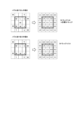
続いて、本例において行うリカバリ処理について、更に詳しく説明をする。図4は、リカバリ処理について更に詳しく説明をする図である。上記のように、本例においては、抜け画素の近傍の吐出位置に形成されるインクのドットのサイズを正常時よりも大きくすることで、リカバリ処理を行う。また、この場合において、例えば以下において説明をするように、リカバリに使用する範囲であるリカバリ範囲を異常ノズルに対応する吐出位置に対して設定して、そのリカバリ範囲内で、ドットのサイズの調整を行う。また、これにより、主走査動作において、制御部30は、異常ノズルにインクを吐出させずに、他のノズルによりインクを吐出可能な吐出位置の一部に対し、他のノズルに正常時よりも多くの量のインクを吐出させる。また、このリカバリ範囲については、Lサイズのドット(以下、Lドットという)が広がる範囲(Lドットがカバーできる画素の範囲)に基づいて決定する。リカバリ範囲については、例えば、異常ノズルの周辺(近傍)にある他のノズルによるインクの吐出量を調整する範囲等と考えることもできる。
Next, the recovery processing performed in this example will be described in more detail. FIG. 4 is a diagram for explaining the recovery process in more detail. As described above, in this example, the recovery process is performed by increasing the size of the ink dots formed at the ejection positions near the missing pixels. In this case, for example, as described below, a recovery range, which is a range used for recovery, is set for the ejection positions corresponding to the abnormal nozzles, and the dot size is adjusted within the recovery range. I do. Accordingly, in the main scanning operation, the
また、リカバリ処理において、異常ノズルの周辺にある他のノズルとしては、少なくとも、異常ノズルと隣接するノズルを用いることが考えられる。また、この場合、他のノズルとして、異常ノズルと隣接するノズルを含む複数のノズルを用いることが好ましい。より具体的には、他のノズルとしては、例えば、異常ノズルに対してノズル列方向における一方側にある2個以上のノズルと、他方側にある2個以上のノズルを用いることが好ましい。また、他のノズルについては、例えば、異常ノズルでの本来の吐出位置に対して影響が生じる吐出位置へインクを吐出可能なノズルを用いると考えることもできる。また、この場合、使用する他のノズルの範囲に合わせて、リカバリ範囲を設定することになる。 Also, in the recovery process, it is conceivable to use at least nozzles adjacent to the abnormal nozzle as other nozzles around the abnormal nozzle. Also, in this case, it is preferable to use a plurality of nozzles including nozzles adjacent to the abnormal nozzle as other nozzles. More specifically, as the other nozzles, it is preferable to use, for example, two or more nozzles on one side of the abnormal nozzle in the nozzle row direction and two or more nozzles on the other side. As for the other nozzles, for example, it is possible to use nozzles capable of ejecting ink to ejection positions that affect the original ejection positions of the abnormal nozzles. Also, in this case, the recovery range is set according to the range of other nozzles to be used.
図4(a)は、リカバリ範囲の例を示す図であり、印刷の解像度とLドットのサイズとの関係が互いに異なる二通りの場合について、リカバリ範囲の例を示す。図4(a)において、左側の図は、主走査方向及び副走査方向のそれぞれにおいて3個の吐出位置が並ぶ3×3画素の範囲にLドットが広がる場合のリカバリ範囲の例を示す。この場合、異常ノズルに対応する吐出位置を中心とする3×3画素に対応する範囲を、リカバリ範囲として用いることになる。また、右側の図は、主走査方向へ3個、副走査方向へ5個の吐出位置が並ぶ3×5画素の範囲にLドットが広がる場合のリカバリ範囲の例を示す。この場合、異常ノズルに対応する吐出位置を中心とする3×5画素に対応する範囲を、リカバリ範囲として用いることになる。このように構成すれば、例えば、印刷の解像度に応じて、リカバリ範囲を適切に決定することができる。また、例えば、解像度に応じて動的にリカバリ範囲を変更すること等も可能になる。 FIG. 4A is a diagram showing an example of the recovery range, and shows an example of the recovery range for two cases in which the relationship between the print resolution and the L dot size is different from each other. In FIG. 4A, the diagram on the left side shows an example of the recovery range when the L dots spread over a 3×3 pixel range in which three ejection positions are arranged in each of the main scanning direction and the sub-scanning direction. In this case, a range corresponding to 3×3 pixels centered on the ejection position corresponding to the abnormal nozzle is used as the recovery range. The figure on the right side shows an example of the recovery range when L dots spread over a range of 3×5 pixels in which 3 ejection positions are arranged in the main scanning direction and 5 ejection positions are arranged in the sub-scanning direction. In this case, a range corresponding to 3×5 pixels centered on the ejection position corresponding to the abnormal nozzle is used as the recovery range. With this configuration, the recovery range can be appropriately determined according to the printing resolution, for example. Also, for example, it becomes possible to dynamically change the recovery range according to the resolution.
また、本例のリカバリ処理においては、異常ノズルに対応する吐出位置を含むように設定されるカバレッジ計算範囲に対してカバレッジを計算して、ノズル抜け前とリカバリ処理後とでカバレッジが一致するように、リカバリ範囲内のインクのドットのサイズを調整する。この場合、カバレッジとは、解像度に対応するマス目がインクにより埋められる程度(ドットが埋まる量)を示す数値であり、各サイズのインクのドットと解像度との関係とを示すドットモデルに基づいて算出される。また、より具体的に、本例において、各サイズのインクのドットに対応するカバレッジは、図4(b)に示すようになる。図4(b)は、各サイズのインクのドットに対応するカバレッジの例を示す。また、この場合、カバレッジ計算範囲のカバレッジについては、例えば、リカバリ範囲内に形成されるインクのドットによりカバレッジ計算範囲に含まれるマス目が埋められる程度を示す数値等と考えることができる。また、リカバリ処理の動作に関し、ノズル抜け前のカバレッジとは、元画像を構成するインクのドットに基づいて算出されるカバレッジのことである。リカバリ処理後のカバレッジとは、リカバリ範囲内の少なくとも一部のインクのドットのサイズを調整した状態で算出されるカバレッジのことである。また、カバレッジが一致するとは、予め設定された許容範囲の誤差の範囲内で一致することであってよい。より具体的に、本例において、カバレッジが一致するとは、カバレッジの差が最小になることであってよい。 In addition, in the recovery process of this example, the coverage is calculated for the coverage calculation range set so as to include the ejection positions corresponding to the abnormal nozzles so that the coverages before the missing nozzles and after the recovery process match. To adjust the size of the ink dots within the recovery range. In this case, coverage is a numerical value that indicates the extent to which the squares corresponding to the resolution are filled with ink (amount of dots filled), based on a dot model that indicates the relationship between ink dots of each size and resolution. Calculated. More specifically, in this example, the coverage corresponding to ink dots of each size is as shown in FIG. 4(b). FIG. 4B shows examples of coverage corresponding to ink dots of each size. Further, in this case, the coverage of the coverage calculation range can be considered, for example, as a numerical value or the like indicating the extent to which the squares included in the coverage calculation range are filled with ink dots formed within the recovery range. Regarding the operation of the recovery process, the coverage before the missing nozzle is the coverage calculated based on the ink dots forming the original image. The coverage after the recovery process is the coverage calculated after adjusting the dot size of at least part of the ink within the recovery range. Also, matching the coverages may mean matching within a preset allowable error range. More specifically, in this example, matching coverage may be that the difference in coverage is minimized.
また、本例において、カバレッジ計算範囲は、異常ノズルでの本来の吐出位置を含む所定の範囲の一例である。カバレッジ計算範囲でのカバレッジを一致させる動作は、このような所定の範囲内でのインクの吐出量の合計に関し、調整後の合計の吐出量を正常時の合計の吐出量に近づけるように調整する動作の一例である。また、カバレッジ計算範囲については、例えば、リカバリ処理時に画像のカバレッジを計算する際の指定範囲等と考えることもできる。 Also, in this example, the coverage calculation range is an example of a predetermined range including the original ejection position of the abnormal nozzle. The operation of matching the coverage in the coverage calculation range relates to the total ink ejection amount within such a predetermined range, and adjusts the adjusted total ejection amount so as to approach the normal total ejection amount. It is an example of operation. Also, the coverage calculation range can be considered as, for example, a specified range when calculating coverage of an image during recovery processing.
また、上記においても説明をしたように、本例においては、影響度マトリクス及び優先順位マトリクスを用いて、リカバリ処理を行う。また、この場合、影響度マトリクス及び優先順位マトリクスについて、Lドットのドットモデル(Lドットモデル)に基づいて作成する。図4(c)は、影響度マトリクス及び優先順位マトリクスの一例を示す図であり、3×3画素に対応する範囲をリカバリ範囲として用いる場合について、影響度マトリクス及び優先順位マトリクスの例を示す。 Also, as described above, in this example, recovery processing is performed using an impact matrix and a priority order matrix. In this case, the influence matrix and the priority matrix are created based on the dot model of L dots (L dot model). FIG. 4(c) is a diagram showing an example of an influence matrix and a priority matrix, and shows examples of the influence matrix and the priority matrix when a range corresponding to 3×3 pixels is used as the recovery range.
ここで、影響度マトリクスとは、例えば、Lドットの配置による影響をランク分けしたマトリクス状のデータのことである。また、本例において、影響度マトリクスは、影響度情報の一例である。この場合、影響度情報とは、例えば、1回の主走査動作においてインクが吐出される複数の吐出位置の間で生じる影響度を示す情報のことである。また、より具体的に、本例において、影響度マトリクスは、リカバリ範囲を構成する複数の吐出位置に対応する要素により構成されるマトリクスである。また、この場合、各吐出位置に対応する要素には、リカバリ範囲における中心の吐出位置にLドットを形成した場合に各吐出位置が受ける影響の大きさを示す値が設定される。この場合、リカバリ範囲における中心の吐出位置とは、図中に×印を付した位置のことである。また、各吐出位置が受ける影響の大きさとは、例えば、リカバリ範囲の中心位置に形成されたLドットにより各吐出位置が覆われる範囲の大きさのことである。 Here, the influence degree matrix is, for example, matrix-like data in which the influence of the arrangement of L dots is ranked. Also, in this example, the impact matrix is an example of impact information. In this case, the degree of influence information is, for example, information indicating the degree of influence between a plurality of ejection positions from which ink is ejected in one main scanning operation. More specifically, in this example, the influence degree matrix is a matrix composed of elements corresponding to a plurality of ejection positions that constitute the recovery range. In this case, the element corresponding to each ejection position is set with a value indicating the magnitude of the effect that each ejection position receives when an L dot is formed at the center ejection position in the recovery range. In this case, the central ejection position in the recovery range is the position marked with an x in the figure. Further, the magnitude of the influence on each ejection position is, for example, the size of the range in which each ejection position is covered by the L dots formed at the center position of the recovery range.
また、より具体的に、影響度マトリクスの要素に設定される値としては、より小さな値がより大きな影響を示すように、影響をランク分けしたランクを示す値が設定される。この場合、影響度マトリクスについては、例えば、一つの吐出位置に生じる影響の大きさについて、当該一つの吐出位置の周辺における複数の吐出位置のそれぞれに対し、影響の大きさが互いに異なる複数種類の影響度の中からいずれかの影響度を対応付ける情報等と考えることができる。また、本例において、リカバリ範囲における中心の吐出位置は、異常ノズルでの本来の吐出位置になっている。この場合、異常ノズルでの本来の吐出位置とは、異常ノズルが正常なノズルであった場合に液体を吐出するはずであった吐出位置のことである。そして、この場合、影響度マトリクスについては、例えば、異常ノズルでの本来の吐出位置を中心とする複数の吐出位置に対して異常ノズルでの本来の吐出位置への影響度を示す数値が定義されたマトリクス等と考えることもできる。また、影響度マトリクスについては、例えば、一つの吐出位置の周辺における複数の吐出位置のそれぞれにインクのドットが形成されることでこの一つの吐出位置に生じる影響の大きさを周辺における複数の吐出位置のそれぞれと対応付けて示す情報等と考えることもできる。また、異常ノズルでの本来の吐出位置については、例えば、異常ノズルに対応する吐出位置である異常ノズル対応位置等と定義することもできる。 Further, more specifically, as the values set for the elements of the influence degree matrix, values are set that indicate ranks in which influences are ranked such that a smaller value indicates a greater influence. In this case, regarding the influence degree matrix, for example, regarding the magnitude of the influence that occurs at one ejection position, a plurality of kinds of influence magnitudes that differ from each other are used for each of the plurality of ejection positions around the one ejection position. It can be considered as information or the like that associates one of the degrees of influence. Also, in this example, the central ejection position in the recovery range is the original ejection position for the abnormal nozzle. In this case, the original ejection position of the abnormal nozzle is the ejection position where the liquid should be ejected if the abnormal nozzle were a normal nozzle. In this case, in the influence degree matrix, for example, numerical values indicating the degree of influence of the abnormal nozzle on the original ejection position are defined for a plurality of ejection positions centering on the original ejection position of the abnormal nozzle. can also be considered as a matrix or the like. In addition, regarding the influence degree matrix, for example, when ink dots are formed at each of a plurality of ejection positions around one ejection position, the magnitude of the influence generated at this one ejection position is It can also be considered as information or the like associated with each position. Further, the original ejection position of an abnormal nozzle can be defined as, for example, an ejection position corresponding to an abnormal nozzle, such as an abnormal nozzle corresponding position.
また、上記においても説明をしたように、影響度マトリクスは、リカバリ処理において用いるものである。そして、リカバリ処理では、異常ノズル以外のノズルにより形成するインクのドットのサイズを調整することで、カバレッジ計算範囲のカバレッジを変化させる。そのため、影響度マトリクスとしては、例えば図中に示すように、異常ノズル以外のノズルに対応する位置のみに値が設定されたマトリクスを用いることが考えられる。このような影響度マトリクスを用いることにより、例えば、異常ノズル以外の他のノズルにより多くのインクを吐出させる吐出位置について、異常ノズルでの本来の吐出位置への影響度を考慮して適切に選択することができる。 Also, as described above, the impact matrix is used in recovery processing. In the recovery process, the coverage of the coverage calculation range is changed by adjusting the size of ink dots formed by nozzles other than the abnormal nozzle. Therefore, as the influence matrix, for example, as shown in the figure, it is possible to use a matrix in which values are set only for the positions corresponding to the nozzles other than the abnormal nozzle. By using such an influence degree matrix, for example, ejection positions from which more ink is ejected by nozzles other than the abnormal nozzles can be appropriately selected in consideration of the degree of influence of the abnormal nozzles on the original ejection positions. can do.
また、優先順位マトリクスとは、リカバリ範囲に含まれる複数の吐出位置に対してドットのサイズを上げる調整を行う順番を指定するマトリクスのことである。また、本例において、優先順位マトリクスは、優先度情報の一例である。優先度情報とは、例えば、同じ影響度と対応付けられている複数の吐出位置に対して選択の優先度を示す情報のことである。また、優先順位マトリクスについては、例えば、優先度として優先順位を示すマトリクス状のデータ等と考えることもできる。また、本例において、優先順位マトリクスは、異常ノズルでの本来の吐出位置を中心とする複数の吐出位置に対して優先順位を示す数値が定義されたマトリクスである。この場合、優先順位を示す数値としては、選択の順番を示す数値を用いる。また、図中において、異常ノズルでの本来の吐出位置とは、図中に×印を付して示した吐出位置のことである。 The priority order matrix is a matrix that designates the order of adjusting the dot size for a plurality of ejection positions included in the recovery range. Also, in this example, the priority order matrix is an example of priority information. Priority information is, for example, information indicating the priority of selection for a plurality of ejection positions associated with the same degree of influence. Also, the priority matrix can be considered, for example, as matrix-like data indicating priority as priority. In this example, the priority order matrix is a matrix in which numerical values indicating priority orders are defined for a plurality of ejection positions centering on the original ejection position of the abnormal nozzle. In this case, a numerical value indicating the order of selection is used as the numerical value indicating the order of priority. Further, in the figure, the original ejection position of the abnormal nozzle is the ejection position marked with an x in the figure.
また、より具体的に、本例の影響度マトリクスにおいては、例えば図中に示すように、複数の吐出位置に対し、同じ影響度が対応付けられる場合がある。そして、このような場合、優先順位マトリクスを更に用いることで、例えば、複数の吐出位置に対し同じ影響度が対応付けられる場合等にも、インクの量を増加させる吐出位置をより適切に選択することができる。また、図中に示すように、本例において、優先順位マトリクスとしては、影響度マトリクスと同じサイズのマトリクスを用いる。本例によれば、例えば、インクの量を増加させてドットのサイズを上げる吐出位置をより適切に選択することができる。 More specifically, in the influence matrix of this example, the same influence may be associated with a plurality of ejection positions, as shown in the drawing. In such a case, by further using the priority order matrix, for example, even when the same degree of influence is associated with a plurality of ejection positions, the ejection position for increasing the amount of ink can be selected more appropriately. be able to. Also, as shown in the figure, in this example, a matrix having the same size as the influence matrix is used as the priority order matrix. According to this example, for example, it is possible to more appropriately select the ejection position for increasing the amount of ink to increase the dot size.
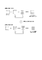
図5は、ドットのサイズを上げる動作等について更に詳しく説明をする図である。図5(a)は、ドットのサイズの上げ方の一例を示す図であり、図4(c)に示した影響度マトリクス及び優先順位マトリクスを用いる場合について、リカバリ範囲に含まれる吐出位置へ形成するドットのサイズを上げる動作の例を示す。また、図中において、処理0回目は、ドットサイズを大きくする処理を行う前の状態を示している。また、処理1回目~処理4回目のそれぞれは、一つの吐出位置におけるドットのサイズを1段階だけ大きくする処理を示している。 FIG. 5 is a diagram for explaining in more detail the operation of increasing the dot size. FIG. 5(a) is a diagram showing an example of how to increase the dot size. In the case of using the influence degree matrix and the priority order matrix shown in FIG. 4(c), dots are formed at ejection positions included in the recovery range. Here is an example of the operation of increasing the size of the dot to be used. Further, in the drawing, the 0th processing indicates the state before performing the processing for increasing the dot size. Also, each of the first to fourth processings indicates a process of increasing the dot size at one ejection position by one step.
上記においても説明をしたように、本例においては、影響度マトリクス及び優先順位マトリクスに基づいてリカバリ範囲内の吐出位置を選択して、その吐出位置に形成するドットのサイズを上げることで、リカバリ処理を行う。また、これにより、例えば、影響度マトリクスにおいて設定されている影響度が高い吐出位置をより優先して選択して、ドットのサイズを大きくする。また、この場合、優先順位マトリクスにおいて指定されている値に従った順番でリカバリ範囲を走査して、同じ影響度が設定されている全ての吐出位置に形成するドットがLドットになるまで、同じ影響度が設定されている吐出位置を対象に、ドットのサイズを大きくする処理を繰り返す。そして、同じ影響度が設定されている全ての吐出位置に形成するドットがLドットになった時点で、更に他の吐出位置に対してもドットのサイズを上げる必要がある場合には、次に高い影響度が設定されている吐出位置を対象に、上記と同様にして、ドットのサイズを大きくする処理を行う。また、これにより、例えば、影響度の同じ吐出位置がLドットで埋められた後に、次の影響度の吐出位置に対するドットのサイズを変更する動作を行う。 As described above, in this example, an ejection position within the recovery range is selected based on the degree of influence matrix and the priority order matrix, and the size of the dots formed at the ejection position is increased. process. Also, in this way, for example, ejection positions with high influence set in the influence matrix are selected with higher priority, and the dot size is increased. Further, in this case, the recovery range is scanned in the order according to the values specified in the priority order matrix, and the dots to be formed at all ejection positions set with the same degree of influence are L dots. Processing for increasing the dot size is repeated targeting the ejection positions for which the degree of influence is set. Then, when the dots formed at all the ejection positions for which the same degree of influence is set become L dots, if it is necessary to further increase the dot size for the other ejection positions, then Targeting ejection positions for which a high degree of influence is set, processing for increasing the dot size is performed in the same manner as described above. Further, as a result, for example, after the ejection positions with the same degree of influence are filled with L dots, an operation of changing the dot size for the ejection position with the next degree of influence is performed.
ここで、本例において用いる影響度マトリクスが示す情報については、例えば、いずれかの影響度とそれぞれが対応付けられる複数の吐出位置として、互いに異なる複数種類の影響度と対応付けられた吐出位置を含んでいると考えることができる。また、この場合において、このような吐出位置として、例えば、複数種類の影響度の中で最も大きな影響を示す影響度である第1の影響度と対応付けられる複数の吐出位置と、第1の影響度よりも小さな影響を示す第2の影響度と対応付けられる吐出位置とを含むと考えることができる。また、この場合、異常ノズルが存在する場合における制御部30(図1参照)の動作については、例えば、影響度マトリクスに基づき、異常ノズルによりインクが吐出される吐出位置の周辺における複数の吐出位置のうち、第1の影響度と対応付けられている吐出位置を優先して選択する動作等考えることができる。このように構成すれば、例えば、異常ノズルでの本来の吐出位置の周辺における複数の吐出位置のうち、より大きな影響を示す影響度に対応付けられている吐出位置をより優先して選択することができる。また、この場合、制御部30は、例えば、第1の影響度と対応付けられている吐出位置の少なくとも一部へ吐出するインクの容量を示す段階について、正常時よりも大きな段階に変更する。また、この場合、第2の影響度と対応付けられている吐出位置については、例えば、第1の影響度と対応付けられている吐出位置へ吐出するインクの容量が最大の段階(Lドットの段階)へ変更された後のみにインクの容量を大きく変更すると考えることができる。すなわち、この場合、制御部30は、例えば、第1の影響度と対応付けられている全ての吐出位置へ吐出するインクの容量が最大の段階へ変更され、かつ、更に他の吐出位置へ吐出するインクの容量を多くする場合にのみ、第2の影響度と対応付けられている吐出位置の少なくとも一部へ吐出するインクの容量を示す段階について、正常時よりも大きな段階に変更することになる。このように構成すれば、例えば、影響度の大きな吐出位置に対し、優先的かつより適切にインクの量を増加させることができる。
Here, regarding the information indicated by the influence degree matrix used in this example, for example, as a plurality of ejection positions each associated with one of the influence degrees, the ejection positions associated with a plurality of different types of influence degrees are used. can be thought of as containing Further, in this case, as such ejection positions, for example, a plurality of ejection positions associated with a first influence degree, which is an influence degree indicating the greatest influence among the plurality of types of influence degrees, and a first influence degree. It can be considered to include ejection positions associated with a second degree of influence that indicates less influence than the degree of influence. Further, in this case, regarding the operation of the control unit 30 (see FIG. 1) when there is an abnormal nozzle, for example, based on the influence matrix, a plurality of ejection positions around the ejection position where ink is ejected by the abnormal nozzle Among them, an operation of preferentially selecting the ejection position associated with the first degree of influence can be considered. With this configuration, for example, among a plurality of ejection positions in the vicinity of the original ejection position of the abnormal nozzle, the ejection position associated with the degree of influence indicating the greater influence can be selected with higher priority. can be done. Also, in this case, the
また、上記においても説明をしたように、本例において行うリカバリ処理では、カバレッジ計算範囲に対してカバレッジを計算して、計算結果に基づき、リカバリ範囲内のインクのドットのサイズを調整する。そして、この場合、カバレッジ計算範囲については、例えば図5(b)に示すように、リカバリ範囲よりも大きくすることが好ましい。 Also, as described above, in the recovery process performed in this example, the coverage is calculated for the coverage calculation range, and the ink dot size within the recovery range is adjusted based on the calculation result. In this case, the coverage calculation range is preferably made larger than the recovery range, as shown in FIG. 5B, for example.
図5(b)は、本例におけるリカバリ範囲とカバレッジ計算範囲との関係を示す図であり、リカバリ範囲を3×3画素の範囲とし、カバレッジ計算範囲を5×5画素の範囲とする場合について、リカバリ範囲とカバレッジ計算範囲との関係の一例を示す。上記においても説明をしたように、カバレッジ計算範囲は、異常ノズルに対応する吐出位置を含むように設定される。また、より具体的に、本例においては、カバレッジ計算範囲として、リカバリ範囲の一番外側のマス目(印刷の解像度に対応するマス目)にLドットを置いた場合にそのLドットが影響を及ぼす範囲を設定する。リカバリ範囲の一番外側のマス目にLドットを置いた場合にそのLドットが影響を及ぼす範囲とは、例えば図中に示すように、リカバリ範囲における隅の吐出位置にLドットを形成した場合にそのLドットの少なくとも一部がかかるマス目のことである。このように構成した場合、カバレッジ計算範囲は、リカバリ範囲よりも大きく、かつ、リカバリ範囲を含む範囲になる。そのため、本例によれば、リカバリ範囲内に形成するインクのドットの影響がリカバリ範囲の外側にまで及ぶ場合にも、周辺への影響を適切に考慮することができる。 FIG. 5B is a diagram showing the relationship between the recovery range and the coverage calculation range in this example. , shows an example of the relationship between the recovery range and the coverage calculation range. As explained above, the coverage calculation range is set to include the ejection positions corresponding to the abnormal nozzles. More specifically, in this example, when L dots are placed in the outermost squares of the recovery range (squares corresponding to the printing resolution) as the coverage calculation range, the L dots have no influence. set the range of effect. When an L dot is placed on the outermost square of the recovery range, the range affected by the L dot is, for example, the case where the L dot is formed at the ejection position at the corner of the recovery range, as shown in the figure. It is a square where at least a part of the L dot overlaps the L dot. With this configuration, the coverage calculation range is larger than the recovery range and includes the recovery range. Therefore, according to this example, even when the influence of the ink dots formed within the recovery range extends to the outside of the recovery range, it is possible to appropriately consider the influence on the periphery.
ここで、カバレッジ計算範囲とリカバリ範囲とが同一である場合、リカバリ範囲内でのカバレッジが適正に調整されたとしても、その周辺において、インクの量が過剰になること等が考えられる。また、その結果、リカバリ処理を行うことで、画像の全体としてインクの合計量が過剰の状態になり、印刷の品質が低下する場合もある。これに対し、本例によれば、リカバリ処理後のインクの合計量が多くなること等を適切に防ぐことができる。また、これにより、高い精度でのリカバリ処理をより適切に行うことができる。 Here, when the coverage calculation range and the recovery range are the same, even if the coverage within the recovery range is properly adjusted, it is conceivable that the amount of ink will be excessive around it. Moreover, as a result, the total amount of ink in the image as a whole becomes excessive by performing the recovery process, and the print quality may be degraded. On the other hand, according to this example, it is possible to appropriately prevent the total amount of ink after recovery processing from increasing. In addition, this makes it possible to more appropriately perform recovery processing with high accuracy.
また、図中に示す場合のリカバリ処理については、例えば、ノズル列において異常ノズルを含んで連続して並ぶ3個のノズルの中の異常ノズル以外のノズルを用いてリカバリ処理を行うと考えることができる。そして、この場合、リカバリ範囲については、例えば、異常ノズルでの本来の吐出位置の周辺においてこのような他のノズルによりインクが吐出される範囲等と考えることができる。また、リカバリ範囲については、例えば、異常ノズルを含んで連続して並ぶ3個のノズルに対応する範囲等と考えることもできる。また、この場合、カバレッジ計算範囲については、例えば、ノズル列において異常ノズルを含んで連続して並ぶ5個のノズルに対応する範囲等と考えることができる。 As for the recovery processing in the case shown in the drawing, for example, it can be considered that the recovery processing is performed using the nozzles other than the abnormal nozzle among the three nozzles that are arranged in succession including the abnormal nozzle in the nozzle row. can. In this case, the recovery range can be considered as, for example, a range in which ink is ejected by other nozzles around the original ejection position of the abnormal nozzle. Also, the recovery range can be considered as, for example, a range corresponding to three consecutive nozzles including an abnormal nozzle. Also, in this case, the coverage calculation range can be considered as, for example, a range corresponding to five nozzles that are consecutively arranged including the abnormal nozzle in the nozzle row.
また、このような特徴について、より一般化して考えた場合、リカバリ処理において、異常ノズルの近傍にある他のノズルとしては、例えば、ノズル列において異常ノズルを含んで連続して並ぶN個(Nは、2以上の整数)のノズルの中の異常ノズル以外のノズルを用いると考えることができる。そして、この場合、リカバリ範囲については、例えば、異常ノズルの本来の吐出位置の周辺においてこのような他のノズルによりインクが吐出される範囲や、異常ノズルを含んで連続して並ぶN個のノズルに対応する範囲等と考えることができる。また、カバレッジ計算範囲については、例えば、ノズル列において異常ノズルを含んで連続して並ぶM個(Mは、2以上の整数)のノズルに対応する範囲等と考えることができる。また、この場合において、例えば、このようなM個のノズルにより主走査方向における所定の範囲内に吐出されるインクの量の合計を範囲内合計吐出量と定義すると、カバレッジ計算範囲については、範囲内合計吐出量が算出される範囲等と考えることができる。また、この場合において、例えば、MをNよりも大きな整数とすることで、カバレッジ計算範囲をリカバリ範囲よりも大きくすることができる。また、この場合、例えば、正常時の範囲内合計吐出量を正常時吐出量と定義し、異常ノズルが存在する場合において他のノズルに吐出させるインクの量を調整した状態での範囲内合計吐出量を調整後吐出量と定義すると、本例において行うリカバリ処理の動作については、例えば、調整後吐出量を正常時吐出量に近づけるように他のノズルに吐出させるインクの量を調整する動作等と考えることができる。 Further, when considering such characteristics more generally, in the recovery process, the other nozzles in the vicinity of the abnormal nozzle are, for example, N (N is an integer greater than or equal to 2) nozzles other than the abnormal nozzles can be considered to be used. In this case, the recovery range is, for example, a range in which ink is ejected by such other nozzles around the original ejection position of the abnormal nozzle, or a range of N nozzles that are continuously arranged including the abnormal nozzle. can be considered as a range corresponding to . Also, the coverage calculation range can be considered, for example, as a range corresponding to M nozzles (M is an integer equal to or greater than 2) arranged in succession including an abnormal nozzle in a nozzle row. Further, in this case, for example, if the total amount of ink ejected within a predetermined range in the main scanning direction by such M nozzles is defined as the total ejection amount within the range, the coverage calculation range is defined as the range It can be considered as a range or the like in which the total ejection amount is calculated. Also, in this case, for example, by setting M to an integer larger than N, the coverage calculation range can be made larger than the recovery range. In this case, for example, the total ejection amount within the normal range is defined as the normal ejection amount, and the total ejection amount within the range is adjusted in the case where there is an abnormal nozzle, and the amount of ink ejected to other nozzles is adjusted. If the amount is defined as the ejection amount after adjustment, the operation of the recovery process performed in this example includes, for example, the operation of adjusting the amount of ink to be ejected from other nozzles so that the ejection amount after adjustment approaches the ejection amount during normal operation. can be considered.
続いて、本例において行うリカバリ処理の全体の流れについて、更に詳しく説明をする。本例において、印刷装置10は、印刷すべき画像を示す画像データとして、RIP処理により生成されたラスタ画像を用いる。この場合、このラスタ画像については、例えば、インクの吐出位置を示すデータ等と考えることができる。また、このラスタ画像については、例えば、印刷装置10の構成や印刷の条件等に合わせて2値化処理が行われた画像(2値化処理済画像)等と考えることもできる。また、本例において、制御部30は、このようなラスタ画像に基づき、ヘッド部12におけるそれぞれのインクジェットヘッド102(図1参照)のそれぞれのノズルにインクを吐出させる。
Subsequently, the overall flow of recovery processing performed in this example will be described in more detail. In this example, the
また、本例においては、リカバリ処理時の入力データ(INPUT)としても、このラスタ画像を用いる。そして、異常ノズルが存在する場合、制御部30は、例えば、影響度マトリクス及び優先順位マトリクスに基づいてラスタ画像を補正することで、リカバリ処理を行う。そして、補正後のラスタ画像であるリカバリ画像(リカバリ処理済画像)に基づいてそれぞれのノズルにインクを吐出させることにより、主走査動作において異常ノズルの周辺の他のノズルによりインクを吐出可能な吐出位置の一部に対し、他のノズルに、正常時よりも多くの量のインクを吐出させる。
In this example, this raster image is also used as input data (INPUT) for recovery processing. Then, if there is an abnormal nozzle, the
図6は、リカバリ処理の一例を示すフローチャートである。本例において、リカバリ処理の実行時には、先ず、必要な入力データの入力を行う(S102)。また、この場合、上記においても説明をしたように、入力データとして、ラスタ画像を入力する。また、ラスタ画像以外に、例えば、リカバリ処理に必要な各種のデータを入力する。本例において、このようなデータとしては、例えば、画像解像度、インクのドットのサイズ(ドット径)、異常ノズルに対応する吐出位置である抜け画素の位置、及び、画像を構成する色数である画像のチャンネル数等を入力する。 FIG. 6 is a flowchart illustrating an example of recovery processing. In this example, when executing recovery processing, first, necessary input data is input (S102). Also, in this case, as described above, a raster image is input as the input data. In addition to raster images, for example, various data necessary for recovery processing are input. In this example, such data includes, for example, the image resolution, the ink dot size (dot diameter), the position of the missing pixel, which is the ejection position corresponding to the abnormal nozzle, and the number of colors forming the image. Enter the number of image channels, etc.
そして、図中のステップS104及びステップS120により示すように、色チャンネルを指定する変数Colorの値を順次変更することで、画像の色チャンネル毎に、ステップS106~S118の動作を行う。また、ステップS106及びステップS118により示すように、抜け画素の位置を画像の高さ方向において指定する変数fltIdxの値を順次変更することで、高さ方向における抜け画素の位置毎に、ステップS108~S118の動作を行う。画像の高さ方向とは、画像において副走査方向と平行になる方向のことである。また、ステップS108及びステップS116により示すように、抜け画素の位置を画像の幅方向において指定する変数cntWの値を順次変更することで、幅方向における抜け画素の位置毎に、ステップS110~S114の動作を行う。画像の幅方向とは、画像において主走査方向と平行になる方向のことである。また、ステップS110~S114の動作は、異常ノズルに対応する一つの吐出位置(異常ノズルでの本来の吐出位置)に対するリカバリ処理を行う動作である。上記のような変数を用いることにより、ステップS110~S114の動作については、色数分、及び抜け画素の数の分だけ、繰り返して実行されることになる。 Then, as indicated by steps S104 and S120 in the drawing, the value of the variable Color specifying the color channel is changed sequentially, thereby performing the operations of steps S106 to S118 for each color channel of the image. In addition, as shown in steps S106 and S118, by sequentially changing the value of the variable fltIdx that specifies the position of the missing pixel in the height direction of the image, for each missing pixel position in the height direction, steps S108 to S118 The operation of S118 is performed. The height direction of the image is the direction parallel to the sub-scanning direction in the image. Further, as shown in steps S108 and S116, by sequentially changing the value of the variable cntW that specifies the position of the missing pixel in the width direction of the image, the values of steps S110 to S114 are changed for each missing pixel position in the width direction. take action. The width direction of an image is a direction parallel to the main scanning direction in the image. Further, the operations of steps S110 to S114 are operations for performing recovery processing for one ejection position corresponding to the abnormal nozzle (original ejection position for the abnormal nozzle). By using the variables as described above, the operations of steps S110 to S114 are repeatedly executed for the number of colors and the number of missing pixels.
また、より具体的に、異常ノズルに対応する一つの吐出位置に対するリカバリ処理では、先ず、その吐出位置に対応するリカバリ範囲の抜き出しを行い(S110)、そのリカバリ範囲に対応するカバレッジ計算範囲に対し、カバレッジを算出する(S112)。この場合、リカバリ範囲を抜き出すとは、例えば、ステップS102において入力される画像から、リカバリ範囲に対応するカバレッジ計算範囲に対応する領域の画像を抜き出すことである。また、この場合、ステップS112においては、少なくとも、ステップS110において抜き出された画像に対し、カバレッジを算出する。そして、ステップS112でのカバレッジの計算結果、影響度マトリクス、及び優先順位マトリクスに基づき、必要に応じて、リカバリ範囲内のいずれかの吐出位置に対応するドットのサイズを上げる(S114)。ステップS110~S114において行う動作については、後に更に詳しく説明をする。また、全ての色及び抜け画素に対して上記の処理を行った後、ドットのサイズを変更した結果を反映したラスタ画像(補正後のラスタ画像)であるリカバリ画像を保存して(S122)、動作を終了する。本例によれば、リカバリ処理を適切に行うことができる。 More specifically, in the recovery process for one ejection position corresponding to an abnormal nozzle, first, the recovery range corresponding to the ejection position is extracted (S110), and the coverage calculation range corresponding to the recovery range is , coverage is calculated (S112). In this case, extracting the recovery range means, for example, extracting the image of the area corresponding to the coverage calculation range corresponding to the recovery range from the image input in step S102. In this case, in step S112, coverage is calculated at least for the image extracted in step S110. Then, based on the coverage calculation result, the influence degree matrix, and the priority order matrix in step S112, the size of the dot corresponding to any ejection position within the recovery range is increased as necessary (S114). The operations performed in steps S110 to S114 will be described in more detail later. After performing the above processing on all colors and missing pixels, save a recovery image that is a raster image (raster image after correction) reflecting the result of changing the dot size (S122), end the action. According to this example, the recovery process can be appropriately performed.
続いて、上記において説明をした各構成や動作について、更に詳しく説明をする。先ず、影響度マトリクス及び優先順位マトリクスの作成の仕方等について、更に詳しく説明をする。上記においても説明をしたように、本例においては、影響度マトリクス及び優先順位マトリクスを用いて、リカバリ処理を行う。また、この場合、影響度マトリクス及び優先順位マトリクスについては、例えば、印刷の解像度とインクのドットのサイズとの関係を示すドットモデル等に基づき、予め作成しておくことが考えられる。 Next, each configuration and operation described above will be described in more detail. First, a more detailed description will be given of how to create the influence degree matrix and the priority order matrix. As described above, in this example, recovery processing is performed using an impact matrix and a priority order matrix. In this case, the influence matrix and the priority matrix may be created in advance based on, for example, a dot model indicating the relationship between printing resolution and ink dot size.
図7は、ドットモデルと影響度マトリクスとの関係について説明をする図である。図7(a)、(b)は、印刷の解像度とインクのドットのサイズとの関係の例を示す図である。また、図7(a)は、印刷の解像度360×360dpiの場合について、印刷の解像度とLドットのサイズとの関係であるLドットモデルの例を示す。図7(b)は、印刷の解像度600×1200dpiの場合について、Lドットモデルの例を示す。図中において、dは、副走査方向における解像度に対応するドット間距離を示している。解像度に対応するドット間距離とは、解像度に応じて設定される吐出位置間の距離のことである。また、Lは、Lドットの直径である。 FIG. 7 is a diagram for explaining the relationship between the dot model and the influence matrix. FIGS. 7A and 7B are diagrams showing an example of the relationship between printing resolution and ink dot size. FIG. 7A shows an example of an L-dot model, which is the relationship between the printing resolution and the L-dot size when the printing resolution is 360×360 dpi. FIG. 7B shows an example of the L dot model for a printing resolution of 600×1200 dpi. In the figure, d indicates the distance between dots corresponding to the resolution in the sub-scanning direction. The inter-dot distance corresponding to the resolution is the distance between ejection positions set according to the resolution. Also, L is the diameter of the L dot.
上記においても説明をしたように、本例においては、リカバリ範囲内のドットのサイズを変更することにより、リカバリ処理を行う。そのため、リカバリ範囲としては、Lドットモデルに基づき、Lドットを形成した場合に異常ノズルでの本来の吐出位置に影響を及ぼす範囲を設定することが考えられる。また、影響度マトリクスについては、このようなリカバリ範囲に対応するように作成することが考えられる。 As described above, in this example, recovery processing is performed by changing the size of dots within the recovery range. Therefore, as the recovery range, based on the L dot model, it is conceivable to set a range that affects the original ejection position of the abnormal nozzle when the L dots are formed. In addition, it is conceivable to create an impact degree matrix so as to correspond to such a recovery range.
図7(c)は、Lドットモデルと影響度マトリクスとの関係の一例を示す図であり、図7(b)に示したLドットモデルに基づいて作成される影響度マトリクスの例を示す。上記においても説明をしたように、影響度マトリクスとは、Lドットの配置による影響をランク分けしたマトリクス状のデータのことである。また、影響度マトリクスについては、例えば、Lドットが周辺の画素に及ぼす影響度をランク付けしてマトリクス化したもの等と考えることもできる。 FIG. 7(c) is a diagram showing an example of the relationship between the L dot model and the influence matrix, and shows an example of the influence matrix created based on the L dot model shown in FIG. 7(b). As described above, the influence matrix is matrix-shaped data that ranks the influence of the arrangement of L dots. Also, the degree of influence matrix can be considered as a matrix obtained by ranking the degrees of influence of L dots on surrounding pixels, for example.
また、図示したLドットモデルから理解できるように、異常ノズルでの本来の吐出位置に対応する抜け画素が周辺に形成されたLドットから影響を受ける範囲は、LドットモデルにおいてLドットが広がる範囲から求めることができる。また、より具体的に、本例においては、Lドットのカバレッジに基づき、抜け画素の近傍にLドットを形成した場合に抜け画素に与える影響の大きさを所定の段階数でランク付けして、マトリクス化することで、影響度マトリクスを作成する。また、より具体的に、図7(c)に示す場合においては、Lドットモデルに基づき、抜け画素への影響度の高い吐出位置から順番に、1,2…と数字を割り当てたマトリクスを作成する。また、この場合、影響度が同じ位置に対しては、同じ数字を割り当てる。また、本例において、影響度が同じとは、ランク付けにおいて同じランクになっていることである。また、この場合、リカバリ処理に使用しない吐出位置には0を割り当てる。また、図7(c)では、図の右側部分に、このようにして作成した影響度マトリクスの例を示している。
Further, as can be understood from the illustrated L dot model, the range in which the missing pixels corresponding to the original ejection positions of the abnormal nozzle are affected by the L dots formed in the periphery is the range in which the L dots spread in the L dot model. can be obtained from More specifically, in this example, based on the coverage of the L dots, the magnitude of the effect on the missing pixels when the L dots are formed in the vicinity of the missing pixels is ranked by a predetermined number of stages, Create an impact matrix by matrixing. More specifically, in the case shown in FIG. 7C, based on the L dot model, a matrix is created in which
尚、印刷装置10の構成によっては、例えば、Lドットの直径が印刷解像度の1マス分に満たない場合等も考えられる。このような場合には、抜け画素に対して副走査方向において隣接する二つの吐出位置と、抜け画素に対応する吐出位置とを含む1×3画素の範囲をリカバリ範囲に設定することが考えられる。
Depending on the configuration of the
また、影響度マトリクスにおいては、例えば図7(c)に示す例の場合のように、複数の吐出位置に対して同じ影響度が対応付けられることが考えられる。そして、この場合、上記においても説明をしたように、優先順位マトリクスを更に用いることで、ドットのサイズを大きくする吐出位置を選択する順序の指定を行う。また、本例においては、影響度マトリクスに基づいて優先順位マトリクスを作成することにより、影響度マトリクスに対応する優先順位マトリクスを作成する。 Further, in the influence degree matrix, it is conceivable that the same influence degree is associated with a plurality of ejection positions, as in the example shown in FIG. 7C. In this case, as described above, the priority order matrix is further used to designate the order of selecting the ejection positions for increasing the dot size. Also, in this example, by creating a priority matrix based on the impact matrix, a priority matrix corresponding to the impact matrix is created.
図8は、優先順位マトリクスについて更に詳しく説明をする図である。図8(a)は、優先順位マトリクスの一例を示す図であり、3×5画素の範囲に対する優先順位を示す優先順位マトリクスの例を示す。また、この優先順位マトリクスは、図7(c)に示した影響度マトリクスに対応する優先順位マトリクスの例である。 FIG. 8 is a diagram explaining the priority matrix in more detail. FIG. 8(a) is a diagram showing an example of a priority matrix, and shows an example of a priority matrix indicating priorities for a range of 3×5 pixels. Also, this priority order matrix is an example of a priority order matrix corresponding to the influence degree matrix shown in FIG. 7(c).
図8(b)は、優先順位マトリクスの作成の仕方の一例を示す図であり、図7(c)に示した影響度マトリクスに対応する優先順位マトリクスの作成の仕方の一例を示す。また、より具体的に、この場合、先ず、最も高い影響度である影響度1(数字1)が影響度マトリクスにおいて指定されている吐出位置に対して、優先順位を順番に割り当てる。より具体的に、この場合、図中の上下方向において抜け画素の両側になる二つの吐出位置に対し、優先順位1、2を割り当てる。また、その後は、例えば図中に示すように、影響度順に、優先順位(数字)を直前に当てはめた吐出位置から優先順位マトリクス内で最も遠くなる吐出位置に次の優先順位を当てはめる。また、これにより、影響度マトリクスにおいて影響度が設定されている各位置に対して、順番に優先順位を当てはめる。また、図8(b)においては、5番目の優先順位を割り当てた状態までを図示している。図示した状態以降も、上記の手順を繰り返すことで、図8(a)に示す優先順位マトリクスが完成する。
FIG. 8(b) is a diagram showing an example of how to create a priority matrix, and shows an example of how to create a priority matrix corresponding to the influence matrix shown in FIG. 7(c). More specifically, in this case, first, priority is assigned in order to the ejection positions designated in the influence degree matrix with an influence degree 1 (number 1), which is the highest degree of influence. More specifically, in this case,
以上のように、本例によれば、影響度マトリクス及び優先順位マトリクスを適切に作成することができる。また、上記においても説明をしたように、本例において、影響度マトリクス及び優先順位マトリクスについては、例えば、リカバリ処理を行う前に予め作成しておくことが考えられる。しかし、印刷装置10の構成によっては、例えば、リカバリ処理を行う動作の中で、影響度マトリクス及び優先順位マトリクスを作成すること等も考えられる。この場合、例えば、図6にフローチャートで示した動作において、例えばステップS104とステップS106との間に影響度マトリクス及び優先順位マトリクスを作成すること等が考えられる。
As described above, according to this example, the influence matrix and the priority matrix can be created appropriately. Also, as described above, in this example, it is conceivable that the impact matrix and the priority order matrix are created in advance, for example, before recovery processing is performed. However, depending on the configuration of the
また、上記においても説明をしたように、本例においては、印刷に使用する色毎(色チャンネル)毎に、リカバリ処理の動作を繰り返す。そして、この場合、影響度マトリクス及び優先順位マトリクスについては、例えば、色毎に別のマトリクスを作成してもよい。この場合、インクの色毎のドットモデルに基づき、各色用の影響度マトリクス及び優先順位マトリクスを作成することが考えられる。このように構成すれば、例えば、リカバリ処理をより高い精度で適切に行うことができる。また、印刷に求められる精度等に応じて、例えば各色のドットモデルが同じと見なせる場合には、全ての色に対し、同じ影響度マトリクス及び優先順位マトリクスを用いてもよい。このように構成すれば、例えば、リカバリ処理をより容易に行うことができる。 Also, as described above, in this example, the operation of recovery processing is repeated for each color (color channel) used for printing. In this case, for the influence degree matrix and priority order matrix, for example, different matrices may be created for each color. In this case, it is conceivable to create an influence matrix and a priority order matrix for each color based on the dot model for each ink color. With this configuration, for example, the recovery process can be appropriately performed with higher accuracy. Further, depending on the accuracy required for printing, for example, if the dot models for each color can be regarded as the same, the same influence matrix and priority order matrix may be used for all colors. With this configuration, for example, recovery processing can be performed more easily.
続いて、リカバリ範囲内でドットのサイズを上げることでカバレッジを調整する動作等について、更に詳しく説明をする。上記において図6等を用いて説明をしたように、本例において行うリカバリ処理では、例えば図6に示したステップS110及びS112の動作として上記において説明をしたうに、リカバリ処理の対象として入力される画像(入力画像)からリカバリ範囲の抜き出しを行い、そのリカバリ範囲に対応するカバレッジ計算範囲に対し、カバレッジを算出する。 Next, the operation of adjusting the coverage by increasing the dot size within the recovery range will be described in more detail. As described above with reference to FIG. 6 and the like, in the recovery process performed in this example, for example, as described above as the operations of steps S110 and S112 shown in FIG. A recovery range is extracted from an image (input image), and coverage is calculated for a coverage calculation range corresponding to the recovery range.
また、この場合、入力画像からリカバリ範囲を抜き出した画像について、元画像と考えることができる。また、元画像については、例えば、ノズル抜けが発生していないノズル抜けなし画像等と考えることもできる。そして、本例においては、抜き出された元画像に基づき、リカバリ範囲に対応するノズル抜け画像、リカバリ画像、及び最大リカバリ画像を作成する。ノズル抜け画像とは、上記においても説明をしたように、異常ノズルにインクを吐出させずに元画像と同じ画像を印刷することで得られる画像のことである。また、この場合、リカバリ範囲に対応するノズル抜け画像については、例えば、元画像の中央において異常ノズルに対応する部分を空白にすることで作成した画像等と考えることもできる。 Also, in this case, the image obtained by extracting the recovery range from the input image can be considered as the original image. Also, the original image can be considered to be, for example, an image without missing nozzles in which no missing nozzles have occurred. In this example, based on the extracted original image, a missing nozzle image, a recovery image, and a maximum recovery image corresponding to the recovery range are created. As described above, the missing nozzle image is an image obtained by printing the same image as the original image without causing the abnormal nozzles to eject ink. In this case, the missing nozzle image corresponding to the recovery range can also be considered as an image created by blanking the portion corresponding to the abnormal nozzle in the center of the original image, for example.
また、リカバリ画像とは、上記においても説明をしたように、リカバリ処理により生成される画像のことである。また、この場合、リカバリ範囲に対応するリカバリ画像については、リカバリ範囲に対するリカバリ処理により生成される画像等と考えることができる。また、より具体的に、本例のリカバリ処理では、リカバリ画像として、先ず、ノズル抜け画像をコピーした画像を生成する。そして、その後の処理においてこの画像に対して上書き処理を行うことで、最終的なリカバリ画像を生成する。 A recovery image is an image generated by recovery processing, as described above. Also, in this case, the recovery image corresponding to the recovery range can be considered as an image or the like generated by recovery processing for the recovery range. More specifically, in the recovery process of this example, first, an image obtained by copying the missing nozzle image is generated as the recovery image. Then, by performing overwriting processing on this image in subsequent processing, a final recovery image is generated.
また、最大リカバリ画像とは、リカバリ範囲内においてドットのサイズの調整対象となっている全ての吐出位置にLドットを形成するとした場合の画像のことである。最大リカバリ画像については、例えば、ノズル抜け位置に届く範囲全てをLドットでリカバリした画像等と考えることもできる。また、本例においては、更に、元画像、ノズル抜け画像、及び最大リカバリ画像に対し、カバレッジ計算範囲の各吐出位置に形成されるインクのドットのサイズに基づき、カバレッジの算出を行う。より具体的に、例えば、図4(b)に示すようなSMLの3種類のサイズのインクのドットを用い、図5(b)に示すような5×5画素の範囲をカバレッジ計算範囲とする場合、各吐出位置に形成される各サイズのインクのドットのカバレッジを行方向及び列方向に加算して、カバレッジ計算範囲内で合計することで、カバレッジ計算範囲に対するカバレッジを算出する。 Further, the maximum recovery image is an image when L dots are formed at all the ejection positions whose dot sizes are to be adjusted within the recovery range. As for the maximum recovery image, for example, it can be considered as an image in which the entire range reaching the missing nozzle position is recovered with L dots. Further, in this example, the coverage is calculated for the original image, the missing nozzle image, and the maximum recovery image based on the size of ink dots formed at each ejection position in the coverage calculation range. More specifically, for example, using SML ink dots of three different sizes as shown in FIG. 4B, a range of 5×5 pixels as shown in FIG. In this case, the coverage for the coverage calculation range is calculated by adding the coverage of the ink dots of each size formed at each ejection position in the row direction and the column direction and totaling them within the coverage calculation range.
図9は、カバレッジの計算結果の一例を示す図であり、元画像及びノズル抜け画像に対するカバレッジの計算結果の一例を示す。図示した場合において、ノズル抜けなしの場合として示す元画像のカバレッジは、30になっている。また、ノズル抜けありの場合として示すノズル抜け画像のカバレッジは、27.8になっている。また、この場合、元画像のカバレッジについて、リカバリ処理での目標のカバレッジ(目標カバレッジ)と考えることができる。そして、この場合、図示した場合のように、ノズル抜け画像のカバレッジが目標カバレッジよりも小さくなっている場合、例えば以降において図10等を用いて更に詳しく説明をするように、リカバリ範囲内のいずれかの吐出位置に対応するドットのサイズを上げる処理を行う。また、図示した場合と異なり、例えばノズル抜け画像のカバレッジが目標カバレッジと等しくなっていた場合には、リカバリ処理が終了していると判断して、次の抜け画素に対応するリカバリ処理へ進むことが考えられる。 FIG. 9 is a diagram showing an example of coverage calculation results, and shows an example of coverage calculation results for an original image and a missing nozzle image. In the illustrated case, the coverage of the original image is 30 for the case of no missing nozzles. Also, the coverage of the nozzle missing image shown as a case with nozzle missing is 27.8. Also, in this case, the coverage of the original image can be considered as the target coverage (target coverage) in the recovery process. In this case, if the coverage of the missing nozzle image is smaller than the target coverage as shown in the figure, for example, as will be described in more detail below with reference to FIG. A process for increasing the size of the dot corresponding to that ejection position is performed. Also, unlike the case shown in the figure, for example, when the coverage of the missing nozzle image is equal to the target coverage, it is determined that the recovery process is finished, and the process proceeds to the recovery process corresponding to the next missing pixel. can be considered.
図10は、リカバリ範囲内の吐出位置に対してドットサイズを上げる処理の一例を示すフローチャートである。また、本例において、図10に示す動作は、図6のステップS114において行う具体的な動作の一例である。また、図10に示す場合においては、例えば、図4(c)に示した影響度マトリクス及び優先順位マトリクスを用い、影響度マトリクス及び優先順位マトリクスに基づいて決定される順番に従って、ドットサイズを上げる処理を行う。 FIG. 10 is a flowchart showing an example of processing for increasing the dot size for ejection positions within the recovery range. Also, in this example, the operation shown in FIG. 10 is an example of a specific operation performed in step S114 of FIG. In the case shown in FIG. 10, for example, the influence matrix and priority matrix shown in FIG. 4C are used, and the dot size is increased according to the order determined based on the influence matrix and priority matrix. process.
また、より具体的に、図10に示す動作では、先ず、リカバリ範囲に対応する元画像のカバレッジと最大リカバリ画像のカバレッジとを比較することにより、リカバリ範囲内の全ての吐出位置に形成するインクのドットをLドットに変更した場合にカバレッジが元画像のカバレッジ(目標カバレッジ)に到達するか否かの判断を行う(S202)。この場合、リカバリ範囲内の全ての吐出位置とは、リカバリ範囲内において異常ノズル以外のノズルでインクを吐出する吐出位置のことである。そして、全ての吐出位置に形成するインクのドットをLドットに変更しても元画像のカバレッジに到達しない場合(S202:Y)、リカバリ範囲内の全ての吐出位置に形成するインクのドットをLドットに変更して(S204)、ステップS222へ進む。ステップS222で行う動作については、後に説明をする。 More specifically, in the operation shown in FIG. 10, first, by comparing the coverage of the original image corresponding to the recovery range and the coverage of the maximum recovery image, the ink to be formed at all ejection positions within the recovery range is determined. It is determined whether or not the coverage reaches the coverage of the original image (target coverage) when the dots are changed to L dots (S202). In this case, all ejection positions within the recovery range refer to ejection positions where ink is ejected by nozzles other than the abnormal nozzle within the recovery range. If the coverage of the original image is not reached even if the ink dots formed at all the ejection positions are changed to L dots (S202: Y), the ink dots formed at all the ejection positions within the recovery range are changed to L dots. After changing to dots (S204), the process proceeds to step S222. The operation performed in step S222 will be described later.
また、全ての吐出位置に形成するインクのドットをLドットに変更した場合に元画像のカバレッジに到達する場合(S202:N)には、ステップS206以降の動作へ進み、リカバリ画像のカバレッジが元画像のカバレッジに到達するまで、抜け画素に対する影響度が高い吐出位置から順に、ドットサイズを上げていく。また、より具体的に、この場合、ステップS206及びステップS220により示すように、影響度を示す変数effidxの値を変化させつつステップS208~S218の動作を必要な回数だけ繰り返す。また、この場合、ステップS206の動作として示すように、effidxの初期値を1として、effidxが影響度の順位最大数以下である間、ステップS208~S218の動作を繰り返す。また、ステップS220の動作として示すように、ステップS208~S218の動作を1回実行する毎に、effidxの値を1だけ増加させる。このような繰り返しの動作については、例えば、プログラムにおいてforループを用いることで適切に実行することができる。 If the coverage of the original image is reached when the ink dots formed at all the ejection positions are changed to L dots (S202: N), the process proceeds to step S206 and the subsequent steps, and the coverage of the recovery image is restored to the original. The dot size is increased in order from the ejection position having the highest degree of influence on missing pixels until the image coverage is reached. More specifically, in this case, as indicated by steps S206 and S220, the operations of steps S208 to S218 are repeated a necessary number of times while changing the value of the variable effidx indicating the degree of influence. Further, in this case, as shown as the operation of step S206, the initial value of effidx is set to 1, and the operations of steps S208 to S218 are repeated while effidx is equal to or less than the maximum number of influence ranks. Also, as shown as the operation of step S220, the value of effidx is increased by 1 each time the operations of steps S208 to S218 are executed. Such repetitive operations can be appropriately executed, for example, by using a for loop in the program.
また、effidxにより指定される一つの影響度に対応する動作では、先ず、影響度マトリクス及び優先順位マトリクスに基づき、effidxと一致する影響度の画素の場所(吐出位置)と、優先順位とを取得する(S208)。そして、effidxと一致する同じ影響度の画素の位置に形成されるドットが全てLドットに変更されるまでの間(S210:N)、優先順位に従って指定される場所(吐出位置)に形成されるドットのサイズを一段階上げ(S212)、変更後の状態をリカバリ画像に反映させる。そして、リカバリ画像のカバレッジを算出し(S214)、算出結果が元画像のカバレッジに到達しているか否かの判断を行う(S216)。そして、算出結果が元画像のカバレッジに到達していなければ(S216:N)、ステップS210に戻り、優先順位に従って指定される次の場所に対し、以降の動作を繰り返す。 In addition, in the operation corresponding to one degree of influence specified by effidx, first, based on the degree of influence matrix and the priority matrix, the location (ejection position) of the pixel with the degree of influence that matches effidx and the priority are acquired. (S208). Until all the dots formed at the positions of pixels with the same degree of influence that match effidx are changed to L dots (S210: N), dots are formed at locations (ejection positions) designated according to the priority order. The dot size is increased by one step (S212), and the state after the change is reflected in the recovery image. Then, the coverage of the recovery image is calculated (S214), and it is determined whether or not the calculation result reaches the coverage of the original image (S216). If the calculation result does not reach the coverage of the original image (S216: N), the process returns to step S210, and the subsequent operations are repeated for the next location designated according to the priority.
また、ステップS210において、同じ影響度の画素の位置に形成されるドットが全てLドットになっていると判断した場合(S210:Y)には、その影響度に対する処理を終えて、ステップS218へ進む。また、ステップS216において、リカバリ画像のカバレッジが元画像のカバレッジに到達していると判断した場合(S216:Y)にも、ステップS218へ進む。 Further, when it is determined in step S210 that all the dots formed at the positions of pixels with the same degree of influence are L dots (S210: Y), the processing for the degree of influence is completed, and the process proceeds to step S218. move on. Further, when it is determined in step S216 that the coverage of the recovery image has reached the coverage of the original image (S216: Y), the process proceeds to step S218.
このように構成すれば、例えば、同じ影響度の吐出位置が複数ある場合にも、それぞれの吐出位置に形成するインクのドットのサイズを適切に調整することができる。また、この場合、ドットのサイズを上げる度にステップS214においてカバレッジの算出を行い、目標カバレッジと比較することで、高い精度で適切にカバレッジを調整することができる。また、この場合、例えば、同じ影響度の吐出位置に形成するドットがすべてLドットになるまで、より影響度の低い吐出位置のドットのサイズは、変更されないことになる。また、ステップS210~S216において行う繰り返しの動作については、例えば、プログラムにおいてwhileループを用いることで適切に実行することができる。 With this configuration, for example, even when there are a plurality of ejection positions with the same degree of influence, it is possible to appropriately adjust the size of the ink dots formed at the respective ejection positions. Also, in this case, the coverage is calculated in step S214 each time the dot size is increased, and is compared with the target coverage, so that the coverage can be appropriately adjusted with high accuracy. Also, in this case, for example, the size of the dots at the ejection positions with the lower influence is not changed until all the dots formed at the ejection positions with the same influence become L dots. Further, the repeated operations performed in steps S210 to S216 can be appropriately executed by using a while loop in the program, for example.
また、本例においては、ステップS218でも、リカバリ画像のカバレッジが元画像のカバレッジに到達しているか否かの判断を行う。また、これにより、一つの影響度に対して行う処理の最後に、リカバリ処理が完了しているか否かの判断を行う。そして、リカバリ画像のカバレッジが元画像のカバレッジに到達していないと判断した場合(S218:N)、ステップS220へ進み、effidxの値を1だけ増加させる。そして、effidxの値が影響度の順位最大数以下であれば(S206)、ステップS208以降の動作を繰り返す。また、effidxの値が影響度の順位最大数を超えた場合には、繰り返しの処理を抜けて、ステップS222へ進む。また、ステップS218において、リカバリ画像のカバレッジが元画像のカバレッジに到達していると判断した場合(S218:Y)にも、ステップS222へ進む。 Also in this example, in step S218, it is determined whether or not the coverage of the recovery image has reached the coverage of the original image. Also, in this way, at the end of the processing performed for one degree of influence, it is determined whether or not the recovery processing has been completed. If it is determined that the coverage of the recovery image has not reached the coverage of the original image (S218: N), the process proceeds to step S220 to increase the value of effidx by one. Then, if the value of effidx is less than or equal to the maximum number of influence ranks (S206), the operations after step S208 are repeated. Further, when the value of effidx exceeds the maximum number of ranks of the degree of influence, the process exits the iterative process and proceeds to step S222. Further, when it is determined in step S218 that the coverage of the recovery image has reached the coverage of the original image (S218: Y), the process proceeds to step S222.
また、ステップS222では、リカバリ処理を行ったか否かの判断を行う。この場合、リカバリ処理を行ったとは、例えば、影響度マトリクス及び優先順位マトリクスを用いていずれかの吐出位置に形成されるドットのサイズを上げる処理を行ったことである。そして、リカバリ処理を行ったと判断した場合(S222:Y)、優先順位マトリクスの上下を反転して(S224)、動作を終了する。また、ステップS222において、リカバリ処理を行っていないと判断した場合(S222:Y)には、そのまま動作を終了する。以上のように構成すれば、例えば、リカバリ範囲内の吐出位置に対してドットサイズを上げる処理を適切に行うことができる。 Also, in step S222, it is determined whether recovery processing has been performed. In this case, performing the recovery process means performing the process of increasing the size of the dots formed at any of the ejection positions using the influence degree matrix and the priority order matrix, for example. If it is determined that the recovery process has been performed (S222: Y), the priority matrix is inverted (S224), and the operation ends. If it is determined in step S222 that recovery processing has not been performed (S222: Y), the operation ends. With the above configuration, for example, it is possible to appropriately perform the process of increasing the dot size for ejection positions within the recovery range.
ここで、上記においても説明をしたように、本例においては、リカバリ画像のカバレッジが目標カバレッジ(元画像のカバレッジ)に到達した場合に、ドットサイズを上げる処理を終了する。この場合、目標カバレッジを超える直前及び直後のリカバリ画像のうち、目標カバレッジにより近い方をリカバリ処理の結果として保存することが好ましい。このように構成すれば、例えば、リカバリ処理をより適切に行うことができる。 Here, as described above, in this example, when the coverage of the recovery image reaches the target coverage (coverage of the original image), the process of increasing the dot size is terminated. In this case, of the recovery images immediately before and after the target coverage is exceeded, the one closer to the target coverage is preferably saved as the result of recovery processing. If comprised in this way, recovery processing can be performed more appropriately, for example.
また、上記において説明をした動作においては、ステップS224の動作として説明をしたように、一つの抜け画素に対してリカバリ処理を行う毎に、優先順位マトリクスの上下を反転している。このように構成すれば、例えば、ドットのサイズを上げる吐出位置の選択の仕方が偏ることを適切に防ぐことができる。より具体的に、上記においても説明をしたように、本例において、異常ノズルが存在する場合、印刷装置10における制御部30(図1参照)は、例えば、異常ノズルでの本来の吐出位置のそれぞれ(複数の異常ノズル対応位置のそれぞれ)に対し、リカバリ処理を行う。そして、この場合において、例えば優先順位マトリクスに基づいて行う吐出位置の選択の仕方が一律であると、インクの吐出後の状態(例えば、印刷結果等)において、吐出位置の選択の仕方の影響が生じること等も考えられる。これに対し、上記のように優先順位マトリクスの上下を反転する動作を行えば、このような問題の発生を適切に防ぐことができる。また、これにより、例えば、高い精度のリカバリ処理をより適切に行うことができる。
Also, in the operation described above, the priority matrix is inverted each time recovery processing is performed on one missing pixel, as described for the operation of step S224. With this configuration, for example, it is possible to appropriately prevent biased selection of ejection positions for increasing the dot size. More specifically, as described above, in this example, when there is an abnormal nozzle, the control unit 30 (see FIG. 1) in the
また、優先順位マトリクスについては、例えば、上下ではなく、左右を反転させてもよい。また、優先順位マトリクスに基づいて行う吐出位置の選択の仕方については、マトリクスの反転以外の方法で行ってもよい。また、吐出位置の選択の仕方を変更するタイミングについても、一つの抜け画素に対してリカバリ処理を行う毎に限らず、例えば、複数の抜け画素に対してリカバリ処理を行う毎等にしてもよい。この場合、吐出位置の選択の仕方を変更するタイミングについては、例えば、予め設定された数の異常ノズル対応位置に対応するリカバリ処理を行う毎(予め設定された回数のリカバリ処理を行う毎)等と考えることができる。 Also, the priority order matrix may be reversed horizontally instead of vertically, for example. Further, the ejection position selection method based on the priority order matrix may be performed by a method other than inversion of the matrix. Also, the timing for changing the method of selecting the ejection position is not limited to each time the recovery process is performed for one missing pixel, but may be, for example, each time the recovery process is performed for a plurality of missing pixels. . In this case, the timing of changing the method of selecting the ejection position is, for example, every time recovery processing corresponding to a preset number of positions corresponding to abnormal nozzles is performed (every time a preset number of times of recovery processing is performed). can be considered.
また、図10を用いて説明をした動作について、より具体的には、例えば、図11に示すように行うことが考えられる。図11は、リカバリ範囲内の吐出位置に対してドットサイズを上げる処理の具体例を示す。図11に示す場合においては、影響度が1の吐出位置に形成される全てのドットがLドットに変更され、影響度が2の一部の吐出位置に形成されるドットのサイズが上げられている。 Further, more specifically, for example, the operation described with reference to FIG. 10 may be performed as shown in FIG. FIG. 11 shows a specific example of processing for increasing the dot size for ejection positions within the recovery range. In the case shown in FIG. 11, all dots formed at ejection positions with an influence of 1 are changed to L dots, and the size of dots formed at some ejection positions with an influence of 2 is increased. there is
続いて、上記において説明をした事項に関連して本願の発明者が行った実験等について、説明をする。上記においても説明をしたように、図10を用いて説明をした動作でリカバリ処理を行う場合、同じ影響度の吐出位置に形成するドットが全てLドットになるまで、より影響度の低い吐出位置のドットのサイズが変更されないことになる。この点に関し、カバレッジを調整するという観点で考えた場合、図10に示した動作以外の動作でドットのサイズを変更すること等も考えられる。また、実際、印刷に求められる品質等によっては、図10に示した動作以外の動作を採用すること等も考えられる。しかし、本願の発明者は、様々な実験等を行うことにより、図10に示した動作を用いることで特に適切にリカバリ処理を行い得ることを確認した。 Next, experiments and the like conducted by the inventors of the present application in relation to the matters explained above will be explained. As described above, when recovery processing is performed using the operation described with reference to FIG. will not change the size of the dots. Regarding this point, from the viewpoint of adjusting the coverage, it is conceivable to change the dot size by an operation other than the operation shown in FIG. Further, it is conceivable to employ operations other than those shown in FIG. 10 depending on the quality required for printing. However, the inventors of the present application have conducted various experiments and the like, and have confirmed that the recovery process can be performed particularly appropriately by using the operation shown in FIG. 10 .
より具体的に、本願の発明者は、リカバリ範囲内でのドットのサイズの上げ方について、以下の1~3のアルゴリズムを比較する実験を行った。
1.空白の吐出位置のドットのサイズを優先して上げる。
2.影響度の同じ吐出位置がLドットで埋まってから次の影響度の吐出位置のドットのサイズを上げる。
3.影響度及びドットのサイズの両方を考慮する。
この場合、図10に示した動作は、2番の動作に相当する。また、3番の動作については、1番の動作と2番の動作を組み合わせた動作(1と2のハイブリッド)と考えることができる。また、実験では、これらの3種類のアルゴリズムに従ってリカバリ範囲を走査することで、ドットのサイズを大きくする吐出位置を選択して、ドットのサイズを大きくする処理を行った。
More specifically, the inventor of the present application conducted an experiment comparing the following
1. Priority is given to increasing the size of dots at blank ejection positions.
2. After the ejection positions with the same degree of influence are filled with L dots, the dot size of the ejection position with the next degree of influence is increased.
3. Consider both impact and dot size.
In this case, the operation shown in FIG. 10 corresponds to the second operation. Further, the action No. 3 can be considered as a action combining the action No. 1 and the action No. 2 (a hybrid of
図12は、本願の発明者が行った実験の結果を示す。図12(a)は、ドットのサイズの上げ方と印刷結果との関係の一例を示すグラフであり、上記の1~3番のアルゴリズムを用いてリカバリ処理を行った結果に関し、ノズル抜けが生じている位置の近傍とそれ以外の位置との色差を各アルゴリズムと対応付けて示す。また、図12(a)に示す結果については、例えば、ドットのサイズを上げる吐出位置を選択する順番による画質の違いを示す結果等と考えることもできる。図中に示す結果から、例えば、2番のアルゴリズムでドットのサイズを上げた場合において、色差が最も小さくなることがわかる。 FIG. 12 shows the results of experiments conducted by the inventors of the present application. FIG. 12(a) is a graph showing an example of the relationship between how to increase the dot size and the print result. Regarding the result of performing recovery processing using the above algorithms Nos. 1 to 3, nozzle missing occurs. The color difference between the vicinity of the position where the color is located and other positions is shown in association with each algorithm. Also, the result shown in FIG. 12A can be considered as a result showing the difference in image quality depending on the order of selecting ejection positions for increasing the dot size, for example. From the results shown in the figure, it can be seen that, for example, the color difference is the smallest when the dot size is increased by the second algorithm.
また、上記においても説明をしたように、本例においては、リカバリ範囲よりも大きくしたカバレッジ計算範囲を用いて、リカバリ処理を行っている。また、この点に関し、本願の発明者は、リカバリ範囲よりも大きなカバレッジ計算範囲を用いてカバレッジを計算する場合と、カバレッジ計算範囲をリカバリ範囲と同じにする場合(リカバリ範囲でカバレッジを計算する場合)とについて、リカバリ処理の結果を比較する実験を更に行った。 Also, as described above, in this example, recovery processing is performed using a coverage calculation range that is larger than the recovery range. In this regard, the inventors of the present application have found that when the coverage is calculated using a coverage calculation range that is larger than the recovery range, and when the coverage calculation range is the same as the recovery range (when the coverage is calculated with the recovery range ) to compare the results of the recovery process.
図12(b)は、カバレッジ計算範囲に関する実験の結果を示すグラフである。また、図中において、カバレッジ計算範囲拡大として示す結果は、リカバリ範囲よりも大きくしたカバレッジ計算範囲を用いた場合の結果である。また、リカバリ範囲でカバレッジ計算として示す結果は、カバレッジ計算範囲をリカバリ範囲と同じにした場合の結果である。また、図12(b)においては、ノズル抜けが生じている位置の近傍とそれ以外の位置との色差を比較した結果を示している。図中に示す結果から、例えば、リカバリ範囲よりも大きくしたカバレッジ計算範囲を用いることで、色差を適切に低減できることがわかる。また、このような結果が得られる理由については、例えば、カバレッジを計算する範囲を拡大したことでリカバリ範囲の周辺の濃度を考慮してリカバリ処理を行うことができるためであると考えられる。 FIG. 12(b) is a graph showing experimental results regarding the coverage calculation range. Also, in the figure, the result shown as coverage calculation range expansion is the result when using a coverage calculation range that is larger than the recovery range. Also, the results shown as coverage calculation in the recovery range are the results when the coverage calculation range is the same as the recovery range. Also, FIG. 12B shows the result of comparing the color difference between the vicinity of the position where the missing nozzle occurs and the position other than that. From the results shown in the figure, it can be seen that the color difference can be appropriately reduced by using, for example, a coverage calculation range that is larger than the recovery range. Also, the reason why such a result is obtained is, for example, that by expanding the coverage calculation range, it is possible to perform the recovery processing in consideration of the densities around the recovery range.
続いて、上記において説明をした事項に関する補足説明や、変形例の説明等を行う。上記においては、印刷装置10の動作に関し、主に、1パスでの動作を行う場合について、説明をした。しかし、印刷装置10の構成の変形例においては、例えば、マルチパス方式での印刷を行ってもよい。この場合も、影響度マトリクス等を用いることで、上記と同一又は同様にして、リカバリ処理を適切に行うことができる。また、上記においても説明をしたように、印刷装置10においては、インクとして、例えば、紫外線硬化型インク等を用いることも考えられる。そして、この場合、紫外線硬化型インクを用いて、マルチパス方式での印刷を行うこと等も考えられる。そして、このような場合、例えばマルチパス方式での動作を利用した従来のリカバリ処理ではなく、本例の方法でのリカバリ処理を行うことが好ましいとも考えられる。より具体的に、マルチパス方式で印刷を行う場合には、従来から、各回の主走査動作における異常ノズルでの本来の吐出位置に対し、他の回の主走査動作で他のノズルからインクを吐出する方法で、リカバリ処理が行われている。しかし、この場合、異常ノズルでの本来の吐出位置に対してインクが着弾するタイミングにも、変化が生じることになる。また、紫外線硬化型インクを用いる場合において、着弾するタイミングに変化が生じると、周囲のインクと硬化するタイミングに差が生じる影響等により、意図しない縞等が発生する場合もある。そして、紫外線硬化型インクを用いる場合において、このような縞等の発生を防ぐためには、例えば印刷の動作自体をマルチパス方式で行うとしても、リカバリ処理については、同じ回の主走査動作の中で行うことが好ましい。そのため、紫外線硬化型インクを用いる場合については、本例のようにリカバリ処理を行うことが特に好ましいといえる。
Subsequently, supplementary explanations regarding the matters explained above, explanations of modifications, etc. will be given. In the above description, regarding the operation of the
また、上記においても説明をしたように、本例において、印刷装置10は、シリアル方式での印刷の動作を行う。しかし、印刷装置10の変形例において、印刷装置10は、ライン方式での印刷の動作を行ってもよい。この場合、ライン方式の印刷の動作とは、例えば、媒体における印刷範囲の幅方向の全体に対して同時にインクを吐出可能なインクジェットヘッドを用いて印刷を行う動作のことである。また、ライン方式の印刷の動作については、例えば、主走査動作及び副走査動作を行うのではなく、主走査動作に対応する走査動作のみを行って印刷を行う動作等と考えることもできる。この場合、例えば媒体を搬送することで媒体に対して相対的にインクジェットヘッドを移動させつつインクジェットヘッドからインクを吐出する動作について、主走査動作の一例と考えることができる。
Also, as described above, in this example, the
また、印刷装置10の構成等については、更に様々な変形を行うことも考えられる。より具体的には、例えば、印刷装置10の制御部30において行う処理の一部について、印刷装置10の外部のコンピュータ等で行うこと等も考えられる。また、記憶部22として、印刷装置10の外部の記憶装置を用いること等も考えられる。そして、これらの場合、印刷装置10の外部の装置を含めた印刷システムについて、液体吐出装置の一例と考えることができる。
Further, various modifications of the configuration of the
また、上記においても説明をしたように、本例において、印刷装置10は、媒体に対してインクを吐出することで媒体上に2次元の画像を描くインクジェットプリンタである。しかし、印刷装置10の構成の変形例においては、印刷装置10として、立体的な造形物を造形する3Dプリンタ(3D印刷装置、造形装置)等を用いることも考えられる。また、この場合、造形中の造形物を支持する造形台や、造形中の造形物について、インクを吐出する対象と考えることができる。この場合も、上記と同様にリカバリ処理を行うことで、異常ノズルが存在することの影響をより適切に抑えることができる。また、この場合、3Dプリンタについて、液体吐出装置の一例と考えることができる。
Also, as described above, in this example, the
本発明は、例えば印刷装置等に好適に用いることができる。 INDUSTRIAL APPLICABILITY The present invention can be suitably used, for example, in a printing device or the like.
10・・・印刷装置、12・・・ヘッド部、14・・・プラテン、16・・・ガイドレール、18・・・走査駆動部、20・・・ヒータ、22・・・記憶部、30・・・制御部、50・・・媒体、102・・・インクジェットヘッド
DESCRIPTION OF
Claims (12)
所定のノズル列方向における位置を互いにずらして並ぶ複数のノズルを有するインクジェットヘッドと、
前記液体の吐出対象に対して相対的に前記ノズル列方向と交差する主走査方向へ移動しつつ前記液体を吐出する主走査動作を前記インクジェットヘッドに行わせる走査駆動部と、
1回の前記主走査動作において前記液体が吐出される複数の吐出位置の間で生じる影響度を示す影響度情報を記憶する影響度記憶部と、
前記インクジェットヘッド及び前記走査駆動部の動作を制御する制御部と
を備え、
前記影響度記憶部は、前記影響度情報として、一つの吐出位置の周辺における複数の吐出位置のそれぞれに前記液体のドットが形成されることで前記一つの吐出位置に生じる影響の大きさを前記周辺における複数の吐出位置のそれぞれと対応付けて示す情報を記憶し、
吐出特性が異常な前記ノズルである異常ノズルが存在する場合、前記制御部は、前記主走査動作時に前記異常ノズルの近傍にある他の前記ノズルである近傍他ノズルにより前記液体を吐出可能な吐出位置の少なくとも一部に対し、前記近傍他ノズルに、前記異常ノズルが存在しない場合である正常時よりも多くの量の前記液体を吐出させ、
かつ、前記正常時よりも多くの量の前記液体を前記近傍他ノズルに吐出させる吐出位置について、前記影響度記憶部に記憶されている前記影響度情報に基づいて選択し、
前記影響度記憶部は、同じ前記影響度と対応付けられている複数の吐出位置に対して選択の優先度を示す優先度情報を更に記憶し、
前記異常ノズルが存在する場合、前記制御部は、前記優先度情報に更に基づき、前記正常時よりも多くの量の前記液体を前記近傍他ノズルに吐出させる吐出位置を選択することを特徴とする液体吐出装置。 A liquid ejection device that ejects liquid by an inkjet method,
an inkjet head having a plurality of nozzles arranged in a line with positions shifted from each other in a predetermined nozzle row direction;
a scanning drive unit that causes the inkjet head to perform a main scanning operation of ejecting the liquid while moving in a main scanning direction that intersects the nozzle row direction relative to the liquid ejection target;
an influence degree storage unit that stores influence degree information indicating an influence degree that occurs between a plurality of ejection positions from which the liquid is ejected in one main scanning operation;
A control unit that controls the operation of the inkjet head and the scanning drive unit,
The influence level storage unit stores, as the influence level information, the magnitude of the influence caused on the one ejection position by forming the dots of the liquid at each of a plurality of ejection positions around the one ejection position. storing information associated with each of a plurality of ejection positions in the vicinity;
When there is an abnormal nozzle that is the nozzle with an abnormal ejection characteristic, the control unit causes other nozzles in the vicinity of the abnormal nozzle to eject the liquid during the main scanning operation. causing the neighboring other nozzles to eject a larger amount of the liquid than in a normal state, which is the case where the abnormal nozzle does not exist, for at least a part of the positions;
selecting, based on the degree of influence information stored in the degree of influence storage unit, an ejection position at which a larger amount of the liquid than in the normal state is to be ejected to the other nozzles in the vicinity ;
The degree-of-impact storage unit further stores priority information indicating a priority of selection for a plurality of ejection positions associated with the same degree of influence,
When the abnormal nozzle exists, the control unit selects a discharge position at which a larger amount of the liquid than in the normal state is discharged to the neighboring other nozzles, further based on the priority information. Liquid ejection device.
かつ、予め設定された数の前記異常ノズル対応位置に対応する前記リカバリ処理を行う毎に、前記優先度情報に基づいて行う吐出位置の選択の仕方を変化させることを特徴とする請求項1に記載の液体吐出装置。 In a case where the ejection position where the liquid should be ejected if the abnormal nozzle was a normal nozzle is defined as the position corresponding to the abnormal nozzle, when the abnormal nozzle exists, the control unit For each of the nozzle corresponding positions, performing a recovery process of determining an amount of liquid to be ejected by the neighboring other nozzles in an amount larger than that in the normal state for ejection positions around the abnormal nozzle corresponding position,
In addition, each time the recovery process corresponding to a preset number of the abnormal nozzle corresponding positions is performed, the method of selecting the ejection positions to be performed based on the priority information is changed. A liquid ejection device as described.
所定のノズル列方向における位置を互いにずらして並ぶ複数のノズルを有するインクジェットヘッドと、
前記液体の吐出対象に対して相対的に前記ノズル列方向と交差する主走査方向へ移動しつつ前記液体を吐出する主走査動作を前記インクジェットヘッドに行わせる走査駆動部と、
1回の前記主走査動作において前記液体が吐出される複数の吐出位置の間で生じる影響度を示す影響度情報を記憶する影響度記憶部と、
前記インクジェットヘッド及び前記走査駆動部の動作を制御する制御部と
を備え、
前記影響度記憶部は、前記影響度情報として、一つの吐出位置の周辺における複数の吐出位置のそれぞれに前記液体のドットが形成されることで前記一つの吐出位置に生じる影響の大きさを前記周辺における複数の吐出位置のそれぞれと対応付けて示す情報を記憶し、
吐出特性が異常な前記ノズルである異常ノズルが存在する場合、前記制御部は、前記主走査動作時に前記異常ノズルの近傍にある他の前記ノズルである近傍他ノズルにより前記液体を吐出可能な吐出位置の少なくとも一部に対し、前記近傍他ノズルに、前記異常ノズルが存在しない場合である正常時よりも多くの量の前記液体を吐出させ、
かつ、前記正常時よりも多くの量の前記液体を前記近傍他ノズルに吐出させる吐出位置について、前記影響度記憶部に記憶されている前記影響度情報に基づいて選択し、
前記異常ノズルの近傍にある前記近傍他ノズルとして、前記複数のノズルが並ぶノズル列において前記異常ノズルを含んで連続して並ぶN個(Nは、2以上の整数)のノズルの中の前記異常ノズル以外のノズルを用い、
前記ノズル列において前記異常ノズルを含んで連続して並ぶM個(MはNよりも大きな整数)のノズルにより前記主走査方向における所定の範囲内に吐出される前記液体の量の合計を範囲内合計吐出量と定義し、前記正常時の前記範囲内合計吐出量を正常時吐出量と定義し、前記異常ノズルが存在する場合において前記近傍他ノズルに吐出させる前記液体の量を調整した状態での前記範囲内合計吐出量を調整後吐出量とした場合、前記制御部は、前記調整後吐出量を前記正常時吐出量に近づけるように、前記近傍他ノズルに吐出させる前記液体の量を調整することを特徴とする液体吐出装置。 A liquid ejection device that ejects liquid by an inkjet method,
an inkjet head having a plurality of nozzles arranged in a line with positions shifted from each other in a predetermined nozzle row direction;
a scanning drive unit that causes the inkjet head to perform a main scanning operation of ejecting the liquid while moving in a main scanning direction that intersects the nozzle row direction relative to the liquid ejection target;
an influence degree storage unit that stores influence degree information indicating an influence degree that occurs between a plurality of ejection positions from which the liquid is ejected in one main scanning operation;
a control unit that controls operations of the inkjet head and the scan driver;
with
The influence level storage unit stores, as the influence level information, the magnitude of the influence caused on the one ejection position by forming the dots of the liquid at each of a plurality of ejection positions around the one ejection position. storing information associated with each of a plurality of ejection positions in the vicinity;
When there is an abnormal nozzle that is the nozzle with an abnormal ejection characteristic, the control unit causes other nozzles in the vicinity of the abnormal nozzle to eject the liquid during the main scanning operation. causing the neighboring other nozzles to eject a larger amount of the liquid than in a normal state, which is the case where the abnormal nozzle does not exist, for at least a part of the positions;
selecting, based on the degree of influence information stored in the degree of influence storage unit, an ejection position at which a larger amount of the liquid than in the normal state is to be ejected to the other nozzles in the vicinity;
The abnormal nozzle among N (N is an integer equal to or greater than 2) nozzles that are consecutively arranged including the abnormal nozzle in the nozzle row in which the plurality of nozzles are arranged, as the neighboring other nozzles near the abnormal nozzle. Using a nozzle other than the nozzle,
The total amount of the liquid ejected within a predetermined range in the main scanning direction by M (where M is an integer greater than N) nozzles arranged in succession including the abnormal nozzle in the nozzle row defined as the total discharge amount, defined as the total discharge amount within the range in the normal state as the normal discharge amount, and adjusted the amount of the liquid to be discharged to the other nozzles in the vicinity when the abnormal nozzle exists. is the post-adjustment ejection amount, the control unit adjusts the amount of the liquid to be ejected by the neighboring other nozzles so that the post-adjustment ejection amount approaches the normal ejection amount. A liquid ejection device characterized by:
前記制御部は、前記液体の吐出量を多くする吐出位置に前記近傍他ノズルに吐出させる前記液体の容量に対応する段階をより大きな容量に対応する段階に変化させることにより、前記近傍他ノズルに、前記正常時よりも多くの量の前記液体を吐出させることを特徴とする請求項1から3のいずれかに記載の液体吐出装置。 The inkjet head can change the volume of the liquid ejected from the nozzle in a plurality of stages,
The control unit changes a stage corresponding to a volume of the liquid to be ejected from the neighboring nozzle to a stage corresponding to a larger volume of the liquid to be ejected to the nozzle at the ejection position where the ejection amount of the liquid is increased. 4. The liquid ejecting apparatus according to any one of claims 1 to 3, wherein the liquid is ejected in a larger amount than in the normal state.
前記異常ノズルが存在する場合、前記制御部は、前記影響度情報に基づき、当該異常ノズルにより前記液体が吐出される吐出位置の周辺における複数の吐出位置のうち、より大きな影響を示す前記影響度に対応付けられている吐出位置をより優先して選択して、選択した吐出位置に対し、前記近傍他ノズルに、前記正常時よりも多くの量の前記液体を吐出させることを特徴とする請求項1から4のいずれかに記載の液体吐出装置。 The influence level information includes a plurality of types of influence levels having different influence levels for each of a plurality of discharge positions in the vicinity of the one discharge position. Information that associates any one of the degrees of impact from among
When the abnormal nozzle exists, the control unit controls the degree of influence indicating a greater influence among a plurality of ejection positions around the ejection position where the liquid is ejected by the abnormal nozzle, based on the degree-of-influence information. is selected with higher priority, and a larger amount of the liquid than in the normal state is caused to be ejected from the other adjacent nozzles to the selected ejection position. Item 5. The liquid ejecting apparatus according to any one of Items 1 to 4 .
前記複数種類の前記影響度の中で最も大きな影響を示す前記影響度である第1の前記影響度である第1影響度と対応付けられる複数の吐出位置と、
前記第1影響度よりも小さな影響を示す第2の前記影響度である第2影響度と対応付けられる吐出位置と
を含み、
前記異常ノズルが存在する場合、前記制御部は、前記影響度情報に基づき、当該異常ノズルにより前記液体が吐出される吐出位置の周辺における複数の吐出位置のうち、前記第1影響度と対応付けられている吐出位置を優先して選択し、前記第1影響度と対応付けられている吐出位置の少なくとも一部へ吐出する液体の容量を示す段階について、前記正常時よりも大きな段階に変更し、
前記第1影響度と対応付けられている全ての吐出位置へ吐出する液体の容量が最大の段階へ変更され、かつ、更に他の吐出位置へ吐出する液体の容量を多くする場合に、前記第2影響度と対応付けられている吐出位置の少なくとも一部へ吐出する液体の容量を示す段階について、前記正常時よりも大きな段階に変更することを特徴とする請求項5に記載の液体吐出装置。 The impact information includes a plurality of ejection positions each associated with one of the impacts in the impact information,
a plurality of ejection positions associated with a first degree of influence, which is the degree of influence indicating the greatest influence among the plurality of types of the degrees of influence;
a discharge position associated with a second degree of influence , which is a second degree of influence indicating an effect smaller than the first degree of influence;
If the abnormal nozzle exists, the control unit associates, based on the influence degree information, with the first influence degree among a plurality of ejection positions around the ejection position where the liquid is ejected by the abnormal nozzle. priority is given to the selected ejection position, and the stage indicating the volume of liquid to be ejected to at least a part of the ejection positions associated with the first degree of influence is changed to a stage larger than that in the normal state. ,
When the volume of liquid to be ejected to all of the ejection positions associated with the first degree of influence is changed to the maximum level and the volume of liquid to be ejected to another ejection position is increased, the first 6. The liquid ejecting apparatus according to claim 5 , wherein the step indicating the volume of the liquid ejected to at least a part of the ejection positions associated with the second degree of influence is changed to a step larger than that in the normal state. .
前記液体吐出装置は、媒体に対してインクを吐出することで印刷を行う印刷装置であることを特徴とする請求項1から7のいずれかに記載の液体吐出装置。 The liquid is ink used for printing,
8. The liquid ejecting apparatus according to claim 1 , wherein the liquid ejecting apparatus is a printing apparatus that performs printing by ejecting ink onto a medium.
所定のノズル列方向における位置を互いにずらして並ぶ複数のノズルを有するインクジェットヘッドに、
前記液体の吐出対象に対して相対的に前記ノズル列方向と交差する主走査方向へ移動しつつ前記液体を吐出する主走査動作を行わせ、
かつ、
影響度記憶部に記憶されている情報であり、1回の前記主走査動作において前記液体が吐出される複数の吐出位置の間で生じる影響度を示す影響度情報を用い、
前記影響度記憶部は、前記影響度情報として、一つの吐出位置の周辺における複数の吐出位置のそれぞれに前記液体のドットが形成されることで前記一つの吐出位置に生じる影響の大きさを前記周辺における複数の吐出位置のそれぞれと対応付けて示す情報を記憶し、
吐出特性が異常な前記ノズルである異常ノズルが存在する場合、前記主走査動作時に前記異常ノズルの近傍にある他の前記ノズルである近傍他ノズルにより前記液体を吐出可能な吐出位置の少なくとも一部に対し、前記近傍他ノズルに、前記異常ノズルが存在しない場合である正常時よりも多くの量の前記液体を吐出させ、
かつ、前記正常時よりも多くの量の前記液体を前記近傍他ノズルに吐出させる吐出位置について、前記影響度記憶部に記憶されている前記影響度情報に基づいて選択し、
前記影響度記憶部は、同じ前記影響度と対応付けられている複数の吐出位置に対して選択の優先度を示す優先度情報を更に記憶し、
前記異常ノズルが存在する場合、前記優先度情報に更に基づき、前記正常時よりも多くの量の前記液体を前記近傍他ノズルに吐出させる吐出位置を選択することを特徴とする液体吐出方法。 A liquid ejection method for ejecting liquid by an inkjet method,
In an inkjet head having a plurality of nozzles arranged in a row with their positions shifted from each other in a predetermined nozzle row direction,
performing a main scanning operation of ejecting the liquid while moving relative to the ejection target of the liquid in a main scanning direction intersecting the nozzle row direction;
And,
using influence degree information stored in an influence degree storage unit and indicating the degree of influence occurring between a plurality of ejection positions from which the liquid is ejected in one main scanning operation;
The influence level storage unit stores, as the influence level information, the magnitude of the influence caused on the one ejection position by forming the dots of the liquid at each of a plurality of ejection positions around the one ejection position. storing information associated with each of a plurality of ejection positions in the vicinity;
When there is an abnormal nozzle that is the nozzle with an abnormal ejection characteristic, at least part of the ejection positions at which the liquid can be ejected by the other nozzles that are adjacent to the abnormal nozzle during the main scanning operation. , causing the neighboring other nozzle to eject a larger amount of the liquid than in a normal state in which the abnormal nozzle does not exist;
selecting, based on the degree of influence information stored in the degree of influence storage unit, an ejection position at which a larger amount of the liquid than in the normal state is to be ejected to the other nozzles in the vicinity ;
The degree-of-impact storage unit further stores priority information indicating a priority of selection for a plurality of ejection positions associated with the same degree of influence,
A method of ejecting liquid, wherein, when the abnormal nozzle exists, an ejection position is further selected based on the priority information so that the adjacent other nozzle ejects a larger amount of the liquid than in the normal state .
所定のノズル列方向における位置を互いにずらして並ぶ複数のノズルを有するインクジェットヘッドに、 In an inkjet head having a plurality of nozzles arranged in a row with their positions shifted from each other in a predetermined nozzle row direction,
前記液体の吐出対象に対して相対的に前記ノズル列方向と交差する主走査方向へ移動しつつ前記液体を吐出する主走査動作を行わせ、 perform a main scanning operation in which the liquid is ejected while moving relative to the liquid ejection target in a main scanning direction intersecting the nozzle row direction;
かつ、And,
影響度記憶部に記憶されている情報であり、1回の前記主走査動作において前記液体が吐出される複数の吐出位置の間で生じる影響度を示す影響度情報を用い、 using influence degree information stored in an influence degree storage unit and indicating a degree of influence occurring between a plurality of ejection positions from which the liquid is ejected in one main scanning operation;
前記影響度記憶部は、前記影響度情報として、一つの吐出位置の周辺における複数の吐出位置のそれぞれに前記液体のドットが形成されることで前記一つの吐出位置に生じる影響の大きさを前記周辺における複数の吐出位置のそれぞれと対応付けて示す情報を記憶し、 The influence level storage unit stores, as the influence level information, the magnitude of the influence caused on the one ejection position by forming the dots of the liquid at each of a plurality of ejection positions around the one ejection position. storing information associated with each of a plurality of ejection positions in the vicinity;
吐出特性が異常な前記ノズルである異常ノズルが存在する場合、前記主走査動作時に前記異常ノズルの近傍にある他の前記ノズルである近傍他ノズルにより前記液体を吐出可能な吐出位置の少なくとも一部に対し、前記近傍他ノズルに、前記異常ノズルが存在しない場合である正常時よりも多くの量の前記液体を吐出させ、 If there is an abnormal nozzle that is the nozzle with an abnormal ejection characteristic, at least part of the ejection positions at which the liquid can be ejected by other nozzles in the vicinity of the abnormal nozzle during the main scanning operation. , causing the neighboring other nozzles to eject a larger amount of the liquid than in a normal state when the abnormal nozzle does not exist;
かつ、前記正常時よりも多くの量の前記液体を前記近傍他ノズルに吐出させる吐出位置について、前記影響度記憶部に記憶されている前記影響度情報に基づいて選択し、selecting, based on the degree of influence information stored in the degree of influence storage unit, an ejection position at which a larger amount of the liquid than in the normal state is to be ejected to the other nozzles in the vicinity;
前記異常ノズルの近傍にある前記近傍他ノズルとして、前記複数のノズルが並ぶノズル列において前記異常ノズルを含んで連続して並ぶN個(Nは、2以上の整数)のノズルの中の前記異常ノズル以外のノズルを用い、 The abnormal nozzle among N (N is an integer equal to or greater than 2) nozzles that are consecutively arranged including the abnormal nozzle in the nozzle row in which the plurality of nozzles are arranged, as the neighboring other nozzles near the abnormal nozzle. Using a nozzle other than the nozzle,
前記ノズル列において前記異常ノズルを含んで連続して並ぶM個(MはNよりも大きな整数)のノズルにより前記主走査方向における所定の範囲内に吐出される前記液体の量の合計を範囲内合計吐出量と定義し、前記正常時の前記範囲内合計吐出量を正常時吐出量と定義し、前記異常ノズルが存在する場合において前記近傍他ノズルに吐出させる前記液体の量を調整した状態での前記範囲内合計吐出量を調整後吐出量とした場合、前記調整後吐出量を前記正常時吐出量に近づけるように、前記近傍他ノズルに吐出させる前記液体の量を調整することを特徴とする液体吐出方法。 The total amount of the liquid ejected within a predetermined range in the main scanning direction by M (where M is an integer greater than N) nozzles arranged in succession including the abnormal nozzle in the nozzle row defined as the total discharge amount, defined as the total discharge amount within the range in the normal state as the normal discharge amount, and adjusted the amount of the liquid to be discharged to the other nozzles in the vicinity when the abnormal nozzle exists. and adjusting the amount of the liquid to be ejected by the neighboring other nozzles so that the adjusted ejection amount is close to the normal ejection amount. liquid ejection method.
所定のノズル列方向における位置を互いにずらして並ぶ複数のノズルを有するインクジェットヘッドと、
前記液体の吐出対象に対して相対的に前記ノズル列方向と交差する主走査方向へ移動しつつ前記液体を吐出する主走査動作を前記インクジェットヘッドに行わせる走査駆動部と、
前記インクジェットヘッド及び前記走査駆動部の動作を制御する制御部と
を備え、
吐出特性が異常な前記ノズルである異常ノズルが存在する場合、前記制御部は、前記主走査動作時に前記異常ノズルの近傍にある他の前記ノズルである近傍他ノズルにより前記液体を吐出可能な吐出位置の少なくとも一部に対し、前記近傍他ノズルに、前記異常ノズルが存在しない場合である正常時よりも多くの量の前記液体を吐出させ、
かつ、
前記異常ノズルの近傍にある前記近傍他ノズルとして、前記複数のノズルが並ぶノズル列において前記異常ノズルを含んで連続して並ぶN個(Nは、2以上の整数)のノズルの中の前記異常ノズル以外のノズルを用い、
前記ノズル列において前記異常ノズルを含んで連続して並ぶM個(MはNよりも大きな整数)のノズルにより前記主走査方向における所定の範囲内に吐出される前記液体の量の合計を範囲内合計吐出量と定義し、前記正常時の前記範囲内合計吐出量を正常時吐出量と定義し、前記異常ノズルが存在する場合において前記近傍他ノズルに吐出させる前記液体の量を調整した状態での前記範囲内合計吐出量を調整後吐出量とした場合、前記制御部は、前記調整後吐出量を前記正常時吐出量に近づけるように、前記近傍他ノズルに吐出させる前記液体の量を調整し、
前記範囲内合計吐出量が算出される範囲をカバレッジ計算範囲と定義した場合、前記制御部は、前記カバレッジ計算範囲における前記範囲内合計吐出量が所定の基準量に到達するまで、前記近傍他ノズルに吐出させる前記液体の量の調整と、前記範囲内合計吐出量を算出する演算とを繰り返し、前記範囲内合計吐出量が前記基準量に到達した後に、前記インクジェットヘッドに前記液体を吐出させることを特徴とする液体吐出装置。 A liquid ejection device that ejects liquid by an inkjet method,
an inkjet head having a plurality of nozzles arranged in a line with positions shifted from each other in a predetermined nozzle row direction;
a scanning drive unit that causes the inkjet head to perform a main scanning operation of ejecting the liquid while moving in a main scanning direction that intersects the nozzle row direction relative to the liquid ejection target;
A control unit that controls the operation of the inkjet head and the scanning drive unit,
When there is an abnormal nozzle that is the nozzle with an abnormal ejection characteristic, the control unit causes other nozzles in the vicinity of the abnormal nozzle to eject the liquid during the main scanning operation. causing the neighboring other nozzles to eject a larger amount of the liquid than in a normal state, which is the case where the abnormal nozzle does not exist, for at least a part of the positions;
And,
The abnormal nozzle among N (N is an integer equal to or greater than 2) nozzles that are consecutively arranged including the abnormal nozzle in the nozzle row in which the plurality of nozzles are arranged, as the neighboring other nozzles near the abnormal nozzle. Using a nozzle other than the nozzle,
The total amount of the liquid ejected within a predetermined range in the main scanning direction by M (where M is an integer greater than N) nozzles arranged in succession including the abnormal nozzle in the nozzle row defined as the total discharge amount, defined as the total discharge amount within the range in the normal state as the normal discharge amount, and adjusted the amount of the liquid to be discharged to the other nozzles in the vicinity when the abnormal nozzle exists. is the post-adjustment ejection amount, the control unit adjusts the amount of the liquid to be ejected by the neighboring other nozzles so that the post-adjustment ejection amount approaches the normal ejection amount. death,
When the range in which the total discharge amount within the range is calculated is defined as a coverage calculation range, the control unit controls the area of the neighboring other nozzles until the total discharge amount within the range in the coverage calculation range reaches a predetermined reference amount. repeating the adjustment of the amount of the liquid to be ejected and the calculation of calculating the total ejection amount within the range, and causing the inkjet head to eject the liquid after the total ejection amount within the range reaches the reference amount. A liquid ejection device characterized by:
所定のノズル列方向における位置を互いにずらして並ぶ複数のノズルを有するインクジェットヘッドに、
前記液体の吐出対象に対して相対的に前記ノズル列方向と交差する主走査方向へ移動しつつ前記液体を吐出する主走査動作を行わせ、
吐出特性が異常な前記ノズルである異常ノズルが存在する場合、前記主走査動作時に前記異常ノズルの近傍にある他の前記ノズルである近傍他ノズルにより前記液体を吐出可能な吐出位置の少なくとも一部に対し、前記近傍他ノズルに、前記異常ノズルが存在しない場合である正常時よりも多くの量の前記液体を吐出させ、
かつ、
前記異常ノズルの近傍にある前記近傍他ノズルとして、前記複数のノズルが並ぶノズル列において前記異常ノズルを含んで連続して並ぶN個(Nは、2以上の整数)のノズルの中の前記異常ノズル以外のノズルを用い、
前記ノズル列において前記異常ノズルを含んで連続して並ぶM個(MはNよりも大きな
整数)のノズルにより前記主走査方向における所定の範囲内に吐出される前記液体の量の合計を範囲内合計吐出量と定義し、前記正常時の前記範囲内合計吐出量を正常時吐出量と定義し、前記異常ノズルが存在する場合において前記近傍他ノズルに吐出させる前記液体の量を調整した状態での前記範囲内合計吐出量を調整後吐出量とした場合、前記調整後吐出量を前記正常時吐出量に近づけるように、前記近傍他ノズルに吐出させる前記液体の量を調整し、
前記範囲内合計吐出量が算出される範囲をカバレッジ計算範囲と定義した場合、前記カバレッジ計算範囲における前記範囲内合計吐出量が所定の基準量に到達するまで、前記近傍他ノズルに吐出させる前記液体の量の調整と、前記範囲内合計吐出量を算出する演算とを繰り返し、前記範囲内合計吐出量が前記基準量に到達した後に、前記インクジェットヘッドに前記液体を吐出させることを特徴とする液体吐出方法。 A liquid ejection method for ejecting liquid by an inkjet method,
In an inkjet head having a plurality of nozzles arranged in a row with their positions shifted from each other in a predetermined nozzle row direction,
performing a main scanning operation of ejecting the liquid while moving relative to the ejection target of the liquid in a main scanning direction intersecting the nozzle row direction;
When there is an abnormal nozzle that is the nozzle with an abnormal ejection characteristic, at least part of the ejection positions at which the liquid can be ejected by the other nozzles that are adjacent to the abnormal nozzle during the main scanning operation. , causing the neighboring other nozzle to eject a larger amount of the liquid than in a normal state in which the abnormal nozzle does not exist;
And,
The abnormal nozzle among N (N is an integer equal to or greater than 2) nozzles that are consecutively arranged including the abnormal nozzle in the nozzle row in which the plurality of nozzles are arranged, as the neighboring other nozzles near the abnormal nozzle. Using a nozzle other than the nozzle,
The total amount of the liquid ejected within a predetermined range in the main scanning direction by M (where M is an integer greater than N) nozzles arranged in succession including the abnormal nozzle in the nozzle row defined as the total discharge amount, defined as the total discharge amount within the range in the normal state as the normal discharge amount, and adjusted the amount of the liquid to be discharged to the other nozzles in the vicinity when the abnormal nozzle exists. adjusting the amount of the liquid to be ejected by the neighboring other nozzles so that the adjusted ejection amount is close to the normal ejection amount, and
When the range in which the total discharge amount within the range is calculated is defined as a coverage calculation range, the liquid to be discharged to the neighboring other nozzles until the total discharge amount within the range in the coverage calculation range reaches a predetermined reference amount. and the calculation of the total ejection amount within the range are repeated, and after the total ejection amount within the range reaches the reference amount, the liquid is ejected from the inkjet head. discharge method.
Priority Applications (5)
| Application Number | Priority Date | Filing Date | Title |
|---|---|---|---|
| JP2018187444A JP7204405B2 (en) | 2018-10-02 | 2018-10-02 | LIQUID EJECTING APPARATUS AND LIQUID EJECTING METHOD |
| US16/585,807 US11273635B2 (en) | 2018-10-02 | 2019-09-27 | Liquid ejecting device and liquid ejecting method |
| CN201910944359.7A CN110978786B (en) | 2018-10-02 | 2019-09-30 | Liquid ejecting apparatus and liquid ejecting method |
| CN202110504594.XA CN113199864B (en) | 2018-10-02 | 2019-09-30 | Liquid ejecting apparatus and liquid ejecting method |
| EP19200717.7A EP3632691B1 (en) | 2018-10-02 | 2019-10-01 | Liquid ejecting device and liquid ejecting method |
Applications Claiming Priority (1)
| Application Number | Priority Date | Filing Date | Title |
|---|---|---|---|
| JP2018187444A JP7204405B2 (en) | 2018-10-02 | 2018-10-02 | LIQUID EJECTING APPARATUS AND LIQUID EJECTING METHOD |
Publications (2)
| Publication Number | Publication Date |
|---|---|
| JP2020055217A JP2020055217A (en) | 2020-04-09 |
| JP7204405B2 true JP7204405B2 (en) | 2023-01-16 |
Family
ID=68109167
Family Applications (1)
| Application Number | Title | Priority Date | Filing Date |
|---|---|---|---|
| JP2018187444A Active JP7204405B2 (en) | 2018-10-02 | 2018-10-02 | LIQUID EJECTING APPARATUS AND LIQUID EJECTING METHOD |
Country Status (4)
| Country | Link |
|---|---|
| US (1) | US11273635B2 (en) |
| EP (1) | EP3632691B1 (en) |
| JP (1) | JP7204405B2 (en) |
| CN (2) | CN113199864B (en) |
Families Citing this family (2)
| Publication number | Priority date | Publication date | Assignee | Title |
|---|---|---|---|---|
| US10855877B2 (en) * | 2018-12-03 | 2020-12-01 | Canon Kabushiki Kaisha | Image processing apparatus, image processing method and storage medium |
| CN114211882B (en) * | 2021-11-04 | 2023-01-17 | 北京大学 | Compensation result generation method based on binary image and spray head compensation method |
Citations (5)
| Publication number | Priority date | Publication date | Assignee | Title |
|---|---|---|---|---|
| JP2013169760A (en) | 2012-02-22 | 2013-09-02 | Fujifilm Corp | Inkjet recording apparatus and image recording method |
| US20150314591A1 (en) | 2014-05-02 | 2015-11-05 | Oce-Technologies B.V. | Method for compensating a failing nozzle |
| JP2017013284A (en) | 2015-06-29 | 2017-01-19 | コニカミノルタ株式会社 | Ink jet recording device and control method for the same |
| JP2018089787A (en) | 2016-11-30 | 2018-06-14 | セイコーエプソン株式会社 | Printer controller, printing control method, and medium recorded with printing control program |
| JP2019162763A (en) | 2018-03-19 | 2019-09-26 | 株式会社リコー | Liquid discharge device, non-discharge nozzle complementary method and program |
Family Cites Families (12)
| Publication number | Priority date | Publication date | Assignee | Title |
|---|---|---|---|---|
| US6863361B2 (en) * | 2001-10-30 | 2005-03-08 | Hewlett-Packard Development Company, L.P. | Method to correct for malfunctioning ink ejection elements in a single pass print mode |
| US7201462B2 (en) * | 2002-07-24 | 2007-04-10 | Canon Kabushiki Kaisha | Ink jet printing apparatus and method for correcting ejection driving |
| JP4262165B2 (en) * | 2003-09-03 | 2009-05-13 | キヤノン株式会社 | Recording apparatus and data processing method |
| EP2474420B1 (en) * | 2009-09-02 | 2019-10-30 | Mimaki Engineering Co., Ltd. | Inkjet printer and printing method |
| JP2015003512A (en) * | 2013-05-24 | 2015-01-08 | 株式会社ミマキエンジニアリング | Printer, and method for detecting discharge abnormality |
| JP6012667B2 (en) | 2013-09-20 | 2016-10-25 | 富士フイルム株式会社 | Image recording device |
| JP6329747B2 (en) * | 2013-10-07 | 2018-05-23 | 株式会社ミマキエンジニアリング | Printing apparatus and landing position determination method |
| JP6398199B2 (en) | 2014-01-23 | 2018-10-03 | セイコーエプソン株式会社 | Print control apparatus, print control method, and print control program |
| JP6278184B2 (en) | 2014-03-17 | 2018-02-14 | セイコーエプソン株式会社 | Recording method and inkjet printer |
| JP6384621B2 (en) * | 2015-03-24 | 2018-09-05 | セイコーエプソン株式会社 | Liquid ejection apparatus, liquid ejection apparatus control method, device driver, and printing system |
| JP6465765B2 (en) * | 2015-07-01 | 2019-02-06 | キヤノン株式会社 | Image processing apparatus and image processing method |
| US9573382B1 (en) | 2016-03-02 | 2017-02-21 | Xerox Corporation | System and method for missing inkjet compensation in a multi-level inkjet printer |
-
2018
- 2018-10-02 JP JP2018187444A patent/JP7204405B2/en active Active
-
2019
- 2019-09-27 US US16/585,807 patent/US11273635B2/en active Active
- 2019-09-30 CN CN202110504594.XA patent/CN113199864B/en active Active
- 2019-09-30 CN CN201910944359.7A patent/CN110978786B/en active Active
- 2019-10-01 EP EP19200717.7A patent/EP3632691B1/en active Active
Patent Citations (5)
| Publication number | Priority date | Publication date | Assignee | Title |
|---|---|---|---|---|
| JP2013169760A (en) | 2012-02-22 | 2013-09-02 | Fujifilm Corp | Inkjet recording apparatus and image recording method |
| US20150314591A1 (en) | 2014-05-02 | 2015-11-05 | Oce-Technologies B.V. | Method for compensating a failing nozzle |
| JP2017013284A (en) | 2015-06-29 | 2017-01-19 | コニカミノルタ株式会社 | Ink jet recording device and control method for the same |
| JP2018089787A (en) | 2016-11-30 | 2018-06-14 | セイコーエプソン株式会社 | Printer controller, printing control method, and medium recorded with printing control program |
| JP2019162763A (en) | 2018-03-19 | 2019-09-26 | 株式会社リコー | Liquid discharge device, non-discharge nozzle complementary method and program |
Also Published As
| Publication number | Publication date |
|---|---|
| CN113199864A (en) | 2021-08-03 |
| EP3632691B1 (en) | 2022-08-10 |
| CN110978786A (en) | 2020-04-10 |
| CN113199864B (en) | 2022-07-01 |
| US20200101718A1 (en) | 2020-04-02 |
| US11273635B2 (en) | 2022-03-15 |
| JP2020055217A (en) | 2020-04-09 |
| CN110978786B (en) | 2021-03-19 |
| EP3632691A1 (en) | 2020-04-08 |
Similar Documents
| Publication | Publication Date | Title |
|---|---|---|
| US20130241997A1 (en) | Ink jet printing apparatus and ink jet printing method | |
| JP7204405B2 (en) | LIQUID EJECTING APPARATUS AND LIQUID EJECTING METHOD | |
| JP6861087B2 (en) | Modeling equipment, modeling method, and modeling system | |
| WO2007007679A1 (en) | Inkjet recording device and inkjet recording method | |
| US20210291512A1 (en) | Liquid ejecting device and liquid ejecting method | |
| WO2017104721A1 (en) | Printing device and printing method | |
| JP5776348B2 (en) | Image forming apparatus and image forming method | |
| JP2006168073A (en) | Inkjet recording system | |
| WO2015133597A1 (en) | Printing device and printing method | |
| JP6552982B2 (en) | Printing apparatus and printing method | |
| JP4468016B2 (en) | Inkjet recording apparatus and inkjet recording method | |
| JP2018089806A (en) | Recording device and recording method | |
| JP5972037B2 (en) | Inkjet recording apparatus and inkjet recording method | |
| JP5448528B2 (en) | Recording apparatus and recording method | |
| JP5031234B2 (en) | Ink jet recording apparatus and recording method | |
| JP7136707B2 (en) | Printing device and printing method | |
| JP2018089804A (en) | Recording device and recording method | |
| JP2017196826A (en) | Droplet discharge controller, droplet discharge control method, and droplet discharge device | |
| JP6212902B2 (en) | Printing apparatus and printing method | |
| JP2005349605A (en) | Ink jet recording method and ink jet recorder | |
| JP7451038B2 (en) | Printing system and printing method | |
| JP7426829B2 (en) | Printing system, printing method, and printing device | |
| JP5787474B2 (en) | Image processing apparatus, image processing method, and program | |
| JP6448315B2 (en) | Inkjet recording apparatus and recording control method | |
| JP2017047644A (en) | Inkjet recording device and recording control method |
Legal Events
| Date | Code | Title | Description |
|---|---|---|---|
| A621 | Written request for application examination |
Free format text: JAPANESE INTERMEDIATE CODE: A621 Effective date: 20210526 |
|
| A977 | Report on retrieval |
Free format text: JAPANESE INTERMEDIATE CODE: A971007 Effective date: 20220304 |
|
| A131 | Notification of reasons for refusal |
Free format text: JAPANESE INTERMEDIATE CODE: A131 Effective date: 20220510 |
|
| A601 | Written request for extension of time |
Free format text: JAPANESE INTERMEDIATE CODE: A601 Effective date: 20220707 |
|
| A521 | Request for written amendment filed |
Free format text: JAPANESE INTERMEDIATE CODE: A523 Effective date: 20220901 |
|
| TRDD | Decision of grant or rejection written | ||
| A01 | Written decision to grant a patent or to grant a registration (utility model) |
Free format text: JAPANESE INTERMEDIATE CODE: A01 Effective date: 20221220 |
|
| A61 | First payment of annual fees (during grant procedure) |
Free format text: JAPANESE INTERMEDIATE CODE: A61 Effective date: 20221228 |
|
| R150 | Certificate of patent or registration of utility model |
Ref document number: 7204405 Country of ref document: JP Free format text: JAPANESE INTERMEDIATE CODE: R150 |