JP7204309B2 - Drilling system - Google Patents
Drilling system Download PDFInfo
- Publication number
- JP7204309B2 JP7204309B2 JP2020159541A JP2020159541A JP7204309B2 JP 7204309 B2 JP7204309 B2 JP 7204309B2 JP 2020159541 A JP2020159541 A JP 2020159541A JP 2020159541 A JP2020159541 A JP 2020159541A JP 7204309 B2 JP7204309 B2 JP 7204309B2
- Authority
- JP
- Japan
- Prior art keywords
- work
- reference axis
- workpiece
- axis
- misalignment
- Prior art date
- Legal status (The legal status is an assumption and is not a legal conclusion. Google has not performed a legal analysis and makes no representation as to the accuracy of the status listed.)
- Active
Links
Images


Landscapes
- Punching Or Piercing (AREA)
Description
本開示は、円筒形のワークの周方向の複数位置に貫通孔を打ち抜き加工する孔開け加工システムに関する。 The present disclosure relates to a punching system for punching through holes at a plurality of positions in the circumferential direction of a cylindrical workpiece.
従来、この種の孔開け加工システムとして、複数のダイ及びパンチを備え、ワークを複数のダイに順次移動して孔開け加工を行うものが知られている(例えば、特許文献1参照)。 Conventionally, as this type of hole punching system, there is known a system that includes a plurality of dies and punches, and performs hole punching by sequentially moving a workpiece to the plurality of dies (see, for example, Patent Document 1).
しかしながら、上述した従来の孔開け加工システムでは、ダイから別のダイに移動する際に各ダイに対するワークの位置がばらつき、それが原因となってワークにおける貫通孔同士の間隔がばらつくことが問題になっていた。 However, in the above-described conventional hole punching system, the position of the workpiece with respect to each die varies when moving from one die to another, which causes variations in the distance between the through-holes in the workpiece. was becoming
上記課題を解決するためになされた請求項1の発明は、円筒形のワークの周方向の複数位置に貫通孔を打ち抜き加工する孔開け加工システムであって、基端部を固定され、先端側から前記ワークが外側に嵌合されるダイと、前記ダイの側面に開口する打抜孔に対して進退するパンチと、前記パンチを駆動するパンチ駆動部と、未加工のワークを支持する未加工ワーク支持部と、移動基準軸の回りに複数の把持部材を有し、それら複数の把持部材を前記ワークの側面に押し付けて前記ワークを把持しかつ前記ワークの中心軸を前記移動基準軸と一致するように芯出しする把持ツールと、ロボット本体の先端部に前記把持ツールを装着してなり、前記把持ツールを移動しかつ前記移動基準軸を中心に回転させることが可能なロボットと、前記把持ツールに把持された前記ワークの中心軸の前記移動基準軸に対する芯ズレ量及び芯ズレ方向を計測する芯ズレ計測部と、前記ロボットと前記把持ツールと前記パンチ駆動部とを制御する制御部と、前記未加工ワーク支持部の前記ワークを前記把持ツールで把持して前記芯ズレ計測部により前記芯ズレ量及び前記芯ズレ方向を計測する計測処理と、前記移動基準軸を前記ダイに設定されたダイ基準軸に一致させて前記ワークを前記ダイに嵌合する嵌合処理と、前記ワークを把持したまま前記パンチにて前記ワークに前記貫通孔を打ち抜き、前記移動基準軸を中心に前記把持ツールを前記ワークと共に回転させてから再度前記パンチにて前記ワークに前記貫通孔を打ち抜く回転打抜処理と、を前記ロボット、前記把持ツール及び前記パンチ駆動部に行わせるための基本動作プログラムを記憶するメモリと、前記制御部が前記基本動作プログラムを実行する度に、前記嵌合処理で前記移動基準軸を前記ダイ基準軸に一致させる位置制御用の目標位置データを、前記計測処理による計測結果を利用して、前記ワークの中心軸を前記ダイ基準軸に一致させる位置制御用の目標位置データに補正する第1補正部と、前記制御部が前記基本動作プログラムを実行する度に、前記回転打抜処理で前記移動基準軸を中心に前記把持ツールを回転させる位置制御用の目標位置データを、前記計測処理による計測結果を利用して、前記ワークの中心軸を中心に前記把持ツールを回転させる位置制御用の目標位置データに補正する第2補正部と、を備える孔開け加工システムである。 The invention of claim 1, which has been made to solve the above problems, is a hole punching system for punching through holes at a plurality of positions in the circumferential direction of a cylindrical work, wherein the base end is fixed and the tip side a die in which the work is fitted to the outside, a punch that advances and retreats with respect to a punching hole that opens in the side surface of the die, a punch driving part that drives the punch, and an unprocessed work that supports the unprocessed work It has a supporting portion and a plurality of gripping members around a movement reference axis, the plurality of gripping members are pressed against the side surface of the work to grip the work, and the center axis of the work is aligned with the movement reference axis. a robot having the gripping tool attached to the front end of a robot body and capable of moving and rotating the gripping tool about the movement reference axis; and the gripping tool. a misalignment measurement unit that measures misalignment amount and misalignment direction of the central axis of the workpiece gripped by the workpiece with respect to the movement reference axis; a control unit that controls the robot, the gripping tool, and the punch driving unit; a measurement process of gripping the workpiece on the unprocessed workpiece support section with the gripping tool and measuring the misalignment amount and the misalignment direction by the misalignment measuring section; a fitting process of fitting the work to the die by aligning the work with the die reference axis; punching the through hole in the work with the punch while holding the work; is rotated together with the workpiece, and then a rotary punching process of punching the through hole in the workpiece again with the punch, and a basic operation program for causing the robot, the gripping tool, and the punch driving section to perform a rotary punching process. A memory stores target position data for position control for matching the movement reference axis with the die reference axis in the fitting process each time the control unit executes the basic operation program, and the measurement result of the measurement process. a first correcting unit for correcting the target position data for position control so that the center axis of the workpiece is aligned with the die reference axis using Target position data for position control for rotating the gripping tool about the movement reference axis in the extraction process is used to rotate the gripping tool about the central axis of the workpiece using the measurement results of the measurement process. and a second corrector for correcting target position data for position control.
請求項2の発明は、前記第1補正部及び前記第2補正部は、前記芯ズレ量が予め設定された基準ズレ量以上であることを条件にして前記補正を行う請求項1に記載の孔開け加工システムである。 According to the invention of claim 2, the first correcting section and the second correcting section perform the correction under the condition that the misalignment amount is equal to or greater than a preset reference misalignment amount. It is a drilling system.
請求項3の発明は、前記芯ズレ計測部は、前記把持ツールに把持された前記ワークが配置されて、前記移動基準軸回りに1回転以上回転される計測エリアと、前記計測エリアの前記ワークの側面に対向するように配置され、前記ワークの側面までの距離を計測する距離センサと、前記ワークの回転位置に応じた前記距離の相違に基づいて前記芯ズレ量及び前記芯ズレ方向を演算するズレ演算部と、を有する請求項1又は2に記載の孔開け加工システムである。 In the third aspect of the present invention, the misalignment measuring unit includes a measurement area in which the workpiece gripped by the gripping tool is arranged and rotated one or more times about the movement reference axis, and the workpiece in the measurement area. and a distance sensor that measures the distance to the side surface of the work, and calculates the amount of misalignment and the misalignment direction based on the difference in the distance according to the rotational position of the work. 3. The drilling system according to claim 1 or 2, further comprising a deviation calculation unit that
請求項4の発明は、前記未加工ワーク支持部は、前記ダイ基準軸と平行な原点軸に前記ワークを芯出しして支持し、前記制御部は、前記未加工ワーク支持部の前記ワークを前記把持ツールに把持させるときに、前記移動基準軸を前記原点軸と一致させるように前記ロボットを制御する請求項1から3の何れか1の請求項に記載の孔開け加工システムである。 According to a fourth aspect of the present invention, the unmachined work support section supports the work by centering it on an origin axis parallel to the die reference axis, and the control section moves the work on the unmachined work support section. 4. The drilling system according to any one of claims 1 to 3, wherein the robot is controlled such that the movement reference axis coincides with the origin axis when the gripping tool grips.
請求項5の発明は、前記ダイ基準軸及び前記原点軸及び前記移動基準軸は、上下方向と平行に配置され、前記ロボット本体は、スカラー型であって、固定ベースに基端部を回転可能に支持されて鉛直軸を中心に回転駆動される第1アームと、前記第1アームの先端部に基端部を回転可能に支持されて鉛直軸を中心に回転駆動されると共に先端部を前記移動基準軸が貫通する第2アームと、前記第2アームの先端部に回転可能かつ直線移動可能に支持されて前記移動基準軸を中心に回転駆動されかつ前記移動基準軸の軸方向にスライド駆動される下向きの出力テーブルと、を有し、前記把持ツールは、前記複数の把持部材を下面に放射状に配置して備えると共に上面に駆動源を有する駆動源付チャックであって、前記出力テーブルの下面に固定されている請求項4に記載の孔開け加工システムである。 In the invention of claim 5, the die reference axis, the origin axis, and the movement reference axis are arranged in parallel with the vertical direction, and the robot main body is of a scalar type, and the base end portion can be rotated on a fixed base. a first arm rotatably driven about a vertical axis supported by the first arm; a second arm through which a movement reference shaft penetrates; and a second arm that is rotatably and linearly movably supported by the distal end of the second arm, driven to rotate about the movement reference shaft, and slidably driven in the axial direction of the movement reference shaft. a downward-facing output table, wherein the gripping tool is a chuck with a drive source having the plurality of gripping members arranged radially on the lower surface and having a drive source on the upper surface, wherein the output table 5. The drilling system of claim 4, fixed to the underside.
請求項1の孔開け加工システムによれば、ロボットの把持ツールがワークを把持した状態で、ワークに貫通孔を打ち抜くので、ワークの周方向の貫通孔同士の間隔のばらつきが従来より抑えられる。また、同じダイ及びパンチを使用してワークの周方向の複数位置に貫通孔を打ち抜くので、同様の加工に複数のダイ及びパンチを使用していた従来のものに比べて、ダイ及びパンチの有効利用が図られる。ここで、把持ツールは、把持したワークの中心軸と把持ツールの移動基準軸とが一致するように芯出しするが、芯ズレが生じる場合がある。これに対し、本開示の孔開け加工システムでは、ワークの移動基準軸に対する芯ズレ量及びその芯ズレ方向を計測し、その計測結果を利用してワークの中心軸をダイ基準軸に一致させるように位置制御用の目標位置データを補正するので、ワークの移動基準軸に対する芯出しのばらつきの影響が抑えられる。 According to the hole punching system of claim 1, since the through-holes are punched in the workpiece while the gripping tool of the robot grips the workpiece, variations in the intervals between the through-holes in the circumferential direction of the workpiece can be suppressed more than before. In addition, since the same die and punch are used to punch through holes at a plurality of positions in the circumferential direction of the workpiece, the efficiency of the die and punch is greater than in the conventional method in which a plurality of dies and punches are used for the same processing. Utilization is planned. Here, the gripping tool is centered so that the central axis of the gripped work and the movement reference axis of the gripping tool are aligned, but misalignment may occur. On the other hand, in the drilling system of the present disclosure, the amount of misalignment of the workpiece with respect to the movement reference axis and the direction of the misalignment are measured, and the measurement results are used to align the central axis of the workpiece with the die reference axis. Since the target position data for position control is corrected immediately, the influence of variations in centering of the workpiece relative to the movement reference axis can be suppressed.
請求項2の孔開け加工システムでは、ワークの中心軸の移動基準軸に対する芯ズレ量が予め設定された基準ズレ量以上であることを条件として上記補正が行われ、ずれ量が基準ずれ量より小さければ上記補正を行われないので、演算処理の負担が軽減される。 In the hole drilling system of claim 2, the above correction is performed on the condition that the amount of misalignment of the center axis of the work with respect to the movement reference axis is equal to or greater than a preset reference amount of misalignment, and the amount of misalignment is greater than the amount of misalignment. If it is smaller, the above correction is not performed, thus reducing the load of arithmetic processing.
なお、芯ズレ計測部としては、例えば、把持ツールに把持されたワークを軸方向からカメラで撮影して画像処理により芯ズレ量及び芯ズレ方向を演算してもよいし、請求項3の構成のように、把持ツールに把持されたワークを移動基準軸回りに1回転以上回転させながら、ワークに側方から対向する距離センサによりワークの側面までの距離を計測して芯ズレ量及び芯ズレ方向を求めてもよい。 As the misalignment measuring unit, for example, the workpiece gripped by the gripping tool may be photographed with a camera in the axial direction, and the amount of misalignment and the direction of misalignment may be calculated by image processing. While rotating the workpiece gripped by the gripping tool by one or more rotations around the movement reference axis, the distance to the side of the workpiece is measured by the distance sensor facing the workpiece from the side, and the amount of misalignment and misalignment are measured. You can ask for directions.
請求項4の孔開け加工システムでは、未加工ワーク支持部がワークを芯出しして支持し、未加工ワーク支持部のワークを把持ツールに把持させるときに、把持ツールを未加工ワーク支持部に対して芯出しするので、把持ツールでワークを把持したときのワークの芯出しが安定する。 In the drilling system of claim 4, when the unmachined work supporting section supports the workpiece by centering the work, and the grasping tool grips the work of the unmachined work supporting section, the grasping tool is moved to the unmachined work supporting section. Since the centering is performed against the gripping tool, the centering of the workpiece is stabilized when the workpiece is gripped by the gripping tool.
ロボット本体は、どのような構造のものでもよいが、請求項5の構成のように、スカラー型であれば、他のタイプのロボットより小型、低コストにすることができる。 The robot main body may have any structure, but if it is of the scalar type as in the configuration of claim 5, it can be made smaller and less expensive than other types of robots.
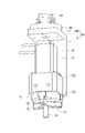
以下、図1~図15を参照して一実施形態に係る孔開け加工システム10について説明する。図1には、本実施形態の孔開け加工システム10の加工対象であるワーク90が示されている。このワーク90は、円筒壁91の上端を底壁93で閉塞した構造をなし、その上下方向の中間部を周方向で複数等分(例えば、9等分)する位置に貫通孔92が孔開け加工システム10によって打ち抜き加工される。
A
図2に示すように、本実施形態の孔開け加工システム10は、孔開け加工機20、ロボット60、パーツフィーダー40等を支持盤11上に備えてなる。支持盤11は、横長の長方形状をなしている。以下、支持盤11の長辺方向を「横方向H1」といい、支持盤11の短辺方向を「前後方向H2」といい、さらには、横方向H1の一端側を単に「左側」、その反対側を単に「右側」といい、前後方向H2の一端側を単に「前側」、その反対側を単に「後側」ということとする。
As shown in FIG. 2, the
支持盤11の上面のうち横方向H1の中央より左側には、第1支持台13と第2支持台14とが前後に並べて固定されている。また、後側の第2支持台14は、前側の第1支持台13より高く、その第2支持台14の上面にロボット60が固定され、第1支持台13の上面に孔開け加工機20のダイホルダ21が固定されている。
A
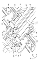
ダイホルダ21は、外形が直方体状をなし、その内部に図3に示したガイド付きダイ22が保持されている。ガイド付きダイ22は、ダイ23とガイドスリーブ24とからなり、ダイ23は、平面形状が長方形をなしたベース部23Aの上面中央から円筒部23Bが起立した構造をなしている。また、円筒部23Bの下端部には、段付き状に拡径された大径部23Cが備えられ、円筒部23Bの中心孔23Hは、ベース部23Aの下面まで延びている。
The die
ガイドスリーブ24は、図4(A)に示すように、平面形状がベース部23Aと同一の長方形をなした角柱体の中央部を断面円形の中央孔24Aが上下に貫通し、図3に示すように、上面からは中央孔24Aと同心のボス24Bが段付き状に突出した構造をなしている。また、中央孔24Aの下端部には、段付き状に拡径した大径部24Cが備えられ、ガイドスリーブ24の下面には高さ調整突部24Gが備えられている。
As shown in FIG. 4(A), the
そして、ガイドスリーブ24の中央孔24Aに、ダイ23の円筒部23Bが挿入されて、両者の大径部23C,24C同士の嵌合当接により両者が芯出しされ、両者間に筒状のワーク受容空間22Wが形成されている。また、高さ調整突部24Gとベース部23Aとの当接によりダイ23に対してガイドスリーブ24が上下方向で位置決めされ、ダイ23と上面とガイドスリーブ24の上面とが面一に配置されている。なお、高さ調整突部24Gは、必要に応じて研削されてガイドスリーブ24のダイ23に対する高さ調整が行われる。
Then, the
ガイド付きダイ22は、ダイホルダ21に形成された断面長方形の受容孔21Zに嵌合されて回り止めされ、ダイホルダ21の上面壁21Wを貫通する貫通孔21Kに、ガイド付きダイ22のボス24Bが嵌合されてダイホルダ21の上面とガイド付きダイ22の上面とが面一に配置されている。また、ダイホルダ21にダイ23の中心孔23Hから下方に延びる排出孔21Hが形成されると共に、第1支持台13に排出孔13Hが形成され、これら排出孔13H,21Hが支持盤11に形成された図示しない貫通孔を貫通して回収ボックスに臨んでいる。
The guide-equipped
ガイド付きダイ22の上端寄り位置には、ダイ23とガイドスリーブ24とを径方向に貫通して前後方向に延びる打抜孔22Hが形成されている。また、ダイホルダ21のうちガイド付きダイ22より前側部分には、打抜孔22Hの同軸延長線上に打抜孔22Hより内径が大きなパンチガイド孔21Gが形成され、そこにパンチ31が受容されている。
At a position near the upper end of the die 22 with guide, a punched
パンチ31は、パンチガイド孔21Gに丁度嵌合されて直線移動可能に支持されている丸棒体の先端部を、打抜孔22Hに丁度嵌合される大きさに縮径する一方、基端部を段付き状に拡径した形状をなしている。そして、パンチ31の基端部が、孔開け加工機20のパンチ駆動装置30(特許請求の範囲の「パンチ駆動部」に相当する)に保持されている。
The
図5に示すように、パンチ駆動装置30は、第1支持台13の上面のうちダイホルダ21より前側位置に固定されたスライド支持部34に、前後方向H2に延びるスライダ33の一端部をスライド可能に支持して備える。また、スライダ33の他端部は、第1支持台13より前方に張り出し、その下面に固定された係合ブロック33Gが、第1支持台13の前面から張り出す上側支持片35Aの上面に重ねられている。そして、例えば、係合ブロック33Gの下面に形成された図示しないカム溝に、上側支持片35Aに回転可能に支持されて偏心回転する図示しないカムが係合し、そのカムが上側支持片35Aの下方の下側支持梁35Bに支持されたサーボモータ30Mにて回転駆動されるようになっている。これにより、パンチ31がスライダ33と共に前後方向H2に往復直線移動し、ダイ23の打抜孔22Hに進退する。詳細には、パンチ31は、図3に示すように、ダイ23の打抜孔22Hから退避してパンチ31の先端面31Sがガイドスリーブ24の打抜孔22H内に位置する退避位置と、ダイ23の打抜孔22Hに突入してパンチ31の先端面31Sがダイ23の中心孔23H内に位置する突入位置との間を往復移動する(図4(A)参照)。
As shown in FIG. 5, the
図2に示すように、ロボット60は、スカラー型の汎用のロボット本体60Hに把持ツール70を取り付けてなる。ロボット本体60Hは、前述の第2支持台14の上面に固定される固定ベース61と、固定ベース61に連結されてその連結部分から水平に延び、固定ベース61に対して鉛直軸を中心にして回転駆動される第1アーム62と、第1アーム62の先端部に連結されてその連結部分から水平に延び、第1アーム62に対して鉛直軸を中心にして回転駆動される第2アーム63と、第2アーム63の先端部を上下に貫通するシャフト部64の下端に配置されて、シャフト部64と共に第2アーム63に対して上下に直線移動されかつ任意の高さで回転駆動される出力テーブル65とを備えてなる。
As shown in FIG. 2, the
以下、ロボット60の駆動部を説明する際には、固定ベース61に対して第1アーム62を回転駆動する駆動軸を「第1回転駆動軸」、第1アーム62に対して第2アーム63を回転駆動する駆動軸を「第2回転駆動軸」、第2アーム63に対して出力テーブル65を回転駆動する駆動軸を「第3回転駆動軸」、第2アーム63に対して出力テーブル65を上下に昇降させる駆動軸を「直線駆動軸」ということとする。
Hereinafter, when describing the drive unit of the
図6に示すように、把持ツール70は、汎用的なチャック71の上面に減速機72Gとサーボモータ72とを重ねて組み付けてなり、ブラケット79を介してロボット本体60Hの出力テーブル65に取り付けられている。
As shown in FIG. 6, the gripping
具体的には、チャック71は、例えば、円盤状のチャックベース71Aの下面の中心軸回りに、複数(例えば、3つ)の把持部材74を放射状に配置して備える。そして、これら把持部材74がサーボモータ72から動力を受けて均等にチャックベース71Aの中心軸に対して接近及び離間する。これにより、チャック71の中央部に配置されたワーク90が複数の把持部材74により把持されると共に、ワーク90の中心軸がチャック71の中心軸と一致するように芯出しされる。以下、複数の把持部材74をチャックベース71Aの中心軸側に移動することを「チャック71を閉じる」といい、その反対側に移動することを「チャック71を開く」という。
Specifically, the
ブラケット79は、L字形に屈曲した平板状をなし、その一方の片がサーボモータ72の一側面に重ねて固定され、他方の片が、サーボモータ72、減速機72Gを挟んでチャック71に対して上方から対向するように取り付けられている。そして、ブラケット79の他方の片がロボット本体60Hの出力テーブル65の下面に重ねられ、前述のチャックベース71Aの中心軸と出力テーブル65の中心軸とが一致するように位置決めされて固定されている。そして、これらチャック71及び出力テーブル65に共通する中心軸が、特許請求の範囲における移動基準軸J3になっている。また、前述したダイ23の中心軸は、特許請求の範囲におけるダイ基準軸J2をなしている。そして、例えば、ダイホルダ21に備えた図示しない姿勢調整機構により、移動基準軸J3とダイ基準軸J2とが平行になるようにダイ23の姿勢が調整されている。
The
図5示すように、パーツフィーダー40は、孔開け加工機20の右側方に配置され、横方向H1に水平に延びるベルトコンベア41を備えて孔開け加工機20へと複数のワーク90を搬送する。そのベルトコンベア41は、幅方向(前後方向H2)の両側に1対のサイドバー41Bを有し、それらの間に差し渡された複数の図示しないローラを覆うようにベルト41Aが張られている。そして、ベルトコンベア41は,1対のサイドバー41Bの一端部を第1支持台13の上面に固定されると共に、1対のサイドバー41Bの長手方向の複数位置を、複数の支持スタンド41Cに支持されている。それら複数の支持スタンド41Cは、支持盤11又は支持盤11から側方に張り出す延長板11Eから起立している。
As shown in FIG. 5, the
ベルト41Aの上方には、1対のガイドレール42が備えられている。1対のガイドレール42は、横方向H1に延びる帯板状をなして、長手方向の複数位置を複数の支持ブラケット45によって支持され、ワーク90の外径と略同一の間隔を空けて前後方向H2で対向している。そして、ベルト41A上に起立した状態で搬送される複数のワーク90が、1対のガイドレール42の間のワーク移動領域R1を移動することで、一列に整列されて孔開け加工機20側へと移動する。
A pair of
なお、各支持ブラケット45は、1対のサイドバー41Bに固定されてそれらの上方に突出する1対の支持ブロック44から1対の支持パイプ43が互いに接近するように延びた構図をなし、それら支持パイプ43の先端に1対のガイドレール42が固定されている。また、1対のガイドレール42は、ベルト41A上で起立するワーク90より低くなっている。
Each
ベルト41Aにおける左側(孔開け加工機20側の端部)の上方には、特許請求の範囲の「未加工ワーク支持部」に相当するワークストッパー50が設けられている。ワークストッパー50は、1対のサイドバー41Bの間に架け渡されて、ガイドレール42と略同一の高さとなる位置に配置されている。そして、図7に示すように、1対のガイドレール42がワークストッパー50に側方から突き合われ、ワークストッパー50のうちワーク移動領域R1の延長上には、ワーク位置決凹部51が形成されている。
Above the left side of the
ワーク位置決凹部51の内面は、その奥側に位置してワーク90の外径と略同一の内径の半円状をなした芯出し当接面51Aと、芯出し当接面51Aの両端からワーク位置決凹部51の開口に向かうに従って互い僅かに離れるように横方向H1に対して傾斜した1対の第2ガイド面51Bと、さらに1対の第2ガイド面51Bからワーク位置決凹部51の開口に向かうに従って急な勾配で互い僅かに離れるように横方向H1に対して傾斜した1対の第1ガイド面51Cとからなる。そして、芯出し当接面51Aの中心軸が特許請求の範囲の原点軸J1をなし、ワーク90が芯出し当接面51Aに押し付けられることで、ワーク90の中心軸が原点軸J1と一致するように芯出しされる。なお、ワークストッパー50には、ワーク位置決凹部51内にワーク90が位置するか否かを検出するためのワーク検出センサ50Sが備えられている。
The inner surface of the
図8に示すように、1対のガイドレール42に案内されて一列に並べられてワーク位置決凹部51に向かう複数のワーク90から先頭のワーク90だけを離してワーク位置決凹部51に受容するために、ベルトコンベア41のうちワークストッパー50より手前位置には、第1堰止部材52が設けられ、その第1堰止部材52より更に手前位置には、第2堰止部材55が設けられている。
As shown in FIG. 8, only the leading
第1堰止部材52は、ベルトコンベア41の前側に配置されたエアーアクチュエータ58のスライダ58Sに取り付けられてワーク移動領域R1に対して前側から進退し、第2堰止部材55は、ベルトコンベア41の後側に配置されたエアーアクチュエータ59のスライダ59Sに取り付けられて、ワーク移動領域R1に対して後側から進退する。なお、エアーアクチュエータ58,59は、前側のサイドバー41Bの側面と、後側のサイドバー41Bの側面とに分けられて固定されている。
The
第1堰止部材52及び第2堰止部材55は、前後方向H2に延びる同一の帯板形状になっていて、ワークストッパー50及びガイドレール42の僅かに上方に位置してワーク移動領域R1に進退する。また、図7に示すように、第1堰止部材52及び第2堰止部材55のうちワーク移動領域R1側となる先端部には、幅方向の中央にV形凹部53が形成され、そのV形凹部53の1対の内側斜面53A,53Bから折り返されるようにV形凹部53の両側に1対の外側斜面54A,54Bが形成され、全体が左右対称な形状になっている。なお、V形凹部53の1対の内側斜面53A,53Bの開き角は90度で、V形凹部53の内側斜面53A(53B)と隣合う外側斜面54A(54B)との間の交差角も90度になっている。
The
ベルトコンベア41は、その前面に備えた電源ボックス41Z(図2参照)のスイッチにてオンオフされ、孔開け加工システム10の運転中は、ベルトコンベア41がオンされてベルト41Aが一定速度でワーク90を送給し続ける。また、第1堰止部材52及び第2堰止部材55を保持するエアーアクチュエータ58,59は、後述する制御部80によって以下のように制御される。
The
孔開け加工システム10が動作を開始する前の初期状態では、例えば、図7に示すように、第1堰止部材52及び第2堰止部材55が共にワーク移動領域R1側に突入していて、第1堰止部材52の一方の外側斜面54Aが、ワーク位置決凹部51内に位置する先頭のワーク90に当接すると共に、他方の外側斜面54Bが先頭から2番目のワーク90に当接する。また、第2堰止部材55の外側斜面54Aと内側斜面53A,53Bと外側斜面54Bとは、2番目、3番目、4番目のワーク90に当接する。
In the initial state before the
この初期状態で、孔開け加工システム10が動作を開始し、図9(A)に示すように、ワーク位置決凹部51からワーク90が抜き取られると、そのことがワーク検出センサ50S(図7参照)によって検出され、その検出結果に基づき、図9(B)に示すように、第1堰止部材52がワーク移動領域R1から後退して、新たに先頭になったワーク90がワーク位置決凹部51内までベルトコンベア41によって前進する。その間、新たな2番目以降のワーク90は、第2堰止部材55によって堰き止められている。
In this initial state, the
そして、その新たな先頭のワーク90がワーク位置決凹部51に受容されたことがワーク検出センサ50Sによって検出されると、図9(C)に示すように、第1堰止部材52がワーク移動領域R1に突入してワーク位置決凹部51内のワーク90に一方の外側斜面54Aを押し付け、その後、第2堰止部材55が後退する。すると、新たな2番目のワーク90がベルトコンベア41によって前進して第1堰止部材52の外側斜面54Bに当接する。それと略同時又はその後に、第2堰止部材55が前進し、初期状態に戻る。そして、この動作が繰り返されることで、前述の通り、一列に並んだ複数のワーク90のうち先頭のワーク90が後続のワーク90から離されてワーク位置決凹部51に受容される。
When the
図5に示すように、パーツフィーダー40の後方には、加工済みのワーク90を回収するためのシュート12が設けられている。シュート12は、板金を角溝構造に折り曲げてなり、横方向H1に傾斜して延び、第1支持台13側の方が高くなっている。また、シュート12の下端は、他端部が支持盤11に形成された開口を通して図示しないワーク収容ボックスに斜め上方から臨んでいる。
As shown in FIG. 5, behind the
図5に示すように、本実施形態の孔開け加工システム10では、例えば、ダイホルダ21の上方空間が計測エリアR2になっていて、その計測エリアR2の後ろ側方には、非接触式の距離センサ94が配置されてブラケット94Kにて第1支持台13に固定されている。そして、ロボット60が把持ツール70にてワーク90を把持し、後述の第3位置に移動するように位置制御されると、ダイ基準軸J2と移動基準軸J3とが一致した状態でワーク90が計測エリアR2内に配置され、距離センサ94にてワーク90の側面までの距離を計測することが可能になる。
As shown in FIG. 5, in the perforating
図10には、孔開け加工システム10の制御部80が示されている。この制御部80は、ロボット本体60H、把持ツール70、孔開け加工機20の各サーボモータの制御を行うメイン制御部81と、エアーアクチュエータ58,59に圧縮エアーを供給するエアー供給回路に含まれるバルブの制御等を行うサブ制御部82とを備える。また、ワーク検出センサ50Sの検出信号は、メイン制御部81及びサブ制御部82に取り込まれ、距離センサ94の計測結果は、メイン制御部81のみに取り込まれる。
FIG. 10 shows the
メイン制御部81のメモリ83には、孔開け加工システム10を動作させるための基本動作プログラムが記憶される。その基本動作プログラムは、公知な方法で作成される。即ち、ロボット60を動作させるための位置データを、ティーチング又は数値入力により設定し、それら位置データと予めロボット本体60Hに用意されているコマンドとを組み合わせて作成される。その際、把持ツール70の位置を特定するために、ロボット60にはツール座標が設定されている。具体的には、図11に示すように、例えば、ツール座標は互いに直交するX軸、Y軸、Z軸を有し、それらの交点である原点が、例えば、複数の把持部材74の下面を含む架空の基準面と移動基準軸J3との交点に位置し、Z軸が移動基準軸J3と一致し、X軸が、何れか1つの把持部材74の幅方向の中央に位置するように設定されている。以下、上記原点を「ツール原点」という。
A
また、ロボット本体60Hに用意されたコマンドとしては、例えば、目標位置が設定されると、ツール座標を現在位置から目標位置まで直線軌跡を描くように平行移動する直動コマンドや、第3回転駆動軸と目標回転量とが設定されると、第3回転駆動軸だけが目標回転量だけ駆動されるツール回転コマンドや、さらには、回転中心位置と回転半径と目標回転量が設定されると、その回転中心位置回りにその回転半径で目標回転量だけツール原点を円弧軌跡を描くように公転させながら、ツール座標の同じ側が回転中心側を向くようにツール座標を自転させる公転コマンド等が挙げられる。
Commands prepared in the robot
また、メイン制御部81は、一般的なロボットの制御部と同様に、ツール原点に所定の軌跡を描かせるコマンドを実行するときには、その軌跡上における単位時間毎の複数の通過位置を演算して求め、それら複数の通過位置にツール原点を位置させるための、ロボット本体60Hの全サーボモータの目標位置データを公知な座標変換により演算する。そして、目標位置データに基づいて各サーボモータが位置制御される。
Further, when executing a command to draw a predetermined locus on the origin of the tool, the
基本動作プログラムは、ワークストッパー50に支持されたワーク90を把持ツール70で把持して距離センサ94により芯ズレ量及び芯ズレ方向を計測する「計測処理」と、移動基準軸J3をダイ23に設定されたダイ基準軸J2に一致させてワーク90をダイ23に嵌合する「嵌合処理」と、ワーク90を把持したままパンチ31にてワーク90に貫通孔92を打ち抜き、移動基準軸J3を中心に把持ツール70をワーク90と共に回転させてから再度パンチ31にてワーク90に貫通孔92を打ち抜く「回転打抜処理」と、が含まれるように作成される。
The basic operation program includes a "measurement process" for gripping the
より具体的には、基本動作プログラムは、孔開け加工システム10に以下の動作を行わせるように作成される。即ち、基本動作プログラムが実行されると、ロボット60は、チャック71を開いた状態にしてワークストッパー50の上方の第1位置にツール原点を位置決めして、移動基準軸J3と原点軸J1とを一致させる。そして、ワーク位置決凹部51にワーク90があることがワーク検出センサ50Sによって検出されると、ロボット60は、直線駆動軸のみを動作させてツール原点を第1位置から第2位置へと降下させて、ワーク位置決凹部51のワーク90をチャック71の中央部に受け入れる。そして、チャック71を閉じてワーク90を把持してからツール原点を第1位置に戻す。
More specifically, the basic operation program is created to cause the
そこから、ロボット60は、第1回転駆動軸及び第2回転駆動軸のみを動作させて、ダイ23の上方の第3位置にツール原点を移動して移動基準軸J3とダイ基準軸J2とを一致させ、ワーク90の側面を距離センサ94に対向させる。そして、ロボット60の第3回転駆動軸のみを動作させて、ワーク90を1回転以上、回転し、そのワーク90の回転位置に対応した距離センサ94の計測結果(つまり、距離センサ94からワーク90の側面までの距離の計測結果)をメイン制御部81に取り込む(ここまでが、「計測処理」に相当する)。
From there, the
次いで、直線駆動軸のみを動作させてツール原点を第3位置から第4位置まで降下させて、ワーク90をダイ23から僅かに上方に離した位置に配置する。そこから速度を下げてツール原点を第5位置まで降下してワーク90をダイ23の外側に嵌合させる。(ここまでが、「嵌合処理」に相当する)。
Next, the tool origin is lowered from the third position to the fourth position by operating only the linear drive shaft, and the
そして、パンチ31を、退避位置、突入位置、退避位置と位置が変わるようにパンチ駆動装置30により往復移動して、把持ツール70に把持された状態のワーク90に貫通孔92を打ち抜き加工する。そして、ロボット60の第3回転駆動軸のみが動作してワーク90をチャック71と共に第5位置から360/n[DEG](nは、ワーク90に形成される貫通孔92の数)だけ離れた第6位置まで回転させてから、パンチ31を再度往復移動してワーク90に貫通孔92を打ち抜き加工する。このような打ち抜き加工動作をn回(例えば、9回)繰り返してワーク90を第m位置(本実施形態では、m=4+n)まで回転させながら打ち抜き加工を行う(ここまでが、「回転打抜処理」に相当する)。
Then, the
次いで、直線駆動軸のみを動作させてツール原点を前述の第4位置に戻してからシュート12の上端部の上方の第14位置まで移動し、チャック71を開いてワーク90をシュート12へと排出する。そして、ツール原点を第1位置に戻す。
Then, only the linear drive shaft is operated to return the tool origin to the above-described fourth position, move to the fourteenth position above the upper end of the
以上の動作を孔開け加工システム10に行わせるように基本動作プログラムが作成されて上述の通りメモリ83に記憶される。なお、上記した第4位置~第m位置の位置データを設定するには、例えば、把持ツール70にワーク90を実際に把持させて、ワーク90の中心と移動基準軸J3とが一致するように調整しておき、そのワーク90を実際にダイ23の外側にマニュアル操作にて嵌合して、その位置を上記した第5位置として記憶する。そして、ロボット60を動かさずに、第5位置の位置データをコピーして位置データに含まれるツール原点の上下方向の位置又はツール座標の回転角だけを編集することで、第4位置~第m位置のデータを容易に作成することができる。
A basic operation program is created so as to cause the
上記した基本動作プログラムはメイン制御部81により繰り返して実行され、これにより複数のワーク90に貫通孔92が打抜き加工される。その際に、メイン制御部81は、基本動作プログラムを実行する度に、計測処理の計測結果に基づいて、嵌合処理と回転打抜処理とに使用する位置制御用の目標位置データを補正する。即ち、メイン制御部81は、嵌合処理で移動基準軸J3をダイ基準軸J2に一致させる位置制御用の目標位置データを、計測処理による計測結果を利用して、ワーク90の中心軸をダイ基準軸J2に一致させる位置制御用の目標位置データに補正する第1補正を行う。また、メイン制御部81は、回転打抜処理で移動基準軸J3を中心に把持ツールを回転させる位置制御用の目標位置データを、計測処理による計測結果を利用して、ワーク90の中心軸を中心に把持ツール70を回転させる位置制御用の目標位置データに補正する第2補正を行う。
The basic operation program described above is repeatedly executed by the
具体的には、例えば、図12に示すように、把持ツール70によるワーク90の芯出しが不良となり、ワーク90の中心軸J4(以下、「ワーク中心軸J4」という)が、ロボット60の移動基準軸J3(把持ツール70の中心軸でもある)とずれてしまった場合、上記した計測処理にて、ロボット60の第3回転駆動軸を動作させたときには、移動基準軸J3の回りをワーク中心軸J4が回転することになり、ワーク90の側面が距離センサ94に接近及び離間する。
Specifically, for example, as shown in FIG. If the reference axis J3 (which is also the central axis of the gripping tool 70) deviates from the reference axis J3, when the third rotation drive axis of the
そこで、メイン制御部81は、距離センサ94からワーク90までの距離の最大値と最小値との差分を2で割った値を、上記したワーク90と移動基準軸J3との芯ズレ量として演算する。また、距離が最小値になったときにはワーク90の中心は、移動基準軸J3と距離センサ94とを結ぶ直線上に位置するから、そのときのワーク90の回転位置から移動基準軸J3に対するワーク90の中心の上記芯ズレ方向を演算する。
Therefore, the
そして、上記第1補正の前は、嵌合処理でワーク90をダイ23に嵌合する際に、移動基準軸J3をダイ基準軸J2に一致させる目標位置データが使用されるようになっていたところを、ワーク中心軸J4をダイ基準軸J2に一致させる目標位置データが使用されるように、前記芯ズレ量及び芯ズレ方向に基づいた第1補正が行われる。また、上記第2補正の前は、回転打抜処理でワーク90を回転する際に、移動基準軸J3を中心に把持ツール70を回転させる目標位置データが使用されるようになっていたところを、ワーク中心軸J4を中心に把持ツール70を回転させる目標位置データが使用されるように、前記芯ズレ量及び芯ズレ方向に基づいた第2補正が行われる。
Before the first correction, target position data for matching the movement reference axis J3 with the die reference axis J2 was used when fitting the workpiece 90 to the die 23 in the fitting process. On the other hand, the first correction based on the misalignment amount and the misalignment direction is performed so that the target position data that aligns the work central axis J4 with the die reference axis J2 is used. Before the second correction, the target position data for rotating the gripping
より具体的には、ワーク中心軸J4と移動基準軸J3とがずれていた場合には、第2補正を行わずに基本動作プログラムを実行すると、回転打抜処理で、第5位置~第m位置において第3回転駆動軸のみを動作させると、移動基準軸J3を中心に把持ツール70が自転し、その移動基準軸J3の回りをワーク90が公転しながらワーク中心軸J4を中心に自転することになる。ここで、上記公転と自転の関係を明確にするために、図12~図14に示すように、把持ツール70がワーク90を把持している構成を、ワーク90と同心で小径のワーク円V1と、把持ツール70と同心で小径のツール円V2とを連絡部V3で連絡した想定部材Vのツール円V2を、縮小した把持ツール70で把持したモデルに置き換える。また、図13,図14では、複数の把持部材74を区別するためにそれらの末尾にA,B,Cを付し、ツール座標の「X軸」、「Y軸」に対して地面に固定されている固定座標のX軸、Y軸を、「固定X軸」、「固定Y軸」として示す。
More specifically, when the work center axis J4 and the movement reference axis J3 are deviated from each other, if the basic operation program is executed without performing the second correction, the rotary punching process will perform the fifth position to the mth position. When only the third rotary drive shaft is operated at the position, the gripping
すると、第2補正を行わずに基本動作プログラムを実行すると、第5位置~第m位置における動作は図13に示すように把持ツール70がツール円V2と共に移動基準軸J3を中心に自転だけすることで、ワーク円V1が移動基準軸J3を中心に公転しながら、常に同じ面がワーク円V1側を向くように自転することが分かる。これを逆にワーク円V1(ワーク90)がワーク中心軸J4を中心に自転だけするようにするには、図14に示すように、把持ツール70をワーク中心軸J4の回りに公転させると共に自転させる必要があることが分かる。そして、メイン制御部81は、第5位置~第m位置において把持ツール70をそのように動作させるために、基本動作プログラムを実行する度に、実測される芯ズレ量及び芯ズレ方向を利用して、上述の通り目標位置データを補正する。
Then, if the basic motion program is executed without performing the second correction, the gripping
詳細には、基本動作プログラムにおける第4位置~第m位置の位置データは、固定座標を利用して(x,y,z,ω)という4つのパラメータで特定される。ここで、x,y,zはツール原点の固定座標上の3次元の位置データで、ωはツール座標の固定座標に対する回転角。そして、第1補正では、嵌合処理で使用する例えば第4位置の当初の位置データ(x4,y4,z4,ω4)を、(x4+dx,y4+dy,z4,ω4)となるように補正する。また、第2補正では、回転打抜処理において、ツール原点を例えば(x5,y5,z5,ω5)で特定される第5位置で、第3回転駆動軸だけを目標回転量θだけ駆動するツール回転コマンドが、(x5+dx,y5+dy,ω5)を回転中心位置に設定し、前述のズレ量を回転半径に設定し、目標回転量θが設定された公転コマンドに置き換える補正を行う。 Specifically, the position data of the 4th to m-th positions in the basic operation program are specified by four parameters (x, y, z, ω) using fixed coordinates. Here, x, y, and z are three-dimensional position data on the fixed coordinates of the tool origin, and ω is the rotation angle of the tool coordinates with respect to the fixed coordinates. Then, in the first correction, the original position data (x4, y4, z4, ω4) of the fourth position, for example, used in the fitting process is corrected to become (x4+dx, y4+dy, z4, ω4). In the second correction, in the rotary punching process, the tool origin is at the fifth position specified by (x5, y5, z5, ω5), and only the third rotary drive shaft is driven by the target rotation amount θ. The rotation command sets (x5+dx, y5+dy, .omega.5) as the rotation center position, sets the aforementioned shift amount as the rotation radius, and performs correction by replacing with a revolution command in which the target rotation amount .theta. is set.
上述した本実施形態の制御上の構成は、図15に示されている。ここで、目標位置データ演算部100は、基本動作プログラムに基づいてロボット60の各駆動軸のサーボモータの目標位置データを演算しているときのメイン制御部81で構成されている。その目標位置データ演算部100には、通常データ演算部101と第1補正部102と第2補正部103とが備えられ、通常データ演算部101は、基本動作プログラムで設定されている通りに目標位置データを演算してロボット60のサーボアンプに付与する。また、第1補正部102は、上記第1補正を実行しているときのメイン制御部81で構成され、ズレ演算部104が演算するワーク中心軸J4の移動基準軸J3に対するズレ量及びズレ方向に基づいて、嵌合処理で前述の通り目標位置データを補正する。また、第2補正部103は、上記第2補正を実行しているときのメイン制御部81で構成され、前記ズレ量及びズレ方向に基づいて、回転打抜処理で前述の通り目標位置データを補正する。また、ズレ演算部104は、距離センサ94の計測結果に基づいてワーク中心軸J4の移動基準軸J3に対するズレ量とズレ方向の演算を実行しているときのメイン制御部81で構成される。また、そのズレ演算部104と上記した計測エリアR2と距離センサ94とにより、特許請求の範囲の「芯ズレ計測部」が構成されている。
The control configuration of this embodiment described above is shown in FIG. Here, the target position
本実施形態の孔開け加工システム10の構成に関する説明は以上である。本実施形態の孔開け加工システム10によれば、ロボット60の把持ツール70がワーク90を把持した状態で、ワーク90に貫通孔92を打ち抜き、ワーク90を回転させて再度貫通孔92を打ち抜くので、ワーク90の周方向の貫通孔92同士の間隔のばらつきが従来より抑えられる。また、同じダイ23及びパンチ31を使用してワーク90の周方向の複数位置に貫通孔92を打ち抜くので、同様の加工に複数のダイ及びパンチを使用していた従来のものに比べて、ダイ23及びパンチ31の有効利用が図られる。また、把持ツール70は、把持したワーク90のワーク中心軸J4と把持ツール70の移動基準軸J3とが一致するように芯出しするが、芯ズレが生じる場合がある。これに対し、本開示の孔開け加工システム10では、ワーク90の移動基準軸J3に対する芯ズレ量及びその芯ズレ方向を計測し、その計測結果を利用してワーク中心軸J4をダイ基準軸J2に一致させるように位置制御用の目標位置データを補正するので、ワーク90の移動基準軸J3に対する芯出しのばらつきの影響が抑えられる。
The above is the description of the configuration of the
[他の実施形態]
(1)上記実施形態では、特許請求の範囲の「ツール移動機構」としてスカラー型のロボット60を用いたが、例えば、レール上を移動可能な把持ツール70を昇降可能且つ移動基準軸J3を中心に回転可能に備えた装置を使用してもよい。なお、汎用的なスカラー型のロボット60を使用すれば、コストを抑えることができる。
[Other embodiments]
(1) In the above embodiment, the
(2)前記実施形態では、非接触式の距離センサ94にてワーク中心軸J4と移動基準軸J3とのズレ量及びズレ方向を計測していたが、例えば、接触式のポテンショメータをワーク90の側面に当接させてズレ量及びズレ方向を計測してもよいし、把持ツール70に把持されたワーク90の画像を撮像し、画像処理にてズレ量及びズレ方向を計測してもよい。
(2) In the above embodiment, the
(3)第1補正及び第2補正は、前記実施形態のように、ツール原点の目標位置データを直接補正するものであってもよいし、ロボット60におけるツール原点を含むツール座標の設定を変更することで、目標位置データを実質的に変更するものであってもよい。
(3) The first correction and second correction may directly correct the target position data of the tool origin as in the above embodiment, or may change the setting of the tool coordinates including the tool origin in the
(4)上記実施形態では、ダイ23は円筒形をなしていたが、例えば、断面半月状又は扇状をなしていてもよい。
(4) In the above embodiment, the
(5)上記実施形態では、ワーク中心軸J4と移動基準軸J3とのズレ量の大小に拘わらず上記第1補正と第2補正とを行っていたが、芯ズレ量が予め設定された基準ズレ量以上であることを条件にして第1補正及び第2補正を行うようにしてもよい。そのような構成にすれば、メイン制御部81の演算処理の負担が軽減される。
(5) In the above embodiment, the first correction and the second correction were performed regardless of the amount of misalignment between the work central axis J4 and the movement reference axis J3. The first correction and the second correction may be performed under the condition that the amount of deviation is equal to or greater than the amount of deviation. With such a configuration, the computation processing load of the
10 孔開け加工システム
20 加工機
22H 打抜孔
23 ダイ
30 パンチ駆動装置(パンチ駆動部)
50 ワークストッパー(未加工ワーク支持部)
60 ロボット
60H ロボット本体
65 出力テーブル
70 把持ツール
71 チャック
74 把持部材
80 制御部
81 メイン制御部
82 サブ制御部
83 メモリ
90 ワーク
102 第1補正部
103 第2補正部
104 ズレ演算部
J1 原点軸
J2 ダイ基準軸
J3 移動基準軸
J4 ワーク中心軸
R2 計測エリア
REFERENCE SIGNS
50 work stopper (raw work support)
60
Claims (5)
基端部を固定され、先端側から前記ワークが外側に嵌合されるダイと、
前記ダイの側面に開口する打抜孔に対して進退するパンチと、
前記パンチを駆動するパンチ駆動部と、
未加工のワークを支持する未加工ワーク支持部と、
移動基準軸の回りに複数の把持部材を有し、それら複数の把持部材を前記ワークの側面に押し付けて前記ワークを把持しかつ前記ワークの中心軸を前記移動基準軸と一致するように芯出しする把持ツールと、
ロボット本体の先端部に前記把持ツールを装着してなり、前記把持ツールを移動しかつ前記移動基準軸を中心に回転させることが可能なロボットと、
前記把持ツールに把持された前記ワークの中心軸の前記移動基準軸に対する芯ズレ量及び芯ズレ方向を計測する芯ズレ計測部と、
前記ロボットと前記把持ツールと前記パンチ駆動部とを制御する制御部と、
前記未加工ワーク支持部の前記ワークを前記把持ツールで把持して前記芯ズレ計測部により前記芯ズレ量及び前記芯ズレ方向を計測する計測処理と、前記移動基準軸を前記ダイに設定されたダイ基準軸に一致させて前記ワークを前記ダイに嵌合する嵌合処理と、前記ワークを把持したまま前記パンチにて前記ワークに前記貫通孔を打ち抜き、前記移動基準軸を中心に前記把持ツールを前記ワークと共に回転させてから再度前記パンチにて前記ワークに前記貫通孔を打ち抜く回転打抜処理と、を前記ロボット、前記把持ツール及び前記パンチ駆動部に行わせるための基本動作プログラムを記憶するメモリと、
前記制御部が前記基本動作プログラムを実行する度に、前記嵌合処理で前記移動基準軸を前記ダイ基準軸に一致させる位置制御用の目標位置データを、前記計測処理による計測結果を利用して、前記ワークの中心軸を前記ダイ基準軸に一致させる位置制御用の目標位置データに補正する第1補正部と、
前記制御部が前記基本動作プログラムを実行する度に、前記回転打抜処理で前記移動基準軸を中心に前記把持ツールを回転させる位置制御用の目標位置データを、前記計測処理による計測結果を利用して、前記ワークの中心軸を中心に前記把持ツールを回転させる位置制御用の目標位置データに補正する第2補正部と、を備える孔開け加工システム。 A hole punching system for punching through holes at a plurality of positions in the circumferential direction of a cylindrical work,
a die to which the base end is fixed and the work is fitted to the outside from the tip side;
a punch that advances and retreats with respect to a punching hole that opens in the side surface of the die;
a punch drive unit that drives the punch;
a raw work support for supporting the raw work;
A plurality of gripping members are provided around a movement reference axis, the plurality of gripping members are pressed against the side surface of the work to grip the work, and centering is performed so that the central axis of the work coincides with the movement reference axis. a grasping tool for
a robot having the gripping tool attached to the tip of a robot main body and capable of moving the gripping tool and rotating it about the movement reference axis;
a misalignment measuring unit that measures misalignment amount and misalignment direction of the central axis of the work gripped by the gripping tool with respect to the movement reference axis;
a control unit that controls the robot, the gripping tool, and the punch driving unit;
a measurement process of gripping the workpiece on the unprocessed workpiece support section with the gripping tool and measuring the misalignment amount and the misalignment direction by the misalignment measuring section; a fitting process of fitting the work to the die by aligning the work with the die reference axis; punching the through hole in the work with the punch while holding the work; is rotated together with the workpiece, and then a rotary punching process of punching the through hole in the workpiece again with the punch, and a basic operation program for causing the robot, the gripping tool, and the punch driving section to perform a rotary punching process. memory;
Each time the control unit executes the basic operation program, target position data for position control for matching the movement reference axis with the die reference axis in the fitting process is generated using the measurement result of the measurement process. a first correcting unit for correcting the target position data for position control so that the central axis of the work coincides with the die reference axis;
Each time the control unit executes the basic operation program, the target position data for position control for rotating the gripping tool about the movement reference axis in the rotary punching process uses the measurement result of the measurement process. and a second corrector for correcting target position data for position control for rotating the gripping tool about the central axis of the workpiece.
前記計測エリアの前記ワークの側面に対向するように配置され、前記ワークの側面までの距離を計測する距離センサと、
前記ワークの回転位置に応じた前記距離の相違に基づいて前記芯ズレ量及び前記芯ズレ方向を演算するズレ演算部と、を有する請求項1又は2に記載の孔開け加工システム。 The misalignment measuring unit includes a measurement area in which the workpiece gripped by the gripping tool is arranged and rotated by one or more rotations around the movement reference axis;
a distance sensor arranged to face a side surface of the work in the measurement area and measuring a distance to the side surface of the work;
3. The drilling system according to claim 1, further comprising a deviation calculation unit that computes the amount of misalignment and the direction of misalignment based on the difference in the distance according to the rotational position of the workpiece.
前記制御部は、前記未加工ワーク支持部の前記ワークを前記把持ツールに把持させるときに、前記移動基準軸を前記原点軸と一致させるように前記ロボットを制御する請求項1から3の何れか1の請求項に記載の孔開け加工システム。 The unprocessed work support part supports the work by centering it on an origin axis parallel to the die reference axis,
4. The controller according to any one of claims 1 to 3, wherein the control unit controls the robot so that the movement reference axis coincides with the origin axis when causing the gripping tool to grip the workpiece of the unprocessed workpiece support unit. The drilling system of claim 1.
前記ロボット本体は、スカラー型であって、固定ベースに基端部を回転可能に支持されて鉛直軸を中心に回転駆動される第1アームと、前記第1アームの先端部に基端部を回転可能に支持されて鉛直軸を中心に回転駆動されると共に先端部を前記移動基準軸が貫通する第2アームと、前記第2アームの先端部に回転可能かつ直線移動可能に支持されて前記移動基準軸を中心に回転駆動されかつ前記移動基準軸の軸方向にスライド駆動される下向きの出力テーブルと、を有し、
前記把持ツールは、前記複数の把持部材を下面に放射状に配置して備えると共に上面に駆動源を有する駆動源付チャックであって、前記出力テーブルの下面に固定されている請求項4に記載の孔開け加工システム。 The die reference axis, the origin axis and the movement reference axis are arranged in parallel with the vertical direction,
The robot main body is of a scalar type, and includes a first arm whose base end is rotatably supported by a fixed base and is driven to rotate about a vertical axis; a second arm that is rotatably supported and driven to rotate about a vertical axis and has a distal end portion through which the movement reference axis passes; a downward output table rotationally driven about a movement reference axis and slidably driven in an axial direction of the movement reference axis;
5. The gripping tool according to claim 4, wherein the gripping tool is a chuck with a driving source having the plurality of gripping members arranged radially on the bottom surface and a driving source on the top surface, and is fixed to the bottom surface of the output table. Drilling system.
Priority Applications (1)
| Application Number | Priority Date | Filing Date | Title |
|---|---|---|---|
| JP2020159541A JP7204309B2 (en) | 2020-09-24 | 2020-09-24 | Drilling system |
Applications Claiming Priority (1)
| Application Number | Priority Date | Filing Date | Title |
|---|---|---|---|
| JP2020159541A JP7204309B2 (en) | 2020-09-24 | 2020-09-24 | Drilling system |
Publications (2)
| Publication Number | Publication Date |
|---|---|
| JP2022052981A JP2022052981A (en) | 2022-04-05 |
| JP7204309B2 true JP7204309B2 (en) | 2023-01-16 |
Family
ID=80962906
Family Applications (1)
| Application Number | Title | Priority Date | Filing Date |
|---|---|---|---|
| JP2020159541A Active JP7204309B2 (en) | 2020-09-24 | 2020-09-24 | Drilling system |
Country Status (1)
| Country | Link |
|---|---|
| JP (1) | JP7204309B2 (en) |
Families Citing this family (1)
| Publication number | Priority date | Publication date | Assignee | Title |
|---|---|---|---|---|
| CN115090747A (en) * | 2022-07-25 | 2022-09-23 | 信尔胜机械(江苏)有限公司 | Integrated punching processing equipment for compressor shell |
Citations (4)
| Publication number | Priority date | Publication date | Assignee | Title |
|---|---|---|---|---|
| JP2001129621A (en) | 1999-10-28 | 2001-05-15 | Asahi-Seiki Mfg Co Ltd | Machine for processing hole in cylindrical wall of cylindrical workpiece |
| US20100083803A1 (en) | 2008-10-03 | 2010-04-08 | Ronald Malcolm Bond Sanderson | Perforating Apparatus |
| JP2018151243A (en) | 2017-03-13 | 2018-09-27 | 株式会社Screenホールディングス | Work holding device, inspection device, and work position correction method |
| JP2019018212A (en) | 2017-07-12 | 2019-02-07 | 株式会社ジェイテクト | C type frame press device and press working method by c type frame press device |
Family Cites Families (1)
| Publication number | Priority date | Publication date | Assignee | Title |
|---|---|---|---|---|
| JPH01150491A (en) * | 1987-12-08 | 1989-06-13 | Toshiba Corp | Working device |
-
2020
- 2020-09-24 JP JP2020159541A patent/JP7204309B2/en active Active
Patent Citations (4)
| Publication number | Priority date | Publication date | Assignee | Title |
|---|---|---|---|---|
| JP2001129621A (en) | 1999-10-28 | 2001-05-15 | Asahi-Seiki Mfg Co Ltd | Machine for processing hole in cylindrical wall of cylindrical workpiece |
| US20100083803A1 (en) | 2008-10-03 | 2010-04-08 | Ronald Malcolm Bond Sanderson | Perforating Apparatus |
| JP2018151243A (en) | 2017-03-13 | 2018-09-27 | 株式会社Screenホールディングス | Work holding device, inspection device, and work position correction method |
| JP2019018212A (en) | 2017-07-12 | 2019-02-07 | 株式会社ジェイテクト | C type frame press device and press working method by c type frame press device |
Also Published As
| Publication number | Publication date |
|---|---|
| JP2022052981A (en) | 2022-04-05 |
Similar Documents
| Publication | Publication Date | Title |
|---|---|---|
| US9724801B2 (en) | Deburring device including visual sensor and force sensor | |
| KR0185567B1 (en) | A method of positioning a metal sheet for a sheetmetal working machine | |
| US9207668B2 (en) | Method of and apparatus for automated path learning | |
| CN107609228B (en) | Automatic drilling method for parallel drilling machine | |
| US10625420B2 (en) | Machining system | |
| US20160257002A1 (en) | Robot system having robot operated in synchronization with bending machine | |
| JP6667376B2 (en) | Component press-in method and component press-in system | |
| EP2584419A2 (en) | CNC machine for cutting with plasma, oxygen and water jet used as a cutting tool with automatic setting up a precise position of a cutting tool in a cutting head by autocalibration and method thereof | |
| CN101934423A (en) | Seam welding equipment and seam welding method | |
| US10987809B2 (en) | Rotary tool adjuster for robot with end of arm tool having multiple tools | |
| JP7204309B2 (en) | Drilling system | |
| US20170045874A1 (en) | Machining system with machine tool and robot for attaching and detaching workpiece | |
| CN111195920B (en) | Workpiece handling manipulators, manipulator systems and robot systems | |
| JP7242146B2 (en) | Drilling system and drilling method | |
| JP6647308B2 (en) | Teaching system of articulated robot | |
| JP7517411B2 (en) | MACHINE TOOL, MACHINE PATH GENERATION METHOD, AND COMPUTER PROGRAM | |
| JPH03110018A (en) | Method and apparatus for positioning work in bending device | |
| US20240308077A1 (en) | Automated calibration of a production machine | |
| JP4344847B2 (en) | Processing apparatus and method using articulated robot | |
| CN109986238B (en) | Robot linear flexible operation vision fuzzy profiling control method | |
| CN119819955B (en) | Automatic feeding method for inverted turning center | |
| JPS635823A (en) | Positioning device for butt of backgage | |
| JPH04100676A (en) | Device and method for profile gas cutting | |
| CN210147390U (en) | Cylindrical magnet assembling mechanism | |
| JP2001321833A (en) | Panel bender controller |
Legal Events
| Date | Code | Title | Description |
|---|---|---|---|
| A621 | Written request for application examination |
Free format text: JAPANESE INTERMEDIATE CODE: A621 Effective date: 20220418 |
|
| A977 | Report on retrieval |
Free format text: JAPANESE INTERMEDIATE CODE: A971007 Effective date: 20221215 |
|
| TRDD | Decision of grant or rejection written | ||
| A01 | Written decision to grant a patent or to grant a registration (utility model) |
Free format text: JAPANESE INTERMEDIATE CODE: A01 Effective date: 20221227 |
|
| A61 | First payment of annual fees (during grant procedure) |
Free format text: JAPANESE INTERMEDIATE CODE: A61 Effective date: 20221227 |
|
| R150 | Certificate of patent or registration of utility model |
Ref document number: 7204309 Country of ref document: JP Free format text: JAPANESE INTERMEDIATE CODE: R150 |
|
| R250 | Receipt of annual fees |
Free format text: JAPANESE INTERMEDIATE CODE: R250 |