JP7203763B2 - DISPLAY SUBSTRATE AND MANUFACTURING METHOD THEREOF, DISPLAY DEVICE - Google Patents
DISPLAY SUBSTRATE AND MANUFACTURING METHOD THEREOF, DISPLAY DEVICE Download PDFInfo
- Publication number
- JP7203763B2 JP7203763B2 JP2019563827A JP2019563827A JP7203763B2 JP 7203763 B2 JP7203763 B2 JP 7203763B2 JP 2019563827 A JP2019563827 A JP 2019563827A JP 2019563827 A JP2019563827 A JP 2019563827A JP 7203763 B2 JP7203763 B2 JP 7203763B2
- Authority
- JP
- Japan
- Prior art keywords
- layer
- protrusion
- display substrate
- protrusions
- display
- Prior art date
- Legal status (The legal status is an assumption and is not a legal conclusion. Google has not performed a legal analysis and makes no representation as to the accuracy of the status listed.)
- Active
Links
Images


Classifications
-
- H—ELECTRICITY
- H10—SEMICONDUCTOR DEVICES; ELECTRIC SOLID-STATE DEVICES NOT OTHERWISE PROVIDED FOR
- H10K—ORGANIC ELECTRIC SOLID-STATE DEVICES
- H10K59/00—Integrated devices, or assemblies of multiple devices, comprising at least one organic light-emitting element covered by group H10K50/00
- H10K59/10—OLED displays
- H10K59/12—Active-matrix OLED [AMOLED] displays
- H10K59/124—Insulating layers formed between TFT elements and OLED elements
-
- H—ELECTRICITY
- H10—SEMICONDUCTOR DEVICES; ELECTRIC SOLID-STATE DEVICES NOT OTHERWISE PROVIDED FOR
- H10K—ORGANIC ELECTRIC SOLID-STATE DEVICES
- H10K50/00—Organic light-emitting devices
- H10K50/80—Constructional details
- H10K50/84—Passivation; Containers; Encapsulations
- H10K50/844—Encapsulations
-
- H—ELECTRICITY
- H10—SEMICONDUCTOR DEVICES; ELECTRIC SOLID-STATE DEVICES NOT OTHERWISE PROVIDED FOR
- H10K—ORGANIC ELECTRIC SOLID-STATE DEVICES
- H10K50/00—Organic light-emitting devices
- H10K50/80—Constructional details
-
- H—ELECTRICITY
- H10—SEMICONDUCTOR DEVICES; ELECTRIC SOLID-STATE DEVICES NOT OTHERWISE PROVIDED FOR
- H10K—ORGANIC ELECTRIC SOLID-STATE DEVICES
- H10K50/00—Organic light-emitting devices
- H10K50/80—Constructional details
- H10K50/805—Electrodes
-
- H—ELECTRICITY
- H10—SEMICONDUCTOR DEVICES; ELECTRIC SOLID-STATE DEVICES NOT OTHERWISE PROVIDED FOR
- H10K—ORGANIC ELECTRIC SOLID-STATE DEVICES
- H10K50/00—Organic light-emitting devices
- H10K50/80—Constructional details
- H10K50/84—Passivation; Containers; Encapsulations
- H10K50/842—Containers
- H10K50/8426—Peripheral sealing arrangements, e.g. adhesives, sealants
-
- H—ELECTRICITY
- H10—SEMICONDUCTOR DEVICES; ELECTRIC SOLID-STATE DEVICES NOT OTHERWISE PROVIDED FOR
- H10K—ORGANIC ELECTRIC SOLID-STATE DEVICES
- H10K59/00—Integrated devices, or assemblies of multiple devices, comprising at least one organic light-emitting element covered by group H10K50/00
-
- H—ELECTRICITY
- H10—SEMICONDUCTOR DEVICES; ELECTRIC SOLID-STATE DEVICES NOT OTHERWISE PROVIDED FOR
- H10K—ORGANIC ELECTRIC SOLID-STATE DEVICES
- H10K59/00—Integrated devices, or assemblies of multiple devices, comprising at least one organic light-emitting element covered by group H10K50/00
- H10K59/10—OLED displays
- H10K59/12—Active-matrix OLED [AMOLED] displays
-
- H—ELECTRICITY
- H10—SEMICONDUCTOR DEVICES; ELECTRIC SOLID-STATE DEVICES NOT OTHERWISE PROVIDED FOR
- H10K—ORGANIC ELECTRIC SOLID-STATE DEVICES
- H10K59/00—Integrated devices, or assemblies of multiple devices, comprising at least one organic light-emitting element covered by group H10K50/00
- H10K59/10—OLED displays
- H10K59/17—Passive-matrix OLED displays
Description
本願は2017年8月31日に提出した中国特許出願第201721106739.6号の優先権を主張し、ここで上記中国特許出願に開示されている全内容が引用により本願の一部として組み込まれている。 This application claims priority from Chinese Patent Application No. 201721106739.6 filed on Aug. 31, 2017, where the entire contents disclosed in the above Chinese patent application are hereby incorporated by reference as part of the present application. there is
本開示の少なくとも1つの実施例は表示基板及びその製造方法、表示装置に関する。 At least one embodiment of the present disclosure relates to a display substrate, a manufacturing method thereof, and a display device.
有機発光ダイオード(OLED、Organic Light-Emitting Diode)は有機薄膜電界発光素子であり、製造プロセスが簡単で、コストが低く、消費電力が少なく、輝度が高く、視野角が広く、コントラストが高く、フレキシブル表示が実現できる等の利点を有するため、人々から大きく注目されている。 Organic Light-Emitting Diodes (OLEDs) are organic thin-film electroluminescent devices with simple manufacturing processes, low costs, low power consumption, high brightness, wide viewing angles, high contrast, and flexibility. Since it has advantages such as realization of display, it has attracted a great deal of attention from people.
しかしながら、OLED電子表示製品の部材は侵入した水蒸気や酸素ガス等の影響によって破損し、OLED電子表示製品の性能低下、耐用年数の短縮を招いてしまう。 However, the members of the OLED electronic display product are damaged by the intrusion of water vapor, oxygen gas, etc., resulting in deterioration of the performance of the OLED electronic display product and shortening of its service life.
本開示の少なくとも1つの実施例は表示基板を提供し、表示領域及び前記表示領域の周囲に位置する非表示領域を含む下地と、前記非表示領域の前記下地に設置される少なくとも1つの突起と、前記下地に設置される封止層と、を含み、前記突起は前記下地と前記封止層との間に位置し、前記封止層は少なくとも部分的に前記突起を被覆する。 At least one embodiment of the present disclosure provides a display substrate, a base including a display area and a non-display area positioned around the display area, and at least one protrusion disposed on the base of the non-display area. , a sealing layer disposed on the substrate, the protrusion being located between the substrate and the sealing layer, the sealing layer at least partially covering the protrusion.
たとえば、本開示の少なくとも1つの実施例に係る表示基板において、前記表示基板は、前記突起と前記下地との間に設置される絶縁層をさらに含み、且つ前記突起は前記絶縁層と前記封止層との間に位置する。 For example, in the display substrate according to at least one embodiment of the present disclosure, the display substrate further includes an insulating layer disposed between the protrusions and the base, and the protrusions are disposed between the insulating layer and the sealing layer. Located between layers.
たとえば、本開示の少なくとも1つの実施例に係る表示基板において、前記絶縁層はパッシベーション層であり、前記突起が前記パッシベーション層に接する。 For example, in the display substrate according to at least one embodiment of the present disclosure, the insulating layer is a passivation layer, and the protrusion contacts the passivation layer.
たとえば、本開示の少なくとも1つの実施例に係る表示基板において、前記絶縁層は層間絶縁層であり、前記突起が前記層間絶縁層に接する。 For example, in the display substrate according to at least one embodiment of the present disclosure, the insulating layer is an interlayer insulating layer, and the protrusion contacts the interlayer insulating layer.
たとえば、本開示の少なくとも1つの実施例に係る表示基板において、前記表示領域の前記下地は複数の画素領域を含み、各前記画素領域の前記下地に少なくとも1つの有機発光素子が設置され、前記有機発光素子が前記絶縁層と前記封止層との間に位置する。 For example, in the display substrate according to at least one embodiment of the present disclosure, the base of the display area includes a plurality of pixel regions, at least one organic light emitting element is provided on the base of each pixel region, and the organic A light emitting device is located between the insulating layer and the encapsulating layer.
たとえば、本開示の少なくとも1つの実施例に係る表示基板において、前記表示基板は、前記下地に設置される画素画定層をさらに含み、前記有機発光素子は前記画素画定層が限定した領域内に設置される。 For example, in the display substrate according to at least one embodiment of the present disclosure, the display substrate further includes a pixel defining layer disposed on the underlying layer, and the organic light emitting device is disposed within a region defined by the pixel defining layer. be done.
たとえば、本開示の少なくとも1つの実施例に係る表示基板において、前記突起は前記画素画定層と同層に配置され、且つ同一の材料で製造される。 For example, in the display substrate according to at least one embodiment of the present disclosure, the protrusions are arranged in the same layer as the pixel definition layer and are made of the same material.
たとえば、本開示の少なくとも1つの実施例に係る表示基板において、前記突起は、少なくとも第1突起層と第2突起層の積層を含むように配置され、前記第1突起層は前記第2突起層と前記下地との間に位置し、前記第1突起層は前記画素画定層と同層に配置され、且つ同一の材料で製造される。 For example, in the display substrate according to at least one embodiment of the present disclosure, the protrusions are arranged to include lamination of at least a first protrusion layer and a second protrusion layer, and the first protrusion layer is the second protrusion layer. and the underlayer, the first protrusion layer is disposed in the same layer as the pixel definition layer and is made of the same material.
たとえば、本開示の少なくとも1つの実施例に係る表示基板において、前記第2突起層の製造材料はフォトレジスト材料である。 For example, in the display substrate according to at least one embodiment of the present disclosure, the manufacturing material of the second protrusion layer is photoresist material.
たとえば、本開示の少なくとも1つの実施例に係る表示基板において、前記突起の製造材料はフォトレジスト材料を含む。 For example, in the display substrate according to at least one embodiment of the present disclosure, the manufacturing material of the protrusions includes photoresist material.
たとえば、本開示の少なくとも1つの実施例に係る表示基板において、前記表示基板は、前記絶縁層の前記下地から離れた一方側に設置される平坦層をさらに含み、前記平坦層は前記突起と前記絶縁層との間に位置する。 For example, in the display substrate according to at least one embodiment of the present disclosure, the display substrate further includes a flat layer disposed on one side of the insulating layer remote from the base, wherein the flat layer includes the protrusions and the Located between insulating layers.
たとえば、本開示の少なくとも1つの実施例に係る表示基板において、前記突起の前記下地における正投影は前記平坦層の前記下地における正投影内に位置する。 For example, in the display substrate according to at least one embodiment of the present disclosure, the orthographic projection of the protrusion on the underlying layer is located within the orthographic projection of the flat layer on the underlying layer.
たとえば、本開示の少なくとも1つの実施例に係る表示基板において、前記突起の少なくとも一部は前記平坦層と同層に配置され、且つ同一の材料で製造される。 For example, in the display substrate according to at least one embodiment of the present disclosure, at least some of the protrusions are arranged in the same layer as the flat layer and are made of the same material.
たとえば、本開示の少なくとも1つの実施例に係る表示基板において、各前記突起は少なくとも第1突起層、第2突起層、第3突起層の積層を含むように配置され、前記第1突起層は前記第2突起層と前記下地との間に位置し、前記第3突起層は前記第1突起層と前記下地との間に位置し、前記第1突起層は前記画素画定層と同層に配置され、且つ同一の材料で製造され、前記第3突起層は前記平坦層と同層に配置され、且つ同一の材料で製造される。 For example, in the display substrate according to at least one embodiment of the present disclosure, each of the protrusions is arranged to include lamination of at least a first protrusion layer, a second protrusion layer, and a third protrusion layer, and the first protrusion layer comprises Positioned between the second protrusion layer and the base, the third protrusion layer positioned between the first protrusion layer and the base, and the first protrusion layer being in the same layer as the pixel definition layer arranged and made of the same material, the third protruding layer being arranged in the same layer as the flat layer and made of the same material;
たとえば、本開示の少なくとも1つの実施例に係る表示基板において、前記第2突起層の製造材料はフォトレジスト材料である。 For example, in the display substrate according to at least one embodiment of the present disclosure, the manufacturing material of the second protrusion layer is photoresist material.
たとえば、本開示の少なくとも1つの実施例に係る表示基板において、前記突起は環状構造として前記表示領域を囲むように設置され、各前記突起は一体化した閉環状構造として設置され、又は各前記突起は互いに離間した少なくとも2つの突起段を含むように設置される。 For example, in the display substrate according to at least one embodiment of the present disclosure, the protrusions are installed as a ring structure so as to surround the display area, each protrusion is installed as an integrated closed ring structure, or each protrusion is is positioned to include at least two protruding steps spaced apart from each other.
たとえば、本開示の少なくとも1つの実施例に係る表示基板において、前記表示基板の同じ側で、前記突起段の長さと前記表示基板の辺長との比が1/3以上である。 For example, in the display substrate according to at least one embodiment of the present disclosure, on the same side of the display substrate, the ratio of the length of the protrusion step to the side length of the display substrate is 1/3 or more.
たとえば、本開示の少なくとも1つの実施例に係る表示基板において、前記突起は少なくとも、前記表示領域を囲んで順に配列された第1突起及び第2突起を含み、前記第1突起は前記第2突起と隣接して設置され、且つ前記第1突起は前記第2突起の内側に位置する。 For example, in the display substrate according to at least one embodiment of the present disclosure, the protrusions include at least first protrusions and second protrusions that are arranged in order surrounding the display area, and the first protrusions are the second protrusions. and the first protrusion is located inside the second protrusion.
たとえば、本開示の少なくとも1つの実施例に係る表示基板において、前記下地が位置する面に垂直な方向において、前記第2突起の高さは前記第1突起の高さより大きい。 For example, in the display substrate according to at least one embodiment of the present disclosure, the height of the second protrusions is greater than the height of the first protrusions in a direction perpendicular to the plane on which the base is located.
たとえば、本開示の少なくとも1つの実施例に係る表示基板において、前記第2突起の高さと前記第1突起の高さとの差が0.5~3ミクロンである。 For example, in the display substrate according to at least one embodiment of the present disclosure, the height difference between the second protrusions and the first protrusions is 0.5 to 3 microns.
たとえば、本開示の少なくとも1つの実施例に係る表示基板において、前記突起の高さは2~15ミクロンであり、及び/又は前記下地が位置する面に平行な方向において、前記突起の幅は30~100ミクロンであり、及び/又は前記下地が位置する面に平行な方向において、前記第1突起と前記第2突起の間隔は30~100ミクロンである。 For example, in the display substrate according to at least one embodiment of the present disclosure, the protrusions have a height of 2 to 15 microns and/or a width of 30 microns in a direction parallel to the plane on which the underlayer is located. ˜100 microns, and/or the distance between the first projection and the second projection is 30-100 microns in a direction parallel to the plane in which the substrate lies.
たとえば、本開示の少なくとも1つの実施例に係る表示基板において、前記封止層は前記下地に順に設置される第1封止層、第2封止層及び第3封止層の積層を含むように配置され、前記第1封止層と前記第3封止層の製造材料は無機材料を含み、前記第2封止層の製造材料は有機材料を含む。 For example, in the display substrate according to at least one embodiment of the present disclosure, the sealing layer may include lamination of a first sealing layer, a second sealing layer and a third sealing layer, which are sequentially disposed on the underlayer. , the material of which the first encapsulation layer and the third encapsulation layer are made comprises an inorganic material, and the material of which the second encapsulation layer is made comprises an organic material.
たとえば、本開示の少なくとも1つの実施例に係る表示基板において、前記第1封止層と前記第3封止層は前記突起を被覆するように配置され、前記突起の前記下地における正投影は前記第2封止層の前記下地における正投影外に位置する。 For example, in the display substrate according to at least one embodiment of the present disclosure, the first sealing layer and the third sealing layer are arranged to cover the protrusions, and the orthographic projection of the protrusions on the base is the It is located outside the orthographic projection of the underlayer of the second encapsulation layer.
本開示の少なくとも1つの実施例は表示装置を提供し、上記実施例のいずれかに記載の表示基板を含む。 At least one embodiment of the present disclosure provides a display device, comprising a display substrate as described in any of the above embodiments.
本開示の少なくとも1つの実施例は表示基板の製造方法を提供し、表示領域及び前記表示領域の周囲に位置する非表示領域を含む下地を提供するステップと、前記下地の前記非表示領域に少なくとも1つの突起を形成するステップと、前記下地に封止層を形成するステップと、を含み、前記突起は前記下地と前記封止層との間に形成され、前記封止層は少なくとも部分的に前記突起を被覆する。 At least one embodiment of the present disclosure provides a method of manufacturing a display substrate, comprising the steps of: providing a substrate including a display area and a non-display area located around the display area; forming a protrusion; and forming an encapsulation layer on the substrate, the protrusion formed between the substrate and the encapsulation layer, the encapsulation layer at least partially covering the protrusions;
たとえば、本開示の少なくとも1つの実施例に係る製造方法は、前記突起と前記下地との間に絶縁層を形成するステップをさらに含み、前記突起は前記絶縁層に接し、且つ前記絶縁層はパッシベーション層又は層間絶縁層である。 For example, the manufacturing method according to at least one embodiment of the present disclosure further includes forming an insulating layer between the protrusion and the base, wherein the protrusion is in contact with the insulating layer and the insulating layer is a passivation layer. layer or interlayer insulating layer.
たとえば、本開示の少なくとも1つの実施例に係る製造方法は、前記絶縁層の前記下地から離れた一方側において前記突起と前記絶縁層との間に平坦層を形成するステップをさらに含み、前記突起の少なくとも一部は前記平坦層と同層にあり、且つ同一の材料で製造される。 For example, the manufacturing method according to at least one embodiment of the present disclosure further includes forming a planarization layer between the protrusion and the insulating layer on one side of the insulating layer remote from the underlying layer, is in the same layer as the planarizing layer and is made of the same material.
本発明の実施例の技術案をより明確に説明するために、以下、実施例の図面を簡単に説明し、もちろん、以下説明される図面は単に本発明のいくつかの実施例に関するものに過ぎず、本発明を制限するものではない。 In order to describe the technical solutions of the embodiments of the present invention more clearly, the drawings of the embodiments will be briefly described below, of course, the drawings described below are merely related to some embodiments of the present invention. However, it is not intended to limit the invention.
本発明の実施例の目的、技術案及び利点をより明瞭にするために、以下、本発明の実施例の図面を参照しながら本発明の実施例の技術案を明瞭かつ完全に説明する。勿論、説明する実施例は本発明の一部の実施例に過ぎず、すべての実施例ではない。説明する本発明の実施例に基づいて、当業者が創造的な労働を必要とせずに想到しうるほかの実施例はいずれも本発明の保護範囲に属する。 In order to make the objects, technical solutions and advantages of the embodiments of the present invention clearer, the following clearly and completely describes the technical solutions of the embodiments of the present invention with reference to the drawings of the embodiments of the present invention. Of course, the described embodiments are only some embodiments of the present invention, but not all embodiments. Based on the described embodiments of the present invention, any other embodiments that a person skilled in the art can conceive without creative efforts shall fall within the protection scope of the present invention.
特に断らない限り、本開示に使用されている技術用語又は科学用語は、当業者が理解しうる一般的な意味である。本開示に使用されている「第1」、「第2」及び類似した用語は、いかなる順番、数量又は重要性を示すものではなく、異なる構成部分を区別するためのものに過ぎない。「含む」又は「備える」などの類似した用語は、該用語の前に記載の素子又は物品が該単語の後に挙げられている素子又は物品及びその同等物を含み、ほかの素子又は物品を排除しないことを意味する。「接続」又は「繋がる」などの類似した用語は、物理的又は機械的接続に限定されず、直接的接続か間接的接続かにもかかわらず、電気的接続も含む。「上」、「下」、「左」、「右」などは、相対位置関係を示すものに過ぎず、説明された対象の絶対位置が変化すると、該相対位置関係もそれに対応して変化する。 Unless defined otherwise, technical or scientific terms used in this disclosure have common meanings that can be understood by those of ordinary skill in the art. The terms "first," "second," and similar terms used in this disclosure do not imply any order, quantity, or importance, but are merely to distinguish between different components. Similar terms such as “including” or “comprising” shall include the elements or items listed after the word or items listed before the term and their equivalents, and exclude other elements or items. means not. Similar terms such as "connection" or "tether" are not limited to physical or mechanical connections, but also include electrical connections, whether direct or indirect. "Upper", "Lower", "Left", "Right", etc. are merely indicative of relative positional relationships, which change correspondingly when the absolute position of the object being described changes. .
有機発光ダイオード(OLED)電子表示製品の発光層、金属陰極等の素子が空気中の水蒸気や酸素ガス等の外部物質に非常に敏感であり、且つ外部から侵入した水、酸素等と反応しやすいため、OLED電子表示製品の性能を損ない、OLED電子表示製品の耐用年数を短縮させる。従って、OLED電子表示製品を封止し、OLED電子表示製品の内部素子への保護を強化する必要がある。 Organic Light Emitting Diode (OLED) Emissive layers of electronic display products, metal cathodes and other elements are very sensitive to external substances such as water vapor and oxygen gas in the air, and easily react with water, oxygen, etc. that enter from the outside. Therefore, the performance of the OLED electronic display product is impaired and the service life of the OLED electronic display product is shortened. Therefore, there is a need for encapsulating OLED electronic display products to provide enhanced protection to the internal elements of the OLED electronic display product.
本開示の一実施例は表示基板を提供し、該表示基板は下地、及び下地に設置される少なくとも1つの突起と封止層を含み、下地は表示領域及び表示領域の周囲に位置する非表示領域を含み、突起は非表示領域の下地に設置され、封止層は下地に設置され、且つ突起は下地と封止層との間に位置し、封止層は少なくとも部分的に突起を被覆する。非表示領域において、突起は下地に向く封止層の面の表面積を増加させ、水、酸素等の物質が表示基板の内部に侵入する経路を増加させ、表示基板の部材を保護し、また、突起の設置によって封止層と表示基板との接面積を増加させ、それにより封止層の表示基板の設置の堅牢性を高め、表示基板の封止効果を向上させる。 An embodiment of the present disclosure provides a display substrate, the display substrate includes a base, and at least one protrusion and a sealing layer disposed on the base, the base having a display area and a non-display area positioned around the display area. a region, wherein the projections are disposed on the substrate of the non-display region, the sealing layer is disposed on the substrate, and the projections are located between the substrate and the sealing layer, the sealing layer at least partially covering the projections do. In the non-display area, the protrusions increase the surface area of the surface of the sealing layer facing the base, increase the paths for substances such as water and oxygen to enter the display substrate, protect the members of the display substrate, and The installation of the protrusions increases the contact area between the sealing layer and the display substrate, thereby increasing the robustness of the installation of the sealing layer on the display substrate and improving the sealing effect of the display substrate.
以下、図面を参照して本開示の少なくとも1つの実施例に係る表示基板及びその製造方法、表示装置を説明する。 A display substrate, a manufacturing method thereof, and a display device according to at least one embodiment of the present disclosure will be described below with reference to the drawings.
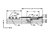
本開示の少なくとも1つの実施例は表示基板を提供し、図1は本開示の一実施例に係る表示基板の平面図であり、図2は図1に示される表示基板のM-N線の断面図である。たとえば、図1及び図2に示すように、表示基板は下地100、及び下地100に設置される封止層300と少なくとも1つの突起200を含み、下地100は表示領域110及び表示領域の周囲に位置する非表示領域120を含み、突起200は非表示領域120の下地100に設置され、且つ下地100と封止層300との間に位置し、封止層300は少なくとも部分的に突起200を被覆する。図2に示すように、非表示領域120に、封止層300が突起200に沿って設置され、それにより、下地100に向く封止層300の面の表面積を増加させ、外部の水、酸素が表示基板の内部に入る経路を増加させ、且つ封止層300の表示基板における付着面積を増加させ、表示基板の封止効果を向上させる。たとえば、封止層300はすべての突起200を被覆してもよく、すなわち突起200の下地100における正投影は封止層300の下地100における正投影内に位置してもよい。
At least one embodiment of the present disclosure provides a display substrate, FIG. 1 is a plan view of the display substrate according to one embodiment of the present disclosure, and FIG. 2 is the MN line of the display substrate shown in FIG. It is a sectional view. For example, as shown in FIGS. 1 and 2, the display substrate includes a
本開示の実施例は下地の製造材料を制限しない。たとえば、下地の製造材料はガラス下地、石英下地又は樹脂類材料であってもよく、樹脂類材料は、たとえば、ポリイミド、ポリカーボネート、ポリアクリレート、ポリエーテルイミド、ポリエーテルスルホン、ポリエチレンテレフタレート及びポリエチレンナフタレート等のうちの1種又は複数種を含む。 Embodiments of the present disclosure do not limit the material of manufacture of the substrate. For example, the base material of manufacture may be a glass base, a quartz base, or a resin class material, such as polyimide, polycarbonate, polyacrylate, polyetherimide, polyether sulfone, polyethylene terephthalate and polyethylene naphthalate. including one or more of
たとえば、図1及び図2に示すように、表示基板の下地100を基準として三次元空間直交座標系を作成して、表示基板の各部材を配向する。上記三次元空間直交座標系において、X軸とY軸の方向は下地100が位置する面に平行する方向であり、Z軸は下地100が位置する面に垂直する方向である。
For example, as shown in FIGS. 1 and 2, a three-dimensional space orthogonal coordinate system is created with the
たとえば、本開示の少なくとも1つの実施例では、表示基板は突起と下地との間に設置される絶縁層をさらに含み、且つ突起は該絶縁層と封止層との間に位置する。突起は外部の水、酸素等が上記絶縁層と封止層との間の界面に沿って表示基板の内部に侵入する経路を増加させ、それにより表示基板の封止効果を向上させる。 For example, in at least one embodiment of the present disclosure, the display substrate further includes an insulating layer disposed between the protrusions and the underlayer, and the protrusions are located between the insulating layer and the sealing layer. The protrusions increase the paths for external water, oxygen, etc. to enter the display substrate along the interface between the insulating layer and the sealing layer, thereby improving the sealing effect of the display substrate.
たとえば、本開示のいくつかの実施例では、上記絶縁層はパッシベーション層であってもよく、突起は該パッシベーション層に接するように設置される。絶縁層がパッシベーション層である場合、表示基板の構造は図2に示したようになる。たとえば、本開示のほかのいくつかの実施例では、上記絶縁層は層間絶縁層であってもよく、突起は該層間絶縁層に接するように設置される。絶縁層が層間絶縁層である場合、表示基板の構造は図6に示される。 For example, in some embodiments of the present disclosure, the insulating layer may be a passivation layer and the protrusions are placed in contact with the passivation layer. If the insulating layer is a passivation layer, the structure of the display substrate will be as shown in FIG. For example, in some other embodiments of the present disclosure, the insulating layer may be an interlayer insulating layer, and the protrusions are placed in contact with the interlayer insulating layer. If the insulating layer is an interlayer insulating layer, the structure of the display substrate is shown in FIG.
以下、絶縁層がパッシベーション層であることを例として、本開示の以下の少なくとも1つの実施例の技術案を説明する。 Hereinafter, the technical solution of the following at least one embodiment of the present disclosure will be described by taking the insulating layer as the passivation layer as an example.
たとえば、本開示の少なくとも1つの実施例では、図1及び図2に示すように、表示基板は突起200と下地100との間に設置されるパッシベーション層400をさらに含み、且つ突起200はパッシベーション層400と封止層300との間に位置する。たとえば、突起200はパッシベーション層400に接する。
For example, in at least one embodiment of the present disclosure, as shown in FIGS. 1 and 2, the display substrate further includes a
本開示の実施例はパッシベーション層400の製造材料を制限しない。たとえば、パッシベーション層400の製造材料は窒化ケイ素(SiNx)、酸化ケイ素(SiOx)、酸窒化ケイ素(SiNxOy)又はほかの適切な材料を含んでもよい。
Embodiments of the present disclosure do not limit the materials of manufacture of
たとえば、本開示の少なくとも1つの実施例では、図1及び図2に示すように、表示領域110の下地100は複数の画素領域111を含み、各画素領域111の下地100に少なくとも1つの有機発光素子600が設置され、有機発光素子600は絶縁層(たとえば、パッシベーション層400)と封止層300との間に位置する。突起200は水、酸素が封止層300とパッシベーション層400の界面に沿って拡散する経路を増加させ、それにより外部の水、酸素等が有機発光素子600に侵入することを阻止又は軽減させ、有機発光素子600を保護する。本開示の実施例は有機発光素子600の構造を制限しない。たとえば、本開示の少なくとも1つの実施例では、図2に示すように、有機発光素子600は第1電極610、第2電極620及び有機発光層630を含んでもよく、有機発光層630は第1電極610と第2電極620との間に位置する。有機発光素子600の構造は上記内容に限定されず、たとえば、有機発光素子600は第1電極610と第2電極620との間に位置する正孔注入層、正孔輸送層、電子輸送層、電子注入層等の構造をさらに含んでもよく、更に、正孔バリア層及び電子バリア層を含んでもよく、正孔バリア層は、たとえば、電子輸送層と有機発光層との間に設置されてもよく、電子バリア層は、たとえば、正孔輸送層と有機発光層との間に設置されてもよい。
For example, in at least one embodiment of the present disclosure, as shown in FIGS. 1 and 2, the underlying 100 of the
本開示の実施例は有機発光素子600の第1電極610及び第2電極620の製造材料を制限しない。たとえば、本開示の少なくとも1つの実施例では、第1電極610及び第2電極620のうちの一方は陽極で、他方は陰極であってもよい。陽極は、たとえば、高仕事関数を有する透明導電材料から形成され、陽極の電極材料は酸化インジウム錫(ITO)、酸化インジウム亜鉛(IZO)、酸化インジウムガリウム(IGO)、酸化ガリウム亜鉛(GZO)、酸化亜鉛(ZnO)、酸化インジウム(In2O3)、酸化アルミニウム亜鉛(AZO)及びカーボンナノチューブ等を含んでもよく、陰極は、たとえば、高導電性及び低仕事関数の材料から形成され、陰極の電極材料はマグネシウムアルミニウム合金(MgAl)、リチウムアルミニウム合金(LiAl)等の合金又はマグネシウム、アルミニウム、リチウム、銀等の単一金属を含んでもよい。
Embodiments of the present disclosure do not limit the materials for manufacturing the
本開示の実施例は有機発光素子600の有機発光層630の製造材料を制限しない。たとえば、本開示の少なくとも1つの実施例では、有機発光層630の材料はその異なる発光色に応じて選択できる。たとえば、有機発光層630の製造材料は蛍光発光材料又は燐光発光材料を含む。たとえば、本開示の少なくとも1つの実施例では、有機発光層630はドーピング系を使用でき、すなわち、ホスト発光材料にドーピング材料を混入させて利用可能な発光材料を得られる。たとえば、ホスト発光材料は金属化合物材料、アントラセンの誘導体、芳香族ジアミン類化合物、トリフェニルアミン化合物、芳香族トリアミン類化合物、ビフェニルジアミン誘導体、又はトリアリールアミン重合体等を使用してもよい。
Embodiments of the present disclosure do not limit the material for making the organic
たとえば、本開示の少なくとも1つの実施例では、図2に示すように、表示基板は下地100に設置される画素画定層700をさらに含んでもよく、有機発光素子600は画素画定層700が限定した領域内に設置される。
For example, in at least one embodiment of the present disclosure, as shown in FIG. 2, the display substrate may further include a
本開示の実施例は画素画定層700の具体的な構造及び製造材料等を制限しない。たとえば、本開示の少なくとも1つの実施例では、画素画定層700は1層又は2層構造であってもよく、複数層の複合層構造であってもよい。たとえば、画素画定層700は少なくとも第1画定層と第2画定層の積層を含み、第1画定層は、たとえば、親水性有機材料から形成され、第2画定層は、たとえば、疎水性有機材料から形成される。第1画定層は下地100と第2画定層との間に位置し、たとえば、インクジェットプリントによって有機発光素子600の部分構造(たとえば、有機発光層630等)を製造する場合、親水性を有する第1画定層は、画素画定層700が限定した領域にインクジェット材料を吸着して固定し、疎水性を有する第2画定層は、それに落ちたインクジェット材料を滑らせて、画素画定層700が限定した領域内に移動させ、それにより表示基板の製造の歩留まりを向上させることができる。
Embodiments of the present disclosure do not limit the specific structure, manufacturing material, etc. of the
たとえば、本開示の少なくとも1つの実施例では、表示基板の突起200は画素画定層700と同層に配置され、且つ同一の材料で製造されてもよい。例示的に、下地100に画素画定層700を製造する過程では、下地100に1層の画素画定層材料を堆積し、次にパターニングプロセスをして画素画定層700と突起200を同時に形成し、それによりマスクの数を減少させ、表示基板の生産時間を短縮させ、表示基板の生産コストを低減させることができる。
For example, in at least one embodiment of the present disclosure, the
本開示の実施例では、画素画定層700の製造材料は高分子樹脂材料であってもよく、パターニングプロセスは、たとえばフォトエッチングパターニングプロセスであり、たとえば、パターニング対象の構造層にフォトレジスト材料(photoresist)膜をスピンコーティング、ブレードコーティング又はロールコーティングの方式によってコーティングするステップと、続いて、マスクを用いてフォトレジスト材料層を露光し、露光したフォトレジスト材料層を現像してフォトレジスト材料パターンを得るステップと、次に、フォトレジスト材料パターンをマスクとして構造層をエッチングするステップと、最後に、残りのフォトレジスト材料を剥離して所要のパターン構造を形成するステップと、を含む。
In the embodiments of the present disclosure, the manufacturing material of the
たとえば、本開示の少なくとも1つの実施例では、画素画定層700の製造材料はフォトレジスト材料であってもよく、このとき、パターニングプロセスは、マスクを用いてフォトレジスト材料層を露光し、露光したフォトレジスト材料を現像して画素画定層700と突起200のパターンを得るステップを含む。
For example, in at least one embodiment of the present disclosure, the fabrication material of the
たとえば、本開示の少なくとも1つの実施例では、表示基板の突起200の少なくとも一部は画素画定層700と同層に配置され、且つ同一の材料で製造されてもよい。図2に示すように、突起200は少なくとも第1突起層201と第2突起層202の積層を含むように配置されてもよく、第1突起層201は第2突起層202と下地100との間に位置し、且つ第1突起層201は、たとえば画素画定層700と同層に配置され、且つ同一の材料で製造されてもよく、第2突起層202の製造材料は、たとえばフォトレジスト材料であってもよい。
For example, in at least one embodiment of the present disclosure, at least some of the
たとえば、本開示の少なくとも1つの実施例の一例では、同一のパターニングプロセスによって、画素画定層700及び画素画定層700と同層にあり、且つ同一の材料で製造される第1突起層201を得ることができる。パターニングプロセスは、たとえばフォトエッチングパターニングプロセスであり、たとえば、下地100に高分子樹脂材料などの1層の画素画定層材料を堆積し、画素画定層材料上にフォトレジスト材料膜をスピンコーティング、ブレードコーティング又はロールコーティングの方式によってコーティングするステップと、続いて、マスクを用いてフォトレジスト材料層を露光し、露光したフォトレジスト材料層を現像してフォトレジスト材料パターンを得るステップと、次に、フォトレジスト材料パターンをマスクとして画素画定層材料をエッチングし、画素画定層700及び画素画定層700と同層にあり、且つ同一の材料で製造される第1突起層201を得て、第2突起層202をフォトレジスト材料で製造し、画素画定層700及び第1突起201を形成した下地100に1層のフォトレジスト材料を堆積し、露光、現像により第2突起層202のパターンを得るステップと、を含む。このようにして、突起200の高さ(突起200の高さは突起200の下地100から離れた一端から突起200の下地100に近い他端までの距離であり、図2では、突起200の高さは突起200の下地100から離れた一端からパッシベーション層400に位置する他端までの距離である)を増加させ、更に水、酸素が表示基板の内部に侵入する経路を増加させることができる。
For example, in one example of at least one embodiment of the present disclosure, the same patterning process obtains the
たとえば、本開示の少なくとも1つの実施例の別の例では、画素画定層700の製造材料はフォトレジスト材料である。たとえば、同一のパターニングプロセスによって、画素画定層700及び画素画定層700と同層にあり、且つ同一の材料で製造される突起200を得る過程は、下地100に1層のフォトレジスト材料を堆積し、マスクを用いてフォトレジスト材料層を露光し、露光したフォトレジスト材料を現像して、画素画定層700及び画素画定層700と同層にあり、且つ同一の材料で製造される第1突起層201を得て、第2突起層202をフォトレジスト材料で製造し、画素画定層700及び第1突起201を形成した下地100に1層のフォトレジスト材料を堆積し、露光、現像により第2突起層202のパターンを得るステップを含む。このようにして、突起200の高さ(突起200の高さは突起200の下地100から離れた一端から突起200の下地100に近い他端までの距離であり、図2では、突起200の高さは突起200の下地100から離れた一端からパッシベーション層400に位置する他端までの距離である)を増加させ、更に水、酸素が表示基板の内部に侵入する経路を増加させることができる。
For example, in another example of at least one embodiment of the present disclosure, the material of manufacture of
たとえば、本開示の少なくとも1つの実施例では、突起200は画素画定層と同層の材料で製造されるものでなくてもよく、例示的に、パターニングプロセスによって画素画定層700を得た後、画素画定層700を形成した下地100に1層のフォトレジスト材料を堆積し、露光、現像により突起200のパターンを得る。
For example, in at least one embodiment of the present disclosure, the
本開示の実施例では、突起200の構造設計は上記いくつかの組み合わせ方式に限定されず、実際の必要に応じて設計でき、本開示の実施例は突起200の具体的な構造を制限しない。
In the embodiments of the present disclosure, the structural design of the
本開示の実施例は表示基板の有機発光素子600の駆動方式を制限しない。たとえば、表示基板の有機発光素子600はアクティブ駆動方式のものやパッシブ駆動方式のものであってもよい。
The embodiments of the present disclosure do not limit the driving scheme of the organic
たとえば、本開示の少なくとも1つの実施例では、表示基板の有機発光素子600はパッシブ駆動方式のものである。図2に示すように、有機発光素子600の第1電極610と第2電極620は積層して設置され、有機発光層630は第1電極610と第2電極620との積層位置にあり、表示基板の駆動回路は、たとえば、テープキャリアパッケージ(Tape Carrier Package、TCP)又はチップオングラス(Chip On Glass、COG)等の接続方式によってボンディング(bonding)される。
For example, in at least one embodiment of the present disclosure, the organic
たとえば、本開示の少なくとも1つの実施例では、表示基板の有機発光素子600はアクティブ駆動方式のものである。図2に示すように、表示基板の各画素領域111に、有機発光素子600を駆動する少なくとも1つの薄膜トランジスタ800がさらに設置される。たとえば、薄膜トランジスタ800は、アクティブ層、ゲート絶縁層810、ゲート電極、層間絶縁層820及びソースドレイン電極層(ソース電極及びドレイン電極を含む)等を含んでもよく、ドレイン電極は、たとえば有機発光素子600の第1電極610に電気的に接続される。
For example, in at least one embodiment of the present disclosure, the organic
本開示の実施例は薄膜トランジスタ800のタイプ及び構造を制限しない。たとえば、薄膜トランジスタ70はトップゲート型薄膜トランジスタ、ボトムゲート型薄膜トランジスタ又はダブルゲート型薄膜トランジスタ等であってもよい。たとえば、表示基板はボトムエミッションモード又はトップエミッションモードを使用してもよく、両面エミッションモードを使用してもよい。たとえば、表示基板はボトムエミッションモードを使用する場合、その第1電極610(たとえば、陽極)は透明電極、たとえば酸化インジウム錫電極であってもよく、その第2電極620(たとえば、陰極)は不透明金属電極であってもよく、表示基板はトップエミッションモードを使用する場合、その第1電極610(たとえば、陽極)は反射型電極を使用してもよく、第2電極620(たとえば、陰極)は半透明電極を使用してもよい。
Embodiments of the present disclosure do not limit the type and structure of
たとえば、本開示の少なくとも1つの実施例では、図3Aは本開示の一実施例に係る別の表示基板の部分断面図である。たとえば、図3Aに示すように、表示基板はパッシベーション層400の下地100から離れた一方側に設置される平坦層500をさらに含んでもよい。表示基板の製造過程では、後続のプロセスに寄与するように、平坦層500は表示基板を平坦化することができる。
For example, in at least one embodiment of the present disclosure, Figure 3A is a partial cross-sectional view of another display substrate according to one embodiment of the present disclosure. For example, the display substrate may further include a
たとえば、本開示の少なくとも1つの実施例では、図3Aに示すように、Z軸の方向に、突起200の下地100における正投影は平坦層500の下地100における正投影内に位置し、すなわち、平坦層500は非表示領域120まで延長し且つ突起200が設置された領域まで延長する。突起200の高さは突起200の下地100から離れた一端から突起200の下地100に近い他端までの距離であり、図3Aの突起200の高さは突起200の下地100から離れた一端から平坦層500に位置する他端までの距離である。
For example, in at least one embodiment of the present disclosure, along the Z-axis direction, the orthographic projection of
たとえば、本開示の少なくとも1つの実施例では、非表示領域120に位置する平坦層500の部分に対してパターニング設計を行って、該領域の平坦層500を突起200の部分構造として配置してもよい。図3Bは本開示の一実施例に係る別の表示基板の部分断面図である。たとえば、図3Bに示すように、非表示領域120の平坦層500に対してパターニングプロセス処理を行い、残りの平坦層500を突起200の一部、たとえば第3突起層203とし、このようにして、突起200の高さを増加させることができ、突起200の高さは突起200の下地100から離れた一端から突起200の下地100に近い他端までの距離であり、図3Bの突起200の高さは突起200の下地100から離れた一端からパッシベーション層400に位置する他端までの距離であり、水、酸素が侵入する経路を更に増加させ、表示基板の封止効果を向上させることができる。
For example, in at least one embodiment of the present disclosure, a patterning design may be applied to the portion of the
本開示の実施例は平坦層500の製造材料を制限しない。たとえば、平坦層500の製造材料は有機材料、たとえばエポキシ樹脂、ポリイミド、ポリアミド、アクリル酸又はほかの適切な材料であってもよい。たとえば、平坦層500の製造材料はフォトレジスト材料であってもよく、パッシベーション層400を形成した下地100に1層のフォトレジスト材料を堆積し、フォトレジスト材料を露光、現像し、平坦層500及び第3突起層203のパターンを形成する。
Embodiments of the present disclosure do not limit the material of manufacture of
本開示の実施例は封止層300の構造を制限せず、封止層300が少なくとも部分的に突起200を被覆すればよい。
Embodiments of the present disclosure do not limit the structure of the
たとえば、本開示の少なくとも1つの実施例では、図2、図3A及び図3Bに示すように、非表示領域120の封止層300は突起200に対応する非平坦部分を有する。水、酸素が表示基板の内部に入る経路を増加させ、表示基板の封止効果を向上させる作用を奏する。
For example, in at least one embodiment of the present disclosure, the
たとえば、本開示の少なくとも1つの実施例では、図2、図3A及び図3Bに示すように、封止層300は単層構造であってもよい。たとえば、封止層300は、表示基板の素子、たとえば有機発光素子600を保護するように、下地100の全面を被覆するように設置されてもよい。封止層300の製造材料は無機材料、たとえば窒化ケイ素(SiNx)、酸化ケイ素(SiOx)、酸窒化ケイ素(SiNxOy)又はほかの適切な材料等であってもよい。
For example, in at least one embodiment of the present disclosure, sealing
たとえば、本開示の少なくとも1つの実施例では、封止層300は2層以上の複合構造であってもよい。図4は本開示の一実施例に係る別の表示基板の部分断面図である。図4に示すように、封止層300は、たとえば、下地100に順に設置される第1封止層310、第2封止層320及び第3封止層330の積層を含んでもよい。たとえば、第1封止層310及び第3封止層330の製造材料は、無機材料、たとえば窒化ケイ素、酸化ケイ素等の材料を含んでもよく、無機材料の緻密性が高く、水、酸素等の侵入を防止でき、たとえば、第2封止層320の製造材料は有機材料、たとえば高分子樹脂等を含み、第2封止層320は第1封止層310及び第3封止層330の応力を軽減させることができ、且つ第2封止層320内に、たとえば乾燥剤等の材料が設置されてもよく、内部に侵入した水、酸素等の物質を吸収して表示基板の部材を保護することができる。
For example, in at least one embodiment of the present disclosure, sealing
たとえば、本開示の少なくとも1つの実施例では、図4に示すように、第1封止層310及び第3封止層330は、表示領域110全体を被覆し、少なくとも非表示領域120の突起200を被覆するように配置され、たとえば、第1封止層310及び第3封止層330は更に下地100の全面を被覆するように配置される。
For example, in at least one embodiment of the present disclosure, the
たとえば、本開示の少なくとも1つの実施例では、図4に示すように、Z軸に平行な方向に、突起200の下地100における正投影は第2封止層320の下地100における正投影外に位置する。たとえば、第2封止層320は突起200が位置する領域まで延長しない。有機材料からなる第2封止層320の厚さが大きく、第2封止層320が突起200を避けていることで、第2封止層320が突起200の両側の領域を満たすことを防止することができる。
For example, in at least one embodiment of the present disclosure, in a direction parallel to the Z-axis, the orthographic projection of
本開示の実施例は封止層300の厚さを制限しない。たとえば、本開示の少なくとも1つの実施例では、図4に示すように、Z軸に平行な方向に、第1封止層310及び第3封止層330の厚さは1ミクロン以下であってもよく、第2封止層320の厚さは2~15ミクロンである。
Embodiments of the present disclosure do not limit the thickness of
本開示の実施例では、下地100における突起200の配列方式を制限せず、突起200は、水、酸素等が表示基板の内部に侵入する経路を増加できるように設置されればよい。
The embodiments of the present disclosure do not limit the arrangement of the
たとえば、本開示の少なくとも1つの実施例では、図1に示すように、突起200は部分的に表示領域110を囲むように設置されてもよく、又は環状構造として表示領域110を囲むように設置されてもよく、各突起200は一体化した閉環状構造として設置されてもよい。このようにして、突起200は表示領域110全体の部材を保護できる。
For example, in at least one embodiment of the present disclosure,
たとえば、本開示の少なくとも1つの実施例では、図5は本開示の一実施例に係る別の表示基板の平面図である。図5に示すように、各突起200は互いに離間した少なくとも2つの突起段230を含む(たとえば、第1突起段231、第2突起段232等を含む)ように設置されてもよい。突起段230は、表示基板の厚さが大きすぎて後続の製造プロセスに不都合等をもたらすことを回避するように、表示基板の具体的な構造に応じて設置されている。
For example, in at least one embodiment of the present disclosure, Figure 5 is a plan view of another display substrate according to one embodiment of the present disclosure. As shown in FIG. 5, each
本開示の実施例は突起段230の長さを制限せず、実際のプロセス条件に応じて設計する。たとえば、図5に示すように、表示基板の同じ側に、突起段230の長さと表示基板の辺長との比は1/3以上であり、さらに好ましくは2/3以上である。例示的に、たとえば、図5に示すように、表示基板のS1側において、第1突起段231がY方向に平行に延長する長さと表示基板のS1側の辺長との比は1/3以上であり、表示基板のS2側において、第2突起段232がX方向に平行に延長する長さと表示基板のS2側の辺長との比は1/3以上である。同様に、表示基板のS3側及びS4側において、突起段230の長さと表示基板の辺長との比は1/3以上である。
The embodiments of the present disclosure do not limit the length of the
本開示の実施例は突起200の表示基板における延長形状を制限しない。たとえば、Z軸に平行な方向から見れば、下地100が位置する面に平行な方向における突起200(たとえば、突起段230)の延長形状(屈曲段の延長形状を含まない)は直線状、波状等であってもよい。例示的に、図5に示すように、Y軸に平行な方向における第1突起段231の延長形状又はX軸に平行な方向における第2突起段232の延長形状は直線状である。
Embodiments of the present disclosure do not limit the extended shape of the
たとえば、本開示の少なくとも1つの実施例では、図4に示すように、下地100が位置する面に平行な方向に、突起200は表示領域110を囲んで複数層設置されてもよい。たとえば、本開示の一実施例では、図4に示すように、突起200は少なくとも、表示領域110を囲んで順に配列される第1突起210及び第2突起220を含み、第1突起210は第2突起220と隣接して設置され、且つ第1突起210は第2突起220の内側に位置する。複数層の突起200は、外部の水、酸素が表示基板の内部に侵入する経路を更に増加させ、表示基板の封止効果を更に向上させることができる。
For example, in at least one embodiment of the present disclosure, multiple layers of
本開示の実施例は異なる層の突起200の高さを制限せず、実際のプロセス条件に応じて設計する。たとえば、表示基板の外層に位置する突起200の高さは内層の突起200の高さより大きく設定されてもよい。例示的に、下地100が位置する面に垂直な方向において、第2突起220の高さHは第1突起210の高さhより大きくなる。第2突起220の高さHは第2突起220の下地100から離れた一端から第2突起220の下地100に近い他端までの距離であり、図4では、第2突起220の高さは第2突起220の下地100から離れた一端からパッシベーション層400に位置する他端までの距離であり、第1突起210の高さhは第1突起210の下地100から離れた一端から第1突起210の下地100に近い他端までの距離であり、図4では、第1突起210の高さは第1突起210の下地100から離れた一端からパッシベーション層400に位置する他端までの距離であり、第1突起210と第2突起220が高度差を有することで、第1突起210と第2突起220との間に形成された溝の深さを低減させることができ、封止層が第1突起210と第2突起220を被覆する時の成膜の品質を向上させることに有利であり、外層に位置する第2突起220の高さHが高いため、水、酸素が侵入する経路を増加させ、表示基板の封止効果を向上させることができる。
The embodiments of the present disclosure do not limit the height of the
本開示の実施例では、隣接する突起200の高度差を制限せず、実際のプロセス条件に応じて設計する。たとえば、本開示の少なくとも1つの実施例では、図4に示すように、第2突起220の高さHと第1突起210の高さhとの差は約0.3~5ミクロンであり、たとえば更に好ましくは約0.5~3ミクロンである。
Embodiments of the present disclosure do not limit the height difference between
本開示の実施例では、突起200の寸法を制限せず、実際のプロセス条件に応じて設計する。たとえば、本開示の少なくとも1つの実施例では、図4に示すように、Z軸に平行な方向における突起200の高さは約2~15ミクロンである。図4に示すように、突起200の高さは突起200の下地100から離れた一端から突起200の下地100に近い他端までの距離であり、且つ突起200の高さは突起200の下地100から離れた一端からパッシベーション層400に位置する他端までの距離である。たとえば、本開示の少なくとも1つの実施例では、図4に示すように、下地100が位置する面に平行な方向における突起200の幅Wは約30~100ミクロンであり、たとえば、本開示の少なくとも1つの実施例では、図4に示すように、下地100が位置する面に平行な方向において、隣接する突起200(たとえば、第1突起210と第2突起220)の間隔Sは約30~100ミクロンである。
The embodiments of the present disclosure do not limit the dimension of the
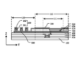
本開示の実施例では、表示基板の絶縁層(突起は該絶縁層に設置される)は上記実施例のパッシベーション層に限定されない。図6は本開示の一実施例に係る別の表示基板の部分断面図である。 In the embodiments of the present disclosure, the insulating layer of the display substrate (on which the protrusions are placed) is not limited to the passivation layer in the above embodiments. FIG. 6 is a partial cross-sectional view of another display substrate according to one embodiment of the present disclosure.
たとえば、本開示の少なくとも1つの実施例では、図6に示すように、表示基板の絶縁層は層間絶縁層820であってもよく、突起200は層間絶縁層820に接するように設置されてもよい。たとえば、本開示の実施例では、表示基板にパッシベーション層が設置されなくてもよく、それにより、突起200の設置によって、水、酸素等が表示基板の内部に侵入する経路を増加させ、表示基板の封止効果を向上させることができるだけでなく、表示基板の厚さを薄くすることができ、表示基板の軽量・薄型化に有利であり、また、非表示領域120に位置する表示基板の構造の複雑度を低減させ、表示基板(たとえば、表示基板はフレキシブル表示基板である)が湾曲等の操作をする過程で、非表示領域120における表示基板の破損(たとえば、破断による割れ目)の確率を低下させ、水、酸素等が割れ目に沿って表示基板の内部に侵入することを防止する。
For example, in at least one embodiment of the present disclosure, as shown in FIG. good. For example, in the embodiments of the present disclosure, the display substrate may not be provided with a passivation layer, so that the provision of the
たとえば、本開示の少なくとも1つの実施例では、図6に示すように、層間絶縁層820に、図2に示されるパッシベーション層400のかわりに、平坦層500を設置してもよい。層間絶縁層500の設置形態は上記実施例(図3A及び図3Bに示される実施例)の関連内容を参照すればよく、本開示の実施例はここでは詳細説明を省略する。
For example, in at least one embodiment of the present disclosure, a
本開示の少なくとも1つの実施例は、上記実施例のいずれかに記載の表示基板を含む表示装置を提供する。たとえば、表示装置の表示基板は、フレキシブル表示分野に適用できるようにフレキシブル下地であってもよい。たとえば、本開示の実施例に係る表示装置では、表示装置にタッチ表示機能を付与するように、表示基板にタッチ下地を設置してもよい。 At least one embodiment of the present disclosure provides a display device including the display substrate according to any of the above embodiments. For example, the display substrate of the display device may be a flexible substrate for application in the flexible display field. For example, in display devices according to embodiments of the present disclosure, a touch substrate may be provided on the display substrate to provide the display device with touch display functionality.
たとえば、該表示装置はテレビ、デジタルカメラ、携帯電話、腕時計、タブレットPC、ノートパソコン、ナビゲータなど表示機能を有する任意の製品又は部材であってもよい。 For example, the display device may be any product or member having a display function, such as a television, digital camera, mobile phone, wrist watch, tablet PC, notebook computer, navigator.
なお、説明の明瞭さの点から、該表示装置のすべての構造を説明していない。表示装置の必要な機能を実現するために、当業者は具体的な応用場面に応じてほかの構造を設置することができ、本開示ではそれを制限しない。 It should be noted that not all structures of the display device have been described for the sake of clarity of description. In order to realize the necessary functions of the display device, those skilled in the art can install other structures according to the specific application, and this disclosure does not limit it.
本開示の少なくとも1つの実施例は表示基板の製造方法を提供し、表示領域及び表示領域の周囲に位置する非表示領域を含む下地を提供するステップと、下地の非表示領域に少なくとも1つの突起を形成するステップと、下地に封止層を形成するステップと、を含み、突起は下地と封止層との間に形成され、封止層は少なくとも部分的に突起を被覆する。上記製造方法に基づき得られた表示基板では、表示基板の非表示領域において、突起は下地に向く封止層の面の表面積を増加させ、水、酸素等の物質が表示基板の内部に侵入する経路を増加させ、表示基板の部材を保護し、また、突起の設置によって封止層と表示基板との接面積を増加させ、それにより封止層の表示基板の設置の堅牢性を高め、表示基板の封止効果を向上させる。 At least one embodiment of the present disclosure provides a method of manufacturing a display substrate, comprising providing a base including a display area and a non-display area positioned around the display area; and forming an encapsulation layer on the substrate, wherein the protrusion is formed between the substrate and the encapsulation layer, the encapsulation layer at least partially covering the protrusion. In the display substrate obtained by the above manufacturing method, in the non-display area of the display substrate, the protrusions increase the surface area of the surface of the sealing layer facing the underlying layer, allowing substances such as water and oxygen to enter the display substrate. It increases the path, protects the members of the display substrate, and increases the contact area between the sealing layer and the display substrate by installing the protrusions, thereby increasing the robustness of the installation of the sealing layer on the display substrate and improving the display. Improve the sealing effect of the substrate.
たとえば、本開示の少なくとも1つの実施例に係る製造方法は、突起と下地との間に絶縁層を形成するステップをさらに含み、突起は絶縁層に接し、且つ絶縁層はパッシベーション層又は層間絶縁層である。このようにして、突起によって封止層とパッシベーション層又は層間絶縁層との間の界面の表面積を増加させ、水、酸素等が該界面に沿って表示基板の内部に侵入する経路を増加させることができる。 For example, the manufacturing method according to at least one embodiment of the present disclosure further includes forming an insulating layer between the protrusion and the base, the protrusion being in contact with the insulating layer, and the insulating layer being a passivation layer or an interlayer insulating layer. is. In this way, the protrusions increase the surface area of the interface between the sealing layer and the passivation layer or the interlayer insulating layer, thereby increasing the paths for water, oxygen, etc. to enter the display substrate along the interface. can be done.
たとえば、本開示の少なくとも1つの実施例に係る製造方法は、絶縁層の下地から離れた一方側において、突起と絶縁層との間に平坦層を形成するステップをさらに含み、且つ突起の少なくとも一部は平坦層と同層にあり、且つ同一の材料で製造される。このようにして、突起の高さを増加させ、それにより、水、酸素が侵入する経路を更に増加させ、表示基板の封止効果を向上させることができる。 For example, a manufacturing method according to at least one embodiment of the present disclosure further includes forming a planarization layer between the protrusion and the insulating layer on one side of the insulating layer remote from the underlying layer; The part is in the same layer as the flat layer and is made of the same material. In this way, the height of the protrusion is increased, thereby further increasing the paths for water and oxygen to enter, and improving the sealing effect of the display substrate.
なお、上記製造方法に基づき得られた表示基板の構造は上記実施例の関連内容を参照すればよく、ここで重複説明を省略する。 For the structure of the display substrate obtained by the above-described manufacturing method, reference can be made to the relevant contents of the above-described embodiments, and redundant description is omitted here.
本開示の実施例は表示基板及びその製造方法、表示装置を提供し、以下の少なくとも1つの有益な効果を有する。 Embodiments of the present disclosure provide a display substrate, a manufacturing method thereof, and a display device, and have at least one of the following beneficial effects.
(1)本開示の少なくとも1つの実施例に係る表示基板において、非表示領域に設置される突起によって、下地に向く封止層の面の面積を増加させ、水、酸素等が表示基板の内部に侵入する経路を増加させ、表示基板の封止効果を向上させることができる。 (1) In the display substrate according to at least one embodiment of the present disclosure, the projections provided in the non-display area increase the area of the surface of the sealing layer facing the base, and prevent water, oxygen, etc. from entering the display substrate. It is possible to increase the number of paths intruding into the display substrate and improve the sealing effect of the display substrate.
(2)本開示の少なくとも1つの実施例に係る表示基板において、突起の設置によって封止層の表示基板にの付着の堅牢性を向上させ、表示基板の封止効果を向上させることができる。 (2) In the display substrate according to at least one embodiment of the present disclosure, the provision of the protrusions can improve the robustness of the adhesion of the sealing layer to the display substrate, and improve the sealing effect of the display substrate.
本開示について、さらに以下の点を説明する。 The following points will be further explained with respect to the present disclosure.
(1)本開示の実施例の図面では、本開示の実施例に関する構造のみを示しており、ほかの構造は通常の設計を参照すればよい。 (1) The drawings of the embodiments of the present disclosure only show the structures related to the embodiments of the present disclosure, and other structures can refer to the general design.
(2)明瞭さのために、本開示の実施例を説明するための図面において、層又は領域の厚さが拡大又は縮小されており、すなわち、これらの図面は実際の縮尺に応じて作成されるものではない。 (2) For the sake of clarity, the thicknesses of layers or regions are exaggerated or reduced in the drawings to illustrate the embodiments of the present disclosure, i.e. the drawings are drawn to actual scale. not something.
(3)矛盾しない限り、本開示の実施例及び実施例における特徴を互いに組み合わせて新たな実施例を得ることができる。 (3) Unless inconsistent, the embodiments of the present disclosure and features in the embodiments can be combined with each other to obtain new embodiments.
以上は本開示の具体的な実施形態に過ぎず、本開示の保護範囲はこれに限定されず、本開示の保護範囲は特許請求の保護範囲に準じるべきである。 The above are only specific embodiments of the present disclosure, the protection scope of the disclosure is not limited thereto, and the protection scope of the disclosure should follow the protection scope of the claims.
100 下地
110 表示領域
111 画素領域
120 非表示領域
200 突起
201 第1突起層
202 第2突起層
203 第3突起層
210 第1突起
220 第2突起
230 突起段
231 第1突起段
232 第2突起段
300 封止層
310 第1封止層
320 第2封止層
330 第3封止層
400 パッシベーション層
500 平坦層
600 有機発光素子
610 第1電極
620 第2電極
630 有機発光層
700 画素画定層
800 薄膜トランジスタ
810 ゲート絶縁層
820 層間絶縁層
100
Claims (14)
表示領域及び前記表示領域の周囲に位置する非表示領域を含む下地と、
前記非表示領域の前記下地に設置される少なくとも1つの突起と、
前記下地に設置される封止層と、を含み、
前記突起は前記下地と前記封止層との間に位置し、前記封止層は少なくとも部分的に前記突起を被覆し、
第2突起の高さと第1突起の高さとの差が、0.5~3ミクロンであり、
前記突起の高さは、2~15ミクロンであり、及び/又は
前記下地が位置する面に平行な方向において、前記突起の幅は、30~100ミクロンであり、及び/又は
前記下地が位置する面に平行な方向において、前記第1突起と前記第2突起の間隔は、30~100ミクロンであることを特徴とする表示基板。 A display substrate,
a base including a display area and a non-display area positioned around the display area;
at least one protrusion placed on the base of the non-display area;
a sealing layer provided on the base,
the protrusions are located between the substrate and the sealing layer, the sealing layer at least partially covering the protrusions;
the difference between the height of the second protrusion and the height of the first protrusion is 0.5 to 3 microns;
the height of the protrusions is between 2 and 15 microns, and/or
In a direction parallel to the plane on which the substrate lies, the width of the protrusions is 30-100 microns, and/or
A display substrate , wherein a distance between said first projections and said second projections is 30 to 100 microns in a direction parallel to a plane on which said base is positioned .
前記絶縁層は層間絶縁層であり、前記突起が前記層間絶縁層に接することを特徴とする、
請求項2に記載の表示基板。 the insulating layer is a passivation layer, the protrusion is in contact with the passivation layer, and
The insulating layer is an interlayer insulating layer, and the protrusion is in contact with the interlayer insulating layer,
The display substrate according to claim 2.
前記表示基板は、前記下地に設置される画素画定層をさらに含み、
前記有機発光素子は、前記画素画定層が限定した領域内に設置され、
前記突起の少なくとも一部は、前記画素画定層と同層に配置され、且つ同一の材料で製造されることを特徴とする、
請求項2又は3に記載の表示基板。 The base of the display area includes a plurality of pixel regions, and at least one organic light-emitting device is disposed on the base of each pixel region, and the organic light-emitting device is positioned between the insulating layer and the encapsulation layer. death,
the display substrate further comprising a pixel definition layer disposed on the underlayer;
the organic light-emitting element is disposed within a region defined by the pixel definition layer;
At least part of the protrusions are arranged in the same layer as the pixel definition layer and are made of the same material,
The display substrate according to claim 2 or 3.
前記第1突起層は前記画素画定層と同層に配置され、且つ同一の材料で製造され、
前記第2突起層の製造材料は、フォトレジスト材料であることを特徴とする、
請求項4に記載の表示基板。 each of the protrusions is arranged to include a laminate of at least a first protrusion layer and a second protrusion layer, the first protrusion layer being positioned between the second protrusion layer and the base;
the first protrusion layer is arranged in the same layer as the pixel definition layer and is made of the same material;
The manufacturing material of the second protrusion layer is a photoresist material,
The display substrate according to claim 4.
請求項2~5のいずれか一項に記載の表示基板。 The material for manufacturing the protrusions comprises a photoresist material,
The display substrate according to any one of claims 2-5.
前記平坦層は前記突起と前記絶縁層との間に位置し、
前記突起の前記下地における正投影は、前記平坦層の前記下地における正投影内に位置し、
前記突起の少なくとも一部は、前記平坦層と同層に配置され、且つ同一の材料で製造されることを特徴とする、
請求項4に記載の表示基板。 further comprising a planarization layer disposed on one side of the insulating layer remote from the underlayer;
the planarization layer is located between the protrusion and the insulating layer;
an orthographic projection of the protrusion on the substrate located within an orthographic projection of the flat layer on the substrate;
At least part of the protrusions are arranged in the same layer as the flat layer and are made of the same material,
The display substrate according to claim 4.
前記第1突起層は、前記第2突起層と前記下地との間に位置し、
前記第3突起層は、前記第1突起層と前記下地との間に位置し、
前記第1突起層は、前記画素画定層と同層に配置され、且つ同一の材料で製造され、
前記第3突起層は、前記平坦層と同層に配置され、且つ同一の材料で製造され、
前記第2突起層の製造材料はフォトレジスト材料であることを特徴とする、
請求項7に記載の表示基板。 each of the protrusions is arranged to include a laminate of at least a first protrusion layer, a second protrusion layer, and a third protrusion layer;
The first protruding layer is located between the second protruding layer and the base,
The third protruding layer is located between the first protruding layer and the base,
the first protrusion layer is arranged in the same layer as the pixel definition layer and is made of the same material;
The third protrusion layer is arranged in the same layer as the flat layer and made of the same material,
The manufacturing material of the second protrusion layer is a photoresist material,
The display substrate according to claim 7.
各前記突起は、一体化した閉環状構造として設置され、又は
各前記突起は、互いに離間した少なくとも2つの突起段を含むように設置されることを特徴とする、
請求項1~8のいずれか一項に記載の表示基板。 The protrusion is installed to surround the display area as an annular structure,
wherein each said projection is arranged as a unitary closed annular structure, or each said projection is arranged so as to include at least two projection steps spaced apart from each other;
The display substrate according to any one of claims 1-8.
請求項9に記載の表示基板。 characterized in that the ratio of the length of the protruding step to the side length of the display substrate is 1/3 or more on the same side of the display substrate;
The display substrate according to claim 9.
前記第1突起は、前記第2突起と隣接して設置され、
且つ前記第1突起は、前記第2突起の内側に位置し、
前記下地が位置する面に垂直な方向において、前記第2突起の高さは、前記第1突起の高さより大きくなることを特徴とする、
請求項1~10のいずれか一項に記載の表示基板。 the projections include at least a first projection and a second projection arranged in order surrounding the display area;
The first projection is installed adjacent to the second projection,
and the first projection is located inside the second projection,
In a direction perpendicular to the surface on which the base is located, the height of the second projection is greater than the height of the first projection,
The display substrate according to any one of claims 1-10.
前記第1封止層と前記第3封止層の製造材料は無機材料を含み、前記第2封止層の製造材料は有機材料を含み、
前記第1封止層と前記第3封止層は、前記突起を被覆するように配置され、
前記突起の前記下地における正投影は、前記第2封止層の前記下地における正投影外に位置することを特徴とする、
請求項1~11のいずれか一項に記載の表示基板。 The sealing layer is arranged to include a lamination of a first sealing layer, a second sealing layer and a third sealing layer, which are arranged in order on the base,
the material for manufacturing the first sealing layer and the third sealing layer comprises an inorganic material, and the material for manufacturing the second sealing layer comprises an organic material;
the first sealing layer and the third sealing layer are arranged to cover the protrusion;
wherein the orthographic projection of the protrusion on the base is located outside the orthographic projection of the second sealing layer on the base,
The display substrate according to any one of claims 1-11 .
表示領域及び前記表示領域の周囲に位置する非表示領域を含む下地を提供するステップと、
前記下地の前記非表示領域に少なくとも1つの突起を形成するステップと、
前記下地に封止層を形成するステップと、を含み、
前記突起は前記下地と前記封止層との間に形成され、前記封止層は少なくとも部分的に前記突起を被覆し、
第2突起の高さと第1突起の高さとの差が、0.5~3ミクロンであり、
前記突起の高さは、2~15ミクロンであり、及び/又は
前記下地が位置する面に平行な方向において、前記突起の幅は、30~100ミクロンであり、及び/又は
前記下地が位置する面に平行な方向において、前記第1突起と前記第2突起の間隔は、30~100ミクロンであることを特徴とする製造方法。 A method for manufacturing a display substrate,
providing a substrate comprising a display area and a non-display area positioned around the display area;
forming at least one protrusion in the non-display area of the substrate;
forming an encapsulation layer on the underlayer;
the protrusions are formed between the substrate and the sealing layer, the sealing layer at least partially covering the protrusions;
the difference between the height of the second protrusion and the height of the first protrusion is 0.5 to 3 microns;
the height of the protrusions is between 2 and 15 microns, and/or
In a direction parallel to the plane on which the substrate lies, the width of the protrusions is 30-100 microns, and/or
A manufacturing method , wherein the distance between the first projection and the second projection is 30 to 100 microns in a direction parallel to the plane on which the underlayer is located .
Applications Claiming Priority (3)
| Application Number | Priority Date | Filing Date | Title |
|---|---|---|---|
| CN201721106739.6U CN207116481U (en) | 2017-08-31 | 2017-08-31 | Display base plate, display device |
| CN201721106739.6 | 2017-08-31 | ||
| PCT/CN2018/090203 WO2019041946A1 (en) | 2017-08-31 | 2018-06-07 | Display substrate and manufacturing method therefor, and display device |
Publications (3)
| Publication Number | Publication Date |
|---|---|
| JP2020532043A JP2020532043A (en) | 2020-11-05 |
| JP2020532043A5 JP2020532043A5 (en) | 2021-07-26 |
| JP7203763B2 true JP7203763B2 (en) | 2023-01-13 |
Family
ID=61585759
Family Applications (1)
| Application Number | Title | Priority Date | Filing Date |
|---|---|---|---|
| JP2019563827A Active JP7203763B2 (en) | 2017-08-31 | 2018-06-07 | DISPLAY SUBSTRATE AND MANUFACTURING METHOD THEREOF, DISPLAY DEVICE |
Country Status (10)
| Country | Link |
|---|---|
| US (1) | US11139450B2 (en) |
| EP (1) | EP3678202A4 (en) |
| JP (1) | JP7203763B2 (en) |
| KR (1) | KR20190141224A (en) |
| CN (1) | CN207116481U (en) |
| AU (1) | AU2018324779B2 (en) |
| BR (1) | BR112019024752B1 (en) |
| MX (1) | MX2019013719A (en) |
| RU (1) | RU2727069C1 (en) |
| WO (1) | WO2019041946A1 (en) |
Families Citing this family (21)
| Publication number | Priority date | Publication date | Assignee | Title |
|---|---|---|---|---|
| CN207116481U (en) | 2017-08-31 | 2018-03-16 | 京东方科技集团股份有限公司 | Display base plate, display device |
| CN108565353B (en) | 2018-04-20 | 2020-03-06 | 京东方科技集团股份有限公司 | Display back plate and display device |
| CN108511503B (en) * | 2018-05-28 | 2020-11-24 | 京东方科技集团股份有限公司 | Electroluminescent display panel, manufacturing method thereof and display device |
| CN108511631A (en) * | 2018-06-08 | 2018-09-07 | 京东方科技集团股份有限公司 | OLED display panel and its manufacturing method, display device |
| CN108963104A (en) * | 2018-07-02 | 2018-12-07 | 武汉华星光电半导体显示技术有限公司 | A kind of OLED display panel and its packaging method |
| CN108987426B (en) * | 2018-07-23 | 2020-09-29 | 上海天马微电子有限公司 | Flexible LED display panel and electronic equipment |
| CN109148522B (en) * | 2018-08-10 | 2020-09-01 | 上海天马微电子有限公司 | Organic light-emitting display panel, manufacturing method of display panel and display device |
| CN109256487B (en) * | 2018-09-12 | 2020-09-01 | 武汉华星光电半导体显示技术有限公司 | Display panel |
| CN109473568B (en) | 2018-11-08 | 2021-01-26 | 京东方科技集团股份有限公司 | Display panel and display device |
| CN109638045B (en) * | 2018-12-07 | 2020-06-16 | 武汉华星光电半导体显示技术有限公司 | Display unit, manufacturing method of display unit and organic light emitting diode display |
| CN111370439A (en) * | 2018-12-07 | 2020-07-03 | 京东方科技集团股份有限公司 | Display panel, preparation method thereof and display device |
| CN109742110B (en) * | 2019-01-04 | 2022-07-08 | 京东方科技集团股份有限公司 | Organic light emitting display and method of manufacturing the same |
| CN109920933B (en) * | 2019-03-05 | 2021-02-09 | 京东方科技集团股份有限公司 | Display substrate and manufacturing method thereof, display panel and display device |
| WO2020248257A1 (en) | 2019-06-14 | 2020-12-17 | 京东方科技集团股份有限公司 | Display substrate and display device |
| CN110265579A (en) | 2019-06-27 | 2019-09-20 | 京东方科技集团股份有限公司 | A kind of display panel and preparation method thereof, display device |
| CN110416266B (en) * | 2019-07-29 | 2022-07-22 | 京东方科技集团股份有限公司 | Display substrate and display panel comprising same |
| US11437599B2 (en) | 2019-08-19 | 2022-09-06 | Wuhan China Star Optoelectronics Semiconductor Display Technology Co., Ltd. | Display panel and display device |
| CN110600630A (en) * | 2019-08-19 | 2019-12-20 | 武汉华星光电半导体显示技术有限公司 | Display panel and display device |
| CN111312921A (en) * | 2020-02-20 | 2020-06-19 | 京东方科技集团股份有限公司 | Display panel, manufacturing method thereof and display device |
| CN113517315A (en) * | 2020-04-09 | 2021-10-19 | 上海和辉光电有限公司 | Flexible organic electroluminescent display panel and display device |
| CN113838996B (en) * | 2021-09-23 | 2024-03-19 | 京东方科技集团股份有限公司 | Display panel and preparation method thereof |
Citations (16)
| Publication number | Priority date | Publication date | Assignee | Title |
|---|---|---|---|---|
| JP2008262796A (en) | 2007-04-12 | 2008-10-30 | Sony Corp | Display device and its manufacturing method |
| JP2010165612A (en) | 2009-01-19 | 2010-07-29 | Seiko Epson Corp | Organic el device, manufacturing method of organic el device, and electronic equipment |
| US20100258346A1 (en) | 2009-04-10 | 2010-10-14 | Industrial Technology Research Institute | Package of environmentally sensitive electronic device and fabricating method thereof |
| JP2011146323A (en) | 2010-01-18 | 2011-07-28 | Canon Inc | Organic el light emitting device |
| JP2013524473A (en) | 2010-04-12 | 2013-06-17 | コミサリア ア レネルジー アトミック エ オ ゼネルジー アルテルナティブ | Organic optoelectronic device and method for encapsulating the same |
| US20140131682A1 (en) | 2012-11-09 | 2014-05-15 | Lg Display Co., Ltd. | Flexible organic electroluminescent device and method for fabricating the same |
| US20150091030A1 (en) | 2013-09-30 | 2015-04-02 | Samsung Display Co., Ltd. | Display devices and methods of manufacturing display devices |
| US20150380685A1 (en) | 2014-06-25 | 2015-12-31 | Lg Display Co., Ltd. | Organic light emitting display apparatus |
| JP2016054144A (en) | 2014-09-03 | 2016-04-14 | エルジー ディスプレイ カンパニー リミテッド | Organic light emitting diode display device and method for manufacturing the same |
| WO2016132954A1 (en) | 2015-02-16 | 2016-08-25 | シャープ株式会社 | Electroluminescence device |
| US20170033312A1 (en) | 2015-07-29 | 2017-02-02 | Samsung Display Co., Ltd. | Organic light-emitting diode display |
| US20170053973A1 (en) | 2015-08-19 | 2017-02-23 | Samsung Display Co., Ltd. | Organic light-emitting display apparatus and method of manufacturing the same |
| JP2017123257A (en) | 2016-01-06 | 2017-07-13 | 株式会社ジャパンディスプレイ | Display device and manufacturing method for the same |
| JP2018532158A (en) | 2015-12-30 | 2018-11-01 | シェンジェン ロイオル テクノロジーズ カンパニー リミテッドShenzhen Royole Technologies Co., Ltd. | Flexible display screen and manufacturing method thereof |
| WO2019030887A1 (en) | 2017-08-10 | 2019-02-14 | シャープ株式会社 | Electrooptical device and method for manufacturing same |
| WO2019064409A1 (en) | 2017-09-28 | 2019-04-04 | シャープ株式会社 | Display device, method for manufacturing display device, and apparatus for manufacturing display device |
Family Cites Families (19)
| Publication number | Priority date | Publication date | Assignee | Title |
|---|---|---|---|---|
| KR20000031459A (en) * | 1998-11-06 | 2000-06-05 | 윤종용 | Reflection type lcd and fabrication method thereof |
| JP5170020B2 (en) * | 2008-10-03 | 2013-03-27 | セイコーエプソン株式会社 | Organic EL device and electronic device |
| US8568184B2 (en) | 2009-07-15 | 2013-10-29 | Apple Inc. | Display modules |
| TWI473264B (en) * | 2012-03-02 | 2015-02-11 | Au Optronics Corp | Organic electroluminescent apparatus |
| KR101978783B1 (en) * | 2012-11-09 | 2019-05-15 | 엘지디스플레이 주식회사 | Flexible organic electroluminescent device and method for fabricating the same |
| KR102080008B1 (en) | 2013-07-12 | 2020-02-24 | 삼성디스플레이 주식회사 | Organic luminescence emitting display device and method for manufacturing the same |
| KR102454664B1 (en) | 2014-06-25 | 2022-10-14 | 엘지디스플레이 주식회사 | Organic light emitting display apparatus |
| US9395574B2 (en) * | 2014-07-31 | 2016-07-19 | Shenzhen China Star Optoelectronics Technology Co., Ltd | Liquid crystal display having black matrix made of molybdenum |
| CN105810710A (en) | 2014-12-31 | 2016-07-27 | 昆山国显光电有限公司 | OLED device and preparing method thereof |
| KR102362819B1 (en) * | 2015-03-23 | 2022-02-14 | 삼성디스플레이 주식회사 | Flexible display device |
| KR102378360B1 (en) * | 2015-05-12 | 2022-03-25 | 삼성디스플레이 주식회사 | Organic light-emitting display |
| CN104900681B (en) * | 2015-06-09 | 2019-02-05 | 上海天马有机发光显示技术有限公司 | Organic light emitting display panel and forming method thereof |
| KR102414110B1 (en) * | 2015-09-07 | 2022-06-29 | 삼성디스플레이 주식회사 | Display apparatus |
| KR102492032B1 (en) * | 2016-04-04 | 2023-01-27 | 삼성디스플레이 주식회사 | Display device and method for fabricating the same |
| KR101854701B1 (en) * | 2016-05-31 | 2018-05-04 | 엘지디스플레이 주식회사 | Organic light emitting device and method of manufacturing the same |
| CN107887405A (en) * | 2016-09-30 | 2018-04-06 | 群创光电股份有限公司 | Organic electric-excitation luminescent displaying panel |
| KR20180060851A (en) * | 2016-11-29 | 2018-06-07 | 엘지디스플레이 주식회사 | Organic light emitting display device |
| CN207116481U (en) * | 2017-08-31 | 2018-03-16 | 京东方科技集团股份有限公司 | Display base plate, display device |
| CN207381403U (en) * | 2017-08-31 | 2018-05-18 | 京东方科技集团股份有限公司 | Display base plate, display panel |
-
2017
- 2017-08-31 CN CN201721106739.6U patent/CN207116481U/en active Active
-
2018
- 2018-06-07 KR KR1020197034395A patent/KR20190141224A/en not_active IP Right Cessation
- 2018-06-07 US US16/338,165 patent/US11139450B2/en active Active
- 2018-06-07 BR BR112019024752-1A patent/BR112019024752B1/en active IP Right Grant
- 2018-06-07 JP JP2019563827A patent/JP7203763B2/en active Active
- 2018-06-07 WO PCT/CN2018/090203 patent/WO2019041946A1/en unknown
- 2018-06-07 EP EP18851736.1A patent/EP3678202A4/en active Pending
- 2018-06-07 RU RU2019136873A patent/RU2727069C1/en active
- 2018-06-07 AU AU2018324779A patent/AU2018324779B2/en active Active
- 2018-06-07 MX MX2019013719A patent/MX2019013719A/en unknown
Patent Citations (16)
| Publication number | Priority date | Publication date | Assignee | Title |
|---|---|---|---|---|
| JP2008262796A (en) | 2007-04-12 | 2008-10-30 | Sony Corp | Display device and its manufacturing method |
| JP2010165612A (en) | 2009-01-19 | 2010-07-29 | Seiko Epson Corp | Organic el device, manufacturing method of organic el device, and electronic equipment |
| US20100258346A1 (en) | 2009-04-10 | 2010-10-14 | Industrial Technology Research Institute | Package of environmentally sensitive electronic device and fabricating method thereof |
| JP2011146323A (en) | 2010-01-18 | 2011-07-28 | Canon Inc | Organic el light emitting device |
| JP2013524473A (en) | 2010-04-12 | 2013-06-17 | コミサリア ア レネルジー アトミック エ オ ゼネルジー アルテルナティブ | Organic optoelectronic device and method for encapsulating the same |
| US20140131682A1 (en) | 2012-11-09 | 2014-05-15 | Lg Display Co., Ltd. | Flexible organic electroluminescent device and method for fabricating the same |
| US20150091030A1 (en) | 2013-09-30 | 2015-04-02 | Samsung Display Co., Ltd. | Display devices and methods of manufacturing display devices |
| US20150380685A1 (en) | 2014-06-25 | 2015-12-31 | Lg Display Co., Ltd. | Organic light emitting display apparatus |
| JP2016054144A (en) | 2014-09-03 | 2016-04-14 | エルジー ディスプレイ カンパニー リミテッド | Organic light emitting diode display device and method for manufacturing the same |
| WO2016132954A1 (en) | 2015-02-16 | 2016-08-25 | シャープ株式会社 | Electroluminescence device |
| US20170033312A1 (en) | 2015-07-29 | 2017-02-02 | Samsung Display Co., Ltd. | Organic light-emitting diode display |
| US20170053973A1 (en) | 2015-08-19 | 2017-02-23 | Samsung Display Co., Ltd. | Organic light-emitting display apparatus and method of manufacturing the same |
| JP2018532158A (en) | 2015-12-30 | 2018-11-01 | シェンジェン ロイオル テクノロジーズ カンパニー リミテッドShenzhen Royole Technologies Co., Ltd. | Flexible display screen and manufacturing method thereof |
| JP2017123257A (en) | 2016-01-06 | 2017-07-13 | 株式会社ジャパンディスプレイ | Display device and manufacturing method for the same |
| WO2019030887A1 (en) | 2017-08-10 | 2019-02-14 | シャープ株式会社 | Electrooptical device and method for manufacturing same |
| WO2019064409A1 (en) | 2017-09-28 | 2019-04-04 | シャープ株式会社 | Display device, method for manufacturing display device, and apparatus for manufacturing display device |
Also Published As
| Publication number | Publication date |
|---|---|
| EP3678202A4 (en) | 2021-04-28 |
| AU2018324779B2 (en) | 2020-08-27 |
| RU2727069C1 (en) | 2020-07-17 |
| KR20190141224A (en) | 2019-12-23 |
| US11139450B2 (en) | 2021-10-05 |
| BR112019024752B1 (en) | 2024-03-05 |
| BR112019024752A2 (en) | 2020-06-09 |
| EP3678202A1 (en) | 2020-07-08 |
| AU2018324779A1 (en) | 2019-11-14 |
| WO2019041946A1 (en) | 2019-03-07 |
| JP2020532043A (en) | 2020-11-05 |
| MX2019013719A (en) | 2020-01-30 |
| CN207116481U (en) | 2018-03-16 |
| US20190280246A1 (en) | 2019-09-12 |
Similar Documents
| Publication | Publication Date | Title |
|---|---|---|
| JP7203763B2 (en) | DISPLAY SUBSTRATE AND MANUFACTURING METHOD THEREOF, DISPLAY DEVICE | |
| CN110416434B (en) | Display substrate, preparation method thereof and display device | |
| US11245094B2 (en) | Display substrate and manufacture method thereof, display panel | |
| CN112186023B (en) | Display substrate, preparation method thereof and display device | |
| JP4902726B2 (en) | Reverse structure top emission type organic light emitting diode display device and manufacturing method thereof | |
| US11871606B2 (en) | Display substrate and display device | |
| US20220359632A1 (en) | Display substrate and display panel | |
| CN107819013B (en) | Display panel and display device | |
| KR20150094950A (en) | Organic light emitting display device and method of manufacturing the same | |
| CN108091675B (en) | Display substrate and manufacturing method thereof | |
| US20130328480A1 (en) | Flat Panel Display Device and Manufacturing Method Thereof | |
| US11563064B2 (en) | Array substrate, display device, and method for fabricating an array substrate | |
| KR102595445B1 (en) | Organic light emitting diode display and manufacturing method of the same | |
| JP6399801B2 (en) | Organic electroluminescence display device | |
| JP2023503668A (en) | Display panel, flexible display, electronic device and display panel manufacturing method | |
| CN114628405A (en) | Display substrate, manufacturing method thereof and display device | |
| US9287524B2 (en) | Organic light emitting display device and method of manufacturing the same | |
| CN114628449A (en) | Display substrate, manufacturing method thereof and display device | |
| US20230006178A1 (en) | Display panel, display apparatus, and method for manufacturing display panel | |
| JP2007179914A (en) | El device and method of manufacturing same | |
| US10483337B2 (en) | Organic light emitting display device and method of manufacturing the same | |
| JP2007179913A (en) | El device and method of manufacturing same | |
| US20220310752A1 (en) | Display Substrate and Display Apparatus | |
| US20220338317A1 (en) | Light emitting device | |
| US20220310568A1 (en) | Display back plate and method for manufacturing same, display panel and display device |
Legal Events
| Date | Code | Title | Description |
|---|---|---|---|
| A521 | Request for written amendment filed |
Free format text: JAPANESE INTERMEDIATE CODE: A523 Effective date: 20210602 |
|
| A621 | Written request for application examination |
Free format text: JAPANESE INTERMEDIATE CODE: A621 Effective date: 20210602 |
|
| A131 | Notification of reasons for refusal |
Free format text: JAPANESE INTERMEDIATE CODE: A131 Effective date: 20220531 |
|
| A521 | Request for written amendment filed |
Free format text: JAPANESE INTERMEDIATE CODE: A523 Effective date: 20220824 |
|
| TRDD | Decision of grant or rejection written | ||
| A01 | Written decision to grant a patent or to grant a registration (utility model) |
Free format text: JAPANESE INTERMEDIATE CODE: A01 Effective date: 20221206 |
|
| A61 | First payment of annual fees (during grant procedure) |
Free format text: JAPANESE INTERMEDIATE CODE: A61 Effective date: 20221227 |
|
| R150 | Certificate of patent or registration of utility model |
Ref document number: 7203763 Country of ref document: JP Free format text: JAPANESE INTERMEDIATE CODE: R150 |