JP7203242B2 - Solenoid device and starter - Google Patents
Solenoid device and starter Download PDFInfo
- Publication number
- JP7203242B2 JP7203242B2 JP2021553947A JP2021553947A JP7203242B2 JP 7203242 B2 JP7203242 B2 JP 7203242B2 JP 2021553947 A JP2021553947 A JP 2021553947A JP 2021553947 A JP2021553947 A JP 2021553947A JP 7203242 B2 JP7203242 B2 JP 7203242B2
- Authority
- JP
- Japan
- Prior art keywords
- terminal
- connection terminal
- coil
- electrically connected
- solenoid device
- Prior art date
- Legal status (The legal status is an assumption and is not a legal conclusion. Google has not performed a legal analysis and makes no representation as to the accuracy of the status listed.)
- Active
Links
Images


Classifications
-
- H—ELECTRICITY
- H01—ELECTRIC ELEMENTS
- H01F—MAGNETS; INDUCTANCES; TRANSFORMERS; SELECTION OF MATERIALS FOR THEIR MAGNETIC PROPERTIES
- H01F7/00—Magnets
- H01F7/06—Electromagnets; Actuators including electromagnets
- H01F7/08—Electromagnets; Actuators including electromagnets with armatures
- H01F7/081—Magnetic constructions
-
- F—MECHANICAL ENGINEERING; LIGHTING; HEATING; WEAPONS; BLASTING
- F02—COMBUSTION ENGINES; HOT-GAS OR COMBUSTION-PRODUCT ENGINE PLANTS
- F02N—STARTING OF COMBUSTION ENGINES; STARTING AIDS FOR SUCH ENGINES, NOT OTHERWISE PROVIDED FOR
- F02N11/00—Starting of engines by means of electric motors
- F02N11/08—Circuits or control means specially adapted for starting of engines
- F02N11/087—Details of the switching means in starting circuits, e.g. relays or electronic switches
-
- H—ELECTRICITY
- H01—ELECTRIC ELEMENTS
- H01F—MAGNETS; INDUCTANCES; TRANSFORMERS; SELECTION OF MATERIALS FOR THEIR MAGNETIC PROPERTIES
- H01F27/00—Details of transformers or inductances, in general
- H01F27/28—Coils; Windings; Conductive connections
- H01F27/29—Terminals; Tapping arrangements for signal inductances
-
- H—ELECTRICITY
- H01—ELECTRIC ELEMENTS
- H01F—MAGNETS; INDUCTANCES; TRANSFORMERS; SELECTION OF MATERIALS FOR THEIR MAGNETIC PROPERTIES
- H01F27/00—Details of transformers or inductances, in general
- H01F27/28—Coils; Windings; Conductive connections
- H01F27/32—Insulating of coils, windings, or parts thereof
- H01F27/324—Insulation between coil and core, between different winding sections, around the coil; Other insulation structures
- H01F27/325—Coil bobbins
-
- H—ELECTRICITY
- H01—ELECTRIC ELEMENTS
- H01F—MAGNETS; INDUCTANCES; TRANSFORMERS; SELECTION OF MATERIALS FOR THEIR MAGNETIC PROPERTIES
- H01F5/00—Coils
- H01F5/02—Coils wound on non-magnetic supports, e.g. formers
-
- H—ELECTRICITY
- H01—ELECTRIC ELEMENTS
- H01F—MAGNETS; INDUCTANCES; TRANSFORMERS; SELECTION OF MATERIALS FOR THEIR MAGNETIC PROPERTIES
- H01F5/00—Coils
- H01F5/04—Arrangements of electric connections to coils, e.g. leads
-
- H—ELECTRICITY
- H01—ELECTRIC ELEMENTS
- H01F—MAGNETS; INDUCTANCES; TRANSFORMERS; SELECTION OF MATERIALS FOR THEIR MAGNETIC PROPERTIES
- H01F7/00—Magnets
- H01F7/06—Electromagnets; Actuators including electromagnets
- H01F2007/062—Details of terminals or connectors for electromagnets
-
- H—ELECTRICITY
- H01—ELECTRIC ELEMENTS
- H01H—ELECTRIC SWITCHES; RELAYS; SELECTORS; EMERGENCY PROTECTIVE DEVICES
- H01H50/00—Details of electromagnetic relays
- H01H50/44—Magnetic coils or windings
- H01H2050/446—Details of the insulating support of the coil, e.g. spool, bobbin, former
Description
本願は、ソレノイド装置、およびスタータに関するものである。 The present application relates to a solenoid device and a starter.
周知のように、コイル等の誘導性負荷に接続され電流をその誘導性負荷に供給するリレー装置の場合、電流遮断時の急激な電流変化によりリレー装置の接点部に大きなサージ電圧が発生し、リレー装置の接点部が破損することがある。したがって、例えば、自動車などの車両に搭載されたエンジンを始動させるためのスタータのソレノイド装置は、一般に、前述のサージ電圧の発生を抑制するためのサージ吸収素子を、コイルの両端子間に接続した構成を備える。 As is well known, in the case of a relay device that is connected to an inductive load such as a coil and supplies current to the inductive load, a sudden change in current when the current is interrupted causes a large surge voltage to occur at the contacts of the relay device. The contacts of the relay device may be damaged. Therefore, for example, in a starter solenoid device for starting an engine mounted in a vehicle such as an automobile, a surge absorbing element for suppressing the generation of the surge voltage is generally connected between both terminals of the coil. with configuration.
特許文献1には、ソレノイド装置を備えた電磁継電器が開示されている。特許文献1に開示された電磁継電器におけるソレノイド装置は、コイルを巻回した樹脂製のボビンのフランジ部上に、端子取付部の取付壁を起立して設け、この取付壁の左右両側に一対のコイル用端子を保持する端子保持部をそれぞれ設け、さらにこの取付壁の中央に中間端子を保持する中間端子保持部を設け、左右両側の端子保持部に一対のコイル用端子をそれぞれ保持し、中間端子保持部に中間端子を保持するとともに、一対のコイル用端子と中間端子との間に、一対のサージ吸収素子を配置するように構成されている。
特許文献1に開示された電磁継電器における従来のソレノイド装置は、サージ吸収素子としてリード線が接続されたアキシャルタイプのサージ吸収素子のパッケージを用い、このサージ吸収素子のパッケージを溶接などの手段により、コイル用端子に電気的に接続するように構成されている。
A conventional solenoid device in an electromagnetic relay disclosed in
一般的に、アキシャルタイプのサージ吸収素子は比較的大型であり、このサージ吸収素子を、コイルを巻回したボビン上で、一対のコイル端子に溶接により接続するためには、溶接空間を比較的大きく確保する必要がある。したがって、特許文献1に開示された従来のソレノイド装置は、前述のようにサージ吸収素子をコイル用端子に溶接により接続するための溶接空間を比較的大きく確保する必要があり、大型化されてしまうという課題があった。
In general, an axial type surge absorbing element is relatively large, and in order to connect this surge absorbing element to a pair of coil terminals by welding on a bobbin around which a coil is wound, a relatively large welding space is required. You have to secure a lot. Therefore, the conventional solenoid device disclosed in
また、従来のソレノイド装置を備えたエンジン始動用のスタータは、前述のようにサージ吸収素子をコイル端子に溶接により接続するための溶接空間を比較的大きく確保する必要があるソレノイド装置を用いているので、大型化されてしまうという課題があった。 In addition, a conventional starter for starting an engine equipped with a solenoid device uses a solenoid device that requires a relatively large welding space for connecting the surge absorbing element to the coil terminal by welding, as described above. Therefore, there is a problem that the size is increased.
本願は、前述のような課題を解決するための技術を開示するものであり、小型化を実現するソレノイド装置を提供することを目的とする。 The present application discloses a technique for solving the above-described problems, and an object of the present application is to provide a solenoid device that achieves miniaturization.
また、本願は、小型化を実現するスタータを提供することを目的とする。 Another object of the present application is to provide a starter that achieves miniaturization.
本願に開示されるソレノイド装置は、
コイル巻回部の軸方向の少なくとも一方の端部にフランジ部を有するボビンと、
前記コイル巻回部に巻回され、前記フランジ部から前記ボビンの外部に導出された第1のコイル端子と第2のコイル端子とを有するコイルと、
前記フランジ部に固定され、前記第1のコイル端子に電気的に接続された正極端子と、
前記フランジ部に固定され、前記第2のコイル端子に電気的に接続された負極端子と、
を有し、
前記正極端子にサージ吸収素子の第1の端子を電気的に接続し、前記負極端子に前記サージ吸収素子の第2の端子を電気的に接続し得るように構成されたソレノイド装置であって、
前記フランジ部は、軸方向に直交して延びる平面部と、前記平面部から前記コイル側に切り下げられた切り下げ面と、を有し、
前記切り下げ面の軸方向の端面に設けられ、前記軸方向に起立する固定壁と、
前記切り下げ面の軸方向の端面に設けられ、前記軸方向に起立し、前記固定壁に対して空間を介して対向する支持壁と、
前記支持壁と前記固定壁とのうちの少なくとも一方に設けられ、前記空間内に突出する凸部と、
を備え、
前記固定壁と前記支持壁は、前記空間内に少なくとも一部分が配置された前記サージ吸収素子を保持し得るように構成され、
前記凸部は、前記支持壁の弾性力に基づいて、前記保持された前記サージ吸収素子を前記切り下げ面の前記軸方向の端面側に押圧し得るように構成されている、
ことを特徴とする
The solenoid device disclosed in the present application is
a bobbin having a flange on at least one axial end of the coil winding;
a coil wound around the coil winding portion and having a first coil terminal and a second coil terminal led out of the bobbin from the flange portion;
a positive terminal fixed to the flange portion and electrically connected to the first coil terminal;
a negative terminal fixed to the flange portion and electrically connected to the second coil terminal;
has
A solenoid device configured to electrically connect a first terminal of a surge absorbing element to the positive terminal and electrically connect a second terminal of the surge absorbing element to the negative terminal,
The flange portion has a flat portion extending orthogonally to the axial direction and a cut-down surface cut down from the flat portion toward the coil,
a fixed wall provided on an axial end surface of the undercut surface and erected in the axial direction ;
a support wall provided on an end face in the axial direction of the undercut surface , erected in the axial direction, and opposed to the fixed wall with a space therebetween;
a convex portion provided on at least one of the support wall and the fixed wall and protruding into the space;
with
The fixed wall and the support wall are configured to hold the surge absorbing element at least partially disposed within the space,
The convex portion is configured to press the held surge absorbing element against the axial end surface side of the undercut surface based on the elastic force of the support wall.
characterized by
また、本願に開示されるスタータは、
エンジンの始動信号により駆動されてリレー接点を閉じるリレー装置と、
前記リレー装置が駆動されたとき前記リレー接点を介して付勢されるコイルと、前記コイルが付勢されたとき閉路するソレノイドスイッチと、を有するソレノイド装置と、
前記コイルに発生するサージ電圧を吸収するサージ吸収素子と、
前記ソレノイドスイッチが閉路したとき駆動されてエンジンを始動させるモータと、
を備えたスタータであって、
前記ソレノイド装置は、上記のソレノイド装置により構成されている、
ことを特徴とするIn addition, the starter disclosed in the present application is
a relay device driven by an engine start signal to close the relay contacts;
a solenoid device having a coil that is energized via the relay contacts when the relay device is energized; and a solenoid switch that is closed when the coil is energized;
a surge absorbing element that absorbs a surge voltage generated in the coil;
a motor driven to start the engine when the solenoid switch is closed;
a starter comprising
The solenoid device is composed of the above solenoid device,
characterized by
本願に開示されるソレノイド装置によれば、小型化を実現するソレノイド装置を得ることができる。 According to the solenoid device disclosed in the present application, it is possible to obtain a solenoid device that realizes miniaturization.
また、本願に開示されるスタータによれば、小型化を実現するスタータを得ることができる。 Further, according to the starter disclosed in the present application, it is possible to obtain a starter that realizes miniaturization.
以下に述べる各実施の形態によるソレノイド装置は、何れも自動車などの車両に搭載されるスタータのソレノイド装置に適用した場合について説明するが、これに限定されるものではない。 The solenoid devices according to the embodiments described below are all applied to a starter solenoid device mounted on a vehicle such as an automobile, but are not limited to this.
実施の形態1.
図1は、実施の形態1によるソレノイド装置を備えたエンジン始動用のスタータの回路図である。ソレノイド装置1は、リレー装置2を介してバッテリ3と電気的に接続されている。ソレノイド装置1は、コイル5と、コイル5により駆動されるプランジャ6と、ソレノイドスイッチ7と、サージ吸収素子としてのダイオード9と、コイル5が巻回された後述の合成樹脂などのボビン10を備えている。
FIG. 1 is a circuit diagram of a starter for starting an engine provided with a solenoid device according to
ソレノイドスイッチ7は、モータ8に接続された第1の固定接点711と、バッテリ3の正極に接続された第2の固定接点712と、プランジャ6に固定され、第1の固定接点711と第2の固定接点712に接触し、又は離反する可動接点72を備えている。コイル5は、第1のコイル端子131がリレー装置2を介してバッテリ3の正極に接続され、第2のコイル端子132が接地電位部に接続されている。サージ吸収素子としてのダイオード9は、アノード端子9aが第2のコイル端子132に接続され、カソード端子9bが第1のコイル端子131に接続されている。
The solenoid switch 7 has a first fixed
以上のように構成されたスタータは、エンジンの始動信号によりリレー装置2が駆動されると、リレー接点4が閉路してバッテリ3からソレノイド装置1のコイル5に電流が供給され、コイル5に磁界が発生する。コイル5に発生した磁界によりプランジャ6が駆動され、プランジャ6の動作に連動して動くソレノイドスイッチ7の可動接点72が、第1の固定接点711と第2の固定接点712とに接触し、ソレノイドスイッチ7は閉路する。
In the starter constructed as described above, when the
ソレノイドスイッチ7が閉路することで、バッテリ3からモータ8に電流が供給され、スタータが動作してエンジンを始動させる。エンジンの始動が完了すると、リレー接点4は開路し、コイル5に流れている電流を遮断する。このとき、コイル5に発生するサージ電圧は、サージ吸収素子としてのダイオード9により吸収されるので、リレー装置2のリレー接点4はサージ電圧から保護される。
By closing the solenoid switch 7, current is supplied from the battery 3 to the
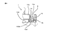
次に、ソレノイド装置1の構成について説明する。図2は、実施の形態1によるソレノイド装置の一部分を示す斜視図、図4は、実施の形態1によるソレノイド装置におけるボビンに、サージ吸収素子が取り付けられた状態を示す側面図、図5は、実施の形態1によるソレノイド装置におけるボビンに、サージ吸収素子が取り付けられた状態を示す上面図である。
Next, the configuration of the
図2、図4、および図5において、合成樹脂製のボビン10は、中央部に貫通穴を有する円筒形状に形成されたコイル巻回部101と、コイル巻回部101の軸方向の一方の端部に設けられた第1のフランジ部102と、コイル巻回部101の軸方向の他方の端部に設けられた第2のフランジ部103とを備えている。第1のフランジ部102には、第1のコイル端子131と第2のコイル端子132とをボビン10の外部へ導出するための2つの切り欠き部104(図2には、一方の切り欠き部104のみが図示されている)が設けられている。
2, 4, and 5, the
コイル5は、第1のフランジ部102の一方の切り欠き部104からボビン10のコイル巻回部101の外周面に導入されてコイル巻回部101の外周面に巻回され、他方の切り欠き部104からボビン10の外部に導出される。2つの切り欠き部104からボビン10の外部に導出されたコイル5の導体は、それぞれ前述の第1のコイル端子131と第2のコイル端子132を形成する。
The coil 5 is introduced from one
第1のフランジ部102の軸方向の端部は、ボビン10の軸方向に対して直交する環状の平面部102aと、平面部102aからボビン10の軸方向でコイル5側に切り下げられた切り下げ面部102bと、有する。切り下げ面部102bは、環状の平面部102aの外周縁部の近傍の一部分を切り下げて形成されている。
The axial end of the
支持壁14は、第1のフランジ部102の切り下げ面部102bに一端部が固定され、切り下げ面部102bからボビン10の軸方向に起立し、その自由端の近傍に第1のフランジ部102の径方向の外側に突出する凸部14aを備えている。凸部14aは、切り下げ面部102bの表面に対して平行に延びるように、固定壁15に対向する支持壁14の壁面に設けられている。支持壁14は、弾力性を有する材料、たとえば弾力性を有する合成樹脂により構成されている。
The
固定壁15は、第1のフランジ部102の切り下げ面部102bの外周縁部に一端部が固定され、ボビン10の軸方向に起立するように設けられている。固定壁15は、支持壁14およびその凸部14aに対して空間を介して対向している。凸部14aは、支持壁14と固定壁15とにより形成された空間内に突出するように設けられている。
One end of the fixed
なお、支持壁14と固定壁15は、第1のフランジ部102と同一材料で一体に形成されていてもよいし、あるいは、第1のフランジ部102とは別体に構成された支持壁14と固定壁15を、第1のフランジ部102にそれぞれ前述のように設けるようにしてもよい。
The
第1のフランジ部102の平面部102aには、正極端子11を保持するための第1の突起部105と、負極端子12を保持するための第2の突起部106とが設けられている。第1の突起部105と第2の突起部106は、それぞれ第1のフランジ部102の平面部102aからボビン10の軸方向に突出するように設けられ、ボビン10の貫通穴を介して対峙するように配置されている。第1の突起部105と第2の突起部106は、それぞれ、第1のフランジ部102と一体に形成されている。なお、第1のフランジ部102とは別体に形成された第1の突起部105と第2の突起部106を、それぞれ第1のフランジ部102の平面部102aに前述のように設けるようにしてもよい。
A
正極端子11は、第1の突起部105にボビン10の軸方向に挿入され、第1の突起部105を介して第1のフランジ部102の平面部102aに固定されている。負極端子12は、第2の突起部106にボビン10の軸方向に挿入され、第2の突起部106を介して第1のフランジ部102の平面部102aに固定されている。
The positive electrode terminal 11 is inserted into the
正極端子11は、第1の突起部105に挿入された基部から、第1のフランジ部102の平面部102aに沿って延びる第1の延出部11aと第2の延出部11bとを備えている。第1の延出部11aと第2の延出部11bは、第1の突起部105からそれぞれ逆方向に延びるように延出されている。
The positive electrode terminal 11 includes a
正極端子11の第1の延出部11aと第2の延出部11bは、それぞれ第1の突起部105に設けられた切り欠き部から、第1の突起部105の外部に導出されている。正極端子11の第1の延出部11aは、第1のコイル端子131に溶接又はロウ付けなどにより電気的に接合されている。正極端子11の第2の延出部11bは、図5に良く示されるように、第2の延出部11bから、第1のフランジ部102の径方向の外側に屈曲し、裏面が切り下げ面部102bと対向するように配置された第1の接続端子部11b1を備えている。第1の接続端子部11b1の裏面は、第1のフランジ部102の切り下げ面部102bの表面に当接している。
The
負極端子12は、第2の突起部106に挿入された基部から、第1のフランジ部102の平面部102aに沿って延びる延出部12aを備えている。負極端子12の延出部12aは、第2の突起部106に設けられた切り欠き部から、第2の突起部106の外部に導出されている。負極端子12の延出部12aは、第2のコイル端子132に溶接又はロウ付けなどにより電気的に接続されている。また、負極端子12の延出部12aは、図4、および図5に良く示されるように、負極端子12の延出部12aから、第1のフランジ部102の径方向の外側に屈曲し、裏面が切り下げ面部102bと対向するように配置された第2の接続端子部12a1を備えている。第2の接続端子部12a1の裏面は、第1のフランジ部102の切り下げ面部102bの表面に当接している。
The
正極端子11の第2の延出部11bにおける第1の接続端子部11b1の表面と、負極端子12の延出部12aにおける第2の接続端子部12a1の表面は、支持壁14と固定壁15の間に形成された空間を介して対峙するように配置されている。
The surface of the first connection terminal portion 11b1 on the
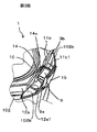
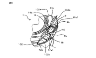
つぎに、サージ吸収素子としてのダイオード9を、ソレノイド装置1におけるボビン10に取り付ける手順について説明する。図3Aは、実施の形態1によるソレノイド装置におけるボビンに、サージ吸収素子を取り付ける手順を示す説明図であって、サージ吸収素子としてのダイオード9をボビン10に取り付ける前の状態を示している。図3Bは、実施の形態1によるソレノイド装置におけるボビンに、サージ吸収素子を取り付ける手順を示す説明図であって、サージ吸収素子としてのダイオード9をボビン10に取り付けた後の状態を示している。
Next, a procedure for attaching the
図3Aに示されるように、サージ吸収素子としてのダイオード9には、基板実装などに用いられる面実装タイプのダイオードが用いられる。このダイオード9は、たとえば、表面と裏面の形状が長方形状に形成された比較的薄型のパッケージとして構成されており、互いに対向する短辺側の側面部に、それぞれ、ダイオード9の第2の端子としてのアノード端子9aと、ダイオード9の第1の端子としてのカソード端子9bと、が露出して設けられている。
As shown in FIG. 3A, a
図3Aに示すように、ダイオード9をボビン10に取り付ける前は、ボビン10に設けられた固定壁15と支持壁14との間の空間に、正極端子11の第1の接続端子部11b1と、負極端子12の第2の接続端子部12a1とが露出した状態にある。図3Aの状態で、ダイオード9をボビン10に取り付けるには、ダイオード9の互いに対向する一対の長辺部を、固定壁15と支持壁14の互いに対向する壁面に平行となるようにそれぞれ対応させ、固定壁15と支持壁14の上端部側から、ボビン10の軸方向に、ダイオード9を第1のフランジ部102の方向に押し入れる。
As shown in FIG. 3A, before the
ダイオード9が支持壁14に設けられた凸部14aを通過するとき、凸部14aがダイオード9の側面に第1のフランジ部102の径方向の内側に押圧されるので、弾力性を有する支持壁14は第1のフランジ部102の径方向の内側に撓むが、ダイオード9が凸部14aを通過すれば、弾力性を有する支持壁14は元の位置に復帰する。ダイオード9は、凸部14aを通過したのち、正極端子11の第1の接続端子部11b1の表面と負極端子12の第2の接続端子部12a1の表面に載置され、図3Bに示す状態となる。
When the
図3Bに示す状態では、ダイオード9は固定壁15と支持壁14との間の空間に保持され、ダイオード9のカソード端子9bと正極端子11の第1の接続端子部11b1との電気的接続と、ダイオード9のアノード端子9aと負極端子12の第2の接続端子部12a1との電気的接続とが行われた状態にある。凸部14aが支持壁14に設けられている切り下げ面部102bからの高さ位置は、ダイオード9のカソード端子9bと第1の接続端子部11b1との間に接触圧力を与えて、これらの電気的接続を維持し、かつ、ダイオード9のアノード端子9aと第2の接続端子部12a1との間に接触圧力を与えて、これらの電気的接続を維持することが可能な位置、に設定されている。
In the state shown in FIG. 3B, the
図3Bにおいて、サージ吸収素子としてのダイオード9は、支持壁14の弾性力に基づいて、支持壁14に設けられた凸部14aにより、第1のフランジ部102の端面側、つまり切り下げ面部102b側に押し付けられた状態にある。
In FIG. 3B, the
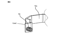
図6は、実施の形態1によるソレノイド装置における、ダイオードと接続端子部との電気的接続の別の例を示す斜視図である。ダイオード9に流れる電流が大きい場合、あるいは、より安定した電気的接続を必要とする場合は、ダイオード9のアノード端子9aは、負極端子12の第2の接続端子部12a1に、接合部材としての、はんだ付けによるはんだ接合部16により電気的に接続され、同様に、ダイオード9のカソード端子9bは、正極端子11の第1の接続端子部11b1に、接合部材としての、はんだ付けによるはんだ接合部(図示せず)により電気的に接続される。
FIG. 6 is a perspective view showing another example of electrical connection between the diode and the connection terminal portion in the solenoid device according to
なお、実施の形態1によるソレノイド装置において、凸部14aは、固定壁15の支持壁14に対向する側の壁面に設けられていてもよい。さらには、凸部14aは、支持壁14と固定壁15の相対向する壁面にそれぞれ設けられていてもよい。
In the solenoid device according to
以上説明したように、実施の形態1によるソレノイド装置によれば、比較的小型の面実装タイプのサージ吸収素子をボビン上に設置することで、サージ吸収素子の取り付けが容易でかつ小型化したソレノイド装置を提供することができる。 As described above, according to the solenoid device according to the first embodiment, by installing a relatively small surface-mount type surge absorbing element on the bobbin, the surge absorbing element can be easily attached and the solenoid can be downsized. Equipment can be provided.
また、実施の形態1によるスタータは、リレー装置を介して付勢されるコイルと、コイルが付勢されたときエンジンを始動させるモータを駆動させるソレノイドスイッチとを有し、ソレノイド装置として、前述の実施の形態1によるソレノイド装置を用いるように構成される。実施の形態1によるスタータによれば、小型化したスタータを提供することができる。
Further, the starter according to
実施の形態2.
つぎに、実施の形態2によるソレノイド装置について説明する。図7は、実施の形態2によるソレノイド装置における、サージ吸収素子と接続端子部との電気的接続を示す上面図、図8は、実施の形態2によるソレノイド装置における、接続端子部を示す斜視図である。実施の形態2では、正極端子における第1の接続端子部と、負極端子における第2の接続端子部と、に対するサージ吸収素子としてのダイオードの電気的接続を、コイルバネの弾性力を用いて行なうようにしたものである。下記に述べる構成以外は、実施の形態1によるソレノイド装置と同様である。
Next, a solenoid device according to
図7、および図8において、正極端子11の第2の延出部11bは、屈曲部11b2と、第1の接続端子部11b3とを備えている。屈曲部11b2は、正極端子11の第2の延出部11bから、第1のフランジ部102の径方向の外側に屈曲し、裏面が切り下げ面部102bに当接している。第1の接続端子部11b3は、屈曲部11b2から反切り下げ面部102b側に屈曲してボビン10の軸方向に起立するように形成されている。第1の接続端子部11b3におけるダイオード9側の表面には、突出部20が設けられている。突出部20は、たとえば、第1の接続端子部11b3から板金加工などで打ち出して形成されている。
7 and 8, the
負極端子12の延出部12aは、第1のフランジ部102の径方向の外側に屈曲した第2の接続端子部12a2を備えている。第2の接続端子部12a2におけるダイオード9側の表面は、第1の接続端子部11b3のダイオード9側の表面と、突出部20の表面とに対して、支持壁14と固定壁15とにより形成された空間を介して対向している。コイルバネ18は、一端部が負極端子12の第2の接続端子部12a2におけるダイオード9側の表面に、電気的に接続されるとともに機械的に固定されている。コイルバネ18の他端は自由端とされている。
The extending
ダイオード9をボビン10に取り付けるには、ダイオード9の互いに対向する一対の長辺部を、固定壁15と支持壁14の互いに対向する壁面に平行となるようにそれぞれ対応させ、固定壁15と支持壁14の上端部から、ボビン10の軸方向にダイオード9をボビン10の第1のフランジ部102に向けて押し入れる。このとき、ダイオード9のアノード端子9aは、コイルバネ18を圧縮させつつその自由端に当接され、ダイオード9のカソード端子9bは、正極端子11の第1の接続端子部11b3の突出部20の表面に当接される。
In order to attach the
ダイオード9が支持壁14に設けられた凸部14aを通過するとき、凸部14aが、ダイオード9の側面により第1のフランジ部102の径方向の内側の方向に押圧されるので、支持壁14は第1のフランジ部102の径方向の内側に撓むが、ダイオード9が凸部14aを通過すれば、支持壁14の弾性力により、支持壁14は元の位置に復帰する。凸部14aを通過したダイオード9は、元の位置に復帰した支持壁14と固定壁15との間に形成された空間に保持される。このとき、凸部14aは、支持壁14の弾性力に基づいて、保持されたダイオード9を、第1のフランジ部102の端面である切り下げ面部102b側に押圧した状態となる。
When the
この状態において、ダイオード9の第2の端子としてのアノード端子9aは、コイルバネ18の自由端に電気的に接続され、コイルバネ18と第2の接続端子部12a2を介して負極端子12に接続される。また、ダイオード9の第1の端子としてのカソード端子9bは、第1の接続端子部11b3に設けられた突出部20に電気的に接続され、突出部20と第1の接続端子部11b3を介して正極端子11に接続される。
In this state, the
以上説明したように、実施の形態2によるソレノイド装置によれば、接続端子部に対するサージ吸収素子としてのダイオード9の電気的接続を、接続端子部に設けられたコイルバネの弾性力を用いて行なうようにしたので、サージ吸収素子の取り付けが容易でかつ小型化したソレノイド装置を提供することができる。
As described above, according to the solenoid device according to the second embodiment, the electrical connection of the
また、実施の形態2によるスタータは、リレー装置を介して付勢されるコイルと、コイルが付勢されたときエンジンを始動させるモータを駆動させるソレノイドスイッチとを有し、ソレノイド装置として、前述の実施の形態2によるソレノイド装置を用いるように構成される。実施の形態2によるスタータによれば、小型化したスタータを提供することができる。
The starter according to the second embodiment has a coil that is energized via a relay device, and a solenoid switch that drives a motor that starts the engine when the coil is energized. It is configured to use the solenoid device according to the second embodiment. According to the starter according to
実施の形態3.
つぎに、実施の形態3によるソレノイド装置について説明する。図9は、実施の形態3によるソレノイド装置における、サージ吸収素子と接続端子部の電気的接続を示す上面図、図10は、実施の形態3によるソレノイド装置における、接続端子部を示す斜視図である。実施の形態3によるソレノイド装置は、正極端子における第1の接続端子部と、負極端子における第2の接続端子部と、に対するサージ吸収素子としてのダイオードの電気的接続を、板バネ部の弾性力を用いて行なうようにしたものである。下記に述べる構成以外は、実施の形態1によるソレノイド装置と同様である。Embodiment 3.
Next, a solenoid device according to Embodiment 3 will be described. 9 is a top view showing the electrical connection between the surge absorbing element and the connecting terminal portion in the solenoid device according to the third embodiment, and FIG. 10 is a perspective view showing the connecting terminal portion in the solenoid device according to the third embodiment. be. In the solenoid device according to the third embodiment, the elastic force of the leaf spring portion is used to electrically connect the diode as a surge absorbing element to the first connection terminal portion of the positive terminal and the second connection terminal portion of the negative electrode terminal. This is done using The configuration other than that described below is the same as the solenoid device according to the first embodiment.
図9、および図10において、正極端子11の第2の延出部11bは、屈曲部11b2と、第1の接続端子部11b3とを備えている。屈曲部11b2は、正極端子11の第2の延出部11bから、第1のフランジ部102の径方向の外側に屈曲し、裏面が切り下げ面部102bに当接している。第1の接続端子部11b3は、屈曲部11b2から反切り下げ面部102b側に屈曲して起立している。第1の接続端子部11b3のダイオード9側の表面には、突出部20が設けられている。突出部20は、たとえば、第1の接続端子部11b3から板金加工などで打ち出して形成されている。
9 and 10, the
負極端子12の延出部12aは、第1のフランジ部102の径方向の外側に屈曲した第2の接続端子部12a2を備えている。第2の接続端子部12a2のダイオード9側の表面は、第1の接続端子部11b3のダイオード9側の表面と突出部20の表面とに対して、支持壁14と固定壁15との間に形成された空間を介して対向している。ターミナル22は、負極端子12の第2の接続端子部12a2のダイオード9側の表面に、溶接、又は、ろう付けなどにより接合されることで、第2の接続端子部12a2に電気的に接続されている。ターミナル22は、板金加工などによりターミナル22と一体に形成された板バネ部23を備えている。板バネ部23は、弾力性を有し、その自由端がダイオード9側に突出している。
The extending
ダイオード9をボビン10に取り付けるには、ダイオード9の互いに対向する一対の長辺部を、固定壁15と支持壁14の互いに対向する壁面に平行となるようにそれぞれ対応させ、固定壁15と支持壁14の上端部側から、ボビン10の軸方向にダイオード9をボビン10の第1のフランジ部102の方向に押し入れる。このとき、ダイオード9のアノード端子9aは、板バネ部23を、その弾性力に抗して第2の接続端子部12a2側に撓ませつつ、板バネ部23に当接される。同時に、ダイオード9のカソード端子9bは、板バネ部23の弾性力により、正極端子11の第1の接続端子部11b3に設けられた突出部20の表面に圧接される。
In order to attach the
ダイオード9が支持壁14の凸部14aを通過するとき、凸部14aがダイオード9の側面により第1のフランジ部102の径方向の内側に押圧されるので、支持壁14は第1のフランジ部102の径方向の内側に撓むが、ダイオード9が凸部14aを通過すれば、支持壁14の弾性力により、支持壁14は元の位置に復帰する。ダイオード9は、凸部14aを通過したのち、アノード端子9aが、板バネ部23に圧接されて電気的に接続されるとともに、カソード端子9bが、正極端子11の第1の接続端子部11b3の突出部20に圧接されて電気的に接続された状態で、第1のフランジ部102の切り下げ面部102bの表面に載置される。
When the
凸部14aを通過したダイオード9は、元の位置に復帰した支持壁14と固定壁15との間に形成された空間に保持される。このとき、凸部14aは、支持壁14の弾性力に基づいて、保持されたダイオード9を、第1のフランジ部102の端面である切り下げ面部102b側に押圧した状態となる。
The
以上説明したように、実施の形態3によるソレノイド装置によれば、接続端子部に対するサージ吸収素子としてのダイオード9の電気的接続を、接続端子部に設けられたターミナルの板バネ部の弾性力を用いて行なうようにしたので、サージ吸収素子の取り付けが容易でかつ小型化したソレノイド装置を提供することができる。
As described above, according to the solenoid device according to the third embodiment, the electrical connection of the
また、実施の形態3によるスタータは、リレー装置を介して付勢されるコイルと、コイルが付勢されたときエンジンを始動させるモータを駆動させるソレノイドスイッチとを有し、ソレノイド装置として、前述の実施の形態3によるソレノイド装置を用いるように構成される。実施の形態3によるスタータによれば、小型化したスタータを提供することができる。 The starter according to the third embodiment has a coil that is energized via a relay device, and a solenoid switch that drives a motor that starts the engine when the coil is energized. It is configured to use the solenoid device according to the third embodiment. According to the starter according to Embodiment 3, a compact starter can be provided.
なお、前述の各実施の形態によるソレノイド装置は、コイルに発生するサージ電圧を吸収するサージ吸収素子を装着したものとして説明したが、サージ吸収素子を装着し得るように構成されているので、ユーザサイドで、サージ吸収素子を本願によるソレノイド装置に装着するようにしてもよい。 Although the solenoid device according to each of the above-described embodiments has been described as having a surge absorbing element that absorbs the surge voltage generated in the coil, it is configured so that the surge absorbing element can be mounted. At the side, a surge absorbing element may be attached to the solenoid device according to the present application.
本願は、様々な例示的な実施の形態及び実施例が記載されているが、1つ、または複数の実施の形態に記載された様々な特徴、態様、及び機能は特定の実施の形態の適用に限られるのではなく、単独で、または様々な組み合わせで実施の形態に適用可能である。従って、例示されていない無数の変形例が、本願に開示される技術の範囲内において想定される。例えば、少なくとも1つの構成要素を変形する場合、追加する場合または省略する場合、さらには、少なくとも1つの構成要素を抽出し、他の実施の形態の構成要素と組み合わせる場合が含まれるものとする。 While this application describes various exemplary embodiments and examples, various features, aspects, and functions described in one or more embodiments may not apply to particular embodiments. can be applied to the embodiments singly or in various combinations. Therefore, countless modifications not illustrated are envisioned within the scope of the technology disclosed in the present application. For example, modification, addition or omission of at least one component, extraction of at least one component, and combination with components of other embodiments shall be included.
本願によるソレノイド装置は、電磁継電器の分野、さらには、電磁継電器を用いたエンジンのスタータを有する自動車などの車両の分野に利用することができる。 The solenoid device according to the present application can be used in the field of electromagnetic relays and further in the field of vehicles such as automobiles having engine starters using electromagnetic relays.
1 ソレノイド装置、2 リレー装置、3 バッテリ、4 リレー接点、5 コイル、131 第1のコイル端子、132 第2のコイル端子、6 プランジャ、7 ソレノイドスイッチ、711 第1の固定接点、712 第2の固定接点、72 可動接点、8 モータ、9 ダイオード、9a アノード端子、9b カソード端子、10 ボビン、101 コイル巻回部、102 第1のフランジ部、102a 平面部、102b 切り下げ面部、103 第2のフランジ部、104 切り欠き部、105 第1の突起部、106 第2の突起部、11 正極端子、11a 第1の延出部、11b 第2の延出部、11b1、11b3 第1の接続端子部、12a1、12a2 第2の接続端子部、11b2 屈曲部、12 負極端子、12a 延出部、131 第1のコイル端子、132 第2のコイル端子、14 支持壁、14a 凸部、15 固定壁、16 はんだ接合部、18 コイルバネ、20 突出部、22 ターミナル、23 板バネ部
1
Claims (8)
前記コイル巻回部に巻回され、前記フランジ部から前記ボビンの外部に導出された第1のコイル端子と第2のコイル端子とを有するコイルと、
前記フランジ部に固定され、前記第1のコイル端子に電気的に接続された正極端子と、
前記フランジ部に固定され、前記第2のコイル端子に電気的に接続された負極端子と、
を有し、
前記正極端子にサージ吸収素子の第1の端子を電気的に接続し、前記負極端子に前記サージ吸収素子の第2の端子を電気的に接続し得るように構成されたソレノイド装置であって、
前記フランジ部は、軸方向に直交して延びる平面部と、前記平面部から前記コイル側に切り下げられた切り下げ面と、を有し、
前記切り下げ面の軸方向の端面に設けられ、前記軸方向に起立する固定壁と、
前記切り下げ面の軸方向の端面に設けられ、前記軸方向に起立し、前記固定壁に対して空間を介して対向する支持壁と、
前記支持壁と前記固定壁とのうちの少なくとも一方に設けられ、前記空間内に突出する凸部と、
を備え、
前記固定壁と前記支持壁は、前記空間内に少なくとも一部分が配置された前記サージ吸収素子を保持し得るように構成され、
前記凸部は、前記支持壁の弾性力に基づいて、前記保持された前記サージ吸収素子を前記切り下げ面の前記軸方向の端面側に押圧し得るように構成されている、
ことを特徴とするソレノイド装置。 a bobbin having a flange on at least one axial end of the coil winding;
a coil wound around the coil winding portion and having a first coil terminal and a second coil terminal led out of the bobbin from the flange portion;
a positive terminal fixed to the flange portion and electrically connected to the first coil terminal;
a negative terminal fixed to the flange portion and electrically connected to the second coil terminal;
has
A solenoid device configured to electrically connect a first terminal of a surge absorbing element to the positive terminal and electrically connect a second terminal of the surge absorbing element to the negative terminal,
The flange portion has a flat portion extending orthogonally to the axial direction and a cut-down surface cut down from the flat portion toward the coil,
a fixed wall provided on an axial end surface of the undercut surface and erected in the axial direction ;
a support wall provided on an end face in the axial direction of the undercut surface , erected in the axial direction, and opposed to the fixed wall with a space therebetween;
a convex portion provided on at least one of the support wall and the fixed wall and protruding into the space;
with
The fixed wall and the support wall are configured to hold the surge absorbing element at least partially disposed within the space,
The convex portion is configured to press the held surge absorbing element against the axial end surface side of the undercut surface based on the elastic force of the support wall.
A solenoid device characterized by:
前記フランジ部に設けられ、前記負極端子に電気的に接続された第2の接続端子部と、
を備え、
前記第1の接続端子部は、前記保持された前記サージ吸収素子の前記第1の端子に、前記押圧に基づいて電気的に接続され得るように構成され、
前記第2の接続端子部は、前記保持された前記サージ吸収素子の前記第2の端子に、前記押圧に基づいて電気的に接続され得るように構成されている、
ことを特徴とする請求項1に記載のソレノイド装置。 a first connection terminal portion provided on the flange portion and electrically connected to the positive electrode terminal;
a second connection terminal portion provided on the flange portion and electrically connected to the negative electrode terminal;
with
The first connection terminal portion is configured to be electrically connected to the first terminal of the held surge absorption element based on the pressure,
The second connection terminal portion is configured to be electrically connected to the second terminal of the held surge absorption element based on the pressure,
2. The solenoid device according to claim 1, characterized in that:
前記フランジ部に設けられ、前記負極端子に電気的に接続された第2の接続端子部と、
を備え、
前記第1の接続端子部は、前記保持された前記サージ吸収素子の前記第1の端子に、接合部材により電気的に接続され得るように構成され、
前記第2の接続端子部は、前記保持された前記サージ吸収素子の前記第2の端子に、接合部材により電気的に接続され得るように構成されている、
ことを特徴とする請求項1に記載のソレノイド装置。 a first connection terminal portion provided on the flange portion and electrically connected to the positive electrode terminal;
a second connection terminal portion provided on the flange portion and electrically connected to the negative electrode terminal;
with
The first connection terminal portion is configured to be electrically connected to the first terminal of the held surge absorption element by a joining member,
The second connection terminal portion is configured to be electrically connected to the second terminal of the held surge absorption element by a joining member,
2. The solenoid device according to claim 1, characterized in that:
前記フランジ部に設けられ、前記負極端子に電気的に接続された第2の接続端子部と、
前記第1の接続端子部と前記第2の接続端子部のうちの少なくとも一方に電気的に接続されたコイルバネと、
を備え、
前記第1の接続端子部と前記サージ吸収素子の前記第1の端子との電気的接続と、前記第2の接続端子部と前記サージ吸収素子の前記第2の端子との電気的接続と、のうちの少なくとも一方の電気的接続は、前記コイルバネを介して行われ得るように構成され、
前記コイルバネの弾性力に基づいて、前記それぞれの電気的接続が維持され得るように構成されている、
ことを特徴とする請求項1に記載のソレノイド装置。 a first connection terminal portion provided on the flange portion and electrically connected to the positive electrode terminal;
a second connection terminal portion provided on the flange portion and electrically connected to the negative electrode terminal;
a coil spring electrically connected to at least one of the first connection terminal portion and the second connection terminal portion;
with
electrical connection between the first connection terminal portion and the first terminal of the surge absorption element; electrical connection between the second connection terminal portion and the second terminal of the surge absorption element; At least one of the electrical connection is configured to be made through the coil spring,
configured so that the respective electrical connections can be maintained based on the elastic force of the coil spring;
2. The solenoid device according to claim 1, characterized in that:
前記フランジ部に設けられ、前記負極端子に電気的に接続された第2の接続端子部と、
前記第1の接続端子部と前記第2の接続端子部のうちの少なくとも一方の接続端子部に電気的に接続された板バネ部と、
を備え、
前記第1の接続端子部と前記サージ吸収素子の前記第1の端子との電気的接続と、前記第2の接続端子部と前記サージ吸収素子の前記第2の端子との電気的接続と、のうちの少なくとも一方の電気的接続は、前記板バネ部を介して行われ得るように構成され、
前記板バネ部の弾性力に基づいて、前記それぞれの電気的接続が維持され得るように構成されている、
ことを特徴とする請求項1に記載のソレノイド装置。 a first connection terminal portion provided on the flange portion and electrically connected to the positive electrode terminal;
a second connection terminal portion provided on the flange portion and electrically connected to the negative electrode terminal;
a leaf spring portion electrically connected to at least one of the first connection terminal portion and the second connection terminal portion;
with
electrical connection between the first connection terminal portion and the first terminal of the surge absorption element; electrical connection between the second connection terminal portion and the second terminal of the surge absorption element; Electrical connection of at least one of is configured to be performed via the leaf spring portion,
The respective electrical connections are configured to be maintained based on the elastic force of the leaf spring portion.
2. The solenoid device according to claim 1, characterized in that:
ことを特徴とする請求項2から5のうちの何れか一項に記載のソレノイド装置。 The first connection terminal portion and the second connection terminal portion are arranged on the undercut surface,
6. A solenoid device according to any one of claims 2 to 5, characterized in that:
前記負極端子は、前記フランジ部の前記平面部に沿って延びる延出部を有し、
前記第1の接続端子部は、前記正極端子の前記延出部に電気的に接続され、
前記第2の接続端子部は、前記負極端子の前記延出部に電気的に接続されている、
ことを特徴とする請求項6に記載のソレノイド装置。 the positive electrode terminal has an extending portion extending along the flat portion of the flange portion;
the negative electrode terminal has an extending portion extending along the flat portion of the flange portion;
The first connection terminal portion is electrically connected to the extension portion of the positive electrode terminal,
The second connection terminal portion is electrically connected to the extension portion of the negative electrode terminal,
7. The solenoid device according to claim 6, characterized in that:
前記リレー装置が駆動されたとき前記リレー接点を介して付勢されるコイルと、前記コイルが付勢されたとき閉路するソレノイドスイッチと、を有するソレノイド装置と、
前記コイルに発生するサージ電圧を吸収するサージ吸収素子と、
前記ソレノイドスイッチが閉路したとき駆動されてエンジンを始動させるモータと、
を備えたスタータであって、
前記ソレノイド装置は、請求項1から7のうちの何れか一項に記載のソレノイド装置により構成されている、
ことを特徴とするスタータ。 a relay device driven by an engine start signal to close the relay contacts;
a solenoid device having a coil that is energized via the relay contacts when the relay device is energized; and a solenoid switch that is closed when the coil is energized;
a surge absorbing element that absorbs a surge voltage generated in the coil;
a motor driven to start the engine when the solenoid switch is closed;
a starter comprising
The solenoid device is configured by the solenoid device according to any one of claims 1 to 7,
A starter characterized by:
Applications Claiming Priority (1)
| Application Number | Priority Date | Filing Date | Title |
|---|---|---|---|
| PCT/JP2019/042507 WO2021084637A1 (en) | 2019-10-30 | 2019-10-30 | Solenoid device and starter |
Publications (2)
| Publication Number | Publication Date |
|---|---|
| JPWO2021084637A1 JPWO2021084637A1 (en) | 2021-05-06 |
| JP7203242B2 true JP7203242B2 (en) | 2023-01-12 |
Family
ID=75714947
Family Applications (1)
| Application Number | Title | Priority Date | Filing Date |
|---|---|---|---|
| JP2021553947A Active JP7203242B2 (en) | 2019-10-30 | 2019-10-30 | Solenoid device and starter |
Country Status (5)
| Country | Link |
|---|---|
| US (1) | US20220359112A1 (en) |
| JP (1) | JP7203242B2 (en) |
| CN (1) | CN114600215A (en) |
| DE (1) | DE112019007863T5 (en) |
| WO (1) | WO2021084637A1 (en) |
Citations (2)
| Publication number | Priority date | Publication date | Assignee | Title |
|---|---|---|---|---|
| JP2006210013A (en) | 2005-01-25 | 2006-08-10 | Jidosha Denki Kogyo Co Ltd | Electromagnetic relay |
| JP2009021186A (en) | 2007-07-13 | 2009-01-29 | Mitsuba Corp | Electromagnetic relay |
Family Cites Families (11)
| Publication number | Priority date | Publication date | Assignee | Title |
|---|---|---|---|---|
| JPS6375930A (en) * | 1986-09-19 | 1988-04-06 | Fujitsu Ltd | Fast complement forming circuit |
| JPS6375930U (en) * | 1986-11-05 | 1988-05-20 | ||
| JP3498355B2 (en) * | 1994-04-28 | 2004-02-16 | 株式会社デンソー | Electromagnetic clutch |
| JP3726114B2 (en) * | 1997-05-14 | 2005-12-14 | 株式会社デンソー | Compressor control valve |
| US7282328B2 (en) | 2002-09-20 | 2007-10-16 | New England Biolabs, Inc. | Helicase dependent amplification of nucleic acids |
| JP2005026637A (en) * | 2003-07-04 | 2005-01-27 | Matsushita Electric Ind Co Ltd | Coil end processing method and bobbin used therefor |
| KR100652246B1 (en) * | 2005-07-20 | 2006-12-01 | 우리산업 주식회사 | A electric power connection part of magnetic clutch field coil assembly connected with vehicle compressor |
| JP5071453B2 (en) * | 2009-08-20 | 2012-11-14 | 富士電機機器制御株式会社 | Magnetic contactor |
| WO2015091202A1 (en) * | 2013-12-19 | 2015-06-25 | Koninklijke Philips N.V. | High voltage transformer comprising a coil bobbin for carrying a high voltage winding |
| JP6176345B2 (en) * | 2016-03-01 | 2017-08-09 | 株式会社デンソー | Manufacturing method of electromagnetic clutch |
| US11257614B2 (en) * | 2017-11-03 | 2022-02-22 | Cyntec Co., Ltd. | Integrated vertical inductor |
-
2019
- 2019-10-30 CN CN201980101609.9A patent/CN114600215A/en not_active Withdrawn
- 2019-10-30 JP JP2021553947A patent/JP7203242B2/en active Active
- 2019-10-30 WO PCT/JP2019/042507 patent/WO2021084637A1/en active Application Filing
- 2019-10-30 DE DE112019007863.1T patent/DE112019007863T5/en active Pending
- 2019-10-30 US US17/619,956 patent/US20220359112A1/en not_active Abandoned
Patent Citations (2)
| Publication number | Priority date | Publication date | Assignee | Title |
|---|---|---|---|---|
| JP2006210013A (en) | 2005-01-25 | 2006-08-10 | Jidosha Denki Kogyo Co Ltd | Electromagnetic relay |
| JP2009021186A (en) | 2007-07-13 | 2009-01-29 | Mitsuba Corp | Electromagnetic relay |
Also Published As
| Publication number | Publication date |
|---|---|
| JPWO2021084637A1 (en) | 2021-05-06 |
| DE112019007863T5 (en) | 2022-08-11 |
| WO2021084637A1 (en) | 2021-05-06 |
| US20220359112A1 (en) | 2022-11-10 |
| CN114600215A (en) | 2022-06-07 |
Similar Documents
| Publication | Publication Date | Title |
|---|---|---|
| US8274345B2 (en) | Electromagnetic relay | |
| US7038563B2 (en) | Electromagnetic switch for starter | |
| JP3985628B2 (en) | Switchgear | |
| JP2002237241A (en) | Electromagnetic relay | |
| JP2018181495A (en) | Electromagnetic relay | |
| KR20010022285A (en) | Method for producing a relay | |
| JP7203242B2 (en) | Solenoid device and starter | |
| JP2007207494A (en) | Electromagnetic relay | |
| JP4858508B2 (en) | Electromagnetic switchgear | |
| JP2562735Y2 (en) | Small motor | |
| JP2011204374A (en) | Electromagnetic relay | |
| US5889451A (en) | electromagnetic relay and its use on a printed circuit board | |
| JP2014154496A (en) | Electromagnetic relay | |
| US8558649B2 (en) | Electromagnetic contact device | |
| JP2009104951A (en) | Electromagnetic relay | |
| JP3035467U (en) | Small motor | |
| CN111863537A (en) | Contact device and electromagnetic relay | |
| JPH0117792Y2 (en) | ||
| JP2009016276A (en) | Electromagnetic relay | |
| JP2004127581A (en) | Electromagnetic relay | |
| JP5525672B2 (en) | Electromagnetic relay yoke structure | |
| CN212365865U (en) | Contact device, electromagnetic relay, and device provided with electromagnetic relay | |
| JP2006210013A (en) | Electromagnetic relay | |
| JPH0717117Y2 (en) | Electric horn | |
| JP3906589B2 (en) | Relay module |
Legal Events
| Date | Code | Title | Description |
|---|---|---|---|
| A621 | Written request for application examination |
Free format text: JAPANESE INTERMEDIATE CODE: A621 Effective date: 20211122 |
|
| A131 | Notification of reasons for refusal |
Free format text: JAPANESE INTERMEDIATE CODE: A131 Effective date: 20220906 |
|
| A521 | Request for written amendment filed |
Free format text: JAPANESE INTERMEDIATE CODE: A523 Effective date: 20221017 |
|
| TRDD | Decision of grant or rejection written | ||
| A01 | Written decision to grant a patent or to grant a registration (utility model) |
Free format text: JAPANESE INTERMEDIATE CODE: A01 Effective date: 20221206 |
|
| A61 | First payment of annual fees (during grant procedure) |
Free format text: JAPANESE INTERMEDIATE CODE: A61 Effective date: 20221226 |
|
| R151 | Written notification of patent or utility model registration |
Ref document number: 7203242 Country of ref document: JP Free format text: JAPANESE INTERMEDIATE CODE: R151 |