JP7203211B2 - Automotive object detection system - Google Patents
Automotive object detection system Download PDFInfo
- Publication number
- JP7203211B2 JP7203211B2 JP2021519091A JP2021519091A JP7203211B2 JP 7203211 B2 JP7203211 B2 JP 7203211B2 JP 2021519091 A JP2021519091 A JP 2021519091A JP 2021519091 A JP2021519091 A JP 2021519091A JP 7203211 B2 JP7203211 B2 JP 7203211B2
- Authority
- JP
- Japan
- Prior art keywords
- object detection
- target
- vehicle
- detection device
- abnormality
- Prior art date
- Legal status (The legal status is an assumption and is not a legal conclusion. Google has not performed a legal analysis and makes no representation as to the accuracy of the status listed.)
- Active
Links
Images


Classifications
-
- G—PHYSICS
- G01—MEASURING; TESTING
- G01S—RADIO DIRECTION-FINDING; RADIO NAVIGATION; DETERMINING DISTANCE OR VELOCITY BY USE OF RADIO WAVES; LOCATING OR PRESENCE-DETECTING BY USE OF THE REFLECTION OR RERADIATION OF RADIO WAVES; ANALOGOUS ARRANGEMENTS USING OTHER WAVES
- G01S13/00—Systems using the reflection or reradiation of radio waves, e.g. radar systems; Analogous systems using reflection or reradiation of waves whose nature or wavelength is irrelevant or unspecified
- G01S13/88—Radar or analogous systems specially adapted for specific applications
- G01S13/93—Radar or analogous systems specially adapted for specific applications for anti-collision purposes
- G01S13/931—Radar or analogous systems specially adapted for specific applications for anti-collision purposes of land vehicles
-
- G—PHYSICS
- G01—MEASURING; TESTING
- G01S—RADIO DIRECTION-FINDING; RADIO NAVIGATION; DETERMINING DISTANCE OR VELOCITY BY USE OF RADIO WAVES; LOCATING OR PRESENCE-DETECTING BY USE OF THE REFLECTION OR RERADIATION OF RADIO WAVES; ANALOGOUS ARRANGEMENTS USING OTHER WAVES
- G01S13/00—Systems using the reflection or reradiation of radio waves, e.g. radar systems; Analogous systems using reflection or reradiation of waves whose nature or wavelength is irrelevant or unspecified
- G01S13/87—Combinations of radar systems, e.g. primary radar and secondary radar
- G01S13/878—Combination of several spaced transmitters or receivers of known location for determining the position of a transponder or a reflector
-
- G—PHYSICS
- G01—MEASURING; TESTING
- G01S—RADIO DIRECTION-FINDING; RADIO NAVIGATION; DETERMINING DISTANCE OR VELOCITY BY USE OF RADIO WAVES; LOCATING OR PRESENCE-DETECTING BY USE OF THE REFLECTION OR RERADIATION OF RADIO WAVES; ANALOGOUS ARRANGEMENTS USING OTHER WAVES
- G01S7/00—Details of systems according to groups G01S13/00, G01S15/00, G01S17/00
- G01S7/02—Details of systems according to groups G01S13/00, G01S15/00, G01S17/00 of systems according to group G01S13/00
- G01S7/40—Means for monitoring or calibrating
- G01S7/4004—Means for monitoring or calibrating of parts of a radar system
- G01S7/4017—Means for monitoring or calibrating of parts of a radar system of HF systems
-
- G—PHYSICS
- G01—MEASURING; TESTING
- G01S—RADIO DIRECTION-FINDING; RADIO NAVIGATION; DETERMINING DISTANCE OR VELOCITY BY USE OF RADIO WAVES; LOCATING OR PRESENCE-DETECTING BY USE OF THE REFLECTION OR RERADIATION OF RADIO WAVES; ANALOGOUS ARRANGEMENTS USING OTHER WAVES
- G01S13/00—Systems using the reflection or reradiation of radio waves, e.g. radar systems; Analogous systems using reflection or reradiation of waves whose nature or wavelength is irrelevant or unspecified
- G01S13/66—Radar-tracking systems; Analogous systems
- G01S13/72—Radar-tracking systems; Analogous systems for two-dimensional tracking, e.g. combination of angle and range tracking, track-while-scan radar
-
- G—PHYSICS
- G01—MEASURING; TESTING
- G01S—RADIO DIRECTION-FINDING; RADIO NAVIGATION; DETERMINING DISTANCE OR VELOCITY BY USE OF RADIO WAVES; LOCATING OR PRESENCE-DETECTING BY USE OF THE REFLECTION OR RERADIATION OF RADIO WAVES; ANALOGOUS ARRANGEMENTS USING OTHER WAVES
- G01S17/00—Systems using the reflection or reradiation of electromagnetic waves other than radio waves, e.g. lidar systems
- G01S17/87—Combinations of systems using electromagnetic waves other than radio waves
-
- G—PHYSICS
- G01—MEASURING; TESTING
- G01S—RADIO DIRECTION-FINDING; RADIO NAVIGATION; DETERMINING DISTANCE OR VELOCITY BY USE OF RADIO WAVES; LOCATING OR PRESENCE-DETECTING BY USE OF THE REFLECTION OR RERADIATION OF RADIO WAVES; ANALOGOUS ARRANGEMENTS USING OTHER WAVES
- G01S17/00—Systems using the reflection or reradiation of electromagnetic waves other than radio waves, e.g. lidar systems
- G01S17/88—Lidar systems specially adapted for specific applications
- G01S17/93—Lidar systems specially adapted for specific applications for anti-collision purposes
- G01S17/931—Lidar systems specially adapted for specific applications for anti-collision purposes of land vehicles
-
- G—PHYSICS
- G01—MEASURING; TESTING
- G01S—RADIO DIRECTION-FINDING; RADIO NAVIGATION; DETERMINING DISTANCE OR VELOCITY BY USE OF RADIO WAVES; LOCATING OR PRESENCE-DETECTING BY USE OF THE REFLECTION OR RERADIATION OF RADIO WAVES; ANALOGOUS ARRANGEMENTS USING OTHER WAVES
- G01S7/00—Details of systems according to groups G01S13/00, G01S15/00, G01S17/00
- G01S7/48—Details of systems according to groups G01S13/00, G01S15/00, G01S17/00 of systems according to group G01S17/00
- G01S7/497—Means for monitoring or calibrating
Landscapes
- Engineering & Computer Science (AREA)
- Radar, Positioning & Navigation (AREA)
- Remote Sensing (AREA)
- Physics & Mathematics (AREA)
- Computer Networks & Wireless Communication (AREA)
- General Physics & Mathematics (AREA)
- Electromagnetism (AREA)
- Radar Systems Or Details Thereof (AREA)
- Traffic Control Systems (AREA)
Description
本願は、車載用物体検知システムに関するものである。 The present application relates to an in-vehicle object detection system.
従来、車載のレーダ装置において、泥、雪などの付着物による検出性能低下を検出し、レーダ装置の異常を判定するものの一例として以下の特許文献に記載されたものが知られている。すなわち、送信波を複数の物標に送信し、それら物標からの反射波を受信手段で受信し、受信された反射強度に関する受信信号の信号レベルが、故障レベル値の範囲である受信信号の個数をカウントし、カウント値に基づいて故障状態を判定している。 2. Description of the Related Art Conventionally, in a vehicle-mounted radar device, the following Patent Document describes an example of detecting deterioration of detection performance due to adhering matter such as mud and snow and determining abnormality of the radar device. That is, the transmission wave is transmitted to a plurality of targets, the reflected waves from the targets are received by the receiving means, and the signal level of the received signal with respect to the received reflection intensity is within the range of the failure level value. The number is counted, and the failure state is determined based on the count value.
しかし、物標の反射強度は、物標の種別で異なる。例えば、トラックの荷台後部は反射が強く、小型自動車の後部は反射が弱い。また、物標とレーダ装置との距離によっても反射強度は変化する。例えば、物標からレーダ装置までの距離が遠い場合は、反射強度も弱く観測される。 However, the reflection intensity of the target differs depending on the type of target. For example, the rear of a truck bed is highly reflective and the rear of a small car is less reflective. In addition, the reflection intensity also changes depending on the distance between the target and the radar device. For example, when the distance from the target to the radar device is long, the reflected intensity is also observed to be weak.
このような、反射強度の相違により、異常が発生していないのに異常と判定を誤る恐れがある。これに対し、異常と誤判定しないように、異常と判定する際のしきい値を高く設定すると、異常が発生しているにもかかわらず、異常と判定されない恐れも生じる。このため、レーダ装置の異常を正確に異常と判断できない走行シーンが存在する。また、しきい値を超えた回数をカウントするなどの統計的処理は、異常と判定されるまで一定時間が必要となり、異常を早期に発見することができないなどの問題があった。 Due to such a difference in reflection intensity, there is a risk of erroneously determining that there is an abnormality even though no abnormality has occurred. On the other hand, if a high threshold value is set for determining an abnormality so as not to erroneously determine an abnormality, there is a possibility that an abnormality may not be determined even though an abnormality has occurred. Therefore, there are driving scenes in which an abnormality in the radar device cannot be accurately determined as an abnormality. Moreover, statistical processing such as counting the number of times the threshold value is exceeded requires a certain amount of time until an abnormality is determined, and there is a problem that an abnormality cannot be detected early.
本願は、上述のような問題を解決するためのなされたもので、統計的処理を複雑にすることなく、レーダ装置などの物体検知装置の異常の発生を、従来よりも誤りなく判定できる車載用物体検知システムを提供することを目的とする。 The present application has been made to solve the above-mentioned problems. It is an object of the present invention to provide an object detection system.
本願に開示される車載用物体検知システムは、
車両に取り付けられた複数の物体検知装置、
複数の物体検知装置で検出された複数の物標反射レベルを受信する物標反射レベル受信部、
同一の物標もしくは同一種別の物標として検出された2以上の物標の物標反射レベルの差を算出し、差が予め定められた値の範囲を超えているとき、複数の物体検知装置のいずれかに異常があると判定する物体検知装置異常判定部、を備え、
物体検知装置異常判定部は、複数の物体検知装置の覆域同士が重なる領域で検出された複数の物標の位置間の距離が予め定めたしきい値内にあるとき、同一の物標であると決定することを特徴とする。
The in-vehicle object detection system disclosed in the present application includes:
a plurality of object detection devices mounted on a vehicle;
a target reflection level receiver that receives a plurality of target reflection levels detected by a plurality of object detection devices;
A difference in target reflection levels of two or more targets detected as the same target or target of the same type is calculated, and when the difference exceeds a predetermined range of values, a plurality of object detection devices An object detection device abnormality determination unit that determines that there is an abnormality in any of
The object detection device abnormality determination unit detects the same target when the distance between the positions of the plurality of targets detected in the region where the coverage areas of the plurality of object detection devices overlap is within a predetermined threshold value. It is characterized by determining that there is
本願に開示される車載用物体検知システムによれば、複数の物体検知装置で物標反射レベルを比較しているので、物標が様々な距離に位置し、反射レベルがそれに対応して様々に変わる場合でも異常の有無を判断できる。 According to the in-vehicle object detection system disclosed in the present application, since target object reflection levels are compared by a plurality of object detection devices, targets are positioned at various distances, and reflection levels correspondingly vary. Even if it changes, the presence or absence of abnormality can be determined.
以下、本願に係る車載用物体検知システムの好適な実施の形態について、図面を参照して説明する。なお、同一内容および相当部については同一符号を配し、その詳しい説明は省略する。以降の実施形態も同様に、同一符号を付した構成について重複した説明は省略する。 Preferred embodiments of an in-vehicle object detection system according to the present application will be described below with reference to the drawings. The same reference numerals are assigned to the same contents and corresponding parts, and detailed description thereof will be omitted. In the following embodiments as well, redundant descriptions of the configurations denoted by the same reference numerals will be omitted.
実施の形態1.
[基本構成および基本動作]
図1は、車載用物体検知システムの概略構成図である。物体検知装置として、レーダ装置11~15が車両1の前後左右に搭載されている。制御装置2は、レーダ装置11~15の情報を受信して、集約し、処理する。
レーダ装置11~15は、電波を射出し、物標で反射した反射波を受信し、物標までの距離、物標との相対速度、角度、および物標からの反射レベルなどを測定するレーダ機能を有する。物標からの反射レベルは、瞬時に測定した値でも良いし、ある程度の時間、測定した値を平均化して用いても良い。平均化することにより、物標との相対的位置関係が急激に変化することを抑制でき、判定結果を安定化できる。なお、制御装置2へは、少なくとも2つ以上のレーダ装置の反射波の受信結果が入力されていれば、後述する物体検知装置異常判定部222の判定動作は可能である。また、物体検知装置は、レーダ装置以外でも、物標を検出でき物標の反射レベルを検出できるように構成されていれば他のセンサでもよく、LIDAR(Laser Imaging Detection and Ranging)または超音波センサなどでもよい。以下の説明はレーダ装置で行うが、その他のセンサでも同様な機能、動作を有する。また、レーダ装置は図中ではレーダと記載する。
[Basic configuration and basic operation]
FIG. 1 is a schematic configuration diagram of an in-vehicle object detection system.
The
図2は、制御装置2のブロック構成図である。制御装置2には、演算部21、記憶部22、通信機能部23およびこれらの間で双方向に信号の送受信を行うためのバス24を備えている。演算部21、記憶部22および通信機能部23は、バス24を介して双方向通信可能に接続されている。演算部21はマイコンまたはDSP(Digital Signal Processor)などの演算装置で構成される。記憶部22はRAM(Random Access Memory)またはROM(Read Only Memory)で構成される。記憶部22には、異常を発生している物体検知装置を判定するための物標反射レベル受信部221、物体検知装置異常判定部222、および異常発生物体検知装置特定部223を含む。
FIG. 2 is a block configuration diagram of the
通信機能部23には、レーダ装置11~15、ヨーレートセンサ16、走行速度センサ17、振動検知センサ18、および車両制御部19が、それぞれ信号線を介して接続されている。レーダ装置11~15、ヨーレートセンサ16、走行速度センサ17、振動検知センサ18からは検出情報が入力され、車両制御部19へは、レーダ装置11~15の測定結果および駆動制御信号が出力される。また、異常が発生した場合、レーダ装置11~15に異常を解消するための指示またはレーダ装置11~15を停止させるための指示が出力される。さらに、車両制御部19を介して通知手段20により異常の発生を車両1の運転者に通知することができる。
The
ヨーレートセンサ16は、車両1の旋回運動を検出する。別の手段として、ハンドル角センサなどで代用もできる。
走行速度センサ17は、車両1の走行速度を検出するセンサであり、例えば、車輪の回転速度を検出するセンサがある。
振動検知センサ18は、車両のピッチ角の変化を検出するセンサを搭載し、予め定められた時間内のピッチ角がしきい値以上に変化した場合に、車両が振動したと判定する方法がある。The
The
The
なお、制御装置2は、レーダ装置11~15から物標までの距離、相対速度および角度を組み合わせ、または単眼カメラ、ステレオカメラ、LIDAR、または超音波センサなど他のセンシング結果と組み合わせて処理を行う、いわゆるセンサフュージョン処理をしてもよい。このセンサフュージョン結果を制御装置2に直接送信するか、あるいはセンサフュージョン結果をもとに車両制御アプリケーションを動作させる駆動制御信号を制御装置2に送信するような構成としてもよい。
The
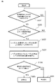
次に車載用物体検知システムの基本的な動作について図3および図4を用いて説明する。
まず、図3において、レーダ装置11の覆域11Aと、レーダ装置12の覆域12Aが重なる領域112Aにある物標Pを、レーダ装置11およびレーダ装置12で検出する。検出された物標Pの位置情報は、レーダ装置11およびレーダ装置12から見たアジマス角θ1、θ2(レーダ軸中心11B、12Bから物標Pまでの角度)と距離D1、D2とからなる相対座標であるため、車両1の任意の点を基準とした車両座標系に変換する。複数検出された物標のうち、位置(距離)の差が予め定められたしきい値より小さい物標同士を同一の物標であるとみなし、それらを比較対象として決定する(図4中、ステップS101)。このような決定は、物体検知装置異常判定部222で行ってもよい。Next, the basic operation of the in-vehicle object detection system will be described with reference to FIGS. 3 and 4. FIG.
First, in FIG. 3, the
このように、同一時刻に同一物標を比較する場合、複数のレーダ装置の検出範囲である覆域が共通しているエリア内に物標が存在していることを条件とすることで、比較の候補となる物標を絞り込むことができる。これにより、制御装置における処理量の削減が期待できる。
また、同一の物標であることの判定には、位置間の距離の差だけでなく、これに加えて進行方位の差、進行速度の差がしきい値より小さいことを加味することにより、より詳細な同一性の判定が可能となる。なお、距離については、一般的なユークリッド距離を用いる方法がある。In this way, when comparing the same target at the same time, by making it a condition that the target exists in an area where the coverage area, which is the detection range of a plurality of radar devices, is common, the comparison can be performed. can be narrowed down. As a result, a reduction in the amount of processing in the control device can be expected.
Further, in determining whether the targets are the same, not only the difference in the distance between the positions but also the fact that the difference in the direction of travel and the difference in the speed of travel are smaller than a threshold value is taken into account. More detailed identity determination is possible. As for the distance, there is a method using a general Euclidean distance.
次に、レーダ装置11とレーダ装置12で、比較対象と決定した物標Pの反射レベルを物標反射レベル受信部221で測定する(ステップS102)。測定した反射レベルを比較してレーダ装置11またはレーダ装置12が異常かどうかを物体検知装置異常判定部222で判定する。具体的には、レーダ装置11の物標Pの反射レベルとレーダ装置12の物標Pの反射レベルとの相対的な差を求め(ステップS103)、相対的な差が予め定められた値と比較し(ステップS104)、予め定められた値以下の場合、異常なしと判定する(ステップS105)。
Next, in the
図5は、異常判定結果をあらわす。図5中、左側にレーダ装置11を記載している行は、レーダ装置11からみたレーダ装置12の状態を示し、今回の判定では異常がないことを示している。また、図5中、左側にレーダ装置12を記載している行は、レーダ装置12からみたレーダ装置11の状態を示し、今回の判定では異常がないことを示している。
FIG. 5 shows the results of abnormality determination. In FIG. 5, the row describing the
レーダ装置11の物標反射レベルとレーダ装置12の物標Pの反射レベルの差が、予め定められた値より大きい場合、異常ありと判定する(図4中、ステップS106)。図6中、左側にレーダ装置11を記載している行は、レーダ装置11からみたレーダ装置12の状態を示し、今回の判定では異常があることを示している。また、図6中、左側にレーダ装置12を記載している行は、レーダ装置12からみたレーダ装置11の状態を示し、今回の判定で異常があることを示している。以上のように、車載用物体検知システムとして、搭載されているレーダ装置に発生した異常をレーダ装置間の物標反射レベルの比較によって判定することができる。なお、ここでの異常とは、例えば、垂直方向の軸ズレ、汚れ、または雪などが付着したことによる性能低下などが挙げられる。
If the difference between the target reflection level of the
しかし、上述の異常ありの判定では、レーダ装置11またはレーダ装置12のどちらに異常が発生しているか特定することはできない。これに対しては、レーダ装置11とレーダ装置12の物標反射レベルの平均値とレーダ装置11またはレーダ装置12の物標反射レベルの差を算出し、この差が予め定められた値を超えている物標反射レベルのレーダ装置を、異常発生物体検知装置特定部223により、異常ありと特定してもよい。
また、レーダ装置11に異常の有無を自己判定する機能を搭載し、レーダ装置11が異常なしと自己判定した場合には、異常発生物体検知装置特定部223により、レーダ装置12に異常があると特定できるようにしてもよい。レーダ装置11の異常の自己判定手段としては、レーダ装置の性能低下を判断するために、レーダ装置の表面の付着物の有無を監視するセンサ(汚れ付着検知センサ)を取付ける方法、レーダ装置により得られる反射強度の情報を用いてレーダ装置表面の付着物の有無を検出する方法、レーダ装置に軸ズレ量を検知するようなセンサを内蔵して軸ズレ量を推定する方法、または内部回路の異常を検知する手段などが知られており、レーダ装置単独で自己判定するどのような手段を用いても良い。However, it is not possible to specify which of the
Further, the
このような構成により、すべてのレーダ装置11~15に自己診断機能を持たせなくても、異常の発生の有無を推定できるので、車載用物体検知システムのトータルコストを低減できる。
また、各レーダ装置が自己診断機能を持っている場合であっても、自己診断機能の構成によっては、判定に時間がかかるようなケースがある。例えば、走行データを1分間または10分間など長時間分蓄積して、統計的な処理によって異常が発生しているか否かを判定する例が挙げられる。しかし、各レーダ装置で、この時間に異常の判定をするのに足る十分なデータを蓄積できるとは限らず、いくつかのレーダ装置にしか異常の判定が完了しないケースも考えられる。このような場合であっても、少なくとも1つのレーダ装置で異常の判定が完了していれば、残りのレーダ装置の異常は相対比較によって判定することができるので、レーダ装置の異常を早期に発見することができる。With such a configuration, it is possible to estimate whether or not an abnormality has occurred without providing all the
Further, even if each radar device has a self-diagnostic function, there are cases where the determination takes time depending on the configuration of the self-diagnostic function. For example, running data for a long period of time such as 1 minute or 10 minutes is accumulated, and whether or not an abnormality has occurred is determined by statistical processing. However, it is not always the case that each radar device can accumulate enough data to make an abnormality determination at this time, and there may be cases where the abnormality determination is completed only for some radar devices. Even in such a case, as long as at least one radar device has completed abnormality determination, it is possible to determine the abnormality of the remaining radar devices by relative comparison. can do.
次に、3つのレーダ装置の情報を用いる場合の異常発生物体検知装置特定部223の動作を説明する。上述した2つのレーダ装置11、12の時と同様に、同一物標を比較対象として決定し、レーダ装置11、12、13の物標に対する反射レベルを物標反射レベル受信部221で測定する。測定した反射レベルを比較して、レーダ装置11、レーダ装置12、またはレーダ装置13が異常か否かを物体検知装置異常判定部222で判定する。図7は、判定した結果を表す。ここまでの説明で分かる通り、図7に示した表の右上半分の三角形部分と、左下半分の三角形部分は、どちらのレーダ装置からみるかが変わっただけで、相対的に反対のことを書いているだけなので、ここからは、右上半分にのみ判定例を記入して説明する。
Next, the operation of the abnormal object detection
物体検知装置異常判定部222において、図7で示すように、
(1)レーダ装置11の反射レベルとレーダ装置12の反射レベルを比較して異常あり
(2)レーダ装置11の反射レベルとレーダ装置13の反射レベルを比較して異常あり
(3)レーダ装置12の反射レベルとレーダ装置13の反射レベルを比較して異常なし
と判定された場合、異常発生物体検知装置特定部223により、レーダ装置11に異常が発生していると特定することができる。これは、レーダ装置12とレーダ装置13で、物標反射レベルが同程度になるような異常が、システム内の複数のレーダ装置に対して同じように発生するとは考えにくいことを利用している。これにより、2つのレーダ装置だけでは、異常の発生しているレーダ装置を特定できなかったが、3つ以上のレーダ装置の搭載された車載用物体検知システムにおいては、異常の発生しているレーダ装置を特定することができる。In the object detection device abnormality determination unit 222, as shown in FIG.
(1) The reflection level of the
以上のように、実施の形態1では、複数の物体検知装置で物標反射レベルを比較しているので、物標が様々な距離に位置し、反射レベルがそれに対応して様々に変わる場合でも異常の有無を判断できる。これにより、1つの物体検知装置でそれ自身の異常を判断する場合よりも、より多くの走行環境で、より短時間に、異常の有無を判断可能である。
As described above, in
[誤動作防止のための手法]
なお、実施の形態1の車載用物体検知システムの誤動作を防止するために、図8に示すように、振動検知センサ18により、一定時間内のピッチ角を検知し、ピッチ角がしきい値以上変化した場合に車両1が振動したと判定し、レーダ装置での物標の検出およびレーダ装置の異常の有無の判定を行わないこととしてもよい(図8中、ステップS107)。すなわち、車両1が振動した場合、例えば小さい段差などを乗り越えた場合、レーダ装置は物標に対し相対的に上を向いたり、下を向いたりする。このようなケースでは、レーダ装置は、段差の分だけ物標とのなす角が変化してしまう。この影響で異常と誤判定する恐れがある。このため、車両1の振動を検出した場合は、異常の判定を行わず始めに戻り、物標の検出から始める。図8では、振動検知センサ18の振動検出は最初に行っているが、異常判定前のどの段階で振動が検知されても異常判定を行わず始めに戻ることにしてもよい。[Method for preventing malfunction]
In order to prevent the in-vehicle object detection system of
[物標反射レベルの正規化]
また、実施の形態1で説明したレーダ装置11、12および13は、全く同じ仕様、全く同じ取付高さであるとは限らない。このような場合には、図9に示すように、例えば、レーダ装置11およびレーダ装置12間で物標反射レベルを正規化して(図8中、ステップS108)、レーダ装置間で同じ指標で物標反射レベルを比較できることが望ましい。[Normalization of Target Reflection Level]
Moreover, the
正規化の対象となるものとして、例えば以下の(1)~(5)が挙げられる。これらは単独で用いてもよいし、組み合わせて用いてもよい。また、正規化の手法はこれら(1)~(5)に限られるわけではない。 Items to be normalized include, for example, the following (1) to (5). These may be used alone or in combination. Also, the normalization method is not limited to these (1) to (5).
(1)レーダ装置の反射強度は、物標までの距離の4乗に反比例することが知られている。ミリ波レーダでは、物標までの距離を検出することが可能であるため、得られた物標反射レベルに距離の4乗分の減衰を補正することで距離による影響を抑えてレーダ装置間の物標反射レベルを比較できる。 (1) It is known that the reflection intensity of the radar system is inversely proportional to the fourth power of the distance to the target. Millimeter-wave radar is capable of detecting the distance to a target. Therefore, by correcting the attenuation of the obtained target reflection level by the fourth power of the distance, the effect of distance is suppressed and the inter-radar system is improved. Target reflection levels can be compared.
(2)また、水平方向のアンテナ利得も正規化のための補正対象となる。アンテナは、所定の方向に指向性を持つ。この指向性の特性を予め取得しておき、レーダ装置で得られた水平方向の測角値を用いて、水平方向のアンテナ利得の分だけ物標反射強度を補正することで、レーダ装置間の水平方向のアンテナ利得の違いの影響を抑えて、物標反射レベルを比較できる。 (2) The antenna gain in the horizontal direction is also subject to correction for normalization. An antenna has directivity in a predetermined direction. This directivity characteristic is acquired in advance, and the horizontal angle measurement value obtained by the radar device is used to correct the target reflection intensity by the amount of the horizontal antenna gain. Target reflection levels can be compared while suppressing the influence of differences in antenna gain in the horizontal direction.
(3)また、垂直方向のアンテナ利得も正規化のための補正対象となる。垂直に軸がずれていない場合、レーダ装置からみて、物標の方向は、取り付け高さと、物標までの距離によって一意に定まる。垂直方向のアンテナ利得を予め取得しておき、レーダ装置で得られた物標までの距離情報によって、レーダ装置と物標とのなす垂直方向の角度を求め、垂直方向のアンテナ利得を補正することで、レーダ装置間の垂直方向のアンテナ利得の違いの影響を抑えて、レーダ装置間の物標反射レベルを比較できる。 (3) Also, the antenna gain in the vertical direction is subject to correction for normalization. If the axis is not vertically displaced, the direction of the target as viewed from the radar device is uniquely determined by the installation height and the distance to the target. Acquiring the vertical antenna gain in advance, obtaining the vertical angle between the radar system and the target based on the distance information to the target obtained by the radar system, and correcting the vertical antenna gain. , the influence of the difference in antenna gain in the vertical direction between radar devices can be suppressed, and target object reflection levels between radar devices can be compared.
(4)また、レーダ装置を構成するハードウェア特性も正規化のための補正対象となる。たとえば、レーダ装置では、アンテナで受信した信号は、ローパスフィルタ、ハイパスフィルタ、および増幅器などを通して、ADコンバータへ入力される場合がある。このような場合には、これらの回路部品が持つ特性を加味して、物標反射強度を補正することで、レーダ装置のハードウェア特性の差の影響を抑えて、物標反射レベルを比較できる。 (4) In addition, the characteristics of the hardware constituting the radar device are also subject to correction for normalization. For example, in radar equipment, a signal received by an antenna may be input to an AD converter through a low-pass filter, a high-pass filter, an amplifier, and the like. In such a case, by correcting the target reflection intensity in consideration of the characteristics of these circuit components, the influence of the difference in the hardware characteristics of the radar equipment can be suppressed and the target reflection levels can be compared. .
(5)また、入射されるレーダ波に対する物標の反射能力を示すレーダ反射断面積(RCS:Radar Cross Section)を推定し、この推定値を正規化された物標反射強度の代わりに用いてもよい。レーダ反射断面積は、物標からの反射電力、アンテナと物標の距離、アンテナの特性、レーダのハードウェア特性等からレーダ方程式を用いて計算できる。また、予め代表的な値の範囲とステップを定めてテーブル化しておいた結果を参照してもよい。テーブルの作成には、レーダ方程式を用いて計算した結果を用いてもよいし、レーダ反射断面積が既知であるリフレクタを用いて実測した結果を用いてもよい。 (5) In addition, the radar reflection cross section (RCS: Radar Cross Section) indicating the reflectivity of the target against the incident radar wave is estimated, and this estimated value is used instead of the normalized target reflection intensity. good too. The radar reflection cross section can be calculated from the reflected power from the target, the distance between the antenna and the target, the characteristics of the antenna, the hardware characteristics of the radar, etc., using radar equations. Alternatively, a table of results obtained by predetermining typical value ranges and steps may be referred to. The results of calculation using radar equations may be used to create the table, or the results of actual measurements using a reflector with a known radar reflection cross section may be used.
なお、物標反射レベルの正規化は必ずしも必須ではない。たとえば、正規化してもしなくてもレーダ装置間の物標反射レベルの値に大きな違いが無く、所望のレーダ装置の異常の判定ができる場合は必須ではない。また、すべてのレーダ装置が同じ仕様で、同じ取り付け条件である場合は必須ではない。 Note that normalization of the target reflection level is not necessarily essential. For example, it is not essential if there is no significant difference in target object reflection level values between radar devices whether or not normalization is performed, and it is possible to determine the abnormality of the desired radar device. Also, it is not essential if all radar devices have the same specifications and the same installation conditions.
[異常ありと判断された場合の対応]
物体検知装置異常判定部222で異常ありと判定された結果は、図2に記載された通信機能部23を経由して車両制御部19に通知される。異常の通知を受信した車両制御部19は、車両制御の停止あるいは、車両制御の一部動作を制限することが可能となる。
また、車両制御部19の指示で、運転手に異常が発生していることを通知手段20により通知して、例えばレーダ装置が汚れていないか点検するように促すなどの対応をしてもよい。[Response when it is determined that there is an abnormality]
The result of the determination that there is an abnormality by the object detection device abnormality determination section 222 is notified to the
In addition, in accordance with an instruction from the
また、レーダ装置間の物標反射レベルの差が小さい場合は異常の程度が小さいと考えられる。このような場合は、異常の程度を段階的に判定するようにしてもよい。たとえば異常の程度が小さい場合は、特定の車両制御アプリケーションは停止または機能を抑えるような構成としてもよい。例えば、高速走行時は遠方の物体検知性能が必要となることに対し、低速走行時は近距離、たとえば100m以下程度でもACC(Adaptive Cruise Control)あるいはAEB(Automatic Emergency Braking)などの車両制御アプリケーションには大きな影響がないので、異常発生時はアプリケーションの動作を継続させるなどとしても良い。 Also, when the difference in target object reflection level between radar devices is small, the degree of abnormality is considered to be small. In such a case, the degree of abnormality may be determined step by step. For example, when the degree of abnormality is small, a specific vehicle control application may be configured to stop or suppress its function. For example, long-distance object detection performance is required when driving at high speeds, while short distances when driving at low speeds, such as 100 m or less, are suitable for vehicle control applications such as ACC (Adaptive Cruise Control) or AEB (Automatic Emergency Braking). does not have a large impact, so it is possible to continue the operation of the application when an error occurs.
さらに、物体検知装置異常判定部222から、異常発生の有無をレーダ装置11~15に通知することもできる。異常を通知されたレーダ装置は、異常を解消する動作を行うことも可能となる。例えば、レーダ装置で発生している異常の1つとして、雪が付着していることによってレーダ装置で適切に物標からの反射を受信できなくなっている可能性が考えられる。このような場合は、レーダ装置11~15にヒータなどを取り付けてもよい。
また、周囲の雰囲気温度を取得できる構成として、周囲の雰囲気温度が所定の温度より低く、かつ、物体検知装置異常判定部222で異常ありと判定されている場合には、一定時間ヒータを動作させて、雪が解けることで異常が解消されるか否かを監視するような構成としてもよい。Furthermore, the presence or absence of an abnormality can also be notified to the
In addition, as a configuration that can acquire the surrounding atmosphere temperature, when the surrounding atmosphere temperature is lower than a predetermined temperature and the object detection device abnormality determination unit 222 determines that there is an abnormality, the heater is operated for a certain period of time. Then, it may be configured to monitor whether or not the abnormality is resolved by melting the snow.
異常が発生しているレーダ装置を異常発生物体検知装置特定部223にて特定できる場合は、そのレーダ装置にのみ、異常の発生を通知し、ヒータを動作させるようにしてもよい。また、異常の発生しているレーダ装置を特定できない場合は、物体検知装置異常判定部222で異常と判定された全てのレーダ装置に対して車載用物体検知システムとしての異常の発生を通知するようにし、すべてのレーダ装置のヒータを動作させ、異常が解消されるかどうかを監視してもよい。また、ヒータを動作させても異常が解消されない場合は、他の異常の可能性もあるので、例えばレーダ装置の垂直方向の軸ズレが疑われる場合は、軸の向きを補正するような動作をさせてもよい。
If the abnormal radar device can be identified by the abnormal object detection
また、異常を解消するように動作させる以外に、レーダ装置の動作そのものを止めてもよい。異常が発生しているレーダ装置を継続して動作させておいたとしても、車両制御アプリケーションの動作が保証できないような場合には、該当するレーダ装置の動作を止めることで、車載用物体検知システムの消費電力を低減できる。 Further, the operation of the radar device itself may be stopped in addition to the operation for resolving the abnormality. If the operation of the vehicle control application cannot be guaranteed even if the abnormal radar device continues to operate, by stopping the operation of the corresponding radar device, the in-vehicle object detection system power consumption can be reduced.
実施の形態2.
実施の形態1と異なり、レーダ装置11、12で検出した物標が異なる物体であるが、種別が同じ場合について説明する。この種別とは、車、バイク、自転車、または人といったものであり、車についてはさらにトラック、バス、乗用車などと細分化しても良い。
Unlike the first embodiment, a case where targets detected by the
図10において、実施の形態1で説明したように、レーダ装置11が物標Pを検出し、レーダ装置12が物標Qを検出する。物標Pの検出は実施の形態1で説明した通りであるが、検出された物標Qの位置情報も、レーダ装置12から見たアジマス角θ3(レーダ軸中心12Bから物標Qまでの角度)と距離D3とからなる相対座標であるため、車両1の任意の点を基準とした車両座標系に変換する。物標Pと物標Qが同一の物標と検出されない場合、これに加えて種別の検出も行う(図11中、ステップS201)。
In FIG. 10, the
すなわち、実施の形態1と異なり、種別の検出は、覆域11A、12Aが重なる領域である必要はない。種別の検出は、レーダ装置単体で反射波の特性を分析して、物標とレーダ装置の位置関係から推定される種別から識別を行っても良いし、光学カメラを別途設置して、そのカメラが検出した種別を用いて識別しても良い。検出された物標のうち、物標P、Qの種別が同じであると検出された場合、物標P、Qを比較対象として決定する。レーダ装置11の物標Pの反射レベルとレーダ装置12の物標Qの反射レベルの相対的な差を計算し異常の有無を判定する(ステップS103~S106)。この詳細は、図11で示す通り、実施の形態1と同様とする。また、実施の形態1で説明したステップS107、S108については、実施の形態1で説明したように、必要に応じて選択的に行うことにしてもよい。
In other words, unlike the first embodiment, detection of the type does not have to be the area where the
以上のように、実施の形態2では、複数の物体検知装置で同一種類の物標反射レベルを比較しているので、物標が物体検知装置の覆域が重なる領域に無く、様々な距離に位置し、反射レベルがそれに対応して様々に変わる場合でも異常の有無を判断できる。これにより、1つの物体検知装置でそれ自身の異常を判断する場合よりも、より多くの走行環境で、より短時間に、異常の有無を判断可能である。 As described above, in the second embodiment, since the target object reflection levels of the same type are compared by a plurality of object detection devices, the target is not in the area where the coverage areas of the object detection devices overlap, and is at various distances. The presence or absence of an anomaly can be determined even if the position and the reflection level vary correspondingly. As a result, it is possible to determine the presence or absence of an abnormality in a greater number of driving environments in a shorter period of time than when a single object detection device determines its own abnormality.
実施の形態3.
レーダ装置で検出した物体の種別が特に側壁である場合の例について説明する。図12で示すように、車両1の横に側壁30が存在するとき、レーダ装置11、12が検出する物標が最も反射強度の大きいのは、レーダ装置11、12の真横の1点である。この点が物標R、物標Sとして検出される場合を想定する。
An example in which the type of object detected by the radar device is a side wall will be described. As shown in FIG. 12, when a
まず、レーダ装置11とレーダ装置12のそれぞれで物標を検出し、加えて物標は同一種類であり、かつ側壁であるとの検出も行う(図13中、ステップS301、S302)。実施の形態2同様、物標の種別の検出は、レーダ装置単体で反射波の特性を分析して行っても良いし、光学カメラを別途設置して、そのカメラが検出した種別を用いても良い。また、側壁30が存在する位置が格納された地図(図示せず)を用いて、検出物標の位置が地図上で側壁30が存在する位置に合致していれば種別を側壁としてもよい。また、地図に側壁の情報が無くても、車両1が走行している道路の境界線が分かればそこに側壁があると推定しても良い。また、地図にトンネル情報があり、車両1がトンネル内を走行していることが分かれば側壁とみなせるトンネルの壁の存在を推定しても良い。これ以外に、レーダ装置11とレーダ装置12において、車両1の真横かつ同一距離に物標が検出されていることで側壁30があると推定しても良い。
First, each of the
物標が側壁30であるとの検出結果を用いて、レーダ装置11の側壁30の物標Rでの反射レベル、レーダ装置12の側壁30の物標Sでの反射レベルを測定する(ステップS302)。物標Rでの反射レベルと物標Sでの反射レベルの相対的な差を計算し異常の有無を判定することの詳細は、図13で示されている通り、実施の形態1と同様とする(ステップS103~S106)。なお、図13で示すステップS107、S108については、実施の形態1で説明したように、必要に応じて選択的に行うことにしてもよい。
Using the detection result that the target is the
以上のように、実施の形態3では、複数の物体検知装置で側壁上の物標反射レベルを比較しているので、同じ反射レベルの物標が連続的に存在することにより、より短時間に、異常の有無を判断可能である。
As described above, in
実施の形態4.
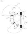
側壁を用いる別の例について説明する。図14に示すように、車両1の横に側壁30が存在するとき、レーダ装置11、12が検出した複数の物標R1~R4、物標S1~S4となる場合を想定する。
Another example using sidewalls is described. As shown in FIG. 14, it is assumed that a plurality of targets R1 to R4 and targets S1 to S4 are detected by the
まず、レーダ装置11とレーダ装置12のそれぞれで物標R1~R4、物標S1~S4を検出する。検出された物標R1~R4の位置情報は、レーダ装置11から見たアジマス角θ11~θ14(レーダ軸中心11Bからそれぞれの物標までの角度)と距離D11~D14となる相対座標であり、物標S1~S4の位置情報は、レーダ装置12から見たアジマス角θ31~θ34(レーダ軸中心12Bからそれぞれの物標までの角度)と距離D31~D34となる相対座標であり、車両1の任意の点を基準とした車両座標系に変換する。複数検出された物標のうち、位置の差、進行方位の差、進行速度の差が予め定められたしきい値より小さい物標同士を同一の物標であるとみなし、それらを比較対象として決定する。しかし、今回の場合、レーダ装置11とレーダ装置12の覆域の重なる部分に物標R1と物標S4が存在するが、これらは同一の物標とみなされていない。
First, targets R1 to R4 and targets S1 to S4 are detected by the
上述の物標の検出に加え、物標の種別の検出も行う。種別の検出は、実施の形態3と同様に行うが、特にこの例では側壁が直線形状であるため、レーダ装置11で検出された物標R1~R4、およびレーダ装置12で検出された物標S1~S4が車両1の進行方向と平行に直線状に並ぶことを利用してそれらを側壁とみなしても良い(図15中、ステップS402)。
In addition to the target detection described above, the type of target is also detected. Detection of the types is performed in the same manner as in the third embodiment, but particularly in this example, since the sidewalls are linear, the targets R1 to R4 detected by the
この物標の種別の検出結果を用いて異常なしとする場合、異常ありとする場合の判定の詳細は、実施の形態1と同様とする。この際、反射レベルの相対的な差を求めるに際し、レーダ装置11の反射レベルおよびレーダ装置12の反射レベルを、それぞれ物標R1~R4の反射レベルの総和または平均値、物標S1~S4の反射レベルの総和または平均値としてもよい。
なお、本実施の形態では、側壁でなくても前後方向に長いトラックまたはバスなどの移動体であっても適用が可能である。
なお、図13で示すステップS107、S108については、実施の形態1で説明したように、必要に応じて選択的に行うことにしてもよい。When determining that there is no abnormality using the detection result of the target type, the details of the determination when determining that there is an abnormality are the same as those in the first embodiment. At this time, when obtaining the relative difference in the reflection level, the reflection level of the
It should be noted that this embodiment can be applied not only to a side wall but also to a moving body such as a truck or a bus that is long in the front-rear direction.
Note that steps S107 and S108 shown in FIG. 13 may be selectively performed as necessary, as described in the first embodiment.
以上のように、実施の形態4では、1つの物体検知装置で側壁上の複数の物標反射レベルを検出しているので、同じ反射レベルの物標が連続的に存在することが、実施の形態3で説明したシステムよりも短時間に検出できるため、側壁の検出がより短時間に可能となり、異常の有無の判断もさらに短縮可能である。
As described above, in the fourth embodiment, one object detection device detects a plurality of target object reflection levels on the side wall. Since detection can be performed in a shorter period of time than the system described in
実施の形態5.
本実施の形態は、移動する物標により物体検知装置の異常の有無を検出するものである。例えば図16において、レーダ装置12とレーダ装置13は、車両1からみて右側に搭載されているので、車両1が走行中に他車に追い抜かれるような場合は、レーダ装置12とレーダ装置13は、他車を、同じ物標Tとして時間的にずれたタイミングで検出する。このため、レーダ装置12で検出した物標Tの反射レベルを記憶し、かつその物標を追尾し、その物標Tがレーダ装置13でも検出された場合に、その物標Tの反射レベルを比較する構成とすることで、物標Tがレーダ装置間で同じ覆域に存在していなくても、同一物標の反射レベルを比較することができる。Embodiment 5.
This embodiment detects the presence or absence of an abnormality in an object detection device using a moving target. For example, in FIG. 16, the
具体的には、図16で示すような、覆域12A、13Aが重ならないレーダ装置12とレーダ装置13において、レーダ装置12で物標Tを検出する(図17中ステップS501)。検出された物標Tの位置情報は、レーダ装置12から見たアジマス角θ3(レーダ軸中心12Bから物標Tまでの角度)と距離D3とからなる相対座標であり、車両1の任意の点を基準とした車両座標系に変換する。
Specifically, in the
検出された物標Tが車両1を追い抜くように図16の矢印Y方向に移動し、一旦レーダ装置12の覆域12Aの外に出た場合、その物標Tの検出した反射レベルを記憶し、さらに追尾対象としてマークする(図17中、ステップS502)。
物標Tが追尾区間TRを移動中も継続して追尾を行い、最終的にレーダ装置13の覆域13Aに入った場合、レーダ装置13で、実際に検出された物標と合致する追尾中の物標Tの存在を確認する(ステップS503)。レーダ装置13で検出された物標Tの位置情報は、レーダ装置13から見たアジマス角θ4(レーダ軸中心13Bから物標Tまでの角度)と距離D4とからなる相対座標であり、車両1の任意の点を基準とした車両座標系に変換する。物標Tの確認には、物標の位置だけでなく、速度、進行方位を用いても良い。そして、同一物標と確認された場合、実施の形態1の図9中、ステップS103~ステップS106で説明したのと同様に、それらの物標反射レベルを比較してレーダ装置12またはレーダ装置13が異常かどうかを判定する(図17中、ステップS507~S510)。なお、図17で示すステップS107、S506については、実施の形態1で説明したように、必要に応じて選択的に行うことにしてもよい。When the detected target T moves in the direction of the arrow Y in FIG. 16 so as to overtake the
When the target T is continuously tracked while moving in the tracking section TR and finally enters the
物標の追尾には例えば、最後に観測された位置および速度とその進行方位から、等速直線運動を行うものとしてその位置を予測する方法、観測された物標の位置の時系列情報を用いてカルマンフィルタにより位置を予測する方法でも良い。物標が長時間追尾区間に留まる場合、進路を変更した場合に対応するために、物標の追尾には一定の時間制限を設け、制限時間を超過した場合は追尾をとりやめるなどしてもよい。 For tracking a target, for example, a method of predicting its position assuming uniform linear motion from the last observed position and velocity and its direction of travel, and using time-series information of the observed positions of the target. A method of predicting the position using a Kalman filter may also be used. If the target stays in the tracking section for a long time or changes course, set a certain time limit for tracking the target, and if the time limit is exceeded, tracking may be stopped. .
図18は、実施の形態5を行うための制御装置2のブロック構成図である。実施の形態1で説明した構成に加え、レーダ装置12または15で検出された物標の移動を追尾するための物標追尾部224を含む以外は、図2と同様の構成であり、各構成部分の詳細な説明は省略する。
FIG. 18 is a block configuration diagram of the
以上のように、実施の形態5では、移動する他の物体の物標を検出するため、静止物体の有無にかかわらず物体検知装置で反射レベルを検出することが可能となる。 As described above, in Embodiment 5, since the target of another moving object is detected, the reflection level can be detected by the object detection device regardless of the presence or absence of a stationary object.
実施の形態1から5では、説明を簡単にするため、2つ、または、3つのレーダ装置で相対比較を行う場合について説明したが、レーダ装置の個数に寄らず適用が可能である。
各実施の形態では検出する物標は移動体および静止物体(側壁)を想定して記載したが、特に静止物体については側壁だけでなく電柱、標識、またはガードレールなどの構造物でも適用が可能である。In the first to fifth embodiments, for the sake of simplicity, two or three radar devices are used for relative comparison, but the present invention can be applied regardless of the number of radar devices.
In each embodiment, the targets to be detected are assumed to be a moving object and a stationary object (side wall). be.
本願は、様々な例示的な実施の形態及び実施例が記載されているが、1つ、または複数の実施の形態に記載された様々な特徴、態様、及び機能は特定の実施の形態の適用に限られるのではなく、単独で、または様々な組み合わせで実施の形態に適用可能である。
従って、例示されていない無数の変形例が、本願明細書に開示される技術の範囲内において想定される。例えば、少なくとも1つの構成要素を変形する場合、追加する場合または省略する場合、さらには、少なくとも1つの構成要素を抽出し、他の実施の形態の構成要素と組み合わせる場合が含まれるものとする。While this application describes various exemplary embodiments and examples, various features, aspects, and functions described in one or more embodiments may not apply to particular embodiments. can be applied to the embodiments singly or in various combinations.
Accordingly, numerous variations not illustrated are envisioned within the scope of the technology disclosed herein. For example, modification, addition or omission of at least one component, extraction of at least one component, and combination with components of other embodiments shall be included.
1:車両、2:制御装置、11、12、13、14、15:レーダ装置(物体検知装置)、16:ヨーレートセンサ、17:走行速度センサ、18:振動検知センサ、19:車両制御部、20:通知手段、21:演算部、22:記憶部、23:通信機能部、24:バス、30:側壁、221:物標反射レベル受信部、222:物体検知装置異常判定部、223:異常発生物体検知装置特定部、224:物標追尾部 1: vehicle, 2: control device, 11, 12, 13, 14, 15: radar device (object detection device), 16: yaw rate sensor, 17: running speed sensor, 18: vibration detection sensor, 19: vehicle control unit, 20: notification means, 21: calculation unit, 22: storage unit, 23: communication function unit, 24: bus, 30: side wall, 221: target object reflection level reception unit, 222: object detection device abnormality determination unit, 223: abnormality Generated object detection device identification unit, 224: target tracking unit
Claims (19)
前記複数の物体検知装置で検出された複数の物標反射レベルを受信する物標反射レベル受信部、
同一の物標もしくは同一種別の物標として検出された2以上の物標の物標反射レベルの差を算出し、前記差が予め定められた値の範囲を超えているとき、前記複数の物体検知装置のいずれかに異常があると判定する物体検知装置異常判定部、を備え、
前記物体検知装置異常判定部は、前記複数の物体検知装置の覆域同士が重なる領域で検出された複数の物標の位置間の距離が予め定めたしきい値内にあるとき、同一の物標であると決定することを特徴とする車載用物体検知システム。 a plurality of object detection devices mounted on a vehicle;
a target reflection level receiver that receives a plurality of target reflection levels detected by the plurality of object detection devices;
calculating a difference in target reflection level between two or more targets detected as the same target or a target of the same type; an object detection device abnormality determination unit that determines that there is an abnormality in any of the detection devices,
The object detection device abnormality determination unit detects the same object when the distance between the positions of the plurality of targets detected in the overlapping area of the plurality of object detection devices is within a predetermined threshold value. An in-vehicle object detection system characterized by determining that an object is a target.
前記複数の物体検知装置で検出された複数の物標反射レベルを受信する物標反射レベル受信部、
同一の物標もしくは同一種別の物標として検出された2以上の物標の物標反射レベルの差を算出し、前記差が予め定められた値の範囲を超えているとき、前記複数の物体検知装置のいずれかに異常があると判定する物体検知装置異常判定部、を備え、
前記複数の物体検知装置のうち、第1の物体検知装置で検出された第1の物標反射レベルを記憶しておく記憶部、前記第1の物体検知装置で検出された物標の位置を追尾し将来の位置を予測する物標追尾部、前記物標追尾部で追尾した物標が第2の物体検知装置で検出された場合、同一の物標であると決定し、検出された第2の物標反射レベルと記憶された前記第1の物標反射レベルとの差を算出することを特徴とする車載用物体検知システム。 a plurality of object detection devices mounted on a vehicle;
a target reflection level receiver that receives a plurality of target reflection levels detected by the plurality of object detection devices;
calculating a difference in target reflection level between two or more targets detected as the same target or a target of the same type; an object detection device abnormality determination unit that determines that there is an abnormality in any of the detection devices,
a storage unit for storing a first target reflection level detected by a first object detection device among the plurality of object detection devices; a target tracking unit for tracking and predicting a future position; when the target tracked by the target tracking unit is detected by a second object detection device, the target is determined to be the same target; and calculating a difference between the second target reflection level and the stored first target reflection level.
前記複数の物体検知装置で検出された複数の物標反射レベルを受信する物標反射レベル受信部、
同一の物標もしくは同一種別の物標として検出された2以上の物標の物標反射レベルの差を算出し、前記差が予め定められた値の範囲を超えているとき、前記複数の物体検知装置のいずれかに異常があると判定する物体検知装置異常判定部、を備え、
前記物体検知装置異常判定部は、前記複数の物体検知装置で検出された物標が、前記物体検知装置が出力する物標識別結果、もしくは前記物標と前記物体検知装置の位置関係から推定される種別から、同一の種別の物標と決定することを特徴とする車載用物体検知システム。 a plurality of object detection devices mounted on a vehicle;
a target reflection level receiver that receives a plurality of target reflection levels detected by the plurality of object detection devices;
calculating a difference in target reflection level between two or more targets detected as the same target or a target of the same type; an object detection device abnormality determination unit that determines that there is an abnormality in any of the detection devices,
The object detection device abnormality determination unit determines whether the target detected by the plurality of object detection devices is estimated from the result of each object marker output by the object detection device or the positional relationship between the target and the object detection device. An in-vehicle object detection system, characterized in that a target object of the same type is determined based on the type of object.
前記複数の物体検知装置で検出された複数の物標反射レベルを受信する物標反射レベル受信部、
同一の物標もしくは同一種別の物標として検出された2以上の物標の物標反射レベルの差を算出し、前記差が予め定められた値の範囲を超えているとき、前記複数の物体検知装置のいずれかに異常があると判定する物体検知装置異常判定部、を備え、
前記物体検知装置がレーダ装置である場合、RCS推定値に基づいて物標反射レベルの強度を補正することを特徴とする車載用物体検知システム。 a plurality of object detection devices mounted on a vehicle;
a target reflection level receiver that receives a plurality of target reflection levels detected by the plurality of object detection devices;
calculating a difference in target reflection level between two or more targets detected as the same target or a target of the same type; an object detection device abnormality determination unit that determines that there is an abnormality in any of the detection devices,
A vehicle-mounted object detection system, wherein when the object detection device is a radar device, the intensity of a target reflection level is corrected based on an RCS estimated value.
Applications Claiming Priority (1)
| Application Number | Priority Date | Filing Date | Title |
|---|---|---|---|
| PCT/JP2019/019036 WO2020230254A1 (en) | 2019-05-14 | 2019-05-14 | Vehicle-mounted object detection system |
Publications (2)
| Publication Number | Publication Date |
|---|---|
| JPWO2020230254A1 JPWO2020230254A1 (en) | 2020-11-19 |
| JP7203211B2 true JP7203211B2 (en) | 2023-01-12 |
Family
ID=73289859
Family Applications (1)
| Application Number | Title | Priority Date | Filing Date |
|---|---|---|---|
| JP2021519091A Active JP7203211B2 (en) | 2019-05-14 | 2019-05-14 | Automotive object detection system |
Country Status (5)
| Country | Link |
|---|---|
| US (1) | US20220171054A1 (en) |
| JP (1) | JP7203211B2 (en) |
| CN (1) | CN113811788A (en) |
| DE (1) | DE112019007325T5 (en) |
| WO (1) | WO2020230254A1 (en) |
Families Citing this family (1)
| Publication number | Priority date | Publication date | Assignee | Title |
|---|---|---|---|---|
| JP7351321B2 (en) | 2021-04-13 | 2023-09-27 | トヨタ自動車株式会社 | Sensor abnormality estimation device |
Citations (8)
| Publication number | Priority date | Publication date | Assignee | Title |
|---|---|---|---|---|
| JP2000304846A (en) | 1999-04-22 | 2000-11-02 | Honda Motor Co Ltd | On-vehicle radar device |
| JP2006023236A (en) | 2004-07-09 | 2006-01-26 | Honda Motor Co Ltd | Radar apparatus and vehicle control system equipped with the radar apparatus |
| JP2008309512A (en) | 2007-06-12 | 2008-12-25 | Denso Corp | Self-diagnosis method of ultrasonic sensor |
| JP2015078925A (en) | 2013-10-17 | 2015-04-23 | 株式会社デンソー | Periphery monitoring device and periphery monitoring system |
| JP2015200563A (en) | 2014-04-08 | 2015-11-12 | パナソニックIpマネジメント株式会社 | Object detection apparatus |
| JP2016048179A (en) | 2014-08-27 | 2016-04-07 | オムロンオートモーティブエレクトロニクス株式会社 | Laser radar device and object detection method |
| JP2016166752A (en) | 2015-03-09 | 2016-09-15 | 三菱電機株式会社 | Distance measuring device and performance deterioration detection method of distance measuring device |
| US20180143298A1 (en) | 2016-11-21 | 2018-05-24 | Nio Usa, Inc. | Sensor surface object detection methods and systems |
Family Cites Families (15)
| Publication number | Priority date | Publication date | Assignee | Title |
|---|---|---|---|---|
| JP3448946B2 (en) * | 1994-03-11 | 2003-09-22 | 日産自動車株式会社 | Vehicle periphery monitoring device |
| JP3488610B2 (en) | 1997-12-03 | 2004-01-19 | 富士通テン株式会社 | Radar equipment |
| JP4771724B2 (en) * | 2005-03-30 | 2011-09-14 | 富士通テン株式会社 | Radar equipment |
| FR2919726B1 (en) * | 2007-08-03 | 2009-11-20 | Valeo Vision | METHOD FOR DETECTING A WATER GERBE AT THE BACK OF A VEHICLE |
| JP5697911B2 (en) * | 2010-07-06 | 2015-04-08 | 古野電気株式会社 | Threshold setting method, target detection method, threshold setting program, target detection program, and target detection apparatus |
| JP5901896B2 (en) * | 2011-06-13 | 2016-04-13 | 古野電気株式会社 | Ship tracking information management system and ship radar device |
| US8441394B2 (en) * | 2011-07-11 | 2013-05-14 | Delphi Technologies, Inc. | System and method for detecting obstructions and misalignment of ground vehicle radar systems |
| US9453910B2 (en) * | 2014-04-23 | 2016-09-27 | Ford Global Technologies, Llc | Detecting radar blockage based on drive history |
| JP6593588B2 (en) * | 2015-02-16 | 2019-10-23 | パナソニックIpマネジメント株式会社 | Object detection apparatus and object detection method |
| US10054672B2 (en) * | 2015-08-31 | 2018-08-21 | Veoneer Us, Inc. | Apparatus and method for detecting and correcting for blockage of an automotive radar sensor |
| US10162046B2 (en) * | 2016-03-17 | 2018-12-25 | Valeo Radar Systems, Inc. | System and method for detecting blockage in an automotive radar |
| JP6609229B2 (en) * | 2016-09-02 | 2019-11-20 | 株式会社デンソー | Object detection device |
| EP3290946B1 (en) * | 2016-09-02 | 2019-08-14 | Preco Electronics, LLC | Monitoring and alert apparatus for radome performance affected by dirt or debris |
| CN106908783B (en) * | 2017-02-23 | 2019-10-01 | 苏州大学 | Based on obstacle detection method combined of multi-sensor information |
| US11906612B2 (en) * | 2018-05-14 | 2024-02-20 | Mitsubishi Electric Corporation | Object detection device and object detection method |
-
2019
- 2019-05-14 DE DE112019007325.7T patent/DE112019007325T5/en active Pending
- 2019-05-14 WO PCT/JP2019/019036 patent/WO2020230254A1/en active Application Filing
- 2019-05-14 CN CN201980096253.4A patent/CN113811788A/en active Pending
- 2019-05-14 JP JP2021519091A patent/JP7203211B2/en active Active
- 2019-05-14 US US17/599,870 patent/US20220171054A1/en active Pending
Patent Citations (8)
| Publication number | Priority date | Publication date | Assignee | Title |
|---|---|---|---|---|
| JP2000304846A (en) | 1999-04-22 | 2000-11-02 | Honda Motor Co Ltd | On-vehicle radar device |
| JP2006023236A (en) | 2004-07-09 | 2006-01-26 | Honda Motor Co Ltd | Radar apparatus and vehicle control system equipped with the radar apparatus |
| JP2008309512A (en) | 2007-06-12 | 2008-12-25 | Denso Corp | Self-diagnosis method of ultrasonic sensor |
| JP2015078925A (en) | 2013-10-17 | 2015-04-23 | 株式会社デンソー | Periphery monitoring device and periphery monitoring system |
| JP2015200563A (en) | 2014-04-08 | 2015-11-12 | パナソニックIpマネジメント株式会社 | Object detection apparatus |
| JP2016048179A (en) | 2014-08-27 | 2016-04-07 | オムロンオートモーティブエレクトロニクス株式会社 | Laser radar device and object detection method |
| JP2016166752A (en) | 2015-03-09 | 2016-09-15 | 三菱電機株式会社 | Distance measuring device and performance deterioration detection method of distance measuring device |
| US20180143298A1 (en) | 2016-11-21 | 2018-05-24 | Nio Usa, Inc. | Sensor surface object detection methods and systems |
Also Published As
| Publication number | Publication date |
|---|---|
| JPWO2020230254A1 (en) | 2020-11-19 |
| WO2020230254A1 (en) | 2020-11-19 |
| DE112019007325T5 (en) | 2022-02-17 |
| US20220171054A1 (en) | 2022-06-02 |
| CN113811788A (en) | 2021-12-17 |
Similar Documents
| Publication | Publication Date | Title |
|---|---|---|
| JP7203210B2 (en) | Automotive object detection system | |
| US9731728B2 (en) | Sensor abnormality detection device | |
| US10422857B2 (en) | Device for ascertaining a misalignment of a detection unit fastened on a vehicle | |
| US7825849B2 (en) | Object detecting apparatus and method for detecting an object | |
| JP3087606B2 (en) | Apparatus and method for measuring distance between vehicles | |
| CN107770724A (en) | Vehicular communication system for cloud trustship sensing data | |
| US10583737B2 (en) | Target determination apparatus and driving assistance system | |
| US20170305341A1 (en) | Method for warning a driver of a vehicle of the presence of an object in the surroundings, driver assistance system and motor vehicle | |
| US8589116B2 (en) | Object sensor | |
| JP2006240453A (en) | Sensor failure detector and detection method of sensor failure | |
| TWI509275B (en) | Alarm system and method for vehicle | |
| JP5083172B2 (en) | Collision prediction device | |
| JP5312493B2 (en) | Automotive radar equipment | |
| US8094000B2 (en) | Surroundings monitoring apparatus for a motor vehicle | |
| JP7203211B2 (en) | Automotive object detection system | |
| JP6967157B2 (en) | Methods and devices for checking the validity of lateral movement | |
| US20210405186A1 (en) | Obstacle detection system and method using distance sensor | |
| JP6169119B2 (en) | Ranging device and method for detecting performance degradation of ranging device | |
| US20050004719A1 (en) | Device and method for determining the position of objects in the surroundings of a motor vehicle | |
| US20040117115A1 (en) | Method for identifying obstacles for a motor vehicle, using at least three distance sensors for identifying the laterla extension of an object | |
| CN109932721B (en) | Error and detection probability analysis method applied to multi-sensor fusion | |
| JP6593682B2 (en) | Collision prediction system | |
| JP7150165B2 (en) | Object detection system and object detection method | |
| KR20080107593A (en) | Integrated side/rear safety system for automobile | |
| JP7546704B2 (en) | Radar Signal Processing Device |
Legal Events
| Date | Code | Title | Description |
|---|---|---|---|
| A621 | Written request for application examination |
Free format text: JAPANESE INTERMEDIATE CODE: A621 Effective date: 20210830 |
|
| A131 | Notification of reasons for refusal |
Free format text: JAPANESE INTERMEDIATE CODE: A131 Effective date: 20220712 |
|
| A521 | Request for written amendment filed |
Free format text: JAPANESE INTERMEDIATE CODE: A523 Effective date: 20220830 |
|
| TRDD | Decision of grant or rejection written | ||
| A01 | Written decision to grant a patent or to grant a registration (utility model) |
Free format text: JAPANESE INTERMEDIATE CODE: A01 Effective date: 20221206 |
|
| A61 | First payment of annual fees (during grant procedure) |
Free format text: JAPANESE INTERMEDIATE CODE: A61 Effective date: 20221226 |
|
| R151 | Written notification of patent or utility model registration |
Ref document number: 7203211 Country of ref document: JP Free format text: JAPANESE INTERMEDIATE CODE: R151 |