JP7202529B2 - Connectors and connector assemblies - Google Patents
Connectors and connector assemblies Download PDFInfo
- Publication number
- JP7202529B2 JP7202529B2 JP2019089506A JP2019089506A JP7202529B2 JP 7202529 B2 JP7202529 B2 JP 7202529B2 JP 2019089506 A JP2019089506 A JP 2019089506A JP 2019089506 A JP2019089506 A JP 2019089506A JP 7202529 B2 JP7202529 B2 JP 7202529B2
- Authority
- JP
- Japan
- Prior art keywords
- flexible cable
- reinforcing plate
- connector
- connector housing
- circuit board
- Prior art date
- Legal status (The legal status is an assumption and is not a legal conclusion. Google has not performed a legal analysis and makes no representation as to the accuracy of the status listed.)
- Active
Links
Images


Classifications
-
- H—ELECTRICITY
- H01—ELECTRIC ELEMENTS
- H01R—ELECTRICALLY-CONDUCTIVE CONNECTIONS; STRUCTURAL ASSOCIATIONS OF A PLURALITY OF MUTUALLY-INSULATED ELECTRICAL CONNECTING ELEMENTS; COUPLING DEVICES; CURRENT COLLECTORS
- H01R12/00—Structural associations of a plurality of mutually-insulated electrical connecting elements, specially adapted for printed circuits, e.g. printed circuit boards [PCB], flat or ribbon cables, or like generally planar structures, e.g. terminal strips, terminal blocks; Coupling devices specially adapted for printed circuits, flat or ribbon cables, or like generally planar structures; Terminals specially adapted for contact with, or insertion into, printed circuits, flat or ribbon cables, or like generally planar structures
- H01R12/50—Fixed connections
- H01R12/51—Fixed connections for rigid printed circuits or like structures
- H01R12/55—Fixed connections for rigid printed circuits or like structures characterised by the terminals
- H01R12/58—Fixed connections for rigid printed circuits or like structures characterised by the terminals terminals for insertion into holes
-
- H—ELECTRICITY
- H01—ELECTRIC ELEMENTS
- H01R—ELECTRICALLY-CONDUCTIVE CONNECTIONS; STRUCTURAL ASSOCIATIONS OF A PLURALITY OF MUTUALLY-INSULATED ELECTRICAL CONNECTING ELEMENTS; COUPLING DEVICES; CURRENT COLLECTORS
- H01R12/00—Structural associations of a plurality of mutually-insulated electrical connecting elements, specially adapted for printed circuits, e.g. printed circuit boards [PCB], flat or ribbon cables, or like generally planar structures, e.g. terminal strips, terminal blocks; Coupling devices specially adapted for printed circuits, flat or ribbon cables, or like generally planar structures; Terminals specially adapted for contact with, or insertion into, printed circuits, flat or ribbon cables, or like generally planar structures
- H01R12/70—Coupling devices
- H01R12/71—Coupling devices for rigid printing circuits or like structures
- H01R12/75—Coupling devices for rigid printing circuits or like structures connecting to cables except for flat or ribbon cables
-
- H—ELECTRICITY
- H01—ELECTRIC ELEMENTS
- H01R—ELECTRICALLY-CONDUCTIVE CONNECTIONS; STRUCTURAL ASSOCIATIONS OF A PLURALITY OF MUTUALLY-INSULATED ELECTRICAL CONNECTING ELEMENTS; COUPLING DEVICES; CURRENT COLLECTORS
- H01R12/00—Structural associations of a plurality of mutually-insulated electrical connecting elements, specially adapted for printed circuits, e.g. printed circuit boards [PCB], flat or ribbon cables, or like generally planar structures, e.g. terminal strips, terminal blocks; Coupling devices specially adapted for printed circuits, flat or ribbon cables, or like generally planar structures; Terminals specially adapted for contact with, or insertion into, printed circuits, flat or ribbon cables, or like generally planar structures
- H01R12/70—Coupling devices
- H01R12/71—Coupling devices for rigid printing circuits or like structures
- H01R12/712—Coupling devices for rigid printing circuits or like structures co-operating with the surface of the printed circuit or with a coupling device exclusively provided on the surface of the printed circuit
- H01R12/716—Coupling device provided on the PCB
-
- H—ELECTRICITY
- H01—ELECTRIC ELEMENTS
- H01R—ELECTRICALLY-CONDUCTIVE CONNECTIONS; STRUCTURAL ASSOCIATIONS OF A PLURALITY OF MUTUALLY-INSULATED ELECTRICAL CONNECTING ELEMENTS; COUPLING DEVICES; CURRENT COLLECTORS
- H01R12/00—Structural associations of a plurality of mutually-insulated electrical connecting elements, specially adapted for printed circuits, e.g. printed circuit boards [PCB], flat or ribbon cables, or like generally planar structures, e.g. terminal strips, terminal blocks; Coupling devices specially adapted for printed circuits, flat or ribbon cables, or like generally planar structures; Terminals specially adapted for contact with, or insertion into, printed circuits, flat or ribbon cables, or like generally planar structures
- H01R12/70—Coupling devices
- H01R12/77—Coupling devices for flexible printed circuits, flat or ribbon cables or like structures
-
- H—ELECTRICITY
- H01—ELECTRIC ELEMENTS
- H01R—ELECTRICALLY-CONDUCTIVE CONNECTIONS; STRUCTURAL ASSOCIATIONS OF A PLURALITY OF MUTUALLY-INSULATED ELECTRICAL CONNECTING ELEMENTS; COUPLING DEVICES; CURRENT COLLECTORS
- H01R13/00—Details of coupling devices of the kinds covered by groups H01R12/70 or H01R24/00 - H01R33/00
- H01R13/40—Securing contact members in or to a base or case; Insulating of contact members
- H01R13/42—Securing in a demountable manner
-
- H—ELECTRICITY
- H01—ELECTRIC ELEMENTS
- H01R—ELECTRICALLY-CONDUCTIVE CONNECTIONS; STRUCTURAL ASSOCIATIONS OF A PLURALITY OF MUTUALLY-INSULATED ELECTRICAL CONNECTING ELEMENTS; COUPLING DEVICES; CURRENT COLLECTORS
- H01R13/00—Details of coupling devices of the kinds covered by groups H01R12/70 or H01R24/00 - H01R33/00
- H01R13/46—Bases; Cases
- H01R13/502—Bases; Cases composed of different pieces
Landscapes
- Coupling Device And Connection With Printed Circuit (AREA)
Description
本発明は、コネクタおよびコネクタ実装体に関する。 The present invention relates to connectors and connector mounts.
特許文献1に開示されたコネクタは、表面実装コネクタであって、コンタクトとハウジングとを備えている。ハウジングは、合成樹脂製であって箱状をなし、回路基板に接する底面を有している。コンタクトは、金属製であってタブ状をなし、一端部に、相手側の雌端子に接続される接触部を有し、他端部に、回路基板に接続される接続部を有している。接続部の先端部は、回路基板の表面に沿って配置され、回路基板に半田付けされる。 The connector disclosed in Patent Literature 1 is a surface mount connector and includes contacts and a housing. The housing is made of synthetic resin, has a box shape, and has a bottom surface in contact with the circuit board. The contact is made of metal and has a tab shape, and has a contact portion connected to a mating female terminal at one end and a connection portion connected to a circuit board at the other end. . The tip of the connecting portion is arranged along the surface of the circuit board and soldered to the circuit board.
特許文献2に開示されたコネクタは、コンタクトと、コンタクトを保持するハウジングと、コンタクトと基板との間に介在するフレキシブル端子とを備えている。フレキシブル端子は、コンタクトに接続される上端部と、基板に接続される下端部とを有している。上端部は、フレキシブル端子に段付き状に貫通する挿入孔を有している。コンタクトは、金属製であってピン状をなし、挿入孔に挿入された状態で、二股状の後端を割り開くことで、フレキシブル端子に圧着して接続される。 A connector disclosed in Patent Document 2 includes contacts, a housing that holds the contacts, and flexible terminals interposed between the contacts and a substrate. A flexible terminal has a top end connected to the contact and a bottom end connected to the substrate. The upper end portion has an insertion hole that passes through the flexible terminal in a stepped manner. The contact is made of metal and has a pin shape, and is crimped and connected to the flexible terminal by splitting open the rear end of the bifurcated shape while being inserted into the insertion hole.
特許文献1において、例えば、コンタクトを回路基板に接続させる際に、リフロー炉などの加熱装置を用いて加熱処理を施すと、回路基板およびハウジングが熱負荷を受けて反り変形することがある。ハウジングと回路基板との間には熱膨張率に差があるため、回路基板およびハウジングが反り変形すると、ハウジングの一部が回路基板から浮き上がり、コンタクトの後端部が回路基板から離れるという事情がある。したがって、特許文献1の場合は、各コンタクトの後端部が同一平面上に位置するよう調整することが難しくなり、作業工程が煩雑になるとともに、コンタクトと回路基板の接続信頼性が課題となる。 In Patent Document 1, for example, if heat treatment is performed using a heating device such as a reflow furnace when connecting the contacts to the circuit board, the circuit board and housing may be subjected to heat load and warped. Since there is a difference in the coefficient of thermal expansion between the housing and the circuit board, when the circuit board and the housing warp and deform, part of the housing rises from the circuit board and the rear ends of the contacts separate from the circuit board. be. Therefore, in the case of Patent Document 1, it becomes difficult to adjust the rear ends of the contacts so that they are positioned on the same plane, which complicates the work process and raises the issue of connection reliability between the contacts and the circuit board. .
これに対し、特許文献2の場合は、挿入孔の形状が複雑であるのに加え、コンタクトの後端を二股状に加工した上、コンタクトとフレキシブル端子とを接続させる際に圧着作業を行う必要があり、作業工程が煩雑になるという問題がある。 On the other hand, in the case of Patent Document 2, in addition to the complicated shape of the insertion hole, it is necessary to process the rear end of the contact into a bifurcated shape and perform a crimping operation when connecting the contact and the flexible terminal. There is a problem that the work process becomes complicated.
そこで、製造時の作業性が良好で、回路基板との接続信頼性を確保できるコネクタおよびコネクタ実装体を提供することを目的とする。 SUMMARY OF THE INVENTION Accordingly, it is an object of the present invention to provide a connector and a connector mounting body which are easy to work in manufacturing and which can ensure connection reliability with a circuit board.
本開示のコネクタは、コネクタハウジングと、前記コネクタハウジング内に配置され導電路を有するフレキシブルケーブルとを備え、前記フレキシブルケーブルは、前記導電路の一端側において相手側端子に接続される端子接続部と、前記導電路の他端側において回路基板に接続される基板接続部とを有しており、前記フレキシブルケーブルにおける前記端子接続部側の領域を補強する補強板を備えるコネクタである。 A connector of the present disclosure includes a connector housing and a flexible cable having a conductive path disposed in the connector housing, the flexible cable including a terminal connection portion connected to a mating terminal at one end of the conductive path. and a board connecting portion connected to a circuit board on the other end side of the conductive path, and a reinforcing plate for reinforcing a region of the flexible cable on the terminal connecting portion side.
本開示によれば、製造時の作業性が良好で、回路基板との接続信頼性を確保できるコネクタを提供することが可能となる。 Advantageous Effects of Invention According to the present disclosure, it is possible to provide a connector that has good workability during manufacturing and can ensure connection reliability with a circuit board.
[本開示の実施形態の説明]
最初に本開示の実施態様を列記して説明する。
本開示のコネクタは、
(1)コネクタハウジングと、前記コネクタハウジング内に配置され導電路を有するフレキシブルケーブルとを備え、前記フレキシブルケーブルは、前記導電路の一端側において相手側端子に接続される端子接続部と、前記導電路の他端側において回路基板に接続される基板接続部とを有しており、前記フレキシブルケーブルにおける前記端子接続部側の領域を補強する補強板を備える。この構成によれば、基板接続部は、フレキシブルケーブル自体の柔軟性(変形性)を発揮することができる。このため、仮に、リフロー工程でコネクタハウジングなどが反り変形しても、基板接続部が回路基板に接続される状態を維持することができる。一方、端子接続部側の領域は、フレキシブルケーブルの一部であるが補強板で補強されているため、端子接続部と相手側端子との接続時に変形しない強度を確保することができる。したがって、金属製のコンタクトとフレキシブルケーブルとを圧着する作業などを行わずに済み、製造時の作業性が良好になる。
[Description of Embodiments of the Present Disclosure]
First, the embodiments of the present disclosure are listed and described.
The connector of the present disclosure is
(1) A connector housing and a flexible cable arranged in the connector housing and having a conductive path, the flexible cable including a terminal connection portion connected to a mating terminal at one end of the conductive path, and the conductive cable. and a board connecting portion connected to the circuit board on the other end side of the path, and a reinforcing plate for reinforcing a region of the flexible cable on the terminal connecting portion side. According to this configuration, the board connecting portion can exhibit the flexibility (deformability) of the flexible cable itself. Therefore, even if the connector housing or the like is warped and deformed in the reflow process, the state where the board connecting portion is connected to the circuit board can be maintained. On the other hand, the area on the side of the terminal connecting portion, which is part of the flexible cable, is reinforced by the reinforcing plate, so that it is possible to secure strength so as not to deform when connecting the terminal connecting portion and the mating terminal. Therefore, work such as crimping a metal contact and a flexible cable is not required, and workability during manufacturing is improved.
(2)前記フレキシブルケーブルを保持して前記コネクタハウジングに収容される保持部材を備えるのが好ましい。この構成によれば、端子接続部および基板接続部の姿勢を保持部材で矯正しておくことができる。 (2) It is preferable to provide a holding member that holds the flexible cable and is accommodated in the connector housing. According to this configuration, the postures of the terminal connection portion and the board connection portion can be corrected by the holding member.
(3)前記保持部材は、前記回路基板に対する前記基板接続部の角度を規制する角度規制部を有していると良い。この構成によれば、基板接続部を角度規制部によって適正な姿勢(角度)とした状態で回路基板に接続させることができる。 (3) The holding member preferably has an angle regulating portion that regulates an angle of the board connecting portion with respect to the circuit board. According to this configuration, the board connection portion can be connected to the circuit board in a state of being in a proper posture (angle) by the angle regulating portion.
(4)前記補強板は前記フレキブルケーブルと一体化されており、前記保持部材は、前記補強板の位置規制を行う位置規制部を有していると良い。補強板が位置規制部で位置規制されると、フレキシブルケーブルの端子接続部も位置規制され、ひいては端子接続部が相手側端子と良好に接続できるようになる。 (4) Preferably, the reinforcing plate is integrated with the flexible cable, and the holding member has a position regulating portion for regulating the position of the reinforcing plate. When the reinforcing plate is positionally regulated by the positional regulating portion, the position of the terminal connection portion of the flexible cable is also regulated, so that the terminal connection portion can be satisfactorily connected to the mating terminal.
(5)前記フレキシブルケーブルは、前記コネクタハウジングと前記保持部材との間に挟まれて保持されると良い。この構成によれば、フレキシブルケーブルが簡易な構成でハウジングに保持される。また、フレキシブルケーブルと保持部材との保持状態を安定に維持することができる。 (5) The flexible cable may be held by being sandwiched between the connector housing and the holding member. According to this configuration, the flexible cable is held by the housing with a simple configuration. Moreover, the holding state of the flexible cable and the holding member can be stably maintained.
(6)前記端子接続部および前記補強板は一体化されて、前記端子接続部の先端に向かって突出して設けられており、前記コネクタハウジングは、前記補強板を前記先端とは反対側から支持する支持部を有していると良い。この構成によれば、端子接続部が相手側端子に接続される際に、相手側端子から補強板に加わる力を支持部で受け止めることができ、コネクタハウジングに対する補強板の位置ずれを防止することができる。 (6) The terminal connecting portion and the reinforcing plate are integrated and provided so as to protrude toward the tip of the terminal connecting portion, and the connector housing supports the reinforcing plate from the side opposite to the tip. It is preferable to have a supporting part that According to this configuration, when the terminal connecting portion is connected to the mating terminal, the force applied to the reinforcing plate from the mating terminal can be received by the supporting portion, thereby preventing the reinforcing plate from being displaced with respect to the connector housing. can be done.
(7)上述した(1)から(6)のいずれかに記載のコネクタと回路基板とを備え、前記基板接続部が前記回路基板の表面に半田付けされているコネクタ実装体であると良い。この構成によれば、基板接続部が柔軟性を発揮し得るため、基板接続部と回路基板との接続の信頼性が高いコネクタ実装体を提供することができる。 (7) It is preferable that the connector assembly includes the connector according to any one of (1) to (6) above and a circuit board, and the board connecting portion is soldered to the surface of the circuit board. According to this configuration, since the board connecting portion can exhibit flexibility, it is possible to provide a connector mounting body in which the connection between the board connecting portion and the circuit board is highly reliable.
[本開示の実施形態の詳細]
本開示のコネクタおよびコネクタ実装体の具体例を、以下に図面を参照しつつ説明する。なお、本発明はこの例示に限定されるものではなく、特許請求の範囲によって示され、特許請求の範囲と均等の意味および範囲内でのすべての変更が含まれることが意図される。
[Details of the embodiment of the present disclosure]
Specific examples of connectors and connector mounts of the present disclosure will be described below with reference to the drawings. The present invention is not limited to this example, but is indicated by the scope of the claims, and is intended to include all modifications within the scope and meaning equivalent to the scope of the claims.
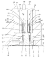
本実施形態にかかるコネクタは、図1に示すように、固定部材90と、コネクタハウジング10と、フレキシブルケーブル30と、補強板50と、保持部材70とを備えている。フレキシブルケーブル30および補強板50は、互いに一体化されてケーブルユニット40を構成する。コネクタは、図2および図3に示すように、回路基板60(剛性のプリント回路基板)に実装され、回路基板60とともにコネクタ実装体を構成する。
コネクタハウジング10は、相手コネクタハウジング100に嵌合される。相手コネクタハウジング100は、合成樹脂製であって、詳細は図示しないが、図2および図3に示すように、複数の相手側端子130を収容している。各相手側端子130は金属製の板材であって、電線190の端末部に接続され、筒状の箱部131を有している。箱部131は、内側に、撓み変形可能な弾性接触片132を有している。
The connector according to this embodiment includes a
The
<固定部材90>
固定部材90は、金属製の平板材であって、コネクタの幅方向の両端側に対をなして設けられている。固定部材90は、図5に示すように、断面がL字形をなし、上下方向に沿って配置される第1板部91と、幅方向に沿って配置される第2板部92とを有している。第1板部91は、コネクタハウジング10に装着される。第2板部92は、回路基板60に半田付けして固定される。コネクタハウジング10は固定部材90を介して回路基板60に固定される。
<Fixing
The
<コネクタハウジング10>
コネクタハウジング10は、合成樹脂製であって、図1および図4に示すように、幅方向に長い角筒状のフード部11を有している。フード部11は、図5に示すように、周壁12と隔壁13とを有している。周壁12は、前後で対をなす前後壁と、左右(幅方向)で対をなす両側壁とを有し、上下方向に沿って配置されている。隔壁13は、周壁12内の下部に一体に連なり、幅方向に沿って配置されている。フード部11内における隔壁13より上方の空間は、相手コネクタハウジング100が挿入される嵌合空間14として構成される。フード部11内における隔壁13より下方の空間は、保持部材70が挿入される収容空間15として構成される。
隔壁13は、複数の挿通孔16を有している。各挿通孔16は、隔壁13を上下に貫通し、前後2列で幅方向に多数並んで配置されている。隔壁13の各挿通孔16には、フレキシブルケーブル30の後述する端子接続部32が挿通される。
<
The
The
周壁12は、両側壁に、一対の装着部17を有している。装着部17は、側壁の下部において、前後に拡張された形状をなしている。固定部材90の第1板部91は、装着部17の内側に形成された溝部分に差し込まれて保持される。
The
図4および図5に示すように、周壁12は、前後壁の内面に、複数の支持部18を有している。各支持部18は、収容空間15に爪状に突出する形状をなし、前後壁の下端に幅方向に間隔を置いて設けられている。各支持部18の上面は、嵌合空間14に向けて前後方向に平坦に配置されている。図2および図3に示すように、ケーブルユニット40は、各支持部18によって下方から支持可能となっている。
As shown in FIGS. 4 and 5, the
各支持部18は、前後壁の下端における幅方向の両端部(図2を参照)と、幅方向の中央を挟んだ両側の中間部(図3を参照)とに設けられている。両端部の各支持部18は、中間部の各支持部18より上下寸法が大きくされている。両端部の各支持部18の上面は、中間部の各支持部18の上面より下方に位置している。図4および図5に示すように、周壁12の前後壁の内面は、両端部の各支持部18と隣接する位置に、凹部19を有している。また、前後壁の内面は、中間部の各支持部18を挟んだ両側に、凹所21を有している。凹部19は、前後壁の内面において、上下方向に延びる形状になっている。
Each
<フレキシブルケーブル30>
フレキシブルケーブル30は、FFC(Flexible Flat Cable)やFPC(Flexible Printed Circuits)に例示されるケーブルであって、外力を受けて容易に変形可能な柔軟性(変形性)を有している。
<
The
図1および図6に示すように、フレキシブルケーブル30は、幅方向に延びる矩形帯状の連結部31と、連結部31の上端において幅方向に並びつつ上方に突出する複数の端子接続部32と、連結部31の下端において幅方向に並びつつ下方に突出する複数の基板接続部33とを有している。
As shown in FIGS. 1 and 6, the
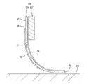
また、フレキシブルケーブル30は、図9に示す板厚方向に見た場合に、各端子接続部32から各基板接続部33にかけて上下方向に延びる導電路34と、各端子接続部32および各基板接続部33の一面を除いて各導電路34の両面を被覆するとともに幅方向に延びて連結部31を形成する保護部36とを有している。各導電路34は、例えば、銅箔によって形成されている。保護部36は、例えば、絶縁樹脂製のフィルムまたはシートによって形成されている。各端子接続部32および各基板接続部33の一面は保護部36で覆われず、各導電路34が露出している。各導電路34は、各端子接続部32および各基板接続部33の一面において、個別に分離された状態で設けられている。このように、端子接続部32は、導電路34の一端側(上端側)に配置され、基板接続部33は、導電路34の他端側(下端側)に配置されている。
9, the
フレキシブルケーブル30は、コネクタにおいて、前後に対をなして設けられている。前側および後側のフレキシブルケーブル30の各端子接続部32は、それぞれ前列および後側の各挿通孔16に挿入される。
The
<補強板50>
補強板50は、ポリイミド樹脂またはガラスエポキシ樹脂からなり、フレキシブルケーブル30の各端子接続部32側の領域を補強する。図6および図7に示すように、補強板50は、連結部31の上部および各端子接続部32と対応する形状に成形され、連結部31の上部および各端子接続部32における他面側(保護部36を有する面側)に設けられている。例えば、補強板50は、接着剤を介してフレキシブルケーブル30の連結部31の上部および各端子接続部32における他面に貼り付けられている。補強板50とフレキシブルケーブル30とが分離するのを規制されて一体化されることにより、ケーブルユニット40が構成される。
<Reinforcing
The reinforcing
補強板50は、図2および図3に示すように、一対のフレキシブルケーブル30がコネクタ内で前後に配置された状態において、各フレキシブルケーブル30の外面(コネクタ内で各フレキシブルケーブル30が対向する面とは反対)の上端側に設けられている。
As shown in FIGS. 2 and 3, the reinforcing
図6および図7に示すように、補強板50における連結部31の上部と対応する部分は、幅方向に延びる基部51として構成される。基部51は、幅方向の両端部に、張り出し部52を有している。張り出し部52は、連結部31の幅方向両側に張り出す形状になっている。そして、基部51は、幅方向に沿った上下縁を有している。
As shown in FIGS. 6 and 7, the portion of the reinforcing
基部51は、上下縁に、複数のロック受け部53を有している。各ロック受け部53は、図7に示すように、基部51の上縁における幅方向中央を挟んだ両側に一対設けられ、さらに基部51の下縁における幅方向中央を挟んだ両側に一対ずつ設けられている。上縁の各ロック受け部53と下縁の各ロック受け部53とは、幅方向に関して異なる位置に配置される。各ロック受け部53は、基部51の上下縁において、矩形に切り欠かれた凹形状をなしている。
The
フレキシブルケーブル30の連結部31は、基部51の各ロック受け部53と対応する部分に、同じくロック受け部53を有している。連結部31の各ロック受け部53は、幅方向に隣接する端子接続部32間において、連結部31の上縁に矩形に切り欠かれるように設けられ、さらに連結部31の上下方向の中間部において、矩形の開口形状に貫通している。連結部31の各ロック受け部53は、各導電路34から離れた位置にて保護部36を貫通している。
The connecting
図6および図7に示すように、基部51は、下縁に、複数の支持受け部54を有している。各支持受け部54は、基部51の下縁における幅方向の両端部(張り出し部52)と、幅方向の中央を挟んだ両側の中間部とに間隔を置いて設けられている。張り出し部52の各支持受け部54は、基部51の下縁の角部に矩形に切り欠かれたL形状をなし、下方と側方とに開口している。中間部の各支持受け部54は、基部51の下縁に矩形に切り欠かれた凹形状をなし、下方に開口している。そして、中間部の各支持受け部54は、幅方向に対をなすロック受け部53の間に設けられている。
As shown in FIGS. 6 and 7, the
フレキシブルケーブル30の連結部31は、中間部の各支持受け部54と対応する部位に、同じく支持受け部54を有している。連結部31の各支持受け部54は、連結部31の上下方向の中間部において、矩形の開口形状に貫通している。連結部31の各支持受け部54は、各導電路34から離れた位置にて保護部36を貫通している。
The connecting
<保持部材70>
保持部材70は合成樹脂製であって、幅方向に長く、断面が山型の台形状をなしている。図3に示すように、保持部材70は、内側に、下方に開口する開口部71を有している。
保持部材70の下端面は、回路基板60の表面と平行に配置される。保持部材70の上面は、平坦であって、コネクタハウジング10の隔壁13の下面と平行に配置される。保持部材70の前後面は、幅方向の両端部を除いて、図3に示すように、ケーブルユニット40の連結部31が対面して装着される装着面72として構成される。
<Holding
The holding
A lower end surface of the holding
保持部材70の装着面72の上部は、上下方向に沿って配置される。保持部材70の装着面72の下部は、上部に曲面状に連なり、下方へ向けて湾曲状に拡開する角度規制部73とされている。図3および図6に示すように、角度規制部73は、ケーブルユニット40の各基板接続部33の上部と連結部31の下部とを湾曲させた状態で支持する。
The upper portion of the mounting
図1および図8に示すように、保持部材70は、装着面72に、複数のロック部74を有している。各ロック部74は、装着面72の上端における幅方向中央を挟んだ両側に一対設けられ、さらに装着面72の上下方向の中間部における幅方向中央を挟んだ両側に一対ずつ設けられている。上側の各ロック部74と下側の各ロック部74とは、幅方向に関して異なる位置に配置される。
As shown in FIGS. 1 and 8 , the holding
各ロック部74は、保持部材70の装着面72に爪状に突出する形状をなしている。保持部材70の装着面72は、各ロック部74を下方に投影した投影範囲に、型抜きに起因する溝部75を開口させている。図6に示すように、各ロック部74は、各ロック受け部53に挿入され、ケーブルユニット40を上下に挟み込んでロックする。
Each locking
図1に示すように、保持部材70は、幅方向の両端部に、前後方向に延びる基端部76と、各基端部76の前後端部から上方に起立する位置規制部77とを有している。各位置規制部77は、断面が矩形の柱状をなし、対向する前後面との間に、上下方向に延びて上方に開口する差し込み空間78を有している。図6に示すように、ケーブルユニット40の張り出し部52は差し込み空間78に差し込まれる。
As shown in FIG. 1, the holding
図1に示すように、保持部材70は、装着面72に、隣接する部分より凹む形状の逃がし部79を有している。逃がし部79は、保持部材70の装着面72における幅方向の両端部と幅方向の中央を挟んだ両側の中間部とに設けられている。ケーブルユニット40の一部は、後述するように、支持部18との干渉時に撓み変形して逃がし部79に進入することが可能となっている。
As shown in FIG. 1, the mounting
<コネクタおよびコネクタ実装体の製造方法>
ケーブルユニット40は、コネクタハウジング10への組み付けに先立ち、保持部材70に取り付けられる。ケーブルユニット40の取り付けに際し、各張り出し部52は、保持部材70の各差し込み空間78に上方から差し込まれる。ケーブルユニット40の差し込み過程において、連結部31は、保持部材70の装着面72に沿ってスライドさせられる。連結部31は、保持部材70の各ロック部74と干渉して、撓み変形する。ケーブルユニット40が正規に差し込まれると、連結部31が弾性的に復帰し、保持部材70の各ロック部74がケーブルユニット40の各ロック受け部53に嵌まり込む(図6を参照)。ケーブルユニット40は、各張り出し部52が保持部材70の各位置規制部77に当たることで、保持部材70の装着面72から離れる方向に脱落するのが防止される。
<Manufacturing Method of Connector and Connector Mounted Body>
上記のように、補強板50の前後位置が各位置規制部77で規定され、補強板50の上下位置が各ロック部74で規定されることにより、補強板50が保持部材70に位置決めされた状態に保持される。このように補強板50が保持部材70に対し各位置規制部77などを介して位置規制されると、各端子接続部32も位置規制される。ケーブルユニット40は、前後それぞれの装着面72に対応し、保持部材70に前後に対をなして取り付けられる。
As described above, the front and rear positions of the reinforcing
ケーブルユニット40が保持部材70に取り付けられた状態において、連結部31、各端子接続部32および補強板50は、上下方向に沿って配置される。各端子接続部32は、補強板50の対応部分とともに、幅方向に一定間隔に整列させられ、上方に起立して配置される。各基板接続部33は、連結部31の下部(補強板50で補強されない部分)とともに、保持部材70の角度規制部73に沿って湾曲状に変形させられ、前後方向に対し所定角度に傾斜して配置される。
In a state where the
ケーブルユニット40を取り付けた保持部材70は、コネクタハウジング10の収容空間15に下方から挿入される。収容空間15への挿入過程において、ケーブルユニット40がコネクタハウジング10の各支持部18と干渉し、ケーブルユニット40の一部が逃がし部79に撓み変形する。保持部材70が正規に挿入されると、ケーブユニットの一部が弾性的に復帰し、コネクタハウジング10の各支持部18がケーブルユニット40の各支持受け部54に嵌まり込む。各支持部18の上面は、各支持受け部54の奥端面に当たり得る状態になる。これにより、各支持部18は、ケーブルユニット40の補強板50を、各端子接続部32の先端側とは反対側(下側)から支持することが可能となる(図2および図3を参照)。
The holding
保持部材70が収容空間15に挿入されると、各位置規制部77は、コネクタハウジング10の各凹部19に適合して挿入される。また、各支持受け部54の先端は、コネクタハウジング10の各凹所21に進入して配置される。そして、ケーブルユニット40は、コネクタハウジング10の収容空間15の内面と保持部材70の装着面72との間に圧入状態に挟まれて固定される。
When the holding
保持部材70の上面は、隔壁13に対面して配置される。各端子接続部32は、補強板50の対応部分とともに、隔壁13の各挿通孔16を貫通してフード部11の嵌合空間14に突出して配置される。ここで、各端子接続部32は、各位置規制部77で位置規制され、上下方向に沿って直立した姿勢が維持されている。このため、各端子接続部32は、各挿通孔16に円滑に挿通される。
The upper surface of the holding
続いて、ケーブルユニット40および保持部材70を装着したコネクタハウジング10(以下、コネクタという)は、回路基板60の表面上に設置される。ここで、各基板接続部33は、補強板50によって補強されておらず、フレキシブルケーブル30の本来の変形容易な特性を備えている。また、各基板接続部33は、角度規制部73によって一面側の導電路34が下向きに湾曲させられ、回路基板60に対する設置角度があらかじめ調整されている。このため、各基板接続部33は、設置過程でコネクタの荷重(自重)が加わるのに伴い回路基板60の表面に沿って柔軟に撓み変形し、一面側の導電路34が回路基板60の表面に円滑に接することができる(図9を参照)。
Subsequently, the connector housing 10 (hereinafter referred to as connector) with the
続いて、コネクタは図示しないリフロー炉内に搬入される。リフロー工程において、回路基板60の表面上に塗布されたペースト半田が溶融され、溶融された半田が各基板接続部33に付着する。その後、半田が冷却して固化される。これにより、基板接続部33が回路基板60の表面上の導電部分に電気的に接続される。仮に、回路基板60およびコネクタハウジング10がリフロー時の熱により変形しても、各基板接続部33はその柔軟性によって回路基板60の表面上から浮き上がることがなく回路基板60との接続状態を維持することができる。また、各固定部材90の第2板部92もリフロー半田によって回路基板60に固定される。以上により、コネクタが回路基板60の表面に実装され、コネクタ実装体が得られる。
Subsequently, the connector is carried into a reflow furnace (not shown). In the reflow process, the paste solder applied on the surface of the
次いで、コネクタは相手コネクタハウジング100に嵌合される。相手コネクタハウジング100は、フード部11の嵌合空間14に挿入される(図2および図3を参照)。各端子接続部32は、各相手側端子130の箱部131内に進入する。そして、各端子接続部32の一面側の導電路34が各相手側端子130の弾性接触片132と弾性的に接触する。これにより、各端子接続部32は各相手側端子130と電気的に接続される。ここで、各端子接続部32は、他面側に設けられた補強板50によって補強されている。その結果、各端子接続部32は、各相手側端子130からの荷重に抗する強度を確保することができ、各相手側端子130との接続時に変形するのが防止される。また、各位置規制部77および各ロック部74が保持部材70に対する補強板50の位置規制を行うことにより、各端子接続部32は、対応する各相手側端子130の箱部131内に円滑に進入することができる。したがって、端子接続部32と相手側端子130との良好な接続を実現することができる。
The connector is then mated to the
両コネクタハウジング10、100の嵌合時に、フレキシブルケーブル30は、相手コネクタハウジング100側から下向きの力(嵌合力)を受ける。ここで、コネクタハウジング10の各支持部18は、各支持受け部54の奥端面に当たることで、上記の力に抗して補強板50を下方から支持することができる。したがって、補強板50は、コネクタハウジング10に対して位置ずれするのが防止される。
When the two
以上説明したように、本実施形態によれば、リフロー工程で熱が加わっても、各基板接続部33が柔軟に変形して回路基板60に接続される状態を維持することができるため、各基板接続部33が回路基板60の表面(平面)上に位置する状態を容易に実現することができる。その結果、フレキシブルケーブル30と回路基板60との接続信頼性を確保することができる。一方、端子接続部32は、補強板50で補強されているため、相手側端子130との接続時に変形しない強度を備えることができる。
As described above, according to the present embodiment, even if heat is applied in the reflow process, each
また、本実施形態の場合、フレキシブルケーブル30と補強板50とが一体化されてケーブルユニット40を構成しており、ケーブルユニット40が保持部材70に保持された状態で、コネクタハウジング10に組み付けられる。フレキシブルケーブル30が保持部材70で保持されるため、コネクタハウジング10への組み付け前に、端子接続部32および基板接続部33の姿勢を保持部材70であらかじめ矯正しておくことができる。その結果、コネクタハウジング10への組み付け作業を円滑かつ迅速に行うことができる。
In the case of this embodiment, the
また、各基板接続部33を角度規制部73によって適正な姿勢(角度)にした状態で回路基板60に接続させることができる。さらに、フレキシブルケーブル30がコネクタハウジング10と保持部材70との間に挟まれて保持されるため、ケーブルユニット40と保持部材70との保持状態を簡易な構成で安定に維持することができる。
In addition, each
[本開示の他の実施形態]
今回開示された実施の形態はすべての点で例示であって制限的なものではないと考えるべきである。
上記実施形態の場合、補強板50は、各端子接続部32から連結部31の上部に亘って設けられていたが、他の実施形態としては、補強板50は、各端子接続部32のみに設けられていても良く、あるいは、各端子接続部32から連結部31の全体に亘って設けられていても良い。補強板50は、フレキシブルケーブル30における端子接続部32側の領域に対応して設けられていると良い。
上記実施形態の場合、フレキシブルケーブル30はコネクタハウジング10に対をなして組み付けられていたが、他の実施形態としては、フレキシブルケーブル30はコネクタハウジング10に一つのみ、あるいは3つ以上組み付けられていても良い。
上記実施形態の場合、フレキシブルケーブル30は保持部材70に保持された状態でコネクタハウジング10に組み付けられていたが、他の実施形態としては、フレキシブルケーブル30は保持部材70を介さずにコネクタハウジング10に直接組み付けられていても良い。
上記実施形態の場合、補強板50とフレキシブルケーブル30とが一体化されてケーブルユニット40を構成していたが、他の実施形態としては、補強板50とフレキシブルケーブル30とが分離可能に設けられていてもよい。
上記実施形態の場合、フレキシブルケーブル30の各基板接続部33が回路基板60にリフロー半田付けして接続されていたが、他の実施形態としては、フレキシブルケーブルの各基板接続部33が回路基板に手半田で接続されても良い。ここで、コネクタハウジング10および回路基板60の変形はリフロー工程の場合に限らない。例えば、コネクタ実装体が熱源近くの高熱下に設置され、コネクタハウジング10および回路基板60が反り変形する可能性がある場合に、本開示の構成を適用することができる。
[Other embodiments of the present disclosure]
It should be considered that the embodiments disclosed this time are illustrative in all respects and not restrictive.
In the above embodiment, the reinforcing
In the above embodiment, the
In the above embodiment, the
In the case of the above embodiment, the reinforcing
In the case of the above embodiment, each
10…コネクタハウジング
11…フード部
12…周壁
13…隔壁
14…嵌合空間
15…収容空間
16…挿通孔
17…装着部
18…支持部
19…凹部
21…凹所
30…フレキシブルケーブル
31…連結部
32…端子接続部
33…基板接続部
34…導電路
36…保護部
40…ケーブルユニット
50…補強板
51…基部
52…張り出し部
53…ロック受け部
54…支持受け部
60…回路基板
70…保持部材
71…開口部
72…装着面
73…角度規制部
74…ロック部
75…溝
76…基端部
77…位置規制部
78…差し込み空間
79…逃がし部
90…固定部材
91…第1板部
92…第2板部
100…相手コネクタハウジング
130…相手側端子
131…箱部
132…弾性接触片
190…電線
DESCRIPTION OF
Claims (7)
前記フレキシブルケーブルは、前記導電路の一端側において、相手側端子の箱部内に入って、前記相手側端子に接続される端子接続部と、前記導電路の他端側において回路基板に接続される基板接続部と、前記端子接続部と前記基板接続部との間に位置する帯状の連結部と、を有しており、
前記フレキシブルケーブルにおける前記端子接続部側の領域を補強する補強板を備え、
複数の前記端子接続部が前記連結部の一側縁に並んでそれぞれ一側に突出しており、
前記補強板は、複数の前記端子接続部のそれぞれに対応した形状を有しているコネクタ。 a connector housing; and a flexible cable disposed in the connector housing and having a conductive path,
The flexible cable is connected to a circuit board at the other end of the conductive path, and a terminal connection portion that enters the box portion of the mating terminal and is connected to the mating terminal at one end of the conductive path. a substrate connecting portion , and a strip-shaped connecting portion located between the terminal connecting portion and the substrate connecting portion ;
a reinforcing plate that reinforces a region of the flexible cable on the terminal connection side ;
a plurality of the terminal connection portions are arranged along one side edge of the connecting portion and protrude to one side;
The connector, wherein the reinforcing plate has a shape corresponding to each of the plurality of terminal connection portions .
前記フレキシブルケーブルは、前記導電路の一端側において相手側端子に接続される端子接続部と、前記導電路の他端側において回路基板に接続される基板接続部とを有しており、
前記フレキシブルケーブルにおける前記端子接続部側の領域を補強する補強板を備え、
前記端子接続部および前記補強板は一体化されて、前記端子接続部の先端に向かって突出して設けられており、
前記コネクタハウジングは、前記補強板を前記先端とは反対側から支持する支持部を有しているコネクタ。 a connector housing; and a flexible cable disposed in the connector housing and having a conductive path,
The flexible cable has a terminal connection portion connected to a mating terminal on one end side of the conductive path, and a substrate connection portion connected to a circuit board on the other end side of the conductive path,
a reinforcing plate that reinforces a region of the flexible cable on the terminal connection side;
The terminal connection portion and the reinforcing plate are integrated and provided to protrude toward the tip of the terminal connection portion,
The connector housing has a support portion that supports the reinforcing plate from a side opposite to the tip .
前記保持部材は、前記補強板の位置規制を行う位置規制部を有している請求項3または請求項4に記載のコネクタ。 The reinforcing plate is integrated with the flexible cable,
5. The connector according to claim 3, wherein said holding member has a position regulating portion for regulating the position of said reinforcing plate .
Priority Applications (4)
| Application Number | Priority Date | Filing Date | Title |
|---|---|---|---|
| JP2019089506A JP7202529B2 (en) | 2019-05-10 | 2019-05-10 | Connectors and connector assemblies |
| PCT/JP2020/017017 WO2020230532A1 (en) | 2019-05-10 | 2020-04-20 | Connector and connector mounting body |
| US17/605,937 US20220216627A1 (en) | 2019-05-10 | 2020-04-20 | Connector and connector mounting body |
| CN202080031638.5A CN113728517B (en) | 2019-05-10 | 2020-04-20 | Connector and connector assembly |
Applications Claiming Priority (1)
| Application Number | Priority Date | Filing Date | Title |
|---|---|---|---|
| JP2019089506A JP7202529B2 (en) | 2019-05-10 | 2019-05-10 | Connectors and connector assemblies |
Publications (2)
| Publication Number | Publication Date |
|---|---|
| JP2020187834A JP2020187834A (en) | 2020-11-19 |
| JP7202529B2 true JP7202529B2 (en) | 2023-01-12 |
Family
ID=73222879
Family Applications (1)
| Application Number | Title | Priority Date | Filing Date |
|---|---|---|---|
| JP2019089506A Active JP7202529B2 (en) | 2019-05-10 | 2019-05-10 | Connectors and connector assemblies |
Country Status (4)
| Country | Link |
|---|---|
| US (1) | US20220216627A1 (en) |
| JP (1) | JP7202529B2 (en) |
| CN (1) | CN113728517B (en) |
| WO (1) | WO2020230532A1 (en) |
Families Citing this family (3)
| Publication number | Priority date | Publication date | Assignee | Title |
|---|---|---|---|---|
| JP7444005B2 (en) * | 2020-09-16 | 2024-03-06 | 住友電装株式会社 | connector |
| KR102642877B1 (en) * | 2021-05-21 | 2024-03-05 | 세방리튬배터리 주식회사 | Flexible printed circuit connector for battery |
| WO2024180439A1 (en) * | 2023-03-02 | 2024-09-06 | Molex, Llc | Connector with stiffeners |
Citations (5)
| Publication number | Priority date | Publication date | Assignee | Title |
|---|---|---|---|---|
| JP2000277219A (en) | 1999-03-24 | 2000-10-06 | Kel Corp | Connector having low-pass filter function |
| JP2000311736A (en) | 1999-02-24 | 2000-11-07 | Kel Corp | Surface mount connector |
| JP2006275543A (en) | 2005-03-28 | 2006-10-12 | Kurio:Kk | Probe device |
| CN202423650U (en) | 2011-12-16 | 2012-09-05 | 信音电子(中山)有限公司 | Socket structure of electric connector |
| JP2013122885A (en) | 2011-12-12 | 2013-06-20 | Japan Aviation Electronics Industry Ltd | Connector |
Family Cites Families (20)
| Publication number | Priority date | Publication date | Assignee | Title |
|---|---|---|---|---|
| JPS55129389U (en) * | 1979-03-07 | 1980-09-12 | ||
| JPS59104562U (en) * | 1982-12-28 | 1984-07-13 | 日本メクトロン株式会社 | flexible circuit board |
| JPS59185866U (en) * | 1983-05-28 | 1984-12-10 | 株式会社リコー | printed circuit board |
| JPH03112082A (en) * | 1989-09-26 | 1991-05-13 | Keru Kk | Two-piece connector |
| US5156553A (en) * | 1990-05-29 | 1992-10-20 | Kel Corporation | Connector assembly for film circuitry |
| JPH07312268A (en) * | 1994-05-13 | 1995-11-28 | Niles Parts Co Ltd | Independent contact card edge terminal |
| JP3824352B2 (en) * | 1996-07-15 | 2006-09-20 | 第一電子工業株式会社 | Electrical connector |
| JP3331298B2 (en) * | 1997-01-08 | 2002-10-07 | 第一電子工業株式会社 | Electrical connector |
| EP0908978A3 (en) * | 1997-10-09 | 2000-06-21 | Molex Incorporated | Card connector assembly |
| JP2003101167A (en) * | 2001-09-21 | 2003-04-04 | Canon Inc | Flexible printed board |
| JP2005136182A (en) * | 2003-10-30 | 2005-05-26 | Optrex Corp | Flexible wiring board |
| JP4398908B2 (en) * | 2005-06-30 | 2010-01-13 | モレックス インコーポレイテド | Board connector |
| JP2007214087A (en) * | 2006-02-13 | 2007-08-23 | Fujikura Ltd | Connector |
| JP2008047335A (en) * | 2006-08-11 | 2008-02-28 | Bando Densen Kk | Flexible board |
| JP5589858B2 (en) * | 2011-01-14 | 2014-09-17 | 日立金属株式会社 | connector |
| JP5673457B2 (en) * | 2011-01-19 | 2015-02-18 | 日立金属株式会社 | connector |
| TWI493797B (en) * | 2013-01-04 | 2015-07-21 | Acer Inc | Adaptor for flexible printed circuit board |
| JP6101112B2 (en) * | 2013-02-28 | 2017-03-22 | タイコエレクトロニクスジャパン合同会社 | Surface mount connector |
| TWM486160U (en) * | 2013-11-19 | 2014-09-11 | Ya-Li Huang | Flexible flat cable capable of preventing conductive member from end deformation |
| JP6238826B2 (en) * | 2014-04-11 | 2017-11-29 | 日本圧着端子製造株式会社 | Surface mount connector |
-
2019
- 2019-05-10 JP JP2019089506A patent/JP7202529B2/en active Active
-
2020
- 2020-04-20 WO PCT/JP2020/017017 patent/WO2020230532A1/en active Application Filing
- 2020-04-20 CN CN202080031638.5A patent/CN113728517B/en active Active
- 2020-04-20 US US17/605,937 patent/US20220216627A1/en active Pending
Patent Citations (5)
| Publication number | Priority date | Publication date | Assignee | Title |
|---|---|---|---|---|
| JP2000311736A (en) | 1999-02-24 | 2000-11-07 | Kel Corp | Surface mount connector |
| JP2000277219A (en) | 1999-03-24 | 2000-10-06 | Kel Corp | Connector having low-pass filter function |
| JP2006275543A (en) | 2005-03-28 | 2006-10-12 | Kurio:Kk | Probe device |
| JP2013122885A (en) | 2011-12-12 | 2013-06-20 | Japan Aviation Electronics Industry Ltd | Connector |
| CN202423650U (en) | 2011-12-16 | 2012-09-05 | 信音电子(中山)有限公司 | Socket structure of electric connector |
Also Published As
| Publication number | Publication date |
|---|---|
| US20220216627A1 (en) | 2022-07-07 |
| CN113728517A (en) | 2021-11-30 |
| WO2020230532A1 (en) | 2020-11-19 |
| CN113728517B (en) | 2024-05-14 |
| JP2020187834A (en) | 2020-11-19 |
Similar Documents
| Publication | Publication Date | Title |
|---|---|---|
| US7147481B2 (en) | Shielded electrical connector with anti-mismatching means | |
| US6939172B2 (en) | Electrical connector with anti-mismating arrangement | |
| KR101195355B1 (en) | Anti-wicking terminal and connector | |
| US7189090B2 (en) | Coupler for flat cables and electrical connector assembly | |
| US9502815B2 (en) | Electrical connector | |
| JP7202529B2 (en) | Connectors and connector assemblies | |
| EP3316406B1 (en) | Electronic device and connector | |
| US9722356B2 (en) | Connector | |
| TW201036282A (en) | Electrical connector for circuit board | |
| WO2013052280A1 (en) | Power cable connector | |
| JP5315912B2 (en) | Multiple electrical connector | |
| WO2008133890A1 (en) | Floating connector | |
| US9343832B2 (en) | Plug connector and method of manufacturing the same | |
| JP2008112682A (en) | Card edge type connector | |
| US9236686B2 (en) | Electrical connector assembly having anti-displacement socket ribs | |
| EP1993173B1 (en) | A set of circuit board connectors and a method of mounting a connector to a circuit board | |
| WO2010135549A1 (en) | Loop connector and closed-circuit forming connector | |
| WO2022249679A1 (en) | Connector and connector mounting body | |
| US20240106149A1 (en) | Connector | |
| US10122104B2 (en) | Connector for a flexible printed circuit | |
| JP4837631B2 (en) | Electrical connection parts | |
| KR102246509B1 (en) | Electrical connector | |
| WO2022259842A1 (en) | Board connector | |
| JP2001143793A (en) | Structure for connecting flat cable to printed circuit board and connector clip | |
| TWI661615B (en) | Automotive connector assembly |
Legal Events
| Date | Code | Title | Description |
|---|---|---|---|
| A621 | Written request for application examination |
Free format text: JAPANESE INTERMEDIATE CODE: A621 Effective date: 20210830 |
|
| A131 | Notification of reasons for refusal |
Free format text: JAPANESE INTERMEDIATE CODE: A131 Effective date: 20220630 |
|
| A521 | Request for written amendment filed |
Free format text: JAPANESE INTERMEDIATE CODE: A523 Effective date: 20220727 |
|
| TRDD | Decision of grant or rejection written | ||
| A01 | Written decision to grant a patent or to grant a registration (utility model) |
Free format text: JAPANESE INTERMEDIATE CODE: A01 Effective date: 20221124 |
|
| A61 | First payment of annual fees (during grant procedure) |
Free format text: JAPANESE INTERMEDIATE CODE: A61 Effective date: 20221207 |
|
| R150 | Certificate of patent or registration of utility model |
Ref document number: 7202529 Country of ref document: JP Free format text: JAPANESE INTERMEDIATE CODE: R150 |